Navigating static environments using image-space simplification and morphing
10
Navigating Static Environments Using Image-Space Simplification and Morphing Lucia Darsa Bruno Costa Silva Amitabh Varshney State University of New York Abstract We present a -buffered image-space-based rendering technique that allows navigation in complex static environments. The ren- dering speed is relatively insensitive to the complexity of the scene as the rendering is performed a priori, and the scene is converted into a bounded complexity representation in the image space. Real- time performance is attained by using hardware texture mapping to implement the image-space warping and hardware affine trans- formations to compute the viewpoint–dependent warping function. Our proposed method correctly simulates the kinetic depth effect (parallax), occlusion, and can resolve the missing visibility infor- mation by combining -buffered environment maps from multiple viewpoints. CR Categories and Subject Descriptors: I.3.3 [Computer Graph- ics]: Picture/Image Generation - Display Algorithms, Viewing Al- gorithms; I.3.7 [Computer Graphics]: Three-Dimensional Graphics and Realism - Animation, Texture; I.4.8 [Image Processing]: Scene Analysis - Range data. Additional Keywords: image-based rendering, synthetic environ- ments, image morphing, visibility. 1 Introduction Traditional approaches to graphics acceleration for the navigation of a three-dimensional environment have involved: reducing the geometric complexity of the scene, by using level-of-detail hierarchies (Turk, 1992; Schroeder, Zarge and Lorensen, 1992; Rossignac and Borrel, 1993; Cohen et al., 1996; Hoppe, 1996; DeRose, Lounsbery and Warren, 1993; He et al., 1996), and by visibility-based culling(Airey, 1990; Teller and S´ equin, 1991; Greene and Kass, 1993; Luebke and Georges, 1995; Greene, 1996). reducing the rendering complexity by using texture mapping (Blinn and Newell, 1976; Blinn, 1978), and by using vari- [email protected], Recently graduated from the Department of Com- puter Science, State University of New York, Stony Brook, NY 11794-4400 [email protected], Microsoft Corp., One Microsoft Way, Red- mond WA 98052-6399 [email protected],Department of Computer Science, State Uni- versity of New York, Stony Brook, NY 11794-4400 ous levels of complexity in shading and illumination mod- els(Bergman et al., 1986). exploiting frame-to-frame coherence with one of the above (Bishop et al., 1994; Xia and Varshney, 1996). However, as the complexity of the three-dimensional object- space has increased beyond the bounded image-space resolution, image-based rendering has begun to emerge as a viable alternative to the conventional three-dimensional geometric modeling and ren- dering, in specific application domains. Image-space-based render- ing has been used to navigate (although with limited freedom of movement) in environments modeled from real-world digitized im- ages (Chen, 1995; Szeliski, 1996; McMillan and Bishop, 1995). More recent approaches (Gortler et al., 1996; Levoy and Hanrahan, 1996) generalize the idea of plenoptic modeling by characterizing the complete flow of light in a given region of space. A clever com- bination of simple geometric building blocks with view-dependent textures derived from image-based rendering (Debevec, Taylor and Malik, 1996) has resulted in a viable technique for navigation in environments that can be described by those simple blocks. The potential of image-based rendering specifically for the navigation in generic synthetic environments, however, has been investigated in fewer instances (Chen and Williams, 1993). In this paper we present a conceptual discussion and an imple- mented system for the problem of image-based rendering using image-space simplification and morphing. Given a collection of - buffered images representing an environment from fixed viewpoints and view directions, our approach first constructs an image-space simplification of the scene as a pre-process, and then reconstructs a view of this scene for arbitrary viewpoints and directions in real- time. We achieve speed through the use of the commonly available texture-mapping hardware, and partially rectify the visibility gaps (“tears”) pointed out in previous work on image-based rendering (Chen and Williams, 1993; Chen, 1995) through morphing. 2 Image-based Navigation Image-based rendering uses images as the basic primitive for gen- erating other images, as opposed to the more traditional approach that renders directly from geometric models. Images are a sampled version of the scene, viewed from a certain position and direction, and not a full representation of the actual scene. Since the images used as the basis for the rendering are generated and viewed from different points of view, they represent view-dependent informa- tion only for the originally generated positions. Thus, image-based rendering methods have an inherent difficulty in dealing with view- dependent effects, such as specular highlights, reflection, and re- fraction. However, view-independent effects that are usually very expensive to simulate – such as diffuse reflections, soft shadows and caustics – can be used with image-based rendering without any additional runtime cost. Navigation in an environment using image-based rendering can be classified into four different levels based on freedom allowed in user-movement:
-
Upload
independent -
Category
Documents
-
view
1 -
download
0
Transcript of Navigating static environments using image-space simplification and morphing

Navigating Static Environments Using Image-Space Simplification andMorphing
Lucia Darsa� Bruno Costa Silvay Amitabh Varshneyz
State University of New York
Abstract
We present az-buffered image-space-based rendering techniquethat allows navigation in complex static environments. The ren-dering speed is relatively insensitive to the complexity of the sceneas the rendering is performeda priori, and the scene is convertedinto a bounded complexity representation in the image space. Real-time performance is attained by using hardware texture mappingto implement the image-space warping and hardware affine trans-formations to compute the viewpoint–dependent warping function.Our proposed method correctly simulates the kinetic depth effect(parallax), occlusion, and can resolve the missing visibility infor-mation by combiningz-buffered environment maps from multipleviewpoints.CR Categories and Subject Descriptors:I.3.3 [Computer Graph-ics]: Picture/Image Generation - Display Algorithms, Viewing Al-gorithms; I.3.7 [Computer Graphics]: Three-Dimensional Graphicsand Realism - Animation, Texture; I.4.8 [Image Processing]: SceneAnalysis - Range data.Additional Keywords: image-based rendering, synthetic environ-ments, image morphing, visibility.
1 Introduction
Traditional approaches to graphics acceleration for the navigationof a three-dimensional environment have involved:
� reducing the geometric complexity of the scene, by usinglevel-of-detail hierarchies (Turk, 1992; Schroeder, Zarge andLorensen, 1992; Rossignac and Borrel, 1993; Cohen et al.,1996; Hoppe, 1996; DeRose, Lounsbery and Warren, 1993;He et al., 1996), and by visibility-based culling(Airey,1990;Teller and S´equin, 1991; Greene and Kass, 1993; Luebke andGeorges, 1995; Greene, 1996).
� reducing the rendering complexity by using texture mapping(Blinn and Newell, 1976; Blinn, 1978), and by using vari-
�[email protected], Recently graduated from the Department of Com-puter Science, State University of New York, Stony Brook, NY 11794-4400
[email protected], Microsoft Corp., One Microsoft Way, Red-mond WA 98052-6399
[email protected],Department of Computer Science, State Uni-versity of New York, Stony Brook, NY 11794-4400
ous levels of complexity in shading and illumination mod-els(Bergman et al., 1986).
� exploiting frame-to-frame coherence with one of the above(Bishop et al., 1994; Xia and Varshney, 1996).
However, as the complexity of the three-dimensional object-space has increased beyond the bounded image-space resolution,image-based rendering has begun to emerge as a viable alternativeto the conventional three-dimensional geometric modeling and ren-dering, in specific application domains. Image-space-based render-ing has been used to navigate (although with limited freedom ofmovement) in environments modeled from real-world digitized im-ages (Chen, 1995; Szeliski, 1996; McMillan and Bishop, 1995).More recent approaches (Gortler et al., 1996; Levoy and Hanrahan,1996) generalize the idea of plenoptic modeling by characterizingthe complete flow of light in a given region of space. A clever com-bination of simple geometric building blocks with view-dependenttextures derived from image-based rendering (Debevec, Taylor andMalik, 1996) has resulted in a viable technique for navigation inenvironments that can be described by those simple blocks. Thepotential of image-based rendering specifically for the navigationin generic synthetic environments, however, has been investigatedin fewer instances (Chen and Williams,1993).
In this paper we present a conceptual discussion and an imple-mented system for the problem of image-based rendering usingimage-space simplification and morphing. Given a collection ofz-buffered images representing an environment from fixed viewpointsand view directions, our approach first constructs an image-spacesimplification of the scene as a pre-process, and then reconstructsa view of this scene for arbitrary viewpoints and directions in real-time. We achieve speed through the use of the commonly availabletexture-mapping hardware, and partially rectify the visibility gaps(“tears”) pointed out in previous work on image-based rendering(Chen and Williams,1993; Chen, 1995) through morphing.
2 Image-based Navigation
Image-based rendering uses images as the basic primitive for gen-erating other images, as opposed to the more traditional approachthat renders directly from geometric models. Images are a sampledversion of the scene, viewed from a certain position and direction,and not a full representation of the actual scene. Since the imagesused as the basis for the rendering are generated and viewed fromdifferent points of view, they represent view-dependent informa-tion only for the originally generated positions. Thus, image-basedrendering methods have an inherent difficulty in dealing with view-dependent effects, such as specular highlights, reflection, and re-fraction. However, view-independent effects that are usually veryexpensive to simulate – such as diffuse reflections, soft shadowsand caustics – can be used with image-based rendering without anyadditional runtime cost.
Navigation in an environment using image-based rendering canbe classified into four different levels based on freedom allowed inuser-movement:

1. Discrete viewpoints, discrete view directions
2. Discrete viewpoints, continuous view directions
3. Continuous viewpoints, discrete view directions
4. Continuous viewpoints, continuous view directions
The first group is the simplest approach, providing a very limitedimmersive experience and interaction. The images are rendered ordigitized for selected positions and selected viewing directions andduring navigation the one that is closest to the desired is displayed.One early instance of this situation is described in (Lippman, 1980),and the same concept has been used at the consumer level morerecently (Cyan, 1994).
The second group uses one image, or a series of images stitchedtogether, to represent the environment around a certain point ofview, which is equivalent to providing a complete sample of theplenoptic function (McMillan and Bishop, 1995) for that point.This form of information enables the simulation of a rotation ofthe observer, around the original point of view, to look in any direc-tion by reprojecting the given images to the new viewing frustum.To allow observer limited translation (at discrete viewpoints), thesolution is to have a set of environment maps, each computed fora different viewpoint. If these points are carefully selected and notvery far from each other, it is possible to simulate movement byselecting the closer environment map. This jump between discreteviewpoints around which one can rotate almost freely allows for aquality of simulation that can be consideredacceptable for some sit-uations, as shown by current applications of Quicktime VR (Chen,1995), for instance.
The third group has been bypassed in theliterature and its re-sults are subsumed in the fourth group in which the user is allowedfreedom to continuously translate and rotate. In “View Interpola-tion for Image Synthesis” (Chen and Williams,1993), the mappingfunction and the depth are obtained from the camera model and therendering. The mapping is applied as an image warping transfor-mation, and a binary combination of the images is performed basedon depth—the front most pixel wins. That technique is not actu-ally based on environment maps, but on single images with depthinformation. The movement of the observer had to be restricted,though, to achieve the desired performance. In “Plenoptic Model-ing” (McMillan and Bishop, 1995), the nodes are represented bycylindrical maps, which the authors describe as a complete sampleof the plenoptic function. They focus on the image-based model-ing aspect of the problem, concentrating on the techniques for re-construction of a complete sample of the plenoptic function froma set of overlapping partial samples from non-computer-generatedsources (photographs or video frames). The navigation, however,was limited and required closely spaced nodes and user input forproper matching.
When the environment is modeled from photographs or video,the depth information has to be inferred from the disparities in-duced by translations of the camera. This is an important problemin computer vision to which a considerable effort has been ded-icated (Aggarwal and Nandakumar, 1988). However, the drivingproblem for our work is smooth navigation in complex computer-generated virtual environments, that are slow to render, and forwhich we have access toz-buffered images at fixed viewpoints andview-directions. Thus, our work falls in category four listed above.
3 Environment Mapping and Morphing
Changes of visibility that occur as an observer moves freely in anenvironment can be simulated by using precomputed views of thescene at selected viewpoints. Anodeis associated with every se-lected viewpoint and consists of an environment map with depth
(a) (b)
Figure 1: Visibility: (a) Rotation (b) Translation.
and color information for every direction. This is essentially anextension to the plenoptic function, that also associates depth infor-mation to each direction, in addition to color.1
Each node provides limited information about the world, whichis not sufficient to determine the view from an arbitrary viewpointand direction. If the desired visualization parameters differ only inthe direction, there is no parallax and no new areas can become visi-ble (see Figure 1). If they differ in the position, however, parallax isintroduced and the restricted information provided by a single nodebecomes evident.
This problem can be overcome by combining the informationfrom neighboring nodes—through node morphing—to create animage for any viewpoint and direction. Morphing two nodes in-volves two warpings to register the information, followed by a com-bination (Gomes et al., 1995). The particular case of image morph-ing is extensively discussedin (Wolberg, 1990). The depth informa-tion and the visualization parameters allow the determination of themapping functions between the original views and the new arbitraryview. After applying these mappings, the warped information canbe combined with local control, used to determine the predominantinformation at each region.
A more detailed discussion of this form of morphing is presentedin the next sections. We will focus on a simpler case of two planarz-buffered images, although it can be directly applied to environ-ment maps.
3.1 Environment Map Warping
An adequate mathematical model for acontinuousimage withdepth is a function that relates points in a subset of the Euclideanplane to colors in a color space and to depths. Az-buffered imagecan be considered as a functionIz : U � R
2! C �R, whereC
is a color space.
The class of rendering processes that are relevant to our appli-cation are those that are able to yield az-buffered image. Each ofthose processes can be seen as a functionR that maps a scene,S(the collection of models and information that define a scene) anda projectionP (a transformation derived from a set of visualizationparameters) into az-buffered image:
R : S �P ! Iz; (1)
P = fP : R3! R
3g: (2)
Given az-buffered imageIz1 and the projection transformationP1 that originated this image, we are interested in applying a repro-jection using a new set of visualization parameters described byPto obtain a new imageIz. Our specific case is depicted in Figure 2.This is a transformation of the domain of definition of the originalimage, or a warping transformationW = P �P�1
1, that essentially
reprojects the image to a different point of view2.

Figure 2: Environment map warping.
Figure 3: Blending from two nodes (visibility gaps in black).
Figure 4: Environment map morphing.
3.2 Environment Map Morphing
The information from a single node is not sufficient to generate anarbitrarily different view, that is, this particular form of warping isnot described in general by an onto function. Therefore, to coverthe domain of the resulting imageIz it is generally necessary tocombine the information from two or more nodes.
This combination is exemplified in figure 3, which shows an im-age obtained in real-time from the combination of two nodes. Thetop left node was originally generated as a top view of the sphere;the top right node, as a side view. Notice how the visibility infor-mation that is missing from the top view is completely filled by thesecond node. Similarly, the visibility gaps in the secondnode arecovered by the first.
By applying the warping process described in the previous sec-tion to each node individually, we get two differentz-buffered im-agesIz
0
1 andIz0
2 —from P1 andP2, respectively—as illustrated infigure 4. What remains is the combination ofIz
0
1 andIz0
2 , a rangetransformationB which, for each point(x; y), depends solely onthe values of thez-buffered images at that position, resulting in theimageIzf = B(Iz
0
1 ; Iz0
2 ). Different forms of this blending functionare described in section 6.
4 Image-Space Simplification
Given an environment map with depth and color information at aviewpoint, we have seen that it is possible to create views from newpositions and directions by appropriately warping the environmentmap. To generate environment maps for viewpoints intermediate tothe previously selected nodes, we morph neighboring environmentmaps into an intermediate one.
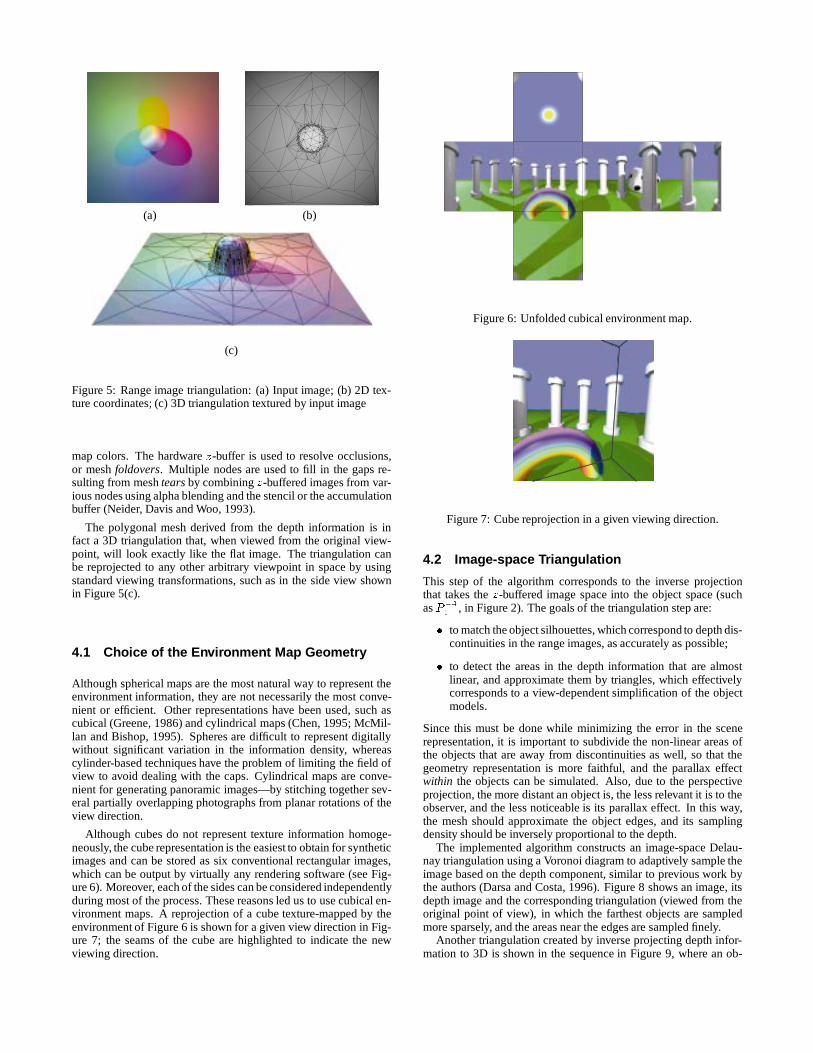
Our solution to the image-space-based rendering problem sim-plifies the environment, as seen from a given viewpoint, by linearpolygons. This polygonal mesh is created by triangulating the depthinformation associated with the environment map, as shown in theexample in Figure 5(b). Each triangle in this mesh represents anobject (or part of an object) at a certain depth.
The parallax effect can then be correctly simulated by warpingeach of these triangles appropriately. Since image warping canbe efficiently performed with hardware assistance through texturemapping, we determine the appropriate projective transformationwhich is then applied to this mesh textured by the environment
1This implies indirectly that the modeled world is opaque.2It also fills in the gaps in the domain of definition with a background
color/depth, and solves foldovers usingz-buffering.
(a) (b)
(c)
Figure 5: Range image triangulation: (a) Input image; (b) 2D tex-ture coordinates; (c) 3D triangulation textured by input image
map colors. The hardwarez-buffer is used to resolve occlusions,or meshfoldovers. Multiple nodes are used to fill in the gaps re-sulting from meshtearsby combiningz-buffered images from var-ious nodes using alpha blending and the stencil or the accumulationbuffer (Neider, Davis and Woo, 1993).
The polygonal mesh derived from the depth information is infact a 3D triangulation that, when viewed from the original view-point, will look exactly like the flat image. The triangulation canbe reprojected to any other arbitrary viewpoint in space by usingstandard viewing transformations, such as in the side view shownin Figure 5(c).
4.1 Choice of the Environment Map Geometry
Although spherical maps are the most natural way to represent theenvironment information, they are not necessarily the most conve-nient or efficient. Other representations have been used, such ascubical (Greene, 1986) and cylindrical maps (Chen, 1995; McMil-lan and Bishop, 1995). Spheres are difficult to represent digitallywithout significant variation in the information density, whereascylinder-based techniques have the problem of limiting the field ofview to avoid dealing with the caps. Cylindrical maps are conve-nient for generating panoramic images—by stitching together sev-eral partially overlapping photographs from planar rotations of theview direction.
Although cubes do not represent texture information homoge-neously, the cube representation is the easiest to obtain for syntheticimages and can be stored as six conventional rectangular images,which can be output by virtually any rendering software (see Fig-ure 6). Moreover, each of the sides can be considered independentlyduring most of the process. These reasons led us to use cubical en-vironment maps. A reprojection of a cube texture-mapped by theenvironment of Figure 6 is shown for a given view direction in Fig-ure 7; the seams of the cube are highlighted to indicate the newviewing direction.
Figure 6: Unfolded cubical environment map.
Figure 7: Cube reprojection in a given viewing direction.
4.2 Image-space Triangulation
This step of the algorithm corresponds to the inverse projectionthat takes thez-buffered image space into the object space (suchasP�1
1, in Figure 2). The goals of the triangulation step are:
� to match the object silhouettes, which correspond to depth dis-continuities in the range images, asaccurately as possible;
� to detect the areas in the depth information that are almostlinear, and approximate them by triangles, which effectivelycorresponds to a view-dependent simplification of the objectmodels.
Since this must be done while minimizing the error in the scenerepresentation, it is important to subdivide the non-linear areas ofthe objects that are away from discontinuities as well, so that thegeometry representation is more faithful, and the parallax effectwithin the objects can be simulated. Also, due to the perspectiveprojection, the more distant an object is, the less relevant it is to theobserver, and the less noticeable is its parallax effect. In this way,the mesh should approximate the object edges, and its samplingdensity should be inversely proportional to the depth.
The implemented algorithm constructs an image-space Delau-nay triangulation using a Voronoi diagram to adaptively sample theimage based on the depth component, similar to previous work bythe authors (Darsa and Costa, 1996). Figure 8 shows an image, itsdepth image and the corresponding triangulation (viewed from theoriginal point of view), in which the farthest objects are sampledmore sparsely, and the areas near the edges are sampled finely.
Another triangulation created by inverse projecting depth infor-mation to 3D is shown in the sequence in Figure 9, where an ob-

(a) (b) (c)
Figure 8: Triangulation using depth and discontinuity.
(a) (b) (c)
Figure 9: Handling Visibility Changes in Translation.
server is moving away from the spheres—9(b) shows the view fromthe position where thenode was generated. Note how the visibil-ity changes are correctly handled, with the closer sphere coveringa greater part of the other spheres (9(a)) and the visibility gaps ap-pearing where no information was available (9(c)). Methods to fill-in these visibility gaps using information from neighboring nodesare presented in Section 6.
The projection transformation that relates the triangulation andthez-buffered image, when applied to each vertex of the 3D trian-gulation, yields the texture coordinates that have to be assigned tothat vertex.
4.3 View-dependent Texture Mapping
Simply assigning the texture coordinates, however, does not resultin the desired behavior, since the graphics engine generally inter-polates the interior pixels of each triangle using perspective correc-tion. This texture mapping correction, essentially a divide byz, isperformed on a per-pixel basis for the texture coordinates (Segalet al., 1992). In our case, however, the texture maps already havethe necessary perspective distortion in them. Letting the hardwareperform perspective correction results in an incorrect double per-spective effect. Figure 10(a) shows such double perspective effectfor an oblique view of a checkerboard pattern mapped to a square.Disabling perspective correction is necessary to obtain the correcteffect shown in (b). To achieve this effect in OpenGL we transformthe texture coordinates according to the depth of the correspondingvertices so that the automatic perspective correction is nullified (Se-gal, 1996). Details of this transformation appear in the Appendix.
(a) (b)
Figure 10: Handling Perspective: (a) Double Perspective; (b) Com-pensated.
(a) (b)
Figure 11: Triangulation qualities from two differentnodes.
Figure 12: Node triangulation viewed from within the node.
4.4 Triangle Quality Measure
Each triangle of the mesh carries a certain amount of texture infor-mation, which we will measure by a triangle quality factor. Thisquality is related to the angle that the normals of the triangles makewith the view ray, i.e., how oblique is the triangle in relation to theimage plane for a perspective projection. Triangles with greater an-gles are projected to proportionally smaller areas in 2D and thus,less pixels will be texture mapped to it. The quality that is assignedto each triangle can be calculated therefore as the dot product be-tween the normal to each triangle and the ray direction:
w = kN:V k = j cos(�)j
The quality of the triangles is a static property, that is computedbefore navigation for the observer in the original position. It de-notes the proportion of pixels from the texture map that are used inthe representation of this triangle. When the observer moves, thisquality indicates how much a triangle can be warped without no-ticeable error. If the quality of a triangle is low, a modification inthe observer position can cause it to become more visible, and thelow quality of its texture would become apparent. In this case, wecombine or replace it by a better quality triangle, from a triangu-lation of another node. Figure 11 shows the qualities—indicatedas gray levels with white being the best—of the triangles of twodifferent nodes viewed from the same position.
5 Single Node Navigation
A node consists of a cubical environment map and its triangulationas discussed in Section 4. An example of this is shown in Figure 12.The navigation inside a node involves projecting these triangula-tions for a given viewpoint and viewing direction. The projectionand the subsequentz-buffering correctly handle the visibility andthe perspective for regions where adequate information is available.
The six sides of a node are not normally all visible at once. Acube divides the space into six pyramidal regions that are joined by

Figure 13: View frustum culling.
(a) (b)
Figure 14: Visibility gaps: (a) black; (b) filled by linear interpola-tion.
their apices at the center of the cube . We cull the triangulations inlarge batches, by computing the intersection of the viewing frustumwith the six pyramidal regions to determine which sides of the nodecan possibly take part in the view. In Figure 13, for instance, just thetriangles from the highlighted sides are sent through the graphicspipeline.
When an observer translates, regions not visible from the origi-nal viewing parameters appear. These visibility gaps can be eithershown in a background color or can be filled by a linear interpo-lation of the colors of their vertices. Both options are shown inFigure 14, where the observer has moved down and to the rightfrom the original position, which was directly above the sphere. Inan image-based navigation system, the visibility information fromthe original viewpoint is projected to a 2D plane and any obscuredobjects are “lost”. Therefore, the system at this stage does not haveany information to fill uncovered areas and an interpolation is justa crude approximation that is acceptable for very small gaps. Nev-ertheless, some systems rely on this type of technique. We shallnext discuss an approach that uses information from other nodes tofill-in the missing visibility information where possible.
6 Multiple Node Navigation
Given a set of nodes, solving the visibility problem for a certainviewpoint and direction involves two subproblems: selecting theappropriate nodes and combining the information from these nodes.If the nodes are uniformly distributed, the selection of the nodes thatare closer to the observer is a simple solution that yields acceptableresults. This is the approach that we have implemented. The re-mainder of this section discusses the combination of informationfrom two nodes. Combination of information from three or morenodes proceeds in the same manner if we are iteratively combin-ing information from two nodes at a time, until all or most of thevisibility gaps are filled.
The information from two different nodes has to be merged toform a new view of the scene in real-time, combining or replacingtriangles based on their quality (see section 4.4). We next some
ways to perform such merging.
6.1 Mesh Layering
(a) (b)
(c)
Figure 15: Mesh Layering
This node merging technique begins by projecting the triangles ofthe visible triangulations from the node that is closest to the ob-server. Clearly, if the observer is not at the center of the node, vis-ibility gaps can appear. The next closestnode is then reprojected,and the process can be repeated until all the visibility gaps are filled,or a subset of the neighboring nodes has been used. Az-buffer isemployed for hidden surface removal. Although this simple schemefills most of the visibility gaps, it suffers from the drawback that,for triangles with similarz-values but different qualities, the winneris determined solely by the depth ordering, which can cause partsof low quality triangles to dominate over high quality ones that areslightly farther. Figure 15 shows the visibility gaps (in black) fromtwo different nodes. Notice the the discontinuities, especially in therainbow in Figure 15(c) generated using this method.
6.2 Binary Merge
To allow the quality measure to play a more important role, westore the quality ofeach triangle on a pixel-by-pixel basis to thestencil or alpha buffer during its rasterization. The combination ofthe two images is now performed by first comparing thez-values.If the z values are sufficiently different, the pixel that is closer to theobserver wins; otherwise, the pixel that is output to the final imagewill be the one that has a higher quality. Although this functionis not a continuous blend it yields good results. Figure 16 showsa combination using this technique (see Figure 11 for the trianglequalities).

Figure 16: Binary merge.
Figure 17: Weighted blending.
6.3 Simple Weighted Blending
This method is an extension of the binary merge approach with thedifference that for closez-values, the output pixel is an interpola-tion of the pixels from different nodes, with the alpha factor basedon the relative quality values. Since the quality values of two trian-gles do not, in general, sum to1, we choose the output pixel to be aquality-weighted average of the input pixels:
p =q1p1 + q2p2
q1 + q2
The result using this computation is shown in Figure 17, where thecombination produced a smoother image.
6.4 Positional Weighted Blending
The weighted average technique can be further refined by consid-ering the position of the observer: the closer is the observer to thecenter of a node, the more should be the influence of that node onthe resulting image. This is achieved by multiplying the qualitiesstored in the buffers by a factor proportional to the distancedi ofthe observer from the center of the nodei:
p =tq1p1 + (1� t)q2p2
tq1 + (1� t)q2; t =
d2
d1 + d2:
This solution produces a smooth morphing between the nodes(see Figure 18). When the observer is exactly at the center of anode, the resulting image is exact, and it becomes a combination ofthe two nodes as the observer moves. Although the accumulationbuffer of OpenGL can produce a weighted average of two images itcannot be used here directly, sinceq1 andq2 do not sum to1. Forthis, qi must be normalized on a pixel-by-pixel basis which makesthis approach impractical for OpenGL. However, in other systemsit might be possible to directly execute this solution in the graphicspipeline.
Figure 18: Positional weighted blending.
Figure 19 shows frames of an animation obtained by blendingtwo nodes using the weighted average technique in software. Thecenter of the first node is directly in front of the rainbow torus,and the second is to the its left and front of the first center. Inthe navigation, the observer starts at the center of the first node, istranslated to the left, then rotates to the right in the last two frames.
7 Results and Conclusions
We have described an image-based rendering technique for navi-gation of 3D environments by using viewpoint-dependent warpingand morphing. The method relies on a set of cubical environmentmaps that are pre-rendered from a collection of fixed (and prefer-ably uniformly distributed) viewpoints within the virtual model.Every given viewpoint is represented by a node that consists of acubical environment map and an associated 3D triangulation of thesix faces of the map. We have described the construction of suchtriangulations of the faces and discussed navigation by combininginformation from multiplenodes. Our scheme relies heavily on,and derives its speed from, hardware texture mapping facilities.
We have tested our implementation on a model of the Stone-henge generated by us. The initial model was ray-traced and twocubical environment maps, each consisting of six256 � 256 im-ages (with depth) were generated. From these786K data points,we obtained a simplified representation consisting of a total of30Ktexture-mapped triangles using a top-down approach to generate aDelaunay triangulation. We have tested our system on a single SGIChallenge R10000 processor with – one Raster Manager, InfiniteReality with 64 MB of texture memory, and 2 MB of secondarycache. We compared mesh layering, binary merge, weighted blend-ing, and positional weighted blending schemes for the same naviga-tion path consisting of 250 frames between the two nodes. For meshlayering we achieved an average frame-rate of 9.59 frames per sec-ond, for binary merge 4.27 frames per second, for weighted blend-ing 3.58 frames per second, and for positional weighted blending3.53 frames per second. Our current implementation does not usetriangle strips; from our past experience with triangle strips, theabove frame-rates should roughly double with triangle strips. Theresults are shown in Figures 16, 17, 18, and 19. The differencesamongst these figures although present are subtle and not very ob-vious at the scale at which these figures have been reproduced inthis paper. The difference between mesh layering and positionalweighted blending, for instance, is more obvious in Figure 20 inthe spurious triangles near the left side of the sphere in the meshlayering approach.
In our current implementation, reprojection of the second node isdone for the entire image. However, to speed-up the results, a maskcan be created to determine the visibility gaps exactly and the sec-ondary projections restricted to the missing parts of the scene. Thiscan be done by using a binary stencil and modifying the viewing

Figure 19: Navigating in Image-Space: Top Row – Frames from Node 1; Middle Row – Frames from Node 2; Bottom Row – Frames fromPositional Weighted Blending of Node 1 and Node 2
(a) (b)
Figure 20: Mesh layering (a) versus Positional weighted blending(b).
frustum to be restricted to the bounding box of the visibility gaps.An approach similar to this has been shown to work well (Luebkeand Georges, 1995).
The triangulation scheme that was used could take advantage offurther improvements. Its current version is better suited when thesampling process is expensive, since it never discards samples. Inmany situations, such as with range images, the information is al-
ready fully sampled, and resampling it incurs a minimal cost. Inthese cases, it is better to use a technique that works bottom up, bytrying to combine similar areas that can be approximated by a lin-ear polygon, instead of top down, trying to guess sample positions.Also, the triangulation of each of the sides of the environment mapcould not actually be performed in an entirely independent way, toavoid cracks at the seams. A single integrated triangulation stepmay yield a better junction between the sides.
The use of multi-resolution images, as well as multi-resolutiontriangulations, could be useful, if the nodes are positioned sparsely.
The position of thenodes is currently determined manually bythe user, as part of the scene modeling. Ideally, a minimum amountof nodes should be positioned in such a way so as to cover all theareas of interest in the scene. Also, the problem of selecting thesubset of the nodes that will be combined at a given position duringnavigation must be solved in an efficient way, so that the node re-projections are kept to a minimum. There is a clear coherence in thenode selection that adapts itself to a working set model, where theactive nodes are cached, and a node replacement occurs sparsely.

Figure 21: Linear and perspective corrected interpolations.
8 Acknowledgements
We deeply appreciate the thorough review and detailed and insight-ful comments by the anonymous referees. We would like to thankCNPq (Brazilian Council of Scientific and Technological Develop-ment) for the financial support to first two authors. This work hasbeen supported in part by the National Science Foundation CA-REER award CCR-9502239. This research was performed at theVisualization laboratory at SUNY Stony Brook.
A Disabling perspective correction
A texture coordinate in OpenGL is specified by a tuple(s; t; r; q).After multiplying the texture coordinates by the texture matrix,OpenGL interprets the result(s0; t0; r0; q0) as homogeneous texturecoordinates. This computation is performed at each triangle vertexand the information is interpolated by the rasterizer to yield a valuefor each pixel. If the interpolation used is linear, the results differfrom those obtained from the actual computation at each pixel, asillustrated in Figure 21. For the computation of the texture coordi-nates at the pixelM , at the center of the image, linear interpolationyields(s1+s2)=2, which is incorrect since those are the texture co-ordinates of pointL. With perspective correction the computationatM must yield the coordinates ofP . This is done by linearly inter-polating(s1=w1; t1=w1) and(s2=w2; t2=w2) at each pixel wherewi is the homogeneous coordinate of the polygon vertexi. Therandq texture coordinates are also divided bywi, and interpolatedin the same way, although they are not needed for simple texturemapping. At each pixel, a division is performed using the interpo-lated values of(s=w; t=w;r=w; q=w), yielding (s=q; t=q), whichare the final texture coordinates. To disable this effect, which is notpossible in OpenGL directly3, we transform, a priori, the originaltexture coordinates(si; ti) into (wisi; witi; 0; wi), so that at theend of the transformation performed by OpenGL, we have(si; ti),at no performance cost. In our case, the 3D triangulation includesthe depth of each vertex which is the requiredw value.
References
Aggarwal, J. K. and Nandakumar, N. (1988). On the computationof motion from sequences of images–a review.Proceedingsof the IEEE, 76(8):917–935.
Airey, J. M. (1990).Increasing Update Rates in the Building Walk-through System with Automatic Model-Space Subdivision andPotentially Visible Set Calculations. PhD thesis, Universityof North Carolina at Chapel Hill, Department of ComputerScience, Chapel Hill, NC27599-3175.
3In other APIs, such as Microsoft Direct3D, this feature can be disabledwith a single command.
Bergman, L. D., Fuchs, H., Grant, E., and Spach, S. (1986). Imagerendering by adaptive refinement. In Evans, D. C. and Athay,R. J., editors,Computer Graphics (SIGGRAPH ’86 Proceed-ings), volume 20, pages 29–37.
Bishop, G., Fuchs, H., McMillan, L., and Zagier, E. (1994). Frame-less rendering: Double buffering considered harmful. InPro-ceedings of SIGGRAPH ’94 (Orlando, Florida, July 24–29,1994), Computer Graphics Proceedings, Annual ConferenceSeries, pages 175–176. ACM SIGGRAPH.
Blinn, J. F. (1978). Simulation of wrinkled surfaces. InSIG-GRAPH ’78, pages 286–292. ACM.
Blinn, J. F. and Newell, M. E. (1976). Texture and reflection incomputer generated images.CACM, 19(10):542–547.
Chen, S. E. (1995). Quicktime VR – an image-based approachto virtual environment navigation. InComputer GraphicsAnnual Conference Series (SIGGRAPH ’95), pages 29–38.ACM.
Chen, S. E. and Williams, L. (1993). View interpolation for imagesynthesis. InComputer Graphics (SIGGRAPH ’93 Proceed-ings), volume 27, pages 279–288.
Cohen, J., Varshney, A., Manocha, D., Turk, G., Weber, H., Agar-wal, P., Brooks, Jr., F. P., and Wright, W. V. (1996). Simpli-fication envelopes. InProceedings of SIGGRAPH ’96 (NewOrleans, LA, August 4–9, 1996), Computer Graphics Proceed-ings, Annual Conference Series, pages 119 – 128. ACM SIG-GRAPH, ACM Press.
Cyan (1994).Myst: The Surrealistic Adventure That Will BecomeYour World. Broderbund Software.
Darsa, L. and Costa, B. (1996). Multi-resolution representationand reconstruction of adaptively sampled images. InSIB-GRAPI’96 Proceedings, pages 321–328.
Debevec, P. E., Taylor, C. J., and Malik, J. (1996). Modeling andrendering architecture from photographs: A hybrid geometry-and image-based approach. InProceedings of SIGGRAPH’96 (New Orleans, LA, August 4–9, 1996), Computer Graph-ics Proceedings, Annual Conference Series, pages 11–20.ACM SIGGRAPH, ACM Press.
DeRose, T. D., Lounsbery, M., and Warren, J. (1993). Multireso-lution analysis for surface of arbitrary topological type. Re-port 93-10-05, Department of Computer Science, Universityof Washington, Seattle, WA.
Gomes, J., Costa, B., Darsa, L., Velho, L., Wolberg, G., and Berton,J. (1995).Warping and Morphing of Graphical Objects. SIG-GRAPH ’95 Course Notes #3.
Gortler, S. J., Grzeszczuk, R., Szelinski, R., and Cohen, M. F.(1996). The lumigraph. InProceedings of SIGGRAPH ’96(New Orleans, LA, August 4–9, 1996), Computer GraphicsProceedings, Annual Conference Series, pages 43–54. ACMSIGGRAPH, ACM Press.
Greene, N. (1986). Environment mapping and other applications ofworld projections.IEEE CG&A, 6(11):21–29.
Greene, N. (1996). Hierarchical polygontiling with coveragemasks. InProceedings of SIGGRAPH ’96 (New Orleans,LA, August 4–9, 1996), Computer Graphics Proceedings, An-nual Conference Series, pages 65 – 74. ACM Siggraph, ACMPress.
Greene, N. and Kass, M. (1993). Hierarchical Z-buffer visibility. InComputer Graphics Proceedings, Annual Conference Series,1993, pages 231–240.
He, T., Hong, L., Varshney, A., and Wang, S. (1996). Controlledtopology simplification.IEEE Transactions on Visualizationand Computer Graphics, 2(2):171–184.
Hoppe, H. (1996). Progressive meshes. InProceedings of SIG-GRAPH ’96 (New Orleans, LA, August 4–9, 1996), ComputerGraphics Proceedings, Annual Conference Series, pages 99 –108. ACM SIGGRAPH, ACM Press.
Levoy, M. and Hanrahan, P. (1996). Light field rendering. InPro-ceedings of SIGGRAPH ’96 (New Orleans, LA, August 4–9,1996), Computer Graphics Proceedings, Annual ConferenceSeries, pages 31–42. ACM SIGGRAPH, ACM Press.
Lippman, A. (1980). Movie maps: An application of the opticalvideodisc to computer graphics. InComputer Graphics (SIG-GRAPH ’80 Proceedings), pages 32–43.
Luebke, D. and Georges, C. (1995). Portals and mirrors: Sim-ple, fast evaluation of potentially visible sets. InProceed-ings, 1995 Symposium on Interactive 3D Graphics, pages 105– 106.
McMillan, L. and Bishop, G. (1995). Plenoptic modeling: Animage-based rendering system. InComputer Graphics An-nual Conference Series (SIGGRAPH ’95), pages 39–46.ACM.
Neider, J., Davis, T., and Woo, M. (1993).OpenGL ProgrammingGuide: The Official Guide to Learning OpenGL, Release 1.Addison-Wesley.
Rossignac, J. and Borrel, P. (1993). Multi-resolution 3D approx-imations for rendering. InModeling in Computer Graphics,pages 455–465. Springer-Verlag.
Schroeder, W. J., Zarge, J. A., and Lorensen, W. E. (1992). Deci-mation of triangle meshes. InComputer Graphics: Proceed-ings SIGGRAPH ’92, volume 26, No. 2, pages 65–70. ACMSIGGRAPH.
Segal, M. (1996). Personal communication.
Segal, M., Korobkin, C., van Widenfelt, R., Foran, J., and Hae-berli, P. (1992). Fast shadows and lighting effects using tex-ture mapping.Computer Graphics (SIGGRAPH ’92 Proceed-ings), 26(2):249–252.
Szeliski, R. (1996). Video mosaics for virtual environments.IEEECG&A, pages 22–30.
Teller, S. and S´equin, C. H. (1991). Visibility preprocessing forinteractive walkthroughs.Computer Graphics: Proceedingsof SIGGRAPH’91, 25, No. 4:61–69.
Turk, G. (1992). Re-tiling polygonal surfaces.Computer Graphics(SIGGRAPH ’92 Proceedings), 26(2):55–64.
Wolberg, G. (1990).Digital Image Warping. IEEE Computer So-ciety Press, Los Alamitos, CA.
Xia, J. and Varshney, A. (1996). Dynamic view-dependent sim-plification for polygonal models. InIEEE Visualization ’96Proceedings. ACM/SIGGRAPH Press.