MERI TURUNEN AUTOMATED UAV TESTING - Trepo
70
MERI TURUNEN AUTOMATED UAV TESTING Master of Science Thesis Examiner: prof. Timo D. Hämäläinen Examiner and topic approved on 30th May 2018
-
Upload
khangminh22 -
Category
Documents
-
view
0 -
download
0
Transcript of MERI TURUNEN AUTOMATED UAV TESTING - Trepo
MERI TURUNEN
AUTOMATED UAV TESTING
Master of Science Thesis
Examiner: prof. Timo D. Hämäläinen Examiner and topic approved on 30th May 2018

i
ABSTRACT
Meri Turunen: Automated UAV Testing Tampere University of Technology Master of Science Thesis, 62 pages October 2018 Master’s Degree Programme in Electrical Engineering Major: Embedded Systems Examiner: Professor Timo D. Hämäläinen Keywords: test automation, Robot Framework, keyword-driven test framework, Ubuntu Core, UAV, ArduPilot, Test-Driven Development, Continuous Integration, agile software development, software reusability, system validation
The thesis presents perspectives and documents a single solution to test automation
framework as a part of system validation for a Linux-based embedded project. Test auto-
mation frameworks has been utilized earlier by Intel’s system validation team, but on
different products and in the case of unmanned aerial vehicles (UAV) only for payload
testing. In this work, test automation framework has been developed to be usable with
various UAVs and specifically with Vertical Take-Off and Landing (VTOL) typed UAV.
Automated testing reduces required time and amount of labor between the software inte-
gration cycles, and thus speeds up the whole development process and enables the release
of the product at any time. In every cycle, automated tests can provide almost everything
that is required from testing. Well-designed test automation framework reduces work for
future projects as some modules can be reused. Keyword-driven test automation frame-
work allows a simple way to make new automated tests.
The test automation framework is accomplished by utilizing the keyword driven test au-
tomation framework Robot Framework. It consists of test files that define the executed
test in high-level and libraries that define test keywords and interfaces to the tested soft-
ware. There are libraries to control devices such as power supply and USB-hubs, but the
interface between the framework and them are made along with the thesis. The test files
and test libraries that define keywords used in test files have been made based on previous
automation projects of Intel. There are plenty of test libraries in Robot Framework, but
many are not useful in test automation framework of an embedded Linux project, so some
have been created for that purpose. Robot Framework’s logs and reports are gathered into
Jenkins, so that the information about the software version, test device and the test exe-
cution can be found in the same place. An automation build server, Jenkins, is utilized to
build new developed software automatically on every test device and to execute certain
automatic tests on the devices.
The result of this thesis is a test automation framework for an UAV and suitable test
libraries for frameworks of future UAV projects. Automated testing can be profitable and
speeds up the whole testing and reporting process. It takes from several weeks to months
to create fully functional test automation framework with all the required tests. In future
projects most of the modules can be utilized and this can shorten the assembly of the
framework by a few workweeks. Automated testing is a suitable way to execute testing
and system validation in an embedded UAV project and especially at the early stage of a
project it’s a good target to work on by a testing team.

ii
TIIVISTELMÄ
Meri Turunen: Automatisoitu miehittämättömän ilma-aluksen testaus Tampereen teknillinen yliopisto Diplomityö, 62 sivua Lokakuu 2018 Sähkötekniikan diplomi-insinöörin tutkinto-ohjelma Pääaine: Sulautetut järjestelmät Tarkastaja: Professor Timo D. Hämäläinen Avainsanat: testiautomaatio, Robot Framework, avainsanapohjainen testauskehys, Ubuntu Core, ArduPilot, testivetoinen kehys, jatkuva integraatio, ketterä ohjelmistokehitys, ohjelmiston uudelleenkäytettävyys, systeemivalidaatio
Diplomityö esittelee näkökulmia testiautomaation käytöstä osana Linux-pohjaisen
projektin järjestelmätestausta sekä dokumentoi erään tavan sen toteuttamiseen. Intelin
järjestelmien varmennustiimi on hyödyntänyt testiautomaatiota aiemmissa
testausprojekteissa, mutta ei miehittämättömien ilma-aluksien testauksessa. Kehitetty
testiautomaatio on tarkoitus olla helposti uudelleenkäytettävä suuriltaosin tulevissa
miehittämättömien ilma-aluksien testausprojekteissa. Työhön luotu testiautomaatio sopii
lenkonemaiselle dronelle. Testiautomaation on määrä vähentää testausaikaa ja
testaukseen tarvittavaa työtä ohjelmistointegrointien väleissä. Hyvin suunnitelussa ja
toteutetussa testiautomaatiosssa on uudelleen käytettäviä testikirjastoja tulevia projekteja
ajatellen ja siihen on helppo lisätä uusia automatisoituja testejä.
Testiautomaatio on toteutettu avainsanapohjaisella testauskehyksellä, Robot
Frameworkillä. Se koostuu testitiedostoita, joissa on määritetty suoritettavat testit
korkealla tasolla sekä testikirjastoista, jotka määrittelevät testitiedostojen avainsanat sekä
rajapinnan testattaviin laitteisiin. Testitiedostojen ja –kirjastojen pohjana on käytetty
Intelin systeemivalidaatiotiimin aiempia testiautomaatioprojekteja. Testausta ohjaavia
kontrollilaitteita varten luotu rajapinta, jotta niitä on yhtenäistä käyttää testitiedostoissa.
Robot Frameworkillä on useita valmiita testikirjastoja, mutta niistä ei suoraan löydy
sopivaa kommunikointiin Linux-pohjaisen sulautetun järjestelmän kanssa. Testaus
käynnistyy uuden ohjelmistoversion julkaisun jälkeen Jenkins automaatiopalvelimella.
Testauskehyksen testit suoritetaan kaikilla määritellyillä testilaitteilla automaattisesti ja
niistä kootaan testiraportit ja lokit Jekniksiin testilaite- ja -ajokohtaisesti.
Diplomityön tuloksena syntyi testiautomaatio miehittämättömälle ilma-alukselle sekä
sille sopivia testikirjastoja, joita voidaan hyödyntää tulevissa vastaavanlaisissa
testauksissa. Testiautomaatio voi nopeuttaa testausta ja testiraportointia, etenkin pitkien
iteratiivisien testien osalta. Testiautomaatiosta suurin hyöty saadaan silloin kun testit ovat
yksinkertaisia ja niitä joudutaan ajamaan useita kertoja. Täysin automaattisesti toimivan
testiautomaation kokoamiseen ja sen testien tekemiseen menee muutamasta työviikosta
kuukausiin. Uudelleen hyödynnettävä testiautomaatio voi vähentää työntarvetta useita
viikkoja tulevissa projekteissa. Kun testiautomaation tekiminen aloitetaan varhaisessa
vaiheessa projektia, voi testaustiimi hyödyntää ajan ennen varsinaisen testauksen
alkamista ja vähentää sitä työtaakkaa, mikä tulee testattavaksi projektin edetessä.

iii
PREFACE
This Master’s Thesis is written in an employment relationship with Intel. The thesis has
been started at Intel’s Tampere office in May 2018. It has been done as a part of a Drone
group’s project.
Support of Intel’s Drone Group and system validation team has been invaluable since the
beginning of the work. Great thanks for helping with planning the thesis and guiding
through the problems along the way, Niko Rantalainen and Marita Haavisto. In addition
to the above, thanks for letting me to know more about test automation systems and get
into an interesting project, Jarkko Mikkola.
I would also like to thank the examiner of this Master’s Thesis, professor Timo Hämä-
läinen from Tampere University of Technology, for good comments and refinements to
the thesis.
Tampere, 25.10.2018
Meri Turunen
iv
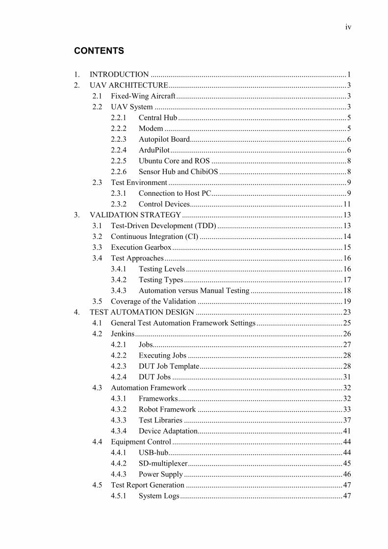
CONTENTS
1. INTRODUCTION .................................................................................................... 1
2. UAV ARCHITECTURE ........................................................................................... 3
2.1 Fixed-Wing Aircraft ....................................................................................... 3
2.2 UAV System .................................................................................................. 3
2.2.1 Central Hub ...................................................................................... 5
2.2.2 Modem ............................................................................................. 5
2.2.3 Autopilot Board................................................................................ 6
2.2.4 ArduPilot .......................................................................................... 6
2.2.5 Ubuntu Core and ROS ..................................................................... 8
2.2.6 Sensor Hub and ChibiOS ................................................................. 8
2.3 Test Environment ........................................................................................... 9
2.3.1 Connection to Host PC ..................................................................... 9
2.3.2 Control Devices.............................................................................. 11
3. VALIDATION STRATEGY .................................................................................. 13
3.1 Test-Driven Development (TDD) ................................................................ 13
3.2 Continuous Integration (CI) ......................................................................... 14
3.3 Execution Gearbox ....................................................................................... 15
3.4 Test Approaches ........................................................................................... 16
3.4.1 Testing Levels ................................................................................ 16
3.4.2 Testing Types ................................................................................. 17
3.4.3 Automation versus Manual Testing ............................................... 18
3.5 Coverage of the Validation .......................................................................... 19
4. TEST AUTOMATION DESIGN ........................................................................... 23
4.1 General Test Automation Framework Settings ............................................ 25
4.2 Jenkins .......................................................................................................... 26
4.2.1 Jobs................................................................................................. 27
4.2.2 Executing Jobs ............................................................................... 28
4.2.3 DUT Job Template ......................................................................... 28
4.2.4 DUT Jobs ....................................................................................... 31
4.3 Automation Framework ............................................................................... 32
4.3.1 Frameworks .................................................................................... 32
4.3.2 Robot Framework .......................................................................... 33
4.3.3 Test Libraries ................................................................................. 37
4.3.4 Device Adaptation.......................................................................... 41
4.4 Equipment Control ....................................................................................... 44
4.4.1 USB-hub......................................................................................... 44
4.4.2 SD-multiplexer ............................................................................... 45
4.4.3 Power Supply ................................................................................. 46
4.5 Test Report Generation ................................................................................ 47
4.5.1 System Logs ................................................................................... 47

v
4.5.2 Robot Framework Reports ............................................................. 48
4.5.3 Robot Framework Logger and Traces ........................................... 49
4.5.4 Robot Framework Listener ............................................................ 49
4.5.5 Excel Sheets ................................................................................... 51
4.5.6 Sharing Logs .................................................................................. 51
5. EVALUATION OF THE TEST AUTOMATION FRAMEWORK ...................... 52
6. CONCLUSIONS ..................................................................................................... 55
REFERENCES ................................................................................................................ 57

vi
LIST OF FIGURES
Control surfaces can change movement of the plane. In the left is
shown how control surface elevator changes pitch, in the middle
how aileron changes roll and in the left how rudder changes yaw.
[1, edited] Orientation of the plane is viewed from the plane and
port is on left, STBD on right. ................................................................... 3
Simplified hardware block diagram of an UAV explains the
relationships between devices and boards. ............................................... 4
OS layer structure of processors that ArduPilot is running on. ................ 8
Simplified hardware block diagram of the UAV shows connections
between PCBs and debug UART connectors of them. Host PC can
connect to debug connectors with serial connection and to
Autopilot with SSH connection. ............................................................... 10
Hardware block diagram of the test environment includes main
PCB of the UAV, Autopilot, programmable power supply and
Central Hub together with sytem that can read and write to SD-
card or listen to debug UART. Modem can be tested with another
controllable modem. ................................................................................ 11
Automation can easily be utilized in TDD. [24]...................................... 14
Agile tested product is ready for release any time, whereas plan-
driven development proceeds straightforwardly without the
iteration rounds [26] ............................................................................... 15
Block diagram of the software architecture of the test automation
system presents the components that the whole system is consisted
of. ............................................................................................................. 23
Message sequence chart clarifies the division of responsibilities of
Jenkins and Robot Framework. ............................................................... 24
The arcitecture of Robot Framework includes from top to bottom
test cases in test data, automation framework itself as Robot
Framework, test libraries and modules where the actual
implementation of the system under test. [45] ......................................... 34
Class diagram visualizes the relations between custom test
libraries and device interface. ................................................................. 40

vii
LIST OF SYMBOLS AND ABBREVIATIONS
API Application Programming Interface
CAN Controller Are Network
CI Continuous Integration
CPU Central Processing Unit
DUT Device Under Test
EEPROM Electronically Erasable Programmable Read-Only Memory
ESC Electronic Speed Controller
GCS Ground Control Station
GPS Global Positioning System
HLOS High-Level Operating System
HTML Hypertext Markup Language
IMU Inertial Measurement Unit
JAR Java ARchive
LiDAR Light Detection and Ranging
MAVLink Micro Air Vehicle Link
OpenJDK Open Java Development Kit
OS Operating System
PCB Printed Circuit Board
PCRE Perl Regular Expression
POXIS Portable Operating System Interface
PPP Point-to-Point Protocol
ROS Robot Operating System
SoC System on Chip
SCM Source Code Management
SCP Secure Copy
SMTP Simple Mail Transfer Protocol
SSH Secure Shell
STBD Starboard
SW Software
TDD Test-Driven Development
TSV Tab-Separated Values
UART Universal Asynchronous Receiver Transmitter
UAV Unmanned Aerial Vehicle
UDHCP Micro Dynamic Host Configuration Protocol
VTOL Vertical Take-Off and Landing
bps Baud Per Second
h hour
min minute
WD Working Day

1
1. INTRODUCTION
This Master’s Thesis is about a test automation system of a Linux-based UAV, which
type is vertical take-off and landing (VTOL) fixed-wing aircraft. Test automation frame-
works have been utilized earlier by Intel’s system validation team, but on different prod-
ucts and in the case of UAVs it has only been used for payload testing. In this work, test
automation framework has been developed to be usable with various UAVs in the future.
The test automation framework has been made at an early stage of the project to improve
and expand the testing methods that the system validation team of Intel utilized for UAV
testing. The use of test automation framework can be justified by increased testing cov-
erage and a shortened testing time between the development cycles.
Automated testing is used to reduce work load of testing team during test execution and
make test set more comprehensive. Drone testing obviously includes drone flying but it
is not the most efficient and thorough way to test a drone. Drone flying requires always
at least one drone pilot per flying drone and bunch of charged batteries, spare parts and a
suitable area for flying. Many basic functionalities can be tested inside without pilots as
well. With test automation framework the required amount of test devices can be con-
trolled remotely and tests can also be run out-side working hours. Automation also ena-
bles different types of testing compared to manual testing. Similar UAV projects require
similar testing, so the test automation framework is to be utilized as widely as possible
with them.
Test automation framework is developed at an early stage of the project, so that it could
be quicker and easier to create new tests into it later when functionality of a product in-
creases due to development. It has also focused especially on its re-usability for future
projects that can be mostly implemented using the same technology. The test automation
framework is built on an open source build server and an automation framework. An
important part of the framework is also reporting and clear presentation of the test results.
Bugs should be reported so that the mistakes that have caused them can be found quickly.
Recent articles or publications are not found about automated UAV testing. There have
been numerous articles about automated testing, but most of the tests are targeted at an
application with UI or at automated testing with external test automation tools. There are
also articles and comprehensive documentation about test automation frameworks and
automated testing.

2
Chapter 2, UAV architecture, covers the UAV system and the environment, which has
been created for testing. The following chapter 3 illustrates the backgrounds of testing
and validation. Software of the test automation system is explained in chapter 4, Test
Automation Design. Finally, Evaluation of the Test Automation Framework -chapter
compiles the results of automated testing in this project and explains some reasons for its
use.

3
2. UAV ARCHITECTURE
The tested UAV and control devices are the physical environment that is needed for au-
tomated testing. The upcoming chapter focuses on the structure and functionality of most
important modules of an UAV and the controlling devices from the point of view of au-
tomated testing. It is good to understand how control devices can perform tests on the
DUT and utilize the data that the device sends on the basis of the tests.
2.1 Fixed-Wing Aircraft
VTOL plane type UAVs have some similar features with actual fixed-wing aircrafts and
some of them may be useful for understanding the whole system and reasons for testing
certain things. The examined UAV is like a fixed-wing aircraft with four control surfaces.
The control surfaces control the movement of the aircraft. They are ailerons of the wings
and elevator and rudder of the rear of the plane. The orientation of the plane is presented
with terms port and starboard (STBD). The left-hand side from the plane is port and right
STBD. The control surfaces and orientation terms are presented in figure 1.
Control surfaces can change movement of the plane. In the left is shown
how control surface elevator changes pitch, in the middle how aileron changes
roll and in the left how rudder changes yaw. [1, edited] Orientation of the plane
is viewed from the plane and port is on left, STBD on right.
By adjusting the elevator, the pitch of the plane can be changed. The pitch affects the
vertical movement of the plane. Ailerons roll the plane, which means that one wing raises
and the other lowers. Rudder can change the yaw of the plane. The movement of yaw is
horizontal. The pitch, the roll and the yaw are the axes of rotation. Propeller in the front
of the plane is thrust and it adjust the speed. [1]
2.2 UAV System
The UAV system consist of boards that are responsible for steering the UAV and boards
that make it possible. The Autopilot board has the greatest responsibility for functionality

4
and flying and it consist of plenty of sensors and a lot of processing power. The Autopilot
board needs the flight control devices for flights and some power to operate. A simplified
hardware block diagram of the UAV system is present in figure 2.
Autopilot Central Hub
Wing PCB
Wing PCB
ESP PCB
Battery PCB
MODEM
CAN 0
CAN 0SERVO
SUPPLIES AND
CONTROL
CAN 0CAN 1
CAN 1
Se
rvo
Co
nn
ect
or
WIN
G C
ON
N
Serv
o Co
nnec
tor
Serv
o C
on
nec
tor
PORT
STBD
Rudder
Elevator
Button Board
PWR
PWR
PWR
PWR
PWR
PWR
WIN
G C
ON
N
Pay
load
C
on
ne
cto
rP
ay
load
C
on
nec
tor
CAN 1
CAN 0
GPS_TIMEPULSE
MODEM TX/RX
SD CARD
SENSOR HUB
USB HUB
THRUST
EEPROM
Servo Connector
TEMP SENSOR
SoC
BACKUP GPS
PWR
PWR
CAN 1
Simplified hardware block diagram of an UAV explains the relationships
between devices and boards.
The purpose of an Autopilot board is to control the other boards so that flying without a
human pilot would be possible. It is conned to Central Hub via both Controller Are Net-
work (CAN) busses. Payloads are attached to the Autopilot via either CAN1 or CAN0,
and there can be a maximum of two payloads connected at a time. Autopilot collects data
from sensors to enable automatic flying. The Autopilot board has a processor, which is
responsible for running the UAV’s applications.
Batteries and thrust are controlled by electronic speed controller (ESC) Printed Circuit
Board (PCB) board. The ESC PCB takes care of the amount of power that is distributed
from the battery. It has motor driver for the motor of the thrust and for instance EEPROM
and a temperature sensor for batteries. Batteries are smart, and they are capable for power
level, temperature and error condition monitoring. ESC PCB is connected to Central Hub
via CAN0 bus and power connection. Central Hub spreads power to the motors after con-
verting it into the right voltage levels.

5
The control surfaces are attached to the central hub. Surfaces of the wings are connected
to Wing PCBs. Wing PCBs have connectors for servomotors and they are connected to
the central hub via CAN busses. Elevator, rudder and main power switch in button board
are connected similarly to the Central Hub but they do not have separate control PCBs.
2.2.1 Central Hub
Central Hub board is responsible for connecting devices and providing them power from
batteries. Central Hub takes power from battery PCBs and converts it to a suitable voltage
level for each PCB. Modem is part of the Central Hub and it is for connecting to controller
and collecting commands from the pilot or autopilot software. The connection between
two modems is made with Point-to-Point Protocol (PPP) and with two different baud rates
for control and data channels. The modem data is sent to Autopilot board, where it is
processed.
The control surface peripherals receive the control data from the autopilot through the
central hub and they send information about their operations back to the Autopilot via
Central Hub. CAN busses are used for data transfer. There are two CAN busses, CAN1
for wings and one payload and CAN0 for battery and another payload. CAN0 is critical
for flying and if critical problems arise, its peripherals attempt to bring the UAV safely
to the ground. CAN busses use UAVCAN protocol, which is designed for aerospace and
robotic applications.
2.2.2 Modem
Connection between Ground Control Station (GCS) and UAV is done by modems. The
control signals from the pilot goes to the UAV via GCS [2]. The communication protocol
in air link is Micro Air Vehicle Link (MAVLink), which is generally used with UAVs.
MAVLink sends header-only messages that contains packed messages according to the
data transfer protocol of the receiving UAV. MAVLink can pack its messages to serial
channels and CAN bus based UAVCAN. Header-only message packets are really short,
only 8 bytes long, so it is quite efficient for energy consumption. [3]
MAVLink messages can be sent either wirelessly or wired, and usually latter one is used
while testing and using simulators. Baud rate of wireless communication is small, 57600
baud per second (bps), and it seeks to ensure more reliable data transfer. Lower baud rate
enables also larger range to send messages while the signal to noise ratio is smaller. [4]

6
2.2.3 Autopilot Board
Autopilot board is responsible for operation of the UAV and especially for the ones that
are for automatic flying. Autopilot has a lot of sensors, whose data it processes so that it
can handle different kind of situations and circumstances and send suitable controls to its
peripherals. There are plenty of Autopilot boards on market and they can be used from
homemade projects to professional ones. Boards usually have a processor, which is re-
sponsible for reading sensor data and processing based on that control data. Sensor data
can be obtained from sensors that are commonly found from Autopilot boars, like accel-
erometer, gyroscope, magnetometer, barometer and airspeed sensor. Like in real aircraft,
there is a black box, which means that all the actions that pilot have done is logged and
saved for later review. [5]
Autopilot gets data from modem and GPS sensors via UAVCANs. The backup-GPS on
Autopilot board is for situations where the GPS has failed on the Central Hub. Autopilot
can also send GPS-data to the Central Hub. The power required for the operations is got
from the Central Hub.
CAN busses are for bidirectional communication and from the Autopilot they are con-
nected to the Central Hub and the payloads. Autopilot sends control data via busses to the
payloads and the peripherals that are responsible for the control surfaces. Their responses
are received via CAN busses.
Sensor Hub collects essential data, for instance, for the Central Processing Units (CPU)
and the speed control unit. In addition, its duty is to be in reserve and take control of the
UAV in situations where there are issues in the main control software.
There are two CPUs in the Base Pilot, one in the sensor hub and one standalone. Both
CPUs have their own Linux based Operating Systems (OS), main CPU Ubuntu Core and
Sensor Hub ChibiOS. Their main purpose is to run software modules based on UAV au-
topilot software suite ArduPilot. There is also some SDRAM to support processing. The
SD-card is responsible for updating the software. New version of firmware image is writ-
ten to the SD-card and it can be flashed from there.
2.2.4 ArduPilot
ArduPilot is an opensource project for automatically controlling different types of un-
manned vehicles. Currently it has support for certain autopilot hardware that are used in
several UAV-types like copter and plane and vehicles that operate in water. There are a
lot of features ArduPilot can provide and they are plenty to achieve a versatile and durable
system. ArduPilot based modules can be utilized, among other things, in flight controls,
payload integration, logging and security mechanism. [6] For a plane-type UAV there is

7
ArduPilot’s Plane firmware, in which special features of VTOL UAVs have been taken
into account. [7]
ArduPilot has support to different kind of flight modes. Plane-type UAV can fly in several
flight modes but basically there are manual mode, full automatic mode and various as-
sisted modes. In manual mode all the parts of UAV that control the flight aka ailerons of
the wings, thrust, elevator and rudder are controlled by pilot via controller. For instance,
acceleration data from sensors are not then taken into account to stabilize the UAV and
GPS signal is not used to solve the location. The auto mode is another extreme and the
UAV is totally controlled by predetermined flight plan and sensor data. Numerous as-
sisted flight modes have all some level of assistance for rolling and pitching UAV, while
they often require quite a lot attention on the fly due to changing air flows. Assisted modes
can be with or without throttle assistance and GPS. Usually there are at least three flight
modes that the pilot can select: totally manual, assisted and fully automatic. Presented
flight modes can be, and often are sum of numerous flight modes that ArduPilot offers.
[8]
ArduPilot has support for plenty of sensors that ease navigation and position control. [9]
In addition, among other thigs, barometers, airspeed sensors and magnetometers can be
used to track motion of the UAV [10]. Light Detection and Ranging (LiDAR) - based
sensors are supported from rangefinders [11]. LiDAR-radars are useful for auto landings
and avoiding obstacles. Sensor communication take place via different types of interface
specifications, which allows a wide range of sensors to be connected.
Payloads are also connected to Autopilot board via CAN1 bus and they are controlled by
ArduPilot-based modules. Payloads consist usually of a gimbal and a camera, which is
connected via the gimbal to the UAV. The UAV that are used mostly to photographing
usage have payloads that can be directed to desired directions to capture the desired im-
ages. [12] ArduPilot enables two kinds of log collecting, mainly due to error situations.
Telemetry logs are collected by GCS. With the data of a telemetry log, it is possible to
replay the whole flight with a suitable tool. The logs include information about flight
speed, height, pitch, yaw, roll and so forth. [13] Dataflash logs are created after a boot of
the UAV and they can be collected after a flight. Dataflash logs are good for examining
failure situations and a need for failsafe systems. The log shows if there have been prob-
lems with mechanical peripherals such as engines. Unexpected behavior launces a failsafe
in situations where an UAV have got into troubles either by losing the GPS-signal or
signal to GCS, having almost empty batteries, hitting a geofence or being in a challenging
environment. [14] There are ArduPilot supported programs that can simulate flights and
connection between an UAV and a GCS without actually flying. Especially on the devel-
opment stage it is useful to exploit simulators for adjusting flight parameters and testing
8
communications because there might be quite a lot of adjustment and instability while
flying.
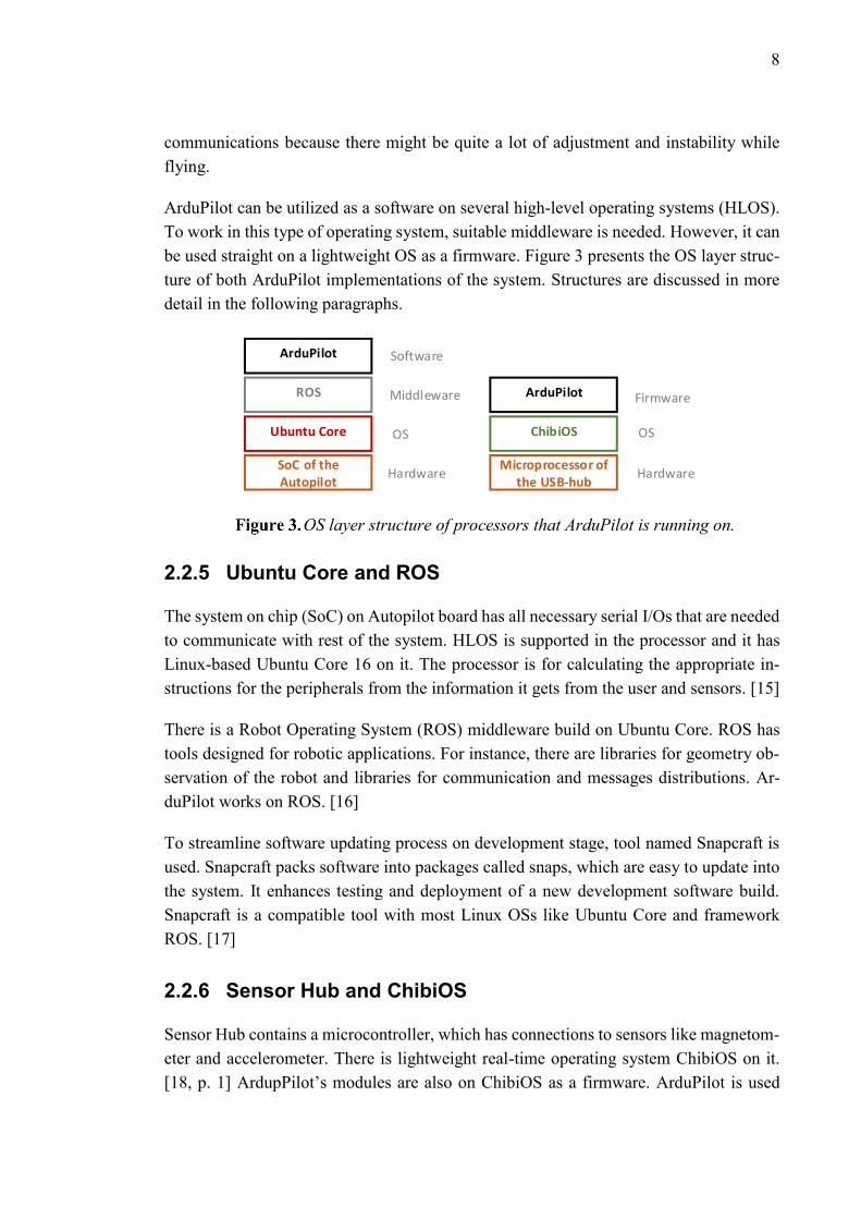
ArduPilot can be utilized as a software on several high-level operating systems (HLOS).
To work in this type of operating system, suitable middleware is needed. However, it can
be used straight on a lightweight OS as a firmware. Figure 3 presents the OS layer struc-
ture of both ArduPilot implementations of the system. Structures are discussed in more
detail in the following paragraphs.
ArduPilot
ROS
ChibiOS
SoC of the Autopilot
Microprocessor of the USB-hub
Ubuntu Core
Software
Hardware
Middleware
OS
Hardware
OS
ArduPilot Firmware
OS layer structure of processors that ArduPilot is running on.
2.2.5 Ubuntu Core and ROS
The system on chip (SoC) on Autopilot board has all necessary serial I/Os that are needed
to communicate with rest of the system. HLOS is supported in the processor and it has
Linux-based Ubuntu Core 16 on it. The processor is for calculating the appropriate in-
structions for the peripherals from the information it gets from the user and sensors. [15]
There is a Robot Operating System (ROS) middleware build on Ubuntu Core. ROS has
tools designed for robotic applications. For instance, there are libraries for geometry ob-
servation of the robot and libraries for communication and messages distributions. Ar-
duPilot works on ROS. [16]
To streamline software updating process on development stage, tool named Snapcraft is
used. Snapcraft packs software into packages called snaps, which are easy to update into
the system. It enhances testing and deployment of a new development software build.
Snapcraft is a compatible tool with most Linux OSs like Ubuntu Core and framework
ROS. [17]
2.2.6 Sensor Hub and ChibiOS
Sensor Hub contains a microcontroller, which has connections to sensors like magnetom-
eter and accelerometer. There is lightweight real-time operating system ChibiOS on it.
[18, p. 1] ArdupPilot’s modules are also on ChibiOS as a firmware. ArduPilot is used

9
when data flows are disturbed in CAN1 bus and for instance no messages are received
from its peripherals. In the error situation, processor of the central hub tries to get the
UAV to the ground by using sensor data and CAN0 peripherals. A fast real-time operating
system ChibiOS is used for backup operations, while the response time can be guaranteed.
Sensor Hub has 3 Inertial Measurement Units (IMU), which can determine the exact po-
sition of the UAV. An IMU can detect acceleration and directions where it occurs. From
acceleration information rotational attributes roll, yaw and pitch can be calculated. With
a magnetometer and an air speed sensor the position of the UAV can roughly be estimated
in the situations where GPS-signal is not available.
2.3 Test Environment
The drone system requires some more connections and devices to function as a system
that can be automatically tested. The computer on which the testing is performed is the
host PC and through connections to it, the host PC must be able to read data, and in the
case of Autopilot board, also write, so that commands can be run.
2.3.1 Connection to Host PC
Serial connections can be taken via Universal Asynchronous Receiver Transmitters
(UART) to most of the PCBs. The PCBs have debug UARTs and they are connected to
the host PC via ST-Link debug connector or USB-ports. Debug UART connectors are
shown in the figure 4.
Secure Shell (SSH) via Ethernet cable is another option to connect host PCs to the UAV.
On the UAV there is one Ethernet port on the Autopilot. With SSH connection host PC
can use the Ubuntu Core of the Autopilot, run commands on it and read their results.

10
Host PC
Autopilot Central Hub
Wing PCB
Wing PCB
ESP PCBBattery PCB
MODEM
DEBUG CONN
TC2030
MODEM DEBUG CONN
TC2030
DEBUG CONN
TC2030
DEBUG CONN
TC2030
DEBUG CONN
TC2030
DEBUG CONN
TC2030
MOLEX DEBUG CONN
CAN 0
CAN 0SERVO
SUPPLIES AND
CONTROL
CAN 0
ST LINK
CAN 1
CAN 1
CAN 1
Serv
o C
onn
ecto
rW
ING
CO
NN
Serv
o C
onn
ecto
rSe
rvo
Con
nec
tor
PORT
STBD
Rudder
Elevator
Button Board
WIN
G C
ON
N
Pay
load
C
onn
ecto
rP
aylo
ad
Con
nec
tor
CAN 1
CAN 0
GPS_TIMEPULSE
SD CARD
USB HUB
ETHERNET PORT
SSH
UART
UART
ETHERNET PORT
USB PORT
Simplified hardware block diagram of the UAV shows connections
between PCBs and debug UART connectors of them. Host PC can connect to
debug connectors with serial connection and to Autopilot with SSH connection.
Debug connectors can be found from all the PCB that have the task of controlling the
peripherals. There are two debug connectors on the Central Hub, for the modem and for
the Hub, one on Autopilot, one on both Wing PCBs, one on both Battery and ASP PCBs.
Information on operations can be improved in development and testing.
Serial connection is a good way to look at the functionality of PCBs. It can be connected
even if the target PCB is not powered. Compared to the SSH connection of the Autopilot
that allows to examine boot sequence of Ubuntu Core. The boot sequence is useful for
initializing tests and boot tests. On other PCBs, serial connection is a great way to check
functionality because it is possible to print information through it to the host.
SSH connection cannot be established before the device has been booted totally up. How-
ever, there are some other great benefits from using SSH-connection. There can be an
unlimited amount of SSH-connections, while one UART cable can handle only one serial
connection. Hence, multiple users or tests can take advantage of connection at the same
time. SSH connection is stable, easy to use and to shut down. Other PCBs can be read
from Autopilot as well, as they transmit information about their activities to it. Due to the
benefits listed above, most of the tests are run via the SSH connection.

11
2.3.2 Control Devices
Some tests and initializations of tests need human actions. There needs to be control de-
vices that can be used to replace human actions so that the tests can be totally automated.
That will streamline testing a lot. The control devices are presented in figure 5.
POWER SUPPLY
Central Hub
VBAT
ETHERNET PORT
Modem
Modem Debug Board
Host PCAutopilot
ETHERNET PORT
ST LINK
SD-multiplexer
SD-cardProgrammable USB hub
VBAT
SSH
DEBUG CONN
UART
SDIO
USB PORT
UART
USB PORT
UART
UART
SD- card-slot
Hardware block diagram of the test environment includes main PCB of
the UAV, Autopilot, programmable power supply and Central Hub together with
sytem that can read and write to SD-card or listen to debug UART. Modem can
be tested with another controllable modem.
The SD-card can be connected either to the host PC or the Autopilot. USB-hub is used to
change ways of the connection. A UART connection is formed from the host PC to the
hub. Controlling the USB-hub is easy with open source scripts that are suitable for mul-
tiple USB-hubs that are using the same technology. This project has utilized Transcend’s
and Amazons’ programmable USB-hubs, whose ports can be controlled with the uhubct
utility. It allows the ports to be powered on and off individually. [19]
The SD-card is for flashing software to Autopilot board when snaps are not available.
Updating with snaps takes place by downloading them from the build server and moving
them into the device and running the snapcraft tool. SD- multiplexer can be in two modes,

12
either it is listening to host PC and writing image into SD-card or connected to the Auto-
pilot board. The SD-card of the multiplexer is connected to the SD-card-slot of the Auto-
pilot.
In this test environment, the UAV is powered by an external power supply. The power
supply is connected to the host PC, so that it can be controlled programmatically. The
power supplies were selected from pre-purchased ones that have been used in similar test
automation projects. They should enable cold boot tests and as well as functionality test
when there is limited power. In most tests the power supply provides a constant output
voltage, around 15V. One of the available power supplies was Aim TTi’s PLI 155-p and
that was used during development of the test automation framework. It is programmable
and controlled by host PC via SSH connection. [20, p. 4]
In order to test a modem of the DUT, another modem is needed. The modem for testing
purposes is in external board and it is connected to the host PC via UART connection.
Modems communicate with each other via PPP. The communication between modems
can be observed from host PC and there are programs that enables network performance
analyzes.

13
3. VALIDATION STRATEGY
Software validation aims to ensure that the software project meets the requirements that
it is given while planning the project. Quality, stability, functionality and reliability of the
developed product needs to be validated through the whole cycle. Testing is a great way
to support validation. It tries to find out features that prevent the program from meeting
the requirements. [21, p.61]
Automated testing is a method to execute testing, alongside testing manually. Automated
testing is an important part of agile software development. The key of it is focus on soft-
ware, response rapid to changes and invest in good communication. Good communication
in agile development is direct and immediate. There are a number of tools that can be
used to improve it. An issue tracing product Jira supports agile development and commu-
nication. Test executions, upcoming features, bugs, Kanban boards and so on can be
tracked in Jira. Instant messaging programs such as Slack and Skype can also be utilized
for improving the communication. There are several agile software development meth-
ods, many of them are characterized by short iterations in order to minimize risks. [22]
3.1 Test-Driven Development (TDD)
Tests give direction to the development process in test-driven development (TDD). Tests
and their success conditions have been created in accordance with the project plan and
specifications at the beginning of the product cycle. Development of the product is done
on the base of them. TDD eases execution of the automated tests after the changes, be-
cause new version of software can be easily tested automatically and straight after inte-
gration. The test results determine whether the generated code was successful or not. An
unsuccessful test indicates that the code has to be changed for that feature. Thus, TDD is
an essential part of agile software development. [23, p.281] Compared to other develop-
ment methods, TDD strives for a high-quality code. Developers receive continuously
feedback about the code from tests, which contributes to the quality of the product and
the flow of the process. [23, p.283] Figure 6 shows the practical implementation of TDD’s
principles.

14
RepositoryDeveloper
Jenkins
Robot Framework
Test Results
Changes
Automation can easily be utilized in TDD. [24]
Figure 6 is an iteration that has been launched by a developer, who has integrated a new
feature into project or tuned one that had inadequate functionality. Changes in the repos-
itory provoke the build server Jenkins and test automation framework Robot Framework.
The developer has tried to make his code compliant with specification of the product by
getting through the tests. He gets feedback from the code via statuses of executed tests.
Errors can be corrected again in the next iteration.
3.2 Continuous Integration (CI)
CI is an essential part of agile software development. New software features are delivered
continuously and integrated as a part of the project. When the delivery and the integration
are continuous down times are short and risks small because the changes are not huge
between different builds. This aims to ensure that the project could be released at any
time. New and old features work better together and bugs are easier to catch when there
are less to test between short delivery cycles. [25] Figure 7 compares agile development
with a more traditional, plan-driven, one, where testing is done after a long development
period.

15
Plan-Driven Development
Agile Development
Requirements
Specifications
Code
Testing
Release
Iteration 0 Iteration 1 Iteration 2 Iteration 3 Iteration 4
A A A AB B B
C C
D
Agile tested product is ready for release any time, whereas plan-driven de-
velopment proceeds straightforwardly without the iteration rounds [26]
Plan-driven development is a traditional way of thinking what comes to software product
development cycle. The software project is implemented straightforward from designing
through implementing to the release. CI is essential part of agile development where it is
done in in iterations. Each iterations consist of cycles that comply with TDD’s principles.
The following iteration are made on the base of the test results. Basically after every
iteration projects could be ready for release, for it is tested and its functionality has been
checked.
3.3 Execution Gearbox
Daily builds are principles of CI. Basic smoke tests are executed automatically after every
build. Results of the tests define if the code quality is enough for the product according
to TDD’s principles. The tests cover basic features such as boot and responses of periph-
erals. The features that have been corrected or added to the build should also be checked,
while there may be recession and bugs in the related features.
Once a week one of the daily builds is selected to be the weekly release candidate. The
release candidate aims to be the most stable and functional build of the week, and it may
have new features or fixed bugs compared to previous weeks. Basic sanity tests are exe-
cuted to the candidate, but some functionality test results can be cumulative from previous
weeks if no changes have been made to that topic. Weekly executed tests cover more
functionality testing than the daily ones as well as longer and more extensive automation

16
of test runs. Automated tests can be repeated iteratively so that the stability of the device
can be tested. The tests can be run during nights and weekends so that test results of
weekly release candidates can be obtained within few working days. The results are gath-
ered into a week report and reviewed by project management.
One of the operating release candidates will be the ultimate release candidate, which can
be published. To the final release candidate comprehensive functional, stability and reli-
ability tests are executed.
Jira is an issue tracking product which can be used to review the status of the program.
Developer teams report the functionalities that should be supported on product or coming
at some point. If some issues or bugs are found from the product, they should be reported
on Jira, so that the responsible parties can fix it. Issues and stories can be arranged into
Kanban and scrum boards, which clarifies the status of the project and supports agile
software development. Test sets can be created into Jira and they can be executed in order
to get validation reports. Weekly release testing reports as well as milestone test set results
and reports are gathered based on test set executions of Jira. [27]
3.4 Test Approaches
Testing must be designed properly to make a useful test automation framework. Software
testing consist of different testing levels, methods and types. The method involves the
point of view of testing. That is, how much the tester knows about the system being tested.
Testing methods are not the most important part of designing test automation framework.
Methods play a part somewhat when selecting suitable testing types. The automated tests
are based around the testing types and try to test the system in various testing levels and
methods.
3.4.1 Testing Levels
There are different test approaches for different level testing and for different stages of
the project development. In many cases, automated testing can be utilized. In general,
testing levels goes from specific unit testing to system testing that cover the complete
integrated system.
Unit testing is the lowest level of software testing. There individual software components
and units are tested. Unit receives inputs whose responses can be used to clarify the be-
havior of it. [28, p.27] Integration testing takes its place in software testing level between
unit and system testing. Developed and tested unit is integrated into the whole system of
other units and its functionality must be ensured in it. [28, p.29] In system testing the
whole integrated software is tested. System testing covers widely various units and a sys-
tem test consist of several of features to be tested. Combining different features in a test

17
enables, for instance, recovery, security, stress and performance testing to the developed
software. [28, p.31] Comprehensive test automation framework covers tests in all the
testing levels.
3.4.2 Testing Types
Test types can be roughly divided into functional and non-functional aka structural. Func-
tional testing is focused on the activities of the product and responses to inputs and the
correctness of them. Structural testing concerns the code and tries to find out errors of it.
[29, p.270-271] Structural testing is known as white box testing because the implementa-
tion of the product and software is visible to testers and it is an important part of testing.
Correspondingly, functional testing is known as black box testing, for knowing the struc-
ture of software is not needed to test functional tests. [29, p.271]
Functional test can be executed in all testing levels. There are functional test sets for
different purposes. Smoke tests are the first to execute on DUTs after a build. Their intent
is make sure that the new software works at some level. With simple smoke test it is
possible to figure out quicker whether the build is mature for more comprehensive test or
not. [29, p.271] Smoke tests are simple to execute on DUT automatically after the build.
Smoke tests can be used to ensure that the DUT boots up, its peripherals respond to re-
quest and it performs other simple functions. Also, sanity checks can be executed right
after the new build. Sanity checks test the system widely but not deeply and thus tries to
find out which features are causing problems before actual testing begins [29, p.175].
Newly integrated software may cause problems. One type of functional integration test-
ing, regression testing, aims to find bugs that appear due to a change of software structure.
The tests are executed before and after the integration, so that the change of behavior can
be detected. [28, p.29]
Functional acceptance tests ensure that the software has planned functionalities [30, p.42].
All the software components and their functionality are tested unit and system wide. Au-
tomated tests can be utilized in acceptance testing, where the user interface can be re-
placeable with tests scripts.
Structural testing can be done in all testing levels. It aims to figure out if the software
meets non-functional requirements. During testing, the program is subjected to various
stress factors to find out the limits of it. In performance testing, the performance and
capability are measured. The system has constant load through the testing times. Load
testing figures out how the system works under different loads. It is important to sort out
the limits of the load, especially if it is below the requirements. Stress testing is utilized
to figure out the limit of the maximum load that DUT can be under. Endurance testing
solves ability to maintain performance through time and longer executions. In security

18
testing, the device is disturbed so that maintenance of the functionality can be ensured in
similar cases. The tests are designed to measure the ability of the system to protect itself
and its data from malicious attempts. Recovery testing is examining ability to recover and
function again after a crash or a hardware failure. Compatibility testing ensures that the
tested software works with the rest of the system and environment considering hardware,
software and operating systems. [29, p.271]
Test on the DUTs can be executed either manually or automatically. Manual testing is
executed by a person which handles the device during testing and provides the functions
therein. In automated testing the machine is responsible for test execution and it performs
the test scripts. [31] Some testing types are ideally suited for autometed testing, some
manually. The character of the software project means a lot when choosing suitable
method and test type. Often, structural tests are easier to test more comprehensively with
automated tests and functional manually.
3.4.3 Automation versus Manual Testing
There can be great advantages in automated testing depending on software project. With-
out automated testing, the execution gearbox would extend in agile software develop-
ment. Testing time is reduced between the scrums, when the test can be executed in sev-
eral devices simultaneously and around the clock. Debugging is easier when they are val-
idated continuously. Fewer bugs are detected at a time and so they can be fixed faster.
Also the priorization of requirements in TDD helps to complete the project timely and is
desirable when the requirements are well planned. [32, p.1812] Automated testing is ben-
eficial to agile software development but on the other hand, it is at its best in agile devel-
opment [33, p.542].
As a validation method, TDD has advantages as well. Developers get continuous feed-
back of their product and it can be ensured that the new integrated features do not ruin
the system. Test in context of TDD are usually designed so that they are easy to execute
automatically. [34, p.357] TDD has proved to be more motivating for developers and thus
there is more quality software processed using its principles [34, p.361]. The motivation
of test engineers can also be improved by automated testing, since frequent repeated tests
that requires simple and repeatable functions may be omitted from manual testing [33,
p.543].
Robustness and reliability are advantages of manual testing, but well-done test automa-
tion framework is also able to be comprehensive [31]. Human intervention enables more
creative testing. More bugs are found with manual testing, but as it takes more time to
execute, it is way more expensive than automation. [33, p.543] Manual way of testing
suits well, if there is a short testing term and test are not repeated many times, because
19
they take no time in initial configuration [33, pp.543-544]. In some projects maintenance
of the tests would be a significant part of the tests automation development which can
make it too laborious to make it sensible. The user interface of a well-planned Linux
based system does not change as frequently as in UI-based software project where
changes of the test automation framework may have to be done for each test round. If
visual references are tested, it is almost impossible or at least very difficult to use test
automation framework [33, p.544].
3.5 Coverage of the Validation
The important functions for many essential features of the DUT have been implemented
and can be tested. The testable features include, among others, Ubuntu Core and its Linux
Kernel and bootloader and drivers to Central Hub, wings and battery system. These fea-
tures allow a simple test flying. Subparts of the project, like ArduPilot and MAVLink
modules and Ubuntu Core, are tested for its part. They are in wide use and new features
and their bugs can often be found quickly and corrected.
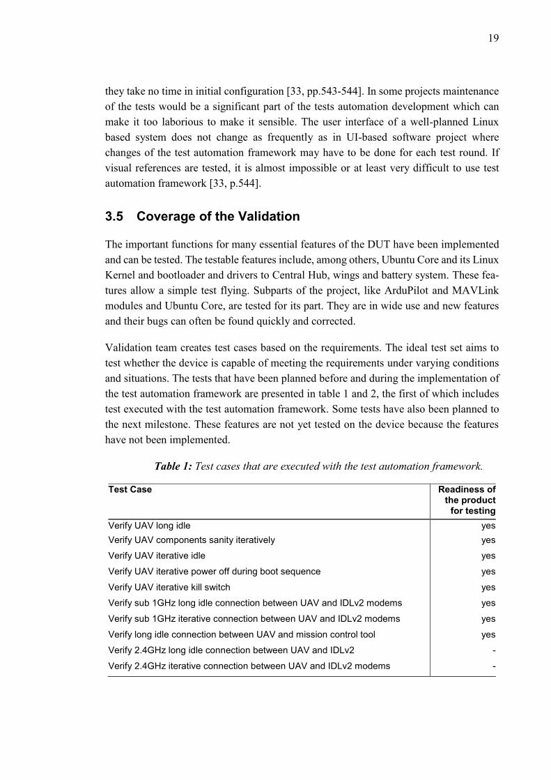
Validation team creates test cases based on the requirements. The ideal test set aims to
test whether the device is capable of meeting the requirements under varying conditions
and situations. The tests that have been planned before and during the implementation of
the test automation framework are presented in table 1 and 2, the first of which includes
test executed with the test automation framework. Some tests have also been planned to
the next milestone. These features are not yet tested on the device because the features
have not been implemented.
Table 1: Test cases that are executed with the test automation framework.
Test Case Readiness of the product
for testing
Verify UAV long idle yes
Verify UAV components sanity iteratively yes
Verify UAV iterative idle yes
Verify UAV iterative power off during boot sequence yes
Verify UAV iterative kill switch yes
Verify sub 1GHz long idle connection between UAV and IDLv2 modems yes
Verify sub 1GHz iterative connection between UAV and IDLv2 modems yes
Verify long idle connection between UAV and mission control tool yes
Verify 2.4GHz long idle connection between UAV and IDLv2 -
Verify 2.4GHz iterative connection between UAV and IDLv2 modems -

20
Automated testing is particularly advantageous in iterative tests. During an iterative test
the testable property can be repeated many times, from dozens to hundreds. Iterative test
can review reliability and stability of the device. At this stage of the project iterative tests
are for simple idle and booting tests.
Functionality of the modem is restricted to a trivial pairing in one of the planned band, so
there is not much to test. The protocol and messages of the modems cannot be tested
while flying in this phase. Also support for payloads are lacking so they cannot be tested
yet.
With the automation framework, it is possible to execute highly variant types of tests. It
can be used to test functional tests, the overall functioning of the whole system although
manual testing is also used for that. The functionality of boards connected to the autopilot
board and their drivers can be easily checked by test automation framework. It is possible
to review if they are connected after each boot and do they send correct responses back
to the Autopilot. Test automation framework enables unit test, tests that test the function-
ality of a certain part of the system or code. Performance can be analyzed with test auto-
mation framework, as a matter of fact it makes it makes it very easy to take the exact time
between different functions and responses. Automatic framework can also be used in load
testing, which enables scalability of the DUT to be tested in the projects where the number
of users is important. It can be used for regression testing, where it ensures that earlier
functionalities still work with new updates. Some security tests can also be done to con-
firm that certain operations will not harm DUT. [35]
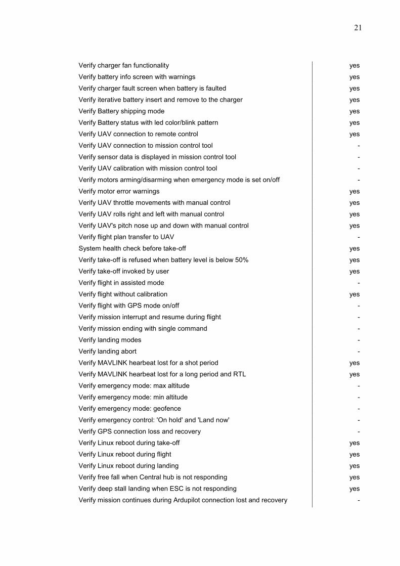
Tests below in table 2 would need a more advanced test environment so that they could
be executed automatically. Many of the tests are related to flying, so the operation of the
device must be checked somehow in the air. At this stage, the UAV is not capable of
flying because there is not enough suitable hardware manufactured or delivered for the
teams that are responsible for the project. Part of the tests in table 2 can be moved to table
1 when it is known more precisely how testing is performed.
Table 2: Test cases that are executed manually.
Test Case Readiness of the product
for testing
Mission planning tool installed in to PC yes
Create flight plan with mission planning tool yes
Verify UAV SW/FW update yes
Verify battery can be stored in a charger for long period yes
Verify UAV charger FW update yes
Verify charger info screen and led status yes
21
Verify charger fan functionality yes
Verify battery info screen with warnings yes
Verify charger fault screen when battery is faulted yes
Verify iterative battery insert and remove to the charger yes
Verify Battery shipping mode yes
Verify Battery status with led color/blink pattern yes
Verify UAV connection to remote control yes
Verify UAV connection to mission control tool -
Verify sensor data is displayed in mission control tool -
Verify UAV calibration with mission control tool -
Verify motors arming/disarming when emergency mode is set on/off -
Verify motor error warnings yes
Verify UAV throttle movements with manual control yes
Verify UAV rolls right and left with manual control yes
Verify UAV's pitch nose up and down with manual control yes
Verify flight plan transfer to UAV -
System health check before take-off yes
Verify take-off is refused when battery level is below 50% yes
Verify take-off invoked by user yes
Verify flight in assisted mode -
Verify flight without calibration yes
Verify flight with GPS mode on/off -
Verify mission interrupt and resume during flight -
Verify mission ending with single command -
Verify landing modes -
Verify landing abort -
Verify MAVLINK hearbeat lost for a shot period yes
Verify MAVLINK hearbeat lost for a long period and RTL yes
Verify emergency mode: max altitude -
Verify emergency mode: min altitude -
Verify emergency mode: geofence -
Verify emergency control: 'On hold' and 'Land now' -
Verify GPS connection loss and recovery -
Verify Linux reboot during take-off yes
Verify Linux reboot during flight yes
Verify Linux reboot during landing yes
Verify free fall when Central hub is not responding yes
Verify deep stall landing when ESC is not responding yes
Verify mission continues during Ardupilot connection lost and recovery -

22
Verify mission continues during Ardupilot connection lost for ever -
Verify UAV does failsafe landing when Ardupilot and Sensor hub is no more
responding
-
Verify UAV goes to free fall when UAVCAN messages are lost -
Verify ESC motor disable when maximum flight time is met -
Verify landing is enabled due battery shutdown when overheating/current/VLO -
Verify UAV disconnect and power off yes
Verify UAV has recorded all telemeter data yes
Verify trace and debug data yes
The final mission control tool is not implemented. Test flights can be done by utilizing
commercial cockpits and existing controlling software. Mission planning tool is sepa-
rately produced in the company and it has support to the developed fixed-wing UAV. On
the other hand, the correctness of the plans must also be explored and tested when there
is support for flying plans. Flying in manually mode is possible so some of the flying tests
can be done.
Smart batteries are an important part of the UAV and their proper operation is essential
for stable and safe flying. At this point, another team is testing the batteries, as they have
not yet been produced enough. Some of the smart battery tests are good to automate as,
for instance, finding a certain tested value from the log can greatly accelerate testing.
However, such tests can only be carried out after more accurate knowledge of how the
batteries behave and what kind of logging they are doing is acquired.
Uploading Snapcraft’s packages, snaps, and updating the software of a DUT with them
is not tested in this phase. The implementation of software updating is not responsible for
the final one. Therefore, software updating test are done manually, although they are easy
to test automatically.
Simple security check can be done and tested. Potential fault conditions and recovering
from them must be taken into account in testing. The UAV should recover and land suc-
cessfully after rebooting the operating system that is responsible for flying or shutting
down the peripherals that are needed to collect essential flight data. Wrong credentials
can be used to login into the DUT, harmful files can be copied into it and its essential
features can be disturbed for instance with stack overflows. However, all the telecommu-
nications harassment tests and flying UAV capture tests can not be done comprehensively
at this stage, for the emergency protocols of landing the UAV are not implemented.

23
4. TEST AUTOMATION DESIGN
A well implemented test automation framework is reusable in different testing environ-
ments, generates clear, clarifying and informative test reports and is easy to use in addi-
tion to perform valid tests reliably. The following automation environment is the result
of this thesis and it has been attempted to do so that it can be reused with other upcoming
projects, which in principle, carry out similar functions. Moreover, the automatic creation
of the test reports and automatic test runs after every new software build have been im-
portant factors in planning and implementing a test automation framework. In figure 8
relations between different software modules and frameworks are presented as a block
diagram of the software architecture of the test automation system. Figure 9 concerns in
more detail the division of responsibilities about test execution, Jenkins Jobs and Robot
Framework.
HOST PC
Device Control
Jenkins
Robot Framework
Powercontrol
Template Job
Testbench Job
DUTs Job
Test Data Files
Robot Test Libraries
Execution scripts
Device Interface
Device
Fixed Wing Device
SSH Connection
Serial Connection
Flash
SD mux
USB Hub Control
Environment Configuration Files
Build Server
Jenkins
SW Build Job Automatic Reports-excel
Robot Framework s Reports and Logs
Response from the Test
DUTFixed-Wing
DUT
Post-build scripts
HOST PC
Device Control
Jenkins
Robot Framework
Powercontrol
Template Job
Testbench Job
DUTs Job
Test Data Files
Robot Test Libraries
Execution scripts
Device Interface
Device
Fixed Wing Device
SSH Connection
Serial Connection
Flash
SD mux
USB Hub Control
Environment Configuration Files
Build Server
Jenkins
SW Build JobLaunching Test
AutomationFramework
Automatic Reports-excel
Robot Framework s Reports and Logs
Response from the Test
DUTFixed-Wing
DUT
Post-build scripts
Block diagram of the software architecture of the test automation system
presents the components that the whole system is consisted of.

24
SW Build Job Testbench Job DUT Job (1...n) Template Job Robot Framework DUT (1...n)
Test Automation Launch
Test ParametersTest File Source
DUT configuration(1...n)
Test Run ConfigurationTest Inputs
Responses from the Tests
Test Reports and Logs
Executing Tests
Collecting Logs and
Reports to Workspace
Creating Test Reports
Message sequence chart clarifies the division of responsibilities of Jenkins
and Robot Framework.
Most of the software modules are run in the host PC. Software (SW) Build Job comes
from outside of the host PC, from Build Server. Both build server and host PC are con-
nected to automation server Jenkins. Jenkins is used to configure test devices, so that new
software can be built and automated tests can be executed on them. Modules in Jenkins
are called Jobs. There is a Job for each DUT and together they are presented in figure 8
as DUT Jobs. A DUT Job defines the interface through which connection to the device
can be created. Template Jobs are similar to all DUT. It includes definition of other de-
vices used in the test environment. DUTs and executable tests are defined in Test Bench
Job, which eventually calls Execution scripts. Execution scripts start test scripts of Robot
Framework.
Test automation framework is responsible for tests. Keyword-driven Robot Framework
is used as the automation framework in this project. The test cases have been defined in
Robot Framework’s Test Data Files. Robot Framework works by using keywords. The
keywords are defined in Robot Test Libraries. The amount of existing test libraries of
Robot Framework is comprehensive. Keyword libraries are easy to create, and it is good
to make entities from keywords that can be utilized in other similar projects. Every DUT
and control device has a Configure File, which allows the test libraries to create right
connections to the devices. Configure files can also be a part of the Jenkins implementa-
tions.
25
Robot Framework test scripts take advantage of keywords that are defined in Device In-
terface –module of the software architecture block diagram. The module implements key-
words that are needed for the tests. Keywords are defined in general terms in this level.
Device Control Module defines actual implementation behind functions that uses control
devices: power supply, USB hub and SD- multiplexer, and serial and SSH connections
from host PC to the DUT.
Collected logs and debug traces can be attached to finally generated test report. They can
give the most detailed description; what tests have been done and where they have failed.
Robot Framework forms a report from the test suite where each status of the test result is
attached with logs and traces related to it. Robot Framework make reports as html-files.
For test reporting, it's good to do an excel sheet as well so it is easy to calculate the pass
rate and run rate for the whole test set. Jenkins takes advantage of Robot Framework
reports, logs and debug traces and they can be saved test run-specifically. Through Jen-
kins they can be automatically sent by e-mail.
4.1 General Test Automation Framework Settings
All the files that are needed for the test automation framework are in a version control
system GIT. It enables easy sharing between all users and devices of the test automation
framework. GIT can also benefit in version management mind. It can be useful to return
to earlier versions of the test automation framework if the changes in the program being
developed change the test environment or if the framework does not work after its devel-
opment as desired but worked well before. Some files in the GIT required execute per-
missions to all users that are going to run tests, which should be considered when config-
uring the GIT repository.
DUTs and control devices that are connected to host pc via SSH-connection have con-
stant IP-addresses, so that connecting to them would be the same every time. A constant
IP-address can be provided by Micro Dynamic Host Configuration Protocol (UDHCP).
UDHCP is lighter network management protocol than usual DHCPs and it is specifi-
cally targeted at embedded systems. [36] Modems are configured so that the connection
between them successes easily when needed. Certain IP-addresses can be set on mo-
dems of the DUT and modem debug board.
In addition to the general settings, each section of the test automation framework has its
own installations and initialization. They are presented in paragraphs handling them.

26
4.2 Jenkins
Developed software needs to be built before it can be executed or tested. The build in-
cludes converting source files of the program into binaries and packing them into com-
pressed formats. To simplify the process, it is automated. Build automation enables build-
ing whenever necessary for testing and it is therefore an important part of continuous
integration (CI). [37]
Originally build automation was made with makefiles, which were used to convert the
source code of the program into a binary code. Nowadays there are build-automation
utilities or servers. Build-automation utilities deliver mostly the role of makefiles, and
convert source code to binary code. Build-automation servers allows for building and
testing in a controlled and timed manner, which suits well for CI.
Jenkins is an open source automation server. It enables automated building, testing and
delivering. There are plenty of plugins that can add functionality to Jenkins. Users can
also extend it by developing plugins. [38] Jenkins is utilized widely in Intel by numerous
teams. There are good opportunities to take advantage of it, because the features can be
utilized comprehensively and there are previous projects, which can be used to model
future projects.
Jenkins needs to be installed on the server machine that manages Jenkins projects and
jobs. The nodes aka slave machines of Jenkins server machine needs to be defined in
Jenkins. Server machine needs to be in same network with its nodes in order to connect
to them. The connection can be made with SSH, whereby after switching the SSH keys,
the connection between the server and a node is simple. Open Java Development Kit
(OpenJDK) needs to be installed into the node PC of the Jenkins project. The master PC
will download Java Archive-typed (JAR) package into the node. OpenJDK is capable of
handling java based JARs. Package includes information about the jobs that are executed
on the node. [39]
The PCs that are supposed to be places where tests are executed, must be configured into
Jenkins. Those PCs are nodes that can be connected via Jenkins. The nodes are called as
agents in Jenkins versions over 2. So that the connection to agents can be created, creden-
tials needs to be defined and Jenkins needs to be installed to it. In addition it is needed to
determine how Jenkins launches methods in the node. Jenkins can launch slave agents via
SSH connection, control its agent as Windows service or use execution of command on
the master. The latter actions are not appropriate, so in this project SSH-connection is
used.
27
4.2.1 Jobs
The functionality of Jenkins is determined in the jobs. The basic structure of the jobs that
were created for this project is copied from previous project. They have been finalized to
be compatible with this project. Thus, for instance, the configuration of DUTs and their
control device, source of test files, arranging the test reports as well as calling the test
framework.
Jobs can be exported, copied or created as a freestyle project, which is suitable for a cer-
tain project. A freestyle job consist of following sub-parts which determines how it works:
General, Source Code Management (SCM), Build Triggers, Build Environment, Build
and Post-build Actions. There are many types of plugins for each section and the search
and installation of those is necessary in most projects. [40]
General includes basic settings of the job: project name, description and type of the pro-
ject. Project can be set to be, for instance, a GitHub project or parametrized. Parametrized
projects enable a user to define the execution by giving defining input parameters. SCM
provides a way to get the necessary files for the project. There is a lot of plugins for a
variety of ways to manage source code for example a plugin for multiple SMCs and clon-
ing them from GIT. Build Triggers cover the ways the job can be launched and executed.
It can be done periodically, remotely and after some other build. Build Environment ini-
tializes the upcoming build. Old workspace can be deleted, console output can be high-
lighted and time stamped and source files can be defined. Build evokes the missions for
which the job is defined. External programs, different types of scripts or other projects
can be utilized for it. In addition, there can be determined build steps that, for instance,
set the timeout of the execution, add description to it or change status in a GitHub commit.
Post-build Actions includes procedures that are done last in the job execution. Another
job can be called, scripts can be executed and e-mail notifications can be sent. There are
several ways to gather and publish results of the execution in post-build actions. Scripts
can be used to gather the results into workspace and some plugins can set status of the
build into GitHub commit or corresponding services.
There are four kind of Jenkins jobs that are related to executing a test on a node aka the
host PC of the test automation framework. One job, testbench job, is responsible for
launching same test sets in all configured DUTs. It can be launched manually. There can
also be another job, build job, that can trigger the testbench job according external SW
builds, GIT commits as well as periodically after certain times. An external SW build
server can handle building the Jenkins job that creates the new developed image. One job,
template job, is utilized to execute tests on DUTs and it is the basis for their accomplish-
ment. Other jobs are for each DUT. They are configured with the control devices there.

28
4.2.2 Executing Jobs
The testbench job gathers all the DUTs into the same build. In general settings the job is
defined to be parametrized, so that input parameters can be given to it. In this project the
parameters are for a script that is defined in a template job for DUTs. In them the input
parameters can determine what test are executed and how the e-mails about test execution
are received. Most of the input parameters are Boolean parameters, which are easy to
select or unselect when starting the build. Input parameters can also be string parameters,
and then a test can be selected to be executed by giving its name, a build can take descrip-
tion as an input or a URL can be presented, where a new SW image to the DUT can be
uploaded. Parameter can also be selected from a list and then it is called a choice param-
eter. This way is practical for selecting e-mail addresses of the recipient, when appropriate
addresses can be defined in the selection menu. Testbench job does not take any source
code, as its mission is to trigger other builds on other projects. Those projects are DUT-
specific jobs and defined in build section.
The build job is highly similar to a testbench job. It does not launch a DUT-specific job
but the testbench and takes SCM values from GIT. Source code can be one of the triggers
for the build job. Test execution can start by a GIT commit, a successful SW build or it
can be set to launch test periodically for instance once a day.
4.2.3 DUT Job Template
A template job defines where the build is done and what it does. Template aims to have
as many as possible common configuration and operations that are for all the DUTs. Gen-
eral settings defines restrict where the build is done. A node is needed to be configured
so that it can be selected as a place where build can be done. Program files of the test
automation framework are required for template, so in its source code management they
are pull from GIT. Getting file from GIT requires a repository URL and someone’s cre-
dentials to the repository. In this context, no changes are pushed into GIT, even if they
would change during the build. They can be pushed later after the build.
The build contains a shell script, which gathers the variables for connections to DUT and
its control devices as well as operations to them based on input parameters. It handles
image updating, if an input parameter defines that image needs to be changed or the exe-
cution has been launched by a new SW build. The execution shell of the build is repre-
sented in program 1.
#!/bin/bash -xe if [ -n "$IMG_URL" ]; then python3 ctrl.py power off && python3 Img_downloader.py $IMG_URL && python3 ctrl.py uhub transcend off &&

29
python3 ctrl.py sdmux hostpc && python3 ctrl.py uhub transcend on && number=$(ls ubuntu-core-image* | grep -oP '(?<=-)\d+(?=\.)') echo $number sudo dd if=ubuntu-core-image-$number.img of=/dev/sdb bs=32M
status=progress && sync && python3 ctrl.py sdmux basepilot && python3 ctrl.py power on fi cd tests tee conf.py <<-HERE CONNECTION = {'type' : 'ssh', 'host' : '$HOST'} SERIAL_PORT = {'port' : '$SERIAL_PORT', 'baudrate' : 115200} CREDENTIALS = {'username' : 'ubuntu', 'password' : 'ubuntu'} POWER_CONTROL = {'type' : '$POWER_CTRL_TYPE', 'ip': '$POWER_CTRL_IP', 'port' : $POWER_CTRL_PORT} HERE cmd="robot --variablefile conf.py -L DEBUG --listener Reporter.py" args= if $RUN_SMOKE; then args="$args -i smoke" fi if $RUN_FUNCTIONAL; then args="$args -i functional" fi if $RUN_STABILITY; then args="$args -i stability" fi if [ -n "$CUSTOM_TEST" ]; then args="$CUSTOM_TEST" fi if [ -z "$args" ]; then echo "No arguments given, exit" exit 1 fi if [ -n "$BUILD_DESCRIPTION" ]; then echo "Build description: $BUILD_DESCRIPTION" fi $cmd $args fixed-wing.robot python3 create_report.py
Program 1. Build script is a shell script that enables a test execution with different
parameters.
At the beginning of the script in program 1, a shell script is configured. There are infor-
mation according to which an interpreter can be selected and the way in which the script
is executed can be determined. X parameter prints commands and their arguments into
console and e exits if any error occurs while the execution.

30
If an URL to a new SW image is given as an input parameter, a look to the URL can be
made and an image is uploaded if there is one. In Jenkins, there is a page that contains
always the newest build of a project. Often the newest build and image is flashed into
DUT, so that the URL is good to be the default URL. An interface script crtl.py is used
to control power supply, USB-hub and SD-multiplexed of a DUT. More about the script
is clarified later on in Equipment control -chapter. First the DUT is powered off. It is
powered off until the updated image is written into SD-card. The image is uploaded with
a Python script. This upload script connects to the URL and tries to find suitable package
that includes the image. The image can be from a webpage with a python library beautiful
soup. The library can convert HTML and XML data into more readable and structured
form [41]. The upload script downloads the found image into the host PC. The read di-
rection is turned to the host PC from SD-multiplexer so that the image can be written
from it to the SD-card. The SD-card reader is restarted so that it could be recognized by
the host PC. The image can be found with command-line utility grep. Only the latest
uploaded image is restored after upload script. Here, the parameter o gathers only match-
ing parts of the lines that have found by grep and the parameter P is for Perl regular
expression (PCRE). It can be used to determine the requested lines instead of using port-
able operating system interface (POXIS) basic regular expressions. With PCRE all but a
certain part of the line can be parsed, in this case all before a minus and after a dot. [42]
The command finds the number series of downloaded image and assigns it into the vari-
able number. When the image is downloaded and found it can be written to SD card. A
command-line utility dd can convert and copy files as well as overwrite partitions. Along
with the image, partitions has to be written again into flash media. Finally the SD-multi-
plexer is turned the other way around and DUT powered and the flashing from the SD-
card can start.
The folder structure of the files from GIT is such that the tests must be executed in one
subdirectory, the test folder, so it is needed to move into that folder. A file that includes
configuration details to the DUT and its control devices, is created into this test folder.
The base of the executed command is in variable cmd and the rest of it is gathered into
args-variable along the script. The base contains created configure file and reporter gives
as command line options variable file and listener.
The script obtains the input parameter. Boolean parameters are easy to go through with
simple if-clauses. In these clauses a command line option include can be added to args-
variable with a tag name. On basis of them certain test with same tags can be selected for
execution. It can be also checked if string parameters are given as input parameters. With
custom_test-variable, a single test can be executed and with a build_description-variable
information of the execution can be conveyed into console.
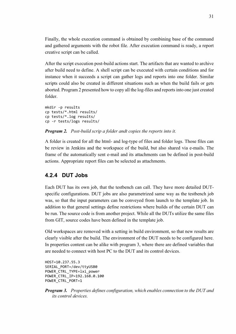
31
Finally, the whole execution command is obtained by combining base of the command
and gathered arguments with the robot file. After execution command is ready, a report
creative script can be called.
After the script execution post-build actions start. The artifacts that are wanted to archive
after build need to define. A shell script can be executed with certain conditions and for
instance when it succeeds a script can gather logs and reports into one folder. Similar
scripts could also be created in different situations such as when the build fails or gets
aborted. Program 2 presented how to copy all the log-files and reports into one just created
folder.
mkdir -p results cp tests/*.html results/ cp tests/*.log results/ cp -r tests/logs results/
Program 2. Post-build scrip a folder andt copies the reports into it.
A folder is created for all the html- and log-type of files and folder logs. Those files can
be review in Jenkins and the workspace of the build, but also shared via e-mails. The
frame of the automatically sent e-mail and its attachments can be defined in post-build
actions. Appropriate report files can be selected as attachments.
4.2.4 DUT Jobs
Each DUT has its own job, that the testbench can call. They have more detailed DUT-
specific configurations. DUT jobs are also parametrized same way as the testbench job
was, so that the input parameters can be conveyed from launch to the template job. In
addition to that general settings define restrictions where builds of the certain DUT can
be run. The source code is from another project. While all the DUTs utilize the same files
from GIT, source codes have been defined in the template job.
Old workspaces are removed with a setting in build environment, so that new results are
clearly visible after the build. The environment of the DUT needs to be configured here.
In properties content can be alike with program 3, where there are defined variables that
are needed to connect with host PC to the DUT and its control devices.
HOST=10.237.55.3 SERIAL_PORT=/dev/ttyUSB0 POWER_CTRL_TYPE=lxi_power POWER_CTRL_IP=192.168.0.100 POWER_CTRL_PORT=1
Program 3. Properties defines configuration, which enables connection to the DUT and
its control devices.

32
Environment properties are conveyed to the template, whose build script need the values
of them to connect to the DUT and environment. Build and post-build activities of DUT
jobs are the same for all the DUTs so again the template job is done for this purpose and
builders are taken from that project.
4.3 Automation Framework
An automation framework is an entity that allows the creation and execution of automated
tests. There are different types of automation frameworks all of which have a slightly
different approach to testing. However, all of them try to have certain features; framework
should be scalable, easy to maintain and reuse, reliable, consistent, able to log and last
but not least improve the testing. The automation framework choice will be affected by
usability in a certain project, whether it is open source framework or not, amount of good
documentation, implementation and language.
4.3.1 Frameworks
Linear Automation Framework is the simplest automation framework. Its use is based on
the replication of the tests based on how the user has performed them earlier. This kind
of framework can be utilized especially in applications with UI. Linear Automation
Framework is easy way to create new test automation framework, and adding new tests
does not require significant programming skills. However, the disadvantage is the fact
that it is not easily re-used even with other similar types of applications and even small
change in application can break the automation. [43]
Data-driven Automation Framework is based on the simplest framework, Linear Auto-
mation Framework, but its operation can be defined by inputs before execution. The input
determines the test so that its implementation can be reduced. That brings advantages that
the linear framework did not have; tests are reusable for different test conditions and little
changes in the application may not be the problem in terms of functionality. Initializing
testing takes more time and requires both system design and programming. External data
may also be associated with problems that may interfere with the manual testing of the
system. [43]
Keyword-driven Automation Framework works in highly same way as data-driven, ex-
cept that the data to be tested will not come as an input but it is given as an external data
file. The code of the framework consists of the functions that are called keywords. The
keywords define the tests. In addition to advantages of data-driven framework, keywords
provide even more reusable implementation. Keyword can be used for different tests and
DUTs, because their implementation can be done hierarchically on many levels. The use

33
of keywords does not require much technical knowledge but creating them needs time for
planning and developing. [43]
In Modular Automation Framework test functions are divided into modules. A module
forms a test. Multiple modules can be combined and with their functions wider tests can
be created. When the functions are divided into suitable small parts, a test automation
framework is easy to maintain, because changes in the application being tested cause only
changes to certain modules. The use of modules may be complicated and require much
modifications if the tests change. Compared to the previous frameworks, this one needs
more test scripts in relation to tests. [43]
4.3.2 Robot Framework
Robot Framework is a keyword-driven Python-based test automation framework, that
works both with versions 2 and 3. Robot Framework can be used in quite different appli-
cations and technologies; it has plenty of test libraries and tools for very large variety of
projects. [35] The framework has libraries like Selenium which enables web testing, GUI
testing and taking SSH connections.
Robot Framework was used in this project because it has good documentation and both
usage and language of it are familiar to the author of the test automation framework. A
test automation framework, which was created earlier by Intel’s validation team, was used
as the basis for automation of this thesis. Especially, when developing the test libraries,
the previous project and its test libraries gave a good starting point for development. The
thesis was to create a test automation framework to fit the new project and to develop test
libraries so that they would be more modular and easily reusable in future.
Robot Framework has a lot of features that supported the choice; Keywords can be created
from keywords that make them easier to reuse and the framework easier to use. Test cases
are easy to create using high-level keywords. Especially the highest-level keywords can
be well utilized in future test automation projects. It is easy select and execute certain test
by tagging them. Test can have different priorities. The framework provides possibility
to setup and teardown the whole test-suite as well as individual test cases. Robot Frame-
work can report status of the test after running it. There are also different log levels that
informs about test, which facilitates debugging. [44]
Robot Framework is independent of the application and technology, so an important part
of its architecture are the modules, which it is consist of. The architecture is highly mod-
ular and presented in figure 10.

34
The arcitecture of Robot Framework includes from top to bottom
test cases in test data, automation framework itself as Robot Framework, test
libraries and modules where the actual implementation of the system under test.
[45]
The highest module of figure 10 includes the test cases. In Robot Framework test cases
have been defined in test data files. They consist of the implementations of the tests. Ro-
bot Framework processes given test data file when the automation framework is launched.
Framework executes tests from the file and generates log about the execution. Logs al-
lows the user to know the status of the test executions.
The keywords that are used in the data test files are defined in the test libraries, the middle
module in figure 10. Through the test library application programming interface (API),
Robot Framework requests keywords from their libraries and gets in exchange infor-
mation about the success of executing keywords. The test libraries determine implemen-
tations of the keywords at the required levels. If test libraries are carefully chosen and
created, the automation framework can be highly reusable in similar projects. In some
cases, depending on the application, test libraries can directly communicate with the sys-
tem under test via application interface. If the direct connection to system is not possible,
test tools can be utilized. Such can be drivers for the system under test. [45]
Test data files are in tabular format. That format is suitable for keyword-driven automa-
tion framework, for keywords are easy to use and edit there. The test data file can consist
of four types of tables: Setting, Variables, Test Cases and Keywords -tables. The Settings-
table incudes possible import of test libraries, resource files and variable files as well as
test suite and case setup and teardown definitions. The Variable-table defines general
variables that are used in tests. Tests are defined in the Test Case –table. The Keyword-
table consists of higher-level keywords. They have formed from lower-level keywords,
which can be obtained from test libraries. Higher-level keywords can be utilized in test
cases. Cells in the tables contain individual keywords, parameters related to them or test
and table definitions. [46]

35
Supported tabular file formats are for example hypertext markup language (HTML), tab-
ular separated values (TSV) and plain text in tabulars. Advantage of HTML format is a
clear table like syntax which makes the content of the test data file easy to read and un-
derstand. Editing it in comparison with other formats is difficult and requires more ad-
vanced text editors. TSV format is very simple, and it is good to create, for example,
programmatically. It suites slightly better to different text editors than HTML, because
the data is structured in one large table instead of many smaller ones. [46]
Plain text formats are often utilized, if there is no need for the specific features of some
other formats. The text is formatted into one big table as in TSV format, but the separating
method between table cells is different. Robot Framework’s plain text can be used two
ways, either in space-separated format or in pipe-and-space-separated format. In space-
separated format the cells in the table are separated by two spaces while in pipe-and-
space-separated format by pipe character and spaces. Plait text format can be edited in
highly simple text editors. [46] Program 4 is written in plain text and space-separated
format and it is a simple example of a test data file that could cover very basic tests of an
embedded system.
*** Settings *** Library OperatingSystem Library ../lib/DutLibrary.py Library ../lib/FixedWingLibrary.py Test Setup Setup Test Teardown Teardown Suite Setup Setup Testrun *** Variables *** ${LOGS_DIR} logs *** Keywords *** Setup Testrun Create Directory ${LOGS_DIR} Empty Directory ${LOGS_DIR} *** Test Cases *** Cold Boot 2 times [Tags] smoke cold_boot_2_times [Setup] [Teardown] ${boot_times}= Cold Boot Test ${2} Set Test Message ${boot_times} Cold Boot 10 times [Tags] functional cold_boot [Setup] [Teardown] ${boot_times}= Cold Boot Test ${10} Set Test Message ${boot_times} Cold Boot 100 times [Tags] stability cold_boot_stability
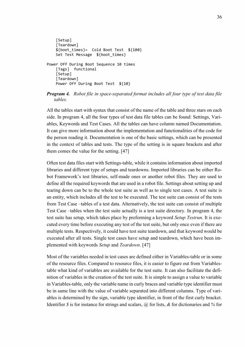
36
[Setup] [Teardown] ${boot_times}= Cold Boot Test ${100} Set Test Message ${boot_times} Power Off During Boot Sequence 10 times [Tags] functional [Setup] [Teardown] Power Off During Boot Test ${10}
Program 4. Robot file in space-separated format includes all four type of test data file
tables.
All the tables start with syntax that consist of the name of the table and three stars on each
side. In program 4, all the four types of test data file tables can be found: Settings, Vari-
ables, Keywords and Test Cases. All the tables can have column named Documentation.
It can give more information about the implementation and functionalities of the code for
the person reading it. Documentation is one of the basic settings, which can be presented
in the context of tables and tests. The type of the setting is in square brackets and after
them comes the value for the setting. [47]
Often test data files start with Settings-table, while it contains information about imported
libraries and different type of setups and teardowns. Imported libraries can be either Ro-
bot Framework’s test libraries, self-made ones or another robot files. They are used to
define all the required keywords that are used in a robot file. Settings about setting up and
tearing down can be to the whole test suite as well as to single test cases. A test suite is
an entity, which includes all the test to be executed. The test suite can consist of the tests
from Test Case –tables of a test data. Alternatively, the test suite can consist of multiple
Test Case –tables when the test suite actually is a test suite directory. In program 4, the
test suite has setup, which takes place by preforming a keyword Setup Testrun. It is exe-
cuted every time before executing any test of the test suite, but only once even if there are
multiple tests. Respectively, it could have test suite teardown, and that keyword would be
executed after all tests. Single test cases have setup and teardown, which have been im-
plemented with keywords Setup and Teardown. [47]
Most of the variables needed in test cases are defined either in Variables-table or in some
of the resource files. Compared to resource files, it is easier to figure out from Variables-
table what kind of variables are available for the test suite. It can also facilitate the defi-
nition of variables in the creation of the test suite. It is simple to assign a value to variable
in Variables-table, only the variable name in curly braces and variable type identifier must
be in same line with the value of variable separated into different columns. Type of vari-
ables is determined by the sign, variable type identifier, in front of the first curly bracket.
Identifier $ is for instance for strings and scalars, @ for lists, & for dictionaries and % for
37
environmental variables. Variables can be only strings in various data structures in Vari-
ables-table, which limits its use in relation to recourse files. [48]
Keywords-table contains high-level keywords that may have been formed from higher-
level keywords or other keywords received from test libraries or other Robot Framework
files. These high-level keywords can be utilized in all the tests of the test suite. If Key-
words-table has a value in the first column of a row, the keyword definition starts. Defi-
nition continues until next keyword definition or the end on Keywords-table. When a
keyword is called, all the keywords in it are executed in turns. [49]
The last table in program 4 is Test-Cases –table. Values in the first column of the table
determine name of the tests and the keywords in the following lines of test names forms
the tests. Test Cases can have settings, and those are defined in square brackets under the
name of test case. They are test case specific. Settings can be related to documenting,
tagging, setting up or tearing down the tests or setting timeout or template for test execu-
tion.
Tags can be added to tests with Tags-setting. Tags can group the test so that tests with the
same tag can be executed easily with a one command. With Setup and Teardown –settings
it can be determined whether specific test has modified setup or teardown. It can also be
determined that there is no setup or teardown at all. Then the settings are left as blank like
in many test cases in program 4. In Template-setting, a test template can be defined to be
a basis for a test. If a template is used in a test, the data for executing the template is given
in the test case. Timeout-settings is used to set time limit for executing specific test case.
If the specified time elapses before the test execution is finished, the test fails. [50]
Information about test runs is recorded by Robot Framework and some keywords into
logs. Test reports can be generated from the logs. Reports from Robot Framework logs
are described in more detail in the paragraph 3.5 Test Report Generation. [51]
4.3.3 Test Libraries
Libraries, which are delivered with Robot Framework, are called standard libraries. There
are two types of standard libraries, normal standard libraries and remote libraries. Stand-
ard libraries needs to be imported if they are used except one. Keywords from BuiltIn-
library can be used without importing it into robot-files. It includes keywords that are
often needed to do some simple operations in robot-files like creating for-loop or pass
execution. BuiltIn-library is one of the normal standard libraries, which are widely used
with Robot Framework. There are normal standard libraries that for instance enables time
taking, formatting strings and using lists. [52]
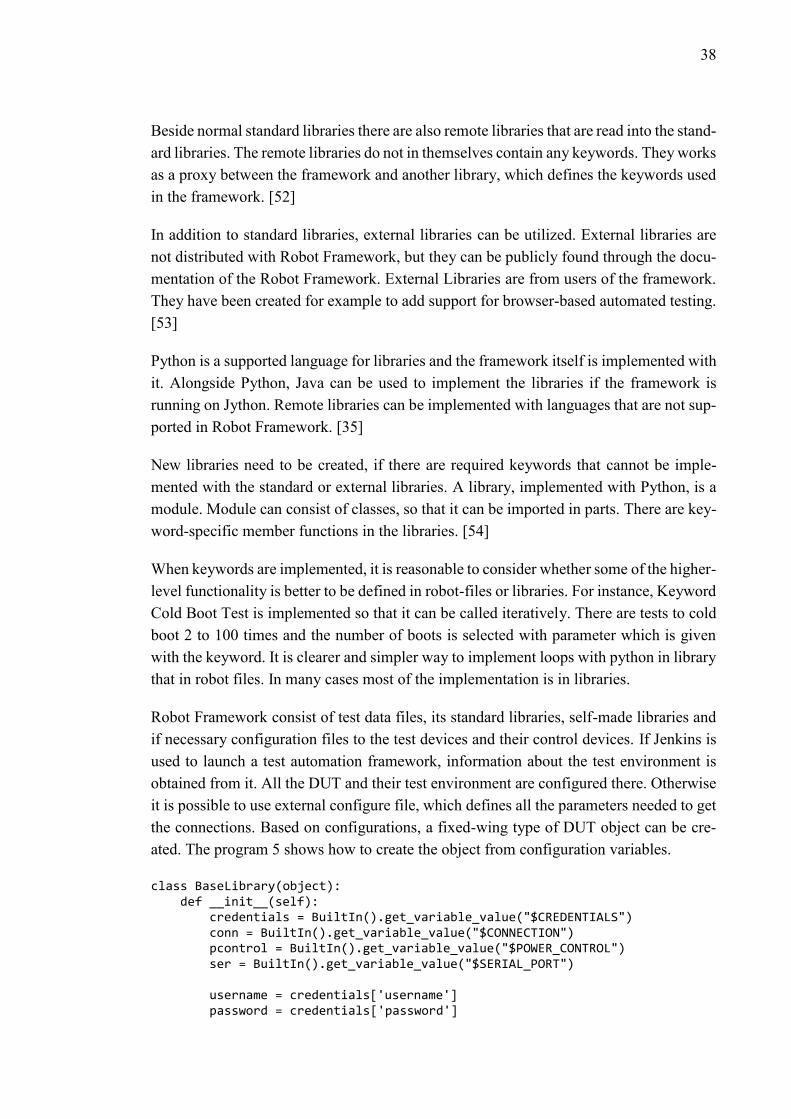
38
Beside normal standard libraries there are also remote libraries that are read into the stand-
ard libraries. The remote libraries do not in themselves contain any keywords. They works
as a proxy between the framework and another library, which defines the keywords used
in the framework. [52]
In addition to standard libraries, external libraries can be utilized. External libraries are
not distributed with Robot Framework, but they can be publicly found through the docu-
mentation of the Robot Framework. External Libraries are from users of the framework.
They have been created for example to add support for browser-based automated testing.
[53]
Python is a supported language for libraries and the framework itself is implemented with
it. Alongside Python, Java can be used to implement the libraries if the framework is
running on Jython. Remote libraries can be implemented with languages that are not sup-
ported in Robot Framework. [35]
New libraries need to be created, if there are required keywords that cannot be imple-
mented with the standard or external libraries. A library, implemented with Python, is a
module. Module can consist of classes, so that it can be imported in parts. There are key-
word-specific member functions in the libraries. [54]
When keywords are implemented, it is reasonable to consider whether some of the higher-
level functionality is better to be defined in robot-files or libraries. For instance, Keyword
Cold Boot Test is implemented so that it can be called iteratively. There are tests to cold
boot 2 to 100 times and the number of boots is selected with parameter which is given
with the keyword. It is clearer and simpler way to implement loops with python in library
that in robot files. In many cases most of the implementation is in libraries.
Robot Framework consist of test data files, its standard libraries, self-made libraries and
if necessary configuration files to the test devices and their control devices. If Jenkins is
used to launch a test automation framework, information about the test environment is
obtained from it. All the DUT and their test environment are configured there. Otherwise
it is possible to use external configure file, which defines all the parameters needed to get
the connections. Based on configurations, a fixed-wing type of DUT object can be cre-
ated. The program 5 shows how to create the object from configuration variables.
class BaseLibrary(object): def __init__(self): credentials = BuiltIn().get_variable_value("$CREDENTIALS") conn = BuiltIn().get_variable_value("$CONNECTION") pcontrol = BuiltIn().get_variable_value("$POWER_CONTROL") ser = BuiltIn().get_variable_value("$SERIAL_PORT") username = credentials['username'] password = credentials['password']

39
if conn['type'] != "ssh": raise ConfigError(‘…’) if pcontrol['type'] == 'expert_power': power_control = ExpertPowerControl(pcontrol['ip'], pcontrol['port']) elif pcontrol['type'] == 'lxi_power': power_control = LxiPowerSupply(pcontrol['ip'], 9221, pcontrol['port']) else: raise ConfigError(‘…’) serial_port = SerialPort(ser['port'], ser['baudrate'], username, password) ssh_connection = SshConnection(conn['host'], username, password) self.dut = DeviceUnderTest(power_control, serial_port, ssh_connection, Logger())
Program 5. BaseLibrary creates DeviceUnderTest-typed object using variables thet are
get from configuration files.
Robot Framework’s BuiltIn-library is utilized to get variables from configuration files.
The variables are stored in dictionaries, from which the required values can be found
based on keywords. Credentials-dictionary includes values for username and password
of the DUT, Connection-dictionary a type of a connection and IP-address of the DUT,
Power_Control-dictionary type, IP-address and port of the external power supply and
Serial_port-dictionary port and baud rate of the DUT to serial connection. With these
variables serial port, SSH connection and certain power control -typed objects can be
created and given as parameters to DUT object. In addition to the three objects, DUT
object gets Robot Framework’s logger. It enables writing messages about test executions
into console and log files. [55]
When an object with all the necessary information has been created for the DUT, Only a
system is needed that combines somehow the keywords of the test files with the real im-
plementation of the DUT. The class diagram of that system is presented in figure 11. It
clarifies the relations between classes of custom test libraries, device specific classes and
interface classes as well as the functions of them.
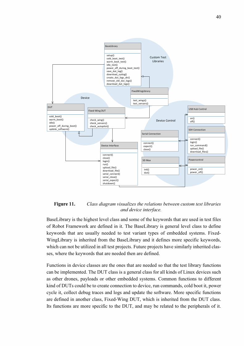
40
SD Mux
init()dut()
USB Hub Control
on()off()
Powercontrol
power_on()power_off()
SSH Connection
connect()login()run_command()upload_file()download_files()
Serial Connection
connect()expect()close()
Fixed-Wing DUT
check_wing()check_sensors()check_autopilot()
DUT
cold_boot()warm_boot()idle()power_off_during_boot()update_software()
FixedWingLibrary
test_wings()test_sensors()
BaseLibrary
setup()cold_boot_test()warm_boot_test()idle_test()power_off_during_boot_test()save_dut_log()download_syslog()create_dut_logs_dir()remove_old_dut_logs()download_dut_logs()
Device
Device Control
Custom Test Libraries
Device Interface
connect()close()login()run()upload_file()download_file()serial_connect()serial_close()serial_expect()shutdown()
Class diagram visualizes the relations between custom test libraries
and device interface.
BaseLibrary is the highest level class and some of the keywords that are used in test files
of Robot Framework are defined in it. The BaseLibrary is general level class to define
keywords that are usually needed to test variant types of embedded systems. Fixed-
WingLibrary is inherited from the BaseLibrary and it defines more specific keywords,
which can not be utilized in all test projects. Future projects have similarly inherited clas-
ses, where the keywords that are needed then are defined.
Functions in device classes are the ones that are needed so that the test library functions
can be implemented. The DUT class is a general class for all kinds of Linux devices such
as other drones, payloads or other embedded systems. Common functions to different
kind of DUTs could be to create connection to device, run commands, cold boot it, power
cycle it, collect debug traces and logs and update the software. More specific functions
are defined in another class, Fixed-Wing DUT, which is inherited from the DUT class.
Its functions are more specific to the DUT, and may be related to the peripherals of it.

41
Basic sanity tests of peripherals are to check if they are connected to the main board and
do they produce right responses to calls.
As an example to different classes, two keyword from test data file can be researched:
cold boot test and wing board check test. Both keywords are defined in self-made library
that is made for drone testing. A cold boot test -function of the test library calls a member
function of the DUT object, cold boot and correspondingly, wing board check test calls
one from Fixed-Wing DUT class, check wing board. Both functions utilize Device Con-
trol -classes to connect and control DUT. The library handles also debug logging if some
part of the function fails and output printing so that user can figure out where the test
execution in going.
Functions in the device classes are defined by utilizing functions from the device interface
class. Device Interface class is the lowest level implementation in the device. Its functions
connects to the modules that creates connections to the DUT or the controlling devices.
There are more about the device control classes are presented in following chapters.
4.3.4 Device Adaptation
Device control classes are responsible for the application interface between the frame-
work and tested system. It is formed from classes, which can create and communicate via
serial and SSH connection and are able to drive control devices. Connections and control
devices enable the actual implementation in Linux-based embedded systems.
Host PC can have both serial and SSH connections to the DUT, but only one serial con-
nection per USB port at a time. Connection objects to the DUT are created at same time
as the DUT object, and they are member variables of it. Information about username,
password, hostname and port of the DUT are needed from configuration files to initialize
the connections. SSH connection is simple and stable way to connect to the DUT and
execute commands on that. SSH-connection class is shown partly for the most important
functions in program 6.
class SshConnection(object): def __init__(self, hostname, username, password=None): self.hostname = hostname self.connection = pxssh.pxssh(options={'StrictHostKeyChecking': 'no'}, echo=False) self.username = username self.password = password self.logged_in = False def connect(self): self.logged_in = False self.connection = pxssh.pxssh(options={'StrictHostKeyChecking': 'no'}, echo=False)

42
def login(self): if self.logged_in: return if self.password != None: self.connection.login(self.hostname, self.username, self.password) else: self.connection.login(self.hostname, self.username) self.logged_in = True def send_line(self, command, timeout=10, prompt=None): self.connection.sendline(command) if prompt: self.connection.expect(prompt, timeout) else: self.connection.prompt(timeout) output = self.connection.before output = output.decode('utf-8') return output
Program 6. Some of the member functions of SSH connection class are to connect, login
and send commands to the DUT.
Initializing the SSH connection object requires the information about the hostname,
username and password associated with the device to be connected. SSH connection is
placed into the member parameter connection. It is created with pxssh. Pxssh is an ex-
tended class from pexpect-class, and it is specialized for SSH connections. It allows also
login and expect shell prompts from the connection. [56] SSH connection can also be
created using a separate connect- member function, so establishing a connection after
initialization can be done.
In order to exploit SSH connection, one must remember to log in after connecting. It must
be done every time when it is necessary to create a new connection to replace the discon-
nected one. The status of logging in is monitored by member parameter logged_in. With
it the login –function can be safely called even if the previous connection is still success-
fully logged in. Logging in to the device that is connected with SSH utilizes login-func-
tion of pxssh.
The main use of the SSH connection is to send commands on the DUT and check if their
responses are desired. One of the functions that are used to it is send_line-member func-
tion. The command is sent to the connection using the sendline-function of pxssh. Com-
mand prompt can be changed, if it contains troublesome signs for testing. Either default
prompt or modified one is waited for after sending the command. Prompt is waited to
know that the just sent command has been totally processed. The returned output is a
value that was generated after submitting the command on the DUT.
Serial connection is preferred over SSH connection, when it is only possible to use serial
one. This situation typically arises after a boot in which case SSH connection can only be

43
established when the device is fully booted up. The serial connection to the device re-
mains during boots, unlike SSH connection. It can be used to review whether the boot
process is completed or at the desired phase. One port can only have one serial connec-
tion, so its creation needs to be handled as needed and it should be closable. Therefore,
unlike the SSH connection, the serial connection -class has connect and close functions.
The SerialPort-class with its member functions is presented in program 7.
class SerialPort(): def __init__(self, port, baudrate, username=None, password=None): self.port = port self.baudrate = baudrate self.username = username self.password = password self._p = None self.log_file = None self.connected = False def connect(self): self.log_file = open('serial.log', 'a') self.log_file.write('\n\n') self._p = pexpect.spawn('cu -s %d -l %s' % (self.baudrate, self.port), encoding='utf-8', codec_errors='replace', timeout=20) self._p.logfile = self.log_file self._p.expect(['Connected'], timeout=20) self.connected = True def close(self): self.connected = False if self._p: self._p.close() if self.log_file: self.log_file.close() def expect(self, pattern, timeout): try: self._p.expect(pattern, timeout=timeout) output = self._p.before + self._p.after return output except pexpect.TIMEOUT: msg = 'expected pattern "%s" not found' % pattern raise TimeoutExpired(msg)
Program 7. Serial connection class takes care that only one serial connection is on at
the moment and reviw and record what have occurred in connections.
To initialize a SerialPort-object, some information about the device to be connected is
needed. One needs to know to which of the ports the DUT is attached, what is the baud
rate of data transfer and credentials to log in it. In addition, a few parameters are needed
to show the connection and its status. _p-parameter of the initialize function reflects suc-
cessfully created serial connection and log_file-parameter is for collecting serial outputs
to one serial log -file. Connected-parameter is for tracking whether serial connection is

44
already established or not. Re-connection should be avoided as it causes unnecessary er-
rors while testing.
Serial connection is created in connect-function with cu-command. It makes connection
between two Unix-systems basis on the port which DUT is attached. Pexpect is used to
send the command. Thereafter a pexpect-connection is created and through it the con-
nected device can be controlled automatically. [57] The created connection is placed in
the member variable _p. All the outputs from serial connections are collected to a file, so
that can be viewed later if the device has encountered problems.
Close-function is closes the ongoing serial connecting when it is not needed anymore, at
the latest at the end of each test. The ongoing serial connection can be found in member
variable _p. When the close-method of pexpect is applied to the connection, it can be
killed and established in the following test. The connection status is restored unconnected
and the log file is closed.
Expect-function is necessary for the most important use of serial connection, checking
boot up printouts. Expect-method of pexpect has certain time to find expected output from
the connection. If successful, the function can return all outputs before the expected out-
put with the expected output.
4.4 Equipment Control
Control equipment are either commercial or open source projects, so there exist modules
and classes to control them. The modules are easy to take into use in a test automation
framework and make them a part of its libraries. There can be coherent interface to control
equipment, which could make use of different devices to simplify their use in a test auto-
mation framework.
A script acts as an interface between automation and control devices. There are imple-
mented control possibilities to power supply, SD-multiplexer and programmable USB-
hubs. The script is easy to call, also from a test automation framework because it is a
python script. Controlled device and aimed operation are given as parameters with script
call.
4.4.1 USB-hub
There are open source projects to control typical programmable USB-hubs. Uhubctl util-
ity is based on controlling the ports of the hub on and off. It is called in interface for USB-
hubs in program 8. [36]
if (target_device == "uhub"):

45
uhub_ctrl = ["sudo", "uhubctl", "-a"] port_1 = "-p 1" port_2 = "-p 2" controlled_device = sys.argv[2] command = sys.argv[3] if (controlled_device == "mux" and (command == "off" or command == "on")): uhub_ctrl.extend((command, port_1)) subprocess.call(uhub_ctrl) elif (controlled_device == "transcend" and (command == "off" or command == "on")): uhub_ctrl.extend((command, port_2)) subprocess.call(uhub_ctrl)
Program 8. The interface can be used to control port of the USB hubs on and off.
The Uhubctl utility needs to be compiled and stored into project folders. Hub setup has
been done so that a certain device is in a certain port of the hub. Therefore, the name of
the device can be used as a parameter for the script. In addition to the device, it is neces-
sary to determine whether it is wanted to be on or off. The mode can be added directly to
the command, which calls the control utility. The script sends the command with a call-
method of subprocess module according to the parameters it receives if they are realiza-
ble. Subprocess is a Python module for creating new processes, connecting to them and
receiving the responses from them. [58]
4.4.2 SD-multiplexer
The SD-multiplexer has been implemented based on the open source project for the hard-
ware layout and the software. The project is named as sd-mux and its binary needs to be
built and installed into the test automation project folder. [59] It is used to change the
reading direction of SDIO, so that at one time SD-card could be written by the host PC
and at another time read by the Autopilot. Program 9 represents how the direction of the
SD-multiplexer can be change with the control device interface script.
elif (target_device == "sdmux"): serial_device_name = "mux" state = sys.argv[2] sd_mux_ctrl = ["sudo", "LD_LIBRARY_PATH=$LD_LIBRARY_PATH:/usr/lo-cal/lib/", "../sd-mux/src/sd-mux-ctrl","--device-serial="+serial_device_name] if (state == "hostpc"): sd_mux_ctrl.append("--init") process = subprocess.Popen(sd_mux_ctrl) returncode = process.wait() elif (state == "basepilot"): sd_mux_ctrl.append("--dut") process = subprocess.Popen(sd_mux_ctrl) returncode = process.wait()
Program 9. The interface can change SDIO connection eiher to the host PC or to
Autopilot board.

46
When the target device is determined as sdmux, binaries of SD-multiplexer are called
with a parameter that defines what will be done. In this case, the parameter can be either
for initializing the SD-multiplexer, and then the SD card moves to listen to the host PC
or for connecting to the DUT. Call-method of the subprocess module is not usable, when
command is list of parameters. Popen is suitable for long and changing commands.
4.4.3 Power Supply
The host PC is connected to the power supply with SSH connection and the power supply
is connected through power wires to the central hub. The power supply is configured with
udhcpd server before deployment, so that it could be found always at the same IP address.
Power supply specific classes are utilized in connecting to a supply and changing its state.
The power supplies operate in a different way depending on maker etc., so implementa-
tions must be done separately. Classes define functions that the power supply needs for
test executions, most important one is connecting to the supply, turning its power output
on and off, but also for instance getting voltage and current and limiting them. Thanks to
the classes the interface script is very simple for the power supplies. Principals of it are
show in program 10.
elif (target_device == "power"): power_ctrl = LxiPowerSupply("dutpower",9221, 1) state = sys.argv[2] if (state == "on"): power_ctrl.power_on() elif (state == "off"): power_ctrl.power_off() power_ctrl.close()
Program 10. The interface enables easy power on and off calls to the power supply.
Using the power supply through the interface script is very straightforward. A suitable
power supply object is created before calling its member function according the parameter
that the script gets. When creating the power supply object, connection to it is also cre-
ated. The object get three parameters: IP address, port and channel that are needed to
creating connection. While the power supply was configured and IP address was defined,
an alias can also be created to point the IP address. Hence the address is even easier to
remember and use in scripts and otherwise. The connection is established with socket
through SSH connection in the case of Aim TTi’s PLI 155-p. Python’s Socket module is
utilized and it is for low-level networking interfaces. The member functions of the object
are simple and it either tries to receive values from socket connection or send them to it.
47
4.5 Test Report Generation
Test reports are the most important part of the test automation framework, because the
status of the test executions can only be discovered this way. The thesis utilized a script
that is used in previous projects and can collect system log from Linux-device. Other
implementations for collecting logs and generating test reports have been made during
this project, so that reports contain essential information for these tests.
There are different levels of logging and reports. They have slightly different target audi-
ence and purpose. The most accurate logs and debug traces are interesting for test engi-
neers and developers, and they are especially needed when developing the test automation
framework and the DUT itself. Higher-level reports give a better view about functionality
of the DUT, especially if they contain a broad set of tests. These are also interesting for
developers, but it can be difficult to say the origin of bugs only based on this sort of report.
However, usually a comprehensive and clear report is of interest to the person responsible
for the project, as it gives an overall picture of it. Features of a good report includes the
ability to find out details from the test execution but also create simple and clear overview
from the whole execution. In addition, it must be shared with the right parties.
4.5.1 System Logs
In addition to the logs created during tests, the logs generated in the system can be uti-
lized. In UAV, Ubuntu Core records all the events of it into system log aka syslog. The
syslog can be used during the test to review the system. The greatest benefit of the syslog
is obtained when it is transmitted via host PC to Jenkins and attached to test report. It is
often best describing what has caused the error, because from there one can discover the
event after which the program has crashed. Syslog can be found from /var/log/ - folder of
Ubuntu. When coping a file, the user running the test must have read access to it. The
measures have been taken in program 11.
def download_syslog(self, dest_dir): try: # To be able to download as current user self.dut.run('sudo chmod a+r %s' % SYSLOG_PATH) self.dut.download_files(SYSLOG_PATH, dest_dir, 120) except Exception: logger.error('Failed to download syslog') logger.error(format_exc())
Program 11. Download Syslog -function from library of DUT gives read access on line
4 and then downlods syslog files from predefined path SYSLOG_PATH and copies
them into destination directory dest_dir.
In the program 11, run-function of DUT-class is utilized to run command on DUT and
download_files-function to copy files to host PC. They are presented in a very general
48
way and are thus suitable for a variety of DUT. The actual implementation takes place in
the SSH-connection-class which DUT-class calls in its member functions run and
download_files. The program 12 describes a lower level implementation of downloading.
This implementation could work for DUTs, which are capable of SSH connection. The
implementation uses the command-line program Secure Copy (SCP), where files are
copied over the SSH-connection. [60]
def download_files(self, src_path_pattern, dest_dir='', timeout=30): command = 'scp {0}@{1}:{2} {3}'.format(self.username, self.hostname, src_path_pattern, dest_dir) scp = pexpect.spawn(command) idx = scp.expect(['yes/no', 'password:', pexpect.EOF]) if idx == 2: raise ConnectError('download_files: could not connect to host') if idx == 0: scp.sendline('yes') idx = scp.expect(['yes/no', 'password', pexpect.EOF]) if idx == 1: if self.password: scp.sendline(self.password) scp.expect(pexpect.EOF, timeout) return scp.before.decode('utf-8', 'replace') else: raise Exception("Password needed but not given")
Program 12. Download_files-function implementation in SSH-connection-class in more
spesific than the one program 11.
SCP copies a certain file from DUT to host PC. The scp-command is given on host pc
with pexpext. Based on the return value, it is possible to continue copying so that it can
be completed.
The copied syslog is parsed according to a line from boot seqvence, as each test has either
setup, which includes boot of the system or keywords that restart the device. Thus test-
specific system logs can be collected.
4.5.2 Robot Framework Reports
By default, three files are generated from test execution of Robot Framework: output-,
report- and log-file. Execution command can be given parameters to prevent files from
being created. The output file is the most comprehensive. There are all the events that the
framework has go through with exact time stamps. Output-file is in XML format, which
is easily readable by machine but also understandable by human. Other generated files
are generated on basis of output-file. [61]

49
Log- and report-file are both visual files in HTML format. The format is well suited for
sharing and exploring them without special text editors. In log-file the test execution is
presented hierarchically from the test suite to single keywords. Each part has information
about its own status, elapsed time and both start and end time of execution of it. [62]
Report-file summarizes the test execution and has more detailed statistics about the tests
of it. The background color of the report-file shows straightaway whether the execution
failed or passed totally, for if there are any failed critical test case it is red, otherwise
green. There are links between log- and report-file. A specific test from report can be
viewed in more detail in the log using a link that is part of its name. [63]
4.5.3 Robot Framework Logger and Traces
There are a public logging API for Robot Framework’s test libraries. This logger is for
writing down messages about test execution to the console or logs. Messages are received
both when executing tests from console and Jenkins, as a console can be tracked from it.
Different log levels can be set for messages. Based on log levels, messages can be shown
as warning, error, debug, trace or plain info printouts. Debug and traces need to be ena-
bled with command line option –-loglevel, but otherwise the levels can be logged by de-
fault. Logger messages are clearly visible in log-file, which makes them very practical
for monitoring the operations of the tests. [64]
It is particularly useful to have information about failed executions. Tracing is suitable
way to get information about executions. There is a Python module, traceback, which can
handle traces. Format_exc-function of the module is useful when exceptions occurs. The
function returns type of the exception and the value that defines what caused exception
as a string. With logger’s error function the trace that describes occurred problem can be
printed into console and log. [65]
4.5.4 Robot Framework Listener
The test execution can also have a listener. Listeners are yet another way to receive infor-
mation about the test execution. Robot Framework has an interface for listeners that are
implemented with either Python or Java. Listeners can be given as a command line option
–listener, and should if it is intended to use one that covers the full execution. [66] Pro-
gram 13 is a listener that collects suitable data from test executions and saves them to a
simple text file. Important data is easy to read from it and edit into an excel sheet.
class Reporter(object): ROBOT_LISTENER_API_VERSION = 2 def __init__(self): pass

50
def close(self): self.report.close() def start_suite(self, name, attrs): timestamp = time.strftime("%Y%m%d%H%M") filename = "summary" + "_" + timestamp + ".txt" self.report = open(filename, 'w') def start_test(self, name, attrs): longname = attrs['longname'] name = longname.split('.')[1] self.report.write('*** ' + name + ' ***\n') def end_test(self, name, attrs): longname = attrs['longname'] name = longname.split('.')[1] msg = attrs['message'] if msg != "": msg = msg.splitlines() mesg = "" for line in msg: mesg = mesg + line + " " self.report.write('Boot Times: ' + mesg + '\n') self.report.write('Status: '+ name + ': ') if attrs['status'] == 'PASS': self.report.write('Pass\n') else: self.report.write('Fail\n')
Program 13. Reporter that is given to test execution as listener can collect suitable the
information from test executions.
Listener is called several times during the test execution. Listeners have methods that can
be called in particular stages of the execution. There are methods that are called before
and after every test suite. Correspondingly every test and keyword can also trigger a lis-
tener method before and after its execution. Some other actions can also enable a listener
method call, for instance, importing resource files, variables or libraries or closing the
execution. All the methods that consist of information about the test execution have two
arguments, name and attributes. Attributes is a dictionary that contains, according to the
method, values about the specific method. Attributes can contain, for instance, the name,
tags, documentation and start time of the test that have triggered the method of the lis-
tener. [66]
The implementation of a listener should start by defining the version of Robot Frame-
work’s listener interface. There are few differences between the newest version 3 and in
the program 13 presented version 2. The biggest change that has come is the possibility
to change test results after the execution. After initialization of the reporter object, first
method called after the test execution is successful, is start_suite. Before starting a test
suite execution, a report-file named summary with timestamp is opened. Before every test
execution, the name of the test is written into this opened file as implemented in start_test.

51
End_test adds the test status after it. In addition to statuses, this listener examines Robot
Framework’s messages. In the test data file, boot times were saved into messages, so the
message attribute includes the boot times related to the test. However, if the test has failed,
messages attribute includes the last error-message. Then the reason of the error is written
into summary-file and finally to the report that is parsed from it. Final method, close,
closes the summary-file. [66]
4.5.5 Excel Sheets
Excel can calculate relations between successful and failed tests in several ways, in terms
of, for example, with respect to certain types of tests or the whole series of tests. Relations
can be used to compare how the regression is shown between different software versions.
Excel provides test results in an understandable visual form that is easy to share and attach
into test reports.
The summary file that the listener has collected is used as the base for the excel sheet of
the execution. A suitable module is utilized to form an excel sheet, for instance openpyxl.
Each test with its status and possible additional information are in one line. Additional
information may be error messages, if the test have failed or boot times of the boot tests.
With numpy-module some useful values from boot times can be calculated, like the me-
dian of them.
4.5.6 Sharing Logs
Jenkins provides several ways to share generated reports. Post build task usually consider
reporting, storing reports and sharing them. Sending e-mail about test execution is one
way to share selected reports and information about test execution. Email Extension
plugin is needed for it. The recipients to e-mails can be selected as parameters when ini-
tializing the test execution. For sending mails a simple mail transfer protocol (SMTP)
server need to be configured in configuration of Jenkins. The SMTP needs to be config-
ured to fit the network.
Jenkins jobs have a workspace, where logs and reports can be saved. Post-build actions
can collect them into one folder, from which they can be viewed. A link to the workspace
and reports can be shared to coworkers, while the access to it requires to being in the same
corporate network.

52
5. EVALUATION OF THE TEST AUTOMATION
FRAMEWORK
Many of the previously presented testing types can be utilized in the UAV testing and in
many cases, also automated testing can be utilized. To know whether it was profitable to
create a test automation framework to this project and if the right features have been tested
with it, the testing way should be evaluated. The significant factors in the selection are
time and resources, amount and quality of found errors and time that is required for main-
taining the method. At this stage of the project, the whole testing is focused naturally only
on those features that have already implemented into the product.
Both functional and structural tests need to be executed to ensure the overall functionality
of the device. Functional tests can be executed in all testing levels. For instance, in the
case of UAVs, it could mean testing a single peripheral device alone outside the system
and after integration as part of the system with longer and more peripherals including
tests. Following, there are some examples of the implementation of automated structural
tests of the UAV.
Performance testing can be done, and the system can be stressed to simulate fly behavior
aka collecting data in various environment simultaneously with changing positions of
flight controllers. With automated tests, performance is easier to measure by inspecting
power usage and delays of functions.
Endurance testing is often suitable to be executed by a test automation framework, be-
cause it can take quite a lot of time to complete an endurance test. It may include many
repeat functions, which is always a good reason to at least consider automated testing. It
is easy to extend functional or structural test with automation when there is need for en-
durance tests. The UAV has endurance test for idling 10 hours and booting up up to 100
times.
There are lots of issues that need to be considered when testing the safety of the UAV. A
flying UAV is susceptible to various harassment attempts. Someone may be tempted to
interfere with the signals or try to dump it down physically. In addition, it has to be pos-
sible to prevent penetration into the device when the connection has been received. Secu-
rity testing is complicated area in this kind of project and requires particularly complex
test environments. Software security issues can be tested by a test automation framework,
but much remains to be tested manually. Tests feed some harmful input and ensures that
the device can maintain its functionality.

53
Recovery testing can be executed on the DUT by causing malfunctions on it. For example,
a malfunction can be caused by closing the power supply at an unsuitable moment. Alt-
hough the device is powered off during boot sequence, it should boot up correctly next
time and be fully functional. In tests of this type, the automated testing is useful, because
the device can be properly looked at and can be disturbed in the worst possible moments.
Evaluation of the testing method is easier when the methods are compared based on re-
sources and found errors. The actual testing has not started yet, so errors were found
randomly when the test automation framework was under construction. At this phase of
the project comprehensive material for errors was not obtained. However, more accurate
comparisons can be made regarding time consumption and resources. Table 3 shows the
time elapsed in different phases of testing a test case or other function specifically. The
times are estimates and selected by this project and author. They may vary, for instance,
depending on the experience of tester. Selected tests are a part of tests that have been
executed by the test automation framework. Idle time is chosen to be 1h, because it is a
target time for the UAV to be in the sky. The abbreviation WD stands for working day.
Table 3: Estimates of time consumption during various phases of testing are
compared based on the testing method.
Test Case or other function Method Preparation Time
Testing Time, one DUT
Testing Time, 5 DUTs
Verify UAV components sanity itera-
tively, 100 times
Automatic 1 WD 30 min 30 min
Manually 30 min 1 WD 5 WD
Verify UAV iterative idle, 20 times 1h Automatic 4 h 20 h 20 h
Manually - 7 WD 7 WD
Verify UAV iterative power off during
boot sequence, 100 times
Automatic 1 WD 25 min 25 min
Manually 1 h 1 WD 5 WD
Verify UAV iterative kill switch, 100
times
Automatic 4 h 27 min 27 min
Manually - 1 WD 5 WD
Creating Test Report Automatic 5 WD > 1 min 1 h
Manually - 1 h 2 h
It takes time to complete a test automation framework and it must be a functional entity
at some level before it can be used in testing. Finishing the whole framework with com-
prehensive reporting scripts and working build server takes several work weeks in addi-
tion to the automated tests. Adding tests to test automation takes time from a few hours
to workdays and it must be considered that the tests may have to be updated as the project
goes on. Compared to manual testing, generally automated testing needs to have much
more preparation time. The more complicated the tested feature is and the later it will be
tested (alas the less iterations), the better it is to be tested manually.

54
Time benefits are considerable already after a couple of test execution cycles. It is also
important to note that automated testing can be executed around the clock and the week
and it is not obligatory to have employees constantly with the tests when they are run-
ning. In manual testing, testing takes considerably more resources, when the tests are
executed on many DUTs at the same time. Even if one sanity check lasts only 5
minutes, repeating a hundred times takes more than 8 hours and testing with several
DUT even for weeks.
Automated tests can be easily launched by a person that is not familiar with the tested
system. Test scripts can be launched from the UI of the build server or just executing
right test scripts on the host PC. Executing tests and tracking the results can also be per-
formed remotely. Automatic reports can be more clearly understood by people who are
familiar with the tested system than the system logs. Robot Framework’s debug mes-
sages informs the exact moment when the errors have occurred.
At the beginning of the project when piling and executing the test automation framework,
couple of bugs were found. When the test is executed by test scripts, it is easier to schedule
test events for relevant events. Reports and debug messages can ease finding the reason
for the error. Also positive test results can help to eliminate bugs, since they can exclude
possible sources of error. However, skills of the tester are more important and useful in
manual testing. When the tester is aware of the software and its changes, he may be able
to test any related features and find errors that may not have been apparent in automated
testing.
The time consumption table shows that automation for these tests is profitable and speeds
up testing and reporting, and significantly then when iterative testing is performed several
times. Automated testing is a suitable way to execute testing and system validation in an
embedded UAV project. Especially at the early stage of the project, the test team spent
time well by preparing the test automation framework to the project even before it had a
lot of functionality. In future projects most parts of the test automation system can be
utilized, whereby creation of a test automation framework can be shortened by a few
workweeks.

55
6. CONCLUSIONS
The thesis presented perspectives and documented a solution for the system validation of
a Linux-based UAV project. Automated testing is a suitable way to execute testing and
system validation in an embedded UAV project, as it makes testing more comprehensive
and can speed up the execution time of some tests by as much as a workweek. At the early
stage of the project developing the test automation framework is a good target to use time
on by a testing team, as it can reduce the testing time later.
The testing part of the thesis is based on literature sources and aims to represent principles
of system validation and automated testing as a part of it. It also reflects the features and
benefits of both automation and manual testing. Various types of test were performed
comprehensively by the test automation framework. When the basics of the test automa-
tion framework and libraries were completed, adding new automatic tests was simple and
fast. That is a fine feature in automated testing, as the new developed features can easily
be included into test executions.
As a result from evaluating the testing method, the most beneficial features of automated
testing in this project were found. Tests of the test automation framework expand the
ways of testing and validating the product and make it more comprehensive. Especially,
stability and reliability types of tests can be added to weekly testing because they can be
performed in a significantly shorter time because of automated testing, as the speed up is
noticeable especially in long iterative tests.
The whole product development cycle can be shortened by automation. Test engineer can
start developing a test automation framework right after the tests and the testable system
are planned. That time is out of the testing time during development cycles. Automated
testing shortens testing time also because it allows tests to be executed on many devices
simultaneously and around the clock. Quickening the cycle and making it more compre-
hensive with long reliability and stability test will contribute to the product being finished.
There are ready-made solutions to many problems that are encountered when constructing
a test automation framework. By applying and combining them, it is relatively uncompli-
cated to achieve a comprehensive and reusable test automation environment. Jenkins is a
widely used automation server, among other things because it is open source and has
comprehensive scope for application as well as documentation. Combined with a com-
pleted test framework and self-made test libraries, a functional test automation system for
embedded Linux-devices can be achieved.
An example about a working test automation framework for Linux-based embedded sys-
tem was created and presented in the thesis. It includes reasoning that can help the reader

56
to understand the basic structure of the modular automatically building test automation
framework. Some basics of the automation servers is good to understand, if it is intended
to use it to launch a test automation framework and automated builds on DUTs. It can
also be utilized to gather test results with the help of the test scripts. The test libraries that
enabled both SSH- and serial connection to the DUTs can be utilized later. They enable
bidirectional communication between test framework and DUT.
The modular structure of the automation framework makes it easy to add them to different
platforms as well as adding new commands and functions to them. The created testing
environment could be utilized in future projects, especially in those that are intended to
create with agile software development and are based on the same technology. In Intel,
this created test automation framework will be the basis of the next planned UAV auto-
mated SW validation. It can also be utilized in testing of Linux-based payloads, although
the functionality needs to be changed more than in the UAV project.
The research and development of the test automation framework could have been carried
on with the product development. That would have allowed the creation of more compre-
hensive testing by utilizing different testing types and levels wider than in the current test
automation framework implementation. Then it would have been possible to concentrate
on more important tests for the final product, such as security and functional acceptance
tests. The test automation environment could then be expanded with new devices that
could test the aforementioned features. Interesting research subjects would have been also
longer-term studies, where the impact of automated testing on finding errors, testing du-
ration and costs would have been explored. Their examination requires a wider sampling
of different test automation projects, so they weren’t examined closer in this thesis.
57
REFERENCES
[1] Dr. Robert J. Shaw, Dynamics of Flight, Ultra-Efficient Engine Technology, Jun
2014, URL: https://www.grc.nasa.gov/www/k-12/UEET/StudentSite/dynamic-
sofflight.html
[2] ArduPilot Dev Team, Choosing a Ground Station: Overview, ArduPilot Plane
Docs, 2016, URL: http://ardupilot.org/plane/docs/common-choosing-a-ground-sta-
tion.html?highlight=ground%20control%20station
[3] MAVLink Developer Guide, mavlink.io, referred: Jun 2018, URL:
https://mavlink.io/en/
[4] Shyam Balasubmanian, MavLink Tutorial for Absolute Dummies (Part -I), URL:
https://api.ning.com/files/i*tFWQTF2R*7Mmw7hksAU-u9IAB-
KNDO9apguOiSOCfvi2znk1tXhur0Bt00jTOldFvob-Sczg3*lDcgChG26QaH-
ZpzEcISM5/MAVLINK_FOR_DUMMIESPart1_v.1.1.pdf
[5] Unmanned Tech, Beginners guide to drone autopilots (flight controllers) and how
the work: Flight Controller, DroneTrest, Nov 2015, URL:
https://www.dronetrest.com/t/beginners-guide-to-drone-autopilots-flight-control-
lers-and-how-they-work/1380
[6] ArduPilot Dev Team, Choosing a Ground Station: Overview, ArduPilot, 2016,
URL: http://ardupilot.org/ardupilot/
[7] ArduPilot Dev Team, Plane Home, ArduPilot Plane Docs, 2016, URL: http://ar-
dupilot.org/plane/
[8] ArduPilot Dev Team, Flight Modes: Major Flight Modes, ArduPilot Plane Docs,
2016, URL: http://ardupilot.org/plane/docs/flight-modes.html
[9] ArduPilot Dev Team, GPS/Compass (landing page), ArduPilot Plane Docs, 2016,
URL: http://ardupilot.org/plane/docs/common-positioning-landing-page.html
[10] ArduPilot Dev Team, Using an Airspeed Sensor, ArduPilot Plane Docs, 2016,
URL: http://ardupilot.org/plane/docs/airspeed.html
[11] ArduPilot Dev Team, Rangefinders (landing page), ArduPilot Plane Docs, 2016,
URL: http://ardupilot.org/plane/docs/common-rangefinder-landingpage.html

58
[12] ArduPilot Dev Team, Cameras and Gimbals, ArduPilot Plane Docs, 2016, URL:
http://ardupilot.org/plane/docs/common-cameras-and-gimbals.html
[13] ArduPilot Dev Team, Mission Planer Telemetry Logs, ArduPilot Planner Docs,
2016, URL: http://ardupilot.org/planner/docs/common-mission-planner-telemetry-
logs.html#common-mission-planner-telemetry-logs
[14] ArduPilot Dev Team, Diagnosing problems using Logs: Log Types (Dataflash vs
tlogs), ArduPilot Plane Docs, 2016, URL: http://ardupilot.org/plane/docs/common-
diagnosing-problems-using-logs.html
[15] Texas Instruments Incorporated, AM3353, Jun 2018, URL:
http://www.ti.com/product/AM3352#
[16] ROS, Core Components: Communications Infrastructure; Robot-Specific Features,
Jun 2018, URL: http://www.ros.org/core-components/
[17] Canonical Ltd., Robot Operating System (ROS): What problems do snaps solve for
ROS applications?, Jun 2018, URL: https://docs.snapcraft.io/build-snaps/ros
[18] ST, STM32F413xG STM32F413xH, Datasheet – production data, Sep 2017, Do-
cID029162, Rev 6, URL: https://www.st.com/content/ccc/resource/technical/docu-
ment/datasheet/group3/f6/1d/4a/d9/f9/96/43/2a/DM00282249/files/DM00282249.
pdf/jcr:content/translations/en.DM00282249.pdf
[19] Vadim Mikhailov, uhubctl, GitHub-project, Jul 2018, URL:
https://github.com/mvp/uhubctl
[20] Aim TTi, New PL & PL-P Series: Precisin Linear DC Power Supplies, Instruction
Manual, 48511-1140, Issue 18, URL: http://resources.aimtti.com/manu-
als/New_PL+PL-P_Series_Instruction_Manual-Iss18.pdf
[21] David Gelperin, A Software Test Documentation Standard, Proceeding, SIGDOC
’82 Proceedings of the 1st annual international conference on System documenta-
tion, Carson, California, USA, January 22-23, 1982, pages 61-63, ISBN:0-89791-
080-X, doi: 10.1145/800065.801310
[22] Atlassian, The Agile Coach, atlassian.com, referred Aug 2018, URL:
https://www.atlassian.com/agile
[23] Parsons, David; Lal, Ramesh; Lange, Test Driven Development: Advancing
Knowledge by Conjecture and Confirmation, Manfred. Future Internet; Basel Vol.
3, Iss. 4, 2011, pages 281-297. DOI:10.3390/fi3040281, URL: https://search-

59
proquest-com.libproxy.tut.fi/docview/1525785367?pq-origsite=sum-
mon&https://search.proquest.com/business/advanced?
[24] Toivo Vaje, On an Agile Journey: DIY Build Light Indicator, agilehope.block-
spot.com, Dec 6, 2014, URL: https://agilehope.blogspot.com/2014/12/diy-build-
light-indicator.html
[25] Jez Humble, Continuous Delivery: Principles, continuousdelivery.com, 2017,
URL: https://continuousdelivery.com/principles/
[26] Tuukka Virtanen, Literature Review of Test Automation Models in Agile Testing,
Master of Science Thesis Information and Knowledge Management, Tampere Uni-
versity of Technology, May 2018, p. 6, URL: https://dspace.cc.tut.fi/dpub/bit-
stream/handle/123456789/25869/Virtanen.pdf?sequence=3&isAllowed=y
[27] Atlassian, Jira Software: Featured for software development, atlassian.com, 2018,
URL: https://www.atlassian.com/software/jira/features
[28] A. Sethi, A Review Paper on Levels, Types & Techniques in Software Testing,
International Journal of Advanced Research in Computer Science, 8(7), 2017, pages
26-33, Retrieved from https://search-proquest-com.lib-
proxy.tut.fi/docview/1931133076?accountid=27303
[29] A. Jomeiri, Validation Tools in Software Testing Process: A Comparative Study,
International Journal of Advanced Research in Computer Science, 5(7), 2014, pages
269-272, Retrieved from https://search-proquest-com.lib-
proxy.tut.fi/docview/1639254178?accountid=27303
[30] Derk-Jan De Grood, TestGoal: Result-Driven Testing, Springer, 2008, pages 42,
175 and 271, Online ISBN 978-3-540-78829-4, DOI: https://doi-org.lib-
proxy.tut.fi/10.1007/978-3-540-78829-4
[31] Sten Pittet, The different types of software testing, Atlassian.com, referred: Sep
2018, URL: https://www.atlassian.com/continuous-delivery/different-types-of-
software-testing
[32] Mundita Awotar, Roopesh Kevin Sungkur, Optimization of Software Testing, Pro-
cedia Computer Science, Volume 132, 2018, Pages 1804-1814, ISSN 1877-0509,
https://doi.org/10.1016/j.procs.2018.05.142.
[33] Rana Muhammad Saleem, Salman Qadri, Imran ul Hassan, Rab Nawaz Bashir, and
Yasir Ghafoor, Testing Automation in Agile Software Development, International

60
Journal of Innovation and Applied Studies, Vol. 9, No. 2, Nov. 2014, pp. 541-546,
ISSN 2028-9324
[34] Thirumalesh Bhat, Nachiappan Nagappan, Evaluating the Efficacy of Test-Driven
Development: Industrial Case Studies, Proceeding, ISESE 2006 Proceedings of the
2006 ACM/IEEE international symposium on Empirical software engineering, Rio
de Janeiro, Brazil, September 21-22, 2006, pages 356-363, ISBN:1-59593-218-6,
doi: 10.1145/1159733.1159787
[35] Robot Framework Foundation, Robot Framework User Guide: Introduction, re-
ferred Jul 2018, URL: http://robotframework.org/robotframework/latest/Robot-
FrameworkUserGuide.html#introduction
[36] R. Dill and M. Ramsay, udhcp Server/Client Package, documentation, Dec 2004,
URL: https://udhcp.busybox.net/
[37] Agile Alliance, Automated Build, Agile Alliance web-page, 2018, URL:
https://www.agilealliance.org/glossary/automated-build
[38] Jenkins User Documentation, jenkins.io, Aug 2018, URL: https://jenkins.io/doc/
[39] Installing Jenkins, jenkins.io, Aug 2018, URL: https://jenkins.io/doc/ book/in-
stalling/
[40] Kohsuke Kawaguchi, Building a software project, wiki.jenkins.io, Aug 2018, URL:
https://wiki.jenkins.io/display/JENKINS/Building+a+software+project
[41] Leonard Richardson, Beautiful Soup Documentation, crummy.com, 2015, URL:
https://www.crummy.com/software/BeautifulSoup/bs4/doc/
[42] P. Hazel, PCRE - Perl Compatible Regular Expressions, pcre.org, 2015, URL:
https://www.pcre.org/
[43] Bas Dijkstra, What Is an Automation Framework?, smartsheet, refered Jul 2018,
URL: https://www.smartsheet.com/test-automation-frameworks-software
[44] Robot Framework Foundation, Robot Framework User Guide: Why Robot Frame-
work, referred Jul 2018, URL: http://robotframework.org/robotframework/lat-
est/RobotFrameworkUserGuide.html#why-robot-framework
[45] Robot Framework Foundation, Robot Framework User Guide: High-level architec-
ture, referred Jul 2018, URL: http://robotframework.org/robotframework/latest/Ro-
botFrameworkUserGuide.html#high-level-architecture
61
[46] Robot Framework Foundation, Robot Framework User Guide: Test data syntax,
referred Jul 2018, URL: http://robotframework.org/robotframework/latest/Robot-
FrameworkUserGuide.html#test-data-syntax
[47] Robot Framework Foundation, Robot Framework User Guide: Creating test suite,
referred Jul 2018, URL: http://robotframework.org/robotframework/latest/Robot-
FrameworkUserGuide.html#creating-test-suites
[48] Robot Framework Foundation, Robot Framework User Guide: Creating variables,
referred Jul 2018, URL: http://robotframework.org/robotframework/latest/Robot-
FrameworkUserGuide.html#creating-variables
[49] Robot Framework Foundation, Robot Framework User Guide: Creating user key-
words, referred Jul 2018, URL: http://robotframework.org/robotframework/lat-
est/RobotFrameworkUserGuide.html#creating-user-keywords
[50] Robot Framework Foundation, Robot Framework User Guide: Creating test cases,
referred Jul 2018, URL: http://robotframework.org/robotframework/latest/Robot-
FrameworkUserGuide.html#creating-test-cases
[51] Robot Framework Foundation, Robot Framework User Guide: Log levels, referred
Jul 2018, URL: http://robotframework.org/robotframework/latest/RobotFrame-
workUserGuide.html#log-levels
[52] Robot Framework Foundation, Robot Framework User Guide: Standard libraries,
referred Jul 2018, URL: http://robotframework.org/robotframework/latest/Robot-
FrameworkUserGuide.html#standard-libraries
[53] Robot Framework Foundation, Robot Framework User Guide: External libraries,
referred Jul 2018, URL: http://robotframework.org/robotframework/latest/Robot-
FrameworkUserGuide.html#external-libraries
[54] Robot Framework Foundation, Robot Framework User Guide: Creating test library
class or module, referred Jul 2018, URL: http://robotframework.org/robotframe-
work/latest/RobotFrameworkUserGuide.html#creating-test-library-class-or-mod-
ule
[55] Nokia Solutions and Networks, robot.api package, robot-frame-
work.readthedocs.io, 2015, URL: https://robot-frame-
work.readthedocs.io/en/2.9.2/autodoc/robot.api.html
62
[56] Noah Spurrier and contributors, pxssh - control an SSH session, pex-
pect.readthedocs.io, 2013, URL: https://pexpect.readthedocs.io/en/sta-
ble/api/pxssh.html
[57] Noah Spurrier and contributors, Pexpect version 4.6, pexpect.readthedocs.io, 2013,
URL: https://pexpect.readthedocs.io/en/stable/
[58] Python Software Foundation, subprocess — Subprocess management, docs.py-
thon.org, Aug 07 2018, URL: https://docs.python.org/3/library/subprocess.html
[59] Theo Markettos, sd-mux, GitHub-project, Jun 2018, URL: https://github.com/tmar-
kettos/sd-mux
[60] SCP, linux.fi, Jun 2014, URL: https://www.linux.fi/wiki/SCP
[61] Robot Framework Foundation, Robot Framework User Guide: Output file, referred
Jul 2018, URL: http://robotframework.org/robotframework/latest/RobotFrame-
workUserGuide.html#output-file
[62] Robot Framework Foundation, Robot Framework User Guide: Log file, referred Jul
2018, URL: http://robotframework.org/robotframework/latest/RobotFrame-
workUserGuide.html#log-file
[63] Robot Framework Foundation, Robot Framework User Guide: Report file, referred
Jul 2018, URL: http://robotframework.org/robotframework/latest/RobotFrame-
workUserGuide.html#report-file
[64] Nokia Solutions and Networks, robot.api.logger module, robot-frame-
work.readthedocs.io, 2015, URL: https://robot-frame-
work.readthedocs.io/en/2.9.2/autodoc/robot.api.html#module-robot.api.logger
[65] Python Software Foundation, traceback — Print or retrieve a stack traceback,
docs.python.org, Aug 07 2018, URL: https://docs.python.org/3/library/trace-
back.html
[66] Robot Framework Foundation, Robot Framework User Guide: Listener interface,
referred Jul 2018, URL: http://robotframework.org/robotframework/latest/Robot-
FrameworkUserGuide.html#listener-interface