UAV Photogrammetry under Poor Lighting Conditions ... - MDPI
Upload
khangminh22Category
view
0download
0
A UAV mechanism for autonomous landing and transportation of cargo
Tryggvi Stefánsson
Master of Science Thesis MMK 2014:28 MKN 118
KTH Industrial Engineering and Management
Machine Design
SE-100 44 STOCKHOLM


“If you don’t have a consensus that it’s nonsense, you don’t have a breakthrough.”
Burt Rutan


Examensarbete MMK 2014:28 MKN118
UAV mekanism for autonom landning ochtransportering av goods
Tryggvi Stefansson
Godkant Examinator Handledare
2014-month-date Ulf Sellgren Ulf Sellgren
Uppdragsgivare Kontaktperson
Name Name
SammanfattningAnvandningen av robotar blir allt vanligare i vardagen och robotar kan klara av allt
mer komplexa jobb. Obemannade luftfartyg (UAV) ar en del av denna revolution och
de dominerar luftrummet i robotomradet. Framsteg inom elektronik har i hog grad
bidragit till de snabba framsteg i robotar och UAV, genom att minska kostnaderna och
samtidigt oka kapacitet och minska stromforbrukningen av komponenter. Gemenskapen
for oppen kallkod har dessutom i hog grad bidragit till utvecklingen och anvandningen
av UAV i allmanhet. Multi-helikoptrar ar ett nytt ras av UAV som har tagit fart senare
tid pa grund av deras mekaniska enkelhet med stod av komplexa elektriska komponen-
ter och algoritmer for stabilitet. I dag anvandas helikoptrar och andra UAV framst
for flygfotografering, men deras anvandning inom andra omrader ar fortfarande mycket
begransad, bortsett fran forskningsprojekter till exempel pa universiteter och nagra an-
dra foretager. UAV har en stor potential for att anvandas som befordringsmedel och
de kunde darmed kraftigt minska kostnaderna och leveranstider. Flera hinder maste
overvinnas innan detta kan bli verklighet. For att namna nagra hinder for transport
av gods med UAV ar deras begransade formaga av att uppfatta miljoer och ocksa ut-
maningen med automatisk grepp av last av olika former och storlekar som ligger pa
marken. Malet med detta examensarbete ar att hitta en ny och robust mekanisk losning
pa problemet dar huvudfokus kommer att ligga pa att ta tag i lasten.
Nyckelord: UAV, Last, Befordringsmedel, Multi-copter, Dockning


Master of Science Thesis MMK 2014:28 MKN118
A UAV mechanism for autonomous landing andtransportation of cargo
Tryggvi Stefansson
Approved Examiner Supervisor
2014-month-date Ulf Sellgren Ulf Sellgren
Commissioner Contact person
Name Name
AbstractThe utilisation of robots is becoming more and more common in every day life and
robots are capable of accomplishing assignments of increased complexity. Unmanned
Aerial Vehicles (UAVs) are part of this revolution and are dominating the skies of the
robotic field. Advancements in electronisc have contributed greatly to those rapid ad-
vancements of robots and UAVs, by reducing cost while increasing the capabilities and
reducing power consumption of components. Open source communities have furthermore
greatly contributed to the development and usage of UAVs in general. Multi-copter’s are
a newly introduced breed of UAVs that have been gaining momentum recently due to
their mechanical simplicity supported by complex electrical components and algorithms
to keep them stable. Today multi-copters and other UAVs are mostly used for aerial
photography but their usage in other applications other than in research projects at
universities and some other companies is still very limited. UAVs have a great potential
to be used in transportation of cargo and consequently greatly reduce cost and shipping
time. Multiple obstacles need to be overcome before this comes a reality. To name some
obstacles facing transportation of goods with UAVs are their limited capability to sense
the environment and also the challenge of automatic grabbing of cargo of various shapes
and sizes located on the ground. The goal of this thesis is to find a novel and robust
mechanical solution to those problems where the main focus will be on grabbing of the
cargo.
Keywords: UAV, Cargo, Transportation, Multi-copter, Docking


Foreword
I would like to thank my supervisor, Ulf Sellgren for his help especially by pointing me
in the right directions at times when I was confused and had missed what the important
factors were in my thesis work. I also want to thank Kjell Andersson Professor at KTH
and Fredrik Sjogren at MSC Software Sweden AB for their help in solving complex
issues within MSC. Adams. As an aviation enthusiast I have been flying aeroplanes
and building small radio controlled unmanned aircrafts throughout my life. I have
been greatly inspired by those who accomplish to solve previously thought impossible
problems with their innovation, engineering skills and their unstoppable mindset of doing
the impossible. The work of the engineers at NASA in the Mercury, Gemini and Apollo
programs as well as the work of Elbert Leander ”Burt” Rutan to achieve the unthinkable
have inspired me to progress aviation in the form of unmanned aircrafts. Last but not
least I would like to thank my fiancee and my mother for their tremendous support
throughout my thesis work.
Tryggvi Stefansson
Reykjavık, October, 2014
viii


Contents
Sammanfattning iv
Abstract vi
Foreword viii
List of Figures xiii
List of Tables xv
Abbreviations xviii
Symbols xxii
1 Introduction 1
1.1 Background . . . . . . . . . . . . . . . . . . . . . . . . . . . . . . . . . . . 2
1.2 Purpose . . . . . . . . . . . . . . . . . . . . . . . . . . . . . . . . . . . . . 3
1.3 Problem Definition . . . . . . . . . . . . . . . . . . . . . . . . . . . . . . . 4
1.3.1 Boundaries of thesis . . . . . . . . . . . . . . . . . . . . . . . . . . 4
1.3.2 Assumptions . . . . . . . . . . . . . . . . . . . . . . . . . . . . . . 5
2 FRAME OF REFERENCE 7
2.1 Multi-copters . . . . . . . . . . . . . . . . . . . . . . . . . . . . . . . . . . 7
2.1.1 Control theory . . . . . . . . . . . . . . . . . . . . . . . . . . . . . 8
2.1.2 Limitations . . . . . . . . . . . . . . . . . . . . . . . . . . . . . . . 9
2.2 Docking and berthing . . . . . . . . . . . . . . . . . . . . . . . . . . . . . 10
2.2.1 A brief history of docking and berthing in space . . . . . . . . . . 10
2.2.2 Docking mechanism in space . . . . . . . . . . . . . . . . . . . . . 11
2.2.3 Other docking mechanisms . . . . . . . . . . . . . . . . . . . . . . 13
2.3 Contact theory . . . . . . . . . . . . . . . . . . . . . . . . . . . . . . . . . 13
3 THE DESIGN PROCESS 15
3.1 Design requirements . . . . . . . . . . . . . . . . . . . . . . . . . . . . . . 15
3.2 Design concepts . . . . . . . . . . . . . . . . . . . . . . . . . . . . . . . . . 15
3.2.1 Concept 1-A . . . . . . . . . . . . . . . . . . . . . . . . . . . . . . 17
xi
Contents
3.2.2 Concept 1-B . . . . . . . . . . . . . . . . . . . . . . . . . . . . . . 18
3.2.3 Concept 1-C . . . . . . . . . . . . . . . . . . . . . . . . . . . . . . 19
3.2.4 Concept 1-D . . . . . . . . . . . . . . . . . . . . . . . . . . . . . . 19
3.2.5 Concept 2 . . . . . . . . . . . . . . . . . . . . . . . . . . . . . . . . 20
3.2.6 Concept 3 - Eccentric cams . . . . . . . . . . . . . . . . . . . . . . 20
3.2.7 Concept 4 - Ball end . . . . . . . . . . . . . . . . . . . . . . . . . . 21
3.2.8 Concept 5 - Electro magnet . . . . . . . . . . . . . . . . . . . . . . 22
3.3 Adams model . . . . . . . . . . . . . . . . . . . . . . . . . . . . . . . . . . 23
3.3.1 Normal contact forces . . . . . . . . . . . . . . . . . . . . . . . . . 25
3.3.2 Contact friction . . . . . . . . . . . . . . . . . . . . . . . . . . . . . 26
3.4 Materials . . . . . . . . . . . . . . . . . . . . . . . . . . . . . . . . . . . . 28
3.5 Concept evaluation . . . . . . . . . . . . . . . . . . . . . . . . . . . . . . . 28
3.6 Design cases for concept evaluation . . . . . . . . . . . . . . . . . . . . . . 29
3.7 Parameter optimization . . . . . . . . . . . . . . . . . . . . . . . . . . . . 30
3.7.1 Performance . . . . . . . . . . . . . . . . . . . . . . . . . . . . . . 32
3.8 Visual comparison . . . . . . . . . . . . . . . . . . . . . . . . . . . . . . . 36
4 RESULTS 39
4.0.1 Concept evaluation results . . . . . . . . . . . . . . . . . . . . . . . 39
4.1 Optimum shape . . . . . . . . . . . . . . . . . . . . . . . . . . . . . . . . . 40
4.2 Results from visual comparison . . . . . . . . . . . . . . . . . . . . . . . . 40
4.3 Final result . . . . . . . . . . . . . . . . . . . . . . . . . . . . . . . . . . . 41
5 DISCUSSION AND CONCLUSION 43
5.1 Discussion . . . . . . . . . . . . . . . . . . . . . . . . . . . . . . . . . . . . 43
5.2 Conclusions . . . . . . . . . . . . . . . . . . . . . . . . . . . . . . . . . . . 44
6 RECOMMENDATIONS AND FUTURE WORK 47
6.1 Recommendations . . . . . . . . . . . . . . . . . . . . . . . . . . . . . . . 47
6.2 Future work . . . . . . . . . . . . . . . . . . . . . . . . . . . . . . . . . . . 48
A Impact parameters, MSC. Adams 51
B Design of experiments 53
C PDS 55
Bibliography 59

List of Figures
2.1 A very common type of multi-copters is the quad-copter as pictured, withfour motors and propellers. Design by author for Svarmi. . . . . . . . . . 7
2.2 An octocopter designed by Svarmi. Motors are arranged in a coaxialconfiguration . . . . . . . . . . . . . . . . . . . . . . . . . . . . . . . . . . 8
2.3 The spinning direction of propellers on a quad-copter in an ”X” mode setup 9
2.4 To counteract external forces like wind the multi-copter needs to tiltagainst the wind. This can be achieved autonomously by the use of aGPS on-board or other similar sensor that can detect the movement ofthe quad-copter with respect to the ground. . . . . . . . . . . . . . . . . . 9
2.5 The Gemini docking mechanism.(Image courtesy of NASA. [1]) . . . . . . 12
2.6 An exploded view of the Apollo docking mechanism.(Image courtesy ofNASA. [2]) . . . . . . . . . . . . . . . . . . . . . . . . . . . . . . . . . . . 13
3.1 A typical rubber dampener designed for carrying tensional loads used onvarious multi-copter platforms to isolate camera system from vibrationsin the main from induced from the motors . . . . . . . . . . . . . . . . . . 16
3.2 Having six degrees of movement for the lower platform helps to improvethe docking process. Here this is represented with traditional springs butthis configuration is possible with the use of rubber dampeners as seenon figure 3.1 . . . . . . . . . . . . . . . . . . . . . . . . . . . . . . . . . . . 16
3.3 This concept uses arms to clamp around the lower platform. The armsare open and closed by rotating a ring that has cams attached to it. Themovement is done by a single servo motor located on top fixed to the camring. The image on the left shows a top view of how the arms and thecam ring and how they interact . . . . . . . . . . . . . . . . . . . . . . . . 18
3.4 This concept is in almost every way the same as Concept 1-A except thecams are used to open the arms instead of closing the arms. A torsionalspring is required to keep the arms locked . . . . . . . . . . . . . . . . . . 18
3.5 This concept is in some ways similar to Concept 1-A but instead of usingcam ring to close the arms it uses rubber band and a pulley fixed to aservo motor. By rotating the motor and the pulley the rubber band locksthe arms. . . . . . . . . . . . . . . . . . . . . . . . . . . . . . . . . . . . . 19
3.6 This concept has very few moving parts. Instead of using servo motor orother actuator as in previous concepts this one relays on another kind oflocking mechanism . . . . . . . . . . . . . . . . . . . . . . . . . . . . . . . 20
3.7 This concept is in many ways simple and the locking mechanism is inspiredby the quick coupling used in many industries as for the air hoses and more 20
xiii

List of Figures
3.8 This concept is inspired by climbing equipment called ascender or Jumarthat is specifically designed to climb up ropes. It is a one way tool meaningthat to release the lower platform the electric magnets needs to be releasedso that the arms fold away from each other around the upper joint . . . . 21
3.9 This concept works similarly to the one used on the Soyuz spacecraftdocking system a drogue and a cone with ball end. It is very hard toimplement camera or sensors in the center . . . . . . . . . . . . . . . . . . 22
3.10 A very simple concept with few parts, electric magnets are used to lockand release the lower platform to the upper one. A camera or sensor canbe mounted in the center . . . . . . . . . . . . . . . . . . . . . . . . . . . 22
3.11 The setup for testing within MSC. ADAMS VIEW. Acceleration due togravity was set in the negative direction of the y-axis . . . . . . . . . . . . 24
3.12 Representation of how the coefficient of friction is calculated within theCoulomb friction force function in MSC. Adams. Image courtesy of MSC.Software [3] . . . . . . . . . . . . . . . . . . . . . . . . . . . . . . . . . . . 27
3.13 Three different cases were developed to test different concepts within theMSC. Adams software . . . . . . . . . . . . . . . . . . . . . . . . . . . . . 29
3.14 The geometry of the Cone (upper part) and the Drogue (lower part)andthe definition of all the parameters for referencing the name of each pa-rameter see table 3.4 . . . . . . . . . . . . . . . . . . . . . . . . . . . . . . 31
3.15 The results from the DOE for Case 1 for different values for the coefficientof static friction . . . . . . . . . . . . . . . . . . . . . . . . . . . . . . . . . 33
3.16 The average results resulting from merging the plots on figure 3.15 to-gether. A red ellipse is drawn around an area with feasible values for theparameters . . . . . . . . . . . . . . . . . . . . . . . . . . . . . . . . . . . 33
3.17 The results from the DOE for Case 2 for different values for the coefficientof static friction, cone fillet radius is kept constant at 20 [mm] . . . . . . 34
3.18 The average results resulting from merging the plots on figure 3.17 together 35
3.19 The results from the design study by testing 100 values of the cone radiusbetween 10 [mm] and 28/[mm] . . . . . . . . . . . . . . . . . . . . . . . . 36
3.20 Simulation of Concept 1 for all variations. . . . . . . . . . . . . . . . . . . 37
4.1 The center of mass of the multi-copter (represented by a center of massicon) is off-setted from the point of contact that causes a moment thatresults in a rotation of the multi-copter from the lower platform. . . . . . 39
4.2 The final shape of the two platforms, determined with DOE and detailedanalysis . . . . . . . . . . . . . . . . . . . . . . . . . . . . . . . . . . . . . 40
A.1 The effect of varying the stiffness force exponent, e while other parametersare kept fixed at their default values. . . . . . . . . . . . . . . . . . . . . 51
A.2 The effect of varying the stiffness coefficient, k while other parametersare kept fixed at their default values except the damping coefficient, cmax
was determined to be 1[%] of the stiffness value . . . . . . . . . . . . . . . 51

List of Tables
3.1 Parameters values for spring dampeners within MSC. Adams . . . . . . . 24
3.2 Settings for the Couloumb friction force function in MSC. Adams . . . . . 28
3.3 The Pugh matrix, one concept stands out as an obvious winner . . . . . . 28
3.4 List of all the parameters used to describe the shape of the Cone and theDrogue . . . . . . . . . . . . . . . . . . . . . . . . . . . . . . . . . . . . . 31
3.5 DOE set-up for Case 1 and 2 to determine robust parameter values . . . . 32
3.6 The range of the parameters chosen from figure 3.16 . . . . . . . . . . . . 34
B.1 The results from the DOE for Case 1 . . . . . . . . . . . . . . . . . . . . . 53
B.2 The results from the DOE for Case 2 . . . . . . . . . . . . . . . . . . . . . 53
xv


Abbreviations
GPS Global Positioning Ssystem
UAV Unmanned Aerial Vehicle
CAD Computer Aided Design
PDS Product Design Specification
DOE Design Of Experiments
xix


Symbols
µu Coefficient of static friction No unit
µd Coefficient of dynamic friction No unit
Vmax Maximum velocity at impact m/s
Hmax Maximum height in free fall m
g Gravitational acceleration m/s2
xxiii


Chapter 1
Introduction
As of today unmanned aerial vehicles (UAVs) have come increasingly popular, espe-
cially multi-copters, due to their mechanical simplicity and low cost. The most common
application for UAVs is with out a doubt aerial photography in different fields. The
potential to use them in other applications has been explored, one of them being trans-
portation of goods. Multiple obstacles need to be overcome as well as regulation and
ethical perspective need to be taken into account before transportation of goods can
become reality. Technical challenges are here divided here into two categories, sensing
and understanding and gripping of cargo.
The first category, sensing and understanding, allows the UAV to sense the environment
and make decision based on those observations. This topic is vast in robotic research
today, for example in making autonomous cars. When entering new unknown territory,
the UAV needs to be able to avoid all obstacles on the ground as well as in the air.
The second category, gripping, is about using the UAV to pick up cargo autonomously
and to allow the UAV to securely grab the cargo that can vary in size and shape. Today
autonomous flying can be easily achieved by readily available UAVs or custom made
UAVs by installing a flight controller computer. By using a special platform that can
be fixed manually to the cargo by the user will greatly reduce the complexity of such
equipment since the size and shape of the lower platform is known, resulting in a lower
weight of the equipment attached to the multi-copter allowing the UAV to carry heavier
cargo over longer distances. Using this platform, greater robustness can be more easily
achieved since the platform will always have the same size and shape. Furthermore, this
can also help with autonomous flight since the main constraints today are landing the
multi-copter. If the UAV is able to recognise the platform located on the cargo on the
ground, complex sensing can be avoided making this a feasible option today for pick up
and transportation of cargo.
1

Chapter 1. Backround
The main focus of designing such a platform must therefore be to increase the robustness
and making it as insensitive to environmental factors like dust, water, temperature,
wind and wear of the equipment that affects the coefficient of friction. This thesis work
therefore aims to answer the questions of what the best way is to accommodate for the
inaccuracy in landing at a predetermined location and how can the robustness of such
a system be maximized.
1.1 Background
Unmanned aerial vehicle (UAV) usage has increased greatly the last couple of years both
in government usage as well as company and amateur usage. This is partly because of
great advances in the technological development over the last couple of years. For exam-
ple batteries have undergone a huge increase in power versus weight ratio as well as price
has been greatly reduced by batteries like lithium polymer and lithium iron. UAVs have
also benefited from the development of smart phones and small computers but with
them a great development has taken place in sensors like accelerometers, gyroscopes,
compasses and GPS (Global Positioning system) sensors as well as great reduction in
size with increased efficiency of processors and other electrical components. All these
developments have greatly advanced the UAVs and made them capable of flying fully
autonomous missions and being capable of stabilising the aircraft in flight. Especially
has one type of unmanned aerial vehicles benefited from this technological development
namely multi-copters.
Multi-copters are generally equipped with three to eight motors located far from the
center of the vehicle. To keep the multi-copter aloft the motors turning opposite direc-
tions are required to give the same amount of upward force. This is done by a feedback
circuit on-board that senses the orientation of the multi-copter and controls the rota-
tional speed of each motor. Generally the propellers have a fixed pitch so the mechanical
layout is very simple compared to the traditional helicopter that uses two propellers,
one to generate the upward force and another located on the tail that counteracts the
torque generated by the main propeller. The movement of the multi-copter is therefore
achieved by altering each motor’s angular velocity instead of using mechanical actuators
that change the pitch of the helicopter blade respectively. This simpler mechanic is of
great interest since it reduces maintenance, increases the robustness and lowers the op-
erational cost. Multi-copters could also be said to be safer for people due to the fact for
the equivalent weight of the helicopter, a multi-copter has a higher number of propellers,
compared to traditional helicopters. In addition each propeller has lower kinetic energy
2

Chapter 1. Backround
than the main propeller on the helicopter and therefore will cause less damage or injury
on impact.
1.2 Purpose
Multi-copters today are much used in various kinds of aerial photography but have until
now not been a feasible solution for transporting goods. Over recent years the inter-
est in using them for transporting goods has grown[4], as well as in allowing them to
operate more autonomously. Multiple challenges are facing the operation of using multi-
copters to pick up and deliver packages. The main difficulties are to accomplish a fully
autonomous landing due to the complexity of different environmental factors that the
multi-copter needs to sense, process and avoid. Today’s flight controllers or computers
are very limited when it comes to sensing and understanding environmental factors.
Popular flight controllers like the Pixhawk [5] designed by the open source and open
hardware project PX4, supported by the Computer Vision and Geometry Group, Au-
tomatic Control Laboratory and autonomous system lab that are all part of the Swiss
Federal Institute of Technology (ETH) Zurich as well as by multiple individuals and
manufactured by 3D Robotics Inc. However popular, the Pixhawk controllers are very
limited when it comes to sensing the environment. The Pixhawk relies on GPS, mag-
netometer, barometer, accelerometer and a gyroscope to be able to determine internal
values of the aircraft as the position, heading, altitude and attitude of the aircraft. It
can support other sensors like different distance sensors, airspeed sensor and an optical
flow smart camera. All the current capabilities of current flight controllers for UAVs
are therefore only or mostly capable of sensing the internal values but not the external
environmental values like trees, power lines, roads, animals and other obstacles on the
ground or in the air such as birds or other air crafts. Furthermore the flight controllers
can not sense the conditions on the ground, like the slope, bumps, water or ice or other
factors required to make an fully autonomous landing. As of today, UAVs are therefore
capable of a fully autonomous flight but require that they are flown in known loca-
tions without any other air traffic or environmental obstacles. Therefore to make an
autonomous landing the conditions of the landing site and other environmental factors
need to be well known and a location with large view of the sky is required.
To be able to sense the environment multiple additional sensors are required but with
added sensors the computational power required greatly increases. With added sensors
and more powerful computers the size, weight, cost and inefficiency of this equipment
make it an infeasible solution as of today. Although a lot of research is ongoing in this
field making UAVs and other robotic vehicles better capable of sensing the environment,
3

Chapter 1. Backround
for example in many universities as well as at auto manufacturers. The problems of au-
tonomous landing to pick up goods are therefore finding the goods, full capability of
understanding the environment, descending to the cargo to be picked up accurately and
lastly locking the cargo securely to the multi-copter so the cargo can be transported to
a predetermined location where it is then released. The cargo to be transported can
be of variety of shapes and sizes and therefore require a universal solution capable of
accommodating all the different shapes for the goods.
The purpose of this thesis is therefore to develop a solution for multi-copters that allows
them to pick up cargo in a robust manner.
1.3 Problem Definition
As described previously multiple problems need to be solved to allow for a fully au-
tonomous pick up and transport of goods by a multi-copter. Upon descending to the
package to be transported a mechanical solution is required to lock the multi-copter to
the package. Being able to land the multi-copter on the package with great accuracy
is hard to accomplish especially under different environmental effects like strong winds.
This thesis work will only focus on the mechanical aspect of a platform to mount onto
the multi-copter and another platform to mount on the cargo to be transported. The
main purpose is to increase the robustness of the contact and locking mechanism that
also allows for little accuracy (1-4 [cm]) for the multi-copter to land. The platform needs
to accommodate for different orientation of the multi-copter at the time of contact and
also be insensitive to accumulation of dirt. The solution needs to consider different ve-
locities respectively between the platforms. Multiple parameters are to be considered:
the maximum velocity between the multi-copter and the ground platform at contact,
the angular and horizontal misalignment, mass of the multi-copter, mass of the docking
platform, dampening coefficient and stiffness between the platform and the multi-copter
as well as the coefficient of friction in all contacting mechanisms.
1.3.1 Boundaries of thesis
This thesis work will only cover the mechanical aspect, the geometry and dynamic
simulation of mating the two platforms together, the cost and as well the robustness.
Little consideration will be given to electrical or software solution for example integration
of sensors and actuators. The thesis will focus on trying to reduce the accuracy needed
to align the two platforms together. No physical testing nor any physical prototypes
will be constructed. The thesis work is to be done only by calculations and computer
simulations.
4

Chapter 1. Backround
1.3.2 Assumptions
It is assumed that the multi-copter is capable of bringing the two platforms in contact
with certain amount of accuracy defined in the PDS so that a secure connection can be
established. It is furthermore assumed that the size of actuators needed is sufficient to
accomplish the task and no calculations or other estimations will be done regarding the
power of actuators (motors, magnets, etc.).
The maximum loads are assumed to take place when the multi-copter falls freely from a
height of Hmax = 0, 02[m] under different angles as defined with the design cases. The
maximum vertical velocity upon impact is assumed to take place after a free fall from
this height Hmax and is calculated from equation 1.1.
Vmax =√
2gHmax (1.1)
Dampeners and springs used in the design are assumed to behave linearly and all other
bodies to be rigid. Furthermore no plastic deformation is expected to occur.
In all simulation and calculations the input from the multi-copter flight controller are
ignored. This is done to represent worst case scenarios where the multi-copter has turned
off the motors and is falling onto the platform. The inputs from the multi-copter flight
controller oppose motion and could both help with docking as well as oppose docking.
Factors from this will kept in mind but in calculations and simulations will not be
introduced, but it will be mentioned whether they have negative or positive effect on
the docking between the two platforms. Furthermore, inertia due to the multi-copter
will be ignored based on the assumption that the inertia of the multi-copter will in
general help with docking since it opposes the motion of the multi-copter and will have
negligible effect compared to the motor inputs from the flight controller.
5


Chapter 2
FRAME OF REFERENCE
2.1 Multi-copters
The layout or set-up of multi-copters can vary greatly but they all have in common that
they utilise two or more motors with attached fixed pitch propellers. The orientation
of the multi-copter is then controlled by different angular velocities on each motor that
rotates, yaws, pitches or elevates the multi-copter. A very popular multi-copter is the
quad-copter as on figure 2.1 that utilises four motors and propellers, hence the name.
Figure 2.1: A very common type of multi-copters is the quad-copter as pictured, withfour motors and propellers. Design by author for Svarmi.
7

Chapter 2. Model
Figure 2.2: An octocopter designed by Svarmi. Motors are arranged in a coaxialconfiguration
Quad-copters as well as other multi-copters can vary in their shape by having uneven
spacing between the motors or different set up of the frame. The frame layout is altered
to suit different applications, for example to increase or decrease the mechanical stability
or to accommodate for a camera with very large field of view where parts of the multi-
copter could be in the view of the camera. Additional motors are usually added to
increase the take-off weight or increase robustness (figure 2.2) so that if one motor or
propeller fails it will not affect the flight of the multi-copter allowing the user to land it
safely.
2.1.1 Control theory
The mechanism of multi-copters is fairly simple as the only moving parts are the motors.
This mechanical simplicity makes them inexpensive and easy to operate. Multi-copters
are inherently unstable and require an on-board computer with multiple sensor arranged
in a closed feedback loop to keep the multi-copter stable in the air by giving different
signals to motors to alter their angular velocity. The purpose of the on-board computer
is to read the sensor values and change the orientation or position of the multi-copter
according to a desired value which can either be a user input generated by the radio
controller or to achieve certain position or height preprogrammed in the flight controller.
Therefore all movement is effected by changing force vectors by adjusting the angular
velocity of each motor and therefore increasing or decreasing lift. Yaw or rotation of
the multi-copter is also done in the same way by increasing or decreasing the angular
velocity of the motors spinning in counter-clockwise motion and decreasing or increasing
the angular velocity of the clockwise spinning motors respectively. An example of motor
spin direction can be seen on figure 2.3.
8

Chapter 2. Model
Figure 2.3: The spinning direction of propellers on a quad-copter in an ”X” modesetup
To move forward and therefore to account for external forces caused by wind the multi-
copter needs to tilt against the wind or towards the direction of flight, figure 2.4.
Figure 2.4: To counteract external forces like wind the multi-copter needs to tiltagainst the wind. This can be achieved autonomously by the use of a GPS on-boardor other similar sensor that can detect the movement of the quad-copter with respect
to the ground.
The affect of external forces like wind therefore greatly interacts with the landing of the
multi-copter since the multi-copter is tilted against the wind.
2.1.2 Limitations
Multi-copters today are very capable machines and can achieve complicated autonomous
flights where fully autonomous landings are a big limiting factor. The multi-copters can
take off and fly trough preprogrammed trajectories fully autonomously and landing is
done by lowering the multi-copter slowly to the ground with no feedback on obstacles
on the ground only relaying on height measurements from barometer and an optional
9

Chapter 2. Model
distance sensor or height calculated from GPS coordinates. Therefore the landing ground
needs to be known by the operator before landing takes place with no obstacles on the
site. Some research has been ongoing in this field of autonomous landing [6] with added
equipment, a smart phone on board the multi-copter and a computer on the ground the
interacts with the multi-copter trough wireless communications and allows the multi-
copter to land with greater accuracy.
2.2 Docking and berthing
In many application the need arises to connect two objects quickly and easily in three
dimensional space. This can be and has been solved by a docking and berthing mecha-
nism. Mechanisms of that sort have been involved from early days of space exploration.
Where the need has often arisen to connect two space-crafts together both for crew and
cargo transfer between the spacecraft or only as a connecting point to accommodate
for extra thrusters or other features. Docking or berthing is therefore frequently used
in space as cargo or crew transfer takes place. The transfer of crew and cargo can be
done trough the docking or berthing mechanisms which is the most common case, or
the transfer takes place on the outside of the two space-crafts.
Berthing mechanism in general is a simpler mechanic but the mating of two bodies is
done by a mechanical crane or robotic arm that joins the two objects together. The
mechanical docking is often described with two steps. The first step is often called soft
docking when the two objects are first joined together. In this step a mechanical lock is
actuated and then the two objects are aligned before the second step of docking, hard
docking is accomplished. In hard docking the two objects are clamped together more
rigidly and the purpose of this step is to make them structurally stronger and more
importantly when a transfer between the two is to take place the hard locking makes a
seal that can be pressurised for manned transfer between the two space-crafts.
2.2.1 A brief history of docking and berthing in space
The first docking in space was achieved by USA, with a manually operated docking
between Gemini 8 and an unmanned Agena Target Vehicle on March 16, 1966, piloted
by Neil Armstrong [7]. This was than followed by the first automated unmanned soft
docking by the Soviet between Cosmos 186 and Cosmos 188 on October 30, 1967 [8].
Hard docking was not accomplished and soft docking was accomplished in the second
attempt. Docking played a crucial part in the success of the Apollo program and the
moon landing [9]. Docking was required two times over each mission when the command
module first connected to the lunar module (LM) and when the LM separated in lunar
orbit for landing and then docked again after landing on the lunar surface. The Gemini
10

Chapter 2. Model
project was carried out in order to, among other tasks, experiment if successful ren-
dezvous and docking could be accomplished in space. This task was of special interest
since it could greatly reduce the weight of the lunch rocket and that could have delayed
the mission that USA president John F. Kennedy set out to accomplish before the end
of the decade (1970) of landing a man on the moon and bring him safely back to earth.
Early docking systems were all non-androgynous [10]. In non-androgynous docking sys-
tems two different types of platforms join together. An example of that is the one of a
gender like joining (male and female counterparts). Androgynous systems have the bene-
fit over non-androgynous docking system that they are identical and can dock each other.
This greatly helps in increasing redundancy and greatly reduces training required for
astronauts. Androgynous system have been coming increasingly used in space and a In-
ternational Docking System Standard (IDSS) and Interface Definition Document(IDD)
has been published in a joint collaboration by the International Space Station mem-
bership comprised of NASA, ESA, Roscosmos, CSA and JAXA. This document was
intended to increase possibilities of rescue scenarios and increase space expedition col-
laboration between countries and privately owned space companies [11]. Today on the
international space station two different docking mechanisms are used and one type of
berthing mechanism. One of the docking mechanism is androgynous while the other is
non-androgynous.
2.2.2 Docking mechanism in space
The docking mechanism of the Gemini, the first mechanism to be docked in space was
very simple and was merely to demonstrate that a rendezvous and docking was possible
in orbit but had no other important role in the Gemini program. The Gemini space-
craft had a fairly large cone on the top of the command module and a drogue on the
unmanned Agena Target Vehicle.
11

Chapter 2. Model
Figure 2.5: The Gemini docking mechanism.(Image courtesy of NASA. [1])
The first importance of a docking mechanism in space was probably demonstrated in
the Apollo programme. The Apollo docking mechanism was described by Dave Scott
commander of Apollo 15 and the first command module pilot to use the docking mech-
anism in the Apollo 9 expedition: ”It is really quite important to the whole scheme
of the Apollo concept - a very complex apparatus and one of the few single-point fail-
ures in the entire system. But at the end of the day, it was probably one of the more
brilliant mechanical device of the programme” [9]. It can be said that this apparatus
was perhaps the most underplayed of the engineering accomplishments in the Apollo
programme. This docking mechanical system was in some way similar to the Gemini
docking system, that is, it was non-androgynous but the main challenge it had to over-
come was to allow the crew to transfer trough where the docking mechanism is located.
All the active parts of the docking system were located on the command module and
instead of having the dampening mechanism on the drogue it was located on the cone
of the command module.
12

Chapter 2. Model
Figure 2.6: An exploded view of the Apollo docking mechanism.(Image courtesy ofNASA. [2])
The cone of the Apollo docking mechanism could be extended before mating of the two
surfaces and dampeners would than be activated with the purpose to reduce the impact
force and to extend the time available to latch the two space-crafts together before they
would apart again. After the latches in the front cone engaged the cone would retract
and bring the two circular rings in contact, namely the LM tunnel ring and the docking
ring. On the docking ring 12 latch assemblies are located but their purpose is to make
a structural connection as well as a air tight seal. The air tight seal is a soft O-ring.
The docking mechanism was then stowed away to allow crew transfer between the two
vehicles.
The Soviets had developed similar solution to the one of the Apollo space-crafts, which
also used a non-androgynous solution. Today the Russian federal space agency still uses
the same docking mechanism on their Soyuz and their unmanned counterpart Progress
space-crafts. This docking mechanism has gone trough extensive improvement through-
out the years. Non-androgynous docking mechanisms have many advantages over an-
drogynous mainly due to their simplicity and reduced weight. On the other hand, their
main disadvantage is less redundancy, which is of great importance especially in space.
2.2.3 Other docking mechanisms
Although being a vast topic in space exploration docking system are used in many other
applications. One common usage is mid air refuelling where an aircraft aligns with
another aircraft, the former being the airplane carrying the fuel and the latter the one
requesting fuel. After successful docking the transfer of fuel can start.
2.3 Contact theory
The contact mechanics of the two surfaces of the two platforms plays a crucial role in
the performance of the product. Contact mechanics is a very complex subject and as
13

Chapter 2. Model
mentioned before, experimental data is necessary to estimate some of the parameters
required for analysis. One of the biggest achievements in contact mechanics was the
work of Hertz on elastic contact of semi infinite solids that was published in the year
1882. This work covers the distribution of stress in the contact zone between two bodies
of a surface revolution. Although this work does not cover the impact of two spheres,
further work of others like Timoshenko, Goldsmith and Johnson the work has been
extended and those analysis constitutes now to what is known as the Hertz theory of
impact [12]. This theory is limited in some ways and can for example not be applied
for bodies having the radii of curvature at the point of contact to close to each other.
The theory is therefore not applicable for example for journal bearings or plane to plane
contact. To be able to apply this theory furthermore the area of contact needs to be
relatively small compared to the body’s radii of curvature and dimension. Also such
formulas should be used with great caution on materials with large elastic strain such
as rubber. To be able to apply the Hertz theory of contact one must assume that no
plastic deformation occurs and therefore need to be able to come up with some kind of
validation by testing or with other methods.
14

Chapter 3
THE DESIGN PROCESS
3.1 Design requirements
To clearly state the performance requirements for the design a product design specifi-
cation (PDS) [13] was used to define the goals for the design process and can be found
in Appendix C. The PDS was regularly revisited and updated as required. The need to
update the PDS on regular basis was to accommodate for important factors that had
not been foreseen in the beginning of the design phase and to update parameters that
could be easily achieved.
3.2 Design concepts
An important inspiration for the design of the platform was sought from the design of
docking system used in space when mating two objects together. Some of them are
described in chapter 2. As one can assume there is quite a difference between mating
that takes place in space at almost zero gravity versus mating in the atmosphere here
at earth. The main difference would be the presence of gravity here on Earth as well
as environmental factors, winds in particular. The forces generated by the gravitational
acceleration can be a great benefit for the design of a mating system. In fact the lack
of gravity in outer space causes one major difficulty in the design of a mating system.
This difficulty due to lack of gravity causes the two mating platforms to bounce and
separate since impacts are not perfectly inelastic and due to the kinetic energy of the
objects. To accommodate for this the need for dampeners are very important to transfer
some of the kinetic energy to heat or other form of energy and therefore reducing the
kinetic energy of the system. The dampeners therefore increase the time that the two
surfaces are in contact and hence the time frame increases for the locking mechanism
to engage and lock the two objects together. For a docking system based on Earth like
the one to be designed in this thesis, the gravity does help since the mating is to take
place vertically and therefore parallel to the acceleration due to gravity. Even though
15

Chapter 3. Evaluation
the gravity does help it is still very important to consider the stiffness and dampening of
the system. If the stiffness is to high along with a very low dampening the two objects
will bounce back depending on the relative velocity between the two objects. Therefore
an under-damped system is required. With this in mind all concepts were designed to
accommodate for a dampener between the upper platform and the multi-copter. Due
to the weight requirements of the system it was concluded that traditional spring-gas
dampeners were to heavy and rubber dampeners to be used instead. Those rubber
dampeners (see figure 3.1)are commonly used in multi-copter application to isolate a
camera platform from the main frame vibrations caused by the motors.
Figure 3.1: A typical rubber dampener designed for carrying tensional loads used onvarious multi-copter platforms to isolate camera system from vibrations in the main
from induced from the motors
The rubber dampeners offer a great feature along with low weight that is they do provide
dampening for six degrees of freedom. This benefit is graphically represented in picture
3.2.
Figure 3.2: Having six degrees of movement for the lower platform helps to improvethe docking process. Here this is represented with traditional springs but this configu-
ration is possible with the use of rubber dampeners as seen on figure 3.1
16

Chapter 3. Evaluation
This is a great benefit for a docking system in a way that less accuracy is needed when
docking is to occur. Since the multi-copter control system strives to keep the copter
level it is beneficial to have as many degrees of freedom for the lower platform so it can
align to the lower platform as easily as possible. The downside of the rubber dampeners
is their non-linear properties that make all simulations more complex. Therefore, for
the purpose of this thesis the rubber dampener’s properties are considered to be linear
for reduced complexity.
3.2.1 Concept 1-A
Concept 1-A is a simple cone and drogue design inspired by early docking systems used
in space exploration. The concept is assumed to have around 25 components in total.
Manufacturing and assembly is fairly simple and most of the components can be man-
ufactured with plastic injection moulding except the servo motor and the shaft holding
the arms. The cam ring requires quite accurate tolerances and surface roughness and
could therefore require a different manufacturing method or some further surface treat-
ment. The contact surfaces on the arms and cam ring can greatly reduce life time of the
product and are also very sensitive to environmental factors like dust that can wear the
contact surfaces down and also result in an unpredictable performance. The servo mo-
tor or other similar actuators need to be placed inside the upper platform and therefore
consumes a lot space that could otherwise be used for other electronic components. Due
to the shape of the lower platform build up of dust or other contaminants are assumed
to be minimum and that is true for all variations of Concept 1-A benefit of this system
is that once the Servo motors or other actuator have locked the arms very little or no
power consumption is required to keep the arms locked or open.
17

Chapter 3. Evaluation
Figure 3.3: This concept uses arms to clamp around the lower platform. The armsare open and closed by rotating a ring that has cams attached to it. The movement isdone by a single servo motor located on top fixed to the cam ring. The image on the
left shows a top view of how the arms and the cam ring and how they interact
3.2.2 Concept 1-B
This concept is assumed to have approximately 25 components in total, the same as
Concept 1-A since those concepts have very similar mechanism. This concept is therefore
very sensitive to environmental factors and unpredictable performance due to wear of
the contacting surfaces. Additionally the use of torsional springs to lock the arms in
place can result in unpredictable performance under varying vertical acceleration of the
multi-copter as well as varying weight of the cargo to carry. Servo motor or other
actuators consume a lot of space inside the upper platform like in Concept 1-A. The
manufacturing methods and problems would be very similar to Concept 1-A. The power
consumption of actuators is assumed as in Concept 1-A to be very little.
Figure 3.4: This concept is in almost every way the same as Concept 1-A exceptthe cams are used to open the arms instead of closing the arms. A torsional spring is
required to keep the arms locked
18

Chapter 3. Evaluation
3.2.3 Concept 1-C
This concept is assumed to have 31 components in total. Manufacturing is assumed to
be fairly simple and most of the parts could be manufactured by using plastic injection
moulding except rubber bands, actuator and shafts holding the arms. Assembly time is
quite high due to number of components and complex assembly. This concept is similar
to Concept 1-A but instead of using cams it uses rubber band to lock the arms in place.
This concept is assumed to have many of the weaknesses present in Concept 1-A except
it is not as sensitive to environmental factors since there are less surfaces in contact.
This concept also requires an actuator as described in previous concept that greatly
reduces the space available for addition electronic components. The power consumption
when arms are locked is considerable with this concept compared to Concepts 1-A and
1-B.
Figure 3.5: This concept is in some ways similar to Concept 1-A but instead of usingcam ring to close the arms it uses rubber band and a pulley fixed to a servo motor. By
rotating the motor and the pulley the rubber band locks the arms.
3.2.4 Concept 1-D
This concept is assumed to have 20 components in total. Due to the simplicity and low
number of moving parts the manufacturing is very easy since almost all parts can be
manufactured with plastic injection moulding. Assembly is also very simple and much
easier than for the previous concepts. The power consumption while arms are locked or
open is very little and is assumed to be under 0.025[W ].
19

Chapter 3. Evaluation
Figure 3.6: This concept has very few moving parts. Instead of using servo motoror other actuator as in previous concepts this one relays on another kind of locking
mechanism
3.2.5 Concept 2
This concept was assumed to have about 20 components. The components are quite well
suited for plastic injection molding but other complex parts are required as the servo
motor, belt and the steel balls. Therefore multiple manufacturing methods are required.
The concept is furthermore assumed to have little lifetime due to the moving parts, high
serviceability and sensitive to environmental factors such as dust and water. The power
consumption while locked or open is assumed to be very little.
Figure 3.7: This concept is in many ways simple and the locking mechanism is inspiredby the quick coupling used in many industries as for the air hoses and more
3.2.6 Concept 3 - Eccentric cams
This concept was assumed to have about 36 components. The components are quite
well suited to for plastic injection moulding and requires very few other manufacturing
methods. Assembly is quite time consuming due to number of parts. The concept is
assumed to have short lifetime due to number of components and number of moving
20

Chapter 3. Evaluation
parts. The serviceability is also very high. This concept is very sensitive to environmen-
tal factor since the clamping is provided trough friction. The power consumption when
locked or open is assumed to be very little.
Figure 3.8: This concept is inspired by climbing equipment called ascender or Jumarthat is specifically designed to climb up ropes. It is a one way tool meaning that torelease the lower platform the electric magnets needs to be released so that the arms
fold away from each other around the upper joint
3.2.7 Concept 4 - Ball end
This concept is inspired by the Russian docking system used for example on their Soyuz
spacecraft. It is assumed to have 27 components in total and to be very complex to
manufacture due to different manufacturing methods. Assembly is also time consuming.
The lifetime is therefore very little with a high serviceability. This concept is considered
to be insensitive to environmental factors. The power consumption is considerable when
the platforms are locked together but very little when open.
21

Chapter 3. Evaluation
Figure 3.9: This concept works similarly to the one used on the Soyuz spacecraftdocking system a drogue and a cone with ball end. It is very hard to implement camera
or sensors in the center
3.2.8 Concept 5 - Electro magnet
Figure 3.10: A very simple concept with few parts, electric magnets are used to lockand release the lower platform to the upper one. A camera or sensor can be mounted
in the center
This concept was assumed to have about 12 components. The components are quite
well suited for manufacturing with plastic injection moulding and assembly is very easy.
Due to the simplicity and no moving parts the lifetime is assumed to be quite long as
well a very low service is required. The concept is considered to be very sensitive to
environmental factors such as dust that can prevent the magnets to lock safely. The
power consumption is assumed to be very little when locked or open.
22

Chapter 3. Evaluation
3.3 Adams model
To achieve a satisfying comparison of concepts and to optimize the design parameters,
Adams View from MSC software was used for dynamic simulation. Due to time restric-
tions, no physical experiments were to be carried out within the scope of this thesis and
therefore a huge consideration needs to be given to contact mechanics in Adams View.
This field is very complex and subsequently hard to predict contact forces without any
experimental data. This is due to the fact that the parameters set for the simulation
are not solely based on material properties but also on the area of solids in contact,
dampening and stiffness.
The material used for all simulation was Nylon 6/6 for both platforms and the frictional
coefficients were chosen accordingly to that material. The need for exact frictional co-
efficient according to a manufacturer for a specific Nylon polymer were not of a great
concern. This is due to the fact as mentioned before that the exact true values of normal
forces could not be attained and therefore the exact true friction forces could therefore
also not be determined. Furthermore the coefficient of friction is assumed to vary over
the lifetime of the product and therefore a range of coefficient of friction is of more
interest. The aim of the simulation within Adams was therefore finding the influences
the frictional forces has on the performance of the design and making the design as in-
sensitive to variations caused by frictional forces. Both the coefficient of kinetic friction
(µk) and static friction (µst) were considered in the design. The values used for the
coefficient of kinetic friction was 0.05 - 0.2 and for the coefficient of static friction was
0.2 - 0.35. To motive the choice to have a general value for the coefficients of frictions
in stead of only one value from a specific manufacturer data sheet, was the fact that the
coefficient of friction will change over the lifetime of the product. Both dust and other
contaminations are likely to accumulate over time on the platforms as well as usage
may scratch the contact surfaces and/or polish them. Other factors like temperature
contribute to the coefficient of friction. The function used in ADAMS for estimation of
frictional forces was the Coulomb friction.
The parametric model was created with design variables in ADAMS View and the same
model was used for all simulations results in chapter 4. To simplify simulation a point
mass was used to simulate the effect of the multi-copter. The point mass only has
mass properties and no inertia properties. The reason that inertia was not included in
simulations was both that no model was available of the multi-copter and therefore an
estimation would be required and it was furthermore assumed that the inertia of the
multi-copter would have negligible effect compared to the resistance of the multi-copter
to move caused by applied forces and therefore keeping it level at all time. As mentioned
23

Chapter 3. Evaluation
before, no simulation was done including the control mechanism of the multi-copter. The
simulation set up can be seen on figure 3.11.
Figure 3.11: The setup for testing within MSC. ADAMS VIEW. Acceleration due togravity was set in the negative direction of the y-axis
The lower platform was fixed to the ground while the upper platform was located as
is described in the design cases, see figure 3.13. No constrain was therefore on the
upper platforms but contact element was created between the lower platform and the
upper platform as described later. To accommodate for the dampeners three spring
dampeners were connected from the point mass to the top edge of the upper platform
in a tripod set-up. This set-up therefore accommodated for the required movement
allowing six degrees of freedom. The rubber dampeners that were determined to be
used do have very little stiffness. To determine their values for the simulation multiple
simulations were done for the different design cases and their values were determined as
to provide under-dampened characteristics but be just stiff enough allowing the point
mass to return to its original equilibrium position after impact. The values to be used
for the dampeners are presented in table 3.1.
Table 3.1: Parameters values for spring dampeners within MSC. Adams
Stiffness [N/mm] 8
Dampening [N-sec/mm] 0.6
Preload [N] 0
It should be noted here that although these values are quite high for such a small system
the spring dampeners were inclined and therefore vertical stiffness is much less than
those numbers represent and can be calculated with simple trigonometry calculations
at a given angle for the spring dampeners. No available data was attained on the
24

Chapter 3. Evaluation
dampener properties and no physical tests were done for comparison. Furthermore the
dampeners used in the simulation behave linearly while the rubber dampeners do behave
non linearly. Simulation time of 0.5[sec] was used for all simulation runs with 500 steps
except for where analysis for contact parameters for the impact function were analysed.
3.3.1 Normal contact forces
The true value of the normal contact forces can not be evaluated precisely without
experimental data to confirm the approximation one needs to make the simulations.
Therefore the goal was to find out if any pattern did arise between the geometry shape
and the contact forces and to consequently minimize the contact forces. This method
would therefore reduce the contact forces as possible although not predicting the exact
value of the contact forces. For all cases the ”Impact function model” was used in
Adams that assumes a Hertzian contact between the two solids. Four variables must be
defined, namely stiffness, force exponent, damping and penetration depth. The Impact
function is described as follow within Adams: IMPACT (q, q, qo, k, e, cmax, d) where q
is the actual distance between the objects, q is the time rate of change of the variable
q, q0 is the trigger distance used to determine when the contact force turns on or off
respectively and it is recommended to be a real and constant value, k is the stiffness
coefficient, e is the stiffness force exponent, cmax is the damping coefficient and finally
d is the damping ramp-up distance and defines where the maximum dampening occurs.
The equations used to calculate the impact force are as follows:
F = 0ifq > q0 (3.1)
F = k(q0 − q)e − cmaxq · STEP (q, q0 − d, 1, q0, 0)ifq < q0 (3.2)
The STEP function is used approximate an ideal mathematical step function but dis-
continuous function is not acceptable. The benefits of the IMPACT function for the
analysis is that it is better suited for analysing the contact forces that are of great im-
portance of the design [12] compared to the Restitution function.
The method to determine parameters was by inspecting behaviour of a simulation that
one would not expect to happen in the real world. To achieve this each and every
parameter was altered from the default values and the effect noted by plotting the
movement of the center of mass of the upper platform against time. The case used for this
analysis was when the upper platform was dropped from the height of Hmax aligned with
the lower platform and horizontal. To determine the coefficients the default parameters
within MSC. Adams were used. First the force exponent e was varied. Recommended
values for the force exponent are 1.1 < e < 2.2 [14] [3] since lower values of the force
25

Chapter 3. Evaluation
exponent could cause discontinuities. To compare the position of center of mass was
plotted against time to represent any vibration that would occur. Figure A.1 in the
appendix A shows that at e = 1.8 little vibration occurs and this happens as well
for e = 2.2. It was noted that at high values of the force exponent that unrealistic
oscillation occurred over longer time periods. Figure A.1 in appendix A was made with
simulation time of 0.5[s] and with 200 steps. It was also noted that with low resolution
(few steps) the results changed considerably and that large movements did not occur
but the smaller oscillation was still noticeable. By a recommendation, soft materials
(rubber) should have lower exponent of e = 1.1, soft metals have exponent of e = 1.5
and hard material to have exponent of e = 2.2 [14]. The damping ramp up distance
was chosen to be 0.1[mm] This was based upon a recommended value of 0.01[mm] [3]
in the Adams solver documentations that was assumed to be suited for metals. Since a
Nylon polymer was to be used the assumption was used to increase the depth were the
maximum dampening occurs. Considering the results from the test the force exponent
used for nylon was determined to be e = 1.6. The stiffness, k can not be simply
determined from the material properties since the geometry and therefore the contact
area plays a crucial role in determining its value. Adding complexity to determine the
stiffness was the fact that the upper platform is designed to be over damped. This makes
determining, when the stiffness levels are to high causing great oscillation, impossible
with the current set-up. It can be noted that too low stiffness causes the upper platform
to penetrate through the lower platform. The analysis was done by having the damping
coefficient, cmax to be equal to 1[%] [14] of the stiffness and then changing the value
of the stiffness. The results can be found in figure A.2. From this figure the value of
the stiffness was determined to be about 1e5 [N/mm] and was this used for all dynamic
simulations. For further investigation of the chosen values the HertzWin software was
used. The HertzWin software is a Hertzian stress calculator and with it one can calculate
all the resulting stresses, contact area size, Hertz contact stiffness, the damping ramp
up distance and other parameters of interest for elliptical contact [15] [16] [17] as well
as Line contact. Further literature for the equation and method used can be found in
the software that is free to download.
3.3.2 Contact friction
Frictional forces were included in all the simulations and a Coulomb frictional model
was used for the analysis. The friction force function is set within the ”create contact”
function within MSC Adams and it can be set to none, Coulomb or user defined. The
Coulomb model is relatively simple and is based on velocity. A graphical representation
of the frictional forces is represented on figure 3.12.
26

Chapter 3. Evaluation
Figure 3.12: Representation of how the coefficient of friction is calculated within theCoulomb friction force function in MSC. Adams. Image courtesy of MSC. Software [3]
On figure 3.12 µs is the coefficient of static friction, µd is the coefficient of dynamic
friction, Vs and Vs represents the velocity when µs is used and when µd is used. V
represents the stiction velocity at a contact point. The function is therefore a cubic
step function that defines the coefficient of friction. Although contact is fundamentally
a discontinuous event as the acceleration of the two geometries is discontinuous and
therefore generates a large spike that represents large force or impulse at the moment
contact occurs. This function within Adams however uses a continuous function except
at zero stiction velocity the coefficient of friction is not defined [3]. The values used
for the Coulumb friction force can be found in table 3.2. The coefficients of friction
are an assumption of how they can vary over their lifetime and are based on multiple
material data-sheets from different manufacturers that manufacture Nylon plastic. The
stiction and friction transition velocity were kept at their default value since no better
estimation could be generated for this analysis.
27

Chapter 3. Evaluation
Table 3.2: Settings for the Couloumb friction force function in MSC. Adams
Coefficient of static friction µs 0.2-0.35
Coefficient of dynamic friction [N-sec/mm] 0.05-0.2
Stiction transition Velocity [mm/s] 100
Friction transition Velocity[mm/s] 1000
3.4 Materials
Based on the PDS it is a demand to achieve a lightweight product with a very low cost.
Those two criteria are the two most critical ones. Since the product is to be designed
for mass production and it is intended to carry low weights, plastic materials are very
feasible. Based on those criteria it was therefore determined that Nylon would be a
good choice for the material. More specifically a Zytel R© nylon resin was chosen as the
material for the design.
3.5 Concept evaluation
Total of eight concepts, thereof four variations of one concept were developed to solve
the problem of autonomous landing and transportation of cargo. A detailed analysis
of all the concepts would require great amount of time and would greatly exceed the
time-scope given for this project. Rough sketches were made of all the concepts so that
each concept could be evaluated against each other. This was done by using a table
where the most important design parameters were weighted and each concept given a
score ranging from one to five where 5 is the highest score achievable.
Table 3.3: The Pugh matrix, one concept stands out as an obvious winner
ConceptConcept 1 - A Concept 1 - B Concept 1 - C Concept 1 - D Concept 2 Concept 3 Concept 4 Concept 5
Selection criteria Weight Rating Weight. score Rating Weight. score Rating Weight. score Rating Weight. score Rating Weight. score Rating Weight. score Rating Weight. score Rating Weighted score
Total weight 25% 2 0,5 2 0,5 1 0,25 4 1 2 0,5 3 0,75 1 0,25 5 1,25
Robustness 15% 2 0,3 1 0,15 3 0,45 4 0,6 2 0,3 2 0,3 3 0,45 3 0,45
# Of components 20% 3 0,6 3 0,6 2 0,4 5 1 5 1 1 0,2 4 0,8 1 0,2
Cost 15% 2 0,3 2 0,3 2 0,3 4 0,6 2 0,3 3 0,45 1 0,15 5 0,75
Environment 10% 2 0,2 2 0,2 3 0,3 4 0,4 3 0,3 1 0,1 3 0,3 1 0,1
Sensor/electrics 10% 2 0,2 2 0,2 2 0,2 4 0,4 2 0,2 3 0,3 1 0,1 5 0,5
Servicability 5% 1 0,05 1 0,05 2 0,1 4 0,2 2 0,1 2 0,1 2 0,1 5 0,25
Total score 2,15 2 2 4,2 2,7 2,2 2,15 3,5
Rank 5/6 7/8 7/8 1 3 4 5/6 2
Continue? No No No Continue Continue No No Continue
The number of parts was chosen to be the most important criteria since it contributes
greatly to almost all the selection criteria except the sensor/electric and environment
criteria. The weight is determined by the material of the component required as well as
the number of components. Robustness is determined from the number of parts as well
as the complexity of the locking mechanism where contact mechanisms like cams was
determined to greatly reduce robustness of the design. Cost was determined from the
number of components, manufacturing methods required to manufacture the concept
as well, materials required and assembly time. Environment is used to determine how
well the concepts can cope with dust build up, different temperatures, water and how
28

Chapter 3. Evaluation
that affects their performance. Sensor/electrics determines how easily sensors and other
required electrics can be fitted to the concept and great concern was given to if a sensor
could be located in the center position of each concept. Serviceability was determined
from the number of components, especially moving parts as well as the complexity for
example of the locking mechanism.
3.6 Design cases for concept evaluation
For better comparison of the performance of each of the three remaining concepts (Con-
cepts 1-D, 2 and 5) three different cases were developed. All the remaining concepts
have in common the same geometrical shapes which greatly simplified simulations. The
aim was to check the performance of the different concepts for better comparison and
evaluation. The performance parameters evaluated were the contact forces on impact,
the average distance between the upper and lower platform measured from the center
of the smaller diameter of each cone and finally a visual inspection of the docking. The
cases developed can be seen on figure 3.13.
Figure 3.13: Three different cases were developed to test different concepts withinthe MSC. Adams software
The cases were made to represent the design’s worst cases. Furthermore they represent a
free fall of the upper platform from the height of Hmax200[mm] above the lower platform.
Case 1 represents a case where the upper platform’s center line is offset by 20[mm] with
respect to the lower platform’s center line. The upper platform is furthermore completely
horizontal with respect to the lower platform. In Case 2 there is no offset between the
centrelines but the upper platform has been rotated by 20[◦] with respect to the lower
platform. Case 3 is a combination of Case 1 and 2. Cases 2 and 3 can be expected when
29

Chapter 3. Evaluation
the multirotor vehicle is flying in winds and the angular rotation is to counteract the
drag forces caused by a wind as represented in chapter 1. It is predicted that Case 1
and Case 3 are more likely to happen in the real world but are highly dependant on the
layout of electrical sensors. If the electrical sensors are located in the center the sensors
would have better overview of the lower platform in Cases 1 and 3 than in Case 2. The
parameters used for those cases are Cmax = 20[mm], Hmax = 200[mm], Hmc = 30[mm]
and α = 20[◦]. The lower platform on figure 3.13 is grounded with no degrees of freedom.
The upper platform has six degrees of freedom and initial velocity was zero with respect
to the lower platform. Gravitational acceleration is applied downwards causing the
motion of the upper platform toward the lower stationary platform. To simulate the
effect of the multirotor vehicle a point mass representing the mass of the vehicle was
constructed at 30[mm] above the upper platform connected by three dampeners-springs.
The coefficient for the springs were kept the same at all times for all of the cases and
both of the concepts.
3.7 Parameter optimization
For the design to be successful a great consideration needs to be given to multiple param-
eters of the product. For many design cases the number of parameters can seem to be
overwhelmingly many and very hard to determine how or where to start. As described in
the product design specification the main purpose of the parameter optimization was to
achieve a design that performed in the best manner possible within the constrains from
the PDS and to strive to achieve all of the requirements within the PDS. The design de-
scribed in this thesis had a great number of different parameters, some independent and
some related. Some of those parameters could be determined from the PDS while others
were not as easily determined whereas others are uncontrollable. To better understand
the design and the parameters involved a list of all parameters describing the design,
shape and properties of product. Those parameters were then used to create a paramet-
ric CAD model within Autodesk Inventor and MSC Adams view. This parametrization
saved a tremendous amount of time, especially since multiple simulation runs could be
done within Adams were a specific constrains or limits were set to each and every design
parameter. From initial simulation studies within ADAMS it could be understood by
visual inspection as well as by looking at the simulation results the desired value for
some of the parameters. Some parameters were needed to be maximized or minimized
and therefore their values could be set according to constrains within the PDS or simply
from the geometrical constrains. Figure 3.14 shows the geometry of the upper (Cone)
and lower (Drogue) platform and how the shape is parametrised. Table 3.4 shows a list
of those parameters and their constraints.
30

Chapter 3. Evaluation
Figure 3.14: The geometry of the Cone (upper part) and the Drogue (lower part)andthe definition of all the parameters for referencing the name of each parameter see table
3.4
Table 3.4: List of all the parameters used to describe the shape of the Cone and theDrogue
Sign Parameters Constrains Units Comment
A Drogue mid diameter G ≤ A ≤ J − 30 [mm] Controllable
B Drogue mid height 10 ≤ B ≤ F − 10 [mm] Controllable
C Drogue fillet 10 ≤ C ≤ 28 [mm] Controllable
F Drogue height F5 ≥ 0 [mm] Maximize
G Drogue bottom diameter G ≥ 22 [mm] Minimize
H Cone fillet H ≤ 10 [mm] Maximize
I Drogue diameter I ≤ J − 10 [mm] Maximize
J Drogue edge diameter J ≤ 110 [mm] Maximize
K Drogue edge fillet F ≤ 10 [mm] Maximize
D Coefficient of kinetic friction 0.05 ≤ D ≤ 0.2 NA Uncoontrollable
E Coefficient of static friction 0.2 ≤ E ≤ 0.35 NA Uncontrollable
31

Chapter 3. Evaluation
The constrains on some parameters in table 3.4 could be defined by maximizing the
allowed offset from the centres between the centrelines of the Drogue and Cone (Cmax)
and using the constrains from the PDS. Also maximizing the fillets on possible contact
surfaces would distribute the impact forces better and reduce the likelihood of failure
due to plastic deformation. Bigger radius on fillets also increased the allowable Cmax.
Three controllable parameters (A, B, C) remained and could not be determined with
this method and required further investigation. The uncontrollable parameters were
included in this investigation and the effort was to find their effect on performance and
see how the design could be made to be as insensitive to variation for those uncontrollable
parameters as possible.
3.7.1 Performance
To find how the remaining parameters would effect the design a Design of experiments
(DOE) was conducted. A factorial experiment was carried out for Case 1 and Case 2
since initial tests showed that the current design was not able to perform as required in
Case 3 as described in Chapter 4. The parameters used in the experiment can be seen
in table 3.4, marked as controllable or uncontrollable.
The results from the DOE can be found in table B.1 and B.2. It can be noted what
parameters (Main effects) contribute the most to the performance. It is obvious from this
table that parameters A (Cone mid diameter) and B (Cone mid diameter) contribute the
most and it also interesting to note that their contribution is very much related to each
other from the combined main effect. Parameter C (Cone fillet) furthermore shows that
it effects the performance very little and especially for Case 1. The table B.1 and B.2
also shows how the uncontrollable factors that contribute to the performance. Parameter
D (Dynamic friction coefficient) contributes very little but parameter E (Static friction
coefficient) does greatly effect the performance. From this analysis it can therefore be
determined that controllable parameters A and B need to be investigated further as well
as the effect of the uncontrollable parameter E. This DOE therefore greatly reduced the
number of parameters making further investigation much simpler. To investigate the
three parameters considered to have greatest effect on the performance a new DOE was
carried out within Adams. Three different DOE were carried out where the coefficient
of friction was kept at a fixed value for each experiment. Table 3.5 shows the setting for
this DOE.
Table 3.5: DOE set-up for Case 1 and 2 to determine robust parameter values
# of run st coeff. A (Cone mid diameter) B (Cone mid height)
1 0.2 Full factorial, 10 levels, range 22 − 80 [mm] Full factorial, 10 levels, range 20 − 40 [mm]
2 0.275 Full factorial, 10 levels, range 22 − 80 [mm] Full factorial, 10 levels, range 20 − 40 [mm]
3 0.35 Full factorial, 10 levels, range 22 − 80 [mm] Full factorial, 10 levels, range 20 − 40 [mm]
32

Chapter 3. Evaluation
From this three DOE the resulting values were plotted as a surface within Matlab. The
results can be seen on figure 3.15.
Figure 3.15: The results from the DOE for Case 1 for different values for the coefficientof static friction
The plots give an indication on what areas the combined parameters give the lowest
average distance and therefore the time it takes to achieve successful docking. Even
more interesting result can be interpreted from the plots that the static coefficient of
friction plays big role in the docking as predicted from the first DOE. By combining all
the results with a plot showing the average values from the simulation a clearer picture
can be attained on a preferred value for the parameters. This plot can be seen on figure
3.16.
Figure 3.16: The average results resulting from merging the plots on figure 3.15together. A red ellipse is drawn around an area with feasible values for the parameters
One particular spot on figure 3.16 (shown with a red ellipse) is very interesting it seems
both on the combined plot on figure 3.16 as well as on the three different plots on figure
3.15 that all show a successful docking. And what is even more important is that this
area seems to be not sensitive (Low gradient around it). For the smallest mid radius
and a mid height of about 31 [mm] it can be noted that this is configuration produces
the lowest result with a average distance of about 46 [mm]. This configuration is very
33

Chapter 3. Evaluation
sensitive though (very high gradients around the area) and therefore it can be said that
it is not as robust and for higher coefficients of friction than tested for here it might not
achieve a successful docking. On top on that having a small diameter for the parameter,
cone mid diameter is not feasible since it both could make manufacturing harder (Plastic
injection moulding) and also there is less room for sensors inside or other equipment that
might be required. From the resulting plots it was therefore determined a range for the
parameters. This range can be found in table 3.6 and is represented approximately by
the red ellipse on figure 3.16.
Table 3.6: The range of the parameters chosen from figure 3.16
Parameter Min. value Max value
Cone mid diameter 35 42
Cone mid height 23 26
The same was done for Case 2 as for Case 1. the results from the DOE can be found
in appendix B. The results there show a similar pattern for the coefficients of frictions,
that is coefficient of kinetic friction has negligible effect on the performance on docking
between the two platforms but the coefficient of static friction has some effect but much
less effect than noted in the DOE for Case 1. On the other hand the drogue fillet param-
eter has much more effect on the performance and all the three controllable parameters
seem to effect the performance. Very important fact is that although for Case 2 that for
all cases tried out successful docking occurs within the given time frame. This gives the
results for Case 1 higher importance since not all set-ups result in a successful docking
within the given time frame. Although Case 2 is not of the same importance the same
three DOE were carried out as for Case 1 with different values for the coefficient of
static friction and by keeping the drogue fillet parameter fixed to value of 20 [mm]. The
results are shown in figures 3.17 and 3.18.
Figure 3.17: The results from the DOE for Case 2 for different values for the coefficientof static friction, cone fillet radius is kept constant at 20 [mm]
34

Chapter 3. Evaluation
Figure 3.18: The average results resulting from merging the plots on figure 3.17together
From those plots it can be noted that the values determined for the parameters cone
mid height and cone mid diameter previously for Case 1 the result also produce a
good performance. It is important to note that the range of the average distance is
considerably less for Case 2 as mentioned before meaning that for all set-ups a successful
docking did occur. Since the value of the drogue fillet had very little effect on results for
Case 1 but considerable effect on Case 2, Case 2 was used to determine a good value for
that parameter. This was done with a design study with 10 and 100 levels respectively
for the value of the drogue fillet radius. The coefficient of static friction, µs was kept at
a constant value of 0.275 and the parameters cone mid diameter and cone mid height
were also kept at a fixed value of 38.5 [mm] and 24.5 [mm] respectively. The results are
shown in figure 3.19.
35

Chapter 3. Evaluation
Figure 3.19: The results from the design study by testing 100 values of the coneradius between 10 [mm] and 28/[mm]
According to the PDS it is desirable to increase the volume inside the cone to be able to
better fit sensors or other electronics it is good to have the drogue fillet radius relatively
large. Therefore the value of the drogue fillet radius was determined to be 22[mm]
from the result shown in figure 3.19 and with the PDS. This gave a decent performance
compared to other values although performance difference could be neglected.
It should be pointed out here that since it is very hard to determine the contact forces
without experimental data that some inaccuracy is expected in the results of the average
distance. This is due to the fact that the frictional forces are highly dependant on
the contact forces. The simulation above are therefore merely a way to show how the
frictional forces impact the performance and to find the trend of how the frictional forces
affect the performance and to come up with a product that is insensitive to the frictional
forces. This is important since the coefficient of friction will change with use and under
different environmental conditions.
3.8 Visual comparison
In all the dynamic simulation described earlier the shape of the cone and drogue was
analysed. Those simulations therefore did not include the arms shown in the multiple
36

Chapter 3. Evaluation
variations of Concept 1. To accommodate for this multiple dynamic simulations were
carried out including those arms. The model was made within Autodesk Inventor and
exported to the MSC. Adams View environment and can be seen on figure 3.20.
Figure 3.20: Simulation of Concept 1 for all variations.
The cone and drogue had the optimum shape that was determined from earlier simula-
tions. The arms have a torsional spring located at their revolute joints. The values for
the torsional spring were attained from a documentations from manufacturers to attain
reasonable estimation on stiffness of the spring that could be fitted at the joints. The
springs furthermore had no pre-load and their stiffness was set to 0.256 [Nmm/deg].
The effect of locking the arms were not included in the simulation.
37

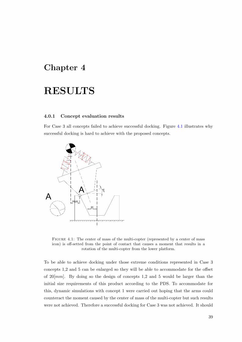
Chapter 4
RESULTS
4.0.1 Concept evaluation results
For Case 3 all concepts failed to achieve successful docking. Figure 4.1 illustrates why
successful docking is hard to achieve with the proposed concepts.
Figure 4.1: The center of mass of the multi-copter (represented by a center of massicon) is off-setted from the point of contact that causes a moment that results in a
rotation of the multi-copter from the lower platform.
To be able to achieve docking under those extreme conditions represented in Case 3
concepts 1,2 and 5 can be enlarged so they will be able to accommodate for the offset
of 20[mm]. By doing so the design of concepts 1,2 and 5 would be larger than the
initial size requirements of this product according to the PDS. To accommodate for
this, dynamic simulations with concept 1 were carried out hoping that the arms could
counteract the moment caused by the center of mass of the multi-copter but such results
were not achieved. Therefore a successful docking for Case 3 was not achieved. It should
39

Chapter 4. Optimization
be pointed out that simulation including the control circuit of the multi-copter could
allow for a successful docking.
4.1 Optimum shape
By using table 3.4 and the results from the DOE a shape of the two platforms could be
determined to be the optimum shape with the given constrains of the PDS. The final
shape of the cone and drogue can be seen on figure 4.2.
Figure 4.2: The final shape of the two platforms, determined with DOE and detailedanalysis
This shape of the two platforms was therefore found to perform best under varying
coefficient of friction and be within the given size boundaries described in the PDS. For
Design cases 1 and 2 the proposed design did perform as required but not for Design
case 3.
4.2 Results from visual comparison
From visual inspection it was concluded that Concept 1 with arms included performed
better since it reduced the rebound of the upper platform. This did not greatly influence
40

Chapter 4. Optimization
the average distance but once the larger diameter of the drogue and the cone touched
they were not separated again. This result therefore could greatly help in docking,
especially in windy conditions that could otherwise blow the multi-copter off the lower
platform before the two parts could be locked together.
4.3 Final result
As a final result concept 1-D was considered to outperform all other concepts. This
result is therefore both based on the Pugh matrix, DOE and visual inspection. In all
of those analyses Concept 1-D performed as good or better than all the other concepts.
Furthermore all variations of Concept 1 do have a potential to be able to dock for
Case 3, by utilizing the arms as a support and counteract the moment caused by the
center of mass of the multi-copter. Finally the concept proposed therefore was capable of
achieving most of the requirements defined in the PDS. As mentioned before the concept
did not achieve successful docking for Case 3 and therefore could not achieve the demand
to be able to dock with horizontal misalignment of 20 [mm] and angular misalignment of
20 [◦] both at the same time. All other demands of the PDS were otherwise achieved as
well as some of the wishes in the PDS and the weight of the upper platform is assumed
from the CAD model to be around 200 [g] And therefore only about 10% of the assumed
weight of the multi-copter.
41


Chapter 5
DISCUSSION AND
CONCLUSION
5.1 Discussion
To set-up a realistic contact mechanism with the impact function in Adams it can be
said that experimental data can greatly increase the accuracy of the dynamic simulation
and is extremely important to validate the results. This thesis is therefore a tool to
identify any trends that arise between the coefficients of friction and the contact forces
between the geometry of the two platforms. Much of the background research and in-
spiration for this thesis was from docking mechanism developed for space exploration.
Mainly this was due to extensive information available on those systems and decades of
experience in such systems. Those systems were considered to be a good source partly
because they rely on one stationary platform while the other is platform is guided in
place very similar to the application in this thesis. Although those systems are used in
almost zero gravity it was assumed that a system as proposed within this system the
presence of gravity would only aid in successful engagement of the two platforms since
the lack of gravity in space makes such system more challenging to design.
A major consideration was given not to make the optimum system with unlimited cost
but rather a feasible solution for mass production that could be used for transportation
of goods worldwide with low cost as well as reducing the weight of the system as much as
possible, but cost and weight often go hand in hand. The weight of the upper platform
is 50% lighter than the initial demand and the weight could furthermore be decreased
by further analysis of force distribution over the platforms with finite element analy-
sis. In this thesis very little consideration was given to the weight carrying capability
of actuators and the structure itself for simplification. The weight carrying capacity
was nevertheless kept to minimum by adding restraints on the movement of the lower
43

Chapter 5. Results
platform with respect to the upper platform when they were engaged. For example
forces generated by horizontal movements of the lower platform where not carried by
the actuator but the geometry of the platforms instead, therefore forces generated by
horizontal movements do not have to be considered in calculation on maximum forces
expected on actuators.
Having the PDS made at the beginning of the project helped greatly by serving as a
document for desirable results of the design and was frequently looked at in the design
process and it helped in keeping a good overview of feasible solutions. The PDS also
helped greatly in organizing and simplifying the decision process of determining multiple
parameter values when it was down to determining the shape of the platforms. In the
end only three controllable parameters were left that could not be determined from the
PDS.
5.2 Conclusions
It can be noted that the kinetic coefficient of friction has very little effect on the per-
formance compared to the static coefficient of friction. Therefore it can be concluded
that further design would not require detailed analysis of the kinetic friction if both
kinetic and static coefficients of frictions are within the boundaries given in this thesis.
Although a more thorough analysis of the stiction and friction velocities along with the
normal force could give better understanding on the effect of the two coefficients of fric-
tion.
The diameter of the cone greatly contributes to the required accuracy of the electronics
and software for automatic landing and therefore can be increased to accommodate for
lower accuracy of electronic sensors than assumed in this thesis.
This thesis work and the analysis described in it are based upon multiple assumptions.
Most of those assumptions were regarding the contact mechanics. No complete guide-
lines could be found for method to determine the correct parameters within MSC. Adams
without doing physical testing. Only vague recommendation and guidelines could be
found. Therefore it is important to point out that the results from the dynamic sim-
ulation should be read with precaution. A good model has therefore been created for
testing different parameters of the design and changing the parameters of the impact
function within MSC. Adams can be quickly and easily done as better estimation of
their values is attained.
44

Chapter 5. Results
The thesis findings are therefore that the best method to align two platforms is to use
a cone on the upper platform and a drogue on the lower platform. For maximized
robustness the number of components and especially the number of moving components
are minimized and all sensitive areas are enclosed and therefore protected against the
environment. Therefore Concept 1-D is the best method for autonomous landing and
transportation of cargo with a UAV.
45


Chapter 6
RECOMMENDATIONS AND
FUTURE WORK
6.1 Recommendations
Further verification of the contact mechanism is recommended. This thesis is mainly a
tool to identify the parameters that have the most impact on performance under varying
coefficient of friction as well as to reduce the impact forces. To determine those exact
values multiple parameters of the material used need to be known in details and it is
recommended that the coefficient of friction is to be measured under different tempera-
tures and with different surface roughness since the material will wear with use.
Further verification of this thesis work could be done in MSC. Adams by using the
contact feature Poission restitution model where the coefficient of restitutions can be
attained from physical testing.
It is recommended to increase the Hertz contact stiffness as later results with calculation
based on the HertzWin software showed that the stiffness used could be to low for some
of the design cases. Also, the effect of the stiffness parameter in the impact function
within MSC. Adams should be increased and the effect on the simulation be compared
to the simulations done within this thesis.
Validation for all of the multiple parameters used in the impact function within Adams is
therefore highly recommended both with physical testing and also by changing different
parameters to see how they influence the simulations.
47

Chapter 6. Discussion
6.2 Future work
Future work includes further testing of a prototype of the two platforms to compare
to the analyses done in this thesis. By being able to predict the forces in the dynamic
simulation by validation of the multiple parameters required for the contact mechanism
as well as being able to better measure the range of the coefficient of friction especially
the static coefficient of friction it is possible to use those results to do a finite element
analysis to reduce the weight of the platforms.
The geometry proposed here could be made more complex by introducing spline curves
or other similar geometrical curves, this would greatly increase the number of control-
lable parameters and therefore making simulations and or DOE more difficult and time
consuming.
For simplification in this thesis, it was assumed that all actuators would be able to carry
the given load, further analysis is required to determine if the size of the required actu-
ator is sufficient and if not it could greatly alter the size of the proposed platforms.
Furthermore, analysis should be done by including the control circuit of the multi-copter.
This could perhaps be done with integration of Matlab Simulink and MSC Adams and
analysis carried out on the resistance of the multi-copter to forces applied trough the
two platforms when they come in contact. By also adding the inertia of the multi-copter
one could therefore validate the assumptions made within the thesis when inertia is not
included since it is assumed to have neglectful effect on the result compared to the con-
trol circuit of the multi-copter that contributes greatly to the final result.
Another effect that could be considered is the ground effect generated by the pressure
difference on the propellers that will greatly contribute to the behaviour of the multi-
copter when it gets closer to the ground. Further analysis as described here are very
complex and might require extensive physical testing to fully validate assumptions re-
quired to carry out further more detailed analyses than done in this thesis.
A very important work needs to be done in computer vision hardware and algorithms to
fully validate if automatic landing is possible with the accuracy required of the platform
proposed in this thesis and also analysis of the robustness of such a system is required
to be able to fully solve the problem of autonomous pick up and transportation of cargo
with UAVs. To fully complete the design concept proposed in this thesis electrical sen-
sors need to be integrated to the design and to make sure they can fit within the space
in the concept.
48

Chapter 6. Discussion
Further work of this platform would greatly benefit from more detailed analysis and
design of the dampeners. Optimization of the best dampening characteristics would
benefit the design but it is recommended that those analyses would be carried out after
determining the contact forces and frictional forces as well as after the control system
of the multi-copter is included in the analysis. By including all those factors a very
realistic behaviour could be attained and further simulation could be carried out for
example by incorporating the environmental effects like wind and the affect it has on
the performance of the system.
A very helpful tool could be the creation of an extensive guide for MSC. Adams where
results of analysis of contact and impact of different materials and shapes and sizes are
periodically tested and the result measured under different conditions, for example im-
pacts at different velocities. All this data could then be used for carrying out dynamic
simulation where parameters could be adjusted to attain similar results as in the exper-
imental analysis. This guide could therefore serve as a guideline for future simulations
although it would never replace physical testing for comparison.
49


Appendix A
Impact parameters, MSC. Adams
Figure A.1: The effect of varying the stiffness force exponent, e while other parametersare kept fixed at their default values.
Figure A.2: The effect of varying the stiffness coefficient, k while other parameters arekept fixed at their default values except the damping coefficient, cmax was determined
to be 1[%] of the stiffness value
51


Appendix B
Design of experiments
Table B.1: The results from the DOE for Case 1
D µdy - - + +Run
E µst - + - +
A B C AB AC BC ABC Average Range STD Main effect Average STD
1 - - - + + + - 48,58 47,37 48,58 47,37 47,97 1,21 0,60 A 38,18 0,75
2 - - + + - - + 56,03 54,66 56,03 54,66 55,34 1,37 0,69 B 42,79 14,59
3 - + - - + - + 72,57 94,75 72,57 94,75 83,66 11,09 C 1,02 1,59
4 - + + - - + - 59,65 94,62 59,65 94,62 77,13 34,97 17,48 AB -72,17 0,95
5 + - - - - + + 78,71 79,60 78,71 79,60 79,15 0,88 0,44 AC -0,67 -1,65
6 + - + - + - - 78,89 79,78 78,89 79,78 79,33 0,89 0,45 BC -14,08 1,54
7 + + - + - - - 55,85 87,95 55,85 87,95 71,90 32,10 16,05 ABC 13,72 -1,61
8 + + + + + + + 55,99 87,81 55,99 87,81 71,90 31,82 15,91 D 0,00 0,00
Average 63,28 78,32 63,28 78,32 E 34,14 5,79Range 30,31 47,38 30,31 47,38STD 10,95 16,73 10,95 16,73
Table B.2: The results from the DOE for Case 2
D µdy - - + +E µst - + - +
RunA B C AB AC BC ABC Average Range STD Main effect Average STD
1 - - - + + + - 46,51 47,19 46,51 47,19 46,85 0,68 0,34 A -13,26 -0,35
2 - - + + - - + 48,60 50,67 48,60 50,67 49,63 2,08 1,04 B 12,90 -0,11
3 - + - - + - + 68,97 69,33 68,97 69,33 69,15 0,36 0,18 C -19,77 0,31
4 - + + - - + - 47,59 46,12 47,59 46,12 46,86 1,48 0,74 AB -26,15 0,12
5 + - - - - + + 50,92 51,75 50,92 51,75 51,34 0,84 0,42 AC 19,24 -0,31
6 + - + - + - - 51,62 51,57 51,62 51,57 51,60 0,05 0,03 BC -25,87 0,16
7 + + - + - - - 48,37 48,45 48,37 48,45 48,41 0,08 0,04 ABC 24,30 0,23
8 + + + + + + + 48,32 47,45 48,32 47,45 47,89 0,87 0,43 D 0 0
Average 51,36 51,57 51,36 51,567 E 0,41 0,16Range 22,46 23,21 22,46 23,21STD 6,84 7,00 6,84 7,00
53


Appendix C. Product Design Specification
Appendix C
PDS
Specification for autonomous docking platform Rev. AB
01/10/2014
D/W RequirementsChanges
(Date)
Performance
D Centerline misalignment between platform and copter can be up to 20 [mm] 19.03.14
W Centerline misalignment between platform and copter can be up to 80 [mm] 19.03.14
D Angular misalignment beetween platform and copter can be up to 20 [°] 19.03.14
W Angular misalignment beetween platform and copter can be up to 30 [°] 19.03.14
D Rotational misalignment around vertical axes (Yaw) inensitive
D Maximum joining velocity to be up to 0,63 [m/s], calculated from fall form 0,2 [m] height 19.03.14
W Maximum joining velocity to be up to 0,76 [m/s], calculated from fall form 0,3 [m] height 19.03.14
D Attachment of docking unit to quadrocopter requires maximum three bolts
D Docking platform with small enough footprint so ground effect is not expereienced
D Maximum horizontal velocity to be 0,4 [m/s], regardless of vertical velocity 28.04.14
Weight
D Weight to be less than 400 [g] 19.03.14
W Weight to be less than 20% of the copter total weight
Quality reliability
D Reduce the number of components to maximum 20 components 20.05.14
D Be normally closed without requiring energy
D Opens when electric current is applied
D Design must be done to prevent dust buildup that can render the product not to work
Size
D Product to fit inside a bounding box of size 120x150x50 [mm] 19.03.14
D Product to fit all necessery electric sensors and circuits
Time scale
D Fully designed product in end of June 2014, mechanical
D Fully tested prototype end of August 2014
D Production ready product end of January 2015
Product cost
D Mechanical parts maximum cost 150$
D Electrical parts maximum cost 150$ 19.03.14
D Total product maximum cost 300$ 19.03.14
W Total product cost below 200$
Patents
D Product not to violate any current patents
W Parts of product to be patented for protection against competition
Processes
D 80% of parts to be plastic injection molded
W Now circuits for the equipment56

Appendix C. Product Design Specification
Specification for autonomous docking platform Rev. AB
01/10/2014
D/W RequirementsChanges
(Date)
Materials
D Reduce the use of metals to be less than 5% of total material usage
D 80% or more of parts to be plastic injection molded
Installation
D Installation of platform to copter to take less than 5 minutes
D Installation of platform to cargo to take less than 5 minutes
Maintenance
D Cleaning to be done after 1000 docking 01.10.14
D Inspection on platform carried out every 500 dockings, looked for failures or cracks 01.10.14
Quantity
D Manufacured quantity >2000 units 01.10.14
Life in service
D >2 years
Testing
Verification of simulated results done trough testing on a prototype
Safety
D No sharp edges on product that can cause injury to people on impact
Product life span
D Minimum life time 5 year without any usage
Disposal
W No parts made from different materials glued together
Competition
D Extensive search for granted patents on similar solutions
Standard specification
D Product to be CE marked
Documentation
D User guide with warnings
D Assembly guide
Environment
D Dust and other contiminants can not accumulate on platform so they effect performance
D Not effected by altitudes/air pressures
D Working temperature 0°C to 40°C
57


Bibliography
[1] Nolting R. Hoyler W. Havey J. Carter T. Dotts, H. and R. Johnson. Operational
characteristics of the docked configuration. In F. Cucker and M. Shub, editors,
Gemini Summary Conference, pages 41–54. NASA-SP-138, Houston, TX, 1967.
[2] National Aeronautics and Space Administration. Apollo Operations Handbook Block
II Spacecraft - Volume 1 Spacecraft Description. National Aeronautics And Space
Administration, Spacecraft Systems Operation Branch, Flight Crew Support Divi-
sion, 1969.
[3] MSC. Software. Adams/Solver help. MSC. Software, 2014.
[4] Preeti Kannan. Million-dollar contest launched to invent drones for uae gov-
ernment services, 2014. URL http://www.thenational.ae/uae/government/
million-dollar-contest-launched-to-invent-drones-for-uae-government-services.
[5] 3D Robotics Inc. 3dr pixhawk, 2013. URL https://store.3drobotics.com/
products/3dr-pixhawk.
[6] Sima Mitra. Autonomous Quadcopter Docking System. Master’s thesis, Cornell
University, address = the USA, year = 2013,.
[7] B.C. Hacker, J.M. Grimwood, United States. National Aeronautics, Space Ad-
ministration. Scientific, and Technical Information Division. On the Shoulders
of Titans: A History of Project Gemini. NASA SP. Scientific and Technical In-
formation Office, National Aeronautics and Space Administration, 1978. URL
http://books.google.se/books?id=crwgAAAAIAAJ.
[8] Brian Harvey. Soviet and Russian Lunar Exploration. Praxis Publishing Ltd.,
Chichester, UK, 2007. ISBN 978-0-387-73976-2.
[9] W. David. Woods. How Apollo Flew to the Moon [electronic resource]. Praxis
Publishing Ltd., New York, USA, 2008. ISBN 9780387740669.
[10] Wigbert Fehse. Automated Rendezvous and Docking of Spacecraft. Cambridge
University Press, New York, USA, 2003. ISBN 9780511543388.
59

Appendix C. Product Design Specification
[11] Mr. Thomas Reiter Dr. Jean-Claude Piedbouef MR. Yoshiyuki Hasegawa Mr.
William Gerstenmaier, Mr. Alexey Krananov. International Docking System Stan-
dard (IDSS) Interface Definition Document (IDD) - Revision C. Nasa, Roscosmos,
ESA, CSA, Jaxa, 2013. URL http://www.internationaldockingstandard.com/
index.html.
[12] Proc. International ADAMS User Conference (DISC 2000), Toronto, Canada, June
2000. Schneider Electric.
[13] Stuart Pugh. Total Design: Integrated Methods for Successful Product Engineering.
Addison-Wesley Pub, February 1991.
[14] Jochem Giesbers. Bachelor thesis - CONTACT MECHANICS IN MSC ADAMS -
A technical evaluation of the contact models in multibody dynamics software MSC
Adams. Master’s thesis, University of Twente, address = the Netherlands, year =
2012,.
[15] R. Budynas and K. Nisvett. Shigley’s Mechanical Engineering Design, Eighth Edi-
tion. McGraw-Hill, 2008.
[16] K.L. Johnson. Contact Mechanics. Cambridge University Pressll, 2003.
[17] E.W. Deeg. New algorithms for calculating hertzian stresses. AMP Journal of
Technology, 2:1236–1239, November 1992.
60

Copyright © 2022 FDOKUMEN