First Flight of Scaled Electric Solar Powered UAV ... - CiteSeerX
Upload
khangminh22Category
view
3download
0
Design of a MedEvac UAV for
Operation in Physically Constrained
Environments
Multi-Disciplinary Design Project 2012-13
14th
January 2013
Group 1:
Wasim Aslam (Medical Engineer); Michael Collison (Aerospace Engineer);
Sarad Limbu Lawati (Aerospace Engineer); Matthew Temple (Electrical
Engineer); Maria Wood (Mechanical Engineer); Dela Yohuno (Medical
Engineer)
Supervisors:
Chris Newbold (Qinetiq); Prof. Roger Webb (University of Surrey); Dr. Andrew
Pennycott (University of Surrey)

Design of MedEvac UAV for Operation in physically constrained environments
1-2
Contents
1 Executive Summary ............................................................................................................... 1-8
2 Introduction ......................................................................................................................... 2-10
3 Aircraft Configuration ......................................................................................................... 3-11
3.1 Single and Coaxial Rotor Configurations Rejection ................................................... 3-11
3.2 Fixed wing design rejection ......................................................................................... 3-11
3.3 Tilt rotor design rejection ............................................................................................ 3-12
3.4 Chosen Configuration .................................................................................................. 3-13
4 Duct design .......................................................................................................................... 4-14
4.1 Double Ducted Fan concept ........................................................................................ 4-15
4.2 Stator Vanes & Flaps ................................................................................................... 4-19
5 Fan/Rotor design ................................................................................................................. 5-20
5.1 Blade Element Theory (Leishman, 2006) .................................................................... 5-22
5.2 Materials and Stress analysis ....................................................................................... 5-24
6 Transmission........................................................................................................................ 6-25
6.1 Transmission Concept 1 .............................................................................................. 6-26
6.2 Transmission Concept 2 .............................................................................................. 6-27
6.3 Transmission Concept 3 .............................................................................................. 6-29
6.4 Transmission Design ................................................................................................... 6-30
7 UAV dimensions ................................................................................................................. 7-34
8 Structures ............................................................................................................................. 8-34
8.1 Main Spar .................................................................................................................... 8-34
8.2 Skin and Bulkheads ..................................................................................................... 8-35
8.3 Frames and Stringers ................................................................................................... 8-36
8.4 Floor and Ceiling ......................................................................................................... 8-36
8.5 Landing Gear ............................................................................................................... 8-37
8.6 Miscellaneous .............................................................................................................. 8-38
8.7 Cabin Door .................................................................................................................. 8-38
8.8 Structural CAD Representation ................................................................................... 8-38

Design of MedEvac UAV for Operation in physically constrained environments
1-3
9 Flight modes ........................................................................................................................ 9-39
10 Drag Estimation ............................................................................................................. 10-40
11 Power requirements ....................................................................................................... 11-41
11.1 Induced Power ........................................................................................................... 11-41
11.2 Blade Profile Power ................................................................................................... 11-43
11.3 Total, and Available Power Analysis ........................................................................ 11-43
11.4 Flight Envelope ......................................................................................................... 11-44
12 MTOW mass iteration using fuel and structural mass................................................... 12-46
13 Operational Flight Profile .............................................................................................. 13-47
13.1 Acceleration ............................................................................................................... 13-47
13.2 Climb Performance .................................................................................................... 13-48
13.3 Overall Mission Profile ............................................................................................. 13-49
14 Performance ................................................................................................................... 14-50
14.1 Disk Loading ............................................................................................................. 14-50
14.2 Range ......................................................................................................................... 14-50
14.3 Centre of Gravity & Stability .................................................................................... 14-51
15 Processors ...................................................................................................................... 15-51
16 Sensors ........................................................................................................................... 16-52
16.1 Terrain Mapping ........................................................................................................ 16-52
16.2 Colour Camera........................................................................................................... 16-56
16.3 Attitude Determination Sensors................................................................................. 16-57
16.4 Altitude Determination .............................................................................................. 16-59
16.5 Tachometer ................................................................................................................ 16-59
17 Electrical Bus Layout .................................................................................................... 17-60
18 Navigation and Flight Operations.................................................................................. 18-61
19 Communication ............................................................................................................. 19-62
19.1 Operating Frequency ................................................................................................. 19-63
19.2 Satellite Networks ..................................................................................................... 19-63
19.3 Modulation, Error Correction and Polarisation ......................................................... 19-64

Design of MedEvac UAV for Operation in physically constrained environments
1-4
19.4 Encryption ................................................................................................................. 19-65
19.5 Antenna Design ......................................................................................................... 19-65
20 Electrical Power Generation .......................................................................................... 20-68
21 Ground Control Station ................................................................................................. 21-70
21.1 Pilot Control Station .................................................................................................. 21-71
21.2 Medic Control Station ............................................................................................... 21-71
22 Environmental Control .................................................................................................. 22-72
23 Fuel Tank Protection ..................................................................................................... 23-73
23.1 Minimising Explosion Risks ..................................................................................... 23-73
23.2 Stopping Leaks from Punctured Fuel Tanks ............................................................. 23-74
24 Defence systems ............................................................................................................ 24-75
24.1 CROSSHAIRS .......................................................................................................... 24-75
24.2 Basic Countermeasures ............................................................................................. 24-76
24.3 RAFAEL Trophy Family .......................................................................................... 24-76
25 Transportation of UAV .................................................................................................. 25-76
25.1 Air Transportation ..................................................................................................... 25-76
25.2 Land Transportation .................................................................................................. 25-77
26 Regulations .................................................................................................................... 26-78
26.1 Training Requirements .............................................................................................. 26-78
26.2 Sense and Avoid Criteria ........................................................................................... 26-78
26.3 Redundant Engines .................................................................................................... 26-78
26.4 Emergency Landings Procedures .............................................................................. 26-79
27 Casualty Movement ....................................................................................................... 27-79
28 Initial preliminary research (Battlefield injuries) .......................................................... 28-81
28.1 Choosing the injuries to treat ..................................................................................... 28-82
29 Adapting Medical treatments and diagnostics for the UAV .......................................... 29-83
29.1 Deciding on Medical treatments and diagnostics ...................................................... 29-83
30 Casualty Diagnostics ..................................................................................................... 30-84
30.1 Pulse Oximetry .......................................................................................................... 30-84

Design of MedEvac UAV for Operation in physically constrained environments
1-5
30.2 Blood Pressure ........................................................................................................... 30-86
31 Insertion of a Line for injection of fluids ...................................................................... 31-87
32 Blood Transfusion ......................................................................................................... 32-89
33 Injuries and Treatments ................................................................................................. 33-91
33.1 Occurrence ................................................................................................................. 33-91
33.2 Specific Injuries ......................................................................................................... 33-93
33.2.1 Open wounds ..................................................................................................... 33-93
33.2.2 Potential solutions ............................................................................................. 33-95
33.2.3 Burn Injuries ...................................................................................................... 33-99
33.2.4 Chemical and Radiation Injuries ..................................................................... 33-100
34 Fractures ...................................................................................................................... 34-106
34.1 Open fractures ......................................................................................................... 34-106
34.2 Closed fractures ....................................................................................................... 34-107
35 CPR ............................................................................................................................. 35-107
35.1 Chest compressions ................................................................................................. 35-107
35.2 Automatic External Defibrillator (AED) ................................................................. 35-108
36 Open chest wounds ...................................................................................................... 36-109
37 Airway management .................................................................................................... 37-110
37.1 Blocked airway ........................................................................................................ 37-110
37.2 Medical portable ventilation .................................................................................... 37-111
38 Casualty Compartment ................................................................................................ 38-113
39 Effects of altitude on patient ........................................................................................ 39-114
40 Disinfection ................................................................................................................. 40-115
41 Patient cabin layout ..................................................................................................... 41-116
41.1 Patient stretcher platform ........................................................................................ 41-116
41.2 Medical device layout .............................................................................................. 41-117
42 Robot Arm ................................................................................................................... 42-120
42.1 Possible Options ...................................................................................................... 42-120
42.2 Robotic Arm Sensors ............................................................................................... 42-121

Design of MedEvac UAV for Operation in physically constrained environments
1-6
42.3 Layout ...................................................................................................................... 42-122
43 Robotic tools ................................................................................................................ 43-124
44 Program Costs ............................................................................................................. 44-128
45 Overall CAD Technical Drawing ................................................................................ 45-130
46 Specification ................................................................................................................ 46-132
46.1 Performance ............................................................................................................. 46-132
46.2 Control and Stability ................................................................................................ 46-132
46.3 Operation ................................................................................................................. 46-132
46.4 Powerplant ............................................................................................................... 46-133
46.5 Aircraft Systems ...................................................................................................... 46-133
46.6 Flight Controls ......................................................................................................... 46-133
46.7 Sensing .................................................................................................................... 46-133
46.8 Communication ....................................................................................................... 46-134
46.9 Remote Control ....................................................................................................... 46-134
46.10 Casualty Loading ................................................................................................. 46-134
46.11 Medical ................................................................................................................ 46-134
46.11.1 Operation ..................................................................................................... 46-134
46.11.2 Diagnosis ..................................................................................................... 46-135
46.11.3 Treatment ..................................................................................................... 46-135
46.12 Regulatory/Safety ................................................................................................ 46-135
46.13 Assumptions ........................................................................................................ 46-136
47 Medical Treatment ....................................................................................................... 47-136
48 Medical Training ......................................................................................................... 48-139
49 Mass, Size and Power Estimation................................................................................ 49-140
50 Financial Analysis ....................................................................................................... 50-142
50.1 Development Program Costs ................................................................................... 50-142
50.2 Operational Costs .................................................................................................... 50-144
51 Project Management .................................................................................................... 51-147
52 Conclusion ................................................................................................................... 52-149

Design of MedEvac UAV for Operation in physically constrained environments
1-7
54 Bibliography ................................................................................................................ 54-150
Appendix A – Current Aircraft Data ....................................................................................... 54-159
Appendix B .............................................................................................................................. 54-160
Appendix C – Gear Terminology ............................................................................................ 54-168
Appendix D – Satellite Communication Equations ...................................................................... 169
Appendix E – Finance Equations ................................................................................................. 170
Electronics Development Cost Estimate .................................................................................. 170
Analytical Spreading Function for Research and Development Projects ................................. 170
Appendix F - Flowcharts .............................................................................................................. 171
Communications System .......................................................................................................... 171
Flight Operations ................................................................................................................. 54-172
Medical Operations ............................................................................................................. 54-174
Appendix G - Communication Bus Diagram .......................................................................... 54-180
Appendix H - Failure Mode Effect Analysis ........................................................................... 54-181
Design of MedEvac UAV for Operation in physically constrained environments
Author: Group 1-8
1 Executive Summary
A Medical Evacuation Unmanned Aerial Vehicle (MedEvac UAV) preliminary design solution is
discussed and presented herein, which is able to fulfil an MOD need for a UAV that is capable of
operating in a physically constrained urban environment and providing not only casualty
extraction to a field hospital, but also autonomous medical diagnosis and treatment at the scene
and in transit.
The chosen UAV configuration is an innovative double ducted fan configuration, using a series of
flaps and vanes to give the desired control and stability movements. This configuration was
chosen in order to be able to land in physically constrained urban environments, whereby a small
UAV footprint allows more potential landing zones to be accessed. For example, the ducted fan
UAV with a footprint of 2.91m x 7.59m allows it to land on a single lane road, whereas a standard
helicopter or fixed wing configuration would not be able to operate in these conditions.
The secondary duct enables the UAV to fly level with the fans perpendicular to the oncoming
airflow due to their presence creating a flow of air around the duct lip, which prevents separation
occurring at this point as would normally happen in this flight condition without the secondary
duct. Furthermore, the fans themselves are designed with stators to straighten the flow by
removing the swirl, along with the blade design reducing the noise and vibration levels of the
UAV. The two fans need to be able to alter their speed independently to overcome the effects of
UAV pitch disturbances, therefore the transmission of power from the engines to the fans will be
transferred via a differential gearbox, similar to that used in the rear axle of a vehicle.
The UAV has dual redundant engines in case of failure which allow the UAV to have a ceiling of
5000m with a cruise speed of 57m/s (205km/h) at sea level and a maximum flight speed of 71m/s
(256km/h) at 4500m, this is slightly slower than a typical helicopter but is limited by the choice of
configuration to give a small landing footprint. The semi-monocoque UAV structure contains a
central pressurised casualty cabin section and a fan at either end, with the drive shafts, engines
and other equipment stowed internally above the cabin ceiling, or below the cabin floor.
There is sufficient technology currently available on the market to enable the UAV to operate as
an autonomously controlled aircraft. A complete flight control system is assembled from the
following units, which are controlled with a single field programmable gate array. The sensors
provided in the UAV are: a Global Positioning System (GPS), to sense geographic position and
velocity of the UAV; an Inertial Measurement Unit (IMU), to sense the attitude of the UAV; and
a pressure sensor, to sense the altitude of the UAV. These components provide all of the
necessary sensory data to accurately determine the position and attitude of the UAV. When
combined with other sensors to measure the fan speed and flap positions the on-board computer
has sufficient data to control the aircraft, and fly the UAV to the desired locations without the
need of a constant control signal from the ground station.
Design of MedEvac UAV for Operation in physically constrained environments
Author: Group 1-9
To aid in the autonomous operations of the aircraft a Light Detection and Ranging (LiDAR)
system can be used to not only detect obstacles around the UAV, but also scan nearby terrain for
suitable landing sites from high altitude. A remote robotic arm controlled by medics on the
ground then completes the package.
The MedEvac is designed to only carry the NATO stretcher since it is currently used on the
battlefield due to it being lightweight and having the ability to collapse to the size of a rucksack,
and can be inter-operable with other military vehicles which can also carry the stretcher.
Detachable wheels will be provided to clamp onto the handles on one side of the stretcher so it
can be manoeuvred by one person.
Since no medic will be on board the UAV, non-invasive diagnostic equipment will play an
essential role in the treatment of the casualty. To measure and record the blood pressure of the
casualty, an adhesive blood pressure patch will be utilised, and to measure the blood oxygen
levels, a forehead pulse oximeter will be applied.
One of the major issues for the MedEvac is the treatment of open wounds and the blood loss that
results as a consequence. The proposed solution is the use of a haemostatic powder (Celox) which
would be applied by a robotic arm with a specialised attachment to any open wounds; the powder
would then form a gel like clot. Fluid resuscitation is also implemented via a fluid and medication
delivery system using the intraosseous (IO) method to maintain blood volume at sufficient levels
for tissue perfusion to occur. Medications such as morphine for pain relief and tranexamic acid to
reduce the severity of bleeding can be implemented through the IO fluid delivery system within
the UAV. Furthermore a ventilator is implemented to provide support for those with breathing
problems. Several specialised attachments are designed for use by the robotic arm to allow for
treatment of several conditions including a spring loaded needle attachment which is designed for
the treatment of pneumothorax, a potentially fatal condition.
The production quantity of 50 UAVs gives rise to program costs associated with the research,
development, design and manufacture of the UAV to be £132million, giving a unit cost of
£2.6million for each operational aircraft.
The solution provided removes the risks involved with committing extra personnel to a dangerous
situation as is the case with current military MedEvacs. It is also able to integrate with current
operations with minimal training requirements, and provide a cost effective upgrade to current
MedEvacs with added capabilities such as accessing physically constrained locations for casualty
extraction.

Design of MedEvac UAV for Operation in physically constrained environments
Author: Group 2-10
2 Introduction
Air ambulances are an important and crucial part of the medical services provided worldwide
particularly in military settings. However in military use where air ambulances usually have to
enter conflict zones they are putting themselves at danger, this risk to the personnel of the air
ambulance is an important part of the decision to deploy air ambulances. With 6311 aeromedical
evacuations occurring over the period covering the 1 January 2006 to 31 October 2012 (Gov.co,
2012), it can be seen that medical personnel are risking their lives on numerous occasions. It is for
this reason that interest in the development of MedEvac UAVs is so high, the potential to remove
the risk to medical personnel while still being able to evacuate wounded soldiers and provide
treatment is one that the military is very interested in. Also with warfare having moved on from
large scale wars fought in the open to smaller battles fought in smaller areas such as towns and
cities it is important that the UAV is able to operate within these physically constrained
environments.
A successful design which meets these requirements will provide numerous benefits to both the
MOD and to the soldiers who risk their lives. It also has the potential to save more lives compared
to the current MedEvac fleet which would not be allowed to undertake any missions which are
deemed too dangerous for the personnel on board the aircraft. It also has the potential for use in
civilian applications in the instance of environmental disasters, extreme weather and other
hazardous environments.
This report details the design of a MedEvac UAV designed specifically for small constrained
spaces such as urban environments for the UK MOD. It covers the specific aircraft configuration,
the medical systems implemented, the electronic systems and operational procedures all of which
should be able to be monitored and controlled autonomously. The proposed solution is intended
for an entry in to service of 5 years, and should integrate with current operations as much as
possible.

Design of a MedEvac UAV for Operation in Physically Constrained Environments
Author: Michael Collison and Sarad Limbu Lawati 3-11
3 Aircraft Configuration
UAV systems have a wide range of applications (military or civil) due to their advanced
capabilities and some distinct advantages over manned aircraft. However, the design and
capabilities of the UAV system is specifically determined by its role.
Casualty rescue operations, particularly in hostile or difficult urban environment are the focal
design requirements for the MedEvac UAV design proposed by the UK mod. Taking the
operational constraints into consideration, the aspects that offered the optimal base concept for the
mission requirement were narrowed down to a UAV system providing good manoeuvrability,
stability, control and minimal footprint.
Prior to the selection of the VTOL ducted fan design for the MedEvac, an incomprehensive
analysis of a fixed-wing (HTOL) and tilt-rotor aircraft (hybrid) design were conducted to decide
on most suitable solution.
3.1 Single and Coaxial Rotor Configurations Rejection
Using the data for helicopters with a similar MTOW as the UAV presented in Table 28 it can be
seen that the average rotor diameter is 10.1m, and that the average disk loading is 252N/m2;
assuming that the consistency of these values across all the helicopters implies that the values are
near optimal, then both of these values present limits on the minimum footprint of the UAV due
to the size of the rotor disk diameter. Even if a coaxial rotor is used to provide the same amount of
lift then the diameter is typically only reduced by a factor of √ , in this case to 7.1m. However,
even this diameter restricts the UAV footprint to greater than the 3.7m required as stated in
specification point 46.3.1 and therefore in order to meet this requirement it is deemed that it is not
viable to use a single or coaxial rotor configuration for the UAV.
3.2 Fixed wing design rejection
Figure 1: MQ-1B Predator Fixed wing UAV(Keller, 2012)
Typical HTOL (Horizontal Take-off and Landing) aircrafts are of fixed wing configurations
which require a strip of runway for take-off and landing. The wings generate majority of the
aerodynamic lift that keeps the aircraft afloat as it moves forward through air powered by thrust
produced from its engines.

Design of a MedEvac UAV for Operation in Physically Constrained Environments
Author: Michael Collison and Sarad Limbu Lawati 3-12
Fixed wing aircrafts are designed to have low aerodynamic drag in order to obtain long range and
mostly cruise at higher altitudes. Parasitic drag is less at higher altitudes because the air density is
low. It comprises of drag that originate from the aircraft’s skin friction, form, momentum,
interference and cooling factors but can be minimised by innovative airframe design and limiting
the aircraft to fly at low speeds (minimum drag speed). However, induced drag is higher if the air
density is low unless wing span loading for the aircraft is low i.e. longer but optimal wing span is
required. Although fixed wing aircrafts have a high disposable load fraction acquired by taking
advantages of advanced materials and careful structural design, this disposable load needs to be
shared between the payload and fuel to be carried when designing for long range. Fixed wing
aircrafts usually have high response to atmospheric turbulence because of its large surface area to
mass ratio which is easily disturbed by air gusts far more than an aircraft with high mass to
surface area. Aircraft with high mass, therefore high inertia is less affected by the acceleration
resulting from an imposed force(Austin, 2010). Figure 87 in Appendix B shows Aircraft vertical
response to a vertical gust derived from simple calculations.
3.3 Tilt rotor design rejection
Figure 2: V22 Osprey tilt rotor design(Anon., 2005)
Helicopters fly at lower flight speeds and their rotors have large diameter blades with relatively
less twist that operate at lesser RPMs compared to propellers. They have better efficiency because
of low disk loading and drag created from rotors is minimised. Conversely, propellers need
operate at higher RPMs to generate sufficient thrust for airplanes to be able to fly at higher
speeds. So, they require much smaller diameter blades (high disk loading) with more twist to
maximise the mass flow rate of air to generate enough thrust. The propeller blades are also
designed to be swept to deal with conditions that arise with blade tips operating at supersonic
speeds.
Tilt rotors are a hybrid concept that combines both HTOL fixed wing capabilities of a propeller
airplane and the VTOL (Vertical Take-off and Landing) capabilities of helicopter. In vertical
flight the rotors are horizontal, but for cruise flight they tilt forward through 90 degrees to behave
as propellers. (Austin, 2010)However, the enhanced performances gained from a design
compromise between a helicopter’s rotor and an airplane’s propeller has a downside to it.
Design of a MedEvac UAV for Operation in Physically Constrained Environments
Author: Michael Collison and Sarad Limbu Lawati 3-13
Inclusive of all the design characteristics associated with fixed wing aircraft for HTOL
comparison, a tilt rotor airplane has much more drag because of its short span and high wing
thickness than for an airplane. Furthermore, the huge prop rotors create more drag and are less
efficientathigherspeedswhichaffecttheaircraft’sfuelefficiencyandrange.Therefore,notonly
are tilt rotors less efficient but also have neither the payload ranges nor capacity of a similar sized
airplane or a helicopter.
The calculations that were carried out using basic aerodynamic formulae to analyse the suitability
of both fixed wing and tilt rotors are shown in Table 29 & Table 30. A symmetrical and cambered
aerofoil profile (Figure 88) was used to obtain the CL values for lift from the wing.
Including the aspects of both designs discussed above, the main reasons for the rejecting the two
concepts are:
Both designs require very large wingspans, tilt rotors even more because the prop rotor
radius is included.
Apart from the VTOL capability that tilt rotors provide, its other characteristics are
similar to fixed wings HTOL aircrafts. They are less manoeuvrable and have low control
response if the aircraft is designed to be light weight and stable. To increase the aircrafts
control and manoeuvrability the aircraft needs to be statically and dynamically less stable
and requires better structural integrity (i.e. added weight) to be able to bear the loads
during various manoeuvres.
A VTOL capability is more appropriate to fulfil our mission requirements (close-range
battlefield aircraft). Flying at low altitudes means flight is affected by air turbulence but
yet a stable platform is required to sense ground targets and maintain desired attitude for
the aircraft.(Austin, 2010)
Tilt rotors lack efficient transition between hover to forward flight mode and vice versa
whereas fixed wing aircrafts require runways for take-off and landings.
As a result, the ducted fan VTOL design, with thrust vectoring was selected for our MedEvac
UAV design because its performance characteristics offer the closest solution for the design
requirements, as explained in section 3.4.
3.4 Chosen Configuration
Due to the high footprint requirements of the fixed wing, tilt-rotor, single rotor and coaxial rotor
configurations, it was necessary for the design of this UAV to find an alternative solution to
provide the performance whilst keeping the footprint below the 3.7m width requirement.
Therefore ducted fans were considered due to their high disk loading, (thrust output per unit area),
which suits the UAV design criteria.
Therefore the configuration chosen to be used for the UAV was a ducted fan design whereby the
same fans are used for both lift and forward propulsion. This is achieved by not utilising a tilted

Design of a MedEvac UAV for Operation in Physically Constrained Environments
Author: Michael Collison and Sarad Limbu Lawati 4-14
fan as some aircraft do, for example the Bell X-22, but by maintaining the fans in a horizontal
position relative to the flight path and then altering the flow direction by angling the stator flaps in
the fan exit flow so as to give a thrust vector with both lift and forward flight components.
The advantages of not tilting the fans are that the mechanical complexity associated with doing
this is negated especially with regards to maintaining the transmission connection, and also there
is a significant mass saving due to there being no need for a heavy tilting mechanism. However
there are still issues with the configuration, such as ensuring that the fan flow is deflected to the
correct level and that whilst in forward flight the flow entering the fan does not become separated,
these issues and there solutions are discussed in Sections 4 and 5. The main disadvantage of this
configuration is that there is a maximum to how much the flow can be deflected, around 40
degrees, and hence there is a maximum amount of thrust that can be produced in the forward
direction. This limits the maximum attainable speed which can be achieved by the UAV, and the
chosen configuration therefore has a lower cruise speed than a standard helicopter, however the
magnitude of difference is not large, the UAV top speed is approximately 200km/h compared to
other helicopters which are normally between 200-300km/h, see Table 28.
4 Duct design
The design for the ducted fan is comprised of combination of a few concepts that have been
successfully tested and some of which are already in use in real applications. Implementation of
these design concepts is to overcome the major problems associated with the performance of
standard ducted fans.
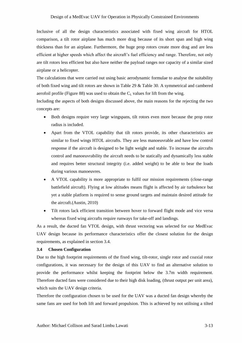
Most of the problems that arise are a result of the primary problem i.e. upstream inlet lip
separation in forward flight. In forward flight or crosswinds, the flow separates on the upstream
duct lip which distorts the inlet flow into the fan rotor (as shown in Figure 3 below). As a result of
this occurrence the thrust generation is reduced from the upstream side of the duct which gives
rise to asymmetric loading. The flow separation creates an imbalance in the fluid momentum
entering the duct at the leading and trailing edges which give rise to severe static pressure field
inside the duct leading edge and also the excess noise and vibrations from the fan rotor. The
power requirement and fuel consumption are also affected while trying to maintain the operational
requirements. All these factors make the standard ducted fan configuration very inefficient at
horizontal forward flight.(C. Camci, 2010)
Design of a MedEvac UAV for Operation in Physically Constrained Environments
Author: Sarad Limbu Lawati 4-15
Figure 3: Inlet flow separation (left) and
total pressure distribution (right)
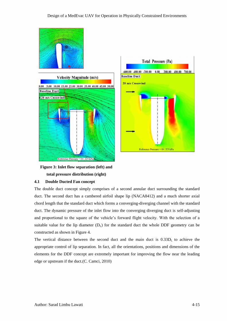
4.1 Double Ducted Fan concept
The double duct concept simply comprises of a second annular duct surrounding the standard
duct. The second duct has a cambered airfoil shape lip (NACA8412) and a much shorter axial
chord length that the standard duct which forms a converging-diverging channel with the standard
duct. The dynamic pressure of the inlet flow into the converging diverging duct is self-adjusting
and proportional to the square of the vehicle’s forward flight velocity.With the selection of a
suitable value for the lip diameter (DL) for the standard duct the whole DDF geometry can be
constructed as shown in Figure 4.
The vertical distance between the second duct and the main duct is 0.33DL to achieve the
appropriate control of lip separation. In fact, all the orientations, positions and dimensions of the
elements for the DDF concept are extremely important for improving the flow near the leading
edge or upstream if the duct.(C. Camci, 2010)

Design of a MedEvac UAV for Operation in Physically Constrained Environments
Author: Sarad Limbu Lawati 4-16
Figure 4: a) Standard duct b) DDF geometry with recommended dimensions(C. Camci,
2010)
Figure 5: Reduction in flow distortion in the leading and trailing edge for the selected
(CASE B) design (C. Camci, 2010)
The DDF configuration (CASE B) in Figure 5 shows improvement in pressure deficit of the
standard duct caused by the inlet lip separation. It also improves the thrust performance and
reduces the amount of pitching moment generated by the imbalance in total pressure or thrust
between the leading and trailing edge of the rotor (shown Figure 8).

Design of a MedEvac UAV for Operation in Physically Constrained Environments
Author: Sarad Limbu Lawati 4-17
Figure 6: Comparison of inlet flow/velocity magnitude between standard and DDF concept
at 20m/s (C. Camci, 2010)
Similar, to the flow accelerating over the top surface of an airfoil, the flow at the leading edge of
the secondary duct is accelerated and directed into the duct. This is possible because of the
positioning of the second duct at a height slightly above the standard duct. The fluid that enters
through the converging-diverging duct remains attached to the surface of the standard duct (due to
the nature of the whole arrangement) and automatically adjusts the dynamic pressure and fluid
momentum thereby, reducing flow distortion.
The DDF geometry improves the performance of the standard ducted fan in forward flight
conditions by maintaining low loss of mass flow rate which otherwise would have dropped by
33%. The mass flow rate on the standard duct alone drops very rapidly with increase in forward
flight velocity and suffers a high level of inlet flow distortion, Figure 7.

Design of a MedEvac UAV for Operation in Physically Constrained Environments
Author: Sarad Limbu Lawati 4-18
Figure 7: Rotor disk MFR versus forward flight speed(C. Camci, 2010)
Figure 8: Total Pressure distribution through duct (bottom) and at rotor
exit plane (top) for the standard and DDF types(C. Camci, 2010)
Ducted fans generate a greater static thrust compared to isolated propellers. The shroud provides a
supplementary safety feature by enclosing the high RPM rotating fan and also an option for

Design of a MedEvac UAV for Operation in Physically Constrained Environments
Author: Sarad Limbu Lawati 4-19
including noise treatments inside the duct. The fan produces lift vertically by drawing the air into
the duct. Altering the axial chord length of the standard duct has no change in the lift generated.
The air flow divides at a stagnation point at the ducts leading edge and the duct cross-section
behaves similar to an airfoil. Therefore the resultant lift vectors of the duct are strongly canted
towards the centre while the vertical lift components provide additional lift. This allows for
effectivethrustvectoringbyusingflapsattheduct’sexittogeneratethedesiredcontrol moments
to manoeuvre the aircraft(Anita I. Abrego, n.d.).
4.2 Stator Vanes & Flaps
The stators provide structural support to the duct and hub while also assisting to align the swirl
from the flow at the fan exit. The flaps are positioned at the end of the duct at a suitable distance
away from the centre of mass of the vehicle and help to generate the required control moments by
deflecting the flow at the exit by ± 40 degrees.
Figure 9: Stator Vanes and flaps
The stators have a specific design to achieve maximum noise reduction and are positioned within
2.5 -10cmfromthefantoremovetheexistingswirlintheflow.“Thestatorsareleaninaplane
of fan rotation and swept in a plane normal to fan rotation to create the optimum amount of noise
reduction in the ducted fan air-vehicle.” (Burdisso, 2010) Sweep is the axial displacement of
stator leading edge that varies span wise and lean is the circumferential displacement of the stator.
The angle of sweep on the stators should be between 0-20 degrees downward while a maximum
lean of 20 degrees in the direction of fan rotation (Figure 10 and Figure 11 respectively). These
orientations are important because opposite direction leads to increase in noise rather than its
reduction. The lean and sweep on the stator introduces a phase variation in the upwash velocity
which is responsible for the loud noise. The phase variation results in strong cancellation between
contributions to the noise field from different locations along the stator span.(Burdisso, 2010)

Design of a MedEvac UAV for Operation in Physically Constrained Environments
Author: Sarad Limbu Lawati 5-20
Figure 10: Span wise sweep on the stator vanes along its leading edge
Figure 11: Lean on stator vanes
5 Fan/Rotor design
The axial flow fan has 5 airfoil shaped blades (NACA 4412) and is 2 m in diameter with the hub
diameter of 0.6 m. The blade has a pitch of 30 degree at the hub and a gradual linear twist which
terminates at the blade tip at 15degrees. The fan blades generate lift similar to a wing generates
lift except the air flow over the blade root is lower compared to the blade tip because the
tangential velocity is greater at the blade tip than at its root. Therefore, the chord length and blade
pitch are gradually reduced towards the blade tip in order to remove variation in loads across the
blade’sspanwhichcouldgeneratehugedeflectiononthebladetipandaffecttheperformanceof
the fan. (Shown in Figure 90)
Reducing fan noise and vibration were important consideration for the design even though the
thrust requirements could have been achieved by changing the fan diameter and RPM. But a fan
with small diameter would have to spin at higher RPMs to generate the equivalent thrust and
would also increase the power requirement and noise and vibration. Conversely, a larger diameter
fan can generate the same thrust spinning at lesser RPM and also minimizing the noise levels but
requires more torque than power. Fan operating at higher RPM also give rise to design
complications: the blade tip speed operating at supersonic Mach speeds requires the blade design

Design of a MedEvac UAV for Operation in Physically Constrained Environments
Author: Sarad Limbu Lawati 5-21
to have sweep and smaller chord length to cope with the operating conditions. The noise level is
proportional to the tip speed, for a given pressure while also roughly proportional to the pressure
developed regardless of the blade type. Three of the fan laws below describe the relation between
fan speed, pressure, power and therefore noise levels.
1. The capacity is directly proportional to the fan speed.
2. The pressure (static, total, or velocity) is proportional to the square of the fan speed.
3. The power required is proportional to the cube of the fan speed. (BASF Corporation, n.d.)
Therefore, the tip speed of the fan blades has been limited to Mach 0.8 however the airfoil profile
(NACA 4412) for the blade operates fine in transonic conditions.
Figure 12: Complete Double Ducted Fan assembly
If the fan blade stalls during flight, it can be corrected by increasing the rotor speed or by reducing
the flight altitude which helps to regain the airflow. The variable pitch blades option was
discarded because there is other simpler solution.

Design of a MedEvac UAV for Operation in Physically Constrained Environments
Author: Sarad Limbu Lawati 5-22
Hub diameter was set to 30% of the total fan diameter which is a typical value.
The number of blades was chosen to be 5 because it provides better airflow stress distribution
properties (Figure 92). However, more than 5 blades can provide better airflow and thrust but
with added torque and power requirements.
Chord thickness (0.3 m) was determined by Equation 1.
Equation 1
Where, c = chord length; Dh = hub diameter and Nb = number of blades
TheSeparationgapbetweentherotorbladetipandtheductwassetto2%ofthefan’sradiusi.e.
0.02 m because it provides the best thrust coefficient value at the RPM the fan operates in, Figure
91.
5.1 Blade Element Theory (Leishman, 2006)
Figure 13: a) A strip of blade element b) Incident velocities and
aerodynamic environment at a typical blade element(Leishman, 2006)
The blade element theory was used to predict the thrust generated and power required for the fan.
The results show that the MedEvac UAV can hover at sea level with both the fans operating at
1800 RPM and is capable of cruising at 55 m/s at an altitude of 5000m at 2500 RPM.
The blade element theory predicts the performance of a propeller/fan by dividing the blade into a
number of independent sections along the length. Using a set of non-linear equations shown
below the values of thrust, torque and power can be calculated for each section and summed up to

Design of a MedEvac UAV for Operation in Physically Constrained Environments
Author: Sarad Limbu Lawati 5-23
get the whole value. The values obtained for these calculations are represented in Table 31: fan
Parameters to Table 35in the appendix.
In Figure 13 a) above R = blade radius; dy = blade element length
UR = radial velocity; UT = tangential velocity and U = resultant velocity
And in Figure 13 b) dL, dD and dM represent blade element lift, drag and moment respectively.
Θ=Bladepitchangle;α=angleofattack;φ=inducedangle of attack
Equation 2 Resultant velocity, √
Equation 3 Where,
Local plane resultant velocity on any element
Equation 4
Equation 5
Equation 6 √
Where, T = half of total thrust required and A = rotor disc area.
Assumptions made:
Constant lift curve slope, ao = 6.2832 /rad based on NACA4412 CL curve
Linear blade angle distribution (linear twist)
Near hub region (r < 0.37) of the fan blade does not generate thrust
Step-by-Step Calculation for Table 7:
Step 1
For each blade element
Equation 7 Calculate induced angle of attack, (
)
Where UT and UP are obtained from Equation 3and Equation 4
Step 2
Equation 8 Solidity of blades is given by,
Step 3
Bladepitchangle,θprovidedinTable 33 in radians.
Equation 9 Then, blade angle of attack,
Step 4
Equation 10 Coefficient of lift,
Step 5

Design of a MedEvac UAV for Operation in Physically Constrained Environments
Author: Sarad Limbu Lawati 5-24
Equation 11 Increment in Thrust,
Equation 12 Where element lift,
Equation 13
Where U is obtained from Equation 2 and c is the blade chord length
Step 6
Equation 14 Power increment,
Equation 15 Where,
And dL and dD are obtained from Equation 11and Equation 12
Step 7
Calculateelementthrust(∑T)andelementpower(∑P)requiredusing Trapezium Rule
Equation 16 ∫ ( )
( )
( ) ( )
Repeat Steps 1-7fortheremainingsectionsofthebladeandaddtogether(∑T)foreachsectionto
getthetotalthrustand(∑P)togetthetotalpowerforasingle blade. Multiply these values by the
number if blades (Nb) to obtain the thrust and power for the fan. Finally, multiply by 2 (because
two ducted fans) to obtain the total thrust Generated and Power required for the MedEvac UAV.
All Equation are obtained from Blade element analysis (Leishman, 2006)
5.2 Materials and Stress analysis
All the components of the DDF will be constructed from carbon fibre composites. Carbon fibre
composites are an extremely durable material and have high strength-to-weight ratio and stiffness,
thereby a strong light weight solution. The ultimate tensile strength for carbon fibre range
between 4130MPa-63 GPa where the higher strength limits are for carbon nano-tubes. The
material is stronger in the direction of the fibre and can be manufactured in different
configurations to optimize the strength, rigidity and other material properties such as high
temperature and corrosion resistance.(F. Li, 2000)
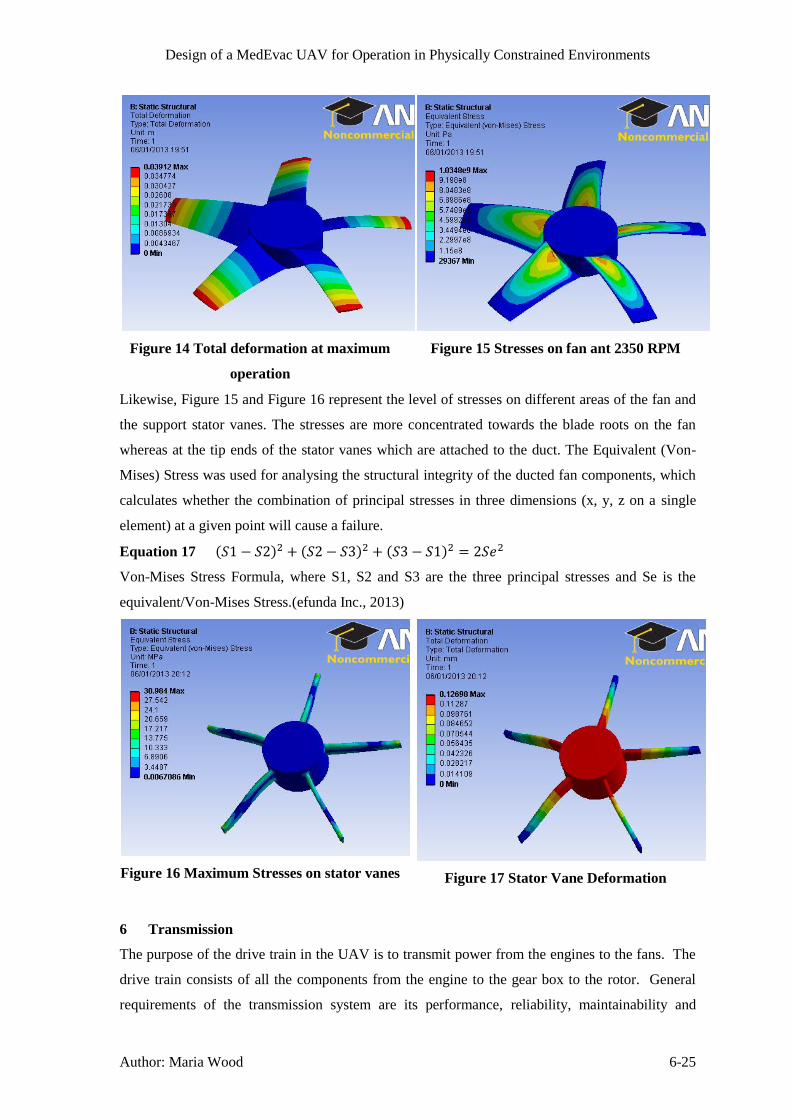
Figure 14 and Figure 17 below show the deformation on the Fan blades and Stator vanes
respectively at maximum operation (2350 RPM). The maximum deformations are on the fan
blade tips and in the hub on the stator vanes. These deformations are minimal and should not
hugely affect the performance of the ducted fan.
Design of a MedEvac UAV for Operation in Physically Constrained Environments
Author: Maria Wood 6-25
Figure 14 Total deformation at maximum
operation
Figure 15 Stresses on fan ant 2350 RPM
Likewise, Figure 15 and Figure 16 represent the level of stresses on different areas of the fan and
the support stator vanes. The stresses are more concentrated towards the blade roots on the fan
whereas at the tip ends of the stator vanes which are attached to the duct. The Equivalent (Von-
Mises) Stress was used for analysing the structural integrity of the ducted fan components, which
calculates whether the combination of principal stresses in three dimensions (x, y, z on a single
element) at a given point will cause a failure.
Equation 17 ( ) ( ) ( )
Von-Mises Stress Formula, where S1, S2 and S3 are the three principal stresses and Se is the
equivalent/Von-Mises Stress.(efunda Inc., 2013)
Figure 16 Maximum Stresses on stator vanes
Figure 17 Stator Vane Deformation
6 Transmission
The purpose of the drive train in the UAV is to transmit power from the engines to the fans. The
drive train consists of all the components from the engine to the gear box to the rotor. General
requirements of the transmission system are its performance, reliability, maintainability and

Design of a MedEvac UAV for Operation in Physically Constrained Environments
Author: Maria Wood 6-26
survivability. Performance considers the weight of the system, its efficiency, the size of the
system and the noise level produced.
To design the drive train of the UAV, first the torque required was calculated using Equation 18.
Equation 18
⁄
The Turbomeca Tm333 has a shaft output speed of 628.3 rad/s and a continuous power of 736 kW
which produces a continuous torque of 1171 Nm (Safran Turbomeca, 2010). For hover, the
required fan speed is 1750 rpm with a torque of 2500 Nm. For safe decent with one engine
inoperable, the maximum torque available at 736 kW and fan speed of 1750 rpm is 4016 Nm,
which is sufficient to overcome the torque of the fans. For cruise at 5000 m, the fans require a
torque of 4500 Nm at 2350 rpm. The engines are able to provide a maximum continuous power
of 1472 Nm at 2350 rpm fan speed which produces a maximum continuous torque of 5982 Nm,
sufficient to overcome the torque of the fans.
To reduce weight, the driveshaft shall be made from a high strength material such as carbon fibre.
As explained in section 26.3, two engines are required for redundancy purposes, therefore the
transmission must include a method to connect the drive of the engines together, since both
engines will be operating at the same time else there would be a lag time between an engine
failing and the second engine starting up. The propulsion is given by two ducted fans, which
require individual speed control to overcome unbalances in the pitch angle; therefore the fans
cannot be directly connected to the engines. Also, one engine cannot drive one fan, since if one
engine fails, the UAV cannot fly with one fan in operation.
6.1 Transmission Concept 1
The initial concept was to use a planetary gear box contained within the hub of each fan, as used
in the Chinook depicted in Figure 19. Planetary gears are often used in aircrafts due to their
compact structure and high torque to weight ratio (Dudley, 1984). Simple planetary gears consist
of a sun gear, planetary gears on a carrier and the ring gear as displayed in Figure 18. By
changing which gear is the input, the output or held stationary the output shaft speed can be
varied; this gives two forward gear ratios and one reverse gear ratio. Compound planetary gears,
as used in automatic vehicle transmissions, consist of two sun gears, two sets of planetary gears
and one ring gear; this gives four forward gear ratios and one reverse (Nice, n.d.). The advantage
of this gearbox is they offer a much larger gear reduction ratio; can transmit a higher torque and
can achieve more configurations (Guo, 2011). A reverse gear would not be necessary in this
application. Also, the fans only need to operate within a narrow speed range, between 1500 rpm
and 2500 rpm, therefore several gear ratios would not be required. Transition between gears
would not be smooth and it requires varying the speed of the engines. A progression from using
an epicyclic gear box is to include a split torque system to distribute the torque to allow for
smaller, lighter gears to be used, as in the Mi-26 Helicopter (Hameer, 2009). Epicyclic gear trains

Design of a MedEvac UAV for Operation in Physically Constrained Environments
Author: Maria Wood 6-27
are also known for high vibration levels (Guo, 2011) which can mean a short life time for the
gears and discomfort to the casualty within the UAV.
Figure 18: A schematic of a Planetary Gear set (Oriental Motor USA Corp., 2006)
Figure 19: The Chinook CH-47D Drive Train utilising planetary gearboxes for each rotor
(Company H, 4th Battalion, 7th Aviation Regiment, 2012)
6.2 Transmission Concept 2
The second concept looked into the use of continuous variable transmission (CVT). This would
allow a constant, smooth transition of the output speed of the fans, whilst allowing the engine to
operate at its most efficient condition. Some types of CVT also offer an infinitesimal range of
gear ratios which would allow both fans to operate at the required speed. There are several types
of CVT systems available; frictional types such as the variable diameter pulley CVT whereby the
drive pulley is made from two cones at a 20o pitch angle attached via a belt to the driven pulley
(Harris, n.d.). There is an inverse relationship between the diameter, D, of the pulleys and the
output speed, as expressed in Equation 19. Problems with frictional CVTs are their low
efficiency, low reliability, high weight, high vibration levels and lower power capacity, therefore
is unsuitable for this application.

Design of a MedEvac UAV for Operation in Physically Constrained Environments
Author: Maria Wood 6-28
Equation 19 (Hameer, 2009)
AnothertypeisthehydrostaticCVTwhich“transmitspowerthroughtheuseofhighpressureoil”
(Beachley & Frank, 1979). It utilises a hydrostatic pump to produce hydraulic power by
transferring the rotational motion of the engine to move fluid around a circuit to a hydraulic
motor, which transfers the pressure from the fluid into a rotational output. Output speed is varied
by altering the displacement of the fluid by changing the angle of the vanes within the pump
and/or motor. It can produce an infinite range of gear ratios (Beachley & Frank, 1979). Electric
systems are analogous to hydrostatic systems, except use an electric alternator and an electric
motor to vary the output speed by altering the either the frequency of current or the electric flux
(Renius, 2005). However they need complex controllers(Beachley & Frank, 1979) and are better
suited to hybrid or electric vehicles. Both these systems are used in heavy machinery, such as
tractors (Renius, 2005).
After analysing the common types of CVT, the hydrostatic system seemed the most appropriate
for integration into the UAV. A preliminary design can be viewed in Figure 20. A hydraulic
pump was connected to each engine which pumped the fluid around to a control point where the
fluid was then distributed between two hydraulic motors, each connected to a propulsion rotor.
The pumps were positive displacement pumps, to allow the engine to operate at its most efficient
condition. The motors were variable vane displacement, allowing the speed of the fans to vary.
The control point would also control the amount of fluid distributed to each motor, allowing the
fans to vary independently of each other. The configuration of the hydrostatic CVT allows for
one engine inoperable, and also for a fault in one of the hydraulic lines. It also eliminates the
need for drive shafts and gears. The disadvantages of this system are the size and weight of the
pumps and motors that would be required to transmit the torque required. This would also lead to
the necessity of a cooling system for the hydraulic fluid. Also, it is only a moderately efficient
system. However if further study was made into the hydraulic system so smaller pumps and
motors could transmit a higher power, there is the possibility for this to be an effective
transmission. It may also be more beneficial for a single rotor aircraft, since there would only be
a need for one pump and one motor.

Design of a MedEvac UAV for Operation in Physically Constrained Environments
Author: Maria Wood 6-29
Figure 20: The Preliminary Design of the Hydraulic CVT System
6.3 Transmission Concept 3
After establishing that the hydrostatic CVT drive train was not suitable for this application, the
necessity of having the ability to vary the speed of the fans independently was questioned. Since
this is only required to overcome the change in angle of the UAV, the difference in speed between
the fans does not have to be great. Therefore the possibility of controlling this through a
differential type gearbox system seemed possible. The benefit between this gearing system and
using a gear box is that only one set of gears is required. Also, there will be no jerk from a gear
change and continuous variation of engine speed through acceleration or deceleration.
Differential systems are widely used on vehicles to allow the rear wheels to rotate at differing
speeds whilst travelling around a corner. Open differentials consist of a gear driven from the
power source; pinion gears and side gears, as shown in Figure 21. When the fans on the UAV
need to operate at the same speed, the pinion gears do not rotate, Figure 21 a). However, when
there needs to be a difference in the speed of the fans, the pinion gear rotates, transferring more
power to one shaft than the other, but at the same torque so the speed of that fan increases, Figure
21 b). One issue with open differentials is they distribute the torque equally between the drive
axles, which, on poor terrain, can mean the vehicles wheel slips (Nice, n.d.); however this should
not be an issue for the UAV. Being a simple system, it allows for low maintenance and low
manufacturing costs. The differential will be controlled mechanically by a gyroscope that was
already selected for the UAV.

Design of a MedEvac UAV for Operation in Physically Constrained Environments
Author: Maria Wood 6-30
a) b)
Figure 21: Arrangement of a Differential Gear Box, a) the half shafts are rotating at the
same speed, b) the half shafts are rotating at different speeds (Wikipedia, n.d.)
6.4 Transmission Design
First, the maximum torque from the engines was calculated. The Turbomeca Tm333 has a
maximum power (One Engine Inoperable, OEI) of 910 kW (Safram Turbomeca, 2010) and the
minimum shaft speed the engine will operate at is 3600 rpm or 377 rad/s. Therefore the
maximum torque from the engines is 2414 Nm, calculated from Equation 18. There is a reduction
in speed between the engines and fans of ratio 2.4:1. Therefore the maximum torque output from
the gearbox at 910 kW and 157 rad/s is 5796 Nm. The reduction ratio of 2.4 was calculated from
a nominal engine rotation speed of 6000 rpm and maximum fan speed of 2500 rpm, which is a
reduction of 2.4.
The engines will connect to the main drive shaft via a spur gear drive train, which encompasses
the reduction gear. Since two engines are required, this seemed the most simple and efficient
method to connect both engines to the drive shaft. There will be an override clutch between each
engine and the spur gear should an engine fail, therefore power would not be wasted turning an
inoperable engine (Dreier, 2001). This configuration is typical for two engine helicopters as
depicted in Figure 22. The differential and drive to the fans will be a bevel gear train.
Figure 22: Typical Drive Train Arrangement for a Single Main Rotor Helicopter with Two
Engines (Dreier, 2001)
An initial design to the size of the gear required can be calculated by approxmating the teeth as
cantilever beams and determing the safe working stress, as used in the Lewis Stress Formula. The

Design of a MedEvac UAV for Operation in Physically Constrained Environments
Author: Maria Wood 6-31
Lewis Stress Formula for spur gears is given in Equation 20. The terminology of the spur gear
can be seen in Figure 93.
Equation 20 (Stokes, 1970)
The impact from the gears rotating can be included into this equation using the Barth Equation for
milled, hellical gears.
Equation 21 (RoyMech, 2011)
Where V is the Pitch Line Velocity and can be calculated from Equation 22.
Equation 22 (RoyMech, 2011)
This transforms the Lewis Equation to Equation 23.
Equation 23 (RoyMech, 2011)
The Lewis form factor for 20o pressure angle, full depth teeth is found from Equation 24.
Equation 24 (Stokes, 1970)
Tangential load on teeth is calcualted from Equation 25
Equation 25 (Stokes, 1970)
The module is defined as the ratio between the pitch diameter of the gear and the number of teeth
(RoyMech, 2011).
The differential and drive between the main drive shaft and fans will be transmitted via spiral
bevel gears. The terminology of the bevel gear is given in Figure 94. The Lewis Formula has
been modified to apply to bevel gears, Equation 26 .
Equation 26 (Stokes, 1970)
The lewis form factor is the same as Equation 24 , however the number of teeth used is
determined by finding the equivalent number of teeth on a spur wheel, Equation 27 .
Equation 27 (Stokes, 1970)
The main drive shaft has been calculated to minimise twist, Equation 28, and shear stress,
Equation 29.

Design of a MedEvac UAV for Operation in Physically Constrained Environments
Author: Maria Wood 6-32
Equation 28 (The Engineering Toolboox, n.d.)
(
) (
)
Equation 29 (The Engineering Toolboox, n.d.)
(
)
A schematic of the differential transmission arrangement is found in Figure 23. It was found that
the shafts from the bevel gear to the fan would not be required since the fan is at the correct height
to connect directly to the gear.
Figure 23: Differential Transmission Schematic for the MedEvac UAV
The gears will be manufactured from titanium alloy (Ti-8-1-1) since this has a high tensile stress
(1070 MPa) but lower density (4370 Kg/m3) than steel alloys commonly used, which is required
to keep the mass of the UAV as low as possible (Aerospace Specification Metals Inc., n.d.). This
material allows a minimum safety factor of 35% though the design of the gears, however it would
be preferable for this value to be higher. Due to the application of the UAV, noise and vibration
will have to be kept a minimum, therefore double helical gears will be used instead of spur gears
and spiral bevel gears replacing straight bevel gears, Figure 24. These gears are around 98%-99%
efficient.
Figure 24: Double-Helical Gear and Spiral Bevel Gear (Coord 3 Metrology, 2012)
The drive shaft shall be made from carbon fibre tube at fibre directions of (+/-450). The modulus
of rigidity for this material is 330 GPa, shear strength of 260 MPa and density 1600 kg/m3
(Performance Composites Ltd., n.d.). The angular shaft defelction has to be below that permitted

Design of a MedEvac UAV for Operation in Physically Constrained Environments
Author: Maria Wood 6-33
by support bearings. For bearings that would be suitable in this application, a maximum angular
defelection of 2o is permitted (RoyMech, 2011).
Table 1 displays the determined values for the gear train and drive shaft based on the equations
above. The pinion spur gear is attached to the shaft from the engine and the wheel spur gear is
attached to the main drive shaft. An iterative procedure was used to obtain the best design, the
cells highlighted portray the variables.
Table 1: The Design of the Gears used in the Transmission of the UAV
Pinion Spur Gear
Torque Transmitted [Nm] 2414
Angular Speed [rad/s] 377
Pitch line Velocity [m/s] 37.7
Pitch Circle Diameter [m] 0.2
Module [mm] 20
Number of Gear Teeth 10
Diametrical Pitch 50
Circular Pitch 0.06
Width of Teeth [mm] 200
Tangential Load on Teeth [N] 24140
Lewis Form Factor 0.063
Velocity Factor 7.18
Lewis Formula [MPa] 690.0
Volume [m3] 0.0027
Density [kg/m3] 4370
Mass [kg] 12.01
Wheel Spur Gear
Torque Transmitted [Nm] 9371
Angular Speed [rad/s] 157
Pitch line Velocity [m/s] 37.7
Pitch Circle Diameter [m] 0.48
Module [mm] 20
Number of Gear Teeth 24
Diametrical Pitch 50
Circular Pitch 0.06
Width of Teeth [mm] 200
Tangential Load on Teeth [N] 39046
Lewis Form Factor 0.116
Velocity Factor 7.18
Lewis Formula [MPa] 604.2
Volume [m3] 0.0327
Density [kg/m3] 4370
Mass [kg] 142.71
Bevel Gear
Torque Transmitted [Nm] 4686
Pitch Circle Radius [m] 0.18
Tangential Load [N] 26033
Outside Pitch Radius [m] 0.18
Inside Pitch Radius [m] 0.08
Mean Pitch Radius [m] 0.13
Lewis Form Factor 0.074
Tooth Width [m] 0.1
Diametrical Pitch 50
Circular Pitch 0.06
Number of Bevel Gear Teeth 18
Pitch Cone Angle [rad] 1.57
Number of Teeth Equiv Spur 11.46
Safe Working Stress [MPa] 593.0
Volume [m3] 0.0149
Density [kg/m3] 4370
Mass [kg] 65.31
Drive Shaft
Torque [Nm] 9371
Length [m] 2.5
Outer Radius [m] 0.075
Inner Radius [m] 0.06
Modulus of Rigidity [Pa] 3.30E+10
Twist [rad] 0.024
Twist [deg] 1.39
Shear Stress [MPa] 23.95
Volume [m3] 0.016
Density [kg/m3] 1600
Mass [kg] 25.45

Design of a MedEvac UAV for Operation in Physically Constrained Environments
Author: Michael Collison 8-34
The total mass of the system is 675 kg, which is much higher than anticipated, even with the use
of high strength to weight materials. This mass of the gear system was not used in the propulsion
calculations, therefore will require consideration in the future design of the MedEvac UAV. This
transmisison design also requires consideration of the lubrication system, gear housing and
bearing design.
7 UAV dimensions
The exterior dimensions of the UAV were determined mainly from the size of the casualty
stretcher, (2.29 m x 0.58 m) and the duct diameter from fan diameter, section 5, to give sufficient
thrust. Therefore the width of the cabin cross section was determined as 2.5m to match the duct
size, and the height of the cabin cross section was chosen as 1.5m to give sufficient head room for
the casualty and to also allow room for the engines and other equipment. The length of the cabin
section was chosen to be 2.5m to allow the casualty stretcher to be placed longitudinally, therefore
the UAV length totals approximately 7.5m.
8 Structures
The structural elements of the UAV are chosen to have a similar layout to that of a semi-
monocoque aircraft fuselage which uses the combination of the skin, frames and stringers to resist
the forces from pressurisation and bending moments and maintain the fuselage shape. In the
following sections the structural analysis is undertaken for an UAV mass of 1500kg which was an
initial estimate, the structural mass will then be iterated using mass fractions to obtain the final
UAV mass.
8.1 Main Spar
In the case of this UAV, there are strong longitudinal bending moments produced by the fans on
the cabin, somewhat like a wing on a standard aircraft; two I-beam main spars will run the length
of the cabin section between the two fans in order to handle these loads, and the spars will meet as
they follow the circumference of the ducts at either end to add further structural rigidity. The free
body diagram of the level flight condition is shown in Figure 25 from which the maximum shear
force and bending moments were found to be 16.6kN and 3.72x10⁷Nmm respectively using a load
factor of 2.25 from 1.5 for maximum thrust and 1.5 for g number, as well as 4500mm for L which
is the distance between centres of both fans.

Design of a MedEvac UAV for Operation in Physically Constrained Environments
Author: Michael Collison 8-35
Figure 25: Free Body Diagram and Maximum Bending Moment and Shear Force
A particular I-beam section is then chosen to handle these loads with a second moment of area of
1.13x107mm
4 and a cross sectional area of 1390mm
2. The maximum shear stress, Equation 30,
and compressive/tensile stress, Equation 31, can then be found using beam bending theory.
Equation 30
Equation 31
The spars are to be made from aluminium alloy 7075-T6 because of its high strength and
toughness properties; this material has a yield strength and shear strength of 503N/mm2 and
331N/mm2 respectively, with a density of 2810kg/m
3. Therefore comparing the maximum stresses
in the spar with the material strengths there is a safety factor of 2.4 in yield and 27.9 in shear
which are satisfactory. The length of I-beam required is twice the straight length plus the fan
circumference, giving a length of 16.1m, which combined with the beam cross sectional area and
material density, gives a mass for the I-beam spar of 62.9kg.
8.2 Skin and Bulkheads
Due to the requirement that the cabin needs to be pressurised for the casualty and equipment, from
a structural point of view the elliptical cross section can be treated as a pressure vessel. Typically
a cabin needs to be pressurised to an altitude of 2440m (8000ft) at which the ambient pressure is
0.0753N/mm2, whereas at the UAV ceiling of 5000m the ambient pressure is 0.0540N/mm2;
However due to the medical requirements of the patient it is more beneficial to pressurise the
cabin to sea level (0.101N/mm2) which gives a pressure differential of 0.0473N/mm
2 which will
produce longitudinal and hoop stresses which for the elliptical section are calculated from
Equation 32and Equation 33 using standard pressure vessel relationships, noting that the highest
hoop stress will occur at the sides of the cross section due to the higher radius of curvature in that
region.
Equation 32
Equation 33
L T=W/2
W
T=W/2

Design of a MedEvac UAV for Operation in Physically Constrained Environments
Author: Michael Collison 8-36
The skin thickness was chosen as 1mm mostly due to it being the minimum gauge to resist
indentations, because the pressurisation stresses were not significant with a minimum safety
factor of 4.8 on the yield stress of 345N/mm2 for the aluminium alloy 2024-T3, which was
chosen for the skin as it is generally used on pressure critical skins. The same skin will be used for
the ducts and bulkheads (which are at each end of the cabin) as well as the cabin, and therefore
using an estimate of the total surface area and the 2024-T3 density of 2780kg/m3 the skin mass is
estimated to be 128kg and the bulkhead mass to be 20kg. These skin and bulkhead estimations
also include a 10mm layer of insulating foam material with a density of 100kg/m3 around the
casualty cabin section to shield the casualty from external noise and temperatures. Because the
main spar is deemed to carry all the bending moments produced by the fan an analysis of these
moments on the skin is not carried out here.
8.3 Frames and Stringers
In order to help hold the shape of the cabin and ducts, as well as to prevent catastrophic failure of
the skin in the event of a local skin failure, a series of cross sectional frames and longitudinal
stringers are used to stiffen the structure. These frames and stringers are made from 2024-T3
aluminiumalloywith a ‘C-section’, side length of 10mmand awall thickness of 1mm. In the
cabin section the frame spacing is 250mm and the stringer spacing is approximately every 400mm
around the circumference so that the pillowing of the skin between each set of frames and
stringers is kept to a minimum. This effective sectioning of the skin also means that if a puncture
to the skin occurs, for example from a bullet, then the skin will only tear and fail in that section,
meaning that the structural integrity is retained, though the cabin will depressurise. In the
unpressurised duct regions, there are much less forces on the skin and therefore the spacing of the
frames is increased to 500mm and there is only a stringer on the top and bottom extremes.
Therefore the total length of frames and stringers can be estimated, from which using the C-
section cross sectional area of 28mm2 and the density of the material, the mass of the frames and
stringers can be estimated as 11.6kg.
Furthermore, any cut-outs in the skin for reasons such as landing gear hatches, engine intakes and
doors reduce the strength of the skin. Therefore strengthening frame follows the edges of these
cut-outs which diverts the skin stresses along the frames so that the skin can continue to function
against the loads. The cut-out frames have the same properties as the normal frames, but with
double wall thickness of the C-section, and therefore their mass is estimated as 1.0kg which
covers the landing gear, door, engine intakes and engine exhaust cut-outs.
8.4 Floor and Ceiling
Using the initial mass estimates, it was determined that the floor and ceiling would have to carry
masses of 319kg and 762kg respectively. For the purposes of this analysis these loads were
deemed to be evenly distributed over the rectangular surface areas, therefore a constrained edge,
uniformly loaded, rectangular plate stress analysis can be undertaken as described below.

Design of a MedEvac UAV for Operation in Physically Constrained Environments
Author: Michael Collison 8-37
Figure 26: Constrained and Uniformly Loaded Rectangular Flat Plate Stress Analysis
(Beardmore, 2011)
In order to effectively handle these loads a sandwich panel is used with CFRP skins and the same
insulating material as discussed in 8.2 as the core. For the purposes of this analysis only the
thickness of the CFRP is considered due to the core having negligible strength; the CFRP has a
Young’sModulusof400GPa and a density of 1800kg/m3. Therefore the thickness of the skins is
determined by specifying a maximum centre deflection of 5mm, and then the maximum stress can
be calculated from this thickness, a summary of the results is shown in Table 2.
Table 2: Properties of the Floor and Ceiling
p (N/m2) a (mm) b (mm) t (mm) σm (N/mm
2) ym (mm)
Floor 0.92x10⁻³
2500 1360 3.5 69 5
Ceiling 1.55x10⁻³
2500 1930 6 67 5
The mass of the floor and ceiling can then be calculated from the CFRP and core thicknesses and
densities, (note the core thickness is again 10mm), giving the floor mass as 24.8kg, and the ceiling
mass as 56.9kg.
8.5 Landing Gear
The first component of the landing gear is the vertical strut, which is required to be 400mm in
length to give sufficient clearance for the UAV and tyres. To determine the required diameter of
the strut it is necessary to consider the buckling and yielding failure modes when it is assumed the
whole UAV mass is transferred through one strut with a load factor of 2, for example in a rough
landing, which equates to a load of 29.4kN. Therefore using a 28mm diameter, 1mm thin wall
tube, the critical buckling load can be calculated from Equation 34.
Equation 34
With the strut made out of high strength steel, which has a yield strength of 2000N/mm2 and
Young’sModulusof210GPa,theyieldstresscanalsobecalculatedfrom Equation 35.
Equation 35
This means the safety factors in buckling and yield are 4.3 and 5.7 respectively. Using the
maximum mass on each tyre of 3000kg (6600lb), suitable tyres can be selected that can withstand

Design of a MedEvac UAV for Operation in Physically Constrained Environments
Author: Michael Collison 8-38
this mass; using (Goodyear, 2002) the 504T41-2 type tyre was chosen which has a diameter of
337mm, a width of 128mm, and a mass of 2.9kg each. Therefore assuming that the landing strut
length is doubled for a supporting strut, the landing gear strut mass is 2.7kg, with the four tyres
being 11.6kg.
8.6 Miscellaneous
The remaining structural weight such as the fan hubs and stators are not calculated in this report,
but are estimated at 35kg for the purposes of mass iteration.
8.7 Cabin Door
The cabin door is deemed to not require any extra structure, however due to its large area it will
require a solid securing system so that it doesn’t weaken the pressure vessel, a securing
mechanism similar to aircraft doors is suggested here which has multiple automatically securing
latches. To allow good access for loading/unloading the casualty, the cabin door will be the length
of the cabin section and its height will be between the floor and ceiling; when opened it can rotate
down to rest on the floor as shown in Figure 27.
Figure 27: Cabin Door Open
8.8 Structural CAD Representation
Figure 28 below shows the layout of the cabin structural elements, without the skin shown so that
the other elements can be seen.
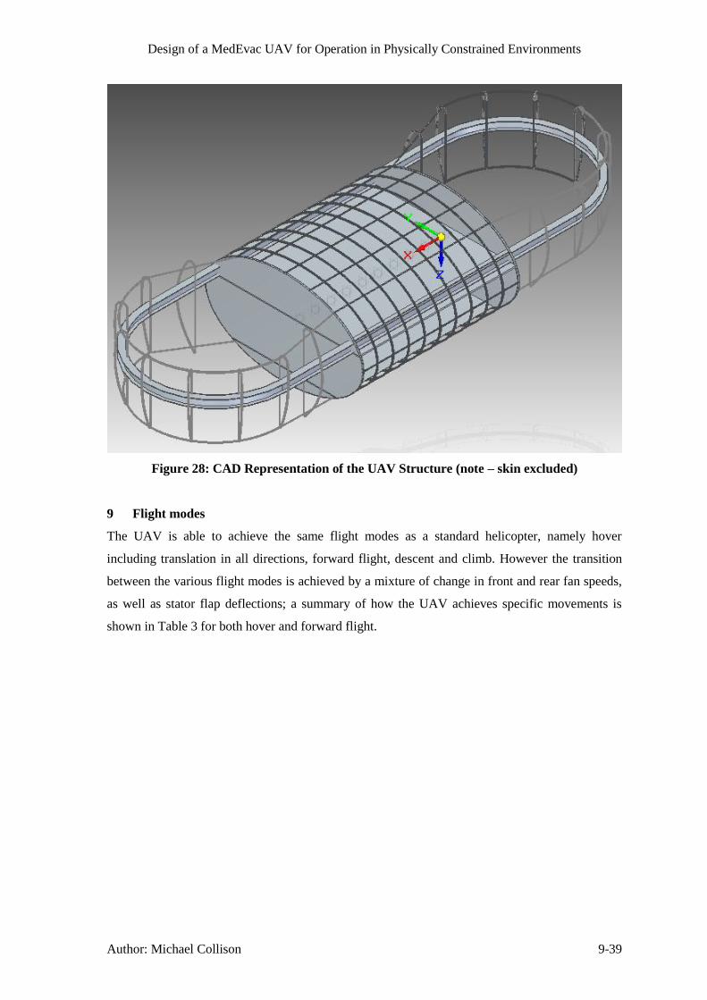
Design of a MedEvac UAV for Operation in Physically Constrained Environments
Author: Michael Collison 9-39
Figure 28: CAD Representation of the UAV Structure (note – skin excluded)
9 Flight modes
The UAV is able to achieve the same flight modes as a standard helicopter, namely hover
including translation in all directions, forward flight, descent and climb. However the transition
between the various flight modes is achieved by a mixture of change in front and rear fan speeds,
as well as stator flap deflections; a summary of how the UAV achieves specific movements is
shown in Table 3 for both hover and forward flight.

Design of a MedEvac UAV for Operation in Physically Constrained Environments
Author: Michael Collison 10-40
Table 3: Methods of Flight Movement
Hover Forward Flight
Translation Longitudinal and spanwise
stator flaps deflection to
translate whilst in hover.
N/A
Roll Duct side wall deflection to maintain level flight and to correct
any undesirable roll moments, such as from cross winds.
Pitch Use of main shaft differential combined with engine speed
adjustments as necessary to achieve front and rear fan rpm
difference to maintain level flight and to correct any undesirable
pitch moments, such as from wind gusts or duct drag.
Yaw Opposite deflection of front and rear fan longitudinal stator flaps
to correct any undesirable yaw moments. Also allows
directional control in hover and forward flight.
Acceleration/Deceleration N/A Deflection of both front and
rear spanwise stator flaps
backwards (acceleration) or
forwards (deceleration).
Climb/Descent Change in both front and rear fan speeds by increasing (climb),
or decreasing (descent) engine rpm output. Can be used for axial
climb/descent and also in combination with forward flight.
Note that all flight movements described in Table 3, involving stator flap deflections require an
increase in both fan speeds (see climb/descent), in proportion to the level of deflection required,
as the thrust vector is altered from vertical and thus the increase is needed so as to maintain the
same magnitude of lift force.
Potentially the most troublesome flight mode of the UAV is the transition to forward flight from
hover. This transition would be achieved by gradual simultaneous increase in both stator flap
deflection and fan speeds to provide a component of the thrust vector in the forward flight
direction, and to maintain the vertical component at a constant level respectively. Any undesirable
effects of the manoeuvre, such as roll, pitch or yaw moments will be corrected as described in
Table 3.
10 Drag Estimation
Due to the clean shape of the UAV, it was modelled as fuselage body for drag estimation
purposes, with the length of the body estimated as the distance between the midpoint of the two

Design of a MedEvac UAV for Operation in Physically Constrained Environments
Author: Michael Collison 11-41
fans, due to the presence of the fans removing surfaces from the body that would otherwise be
prone to drag. Based on this characteristic length and the kinematic viscosity at 5000m ISA of
2.21x10⁻⁵
the Reynolds number of the aircraft at its design cruise speed of 200km/h (55m/s) was
calculated as 1.12x10⁷. From this Reynolds number the friction coefficient can be estimated using
(Roskam, 1971, p. 3.9) as 0.0028, this value of friction coefficient is solely based on the Reynolds
number which is defined from the worst case scenario – notably the maximum cruise altitude,
however the Reynolds number, and hence skin coefficient values are largely unaffected by the
range of altitudes; therefore the value of 0.0028 and the corresponding CD value are used
throughout the drag analysis at all altitudes and flight speeds.
The drag of the aircraft is deemed to be solely due to the fuselage body, due to the fans not
directly seeing the oncoming flow, therefore the drag coefficient is equal solely to the parasitic
drag, as the fuselage body produces no induced drag, CD=CD0. The parasitic drag coefficient of a
fuselage body can be estimated following the process defined in (Raymer, 1992, p. 283) to
include both the skin friction and form drag, by means of a form factor, FF, which is calculated
from Equation 36 and Equation 37. In order to calculate the form factor and drag coefficient it is
also necessary to calculate the wetted area and frontal area of the UAV. The frontal area was
simply taken as the maximum cross sectional area that the flow sees, equivalent to the fuselage
elliptical cross section as 2.95m2. The total wetted area was taken as the external surfaces of the
fuselage, and was determined from the CAD model as 22.9m2. The fineness ratio is also required
to calculate the form factor, and is equal to the length divided by the cross section diameter.
Equation 36
Equation 37
This form factor is then used with the friction coefficient, wetted area and frontal area to calculate
the parasitic drag coefficient, Equation 38.
Equation 38 (
)
11 Power requirements
The power requirements of the UAV have three components, induced power to provide the thrust,
the power required to maintain forward flight, and the blade profile power to overcome the drag
of the fan blades; any excess power can be used for climb.
11.1 Induced Power
The power required to maintain forward flight is modelled as an increase in induced power by
requiring an increased amount of thrust, due to there being no vertical air flow speed because of
the aircraft flying level even in forward flight. At each flight speed, the equivalent thrust is
calculated from the horizontal force required to overcome the drag at that constant flight speed

Design of a MedEvac UAV for Operation in Physically Constrained Environments
Author: Michael Collison 11-42
(TH=D) and the vertical force to overcome the UAV weight (TV=W). The equivalent thrust
required and the stator flap deflection required to achieve that thrust can then be calculated using
Pythagoras’theorem,asshownbelow:
Figure 29: Diagram of Fan Thrust Components
Equation 39 √
Equation 40 (
)
This configuration means that there is a maximum amount of horizontal thrust that can be
produceddependentonthestatorflapangle,θ,andtheverticalthrustrequiredwhichisequalto
the weight of the UAV in level flight. Therefore the maximum horizontal thrust available in level
flight is defined with the maximum take-off weight of 1350kg and the maximum stator flap
deflection angle of 40°, Equation 41.
Equation 41
The effects of this maximum horizontal thrust on the maximum attainable flight speeds are
discussed in Section 11.4.
To calculate the induced power requirement based on the required thrust, a helicopter approach is
used as described in (Leishman, 2006, p. 83), with the adjustment that a ducted fan consumes a
factor of √ less power than an open rotor (Leishman, 2006, p. 323). The induced power
required is then related to the induced velocity, vi, including an efficiency factor, k, to account for
non-ideal losses, Equation 42and Equation 43.
Equation 42 √
Equation 43
⁄
√
√
Where the area used in the above equation is determined from the fan diameter, scaled by a tip
loss factor, B, minus the hub area which for ducted fans have a diameter of 0.3 times the fan
diameter section 4; therefore using a tip loss factor 0.98 for the ducted fan due to the presence of
the duct reducing the effect of the tip loss vortices the equivalent disk area is given by Equation
44.
Tequiv TV
TH
θ

Design of a MedEvac UAV for Operation in Physically Constrained Environments
Author: Michael Collison 11-43
Equation 44
For the 2m diameter fan chosen for the UAV, this gives a disk area of 2.73m. It should be noted
that the induced power requirement increases with respect to both altitude, due to decreased air
density, and forward flight speed, due to increased equivalent thrust requirement. Furthermore the
result of this simplification is very close to the actual result using blade element theory.
11.2 Blade Profile Power
The power required to overcome the fan blades drag is calculated using aerofoil theory, where for
the purposes of this analysis the fan blade is treated as having constant properties throughout its
length. Therefore assuming the blade is rectangular in platform, and the drag coefficient of the
blade aerofoil is constant, then the blade profile power for each fan can be calculated as in
(Leishman, 2006, p. 69), where Nb is the number of blades, c is the blade chord, and R is the blade
radius.
Equation 45
The angular velocity for the purposes of this analysis was determined from the maximum rpm
required of 2350, and the other values are fixed as described in section 5.
11.3 Total, and Available Power Analysis
The total power required was then calculated by summing the induced power and blade profile
power at a range of altitudes and flight speeds. Using the fixed parameters and the estimated
maximum take-off weight, the most demanding power requirement is found at the cruise speed at
5000m altitude. In order to choose the turboshaft engines with the correct power rating, it was
determined that it was necessary for one of the two engines to be able to continue this mode of
flight for a short amount of time. This is known as One Engine Inoperative (OEI), and the
selected Turbomeca TM333 engines have various OEI ratings each referring to a different time
period for which the single engine can safely be used at this power rating without the need for
maintenance action; a summary of the power ratings of the Turbomeca TM333 is shown in Table
4.
Table 4: Turbomeca TM333 Power Output Data (Turbomeca, n.d.)
All engines operative, maximum continuous power 736kW
One engine inoperative – power for 30 minutes 807kW
One engine inoperative – power for 2 minutes 841kW
One engine inoperative – power for 30 seconds 910kW
These engine powers are then calculated at a range of altitudes by using the ISA pressure and
temperature ratios at each altitude using the relationship as described in Equation 46 (Leishman,

Design of a MedEvac UAV for Operation in Physically Constrained Environments
Author: Michael Collison 11-44
2006, p. 232) where PMSL is the power available at sea level and Palt is the equivalent power at
altitude.
Equation 46 (
) (
⁄
⁄)
11.4 Flight Envelope
Combining the available power curves at each altitude with the required power curves at each
altitude to maintain hover and for cruise (55m/s) gives the results as shown in Figure 30.
Figure 30: Available and Required Power against Altitude
It can be seen from Figure 30 that in the event of an engine failure, even the most demanding
flight regime of 55m/s flight at 5000m can be maintained for 30 seconds, and therefore this
altitudeistakenastheUAV’sceiling, despite it being able to achieve a ceiling of 8400m when
both engines are operating normally. However it can also be seen that the engine cannot provide
the amount of power required to maintain this flight mode for a prolonged period of time, and
therefore to maintain the flight speed the UAV must descend to 4500m within 30 seconds of the
0 1000 2000 3000 4000 5000 6000 7000 8000 9000 10000200
400
600
800
1000
1200
1400
1600
altitude (m)
pow
er
(kW
)
Cruise (55m/s) Power Req
Hover (0m/s) Power Req
OEI 30sec Power Available
OEI 2min Power Available
OEI 30min Power Available
AEO max. cont. Power Available

Design of a MedEvac UAV for Operation in Physically Constrained Environments
Author: Michael Collison 11-45
engine failure and to 4000m within 2 minutes so as to not damage the engines and maintain a safe
flight. Even taking these precautions in to account, it is advisable to land the UAV within 30
minutes, as the risk mitigations are reduced.
By using the OEI power availability case to determine the flight envelope, as described above for
the ceiling classification, the rest of the flight envelope in terms of maximum speeds at each
altitude can be determined. The maximum speed at each altitude is either restricted by the power
available, or by the maximum thrust available to counter drag. The maximum speed due to drag
restrictions can be calculated using the drag equation and the value of the drag coefficient
presented in Section 10, but instead using the maximum available horizontal thrust as the value
for drag, and then solving for forward flight speed, Umax, as shown in Equation 47.
Equation 47 √
The results of this analysis are summarised in Figure 31 which shows that the flight envelope to
allow safe transition to OEI operation gives a maximum attainable forward flight speed of
approximately 71m/s (256km/h) at 4500m. At this altitude of 4500m, the UAV is therefore able to
achieve higher flight speeds, more equivalent to those delivered by helicopters. Therefore it is
desirable to fly at higher altitudes in terms of achieving a faster forward flight speed, however in
terms of operational risks this may not be advisable as it will be easier for the enemy to identify
and attack the UAV. It can also be seen that at SL the maximum speed is 57m/s (205km/h), with
the maximum speeds being restricted by drag up to 4500m, after which the maximum attainable
speed falls rapidly to zero due to OEI available power restrictions.
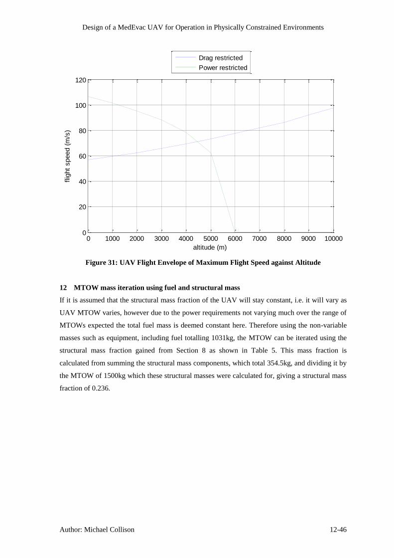
Design of a MedEvac UAV for Operation in Physically Constrained Environments
Author: Michael Collison 12-46
Figure 31: UAV Flight Envelope of Maximum Flight Speed against Altitude
12 MTOW mass iteration using fuel and structural mass
If it is assumed that the structural mass fraction of the UAV will stay constant, i.e. it will vary as
UAV MTOW varies, however due to the power requirements not varying much over the range of
MTOWs expected the total fuel mass is deemed constant here. Therefore using the non-variable
masses such as equipment, including fuel totalling 1031kg, the MTOW can be iterated using the
structural mass fraction gained from Section 8 as shown in Table 5. This mass fraction is
calculated from summing the structural mass components, which total 354.5kg, and dividing it by
the MTOW of 1500kg which these structural masses were calculated for, giving a structural mass
fraction of 0.236.
0 1000 2000 3000 4000 5000 6000 7000 8000 9000 100000
20
40
60
80
100
120
altitude (m)
flig
ht
speed (
m/s
)
Drag restricted
Power restricted

Design of a MedEvac UAV for Operation in Physically Constrained Environments
Author: Michael Collison 13-47
Table 5: MTOW and Structural Mass Iteration
MTOW Non-Variable
Structural = 0.236 x
MTOW
1500 1031 354
1385 1031 327
1358 1031 320
1351 1031 319
1350 1031 319
1350 1031 319
Therefore from Table 5 it can be seen that the iteration converges to giving an MTOW of 1350kg,
and structural mass of 319kg. This MTOW will be used for further analysis.
13 Operational Flight Profile
13.1 Acceleration
The acceleration of the UAV is important for two reasons, the first being that it is desirable to get
to the maximum flight speed as quickly as possible to get out of the danger area rapidly, and the
second being that if the acceleration is too high, then the g forces imparted on the casualty may
inhibit their recovery and any medical procedures that are being undertaken. Therefore a
maximum limit of 1.25g was imposed on the flight profile, which means that the acceleration to
maximum flight speed must be gradual; the profile of speed, acceleration and g were calculated
against time from a stationary start as shown in Figure 32, with the thrust linearly increased from
zero to maximum over a period of 40 seconds. The acceleration at each epoch was calculated
using the difference in thrust and drag at each epoch, divided by the UAV mass.

Design of a MedEvac UAV for Operation in Physically Constrained Environments
Author: Michael Collison 13-48
Figure 32: Speed, Acceleration and g Number Profile Against Time at Sea Level
It can be seen from Figure 32 that it takes approximately 50 seconds for the UAV to reach its top
speed at sea level, with the maximum g at approximately 1.22. The Flight Control System (FCS)
would be designed to accelerate as quickly as possible whilst adhering to this g limit.
13.2 Climb Performance
The climb performance of the UAV can be simply modelled by taking the excess power in any
flight condition and dividing it by the weight of the aircraft for the maximum rate of climb; if the
available power is less than the required power to maintain level flight then the climb rate is
negative (i.e. a descent). If the performance is considered with all engines operative, with which
the minimum excess power is 400kW, then in all regions of the flight envelope the UAV is
capable of climb rates up to 30m/s. However, as for the forward acceleration the acceleration to
the climb rates needs to be kept within the 1.25g boundary, this means that the acceleration to this
climb velocity needs to take place over 20 seconds, with the maximum climb velocity being
achieved within approximately 30 seconds. This climb rate is significantly higher than a typical
0 10 20 30 40 50 60 700
20
40
60
time (s)
forw
ard
flig
ht
speed (
m/s
)
0 10 20 30 40 50 60 700
1
2
3
time (s)
accele
ration (
m/s
2)
0 10 20 30 40 50 60 701
1.1
1.2
1.3
1.4
time (s)
g n
um
ber

Design of a MedEvac UAV for Operation in Physically Constrained Environments
Author: Michael Collison 13-49
helicopter climb rate of around 8m/s, however if the excess power available to climb is limited to
100kW due to the possibility of OEI operation, then the maximum climb rate is 7.5m/s, which is
more comparable to helicopters. At higher altitudes the excess power decreases and ergo so does
the maximum achievable climb rate, until the service ceiling where climb rate is zero. It follows
from the above analysis that in order to descend at 7.5m/s then the power produced should be
100kW less than the power required for level flight.
13.3 Overall Mission Profile
The UAV Gross Still Air Range (GSAR) of 299km can be used for two distinctly different typical
mission profiles assuming that the UAV can be transported on the ground before it is used. The
first option is to have a mission radius of 100km from the main medical base, or the second option
would be to take the UAV to the battlefield if it is greater than 100km away from the base so that
it only has to fly one way virtually. The second option effectively increases the mission radius of
the UAV to around 250km and it also verifies that the MTOW should include the maximum fuel
mass and casualty mass together. However this second option would be difficult to employ widely
as it would need a UAV and the supporting ground transport team for each battlefield, but there
would be occasions where this mission profile would be beneficial such as distant battlefields
which are expected to incur casualties. Also the 250km distance will take more than an hour to
cover even at top speed, therefore the UAV could be used to just take the casualty to an
intermediate manned medical vehicle (either helicopter or truck) so that human intervention can
be given quicker whilst the UAV is still used to avoid the extraction danger; or alternatively if it is
deemed safe to do, or there is no other option the casualty could be flown the 250km back to the
medical base as there will be immediate medical action provided due to the UAV being at the
scene of battle.
The actual profile of any flight will be such that the UAV will always be fully fuelled, medically
supplied, and ready to depart with a ground control mission commander and ground control medic
on standby at all times. When a call is received the mission commander will input the location to
be flown to and return to and tell the UAV to depart. At this point the UAV will use its LIDAR
system to avoid obstacles, whilst the FCS allows the fully automated flight to the selected
location. The flight will typically consist of a small time climbing and increasing forward flight
speed to the maximum, then cruising at this speed to the target location, upon reaching which the
UAV will spend a small time decelerating to a hover before automatically detecting a suitable
landing zone and descending to it. The casualty will then be loaded with engines idling to allow a
quick turnaround and the above process will be repeated to fly to the return location. Although
flying at higher altitudes allows for increased flight speeds as discussed in Section 11.4 in order to
avoid enemy detection as much as possible the height flown above the local terrain will be kept to
a few hundred metres, furthermore if there are known danger areas on the route then the mission
commander may add waypoints to the flight path so as to avoid these areas.
Design of a MedEvac UAV for Operation in Physically Constrained Environments
Author: Michael Collison 14-50
14 Performance
14.1 Disk Loading
The disk loading of the UAV is calculated by dividing the weight of the aircraft by the equivalent
area of the fan disks as shown in Equation 48.
Equation 48
Comparing this value to data of other helicopters in Table 28, it can be seen that it is a lot higher
than the average value of 252N/m2, however it is in the range of the ducted fan aircraft, especially
the Urban Aero Airmule (2710N/m2) which is a similar style of aircraft; The other ducted fan
aircraft have disk loadings up to 6300N/m2, this shows that the disk loading of the UAV, whilst
high, is not at an unphysical level.
14.2 Range
Specification point 46.1.1 gives a 100km mission radius requirement which equates to a minimum
GSAR of 200km, but more ideally 300km to allow for landings, take-offs, and any indirect
routings.FirstlythesizeoftheUAV’sfueltankswascalculatedtoachievea300kmGSARatan
average power consumption of 360kW per engine, which was determined from the average of the
sea-level equivalent power for cruise flight at 0m (264kW per engine) and 5000m (455kW per
engine) altitude, taken from Figure 30. Noting that the value of specific fuel consumption (SFC)
varies with power as shown in (Leishman, 2006, p. 232) from the TM333 maximum continuous
power reference value of 0.322kg/kWhr (Meier, 2005), and that the fuel mass flow rate varies
linearly with power from the reference value of 119kg/hr, it is possible to calculate the SFC at any
power as follows, shown here for the 360kW case:
Equation 49 (
) (
)
Equation 50
Where a and b are constants dependent on the engine, and here are modelled as 50 and 0.5
respectively to give the SFC-power curve the same shape as that described above. Using this
value of SFC the fuel mass value can be calculated to obtain a 300km GSAR from Equation 51.
Equation 51
If the fuel mass flow rate and SFC are plotted for this engine it can be seen from Figure 33 that
although the engine runs less efficiently (with a higher SFC) at power outputs below its
maximum, because the fuel mass flow rate reduces linearly the maximum range actually increases
with reduced power from the same quantity of fuel; range is calculated by re-arranging Equation
51.

Design of a MedEvac UAV for Operation in Physically Constrained Environments
Author: Michael Collison 15-51
Figure 33: Variation of Fuel Mass Flow Rate, SFC and Range with Engine Power
It can be seen that a range of greater than 200km is achievable for all engine powers below
800kW, which means that under all normal flight conditions with all engines operative this range
is achievable by the UAV.
14.3 Centre of Gravity & Stability
In order for the UAV to be stable in flight it is necessary for the centre of gravity (CG) of the
UAV to be at or near to the midpoint between the two fans. With the UAV being mostly
symmetrical about this mid-point this is not a big issue, as the extra front mass of the 2nd
duct can
be offset by moving the engines slightly aft. The main issue is maintaining the CG throughout the
flight, as fuel is burnt, and also if there is a casualty loaded or not. To mitigate the effects of these
variable masses, it was decided to ensure that the CG of these components is at the desired CG of
the UAV; hence the fuel tanks and casualty position are centred around the UAV CG so that as
their masses vary there is no change in the global UAV CG.
15 Processors
There are several options for the type of processors that could be used for this type of aircraft.
These range from Application Specific Integrated Circuits (ASIC) such as the IBM PPC750FL to
Field Programmable Gate Array (FPGA) type processors.
A FPGA is a semiconductor integrated circuit containing a matrix of configurable logic blocks
(CLB) that are connected together by software defined connections. This has the advantage over
ASIC processors that the entire FPGA can be reconfigured as needed and on the fly if
circumstances change whilst in flight (e.g. damage sustained etc.). There arealsospecificFPGA’s
that are military rated to survive radiation, such as an electromagnetic pulse. The ASIC based
system offers a similarly high performance low mass system, however the inputs to the processor

Design of a MedEvac UAV for Operation in Physically Constrained Environments
Author: Matthew Temple 16-52
and how the processor operates cannot be changed. Therefore as the types of sensors on the
aircraft will be constantly evolving over time a reprogrammable processor approach is to be
preferred to afford maximum flexibility in both design and operation of the aircraft.
The type of processor that is programmed onto a FPGA is called an Intellectual Property (IP)
core. This is because the processor can be downloaded from a number of companies other than the
manufacturer of the FPGA device itself, and as the software description of the processor is unique
it can be patented in a similar way to a microprocessor die. The advantage of the FPGA approach
is that once the software description of the processor is loaded onto the FPGA, the inputs and
outputs of the FPGA can be dynamically reconfigured as required. This means that if in the future
a new/additional sensor is needed it can be connected directly to the processor by simply
reprogramming the FPGA to allow a new communication port. The only limitation to this
approach is that there needs to be a physical connection on the circuit board to connect the sensor
to the processor.
Due to the rapidly increasingpopularityofFPGA’s asprocessorsmore andmore IPCores are
being released with greater speed and functionality and occupying an ever decreasing amount of
space on the FPGA. This means that multiple processors can be programmed onto a single FPGA
to create multiple cores allowing parallel processing and all that this offers in terms of increased
processing speed. This means that for the flight computer all of the raw data from the sensors can
be processed live before being combined to determine the aircrafts exact orientation. This allows
for far greater processing power and flexibility than using ASIC based processors. For this reason
most of the computers on the aircraft should be FPGA based as this allows for a custom designed
computer that can be reconfigured as new equipment is added and the
performance/functionality/design of the aircraft is changed over the operating life time.
The other advantage ofFPGA’sisthatasthedevicecanbereprogrammedwhilsttheaircraftisin
operation by uploading a new program over the communication system, if a processor fails
another processor can be reprogrammed to take over operations as needed provided there is a
sufficient level of redundancy on the aircraft. This would allow the aircraft to safely return to base
to receive repairs.
16 Sensors
Sensors on the aircraft fall into two distinct functional categories; those to inform and control
flight operation and those to inform and control medical operations.
This section details the flight control sensors only, (see Section 29 and 30 for medical sensor
details).
16.1 Terrain Mapping
To identifying optimal landing sites for the UAV, the UAV needs to be able to accurately map the
ground. There are two main sensor options for doing this, either Light Detection or Ranging

Design of a MedEvac UAV for Operation in Physically Constrained Environments
Author: Matthew Temple 16-53
(LiDAR) or Synthetic Aperture Radar (SAR) sensors. Both sensor types are capable of mapping
the terrain however SARs generally have greater power requirements, an example of a SAR unit
power consumption is shown in (Sandia National Laboratories, 2005), and transmit radio waves at
similar frequencies to the communications antenna which could increase the noise and therefore
decrease performance of the communication system of the aircraft, and possible ground based
systems near the aircraft. Consequently an alternate sensor system that minimises these issues,
such as a LiDAR based system would be preferred for this UAV.
LiDAR Systems work by using a laser and a rotating mirror / housing to scan the area around the
unit. By measuring the time it takes for a transmitted laser pulse to return to the issuing LiDAR
unit an image can be built up of the distance to various points around the LiDAR unit. There are
several potential LiDAR units that could be used on this aircraft, each offering different benefits.
A unit such as the Velodyne HDL-32E LiDAR unit could be used to scan in one plane to detect
obstacles around the aircraft; as the unit is small enough to fit on top of the aircraft without
affecting airflow. However this unit would not be suitable for scanning for landing sites, because
the maximum range of the unit is 70m and the cruise altitude of this aircraft is typically between 3
and 5km. The specification for this LiDAR unit can be found in (Velodyne, 2012). This unit uses
a rotating housing to scan the area around the sensor, giving a 360 degree view around the LiDAR
scanner.
To enable the aircraft to map the landing sites from higher altitudes (3 – 5km), a different LiDAR
unit is needed. At these altitudes more sophisticated processing is required because at high
altitude the time between a laser pulse leaving the unit and the return being received is so long
that some of the laser pulses could be interpreted incorrectly, for this reason several sophisticated
algorithms are needed to identify which pulse is which and to combine the necessary information
to create the 3D image. For mapping potential landing sites at high altitude a LiDAR unit such as
the Ingenieur-Gesellschaft für Interfaces (IGI) – LiteMapper 6800 is a good candidate. This
LiDAR unit has been specifically designed for aerial use, unlike the Velodyne system which is for
close range obstacle detection, making it ideal for mapping potential landing sites from higher
altitudes. High altitude operation is a feature essential for this application as if the aircraft has to
drop to low altitude to scan for landing sites the risk to the aircraft and the patient is dramatically
increased. These risks are either from physical obstacles such as electrical pylons, cables, bridges
etc. or weapons fire which could bring down the aircraft.
The IGI – LiteMapper 6800 can be used from altitudes as high as 3 km if the unit is mounted
vertically underneath the aircraft, according to (Ingenieur-Gesellschaft für Interfaces, 2012). This
means that to survey an area for a potential landing site the aircraft would need to fly in a pattern
over the area to map all the candidate areas before making a decision on which one to land at. The
image is formed by panning a laser across an area to produce a set of range data points, the unit
then needs to be moved before repeating this process. Each pan produces a linear set of data that

Design of a MedEvac UAV for Operation in Physically Constrained Environments
Author: Matthew Temple 16-54
when combined with the location of the sensor when taken can be used to create an artificial array
of range data points to generate a three dimensional image of the area scanned.
The IGI LiDAR Unit is shown in Figure 34.
Figure 34: IGI LiteMapper 6800 LiDAR Unit (http://www.igi.eu/lm-6800.html)
To speed selection of a suitable landing area, using this type of LiDAR unit, a single pass of the
aircraft over an area could map the terrain as long as the field of view of the sensor was sufficient
to allow for one pass. By using the maximum range of this LiDAR unit (3 km), the maximum
possible swath width and optimum altitude can be calculated using simple trigonometry. The
maximum swath width can be calculated using Equation 52, using the data supplied in the
products datasheet.
Equation 52: Calculating Maximum Swath Width of LiDAR Unit
[ (
) ]
Using Equation 52, the maximum swath width is calculated as 3 km. In a similar way the
optimum altitude that the sensor can be used at to get the widest field of view, can be calculated
using trigonometry as shown in Equation 53.
Equation 53: Calculating Optimum Altitude for LiDAR
(
)
Using Equation 53 and substituting the necessary values the optimum altitude that the scanner
needs to operate at to get the best possible field of view can be calculated. For this scanner the
UAV would need to fly at an altitude of 2.59 km.
Then by processing the image produced all of the areas large enough for the aircraft to land could
be calculated. To do this the 3D image would need to be processed, by the on board computer,
looking for areas of ground which are not only smooth enough for a safe landing, but are large
enough for the UAV to land in. An example of this is shown in Figure 35 of the Petronas Twin
Towers in Kuala Lumpur.

Design of a MedEvac UAV for Operation in Physically Constrained Environments
Author: Matthew Temple 16-55
Figure 35: LiDAR Image generate by LiteMapper 6800 (http://www.igi.eu/lm-6800.html)
Once a potential landing site has been identified, the aircraft needs to be able to photograph the
site to relay an image back to the ground station to get permission to land at that location. A visual
image is needed because although the LiDAR might interpret an area as smooth it might not be a
suitableforlandingtheaircraft,forexampleitmightbesmoothbecauseit’saglassroof!
For the LiDAR Unit to be able to produce an image such as the one shown in Figure 35, the
processor needs to be able to accurately determine the scanner’s forward velocity, and its roll,
pitch and yaw angles with respect to the ground. To determine these parameters and hence the
attitude of the sensor a device such as a gyroscope is needed to accurately determine the sensors
orientation to the ground. The IGI – LiteMapper 6800 unit has an optional Inertial Measurement
Unit (IMU), effectively a series of sensors including a gyroscope based system that can be
incorporated into a custom anti-shock housing to ensure that the orientation of the sensor can be
accurately calculated and reported. This means that to have one of the IGI – LiteMapper 6800
units on the MedEvac UAV, the total mass will be as shown in Table 6.
Possible Landing Site

Design of a MedEvac UAV for Operation in Physically Constrained Environments
Author: Matthew Temple 16-56
Table 6: IGI - LiteMapper 6800 LiDAR Unit Masses
Item Dimensions Weight
Laser Scanner Unit 480 x 212 x 230 mm 17.5 kg
Data Recorder DR560 337 x 178 x 197 mm 7.0 kg
LiteMapper Control 270 x 162 x 62 mm 2.2 kg
AERO Control 250 x 209 x 132 mm 1.8 kg
IMU – IIe 146.5 x 126.5 x 98 mm 2.2 kg
Total 30.7 kg
Although this is a significant amount of mass to add to the aircraft, the accuracy that this system
offers is far superior to the Velodyne system, as it gives a range resolution of 20mm when looking
straight down. This level of accuracy means that the aircraft can identify individual people on the
ground, as the sensor can detect a 20mm object whilst at high altitude and as long as the distance
between each point is small enough the shape of a person could be detected, allowing the aircraft
to actually pick up the location of personnel if they are out in the open. This would enable the
aircraft to prioritise the landing site to ensure that it lands as close as possible to the injured
casualty or friendly forces.
16.2 Colour Camera
The purpose of this camera is to provide a high resolution image of an identified potential landing
site by the LiDAR unit so that the ground staff can make an informed decision on whether the
potential site is suitable. This means that the camera needs to be mounted next to the LiDAR unit
in similar orientation i.e. directly facing downward and mounted on a shock proof platform to
achieve stable images.
The company, IGI that make the LiDAR unit also make several high resolution cameras for aerial
photography, and these can be integrated into the same control computer and sensors used for the
LiDAR unit so that the exact position and orientation of the camera can be calculated. This means
that the camera can be aimed at exactly the same area as the LiDAR unit. One such example is the
IGI-DigiCAM, which can be configured in several different ways to change the type of image that
can be taken depending on if the camera is aligned along or across the flight track. There are also
three different resolutions for the IGI-DigiCAM 40, 50 or 60 Megapixel. It is important to use the
highest possible resolution so that the image can be magnified without loss of quality. The
specification for these cameras can be found in (Ingenieur-Gesellschaft für Interfaces , 2012). An
example of the image quality produced by these cameras from altitude is shown in Figure 36.

Design of a MedEvac UAV for Operation in Physically Constrained Environments
Author: Matthew Temple 16-57
Figure 36: IGI-DigiCAM Example Photograph (http://www.igi.eu/single-digicam.html)
The ground areas that can be imaged can be calculated for the different lenses by using Equation
54 and Equation 55.
Equation 54: Coverage width of DigiCAM
( ) ( )
Equation 55: Coverage Width per Pixel
( ) (
)
If the aircraft uses a 60 Megapixel camera at the optimum cruise altitude of 2.6 km, then the
number of pixels in each direction is 8956 x 6708. Using Equation 54 and 4, the results in Table 7
have been calculated for a range of different lenses.
Table 7: DigiCAM Ground Resolutions
The results in Table 7 shows that to be able to accurately image the landing site the camera would
need to have the 300mm lens to make sure that the images produced can show as much detail as
possible from typical cruise altitude. If however it was more important to photograph a large area
then one of the small lenses could be used to get a large area photograph, but the individual streets
could be missed if operating over an urban area.
16.3 Attitude Determination Sensors
In order to determine the exact location and orientation of the aircraft, data from several different
sensorsisrequired.Themostcommonmethodofdeterminingtheaircraft’sgeographiclocationis
to use a Global Positioning System (GPS), however because of the risk of enemy forces
Focal Length (m) Field of View (Degrees) Coverage Width (km)
Along Track Cross Track
0.028 70 363.73 40.61 54.22
0.035 59 306.57 34.23 45.70
0.05 44 228.63 25.53 34.08
0.08 27 140.30 15.67 20.91
0.1 23 119.51 13.34 17.82
0.15 15 77.94 8.70 11.62
0.21 11 57.16 6.38 8.52
0.3 8 41.57 4.64 6.20
Coverage Width Per Pixel (m)

Design of a MedEvac UAV for Operation in Physically Constrained Environments
Author: Matthew Temple 16-58
interrupting the signal and causing the UAV to crash or divert GPS cannot be the only method of
determining position.
GPS units are available in two different formats: civilian and military. A GPS satellite transmits
two different signals: Course Acquisition code and Precision Code. Course Acquisition code is
available to civilian users and is accurate to a couple of meters in latitude and longitude, however
military users can have access to the Precision code which is capable of determining the position
to within a couple of centimetres. There are two main issues to consider when using GPS, firstly,
as the GPS system is maintained by the American Military they can turn off the GPS signal or
degrade performance at will, secondly; GPS is not accurate at determining altitude. Consequently
whilst GPS could be used on this aircraft to primarily determine the position and velocity of the
aircraft, a backup/secondary confirmatory system is advised. The new Galileo system would be a
better candidate for determining the positioning of the aircraft as this system is maintained by
European Space Agency and is based on significantly more advanced technology than the ageing
GPS system offering improved accuracy and performance. Galileo is therefore a better choice for
this aircraft, however as Galileo is not due to go operational until 2014 / 2015 initially the aircraft
would need to use GPS for testing. As Galileo and GPS data feeds and utilisation are similar
changingbetweenthetwoshouldn’tneedmuch more than a simple hardware change to change
the receiver from GPS to Galileo.
To accurately determine the aircrafts attitudinal position an inertial measurement unit (IMU)
could be used in conjunction with the GPS / Galileo system. An IMU consist of a combination of
gyroscope, accelerometers and magnetometer sensors. To calculate the current acceleration in
each direction using accelerometers and the rotational changes in roll, pitch and yaw using a
gyroscope. Both the gyroscope and magnetometer have inaccuracies which can cause the position
and orientation sensed by the IMU to drift. For this reason an IMU is traditionally combined with
a GPS transceiver to calibrate out these errors.
The biggest source of error is the gyroscope in the IMU as these have a tendency to drift rapidly
when operating. There are two main types of gyroscope that could be used; a mechanical or an
optical based gyroscope. The mechanical gyroscope is now more likely to be based on a vibrating
structure, such as an oscillating crystal, rather than a spinning mass, so that as the device changes
direction the vibration changes and can be used to determine the change in direction. These are
now so cheap that they can be used on small remote control helicopters. However an optical
gyroscope works by injecting two laser beams into a fibre optic cable in opposite directions,
therefore as the gyroscope experiences a rotation the time delay of each pulse is altered due to the
Sagnac effect, this effect is shown in (Post, 1967). Therefore using interferometry the difference
can be measured and the rotation calculated. However both gyroscope types suffer from
significant drift over small periods of time, as much as 0.02 degrees per second for the Sensonor
SAR100 IMU commercial unit. This would not be suitable for use on this aircraft as it is vital that

Design of a MedEvac UAV for Operation in Physically Constrained Environments
Author: Matthew Temple 16-59
theaircraft’spositioncanbesensedaccurately,thereforeahighergradeunitspecificallybuiltfor
the military would be needed, such as the MOOG Crossbow VG700MB Fibre Optic Vertical
Gyro. The advantage of the MOOG Crossbow is that the IMU is military hardened and tested
making it more robust for battlefield operations meaning that less development time is needed to
make a working system. This unit has a built in processor to automatically calibrate out the errors
to provide a complete IMU that can simply be connected to the flight computer to give the
aircraft’s orientation and a crude estimation of its position using flight time and direction
information.
By combining an IMU and a GPS type system then even if the GPS fails then the flight computer
can still have a reasonable estimation of the position of the aircraft. This means that even if
someone manages to tamper with the GPS signal then the flight computer can detect this and still
manage to navigate itself back close enough to a suitable site where a ground pilot could land the
aircraft safely.
16.4 Altitude Determination
The only other sensor that is needed to accurately determine the position of the aircraft is a
method of calculating the altitude. On small aircraft this is done by using a barometric pressure
sensor to detect the difference in pressure between sea level and the current air pressure around
the aircraft. Air pressure changes with altitude at a rate of 100 hectopascals per 800 meters, giving
a total change in pressure, between sea level and the maximum cruise altitude of 5 km, of 625
hectopascals. An example of such as sensor is the Bosch BMP085 sensor that can sense altitudes
up to a maximum of 9 km and itself measures just 5 x 5 x 1.2 mm in size. At lower altitudes (less
than 3 km), the data produced by this sensor can be double checked with the LiDAR system
pointing straight down.
16.5 Tachometer
In order for the flight computer to be able to measure the speed of each of the fans described in
section 4,itmustbeabletosensetherotationalspeedofeachofthefans’driveshafts.Theeasiest
way to do this is to use a tachometer. There are two main types of tachometer: mechanical or
optical. The mechanical tachometer uses a rotating magnet to induce a current in a Hall Effect
transistor. The mechanical tachometer requires a physical mechanical connection to the object that
is to be measured (the wheel of the tachometer and the drive shaft need to be in contact), which
would wear out and need replacing at regular intervals and requires mounting the sensor at exactly
the correct distance from the rotating object.
For this reason an optical tachometer is preferred for this application of measuring the rotational
speed of the drive shaft, as the optical tachometer will not wear out as quickly and will allow for
vibrations in the drive shaft whilst still measuring the speed accurately. The optical tachometer
works by measuring the intensity of a laser reflection off the surface of the rotating object. By
using a mark on the drive shaft as a target, as the shaft rotates the reflection will change which can

Design of a MedEvac UAV for Operation in Physically Constrained Environments
Author: Matthew Temple 17-60
be picked up and the rotational speed calculated accurately by the tachometer. An example of this
type of tachometer is the LaserTach -ICP Laser Tachometer as shown in (LaserTach, 2006).
17 Electrical Bus Layout
To enable all of the different systems on the aircraft to be connected together, there needs to be
several different communication buses to transfer the data needed between the various devices to
perform all of the operations on the aircraft. There are several different communication buses that
could be used however each Communication Bus type has different performance characteristics.
Most of the navigational flight sensors such as the IMU and GPS systems have a low data rate,
but need a high reliability therefore for this an RS232 communication system is needed. This
should be used as there are several military grade terminal nodes that could be used to connect the
sensors via the RS232 Bus to the flight computer. The RS232 Bus should be used for the
navigation sensors as it has been proven reliable for military operations.
However the LiDAR and the camera feeds need a significantly higher data rate capacity to
transmit their data output to the central flight computer and if they used the RS232 bus too then
all of the other sensor data (such as the IMU or GPS) would be blocked, while transmitting the
LiDAR or Camera Data. Therefore keeping the navigational sensors on their own specific bus
means that there is little chance of the bus jamming and stopping the data from reaching the flight
computer. By jamming the RS232 (navigational) communication bus this could cause the aircraft
to become unstable and possibly even crash therefore a secondary high speed bus is required. For
the LiDAR and Camera sensors an Ethernet bus is proposed as it allows for a simple high speed
communication bus that also can be implemented on the FPGA.
The majority of the Medical system sensors have a low data rate, and because the connections to
the processor need to be mechanically flexible in order to allow the sensors to be placed on the
patient a communication bus with a small number of wires is needed. For this reason an Inter
Integrated Circuit (I2C) bus could be used. This is a simple and reliable communication system
that only requires two wires. This bus also allows for new nodes (sensors) to be added, without
the need to change the wiring inside the aircraft and a simple software update to enable them and
make them work.
A basic wiring diagram for the UAV is shown in Figure 104, using this layout the three main
computers on the UAV are connected on a common bus. The use of a common bus means that the
three main computers can share information without needing to pass through another device,
therefore increasing the data throughput of the entire system. However using this communication
bus layout means that there is only one root for data to enter and leave the UAV, this makes the
communication computer the master control computer on the UAV. The master control computer
handles the flow of information around the UAV and out to the Ground stations, and needs to be

Design of a MedEvac UAV for Operation in Physically Constrained Environments
Author: Matthew Temple 18-61
able to monitor the status of the other devices on the UAV to ensure that the UAV is operating
correctly.
18 Navigation and Flight Operations
To simplify the control of the aircraft most of the flight operations will be performed on board the
aircraft. For this to work the ground controller or medic will need to load the co-ordinates where
the UAV needs to fly to onto the aircrafts flight computer at outset, the aircraft will then create a
flight path that avoids areas where friendly ground forces were recently engaged. This is to avoid
endangering the aircraft as much as possible, by keeping away from the most dangerous areas on
the battlefield as much as possible.
To protect the aircraft from weapons fire, there needs to be a system to detect incoming projectiles
and deploy countermeasures such as chaff or move the UAV out of the way if possible. This
system is further described in section 24. The data produced by the anti-weapon system then
needstobefedintotheflightcomputertoredirecttheaircraftoutofharm’sway.Theprocessof
generating a flight path is shown in Figure 97.
When the aircraft approaches the co-ordinates uploaded by the dispatching medic the flight
computer checks to see if the co-ordinates indicated a medical facility landing site or a casualty
pick up location. If they indicate a casualty pick up location then the aircraft needs to image the
area with the LiDAR and Colour camera system to identify possible landing sites within a
specified radius of the given co-ordinates. The identified sites are then ranked in terms of size,
space around the landing site and distance from the co-ordinates supplied. This information is
then relayed back to the ground controller who has to authorise the landing site selected by the on
board computer. This is to keep the complex variety of additional considerations under human
control, eventually this could be replaced by Artificial Intelligence or inference engines.
In special circumstances the UAV can be flown by the ground controller to fit into areas that the
autopilotisn’tcalibratedtopermittodoso.Thebiggest issue when operating in this mode is the
timedelaybetweentheUAVandthegroundcontroller’scommands.InthesesituationstheUAV
has to switch into a hover mode and using the LiDAR system make sure that there are no
obstacles within half a meter around the aircraft. The Auto pilot function is shown in Figure 96.
If the UAV loses its communication link with the ground control station or is waiting for
authorisation, then the UAV should fly in a random pattern to make it hard for hostile forces to
target the aircraft. If however the aircraft is flying between buildings then the aircraft cannot fly in
a pattern without the risk of hitting an obstacle, therefore in these conditions the aircraft would
have to automatically be able to retrace its flight path until the communication link is restored.
The flight computer must be able to monitor the strength of the communication link, so that when
it starts to degrade and before it reaches a certain breakdown threshold the UAV must warn the
ground station before carrying out the command in case the signal is subsequently lost.

Design of a MedEvac UAV for Operation in Physically Constrained Environments
Author: Matthew Temple 19-62
The entire flight computer can be programmed into a single Field Programmable Gate Array
(FPGA) such as the AeroControl Integral 2X AutoPilot unit. This autopilot has most of the
functions described in sections 16.3 and 16.4 built in including gyroscopes, accelerometers and a
GPS based navigation system. The whole of this computer i.e. the FPGA fits into a box just 66 x
98 x 35mm. this is shown in (AeroControl Inc, 2012). This system uses two software defined 64
MHz processors to operate, one to perform the auto pilot functions and one for payload sensors.
The AeroControl Integral 2X Auto Pilot systemwasoriginallydesignedforuseonsmallUAV’s
that are launched by either a rail or thrown by hand. An Example of the AeroControl unit is
shown in Figure 37.
Figure 37: Integral 2X Flight Control System (http://www.aerocontrol.com/products)
This shows how for this aircraft even using all of the sensors described above, the entire flight
computer for this aircraft can be programmed onto a single FPGA. Therefore to speed up
development, a company that produces a FPGA based auto pilot (like AeroControl) could be
hired to modify their existing system to work with the MedEvac UAV, and all of the sensors
specified to produce a flight worthy system that could be produced within five years. The biggest
time constraint is to achieve regulatory approval that the system is safe to operate over populated
areas such as towns and cities.
19 Communication
To communicate with the UAV, there needs to be a communication system with sufficient
bandwidth to stream two video feeds and telemetry information at the same time back to a ground
control station. Due to the urban environment that this aircraft is going to be operating in, the
communication system needs to work in two different modes: Line of Sight (LOS) and Beyond
Line of Sight (BLOS). Both LOS and BLOS systems can operate on the same frequency using the
sane equipment, the only difference between these two systems is the transmission power needed
and the sensitivity of the receiver. BLOS uses either a geostationary communication satellite to
relay the information from the UAV back to the ground station, or the signal can be relayed via
another aircraft to avoid obstacles such as buildings or natural features, whereas LOS
communication is used in cases where the satellite or another aircraft cannot be seen. The data
produced by the UAV needs to be processed to create a linear data stream for transmission to the

Design of a MedEvac UAV for Operation in Physically Constrained Environments
Author: Matthew Temple 19-63
ground control station; this process is shown in Figure 95. This shows how the data is combined
by the processor to create a linear data stream that is sent back to the ground station, ensuring that
all of the data is received by the ground station in sufficient time for the ground controller to
operate the aircraft. The on-board computer also has to be able to decode the commands returning
from the ground station. To be able to mix all of this data and carry out all of the other
communication system operations in real time, a processor such as a Field Programmable Gate
Array (FPGA) PowerPC (IP Core) could be used.
If the satellite communication link is lost and cannot be automatically restored, then the UAV
must switch to a LOS operation by turning down the power of the communication system to a
lower power setting. This would enable the ground personnel to bring a mobile control station
into range of the UAV to enable the aircraft to be rescued and moved to a position where the
satellite communication link can be restored; once the satellite link is restored the UAV can return
to normal operation and switch back to BLOS operation.
19.1 Operating Frequency
There are several different radio frequencies available for military use; these are selected
depending on the performance and availability required by the system in question. For the UAV a
large bandwidth is needed with a high data rate in order to stream all of the data live, including
two video feeds and telemetry data. X-Band radio frequencies support these requirements, and
therefore should be used as there is a sufficient amount of hardware currently used by the UK
Ministry of Defence to choose from, X-Band also offers a higher data rate than C-Band (civilian
satellite communication systems) and other lower frequency communication systems. The X-
Band hardware systems range from mobile terminals for the infantry to ground control stations for
UAV drones, this means that if the MedEvac UAV were to use these frequencies there would be
no need to develop a new unit for the infantry or a satellite receiver system.
The X-Band frequencies cover 7 – 11.2 GHz, this means that there is a limited risk that rain will
affect this communication link as rain only becomes a problem at frequencies above 15 GHz.
Rain drops can attenuate a radio wave, by either absorbing the energy or scattering the signal, the
amount of attenuation is related to the size of the rain drops and the wavelength of the radio wave.
However the average size of rain drops is too small to affect radio waves less than 15 GHz; this
means that the availability of the communication link is sufficiently higher than if using a higher
frequency, higher data rate system such as Ku-Band (~20 GHz).
19.2 Satellite Networks
Currently there are only a couple of satellites that use X-Band in orbit; this means that there is a
large separation between the satellites making it ideal for communication on the move, as there is
no need to worry about interfering with neighbouring communication satellites. Skynet 5 is
currently being deployed to increase the capacity of X-Band communication networks around the
world. Skynet 5 provides a large bandwidth capable system with protection from interference and

Design of a MedEvac UAV for Operation in Physically Constrained Environments
Author: Matthew Temple 19-64
attack from hostile forces. Skynet 5 was built by Astrium and started deployment in 2007, this
network has been designed to operate for 15 years and to provide secure military satellite
communication for UK Ministry of Defence systems around the world.
19.3 Modulation, Error Correction and Polarisation
To encode the data on to a Radio Frequency Carrier Wave there are several different methods that
could be employed, these work by changing the amplitude, phase or frequency of the carrier
wave. The most common of these for satellite communication is phase shift keying. To get the
best possible performance out of the communication link the encoding rate (number of symbols,
each symbol represents a certain amount of data to be transmitted) of the signal needs to be able
to dynamically change with the signal strength. The performance of the communication link is
measured in the terms of carrier to noise power, as this ratio starts to degrade due to the noise
level increasing the number of symbols used to encode the data needs to reduce increasing the
tolerance to noise. When flying between buildings or close to obstacles the signal can bounce off
these obstacles and increase the amount of noise at the antenna. Therefore by using an adaptive
modulation scheme the tolerance to the amount of noise that this communication system can
tolerate before failing is significantly higher than using a fixed modulation scheme. This also
means that when there is a small amount of noise, the data rate can be significantly increased to
transfer more data providing the ground control station with extra information. However when
operating in a noisy environment, only mission critical data can be sent as the data rate is
significantly lower than optimum.
To protect against errors, redundancy bits need to be added to the data stream so that error
correction programs can be used to identify and correct errors. The simplest method for this is to
use forward error correction, where algorithms are used on the data to generate redundancy bits,
which are then added to the data stream at the transmitter end. At the receiver the data and
redundancy bits are separated and by using the same algorithms the redundancy bits generated can
be checked against the ones received. If the redundancy bits match then there is a high possibility
that there were no errors in the received data stream. Depending on the number of errors in the
data set, the errors can either be corrected or if there are too many errors in the data set they
cannot be corrected but can be identified. Just like modulation the strength of the error protection
(number of redundancy bits) needs to be able to change dynamically to balance an acceptable data
rate for error protection of data. This means that as the signal level degrades the encoding rate
needs to reduce and the amount of error protection needs to increase to ensure that the probability
of the communication link failing (too many errors in received data) is reduced.
There are three different types of polarisation (orientation of electric field vector): circular,
horizontal or vertical. For this communication system circular polarisation is best as this means
that the antenna doesn’t have to be aligned as carefully with the satellite, thismeans that the
motion/attitude of the aircraft will not affect the performance of the antenna on the aircraft.

Design of a MedEvac UAV for Operation in Physically Constrained Environments
Author: Matthew Temple 19-65
19.4 Encryption
To ensure that the communication signals to and from the aircraft cannot be intercepted or
interfered with the signal need to be encrypted. There are several different types of data
encryption that could be used on the communication system, both software or hardware based
techniques.
A software based encryption system reduces the data throughput of the communication system
significantly as the processor has to deal with not only the data that needs to be sent but the
encryption program to scramble the data also. This means that the encryption process introduces a
significant bottleneck on the processor that could mean that not all of the information from the
UAV can be sent back to the ground station in sufficient time.
For this reason a hardware based encryption system has several advantages. With hardware
encryption there needs to be a physical processor just to deal with the encryption process, adding
a small amount of mass to the whole system. Again the use of encryption will decrease the data
rate of the system but as there is a separate processor just for the encryption, the data can be
scrambled live meaning that there is no bottleneck introduced. One such example of this
encryption technique is called the Tactically Unbreakable Communication Security (TUC). This
encryption uses an Asymmetric Key Establishment Scheme that enables the secret and public
keys to be levered as needed creating a real time encryption scheme that is suited for encrypting a
communication for a moving vehicle.
The FPGA Company Xilinx has been working with defence solution developers and governments
to develop a single chip encryption method, which can be used on moving vehicles such as
UAV’s using a singleFieldProgrammableGateArray (FPGA).For this encryptionmethod to
work the encrypted and unencrypted data must be kept separate at all times with the encryption
processor sitting between the two. This entire encryption process has been demonstrated on a
Xilinx Vertex 5, using a Power PC processor core in the FPGA. This process has been
successfullydemonstratedonUAV’sandfurtherinformationcanbefoundin(Anderson, 2011).
This type of encryption is suitable for encrypting both video and telemetry data from the aircraft.
By using this technique to encrypt the communications from the UAV only a single chip would be
needed to encrypt the data without significantly reducing the data rate of the system, or increasing
the power consumed by the communication system.
19.5 Antenna Design
There are several different types of antenna that could be used for this aircrafts communication
system, these are: Dipole, Helix or Dish antennas. Dish antennas offer the best performance as
they produce a highly directional beam; however they require a large physical size and weigh
considerably more than the alternatives. Therefore for this aircraft a dish antenna is not suitable.
Dipole antennas on the other hand provide an Omni-directional radiation pattern which would be

Design of a MedEvac UAV for Operation in Physically Constrained Environments
Author: Matthew Temple 19-66
fine for line of sight communication, however there is insufficient directionality to enable the
aircraft to transmit and receive data from a Geostationary Satellite network.
For these reasons a helical antenna should be used as it offers a lightweight antenna that produces
a directional radiation pattern that could reach a satellite if BLOS or LOS were required, another
reason for choosing helical antennas is because they are used on portable Sat-Phone systems,
demonstrating their effectiveness for communicating with geostationary satellite systems.
To calculate the size and performance characteristics of the antenna needed for the UAV, the
following calculations are needed. The best antenna performance is obtained when the antenna is
exactly matched to the operating frequency, but since that is not known at the present time an
average frequency of (centre of the X-Band frequency range) will be used to estimate the
size of the antenna needed. There are several other inputs needed to calculate the size of this
antenna, they are the number of turns in the helical antenna, and the amount of power to be
transmitted by the communication system.
The spacing between the turns of the antenna is calculated using Equation 56.
Equation 56: Calculating the spacing between turns of a Helical Antenna
When using the 9 GHz operating frequency, Equation 56 gives a spacing of 0.008m. Now the
diameter of the coils in the antenna can then be calculated using Equation 57.
Equation 57: Calculating the diameter of the coils in a Helical Antenna
Equation 57 therefore gives a diameter of 0.01m for this antenna. Therefore the total length of the
antenna can then be calculated using Equation 58.
Equation 58: Calculating the length of a Helical Antenna
Now using Equation 58, the total length of the antenna is calculated as 0.08m. The circumference
of the antenna can then be calculated using Equation 59.
Equation 59: Calculating the circumference of a Helical Antenna
Using Equation 59, the circumference of the antenna is calculated as 0.03m. Using the
circumference, the Half Power Beam Width can now be calculated using Equation 60.
Equation 60: Calculating the half power beam width of a Helical Antenna
( )
(
)
For this antenna the Half Power Beam Width is calculated as 26 degrees, this means that this
antenna sends half of the power in a cone 26 degrees around the Boresight (centre) of the antenna.

Design of a MedEvac UAV for Operation in Physically Constrained Environments
Author: Matthew Temple 19-67
The other performance characteristic of importance is the gain of the antenna; this can be
calculated using Equation 61.
Equation 61: Calculating the gain of a Helical Antenna
(
)
The gain of this antenna is calculated as 11.9dB, this indicates a reasonable gain antenna for its
physical size. The only other characteristic of interest is the Effective Isotropic Radiated Power
(EIRP); this can be calculated by Equation 62.
Equation 62: Calculating the EIRP of a Helical Antenna
( )
Using a transmit power of 10 Watts, this gives an EIRP of 21.9dB for this antenna system. This
means that the communication system is going to rely on the amplification power of the Skynet 5
satellite rather than the antenna on the UAV to minimise the amount of power that needs to be
transmitted by the UAV. The only other factor that is going to affect the antenna design is the
orientation that it needs to point to reach the satellites in the network. These calculations will be
based on the uplink from the UAV to the Satellite at two RAF bases; the results are shown in
Table 8.
Table 8: Antenna Pointing Data
The variations in the elevation angle required means that antenna will need to be mounted on a
platform that can track the satellite while the UAV is flying; therefore to protect the antenna from
damage it will need to be placed inside a Radome. A basic design for the UAV antenna is shown
in Figure 38.
Satellite Information Units RAF Dounreay Camp Bastion
Name Skynet 5C Skynet 5B
Longitude (+ve E) -17.8 52.8
Altitude km 35786 35786
UAV Information Units
Longitude (+ve E) degrees -3.43 64.13
Latitude (N) degrees 58.35 31.24
Antenna Pointing Units
Latitude Angle degrees 59.45 33.03
Azimuth degrees 196.75 201.12
Elevation degrees 22.52 51.57

Design of a MedEvac UAV for Operation in Physically Constrained Environments
Author: Matthew Temple 20-68
Figure 38: Custom Antenna with and without Radome
For the tracking system to work the communications processor needs to be able to find the exact
position and orientation of the UAV and calculate the elevation and azimuth needed to point the
antenna at the satellite with the best possible view of the UAV, the processor also needs to be able
to switch between satellites as needed to ensure that the communication link is maintained as the
UAV is travelling.
Communicating with a Geostationary Satellite introduces a significant time delay between the
UAV and the ground station; this is because of the massive distance that the radio wave needs to
travel between the transmitter and receiver. The following calculations (shown in Table 9) are
based on the UAV and the Ground Station being in the same location i.e. same distance from the
satellite.
Table 9: Propagation Delay Calculations
Table 9 shows that for these two geographic locations there is a quarter second delay between the
two ends of the link, this means that there will be at least a half a second delay between anything
being detected on the UAV to an operation happening after being authorised by the ground
station.
20 Electrical Power Generation
There are several options for generating power on this type of aircraft. These are: turning a
dynamo to generate power, fuel cells or rechargeable battery packs. The rechargeable battery
packs offer a good power to mass ratio but require large amounts of time to recharge the battery
when they have been used. The packs also have to be replaced at intervals as the storage capacity
degrades over time. This makes batteries unsuitable for the aircraft as the primary power source,
as there would be insufficient warning to charge the battery before launching the aircraft. The
only choice would be to leave the aircraft charging all of the time wasting power. The batteries
Propagation Delay Units RAF Dounreay Camp Bastion
Maximum Range km 39306.97 36980.65
Time Delay seconds 0.26 0.25

Design of a MedEvac UAV for Operation in Physically Constrained Environments
Author: Matthew Temple 20-69
could be used however to store excess power that is produced by other means, and provide the
high current needed to start the turbine.
A dynamo could be used on this aircraft to provide a continuous supply of power whilst the
propulsion turbine is running. However the size of the dynamo required to provide the amount of
power specified in Table 20 and survive the amount of torque generated by the turbines in the
aircraft would weigh too much for the aircraft to lift without sacrificing space for the patient or
medical equipment.
For this reason to save space and mass, a fuel cell could be used as this offers a high energy
density and can be recharged by simply replacing a fuel tank. A system like the Horizon Aeropak
could be used where a tank is filled with water, generating hydrogen gas. This hydrogen is then
combined with oxygen in a Polymer Electrolyte Membrane (PEM) which generates power as
needed. An example of this can be seen in Figure 39.
Figure 39: Aeropak Hydrogen Fuel Cell
Although these Fuel Cells have a limited operating life time they can be recharged by simply
replacing the water in the tank allowing the aircraft to be recharged anywhere without the need to
worry about needing special fuel. This means that apart from the fuel to power the turbine the
only other fuel that the aircraft needs is water available everywhere where the soldiers might be
stationed.
For this aircraft two of these Aeropak Fuel Cells would be needed to provide sufficient power to
operate the equipment on the aircraft. These Hydrogen fuel cells are small in size, and only weigh
3.5kg when fully hydrated. The Aeropak generator needs to be replaced after 500 hours of
continuous use, sufficient for at least 250 flights (based on a standard mission lasting for 2 hours)
before needing to be replaced. Using the Type II fuel cartridge one of these systems could supply
the necessary power to the aircraft for at least 10 hours. This can be seen in(Horizon, 2010).
To deliver the power generated to the various parts of the aircraft all of the elements need to be
connected to the power source, however connecting them directly to the fuel cell would mean that
if one element fails it could draw too much power and cause the whole power system to fail. To

Design of a MedEvac UAV for Operation in Physically Constrained Environments
Author: Matthew Temple 21-70
avoid this microprocessor is needed that is able to turn individual elements on and off. This is
done by using a latching switching circuit, an example of this is shown in Figure 40.
InputVoltage
OutputVoltage
+10 V
0 V
CommandSignal
Figure 40: Power Switch with Safety Cut off
The circuit in Figure 40 not only allows the microprocessor to turn individual elements on and
off, but if one of the components tries to draw too much power then it will cause the voltage on
the transistors bias pins to fall, at a certain point (set by bias resistors) the transistors will switch
off, which will then cut the power to the element turning it off before any damage can be done.
There also needs to be a power regulation system to make sure that the voltage in the aircraft is
safe, and to ensure that each element is supplied with the correct voltage. There are several ways
to do this: regulating the voltage at each element on the aircraft, or using a central power regulator
that supplies a regulated bus to the aircraft which each element can connect to. The central power
regulating method is safer as none of the elements have direct access to the fuel cell, meaning that
they cannot drop the entire power in one unit allowing the aircraft to continue operating even if
one element fails.
21 Ground Control Station
By making the MedEvac UAV mostly autonomous, the ground control station can be simplified
compared to other UAV control stations such as the ground control station used by the Predator
UAV. This aircraft would need two control computers one for the pilot to control the flight of the
aircraft and one for a medic to control all of the medical equipment on board the UAV.
As most of the control operations are carried out on board the UAV, the ground control stations
can simply be a modified laptop connected to a satellite communication system. Such as the (L-3
Unmanned Systems, 2010) Ground SATCOM system which can be connected to a laptop to
communicate with the UAV for a small and mobile ground station that could be placed inside
existing building such as field hospitals or Forward Operating Bases. If the ground station is to be
located in a building with an existing satellite communication system, then the computer to
control the UAV can be connected to an existing satellite connection and the information passed
into the control computers for this aircraft.

Design of a MedEvac UAV for Operation in Physically Constrained Environments
Author: Matthew Temple 21-71
21.1 Pilot Control Station
For the pilot control computer all that is needed is a video feed from the front facing camera on
theUAVandasetofsensorreadoutsshowingtheUAV’spositionandorientation similar to the
screen shown in Figure 41.
Figure 41: Draganfly Heads-up Video Screen (www.draganfly.com)
Figure 41 showshowalloftheinformationabouttheaircraft’ssensorscanbeshownalongwitha
live video feed allowing the ground controller to remotely fly the aircraft if needed.
The pilot also needs to be able to switch to a map screen during flight. When landing the front
facing camera feed can be swapped to show the data produced by the LiDAR sensor. This is to
make sure that the ground controller has an accurate image of the landing site in 3D to make the
best possible decision on where to land the aircraft. When the UAV is on the ground the video
feed needs to switch to the inner-cabin video feed so the pilot can see what is going on in the
patient cabin and when it is safe to lift off.
There will also need to be a joystick to manually control the UAV in case the on board computer
fails, or for unusual operations which cannot be simply programmed into the UAV using the
normal procedures. To fly the UAV to a specific location the pilot simply needs to put down a
waypoint on the map and then specify whether the UAV has to land or simply fly to the waypoint.
This will then be sent to the UAV which will work out how the UAV needs to move to reach this
waypoint.
21.2 Medic Control Station
Similar to the Pilot Control Station all that is needed is a modified laptop and a joy stick. The
joystick is needed to control the robotic arm. The laptop has to be able to show the feed from the
cameras inside the UAV one at a time switching when commanded by the operator. There also
has to be buttons to operate the various pieces of medical equipment on board. When one of the
pieces of equipment is requesting authorisation a pop up will be displayed on the screen of the
control station.
A similar screen as shown in Figure 41 will be shown on the Medics terminal but instead of the
flight dials the status of the medical sensors will be shown. This would enable the ground medic

Design of a MedEvac UAV for Operation in Physically Constrained Environments
Author: Matthew Temple 22-72
to see the status of all of the medical equipment on the UAV along with the video feed from one
of the on board video systems either: the cabin view, the robot camera or the thermal imaging
camera feed. This would enable the medic to monitor the patient’shealthandmakesurethatthe
patient is not suffering more than necessary.
For the medics terminal there also needs to be a microphone and speaker to enable the medic to
talk to and listen to either the patient or the medic at the pickup location. All of this equipment
needs to be placed in a single case so that it is easy to move around when needed. Therefore the
control computer would look similar to the computer shown in Figure 42.
Figure 42: UAV Ground Station Terminal (www.armedforces-int.com/article/mini-
unmanned-aerial-vehicle.html)
Figure 42 shows a rugged laptop with a joystick and control pad contained within a shockproof
case; this means that the components would be protected from shock and damage when the
terminal is being shipped. With all of the equipment inside one case the whole terminal could be
moved quickly as needed, including shipping the terminal out to the battlefield.
22 Environmental Control
To ensure that the patient cabin within the aircraft remains at a constant temperature, an
environmental control system is needed.
Commonly on aircraft a device called an Air Cycle Machine is used as the turbine used to power
the aircraft can be used to also power the environmental control system without needing another
heavy compressor system like in traditional air conditioning units.
An air cycle machine works by taking a portion of the hot bleed air from the turbine, this air is
normally at around 150oC. This hot air is then mixed with air from outside the aircraft in a heat
exchanger and cooled (1). This cooled air is then passed into a compressor which raises the
temperature up to around 250oC (2). This heated air is then passed through another heat exchanger
to reduce the temperature again using the external air as a coolant (3). At this point the
compressed air is still warmer than the outside temperature, to cool this down the compressed air

Design of a MedEvac UAV for Operation in Physically Constrained Environments
Author: Matthew Temple 23-73
is then passed into an expansion chamber which drops the temperature to around -20oC (4). At
this point the cooled air contains significant amounts of water vapour which can be removed by a
centrifugal turbine which separates the water vapour from the air. This cooled air can now be
mixed with a controlled amount of hot air from the turbine to produce the desired temperature (5),
which can be introduced into the patient cabin. This can be seen in Figure 43.
Figure 43: Air Cycle Machine (http://thisisecs.com/blog/2008/12/09/air-cycle/)
Air Cycle machines are compact, so for the MedEvac UAV only one would be needed to control
the temperature inside the patient cabin. A second Air Cycle Machine could be used on the
aircraft to cool a storage box down to the desired temperature for storing medication and blood
needed to carry out the operations on board the aircraft.
These Air Cycle Machines have a high performance to weight ratio and reliability which is why
most aircraft use these devices, from large passenger aircraft down to small private business
aircraft. These devices are custom built for each aircraft, therefore there is no standard unit that
could be simply plugged into the MedEvac UAV meaning that a custom unit would need to be
designed and built for this application. However due to the simplicity of the design the
development time should be short compared to the other systems on the aircraft. The proportional
valve that lets the hot air into the mixing chamber can be controlled simply by a microprocessor
with temperature sensors in the compartment where the temperature control is needed.
23 Fuel Tank Protection
The fuel tanks on the MedEvac pose a large amount of risk to the aircraft, if punctured by a bullet
or shrapnel. There are two main risks with the fuel tanks, these are: risk of the fuel leaking over
the aircraft; and the risk of the fuel exploding. These are common problems with most fuel tanks
on military vehicles giving rise to the military standard (United States Air Force (USAF), 1973)
for suppressing fuel tank explosions by placing foam or baffles inside the fuel tank.
23.1 Minimising Explosion Risks
By placing specially constructed foam inside the fuel tank the structure of the foam act as a three
dimensional fire screen that will stop fire from spreading into the fuel tank creating a chain

Design of a MedEvac UAV for Operation in Physically Constrained Environments
Author: Matthew Temple 23-74
reaction that could detonate the fuel tank. The foam also reduces the sloshing effect of the fuel
during flight making it easier to control the aircraft in flight.
There are several different types of this foam on the market to reduce the risk of fire /explosion,
being used in military vehicles, boats and racing cars for the same reasons. One such example of
this foam is called TSS Safety Foam, which can be retrofitted to existing fuel tanks. By adding
this foam to the fuel tank the total capacity of the tank is reduced by only 3%, however the risk of
the tank exploding is significantly reduced. This is shown by (TSS International BV, 2012); an
example of a converted fuel tank is shown in Figure 44.
Figure 44: TSS ProtecTank - Explosion-Suppressant Fuel Tank
The fuel is stored within the foam and slowly diffuses into the centre where it can be withdrawn
as needed. Figure 44 also has a built in Fuel level indicator that can be connected to existing
gauges and meters.
23.2 Stopping Leaks from Punctured Fuel Tanks
There are two main techniques to stop the fuel leaking when the tank has been punctured; the first
is to introduce a layer of a rubber like material to the surface of the fuel tank. This rubber coating
means that as the projectile passes through the tank the hole naturally wants to close sealing the
hole as long as the projectile is small. This rubber coating closes around the puncture quick
enough that for small projectiles very little fuel is released from the tank before the hole is sealed.
However if the projectile is too large then the rubber coating will not be able to reseal the hole left
by the projectile, therefore a second material is needed that is capable of actively resealing the
hole caused by the projectile. This is normally done by a chemical coating that when exposed to
the fuel in the tank swells sealing the hole left by the projectile. This means that much larger holes
can be sealed compared to the rubber coating. Unlike the rubber coating though this process will
take some time allowing more fuel to leak from the tank compared to the rubber coating.
Both of these can be applied to existing fuel tanks, however there will be a slight increase in the
mass of the fuel tank when these coatings are applied the amount of mass added to the tank
depends on the level of protection required. One such example of this technique is ARM-R-
COAT this is shown in (Aircraft Rubber Manufacturing Inc, 2010), where the amount of mass of
the material needed to protect against different projectiles is given.

Design of a MedEvac UAV for Operation in Physically Constrained Environments
Author: Matthew Temple 24-75
As the main objective of this UAV is to go into situations under heavy fire, a level IV protection
is needed to try and best protect the fuel tank against the majority of projectiles and ensure that
the patient is safe inside the UAV from most projectiles up to and including a .50 calibre round
while increasing the total mass by 15.6kg/m2 according to the manufactures datasheet.
24 Defence systems
The defence systems installed in the MedEvac UAV were determined focusing on battlefield
scenarios in urban areas i.e. the UAV will be vulnerable to a range of attacks mainly from small
firearms such as bullets, rocket-propelled Grenades (RPG), anti-tank guided missiles (ATGM)
and direct fire mortars.
The defence systems implemented on the MedEvac comprises of sense and avoiding systems
(24.1) and basic countermeasures. Other defence systems that were considered (24.3 Trophy APS
Family and Add-on armour from RAFAEL) have been ignored because of their mass (200-500
kg) which affect the unit and operational cost. However, these systems can be integrated on board
if the UK mod considers that they are imperative but they require further testing in airborne
operations and selection of power plant to adjust to power requirements due to added weight.
These factors limit the level of protection to the casualty, therefore capable of protection from
attacks only when airborne at higher altitudes. It simply detects the hot zones in the battlefield and
takes a safer route to its destination while providing protection against ATGMs and heat seeking
missiles using countermeasures such as flares, chaffs and electro/optical jammers (E/O jammer).
The highest risk to the UAV and other personnel (medic and casualty) is whilst loading the
casualty onto the MedEvac but it has been assumed that other soldiers present in the field would
provide cover fire for protection.
24.1 CROSSHAIRS
CROSSHAIRS is a counter-shooterdetectionandlocationsystemcomprisedofMustang’sradar
sensor which detects subsonic weapons (RPGs, ATGMs etc.) using radio waves and the
Boomerang acoustic sensor system for detecting supersonic weapons (such as bullets). It provides
a 360degree effective coverage whilst stationary and also on the move. The system also provides
real-time data on geo-location of the shooter which can be shared with other vehicles and tactical
operations centre (TOC). It also provides an interface for integration of Active Protection Systems
(APS) for threat neutralization.(England, 2009-12)

Design of a MedEvac UAV for Operation in Physically Constrained Environments
Author: Sarad Limbu Lawati 25-76
Figure 45: CROSSHAIRS counter-shooter detection and neutralization system(England,
2009-12)
24.2 Basic Countermeasures
Flares are very effective against IR (infra-red) missiles. They burn at temperatures much higher
than that of jet engine exhausts and confuse the IR sensors from seeking the actual target.
The Shock Absorber is a man-portable Active Protection System weighing only about 25 kg
developed by the Israeli Military Industries Ltd. While also being able to determine the launch
position of the threats it provides Soft Kill protection against second generation ATGMs using
directional E/O jammer.(Israeli Military Industries, Land system Division, 2012)
24.3 RAFAEL Trophy Family
The RAFAEL trophy family consists of Active Protection Systems for a range of armoured
vehicles and provide 360 degree protection from a wide range of simultaneous threats using both
Hard Kill and Soft Kill countermeasures. These systems detect, track and intercept the threat
before it reaches its target. Hard Kill countermeasures work by firing multiple explosive Formed
Penetrators (MFRP) or energetic blades while the Soft Kill counter measures jam the sensors on
the incoming threat. (RAFAEL Defense System Ltd., 2010) A List of Technical Specifications is
in the Appendix Figure 89.
25 Transportation of UAV
25.1 Air Transportation
Themod’s RAFAir Transportation (AT) fleet has a range of transportation aircrafts that can
deliver the MedEvac UAV to battlefield operation bases worldwide. The AT fleet comprises of

Design of a MedEvac UAV for Operation in Physically Constrained Environments
Author: Sarad Limbu Lawati 25-77
the C-17 A Globemaster III which is a heavy-lift transport aircraft for long range missions and a
range of C 130 Hercules tactical transport aircraft. Both aircrafts have a huge payload capacity
and can accommodate a range of payloads from troops to a range of wheeled or tracked combat
vehicles.
The C-17A Globemaster III is designed to operate in difficult terrain and unfavourable weather
conditions. With the ability to perform high-angled steep approaches at very low speeds and a
small turning radius on the ground, the aircraft can operate effectively in airfields and short
runways. (Royal Air Force, n.d.)
Table 10: Payload Comparison between C-17A and C 130(Boeing, n.d.)
C-17A Globemaster III C 130 Hercules Family
Payload Capacity (kg) 45,360 20,000
Range (km) 8,334 3,704
Cargo bay Length (m) 20.78 12.3 – 19.9
Loadable Height (m) 3.76 2.74
Loadable Width (m) 5.49 3.12
No. of UAVs it can contain 4-8 (5,200 – 10,400 kg) 1-2 (1,300 – 2,600 kg)
The C130 Hercules family has a much smaller payload compared to the C-17A Globemaster III
but with a range of freight sizes and can operated round the clock from unprepared to semi-
prepared surfaces.(Royal Air Force, n.d.)
25.2 Land Transportation
Figure 46: HET by OSKOSH (British Army Website, n.d.)
Heavy Equipment Transporters (HET) by OSKOSH Defence consists of an Oshkosh 1070F 8 x 8
tractor truck and a King Trailer GTS 100 seven axle semi-trailer and is capable of carrying 72
tonnes of either tanks or light armoured vehicles within a range of 300 miles at. It can have
transport 2 MedEvac UAVs on board while also towing the mobile Ground Control Station

Design of a MedEvac UAV for Operation in Physically Constrained Environments
Author: Sarad Limbu Lawati 26-78
(GTC) behind it. It delivers the equipment to its destination much quicker and in mission ready
condition.(Oshkosh Defence, n.d.)
26 Regulations
Regulations and standard documents specifically for the design and operations of the UAVS
(Unmanned Aerial Vehicle Systems) have not been fully established because of their relatively
recent emergence in battlefield applications. Therefore, the guidance documents for design and
operations of UAVS compiled by the UK mod and CAA indicate that the UAVS should meet the
same airworthiness and safety requirements to that of manned aircrafts. Thereby, requiring
compliance with current CAA and military regulations:
1. UK MOD Defence Standard 00970 – Volume 1 and 2.(Defence Standards 00970, 1999)
2. Regulatory Articles 1000-5000 series by the MAA(Military Aviation Authority, 2012)
3. THE UK APPROACH TO UNMANNED AIRCRAFT SYSTEMS -Joint Doctrine Note
2/11(Defence, 2011)
4. CAP 722 Unmanned Aerial Vehicle Operations in UK Airspace – Guidance, to allow
training operations to be carried out in the UK.(Directorate of Airspace Policy, 2002)
Some of the essential design and operation aspects demanded by the regulations and UAV
guidance documents (discussed below) have been considered in the design of the MedEvac UAV.
26.1 Training Requirements
Additional training, required qualifications and knowledge necessary to operate the UAVS should
be outlined in the (Flight) Operations Manual.(Directorate of Airspace Policy, 2002) The
following aspects for MedEvac UAV have been discussed in detail in relevant sections.
Training requirements for Medical personnel and operation of equipment section 48.
Communication Procedures, section 19.
Information of Flight Critical Systems.
UAV flight information, section 9.
26.2 Sense and Avoid Criteria
UAVS are required to have reliable sense and avoid systems to be allowed to operate in
unsegregated airspace. Currently, range of parameters such as specific distances, or time factors
by which a UAV should avoid other airborne objects have yet to be established. Nonetheless, the
CAA has provided guidance on factors that need to be considered for the development of Sense
and avoid systems.(Directorate of Airspace Policy, 2002)
26.3 Redundant Engines
There are no specific statements that require aircrafts to have redundant engines. However, the
aircraft (either single or twin engine) must be able to perform controlled landing manoeuvres in
case of an engine failure. This is inevitable specially when operating over populated areas. So, a

Design of a MedEvac UAV for Operation in Physically Constrained Environments
Author: Sarad Limbu Lawati 27-79
twin engine configuration with a single drive shaft that powers both fans was selected because
ducted fans rotors do not auto rotate like helicopters for controlled landing. (MAA - Military
Aviation Authority, 2010)
26.4 Emergency Landings Procedures
There are well established landing procedures and control manoeuvres for both single and twin
engine fixed wing airplanes and rotor crafts. Since, the ducted fan MedEvac UAV design has
novel control manoeuvres and flight performance it is imperative that its emergency landing
procedures and manoeuvres are provided. See Section 13.
In case a fan failure occurs rather than an engine failure, the UAV will not be able to carry out any
of the operations mentioned for a safe landing. Therefore, the UAV can implement the steerable
parachute controlled by GPS that current UAVS use for a safe landing approach while airbags can
be deployed to reduce the impact on the aircraft due the landing.(Rogers, 1999)
27 Casualty Movement
One of the main purposes of the MedEvac UAV is to transport casualties from the battlefield to a
safe place where they can receive specialist medical treatment. This may mean that they are not
taken directly to a field hospital, but to a safer space where they can be further transported by a
manned vehicle. Therefore, due to its current use in the military, the NATO stretcher, Figure 47,
was chosen to be utilised in the design of the MedEvac. It has the benefits of being a lightweight
stretcher, able to fold down to the size of a rucksack making it easy to be carried by a soldier and
most military emergency vehicles and field hospitals are equipped to accommodate the NATO
stretcher. Although, if the casualty has sustained a spinal injury a spinal board is able to give the
additional support required, the use of multiple stretchers is outweighed by the damage that can be
caused by moving a casualty between stretchers; i.e. it is highly likely that the casualty will be
placed onto a NATO stretcher in the first instance, therefore could be an increased risk of adding
severity to the casualty’s injuries bymoving them onto different stretchers, especially if other
medical vehicles are not able to secure other types of stretchers. A NATO stretcher shall be
carried on board the MedEvac to replace the one used by the soldier.

Design of a MedEvac UAV for Operation in Physically Constrained Environments
Author: Maria Wood 27-80
Figure 47: The NATO Stretcher (Nodin Aviation AS, 2012)
This type of stretcher would normally require at least two people to carry it. However, since it
would be beneficial to assume only one additional soldier will be on the ground with the casualty,
another method for moving the casualty on the stretcher to the MedEvac will be required. In the
Inception report (Wood, et al., 2012), the Roadless Stretcher was considered, which utilises tracks
on one end of the stretcher and handles at the opposite end so the soldier could push the casualty
along. Applying this design, it was decided to carry on board the MedEvac wheels capable of
being clamped over the handles on one end of the NATO stretcher, allowing one soldier to push
the casualty onto the UAV. The clamp that could be used is similar to that used in the building of
scaffolding. It uses a small nut and threaded bar to clamp the poles of the scaffolding together.
This small nut would be tightened by hand to increase the grip of the clamp over the handle of the
stretcher as portrayed in Figure 48. The wheels used would need to be operable over a variety of
terrains. The wheels to attach to the stretcher will be kept separate, i.e. not attached to a common
axle, since the diameter of the stretcher will alter depending upon the build of the casualty on the
stretcher. Further research would be required to determine the most appropriate height the wheels
should raise the stretcher to ensure the patient is not raised to a high angle and the soldier can
comfortable push the stretcher.
Figure 48: Arrangement for the attachment of wheels to the handles of the NATO stretcher
(Scaffolding Direct, 2011)
To place the casualty inside the MedEvac, a platform will slide out from the casualty
compartment. The casualty will then be pushed onto the platform, via a ramp, length ways. This
Stretcher Handle
Wheel Axle

Design of a MedEvac UAV for Operation in Physically Constrained Environments
Author: Maria Wood 28-81
means minimal space is required for loading the casualty, keeping the footprint of the UAV low,
which is a requirement in the specification 46.3.
Since the NATO stretcher is only a cloth supporting the casualty, one concern is if the casualty
has sustained a spinal injury, no stabilisation of the spine is given. Therefore, the floor of the
MedEvac shall be flat and hard to give the necessary support. It will be necessary to support the
head and neck of the casualty during transport to reduce the possibility of secondary cervical
spinal damage (James, et al., 2004).
28 Initial preliminary research (Battlefield injuries)
It is important to specify which medical interventions to incorporate within the MedEvac UAV
this will be based upon the likely injuries which will be encountered in an urban battlefield
environment. Research was done into common battlefield injuries, data was taken from previous
conflicts, data on the type of injuries and the anatomical region of the injuries from the Vietnam,
World War I, II and Iraq and Afghanistan conflicts (2002-2006) was collected and a decision on
which treatments to focus on was made based on the most frequently occurring injuries and the
severity of these injuries.
Table 11: Injury likelihood and severity chart data from (Dougherty & Mohrle,
2009)(clifford & Cloonan, n.d.)
Table 11 shows that the most common type of injuries in Iraq and Afghanistan on the battlefield
were open wounds, 50% of the injuries were open wounds, the second most frequently occurring
injury were fractures, 19% and the third most frequently occurring injury were contusions with
9.2% (Dougherty & Mohrle, 2009). Data was taken from a study performed in Iraq and
Afghanistan between 2002-2006.

Design of a MedEvac UAV for Operation in Physically Constrained Environments
Author: Dela Yohuno 28-82
The injuries highlighted in blue are injuries that would be focused on, injuries in green we will
provide some care to and injuries in the red we will not focus on treating.
Additionally more research was done on the most common region that injury occurs and the
severity of the injury sustained on that body part. The result of this research is shown in Table 12,
the data for this taken from two separate studies of the WWI, WWII and the Vietnam war, it was
found that the most common injuries were sustained in the lower extremity with 35% of soldiers
having these injuries the second most common type of injury was upper extremity injuries with
31% other common injuries were head and neck injuries 17% and chest injuries 13% (clifford &
Cloonan, n.d.). The severity of the injuries sustained was also shown in the table. With head and
neck injuries being the most fatal with 40% of these injuries being fatal in one study(clifford &
Cloonan, n.d.) and 31% in another study (Parsons, 2005). 22% of lower extremity injuries were
fatal and 10% of upper extremity injuries were fatal. As a result of this study it was decided that
we would focus on treating injuries in the blue and green. The decision of which injuries to treat
was a compromise between the likelihood of the injury occurring and probability of the soldier
surviving the injury once the injury has been sustained for example head, face and neck injuries
are in most cases fatal therefore the MedEvac would provide some level of intervention to these
injuries but will be more likely to successfully treat less fatal/severe injuries such as chest injuries
or upper/ lower extremity injuries.
Table 12: Anatomical Region of Injury likelihood and severity
28.1 Choosing the injuries to treat
After the preliminary research into the likely injuries that will need to be treated on the battlefield
a table was drawn that had listed each common injury and how we plan to diagnose, treat the
injury as well as the equipment needed to provide treatment. A copy of this can be found in

Design of a MedEvac UAV for Operation in Physically Constrained Environments
Author: Dela Yohuno 29-83
section 47. The list of injuries we plan on treating is listed in the left hand column, they include:
Open wounds, contusions, fractures, Pneumothorax, Burns, Dislocations, Strains and Sprains and
Amputations. The table details potential issues with each treatment in the context of treating the
casualty using an unmanned vehicle without the assistance of medic and also the problem of
operating in a hostile urban environment. Automation of the treatment would be one solution in
overcoming the issue of needing continuous medical assistance, in the table it is shown whether or
not we could automate each treatment. After considering the likelihood of encountering the injury
and the potential issues in the treatment of each injury a decision was made whether the MedEvac
was going to provide treatment for the injury and how we were going to treat each injury this is
shownin‘treat?’column,therowshighlightedingreenwewouldfocusonprovidingtreatment
for whereas the yellow rows the MedEvac would only provide some treatment to an the red rows
we would not be treated.
29 Adapting Medical treatments and diagnostics for the UAV
There were numerous problems in designing, creating treatments for an unmanned aerial vehicle
where there is minimal contact with the medic during air transit. As a result of the complications
which arise, it is not possible to incorporate all the treatments, it was decided not to incorporate
invasive airway management procedures during transit such as jaw thrusts or endotracheal tubes
asthereissomeriskassociatedwiththemandachancethatthepatient’sconditioncanbemade
worse. Similarly treating nerve injuries without medic to supervise the treatment will result in
further damage to the injured patient due to the fragile nature of nerves. It was initially proposed
that a x- ray machine should be used in the MedEvac for diagnostic screening for fractured bones
however a suitable portable x-ray machine was not found for the UAV, the weight and the power
requirements of the x-ray machine were reasons for not including the x-ray machine additionally
x-ray machine could cause interference with electronic equipment.
29.1 Deciding on Medical treatments and diagnostics
One of the main spec points of the MedEvac UAV was that treatment should be administered
quickly with the aid of the standard NATO stretcher, the main priority of the UAV is to provide
some level of intervention to the casualty, to stabilize the patient and transport the patient to a
medical field hospital as soon as possible, time on the ground should be minimized, as a result
treatments have had to be modified, and adapted to suit rapid treatment and evacuation of
deployment zone. For instance for treatment of fractures, vacuum splinting has been favoured in
place of Sagar- traction splints. Vacuum splints are easy and quickly applied to the casualty for
immobilisation of the patients injured limbs they can be applied by 1 medic whilst traction splints
require 2 medics. CPR treatment was adapted for rapid treatment by semi – automating the
treatment using automatic chest compression equipment – Autopulse™, ventilator and AED
Defibrillator which has an inbuilt algorithm to guide the medic through the CPR procedure. Flow

Design of a MedEvac UAV for Operation in Physically Constrained Environments
Author: Dela Yohuno 30-84
charts were developed to link the 3 systems for effective and quick delivery of CPR during transit.
Time is spent on the ground primarily attaching the equipment to the patient which is a quick
process. Open chest wounds caused by penetrating trauma such as bullets, shrapnel and knives
can cause lung issues and breathing problems the focus in treating this is to stabilise the patient
stop further complications due to the injury such as pneumothorax, tension pneumothorax caused
by air in the pleural cavity which will make it difficult for the patient to breath. An easy way to do
this is to apply the Bolin chest seal this can be done quickly by the medic and diagnosed by
cameras inside the MedEvac. Airway management and oxygen therapy can be administered
quickly provided the medic has inserted the nasophyneal airway to the casualty in case of a
blocked airway air can be given to the patient through an oxygen mask via the ventilator.
30 Casualty Diagnostics
Since no medic will be aboard the MedEvac UAV, patient diagnostics will play a vital role in
ensuring the correct treatment is given to the casualty. Non-invasive diagnostics have the
advantages of minimising the risk transmission of infections and few complications (Northrop,
2002). Diagnostic equipment will be applied to every casualty that is transported via the
MedEvac UAV. If the equipment is inoperable or producing poor signals, spare equipment will
be kept inside the casualty compartment. However, it will be at the discretion of the soldier on
the ground with the casualty and the ground station medic as to whether the UAV can take off
with the diagnostic equipment inoperable. The balance between fast transport to the field hospital
for expert treatment or spending time to ensure their condition can be monitored will have to be
made.
30.1 Pulse Oximetry
Pulse oximetry (SpO2) is a continuous, non-invasive procedure to measure the “percentage of
haemoglobin that is oxygen saturated” (Borton, 2010), which is used to assess and monitor the
respiratory status of a casualty (Fernandez, et al., 2007). For a healthy person, the reading should
be between 95% and 100%. A low oxygen alarm default setting is at 90% since below this the
oxyhaemoglobin dissociation curve rapidly increases as the partial pressure of oxygen diminishes
(Borton, 2010). The pulse oximeter can be used to measure the amount of oxygen the casualty
requires to return the saturation level to at least 90%, at which point the oxygen can be stopped or
the rate reduced, which will avoid wasting oxygen (Borton, 2010).
The pulse oximeter, typically placed on a finger, ear lobe or toe, operates by applying two light
emitting diodes, one radiating red light and the other infrared light, on an area of the body where
thereis“goodlocalbloodflow”(Fernandez, et al., 2007). A detector on the opposite side of the
sensor receives the information, which is then sent to a signal processing unit to calculate the
oxygen saturation in the blood (Fernandez, et al., 2007).“Theamountoflightabsorbedateach
frequency is recorded and compared to compute the oxygen saturation. This measurement is

Design of a MedEvac UAV for Operation in Physically Constrained Environments
Author: Maria Wood 30-85
directly related to the partial pressure of oxygen in haemoglobin which determines how well
oxygen is delivered to cell tissuesinthebody”(Wendelken, 2004).
Pulseoximetersmayloseaccuracyorhave‘drop-out’readingsduetomovement;lowbloodflow
due to low body temperature; sensor adherence (Fernandez, et al., 2007). Another type of pulse
oximeter can be placed on the forehead, which would improve accuracy and reliability due to the
effects of movement, as depicted in Figure 49 (Fernandez, et al., 2007). The forehead pulse
oximeter is a reflectance sensor, whereby instead of having the emitter and detector on opposing
sides of the application area; they are adjacent (Fernandez, et al., 2007).
Figure 49: OxiMax Max-Fast Forehead Sensor (Nellcor Puritan Bennett LLC, 2013)
In a report comparing the traditional pulse oximeter to the forehead sensor, it was found that the
forehead sensor tracked (SpO2) with increased accuracy due to the tissue blood flow in the
forehead being less affected by thermoregulatory vasoconstriction (blood vessels closing to
conserve the heat of the body) compared to peripheral sites (Fernandez, et al., 2007). It also
appears to respond faster to changes in oxygen saturation than traditional methods (Shelley, et al.,
2005). However the forehead sensor requires pressure to ensure complex waveforms are not
produced (Shelley, et al., 2005).
The Max-Fast forehead sensor produced by OxiMax contains a chip inside the sensor which
contains the calibration information and specific operating characteristics (Nellcor Technical
Staff, 2011). The monitor displaying the information can also display trouble shooting tips to
ensure correct use of the equipment, such as reposition sensor; warm application site; clean sensor
site; secure the cable or bandage the assembly (Nellcor Technical Staff, 2011).
Errors may arise with pulse oximetry readings since the sensors are unable to differentiate
between different types of haemoglobin; environmental interference such as vibration; cold skin;
the use of intravascular dyes (Borton, 2010).
Due to the possibility of amputation of limbs, it will be more beneficial to utilise the forehead
pulse oximetry sensor to monitor the casualty whilst on board the MedEvac UAV. Also since it is
less sensitive to movement and thermoregulatory vasoconstriction, the reading will be more
accurate and reliable than traditional pulse oximetry methods. One issue could be from external
Design of a MedEvac UAV for Operation in Physically Constrained Environments
Author: Maria Wood 30-86
vibrations of the UAV which could affect the sensor. The additional pressure required across the
sensor could come from a securing strap inside the aircraft. The forehead sensors are can be used
for up to 2 days with regular checks of the application site (Nellcor Technical Staff, 2011). The
flowchart for the application of the pulse oximeter can be found in Figure 98.
30.2 Blood Pressure
Blood pressure (BP) is another non-invasive diagnostic procedure which will be used to identify if
the casualty is in shock or has a sucking chest wound. Traditionally to measure the blood
pressure of a patient, a sphygmomanometer is used (Northrop, 2002). This is a cuff which is
wrapped around the upper arm; a bladder inside the cuff is inflated to exert a pressure on the
upper arm, above the pressure required to collapse the brachial artery (Northrop, 2002). The
pressures of the tissues in the upper arm are assumed to be the same as the air pressure inside the
cuff (Northrop, 2002). The cuff pressure is then slowly released through a valve at 2 mm Hg/sec
(Northrop, 2002). A stethoscope is then used to listen for the first of what is known as the
korotkoffsounds.ThesystolicBPiswhena‘thump’issoundedthroughthestethoscope,when
the “upper artery forces the artery open momentarily allowing a bolus of blood to flow”
(Northrop, 2002).The‘thumps’soundperiodicallybutgraduallyfadeawayasthepressureinside
the cuff reduces. The disappearance of this sound is the diastolic BP, when blood flow returns to
normal (Northrop, 2002). Issues associated with this method of obtaining BP readings are it is not
taken in a beat by beat manner, not dynamic; takes around 1 minute to take a measurement;
constant use of the pressure cuff on one arm may decrease the accuracy of the readings by
blocking the venous return from the lower part of that arm and it is possible to miss the systolic
BP (underestimated by 5-15 mm Hg) and the diastolic pressure (overestimated by 10-20 mm Hg)
due to the periodic events (Northrop, 2002). Errors may also occur if a small cuff is used on a
large arm, since the pressure is concentrated to a point instead of evenly distributed around the
arm (Northrop, 2002). The only advancement in the method of obtaining the blood pressure is to
automate the procedure.
An adhesive, disposable blood pressure patch which operates in a similar method to a pulse
oximeter is currently undergoing clinical trials is portrayed in Figure 50. Red and infrared LEDs
areusedtoirradiateanarterylyingbelowthepatchwhichgeneratesanopticalsignalanda“horse
shoe-shaped metal electrode surrounds these optical components and generates an electrical
waveform” (Banet, 2005). A processing module determines the systolic and diastolic pressures
from the electrical and optical waveforms, which is sent to a wireless component (Banet, 2005).
The change in the volume of blood changes the amount of the light the blood cells absorb and
transmit (Banet, 2005). An electrical signal is transmitted from the heart to the BP patch almost
immediately after a heartbeat. There is a time delay between the electrical and optical signals
which correlates to the systolic and diastolic blood pressure (Banet, 2005). Advantages of this
method are it increases the accuracy of BP measurement by being continuous; is cuffless; and

Design of a MedEvac UAV for Operation in Physically Constrained Environments
Author: Maria Wood 31-87
does not require specialist communication devices (Banet, 2005). It can also be programmed to
calculate heart rate and blood oxygen saturation.
Figure 50: The continuous measurement blood pressure patch (Medgadget LLC, 2012)
The application of the blood pressure patch to monitor the blood pressure of the casualty whilst in
the MedEvac will be much easier than applying a pressure cuff. It is also smaller and lighter than
the traditional equipment utilised. Although the patch was designed to monitor the blood pressure
of someone during their daily tasks, it could be most beneficial in this application. Since the
patch is not yet commercially available, the cost is unknown. The flowchart for the application of
the blood pressure patch can be found in Figure 99.
31 Insertion of a Line for injection of fluids
In emergency situations, immediate access may be required for the administration of vital drugs
andfluidsintothecasualty’scirculationtoaidtheirrecovery.Traditionallyanintravenous(IV)
line is inserted into the vein of the casualty; however there are several cases where this method
can be inappropriate. The most common reasons are that a vein cannot be found or the procedure
is too time consuming (Wayne, 2009). An alternative procedure is to insert a hollow needle into
the bone marrow of the casualty. This is known as intraosseous (IO). It was first widely used
during the Second World War; however advancements have since been made to assist in the
application (Wayne, 2009). Research suggests that drugs and fluids are absorbed into the
casualty’sblood stream as quickly as if a central intravenous line was used and faster than if a
peripheral intravenous line was inserted (Wayne, 2009). Some situations where IV access is
urgently required but most difficult to administer include trauma, cardiac arrest, profound shock,
haemodynamic instability, overwhelming sepsis, severe respiratory distress, severe burns, severe
agitation, severe dehydration or toxic conditions where an antidote is urgently required (Wayne,
2009). Many of these conditions could be seen within the battle zone within which the MedEvac

Design of a MedEvac UAV for Operation in Physically Constrained Environments
Author: Maria Wood 31-88
will operate. The use of IO will also be beneficial on board the MedEvac due to the type of
trauma that will be encountered, the need for rapid insertion of drugs, fluids and blood and the
evacuation method (Harcke, et al., 2001).
ComplicationsassociatedwiththeinsertionoftheIOlineare“extravasationsintothesofttissues
surrounding the insertion site; dislodgement of the needle; embolism; compartment syndrome;
fracture or chipping of the bone during insertion; pain related to the infusion of drugs/fluids;
infection/osteomyelitis” (Resuscitation Council (UK), 2011). Contraindications (reasons as to
whyamedicalprocedure is inadvisable) include“fracturein the targetedboneproximal to the
insertion site; recent IO in the same limb (past 24 – 48 hours); signs of infections at insertion site;
inability to locate landmarks or excessive tissue” (Resuscitation Council (UK), 2011). The
maximum time an IO line should be left in position is 24 hours (Resuscitation Council (UK),
2011); therefore if one is applied within the MedEvac, once the casualty has been admitted into
the field hospital, it should be replaced with an intravenous central line.
Common insertion sites for IO are the proximal tibia, proximal humerous or the sternum (Wayne,
2009). US Military medics are currently trained to insert an IO line into the sternum in most
severe situations (Harcke, et al., 2001). There are currently three main devices, pictured in Figure
51, used to insert the IO line; each has a specific site for operation. EZ-IO is a reusable, battery
operated power drill; the depth of insertion is controlled by the operator; it can be used in the
proximal tibia, distal tibia or proximal humerous (Resuscitation Council (UK), 2011). This
device will not be used on the MedEvac since it is the largest of the three devices; needs
assembling prior to use and is more difficult to remove the cannula (Day, 2011). The Bone
Injection Gun (BIG) is a disposable, spring loaded injection gun which can also be used in the
proximal tibia and humorous however the depth is set prior to insertion (Resuscitation Council
(UK), 2011). This device is small and compact so can easily be stored (Day, 2011). The third
type is known as FAST, another small, compact device with automatic depth control; however it
can only be used in the sternum. It utilises stabilizer points to assist with the insertion of the
cannula. A target patch is also supplied to ensure the correct insertion site is used. By inserting
the cannula in the sternum, it avoids sites where lifesaving interventions are applied.

Design of a MedEvac UAV for Operation in Physically Constrained Environments
Author: Maria Wood 32-89
Figure 51: The Intraosseous Devices, EZ-IO, BIG and FAST respectively (Day, 2011)
In the report by (Harcke, et al., 2001) a sample of consecutive deaths in theatre were examined
where a tibial IO was placed and a 95% success rate of correct positioning of the IO needle was
found. In another report by (Reades, et al., 2011) comparing the effectiveness between IO and IV,
“frequency of first attempt success at the tibial intraosseous route exceeded that of both the
humeral IO and peripheral IV routes by greater than 40%. Time to initial needle placement was
decreased and needle dislodgements occurred less often when the tibial intraosseous route was
usedforinitialvascularaccess”.
Pain associated with the insertion of fluids or drugs into the casualty through an IO line has been
said to be similar to the associate pain through a central line (Wayne, 2009). Time to insert an IO
line much faster than IV line, which is important since it will be the soldier with the casualty that
will have to insert the IO line, and since the time the UAV is on the ground needs to be
minimised, IO is a better route than IV.
An IO line will be required for any soldier with severe blood loss, requiring fluid resuscitation,
pain relief or if they are unconscious. For other injuries cases it will be recommended that an IO
lineisinsertedsincethecasualty’sconditionmayworsenduringtheflight,howeveritwillnotbe
compulsory if the casualty strongly objects and only has a minor injury. The only IO devices that
will be utilised within the MedEvac will be the BIG and FAST since they are easy to store,
require no assembly prior to use and are disposable, reducing the spread of infection. Although
medics are already trained in the insertion of an IO line in the sternum of a casualty, it will be
required that all soldiers are trained in the insertion of an IO line using the BIG and FAST
devices. It will be at the discretion of the soldier with the casualty as to which method they use,
although the BIG cannula is small and so can be easily knocked if it is not noticed. The flowchart
for the insertion of the intraosseous cannula can be found in Figure 100.
32 Blood Transfusion
The typical wounds found within the military can lead to severe blood loss. Although blood
clotting agents will be used to slow down the blood loss, it may be necessary to offer a blood
transfusion if excessive amounts of blood is lost and to reduce the possibility of the casualty going
into shock.

Design of a MedEvac UAV for Operation in Physically Constrained Environments
Author: Maria Wood 32-90
Each person belongs to a specific blood group; A, B, AB or O (National Heart Lung and Blood
Institute, 2012). These groups are further divided into Rh-positive and Rh-negative (National
Heart Lung and Blood Institute, 2012). For blood transfusion, the blood type must be compatible
withthebloodgroupofthecasualty.Itisbeneficialifthecasualty’sbloodcanbetestedtoensure
a compatible blood type is transfused, however in the case of the MedEvac UAV, it will not be
possible to identify and obtain a blood match unless it is known prior to the UAV taking off.
However, almost everyone can accept type O blood (National Heart Lung and Blood Institute,
2012). Also, those with Rh-positive blood can accept both Rh-positive and Rh-negative blood,
but those with Rh-negative blood are only compatible with this type (National Heart Lung and
Blood Institute, 2012). Therefore the type of blood that will be transported within the MedEvac
will be of type O Rh-negative.
Blood is made up of individual parts; each has a specific role to play in a transfusion. Blood can
be transfused as a whole or in its individual parts. Red blood cells are transfused if the casualty
has lost a lot of blood (National Heart Lung and Blood Institute, 2012). Therefore, this will be
required in the MedEvac. Red blood cells carry oxygen to the lungs and other organs and remove
carbon dioxide (National Heart Lung and Blood Institute, 2012). Therefore a reduction in the
number of red blood cells can be fatal. Platelets help the blood to clot to stop bleeding, both
internally and externally (National Heart Lung and Blood Institute, 2012). There are other
methods being utilised on board the MedEvac to help external wounds to clot, therefore platelets
will not be required. Plasma transfusions may be required if the casualty has suffered severe
burns or a severe infection. It contains proteins, clotting factors, hormones, vitamins, cholesterol,
sugar, sodium, potassium, calcium etc. (National Heart Lung and Blood Institute, 2012).
There are strict quality control procedures which must be adhered to when obtaining blood from a
donor, the transportation and storage of blood and the transfusion into the casualty (Overfield, et
al., 2008). Standards and regulations must also be followed for the processing of the components
within blood (Overfield, et al., 2008). One procedure that must be followed is the traceability of
the blood (Overfield, et al., 2008). Red blood cells must be stored at 4-6 oC which is cold enough
to kill most types of bacteria. However there are still some bacteria that can grow if the blood is
removed from the refrigerator and begins to warm. Therefore a transfusion of the red blood cells
must start within 30 minutes and be completed within 4 hours of removing from the refrigerator
(Overfield, et al., 2008). Red blood cells have a shelf life of 35-42 days, since the oxygen
carrying capacity decreases over time (Overfield, et al., 2008). However, often blood bags have
to be opened, to remove plasma or for the attachment of leucocyte depletion filter, which means
that the blood has to be used within 12 hours being stored between 4-6 oC (Overfield, et al.,
2008).
There are risks associated with blood transfusions; some are visible almost immediately however
some can take hours to develop. These risks include allergic reaction; virus or infectious disease

Design of a MedEvac UAV for Operation in Physically Constrained Environments
Author: Maria Wood 33-91
carried in the donor blood (it is screened for HIV, Hepatitis B, Hepatitis C and Human T-cell
Lyphotropic virus); fever; iron overload; lung injury; acute immune haemolytic reaction, the body
attacks the new blood cells usually because the blood isnotcompatiblewiththecasualty’sblood
type; delayed immune haemolytic reaction, a delayed reaction to the previous; graft-versus-host
disease, thewhite blood cells attack he patient’s body tissue (National Heart Lung and Blood
Institute, 2012). The temperature of the blood and speed of the transfusion has to be monitored
since if it is too cold and too fast there is a risk of the casualty developing hypothermia or cardiac
arrest. A heater will be required to heat the blood up to 35 oC before entering the body, however
if the blood is transfused slowly, the blood can be cooler than this (Lippincott, et al., 2008). One
unit is the same as one bag of blood which can be transfused between 1-4 hours; therefore only
one bag of blood would be required on board the MedEvac.
In compliance with the British Standard regulation for ‘Electrically Operated Blood Storage
Refrigerators’,therefrigeratormustbeofatype1;“refrigeratorfittedwithasingle refrigeration
system”;ortype2;refrigeratorfittedwithtwoindependentrefrigeratingsystems”whichcanbe
changed over in the occurrence of a failure (British Standard 4376-1, 1991). It must also have a
temperature read out and alarm system if the temperature is not maintained. Something similar to
the AcuTemp mobile refrigerator, Figure 52, will be used. This product meets the military
specifications MIL-STD and MIL-STD461E (AcuTemp, 2013). It is small and compact so will
be easy to transport within the UAV and since only one unit of blood is required per flight, other
drugs which required refrigeration could be stored also.
Figure 52: AcuTemp Mobile Refrigerator and Freezer (AcuTemp, 2013)
33 Injuries and Treatments
33.1 Occurrence
The operating conditions of the MedEvac have to be considered carefully when it comes to the
medical procedures required. The nature of the situations and the areas of operation of the
MedEvac mean that it will be dealing with specific sets of circumstances unique to military use
which will be the primary area of use of the MedEvac. This required a more in depth look at the
special requirements for an air ambulance in the military.

Design of a MedEvac UAV for Operation in Physically Constrained Environments
Author: Wasim Aslam 33-92
The types of injury and how often they occur was looked at in detail. A table detailing this
information and more was created in section 47. Looking at the types of injury and their
incidence as seen in (Arul Ramasamy, 2009), an investigation into the types of injury found at a
British field hospital, a better view and understanding of the requirements of the MedEvac can be
obtained.
Table 13
Diagnosis IED Mortars RPG Small
Arms
Other Total %
Open wounds 72 36 1 26 2 137 59.1
Fractures 16 3 1 14 0 34 14.7
Burns 6 0 0 0 0 6 2.6
Amputations 3 0 2 0 0 5 2.2
Contusions 0 0 0 0 1 1 0.4
Acute post-haemorrhagic anaemia 5 2 1 5 0 13 5.6
Superficial injuries 4 2 0 0 1 7 3.0
Intracranial injuries 1 1 0 1 0 3 1.3
Hearing loss 6 1 0 2 0 9 3.9
Nerve injuries 1 1 0 4 0 6 2.6
blindness, visual disturbances 2 0 0 0 0 2 0.9
Internal injury of thorax, abdomen
and pelvis
0 1 0 8 0 9 3.9
Total 116 47 5 60 4 232 100
Patients 42 18 2 20 4 86
Diagnosis per patient 2.82 2.61 2.5 3 1 2.70
What was found was that the most common type of injury was an open wound, which can be
clearly seen in Table 13 with an incidence of 59.1%. The second most common injury was found
to be fractures with an incidence of 14.7% while the remaining injury types had incidences of less
than 6%. This showed that the MedEvac will need to be able to treat open wounds and any
complications arising from them as a priority as this will be the main type of injury encountered.
The main issues arising from open wounds is blood loss, which can range from being either
insignificant or life threatening. Our main concern medically is haemorrhagic and hypovolemic
shock, which occurs if a large volume of blood, is lost from the circulatory system which can
result in decreased tissue perfusion throughout the body (a lack of oxygen and nutrients being
supplied to the cells of the body). This can be potentially fatal.

Design of a MedEvac UAV for Operation in Physically Constrained Environments
Author: Wasim Aslam 33-93
This means that the MedEvac will need to be able to stem or slow blood flow from any open
wounds as well as being able to increase or maintain the volume of fluid in the circulatory system
at a sufficient level for adequate tissue perfusion throughout the body. Other potential issues that
could arise are hypothermia and cardiac arrest due to the lack of heating provided by the
circulatory system as well as oxygen deprivation to the heart.
Most of the other injuries listed in Table 13 have a very small incidence so the benefit/case for
treating them all is limited. However for the conditions that could be potentially fatal such as
amputations, burns and internal injuries some level of care should be provided as they could prove
fatal unlike the other injuries listed.
A full list of the injuries that could occur can be seen in section 47 which also lists the
considerations and issues with each injury type as well as the likelihood of the injury occurring
and the severity if it did occur. Weighing up these two factors the decision was made if the
MedEvac would provide treatment for that injury or not, the decisions can be seen in the table.
The viability of the treatment options was also considered in this decision. By doing this we were
able to specify what the MedEvac should be able to do and the issues with implementing these.
33.2 Specific Injuries
33.2.1 Open wounds
Open wounds as mentioned earlier are the most common types of injury found on the battlefield
and therefore something the MedEvac needs a solution for. Open wounds can range in severity
from minor injuries such as a small cut or scrape to severe or critical injuries such as a deep cut to
an artery. It is for these moderate to severe cases that a solution is required.
As mentioned earlier the main danger from open wounds occurs due to the occurrence of shock
due to the blood loss sustained. There are many stages of shock and specific signs for each stage,
with these being shown in Table 14. Eachstageisprogressivelyworsewithacasualty’schance
of survival continually decreasing; as a result it is important to identify shock as early as possible.

Design of a MedEvac UAV for Operation in Physically Constrained Environments
Author: Wasim Aslam 33-94
Table 14
CLASSIFICATIONS OF HEMORRHAGIC SHOCK
Class I Class II Class III Class IV
Amount of
Blood Loss
(% total blood
volume)
<750ml
(<15%)
750-
1500ml
(15%- 30%)
1500-2000ml
(30%- 40%)
>2000ml
(>40%)
Heart rate Normal or
minimally
increased
>100 >120 >140
Pulse
(quality)
Normal Thready Thready/ very
weak
No Radial/ thready
Carotid
Capillary
Refill
Normal Delayed
(3-5 seconds)
Delayed
(>5 seconds)
Delayed
(>5 seconds)
Respiratory
Rate
Normal 20-30 30-40 >35
SBP Normal Normal Decreased
(<80 mmHg)
Greatly Decreased
(approx. 60 mmHg)
Skin Colour Pink Pale White
extremities/
Ashen Gray
White extremities/
Ashen Gray/
Cyanotic
Skin
Temperature
Cool Cool, Moist Cool
Extremities
Cold Extremities
Mental Status Normal Anxiety Fright Severe Anxiety
Confused
Lethargic
Unconscious
One of the first actions or treatments that should be carried out for an open wound is to prevent
further blood loss or slow the rate of bleeding down. For small to moderate wounds the body is
perfectly capable of doing this on its own given time however for more serious cases either the
body’s own defences are not enough or can’t take effect quick enough. In this case pressure
should be applied to the area usually with a bandage or dressing in place. In the military the
standard response is to apply a bandage to the area and apply pressure until a clot forms on its
own, pressure bandages are also used in which case once the dressing is applied a self-sustained
pressure is applied to the wound. For more serious cases where an artery has been cut for example
haemostatic dressings have been used, these are dressings which promote clot growth either by
boostingthebody’sownsystemorbyamethodindependentofthebody’simmunesystem.

Design of a MedEvac UAV for Operation in Physically Constrained Environments
Author: Wasim Aslam 33-95
The other important treatment for open wounds and more specifically shock is fluid resuscitation;
this is the replacement of lost fluid from the body. It is important for the more severe cases where
shock has occurred or the casualty is in danger of going into shock. The initial or basic type of
fluid resuscitation is to bring the volume of fluid in the circulatory system up to a sufficient level
so that it can perform its intended function of delivering oxygen to the cells of the body.
This is done by the injection of crystalloid or colloid solutions into the circulatory system both
can be used but crystalloid is the most commonly used on the battlefield because of its
effectiveness and comparatively lower price. These solutions make up the volume deficit in the
circulatory system and are also isotonic to blood meaning that they have a similar make up and
properties compared to blood plasma, this ensures that the normal fluid balance and transfer
across the arterial walls is maintained.
The use of crystalloid and colloid solutions is enough in many cases to stabilise and improve a
casualty’sstatus,howeverinthemostseverecaseswhenthecasualtyisinstageIIIorIVshock
too much blood has been lost for crystalloid and colloid solutions too be enough on their own to
stabiliseandimprovethepatient’scondition.Thisisbecause too much red blood cells have been
lost and the body’s ability to transport oxygen has been severely affected. In this case the
injection of oxygen carrying fluids is required, although much research has been carried out into
oxygen carrying blood substitutes there are no real alternatives to blood and so blood transfusions
are required if the casualty has reached stage III or IV shock.
Blood transfusions have only recently been implemented on the battlefield and in air ambulances
mainly for the storage requirements. Blood packs need to be kept frozen which was a problem on
thebattlefieldandinairambulances.Therecentintroductionof‘goldenhourboxes’whichkeep
blood packs frozen for up to 72 hours has allowed for their use mainly in battlefield hospitals.
33.2.2 Potential solutions
One potential solution/treatment that was considered was the use of the IT clamp, which was a
clamp with curved spikes along the jaw of the clamp which when applied to a wound site would
draw the wound into the clamp applying a pressure to the wound and allowing a clot to form
underneath it, Figure 53 shows the IT clamp in use. The benefits of this device were that it was
effective even on severe arterial cuts and it was very quick to apply. However its usage was
limited by its size and the location of the wounds, any wounds bigger than its 5cm length
wouldn’tbetreatedaseffectivelyaspossible.Itwouldalsobedifficult to implement unmanned
as it would be difficult to accurately place and apply, while determining correct placement would
also be difficult. It could have been applied by the person on the ground but overall considering
its limited use and the difficulty in its application it was rejected.

Design of a MedEvac UAV for Operation in Physically Constrained Environments
Author: Wasim Aslam 33-96
Figure 53: The IT Clamp
Another potential solution that was considered was the use of photochemical bonding, which uses
a special dye which when exposed too light of a certain wavelength forms crosslinks which can
bond surfaces together. In practice the dye would be applied to the area of a wound and a specific
wavelength (green) of light would be applied which would activate the dye and seal the wound.
The main problem with this solution was that the technology was relatively new and had only
been proven to be effective for small and thin wounds. There was the potential to use it as an
alternativetosuturesbutitwouldn’tbeviableforlargerwounds,alsoforopenlybleedingwounds
the application of the dye could be difficult. As a result this solution was also rejected.
Another potential solution was the use of haemostatic dressings and powders. Haemostatic
dressings are currently used in the army due to their effectiveness compared to traditional
dressings. Haemostatic agents are agents that help stop bleeding through several different
methods, they have been in use in the military for some time and have a very good record even for
very serious and life threatening wounds. There are several forms of haemostatic agent with the
most common being in powder form or as dressings impregnated with a haemostatic powder. The
haemostatic dressings tend to be used in military operations due to their ease of use; they are
usually in the form of a gauze bandage which can be unrolled and applied quickly to any wounds
either by wrapping it around the area or by packing it into the wound.
The haemostatic powders usually come in packs of a predetermined amount and can be poured
into a wound where the powder helps cause rapid clot formation. The method through which they
actcaneitherbedependentuponthebody’snaturalclottingprocessesorindependent.
It was decided that haemostatic agents would be used in the MedEvac to prevent further blood
loss from any wounds due to their effectiveness; they are able to form rapid clots even for arterial

Design of a MedEvac UAV for Operation in Physically Constrained Environments
Author: Wasim Aslam 33-97
bleeding, and also because of their practicality. They can be applied to any open wounds and are
relatively easy to apply.
It was decided that we would use Celox powder as our choice of haemostatic agent. It was felt
that a powder would be able to be applied much more easily in our unmanned MedEvac and the
powders offer additional advantages compared to the dressings in that they can be used to treat
penetrating trauma, such as gunshot or shrapnel wounds, which the dressings were not as effective
at treating.
Celox gauze is also part of the standard equipment for the MOD so a product from the same line
is already in use in the British military. It has been in use since 2006 so the product has been
proventowork.Italsoworksindependentlyofthebody’snaturalclottingmethodsandformsa
gel like clot with any blood it comes into contact with within 30 seconds. This was seen as an
advantage in the case of any radiation exposure as there would be no negative impact to the
treatment of open wounds, more detail can be found in section 33.2.4 .
It was decided that this was the best option and so a method to apply the powder was needed,
alongside a method to apply a pressure to the wound site. The solution can be found in section 43.
It was decided that the use of fluid resuscitation and blood transfusion should be implemented in
the MedEvac so a fluid delivery system was designed, which is discussed in section 31. A flow
diagram was also made which shows how the on board sensors would detect the presence of
shock and how the appropriate response would be decided. The flow diagram can be seen in
Figure 54, all decisions would go through the ground medic initially who would confirm the
decisions made by the system. A time limit could be placed after which the system would carry
out the action if there had been no response which could be useful in the case of a loss of
communication.
With thefluiddeliverysystemable todeliverfluidsandotherdrugs toapatient’sbody, itwas
decided that other medications would be used that could provide some benefit. The first of these
was the use of pain killers, such as morphine to provide relief to casualties who will be suffering
from severe and most likely painful injuries. Tranexamic acid was also incorporated into the
MedEvac, tranexamic acid is a drug that is used to prevent or reduce heavy bleeding. It works by
preventing the breakdown of blood clots that your body forms. This is an advantage for both
severe haemorrhaging and internal bleeding which is otherwise hard to treat or prevent. This is
because in severe injuries the immediate response is the application of fluid resuscitation to
stabilise blood volume, however this dilutes the blood and its clotting factors causing blood clots
to breakdown more easily. Tranexamic acid prevents this from happening and allows blood clots
to form quickly which is of particular use for internal bleeding.

Design of a MedEvac UAV for Operation in Physically Constrained Environments
Author: Wasim Aslam 33-98
Figure 54: Flowchart showing how shock would be treated within the MedEvac

Design of a MedEvac UAV for Operation in Physically Constrained Environments
Author: Wasim Aslam 33-99
33.2.3 Burn Injuries
Burninjuriesaren’tverycommononthebattlefield as can be seen from Table 13 which showed
an incidence of 2.6%. However burn injuries have the potential to be very serious and potentially
fatal injuries. Also burn injuries are a big potential risk if chemical or radiation weapons were to
be used, more detail on radiation and chemical warfare can be found in section 33.2.4. This is why
potential solutions for this type of injury were considered.
Burn injuries like open wounds can range in severity from minor inconveniences to potentially
fatal wounds. The severity of the wound depends upon the thickness of the burn and the extent of
it. First degree burns are those that only involve the top layer of skin, the epidermis, and are
usually not very serious although they can be painful. The more serious types of burns are second
and third degree burns with these involving either part or all of the dermis respectively. Second
degree burns can still be painful but third degree burns are usually accompanied by a lack of pain
or feeling in the area affected as the nerves in the skin have been damaged. The most severe type
of burn is fourth degree burns which extend through the skin to the muscles and bone beneath.
The other factor affecting the severity of the wound is the surface area affected by the burn. A
burn covering more than 15% of the body will usually require some treatment however this also
depends upon the thickness of the burn.
The main concern with burn injuries is the affect it has on the vascular system at a local level.
Burns cause damage to cell structure and can cause cell death, it is in this way that it affects the
blood vessels in the area of the burn. This causes structural damage to the blood vessels and
increases their permeability resulting in fluid leakage and also increased blood viscosity. As a
result there is a fluid build-up at the site of the burn, otherwise known as an edema. This causes a
decrease in the volume of circulating blood while also increasing the resistance of blood at the site
of injury. If the burn is severe enough it can result in shock in a similar manner as that of severe
open wounds, the treatment required is the same as that mentioned earlier with the maintenance of
bloodvolumeatsufficientlevelsfortissueperfusion.Howeverusuallylactatedringer’ssolution
is enough and blood transfusions are not required, Table 15 shows the formula for determining the
right amount of fluid required for casualties suffering from burns. The extent of the fluid loss is
mainly dependent upon the surface area of the body affected with burns affecting large areas of
the body causing large widespread edema and therefore large blood volume decreases.

Design of a MedEvac UAV for Operation in Physically Constrained Environments
Author: Wasim Aslam 33-100
Table 15: Taken from (US Army, 2000)
33.2.4 Chemical and Radiation Injuries
Although chemical and radiation injuries are rarely seen in the military, radiation more so than
chemical injuries, the risk of chemical and nuclear warfare being used is taken very seriously by
the military. With more countries having access to both nuclear and chemical weapons the
potential for their use is there, this coupled with the potential for chemical and nuclear weapons to
cause large scale destruction and massive numbers of casualties means that methods to deal with
the consequences are needed. Also the very nature of chemical and nuclear weapons means that
there are risks to any personnel who either enter an area where they have been used or interact
with a casualty who has been wounded or come into contact with them. This is why it was
decided that the MedEvac should be able to deal with injuries caused by chemical and nuclear
weapons, because if a moment came were either of these were used a unmanned MedEvac would
be of great use as it would allow for quick evacuation while maintaining any casualties conditions
and it would also prevent other personnel having to be sent in and exposing themselves to
potential risks.
There are essentially 6 classes of chemical agents which describe the symptoms and effects of the
chemicals which come under its category. These are nerve, blister, blood, chocking, incapacitation
and riot control agents.
Nerve agents are an extremely potent chemical weapon and considered a major threat. They work
by inhibiting choline esterase and preventing it from hydrolysing acetylcholine, a neurotransmitter
which activates skeletal muscle and has an inhibitory affect in cardiac tissue where it slows heart
rate. Nerve agents can cause a wide range of symptoms and effects some of which include nausea;
vomiting; increased secretion by glands in the airway; convulsions; muscle fatigue and flaccidity;
a decreased heart rate and apnea (stopping of respiration). Nerve agents can come in either vapour
or liquid form and depending upon the dosage can be fatal within minutes, however there is

Design of a MedEvac UAV for Operation in Physically Constrained Environments
Author: Wasim Aslam 33-101
usually a latent period with no symptoms when contact is made with the liquid form. Treatment
for nerve agents requires rapid injection of atropine to block the effects of excess acetylcholine
alongside injection of pralidoxime chloride to reactivate cholinesterase. Diazepam can also be
administered to reduce convulsions and prevent brain damage due to seizures. Soldiers will carry
both atropine and pralidoxime chloride on them for injection if they come into contact with nerve
agents. Due to the rapid onset of symptoms and the likelihood of death it is unlikely that the
MedEvac will be able to reach and treat a casualty suffering from exposure to large amounts of
nerve agents, it is more likely that a casualty exposed to nerve agents will have already been
treated if they are still alive to be picked up by the MedEvac. The MedEvac could potentially
carry these antidotes if required and apply them through the same method as that used for
administering fluid resuscitation as mentioned in section 31. The other potential treatments that
could be required would be removal of any secretion through prone turning as well as the use of
automated ventilation which are mentioned in detail in 37.
Blister agents also known as mustard gas are a group of chemicals which primarily cause
irritation to exposed skin and the formation of blisters. It can be in either liquid or vapour form
and can affect skin through thin layers of clothing. It is quickly absorbed through the skin with
heat and moisture increasing the diffusion rate; this makes it more of an issue in hotter countries.
The main symptoms and effects of blister agents are painful blisters forming on exposed skin
along with irritation of the eyes and respiratory tract. In severe cases pulmonary edemas can form
along with airway obstruction, there can also be some neurological affects although theyaren’t
well understood. There are no specific therapies for blister agents, only treatments for the
symptoms. Decontamination should occur immediately after exposure or as soon as possible, this
involves washing of the eyes and skin with cool water with possible a mild soap for the skin.
Early use of CPAP ventilation as well as oxygen therapy is recommended if the respiratory tract is
affected. Blister agents unlike nerve agents have a large latent period where symptoms do not
occur which can last from between 2 to 48 hours depending upon dosage. Blister agents generally
don’tcauselifethreateninginjuriesunlessaseveredosehasbeengiveninwhichcasedeathcan
occur through respiratory failure however this is a rarity. It was decided that the MedEvac would
only need to treat the effects of the agent on the airway which are covered by the use of a
ventilator, as mentioned in section 37, as these are the only potentially fatal injuries that could
occur as a result of blister agents and in the majority of cases of exposure a MedEvac would not
be required. However it was decided that a method to decontaminate chemical injuries would be
needed, a way to wash the patient’s skin and eyes to prevent further damage if any casualties with
chemical injuries were collected by the MedEvac.
Choking agents are another group of chemical weapons which mainly affect the lungs of
casualties by affecting the membrane between the alveoli and the capillaries. The permeability of
this membrane is affected which causes a build-up of fluid in the alveoli and lungs known as a

Design of a MedEvac UAV for Operation in Physically Constrained Environments
Author: Wasim Aslam 33-102
pulmonary edema. Choking agents generally manifest themselves as dense low hanging gases
which are very noticeable; they don’t have an immediate impact but a delayed one. Choking
agents generally cause eye and airway irritation, coughing, breathlessness, pulmonary edema and
hypoxemia (low blood oxygen levels). Again there is no specific treatment for choking agents just
of the symptoms experienced, firstly decontamination to prevent worsening of the condition as
well as to prevent contamination of others. The primary concern is the respiratory distress which
means that ventilation of the casualty is usually required; this also helps prevent and treat
hypoxia. Also the airway secretions must be allowed to be expelled either through draining it or
placing the casualty in a position so that he may expel them easily himself. Choking agents are
another delayed onset chemical and symptoms can be delayed by up to 24 hours with severe cases
having symptoms appear after 4. The MedEvac would require no new treatments that haven’t
been mentioned already, only decontamination and use of a ventilator.
Blood agents are a potentially lethal group of chemical agents which include cyanide. They work
by inhibiting aerobic metabolism in cells; this is done by inhibiting the enzyme cytochrome
oxidase which is responsible for the formation of ATP via hydrolysis of oxygen. As a result
aerobic respiration in cells comes to a stop meaning that cells have no energy for their normal
processes and eventually cell death can occur. Typical symptoms and effects include an increased
rate of breathing, feelings of weakness, nausea, muscular trembling, convulsions, decreased heart
rate and eventually cessation of a heartbeat. Blood agents have a rapid onset with symptoms
occurring as quickly as 15 seconds after exposure and death occurring within 6 to 8 minutes after
exposure for a strong dose. Casualties exposed to blood agents should be removed from the
source immediately and then offered treatment. Removal of wet clothing and cleaning of the skin
where liquid is likely to be found should be done quickly to prevent further damage or
contamination. Ventilation and 100% oxygen therapy can help to provide relief and can be
enough for the patient to recover. For severe patients specific antidotes are recommended such as
sodium nitrite which causes cyanide to attach to it over cytochrome oxidase freeing the enzyme
and allowing aerobic respiration to occur again. A sulphur donor such as sodium thiosulphate is
then administered which breaks the agent such as cyanide down into a less damaging form.
Although blood agents are extremely dangerous with severe effects on a person due to its nature
unless a high dose is administered few symptoms are experienced with their severity being
reduced. It was decided that no additional treatments or therapies would be needed to treat
patients exposed to blood agents as due to its rapid onset and the time for death to occur it is
unlikely for the MedEvac to reach that patient in time, if a patient with blood agent exposure is
picked up it is most likely that they have received antidotal treatment already and therefore are not
critical.
Incapacitation agents are a group of chemicals which affect the nervous system of a casualty, they
can cause a wide range of effects and are extremely debilitating. They suppress nerve activity

Design of a MedEvac UAV for Operation in Physically Constrained Environments
Author: Wasim Aslam 33-103
through competing with acetylcholine, the neurotransmitter. Incapacitation agents bind to the
acetylcholine binding sites at the ends of neurons which results in a reduced or lack of stimulation
of the nerve. Incapacitation agents have a wide range of symptoms and effects which include
confusion, disorientation, decreased levels of consciousness, hallucinations, impaired memory,
slurred speech and paranoia. It can also cause hyperthermia due to the reduction or failure of the
body’s normal temperature regulationmethods, reduction or cessation of sweating is common
alongside vasodilation of the extremity blood vessels. Effects and symptoms can occur from
between 30 minutes to 20 hours with these being able to last up to 96 hours. Again
decontamination of the patient is required to prevent further deterioration, there is also an
antidotal treatment which can be applied called carbamate anticholinesterase physostigmine
which boosts the amount of cholinesterase at the ends of neurons. The other important
consideration is the maintenance of thecasualty’sbody temperature topreventhyperthermia. It
was decided that we would have a temperature controlled patient cabin to allow us to maintain a
good body temperature for the patient in this case and also due to the temperature differences at
varying altitudes. A more in depth look can be found in section 22. Overall the effects of
incapacitation agents are very debilitating but they are not potentially life threatening, therefore it
was decided that other than temperature control and decontamination of the patient other
treatmentsweren’tnecessary.
The final group of chemical agents is riot control agents which include tear gas and are usually
used by police forces. Symptoms of riot control agents typically include irritation of the eyes,
noseandskinaswellastheairways.Thesymptomsproducedbytheseagentsaren’tparticularly
harmful and the agents are self-limiting and do not usually last for more than 15 minutes. There
aren’t any specific treatments required for this agent apart from perhaps gentle rinsing and
washing of the eyes.
The use of nuclear weapons introduces many new concerns and problems that have to be thought
about. Not only are there the potential injuries that could occur but the scale of the injuries that
would occur if a nuclear weapon were to go off. Nuclear weapons possess large amounts of
energy and can cause widespread destruction. They have three primary methods of causing harm
which are thermal radiation, the initial blast and ionising radiation.
If a nuclear weapon is used there is likely to be a large number of casualties who have received
burn injuries due to the high temperatures caused by the explosion and the speed at which this
thermal radiation travels which allows it to cause burns at large distances from the epicentre of the
explosion. This means it is even more important that the MedEvac can treat burn injuries as
shown in section 33.2.3.
Another concern is the effect of the initial blast caused by the nuclear weapon. Injuries could
occur either due to the primary blast wave (direct) or due to the accompanying wind (indirect).
Direct injuries would be rare as any casualties close enough to the epicentre would most likely

Design of a MedEvac UAV for Operation in Physically Constrained Environments
Author: Wasim Aslam 33-104
receive immediately fatal injuries. Indirect injuries are to be more likely with many casualties
suffering from missile induced injuries due to the accompanying winds. As a result it is important
thatgoodcareisreceivedforanyseriousopenwounds.Blastinjuriesaren’tlikelytocauseany
potentially serious injuries on their own but may complicate the treatment of other more severe
injuries.
Ionising radiation is the major concern when it comes to nuclear weapons; this is due in part to its
prolonged effects. At the time of detonation radiation in the form of alpha, beta, gamma and
neutron radiation is present in great amounts and it can persist for large amounts of time
depending on the half-life of the nuclear materials. Although the levels of radiation decrease over
time the length of time for it to reach safe levels is usually great, this causes many problems
operationally as sending in evacuation or medical teams introduces them to the risk associated
with radiation exposure.
The main cause for concern is the damage and effect ionising radiation can have on the body of
anyone exposed to it. The extent of the damage caused is mainly down to the amounts of radiation
present or that the person is exposed to along with the time that they are exposed to it, this means
rapid evacuation is extremely important to prevent further deterioration of casualties in the field.
Radiation sickness is not usually immediately fatal but depending upon the dose death can occur
from anywhere between a few days to a few weeks after exposure. The effects of radiation
exposure and radiation sickness can be divided into three different syndromes which describe the
dosage received, the primary organ affected and which are progressive meanings that if a person
suffers from the effects of the second syndrome he also has the symptoms of the first. The
response of the body to radiation injury follows a similar pattern independent of the dosage
received and has 3 stages. There is an initial response which is generally independent of the
dosage which is followed by a latent period and finally the clinical stage which is different
dependent upon the dosage received. The initial response of the body occurs within a few hours
after exposure and generally consists of weakness, anorexia, vomiting, diarrhoea and generally
feeling unwell. This can last for up to a few hours and during this time it is difficult to determine
the dosage and severity of exposure. This is then followed by a period where there are no
symptoms which can be negligible or last up to 6 weeks dependent upon the dose received. There
are no obvious signs during this time and the patient typically feels well. The final stage known as
the clinical stage is unique dependent upon the dose received and is marked by one or more of the
three syndromes mentioned earlier.
The primary syndrome known as hematopoietic syndrome affects mainly the bone marrow of
patients by causing bone marrow depression which affects blood cell creation. This means that
there is a decrease in the number of red blood cells, white blood cells and platelets. As a result
they are more prone to infection, have a reduced or non-existent clotting response and become
prone to bleeding. Patients normally develop haemorrhaging throughout the body which coupled

Design of a MedEvac UAV for Operation in Physically Constrained Environments
Author: Wasim Aslam 33-105
with the lowered immune system of the patient can cause many difficulties. Infections become
common and are the usual cause of death with treatment usually limited to the use of antibiotics
and fluid therapy. There is a chance of recovery depending upon the ability of the bone marrow to
recover. The latent period is usually around 2 to 3 weeks.
The secondary syndrome known as gastrointestinal syndrome is caused by doses of about
1000cGy. As well as the effects seen in the hematopoietic syndrome this syndrome also affects
the gastrointestinal tract severely with severe bloody diarrhoea within 4 to 5 days. This combined
with the aforementioned symptoms results in large fluid and electrolyte losses as well as large
blood losses. Bone marrow recovery is unlikely and bone marrow depression will usually
deteriorate to a fatal level. Survival is unlikely with death occurring early unless fluid therapy is
provided to deal with the massive fluid and blood losses in which case death will usually occur
due to severe bone marrow injury.
The final syndrome is neurovascular syndrome which typically requires doses of 3000cGy. The
patient’s mental facilities will start to deteriorate with this taking the form of an increasing
depression which leads to a coma and eventually death. Convulsions are also frequent with ataxia
(inability to coordinate muscle movement) occurring early on. Symptoms usually occur after 5 to
6 hours without the symptoms of the previous two syndromes occurring apart from diarrhoea due
to the rapid onset of other symptoms and death. Patients are not expected to survive this syndrome
with death occurring rapidly.
Nuclear weapons introduce many issues and concerns that need to be considered and that the
MedEvac will need to be able to cope with. The first are the primary injuries which are extremely
dangerous and have the potential to cause many fatalities, the main concern here is the internal
bleeding that occurs as well as the fluid losses. There are no real methods available and practical
that the MedEvac can use to stop the bleeding unlike open wounds, however the effects caused by
it can be treated similarly by the use of fluid therapy as mentioned in section 33.2.1.
Unfortunately there are no real treatments that the MedEvac can provide for the patients with
neurovascular syndrome apart from treating any other injuries. Although the likelihood of patients
with burns injuries is likely to increase in the case of a nuclear weapon being used the MedEvac is
already equipped to deal with it as mentioned in section 33.2.3. A major concern for radiation
injuries is the effect it has on the immune system, the damage done to the bone marrow means
that wound healing is slowed in all cases with clot formation being delayed and infections
becoming a greater threat.Althoughthereisn’tadirectsolutionortreatmentforthisproblemit
was considered when looking at solutions for other injuries, for example one of the reasons celox
powder was used to treat open wounds was that it worked independently of the body’simmune
systemmeaningthatitseffectivenesswouldn’tbeeffectedbytheloweredimmunesystemdueto
radiation sickness. The main concern was the symptoms of the initial stage which will always
occur, the main concern here is the nausea and the vomiting that accompanies it. Although it

Design of a MedEvac UAV for Operation in Physically Constrained Environments
Author: Wasim Aslam 34-106
doesn’tseemanoverlyseriousconditionbutduetothefactthattherearenomedicsaboardand
the patient will be strapped into the patient cabin on their back the potential for the patient to
suffocate on their vomit is there. Therefore it was decided to provide the patient with Dolasetron,
a drug used to treat nausea and patients at risk of vomiting. Although this would reduce the
likelihoodofpatientsvomiting itwouldn’teliminate the risk.Therefore itwasdecided that the
patient platform in the patient cabin would be able to rotate 90 degrees so that the patient would
be in a position where he could freely vomit if required.
34 Fractures
Fractures are to be treated using splints, with the main aim of treatment being to treat for shock,
control haemorrhaging in the case of open or closed fractures, provide some pain relief and
immobilize the injured limb to prepare the patient for transportation. Upon arrival at the scene of
the injury the medic should carry out an assessment of the casualty’s Airway, Breathing and
circulation(ABC’s).Theinitialassessmentwillbecommonforallcasualtiesatthesceneofthe
injury. After this initial assessment the casualty should be moved onto the standard military
NATO stretcher and transported to the patient cabin in the MedEvac. Diagnosis of the fractures
should be made by examination of the fracture site, indications of fractures include swelling,
bruising, deformity and angulation(Ian Greaves, 2011) these can be seen by the medic before
transportation or with internal cameras.
34.1 Open fractures
Open fractures are easier to diagnose than closed fractures, they feature bone exiting and
penetrating the skin and can be visibly diagnosed by the medic or cameras within the MedEvac.
In cases of open fractures a sterile dressing should be applied on the site of the injury to control
haemorrhaging, this can be done on the scene of the injury with the use of the bandages available
inthemedics’firstaidkit.SparebandagesareavailableasconsumablesintheMedEvac UAV. A
vacuum splint supplied by the MedEvac UAV should then be applied on the casualty to
immobilize the injured limb. The Evac- U-Splint® shown in Figure 55. The Evac-U-Splint can be
applied around the injured limb, air is removed from the splint manually or via the suction pump,
the vacuum splint forms a ridged mould around the patient’s limb for immobilization. After
immobilization the pulse and Oxygen saturation levels should be monitored using pulse oximetry
during transit. Oxygen therapy should also be given to the patient using the portable ventilator.
Additional immobilization of the neck and spine can achieve using Maimi J® cervical collar. A
flowchart of the treatment procedure for fractures is shown in Figure 101.

Design of a MedEvac UAV for Operation in Physically Constrained Environments
Author: Dela Yohuno 35-107
Figure 55: Evac-U-Splint vacuum splint for immobilisation
34.2 Closed fractures
Closed fractures are often more difficult to diagnose than open fractures. There is no penetrating
trauma in closed fractures and the rigid ends of the bones fracture site can do significant damage
to underlying tissue and blood vessels causing pain and blood loss. Although diagnosis of closed
fracture is not as easy as open fractures there are some distinguishing features of closed wounds
such as pain, swelling, tenderness, angulation of fracture site and loss of function (Ian Greaves,
2011). All of these symptoms can be observed by the medic on the ground or by cameras in the
MedEvac UAV. After the diagnosis of a closed fracture has been made the limb can be
immobilized by the Evac-U-Splint vacuum splint and be treated for shock by administering 100%
oxygen using the ventilator, the pulse and oxygen saturation levels should be monitored using the
pulse oximeter the distal pulse of the limb should also be measured. The casualty is likely to be in
pain therefore a local anaesthetic can be administered to the site fracture, the closed fracture
procedure is covered in Figure 101.
35 CPR
The main aim in CPR is to maintain breathing and circulation in a casualty who is unconscious
and without a pulse. The airway, breathing and circulation –ABC5 should be checked on arrival at
the scene of the injury. In the case of a blocked airway the airway must be opened by lifting the
chin and tilting the head. A nasopharyngeal tube can be used by the ground medic carrying a first
aid kit, nasopharyngeal tube spares can be found within the MedEvac UAV. In the case of head
and neck trauma movement in these areas can cause further harm, use of the Miami J cervical
collars can help protect the victim from further harm.
35.1 Chest compressions
Chest compressions should be started, 30 compressions should be administered at a rate of 100
compressions per minute. After 30 compressions 2 rescue breaths should be delivered this can be
done using the Autopulse® shown in Figure 56. The Autopulse is placed underneath the patient

Design of a MedEvac UAV for Operation in Physically Constrained Environments
Author: Dela Yohuno 35-108
platform and the patient will be strapped in using the lifeband as shown in Figure 66. The
Autopulse will have the ability to slide up and down underneath the patient platform so that it can
be adjusted for different patients. The lifeband is a disposable strap that tightens around the
patient thorax and will be used to secure the patient. The Autopulse is able to deliver 30
compressions after which there will be a pause for two breaths to be given to the patient using the
ventilator. One of the main disadvantages of using the Autopulse is that it can cause disruptions to
ECG monitoring and it must be paused and interrupted to avoid an ECG motion artefact and
incorrect ECG trail, the Autopulse will be paused remotely when the assessment of heart rhythm
is needed. The oxygen ventilation can be given using the ventilator after 30 compressions during
the breathing period; use of the Autopulse is detailed in Figure 102.
Figure 56: Autopulse Chest Compressions Equipment
35.2 Automatic External Defibrillator (AED)
An automatic external defibrillator will be used as part of the CPR equipment to deliver
defibrillation to patients suffering a cardiac arrest caused by heart arrhythmias, the Zoll AED
Pro® will be used to deliver defibrillation Figure 57, the AED will be connected to the patient
using CPR-D-Padz® defibrillation electrodes. The 2 electrodes are contained within a large pad
for2leadECGmonitoringandcanbeeasilylocatedandplacedonthepatient’schestusingthe
crosshairs on the pads(ZOLL Medical Corporation, 2011), the pads should be placed before the
chest straps are secured. The AED is located on the floor next to the patient platform and is within
reach of the medic. The AED issues prompts for each stage of CPR, it prompts the rescuer when a
shock is advisable after monitoring the rhythm of the patient it is then up to the rescuer to press
the button and shock the patient however the shock will be administered remotely by the remote
hospital. If a shock is not advised, chest compressions will be resumed by the Autopulse, the
remote hospital will be notified during each stage of CPR occurring in the MedEvac. A flowchart
of the treatment procedure for CPR is shown in Figure 102.

Design of a MedEvac UAV for Operation in Physically Constrained Environments
Author: Dela Yohuno 36-109
Figure 57: CPR Zoll AED
36 Open chest wounds
One of the most common occurring injuries on the battlefield was open and closed chest wounds,
according to one source 13% of injuries on the battlefield are open chest wounds(clifford &
Cloonan, n.d.) As a result of knife or gunshot wounds traffic accidents and falls(Ian Greaves,
2011). Open chest wounds cause sucking chest wounds where air enters the pleural space during
inspiration through the open wound this can lead to a collapsed lung or
pneumothorax.(About.com, 2004) One solution to this would be to place a seal over the open
chest wound; this will stop air entering through the open wound site. The Bolin® chest seal
shown in Figure 58will be one solution to treat open chest wounds, one of the main benefit of the
Bolin chest seal is that air can be made to leave the pleural space, this reduces the risk and
likelihood of the collapse lung developing into a more severe case of tension pneumothorax which
can be life threatening and cause significant reductions in blood oxygen levels.(Ian Greaves,
2011). The Bolin chest seal has a triple valve design to allow air and blood to escape the pleural
space and reduce the build-up of pressure in the pleural space causing collapsed lungs. Indications
of a tension pneumothorax are uneven left and right chest movement of the chest, shortness of
breath, low blood oxygen levels and blood pressure which can be diagnosed by the ground medic,
cameras, pulse oximetry and blood pressure sensors in the MedEvac. The chest seals will be
placed as spare consumables in the MedEvac UAV. Flowcharts for the treatment of
pneumothorax, tension pneumothorax are shown in Figure 103.

Design of a MedEvac UAV for Operation in Physically Constrained Environments
Author: Dela Yohuno 37-110
Figure 58: Bolin chest seal for open chest wound
37 Airway management
Management of the casualties airway will be an essential task to be performed before the patient
is prepared and stabilized for transit to the hospital. The patient is likely to require assistance in
breathing if they are suffering from unconscious, cardiac arrest and respitory depression caused
by trauma. Additionally alternative methods in maintaining a casualties airway and breathing will
be required if the airway is blocked by blood or vomit, however suction using a portable suction
device of the upper airway can be done to remove these obstructions(Manitoba Health, 2011).
37.1 Blocked airway
In the case of a unconscious patient with a blocked airway and no breathing the head tilt
manoeuvre should be performed to open the airway, the breathing rate should then be reassessed.
If the airway is still blocked and there is injury to the mouth or clenched teeth, a naso phalyngeal
tube can be inserted in through the nostril as a passage for administering oxygen. The NPA
(Figure 59) comes as part of first aid medical kit, and can be adapted with the addition of a
medical ventilator to administer artificial oxygen and support the breathing of a patient(Manitoba
Health, 2011). The MedEvac will provide spares of the NPA. Some contraindications to the use of
the NPA tube are if there are skull and facial fractures. Additionally the chance of vomiting and
gastric distension increases.
Figure 59: Nasopharyngeal airway, medical device for airway access
In the case that casualty finds it difficult to breath due to obstruction of the airway as a result of
blood, vomit in the oral cavity a portable suction pump in the MedEvac should be used to suction,

Design of a MedEvac UAV for Operation in Physically Constrained Environments
Author: Dela Yohuno 37-111
blood vomit, the breathing should be re assessed and the supplemental oxygen should be
administered if required. Flowchart of the airway management procedure is shown in Figure 60.
The Bag valve mask can be used with a nasopharyngeal tube or a laryngeal mask, the soldier can
provide manual air to the patient through the compression of the bag. 100% oxygen can also be
administered to the patient by using the oxygen reservoir at the rear of the bag which can be
attached to oxygen tank, indications for use include:
No chest movement casualty is not breathing by him/herself
During CPR
Airway management flowchart
Attach diagnostic
equipment
Remove
clothing
Perform ABC
Assesment (Check
airway, breathing
and circulation)
Is the airway
blocked
Is the
patient
breathing
No
Yes
Carefully tilt the chin
up to open the airway
and open mounth with
jaw thrust
No
Use the Medical
ventilator to administer
postive pressure
ventilation 50-100%
No
Does the
patient have
pulse heart
beat? (ECG/
Pulse Ox)
Administer
CPRNo
Use portable
suction device
to remove
blood in the
chest cavity/
oral cavity/
trachea
Is the patient airway still blocked?
Yes
Insert the
Nasopharynge
al tube
Is it possible
to use the
mouth as the
airway?
No
Yes
Figure 60: Flowchart for airway management
37.2 Medical portable ventilation
The flight 60® medical ventilator will be used to provide oxygen to the patient, in the case that
the patient finds it difficult to breath indicated by low breathing rate or not breathing
spontaneously, the Assist control mode will be used to provide assistance in helping the patient
inspire air, the patient initiates a mechanical breath delivered by the machine and the machine aids
the patient. If the patient is not capable of initiating a breath the machine will take control.
Indications of the patient requiring ventilator assistance are:
Respitory distress
Breathing rate is 8 BPM or less
Breathing rate is 30 BPM or more
Signs and symptoms of hypoxia (Manitoba Health, 2011).

Design of a MedEvac UAV for Operation in Physically Constrained Environments
Author: Dela Yohuno 37-112
Other diagnostic equipment such as the pulse oximetry and blood pressure sensor will help
determine what to set the respitory rate, the FiO2 oxygen percentage and PEEP on the ventilator
to keep the patient breathing.(Advanced Patient Education, 2010-2012), the settings and readings
on the ventilator should be controlled and monitored remotely during transit.
Figure 61: Flight 60 mechanical ventilator
An oxygen tank must be attached to the ventilator to supply the inspired oxygen, the required
volume of oxygen to take in the MedEvac should be calculated, from Equation 63 there must be
enough oxygen for the patient during transit:
Equation 63
( ) ( ( ) ( )
( )
For a healthy young adult the average tidal volume is: 500ml
Average normal breathing rate is: 30 bpm
The transport time is likely to be: 40min
Safety factor: 1.5
Oxygen required for the single journey from the battlefield to the hospital is equal to: 360 L, this
value is likely to be slightly less because the FiO2 percentage given to the patient should be
reduced during transit to less than 60% to avoid oxygen poisoning. The oxygen cylinder tank to
be used will be a 1000L tanks supplied by Quirumed® enough oxygen will be stored within the
MedEvac for transport of two patients on the medical ventilator. A portable suction unit such as
the laerdal suction unit in Figure 62 will be supplied in the patient cabin for suctioning of the
patients airway when the airway is blocked, suctioning should be administered to the patient by
the medic before the transporting the casualty, suctioning during transit will be potentially
dangerous therefore the procedure will not be automated.

Design of a MedEvac UAV for Operation in Physically Constrained Environments
Author: Maria Wood 38-113
Figure 62: Laerdal suction unit manufactured by Laerdal
38 Casualty Compartment
The casualty compartment within the MedEvac must be able to sustain certain conditions to
provide as comfortable journey as possible. In accordance with (British Standard 13718-2, 2008),
there should be a heating system which is capable of raising the temperature from 0 oC to 18
oC
within 20 minutes; the compartment must have a lighting system capable of changing between 10
lx and 200 lx, which is brighter than a dark, overcast day (100 lx) but dimmer than office lighting
(320 lx); the noise exposure must be kept below 85 dB which is equivalent to city traffic inside a
car but louder than a telephone dial tone (Glaren Carol Audio, 2007). Following the guidelines
given by the HSE, vibration should be kept below 5 m/s2 for a maximum exposure time of 2 hours
to keep discomfort of the casualty to a minimum as portrayed in Figure 63 (Health and Safety
Executive, n.d.). Therefore it will be essential to insulate the walls, floor and ceiling of the
casualty compartment with anti-noise and anti-vibration protection and also mount the power
plant on anti-vibration mounts.
Figure 63: Guidance to Maximum Vibration Exposure against Time of Exposure (Health
and Safety Executive, n.d.)

Design of a MedEvac UAV for Operation in Physically Constrained Environments
Author: Dela Yohuno 39-114
39 Effects of altitude on patient
The effect of low blood oxygen saturation levels are hypoxia and hypocania, arterial oxygen
partial pressure of less than 80mmHg in room air can cause hypoxia and trigger symptoms in
individuals due to low oxygen saturation levels. Hypoxia frequently occurs in personnel who
operate at high altitudes 4572m- 6096m (1500-2000) ft. In this operating range the saturation of
arterial blood SaO2 is 70-80%(Ian Greaves, 2011). Figure 64 below shows the variation of Partial
pressure of oxygen outside and inside the human body at various altitudes, values of partial
pressure were calculated assuming PaCO2 expired remains the same at 37mm Hg a
Figure 64: Variation of PaO2 at different altitudes at different environments
The arterial blood pressure range for a healthy individual ranges from 75mm Hg -100mHg as
shown by the dashed lines in Figure 64. A PaO2 of less than 60 mmHg suggests supplemental
oxygen should be administered and a PaO2 below 26mm Hg will put an individual at risk of
death(Wikipedia, 2012). At the operating altitude of 5000, the partial pressure of arterial blood is
roughly 20 mmHg, this will vary slightly from individual depending on age, fitness etc. However
if the MedEvac is to operate in these high altitude, it will be essential that the casualty should be
given supplemental oxygen via a portable ventilator or otherwise systems should be put in place
to pressurize the cabin. The oxygen deficit causes symptoms such as: head ache, amnesia,
decreased level of consciousness, nausea, weakness numbness and tingling as well as other
symptoms. Additionally the casualty is likely to experience some discomfort in ascent due to
expansion of gases in gas containing organs/ cavities. Pressurised cabin will solve this problem.
In addition to the physiological effects on the personnel medical diagnostic equipment is also
susceptible to malfunction and loss of accuracy (Ian Greaves, 2011) due to the change in altitude.
The list includes:
-40
-20
0
20
40
60
80
100
120
140
160
180
0 50
0
10
00
15
00
20
00
25
00
30
00
35
00
40
00
45
00
50
00
55
00
60
00
65
00
70
00
75
00
80
00
85
00
90
00
Par
tial
pre
ssu
re o
f o
xyge
n P
aO2
Altitude m
PaO2 variation in different environments PaO2 inAir
Pa O2inTrachea
Pa O2in lungs
PaO2arterialblood

Design of a MedEvac UAV for Operation in Physically Constrained Environments
Author: Wasim Aslam 40-115
Gas intravenous fluid bottles
Pressure bags
Chest drainage bags
Pneumatic shock garments
Air splints.
The values of atmospheric pressure at varying altitudes were calculated using:
Equation 64 (society, 2004) (
)
The partial pressure of oxygen in the air is 0.21 times the atmospheric pressure:
Equation 65 ( )
The partial pressure of oxygen in the trachea is 47mmHg less than the expired air:
Equation 66 ( )
The partial pressure of oxygen in the aveoli is equal to:
Equation 67 ( )
Partial pressure of oxygen in the blood:
Equation 68 ( )
Where 10.75 in the Aveoli- arterial gradient.
40 Disinfection
Another issue that we faced in the MedEvac was the disinfection and sterilisation of the patient
compartment and the medical devices contained within. The normal procedure would be the use
of disinfectants and manually cleaning the surfaces within the compartment but this could take too
long if there is a demand for the services of the MedEvac and could affect redeployment time.
The main purpose of disinfection and sterilisation is to prevent the spread of infection which can
be a major concern for some of the casualties that the MedEvac is likely to see, for example
casualties with radiation sickness who have lowered immune systems as well as those with open
wounds which may be more susceptible to picking up these infections.
Therefore it was decided that UV sterilisation could be used to decrease the time for
redeployment. UV light works by disrupting the chemical bonds present in DNA, if bacteria and
other pathogens are exposed long enough the damage is permanent. However for UV sterilisation
to be successful there has to be line of sight between the UV source and the surface. UV light can
also be dangerous to people as it can damage the eyes and skin. Therefore in order for it to be
used the layout of the lights have to be arranged precisely to cover all of the areas that are
required, in our case this would be the passenger bed and the surfaces that the patient will be in
contact with. Precautions would have to be taken to prevent anyone from being harmed by the UV
light, such as preventing the activation of UV lights if the compartment doors are open as well as

Design of a MedEvac UAV for Operation in Physically Constrained Environments
Author: Dela Yohuno 41-116
checkingforanypeopleinthecabinbytheuseoftheonboardsensorsandcamera’sbeforeUV
sterilisation begins.
41 Patient cabin layout
The cabin where the patient will be placed during transit to the field hospital is shown in Figure
68. The dimensions of the cabin space are 2.5m × 1.7m × 0.8m, it is a relatively small
compartment and only one casualty/ person can occupy the space at any one time. However the
small cabin space allows for the necessary equipment to be accessible from outside of the
MedEvac. Additionally it reduces the length of medical leads required for attachment to the
patient such as ECG lead or connections between equipment such as the ventilator and the oxygen
cylinders.Thecasualty’sconditionwillbe monitored using the medical equipment and treatment
will be administered to the patient when necessary to stabilise the patient’s condition. The settings
of the medical device will be able to be set by the medic at the pick-up location, additionally the
patients physiological condition,: heart rate, ECG trails, respitory rate, oxygen saturation levels,
blood pressure will be transmitted to the ground station using the Xilinx Artix computer, the
medic at the base station will be able to change the medical equipment setting from the ground
base station using the communication with the computer when the patient requires a change in
delivery dose. In addition the diagnostic and treatment devices there are various compartments
and cabinets for storage of: medications, consumables such as the Bolin® chest seal and combat
lifesaver first aid kit, spares and splints
41.1 Patient stretcher platform
The patient platform is located at the centre of the cabin space and is shown in Figure 67 the
dimensions of the platform are 2.0m × 0.6m which is enough to hold the army NATO stretcher.
The NATO stretcher will be secured to the platform to stop the stretcher from dropping off; the
platform is linked to rotory servo motors on either end of the platform to allow the platform to
pivot about the Y axis as shown in Figure 67. A servo motor brake such as the one shown in
Figure 65, can be fitted to the rotary servo motor to hold the platform at the desired angles using
a spring applied electromagnetic brake, the brake is engaged when power is turned off and is
disengaged when voltage is applied to the motor(Mendolia, n.d.) holding torques of 180Nm can
be provided by each of the 2 brakes which is possible using a 1EB60 servo motor bake
manufactured by matrix international (Matrix international, 2009).

Design of a MedEvac UAV for Operation in Physically Constrained Environments
Author: Dela Yohuno 41-117
Figure 65: Matrix international servo motor brake for angle positioning of platform
This tilt mechanism will be controlled remotely by the ground medic in case the unconscious
patient vomits during transit and needs to be tilted to allow the vomit to be expired. The patient
platform sits on rails on the floor of the MedEvac and is able to slide towards the cabin door for
the loading phase of the patient transport. The Platform will then slide back into the MedEvac and
be secured; the position of the platform is suited to provide access to all of the medical devices.
The Autopulse chest compression medical device will be attached underneath the stretcher using a
slider and rail mechanism to allow it to be adjusted to the patient as shown in Figure 66.
Figure 66: Autopulse rail mechanism
Figure 67: Patient platform tilt mechanism
41.2 Medical device layout
The layout of the patient cabin is shown in Figure 68, most of the devices are located nearer to the
cabin door, this is because of the ease of which the devices can be accessed. The equipment need
to be at least within arm’sreach of the medic loading the casualty. The ventilator and the oxygen
cylinders have been positioned close to each other because the oxygen tank will feed the
ventilator oxygen therefore the output and input ports must be in reach of each other for the feed
lines to reach. Additionally the ventilator will sit in a compartment and be moved and secured by
an overhead rail as shown in Figure 70 this will allow the medic to choose the appropriate setting
and position the gas mask on the patient then slide the ventilator back to where the platform is

Design of a MedEvac UAV for Operation in Physically Constrained Environments
Author: Dela Yohuno 41-118
secured. The oxygen cylinder will be secured by onto the cabin wall by sheet metal which can be
attached to the wall with screws.
Figure 68: Internal cabin layout
Figure 69: Internal cabin layout section view

Design of a MedEvac UAV for Operation in Physically Constrained Environments
Author: Dela Yohuno 41-119
Figure 70: Medical ventilator location and rail
The AED defibrillator will be positioned in a metal compartment on the floor of the MedEvac
bellow the patient platform. This will allow the defibrillator pads to be in reaching distance of the
patient’s chest and easy placement. The AED compartment is within reaching distance from the
cabin door and can be taken out of the compartment if needed.
The 3 channel IV pump will be attached using a clamp to the pole protruding from side of the
patient platform as in Figure 71 the pump can be moved along the platform slightly to suit the
patient’sneeds. The drug dosage parameters can be set by the medic when the platform slides
towards the cabin door. The close proximity of the IV pump to the patient will allow the IV lines
easy access to the patient and intraosseous devices. Additionally the IV bags will be on a pole
which will be on a sliding rail attached to the patient platform as in Figure 72 the pole will be
height adjustable such IV poles are available from suppliers ( Scimthz and Shöne). 4 IV bags can
be attached on the pole so drug administration can be done simultaneously. The IV bags will
supply the IV pump with the required medicine.
Figure 71: IV Pump pole and clamp

Design of a MedEvac UAV for Operation in Physically Constrained Environments
Author: Dela Yohuno 42-120
Figure 72: IV pole hooks and IV pump
The Evac- U splint ® vacuum splints along with the manual suction pump come in a duffle style
carry case and will be stored in a compartment at the roof of the cabin. There will be two
partitions to the cabinet the second smaller space will be for storage of the Miami J cervical
collars. Drugs and medical consumables such as the chest seals will be stored in a medical cabinet
on the right of the patient cabin. The location of the medication cabinet is close to the cabin door
so it is easy for the medic to access.
42 Robot Arm
During the flight from the pickup location to the hospital there are several problems that could
arise with the patient. Most commonly these would be: lung collapse and rapid blood loss, both of
which could kill the patient in a very short amount of time. Therefore a method of treatment is
needed, for this particular UAV a specialised robot arm is proposed the design of which is such
that it could provide the lifesaving treatmentneededtosustainthepatient’slifeuntiltheUAVhas
landed at the designated medical treatment centre.
42.1 Possible Options
The first option considered was a robot similar to the Festo ExoHand as shown in Figure 73.
Figure 73: Festo ExoHand (http://www.popsci.com/technology/article/2012-04/video-3-d-
printed-exoskeletal-glove-provides-precision-control-super-strong-robot-arm)
Design of a MedEvac UAV for Operation in Physically Constrained Environments
Author: Matthew Temple 42-121
This system allows the robot to accurately mimic the controller using a series of sensors that maps
the controller’s position, and by monitoring the sensors located in the glove the user can
command the robot to pick up and use an object remotely. This type of system would allow the
robot to perform the operations required on the patient as needed with very little operator training
being given to the medic as the robot is simply mimicking the movements that the medic would
actually do if they were there. This type of robot would work on the ground, however in the air,
turbulence could cause the robot to unintentionally/uncontrollably collide with the patient and
possibly cause more damage than good.
Therefore to counteract this problem a linear robot arm control was considered; if all of the parts
were controlled using threaded rods then the robot arm would be very stable and therefore almost
immune to the turbulence that could occur during flight. Although this type of robot arm is
limited to where the arm can actually reach on the patient the control and stability offered is
significantly better than most other types of robotic arm devices. For this reason this type of robot
arm was chosen to be the basis of the treatment system.
42.2 Robotic Arm Sensors
To carry out the treatments that the robot is intended for, the robot needs several sensors to
identify what is going on. The robot needs to be able to provide a close up colour video feed of
what the robot is looking at, a 3D view of what is below the robot and a method of telling if there
is severe blood loss.
There are several different sensors that can produce a 3D scan of what is going on underneath the
robot arm and lots of small colour cameras that could be used. However the Microsoft Kinect has
both a colour camera and Depth Sensing system. The Depth sensing system works by projecting a
pattern of infrared dots across the viewing area, the shape of the dots on the object can be
processed to determine the orientation of an object in the viewing area and the distance between
the dots showing the distance the object is from the sensor. This is shown in Figure 74.

Design of a MedEvac UAV for Operation in Physically Constrained Environments
Author: Matthew Temple 42-122
Figure 74: Kinect View of a Person (http://blog.jozilla.net/2012/03/29/getting-up-and-
running-with-the-kinect-in-ubuntu-12-04/)
Once the image in Figure 74 is processed an accurate image of the object can be generated
containing both depth and orientation information, which can then be used to accurately control
where the robots tools need to go to treat the patient.
To detect if there is blood loss a thermal imaging camera could be used as this would clearly show
which areas of the patient were at a different temperature to the rest of patient and if there were
pools of blood on the stretcher. One such thermal imaging camera that could be used is a FLIR
Quark Thermal Imaging Camera, which allows for interchangeable lenses to make sure that he
camera can see as much as possible from each possible location. This camera is shown in Figure
75.
Figure 75: FLIR Quark
(http://www.flir.com/cvs/cores/view/?id=51266&collectionid=549&col=51267)
With the 13mm lens fitted to this camera at the furthest point from the patient (0.4m) the swath
width would be about 0.33m, which would be sufficient to see the whole width of the patient
without needing to move.
42.3 Layout
In order to give the operator the best possible view of where the tools on the robot are pointing the
Kinect Sensor and Thermal Imaging Camera are arranged either side of the connecting fitting for
the tool. This enables each of the cameras to have an unobstructed view of the patient even when
the tools are attached. A basic design is shown in Figure 76.

Design of a MedEvac UAV for Operation in Physically Constrained Environments
Author: Matthew Temple 42-123
Figure 76: Robotic Head showing Thermal Imaging Camera and Kinect Sensor Locations
The tools that attach to this robot are detailed in Section 43.The Kinect Sensor is mounted on a
swivel bracket enabling the sensor to be tilted and scan the patient without the robot moving. This
allows the operator at the ground station to generate a three dimensional image of the patient to
identify where the patient is in the cabin in relation to the robotic arm. By having the cameras on
the robotic arm the ground controller can move the robotic arm over the patient to have a closer
look at areas on the patient to help diagnose injuries better than the overhead camera mounted in
the cabin can, allowing the ground controller to diagnose the patient better.
To move the robotic arm a stepper motor is used to turn a threaded rod to precisely move the parts
of the robot to the desired position. To ensure that the robotic arm remains rigid there also needs
to be a smooth rod to stabilise the horizontal parts of the robotic arm, this is shown in Figure 77.
Figure 77: Robotic Tool to Aid Treatment
Stepper motors are used for this robot as the speed, direction and position can be accurately
controlled compared to a standard DC motor. Although the stepper motor is slower than the DC
motor, because the stepper can be moved an exact distance the accuracy of the robot positioning is
significantly higher than if using DC motors. To stop the motors burning out and trying to move
the robot off the ends of the rods, micro-switches are needed that would detect when the parts
reach the end of the rod and stop the motor from turning anymore.
Due to the simplicity of this design the movement of the robotic arm can be controlled by a
simple microcontroller. This means that the whole of the robotic arm weighs no more than 40kg
Thermal Imaging Camera Kinect Sensor
Tool Attachment Fitting

Design of a MedEvac UAV for Operation in Physically Constrained Environments
Author: Matthew Temple 43-124
with a majority of the weight being made up of the stepper motors. A breakdown of the
components is shown in Table 16.
Table 16: Robotic Arm Component Masses
This is therefore a small amount of mass to add to the aircraft to ensure that the operator can treat
the patient correctly and treat the most common medical problems that could kill the patient
before the aircraft lands.
43 Robotic tools
It was decided that the robotic arm should have interchangeable heads to allow for the use of
different treatments. A simple design for the robotic arm head and is attachment point on the tools
was chosen. The head of the arm was designed in a way that it could slide into the attachment
point and that once inserted fully if rotated 90 degrees it would lock into place and would not be
able to slide out again unless rotated back to the original position. The arm head and insertion
point can be seen in Figure 78. This design allows for the robotic arm to have interchangeable
tools which it can switch between easily.
Component Individual Mass (Kg) Quantity Total Mass (Kg)
Stepper Motor - NEMA 34 5 6 30
Kinect Sensor 0.2 1 0.2
Thermal Imaging Camera - FLIR Quark 0.023 1 0.023
Structure 5 1 5
Total Mass 35.223

Design of a MedEvac UAV for Operation in Physically Constrained Environments
Author: Wasim Aslam 43-125
Figure 78
The first tool required was one that allowed for the application of celox powder to any open
wounds. The design that was chosen can be seen in Figure 79, it has an opening for the head of
the robot arm to attach too as well as an attachment point for the tube carrying the celox. There is
a rigid tube attached to the bottom of the tool as well which will allow for more precise
application of celox powder, which will help application to penetrating injuries such as that
caused by bullets and shrapnel.
Figure 79

Design of a MedEvac UAV for Operation in Physically Constrained Environments
Author: Wasim Aslam 43-126
The second tool was one that allowed for a pressure to be applied to a wound to ensure a seal was
formed by the celox powder, which might be required for the more severe injuries. The CAD
model of it can be seen in Figure 80. The design is simple and basic but it meets our requirements,
it is essentially a solid block which provides an attachment area for the robot arm and it has a
softer padding at the base which can conform to the area where the pressure is being applied.
Figure 80
The third tool required was one that allowed for needle decompression to be carried out if
required. The inner part of the tool can be seen in Figure 81, it would have an outer covering
normally. The main part of the tool is the needle attached to a spring which is being compressed
and prevented from moving by a second part. The part holding the spring back is hinged at the
middle with a solid bar attached to it which extends below the level of the needle. When the tool
is pressed against the skin that solid bar is forced upwards and applies a moment to the part
holding the spring back causing it to become parallel to the vertical bar. This means the spring
loaded needle is no longer held back and therefore extends, puncturing the skin and allowing for
needle decompression to occur. It is only capable of being used once within the MedEvac but it
was thought it would bebetterasaconsumableitemwhichhastoberestockedasit’saninvasive
medical device, which means the risk of infection, is high. With a consumable device it can be
made sterile and therefore less of a risk.

Design of a MedEvac UAV for Operation in Physically Constrained Environments
Author: Wasim Aslam 43-127
Figure 81
Another tool required was a tool which could be used to grip things and move them about, the
main use being to move clothing out of the way to allow for other treatments if it is inhibiting
their application. The final design was a standard two pronged gripping tool with motors
controlling the position of the arms; it was attached to a base which had the attachment site for it
to connect to the robotic arm. A basic CAD model can be seen in Figure 82.
Figure 82

Design of a MedEvac UAV for Operation in Physically Constrained Environments
Author: Michael Collison 44-128
44 Program Costs
The costs incurred by the research, development, materials procurement, manufacture, quality
control and flight testing make up the program cost of the UAV. In the preliminary design phase
these costs are difficult to estimate with any degree of accuracy, and therefore it is normal for cost
models to be employed at this stage based on knowledge gained from previous aircraft
development programs. One example of a cost model is the DAPCA IV model (Raymer, 1992, p.
507) which uses cost estimating relationships (CERs) to estimate the costs of the various program
elements from the simple inputs of the aircraft cruise speed, its empty weight, the quantity to be
produced, the number of aircraft required for flight testing, and the number of engines required.
The number of UAVs to be produced in this project was decided to be 50 units with 2 flight test
aircraft, a cruise speed of 55m/s (107kts), an empty weight of 950kg (2090lb), and 2 engines on
each UAV. For the following program elements, first the number of man hours required for that
component are estimated, which are then multiplied by the hourly wrap rate to get the component
cost. The hourly wrap rate includes the direct salary costs as well as the indirect costs involved
with the work including benefits and manager overheads. These average wrap rates are typically
three times the individual salary, which for the case of engineering was taken as £40k giving an
hourly rate of £20 and therefore an hourly wrap rate of £60. This was also used for the hourly rate
of the tooling hours, but £50 and £55 were used as the hourly wrap rates for manufacturing and
quality control respectively, as slightly reduced rates for these areas are suggested in the DAPCA
IV model.
( )
The remaining program element costs below are calculated in 1986 dollars, and therefore they
also need to be converted to firstly 2012 dollars and then to 2012 pounds. The conversion of 1986
dollars to 2012 dollars is at the rate of 2.09 (Manuel, 2012) and then the current exchange rate of
0.62 is used to convert this to 2012 pounds.
Finally the costs of the engines is determined from similar engines as the unit price of the TM333
engine was not available, this cost was found to be $900,000 (£562,000); the avionics costs are
not estimated by the DAPCA IV model, however due to their complex nature in this project, they
are estimated as 25% of the flyaway costs here, which is the upper limit of the 5-25% suggested
by (Raymer, 1992, p. 510).

Design of a MedEvac UAV for Operation in Physically Constrained Environments
Author: Michael Collison 44-129
( )
The total program cost is then found by summing these elements to give £132million which
between the 50 operational UAVs gives a unit cost of £2.6million.
A sensitivity study was also carried out to determine how the program cost and unit cost varied
with the production quantity. It was found that program cost followed a near linear relationship as
shown in Figure 83 with production quantity and therefore in terms of program cost there are no
optimal production quantities.
Figure 83: Variation of Program Cost with Production Quantity
However the unit cost was found to follow an inverse power relationship with production
quantity, and therefore the unit cost falls sharply as production quantity increases from 10 to 50,
but then the unit cost reduction with increasing production quantity begins to reduce as shown in
Figure 84. Therefore this shows that whilst the optimal unit cost solution would be to make as
many units as possible, that by producing 50 units most of the mass production costs saving
benefits are achieved.

Design of a MedEvac UAV for Operation in Physically Constrained Environments
Author: Michael Collison 45-130
Figure 84: Variation of Unit Cost with Production Quantity
45 Overall CAD Technical Drawing
The technical drawings shown below provide an overview of the UAVs key dimensions, and also
the relative layout of the main components; however for clarity purposes the structural elements
are not shown, nor are the internal cabin equipment on the front and top views. An overview of
the structural elements layout is given in Figure 28 for reference. The UAV is shown to have
principal dimensions of a 2.91m x 7.59m footprint, with a height of 2.03m.

Design of a MedEvac UAV for Operation in Physically Constrained Environments
Author: Group 45-131
1:50
1:50
1:50
1:50
7587
2500
1045
1016
480
2029
R24
6.5
2500
O 2040O
2348O
2909
735 1500
1168
2909
389
O 600

Design of a MedEvac UAV for Operation in Physically Constrained Environments
Author: Group 46-132
46 Specification
The following specification points have been developed using the research presented in this report
and the inception report, and any quantitative specifications have been chosen based on typical
values of competitors and similar aircraft as well as research. Note that ‘must’ means the
requirement must be met; ‘should’meanstherequirementisadesirablefeatureandthereforedoes
not have to be met.
46.1 Performance
1. The UAV must have a mission radius of at least 100km and should be maximised.
2. The UAV maximum take-off weight (MTOW) must be less than 2000kg and should be
minimised.
3. The UAV must be capable of carrying a casualty payload of up to 150kg including
apparel.
4. The UAV must have a service ceiling of at least 5000m and should be maximised.
5. The UAV must have a cruise speed of at least 200km/h, and should be maximised.
6. The UAV lift to drag ratio should be maximised.
46.2 Control and Stability
1. The UAV must be capable of vertical take-off and landing (VTOL)
2. The UAV must be capable of maintaining stable flight in cross winds and/or turbulent
conditions in all flight modes.
3. The disturbances to the UAV flight path from cross winds and/or turbulent conditions
must be minimised.
4. The UAV must be inherently stable or have appropriate control algorithms for stability.
46.3 Operation
1. The UAV footprint must be less than 3.7m in width (the standard width of a single lane
road), and should be minimised as much as possible.
2. The UAV must have sufficient interior volume for a casualty, avionics, fuel, and medical
equipment.
3. The UAV must be capable of operating in the outside air temperatures (OAT) expected
within its possible deployment zones, approximately between -30°C and 60°C.
4. The UAV must have de-icing capabilities.
5. The UAV must be capable of landing and take-off in constricted spaces either by the use
of automatic sensing, or through ground control station piloting.
6. The UAV must where possible utilise contra-rotating blades/fans to reduce continual
stressing of the airframe through neutralising the torque created by the blades/fans.
7. The UAV electronics must be protected from adverse atmospheric conditions if required.
8. The UAV must utilise existing systems as much as possible to reduce training and
development overheads.

Design of a MedEvac UAV for Operation in Physically Constrained Environments
Author: Group 46-133
9. The loading mechanism for the casualty must be ergonomically designed for ease and
speed of use.
10. The UAV must be capable of automatically determining its altitude, heading, airspeed,
pitch, yaw and roll.
11. Background acoustic noise levels inside the casualty cabin should be less than 70 dB in
the vicinity of the casualty’s head and the location of any voice communication
equipment.
46.4 Powerplant
1. Due to the UAV entering service in 5 year, the powerplant must be selected from existing
designs with a proven performance.
2. The UAV powerplant must be capable of providing sufficient thrust/power.
3. The UAV powerplant must be capable of safe operation within the specified flight
conditions.
4. The UAV powerplant fuel burn should be minimised.
5. The UAV and its powerplant must be able to operate in adverse weather conditions such
as rain, hail and snow.
6. The UAV electronics and powerplants must have sufficient protection against fire.
7. Acoustic noise emitted from the UAV and associated powerplants must be minimised.
46.5 Aircraft Systems
1. All of the UAV systems must be capable of being operated and monitored remotely.
2. The UAV payload doors must be operated manually via a button on the outside of the
aircraft.
46.6 Flight Controls
1. The UAV must have remote throttle control.
2. The UAV must have remote navigation control.
46.7 Sensing
1. The UAV must be capable of accurately determining its current position anywhere on the
planet.
2. The UAV must be able to accurately determine its current heading at all times.
3. The UAV must be able to accurately determine its altitude.
4. The UAV must be able to avoid obstacles in its path.
5. The UAV must be able to operate in low light conditions.
6. The UAV should be able to return to base automatically.
7. The UAV should be able to fly to a user entered waypoint automatically.
8. The UAV should be able to identify a suitable landing site automatically.

Design of a MedEvac UAV for Operation in Physically Constrained Environments
Author: Group 46-134
46.8 Communication
1. The UAV must have a communication link suitable for sending control commands to the
aircraft, for flight operations, from a remote location.
2. The UAV must have a communication link suitable for sending information from the
aircraft to the ground station pertaining to the location, heading and health of the aircraft.
3. The UAV must have a communication link to relay live information from the sensors on
the aircraft to the ground station.
4. The UAV must have a communication system that can be encrypted to stop unauthorised
control of the aircraft.
5. The UAV should be capable of automatically returning to base if the communication link
to the aircraft is lost.
6. The UAV must be immune to communication jamming equipment.
7. The UAV must be able to send and receive information / data when operating at low
altitude or between obstacles.
46.9 Remote Control
1. The UAV should be capable of being flown accurately and safely with minimal training.
2. It should be possible for manual control of the UAV to override automatic control when
desired.
46.10 Casualty Loading
1. The casualty loading system must be capable of being operated, by a maximum of, one
person.
2. The casualty loading stretcher should allow treatment to be performed, if required, on the
casualty’sback.
3. The casualty loading stretcher must be easily integrated with current military casualty
transport.
4. The casualty loading system must be capable of carrying a casualty payload of up to
150kg including apparel plus any medical equipment it should carry.
5. The casualty loading system should provide support for the worst case casualty.
46.11 Medical
46.11.1 Operation
1. The UAV must be able to reach the patient from the point of deployment within 40
minutes.
2. All medical equipment on the UAV must be able to be operated remotely or
automatically.
3. The UAV should provide relevant medical diagnosis information to the field hospital to
allow for uninterrupted care.
4. The UAV should be able to store any amputated body parts.

Design of a MedEvac UAV for Operation in Physically Constrained Environments
Author: Group 46-135
5. The UAV must have enough suitable storage space for any medication or disposable
equipmentrequiredforthecasualty’streatment.
6. The UAV interior should be easily and quickly cleaned and sterilised to enable a short
turnaround time.
7. Any medication and disposable equipment used in the UAV should be easily and quickly
replaced if necessary.
8. The UAV should have a method by which the casualty and a medic at the ground station
may communicate.
46.11.2 Diagnosis
1. The UAV should provide the necessary equipment to enable the medic at the scene to
removeacasualty’sclothing.
2. The UAV must be able to identify critical injuries to the casualty.
46.11.3 Treatment
1. The UAV must be able to continue or begin CPR effectively during transit according to
Advanced Life Support (ALS).
2. The UAV must be able to treat the upper extremities, lower extremities and chest wounds.
3. The UAV must be able to treat open wounds, fractures, contusions and collapsed lungs.
4. The UAV must be able to treat haemorrhaging of the casualty, including from amputation
of a limb.
5. The UAV must be able to treat severe burns.
6. The UAV must be able to provide ventilation and airway support to a casualty suffering
from impaired breathing.
7. The UAVmust be able to provide defibrillation for casualty’s suffering from cardiac
arrest.
8. The UAV should provide adequate support and stabilisation for the casualty’sneckand
spine.
9. The UAV must be able to provide fluid resuscitation quickly and efficiently to any
casualty requiring it.
46.12 Regulatory/Safety
5. The UAV must adhere to MOD regulations as defined in UK MOD Defence Standard
00970 – Part 9.
6. The UAV should meet the CAA regulations as defined in CAP 722 Unmanned Aerial
Vehicle Operations in UK Airspace – Guidance, to allow training operations to be carried
out in the UK.

Design of a MedEvac UAV for Operation in Physically Constrained Environments
Author: Group 47-136
46.13 Assumptions
1. It is assumed that a person other than the casualty is present at the scene to assist with the
loading of the casualty to the UAV, initial medical diagnosis and treatment; including
removing any clothing in the injured areas as appropriate.
47 Medical Treatment
A table was produced, Table 18, to identify the most likely injuries that would be seen on the
battlefield, the treatments and diagnostics they require and whether the MedEvac should be
equipped to treat these. To assist in the selection of procedures to offer on board the MedEvac, a
severity and likelihood scoring was used, as detailed in Table 17. Issues associated with the
medical procedures were also identified.
Table 17: The Severity and Likelihood Scoring System
Severity Likelihood
1. minor 1. <10%
2.
moderate 2. 11-20%
3. serious 3. 21-30%
4. severe 4. 31-40%
5. critical 5. 41-50%
6. maximal 6. >51%

Design of a MedEvac UAV for Operation in Physically Constrained Environments
Author: Group 47-137
Table 18: Medical Treatment Evaluation
Injury Considerations Diagnostics Treatment Equipment needed Likelihood Severity Treat? Issues
Haemostasis Camera Iv Drips, Stopping blood loss IV/IO, Haemostatic agents Y
Infections N/A Debridment, Antibiotics, Removal of foreign bodies IV/IO, Antibiotics Y
Shock Blood Pressure IV drips, Blood Transfusion, Anti-shock garment IV/IO, Blood Y
Pain Relief Camera / Audio Morphine IV, Painkil lers IV/IO, Painkil lers Y
Immobilisation X-ray Apply splint Splints Y Could be difficult to detect
Shock Blood Pressure IV drips, Blood Transfusion, Anti-shock garment IV/IO, Blood Y
Nerve Injuries N/A N No real method of treatment, only possible to control
Pain Relief Camera / Audio Morphine IV, Bandages IV/IO Y
Shock Blood Pressure IV drips, Blood Transfusion, Anti-shock garment IV/IO, Blood Y Difficult to determine presence of open wound
Obstruction of Airway Camera Endotrachial tube, Jaw thrust Endotracheal tube N Tube may be inserted prior by medic
Nerve Injuries N/A N No real method of treatment, only possible to control
Pain Relief Camera / Audio Morphine IV IV/IO Y
Sucking chest woundsCamera / Audio / X-ray /
Blood Pressure / Heart RateAsherman seal Asherman seal Y unable to insert endotracheal tube as invasive procedure
Removal of fluid X-ray Chest drain Chest tube ?
Manual ventilation Breathing rate Tracheal intubation Manual ventilator Y Assuming tube has been entered by Medic
Decompression X-ray Needle thoracentesis Needle thoracentesis kit ?
Shock Blood Pressure IV drips, blood transfusion, anti-shock garment IV/IO, Blood Y Depending on the extent of burns, could inhibit other treatment
Fluid resuscitation Blood Pressure IV drip IV/IO, Blood, Colloid and Crystalloid solution Y
Burn dressings Camera Cover in a special bandage Special Bandage Y
Blocked airways Camera Endotrachial tube, jaw thrust Endotracheal tube N Tube may be inserted prior by medic
Dislocations Immobilise Pre-identified Apply splint Splints 1 1-2 Y To be applied prior to take off by Medic
Sprains and strains Immobilise Pre-identified Apply splint Splints 1 1 Y To be applied prior to take off by Medic
3-51
1-61
5 1-5
2 2-4
1 1-6
Open wound
Fractures
Contusion
Tension
Pneumothorax
Burns

Design of a MedEvac UAV for Operation in Physically Constrained Environments
Author: Group 47-138
Injury Considerations Diagnostics Treatment Equipment needed Likelihood Severity Treat? Issues
Haemostasis Camera Iv Drips, Stopping blood loss IV/IO, Haemostatic agents Y
Shock Blood Pressure IV drips, blood transfusion, anti-shock garment IV/IO, Blood Y
Storing Limb Medic Freezer blocks Freezer/ice box N Likely to be too much damage to tissue to reattach limb
Immobilisation Medic Apply splint Splints Y To be applied prior to take off by Medic
Pain Relief Camera / Audio Morphine IV, bandages IV/IO Y
Infections N/A Debridment, Antibiotics, Removal of foreign bodies IV/IO, Antibiotics Y
Blocked airway Camera Endotrachial tube, jaw thrust Endotracheal tube N Unless medic could put tube in
Chest Compressions Heart rate ECG Y
Defibril lation Heart rate ECG Defibril lator Y Placement of chestpads
Ventil lation Breathing rate Ventil lator Y
Heart Monitoring ECG Y
Chemical burns Camera / Pre-information Wash burn Water Y
Vomiting Camera Stomach drainage / Medication IV/IO, Medication Y
Infections N/A Debridment, antibiotics, removal of foreign bodies IV/IO, Antibiotics Y
Healing process slowed down N/A Monitor Process ? Can impair healing and other treatment
Pain Relief Camera / Fang Marks Apply bandage- cravat over affected limb to constrain ?
Vomiting Camera Immobilise l imb leave limb below heart level Splint Y To be applied prior to take off by Medic
Shock Blood Pressure Clean wound with soap and water Water Y
Hyperventilation Breathing Rate, Camera Controlling the effect of toxins using medication Medication Y
Convulsions ?
Control Bleeding Y
Blood Pressure Blood Pressure Patch Y
Breathing rate Ventil lator Y
Oxygen saturation level Pulse Oximeter Y
4-52
4-61
N/AN/A
1-6
4 -51
Resuscitation
Radiation
General
Amputations
Bites and stings

Design of a MedEvac UAV for Operation in Physically Constrained Environments
Author: Group 48-139
48 Medical Training
The MedEvac introducesmanynewproceduresandtreatmentsthataren’tpracticedinthemilitary
at present; this means that training personnel in how to use the MedEvac to its fullest capability
will be required.
The majority of the training required will be focused on those personnel who will be controlling
the medical procedures of the MedEvac. The MedEvac requires most of the procedures to go
through a medic at the base station, these procedures range from confirming or altering the actions
decided by the MedEvac such as the required fluids for fluid resuscitation or procedures which
require direct control such as the application of the haemostatic powder celox.
The medics chosen for this role will either already have medical training or will require it before
they can start training in the use of the MedEvac’s systems. The medics will require training in
controlling the medical systems remotely; this includes altering and setting medical procedures as
well as controlling the method of delivery. An example being using the medication delivery
system to inject lactated ringers solution alongside morphine but with an alternating delivery.
They will also require training in the control and use of the robotic arm and the tools that can be
used by it; which would include changing the tools, moving them to the correct area and using
them correctly. The diagnostics and sensors would also have to be covered to ensure they can
quickly diagnose patients. This would most likely involve placing medics on a training course
covering a few weeks to ensure familiarity with the system; virtual training programs could be
created and used to help in this regard.
Training would also be needed for troops on the ground so that they can correctly load and secure
a patient in the MedEvac without any problems or delays which could have a negative impact on a
patient’s health and their chances of recovery. The training required would involve how to
correctly load a patient as well as set up the various treatments that are required beforehand. This
would include how to set up an intraosseous injection, remove clothing covering wounds and treat
fractures as well as other treatments. They would also have to cover the situations in which the
MedEvac would be used and any situations it wouldn’t be able to deal with as well as the
information that should be provided to the ground medic or when calling in the MedEvac. This
trainingwouldn’tbeasdetailedasthat requiredfor themedicscontrolling the medical systems
and could be incorporated into the basic military first aid training that all personnel undergo,
however this would require training sessions for all current personnel to be up to date with new
personnel. This could take up considerable resources, an alternative is to provide this training to
combat medical technicians who undergo a 27 week training course where it could be fit in. 1 in 4
ground personnel are medical technicians, which would have a lower resource requirement for
their training however we would have to assume that they would be the personnel loading any
injured patients into the MedEvac. This isn’t a bad assumption considering theMedEvac will

Design of a MedEvac UAV for Operation in Physically Constrained Environments
Author: Group 49-140
have to be called in and in most cases it will be the medical technician who has done this after
providing immediate care.
49 Mass, Size and Power Estimation
To get the best possible estimation of the mass of the UAV, the individual masses of each of the
identified constituent components have been aggregated. As some components are custom and
full details are not available some of the component masses themselves have been estimated
(highlighted in yellow).
Table 19: Mass and Size Budget for MedEvac UAV
Subsystem Item Individual Mass Quantity Total Mass
Kg Kg
Propulsion
Engine 156.50 2 313.00
Transmission 100.00 1 100.00
Fuel 251.00 1 251.00
Structural
All Structural Elements 319.00 1 319.00
Electrical
Battery 10.00 3 30.00
Power Supply - Fuel Cell 2.60 1 2.60
Electrical Harness 66.00 1 66.00
Communicaion
SatCom Router 1.49 1 1.49
SatCom HPA/LNA 2.72 1 2.72
SatCom SBU 2.27 1 2.27
SatCom Antenna 2.32 1 2.32
Navigation
GPS Tansciever 0.53 1 0.53
Inertial Mesurement Unit 0.58 1 0.58
LIDAR 2.00 1 2.00
Radio Altimeter 2.09 1 2.09
On Board Computer
Computer 1.50 3 4.50
Mass Memory Unit 1.00 1 1.00
Medical
Robotic Arm 40.00 1 40.00
NATO stretcher 7.60 1 7.60
Equipment
Defibrillator (ECG) 2.90 1 2.90
CPR- D -Padz negligible 1
Ventillator 6.30 1 6.30
Splints for limbs 2.50 2 5.00
Neck brace 0.50 1 0.50
Refrigerator for blood 9.00 1 9.00
FAST1 0.50 1 0.50
BIG 0.50 1 0.50
Bag valve mask 0.50 1 0.50
Autopulse 2.25 1 2.25
Portable suction device 4.00 1 4.00
Spare first aid IFEK 0.23 1 0.23
Oxitone wireless Pulse oximeter 0.01 1 0.01
Supplies
Oxygen tanks 9.10 1 9.10
IV drugs 6.34 1 6.34
Blood 4.00 1 4.00
Casualty
Casualty and Apparel 150.00 1 150.00
Estimated mass TOTAL 1349.83

Design of a MedEvac UAV for Operation in Physically Constrained Environments
Author: Group 49-141
The total mass, shown in Table 19, can then be used to inform selection of engines that are
sufficient to power the aircraft and to ensure that the structure designed is sufficient to support the
entire mass of the aircraft. The support structure and design is described in section 8.
The electrical power requirement for the aircraft is shown in Table 20. As not all of the equipment
needs to be powered at all times, the continuous power draw is different to the maximum power
draw required if all systems are powered at the same time.
Table 20: Power Budget for MedEvac UAV
Table 20 shows the navigation sensors, particularly the IGI Litemapper and IGI DigiCam use a
significant amount of power, indeed some 44% between them of the total power requirement.
This table also shows that on average, only 180.46 Watts\Hour is needed, however on some
occasions, if all the components are active, then the power system needs to be able to supply some
217.81 Watts. The power system designed to supply this amount of power is shown in Section 20.
Subsystem Item Active Power Draw Time On Power Draw
Watts % Watts\Hour
Propulsion
Transmission 5.00 10% 0.50
Fuel Sensor 0.10 100% 0.10
Front Fan Optical Tachometer 0.50 100% 0.50
Rear Fan Optical Tachometer 0.50 100% 0.50
Communicaion
Antenna + Radome 5.00 100% 5.00
X-Band Transciever 30.00 100% 30.00
Communcations Computer - Xilinx Artix 7 2.00 100% 2.00
Navigation
LiDAR - Velodyne HDL-32E 24.00 100% 24.00
LiDAR - IGI LiteMapper 6800 40.00 100% 40.00
Imaging System - IGI DigiCAM 40.00 100% 40.00
Inertial Measurement Unit - MOOG Crossbow 9.00 100% 9.00
Altitude Sensor - Pressure Transducer 0.01 100% 0.01
Flight Computer - Xilinx Artix 7 2.00 100% 2.00
Mass Memory Unit 5.00 100% 5.00
Medical
Medical Computer - Xilinx Artix 7 2.00 100% 2.00
Robotic Arm 5.00 10% 0.50
Ventilator 10.00 50% 5.00
Defibrilator 10.00 5% 0.50
Blood Pressure Patch 0.10 50% 0.05
Blood Oximeter 0.10 50% 0.05
IV Pumps 5.00 50% 2.50
Auto Pulse (CPR) 20.00 50% 10.00
Monitor 1.00 50% 0.50
Cabin Camera 0.50 50% 0.25
Robot Camera 0.50 50% 0.25
Thermal Imaging Camera 0.50 50% 0.25
Total 217.81 180.46

Design of a MedEvac UAV for Operation in Physically Constrained Environments
Author: Group 50-142
50 Financial Analysis
50.1 Development Program Costs
To calculate the program cost for this particular aircraft there are three main sections that need to
be examined, these are:
Airframe, Structure and Engines
Electronics
Medical Equipment
Table 21: Airframe Development Cost
The amount of inflation that needed to be applied was generated using the online inflation
calculator hosted at http://www.davemanuel.com/inflation-calculator.php. The electronic
development cost for this UAV has been calculated using (Wertz & Larson, 1999). This cost
estimation has been used as this Aircraft has a lot of similarities with a satellite, in terms of the
payload needed and the remote operation of the device. By using the mass estimations in Table 19
and the equations in Section Electronics Development Cost Estimate, the results in Table 22 were
produced. The development cost and the cost of installing each UAV with the necessary
electrical equipment is shown separately.
Table 22: Electronics Development Cost
Most of the medical development costs will be the costs incurred by modifying the existing
equipment; the modifications are needed to enable the data generated by the equipment to be sent
to a processor on board the UAV. The cost of these modifications is therefore likely to be
Hours Rate (£/hr) Cost (£)
Engineering Hours 227248.51 60 £13,634,910.31
Tooling Hours 164290.34 60 £9,857,420.52
Manufacturing Hours 457782.09 50 £22,889,104.32
Quality Control Hours 60885.02 55 £3,348,675.96
Total £49,730,111.12
(FY00) (FY12)
Communications System 15.50 $2,170,000.00 $2,886,100.00
Electrical Power System 15.20 $893,232.84 $1,187,999.67
Attitude Determination and Control System 14.60 $2,352,717.53 $3,129,114.32
Integration, Assemble and Test 44.51 $462,904.00 $615,662.32
Total $7,818,876.31
(FY00) (FY12)
Hardware Component Cost £206,608.00
Integration, Assemble and Test 44.51 £287,000.48 £381,710.64
Total £588,318.64
Development Cost Component Parameter
RDT&E Costs
Individual Aircraft Cost Component Parameter
RDT&E Costs
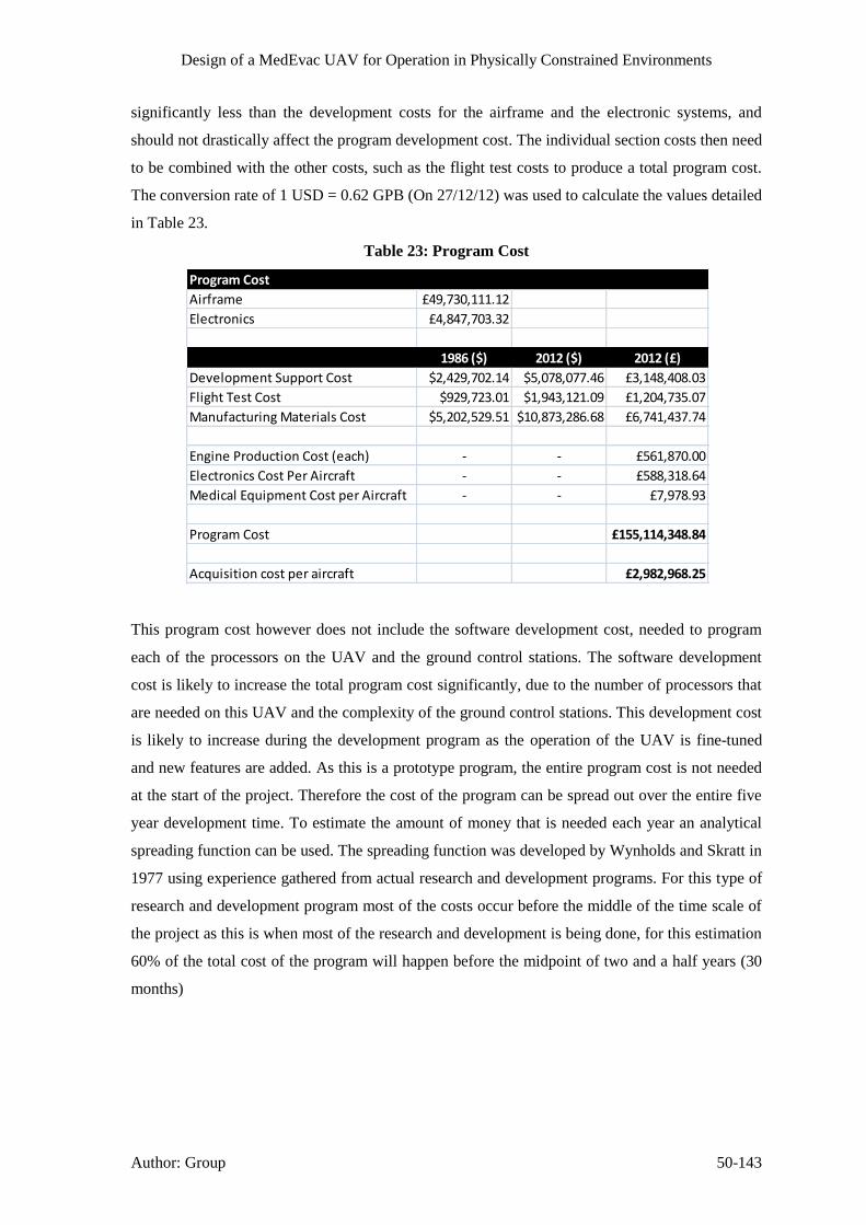
Design of a MedEvac UAV for Operation in Physically Constrained Environments
Author: Group 50-143
significantly less than the development costs for the airframe and the electronic systems, and
should not drastically affect the program development cost. The individual section costs then need
to be combined with the other costs, such as the flight test costs to produce a total program cost.
The conversion rate of 1 USD = 0.62 GPB (On 27/12/12) was used to calculate the values detailed
in Table 23.
Table 23: Program Cost
This program cost however does not include the software development cost, needed to program
each of the processors on the UAV and the ground control stations. The software development
cost is likely to increase the total program cost significantly, due to the number of processors that
are needed on this UAV and the complexity of the ground control stations. This development cost
is likely to increase during the development program as the operation of the UAV is fine-tuned
and new features are added. As this is a prototype program, the entire program cost is not needed
at the start of the project. Therefore the cost of the program can be spread out over the entire five
year development time. To estimate the amount of money that is needed each year an analytical
spreading function can be used. The spreading function was developed by Wynholds and Skratt in
1977 using experience gathered from actual research and development programs. For this type of
research and development program most of the costs occur before the middle of the time scale of
the project as this is when most of the research and development is being done, for this estimation
60% of the total cost of the program will happen before the midpoint of two and a half years (30
months)
Program Cost
Airframe £49,730,111.12
Electronics £4,847,703.32
1986 ($) 2012 ($) 2012 (£)
Development Support Cost $2,429,702.14 $5,078,077.46 £3,148,408.03
Flight Test Cost $929,723.01 $1,943,121.09 £1,204,735.07
Manufacturing Materials Cost $5,202,529.51 $10,873,286.68 £6,741,437.74
Engine Production Cost (each) - - £561,870.00
Electronics Cost Per Aircraft - - £588,318.64
Medical Equipment Cost per Aircraft - - £7,978.93
Program Cost £155,114,348.84
Acquisition cost per aircraft £2,982,968.25

Design of a MedEvac UAV for Operation in Physically Constrained Environments
Author: Group 50-144
Figure 85: Yearly Expenditure needed for Program
Figure 85 shows that initially this project would only need a small amount of investment to start
the project off, to test the feasibility of the idea. However after the first couple of months the level
of investment needs to rapidly increase to ensure that the project is finished by the deadline.
As this project is a United Kingdom Ministry of Defence Project it is not necessary to produce a
plan to generate the capital to fund this project, as all funds would be supplied by the Ministry of
Defence.
50.2 Operational Costs
The main operation costs for this UAV are the initial cost for the aircraft and then the cost to
replace all of the consumables on the aircraft. A breakdown of the cost of the UAV is shown in
Table 24.
£0.00
£2,000.00
£4,000.00
£6,000.00
£8,000.00
£10,000.00
£12,000.00
£14,000.00
£16,000.00
3 6 9 12 15 18 21 24 27 30 33 36 39 42 45 48 51 54 57 60
Ye
arky
Exp
en
dit
ure
(£
K)
Time Since Start of Project (Months)
Yearly Expenditure

Design of a MedEvac UAV for Operation in Physically Constrained Environments
Author: Group 50-145
Table 24: UAV Cost Breakdown Estimate
Table 24 shows an estimate of the total cost to purchase all of the equipment needed to build the
MedEvac UAV is about £1.5 Million (Component Cost Total), whereas the Aircraft Cost Total
includes an estimate of the cost of assembling the aircraft ready for flight, and an equal proportion
of the program cost, is about £3 Million. This cost is similar to that of a civilian Air Ambulance
Subsystem Item Quantity Individual Cost Total
Structure
Manufacturing Materials Cost 1 89,889.99£ 89,889.99£
Propulsion
Turbofan Engine - Turbomecha TM333 2 561,870.00£ 1,123,740.00£
Communication
Antenna + Radome 1 1,000.00£ 1,000.00£
X-Band Transciever 1 50,000.00£ 50,000.00£
Communcations Computer - Xilinx Artix 7 2 210.00£ 420.00£
Medical Robot
Robot Motors - NEMA 34 6 250.00£ 1,500.00£
Kinect Sensor 1 100.00£ 100.00£
Thermal Imaging Camera - FLIR Quark 1 15,000.00£ 15,000.00£
Structure 1 500.00£ 500.00£
Navigation
LiDAR - Velodyne HDL-32E 1 25,000.00£ 25,000.00£
LiDAR - IGI LiteMapper 6800 1 75,000.00£ 75,000.00£
Imaging System - IGI DigiCAM 1 5,000.00£ 5,000.00£
Inertial Measurement Unit - MOOG Crossbow 2 12,000.00£ 24,000.00£
Altitude Sensor - Pressure Transducer 2 50.00£ 100.00£
Flight Computer - Xilinx Artix 7 2 210.00£ 420.00£
Electrical
Tachometer - LaserTach - ICP Laser Tachometer 2 150.00£ 300.00£
Internal Cabin Camera 1 200.00£ 200.00£
Enviromental Sensors - SENSIRION - SHT15 4 17.00£ 68.00£
Hydrogen Fuel Cell 2 4,000.00£ 8,000.00£
Medical
Medical Computer - Xilinx Artix 7 2 210.00£ 420.00£
Flight 60 Ventilator 1 15.60£ 15.60£
Combat life saver bag 1 126.00£ 126.00£
Auto- External Defibrillator 1 3,180.00£ 3,180.00£
CPR- D-Padz 1 79.00£ 79.00£
Evac -U -Splint set 1 364.00£ 364.00£
Maimi J collar Advanced 1 87.00£ 87.00£
Head immobilizer 1 44.33£ 44.33£
Autopulse 1 2,690.00£ 2,690.00£
Pulse oximeter 1 154.00£ 154.00£
Suction unit 1 819.00£ 819.00£
1,428,216.92£
Development
Engineering Cost 1 272,698.21£ 272,698.21£
Tooling Cost 1 197,148.41£ 197,148.41£
Manufacturing Cost 1 457,782.09£ 457,782.09£
Quality Control Cost 1 66,973.52£ 66,973.52£
Develepment Support Cost 1 63,354.09£ 63,354.09£
Flight Test Cost 1 24,242.38£ 24,242.38£
Electronics Devlopment Cost 1 96,954.07£ 96,954.07£
Electronics IAT 1 381,710.00£ 381,710.00£
2,989,079.68£
Component Cost Total
Aircraft Cost Total
Cost of UAV

Design of a MedEvac UAV for Operation in Physically Constrained Environments
Author: Group 50-146
such as the Eurocopter EC10, costing around £2.6 Million. However this is not the only cost
associated with this aircraft, there are also numerous consumables that are needed for each flight
to enable the aircraft to perform all of the necessary functions.
If all of the fuel on board the aircraft was consumed for each flight then the cost of the fuel for
each flight can be calculated, firstly the total amount of fuel that can be held in the aircraft needs
to be calculated as shown in Table 25.
Table 25: UAV Fuel Costing
This amount of fuel can then be added to all of the other consumables that the UAV needs for
each flight to produce a cost estimate of how much each flight would cost the operator.
Table 26: UAV Consumables Costing
Table 26 shows that the total cost of each flight is about £1,500. If the aircraft was to carry out ten
missions a month, then the total cost of the aircraft to purchase and then run for a year can be
calculated. This value is shown in Table 27.
Table 27: Cost to Purchase UAV and Operate for One Year
Density of Fuel 804 kg/m^3
Cost Per Litre 0.54£ £/litre inc. VAT
Fuel Tank Capacity 251 kg
Fuel Required 312.19 litres
Fuel Costing
Item Quantity Individual Cost Total
ATF K-50 Fuel (Jet A1) 312.19 0.54£ 169.56£
Lactated ringers souton 3 25.87£ 77.61£
Blood units 4 125.00£ 500.00£
Oxygen canister 1 217.63£ 217.63£
Recplacement First Aid Kit (IFAK) 1 164.76£ 164.76£
Big IO 1 106.00£ 106.00£
Fast IO 1 40.00£ 40.00£
Celox 3 17.50£ 52.50£
Morphine 1 157.00£ 157.00£
Tranexamic acid 1 6.74£ 6.74£
Pulse Oximeter 1 154.00£ 154.00£
Cost Per Flight Total 1,491.80£
Cost Per Flight
Cost of UAV 2,988,925.68£
Cost Per Flight 1,491.80£
Number of Flights per Month 10
Total Number of Flights in a Year 120
Number of Operational Years 20
Total 6,569,236.37£
Total Cost Of UAV and One Years Operating

Design of a MedEvac UAV for Operation in Physically Constrained Environments
Author: Group 51-147
Table 27 shows that the total cost to purchase and operate this MedEvac UAV (Excluding
maintenance charges) over a lifetime of 20 years is £6.6 Million, which is significantly less than
the £13.2 Million needed just to purchase the Sikorsky HH-60M (Blackhawk).
51 Project Management
Due to the wide array of disciplines needed to design the UAV, the project has been broken down
intosmaller sections relevant to the individualgroupmember’sdisciplines.Each taskwas then
assigned to a specific member of the team who could ask other group members for assistance if
needed.
Using the Gantt chart outlined in (Wood, et al., 2012), the progress of each of the tasks has been
monitored and recorded using the original Gantt chart as the Project Baseline. A copy of this
Gantt chart is shown in Figure 86.
The Gantt chart shows that during the project the initial time estimates have changed. The biggest
slippage was for the medical treatment and diagnosis, as it took longer than predicted to identify
which treatments and what equipment is needed to treat the injuries that could be faced by the
UAV. The delay caused by the medical treatment, caused a one week delay in starting work on
the financial analysis of the project. The project has still been completed on schedule as several of
the tasks in the project have been completed ahead of schedule enabling the time lost to be
absorbed by the other tasks.

Design of a MedEvac UAV for Operation in Physically Constrained Environments
Author: Group 51-148
Figure 86: Gantt Chart

Design of a MedEvac UAV for Operation in Physically Constrained Environments
Author: Group 53-149
52 Conclusion
The purpose of this project was to investigate and design a potential solution for a MedEvac UAV
which will operate in a physically constrained urban environment. Our solution to the project
brief is the integration of: Aerospace, Mechanical, Biomedical and electrical engineering
principles to solve the problems and issues that will be encountered if such an air ambulance
vehicle was to be designed. The design of such an aircraft was problematic as the footprint of the
aircraft had to be kept low, the aircraft had to be capable of VTOL and manoeuvre well between
buildings. A double ducted fan design with minimal footprint was investigated as a potential
solution. Furthermore redundant engines were used to be able to land safely in case of engine
failure. The UAV is capable of operating up to 5000m altitude with a 100km mission radius and a
maximum cruise speed of 71m/s (256km/h).
Two LiDAR units can be used in conjunction with each other to map possible landing sites from
altitude and detect obstacles around the UAV when operating in confined spaces. The aircraft is
designed to fly completely autonomously using an automatic flight control system, which is fed
by a variety of sensors including GPS and gyroscopes to accurately determine the position and
attitude of the aircraft. The autonomous operation was selected to minimise the amount of
interaction needed to operate the UAV, enabling the aircraft to fly in constrained locations
without worrying about the delay in commands, introduced by the communication system.
The MedEvac is designed to transport a casualty and provide the necessary treatment and
intervention to increase the possibility of survival without risking the life of other personnel. The
MedEvac has internal systems which are designed to operate with minimal human interaction and
can be remotely controlled by a medic at the ground station, thereby providing all of the necessary
medical treatment that conventional air ambulances are capable of. The MedEvac assumes there
is one trained medical soldier on the ground with the casualty to assist in initial medical
assessment, treatment and casualty loading.
Due to the hazardous environment that the MedEvac will be operating in several defence
countermeasures have been implemented to protect the casualty and the UAV, such as the
Crosshairs sense and avoid systems, flare and chaffs and E/O jammers.
The operation of the MedEvac can be easily integrated with current military operations, and the
program cost of manufacturing 50 MedEvac UAV’s is £155million the initial funding of this
project will come from the MOD.

Design of a MedEvac UAV for Operation in Physically Constrained Environments
54-150
54 Bibliography
About.com, 2004. Treating Sucking chest wounds. [Online]
Available at:
http://firstaid.about.com/od/shortnessofbreat1/ht/09_How_to_Treat_a_Sucking_Chest_Wound.ht
m
[Accessed 28 12 2012].
AcuTemp, 2013. AcuTemp AX56L Mobile Refrigerator/Freezer. [Online]
Available at: http://www.acutemp.com/products/acutemp-ax56l-mobile-refrigeratorfreezer
[Accessed 3 January 2013].
Advanced Patient Education, 2010-2012. Mechanical ventilation. [Online]
Available at: http://advancedpatienteducation.com/Mechanical_Ventilation.html
[Accessed 30 12 2012].
AeroControl Inc, 2012. Integral 2X, Boulder: AeroControl Inc.
Aerospace Specification Metals Inc., n.d. Titanium Ti-8Al-1Mo-1V (Ti-8-1-1). [Online]
Available at: http://asm.matweb.com/search/SpecificMaterial.asp?bassnum=MTA812
[Accessed 3 January 2013].
Aircraft Rubber Manufacturing Inc, 2010. ARM-R-Coat Self-Sealing Fuel Tank Coating,
Redmond: Aircraft Manufacturing Inc.
Anderson, J., 2011. Case Study: Secure FPGA technology enables UAV communications and
control. [Online]
Available at: http://mil-embedded.com/articles/case-enables-uav-communications-control/
[Accessed 20 December 2012].
Anita I. Abrego, R. W. B., n.d. Performance study of a Ducted Fan system, Moffett Field &
Sunnyvale, CA: NASA Ames Research Centre and Millenium Jet Incorporated.
Anon., 2005. File:V-22 Osprey tiltrotor aircraft.jpg. [Online]
Available at: http://en.wikipedia.org/wiki/File:V-22_Osprey_tiltrotor_aircraft.jpg
[Accessed 12 2012].
Arul Ramasamy, S. H. I. L. M. P. S., 2009. A review of casualties during the Iraqi insurgency
2006–A British field hospital experience.. Injury, 40(5), pp. 493-497.
Austin, R., 2010. Characteristics of aircraft types. In: I. Moic, ed. Unmanned Aircraft Systems,
UAVS Design, Development and Deployment. 1st ed. Chichester(West Sussex): John Wiley &
Sons Ltd., pp. 45-59.

Design of a MedEvac UAV for Operation in Physically Constrained Environments
54-151
Banet, M. J., 2005. Patch Sensor for Measuring Blood Pressure without a Cuff. United States,
Patent No. US 2005/0228299 A1.
BASF Corporation, n.d. [Online]
Available at: http://www2.basf.us//PLASTICSWEB/displayanyfile?id=0901a5e180004891
[Accessed 1 2013].
Beachley, N. H. & Frank, A. A., 1979. Continuously Variable Transmission: Theory and
Practice, Madison: University of Wisconsin.
Beardmore, R., 2011. Loaded Flat Plates. [Online]
Available at: http://www.roymech.co.uk/Useful_Tables/Mechanics/Plates.html
[Accessed 14 November 2012].
Boeing, n.d. Boeing: C-17 Globemaster III - Technical Specifications. [Online]
Available at: http://www.boeing.com/defense-space/military/c17/c17spec.htm
[Accessed 1 1 2013].
Borton, (. C., 2010. Pulse Oximetry. [Online]
Available at: http://www.patient.co.uk/doctor/Pulse-Oximetry.htm
[Accessed 3 January 2013].
British Army Website, n.d. Heavy Equipment Transporter. [Online]
Available at: http://www.army.mod.uk/equipment/engineering/1500.aspx
[Accessed 1 1 2013].
British Standard 13718-2, 2008. Medical Vehicles and their Equipment - Air Ambulances, s.l.: s.n.
British Standard 4376-1, 1991. Electrically Operated Blood Storage Refrigerators, s.l.: s.n.
Burdisso, R., 2010. UAV Ducted Fan Lean and Sweep Stator design. US, Patent No. EP2193994
A2.
C. Camci, A. A., 2010. Double Ducted Fan (DDF), Pennsylvania: Department of Aerospace
Engineering, Pennsylvania state University.
clifford, C. & Cloonan, C., n.d. Profiles in combat casualties. In: s.l.:s.n., pp. Slides 14-16, 28-33.
Company H, 4th Battalion, 7th Aviation Regiment, 2012. The Drive Shafting. [Online]
Available at: http://www.chinook-helicopter.com/standards/areas/drive_train.html
[Accessed 10 November 2012].
Coord 3 Metrology, 2012. Gear Measuring Machines for the Inspection of Gear Geometry.
[Online]
Available at: http://www.gearcmm.com/gear-measuring-machines-for-the-inspection-of-gear-
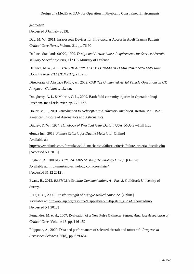
Design of a MedEvac UAV for Operation in Physically Constrained Environments
54-152
geometry/
[Accessed 3 January 2013].
Day, M. W., 2011. Inraosseous Devices for Intravascular Access in Adult Trauma Patients.
Critical Care Nurse, Volume 31, pp. 76-90.
Defence Standards 00970, 1999. Design and Airworthiness Requirements for Service Aircraft,
Military Specidic systems, s.l.: UK Ministry of Defence.
Defence, M. o., 2011. THE UK APPROACH TO UNMANNED AIRCRAFT SYSTEMS Joint
Doctrine Note 2/11 (JDN 2/11), s.l.: s.n.
Directorate of Airspace Policy, w., 2002. CAP 722 Unmanned Aerial Vehicle Operations in UK
Airspace - Guidance, s.l.: s.n.
Dougherty, A. L. & Mohrle, C. L., 2009. Battlefield extremity injuries in Operation Iraqi
Freedom. In: s.l.:Elsievier, pp. 772-777.
Dreier, M. E., 2001. Introduction to Helicopter and Tiltrotor Simulation. Reston, VA, USA:
American Institute of Aeronautics and Astronautics.
Dudley, D. W., 1984. Handbook of Practical Gear Design. USA: McGraw-Hill Inc..
efunda Inc., 2013. Failure Criteria for Ductile Materials. [Online]
Available at:
http://www.efunda.com/formulae/solid_mechanics/failure_criteria/failure_criteria_ductile.cfm
[Accessed 5 1 2013].
England, A., 2009-12. CROSSHAIRS Mustang Technology Group. [Online]
Available at: http://mustangtechnology.com/crosshairs/
[Accessed 31 12 2012].
Evans, B., 2012. EEEM031: Satellite Communications A - Part 3. Guildford: University of
Surrey.
F. Li, F. C., 2000. Tensile strength of a single-walled nanotube. [Online]
Available at: http://apl.aip.org/resource/1/applab/v77/i20/p3161_s1?isAuthorized=no
[Accessed 5 1 2013].
Fernandez, M. et al., 2007. Evaluation of a New Pulse Oximeter Sensor. Americal Association of
Critical Care, Volume 16, pp. 146-152.
Filippone, A., 2000. Data and performances of selected aircraft and rotorcraft. Progress in
Aerospace Sciences, 36(8), pp. 629-654.

Design of a MedEvac UAV for Operation in Physically Constrained Environments
54-153
Glaren Carol Audio, 2007. Decibel Comparison Chart. [Online]
Available at: http://www.gcaudio.com/resources/howtos/loudness.html
[Accessed 3 January 2013].
Goodyear, 2002. Aircraft Tire Data Book. [Online]
Available at: http://www.wattsaviation.co.uk/download/goodyear_airdatabook.pdf
[Accessed 27 November 2012].
Gov.co, 2012. Uk Forces: Operations in Afghanistan. [Online]
Available at: https://www.gov.uk/uk-forces-operations-in-afghanistan#medical-facilities-and-
classifying-injuries
[Accessed 3 January 2013].
Guo, Y., 2011. Analytical Study on Compound Planetary Gear Dynamics, US: The Ohio State
University.
Hameer, S., 2009. A Comparitive Study and Application of Continuously Variable Transmission
to a Single Main Rotor Heavy Lift Helicopter, US: Georgia Institute of Technology.
Harcke, C. H. T., Crawley, C. G., Mabry, M. R. & Mazuchowski, C. (. E., 2001. Placement of
Tibial Intraosseous Infustion Devices. Military Medicine, 176(7:824), p. 4.
Harris, W., n.d. How CVTs Work. [Online]
Available at: http://auto.howstuffworks.com/cvt2.htm
[Accessed 10 December 2012].
Health and Safety Executive, n.d. Employer's Responsibilities - Legal Duties. [Online]
Available at: http://www.hse.gov.uk/vibration/hav/advicetoemployers/responsibilities.htm
[Accessed 12 December 2012].
Horizon, 2010. Aeropak Fuel Cell Propulsion System for Unmanned Areal Vehicles. [Online]
Available at: http://www.hes.sg/products.html
[Accessed 19 December 2012].
Ian Greaves, K. P. J. S., 2011. Practical Prehospital Care. s.l.:Churchill livingstone elsevier.
Ingenieur-Gesellschaft für Interfaces , 2012. DigiCAM, Kreuztal: Ingenieur-Gesellschaft für
Interfaces .
Ingenieur-Gesellschaft für Interfaces, 2012. LiteMapper 6800 - Airbourne Lidar Terrain Mapping
System, Kreuztal: Ingenieur-Gesellschaft für Interfaces.
Israeli Military Industries, Land system Division, 2012. Shock Absorber. [Online]
Available at: http://www.imi-israel.com/home/doc.aspx?mCatID=68195
[Accessed 31 12 2012].

Design of a MedEvac UAV for Operation in Physically Constrained Environments
54-154
James, C. Y., Riemann, B. L., Munkasy, B. A. & Joyner, A. B., 2004. Comparison of Cervical
Spine Motion During Application Among 4 Rigid Immobilization Collars. Journel of Athletic
Training, Volume 39, pp. 138-145.
Keller, J., 2012. Raytheon to improve resolution of UAV electro-optical sensor payload in Air
Force contract. [Online]
Available at: http://www.militaryaerospace.com/articles/2012/01/raytheon-to-improve-resolution-
of-uav-electro-optical-sensor-payload-in-air-force-contract.html
[Accessed 27 12 2012].
L-3 Unmanned Systems, 2010. LinkTEK Information Dissemination System, New York: L-3.
LaserTach, 2006. ICP Laser Tacjometer, Cincinati: The Modal Shop.
Leishman, G. J., 2006. Principles of Helicopter Aerodynamics. 2nd ed. s.l.:Cambridge University
Press.
Leishman, J. G., 2006. Principle of Helicopter Aerodynamics. 2nd ed. New York: Cambridge
University Press.
Lippincott, Williams & Wilkins, 2008. Critical Care Nursing Made Incredible Easy. 2nd ed.
s.l.:Wolters Kluwer.
MAA - Military Aviation Authority, 2010. Regulatory Articles 200 series- RA2425 Aircraft
Accidents, Forced Landings or incidents. [Online]
Available at: http://www.maa.mod.uk/linkedfiles/regulation/fly2000seriesprint.pdf
[Accessed 31 12 2012].
Manitoba Health, 2011. Emergency treatment guidelines. [Online]
Available at: http://www.gov.mb.ca/health/ems/guidelines/G11.pdf
[Accessed 29 12 2012].
Manuel, D., 2012. Inflation Calculator. [Online]
Available at: http://www.davemanuel.com/inflation-calculator.php
[Accessed 2 December 2012].
Matrix international, 2009. Servo motor brakes. s.l.:s.n.
Medgadget LLC, 2012. New Startup Develops Continous Blood Pressure Measurement Without a
Counter-Pressure Cuff. [Online]
Available at: http://www.medgadget.com/2012/02/new-startup-develops-continuous-blood-
pressure-measurement-without-a-counter-pressure-cuff.html
[Accessed 10 November 2012].

Design of a MedEvac UAV for Operation in Physically Constrained Environments
54-155
Meier, N., 2005. Military Turboshaft Specifications. [Online]
Available at: http://jet-engine.net/miltsspec.html
[Accessed 12 November 2012].
Mendolia, J., n.d. Choosing servo motor brakes. [Online].
Military Aviation Authority, 2012. MAA Regulatory Articles. [Online]
Available at: http://www.maa.mod.uk/regulation/regulatory_articles.htm
[Accessed 12 2012].
National Heart Lung and Blood Institute, 2012. Explore Blood Transfusion. [Online]
Available at: http://www.nhlbi.nih.gov/health/health-topics/topics/bt/
[Accessed 14 November 2012].
Nellcor Puritan Bennett LLC, 2013. OxiMax Max-Fast Forehead Sensor. [Online]
Available at: http://www.nellcor.com/prod/product.aspx?id=246
[Accessed 3 January 2013].
Nellcor Technical Staff, 2011. A Technology Overview of the Nellcor OxiMax Pulse Oximetry
System, Boulder, CO: Covidien.
Nice, K., n.d. How Automatic Transmissions Work. [Online]
Available at: http://auto.howstuffworks.com/automatic-transmission3.htm
[Accessed 5 December 2012].
Nice, K., n.d. How Differentials Work. [Online]
Available at: http://auto.howstuffworks.com/differential3.htm
[Accessed 22 December 2012].
Nodin Aviation AS, 2012. NATO MedEvac Stretcher. [Online]
Available at: http://www.medevac.no/en/naval-systems/item/18-nato-stretcher.html
[Accessed 10 October 2012].
Northrop, R. B., 2002. Noninvasive Instrumentation and Measurement in Medical Diagnosis.
USA: CRC Press.
Oriental Motor USA Corp., 2006. Planetary Gears. [Online]
Available at: http://www.orientalmotor.com/newsletter/PN-Geared.htm
[Accessed 3 January 2013].
Oshkosh Defence, n.d. Heavy Tactical Vehicles. [Online]
Available at: http://www.oshkoshdefense.co.uk/heavy-tactical-vehicles
[Accessed 1 1 2013].

Design of a MedEvac UAV for Operation in Physically Constrained Environments
54-156
Overfield, J., Dawson, M. & Hamer, D., 2008. Transfusion Science. 2nd ed. Oxfordshire: Scion
Publishing Ltd..
Parsons, c., 2005. Battlefield medicine a new perspective. [Online]
Available at: http://www.health.mil/Libraries/110808_TCCC_Course_Materials/0797-TCCC-
Parsons-Battlefield-Medicine-Infantry-2004.pdf
Performance Composites Ltd., n.d. Mechanical Properties of Carbon Fibre Composite Materials,
Fibre / Epoxy resin (120°C Cure). [Online]
Available at: http://www.performance-composites.com/carbonfibre/mechanicalproperties_2.asp
[Accessed 3 January 2012].
Post, E., 1967. Sagnac Effect. Reviews of Modern Physics, 39(2), pp. 475-494.
RAFAEL Defense System Ltd., 2010. Rafael Advanced Defense Systems LTd.. [Online]
Available at: http://www.rafael.co.il/Marketing/349-963-en/Marketing.aspx
[Accessed 31 12 2012].
Raymer, D. P., 1992. Aircraft Design: A Conceptual Approach. 2nd ed. Washington D.C.:
American Institute of Aeronautics and Astronautics Inc..
Reades, R., Studnek, J. R., Vandeventer, S. & Garrett, J., 2011. Intraosseous Versus Intravenous
Vascular Access During Out-of-Hospital Cardiac Arrest: A Randomized Controlled Trial. Annals
of Emergency Medicine, 58(6), p. 8.
Renius, K. T., 2005. Continuously Variable Tractor Transmission, USA: ASAE.
Resuscitation Council (UK), 2011. Use of Intraosseous (IO) Access During Cardiac Arrest,
London: Advanced Life Support.
Rogers, B. C., 1999. Design and Airworthiness Requirements For Military and UAVS. [Online]
Available at: http://ftp.rta.nato.int/public//PubFulltext/RTO/EN/RTO-EN-009///EN-009-04.pdf
[Accessed 31 12 2012].
Roskam, J., 1971. Methods of Estimating Drag Polars for Subsonic Aircraft. Kansas: s.n.
Royal Air Force, n.d. RAF - C17 A Globemaster. [Online]
Available at: http://www.raf.mod.uk/equipment/c17aglobemaster.cfm
[Accessed 31 12 2012].
Royal Air Force, n.d. RAF - Hercules C1/C3. [Online]
Available at: http://www.raf.mod.uk/equipment/herculesc1c3.cfm
[Accessed 1 1 2013].

Design of a MedEvac UAV for Operation in Physically Constrained Environments
54-157
RoyMech, 2011. Bevel Gears. [Online]
Available at: http://www.roymech.co.uk/Useful_Tables/Drive/Bevel_Gears.html
[Accessed 12 December 2012].
RoyMech, 2011. Spur Gears. [Online]
Available at: https://www.roymech.co.uk/Useful_Tables/Drive/Gears.html
[Accessed 11 December 2012].
Safram Turbomeca, 2010. TM 333 2M2. [Online]
Available at: http://www.turbomeca.com/english/our-products/helicopter-engines/tm-333-46/tm-
333-2m2-24.html
[Accessed 3 December 2012].
Safran Turbomeca, 2010. TM 333 2B2. [Online]
Available at: http://www.turbomeca.com/english/our-products/helicopter-engines/tm-333-46/tm-
333-2b2-23.html
[Accessed 10 November 2012].
Sandia National Laboratories, 2005. MiniSAR Radar, Albuquerque: Sandia National Laboratories.
Scaffolding Direct, 2011. Scaffolding Fittings - Pressed Steel Double Coupler. [Online]
Available at: http://www.scaffolding-direct.co.uk/scaffolding-fittings-pressed-steel-double-
coupler-25-.aspx
[Accessed 3 January 2013].
Shelley, K. H. et al., 2005. The Effect of Venous Pulsation on the Forehead Pulse Oximeter Wave
Form as a Possible Source of Error in Spo2 Calculation. Anesthesia Analg, Volume 100, pp. 743-
747.
society, P. s. A., 2004. A quick derivation relating altitude to air pressure. [Online]
Available at: http://psas.pdx.edu/RocketScience/PressureAltitude_Derived.pdf
[Accessed 09 11 2012].
Stokes, A., 1970. High Performance Gear Design. Sussex, UK: The Machinary Publishing Co.,
Ltd..
The Engineering Toolboox, n.d. Torsion of Shafts. [Online]
Available at: http://www.engineeringtoolbox.com/torsion-shafts-d_947.html
[Accessed 12 December 2012].
TSS International BV, 2012. Avoid the danger of fire and explosion with TSS Protected Fuel
Tanks, Barendrecht: TSS International BV.

Design of a MedEvac UAV for Operation in Physically Constrained Environments
54-158
Turbomeca, n.d. Turbomeca - TM333 2B2. [Online]
Available at: http://www.turbomeca.com/english/our-products/helicopter-engines/tm-333-46/tm-
333-2b2-23.html
[Accessed 6 December 2012].
United States Air Force (USAF), 1973. Baffle and Inerting Material, Aircraft Fuel Tank, s.l.:
United States Air Force (USAF).
US Army, 2000. Emergency War Surgery. s.l.:s.n.
Velodyne, 2012. High Definition LiDAR HDL-32E, San Jose: Velodyne Lidar Inc.
Wayne, M. A., 2009. Adult Intraosseous Vascualr Access in Emergency Medicine. European
Critical Care and Emergency Medicine, p. 4.
Wendelken, S. M., 2004. Using a Forehead Reflectance Pulse Oximeter to Detect Changes in
Systempathetic Tone, New Hampshire, USA: Thayer School of Engineering.
Wertz, J. R. & Larson, W. J., 1999. Space Mission Analysis and Design. 3rd ed. El Segundo:
Microcosm Press and Kluwer Academic Publishers.
Wikipedia, 2012. Arterial blood gas. [Online]
Available at: http://en.wikipedia.org/wiki/Arterial_blood_gas
[Accessed 11 11 2012].
Wikipedia, n.d. Differential. [Online]
Available at: http://en.wikipedia.org/wiki/Differential_(mechanical_device)
[Accessed 3 January 2013].
Wood, M. et al., 2012. Design of a MedEvac UAV for Operation in Physically Constrained
Environments - Inception Report, Surrey: University of Surrey.
ZOLL Medical Corporation, 2011. AED Pro Operators Guide. In: s.l.:ZOLL Medical
Corporation.

Design of a MedEvac UAV for Operation in Physically Constrained Environments
Author: Michael Collison 54-159
Appendix A – Current Aircraft Data
Table 28: Data for Helicopters and Selected Aircraft (Filippone, 2000), *added separately
Aircraft Type D (m) u (km/h) rpm MTOW
Disk Loading
(N/m2)
Bell 406/OH-58D Helicopter 10.7 232 395 2500 274
Bell 407 Helicopter 10.7 237 413 2270 249
Bell 427 Helicopter 11.3 250 395 2835 278
MD-500E Helicopter 8.1 248 492 1360 262
Enstrom 480 Helicopter 9.8 204 334 1300 170
Aerospatiale 550 Helicopter 10.7 248 394 2250 246
Eurocopter BO 105 Helicopter 9.8 240 424 2500 322
Eurocopter EC 120B Helicopter 10.0 228 415 1700 212
AVERAGE OF HELICOPTERS 10.1 236 408 2089 252
Bell/Boeing V-22 Tilt Rotor 11.6 185 333 27440 1271
Bell X-22A* Ducted Fan 2.1 - 2590 8000 5506
Doak VZ-4* Ducted Fan 1.2 - 4800 1451 6293
Urban Aero Airmule* Ducted Fan 1.8 - - 1406 2710
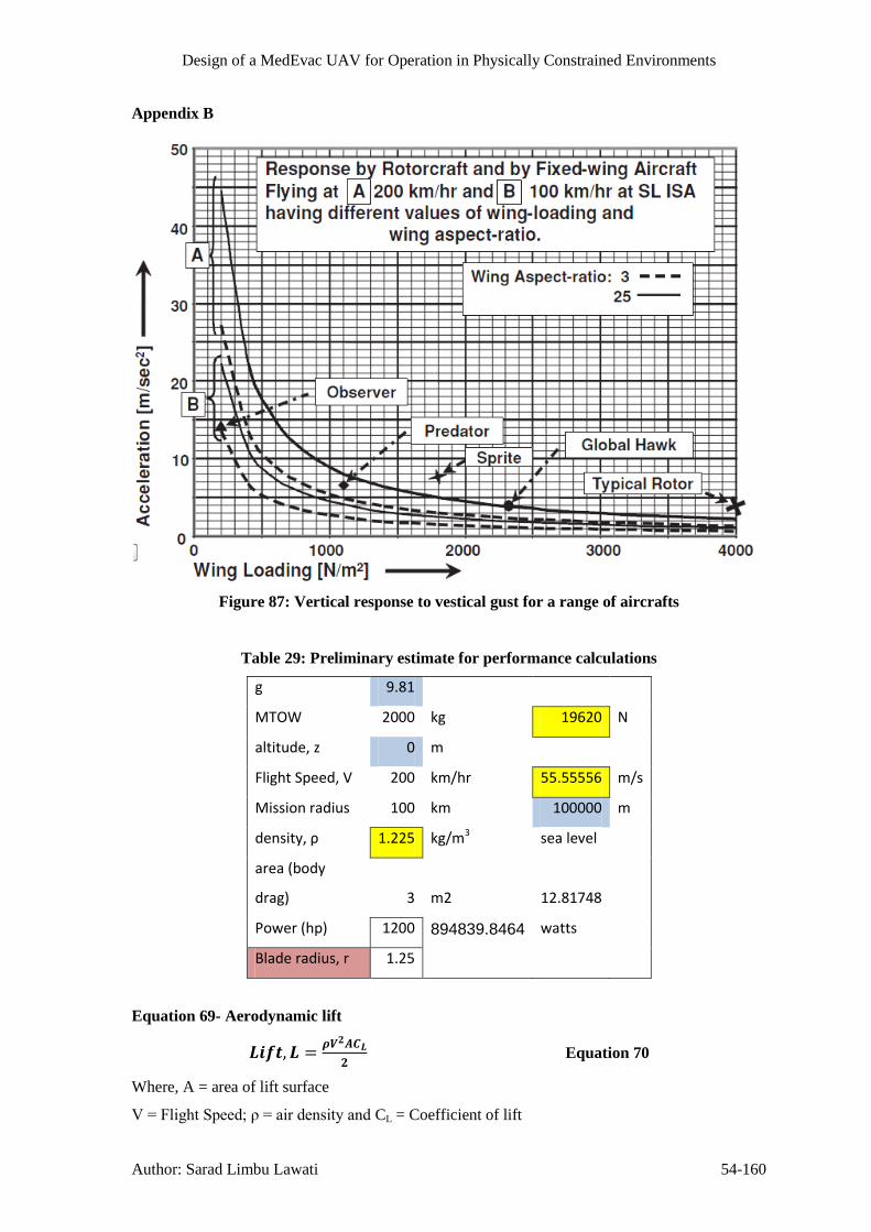
Design of a MedEvac UAV for Operation in Physically Constrained Environments
Author: Sarad Limbu Lawati 54-160
Appendix B
Figure 87: Vertical response to vestical gust for a range of aircrafts
Table 29: Preliminary estimate for performance calculations
g 9.81
MTOW 2000 kg 19620 N
altitude, z 0 m
Flight Speed, V 200 km/hr 55.55556 m/s
Mission radius 100 km 100000 m
density, ρ 1.225 kg/m3 sea level
area (body
drag) 3 m2 12.81748
Power (hp) 1200 894839.8464 watts
Blade radius, r 1.25
Equation 69- Aerodynamic lift
Equation 70
Where, A = area of lift surface
V=FlightSpeed;ρ=airdensityand CL = Coefficient of lift

Design of a MedEvac UAV for Operation in Physically Constrained Environments
Author: Sarad Limbu Lawati 54-161
Table 30: Calculations to obtain wingspan required
α CL
S = (b*c)
m2
Wing span,
b chord, c
S = (b*c)
m2
Wing span,
b α CL CL/CD
wing loading
(W/S) Flight Speed
0
-1.15E-
11 -9.016E+11 -4.508E+11 2 42.406 21.203 0 0.244744 20.11 47.16 108.89
1 0.203546 50.989 25.494
28.717 14.358 1 0.361413 30.03 69.65 89.60
2 0.410942 25.256 12.628
23.080 11.540 2 0.449677 35.34 86.65 80.33
3 0.48022 21.612 10.806
19.315 9.658 3 0.537322 38.57 103.54 73.49
4 0.538661 19.267 9.634
16.554 8.277 4 0.626958 40.96 120.82 68.03
5 0.602125 17.237 8.618
14.441 7.221 5 0.718688 42.67 138.49 63.54
6 0.674122 15.396 7.698
12.781 6.391 6 0.812014 43.56 156.48 59.78
7 0.752276 13.796 6.898 11.465 5.733 7 0.905224 43.73 174.44 56.62
8 0.823253 12.607 6.303
10.397 5.198 8 0.998264 43.20 192.37 53.91
symmetrical airfoil
9.521 4.760 9 1.090118 42.37 210.07 51.59
8.808 4.404 10 1.178328 41.68 227.07 49.62
8.265 4.132 11 1.255761 41.18 241.99 48.07
Variation of CL with α was obtained from XLR5 airfoil 7.857 3.928 12 1.32095 40.83 254.55 46.87
http://www.xflr5.com/xflr5.htm 7.609 3.804 13 1.363996 39.37 262.85 46.12
7.616 3.808 14 1.362771 34.25 262.61 46.14
Cambered airfoil 27.06
19.59

Design of a MedEvac UAV for Operation in Physically Constrained Environments
Author: Sarad Limbu Lawati 54-162
14.78
Drag, Fuselage lift and high lift devices haven’t been
considered
Disc Loading
(W/AR)
Rotor Area
(Pi*r2)
407.4366543 4.909
Tilt rotor
Effective Wing Span 8.23 metres
Power loading 91147.64
Fixed wing aircraft Effective Wing Span 5.73 metres
Thrust Loading 0.25
Lift 22780.45

Design of a MedEvac UAV for Operation in Physically Constrained Environments
Author: Sarad Limbu Lawati 54-163
Figure 88: NACA23012 – cambered aerofoil profile
Figure 89: Technical Specification of TROPHY Family(RAFAEL Defense System Ltd.,
2010)

Design of a MedEvac UAV for Operation in Physically Constrained Environments
Author: Sarad Limbu Lawati 54-164
Figure 90: Span wise distributions of inflow and thrust on a
rotor blade for different linear twist rates(Leishman, 2006)
Figure 91 - Thrust variation with RPM and tip gap

Design of a MedEvac UAV for Operation in Physically Constrained Environments
Author: Sarad Limbu Lawati 54-165
Figure 92: Effect of blades’ number on airflow
Table 31: fan Parameters
mass 1300kg 1275N R eff.
R 1.00 blade radius 0.70
Nb 5.00 No. of blades
θ 30.00 Pitch angle
RPM 2450.00 40.83333333
Ω 256.56 rad/s
Vinf 30.17 m/s
Table 32: Data used in calculation
Body Drag 4.00 m2
rhub 0.3 m
Adisk 2.86 m2
blade twist 1.50 degrees
Density, ρ 1.225 kg/m3
Chord, c 0.3 m
CD 0.35
a0 6.283185 rad-1
Power Available (single engine)
950.00 kw sea level
600.00 kw 5000 m

Design of a MedEvac UAV for Operation in Physically Constrained Environments
Author: Sarad Limbu Lawati 54-166
Table 33: Blade section data and linear twist
Propeller geometry data
0.1 0.2 0.3 0.4 0.5 0.6 0.7 0.8 0.9 0.95 1
Element radius, r 0.37 0.44 0.51 0.58 0.65 0.72 0.79 0.86 0.93 0.965 1
Chord (m) 0.28 0.2686567 0.2791667 0.3 0.275 0.2955 0.286154 0.2612903 0.2444 0.1841 0.18409
θ(deg) 30.00 28.50 27.00 25.50 24.00 22.50 21.00 19.50 18.00 16.50 15.00
(rad) 0.524 0.497 0.471 0.445 0.419 0.393 0.367 0.340 0.314 0.288 0.262

Design of a MedEvac UAV for Operation in Physically Constrained Environments
Author: Sarad Limbu Lawati 54-167
Table 34: calculation for each blade element
combined Blade Element Momentum Calculation
φ 0.30774736 0.2611742 0.2266323 0.200051368 0.179 0.1619 0.147779 0.1359045 0.1258 0.1213 0.11707 radians
σ 0.23873241 0.2387324 0.2387324 0.238732415 0.2387 0.2387 0.238732 0.2387324 0.2387 0.2387 0.23873
θ 0.524 0.497 0.471 0.445 0.419 0.393 0.367 0.340 0.314 0.288 0.262
α 0.2159 0.2362 0.2446 0.2450 0.2399 0.2308 0.2187 0.2044 0.1884 0.1667 0.1447
CL 1.35623444 1.4843691 1.5369087 1.539428096 1.5073 1.4501 1.374384 1.2845009 1.1836 1.0475 0.90939
CD 0.02 0.02 0.02 0.02 0.02 0.02 0.02 0.02 0.02 0.02 0.02
ΔT 809.938065 1412.5697 2347.8073 3697.119827 4652.7 6518.1 7886.826 8668.5415 9437.1 7021.6 6778.55
ΣT 77.7877703 131.61319 211.57245 292.2444109 390.98 504.17 579.4379 633.6964 288.03 241.5 Trapezium Rule
ΔP 25692.1665 44931.235 75062.348 119012.7144 151043 213756 261795 291954.62 323481 245626 243404
ΣP 2471.81904 4199.7754 6792.6272 9451.947851 12768 16644 19381.24 21540.262 9959.4 8558
Single blade Thrust (T) 1609.77 N
single blade power 111767.33 W
total fan thrust 8048.85 N
total fan power 558836.64 W
total thrust 16097.69 N
total power 1117673.3 W
Table 35: Blade tip speed, thrust and power predictions at different altitudes
Vblade_Tip 198.97 m/s Single Fan
Both Fans
a Mblade_Tip Temperature (K) RPM
Altitude (m)
Density
(ρ) Thrust, T Thrust (N) Power Req
340.32 0.58 288.15 1900 0.00 1.23 8048.85 16097.69 558.57 kw
320.59 0.77 255.70 2350
5000.00 0.74 7103.68 14207.36 634.27 kw
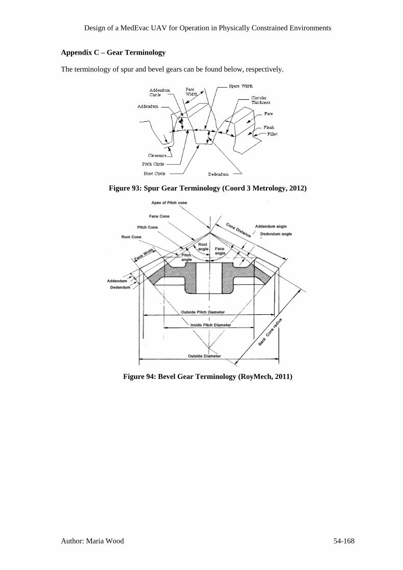
Design of a MedEvac UAV for Operation in Physically Constrained Environments
Author: Maria Wood 54-168
Appendix C – Gear Terminology
The terminology of spur and bevel gears can be found below, respectively.
Figure 93: Spur Gear Terminology (Coord 3 Metrology, 2012)
Figure 94: Bevel Gear Terminology (RoyMech, 2011)

Design of a MedEvac UAV for Operation in Physically Constrained Environments
Author: Matthew Temple 169
Appendix D – Satellite Communication Equations
Azimuth, Elevation and Range Equations for Satellite Communications
These equations are taken from (Evans, 2012)
Table 36: Azimuth, Elevation and Range Equations
( ( )
( ))
(1)
( ( )
( ))
(2)
√( ( ( ))) (3)
Where
( ( ) ( )) (4)
( ) (5)
(6)
( )
( )
( )
( )
( )

Design of a MedEvac UAV for Operation in Physically Constrained Environments
Author: Matthew Temple 170
Appendix E – Finance Equations
Electronics Development Cost Estimate
Taken from (Wertz & Larson, 1999), Page 796.
( )
( )
( )
( )
Analytical Spreading Function for Research and Development Projects
Taken from (Wertz & Larson, 1999), Page 806
( ) [ (( ) ) ( ) ( ) ( ) ]
Where:
( )
A B
80% 0.96 0.04
60% 0.32 0.68
50% 0 1
40% 0 0.68
20% 0 0.04
% Expenditure at
Schedule Midpoint
Coefficients

Design of a MedEvac UAV for Operation in Physically Constrained Environments
Author: Matthew Temple 171
Appendix F - Flowcharts
Communications System
Communication System
Is there an Interupt
Was the Last Packet Data or
Video
Prepare Video Frame for
TransmissionVideo Frame
Telemetry
Prepare Attitude Telemetry Data
Video
Prepare Sensor Telemetry Data
Prepare System Status Telemetry
Data
Attitude Data
Sensor Data
System Status Data
Encrypt Data For Transmission
What was the Interupt
Prepare LiDAR DataLiDAR Sensor
Data
3D Scan Requested
Prepare Attitude Data
Attitude Data
UAV Under Fire
Prepare location engaged from Data
Direction of Fire
Prepare LiDAR Data
Obstacle Detected
Prepare Attitude Data
LiDAR Data
Attitude Data
Figure 95: Communication System Flowchart
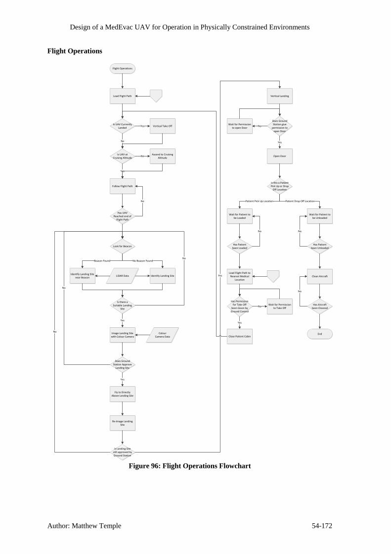
Design of a MedEvac UAV for Operation in Physically Constrained Environments
Author: Matthew Temple 54-172
Flight Operations
Flight Operations
Load Flight Path
Is UAV Currently Landed
Is UAV at Cruising Altitude
No
Vertical Take OffYes
Ascend to Cruising Altitude
No
Follow Flight Path
Yes
Has UAV Reached end of
Flight Path
No
Look for Beacon
Identify Landing Site near Beacon
Identify Landing Site
Beacon Found No Beacon Found
LiDAR Data
Is there a Suitable Landing
Site
No
Does Ground Station Approve
Landing Site
No
Fly to Directly Above Landing Site
Image Landing Site with Colour Camera
Yes
Yes
Colour Camera Data
Re-Image Landing Site
Is Landing Site still approved by Ground Station
No
Vertical Landing
Yes
Does Ground Station give
permission to open Door
Open Door
Wait for Permission to open Door
No
Yes
Is this a Patient Pick Up or Drop
Off Location
Wait for Patient to be Loaded
Wait for Patient to be Unloaded
Patient Pick Up Location Patient Drop Off Location
Has Patient been Loaded
No
Has Patient been Unloaded
No
Clean Aircraft
Has Aircraft been Cleaned
No
End
Load Flight Path to Nearest Medical
Location
Has Permission for Take Off
been Given by Ground Control
Wait for Permission to Take Off
No
Close Patient Cabin
Yes
Figure 96: Flight Operations Flowchart

Design of a MedEvac UAV for Operation in Physically Constrained Environments
Author: Matthew Temple 54-173
Load Co-Ordinates of nearest Medical Treatment Centre
Generate Flight Path between
current location and new Co-Ordinates
Check for Danger Zones on Flight Path
Current Danger Zones
Does the Flight Path cross any Danger Zones
Relay Flight Path to Ground Control
Station
No
Does Control Station accept
Flight Path
Save Flight Path to Memory
Yes
End
Flight Path
Current Engagement Zone across Battlefiled
Current Flight Path
Generate New Flight Path avoiding
Danger ZonesYes
No
Nearest Medical
Treatment Centre
Location
Medical Treatment
Centres
What is the Destination
Medical Treatment Centre
Co-Ordinates of Patient / Landing Site
Transmitted by Ground Personel
Load Co-Ordinates of Patient / Landing
Site
Patient / Landing Site
Figure 97: Flight Path Creation Flowchart

Design of a MedEvac UAV for Operation in Physically Constrained Environments
Author: Maria Wood 54-174
Medical Operations
Figure 98: Pulse Oximeter Application Flow Chart

Design of a MedEvac UAV for Operation in Physically Constrained Environments
Author: Maria Wood 54-175
Figure 99: Blood Pressure Patch Application Flow Chart

Design of a MedEvac UAV for Operation in Physically Constrained Environments
Author: Maria Wood 54-176
Figure 100: Insertion of Intraosseous Cannula

Design of a MedEvac UAV for Operation in Physically Constrained Environments
Author: Dela Yohuno 54-177
Evac- U Splint, Pulse oximeter, Heamoclot, Manual ventilator, Portable suction machine
Procedure for dealing with fractures splintingA
sse
sm
en
t o
f A
irw
ay,
bre
ath
ing
an
d c
ircu
latio
nT
rea
tme
nt o
f F
ractu
res
Tra
nsp
ort
to
UA
V
Treatment fpr
fractures
(Immobilisation)
Locate patient and place on mobile
stretcher do not move limbs too far from
current postion
Transpot casualty to
Medevac UAV
No
Yes
No
Yes
NoAdminister CPRDoes the patient have pulse heart beat? (ECG/Pulse
Ox)
Carefully tilt the chin up to open the airway and open mounth with
jaw thrust
Is the patient breathingAdminister CPR
Is the airway blocked
Perform ABC Assesment (Check airway, breathing
and circulation)
Does the casualty
have a upper
extremity or lower
extremity injury
Does the
casualty have
an open or
closed
fracture
Does the
casualty have
an open or
closed fracture
Asses fracture site
for tenderness and
swelling
Asses for deformity
in limb and ask
patient if concious for
area of pain
Locate the
fracture site is the
fracture in the
knee, lower leg,
ankle, hip or
pelvis is there
partial
amputation?
Clontrol bleeding by
applying pressure and
dressing to the wound,
apply heamoclot
Does the
casualy have a
head/neck
injury
Apply a cervical
collar
Asses distal
pulse and
blood pressure
Closed
Asses for deformity
in limb and ask
patient if concious for
area of pain
Asses fracture site
for tenderness and
swelling
Locate the
fracture site
is the fracture
a shoulder or
wrist
fracture?
Closed
Upper extremity
Attempt to straighten the limb
and apply traction Apply the
vacuum splint
Lower extremity
Do not, apply
traction, apply
vacuum splint
Yes
Is the fracture
in the mid
thigh reigon?
Yes
No
Manually
straighten the
limb
Apply the
vacuum splint to
the limb
Open Clontrol bleeding by
applying pressure and
dressing to the wound,
apply heamoclot
Open
No
Yes
Administer 50-100% oxygen,
continue to monitor patients
condition & transfer
Administer 50-100% oxygen,
continue to monitor patients
condition & transfer
Administer 50-100% oxygen,
continue to monitor patients
condition & transfer
No
Figure 101: Flowchart of treatment for fractures

Design of a MedEvac UAV for Operation in Physically Constrained Environments
Author: Dela Yohuno 54-178
Equipment: Autopulse, AED, Defib Pads
CPR, AED Autopulse device communication
Remove clothing on
Patient
Remove, oil
moisture from
patients chest
Apply defibrillation
electrode pads
CPR D-Pads and
plug into AED
Attach chest
compressions
straps
Power ON the
AED & Autopulse
Do not touch the
AED wait for AED
to finish analysis
on patient
Check rhythm
is shockable
After 30:2 compressions
stand clear allow AED to
monitor patient
Continue chest
compression 30:2
Autopulse
Wait for
defibrillator to
charge
Once charged and
tone sounds shock
button flashes
Press the shock
buttin/ initiate
shock/
Automatically from
base
Unit delivers
shock
Does the unit
resume ECG
analysis
Unit displays start
CPR
No
30:2 complete send message
Yes
base alert shock needed
Alert base on charges
Alert base after shock
Yes
No
Send message/ ECG trail & heart rate
Figure 102: CPR Flowchart

Design of a MedEvac UAV for Operation in Physically Constrained Environments
Author: Dela Yohuno 54-179
Treatment for casualty suffereing tension Pneumothorax
Attach diagnostic equipment
Remove clothing
Perform ABC Assesment (Check airway, breathing and
circulation)
Is the airway blocked
Is the patient breathing
No
Yes
Carefully tilt the chin up to open the airway and open mounth with jaw
thrust
No
Administer CPR
No
Does the patient have pulse heart beat? (ECG/Pulse
Ox)
Yes
Administer CPR No
Yes
Use portable suction device to
remove blood in the chest cavity/oral cavity/ trachea
Does the casualty have a noticable chest wound, does it make a sucking
sound?
Administer high concentration
oxygen 75-100%Yes
Apply Bolin chest seal
Continue to monitor the patients SPO2 level and breathing rate ( Pulse
ox)
No
Does the casualty have shortness of
(Difficulty breathing)
Check the SPO2 level on the pulse
oximeter is it < 60mm Hg, check
blood pressurer and pulse rate
Yes
Administer 75-100% oxygen
Continue to monitor the patients SPO2
level and breathing rate
Does the patient have equal chest
movement on both sides
No
No
Yes
Equipment
ECG monitor Pulse oximeter Bolin chest seal Ventilator Blood pressure
patch
Is the patient airway still blocked?
Yes
Figure 103: Tension Pneumothorax Flowchart

Design of a MedEvac UAV for Operation in Physically Constrained Environments
Author: Matthew Temple 54-180
Appendix G - Communication Bus Diagram
Medical Control SystemFlight Control System Communications Subsystem
Anti Weapon System
Aircraft Counter Measures
Ventilator Unit Defibrillator Unit
IV / IO Unit
Robot
Blood Oximeter
Blood Pressure Meter
Automatic CPR Unit
Key
Intermediate Gain Antenna - IGA
HPA / LNA
Communications Processor
Flight Computer Medical Computer
Flight Redundant Computer
Light Detection and Ranging
Colour High Resolution CMOS
Camera
Inertial Measurement Unit
Global Positioning System Sensor - GPS
Anti Weapon System Computer
Radar Unit Acoustic Sensor
Flares
Chaff
Anti Aircraft Missile Jammer
Redundant Medical Computer
Mass Memory Unit
Fuel Level Sensor
Microcontroller
Microcontroller
Optical Tachometer 1
Optical Tachometer 2
Ventilator
Breathing Rate Sensor
Defibrilator
Electrocardiogram
Microcontroller
IV / IO Pump 1
IV / IO Pump ...
Microcontroller
Linear Motors X Axis
Linear Motors Y Axis
Linear Motors Z Axis
Microcontroller
Blood Oximeter
Microcontroller Blood Pressure Patch
Microcontroller
Autopulse
RF / Co-ax
UART
I2C
RS 232
Ethernet
Motor Driver
Thermal Imaging Camera
Microsoft Kinect Sensor
Figure 104: Communication Bus Diagram

Design of a MedEvac UAV for Operation in Physically Constrained Environments
Author: Michael Collison 54-181
Appendix H - Failure Mode Effect Analysis
Product Name:
Various
Developer: Michael Collison
Date: 28th December 2012
Revision Number: 0
Product,
Device, Process
or System
Name & No.
Function Possible
Failure Mode
Effect of
Failure
Cause of
Failure
Control
Procedure
Occ
urr
ence
Sev
erit
y
Det
ecti
on
Ris
k P
rio
rity
Nu
mb
er
Remarks/
Actions Taken
TM333 Engine Propulsion Single engine
shutdown
Partial loss of
propulsive
power available
Malfunction Automatic
detection of
engine failure
from engine
control unit.
4 8 4 128 Attempt to
restart engine.
Stable flight
possible for
limited amount
of time –
truncate
mission if
necessary.
Cabin Pressure
Vessel
Structural Skin
Maintain cabin
pressurisation
Skin failure Cabin
depressurises
Material failure Periodic
inspection of
skin for defects.
3 6 2 36 Descend to an
altitude that is
safe with a de-
pressurised
cabin –
truncate
mission if
necessary.
Bullets Avoidance of
enemy fire
where possible.
5 6 2 60
Main Structural Maintain UAV Fracture Loss of UAV Fatigue cracking Periodic 3 10 4 120

Design of a MedEvac UAV for Operation in Physically Constrained Environments
Author: Michael Collison 54-182
Elements, e.g.
spars.
structural
integrity
structural
integrity –
catastrophic loss
of UAV likely.
or corrosion. inspection of
structural
elements for
cracks or
corrosion.
Landing Gear Maintain ground
clearance for
UAV body and
fans.
Failure to lower
from bay
Unstable
landing platform
Mechanical /
control system
failure
Control system
has multiple
redundancies,
and landing gear
will
automatically
lock in lowered
position under
its own weight.
3 8 2 48 If failure
occurs when
landing at
casualty site,
other means of
MedEvac will
be required and
mission will be
cancelled as it
won’tbe
possible to
safely load the
casualty. If
failure occurs
when ending
mission,
casualty may
be unloaded
with other
means of UAV
stabilisation
utilised.
Allow ground
movement of
Tyre failure Ground
movement not
Puncture Post/pre-flight
checks will
4 4 2 16 Tyre
replacement

Design of a MedEvac UAV for Operation in Physically Constrained Environments
Author: Michael Collison 54-183
UAV possible until
tyre is replaced,
but no effect to
landings/take-
offs.
notice any tyre
failures.
between
missions, no
ground
movement of
UAV until tyre
is replaced.

Design of a MedEvac UAV for Operation in Physically Constrained Environments
Author: Wasim Aslam 54-184
Product Name: Various
Developer: Wasim Aslam
Date: 28th November 2012
Revision Number: 0
Product,
Device, Process
or System
Name & No.
Function Possible
Failure Mode
Effect of
Failure
Cause of
Failure
Control
Procedure
Occ
urr
ence
Sev
erit
y
Det
ecti
on
Ris
k P
rio
rity
Nu
mb
er
Remarks/
Actions Taken
IV lines Deliver fluids
and medication
to patient
Developing air
bubbles
Introduces air
embolisms to
bloodstream
Introduction of
air into line
Ensure drip
chamber half
full and iv
placed above
patient
7 3 2 42 Not a serious
occurrence,
large amounts of
air would be
required for
severe injuries
which is
unlikely
IV lines Deliver fluids
and medication
to patient
Partially/fully
blocked lines
Prevents
medication to
patient, possibly
fatal effects
Sediment build
up within line
Perform regular
checks of line
and replace
regularly
2 9 2 36 Use of several
lines further
reduces risk
Ventilator Provide oxygen
and support
patient breathing
Malfunction of
ventilator
Lack of oxygen
to patient as
well as lack of
assisted
breathing
Perform regular
checks/
maintenance
1 9 2 18
Decompression
tool
To prevent
worsening of
pneomothorax
Failure of spring
mechanism
Pneumothorax
could worsen,
potentially fatal
Damage to
mechanism
Provide multiple
tools to reduce
risk
3 10 3 90
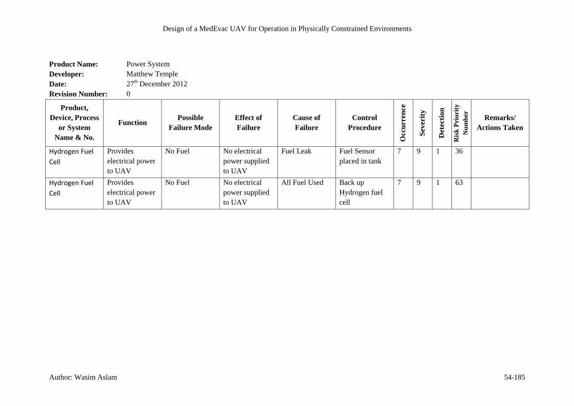
Design of a MedEvac UAV for Operation in Physically Constrained Environments
Author: Wasim Aslam 54-185
Product Name: Power System
Developer: Matthew Temple
Date: 27th December 2012
Revision Number: 0
Product,
Device, Process
or System
Name & No.
Function Possible
Failure Mode
Effect of
Failure
Cause of
Failure
Control
Procedure
Occ
urr
ence
Sev
erit
y
Det
ecti
on
Ris
k P
rio
rity
Nu
mb
er
Remarks/
Actions Taken
Hydrogen Fuel
Cell
Provides
electrical power
to UAV
No Fuel No electrical
power supplied
to UAV
Fuel Leak Fuel Sensor
placed in tank
7 9 1 36
Hydrogen Fuel
Cell
Provides
electrical power
to UAV
No Fuel No electrical
power supplied
to UAV
All Fuel Used Back up
Hydrogen fuel
cell
7 9 1 63

Design of a MedEvac UAV for Operation in Physically Constrained Environments
Author: Matthew Temple 54-186
Product Name: Communications System
Developer: Matthew Temple
Date: 27th December 2012
Revision Number: 0
Product,
Device, Process
or System
Name & No.
Function Possible
Failure Mode
Effect of
Failure
Cause of
Failure
Control
Procedure
Occ
urr
ence
Sev
erit
y
Det
ecti
on
Ris
k P
rio
rity
Nu
mb
er
Remarks/
Actions Taken
Antenna Send or Receive
data from
satellite
Loss of control Loss of
Communication
Motor Jam Motion sensors
in antenna used
to sense current
position
1 10 2 20 If the antenna
fails, the UAV
must fly back to
the home base
autonomously
Antenna Send or Receive
data from
satellite
Loss of control Loss of
Communication
Damage from
Projectiles
Motion sensors
in antenna used
to sense current
position
4 10 2 80 If the antenna is
damaged, the
UAV must fly
back to the
home base
autonomously
Communication
s Computer
Controls all of
the control
based
operations on
the UAV
System Crash Loss of
communication
Software crash Resetable by
flight computer
if no response
1 9 2 18

Design of a MedEvac UAV for Operation in Physically Constrained Environments
Author: Matthew Temple 54-187
Product Name: Navigation System
Developer: Matthew Temple
Date: 27th December 2012
Revision Number: 0
Product,
Device, Process
or System
Name & No.
Function Possible
Failure Mode
Effect of
Failure
Cause of
Failure
Control
Procedure
Occ
urr
ence
Sev
erit
y
Det
ecti
on
Ris
k P
rio
rity
Nu
mb
er
Remarks/
Actions Taken
Obstacle LiDAR
Unit
Detects
obstacles
around the UAV
Mechanical
Failure
Loss of scan
capability,
resulting in
single point
measurement
Motor Jam 3 9 2 54 Flight computer
needs to
monitor power
consumption, as
motor jam
would increase
power draw
Obstacle LiDAR
Unit
Detects
obstacles
around the UAV
System Crash Loss of Obstacle
Detection
capability
Software Crash Resettable by
Flight Computer
1 9 2 18
Landing LiDAR
Unit
Detects suitable
landing sites for
the UAV
Mechanical
Failure
Loss of scan
capability,
resulting in
single point
measurement
Motor Jam 3 9 2 54 Flight computer
needs to
monitor power
consumption, as
motor jam
would increase
power draw
Landing LiDAR
Unit
Detects suitable
landing sites for
System Crash Loss of landing
site detection
Software Crash Resettable by
Flight Computer
1 9 2 18

Design of a MedEvac UAV for Operation in Physically Constrained Environments
Author: Matthew Temple 54-188
the UAV capability
Altitude Sensor Detects the
current altitude
of the UAV
Sensor Failure Cannot
calculate
altitude of UAV
Damage from
Projectile
4 9 2 72 Flight computer
needs to send
warning to
ground control
station, add
redundancy
Inertial
Measurement
Unit
Detects the
current
orientation of
the UAV
Sensor Failure Cannot
calculate
orientation of
UAV
Damage from
Projectile
4 9 2 72 Flight computer
needs to send
warning to
ground control
station, add
redundancy
Global
Positioning Unit
Detects the
current position
of the UAV
Sensor Failure Cannot detect
position of UAV
Damage from
Projectile
4 9 2 72 Flight computer
needs to send
warning to
ground control
station, add
redundancy
Landing Camera Images possible
landing sites for
the ground staff
System Crash Cannot image
landing sites for
ground control
staff
Software Crash Resettable by
Flight Computer
1 9 2 18
Flight Computer Controls all of
the flight
operations on
the UAV
System Crash Loss of control
of the Aircraft
Software Crash Back up
computer to
take over if
needed
1 9 2 18

Design of a MedEvac UAV for Operation in Physically Constrained Environments
Author: Matthew Temple 54-189
Product Name: Communications System
Developer: Matthew Temple
Date: 27th December 2012
Revision Number: 0
Product,
Device, Process
or System
Name & No.
Function Possible
Failure Mode
Effect of
Failure
Cause of
Failure
Control
Procedure
Occ
urr
ence
Sev
erit
y
Det
ecti
on
Ris
k P
rio
rity
Nu
mb
er
Remarks/
Actions Taken
Power Cable Provides power
to the
components on
the UAV
Cable Severed Loss of power to
component
Vibration /
Damage from
projectile
Multicore cable
used to
minimise risk
4 10 2 80
Power Cable Provides power
to the
components on
the UAV
Loose connector Loss /
intermittent
power supply
Vibration Screw type
connector used
3 10 2 60
Data Cable Sends data
between
components on
the UAV
Cable Severed Loss of
communication
Vibration /
Damage from
projectile
Multicore cable
used to
minimise risk
4 9 2 72
Data Cable Sends data
between
components on
the UAV
Loose connector Loss /
intermittent
communication
Vibration Screw type
connector used
3 10 2 60

Design of a MedEvac UAV for Operation in Physically Constrained Environments
Author: Maria Wood 54-190
Product Name: Transmission
Developer: Maria Wood
Date: 17th December 2012
Revision Number: 0
Product,
Device, Process
or System
Name & No.
Function Possible
Failure Mode
Effect of
Failure
Cause of
Failure
Control
Procedure
Occ
urr
ence
Sev
erit
y
Det
ecti
on
Ris
k P
rio
rity
Nu
mb
er Remarks/
Actions
Taken
Drive Shaft Transmit
rotational power
from engines to
fans
Torsion No transmission Overloading Ensure high
safety margin,
Regular
inspection of
cracks etc
4 10 6 240 Use strain
gauges to
monitor,
testing to
fatigue life
Drive Shaft Transmit
rotational power
from engines to
fans
Bending No transmission Overloading Ensure high
safety margin,
Regular
inspection of
cracks etc
4 10 6 240 Use strain
gauges to
monitor,
testing to
fatigue life
Gears Transmit
rotational power
from engines to
fans
Gear teeth
shearing
No transmission Overloading Ensure high
safety margin,
Regular
inspection of
cracks etc
4 10 6 240 Use strain
gauges to
monitor,
testing to
fatigue life

Design of a MedEvac UAV for Operation in Physically Constrained Environments
Author: Maria Wood 54-191
Product Name: Pulse Oximeter
Developer: Maria Wood
Date: 17th December 2012
Revision Number: 0
Product,
Device, Process
or System
Name & No.
Function Possible
Failure Mode
Effect of
Failure
Cause of
Failure
Control
Procedure
Occ
urr
ence
Sev
erit
y
Det
ecti
on
Ris
k P
rio
rity
Nu
mb
er
Remarks/
Actions Taken
Pulse Oximeter Monitor
casualty blood-
oxygen level
No connection No
measurement of
blood-oxygen
level
Electrical
breakage
No connection
to computer; try
another device
4 4 2 32 Severity
dependent upon
casualty
condition
Pulse Oximeter Monitor
casualty blood-
oxygen level
Incorrect
positioning
No or inaccurate
measurement of
blood-oxygen
level
Soldier with
casualty
Training;
information
inside MedEvac;
support from
ground station
Medic
6 4 2 48 Severity
dependent upon
casualty
condition
Pulse Oximeter Monitor
casualty blood-
oxygen level
Faulty device No or inaccurate
measurement of
blood-oxygen
level
Manufacture of
Pulse Oximeter
No connection
to computer; try
another device
4 4 2 32 Severity
dependent upon
casualty
condition

Design of a MedEvac UAV for Operation in Physically Constrained Environments
Author: Maria Wood 54-192
Product Name: Blood Pressure Patch
Developer: Maria Wood
Date: 17th December 2012
Revision Number: 0
Product,
Device, Process
or System
Name & No.
Function Possible
Failure Mode
Effect of
Failure
Cause of
Failure
Control
Procedure
Occ
urr
ence
Sev
erit
y
Det
ecti
on
Ris
k P
rio
rity
Nu
mb
er
Remarks/
Actions Taken
Blood Pressure
Patch
Monitor
casualty blood
pressure
No connection No
measurement of
blood pressure
Electrical
breakage
No connection
to computer; try
another device
4 4 2 32 Severity
dependent upon
casualty
condition
Blood Pressure
Patch
Monitor
casualty blood
pressure
Incorrect
positioning
No or inaccurate
measurement of
blood pressure
Soldier with
casualty
Training;
information
inside MedEvac;
support from
ground station
Medic
6 4 2 48 Severity
dependent upon
casualty
condition
Pulse Oximeter Monitor
casualty blood
pressure
Faulty device No or inaccurate
measurement of
blood pressure
Manufacture of
blood pressure
patch
No connection
to computer; try
another device
4 4 2 32 Severity
dependent upon
casualty
condition

Design of a MedEvac UAV for Operation in Physically Constrained Environments
Author: Maria Wood 54-193
Product Name: Intraosseous Insertion
Developer: Maria Wood
Date: 17th December 2012
Revision Number: 0
Product,
Device, Process
or System
Name & No.
Function Possible
Failure Mode
Effect of
Failure
Cause of
Failure
Control
Procedure
Occ
urr
ence
Sev
erit
y
Det
ecti
on
Ris
k P
rio
rity
Nu
mb
er
Remarks/
Actions Taken
Intraosseous
Insertion
For the insertion
of fluids, drugs,
blood
Incorrect
insertion
Unable to insert
fluids; cause
additional injury
to casualty
Lack of training Training 6 10 5 300 Support from
ground medic
Intraosseous
Insertion
For the insertion
of fluids, drugs,
blood
Fracture in bone Unable to insert
fluids; cause
additional injury
to casualty
Injury Multiple
insertion sites
6 7 7 294 Support from
ground medic
Intraosseous
Insertion
For the insertion
of fluids, drugs,
blood
Needle breaks Unable to insert
fluids; cause
additional injury
to casualty
Faulty
equipment; lack
of training
Multiple
insertion sites
5 10 4 200 Support from
ground medic

Design of a MedEvac UAV for Operation in Physically Constrained Environments
Author: Maria Wood 54-194
Product Name: Blood Transfusion
Developer: Maria Wood
Date: 17th December 2012
Revision Number: 0
Product,
Device, Process
or System
Name & No.
Function Possible
Failure Mode
Effect of
Failure
Cause of
Failure
Control
Procedure
Occ
urr
ence
Sev
erit
y
Det
ecti
on
Ris
k P
rio
rity
Nu
mb
er
Remarks/
Actions Taken
Blood
Transfusion
To recover
blood loss
Reaction to
blood type used
Casualty
condition
worsens
Incompatibility
of blood
Stop blood
transfusion;
Require
immediate
attention; access
to casualty notes
3 9 10 270 Unless blood
type of
casualty is
known, type O
Rh-negative
blood will be
used. Will not
know there is
an
incompatibility
until reaction is
seen in
casualty
Blood
Transfusion
To recover
blood loss
Blood not kept
at correct
temperature
which leads to
bacteria growth
Casualty
condition
worsens
Insufficient
monitoring of
refrigeration
system
Stop blood
transfusion;
Require
immediate
attention
4 9 3 108 Alarms on
refrigeration
system/ power
loss

Design of a MedEvac UAV for Operation in Physically Constrained Environments
Author: Sarad Limbu Lawati 54-195
Product Name: Ducted Fans
Developer: Sarad Limbu Lawati
Date: 9th January 2013
Revision Number: 0
Sheet Number: 1 of 1
Product,
Device, Process
or System
Name & No.
Function Possible
Failure Mode
Effect of
Failure
Cause of
Failure
Control
Procedure
Occ
urr
ence
Sev
erit
y
Det
ecti
on
Ris
k P
rio
rity
Nu
mb
er
Remarks/
Actions Taken
Fans Propulsion/
Thrust.
Damage Low thrust
performance and
unstable flight
Bird strikes,
stuff entering
the duct while in
operation
Cover the duct
with a net made
of strong fibre.
1 7 1 7 Replace or
repair the
damaged fan or
fan blades.
Static Pressure
loss or
insufficient
airflow.
Fan blades stall Auto detection
from control
unit.
2 2 1 4 Control systems
auto adjust fan
RPM (and )or
descend to a
lower altitude.
Main Ducts Improve air
flow, thrust and
shield the fan
blades.
Material failure
due to stress
loads
Material Failure,
enemy fire
(bullets etc) and
cracking growth
due to cyclic
loading for long
periods.
Routine Checks
and Repairs.
Avoid enemy
attacks where
possible.
3 4 2 24 Repair /
Replace.
Second Duct Divert airflow
into the main
duct in order to
reduce flow
separation
problems.
Same as above.
Also, noise
increase and
power demand.
4 2 1 8 Critical to duct
performance in
forward flight.
So, Replace
/repair. And
since a 2nd
duct

Design of a MedEvac UAV for Operation in Physically Constrained Environments
Author: Sarad Limbu Lawati 54-196
is on each end
of UAV, it can
fly either ways
facing forward.
Stator Vanes Support
structure for
duct
components and
straightening the
flow as well as
noise control.
No/less support
for Fan. If all
fail then no
thrust. If only
one fails then
reduced
performance.
Routine Checks
and Repairs.
5 4 4 80 Continuous
checks.
Flow diverting
Flaps
Thrust
Vectoring
Failure due to its
structural
components.
Less control of
the UAV.
Components
such as screws
and bolts being
loose of
jammed.
Control
algorithms will
adjust the flight
.
7 2 1 14 Routine Checks,
maintenance and
Repairs
Duct Flaps Control for
rolling moments
7 2 1 14

Design of a MedEvac UAV for Operation in Physically Constrained Environments
Author: Dela Yohuno 54-197
Product Name: Medical systems
Developer: Dela Yohuno
Date: 28th November 2012
Revision Number: 0
Sheet Number: 1 of 1
Product,
Device, Process
or System
Name & No.
Function Possible
Failure Mode
Effect of
Failure
Cause of
Failure
Control
Procedure
Occ
urr
ence
Sev
erit
y
Det
ecti
on
Ris
k P
rio
rity
Nu
mb
er
Remarks/
Actions Taken
Chest
compressions
and ECG
analysis
Performing CPR
to a casualty
Chest
compressions
interfering with
ECG analysis
Unable to
monitor ECG
signal and shock
patient
Interference
between two
devices
Pause chest
compression
before ECG
monitoring
4 4 4 64 Enable the two
devices to
communicate,
pause chest
compressions
before ECG
analysis.
Rotary servo
motors
Provide a stable
platform for the
patient
Patient is too
heavy/ power
cut
Loose, unstable
platform, unable
to lock the angle
in a position
Power-loss/ high
torque applied
Servo motor
brake mounted
locks angle in
case of
powercut and
higher brake
torque
6 4 2 48
Oxygen cylinder
gas leak
Supplying
oxygen to
ventilator and
other necessary
equipment
Damage
resulting in
puncture of
cylinder
Potentially
dangerous
explosive
environment
because of
Cylinder
damage,
Oxygen sensors
to detect leak,
vales to bleed
oxygen out of
the cabin,
3 6 1 18

Design of a MedEvac UAV for Operation in Physically Constrained Environments
Author: Dela Yohuno 54-198
electronics and
possible spark
Medical
equipment
Provide medical
trestment
Movement of
Medevac
causing medical
equipment to be
hazardous to
patient
Dangerous for
patient
Equipment not
secured
Secure
equipment well
2 5 1 10
IV Lines Supply the
patient with
fluids
Electromagnetic
interference
Stops treatment
or malfunction
High energy
radio
frequencies
Locate away
from High
frequency
raioation
4 3 1 12

Design of a MedEvac UAV for Operation in Physically Constrained Environments
Author: Group 54-199
Estimate the Frequency of Occurrence of the Failure
1. 1 in 1500000
2. 1 in 150000
3. 1 in 15000
4. 1 in 2000
5. 1 in 400
6. 1 in 80
7. 1 in 20
8. 1 in 8
9. 1 in 3
10. 1 in 2
Estimate the Severity of Failure – Severity Rating
1. No effect
2. Defect noticed by discriminating customers. Defect product - rectified in process
3. Defect noticed by average customers. Defect products <100% - rectified in process
4. Defect noticed by most customers. Defect products 100% - rectified or sorted
5. Secondary functionality operable at reduced performance level. Defect products 100% -
rectified or sorted
6. Secondary functionality unavailable. Defect products 100% - scrapped
7. Primary functionality operable at reduced performance level. Defect products <100% -
scrapped
8. Primary functionality unavailable. Defect products 100% - scrapped
9. Failure would endanger customer, machine or operator with a warning
10. Failure would endanger customer, machine or operator without warning
Estimate the Detection of Failure – Detection Rating
1. Current controls certain to detect/prevent failure mode
2. Current controls almost certain to detect/prevent failure mode
3. Very high likelihood current controls detect/prevent failure mode
4. High likelihood current controls detect/prevent failure mode
5. Moderately high likelihood current controls detect/prevent failure mode
6. Low likelihood current controls detect/prevent failure mode
7. Very low likelihood current controls detect/prevent failure mode
8. Remote likelihood current controls detect/prevent failure mode
9. Very remote likelihood current controls detect/prevent failure mode
10. Current controls will not detect/prevent failure mode
Estimate the Risk Priority Number
Multiply together the ratings for occurrence, severity and detection.
Copyright © 2022 FDOKUMEN