ROBUST SECOND ORDER SLIDING MODE CONTROL FOR A QUADROTOR CONSIDERING MOTOR DYNAMICS
562 IEEE TRANSACTIONS ON CONTROL SYSTEMS TECHNOLOGY, VOL. 14, NO. 3, MAY 2006
Attitude Stabilization of a VTOL Quadrotor AircraftAbdelhamid Tayebi and Stephen McGilvray
Abstract—In this paper, we propose a new quaternion-basedfeedback control scheme for exponential attitude stabilization ofa four-rotor vertical takeoff and landing aerial robot known asa quadrotor aircraft. The proposed controller is based upon thecompensation of the Coriolis and gyroscopic torques and the useof a PD2 feedback structure, where the proportional action isin terms of the vector quaternion and the two derivative actionsare in terms of the airframe angular velocity and the vectorquaternion velocity. We also show that the model-independentPD controller, where the proportional action is in terms of thevector-quaternion and the derivative action is in terms of the air-frame angular velocity, without compensation of the Coriolis andgyroscopic torques, provides asymptotic stability for our problem.The proposed controller as well as some other controllers havebeen tested experimentally on a small-scale quadrotor aircraft.
Index Terms—Attitude stabilization, nonlinear control,quadrotor, rigid body in space, vertical takeoff and landing(VTOL) aircraft.
I. INTRODUCTION
UNMANNED vehicles are important when it comes to per-forming a desired task in a dangerous and/or unacces-
sible environment. Unmanned indoor and outdoor mobile robotshave been successfully used for some decades. More recently, agrowing interest in unmanned aerial vehicles (UAVs) has beenshown among the research community. Being able to design avertical takeoff and landing (VTOL)-UAV, which is highly ma-neuverable and extremely stable, is an important contributionto the field of aerial robotics since potential applications aretremendous (e.g., high buildings and monuments investigation,rescue missions, film making, etc.). In practical applications, theposition in space of the UAV is generally controlled by an op-erator through a remote-control system using a visual feedbackfrom an onboard camera, while the attitude is automatically sta-bilized via an onboard controller. The attitude controller is animportant feature since it allows the vehicle to maintain a de-sired orientation and, hence, prevents the vehicle from flippingover and crashing when the pilot performs the desired maneu-vers.
The attitude control problem of a rigid body has been investi-gated by several researchers and a wide class of controllers hasbeen proposed (see, for instance, [3], [7], [10], [17], and [19],and the list is not exhaustive). This is a particularly interesting
Manuscript received September 20, 2004; revised February 11, 2005. Man-uscript received in final form December 2, 2005. Recommended by AssociateEditor C.-Y. Su. This work was supported in part by the Natural Sciences andEngineering Research Council (NSERC) of Canada, in part by the Canada Foun-dation for Innovation (CFI), and in part by the Ontario Innovation Trust (OIT).
A. Tayebi is with the Department of Electrical Engineering, Lakehead Uni-versity, Thunder Bay, ON P7B 5E1, Canada (e-mail: [email protected]).
S. McGilvray is with the Department of Electrical and Computer Engi-neering, University of Western Ontario, London, ON N6A 5B8, Canada (e-mail:[email protected]).
Digital Object Identifier 10.1109/TCST.2006.872519
problem in dynamics since the angular velocity of the bodycannot be integrated to obtain the attitude of the body [7]. Thepaper [17] contains an interesting list of references and proposesseveral control algorithms guaranteeing asymptotic stabilityand, under certain initial conditions, local exponential stabilityis shown. Most of the existing attitude controllers in the litera-ture are based upon the use of the quaternion representation todescribe the attitude of the body. This particular representationallows avoiding the singularities inherent to the direction cosinematrix obtained from Euler rotations [6], [8]. To the best of ourknowledge, most of the proposed controllers in the availableliterature in this field are tested in simulation. In [12], a com-plete description of an experimental four-rotor aerial robot hasbeen presented without any experimental results. In [2], a com-mercially available gyro-stabilized quadrotor (Draganflyer III)has been used to test their controller without bypassing the gyro-stabilization feature.
In this paper, we consider the attitude stabilization problemof the quadrotor aircraft. The dynamical model describing theattitude of the quadrotor aircraft contains an additional gyro-scopic term caused by the combination of the rotations of theairframe and the four rotors, as well as four additional equationsdescribing the dynamics of the four rotors. In the case wherethe gyroscopic term is set to zero, and the airframe torques aretaken as the actual control inputs, this dynamical model reducesto the well-known model used in the literature concerning theattitude control of a rigid body. Despite the additional gyro-scopic term, we show that the classical model-independent pro-portional derivative (PD) controller can asymptotically stabilizethe attitude of the quadrotor aircraft. Moreover, using a newLyapunov function, we derive an exponentially stabilizing con-troller based upon the compensation of the Coriolis and gyro-scopic torques and the use of a PD feedback structure, wherethe proportional action is in terms of the vector-quaternion andthe two derivative actions are in terms of the airframe angularvelocity and the vector-quaternion velocity. The global expo-nential stability property of our new controller, due mainly tothe introduction of the derivative action in terms of the quater-nion vector and the compensation of the Coriolis and gyroscopictorques, offers a great advantage in practical applications interms of transient performance and disturbance rejection espe-cially for large angles and high-speed maneuvers. The proposedcontroller as well as some other controllers have been tested ex-perimentally on a small-scale quadrotor aircraft. A preliminaryversion of this paper has been presented in [16].
II. MATHEMATICAL MODEL
The quadrotor aircraft under consideration consists of a rigidcross frame equipped with four rotors as shown in Fig. 1. Theup (down) motion is achieved by increasing (decreasing) the
1063-6536/$20.00 © 2006 IEEE
Authorized licensed use limited to: Harbin Institute of Technology. Downloaded on April 6, 2009 at 11:35 from IEEE Xplore. Restrictions apply.

IEEE TRANSACTIONS ON CONTROL SYSTEMS TECHNOLOGY, VOL. 14, NO. 3, MAY 2006 563
Fig. 1. Quadrotor aircraft.
total thrust while maintaining an equal individual thrust. Theforward/backward, left/right and the yaw motions are achievedthrough a differential control strategy of the thrust generatedby each rotor. In order to avoid the yaw drift due to the reac-tive torques, the quadrotor aircraft is configured such that theset of rotors (right–left) rotates clockwise and the set of ro-tors (front-rear) rotates counterclockwise. There is no changein the direction of rotation of the rotors (i.e., ,
). If a yaw motion is desired, one has to reduce thethrust of one set of rotors and increase the thrust of the otherset while maintaining the same total thrust to avoid an up–downmotion. Hence, the yaw motion is then realized in the direc-tion of the induced reactive torque. On the other hand, forward(backward) motion is achieved by pitching in the desired direc-tion by increasing the rear (front) rotor thrust and decreasingthe front (rear) rotor thrust to maintain the total thrust. Finally,a sideways motion is achieved by rolling in the desired direc-tion by increasing the left (right) rotor thrust and decreasingthe right (left) rotor thrust to maintain the total thrust. Let
denote an inertial frame, and de-note a frame rigidly attached to the aircraft as shown in Fig. 1.The dynamical model described in [4], ignoring aerodynamiceffects,1 with a slight modification of the gyroscopic torques ex-pression due to the fact that the pair of rotors 1–3 rotate in op-posite direction of the pair 2–4, is given as follows:
(1)
(2)
(3)
(4)
(5)
where denotes the mass of the airframe, denotes the accel-eration due to gravity, denotes the unit vector
1This is justified since our experiment involves a small-scale quadrotor fixedto a ball joint base designed to test the attitude control.
in the frame , the vector denotes the positionof the origin of the body-fixed frame with respect to the in-ertial frame , the vector denotes the linearvelocity of the origin of expressed in , denotes the an-gular velocity of the airframe expressed in the body-fixed frame
. The orientation of the airframe is given by the orthogonal ro-tation matrix depending on the three Euler angles
, , and denoting, respectively, the roll, the pitch, and theyaw [16]. is a symmetric positive–definite constantinertia matrix of the airframe with respect to the frame whoseorigin is at the center of mass. The speed and moment of inertiaof the rotor are denoted, respectively, by and . The matrix
is a skew-symmetric matrix such that forany vector , where denotes the vector cross-product.
The reactive torque generated, in free air, by the rotor dueto rotor drag is given by
(6)
and the total thrust generated by the four rotors is given by
(7)
where is the lift generated by the rotor in freeair (expressed in ), and , are two parametersdepending on the density of air, the size, shape, and pitch angleof the blades, as well as other factors (see [11] and [13] for moredetails).
The vector contains the gyroscopic torques due to thecombination of the rotation of the airframe and the four rotors,and is given by
(8)
The airframe torques generated by the rotors are given by, with
(9)
where represents the distance from the rotors to the center ofmass of the quadrotor aircraft.
Finally, the four control inputs of the system are ,, which represent the torques produced by the rotors.
Remark 1: Some comparative points with respect to a tra-ditional helicopter can be given as follows: In traditional heli-copters, the yaw motion, due to the reactive torque of the mainrotor, is compensated by the torque produced by the tail rotor.The energy spent on the tail rotor makes no contribution to theupward thrust of the helicopter. Comparatively, in the quadrotordesign, if the four rotors rotate at the same speed, there will beno yaw motion since the reactive torques are cancelled out, asone pair of rotors rotates in the opposite direction of the otherpair. In this case, all of the energy spent on the four rotors con-tributes to generate the upward thrust. The same upward thrustgenerated by a single rotor in traditional helicopters can be gen-erated by four smaller rotors for the quadrotor; and the fact ofusing rotors with smaller size helps to reduce the induced me-chanical vibrations comparatively to a single large main rotor.
Authorized licensed use limited to: Harbin Institute of Technology. Downloaded on April 6, 2009 at 11:35 from IEEE Xplore. Restrictions apply.

564 IEEE TRANSACTIONS ON CONTROL SYSTEMS TECHNOLOGY, VOL. 14, NO. 3, MAY 2006
On the other hand, traditional helicopters have somewhat com-plicated mechanisms for achieving controlled flight, while forthe quadrotor, controlled flight is achieved in a quite intuitivemanner by differential thrust control of the four rotors as ex-plained in the previous section.
III. ATTITUDE CONTROL DESIGN
In this section, we aim to design a feedback control schemefor the attitude stabilization of the quadrotor aircraft. To thisend, we will make use of (3)–(5). Equations (1)–(2) describingthe position and the linear velocity of the center of the body-at-tached frame are not used. Our approach consists of two parts.In the first part, we design the desired airframe torques forthe attitude stabilization. In this part, we present two controlschemes; the first one is model dependent and guarantees ex-ponential stability while the second one is model independentbut guarantees only asymptotic stability. In the second part, wedesign the rotor torques required to obtain the desired airframetorques designed in the first part.
One of the drawbacks related to the use of the direction cosinematrix is the inherent geometric singularity. This drawbackcan be avoided by using the four-parameter description of theorientation called the quaternion representation [6]–[9], [17],which is based upon the fact that any rotation of a rigid body canby described by a single rotation about a fixed axis [15]. Thisglobally nonsingular representation of the orientation is givenby the vector with
(10)
where is the equivalent rotation angle about the axis describedby the unit vector , subject to the constraint
(11)
The rotation matrix is related to the quaternion through theRodriguez formula [5], [15], and an algorithm for the quater-nion extraction is presented in [9]. Although the quaternion rep-resentation is nonsingular, it contains a sign ambiguity (i.e.,
and lead to the same orientation) which canbe resolved by choosing the following differential equations [5],[17]:
(12)
where is a 3 3 identity matrix.
A. Step 1: Airframe Torques Design
In this part, we consider as a control input to be designedfor the attitude stabilization of the quadrotor aircraft. Withoutthe gyroscopic term, the dynamical model (3)–(4) is similar tothe well-known model used in the literature concerning the at-titude control of a rigid body. Our objective is to stabilize theequilibrium point , or . This canbe achieved by the stabilization of the two equilibrium points
for (12) and (4). Sincecorresponds to and corresponds to ,it is clear that correspond to the same physical point.Hence, the two equilibrium points are,
in reality, a unique physical equilibrium point corresponding to. In the sequel, the Euler angles and the equiva-
lent rotation angle are taken between and , which implythat .
Now, one can state the following result:Theorem 1: consider (3) and (4) under the following control
law:
(13)
where , , and, with is a 3 3 symmetric
positive definite matrix and
• , are 3 3 diagonal positive definite matrices in thecase where is diagonal;
• is a 3 3 symmetric positive definite matrix and, where is a positive scalar, in the case where is not
diagonal.Then, the equilibrium point is exponentiallystable.
Proof: Let us consider the following Lyapunov functioncandidate:
(14)
whose time derivative, in view of (4) and (11)–(13) is given by
(15)
which implies that the state variables of (4) and (12) arebounded and . This implies that
. Hence, from (11), one can con-
clude that (note that is excluded
since the angles are taken such that ).Now, let us show the exponential stability. From the fact that
and (11), we have
(16)
Consequently, can be bounded from above as follows:
(17)
On the other hand, can be bounded from above as follows:
(18)
Hence, from (17) and (18), one can conclude that ,where
with and denoting, respectively, the minimumand maximum eigenvalue of .
Remark 2: If we consider the system such that is suffi-ciently small and close to identity, the Coriolis and gyroscopicterms can be neglected in the control law (13) to obtain the fol-lowing reduced-complexity locally stabilizing controller:
(19)
Note that the control law (13) requires the compensation of theCoriolis and gyroscopic torques involving the airframe inertia
and the rotor inertia . Now, we will show that the clas-sical PD feedback control without compensation of the Coriolis
Authorized licensed use limited to: Harbin Institute of Technology. Downloaded on April 6, 2009 at 11:35 from IEEE Xplore. Restrictions apply.

IEEE TRANSACTIONS ON CONTROL SYSTEMS TECHNOLOGY, VOL. 14, NO. 3, MAY 2006 565
and gyroscopic torques (i.e., model-independent control) canasymptotically stabilize the attitude of the quadrotor aircraft.
Theorem 2: Consider (3) and (4) under the following controllaw:
(20)
where is a 3 3 symmetric positive definite matrix and is apositive parameter. Then, the equilibrium pointis globally asymptotically stable.
Proof: The time derivative of the following Lyapunovfunction candidate:
(21)
in view of (4), (11), (12), and (20), and usingthe fact that and
, is given by
(22)
which implies that , and are bounded. UsingLa Salle’s invariance theorem, one can easily show that
and . Therefore,
the equilibrium point is globally asymptoti-cally stable.
Remark 3: It is easy to show the following controller withCoriolis and gyroscopic torques compensation:
(23)
with
• and are 3 3 diagonal positive definite matrices inthe case where is diagonal;
• is a 3 3 symmetric positive-definite matrix and, where is a positive scalar, in the case where is
not diagonal, provides global asymptotic stability for ourproblem. In fact, in contrast to the control law (20), thiscontroller allows to use a matrix gain for the quaternionfeedback.
Remark 4: The control law (13) can be written in the fol-lowing form:
(24)
which is basically a PD feedback with Coriolis and gyroscopictorques compensation. The two derivative actions are related tothe angular velocity ( ) and the “quaternion velocity” ( ). Notethat is obtained explicity from (12). The control law (20) isa classical PD feedback, where the derivative action is relatedto the angular velocity ( ). It is similar to the control laws pro-posed in [7], [10], and [19]. The main advantage of the controllaw (20) with respect to the control law (13) is the fact that themodel parameters are not required and the control law is muchsimpler to implement. The main advantages of the control law(13) with respect to the control law (20) are:
1) the ability to use a matrix gain instead of a scalar gainin the quaternion feedback;
2) the exponential convergence property mainly due to thecompensation of the Coriolis and gyroscopic terms and theuse of the vector-quaternion time-derivative .
Remark 5: It is worth noting that the set-point regulationproblem is implicitly included in the previous results. In fact, ifwe want to stabilize the quadrotor at an arbitrary configuration,we have to define the error vector asand obtain the corresponding quaternion to be used in theprevious control laws. Note that the desired attitude angles ,
, and can be specified by the pilot to control the motion ofthe quadrotor in space.
B. Step 2: Motor Torques Design
In reality, the control inputs in (1)–(5) are the four rotortorques , . To design the rotor torques, one hasto find the desired speed of each rotor , , cor-responding to the desired airframe torquesobtained from (13) or (20). To this end, we must specify thedesired total thrust or, for instance, obtain it from the altitudefeedback controlling the -position of the quadrotor aircraftas discussed later in Remark 7. The desired speed for the fourmotors can be obtained from (7) and (9). That is, ,with , and
(25)
where is nonsingular as long as .Note that in certain cases, some elements of resulting
from might be negative, suggesting the reversal of therotors direction, which is not feasible in our case. This case isnot likely to occur if the desired total thrust is sufficientlylarge with respect to the required airframe torques.
Now, having , , one can design as fol-lows:
(26)
where , are four positive parameters, and. In fact, applying (26) to (5) leads to
(27)
which shows the exponential convergence of to and,hence, the convergence of the airframe torques to the desiredvalues leading to the attitude stabilization of the quadrotoraircraft.
In our application, the dc motors are voltage controlled, sowe need to obtain the voltage input to each motor. Assumingthat the motor inductance is small and taking into considerationthe gear ratio, one can obtain the voltage to be applied to eachmotor as follows:
(28)
where is the motor resistance, is the motor torque-con-stant, and is the gear ratio. Since we are using the same mo-tors, all of the parameters are the same for the four motors. Fi-nally, the voltage is used to generate the pulsewidth-modu-lated (PWM) signal for the control of the motor .
Intuitively, for better transient performance, one has to en-sure that the convergence of to is faster than the conver-gence of the attitude to zero. This could be realized by taking
Authorized licensed use limited to: Harbin Institute of Technology. Downloaded on April 6, 2009 at 11:35 from IEEE Xplore. Restrictions apply.

566 IEEE TRANSACTIONS ON CONTROL SYSTEMS TECHNOLOGY, VOL. 14, NO. 3, MAY 2006
, where is defined in the proof of Theorem 1.Remark 6: In the control law (26), the derivative of the de-
sired rotors speed is required. It is possible to derive the analyt-ical expression for , using as follows:
(29)
where , , and. If we consider that the
desired total thrust is a constant, and , one can obtainfrom (29), using . The derivative of the desired air-
frame torque can be obtained explicitly from (13) or (20). Forthe control law in Theorem 2, one can obtain , using (4), (12),and (20), as follows:
(30)
However, to simplify our control implementation and avoidthe singularity occuring at , in our experiments, wewill obtain from using a filtered derivative also calledthe “dirty derivative” (i.e., , with
, where is the cutoff frequency).Remark 7: As stated before, the total thrust can be
designed in order to control the altitude ( -position) of thequadrotor aircraft. Assuming that the -position is availablefor feedback, one can use (1) and (2) to design in order tomake the altitude converge to the desired setpoint . For thesake of simplicity, one can consider the hover (or near to hover)case (i.e., ). In this case, one can easily design a linearfeedback controller using the tools from linear control theory.
Remark 8: In practice, the motion of the quadrotor aircraftin space is achieved by the pilot (onboard or through a remotecontrol) by specifying the desired total thrust, roll, pitch andyaw, while the attitude is automatically controlled according tothe algorithms proposed in the previous section. The pilot canalso use an automatic altitude controller discussed in Remark 7,in order to hover at a constant desired altitude. In the box“Pilot/Remote control” shown in Fig. 2, an adequate strategycould be implemented to generate the desired attitude anglesand the desired total thrust.
IV. EXPERIMENTAL RESULTS
Our experimental quadrotor aircraft is an “in-house” modi-fied version of the Draganflyer III from RC Toys (http://www.rctoys.com). In fact, we kept the airframe, the motors, and theblades of the Draganflyer III and added our own “low-cost” sen-sors and electronic circuitry. Since, our objective was to safelytest our attitude controller, we decided to use a stationary balljoint base, as shown in Fig. 3. This base gives the aircraft unre-stricted yaw movement and around of pitch and roll, whilerestricting the aircraft to a fixed point in the three-dimensionalspace.
Experimental testing has been performed, with a samplingfrequency of 2 kHz, using a dSPACE DS1104 R&D controllerboard. The dSPACE ControlDesk software in combination with
Fig. 2. Control implementation.
Fig. 3. Quadrotor aircraft experimental setup.
Matlab, Simulink, and Real-Time Workshop allows an easy im-plementation of the control algorithm in block diagram formatvia simulink, with real-time adjustments of the control gains.
The four dc permanent-magnet mini motors are geared toeach rotor by a speed reduction ratio of 5.6:1. The motors arecurrent amplified with a power metal-oxide semiconductorfield-effect transistor and driven by PWM signals.
The rotor velocities , are obtained from HallEffect sensors in combination with earth magnets.
The desired acceleration of each rotorrequired for the motor torques
control design has been obtained by using a filtered derivativeof the form whererepresents a cutoff frequency of 20 Hz. The angular velocityof the aircraft is obtained from three orthogonally mountedgyroscopes. High-frequency noise is sufficiently removed fromthe measurement by adding first-order low-pass softwarefilters each with a cutoff frequency of 20 Hz.
Attitude estimation of the aircraft has proven to be a chal-lenge. Accurate measurements of the roll, pitch and yaw an-gles in real-time over a wide range of operating conditions arenot easily achieved. Real-time attitude estimation has requiredfusing measurements from the gyroscopes with measurements
Authorized licensed use limited to: Harbin Institute of Technology. Downloaded on April 6, 2009 at 11:35 from IEEE Xplore. Restrictions apply.

IEEE TRANSACTIONS ON CONTROL SYSTEMS TECHNOLOGY, VOL. 14, NO. 3, MAY 2006 567
TABLE IQUADROTOR AIRCRAFT MODEL PRAMETERS
Fig. 4. Aircraft angles, controller (13), Experiment 1.
Fig. 5. Angular velocity, controller (13), Experiment 1.
from accelerometers. Configuring accelerometers2 along theand the axes as tilt-meters and fusing this data with the
2A dual axis low-power device manufactured with microelectromechan-ical-system (MEMS) technology on a single integrated circuit (IC) weighsless than 1 g.
Fig. 6. Aircraft angles, controller (19), Experiment 1.
Fig. 7. Angular velocity, controller (19), Experiment 1.
measurements from the two gyroscopes mounted along thesame axes by complementary filtering yields relatively accurateand drift free pitch and roll angle measurements [1]. Similarresults are also possible for the yaw angle by fusing compassdata with the yaw gyro signal, but have not been realized dueto difficulties with compass readings.
In fact, the roll and pitch, for relatively small variationsaround the equilibrium point, are obtained through the fusionprocess, as follows , where denotes
or . The signal is obtained from the tilt-meter andis obtained from the gyroscope. The transfer functions and
are calculated such that the following equality is satisfied:
(31)
where and denote the transfer functions describing thedynamics of the tilt-meter and the gyroscope, respectively.
Authorized licensed use limited to: Harbin Institute of Technology. Downloaded on April 6, 2009 at 11:35 from IEEE Xplore. Restrictions apply.

568 IEEE TRANSACTIONS ON CONTROL SYSTEMS TECHNOLOGY, VOL. 14, NO. 3, MAY 2006
Fig. 8. Aircraft angles, controller (20), Experiment 1.
Fig. 9. Angular velocity, controller (20), Experiment 1.
Including the known dynamics for the tilt-meter, and assumingideal dynamics for the gyroscope, we have
(32)
Therefore, we can choose the filter-transfer functions as
(33)
The high-pass filter on the gyro branch effectively removes thelow-frequency signal components at 40 dB per decade, suffi-ciently reducing the effects of drift at lower frequencies. Sim-ilarly, the low-pass filter on the tilt-meter branch effectivelyremoves the high-frequency signal components at 20 dB perdecade.
Fig. 10. Aircraft angles, controller (23), Experiment 1.
Fig. 11. Angular velocity, controller (23), Experiment 1.
In fact, the need for additional filtering has been observedand implemented on both the gyroscope and tilt-meter measure-ments to obtain a cleaner fused signal. The first-order low-passfilters have cutoff frequencies set at 20 Hz for the roll and pitchgyro signals, 10 Hz for the yaw gyro signal, and 2 Hz for theroll and pitch tilt-meter signals.
This type of angle estimation through complementary fil-tering has proven effective for relatively small roll and pitchaircraft angles. However, if we consider larger aircraft angles,this method will only give accurate estimates for individualplanar rotations. More complex rotations of simultaneous roll,pitch and yaw angles require a nonlinear fusion technique as de-scribed in [14]. Due to the relative complexity and restrictionsof this method and the fact that our experiments are controlledwithin restricted aircraft angles, we opted for the linear fusionmethod for the roll and pitch angles estimation.
The yaw angle estimation , for relatively small vari-ations around the equilibrium point, is obtained by
, where denotes the measured angular ratefrom the yaw gyroscope and is a
Authorized licensed use limited to: Harbin Institute of Technology. Downloaded on April 6, 2009 at 11:35 from IEEE Xplore. Restrictions apply.

IEEE TRANSACTIONS ON CONTROL SYSTEMS TECHNOLOGY, VOL. 14, NO. 3, MAY 2006 569
Fig. 12. Aircraft angles, controller (13), Experiment 2 (disturbance rejection).
Fig. 13. Angular velocity, controller (13), Experiment 2 (disturbancerejection).
low-pass filter. The drift of the integrated yaw signal fromthe gyro alone has been noted and considered acceptable, andexperimentation has continued without compensation for theyaw drift.
Once the Euler angles have been obtained, it is necessary todetermine the equivalent Euler parameters, or quaternion repre-senting this attitude. As shown in [18], this can be achieved asfollows:
(34)The quadrotor aircraft model parameters are given inTable I. , , and denote the inertia of the air-frame in the roll, pitch and yaw rotational directions (i.e.,
).
Fig. 14. Aircraft angles, controller (19), Experiment 2 (disturbance rejection).
Fig. 15. Angular velocity, controller (19), Experiment 2 (disturbancerejection).
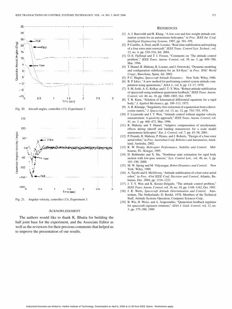
To explore the performance of each controller, three sets ofexperiments have been performed. Experiment 1 involves theaircraft attitude stabilization to zero starting from some initialconfigurations. In Experiment 2, we start the aircraft from an ini-tial configuration and we stabilize its attitude to zero; thereafter,disturbances are introduced on the pitch, roll and yaw to ex-plore the disturbance rejection performance. Both experiment 1and 2 are performed for the control laws (13), (19), (20), and(23). Finally, Experiment 3 is performed only for the control law(13). It illustrates the attitude stabilization to the desired config-uration ( , , ), starting fromsome initial angles. As shown in Figs. 4–21, for the three exper-iments, we plotted the time-response of the yaw, pitch and rollin one graph and the three angular velocities in another graph.
Experiments on controllers (13) and (19) were performedwith the following gains:
, , and .Experiments on controllers (20) and (23) were performed withthe following gains and . The
Authorized licensed use limited to: Harbin Institute of Technology. Downloaded on April 6, 2009 at 11:35 from IEEE Xplore. Restrictions apply.

570 IEEE TRANSACTIONS ON CONTROL SYSTEMS TECHNOLOGY, VOL. 14, NO. 3, MAY 2006
Fig. 16. Aircraft angles, controller (20), Experiment 2 (disturbance rejection).
Fig. 17. Angular velocity, controller (20), Experiment 2 (disturbancerejection).
desired thrust and gain remained the same throughout eachexperiment at , , respectively, while theinitial roll, pitch and yaw angles varied only slightly.
V. CONCLUSION
In this paper, it is shown that global exponential attitude sta-bilization can be achieved for the quadrotor aircraft. This resultis based upon the compensation of the Coriolis and gyroscopictorques and the use of a PD feedback structure, where the pro-portional action is in terms of the vector-quaternion and the twoderivative actions are in terms of the airframe angular velocityand the vector-quaternion velocity. We also showed that themodel-independent PD controller, where the proportional actionis in terms of the vector-quaternion and the derivative action isin terms of the airframe angular velocity, without compensationof the Coriolis and gyroscopic torques, provides global asymp-totic stability for our problem. The proposed controllers have
Fig. 18. Aircraft angles, controller (23), Experiment 2 (disturbance rejection).
Fig. 19. Angular velocity, controller (23), Experiment 2 (disturbancerejection).
been tested experimentally on a small-scale quadrotor aircraftequipped with “low-cost” sensors.
According to our experimental results (Figs. 4–21), the fourcontrollers (13), (19), (20), and (23) provided quite similar re-sults in terms of convergence and disturbance rejection. In fact,the compensation of the Coriolis and gyroscopic torques did notmake much of a difference in our particular case due to the ini-tial conditions and also to the relatively low speed. However, thiswill certainly make a difference in the case of large-angle ma-neuvers at high speed. Another important point that one shouldmention is the use of low-cost sensors for the attitude estimationas well as the linear fusion method used in our experiments. Thiswas justified since our experimental setup was restricted to rela-tively small initial conditions. In fact, for large-angle maneuversin the real world, more rigorous methods for the attitude estima-tion should be considered.
Authorized licensed use limited to: Harbin Institute of Technology. Downloaded on April 6, 2009 at 11:35 from IEEE Xplore. Restrictions apply.
IEEE TRANSACTIONS ON CONTROL SYSTEMS TECHNOLOGY, VOL. 14, NO. 3, MAY 2006 571
Fig. 20. Aircraft angles, controller (13), Experiment 3.
Fig. 21. Angular velocity, controller (13), Experiment 3.
ACKNOWLEDGMENT
The authors would like to thank K. Bhatia for building theball joint base for the experiment, and the Associate Editor aswell as the reviewers for their precious comments that helped usto improve the presentation of our results.
REFERENCES
[1] A. J. Baerveldt and R. Klang, “A low-cost and low-weight attitude esti-mation system for an autonomous helicopter,” in Proc. IEEE Int. Conf.Intelligent Engineering Systems, 1997, pp. 391–395.
[2] P. Castillo, A. Dzul, and R. Lozano, “Real-time stabilization and trackingof a four rotor mini rotorcraft,” IEEE Trans. Control Syst. Technol., vol.12, no. 4, pp. 510–516, Jul. 2004.
[3] O.-E. Fjellstad and T. I. Fossen, “Comments on ’The attitude controlproblem’,” IEEE Trans. Autom. Control, vol. 39, no. 3, pp. 699–700,Mar. 1994.
[4] T. Hamel, R. Mahony, R. Lozano, and J. Ostrowski, “Dynamic modelingand configuration stabilization for an X4-flyer,” in Proc. IFAC WorldCongr., Barcelona, Spain, Jul. 2002.
[5] P. C. Hughes, Spacecraft Attitude Dynamics. New York: Wiley, 1986.[6] B. P. Ickes, “A new method for performing control system attitude com-
putation using quaternions,” AIAA J., vol. 8, pp. 13–17, 1970.[7] S. M. Joshi, A. G. Kelkar, and J. T.-Y. Wen, “Robust attitude stabilization
of spacecraft using nonlinear quaternion feedback,” IEEE Trans. Autom.Control, vol. 40, no. 10, pp. 1800–1803, Oct. 1995.
[8] T. R. Kane, “Solution of kinematical differential equations for a rigidbody,” J. Applied Mechanics, pp. 109–113, 1973.
[9] A. R. Klumpp, “Singularity-free extraction of a quaternion from a direct-cosine matrix,” J. Spacecraft, vol. 13, no. 12, pp. 754–755, 1976.
[10] F. Lizarraide and J. T. Wen, “Attitude control without angular velocitymeasurement: A passivity approach,” IEEE Trans. Autom. Control, vol.41, no. 3, pp. 468–472, Mar. 1996.
[11] R. Mahony and T. Hamel, “Adaptive compensation of aerodynamiceffects during takeoff and landing manoeuvers for a scale modelautonomous helicopter,” Eur. J. Control, vol. 7, pp. 43–58, 2001.
[12] P. Pounds, R. Mahony, P. Hynes, and J. Roberts, “Design of a four-rotoraerial robot,” in Proc. Australian Conf. Robotics and Automation, Auck-land, Australia, 2002.
[13] R. W. Prouty, Helicopter Performance, Stability and Control. Mel-bourne, FL: Krieger, 1995.
[14] H. Rehbinder and X. Hu, “Nonlinear state estimation for rigid bodymotion with low-pass sensors,” Syst. Control Lett., vol. 40, no. 3, pp.183–190, 2000.
[15] M. W. Spong and M. Vidyasagar, Robot Dynamics and Control. NewYork: Wiley, 1989.
[16] A. Tayebi and S. McGilvray, “Attitude stabilization of a four-rotor aerialrobot,” in Proc. 43rd IEEE Conf. Decision and Control, Atlantis, Ba-hamas, Dec. 2004, pp. 1216–1221.
[17] J. T.-Y. Wen and K. Kreutz-Delgado, “The attitude control problem,”IEEE Trans. Autom. Control, vol. 36, no. 10, pp. 1148–1162, Oct. 1991.
[18] J. R. Wertz, Spacecraft Attitude Determination and Control. Ams-terdam, The Netherlands: D. Reidel, 1978, Members of the TechnicalStaff, Attitude Systems Operation, Computer Sciences Corp..
[19] B. Wie, H. Weiss, and A. Arapostathis, “Quaternion feedback regulatorfor spacecraft eigenaxis rotations,” AIAA J. Guid. Control, vol. 12, no.3, pp. 375–380, 1989.
Authorized licensed use limited to: Harbin Institute of Technology. Downloaded on April 6, 2009 at 11:35 from IEEE Xplore. Restrictions apply.
Copyright © 2022 FDOKUMEN