Video Transmission Using Quadrotor
84
A PROJECT REPORT ON VIDEO TRANSMISSION USING QUAD ROTOR By M.Zeeshan Shaikh (10S5918) Guided by Dr. Vrejesh Mehta A Project report submitted in partial fulfillment of the requirements for the award of Bachelors Project in Electronics & Telecommunication Engineering i
-
Upload
independent -
Category
Documents
-
view
2 -
download
0
Transcript of Video Transmission Using Quadrotor

A PROJECT REPORT
ON
VIDEO TRANSMISSION
USING QUAD ROTORBy
M.Zeeshan Shaikh (10S5918)
Guided by
Dr. Vrejesh Mehta
A Project report submitted in partial fulfillment
of the requirements for the award of
Bachelors Project in Electronics &
Telecommunication Engineering
i
MIDDLE EAST COLLEGE
Knowledge Oasis Muscat, Muscat, Oman
January, 2014.
A PROJECT REPORT
ON
VIDEO TRANSMISSION
USING QUAD ROTORBy
M.Zeeshan Shaikh (10S5918)
ii

January, 2014.
iii

DECLARATION
I, M.Zeeshan Shaikh, hereby declare that the work presented
herein is genuine and has not been copied in part or in
whole from any other source except where duly acknowledged.
As such, all use of previously published work (from books,
journals, magazines, internet, etc.) has been acknowledged
within the main report to an item in the references or
bibliography lists.
Copyright Acknowledgement
I acknowledge that the copyright of this project and report
belongs to MEC.
Student Name Student ID
Signature
M.Zeeshan Shaikh 10S5918
iv

APPROVAL FORM
The project report entitled Video Transmission Using Quad
Rotor is submitted by M.Zeeshan Shaikh (10S5918) is approved
in partial fulfillment of the requirements for degree of
Bachelors of Engineering in Electronics and
Telecommunication.
_________________________
Supervisor
Electronic & Telecommunication Engineering
Date:
____________
_____________
v
Examiner 1
Examiner 2
Electronic & Telecommunication Engineering
Date:
vi
ACKNOWLEDGEMENT
I would like to express my special gratitude to the Dean of
our college, Management of MEC for providing the resources,
to the Head Mr. Chandrashekar and the Department for the
support as well as to my project guide Dr. Vrajesh Maheta
who gave me the golden opportunity to do this wonderful
project on the topic Video Transmission Using Quad Rotor.
This project helped me in doing a lot of research in
Electronics and Telecommunication and I came across new
information about components, circuits, their working and
applications.
Secondly I would also like to thanks to my Parents who help
me financially for completing this project.
vii

ABSTRACT
The project is designed to implement an idea for Unmanned
Aerial Vehicles (UAVs). UAVs have ability to fly without
pilot, and can be controlled remotely. This phenomenon can
easily be performed using pre-program device which controls
the flight and the execution of instructions. It uses
ultrasonic sensor to avoid obstacle and send commands to
microcontroller accordingly to operate the rotors. This kind
of project is beneficial for first responders. Military uses
this kind of vehicle for many applications, as it is of
different shapes and sizes. It could be used for other
application as well like small size transportation, video
transmission, scientific exploration, aerial photography
etc.
UAVs are of unique kind which has four motor installed in
plus shape, two motor per axis aligned on opposite sides.
These motors generate thrust against the weight which give
power to lift and move the craft. The movement to craft can
be controlled by controlling the speed of motors. To make
the flight stable, a control system is integrated on board
to controls the algorithm for execution.
Quad rotor has many qualities compared to other UAVs, such
as the ability of maneuvering which makes it naturally fast
and agile. It could be handled easily in narrow and small
area like caves, streets, or the dead end for visual. As the
viii

propeller edges is protected by cover sheet, it will not
harm any human while flying.
Other applications includes explore & rescue, transportation
of small items like drugs for injured person, first aerial
responder for intruder, aerial photography, gas leakage in
labs and scientific exploration.
ix
Contents
ACKNOWLEDGEMENT…………………………………………….……v
ABSTRACT………………………………………………………….……..vi
LIST OF FIGURE…………………………………………………………..ix
LIST OF ABBREVIATION……………………..………………………….x
Chapter 1: INTRODUCTION…………………………………………………………………......
1
1.1 Background of the Project.................2 1.2 Statement of the Problem..................2
1.3 Objectives of the Project.................3 1.4 Project Scope and Limitation..............3
Chapter 2: Literature Review………………………………………………………………………4
2.1 Feasibility Analyses.......................4
2.2 Past Related Projects......................4 2.2.1 Pennsylvania State University.........4
2.2.2 Middle East Technical University......5 2.3 Current Innovation.........................6
2.4 Project Trend & Future Scope...............7Chapter 3: Methodology………………………………………………………………………...…8
3.1 System Initial Design...................8 3.1.1 Function of Block Diagram:.......9
3.1.2 System Flow Chart............10 3.2 Technical Requirement..................13
3.2.1 Hardware Components............13 3.2.1.1 Control Board.....13
x

3.2.1.2 Brushless DC (BLDC)Motor........................................................14
3.2.1.3 Electronic Speed Controller (ESCs)............................................15
3.2.1.4 Gyroscope Sensor. 16 3.2.1.5 Accelerometer....16
3.2.1.6 List of Components.............................................................17
3.2.2 Software Components..............18 Stage 1: Arduino Nightly Softwarefor ATmega328................................................18 Stage 2: ISIS..................19
Stage 3: Arduino Board........19 3.3 Risk Analyses........................20
3.4 Gantt Chart..........................21 3.4.1 Planning Gantt Chart..........21
3.4.2 Implementation Gantt chart. . .21Chapter 4 Design, Testing and Implememtation………………………………...………….……22
4.1 Schematic Diagram................22
4.2 System Analysis and Design.......24 4.3 System Simulation................37
4.4 System Testing...................39 4.5 System Implementation and Prototyping....................................................40 4.6 Critical Evaluation..............43
4.7 Legal, Social & Ethical Aspects of the Project…….……………………..…45
Chapter 5: Conclusion and Recommendation……………………………………………………46
Reference…………………………………………………………………………………………48
xi

xii
LIST OF FIGURES
Figure 1.1: Quad Rotor Shape & Rotor's Movement…………….………………………1
Figure 2.1: Pennsylvania State University Design………………………………………..5
Figure 2.2: Middle East Technical University Design……………………………………5
Figure 2.3: Actual Shape of Quad Rotor………………………………………………….6
Figure 2.4: Russian Army Quad Rotor having Machine gun……………………………..7
Figure 3.1: Block Diagram………………..……………………………………….....…...8
Figure 3.2: PID Block Diagram……………...........………………………………….…...9
Figure 3.3: Initialization Flow Chart……………………………...…………….…….…10
Figure 3.4: Initialization of Sensors & Motors………………………........…………….11
Figure 3.5: Flow Chart…………….............…………………………………………….12
Figure 3.6: Arduino Uno ATmega328 Microcontroller………………………………....14
Figure 3.7: Brushless DC Motor………………………………………………….……..15
Figure 3.8: Electronic Speed Controller…………………………………………………15
Figure 3.9: Gyro Sensor………………………...……………………….………………16
Figure 3.10: Function of Accelerometer………………………………….................…..17
xiii

Table 3.1: Required Component for Quad Rotor…………………………………….….17
Figure 3.11: MikroBasic Pro for PIC…………………………………..……..………….18
Figure 3.12: ISIS…………………………………………………………..…………..…19
Figure 3.13: DIY K150………………………………..…………………………..……..19
Figure 3.14: Planning Gantt chart……………………………………………….……….20
Figure 3.15: Implementation Gantt chart………………………………………………...21
xiv
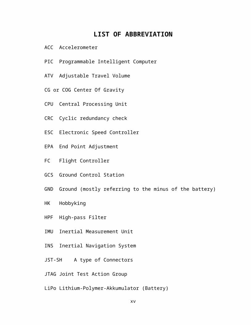
LIST OF ABBREVIATIONACC Accelerometer
PIC Programmable Intelligent Computer
ATV Adjustable Travel Volume
CG or COG Center Of Gravity
CPU Central Processing Unit
CRC Cyclic redundancy check
ESC Electronic Speed Controller
EPA End Point Adjustment
FC Flight Controller
GCS Ground Control Station
GND Ground (mostly referring to the minus of the battery)
HK Hobbyking
HPF High-pass Filter
IMU Inertial Measurement Unit
INS Inertial Navigation System
JST-SH A type of Connectors
JTAG Joint Test Action Group
LiPo Lithium-Polymer-Akkumulator (Battery)
xv
LOS Line Of Sight, also can mean Loss Of Signal
LPF Low-pass Filter
MEMS Micro Electro Mechanical System
PCB Printed Circuit Board
PCM Pulse-code Modulation
PID Proportional-Integral-Derivative
PFD Primary Flight Display
PPM Pulse Position Modulation
PWM Pulse Width Modulation
PWR Power (often referring to the plus of the battery)
RC Remote Controlled
RX Receiver
SCCP Source Code Control Program (OP uses Git for this)
SCL Serial Clock Line (I2C bus)
SDA Serial Data Line (I2C bus)
SOC System On a Chip
TX Transmitter
UART Universal Asynchronous Receiver/Transmitter
UAV Unmanned Aerial Vehicle
xvi

USART Universal Synchronous-Asynchronous
Receiver/Transmitter
xvii
Chapter 1: INTRODUCTION
In the past few decades, some rapid development has come to
eyes in autonomous aerial robots having less then 1kg in
weight and are so small like an insect. There are many range
of aircraft from fixed wings to flap wings vehicles. After
that one of the most inspiring flying vehicle is insect
vehicle with very tiny wireless camera. Militry use this
kind of vehicle for many different applications like
servaillance, drone attacks and for different other purpose.
Most of the areas in our college is having fixed cameras for
surveillance purpose which sometimes do not cover the blind
spots. So for that Quard rotor is designed which can be
controlled remotely and it will cover the blind spots which
is unable to covered by fixed camera.
It flies with four propeller using frame in plus (+) shaped.
If one rotor rotates faster than the rotor on opposite side,
then the rotor which moves faster will have higher lift or
thrust and there will be a tilt in position which wil make
quad to move forward, backward, left or right.
1

Figure 3.1: Quad Rotor Shape & Rotor's Movement
1.1 Background of the ProjectIt is not possible to fix cameras in every place. In our
campus there are some blind spot where we cannot fix camera.
In case of extreme emergency, fast economical and great
solution could be possible through Quad rotors, which will
provide valid and live information of the present situation
by sweeping the specific areas. It is also possible to
provide emergency drugs and kits to distant areas who ever
so needed. A quad rotor is a kind of driving element in the
sky, through which we can visualize situation using wireless
camera on it. It can be used for many applications.
2

The Quad rotor project provides interesting subject material
for research and scientific publication, which is the
uniqueness of Quad rotors.
1.2 Statement of the ProblemThe project has been selected to overcome the problem of
specific spot in our campus which cannot be able to cover
using fixed cameras. Due to less resource there are many
challenging task to build the Quad rotor which can provide
visual information.
The most challenging part of this project was the
programming of the software, which can stabilize the flight
by compensation. The complete success of the project mainly
depends on how best the algorithm is; to control the flight
through every feedback of the sensor.
Microcontroller need a great care in the speed of error
occurrence and compensation because it should not be so fast
as well as painfully slow. This is really a challenging task
to get balance in between error and compensation. Because on
each millisecond, the process of execution counts take place
which commands the rotors to take specific position to move.
In control system, control theory using integration
techniques has been studied. This technique is important to
approach the objectives, it is called (PID) Proportional-
3
Integral-Derivative. This is the most useful way to design
these kinds of projects.
1.3 Objectives of the ProjectDue to some limitations and given time frame, the goals and
aims of the project is most important part to propose. The
targets to be achieved are given below:
1. Designing a light weight Quad rotors body with
protective edges.
2. To make the project base so that it could be possible
to upgrade later on for other application as well.
3. To achieve stable flight using accelerometer and gyro
sensor.
4. To get successful video transmission using camera on
Quad rotors.
1.4 Project Scope and LimitationNowadays people are working on Autonomous Agile Robots,
which take its own decision according to the situation
provided. These kinds of robots are so ‘SMART’ or would be
smart enough to make decisions that only human can do. So,
the engineers introduced the flying vehicle which flies
without pilots, known as Unmanned Aerial Vehicle (UAVs) or
Unmanned Aircraft.
4

Unmanned Aerial Vehicles (UAVs) got increasing attraction in
past few years because of its broader application such as
Security, Management of Natural Risks, Surveillance,
Environment Exploration, Agriculture, Military, Small
Package transporter and many other different applications in
RADAR communication.
Basically it is a hovercraft or helicopter which carries a
system itself, depending on the kind of application. So,
through this project an attempt has made to use these UAVs
on video transmission which could be helpful for
surveillance, live broadcasting of any incident and so on.
5
Chapter 2: LITERATURE REVIEW
This chapter will explain about effectiveness of project
with respect to time and cost. The past researches which has
been done regarding Quad Rotor, the advance development in
Quads, current trends and upcoming scope of the project.
2.1 Feasibility AnalysesSuppose in case of emergencies like fire in building, the
quad rotor can sneak inside the building to search and
rescue people inside. Quad rotor component are easily
available to design it but the cost of the component is
expensive. But as compared to human life, the cost of
project is very less. Also it saves time because during
emergency this is the quick economical solution which can
save life of human beings.
2.2 Past Related ProjectsAs now people has done tremendous development in techniques
for designing rotor craft. VLSI has made the possibility to
design very small sensor using mechanical and electronic
principles on ICs. Now in market very small size Gyros,
accelerometers and magnetometers are available. As a result,
very small size Quad rotors are designed around the world.
6

2.2.1 Pennsylvania State UniversityPennsylvania State University has done studies on two
methods:
1. They have tested the quad rotor on test bench which
consist the Inertial Measurement Unit (IMU) that is
Gyro & Accelerometer.
2. They have also done the two camera method to capture
the path trajectory motion of quad rotor.
Simulation is done using MATLAB simu-link, which gives the
output of controlled tracking system even though error
occurred on state estimates.
Figure 4.1: Pennsylvania State University Design
2.2.2 Middle East Technical UniversityMiddle East Technical University has designed one Quad rotor
using three orthogonal piezoelectric Gyros, which stabilize
the flight by controlling altitude of Quad rotor. The
technique that is used to control the altitude is PD
controller and Linear Quadratic Regulator (LQR). They
7

designed the frame in aluminum metal in rectangular shape
which is light in weight.
Figure 2.2: Middle East Technical University Design
2.3 Current InnovationThe common thing in this project is that the Quad rotor
designing based on the principle of helicopter. The entire
past research project uses the sensors which stabilized the
flight through Microcontroller Unit (MCU). Sensors which are
used on board are Gyros, Accelerometer and Magnetometer. In
past project Quad rotor are utilized for different
applications that depends on situation for which it is
designed.
The biggest problem in Quad rotor is designing its body
frame which should be light in weight. Because frame holds
8

the motors, and there should be minimum gap in the frame to
generate maximum thrust so that it carries all boards
installed on it. The precise idea used to build the body of
Quad rotor is sketched in (figure 2.3). It is very much
light in weight and easy to design. The material used is
thermo coal sheet. It can be cut in any shape as required.
Figure 2.3: Actual Shape of Quad Rotor
The above figure will be used to design the body of Quad
rotor on thermo coal sheet, which is available in market at
lower cost and the most interesting part is that they are
light in weight.
2.4 Project Trend & Future ScopeThis Quad rotor is now very much famous for many
applications especially in Drone Attacks. The advanced Quad
9

Rotor is made by Russian army for weaponry which has camera
with machine gun having 100 rounds in it. In future may be
after ten to fifteen year these kinds of electronic weapons
will be used to kill enemy.
Figure 2.4: Russian Army Quad Rotor having Machine gun [Alipac (2013)]
10
Chapter 3: METHODOLOGY
In this chapter, collected data has been analyzed. The
designs of system block diagram and the method has been
discussed. System flow chart is discussed in detail to show
how every instruction will execute. The programmer kit,
microcontroller and the software for simulation and
implementation has been discussed. Hardware and software
tool has been specifically described. The risk analysis is
also explained and the Gantt chart for the project life
cycle has been provided in this chapter.
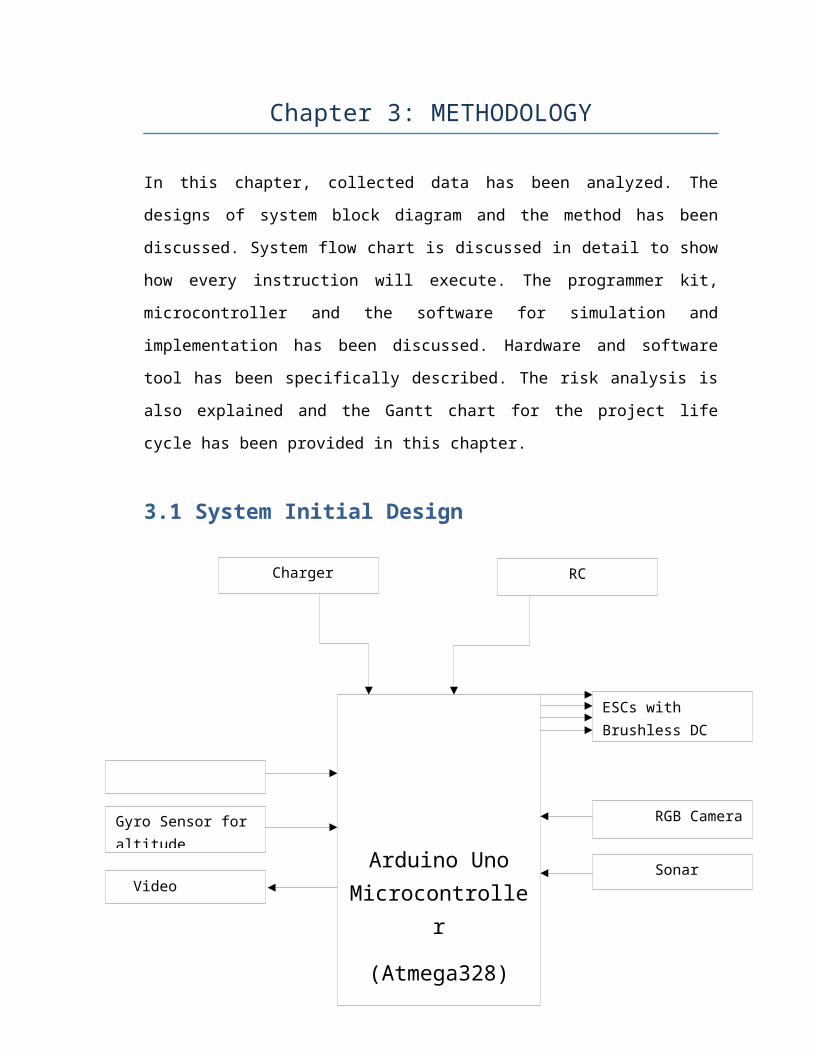
3.1 System Initial Design
11
Arduino UnoMicrocontrolle
r
(Atmega328)
RGB Camera
ESCs with Brushless DC
Accelerometer
Sonar Sensor
Gyro Sensor for altitude
Charger Circuit
RC Transceiver
Video Transmitter

Figure 3.1: Block Diagram
3.1.1 Function of Block Diagram:Arduino Uno Microcontroller is the heart of the circuit,
which will execute all the command according to the project
objectives. Arduino Uno is using Inertial Measurement Unit
(IMU) which includes Accelerometer and Gyro sensor, using
these sensors the microcontroller will calibrate the angular
motion, altitude and the force to stabilize the flight of
quad rotor. The feedback from these sensors are fed to the
Arduino Uno microcontroller, it generates PWM using analog
to digital convertor which gives commands to the rotors to
stabilize the flight accordingly. Sonar sensor is used to
avoid the obstacles, which will generate the pulse 600 times
a second and calibrate the position so that the flight will
not collide anywhere.
RGB Camera and the Video transmitter are used to transmit
the video while quad rotor is flying. For these entire
targets we need to select microcontroller of good speed.
Arduino Uno with ATmega328 is selected, which has 16MHz
cycle speed, and 16MHz of crystal oscillator is given on
board for proper reception. The sensor calibration is based
on the Proportional-Integral-Derivative (PID) control12
RF Transceiverfor Video
Remote

system. This is the heart of our programming, through which
pitch, roll, yaw and throttle of quad rotor is controlled.
This (PID) algorithm can be used to control any system by
using its feedback. The sensors are programmed using (PID)
block diagram which removes the error by taking feedback
from output, and recalibrating the error for desired output.
Figure 3.2: PID Block Diagram [Ben (2011)]
3.1.2 System Flow ChartFlow chart is used to design the program in systematic and
organized manner. It provides the sequence of program flow
till last execution. The flow chart which is given below
describes the flow of program in microcontroller, the input
device commands and the output given to specific component,
part or element to perform its task.
The general flow of program is given below:
13
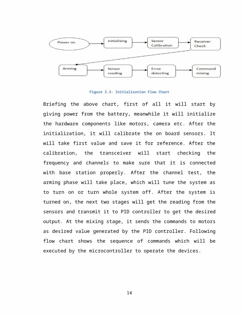
Figure 3.3: Initialization Flow Chart
Briefing the above chart, first of all it will start by
giving power from the battery, meanwhile it will initialize
the hardware components like motors, camera etc. After the
initialization, it will calibrate the on board sensors. It
will take first value and save it for reference. After the
calibration, the transceiver will start checking the
frequency and channels to make sure that it is connected
with base station properly. After the channel test, the
arming phase will take place, which will tune the system as
to turn on or turn whole system off. After the system is
turned on, the next two stages will get the reading from the
sensors and transmit it to PID controller to get the desired
output. At the mixing stage, it sends the commands to motors
as desired value generated by the PID controller. Following
flow chart shows the sequence of commands which will be
executed by the microcontroller to operate the devices.
14

Figure 3.4: Initialization of Sensors & Motors
15

The above flow chart shows the initialization stages in
which all the device is tested by the microcontroller
ATmega328. The devices will respond to the microcontroller
that they are working in proper manner. If any of this
devices does not work properly it will again check the
devices from start, if it detects any problem in any device
it will stop the execution of code and go back to the
rechecking mode.[Scolton (2013)]
After reaching at hovering stage the sequences of command
will be as follows.
16
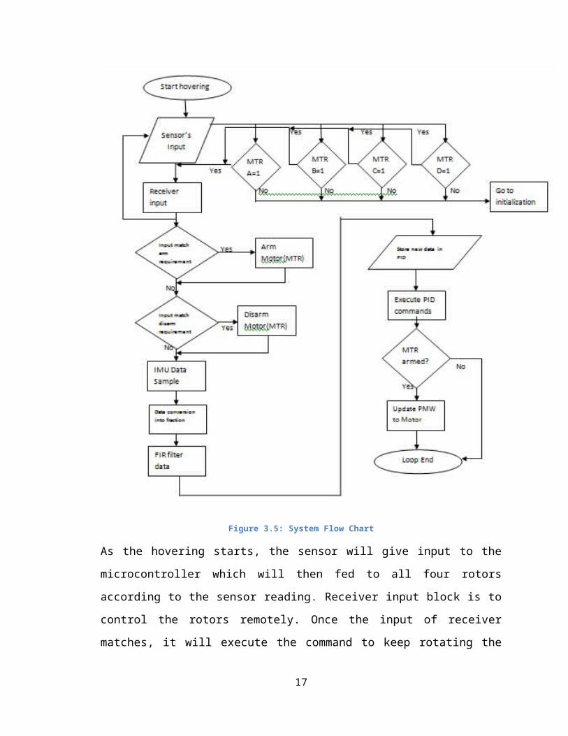
Figure 3.5: System Flow Chart
As the hovering starts, the sensor will give input to the
microcontroller which will then fed to all four rotors
according to the sensor reading. Receiver input block is to
control the rotors remotely. Once the input of receiver
matches, it will execute the command to keep rotating the
17
motors as per instruction, that could be turn left or right,
this process is called arming. If it matches to disarm
requirement it will execute the command to the motors to
stop or land the Quad rotor. Suppose if quad rotor need to
be turn left side, the input from receiver will fed to the
motors so that the speed of rotor could be controlled
accordingly. The sequences of getting the command in the
loop are IMU data converts to fractional form and fed to FIR
filter for error detection, as FIR filter is infinite in
nature. As the calibration took place in FIR filter, it will
then store the new data in PID control system. After that it
will execute the command to the motor by updating the PWM
value, if the motor is not armed then it will end the loop.
3.2 Technical Requirements & SpecificationsThis is the most important part of the whole project to be
explained, because to achieve the specific task the
technical requirement is must to get the cheap and reliable
components for project.
3.2.1 Hardware ComponentsThis part explains about the overview of some components
which are being used to design Quad rotor.
3.2.1.1 Control BoardThe heart of the whole Quad rotor is the ATmega328
microcontroller unit which is also called Arduino Uno
18

prototype kit. The Arduino Uno is a microcontroller board
based on the ATmega328. It has 14 digital I/O pins, of which
6 can be used as PWM outputs, 6 analog inputs are there, a
16MHz ceramic resonator is present on board, a USB
connection to burn program, a power jack, an ICSP header,
and a reset button. It contains everything needed to support
the microcontroller by simply connecting it to a computer
with USB cable or power it with AC-to-DC adapter or battery
to get started.
The Arduino Uno differs from all preceding boards which uses
FTDI USB-to-Serial driver chip. Instead, it features the
ATmega16U2 programmed as a USB-to-Serial converter. The new
features added SDA and SCL pins that are near to the AREF
pin and two other new pins placed near to the reset pin, the
IOREF that allow the shields to adapt to the voltage
provided from the board, which is detail discussed in
chapter 4. In future, shields will be compatible both with
the board that uses AVR, which operate at 5V and with the
Arduino Due that operate with 3.3V. It has strong reset
circuit. It has 32KB with 0.5KB used for the boot loader. It
also has 2KB of SRAM and 1KB of EEPROM which can be read and
written with the EEPROM library. All technical short words
are discussed in chapter 4.
19

Figure 3.6: Arduino Uno ATmega328 Microcontroller
3.2.1.2 Brushless DC (BLDC) MotorMotors are one of the most important parts of the Quad rotor
because Quad rotor is named due to four motors installed on
board. These all are the muscles of Quad rotor which helps
in flying. The difficult task is to select the specific
motors while designing these kinds of project. One should
know the project application well so that accordingly the
motor can be selected. Since BLDC motor has no friction due
to brushes, it work for long life and can give maximum RPM.
It produces less noise and has better reliability. The only
disadvantage of BLDC motor is the cost since the design
principle of BLDC motor is difficult in design. The BLDC
outrunner motor has higher torque then the inrunner motor,
that is why BLDC outrunner is expansive. BLDC is very good
choice as we are considering weight. It produces maximum
inertia so that the flight cannot fall down suddenly.
20

Figure 3.7: Brushless DC Motor [Hextronik Limited (2012)]
3.2.1.3 Electronic Speed Controller (ESCs)ESCs are the devices which control the speed of motor
according to the command provided by the remote controller
or saved in microchip. It is a single chip which linked with
the receiver’s channel and the output is connected to BLDC.
ESCs uses Pulse Width Modulation (PWM) to control the
motors. PWM is one of the best way to run BLDC motors
through ESCs. Through PWM we can control the duty cycle or
the width of wave as per time interval, which gives precise
speed control.
21

Figure 3.8: Electronic Speed Controller
3.2.1.4 Gyroscope SensorThe aim of the project is to get the stabilize flight while
operating the quad rotor. So to get the stabilize flight
there must be feedback system which could be achieved by PID
control system. This system will provide the feedback to
microcontroller that one side of quad rotor is tilted or
leaned, so supply more current to that specific motor for
faster rotation which will produce more thrust to stabilize
the flight. Through gyro sensor one can detect the exact
altitude of the quad rotor. Selection of gyroscope depends
on many factors. Response should be fast so that the change
in angular velocity can be detected and compensate according
to the error occurred. Also by considering the size and
weight it should be light and small. Some of them have in
built filter to reduce the probability of noise; if this
kind of gyro is available then this will be the plus point.
22

Figure 3.9: Gyro Sensor [Felix & Arnold (2013)]
3.2.1.5 AccelerometerAccelerometer is used to measure the amount of acceleration
and the tilt produce with respect to gravity. Its function
is like an iron bob inside the box which has no
gravitational force. If we push or apply force from one side
of the box, then the bob will touch that side as shown in
figure 3.10. Accelerometer controls the force acting on Quad
rotor due to air pressure and friction. It is one of the
components of inertial measurement unit called IMU.
Figure 3.10: Function of Accelerometer
So the acceleration acts as the force calculator as the bob
touches the wall of the box. If we use gyro and
23
accelerometer together it is called as Inertial Measurement
Unit (IMU).
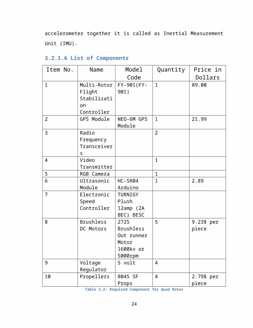
3.2.1.6 List of Components
Item No. Name ModelCode
Quantity Price inDollars
1 Multi-RotorFlight Stabilization Controller
FY-901(FY-901)
1 89.00
2 GPS Module NEO-6M GPSModule
1 21.99
3 Radio Frequency Transceivers
2
4 Video Transmitter
1
5 RGB Camera 16 Ultrasonic
ModuleHC-SR04 Arduino
1 2.89
7 Electronic Speed Controller
TURNIGY Plush 12amp (2A BEC) BESC
8 Brushless DC Motors
2725 Brushless Out runnerMotor 1600kv or 5000rpm
5 9.23$ per piece
9 Voltage Regulator
5 volt 4
10 Propellers 8045 SF Props
4 2.79$ per piece
Table 3.2: Required Component for Quad Rotor
24

3.2.2 Software ComponentsThere are some stages discussed in this part of the chapter,
which will elaborate how the steps are followed to design
the project software by using different tools:
Stage 1: Arduino Nightly Software for ATmega328There are many version and series of software for Arduino
kit, designed by the Arduino manufacturer. Arduino Nightly
is a commonly used software to program Arduino Uno with
ATmega328. It is one of the popular programming tool in
Arduino platform. It has basic compiler with full featured
library and examples, which provide Arduino Uno suitable for
all application. This tool is good for beginners due to its
easy syntax and the easiest possible solution for developing
embedded applications. IDE code editor allows quick
development and reduce bug and design complex applications.
It uses basic C language. User must know the basic of C,
which helps them to make program easily by following rules.
25
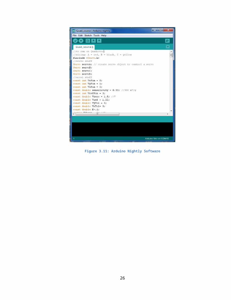
Figure 3.11: Arduino Nightly Software
26
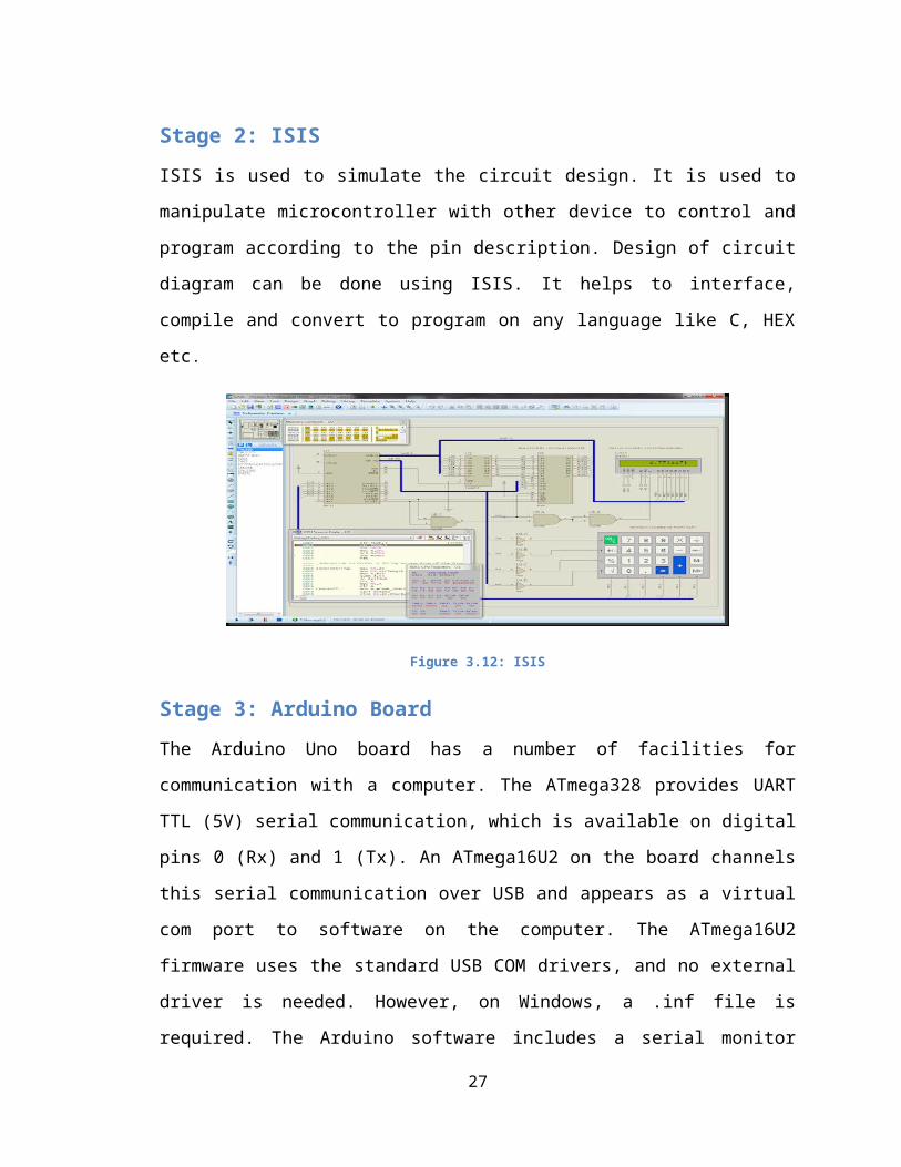
Stage 2: ISISISIS is used to simulate the circuit design. It is used to
manipulate microcontroller with other device to control and
program according to the pin description. Design of circuit
diagram can be done using ISIS. It helps to interface,
compile and convert to program on any language like C, HEX
etc.
Figure 3.12: ISIS
Stage 3: Arduino BoardThe Arduino Uno board has a number of facilities for
communication with a computer. The ATmega328 provides UART
TTL (5V) serial communication, which is available on digital
pins 0 (Rx) and 1 (Tx). An ATmega16U2 on the board channels
this serial communication over USB and appears as a virtual
com port to software on the computer. The ATmega16U2
firmware uses the standard USB COM drivers, and no external
driver is needed. However, on Windows, a .inf file is
required. The Arduino software includes a serial monitor
27
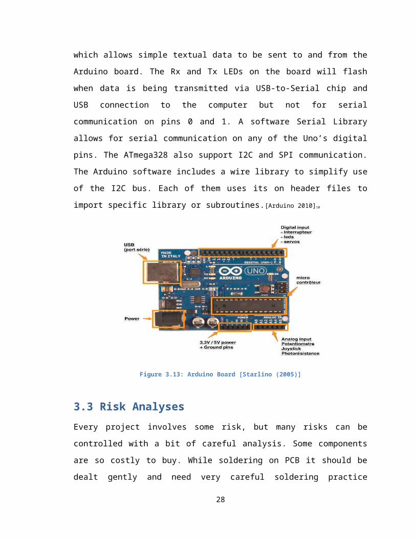
which allows simple textual data to be sent to and from the
Arduino board. The Rx and Tx LEDs on the board will flash
when data is being transmitted via USB-to-Serial chip and
USB connection to the computer but not for serial
communication on pins 0 and 1. A software Serial Library
allows for serial communication on any of the Uno’s digital
pins. The ATmega328 also support I2C and SPI communication.
The Arduino software includes a wire library to simplify use
of the I2C bus. Each of them uses its on header files to
import specific library or subroutines.[Arduino 2010]10
Figure 3.13: Arduino Board [Starlino (2005)]
3.3 Risk AnalysesEvery project involves some risk, but many risks can be
controlled with a bit of careful analysis. Some components
are so costly to buy. While soldering on PCB it should be
dealt gently and need very careful soldering practice
28

because excess heat can damage the component. The weight of
whole quad rotor should be under consideration while
installing any component because if the rotor is unable to
produce maximum thrust against the weight then the project
will be failed. So the weight and size are the most
important parameters of this project.
Programming is another challenging task to do. Programming
microcontroller needs lot of concentration and patience.
Each pin description must defined clearly for initialization
and sold it according to the diagram designed in fritzing
software.
29

3.4 Gantt Chart
3.4.1 Planning Gantt Chart
Figure 3.14: Planning Gantt chart
30
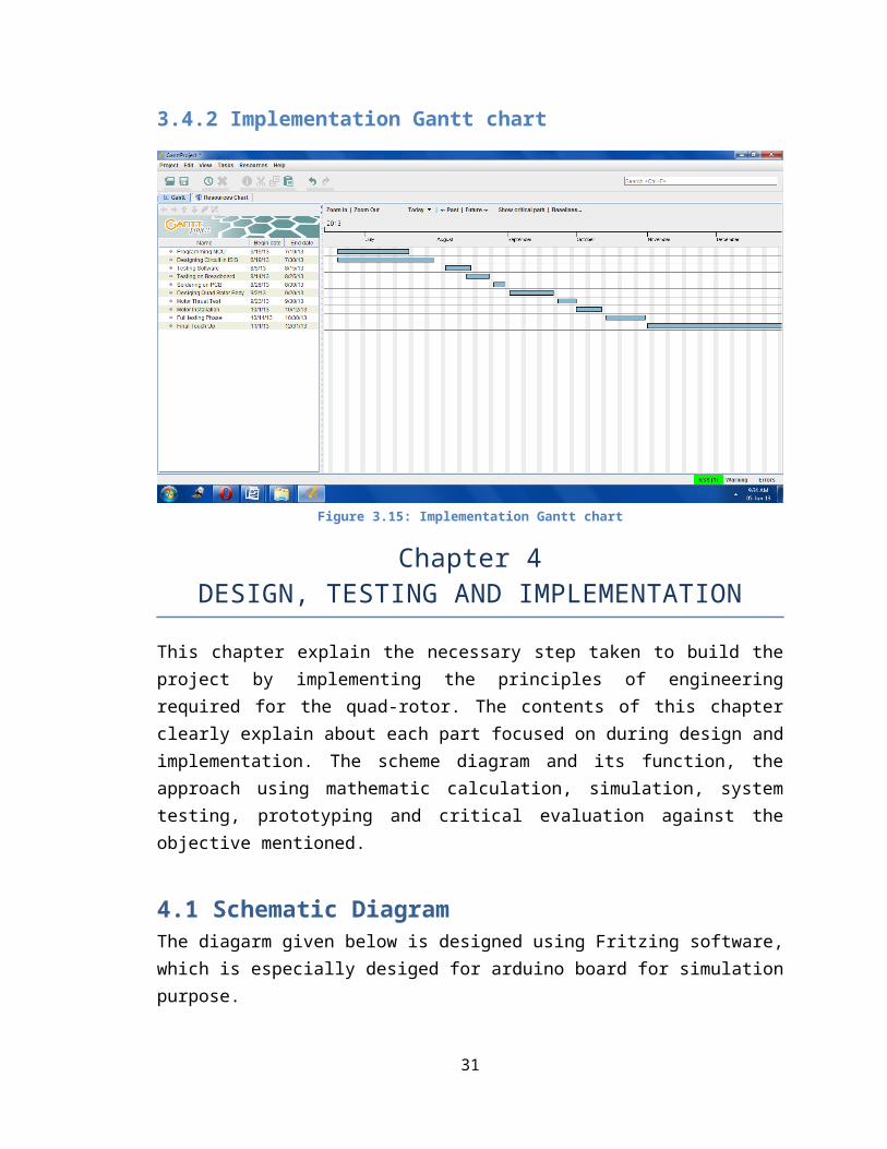
3.4.2 Implementation Gantt chart
Figure 3.15: Implementation Gantt chart
Chapter 4DESIGN, TESTING AND IMPLEMENTATION
This chapter explain the necessary step taken to build theproject by implementing the principles of engineeringrequired for the quad-rotor. The contents of this chapterclearly explain about each part focused on during design andimplementation. The scheme diagram and its function, theapproach using mathematic calculation, simulation, systemtesting, prototyping and critical evaluation against theobjective mentioned.
4.1 Schematic DiagramThe diagarm given below is designed using Fritzing software,which is especially desiged for arduino board for simulationpurpose.
31
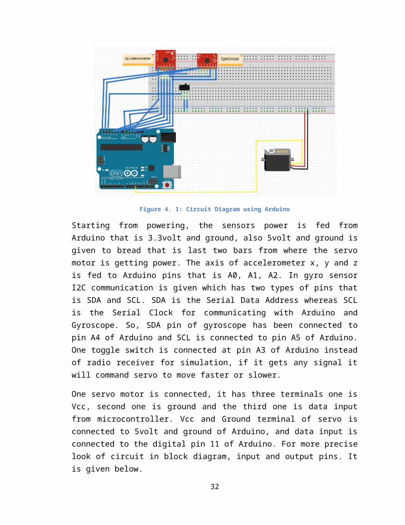
Figure 4. 1: Circuit Diagram using Arduino
Starting from powering, the sensors power is fed fromArduino that is 3.3volt and ground, also 5volt and ground isgiven to bread that is last two bars from where the servomotor is getting power. The axis of accelerometer x, y and zis fed to Arduino pins that is A0, A1, A2. In gyro sensorI2C communication is given which has two types of pins thatis SDA and SCL. SDA is the Serial Data Address whereas SCLis the Serial Clock for communicating with Arduino andGyroscope. So, SDA pin of gyroscope has been connected topin A4 of Arduino and SCL is connected to pin A5 of Arduino.One toggle switch is connected at pin A3 of Arduino insteadof radio receiver for simulation, if it gets any signal itwill command servo to move faster or slower.
One servo motor is connected, it has three terminals one isVcc, second one is ground and the third one is data inputfrom microcontroller. Vcc and Ground terminal of servo isconnected to 5volt and ground of Arduino, and data input isconnected to the digital pin 11 of Arduino. For more preciselook of circuit in block diagram, input and output pins. Itis given below.
32

Figure 4.2: Quad Rotor Actual Circuit
When Arduino kit is burned with the Quad rotor program, theaccelerometer and Gyro sensor will take the initial readingand store it and start sending the address and x, y and zaxis through gyro and accelerometer respective. If there isa tilt on any four side of Quad, through the gyro sensor andaccelerometer it will command that specific should rotatefaster for up thrust to minimize the tilt by the using thePID control unit in the Electronic Speed Controller (ESCs).As the command from accelerometer and gyro sensor isexecuting automatically according to the program designedfor the microcontroller, it makes the Quad rotor agile. Ingeneral, it is very difficult to control Quad rotor only byremote transceiver. Hence, to control the Quad rotorefficiently and to make the stable flight that it does notland so quickly or while flight it tilts, it is important touse specific kind of motion sensor and apply programmingalgorithm to the reading from the sensors, so the Quad rotorbalance its motion by taking feeds from sensors. Thistechnique of Quad rotor makes it autonomously agile.
For precise reading from accelerometer and gyro sensor thetable is given in the Arduino example programs, which tells
33

about the amount of voltage generated by the accelerometerand gyro on specific degrees. Most of the programming partof project is related to the examples of Arduino given inthe tutorials.
4.2 System Analysis and DesignA Quad rotor is a system which has multi rotor or moresimply multi motors which is used to lift and propel thewhole body and on board sensors installed in between fourrotors. The project is aimed to build the light weight bodyof Quad rotor and to make the PCB in such a way that infuture it could be possible to extend the feature of Quadrotor and by getting the reading from on board sensors tostabilize the flight autonomously and transmit the videousing RGB camera and video transmitter.
Three aims has been completed that is by designing the lightweight body of Quad rotor using thermo coal, and Arduino Unokit is chosen for programming microcontroller which can beeasily upgraded or any change required in programming couldbe possible. The Quad rotor is also consists of radiotransmitter and receiver to control manually. Arduino Unokit is used in this project to program microcontrollerATmega328 and applying the technique of Pulse WidthModulation (PWM) and PID controller to compute the value ofon board sensors and motor by controlling the pulse dutycycle.
34

Figure 4.3: PWM & AnalogWrite( ) Command [Arduino 2010)
Before selecting any microcontroller for Quad rotor project,one should know the number Capture/Compare/PWM in short CCPand Enhanced Capture/compare/PWM (ECCP) module required forQuad rotor because ESCs can only be controlled using PWMduty cycle. For driving the specific duty cycle there is acommand in Arduino that is analogWrite( ). There are sixpins in Arduino which are able to drive PWM by just givingthese command and changing the precise value of duty whichis required. There is a table design to drive PWM accordingto the motion of Quad rotor which is given below.
X axis Y axis Z axis Rotor A(PWM)
Rotor B(PWM)
Rotor C(PWM)
Rotor D(PWM)
0 0 0 0 0 0 00 0 1 255 255 255 2550 1 0 255 192 255 2550 1 1 255 192 255 1921 0 0 192 255 255 2551 0 1 192 255 255 2551 1 0 192 255 255 192
35

1 1 1 255 255 255 255Table 4.1: Axis & PWM on Motor 1
The table given above explains the idea about the PWM valuedriven on each rotor by the axis position. This table hasbeen used in programming the Quad rotor. Each value of X, Yand Z tells about the Pitch, Roll, Yaw and Throttle positionof Quad rotor. Accelerometer and Gyro sensor gives the valueof the angular velocities and angles of Quad rotor frame.The diagram given below will give the precise idea about thechanging in position of Quad rotor.
Figure 4.4: Quad Rotor Angles & Angular Velocities
All the rotors move and generate thrust and torque from itscenter of rotation and creating air pressure and forceswhich is used to move and fly the Quad rotor. There are four
36

rotors mounted on the frame, two rotors opposite to eachother. Two of them move clockwise while others moveanticlockwise. These clockwise and anticlockwise rotationand direction cancel the torque generated when the rotorstart with full speed. Now gradually increase the speed ofrotors attached on the right and left of Quad rotor bykeeping the speed of the others rotor same, it will create‘Yaw’ angle. Likewise Pitch and Roll will be gained byaccelerating the speed of other rotors.
In this project Brushless DC motors are used. BLDC rotorsrequire electronic speed controller which can control thespeed of rotors and supply of the proper current required bythe rotors. To control the Quad rotor manually, the receiversignal is directly fed to the BLDC rotors, when the inputfrom the transmitter changes the receiver feed the signal inthe form of PWM which is received from transmitter to therotors directly and hence the motion can be controlledmanually. The analog signal from the receiver is convertedto PWM, which causes the change in the speed of rotors whichcould be faster or slower. In this Quad rotor LANSUtransmitter and receiver is used.
Some mathematical formulas are there to understand thecoordinates and the free body motion. According to somephysical laws when we scales the things down in Quad rotor,the robot will naturally become agile.
37

Figure 4.5: Coordinate & Free Body Motion [Quad Rotor dynamic & Control (2008)]
The figure (4.5) given above explains the exact coordinatesx, y and z of Quad rotor, where P is the center point ofcoordinate and L is the length from P to T3. Similarly P toT1, P to T2 and P to T4 has the equal length. Now to makethe robot agile by it physical law, length L is the veryimportant factor because lots of parameter changes when wechange ‘L’. Some scaling are given below for making therobot agile.
1. Blade Tip Speed v √L Where V is Velocity, L is Length from P to T1, T2, T3and T4.
2. Lift F=CLAv2 L3
Where F is Force, C is Thrust, A is Acceleration, V isVelocity.
3. Inertia m L3,I L5
4. Accelerationfor linear: a 1
38

for angular: a 1L
So, the smaller the ‘L’, the more quickly we can turn therobot.
The Arduino Uno program which has been design and compilefor Quad rotor is as follows:
Program
//to run on Quad Rotor:
//wiring: A = red, B = black, C = yellow
#include <Servo.h> // calling Servo library
#include <ADLX335.h> // calling accelerometer library
#include <Wire.h> //calling I2C library for Gyro
//servo stuff
Servo servoA; // create servo object to control a servo
Servo servoB;
Servo servoC;
Servo servoD;
//accel stuff
const int VxPin = 0;
const int VyPin = 1;
const int VzPin = 2;
const double sensitivity = 0.33; //300 mV/g
const int VrefPin = 3;
const double Vzero = 1.5; //V39
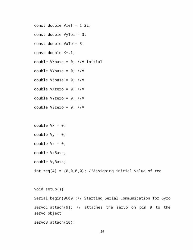
const double Vref = 1.22;
const double VyTol = 3;
const double VxTol= 3;
const double K=.1;
double VXbase = 0; //V Initial
double VYbase = 0; //V
double VZbase = 0; //V
double VXzero = 0; //V
double VYzero = 0; //V
double VZzero = 0; //V
double Vx = 0;
double Vy = 0;
double Vz = 0;
double VxBase;
double VyBase;
int reg[4] = {0,0,0,0}; //Assigning initial value of reg
void setup(){
Serial.begin(9600);// Starting Serial Communication for Gyro
servoC.attach(9); // attaches the servo on pin 9 to theservo object
servoB.attach(10);
40

servoA.attach(11);
servoD.attach(6);
pinMode(VxPin,INPUT);//Assigning analog pins forAccelerometer
pinMode(VyPin,INPUT);
pinMode(VzPin,INPUT);
pinMode(VrefPin,INPUT);
servoA.write(0);// Initial value assigned to all Motors
servoB.write(0);
servoC.write(0);
servoD.write(0);
delay(3000);// Delay of 3 second
VXzero = readAcc(VxPin);
VYzero = readAcc(VyPin);
//VZzero = 1.574;
VZzero = 1.464;
VXbase=getXAngle();
VYbase=getYAngle();
VZbase=getZAngle();
Serial.print("Vx: ");
Serial.println(VxBase);
Serial.print("Vy: ");
41

Serial.println(VyBase);
}
void loop() //Starting Loop
{
Serial.print("A: "); //
Serial.print(servoA.read());
Serial.print(", B: ");
Serial.print(servoB.read());
Serial.print(", C: ");
Serial.print(servoC.read());
Serial.print(", D: ");
Serial.println(servoD.read()); // Taking position of allmotors and reading it
//initial motor setting
char test;
if(Serial.available() > 0){
for(int i = 0; i < 4; i++){
reg[i] = Serial.read();
//reg = int(test);
if(reg[i]==200)
42
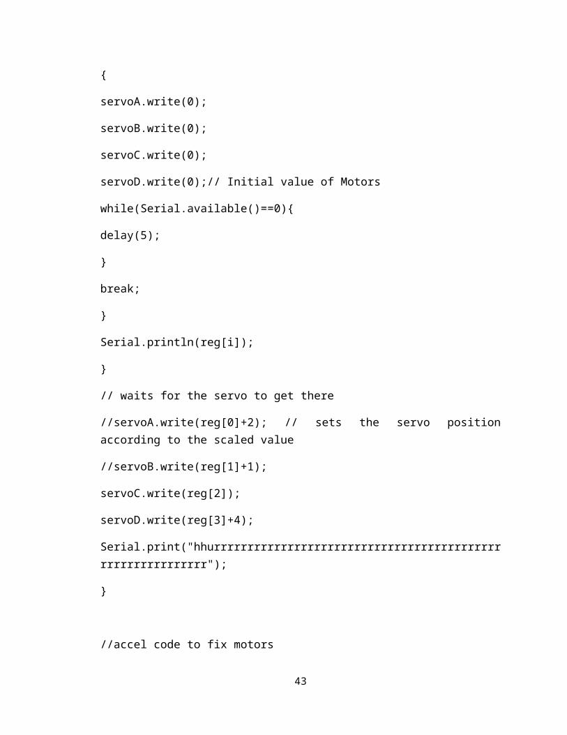
{
servoA.write(0);
servoB.write(0);
servoC.write(0);
servoD.write(0);// Initial value of Motors
while(Serial.available()==0){
delay(5);
}
break;
}
Serial.println(reg[i]);
}
// waits for the servo to get there
//servoA.write(reg[0]+2); // sets the servo positionaccording to the scaled value
//servoB.write(reg[1]+1);
servoC.write(reg[2]);
servoD.write(reg[3]+4);
Serial.print("hhurrrrrrrrrrrrrrrrrrrrrrrrrrrrrrrrrrrrrrrrrrrrrrrrrrrrrrrrrrr");
}
//accel code to fix motors
43
/*
Serial.print("Vx: ");
Serial.println(Vx);
Serial.print("Vy: ");
Serial.println(Vy);
Serial.print("Vz: ");
Serial.println(Vz);
Serial.println();
*/
/*
A in +x, B in -x, D in +y, C in -y
Neutrals:
X: 2.94-2.955 but for humans: 2.8-3
Y: 2.860-80 but for humans: 2.8-3
Z: 1.814-1.826
Gy=260
Gx=260 (267?)
+gy means reduce c add to d
+gx means reduce b add to a
on Quad rotor neutrals:
44

*/
balance(); //uses the gyroscope and accelerometer to try andbalance the Quad Rotor
delay(5);
}
double balance()
{
double Xang=getXAngle();
double Yang=getYAngle();
double Zang=getZAngle();
double aval;
double bval;
//+x means increace C decreace D
//+y means increace A decreace B
if(Yang>=VYbase+VyTol &&servoC.read()<80){
aval=servoC.read();
bval=servoD.read();
servoC.write(aval+(int)((Yang-(VYbase+VyTol))*K));
servoD.write(aval-(int)((Yang-(VYbase+VyTol))*K));
delay(20);
Yang=getYAngle();
}
if(Yang<=VYbase-VyTol&&servoD.read()<80){
45

aval=servoC.read();
bval=servoD.read();
servoC.write(aval-(int)(((VYbase-VyTol)-Yang)*K));
servoD.write(aval+(int)(((VYbase-VyTol)-Yang)*K));
delay(20);
}
/*
if(Xang>=VXbase+VxTol){
servoA.write(servoA.read()+1);
servoB.write(servoB.read()-1);
}
if(Xang<=VXbase-VxTol){
servoA.write(servoA.read()-1);
servoB.write(servoB.read()+1);
}
Serial.print("Xang: ");
Serial.println(Xang,3);
Serial.print("Yang: ");
Serial.println(Yang,3);
*/
}
46

/*
notes:
voltages accurate to +/- 0.02
formula to find force in terms of g: Fx or Fy or Fz = (Vx orVy or Vz * Vref / 255 - VzeroG) / Sensitivity, F = sqrt(Fx^2+ Fy^2 + Fz^2)
formula to find angle: Xangle = arccos(Fx/F), Yangle =arccos(Fy/F), Zangle = arccos(Fz/F)
*/
double readAcc(int pin){
int repeat = 20;
double V = 0;
for(int x=0; x<repeat; x++)
V += analogRead(pin);
V /=repeat;
V = V* Vref / 255;
//V -= Vzero;
return V;
}
double getXAngle(){
double Vx = 0;
double Vy = 0;
double Vz = 0;
47

double Fx = 0;
double Fy = 0;
double Fz = 0;
double F = 0;
Vx = readAcc(VxPin);
Vy = readAcc(VyPin);
Vz = readAcc(VzPin);
Vx -= VXzero;
Vy -= VYzero;
Vz -= VZzero;
Fx = Vx/sensitivity;
Fy = Vy/sensitivity;
Fz = Vz/sensitivity;
F = sqrt(sq(Fx)+sq(Fy)+sq(Fz));
return asin(Fx/F)*(180/PI);
}
double getYAngle(){
double Vx = 0;
double Vy = 0;
double Vz = 0;
double Fx = 0;
double Fy = 0;
48

double Fz = 0;
double F = 0;
Vx = readAcc(VxPin);
Vy = readAcc(VyPin);
Vz = readAcc(VzPin);
Vx -= VXzero;
Vy -= VYzero;
Vz -= VZzero;
Fx = Vx/sensitivity;
Fy = Vy/sensitivity;
Fz = Vz/sensitivity;
F = sqrt(sq(Fx)+sq(Fy)+sq(Fz));
return asin(Fy/F)*(180/PI);
}
double getZAngle(){
double Vx = 0;
double Vy = 0;
double Vz = 0;
double Fx = 0;
double Fy = 0;
double Fz = 0;
double F = 0;
49

Vx = readAcc(VxPin);
Vy = readAcc(VyPin);
Vz = readAcc(VzPin);
Vx -= VXzero;
Vy -= VYzero;
Vz -= VZzero;
Fx = Vx/sensitivity;
Fy = Vy/sensitivity;
Fz = Vz/sensitivity;
F = sqrt(sq(Fx)+sq(Fy)+sq(Fz));
return asin(Fz/F)*(180/PI);// controlling the flying heightof Quad rotor
}
4.3 System SimulationIn this project, Accelerometer and Gyro sensors is used tomake the Quad rotor agile with the Arduino Uno programmerkit. PID controller is already installed in ESCs circuits,thus the motor is only controlled by PWM output generated bytaking the analog signals from sensors and receiver. Firstaim is to use accelerometer and gyro sensor readings and fedit to the Arduino Uno microcontroller analog pins accordingto axis coordinates, so that the Quad rotor can self-stabilize from the vibration generated due to non-zeroangular velocity to acquire position of current situation.The library used for accelerometer and gyro sensor fromArduino are “ #include < ADXL3xx.h> “and “ #include <Wire.h> respectively.
50

Figure 4.6: Fritzing Simulation Software
Fritzing software is used to for simulation of hardwarecomponents. It is a very useful software for actualconnection on bread board to get the desired output. Theaccelerometer and gyro sensor is tested after pinssoldering, and tagged on bread same like this. The actualimage is given below.
Figure 4.7: Accelerometer & Gyro Hardware Simulation
51

The output of accelerometer and gyro sensor is tested byconnecting the servo motor on each output of accelerometerthat is x, y, z, and the output of gyro sensor SCL and SDApins. Arduino program has two part that Setup and Loop whichexecute continues command contains the calculation part.Quad rotor has been programmed by using the formula ofgravitational force and calculating the height of flying andmaintaining it balance by these two sensors andmicrocontroller.
52
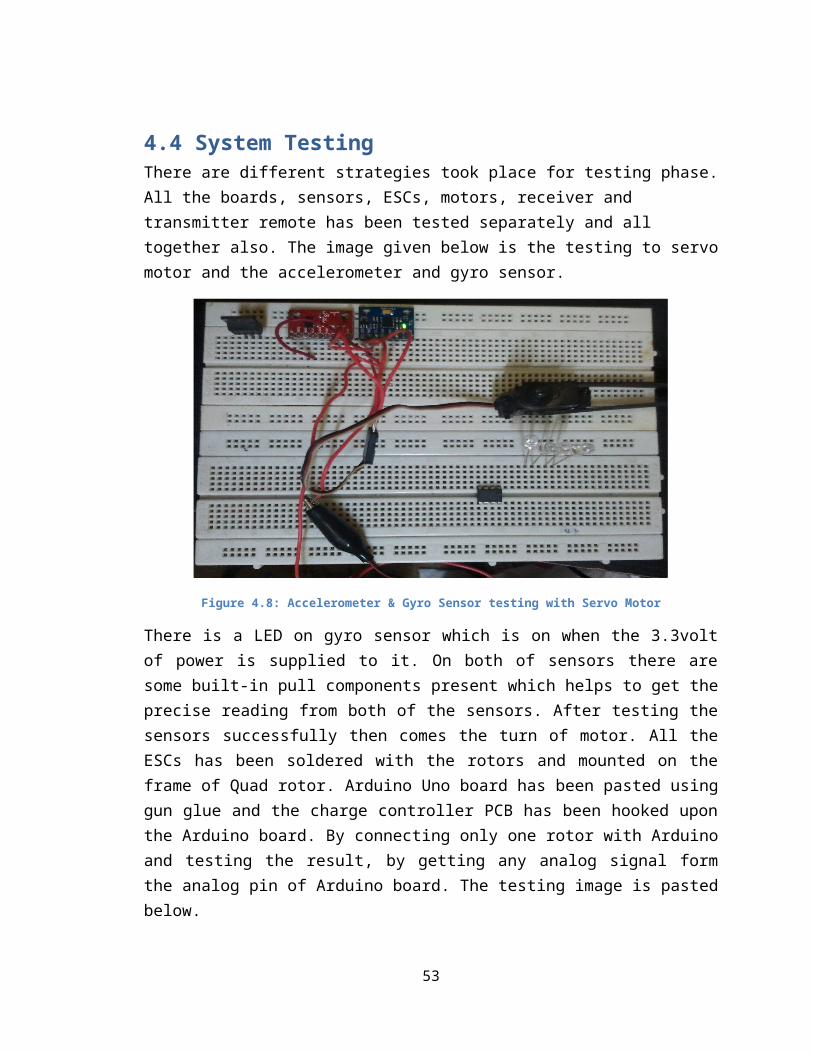
4.4 System TestingThere are different strategies took place for testing phase.All the boards, sensors, ESCs, motors, receiver and transmitter remote has been tested separately and all together also. The image given below is the testing to servomotor and the accelerometer and gyro sensor.
Figure 4.8: Accelerometer & Gyro Sensor testing with Servo Motor
There is a LED on gyro sensor which is on when the 3.3voltof power is supplied to it. On both of sensors there aresome built-in pull components present which helps to get theprecise reading from both of the sensors. After testing thesensors successfully then comes the turn of motor. All theESCs has been soldered with the rotors and mounted on theframe of Quad rotor. Arduino Uno board has been pasted usinggun glue and the charge controller PCB has been hooked uponthe Arduino board. By connecting only one rotor with Arduinoand testing the result, by getting any analog signal formthe analog pin of Arduino board. The testing image is pastedbelow.
53

Figure 4.8: Rotor Testing using Analog Signal
4.5 System Implementation and PrototypingAll the idea and research data has been analyzed andimplemented step wise. The first step was to design thelight weight frame of Quad rotor which is the firstobjective to accomplish. Therefore first task has beensuccessfully completed by designing the handmade frame usingthe thermo coal sheet and sketching the frame on the sheetand cutting it by surgical blade. Below is given the imageof thermo coal Quad rotor frame sheet.
54

Figure 4.9: Quad Rotor Thermo Coal Frame
Now the second objective was to make the base of Quad rotorthat its feature could be extend in future because theremany kind of Quad rotor which has been designed depending onthe application. So, to fulfill the second objective anArduino Uno board is selected which has the microcontrollerATmega328P with the special category feature for Quad rotorthat six analog input pins with six PWM digital output pinsand having constants output for 3.3volt pin, from where gyroand accelerometer has given the power to run. All fourrotors has been mounted between the centers of the each fourcircle frame. And little beside the circles the ESCs ispasted using gun glue. And at the midpoint of the frame theArduino board is pasted using glue. The image is givenbelow.
55

Figure 4.10: Mounting if Motors and Arduino Board
After mounting all the motors, ESCs and Arduino board, nowthe time to fix the charge controller PCB upon the Arduinowith the help of screws, and keeping the important point inmind that the sensor should be right tagged on boardaccording to the coordinate of gyro and accelerometer. Belowis the image of charger controller.
56

Figure 4.11: Charge Controller PCB
After hooking the PCB board on Arduino, all the pinsconnection has been made by careful consideration that noneof the single wire touches the propeller of rotors. Givenbelow is the image when hardware design is almost completed.
57

Figure 4.12: Upper view of Quad Rotor
Figure 4.13: Side View of Quad Rotor
Now after complete mounting of all the boards, motors andsensor. It was the time to design the program for Quad rotorto move all the motors and runs sensors parallel when power
58

is supplied. The Quad Rotor program is given above in thesystem analysis design part.
4.6 Critical EvaluationThere are many problem faced during different phases ofdesigning Quad rotor. First of all, finding the exacthardware require for Quad rotor, because there are differenttypes of microcontroller available in the market. One shouldsee the requirement of the project and then select the goodspeed microcontroller with maximum number of PWM.
First and second objective is successfully completed asmentioned before. Quad rotor frame is designed using thermocoal sheet, because Quad rotor require a light weight bodyto take off from the ground easily by generating maximumthrust using propellers. If the body or frame of the Quadrotor is not considered properly then there might be afailure in flight, because thrust is inversely proportionalto the weight. The base of the Quad rotor is mounted afterdesign the frame. It could be upgrade later on for otherapplications as the Arduino Uno board is specially used forprototyping, and it could be easily program through USBcable. This kit is not like simple microcontroller which isburned first and then soldered on PCB layout. Arduino Unohas special category of prototyping. All the output andinput pins are easily visible on board. Just need the goodprogramming skill to use it.
Third objective requires more consideration on balancing andpower part of Quad rotor. All the rotors are getting theanalog signal from on board sensors and driving specific PWMduty cycle to the all four rotors. Sometime the rotorssudden stops rotating while driving on full speed, this isbecause of radio frequency from the receiver. It sends the
59

certain amount to signal and then sudden stop sending it tomicrocontroller due to which rotors stops rotating. Alsosometime power is not much accessible for rotors, as itrequires 30A to run the motors very fast by producing greattorque. The most critical part is to communicate the alldevices together at a time. Gyro sensor produce 8bit addressmode use SDA and SCL pins. To read the address efficientlyone should require the good resolution of themicrocontroller.
Fourth objective is on process right now because it requirea whole separate module for video transmission that is RGBcamera and video transmitter. Both the parts are availablebut due insufficient time of submitting project beforedeadline, this objective is not considered now. But theresearch and the communication part of this objective is onprocess.
60

4.7 Legal, Social & Ethical Aspects of the ProjectDuring designing phase of Quad rotor, there many othernontechnical aspects had to be considered in design. Thetotal cost of manufacturing the Quad rotor should be low butthe cost of the component like BLDC motors and Arduino kitare little bit expensive to design prototype. While designthe Quad rotor, lots of components came under considerationin the mean of cost and reliability. The major concern was asafety because flying object could be dangerous, as Quadrotor have sharp blades as propeller. As an engineer, wecontinually learn new technology with ongoing legal, socialand ethical issues affecting our country. The aim of anengineer must be to design and create new technology withlow cost and better models then then previous one.
The benefit of Quad rotor in economy would be small becauseit has seen as more of a hobby item and toys which can giveprofit to the company which sells them. The social benefitsare big depending on the application how it is used. Quadrotor has many applications in social aspects. It could beused as first responder in surveillance by fixing camera andmicrophone in Quad rotor as one of its feature. It could beused as backup traffic system using Quad rotor by fixingtraffic light unit in it. The impact will vary if it is usedfor government purpose.
It could cause a legal issue if someone is using the radiofrequency to control the flight for long distance withoutany permission from Telecommunication Regularity Authority.Because it may cause the disturbance in radio communication.So, before using the long range frequencies one should havethe permission from authorities.
61

Oman has the large mountainous area and has very beautifullocations. Quad rotor could be used to discover the naturalbeauty of Oman. Also in Oman, as technology increasing thenumber of road accidents is also increasing day by day. So,this Quad rotor could be used for first aids for thoseinjured people who met an accident and are in need of firstaid kit. Due to heavy road traffic after accident, sometimeambulance does not reach easily on the spot of accident. So,the Quad rotor could use to send the first aid kit to theinjured patient.
62

Chapter 5CONCLUSION AND RECOMMENDATION
The quad rotor is designed to use for surveillance purpose
in the campus. It can be controlled remotely and cover the
blind spots. It consists of four propellers with motor, each
fixed orthogonally. In case of emergency, quad rotor provide
immediate help like live video information, drugs and kits
for injured person etc.
The project has been selected to overcome the problem of
blind spot in our campus. Due to less resource and different
parameters, designing light weight quad rotor is the
challenging task which can provide proper video reception
all over the campus. Quad rotor will compensate the errors
by the sensor installed on board; this will provide the
stable flight to the quad rotor. And this will make it
agile, which can take decisions to choose its own path by
avoiding obstacle using sensors.
The entire project of quad rotor is based on the principle
of aero dynamic which is controlled by certain algorithms,
that is FIR filter designs, PID structure for control system
etc. The body of quad rotor is made up of very light
material called thermo coal sheet, cheaply available in the
market.
63
For this project of Quad rotor it is recommended that the
component which it require are very much sensitive and
expansive, so one should deal it very carefully while
soldering and tagging on board. Especially sensors require
more concentration while soldering output pins to tack it on
input slot. One of the drawback of Sonar sensor is that due
to the high turbulence generated from the propeller some
time it will give wrong reading to the microcontroller. To
avoid this, Sonar sensor should beneath the Quad rotor at
the middle so the turbulence sound is less for sonar.
Only BLDC heavy duty motor are recommended for Quad rotors,
as motors are the muscles of Quad rotor which helps to fly
and move in any direction. There are many kind of motor but
only BLDC motor is require because while shifting from
clockwise rotation to anti clockwise rotation, it does not
take any delay and on the moment it changes its direction.
While in normal DC motor it takes delay due to carbon brush.
While selecting the microcontroller, it is require to have
broad idea of project that which microcontroller will be
required of having good speed of communication, not only for
Quad rotor but for any project it is considered that a
specific microcontroller or any good prototyping kit is
required. Arduino is the best tool and prototyping kit for
Quad rotor. There are many series in Arduino kits for WiFi
64

communication, Bluetooth communication, Radio controller or
other microwave communication kits are available in market.
Radio controller should be of higher frequency for long
distance flight. In this project 2.4Ghz of receiver and
transmitter is used, which is of good frequency but sometime
it does not take proper reception.
Basically Quad rotor is a kind of Unmanned Aerial Vehicles
(UAVs), which is now got increasingly attraction in past few
years because of its broader application such as Security,
Management of Natural Risks, Surveillance, Environment
Exploration, Agriculture, Military and many other different
applications in RADAR communication.
65

References
1. Hextronik Limited, (2012). Multi Rotors.[online] Available
at: http://www.hobbyking.com/hobbyking/store [Last
accessed 20th April, 2013].
2. Scolton, (2013). PCB Quadrotors. [online] Available at:
<http://www.instructables.com/id/PCB-Quadrotor-
Brushless/>. [Last accessed 25th April, 2013].
3. B.Ben, (2011). Building a Quadrotor Helicopter UAV. [online]
Available at:
<https://decibel.ni.com/content/blogs/quadrotor/2009/08
/12/hardware-part-1-the-physical-structure>. [Last
accessed 30th April, 2013].
4. J.Louis, (2013). Quad Rotor Observer. [online] Available
at: <http://diydrones.com/profiles/blogs/quad-rotor-
observer-v5-flights>. [Last accessed 7th May, 2013].
5. Starlino, (2009). A Guide to Using IMU. [online] Available
at: <http://www.starlino.com/imu_guide.html>. [Last
accessed 7th May, 2013].
6. K.Felix & S.Arnold, (2013). Gyroscope. [online]
Available at: <http://en.wikipedia.org/wiki/Gyroscope>.
[Last accessed 29 April,2013].
7. S.Alipac, (2013). Quard Rotor. [online] Available at:
<https://www.google.com/search?
q=quadrotor+with+machine+gun&safe=off&hl=en&tbm=isch&tb
o=u&source=univ&sa=X&biw=1212&bih=587&sei=ygumUYLSJPPn4
66

QSd-IGoBg#facrc=_&imgrc=8S1Goahapxi5zM%3A
%3Ba_tQpiERpqG97M%3>. [Last accessed 20th May, 2013].
8. OPAmp, 2002. OPAmp-Electronics. [online] Available at:
<
http://www.opamp-electronics.com/tutorials/digital_theo
ry_ch_004.htm> [Last accessed 18th
May, 2013].
9. IEEE Xplore, 2009. IEEE Xplore Digital Library. [online]
Available at: <
http://ieeexplore.ieee.org/xpl/freeabs_all.jsp?
reload=true&arnumber=4939529> [Last accessed 12th May,
2013].
10. Arduino. 2010. Arduino Uno. [ONLINE] Available
at:< http://arduino.cc/.> [Accessed 20 December 13].
11. W. Beard, Randal, 2008. Quadrotor Dynamics and
Control. Brigham Young University Journal, Vol.5, Page [2-8].
12. Instructables. 2014. Arduino Demo: PWM Output. [ONLINE]
Available at: <http://www.instructables.com/id/RC-Quadrotor-
Helicopter/step13/Arduino-Demo-PWM-Output/ > . [Accessed 04
January 14].
13. Mechatronics Project Site. 2011. PID Tuning & Flight Testing.
[ONLINE] Available at: <http://robots.dacloughb.com/project-
3/pid-tuning-flight-testing/ > . [Accessed 15 January 14].
67