Joint Optimization in UMTS-Based Video Transmission
15
Hindawi Publishing Corporation Advances in Multimedia Volume 2007, Article ID 28340, 14 pages doi:10.1155/2007/28340 Research Article Joint Optimization in UMTS-Based Video Transmission Attila Zsiros, Attila F ¨ ul ¨ op, and G ´ abor Jeney Department of Telecommunications, Budapest University of Technology and Economics, Magyar tud´ osok k¨ or´ utja 2, 1117 Budapest, Hungary Received 1 May 2007; Revised 1 October 2007; Accepted 11 November 2007 Recommended by Stavros Kotsopoulos A software platform is exposed, which was developed to enable demonstration and capacity testing. The platform simulates a joint optimized wireless video transmission. The development succeeded within the frame of the IST-PHOENIX project and is based on the system optimization model of the project. One of the constitutive parts of the model, the wireless network seg- ment, is changed to a detailed, standard UTRA network simulation module. This paper consists of (1) a brief description of the projects simulation chain, (2) brief description of the UTRAN system, and (3) the integration of the two segments. The role of the UTRAN part in the joint optimization is described, with the configuration and control of this element. Finally, some simulation results are shown. In the conclusion, we show how our simulation results translate into real-world performance gains. Copyright © 2007 Attila Zsiros et al. This is an open access article distributed under the Creative Commons Attribution License, which permits unrestricted use, distribution, and reproduction in any medium, provided the original work is properly cited. 1. INTRODUCTION The rapid development of telecommunication networks moves towards the direction of an even integrated, global sys- tem. According to the traditional (ISO/OSI) approach, func- tions of communication are shared between network lay- ers. Thus, every layer can be implemented independently from each other. Nowadays, however, increasing industrial and customer needs can only be fulfilled with convergence of technologies. This means (among others) that the layers cannot be perfectly separated any more: functions of layers interplay with each other. In this paper, we introduce a soft- ware demonstration platform, the purpose of which was sup- porting joint optimization among layers. The software en- ables performance testing of joint optimized application and other (e.g., physical) layers in wireless video transmission. The platform was developed in the IST-PHOENIX project (http://www.ist-phoenix.org) and is based on the project model. The system architecture basically follows the traditional ISO/OSI model, but also has the goal of accomplishing a strategy where source coding, channel coding, and modula- tion parameters are assigned by a common centralized con- troller intelligence. We call this joint source and channel cod- ing/decoding (JSCC/D). In the traditional model, the source and channel codings are implemented separately, following the well-known separation theorem of Shannon [1]. The re- sults of this rule are complex, but highly transparent systems. These systems are not very effective in the case of such pop- ular applications like audio/video stream transmission [2]. Modern applications, however, often have requirements that cannot be perfectly satisfied using the traditional ISO/OSI approach. Such requirements are (among others) the real- time transmission or the unequal error protection of streams with alternating sensitivity against errors. The architecture published in this paper can be used with different access techniques, for example, with OFDM or WCDMA. The H.264/AVC [3] and the MPEG-4 video coding are also supported in the application layer. Several transport protocols can be used (UDP, UDP-Lite, DCCP) for the transmission. The model and simulation tool developed by the project provides the opportunity to test the already- mentioned joint optimization principle in a life-like system: in our case, an UMTS network. In this paper, we focus on the system model using the UTRAN WCDMA network, as the detailed UMTS simulation environment has been devel- oped at our university [4]. After functional introduction of the model parts, an analysis of possibilities for optimiza- tion with detailed description of configurations offered by UTRAN simulation follows. The effects of optimization on the video transmission (as a function of several different pa- rameter settings) are also shown.
Transcript of Joint Optimization in UMTS-Based Video Transmission
Hindawi Publishing CorporationAdvances in MultimediaVolume 2007, Article ID 28340, 14 pagesdoi:10.1155/2007/28340
Research ArticleJoint Optimization in UMTS-Based Video Transmission
Attila Zsiros, Attila Fulop, and Gabor Jeney
Department of Telecommunications, Budapest University of Technology and Economics, Magyar tudosok korutja 2,1117 Budapest, Hungary
Received 1 May 2007; Revised 1 October 2007; Accepted 11 November 2007
Recommended by Stavros Kotsopoulos
A software platform is exposed, which was developed to enable demonstration and capacity testing. The platform simulates ajoint optimized wireless video transmission. The development succeeded within the frame of the IST-PHOENIX project and isbased on the system optimization model of the project. One of the constitutive parts of the model, the wireless network seg-ment, is changed to a detailed, standard UTRA network simulation module. This paper consists of (1) a brief description of theprojects simulation chain, (2) brief description of the UTRAN system, and (3) the integration of the two segments. The roleof the UTRAN part in the joint optimization is described, with the configuration and control of this element. Finally, somesimulation results are shown. In the conclusion, we show how our simulation results translate into real-world performancegains.
Copyright © 2007 Attila Zsiros et al. This is an open access article distributed under the Creative Commons Attribution License,which permits unrestricted use, distribution, and reproduction in any medium, provided the original work is properly cited.
1. INTRODUCTION
The rapid development of telecommunication networksmoves towards the direction of an even integrated, global sys-tem. According to the traditional (ISO/OSI) approach, func-tions of communication are shared between network lay-ers. Thus, every layer can be implemented independentlyfrom each other. Nowadays, however, increasing industrialand customer needs can only be fulfilled with convergenceof technologies. This means (among others) that the layerscannot be perfectly separated any more: functions of layersinterplay with each other. In this paper, we introduce a soft-ware demonstration platform, the purpose of which was sup-porting joint optimization among layers. The software en-ables performance testing of joint optimized application andother (e.g., physical) layers in wireless video transmission.The platform was developed in the IST-PHOENIX project(http://www.ist-phoenix.org) and is based on the projectmodel.
The system architecture basically follows the traditionalISO/OSI model, but also has the goal of accomplishing astrategy where source coding, channel coding, and modula-tion parameters are assigned by a common centralized con-troller intelligence. We call this joint source and channel cod-ing/decoding (JSCC/D). In the traditional model, the sourceand channel codings are implemented separately, following
the well-known separation theorem of Shannon [1]. The re-sults of this rule are complex, but highly transparent systems.These systems are not very effective in the case of such pop-ular applications like audio/video stream transmission [2].Modern applications, however, often have requirements thatcannot be perfectly satisfied using the traditional ISO/OSIapproach. Such requirements are (among others) the real-time transmission or the unequal error protection of streamswith alternating sensitivity against errors.
The architecture published in this paper can be usedwith different access techniques, for example, with OFDMor WCDMA. The H.264/AVC [3] and the MPEG-4 videocoding are also supported in the application layer. Severaltransport protocols can be used (UDP, UDP-Lite, DCCP) forthe transmission. The model and simulation tool developedby the project provides the opportunity to test the already-mentioned joint optimization principle in a life-like system:in our case, an UMTS network. In this paper, we focus onthe system model using the UTRAN WCDMA network, asthe detailed UMTS simulation environment has been devel-oped at our university [4]. After functional introduction ofthe model parts, an analysis of possibilities for optimiza-tion with detailed description of configurations offered byUTRAN simulation follows. The effects of optimization onthe video transmission (as a function of several different pa-rameter settings) are also shown.
2 Advances in Multimedia
Section 2 gives an overview on the system architecture.Joint optimization issues are discussed in Section 3. Inter-faces between blocks and data format at interfaces are de-scribed in Section 4. The two parts of protocol hierarchy (i.e.,application and transmission modules) are detailed in Sec-tions 5 and 6, respectively. These sections describe the mod-ules briefly from the optimization point of view. Detailed in-formation about RRC layer’s mechanisms and control sig-nalling is provided in Section 7; testing architecture, evalua-tion goals, and some results (with their interpretations) arepresented in Section 8.
2. SYSTEM ARCHITECTURE OF SIMULATION MODEL
Rather than keeping the traditional approach of having eachnetwork layer work transparently from the other, in thePhoenix project it is proposed to make the endpoints awareof each other in order to perform a joint optimization of theuse of available resources in the transmission chain. In prac-tice, this means that the transmission chain components will(via the controllers) exchange information that they previ-ously did not share with each other.
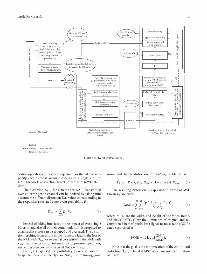
System model using UTRAN WCDMA network is shownon Figure 1: a video transmission is depicted as an example.The modules following each other represent a wired (IPv6)and a wireless (UMTS in this case) network. The wired partis the IP network “cloud,” while the wireless medium isthe channel block. The data transmission layers of the sys-tem correspond to the ISO/OSI model. The system is us-ing JSCC/D control information: this controls, for example,the UEP (unequal error protection) module, or the JSCC/Dadapted channel coding. Separate control layer is definedfor application and physical layers that in fact only virtu-ally differ: practically they make decisions jointly. The phys-ical control layer is (in our case) the RRC (radio resourcecontrol) layer. The feedback controller in the applicationlayer (JSCC/D) joins to the source coder, to the applicationprocessing module (ciphering, UEP), and to the streaming,transport and IPv6 protocols. These modules guarantee QoSneeded by a real-time multimedia stream, for example, se-quential delivery, and so on. The role of these modules is de-tailed in Section 5. The modules support information aboutsubscriber needs and about network or channel state. Thisinformation is forwarded to the control modules that makedecisions based on the received feedback information. Adap-tation control sets the video coding rate, or the protectionlevel of channel coding.
In Figure 1, the solid lines refer to effective data, payload(video), and joint information flows. The video data flows af-ter source coding and other application processes (e.g., UEP)using streaming and transport protocols through an IPv6network. Essential control information and protocol head-ers for optimization are attached to effective data packets.The information that is not synchronized to the data flowis transmitted in a separate flow (see dotted line). Controllerinterfaces were needed to be built to receive feedback fromother modules. This feedback communication is depicted bythe dotted line in Figure 1; the interfaces between the radioresource controller and the signal processing layers (PDCP,
RLC, MAC and PHY) are drawn similarly. These SAPs (ser-vice access points) are defined in the standards [5], but thefunctionalities had to be extended to allow joint optimiza-tion.
Joint optimization is performed at two protocol levels.The first one is the primary at application level, which is aseparate layer called “joint controller” in Figure 1. The otheris a secondary level in the RRC layer of UTRAN, which isalso using the control signals of the application level. Therole of the application-level joint controller is described inSection 3; the RRC mechanism is detailed in Section 7.
3. CONTROL OF JOINT OPTIMIZATION
The joint controller (depicted in Figure 1 at both transmitterand receiver sides) plays a key role, being responsible for theoptimization of the whole system. The task of the joint con-troller is to be aware of the global state of the system (which isrepresented as the union of state information that is presentin different layers), exchange this information with other sys-tem layers, and jointly optimize different transmission pa-rameters according to the system state in various layers. Notethat, in the so-called “preliminary handshaking” phase (con-nection establishment phase), further information can be ex-changed among the system blocks. This information consistsof the characteristics of the system, such as the type of avail-able channel encoders, modulator, or security options. In ourcase, this preliminary phase is not simulated, assuming con-trollers already know the capabilities of all blocks.
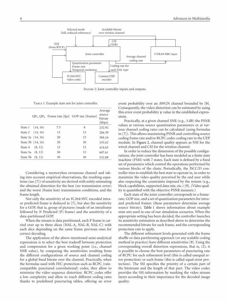
The joint controller on receiver side uses an error-freefeedback channel to deliver parameters and measurementsfor controller of transmitter side. The joint controller makesdecisions on the output parameters based on several inputparameters (see Figure 2) [6].
The joint controller inputs needed to let the protectionallocation run efficiently are the following:
(i) state information, on both network (NSI) and channel(CSI);
(ii) constraint on the total bandwidth available over thewireless channel (i.e., the target channel bitrate forcompressed and protected stream, including the net-work headers size);
(iii) type of joint controller mode (i.e., full or reduced ref-erence method) that will be detailed below;
(iv) feedback coming from the video encoding process (av-erage quantization parameter, PSNR).
The most important input parameter from the sourcecoder is SSI (source significance information). The deriva-tion and use of SSI for joint optimization is detailed in [7];this section only gives a short introduction for H.264/AVCcodec solely. A simple semi-analytical method is proposedto optimize the protection levels on the different parts of anH.264/AVC bitstream for transmission over an error-pronechannel. The model used for simulating video stream sen-sitivity allows the prediction of the resulting distortion de-pending on the channel errors (experienced by the video de-coder). The model proposes to estimate the average expectedend-to-end distortion DS+C after the source and channel
Attila Zsiros et al. 3
Packet data convergenceprotocol (PDCP), which
containes headercompression (RoHC)
Radio link controller layer
(RLC)
Medium access controllayer (MAC)
Physical layer (PHY)
IP
Transport protocol
Streaming protocol
(RTP & RTCP)
Application processing
Source decoding
Join
tco
ntr
olle
r(a
pplic
atio
nla
yer)
Rad
iore
sou
rce
con
trol
ler
laye
r(R
RC
),w
hic
his
capa
ble
for
join
top
tim
izat
ion
(phy
sica
llay
er)
SSI
NSI
CSI
CSI
Receiving wireless IP terminal:
UMTS mobile equipement
Channel
Generate CSI
Generate NSI
Get SSI fromdata flow
Packet data convergenceprotocol (PDCP), which
containes headercompression (RoHC)
Radio link controller layer
(RLC)
Medium access controllayer (MAC)
Physical layer (PHY)
Radio link transmitter:UMTS terrestrial radio access
network
Rad
iore
sou
rce
con
trol
ler
laye
r(R
RC
),w
hic
his
capa
ble
for
join
top
tim
izat
ion
(phy
sica
llay
er)
End to end QoS
Packet delays and packet losses
influences the NSI value
Generate SSI, join
to the data
Source encoding
(MPEG-4/H.264/SVC)Application processing
(content {cipher, UEP})
Streaming protocol
(generic RTP)
Transport protocol
(UDP/UDP-Lite/DCCP)
IPv6
Join
tco
ntr
olle
r(a
pplic
atio
nla
yer)
IP network(+mobility)
Sending IP terminal
Payload
Crosslayer communication
Block specific control
Figure 1: Overall system model.
coding operations for a video sequence. For the sake of sim-plicity, each frame is assumed coded into a single slice (orNAL (network abstraction layer) in the H.264/AVC stan-dard).
The distortion DS+C for a frame (or NAL) transmittedover an error-prone channel can be derived by taking intoaccount the different distortion Diψ values corresponding tothe respective associated error event probability Pi:
DS+C =∑
i∈NDi·Pi. (1)
Instead of taking into account the impact of every singlebit error and also all of their combinations, it is proposed toassume that errors can be grouped and averaged. The distor-tion resulting from errors in the frame can lead to the loss ofthe NAL with Dloss, or to partial corruption of the NAL withDcorr, and the distortion inherent to compression operation,impacting even correctly received NALs with Do.
For Pcψ (resp., Pl) the probability to receive correctly(resp., to loose completely) an NAL, the following joint
source and channel distortion, or sensitivity is obtained as
DS+C = Pc·Do + Pl·Dloss +(
1− Pc − Pl)·Dcorr. (2)
The resulting distortion is expressed in terms of MSE(mean square error):
MSE =M∑
i=1
Q∑
j=1
(
pl∗(i, j)− pl(i, j))2
M ×Q , (3)
where M, Q are the width and height of the video frame,and pl(i, j), pl∗(i, j) are the luminance of original and re-constructed frames’ pixels. Peak signal-to-noise ratio (PSNR)can be expressed as
PSNR = 10 log10
(
2552
MSE
)
. (4)
Note that the goal is the minimization of the end-to-enddistortion DS+C, defined as MSE, which means maximizationof PSNR.
4 Advances in Multimedia
Joint controller UTRAN RRC layer
NSI(from RTCP)
Quantization parameterFrame rateTemporal resolution
Coding rate foreach NAL type
Selected mode(full, reduced referernce)
Available bitrateover wireless channel
CSI(SNR)
Average channelcoding rate
H.264/AVCvideo codec
Content UEPencoder
Figure 2: Joint controller inputs and outputs.
Table 1: Example state sets for joint controller.
QPI, QPP Frame rate [fps] GOP size [frames]
Averagesourcebitrate[kbps]
State 1 (14, 16) 7.5 8 232.92
State 2 (14, 16) 15 15 266.39
State 3a (14, 16) 30 15 384.16
State 3b (14, 16) 30 30 335.62
State 4 (8, 12) 15 15 414.63
State 5a (8, 12) 30 15 607.61
State 5b (8, 12) 30 30 532.08
Considering a memoryless erroneous channel and tak-ing into account empirical observations, the resulting equa-tions (see [7]) of sensitivity are derived with solely estimatingthe obtained distortion for the best (no transmission error)and the worst (frame lost) transmission conditions, and theframe length.
Not only the sensitivity of an H.264/AVC encoded intra-or predicted frame is deduced in [7], but also the sensitivityfor a GOP, that is, group of pictures (made of an intraframefollowed by N Predicted (P) frame) and the sensitivity of adata-partitioned GOP.
When the stream is data partitioned, each P frame is car-ried over up to three slices (NAL-A, NAL-B, NAL-C) witheach slice depending on the same frame previous ones forcorrect decoding.
The application of the above-mentioned semi-analyticalexpressions is to select the best tradeoff between protectionand compression for a given working point (i.e., channelSNR value), by comparing the sensitivities resulting fromthe different configurations of source and channel codingfor a global fixed bitrate over the channel. Practically, whenthe formulas used with FEC protection such as RCPC (rate-compatible punctured convolutional) codes, they allow tominimize the video sequence distortion. RCPC codes offera low complexity and allow to reach different coding ratesthanks to predefined puncturing tables, offering an error
event probability over an AWGN channel bounded by [8].Consequently, the video distortion can be estimated by usingthis error event probability ψ value in the established expres-sions.
Practically, at a given channel SNR (e.g., 3 dB) the PSNRvalues at various source quantization parameters or at var-ious channel coding rates can be calculated (using formulasin [7]). This allows maximizing PSNR and controlling sourcecoding frame rate and/or RCPC codec coding rate in the UEPmodule. In Figure 2, channel quality appears as NSI for thewired channel and CSI for the wireless channel.
In order to reduce the dimension of the possible configu-rations, the joint controller has been modeled as a finite statemachine (FSM) with 7 states. Each state is defined by a fixedset of parameters which control the operations performed byvarious blocks of the chain. Periodically, the JSCC/D con-troller tries to establish the best state to operate in, in order tomaximize the video quality perceived by the end user whilealso respecting the constraints imposed by the system (e.g.,block capabilities, supported data rate, etc.) [9]. (Video qual-ity is quantified with the objective PSNR measure.)
Each state of the joint controller corresponds to a frame-rate, GOP size, and a set of quantization parameters for intra-and predicted frames (these parameters determine averagesource bitrate). Table 1 shows information about examplestate sets used in one of our simulation scenarios. When theappropriate setting has been decided, the controller launchesits sensitivity estimation as described above to determine therecommended bitrate for each frame, and the correspondingprotection rate to apply.
The different refinement levels generated with the frameshuffle or data partitioning approach (or any scalable codingmethod in practice) have different sensitivities [9]. Using thecorresponding overall distortion expressions, that is, (2), itis possible to choose the best parameters of puncturing rateof RCPC for each refinement level (this is called unequal er-ror protection) or each frame (this is called equal error pro-tection). The SSI specifies the priority of a certain part ofthe bitstream and the length of that part. The video codecprovides the SSI-information by marking the video streamlayers according to their importance for the decoded imagequality.
Attila Zsiros et al. 5
DLheader
IPheader
AHheader
RoHCheader
TRheader
RTPheader Extra information Payload
CIPHER TOBECIPH
SSI
1L
EN
GT
H
SSI
2L
EN
GT
H
SSI
3L
EN
GT
H
SRI
1
SRI
2
SRI
3
SRI
4
SRI
5
SSI NUM
SSI
1ID
SSI
2ID
SSI
3ID
PUNCNUM
PU
NC
1R
AT
EP
UN
C1
LE
NG
TH
PU
NC
2R
AT
EP
UN
C2
LE
NG
TH
PU
NC
3R
AT
EP
UN
C3
LE
NG
TH
IS PAYLOADQ
UCR NBBITS
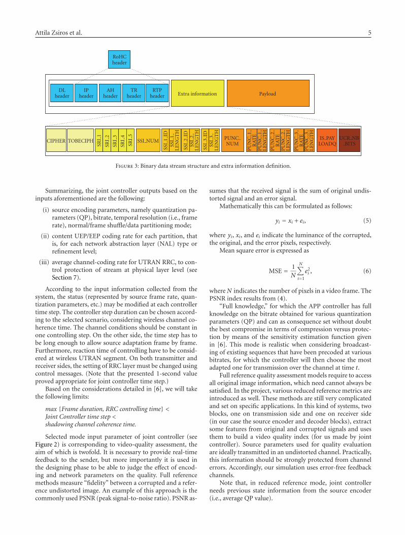
Figure 3: Binary data stream structure and extra information definition.
Summarizing, the joint controller outputs based on theinputs aforementioned are the following:
(i) source encoding parameters, namely quantization pa-rameters (QP), bitrate, temporal resolution (i.e., framerate), normal/frame shuffle/data partitioning mode;
(ii) content UEP/EEP coding rate for each partition, thatis, for each network abstraction layer (NAL) type orrefinement level;
(iii) average channel-coding rate for UTRAN RRC, to con-trol protection of stream at physical layer level (seeSection 7).
According to the input information collected from thesystem, the status (represented by source frame rate, quan-tization parameters, etc.) may be modified at each controllertime step. The controller step duration can be chosen accord-ing to the selected scenario, considering wireless channel co-herence time. The channel conditions should be constant inone controlling step. On the other side, the time step has tobe long enough to allow source adaptation frame by frame.Furthermore, reaction time of controlling have to be consid-ered at wireless UTRAN segment. On both transmitter andreceiver sides, the setting of RRC layer must be changed usingcontrol messages. (Note that the presented 1-second valueproved appropriate for joint controller time step.)
Based on the considerations detailed in [6], we will takethe following limits:
max {Frame duration, RRC controlling time} <Joint Controller time step <shadowing channel coherence time.
Selected mode input parameter of joint controller (seeFigure 2) is corresponding to video-quality assessment, theaim of which is twofold. It is necessary to provide real-timefeedback to the sender, but more importantly it is used inthe designing phase to be able to judge the effect of encod-ing and network parameters on the quality. Full referencemethods measure “fidelity” between a corrupted and a refer-ence undistorted image. An example of this approach is thecommonly used PSNR (peak signal-to-noise ratio). PSNR as-
sumes that the received signal is the sum of original undis-torted signal and an error signal.
Mathematically this can be formulated as follows:
yi = xi + ei, (5)
where yi, xi, and ei indicate the luminance of the corrupted,the original, and the error pixels, respectively.
Mean square error is expressed as
MSE = 1N
N∑
i=1
e2i , (6)
whereN indicates the number of pixels in a video frame. ThePSNR index results from (4).
“Full knowledge,” for which the APP controller has fullknowledge on the bitrate obtained for various quantizationparameters (QP) and can as consequence set without doubtthe best compromise in terms of compression versus protec-tion by means of the sensitivity estimation function givenin [6]. This mode is realistic when considering broadcast-ing of existing sequences that have been precoded at variousbitrates, for which the controller will then choose the mostadapted one for transmission over the channel at time t.
Full reference quality assessment models require to accessall original image information, which need cannot always besatisfied. In the project, various reduced reference metrics areintroduced as well. These methods are still very complicatedand set on specific applications. In this kind of systems, twoblocks, one on transmission side and one on receiver side(in our case the source encoder and decoder blocks), extractsome features from original and corrupted signals and usesthem to build a video quality index (for us made by jointcontroller). Source parameters used for quality evaluationare ideally transmitted in an undistorted channel. Practically,this information should be strongly protected from channelerrors. Accordingly, our simulation uses error-free feedbackchannels.
Note that, in reduced reference mode, joint controllerneeds previous state information from the source encoder(i.e., average QP value).
6 Advances in Multimedia
4. CROSS-LAYER COMMUNICATION ANDSIGNALLING INFORMATION
The reality of cross-layer communication for our simulationchain implies that the different signalling information (SSI,cipher key, etc.) is indeed transmitted together with the bit-stream. In practice, the extra data is being transferred di-rectly into a binary packet which is made of the payload ob-tained after video encoding and application processing (con-tent cipher and UEP), with the addition of an extra infor-mation field viewed as an additional header, as illustratedby Figure 3. Extra information is exchanged using the IPv6header by Hop-by-Hop option. Payload contains cipheredprotected video frame (or NAL).
First two parameters are cipher key and cipher mode (en-abled or disabled). The SRI contains information from thesource known a priori. In practice, SRI 1, . . . , SRI 5 are usedonly by the soft-input H.264 decoder and are neither usedmandatory for hard-input H.264 decoding. IS PAYLOADQand UCR NB BITS fields also carry useful information forsoft decoding. UTRAN module is not capable of transfer-ing soft information, instead of bits of packets; accordingly,SRI is not applied. SSI NUM means the number of SSI fields,which contain ID for priority class and length of the data partbelonging to the class. PUNC fields refer to the puncturingparameter for UEP module to adjust data rate.
CSI describes the wireless channel state using measuredsignal-to-noise ratio. This unsynchronized feedback infor-mation can be forwarded by the ICMPv6 protocol (internetcontrol message protocol version 6), because it entails lowoverhead. NSI, which contains inter-arrival jitter, average de-lay for packets, and packet loss rate, should be exchangedusing the RTCP packets, even if the overhead introduced isslightly higher than with other schemes (e.g., ICMPv6 mes-sages), because the RTCP packets are already exchanged be-tween the receiver and the sender and because their formatdo not require any modification to include NSI informa-tion. Video quality, that is, PSNR measure is also feedbackinformation produced after video decoding, mentioned inSection 3.
5. APPLICATION PART
In this section, layers controlled directly by the joint con-troller (JSCC/D) are detailed.
The source coding and decoding modules on the top ofFigure 1 are using MPEG-4 or H.264/AVC codecs. Althoughfeatures of these encoders are beyond standard capabilities,in this paper only H.264/AVC (advanced video coding) codecis detailed. The reason behind is that this codec fits well inour UTRAN simulation environment, and real-time wire-less services with low latency and bitrate below 1 Mb/s. Therationale for choosing H.264/AVC is its design, which pro-vides a more efficient compression when compared to theformer standards (such as MPEG-2, H.263, MPEG-4), whilepresenting a reasonable implementation complexity versuscoding efficiency ratio, and that is easily adaptable to net-worked applications, in particular wireless networks and in-
ternet, thanks to its network abstraction layer (NAL) struc-ture.
The integration of the H.264 codec into the simulationchain meant the adaptation of the H.264 joint verificationmodel (JM) version 10.1 [10] that had been developed by theITU-T and MPEG joint video team. The H.264/AVC videocodec implemented in Phoenix project using frame shuffleand data partitioning techniques in addition to standard op-eration. The difference introduced by the frame shuffle oper-ation when compared to classical GOP ordering and codingprocess is the introduction of different dependencies amongframes. Frame shuffle technique allows with a large set ofshuffling patterns to envisage the adaptation of the encodingprocess to the video content features, as well as to the userequipment and transmission channel characteristics. Thisapproach relies on shuffling the frames inside a group of pic-tures, which led to call it “frame shuffle” [11].
Furthermore, adaptation of the codec has been made inlink with the controlling module to ensure that the modifica-tion of the source coding parameters can be done at each newapplication controller decision. The establishment of sensi-tivity measurements (mentioned in Section 3) allows to ap-ply efficient error-protection scheme by UEP module.
5.1. UEP, ciphering
UEP module can produce equal error protection (EEP) fordata or unequal error protection for critical parts of the datathan for other less critical parts. The joint controller adjuststhe UEP mode based on the information about SSI, NSI, andreduced CSI.
This module relies on RCPC codes with mother code ofcode rate 1/3, constraint length 5, and number of puncturingtables 9, resulting in the punctured code rates: 8/9, 4/5, 2/3,4/7, 1/2, 4/9, 2/5, 4/11, 1/3.
Selective video ciphering algorithm is realized in thePhoenix system. It encrypts all the I frames and keeps theother parts untouched. Depending on the GOP structure ofthe video stream, this algorithm may lead to significant com-plexity reduction compared to naive algorithm. Cipheringuses a stream cipher, which can be RC4 or AES operationin counter mode.
5.2. Streaming module
On the sending site, the objective of the streaming module isthe packetization of data flow into IP packets; on the receiverside, its task is the reconstruction of data flow from receivedIP packets for upper layers. But the IP packet means not onlythe IP protocol, besides the transport layer function belonghere the RTP and the RTCP protocols.
RTP has been designed for real-time multimedia appli-cations, because it provides timestamps and sequence num-bers. Note that RTP itself does not provide any error detec-tion/recovery; it is the application on top of RTP that mayprovide them. RTCP is used to monitor the quality of ser-vice and convey information about the participants in an on-going session. This is achieved by sending reports betweensender(s) and receiver(s). The receiver analyzes RTP header
Attila Zsiros et al. 7
information and calculates data rate, inter-arrival jitter, andaverage delay for packets. The NSI parameter used by jointcontroller is packet loss rate (PLR) monitored by RTCP.
In the simulation chain UDP, UDP-Lite and DCCP pro-tocols are implemented. The UDP protocol offers connec-tionless, best-effort service, which means no sequence num-bering. Duplicate packets can also occur. The UDP-Lite pro-tocol is the extended version of UDP protocol, which differsfrom the original UDP protocol with a partial CRC check-sum. This partial checksum covers only the header and partof the payload data. If there is an error within the CRC cov-ered part of the data, then the packet will be dropped. If theUDP checksum covers the whole packet, then the behaviorof UDP-Lite is the same with the classical UDP. But if weprotect only the header field, then can we achieve more ef-fective functionality, because with this technique the num-ber of discards decreases with circa 40%. Another trans-port layer protocol the DCCP offers is not reliable conges-tion controlled data flow service with acknowledgement ofthe correctly received data. The implemented DCCP proto-col contains no possibility for retransmission of datagrams,and contains alike to the UDP-Lite protocol a partial check-sum. The DCCP partial checksum covers in any case thewhole header and the n·4 byte part of the payload. Note thatthe IPv4/IPv6 packet generation demands that the transportlayer protocols have to use checksum, but this checksum canbe partial alike to UDP-Lite or to DCCP.
The packets containing the header field of transport pro-tocols are nested into IP packets. The simulation chain sup-ports only the IPv6, the internet protocol version 6, becausethis protocol is the protocol of future internet. The EuropeanCommittee pretends from every IST projects to use IPv6.
The existent effective audio/video decoders are capa-ble of processing the erroneous packets, thus increasing thevideo quality. Consequently, with the above-mentioned par-tial checksum the number of lost packets decreases and thenumber of video decoder processed packets increases.
The RTP/RTCP protocols can sit on top of UDP/UDP-Lite protocols, but in the case of DCCP protocol they aresuperfluous. The DCCP protocol implements all the func-tions that make the RTP/RTCP protocols essential. The cur-rent version of simulation chain uses in every case RTP/RTCPprotocols according to practical reasons.
6. TRANSMISSION PART
6.1. IPv6 network
The simulated IP network can be considered as an IP cloudwith a bunch of unknown routers. This module representsthe wired component of the network. Capacity and buffersize of this virtual network are configurable. The servicetreatment that a packet can experience at IP interface is char-acterized by a set of QoS parameters: delay, delay variations(jitter), and loss. End-to-end delay is modeled by gamma dis-tribution, and uniform distribution is employed to representdrop probability. Complexity of wired network, the numberof routers, and their parameters are also adjustable. The reli-ability of wired medium is rather high. The duration of our
L3
L2/PDCPPDCP PDCP
BMC L2/BMC
L2/RLC
L2/MAC
L1
RRC Control
RLCRLCRLC
RLC
RLCRLC
RLCRLC
MAC
PHY
U-plane informationC-plane signalling
Radiobearers
Logicalchannels
Transportchannels
Con
trol
Con
trol
Con
trol
Con
trol
Figure 4: UTRAN protocol architecture.
presented simulation run is relatively low, only 20 seconds.On the other hand, in our simulated case, enough resourcesare allocated for video transmission, so packet loss proba-bility of wired segments is negligible. IPv6 network typicallyaffects delaying packets; hence order of packets can changeand transmission usually becomes more bursty at the out-put. Since we focus on wireless UTRAN segment, packet lossis set to minimum in wired components. During the trans-mission of 20-seconds long video, no packet drop occurredat the presented numerical example results.
Futhermore, a mobility model is adopted at IP layer. Theresults show that the higher the handover frequency is, thehigher the end-to-end packet loss and the packet loss rate(PLR) becomes. Its impact can be summarized into two as-pects. There will be an increase in the packet loss rate, be-cause during a handover all packets will be lost. This meansthat the higher the handover rate is, the higher the PLR be-comes. However, according to reality when there are not han-dovers, a delay will be introduced due to mobility effects. Thepresence of application controller can improve the perceivedquality also when mobility is present, because when the lossesare high the source coding rate is properly reduced. We con-sidered in this paper a low handover frequency scenario, sono handover has occurred.
When there is a network congestion, indicated by a highvalue for the PLR feedback in the NSI, the controller sets im-mediately the state to the first, characterized by the lowestsource bitrate, in order to reduce as much as possible theamount of data which have to flow through the IPv6 net-work.
6.2. UTRAN
6.2.1. Structure and functionalities
Main considerations of designing our UTRAN moduleswere the following: (1) flexibility, (2) platform independentcode, (3) efficient implementation, and (4) compliance with
8 Advances in Multimedia
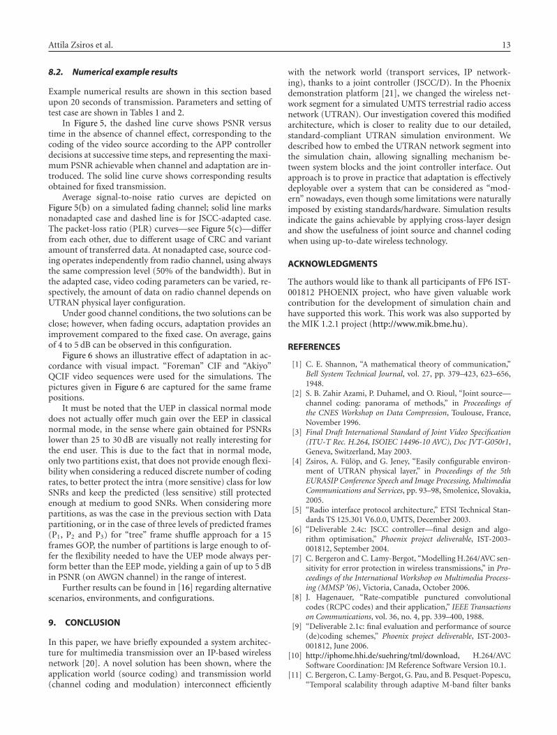
05
10
15202530354045
Ave
rage
PSN
R(d
B)
1 3 5 7 9 11 13 15 17 19
NonadaptedAdapted
Time (s)
(a) PSNR for Scenario 7-H.264/AVC coding
201816141210
86420−2
chan
nel
SNR
(dB
)
1 3 5 7 9 11 13 15 17 19
NonadaptedAdapted
Time (s)
(b) Channel SNR for Scenario 7
0
0.2
0.4
0.6
0.8
1
PLR
1 3 5 7 9 11 13 15 17 19
NonadaptedAdapted
Time (s)
(c) PLR for Scenario 7
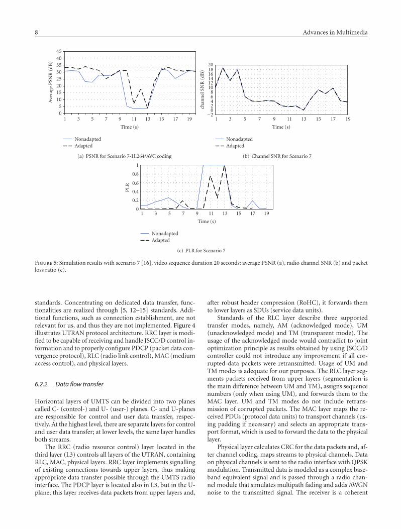
Figure 5: Simulation results with scenario 7 [16], video sequence duration 20 seconds: average PSNR (a), radio channel SNR (b) and packetloss ratio (c).
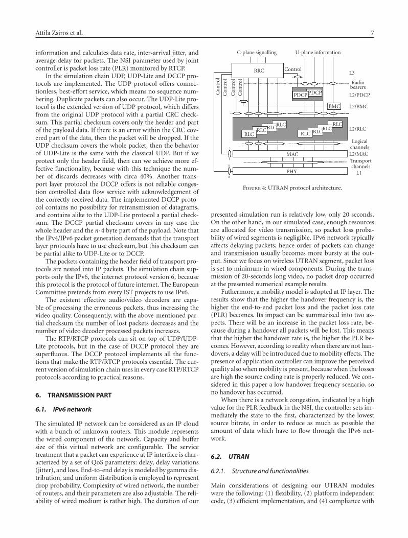
standards. Concentrating on dedicated data transfer, func-tionalities are realized through [5, 12–15] standards. Addi-tional functions, such as connection establishment, are notrelevant for us, and thus they are not implemented. Figure 4illustrates UTRAN protocol architecture. RRC layer is modi-fied to be capable of receiving and handle JSCC/D control in-formation and to properly configure PDCP (packet data con-vergence protocol), RLC (radio link control), MAC (mediumaccess control), and physical layers.
6.2.2. Data flow transfer
Horizontal layers of UMTS can be divided into two planescalled C- (control-) and U- (user-) planes. C- and U-planesare responsible for control and user data transfer, respec-tively. At the highest level, there are separate layers for controland user data transfer; at lower levels, the same layer handlesboth streams.
The RRC (radio resource control) layer located in thethird layer (L3) controls all layers of the UTRAN, containingRLC, MAC, physical layers. RRC layer implements signallingof existing connections towards upper layers, thus makingappropriate data transfer possible through the UMTS radiointerface. The PDCP layer is located also in L3, but in the U-plane; this layer receives data packets from upper layers and,
after robust header compression (RoHC), it forwards themto lower layers as SDUs (service data units).
Standards of the RLC layer describe three supportedtransfer modes, namely, AM (acknowledged mode), UM(unacknowledged mode) and TM (transparent mode). Theusage of the acknowledged mode would contradict to jointoptimization principle as results obtained by using JSCC/Dcontroller could not introduce any improvement if all cor-rupted data packets were retransmitted. Usage of UM andTM modes is adequate for our purposes. The RLC layer seg-ments packets received from upper layers (segmentation isthe main difference between UM and TM), assigns sequencenumbers (only when using UM), and forwards them to theMAC layer. UM and TM modes do not include retrans-mission of corrupted packets. The MAC layer maps the re-ceived PDUs (protocol data units) to transport channels (us-ing padding if necessary) and selects an appropriate trans-port format, which is used to forward the data to the physicallayer.
Physical layer calculates CRC for the data packets and, af-ter channel coding, maps streams to physical channels. Dataon physical channels is sent to the radio interface with QPSKmodulation. Transmitted data is modeled as a complex base-band equivalent signal and is passed through a radio chan-nel module that simulates multipath fading and adds AWGNnoise to the transmitted signal. The receiver is a coherent
Attila Zsiros et al. 9
RAKE receiver that estimates the attenuation of the channelmain signal paths optimally. After the RAKE receiver, inversesignal- and data-processing algorithms of the layers MAC,RLC, PDCP are performed.
6.2.3. Control of UTRAN module
RRC (radio resource control) layer is responsible for con-trolling other UMTS layers. Joint optimization parameters ofPhoenix simulation chain influence the operation of UMTSmodules via RRC. Mode of data transfer in UTRAN is de-fined via the active transport format, which combines theRLC, MAC, and physical layer settings. The actually validtransport format is chosen by MAC from the configured set.The selection algorithm is based on data flow priorities andRLC buffer occupancy [4]. This primary configuration, car-ried out by MAC, is relatively fast, thus its period time is 10–80 milliseconds. Transport format includes
(i) type of error protection (turbo, convolutional, no cod-ing),
(ii) coding rate,(iii) TTI (transmission time interval), that is, the inter-
arrival time of transport block sets (10, 20, 40 or 80milliseconds),
(iv) amount of data in one TTI (transport block size, num-ber of transport blocks),
(v) size of CRC (0, 8, 12, 16, 24 bit),(vi) rate matching parameter (puncturing).
Besides, RRC layer can change the set of transport for-mats, from which MAC selects. This secondary configurationcan be accomplished more slowly than primary, because it isrequired to be synchronized sets among sender and receiver.In our simulation, adaptation controlled by JSCC/D is set toone second, which time is comparably needed to enforce newtransport format set.
The RRC layer chooses a configuration setting based oncontrol information received from the JSCC/D controller.The set of configuration settings has been determined basedon [13]; the set contains transport format sets, RLC layermode, channel type, payload and header sizes in bits, max-imal bitrates, and so on. Upon a single simulation run, noneof the above parameters changes except for the transport for-mat set. The above parameters are adjustable in both uplinkand downlink directions. Configuration settings used in thesimulations are based on values described in standards [13]:8–2048 kbps in downlink, 8–384 kbps in uplink is availablefor the system.
Usage of CRC might also affect the system performance.As it has already been mentioned, concatenation of CRCcodes to data units (transport blocks) takes place in the phys-ical layer on the transmitter side. On the receiver side, pack-ets with an erroneous CRC checksum are not forwarded toupper PDCP layer by RLC. If CRC check is disabled, UMTSwill drop less PDUs, and thus more erroneous packets willreach the source decoder. Clearly, packets can still be lost,even if CRC is completely switched off, because RLC can dropthem for invalid control information (sequence number, datalength indicator) and PDCP can also drop them while de-
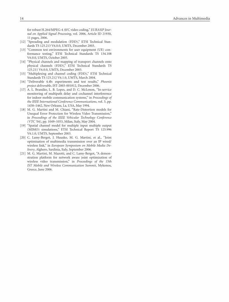
(a) (b)
(c) (d)
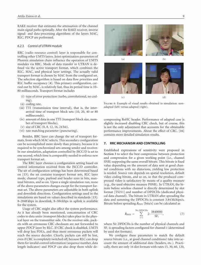
Figure 6: Example of visual results obtained in simulation: non-adapted (left) versus adapted (right).
compressing RoHC header. Performance of adapted case isslightly increased disabling CRC check, but of course, thisis not the only adjustment that accounts for the obtainableperformance improvements. About the effect of CRC, [16]contains more detailed simulation results.
7. RRC MECHANISM AND CONTROLLING
Established expressions of sensitivity were proposed inSection 3 to select the best compromise between protectionand compression for a given working point (i.e., channelSNR) supposing the same overall bitrate. This bitrate is fixedvalue depending on the amount of data sent at good chan-nel conditions with no distorions, yielding low protectionis needed. Source rate depends on spatial resolution, defaultvideo coding bitrate, and so on, so that the produced com-pressed video is satisfactory by means of a quality measure(e.g., the used objective measure PSNR). In UTRAN, the bi-trate before wireless channel is directly determined by slotformat [TS211] and number of DPDCHs (dedicated physi-cal data channel). The bitrate in UTRAN after spreading thedata and summing the DPDCHs is constant 3.84 Mchips/s.Bitrate before spreading RPHY [bits/s] can be calculated as
RPHY =Nr DPDCHs∑
i=1
2·3840000SFi
, (7)
where Nr DPDCHs is the number of physical channels andSFi is spreading factors configured for channel i (determinedby used slot formats).
We configure these parameters to match the defaultsource bitrate (i.e., at good channel conditions) take into ac-count the amount of additional data (headers, etc.). Practi-cally, there are only 16 slot formats with rates 15, 30, 60, 120,
10 Advances in Multimedia
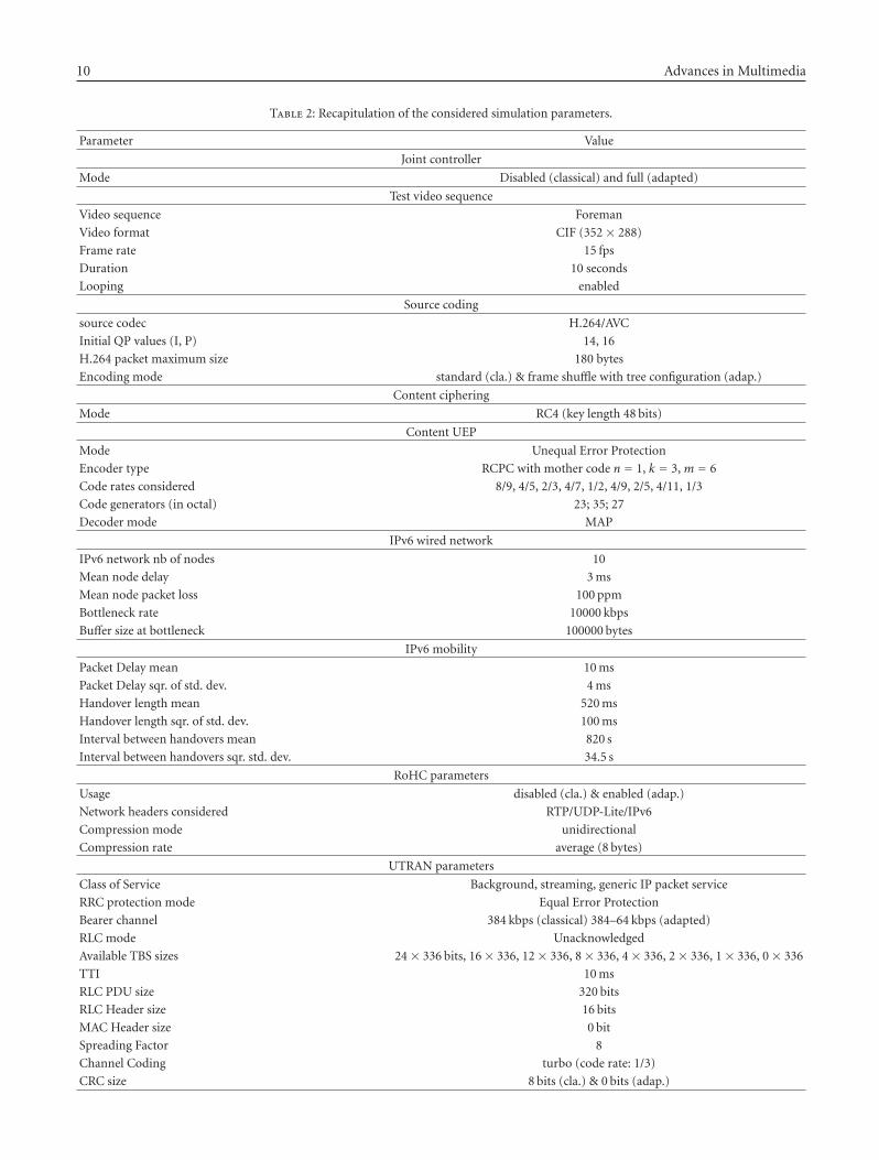
Table 2: Recapitulation of the considered simulation parameters.
Parameter Value
Joint controller
Mode Disabled (classical) and full (adapted)
Test video sequence
Video sequence Foreman
Video format CIF (352 × 288)
Frame rate 15 fps
Duration 10 seconds
Looping enabled
Source coding
source codec H.264/AVC
Initial QP values (I, P) 14, 16
H.264 packet maximum size 180 bytes
Encoding mode standard (cla.) & frame shuffle with tree configuration (adap.)
Content ciphering
Mode RC4 (key length 48 bits)
Content UEP
Mode Unequal Error Protection
Encoder type RCPC with mother code n = 1, k = 3, m = 6
Code rates considered 8/9, 4/5, 2/3, 4/7, 1/2, 4/9, 2/5, 4/11, 1/3
Code generators (in octal) 23; 35; 27
Decoder mode MAP
IPv6 wired network
IPv6 network nb of nodes 10
Mean node delay 3 ms
Mean node packet loss 100 ppm
Bottleneck rate 10000 kbps
Buffer size at bottleneck 100000 bytes
IPv6 mobility
Packet Delay mean 10 ms
Packet Delay sqr. of std. dev. 4 ms
Handover length mean 520 ms
Handover length sqr. of std. dev. 100 ms
Interval between handovers mean 820 s
Interval between handovers sqr. std. dev. 34.5 s
RoHC parameters
Usage disabled (cla.) & enabled (adap.)
Network headers considered RTP/UDP-Lite/IPv6
Compression mode unidirectional
Compression rate average (8 bytes)
UTRAN parameters
Class of Service Background, streaming, generic IP packet service
RRC protection mode Equal Error Protection
Bearer channel 384 kbps (classical) 384–64 kbps (adapted)
RLC mode Unacknowledged
Available TBS sizes 24 × 336 bits, 16 × 336, 12 × 336, 8 × 336, 4 × 336, 2 × 336, 1 × 336, 0 × 336
TTI 10 ms
RLC PDU size 320 bits
RLC Header size 16 bits
MAC Header size 0 bit
Spreading Factor 8
Channel Coding turbo (code rate: 1/3)
CRC size 8 bits (cla.) & 0 bits (adap.)
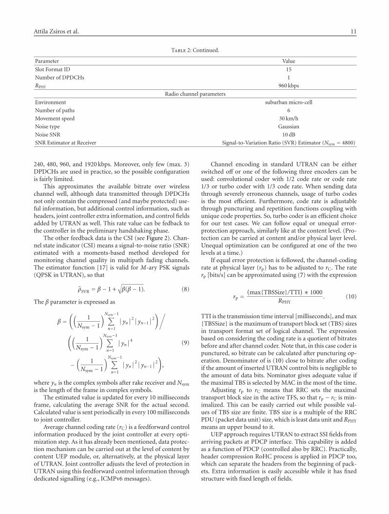
Attila Zsiros et al. 11
Table 2: Continued.
Parameter Value
Slot Format ID 15
Number of DPDCHs 1
RPHY 960 kbps
Radio channel parameters
Environment suburban micro-cell
Number of paths 6
Movement speed 30 km/h
Noise type Gaussian
Noise SNR 10 dB
SNR Estimator at Receiver Signal-to-Variation Ratio (SVR) Estimator (Nsym = 4800)
240, 480, 960, and 1920 kbps. Moreover, only few (max. 3)DPDCHs are used in practice, so the possible configurationis fairly limited.
This approximates the available bitrate over wirelesschannel well, although data transmitted through DPDCHsnot only contain the compressed (and maybe protected) use-ful information, but additional control information, such asheaders, joint controller extra information, and control fieldsadded by UTRAN as well. This rate value can be fedback tothe controller in the preliminary handshaking phase.
The other feedback data is the CSI (see Figure 2). Chan-nel state indicator (CSI) means a signal-to-noise ratio (SNR)estimated with a moments-based method developed formonitoring channel quality in multipath fading channels.The estimator function [17] is valid for M-ary PSK signals(QPSK in UTRAN), so that
ρSVR = β − 1 +√
β(β− 1). (8)
The β parameter is expressed as
β =(
(
1Nsym − 1
)Nsym−1∑
n=1
∣
∣yn∣
∣
2∣∣yn−1
∣
∣
2)/
(
(
1Nsym − 1
)Nsym−1∑
n=1
∣
∣yn∣
∣
4
−(
1Nsym − 1
)Nsym−1∑
n=1
∣
∣yn∣
∣
2∣∣yn−1
∣
∣
2)
,
(9)
where yn is the complex symbols after rake receiver and Nsym
is the length of the frame in complex symbols.The estimated value is updated for every 10 milliseconds
frame, calculating the average SNR for the actual second.Calculated value is sent periodically in every 100 millisecondsto joint controller.
Average channel coding rate (rC) is a feedforward controlinformation produced by the joint controller at every opti-mization step. As it has already been mentioned, data protec-tion mechanism can be carried out at the level of content bycontent UEP module, or, alternatively, at the physical layerof UTRAN. Joint controller adjusts the level of protection inUTRAN using this feedforward control information throughdedicated signalling (e.g., ICMPv6 messages).
Channel encoding in standard UTRAN can be eitherswitched off or one of the following three encoders can beused: convolutional coder with 1/2 code rate or code rate1/3 or turbo coder with 1/3 code rate. When sending datathrough severely erroneous channels, usage of turbo codesis the most efficient. Furthermore, code rate is adjustablethrough puncturing and repetition functions coupling withunique code properties. So, turbo coder is an efficient choicefor our test cases. We can follow equal or unequal error-protection approach, similarly like at the content level. (Pro-tection can be carried at content and/or physical layer level.Unequal optimization can be configured at one of the twolevels at a time.)
If equal error protection is followed, the channel-codingrate at physical layer (rp) has to be adjusted to rC. The raterp [bits/s] can be approximated using (7) with the expression
rp =(
max{TBSSize}/TTI)∗ 1000
RPHY. (10)
TTI is the transmission time interval [milliseconds], and max{TBSSize} is the maximum of transport block set (TBS) sizesin transport format set of logical channel. The expressionbased on considering the coding rate is a quotient of bitratesbefore and after channel coder. Note that, in this case coder ispunctured, so bitrate can be calculated after puncturing op-eration. Denominator of is (10) close to bitrate after codingif the amount of inserted UTRAN control bits is negligible tothe amount of data bits. Nominator gives adequate value ifthe maximal TBS is selected by MAC in the most of the time.
Adjusting rp to rC means that RRC sets the maximaltransport block size in the active TFS, so that rp − rC is min-imalized. This can be easily carried out while possible val-ues of TBS size are finite. TBS size is a multiple of the RRCPDU (packet data unit) size, which is least data unit and RPHY
means an upper bound to it.UEP approach requires UTRAN to extract SSI fields from
arriving packets at PDCP interface. This capability is addedas a function of PDCP (controlled also by RRC). Practically,header compression RoHC process is applied in PDCP too,which can separate the headers from the beginning of pack-ets. Extra information is easily accessible while it has fixedstructure with fixed length of fields.
12 Advances in Multimedia
Data can be separated to more flows of layers or parti-tions belonging to the same sensitivity class. The layer archi-tecture of UTRAN depicted on Figure 4 clearly shows thatmore RLC entities can operate parallel. Creating RLC entitiesfor all data flows makes it possible to transfer the sequences toMAC using different logical channels. The advantage of us-ing different logical channels is that transfer parameters, thatis, transport format sets can be distinguished for each chan-nel. Allowed combinations of transport formats for logicalchannels define transport format combination sets (TFCS).The currently used transfer parameters (i.e., the used combi-nation) are selected by MAC layer. Selection is based on thebuffer occupancies of RLC entities and the priority of logicalchannels, which well fits the priority of sensitivity classes.
When we consider a source represented by the incomingbitstream at UTRAN PDCP interface that may be separatedin layers or partitions Pi of different significance, each parti-tion may be protected with a different channel code of raterp,i according to its sensitivity to channel errors, which canbe determined by using (10). Our goal is the minimalizationof end-to-end distortion.
Each partition Pi has a source rate
RS,i = φiRS = BiBRS, (11)
where RS is the overall source rate, φi = Bi/B is the rationbetween the number of bits per frame of the ith partition, Bi,and the total number of bits/frame, B. The total source andchannel coding rate, RS+C is given by
RS+C = rN∑
i=1
RS,i
rp,i, (12)
where N is the number of partitions considered. Here we areinterested in a source-dependent choice of channel codingrates for a source coded bitstream with fixed parameters. Foreach channel condition, for a given source rate RS and a giventotal channel coding rate rC, the problem consists in find-ing the channel coding rates rp,i such that the total distortionDS+C is minimized. The constraint to satisfy [18] is
RS+C ≤ RS
rC. (13)
For analytical deduction and more details see [18] or [6].
8. SIMULATION RESULTS
This section presents experimental tests carried out over thePhoenix end-to-end simulation chain containing UTRANwireless segment. Our primary goal is to demonstrate the ef-ficiency of an end-to-end optimization of a video transmis-sion over an UTRAN wireless link.
8.1. Practical settings of simulation parameters
In order to validate the usefulness of our approach under re-alistic conditions, we used seven candidate scenarios definedby the Phoenix project. Results presented here are created
by using settings for each module of Scenario 7. The cor-responding settings are detailed in project deliverable [16]and summarized in Table 2. This scenario represents pushedvideo information transfer, such as live news, which corre-sponds to low delay, multicast, streaming mode and mobileusers. Data transfer between a mobile station, as a receiver,and a transmitter station (multicasting news) is simulated.
The raw video sequence “foreman” is CIF resolutionYUV format, which is compressed with H.264/AVC pictureencoding in the application layer. Frame shuffle mode is ac-tivated to ensure scalability of video content. UEP policy isactivated for 4 sensitivity classes of video content. The re-sulting binary stream is then fed to the network layer, whichperforms RTP/UDP-Lite/IPv6 packetization with the inser-tion of the extra signalling information as detailed Section 4.This is followed by an IPv6 network emulator (which takesinto account possible packet losses and delay due to possi-ble congestions in a wired IP network) and an IP mobilityemulator introducing further delays and losses due to the IPwireless mobility. RLC layer (located in UTRAN) is config-ured in unacknowledged mode (UM) using packet sequencenumbering without retransmission of corrupted packets. Asit has already been mentioned before, UM is necessary for ef-ficient adaptation. Data errors are needed to be reduced notby retransmission, but joint optimization, reconfiguration ofthe whole system. In acknowledged mode, RLC layer wouldhide erroneous packets from higher layers, losing essentialinformation for joint optimization. Radio channel is simu-lated based on [19] suburban micro-cell environment. As de-picted on Figure 1, downlink transmission is carried over inUTRAN.
If the adaptation is “on,” the application layer controllerwill decide (based on SSI information) on both source cod-ing compression level and radio link protection. Joint con-troller also takes into account side information signals (CSIand NSI continuously fed back to the transmitter side con-troller), optimizing the average repartition of bandwidth be-tween compression and protection by using PSNR modelsfor respective channels. Video encoding parameters are setonce in a second—this is the time to reconfigure each mod-ule in the adapted case. In nonadapted case, JSCC/D is dis-abled and MAC layer selects the transport format combina-tion to use from a configured set, which is equivalent to a384 kbps radio bearer [5]. In the nonadapted case, 8 bit CRCchecksum is set for each packet data unit. CRC is avoided inthe adapted case, and similarly to classical mode, slot formatnumber 15 is set at spreading and modulation. This enablesRPHY = 960 kbps overall data rate through the wireless chan-nel, which means a spreading factor of 8 and the usage ofonly one DPDCH.
Both adapted and nonadapted transmissions use stan-dard turbo channel coding. If we did not apply the same typeof error correction, significant difference could be observed,for example, in the case of convolutional coding. If the adap-tation is enabled, the level of protection is not static; it is de-termined by the level of the puncturing mechanism. Equalerror protection approach is applied at UTRAN, so RRCdetermines in every second the available transport formatset.
Attila Zsiros et al. 13
8.2. Numerical example results
Example numerical results are shown in this section basedupon 20 seconds of transmission. Parameters and setting oftest case are shown in Tables 1 and 2.
In Figure 5, the dashed line curve shows PSNR versustime in the absence of channel effect, corresponding to thecoding of the video source according to the APP controllerdecisions at successive time steps, and representing the maxi-mum PSNR achievable when channel and adaptation are in-troduced. The solid line curve shows corresponding resultsobtained for fixed transmission.
Average signal-to-noise ratio curves are depicted onFigure 5(b) on a simulated fading channel; solid line marksnonadapted case and dashed line is for JSCC-adapted case.The packet-loss ratio (PLR) curves—see Figure 5(c)—differfrom each other, due to different usage of CRC and variantamount of transferred data. At nonadapted case, source cod-ing operates independently from radio channel, using alwaysthe same compression level (50% of the bandwidth). But inthe adapted case, video coding parameters can be varied, re-spectively, the amount of data on radio channel depends onUTRAN physical layer configuration.
Under good channel conditions, the two solutions can beclose; however, when fading occurs, adaptation provides animprovement compared to the fixed case. On average, gainsof 4 to 5 dB can be observed in this configuration.
Figure 6 shows an illustrative effect of adaptation in ac-cordance with visual impact. “Foreman” CIF and “Akiyo”QCIF video sequences were used for the simulations. Thepictures given in Figure 6 are captured for the same framepositions.
It must be noted that the UEP in classical normal modedoes not actually offer much gain over the EEP in classicalnormal mode, in the sense where gain obtained for PSNRslower than 25 to 30 dB are visually not really interesting forthe end user. This is due to the fact that in normal mode,only two partitions exist, that does not provide enough flexi-bility when considering a reduced discrete number of codingrates, to better protect the intra (more sensitive) class for lowSNRs and keep the predicted (less sensitive) still protectedenough at medium to good SNRs. When considering morepartitions, as was the case in the previous section with Datapartitioning, or in the case of three levels of predicted frames(P1, P2 and P3) for “tree” frame shuffle approach for a 15frames GOP, the number of partitions is large enough to of-fer the flexibility needed to have the UEP mode always per-form better than the EEP mode, yielding a gain of up to 5 dBin PSNR (on AWGN channel) in the range of interest.
Further results can be found in [16] regarding alternativescenarios, environments, and configurations.
9. CONCLUSION
In this paper, we have briefly expounded a system architec-ture for multimedia transmission over an IP-based wirelessnetwork [20]. A novel solution has been shown, where theapplication world (source coding) and transmission world(channel coding and modulation) interconnect efficiently
with the network world (transport services, IP network-ing), thanks to a joint controller (JSCC/D). In the Phoenixdemonstration platform [21], we changed the wireless net-work segment for a simulated UMTS terrestrial radio accessnetwork (UTRAN). Our investigation covered this modifiedarchitecture, which is closer to reality due to our detailed,standard-compliant UTRAN simulation environment. Wedescribed how to embed the UTRAN network segment intothe simulation chain, allowing signalling mechanism be-tween system blocks and the joint controller interface. Outapproach is to prove in practice that adaptation is effectivelydeployable over a system that can be considered as “mod-ern” nowadays, even though some limitations were naturallyimposed by existing standards/hardware. Simulation resultsindicate the gains achievable by applying cross-layer designand show the usefulness of joint source and channel codingwhen using up-to-date wireless technology.
ACKNOWLEDGMENTS
The authors would like to thank all participants of FP6 IST-001812 PHOENIX project, who have given valuable workcontribution for the development of simulation chain andhave supported this work. This work was also supported bythe MIK 1.2.1 project (http://www.mik.bme.hu).
REFERENCES
[1] C. E. Shannon, “A mathematical theory of communication,”Bell System Technical Journal, vol. 27, pp. 379–423, 623–656,1948.
[2] S. B. Zahir Azami, P. Duhamel, and O. Rioul, “Joint source—channel coding: panorama of methods,” in Proceedings ofthe CNES Workshop on Data Compression, Toulouse, France,November 1996.
[3] Final Draft International Standard of Joint Video Specification(ITU-T Rec. H.264, ISOIEC 14496-10 AVC), Doc JVT-G050r1,Geneva, Switzerland, May 2003.
[4] Zsiros, A. Fulop, and G. Jeney, “Easily configurable environ-ment of UTRAN physical layer,” in Proceedings of the 5thEURASIP Conference Speech and Image Processing, MultimediaCommunications and Services, pp. 93–98, Smolenice, Slovakia,2005.
[5] “Radio interface protocol architecture,” ETSI Technical Stan-dards TS 125.301 V6.0.0, UMTS, December 2003.
[6] “Deliverable 2.4c: JSCC controller—final design and algo-rithm optimisation,” Phoenix project deliverable, IST-2003-001812, September 2004.
[7] C. Bergeron and C. Lamy-Bergot, “Modelling H.264/AVC sen-sitivity for error protection in wireless transmissions,” in Pro-ceedings of the International Workshop on Multimedia Process-ing (MMSP ’06), Victoria, Canada, October 2006.
[8] J. Hagenauer, “Rate-compatible punctured convolutionalcodes (RCPC codes) and their application,” IEEE Transactionson Communications, vol. 36, no. 4, pp. 339–400, 1988.
[9] “Deliverable 2.1c: final evaluation and performance of source(de)coding schemes,” Phoenix project deliverable, IST-2003-001812, June 2006.
[10] http://iphome.hhi.de/suehring/tml/download, H.264/AVCSoftware Coordination: JM Reference Software Version 10.1.
[11] C. Bergeron, C. Lamy-Bergot, G. Pau, and B. Pesquet-Popescu,“Temporal scalability through adaptive M-band filter banks
14 Advances in Multimedia
for robust H.264/MPEG-4 AVC video coding,” EURASIP Jour-nal on Applied Signal Processing, vol. 2006, Article ID 21930,11 pages, 2006.
[12] “Spreading and modulation (FDD),” ETSI Technical Stan-dards TS 125.213 V6.0.0, UMTS, December 2003.
[13] “Common test environments for user equipment (UE) con-formance testing,” ETSI Technical Standards TS 134.108V6.0.0, UMTS, October 2005.
[14] “Physical channels and mapping of transport channels ontophysical channels (FDD),” ETSI Technical Standards TS125.211 V6.0.0, UMTS, December 2003.
[15] “Multiplexing and channel coding (FDD),” ETSI TechnicalStandards TS 125.212 V6.1.0, UMTS, March 2004.
[16] “Deliverable 4.4b: experiments and test results,” Phoenixproject deliverable, IST-2003-001812, December 2006.
[17] A. L. Brandao, L. B. Lopes, and D. C. McLenon, “In-servicemonitoring of multipath delay and cochannel interfererncefor indoor mobile communication systems,” in Proceedings ofthe IEEE International Conference Communications, vol. 3, pp.1458–1462, New Orleans, La, USA, May 1994.
[18] M. G. Martini and M. Chiani, “Rate-Distortion models forUnequal Error Protection for Wireless Video Transmission,”in Proceedings of the IEEE Vehicular Technology Conference(VTC ’04), pp. 1049–1053, Milan, Italy, May 2004.
[19] “Spatial channel model for multiple input multiple output(MIMO) simulations,” ETSI Technical Report TS 125.996V6.1.0, UMTS, September 2003.
[20] C. Lamy-Bergot, J. Huusko, M. G. Martini, et al., “Jointoptimisation of multimedia transmission over an IP wired/wireless link,” in European Symposium on Mobile Media De-livery, Alghero, Sardinia, Italy, September 2006.
[21] M. G. Martini, M. Mazotti, and C. Lamy-Bergot, “A demon-stration platform for network aware joint optimization ofwireless video transmission,” in Proceedings of the 15thIST Mobile and Wireless Communication Summit, Mykonos,Greece, June 2006.

International Journal of
AerospaceEngineeringHindawi Publishing Corporationhttp://www.hindawi.com Volume 2010
RoboticsJournal of
Hindawi Publishing Corporationhttp://www.hindawi.com Volume 2014
Hindawi Publishing Corporationhttp://www.hindawi.com Volume 2014
Active and Passive Electronic Components
Control Scienceand Engineering
Journal of
Hindawi Publishing Corporationhttp://www.hindawi.com Volume 2014
International Journal of
RotatingMachinery
Hindawi Publishing Corporationhttp://www.hindawi.com Volume 2014
Hindawi Publishing Corporation http://www.hindawi.com
Journal ofEngineeringVolume 2014
Submit your manuscripts athttp://www.hindawi.com
VLSI Design
Hindawi Publishing Corporationhttp://www.hindawi.com Volume 2014
Hindawi Publishing Corporationhttp://www.hindawi.com Volume 2014
Shock and Vibration
Hindawi Publishing Corporationhttp://www.hindawi.com Volume 2014
Civil EngineeringAdvances in
Acoustics and VibrationAdvances in
Hindawi Publishing Corporationhttp://www.hindawi.com Volume 2014
Hindawi Publishing Corporationhttp://www.hindawi.com Volume 2014
Electrical and Computer Engineering
Journal of
Advances inOptoElectronics
Hindawi Publishing Corporation http://www.hindawi.com
Volume 2014
The Scientific World JournalHindawi Publishing Corporation http://www.hindawi.com Volume 2014
SensorsJournal of
Hindawi Publishing Corporationhttp://www.hindawi.com Volume 2014
Modelling & Simulation in EngineeringHindawi Publishing Corporation http://www.hindawi.com Volume 2014
Hindawi Publishing Corporationhttp://www.hindawi.com Volume 2014
Chemical EngineeringInternational Journal of Antennas and
Propagation
International Journal of
Hindawi Publishing Corporationhttp://www.hindawi.com Volume 2014
Hindawi Publishing Corporationhttp://www.hindawi.com Volume 2014
Navigation and Observation
International Journal of
Hindawi Publishing Corporationhttp://www.hindawi.com Volume 2014
DistributedSensor Networks
International Journal of