UMTS-WLAN Service Integration at Core Network Level
10
UMTS-WLAN Service integration at core network level Paulo Pinto 1 , Luis Bernardo 2 , and Pedro Sobral 3 1 , 2 Faculdade de Ciências e Tecnologia, Universidade Nova de Lisboa, P-2829-516 Caparica, Portugal, {pfp,lflb}@uninova.pt 3 Faculdade de Ciência e Tecnologia, Universidade Fernando Pessoa, Porto, Portugal, [email protected] Abstract. The integration of wireless LANs (WLANs) and 3G systems performed at core network level requires very little modifications to the current 3GPP architec- ture and provides a large set of benefits: seamless service integration, exploration of user mobility by applications, seamless use of different radio access network (RANs), easy availability of current services such as Short Message Service (SMS) in other RANs, etc. This paper describes an architecture that has the GPRS as the primary network. Each of the other networks has a core-level component to manage it and to perform the integration. Vertical handovers between RANs are not needed and secondary networks are used on an availability basis. Users can have at least one session per RAN that is maintained even when they are moving in dark areas of that RAN (and the communication is still possible via the primary network). Our proposal does not require the system to be all-IP, but simply IP-enabled. 1 Introduction The traditional approaches to the integration of wireless LANs (WLANs) and 3GPP sys- tems have avoided any changes to the core 3GPP network. WLANs can either appear as 3GPP cells (known as the tightly coupled approach [1], [2]) or interact with the 3GPP at IP level (the loosely coupled approach [1], [3]). If one considers that it might be possible to change the core network (basically minor software upgrades) the integration of wireless systems can become very powerful and attractive at various levels. We assume that the GPRS (General Packet Radio Service) network is ubiquitous and forms the primary radio access network (RAN) (In the rest of the paper, we consider GPRS as a packet service in both 2.5G and 3G 3GPP systems). Users can have sessions over the different RANs and these sessions persist over out of range periods. Consequently, users can always be con- tacted (either using that RAN, or the GPRS). All non-primary RANs are used as a com- plement to the GPRS making vertical handovers less critical. In fact, there is not really any vertical handover as users maintain the GPRS connectivity all the time. The management of contexts at core level allows the exploration of the user mobility in such aspects as available connections in other RANs and decisions for forwarding traffic through certain RANs. Currently, user mobility in 3GPP systems is mainly concerned with maintaining the bearer services (control and data channels) to enable communication. The
Transcript of UMTS-WLAN Service Integration at Core Network Level

UMTS-WLAN Service integration at core network level
Paulo Pinto1, Luis Bernardo2, and Pedro Sobral 3
1,2Faculdade de Ciências e Tecnologia, Universidade Nova de Lisboa, P-2829-516 Caparica, Portugal, {pfp,lflb}@uninova.pt
3Faculdade de Ciência e Tecnologia, Universidade Fernando Pessoa, Porto, Portugal, [email protected]
Abstract. The integration of wireless LANs (WLANs) and 3G systems performed at core network level requires very little modifications to the current 3GPP architec-ture and provides a large set of benefits: seamless service integration, exploration of user mobility by applications, seamless use of different radio access network (RANs), easy availability of current services such as Short Message Service (SMS) in other RANs, etc. This paper describes an architecture that has the GPRS as the primary network. Each of the other networks has a core-level component to manage it and to perform the integration. Vertical handovers between RANs are not needed and secondary networks are used on an availability basis. Users can have at least one session per RAN that is maintained even when they are moving in dark areas of that RAN (and the communication is still possible via the primary network). Our proposal does not require the system to be all-IP, but simply IP-enabled.
1 Introduction
The traditional approaches to the integration of wireless LANs (WLANs) and 3GPP sys-tems have avoided any changes to the core 3GPP network. WLANs can either appear as 3GPP cells (known as the tightly coupled approach [1], [2]) or interact with the 3GPP at IP level (the loosely coupled approach [1], [3]). If one considers that it might be possible to change the core network (basically minor software upgrades) the integration of wireless systems can become very powerful and attractive at various levels. We assume that the GPRS (General Packet Radio Service) network is ubiquitous and forms the primary radio access network (RAN) (In the rest of the paper, we consider GPRS as a packet service in both 2.5G and 3G 3GPP systems). Users can have sessions over the different RANs and these sessions persist over out of range periods. Consequently, users can always be con-tacted (either using that RAN, or the GPRS). All non-primary RANs are used as a com-plement to the GPRS making vertical handovers less critical. In fact, there is not really any vertical handover as users maintain the GPRS connectivity all the time. The management of contexts at core level allows the exploration of the user mobility in such aspects as available connections in other RANs and decisions for forwarding traffic through certain RANs. Currently, user mobility in 3GPP systems is mainly concerned with maintaining the bearer services (control and data channels) to enable communication. The

core just pushes packets through without any high level concern such as different cell capacity. In the scenarios envisaged by 3GPP with more than one RAN the situation does not change very much. First, the use of any RAN is based on secure associations. Then, proxies are used as interworking units for services and need, themselves, secure associa-tions as well. We will see how the provision of services over different RANs becomes a simple task in our system (e.g. SMS). In less technical aspects, our system allows WLANs to be owned by providers other than 3GPP system operators. Our envisaged application scenarios are an extension of the infostation model [4] with cellular network integration. Imagine a user landing on an airport. Once there, he starts a session using the airport’s WLAN. He wants to download a report. Next he takes a taxi to the hotel. On his way to the hotel, any WLAN will be used to send parts of the report (semaphores, etc.). Inside the taxi, in areas not covered by WLAN, the user can still be contacted using the GPRS RAN. Eventually all the report will be transferred by WLAN. When he arrives at the hotel (which has also a WLAN) the same session is still on. We assume that UEs (User Equipments) are equipped with two, or more, wireless interfaces working simultaneously.
2 Hotspot Integration
In the future, 3GPP cells will be smaller and will have more bandwidth. However, ex-tremely high rates will not be necessary everywhere, but just in small hotspots [5]. How will these hotspots be integrated?
2.1 Homogeneous Approach
One possibility is that these new cells will make WLAN integration useless because they will have the same characteristics. There are some drawbacks though. The network would have to predict the user movement (using cell information) to schedule data when the user enters in this kind of cells. It is a hard task to be performed at network level because it needs knowledge of the application. Such seamless environment is also difficult for users because they can step out of the cell and feel a drop in the bandwidth. The tightly coupled approach [1], [2] of integrating WLANs is somehow similar to this homogeneous ap-proach: WLAN cells behave like ordinary cells offering an interface compatible with the 3GPP protocols. This approach has further disadvantages: (a) the WLAN must be owned by the 3GPP operator (due to strong exposure of core network interfaces); (b) it is hard to incorporate a WLAN cell because cell displacement demands carefully engineered net-work planning tools and because a great deal of control procedures are based on configu-ration parameters (CellID, UTRAN Registration Area (URA), Routing Area (RA), etc.); (c) paging procedures, registration updates and handovers (including vertical handovers) have to be defined and some technologies (e.g. IEEE 802.11) are not so optimized to make them fast enough; and (d) high-rate traffic has to pass through the current 3GPP core network.

2.2 Heterogeneous Approach
Another way to integrate WLANs is the loosely coupled approach [1][3]. It assumes there is a WLAN gateway on the WLAN network with functionalities of Foreign Agent, fire-wall, AAA (Authentication, Authorization and Accounting) relaying, and charging. The connection to the 3GPP uses the GGSN (Gateway GPRS Support Node) having a func-tionality of Home Agent. It only makes sense to use this option with multi-mode UEs because a vertical handover to WLANs would disconnect the UE from all the functional-ity of the cellular networks (paging, etc.). One advantage is that high-speed traffic is never injected into the 3GPP core network. A major disadvantage is the degree of integration. WLAN networks are handled independently and will be used on an availability basis by the users, whom have to stay within the same coverage. WLAN access to any service provided by the 3GPP (e.g. SMS) has to consider the cellular system’s internet interface becoming more complex. Any exploitation of the UE’s mobility (both in the cellular sys-tem and inside the WLAN aggregation of cells) is hidden by the mechanism of Mobile IP, for instance. From an application point of view, the UE is stationary, placed inside a big cloud called GPRS (or WLAN). I.e. it has a stable IP address and any mobility inside the 3GPP network is not seen from the exterior.
2.3 Core-level Approach
Yet another possibility is that high bandwidth cells are seen as special cells, not integrated in the cellular system and having a special (direct) connection to a packet data network. The user knows he is using a different interface and stepping out of coverage is easy to detect. This possibility is easy to implement if the integration is performed somewhere in between the tightly and the loosely coupled approaches – at core network level. The packet data network of these special cells is added to the current 3GPP core network and can communicate with the current elements (SGSN, HSS, etc.). Any communication from the core to the UE (regardless of the RAN that is used) does not have to leave the core. This makes some fundamental differences towards the loosely coupled approach as we will see. A first one is related with authentication and authorization: in 3GPP, users be-come valid after an AAA procedure with the core and can use any available service. Hav-ing an AAA procedure in WLANs identical to the one used in UMTS allows the delivery of any packet from the core (either belonging to GPRS or to other WLANs) using any RAN. At a certain layer in the core there is no notion of services, but only packets. A second difference is related with mobility management: a cellular network has its own model to handle mobility (i.e. below the IP level with its own authentication procedures and control nodes). The current state-of-the-art in the Internet is Mobile IP where care-of-addresses and tunnels are used to hide mobility. In the heterogeneous approach the GGSN is overloaded with these tasks. The introduction of a control node inside the core for WLANs avoids such complexity and unifies the mobility management model with the one used in 3GPP. This control node can also offer a standard and protected programming interface for developing new services that are aware of both mobility and available RANs. In summary, this core-level approach allows the use of WLAN as a complement to the GPRS network and can easily extend the current 3GPP standard.

3GPP defined requirements for six scenarios [6] of increasing levels of integration be-tween 3GPP systems and WLANs. Scenario 3 addresses access to 3GPP packet services including access control and charging; [7] specifies how it should be done. A loosely coupled approach was adopted but the data routing aspects are still not fully agreed ([7] covers mainly the access control and charging). We will take this document as a basis to compare our proposal.
3 Architecture
3.1 Primary and Secondary RANs
The GPRS forms the primary network. It is the only one to have control services (pag-ing, compulsory registration updates, etc.) and the user is always attached to it. All other networks (secondary networks) are simpler and are basically data networks (if they have a paging facility to save battery life, it is only an internal optimization not seen at core net-work level). Most of the works in internetworking [8][9][10] assume that all control fea-tures exist in all networks and are seen at core level. IDMP [11] is one of the exceptions stating that they should be customized. The most similar approach to ours was taken by MIRAI [12]. They also have a primary network but it is mostly concerned about control features – the Basic Access Network (BAN). Its most important task is to help users in choosing a RAN. The choice is based on a list provided by the BAN considering user location and preferences. Although the authors consider a long list of issues to help the UE choose the RAN, some too low level or “external” reasons (e.g. battery life) can lead to unexpected choices from the applications’ point of view. The control features of the BAN are very similar to the ones in UMTS. It could have been implemented by the 3G system (as also stated in [12]) but MIRAI authors decided to implement a new radio inter-face.
Other works consider all RANs at the same level. [13] defines a flow router at the core that uses all RANs. This will lead to the existence of control functions in all of them. If only one is chosen to have these features the system will fall back to ours. Moreover, with a monolithic core it would be more difficult to add a new RAN.
3.2 General Description
Secondary RANs are not ubiquitous. Sets of cells form islands and the group of islands belonging to a certain technology (e.g. 802.11, Hyperlan) is seen as a Hotspot Network (HN) (Figure 1). Each island is controlled by a local Island Manager (IM), and a compo-nent at the core, called HNAC (Hotspot Network Area Controller), is responsible for one, or more, islands of the same HN. One task of HNAC is also to maintain a user session regardless of the connection status of the user at a certain moment.
Figure 2 shows the main components responsible for the data traffic. The novel parts at core level are the connection between the SGSN (Serving GPRS Support Node) and the HNAC; the ability of the HNAC to access information stored at the HSS (Home Sub-
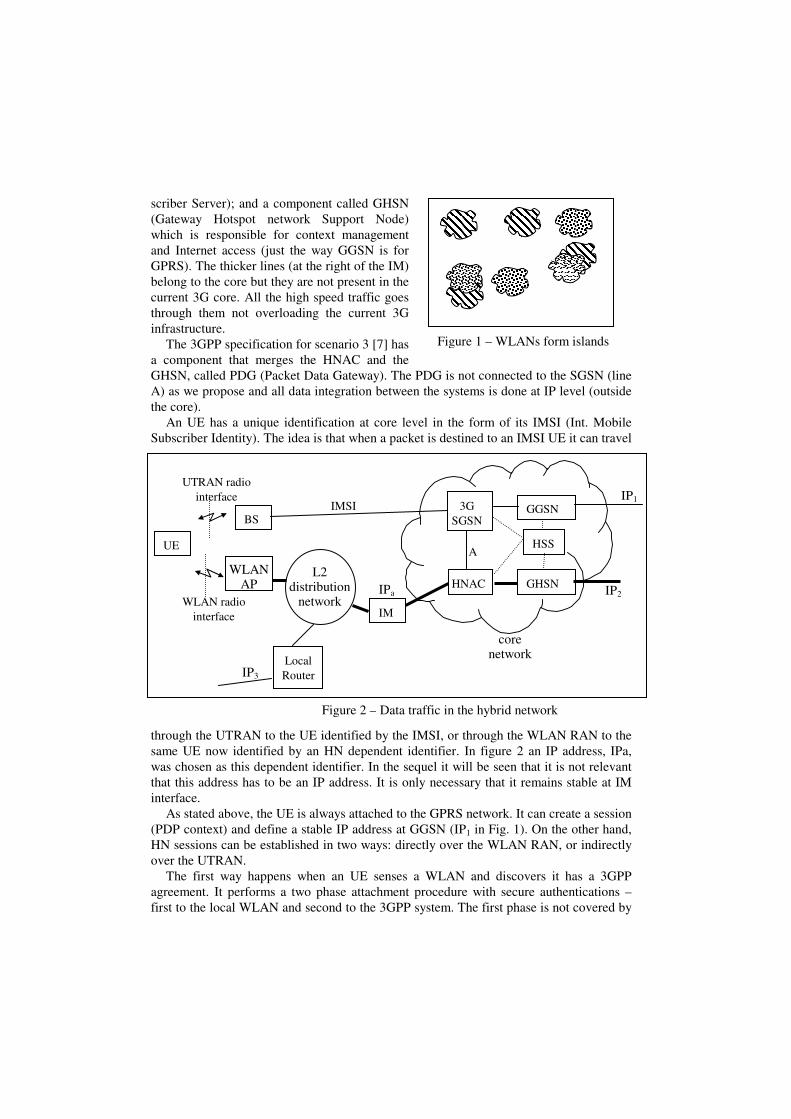
Figure 2 – Data traffic in the hybrid network
UE
WLAN AP
IM
L2 distribution
network WLAN radio interface
core network
BS
UTRAN radio interface
IPa
IP1 IMSI
IP2
Local Router IP3
3G SGSN
HNAC
GGSN
GHSN
HSS A
scriber Server); and a component called GHSN (Gateway Hotspot network Support Node) which is responsible for context management and Internet access (just the way GGSN is for GPRS). The thicker lines (at the right of the IM) belong to the core but they are not present in the current 3G core. All the high speed traffic goes through them not overloading the current 3G infrastructure.
The 3GPP specification for scenario 3 [7] has a component that merges the HNAC and the GHSN, called PDG (Packet Data Gateway). The PDG is not connected to the SGSN (line A) as we propose and all data integration between the systems is done at IP level (outside the core).
An UE has a unique identification at core level in the form of its IMSI (Int. Mobile Subscriber Identity). The idea is that when a packet is destined to an IMSI UE it can travel
through the UTRAN to the UE identified by the IMSI, or through the WLAN RAN to the same UE now identified by an HN dependent identifier. In figure 2 an IP address, IPa, was chosen as this dependent identifier. In the sequel it will be seen that it is not relevant that this address has to be an IP address. It is only necessary that it remains stable at IM interface.
As stated above, the UE is always attached to the GPRS network. It can create a session (PDP context) and define a stable IP address at GGSN (IP1 in Fig. 1). On the other hand, HN sessions can be established in two ways: directly over the WLAN RAN, or indirectly over the UTRAN.
The first way happens when an UE senses a WLAN and discovers it has a 3GPP agreement. It performs a two phase attachment procedure with secure authentications – first to the local WLAN and second to the 3GPP system. The first phase is not covered by
Figure 1 – WLANs form islands

3GPP standards. Our solution is a challenge/response procedure between the UE and the IM: a provisional secure channel is established between them and the IM asks the HNAC for a challenge based on authorization vectors of the 3GPP. The IM sends the challenge to the UE, relays its response to the HNAC, and trusts in the HNAC’s decision. Based on an authorization database at the IM the second phase can be entered. The second phase (to-wards the 3GPP system) follows the lines of [7]. After the first phase the UE can use the local services of the WLAN (if authorization is given to use them, instead of authorization just to access the 3GPP network), including direct Internet access using the IP3 address given by the Local Router (LR) in fig. 2. Once registered in the HN (second phase) the UE can create a context with the GHSN defining a stable and routable IP address, IP2.
The second way can happen during dark areas and the UTRAN is used to connect the UE to one HNAC (see below).
3.3 Overview of the core network interactions
The HSS has information about the UEs (identity and routing information, etc.). It must be enlarged with information about HN related status (registered, reachable, current iden-tification, serving HNAC, etc.). HNAC will go to HSS to get updated information in the same way as the SGSN goes nowadays. The HSS also provides authentication vectors, subscriber profiles, and charging information to HNACs.
We will describe two working scenarios: the smooth one that requires very little changes to the current core network; and the abrupt one demanding more modifications. In the smooth one, the PS domain works as today and the HNAC can access the UE directly or via SGSN (line A in fig. 1). An easy way to implement the relaying function is to allow HNAC to establish a PDP context with the SGSN (similar to the PDP context of the GGSN). A GTP-U (GPRS Tunneling Protocol – for User Plan) is established between the HNAC and the serving RNC (Radio Network Controller) and used at HNAC discretion. The second scenario is more interesting and both SGSN and HNAC can convey their traffic through the other one if they see some advantage. One first change is the partition of the current GTP-U tunnel between the GGSN and the SRNC into two half-tunnels: GGSN-SGSN and SGSN-SRNC. It is very much a return to the original GPRS specification. The latter second half-tunnel could be replaced by a SGSN-IM tunnel via HNAC. So, the major modification is the ability of the SGSN to use the HNAC to reach the UE. Before describing in functional terms the new interfaces let’s see how the communication between the core and the UE takes place.
Figure 3 shows the protocol stack in the UE. There is a Connection Manager (CM) that manages the status of both connections and offers a unique upward interface to both
L1/L2 L1/L2
Connection Manager
(CM)
UTRAN WLAN
Applicat. A Applicat. B
Figure 3 – Protocol stack at a UE
IP
Delivery Service
Session Control
RANs. The Delivery Service is a confirmed service and switches to the UTRAN if it senses a failure in the WLAN. If more than one RAN is active the default one for each message is used. The CM can signal the applications (and be queried by them) about the current status of a specific connection. With this information, applications can avoid using the link if the proper interface is not active (transferring only urgent or control informa-tion, for instance). The CM is able to contact each of the core network components (SGSN or HNAC) either directly or via the other RAN (for link maintenance messages, etc.). The session control layer is responsible for session survival when the UE is in dark areas. This setting is functionally similar to the tightly coupled approach [1], without the need to expose the core network interfaces (Iu). Instead, the HNAC has to be introduced in the core.
3.4 Interfaces in the core network
For the second scenario (abrupt) the following interactions are needed: (a) HSS must store information about the HN activity of UEs. It must provide this information to HNACs as well as authorization vectors, registration procedures, updates, etc. It is as-sumed that HNACs have the functionality of an AAA proxy (Authorization, Authentica-tion and Accounting); (b) SGSN must allow the creation of a PDP context between the HNAC and the UE; (c) HNAC must allow the creation of a GTP-U tunnel for the informa-tion coming from the SGSN towards the UE. This tunnel is functionally identical to the second half-tunnel described above between SGSN and SRNC (both (b) and (c) allow core components to communicate with the UE via the other RAN); (d) logic must exist in the SGSN to enable it to use WLAN in advantageous circumstances; (e) SGSN must have an event service to notify any interested core component (namely HNAC) about relevant events – “UE availability”, “cell update”, “routing area update”, “positive cell identifica-tion” and “undefined cell identification”; (f) SGSN must provide access to its mobility management information (cell identification if in GPRS state ready, or routing area identi-fication, otherwise) - it can be useful for the HNAC if it has a relation between CellIDs and WLAN placements (it can force the WLAN interface to switch off if no islands are known in a certain routing area, for instance). It is also important because HNAC change of responsibility can happen when the UE performs a routing area update.
4 Discussion and Performance Evaluation
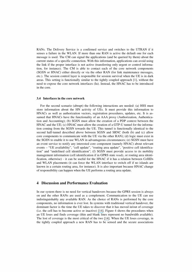
In our system there is no need for vertical handovers because the GPRS session is always on and the other RANs are used as a complement. Communication to the UE can use indistinguishably any available RAN. As the choice of RANs is performed by the core components, no information is ever lost. In systems with traditional vertical handover, the dominant factor is the time the UE takes to discover that it has moved in/out of coverage (i.e. the cell has to become active or inactive) [14]. Figure 4 shows the procedures when an UE loses and finds coverage (thin and blank lines represent no bandwidth available). The lost of coverage is the most critical of the two [14]. When the UE loses coverage, in the tightly coupled approach a new RAN has to be sensed and the secure associations

must be re-establishment. As the new RAN behaves like the old one everything is in order after that. In the loosely coupled approach the same thing happens but an extra phase of mobility management must exist (tunnels, care-of-address, etc.). In our approach the new RAN is always ready to be used and the core just starts to use it (if not any other RAN, the UTRAN is always ready). Considering multi-mode UEs, the sensing and authorization phases could be made in advance and the tightly approach will be similar to ours. How-ever, it is questionable if a new AAA establishment with another cell could be done while the current one is still valid. In the loosely coupled approach these two phases could be done in advance but the mobility management phase cannot. Finding coverage makes only sense for multi-mode UEs. In this case (assuming that AAA procedures could always be performed in advance as we do) our approach is as good as the tightly coupled approach. The loosely coupled approach needs the mobility management phase. Another aspect is the requirement of either an all-IP architecture or an IP-enabled one. Our system only re-quires the establishment of an IP tunnel from the core to the IM to convey packets to an UE identified by a stable identifier. The identifier can be IP, or not (in figure 2 is IPa) – it is a local identifier not seen by the ap-plications. For the applications, the UE can either be working with the IP1 or the IP2 address. These are the working addresses at IP layer of fig-ure 3. The Delivery Service is responsible for forwarding the packets between the IP layer of the core component (HNAC or SGSN) and the IP layer of the UE using the IMSI or the other identifier. Therefore, there are no assumptions about the necessity of using Mobile IP, for instance. The mobility management inside an island is performed by the IM with-out any knowledge of the core components. It can be based on IP, use VLANs, etc. So, if IPa is used in the routing process, or not, is not a requirement either. The stability of IPa is needed to avoid resolution towards the IMSI every time the core wants to use it. HNACs can play an important role in user mobility management. They can have a stan-dard (and protected) programming interface to be used by third-party organizations to build services that take advantage of the information gathered at the core (HSS) not ex-plored fully today (e.g. if the user has a HN session, if it is under coverage, etc.). Most of the mobility management nowadays in 3GPP systems is only concerned on maintaining RABs (Radio Access Bearers). HNACs can store data (locally, or in components inside the core) in cooperation with the application, to defer its transfer until the UE gets into an island again (having the data nearby can be decisively if connection times are very short).
Figure 4 - Handovers between RANs
Lose coverage
Find coverage
tightly
core
loosely
AAA �t2 �t1
sense
AAA �t2 �t1
sense Mob
�t3
AAA �t2 �t1
sense tightly
core
loosely
AAA �t2 �t1
sense
AAA �t2 �t1
sense Mob
�t3

5 Examples of Service Integration
A good example that shows how this architecture can simplify the integration of wireless systems a great deal is taken from [7]. Figure 5, taken from [7], shows how 3GPP plans to support SMS over WLANs. A service specific gateway, called IP-SM-GW, must exist and offer an interface similar to an MSC or an SGSN (interfaces E or Gd) to the GMSC/SMS-IWMSC. The address of this gateway is returned by the HSS in the “send rout-ing information for short message” primitive. This gateway has a private data-base to associate MSISDN to IP addresses. UEs in WLAN have to specifically register and specifically authenticate for SMS services and have secure associations to the gateway. The gateway communicates with the UE via Internet (PDG, etc.). In our system (second scenario), the SMS service could be provided without any need for service-specific extra components, service-specific private databases, or service-specific registration by the UEs. The SGSN just gets the message from the GMSC/SMS-IWMSC as before and can use the HNAC to convey the message to the UE, using the secure asso-ciations that are already in place between the HNAC and the UE.
6 Conclusions
The internetworking of wireless infrastructures performed at core level with a pivot net-work seems a simple and executable model with many advantages: (a) as most of the con-trol features already exist in the 3GPP network, they can be absent in other networks; (b) certain details (such as micro-mobility) are not managed at core level; (c) it defines an environment where new features and services can be added to the core; (d) it does not impose an all-IP architecture; (e) there is no critical dependence on vertical handovers; and (f) it does not create extra load to the current 3GPP core network. The addition of new modules at core level with standard (and protected) programming interfaces can open up new possibilities to explore terminal mobility (a topic that is absent today). Topics relevant for further work include the algorithms to be used on top of the HNACs to explore the mobility of UEs and their connection periods, and the viability of service continuity using this type of handovers.
SM-SC
GMSC / SMS-IWMSC
IP-SM-GW
HSS/(HLR)
UE WLAN UE
MSC
E E’ or Gd’
SGSN
Gd
WLAN AAA
Wx/(D’/Gr’)
PDG
Wi
C
SME
IP address database
Figure 5 – Support of SMS over WLAN (3GPP version)

References
1. Salkintzis, A., et al., “WLAN-GPRS Integration for Next-Generation Mobile Data Networks”, IEEE Wireless Comm., vol. 9, pp. 112-124, Oct 2002
2. Bing, H., et al., “Performance Analysis of Vertical Handover in a UMTS-WLAN Integrated Network”, IEEE PIMRC 2003.
3. Buddhikot, M., et al., “Design and Implementation of a WLAN/CDMA2000 Interworking Archi-tecture”, IEEE Comm. Mag., pp 90-100, November 2003.
4. Frenkiel, R., et al, “The Infostations Challenge: Balancing Cost and Ubiquity in Delivering Wire-less Data”, IEEE Personal Comm., v 7, pp. 66-71, Ap 2000
5. Frodigh, M, et al, “Future-Generation Wireless Networks”, IEEE Personal Communications, vol. 8, pp. 10-17, October 2001
6. 3GPP, Group Services and System Aspects; Feasibility study on 3GPP system to WLAN inter-networking; (Release 6), TS 22.934.v.6.1.0, Dec. 2002
7. 3GPP, Group Services and System Aspects; 3GPP system to WLAN internetworking; System Description (Release 6), TS 23.234.v.2.3.0, Nov. 2003
8. Campbell, A., et al, “Design, Implementation, and Evaluation of Cellular IP”, IEEE Personal Communications, vol. 7, pp. 42-49, August 2000
9. Ramjee, R., et al, “IP-Based Network Infrastructure for Next-Generation Wireless Data Net-works”, IEEE Personal Communications, vol 7, pp. 34-41, Aug 2000
10. Das, S., et al, “TeleMIP: Telecommunications-Enhanced Mobile IP Architecture for Fast Intra-domain Mobility”, IEEE Personal Communications, vol. 7, pp. 50-58, August 2000
11. Misra, A., et al, “Autoconfiguration, Registration, and Mobility Management for Pervasive Computing”, IEEE Personal Comm., vol. 8, pp. 24-31, August 2001
12. Wu, G., Havinga, P., Mizuno, M., “MIRAI Architecture for Heterogeneous Network”, IEEE Commun. Mag., pp. 126-134, Feb. 2002
13. Tönjes, R., “Flow-control for multi-access systems”, PIMRC’02, 13th IEEE Int. Symp. On Personal and Mobile Radio Communication, pp. 535-539, Sep. 2002, Lisboa, Portugal.
14. Steem, M., Katz, R., “Vertical handoffs in wireless overlay networks”, Mobile Networks and Applications, vol. 3, pp 335-350, 1998