Statistical Modeling of the FSO Fronthaul Channel for UAV ...
Upload
khangminh22Category
view
0download
0
24 CIRCUIT CELLAR® • www.circuitcellar.com
April
201
1 –
Issue
249
This two-part article series covers the design, development, and testing of areprogrammable UAV autopilot system. Here you get a detailed system-leveldescription of the autopilot design, with specific emphasis on its hardwareand software.
Reprogrammable UAV AutopilotSystem (Part 1)
U
FEAT
URE
ARTICLEby Mariano Lizarraga, Renwick Curry, and Gabriel Elkaim (USA)
nmanned aerial vehicle (UAV) usage has increasedtremendously in recent years. Although this
growth has been fueled mainly by demandfrom government defense agencies, UAVsare now being used for non-militaryendeavors as well. Today, UAVs areemployed for purposes ranging fromwildlife tracking to forest fire monitoring.Advances in microelectronics technologyhave enabled engineers to automate suchaircraft and convert them into usefulremote-sensing platforms. For instance, dueto sensor development in the automotiveindustry and elsewhere, the cost of thecomponents required to build such systemshas fallen greatly. In this two-part article series, we’ll pres-
ent the design, development, and flight testresults for a reprogrammable UAV autopi-lot system. The design is primarily focusedon supporting guidance, navigation, andcontrol (GNC) research. It facilitates a fric-tionless transition from software simulationto hardware-in-the-loop (HIL) simulation toflight tests, eliminating the need to writelow-level source code. We can easily make,simulate, and test changes in the algorithmson the hardware before attempting flight.The hardware is primarily “programmed”using MathWorks Simulink, a block-dia-gram-based tool for modeling, simulating,and analyzing dynamical systems.
The complete system, called the Santa Cruz Low-costUAV GNC System (SLUGS), was developed by the
System Hardware and Software
Figure 1—The autopilot hardware architecture
Barometer
Thermometer
Battery monitorAccelerometers
SPI 1
CANUART
I2C
RS-232GPS
Magnetometers
HIL Data
CAN
PWM
PWM
Sensor DSC
SPI
RC Rx
Failsafe
ADC
ADC
I2C
SPI 2IC
IC
PWM /OC
PWM
PWM
Actuator 2
Actuator 10
Differentialpressure
Angular ratesensors
Optionaldaughterboards
CANTransceiver
SPI
SPI 1
Radio modem
UART RS-232
Power
Control DSCOptional serial
device
12 to 6.0Switchingregulator
6.0 to 5.0Linear
regulator
5.0 ESC to3.3 Linearregulator
6.0 to 3.3Linear
regulator
10-BitMUX
2011-4-014_Lizarraga_part1_Layout 1 3/8/2011 3:54 PM Page 24
www.circuitcellar.com • CIRCUIT CELLAR® 25
April
201
1 –
Issue
249
Autonomous Systems Laboratory at the University of Cal-ifornia Santa Cruz and released under the MIT open-source license. Due to space restrictions, this article isfocused exclusively on a system-level view of the autopi-lot, its hardware, and software. Refer to the Resourceslisted at the end of this article to learn more about thesystem’s other components and the autopilot itself.
THE COMPLETE UAV SYSTEMFirst, we’ll provide a high-level description of the com-
plete UAV system and how the components interrelate.On the aircraft, the autopilot takes readings from a vari-ety of sensors and uses them to stabilize the aircraft inflight: holding altitude, maintaining velocity, trackingstraight lines, or constant rate turns. It then uses these“inner loop” modes to navigate through a sequence ofwaypoints, either preloaded or communicated to theautopilot via an RF link from the ground station. The autopilot has two operating modes: Autonomous
and Manual. In the former mode, the autopilot directlycommands the control surfaces and is fully responsiblefor the aircraft. In Manual mode, the autopilot relays thecommands from an RC pilot directly to the control sur-faces, leaving the pilot in command. (Essentially, theautopilot removes itself from the system and followsalong, ready to take over if switched back toAutonomous mode.)Controlling and monitoring the UAV is conducted
from a ground control station (GCS), which receives anddisplays the UAV’s sensor telemetry, controlling its vari-ous high-level functions. The ground equipment alsoincludes a conventional RC transmitter for take-off, landing, and control of the aircraft in case ofmalfunction. All mission planning and control isexercised from the GCS, which consists of a laptopPC, a two-way RF link to the aircraft, antenna,batteries, and some level-shifting hardware tomatch the RF link to the PC ports. The core component of the GCS is its software.
The operator uses the GCS software to interactwith the UAV and modify its mission and autopi-lot parameters while still airborne. The UAV sen-sor data is graphically displayed on the GCS, andthe position of the UAV is shown in real timeoverlaid onto a geo-referenced map image.
The third component of the system is the HIL simula-tor. In this mode, the autopilot gets its sensor data froman external computer pretending to be the world (asopposed to the internal sensor suite). This enables theautopilot to operate using simulated data and thus “fly”the aircraft without ever leaving the ground and riskingthe airframe. The autopilot does not know that it is notflying a real UAV; the algorithms and outputs are runningin real time on the actual flight hardware. This enablesend users and researchers to safely test the system andverify its correct operation.The essential component here is the autopilot. Its suite
of custom avionics makes autonomous flight possible,while the hardware and software at the center control theaircraft in flight, guiding it along the desired flight pathand navigating from waypoint to waypoint. This is thekey difference between autonomous aircraft and remotelypiloted ones.
AUTOPILOT HARDWAREAt its core, the SLUGS autopilot hardware has two
Microchip Technology dsPIC33 digital signal controllers(DSCs) as its main processing units, each running at 40 MIPS.These are interconnected via SPI at 10 MHz and are calledthe “sensor” and “control” DSC, respectively. The sensorDSC reads the data from all of the sensors in the sensor suite,such as rate gyros, accelerometers, and static and differentialpressure. The data is then fed into a complementary filter,which fuses the data and computes the aircraft’s position andattitude (3-D orientation). This information is packed in apredefined communication protocol (described in the secondpart of this series) and sent via the SPI to the control DSC.The control DSC (based on the data received from the sensorDSC), the aircraft current location (established via GPS), andthe current commands received from the GCS generate thecommands for the control surfaces and schedule the data tobe sent to the ground telemetry via the RF link.The autopilot hardware has four key subsystems: the
sensor DSC and its sensor suite, the control DSC, the RCcommands multiplexor, and the power supply. Each of theindividual integrated circuits that comprise the autopilotwas selected based on three key deciding factors. The firstwas functionality. The component included features thatreduced the required external components (e.g., capacitors
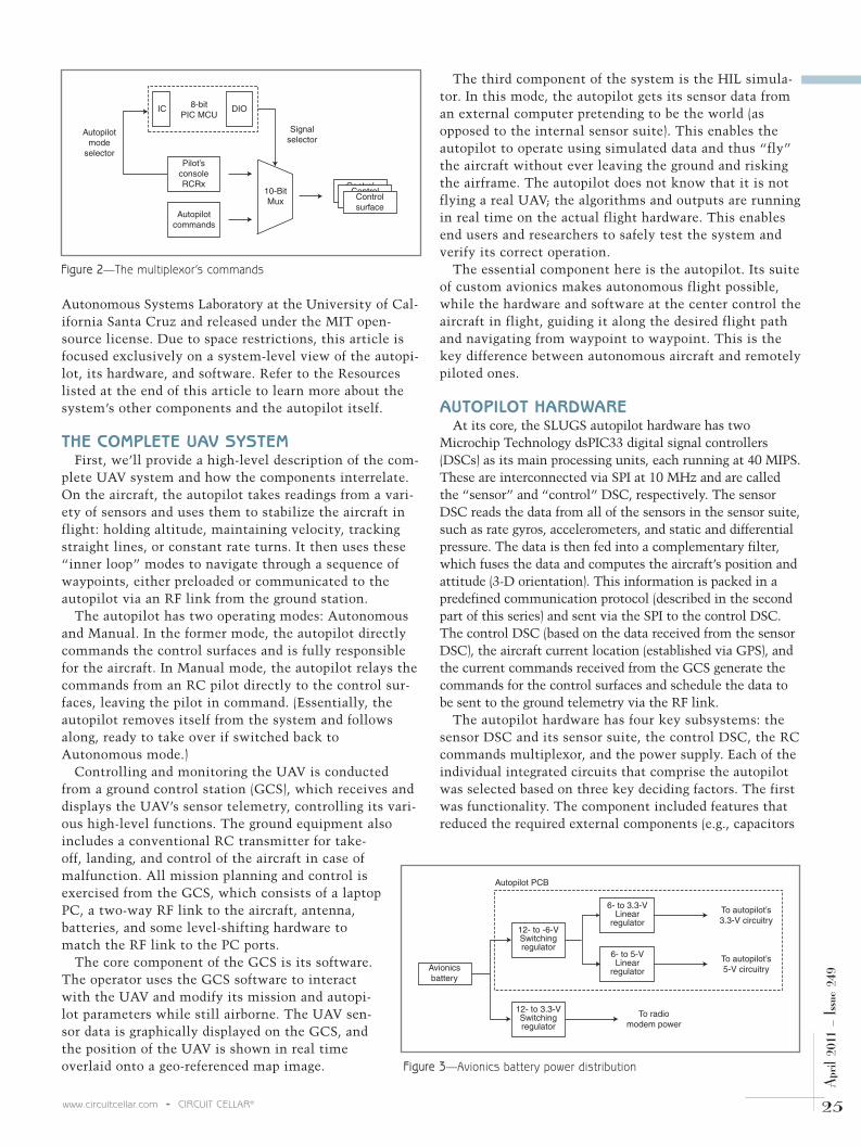
Figure 3—Avionics battery power distribution
Avionics battery
To radiomodem power
Autopilot PCB
To autopilot’s3.3-V circuitry
To autopilot’s5-V circuitry
12- to 3.3-VSwitchingregulator
12- to -6-VSwitchingregulator
6- to 5-VLinear
regulator
6- to 3.3-VLinear
regulator
Figure 2—The multiplexor’s commands
IC DIO8-bitPIC MCU
Autopilotcommands
10-BitMux
Controlsurface
Controlsurface
Signalselector
Pilot’sconsoleRCRx
Autopilotmode
selector
Controlsurface
2011-4-014_Lizarraga_part1_Layout 1 3/8/2011 3:54 PM Page 25

26 CIRCUIT CELLAR® • www.circuitcellar.com
April
201
1 –
Issue
249
SENSOR DSCAs its name implies, the
sensor DSC reads data from allsensors available to theautopilot and performs low-level transformations (e.g.,scaling, temperature compen-sation, null shifts, and dataalignment) to generate engi-neering units. The positionand attitude estimation algo-rithms then use these meas-urements to determine the air-craft’s position and orientationat 100 Hz. This data is packedin several communication pro-tocol sentences and deliveredto the control DSC, making
use of most of the peripherals avail-able in the DSC.The sensor suite read by the sensor
DSC consists of several sensors. Referto Figure 1 as we describe each.One is a San Jose Navigation FV-M8
(formerly EB-85) GPS, which is usedto obtain the UAV’s latitude, longi-tude, height, speed over ground, andcourse over ground. A tri-axis Honeywell HMC5843
I2C magnetometer is used in the ori-entation computation. Three-axisaccelerometers and gyros are alsoincluded via the Analog DevicesADIS16405 AMLZ SPI tri-axis iner-tial sensor for the rate gyro andaccelerometer readings.
and inductors), the required softwarefor utilizing its data (e.g., factory cali-bration or temperature compensation),or the interface to communicate withthe device (where digital was alwayspreferred over analog for simplicity). Size was the secondary key factor.
Great care was taken to make theautopilot as small as possible with-out sacrificing functionality.
The last key factor was availability.All of the components were chosen sothat they were easily available with norestriction to their purchase in coun-tries outside the United States. Theidea was to make the SLUGS platformavailable to the widest possible groupof research laboratories.
Figure 4—Main motor battery power distribution
Main motor battery
Power toRCRx
Power toMUX
Main motor
Power to controlsurface’s servos
Autopilot PCB
Motor’s electronicspeed controller
(ESC)
Throttlecommandfrom MUX
5- to 3.3-VLinear
regulator
Photo 1—(Bottom) Version 1.0 of the SLUGS autopilot. It consisted of two four-layer boardsstacked. (Top) Version 2.0 is a single four-layer board in a 3.25” x 1.75” board.
2011-4-014_Lizarraga_part1_Layout 1 3/8/2011 3:54 PM Page 26

28 CIRCUIT CELLAR® • www.circuitcellar.com
April
201
1 –
Issue
249
Figure 5a—The autopilot circuitry includes sensor and control DSCs. The rest of this schematic is on page 30.
a)
Continued on page 30
2011-4-014_Lizarraga_part1_Layout 1 3/8/2011 3:54 PM Page 28

www.nxp.com/cortex-m0
We’re changing how engineers think about design, with Cortex-M0™ solutions that let you save power, reduce cost, shrink your design, and get to market fast.
Lowest active power — as low as 130µA/MHz
Superior Code Density — 50% less code for most tasks
Higher performance — LCP1100 runs at over 45 DMIPS
Smallest size — the LPC1102 has a footprint of 5 mm2
Low-cost toolchain — LPCXpresso for less than USD 30
Show us how you switched from your old 8-/16-bit habit to the new 32-bit NXP Cortex-M0 solution and we’ll send you a FREE LPCXpresso development board.
Cortex-M0 a simple choice
7_Layout 1 2/8/2011 3:09 PM Page 1

30 CIRCUIT CELLAR® • www.circuitcellar.com
April
201
1 –
Issue
249
We included a Microchip Technology MCP9700 low-power linear active thermistor for temperature compen-sation of the sensors. To monitor the battery voltage, weused a voltage divider. A voltage divider built with 1%resistors connected to the dsPIC’s ADC module moni-tors the avionics battery voltage. A Freescale Semiconductor MPXV5004DP differential
pressure sensor is used to compute the UAV’s airspeed.The system uses a Freescale SemiconductorMPXH6115A6U absolute pressure sensor to computealtimetry for the UAV.The battery voltage monitor, the absolute, and the dif-
ferential pressure signals are first buffered (and somebasic signal conditioning is applied) by a National Semi-conductor LMV844MT quad op-amp in voltage-followerconfiguration. Additionally, the sensor DSC employs itsinput capture (IC) module to record the pilot’s PWMcommands to the servos, its remaining UART module(the other one is used by the GPS) to receive simulatedreadings during a HIL simulation, and the remaining SPImodule (the other is used by the ADIS16355) to commu-nicate with the control DSC.
CONTROL DSCThe control DSC receives commands from the GCS via
its UART module (see Figure 1). It also gets attitude andposition information from the sensor DSC through itsSPI module. With these inputs, it runs its navigation andcontrol algorithms to produce, as its name implies, thecontrol surface commands. These commands are translat-ed into the appropriate PWM duty cycle and are sent outby the dsPIC’s PWM motor control module to actuate theUAV’s control surfaces servos. As in the sensor DSC, thecontrol DSC records the pilot’s PWM commands. Thesereadings are used to obtain the control surface trim con-ditions when transitioning from manual to autonomousflight. This prevents any unwanted large input distur-bances when “throwing the switch.”Additionally, the autopilot uses Maxim Integrated Prod-
ucts’s popular MAX232E driver/interface to have telemetryavailable in both signal levels, direct from the UART andRS-232 for its use directly in a PC. This driver also levelshifts the signals to and from the HIL simulator.For easy expansion (to other sensors, payloads, etc.), it
is possible to connect to external daughterboards via a
Figure 5b—The RC command multiplexor, status LEDs, and I/O interface
b)
Continued from page 28
2011-4-014_Lizarraga_part1_Layout 1 3/8/2011 3:54 PM Page 30

www.circuitcellar.com • CIRCUIT CELLAR® 31
April
201
1 –
Issue
249
controller area network (CAN). This provides extensibilitywithout the need to redesign the hardware. For this, bothDSCs are connected to a properly terminated CAN bus viatwo Texas Instruments SN65HVD230D CAN transceivers.
RC COMMAND MULTIPLEXORAs with any vehicle, safety is critical. Because we are
dealing with an aircraft, there is always a crash risk to theaircraft itself, as well as to people on the ground. There’s afundamental safety requirement. In the case of any mal-function, the safety pilot can retake control of the aircraftfrom the ground through the RC transmitter. This back-upsystem not only has to be reliable, but also completelyindependent (power, signal, and radio) from the autopilot.The pilot’s commands are received onboard the aircraft byan off-the-shelf radio control receiver (RCRx). This receiverproduces independent PWM outputs for each channel. Fivechannels are used in total: four contain the pilot’s controlsurface commands (ailerons, rudder, elevator, and throttle)and the fifth is the commanded autopilot mode selector(autonomous or manual).The commands multiplexor architecture in Figure 2
comprises a Microchip Technology PIC12F683 8-bit MCUand a Texas Instruments SN74CBTLV16210 20-bit FET busswitch (mux). The mux sits between the autopilot and theRC servos. The MCU’s IC module reads the RCRx’s modeselector PWM command and configures the bus switch withtwo digital input/output (DIO) lines. The bus switch, basedon its configuration, routes the PWM signals from either the
autopilot or the RCRx to the control surfaces’ servos.
POWER SUPPLYThe power supply architecture was designed to provide
power to the avionics independent of the airborne-criticalsystems and propulsion (see Figure 1). For this purpose, twoThunder Power Lithium-Polymer (LiPo) batteries areemployed. A 1,325-mAHr battery powers the avionics andradio modem. A 5,000-mAHr battery powers the airborne-critical systems. This yields approximately 25 minutes offlight on our prototype UAV.The avionics battery output is connected to a Texas
Instruments PTN78000WAZ plug-in power module (in theautopilot PCB) that drops the voltage from 12 to 6 V using aswitching regulator (see Figure 3). Further down the powerline, two National Semiconductor LP2986 and LP38690SDlow-dropout (LDO) linear regulators lower the voltage to 5and 3.3 V for the circuitry in the autopilot. These regulatorsand their accompanying filter capacitors also serve the pur-pose of reducing some of the noise intrinsic to the output ofswitching regulators. An independent PTN78000WAZ plug-in power module board drops the voltage from 12 to 3.3 V topower the UAV’s radio modem for telemetry.The main motor battery powers an off-the-shelf 60-A elec-
tronic speed controller (ESC). The ESC performs a few essen-tial tasks (see Figure 4). One, it provides 5-V power to theRCRx. Two, it provides power to the control surfaces’ servos.Three, it provides power to another LP38690SD 5-to-3.3-VLDO linear regulator (in the autopilot PCB), which, in turn,
Photo 2a—The ground station setup includes a laptop, battery, RFlink, and antenna. b—This is the ground station deployed in thefield.
a) b)
2011-4-014_Lizarraga_part1_Layout 1 3/8/2011 3:54 PM Page 31

32 CIRCUIT CELLAR® • www.circuitcellar.com
April
201
1 –
Issue
249
assembled. (This excludes the flight harness and the batterypower cables.)The first board prototype (Version 1.0), which you can see
at the bottom of Photo 1, was sent for manufacture toAdvanced Circuits and the components were later hand-sol-dered under a microscope. For the next batch of prototypes(Version 2.0, shown in Photo 1 at the top), the board size wassignificantly reduced, which made the component densitygrow. Thus, for manufacturing, we used Sierra Proto Express,
powers the commands multiplexor. And four, it receivesthrottle commands from the commands multiplexor and gen-erates the necessary signals to drive the three-phase brushlessDC motor at that desired setting. This architecture guaran-tees that in the case of an autopilot power loss or malfunc-tion, the safety pilot can always retake control of the UAV.The total power consumption of the autopilot and the
commands multiplexor in normal operation is 3.1 W at 12 V.It measures 3.25” × 1.75” and weighs 50 grams when fully
Figure 6—Here you see a Texas Instruments PTN78000WAZ power module and National Semiconductor linear regulators.
2011-4-014_Lizarraga_part1_Layout 1 3/8/2011 3:54 PM Page 32

www.circuitcellar.com • CIRCUIT CELLAR® 33
April
201
1 –
Issue
249
which specializes in low-count orders.These too were hand-soldered under amicroscope and used extensively duringseveral months of flight tests. Morerecently, a third batch (Version 2.1) wassent for manufacture and population toSierra Proto Express and will be used ina new UAV research project. The SLUGS v2.x board has only two
electrical connectors to the outsideworld, and a set of two narrow plastichoses for static and dynamic pressure.To simplify moving the autopilot fromthe aircraft to the lab for testing, it has aminiature screw terminal to connectpower and ground from the avionics bat-tery and a Samtec CLM-112-02-L-Dhigh-density 60-pin connector for therest of the signals. Figure 5, Figure 6, andFigure 7 depict the hardware circuitry.
GROUND STATION HARDWAREThe GCS hardware consists of a con-
ventional laptop (1.5-GHz Pentium M,1-GB RAM, 160-GB hard drive) runningWindows XP, QGroundControl, andOpen Source ground station software. AUSB-to-serial converter is used to con-nect to the radio. The GCS allows con-
Figure 7—Sensor and signal conditioning schematic
2011-4-014_Lizarraga_part1_Layout 1 3/8/2011 3:54 PM Page 33

34
Authors’ notes: We’d like toexpress our deepest grati-tude to Greg Horn for workingso hard on the boardschematics and layout andhand-soldering the compo-nents of the first two batchesof autopilots. He was also oursafety pilot, and more than
CIRCUIT CELLAR® • www.circuitcellar.com
April
201
1 –
Issue
249
figuration and control of the UAV(which will be detailed in the secondpart of this article), and also allows thetelemetry stream to be dumped straightto a file. A Digi International XTend900-MHz radio module is connected to aHyperlink half-wave whip antenna. Asmall custom-made board has the serialsplitter, RS-232 level shifter, and powerregulator for the radio modem. Theentire ground station is housed in asmall briefcase, including the antennamount and a lead-acid 12-V battery (seePhoto 2).
HIL SIMULATORIn order to test the autopilot without
risking the airframe, it is critical to sim-ulate the algorithms in realistic condi-tions. The Simulink programming para-digm—which we’ll describe in the sec-ond part of this article series—makes iteasy to simulate the algorithms on thePC using MATLAB and Simulink, butthis is purely a theoretical simulation.To test both the hardware and the soft-ware, it is necessary to run the algo-rithms on the actual hardware. Usingthe HIL simulator, these real-time simu-lations reveal flaws and untrapped errorsthat would destroy the airframe if theyoccurred in the field. In the HIL simulator, a computer runs
a physics-based simulation of the UAV(see Figure 8). After it is corrupted bynoise, bias shifts, or other imperfections,the data from the simulation is pushedonto the autopilot, overwriting its ownsensor data. From there, the autopilotflies the aircraft, but the generated com-mands are intercepted and sent back tothe simulation, causing the simulationto react as if the autopilot were flying areal plane.
In our case, the physics engine is a fullnonlinear, six degree of freedom (6DOF)simulation running in Simulink. Theaircraft can be started in any environ-ment and configuration, with completecontrol of the simulation. This meansthat sensors can be failed (GPS outage),gusts introduced, winds changed sudden-ly, and the actions of the autopilotobserved. A simulation crash simplyrequires the simulator to be reset. Whilethe specifics of matching the simulationto a given airframe model are beyond thescope of this article, more details can befound in the references.The simulation generates the sensor
packet and is sent via a UDP port, whilethe GCS program listens in the sameport and interprets the data. This is thensent to the autopilot over a serial link.The GCS receives the autopilot controlsurface commands using the serial link,and then sends them back to the simula-tion via UDP. The advantage here is thata separate computer can run the simula-tion (processor intensive), while the GCScontinues to display the results of theincoming telemetry as if the aircraftwere flying. (HIL also enables the testingof the GCS.) It is very easy to plug oursimulation results into standard flightsimulators (FlightGear, X-plane) for visu-alization of the flight.
SOFTWARE DEVELOPMENTIn the next part of this article series,
we’ll present all of the software devel-oped for the autopilot: the low-leveldrivers, a brief description of the posi-tion and attitude estimation filters, andnavigation and control algorithms. We’llalso present flight test results and dis-cuss the convenience of using Simulinkwith SLUGS as a development platform
compared to writing thecode in a traditional pro-gramming environment,such as C or C++. I
Figure 8—HIL signal flow paths
SensorMCU
Sensordata
Sensordata
ControlMCU
Autopilot
SPI
RS-232UDP
Simulation PC
Simulation station PC
Ground station software
Simulink 6-DOF, engine andweather model
Controlsurfaces
commandsControlsurfaces
commands
2011-4-014_Lizarraga_part1_Layout 1 3/8/2011 3:54 PM Page 34
www.circuitcellar.com • CIRCUIT CELLAR® 35
April
201
1 –
Issue
249
Mariano Lizarraga ([email protected]) holds a BS in Naval Sciences Engineering fromthe Mexican Naval Academy, an MSEE and Electrical Engineer’s degree from the U.S. NavalPostgraduate School, and a PhD in Computer Engineering from UCSC. He has more thaneight years of experience writing software and designing hardware for UAVs. He is currentlya Research Fellow in the Computer Engineering Department at the University of CaliforniaSanta Cruz.
Renwick Curry ([email protected]) earned an AB in Physics from Middlebury College, and heholds a BS, MS, and PhD in Aeronautics and Astronautics from MIT. He has worked as afaculty member (MIT and Cornell), a spacecraft guidance engineer (Mariner and Apollo proj-ects), and an aviation safety engineer for NASA. Renwick is currently an Adjunct Professorin the Computer Engineering Department at University of California Santa Cruz, and presi-dent of AASI (www.aasi.com), a company specializing in aircraft flight-path optimization.
Gabriel Hugh Elkaim ([email protected]) holds a BSE in Aerospace Engineering fromPrinceton University, as well as an MS and PhD in Aeronautics and Astronautics from Stan-ford University. He is an Associate Professor in the Computer Engineering Department atUniversity of California Santa Cruz, where he works on autonomous vehicle guidance, navi-gation, and control.
RESOURCESSLUGS Project, http://slugsuav.soe.ucsc.edu
UC Santa Cruz Autonomous Systems Lab, http://asl.soe.ucsc.edu
SOURCESADIS16355 iSensorAnalog Devices | www.analog.com
XTend OEM 900-MHz RF moduleDigi International, Inc. | www.digi.com
HMC5843 I2C MagnetometerHoneywell International | www.honeywell.com
dsPIC33 DSC, MCP9700 Thermistor, and PIC12F683 microcontrollerMicrochip Technology, Inc. | www.microchip.com
LP2986 and LP38690SD LDO Linear regulatorsNational Semiconductor | www.national.com
CLM-112-02-L-D High-density 60-pin connectorSamtec, Inc. | www.samtec.com
FV-M8 GPS Engine board San Jose Technology, Inc. | www.sanav.com
PTN78000WAZ Power module and SN65HVD230D CAN transceiversTexas Instruments, Inc. | www.ti.com
Simulink Simulation and model-based designThe MathWorks, Inc. | www.mathworks.com
Lithium-Polymer (LiPo) batteriesThunder Power RC | www.thunderpowerrc.com
once he saved us from having to build another UAV. We’d also like to thank VladimirDobrokhodov for all of his help in making SLUGS happen and lending his experience asa long-time UAV developer and end user. Finally, note that code for the SLUGS projectis posted at http://github.com/malife/SLUGS.
2011-4-014_Lizarraga_part1_Layout 1 3/8/2011 3:54 PM Page 35
Copyright © 2022 FDOKUMEN