
BRUSHLESS WIND POWER GENERATOR FOR LIMITED ...
26
BRUSHLESS WIND POWER GENERATOR FOR LIMITED SPEED RANGE REPORT 2018:503
-
Upload
khangminh22 -
Category
Documents
-
view
1 -
download
0
Transcript of BRUSHLESS WIND POWER GENERATOR FOR LIMITED ...

BRUSHLESS WIND POWER GENERATOR FOR LIMITED SPEED RANGEREPORT 2018:503


Brushless Wind Power Generator for Limited Speed Range
CHANDUR SADARANGANI
ISBN 978-91-7673-503-9 | © Energiforsk May 2018
Energiforsk AB | Phone: 08-677 25 30 | E-mail: [email protected] | www.energiforsk.se

BRUSHLESS WIND POWER GENERATOR FOR LIMITED SPEED RANGE
3
Foreword
With today’s climate challenges, a transition to renewable energy resources becomes more and more urgent. Wind power stands for an increasing share of the renewable power supply, both onshore and offshore. In order for wind power to become an even more efficient resource, it is desirable to lower the need for maintenance and maintenance costs. This is especially important for offshore plants, where maintenance is naturally more complicated and expensive.
The generator of wind turbines is a component that demands a lot of maintenance. One of the reasons is that the slip rings and carbon brushes commonly used for speed control need regular maintenance and must be replaced at least once a year. This project has tested a prototype - developed theoretically in a former phase of the project – of a Brushless Doubly-Fed Induction Generator (BDFIG). This new type of generator could increase the reliability of the generator and decrease the maintenance costs for wind turbines.
The project ”Brushless wind power generator for limited speed range” has been carried out within the research program Vindforsk IV. Vindforsk IV coordinates eighteen projects, which provide knowledge and innovations to the wind industry. Energimyndigheten, together with companies in the wind industry through Energiforsk AB, funds the program.
This project was accomplished by project leader Chandur Sadarangi, PhD student Naveed ur Rehman Malik, Dr. Alija Cosic, and PhD student Yanmei Yao, at KTH Royal Institute of Technology. The reference group has contributed with valuable insights and comments. Reference group members have been: Robert Chin (ABB), Luca Peretti (ABB), Jouku Niiranen (ABB), Enes Kursumovic (E.on) and Åsa Elmqvist (Energiforsk).
Stockholm, May 2016
Åsa Elmqvist
Progam manager, Vindforsk IV
Electricity and heat production, Energiforsk AB
BRUSHLESS WIND POWER GENERATOR FOR LIMITED SPEED RANGE
4
Sammanfattning
Denna rapport presenterar målet och resultat från projektet “V308 – Borstlös Vindkraft Generator för begränsat varvtalsområde – fas 3”.
Målet med projektet är att undersöka en innovativ topologi av en borstlös dubbelmattad induktionsgenerator (BDFIG). En viktig fördel som man kan uppnå genom eliminering av borstar särskild för havsbaserade vindkraftgeneratorer är minskning av underhålls-kostnaderna och förbättring av tillförlitligheten hos generatorn.
För att åstadkomma detta, har en variant av en borstlös dubbelmattad induktionsgenerator undersökts där släpringarna och kolborstarna har ersatts med en roterande kraftelektronisk strömriktare och en roterande matare som är mekaniskt kopplad på samma axel som den dubbelmattad induktionsgenerator. All vindkraft som levereras till nätet sker genom BDFIG’s stator. Konceptet benämns RPE-BDFIG.
Huvuddelen av projektet ingick i ett doktorsarbete och har rapporterats i en doktorsavhandling [2] som framgångsrikt försvarades av kandidaten Naveed ur Rehman Malik i oktober 2015. En sammanfattning av hans arbete ges i kapitel 1 och 2 i denna rapport. Hela publikationslistan är sammanställt i kapitel 4.
Ett annat mål i projektet var att konstruera en Roterande Kraftelektroniskomvandlare (RPEC) som kan regleras trådlöst. Komponenter för denna omvandlare har designats, tillverkats och testats för trådlös kommunikation med komponenterna på bordet [15].
Ett annat mål i projektet var att utvärdera en fullskallig RPE-BDFIM både tekniskt och ekonomiskt. Arbetet skulle genomföras av ABB som en del av det utlovat naturabidrag till projektet. Som ett första steg i denna riktning har ett intressant koncept undersökts där två BDFIG med olika poltal är mekaniskt kopplade till varandra med en RPEC emellan dem. Som redovisas i [16] kan man uppnå en väsentlig storleksminskning (och därmed kostnadsminskning) av RPEC med lämplig val av poltal och effekt på de två BDFIG. Ytterligare utredning av detta koncept har rekommenderats i slutsatserna i kapitel 3.
BRUSHLESS WIND POWER GENERATOR FOR LIMITED SPEED RANGE
5
Summary
This report presents the aims and results of the project “V308 – Brushless Wind Power Generator for Limited Speed Range – phase 3”.
The purpose of the project is to investigate an innovative topology of brushless doubly-fed induction generator (BDFIG). The main advantage of eliminating the brushes and slip rings particularly for offshore applications is the reduction of maintenance costs and improvement in reliability of the generator.
A Brushless Doubly-Fed Induction Generator is considered in which the slip rings and carbon brushes are replaced by power electronic converters that are mounted on the rotor and a exciter that is mechanically connected to the shaft. All power from the wind is delivered to mains through the stator of the BDFIG. The concept is denoted RPE-BDFIG.
The main part of the project was included in a PhD thesis [2] that was successfully defended by candidate Naveed ur Rehman Malik in October 2015. A summary of the work is given in chapters 1 and 2. A complete list of publications from the thesis is given in chapter 4.
Another goal of the project was to construct a wireless controlled Rotating Power Electronic Converter (RPEC). This has been designed, built and tested using wireless communication with the components on the table [15].
Another goal for the project was to evaluate a full scale RPE-BDFIM both technically and economically. This was to be done by ABB as part of the contribution in-kind for the project. As a first step in this direction an interesting concept has been investigated whereby two BDFIGs with different pole numbers are mechanically connected to each other with a RPEC in between the two machines. As is shown in [16] a significant reduction in size (and correspondingly the cost) of the RPEC can be achieved for a suitable choice of pole numbers and powers of the BDFIGs. Further research on this concept is recommended in the conclusions in chapter 3.
BRUSHLESS WIND POWER GENERATOR FOR LIMITED SPEED RANGE
6
List of content
Abbreviations 7 1 Introduction 8
1.1 Types of generator topologies 8 1.2 Aims of the Project 10
2 Modeling and Results 12 2.1 Working principle of the Rotating Power Electronic Doubly-Fed Induction
Generator (RPE-DFIG) 12 2.2 Results from simulation and measurements 13 2.3 Low Voltage Ride-Through of a RPE-BDFIM 17
3 Conclusions 21 4 Publications 22
BRUSHLESS WIND POWER GENERATOR FOR LIMITED SPEED RANGE
7
Abbreviations
BDFIG Brushless Doubly-Fed Induction Generator
DFIG Doubly-Fed Induction Generator
EVC Extended Vector Control
LVRT Low Voltage Ride Through
PRN Passive Resistive Network
PLL Phase Locked Loop
RPE-BDFIG Rotating Power Electronic Brushless Doubly-Fed Induction Generator
BRUSHLESS WIND POWER GENERATOR FOR LIMITED SPEED RANGE
8
1 Introduction
In the wind industry different types of generators are in use for producing electricity. Traditionally generators are directly connected to the grid and hence operate at constant speed. For fixed speed generators efficiency of power conversion from the wind is low as speed of the generator should vary with the speed of the wind for maximum power extraction. With the continuous progress in power electronic converters for high power range, variable speed drives have become more attractive and are now employed in the wind industry. As a result variable speed drives are quite common today.
1.1 TYPES OF GENERATOR TOPOLOGIES
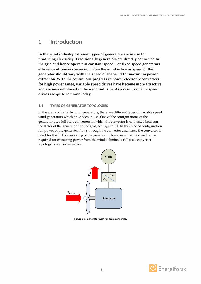
In the arena of variable wind generators, there are different types of variable speed wind generators which have been in use. One of the configurations of the generator uses full scale converters in which the converter is connected between the stator of the generator and the grid, see Figure 1-1. In this type of configuration, full power of the generator flows through the converter and hence the converter is rated for the full power rating of the generator. However since the speed range required for extracting power from the wind is limited a full scale converter topology is not cost-effective.
Figure 1-1: Generator with full scale converter.
BRUSHLESS WIND POWER GENERATOR FOR LIMITED SPEED RANGE
9
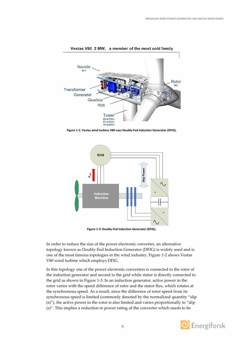
Figure 1-2: Vestas wind turbine V80 uses Doubly-Fed Induction Generator (DFIG).
Figure 1-3: Doubly-Fed Induction Generator (DFIG).
In order to reduce the size of the power electronic converter, an alternative topology known as Doubly-Fed Induction Generator (DFIG) is widely used and is one of the most famous topologies in the wind industry. Figure 1-2 shows Vestas V80 wind turbine which employs DFIG.
In this topology one of the power electronic converters is connected to the rotor of the induction generator and second to the grid while stator is directly connected to the grid as shown in Figure 1-3. In an induction generator, active power in the rotor varies with the speed difference of rotor and the stator flux, which rotates at the synchronous speed. As a result, since the difference of rotor speed from its synchronous speed is limited (commonly denoted by the normalized quantity “slip (s)”), the active power in the rotor is also limited and varies proportionally to “slip (s)”. This implies a reduction in power rating of the converter which needs to be
BRUSHLESS WIND POWER GENERATOR FOR LIMITED SPEED RANGE
10
around 30% of the power rating of the machine for speed ranges between ±25% of the synchronous speed. This is a huge advantage in terms of cost savings which is the main reason for the commercial success of the Doubly-Fed Induction Generator (DFIG).
However, DFIG’s also suffer from some disadvantages. The main disadvantage is that these generators employ slip-rings and carbon brushes in order to extract active power from the rotating part of the machine and deliver it to the stationary grid. It is a well-known fact that carbon brushes wear out with passage of time and also produce carbon dust during their operation which affects the insulation of the windings and hence reduces the lifetime of the generator. Moreover carbon brushes are sensitive to the air temperature, humidity and thermal heating due to handling of large magnitudes of rotor currents. Due to aforementioned reasons, carbon brushes need to be replaced every few months. This implies that the maintenance costs and down time of the generator increases. In addition maintenance of offshore wind turbines is tedious and difficult since inspection and maintenance is dependent upon weather conditions as turbine-units are not accessible during certain time periods of the year. Therefore, a DFIG without carbon brushes and slip rings will be a huge advantage in terms of cost savings and better reliability and robustness.
Earlier researchers have studied and developed several types of Brushless Doubly-Fed Machines (BDFIM). These are well described in chapter 2 of the thesis [2]. The main disadvantages of these systems are:
• Low power density. • Low efficiency. • Low power factor.
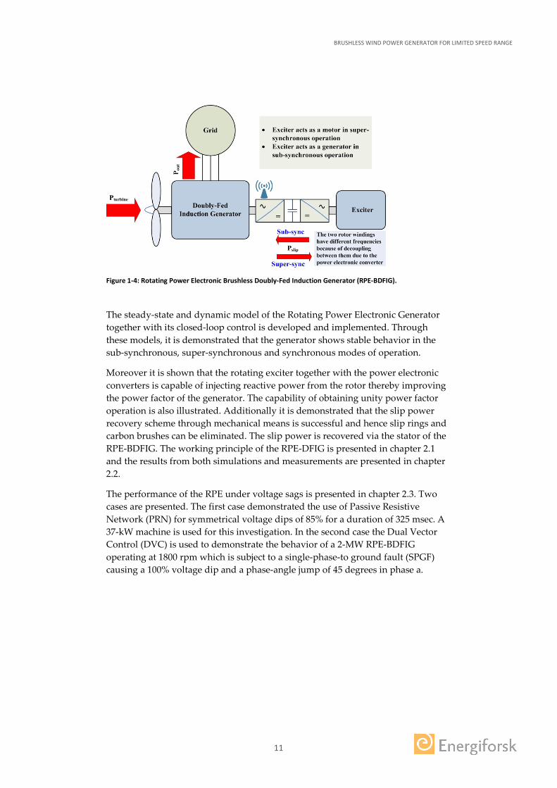
1.2 AIMS OF THE PROJECT Due to aforementioned reasons an alternate topology of the brushless configuration is studied and analyzed in this project. The configuration is shown in Figure 1-4 below. It is made up of a conventional Doubly-fed Induction Generator (without the slip rings and brushes) that is mechanically connected to a second, auxiliary machine, which is an inside-out synchronous machine. As can be seen from Figure 1-4 the power electronic converters are mounted on the shaft in between the rotors of the two machines. By doing so it is possible to achieve better power factor control over a wide speed range with lower power rating of the power electronic converters. Furthermore smaller generator sizes can be expected.
BRUSHLESS WIND POWER GENERATOR FOR LIMITED SPEED RANGE
11
Figure 1-4: Rotating Power Electronic Brushless Doubly-Fed Induction Generator (RPE-BDFIG).
The steady-state and dynamic model of the Rotating Power Electronic Generator together with its closed-loop control is developed and implemented. Through these models, it is demonstrated that the generator shows stable behavior in the sub-synchronous, super-synchronous and synchronous modes of operation.
Moreover it is shown that the rotating exciter together with the power electronic converters is capable of injecting reactive power from the rotor thereby improving the power factor of the generator. The capability of obtaining unity power factor operation is also illustrated. Additionally it is demonstrated that the slip power recovery scheme through mechanical means is successful and hence slip rings and carbon brushes can be eliminated. The slip power is recovered via the stator of the RPE-BDFIG. The working principle of the RPE-DFIG is presented in chapter 2.1 and the results from both simulations and measurements are presented in chapter 2.2.
The performance of the RPE under voltage sags is presented in chapter 2.3. Two cases are presented. The first case demonstrated the use of Passive Resistive Network (PRN) for symmetrical voltage dips of 85% for a duration of 325 msec. A 37-kW machine is used for this investigation. In the second case the Dual Vector Control (DVC) is used to demonstrate the behavior of a 2-MW RPE-BDFIG operating at 1800 rpm which is subject to a single-phase-to ground fault (SPGF) causing a 100% voltage dip and a phase-angle jump of 45 degrees in phase a.
BRUSHLESS WIND POWER GENERATOR FOR LIMITED SPEED RANGE
12
2 Modeling and Results
2.1 WORKING PRINCIPLE OF THE ROTATING POWER ELECTRONIC DOUBLY-FED INDUCTION GENERATOR (RPE-DFIG)
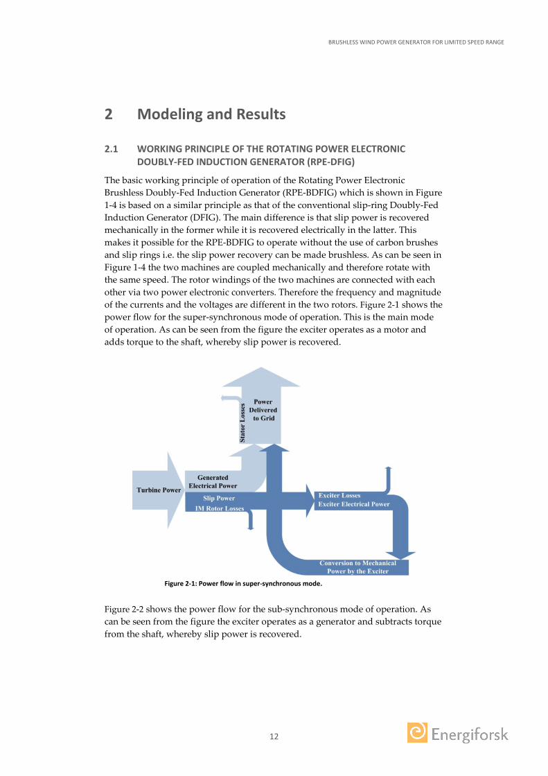
The basic working principle of operation of the Rotating Power Electronic Brushless Doubly-Fed Induction Generator (RPE-BDFIG) which is shown in Figure 1-4 is based on a similar principle as that of the conventional slip-ring Doubly-Fed Induction Generator (DFIG). The main difference is that slip power is recovered mechanically in the former while it is recovered electrically in the latter. This makes it possible for the RPE-BDFIG to operate without the use of carbon brushes and slip rings i.e. the slip power recovery can be made brushless. As can be seen in Figure 1-4 the two machines are coupled mechanically and therefore rotate with the same speed. The rotor windings of the two machines are connected with each other via two power electronic converters. Therefore the frequency and magnitude of the currents and the voltages are different in the two rotors. Figure 2-1 shows the power flow for the super-synchronous mode of operation. This is the main mode of operation. As can be seen from the figure the exciter operates as a motor and adds torque to the shaft, whereby slip power is recovered.
Figure 2-1: Power flow in super-synchronous mode.
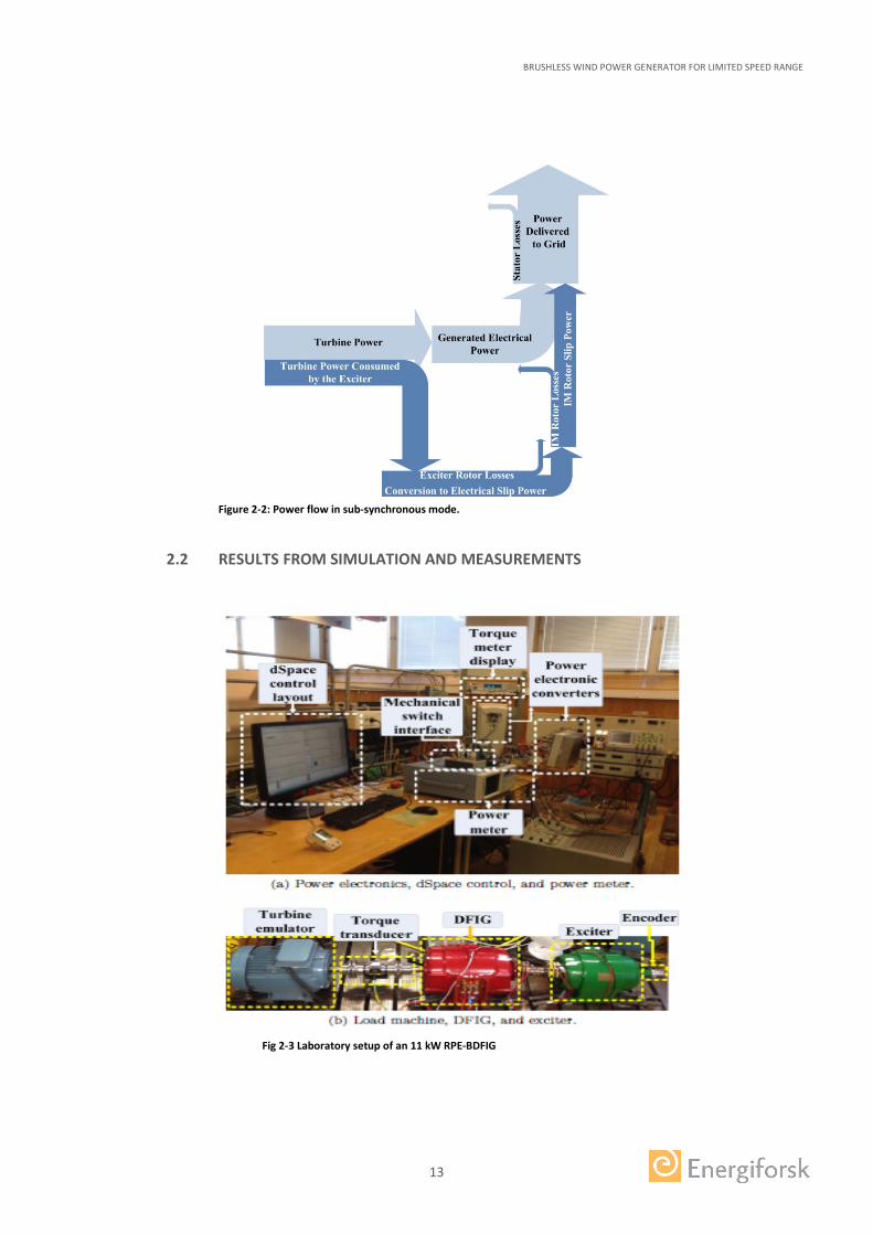
Figure 2-2 shows the power flow for the sub-synchronous mode of operation. As can be seen from the figure the exciter operates as a generator and subtracts torque from the shaft, whereby slip power is recovered.
BRUSHLESS WIND POWER GENERATOR FOR LIMITED SPEED RANGE
13
Figure 2-2: Power flow in sub-synchronous mode.
2.2 RESULTS FROM SIMULATION AND MEASUREMENTS
Fig 2-3 Laboratory setup of an 11 kW RPE-BDFIG
BRUSHLESS WIND POWER GENERATOR FOR LIMITED SPEED RANGE
14
The steady-state and dynamic models of the RPE-BDFIG together with the closed-loop control of the system is well described in chapters 3 and 4 of the thesis [2] and will not be covered in this report. For the measurements a laboratory setup was developed in the laboratory. This is shown in figure 2-3 above. The main machine is an 11 kW wound rotor machine while the exciter is a 6 kW wound rotor machine which is used to emulate the exciter machine.
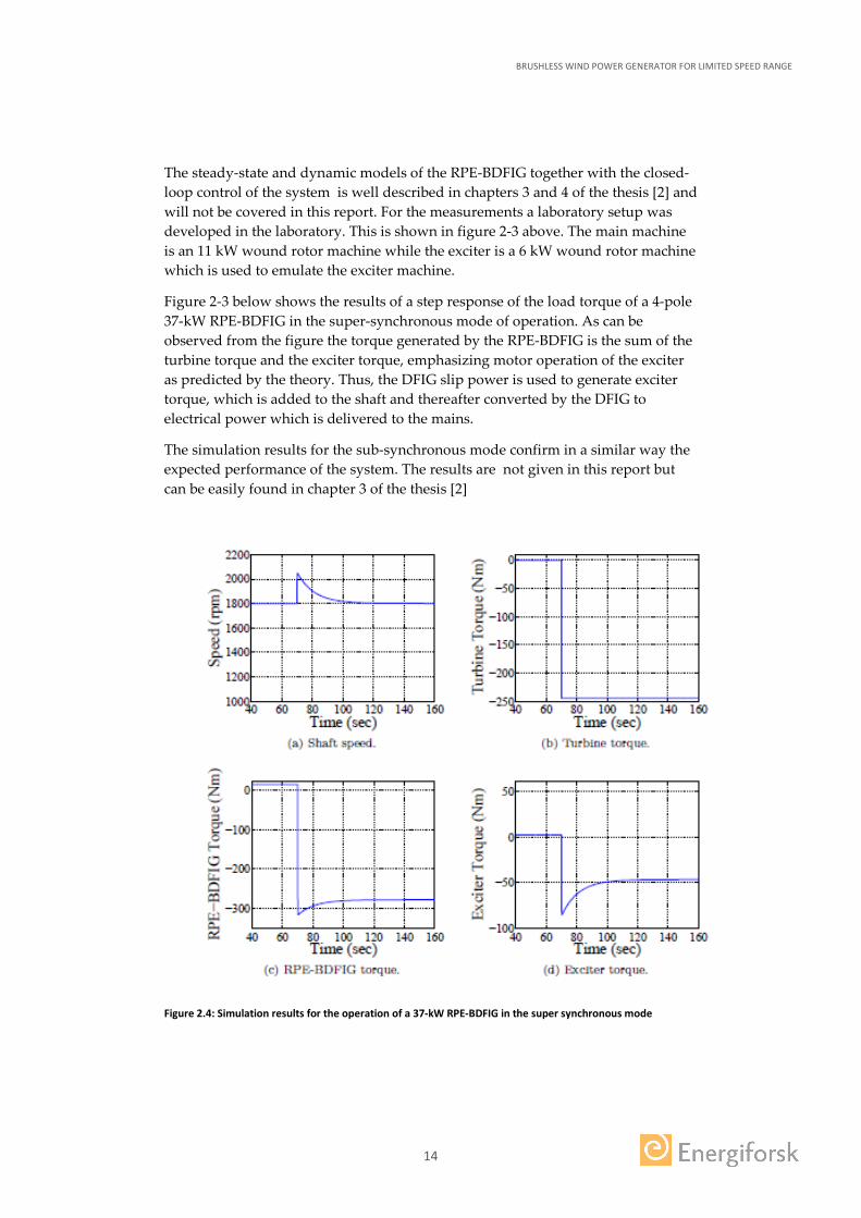
Figure 2-3 below shows the results of a step response of the load torque of a 4-pole 37-kW RPE-BDFIG in the super-synchronous mode of operation. As can be observed from the figure the torque generated by the RPE-BDFIG is the sum of the turbine torque and the exciter torque, emphasizing motor operation of the exciter as predicted by the theory. Thus, the DFIG slip power is used to generate exciter torque, which is added to the shaft and thereafter converted by the DFIG to electrical power which is delivered to the mains.
The simulation results for the sub-synchronous mode confirm in a similar way the expected performance of the system. The results are not given in this report but can be easily found in chapter 3 of the thesis [2]
Figure 2.4: Simulation results for the operation of a 37-kW RPE-BDFIG in the super synchronous mode
BRUSHLESS WIND POWER GENERATOR FOR LIMITED SPEED RANGE
15
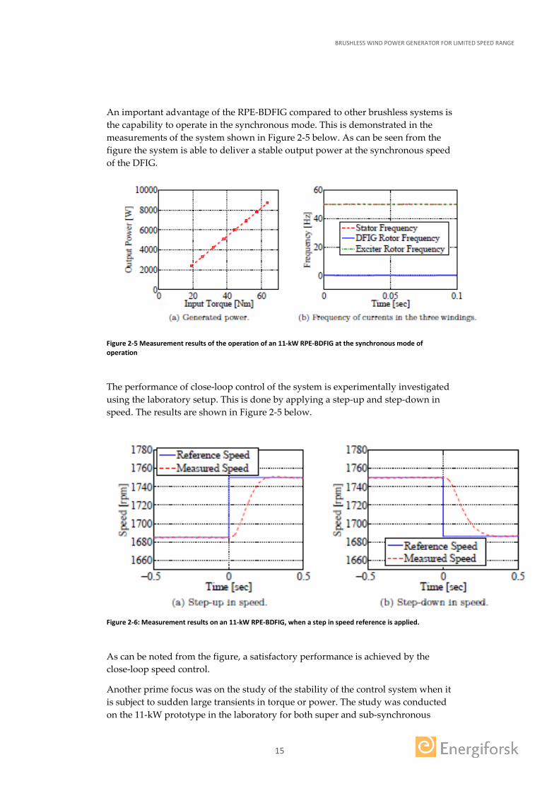
An important advantage of the RPE-BDFIG compared to other brushless systems is the capability to operate in the synchronous mode. This is demonstrated in the measurements of the system shown in Figure 2-5 below. As can be seen from the figure the system is able to deliver a stable output power at the synchronous speed of the DFIG.
Figure 2-5 Measurement results of the operation of an 11-kW RPE-BDFIG at the synchronous mode of operation
The performance of close-loop control of the system is experimentally investigated using the laboratory setup. This is done by applying a step-up and step-down in speed. The results are shown in Figure 2-5 below.
Figure 2-6: Measurement results on an 11-kW RPE-BDFIG, when a step in speed reference is applied.
As can be noted from the figure, a satisfactory performance is achieved by the close-loop speed control.
Another prime focus was on the study of the stability of the control system when it is subject to sudden large transients in torque or power. The study was conducted on the 11-kW prototype in the laboratory for both super and sub-synchronous

BRUSHLESS WIND POWER GENERATOR FOR LIMITED SPEED RANGE
16
mode of operations. Only the results from the super-synchronous mode are given in this report, see Figure 2.7 below. For the sub-synchronous mode the reader is requested to refer to chapter 4 of the thesis [2].
Figure 2-7: Experimental results for the stability study conducted on a 11-kW RPE-BDFIG at 1750 rpm, i.e. in the super-synchronous mode of operation
The results in Figure 2-7 show that the dynamic response of the generator is fast as the power reference set-point is achieved with considerable accuracy and speed.
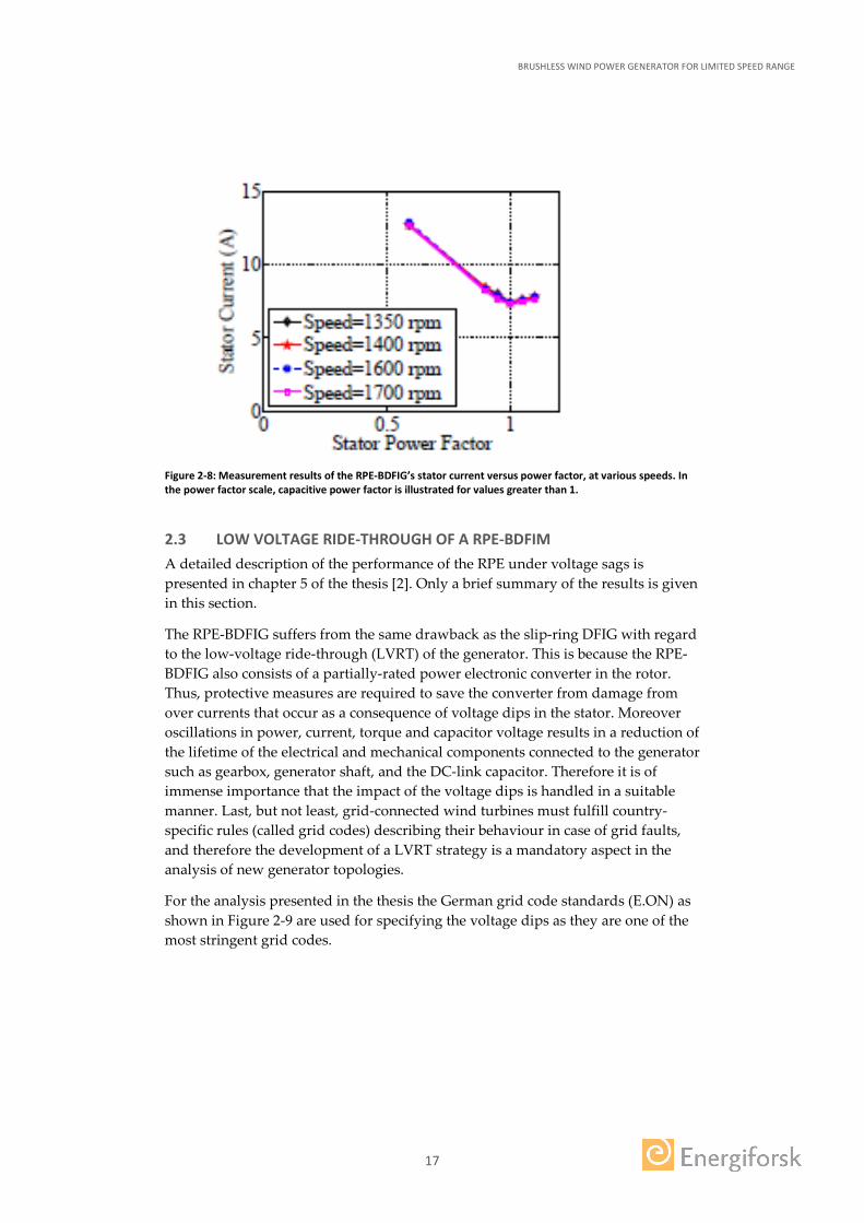
Besides, findings of the experimental results indicate that large amount of reactive power can be supplied to the grid by the RPE-BDFIG. This is shown in Figure 2-8 below where the stator current is plotted against the power factor. Unity power factor is achieved at minimum stator current. Below the minimum current value the RPE-BDFIG is inductive while above the minimum current value the RPE-BDFIG is capacitive delivering reactive power to the mains.
BRUSHLESS WIND POWER GENERATOR FOR LIMITED SPEED RANGE
17
Figure 2-8: Measurement results of the RPE-BDFIG’s stator current versus power factor, at various speeds. In the power factor scale, capacitive power factor is illustrated for values greater than 1.
2.3 LOW VOLTAGE RIDE-THROUGH OF A RPE-BDFIM A detailed description of the performance of the RPE under voltage sags is presented in chapter 5 of the thesis [2]. Only a brief summary of the results is given in this section.
The RPE-BDFIG suffers from the same drawback as the slip-ring DFIG with regard to the low-voltage ride-through (LVRT) of the generator. This is because the RPE-BDFIG also consists of a partially-rated power electronic converter in the rotor. Thus, protective measures are required to save the converter from damage from over currents that occur as a consequence of voltage dips in the stator. Moreover oscillations in power, current, torque and capacitor voltage results in a reduction of the lifetime of the electrical and mechanical components connected to the generator such as gearbox, generator shaft, and the DC-link capacitor. Therefore it is of immense importance that the impact of the voltage dips is handled in a suitable manner. Last, but not least, grid-connected wind turbines must fulfill country-specific rules (called grid codes) describing their behaviour in case of grid faults, and therefore the development of a LVRT strategy is a mandatory aspect in the analysis of new generator topologies.
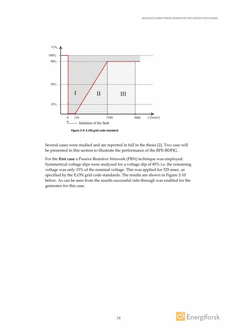
For the analysis presented in the thesis the German grid code standards (E.ON) as shown in Figure 2-9 are used for specifying the voltage dips as they are one of the most stringent grid codes.
BRUSHLESS WIND POWER GENERATOR FOR LIMITED SPEED RANGE
18
Figure 2-9: E.ON grid code standard.
Several cases were studied and are reported in full in the thesis [2]. Two case will be presented in this section to illustrate the performance of the RPE-BDFIG.
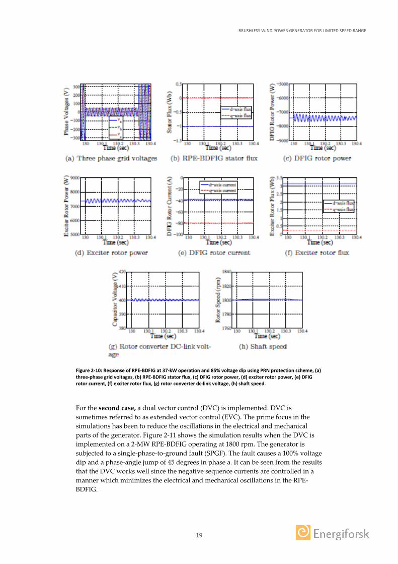
For the first case a Passive Resistive Network (PRN) technique was employed. Symmetrical voltage dips were analyzed for a voltage dip of 85% i.e. the remaining voltage was only 15% of the nominal voltage. This was applied for 325 msec. as specified by the E.ON grid code standards. The results are shown in Figure 2-10 below. As can be seen from the results successful ride-through was enabled for the generator for this case.
BRUSHLESS WIND POWER GENERATOR FOR LIMITED SPEED RANGE
19
Figure 2-10: Response of RPE-BDFIG at 37-kW operation and 85% voltage dip using PRN protection scheme, (a) three-phase grid voltages, (b) RPE-BDFIG stator flux, (c) DFIG rotor power, (d) exciter rotor power, (e) DFIG rotor current, (f) exciter rotor flux, (g) rotor converter dc-link voltage, (h) shaft speed.
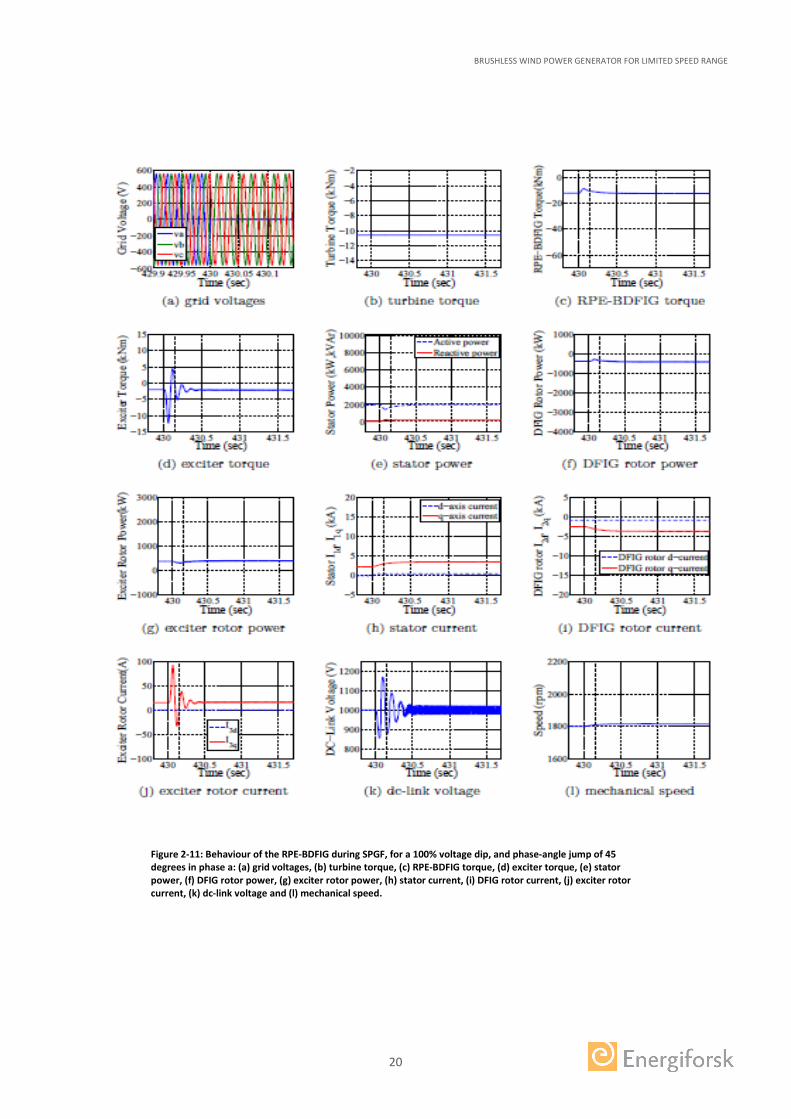
For the second case, a dual vector control (DVC) is implemented. DVC is sometimes referred to as extended vector control (EVC). The prime focus in the simulations has been to reduce the oscillations in the electrical and mechanical parts of the generator. Figure 2-11 shows the simulation results when the DVC is implemented on a 2-MW RPE-BDFIG operating at 1800 rpm. The generator is subjected to a single-phase-to-ground fault (SPGF). The fault causes a 100% voltage dip and a phase-angle jump of 45 degrees in phase a. It can be seen from the results that the DVC works well since the negative sequence currents are controlled in a manner which minimizes the electrical and mechanical oscillations in the RPE-BDFIG.
BRUSHLESS WIND POWER GENERATOR FOR LIMITED SPEED RANGE
20
Figure 2-11: Behaviour of the RPE-BDFIG during SPGF, for a 100% voltage dip, and phase-angle jump of 45 degrees in phase a: (a) grid voltages, (b) turbine torque, (c) RPE-BDFIG torque, (d) exciter torque, (e) stator power, (f) DFIG rotor power, (g) exciter rotor power, (h) stator current, (i) DFIG rotor current, (j) exciter rotor current, (k) dc-link voltage and (l) mechanical speed.
BRUSHLESS WIND POWER GENERATOR FOR LIMITED SPEED RANGE
21
3 Conclusions
In this project a novel topology of brushless doubly-fed induction machine was investigated in which the slip rings and carbon brushes could be replaced by power electronic converters mounted on the shaft and an exciter that is mechanically connected to same shaft. The system is denoted RPE-BDFIG.
For the first time, a dynamic model for the RPE-BDFIG was developed together with a feedback control. It was shown through both simulations and measurements that the system was successfully able to operate at stable points, including the synchronous speed. Moreover it was shown that the rotating exciter was able to magnetize the generator from the rotor thereby improving the stability of the grid.
A suitable low-voltage ride through technique called Passive Resistive Network was implemented for this type of generator and it was shown that this type of generator is successfully able to handle symmetrical voltage dips in the grid. It was also shown that the Dual Vector Control (DVC) strategy works well for this type of generator and it was shown that the oscillations in the different components of the RPE-BDFIG were reduced considerably during the unsymmetrical grid faults. Moreover the generator is capable of withstanding up to 85% of symmetrical and unsymmetrical voltage dips thus fulfilling the requirements of the stringent E.ON grid code standards.
An interesting concept that could considerably decrease the cost of the complete system has been investigated at ABB. This is based on two BDFIGs with different pole numbers that are mechanically connected to each other with a RPEC in between them. As is shown in [16] a significant reduction in size (and correspondingly the cost) of the RPEC can be achieved for a suitable choice of pole numbers and powers of the BDFIGs. Further research on this concept is recommended.
BRUSHLESS WIND POWER GENERATOR FOR LIMITED SPEED RANGE
22
4 Publications
The detailed analysis, working principle, modeling, control aspects and measurement results of the BDFIM are given in the following publications. These are included in the PhD thesis by Naveed ur Rehman Malik.
Thesis
[1] Malik, Naveed ur Rehman, “Analysis and Control Aspects of Brushless Induction Machines with Rotating Power Electronic Converters” Licentiate Thesis, KTH October 2012
[2] Malik, Naveed ur Rehman, “Brushless Doubly-Fed Generator with Rotating Power Electronic Converter” Doctoral Thesis, KTH October 2015
Journal Publications
[3] Malik, Naveed ur Rehman, Sadarangani, C, A. Cosic and L. Harnefors, “Experimental validation of a rotating power electronic brushless doubly-fed induction generator for variable-speed operation” accepted first version in IEEE Trans. Energy Conv., May 2015, and revised version resubmitted.
[4] Malik, Naveed ur Rehman, Sadarangani, C, A. Cosic and L. Harnefors, “Variable reactive power control of a rotating power electronic brushless doubly-fed generator” submitted to IEEE Trans. Energy Conv., Aug. 2015.
[5] Malik, Naveed ur Rehman, Sadarangani and L. Harnefors, “Low voltage ride-through of a 2-MW rotating power electronic brushless doubly-fed generator” submitted to IEEE Trans. on Sustainable Energy, Sept. 2015.
[6] Malik, Naveed ur Rehman, I. Husain, “Dynamic and steady-state 3-D thermal design and investigation of the rotating power electronic IGBT converter” submitted to IEEE Trans. Emerging and Selected Topics in Power Electronics, June 2015.
Conference Publications
[7] Malik, Naveed ur Rehman, Sadarangani, C., “Brushless doubly-fed induction machine with rotating power electronic converter for wind power applications,” Electrical Machines and Systems (ICEMS), 2011 International Conference on , vol., no., pp.1-6, 20-23 Aug. 2011.
[8] Malik, Naveed ur Rehman, Sadarangani, C., “Dynamic modeling and control of a brushless doubly-fed induction generator with a rotating power electronic converter,” XXth International Conference on Electrical Machines (ICEM) pp. 900-906, 2-5 Sept. 2012.
[9] Malik, Naveed ur Rehman, Sadarangani, C., “Behavior of a brushless doubly-fed induction generator with a rotating power electronic converter during symmetrical voltage sags,” XXth International Conference on Electrical Machines (ICEM) pp. 865-871, 2-5 Sept. 2012.
BRUSHLESS WIND POWER GENERATOR FOR LIMITED SPEED RANGE
23
[10] Malik, Naveed ur Rehman, Sadarangani, C., “Extended vector control of a rotating power electronic brushless doubly-fed induction generator under unsymmetrical voltage sags ,” 38th Annual Conference on IEEE Industrial Electronics Society (IECON) pp. 1793-1798, 25-28 Oct. 2012.
[11] Malik, Naveed ur Rehman, Sadarangani, C., Lindmark, M., “Theoretical and experimental investigation of the self-excited rotating power electronic induction machine,” IECON 2011 - 37th Annual Conference on IEEE Industrial Electronics Society, pp.2048-2053, 7-10 Nov. 2011.
[12] Malik, Naveed ur Rehman, Sadarangani, C., Cosic, A., Lindmark, M., “Induction machine at unity power factor with rotating power electronic converter,” International Symposium on Power Electronics, Electrical Drives, Automation and Motion (SPEEDAM), pp. 401-408, 20-22 June 2012.
[13] Malik, Naveed ur Rehman, Sadarangani, C., Cosic, A.,“ Synchronous operation of a rotating power electronic brushless doubly-fed generator”, Annual conference on IEEE Industrial Electronics Society (IECON), 9 -12 Nov. 2015.
[14] Malik, Naveed ur Rehman, I. Husain, “Transient and Steady-State 3-D Electro-Thermal Design and Analysis of the Rotating Power Electronic IGBT Converter”, IEEE International Electrical Machines and Drives Conference (IEMDC), 10-13 May 2015.
The following publication is related to the construction of the rotating power electronic converter and the wireless communication
[15] Cosic, A., Yao, Y., Sadarangani C., Malik, Naveed ur Rehman, “Construction of a rotating power electronic converter for induction machine operation” International Conference on Electrical machines and Systems (ICEMS), Thailand Oct. 2015.
The following publication is related to the study made at ABB as part of their contribution in kind
[16] Federico Mizzon, “Analysis of the integration of two DFIGs with rotating power electronics for wind power application” ABB report, June 2016

BRUSHLESS WIND POWER GENERATOR FOR LIMITED SPEED RANGE The aim has been to develop a prototype of a new type of wind turbine generator, the Brushless Doubly-Fed Induction Generator, or BDFIG. The DFIG is one of the most popular generator types used in wind turbines today, however, it does have certain disadvantages. The conventional DFIG uses slip rings and carbon brushes for speed control. These components demands a lot of maintenance, which is costly, especially for offshore wind power plants.
The BDFIG lacks brushes and slip rings, and uses instead power electronic converters mounted on the rotor and an exciter mechanically connected to the shaft. Also within the project, a wireless controlled Rotating Power Electronic Converter, RPEC, has been constructed. The RPEC and the BDFIG have been built and tested in full scale in a laboratory environment, and have been evaluated both technically and economically.
Energiforsk is the Swedish Energy Research Centre – an industrially owned body dedicated to meeting the common energy challenges faced by industries, authorities and society. Our vision is to be hub of Swedish energy research and our mission is to make the world of energy smarter! Vindforsk is operated in cooperation with the Swedish Energy Agency.