W650 Wind Generator Protection System
622
GE Multilin 215 Anderson Avenue L6E 1B3 Markham, ON -CANADA T (905) 294 6222 F (905) 294 8512 E [email protected] Internet: www.GEMultilin.com Firmware version: 3.02 EnerVista 650 Setup version: 3.02 Copyright © 2006 GE Multilin W650 Wind Generator Protection System Instruction manual GEK-113032A GE Multilin Avda. Pinoa, 10 48170 Zamudio SPAIN T +34 94 485 88 00 F +34 94 485 88 45 E [email protected] g GE Consumer & Industrial Multilin
-
Upload
khangminh22 -
Category
Documents
-
view
1 -
download
0
Transcript of W650 Wind Generator Protection System
GE Multilin215 Anderson AvenueL6E 1B3 Markham, ON -CANADAT (905) 294 6222 F (905) 294 8512E [email protected]
Internet: www.GEMultilin.com
Firmware version: 3.02EnerVista 650 Setup version: 3.02
Copyright © 2006 GE Multilin
W650Wind Generator Protection System
Instruction manualGEK-113032A
GE MultilinAvda. Pinoa, 1048170 Zamudio SPAINT +34 94 485 88 00 F +34 94 485 88 45E [email protected]
g GE Consumer & IndustrialMultilin

GEK-113032A W650 Wind Generator Protection System I
TABLE OF CONTENTS
1. GETTING STARTED 1.1 IMPORTANT PROCEDURES1.1.1 CAUTIONS AND WARNINGS........................................................................... 1-11.1.2 INSPECTION CHECKLIST................................................................................ 1-41.1.3 SAFETY INSTRUCTIONS................................................................................. 1-6
1.2 OVERVIEW1.2.1 INTRODUCTION TO 650 FAMILY OF RELAYS ............................................... 1-71.2.2 HARDWARE ARCHITECTURE......................................................................... 1-71.2.3 SOFTWARE ARCHITECTURE ......................................................................... 1-91.2.4 COMMUNICATIONS ARCHITECTURE ............................................................ 1-9
1.3 ENERVISTA 650 SETUP SOFTWARE1.3.1 SYSTEM REQUIREMENTS ............................................................................ 1-111.3.2 INSTALLATION ............................................................................................... 1-111.3.3 CONNECTING ENERVISTA 650 SETUP WITHW650.................................... 1-16
1.4 W650 HARDWARE1.4.1 MOUNTING & WIRING ................................................................................... 1-171.4.2 W650 COMMUNICATIONS............................................................................. 1-171.4.3 FACEPLATE DISPLAY.................................................................................... 1-181.4.4 MAINTENANCE............................................................................................... 1-19
2. PRODUCT DESCRIPTION 2.1 OVERVIEW2.1.1 W650 OVERVIEW ............................................................................................. 2-1
2.2 SUMMARY2.2.1 ANSI DEVICE NUMBERS AND FUNCTIONS................................................... 2-3
2.3 ORDERING CODE2.4 TECHNICAL SPECIFICATIONS
2.4.1 PROTECTION ELEMENTS............................................................................... 2-62.4.2 CONTROL ....................................................................................................... 2-142.4.3 MONITORING ................................................................................................. 2-152.4.4 USER –PROGRAMABLE ELEMENTS............................................................ 2-172.4.5 METERING...................................................................................................... 2-182.4.6 INPUTS............................................................................................................ 2-192.4.7 REAL TIME CLOCK ........................................................................................ 2-212.4.8 OUTPUTS........................................................................................................ 2-212.4.9 CONTROL POWER SUPPLY ......................................................................... 2-222.4.10 COMMUNICATIONS ....................................................................................... 2-222.4.11 OPTIC FEATURES.......................................................................................... 2-242.4.12 ENVIRONMENTAL CHARACTERISTICS....................................................... 2-252.4.13 PACKAGING AND WEIGHT ........................................................................... 2-252.4.14 TYPE TESTS................................................................................................... 2-252.4.15 APPROVALS ................................................................................................... 2-25
2.5 EXTERNAL CONNECTIONS
3. HARDWARE 3.1 MODULE DESCRIPTION3.2 POWER SUPPLY3.3 MECHANICAL DESCRIPTION
3.3.1 MOUNTING ....................................................................................................... 3-33.3.2 REAR DESCRIPTION ....................................................................................... 3-5
3.4 WIRING3.4.1 EXTERNAL CONNECTIONS ............................................................................ 3-93.4.2 DIGITAL INPUTS WITH TRIP CIRCUIT SUPERVISION .................................. 3-93.4.3 CABLE/FIBER ETHERNET BOARD ................................................................. 3-9
II W650 Wind Generator Protection System GEK-113032A
TABLE OF CONTENTS
3.5 TRANSCEIVER OPTICAL POWER BUDGET VERSUS LINK LENGTH
4. HUMAN INTERFACES. 4.1 ENERVISTA 650 SETUP SOFTWARE INTERFACE4.1.1 INTRODUCTION................................................................................................4-14.1.2 ENERVISTA 650 SETUP SOFTWARE OVERVIEW .........................................4-14.1.3 MAIN SCREEN...................................................................................................4-34.1.4 COMMUNICATION MENU.................................................................................4-44.1.5 FILE MANAGEMENT .........................................................................................4-64.1.6 ENERVISTA 650 SETUP MENUS STRUCTURE............................................4-124.1.7 FILE MENU OVERVIEW..................................................................................4-134.1.8 SETPOINT MENU OVERVIEW........................................................................4-174.1.9 ACTUAL VALUES MENU OVERVIEW ............................................................4-264.1.10 OPERATIONS MENU OVERVIEW..................................................................4-304.1.11 COMMUNICATION MENU OVERVIEW ..........................................................4-304.1.12 SECURITY MENU OVERVIEW .......................................................................4-334.1.13 VIEW MENU OVERVIEW ................................................................................4-334.1.14 HELP MENU OVERVIEW ................................................................................4-33
4.2 HUMAN MACHINE INTERFACE (HMI)4.2.1 DISPLAY ..........................................................................................................4-344.2.2 FRONT LED INDICATORS..............................................................................4-354.2.3 PUSHBUTTONS .............................................................................................4-354.2.4 FRONT PORT AND COVER SEALING SYSTEM ...........................................4-364.2.5 TEXT MENUS ..................................................................................................4-374.2.6 GRAPHIC DISPLAY.........................................................................................4-55
4.3 WEB SERVER4.3.1 HOME...............................................................................................................4-644.3.2 SNAPSHOT EVENTS ......................................................................................4-654.3.3 CONTROL EVENTS.........................................................................................4-664.3.4 ALARMS...........................................................................................................4-674.3.5 OSCILLOGRAPHY...........................................................................................4-684.3.6 FAULT REPORT ..............................................................................................4-694.3.7 DATA LOGGER................................................................................................4-704.3.8 METERING.......................................................................................................4-71
5. SETTINGS 5.1 OVERVIEW5.1.1 SETTING MAIN MENU ......................................................................................5-1
5.2 PRODUCT SETUP5.2.1 COMMUNICATION SETTINGS .........................................................................5-35.2.2 MODBUS USER MAP........................................................................................5-65.2.3 FAULT REPORT ................................................................................................5-75.2.4 OSCILLOGRAPHY.............................................................................................5-95.2.5 DATA LOGGER................................................................................................5-125.2.6 DEMAND .........................................................................................................5-14
5.3 SYSTEM SETUP5.3.1 GENERAL SETTINGS .....................................................................................5-205.3.2 FLEX CURVES.................................................................................................5-205.3.3 BREAKER ........................................................................................................5-225.3.4 SWITCHGEAR .................................................................................................5-24
5.4 PROTECTION ELEMENTS5.4.1 CHANGE OF SETTING TABLES IN W650 ELEMENTS .................................5-255.4.2 INVERSE TIME CURVES CHARACTERISTICS .............................................5-295.4.3 PHASE CURRENT...........................................................................................5-395.4.4 NEUTRAL CURRENT ......................................................................................5-495.4.5 GROUND CURRENT.......................................................................................5-565.4.6 SENSITIVE GROUND CURRENT ...................................................................5-595.4.7 NEGATIVE SEQUENCE CURRENT................................................................5-625.4.8 VOLTAGE ELEMENTS ....................................................................................5-635.4.9 POWER............................................................................................................5-68
GEK-113032A W650 Wind Generator Protection System III
TABLE OF CONTENTS
5.5 CONTROL ELEMENTS5.5.1 SETTING GROUP ........................................................................................... 5-745.5.2 UNDERFREQUENCY ELEMENT (81U).......................................................... 5-755.5.3 OVERFREQUENCY ELEMENT (81O)............................................................ 5-755.5.4 AUTORECLOSE (79) ...................................................................................... 5-765.5.5 BREAKER FAILURE ELEMENT (50BF).......................................................... 5-835.5.6 VT FUSE FAILURE ELEMENT (VTFF) ........................................................... 5-86
5.6 INPUTS/OUTPUTS5.6.1 INPUT/OUTPUT PLACEMENT ....................................................................... 5-885.6.2 CONTROL SETTINGS FOR INPUTS/OUTPUTS ........................................... 5-895.6.3 INPUTS............................................................................................................ 5-915.6.4 OUTPUTS........................................................................................................ 5-935.6.5 CIRCUIT SUPERVISION AND CONTACT SEAL-IN CIRCUITS..................... 5-955.6.6 ANALOG BOARDS SPECIFIC SETTINGS ................................................... 5-1055.6.7 VIRTUAL INPUTS ......................................................................................... 5-1065.6.8 VIRTUAL OUTPUTS ..................................................................................... 5-106
5.7 TESTINGS5.7.1 FORCE IO –INPUT TESTING ....................................................................... 5-1075.7.2 FORCE IO –OUTPUT TESTING ................................................................... 5-107
5.8 RELAY CONFIGURATION5.8.1 OUTPUTS...................................................................................................... 5-1085.8.2 LEDS ............................................................................................................. 5-1095.8.3 OPERATIONS ............................................................................................... 5-1105.8.4 PROTECTION ELEMENTS........................................................................... 5-1145.8.5 OSCILLOGRAPHY ........................................................................................ 5-1155.8.6 CONTROL EVENTS...................................................................................... 5-1165.8.7 SWITCHGEAR ............................................................................................. 5-1185.8.8 HMI (HUMAN-MACHINE INTERFACE)......................................................... 5-119
5.9 LOGIC CONFIGURATION (PLC EDITOR)5.9.1 INTRODUCTION ........................................................................................... 5-1225.9.2 THEORY OF OPERATION............................................................................ 5-1235.9.3 MAIN MENU .................................................................................................. 5-1265.9.4 CONFIGURATION GENERATION................................................................ 5-1275.9.5 GENERATION OF LIBRARIES .................................................................... 5-1285.9.6 EXAMPLE OF APPLICATION ....................................................................... 5-130
6. ACTUAL VALUES 6.1 FRONT PANEL6.1.1 LEDS ................................................................................................................. 6-1
6.2 STATUS6.2.1 OPERATION BITS............................................................................................. 6-26.2.2 BREAKER.......................................................................................................... 6-26.2.3 PROTECTION ................................................................................................... 6-26.2.4 CONTROL ELEMENTS..................................................................................... 6-86.2.5 PROTECTION SUMMARY.............................................................................. 6-136.2.6 SNAPSHOT EVENTS SUMMARY .................................................................. 6-156.2.7 MODBUS USER MAP ..................................................................................... 6-176.2.8 SWITCHGEAR STATUS ................................................................................. 6-176.2.9 CALIBRATION................................................................................................. 6-196.2.10 FLEX CURVES................................................................................................ 6-206.2.11 SYSTEM INFO ................................................................................................ 6-206.2.12 RECORD STATUS .......................................................................................... 6-20
6.3 METERING6.3.1 PRIMARY VALUES ......................................................................................... 6-256.3.2 SECONDARY VALUES................................................................................... 6-286.3.3 PHASOR DIAGRAM........................................................................................ 6-306.3.4 FREQUENCY .................................................................................................. 6-306.3.5 INPUTS / OUTPUTS ....................................................................................... 6-31
6.4 RECORDS6.4.1 EVENT RECORDER ....................................................................................... 6-376.4.2 WAVEFORM CAPTURE ................................................................................. 6-396.4.3 FAULT REPORT ............................................................................................. 6-40
IV W650 Wind Generator Protection System GEK-113032A
TABLE OF CONTENTS
6.4.4 DATA LOGGER................................................................................................6-42
7. IEC 61850 PROTOCOL 7.1 IEC61850 GENERIC SUBSTATION STATE EVENT (GSSE)7.1.1 REMOTE DEVICES ...........................................................................................7-17.1.2 REMOTE INPUTS..............................................................................................7-37.1.3 REMOTE OUTPUTS..........................................................................................7-4
7.2 IEC 61850 PROFILE FOR W650 7.2.1 INTRODUCTION................................................................................................7-67.2.2 ACSI CONFORMANCE STATEMENT...............................................................7-67.2.3 LOGICAL NODES ............................................................................................7-117.2.4 COMMON DATA CLASS .................................................................................7-297.2.5 DATASETS.......................................................................................................7-447.2.6 MAPPINGS BETWEEN TOC CURVES IN IEC 61850 AND W650 RELAY
IMPLEMENTATION..........................................................................................7-467.2.7 ANALOG DATA UNITS AND SCALES ............................................................7-47
8. W650 CANOPEN PROFILE 8.1 INTRODUCTION8.1.1 DEFINITIONS.....................................................................................................8-1
8.2 CANOPEN INTERFACE SPECIFICATION8.3 SERVICES8.4 OBJECT DICTIONARY
8.4.1 STANDARD OBJECTS ......................................................................................8-48.4.2 MANUFACTURER SPECIFIC OBJECTS ..........................................................8-7
9. SECURITY 9.1 ADDING USERS9.1.1 USER RIGHTS...................................................................................................9-1
9.2 CHANGING PASSWORDS9.3 ENABLING SECURITY9.4 LOGING INTO ENERVISTA 650 SETUP
10. BOOTCODE AND FIRMWARE UPGRADE
10.1 INTRODUCTION10.1.1 COMMUNICATION PARAMETERS.................................................................10-2
10.2 BOOT CODE UPGRADE10.3 FIRMWARE VERSION UPGRADE
10.3.1 FIRMWARE UPGRADE ...................................................................................10-910.3.2 BOOT CODE UPGRADE (*) ..........................................................................10-1110.3.3 FIRMWARE UPGRADE (*) ............................................................................10-12
GEK-113032A W650 Wind Generator Protection System V
TABLE OF CONTENTS
11. COMMISSIONING 11.1 VISUAL INSPECTION11.2 GENERAL CONSIDERATIONS ON THE POWER SUPPLY NETWORK11.3 ISOLATION TESTS11.4 INDICATORS11.5 POWER SUPPLY TESTING11.6 COMMUNICATIONS11.7 VERIFICATION OF MEASUREMENT
11.7.1 VOLTAGES ..................................................................................................... 11-711.7.2 PHASE CURRENTS........................................................................................ 11-711.7.3 ACTIVE, REACTIVE POWER, AND COSJ METERING ................................. 11-811.7.4 FREQUENCY .................................................................................................. 11-8
11.8 INPUTS AND OUTPUTS11.8.1 DIGITAL INPUTS............................................................................................. 11-911.8.2 CONTACT OUTPUTS ................................................................................... 11-1011.8.3 CIRCUIT CONTINUITY SUPERVISION INPUTS ......................................... 11-1011.8.4 LATCHING CIRCUITS................................................................................... 11-10
11.9 CONNECTIONS FOR TESTING PROTECTION ELEMENTS11.10 INSTANTANEOUS OVERCURRENT (50PH, 50PL, 50N, 50G Y 50SG)11.11 TIME OVERCURRENT (51PH, 51PL, 51N AND 51G)11.12 DIRECTIONAL ELEMENTS (67P, 67N, 67G, 67SG)
11.12.1 67P ELEMENT .............................................................................................. 11-1411.12.2 67N ELEMENT .............................................................................................. 11-1411.12.3 67G ELEMENT .............................................................................................. 11-1511.12.4 67SG ELEMENT............................................................................................ 11-16
11.13 UNDERVOLTAGE ELEMENTS (27P, 27X) 11.13.1 27P ELEMENT .............................................................................................. 11-1711.13.2 27X ELEMENT .............................................................................................. 11-17
11.14 OVERVOLTAGE ELEMENTS (59P, 59X, 59NH, 59NL) 11.14.1 59P ELEMENT .............................................................................................. 11-1811.14.2 59X ELEMENT .............................................................................................. 11-1811.14.3 59NH AND 59NL ELEMENTS ....................................................................... 11-19
11.15 RECLOSER (79)11.15.1 RECLOSING CYCLE..................................................................................... 11-2011.15.2 RECLOSER STATUS.................................................................................... 11-2111.15.3 EXTERNAL RECLOSE INITIATION.............................................................. 11-21
12. APPLICATION EXAMPLES 12.1 EXAMPLE 1: COMMUNICATION & PROTECTION SETTINGS PROCEDURE
12.1.1 DESCRIPTION OF THE EXERCISE............................................................... 12-112.1.2 PROCEDURE TO COMMUNICATE WITH THE RELAY................................. 12-112.1.3 PROCEDURE TO SET THE PROTECTION FUNCTION................................ 12-312.1.4 TEST................................................................................................................ 12-4
12.2 EXAMPLE 2: TOC PROTECTION + RECLOSING SETTINGS PROCEDURE
12.2.1 DESCRIPTION OF THE EXERCISE............................................................... 12-512.2.2 PROCEDURE TO COMMUNICATE THE RELAY........................................... 12-512.2.3 PROCEDURE TO SET THE PROTECTION FUNCTION................................ 12-512.2.4 PROCEDURE TO SET THE RECLOSER....................................................... 12-612.2.5 PROCEDURE TO SET THE SYNCHRO CHECK ........................................... 12-6
12.3 EXAMPLE 3: PROCEDURE TO SET AN OPERATION12.3.1 DESCRIPTION OF THE EXERCISE............................................................... 12-812.3.2 PROCEDURE ................................................................................................. 12-812.3.3 TEST.............................................................................................................. 12-10
VI W650 Wind Generator Protection System GEK-113032A
TABLE OF CONTENTS
13. FREQUENTLY ASKED QUESTIONS
13.1 COMMUNICATIONS13.2 PROTECTION13.3 CONTROL AND HMI13.4 RELAY CONFIGURATION
14. TROUBLESHOOTING GUIDE
14.1 SYMPTOMS AND RECOMMENDED ACTIONS
A. LOGIC OPERANDS A.1 LOGIC OPERANDS
B. MODBUS PROTOCOL B.1 ACCESS TO W650 DATAB.2 MODBUS W650
B.2.1 FUNCTIONS USED........................................................................................... B-2B.2.2 PHYSICAL LAYER ............................................................................................ B-3B.2.3 DATA LINK LAYER ........................................................................................... B-4B.2.4 GENERIC READING ......................................................................................... B-5B.2.5 GENERIC WRITING.......................................................................................... B-6B.2.6 FUNCTION CODES ......................................................................................... B-7B.2.7 EXCEPTIONS AND ERROR RESPONDS........................................................ B-8
B.3 DATA TYPEB.4 MODBUS APPENDIX
B.4.1 DATA MANAGEMENT .................................................................................... B-10B.4.2 WRITING SETTINGS ...................................................................................... B-11B.4.3 SNAP-SHOT EVENTS .................................................................................... B-12B.4.4 OPERATIONS ................................................................................................. B-15
B.5 OUTPUT WRITINGB.5.1 CONTROL EVENTS........................................................................................ B-17B.5.2 EVENT STRUCTURE...................................................................................... B-18
B.6 EVENTS STATUS REQUEST (ALARMS)B.6.1 CONTROL EVENTS RETRIEVAL FROM THE COMMAND LINE ................. B-21B.6.2 SERIAL COMMUNICATION............................................................................ B-22B.6.3 ETHERNET COMMUNICATION ..................................................................... B-23B.6.4 ACKNOWLEDGEMENT OF EVENTS (ALARMS)........................................... B-24B.6.5 VIRTUAL INPUTS WRITING........................................................................... B-25B.6.6 USER MAP ...................................................................................................... B-26B.6.7 RETRIEVING OSCILOGRAPHY ..................................................................... B-27B.6.8 TIME SYNCHRONIZATION ............................................................................ B-28B.6.9 ENQUEUEING MESSAGES .......................................................................... B-29B.6.10 TRACES AND TROUBLESHOOTING............................................................. B-30B.6.11 MODBUS CHECK FUNCTION........................................................................ B-31
B.7 MEMORY MAP
C. DNP 3.0 PROTOCOL FOR W650
C.1 DNP 3.0 PROTOCOL SETTINGSC.2 DNP 3.0 DEVICE PROFILE DOCUMENT C.3 IMPLEMENTATION TABLEC.4 BINARY INPUT POINTSC.5 DNP CONFIGURATION EXAMPLES
C.5.1 CONFIGURING DNP USER MAP...................................................................C-11
GEK-113032A W650 Wind Generator Protection System VII
TABLE OF CONTENTS
C.5.2 EXAMPLE OF CUSTOM BINARY INPUT POINTS MAP ................................C-13C.5.3 MULTIPLE DNP 3.0 MASTERS COMMUNICATION WITH W650..................C-15
C.6 BINARY OUTPUT AND CONTROL RELAY OUTPUTC.7 BINARY COUNTERSC.8 ANALOG INPUTS
D. IEC 60870-5-104 PROTOCOL D.1 INTRODUCTIOND.2 TECHNICAL DESCRIPTIOND.3 BASIC APPLICATION FUNCTIONSD.4 IEC 104 SETTINGSD.5 IEC 60870-5-104 POINT LIST
E. FACTORY DEFAULT CONFIGURATION
E.1 FACTORY DEFAULT SETTINGSE.2 FACTORY DEFAULT CONFIGURATION
F. MISCELLANEOUS F.1 GE MULTILIN WARRANTY

VIII W650 Wind Generator Protection System GEK-113032A
TABLE OF CONTENTS
GEK-113032A W650 Wind Generator Protection System 1-1
1 GETTING STARTED 1.1 IMPORTANT PROCEDURES
11 GETTING STARTED 1.1IMPORTANT PROCEDURES 1.1.1 CAUTIONS AND WARNINGS
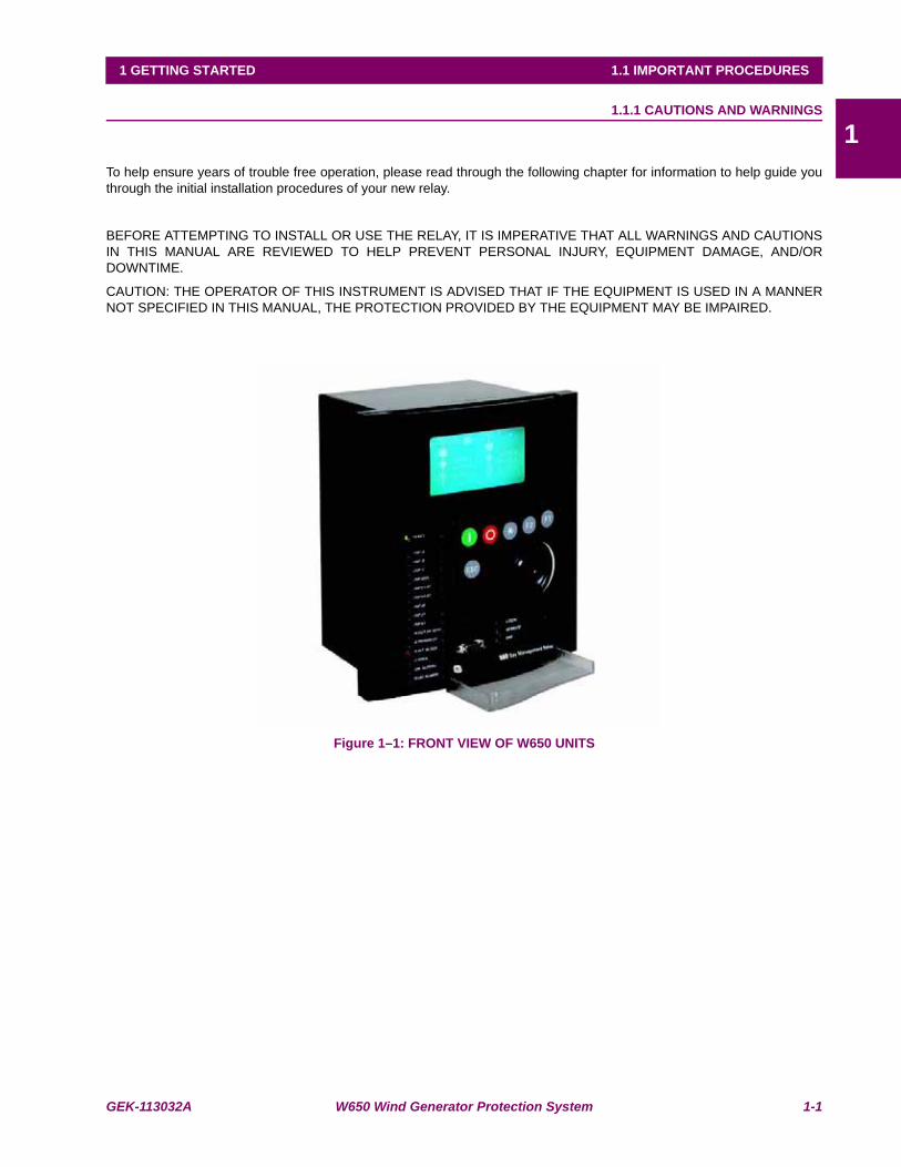
To help ensure years of trouble free operation, please read through the following chapter for information to help guide youthrough the initial installation procedures of your new relay.
BEFORE ATTEMPTING TO INSTALL OR USE THE RELAY, IT IS IMPERATIVE THAT ALL WARNINGS AND CAUTIONSIN THIS MANUAL ARE REVIEWED TO HELP PREVENT PERSONAL INJURY, EQUIPMENT DAMAGE, AND/ORDOWNTIME.
CAUTION: THE OPERATOR OF THIS INSTRUMENT IS ADVISED THAT IF THE EQUIPMENT IS USED IN A MANNERNOT SPECIFIED IN THIS MANUAL, THE PROTECTION PROVIDED BY THE EQUIPMENT MAY BE IMPAIRED.
Figure 1–1: FRONT VIEW OF W650 UNITS

1-2 W650 Wind Generator Protection System GEK-113032A
1.1 IMPORTANT PROCEDURES 1 GETTING STARTED
11.1.1.1 COMMUNICATION BOARDS WITHDRAWAL / INSERTION
The modular design of the relay allows for the withdrawal and insertion of the communication module.
Figure 1–2: shows the location of communication modules on the rear part of the relay. Qualified personnel must carry outthe insertion or extraction of the communication boards only after interrupting the relay auxiliary voltage and ensuring thatall the rear terminals are potential free.
Communication boards are installed on the rear of the unit, the upper port being reserved for the asynchronouscommunications board and CAN, and the lower port for the ETHERNET board in any of its configurations.
Figure 1–2: MODULE WITHDRAWAL/INSERTION
WARNING: MODULE WITHDRAWAL AND INSERTION SHALL ONLY BE PERFORMED BY DULY QUALIFIED SERVICE PERSONNEL. FOR PERSONAL SECURITY PURPOSES, BEFORE ACCOMPLISHING ANY
WITHDRAWAL OR INSERTION OPERATION, THE RELAY MUST BE POWERED OFF AND ALL THE REAR TERMINALS MUST BE POTENTIAL FREE. THE RELAY MUST BE GROUNDED USING THE REAR GROUNDING
SCREW.
Before performing any of these actions, control power must be removed from the relay and all the rear terminalsmust be potential free. A grounded antistatic wristband must be used when manipulating the module in order to avoidelectrostatic discharges that may cause damage to the electronic components.
WITHDRAWAL: Loosen the small screws that keep the faceplate in place and extract the module.
INSERTION: Insert the module and press it firmly in the case, until it is completely fixed. After this, bolt the faceplatescrews and replace the control power. Check that the relay is fully operative.
GE Multilin will not be responsible for any damage of the relay, connected equipment or personnel whenever these safety rules are not followed.
GEK-113032A W650 Wind Generator Protection System 1-3
1 GETTING STARTED 1.1 IMPORTANT PROCEDURES
11.1.1.2 MAGNETIC MODULE TERMINALS
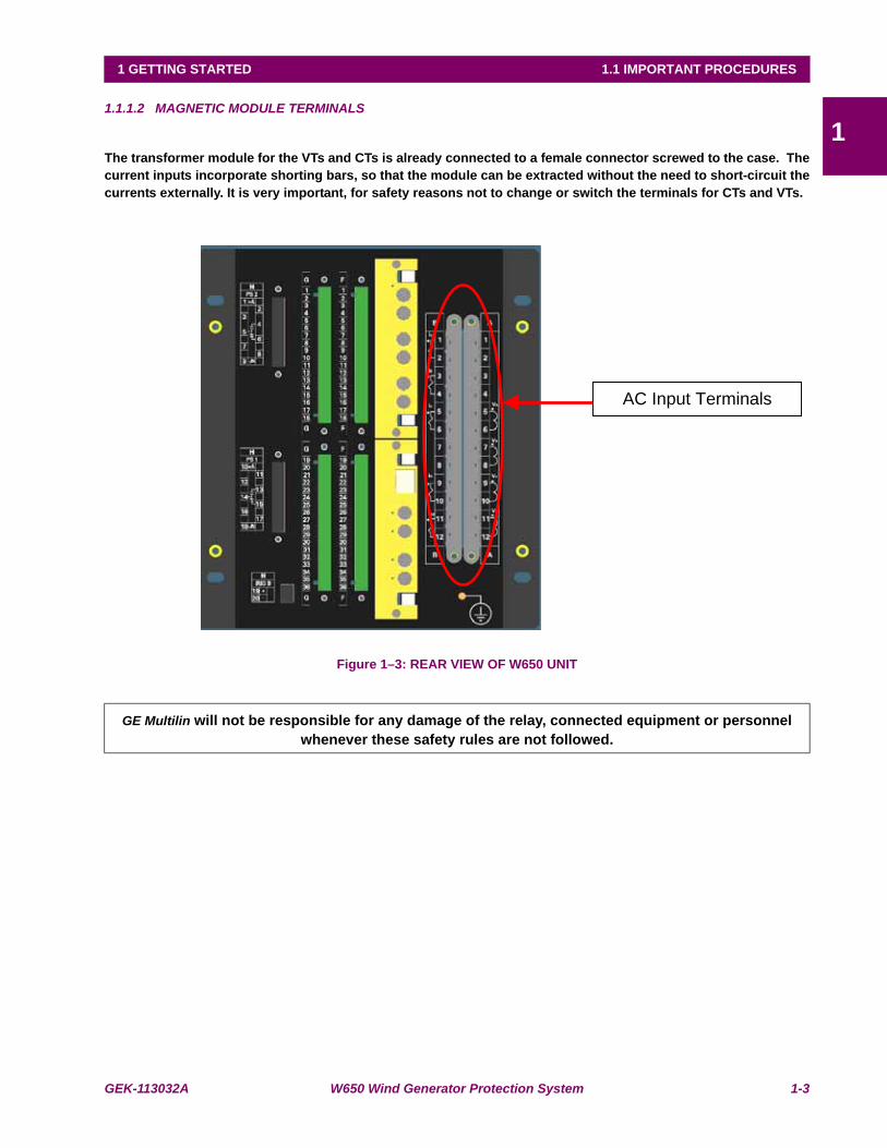
The transformer module for the VTs and CTs is already connected to a female connector screwed to the case. Thecurrent inputs incorporate shorting bars, so that the module can be extracted without the need to short-circuit thecurrents externally. It is very important, for safety reasons not to change or switch the terminals for CTs and VTs.
Figure 1–3: REAR VIEW OF W650 UNIT
GE Multilin will not be responsible for any damage of the relay, connected equipment or personnel whenever these safety rules are not followed.
AC Input Terminals
1-4 W650 Wind Generator Protection System GEK-113032A
1.1 IMPORTANT PROCEDURES 1 GETTING STARTED
11.1.2 INSPECTION CHECKLIST
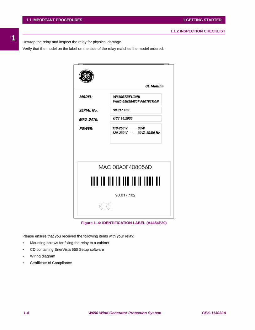
Unwrap the relay and inspect the relay for physical damage.
Verify that the model on the label on the side of the relay matches the model ordered.
Figure 1–4: IDENTIFICATION LABEL (A4454P20)
Please ensure that you received the following items with your relay:
• Mounting screws for fixing the relay to a cabinet
• CD containing EnerVista 650 Setup software
• Wiring diagram
• Certificate of Compliance

GEK-113032A W650 Wind Generator Protection System 1-5
1 GETTING STARTED 1.1 IMPORTANT PROCEDURES
1For product information, instruction manual updates, and the latest software updates, please visit the GE Multilin HomePage www.geindustrial.com/multilin.
Note: If there is any physical damage detected on the relay, or any of the contents listed are missing, pleasecontact GE Multilin immediately at:
EUROPE, MIDDLE EAST AND AFRICA:
GE MULTILIN
Av. Pinoa, 10
48170 Zamudio, Vizcaya (SPAIN)
Tel.: (34) 94-485 88 54, Fax: (34) 94-485 88 38
E-mail: [email protected]
AMERICA, ASIA AND AUSTRALIA:
GE MULTILIN
215, Anderson Avenue
L6E 1B3 Markham, ON (CANADA)
Tel.: +1 905 294 6222, Fax: +1 905 201 2098
E-mail: [email protected]
The information provided herein is not intended to cover all the details of the variations of the equipment, nor doesit take into account the circumstances that may be present in your installation, operating or maintenanceactivities.
Should you wish to receive additional information, or for any particular problem that cannot be solved by referringto the information contained herein, please contact GENERAL ELECTRIC MULTILIN.

1-6 W650 Wind Generator Protection System GEK-113032A
1.1 IMPORTANT PROCEDURES 1 GETTING STARTED
11.1.3 SAFETY INSTRUCTIONS
The W650 ground screw shown in Figure 1–5: must be correctly grounded.
Figure 1–5: LOCATION OF GROUNDING SCREW
Before communicating with a W650 unit through the front serial port, please ensure that the computer is grounded.
In case of using a laptop, it is recommended not to have it connected to its power supply. In many cases it might not becorrectly grounded either due to the power supply or to the connector cables used.
This is required not only for personal protection, but also to avoid a potential voltage difference between therelay’s serial port and the computer’s port, which could produce permanent damage to the computer or the relay.
GE Multilin will not be responsible for any damage to the relay or connected equipment whenever this elementalsafety rule is not followed.

GEK-113032A W650 Wind Generator Protection System 1-7
1 GETTING STARTED 1.2 OVERVIEW
11.2OVERVIEW 1.2.1 INTRODUCTION TO 650 FAMILY OF RELAYS
Historically, substation protection, control and metering functions were performed with electromechanical equipment. Thisfirst generation of equipment was gradually replaced by analog electronic equipment (called static devices), most of whichemulated the single-function approach of their electromechanical precursors. Both of these technologies requiredexpensive cabling and auxiliary equipment to produce functioning systems.
Recently, digital electronic equipment has begun to provide protection, control and metering functions. Initially, thisequipment was either single function or had very limited multi-function capability, and did not significantly reduce thecabling and auxiliary equipment required. However, recent digital relays have become quite multi-functional, reducingcabling and auxiliaries significantly. These devices also transfer data to central control facilities and Human MachineInterfaces using electronic communications. The functions performed by these products have become so broad that manyusers prefer the term IED (Intelligent Electronic Device).
It is obvious to station designers that the amount of cabling and auxiliary equipment installed in stations can be even furtherreduced, to 20% to 70% of the levels common in 1990, to achieve large cost reductions. This requires placing even morefunctions within the IEDs.
Users of power equipment are also interested in reducing cost by improving power quality and personnel productivity, andas always, in increasing system reliability and efficiency. These objectives are realized through software which is used toperform functions at both the station and supervisory levels. The use of these systems is growing rapidly.
High speed communications are required to meet the data transfer rates required by modern automatic control andmonitoring systems. In the near future, very high speed communications will be required to perform protection signalling.This has been established by the IEC 61850 standard.
IEDs with capabilities outlined above will also provided significantly more power system data than is presently available,enhance operations and maintenance, and permit the use of adaptative system configuration for protection and controlsystems. This new generation of equipment must also be easily incorporated into automation systems, at both the stationand enterprise levels.
1.2.2 HARDWARE ARCHITECTURE
650 family of relays has been designed to meet the goals described above that are appearing nowadays in the environmentof new substations.
The 650 is a digital-based device containing a central processing unit (CPU) that handles multiple types of input and outputsignals. The 650 family can communicate over a local area network (LAN) with an operator interface, a programmingdevice, or another 650 or UR device.
The CPU module contains firmware that provides protection elements in the form of logic algorithms, as well asprogramming logic gates, timers, and latches for control features. It incorporates two internal processors, one for genericuse and a second one dedicated for communications.
Input Elements accept a variety of analog or digital signals from the field. The 650 isolates and converts these signals intologic signals used by the relay.
Output Elements convert and isolate the logic signals generated by the relay into digital signals that can be used to controlfield devices.
1-8 W650 Wind Generator Protection System GEK-113032A
1.2 OVERVIEW 1 GETTING STARTED
1
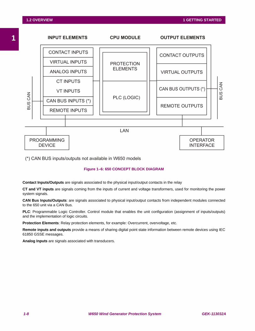
Figure 1–6: 650 CONCEPT BLOCK DIAGRAM
Contact Inputs/Outputs are signals associated to the physical input/output contacts in the relay
CT and VT inputs are signals coming from the inputs of current and voltage transformers, used for monitoring the powersystem signals.
CAN Bus Inputs/Outputs: are signals associated to physical input/output contacts from independent modules connectedto the 650 unit via a CAN Bus.
PLC: Programmable Logic Controller. Control module that enables the unit configuration (assignment of inputs/outputs)and the implementation of logic circuits.
Protection Elements: Relay protection elements, for example: Overcurrent, overvoltage, etc.
Remote inputs and outputs provide a means of sharing digital point state information between remote devices using IEC61850 GSSE messages.
Analog Inputs are signals associated with transducers.

GEK-113032A W650 Wind Generator Protection System 1-9
1 GETTING STARTED 1.2 OVERVIEW
11.2.3 SOFTWARE ARCHITECTURE
The firmware (software embedded in the relay) has been designed using object oriented programming techniques (OOP).These techniques are based on the use of objects and classes, and provide the software architecture with the samecharacteristics as the hardware architecture, i.e., modularity, scalability and flexibility.
1.2.4 COMMUNICATIONS ARCHITECTURE
The main processor performs protection, control, and communication functions, incorporating two internal processors, onefor generic use and a second one dedicated for communications.
A dedicated serial port is used for communication between the main processor and the human-machine interface. Theserial connection provides great immunity against electromagnetic disturbances, thus increasing system safety.
All W650 units incorporate an RS232 serial port on the front of the relay. There is also a possibility to incorporate up to twoadditional communication modules on the rear.
One of the modules provides asynchronous serial communications, using different physical media (RS485, plastic or glassfiber optic) depending on the selected model. The module incorporates two identical ports, COM1 and COM2. The COM2port is multiplexed with the front port.
Available options are:
Table 1–1: REAR SERIAL COMMUNICATIONS BOARD 1
The other module provides Ethernet communications (COM3 port), using 10/100BaseTX (self-negotiable speed) or100BaseFX connectors, depending on the selected model. The most complete models include a double redundant100BaseFX fiber optic port. Redundancy is provided at the physical level; the unit incorporates internally duplicated andindependent controllers for extended system reliability and accessibility.
Available Options are:
Table 1–2: REAR ETHERNET COMMUNICATIONS BOARD 2
For options C and D it is required to select the active physical media, by means of an internal selector inside the module.The factory configuration for this selection is the 10/100BaseTX port.
Finally, internal communication with input and output modules is performed via an internal CAN bus. This fact providesincreased communication speed, as well as the possibility of acknowledgement of modules, abnormalities, etc. As this is aserial port supporting a communications protocol, it provides extraordinary immunity against external or internaldisturbances.
BOARD CODE FUNCTIONALITYF NoneA Redundant RS 485p Redundant plastic fiber opticG Redundant glass fiber opticX Redundant RS485 + Can port (CANopen)Y Redundant plastic fiber optic + Can port (CANopen)Z Redundant glass fiber optic + Can port (CANopen)C CAN port (CANopen)M RS485 + CAN port (CANopen)
BOARD CODE
FUNCTIONALITY
B One 10/100BaseTX port (self-negotiable speed)C One 10/100BaseTX port and one 100BaseFX port.D One 10/100BaseTX port and redundant 100BaseFX portsE Redundant 10/100BaseTX ports

1-10 W650 Wind Generator Protection System GEK-113032A
1.2 OVERVIEW 1 GETTING STARTED
1
Figure 1–7: COMMUNICATIONS ARCHITECTURE (B6816F1)

GEK-113032A W650 Wind Generator Protection System 1-11
1 GETTING STARTED 1.3 ENERVISTA 650 SETUP SOFTWARE
11.3ENERVISTA 650 SETUP SOFTWARE 1.3.1 SYSTEM REQUIREMENTS
The EnerVista 650 Setup software interface is the preferred method to edit settings and view actual values because the PCmonitor can display more information in a simple comprehensible format.
The following minimum requirements must be met for the EnerVista 650 Setup software to properly operate on a PC:
• Pentium® class or higher processor (Pentium® II 300 MHz or higher recommended)
• Windows® NT 4.0 (Service Pack 3 or higher), Windows® 2000, Windows® XP
• Internet Explorer® 5.0 or higher
• 64 MB of RAM (128 MB recommended)
• 40 MB of available space on system drive and 40 MB of available space on installation drive
• RS232C serial and/or Ethernet port for communications to the relay
1.3.2 INSTALLATION
After ensuring the minimum requirements for using EnerVista 650 Setup are met (see previous section), use the followingprocedure to install the EnerVista 650 Setup from the GE EnerVista CD.
1. Insert the GE EnerVista CD into your CD-ROM drive.
2. Click the Install Now button and follow the installation instructions to install the no-charge EnerVista software.
3. When installation is complete, start the EnerVista Launchpad application.
4. Click the IED Setup section of the Launch Pad window.
Figure 1–8: LAUNCHPAD WINDOW
1-12 W650 Wind Generator Protection System GEK-113032A
1.3 ENERVISTA 650 SETUP SOFTWARE 1 GETTING STARTED
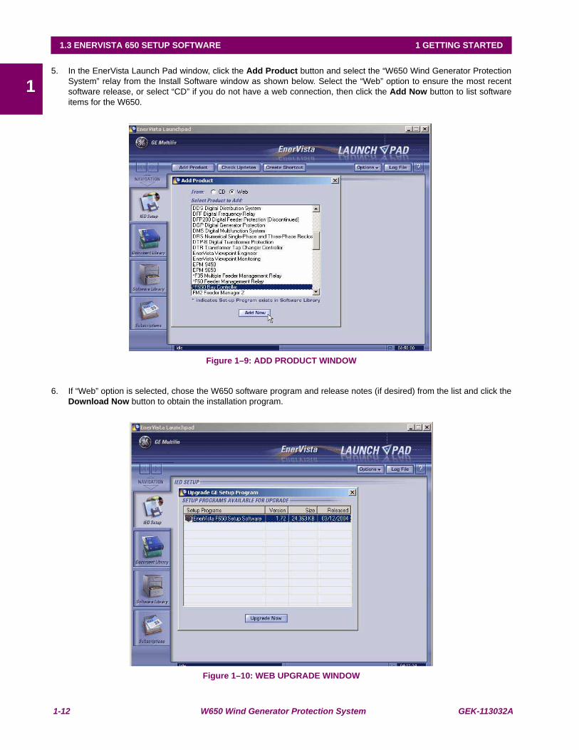
15. In the EnerVista Launch Pad window, click the Add Product button and select the “W650 Wind Generator Protection
System” relay from the Install Software window as shown below. Select the “Web” option to ensure the most recentsoftware release, or select “CD” if you do not have a web connection, then click the Add Now button to list softwareitems for the W650.
Figure 1–9: ADD PRODUCT WINDOW
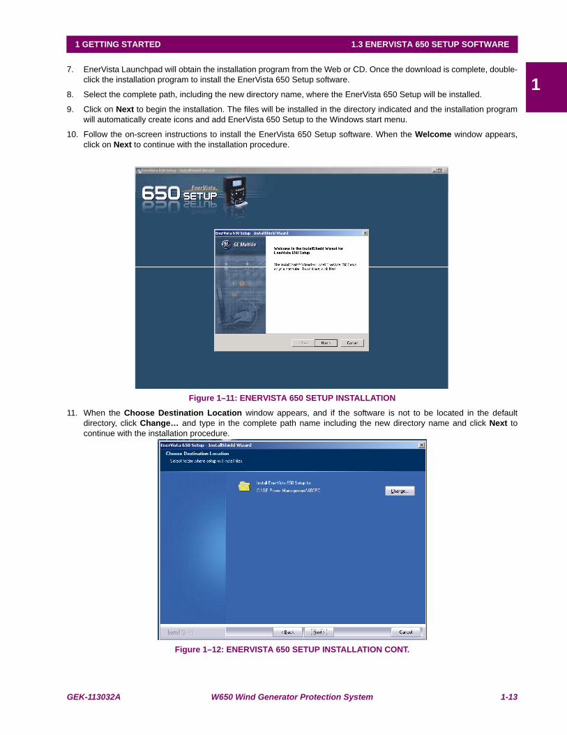
6. If “Web” option is selected, chose the W650 software program and release notes (if desired) from the list and click theDownload Now button to obtain the installation program.
Figure 1–10: WEB UPGRADE WINDOW
GEK-113032A W650 Wind Generator Protection System 1-13
1 GETTING STARTED 1.3 ENERVISTA 650 SETUP SOFTWARE
17. EnerVista Launchpad will obtain the installation program from the Web or CD. Once the download is complete, double-
click the installation program to install the EnerVista 650 Setup software.
8. Select the complete path, including the new directory name, where the EnerVista 650 Setup will be installed.
9. Click on Next to begin the installation. The files will be installed in the directory indicated and the installation programwill automatically create icons and add EnerVista 650 Setup to the Windows start menu.
10. Follow the on-screen instructions to install the EnerVista 650 Setup software. When the Welcome window appears,click on Next to continue with the installation procedure.
Figure 1–11: ENERVISTA 650 SETUP INSTALLATION
11. When the Choose Destination Location window appears, and if the software is not to be located in the defaultdirectory, click Change… and type in the complete path name including the new directory name and click Next tocontinue with the installation procedure.
Figure 1–12: ENERVISTA 650 SETUP INSTALLATION CONT.
1-14 W650 Wind Generator Protection System GEK-113032A
1.3 ENERVISTA 650 SETUP SOFTWARE 1 GETTING STARTED
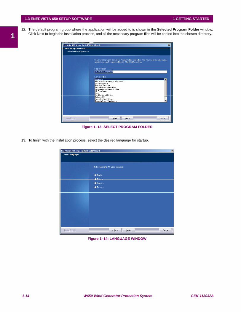
112. The default program group where the application will be added to is shown in the Selected Program Folder window.
Click Next to begin the installation process, and all the necessary program files will be copied into the chosen directory.
Figure 1–13: SELECT PROGRAM FOLDER
13. To finish with the installation process, select the desired language for startup.
Figure 1–14: LANGUAGE WINDOW
GEK-113032A W650 Wind Generator Protection System 1-15
1 GETTING STARTED 1.3 ENERVISTA 650 SETUP SOFTWARE
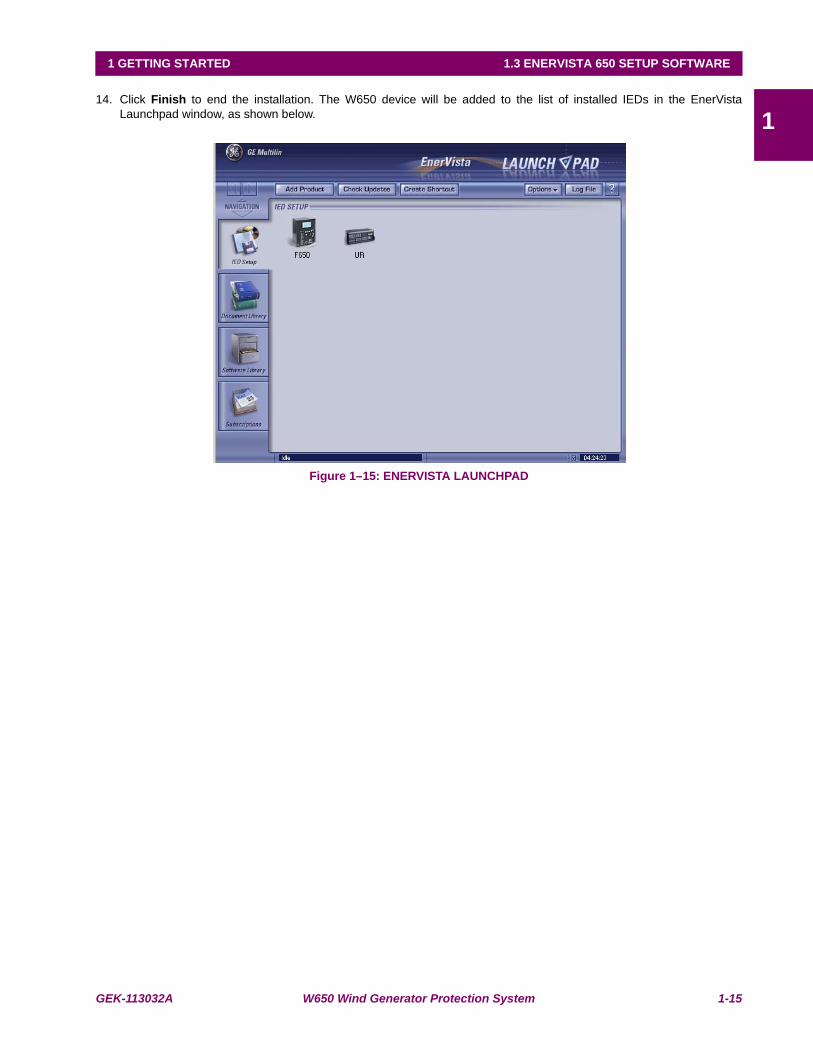
114. Click Finish to end the installation. The W650 device will be added to the list of installed IEDs in the EnerVista
Launchpad window, as shown below.
Figure 1–15: ENERVISTA LAUNCHPAD
1-16 W650 Wind Generator Protection System GEK-113032A
1.3 ENERVISTA 650 SETUP SOFTWARE 1 GETTING STARTED
11.3.3 CONNECTING ENERVISTA 650 SETUP WITHW650
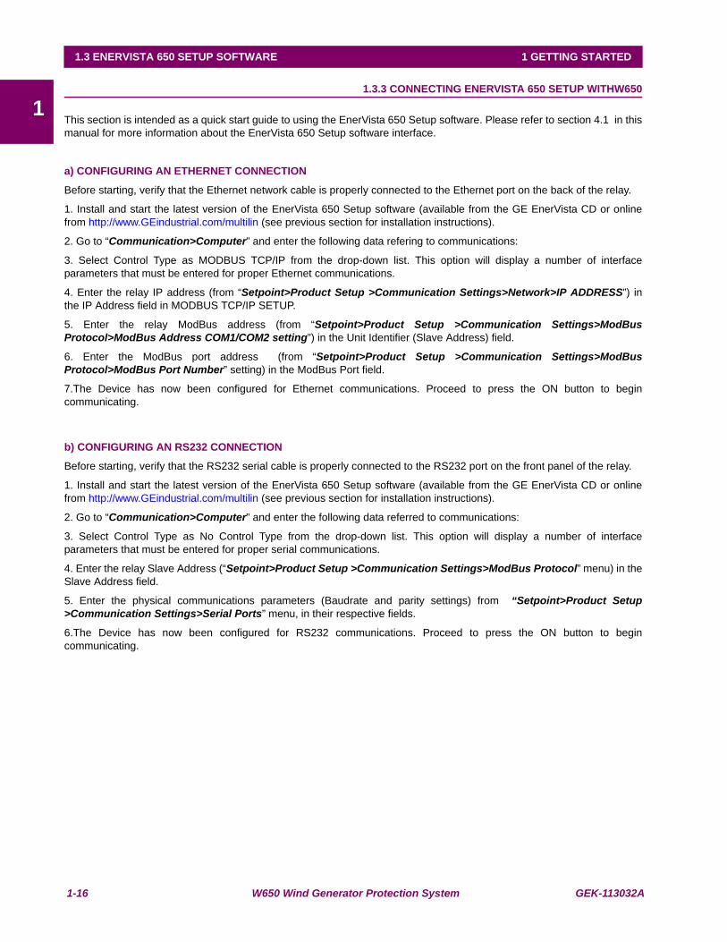
This section is intended as a quick start guide to using the EnerVista 650 Setup software. Please refer to section 4.1 in thismanual for more information about the EnerVista 650 Setup software interface.
a) CONFIGURING AN ETHERNET CONNECTION
Before starting, verify that the Ethernet network cable is properly connected to the Ethernet port on the back of the relay.
1. Install and start the latest version of the EnerVista 650 Setup software (available from the GE EnerVista CD or onlinefrom http://www.GEindustrial.com/multilin (see previous section for installation instructions).
2. Go to “Communication>Computer” and enter the following data refering to communications:
3. Select Control Type as MODBUS TCP/IP from the drop-down list. This option will display a number of interfaceparameters that must be entered for proper Ethernet communications.
4. Enter the relay IP address (from “Setpoint>Product Setup >Communication Settings>Network>IP ADDRESS”) inthe IP Address field in MODBUS TCP/IP SETUP.
5. Enter the relay ModBus address (from “Setpoint>Product Setup >Communication Settings>ModBusProtocol>ModBus Address COM1/COM2 setting”) in the Unit Identifier (Slave Address) field.
6. Enter the ModBus port address (from “Setpoint>Product Setup >Communication Settings>ModBusProtocol>ModBus Port Number” setting) in the ModBus Port field.
7.The Device has now been configured for Ethernet communications. Proceed to press the ON button to begincommunicating.
b) CONFIGURING AN RS232 CONNECTION
Before starting, verify that the RS232 serial cable is properly connected to the RS232 port on the front panel of the relay.
1. Install and start the latest version of the EnerVista 650 Setup software (available from the GE EnerVista CD or onlinefrom http://www.GEindustrial.com/multilin (see previous section for installation instructions).
2. Go to “Communication>Computer” and enter the following data referred to communications:
3. Select Control Type as No Control Type from the drop-down list. This option will display a number of interfaceparameters that must be entered for proper serial communications.
4. Enter the relay Slave Address (“Setpoint>Product Setup >Communication Settings>ModBus Protocol” menu) in theSlave Address field.
5. Enter the physical communications parameters (Baudrate and parity settings) from “Setpoint>Product Setup>Communication Settings>Serial Ports” menu, in their respective fields.
6.The Device has now been configured for RS232 communications. Proceed to press the ON button to begincommunicating.
GEK-113032A W650 Wind Generator Protection System 1-17
1 GETTING STARTED 1.4 W650 HARDWARE
11.4W650 HARDWARE 1.4.1 MOUNTING & WIRING
Please refer to Chapter 3. Hardware for detailed mounting and wiring instructions.
1.4.2 W650 COMMUNICATIONS
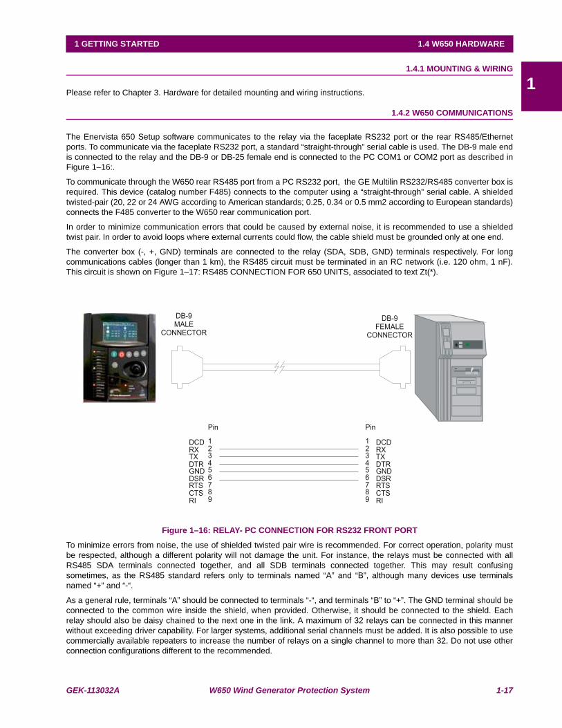
The Enervista 650 Setup software communicates to the relay via the faceplate RS232 port or the rear RS485/Ethernetports. To communicate via the faceplate RS232 port, a standard “straight-through” serial cable is used. The DB-9 male endis connected to the relay and the DB-9 or DB-25 female end is connected to the PC COM1 or COM2 port as described inFigure 1–16:.
To communicate through the W650 rear RS485 port from a PC RS232 port, the GE Multilin RS232/RS485 converter box isrequired. This device (catalog number F485) connects to the computer using a “straight-through” serial cable. A shieldedtwisted-pair (20, 22 or 24 AWG according to American standards; 0.25, 0.34 or 0.5 mm2 according to European standards)connects the F485 converter to the W650 rear communication port.
In order to minimize communication errors that could be caused by external noise, it is recommended to use a shieldedtwist pair. In order to avoid loops where external currents could flow, the cable shield must be grounded only at one end.
The converter box (-, +, GND) terminals are connected to the relay (SDA, SDB, GND) terminals respectively. For longcommunications cables (longer than 1 km), the RS485 circuit must be terminated in an RC network (i.e. 120 ohm, 1 nF).This circuit is shown on Figure 1–17: RS485 CONNECTION FOR 650 UNITS, associated to text Zt(*).
Figure 1–16: RELAY- PC CONNECTION FOR RS232 FRONT PORT
To minimize errors from noise, the use of shielded twisted pair wire is recommended. For correct operation, polarity mustbe respected, although a different polarity will not damage the unit. For instance, the relays must be connected with allRS485 SDA terminals connected together, and all SDB terminals connected together. This may result confusingsometimes, as the RS485 standard refers only to terminals named “A” and “B”, although many devices use terminalsnamed “+” and “-“.
As a general rule, terminals “A” should be connected to terminals “-“, and terminals “B” to “+”. The GND terminal should beconnected to the common wire inside the shield, when provided. Otherwise, it should be connected to the shield. Eachrelay should also be daisy chained to the next one in the link. A maximum of 32 relays can be connected in this mannerwithout exceeding driver capability. For larger systems, additional serial channels must be added. It is also possible to usecommercially available repeaters to increase the number of relays on a single channel to more than 32. Do not use otherconnection configurations different to the recommended.

1-18 W650 Wind Generator Protection System GEK-113032A
1.4 W650 HARDWARE 1 GETTING STARTED
1Lightning strikes and ground surge currents can cause large momentary voltage differences between remote ends of thecommunication link. For this reason, surge protection devices are internally provided. To ensure maximum reliability, allequipment should have similar transient protection devices installed.
Figure 1–17: RS485 CONNECTION FOR 650 UNITS
To comunícate through theW650 rear Ethernet port from a PC a crossover cable is required. If the connection isperformedthrough a hub or a switch, a direct Ethernet cable is required.
1.4.3 FACEPLATE DISPLAY
All messages are displayed on a 20x4 character LCD display. An optional graphic display is also available. Messages aredisplayed in different languages according to selected model.

GEK-113032A W650 Wind Generator Protection System 1-19
1 GETTING STARTED 1.4 W650 HARDWARE
11.4.4 MAINTENANCE
W650 requires a minimum amount of maintenance when it is commissioned into service.W650 is a microprocessor basedrelay and its characteristics do not change over time. As such no further functional tests are required. However, it isrecommended that maintenance on theW650 be scheduled with other system maintenance. The maintenance may involvethe following:
In-service maintenance:
1. Visual verification of the analog values integrity such as voltage and current (in comparison to other devices on thecorresponding system).
2. Visual verification of active alarms, relay display messages and LED indications.
3. Visual inspection for any damage, corrosion, dust or loose wires.
4. Event recorder file download with further event analysis.
Out-of-service maintenance:
1. Check wiring connections for firmness.
2. Analog values (current, voltages, analog inputs) injection test and metering accuracy verification. Calibrated testequipment is required.
3. Protection elements setpoints verification (analog values injection or visual verification of setting file entries againstrelay settings schedule).
4. Contact inputs and outputs verification. This test can be conducted by direct change of state forcing or as part of thesystem functional testing.
5. Visual inspection for any damage, corrosion or dust.
6. Event recorder file download with further events analysis.
Unscheduled maintenance such as during a disturbance causing system interruption:
1. View the event recorder and oscillography or fault report for correct operation of inputs, outputs and elements.
If it is concluded that the relay or one of its modules is of concern, contact GE Multilin or one of its representative for promptservice.

1-20 W650 Wind Generator Protection System GEK-113032A
1.4 W650 HARDWARE 1 GETTING STARTED
1

GEK-113032A W650 Wind Generator Protection System 2-1
2 PRODUCT DESCRIPTION 2.1 OVERVIEW
2
2 PRODUCT DESCRIPTION 2.1OVERVIEW 2.1.1 W650 OVERVIEW
The modular W650 unit has been designed as a comprehensive generator controller specially adapted to wind turbinegenerators. Based on the state of the art 650 family, it utilizes modern 32 bit processor platform to provide a completesolution not only for the needs of present systems but also ready for the future. W650 simplifies the design of systems inwind turbine generation due to the complete set of protection, measurement, control and recording functions. Maintenanceis eased thanks to the modular design whereas cost is scalable depending on the options to allow a cost effective solutionfrom medium to large size generators.
The main features of W650 devices include:
• Directional overcurrent protection for phases, neutral, ground and sensitive ground
• High Speed Under and overvoltage protection
• Neutral Overvoltage
• Voltage Unbalance
• Under and overfrequency protection
• Autorecloser
• Metering
• Oscillography registers, fault reports, data logger
• Bay control (open/close commands, etc.)
• Bay mimic.
• Communications (RS232/RS485/CAN/Ethernet)
2-2 W650 Wind Generator Protection System GEK-113032A
2.1 OVERVIEW 2 PRODUCT DESCRIPTION
2
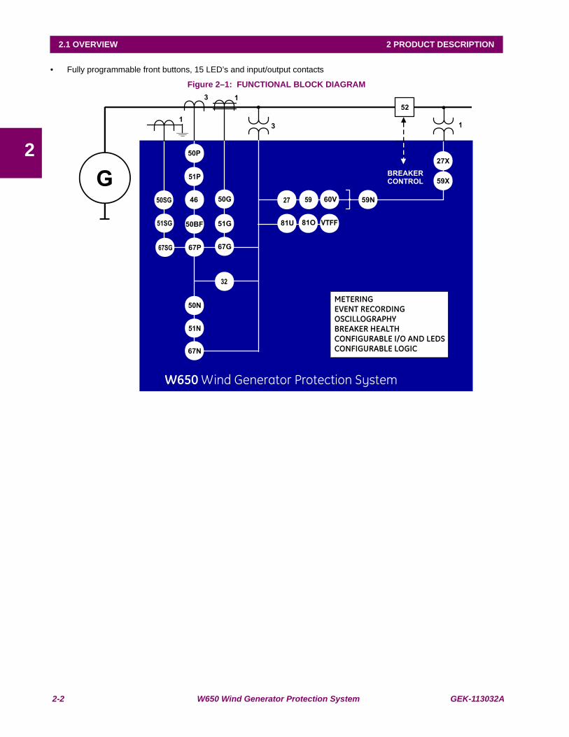
• Fully programmable front buttons, 15 LED’s and input/output contacts
Figure 2–1: FUNCTIONAL BLOCK DIAGRAM
GEK-113032A W650 Wind Generator Protection System 2-3
2 PRODUCT DESCRIPTION 2.2 SUMMARY
2
2.2SUMMARY
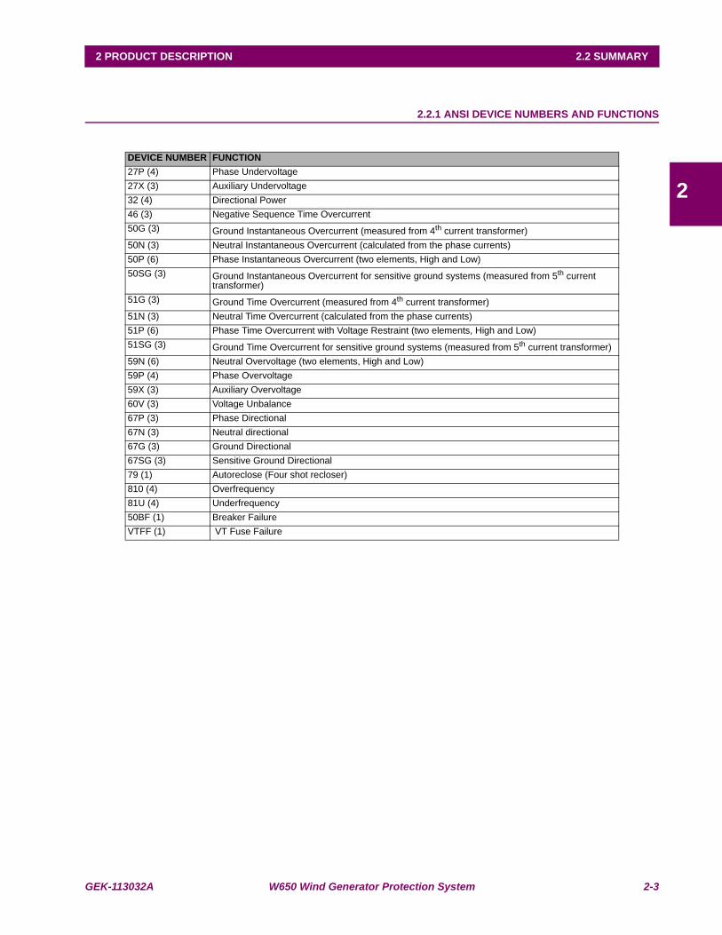
2.2.1 ANSI DEVICE NUMBERS AND FUNCTIONS
DEVICE NUMBER FUNCTION27P (4) Phase Undervoltage27X (3) Auxiliary Undervoltage32 (4) Directional Power46 (3) Negative Sequence Time Overcurrent50G (3) Ground Instantaneous Overcurrent (measured from 4th current transformer)50N (3) Neutral Instantaneous Overcurrent (calculated from the phase currents)50P (6) Phase Instantaneous Overcurrent (two elements, High and Low)50SG (3) Ground Instantaneous Overcurrent for sensitive ground systems (measured from 5th current
transformer)51G (3) Ground Time Overcurrent (measured from 4th current transformer)51N (3) Neutral Time Overcurrent (calculated from the phase currents)51P (6) Phase Time Overcurrent with Voltage Restraint (two elements, High and Low)51SG (3) Ground Time Overcurrent for sensitive ground systems (measured from 5th current transformer)59N (6) Neutral Overvoltage (two elements, High and Low)59P (4) Phase Overvoltage59X (3) Auxiliary Overvoltage60V (3) Voltage Unbalance67P (3) Phase Directional67N (3) Neutral directional67G (3) Ground Directional67SG (3) Sensitive Ground Directional79 (1) Autoreclose (Four shot recloser)810 (4) Overfrequency81U (4) Underfrequency50BF (1) Breaker FailureVTFF (1) VT Fuse Failure
2-4 W650 Wind Generator Protection System GEK-113032A
2.2 SUMMARY 2 PRODUCT DESCRIPTION
2
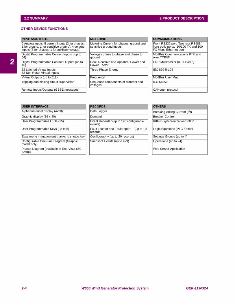
OTHER DEVICE FUNCTIONS
INPUTS/OUTPUTS METERING COMMUNICATIONS9 Analog Inputs: 5 current inputs (3 for phases, 1 for ground, 1 for sensitive ground), 4 voltage inputs (3 for phases, 1 for auxiliary voltage)
Metering Current for phases, ground and sensitive ground inputs
Front RS232 port, Two rear RS485/fibre optic ports, 10/100 TX and 100 FX Mbps Ethernet port
Digital Programmable Contact Inputs (up to 64)
Voltages phase to phase and phase to ground
ModBus Communications RTU and over TCP/IP
Digital Programmable Contact Outputs (up to 16)
Real, Reactive and Apparent Power and Power Factor
DNP Multimaster (3.0 Level 2)
32 Latched Virtual Inputs32 Self-Reset Virtual Inputs
Three Phase Energy IEC 870-5-104
Virtual Outputs (up to 512) Frequency ModBus User MapTripping and closing circuit supervision Sequence components of currents and
voltagesIEC 61850
Remote Inputs/Outputs (GSSE messages) CANopen protocol
USER INTERFACE RECORDS OTHERSAlphanumerical display (4x20) Data Logger Breaking Arcing Current (I2t)Graphic display (16 x 40) Demand Breaker ControlUser Programmable LEDs (15) Event Recorder (up to 128 configurable
events)IRIG-B synchronization/SNTP
User Programmable Keys (up to 5) Fault Locator and Fault report (up to 10 records)
Logic Equations (PLC Editor)
Easy menu management thanks to shuttle key Oscillography (up to 20 records) Settings Groups (up to 4)Configurable One-Line Diagram (Graphic model only)
Snapshot Events (up to 479) Operations (up to 24)
Phasor Diagram (available in EnerVista 650 Setup)
Web Server Application

GEK-113032A W650 Wind Generator Protection System 2-5
2 PRODUCT DESCRIPTION 2.3 ORDERING CODE
2
2.3ORDERING CODE
W650 units are supplied as ½ 19” rack, 6 units high, containing the following modules: power supply, CPU, I/O modules,communication modules. The required information to completely define an W650 model is shown on Table 2–1:
Table 2–1: ORDERING CODE
Notes:(1) The digit selected for option G must be equal or higher than the digit selected for option F: W650***F1G5*****: is a valid selection W650***F5G1*****: is an invalid selection
As exceptions to this rule, 0 is always available for option G, and F2G1 is also a valid selection.
W650 - - - F - G - - - - - DESCRIPTIONB Basic display (4x20 characters)M Graphic display (240x128 pixels)
REAR SERIAL COMMUNICATIONS BOARD 1F NoneA Redundant RS485 P Redundant plastic fiber optic G Redundant glass fiber opticX Redundant RS485 + fiber Can port (CANopen)Y Redundant plastic fiber optic + fiber Can port (CANopen)Z Redundant glass fiber optic + fiber Can port (CANopen)C CableCan port (CANopen)M Cable can port (CANopen)+RS485
REAR ETHERNET COMMUNICATIONS BOARD 2 B 10/100 Base TXC 10/100 Base TX + 100 Base FXD 10/100 Base TX + Redundant 100 Base FXE Redundant 10/100 Base TX
I/O BOARD IN SLOT F1 16 Digital Inputs + 8 Outputs2 8 Digital Inputs + 8 Outputs + 2 trip/close circuit supervision
circuits4 32 Digital Inputs5 16 Digital Inputs + 8 Analog Inputs
I/O BOARD IN SLOT G0 None1 16 Digital Inputs + 8 Outputs4 32 Digital Inputs (see Note 1)5 16 Digital Inputs + 8 Analog Inputs (See Note 1)
AUXILIARY VOLTAGELO 24-48 Vdc (range 19.2 – 57.6)HI 110-250 Vdc (range 88 – 300)
120-230 Vac (range 96 – 250)LOR Redundant LO HIR Redundant HI
COMMUNICATION PROTOCOL- Without IEC 61850 protocol6 IEC 61850
ENVIRONMENTAL PROTECTION- Without Harsh (Chemical) Environment Conformal CoatingH Harsh (Chemical) Environment Conformal Coating

2-6 W650 Wind Generator Protection System GEK-113032A
2.4 TECHNICAL SPECIFICATIONS 2 PRODUCT DESCRIPTION
2
2.4TECHNICAL SPECIFICATIONS
NOTE: TECHNICAL SPECIFICATIONS ARE SUBJECT TO CHANGE WITHOUT NOTICE
2.4.1 PROTECTION ELEMENTS
Phase and ground units use as operation magnitude the current value received by the unit in current inputs, while theneutral unit uses the calculated current value from the three phase currents.
The isolated ground unit will be used only for those applications where the neutral is completely isolated, and it uses thefifth CT of the unit. This CT has a sensitivity that is 10 times higher than the universal model (connected to 1A or 5Atransformers). Therefore, it does not admit such a high permanent overload.
2.4.1.1 PHASE TIME OVERCURRENT (51PH/51PL)
2.4.1.2 GROUND TIME OVERCURRENT (51G)
Current Input Phasor (without harmonics) or RMSRated current For connection to 1 or 5 A CTs.Pickup level 0.05 to 160.00 A in steps of 0.01 ADropout level 98% of the pickup levelLevel Accuracy ±0.5% of the reading ± 10 mA from 0.05 to 10 A
±1.5% of the reading for higher values.Curve Shapes IEEE extremely / very / moderately inverse
IEC A/B/C/long-time inverse/short time inverse curveIAC extremely / very / normally / moderately inverseANSI extremely / very / normally / moderately inverseI2tDefinite timeRectifier curveFlexCurve™ A/B/C/D user curve
Curve Multiplier (Time Dial) 0.00 to 900.00 s in steps of 0.01 sReset type Instantaneous or time delayed according to IEEETiming accuracy Operate at > 1.03 times the pickup ±3% of operate time or
30 ms. (whichever is greater)Voltage restraint Selectable by setting Saturation Level 48 times the pickup levelSnapshot Events Selectable by setting
Current Input Phasor (without harmonics) or RMSRated current For connection to 1 or 5 A CTs.Pickup level 0.05 to 160.00 A in steps of 0.01 ADropout level 98% of the pickup levelLevel Accuracy ±0.5% of the reading ± 10 mA from 0.05 to 10 A
±1.5% of the reading for higher values.

GEK-113032A W650 Wind Generator Protection System 2-7
2 PRODUCT DESCRIPTION 2.4 TECHNICAL SPECIFICATIONS
2
2.4.1.3 NEUTRAL TIME OVERCURRENT (51N)
Curve Shapes IEEE extremely / very / moderately inverse IEC A/B/C/long-time inverse/short time inverse curveIAC extremely / very / normally / moderately inverseANSI extremely / very / normally / moderately inverseI2tDefinite timeRectifier curveFlexCurve™ A/B/C/D user curve
Curve Multiplier (Time Dial) 0.00 to 900.00 s in steps of 0.01 sReset type Instantaneous or time delayed according to IEEETiming accuracy Operate at > 1.03 times the pickup ±3% of operate time or
30 ms. (whichever is greater)Saturation Level 48 times the pickup levelSnapshot Events Selectable by setting
Current Input Fundamental Phasor (without harmonics)Pickup level 0.05 to 160.00 A in steps of 0.01 ADropout level 98% of the pickup levelLevel Accuracy ±0.5% of the reading ± 10 mA from 0.05 to 10 A
±1.5% of the reading for higher values.Curve Shapes IEEE extremely / very / moderately inverse
IEC A/B/C/long-time inverse/short time inverse curveIAC extremely / very / normally / moderately inverseANSI extremely / very / normally / moderately inverseI2tDefinite timeRectifier curveFlexCurve™ A/B/C/D user curve
Curve Multiplier (Time Dial) 0.00 to 900.00 s in steps of 0.01 sReset type Instantaneous or time delayed according to IEEETiming accuracy Operate at > 1.03 times the pickup ±3% of operate time
or 30 ms. (whichever is greater)Saturation Level 48 times the pickup levelSnapshot Events Selectable by setting
2-8 W650 Wind Generator Protection System GEK-113032A
2.4 TECHNICAL SPECIFICATIONS 2 PRODUCT DESCRIPTION
2
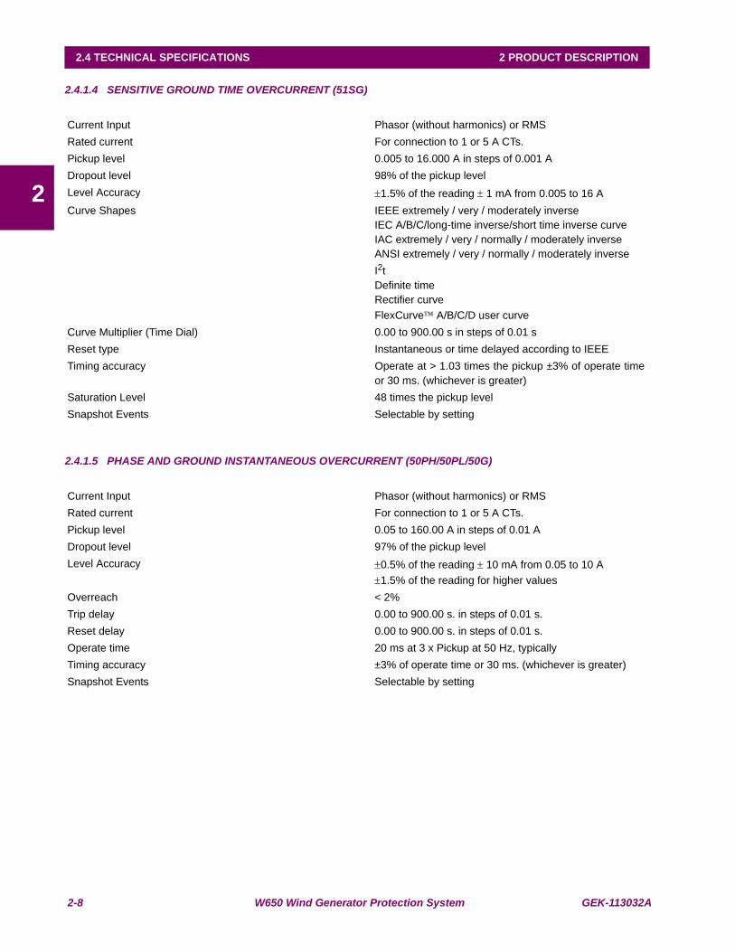
2.4.1.4 SENSITIVE GROUND TIME OVERCURRENT (51SG)
2.4.1.5 PHASE AND GROUND INSTANTANEOUS OVERCURRENT (50PH/50PL/50G)
Current Input Phasor (without harmonics) or RMSRated current For connection to 1 or 5 A CTs.Pickup level 0.005 to 16.000 A in steps of 0.001 ADropout level 98% of the pickup levelLevel Accuracy ±1.5% of the reading ± 1 mA from 0.005 to 16 ACurve Shapes IEEE extremely / very / moderately inverse
IEC A/B/C/long-time inverse/short time inverse curveIAC extremely / very / normally / moderately inverseANSI extremely / very / normally / moderately inverseI2tDefinite timeRectifier curveFlexCurve™ A/B/C/D user curve
Curve Multiplier (Time Dial) 0.00 to 900.00 s in steps of 0.01 sReset type Instantaneous or time delayed according to IEEETiming accuracy Operate at > 1.03 times the pickup ±3% of operate time
or 30 ms. (whichever is greater)Saturation Level 48 times the pickup levelSnapshot Events Selectable by setting
Current Input Phasor (without harmonics) or RMSRated current For connection to 1 or 5 A CTs.Pickup level 0.05 to 160.00 A in steps of 0.01 ADropout level 97% of the pickup levelLevel Accuracy ±0.5% of the reading ± 10 mA from 0.05 to 10 A
±1.5% of the reading for higher valuesOverreach < 2%Trip delay 0.00 to 900.00 s. in steps of 0.01 s.Reset delay 0.00 to 900.00 s. in steps of 0.01 s.Operate time 20 ms at 3 x Pickup at 50 Hz, typicallyTiming accuracy ±3% of operate time or 30 ms. (whichever is greater)Snapshot Events Selectable by setting

GEK-113032A W650 Wind Generator Protection System 2-9
2 PRODUCT DESCRIPTION 2.4 TECHNICAL SPECIFICATIONS
2
2.4.1.6 NEUTRAL INSTANTANEOUS OVERCURRENT (50N)
2.4.1.7 SENSITIVE GROUND INSTANTANEOUS OVERCURRENT (50SG)
Current Input Fundamental Phasor (without harmonics)Pickup level 0.05 to 160.00 A in steps of 0.01 ADropout level 97% of the pickup levelLevel Accuracy ±0.5% of the reading ± 10 mA from 0.05 to 10 A
±1.5% of the reading for higher valuesOverreach < 2%Trip delay 0.00 to 900.00 s. in steps of 0.01 s.Reset delay 0.00 to 900.00 s. in steps of 0.01 s.Operate time 20 ms at 3 x Pickup at 50 Hz, typicallyTiming accuracy ±3% of operate time or 30 ms. (whichever is greater)Snapshot Events Selectable by setting
Current Input Phasor (without harmonics) or RMSRated current For connection to 1 or 5 A CTs.Pickup level 0.005 to 16.000 A in steps of 0.001 ADropout level 97% of the pickup levelLevel Accuracy ±1.5% of the reading ± 1 mA from 0.005 to 16 AOverreach < 2%Trip delay 0.00 to 900.00 s. in steps of 0.01 s.Reset delay 0.00 to 900.00 s. in steps of 0.01 s.Operate time 20 ms at 3 x Pickup at 50 HzTiming accuracy ±3% of operate time or 30 ms. (whichever is greater)Snapshot Events Selectable by setting

2-10 W650 Wind Generator Protection System GEK-113032A
2.4 TECHNICAL SPECIFICATIONS 2 PRODUCT DESCRIPTION
2
2.4.1.8 NEGATIVE SEQUENCE CURRENT (46)
2.4.1.9 PHASE DIRECTIONAL (67P)
2.4.1.10 GROUND DIRECTIONAL (67G)
Current Input Fundamental Phasor (without harmonics)Pickup level 0.05 to 160.0 A in steps of 0.01 ADropout level 98% of the pickup levelLevel Accuracy ±0.5% of the reading ± 10 mA from 0.05 to 10 A
±1.5% of the reading for higher valuesCurve Shapes IEEE extremely / very / moderately inverse
IEC A/B/C/long-time inverse/short time inverse curveIAC extremely / very / normally / moderately inverseANSI extremely / very / normally / moderately inverseI2tDefinite timeRectifier curveFlexCurve™ A/B/C/D user curve
Curve Multiplier (Time Dial) 0.00 to 900.00 s in steps of 0.01 sReset type Instantaneous or time delayed according to IEEETiming accuracy Operate at > 1.03 times the pickup ±3% of operate time
or 30 ms. (whichever is greater)Saturation Level 48 times the pickup levelSnapshot Events Selectable by setting
Directionality Forward and reverse selectable by settingPolarizing Quadrature Voltage:
ABC seq: Phase A (VBC), Phase B (VCA), Phase C (VAB)ACB seq: Phase A (VCB), Phase B (VAC), Phase C (VBA)
Polarizing voltage threshold 0 to 850 Vac in steps of 1 VCharacteristic angle -90º to +90º in steps of 1ºBlock Logic Permission or Block selectable by settingAngle accuracy ±2º for I>0.1 A and V>5 VacOperate time <30ms, typically
Directionality Forward and reverse selectable by settingPolarizing Voltage, current, dualPolarizing Voltage VN (measured or calculated, selected by setting)
Polarizing Current Isg (measured from 5th current transformer)Operating Current Ig (measured from 4th current transformer)Polarizing Voltage threshold 0 to 500 Vac in steps of 1 VPolarizing Current threshold 0.005 A

GEK-113032A W650 Wind Generator Protection System 2-11
2 PRODUCT DESCRIPTION 2.4 TECHNICAL SPECIFICATIONS
22.4.1.11 NEUTRAL DIRECTIONAL (67N)
2.4.1.12 SENSITIVE GROUND DIRECTIONAL (67SG)
2.4.1.13 PHASE OVERVOLTAGE (59P)
Characteristic angle -90º to +90º in steps of 1ºBlock Logic Permission or Block selectable by settingAngle accuracy ±2º for I>0.1 A and V>5 VacOperate time <30ms, typically
Directionality Forward and reverse selectable by settingPolarizing Voltage, current, dualPolarizing Voltage VN (measured or calculated, selected by setting)
Polarizing Current Isg (measured from 5th current transformer)Operating Current INPolarizing Voltage threshold 0 to 500 Vac in steps of 1 VPolarizing Current threshold 0.005 ACharacteristic angle -90º to +90º in steps of 1ºBlock Logic Permission or Block selectable by settingAngle accuracy ±2º for I>0.1 A and V>5 VacOperate time <30ms, typically
Directionality Forward and reverse selectable by settingPolarizing VoltagePolarizing Voltage VN (measured or calculated, selected by setting)
Operating Current Isg (measured from 5th current transformer)Polarizing Voltage threshold 0 to 500 Vac in steps of 1 VCharacteristic angle -90º to +90º in steps of 1ºBlock Logic Permission or Block selectable by settingAngle accuracy ±2º for I>0.1 A and V>5 VacOperate time <30ms, typically
Voltage Input Fundamental Phasor (without harmonics) of phase-to-phase voltages
Pickup level 3 to 850 in steps of 1 VDropout level 97% of the pickup levelLevel Accuracy ±1% reading ±0.1% Full Scale from 10 to 500 VTrip delay 0.00 to 900.00 s. in steps of 0.01 s.Reset delay 0.00 to 900.00 s. in steps of 0.01 s.Timing accuracy ±3.5% of operate time or 30 ms. (whichever is greater)Logic Any/Two/All phases logic selectable by setting
2-12 W650 Wind Generator Protection System GEK-113032A
2.4 TECHNICAL SPECIFICATIONS 2 PRODUCT DESCRIPTION
2
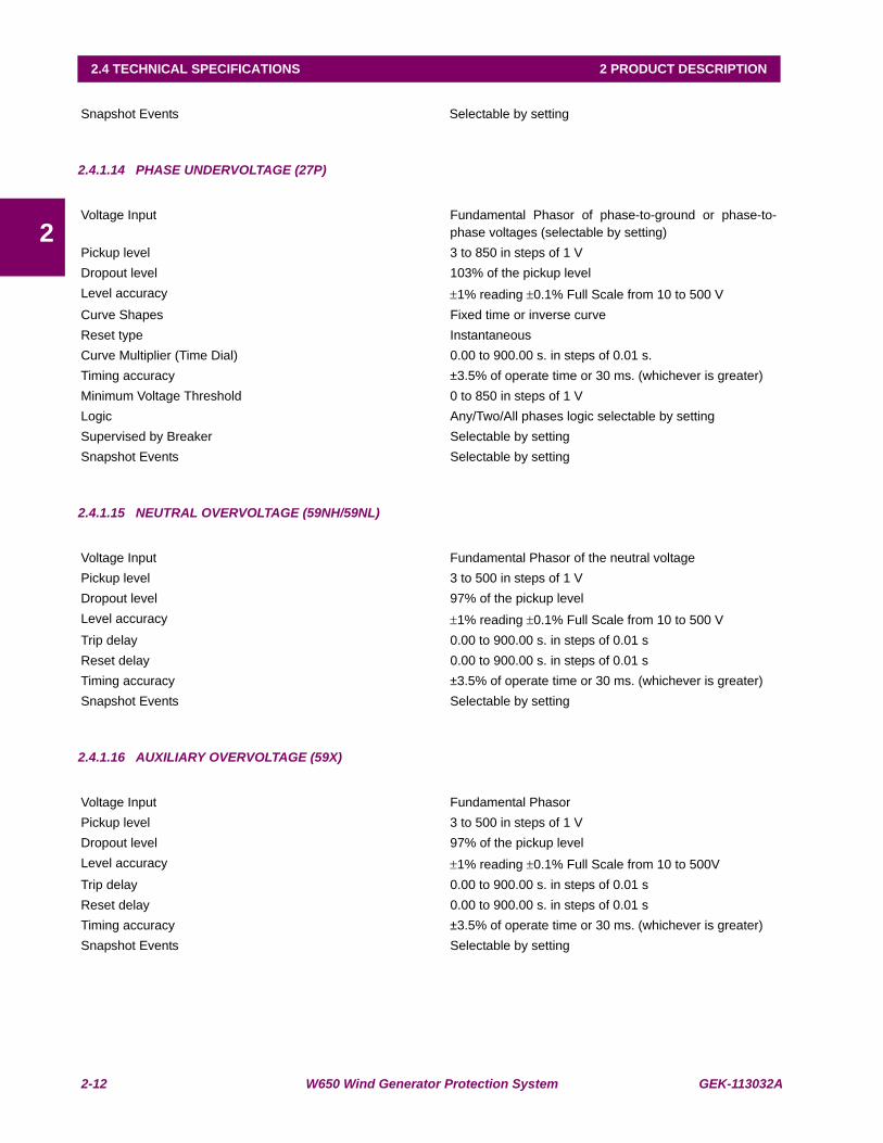
2.4.1.14 PHASE UNDERVOLTAGE (27P)
2.4.1.15 NEUTRAL OVERVOLTAGE (59NH/59NL)
2.4.1.16 AUXILIARY OVERVOLTAGE (59X)
Snapshot Events Selectable by setting
Voltage Input Fundamental Phasor of phase-to-ground or phase-to-phase voltages (selectable by setting)
Pickup level 3 to 850 in steps of 1 VDropout level 103% of the pickup levelLevel accuracy ±1% reading ±0.1% Full Scale from 10 to 500 VCurve Shapes Fixed time or inverse curveReset type Instantaneous Curve Multiplier (Time Dial) 0.00 to 900.00 s. in steps of 0.01 s.Timing accuracy ±3.5% of operate time or 30 ms. (whichever is greater)Minimum Voltage Threshold 0 to 850 in steps of 1 VLogic Any/Two/All phases logic selectable by settingSupervised by Breaker Selectable by settingSnapshot Events Selectable by setting
Voltage Input Fundamental Phasor of the neutral voltagePickup level 3 to 500 in steps of 1 VDropout level 97% of the pickup levelLevel accuracy ±1% reading ±0.1% Full Scale from 10 to 500 VTrip delay 0.00 to 900.00 s. in steps of 0.01 sReset delay 0.00 to 900.00 s. in steps of 0.01 sTiming accuracy ±3.5% of operate time or 30 ms. (whichever is greater)Snapshot Events Selectable by setting
Voltage Input Fundamental PhasorPickup level 3 to 500 in steps of 1 VDropout level 97% of the pickup levelLevel accuracy ±1% reading ±0.1% Full Scale from 10 to 500VTrip delay 0.00 to 900.00 s. in steps of 0.01 sReset delay 0.00 to 900.00 s. in steps of 0.01 sTiming accuracy ±3.5% of operate time or 30 ms. (whichever is greater)Snapshot Events Selectable by setting

GEK-113032A W650 Wind Generator Protection System 2-13
2 PRODUCT DESCRIPTION 2.4 TECHNICAL SPECIFICATIONS
2
2.4.1.17 AUXILIARY UNDERVOLTAGE (27X)
2.4.1.18 UNDERFREQUENCY (81U)
2.4.1.19 OVERFREQUENCY (81O)
2.4.1.20 DIRECTIONAL POWER (32)
Voltage Input Fundamental PhasorPickup level 3 to 500 V in steps of 1 VDropout level 97% of the pickup levelLevel accuracy ±1% reading ±0.1% Full Scale from 10 to 500 VCurve Shapes Fixed time or inverse curveReset type Instantaneous Curve Multiplier (Time Dial) 0.00 to 900.00 s. in steps of 0.01 sTiming accuracy ±3.5% of operate time or 30 ms. (whichever is greater)Snapshot Events Selectable by setting
Pickup level 20.00 to 65.00 Hz in steps of 0.01 HzDropout level Pickup + 0.03 HzLevel accuracy ±0.01 Hz of the readingTrip delay 0.00 to 900.00 s. in steps of 0.01 sReset delay 0.00 to 900.00 s. in steps of 0.01 sMinimum voltage threshold 30 to 500V in steps of 1 VTiming accuracy ±3.5% of operate time or 100 ms. (whichever is greater)Snapshot Events Selectable by setting
Pickup level 20.00 to 65.00 Hz in steps of 0.01 HzDropout level Pickup - 0.03 HzLevel accuracy ±0.01 Hz of the readingTrip delay 0.00 to 900.00 s. in steps of 0.01 sReset delay 0.00 to 900.00 s. in steps of 0.01 sMinimum voltage threshold 30 to 500V in steps of 1 VTiming accuracy ±3.5% of operate time or 100 ms. (whichever is greater)Snapshot Events Selectable by setting
Current, Voltage Fundamental Phasor (primary values)Number of stages 2Pickup level (two stages) -10000.00 to 10000.00 MW (primary values) in steps of
0.01 MWCharacteristic Angle (two stages) 0.00 to 359.99 in steps of 0.01Dropout level 97% of the pickup levelAccuracy for primary magnitudes ±3% complete rangeTrip delay (two stages) 0.00 to 900.00 s in steps of 0.01 s
2-14 W650 Wind Generator Protection System GEK-113032A
2.4 TECHNICAL SPECIFICATIONS 2 PRODUCT DESCRIPTION
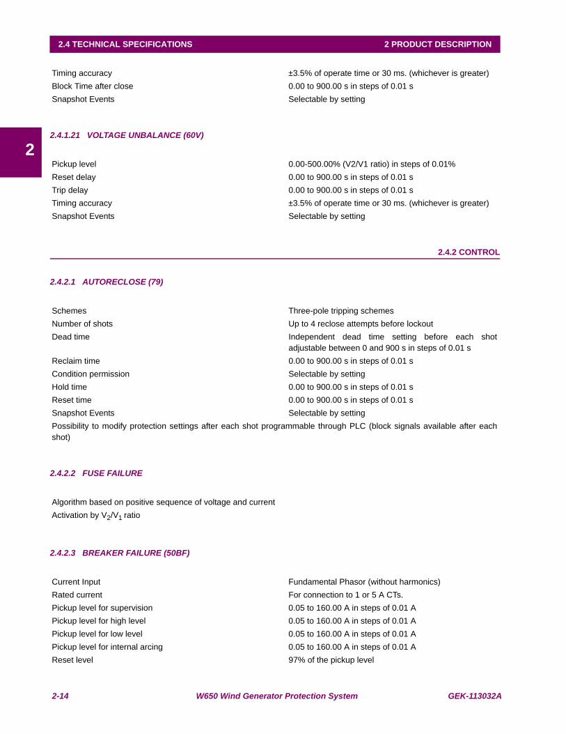
22.4.1.21 VOLTAGE UNBALANCE (60V)
2.4.2 CONTROL
2.4.2.1 AUTORECLOSE (79)
2.4.2.2 FUSE FAILURE
2.4.2.3 BREAKER FAILURE (50BF)
Timing accuracy ±3.5% of operate time or 30 ms. (whichever is greater)Block Time after close 0.00 to 900.00 s in steps of 0.01 sSnapshot Events Selectable by setting
Pickup level 0.00-500.00% (V2/V1 ratio) in steps of 0.01% Reset delay 0.00 to 900.00 s in steps of 0.01 sTrip delay 0.00 to 900.00 s in steps of 0.01 sTiming accuracy ±3.5% of operate time or 30 ms. (whichever is greater)Snapshot Events Selectable by setting
Schemes Three-pole tripping schemesNumber of shots Up to 4 reclose attempts before lockoutDead time Independent dead time setting before each shot
adjustable between 0 and 900 s in steps of 0.01 sReclaim time 0.00 to 900.00 s in steps of 0.01 sCondition permission Selectable by settingHold time 0.00 to 900.00 s in steps of 0.01 sReset time 0.00 to 900.00 s in steps of 0.01 sSnapshot Events Selectable by settingPossibility to modify protection settings after each shot programmable through PLC (block signals available after eachshot)
Algorithm based on positive sequence of voltage and currentActivation by V2/V1 ratio
Current Input Fundamental Phasor (without harmonics)Rated current For connection to 1 or 5 A CTs.Pickup level for supervision 0.05 to 160.00 A in steps of 0.01 APickup level for high level 0.05 to 160.00 A in steps of 0.01 APickup level for low level 0.05 to 160.00 A in steps of 0.01 APickup level for internal arcing 0.05 to 160.00 A in steps of 0.01 AReset level 97% of the pickup level

GEK-113032A W650 Wind Generator Protection System 2-15
2 PRODUCT DESCRIPTION 2.4 TECHNICAL SPECIFICATIONS
22.4.2.4 BREAKER SETTINGS
2.4.2.5 BREAKER MAINTENANCE
2.4.2.6 SWITCHGEAR
2.4.3 MONITORING
2.4.3.1 OSCILLOGRAPHY
Level Accuracy ±0.5% of the reading ± 10 mA from 0.05 to 10 A±1.5% of the reading for higher values.
Timing accuracy ±3.5% of operate time or 30 ms. (whichever is greater)Snapshot Events Selectable by setting
Number of Switchgear 1 to 16 (selection of switchgear for breaker control)
Maximum KI2t 0.00 to 9999.99 in steps of 0.01 (kA)2 s
KI2t integration Time 0.03 to 0.25 s in steps of 0.01 s
Maximum openings 0 to 9999 in steps of 1Maximum Openings in one hour 1 to 60 in steps of 1Snapshot Events Selectable by setting
KI2t Breaker Counters for Phases A, B, C 0.00 to 9999.99 in steps of 0.01 (kA)2 sBreaker Openings Counter 0 to 9999 in steps of 1Breaker Closings Counter 0 to 9999 in steps of 1
Switchgear 1 to16 (configurable in “relay configuration” screen).Snapshot Events Selectable by setting (for each switchgear in “system
setup”)
Maximum Records: Up to 20 Oscillography records.Sampling rate: Programmable to 4, 8, 16, 32 or 64 samples per power cycleCapacity per record: 27592 samples
No of Oscillos * No of samples/cycleTrigger position: 5% to 95% of total lengthTrigger: Programmable via PLCData: 5 current channels and 4 voltage channels
Up to 16 digital channels programmable through PLC
Data Storage: In non volatile memory (flash) without batteryFormat: International Standard COMTRADE ASCII - IEEE C37.111-1999.Automatic Overwrite: Selectable by setting. (Oscillography records can be concatenated)Snapshot Events: Selectable by setting
2-16 W650 Wind Generator Protection System GEK-113032A
2.4 TECHNICAL SPECIFICATIONS 2 PRODUCT DESCRIPTION
2
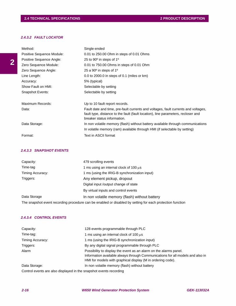
2.4.3.2 FAULT LOCATOR
2.4.3.3 SNAPSHOT EVENTS
2.4.3.4 CONTROL EVENTS
Method: Single-endedPositive Sequence Module: 0.01 to 250.00 Ohm in steps of 0.01 OhmsPositive Sequence Angle: 25 to 90º in steps of 1ºZero Sequence Module: 0.01 to 750.00 Ohms in steps of 0.01 OhmZero Sequence Angle: 25 a 90º in steps of 1ºLine Length: 0.0 to 2000.0 in steps of 0.1 (miles or km)Accuracy: 5% (typical)Show Fault on HMI: Selectable by settingSnapshot Events: Selectable by setting
Maximum Records: Up to 10 fault report records.Data: Fault date and time, pre-fault currents and voltages, fault currents and voltages,
fault type, distance to the fault (fault location), line parameters, recloser and breaker status information.
Data Storage: In non volatile memory (flash) without battery available through communicationsIn volatile memory (ram) available through HMI (if selectable by setting)
Format: Text in ASCII format
Capacity: 479 scrolling eventsTime-tag 1 ms using an internal clock of 100 μsTiming Accuracy: 1 ms (using the IRIG-B synchronization input)Triggers: Any element pickup, dropout
Digital input /output change of state
By virtual inputs and control events
Data Storage In non volatile memory (flash) without batteryThe snapshot event recording procedure can be enabled or disabled by setting for each protection function
Capacity: 128 events programmable through PLCTime-tag: 1 ms using an internal clock of 100 μsTiming Accuracy: 1 ms (using the IRIG-B synchronization input)Triggers: By any digital signal programmable through PLC Alarm Possibility to display the event as an alarm on the alarms panel.
Information available always through Communications for all models and also in HMI for models with graphical display (M in ordering code).
Data Storage: In non volatile memory (flash) without batteryControl events are also displayed in the snapshot events recording

GEK-113032A W650 Wind Generator Protection System 2-17
2 PRODUCT DESCRIPTION 2.4 TECHNICAL SPECIFICATIONS
2
2.4.3.5 DEMAND
2.4.3.6 DATA LOGGER
2.4.4 USER –PROGRAMABLE ELEMENTS
2.4.4.1 PLC LOGIC
2.4.4.2 FLEXCURVES
Channels: 9Parameters: Ia (kA RMS), Ib (kA RMS), Ic (kA RMS), Ig (kA RMS), Isg (kA RMS), I2 (kA), P
(MW), Q (MVAr) and S (MVA)Current and Power Method Thermal Exponential, Block Interval, Rolling DemandMeasurements: Each channel shows the present and maximum measured value, with date and
time for the maximum recorded value. Samples: 5, 10, 15, 20, 30, 60 minutes.Accuracy: ±1%Trigger Input Selectable by setting (operation mode selection for the Block Interval calculation
method)Snapshot Events: Selectable by setting
Number of Channels: 1 to 16Parameters Any available analog actual valueSamples 1 sec., 1, 5, 10, 15, 20, 30, 60 min.Storage Capacity Fixed, 32768 measures
Programming language: The logical configuration is performed using graphical functions based on the IEC 61131-3 standard.
Lines of code: 512Supported operations: NOT, XOR, OR (2 to 8 inputs), AND (2 to 8 inputs), NOR (2 to 8 inputs),
NAND (2 to 8 inputs), Latch (Reset Dominant), Edge Detectors, Timers.2 inputs default gates, from 3 to 8 inputs provided in library format.
Libraries: Logical gates fully programmable by user. To create user-programmable logic tobe distributed as a single object.
Inputs: Any logical variable, contact or virtual inputNumber of timers: 8 maximum in each logic scheme (provided in library format)
Number: 4 (A through D)Reset points: 40 (0 through 1 of pickup)Operate points: 80 (1 through 20 of pickup)Time delay: 0 to 65535 ms in steps of 1Saturation Level 20 times the pickup level

2-18 W650 Wind Generator Protection System GEK-113032A
2.4 TECHNICAL SPECIFICATIONS 2 PRODUCT DESCRIPTION
2
2.4.4.3 USER-PROGRAMMABLE LEDS
2.4.4.4 USER-DEFINABLE DISPLAYS
2.4.4.5 USER-PROGRAMMABLE FRONT KEYS
2.4.5 METERING
2.4.5.1 CURRENT
2.4.5.2 VOLTAGE
2.4.5.3 REAL POWER (WATTS)
2.4.5.4 REACTIVE POWER (VARS)
Number: 15 configurable LEDs plus a ready non configurable LEDProgrammability: from any logical variable, contact, or virtual inputReset mode: Self-reset or Latched.
The first 5 LED’s are latched by hardware (red color ones), usually configured for trip signals.The following 10 ones (yellow and green) are self-reset but can be latched through PLC configuration.
Reset Signal: The LED’s can be reset by hardware, pressing the front “esc” key during more than 3 seconds or using the LED reset signal through PLC configuration.
Number of configurable displays: 1 (one line diagram fully configurable). In graphical displays onlyNumber of fixed displays: 6, Metering (in primary values), Snapshot events (all and new), Alarms, Inputs
and outputs screen with test functionality for inputs and outputs. In graphical displays only
Number of selectable displays: Logotype, metering or both in scrolling mode, can be selectable as default screen in text display for all models (basic and mimic). The metering screen contains current and voltages for phases and ground in primary values.
Number of configurable Keys: 5Operation: drive PLC operands
Accuracy: ±0.5% of the reading ± 10 mA from 0.05 to 10 A (for phases and ground)
±1.5% of the reading ± 1 mA from 0.005 to 5 A (for sensitive ground)
±1.5% of the reading for higher values
Accuracy: ±1% reading ±0.1% Full Scale from 10 to 500 V
Accuracy: ±1% of the reading at-0.8 < PF = -1 and 0.8 <PF=1
Accuracy: ±1% of the reading at-0.2 = PF = 0.2
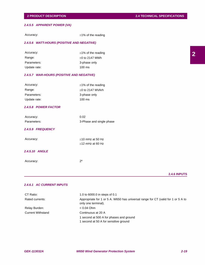
GEK-113032A W650 Wind Generator Protection System 2-19
2 PRODUCT DESCRIPTION 2.4 TECHNICAL SPECIFICATIONS
2
2.4.5.5 APPARENT POWER (VA)
2.4.5.6 WATT-HOURS (POSITIVE AND NEGATIVE)
2.4.5.7 WAR-HOURS (POSITIVE AND NEGATIVE)
2.4.5.8 POWER FACTOR
2.4.5.9 FREQUENCY
2.4.5.10 ANGLE
2.4.6 INPUTS
2.4.6.1 AC CURRENT INPUTS
Accuracy: ±1% of the reading
Accuracy: ±1% of the readingRange: ±0 to 2147 MWhParameters: 3-phase onlyUpdate rate: 100 ms
Accuracy: ±1% of the readingRange: ±0 to 2147 MVArhParameters: 3-phase onlyUpdate rate: 100 ms
Accuracy: 0.02Parameters: 3-Phase and single phase
Accuracy: ±10 mHz at 50 Hz ±12 mHz at 60 Hz
Accuracy: 2º
CT Ratio: 1.0 to 6000.0 in steps of 0.1Rated currents: Appropriate for 1 or 5 A. W650 has universal range for CT (valid for 1 or 5 A to
only one terminal).Relay Burden: < 0.04 OhmCurrent Withstand Continuous at 20 A
1 second at 500 A for phases and ground1 second at 50 A for sensitive ground

2-20 W650 Wind Generator Protection System GEK-113032A
2.4 TECHNICAL SPECIFICATIONS 2 PRODUCT DESCRIPTION
2
2.4.6.2 AC VOLTAGE INPUTS
2.4.6.3 CONTACT INPUTS
2.4.6.4 REMOTE INPUTS
2.4.6.5 ANALOG INPUTS
VT Ratio 1.0 to 1500.0 in steps of 0.1Rated Voltages 500 VacMetering range: From 2 to 500 VacRelay Burden: 0.05 VA at 120 Vac (50 or 60 Hz)Voltage Withstand: Continuous at 500 V to neutral
1 min/hr at 800 to neutral
VAC inputs do not need varistors, as the impulse test is applied to 100% of the transformers
Input Activation Voltage Threshold: 1 to 230 Vdc in steps of 1 V (selectable by setting)Impedance: > 100 kOhmMaximum error: ±10% setting ± 2.5 VLoad for voltage supervision inputs: 2 mA + V/100 kOhmVoltage threshold for voltage supervision inputs
< 10 V (fixed)
Debounce Time: 1 to 50 in steps of 1 msRecognition time: < 1msTiming resolution: 1 msFor Input Activation Voltage Threshold and Debounce Time there is a single setting for all inputs in the samegroup (inputs sharing the same common).Input Type and Delay Input Time are not grouped; there is a different setting for each input.Input Type Positive-Edge / Negative-Edge / Positive/ NegativeDelay Input Time 0 to 60000 ms in steps of 1 ms (Input signal time delay)
Number of input points: 32, configured from 64 incoming bit pointsNumber of remote devices: 16
Default states on loss of comms: On, Off, Latest/on, Latest/off
Current Input (mADC): 0 to -1; 0 to +1; -1 to +1; 0 to 5; 0 to 10; 0 to 20; 4 to 20 (programmable)Conversion Range: -1 to +20mA
Accuracy: +/- 0.2% of full scaleType: Passive

GEK-113032A W650 Wind Generator Protection System 2-21
2 PRODUCT DESCRIPTION 2.4 TECHNICAL SPECIFICATIONS
2
2.4.6.6 IRIG-B INPUT
2.4.7 REAL TIME CLOCK
2.4.8 OUTPUTS
Amplitude modulation: DC SHIFT = Demodulated input (no carrier)
Input Voltage: TTL
Input Burden: 1.5 mAInput Impedance: 3.3 kOhmMinimum Input Voltage: 2.4 VMaximum Input Voltage: +/- 24 VFormats: B000 (*) B001, B002 and B003 (*)
(*) Signal combinations recognized in accordance with IRIG Standard 200-95Isolation: 2 kV
Accuracy: Typical ±20 ppmBackup energy: More than 1 week
Carry continuous: 16 AMake and Carry for 1 sec 60 ABreak at L/R of 40 ms: 0.3 A DC max. at 125 Vdc
0.25 A DC max. at 250 VdcOperate Time: < 8 msContact material: Silver Alloy
Output Logic Type, Output Type and Pulse Output Time are selectable by setting for each outputOutput Logic Type Positive / NegativeOutput Type Normal / Pulse / Latch (Selectable by setting for each output)Pulse Output Time 0 to 60000 ms in steps of 1 ms (applicable only to signals set as pulse type)Separate operate and reset signal can be configured by any digital signal programmable through PLC
Contact Outputs (F31-F33, F34-F36) for board type 2 (supervision) in slot F:
The current seal-in circuit is used for verifying the current condition in a circuitduring the time that the tripping contact remains closed. If the current in thetripping circuit is maintained over 100 mA, the function is sealed independently ofthe status of the function that caused the trip.
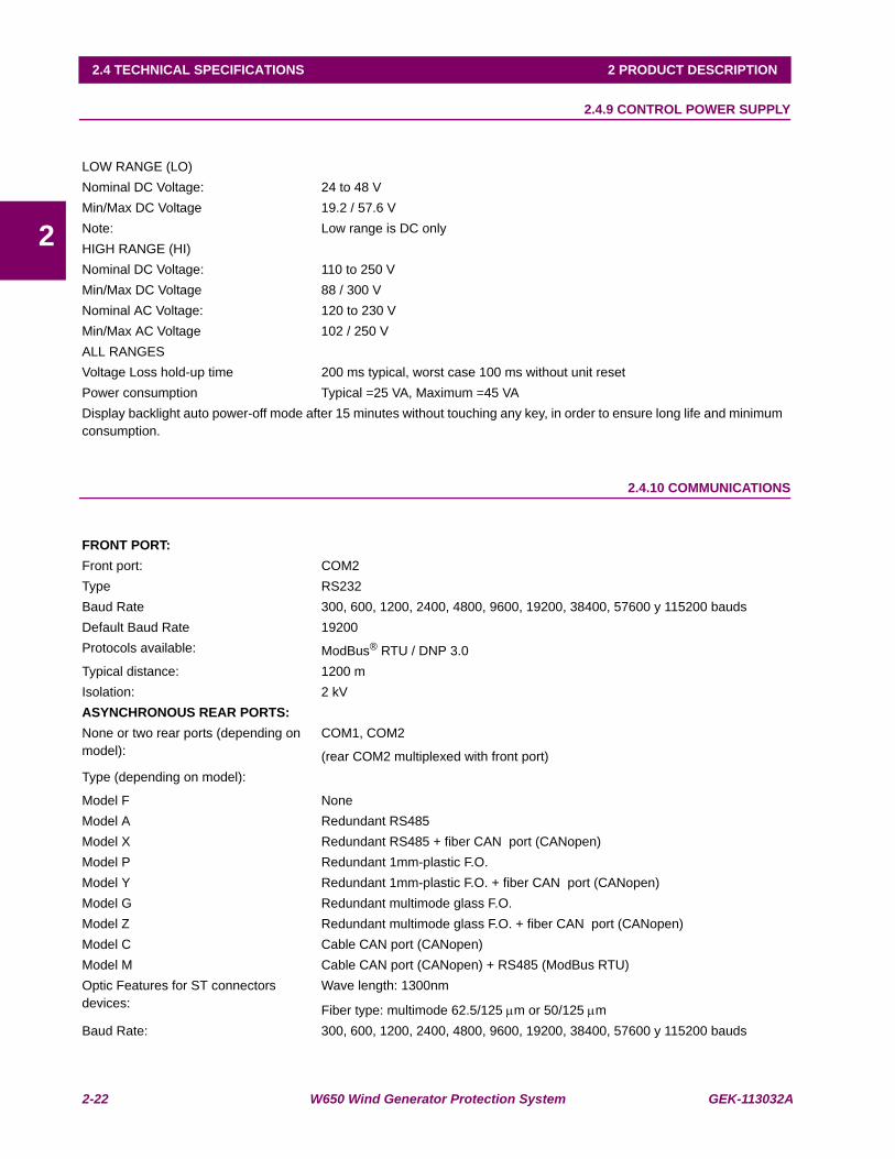
2-22 W650 Wind Generator Protection System GEK-113032A
2.4 TECHNICAL SPECIFICATIONS 2 PRODUCT DESCRIPTION
2
2.4.9 CONTROL POWER SUPPLY
2.4.10 COMMUNICATIONS
LOW RANGE (LO)Nominal DC Voltage: 24 to 48 VMin/Max DC Voltage 19.2 / 57.6 VNote: Low range is DC onlyHIGH RANGE (HI)Nominal DC Voltage: 110 to 250 VMin/Max DC Voltage 88 / 300 VNominal AC Voltage: 120 to 230 VMin/Max AC Voltage 102 / 250 VALL RANGESVoltage Loss hold-up time 200 ms typical, worst case 100 ms without unit resetPower consumption Typical =25 VA, Maximum =45 VADisplay backlight auto power-off mode after 15 minutes without touching any key, in order to ensure long life and minimum consumption.
FRONT PORT:Front port: COM2Type RS232Baud Rate 300, 600, 1200, 2400, 4800, 9600, 19200, 38400, 57600 y 115200 baudsDefault Baud Rate 19200Protocols available: ModBus® RTU / DNP 3.0Typical distance: 1200 mIsolation: 2 kVASYNCHRONOUS REAR PORTS:None or two rear ports (depending on model):
COM1, COM2
(rear COM2 multiplexed with front port)Type (depending on model):
Model F NoneModel A Redundant RS485Model X Redundant RS485 + fiber CAN port (CANopen)Model P Redundant 1mm-plastic F.O.Model Y Redundant 1mm-plastic F.O. + fiber CAN port (CANopen)Model G Redundant multimode glass F.O. Model Z Redundant multimode glass F.O. + fiber CAN port (CANopen)Model C Cable CAN port (CANopen)Model M Cable CAN port (CANopen) + RS485 (ModBus RTU)Optic Features for ST connectors devices:
Wave length: 1300nm
Fiber type: multimode 62.5/125 μm or 50/125 μmBaud Rate: 300, 600, 1200, 2400, 4800, 9600, 19200, 38400, 57600 y 115200 bauds

GEK-113032A W650 Wind Generator Protection System 2-23
2 PRODUCT DESCRIPTION 2.4 TECHNICAL SPECIFICATIONS
2
Default Baud Rate 19200Protocols available: ModBus® RTU / DNP 3.0Typical distance: 1200 mIsolation: dc kV1CAN PORT: Rear port: Fiber CAN port in models X, Y, Z and cable CAN port in models C and M for
rear board 1Physical Layer: ISO11898, High speedBaud rate: 125 / 500 kbaudFiber Type: Multimode glass F.O. port with ST connectorsFiber Wave length: 1300 nmFiber type: multimode 62.5/125 μm or 50/125 μmMaximum recommended length 1km (fiber); 500m (cable)Isolation: 2 kVETHERNET PORT:Rear port: COM3Type (depending on model):
Model B: 10/100BaseTX self-negotiableModel C: 10/100BaseTX + 100Base FX Model D: 10/100BaseTX + redundant 100BaseFX (Physical media redundancy)Model E: Redundant 10/100BaseTX self-negotiable ports10/100BaseTX RJ45 connector100BaseFX ST connectorsWave length: 1300 nmFiber type: multimode 62.5/125 μm or 50/125 μmProtocols available: ModBus® TCP/IP
DNP over TCP/IP and UDP/IP
IEC 61850
Http, ftp, tftp (allow the use of a standard Internet browser)Typical distance: 1.65 kmResponse time to ModBus commands: 10 ms TypicalIsolation: 2 kVIn Models C and D, the 10/100BaseTX port is selected by an internal switch (see 3.3.3)Two witness LED’s for transmission and reception are included
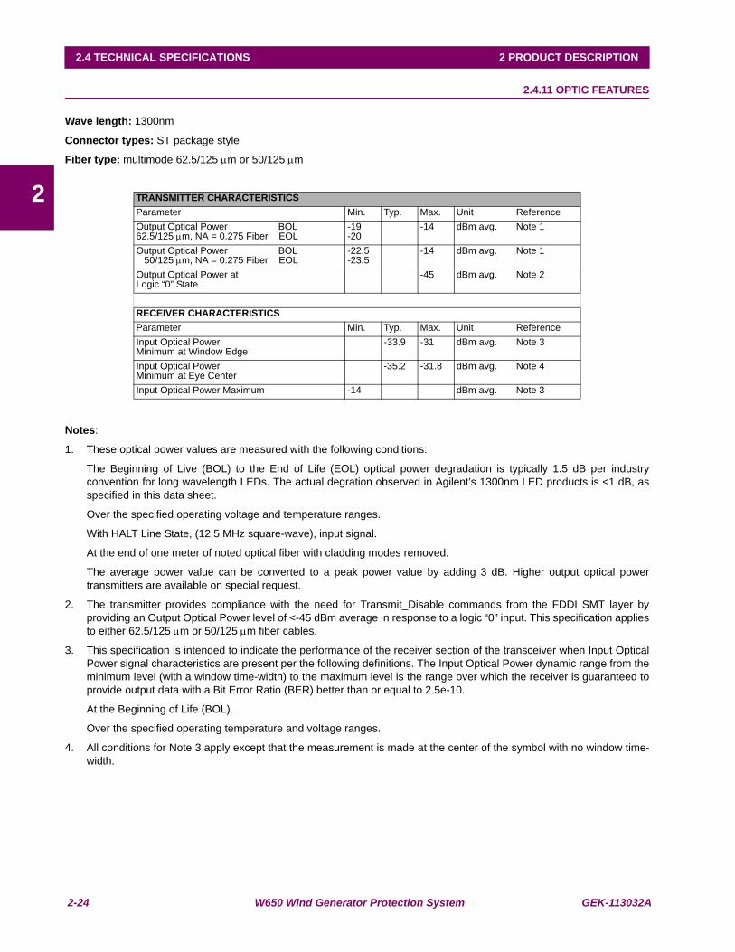
2-24 W650 Wind Generator Protection System GEK-113032A
2.4 TECHNICAL SPECIFICATIONS 2 PRODUCT DESCRIPTION
2
2.4.11 OPTIC FEATURES
Wave length: 1300nm
Connector types: ST package style
Fiber type: multimode 62.5/125 μm or 50/125 μm
Notes:
1. These optical power values are measured with the following conditions:
The Beginning of Live (BOL) to the End of Life (EOL) optical power degradation is typically 1.5 dB per industryconvention for long wavelength LEDs. The actual degration observed in Agilent’s 1300nm LED products is <1 dB, asspecified in this data sheet.
Over the specified operating voltage and temperature ranges.
With HALT Line State, (12.5 MHz square-wave), input signal.
At the end of one meter of noted optical fiber with cladding modes removed.
The average power value can be converted to a peak power value by adding 3 dB. Higher output optical powertransmitters are available on special request.
2. The transmitter provides compliance with the need for Transmit_Disable commands from the FDDI SMT layer byproviding an Output Optical Power level of <-45 dBm average in response to a logic “0” input. This specification appliesto either 62.5/125 μm or 50/125 μm fiber cables.
3. This specification is intended to indicate the performance of the receiver section of the transceiver when Input OpticalPower signal characteristics are present per the following definitions. The Input Optical Power dynamic range from theminimum level (with a window time-width) to the maximum level is the range over which the receiver is guaranteed toprovide output data with a Bit Error Ratio (BER) better than or equal to 2.5e-10.
At the Beginning of Life (BOL).
Over the specified operating temperature and voltage ranges.
4. All conditions for Note 3 apply except that the measurement is made at the center of the symbol with no window time-width.
TRANSMITTER CHARACTERISTICSParameter Min. Typ. Max. Unit ReferenceOutput Optical Power BOL62.5/125 μm, NA = 0.275 Fiber EOL
-19-20
-14 dBm avg. Note 1
Output Optical Power BOL 50/125 μm, NA = 0.275 Fiber EOL
-22.5-23.5
-14 dBm avg. Note 1
Output Optical Power atLogic “0” State
-45 dBm avg. Note 2
RECEIVER CHARACTERISTICSParameter Min. Typ. Max. Unit ReferenceInput Optical PowerMinimum at Window Edge
-33.9 -31 dBm avg. Note 3
Input Optical PowerMinimum at Eye Center
-35.2 -31.8 dBm avg. Note 4
Input Optical Power Maximum -14 dBm avg. Note 3
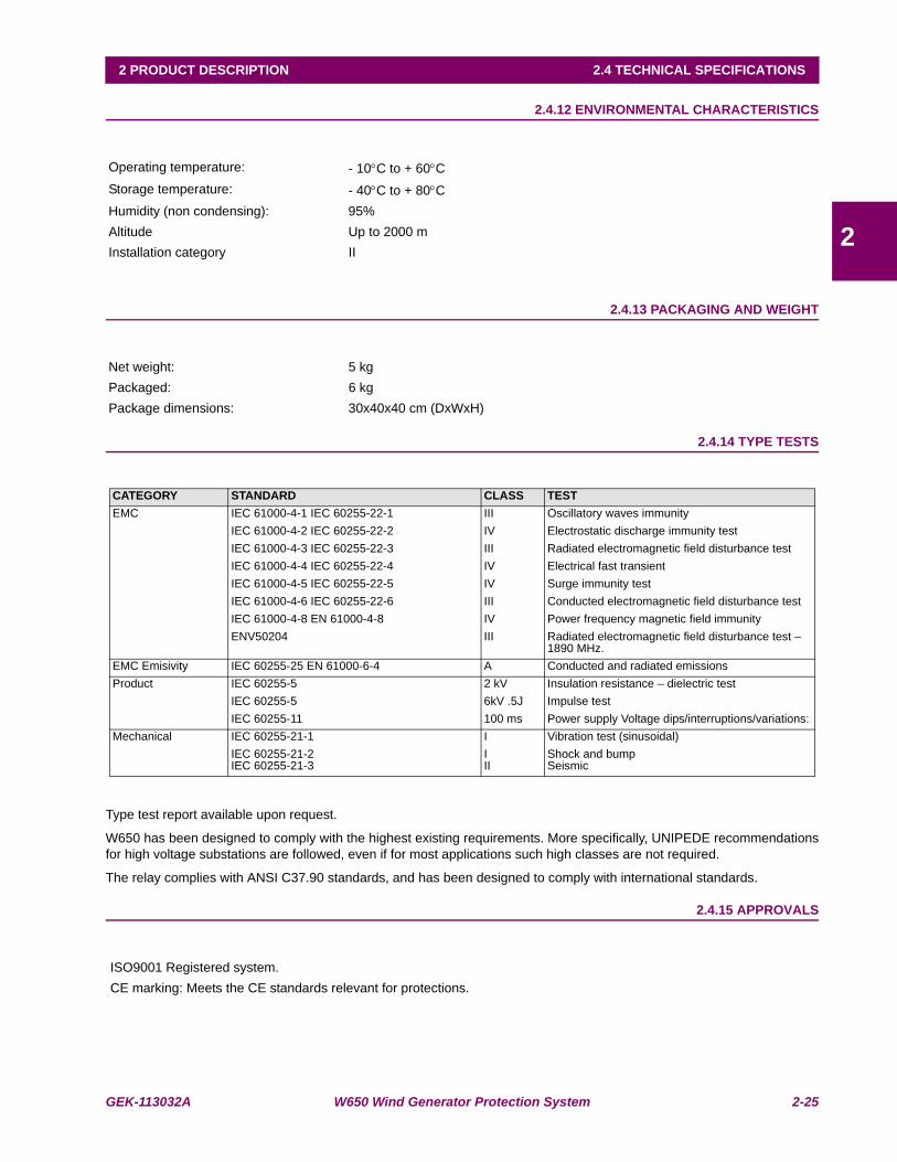
GEK-113032A W650 Wind Generator Protection System 2-25
2 PRODUCT DESCRIPTION 2.4 TECHNICAL SPECIFICATIONS
2
2.4.12 ENVIRONMENTAL CHARACTERISTICS
2.4.13 PACKAGING AND WEIGHT
2.4.14 TYPE TESTS
Type test report available upon request.
W650 has been designed to comply with the highest existing requirements. More specifically, UNIPEDE recommendationsfor high voltage substations are followed, even if for most applications such high classes are not required.
The relay complies with ANSI C37.90 standards, and has been designed to comply with international standards.
2.4.15 APPROVALS
Operating temperature: - 10°C to + 60°CStorage temperature: - 40°C to + 80°CHumidity (non condensing): 95%Altitude Up to 2000 mInstallation category II
Net weight: 5 kgPackaged: 6 kgPackage dimensions: 30x40x40 cm (DxWxH)
CATEGORY STANDARD CLASS TESTEMC IEC 61000-4-1 IEC 60255-22-1 III Oscillatory waves immunity
IEC 61000-4-2 IEC 60255-22-2 IV Electrostatic discharge immunity testIEC 61000-4-3 IEC 60255-22-3 III Radiated electromagnetic field disturbance testIEC 61000-4-4 IEC 60255-22-4 IV Electrical fast transientIEC 61000-4-5 IEC 60255-22-5 IV Surge immunity testIEC 61000-4-6 IEC 60255-22-6 III Conducted electromagnetic field disturbance testIEC 61000-4-8 EN 61000-4-8 IV Power frequency magnetic field immunityENV50204 III Radiated electromagnetic field disturbance test –
1890 MHz.EMC Emisivity IEC 60255-25 EN 61000-6-4 A Conducted and radiated emissionsProduct IEC 60255-5 2 kV Insulation resistance – dielectric test
IEC 60255-5 6kV .5J Impulse testIEC 60255-11 100 ms Power supply Voltage dips/interruptions/variations:
Mechanical IEC 60255-21-1 I Vibration test (sinusoidal)IEC 60255-21-2IEC 60255-21-3
III
Shock and bump Seismic
ISO9001 Registered system.CE marking: Meets the CE standards relevant for protections.
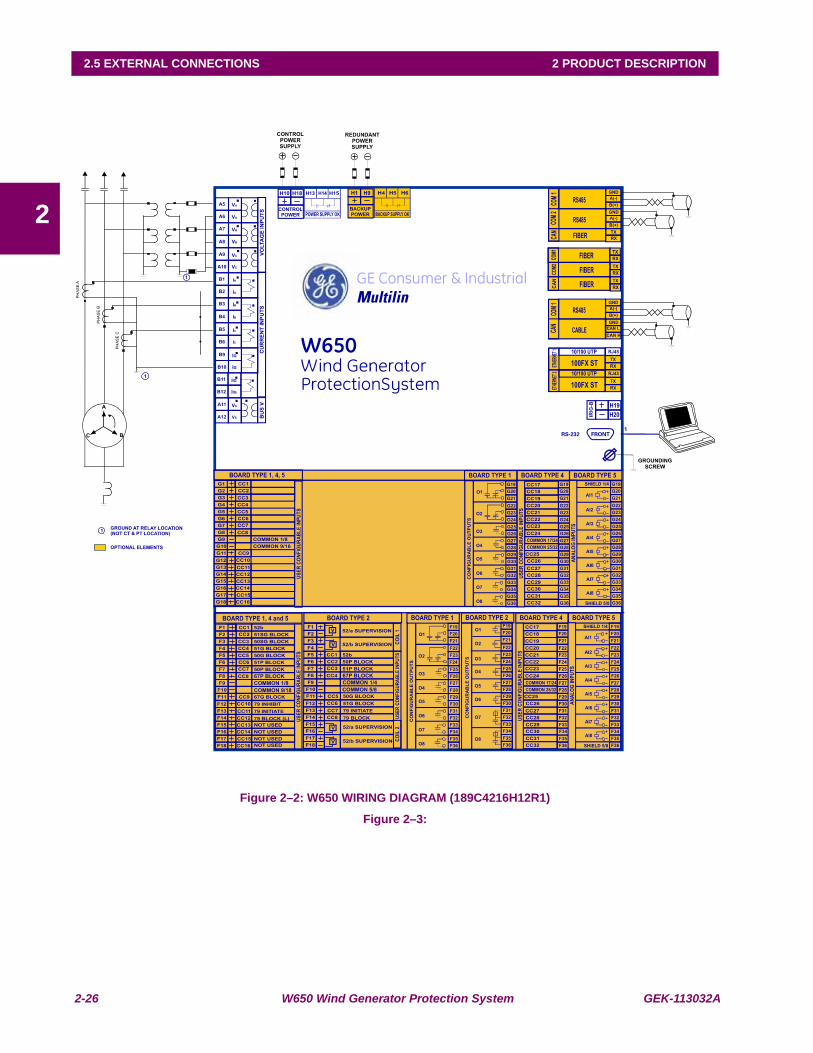
2-26 W650 Wind Generator Protection System GEK-113032A
2.5 EXTERNAL CONNECTIONS 2 PRODUCT DESCRIPTION
2
2.5EXTERNAL CONNECTIONS
Figure 2–2: W650 WIRING DIAGRAM (189C4216H12R1)
Figure 2–3:

GEK-113032A W650 Wind Generator Protection System 3-1
3 HARDWARE 3.1 MODULE DESCRIPTION
3
3 HARDWARE 3.1MODULE DESCRIPTION
Figure 3–1: BLOCK DIAGRAM
W650 units incorporate the following modules:
• Power supply, which can be simple or redundant, depending on the selected model
• Front module with alphanumerical (4 x 20) or optional graphical (16 x 40 characters) display. It includes the buson its rear, which communicates with the rest of modules via a high speed CAN bus.
• Transformers module with 5 current transformers and 4 voltage transformers
• CPU including a powerful DSP for measure processing as well as synchronous and asynchronous communicationaccessories.
• Input/Output module included in basic unit
• Optionally, a second I/O module can be added.
HHiigghh SSppeeeedd sseerriiaall CCAANN BBuuss
AAnnaalloogg
iinnppuuttss
VVTTss
aanndd
CCTTss
CPU
Module
Digital
I/O
Power
Supply
Optional
Digital
I/O
SShhuuttttllee kkeeyy
LLooccaall//
RReemmoottee
LLEE
DDss
SCREEN
KKeeyyppaadd
RRSS
223322
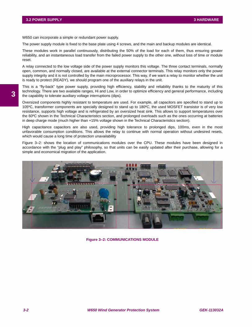
3-2 W650 Wind Generator Protection System GEK-113032A
3.2 POWER SUPPLY 3 HARDWARE
3
3.2POWER SUPPLY
W650 can incorporate a simple or redundant power supply.
The power supply module is fixed to the base plate using 4 screws, and the main and backup modules are identical.
These modules work in parallel continuously, distributing the 50% of the load for each of them, thus ensuring greaterreliability, and an instantaneous load transfer from the failed power supply to the other one, without loss of time or modulereset.
A relay connected to the low voltage side of the power supply monitors this voltage. The three contact terminals, normallyopen, common, and normally closed, are available at the external connector terminals. This relay monitors only the powersupply integrity and it is not controlled by the main microprocessor. This way, if we want a relay to monitor whether the unitis ready to protect (READY), we should program one of the auxiliary relays in the unit.
This is a “fly-back” type power supply, providing high efficiency, stability and reliability thanks to the maturity of thistechnology. There are two available ranges, Hi and Low, in order to optimize efficiency and general performance, includingthe capability to tolerate auxiliary voltage interruptions (dips).
Oversized components highly resistant to temperature are used. For example, all capacitors are specified to stand up to105ºC, transformer components are specially designed to stand up to 180ºC, the used MOSFET transistor is of very lowresistance, supports high voltage and is refrigerated by an oversized heat sink. This allows to support temperatures overthe 60ºC shown in the Technical Characteristics section, and prolonged overloads such as the ones occurring at batteriesin deep charge mode (much higher than +15% voltage shown in the Technical Characteristics section).
High capacitance capacitors are also used, providing high tolerance to prolonged dips, 100ms, even in the mostunfavorable consumption conditions. This allows the relay to continue with normal operation without undesired resets,which would cause a long time of protection unavailability
Figure 3–2: shows the location of communications modules over the CPU. These modules have been designed inaccordance with the “plug and play” philosophy, so that units can be easily updated after their purchase, allowing for asimple and economical migration of the application.
Figure 3–2: COMMUNICATIONS MODULE
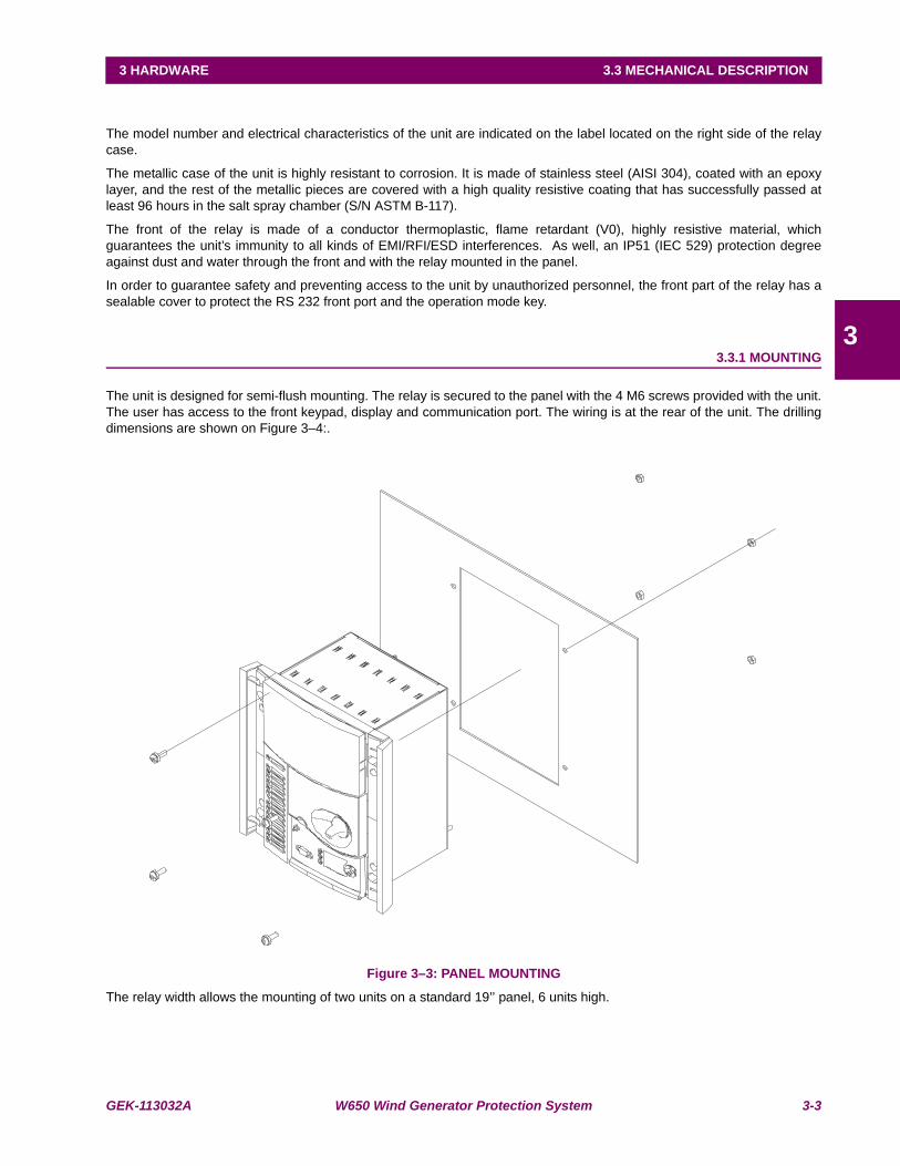
GEK-113032A W650 Wind Generator Protection System 3-3
3 HARDWARE 3.3 MECHANICAL DESCRIPTION
3
3.3MECHANICAL DESCRIPTION
The model number and electrical characteristics of the unit are indicated on the label located on the right side of the relaycase.
The metallic case of the unit is highly resistant to corrosion. It is made of stainless steel (AISI 304), coated with an epoxylayer, and the rest of the metallic pieces are covered with a high quality resistive coating that has successfully passed atleast 96 hours in the salt spray chamber (S/N ASTM B-117).
The front of the relay is made of a conductor thermoplastic, flame retardant (V0), highly resistive material, whichguarantees the unit’s immunity to all kinds of EMI/RFI/ESD interferences. As well, an IP51 (IEC 529) protection degreeagainst dust and water through the front and with the relay mounted in the panel.
In order to guarantee safety and preventing access to the unit by unauthorized personnel, the front part of the relay has asealable cover to protect the RS 232 front port and the operation mode key.
3.3.1 MOUNTING
The unit is designed for semi-flush mounting. The relay is secured to the panel with the 4 M6 screws provided with the unit.The user has access to the front keypad, display and communication port. The wiring is at the rear of the unit. The drillingdimensions are shown on Figure 3–4:.
Figure 3–3: PANEL MOUNTING
The relay width allows the mounting of two units on a standard 19’’ panel, 6 units high.
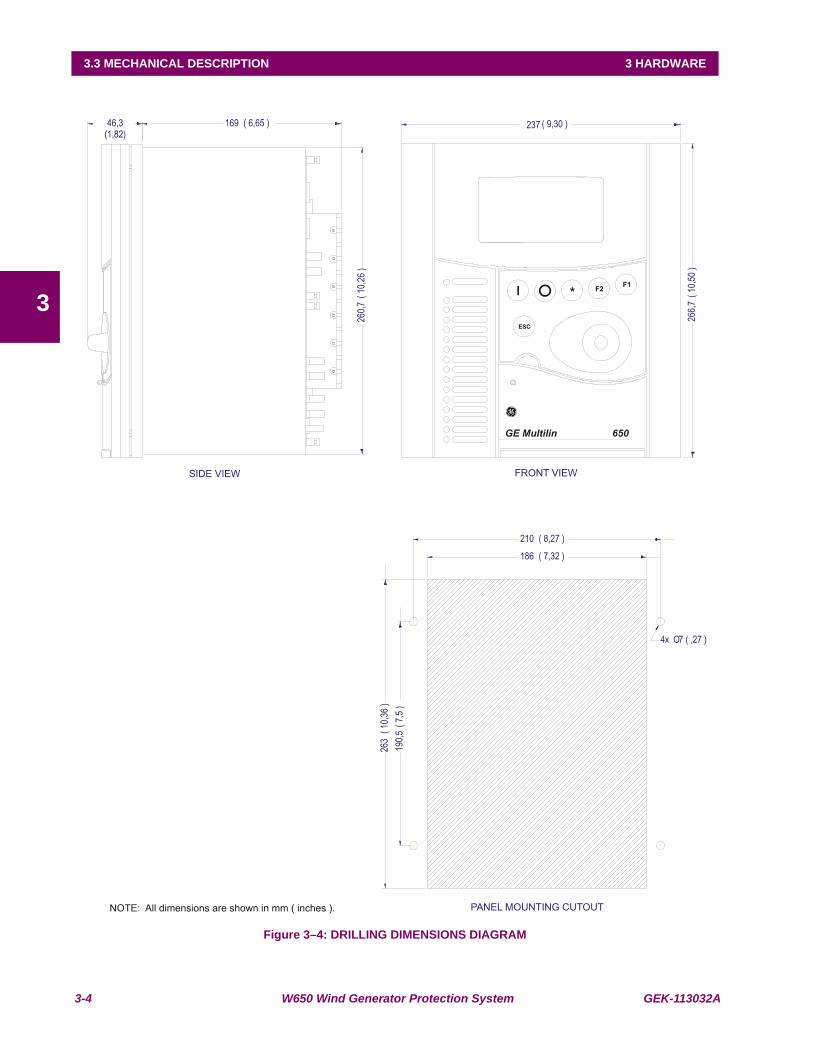
3-4 W650 Wind Generator Protection System GEK-113032A
3.3 MECHANICAL DESCRIPTION 3 HARDWARE
3
Figure 3–4: DRILLING DIMENSIONS DIAGRAM
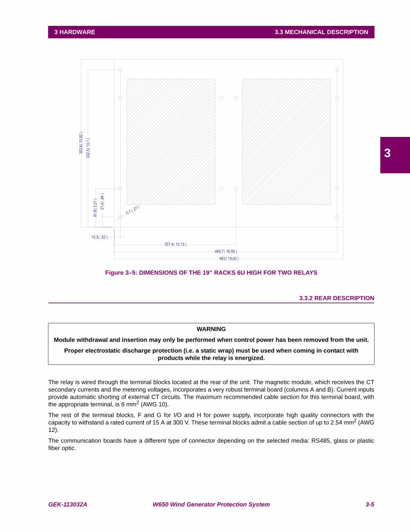
GEK-113032A W650 Wind Generator Protection System 3-5
3 HARDWARE 3.3 MECHANICAL DESCRIPTION
3
Figure 3–5: DIMENSIONS OF THE 19” RACKS 6U HIGH FOR TWO RELAYS
3.3.2 REAR DESCRIPTION
The relay is wired through the terminal blocks located at the rear of the unit. The magnetic module, which receives the CTsecondary currents and the metering voltages, incorporates a very robust terminal board (columns A and B). Current inputsprovide automatic shorting of external CT circuits. The maximum recommended cable section for this terminal board, withthe appropriate terminal, is 6 mm2 (AWG 10).
The rest of the terminal blocks, F and G for I/O and H for power supply, incorporate high quality connectors with thecapacity to withstand a rated current of 15 A at 300 V. These terminal blocks admit a cable section of up to 2.54 mm2 (AWG12).
The communication boards have a different type of connector depending on the selected media: RS485, glass or plasticfiber optic.
WARNING
Module withdrawal and insertion may only be performed when control power has been removed from the unit.
Proper electrostatic discharge protection (i.e. a static wrap) must be used when coming in contact with products while the relay is energized.

3-6 W650 Wind Generator Protection System GEK-113032A
3.3 MECHANICAL DESCRIPTION 3 HARDWARE
3
Figure 3–6: CONNECTORS LOCATION
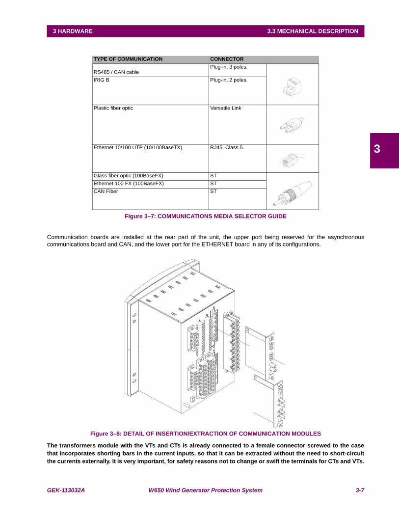
GEK-113032A W650 Wind Generator Protection System 3-7
3 HARDWARE 3.3 MECHANICAL DESCRIPTION
3
Figure 3–7: COMMUNICATIONS MEDIA SELECTOR GUIDE
Communication boards are installed at the rear part of the unit, the upper port being reserved for the asynchronouscommunications board and CAN, and the lower port for the ETHERNET board in any of its configurations.
Figure 3–8: DETAIL OF INSERTION/EXTRACTION OF COMMUNICATION MODULES
The transformers module with the VTs and CTs is already connected to a female connector screwed to the casethat incorporates shorting bars in the current inputs, so that it can be extracted without the need to short-circuitthe currents externally. It is very important, for safety reasons not to change or swift the terminals for CTs and VTs.
TYPE OF COMMUNICATION CONNECTOR
RS485 / CAN cablePlug-in, 3 poles.
IRIG B Plug-in, 2 poles.
Plastic fiber optic Versatile Link
Ethernet 10/100 UTP (10/100BaseTX) RJ45, Class 5.
Glass fiber optic (100BaseFX) STEthernet 100 FX (100BaseFX) STCAN Fiber ST
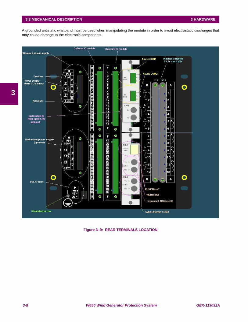
3-8 W650 Wind Generator Protection System GEK-113032A
3.3 MECHANICAL DESCRIPTION 3 HARDWARE
3
A grounded antistatic wristband must be used when manipulating the module in order to avoid electrostatic discharges thatmay cause damage to the electronic components.
Figure 3–9: REAR TERMINALS LOCATION

GEK-113032A W650 Wind Generator Protection System 3-9
3 HARDWARE 3.4 WIRING
3
3.4WIRING 3.4.1 EXTERNAL CONNECTIONS
W650 units can hold different options for F module:
Option 1: Board with 16 digital inputs and 8 outputs.
Option 2: Board with 8 digital inputs, 4 circuit supervision inputs, 6 conventional outputs, and two current sensingoutputs
Option 4: Board with 32 digital inputs.
Option 5: Board with 16 digital inputs and 8 analog inputs.
For slot G there are four different options:
Option 0: No board
Option 1: Board with 16 digital inputs and 8 outputs.
Option 4: Board with 32 digital inputs.
Option 5: Board with 16 digital inputs and 8 analog inputs.
The number selected for slot G must be equal or higher than the number selected for option F for models including boards4 and 5.
3.4.2 DIGITAL INPUTS WITH TRIP CIRCUIT SUPERVISION
The Option 2 I/O board includes two groups of 4 inputs with one common, in terminals F9 to F10. It also includes 6 auxiliaryoutputs, in terminals F19 to F30 with normally open contacts and two current sensing (latching) outputs (F31-F33 and F34-F36).
Besides, there are 2 groups of inputs for trip circuit supervision. The first group includes two isolated digital inputs, terminalsF1-F2 and F3-F4. The second group, symmetrical and identical to the first, is formed by isolated voltage inputs F15-F16and F17-F18.
Using voltage detectors and current sensing, it is possible to implement several trip or close circuit supervision schemes, aswell as protection of the unit output contact.
In order to implement these schemes, it is not necessary to perform any setting in the unit. Internal functions are always operative. The detailed description of trip circuit supervision is included in chapter 5 in this manual.
3.4.3 CABLE/FIBER ETHERNET BOARD
The Ethernet board is the communication board 2 (COM3) shown in Figure 3–2:. It is located in the bottom at the rear partof the relay.
In Models C and D, the 10/100BaseTX port is selected by an internal switch. To select between fiber and cable it isnecessary to extract the board, switch the jumper to the selected position, as indicated on Figure 3–10: FIBER/CABLESELECTION and insert the board again. As with any other relay manipulation, the relay power supply must be removedand the operation must be performed only by skilled personnel.
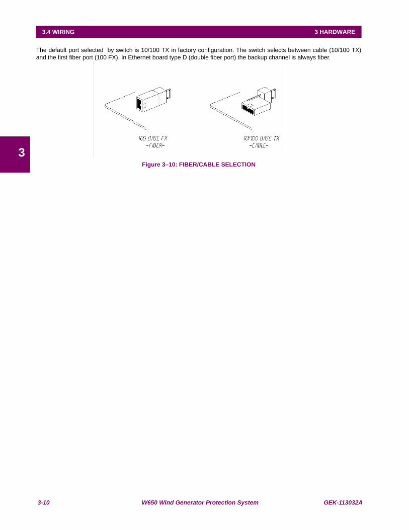
3-10 W650 Wind Generator Protection System GEK-113032A
3.4 WIRING 3 HARDWARE
3
The default port selected by switch is 10/100 TX in factory configuration. The switch selects between cable (10/100 TX)and the first fiber port (100 FX). In Ethernet board type D (double fiber port) the backup channel is always fiber.
Figure 3–10: FIBER/CABLE SELECTION
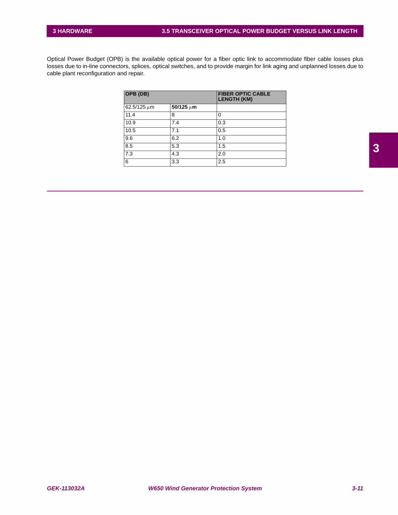
GEK-113032A W650 Wind Generator Protection System 3-11
3 HARDWARE 3.5 TRANSCEIVER OPTICAL POWER BUDGET VERSUS LINK LENGTH
3
3.5TRANSCEIVER OPTICAL POWER BUDGET VERSUS LINK LENGTH
Optical Power Budget (OPB) is the available optical power for a fiber optic link to accommodate fiber cable losses pluslosses due to in-line connectors, splices, optical switches, and to provide margin for link aging and unplanned losses due tocable plant reconfiguration and repair.
OPB (DB) FIBER OPTIC CABLE LENGTH (KM)
62.5/125 μm 50/125 μm11.4 8 010.9 7.4 0.310.5 7.1 0.59.6 6.2 1.08.5 5.3 1.57.3 4.3 2.06 3.3 2.5

3-12 W650 Wind Generator Protection System GEK-113032A
3.5 TRANSCEIVER OPTICAL POWER BUDGET VERSUS LINK LENGTH 3 HARDWARE
3

GEK-113032A W650 Wind Generator Protection System 4-1
4 HUMAN INTERFACES. 4.1 ENERVISTA 650 SETUP SOFTWARE INTERFACE
4
4 HUMAN INTERFACES. 4.1ENERVISTA 650 SETUP SOFTWARE INTERFACE 4.1.1 INTRODUCTION
The EnerVista 650 Setup software provides a graphical user interface (GUI) as one of two human interfaces to a URdevice. The alternate human interface is implemented via the device’s faceplate keypad and display (see Human MachineInterface section in this chapter).
The EnerVista 650 Setup software provides a single facility to configure, monitor, maintain, and trouble-shoot the operationof relay functions, connected over local or wide area communication networks. It can be used while disconnected (i.e.offline) or connected (i.e. on-line) to a 650 device. In off-line mode, settings files can be created for eventual downloading tothe device. In on-line mode, you can communicate with the device in real-time.
The EnerVista 650 Setup software, provided with every W650 relay, can be run from any computer supporting MicrosoftWindows® 95, 98, NT, 2000, ME, and XP. This chapter provides a summary of the basic EnerVista 650 Setup softwareinterface features. The EnerVista 650 Setup Help File provides details for getting started and using the EnerVista 650Setup software interface.
4.1.2 ENERVISTA 650 SETUP SOFTWARE OVERVIEW
This software package uses ModBus protocol, and it is designed to communicate with a single relay at a time. GE offersdifferent communication software packages, such as GE-POWER, which can be used to communicate simultaneously withseveral relays.
EnerVista 650 Setup software provides an easy way to configure, monitor and manage all W650 features.
4.1.2.1 ENGAGING A DEVICE
The EnerVista 650 Setup software may be used in on-line mode (relay connected) to directly communicate with a 650device.
4.1.2.2 USING SETTINGS FILES
The EnerVista 650 Setup software interface supports three ways of handling changes to relay settings:
1. In off-line mode (relay disconnected) to create or edit relay settings files for later download to communicating relays.
2. While connected to a communicating relay to directly modify any relay settings via relay data view windows, and thensave the settings to the relay.
3. You can create/edit settings files and then write them to the relay while the interface is connected to the relay.
Settings files are organized on the basis of file names assigned by the user. A settings file contains data pertaining to thefollowing types of relay settings:
• Product Setup
• System Setup
• Protection Elements
• Control Elements
• Inputs/Outputs
• Relay Configuration
• Logic Configuration
4.1.2.3 VIEWING ACTUAL VALUES
You can view real-time relay data such as input/output status and measured parameters.

4-2 W650 Wind Generator Protection System GEK-113032A
4.1 ENERVISTA 650 SETUP SOFTWARE INTERFACE 4 HUMAN INTERFACES.
4
4.1.2.4 VIEWING TRIGGERED EVENTS
While the interface is in either on-line or off-line mode, you can view and analyze data generated by triggered specified
parameters, via one of the following:
• Event Recorder facility: The event recorder captures contextual data associated with the last 479 events, listed inchronological order from most recent to oldest.
• Oscillography facility: The oscillography waveform traces and digital states are used to provide a visual display ofpower system and relay operation data captured during specific triggered events.
4.1.2.5 FIRMWARE UPGRADES
The firmware of a W650 device can be upgraded, locally or remotely, via the EnerVista 650 Setup software. Thecorresponding instructions are provided by the EnerVista 650 Setup Help file under the topic “Upgrading Firmware”.
Modbus addresses assigned to firmware modules, features, settings, and corresponding data items (i.e. default
values, minimum/maximum values, data type, and item size) may change slightly from version to version of firmware.
The addresses are rearranged when new features are added or existing features are enhanced or modified.
4.1.2.6 ONE LINE DIAGRAMS
You can configure an one line diagram (bay mimic) to be used in relays with graphical display.

GEK-113032A W650 Wind Generator Protection System 4-3
4 HUMAN INTERFACES. 4.1 ENERVISTA 650 SETUP SOFTWARE INTERFACE
4
4.1.3 MAIN SCREEN
The EnerVista 650 Setup software main window supports the following primary display components:
• Title bar
• Main menu bar
• Main icon bar
• Working area
• Status bar
Figure 4–1: ENERVISTA 650 SETUP MAIN SCREEN
Working Area
Main Menu barMain Icon bar
Title
Status bar

4-4 W650 Wind Generator Protection System GEK-113032A
4.1 ENERVISTA 650 SETUP SOFTWARE INTERFACE 4 HUMAN INTERFACES.
4
4.1.4 COMMUNICATION MENU
To start communicating with the relay go to “Communication>Computer>Computer settings” section in the mainEnerVista 650 Setup menu.
Safety instructions must be followed before connecting the computer to the relay. Safety instructions are detailed in section1.1.3. Connect the relay ground terminal and the communicating computer to a good grounding. Otherwise, communicationmay not be viable, or even, in worst cases, the relay and/or the computer could result damaged by overvoltages.
For on-line working, previously ensure that all relay communication parameters, such as baudrate, slave ModBus address,etc, match the computer settings.
Figure 4–2: COMMUNICATION PARAMETERS MENU
The “Communication > computer” screen is divided in several subsections:
• Computer settings: Main communication parameters for serial communication and control type selection.
• ModBus/TCP Setup (if ModBus /TCP is selected as control type): Communication parameters for ModBus TCPcommunication.
• Communication control: Device communication status (communicating or not communicating).
• Communication optimization: allows optimizing the communication time outs and failure establishing.
4.1.4.1 COMPUTER SETTINGS:
Shows the communication parameters necessary in order to establish communication with the unit. Such as slave address,communication port, baud rate, parity, control type and startup mode.
Baud rate, parity, data bits, stop bits and ModBus slave address for com2 (RS232 front port and second serial port in therear communication board) are displayed in the default text logotype main screen.
ModBus Slave Address: ModBus addresses used for serial and Ethernet communication.

GEK-113032A W650 Wind Generator Protection System 4-5
4 HUMAN INTERFACES. 4.1 ENERVISTA 650 SETUP SOFTWARE INTERFACE
4
Communication ports: port used in the computer for serial communication.
Baud Rate: Baud rate for serial communication (from 1200 up to 115200 bauds in EnerVista 650 Setup, from 300 to115200 in relay).
Parity: parity for serial communication. None, odd or even can be selected.
Control Type: The available control modes are:
• No Control Type, this option selects the serial communication mode, for use with serial communication ports (frontport, RS485, or plastic or glass fiber optic).
• MODBUS/TCP, this option selects ModBus TCP/IP communication mode, for communication through the Ethernetport. In this case, the top right window will show the typical parameters to be programmed; IP address, port addressand unit identifier in the MODBUS TCP SETUP section.
• MODEM, this option displays the parameter to set in case of using a modem for the communication, such as Phonenumber, Time out (sec), init. command, type of dialing (tones or pulses).
4.1.4.2 COMMUNICATION CONTROL:
Located at the bottom of the screen, it shows the status of the communication with the relay. With relay not communicating,a message “650 Setup is not talking to a W650” will be shown and ON button will be enable. Pressing this button, 650Setup start communicating with the relay.
With relay communicating a message “650 Setup is now talking to a W650” will be shown and OFF will be enable. Pressingthis button, communications between relay and PC will be closed.
4.1.4.3 COMMUNICATION OPTIMIZATION:
The parameters shown on the bottom right window (Communication optimization) can improve communication, although itis recommended to leave the default values indicated by the EnerVista 650 Setup. These parameters are the maximumtime to wait for a response in the relay (in ms) and the maximum attempts to perform before assuming communicationsfailure.

4-6 W650 Wind Generator Protection System GEK-113032A
4.1 ENERVISTA 650 SETUP SOFTWARE INTERFACE 4 HUMAN INTERFACES.
4
4.1.5 FILE MANAGEMENT
File management with EnerVista 650 Setup software:
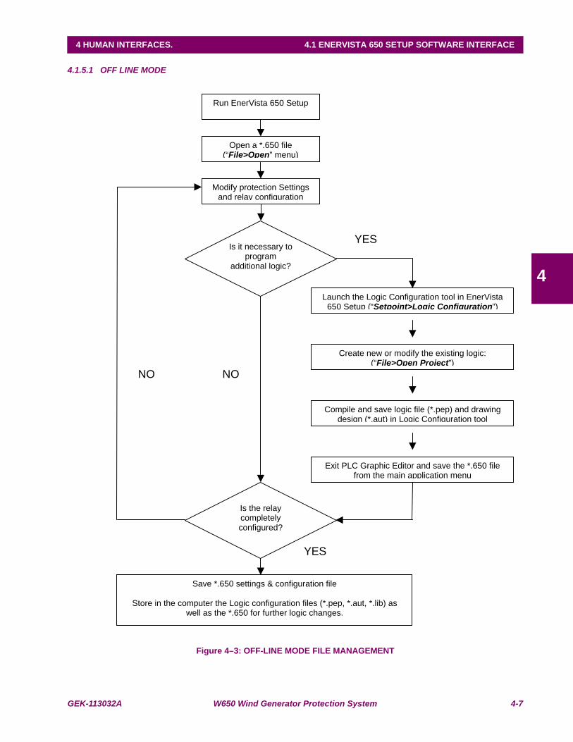
GEK-113032A W650 Wind Generator Protection System 4-7
4 HUMAN INTERFACES. 4.1 ENERVISTA 650 SETUP SOFTWARE INTERFACE
4
4.1.5.1 OFF LINE MODE
Figure 4–3: OFF-LINE MODE FILE MANAGEMENT
Run EnerVista 650 Setup
Open a *.650 file (“File>Open” menu)
Modify protection Settings and relay configuration
Is it necessary to program
additional logic?
Launch the Logic Configuration tool in EnerVista 650 Setup (“Setpoint>Logic Configuration”)
Create new or modify the existing logic: (“File>Open Project”)
Compile and save logic file (*.pep) and drawing design (*.aut) in Logic Configuration tool
Exit PLC Graphic Editor and save the *.650 file from the main application menu
Is the relay completely configured?
Save *.650 settings & configuration file
Store in the computer the Logic configuration files (*.pep, *.aut, *.lib) as well as the *.650 for further logic changes.
YES
YES
NO NO
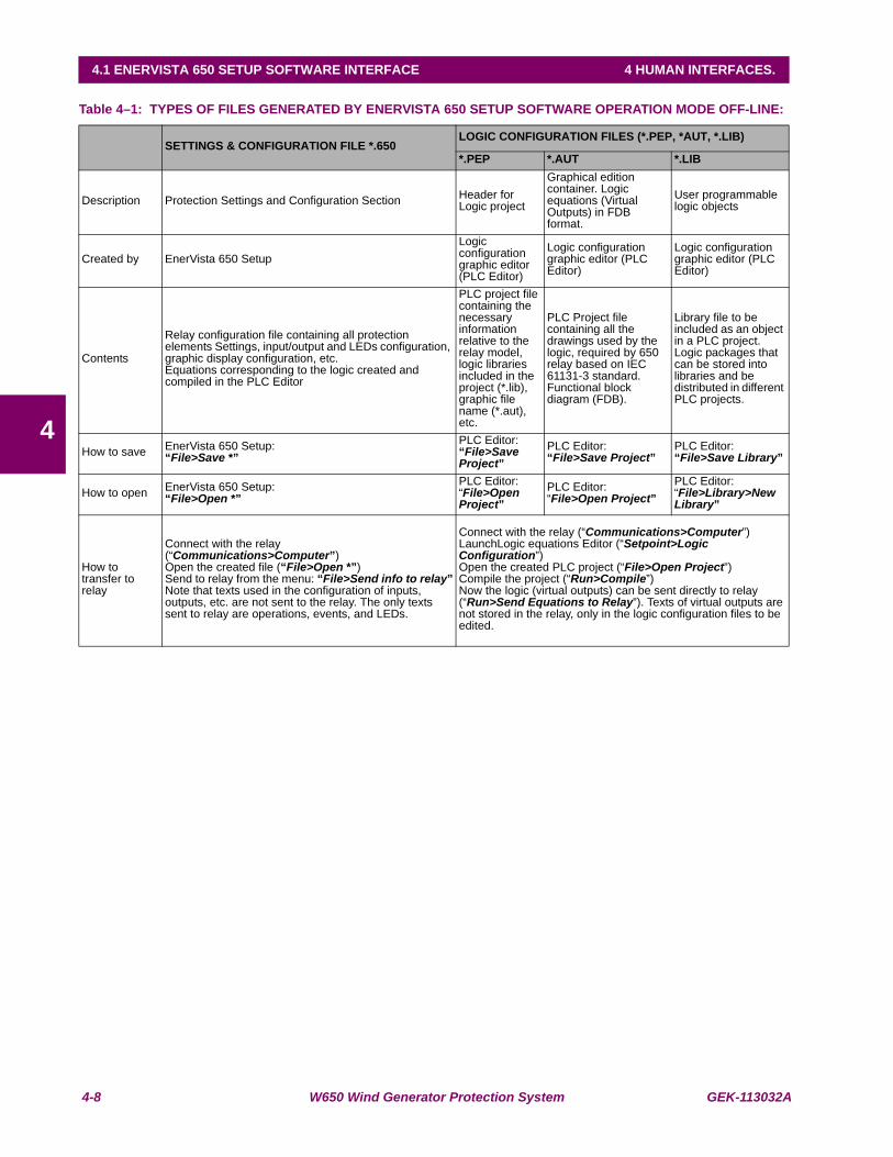
4-8 W650 Wind Generator Protection System GEK-113032A
4.1 ENERVISTA 650 SETUP SOFTWARE INTERFACE 4 HUMAN INTERFACES.
4
Table 4–1: TYPES OF FILES GENERATED BY ENERVISTA 650 SETUP SOFTWARE OPERATION MODE OFF-LINE:
SETTINGS & CONFIGURATION FILE *.650LOGIC CONFIGURATION FILES (*.PEP, *AUT, *.LIB)
*.PEP *.AUT *.LIB
Description Protection Settings and Configuration Section Header for Logic project
Graphical edition container. Logic equations (Virtual Outputs) in FDB format.
User programmable logic objects
Created by EnerVista 650 SetupLogic configuration graphic editor (PLC Editor)
Logic configuration graphic editor (PLC Editor)
Logic configuration graphic editor (PLC Editor)
Contents
Relay configuration file containing all protection elements Settings, input/output and LEDs configuration, graphic display configuration, etc.Equations corresponding to the logic created and compiled in the PLC Editor
PLC project file containing the necessary information relative to the relay model, logic libraries included in the project (*.lib), graphic file name (*.aut), etc.
PLC Project file containing all the drawings used by the logic, required by 650 relay based on IEC 61131-3 standard. Functional block diagram (FDB).
Library file to be included as an object in a PLC project. Logic packages that can be stored into libraries and be distributed in different PLC projects.
How to save EnerVista 650 Setup:“File>Save *”
PLC Editor:“File>Save Project”
PLC Editor:“File>Save Project”
PLC Editor: “File>Save Library”
How to open EnerVista 650 Setup:“File>Open *”
PLC Editor:“File>Open Project”
PLC Editor:“File>Open Project”
PLC Editor:“File>Library>New Library”
How to transfer to relay
Connect with the relay (“Communications>Computer”)Open the created file (“File>Open *”)Send to relay from the menu: “File>Send info to relay”Note that texts used in the configuration of inputs, outputs, etc. are not sent to the relay. The only texts sent to relay are operations, events, and LEDs.
Connect with the relay (“Communications>Computer”)LaunchLogic equations Editor (“Setpoint>Logic Configuration”)Open the created PLC project (“File>Open Project”)Compile the project (“Run>Compile”)Now the logic (virtual outputs) can be sent directly to relay (“Run>Send Equations to Relay”). Texts of virtual outputs are not stored in the relay, only in the logic configuration files to be edited.
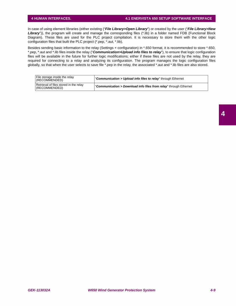
GEK-113032A W650 Wind Generator Protection System 4-9
4 HUMAN INTERFACES. 4.1 ENERVISTA 650 SETUP SOFTWARE INTERFACE
4
In case of using element libraries (either existing (“File Library>Open Library”) or created by the user (“File Library>NewLibrary”)), the program will create and manage the corresponding files (*.lib) in a folder named FDB (Functional BlockDiagram). These files are used for the PLC project compilation. It is necessary to store them with the other logicconfiguration files that built the PLC project (*.pep, *.aut, *.lib).
Besides sending basic information to the relay (Settings + configuration) in *.650 format, it is recommended to store *.650,*.pep, *.aut and *.lib files inside the relay (“Communication>Upload info files to relay”), to ensure that logic configurationfiles will be available in the future for further logic modifications; either if these files are not used by the relay, they arerequired for connecting to a relay and analyzing its configuration. The program manages the logic configuration filesglobally, so that when the user selects to save file *.pep in the relay, the associated *.aut and *.lib files are also stored.
File storage inside the relay (RECOMMENDED) “Communication > Upload info files to relay” through Ethernet
Retrieval of files stored in the relay (RECOMMENDED) “Communication > Download info files from relay” through Ethernet
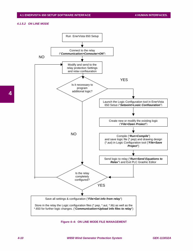
4-10 W650 Wind Generator Protection System GEK-113032A
4.1 ENERVISTA 650 SETUP SOFTWARE INTERFACE 4 HUMAN INTERFACES.
4
4.1.5.2 ON LINE MODE
Figure 4–4: ON LINE MODE FILE MANAGEMENT
NO
Run EnerVista 650 Setup
Connect to the relay (“Communication>Computer>ON”)
Modify and send to the relay protection Settings and relay configuration
Is it necessary to program
additional logic?
Launch the Logic Configuration tool in EnerVista 650 Setup (“Setpoint>Logic Configuration”)
Create new or modify the existing logic (“File>Open Project”)
Compile (“Run>Compile”)and save logic file (*.pep) and drawing design (*.aut) in Logic Configuration tool (“File>Save
Project”)
Send logic to relay (“Run>Send Equations to Relay”) and Exit PLC Graphic Editor
Is the relay completely configured?
Save all settings & configuration (“File>Get info from relay”)
Store in the relay the Logic configuration files (*.pep, *.aut, *.lib) as well as the
*.650 for further logic changes. (“Communication>Upload info files to relay”)
NO
YES
YES
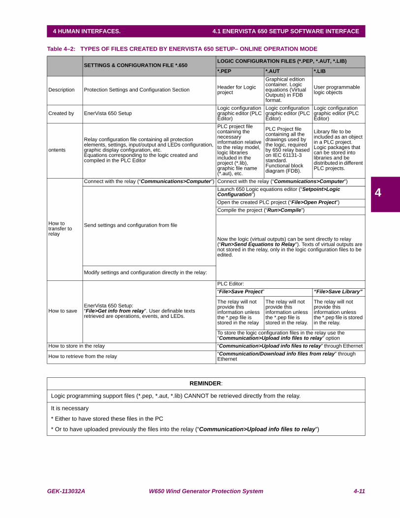
GEK-113032A W650 Wind Generator Protection System 4-11
4 HUMAN INTERFACES. 4.1 ENERVISTA 650 SETUP SOFTWARE INTERFACE
4
Table 4–2: TYPES OF FILES CREATED BY ENERVISTA 650 SETUP– ONLINE OPERATION MODE
SETTINGS & CONFIGURATION FILE *.650LOGIC CONFIGURATION FILES (*.PEP, *.AUT, *.LIB)
*.PEP *.AUT *.LIB
Description Protection Settings and Configuration Section Header for Logic project
Graphical edition container. Logic equations (Virtual Outputs) in FDB format.
User programmable logic objects
Created by EnerVista 650 SetupLogic configuration graphic editor (PLC Editor)
Logic configuration graphic editor (PLC Editor)
Logic configuration graphic editor (PLC Editor)
ontents
Relay configuration file containing all protection elements, settings, input/output and LEDs configuration, graphic display configuration, etc.Equations corresponding to the logic created and compiled in the PLC Editor
PLC project file containing the necessary information relative to the relay model, logic libraries included in the project (*.lib), graphic file name (*.aut), etc.
PLC Project file containing all the drawings used by the logic, required by 650 relay based on IEC 61131-3 standard. Functional block diagram (FDB).
Library file to be included as an object in a PLC project. Logic packages that can be stored into libraries and be distributed in different PLC projects.
How to transfer to relay
Connect with the relay (“Communications>Computer”) Connect with the relay (“Communications>Computer”)
Send settings and configuration from file
Launch 650 Logic equations editor (“Setpoint>Logic Configuration”)Open the created PLC project (“File>Open Project”)Compile the project (“Run>Compile”)
Now the logic (virtual outputs) can be sent directly to relay (“Run>Send Equations to Relay”). Texts of virtual outputs are not stored in the relay, only in the logic configuration files to be edited.
Modify settings and configuration directly in the relay:
How to saveEnerVista 650 Setup:“File>Get info from relay”. User definable texts retrieved are operations, events, and LEDs.
PLC Editor:“File>Save Project” “File>Save Library”
The relay will not provide this information unless the *.pep file is stored in the relay
The relay will not provide this information unless the *.pep file is stored in the relay.
The relay will not provide this information unless the *.pep file is stored in the relay.
To store the logic configuration files in the relay use the “Communication>Upload info files to relay” option
How to store in the relay “Communication>Upload info files to relay” through Ethernet
How to retrieve from the relay “Communication/Download info files from relay” through Ethernet
REMINDER:
Logic programming support files (*.pep, *.aut, *.lib) CANNOT be retrieved directly from the relay.
It is necessary
* Either to have stored these files in the PC
* Or to have uploaded previously the files into the relay (“Communication>Upload info files to relay”)
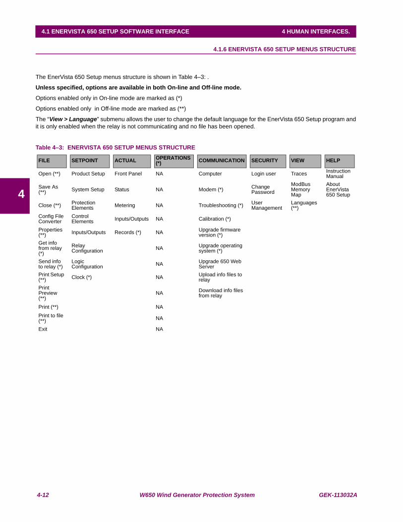
4-12 W650 Wind Generator Protection System GEK-113032A
4.1 ENERVISTA 650 SETUP SOFTWARE INTERFACE 4 HUMAN INTERFACES.
4
4.1.6 ENERVISTA 650 SETUP MENUS STRUCTURE
The EnerVista 650 Setup menus structure is shown in Table 4–3: .
Unless specified, options are available in both On-line and Off-line mode.
Options enabled only in On-line mode are marked as (*)
Options enabled only in Off-line mode are marked as (**)
The “View > Language” submenu allows the user to change the default language for the EnerVista 650 Setup program andit is only enabled when the relay is not communicating and no file has been opened.
Table 4–3: ENERVISTA 650 SETUP MENUS STRUCTURE
FILE SETPOINT ACTUAL OPERATIONS(*) COMMUNICATION SECURITY VIEW HELP
Open (**) Product Setup Front Panel NA Computer Login user Traces Instruction Manual
Save As (**) System Setup Status NA Modem (*) Change
PasswordModBus Memory Map
About EnerVista 650 Setup
Close (**) Protection Elements Metering NA Troubleshooting (*) User
ManagementLanguages (**)
Config File Converter
Control Elements Inputs/Outputs NA Calibration (*)
Properties (**) Inputs/Outputs Records (*) NA Upgrade firmware
version (*)Get info from relay (*)
Relay Configuration NA Upgrade operating
system (*)
Send info to relay (*)
Logic Configuration NA Upgrade 650 Web
ServerPrint Setup (**) Clock (*) NA Upload info files to
relayPrint Preview (**)
NA Download info files from relay
Print (**) NAPrint to file (**) NA
Exit NA

GEK-113032A W650 Wind Generator Protection System 4-13
4 HUMAN INTERFACES. 4.1 ENERVISTA 650 SETUP SOFTWARE INTERFACE
4
4.1.7 FILE MENU OVERVIEW
Table 4–4: GENERAL OVERVIEW OF FILE MENU:
Options enabled only in On-line mode are marked as (*). Options enabled only in Off-line mode are marked as (**)
FILE
Open (**) Open a settings and configuration file for off-line working.
Save As (**) Save *.650 settings and configuration file.
Close (**) Close the opened *.650 file in EnerVista 650 Setup.
Config File (*.650) Converter Tool to convert the *.650 files from one version to another
Properties (**) File properties for *.650.
Get info from relay (*) Retrieve the *.650 settings and relay configuration compiled equations from the relay.
Send info to relay (*) Send and write the *.650 settings and configuration to the relay.
Print Setup (**) To configure printer settings.
Print Preview (**) Preview of settings and configuration file printing format.
Print (**) Launch the *.650 file to be printed.
Print to file (*.xls) (**) *.650 printed to file in excel format.
Exit Quit the application closing all the open windows.
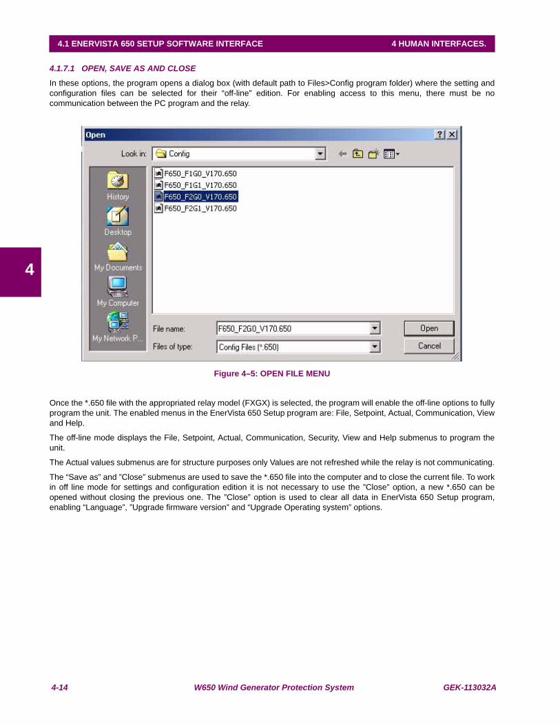
4-14 W650 Wind Generator Protection System GEK-113032A
4.1 ENERVISTA 650 SETUP SOFTWARE INTERFACE 4 HUMAN INTERFACES.
4
4.1.7.1 OPEN, SAVE AS AND CLOSE
In these options, the program opens a dialog box (with default path to Files>Config program folder) where the setting andconfiguration files can be selected for their “off-line” edition. For enabling access to this menu, there must be nocommunication between the PC program and the relay.
Figure 4–5: OPEN FILE MENU
Once the *.650 file with the appropriated relay model (FXGX) is selected, the program will enable the off-line options to fullyprogram the unit. The enabled menus in the EnerVista 650 Setup program are: File, Setpoint, Actual, Communication, Viewand Help.
The off-line mode displays the File, Setpoint, Actual, Communication, Security, View and Help submenus to program theunit.
The Actual values submenus are for structure purposes only Values are not refreshed while the relay is not communicating.
The “Save as” and ”Close” submenus are used to save the *.650 file into the computer and to close the current file. To workin off line mode for settings and configuration edition it is not necessary to use the ”Close” option, a new *.650 can beopened without closing the previous one. The ”Close” option is used to clear all data in EnerVista 650 Setup program,enabling “Language”, ”Upgrade firmware version” and “Upgrade Operating system” options.
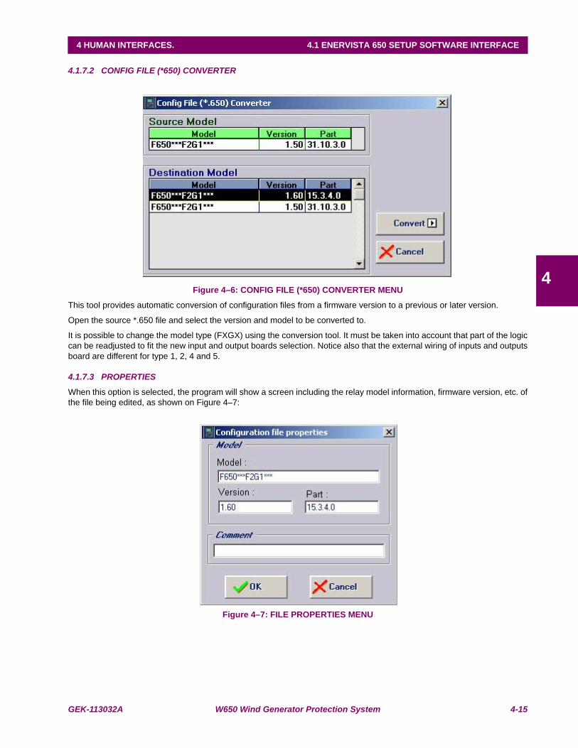
GEK-113032A W650 Wind Generator Protection System 4-15
4 HUMAN INTERFACES. 4.1 ENERVISTA 650 SETUP SOFTWARE INTERFACE
4
4.1.7.2 CONFIG FILE (*650) CONVERTER
Figure 4–6: CONFIG FILE (*650) CONVERTER MENU
This tool provides automatic conversion of configuration files from a firmware version to a previous or later version.
Open the source *.650 file and select the version and model to be converted to.
It is possible to change the model type (FXGX) using the conversion tool. It must be taken into account that part of the logiccan be readjusted to fit the new input and output boards selection. Notice also that the external wiring of inputs and outputsboard are different for type 1, 2, 4 and 5.
4.1.7.3 PROPERTIES
When this option is selected, the program will show a screen including the relay model information, firmware version, etc. ofthe file being edited, as shown on Figure 4–7:
Figure 4–7: FILE PROPERTIES MENU
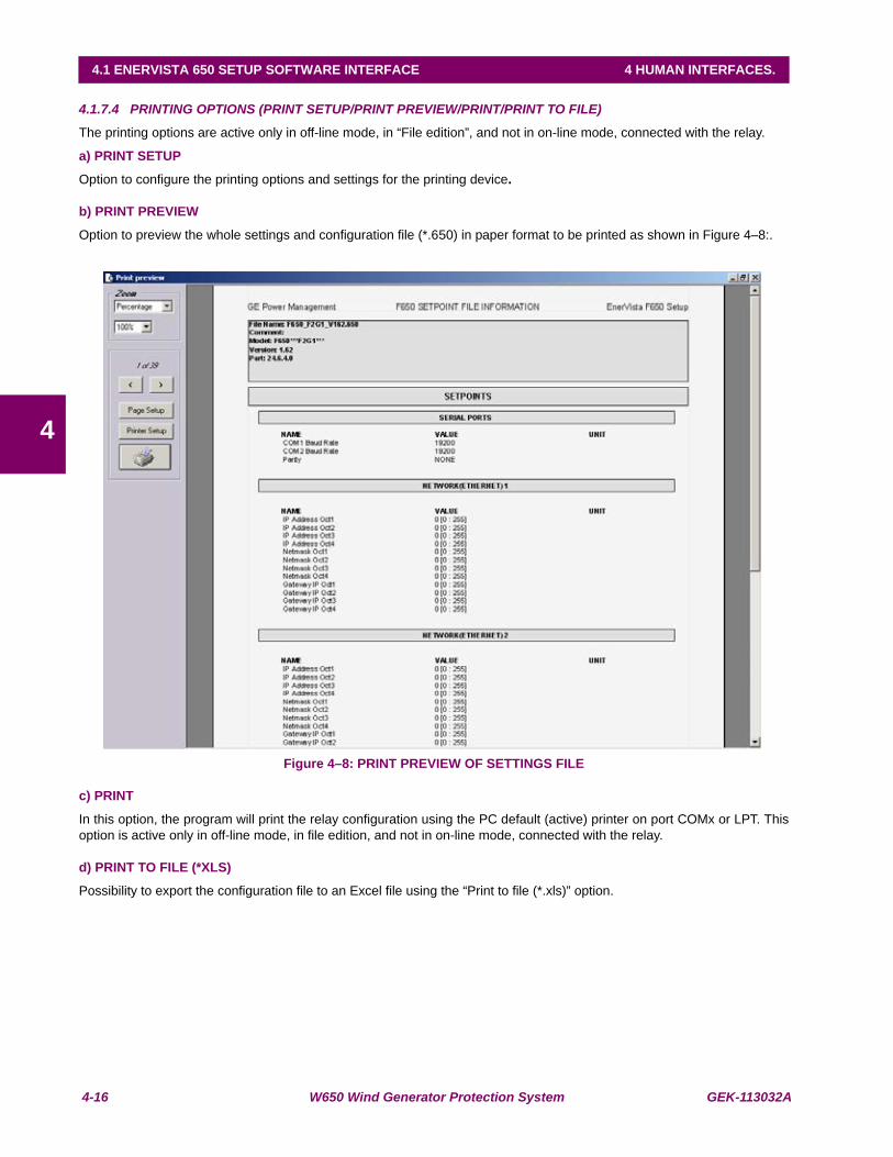
4-16 W650 Wind Generator Protection System GEK-113032A
4.1 ENERVISTA 650 SETUP SOFTWARE INTERFACE 4 HUMAN INTERFACES.
4
4.1.7.4 PRINTING OPTIONS (PRINT SETUP/PRINT PREVIEW/PRINT/PRINT TO FILE)
The printing options are active only in off-line mode, in “File edition”, and not in on-line mode, connected with the relay.
a) PRINT SETUP
Option to configure the printing options and settings for the printing device.
b) PRINT PREVIEW
Option to preview the whole settings and configuration file (*.650) in paper format to be printed as shown in Figure 4–8:.
Figure 4–8: PRINT PREVIEW OF SETTINGS FILE
c) PRINT
In this option, the program will print the relay configuration using the PC default (active) printer on port COMx or LPT. Thisoption is active only in off-line mode, in file edition, and not in on-line mode, connected with the relay.
d) PRINT TO FILE (*XLS)
Possibility to export the configuration file to an Excel file using the “Print to file (*.xls)” option.
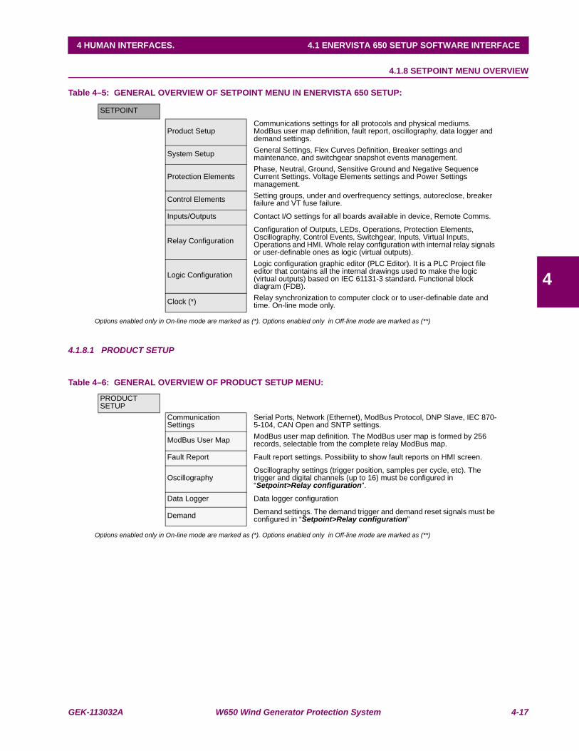
GEK-113032A W650 Wind Generator Protection System 4-17
4 HUMAN INTERFACES. 4.1 ENERVISTA 650 SETUP SOFTWARE INTERFACE
4
4.1.8 SETPOINT MENU OVERVIEW
Table 4–5: GENERAL OVERVIEW OF SETPOINT MENU IN ENERVISTA 650 SETUP:
Options enabled only in On-line mode are marked as (*). Options enabled only in Off-line mode are marked as (**)
4.1.8.1 PRODUCT SETUP
Table 4–6: GENERAL OVERVIEW OF PRODUCT SETUP MENU:
Options enabled only in On-line mode are marked as (*). Options enabled only in Off-line mode are marked as (**)
SETPOINT
Product SetupCommunications settings for all protocols and physical mediums. ModBus user map definition, fault report, oscillography, data logger and demand settings.
System Setup General Settings, Flex Curves Definition, Breaker settings and maintenance, and switchgear snapshot events management.
Protection ElementsPhase, Neutral, Ground, Sensitive Ground and Negative Sequence Current Settings. Voltage Elements settings and Power Settings management.
Control Elements Setting groups, under and overfrequency settings, autoreclose, breaker failure and VT fuse failure.
Inputs/Outputs Contact I/O settings for all boards available in device, Remote Comms.
Relay ConfigurationConfiguration of Outputs, LEDs, Operations, Protection Elements, Oscillography, Control Events, Switchgear, Inputs, Virtual Inputs, Operations and HMI. Whole relay configuration with internal relay signals or user-definable ones as logic (virtual outputs).
Logic ConfigurationLogic configuration graphic editor (PLC Editor). It is a PLC Project file editor that contains all the internal drawings used to make the logic (virtual outputs) based on IEC 61131-3 standard. Functional block diagram (FDB).
Clock (*) Relay synchronization to computer clock or to user-definable date and time. On-line mode only.
PRODUCT SETUP
Communication Settings
Serial Ports, Network (Ethernet), ModBus Protocol, DNP Slave, IEC 870-5-104, CAN Open and SNTP settings.
ModBus User Map ModBus user map definition. The ModBus user map is formed by 256 records, selectable from the complete relay ModBus map.
Fault Report Fault report settings. Possibility to show fault reports on HMI screen.
OscillographyOscillography settings (trigger position, samples per cycle, etc). The trigger and digital channels (up to 16) must be configured in “Setpoint>Relay configuration”.
Data Logger Data logger configuration
Demand Demand settings. The demand trigger and demand reset signals must be configured in “Setpoint>Relay configuration”
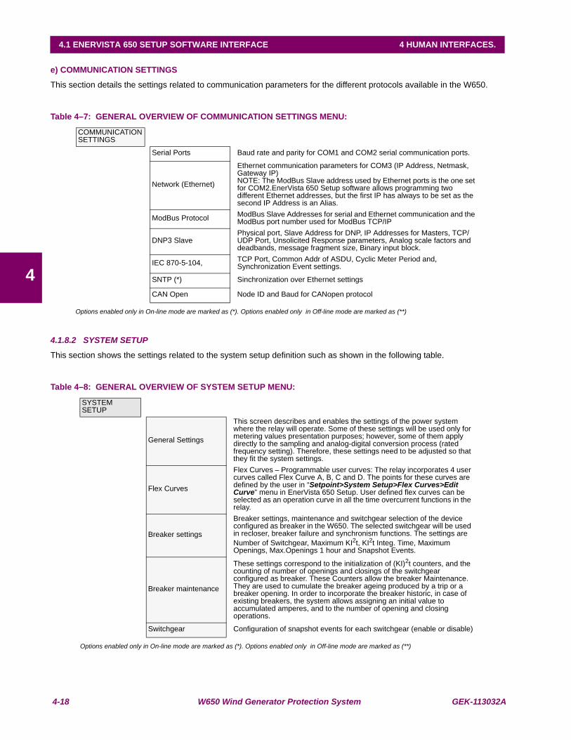
4-18 W650 Wind Generator Protection System GEK-113032A
4.1 ENERVISTA 650 SETUP SOFTWARE INTERFACE 4 HUMAN INTERFACES.
4
e) COMMUNICATION SETTINGS
This section details the settings related to communication parameters for the different protocols available in the W650.
Table 4–7: GENERAL OVERVIEW OF COMMUNICATION SETTINGS MENU:
Options enabled only in On-line mode are marked as (*). Options enabled only in Off-line mode are marked as (**)
4.1.8.2 SYSTEM SETUP
This section shows the settings related to the system setup definition such as shown in the following table.
Table 4–8: GENERAL OVERVIEW OF SYSTEM SETUP MENU:
Options enabled only in On-line mode are marked as (*). Options enabled only in Off-line mode are marked as (**)
COMMUNICATION SETTINGS
Serial Ports Baud rate and parity for COM1 and COM2 serial communication ports.
Network (Ethernet)
Ethernet communication parameters for COM3 (IP Address, Netmask, Gateway IP)NOTE: The ModBus Slave address used by Ethernet ports is the one set for COM2.EnerVista 650 Setup software allows programming two different Ethernet addresses, but the first IP has always to be set as the second IP Address is an Alias.
ModBus Protocol ModBus Slave Addresses for serial and Ethernet communication and the ModBus port number used for ModBus TCP/IP
DNP3 SlavePhysical port, Slave Address for DNP, IP Addresses for Masters, TCP/UDP Port, Unsolicited Response parameters, Analog scale factors and deadbands, message fragment size, Binary input block.
IEC 870-5-104, TCP Port, Common Addr of ASDU, Cyclic Meter Period and, Synchronization Event settings.
SNTP (*) Sinchronization over Ethernet settings
CAN Open Node ID and Baud for CANopen protocol
SYSTEM SETUP
General Settings
This screen describes and enables the settings of the power system where the relay will operate. Some of these settings will be used only for metering values presentation purposes; however, some of them apply directly to the sampling and analog-digital conversion process (rated frequency setting). Therefore, these settings need to be adjusted so that they fit the system settings.
Flex Curves
Flex Curves – Programmable user curves: The relay incorporates 4 user curves called Flex Curve A, B, C and D. The points for these curves are defined by the user in “Setpoint>System Setup>Flex Curves>Edit Curve” menu in EnerVista 650 Setup. User defined flex curves can be selected as an operation curve in all the time overcurrent functions in the relay.
Breaker settings
Breaker settings, maintenance and switchgear selection of the device configured as breaker in the W650. The selected switchgear will be used in recloser, breaker failure and synchronism functions. The settings are Number of Switchgear, Maximum KI2t, KI2t Integ. Time, Maximum Openings, Max.Openings 1 hour and Snapshot Events.
Breaker maintenance
These settings correspond to the initialization of (KI)2t counters, and the counting of number of openings and closings of the switchgear configured as breaker. These Counters allow the breaker Maintenance. They are used to cumulate the breaker ageing produced by a trip or a breaker opening. In order to incorporate the breaker historic, in case of existing breakers, the system allows assigning an initial value to accumulated amperes, and to the number of opening and closing operations.
Switchgear Configuration of snapshot events for each switchgear (enable or disable)

GEK-113032A W650 Wind Generator Protection System 4-19
4 HUMAN INTERFACES. 4.1 ENERVISTA 650 SETUP SOFTWARE INTERFACE
4
4.1.8.3 PROTECTION ELEMENTS
This option shows all the protection-grouped elements available in the relay as shown in Table 4–9:. Each of these groupsincludes the specific protection units of the same type. For example phase currents group includes TOC, IOC, directionalunits, etc. There are three groups available, so there are three protection units of each function that can work in groupedmode or ungrouped (altogether).
Table 4–9: GENERAL OVERVIEW OF PROTECTION ELEMENTS MENU:
Options enabled only in On-line mode are marked as (*). Options enabled only in Off-line mode are marked as (**)
PROTECTION ELEMENTS
Phase Current All overcurrent grouped functions for phase current.
Neutral Current All overcurrent grouped functions for neutral current. (Calculated from phases, not measured)
Ground Current All overcurrent grouped functions for ground current. (Measured from 4th current input)
Sensitive Ground Current
All overcurrent grouped functions for sensitive ground current. (Measured from 5th current input)
Negative Sequence Current Negative sequence time overcurrent function
Voltage Elements All under and overvoltage grouped functions for phases, neutral, auxiliary voltage and voltage unbalance.
Power Directional power grouped protection functions.

4-20 W650 Wind Generator Protection System GEK-113032A
4.1 ENERVISTA 650 SETUP SOFTWARE INTERFACE 4 HUMAN INTERFACES.
4
Table 4–10: PROTECTION ELEMENTS INCLUDED
PHASE CURRENT
Phase TOC High Phase time overcurrent, high level (51PH)
Phase TOC Low Phase time overcurrent, low level (51PL)
Phase IOC High Phase instantaneous overcurrent, high level (50PH)
Phase IOC Low Phase instantaneous overcurrent, low level (50PL)
Phase Directional Phase directional unit (67P). Quadrature Voltage for polarization
NEUTRAL CURRENT
Neutral TOC Neutral time overcurrent (51N)
Neutral IOC Neutral instantaneous overcurrent (50N)
Neutral Directional Neutral directional unit (67N). Voltage, current and dual polarization.
GROUND CURRENT
Ground TOC Ground time overcurrent (51G)
Ground IOC Ground instantaneous overcurrent (50G)
Ground Directional Ground directional unit (67G). Voltage, current and dual polarization.
SENSITIVE GROUND CURRENT
Sensitive Ground TOC Sensitive ground time overcurrent (51SG)
Sensitive Ground IOC Sensitive ground instantaneous overcurrent (50SG)
Sensitive Ground Directional Sensitive ground directional unit (67SG)
NEGATIVE SEQUENCE CURRENT
Negative Sequence TOC Negative sequence time overcurrent (46P)
VOLTAGE ELEMENTS
Phase UV Phase undervoltage (27P)
Phase OV Phase overvoltage (59P)
Neutral OV High Neutral overvoltage, high level (59NH)
Neutral OV Low Neutral overvoltage, low level (59NL)
Auxiliary OV Auxiliary overvoltage (59X)
Auxiliary UV Auxiliary undervoltage (27X)
Voltage Unbalance Voltage unbalance (60V)
POWER
Directional Power Directional power (32), in primary values.
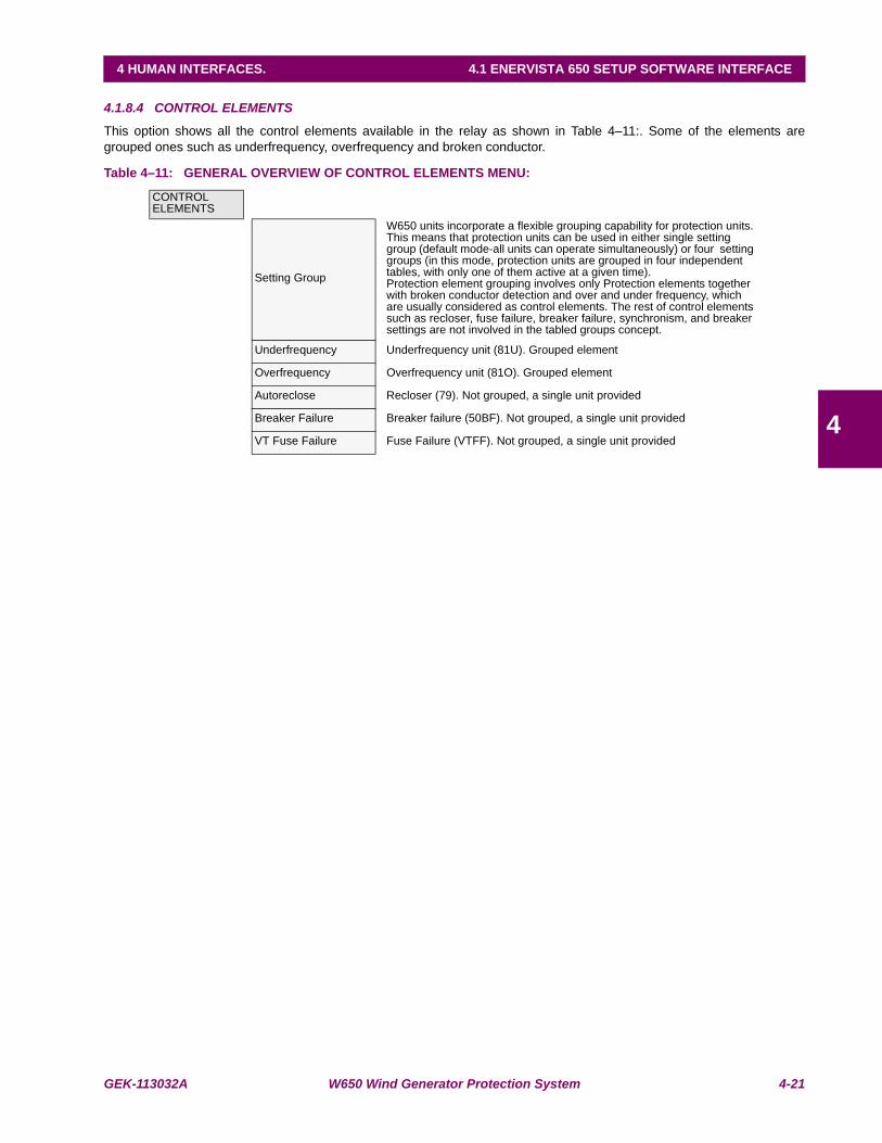
GEK-113032A W650 Wind Generator Protection System 4-21
4 HUMAN INTERFACES. 4.1 ENERVISTA 650 SETUP SOFTWARE INTERFACE
4
4.1.8.4 CONTROL ELEMENTS
This option shows all the control elements available in the relay as shown in Table 4–11:. Some of the elements aregrouped ones such as underfrequency, overfrequency and broken conductor.
Table 4–11: GENERAL OVERVIEW OF CONTROL ELEMENTS MENU:
CONTROL ELEMENTS
Setting Group
W650 units incorporate a flexible grouping capability for protection units. This means that protection units can be used in either single setting group (default mode-all units can operate simultaneously) or four setting groups (in this mode, protection units are grouped in four independent tables, with only one of them active at a given time).Protection element grouping involves only Protection elements together with broken conductor detection and over and under frequency, which are usually considered as control elements. The rest of control elements such as recloser, fuse failure, breaker failure, synchronism, and breaker settings are not involved in the tabled groups concept.
Underfrequency Underfrequency unit (81U). Grouped element
Overfrequency Overfrequency unit (81O). Grouped element
Autoreclose Recloser (79). Not grouped, a single unit provided
Breaker Failure Breaker failure (50BF). Not grouped, a single unit provided
VT Fuse Failure Fuse Failure (VTFF). Not grouped, a single unit provided
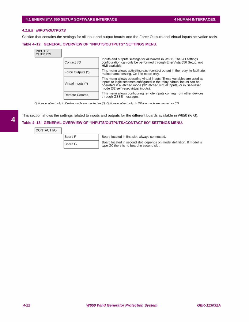
4-22 W650 Wind Generator Protection System GEK-113032A
4.1 ENERVISTA 650 SETUP SOFTWARE INTERFACE 4 HUMAN INTERFACES.
4
4.1.8.5 INPUT/OUTPUTS
Section that contains the settings for all input and output boards and the Force Outputs and Virtual inputs activation tools.
Table 4–12: GENERAL OVERVIEW OF “INPUTS/OUTPUTS” SETTINGS MENU.
Options enabled only in On-line mode are marked as (*). Options enabled only in Off-line mode are marked as (**)
This section shows the settings related to inputs and outputs for the different boards available in W650 (F, G).
Table 4–13: GENERAL OVERVIEW OF “INPUTS/OUTPUTS>CONTACT I/O” SETTINGS MENU.
INPUTS/OUTPUTS
Contact I/OInputs and outputs settings for all boards in W650. The I/O settings configuration can only be performed through EnerVista 650 Setup, not HMI available.
Force Outputs (*) This menu allows activating each contact output in the relay, to facilitate maintenance testing. On line mode only.
Virtual Inputs (*)This menu allows operating virtual inputs. These variables are used as inputs to logic schemes configured in the relay. Virtual inputs can be operated in a latched mode (32 latched virtual inputs) or in Self-reset mode (32 self reset virtual inputs).
Remote Comms. This menu allows configuring remote inputs coming from other devices through GSSE messages.
CONTACT I/O
Board F Board located in first slot, always connected.
Board G Board located in second slot, depends on model definition. If model is type G0 there is no board in second slot.
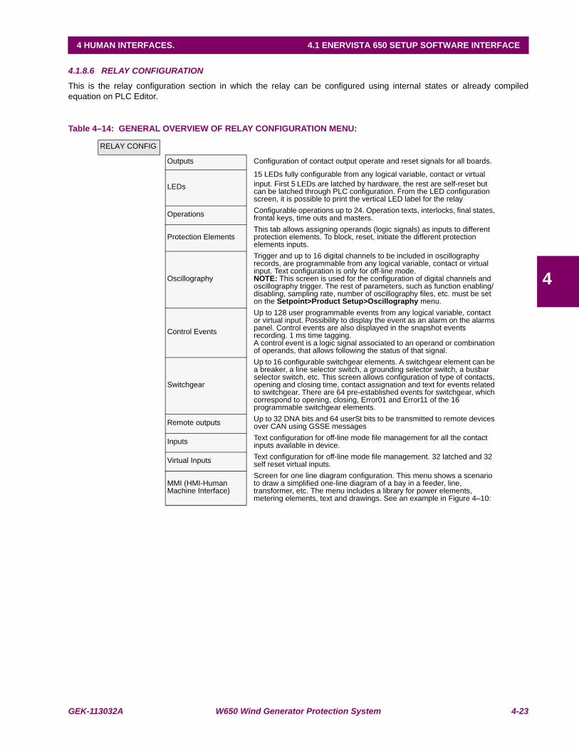
GEK-113032A W650 Wind Generator Protection System 4-23
4 HUMAN INTERFACES. 4.1 ENERVISTA 650 SETUP SOFTWARE INTERFACE
4
4.1.8.6 RELAY CONFIGURATION
This is the relay configuration section in which the relay can be configured using internal states or already compiledequation on PLC Editor.
Table 4–14: GENERAL OVERVIEW OF RELAY CONFIGURATION MENU:
RELAY CONFIG
Outputs Configuration of contact output operate and reset signals for all boards.
LEDs15 LEDs fully configurable from any logical variable, contact or virtual input. First 5 LEDs are latched by hardware, the rest are self-reset but can be latched through PLC configuration. From the LED configuration screen, it is possible to print the vertical LED label for the relay
Operations Configurable operations up to 24. Operation texts, interlocks, final states, frontal keys, time outs and masters.
Protection ElementsThis tab allows assigning operands (logic signals) as inputs to different protection elements. To block, reset, initiate the different protection elements inputs.
Oscillography
Trigger and up to 16 digital channels to be included in oscillography records, are programmable from any logical variable, contact or virtual input. Text configuration is only for off-line mode.NOTE: This screen is used for the configuration of digital channels and oscillography trigger. The rest of parameters, such as function enabling/disabling, sampling rate, number of oscillography files, etc. must be set on the Setpoint>Product Setup>Oscillography menu.
Control Events
Up to 128 user programmable events from any logical variable, contact or virtual input. Possibility to display the event as an alarm on the alarms panel. Control events are also displayed in the snapshot events recording. 1 ms time tagging.A control event is a logic signal associated to an operand or combination of operands, that allows following the status of that signal.
Switchgear
Up to 16 configurable switchgear elements. A switchgear element can be a breaker, a line selector switch, a grounding selector switch, a busbar selector switch, etc. This screen allows configuration of type of contacts, opening and closing time, contact assignation and text for events related to switchgear. There are 64 pre-established events for switchgear, which correspond to opening, closing, Error01 and Error11 of the 16 programmable switchgear elements.
Remote outputs Up to 32 DNA bits and 64 userSt bits to be transmitted to remote devices over CAN using GSSE messages
Inputs Text configuration for off-line mode file management for all the contact inputs available in device.
Virtual Inputs Text configuration for off-line mode file management. 32 latched and 32 self reset virtual inputs.
MMI (HMI-Human Machine Interface)
Screen for one line diagram configuration. This menu shows a scenario to draw a simplified one-line diagram of a bay in a feeder, line, transformer, etc. The menu includes a library for power elements, metering elements, text and drawings. See an example in Figure 4–10:
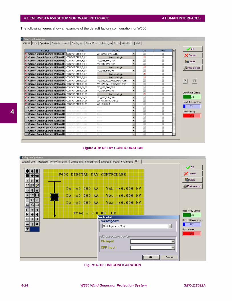
4-24 W650 Wind Generator Protection System GEK-113032A
4.1 ENERVISTA 650 SETUP SOFTWARE INTERFACE 4 HUMAN INTERFACES.
4
The following figures show an example of the default factory configuration for W650.
Figure 4–9: RELAY CONFIGURATION
Figure 4–10: HMI CONFIGURATION

GEK-113032A W650 Wind Generator Protection System 4-25
4 HUMAN INTERFACES. 4.1 ENERVISTA 650 SETUP SOFTWARE INTERFACE
4
4.1.8.7 LOGIC CONFIGURATION
This logic configuration allows creating more complex configurations, using the graphical PLC, than using the tables fromRelay Configuration. For file management detailed information go to section 4.1.5.
File description:
*.pep: Header for Logic project: PLC project file containing the necessary information relative to the relay model, logic librariesincluded in the project (*.lib), graphic file name (*.aut), etc.
*.aut: PLC Project file containing all the drawings used by the logic, required by 650 relay based on IEC 61131-3 standard. Functionalblock diagram (FDB).
*.lib: User programmable logic objects: Library file to be included as an object in a PLC project. Logic packages that can be storedinto libraries and be distributed in different PLC projects.
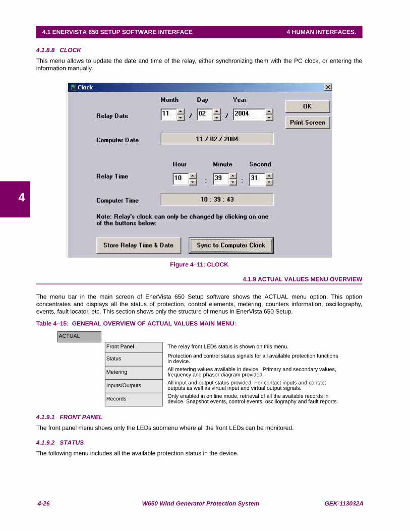
4-26 W650 Wind Generator Protection System GEK-113032A
4.1 ENERVISTA 650 SETUP SOFTWARE INTERFACE 4 HUMAN INTERFACES.
4
4.1.8.8 CLOCK
This menu allows to update the date and time of the relay, either synchronizing them with the PC clock, or entering theinformation manually.
Figure 4–11: CLOCK
4.1.9 ACTUAL VALUES MENU OVERVIEW
The menu bar in the main screen of EnerVista 650 Setup software shows the ACTUAL menu option. This optionconcentrates and displays all the status of protection, control elements, metering, counters information, oscillography,events, fault locator, etc. This section shows only the structure of menus in EnerVista 650 Setup.
Table 4–15: GENERAL OVERVIEW OF ACTUAL VALUES MAIN MENU:
4.1.9.1 FRONT PANEL
The front panel menu shows only the LEDs submenu where all the front LEDs can be monitored.
4.1.9.2 STATUS
The following menu includes all the available protection status in the device.
ACTUAL
Front Panel The relay front LEDs status is shown on this menu.
Status Protection and control status signals for all available protection functions in device.
Metering All metering values available in device. Primary and secondary values, frequency and phasor diagram provided.
Inputs/Outputs All input and output status provided. For contact inputs and contact outputs as well as virtual input and virtual output signals.
Records Only enabled in on line mode, retrieval of all the available records in device. Snapshot events, control events, oscillography and fault reports.
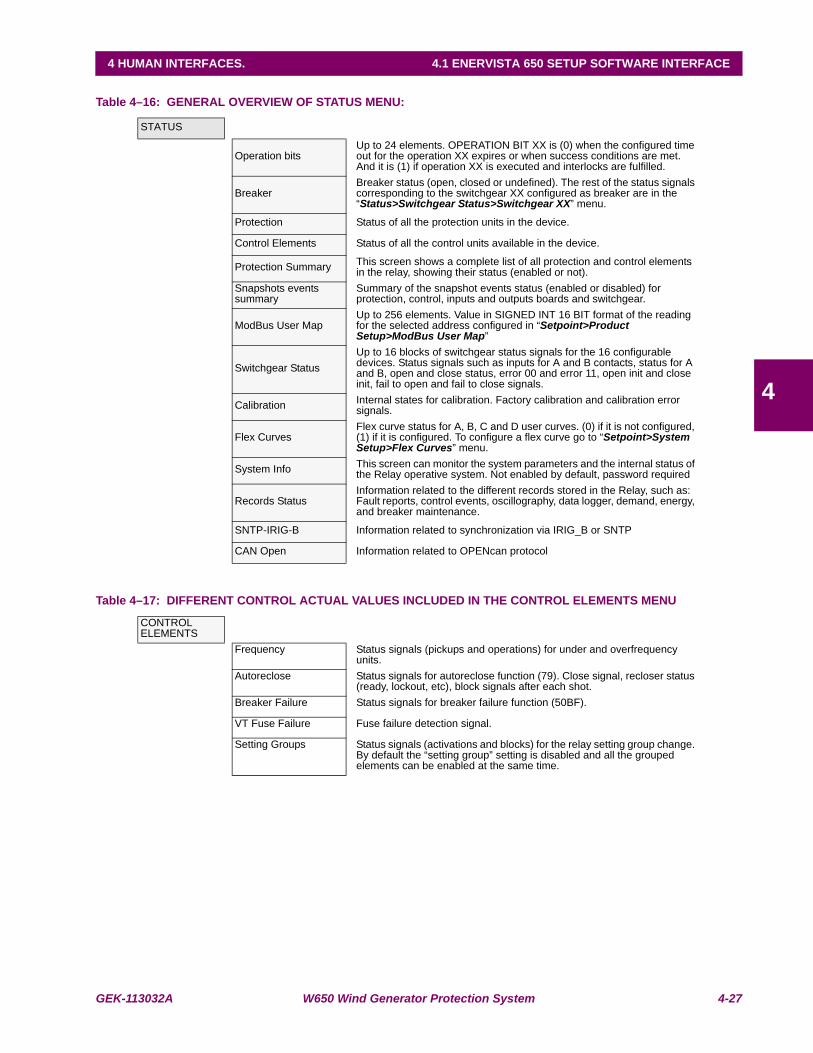
GEK-113032A W650 Wind Generator Protection System 4-27
4 HUMAN INTERFACES. 4.1 ENERVISTA 650 SETUP SOFTWARE INTERFACE
4
Table 4–16: GENERAL OVERVIEW OF STATUS MENU:
Table 4–17: DIFFERENT CONTROL ACTUAL VALUES INCLUDED IN THE CONTROL ELEMENTS MENU
STATUS
Operation bitsUp to 24 elements. OPERATION BIT XX is (0) when the configured time out for the operation XX expires or when success conditions are met. And it is (1) if operation XX is executed and interlocks are fulfilled.
BreakerBreaker status (open, closed or undefined). The rest of the status signals corresponding to the switchgear XX configured as breaker are in the “Status>Switchgear Status>Switchgear XX” menu.
Protection Status of all the protection units in the device.
Control Elements Status of all the control units available in the device.
Protection Summary This screen shows a complete list of all protection and control elements in the relay, showing their status (enabled or not).
Snapshots events summary
Summary of the snapshot events status (enabled or disabled) for protection, control, inputs and outputs boards and switchgear.
ModBus User MapUp to 256 elements. Value in SIGNED INT 16 BIT format of the reading for the selected address configured in “Setpoint>Product Setup>ModBus User Map”
Switchgear StatusUp to 16 blocks of switchgear status signals for the 16 configurable devices. Status signals such as inputs for A and B contacts, status for A and B, open and close status, error 00 and error 11, open init and close init, fail to open and fail to close signals.
Calibration Internal states for calibration. Factory calibration and calibration error signals.
Flex CurvesFlex curve status for A, B, C and D user curves. (0) if it is not configured, (1) if it is configured. To configure a flex curve go to “Setpoint>System Setup>Flex Curves” menu.
System Info This screen can monitor the system parameters and the internal status of the Relay operative system. Not enabled by default, password required
Records StatusInformation related to the different records stored in the Relay, such as: Fault reports, control events, oscillography, data logger, demand, energy, and breaker maintenance.
SNTP-IRIG-B Information related to synchronization via IRIG_B or SNTP
CAN Open Information related to OPENcan protocol
CONTROL ELEMENTS
Frequency Status signals (pickups and operations) for under and overfrequency units.
Autoreclose Status signals for autoreclose function (79). Close signal, recloser status (ready, lockout, etc), block signals after each shot.
Breaker Failure Status signals for breaker failure function (50BF).
VT Fuse Failure Fuse failure detection signal.
Setting Groups Status signals (activations and blocks) for the relay setting group change. By default the “setting group” setting is disabled and all the grouped elements can be enabled at the same time.
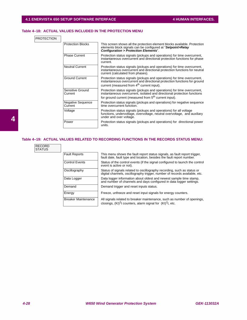
4-28 W650 Wind Generator Protection System GEK-113032A
4.1 ENERVISTA 650 SETUP SOFTWARE INTERFACE 4 HUMAN INTERFACES.
4
Table 4–18: ACTUAL VALUES INCLUDED IN THE PROTECTION MENU
Table 4–19: ACTUAL VALUES RELATED TO RECORDING FUNCTIONS IN THE RECORDS STATUS MENU:
PROTECTION
Protection Blocks This screen shows all the protection element blocks available. Protection elements block signals can be configured at “Setpoint>Relay Configuration > Protection Elements”.
Phase Current Protection status signals (pickups and operations) for time overcurrent, instantaneous overcurrent and directional protection functions for phase current.
Neutral Current Protection status signals (pickups and operations) for time overcurrent, instantaneous overcurrent and directional protection functions for neutral current (calculated from phases).
Ground Current Protection status signals (pickups and operations) for time overcurrent, instantaneous overcurrent and directional protection functions for ground current (measured from 4th current input).
Sensitive Ground Current
Protection status signals (pickups and operations) for time overcurrent, instantaneous overcurrent, isolated and directional protection functions for ground current (measured from 5th current input).
Negative Sequence Current
Protection status signals (pickups and operations) for negative sequence time overcurrent function.
Voltage Protection status signals (pickups and operations) for all voltage functions, undervoltage, overvoltage, neutral overvoltage, and auxiliary under and over voltage.
Power Protection status signals (pickups and operations) for directional power units.
RECORD STATUS
Fault Reports This menu shows the fault report status signals, as fault report trigger, fault date, fault type and location, besides the fault report number.
Control Events Status of the control events (if the signal configured to launch the control event is active or not).
Oscillography Status of signals related to oscillography recording, such as status or digital channels, oscillography trigger, number of records available, etc.
Data Logger Data logger information about oldest and newest sample time stamp, and number of channels and days configured in data logger settings.
Demand Demand trigger and reset inputs status.
Energy Freeze, unfreeze and reset input signals for energy counters.
Breaker Maintenance All signals related to breaker maintenance, such as number of openings, closings, (KI)2t counters, alarm signal for (KI)2t, etc.
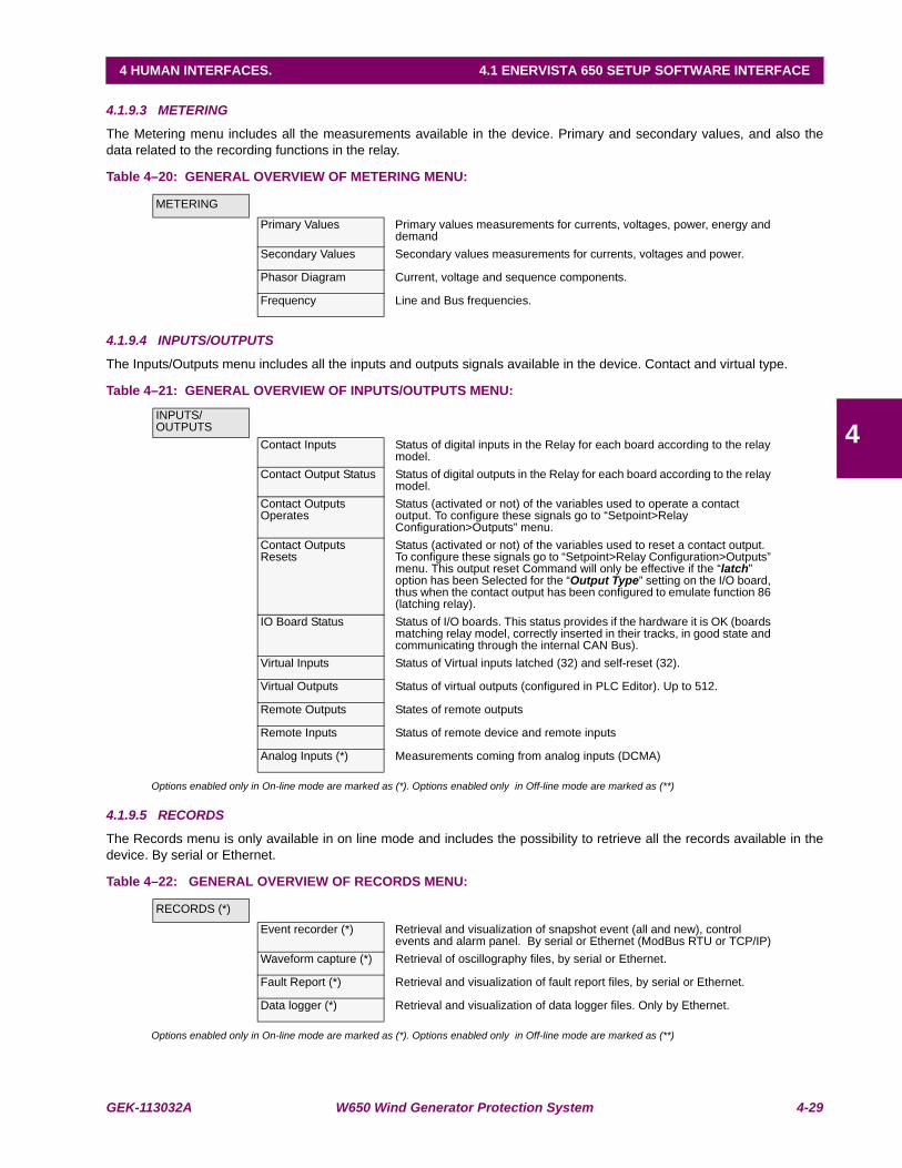
GEK-113032A W650 Wind Generator Protection System 4-29
4 HUMAN INTERFACES. 4.1 ENERVISTA 650 SETUP SOFTWARE INTERFACE
4
4.1.9.3 METERING
The Metering menu includes all the measurements available in the device. Primary and secondary values, and also thedata related to the recording functions in the relay.
Table 4–20: GENERAL OVERVIEW OF METERING MENU:
4.1.9.4 INPUTS/OUTPUTS
The Inputs/Outputs menu includes all the inputs and outputs signals available in the device. Contact and virtual type.
Table 4–21: GENERAL OVERVIEW OF INPUTS/OUTPUTS MENU:
Options enabled only in On-line mode are marked as (*). Options enabled only in Off-line mode are marked as (**)
4.1.9.5 RECORDS
The Records menu is only available in on line mode and includes the possibility to retrieve all the records available in thedevice. By serial or Ethernet.
Table 4–22: GENERAL OVERVIEW OF RECORDS MENU:
Options enabled only in On-line mode are marked as (*). Options enabled only in Off-line mode are marked as (**)
METERING
Primary Values Primary values measurements for currents, voltages, power, energy and demand
Secondary Values Secondary values measurements for currents, voltages and power.
Phasor Diagram Current, voltage and sequence components.
Frequency Line and Bus frequencies.
INPUTS/OUTPUTS
Contact Inputs Status of digital inputs in the Relay for each board according to the relay model.
Contact Output Status Status of digital outputs in the Relay for each board according to the relay model.
Contact Outputs Operates
Status (activated or not) of the variables used to operate a contact output. To configure these signals go to “Setpoint>Relay Configuration>Outputs” menu.
Contact Outputs Resets
Status (activated or not) of the variables used to reset a contact output. To configure these signals go to “Setpoint>Relay Configuration>Outputs” menu. This output reset Command will only be effective if the “latch” option has been Selected for the “Output Type” setting on the I/O board, thus when the contact output has been configured to emulate function 86 (latching relay).
IO Board Status Status of I/O boards. This status provides if the hardware it is OK (boards matching relay model, correctly inserted in their tracks, in good state and communicating through the internal CAN Bus).
Virtual Inputs Status of Virtual inputs latched (32) and self-reset (32).
Virtual Outputs Status of virtual outputs (configured in PLC Editor). Up to 512.
Remote Outputs States of remote outputs
Remote Inputs Status of remote device and remote inputs
Analog Inputs (*) Measurements coming from analog inputs (DCMA)
RECORDS (*)
Event recorder (*) Retrieval and visualization of snapshot event (all and new), control events and alarm panel. By serial or Ethernet (ModBus RTU or TCP/IP)
Waveform capture (*) Retrieval of oscillography files, by serial or Ethernet.
Fault Report (*) Retrieval and visualization of fault report files, by serial or Ethernet.
Data logger (*) Retrieval and visualization of data logger files. Only by Ethernet.
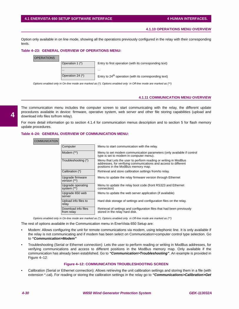
4-30 W650 Wind Generator Protection System GEK-113032A
4.1 ENERVISTA 650 SETUP SOFTWARE INTERFACE 4 HUMAN INTERFACES.
4
4.1.10 OPERATIONS MENU OVERVIEW
Option only available in on line mode, showing all the operations previously configured in the relay with their correspondingtexts.
Table 4–23: GENERAL OVERVIEW OF OPERATIONS MENU:
Options enabled only in On-line mode are marked as (*). Options enabled only in Off-line mode are marked as (**)
4.1.11 COMMUNICATION MENU OVERVIEW
The communication menu includes the computer screen to start communicating with the relay, the different updateprocedures available in device: firmware, operative system, web server and other file storing capabilities (upload anddownload info files to/from relay).
For more detail information go to section 4.1.4 for communication menus description and to section 5 for flash memoryupdate procedures.
Table 4–24: GENERAL OVERVIEW OF COMMUNICATION MENU:
Options enabled only in On-line mode are marked as (*). Options enabled only in Off-line mode are marked as (**)
The rest of options available in the Communication menu in EnerVista 650 Setup are:
• Modem: Allows configuring the unit for remote communications via modem, using telephonic line. It is only available ifthe relay is not communicating and if modem has been select on Communication>computer control type selection. Goto “Communication>Modem”
• Troubleshooting (Serial or Ethernet connection): Lets the user to perform reading or writing in ModBus addresses, forverifying communications and access to different positions in the ModBus memory map. Only available if thecommunication has already been established. Go to “Communication>Troubleshooting”. An example is provided inFigure 4–12:
Figure 4–12: COMMUNICATION TROUBLESHOOTING SCREEN
• Calibration (Serial or Ethernet connection): Allows retrieving the unit calibration settings and storing them in a file (withextension *.cal). For reading or storing the calibration settings in the relay go to “Communications>Calibration>Get
OPERATIONS
Operation 1 (*) Entry to first operation (with its corresponding text)
... ...
Operation 24 (*) Entry to 24th operation (with its corresponding text)
COMMUNICATION
Computer Menu to start communication with the relay.
Modem (**) Menu to set modem communication parameters (only available if control type is set to modem in computer menu).
Troubleshooting (*) Menu that Lets the user to perform reading or writing in ModBus addresses, for verifying communications and access to different positions in the ModBus memory map.
Calibration (*) Retrieval and store calibration settings from/to relay.
Upgrade firmware version (**)
Menu to update the relay firmware version through Ethernet
Upgrade operating system (**)
Menu to update the relay boot code (front RS323 and Ethernet connection)
Upgrade 650 web server
Menu to update the web server application (if available)
Upload info files to relay
Hard disk storage of settings and configuration files on the relay.
Download info files from relay
Retrieval of settings and configuration files that had been previously stored in the relay hard disk.

GEK-113032A W650 Wind Generator Protection System 4-31
4 HUMAN INTERFACES. 4.1 ENERVISTA 650 SETUP SOFTWARE INTERFACE
4
or Set calibration settings” and select the intended calibration file. The calibration retrieval process is necessary tobe performed before updating the unit operative system, when the operating system is updated all the data in the relayis deleted, including the factory calibration settings. When only the firmware is updated (for versions higher than 1.50),the calibration settings are automatically saved in the relay.
• Upgrade firmware version (Ethernet connection): Go to “Communications>Upgrade firmware version”, this menuallows the user to update the firmware version of the relay through Ethernet communication. Firmware is related to therelay internal program, designed by GE Multilin, which performs the protection and control functions, and which is runby the relay main microprocessor.
• Upgrade operating system (Serial and Ethernet connection): Go to “Communications>Upgrade operating system”.This option allows the user to update the relay operative system. The operative system or OS is the program thatsupports the firmware and provides auxiliary services for access to electronic devices included in the relay.
IMPORTANT NOTE:
Thanks to the use of a double flash memory, one with the Bootcode startup program and the operative system, and asecond one with the application program (firmware), a high reliability is guaranteed when updating the unit firmware, aseven if the case of a communication breakdown during the firmware upgrade process, we can retry the process for anunlimited number of times.
• Upgrade 650 web server (Ethernet connection): Go to “Communications> Upgrade 650 web server”. The relay webserver application can be updated to further versions (if available) using this menu without modifying the relayoperative system.
• Upload info files to relay (Ethernet connection): Go to “Communications>Upload info files to relay”. Thisfunctionality is used to store setting files (*.650) inside the relay, as well as auxiliary files used by the programmablelogic graphical editor (*.pep, *.aut, *.lib).
• Download info files from relay (Ethernet connection): Go to “Communications>Download info files from relay”.This functionality is used for retrieving the files (*.650 and *.pep, *.aut, *.lib) that have been previously stored in therelay flash memory.
Important Note:
READ CAREFULLY THE FLASH MEMORY UPDATE PROCEDURE DESCRIBED INSECTION 9 AND CLOSE ALL THE RUNNING APPLICATIONS BEFOREPERFORMING FIRMWARE AND OPERATIVE SYSTEM UPDATING PROCCESS
Before updating firmware check that the firmware version that is going to be updatedmatch the operative system version of the relay. Otherwise it is necessary to update theoperative system before proceeding to update the firmware. Other combinations offirmware and operative system different from the listed below will not be operative
The operative system version is available in the logotype main screen in HMI; it is thenumber between brackets in the first line, e.g. W6501.70 (2.35). The operative systemversion is 2.35
Firmware version up to 1.5X must be used with Boot Code 2.30 (or 2.20 and 2.35)
Firmware version from 1.6X up to 1.8X must be used with Boot Code 2.35
Firmware version 2.00 must be used with Boot Code 3.00
*.650 files contain protection, control settings, relay configuration and compiled logicequations. This file can be retrieved from the relay, using the “File>Get info fromrelay” option in EnerVista 650 Setup (through serial or Ethernet communication).“File>Send info to relay” option stores this *.650 file in the relay.
4-32 W650 Wind Generator Protection System GEK-113032A
4.1 ENERVISTA 650 SETUP SOFTWARE INTERFACE 4 HUMAN INTERFACES.
4
*.pep, *.aut and *.lib files contain the logic configuration projects necessary to modify thelogic (virtual outputs) in the relay. These files can be stored in the relay, using the“Communication>Upload info files to relay” option in EnerVista 650 Setup (throughEthernet communication). They can be retrieved using “Communication>Downloadinfo files to relay” option in EnerVista 650 Setup program (Ethernet communication).Take into account that the *.pep, *.aut and library files are necessary to modify the PLClogic (virtual outputs). Without these files setting and configuration can be modified butnot logic equations (virtual outputs). It is advisable to use the“Communication>Upload info files to relay” option to store these logic configurationfiles into the relay.
It is important to distinguish between “Send / Get info to relay” and “Upload /Download info files to/from relay”. “File>Send/Get info to relay” sends/getssettings and configuration and compiled logic equation to/from the relay (*.650 format),and the relay automatically starts working with the new settings once they are stored.“Communications>Upload/Download info files to relay“, stores/retrieves in therelay hard disk: settings, configuration and compiled logic equations (*.650) besides thePLC files (*.pep, *.aut, *.lib). This is only a physical storage (file backup).

GEK-113032A W650 Wind Generator Protection System 4-33
4 HUMAN INTERFACES. 4.1 ENERVISTA 650 SETUP SOFTWARE INTERFACE
4
4.1.12 SECURITY MENU OVERVIEW
The security menu includes all the menus related to security control in EnerVista 650 Setup. EnerVista 650 Setup securityusers and passwords are not related to passwords in HMI. Each security level has its own access for HMI managementand EnerVista 650 Setup management.
Table 4–25: GENERAL OVERVIEW OF SECURITY MENU:
Options enabled only in On-line mode are marked as (*). Options enabled only in Off-line mode are marked as (**)
4.1.13 VIEW MENU OVERVIEW
The view menu includes the computer screen to start communicating with the relay, the different update proceduresavailable in device: firmware, operative system, web server and other file storing capabilities (upload and download infofiles to/from relay).
The ModBus memory map is detailed in the complete instruction manual (English only) and can be obtained from EnerVista650 Setup program.
Table 4–26: GENERAL OVERVIEW OF VIEW MENU:
Options enabled only in On-line mode are marked as (*). Options enabled only in Off-line mode are marked as (**)
4.1.14 HELP MENU OVERVIEW
Complete instructions manual and data about EnerVista 650 Setup release.
Table 4–27: GENERAL OVERVIEW OF HELP MENU:
SECURITY
Login User (*) Log on menu for EnerVista 650 Setup. Enabled after security control has been enabled in user management menu.
Change Password (*) Menu to change passwords and establish password recovering questions.
User Management (*) User management dialog box.
VIEW
Traces (*) To inspect ModBus communication traces between the EnerVista 650 Setup and the relay.
ModBus Memory map Complete ModBus memory map description.
Languages (**) Option to change the EnerVista 650 Setup default language. Only available if the relay is not communicating and no file (*650) is open.
HELP
Instructions Manual Instructions manual in the language selected in “View>Languages” menu.
About EnerVista 650 Setup
Release version and date of EnerVista 650 Setup program.
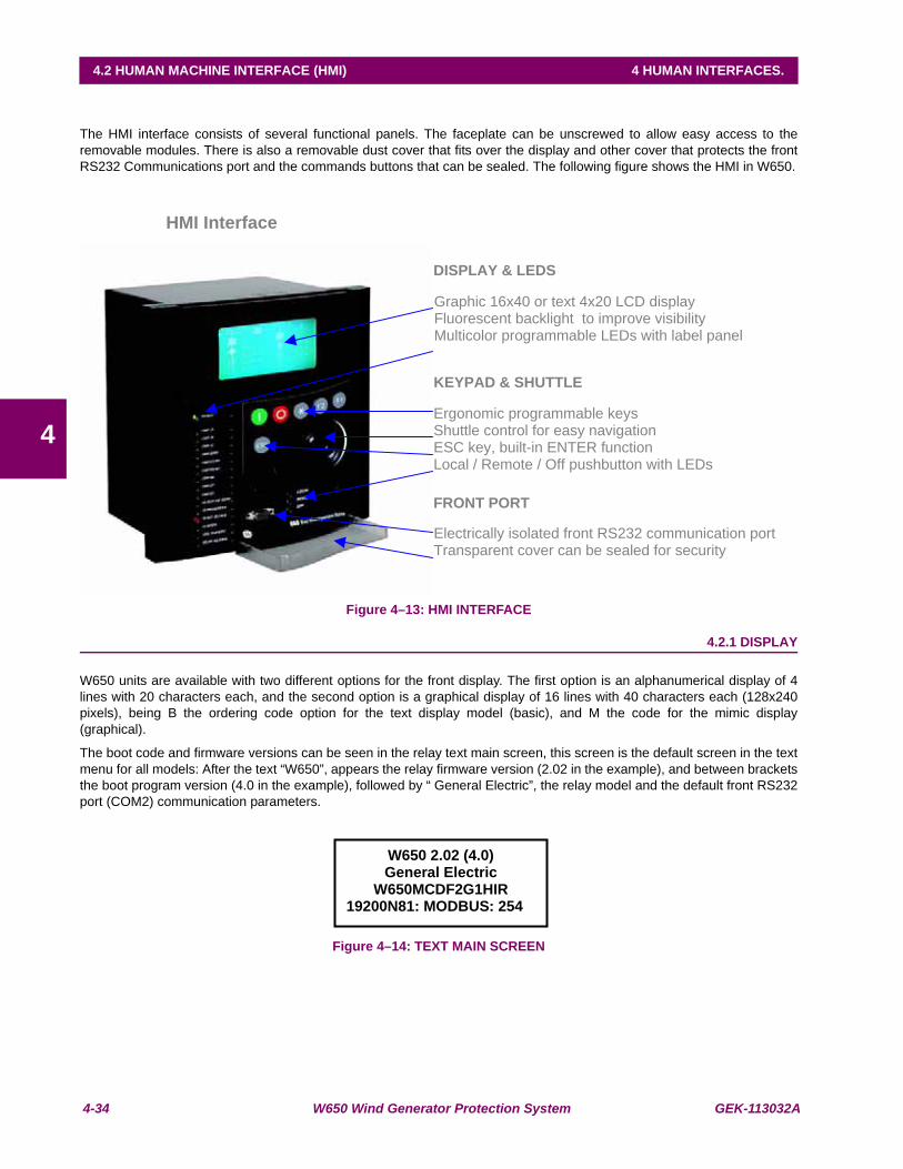
4-34 W650 Wind Generator Protection System GEK-113032A
4.2 HUMAN MACHINE INTERFACE (HMI) 4 HUMAN INTERFACES.
4
4.2 HUMAN MACHINE INTERFACE (HMI)T
The HMI interface consists of several functional panels. The faceplate can be unscrewed to allow easy access to theremovable modules. There is also a removable dust cover that fits over the display and other cover that protects the frontRS232 Communications port and the commands buttons that can be sealed. The following figure shows the HMI in W650.
Figure 4–13: HMI INTERFACE
4.2.1 DISPLAY
W650 units are available with two different options for the front display. The first option is an alphanumerical display of 4lines with 20 characters each, and the second option is a graphical display of 16 lines with 40 characters each (128x240pixels), being B the ordering code option for the text display model (basic), and M the code for the mimic display(graphical).
The boot code and firmware versions can be seen in the relay text main screen, this screen is the default screen in the textmenu for all models: After the text “W650”, appears the relay firmware version (2.02 in the example), and between bracketsthe boot program version (4.0 in the example), followed by “ General Electric”, the relay model and the default front RS232port (COM2) communication parameters.
Figure 4–14: TEXT MAIN SCREEN
Ergonomic programmable keys Shuttle control for easy navigation ESC key, built-in ENTER function and audio feedback Local / Remote / Off pushbutton with LEDs
HMI Interface
Graphic 16x40 or text 4x20 LCD display Fluorescent backlight to improve visibility Multicolor programmable LEDs with label panel
DISPLAY & LEDS
KEYPAD & SHUTTLE
Electrically isolated front RS232 communication port Transparent cover can be sealed for security
FRONT PORT
W650 2.02 (4.0) General Electric
W650MCDF2G1HIR 19200N81: MODBUS: 254
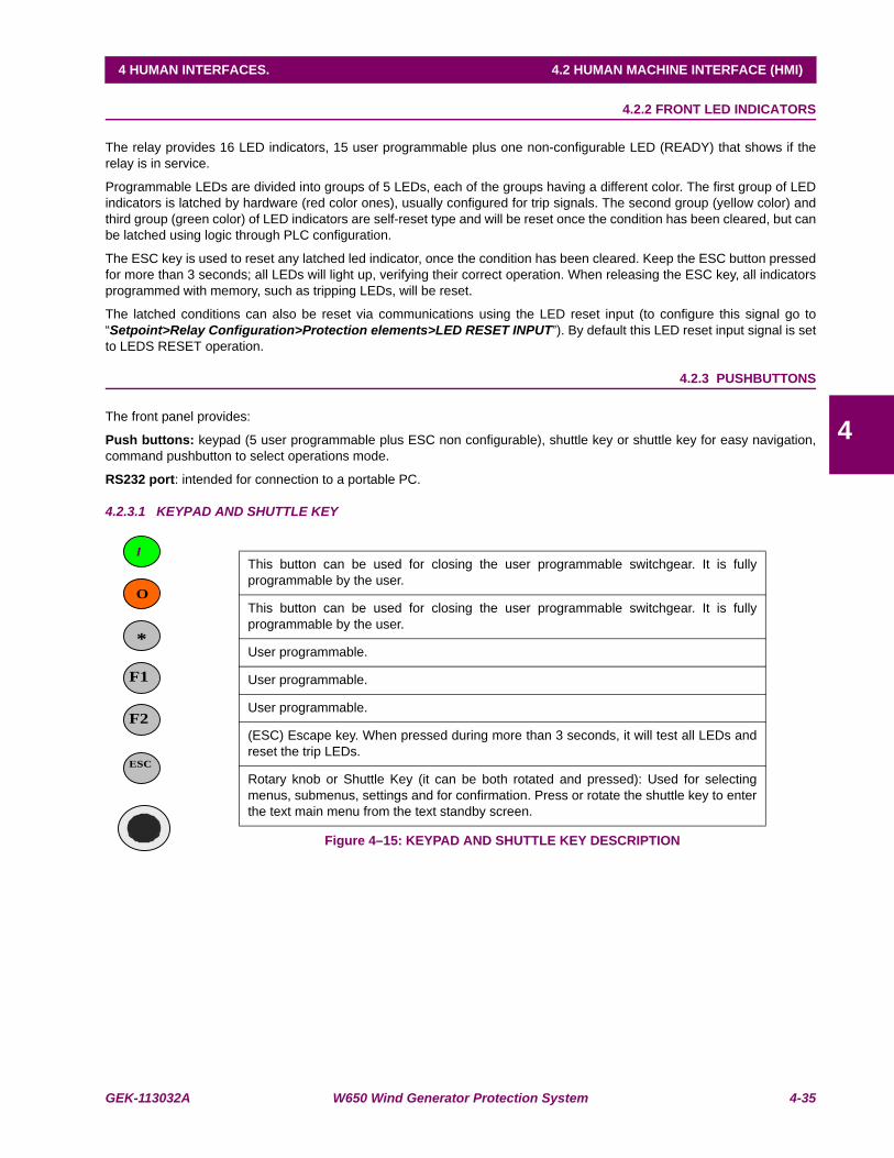
GEK-113032A W650 Wind Generator Protection System 4-35
4 HUMAN INTERFACES. 4.2 HUMAN MACHINE INTERFACE (HMI)
4
4.2.2 FRONT LED INDICATORS
The relay provides 16 LED indicators, 15 user programmable plus one non-configurable LED (READY) that shows if therelay is in service.
Programmable LEDs are divided into groups of 5 LEDs, each of the groups having a different color. The first group of LEDindicators is latched by hardware (red color ones), usually configured for trip signals. The second group (yellow color) andthird group (green color) of LED indicators are self-reset type and will be reset once the condition has been cleared, but canbe latched using logic through PLC configuration.
The ESC key is used to reset any latched led indicator, once the condition has been cleared. Keep the ESC button pressedfor more than 3 seconds; all LEDs will light up, verifying their correct operation. When releasing the ESC key, all indicatorsprogrammed with memory, such as tripping LEDs, will be reset.
The latched conditions can also be reset via communications using the LED reset input (to configure this signal go to“Setpoint>Relay Configuration>Protection elements>LED RESET INPUT”). By default this LED reset input signal is setto LEDS RESET operation.
4.2.3 PUSHBUTTONS
The front panel provides:
Push buttons: keypad (5 user programmable plus ESC non configurable), shuttle key or shuttle key for easy navigation,command pushbutton to select operations mode.
RS232 port: intended for connection to a portable PC.
4.2.3.1 KEYPAD AND SHUTTLE KEY
Figure 4–15: KEYPAD AND SHUTTLE KEY DESCRIPTION
This button can be used for closing the user programmable switchgear. It is fullyprogrammable by the user.
This button can be used for closing the user programmable switchgear. It is fullyprogrammable by the user.
User programmable.
User programmable.
User programmable.
(ESC) Escape key. When pressed during more than 3 seconds, it will test all LEDs andreset the trip LEDs.
Rotary knob or Shuttle Key (it can be both rotated and pressed): Used for selectingmenus, submenus, settings and for confirmation. Press or rotate the shuttle key to enterthe text main menu from the text standby screen.
O
*
F1
I
F2
ESC
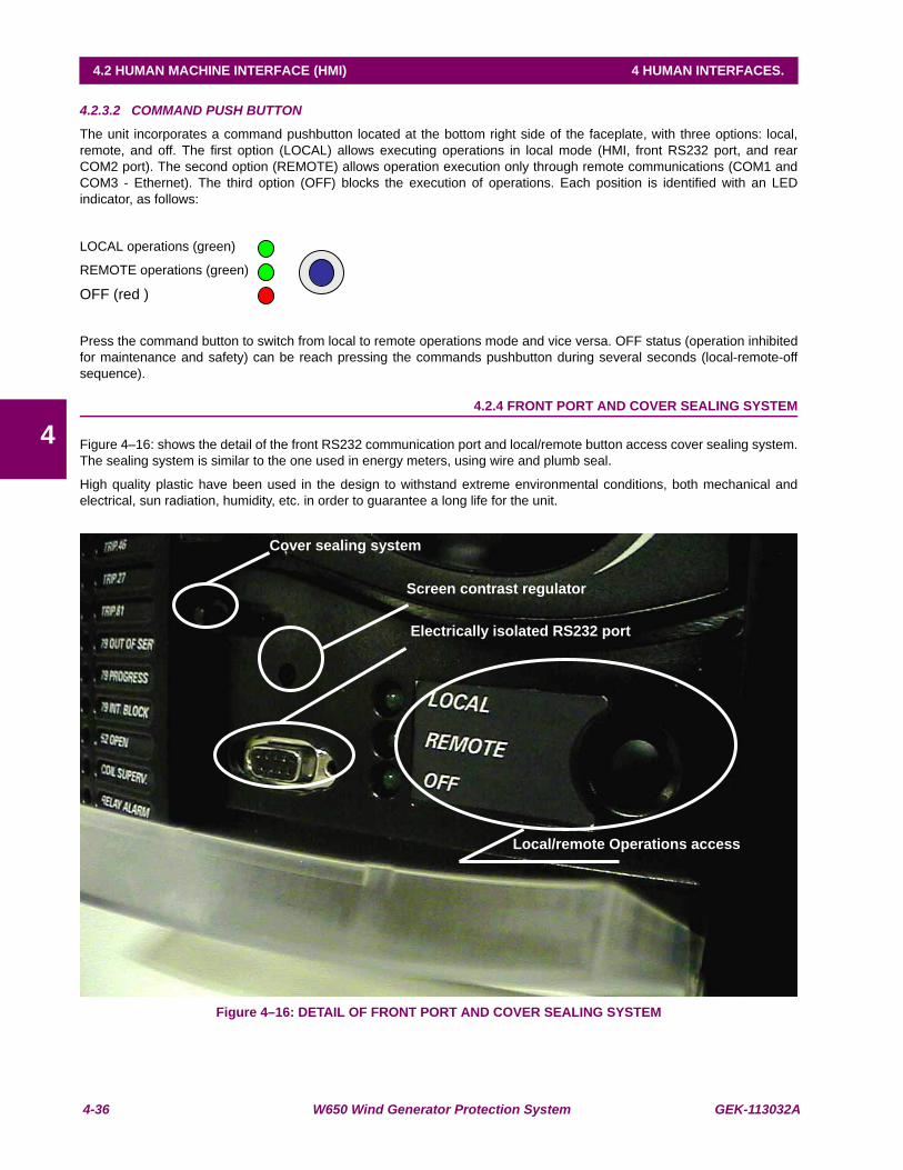
4-36 W650 Wind Generator Protection System GEK-113032A
4.2 HUMAN MACHINE INTERFACE (HMI) 4 HUMAN INTERFACES.
4
4.2.3.2 COMMAND PUSH BUTTON
The unit incorporates a command pushbutton located at the bottom right side of the faceplate, with three options: local,remote, and off. The first option (LOCAL) allows executing operations in local mode (HMI, front RS232 port, and rearCOM2 port). The second option (REMOTE) allows operation execution only through remote communications (COM1 andCOM3 - Ethernet). The third option (OFF) blocks the execution of operations. Each position is identified with an LEDindicator, as follows:
LOCAL operations (green)
REMOTE operations (green)
OFF (red )
Press the command button to switch from local to remote operations mode and vice versa. OFF status (operation inhibitedfor maintenance and safety) can be reach pressing the commands pushbutton during several seconds (local-remote-offsequence).
4.2.4 FRONT PORT AND COVER SEALING SYSTEM
Figure 4–16: shows the detail of the front RS232 communication port and local/remote button access cover sealing system.The sealing system is similar to the one used in energy meters, using wire and plumb seal.
High quality plastic have been used in the design to withstand extreme environmental conditions, both mechanical andelectrical, sun radiation, humidity, etc. in order to guarantee a long life for the unit.
Figure 4–16: DETAIL OF FRONT PORT AND COVER SEALING SYSTEM
Screen contrast regulator
Cover sealing system
Electrically isolated RS232 port
Local/remote Operations access

GEK-113032A W650 Wind Generator Protection System 4-37
4 HUMAN INTERFACES. 4.2 HUMAN MACHINE INTERFACE (HMI)
4
4.2.5 TEXT MENUS
4.2.5.1 NAVIGATION IN TEXT MENU
Text menu is available for all models, this is the main menu for visualizing actual values, metering, changing settings, etc.through the HMI. In models with graphical display (M in ordering code) besides this text main menu there are severalscreens providing more performance for control purposes.
Press (or rotate left or right) the shuttle key to enter the main menu, starting from the standby screen (default main screen).The default main screen can be accessed pressing ESC key till it appears. In all the navigation Press the shuttle key toselect the desired header display (top-level menu). Each press of the shuttle key advances through the main headingpages as illustrated below. To return to previous menus press the ESC key. To move inside the top-level menu withoutchanging to other low levels, rotate the shuttle key left to move up and right to move down.
When rotating the shuttle key the selected menu is marked by a single scroll bar character. The mark (>) in the right part ofany menu means that contains more than one level.
Figure 4–17:shows an example of main menu navigation:
Figure 4–17: NAVIGATION IN MAIN TEXT MENU
Symbol Action Performed Navigation in menu
ENTER Press Shuttle Key Enter next level ESCAPE Press Esc Key Exit to previous level L-R Rotate Shuttle Key Move up and down in the same level L Rotate left Shuttle Key Move up in the same level R Rotate right Shuttle Key Move down in the same level
Menu selection Menu selection > More menus to display More menus to display
W650 2.02 (4.0) GENERAL ELECTRIC W650MCDF2G1HIR
19200N81: MODBUS : 254
Actual Values Snapshot event Fault report View Settings Change Settings Date & Time Commands Passwords Select Main Screen Select Language
Return
Front Panel > Status > Metering > Inputs/Outputs >
Product Setup > System Setup > Protection Element> Control Elements >
Logotype > Metering > All >
Return
ENTER ESCAPE
ENTERESCAPE
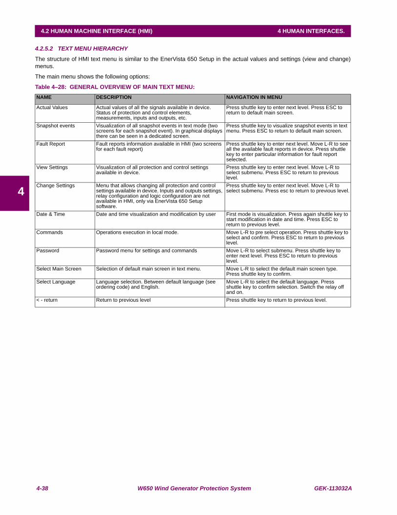
4-38 W650 Wind Generator Protection System GEK-113032A
4.2 HUMAN MACHINE INTERFACE (HMI) 4 HUMAN INTERFACES.
4
4.2.5.2 TEXT MENU HIERARCHY
The structure of HMI text menu is similar to the EnerVista 650 Setup in the actual values and settings (view and change)menus.
The main menu shows the following options:
Table 4–28: GENERAL OVERVIEW OF MAIN TEXT MENU:NAME DESCRIPTION NAVIGATION IN MENU
Actual Values Actual values of all the signals available in device. Status of protection and control elements, measurements, inputs and outputs, etc.
Press shuttle key to enter next level. Press ESC to return to default main screen.
Snapshot events Visualization of all snapshot events in text mode (two screens for each snapshot event). In graphical displays there can be seen in a dedicated screen.
Press shuttle key to visualize snapshot events in text menu. Press ESC to return to default main screen.
Fault Report Fault reports information available in HMI (two screens for each fault report)
Press shuttle key to enter next level. Move L-R to see all the available fault reports in device. Press shuttle key to enter particular information for fault report selected.
View Settings Visualization of all protection and control settings available in device.
Press shuttle key to enter next level. Move L-R to select submenu. Press ESC to return to previous level.
Change Settings Menu that allows changing all protection and control settings available in device. Inputs and outputs settings, relay configuration and logic configuration are not available in HMI, only via EnerVista 650 Setup software.
Press shuttle key to enter next level. Move L-R to select submenu. Press esc to return to previous level.
Date & Time Date and time visualization and modification by user First mode is visualization. Press again shuttle key to start modification in date and time. Press ESC to return to previous level.
Commands Operations execution in local mode. Move L-R to pre select operation. Press shuttle key to select and confirm. Press ESC to return to previous level.
Password Password menu for settings and commands Move L-R to select submenu. Press shuttle key to enter next level. Press ESC to return to previous level.
Select Main Screen Selection of default main screen in text menu. Move L-R to select the default main screen type. Press shuttle key to confirm.
Select Language Language selection. Between default language (see ordering code) and English.
Move L-R to select the default language. Press shuttle key to confirm selection. Switch the relay off and on.
< - return Return to previous level Press shuttle key to return to previous level.
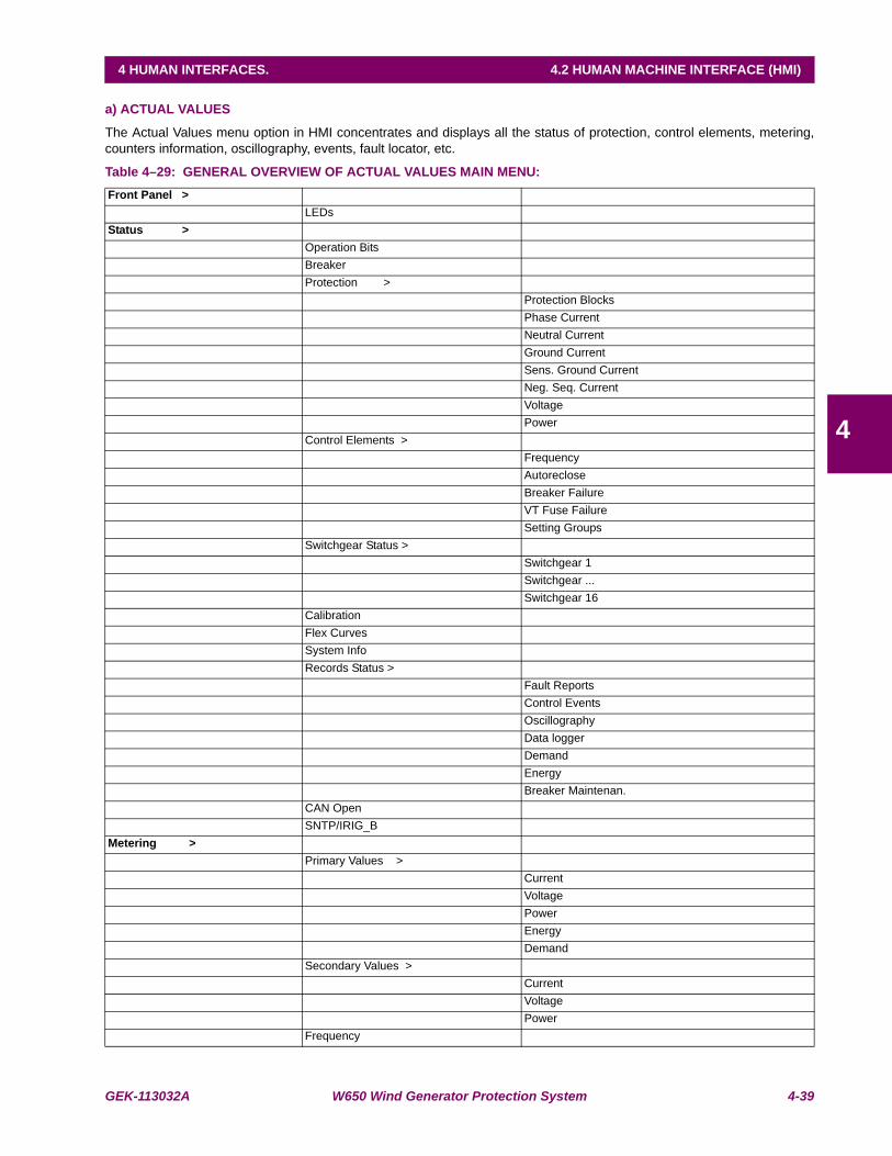
GEK-113032A W650 Wind Generator Protection System 4-39
4 HUMAN INTERFACES. 4.2 HUMAN MACHINE INTERFACE (HMI)
4
a) ACTUAL VALUES
The Actual Values menu option in HMI concentrates and displays all the status of protection, control elements, metering,counters information, oscillography, events, fault locator, etc.
Table 4–29: GENERAL OVERVIEW OF ACTUAL VALUES MAIN MENU:Front Panel >
LEDsStatus >
Operation BitsBreakerProtection >
Protection BlocksPhase CurrentNeutral CurrentGround CurrentSens. Ground CurrentNeg. Seq. CurrentVoltagePower
Control Elements >FrequencyAutorecloseBreaker FailureVT Fuse FailureSetting Groups
Switchgear Status >Switchgear 1Switchgear ...Switchgear 16
CalibrationFlex CurvesSystem InfoRecords Status >
Fault ReportsControl EventsOscillographyData loggerDemandEnergyBreaker Maintenan.
CAN OpenSNTP/IRIG_B
Metering >Primary Values >
CurrentVoltagePowerEnergyDemand
Secondary Values >CurrentVoltagePower
Frequency

4-40 W650 Wind Generator Protection System GEK-113032A
4.2 HUMAN MACHINE INTERFACE (HMI) 4 HUMAN INTERFACES.
4
To enter this menu press the shuttle key when the option Actual Values is selected in main menu. A secondary level will bedisplayed with different sublevels as shown on Table 4–29:. Rotating the shuttle key, (left for moving up and right for movingdown) select the next level to be displayed, press the shuttle key again to enter in next level and press ESC key to return toprevious level if desired. This navigation will be performed the same for all the menus in Actual Values. Once the lastsublevel is reached, move up and down to visualize the actual values selected.
One example of data screen for actual values is shown in Figure 4–18:.
First Line: Header of last level in actual values (Phase Current in the example)
Second Line: Data identifier (in the example PH IOC1 HIGH A, is the pickup signal for the first instantaneousovercurrent function level high for phase A).
Third line: Status of the displayed actual value.
Fourth Line: Relative position in the menu (it is the first value of 114)
Figure 4–18: ACTUAL VALUES SCREEN DATA
In the Actual Values menus are different types of data, each type of data will display its particular status type (on and off, 0or 1, ok or fail, analog values, etc.)
Inputs/Outputs >Contact Inputs >
Board F/ Board GCont. Output St. >
Board F/ Board GCont. Output Op. >
Board F/ Board GCont. Output Rs. >
Board F/ Board GIO Board StatusVirtual Inputs >
Virtual Inp.LatchedVirtual Inp.SR
Virtual OutputsRemote Outputs >
DNAUser St
Remote Inputs >Remote InputRemote Devices
Analog Inputs >Board F/ Board G
Phase Current PH IOC1 HIGH A PKP
OFF(1/114)

GEK-113032A W650 Wind Generator Protection System 4-41
4 HUMAN INTERFACES. 4.2 HUMAN MACHINE INTERFACE (HMI)
4
4.2.5.3 SNAPSHOT EVENTS
To enter this menu press the shuttle key when the option Snapshot events is selected in main menu (). In this menu all thesnapshot events stored can be displayed.
Snapshot events are changes in the relay internal status.
One snapshot event is displayed in two text screens:
The first screen display the status, date and time of the snapshot event: the snapshot event identifier, its status,event number and the date and time of the occurrence. If the snapshot event identifier does not fit the first line, thewhole text will be shown using as well the second line alternating with the status and event number.
The second screen displays currents and voltages in primary values for that particular snapshot event. Ia, Ib, Icand Ig for currents and Vab, Vbc, Vca and V0 for voltages. To access the metering screen in snapshot eventsmenu, press shuttle key from the snapshot event first screen. To exit from the metering screen pres ESC.
To select different snapshot events to be displayed, rotate the shuttle key to select the snapshot event and then press theshuttle key to enter the metering screen. Press esc to exit the metering screen and return to snapshot events menu.

4-42 W650 Wind Generator Protection System GEK-113032A
4.2 HUMAN MACHINE INTERFACE (HMI) 4 HUMAN INTERFACES.
4
Figure 4–19: shows an example of snapshot events navigation:
Press shuttle key from the default main screen and enter in the main text menu.
Move the shuttle key until a single scroll bar character ( ) appears in the left part of Snapshot event header.
Press shuttle key to enter in the snapshot events menu)
Select the snapshot event to display using the shuttle key (left and right to move up and down inside the recorded snapshotevents).
Once selected the snapshot event, identifier , status, date and time will be displayed.
In the second line St: is showing the status and the relative snapshot index from the whole recorded number. Third andfourth lines are used to display the time and date of the snapshot event.
Pressing the shuttle key the metering screen for the snapshot event will be displayed.
To exit from this screen press the ESC key and return to the snapshot events menu.
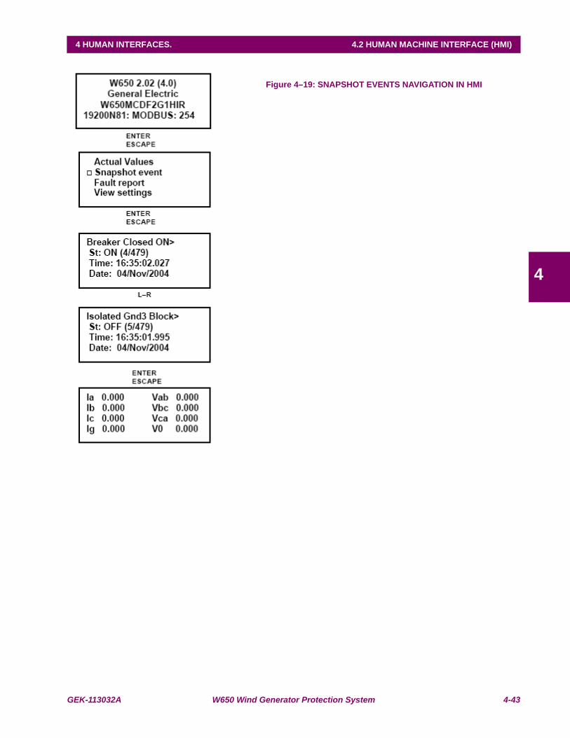
GEK-113032A W650 Wind Generator Protection System 4-43
4 HUMAN INTERFACES. 4.2 HUMAN MACHINE INTERFACE (HMI)
4
Figure 4–19: SNAPSHOT EVENTS NAVIGATION IN HMI
4-44 W650 Wind Generator Protection System GEK-113032A
4.2 HUMAN MACHINE INTERFACE (HMI) 4 HUMAN INTERFACES.
4
4.2.5.4 FAULT REPORT
To enter this menu press the shuttle key when the option Fault report is selected in main menu (). This menu displaysinformation about the last ten faults recorded in the relay.
The Relay HMI allows two types of visualization for the fault reports stored in the Relay:
1. Showing the fault warning messages in the text display when the fault is produced. This option has to be enabledby setting. To change from the HMI go to the menu “Change Settings >Product Setup > Fault Report > ShowFault On HMI” and enable it.
2.Only saving and allowing viewing the information from the last ten faults recorded in the relay.
In the first option, when a fault occurs a warning message is displayed, including information about the fault in two screens,one with general fault information, and a second one with the measured values in the moment of the fault.
The fault-warning message must be acknowledged by the user; this means that the user must press the shuttle key for thisscreen to disappear, The HMI will not allow to perform any other operation until the screen is acknowledged. In the event ofseveral consecutive faults, the HMI will always show the most recent fault, and the user will need to acknowledge all ofthem, up to a maximum of ten faults.
In the second option, viewing the fault reports in the menu available in the HMI, the Fault Report menu in the main textscreen must be accessed by pressing the shuttle key. The display will show the information about the last ten faultsproduced, and both the general information and the metering screens can be viewed for each fault. Displayed informationstarts in the most recent fault, and the user can switch to another fault by rotating the shuttle key.
Displayed information is stored in the relay volatile memory, so if the relay is turned off this information will be lost, as wellas if a “Clear Fault Report” command is executed. However, fault reports stored in the relay non-volatile memory willremain after the Fault reset, and they can be obtained from the relay using EnerVista 650 Setup software, at the“Actual>Records>Fault report” menu.
If there is no fault report available through the display, the relay will show a “Fault report not available” message.
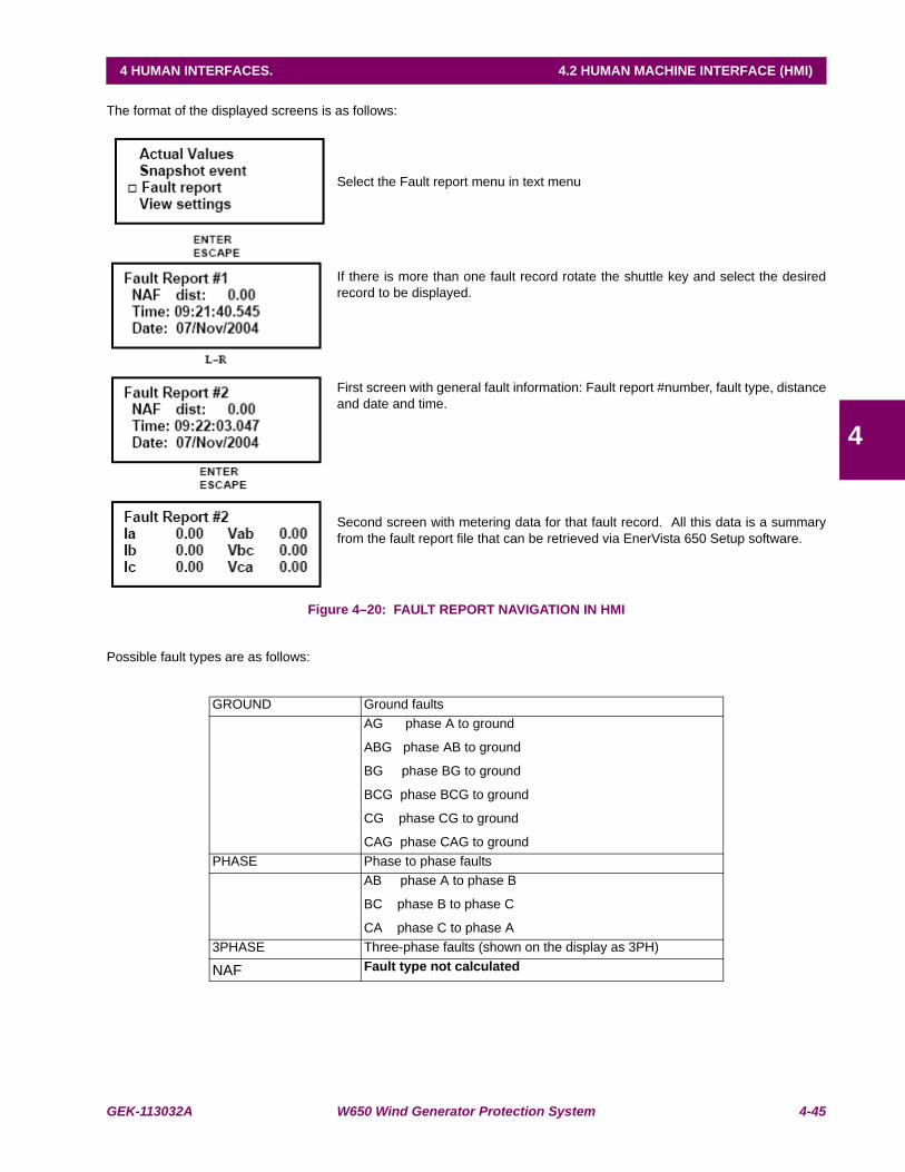
GEK-113032A W650 Wind Generator Protection System 4-45
4 HUMAN INTERFACES. 4.2 HUMAN MACHINE INTERFACE (HMI)
4
The format of the displayed screens is as follows:
Select the Fault report menu in text menu
If there is more than one fault record rotate the shuttle key and select the desiredrecord to be displayed.
First screen with general fault information: Fault report #number, fault type, distanceand date and time.
Second screen with metering data for that fault record. All this data is a summaryfrom the fault report file that can be retrieved via EnerVista 650 Setup software.
Figure 4–20: FAULT REPORT NAVIGATION IN HMI
Possible fault types are as follows:
GROUND Ground faultsAG phase A to ground
ABG phase AB to ground
BG phase BG to ground
BCG phase BCG to ground
CG phase CG to ground
CAG phase CAG to groundPHASE Phase to phase faults
AB phase A to phase B
BC phase B to phase C
CA phase C to phase A3PHASE Three-phase faults (shown on the display as 3PH)
NAF Fault type not calculated
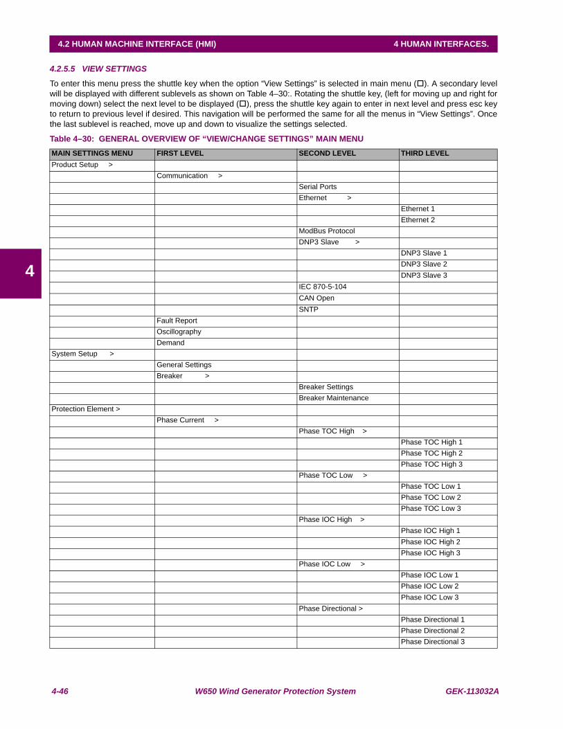
4-46 W650 Wind Generator Protection System GEK-113032A
4.2 HUMAN MACHINE INTERFACE (HMI) 4 HUMAN INTERFACES.
4
4.2.5.5 VIEW SETTINGS
To enter this menu press the shuttle key when the option “View Settings” is selected in main menu ( ). A secondary levelwill be displayed with different sublevels as shown on Table 4–30:. Rotating the shuttle key, (left for moving up and right formoving down) select the next level to be displayed ( ), press the shuttle key again to enter in next level and press esc keyto return to previous level if desired. This navigation will be performed the same for all the menus in “View Settings”. Oncethe last sublevel is reached, move up and down to visualize the settings selected.
Table 4–30: GENERAL OVERVIEW OF “VIEW/CHANGE SETTINGS” MAIN MENUMAIN SETTINGS MENU FIRST LEVEL SECOND LEVEL THIRD LEVELProduct Setup >
Communication >Serial PortsEthernet >
Ethernet 1Ethernet 2
ModBus ProtocolDNP3 Slave >
DNP3 Slave 1DNP3 Slave 2DNP3 Slave 3
IEC 870-5-104CAN OpenSNTP
Fault ReportOscillographyDemand
System Setup >General SettingsBreaker >
Breaker SettingsBreaker Maintenance
Protection Element >Phase Current >
Phase TOC High >Phase TOC High 1Phase TOC High 2Phase TOC High 3
Phase TOC Low >Phase TOC Low 1Phase TOC Low 2Phase TOC Low 3
Phase IOC High >Phase IOC High 1Phase IOC High 2Phase IOC High 3
Phase IOC Low >Phase IOC Low 1Phase IOC Low 2Phase IOC Low 3
Phase Directional >Phase Directional 1Phase Directional 2Phase Directional 3

GEK-113032A W650 Wind Generator Protection System 4-47
4 HUMAN INTERFACES. 4.2 HUMAN MACHINE INTERFACE (HMI)
4
MAIN SETTINGS MENU FIRST LEVEL SECOND LEVEL THIRD LEVELNeutral Current >
Neutral TOC >Neutral TOC 1Neutral TOC 2Neutral TOC 3
Neutral IOC >Neutral IOC 1Neutral IOC 2Neutral IOC 3
Neutral Dir >Neutral Dir 1Neutral Dir 2Neutral Dir 3
Ground Current >Ground TOC >
Ground TOC 1Ground TOC 2Ground TOC 3
Ground IOC >Ground IOC 1Ground IOC 2Ground IOC 3
Ground Dir >Ground Dir 1Ground Dir 2Ground Dir 3
Sens. Ground Curr >Sens. Ground TOC >
Sens. Ground TOC 1Sens. Ground TOC 2Sens. Ground TOC 3
Sens. Ground IOC >Sens. Ground IOC 1Sens. Ground IOC 2Sens. Ground IOC 3
Sens. Ground Dir. >Sens. Ground Dir. 1Sens. Ground Dir. 2Sens. Ground Dir. 3
Neg. Seq. Current >Neg. Seq. TOC >
Neg. Seq. TOC 1Neg. Seq. TOC 2Neg. Seq. TOC 3
Voltage Elements >Phase UV >
Phase UV 1Phase UV 2Phase UV 3Phase UV 4
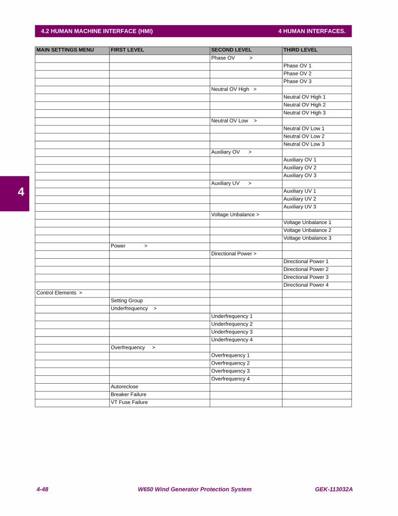
4-48 W650 Wind Generator Protection System GEK-113032A
4.2 HUMAN MACHINE INTERFACE (HMI) 4 HUMAN INTERFACES.
4
MAIN SETTINGS MENU FIRST LEVEL SECOND LEVEL THIRD LEVELPhase OV >
Phase OV 1Phase OV 2Phase OV 3
Neutral OV High >Neutral OV High 1Neutral OV High 2Neutral OV High 3
Neutral OV Low >Neutral OV Low 1Neutral OV Low 2Neutral OV Low 3
Auxiliary OV >Auxiliary OV 1Auxiliary OV 2Auxiliary OV 3
Auxiliary UV >Auxiliary UV 1Auxiliary UV 2Auxiliary UV 3
Voltage Unbalance >Voltage Unbalance 1Voltage Unbalance 2Voltage Unbalance 3
Power >Directional Power >
Directional Power 1Directional Power 2Directional Power 3Directional Power 4
Control Elements >Setting GroupUnderfrequency >
Underfrequency 1Underfrequency 2Underfrequency 3Underfrequency 4
Overfrequency >Overfrequency 1Overfrequency 2Overfrequency 3Overfrequency 4
AutorecloseBreaker FailureVT Fuse Failure
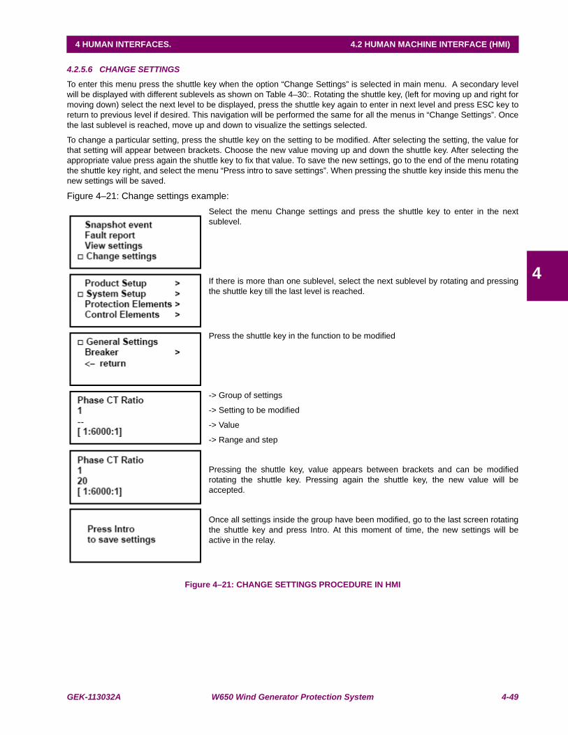
GEK-113032A W650 Wind Generator Protection System 4-49
4 HUMAN INTERFACES. 4.2 HUMAN MACHINE INTERFACE (HMI)
4
4.2.5.6 CHANGE SETTINGS
To enter this menu press the shuttle key when the option “Change Settings” is selected in main menu. A secondary levelwill be displayed with different sublevels as shown on Table 4–30:. Rotating the shuttle key, (left for moving up and right formoving down) select the next level to be displayed, press the shuttle key again to enter in next level and press ESC key toreturn to previous level if desired. This navigation will be performed the same for all the menus in “Change Settings”. Oncethe last sublevel is reached, move up and down to visualize the settings selected.
To change a particular setting, press the shuttle key on the setting to be modified. After selecting the setting, the value forthat setting will appear between brackets. Choose the new value moving up and down the shuttle key. After selecting theappropriate value press again the shuttle key to fix that value. To save the new settings, go to the end of the menu rotatingthe shuttle key right, and select the menu “Press intro to save settings”. When pressing the shuttle key inside this menu thenew settings will be saved.
Figure 4–21: Change settings example:Select the menu Change settings and press the shuttle key to enter in the nextsublevel.
If there is more than one sublevel, select the next sublevel by rotating and pressingthe shuttle key till the last level is reached.
Press the shuttle key in the function to be modified
-> Group of settings
-> Setting to be modified
-> Value
-> Range and step
Pressing the shuttle key, value appears between brackets and can be modifiedrotating the shuttle key. Pressing again the shuttle key, the new value will beaccepted.
Once all settings inside the group have been modified, go to the last screen rotatingthe shuttle key and press Intro. At this moment of time, the new settings will beactive in the relay.
Figure 4–21: CHANGE SETTINGS PROCEDURE IN HMI

4-50 W650 Wind Generator Protection System GEK-113032A
4.2 HUMAN MACHINE INTERFACE (HMI) 4 HUMAN INTERFACES.
4
4.2.5.7 DATE & TIME
The “Date & Time” menu will show the relay date and time information in the following format:
Date:Day/Month/Year
Time:Hour:Minutes:Seconds
To modify date and time, press the shuttle key. The relay will show the year between brackets at the top of the screen. Byrotating the shuttle key, reach the desired value for the year, and press the shuttle key to select and store that value. Afterthe year, the relay will show the month. Proceed as in the case of the year. The date & time modification sequence is asfollows:
Rotate the shuttle key to select the “Date and Time” menu and press to enter in it
The date and time data will appear in the format related above.
Pressing the shuttle key the year can be modified rotating the shuttle key, afterselecting the desired value, press again the shuttle key to store the value.
‘Year’
Date: Day/Month/<Year>
Time: Hour:Minutes:Seconds
After storing the value for Year, Month will appear between brackets and can bemodified
‘Month’
Date: Day/<Month>/Year
Time: Hour:Minutes:Seconds
After storing the value for Month, Day will appear between brackets and can bemodified
‘Day’
Date: <Day>/Month/Year
Time: Hour:Minutes:Seconds
After storing the value for Day, Hour will appear between brackets and can bemodified
‘Hour’
Date: Day/Month/Year
Time: <Hour>:Minutes:Seconds
After storing the value for Hour, Minutes will appear between brackets and can bemodified
‘Minute’
Date: Day/Month/Year
Time: Hour:<Minute>:Seconds
After storing the value for Minutes, Seconds will appear between brackets and canbe modified
‘Second’
Date: Day/Month/Year
Time: Hour: Minute:<Seconds>
Once this sequence is completed, these values will remain stored in the relay, andthe display will show again the date at the bottom of the text screen.
Figure 4–22: CHANGE DATE AND TIME PROCEDURE IN HMI
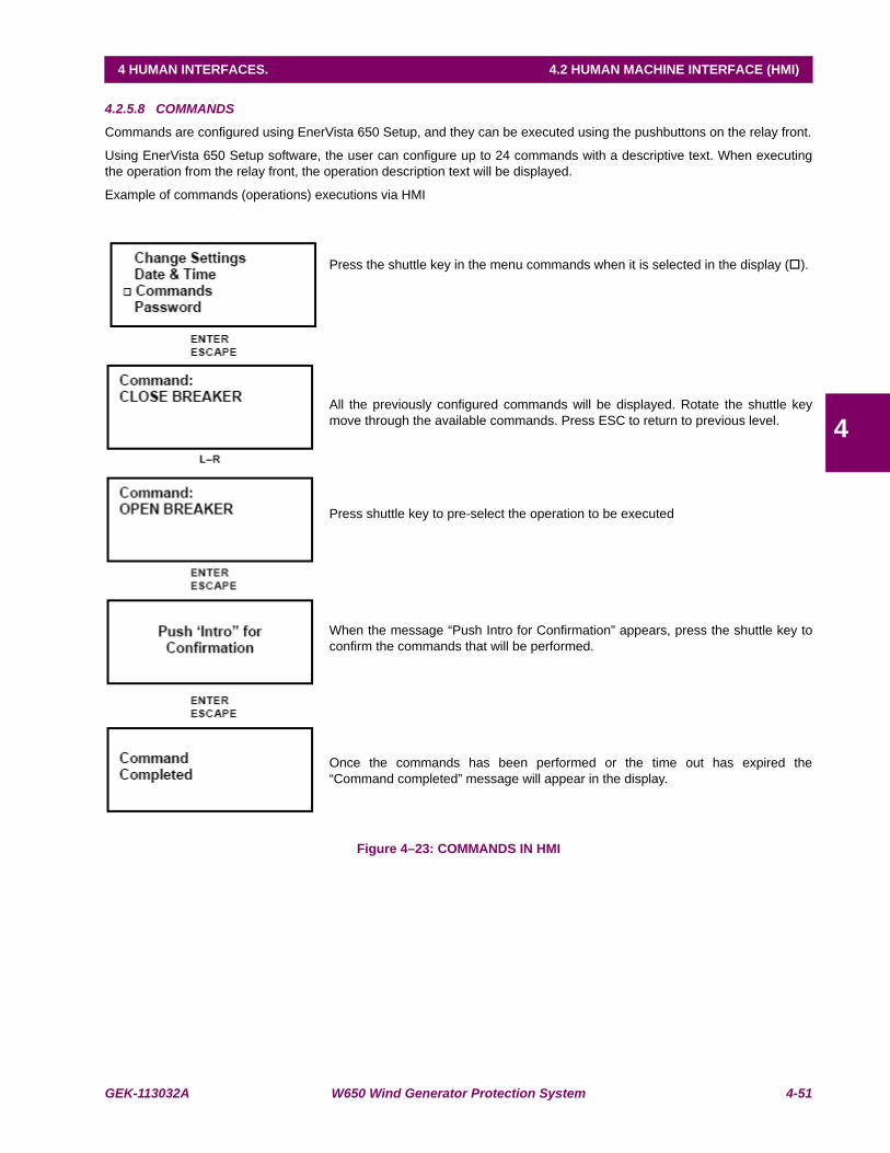
GEK-113032A W650 Wind Generator Protection System 4-51
4 HUMAN INTERFACES. 4.2 HUMAN MACHINE INTERFACE (HMI)
4
4.2.5.8 COMMANDS
Commands are configured using EnerVista 650 Setup, and they can be executed using the pushbuttons on the relay front.
Using EnerVista 650 Setup software, the user can configure up to 24 commands with a descriptive text. When executingthe operation from the relay front, the operation description text will be displayed.
Example of commands (operations) executions via HMI
Press the shuttle key in the menu commands when it is selected in the display ( ).
All the previously configured commands will be displayed. Rotate the shuttle keymove through the available commands. Press ESC to return to previous level.
Press shuttle key to pre-select the operation to be executed
When the message “Push Intro for Confirmation” appears, press the shuttle key toconfirm the commands that will be performed.
Once the commands has been performed or the time out has expired the“Command completed” message will appear in the display.
Figure 4–23: COMMANDS IN HMI

4-52 W650 Wind Generator Protection System GEK-113032A
4.2 HUMAN MACHINE INTERFACE (HMI) 4 HUMAN INTERFACES.
4
4.2.5.9 PASSWORDS
W650 units incorporate independent passwords for protection and control, in order to prevent unauthorized keypad anddisplay access to the relay.
Settings Password:
This password allows restricting access to settings changes in the relay protection elements.
Commands Password:
This password is required for executing operation commands through the keypad and display.
If the Commands Password is activated, when the user tries to execute an operation, the relay will request this password,and in case of using the single-line diagram for graphical display models, all objects will not be operational until thispassword is entered, either logging in Login Pwd Commands, or entering the password in the Commands menu.
Relay settings view, measures, and other monitored information are not password-protected, and they can be accessed byall users.
Access to the password menu is located at the Password option in the relay text menu. This menu includes the followingoptions:
"Login Pwd Settings"
"Logout Pwd Settings"
"Change Pwd Settings"
"Login Pwd Commands"
"Logout Pwd Commands"
"Change Pwd Commands"
"Forgot Password?"
Among the available options in this menu, there are three types of functionality:
Login: For entering the password, either for settings or commands, and enable access to settings orcommands. Once entering the password the relay is no longer password protected, and access isenabled to settings modification or commands execution.
Logout: Once the necessary setting changes or operation commands have been executed, the user can logout, so that the relay is password protected again.
Change: This menu allows setting or modifying the desired password.
Forgot Password: This menu provides the encrypted password, so that it can be recovered if the user loses or forgetsit.
Passwords are restricted for Settings change and Commands execution. To password-protect the relay, it is first necessaryto set the desired password, using the corresponding “Change Pwd ...” menu. The default password is 0000. Thispassword provides access to the whole relay functionality.
Once a new password has been set, the user must log in to access the protected functionality; otherwise, the relay willrequest the password when trying to change settings or execute commands. Once the password is entered the relay isunprotected (as if the user had logged in), and the user must log out to protect again the relay.
a) PASSWORD RANGE
The valid range for W650 passwords is a number from 0000 to 9999.
The default password is 0000, which provides access to the whole relay functionality. This is the default option for enablingrelay use without using passwords.

GEK-113032A W650 Wind Generator Protection System 4-53
4 HUMAN INTERFACES. 4.2 HUMAN MACHINE INTERFACE (HMI)
4
b) ENTERING THE PASSWORD (LOGIN PWD)
This operation is the same for both the settings and commands passwords. The only difference will be the access menu.For entering the password, the user must access the Login menus inside the Password menu.
Login Pwd Settings or Login Pwd Commands:
The relay requests the password with the following message on the screen:
Setting passwd.
Login: < 1000 >
For entering the desired password, the user must rotate the shuttle key to the left (decrease) or to the right (increase), andestablish the desired number. Once entered, the selected password between brackets has been entered, the relay willshow the message “Processing passwd. Wait...”. If the password is correct, the relay will allow access to the settingschange or command execution. It is not necessary to enter the password every time a change is to be performed. The relaywill request the password 15 minutes after the last keypad action has taken place. This period of time is the same that takesthe relay to turn off the display backlighting.
c) LOGGING OUT (LOGOUT PWD)
To disable access to settings and commands, the user must logout.
Logout Pwd Settings or Logout Pwd Commands:
For safety reasons, if the user does not log out, the relay will do it automatically 15 minutes after the last keypadaction.
d) CHANGING THE PASSWORD (CHANGE PWD COMMANDS)
To set a password in the relay, both for settings and commands, the corresponding menu must be accessed inside thePassword menu:
Change Pwd Settings or Change Pwd Commands:
To modify the password, the user must first introduce the existing password; if the relay has the default factory password,this would be 0000.
For modifying the password, the relay requests the existing password with the following message:
(Setting or Command) passwd.
Login: < 0000 >
Once the entered password has been acknowledged, the new password must be entered:
(Setting o Command) passwd.
New passwd: < 1000 >
Once the new password has been entered, the relay returns to the general Passwords menu.
e) PASSWORD RECOVERY (FORGOT PASSWORD?)
If the relay passwords need to be recovered, the “Forgot Password?” menu must be accessed. This menu is the lastoption inside the text Passwords menu.
This menu will show two passwords, which correspond to the encrypted protection settings, and commands passwords, asshown in the following example:
Cod Settings: [35c0]
Cod Commands: [35c0]
<Push Intro>
In order to obtain the decoded password from the encrypted codes provided by the relay, it is necessary to contact GEMultilin and provide these encrypted codes.

4-54 W650 Wind Generator Protection System GEK-113032A
4.2 HUMAN MACHINE INTERFACE (HMI) 4 HUMAN INTERFACES.
4
4.2.5.10 SELECT MAIN SCREEN
The relay display offers the possibility to select the default main screen. For this purpose, the user must access the “SelectMain Screen” menu through the HMI. This menu includes the following options:
Logotype
This option selects as main screen the relay logotype including the firmware and boot code versions, the relay model andthe communication parameters for local port COM2.
Figure 4–24: DEFAULT LOGOTYPE SCREEN
Metering
This option shows a Metering screen including the phase and ground currents as well as phase-to-phase voltage, and zerosequence voltage values, all of them in primary values.
Figure 4–25: DEFAULT METERING SCREEN
All
This option alternates in time the two previous options.
W650 2.02 (4.0) General Electric
W650MCDF2G1HIR 19200N81: MODBUS: 254
Ia 0.000 Vab 0.000Ib 0.000 Vbc 0.000Ic 0.000 Vca 0.000 Ig 0.000 V0 0.000
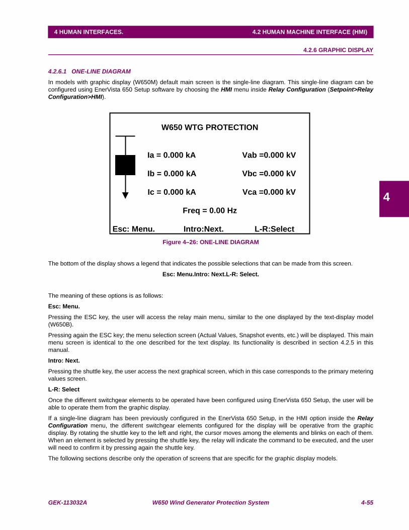
GEK-113032A W650 Wind Generator Protection System 4-55
4 HUMAN INTERFACES. 4.2 HUMAN MACHINE INTERFACE (HMI)
4
4.2.6 GRAPHIC DISPLAY
4.2.6.1 ONE-LINE DIAGRAM
In models with graphic display (W650M) default main screen is the single-line diagram. This single-line diagram can beconfigured using EnerVista 650 Setup software by choosing the HMI menu inside Relay Configuration (Setpoint>RelayConfiguration>HMI).
Figure 4–26: ONE-LINE DIAGRAM
The bottom of the display shows a legend that indicates the possible selections that can be made from this screen.
Esc: Menu.Intro: Next.L-R: Select.
The meaning of these options is as follows:
Esc: Menu.
Pressing the ESC key, the user will access the relay main menu, similar to the one displayed by the text-display model(W650B).
Pressing again the ESC key; the menu selection screen (Actual Values, Snapshot events, etc.) will be displayed. This mainmenu screen is identical to the one described for the text display. Its functionality is described in section 4.2.5 in thismanual.
Intro: Next.
Pressing the shuttle key, the user access the next graphical screen, which in this case corresponds to the primary meteringvalues screen.
L-R: Select
Once the different switchgear elements to be operated have been configured using EnerVista 650 Setup, the user will beable to operate them from the graphic display.
If a single-line diagram has been previously configured in the EnerVista 650 Setup, in the HMI option inside the RelayConfiguration menu, the different switchgear elements configured for the display will be operative from the graphicdisplay. By rotating the shuttle key to the left and right, the cursor moves among the elements and blinks on each of them.When an element is selected by pressing the shuttle key, the relay will indicate the command to be executed, and the userwill need to confirm it by pressing again the shuttle key.
The following sections describe only the operation of screens that are specific for the graphic display models.
W650 WTG PROTECTION
Ia = 0.000 kA Vab =0.000 kV
Ib = 0.000 kA Vbc =0.000 kV
Ic = 0.000 kA Vca =0.000 kV
Freq = 0.00 Hz
Esc: Menu. Intro:Next. L-R:Select
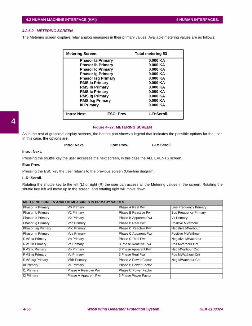
4-56 W650 Wind Generator Protection System GEK-113032A
4.2 HUMAN MACHINE INTERFACE (HMI) 4 HUMAN INTERFACES.
4
4.2.6.2 METERING SCREEN
The Metering screen displays relay analog measures in their primary values. Available metering values are as follows:
Figure 4–27: METERING SCREEN
As in the rest of graphical display screens, the bottom part shows a legend that indicates the possible options for the user.In this case, the options are:
Intro: Next. Esc: Prev. L-R: Scroll.
Intro: Next.
Pressing the shuttle key the user accesses the next screen, in this case the ALL EVENTS screen.
Esc: Prev.
Pressing the ESC key the user returns to the previous screen (One-line diagram)
L-R: Scroll.
Rotating the shuttle key to the left (L) or right (R) the user can access all the Metering values in the screen. Rotating theshuttle key left will move up in the screen, and rotating right will move down.
METERING SCREEN ANALOG MEASURES IN PRIMARY VALUESPhasor Ia Primary V0 Primary Phase A Real Pwr Line Frequency PrimaryPhasor Ib Primary V1 Primary Phase B Reactive Pwr Bus Frequency PrimaryPhasor Ic Primary V2 Primary Phase B Apparent Pwr Vx PrimaryPhasor Ig Primary Vab Primary Phase B Real Pwr Positive MVarhourPhasor Isg Primary Vbc Primary Phase C Reactive Pwr Negative MVarhourPhasor In Primary Vca Primary Phase C Apparent Pwr Positive MWatthourRMS Ia Primary Vn Primary Phase C Real Pwr Negative MWatthourRMS Ib Primary Va Primary 3 Phase Reactive Pwr Pos MVarhour CntRMS Ic Primary Vb Primary 3 Phase Apparent Pwr Neg MVarhour CntRMS Ig Primary Vc Primary 3 Phase Real Pwr Pos MWatthour CntRMS Isg Primary VBB Primary Phase A Power Factor Neg MWatthour CntI0 Primary VL Primary Phase B Power FactorI1 Primary Phase A Reactive Pwr Phase C Power FactorI2 Primary Phase A Apparent Pwr 3 Phase Power Factor
Metering Screen. Total metering 53
Phasor Ia Primary 0.000 KA Phasor Ib Primary 0.000 KA Phasor Ic Primary 0.000 KA Phasor Ig Primary 0.000 KA Phasor Isg Primary 0.000 KA RMS Ia Primary 0.000 KA RMS Ib Primary 0.000 KA RMS Ic Primary 0.000 KA RMS Ig Primary 0.000 KA RMS Isg Primary 0.000 KA
I0 Primary 0.000 KA
Intro: Next. ESC: Prev L-R:Scroll.
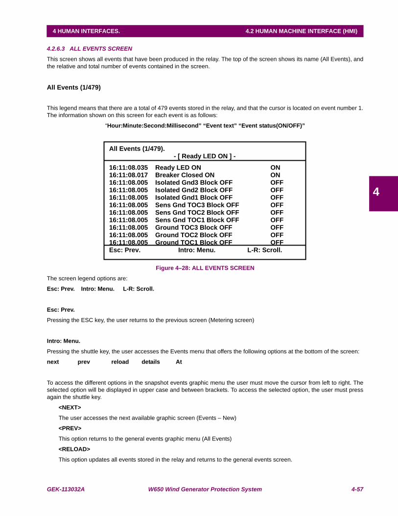
GEK-113032A W650 Wind Generator Protection System 4-57
4 HUMAN INTERFACES. 4.2 HUMAN MACHINE INTERFACE (HMI)
4
4.2.6.3 ALL EVENTS SCREEN
This screen shows all events that have been produced in the relay. The top of the screen shows its name (All Events), andthe relative and total number of events contained in the screen.
All Events (1/479)
This legend means that there are a total of 479 events stored in the relay, and that the cursor is located on event number 1.The information shown on this screen for each event is as follows:
“Hour:Minute:Second:Millisecond” “Event text” “Event status(ON/OFF)”
Figure 4–28: ALL EVENTS SCREEN
The screen legend options are:
Esc: Prev. Intro: Menu. L-R: Scroll.
Esc: Prev.
Pressing the ESC key, the user returns to the previous screen (Metering screen)
Intro: Menu.
Pressing the shuttle key, the user accesses the Events menu that offers the following options at the bottom of the screen:
next prev reload details At
To access the different options in the snapshot events graphic menu the user must move the cursor from left to right. Theselected option will be displayed in upper case and between brackets. To access the selected option, the user must pressagain the shuttle key.
<NEXT>
The user accesses the next available graphic screen (Events – New)
<PREV>
This option returns to the general events graphic menu (All Events)
<RELOAD>
This option updates all events stored in the relay and returns to the general events screen.
All Events (1/479). - [ Ready LED ON ] -
16:11:08.035 Ready LED ON ON 16:11:08.017 Breaker Closed ON ON 16:11:08.005 Isolated Gnd3 Block OFF OFF 16:11:08.005 Isolated Gnd2 Block OFF OFF 16:11:08.005 Isolated Gnd1 Block OFF OFF 16:11:08.005 Sens Gnd TOC3 Block OFF OFF 16:11:08.005 Sens Gnd TOC2 Block OFF OFF 16:11:08.005 Sens Gnd TOC1 Block OFF OFF 16:11:08.005 Ground TOC3 Block OFF OFF 16:11:08.005 Ground TOC2 Block OFF OFF 16:11:08.005 Ground TOC1 Block OFF OFF Esc: Prev. Intro: Menu. L-R: Scroll.
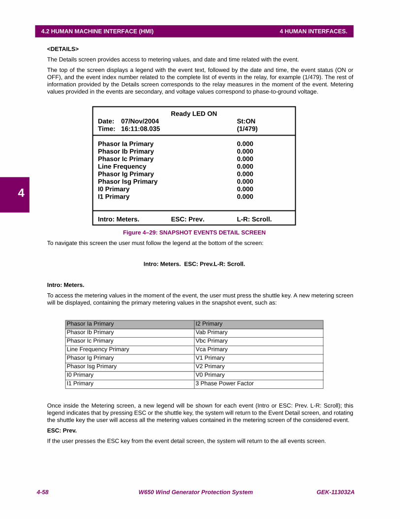
4-58 W650 Wind Generator Protection System GEK-113032A
4.2 HUMAN MACHINE INTERFACE (HMI) 4 HUMAN INTERFACES.
4
<DETAILS>
The Details screen provides access to metering values, and date and time related with the event.
The top of the screen displays a legend with the event text, followed by the date and time, the event status (ON orOFF), and the event index number related to the complete list of events in the relay, for example (1/479). The rest ofinformation provided by the Details screen corresponds to the relay measures in the moment of the event. Meteringvalues provided in the events are secondary, and voltage values correspond to phase-to-ground voltage.
Figure 4–29: SNAPSHOT EVENTS DETAIL SCREEN
To navigate this screen the user must follow the legend at the bottom of the screen:
Intro: Meters. ESC: Prev.L-R: Scroll.
Intro: Meters.
To access the metering values in the moment of the event, the user must press the shuttle key. A new metering screenwill be displayed, containing the primary metering values in the snapshot event, such as:
Once inside the Metering screen, a new legend will be shown for each event (Intro or ESC: Prev. L-R: Scroll); thislegend indicates that by pressing ESC or the shuttle key, the system will return to the Event Detail screen, and rotatingthe shuttle key the user will access all the metering values contained in the metering screen of the considered event.
ESC: Prev.
If the user presses the ESC key from the event detail screen, the system will return to the all events screen.
Phasor Ia Primary I2 PrimaryPhasor Ib Primary Vab PrimaryPhasor Ic Primary Vbc Primary Line Frequency Primary Vca PrimaryPhasor Ig Primary V1 PrimaryPhasor Isg Primary V2 PrimaryI0 Primary V0 PrimaryI1 Primary 3 Phase Power Factor
Ready LED ON Date: 07/Nov/2004 St:ON Time: 16:11:08.035 (1/479)
Phasor Ia Primary 0.000 Phasor Ib Primary 0.000 Phasor Ic Primary 0.000 Line Frequency 0.000 Phasor Ig Primary 0.000 Phasor Isg Primary 0.000 I0 Primary 0.000 I1 Primary 0.000
Intro: Meters. ESC: Prev. L-R: Scroll.

GEK-113032A W650 Wind Generator Protection System 4-59
4 HUMAN INTERFACES. 4.2 HUMAN MACHINE INTERFACE (HMI)
4
L-R: Scroll.
Rotating the shuttle key left (L) or right (R) moves among all the events contained in the all events screen, allowing apreview of the details for each of them.
<AT>
When this option is selected, the system marks the event where the cursor is located. A relative time stamp isperformed, in such a way that the selected event, marked with an asterisk (*) between the time and the event name isset with a relative time of 00:00:00:000 on the top line of the event screen, together with its relative index, and the restof events in the screen will show a date/time that relates to the marked event. This operation mode allows a quickinspection of the relative time passed between several events, which is very useful for analyzing events in the field.The corresponding legend to this relative event-marking screen is as follows:
Esc: Out At. Intro: Tag event.
Esc: Out At.
The relative event marking is eliminated and the system returns to the general events screen.
Intro: Tag event.
If the user places the cursor on a different event by rotating the shuttle key left or right, pressing the shuttle keywill change the relative mark to that new event.
4.2.6.4 NEW EVENTS SCREEN
This screen shows the new events that have been produced in the relay since the last time the New Events screen wasread. The top of the screen shows a “New Events” legend, and the relative and total number of events contained.
Navigation through the different menus in this New Events screen is similar to the one described in the previous section forAll Events. The main difference is that in the case of new events it is necessary to select the RELOAD submenu to updatethe screen with new events that have been produced, while in the All Events screen, this refreshment is automatic.
After the new events have been read, if the user selects again the Reload menu, the system will show a <No new eventsavailable.> message, indicating that there are no more new events available since the last reading.
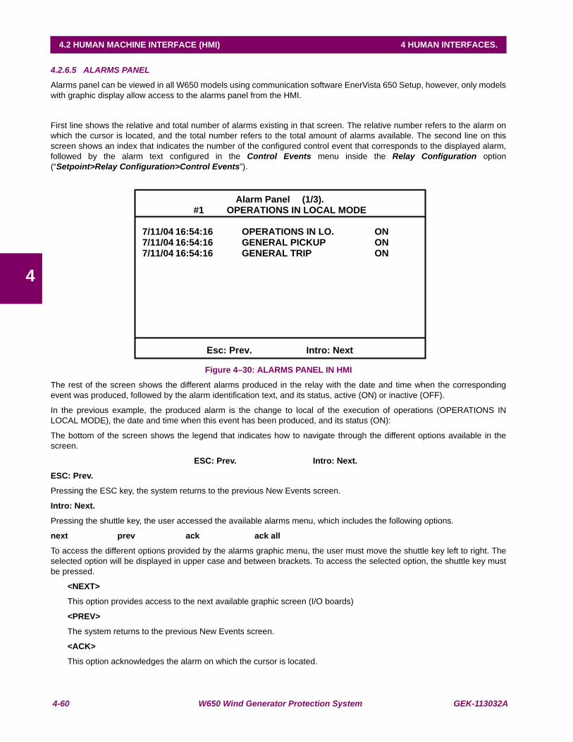
4-60 W650 Wind Generator Protection System GEK-113032A
4.2 HUMAN MACHINE INTERFACE (HMI) 4 HUMAN INTERFACES.
4
4.2.6.5 ALARMS PANEL
Alarms panel can be viewed in all W650 models using communication software EnerVista 650 Setup, however, only modelswith graphic display allow access to the alarms panel from the HMI.
First line shows the relative and total number of alarms existing in that screen. The relative number refers to the alarm onwhich the cursor is located, and the total number refers to the total amount of alarms available. The second line on thisscreen shows an index that indicates the number of the configured control event that corresponds to the displayed alarm,followed by the alarm text configured in the Control Events menu inside the Relay Configuration option(“Setpoint>Relay Configuration>Control Events”).
Figure 4–30: ALARMS PANEL IN HMI
The rest of the screen shows the different alarms produced in the relay with the date and time when the correspondingevent was produced, followed by the alarm identification text, and its status, active (ON) or inactive (OFF).
In the previous example, the produced alarm is the change to local of the execution of operations (OPERATIONS INLOCAL MODE), the date and time when this event has been produced, and its status (ON):
The bottom of the screen shows the legend that indicates how to navigate through the different options available in thescreen.
ESC: Prev. Intro: Next.
ESC: Prev.
Pressing the ESC key, the system returns to the previous New Events screen.
Intro: Next.
Pressing the shuttle key, the user accessed the available alarms menu, which includes the following options.
next prev ack ack all
To access the different options provided by the alarms graphic menu, the user must move the shuttle key left to right. Theselected option will be displayed in upper case and between brackets. To access the selected option, the shuttle key mustbe pressed.
<NEXT>
This option provides access to the next available graphic screen (I/O boards)
<PREV>
The system returns to the previous New Events screen.
<ACK>
This option acknowledges the alarm on which the cursor is located.
Alarm Panel (1/3). #1 OPERATIONS IN LOCAL MODE
7/11/04 16:54:16 OPERATIONS IN LO. ON 7/11/04 16:54:16 GENERAL PICKUP ON 7/11/04 16:54:16 GENERAL TRIP ON
Esc: Prev. Intro: Next

GEK-113032A W650 Wind Generator Protection System 4-61
4 HUMAN INTERFACES. 4.2 HUMAN MACHINE INTERFACE (HMI)
4
<ACK ALL>
This option acknowledges all alarms. Alarm acknowledgement through the graphic HMI is considered as throughcommunication port COM2, as it is considered to be Local in both cases.
When an alarm has been acknowledged, a selection mark will appear to the right of its status. Inactive alarms willdisappear from the screen once they are acknowledged.
4.2.6.6 INPUT/OUTPUT MONITORING SCREEN
This is the last screen available in the graphic display. This screen allows viewing the status of the relay inputs and outputs,as well as emulate inputs (for verification of the logic, or related functions), and contact outputs (to verify wiring).
The format of this screen is shown on the figure below.
The first line shows the name of the screen “I/O Cards”, followed by the type and description of the board where the cursoris located, which will appear between selection marks > < and blinking.
Figure 4–31: INPUTS/OUTPUTS GENERAL SCREEN
The navigation legend on this screen is as follows:
Esc: Prev.Intro: Menu.L-R: Chg CardEsc: Prev.
This option returns to the previous screen (Alarms Panel).
Intro: Menu.
This option provides access to the selected I/O board menu:
This menu includes the following options.
next view test input test output
As in previous screens, to access the different options provided by the inputs/outputs graphic menu, the user must movethe shuttle key left to right. The selected option will be displayed in upper case and between brackets. To access theselected option, the shuttle key must be pressed.
IO Card.Type: 2, Nº IN 8, Nº OUT 8
>F< G
Esc: Prev. Intro: Menu. L-R: Chg Card.

4-62 W650 Wind Generator Protection System GEK-113032A
4.2 HUMAN MACHINE INTERFACE (HMI) 4 HUMAN INTERFACES.
4Figure 4–32: INPUT/OUTPUT VIEWING SCREEN
<NEXT>
This option brings the system back to the one-line diagram.
<VIEW>
This option shows the real status of all inputs and outputs in the selected board. Depending on the type of board, withor without supervision, the screen will vary to get adapted to the characteristics of each board.
The first line of this screen shows the slot where the board is located, For G, and the type of board. The view menudifferentiates inputs and outputs; the active status (ON) is represented by the lighting of the corresponding input oroutput.
The legend at the bottom of the screen indicates how to navigate:
Esc: Prev. Intro: Menu. L-R: Chg Card
Esc: Prev.
Returns to the general I/O screen
Intro: Menu.
Provides access to the I/O menu (next, view, test input, test output).
L-R: Chg Card
Moving the shuttle key to the left or right provides access to the status of inputs/outputs for the different boardsavailable in the relay.
<TEST INPUT>
This option allows testing the input activation (in emulation mode). The displayed screen is similar to the viewingscreen, but in this case the user can operate the different relay inputs.
This screen shows the Input name lit up, showing that this is an Input emulation mode.
The first relay input will appear blinking and between brackets; the user can select a different input by rotating theshuttle key. When the shuttle key is pressed, the selected input will be activated. Navigation through this screen isindicated by the following legend:
Esc: Exit Text. Intro: Chg Input.
IO Card F. Type: 2, # IN 8, # OUT 8
Input (ON OFF) Output
next >VIEW< test input test output
0 CC1 8 Va COIL1 1 CC2 9 Vb COIL1 2 CC3 10 Va COIL2 3 CC4 11 Vb COIL2 4 CC5 12 Isense1 5 CC6 13 Isense1 6 CC7 14 SUP21 7 CC8 15 SUP22
0 OUT1 1 OUT2 2 OUT3 3 OUT4 4 OUT5 5 OUT6 6 OUT7 7 OUT8

GEK-113032A W650 Wind Generator Protection System 4-63
4 HUMAN INTERFACES. 4.2 HUMAN MACHINE INTERFACE (HMI)
4
Esc: Exit Text.
The ESC option returns to the general I/O board menu.
Intro: Chg Input.
Pressing the shuttle key on the blinking input, this input will be activated in emulation mode.
Note: input emulation can only be executed through the TEST INPUT tool on the graphic display.
<TEST OUTPUT>
This option allows testing the output activation in emulation mode. The displayed screen is similar to the viewingscreen, but in this case the user can operate the different relay contact outputs to test the wiring.
This screen shows the Output name lit up, showing that this is an output emulation mode.
The first relay output will appear blinking and between brackets; the user can select a different output by rotating theshuttle key. When the shuttle key is pressed, the selected output will be activated. Navigation through this screen isindicated by the following legend:
Esc: Exit Text. Intro: Chg Output.
Esc: Exit Text.
The ESC option returns to the general I/O board menu.
Intro: Chg Output.
Pressing the shuttle keyshuttle key on the blinking output, this output will be activated in emulation mode.
Note: Output emulation can be executed through the TEST OUTPUT tool on the graphic display, and alsothrough communications using EnerVista 650 Setup software for all W650 models.
L-R: Chg Card
Rotating the shuttle key allows to change the selected I/O board in the main I/O screen.
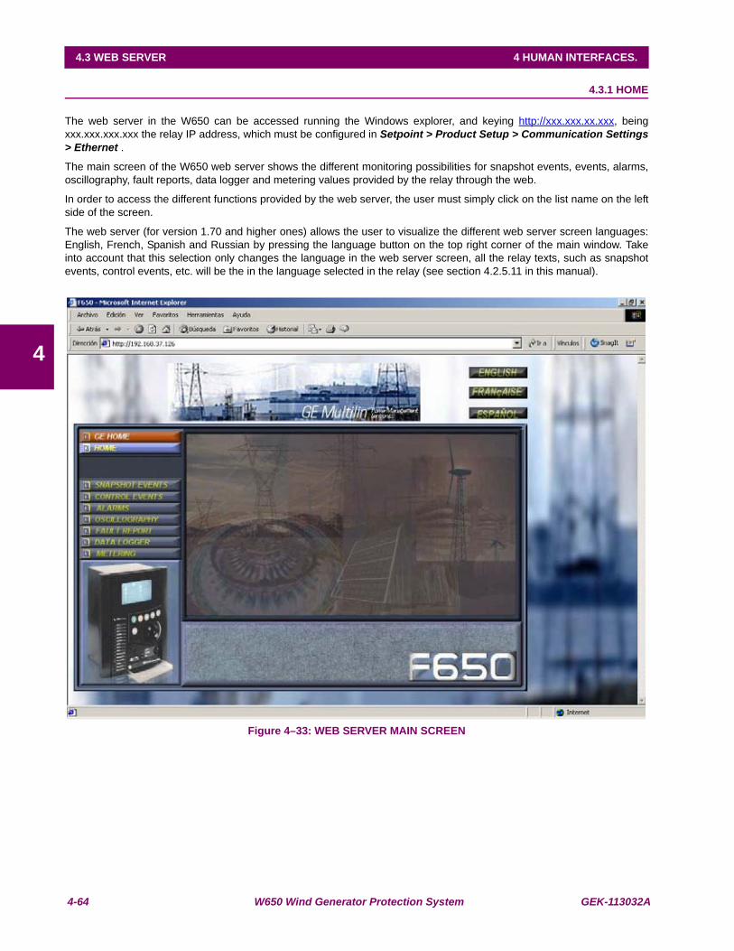
4-64 W650 Wind Generator Protection System GEK-113032A
4.3 WEB SERVER 4 HUMAN INTERFACES.
4
4.3 WEB SERVER 4.3.1 HOME
The web server in the W650 can be accessed running the Windows explorer, and keying http://xxx.xxx.xx.xxx, beingxxx.xxx.xxx.xxx the relay IP address, which must be configured in Setpoint > Product Setup > Communication Settings> Ethernet .
The main screen of the W650 web server shows the different monitoring possibilities for snapshot events, events, alarms,oscillography, fault reports, data logger and metering values provided by the relay through the web.
In order to access the different functions provided by the web server, the user must simply click on the list name on the leftside of the screen.
The web server (for version 1.70 and higher ones) allows the user to visualize the different web server screen languages:English, French, Spanish and Russian by pressing the language button on the top right corner of the main window. Takeinto account that this selection only changes the language in the web server screen, all the relay texts, such as snapshotevents, control events, etc. will be the in the language selected in the relay (see section 4.2.5.11 in this manual).
Figure 4–33: WEB SERVER MAIN SCREEN
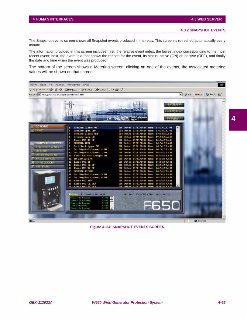
GEK-113032A W650 Wind Generator Protection System 4-65
4 HUMAN INTERFACES. 4.3 WEB SERVER
4
4.3.2 SNAPSHOT EVENTS
The Snapshot events screen shows all Snapshot events produced in the relay. This screen is refreshed automatically everyminute.
The information provided in this screen includes: first, the relative event index, the lowest index corresponding to the mostrecent event; next, the event text that shows the reason for the event, its status, active (ON) or inactive (OFF), and finallythe date and time when the event was produced.
The bottom of the screen shows a Metering screen; clicking on one of the events, the associated meteringvalues will be shown on that screen.
Figure 4–34: SNAPSHOT EVENTS SCREEN

4-66 W650 Wind Generator Protection System GEK-113032A
4.3 WEB SERVER 4 HUMAN INTERFACES.
4
4.3.3 CONTROL EVENTS
The control events screen provides access to all events that have been configured in the Control Events screen inside theRelay Configuration menu of EnerVista 650 Setup.
Figure 4–35: CONTROL EVENTS SCREEN
Unlike the case of Snapshot events, in this screen the highest index corresponds to the most recent event. The informationprovided is the control event index, the text that has been associated to such event when configured, its status, active (ON)or inactive (OFF), and its date and time.

GEK-113032A W650 Wind Generator Protection System 4-67
4 HUMAN INTERFACES. 4.3 WEB SERVER
4
4.3.4 ALARMS
The alarms screen provides access to alarms configured in the relay. As in the case of snapshot events and control events,this screen allows only to view the alarms, but not to acknowledge them.
Figure 4–36: ALARMS SCREEN
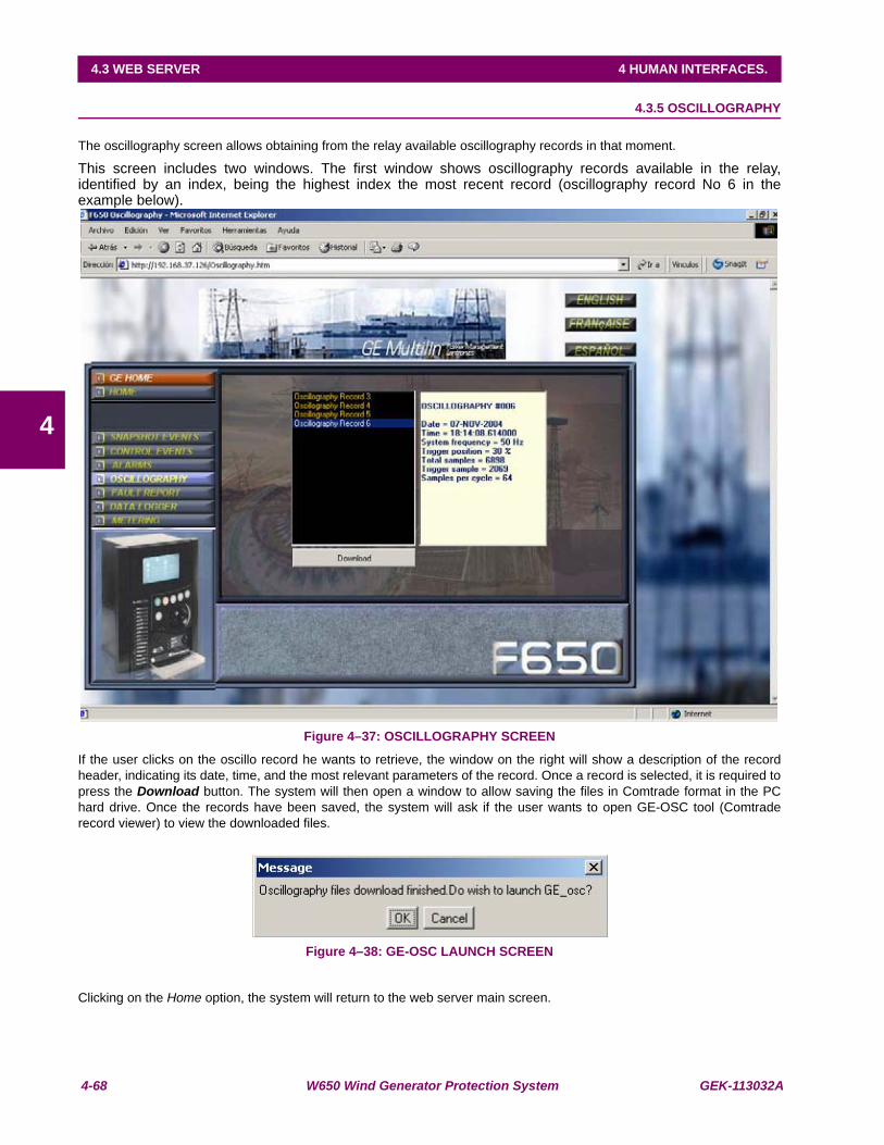
4-68 W650 Wind Generator Protection System GEK-113032A
4.3 WEB SERVER 4 HUMAN INTERFACES.
4
4.3.5 OSCILLOGRAPHY
The oscillography screen allows obtaining from the relay available oscillography records in that moment.
This screen includes two windows. The first window shows oscillography records available in the relay,identified by an index, being the highest index the most recent record (oscillography record No 6 in theexample below).
Figure 4–37: OSCILLOGRAPHY SCREEN
If the user clicks on the oscillo record he wants to retrieve, the window on the right will show a description of the recordheader, indicating its date, time, and the most relevant parameters of the record. Once a record is selected, it is required topress the Download button. The system will then open a window to allow saving the files in Comtrade format in the PChard drive. Once the records have been saved, the system will ask if the user wants to open GE-OSC tool (Comtraderecord viewer) to view the downloaded files.
Figure 4–38: GE-OSC LAUNCH SCREEN
Clicking on the Home option, the system will return to the web server main screen.
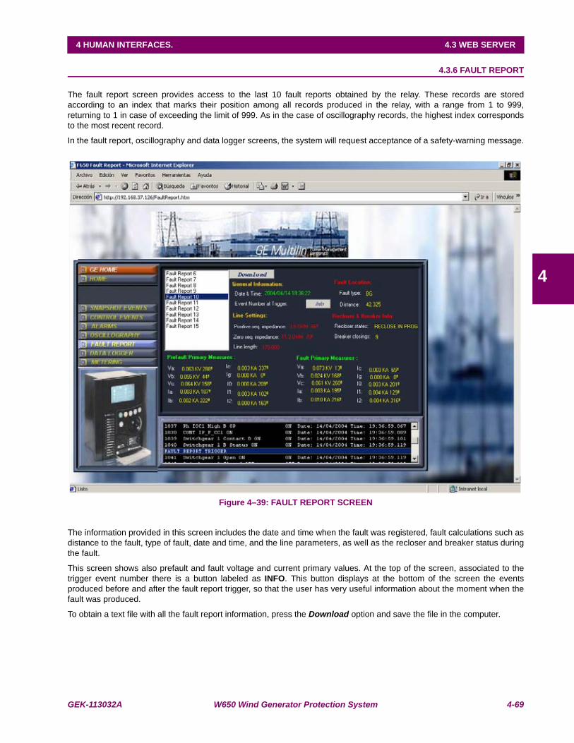
GEK-113032A W650 Wind Generator Protection System 4-69
4 HUMAN INTERFACES. 4.3 WEB SERVER
4
4.3.6 FAULT REPORT
The fault report screen provides access to the last 10 fault reports obtained by the relay. These records are storedaccording to an index that marks their position among all records produced in the relay, with a range from 1 to 999,returning to 1 in case of exceeding the limit of 999. As in the case of oscillography records, the highest index correspondsto the most recent record.
In the fault report, oscillography and data logger screens, the system will request acceptance of a safety-warning message.
Figure 4–39: FAULT REPORT SCREEN
The information provided in this screen includes the date and time when the fault was registered, fault calculations such asdistance to the fault, type of fault, date and time, and the line parameters, as well as the recloser and breaker status duringthe fault.
This screen shows also prefault and fault voltage and current primary values. At the top of the screen, associated to thetrigger event number there is a button labeled as INFO. This button displays at the bottom of the screen the eventsproduced before and after the fault report trigger, so that the user has very useful information about the moment when thefault was produced.
To obtain a text file with all the fault report information, press the Download option and save the file in the computer.
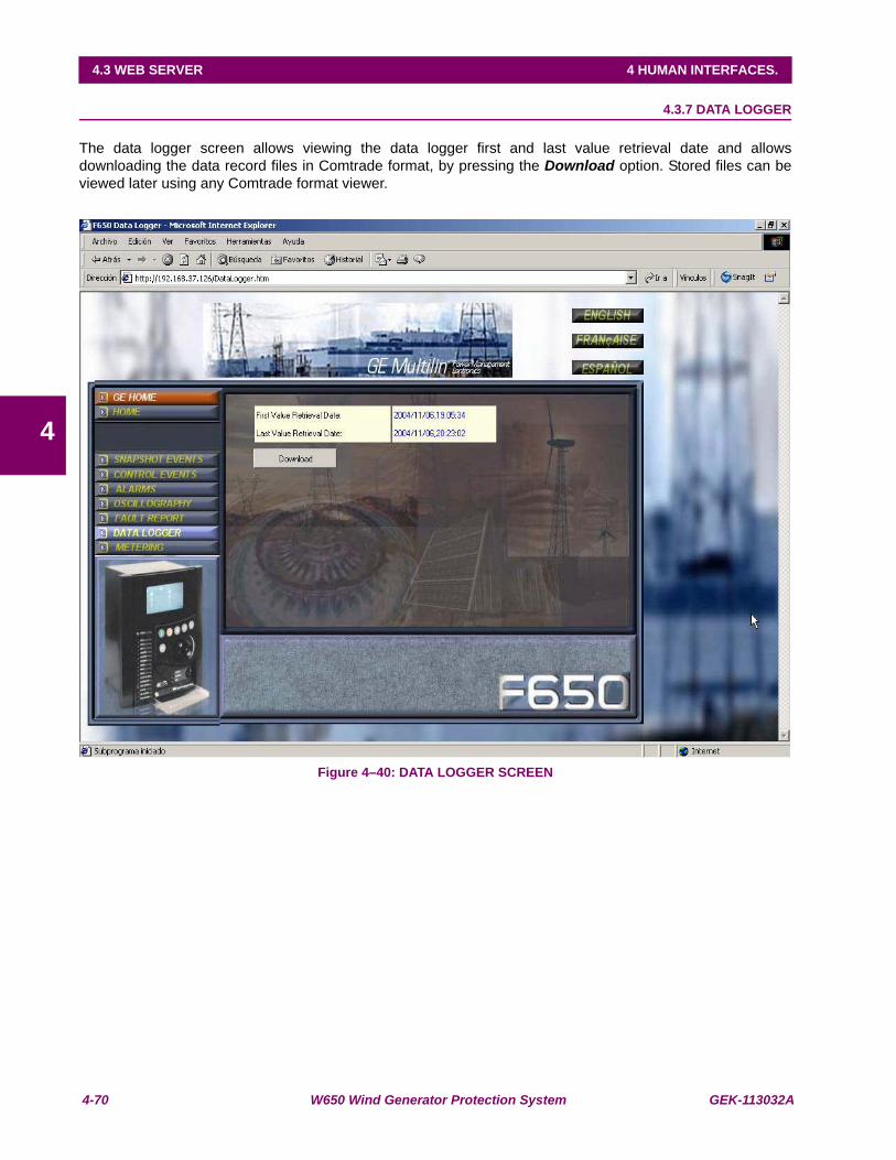
4-70 W650 Wind Generator Protection System GEK-113032A
4.3 WEB SERVER 4 HUMAN INTERFACES.
4
4.3.7 DATA LOGGER
The data logger screen allows viewing the data logger first and last value retrieval date and allowsdownloading the data record files in Comtrade format, by pressing the Download option. Stored files can beviewed later using any Comtrade format viewer.
Figure 4–40: DATA LOGGER SCREEN
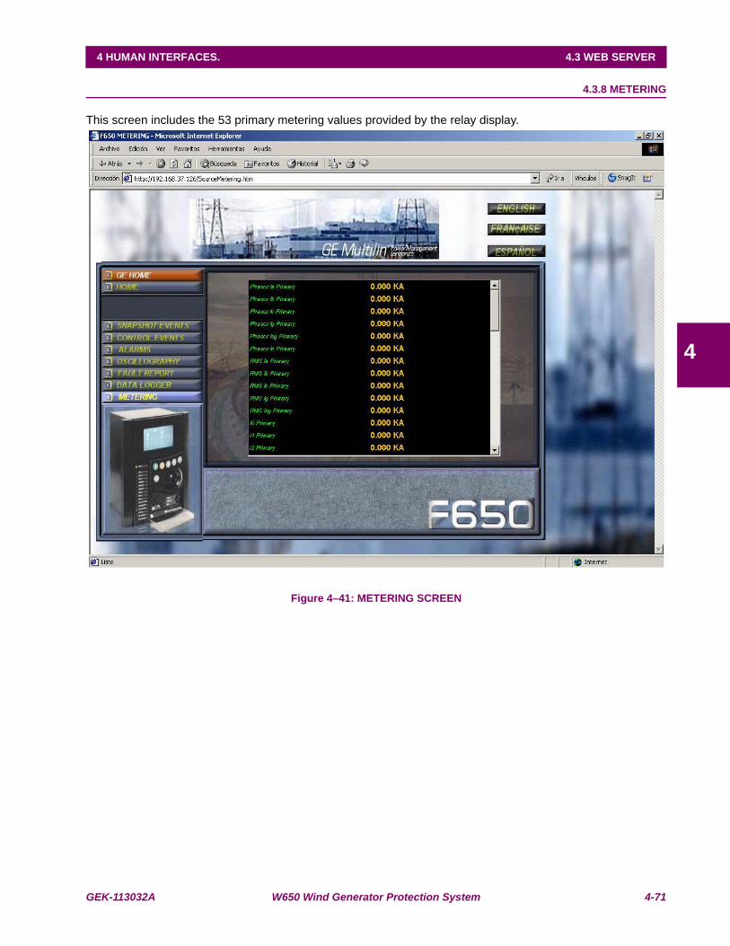
GEK-113032A W650 Wind Generator Protection System 4-71
4 HUMAN INTERFACES. 4.3 WEB SERVER
4
4.3.8 METERING
This screen includes the 53 primary metering values provided by the relay display.
Figure 4–41: METERING SCREEN

4-72 W650 Wind Generator Protection System GEK-113032A
4.3 WEB SERVER 4 HUMAN INTERFACES.
4
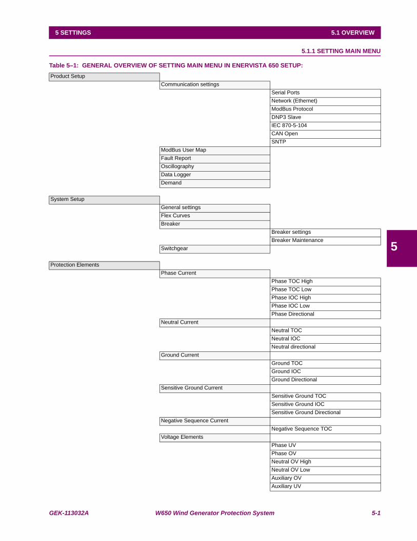
GEK-113032A W650 Wind Generator Protection System 5-1
5 SETTINGS 5.1 OVERVIEW
5
5 SETTINGS 5.1OVERVIEW 5.1.1 SETTING MAIN MENU
Table 5–1: GENERAL OVERVIEW OF SETTING MAIN MENU IN ENERVISTA 650 SETUP:Product Setup
Communication settingsSerial PortsNetwork (Ethernet)ModBus ProtocolDNP3 SlaveIEC 870-5-104CAN OpenSNTP
ModBus User MapFault ReportOscillographyData LoggerDemand
System SetupGeneral settingsFlex CurvesBreaker
Breaker settingsBreaker Maintenance
Switchgear
Protection ElementsPhase Current
Phase TOC HighPhase TOC LowPhase IOC HighPhase IOC LowPhase Directional
Neutral CurrentNeutral TOCNeutral IOCNeutral directional
Ground CurrentGround TOCGround IOCGround Directional
Sensitive Ground CurrentSensitive Ground TOCSensitive Ground IOCSensitive Ground Directional
Negative Sequence CurrentNegative Sequence TOC
Voltage ElementsPhase UVPhase OVNeutral OV HighNeutral OV LowAuxiliary OVAuxiliary UV
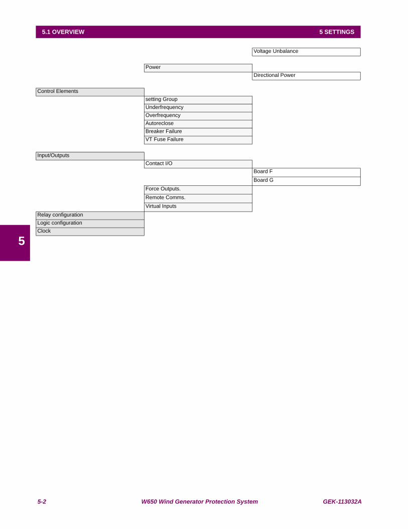
5-2 W650 Wind Generator Protection System GEK-113032A
5.1 OVERVIEW 5 SETTINGS
5
Voltage Unbalance
PowerDirectional Power
Control Elementssetting GroupUnderfrequencyOverfrequencyAutorecloseBreaker FailureVT Fuse Failure
Input/OutputsContact I/O
Board FBoard G
Force Outputs.Remote Comms.Virtual Inputs
Relay configurationLogic configurationClock
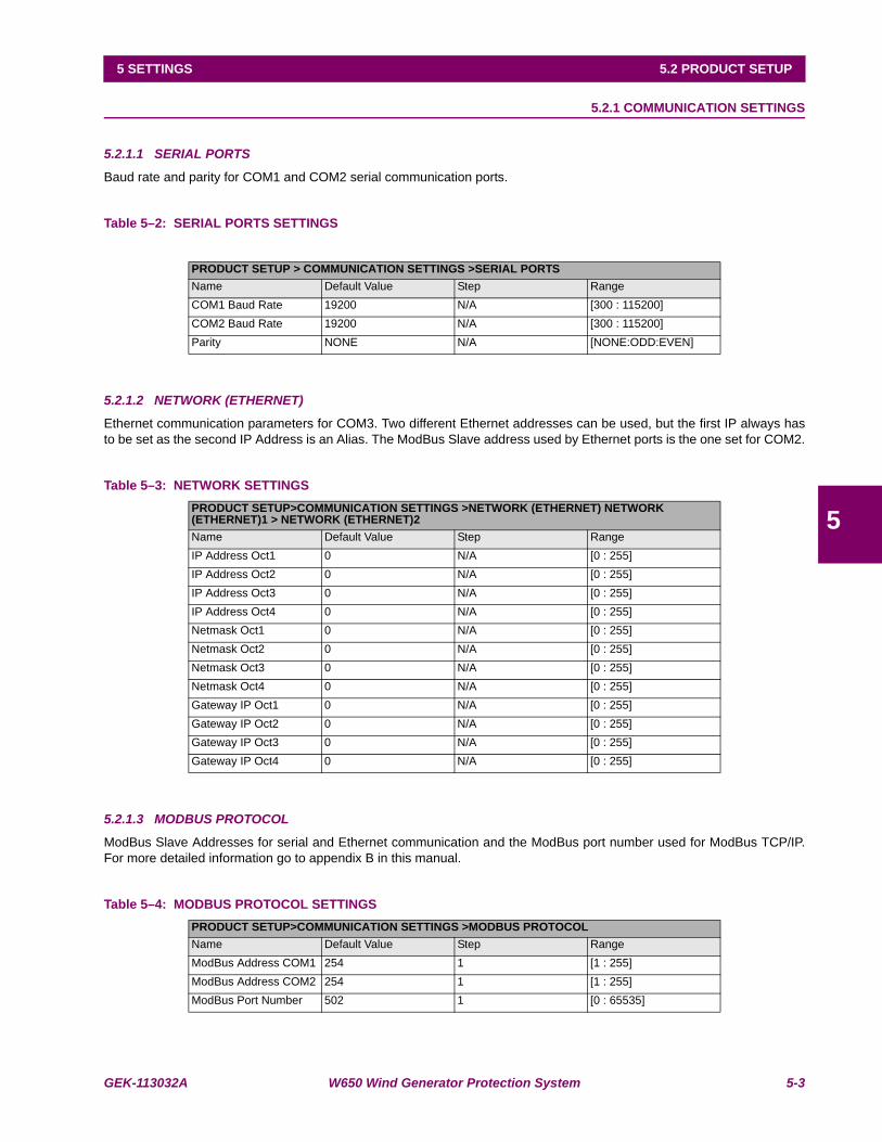
GEK-113032A W650 Wind Generator Protection System 5-3
5 SETTINGS 5.2 PRODUCT SETUP
5
5.2PRODUCT SETUP 5.2.1 COMMUNICATION SETTINGS
5.2.1.1 SERIAL PORTS
Baud rate and parity for COM1 and COM2 serial communication ports.
Table 5–2: SERIAL PORTS SETTINGS
5.2.1.2 NETWORK (ETHERNET)
Ethernet communication parameters for COM3. Two different Ethernet addresses can be used, but the first IP always hasto be set as the second IP Address is an Alias. The ModBus Slave address used by Ethernet ports is the one set for COM2.
Table 5–3: NETWORK SETTINGS
5.2.1.3 MODBUS PROTOCOL
ModBus Slave Addresses for serial and Ethernet communication and the ModBus port number used for ModBus TCP/IP.For more detailed information go to appendix B in this manual.
Table 5–4: MODBUS PROTOCOL SETTINGS
PRODUCT SETUP > COMMUNICATION SETTINGS >SERIAL PORTSName Default Value Step RangeCOM1 Baud Rate 19200 N/A [300 : 115200]COM2 Baud Rate 19200 N/A [300 : 115200]Parity NONE N/A [NONE:ODD:EVEN]
PRODUCT SETUP>COMMUNICATION SETTINGS >NETWORK (ETHERNET) NETWORK (ETHERNET)1 > NETWORK (ETHERNET)2Name Default Value Step RangeIP Address Oct1 0 N/A [0 : 255]IP Address Oct2 0 N/A [0 : 255]IP Address Oct3 0 N/A [0 : 255]IP Address Oct4 0 N/A [0 : 255]Netmask Oct1 0 N/A [0 : 255]Netmask Oct2 0 N/A [0 : 255]Netmask Oct3 0 N/A [0 : 255]Netmask Oct4 0 N/A [0 : 255]Gateway IP Oct1 0 N/A [0 : 255]Gateway IP Oct2 0 N/A [0 : 255]Gateway IP Oct3 0 N/A [0 : 255]Gateway IP Oct4 0 N/A [0 : 255]
PRODUCT SETUP>COMMUNICATION SETTINGS >MODBUS PROTOCOLName Default Value Step RangeModBus Address COM1 254 1 [1 : 255]ModBus Address COM2 254 1 [1 : 255]ModBus Port Number 502 1 [0 : 65535]

5-4 W650 Wind Generator Protection System GEK-113032A
5.2 PRODUCT SETUP 5 SETTINGS
5
5.2.1.4 DNP3 SLAVE
Physical port, Slave Address for DNP, IP Addresses for Masters, TCP/UDP Port, Unsolicited Response parameters, Analogscale factors and deadbands, message fragment size, Binary input block. For more detailed information go to appendix Cin this manual.
Table 5–5: DNP PROTOCOL SETTINGSPRODUCT SETUP>COMMUNICATION SETTINGS >DNP3 SLAVEDNP3 SLAVE 1 > DNP3 SLAVE 2 > DNP3 SLAVE 3Name Default Value Step RangePhysical Port NONE N/A [COM1:COM2:NETWORK]Address 255 1 [0 : 65534]IP Addr Client1 Oct1 0 1 [0 : 255]IP Addr Client1 Oct2 0 1 [0 : 255]IP Addr Client1 Oct3 0 1 [0 : 255]IP Addr Client1 Oct4 0 1 [0 : 255]IP Addr Client2 Oct1 0 1 [0 : 255]IP Addr Client2 Oct2 0 1 [0 : 255]IP Addr Client2 Oct3 0 1 [0 : 255]IP Addr Client2 Oct4 0 1 [0 : 255]IP Addr Client3 Oct1 0 1 [0 : 255]IP Addr Client3 Oct2 0 1 [0 : 255]IP Addr Client3 Oct3 0 1 [0 : 255]IP Addr Client3 Oct4 0 1 [0 : 255]IP Addr Client4 Oct1 0 1 [0 : 255]IP Addr Client4 Oct2 0 1 [0 : 255]IP Addr Client4 Oct3 0 1 [0 : 255]IP Addr Client4 Oct4 0 1 [0 : 255]IP Addr Client5 Oct1 0 1 [0 : 255]IP Addr Client5 Oct2 0 1 [0 : 255]IP Addr Client5 Oct3 0 1 [0 : 255]IP Addr Client5 Oct4 0 1 [0 : 255]TCP/UDP Port 20000 1 [0 : 65535]Unsol Resp Function DISABLED N/A [DISABLED – ENABLED]Unsol Resp TimeOut 5 1 [0 : 60]Unsol Resp Max Ret 10 1 [0 : 255]Unsol Resp Dest Adr 200 1 [0 : 65535]Current Scale Factor 1 N/A [0.00001-0.0001-0.001-0.01-0.1-1-10-100-1000]Voltage Scale Factor 1 N/A [0.00001-0.0001-0.001-0.01-0.1-1-10-100-1000]Power Scale Factor 1 N/A [0.00001-0.0001-0.001-0.01-0.1-1-10-100-1000]Energy Scale Factor 1 N/A [0.00001-0.0001-0.001-0.01-0.1-1-10-100-1000]Other Scale Factor 1 N/A [0.00001-0.0001-0.001-0.01-0.1-1-10-100-1000]Current Deadband 30000 1 [0 : 65535]Voltage Deadband 30000 1 [0 : 65535]Power Deadband 30000 1 [0 : 65535]Energy Deadband 30000 1 [0 : 65535]Other Deadband 30000 1 [0 : 65535]Msg Fragment Size 240 1 [30 : 2048]Binary Input Block 1 CTL EVENTS 1-16 N/ABinary Input Block 2 CTL EVENTS 17-32 N/ABinary Input Block 3 CTL EVENTS 33-48 N/ABinary Input Block 4 CTL EVENTS 49-64 N/ABinary Input Block 5 CTL EVENTS 65-80 N/A
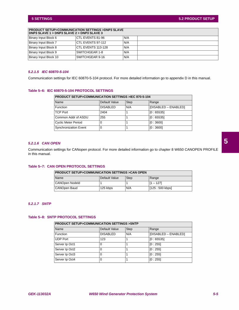
GEK-113032A W650 Wind Generator Protection System 5-5
5 SETTINGS 5.2 PRODUCT SETUP
5
5.2.1.5 IEC 60870-5-104
Communication settings for IEC 60870-5-104 protocol. For more detailed information go to appendix D in this manual.
Table 5–6: IEC 60870-5-104 PROTOCOL SETTINGS
5.2.1.6 CAN OPEN
Communication settings for CANopen protocol. For more detailed information go to chapter 8 W650 CANOPEN PROFILEin this manual.
Table 5–7: CAN OPEN PROTOCOL SETTINGS
5.2.1.7 SNTP
Table 5–8: SNTP PROTOCOL SETTINGS
PRODUCT SETUP>COMMUNICATION SETTINGS >DNP3 SLAVEDNP3 SLAVE 1 > DNP3 SLAVE 2 > DNP3 SLAVE 3Binary Input Block 6 CTL EVENTS 81-96 N/ABinary Input Block 7 CTL EVENTS 97-112 N/ABinary Input Block 8 CTL EVENTS 113-128 N/ABinary Input Block 9 SWITCHGEAR 1-8 N/ABinary Input Block 10 SWITCHGEAR 9-16 N/A
PRODUCT SETUP>COMMUNICATION SETTINGS >IEC 870-5-104Name Default Value Step RangeFunction DISABLED N/A [DISABLED – ENABLED]TCP Port 2404 1 [0 : 65535]Common Addr of ASDU 255 1 [0 : 65535]Cyclic Meter Period 0 1 [0 : 3600]Synchronization Event 0 1 [0 : 3600]
PRODUCT SETUP>COMMUNICATION SETTINGS >CAN OPENName Default Value Step RangeCANOpen Nodeld 1 1 [1 – 127]CANOpen Baud 125 kbps N/A [125 : 500 kbps]
PRODUCT SETUP>COMMUNICATION SETTINGS >SNTPName Default Value Step RangeFunction DISABLED N/A [DISABLED – ENABLED]UDP Port 123 1 [0 : 65535]Server Ip Oct1 0 1 [0 : 255]Server Ip Oct2 0 1 [0 : 255]Server Ip Oct3 0 1 [0 : 255]Server Ip Oct4 0 1 [0 : 255]

5-6 W650 Wind Generator Protection System GEK-113032A
5.2 PRODUCT SETUP 5 SETTINGS
5
The W650 supports the Simple Network Time Protocol specified in RFC-2030. With SNTP, the W650 can obtain the clocktime over an Ethernet network. The W650 acts as an SNTP client to receive time values from an SNTP/NTP server, usuallya dedicated product using a GPS receiver to provide an accurate time. Three different modes of SNTP operation aresupported. These modes are unicast, broadcast and anycast.
If SNTP functionality is enabled at the same time as an IRIG-B source is connected to theW650, the IRIG-B signal providesthe time value to the W650 clock for as long as a valid signal is present. If the IRIG-B signal is removed, the time obtainedfrom the SNTP server is used.
To use SNTP in unicast mode, Server IP Oct1..4 must be set to the SNTP/NTP server IP address. Once this address is setand theFunction setting is “UNICAST”, the W650 attempts to obtain time values from the SNTP/NTP server. Since manytime values are obtained and averaged, it generally takes forty seconds until the W650 clock is synchronized with theSNTP/NTP server. It may take up to one minute for the W650 to signal an SNTP FAIL state if the server is offline.
To use SNTP in broadcast mode, set the Function setting to “BROADCAST”. The W650 then listens to SNTP messagessent to the “all ones” broadcast address for the subnet. The W650 waits up to eighteen minutes (>1024 seconds) withoutreceiving an SNTP broadcast message before signaling an SNTP FAIL state.
To use SNTP in anycast mode, set the Function setting to “ANYCAST”. Anycast mode is designed for use with a set ofcooperating servers whose addresses are not known beforehand by the client. The W650 sends a request to a multicastgroup address aasigned by IANA for NTP protocol. This address is 224.0.1.1 and a group of SNTP/NTP servers listens toit. Upon receiving a request each server sends a unicast response to the SNTP/NTP client. The W650 relay binds to thefirst unicast message received from any server. Then it continues operating with SNTP/NTP server in unicast mode. Anyfurther responses from other SNTP/NTP servers are ignored. In unicast mode of operation the chosen time server can gooffline, in that case it takes about one minute for the W650 to signal an SNTP FAIL state and to switch again to anycastmode to try to find another time server. In anycast mode the W650 tries to send multicast messages up to five minutesbefore signaling an SNTP FAIL state.
The W650 relay does not support the multicast mode of SNTP functionality.
5.2.2 MODBUS USER MAP
The ModBus user map definition. 256 records, selectable from the complete relay ModBus map, form the ModBus usermap. For more detailed information go to appendix B in this manual.
Table 5–9: MODBUS USER MAP SETTINGSPRODUCT SETUP > MODBUS USER MAPName Default Value Step RangeAddress 00 0000 [0000 : FFFF]Address 01 0000 [0000 : FFFF]... ...Address 254 0000 [0000 : FFFF]Address 255 0000 [0000 : FFFF]

GEK-113032A W650 Wind Generator Protection System 5-7
5 SETTINGS 5.2 PRODUCT SETUP
5
5.2.3 FAULT REPORT
5.2.3.1 OVERVIEW
The fault report module defines the type of fault (three-phase, phase-to-phase, phase-to-ground), and the distance to thefault. The fault activation signal (FAULT REPORT TRIGG) is programmed at “Setpoint > Relay Configuration >Protection Elements”.
The fault report provides fault date, fault type and fault location information.
Information referred to the last ten faults is stored as fault report and available to the user through theEnerVista 650 Setupsoftware or the web server application. Each fault report includes the following information:
• Fault date and time
• Pre-fault current and voltage in primary values
• Fault current and voltages in primary values
• Fault type
• Distance to the fault (fault location)
• Line parameters
• Recloser and breaker status information
As an option, the Relay offers the possibility to display a fault-warning message on the relay HMI (selectable by setting).
5.2.3.2 FAULT REPORT SETTINGS
Table 5–10: FAULT REPORT SETTINGS
Function permission (Function): Enabling this setting allows to create a fault report when the FAULT REPORT TRIGG isactivated.
Positive sequence impedance module (Pos Seq Module): Value, in ohms, of the line positive sequenceimpedance module.
Positive sequence impedance Angle (Pos Seq Angle): Value, in degrees, of the line positive sequence angle.
Zero sequence impedance module (Zero Seq Module): Value, in ohms, of the line zero sequence impedancemodule.
Zero sequence impedance Angle (Zero Seq Angle): Value, in degrees, of the line zero sequence angle.
Line Length: The metering element can be kilometers or miles.
Show Fault On HMI: This setting enables or disables the option to displayfaults on the Relay HMI.
Snapshot Events: This setting enables or disables the snapshot eventgeneration for the fault report element.
SETPOINT > PRODUCT SETUP > FAULT REPORTsetting Description Name Default Value Step RangeFunction permission Function DISABLED N/A [DISABLED – ENABLED]Positive sequence impedance module Pos Seq Module 3.00 0.01 Ohm [0.01 : 250.00]Positive sequence impedance angle Pos Seq Angle 75 1 Deg [25 : 90]Zero sequence impedance module Zero Seq Module 9.00 0.01 Ohm [0.01 : 750.00]Zero sequence impedance angle Zero Seq Angle 75 1 Deg [25 : 90]Line length Line Length 100.0 0.1 [0.0 : 2000.0]Display fault on HMI Show Fault On HMI DISABLED N/A [DISABLED – ENABLED]Snapshot Event generation Snapshot Events ENABLED N/A [DISABLED – ENABLED]

5-8 W650 Wind Generator Protection System GEK-113032A
5.2 PRODUCT SETUP 5 SETTINGS
5
5.2.3.3 FAULT REPORT STATES
States associated to the fault report (“Actual >Status>Records Status>Fault Reports”), are shown on Table 5–11:
Table 5–11: FAULT REPORT STATES
FAULT REPORT TRIGG: The activation of this state initiates the calculation of the fault location and the generation ofthe corresponding report.
CLEAR FAULT REPORTS: The activation of this state produces the removal of all faults stored in the relay. Additionally,all active faults on the HMI display will be acknowledged. This signal is programmed at“Setpoint>Relay Configuration>Protection Elements”.
FAULT DATE: Date and time of the last fault.
FAULT TYPE: Type of the last fault produced (3PHASE, AG, BG, CG, AB, ABG, BC, BCG, CA, CAG, NAF).NAF indicates that the type of fault has not been calculated.
FAULT LOCATION: Calculated distance to the last fault (the metering element will be the same used for settingthe line length).
FAULT REPORT NUMBER: Number of the fault report file saved in the relay’s non-volatile memory, associated to thelast fault produced.
5.2.3.4 FAULT REPORT RETRIEVAL
Fault report files can be retrieved using the EnerVista 650 Setup software, or the web server at “http:\\relay IP address”.
For obtaining fault reports using the EnerVista 650 Setup software, the user must access “Actual>Records>Fault report”.The top of the window shows the number of the last fault report stored by the device (Fault Record Number). Clicking onthe “View header” button, the system will show the header of the record selected at “Select Record”.
Clicking on the “Download” button, the file is retrieved, and saved in a folder selected by the user. The file name is“FLTxxx.DAT”, where xxx is the corresponding record number. The fault report retrieval can be done using serialcommunication (ModBus RTU) or Ethernet (ftp, tftp).
Fault reports are stored in the relay’s non-volatile memory, so they are accessible from the EnerVista 650 Setup software orthe relay’s web server. The fault report is a text file named FLTxxx.txt where xxx is the record number, with a range of 001to 999. Only files from the 10 last faults will be stored. If there are already ten files stored and a new fault occurs, the newfault will overwrite the oldest one. Enabling Show Fault on HMI option, this information will also be sent to HMI.
When a fault is produced and a warning message is displayed on the HMI, fault information alternates between twoseparate screens: one with general information, and a second one with the fault metering values. This screen needs to beacknowledged by the user by pressing the INTRO button to exit the fault report screen. If several consecutive faults areproduced, the HMI will always display the most recent one. Each stored fault will need to be acknowledged up to amaximum of 10 faults. The HMI menu offers an option to view the last 10 faults produced, that menu displays both thegeneral information screen and the metering screen for each fault.
FAULT REPORT STATESFAULT REPORT TRIGGCLEAR FAULT REPORTSFAULT DATEFAULT TYPEFAULT LOCATIONFAULT REPORT NUMBER

GEK-113032A W650 Wind Generator Protection System 5-9
5 SETTINGS 5.2 PRODUCT SETUP
5
5.2.4 OSCILLOGRAPHY
5.2.4.1 OVERVIEW
W650 elements allocate 1-Mbyte of memory for storing oscillography records. These oscillography records are stored innon-volatile memory.
Oscillography records are stored in COMTRADE ASCII - IEEE C37.111-1999 standard format.
The oscillography module is in charge of storing the instantaneous values of the 9 analog signals and the 16 programmabledigital signals at Setpoint > Relay Configuration > Oscillography in fault conditions (OSCILLO TRIGGER signalactivation).
All oscillography records store all analog signals (fixed) plus 16 digital signals (programmable). The order of storage in thecase of analog signals is as follows:
Analog 1 IA channel.
Analog 2 IB channel.
Analog 3 IC channel.
Analog 4 IG channel.
Analog 5 ISG channel.
Analog 6 VA or VAB channel, depending on the selected configuration (Wye or Delta at “Setpoint>SystemSetup>General settings>Phase VT Connection”).
Analog 7 VB or VBC channel, depending on the selected configuration (Wye or Delta at “Setpoint>SystemSetup>General settings>Phase VT Connection”).
Analog 8 VC or VCA channel, depending on the selected configuration (Wye or Delta at “Setpoint>SystemSetup>General settings>Phase VT Connection”).
Analog 9 VN or VX channel, depending on the selected configuration (zero sequence measured, or busbar voltage at“Setpoint>System Setup>General settings>Auxiliary Voltage”).
The 16 digital channels and the oscillography trigger signal are programmable using the EnerVista 650 Setup software atSetpoint > Relay configuration > Oscillography. Each digital channel can be associated to a single status or to a logicstatus. In this last case, the logic must be configured using the PLC Editor tool, at Setpoint > Logic Configuration insideEnerVista 650 Setup, and its output must be associated to a virtual output. This virtual output is then associated to a digitalchannel. The oscillography trigger signal can be a single status or a configured logic.
5.2.4.2 OSCILLOGRAPHY SETTINGS
These settings (“Setpoint > Product Setup > Oscillography”) are described in Table 5–12:
Table 5–12: OSCILLOGRAPHY SETTINGSSETPOINT > PRODUCT SETUP > OSCILLOGRAPHYSetting Description Name Default Value Step RangeFunction Permission Function ENABLED N/A [DISABLED – ENABLED]Prefault Trigger Position 30 1 % [5 : 95]Samples per cycle Samples/Cycle 64 N/A [4 – 8 – 16 –32 – 64]Maximum number of oscillos Max. Number Osc. 4 1 oscillo [1 : 20]Automatic oscillography overwrite Automatic Overwrite DISABLED N/A [DISABLED – ENABLED]Snapshot Event generation Snapshot Events ENABLED N/A [DISABLED – ENABLED]

5-10 W650 Wind Generator Protection System GEK-113032A
5.2 PRODUCT SETUP 5 SETTINGS
5
Function Permission (Function): Enabling this setting allows to create an oscillography record when the “TRIGGEROSCILLO” signal is activated.
Trigger Position: This setting defines the prefault data (in percentage) stored every time a new oscillo isproduced.
Samples/Cycle: This setting defines the number of samples per cycle stored in each oscillographyrecord. Please see the example below.
Maximum Number of Oscillos (Max. Number Osc.): 1 to 20 oscillography records can be selected. The capacity of eachrecord is = 1Mbyte / Max. Number Osc. This capacity is divided in 38 bytes (9measurements * 4 bytes/measurement + 2 digital bytes) per stored sample. Pleaserefer to example below.
Automatic Overwrite: This setting allows chained oscillographies during the fault (TRIGGER OSCILLO signalactivated). The maximum allowed value to be stored as a chained oscillography is 1Mbyte. In this case, even if the trip continues during a time longer than the associated1 Mbyte of memory, the relay will stop storing the oscillography in RAM memory untilthe complete record has been saved in non-volatile memory. The oscillographymodule will be reset once the data has been completely stored in Flash memory andthe TRIGGER OSCILLO state is deactivated.
Snapshot Events: This setting enables or disables snapshot event generation for the oscillographyelement.
EXAMPLE
For a Max. Number Osc. of 4, each record will store 1Mbyte / 4 = 262144 bytes.
Therefore, the number of samples per oscillography record is 262144 bytes / 38 bytes = 6898 samples per stored oscillo.
If we set the relay to 64 samples per cycle, each record will store up to 6898 / 64 = 107.78 signal cycles. This valueexpressed in terms of time would be:
For 50 Hz: 107.78 cycles x 20 ms/cycle =2.155 seconds.
For 60 Hz: 107.78 cycles x 16.67 ms/cycle =1.796 seconds.

GEK-113032A W650 Wind Generator Protection System 5-11
5 SETTINGS 5.2 PRODUCT SETUP
5
5.2.4.3 OSCILLOGRAPHY STATES
States associated to the oscillography module (“Actual >Status>Records Status>Oscillography”), are shown in Table 5–13:
Table 5–13: OSCILLOGRAPHY STATES
OSC DIGITAL CHANNEL XX: These states are configured at “Setpoint>Relay configuration>Oscillography”.Each of these states can be associated to a protection state or to a virtual output. Eachoscillography record will reflect the changes experienced by this state during therecord.
OSCILLO TRIGGER: The activation of this state will produce the oscillography record capture. Each recorduses a percentage of its capacity to store prefault information. This percentage isselected in the Trigger Position setting, and the rest of the record’s capacity will storepost-fault information.
NUMBER OF TRIGGERS: This is the number of the most recent oscillography record stored in the relay. Therecord is stored in COMTRADE format. The range is 0 to 999.
CYCLES PER RECORD: This state displays the number of cycles that will be stored in each oscillographyrecord. Although the number of cycles can be a decimal number, the record willrepresent only the integer part.
AVAILABLE RECORDS: This shows the number of records stored in the relay, which can be retrieved by serialcommunication (ModBus RTU) or Ethernet (ftp, tftp). The range is 0 to 20.
OSCILLOGRAPHY STATESOSC DIG CHANNEL 1OSC DIG CHANNEL 2OSC DIG CHANNEL 3OSC DIG CHANNEL 4OSC DIG CHANNEL 5OSC DIG CHANNEL 6OSC DIG CHANNEL 7OSC DIG CHANNEL 8OSC DIG CHANNEL 9OSC DIG CHANNEL 10OSC DIG CHANNEL 11OSC DIG CHANNEL 12OSC DIG CHANNEL 13OSC DIG CHANNEL 14OSC DIG CHANNEL 15OSC DIG CHANNEL 16OSCILLO TRIGGERNUMBER OF TRIGGERSCYCLES PER RECORDAVAILABLE RECORDS
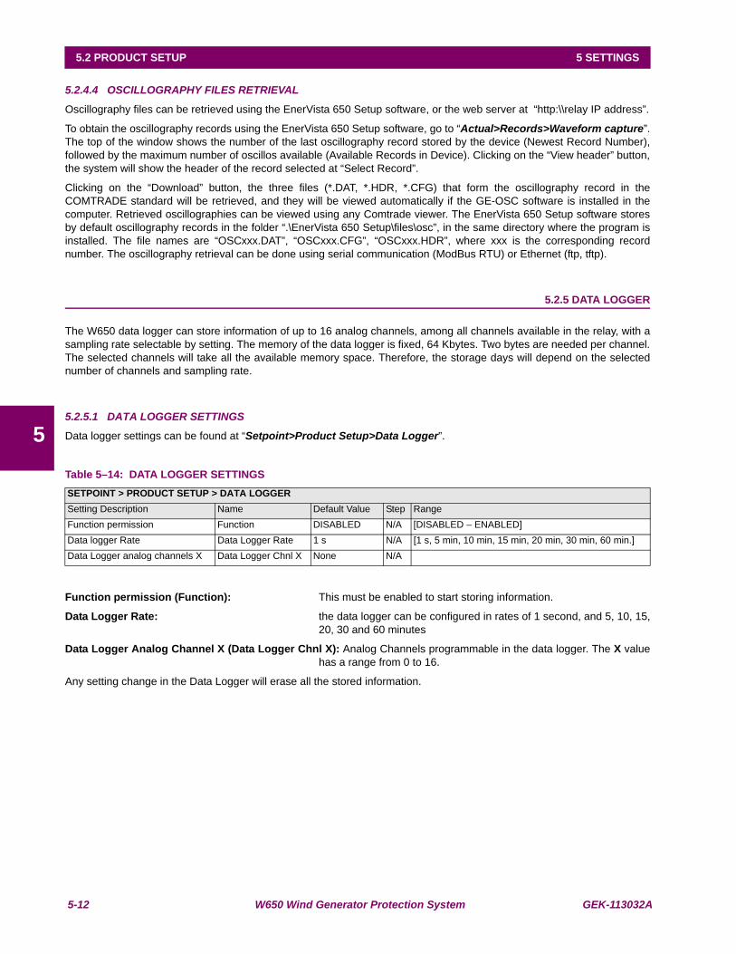
5-12 W650 Wind Generator Protection System GEK-113032A
5.2 PRODUCT SETUP 5 SETTINGS
5
5.2.4.4 OSCILLOGRAPHY FILES RETRIEVAL
Oscillography files can be retrieved using the EnerVista 650 Setup software, or the web server at “http:\\relay IP address”.
To obtain the oscillography records using the EnerVista 650 Setup software, go to “Actual>Records>Waveform capture”.The top of the window shows the number of the last oscillography record stored by the device (Newest Record Number),followed by the maximum number of oscillos available (Available Records in Device). Clicking on the “View header” button,the system will show the header of the record selected at “Select Record”.
Clicking on the “Download” button, the three files (*.DAT, *.HDR, *.CFG) that form the oscillography record in theCOMTRADE standard will be retrieved, and they will be viewed automatically if the GE-OSC software is installed in thecomputer. Retrieved oscillographies can be viewed using any Comtrade viewer. The EnerVista 650 Setup software storesby default oscillography records in the folder “.\EnerVista 650 Setup\files\osc”, in the same directory where the program isinstalled. The file names are “OSCxxx.DAT”, “OSCxxx.CFG”, “OSCxxx.HDR”, where xxx is the corresponding recordnumber. The oscillography retrieval can be done using serial communication (ModBus RTU) or Ethernet (ftp, tftp).
5.2.5 DATA LOGGER
The W650 data logger can store information of up to 16 analog channels, among all channels available in the relay, with asampling rate selectable by setting. The memory of the data logger is fixed, 64 Kbytes. Two bytes are needed per channel.The selected channels will take all the available memory space. Therefore, the storage days will depend on the selectednumber of channels and sampling rate.
5.2.5.1 DATA LOGGER SETTINGS
Data logger settings can be found at “Setpoint>Product Setup>Data Logger”.
Table 5–14: DATA LOGGER SETTINGS
Function permission (Function): This must be enabled to start storing information.
Data Logger Rate: the data logger can be configured in rates of 1 second, and 5, 10, 15,20, 30 and 60 minutes
Data Logger Analog Channel X (Data Logger Chnl X): Analog Channels programmable in the data logger. The X valuehas a range from 0 to 16.
Any setting change in the Data Logger will erase all the stored information.
SETPOINT > PRODUCT SETUP > DATA LOGGERSetting Description Name Default Value Step RangeFunction permission Function DISABLED N/A [DISABLED – ENABLED]Data logger Rate Data Logger Rate 1 s N/A [1 s, 5 min, 10 min, 15 min, 20 min, 30 min, 60 min.]Data Logger analog channels X Data Logger Chnl X None N/A
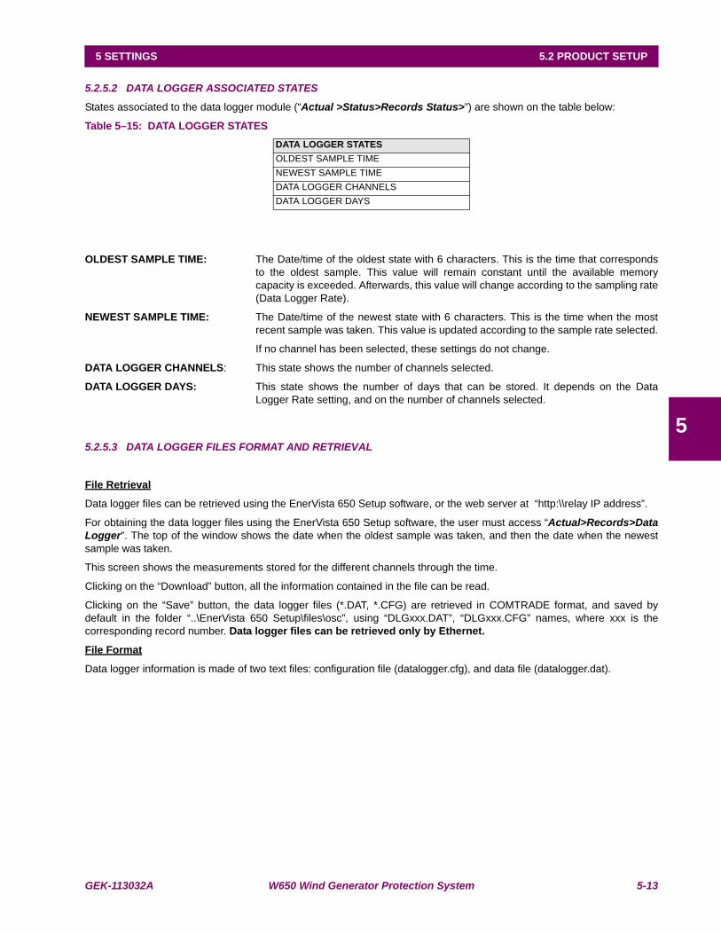
GEK-113032A W650 Wind Generator Protection System 5-13
5 SETTINGS 5.2 PRODUCT SETUP
5
5.2.5.2 DATA LOGGER ASSOCIATED STATES
States associated to the data logger module (“Actual >Status>Records Status>”) are shown on the table below:
Table 5–15: DATA LOGGER STATES
OLDEST SAMPLE TIME: The Date/time of the oldest state with 6 characters. This is the time that correspondsto the oldest sample. This value will remain constant until the available memorycapacity is exceeded. Afterwards, this value will change according to the sampling rate(Data Logger Rate).
NEWEST SAMPLE TIME: The Date/time of the newest state with 6 characters. This is the time when the mostrecent sample was taken. This value is updated according to the sample rate selected.
If no channel has been selected, these settings do not change.
DATA LOGGER CHANNELS: This state shows the number of channels selected.
DATA LOGGER DAYS: This state shows the number of days that can be stored. It depends on the DataLogger Rate setting, and on the number of channels selected.
5.2.5.3 DATA LOGGER FILES FORMAT AND RETRIEVAL
File Retrieval
Data logger files can be retrieved using the EnerVista 650 Setup software, or the web server at “http:\\relay IP address”.
For obtaining the data logger files using the EnerVista 650 Setup software, the user must access “Actual>Records>DataLogger”. The top of the window shows the date when the oldest sample was taken, and then the date when the newestsample was taken.
This screen shows the measurements stored for the different channels through the time.
Clicking on the “Download” button, all the information contained in the file can be read.
Clicking on the “Save” button, the data logger files (*.DAT, *.CFG) are retrieved in COMTRADE format, and saved bydefault in the folder “..\EnerVista 650 Setup\files\osc”, using “DLGxxx.DAT”, “DLGxxx.CFG” names, where xxx is thecorresponding record number. Data logger files can be retrieved only by Ethernet.
File Format
Data logger information is made of two text files: configuration file (datalogger.cfg), and data file (datalogger.dat).
DATA LOGGER STATESOLDEST SAMPLE TIMENEWEST SAMPLE TIMEDATA LOGGER CHANNELSDATA LOGGER DAYS
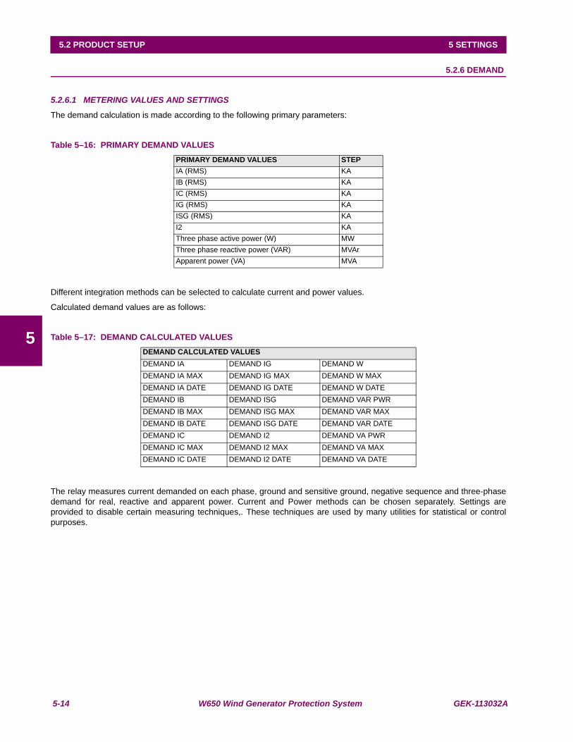
5-14 W650 Wind Generator Protection System GEK-113032A
5.2 PRODUCT SETUP 5 SETTINGS
5
5.2.6 DEMAND
5.2.6.1 METERING VALUES AND SETTINGS
The demand calculation is made according to the following primary parameters:
Table 5–16: PRIMARY DEMAND VALUES
Different integration methods can be selected to calculate current and power values.
Calculated demand values are as follows:
Table 5–17: DEMAND CALCULATED VALUES
The relay measures current demanded on each phase, ground and sensitive ground, negative sequence and three-phasedemand for real, reactive and apparent power. Current and Power methods can be chosen separately. Settings areprovided to disable certain measuring techniques,. These techniques are used by many utilities for statistical or controlpurposes.
PRIMARY DEMAND VALUES STEPIA (RMS) KAIB (RMS) KAIC (RMS) KAIG (RMS) KAISG (RMS) KAI2 KAThree phase active power (W) MWThree phase reactive power (VAR) MVArApparent power (VA) MVA
DEMAND CALCULATED VALUESDEMAND IA DEMAND IG DEMAND WDEMAND IA MAX DEMAND IG MAX DEMAND W MAXDEMAND IA DATE DEMAND IG DATE DEMAND W DATEDEMAND IB DEMAND ISG DEMAND VAR PWRDEMAND IB MAX DEMAND ISG MAX DEMAND VAR MAXDEMAND IB DATE DEMAND ISG DATE DEMAND VAR DATEDEMAND IC DEMAND I2 DEMAND VA PWRDEMAND IC MAX DEMAND I2 MAX DEMAND VA MAXDEMAND IC DATE DEMAND I2 DATE DEMAND VA DATE
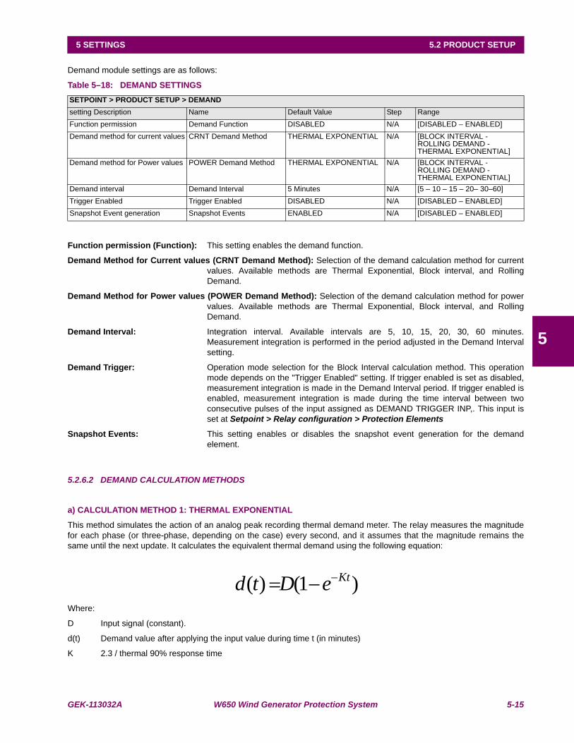
GEK-113032A W650 Wind Generator Protection System 5-15
5 SETTINGS 5.2 PRODUCT SETUP
5
Demand module settings are as follows:
Table 5–18: DEMAND SETTINGS
Function permission (Function): This setting enables the demand function.
Demand Method for Current values (CRNT Demand Method): Selection of the demand calculation method for currentvalues. Available methods are Thermal Exponential, Block interval, and RollingDemand.
Demand Method for Power values (POWER Demand Method): Selection of the demand calculation method for powervalues. Available methods are Thermal Exponential, Block interval, and RollingDemand.
Demand Interval: Integration interval. Available intervals are 5, 10, 15, 20, 30, 60 minutes.Measurement integration is performed in the period adjusted in the Demand Intervalsetting.
Demand Trigger: Operation mode selection for the Block Interval calculation method. This operationmode depends on the "Trigger Enabled" setting. If trigger enabled is set as disabled,measurement integration is made in the Demand Interval period. If trigger enabled isenabled, measurement integration is made during the time interval between twoconsecutive pulses of the input assigned as DEMAND TRIGGER INP,. This input isset at Setpoint > Relay configuration > Protection Elements
Snapshot Events: This setting enables or disables the snapshot event generation for the demandelement.
5.2.6.2 DEMAND CALCULATION METHODS
a) CALCULATION METHOD 1: THERMAL EXPONENTIAL
This method simulates the action of an analog peak recording thermal demand meter. The relay measures the magnitudefor each phase (or three-phase, depending on the case) every second, and it assumes that the magnitude remains thesame until the next update. It calculates the equivalent thermal demand using the following equation:
Where:
D Input signal (constant).
d(t) Demand value after applying the input value during time t (in minutes)
K 2.3 / thermal 90% response time
SETPOINT > PRODUCT SETUP > DEMANDsetting Description Name Default Value Step RangeFunction permission Demand Function DISABLED N/A [DISABLED – ENABLED]Demand method for current values CRNT Demand Method THERMAL EXPONENTIAL N/A [BLOCK INTERVAL -
ROLLING DEMAND -THERMAL EXPONENTIAL]
Demand method for Power values POWER Demand Method THERMAL EXPONENTIAL N/A [BLOCK INTERVAL -ROLLING DEMAND -THERMAL EXPONENTIAL]
Demand interval Demand Interval 5 Minutes N/A [5 – 10 – 15 – 20– 30–60]Trigger Enabled Trigger Enabled DISABLED N/A [DISABLED – ENABLED]Snapshot Event generation Snapshot Events ENABLED N/A [DISABLED – ENABLED]
)1()( KteDtd −−=
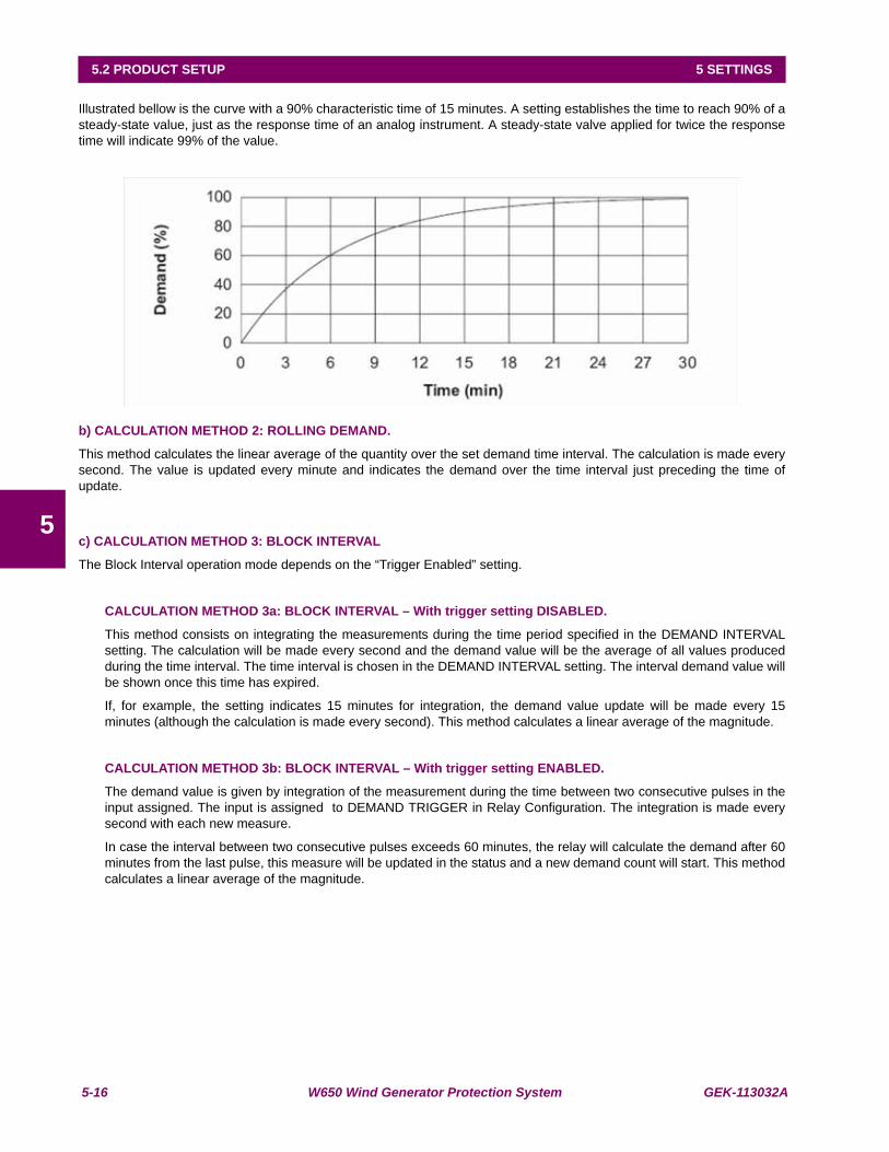
5-16 W650 Wind Generator Protection System GEK-113032A
5.2 PRODUCT SETUP 5 SETTINGS
5
Illustrated bellow is the curve with a 90% characteristic time of 15 minutes. A setting establishes the time to reach 90% of asteady-state value, just as the response time of an analog instrument. A steady-state valve applied for twice the responsetime will indicate 99% of the value.
b) CALCULATION METHOD 2: ROLLING DEMAND.
This method calculates the linear average of the quantity over the set demand time interval. The calculation is made everysecond. The value is updated every minute and indicates the demand over the time interval just preceding the time ofupdate.
c) CALCULATION METHOD 3: BLOCK INTERVAL
The Block Interval operation mode depends on the “Trigger Enabled” setting.
CALCULATION METHOD 3a: BLOCK INTERVAL – With trigger setting DISABLED.
This method consists on integrating the measurements during the time period specified in the DEMAND INTERVALsetting. The calculation will be made every second and the demand value will be the average of all values producedduring the time interval. The time interval is chosen in the DEMAND INTERVAL setting. The interval demand value willbe shown once this time has expired.
If, for example, the setting indicates 15 minutes for integration, the demand value update will be made every 15minutes (although the calculation is made every second). This method calculates a linear average of the magnitude.
CALCULATION METHOD 3b: BLOCK INTERVAL – With trigger setting ENABLED.
The demand value is given by integration of the measurement during the time between two consecutive pulses in theinput assigned. The input is assigned to DEMAND TRIGGER in Relay Configuration. The integration is made everysecond with each new measure.
In case the interval between two consecutive pulses exceeds 60 minutes, the relay will calculate the demand after 60minutes from the last pulse, this measure will be updated in the status and a new demand count will start. This methodcalculates a linear average of the magnitude.
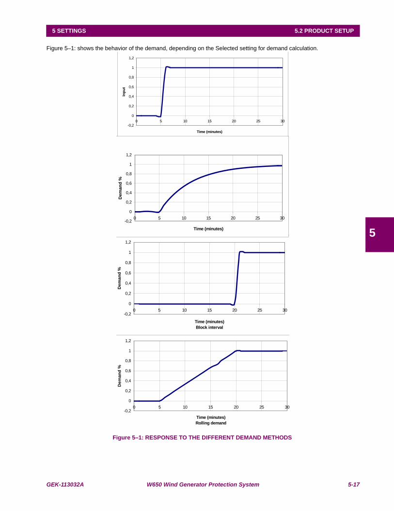
GEK-113032A W650 Wind Generator Protection System 5-17
5 SETTINGS 5.2 PRODUCT SETUP
5
Figure 5–1: shows the behavior of the demand, depending on the Selected setting for demand calculation.
Figure 5–1: RESPONSE TO THE DIFFERENT DEMAND METHODS
-0,2
0
0,2
0,4
0,6
0,8
1
1,2
0 5 10 15 20 25 30
Time (minutes)
Inp
ut
-0,2
0
0,2
0,4
0,6
0,8
1
1,2
0 5 10 15 20 25 30
Time (minutes)
Rolling demand
De
ma
nd
%
-0,2
0
0,2
0,4
0,6
0,8
1
1,2
0 5 10 15 20 25 30
Time (minutes)
Block interval
De
ma
nd
%
-0,2
0
0,2
0,4
0,6
0,8
1
1,2
0 5 10 15 20 25 30
Time (minutes)
De
ma
nd
%
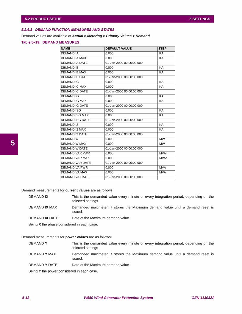
5-18 W650 Wind Generator Protection System GEK-113032A
5.2 PRODUCT SETUP 5 SETTINGS
5
5.2.6.3 DEMAND FUNCTION MEASURES AND STATES
Demand values are available at Actual > Metering > Primary Values > Demand.
Table 5–19: DEMAND MEASURES
Demand measurements for current values are as follows:
DEMAND IX This is the demanded value every minute or every integration period, depending on theselected settings.
DEMAND IX MAX Demanded maximeter; it stores the Maximum demand value until a demand reset isissued.
DEMAND IX DATE Date of the Maximum demand value
Being X the phase considered in each case.
Demand measurements for power values are as follows:
DEMAND Y This is the demanded value every minute or every integration period, depending on theselected settings
DEMAND Y MAX Demanded maximeter; it stores the Maximum demand value until a demand reset isissued.
DEMAND Y DATE Date of the Maximum demand value.
Being Y the power considered in each case.
NAME DEFAULT VALUE STEPDEMAND IA 0.000 KADEMAND IA MAX 0.000 KADEMAND IA DATE 01-Jan-2000 00:00:00.000DEMAND IB 0.000 KADEMAND IB MAX 0.000 KADEMAND IB DATE 01-Jan-2000 00:00:00.000DEMAND IC 0.000 KADEMAND IC MAX 0.000 KADEMAND IC DATE 01-Jan-2000 00:00:00.000DEMAND IG 0.000 KADEMAND IG MAX 0.000 KADEMAND IG DATE 01-Jan-2000 00:00:00.000DEMAND ISG 0.000 KADEMAND ISG MAX 0.000 KADEMAND ISG DATE 01-Jan-2000 00:00:00.000DEMAND I2 0.000 KADEMAND I2 MAX 0.000 KADEMAND I2 DATE 01-Jan-2000 00:00:00.000DEMAND W 0.000 MWDEMAND W MAX 0.000 MWDEMAND W DATE 01-Jan-2000 00:00:00.000DEMAND VAR PWR 0.000 MVArDEMAND VAR MAX 0.000 MVArDEMAND VAR DATE 01-Jan-2000 00:00:00.000DEMAND VA PWR 0.000 MVADEMAND VA MAX 0.000 MVADEMAND VA DATE 01-Jan-2000 00:00:00.000

GEK-113032A W650 Wind Generator Protection System 5-19
5 SETTINGS 5.2 PRODUCT SETUP
5
W Three-phase active power
VAR Three-phase reactive power
VA Three-phase apparent power
The maximum demanded value is stored in non-volatile memory. It is not cleared when the relay is turned off. When therelay is turned on again, the maximum values are updated.
States associated to the demand (“Actual>Status>Records Status>Demand”) are the following:
Table 5–20: DEMAND ASOCIATED VALUES
Besides the previously considered demand measures, two states are used for demand control:
DEMAND TRIGGER INP Bit type state, Programmable at “Setpoint>Relay Configuration>Protection Elements” in theEnerVista 650 Setup software. This signal is used by the Block Interval demand method.
DEMAND RESET INP Bit type state, programmable at “Setpoint>Relay Configuration>Protection Elements” in theEnerVista 650 Setup software. When this bit is activated, the demand measures are reset. Allstored values are reset to zero (for demand dates, this value represents January 1st, 2000).
DEMAND ASOCIATED STATESDEMAND TRIGGER INPDEMAND RESET INP

5-20 W650 Wind Generator Protection System GEK-113032A
5.3 SYSTEM SETUP 5 SETTINGS
5
5.3SYSTEM SETUP
This section shows the settings related to the system setup definition.
5.3.1 GENERAL SETTINGS
This section determines the settings of the element configuration regarding its connection to the power system.
Access to these settings using the EnerVista 650 Setup software is at Setpoint > System Setup > General settings.
The corresponding settings are shown on the table below:
Table 5–21: GENERAL SETTINGS
The system rated voltage is used as reference by the voltage restraint in the phase timed overcurrent element.
The Frequency reference marks the voltage channel to which the system Frequency is measured.
The auxiliary voltage setting can be selected between VN and VX.
VN means that all elements using neutral voltage will take the value directly from the fourth voltage input.
VX means that all elements using neutral voltage will take the value calculated from phase voltages.
5.3.2 FLEX CURVES
The relay incorporates 4 user curves called Flex Curve A, B, C and D. The points for these curves are defined by the userin “Setpoint>System Setup>Flex Curves” menu in EnerVista 650 Setup. User defined flex curves can be selected as anoperation curve in all the time overcurrent functions in the relay.
In the flex curves menu there are 120 points to define a user curve. 40 points for reset (from 0 to 0.98 times the pickupvalue) and 80 for operate (from 1.03 to 20 times the pickup).
SETPOINT > SYSTEM SETUP > GENERAL SETTINGSsetting Description Name Default Value Step RangePhase CT ratio Phase CT Ratio 1.0 0.1 [1.0 : 6000.0]Ground CT ratio Ground CT Ratio 1.0 0.1 [1.0 : 6000.0]Sensitive ground CT ratio Stv Ground CT Ratio 1.0 0.1 [1.0 : 6000.0]Phase VT ratio Phase VT Ratio 1.0 1.0 [1.0 : 1.500.0]Phase VT connection Phase VT Connection WYE N/A [WYE – DELTA]Rated voltage Nominal Voltage 690.0 0.1 [1.0 : 850.0]Rated Frequency Nominal Frequency 50 Hz 1 Hz [50-60]Phase rotation Phase Rotation ABC N/A [ABC – ACB]Frequency reference Frequency Reference VI N/A [VI-VII-VIII]Auxiliary Voltage Auxiliary Voltage VX N/A [VX – VN]Snapshot Event generation Snapshot Events DISABLED N/A [DISABLED – ENABLED]
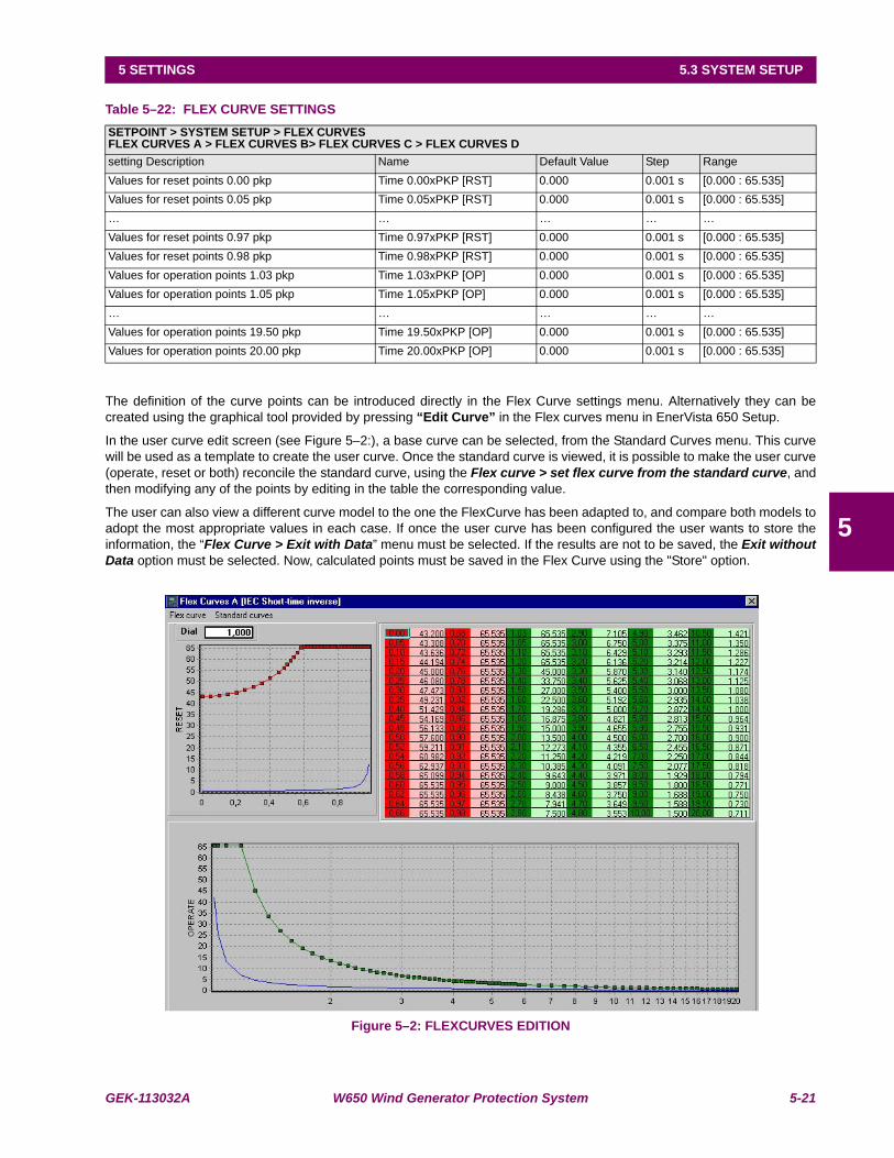
GEK-113032A W650 Wind Generator Protection System 5-21
5 SETTINGS 5.3 SYSTEM SETUP
5
Table 5–22: FLEX CURVE SETTINGS
The definition of the curve points can be introduced directly in the Flex Curve settings menu. Alternatively they can becreated using the graphical tool provided by pressing “Edit Curve” in the Flex curves menu in EnerVista 650 Setup.
In the user curve edit screen (see Figure 5–2:), a base curve can be selected, from the Standard Curves menu. This curvewill be used as a template to create the user curve. Once the standard curve is viewed, it is possible to make the user curve(operate, reset or both) reconcile the standard curve, using the Flex curve > set flex curve from the standard curve, andthen modifying any of the points by editing in the table the corresponding value.
The user can also view a different curve model to the one the FlexCurve has been adapted to, and compare both models toadopt the most appropriate values in each case. If once the user curve has been configured the user wants to store theinformation, the “Flex Curve > Exit with Data” menu must be selected. If the results are not to be saved, the Exit withoutData option must be selected. Now, calculated points must be saved in the Flex Curve using the "Store" option.
Figure 5–2: FLEXCURVES EDITION
SETPOINT > SYSTEM SETUP > FLEX CURVESFLEX CURVES A > FLEX CURVES B> FLEX CURVES C > FLEX CURVES Dsetting Description Name Default Value Step RangeValues for reset points 0.00 pkp Time 0.00xPKP [RST] 0.000 0.001 s [0.000 : 65.535]Values for reset points 0.05 pkp Time 0.05xPKP [RST] 0.000 0.001 s [0.000 : 65.535]… … … … …Values for reset points 0.97 pkp Time 0.97xPKP [RST] 0.000 0.001 s [0.000 : 65.535]Values for reset points 0.98 pkp Time 0.98xPKP [RST] 0.000 0.001 s [0.000 : 65.535]Values for operation points 1.03 pkp Time 1.03xPKP [OP] 0.000 0.001 s [0.000 : 65.535]Values for operation points 1.05 pkp Time 1.05xPKP [OP] 0.000 0.001 s [0.000 : 65.535]… … … … …Values for operation points 19.50 pkp Time 19.50xPKP [OP] 0.000 0.001 s [0.000 : 65.535]Values for operation points 20.00 pkp Time 20.00xPKP [OP] 0.000 0.001 s [0.000 : 65.535]
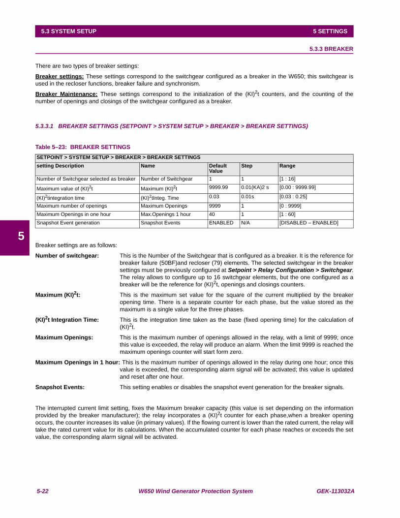
5-22 W650 Wind Generator Protection System GEK-113032A
5.3 SYSTEM SETUP 5 SETTINGS
5
5.3.3 BREAKER
There are two types of breaker settings:
Breaker settings: These settings correspond to the switchgear configured as a breaker in the W650; this switchgear isused in the recloser functions, breaker failure and synchronism.
Breaker Maintenance: These settings correspond to the initialization of the (KI)2t counters, and the counting of thenumber of openings and closings of the switchgear configured as a breaker.
5.3.3.1 BREAKER SETTINGS (SETPOINT > SYSTEM SETUP > BREAKER > BREAKER SETTINGS)
Table 5–23: BREAKER SETTINGS
Breaker settings are as follows:
Number of switchgear: This is the Number of the Switchgear that is configured as a breaker. It is the reference forbreaker failure (50BF)and recloser (79) elements. The selected switchgear in the breakersettings must be previously configured at Setpoint > Relay Configuration > Switchgear.The relay allows to configure up to 16 switchgear elements, but the one configured as abreaker will be the reference for (KI)2t, openings and closings counters.
Maximum (KI)2t: This is the maximum set value for the square of the current multiplied by the breakeropening time. There is a separate counter for each phase, but the value stored as themaximum is a single value for the three phases.
(KI)2t Integration Time: This is the integration time taken as the base (fixed opening time) for the calculation of(KI)2t.
Maximum Openings: This is the maximum number of openings allowed in the relay, with a limit of 9999; oncethis value is exceeded, the relay will produce an alarm. When the limit 9999 is reached themaximum openings counter will start form zero.
Maximum Openings in 1 hour: This is the maximum number of openings allowed in the relay during one hour; once thisvalue is exceeded, the corresponding alarm signal will be activated; this value is updatedand reset after one hour.
Snapshot Events: This setting enables or disables the snapshot event generation for the breaker signals.
The interrupted current limit setting, fixes the Maximum breaker capacity (this value is set depending on the informationprovided by the breaker manufacturer); the relay incorporates a (KI)2t counter for each phase,when a breaker openingoccurs, the counter increases its value (in primary values). If the flowing current is lower than the rated current, the relay willtake the rated current value for its calculations. When the accumulated counter for each phase reaches or exceeds the setvalue, the corresponding alarm signal will be activated.
SETPOINT > SYSTEM SETUP > BREAKER > BREAKER SETTINGSsetting Description Name Default
ValueStep Range
Number of Switchgear selected as breaker Number of Switchgear 1 1 [1 : 16]
Maximum value of (KI)2t Maximum (KI)2t 9999.99 0.01(KA)2 s [0.00 : 9999.99]
(KI)2tintegration time (KI)2tInteg. Time 0.03 0.01s [0.03 : 0.25]
Maximum number of openings Maximum Openings 9999 1 [0 : 9999]Maximum Openings in one hour Max.Openings 1 hour 40 1 [1 : 60]Snapshot Event generation Snapshot Events ENABLED N/A [DISABLED – ENABLED]

GEK-113032A W650 Wind Generator Protection System 5-23
5 SETTINGS 5.3 SYSTEM SETUP
5
The purpose of this function is to provide closer information of the current status of the breaker’s internal contacts. This is,in order to ensure appropriate breaker maintenance, and to decrease the risk of damage when the breaker has sufferedsevere operations during a long time. Once the breaker has been operated, and the preventive maintenance is in place, theaccumulated I2t values and the number of operations are reset to zero.
5.3.3.2 BREAKER MAINTENANCE
To consider used breakers, the relay allows to set initial I2t values as well as an initial number of operations, in order to takeinto account previous breaker operations, as well as operations produced during testing. Breaker maintenance parameterscan be set in the breaker maintenance menu.
BREAKER MAINTENANCE (Setpoint > System Setup > Breaker > Breaker Maintenance)
Table 5–24: BREAKER MAINTENANCE SETTINGS
In this group of settings, the start values of the breaker Counters can beset.
These Counters allow the breaker Maintenance. They are used to accumulate the breaker aging produced by a trip or abreaker opening. In order to incorporate the breaker’s history, in case of used breakers, the system allows assigning aninitial value to accumulated amperes, and to the number of opening and closing operations.
To supervise breaker aging, Σ(KI)2t accumulated values are calculated and stored for each phase in each opening. If therated current is not exceeded, as in the case of a manual opening command, without fault current, the relay uses the ratedcurrent instead of the measured value.
(KI)2t value is accumulated and maintained in independent Counters for each phase. Counters can be accessed throughthe local HMI as well as through the EnerVista 650 Setup software. The element incorporates a setting to select theintegration time ((KI)2t Integ. Time).
The signals associated to the opened or closed status of the breaker can be monitored at “Actual > Status > Breaker”
Table 5–25: BREAKER STATUS
The signals associated to breaker maintenance can be monitored at “Actual > Status > Records Status > BreakerMaintenance”, and they are as follows:
Table 5–26: BREAKER MAINTENANCE STATUS
SETPOINT > SYSTEM SETUP > BREAKER > BREAKER MAINTENANCEsetting Description Name Default Value Step Range
(KI)2t Counter Phase A (KI)2t BKR Ph A Cnt 0.00 0.01 (KA)2 s [0.00 : 9999.99]
(KI)2t Counter Phase B (KI)2t BKR Ph B Cnt 0.00 0.01 (KA)2 s [0.00 : 9999.99]
(KI)2t Counter Phase C (KI)2t BKR Ph C Cnt 0.00 0.01 (KA)2 s [0.00 : 9999.99]
Openings counter BKR Openings Cnt 0 1 [0 : 9999]Closings counter BKR Closings Cnt 0 1 [0 : 9999]
BREAKER STATUS DESCRIPTIONBREAKER OPEN Breaker in open position.BREAKER CLOSED Breaker in close positionBREAKER UNDEFINED Breaker undefined
BREAKER MAINTENANCE DESCRIPTION
(KI)2t PHASE A ALARM This signal activates when the set value for phase A is exceeded.
(KI)2t PHASE B ALARM This signal activates when the set value for phase B is exceeded.
(KI)2t PHASE C ALARM This signal activates when the set value for phase C is exceeded.
BKR OPENINGS ALARM Relay total Number of Openings alarm BKR OPEN 1 HOUR ALRM Relay total Number of Openings in one hour alarm
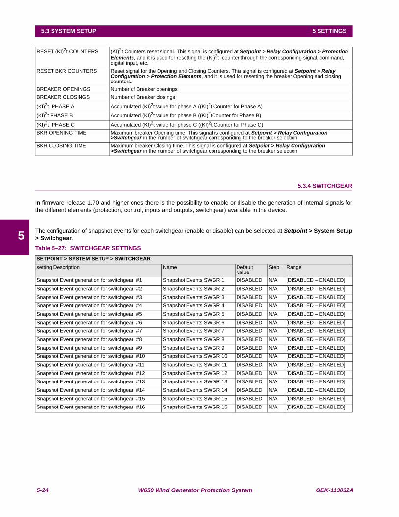
5-24 W650 Wind Generator Protection System GEK-113032A
5.3 SYSTEM SETUP 5 SETTINGS
5
5.3.4 SWITCHGEAR
In firmware release 1.70 and higher ones there is the possibility to enable or disable the generation of internal signals forthe different elements (protection, control, inputs and outputs, switchgear) available in the device.
The configuration of snapshot events for each switchgear (enable or disable) can be selected at Setpoint > System Setup> Switchgear.
Table 5–27: SWITCHGEAR SETTINGS
RESET (KI)2t COUNTERS (KI)2t Counters reset signal. This signal is configured at Setpoint > Relay Configuration > Protection Elements, and it is used for resetting the (KI)2t counter through the corresponding signal, command, digital input, etc.
RESET BKR COUNTERS Reset signal for the Opening and Closing Counters. This signal is configured at Setpoint > Relay Configuration > Protection Elements, and it is used for resetting the breaker Opening and closing counters.
BREAKER OPENINGS Number of Breaker openingsBREAKER CLOSINGS Number of Breaker closings
(KI)2t PHASE A Accumulated (KI)2t value for phase A ((KI)2t Counter for Phase A)
(KI)2t PHASE B Accumulated (KI)2t value for phase B ((KI)2tCounter for Phase B)
(KI)2t PHASE C Accumulated (KI)2t value for phase C ((KI)2t Counter for Phase C)BKR OPENING TIME Maximum breaker Opening time. This signal is configured at Setpoint > Relay Configuration
>Switchgear in the number of switchgear corresponding to the breaker selection BKR CLOSING TIME Maximum breaker Closing time. This signal is configured at Setpoint > Relay Configuration
>Switchgear in the number of switchgear corresponding to the breaker selection
SETPOINT > SYSTEM SETUP > SWITCHGEARsetting Description Name Default
ValueStep Range
Snapshot Event generation for switchgear #1 Snapshot Events SWGR 1 DISABLED N/A [DISABLED – ENABLED]Snapshot Event generation for switchgear #2 Snapshot Events SWGR 2 DISABLED N/A [DISABLED – ENABLED]Snapshot Event generation for switchgear #3 Snapshot Events SWGR 3 DISABLED N/A [DISABLED – ENABLED]Snapshot Event generation for switchgear #4 Snapshot Events SWGR 4 DISABLED N/A [DISABLED – ENABLED]Snapshot Event generation for switchgear #5 Snapshot Events SWGR 5 DISABLED N/A [DISABLED – ENABLED]Snapshot Event generation for switchgear #6 Snapshot Events SWGR 6 DISABLED N/A [DISABLED – ENABLED]Snapshot Event generation for switchgear #7 Snapshot Events SWGR 7 DISABLED N/A [DISABLED – ENABLED]Snapshot Event generation for switchgear #8 Snapshot Events SWGR 8 DISABLED N/A [DISABLED – ENABLED]Snapshot Event generation for switchgear #9 Snapshot Events SWGR 9 DISABLED N/A [DISABLED – ENABLED]Snapshot Event generation for switchgear #10 Snapshot Events SWGR 10 DISABLED N/A [DISABLED – ENABLED]Snapshot Event generation for switchgear #11 Snapshot Events SWGR 11 DISABLED N/A [DISABLED – ENABLED]Snapshot Event generation for switchgear #12 Snapshot Events SWGR 12 DISABLED N/A [DISABLED – ENABLED]Snapshot Event generation for switchgear #13 Snapshot Events SWGR 13 DISABLED N/A [DISABLED – ENABLED]Snapshot Event generation for switchgear #14 Snapshot Events SWGR 14 DISABLED N/A [DISABLED – ENABLED]Snapshot Event generation for switchgear #15 Snapshot Events SWGR 15 DISABLED N/A [DISABLED – ENABLED]Snapshot Event generation for switchgear #16 Snapshot Events SWGR 16 DISABLED N/A [DISABLED – ENABLED]

GEK-113032A W650 Wind Generator Protection System 5-25
5 SETTINGS 5.4 PROTECTION ELEMENTS
5
5.4PROTECTION ELEMENTS 5.4.1 CHANGE OF SETTING TABLES IN W650 ELEMENTS
W650 relays incorporate the following protectionelements:
CURRENT ELEMENTS
Instantaneous overcurrent:
3 x PHASE IOC HIGH (50PH)
3 x PHASE IOC LOW (50PL)
3 x NEUTRAL IOC (50N)
3 x GROUND IOC (50G)
3 x SENSITIVE GROUND IOC (50SG)
Time delayed overcurrent:
3 x PHASE TOC HIGH (51PH)
3 x PHASE TOC LOW (51PL)
3 x NEUTRAL TOC (51N)
3 x GROUND TOC (51G)
3 x SENSITIVE GROUND TOC (51SG)
Negative sequence overcurrent:
3 x NEGATIVE SEQUENCE TOC (46P)
DIRECTIONAL ELEMENTS
3 x PHASE DIR (67P)
3 x NEUTRAL DIR (67N)
3 x GROUND DIR (67G)
3 x SENSITIVE GROUND DIR (67SG)
VOLTAGE ELEMENTS
Phase under/overvoltage
4 x PHASE UV (27P)
4 x PHASE OV (59P)
Zero sequence overvoltage
3 x NEUTRAL OV HIGH (59NH)
3 x NEUTRAL OV LOW (59NL)
Additional under/overvoltage (can be connected to theopen delta for measured zero sequence, or to thebusbar)
3 x AUXILIARY OV (59X)
3 x AUXILIARY UV (27X)
Voltage Unbalance
3 x Voltage Unbalance (60)
POWER
4 x DIRECTIONAL POWER (32)

5-26 W650 Wind Generator Protection System GEK-113032A
5.4 PROTECTION ELEMENTS 5 SETTINGS
5
The W650 elements incorporate also the following control elements:
1 x SETTINGS GROUP
4 x OVERFREQUENCY (81O)
4 x UNDERFREQUENCY (81U)
1 x AUTORECLOSE (79)
1 x BREAKER FAILURE (50BF)
1 x FUSE FAILURE (VTFF)
W650 elements incorporate a flexible grouping capability for protection ELEMENTS. This means that protection elementscan be used in either one of the following modes:
a) SINGLE SETTING GROUPS
In this operation mode, all protection elements can be activated and operated simultaneously.
b) FOUR SETTING GROUPS
In this mode, protection elements are grouped in four independent tables with only one active at a given time.

GEK-113032A W650 Wind Generator Protection System 5-27
5 SETTINGS 5.4 PROTECTION ELEMENTS
5
The distribution of protection elements in tabled groups is described in Table 5–28:
Table 5–28: DISTRIBUTION OF PROTECTION ELEMENTS
The settings used for setting table management are located in Setpoint >Control Elements > Setting Group:
Table 5–29: SETTING GROUP SETTINGS
setting Group settings are as follows:
Function: Possible values are: [DISABLED – ENABLED]
When this setting is disabled, the relay is working in single setting group mode, with all the available protection elementsworking at the same time. If this function is enabled, the setting groups will be enabled, and only the setting group indicatedby the Active Group setting will be active.
Active group: Possible values are 1, 2, 3 or 4.
The setting group selected by default is setting Group 1. This setting indicates which setting group is active (for thispurpose, the previous setting must be set as ENABLED)
The Relay incorporates several signals associated to the Protection elements grouping in tables. First, signals that indicatethe group activation:
GROUP 1 ACT ON This signal produces the activation of setting group 1
GROUP 2 ACT ON This signal produces the activation of setting group 2
TABLE 1 TABLE 2 TABLE 3 TABLE 41x50PH 1x50PH 1x50PH1x50PL 1x50PL 1x50PL1x50N 1x50N 1x50N1x50G 1x50G 1x50G1x50SG 1x50SG 1x50SG1x51PH 1x51PH 1x51PH1x51PL 1x51PL 1x51PL1x51N 1x51N 1x51N1x51G 1x51G 1x51G1x51SG 1x51SG 1x51SG1x46P 1x46P 1x46P1x67P 1x67P 1x67P1x67N 1x67N 1x67N1x67G 1x67G 1x67G1x67SG 1x67SG 1x67SG1x27P 1x27P 1x27P 1x27P1x59P 1x59P 1x59P 1x59P1x59NH 1x59NH 1x59NH1x59NL 1x59NL 1x59NL1x59X 1x59X 1x59X1x27X 1x27X 1x27X1x32 1x32 1x32 1x321x81U 1x81U 1x81U 1x81U1x81O 1x81O 1x81O 1x81O1x60 1x60 1x60
SETPOINT > CONTROL ELEMENTS > SETTING GROUPSetting Description Name Default Value Step RangeSetting Grouping Permission Function DISABLED N/A [DISABLED – ENABLED]Active Group Active Group GROUP 1 N/A [GROUP 1 – GROUP 2 – GROUP 3 – GROUP 4]Snapshot Event generation Snapshot Events ENABLED N/A [DISABLED – ENABLED]

5-28 W650 Wind Generator Protection System GEK-113032A
5.4 PROTECTION ELEMENTS 5 SETTINGS
5
GROUP 3 ACT ON This signal produces the activation of setting group 3
GROUP 4 ACT ON This signal produces the activation of setting group 4
These activation signals for the different setting groups are configured using EnerVista 650 Setup at Setpoint > RelayConfiguration > Protection Elements as shown in the figure.
Figure 5–3: TABLE CHANGE SIGNALS CONFIGURATION EXAMPLE
The example above uses three digital inputs to perform the table selection, but it is possible to use any other logic signal inthe relay.
In case of using digital inputs, the user can select the setting table activating these digital inputs (which could come from thePLC, or from a different relay, or from an auxiliary switch, for adaptive protection). This selection of the active group haspriority over the setting. If several signals are active at the same time, the highest one will be taken as valid. For example, ifselection signals for both groups 1 and 2 are active, the active table will be number 2.
The time used in the table change is one PLC logic scan cycle (5 ms typical), allowing a fast adaptation to system changes.
Another type of signals are block signals. These are internal relay signals that indicate which groups are active, and whichare blocked. For example, if the setting group function is enabled and setting group 1 has been set as active, block signalsfrom setting groups 2, 3 and 4 will be active, and the block signal that corresponds to group 1 will be inactive because thatgroup is enabled.
Block signals are as follows:
GROUP 1 BLOCKED
GROUP 2 BLOCKED
GROUP 3 BLOCKED
GROUP 4 BLOCKED
All signals corresponding to setting Groups, both the activation and the block signals, are located in the Actual > Status >Control Elements > setting Groups menu.

GEK-113032A W650 Wind Generator Protection System 5-29
5 SETTINGS 5.4 PROTECTION ELEMENTS
5
5.4.2 INVERSE TIME CURVES CHARACTERISTICS
Inverse time curves available in time overcurrent elements are as follows:
IEEE extremely/very/moderately inverse
IEC Curve A/B/C/Long-Time Inverse/ Short-Time Inverse
IAC extremely/very/normally/moderately inverse
ANSI extremely/very/normally/moderately inverse
I2t
Definite time curves
Rectifier time curves
User Curve - FlexCurve A/B/C/D
Recloser Curves
The saturation level for the user curve is 20 times the pickup value, for the rest of time overcurrent elements thesaturation level is 48 times the pickup.
All these curves follow the standards defined for each of them, allowing an efficient coordination with other devices locateddownstream. A dial or curve setting allows selection of a tripping time X times the set time in the selected curve. Fixing thisvalue to 0 would produce an instantaneous response for any selected curve.
Tripping time calculations are performed on the base of an internal variable called “energy”. This energy represents thesystem dissipation capability, that is, when 100% of energy is reached, this means that the tripping time associated to thecurve for a certain current value has expired.
Therefore, once the current value has exceeded the pickup value, the relay starts increasing the energy variable value. If itreaches 100%, a trip is produced. When the current value falls below 97% of the pickup value, the element is reset. Thereare two reset types: Instantaneous and Timed (IEEE) or Linear.
The instantaneous mode provides that, when the current value falls below the reset level, energy is immediately reset to 0.This mode is used for coordinating with static devices, which behave in a similar way. In the Linear mode, energy isreduced at a speed associated to the reset times curve (showed in the curve tables), trying to simulate the behavior ofelectromechanical relays.
5.4.2.1 IEEE CURVES
This family of curves follows the standard IEEE C37.112-1996 for extremely inverse, very inverse, and inverse curves. Thefollowing formulas define this type of curve:
Where:
t = Operation time in seconds
Dial = multiplier setting
I = Input current
Itap = Current pickup value
A, B, p = constants defined by the standard
TRESET = reset time in seconds
tr = characteristic constant.
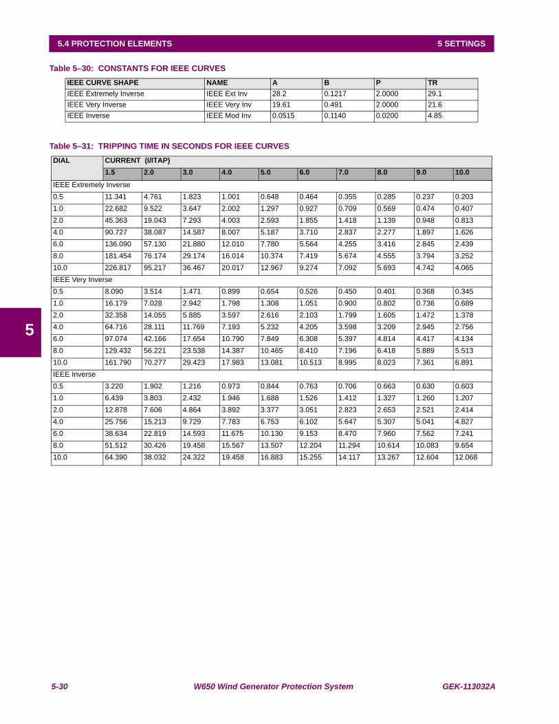
5-30 W650 Wind Generator Protection System GEK-113032A
5.4 PROTECTION ELEMENTS 5 SETTINGS
5
Table 5–30: CONSTANTS FOR IEEE CURVES
Table 5–31: TRIPPING TIME IN SECONDS FOR IEEE CURVES
IEEE CURVE SHAPE NAME A B P TRIEEE Extremely Inverse IEEE Ext Inv 28.2 0.1217 2.0000 29.1IEEE Very Inverse IEEE Very Inv 19.61 0.491 2.0000 21.6IEEE Inverse IEEE Mod Inv 0.0515 0.1140 0.0200 4.85
DIAL CURRENT (I/ITAP)1.5 2.0 3.0 4.0 5.0 6.0 7.0 8.0 9.0 10.0
IEEE Extremely Inverse0.5 11.341 4.761 1.823 1.001 0.648 0.464 0.355 0.285 0.237 0.2031.0 22.682 9.522 3.647 2.002 1.297 0.927 0.709 0.569 0.474 0.4072.0 45.363 19.043 7.293 4.003 2.593 1.855 1.418 1.139 0.948 0.8134.0 90.727 38.087 14.587 8.007 5.187 3.710 2.837 2.277 1.897 1.6266.0 136.090 57.130 21.880 12.010 7.780 5.564 4.255 3.416 2.845 2.4398.0 181.454 76.174 29.174 16.014 10.374 7.419 5.674 4.555 3.794 3.25210.0 226.817 95.217 36.467 20.017 12.967 9.274 7.092 5.693 4.742 4.065IEEE Very Inverse0.5 8.090 3.514 1.471 0.899 0.654 0.526 0.450 0.401 0.368 0.3451.0 16.179 7.028 2.942 1.798 1.308 1.051 0.900 0.802 0.736 0.6892.0 32.358 14.055 5.885 3.597 2.616 2.103 1.799 1.605 1.472 1.3784.0 64.716 28.111 11.769 7.193 5.232 4.205 3.598 3.209 2.945 2.7566.0 97.074 42.166 17.654 10.790 7.849 6.308 5.397 4.814 4.417 4.1348.0 129.432 56.221 23.538 14.387 10.465 8.410 7.196 6.418 5.889 5.51310.0 161.790 70.277 29.423 17.983 13.081 10.513 8.995 8.023 7.361 6.891IEEE Inverse0.5 3.220 1.902 1.216 0.973 0.844 0.763 0.706 0.663 0.630 0.6031.0 6.439 3.803 2.432 1.946 1.688 1.526 1.412 1.327 1.260 1.2072.0 12.878 7.606 4.864 3.892 3.377 3.051 2.823 2.653 2.521 2.4144.0 25.756 15.213 9.729 7.783 6.753 6.102 5.647 5.307 5.041 4.8276.0 38.634 22.819 14.593 11.675 10.130 9.153 8.470 7.960 7.562 7.2418.0 51.512 30.426 19.458 15.567 13.507 12.204 11.294 10.614 10.083 9.65410.0 64.390 38.032 24.322 19.458 16.883 15.255 14.117 13.267 12.604 12.068
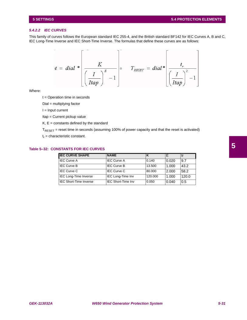
GEK-113032A W650 Wind Generator Protection System 5-31
5 SETTINGS 5.4 PROTECTION ELEMENTS
5
5.4.2.2 IEC CURVES
This family of curves follows the European standard IEC 255-4, and the British standard BF142 for IEC Curves A, B and C,IEC Long-Time Inverse and IEC Short-Time Inverse. The formulas that define these curves are as follows:
Where:
t = Operation time in seconds
Dial = multiplying factor
I = Input current
Itap = Current pickup value
K, E = constants defined by the standard
TRESET = reset time in seconds (assuming 100% of power capacity and that the reset is activated)
tr = characteristic constant.
Table 5–32: CONSTANTS FOR IEC CURVESIEC CURVE SHAPE NAME K E trIEC Curve A IEC Curve A 0.140 0.020 9.7IEC Curve B IEC Curve B 13.500 1.000 43.2IEC Curve C IEC Curve C 80.000 2.000 58.2IEC Long-Time Inverse IEC Long-Time Inv 120.000 1.000 120.0IEC Short-Time Inverse IEC Short-Time Inv 0.050 0.040 0.5
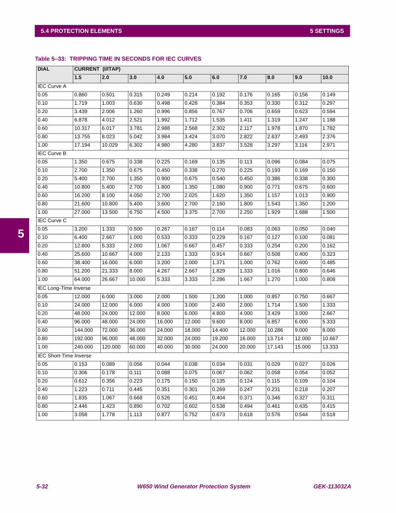
5-32 W650 Wind Generator Protection System GEK-113032A
5.4 PROTECTION ELEMENTS 5 SETTINGS
5
Table 5–33: TRIPPING TIME IN SECONDS FOR IEC CURVESDIAL CURRENT (I/ITAP)
1.5 2.0 3.0 4.0 5.0 6.0 7.0 8.0 9.0 10.0IEC Curve A0.05 0.860 0.501 0.315 0.249 0.214 0.192 0.176 0.165 0.156 0.1490.10 1.719 1.003 0.630 0.498 0.428 0.384 0.353 0.330 0.312 0.2970.20 3.439 2.006 1.260 0.996 0.856 0.767 0.706 0.659 0.623 0.5940.40 6.878 4.012 2.521 1.992 1.712 1.535 1.411 1.319 1.247 1.1880.60 10.317 6.017 3.781 2.988 2.568 2.302 2.117 1.978 1.870 1.7820.80 13.755 8.023 5.042 3.984 3.424 3.070 2.822 2.637 2.493 2.3761.00 17.194 10.029 6.302 4.980 4.280 3.837 3.528 3.297 3.116 2.971IEC Curve B0.05 1.350 0.675 0.338 0.225 0.169 0.135 0.113 0.096 0.084 0.0750.10 2.700 1.350 0.675 0.450 0.338 0.270 0.225 0.193 0.169 0.1500.20 5.400 2.700 1.350 0.900 0.675 0.540 0.450 0.386 0.338 0.3000.40 10.800 5.400 2.700 1.800 1.350 1.080 0.900 0.771 0.675 0.6000.60 16.200 8.100 4.050 2.700 2.025 1.620 1.350 1.157 1.013 0.9000.80 21.600 10.800 5.400 3.600 2.700 2.160 1.800 1.543 1.350 1.2001.00 27.000 13.500 6.750 4.500 3.375 2.700 2.250 1.929 1.688 1.500IEC Curve C0.05 3.200 1.333 0.500 0.267 0.167 0.114 0.083 0.063 0.050 0.0400.10 6.400 2.667 1.000 0.533 0.333 0.229 0.167 0.127 0.100 0.0810.20 12.800 5.333 2.000 1.067 0.667 0.457 0.333 0.254 0.200 0.1620.40 25.600 10.667 4.000 2.133 1.333 0.914 0.667 0.508 0.400 0.3230.60 38.400 16.000 6.000 3.200 2.000 1.371 1.000 0.762 0.600 0.4850.80 51.200 21.333 8.000 4.267 2.667 1.829 1.333 1.016 0.800 0.6461.00 64.000 26.667 10.000 5.333 3.333 2.286 1.667 1.270 1.000 0.808
IEC Long-Time Inverse0.05 12.000 6.000 3.000 2.000 1.500 1.200 1.000 0.857 0.750 0.6670.10 24.000 12.000 6.000 4.000 3.000 2.400 2.000 1.714 1.500 1.3330.20 48.000 24.000 12.000 8.000 6.000 4.800 4.000 3.429 3.000 2.6670.40 96.000 48.000 24.000 16.000 12.000 9.600 8.000 6.857 6.000 5.3330.60 144.000 72.000 36.000 24.000 18.000 14.400 12.000 10.286 9.000 8.0000.80 192.000 96.000 48.000 32.000 24.000 19.200 16.000 13.714 12.000 10.6671.00 240.000 120.000 60.000 40.000 30.000 24.000 20.000 17.143 15.000 13.333
IEC Short-Time Inverse0.05 0.153 0.089 0.056 0.044 0.038 0.034 0.031 0.029 0.027 0.0260.10 0.306 0.178 0.111 0.088 0.075 0.067 0.062 0.058 0.054 0.0520.20 0.612 0.356 0.223 0.175 0.150 0.135 0.124 0.115 0.109 0.1040.40 1.223 0.711 0.445 0.351 0.301 0.269 0.247 0.231 0.218 0.2070.60 1.835 1.067 0.668 0.526 0.451 0.404 0.371 0.346 0.327 0.3110.80 2.446 1.423 0.890 0.702 0.602 0.538 0.494 0.461 0.435 0.4151.00 3.058 1.778 1.113 0.877 0.752 0.673 0.618 0.576 0.544 0.518

GEK-113032A W650 Wind Generator Protection System 5-33
5 SETTINGS 5.4 PROTECTION ELEMENTS
5
5.4.2.3 IAC CURVES
This family of curves follows the time response of General Electric IAC electromechanical relays. The following formulasdefine these curves:
Where:
t = Operation time in seconds
Dial = multiplier setting
I = Input current
Itap = Current pickup value
A, B, C, D, E = predefined constants
TRESET = reset time in seconds
tr = characteristic constant.
Table 5–34: CONSTANTS FOR IAC CURVESIAC CURVE SHAPE NAME A B C D E TRIAC Extremely Inverse IAC Ext Inv 0.0040 0.6379 0.6200 1.7872 0.2461 6.008IAC Very Inverse IAC Very Inv 0.0900 0.7955 0.1000 -1.2885 7.9586 4.678IAC Inverse IAC Mod Inv 0.2078 0.8630 0.8000 -0.4180 0.1947 0.990
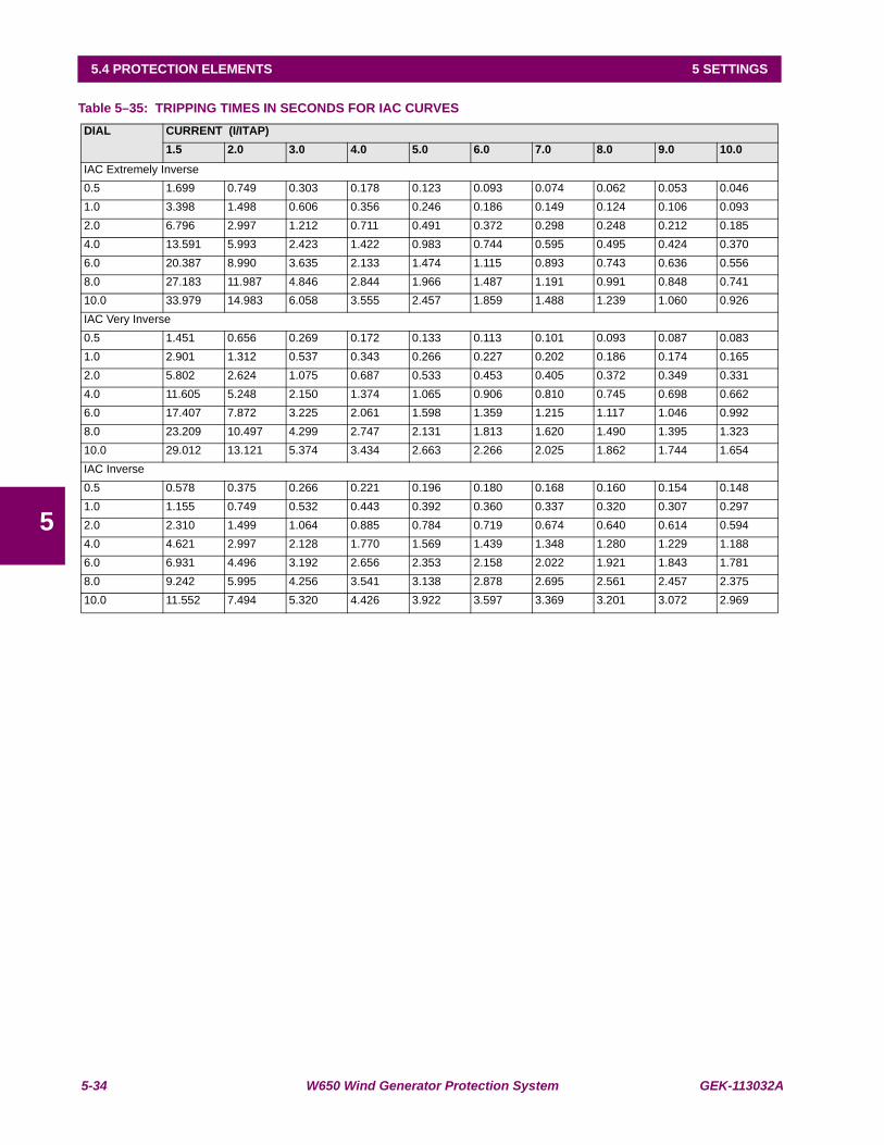
5-34 W650 Wind Generator Protection System GEK-113032A
5.4 PROTECTION ELEMENTS 5 SETTINGS
5
Table 5–35: TRIPPING TIMES IN SECONDS FOR IAC CURVES DIAL CURRENT (I/ITAP)
1.5 2.0 3.0 4.0 5.0 6.0 7.0 8.0 9.0 10.0IAC Extremely Inverse0.5 1.699 0.749 0.303 0.178 0.123 0.093 0.074 0.062 0.053 0.0461.0 3.398 1.498 0.606 0.356 0.246 0.186 0.149 0.124 0.106 0.0932.0 6.796 2.997 1.212 0.711 0.491 0.372 0.298 0.248 0.212 0.1854.0 13.591 5.993 2.423 1.422 0.983 0.744 0.595 0.495 0.424 0.3706.0 20.387 8.990 3.635 2.133 1.474 1.115 0.893 0.743 0.636 0.5568.0 27.183 11.987 4.846 2.844 1.966 1.487 1.191 0.991 0.848 0.74110.0 33.979 14.983 6.058 3.555 2.457 1.859 1.488 1.239 1.060 0.926IAC Very Inverse0.5 1.451 0.656 0.269 0.172 0.133 0.113 0.101 0.093 0.087 0.0831.0 2.901 1.312 0.537 0.343 0.266 0.227 0.202 0.186 0.174 0.1652.0 5.802 2.624 1.075 0.687 0.533 0.453 0.405 0.372 0.349 0.3314.0 11.605 5.248 2.150 1.374 1.065 0.906 0.810 0.745 0.698 0.6626.0 17.407 7.872 3.225 2.061 1.598 1.359 1.215 1.117 1.046 0.9928.0 23.209 10.497 4.299 2.747 2.131 1.813 1.620 1.490 1.395 1.32310.0 29.012 13.121 5.374 3.434 2.663 2.266 2.025 1.862 1.744 1.654IAC Inverse0.5 0.578 0.375 0.266 0.221 0.196 0.180 0.168 0.160 0.154 0.1481.0 1.155 0.749 0.532 0.443 0.392 0.360 0.337 0.320 0.307 0.2972.0 2.310 1.499 1.064 0.885 0.784 0.719 0.674 0.640 0.614 0.5944.0 4.621 2.997 2.128 1.770 1.569 1.439 1.348 1.280 1.229 1.1886.0 6.931 4.496 3.192 2.656 2.353 2.158 2.022 1.921 1.843 1.7818.0 9.242 5.995 4.256 3.541 3.138 2.878 2.695 2.561 2.457 2.37510.0 11.552 7.494 5.320 4.426 3.922 3.597 3.369 3.201 3.072 2.969
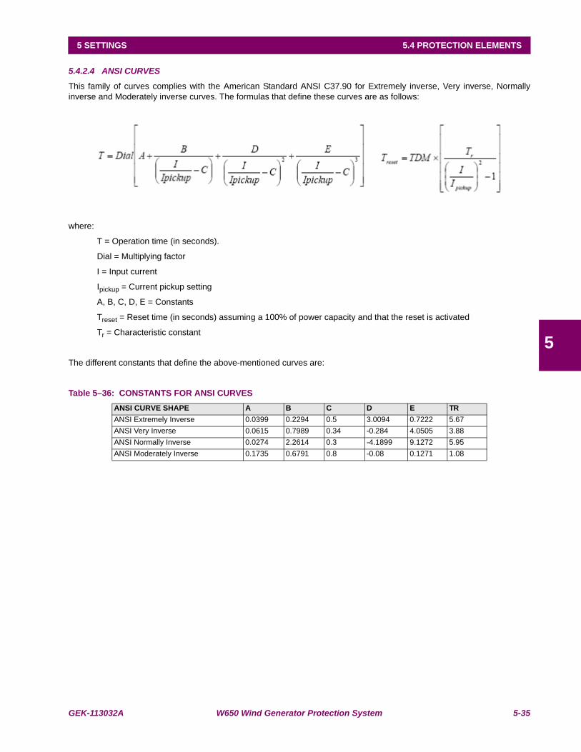
GEK-113032A W650 Wind Generator Protection System 5-35
5 SETTINGS 5.4 PROTECTION ELEMENTS
5
5.4.2.4 ANSI CURVES
This family of curves complies with the American Standard ANSI C37.90 for Extremely inverse, Very inverse, Normallyinverse and Moderately inverse curves. The formulas that define these curves are as follows:
where:
T = Operation time (in seconds).
Dial = Multiplying factor
I = Input current
Ipickup = Current pickup setting
A, B, C, D, E = Constants
Treset = Reset time (in seconds) assuming a 100% of power capacity and that the reset is activated
Tr = Characteristic constant
The different constants that define the above-mentioned curves are:
Table 5–36: CONSTANTS FOR ANSI CURVESANSI CURVE SHAPE A B C D E TRANSI Extremely Inverse 0.0399 0.2294 0.5 3.0094 0.7222 5.67ANSI Very Inverse 0.0615 0.7989 0.34 -0.284 4.0505 3.88ANSI Normally Inverse 0.0274 2.2614 0.3 -4.1899 9.1272 5.95ANSI Moderately Inverse 0.1735 0.6791 0.8 -0.08 0.1271 1.08
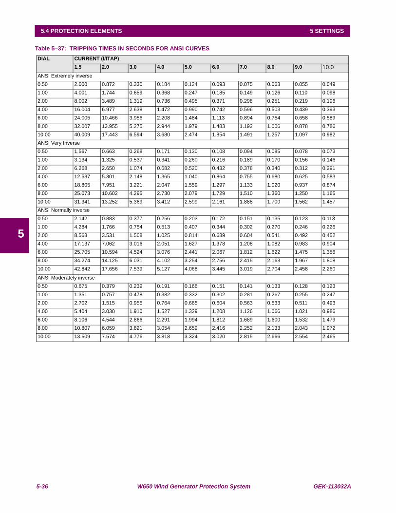
5-36 W650 Wind Generator Protection System GEK-113032A
5.4 PROTECTION ELEMENTS 5 SETTINGS
5
Table 5–37: TRIPPING TIMES IN SECONDS FOR ANSI CURVESDIAL CURRENT (I/ITAP)
1.5 2.0 3.0 4.0 5.0 6.0 7.0 8.0 9.0 10.0ANSI Extremely inverse0.50 2.000 0.872 0.330 0.184 0.124 0.093 0.075 0.063 0.055 0.0491.00 4.001 1.744 0.659 0.368 0.247 0.185 0.149 0.126 0.110 0.0982.00 8.002 3.489 1.319 0.736 0.495 0.371 0.298 0.251 0.219 0.1964.00 16.004 6.977 2.638 1.472 0.990 0.742 0.596 0.503 0.439 0.3936.00 24.005 10.466 3.956 2.208 1.484 1.113 0.894 0.754 0.658 0.5898.00 32.007 13.955 5.275 2.944 1.979 1.483 1.192 1.006 0.878 0.78610.00 40.009 17.443 6.594 3.680 2.474 1.854 1.491 1.257 1.097 0.982ANSI Very Inverse0.50 1.567 0.663 0.268 0.171 0.130 0.108 0.094 0.085 0.078 0.0731.00 3.134 1.325 0.537 0.341 0.260 0.216 0.189 0.170 0.156 0.1462.00 6.268 2.650 1.074 0.682 0.520 0.432 0.378 0.340 0.312 0.2914.00 12.537 5.301 2.148 1.365 1.040 0.864 0.755 0.680 0.625 0.5836.00 18.805 7.951 3.221 2.047 1.559 1.297 1.133 1.020 0.937 0.8748.00 25.073 10.602 4.295 2.730 2.079 1.729 1.510 1.360 1.250 1.16510.00 31.341 13.252 5.369 3.412 2.599 2.161 1.888 1.700 1.562 1.457ANSI Normally inverse0.50 2.142 0.883 0.377 0.256 0.203 0.172 0.151 0.135 0.123 0.1131.00 4.284 1.766 0.754 0.513 0.407 0.344 0.302 0.270 0.246 0.2262.00 8.568 3.531 1.508 1.025 0.814 0.689 0.604 0.541 0.492 0.4524.00 17.137 7.062 3.016 2.051 1.627 1.378 1.208 1.082 0.983 0.9046.00 25.705 10.594 4.524 3.076 2.441 2.067 1.812 1.622 1.475 1.3568.00 34.274 14.125 6.031 4.102 3.254 2.756 2.415 2.163 1.967 1.80810.00 42.842 17.656 7.539 5.127 4.068 3.445 3.019 2.704 2.458 2.260
ANSI Moderately inverse0.50 0.675 0.379 0.239 0.191 0.166 0.151 0.141 0.133 0.128 0.1231.00 1.351 0.757 0.478 0.382 0.332 0.302 0.281 0.267 0.255 0.2472.00 2.702 1.515 0.955 0.764 0.665 0.604 0.563 0.533 0.511 0.4934.00 5.404 3.030 1.910 1.527 1.329 1.208 1.126 1.066 1.021 0.9866.00 8.106 4.544 2.866 2.291 1.994 1.812 1.689 1.600 1.532 1.4798.00 10.807 6.059 3.821 3.054 2.659 2.416 2.252 2.133 2.043 1.97210.00 13.509 7.574 4.776 3.818 3.324 3.020 2.815 2.666 2.554 2.465
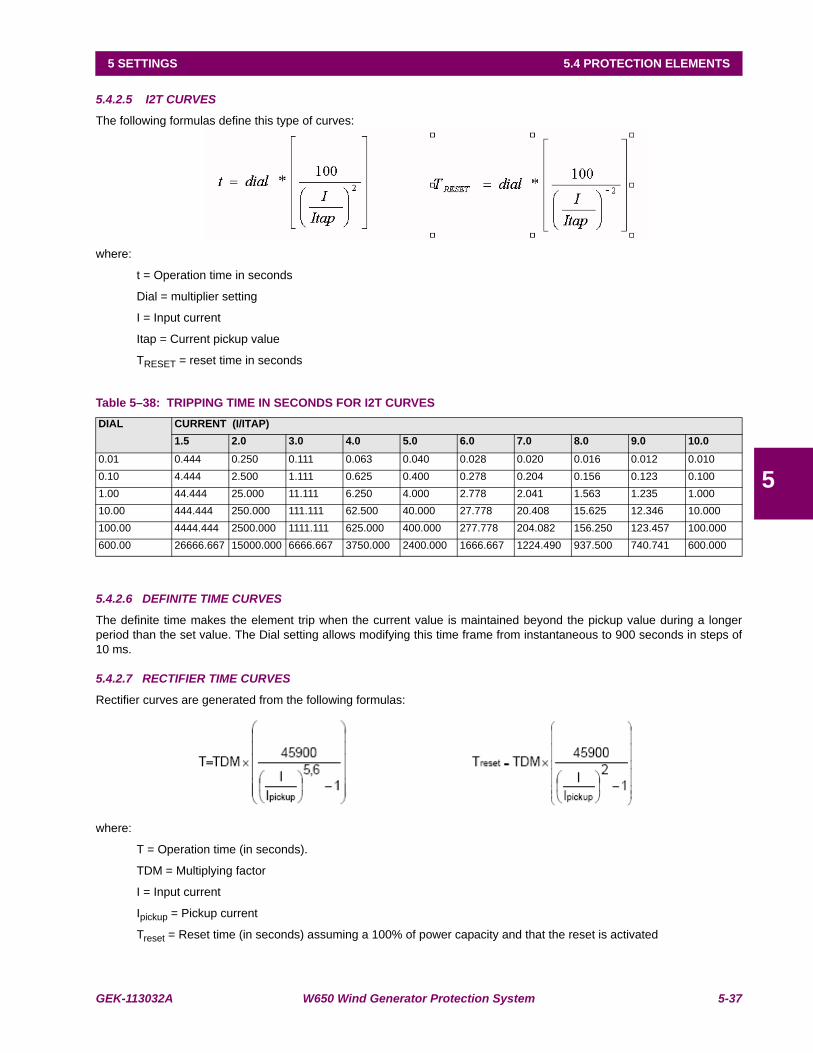
GEK-113032A W650 Wind Generator Protection System 5-37
5 SETTINGS 5.4 PROTECTION ELEMENTS
5
5.4.2.5 I2T CURVES
The following formulas define this type of curves:
where:
t = Operation time in seconds
Dial = multiplier setting
I = Input current
Itap = Current pickup value
TRESET = reset time in seconds
Table 5–38: TRIPPING TIME IN SECONDS FOR I2T CURVES
5.4.2.6 DEFINITE TIME CURVES
The definite time makes the element trip when the current value is maintained beyond the pickup value during a longerperiod than the set value. The Dial setting allows modifying this time frame from instantaneous to 900 seconds in steps of10 ms.
5.4.2.7 RECTIFIER TIME CURVES
Rectifier curves are generated from the following formulas:
where:
T = Operation time (in seconds).
TDM = Multiplying factor
I = Input current
Ipickup = Pickup current
Treset = Reset time (in seconds) assuming a 100% of power capacity and that the reset is activated
DIAL CURRENT (I/ITAP)1.5 2.0 3.0 4.0 5.0 6.0 7.0 8.0 9.0 10.0
0.01 0.444 0.250 0.111 0.063 0.040 0.028 0.020 0.016 0.012 0.0100.10 4.444 2.500 1.111 0.625 0.400 0.278 0.204 0.156 0.123 0.1001.00 44.444 25.000 11.111 6.250 4.000 2.778 2.041 1.563 1.235 1.00010.00 444.444 250.000 111.111 62.500 40.000 27.778 20.408 15.625 12.346 10.000100.00 4444.444 2500.000 1111.111 625.000 400.000 277.778 204.082 156.250 123.457 100.000600.00 26666.667 15000.000 6666.667 3750.000 2400.000 1666.667 1224.490 937.500 740.741 600.000
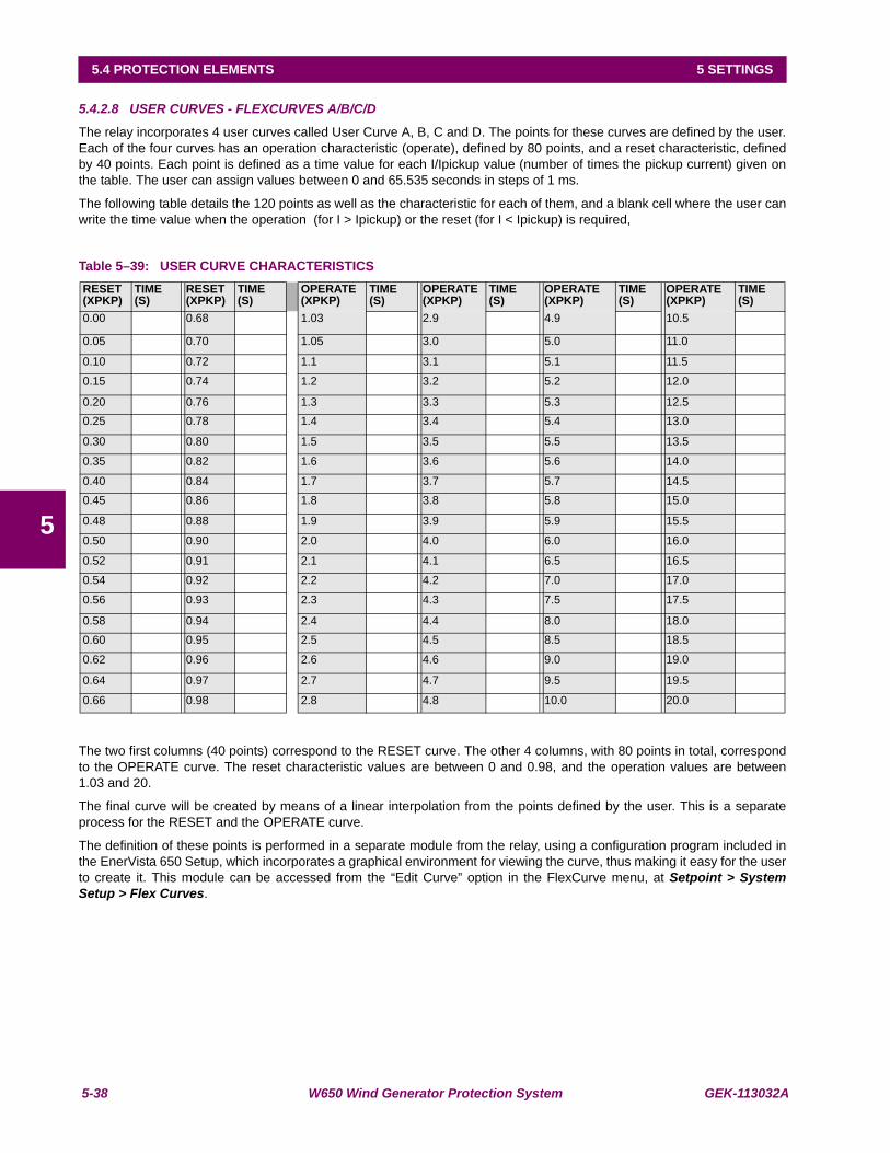
5-38 W650 Wind Generator Protection System GEK-113032A
5.4 PROTECTION ELEMENTS 5 SETTINGS
5
5.4.2.8 USER CURVES - FLEXCURVES A/B/C/D
The relay incorporates 4 user curves called User Curve A, B, C and D. The points for these curves are defined by the user.Each of the four curves has an operation characteristic (operate), defined by 80 points, and a reset characteristic, definedby 40 points. Each point is defined as a time value for each I/Ipickup value (number of times the pickup current) given onthe table. The user can assign values between 0 and 65.535 seconds in steps of 1 ms.
The following table details the 120 points as well as the characteristic for each of them, and a blank cell where the user canwrite the time value when the operation (for I > Ipickup) or the reset (for I < Ipickup) is required,
Table 5–39: USER CURVE CHARACTERISTICS
The two first columns (40 points) correspond to the RESET curve. The other 4 columns, with 80 points in total, correspondto the OPERATE curve. The reset characteristic values are between 0 and 0.98, and the operation values are between1.03 and 20.
The final curve will be created by means of a linear interpolation from the points defined by the user. This is a separateprocess for the RESET and the OPERATE curve.
The definition of these points is performed in a separate module from the relay, using a configuration program included inthe EnerVista 650 Setup, which incorporates a graphical environment for viewing the curve, thus making it easy for the userto create it. This module can be accessed from the “Edit Curve” option in the FlexCurve menu, at Setpoint > SystemSetup > Flex Curves.
RESET (XPKP)
TIME(S)
RESET(XPKP)
TIME(S)
OPERATE(XPKP)
TIME(S)
OPERATE(XPKP)
TIME(S)
OPERATE(XPKP)
TIME(S)
OPERATE(XPKP)
TIME(S)
0.00 0.68 1.03 2.9 4.9 10.5
0.05 0.70 1.05 3.0 5.0 11.0
0.10 0.72 1.1 3.1 5.1 11.5
0.15 0.74 1.2 3.2 5.2 12.0
0.20 0.76 1.3 3.3 5.3 12.50.25 0.78 1.4 3.4 5.4 13.0
0.30 0.80 1.5 3.5 5.5 13.5
0.35 0.82 1.6 3.6 5.6 14.0
0.40 0.84 1.7 3.7 5.7 14.50.45 0.86 1.8 3.8 5.8 15.0
0.48 0.88 1.9 3.9 5.9 15.5
0.50 0.90 2.0 4.0 6.0 16.0
0.52 0.91 2.1 4.1 6.5 16.50.54 0.92 2.2 4.2 7.0 17.0
0.56 0.93 2.3 4.3 7.5 17.5
0.58 0.94 2.4 4.4 8.0 18.00.60 0.95 2.5 4.5 8.5 18.5
0.62 0.96 2.6 4.6 9.0 19.0
0.64 0.97 2.7 4.7 9.5 19.5
0.66 0.98 2.8 4.8 10.0 20.0
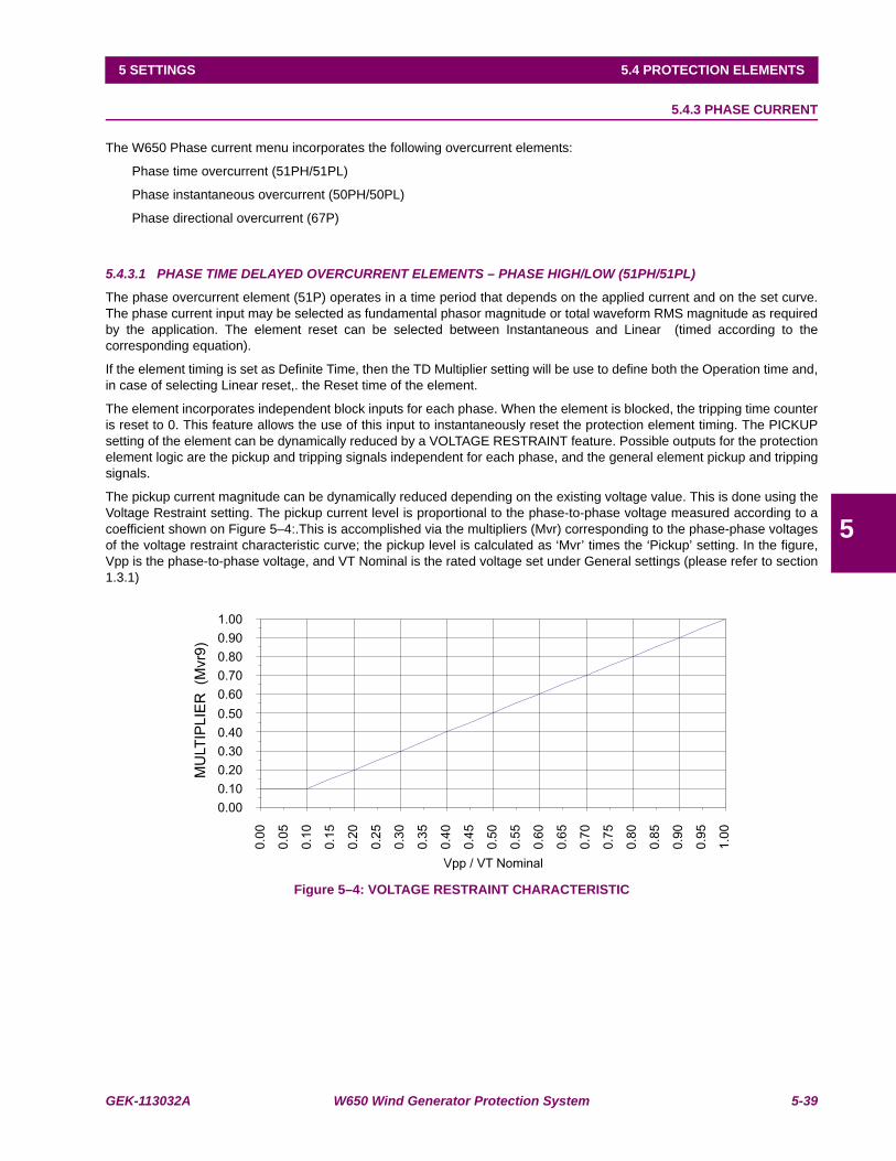
GEK-113032A W650 Wind Generator Protection System 5-39
5 SETTINGS 5.4 PROTECTION ELEMENTS
5
5.4.3 PHASE CURRENT
The W650 Phase current menu incorporates the following overcurrent elements:
Phase time overcurrent (51PH/51PL)
Phase instantaneous overcurrent (50PH/50PL)
Phase directional overcurrent (67P)
5.4.3.1 PHASE TIME DELAYED OVERCURRENT ELEMENTS – PHASE HIGH/LOW (51PH/51PL)
The phase overcurrent element (51P) operates in a time period that depends on the applied current and on the set curve.The phase current input may be selected as fundamental phasor magnitude or total waveform RMS magnitude as requiredby the application. The element reset can be selected between Instantaneous and Linear (timed according to thecorresponding equation).
If the element timing is set as Definite Time, then the TD Multiplier setting will be use to define both the Operation time and,in case of selecting Linear reset,. the Reset time of the element.
The element incorporates independent block inputs for each phase. When the element is blocked, the tripping time counteris reset to 0. This feature allows the use of this input to instantaneously reset the protection element timing. The PICKUPsetting of the element can be dynamically reduced by a VOLTAGE RESTRAINT feature. Possible outputs for the protectionelement logic are the pickup and tripping signals independent for each phase, and the general element pickup and trippingsignals.
The pickup current magnitude can be dynamically reduced depending on the existing voltage value. This is done using theVoltage Restraint setting. The pickup current level is proportional to the phase-to-phase voltage measured according to acoefficient shown on Figure 5–4:.This is accomplished via the multipliers (Mvr) corresponding to the phase-phase voltagesof the voltage restraint characteristic curve; the pickup level is calculated as ‘Mvr’ times the ‘Pickup’ setting. In the figure,Vpp is the phase-to-phase voltage, and VT Nominal is the rated voltage set under General settings (please refer to section1.3.1)
Figure 5–4: VOLTAGE RESTRAINT CHARACTERISTIC
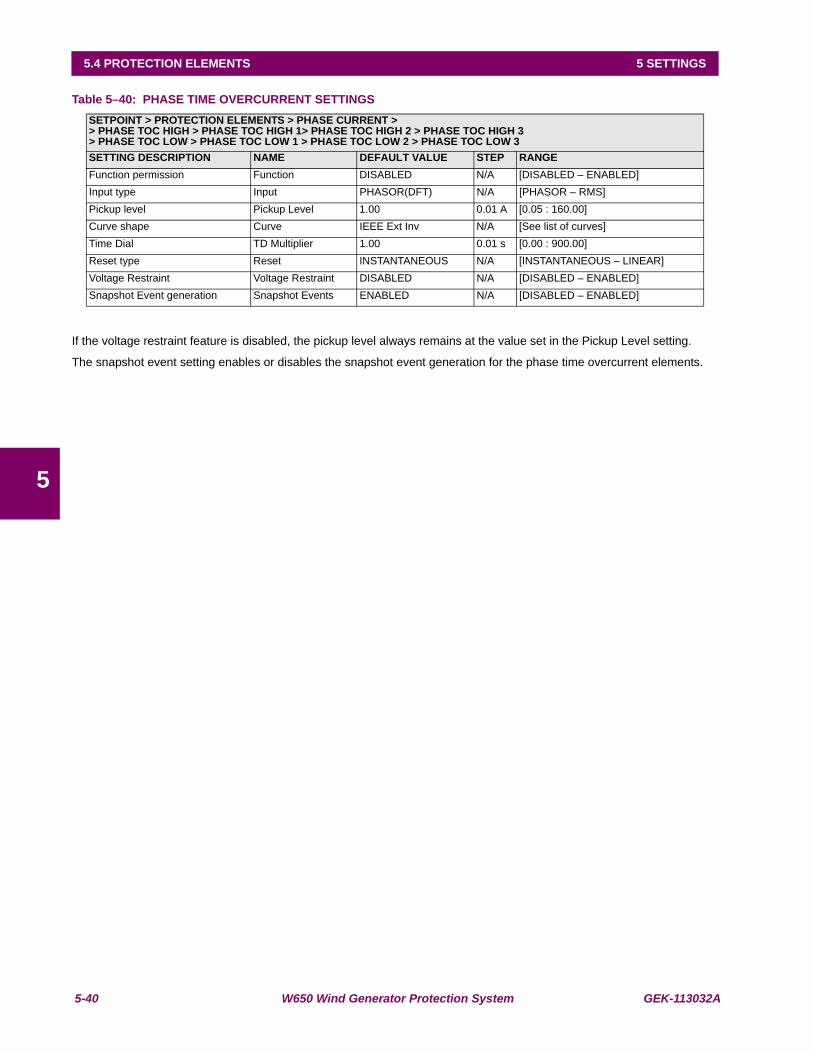
5-40 W650 Wind Generator Protection System GEK-113032A
5.4 PROTECTION ELEMENTS 5 SETTINGS
5
Table 5–40: PHASE TIME OVERCURRENT SETTINGS
If the voltage restraint feature is disabled, the pickup level always remains at the value set in the Pickup Level setting.
The snapshot event setting enables or disables the snapshot event generation for the phase time overcurrent elements.
SETPOINT > PROTECTION ELEMENTS > PHASE CURRENT >> PHASE TOC HIGH > PHASE TOC HIGH 1> PHASE TOC HIGH 2 > PHASE TOC HIGH 3> PHASE TOC LOW > PHASE TOC LOW 1 > PHASE TOC LOW 2 > PHASE TOC LOW 3SETTING DESCRIPTION NAME DEFAULT VALUE STEP RANGEFunction permission Function DISABLED N/A [DISABLED – ENABLED]Input type Input PHASOR(DFT) N/A [PHASOR – RMS]Pickup level Pickup Level 1.00 0.01 A [0.05 : 160.00]Curve shape Curve IEEE Ext Inv N/A [See list of curves]Time Dial TD Multiplier 1.00 0.01 s [0.00 : 900.00]Reset type Reset INSTANTANEOUS N/A [INSTANTANEOUS – LINEAR]Voltage Restraint Voltage Restraint DISABLED N/A [DISABLED – ENABLED]Snapshot Event generation Snapshot Events ENABLED N/A [DISABLED – ENABLED]
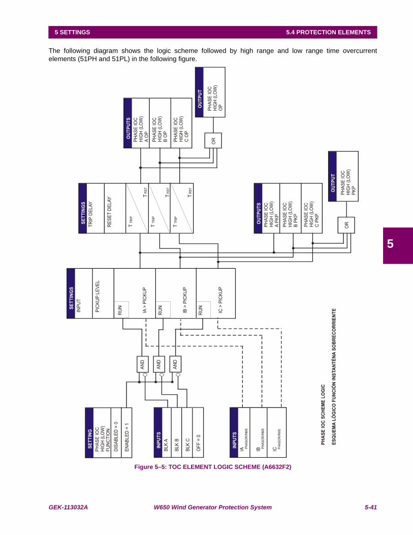
GEK-113032A W650 Wind Generator Protection System 5-41
5 SETTINGS 5.4 PROTECTION ELEMENTS
5
The following diagram shows the logic scheme followed by high range and low range time overcurrentelements (51PH and 51PL) in the following figure.
Figure 5–5: TOC ELEMENT LOGIC SCHEME (A6632F2)

5-42 W650 Wind Generator Protection System GEK-113032A
5.4 PROTECTION ELEMENTS 5 SETTINGS
5
5.4.3.2 PHASE INSTANTANEOUS OVERCURRENT ELEMENT- PHASE HIGH/LOW (50PH/ 50PL)
The Phase instantaneous overcurrent element has a setting range from 0.05 A to 160 A. It can be set as instantaneous ortimed, with the timer selectable between 0.00 and 900 seconds. The input quantities may be chosen as Fundamentalphasor magnitude or RMS magnitude as required by the application. The element incorporates a reset time selectablebetween 0 and 900 seconds.
This element also incorporates a block input for disabling the pickup and trip signals. The logic outputs for the element arethe pickup and trip flags, independent for each phase, and general pickup and trip flags.
Table 5–41: PHASE INSTANTANEOUS OVERCURRENT ELEMENT SETTINGS
The snapshot event setting enables or disables the snapshot event generation for these elements.
SETPOINT > PROTECTION ELEMENTS > PHASE CURRENT >> PHASE IOC HIGH > PHASE IOC HIGH 1> PHASE IOC HIGH 2 > PHASE IOC HIGH 3> PHASE IOC LOW > PHASE IOC LOW 1 > PHASE IOC LOW 2 > PHASE IOC LOW 3SETTING DESCRIPTION NAME DEFAULT VALUE STEP RANGEFunction permission Function DISABLED N/A [DISABLED – ENABLED]Input type Input PHASOR(DFT) N/A [PHASOR – RMS]Pickup level Pickup Level 30.00 0.01 A [0.05 : 160.00]Trip time Trip Delay 0.00 0.01 s [0.00 : 900.00]Reset time Reset Delay 0.00 0.01 s [0.00 : 900.00]Snapshot event generation Snapshot Events ENABLED N/A [DISABLED – ENABLED]
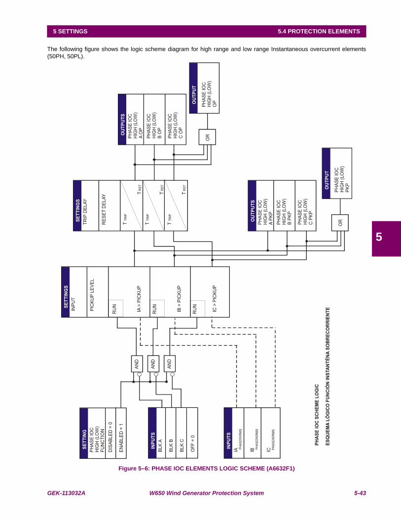
GEK-113032A W650 Wind Generator Protection System 5-43
5 SETTINGS 5.4 PROTECTION ELEMENTS
5
The following figure shows the logic scheme diagram for high range and low range Instantaneous overcurrent elements(50PH, 50PL).
Figure 5–6: PHASE IOC ELEMENTS LOGIC SCHEME (A6632F1)
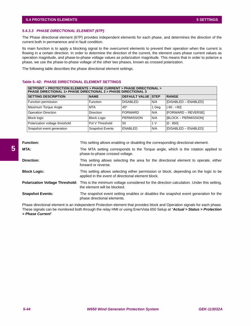
5-44 W650 Wind Generator Protection System GEK-113032A
5.4 PROTECTION ELEMENTS 5 SETTINGS
5
5.4.3.3 PHASE DIRECTIONAL ELEMENT (67P)
The Phase directional element (67P) provides independent elements for each phase, and determines the direction of thecurrent both in permanence and in fault condition.
Its main function is to apply a blocking signal to the overcurrent elements to prevent their operation when the current isflowing in a certain direction. In order to determine the direction of the current, the element uses phase current values asoperation magnitude, and phase-to-phase voltage values as polarization magnitude. This means that in order to polarize aphase, we use the phase-to-phase voltage of the other two phases, known as crossed polarization.
The following table describes the phase directional element settings.
Table 5–42: PHASE DIRECTIONAL ELEMENT SETTINGS
Function: This setting allows enabling or disabling the corresponding directional element.
MTA: The MTA setting corresponds to the Torque angle, which is the rotation applied tophase-to-phase crossed voltage.
Direction: This setting allows selecting the area for the directional element to operate, eitherforward or reverse.
Block Logic: This setting allows selecting either permission or block, depending on the logic to beapplied in the event of directional element block.
Polarization Voltage Threshold: This is the minimum voltage considered for the direction calculation. Under this setting,the element will be blocked.
Snapshot Events: The snapshot event setting enables or disables the snapshot event generation for thephase directional elements.
Phase directional element is an independent Protection element that provides block and Operation signals for each phase.These signals can be monitored both through the relay HMI or using EnerVista 650 Setup at “Actual > Status > Protection> Phase Current”
SETPOINT > PROTECTION ELEMENTS > PHASE CURRENT > PHASE DIRECTIONAL >PHASE DIRECTIONAL 1> PHASE DIRECTIONAL 2 > PHASE DIRECTIONAL 3SETTING DESCRIPTION NAME DEFAULT VALUE STEP RANGEFunction permission Function DISABLED N/A [DISABLED – ENABLED]Maximum Torque Angle MTA 45º 1 Deg [-90 : +90]Operation Direction Direction FORWARD N/A [FORWARD – REVERSE]Block logic Block Logic PERMISSION N/A [BLOCK – PERMISSION]Polarization voltage threshold Pol V Threshold 50 1 V [0 : 850]Snapshot event generation Snapshot Events ENABLED N/A [DISABLED – ENABLED]

GEK-113032A W650 Wind Generator Protection System 5-45
5 SETTINGS 5.4 PROTECTION ELEMENTS
5
Table 5–43: BLOCK AND OPERATION SIGNALS FOR THE PHASE DIRECTIONAL ELEMENT
Signals provided by the directional element are, block and operation signals. Signals used to block overcurrent elementsare configured at Setpoint > Relay Configuration > Protection Elements.
Operation signals are active when operation and polarization magnitudes meet conditions given by the settings.
Block signals indicate blocked elements by an external block input or by polarization voltage loss. Using the "Block logic"setting, the user can select how the directional element responds in case of a block. When the "Block" option is selected,the operational signal will not be activated in a block condition. When the "Permission" option is selected, the operationsignal will be activated in a block condition.
Figure 5–7: shows the default configuration for the phase overcurrent block input. When the "Block logic" setting is set as"Block", this input will be active in case of a block in the directional element, avoiding any phase overcurrent trip.
When the "Block logic" setting is set as "Permission", the phase overcurrent element is enabled to trip as the block input isnot active in case of polarization voltage loss.
BLOCK AND OPERATION FOR 67PPHASE DIR1 BLOCK APHASE DIR1 A OPPHASE DIR1 BLOCK BPHASE DIR1 B OPPHASE DIR1 BLOCK CPHASE DIR1 C OPPHASE DIR2 BLOCK APHASE DIR2 A OPPHASE DIR2 BLOCK BPHASE DIR2 B OPPHASE DIR2 BLOCK CPHASE DIR2 C OPPHASE DIR3 BLOCK APHASE DIR3 A OPPHASE DIR3 BLOCK BPHASE DIR3 B OPPHASE DIR3 BLOCK CPHASE DIR3 C OP
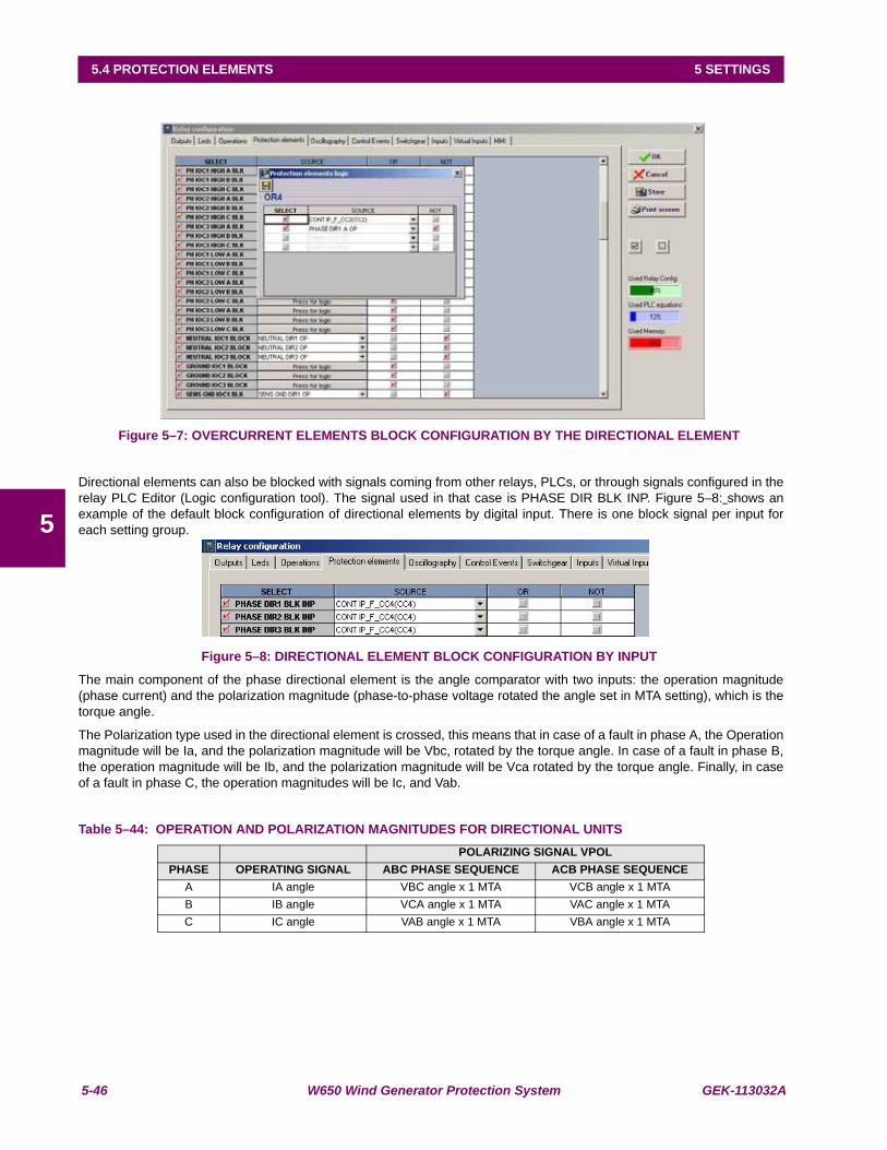
5-46 W650 Wind Generator Protection System GEK-113032A
5.4 PROTECTION ELEMENTS 5 SETTINGS
5
Figure 5–7: OVERCURRENT ELEMENTS BLOCK CONFIGURATION BY THE DIRECTIONAL ELEMENT
Directional elements can also be blocked with signals coming from other relays, PLCs, or through signals configured in therelay PLC Editor (Logic configuration tool). The signal used in that case is PHASE DIR BLK INP. Figure 5–8: shows anexample of the default block configuration of directional elements by digital input. There is one block signal per input foreach setting group.
Figure 5–8: DIRECTIONAL ELEMENT BLOCK CONFIGURATION BY INPUT
The main component of the phase directional element is the angle comparator with two inputs: the operation magnitude(phase current) and the polarization magnitude (phase-to-phase voltage rotated the angle set in MTA setting), which is thetorque angle.
The Polarization type used in the directional element is crossed, this means that in case of a fault in phase A, the Operationmagnitude will be Ia, and the polarization magnitude will be Vbc, rotated by the torque angle. In case of a fault in phase B,the operation magnitude will be Ib, and the polarization magnitude will be Vca rotated by the torque angle. Finally, in caseof a fault in phase C, the operation magnitudes will be Ic, and Vab.
Table 5–44: OPERATION AND POLARIZATION MAGNITUDES FOR DIRECTIONAL UNITSPOLARIZING SIGNAL VPOL
PHASE OPERATING SIGNAL ABC PHASE SEQUENCE ACB PHASE SEQUENCEA IA angle VBC angle x 1 MTA VCB angle x 1 MTAB IB angle VCA angle x 1 MTA VAC angle x 1 MTAC IC angle VAB angle x 1 MTA VBA angle x 1 MTA
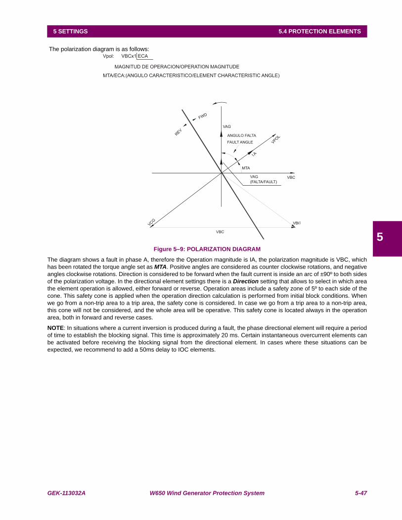
GEK-113032A W650 Wind Generator Protection System 5-47
5 SETTINGS 5.4 PROTECTION ELEMENTS
5
The polarization diagram is as follows:
Figure 5–9: POLARIZATION DIAGRAM
The diagram shows a fault in phase A, therefore the Operation magnitude is IA, the polarization magnitude is VBC, whichhas been rotated the torque angle set as MTA. Positive angles are considered as counter clockwise rotations, and negativeangles clockwise rotations. Direction is considered to be forward when the fault current is inside an arc of ±90º to both sidesof the polarization voltage. In the directional element settings there is a Direction setting that allows to select in which areathe element operation is allowed, either forward or reverse. Operation areas include a safety zone of 5º to each side of thecone. This safety cone is applied when the operation direction calculation is performed from initial block conditions. Whenwe go from a non-trip area to a trip area, the safety cone is considered. In case we go from a trip area to a non-trip area,this cone will not be considered, and the whole area will be operative. This safety cone is located always in the operationarea, both in forward and reverse cases.
NOTE: In situations where a current inversion is produced during a fault, the phase directional element will require a periodof time to establish the blocking signal. This time is approximately 20 ms. Certain instantaneous overcurrent elements canbe activated before receiving the blocking signal from the directional element. In cases where these situations can beexpected, we recommend to add a 50ms delay to IOC elements.
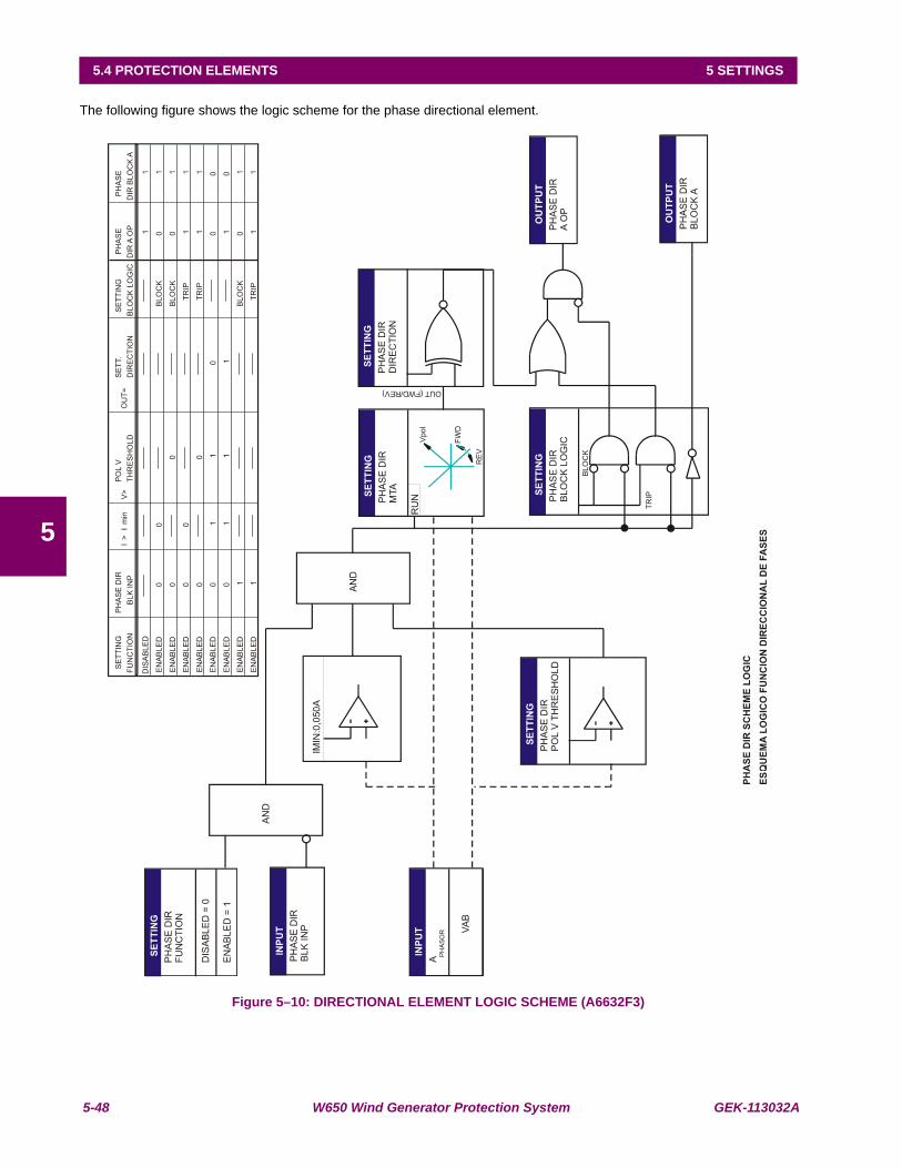
5-48 W650 Wind Generator Protection System GEK-113032A
5.4 PROTECTION ELEMENTS 5 SETTINGS
5
The following figure shows the logic scheme for the phase directional element.
Figure 5–10: DIRECTIONAL ELEMENT LOGIC SCHEME (A6632F3)
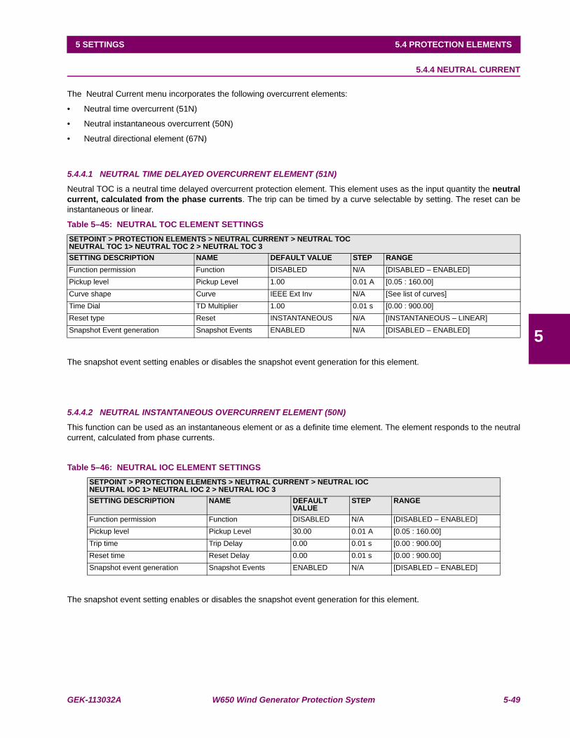
GEK-113032A W650 Wind Generator Protection System 5-49
5 SETTINGS 5.4 PROTECTION ELEMENTS
5
5.4.4 NEUTRAL CURRENT
The Neutral Current menu incorporates the following overcurrent elements:
• Neutral time overcurrent (51N)
• Neutral instantaneous overcurrent (50N)
• Neutral directional element (67N)
5.4.4.1 NEUTRAL TIME DELAYED OVERCURRENT ELEMENT (51N)
Neutral TOC is a neutral time delayed overcurrent protection element. This element uses as the input quantity the neutralcurrent, calculated from the phase currents. The trip can be timed by a curve selectable by setting. The reset can beinstantaneous or linear.
Table 5–45: NEUTRAL TOC ELEMENT SETTINGS
The snapshot event setting enables or disables the snapshot event generation for this element.
5.4.4.2 NEUTRAL INSTANTANEOUS OVERCURRENT ELEMENT (50N)
This function can be used as an instantaneous element or as a definite time element. The element responds to the neutralcurrent, calculated from phase currents.
Table 5–46: NEUTRAL IOC ELEMENT SETTINGS
The snapshot event setting enables or disables the snapshot event generation for this element.
SETPOINT > PROTECTION ELEMENTS > NEUTRAL CURRENT > NEUTRAL TOCNEUTRAL TOC 1> NEUTRAL TOC 2 > NEUTRAL TOC 3SETTING DESCRIPTION NAME DEFAULT VALUE STEP RANGEFunction permission Function DISABLED N/A [DISABLED – ENABLED]Pickup level Pickup Level 1.00 0.01 A [0.05 : 160.00]Curve shape Curve IEEE Ext Inv N/A [See list of curves]Time Dial TD Multiplier 1.00 0.01 s [0.00 : 900.00]Reset type Reset INSTANTANEOUS N/A [INSTANTANEOUS – LINEAR]Snapshot Event generation Snapshot Events ENABLED N/A [DISABLED – ENABLED]
SETPOINT > PROTECTION ELEMENTS > NEUTRAL CURRENT > NEUTRAL IOCNEUTRAL IOC 1> NEUTRAL IOC 2 > NEUTRAL IOC 3SETTING DESCRIPTION NAME DEFAULT
VALUESTEP RANGE
Function permission Function DISABLED N/A [DISABLED – ENABLED]Pickup level Pickup Level 30.00 0.01 A [0.05 : 160.00]Trip time Trip Delay 0.00 0.01 s [0.00 : 900.00]Reset time Reset Delay 0.00 0.01 s [0.00 : 900.00]Snapshot event generation Snapshot Events ENABLED N/A [DISABLED – ENABLED]
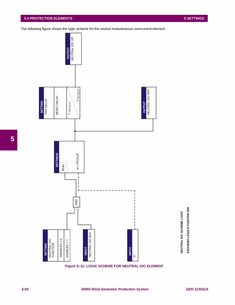
5-50 W650 Wind Generator Protection System GEK-113032A
5.4 PROTECTION ELEMENTS 5 SETTINGS
5
The following figure shows the logic scheme for the neutral Instantaneous overcurrent element.
Figure 5–11: LOGIC SCHEME FOR NEUTRAL IOC ELEMENT

GEK-113032A W650 Wind Generator Protection System 5-51
5 SETTINGS 5.4 PROTECTION ELEMENTS
5
5.4.4.3 NEUTRAL DIRECTIONAL ELEMENT (67N)
The Neutral directional element is used for supervising the neutral (3I0) overcurrent elements. This element can be set touse either the neutral voltage, or the polarization current measured by the 5th current input (Ip), or both as polarizationmagnitude.
Table 5–47: 67N ELEMENT SETTINGS
settings for this element are:
Maximum Torque Angle (MTA): Angle used to rotate the polarization voltage. Positive angles are counter clockwiserotations, and negative angles are clockwise rotations. The polarization magnitude,once rotated, defines the MTA line. Vn rotated by this angle points to the semi planethat corresponds to a Reverse fault. -Vn rotated this angle points to the semi planethat corresponds to a Forward fault. A typical setting can be –45º.
Directional element direction (Direction): This setting indicates the Direction for which the element will allow a trip.Depending on this setting, the element will be activated for faults in the forwarddirection, or ion the reverse direction, allowing its use in tripping or blockingschemes. Possible options for this setting are FORWARD and REVERSE.
Polarization type (Polarization): This setting indicates the type of Polarization to be used. The relay can use voltagepolarization (V0), and/or current polarization (Ip). Possible setting values are:
V0 Voltage polarization
Ip Current polarization
V0 + Ip Voltage or current polarization. This allows the element tooperate when any of the polarization magnitudes allow operation.
V0 * Ip Voltage and current polarization. This allows the element tooperate when both polarization magnitudes allow operation.
If the selected polarization type is V0+Ip, then the relay will operate when any of thepolarization magnitudes indicate the selected direction in the Direction setting.
If the selected polarization type is V0*Ip, then the relay will only operate when bothpolarization magnitudes indicate the selected direction in the Direction setting.
Polarization Voltage Threshold this is the minimum voltage considered for the direction calculation. Under thissetting, the element will be blocked.
Snapshot Events: The snapshot event setting enables or disables the snapshot event generation forthis elements.
SETPOINT > PROTECTION ELEMENTS > NEUTRAL CURRENT > NEUTRAL DIRECTIONAL >NEUTRAL DIRECTIONAL 1> NEUTRAL DIRECTIONAL 2 > NEUTRAL DIRECTIONAL 3SETTING DESCRIPTION NAME DEFAULT VALUE STEP RANGEFunction permission Function DISABLED N/A [DISABLED – ENABLED]Maximum Torque Angle MTA -45 1 Deg [-90 : +90]Operation Direction Direction FORWARD N/A [FORWARD – REVERSE]Polarization type Polarization VO N/A [V0 – IP – V0+IP – V0*IP ]
Block logic type Block Logic PERMISSION N/A [BLOCK – PERMISSION]Polarization voltage threshold Pol V Threshold 50 1 V [0 : 500]Snapshot event generation Snapshot Events ENABLED N/A [DISABLED – ENABLED]

5-52 W650 Wind Generator Protection System GEK-113032A
5.4 PROTECTION ELEMENTS 5 SETTINGS
5
The Neutral directional element is an independent Protection element that provides Block and Operation signals. Thesesignals can be monitored both through the relay HMI or using EnerVista 650 Setup at “Actual > Status > Protection >Neutral Current”
67N Block (NEUTRAL DIR BLOCK): It indicates that the element is blocked by digital input or because the Operationmagnitude (In current), or the Polarization magnitude (Vn voltage and/or Ip current) level is too low.
67N Operation (NEUTRAL DIR OP): It indicates that the directional element is giving permission, that the angle relationsbetween the operation magnitude and the polarization magnitude are met, according to the set conditions, or in case ofhaving selected Permission in the Block Logic setting, it indicates that the element allows operation under block conditions.
Table 5–48: SIGNALS FOR THE NEUTRAL DIRECTIONAL ELEMENT
a) VOLTAGE POLARIZATION OPERATION PRINCIPLES:
Operation Magnitude: In = 3·Io, calculated from the phase currents.
Polarization Magnitude: -3V0. Calculated from the phase voltages or measured at the input terminals (A11, A12).Therelay measures 3V0 and rotates 180º internally to obtain -3V0.
shows the operation of the zero sequence polarization, 3V0, in case of an AG fault. In this case, the polarization magnitude3V0 can be calculated from the three phase voltage values, or measured through the fourth voltage input (Vx). In this lastcase, the voltage transformer must be wye connected, and the Auxiliary Voltage setting in General settings must beconfigured as VX. The operation magnitude In, is calculated from the phase currents.
When Ip Polarization is selected, the Polarization magnitude is Ip, this current value measured at the fifth current input(terminals B11-B12). This polarization current must usually come from a CT measuring the current that flows from theground to the neutral of the neutral fault current source, which will mainly be a transformer. The direction is considered tobe Forward when the neutral current In is inside a ±90º arc at both sides of the polarization current. In any other case, thedirection will be Reverse. If the polarization current is lower than 5 mA, the element output takes the value of the BlockLogic setting.VOLTAGE POLARIZATION
NEUTRAL DIRECTIONAL NEUTRAL DIR1 BLOCKNEUTRAL DIR1 OPNEUTRAL DIR2 BLOCKNEUTRAL DIR2 OPNEUTRAL DIR3 BLOCKNEUTRAL DIR3 OP
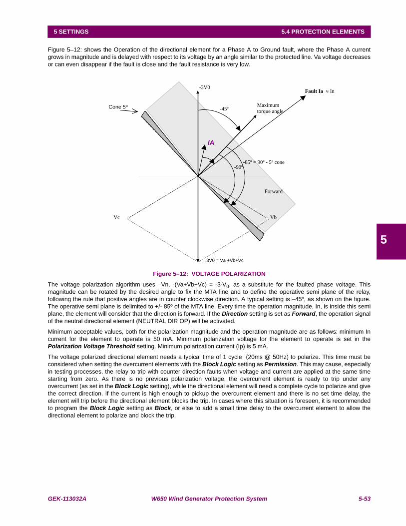
GEK-113032A W650 Wind Generator Protection System 5-53
5 SETTINGS 5.4 PROTECTION ELEMENTS
5
Figure 5–12: shows the Operation of the directional element for a Phase A to Ground fault, where the Phase A currentgrows in magnitude and is delayed with respect to its voltage by an angle similar to the protected line. Va voltage decreasesor can even disappear if the fault is close and the fault resistance is very low.
Figure 5–12: VOLTAGE POLARIZATION
The voltage polarization algorithm uses –Vn, -(Va+Vb+Vc) = -3·V0, as a substitute for the faulted phase voltage. Thismagnitude can be rotated by the desired angle to fix the MTA line and to define the operative semi plane of the relay,following the rule that positive angles are in counter clockwise direction. A typical setting is –45º, as shown on the figure.The operative semi plane is delimited to +/- 85º of the MTA line. Every time the operation magnitude, In, is inside this semiplane, the element will consider that the direction is forward. If the Direction setting is set as Forward, the operation signalof the neutral directional element (NEUTRAL DIR OP) will be activated.
Minimum acceptable values, both for the polarization magnitude and the operation magnitude are as follows: minimum Incurrent for the element to operate is 50 mA. Minimum polarization voltage for the element to operate is set in thePolarization Voltage Threshold setting. Minimum polarization current (Ip) is 5 mA.
The voltage polarized directional element needs a typical time of 1 cycle (20ms @ 50Hz) to polarize. This time must beconsidered when setting the overcurrent elements with the Block Logic setting as Permission. This may cause, especiallyin testing processes, the relay to trip with counter direction faults when voltage and current are applied at the same timestarting from zero. As there is no previous polarization voltage, the overcurrent element is ready to trip under anyovercurrent (as set in the Block Logic setting), while the directional element will need a complete cycle to polarize and givethe correct direction. If the current is high enough to pickup the overcurrent element and there is no set time delay, theelement will trip before the directional element blocks the trip. In cases where this situation is foreseen, it is recommendedto program the Block Logic setting as Block, or else to add a small time delay to the overcurrent element to allow thedirectional element to polarize and block the trip.
VbVc
-3V0
3V0 = Va +Vb+Vc
-45º Maximum
torque angleCone 5º
Forward
IA
Fault Ia In
-85º = 90º - 5º cone -90º
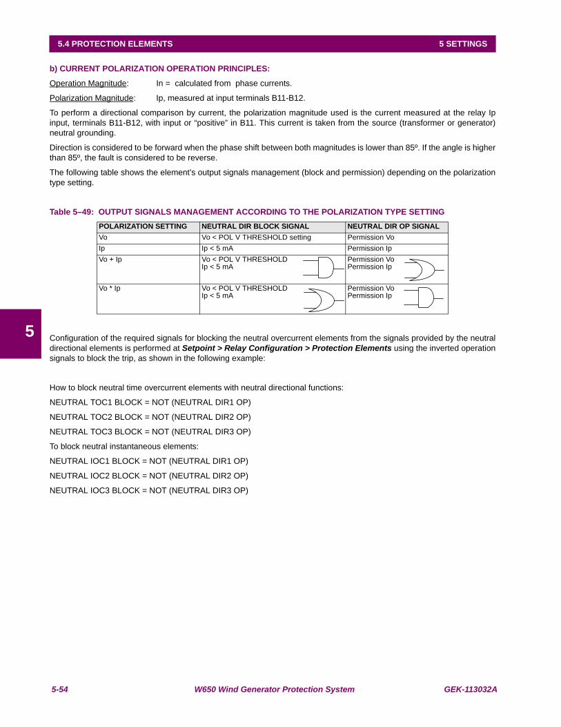
5-54 W650 Wind Generator Protection System GEK-113032A
5.4 PROTECTION ELEMENTS 5 SETTINGS
5
b) CURRENT POLARIZATION OPERATION PRINCIPLES:
Operation Magnitude: In = calculated from phase currents.
Polarization Magnitude: Ip, measured at input terminals B11-B12.
To perform a directional comparison by current, the polarization magnitude used is the current measured at the relay Ipinput, terminals B11-B12, with input or “positive” in B11. This current is taken from the source (transformer or generator)neutral grounding.
Direction is considered to be forward when the phase shift between both magnitudes is lower than 85º. If the angle is higherthan 85º, the fault is considered to be reverse.
The following table shows the element’s output signals management (block and permission) depending on the polarizationtype setting.
Table 5–49: OUTPUT SIGNALS MANAGEMENT ACCORDING TO THE POLARIZATION TYPE SETTING
Configuration of the required signals for blocking the neutral overcurrent elements from the signals provided by the neutraldirectional elements is performed at Setpoint > Relay Configuration > Protection Elements using the inverted operationsignals to block the trip, as shown in the following example:
How to block neutral time overcurrent elements with neutral directional functions:
NEUTRAL TOC1 BLOCK = NOT (NEUTRAL DIR1 OP)
NEUTRAL TOC2 BLOCK = NOT (NEUTRAL DIR2 OP)
NEUTRAL TOC3 BLOCK = NOT (NEUTRAL DIR3 OP)
To block neutral instantaneous elements:
NEUTRAL IOC1 BLOCK = NOT (NEUTRAL DIR1 OP)
NEUTRAL IOC2 BLOCK = NOT (NEUTRAL DIR2 OP)
NEUTRAL IOC3 BLOCK = NOT (NEUTRAL DIR3 OP)
POLARIZATION SETTING NEUTRAL DIR BLOCK SIGNAL NEUTRAL DIR OP SIGNALVo Vo < POL V THRESHOLD setting Permission VoIp Ip < 5 mA Permission IpVo + Ip Vo < POL V THRESHOLD
Ip < 5 mAPermission VoPermission Ip
Vo * Ip Vo < POL V THRESHOLDIp < 5 mA
Permission VoPermission Ip
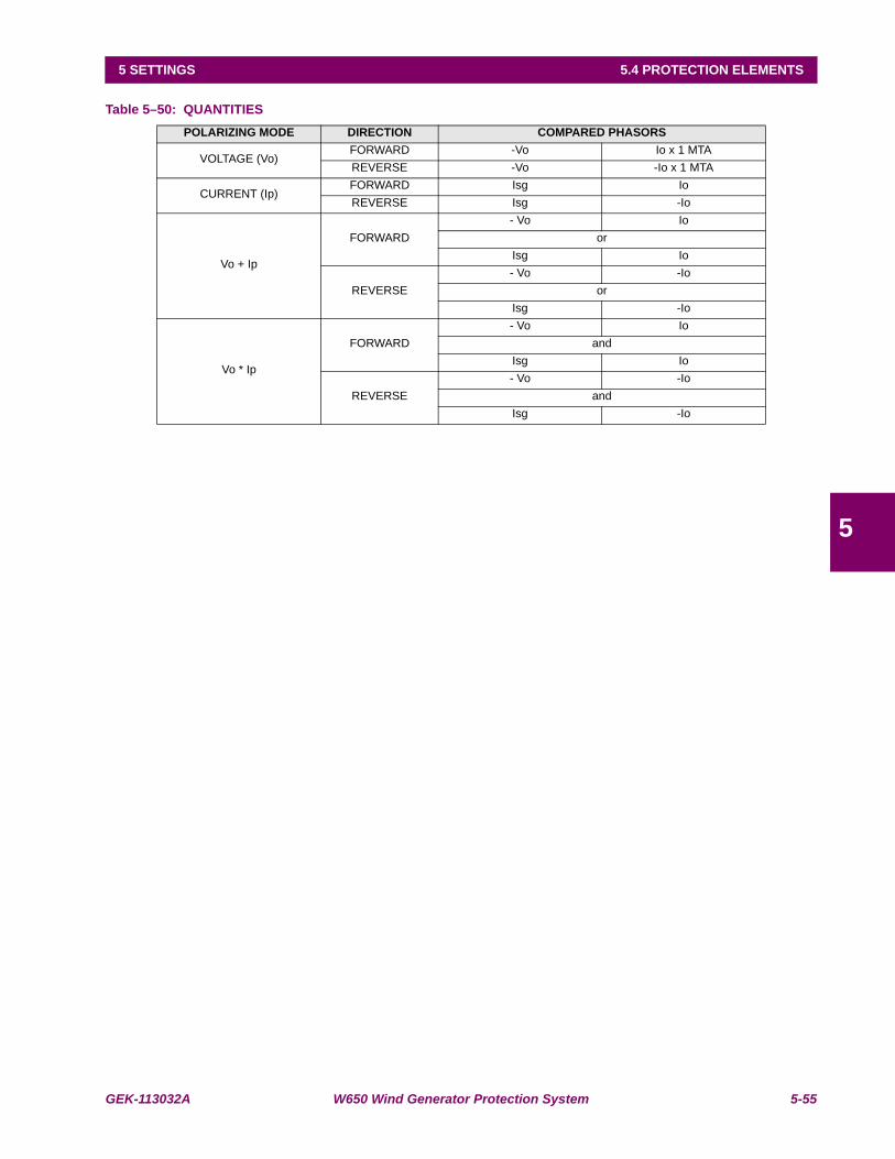
GEK-113032A W650 Wind Generator Protection System 5-55
5 SETTINGS 5.4 PROTECTION ELEMENTS
5
Table 5–50: QUANTITIESPOLARIZING MODE DIRECTION COMPARED PHASORS
VOLTAGE (Vo)FORWARD -Vo Io x 1 MTAREVERSE -Vo -Io x 1 MTA
CURRENT (Ip)FORWARD Isg IoREVERSE Isg -Io
Vo + Ip
FORWARD- Vo Io
orIsg Io
REVERSE- Vo -Io
orIsg -Io
Vo * Ip
FORWARD- Vo Io
andIsg Io
REVERSE- Vo -Io
andIsg -Io
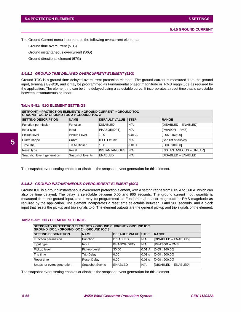
5-56 W650 Wind Generator Protection System GEK-113032A
5.4 PROTECTION ELEMENTS 5 SETTINGS
5
5.4.5 GROUND CURRENT
The Ground Current menu incorporates the following overcurrent elements:
Ground time overcurrent (51G)
Ground instantaneous overcurrent (50G)
Ground directional element (67G)
5.4.5.1 GROUND TIME DELAYED OVERCURRENT ELEMENT (51G)
Ground TOC is a ground time delayed overcurrent protection element. The ground current is measured from the groundinput, terminals B9-B10, and it may be programmed as Fundamental phasor magnitude or RMS magnitude as required bythe application. The element trip can be time delayed using a selectable curve. It incorporates a reset time that is selectablebetween instantaneous or linear.
Table 5–51: 51G ELEMENT SETTINGS
The snapshot event setting enables or disables the snapshot event generation for this element.
5.4.5.2 GROUND INSTANTANEOUS OVERCURRENT ELEMENT (50G)
Ground IOC is a ground instantaneous overcurrent protection element, with a setting range from 0.05 A to 160 A, which canalso be time delayed. The delay is selectable between 0.00 and 900 seconds. The ground current input quantity ismeasured from the ground input, and it may be programmed as Fundamental phasor magnitude or RMS magnitude asrequired by the application. The element incorporates a reset time selectable between 0 and 900 seconds, and a blockinput that resets the pickup and trip signals to 0. The element outputs are the general pickup and trip signals of the element.
Table 5–52: 50G ELEMENT SETTINGS
The snapshot event setting enables or disables the snapshot event generation for this element.
SETPOINT > PROTECTION ELEMENTS > GROUND CURRENT > GROUND TOCGROUND TOC 1> GROUND TOC 2 > GROUND TOC 3SETTING DESCRIPTION NAME DEFAULT VALUE STEP RANGEFunction permission Function DISABLED N/A [DISABLED – ENABLED]Input type Input PHASOR(DFT) N/A [PHASOR – RMS]Pickup level Pickup Level 1.00 0.01 A [0.05 : 160.00]Curve shape Curve IEEE Ext Inv N/A [See list of curves]Time Dial TD Multiplier 1.00 0.01 s [0.00 : 900.00]Reset type Reset INSTANTANEOUS N/A [INSTANTANEOUS – LINEAR]Snapshot Event generation Snapshot Events ENABLED N/A [DISABLED – ENABLED]
SETPOINT > PROTECTION ELEMENTS > GROUND CURRENT > GROUND IOCGROUND IOC 1> GROUND IOC 2 > GROUND IOC 3SETTING DESCRIPTION NAME DEFAULT VALUE STEP RANGEFunction permission Function DISABLED N/A [DISABLED – ENABLED]Input type Input PHASOR(DFT) N/A [PHASOR – RMS]Pickup level Pickup Level 30.00 0.01 A [0.05 : 160.00]Trip time Trip Delay 0.00 0.01 s [0.00 : 900.00]Reset time Reset Delay 0.00 0.01 s [0.00 : 900.00]Snapshot event generation Snapshot Events ENABLED N/A [DISABLED – ENABLED]
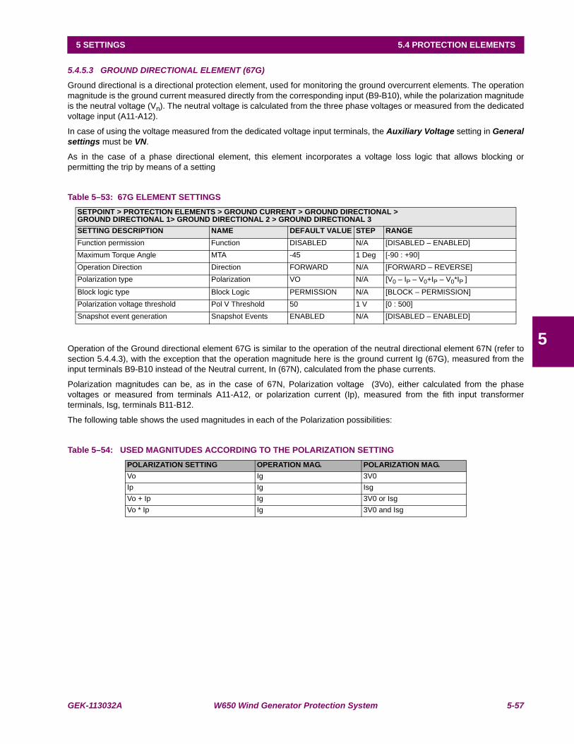
GEK-113032A W650 Wind Generator Protection System 5-57
5 SETTINGS 5.4 PROTECTION ELEMENTS
5
5.4.5.3 GROUND DIRECTIONAL ELEMENT (67G)
Ground directional is a directional protection element, used for monitoring the ground overcurrent elements. The operationmagnitude is the ground current measured directly from the corresponding input (B9-B10), while the polarization magnitudeis the neutral voltage (Vn). The neutral voltage is calculated from the three phase voltages or measured from the dedicatedvoltage input (A11-A12).
In case of using the voltage measured from the dedicated voltage input terminals, the Auxiliary Voltage setting in Generalsettings must be VN.
As in the case of a phase directional element, this element incorporates a voltage loss logic that allows blocking orpermitting the trip by means of a setting
Table 5–53: 67G ELEMENT SETTINGS
Operation of the Ground directional element 67G is similar to the operation of the neutral directional element 67N (refer tosection 5.4.4.3), with the exception that the operation magnitude here is the ground current Ig (67G), measured from theinput terminals B9-B10 instead of the Neutral current, In (67N), calculated from the phase currents.
Polarization magnitudes can be, as in the case of 67N, Polarization voltage (3Vo), either calculated from the phasevoltages or measured from terminals A11-A12, or polarization current (Ip), measured from the fith input transformerterminals, Isg, terminals B11-B12.
The following table shows the used magnitudes in each of the Polarization possibilities:
Table 5–54: USED MAGNITUDES ACCORDING TO THE POLARIZATION SETTING
SETPOINT > PROTECTION ELEMENTS > GROUND CURRENT > GROUND DIRECTIONAL >GROUND DIRECTIONAL 1> GROUND DIRECTIONAL 2 > GROUND DIRECTIONAL 3SETTING DESCRIPTION NAME DEFAULT VALUE STEP RANGEFunction permission Function DISABLED N/A [DISABLED – ENABLED]Maximum Torque Angle MTA -45 1 Deg [-90 : +90]Operation Direction Direction FORWARD N/A [FORWARD – REVERSE]Polarization type Polarization VO N/A [V0 – IP – V0+IP – V0*IP ]
Block logic type Block Logic PERMISSION N/A [BLOCK – PERMISSION]Polarization voltage threshold Pol V Threshold 50 1 V [0 : 500]Snapshot event generation Snapshot Events ENABLED N/A [DISABLED – ENABLED]
POLARIZATION SETTING OPERATION MAG. POLARIZATION MAG.Vo Ig 3V0Ip Ig IsgVo + Ip Ig 3V0 or IsgVo * Ip Ig 3V0 and Isg
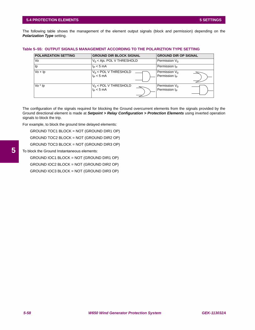
5-58 W650 Wind Generator Protection System GEK-113032A
5.4 PROTECTION ELEMENTS 5 SETTINGS
5
The following table shows the management of the element output signals (block and permission) depending on thePolarization Type setting.
Table 5–55: OUTPUT SIGNALS MANAGEMENT ACCORDING TO THE POLARIZTION TYPE SETTING
The configuration of the signals required for blocking the Ground overcurrent elements from the signals provided by theGround directional element is made at Setpoint > Relay Configuration > Protection Elements using inverted operationsignals to block the trip.
For example, to block the ground time delayed elements:
GROUND TOC1 BLOCK = NOT (GROUND DIR1 OP)
GROUND TOC2 BLOCK = NOT (GROUND DIR2 OP)
GROUND TOC3 BLOCK = NOT (GROUND DIR3 OP)
To block the Ground Instantaneous elements:
GROUND IOC1 BLOCK = NOT (GROUND DIR1 OP)
GROUND IOC2 BLOCK = NOT (GROUND DIR2 OP)
GROUND IOC3 BLOCK = NOT (GROUND DIR3 OP)
POLARIZATION SETTING GROUND DIR BLOCK SIGNAL GROUND DIR OP SIGNALVo V0 < Ajs. POL V THRESHOLD Permission V0
Ip IP < 5 mA Permission IPVo + Ip V0 < POL V THRESHOLD
IP < 5 mAPermission V0Permission IP
Vo * Ip V0 < POL V THRESHOLDIP < 5 mA
Permission V0Permission IP
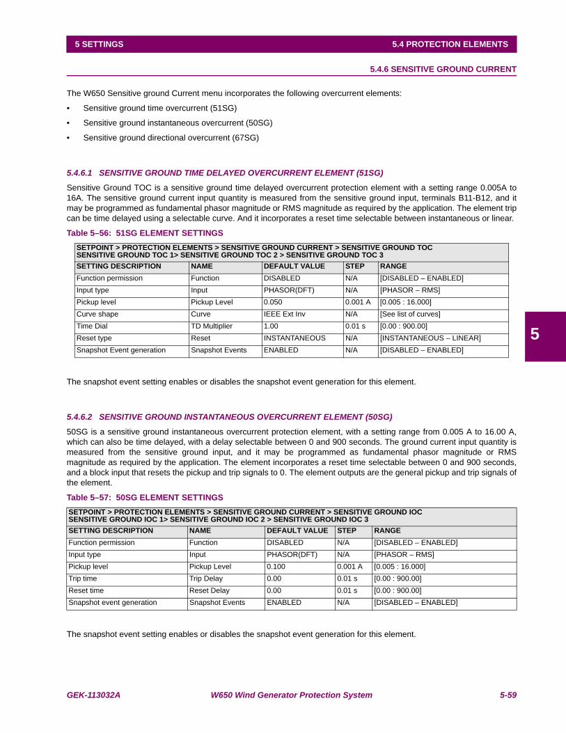
GEK-113032A W650 Wind Generator Protection System 5-59
5 SETTINGS 5.4 PROTECTION ELEMENTS
5
5.4.6 SENSITIVE GROUND CURRENT
The W650 Sensitive ground Current menu incorporates the following overcurrent elements:
• Sensitive ground time overcurrent (51SG)
• Sensitive ground instantaneous overcurrent (50SG)
• Sensitive ground directional overcurrent (67SG)
5.4.6.1 SENSITIVE GROUND TIME DELAYED OVERCURRENT ELEMENT (51SG)
Sensitive Ground TOC is a sensitive ground time delayed overcurrent protection element with a setting range 0.005A to16A. The sensitive ground current input quantity is measured from the sensitive ground input, terminals B11-B12, and itmay be programmed as fundamental phasor magnitude or RMS magnitude as required by the application. The element tripcan be time delayed using a selectable curve. And it incorporates a reset time selectable between instantaneous or linear.
Table 5–56: 51SG ELEMENT SETTINGS
The snapshot event setting enables or disables the snapshot event generation for this element.
5.4.6.2 SENSITIVE GROUND INSTANTANEOUS OVERCURRENT ELEMENT (50SG)
50SG is a sensitive ground instantaneous overcurrent protection element, with a setting range from 0.005 A to 16.00 A,which can also be time delayed, with a delay selectable between 0 and 900 seconds. The ground current input quantity ismeasured from the sensitive ground input, and it may be programmed as fundamental phasor magnitude or RMSmagnitude as required by the application. The element incorporates a reset time selectable between 0 and 900 seconds,and a block input that resets the pickup and trip signals to 0. The element outputs are the general pickup and trip signals ofthe element.
Table 5–57: 50SG ELEMENT SETTINGS
The snapshot event setting enables or disables the snapshot event generation for this element.
SETPOINT > PROTECTION ELEMENTS > SENSITIVE GROUND CURRENT > SENSITIVE GROUND TOCSENSITIVE GROUND TOC 1> SENSITIVE GROUND TOC 2 > SENSITIVE GROUND TOC 3SETTING DESCRIPTION NAME DEFAULT VALUE STEP RANGEFunction permission Function DISABLED N/A [DISABLED – ENABLED]Input type Input PHASOR(DFT) N/A [PHASOR – RMS]Pickup level Pickup Level 0.050 0.001 A [0.005 : 16.000]Curve shape Curve IEEE Ext Inv N/A [See list of curves]Time Dial TD Multiplier 1.00 0.01 s [0.00 : 900.00]Reset type Reset INSTANTANEOUS N/A [INSTANTANEOUS – LINEAR]Snapshot Event generation Snapshot Events ENABLED N/A [DISABLED – ENABLED]
SETPOINT > PROTECTION ELEMENTS > SENSITIVE GROUND CURRENT > SENSITIVE GROUND IOCSENSITIVE GROUND IOC 1> SENSITIVE GROUND IOC 2 > SENSITIVE GROUND IOC 3SETTING DESCRIPTION NAME DEFAULT VALUE STEP RANGEFunction permission Function DISABLED N/A [DISABLED – ENABLED]Input type Input PHASOR(DFT) N/A [PHASOR – RMS]Pickup level Pickup Level 0.100 0.001 A [0.005 : 16.000]Trip time Trip Delay 0.00 0.01 s [0.00 : 900.00]Reset time Reset Delay 0.00 0.01 s [0.00 : 900.00]Snapshot event generation Snapshot Events ENABLED N/A [DISABLED – ENABLED]

5-60 W650 Wind Generator Protection System GEK-113032A
5.4 PROTECTION ELEMENTS 5 SETTINGS
5
5.4.6.3 SENSITIVE GROUND DIRECTIONAL ELEMENT (67SG)
Sensitive Ground directional is a directional element used for supervising sensitive ground overcurrent functions. Theoperation magnitude is the ground current measured directly from the corresponding input (terminals B11-B12), while thepolarization magnitude is the neutral voltage (3Vo). The neutral voltage is either calculated from three phase voltages ormeasured from the dedicated voltage input (A11-A12)
In case of using the voltage measured at the dedicated voltage input terminals, the Auxiliary Voltage setting in Setpoint >System Setup > General settings must be VN.
The same way as the directional element for phases, it has a polarization voltage loss logic that allows blocking orproducing trip depending on the setting.
Table 5–58: SENSITIVE GROUND DIRECTIONAL ELEMENT SETTINGS
Available settings are:
Function permission (Function): This setting determines whether the sensitive Ground directional element is enabled orDisabled.
Maximum Torque Angle (MTA): This angle is used to rotate the Polarization voltage. Positive angles mean counterclockwise rotation, and negative angles mean clockwise. The polarization magnitude,once rotated, defines the MTA line. Vn rotated by this angle points to the semi planethat corresponds to a Reverse fault. (-Vn) rotated this angle points to the semi planethat corresponds to a Forward fault.
Operation Direction (Direction): This setting indicates the Direction for which the element will allow a trip. Depending onthis setting, the element will be activated for faults in a direction or in the oppositedirection. Possible setting values are FORWARD or REVERSE.
Polarization Voltage Threshold (Pol. V Threshold):This is the minimum polarization voltage threshold. For a voltagevalue lower than this setting the directional element will be blocked.
Snapshot Events: The snapshot event setting enables or disables the snapshot event generation for thiselement.
Sensitive ground directional element is an independent Protection element that provides block and Operation signals.These signals can be monitored both through the relay HMI or using EnerVista 650 Setup at “Actual > Status > Protection> Sensitive Ground Current”
SETPOINT > PROTECTION ELEMENTS > SENSITIVE GROUND CURRENT > SENSITIVE GROUND DIRECTIONAL >SENSITIVE GROUND DIRECTIONAL 1> SENSITIVE GROUND DIRECTIONAL 2 > SENSITIVE GROUND DIRECTIONAL 3SETTING DESCRIPTION NAME DEFAULT VALUE STEP RANGEFunction permission Function DISABLED N/A [DISABLED – ENABLED]Maximum Torque Angle MTA -45 1 Deg [-90 : +90]Operation Direction Direction FORWARD N/A [FORWARD – REVERSE]Block logic type Block Logic PERMISSION N/A [BLOCK – PERMISSION]Polarization voltage threshold Pol V Threshold 50 1 V [0 : 500]Snapshot event generation Snapshot Events ENABLED N/A [DISABLED – ENABLED]
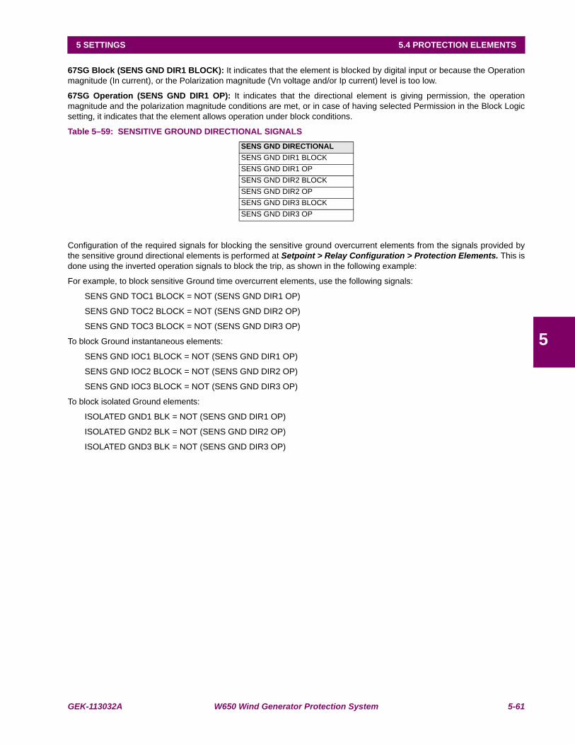
GEK-113032A W650 Wind Generator Protection System 5-61
5 SETTINGS 5.4 PROTECTION ELEMENTS
5
67SG Block (SENS GND DIR1 BLOCK): It indicates that the element is blocked by digital input or because the Operationmagnitude (In current), or the Polarization magnitude (Vn voltage and/or Ip current) level is too low.
67SG Operation (SENS GND DIR1 OP): It indicates that the directional element is giving permission, the operationmagnitude and the polarization magnitude conditions are met, or in case of having selected Permission in the Block Logicsetting, it indicates that the element allows operation under block conditions.
Table 5–59: SENSITIVE GROUND DIRECTIONAL SIGNALS
Configuration of the required signals for blocking the sensitive ground overcurrent elements from the signals provided bythe sensitive ground directional elements is performed at Setpoint > Relay Configuration > Protection Elements. This isdone using the inverted operation signals to block the trip, as shown in the following example:
For example, to block sensitive Ground time overcurrent elements, use the following signals:
SENS GND TOC1 BLOCK = NOT (SENS GND DIR1 OP)
SENS GND TOC2 BLOCK = NOT (SENS GND DIR2 OP)
SENS GND TOC3 BLOCK = NOT (SENS GND DIR3 OP)
To block Ground instantaneous elements:
SENS GND IOC1 BLOCK = NOT (SENS GND DIR1 OP)
SENS GND IOC2 BLOCK = NOT (SENS GND DIR2 OP)
SENS GND IOC3 BLOCK = NOT (SENS GND DIR3 OP)
To block isolated Ground elements:
ISOLATED GND1 BLK = NOT (SENS GND DIR1 OP)
ISOLATED GND2 BLK = NOT (SENS GND DIR2 OP)
ISOLATED GND3 BLK = NOT (SENS GND DIR3 OP)
SENS GND DIRECTIONAL SENS GND DIR1 BLOCKSENS GND DIR1 OPSENS GND DIR2 BLOCKSENS GND DIR2 OPSENS GND DIR3 BLOCKSENS GND DIR3 OP
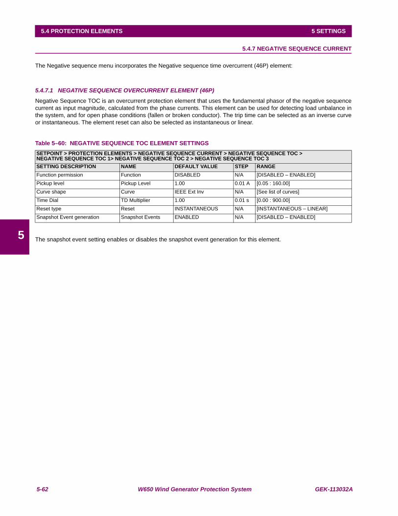
5-62 W650 Wind Generator Protection System GEK-113032A
5.4 PROTECTION ELEMENTS 5 SETTINGS
5
5.4.7 NEGATIVE SEQUENCE CURRENT
The Negative sequence menu incorporates the Negative sequence time overcurrent (46P) element:
5.4.7.1 NEGATIVE SEQUENCE OVERCURRENT ELEMENT (46P)
Negative Sequence TOC is an overcurrent protection element that uses the fundamental phasor of the negative sequencecurrent as input magnitude, calculated from the phase currents. This element can be used for detecting load unbalance inthe system, and for open phase conditions (fallen or broken conductor). The trip time can be selected as an inverse curveor instantaneous. The element reset can also be selected as instantaneous or linear.
Table 5–60: NEGATIVE SEQUENCE TOC ELEMENT SETTINGS
The snapshot event setting enables or disables the snapshot event generation for this element.
SETPOINT > PROTECTION ELEMENTS > NEGATIVE SEQUENCE CURRENT > NEGATIVE SEQUENCE TOC >NEGATIVE SEQUENCE TOC 1> NEGATIVE SEQUENCE TOC 2 > NEGATIVE SEQUENCE TOC 3SETTING DESCRIPTION NAME DEFAULT VALUE STEP RANGEFunction permission Function DISABLED N/A [DISABLED – ENABLED]Pickup level Pickup Level 1.00 0.01 A [0.05 : 160.00]Curve shape Curve IEEE Ext Inv N/A [See list of curves]Time Dial TD Multiplier 1.00 0.01 s [0.00 : 900.00]Reset type Reset INSTANTANEOUS N/A [INSTANTANEOUS – LINEAR]Snapshot Event generation Snapshot Events ENABLED N/A [DISABLED – ENABLED]

GEK-113032A W650 Wind Generator Protection System 5-63
5 SETTINGS 5.4 PROTECTION ELEMENTS
5
5.4.8 VOLTAGE ELEMENTS
The W650 incorporates the following voltage elements:
• Phase undervoltage (27P)
• Phase overvoltage (59P)
• Neutral overvoltage (59NH/59NL)
• Auxiliary overvoltage (59X)
• Auxiliary undervoltage (27X)
• Voltage Unbalance (60)
These protection elements can be used in multiple applications, such as:
Undervoltage protection: for induction motor load types, where a voltage dip can cause an increase of the consumedcurrent. Element 27P (phase undervoltage) can be used to issue a trip or an alarm.
Transfer Schemes: in the event of an undervoltage condition, we can use the 27P element (phase undervoltage) to send asignal that will transfer load to another power source.
Undervoltage elements can be set to operate with definite time or with an inverse time curve. If the element is set asdefinite time, it will operate when voltage remains under the set value during the set period of time. This period can be setfrom 0s to 900.00 s in steps of 10ms.
These elements can also be set as inverse time curves. This family of curves is defined by the following formula:
Where:
T = operation time
D = operation time setting (delay)
V = voltage applied to the relay
Vpickup = pickup setting (Pickup level)
Figure 5–13: INVERSE TIME UNDERVOLTAGE CURVES
VpickupV
DT−
=1
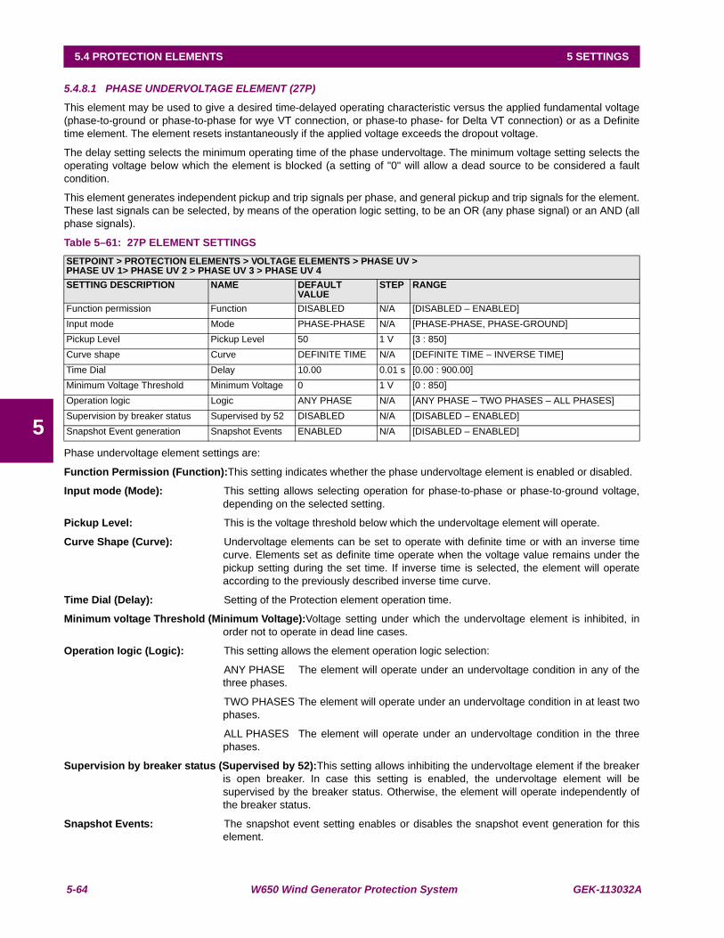
5-64 W650 Wind Generator Protection System GEK-113032A
5.4 PROTECTION ELEMENTS 5 SETTINGS
5
5.4.8.1 PHASE UNDERVOLTAGE ELEMENT (27P)
This element may be used to give a desired time-delayed operating characteristic versus the applied fundamental voltage(phase-to-ground or phase-to-phase for wye VT connection, or phase-to phase- for Delta VT connection) or as a Definitetime element. The element resets instantaneously if the applied voltage exceeds the dropout voltage.
The delay setting selects the minimum operating time of the phase undervoltage. The minimum voltage setting selects theoperating voltage below which the element is blocked (a setting of "0" will allow a dead source to be considered a faultcondition.
This element generates independent pickup and trip signals per phase, and general pickup and trip signals for the element.These last signals can be selected, by means of the operation logic setting, to be an OR (any phase signal) or an AND (allphase signals).
Table 5–61: 27P ELEMENT SETTINGS
Phase undervoltage element settings are:
Function Permission (Function):This setting indicates whether the phase undervoltage element is enabled or disabled.
Input mode (Mode): This setting allows selecting operation for phase-to-phase or phase-to-ground voltage,depending on the selected setting.
Pickup Level: This is the voltage threshold below which the undervoltage element will operate.
Curve Shape (Curve): Undervoltage elements can be set to operate with definite time or with an inverse timecurve. Elements set as definite time operate when the voltage value remains under thepickup setting during the set time. If inverse time is selected, the element will operateaccording to the previously described inverse time curve.
Time Dial (Delay): Setting of the Protection element operation time.
Minimum voltage Threshold (Minimum Voltage):Voltage setting under which the undervoltage element is inhibited, inorder not to operate in dead line cases.
Operation logic (Logic): This setting allows the element operation logic selection:
ANY PHASE The element will operate under an undervoltage condition in any of thethree phases.
TWO PHASES The element will operate under an undervoltage condition in at least twophases.
ALL PHASES The element will operate under an undervoltage condition in the threephases.
Supervision by breaker status (Supervised by 52):This setting allows inhibiting the undervoltage element if the breakeris open breaker. In case this setting is enabled, the undervoltage element will besupervised by the breaker status. Otherwise, the element will operate independently ofthe breaker status.
Snapshot Events: The snapshot event setting enables or disables the snapshot event generation for thiselement.
SETPOINT > PROTECTION ELEMENTS > VOLTAGE ELEMENTS > PHASE UV >PHASE UV 1> PHASE UV 2 > PHASE UV 3 > PHASE UV 4SETTING DESCRIPTION NAME DEFAULT
VALUESTEP RANGE
Function permission Function DISABLED N/A [DISABLED – ENABLED]Input mode Mode PHASE-PHASE N/A [PHASE-PHASE, PHASE-GROUND]Pickup Level Pickup Level 50 1 V [3 : 850]Curve shape Curve DEFINITE TIME N/A [DEFINITE TIME – INVERSE TIME]Time Dial Delay 10.00 0.01 s [0.00 : 900.00]Minimum Voltage Threshold Minimum Voltage 0 1 V [0 : 850]Operation logic Logic ANY PHASE N/A [ANY PHASE – TWO PHASES – ALL PHASES]Supervision by breaker status Supervised by 52 DISABLED N/A [DISABLED – ENABLED]Snapshot Event generation Snapshot Events ENABLED N/A [DISABLED – ENABLED]

GEK-113032A W650 Wind Generator Protection System 5-65
5 SETTINGS 5.4 PROTECTION ELEMENTS
5
5.4.8.2 PHASE OVERVOLTAGE ELEMENT (59P)
The Phase overvoltage element may be used as an instantaneous element with no intentional time delay or as a DefiniteTime element. The input voltage is the phase-to-phase voltage, either measured directly from Delta-connected VTs or ascalculated from phase-to-ground (wye) connected VTs. The time delay can be set from instantaneous to 900 seconds. Theelement reset can be delayed up to 900 seconds.
As in the case of the undervoltage element, this element generates independent pickup and trip signals for each phase.The general signal is selectable by setting to be an OR or an AND of the phase signals.
Table 5–62: 59P ELEMENT SETTINGS
Phase overvoltage element settings are:
Function Permission (Function): This setting indicates whether the phase overvoltage element is enabled or disabled.
Pickup Level: This is the voltage threshold over which the overvoltage element will operate.
Trip time (Trip Delay): setting of the Protection element operation time.
Reset time (Reset Delay): Reset time of the Protection element.
Operation logic (Logic): This setting allows the element operation logic selection:
ANY PHASE The element will operate under an overvoltage condition in any of thethree phases.
TWO PHASES The element will operate under an overvoltage condition in at leasttwo phases.
ALL PHASES The element will operate under an overvoltage condition in the threephases.
Snapshot Events: The snapshot event setting enables or disables the snapshot event generation for thiselement.
SETPOINT > PROTECTION ELEMENTS > VOLTAGE ELEMENTS > PHASE OV >PHASE OV 1> PHASE OV 2 > PHASE OV 3 > PHASE OV 4SETTING DESCRIPTION NAME DEFAULT
VALUESTEP RANGE
Function permission Function DISABLED N/A [DISABLED – ENABLED]Pickup Level Pickup Level 50 1 V [3 : 850]Trip time Trip Delay 10.00 0.01 s [0.00 : 900.00]Reset time Reset Delay 0.00 0.01 s [0.00 : 900.00]Operation logic Logic ANY PHASE N/A [ANY PHASE – TWO PHASES – ALL PHASES]Snapshot Event generation Snapshot Events ENABLED N/A [DISABLED – ENABLED]
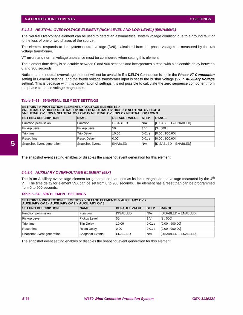
5-66 W650 Wind Generator Protection System GEK-113032A
5.4 PROTECTION ELEMENTS 5 SETTINGS
5
5.4.8.3 NEUTRAL OVERVOLTAGE ELEMENT (HIGH LEVEL AND LOW LEVEL) (59NH/59NL)
The Neutral Overvoltage element can be used to detect an asymmetrical system voltage condition due to a ground fault orto the loss of one or two phases of the source.
The element responds to the system neutral voltage (3V0), calculated from the phase voltages or measured by the 4thvoltage transformer.
VT errors and normal voltage unbalance must be considered when setting this element.
The element time delay is selectable between 0 and 900 seconds and incorporates a reset with a selectable delay between0 and 900 seconds.
Notice that the neutral overvoltage element will not be available if a DELTA Connection is set in the Phase VT Connectionsetting in General settings, and the fourth voltage transformer input is set to the busbar voltage (Vx in Auxiliary Voltagesetting). This is because with this combination of settings it is not possible to calculate the zero sequence component fromthe phase-to-phase voltage magnitudes.
Table 5–63: 59NH/59NL ELEMENT SETTINGS
The snapshot event setting enables or disables the snapshot event generation for this element.
5.4.8.4 AUXILIARY OVERVOLTAGE ELEMENT (59X)
This is an Auxiliary overvoltage element for general use that uses as its input magnitude the voltage measured by the 4th
VT. The time delay for element 59X can be set from 0 to 900 seconds. The element has a reset than can be programmedfrom 0 to 900 seconds.
Table 5–64: 59X ELEMENT SETTINGS
The snapshot event setting enables or disables the snapshot event generation for this element.
SETPOINT > PROTECTION ELEMENTS > VOLTAGE ELEMENTS >>NEUTRAL OV HIGH > NEUTRAL OV HIGH 1> NEUTRAL OV HIGH 2 > NEUTRAL OV HIGH 3>NEUTRAL OV LOW > NEUTRAL OV LOW 1> NEUTRAL OV LOW 2 > NEUTRAL OV LOW 3SETTING DESCRIPTION NAME DEFAULT VALUE STEP RANGEFunction permission Function DISABLED N/A [DISABLED – ENABLED]Pickup Level Pickup Level 50 1 V [3 : 500 ]Trip time Trip Delay 10.00 0.01 s [0.00 : 900.00]Reset time Reset Delay 0.00 0.01 s [0.00 : 900.00]Snapshot Event generation Snapshot Events ENABLED N/A [DISABLED – ENABLED]
SETPOINT > PROTECTION ELEMENTS > VOLTAGE ELEMENTS > AUXILIARY OV >AUXILIARY OV 1> AUXILIARY OV 2 > AUXILIARY OV 3SETTING DESCRIPTION NAME DEFAULT VALUE STEP RANGEFunction permission Function DISABLED N/A [DISABLED – ENABLED]Pickup Level Pickup Level 50 1 V [3 : 500]Trip time Trip Delay 10.00 0.01 s [0.00 : 900.00]Reset time Reset Delay 0.00 0.01 s [0.00 : 900.00]Snapshot Event generation Snapshot Events ENABLED N/A [DISABLED – ENABLED]

GEK-113032A W650 Wind Generator Protection System 5-67
5 SETTINGS 5.4 PROTECTION ELEMENTS
5
5.4.8.5 AUXILIARY UNDERVOLTAGE ELEMENT (27X)
This is an Auxiliary undervoltage element for general use that uses as its input magnitude the voltage measured by the 4th
VT, terminals A11-A12.
Table 5–65: 27X ELEMENT SETTINGS
The snapshot event setting enables or disables the snapshot event generation for this element.
5.4.8.6 VOLTAGE UNBALANCE (60V)
This element controls the power system unbalance margin. It is based on the "Voltage Unbalance Factor" definedaccording to IEC as:
Factor % = V2/V1Table 5–66: VOLTAGE UNBALANCE SETTINGS
FUNCTION Enables/disables function 60V.
PICKUP LEVEL Element 60V pickup level. This setting is based on the system unbalance% according to the formula V2/V1 in the measuring.
The V2 negative sequence or the positive sequence V1 value should be greater than 5 V. The unit will notwork below this threshold.
TRIP DELAY Element 60V trip delay. The equipment will work once the unbalance factor keeps its value above the tripthreshold during the time determined by this setting.
RESET DELAY Once the unit has worked and the unbalance factor is below the 97% of the activation threshold, theequipment will keep the trip until the reset time is over. Then the reset of the unit will take place.
EVENTS Enables or disables the function event generation. All the status in the function are influenced by thissetting.
SETPOINT > PROTECTION ELEMENTS > VOLTAGE ELEMENTS > AUXILIARY UV >AUXILIARY UV 1> AUXILIARY UV 2 > AUXILIARY UV 3setting Description Name Default Value Step RangeFunction permission Function DISABLED N/A [DISABLED – ENABLED]Pickup Level Pickup Level 50 1 V [3 : 500]Curve shape Curve DEFINITE TIME N/A [DEFINITE TIME – INVERSE TIME]Time Dial Delay 10.00 0.01 s [0.00 : 900.00]Snapshot Event generation Snapshot Events ENABLED N/A [DISABLED – ENABLED]
SETPOINT > PROTECTION ELEMENTS > VOLTAGE ELEMENTS > VOLTAGE UNBALANCE 1 > VOLTAGE UNBALANCE 2 >VOLTAGE UNBALANCE 3Name Default Value Unit RangeFunction ENABLE [DISABLED – ENABLED]Pickup Level 1.00 % 0.00 – 500.0 (0.01)Trip Delay 10.00 S 0.00 – 900.00 (0.01)Reset Delay 0.00 S 0.00 – 900.00 (0.01)Events DISABLED [DISABLED – ENABLED]

5-68 W650 Wind Generator Protection System GEK-113032A
5.4 PROTECTION ELEMENTS 5 SETTINGS
5
5.4.9 POWER
5.4.9.1 DIRECTIONAL POWER ELEMENT (32)
a) ELEMENT DESCRIPTION
The Directional Power element responds to three-phase active power measured from the feeder associated to the W650.This element can be selected to operate according to the power threshold adjusted in the corresponding setting. Thiselement is ideal for reverse power applications (F32 REV) or forward power (F32 FWD), depending on the selectedsetting. The relay measures the three-phase power for wye or delta connections.
The element has an adjustable characteristic angle and minimum operating power as shown in the Directional PowerCharacteristic diagram. The element responds to the following condition:
P cos(ϕ) + Q sin (ϕ) > SMIN
where: P and Q are active and reactive powers as measured per the W650 convention, ϕ is the angle set at the 32 setting(DIR POWER ANGLE) in degrees in steps of 0.01º, and SMIN is the minimum operating power.
The element has two independent (as to the pickup and delay settings) elements. Both elements can be used for alarmand trip, and they can be set separately to provide a mixed power protection.
The Directional Power Characteristic is shown in the following diagram.
Figure 5–14: POWER DIRECTIONAL CHARACTERISTIC
By making the characteristic angle adjustable from 0º to 360º in steps of 0.01º, a variety of operating characteristics can beachieved as presented in the figures below. For example, for an angle of 0º, the element would operate as a 32 ForwardPower element, while if setting an RCA angle of 180º, the element would operate as a 32 Reverse Power element. Forangles of 90º and 270º, the case would be similar but with reactive power.
DIR POWER ANGLE
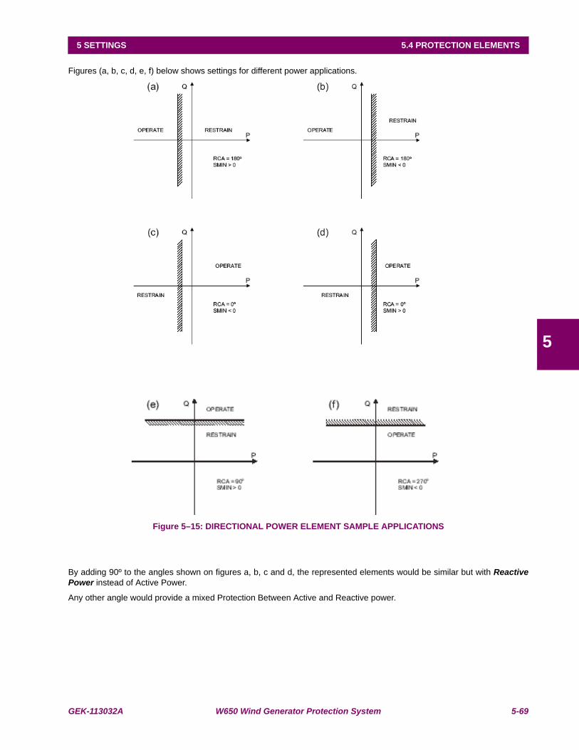
GEK-113032A W650 Wind Generator Protection System 5-69
5 SETTINGS 5.4 PROTECTION ELEMENTS
5
Figures (a, b, c, d, e, f) below shows settings for different power applications.
Figure 5–15: DIRECTIONAL POWER ELEMENT SAMPLE APPLICATIONS
By adding 90º to the angles shown on figures a, b, c and d, the represented elements would be similar but with ReactivePower instead of Active Power.
Any other angle would provide a mixed Protection Between Active and Reactive power.
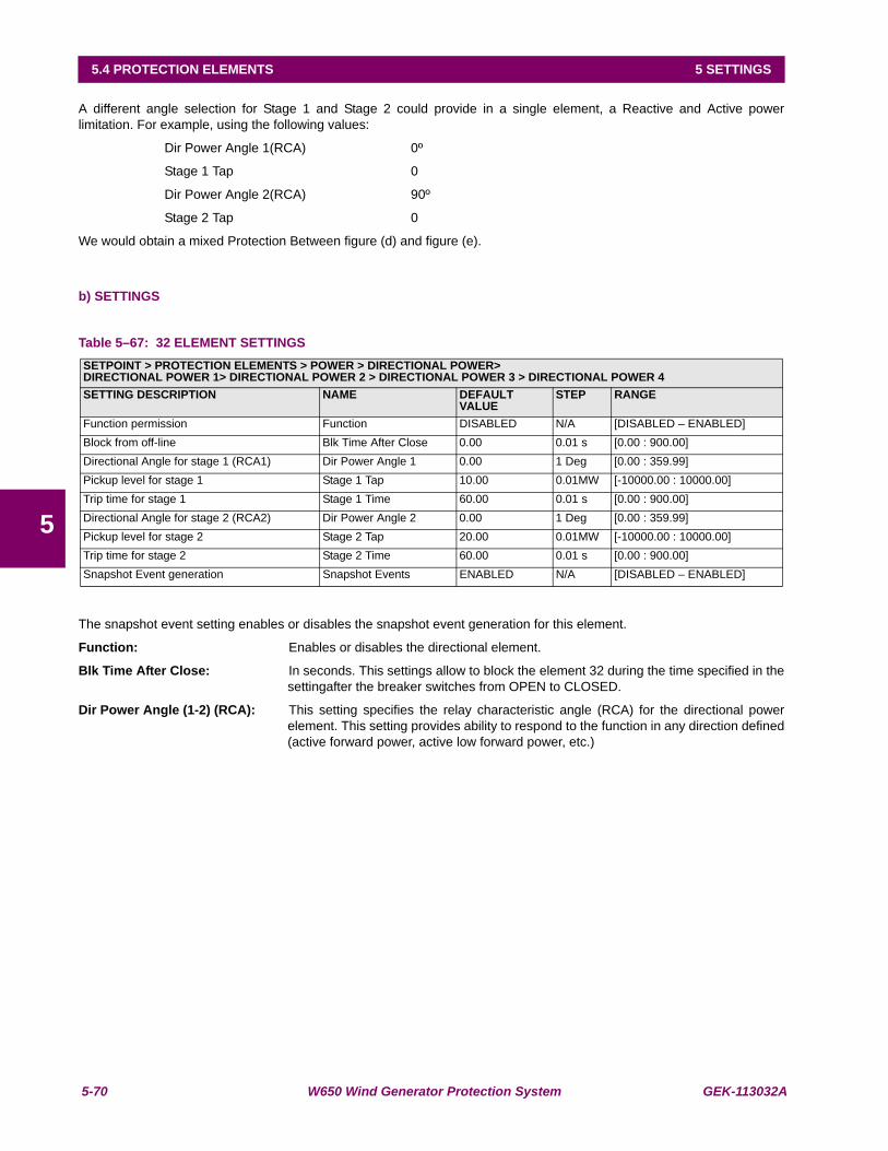
5-70 W650 Wind Generator Protection System GEK-113032A
5.4 PROTECTION ELEMENTS 5 SETTINGS
5
A different angle selection for Stage 1 and Stage 2 could provide in a single element, a Reactive and Active powerlimitation. For example, using the following values:
Dir Power Angle 1(RCA) 0º
Stage 1 Tap 0
Dir Power Angle 2(RCA) 90º
Stage 2 Tap 0
We would obtain a mixed Protection Between figure (d) and figure (e).
b) SETTINGS
Table 5–67: 32 ELEMENT SETTINGS
The snapshot event setting enables or disables the snapshot event generation for this element.
Function: Enables or disables the directional element.
Blk Time After Close: In seconds. This settings allow to block the element 32 during the time specified in thesettingafter the breaker switches from OPEN to CLOSED.
Dir Power Angle (1-2) (RCA): This setting specifies the relay characteristic angle (RCA) for the directional powerelement. This setting provides ability to respond to the function in any direction defined(active forward power, active low forward power, etc.)
SETPOINT > PROTECTION ELEMENTS > POWER > DIRECTIONAL POWER>DIRECTIONAL POWER 1> DIRECTIONAL POWER 2 > DIRECTIONAL POWER 3 > DIRECTIONAL POWER 4SETTING DESCRIPTION NAME DEFAULT
VALUESTEP RANGE
Function permission Function DISABLED N/A [DISABLED – ENABLED]Block from off-line Blk Time After Close 0.00 0.01 s [0.00 : 900.00]Directional Angle for stage 1 (RCA1) Dir Power Angle 1 0.00 1 Deg [0.00 : 359.99]Pickup level for stage 1 Stage 1 Tap 10.00 0.01MW [-10000.00 : 10000.00]Trip time for stage 1 Stage 1 Time 60.00 0.01 s [0.00 : 900.00]Directional Angle for stage 2 (RCA2) Dir Power Angle 2 0.00 1 Deg [0.00 : 359.99]Pickup level for stage 2 Stage 2 Tap 20.00 0.01MW [-10000.00 : 10000.00]Trip time for stage 2 Stage 2 Time 60.00 0.01 s [0.00 : 900.00]Snapshot Event generation Snapshot Events ENABLED N/A [DISABLED – ENABLED]

GEK-113032A W650 Wind Generator Protection System 5-71
5 SETTINGS 5.4 PROTECTION ELEMENTS
5
The following figure illustrates the conventions established:
Figure 5–16: ANGLES
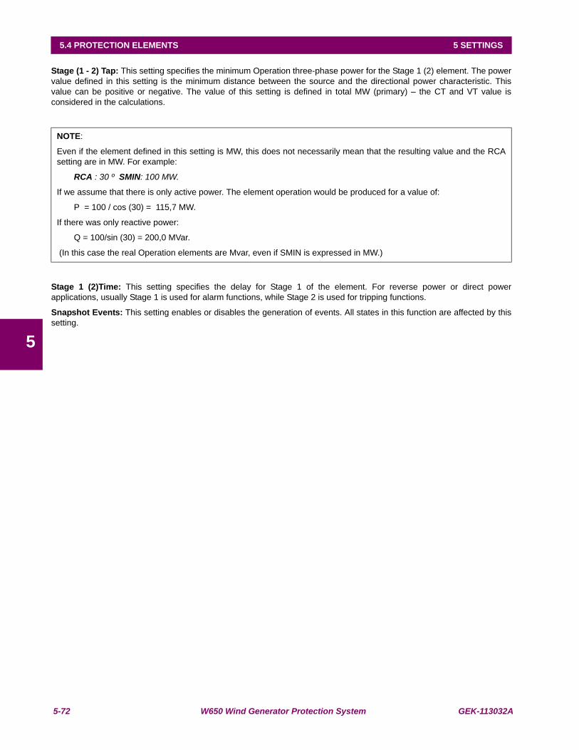
5-72 W650 Wind Generator Protection System GEK-113032A
5.4 PROTECTION ELEMENTS 5 SETTINGS
5
Stage (1 - 2) Tap: This setting specifies the minimum Operation three-phase power for the Stage 1 (2) element. The powervalue defined in this setting is the minimum distance between the source and the directional power characteristic. Thisvalue can be positive or negative. The value of this setting is defined in total MW (primary) – the CT and VT value isconsidered in the calculations.
Stage 1 (2)Time: This setting specifies the delay for Stage 1 of the element. For reverse power or direct powerapplications, usually Stage 1 is used for alarm functions, while Stage 2 is used for tripping functions.
Snapshot Events: This setting enables or disables the generation of events. All states in this function are affected by thissetting.
NOTE:
Even if the element defined in this setting is MW, this does not necessarily mean that the resulting value and the RCAsetting are in MW. For example:
RCA : 30 º SMIN: 100 MW.
If we assume that there is only active power. The element operation would be produced for a value of:
P = 100 / cos (30) = 115,7 MW.
If there was only reactive power:
Q = 100/sin (30) = 200,0 MVar.
(In this case the real Operation elements are Mvar, even if SMIN is expressed in MW.)

GEK-113032A W650 Wind Generator Protection System 5-73
5 SETTINGS 5.4 PROTECTION ELEMENTS
5
c) STATUSES
Statuses defined for this Function are as follows:
DIR PWR1 (2, 3, 4) BLOCK : Writing status, operates by level. When this status is activated externally (via PLC), thedirectional power element is blocked. This status affects both elements in theprotection element (stage 1 and 2).
Activation of this status produces the event: DIR PWR1 (2, 3, 4) BLK ON.
Deactivation produces the event : DIR PWR1 (2, 3, 4) BLK OFF.
DIR PWR1 (2, 3, 4) STG1 (2) OP: This is activated when the element that corresponds to stage 1/2 is activated. Eventsgenerated by this element are:
DIR PWR1 (2, 3, 4) STG1 (2) OP ON
DIR PWR1 (2, 3, 4) STG1 (2) OP OFF
DIR PWR1 (2, 3, 4) STG1 (2) PKP: Activation of this status indicates that the power value has exceeded the thresholdindicated by the Stage 1/2 element. Events generated by this element are:
DIR PWR1 (2, 3, 4) STG1 (2) PKP ON
DIR PWR1 (2, 3, 4) STG1 (2) PKP OFF
DIR PWR1 (2, 3, 4) STG PKP: This status is a logic OR between the DIR PWR STG1 PKP and DIR PWR STG2 PKPstatuses. Activation of this status indicates that the power value has exceeded thethreshold indicated by any of the Stage 1/2 elements. Events generated by thiselement are:
DIR PWR1 (2, 3, 4) STG PKP ON
DIR PWR1 (2, 3, 4) STG PKP OFF
DIR PWR1 (2, 3, 4) STG OP: This status is a logic OR between the DIR PWR STG1 OP and DIR PWR STG2 OPstatuses. This is activated when the element that corresponds to stage 1/2 is activated.Events generated by this element are:
DIR PWR1 (2, 3, 4) STG OP ON
DIR PWR1 (2, 3, 4) STG OP OFF

5-74 W650 Wind Generator Protection System GEK-113032A
5.5 CONTROL ELEMENTS 5 SETTINGS
5
5.5CONTROL ELEMENTS
The W650 incorporates the following control elements:
Setting Group
Underfrequency
Overfrequency
Autoreclose (79)
Breaker Failure (50BF)
VT Fuse Failure
Note: for all control elements related to the breaker, it must be considered that all operations will be performed consideringthe status of the switchgear configured as breaker. In Setpoint > Relay Configuration > Switchgear up to 16 switchgearelements can be configured to operate and be monitored, but only one of them can be configured as a breaker, formonitoring, number of openings and closings counters, (KI)2t.
5.5.1 SETTING GROUP
The settings used for setting table management are located in Setpoint >Control Elements >Setting Group:
Table 5–68: SETTING GROUP SETTINGS
The snapshot event setting enables or disables the snapshot event generation for this element.
For more detailed information go to section 5.4.1
Note: SETTING GROUP 4 includes only protection elements 29P, 59P, 81U and 81O. Please refer to Table 5–28:DISTRIBUTION OF PROTECTION ELEMENTS.
SETPOINT > CONTROL ELEMENTS > SETTING GROUPSETTING DESCRIPTION NAME DEFAULT
VALUESTEP RANGE
Setting Grouping Permission Function DISABLED N/A [DISABLED – ENABLED]Active Group Active Group GROUP 1 N/A [GROUP 1 – GROUP 2 – GROUP 3 – GROUP 4]Snapshot Event generation Snapshot Events ENABLED N/A [DISABLED – ENABLED]
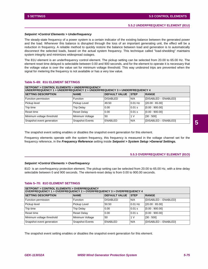
GEK-113032A W650 Wind Generator Protection System 5-75
5 SETTINGS 5.5 CONTROL ELEMENTS
5
5.5.2 UNDERFREQUENCY ELEMENT (81U)
Setpoint >Control Elements > Underfrequency
The steady-state frequency of a power system is a certain indicator of the existing balance between the generated powerand the load. Whenever this balance is disrupted through the loss of an important generating unit, the effect will be areduction in frequency. A reliable method to quickly restore the balance between load and generation is to automaticallydisconnect the selected loads, based on the actual system frequency. This technique called "load-shedding" maintainssystem integrity and minimizes widespread outages.
The 81U element is an underfrequency control element. The pickup setting can be selected from 20.00 to 65.00 Hz. Theelement reset time delayed is selectable between 0.00 and 900 seconds, and for the element to operate it is necessary thatthe voltage value is over the value set for minimum voltage threshold. This way undesired trips are prevented when thesignal for metering the frequency is not available or has a very low value.
Table 5–69: 81U ELEMENT SETTINGS
The snapshot event setting enables or disables the snapshot event generation for this element.
Frequency elements operate with the system frequency, this frequency is measured in the voltage channel set for thefrequency reference, in the Frequency Reference setting inside Setpoint > System Setup >General Settings.
5.5.3 OVERFREQUENCY ELEMENT (81O)
Setpoint >Control Elements > Overfrequency
81O is an overfrequency protection element. The pickup setting can be selected from 20.00 to 65.00 Hz, with a time delayselectable between 0 and 900 seconds. The element-reset delay is from 0.00 to 900.00 seconds.
Table 5–70: 81O ELEMENT SETTINGS
The snapshot event setting enables or disables the snapshot event generation for this element.
SETPOINT > CONTROL ELEMENTS > UNDERFREQUENCYUNDERFREQUENCY 1 > UNDERFREQUENCY 2 > UNDERFREQUENCY 3 > UNDERFREQUENCY 4SETTING DESCRIPTION NAME DEFAULT VALUE STEP RANGEFunction permission Function DISABLED N/A [DISABLED – ENABLED]Pickup level Pickup Level 49.50 0.01 Hz [20.00 : 65.00]Trip time Trip Delay 0.00 0.01 s [0.00 : 900.00]Reset time Reset Delay 0.00 0.01 s [0.00 : 900.00]Minimum voltage threshold Minimum Voltage 50 1 V [30 : 500]Snapshot event generation Snapshot Events ENABLED N/A [DISABLED – ENABLED]
SETPOINT > CONTROL ELEMENTS > OVERFREQUENCYOVERFREQUENCY 1 > OVERFREQUENCY 2 > OVERFREQUENCY 3 > OVERFREQUENCY 4SETTING DESCRIPTION NAME DEFAULT VALUE STEP RANGEFunction permission Function DISABLED N/A [DISABLED – ENABLED]Pickup level Pickup Level 50.50 0.01 Hz [20.00 : 65.00]Trip time Trip Delay 0.00 0.01 s [0.00 : 900.00]Reset time Reset Delay 0.00 0.01 s [0.00 : 900.00]Minimum voltage threshold Minimum Voltage 50 1 V [30 : 500]Snapshot event generation Snapshot Events ENABLED N/A [DISABLED – ENABLED]
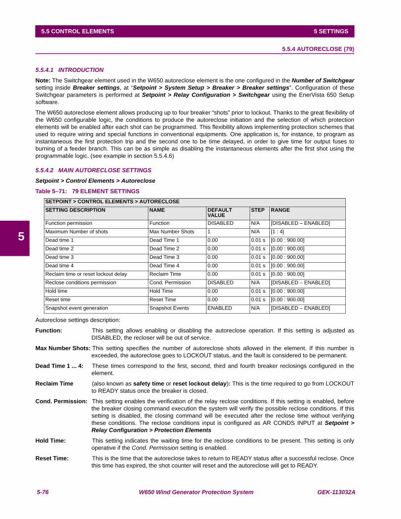
5-76 W650 Wind Generator Protection System GEK-113032A
5.5 CONTROL ELEMENTS 5 SETTINGS
5
5.5.4 AUTORECLOSE (79)
5.5.4.1 INTRODUCTION
Note: The Switchgear element used in the W650 autoreclose element is the one configured in the Number of Switchgearsetting inside Breaker settings, at “Setpoint > System Setup > Breaker > Breaker settings”. Configuration of theseSwitchgear parameters is performed at Setpoint > Relay Configuration > Switchgear using the EnerVista 650 Setupsoftware.
The W650 autoreclose element allows producing up to four breaker “shots” prior to lockout. Thanks to the great flexibility ofthe W650 configurable logic, the conditions to produce the autoreclose initiation and the selection of which protectionelements will be enabled after each shot can be programmed. This flexibility allows implementing protection schemes thatused to require wiring and special functions in conventional equipments. One application is, for instance, to program asinstantaneous the first protection trip and the second one to be time delayed, in order to give time for output fuses toburning of a feeder branch. This can be as simple as disabling the instantaneous elements after the first shot using theprogrammable logic. (see example in section 5.5.4.6)
5.5.4.2 MAIN AUTORECLOSE SETTINGS
Setpoint > Control Elements > Autoreclose
Table 5–71: 79 ELEMENT SETTINGS
Autoreclose settings description:
Function: This setting allows enabling or disabling the autoreclose operation. If this setting is adjusted asDISABLED, the recloser will be out of service.
Max Number Shots: This setting specifies the number of autoreclose shots allowed in the element. If this number isexceeded, the autoreclose goes to LOCKOUT status, and the fault is considered to be permanent.
Dead Time 1 ... 4: These times correspond to the first, second, third and fourth breaker reclosings configured in theelement.
Reclaim Time (also known as safety time or reset lockout delay): This is the time required to go from LOCKOUTto READY status once the breaker is closed.
Cond. Permission: This setting enables the verification of the relay reclose conditions. If this setting is enabled, beforethe breaker closing command execution the system will verify the possible reclose conditions. If thissetting is disabled, the closing command will be executed after the reclose time without verifyingthese conditions. The reclose conditions input is configured as AR CONDS INPUT at Setpoint >Relay Configuration > Protection Elements
Hold Time: This setting indicates the waiting time for the reclose conditions to be present. This setting is onlyoperative if the Cond. Permission setting is enabled.
Reset Time: This is the time that the autoreclose takes to return to READY status after a successful reclose. Oncethis time has expired, the shot counter will reset and the autoreclose will get to READY.
SETPOINT > CONTROL ELEMENTS > AUTORECLOSESETTING DESCRIPTION NAME DEFAULT
VALUESTEP RANGE
Function permission Function DISABLED N/A [DISABLED – ENABLED]Maximum Number of shots Max Number Shots 1 N/A [1 : 4]Dead time 1 Dead Time 1 0.00 0.01 s [0.00 : 900.00]Dead time 2 Dead Time 2 0.00 0.01 s [0.00 : 900.00]Dead time 3 Dead Time 3 0.00 0.01 s [0.00 : 900.00]Dead time 4 Dead Time 4 0.00 0.01 s [0.00 : 900.00]Reclaim time or reset lockout delay Reclaim Time 0.00 0.01 s [0.00 : 900.00]Reclose conditions permission Cond. Permission DISABLED N/A [DISABLED – ENABLED]Hold time Hold Time 0.00 0.01 s [0.00 : 900.00]Reset time Reset Time 0.00 0.01 s [0.00 : 900.00]Snapshot event generation Snapshot Events ENABLED N/A [DISABLED – ENABLED]

GEK-113032A W650 Wind Generator Protection System 5-77
5 SETTINGS 5.5 CONTROL ELEMENTS
5
5.5.4.3 AUTORECLOSE INPUTS
For the correct operation of the autoreclose element, it is required to configure several input signals in the Relay. Thesesignals can be configured using the EnerVista 650 Setup software, at Setpoint > Relay Configuration > ProtectionElements. The Protection Elements screen allows to select simple signals provided directly by the relay (states), or touse more complex logics using virtual outputs, configured at Setpoint > Logic Configuration using the PLC Editor toolinside EnerVista 650 Setup.
Actual> Status > Control Elements > Autoreclose
Table 5–72: 79 CONFIGURABLE INPUTS
AR LEVEL BLOCK: This signal is configured to block the autoreclose by level; when the block signal disappears, therecloser goes to Lockout status before returning to either the READY status, or thecorresponding status in the reclosing cycle.
AR PULSE BLOCK: This signal is configured to block the autoreclose by pulse; a pulse moves the autoreclose toBLOCK status. The autoreclose block is active until an unblock signal is received.
AR PULSE UNBLOCK: This signal is configured as autoreclose unblock by pulse; this pulse is required to bring therecloser out of the block status. The autoreclose goes to Lockout after a block situation.
AR INITIATE: This signal indicates the autoreclose initiation. Usually, the factory default configuration sets thissignal as a combination of the general trip signal (Virtual Output 83), and an external inputconfigured as AR Initiate.
AR CONDS INPUT: This signal configures the conditions that are to be met before executing a breaker closecommand. These conditions are verified once the configured Dead Time has expired, and theyare only considered if the Cond. Permission setting is enabled. Otherwise, these conditionswouldn’t have any effect.
AUTORECLOSE INPUTSAR LEVEL BLOCKAR PULSE BLOCKAR PULSE UNBLOCKAR INITIATEAR CONDS INPUT
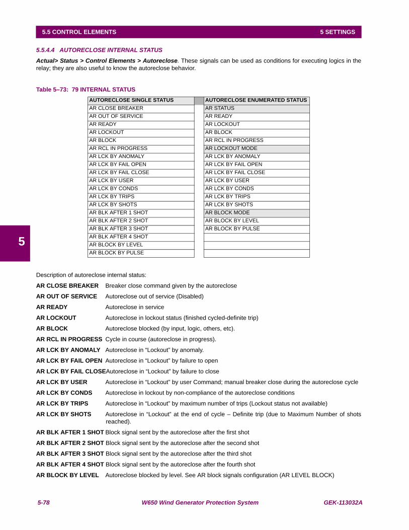
5-78 W650 Wind Generator Protection System GEK-113032A
5.5 CONTROL ELEMENTS 5 SETTINGS
5
5.5.4.4 AUTORECLOSE INTERNAL STATUS
Actual> Status > Control Elements > Autoreclose. These signals can be used as conditions for executing logics in therelay; they are also useful to know the autoreclose behavior.
Table 5–73: 79 INTERNAL STATUS
Description of autoreclose internal status:
AR CLOSE BREAKER Breaker close command given by the autoreclose
AR OUT OF SERVICE Autoreclose out of service (Disabled)
AR READY Autoreclose in service
AR LOCKOUT Autoreclose in lockout status (finished cycled-definite trip)
AR BLOCK Autoreclose blocked (by input, logic, others, etc).
AR RCL IN PROGRESS Cycle in course (autoreclose in progress).
AR LCK BY ANOMALY Autoreclose in “Lockout” by anomaly.
AR LCK BY FAIL OPEN Autoreclose in “Lockout” by failure to open
AR LCK BY FAIL CLOSEAutoreclose in “Lockout” by failure to close
AR LCK BY USER Autoreclose in “Lockout” by user Command; manual breaker close during the autoreclose cycle
AR LCK BY CONDS Autoreclose in lockout by non-compliance of the autoreclose conditions
AR LCK BY TRIPS Autoreclose in “Lockout” by maximum number of trips (Lockout status not available)
AR LCK BY SHOTS Autoreclose in “Lockout” at the end of cycle – Definite trip (due to Maximum Number of shotsreached).
AR BLK AFTER 1 SHOT Block signal sent by the autoreclose after the first shot
AR BLK AFTER 2 SHOT Block signal sent by the autoreclose after the second shot
AR BLK AFTER 3 SHOT Block signal sent by the autoreclose after the third shot
AR BLK AFTER 4 SHOT Block signal sent by the autoreclose after the fourth shot
AR BLOCK BY LEVEL Autoreclose blocked by level. See AR block signals configuration (AR LEVEL BLOCK)
AUTORECLOSE SINGLE STATUS AUTORECLOSE ENUMERATED STATUSAR CLOSE BREAKER AR STATUSAR OUT OF SERVICE AR READYAR READY AR LOCKOUTAR LOCKOUT AR BLOCKAR BLOCK AR RCL IN PROGRESSAR RCL IN PROGRESS AR LOCKOUT MODEAR LCK BY ANOMALY AR LCK BY ANOMALYAR LCK BY FAIL OPEN AR LCK BY FAIL OPENAR LCK BY FAIL CLOSE AR LCK BY FAIL CLOSEAR LCK BY USER AR LCK BY USERAR LCK BY CONDS AR LCK BY CONDSAR LCK BY TRIPS AR LCK BY TRIPSAR LCK BY SHOTS AR LCK BY SHOTSAR BLK AFTER 1 SHOT AR BLOCK MODEAR BLK AFTER 2 SHOT AR BLOCK BY LEVELAR BLK AFTER 3 SHOT AR BLOCK BY PULSEAR BLK AFTER 4 SHOTAR BLOCK BY LEVELAR BLOCK BY PULSE

GEK-113032A W650 Wind Generator Protection System 5-79
5 SETTINGS 5.5 CONTROL ELEMENTS
5
AR BLOCK BY PULSE Autoreclose blocked by pulse. See AR block signals configuration (AR PULSE BLOCK)
AR STATUS Autoreclose status (see Table 5–73:)
AR LOCKOUT MODE Autoreclose lockout mode (see Table 5–73: )
AR BLOCK MODE Autoreclose block mode (see Table 5–73:)

5-80 W650 Wind Generator Protection System GEK-113032A
5.5 CONTROL ELEMENTS 5 SETTINGS
5
5.5.4.5 GENERAL AUTORECLOSE STATUS DIAGRAM
The following diagram describes the different autoreclose states, as well as the transitions between states.
Figure 5–17: GENERAL AUTORECLOSE STATUS DIAGRAM
Description of the general autoreclose status:
OUT OF SERVICE / AR DISABLE
In this status, the autoreclose is disabled. From any state, if the Function setting is set as DISABLED, the autoreclose willmove to OUT OF SERVICE status, where it is not operative.
AR READY
This is the initiation and normality situation status: closed breaker. There are neither faults producing a autorecloseinitiation nor Block signal.
If the autoreclose was in LOCKOUT, if the breaker is closed and the time set in Reclaim Time setting expires, theautoreclose will go to the initial status of READY.
From RECLOSE IN PROGRESS, the recloser will move to READY, if the Reset Time setting expires without anyautoreclose initiation condition.
AR RECLOSE IN PROGRESS
From READY status, a reclose initiation will set the cycle counter to 1 and a reclosing sequence will be initiated whichwill produce breaker close commands, unless any abnormality is produced that will make the autoreclose go toLOCKOUT status.
The reclosing sequence consists on the following steps:
Wait until the breaker is open, if the waiting exceeds the Fail to Open Time setting, the autoreclose will go toLOCKOUT by failure of opening status (AR LCK BY FAIL OPEN).

GEK-113032A W650 Wind Generator Protection System 5-81
5 SETTINGS 5.5 CONTROL ELEMENTS
5
Once the breaker is open, it waits for the time set in the Dead Time N setting, N being the number of the cycle inprogress. If during this waiting the breaker is closed or reclose initiation conditions are given, the recloser will go toLOCKOUT status by anomaly (AR LCK BY ANOMALY).
Once the Dead Time has expired, in case the Conditions Permission setting is disabled, a closing command wouldbe produced. If the conditions permission setting is enabled, the system will wait for the conditions fixed in theconditions input (AR CONDS INPUT) configured at Setpoint > Relay Configuration > Protection Elements; if thewaiting period for the reclosing conditions signal activation exceeds the Hold Time, the autoreclose will go to Lockoutstatus by conditions (AR LCK BY CONDS).
The autoreclose gives a Closing command and waits for the breaker to close. If the Fail to Close Time setting isexceeded, the autoreclose will go to lockout by failure of closing (AR LCK BY FAIL CLOSE).
At this point, the diagram indicates that a reclosing cycle has been reached, and so the cycle counter is increased. In thistime, the period set in Reset Time starts to count. If during the set element reset time there is no autoreclose initiation, thecycle counter will reset to its initial value (1), and the autoreclose will return to the standby status (READY). If during theReset Time setting period, there is a new autoreclose initiation, the Reclose In Progress sequence will start again. If thisreclose is produced after the last configured cycle in the Maximum Number of Shots setting, the autorecloser will go toLockout by maximum number of shots (AR LCK BY SHOTS).
AR LOCKOUT
This is a safety status, scheme lockout blocks all phases of the reclosing cycle, preventing automatic reclosure.
From the out of service (AR DISABLE) and BLOCK statuses, the autoreclose will stay in LOCKOUT prior to going toREADY.
From the RECLOSE IN PROGRESS status, the recloser will go to LOCKOUT status if any of the anomalies describedabove occur.
To go from the LOCKOUT status to READY it is necessary that the breaker is closed and stays closed for preset time inReclaim Time setting.
AR BLOCK
The BLOCK status is similar to the LOCKOUT status, as it guarantees that if the autoreclose is in Block, no breakerclose command will be produced, but the difference between them is that this Block status is reached by an externalaction. The autoreclose block can be configured by pulse or level signals. This configuration must be selected atSetpoint > Relay Configuration > Protection Elements
When the autoreclose block signal is deactivated, either by a level change in the set signal (in case of block by level) orby an Unblock pulse (in case of block by pulse), the block status is abandoned and the autoreclose returns to theLockout status.
Configurable signals to block the autorecloser are described in section 5.5.4.3.
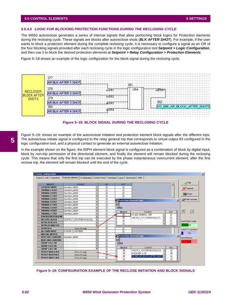
5-82 W650 Wind Generator Protection System GEK-113032A
5.5 CONTROL ELEMENTS 5 SETTINGS
5
5.5.4.6 LOGIC FOR BLOCKING PROTECTION FUNCTIONS DURING THE RECLOSING CYCLE
The W650 autoreclose generates a series of internal signals that allow performing block logics for Protection elementsduring the reclosing cycle. These signals are blocks after autoreclose shots (BLK AFTER SHOT). For example, if the userwants to block a protection element during the complete reclosing cycle, it is necessary to configure a signal as an OR ofthe four blocking signals provided after each reclosing cycle in the logic configuration tool Setpoint > Logic Configuration,and then use it to block the desired protection elements at Setpoint > Relay Configuration > Protection Elements.
Figure 5–18:shows an example of the logic configuration for the block signal during the reclosing cycle.
Figure 5–18: BLOCK SIGNAL DURING THE RECLOSING CYCLE
Figure 5–19: shows an example of the autoreclose initiation and protection element block signals after the different trips.The autoreclose initiate signal is configured to the relay general trip that corresponds to virtual output 83 configured in thelogic configuration tool, and a physical contact to generate an external autoreclose initiation.
In the example shown on the figure, the 50PH element block signal is configured as a combination of block by digital input,block by non-trip permission of the directional element, and finally the element will remain blocked during the reclosingcycle. This means that only the first trip can be executed by the phase instantaneous overcurrent element; after the firstreclose trip, the element will remain blocked until the end of the cycle.
Figure 5–19: CONFIGURATION EXAMPLE OF THE RECLOSE INITIATION AND BLOCK SIGNALS

GEK-113032A W650 Wind Generator Protection System 5-83
5 SETTINGS 5.5 CONTROL ELEMENTS
5
5.5.5 BREAKER FAILURE ELEMENT (50BF)
Note: The Switchgear element used in the Breaker Failure element is the one configured in the Number of Switchgearsetting, inside Breaker settings at Setpoint > Protection Elements > Breaker > Breaker settings
The breaker failure element is used to determine when a trip command sent to a breaker has not been executed within aselectable delay. Most commonly it is a failure to open from the tripped breaker. In the event of a breaker failure, the 50BFelement must issue a signal that will trip the rest of breakers connected at that time to the same busbar, and that canprovide fault current.
Comparing the current measured by the Relay with a setting level makes breaker failure detection. If after receiving abreaker initiate signal, the current level is maintained over the set level for a time period longer than the set time, thisindicates that the breaker that has received the opening command has not been able to open and clear the fault. The relaywould issue the corresponding breaker failure signal.
W650 elements incorporate 2 levels of current and time, together with a trip without current element, and an internal arcdetection element.
The breaker failure Initiate signal is configured at Setpoint > Relay Configuration > Protection Elements. In the BRKFAILURE INITIATE input, the user must select the desired signal for the breaker failure initiation.
The following table describes the breaker failure element settings: Setpoint > Control Elements > Breaker Failure
Table 5–74: 50BF ELEMENT SETTINGS
Settings description for breaker failure element:
Function permission (Function): This setting allows enabling and disabling the 50BF element
Supervision or retrip pickup level (Supervision Pickup): Supervision level pickup current threshold
Hiset pickup level (Hiset Pickup): High-level pickup current threshold.
Lowset pickup level (Loset Pickup): Low level pickup current threshold.
Internal arc pickup level (Internal Arc Pickup): Internal arc element pickup current threshold.
Internal arc time delay (Internal Arc Delay): Time delay applied to the internal arc element
Supervision or Retrip time delay (Supervision Delay): Time delay applied to the supervision or retrip element.
High-level time delay (Hiset Delay): Time delay applied to the high level element.
Low-level time delay (Lowset Delay): Time delay applied to the low level element.
2nd step time delay (2nd Step Delay): Time delay applied to the breaker failure second step.
No current element time delay (No Current Delay): Time delay applied to the trip without current element.
SETPOINT > CONTROL ELEMENTS > BREAKER FAILURESETTING DESCRIPTION NAME DEFAULT VALUE STEP RANGEFunction permission Function DISABLED N/A [DISABLED – ENABLED]Supervision (retrip) pickup level Supervision Pickup 1.00 0.01 A [0.05 : 160.00]Hiset pickup level Hiset Pickup 5.00 0.01 A [0.05 : 160.00]Lowset pickup level Lowset Pickup 2.00 0.01 A [0.05 : 160.00]Internal arc pickup level Internal Arc Pickup 0.10 0.01 A [0.05 : 160.00]Internal arc time delay Internal Arc Delay 10.00 0.01 s [0.00 : 900.00]Retrip time delay Supervision Delay 10.00 0.01 s [0.00 : 900.00]Hiset time delay HiSet Delay 10.00 0.01 s [0.00 : 900.00]Lowset time delay LowSet Delay 10.00 0.01 s [0.00 : 900.00]Second stage time delay 2nd Step Delay 10.00 0.01 s [0.00 : 900.00]WITHOUT current element time delay No Current Delay 10.00 0.01 s [0.00 : 900.00]Snapshot event generation Snapshot Events ENABLED N/A [DISABLED – ENABLED]
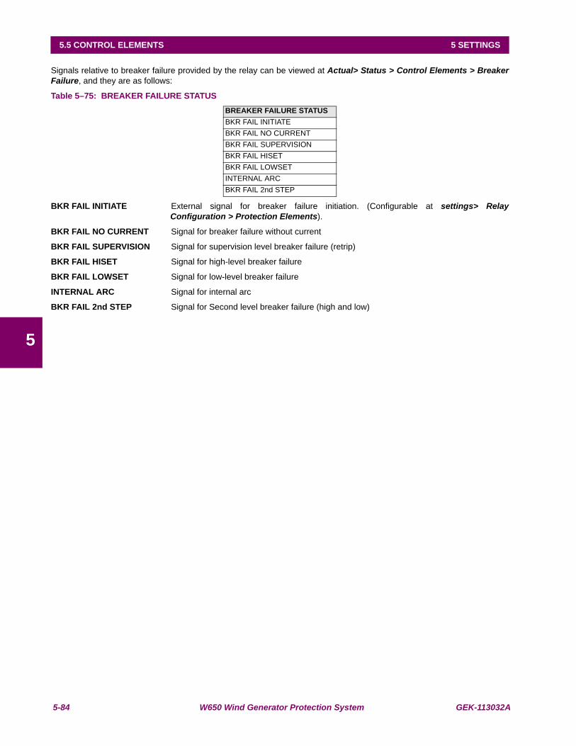
5-84 W650 Wind Generator Protection System GEK-113032A
5.5 CONTROL ELEMENTS 5 SETTINGS
5
Signals relative to breaker failure provided by the relay can be viewed at Actual> Status > Control Elements > BreakerFailure, and they are as follows:
Table 5–75: BREAKER FAILURE STATUS
BKR FAIL INITIATE External signal for breaker failure initiation. (Configurable at settings> RelayConfiguration > Protection Elements).
BKR FAIL NO CURRENT Signal for breaker failure without current
BKR FAIL SUPERVISION Signal for supervision level breaker failure (retrip)
BKR FAIL HISET Signal for high-level breaker failure
BKR FAIL LOWSET Signal for low-level breaker failure
INTERNAL ARC Signal for internal arc
BKR FAIL 2nd STEP Signal for Second level breaker failure (high and low)
BREAKER FAILURE STATUSBKR FAIL INITIATEBKR FAIL NO CURRENTBKR FAIL SUPERVISIONBKR FAIL HISETBKR FAIL LOWSETINTERNAL ARCBKR FAIL 2nd STEP
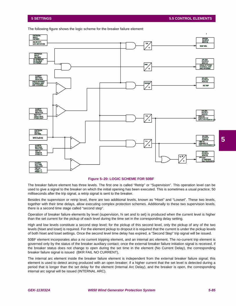
GEK-113032A W650 Wind Generator Protection System 5-85
5 SETTINGS 5.5 CONTROL ELEMENTS
5
The following figure shows the logic scheme for the breaker failure element:
Figure 5–20: LOGIC SCHEME FOR 50BF
The breaker failure element has three levels. The first one is called “Retrip” or “Supervision”. This operation level can beused to give a signal to the breaker on which the initial opening has been executed. This is sometimes a usual practice; 50milliseconds after the trip signal, a retrip signal is sent to the breaker.
Besides the supervision or retrip level, there are two additional levels, known as “Hiset” and “Lowset”. These two levels,together with their time delays, allow executing complex protection schemes. Additionally to these two supervision levels,there is a second time stage called “second step”.
Operation of breaker failure elements by level (supervision, hi set and lo set) is produced when the current level is higherthan the set current for the pickup of each level during the time set in the corresponding delay setting.
High and low levels constitute a second step level; for the pickup of this second level, only the pickup of any of the twolevels (hiset and loset) is required. For the element pickup to dropout it is required that the current is under the pickup levelsof both hiset and loset settings. Once the second level time delay has expired, a “Second Step” trip signal will be issued.
50BF element incorporates also a no current tripping element, and an internal arc element. The no-current trip element isgoverned only by the status of the breaker auxiliary contact; once the external breaker failure initiation signal is received, ifthe breaker status does not change to open during the set time in the element (No Current Delay), the correspondingbreaker failure signal is issued (BKR FAIL NO CURRENT),
The internal arc element inside the breaker failure element is independent from the external breaker failure signal; thiselement is used to detect arcing produced with an open breaker; if a higher current that the set level is detected during aperiod that is longer than the set delay for the element (Internal Arc Delay), and the breaker is open, the correspondinginternal arc signal will be issued (INTERNAL ARC).

5-86 W650 Wind Generator Protection System GEK-113032A
5.5 CONTROL ELEMENTS 5 SETTINGS
5
5.5.6 VT FUSE FAILURE ELEMENT (VTFF)
Note: The Switchgear element used in the VT Fuse Failure element is the one configured in the Number of Switchgearsetting, inside Breaker settings at Setpoint > Protection Elements > Breaker > Breaker settings. This switchgear musthave previously been configured at Setpoint > Relay Configuration > Switchgear
use failure detector is used to block protection elements that can operate incorrectly due to a partial or total voltage loss.This loss can be caused by the voltage transformers secondary circuit protection fuse failure.
Setpoint > Control Elements > VT Fuse Failure
Table 5–76: VT FUSE FAILURE ELEMENT SETTINGS
The fuse failure element has only two settings, one to enable or disable the element and the other to enable or disable thesnapshot event generation.
The fuse failure signal provided by the element (VT FUSE FAILURE) can be monitored at Actual> Status > ControlElements >VT Fuse Failure
5.5.6.1 FUSE FAILURE ALGORITHM
To detect the different types of fuse failure that can occur, it is necessary to use different detection methods. A fuse failureindication with loss of one or two voltage phases provides a significant level of negative sequence voltage, while a failurecaused by loss of the three phases is present with a noticeable positive sequence current level, being the positivesequence voltage level very low.
W650 elements detect fuse failure under three possible situations:
(1)Breaker closed and positive sequence voltage (V1) under an established value (V1<0.5 p.u.).
(2)Positive sequence voltage lower than 0.5 p.u (V1<0.5 p.u.) and positive sequence current higher than 0.075 p.u.(I1>0.075 p.u.).
(3)Ratio between the negative and positive voltage components (V2/V1) higher than 0.25.
With the activation of any of the three previous signals during a period longer than 80 ms, the fuse failure signal (VT FUSEFAILURE) is activated. Once this signal is activated, it is latched until whatever caused it disappears; for this purpose thefollowing condition must be met:
(4)Positive sequence voltage higher than 0.75 p.u and positive sequence current lower than 0.05 p.u.
The fuse failure signal can be used to issue an alarm and/or to block elements that may operate incorrectly due to a partialor total loss of voltage. Protection elements that are usually blocked by the fuse failure signal are voltage restraintovercurrent elements, and directional elements. To configure the block of these elements it is necessary to enter theSetpoint > Relay Configuration > Protection Elements” menu and select as block input for protection elements, the fusefailure operation signal.
SETPOINT > CONTROL ELEMENTS > VT FUSE FAILURESETTING DESCRIPTION NAME DEFAULT VALUE STEP RANGEFunction permission Function DISABLED N/A [DISABLED – ENABLED]Snapshot event generation Snapshot Events ENABLED N/A [DISABLED – ENABLED]
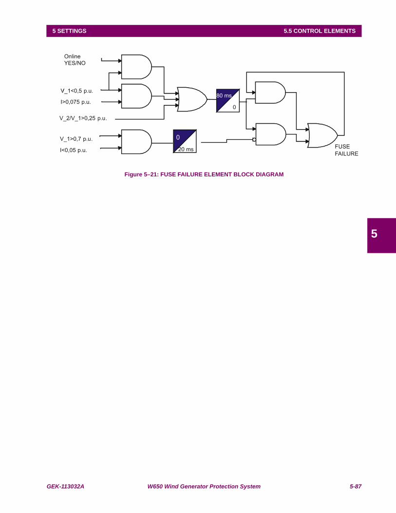
GEK-113032A W650 Wind Generator Protection System 5-87
5 SETTINGS 5.5 CONTROL ELEMENTS
5
Figure 5–21: FUSE FAILURE ELEMENT BLOCK DIAGRAM
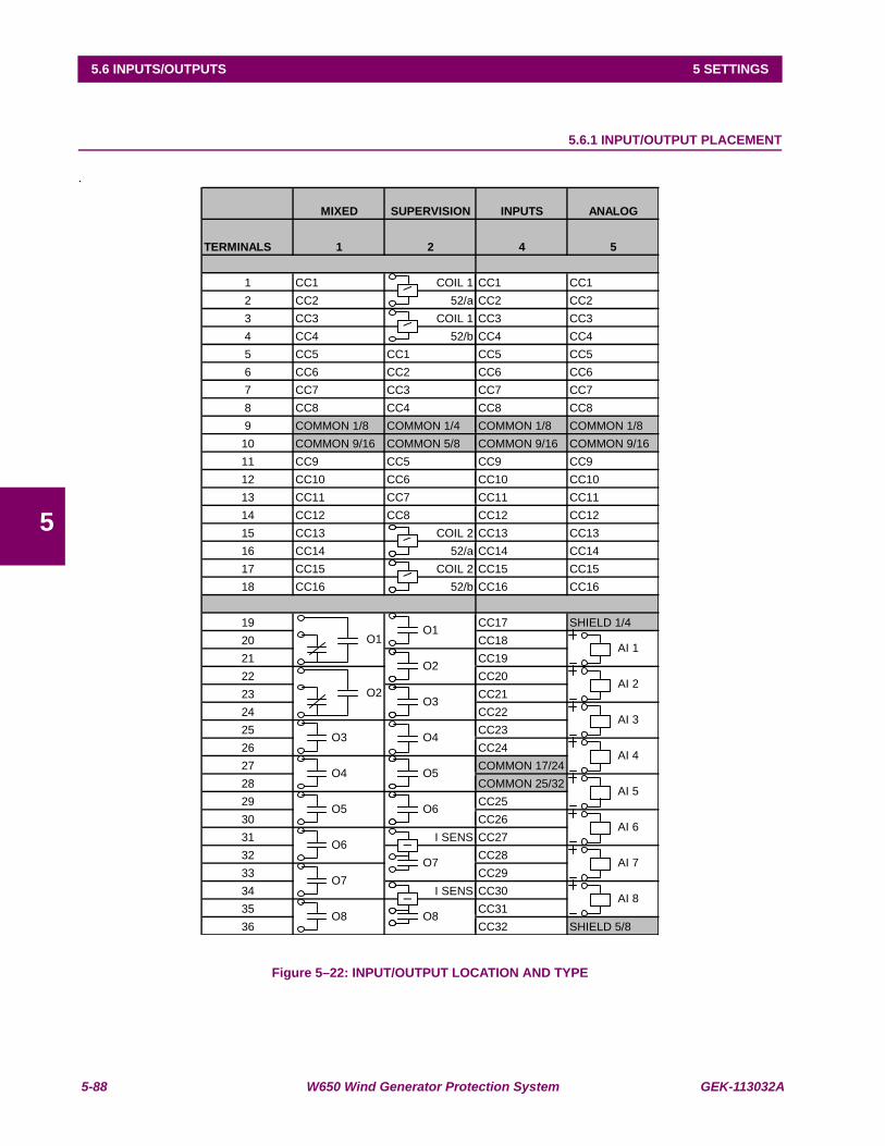
5-88 W650 Wind Generator Protection System GEK-113032A
5.6 INPUTS/OUTPUTS 5 SETTINGS
5
5.6INPUTS/OUTPUTS
5.6.1 INPUT/OUTPUT PLACEMENT
.
Figure 5–22: INPUT/OUTPUT LOCATION AND TYPE
MIXED SUPERVISION INPUTS ANALOG
TERMINALS 1 2 4 5
1 CC1 COIL 1 CC1 CC12 CC2 52/a CC2 CC23 CC3 COIL 1 CC3 CC34 CC4 52/b CC4 CC45 CC5 CC1 CC5 CC56 CC6 CC2 CC6 CC67 CC7 CC3 CC7 CC78 CC8 CC4 CC8 CC89 COMMON 1/8 COMMON 1/4 COMMON 1/8 COMMON 1/810 COMMON 9/16 COMMON 5/8 COMMON 9/16 COMMON 9/1611 CC9 CC5 CC9 CC912 CC10 CC6 CC10 CC1013 CC11 CC7 CC11 CC1114 CC12 CC8 CC12 CC1215 CC13 COIL 2 CC13 CC1316 CC14 52/a CC14 CC1417 CC15 COIL 2 CC15 CC1518 CC16 52/b CC16 CC16
19 CC17 SHIELD 1/420 CC1821 CC1922 CC2023 CC2124 CC2225 CC2326 CC2427 COMMON 17/2428 COMMON 25/3229 CC2530 CC2631 I SENS CC2732 CC2833 CC2934 I SENS CC3035 CC3136 CC32 SHIELD 5/8
O1O1
AI 1O2
O2 AI 2
O3 AI 3
O3 O4 AI 4
O4 O5 AI 5
O5 O6 AI 6
O6O7 AI 7
O7 AI 8
O8 O8
VV
VVV
VI
II
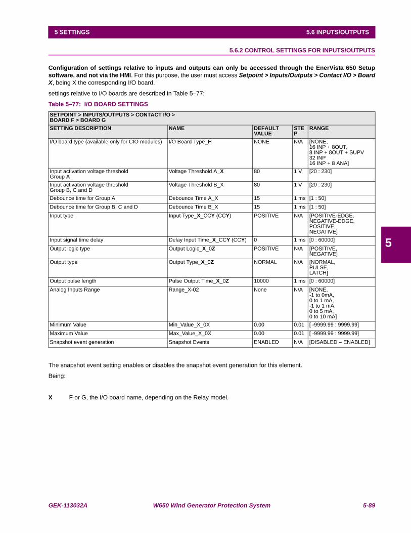
GEK-113032A W650 Wind Generator Protection System 5-89
5 SETTINGS 5.6 INPUTS/OUTPUTS
5
5.6.2 CONTROL SETTINGS FOR INPUTS/OUTPUTS
Configuration of settings relative to inputs and outputs can only be accessed through the EnerVista 650 Setupsoftware, and not via the HMI. For this purpose, the user must access Setpoint > Inputs/Outputs > Contact I/O > BoardX, being X the corresponding I/O board.
settings relative to I/O boards are described in Table 5–77:
Table 5–77: I/O BOARD SETTINGS
The snapshot event setting enables or disables the snapshot event generation for this element.
Being:
X F or G, the I/O board name, depending on the Relay model.
SETPOINT > INPUTS/OUTPUTS > CONTACT I/O >BOARD F > BOARD GSETTING DESCRIPTION NAME DEFAULT
VALUESTEP
RANGE
I/O board type (available only for CIO modules) I/O Board Type_H NONE N/A [NONE,16 INP + 8OUT,8 INP + 8OUT + SUPV32 INP16 INP + 8 ANA]
Input activation voltage thresholdGroup A
Voltage Threshold A_X 80 1 V [20 : 230]
Input activation voltage thresholdGroup B, C and D
Voltage Threshold B_X 80 1 V [20 : 230]
Debounce time for Group A Debounce Time A_X 15 1 ms [1 : 50]Debounce time for Group B, C and D Debounce Time B_X 15 1 ms [1 : 50]Input type Input Type_X_CCY (CCY) POSITIVE N/A [POSITIVE-EDGE,
NEGATIVE-EDGE,POSITIVE,NEGATIVE]
Input signal time delay Delay Input Time_X_CCY (CCY) 0 1 ms [0 : 60000]Output logic type Output Logic_X_0Z POSITIVE N/A [POSITIVE,
NEGATIVE]Output type Output Type_X_0Z NORMAL N/A [NORMAL,
PULSE,LATCH]
Output pulse length Pulse Output Time_X_0Z 10000 1 ms [0 : 60000]Analog Inputs Range Range_X-02 None N/A [NONE,
-1 to 0mA,0 to 1 mA,-1 to 1 mA,0 to 5 mA,0 to 10 mA]
Minimum Value Min_Value_X_0X 0.00 0.01 [ -9999.99 : 9999.99]Maximum Value Max_Value_X_0X 0.00 0.01 [ -9999.99 : 9999.99]Snapshot event generation Snapshot Events ENABLED N/A [DISABLED – ENABLED]
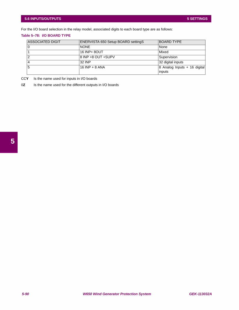
5-90 W650 Wind Generator Protection System GEK-113032A
5.6 INPUTS/OUTPUTS 5 SETTINGS
5
For the I/O board selection in the relay model, associated digits to each board type are as follows:
Table 5–78: I/O BOARD TYPE
CCY Is the name used for inputs in I/O boards
0Z Is the name used for the different outputs in I/O boards
ASSOCIATED DIGIT ENERVISTA 650 Setup BOARD settingS BOARD TYPE0 NONE None1 16 INP+ 8OUT Mixed2 8 INP +8 OUT +SUPV Supervision4 32 INP 32 digital inputs5 16 INP + 8 ANA 8 Analog Inputs + 16 digital
inputs

GEK-113032A W650 Wind Generator Protection System 5-91
5 SETTINGS 5.6 INPUTS/OUTPUTS
5
5.6.3 INPUTS
5.6.3.1 INPUT SETTINGS DESCRIPTION
Input Activation Voltage Threshold: The range of this value goes from 20 to 230 volts. There is a single setting for allinputs in the same group (inputs sharing the same common). In mixed and supervision boards there are two groups ofinputs, called A and B., in 32DI board there are four groups of 8 inputs each.
Debounce Time: This is the debounce time set for inputs (1 to 50 ms). The debounce time is the time window for inputfiltering. If an input suffers a change of level that lasts less than this set time, the change will not be considered. There is asingle setting for all inputs in the same group.
Input Type: Type of logic associated to the physical input. Possible settings are, positive and negative.
Positive and Negative settings correspond to signals that re activated or deactivated with the input level, considering thedelay setting. Positive-edge, and Negative-edge settings correspond to signals that are activated with the change of theinput signal; in this case, the Delay Input Time will not be considered, only the Debounce Time; this edge signals aredeactivated automatically after one PLC scan cycle. shows the types of signals associated to the different inputconfiguration types.
Delay Input Time: This is the delay applied to the input signal; the default value is zero, meaning no delay; the settingrange is 0 to 60000 milliseconds (1 minute). This setting is used in slow switchgear applications.
This is not a grouped setting; there is a different setting for each input. It is important to distinguish between this delayinput time and the debounce time used for filtering undesired transients in the input signal. The Debounce time is alwaysadded to the delay input time.
Figure 5–23: INPUT LOGIC TYPES
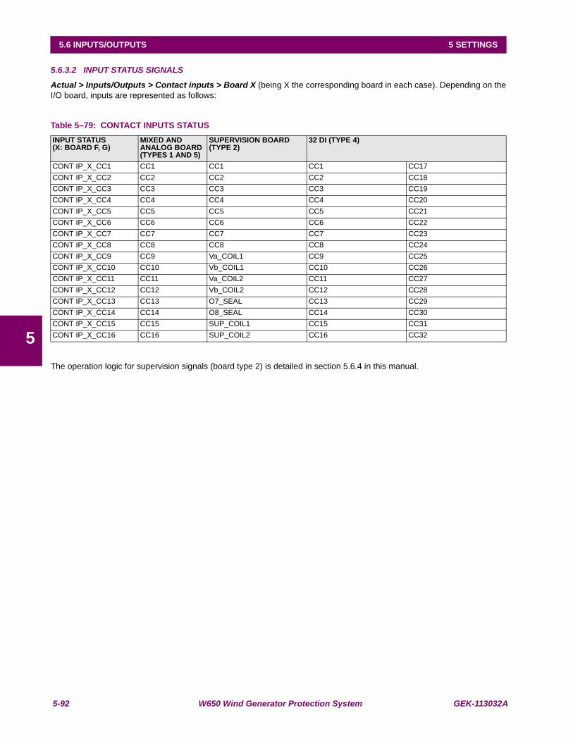
5-92 W650 Wind Generator Protection System GEK-113032A
5.6 INPUTS/OUTPUTS 5 SETTINGS
5
5.6.3.2 INPUT STATUS SIGNALS
Actual > Inputs/Outputs > Contact inputs > Board X (being X the corresponding board in each case). Depending on theI/O board, inputs are represented as follows:
Table 5–79: CONTACT INPUTS STATUS
The operation logic for supervision signals (board type 2) is detailed in section 5.6.4 in this manual.
INPUT STATUS(X: BOARD F, G)
MIXED AND ANALOG BOARD(TYPES 1 AND 5)
SUPERVISION BOARD(TYPE 2)
32 DI (TYPE 4)
CONT IP_X_CC1 CC1 CC1 CC1 CC17CONT IP_X_CC2 CC2 CC2 CC2 CC18CONT IP_X_CC3 CC3 CC3 CC3 CC19CONT IP_X_CC4 CC4 CC4 CC4 CC20CONT IP_X_CC5 CC5 CC5 CC5 CC21CONT IP_X_CC6 CC6 CC6 CC6 CC22CONT IP_X_CC7 CC7 CC7 CC7 CC23CONT IP_X_CC8 CC8 CC8 CC8 CC24CONT IP_X_CC9 CC9 Va_COIL1 CC9 CC25CONT IP_X_CC10 CC10 Vb_COIL1 CC10 CC26CONT IP_X_CC11 CC11 Va_COIL2 CC11 CC27CONT IP_X_CC12 CC12 Vb_COIL2 CC12 CC28CONT IP_X_CC13 CC13 O7_SEAL CC13 CC29CONT IP_X_CC14 CC14 O8_SEAL CC14 CC30CONT IP_X_CC15 CC15 SUP_COIL1 CC15 CC31CONT IP_X_CC16 CC16 SUP_COIL2 CC16 CC32
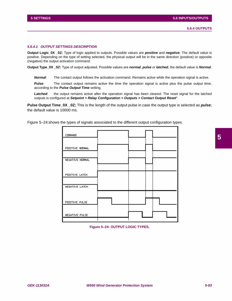
GEK-113032A W650 Wind Generator Protection System 5-93
5 SETTINGS 5.6 INPUTS/OUTPUTS
5
5.6.4 OUTPUTS
5.6.4.1 OUTPUT SETTINGS DESCRIPTION
Output Logic_0X _0Z: Type of logic applied to outputs. Possible values are positive and negative. The default value ispositive. Depending on the type of setting selected, the physical output will be in the same direction (positive) or opposite(negative) the output activation command.
Output Type_0X _0Z: Type of output adjusted. Possible values are normal, pulse or latched, the default value is Normal.
Normal: The contact output follows the activation command. Remains active while the operation signal is active.
Pulse: The contact output remains active the time the operation signal is active plus the pulse output time,according to the Pulse Output Time setting.
Latched: the output remains active after the operation signal has been cleared. The reset signal for the latchedoutputs is configured at Setpoint > Relay Configuration > Outputs > Contact Output Reset”.
Pulse Output Time_0X _0Z: This is the length of the output pulse in case the output type is selected as pulse;the default value is 10000 ms.
Figure 5–24:shows the types of signals associated to the different output configuration types.
Figure 5–24: OUTPUT LOGIC TYPES.

5-94 W650 Wind Generator Protection System GEK-113032A
5.6 INPUTS/OUTPUTS 5 SETTINGS
5
5.6.4.2 OUTPUT STATUS SIGNALS
Boards types 1 and 2 have both 8 outputs, so the representation is the same for both types as shown in Table 5–80:
Actual > Inputs/Outputs >Contact Output Status
Real status of the contact output, which corresponds to the transformation of the output activation signal (Contact outputoperate), by the logic applied to this output in “Setpoint > Inputs/Outputs >Contact I/O > Board X”
Actual > Inputs/Outputs > Contact Output Operates
Activated or deactivated status of those variables used internally to operate a contact output.
Actual > Inputs/Outputs > Contact Output Resets
These are the logic signals associated to the contact output reset, which produce the reset of those signals previouslyconfigured as Latched. Configuration for the contact output reset signal is set at Setpoint > Relay Configuration >Outputs > Contact Output Reset.
Actual > Inputs/Outputs >I/O Board Status
These signals are associated to the different I/O boards. There are internal signals that provide information about the statusof these boards, indicating whether there is any anomaly in the board, or whether the board is not available in the relayaccording to the relay model.
Table 5–80: CONTACT OUTPUT SIGNALS
Being X the corresponding board in each case
CONTACT OUTPUT STATUS CONTACT OUTPUT OPERATES CONTACT OUTPUT RESETS IO BOARD STATUSCONT OP_X_01 CONT OP OPER_X_01 CONT OP RESET_X_01 BOARD F STATUSCONT OP_X_02 CONT OP OPER_X_02 CONT OP RESET_X_02 BOARD G STATUSCONT OP_X_03 CONT OP OPER_X_03 CONT OP RESET_X_03 BOARD H STATUSCONT OP_X_04 CONT OP OPER_X_04 CONT OP RESET_X_04 BOARD J STATUSCONT OP_X_05 CONT OP OPER_X_05 CONT OP RESET_X_05CONT OP_X_06 CONT OP OPER_X_06 CONT OP RESET_X_06CONT OP_X_07 CONT OP OPER_X_07 CONT OP RESET_X_07CONT OP_X_08 CONT OP OPER_X_08 CONT OP RESET_X_08
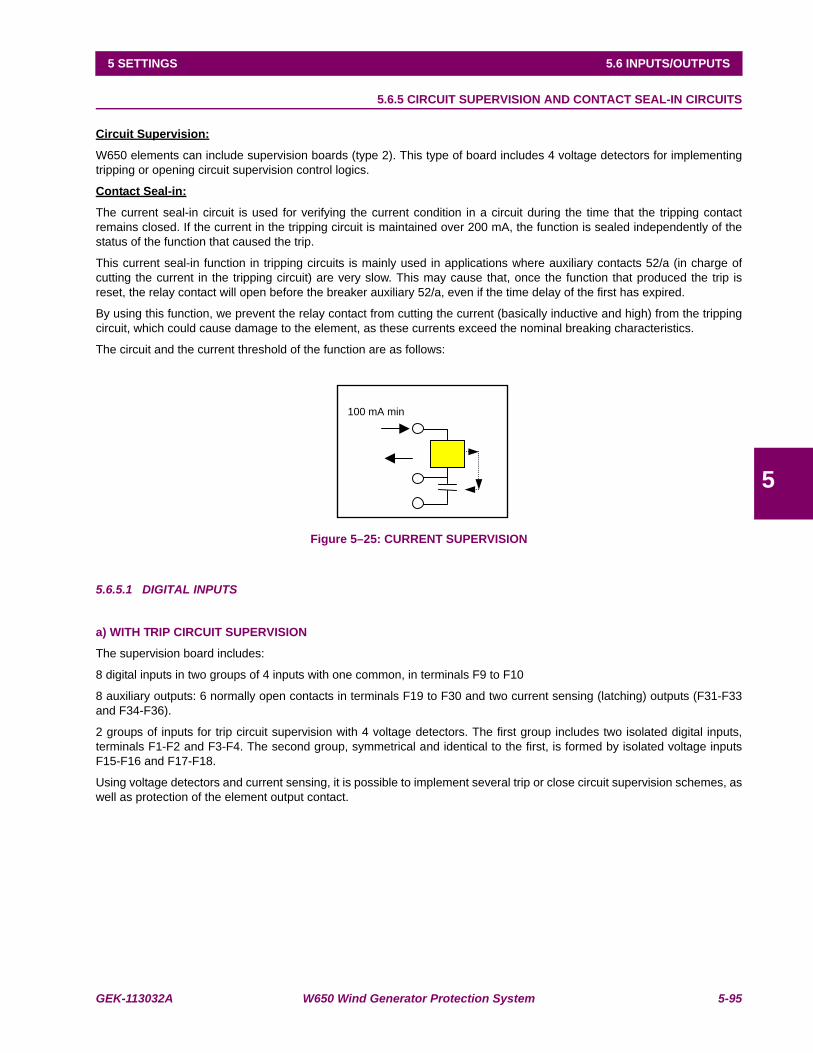
GEK-113032A W650 Wind Generator Protection System 5-95
5 SETTINGS 5.6 INPUTS/OUTPUTS
5
5.6.5 CIRCUIT SUPERVISION AND CONTACT SEAL-IN CIRCUITS
Circuit Supervision:
W650 elements can include supervision boards (type 2). This type of board includes 4 voltage detectors for implementingtripping or opening circuit supervision control logics.
Contact Seal-in:
The current seal-in circuit is used for verifying the current condition in a circuit during the time that the tripping contactremains closed. If the current in the tripping circuit is maintained over 200 mA, the function is sealed independently of thestatus of the function that caused the trip.
This current seal-in function in tripping circuits is mainly used in applications where auxiliary contacts 52/a (in charge ofcutting the current in the tripping circuit) are very slow. This may cause that, once the function that produced the trip isreset, the relay contact will open before the breaker auxiliary 52/a, even if the time delay of the first has expired.
By using this function, we prevent the relay contact from cutting the current (basically inductive and high) from the trippingcircuit, which could cause damage to the element, as these currents exceed the nominal breaking characteristics.
The circuit and the current threshold of the function are as follows:
Figure 5–25: CURRENT SUPERVISION
5.6.5.1 DIGITAL INPUTS
a) WITH TRIP CIRCUIT SUPERVISION
The supervision board includes:
8 digital inputs in two groups of 4 inputs with one common, in terminals F9 to F10
8 auxiliary outputs: 6 normally open contacts in terminals F19 to F30 and two current sensing (latching) outputs (F31-F33and F34-F36).
2 groups of inputs for trip circuit supervision with 4 voltage detectors. The first group includes two isolated digital inputs,terminals F1-F2 and F3-F4. The second group, symmetrical and identical to the first, is formed by isolated voltage inputsF15-F16 and F17-F18.
Using voltage detectors and current sensing, it is possible to implement several trip or close circuit supervision schemes, aswell as protection of the element output contact.
100 mA min

5-96 W650 Wind Generator Protection System GEK-113032A
5.6 INPUTS/OUTPUTS 5 SETTINGS
5
In order to implement these schemes, it is not necessary to set any setting in the element. Internal functions are alwaysoperative and provide the following logic operands:
Table 5–81: SUPERVISION LOGIC OPERANDS
A continuity failure is detected in a circuit when both voltage detectors (Va and Vb) detect lack of voltage during more than500 ms. This function is not influenced by the breaker status.
These operands can be associated to internal signals (virtual outputs), LEDs or element outputs, to issue alarm signals orto block elements, for example for blocking the Breaker close if an anomaly is detected in the trip circuit.
Available schemes are as follows:
1. Without supervision
2. With current supervision (with seal-in)
3. With simple voltage supervision
4. With double voltage supervision
5. With current and simple voltage supervision (with seal-in)
6. With current and double voltage supervision (with seal-in)
7. With current and double voltage supervision (with seal-in) and serial resistor in voltage monitors.
The following subsections describe the different types of connection to create each supervision scheme in an easy way. Asthe supervision circuits are identical, only the first group connection examples will be described, being also applicable to thesecond group.
In order to assure a high isolation level between groups, the digital inputs for supervision have been located in asymmetrical basis. That is to optimize the isolation between groups that can be connected to different batteries, andtherefore requiring a greater distance between circuits.
ACTUAL > INPUTS/OUTPUTS > CONTACT INPUTS > BOARD XBEING X THE CORRESPONDING BOARD IN EACH CASEOPERAND DESCRIPTIONCONT IP_X_CC9 (Va_COIL1) Active when voltage is detected in terminals F1 - F2 (circuit 1)CONT IP_X_CC10 (Vb_COIL1) Active when voltage is detected in terminals F3 - F4 (circuit 1)CONT IP_X_CC11 (Va_COIL2) Active when voltage is detected in terminals F15 - F16 (circuit 2)CONT IP_X_CC12 (Vb_COIL2) Active when voltage is detected in terminals F17 - F18 (circuit 2)CONT IP_X_CC13 (O7_SEAL) Active if current is detected by sensor in output O7 (F31-F33)CONT IP_X_CC14 (O8_SEAL) Active if current is detected by sensor in output O8 (F34-F36)CONT IP_X_CC15 (SUP_COIL1) Active when continuity is detected in circuit 1CONT IP_X_CC16 (SUP_COIL2) Active when continuity is detected in circuit 2
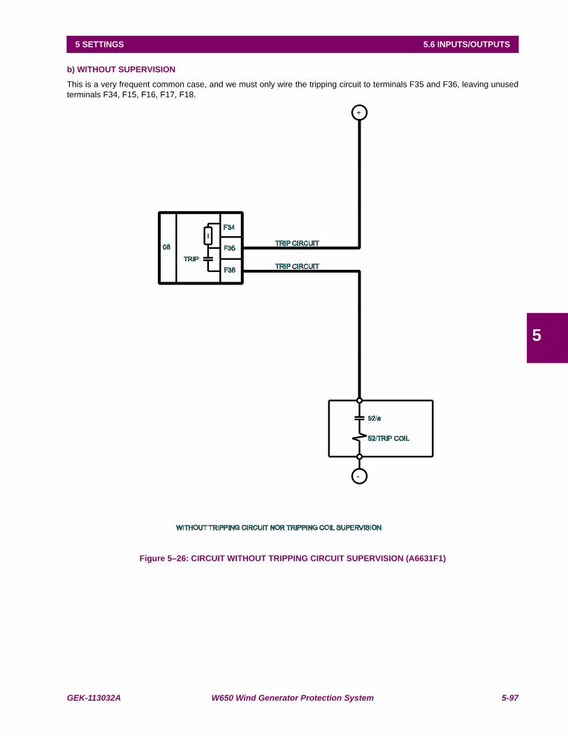
GEK-113032A W650 Wind Generator Protection System 5-97
5 SETTINGS 5.6 INPUTS/OUTPUTS
5
b) WITHOUT SUPERVISION
This is a very frequent common case, and we must only wire the tripping circuit to terminals F35 and F36, leaving unusedterminals F34, F15, F16, F17, F18.
Figure 5–26: CIRCUIT WITHOUT TRIPPING CIRCUIT SUPERVISION (A6631F1)
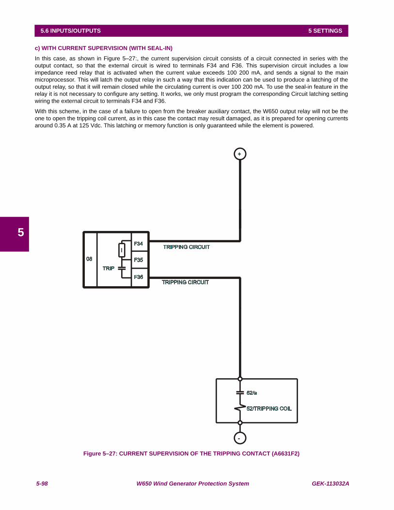
5-98 W650 Wind Generator Protection System GEK-113032A
5.6 INPUTS/OUTPUTS 5 SETTINGS
5
c) WITH CURRENT SUPERVISION (WITH SEAL-IN)
In this case, as shown in Figure 5–27:, the current supervision circuit consists of a circuit connected in series with theoutput contact, so that the external circuit is wired to terminals F34 and F36. This supervision circuit includes a lowimpedance reed relay that is activated when the current value exceeds 100 200 mA, and sends a signal to the mainmicroprocessor. This will latch the output relay in such a way that this indication can be used to produce a latching of theoutput relay, so that it will remain closed while the circulating current is over 100 200 mA. To use the seal-in feature in therelay it is not necessary to configure any setting. It works, we only must program the corresponding Circuit latching settingwiring the external circuit to terminals F34 and F36.
With this scheme, in the case of a failure to open from the breaker auxiliary contact, the W650 output relay will not be theone to open the tripping coil current, as in this case the contact may result damaged, as it is prepared for opening currentsaround 0.35 A at 125 Vdc. This latching or memory function is only guaranteed while the element is powered.
Figure 5–27: CURRENT SUPERVISION OF THE TRIPPING CONTACT (A6631F2)
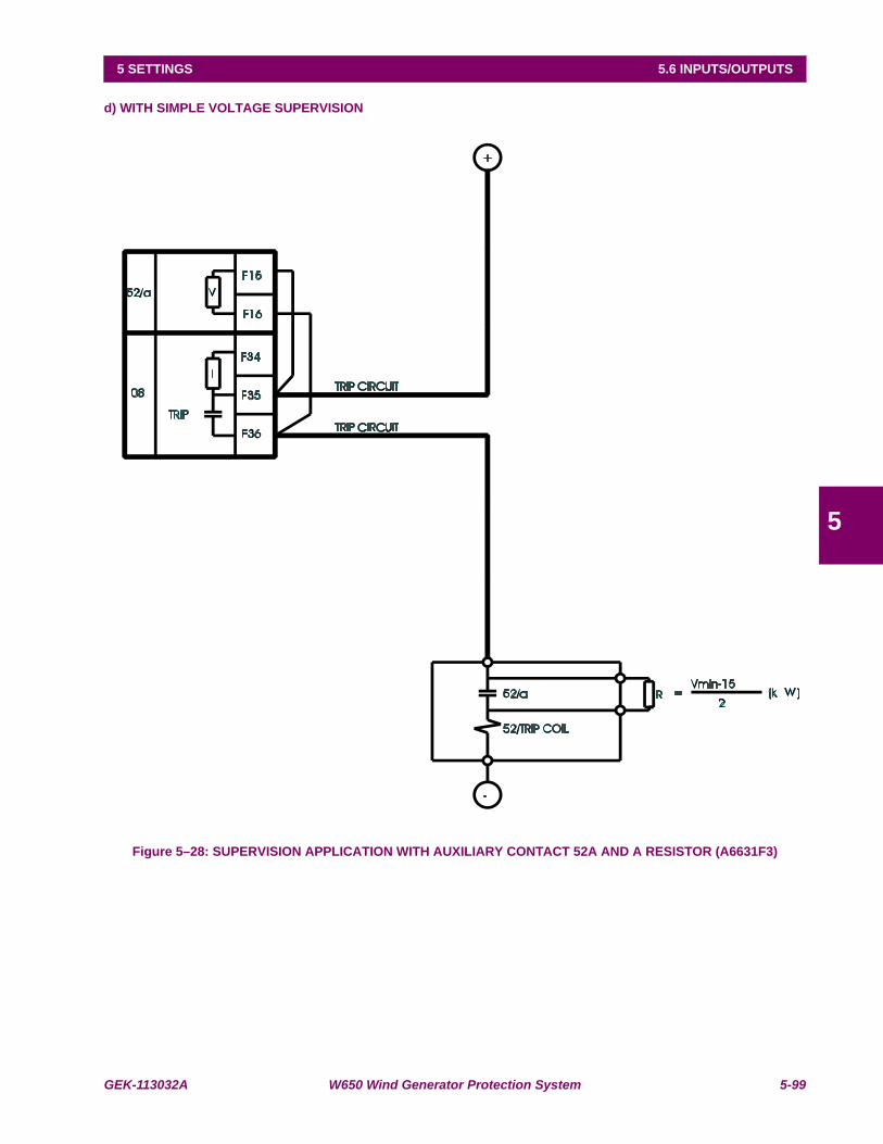
GEK-113032A W650 Wind Generator Protection System 5-99
5 SETTINGS 5.6 INPUTS/OUTPUTS
5
d) WITH SIMPLE VOLTAGE SUPERVISION
Figure 5–28: SUPERVISION APPLICATION WITH AUXILIARY CONTACT 52A AND A RESISTOR (A6631F3)

5-100 W650 Wind Generator Protection System GEK-113032A
5.6 INPUTS/OUTPUTS 5 SETTINGS
5
Table 5–82: SUPERVISION WITH 52/A
There is a possibility to monitor the trip circuit and trip coil continuity. This can be done by monitoring Vdc through theoutput contact when this is open.
Table 5–83: SUPERVISION ALGORITHM WITH SIMPLE VOLTAGE SUPERVISION SCHEME
In this table, ON means that the voltage detector V52/a is active, detecting a voltage.
In the first case shown on the table, with closed breaker, voltage is detected by V 52/a sensor, and this means that there iscontinuity in the supervised circuit.
As shown on Figure 5–28:, when the relay is not tripped, trip contact F35-F36 remains open. If the breaker is closed, itsauxiliary contact 52a is closed. Therefore, a little current is flowing, about 2 mA, through terminals F15 and F16 through thevoltage detector circuit, which flows through 52/a and the tripping coil 52TC (TC = tripping coil). Current will only circulatewhen there is continuity in the whole circuit, so the complete circuit is monitored, and not only the trip coil. This circuitincludes auxiliary 52/a as well as the whole wiring between the battery and the relay tripping terminals, and between theseand the breaker tripping circuit.
For the second case shown on the table, open breaker, its auxiliary contact 52/a remains open, and currentcannot flow through it for detecting continuity. In order to correctly monitor the circuit, a resistor must be used,not included in the protection, connected in parallel. The value of resistance will be selected so that the V 52/ainput circuit minimum detection current flows, but not as high as to activate the breaker-tripping coil. The figureshows the following equation:Where:
Vmin Is the minimum voltage, in Volts, expected in the battery (e.g. 80% of Vn)
R Resistance, in kilo ohms.
2 2 mA of approximate current flowing through input V 52/a
As shown in the second case in the table, with an open breaker, as current will flow through R if there is continuity in theWHOLE tripping circuit, voltage will be detected in input V 52/a.
INTERNAL STATE V 52/A SUPERVISION52 open ON Ok52 closed ON OkTRIP OFF Ok if t < 0.5 sTRIP with 52 open OFF Ok if t < 0.5 s
STATUS OF INVOLVED ELEMENTS INPUT TO 650 DECISIONCIRCUITSTATUS
OUTPUTSTATUS(F35-F36)
BREAKERSTATUS
OPERANDCONT IP_X_CC11(VA_COIL2)V 52/A (F15-F16)
OPERANDCONT IP_X_CC16(SUP_COIL2)
Healthy Open 52 closed ON ONHealthy Open 52 open ON ONHealthy Closed 52 closed OFF ON (if t < 500 ms)
OFF (if t > 500 ms)Healthy Closed 52 open OFF ON (if t < 500 ms)
OFF (if t > 500 ms)Faulty Open 52 closed OFF OFF (500 ms delay)Faulty Open 52 open OFF OFF (500 ms delay)Faulty Closed 52 closed OFF OFF (500 ms delay)Faulty Closed 52 open OFF OFF (500 ms delay)

GEK-113032A W650 Wind Generator Protection System 5-101
5 SETTINGS 5.6 INPUTS/OUTPUTS
5
This works correctly in steady state. However, if the breaker trips, while it is opening, the V 52/a input signal can bedeactivated without this meaning that the circuit is not correct. This is due to the fact that the tripping relay, terminals F35-F36, short circuits input V 52/a temporarily.
Therefore, if there is a trip signal, it is permitted that no signal will be detected during a period of 1 s to allow the breaker toopen, and reopen the tripping relay F35-F36.
Figure 5–29: shows the possibility of monitoring the circuit only when the breaker is closed. In this case resistance R willnot be used, but it must be observed in the element logic that the corresponding signal CONT IP_F_CC16 (SUP_COIL2)will be activated showing a failure when the breaker is open. Therefore it will be required to supervise the continuity failuresignaling by the breaker status information.
Figure 5–29: TRIP CIRCUIT AND TRIP COIL SUPERVISION USING AUXILIARY CONTACT 52/A. ONLY WITH CLOSED BREAKER (A6631F5)
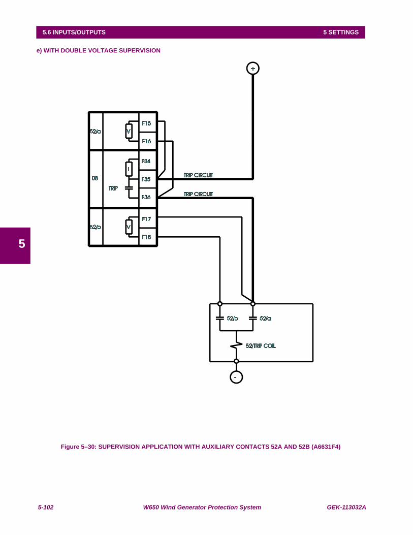
5-102 W650 Wind Generator Protection System GEK-113032A
5.6 INPUTS/OUTPUTS 5 SETTINGS
5
e) WITH DOUBLE VOLTAGE SUPERVISION
Figure 5–30: SUPERVISION APPLICATION WITH AUXILIARY CONTACTS 52A AND 52B (A6631F4)
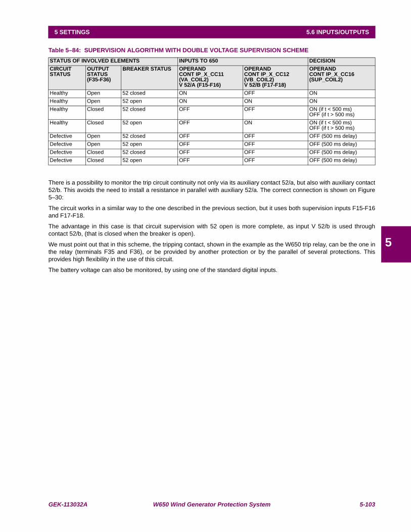
GEK-113032A W650 Wind Generator Protection System 5-103
5 SETTINGS 5.6 INPUTS/OUTPUTS
5
Table 5–84: SUPERVISION ALGORITHM WITH DOUBLE VOLTAGE SUPERVISION SCHEME
There is a possibility to monitor the trip circuit continuity not only via its auxiliary contact 52/a, but also with auxiliary contact52/b. This avoids the need to install a resistance in parallel with auxiliary 52/a. The correct connection is shown on Figure5–30:
The circuit works in a similar way to the one described in the previous section, but it uses both supervision inputs F15-F16and F17-F18.
The advantage in this case is that circuit supervision with 52 open is more complete, as input V 52/b is used throughcontact 52/b, (that is closed when the breaker is open).
We must point out that in this scheme, the tripping contact, shown in the example as the W650 trip relay, can be the one inthe relay (terminals F35 and F36), or be provided by another protection or by the parallel of several protections. Thisprovides high flexibility in the use of this circuit.
The battery voltage can also be monitored, by using one of the standard digital inputs.
STATUS OF INVOLVED ELEMENTS INPUTS TO 650 DECISIONCIRCUIT STATUS
OUTPUT STATUS(F35-F36)
BREAKER STATUS OPERANDCONT IP_X_CC11(VA_COIL2)V 52/A (F15-F16)
OPERANDCONT IP_X_CC12 (VB_COIL2)V 52/B (F17-F18)
OPERANDCONT IP_X_CC16(SUP_COIL2)
Healthy Open 52 closed ON OFF ONHealthy Open 52 open ON ON ONHealthy Closed 52 closed OFF OFF ON (if t < 500 ms)
OFF (if t > 500 ms)Healthy Closed 52 open OFF ON ON (if t < 500 ms)
OFF (if t > 500 ms)Defective Open 52 closed OFF OFF OFF (500 ms delay)Defective Open 52 open OFF OFF OFF (500 ms delay)Defective Closed 52 closed OFF OFF OFF (500 ms delay)Defective Closed 52 open OFF OFF OFF (500 ms delay)
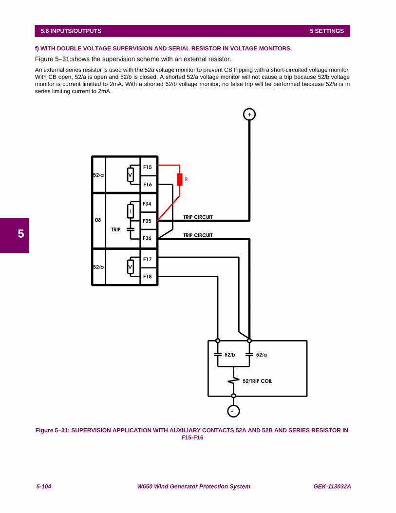
5-104 W650 Wind Generator Protection System GEK-113032A
5.6 INPUTS/OUTPUTS 5 SETTINGS
5
f) WITH DOUBLE VOLTAGE SUPERVISION AND SERIAL RESISTOR IN VOLTAGE MONITORS.
Figure 5–31:shows the supervision scheme with an external resistor.An external series resistor is used with the 52a voltage monitor to prevent CB tripping with a short-circuited voltage monitor.With CB open, 52/a is open and 52/b is closed. A shorted 52/a voltage monitor will not cause a trip because 52/b voltagemonitor is current limitted to 2mA. With a shorted 52/b voltage monitor, no false trip will be performed because 52/a is inseries limiting current to 2mA.
Figure 5–31: SUPERVISION APPLICATION WITH AUXILIARY CONTACTS 52A AND 52B AND SERIES RESISTOR IN F15-F16

GEK-113032A W650 Wind Generator Protection System 5-105
5 SETTINGS 5.6 INPUTS/OUTPUTS
5
5.6.6 ANALOG BOARDS SPECIFIC SETTINGS
Hardware and software is provided to receive signals from external transducers and convert these signals into a digitalformat for use as required. The relay will accept inputs in the range of –1 to +20 mA DC, suitable for use with the mostcommon transducer output ranges; all inputs are assumed to be linear over the complete range.
The Input Range setting specifies the mA DC range of the transducer connected to the input channel.
• Range : -1 to 0, 0 to 1, -1 to 1, 0 to 5, 0 to 10, 0 to 20, 4 to 20.
The Min and Max Value settings are used to program the span of the transducer in primary units.
• Min Value : -9999.99 to 9999.99
• Max Value : -9999.99 to 9999.99
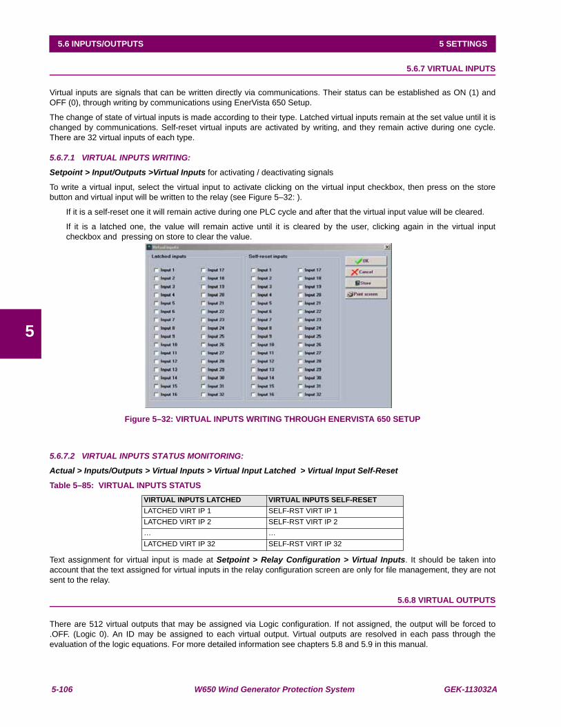
5-106 W650 Wind Generator Protection System GEK-113032A
5.6 INPUTS/OUTPUTS 5 SETTINGS
5
5.6.7 VIRTUAL INPUTS
Virtual inputs are signals that can be written directly via communications. Their status can be established as ON (1) andOFF (0), through writing by communications using EnerVista 650 Setup.
The change of state of virtual inputs is made according to their type. Latched virtual inputs remain at the set value until it ischanged by communications. Self-reset virtual inputs are activated by writing, and they remain active during one cycle.There are 32 virtual inputs of each type.
5.6.7.1 VIRTUAL INPUTS WRITING:
Setpoint > Input/Outputs >Virtual Inputs for activating / deactivating signals
To write a virtual input, select the virtual input to activate clicking on the virtual input checkbox, then press on the storebutton and virtual input will be written to the relay (see Figure 5–32: ).
If it is a self-reset one it will remain active during one PLC cycle and after that the virtual input value will be cleared.
If it is a latched one, the value will remain active until it is cleared by the user, clicking again in the virtual inputcheckbox and pressing on store to clear the value.
Figure 5–32: VIRTUAL INPUTS WRITING THROUGH ENERVISTA 650 SETUP
5.6.7.2 VIRTUAL INPUTS STATUS MONITORING:
Actual > Inputs/Outputs > Virtual Inputs > Virtual Input Latched > Virtual Input Self-Reset
Table 5–85: VIRTUAL INPUTS STATUS
Text assignment for virtual input is made at Setpoint > Relay Configuration > Virtual Inputs. It should be taken intoaccount that the text assigned for virtual inputs in the relay configuration screen are only for file management, they are notsent to the relay.
5.6.8 VIRTUAL OUTPUTS
There are 512 virtual outputs that may be assigned via Logic configuration. If not assigned, the output will be forced to.OFF. (Logic 0). An ID may be assigned to each virtual output. Virtual outputs are resolved in each pass through theevaluation of the logic equations. For more detailed information see chapters 5.8 and 5.9 in this manual.
VIRTUAL INPUTS LATCHED VIRTUAL INPUTS SELF-RESETLATCHED VIRT IP 1 SELF-RST VIRT IP 1LATCHED VIRT IP 2 SELF-RST VIRT IP 2… …LATCHED VIRT IP 32 SELF-RST VIRT IP 32
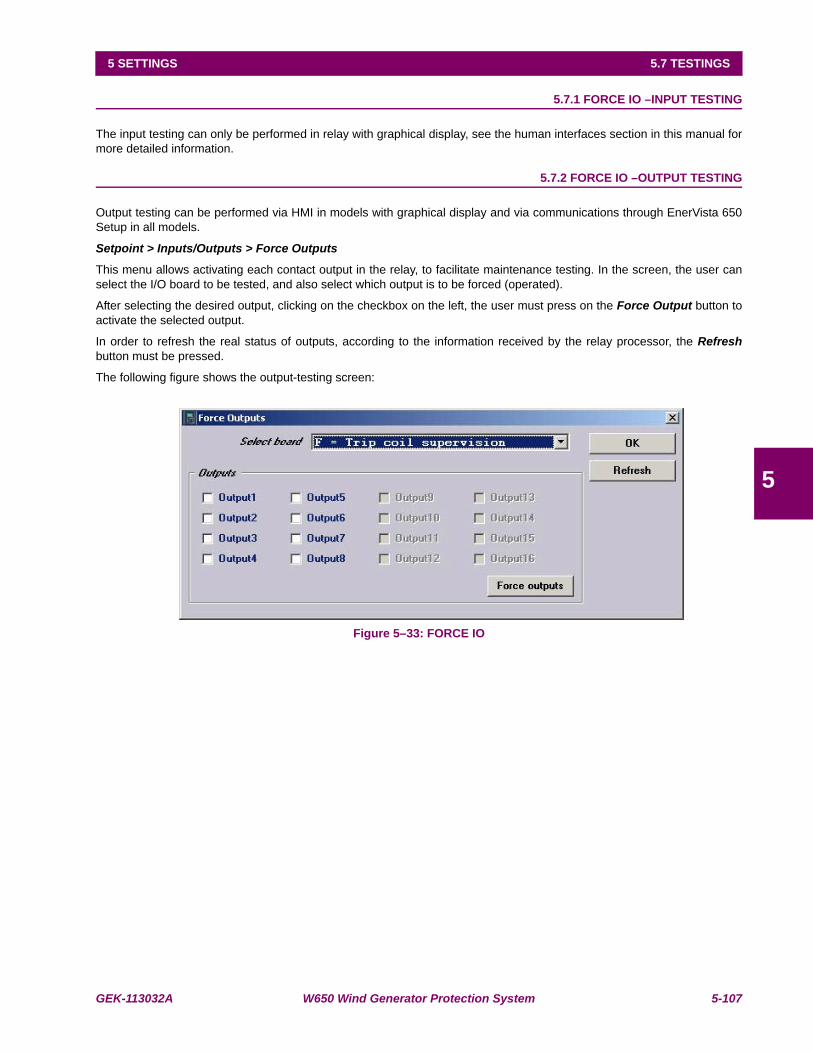
GEK-113032A W650 Wind Generator Protection System 5-107
5 SETTINGS 5.7 TESTINGS
5
5.7TESTINGS 5.7.1 FORCE IO –INPUT TESTING
The input testing can only be performed in relay with graphical display, see the human interfaces section in this manual formore detailed information.
5.7.2 FORCE IO –OUTPUT TESTING
Output testing can be performed via HMI in models with graphical display and via communications through EnerVista 650Setup in all models.
Setpoint > Inputs/Outputs > Force Outputs
This menu allows activating each contact output in the relay, to facilitate maintenance testing. In the screen, the user canselect the I/O board to be tested, and also select which output is to be forced (operated).
After selecting the desired output, clicking on the checkbox on the left, the user must press on the Force Output button toactivate the selected output.
In order to refresh the real status of outputs, according to the information received by the relay processor, the Refreshbutton must be pressed.
The following figure shows the output-testing screen:
Figure 5–33: FORCE IO

5-108 W650 Wind Generator Protection System GEK-113032A
5.8 RELAY CONFIGURATION 5 SETTINGS
5
5.8RELAY CONFIGURATION
Setpoint > Relay Configuration
This is the relay configuration section in which the relay can be configured (all input/output and LEDs configuration,protection elements signals, graphic display configuration, etc) using internal states or already compiled equation on PLCEditor (see section 5.9).
5.8.1 OUTPUTS
Configuration of contact output operates and reset signals for all boards available in the device:
To configure any output it is necessary to select the output to be configured, clicking on the checkbox in the select columnand choose the logic operand in the source column. Simple logics can be performed on this screen, using the “or” and “not”columns, for more complex logics go to the logic configuration tool to create the virtual outputs and afterwards select it inthe source column.
The different options available in this screen are the following:
• Select checkbox enables each output. The output must be enabled before modifying any other setting on that output
• Name setting for defining identification for the output.
• Source setting for defining a function, logic, remote input, digital input, etc. that will activate the contact.
• OR checkbox for configuring the output operation by activation of any of the indicated signals. The element performsan OR of the signals, and its output produces operation.
• NOT checkbox for inverting or not the configured logic.
Figure 5–34: OUTPUTS CONFIGURATION
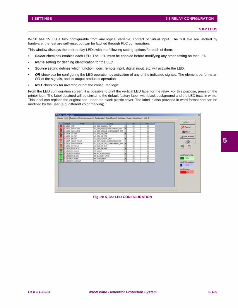
GEK-113032A W650 Wind Generator Protection System 5-109
5 SETTINGS 5.8 RELAY CONFIGURATION
5
5.8.2 LEDS
W650 has 15 LEDs fully configurable from any logical variable, contact or virtual input. The first five are latched byhardware, the rest are self-reset but can be latched through PLC configuration.
This window displays the entire relay LEDs with the following setting options for each of them:
• Select checkbox enables each LED. The LED must be enabled before modifying any other setting on that LED
• Name setting for defining identification for the LED
• Source setting defines which function; logic, remote input, digital input, etc. will activate the LED.
• OR checkbox for configuring the LED operation by activation of any of the indicated signals. The element performs anOR of the signals, and its output produces operation.
• NOT checkbox for inverting or not the configured logic.
From the LED configuration screen, it is possible to print the vertical LED label for the relay. For this purpose, press on theprinter icon. The label obtained will be similar to the default factory label, with black background and the LED texts in white.This label can replace the original one under the black plastic cover. The label is also provided in word format and can bemodified by the user (e.g. different color marking)
Figure 5–35: LED CONFIGURATION
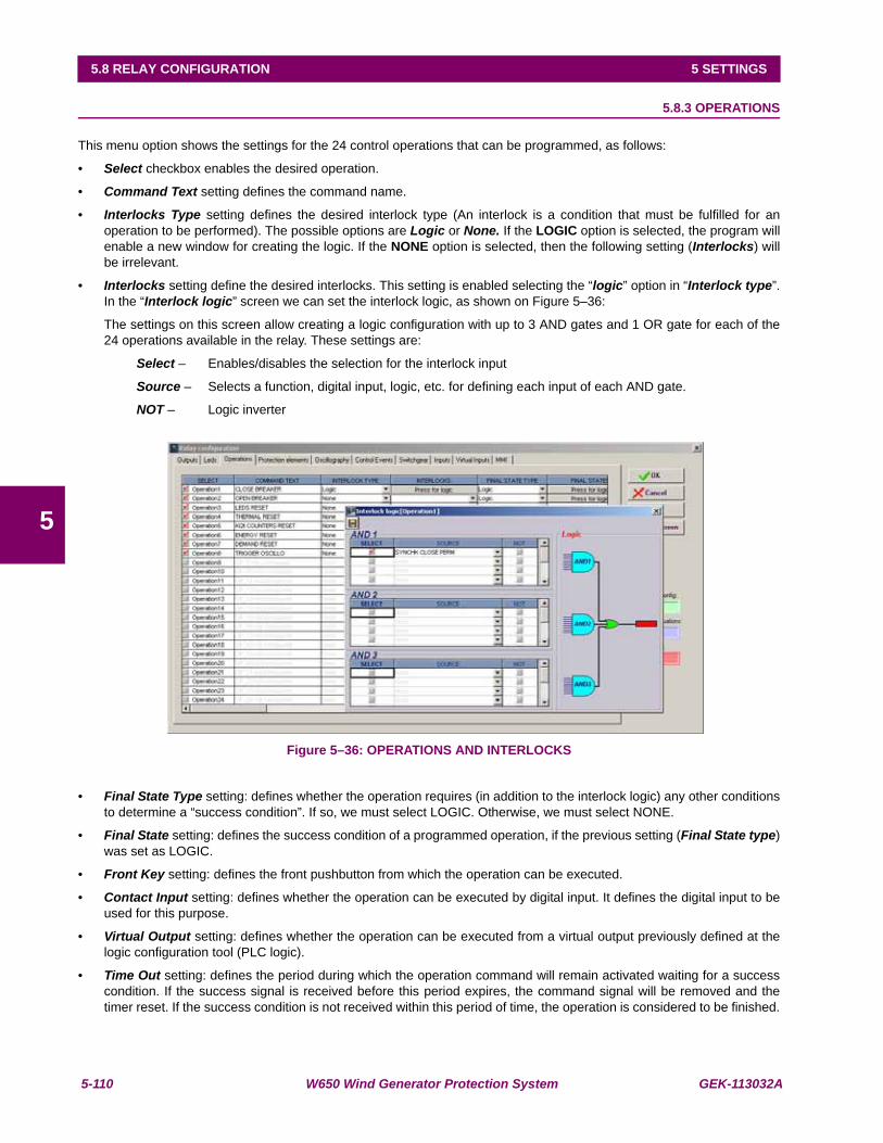
5-110 W650 Wind Generator Protection System GEK-113032A
5.8 RELAY CONFIGURATION 5 SETTINGS
5
5.8.3 OPERATIONS
This menu option shows the settings for the 24 control operations that can be programmed, as follows:
• Select checkbox enables the desired operation.
• Command Text setting defines the command name.
• Interlocks Type setting defines the desired interlock type (An interlock is a condition that must be fulfilled for anoperation to be performed). The possible options are Logic or None. If the LOGIC option is selected, the program willenable a new window for creating the logic. If the NONE option is selected, then the following setting (Interlocks) willbe irrelevant.
• Interlocks setting define the desired interlocks. This setting is enabled selecting the “logic” option in “Interlock type”.In the “Interlock logic” screen we can set the interlock logic, as shown on Figure 5–36:
The settings on this screen allow creating a logic configuration with up to 3 AND gates and 1 OR gate for each of the24 operations available in the relay. These settings are:
Select – Enables/disables the selection for the interlock input
Source – Selects a function, digital input, logic, etc. for defining each input of each AND gate.
NOT – Logic inverter
Figure 5–36: OPERATIONS AND INTERLOCKS
• Final State Type setting: defines whether the operation requires (in addition to the interlock logic) any other conditionsto determine a “success condition”. If so, we must select LOGIC. Otherwise, we must select NONE.
• Final State setting: defines the success condition of a programmed operation, if the previous setting (Final State type)was set as LOGIC.
• Front Key setting: defines the front pushbutton from which the operation can be executed.
• Contact Input setting: defines whether the operation can be executed by digital input. It defines the digital input to beused for this purpose.
• Virtual Output setting: defines whether the operation can be executed from a virtual output previously defined at thelogic configuration tool (PLC logic).
• Time Out setting: defines the period during which the operation command will remain activated waiting for a successcondition. If the success signal is received before this period expires, the command signal will be removed and thetimer reset. If the success condition is not received within this period of time, the operation is considered to be finished.
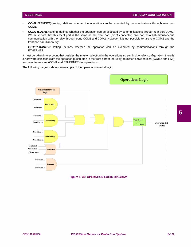
GEK-113032A W650 Wind Generator Protection System 5-111
5 SETTINGS 5.8 RELAY CONFIGURATION
5
• COM1 (REMOTE) setting: defines whether the operation can be executed by communications through rear portCOM1.
• COM2 (LOCAL) setting: defines whether the operation can be executed by communications through rear port COM2.We must note that this local port is the same as the front port (DB-9 connector). We can establish simultaneouscommunication with the relay through ports COM1 and COM2. However, it is not possible to use rear COM2 and thefront port simultaneously.
• ETHER-MASTER setting: defines whether the operation can be executed by communications through theETHERNET.
It must be taken into account that besides the master selection in the operations screen inside relay configuration, there isa hardware selection (with the operation pushbutton in the front part of the relay) to switch between local (COM2 and HMI)and remote masters (COM1 and ETHERNET) for operations.
The following diagram shows an example of the operations internal logic.
Figure 5–37: OPERATION LOGIC DIAGRAM
Condition 1
Condition n
Condition 1
Condition n
Success
Operation
Keyboard
Push button
Digital input
Operation Bit
(state)
Condition 1
Condition n
Interlocking
Without interlock
logic
Interlocking
Interlocking
Operations Logic
Time Out
Reset
Condition 1
Condition n

5-112 W650 Wind Generator Protection System GEK-113032A
5.8 RELAY CONFIGURATION 5 SETTINGS
5
5.8.3.1 HOW TO PROGRAM AN OPERATION
Example of how to program an operation to close a breaker with an operating time of 90 ms (closing), incorporating 52/bcontacts to indicate the change of position, using an interlock logic to enable the operation if Not AR RLC INPROGRESS there is no autoreclose in progress. The operation must be commanded from the relay faceplate using oneof the available operation push buttons.
To configure the related operation, go to Setpoint > Relay Configuration and select Operations tab.
This screen shows all the fields required for the operations configuration in the W650. In order to select an operation, presson the operation name under the Select column, and all the related parameters will be enabled. The chosen name for theoperation is entered in “Command Text”. To configure an interlock logic, select the Logic option in “Interlocks Type”.Once this option has been selected, the interlock configuration screen will be enabled. To display this screen, click on“Press for Logic” for the desired operation on its Interlocks column. On this Interlocks screen, the two conditions thatconform the Interlock that enables the operation have been selected. To save the interlock, press on the disk icon on thetoolbar. A “Logic Saved” message will be displayed.
Once the Interlocks have been defined, the user must define the success conditions for the operation, define Final StateType as LOGIC, and a “PRESS FOR LOGIC” message will light up below Final States. When clicking on “PRESS FORLOGIC”, the success condition screen will be displayed, defining there as BREAKER CLOSED.
The front key to be used for executing the Operation can be selected on the Frontal Key column, in this example the Key Ioption is selected on “Frontal Key”. As none of the other contact input or virtual output options are going to be used theywill be set as None. The success condition time “Time out” is set to 500 ms, and the operation is only enabled through therelay keypad, so only the MMI option is selected, thus disabling the rest of options (COM1, COM2, ETHERNET master arenot selected).
All the selections previously related are summarized in the following table:
Table 5–86: OPERATION SETTINGS
Finally, configure a contact output to be activated with the programmed Operation (Operation1).
OPERATION COMMAND TEXT SETTINGS VALUE/SOURCEOperation1 CLOSE BREAKER INTERLOCK (LOGIC) Not AR RLC IN PROGRESS
FINAL STATES (LOGIC) BREAKER CLOSEDFRONT KEY I KeyINPUT Not configuredVIRTUAL OUTPUT Not configuredTIMEOUT 500CHANNELS MMI
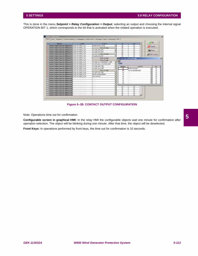
GEK-113032A W650 Wind Generator Protection System 5-113
5 SETTINGS 5.8 RELAY CONFIGURATION
5
This is done in the menu Setpoint > Relay Configuration > Output, selecting an output and choosing the internal signalOPERATION BIT 1, which corresponds to the bit that is activated when the related operation is executed.
Figure 5–38: CONTACT OUTPUT CONFIGURATION
Note: Operations time out for confirmation
Configurable screen in graphical HMI: In the relay HMI the configurable objects wait one minute for confirmation afteroperation selection. The object will be blinking during one minute. After that time, the object will be deselected.
Front Keys: In operations performed by front keys, the time out for confirmation is 10 seconds.
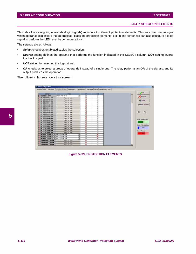
5-114 W650 Wind Generator Protection System GEK-113032A
5.8 RELAY CONFIGURATION 5 SETTINGS
5
5.8.4 PROTECTION ELEMENTS
This tab allows assigning operands (logic signals) as inputs to different protection elements. This way, the user assignswhich operands can initiate the autoreclose, block the protection elements, etc. In this screen we can also configure a logicsignal to perform the LED reset by communications.
The settings are as follows:
• Select checkbox enables/disables the selection.
• Source setting defines the operand that performs the function indicated in the SELECT column. NOT setting invertsthe block signal.
• NOT setting for inverting the logic signal.
• OR checkbox to select a group of operands instead of a single one. The relay performs an OR of the signals, and itsoutput produces the operation.
The following figure shows this screen:
Figure 5–39: PROTECTION ELEMENTS
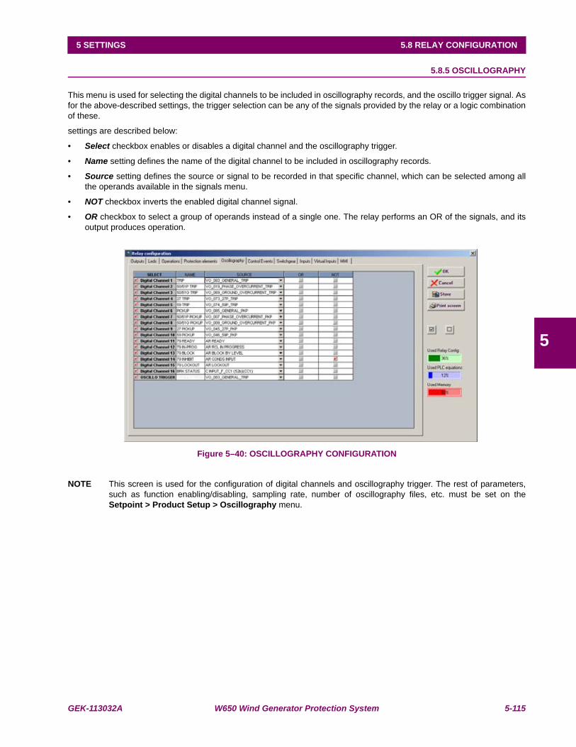
GEK-113032A W650 Wind Generator Protection System 5-115
5 SETTINGS 5.8 RELAY CONFIGURATION
5
5.8.5 OSCILLOGRAPHY
This menu is used for selecting the digital channels to be included in oscillography records, and the oscillo trigger signal. Asfor the above-described settings, the trigger selection can be any of the signals provided by the relay or a logic combinationof these.
settings are described below:
• Select checkbox enables or disables a digital channel and the oscillography trigger.
• Name setting defines the name of the digital channel to be included in oscillography records.
• Source setting defines the source or signal to be recorded in that specific channel, which can be selected among allthe operands available in the signals menu.
• NOT checkbox inverts the enabled digital channel signal.
• OR checkbox to select a group of operands instead of a single one. The relay performs an OR of the signals, and itsoutput produces operation.
Figure 5–40: OSCILLOGRAPHY CONFIGURATION
NOTE This screen is used for the configuration of digital channels and oscillography trigger. The rest of parameters,such as function enabling/disabling, sampling rate, number of oscillography files, etc. must be set on theSetpoint > Product Setup > Oscillography menu.

5-116 W650 Wind Generator Protection System GEK-113032A
5.8 RELAY CONFIGURATION 5 SETTINGS
5
5.8.6 CONTROL EVENTS
This menu is used for defining the CONTROL EVENTS, up to 128 user programmable events.
A control event is a logic signal associated to an operand or combination of operands which monitories the change of statusof the logic operand. The relay shows which events are active each time, as well as their date and time of activation.
There are 128 user programmable events and 64 pre-established events for switchgear, which correspond to opening,closing, Error00 and Error11 of the 16 programmable switchgear elements. (Please refer to section 5.8.8 for more detailedinformation).
As for the rest of previous settings, the source selection can be made between:
• An operand, selecting it directly on this screen.
• An OR of several operands, selecting directly the OR column in this same menu.
• A logic combination of operands, by selecting a VIRTUAL OUTPUT as trigger source, and using the logic configurationavailable in the relay, graphical PLC, that allows to design logic circuits and to assign their outputs to internal variables,called VIRTUAL OUTPUT.
Available settings are as follows:
• Select checkbox: enables or disables the generation of each event.
• Name setting: defines the text for each control event.
• Source setting defines the source that will trigger the event. The source is chosen from the list that shows all theoperands available in the element.
• NOT checkbox inverts the selected signal.
• OR checkbox to select a group of operands instead of a single one. The relay performs an OR of the signals, and itsoutput produces operation.
• Alarm checkbox: allows treating the event as an alarm and making the event activation to be reported on the alarmpanel.
Figure 5–41: CONTROL EVENTS CONFIGURATION

GEK-113032A W650 Wind Generator Protection System 5-117
5 SETTINGS 5.8 RELAY CONFIGURATION
5
The Alarm panel can be displayed in:
HMI screen for models with graphical display.
EnerVista 650 Setup: Actual>Event Recorder>Alarm Panel for all models.
Web Server application: http://xxx. xxx. xxx. xxx /Alarms.htm for all models.
If the event is not selected as an alarm, it can be viewed as an event at:
HMI screen for all models in snapshot event screen (with default text).
EnerVista 650 Setup: Actual>Event Recorder> Control Events for all models.
Web Server application: http://xxx.xxx.xxx.xxx/ControlEvents.htm for all models.
Alarm management in W650:The relay can manage alarms in from three different masters, local, remote com1, remote Ethernet. The alarms can beactive or not active and can be acknowledged or not acknowledged. As shown in the following table:
Table 5–87: ALARM MANAGEMENT
ACTIVE status is shown on the display (relay HMI), showing an ON label on the right of the alarm. The PC will show thealarm text in red color.
ACKNOWLEDGED: Operation acknowledgement can be performed from three independent channels: MMI-COM2 (local),COM1 (remote) and COM3 (Ethernet). Inactive alarms disappear from the HMI when being acknowledged.
HMI: Acknowledged status is shown on the HMI with a selection mark on the right of the ON label.
EnerVista 650 Setup: the acknowledged status is shown by a check mark to the left of the Operation name.
ALARM STATUS MASTER MANAGEMENTACTIVE - NOT ACTIVE ALL MASTERSACKNOWLEDGED - NOT ACKNOWLEDGED LOCAL REMOTE
COM2 & HMI COM1 ETHERNET

5-118 W650 Wind Generator Protection System GEK-113032A
5.8 RELAY CONFIGURATION 5 SETTINGS
5
5.8.7 SWITCHGEAR
This menu is used for defining the SWITCHGEAR elements to be controlled by the relay. A switchgear element can be abreaker, a line selector switch, a grounding selector switch, a busbar selector switch, etc. It is possible to define up to 16switchgear elements. The settings are as follows:
• Select checkbox: enables or disables the control of a new switchgear element
• Contacts setting: allows selecting which type of contact is used for monitoring the status (open/closed) of the element.The selection can be: 52a (contact type A, showing the same status as the represented element), 52b (opposite statusto the represented element), 52a+52b (both types of contacts are used), NONE (no status monitoring).
• Opening Time setting: defines the maximum opening time of an element. It is used for issuing an opening time failuresignal if the element opening is not produced within this time.
• Closing Time setting: defines the maximum closing time of an element. It is used for issuing a closing time failuresignal if the element closing is not produced within this time.
• Contact A checkbox: allows selecting which operand or combination of operands activate the type A contact status.Usually it will be an input contact wired to type A contact of the element (Breaker/selector switch). This column and thenext two columns are only active if the selected contact type in the Contacts column is 52a or 52a+52b.
• OR checkbox: selects a group of operands instead of a single one. The relay performs and OR of the signals, and itsoutput produces operation.
• NOT checkbox inverts the status of the signal selected in column Contact A.
• Contact B checkbox: allows selecting which operand or combination of operands activates the type B contact status.Usually it will be an input contact wired to type B contact of the element (Breaker/selector switch). This column and thenext two columns are only active if the selected contact type in the Contacts column is 52b or 52a+52b.
•OR checkbox selects a group of operands instead of a single one. The relay performs OR of the signals, and itsoutput produces operation.
•NOT checkbox inverts the status of the signal selected in column Contact B.
• Open text setting: allows associating a text to the control event associated to the element opening.
• Close text setting: allows associating a text to the control event associated to the element closing.
• Error 00 text setting: in case of using double contact for the switchgear element status (52a+52b), this setting allowsto associate a text to the Error00 internal status, this means, when both contacts are inactive during a period longerthan the associated to the opening or closing Operation, depending on which Operation is being performed.
• Error 11 text setting: in case of using double contact for the switchgear element status (52a+52b), this setting allowsto associate a text to the Error11 internal status, this means, when both contacts are active during a period longer thanthe associated to the opening or closing Operation, depending on which Operation is being performed.
• ALARM setting: enables the issue of an alarm in the event of a close, open, 00-type, 11-type error. If it is configured asan alarm.
• Opening init setting: this setting selects which operand or combination of operands indicate the initiation of anopening operation, in order to allow the follow up of the operation and generate the corresponding alarms if theoperation is not successful. The operation bit signal used to launch the opening init must be configured in theoperations tab inside relay configuration.
• Closing init setting: this setting selects which operand or combination of operands indicate the initiation of a closingoperation, in order to allow the follow up of the operation and generate the corresponding alarms if the operation is notsuccessful. The operation bit signal used to launch the opening init must be configured in the operations tab insiderelay configuration.
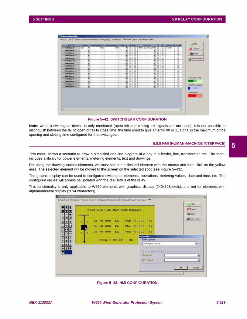
GEK-113032A W650 Wind Generator Protection System 5-119
5 SETTINGS 5.8 RELAY CONFIGURATION
5
Figure 5–42: SWITCHGEAR CONFIGURATION
Note: when a switchgear device is only monitored (open init and closing init signals are not used), it is not possible todistinguish between the fail to open or fail to close time, the time used to give an error 00 or 11 signal is the maximum of theopening and closing time configured for that switchgear.
5.8.8 HMI (HUMAN-MACHINE INTERFACE)
This menu shows a scenario to draw a simplified one-line diagram of a bay in a feeder, line, transformer, etc. The menuincludes a library for power elements, metering elements, text and drawings.
For using the drawing toolbar elements, we must select the desired element with the mouse and then click on the yellowarea. The selected element will be moved to the screen on the selected spot (see Figure 5–43:).
The graphic display can be used to configured switchgear elements, operations, metering values, date and time, etc. Theconfigured values will always be updated with the real status of the relay.
This functionality is only applicable to W650 elements with graphical display (240x128pixels), and not for elements withalphanumerical display (20x4 characters).
Figure 5–43: HMI CONFIGURATION

5-120 W650 Wind Generator Protection System GEK-113032A
5.8 RELAY CONFIGURATION 5 SETTINGS
5
On the left side of the window all the available elements to be programmed on the HMI are displayed. Their meaning isdetailed on the right.
Table 5–88: ACTIVE SYMBOLS CONFIGURABLE IN ONE-LINE DIAGRAM FOR GRAPHICAL HMIACTIVE SYMBOLSICONS IN SCREEN DESCRIPTIONSWITCHGEAR SYMBOLS
These symbols correspond to switchgear elements: breaker (square) and selector switch (rhombus), in vertical and horizontal positions. It is necessary to associate the figure to its corresponding switchgear number. The figure is shown filled if the element is closed, and blank if the element is open. The symbol on the right represents an unpluggable breaker. In this case it is necessary to indicate which operands show whether the element is plugged or unplugged. The figure shows also graphically these two statuses.
MULTISTATE VARIABLE SYMBOLDisplays on screen a dialog box that is one variable status function (like a switch case) for the following internal states AR STATUS, AR LOCKOUT MODE, AR BLOCK MODE and FAULT TYPE.This type of data allows to visualize the different states of one particular value, for example, AR STATUS has several states such as (0) OUT OF SERVICE, (1) READY, (2) LOCKOUT, (3) BLOCK, (4) RECLOSE IN PROGRESS. Significant texts can be associated with those states.
STATUS SYMBOLS (TEXT AND GRAPHIC MODES):BitRepresents the state of an operand by means of a configurable text. It allows associating a test to the active status and a different text to the inactive status.
Led(O)Performs the same function in a graphical mode. This way, it works as a virtual LED. When showing a black circle, it means that the selected operand is active, and if the circle is blank, the operand is inactive
ANALOG MAGNITUDE SYMBOLUsed for displaying analog magnitudes (current, voltage, power, etc.) in floating point numbers, such as a current value (123.5 A). Both the number of decimals and the integer characters can be selected, in order to facilitate the reading. Any of the analog magnitudes available in the relay can be configured
DATE AND TIME SYMBOLSymbol used for displaying in the HMI the date and time provided by the device.
OPERATIONS SYMBOL:This symbol indicates de possibility to configure and execute operations on the graphic display. This symbol can only be selected once the operations have already been configured in the “Operations” screen of the “Relay Configuration” menu. To select an Operation, click on the element and then on the display. The program will show a window to select the required operation among the displayed options, and the tab order. Once selected, a red border square will be shown. Place this square on the object to be operated. When the operated object is selected on the screen to execute this operation, the object on which it is located will blink. It is possible to place several operations on the same object, for example to open and close the breaker object.

GEK-113032A W650 Wind Generator Protection System 5-121
5 SETTINGS 5.8 RELAY CONFIGURATION
5
Table 5–89: GRAPHIC AND TEXT EDITION SYMBOLS GRAPHIC AND TEXT EDITION SYMBOLSICONS IN SCREEN DESCRIPTION
Ground symbols in different positions.
Transformers representation
Symbols reserved for future uses
Symbol for capacitor banks.
Symbol for wye connection
Symbol for open delta and delta connection
Display of a fix text up to 40 ASCII characters
Auxiliary drawing lines

5-122 W650 Wind Generator Protection System GEK-113032A
5.9 LOGIC CONFIGURATION (PLC EDITOR) 5 SETTINGS
5
5.9LOGIC CONFIGURATION (PLC EDITOR)
Setpoint > Logic Configuration
The W650 logic allows setting the relay logic configuration using a sophisticated and complete program based on standardIEC 61131-3, with block diagrams, which is described in this section.
5.9.1 INTRODUCTION
The logic configuration (or PLC Editor) tool is a graphical design tool that allows the W650 built complex logic diagram in aneasy way using different logic functions.
The logical configuration is performed using graphical functions based on the IEC 61131-3 standard.
• This standard defines five basic ways of programming:
•Sequential Function Chart (SFC).
•Instruction List (IL).
•Structured Text (ST).
•Ladder Diagram (LD).
•Function Block Diagram (FBD).
Out of these five methods, FBD has been chosen because it allows for graphical configurations that are morecomprehensive. This method provides the possibility of grouping several basic functions inside a single function (hereoncalled libraries), achieving higher modularity and clarity in the design.
Please take note of the following remarks:
The first equation entered in the PLC can never be a timer
Analog elements (analog comparators, etc,) are not implemented.

GEK-113032A W650 Wind Generator Protection System 5-123
5 SETTINGS 5.9 LOGIC CONFIGURATION (PLC EDITOR)
5
5.9.2 THEORY OF OPERATION
5.9.2.1 DESCRIPTION
As already mentioned in the introduction, this tool uses FBD mode of IEC 61131-3 standard. For this purpose we havedefined a series of basic operations with illustrations below.
The basic operations available in PLC Editor are located in the tool bar of the application and are as follows:
Table 5–90: PLC EDITOR BASIC OPERATION IN W650PLC EDITOR BASIC OPERATION ICONS IN SCREEN DESCRIPTION
INPUT TO LOGIC: Selection of the digital input to the logic. (All available internal status can be used as logic inputs)
OUTPUT FROM LOGIG: Virtual output built with internal logic. (Up to 512)
LIBRARY: Possibility to build blocks of logic in a simple graphic object. OR and AND from 3 to 8 inputs are provided as libraries.
AND of two digital inputs.
OR of two digital inputs.
NOT of a digital input.
NAND of two digital inputs.
XOR of two digital inputs.
SR: Latch (set-reset): reset dominant.
ONS: signal to pulse an logic input to a signal of one scan cycle length.
TIMER: timer signal with set, reset and mask for timing.
TEXT LABEL: text to customize the logic configuration file.
Flip-Flop D : signal that maintains the actual value frozen during a PLC cycle
MASK: Time mask to be used in timing operations.
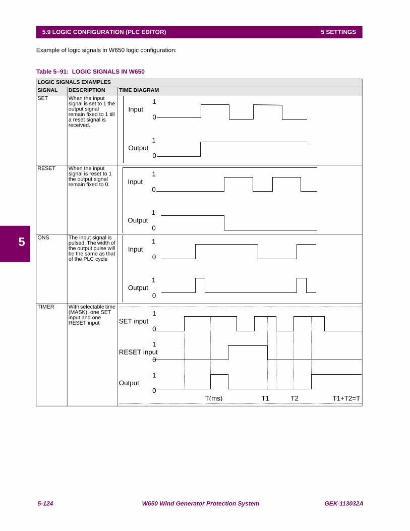
5-124 W650 Wind Generator Protection System GEK-113032A
5.9 LOGIC CONFIGURATION (PLC EDITOR) 5 SETTINGS
5
Example of logic signals in W650 logic configuration:
Table 5–91: LOGIC SIGNALS IN W650LOGIC SIGNALS EXAMPLESSIGNAL DESCRIPTION TIME DIAGRAMSET When the input
signal is set to 1 the output signal remain fixed to 1 till a reset signal is received.
RESET When the input signal is reset to 1 the output signal remain fixed to 0.
ONS The input signal is pulsed. The width of the output pulse will be the same as that of the PLC cycle
TIMER With selectable time (MASK), one SET input and one RESET input
1 Input 0
1 Output 0
1 Input 0
1 Output 0
1Input 0
1 Output 0
1 SET input
0
1 RESET input
0
1 Output
0 T(ms) T1 T2 T1+T2=T
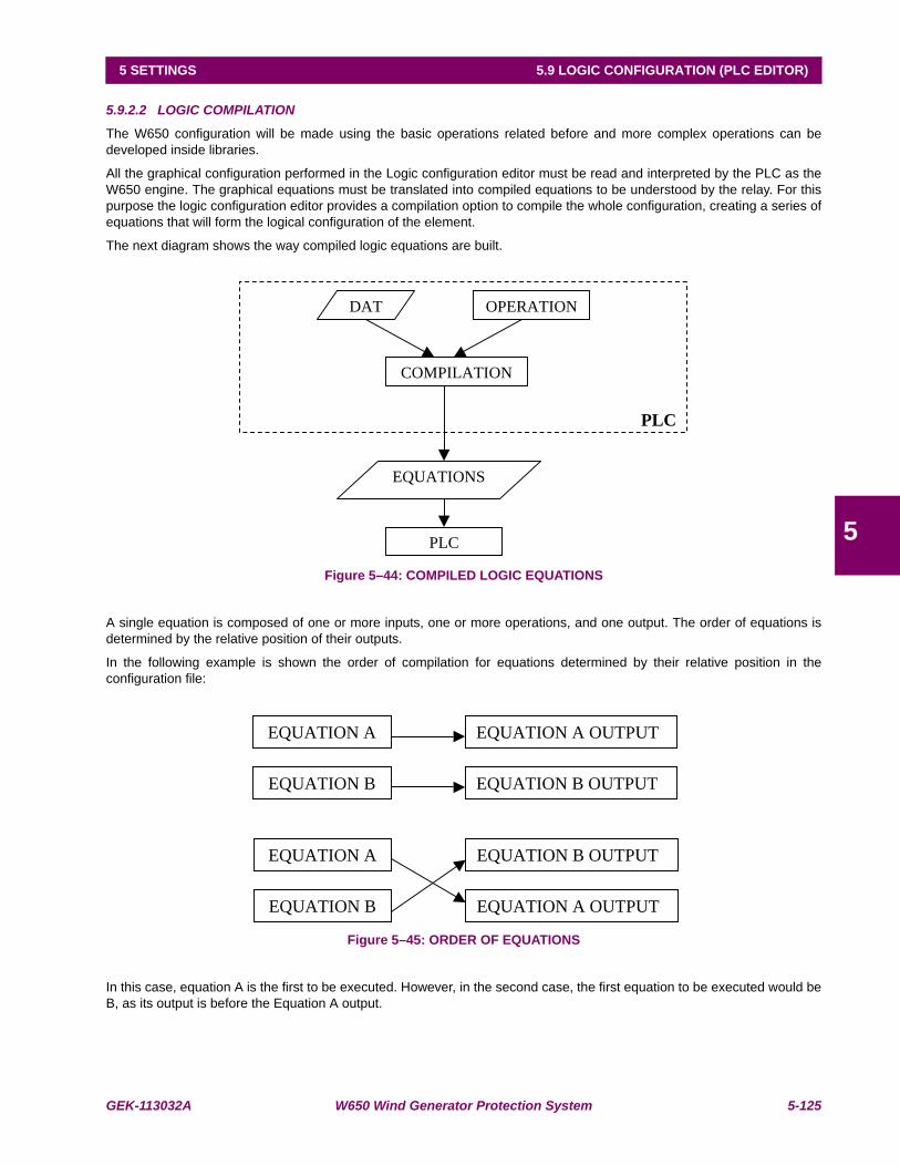
GEK-113032A W650 Wind Generator Protection System 5-125
5 SETTINGS 5.9 LOGIC CONFIGURATION (PLC EDITOR)
5
5.9.2.2 LOGIC COMPILATION
The W650 configuration will be made using the basic operations related before and more complex operations can bedeveloped inside libraries.
All the graphical configuration performed in the Logic configuration editor must be read and interpreted by the PLC as theW650 engine. The graphical equations must be translated into compiled equations to be understood by the relay. For thispurpose the logic configuration editor provides a compilation option to compile the whole configuration, creating a series ofequations that will form the logical configuration of the element.
The next diagram shows the way compiled logic equations are built.
Figure 5–44: COMPILED LOGIC EQUATIONS
A single equation is composed of one or more inputs, one or more operations, and one output. The order of equations isdetermined by the relative position of their outputs.
In the following example is shown the order of compilation for equations determined by their relative position in theconfiguration file:
Figure 5–45: ORDER OF EQUATIONS
In this case, equation A is the first to be executed. However, in the second case, the first equation to be executed would beB, as its output is before the Equation A output.
EQUATIONS
PLC
PLC
DAT OPERATION
COMPILATION
EQUATION A EQUATION A OUTPUT
EQUATION B EQUATION B OUTPUT
EQUATION A EQUATION B OUTPUT
EQUATION B EQUATION A OUTPUT

5-126 W650 Wind Generator Protection System GEK-113032A
5.9 LOGIC CONFIGURATION (PLC EDITOR) 5 SETTINGS
5
5.9.3 MAIN MENU
The PLC Editor tool (Setpoint > Logic Configuration ) provides a main menu with different submenus (File, Project, Edit,Run, View, and Window) that allows the user to built customized logic for the W650 devices.
5.9.3.1 FILE MENU
The FILE menu includes the following options:
New Project: allows to create a new project that will include the files of the logic configuration
Open Project: opens an existing project.
Close Project: closes the currently open project.
Save Project and Save Project as: saves the open project.
Save Automatic Function
& Save Automatic Function As: Saves the file of the active project.
Library: Gives access to the libraries sub-menus, where new libraries can be created andexisting ones can be modified and saved.
Print: Prints the active configuration file.
Preview: Preview of the document before printing.
Exit: The system closes all open projects and exits the application.
5.9.3.2 PROJECT MENU
The Project menu includes the following options:
Project Explorer: Displays a window where we see a tree structure with the files contained in theproject.
Insert library: Inserts a library in the active automatic function.
5.9.3.3 EDIT MENU
The Edit menu includes the following options:
Undo: Undoes the last modification in the active function.
Redo: Remakes the last modification.
Cut: Cuts one or more logic operations.
Copy: Copies one or more logic operations.
Paste: Pastes one or more logic operations.
Find: Looks for a logic operation in the project.
Copy as Bitmap: Copies the active automatic function to the clipboard in picture format.
View Clipboard: Launches the clipboard viewer application.
5.9.3.4 RUN MENU
The RUN menu includes the following options:
Configuration: Not valid in the current application (for analog operations still not available)
Compile: Compiles the configuration functions to generate the equations that will be interpretedby the 650 PLC.
Send Equations to Relay

GEK-113032A W650 Wind Generator Protection System 5-127
5 SETTINGS 5.9 LOGIC CONFIGURATION (PLC EDITOR)
5
5.9.3.5 VIEW MENU
The VIEW menu includes the following options:
Log: Displays in one screen the status name and time stamp of the digital statusesconfigured in the PLC logic (still not available).
Debug-Release window: Displays the values for the different project inputs, outputs, and variables (still notavailable).
Equations: Displays the equations resulting from the compilation.
Grid: Shows or hides the form grid where the configuration functions are developed. Italso aligns the different objects to the grid.
Zoom: Allows selecting the percentage of zoom in the application.
Rectangle Zoom (Zoom rectangular): Allows zooming the Selected rectangle.
5.9.4 CONFIGURATION GENERATION
5.9.4.1 CREATE A NEW PROJECT
Clicking on the “File > New Project” menu option, a new PLC project is open, where the user can program the desiredautomatism. An automatism can be formed by one or more equations.
5.9.4.2 CREATE EQUATION
A single equation can be formed by one or more inputs, one or more operations, and one output.
The order of equations is determined by the relative position of their respective outputs, this order being downward.
To link the output of an equation with the input of another equation, an internal variable (virtual output) must be used.
The virtual output is used as an input to the second equation.
5.9.4.3 ADD AN INPUT TO AN AUTOMATISM
Using the mouse click on the button that represents the inputs in the toolbar at the top of the screen. A logic input can beany of the available digital internal status provided by the relay. Such as protection status, contact inputs, contact outputs, I/O status, other protection status, front keys, LEDs, operation bits, virtual inputs and virtual outputs.
5.9.4.4 ADD AN OUTPUT TO AN AUTOMATISM
Using the mouse click on the button that represents the outputs in the toolbar at the top of the screen. The logic outputs arealways virtual outputs (up to 512 configurable signals).
5.9.4.5 ADD A DIGITAL OPERATION
Press on any of the digital operations in the toolbar at the top of the screen, and then click on the window background.Afterward a box with the selected digital operation will be displayed and the inputs and outputs much be connected to thelogic box as explained before.
5.9.4.6 LINK INPUTS, OUTPUTS AND OPERATIONS
The user can link the different graphic objects clicking on an object output and dragging to the input of another graphicobject. Graphic objects available in the PLC configuration are digital objects.
There is a series of restrictions when performing connections:
It is not possible to auto-link an object; the output of a certain object cannot be linked to its input;
There can only be one input per object input;
RESET and SET outputs must be internal variables or outputs.
We must take into account that as the timer is a digital operation that operates as an analog, there must only be a singleinternal variable or digital input in the timer input.
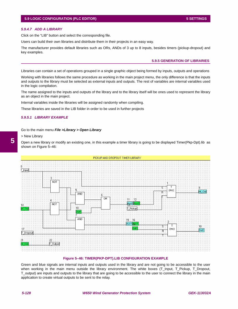
5-128 W650 Wind Generator Protection System GEK-113032A
5.9 LOGIC CONFIGURATION (PLC EDITOR) 5 SETTINGS
5
5.9.4.7 ADD A LIBRARY
Click on the “LIB” button and select the corresponding file.
Users can build their own libraries and distribute them in their projects in an easy way.
The manufacturer provides default libraries such as ORs, ANDs of 3 up to 8 inputs, besides timers (pickup-dropout) andkey examples.
5.9.5 GENERATION OF LIBRARIES
Libraries can contain a set of operations grouped in a single graphic object being formed by inputs, outputs and operations
Working with libraries follows the same procedure as working in the main project menu, the only difference is that the inputsand outputs to the library must be selected as external inputs and outputs. The rest of variables are internal variables usedin the logic compilation.
The name assigned to the inputs and outputs of the library and to the library itself will be ones used to represent the libraryas an object in the main project.
Internal variables inside the libraries will be assigned randomly when compiling.
These libraries are saved in the LIB folder in order to be used in further projects
5.9.5.1 LIBRARY EXAMPLE
Go to the main menu File >Library > Open Library
> New Library
Open a new library or modify an existing one, in this example a timer library is going to be displayed Timer(Pkp-Dpt).lib asshown on Figure 5–46:
Figure 5–46: TIMER(PKP-DPT).LIB CONFIGURATION EXAMPLE
Green and blue signals are internal inputs and outputs used in the library and are not going to be accessible to the userwhen working in the main menu outside the library environment. The white boxes (T_Input, T_Pickup, T_Dropout,T_output) are inputs and outputs to the library that are going to be accessible to the user to connect the library in the mainapplication to create virtual outputs to be sent to the relay.

GEK-113032A W650 Wind Generator Protection System 5-129
5 SETTINGS 5.9 LOGIC CONFIGURATION (PLC EDITOR)
5
Once the library is created and saved it can be selected in the main application menu in Project > Insert Library. Thelibrary will have the following object:
Figure 5–47: LIBRARY OBJECT
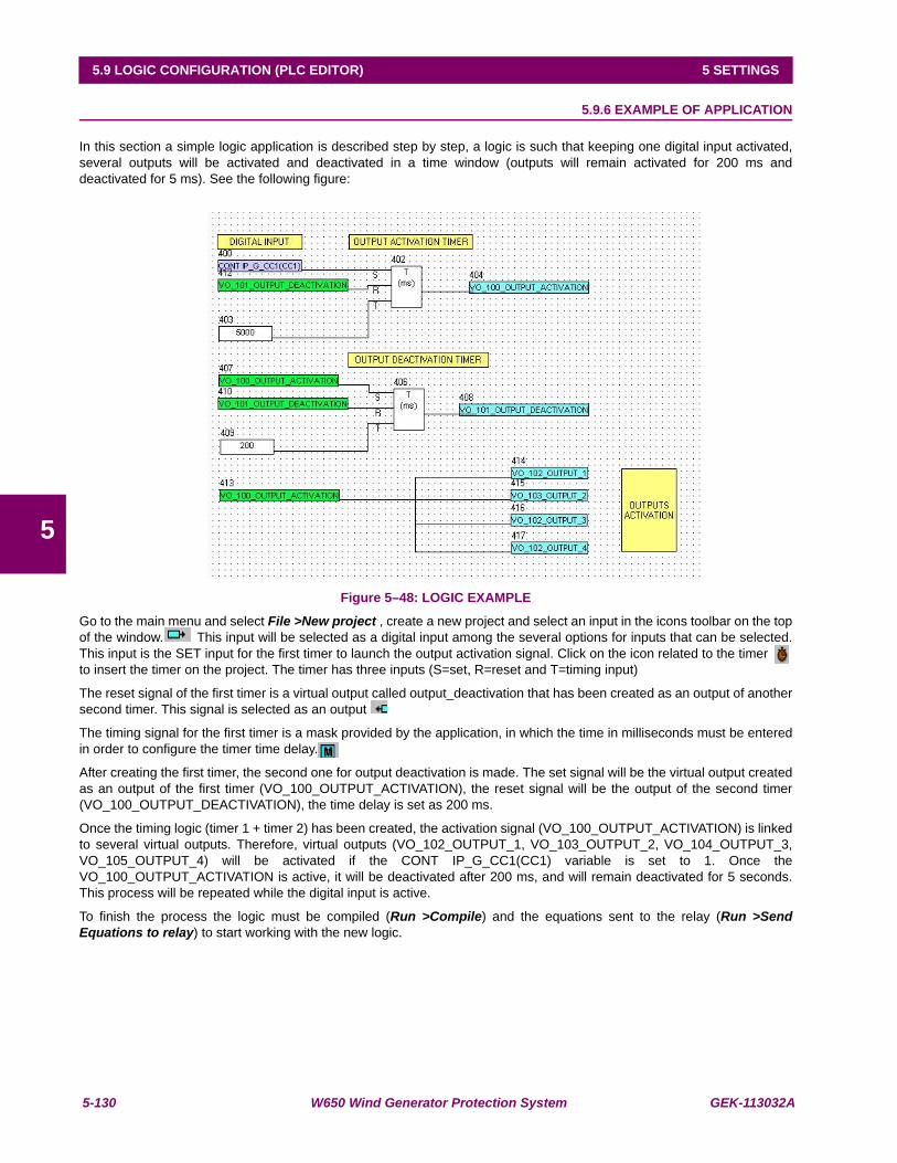
5-130 W650 Wind Generator Protection System GEK-113032A
5.9 LOGIC CONFIGURATION (PLC EDITOR) 5 SETTINGS
5
5.9.6 EXAMPLE OF APPLICATION
In this section a simple logic application is described step by step, a logic is such that keeping one digital input activated,several outputs will be activated and deactivated in a time window (outputs will remain activated for 200 ms anddeactivated for 5 ms). See the following figure:
Figure 5–48: LOGIC EXAMPLE
Go to the main menu and select File >New project , create a new project and select an input in the icons toolbar on the topof the window. This input will be selected as a digital input among the several options for inputs that can be selected.This input is the SET input for the first timer to launch the output activation signal. Click on the icon related to the timer to insert the timer on the project. The timer has three inputs (S=set, R=reset and T=timing input)
The reset signal of the first timer is a virtual output called output_deactivation that has been created as an output of anothersecond timer. This signal is selected as an output
The timing signal for the first timer is a mask provided by the application, in which the time in milliseconds must be enteredin order to configure the timer time delay.
After creating the first timer, the second one for output deactivation is made. The set signal will be the virtual output createdas an output of the first timer (VO_100_OUTPUT_ACTIVATION), the reset signal will be the output of the second timer(VO_100_OUTPUT_DEACTIVATION), the time delay is set as 200 ms.
Once the timing logic (timer 1 + timer 2) has been created, the activation signal (VO_100_OUTPUT_ACTIVATION) is linkedto several virtual outputs. Therefore, virtual outputs (VO_102_OUTPUT_1, VO_103_OUTPUT_2, VO_104_OUTPUT_3,VO_105_OUTPUT_4) will be activated if the CONT IP_G_CC1(CC1) variable is set to 1. Once theVO_100_OUTPUT_ACTIVATION is active, it will be deactivated after 200 ms, and will remain deactivated for 5 seconds.This process will be repeated while the digital input is active.
To finish the process the logic must be compiled (Run >Compile) and the equations sent to the relay (Run >SendEquations to relay) to start working with the new logic.

GEK-113032A W650 Wind Generator Protection System 6-1
6 ACTUAL VALUES 6.1 FRONT PANEL
6
6 ACTUAL VALUES 6.1FRONT PANEL
The menu bar in the main screen of EnerVista 650 Setup software shows the ACTUAL menu option. This optionconcentrates and displays all status of protection, control elements, metering, counters information, oscillography, events,fault locator, etc. This menu is divided in several submenus that will be detailed in the following sections.
6.1.1 LEDS
Operation of the relay front LEDs is shown on the following figure (Actual > Front Panel > LEDs) by the lighting of theassociated LED in the appropriate color. The Ready LED is green when the relay is in service. LEDs 1 to 5 light up in redwhen active, LEDs 6 to 10 light up in orange, and the last 5 LEDs light up in green.
The first five LEDs are latched by hardware and can only be reset by a LEDs RESET Command, either pressing the “esc”key on the Front of the Relay, or by Communications using the appropriate signal. The rest of LEDs are not latched, but canbe latched by logic.
Table 6–1: FRONT PANEL LEDSLEDSREADY LEDLED 1LED 2LED 3LED 4LED 5LED 6LED 7LED 8LED 9LED 10LED 11LED 12LED 13LED 14LED 15LOCAL OPERATION MODEOPERATIONS BLOCKED
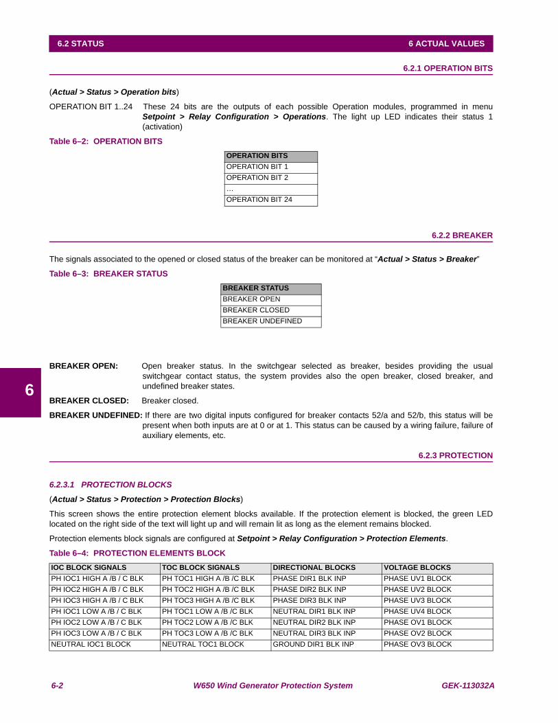
6-2 W650 Wind Generator Protection System GEK-113032A
6.2 STATUS 6 ACTUAL VALUES
6
6.2STATUS 6.2.1 OPERATION BITS
(Actual > Status > Operation bits)
OPERATION BIT 1..24 These 24 bits are the outputs of each possible Operation modules, programmed in menuSetpoint > Relay Configuration > Operations. The light up LED indicates their status 1(activation)
Table 6–2: OPERATION BITS
6.2.2 BREAKER
The signals associated to the opened or closed status of the breaker can be monitored at “Actual > Status > Breaker”
Table 6–3: BREAKER STATUS
BREAKER OPEN: Open breaker status. In the switchgear selected as breaker, besides providing the usualswitchgear contact status, the system provides also the open breaker, closed breaker, andundefined breaker states.
BREAKER CLOSED: Breaker closed.
BREAKER UNDEFINED: If there are two digital inputs configured for breaker contacts 52/a and 52/b, this status will bepresent when both inputs are at 0 or at 1. This status can be caused by a wiring failure, failure ofauxiliary elements, etc.
6.2.3 PROTECTION
6.2.3.1 PROTECTION BLOCKS
(Actual > Status > Protection > Protection Blocks)
This screen shows the entire protection element blocks available. If the protection element is blocked, the green LEDlocated on the right side of the text will light up and will remain lit as long as the element remains blocked.
Protection elements block signals are configured at Setpoint > Relay Configuration > Protection Elements.
Table 6–4: PROTECTION ELEMENTS BLOCK
OPERATION BITSOPERATION BIT 1OPERATION BIT 2…OPERATION BIT 24
BREAKER STATUSBREAKER OPENBREAKER CLOSEDBREAKER UNDEFINED
IOC BLOCK SIGNALS TOC BLOCK SIGNALS DIRECTIONAL BLOCKS VOLTAGE BLOCKSPH IOC1 HIGH A /B / C BLK PH TOC1 HIGH A /B /C BLK PHASE DIR1 BLK INP PHASE UV1 BLOCKPH IOC2 HIGH A /B / C BLK PH TOC2 HIGH A /B /C BLK PHASE DIR2 BLK INP PHASE UV2 BLOCKPH IOC3 HIGH A /B / C BLK PH TOC3 HIGH A /B /C BLK PHASE DIR3 BLK INP PHASE UV3 BLOCKPH IOC1 LOW A /B / C BLK PH TOC1 LOW A /B /C BLK NEUTRAL DIR1 BLK INP PHASE UV4 BLOCKPH IOC2 LOW A /B / C BLK PH TOC2 LOW A /B /C BLK NEUTRAL DIR2 BLK INP PHASE OV1 BLOCKPH IOC3 LOW A /B / C BLK PH TOC3 LOW A /B /C BLK NEUTRAL DIR3 BLK INP PHASE OV2 BLOCKNEUTRAL IOC1 BLOCK NEUTRAL TOC1 BLOCK GROUND DIR1 BLK INP PHASE OV3 BLOCK
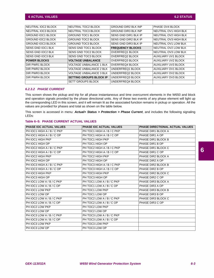
GEK-113032A W650 Wind Generator Protection System 6-3
6 ACTUAL VALUES 6.2 STATUS
6
6.2.3.2 PHASE CURRENT
This screen shows the pickup and trip for all phase instantaneous and time overcurrent elements in the W650 and blockand operation signals provided by the phase directional units. Any of these two events of any phase element will light upthe corresponding LED in this screen, and it will remain lit as the associated function remains in pickup or operation. All thevalues are provided for phases and total as shown on the table below.
This screen is accessed in menu: Actual> Status > Protection > Phase Current, and includes the following signalingLEDs:
Table 6–5: PHASE CURRENT ACTUAL VALUES
NEUTRAL IOC2 BLOCK NEUTRAL TOC2 BLOCK GROUND DIR2 BLK INP PHASE OV4 BLOCKNEUTRAL IOC3 BLOCK NEUTRAL TOC3 BLOCK GROUND DIR3 BLK INP NEUTRAL OV1 HIGH BLKGROUND IOC1 BLOCK GROUND TOC1 BLOCK SENS GND DIR1 BLK IP NEUTRAL OV2 HIGH BLKGROUND IOC2 BLOCK GROUND TOC2 BLOCK SENS GND DIR2 BLK IP NEUTRAL OV3 HIGH BLKGROUND IOC3 BLOCK GROUND TOC3 BLOCK SENS GND DIR3 BLK IP NEUTRAL OV1 LOW BLKSENS GND IOC1 BLK SENS GND TOC1 BLOCK FREQUENCY BLOCKS NEUTRAL OV2 LOW BLKSENS GND IOC2 BLK SENS GND TOC2 BLOCK OVERFREQ1 BLOCK NEUTRAL OV3 LOW BLKSENS GND IOC3 BLK SENS GND TOC3 BLOCK OVERFREQ2 BLOCK AUXILIARY UV1 BLOCKPOWER BLOCKS VOLTAGE UNBALANCE OVERFREQ3 BLOCK AUXILIARY UV2 BLOCKDIR PWR1 BLOCK VOLTAGE UNBALANCE 1 BLK OVERFREQ4 BLOCK AUXILIARY UV3 BLOCKDIR PWR2 BLOCK VOLTAGE UNBALANCE 2 BLK UNDERFREQ1 BLOCK AUXILIARY OV1 BLOCKDIR PWR3 BLOCK VOLTAGE UNBALANCE 3 BLK UNDERFREQ2 BLOCK AUXILIARY OV2 BLOCKDIR PWR4 BLOCK SETTING GROUPS BLOCK IP UNDERFREQ3 BLOCK AUXILIARY OV3 BLOCK
SETT GROUPS BLOCK UNDERFREQ4 BLOCK
PHASE IOC ACTUAL VALUES PHASE IOC ACTUAL VALUES PHASE DIRECTIONAL ACTUAL VALUESPH IOC1 HIGH A / B / C PKP PH TOC1 HIGH A / B / C PKP PHASE DIR1 BLOCK APH IOC1 HIGH A / B / C OP PH TOC1 HIGH A / B / C OP PHASE DIR1 A OPPH IOC1 HIGH PKP PH TOC1 HIGH PKP PHASE DIR1 BLOCK BPH IOC1 HIGH OP PH TOC1 HIGH OP PHASE DIR1 B OPPH IOC2 HIGH A / B / C PKP PH TOC2 HIGH A / B / C PKP PHASE DIR1 BLOCK CPH IOC2 HIGH A / B / C OP PH TOC2 HIGH A / B / C OP PHASE DIR1 C OPPH IOC2 HIGH PKP PH TOC2 HIGH PKP PHASE DIR2 BLOCK APH IOC2 HIGH OP PH TOC2 HIGH OP PHASE DIR2 A OPPH IOC3 HIGH A / B / C PKP PH TOC3 HIGH A / B / C PKP PHASE DIR2 BLOCK BPH IOC3 HIGH A / B / C OP PH TOC3 HIGH A / B / C OP PHASE DIR2 B OPPH IOC3 HIGH PKP PH TOC3 HIGH PKP PHASE DIR2 BLOCK CPH IOC3 HIGH OP PH TOC3 HIGH OP PHASE DIR2 C OPPH IOC1 LOW A / B / C PKP PH TOC1 LOW A / B / C PKP PHASE DIR3 BLOCK APH IOC1 LOW A / B / C OP PH TOC1 LOW A / B / C OP PHASE DIR3 A OPPH IOC1 LOW PKP PH TOC1 LOW PKP PHASE DIR3 BLOCK BPH IOC1 LOW OP PH TOC1 LOW OP PHASE DIR3 B OPPH IOC2 LOW A / B / C PKP PH TOC2 LOW A / B / C PKP PHASE DIR3 BLOCK CPH IOC2 LOW A / B / C OP PH TOC2 LOW A / B / C OP PHASE DIR3 C OPPH IOC2 LOW PKP PH TOC2 LOW PKPPH IOC2 LOW OP PH TOC2 LOW OPPH IOC3 LOW A / B / C PKP PH TOC3 LOW A / B / C PKPPH IOC3 LOW A / B / C OP PH TOC3 LOW A / B / C OPPH IOC3 LOW PKP PH TOC3 LOW PKPPH IOC3 LOW OP PH TOC3 LOW OP
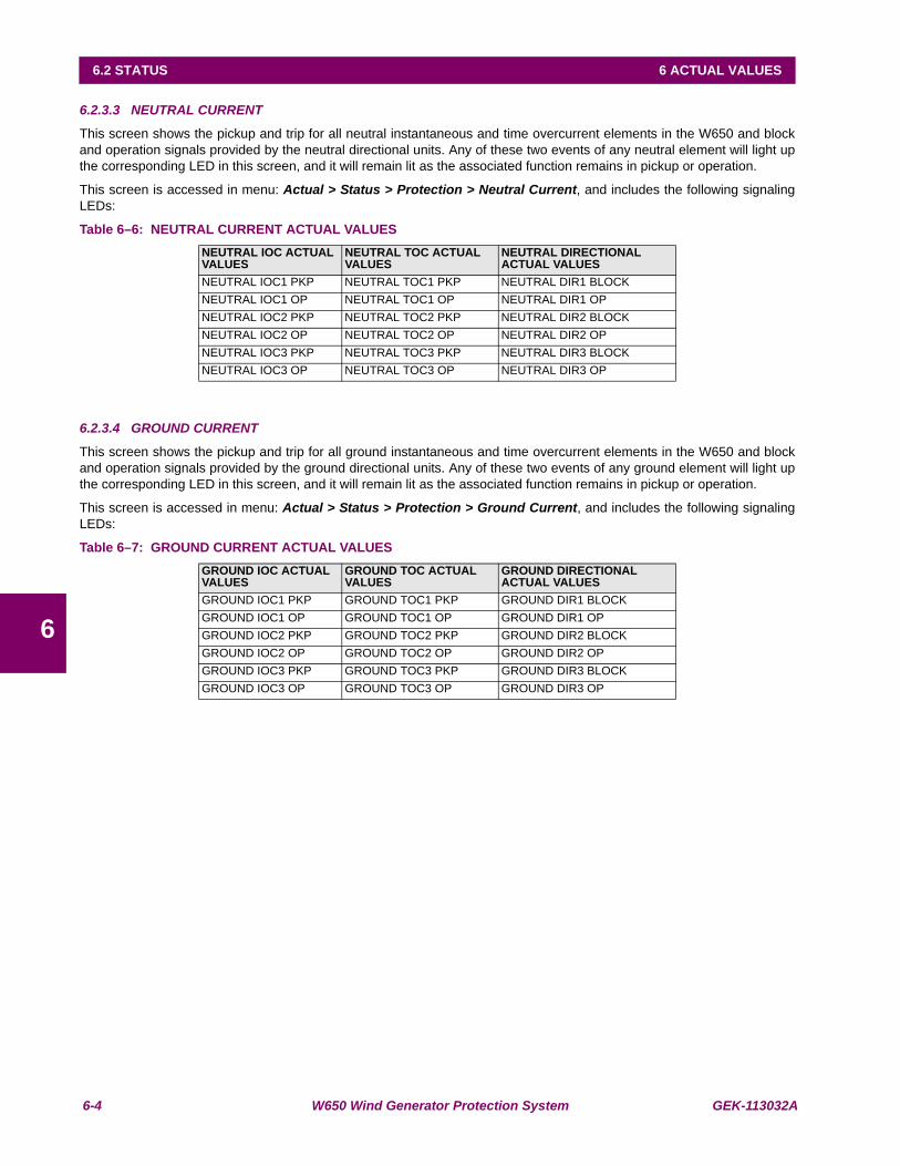
6-4 W650 Wind Generator Protection System GEK-113032A
6.2 STATUS 6 ACTUAL VALUES
6
6.2.3.3 NEUTRAL CURRENT
This screen shows the pickup and trip for all neutral instantaneous and time overcurrent elements in the W650 and blockand operation signals provided by the neutral directional units. Any of these two events of any neutral element will light upthe corresponding LED in this screen, and it will remain lit as the associated function remains in pickup or operation.
This screen is accessed in menu: Actual > Status > Protection > Neutral Current, and includes the following signalingLEDs:
Table 6–6: NEUTRAL CURRENT ACTUAL VALUES
6.2.3.4 GROUND CURRENT
This screen shows the pickup and trip for all ground instantaneous and time overcurrent elements in the W650 and blockand operation signals provided by the ground directional units. Any of these two events of any ground element will light upthe corresponding LED in this screen, and it will remain lit as the associated function remains in pickup or operation.
This screen is accessed in menu: Actual > Status > Protection > Ground Current, and includes the following signalingLEDs:
Table 6–7: GROUND CURRENT ACTUAL VALUES
NEUTRAL IOC ACTUAL VALUES
NEUTRAL TOC ACTUAL VALUES
NEUTRAL DIRECTIONAL ACTUAL VALUES
NEUTRAL IOC1 PKP NEUTRAL TOC1 PKP NEUTRAL DIR1 BLOCKNEUTRAL IOC1 OP NEUTRAL TOC1 OP NEUTRAL DIR1 OPNEUTRAL IOC2 PKP NEUTRAL TOC2 PKP NEUTRAL DIR2 BLOCKNEUTRAL IOC2 OP NEUTRAL TOC2 OP NEUTRAL DIR2 OPNEUTRAL IOC3 PKP NEUTRAL TOC3 PKP NEUTRAL DIR3 BLOCKNEUTRAL IOC3 OP NEUTRAL TOC3 OP NEUTRAL DIR3 OP
GROUND IOC ACTUAL VALUES
GROUND TOC ACTUAL VALUES
GROUND DIRECTIONAL ACTUAL VALUES
GROUND IOC1 PKP GROUND TOC1 PKP GROUND DIR1 BLOCKGROUND IOC1 OP GROUND TOC1 OP GROUND DIR1 OPGROUND IOC2 PKP GROUND TOC2 PKP GROUND DIR2 BLOCKGROUND IOC2 OP GROUND TOC2 OP GROUND DIR2 OPGROUND IOC3 PKP GROUND TOC3 PKP GROUND DIR3 BLOCKGROUND IOC3 OP GROUND TOC3 OP GROUND DIR3 OP

GEK-113032A W650 Wind Generator Protection System 6-5
6 ACTUAL VALUES 6.2 STATUS
6
6.2.3.5 SENSITIVE GROUND CURRENT
This screen shows the pickup and trip for all sensitive ground instantaneousand time overcurrent elements in the W650 andblock and operation signals provided by the sensitive ground directional units. Any of these two events of any groundelement will light up the corresponding LED in this screen, and it will remain lit as the associated function remains in pickupor operation.
This screen is accessed in menu: Actual > Status > Protection >Sensitive Ground Current, and includes the followingsignaling LEDs:
Table 6–8: SENSITIVE GROUND CURRENT ACTUAL VALUES
6.2.3.6 NEGATIVE SEQUENCE CURRENT
This screen shows the pickup and trip for negative sequence elements in the W650. Any of these two events of any groundelement will light up the corresponding LED in this screen, and it will remain lit as the associated function remains in pickupor operation.
This screen is accessed in menu: Actual> Status > Protection >Negative Sequence Current, and includes the followingsignaling LEDs:
Table 6–9: NEGATIVE SEQUENCE CURRENT ACTUAL VALUES
SENSITIVE GROUND IOC ACTUAL VALUES
SENSITIVE GROUND TOC ACTUAL VALUES
SENSITIVE GROUND DIRECTIONAL ACTUAL VALUES
SENS GND IOC1 PKP SENS GND TOC1 PKP SENS GND DIR1 BLOCKSENS GND IOC1 OP SENS GND TOC1 OP SENS GND DIR1 OPSENS GND IOC2 PKP SENS GND TOC2 PKP SENS GND DIR2 BLOCKSENS GND IOC2 OP SENS GND TOC2 OP SENS GND DIR2 OPSENS GND IOC3 PKP SENS GND TOC3 PKP SENS GND DIR3 BLOCKSENS GND IOC3 OP SENS GND TOC3 OP SENS GND DIR3 OP
NEGATIVE SEQUENCE ACTUAL VALUESNEG SEQ TOC1 PKPNEG SEQ TOC1 OPNEG SEQ TOC2 PKPNEG SEQ TOC2 OPNEG SEQ TOC3 PKPNEG SEQ TOC3 OP
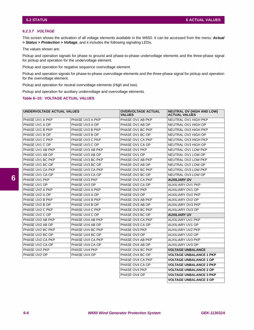
6-6 W650 Wind Generator Protection System GEK-113032A
6.2 STATUS 6 ACTUAL VALUES
6
6.2.3.7 VOLTAGE
This screen shows the activation of all voltage elements available in the W650. It can be accessed from the menu: Actual> Status > Protection > Voltage, and it includes the following signaling LEDs.
The values shown are:
Pickup and operation signals for phase to ground and phase-to-phase undervoltage elements and the three-phase signalfor pickup and operation for the undervoltage element.
Pickup and operation for negative sequence overvoltage element.
Pickup and operation signals for phase-to-phase overvoltage elements and the three-phase signal for pickup and operationfor the overvoltage element.
Pickup and operation for neutral overvoltage elements (High and low).
Pickup and operation for auxiliary undervoltage and overvoltage elements.
Table 6–10: VOLTAGE ACTUAL VALUES
UNDERVOLTAGE ACTUAL VALUES OVERVOLTAGE ACTUAL VALUES
NEUTRAL OV (HIGH AND LOW) ACTUAL VALUES
PHASE UV1 A PKP PHASE UV3 A PKP PHASE OV1 AB PKP NEUTRAL OV1 HIGH PKPPHASE UV1 A OP PHASE UV3 A OP PHASE OV1 AB OP NEUTRAL OV1 HIGH OPPHASE UV1 B PKP PHASE UV3 B PKP PHASE OV1 BC PKP NEUTRAL OV2 HIGH PKPPHASE UV1 B OP PHASE UV3 B OP PHASE OV1 BC OP NEUTRAL OV2 HIGH OPPHASE UV1 C PKP PHASE UV3 C PKP PHASE OV1 CA PKP NEUTRAL OV3 HIGH PKPPHASE UV1 C OP PHASE UV3 C OP PHASE OV1 CA OP NEUTRAL OV3 HIGH OPPHASE UV1 AB PKP PHASE UV3 AB PKP PHASE OV1 PKP NEUTRAL OV1 LOW PKPPHASE UV1 AB OP PHASE UV3 AB OP PHASE OV1 OP NEUTRAL OV1 LOW OPPHASE UV1 BC PKP PHASE UV3 BC PKP PHASE OV2 AB PKP NEUTRAL OV2 LOW PKPPHASE UV1 BC OP PHASE UV3 BC OP PHASE OV2 AB OP NEUTRAL OV2 LOW OPPHASE UV1 CA PKP PHASE UV3 CA PKP PHASE OV2 BC PKP NEUTRAL OV3 LOW PKPPHASE UV1 CA OP PHASE UV3 CA OP PHASE OV2 BC OP NEUTRAL OV3 LOW OPPHASE UV1 PKP PHASE UV3 PKP PHASE OV2 CA PKP AUXILIARY OVPHASE UV1 OP PHASE UV3 OP PHASE OV2 CA OP AUXILIARY OV1 PKPPHASE UV2 A PKP PHASE UV4 A PKP PHASE OV2 PKP AUXILIARY OV1 OPPHASE UV2 A OP PHASE UV4 A OP PHASE OV2 OP AUXILIARY OV2 PKPPHASE UV2 B PKP PHASE UV4 B PKP PHASE OV3 AB PKP AUXILIARY OV2 OPPHASE UV2 B OP PHASE UV4 B OP PHASE OV3 AB OP AUXILIARY OV3 PKPPHASE UV2 C PKP PHASE UV4 C PKP PHASE OV3 BC PKP AUXILIARY OV3 OPPHASE UV2 C OP PHASE UV4 C OP PHASE OV3 BC OP AUXILIARY UVPHASE UV2 AB PKP PHASE UV4 AB PKP PHASE OV3 CA PKP AUXILIARY UV1 PKPPHASE UV2 AB OP PHASE UV4 AB OP PHASE OV3 CA OP AUXILIARY UV1 OPPHASE UV2 BC PKP PHASE UV4 BC PKP PHASE OV3 PKP AUXILIARY UV2 PKPPHASE UV2 BC OP PHASE UV4 BC OP PHASE OV3 OP AUXILIARY UV2 OPPHASE UV2 CA PKP PHASE UV4 CA PKP PHASE OV4 AB PKP AUXILIARY UV3 PKPPHASE UV2 CA OP PHASE UV4 CA OP PHASE OV4 AB OP AUXILIARY UV3 OPPHASE UV2 PKP PHASE UV4 PKP PHASE OV4 BC PKP VOLTAGE UNBALANCEPHASE UV2 OP PHASE UV4 OP PHASE OV4 BC OP VOLTAGE UNBALANCE 1 PKP
PHASE OV4 CA PKP VOLTAGE UNBALANCE 1 OPPHASE OV4 CA OP VOLTAGE UNBALANCE 2 PKP PHASE OV4 PKP VOLTAGE UNBALANCE 2 OPPHASE OV4 OP VOLTAGE UNBALANCE 3 PKP
VOLTAGE UNBALANCE 3 OP
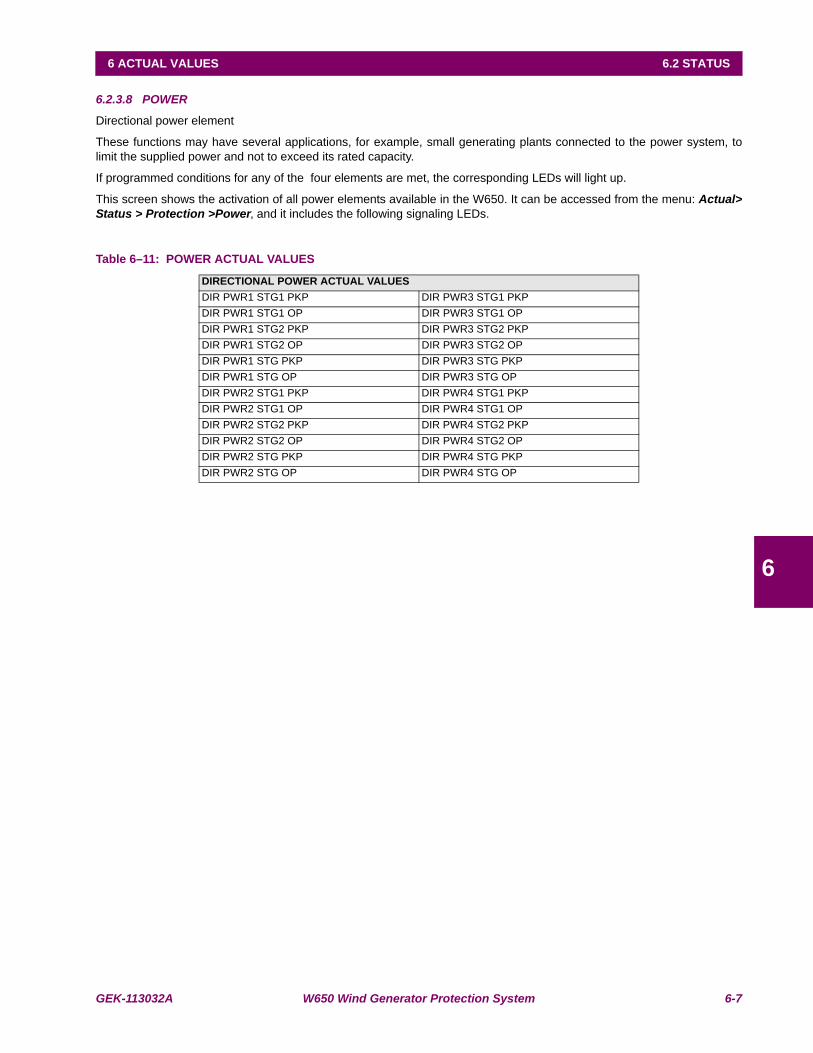
GEK-113032A W650 Wind Generator Protection System 6-7
6 ACTUAL VALUES 6.2 STATUS
6
6.2.3.8 POWER
Directional power element
These functions may have several applications, for example, small generating plants connected to the power system, tolimit the supplied power and not to exceed its rated capacity.
If programmed conditions for any of the four elements are met, the corresponding LEDs will light up.
This screen shows the activation of all power elements available in the W650. It can be accessed from the menu: Actual>Status > Protection >Power, and it includes the following signaling LEDs.
Table 6–11: POWER ACTUAL VALUES
DIRECTIONAL POWER ACTUAL VALUESDIR PWR1 STG1 PKP DIR PWR3 STG1 PKPDIR PWR1 STG1 OP DIR PWR3 STG1 OPDIR PWR1 STG2 PKP DIR PWR3 STG2 PKPDIR PWR1 STG2 OP DIR PWR3 STG2 OPDIR PWR1 STG PKP DIR PWR3 STG PKPDIR PWR1 STG OP DIR PWR3 STG OPDIR PWR2 STG1 PKP DIR PWR4 STG1 PKPDIR PWR2 STG1 OP DIR PWR4 STG1 OPDIR PWR2 STG2 PKP DIR PWR4 STG2 PKPDIR PWR2 STG2 OP DIR PWR4 STG2 OPDIR PWR2 STG PKP DIR PWR4 STG PKPDIR PWR2 STG OP DIR PWR4 STG OP
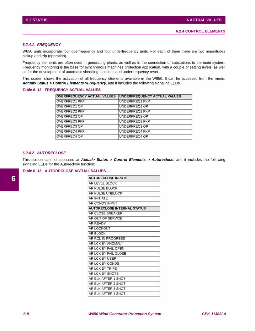
6-8 W650 Wind Generator Protection System GEK-113032A
6.2 STATUS 6 ACTUAL VALUES
6
6.2.4 CONTROL ELEMENTS
6.2.4.1 FREQUENCY
W650 units incorporate four overfrequency and four underfrequency units. For each of them there are two magnitudespickup and trip (operation).
Frequency elements are often used in generating plants, as well as in the connection of substations to the main system.Frequency monitoring is the base for synchronous machines protection application, with a couple of setting levels, as wellas for the development of automatic shedding functions and underfrequency reset.
This screen shows the activation of all frequency elements available in the W650. It can be accessed from the menu:Actual> Status > Control Elements >Frequency, and it includes the following signaling LEDs.
Table 6–12: FREQUENCY ACTUAL VALUES
6.2.4.2 AUTORECLOSE
This screen can be accessed at Actual> Status > Control Elements > Autoreclose, and it includes the followingsignaling LEDs for the Autoreclose function:
Table 6–13: AUTORECLOSE ACTUAL VALUES
OVERFREQUENCY ACTUAL VALUES UNDERFREQUENCY ACTUAL VALUESOVERFREQ1 PKP UNDERFREQ1 PKPOVERFREQ1 OP UNDERFREQ1 OPOVERFREQ2 PKP UNDERFREQ2 PKPOVERFREQ2 OP UNDERFREQ2 OPOVERFREQ3 PKP UNDERFREQ3 PKPOVERFREQ3 OP UNDERFREQ3 OPOVERFREQ4 PKP UNDERFREQ4 PKPOVERFREQ4 OP UNDERFREQ4 OP
AUTORECLOSE INPUTSAR LEVEL BLOCKAR PULSE BLOCKAR PULSE UNBLOCKAR INITIATEAR CONDS INPUTAUTORECLOSE INTERNAL STATUSAR CLOSE BREAKERAR OUT OF SERVICEAR READYAR LOCKOUTAR BLOCKAR RCL IN PROGRESSAR LCK BY ANOMALYAR LCK BY FAIL OPENAR LCK BY FAIL CLOSEAR LCK BY USERAR LCK BY CONDSAR LCK BY TRIPSAR LCK BY SHOTSAR BLK AFTER 1 SHOTAR BLK AFTER 2 SHOTAR BLK AFTER 3 SHOTAR BLK AFTER 4 SHOT
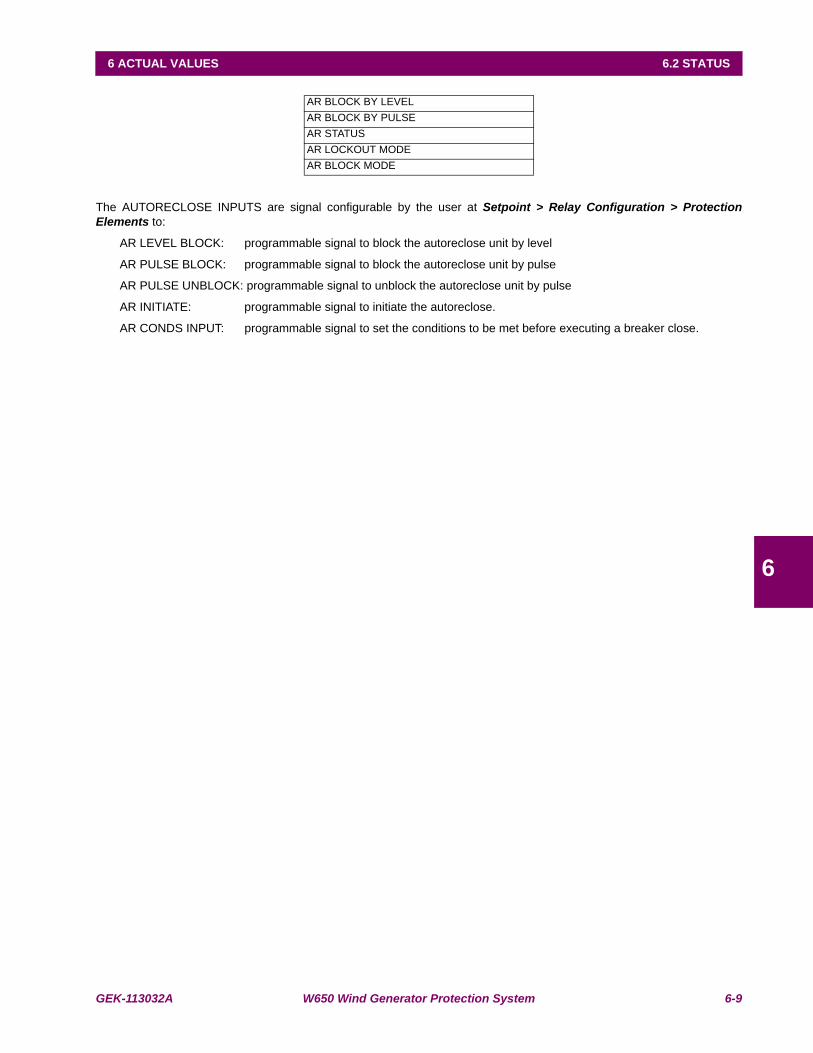
GEK-113032A W650 Wind Generator Protection System 6-9
6 ACTUAL VALUES 6.2 STATUS
6
The AUTORECLOSE INPUTS are signal configurable by the user at Setpoint > Relay Configuration > ProtectionElements to:
AR LEVEL BLOCK: programmable signal to block the autoreclose unit by level
AR PULSE BLOCK: programmable signal to block the autoreclose unit by pulse
AR PULSE UNBLOCK: programmable signal to unblock the autoreclose unit by pulse
AR INITIATE: programmable signal to initiate the autoreclose.
AR CONDS INPUT: programmable signal to set the conditions to be met before executing a breaker close.
AR BLOCK BY LEVELAR BLOCK BY PULSEAR STATUSAR LOCKOUT MODEAR BLOCK MODE
6-10 W650 Wind Generator Protection System GEK-113032A
6.2 STATUS 6 ACTUAL VALUES
6
The AUTORECLOSE INTERNAL STATUS are internal signals provided by the autoreclose unit:
AR CLOSE BREAKER: Breaker close command given by the autoreclose
AR OUT OF SERVICE: Autoreclose out of service (Disabled)
AR READY: Autoreclose in service
AR LOCKOUT: Autoreclose in lockout status (finished cycled-definite trip)
AR BLOCK: Autoreclose blocked (by input, logic, others, etc).
AR RCL IN PROGRESS: Cycle in course (autoreclose in progress).
AR LCK BY ANOMALY: Autoreclose in “Lockout” by anomaly.
AR LCK BY FAIL OPEN: Autoreclose in “Lockout” by a failure in opening the breaker.
AR LCK BY FAIL CLOSE: Autoreclose in “Lockout” by a failure in closing the breaker.
AR LCK BY USER: Autoreclose in “Lockout” by manual close.
AR LCK BY CONDS: Autoreclose in “Lockout” by conditions. See input conditions configuration.
AR LCK BY TRIPS: Autoreclose in “Lockout” by maximum number of trips.
AR LCK BY SHOTS: Autoreclose in “Lockout” at the end of cycle – Definite trip.
AR BLK AFTER 1 SHOT: Signal sent by the autoreclose after the 1st shot.
AR BLK AFTER 2 SHOT: Signal sent by the autoreclose after the 2nd shot.
AR BLK AFTER 3 SHOT: Signal sent by the autoreclose after the 3rd shot.
AR BLK AFTER 4 SHOT: Signal sent by the autoreclose after the 4th shot.
AR BLOCK BY LEVEL: Autoreclose blocked by level. See AR block signals configuration
AR BLOCK BY PULSE: Autoreclose blocked by pulse. See AR block signals configuration
AR STATUS: Autoreclose status (in service – out of service)
AR LOCKOUT MODE: Relay “Lockout” status.
AR BLOCK MODE: Relay “Block” status
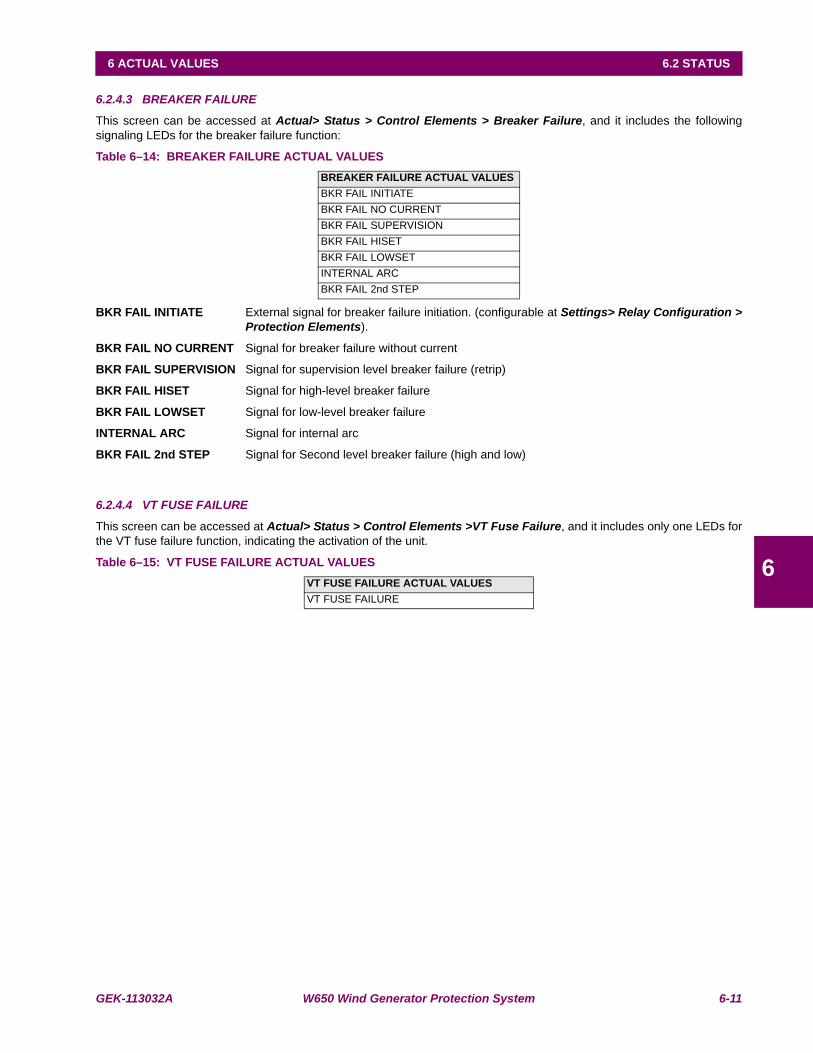
GEK-113032A W650 Wind Generator Protection System 6-11
6 ACTUAL VALUES 6.2 STATUS
6
6.2.4.3 BREAKER FAILURE
This screen can be accessed at Actual> Status > Control Elements > Breaker Failure, and it includes the followingsignaling LEDs for the breaker failure function:
Table 6–14: BREAKER FAILURE ACTUAL VALUES
BKR FAIL INITIATE External signal for breaker failure initiation. (configurable at Settings> Relay Configuration >Protection Elements).
BKR FAIL NO CURRENT Signal for breaker failure without current
BKR FAIL SUPERVISION Signal for supervision level breaker failure (retrip)
BKR FAIL HISET Signal for high-level breaker failure
BKR FAIL LOWSET Signal for low-level breaker failure
INTERNAL ARC Signal for internal arc
BKR FAIL 2nd STEP Signal for Second level breaker failure (high and low)
6.2.4.4 VT FUSE FAILURE
This screen can be accessed at Actual> Status > Control Elements >VT Fuse Failure, and it includes only one LEDs forthe VT fuse failure function, indicating the activation of the unit.
Table 6–15: VT FUSE FAILURE ACTUAL VALUES
BREAKER FAILURE ACTUAL VALUESBKR FAIL INITIATEBKR FAIL NO CURRENTBKR FAIL SUPERVISIONBKR FAIL HISETBKR FAIL LOWSETINTERNAL ARCBKR FAIL 2nd STEP
VT FUSE FAILURE ACTUAL VALUESVT FUSE FAILURE
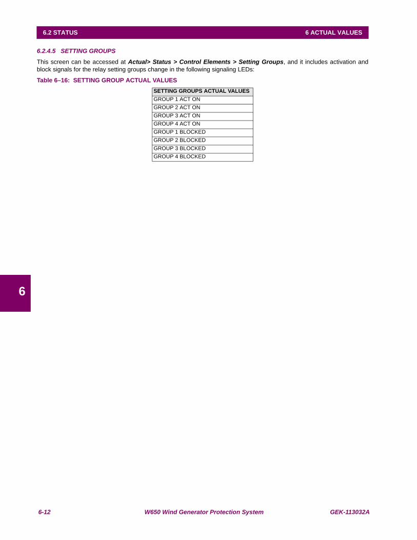
6-12 W650 Wind Generator Protection System GEK-113032A
6.2 STATUS 6 ACTUAL VALUES
6
6.2.4.5 SETTING GROUPS
This screen can be accessed at Actual> Status > Control Elements > Setting Groups, and it includes activation andblock signals for the relay setting groups change in the following signaling LEDs:
Table 6–16: SETTING GROUP ACTUAL VALUESSETTING GROUPS ACTUAL VALUESGROUP 1 ACT ONGROUP 2 ACT ONGROUP 3 ACT ONGROUP 4 ACT ONGROUP 1 BLOCKEDGROUP 2 BLOCKEDGROUP 3 BLOCKEDGROUP 4 BLOCKED

GEK-113032A W650 Wind Generator Protection System 6-13
6 ACTUAL VALUES 6.2 STATUS
6
6.2.5 PROTECTION SUMMARY
Actual > Status > Protection Summary . This screen shows a complete listing of all protection and control elements inthe relay, showing their status (enabled or not) through the corresponding LED . Table 6–17:
Phase IOC1 HighPhase IOC2 HighPhase IOC3 HighPhase IOC1 LowPhase IOC2 LowPhase IOC3 LowNeutral IOC1Neutral IOC2Neutral IOC3Ground IOC1Ground IOC2Ground IOC3Sensitive Ground IOC1Sensitive Ground IOC2Sensitive Ground IOC3Phase TOC1 HighPhase TOC2 HighPhase TOC3 HighNeutral TOC1Neutral TOC2Neutral TOC3Ground TOC1Ground TOC2Ground TOC3Sensitive Ground TOC1Sensitive Ground TOC2Sensitive Ground TOC3Phase UV1Phase UV2Phase UV3Phase UV4Phase Directional1Phase Directional2Phase Directional3Neutral Directional1Neutral Directional2Neutral Directional3Ground Directional1Ground Directional2Ground Directional3Breaker FailureFuse FailureRecloserNeutral OV1 HighNeutral OV2 HighNeutral OV3 HighNeutral OV1 LowNeutral OV2 LowNeutral OV3 Low
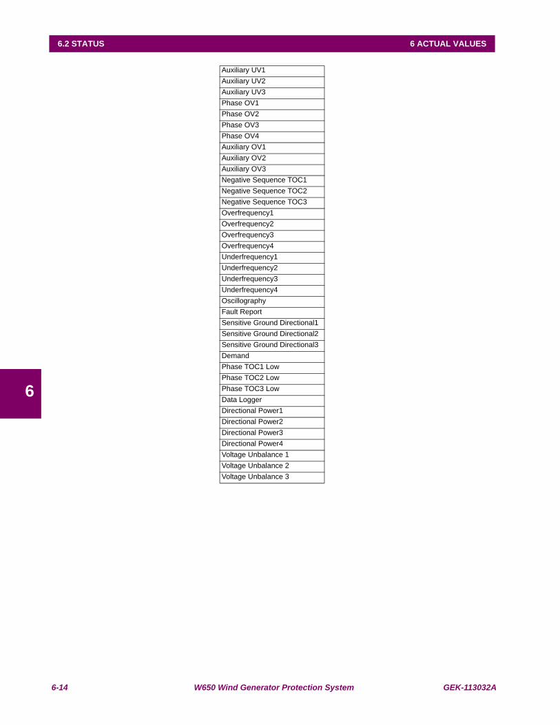
6-14 W650 Wind Generator Protection System GEK-113032A
6.2 STATUS 6 ACTUAL VALUES
6
Auxiliary UV1Auxiliary UV2Auxiliary UV3Phase OV1Phase OV2Phase OV3Phase OV4Auxiliary OV1Auxiliary OV2Auxiliary OV3Negative Sequence TOC1Negative Sequence TOC2Negative Sequence TOC3Overfrequency1Overfrequency2Overfrequency3Overfrequency4Underfrequency1Underfrequency2Underfrequency3Underfrequency4OscillographyFault ReportSensitive Ground Directional1Sensitive Ground Directional2Sensitive Ground Directional3DemandPhase TOC1 LowPhase TOC2 LowPhase TOC3 LowData LoggerDirectional Power1Directional Power2Directional Power3Directional Power4Voltage Unbalance 1Voltage Unbalance 2Voltage Unbalance 3
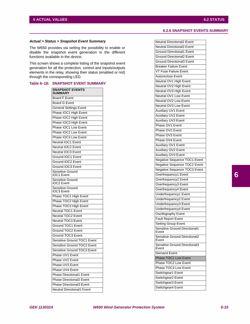
GEK-113032A W650 Wind Generator Protection System 6-15
6 ACTUAL VALUES 6.2 STATUS
6
6.2.6 SNAPSHOT EVENTS SUMMARY
Actual > Status > Snapshot Event Summary
The W650 provides via setting the possibility to enable ordisable the snapshot event generation in the differentfunctions available in the device.
This screen shows a complete listing of the snapshot eventgeneration for all the protection, control and inputs/outputselements in the relay, showing their status (enabled or not)through the corresponding LED.
Table 6–18: SNAPSHOT EVENT SUMMARYSNAPSHOT EVENTS SUMMARYBoard F EventBoard G EventGeneral Settings EventPhase IOC1 High EventPhase IOC2 High EventPhase IOC3 High EventPhase IOC1 Low EventPhase IOC2 Low EventPhase IOC3 Low EventNeutral IOC1 EventNeutral IOC2 EventNeutral IOC3 EventGround IOC1 EventGround IOC2 EventGround IOC3 EventSensitive Ground IOC1 EventSensitive Ground IOC2 EventSensitive Ground IOC3 EventPhase TOC1 High EventPhase TOC2 High EventPhase TOC3 High EventNeutral TOC1 EventNeutral TOC2 EventNeutral TOC3 EventGround TOC1 EventGround TOC2 EventGround TOC3 EventSensitive Ground TOC1 EventSensitive Ground TOC2 EventSensitive Ground TOC3 EventPhase UV1 EventPhase UV2 EventPhase UV3 EventPhase UV4 EventPhase Directional1 EventPhase Directional2 EventPhase Directional3 EventNeutral Directional1 Event
Neutral Directional2 EventNeutral Directional3 EventGround Directional1 EventGround Directional2 EventGround Directional3 EventBreaker Failure EventVT Fuse Failure EventAutoreclose EventNeutral OV1 High EventNeutral OV2 High EventNeutral OV3 High EventNeutral OV1 Low EventNeutral OV2 Low EventNeutral OV3 Low EventAuxiliary UV1 EventAuxiliary UV2 EventAuxiliary UV3 EventPhase OV1 EventPhase OV2 EventPhase OV3 EventPhase OV4 EventAuxiliary OV1 EventAuxiliary OV2 EventAuxiliary OV3 EventNegative Sequence TOC1 EventNegative Sequence TOC2 EventNegative Sequence TOC3 EventOverfrequency1 EventOverfrequency2 EventOverfrequency3 EventOverfrequency4 EventUnderfrequency1 EventUnderfrequency2 EventUnderfrequency3 EventUnderfrequency4 EventOscillography EventFault Report EventSetting Group EventSensitive Ground Directional1 EventSensitive Ground Directional2 EventSensitive Ground Directional3 EventDemand EventPhase TOC1 Low EventPhase TOC2 Low EventPhase TOC3 Low EventSwitchgear1 EventSwitchgear2 EventSwitchgear3 EventSwitchgear4 Event
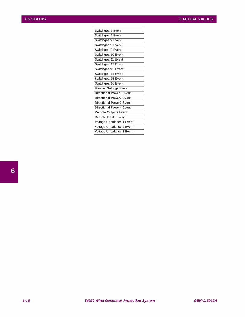
6-16 W650 Wind Generator Protection System GEK-113032A
6.2 STATUS 6 ACTUAL VALUES
6
Switchgear5 EventSwitchgear6 EventSwitchgear7 EventSwitchgear8 EventSwitchgear9 EventSwitchgear10 EventSwitchgear11 EventSwitchgear12 EventSwitchgear13 EventSwitchgear14 EventSwitchgear15 EventSwitchgear16 EventBreaker Settings EventDirectional Power1 EventDirectional Power2 EventDirectional Power3 EventDirectional Power4 EventRemote Outputs EventRemote Inputs EventVoltage Unbalance 1 EventVoltage Unbalance 2 EventVoltage Unbalance 3 Event
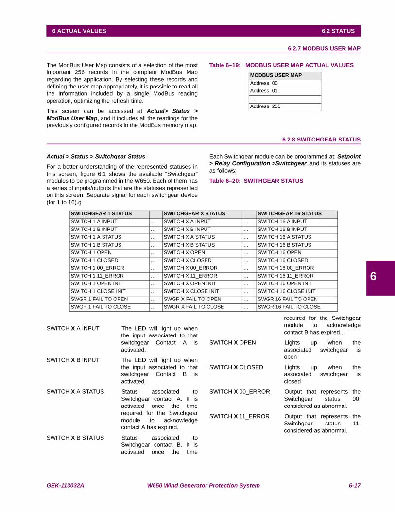
GEK-113032A W650 Wind Generator Protection System 6-17
6 ACTUAL VALUES 6.2 STATUS
6
6.2.7 MODBUS USER MAP
The ModBus User Map consists of a selection of the mostimportant 256 records in the complete ModBus Mapregarding the application. By selecting these records anddefining the user map appropriately, it is possible to read allthe information included by a single ModBus readingoperation, optimizing the refresh time.
This screen can be accessed at Actual> Status >ModBus User Map, and it includes all the readings for thepreviously configured records in the ModBus memory map.
Table 6–19: MODBUS USER MAP ACTUAL VALUES
6.2.8 SWITCHGEAR STATUS
Actual > Status > Switchgear Status
For a better understanding of the represented statuses inthis screen, figure 6.1 shows the available “Switchgear”modules to be programmed in the W650. Each of them hasa series of inputs/outputs that are the statuses representedon this screen. Separate signal for each switchgear device(for 1 to 16).g
Each Switchgear module can be programmed at: Setpoint> Relay Configuration >Switchgear, and its statuses areas follows:
Table 6–20: SWITHGEAR STATUS
SWITCH X A INPUT The LED will light up whenthe input associated to thatswitchgear Contact A isactivated.
SWITCH X B INPUT The LED will light up whenthe input associated to thatswitchgear Contact B isactivated.
SWITCH X A STATUS Status associated toSwitchgear contact A. It isactivated once the timerequired for the Switchgearmodule to acknowledgecontact A has expired.
SWITCH X B STATUS Status associated toSwitchgear contact B. It isactivated once the time
required for the Switchgearmodule to acknowledgecontact B has expired..
SWITCH X OPEN Lights up when theassociated switchgear isopen
SWITCH X CLOSED Lights up when theassociated switchgear isclosed
SWITCH X 00_ERROR Output that represents theSwitchgear status 00,considered as abnormal.
SWITCH X 11_ERROR Output that represents theSwitchgear status 11,considered as abnormal.
MODBUS USER MAP Address 00Address 01…Address 255
SWITCHGEAR 1 STATUS SWITCHGEAR X STATUS SWITCHGEAR 16 STATUSSWITCH 1 A INPUT … SWITCH X A INPUT … SWITCH 16 A INPUTSWITCH 1 B INPUT … SWITCH X B INPUT … SWITCH 16 B INPUTSWITCH 1 A STATUS … SWITCH X A STATUS … SWITCH 16 A STATUSSWITCH 1 B STATUS … SWITCH X B STATUS … SWITCH 16 B STATUSSWITCH 1 OPEN … SWITCH X OPEN … SWITCH 16 OPENSWITCH 1 CLOSED … SWITCH X CLOSED … SWITCH 16 CLOSEDSWITCH 1 00_ERROR … SWITCH X 00_ERROR … SWITCH 16 00_ERRORSWITCH 1 11_ERROR … SWITCH X 11_ERROR … SWITCH 16 11_ERRORSWITCH 1 OPEN INIT … SWITCH X OPEN INIT … SWITCH 16 OPEN INITSWITCH 1 CLOSE INIT … SWITCH X CLOSE INIT … SWITCH 16 CLOSE INITSWGR 1 FAIL TO OPEN … SWGR X FAIL TO OPEN … SWGR 16 FAIL TO OPENSWGR 1 FAIL TO CLOSE … SWGR X FAIL TO CLOSE … SWGR 16 FAIL TO CLOSE
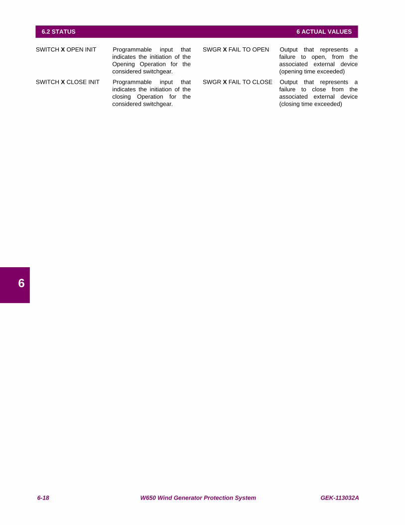
6-18 W650 Wind Generator Protection System GEK-113032A
6.2 STATUS 6 ACTUAL VALUES
6
SWITCH X OPEN INIT Programmable input thatindicates the initiation of theOpening Operation for theconsidered switchgear.
SWITCH X CLOSE INIT Programmable input thatindicates the initiation of theclosing Operation for theconsidered switchgear.
SWGR X FAIL TO OPEN Output that represents afailure to open, from theassociated external device(opening time exceeded)
SWGR X FAIL TO CLOSE Output that represents afailure to close from theassociated external device(closing time exceeded)
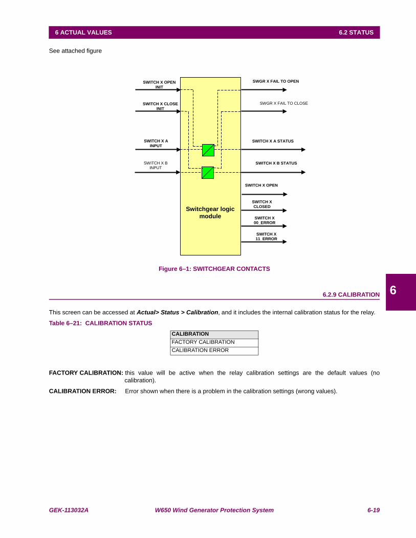
GEK-113032A W650 Wind Generator Protection System 6-19
6 ACTUAL VALUES 6.2 STATUS
6
See attached figure
Figure 6–1: SWITCHGEAR CONTACTS
6.2.9 CALIBRATION
This screen can be accessed at Actual> Status > Calibration, and it includes the internal calibration status for the relay.
Table 6–21: CALIBRATION STATUS
FACTORY CALIBRATION: this value will be active when the relay calibration settings are the default values (nocalibration).
CALIBRATION ERROR: Error shown when there is a problem in the calibration settings (wrong values).
CALIBRATIONFACTORY CALIBRATIONCALIBRATION ERROR
SWGR X FAIL TO OPEN
SWGR X FAIL TO CLOSE
SWITCH X OPEN
INIT
SWITCH X CLOSE
INIT
SWITCH X B INPUT
SWITCH X A STATUS SWITCH X A
INPUT
SWITCH X B STATUS
SWITCH X OPEN
SWITCH X
CLOSED
SWITCH X 00_ERROR
SWITCH X 11_ERROR
Switchgear logic
module
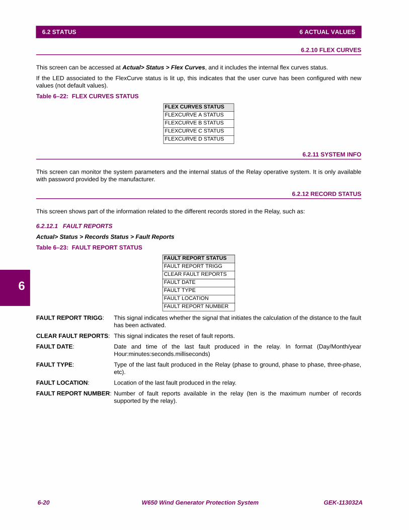
6-20 W650 Wind Generator Protection System GEK-113032A
6.2 STATUS 6 ACTUAL VALUES
6
6.2.10 FLEX CURVES
This screen can be accessed at Actual> Status > Flex Curves, and it includes the internal flex curves status.
If the LED associated to the FlexCurve status is lit up, this indicates that the user curve has been configured with newvalues (not default values).
Table 6–22: FLEX CURVES STATUS
6.2.11 SYSTEM INFO
This screen can monitor the system parameters and the internal status of the Relay operative system. It is only availablewith password provided by the manufacturer.
6.2.12 RECORD STATUS
This screen shows part of the information related to the different records stored in the Relay, such as:
6.2.12.1 FAULT REPORTS
Actual> Status > Records Status > Fault Reports
Table 6–23: FAULT REPORT STATUS
FAULT REPORT TRIGG: This signal indicates whether the signal that initiates the calculation of the distance to the faulthas been activated.
CLEAR FAULT REPORTS: This signal indicates the reset of fault reports.
FAULT DATE: Date and time of the last fault produced in the relay. In format (Day/Month/yearHour:minutes:seconds.milliseconds)
FAULT TYPE: Type of the last fault produced in the Relay (phase to ground, phase to phase, three-phase,etc).
FAULT LOCATION: Location of the last fault produced in the relay.
FAULT REPORT NUMBER: Number of fault reports available in the relay (ten is the maximum number of recordssupported by the relay).
FLEX CURVES STATUSFLEXCURVE A STATUSFLEXCURVE B STATUSFLEXCURVE C STATUSFLEXCURVE D STATUS
FAULT REPORT STATUSFAULT REPORT TRIGGCLEAR FAULT REPORTSFAULT DATEFAULT TYPEFAULT LOCATIONFAULT REPORT NUMBER

GEK-113032A W650 Wind Generator Protection System 6-21
6 ACTUAL VALUES 6.2 STATUS
6
6.2.12.2 CONTROL EVENTS
Actual> Status > Records Status > Control Events
In this screen Actual> Status > Records Status > Control Events, the status of the signals configured to launch thecontrol events can be seen, activated or not.
The W650 provides the possibility to configure 128 control events (at Settings>Relay Configuration > Control Events).In the Actual > Records > Event Recorder > Control Events it is possible to see and retrieve the recorded control eventsto a file, seeing the text and date and time and status of the preconfigured control event.
Table 6–24: CONTROL EVENTS STATUS
6.2.12.3 OSCILLOGRAPHY
Actual> Status > Records Status > Oscillography
The following figure shows the status of the different digital channels that can be programmed to be included inoscillography records. When the signal associated to a specific channel is active, its LED will light up on this screen.
This screen shows as well the oscillography trigger status, active or inactive, by lighting up that channel.
Table 6–25: OSCILLOGRAPHY STATUS
The last three values shown are as follows:
NUMBER OF TRIGGERS: This is the number of the last oscillography record obtained in the relay. This value has a rangeof 0 to 999.
CYCLES PER RECORD: This is the number of cycles contained in the oscillography record; this value depends on thesettings adjusted on the oscillography menu at Setpoint > Product Setup > Oscillography.
AVAILABLE RECORDS: This is the number of available oscillography records in the relay.
Values for these last 3 fields are reset every time the oscillography settings are modified.
CONTROL EVENTSCONTROL EVENT 1CONTROL EVENT 2…CONTROL EVENT 128
OSCILLOGRAPHYOSC DIG CHANNEL 1OSC DIG CHANNEL 2OSC DIG CHANNEL 3OSC DIG CHANNEL 4OSC DIG CHANNEL 5OSC DIG CHANNEL 6OSC DIG CHANNEL 7OSC DIG CHANNEL 8OSC DIG CHANNEL 9OSC DIG CHANNEL 10OSC DIG CHANNEL 11OSC DIG CHANNEL 12OSC DIG CHANNEL 13OSC DIG CHANNEL 14OSC DIG CHANNEL 15OSC DIG CHANNEL 16OSCILLO TRIGGERNUMBER OF TRIGGERSCYCLES PER RECORDAVAILABLE RECORDS
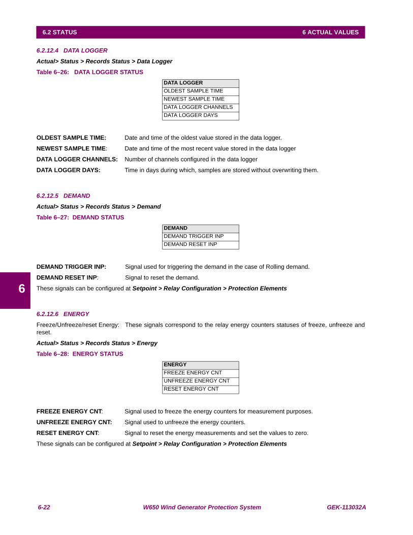
6-22 W650 Wind Generator Protection System GEK-113032A
6.2 STATUS 6 ACTUAL VALUES
6
6.2.12.4 DATA LOGGER
Actual> Status > Records Status > Data Logger
Table 6–26: DATA LOGGER STATUS
OLDEST SAMPLE TIME: Date and time of the oldest value stored in the data logger.
NEWEST SAMPLE TIME: Date and time of the most recent value stored in the data logger
DATA LOGGER CHANNELS: Number of channels configured in the data logger
DATA LOGGER DAYS: Time in days during which, samples are stored without overwriting them.
6.2.12.5 DEMAND
Actual> Status > Records Status > Demand
Table 6–27: DEMAND STATUS
DEMAND TRIGGER INP: Signal used for triggering the demand in the case of Rolling demand.
DEMAND RESET INP: Signal to reset the demand.
These signals can be configured at Setpoint > Relay Configuration > Protection Elements
6.2.12.6 ENERGY
Freeze/Unfreeze/reset Energy: These signals correspond to the relay energy counters statuses of freeze, unfreeze andreset.
Actual> Status > Records Status > Energy
Table 6–28: ENERGY STATUS
FREEZE ENERGY CNT: Signal used to freeze the energy counters for measurement purposes.
UNFREEZE ENERGY CNT: Signal used to unfreeze the energy counters.
RESET ENERGY CNT: Signal to reset the energy measurements and set the values to zero.
These signals can be configured at Setpoint > Relay Configuration > Protection Elements
DATA LOGGEROLDEST SAMPLE TIMENEWEST SAMPLE TIMEDATA LOGGER CHANNELSDATA LOGGER DAYS
DEMAND DEMAND TRIGGER INPDEMAND RESET INP
ENERGYFREEZE ENERGY CNTUNFREEZE ENERGY CNTRESET ENERGY CNT
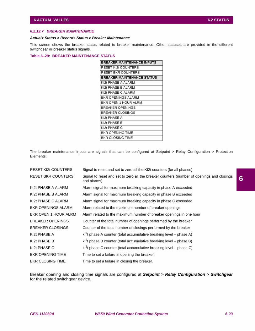
GEK-113032A W650 Wind Generator Protection System 6-23
6 ACTUAL VALUES 6.2 STATUS
6
6.2.12.7 BREAKER MAINTENANCE
Actual> Status > Records Status > Breaker Maintenance
This screen shows the breaker status related to breaker maintenance. Other statuses are provided in the differentswitchgear or breaker status signals.
Table 6–29: BREAKER MAINTENANCE STATUS
The breaker maintenance inputs are signals that can be configured at Setpoint > Relay Configuration > ProtectionElements:
RESET KI2t COUNTERS Signal to reset and set to zero all the KI2t counters (for all phases)
RESET BKR COUNTERS Signal to reset and set to zero all the breaker counters (number of openings and closingsand alarms)
KI2t PHASE A ALARM Alarm signal for maximum breaking capacity in phase A exceeded
KI2t PHASE B ALARM Alarm signal for maximum breaking capacity in phase B exceeded
KI2t PHASE C ALARM Alarm signal for maximum breaking capacity in phase C exceeded
BKR OPENINGS ALARM Alarm related to the maximum number of breaker openings
BKR OPEN 1 HOUR ALRM Alarm related to the maximum number of breaker openings in one hour
BREAKER OPENINGS Counter of the total number of openings performed by the breaker
BREAKER CLOSINGS Counter of the total number of closings performed by the breaker
KI2t PHASE A kI2t phase A counter (total accumulative breaking level – phase A)
KI2t PHASE B kI2t phase B counter (total accumulative breaking level – phase B)
KI2t PHASE C kI2t phase C counter (total accumulative breaking level – phase C)
BKR OPENING TIME Time to set a failure in opening the breaker.
BKR CLOSING TIME Time to set a failure in closing the breaker.
Breaker opening and closing time signals are configured at Setpoint > Relay Configuration > Switchgearfor the related switchgear device.
BREAKER MAINTENANCE INPUTSRESET KI2t COUNTERSRESET BKR COUNTERSBREAKER MAINTENANCE STATUSKI2t PHASE A ALARMKI2t PHASE B ALARMKI2t PHASE C ALARMBKR OPENINGS ALARMBKR OPEN 1 HOUR ALRMBREAKER OPENINGSBREAKER CLOSINGSKI2t PHASE AKI2t PHASE BKI2t PHASE CBKR OPENING TIMEBKR CLOSING TIME

6-24 W650 Wind Generator Protection System GEK-113032A
6.2 STATUS 6 ACTUAL VALUES
6
6.2.12.8 CAN OPEN
Actual> Status > CAN Open
This screen shows the communication status between W650 and an external PLC using CAN bus.
6.2.12.9 SNTP/IRIGB
Actual > Status > SNTP/IRIGB
This screen shows if the relay is synchronized by external devices using or SNTP protocol or IRIGB input port. In case ofrelays synchronized by both elements at the same time, IRIGB time will be used by the relay.
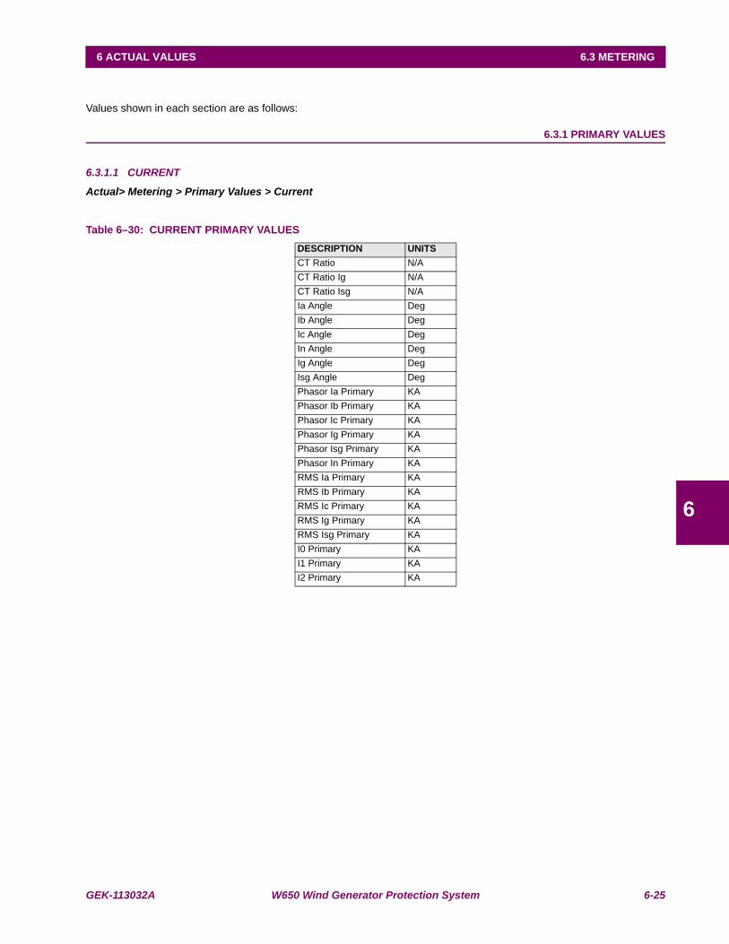
GEK-113032A W650 Wind Generator Protection System 6-25
6 ACTUAL VALUES 6.3 METERING
6
6.3METERING
Values shown in each section are as follows:
6.3.1 PRIMARY VALUES
6.3.1.1 CURRENT
Actual> Metering > Primary Values > Current
Table 6–30: CURRENT PRIMARY VALUESDESCRIPTION UNITSCT Ratio N/ACT Ratio Ig N/ACT Ratio Isg N/AIa Angle DegIb Angle DegIc Angle DegIn Angle DegIg Angle DegIsg Angle DegPhasor Ia Primary KAPhasor Ib Primary KAPhasor Ic Primary KAPhasor Ig Primary KAPhasor Isg Primary KAPhasor In Primary KARMS Ia Primary KARMS Ib Primary KARMS Ic Primary KARMS Ig Primary KARMS Isg Primary KAI0 Primary KAI1 Primary KAI2 Primary KA
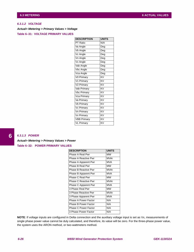
6-26 W650 Wind Generator Protection System GEK-113032A
6.3 METERING 6 ACTUAL VALUES
6
6.3.1.2 VOLTAGE
Actual> Metering > Primary Values > Voltage
Table 6–31: VOLTAGE PRIMARY VALUES
6.3.1.3 POWER
Actual> Metering > Primary Values > Power
Table 6–32: POWER PRIMARY VALUES
NOTE: If voltage inputs are configured in Delta connection and the auxiliary voltage input is set as Vx, measurements of single phase power value cannot be duly calculated, and therefore, its value will be zero. For the three-phase power value, the system uses the ARON method, or two-wattmeters method.
DESCRIPTION UNITSPT Ratio N/AVa Angle DegVb Angle DegVc Angle DegVn Angle DegVx Angle DegVab Angle DegVbc Angle DegVca Angle DegV0 Primary KVV1 Primary KVV2 Primary KVVab Primary KVVbc Primary KVVca Primary KVVa Primary KVVb Primary KVVc Primary KVVn Primary KVVx Primary KVVBB Primary KVVL Primary KV
DESCRIPTION UNITSPhase A Real Pwr MWPhase A Reactive Pwr MVArPhase A Apparent Pwr MVAPhase B Real Pwr MWPhase B Reactive Pwr MVArPhase B Apparent Pwr MVAPhase C Real Pwr MWPhase C Reactive Pwr MVArPhase C Apparent Pwr MVA3 Phase Real Pwr MW3 Phase Reactive Pwr MVAr3 Phase Apparent Pwr MVAPhase A Power Factor N/APhase B Power Factor N/APhase C Power Factor N/A3 Phase Power Factor N/A
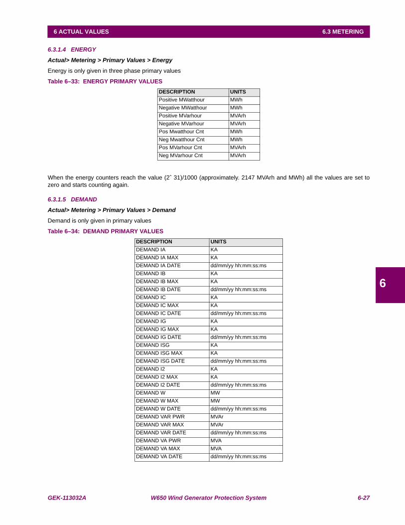
GEK-113032A W650 Wind Generator Protection System 6-27
6 ACTUAL VALUES 6.3 METERING
6
6.3.1.4 ENERGY
Actual> Metering > Primary Values > Energy
Energy is only given in three phase primary values
Table 6–33: ENERGY PRIMARY VALUES
When the energy counters reach the value (2ˆ 31)/1000 (approximately. 2147 MVArh and MWh) all the values are set tozero and starts counting again.
6.3.1.5 DEMAND
Actual> Metering > Primary Values > Demand
Demand is only given in primary values
Table 6–34: DEMAND PRIMARY VALUES
DESCRIPTION UNITSPositive MWatthour MWhNegative MWatthour MWhPositive MVarhour MVArhNegative MVarhour MVArhPos Mwatthour Cnt MWhNeg Mwatthour Cnt MWhPos MVarhour Cnt MVArhNeg MVarhour Cnt MVArh
DESCRIPTION UNITSDEMAND IA KADEMAND IA MAX KADEMAND IA DATE dd/mm/yy hh:mm:ss:msDEMAND IB KADEMAND IB MAX KADEMAND IB DATE dd/mm/yy hh:mm:ss:msDEMAND IC KADEMAND IC MAX KADEMAND IC DATE dd/mm/yy hh:mm:ss:msDEMAND IG KADEMAND IG MAX KADEMAND IG DATE dd/mm/yy hh:mm:ss:msDEMAND ISG KADEMAND ISG MAX KADEMAND ISG DATE dd/mm/yy hh:mm:ss:msDEMAND I2 KADEMAND I2 MAX KADEMAND I2 DATE dd/mm/yy hh:mm:ss:msDEMAND W MWDEMAND W MAX MWDEMAND W DATE dd/mm/yy hh:mm:ss:msDEMAND VAR PWR MVArDEMAND VAR MAX MVArDEMAND VAR DATE dd/mm/yy hh:mm:ss:msDEMAND VA PWR MVADEMAND VA MAX MVADEMAND VA DATE dd/mm/yy hh:mm:ss:ms

6-28 W650 Wind Generator Protection System GEK-113032A
6.3 METERING 6 ACTUAL VALUES
6
6.3.2 SECONDARY VALUES
6.3.2.1 CURRENT
Actual> Metering > Secondary Values > Current
Table 6–35: CURRENT SECONDARY VALUES
6.3.2.2 VOLTAGE
Actual> Metering > Secondary Values > Voltage
Table 6–36: VOLTAGE SECONDARY VALUES
DESCRIPTION UNITSPhasor Ia ARMS Ia APhasor Ib ARMS Ib APhasor Ic ARMS Ic APhasor In APhasor Ig ARMS Ig APhasor Isg ARMS Isg AZero seq I0 APositive Seq I1 ANegative Seq I2 A
DESCRIPTION UNITSPhasor Vab VPhasor Vbc VPhasor Vca VPhasor Van VPhasor Vbn VPhasor Vcn VPhasor Vn VPositive Seq V1 VNegative Seq V2 VZero Seq V0 VPhasor Vx VNominal Voltage VLine Voltage VBus Voltage V

GEK-113032A W650 Wind Generator Protection System 6-29
6 ACTUAL VALUES 6.3 METERING
6
6.3.2.3 POWER
Actual> Metering > Secondary Values > Power
Table 6–37: POWER SECONDARY VALUES
NOTE: If voltage inputs are configured in Delta connection and the auxiliary voltage input is set as Vx, measurements of single phase power value cannot be duly calculated, and therefore, its value will be zero. For the three-phase power value, the system uses the ARON method, or two-wattmeters method.
DESCRIPTION UNITSPhase A Apparent Pwr VAPhase B Apparent Pwr VAPhase C Apparent Pwr VAPhase A Real Pwr WPhase B Real Pwr WPhase C Real Pwr WPhase A Reactive Pwr VARSPhase B Reactive Pwr VARSPhase C Reactive Pwr VARS3 Phase Apparent Pwr VA3 Phase Real Pwr W3 Phase Reactive Pwr VARSPhase A Power Factor N/APhase B Power Factor N/APhase C Power Factor N/A3 Phase Power Factor N/A
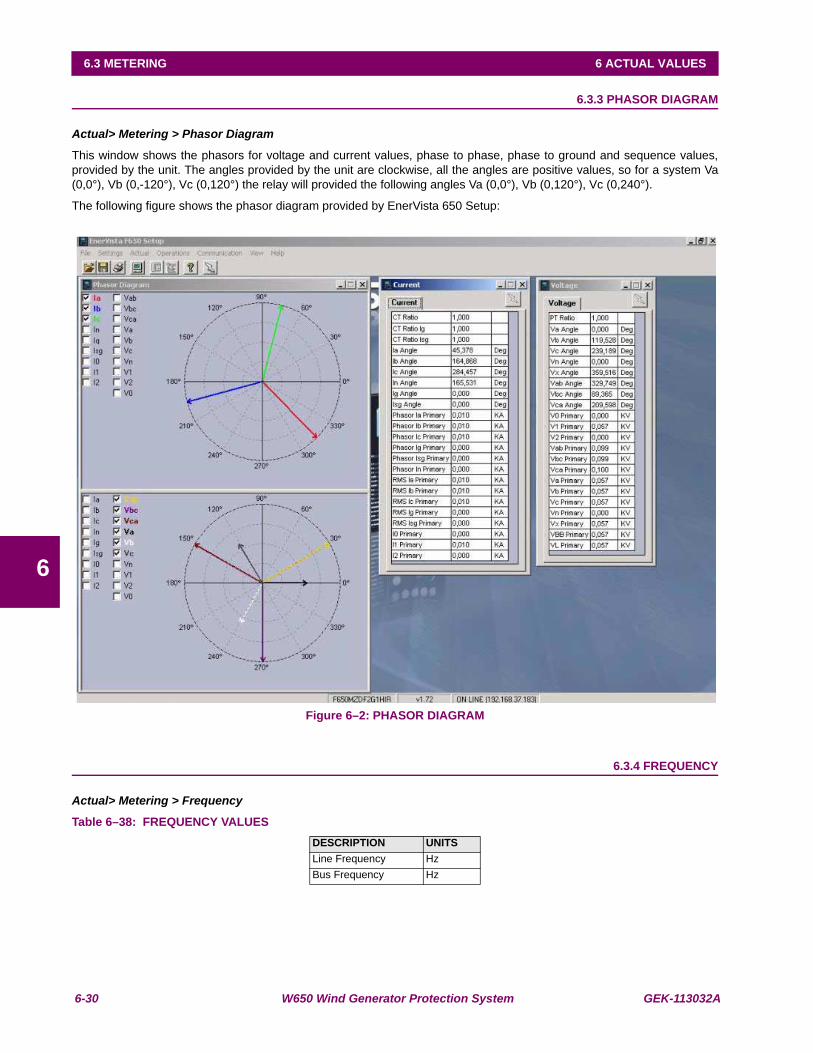
6-30 W650 Wind Generator Protection System GEK-113032A
6.3 METERING 6 ACTUAL VALUES
6
6.3.3 PHASOR DIAGRAM
Actual> Metering > Phasor Diagram
This window shows the phasors for voltage and current values, phase to phase, phase to ground and sequence values,provided by the unit. The angles provided by the unit are clockwise, all the angles are positive values, so for a system Va(0,0°), Vb (0,-120°), Vc (0,120°) the relay will provided the following angles Va (0,0°), Vb (0,120°), Vc (0,240°).
The following figure shows the phasor diagram provided by EnerVista 650 Setup:
Figure 6–2: PHASOR DIAGRAM
6.3.4 FREQUENCY
Actual> Metering > Frequency
Table 6–38: FREQUENCY VALUESDESCRIPTION UNITSLine Frequency HzBus Frequency Hz
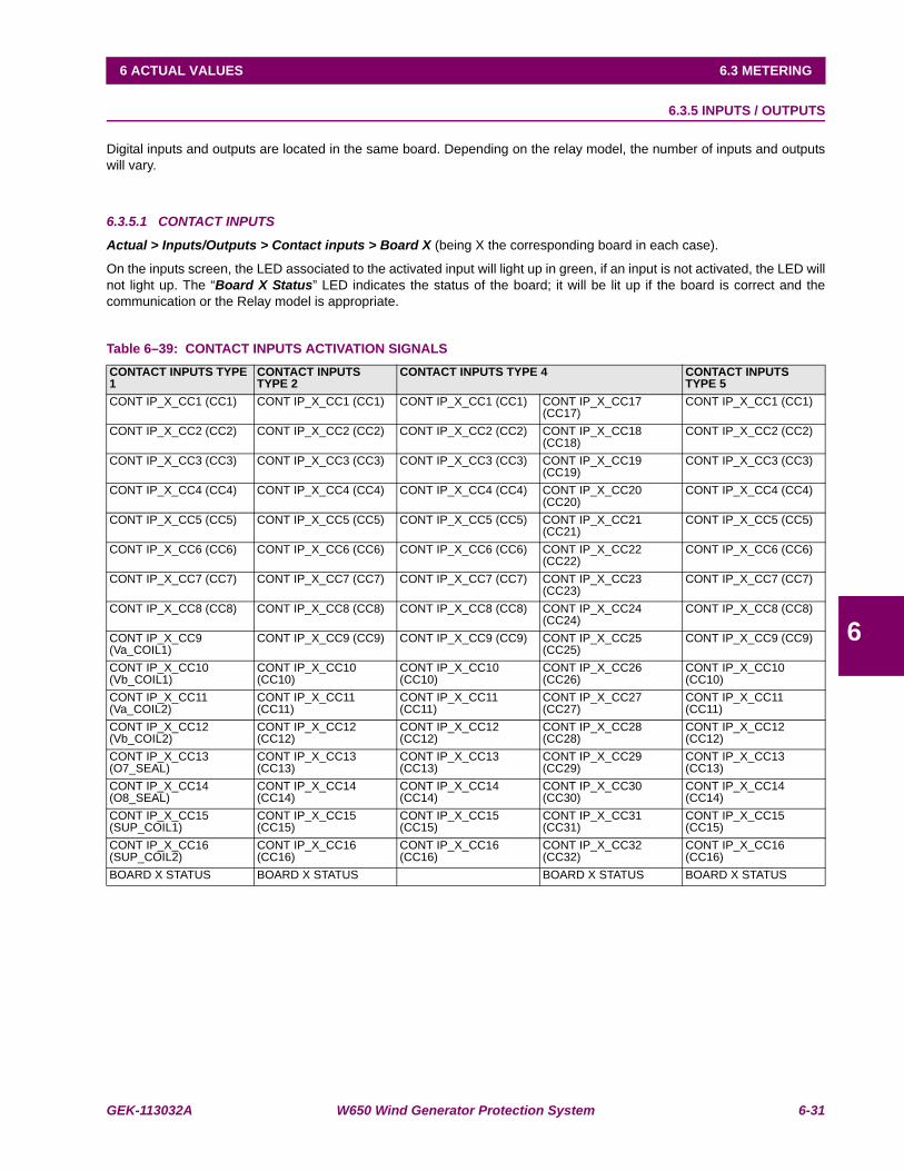
GEK-113032A W650 Wind Generator Protection System 6-31
6 ACTUAL VALUES 6.3 METERING
6
6.3.5 INPUTS / OUTPUTS
Digital inputs and outputs are located in the same board. Depending on the relay model, the number of inputs and outputswill vary.
6.3.5.1 CONTACT INPUTS
Actual > Inputs/Outputs > Contact inputs > Board X (being X the corresponding board in each case).
On the inputs screen, the LED associated to the activated input will light up in green, if an input is not activated, the LED willnot light up. The “Board X Status” LED indicates the status of the board; it will be lit up if the board is correct and thecommunication or the Relay model is appropriate.
Table 6–39: CONTACT INPUTS ACTIVATION SIGNALSCONTACT INPUTS TYPE 1
CONTACT INPUTS TYPE 2
CONTACT INPUTS TYPE 4 CONTACT INPUTS TYPE 5
CONT IP_X_CC1 (CC1) CONT IP_X_CC1 (CC1) CONT IP_X_CC1 (CC1) CONT IP_X_CC17 (CC17)
CONT IP_X_CC1 (CC1)
CONT IP_X_CC2 (CC2) CONT IP_X_CC2 (CC2) CONT IP_X_CC2 (CC2) CONT IP_X_CC18 (CC18)
CONT IP_X_CC2 (CC2)
CONT IP_X_CC3 (CC3) CONT IP_X_CC3 (CC3) CONT IP_X_CC3 (CC3) CONT IP_X_CC19 (CC19)
CONT IP_X_CC3 (CC3)
CONT IP_X_CC4 (CC4) CONT IP_X_CC4 (CC4) CONT IP_X_CC4 (CC4) CONT IP_X_CC20 (CC20)
CONT IP_X_CC4 (CC4)
CONT IP_X_CC5 (CC5) CONT IP_X_CC5 (CC5) CONT IP_X_CC5 (CC5) CONT IP_X_CC21 (CC21)
CONT IP_X_CC5 (CC5)
CONT IP_X_CC6 (CC6) CONT IP_X_CC6 (CC6) CONT IP_X_CC6 (CC6) CONT IP_X_CC22 (CC22)
CONT IP_X_CC6 (CC6)
CONT IP_X_CC7 (CC7) CONT IP_X_CC7 (CC7) CONT IP_X_CC7 (CC7) CONT IP_X_CC23 (CC23)
CONT IP_X_CC7 (CC7)
CONT IP_X_CC8 (CC8) CONT IP_X_CC8 (CC8) CONT IP_X_CC8 (CC8) CONT IP_X_CC24 (CC24)
CONT IP_X_CC8 (CC8)
CONT IP_X_CC9 (Va_COIL1)
CONT IP_X_CC9 (CC9) CONT IP_X_CC9 (CC9) CONT IP_X_CC25 (CC25)
CONT IP_X_CC9 (CC9)
CONT IP_X_CC10 (Vb_COIL1)
CONT IP_X_CC10 (CC10)
CONT IP_X_CC10 (CC10)
CONT IP_X_CC26 (CC26)
CONT IP_X_CC10 (CC10)
CONT IP_X_CC11 (Va_COIL2)
CONT IP_X_CC11 (CC11)
CONT IP_X_CC11 (CC11)
CONT IP_X_CC27 (CC27)
CONT IP_X_CC11 (CC11)
CONT IP_X_CC12 (Vb_COIL2)
CONT IP_X_CC12 (CC12)
CONT IP_X_CC12 (CC12)
CONT IP_X_CC28 (CC28)
CONT IP_X_CC12 (CC12)
CONT IP_X_CC13 (O7_SEAL)
CONT IP_X_CC13 (CC13)
CONT IP_X_CC13 (CC13)
CONT IP_X_CC29 (CC29)
CONT IP_X_CC13 (CC13)
CONT IP_X_CC14 (O8_SEAL)
CONT IP_X_CC14 (CC14)
CONT IP_X_CC14 (CC14)
CONT IP_X_CC30 (CC30)
CONT IP_X_CC14 (CC14)
CONT IP_X_CC15 (SUP_COIL1)
CONT IP_X_CC15 (CC15)
CONT IP_X_CC15 (CC15)
CONT IP_X_CC31 (CC31)
CONT IP_X_CC15 (CC15)
CONT IP_X_CC16 (SUP_COIL2)
CONT IP_X_CC16 (CC16)
CONT IP_X_CC16 (CC16)
CONT IP_X_CC32 (CC32)
CONT IP_X_CC16 (CC16)
BOARD X STATUS BOARD X STATUS BOARD X STATUS BOARD X STATUS
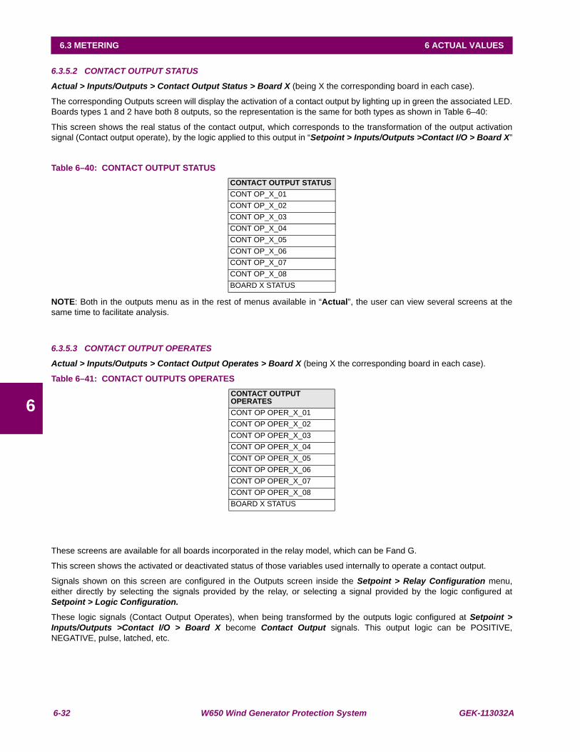
6-32 W650 Wind Generator Protection System GEK-113032A
6.3 METERING 6 ACTUAL VALUES
6
6.3.5.2 CONTACT OUTPUT STATUS
Actual > Inputs/Outputs > Contact Output Status > Board X (being X the corresponding board in each case).
The corresponding Outputs screen will display the activation of a contact output by lighting up in green the associated LED.Boards types 1 and 2 have both 8 outputs, so the representation is the same for both types as shown in Table 6–40:
This screen shows the real status of the contact output, which corresponds to the transformation of the output activationsignal (Contact output operate), by the logic applied to this output in “Setpoint > Inputs/Outputs >Contact I/O > Board X”
Table 6–40: CONTACT OUTPUT STATUS
NOTE: Both in the outputs menu as in the rest of menus available in “Actual”, the user can view several screens at thesame time to facilitate analysis.
6.3.5.3 CONTACT OUTPUT OPERATES
Actual > Inputs/Outputs > Contact Output Operates > Board X (being X the corresponding board in each case).
Table 6–41: CONTACT OUTPUTS OPERATES
These screens are available for all boards incorporated in the relay model, which can be Fand G.
This screen shows the activated or deactivated status of those variables used internally to operate a contact output.
Signals shown on this screen are configured in the Outputs screen inside the Setpoint > Relay Configuration menu,either directly by selecting the signals provided by the relay, or selecting a signal provided by the logic configured atSetpoint > Logic Configuration.
These logic signals (Contact Output Operates), when being transformed by the outputs logic configured at Setpoint >Inputs/Outputs >Contact I/O > Board X become Contact Output signals. This output logic can be POSITIVE,NEGATIVE, pulse, latched, etc.
CONTACT OUTPUT STATUSCONT OP_X_01CONT OP_X_02CONT OP_X_03CONT OP_X_04CONT OP_X_05CONT OP_X_06CONT OP_X_07CONT OP_X_08BOARD X STATUS
CONTACT OUTPUT OPERATESCONT OP OPER_X_01CONT OP OPER_X_02CONT OP OPER_X_03CONT OP OPER_X_04CONT OP OPER_X_05CONT OP OPER_X_06CONT OP OPER_X_07CONT OP OPER_X_08BOARD X STATUS
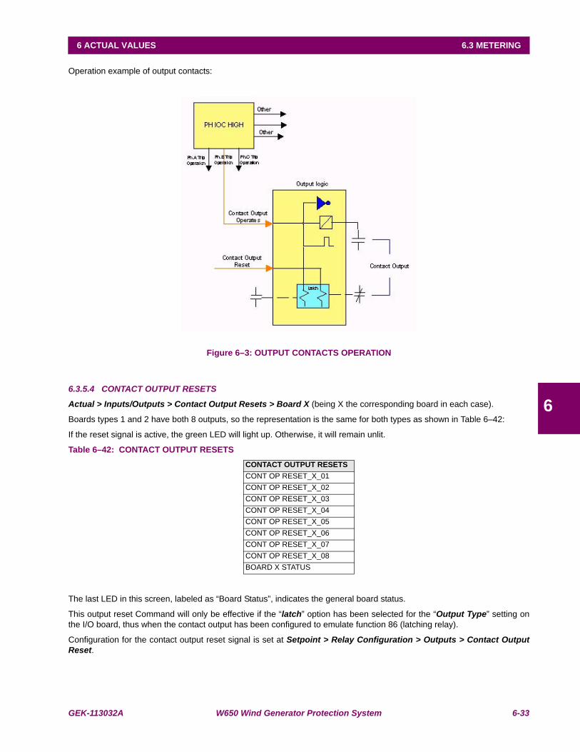
GEK-113032A W650 Wind Generator Protection System 6-33
6 ACTUAL VALUES 6.3 METERING
6
Operation example of output contacts:
Figure 6–3: OUTPUT CONTACTS OPERATION
6.3.5.4 CONTACT OUTPUT RESETS
Actual > Inputs/Outputs > Contact Output Resets > Board X (being X the corresponding board in each case).
Boards types 1 and 2 have both 8 outputs, so the representation is the same for both types as shown in Table 6–42:
If the reset signal is active, the green LED will light up. Otherwise, it will remain unlit.
Table 6–42: CONTACT OUTPUT RESETS
The last LED in this screen, labeled as “Board Status”, indicates the general board status.
This output reset Command will only be effective if the “latch” option has been selected for the “Output Type” setting onthe I/O board, thus when the contact output has been configured to emulate function 86 (latching relay).
Configuration for the contact output reset signal is set at Setpoint > Relay Configuration > Outputs > Contact OutputReset.
CONTACT OUTPUT RESETSCONT OP RESET_X_01CONT OP RESET_X_02CONT OP RESET_X_03CONT OP RESET_X_04CONT OP RESET_X_05CONT OP RESET_X_06CONT OP RESET_X_07CONT OP RESET_X_08BOARD X STATUS

6-34 W650 Wind Generator Protection System GEK-113032A
6.3 METERING 6 ACTUAL VALUES
6
6.3.5.5 I/O BOARD STATUS
Actual > Inputs/Outputs > I/O Board Status
This screen is used for verifying the status of I/O boards. If all the I/O boards, one (F) or both (F and G) depending on therelay model, are correctly inserted in their tracks and are in good state and communicating through the internal CAN Bus,the green LED will remain lit.
If one of the boards has been extracted, or the relay model does not match the installed hardware, the corresponding LEDwill remain unlit.
Table 6–43: I/O BOARD STATUS
For all I/O board screens described above, the last LED provides this same information individually.
6.3.5.6 VIRTUAL INPUTS
Actual > Inputs/Outputs > Virtual Inputs > Virtual Input Latched > Virtual Input Self-Reset
“Virtual Inputs” are signals transmitted by communications. The EnerVista 650 Setup provides a tool to set virtual inputsthrough ModBus at Setpoint > Inputs /Outputs /Virtual inputs that is only available in on line mode (communicating to therelay). There are two available groups of 32 signals each: Latched inputs and Self-reset inputs, and all of them can be usedinternally to perform operations, new logics in the PLC, etc.
In this actual values screen the status of the assigned virtual inputs can as shown on Table 6–44:
Table 6–44: VIRTUAL INPUTS STATUS
6.3.5.7 VIRTUAL OUTPUTS
Actual > Inputs/Outputs > Virtual Outputs
This screen provides the status of the 512 configurable virtual outputs (internal variables) used in the logic scheme. Thevirtual outputs are set from 000 to 511.
The configuration of the logic associated to the virtual output is in the Setpoint > Logic Configuration tool provided byEnerVista 650 Setup program.
Table 6–45: VIRTUAL OUTPUTS STATUS
6.3.5.8 REMOTE OUTPUTS
Actual > Inputs/Outputs > Remote Outputs > DNA
This screen provides the status of the 32 DNA remote outputs.
I/O BOARD STATUSBOARD F STATUSBOARD G STATUS
VIRTUAL INPUTS LATCHED VIRTUAL INPUTS SELF-RESETLATCHED VIRT IP 1 SELF-RST VIRT IP 1LATCHED VIRT IP 2 SELF-RST VIRT IP 2… …LATCHED VIRT IP 32 SELF-RST VIRT IP 32
VIRTUAL OUTPUT STATUSVIRTUAL OUTPUT 000VIRTUAL OUTPUT 001…VIRTUAL OUTPUT 511
DNA STATUS
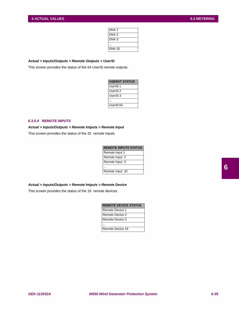
GEK-113032A W650 Wind Generator Protection System 6-35
6 ACTUAL VALUES 6.3 METERING
6
Actual > Inputs/Outputs > Remote Outputs > UserSt
This screen provides the status of the 64 UserSt remote outputs.
6.3.5.9 REMOTE INPUTS
Actual > Inputs/Outputs > Remote Intputs > Remote Input
This screen provides the status of the 32 remote inputs.
Actual > Inputs/Outputs > Remote Intputs > Remote Device
This screen provides the status of the 16 remote devices.
DNA 1DNA 2DNA 3...DNA 32
USERST STATUSUserSt 1UserSt 2UserSt 3...UserSt 64
REMOTE INPUTS STATUSRemote Input 1Remote Input 2Remote Input 3...Remote Input 32
REMOTE DEVICE STATUSRemote Device 1Remote Device 2Remote Device 3...Remote Device 16
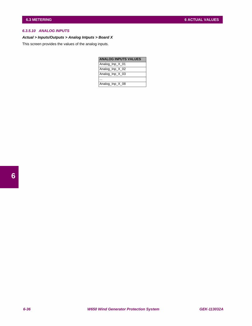
6-36 W650 Wind Generator Protection System GEK-113032A
6.3 METERING 6 ACTUAL VALUES
6
6.3.5.10 ANALOG INPUTS
Actual > Inputs/Outputs > Analog Intputs > Board X
This screen provides the values of the analog inputs.
ANALOG INPUTS VALUESAnalog_Inp_X_01Analog_Inp_X_02Analog_Inp_X_03...Analog_Inp_X_08
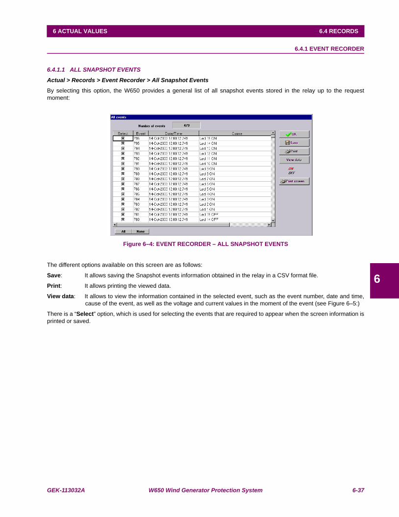
GEK-113032A W650 Wind Generator Protection System 6-37
6 ACTUAL VALUES 6.4 RECORDS
6
6.4RECORDS 6.4.1 EVENT RECORDER
6.4.1.1 ALL SNAPSHOT EVENTS
Actual > Records > Event Recorder > All Snapshot Events
By selecting this option, the W650 provides a general list of all snapshot events stored in the relay up to the requestmoment:
Figure 6–4: EVENT RECORDER – ALL SNAPSHOT EVENTS
The different options available on this screen are as follows:
Save: It allows saving the Snapshot events information obtained in the relay in a CSV format file.
Print: It allows printing the viewed data.
View data: It allows to view the information contained in the selected event, such as the event number, date and time,cause of the event, as well as the voltage and current values in the moment of the event (see Figure 6–5:)
There is a “Select” option, which is used for selecting the events that are required to appear when the screen information isprinted or saved.
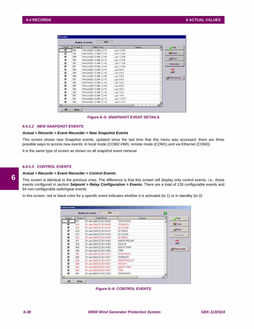
6-38 W650 Wind Generator Protection System GEK-113032A
6.4 RECORDS 6 ACTUAL VALUES
6
Figure 6–5: SNAPSHOT EVENT DETAILS
6.4.1.2 NEW SNAPSHOT EVENTS
Actual > Records > Event Recorder > New Snapshot Events
This screen shows new Snapshot events, updated since the last time that this menu was accessed; there are threepossible ways to access new events; in local mode (COM2-HMI), remote mode (COM1) and via Ethernet (COM3).
It is the same type of screen as shown on all snapshot event retrieval.
6.4.1.3 CONTROL EVENTS
Actual > Records > Event Recorder > Control Events
This screen is identical to the previous ones. The difference is that this screen will display only control events, i.e., thoseevents configured in section Setpoint > Relay Configuration > Events. There are a total of 128 configurable events and64 non-configurable switchgear events.
In this screen, red or black color for a specific event indicates whether it is activated (to 1) or in standby (to 0)
Figure 6–6: CONTROL EVENTS
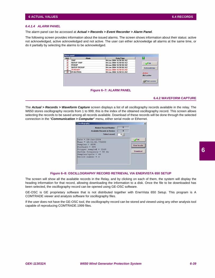
GEK-113032A W650 Wind Generator Protection System 6-39
6 ACTUAL VALUES 6.4 RECORDS
6
6.4.1.4 ALARM PANEL
The alarm panel can be accessed at Actual > Records > Event Recorder > Alarm Panel.
The following screen provides information about the issued alarms. The screen shows information about their status: activenot acknowledged, active acknowledged and not active. The user can either acknowledge all alarms at the same time, ordo it partially by selecting the alarms to be acknowledged.
Figure 6–7: ALARM PANEL
6.4.2 WAVEFORM CAPTURE
The Actual > Records > Waveform Capture screen displays a list of all oscillography records available in the relay. TheW650 stores oscillography records from 1 to 999; this is the index of the obtained oscillography record. This screen allowsselecting the records to be saved among all records available. Download of these records will be done through the selectedconnection in the “Communication > Computer” menu, either serial mode or Ethernet.
Figure 6–8: OSCILLOGRAPHY RECORD RETRIEVAL VIA ENERVISTA 650 SETUP
The screen will show all the available records in the Relay, and by clicking on each of them, the system will display theheading information for that record, allowing downloading the information to a disk. Once the file to be downloaded hasbeen selected, the oscillography record can be opened using GE-OSC software.
GE-OSC is GE proprietary software that is not distributed together with EnerVista 650 Setup. This program is ACOMTRADE viewer and analysis software for oscillography files.
If the user does not have the GE-OSC tool, the oscillography record can be stored and viewed using any other analysis toolcapable of reproducing COMTRADE.1999 files.
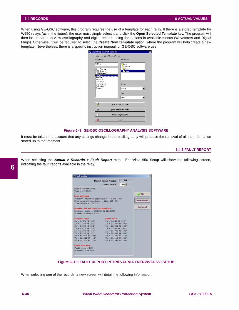
6-40 W650 Wind Generator Protection System GEK-113032A
6.4 RECORDS 6 ACTUAL VALUES
6
When using GE-OSC software, this program requires the use of a template for each relay. If there is a stored template forW650 relays (as in the figure), the user must simply select it and click the Open Selected Template key. The program willthen be prepared to view oscillography and digital records using the options in available menus (Waveforms and DigitalFlags). Otherwise, it will be required to select the Create New Template option, where the program will help create a newtemplate. Nevertheless, there is a specific instruction manual for GE-OSC software use.
Figure 6–9: GE-OSC OSCILLOGRAPHY ANALYSIS SOFTWARE
It must be taken into account that any settings change in the oscillography will produce the removal of all the informationstored up to that moment.
6.4.3 FAULT REPORT
When selecting the Actual > Records > Fault Report menu, EnerVista 650 Setup will show the following screen,indicating the fault reports available in the relay.
Figure 6–10: FAULT REPORT RETRIEVAL VIA ENERVISTA 650 SETUP
When selecting one of the records, a new screen will detail the following information:

GEK-113032A W650 Wind Generator Protection System 6-41
6 ACTUAL VALUES 6.4 RECORDS
6
• Date
• Time
• Pre-fault current and voltage in primary values
• Fault current and voltage in primary values
• Fault type
• Distance to the fault
The operation of this screen is similar to that of the previous oscillography screen, being in this case the number of faultreports a fixed number (10), instead of variable and setting-selected like as in the previous case.
Once a fault report is selected, its heading description will be displayed, showing pre-fault information, fault information andthe distance to the fault. This file can be downloaded to the computer in a CSV format file.
Fault report file retrieval can be performed via serial or Ethernet communications. It must be taken into account that anysettings change in the fault report will produce the removal of all the information stored up to that moment.
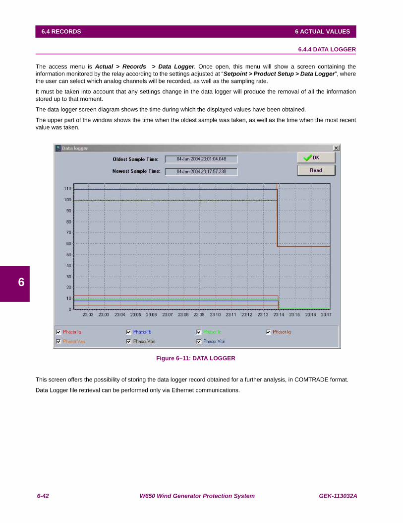
6-42 W650 Wind Generator Protection System GEK-113032A
6.4 RECORDS 6 ACTUAL VALUES
6
6.4.4 DATA LOGGER
The access menu is Actual > Records > Data Logger. Once open, this menu will show a screen containing theinformation monitored by the relay according to the settings adjusted at “Setpoint > Product Setup > Data Logger”, wherethe user can select which analog channels will be recorded, as well as the sampling rate.
It must be taken into account that any settings change in the data logger will produce the removal of all the informationstored up to that moment.
The data logger screen diagram shows the time during which the displayed values have been obtained.
The upper part of the window shows the time when the oldest sample was taken, as well as the time when the most recentvalue was taken.
Figure 6–11: DATA LOGGER
This screen offers the possibility of storing the data logger record obtained for a further analysis, in COMTRADE format.
Data Logger file retrieval can be performed only via Ethernet communications.

GEK-113032A W650 Wind Generator Protection System 7-1
7 IEC 61850 PROTOCOL 7.1 IEC61850 GENERIC SUBSTATION STATE EVENT (GSSE)
7
7 IEC 61850 PROTOCOL 7.1IEC61850 GENERIC SUBSTATION STATE EVENT (GSSE) 7.1.1 REMOTE DEVICES
7.1.1.1 REMOTE I/O OVERVIEW
Remote inputs and outputs, which are a means of exchanging information regarding the state of digital points betweenremote devices, are provided in accordance with the IEC61850 Generic Substation State Event (GSSE) specifications.
The sharing of digital point state information between GSSE equipped relays is essentially an extension to PLC to allowdistributed PLC by making operands available to/from devices on a common communications network. In addition to digitalpoint states, GSSE messages identify the originator of the message and provide other information required by thecommunication specification. All devices listen to network messages and capture data from only those messages that haveoriginated in selected devices.
GSSE messages are designed to be short, high priority and with a high level of reliability. The GSSE message structurecontains space for 128 bit pairs representing digital point state information. The IEC61850 specification provides 32 DNAbit pairs, which are status bits representing pre-defined events. All remaining bit pairs are UserSt bit pairs, which are statusbits representing user-definable events. The W650 implementation provides 64 of the 96 available UserSt bit pairs.
The IEC61850 specification includes features that are used to cope with the loss of communication between transmittingand receiving devices. Each transmitting device will send a GSSE message upon a successful power-up, when the state ofany included point changes, or after a specified interval (the “default update” time) if a change-of-state has not occurred.The transmitting device also sends a “hold time” which is set to four point five times the programmed default time, which isrequired by the receiving device.
Receiving devices are constantly monitoring the communications network for messages they require, as recognized by theidentification of the originating device carried in the message. Messages received from remote devices include themessage “hold time” for the device. The receiving relay sets a timer assigned to the originating device to the “hold time”interval, and if it has not received another message from this device at time-out, the remote device is declared to be non-communicating, so it will use the programmed default state for all points from that specific remote device. This mechanismallows a receiving device to fail to detect a single transmission from a remote device which is sending messages at theslowest possible rate, as set by its “default update” timer, without reverting to use of the programmed default states. If amessage is received from a remote device before the “hold time” expires, all points for that device are updated to the statescontained in the message and the hold timer is restarted. The status of a remote device can be displayed. The GSSEfacility provides for 32 remote inputs and 96 remote outputs.
7.1.1.2 LOCAL DEVICES ID OF DEVICE FOR TRANSMITTING GOOSE MESSAGES
The device ID that identifies the originator of the message is ONLY programmed in the EnerVista 650 Setup (see Figure 7–1:)
Setpoint > Input/Outputs > Remote Comms > W650 ID
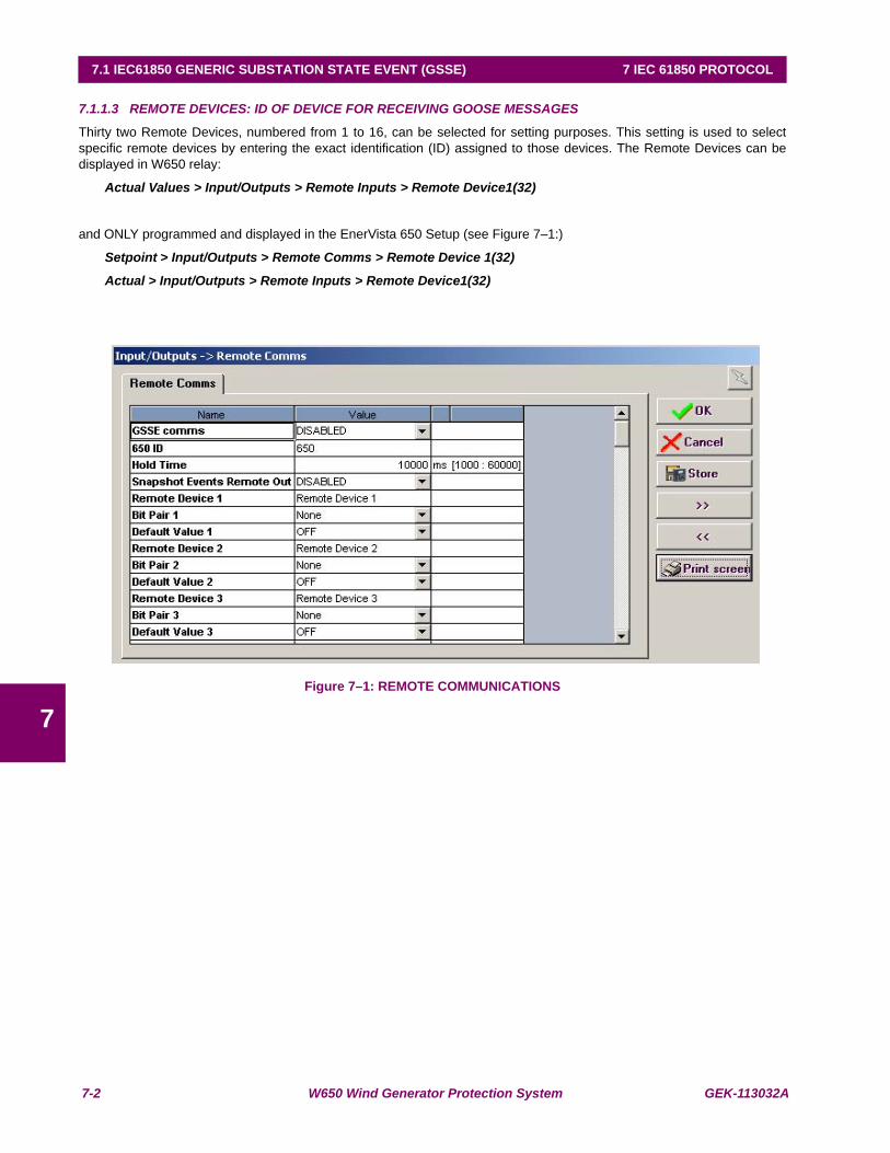
7-2 W650 Wind Generator Protection System GEK-113032A
7.1 IEC61850 GENERIC SUBSTATION STATE EVENT (GSSE) 7 IEC 61850 PROTOCOL
7
7.1.1.3 REMOTE DEVICES: ID OF DEVICE FOR RECEIVING GOOSE MESSAGES
Thirty two Remote Devices, numbered from 1 to 16, can be selected for setting purposes. This setting is used to selectspecific remote devices by entering the exact identification (ID) assigned to those devices. The Remote Devices can bedisplayed in W650 relay:
Actual Values > Input/Outputs > Remote Inputs > Remote Device1(32)
and ONLY programmed and displayed in the EnerVista 650 Setup (see Figure 7–1:)
Setpoint > Input/Outputs > Remote Comms > Remote Device 1(32)
Actual > Input/Outputs > Remote Inputs > Remote Device1(32)
Figure 7–1: REMOTE COMMUNICATIONS

GEK-113032A W650 Wind Generator Protection System 7-3
7 IEC 61850 PROTOCOL 7.1 IEC61850 GENERIC SUBSTATION STATE EVENT (GSSE)
7
7.1.2 REMOTE INPUTS
Remote Inputs which create PLC operands at the receiving relay, are extracted from GSSE messages originating in remotedevices. The relay provides 32 remote inputs, each of which can be selected from a list consisting of 96 selections: DNA-1through DNA-32 and UserSt-1 through UserSt-64. The function of DNA and UserSt bits is in both cases the same so usercan assign a Remote Input either of them through the Bit Pair 1 (32) field (see figure 1). They can be accessed either fromW650 relay :
Actual Values > Input/Outputs > Remote Inputs > Remote Input 1(32)
or from EnerVista 650 Setup (see Figure 7–1:):
Setpoint > Input/Outputs > Remote Comms > Bit Pair 1(32)
Actual > Inputs/Outputs > Remote Inputs > Remote Input
The Default Value 1(32) setting selects the logic state for this point if the local relay has just completed startup or theremote device sending the point is declared to be non-communicating. The following choices are available:
• ON value defaults the input to Logic 1.
• OFF value defaults the input to Logic 0.
• Latest OFF freezes the input in case of lost communications. If the latest state is not known, such as after relay power-up but before the first communication exchange, the input will default to Logic 0. When communication resumes, theinput becomes fully operational.
• Latest ON freezes the input in case of lost communications. If the latest state is not known, such as after relay power-up but before the first communication exchange, the input will default to Logic 1. When communication resumes, theinput becomes fully operational.
They can ONLY be accessed either from EnerVista 650 Setup (see Figure 7–1:)
Setpoint > Input/Outputs > Remote Comms > Default Value 1(32)
If the user wants a remote input to generate an event or not it can ONLY be set in EnerVista 650 Setup:
Setpoint > Input/Outputs > Remote Comms > Events Remote Inp
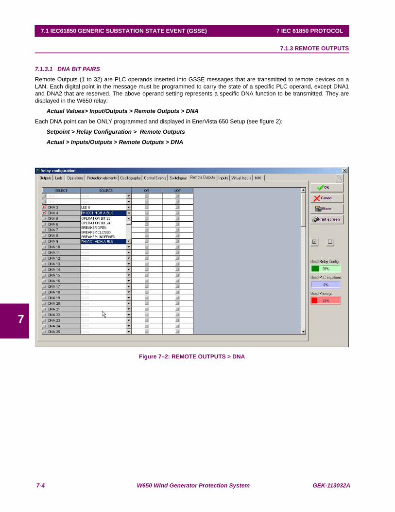
7-4 W650 Wind Generator Protection System GEK-113032A
7.1 IEC61850 GENERIC SUBSTATION STATE EVENT (GSSE) 7 IEC 61850 PROTOCOL
7
7.1.3 REMOTE OUTPUTS
7.1.3.1 DNA BIT PAIRS
Remote Outputs (1 to 32) are PLC operands inserted into GSSE messages that are transmitted to remote devices on aLAN. Each digital point in the message must be programmed to carry the state of a specific PLC operand, except DNA1and DNA2 that are reserved. The above operand setting represents a specific DNA function to be transmitted. They aredisplayed in the W650 relay:
Actual Values> Input/Outputs > Remote Outputs > DNA
Each DNA point can be ONLY programmed and displayed in EnerVista 650 Setup (see figure 2):
Setpoint > Relay Configuration > Remote Outputs
Actual > Inputs/Outputs > Remote Outputs > DNA
Figure 7–2: REMOTE OUTPUTS > DNA
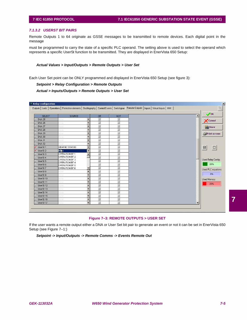
GEK-113032A W650 Wind Generator Protection System 7-5
7 IEC 61850 PROTOCOL 7.1 IEC61850 GENERIC SUBSTATION STATE EVENT (GSSE)
7
7.1.3.2 USERST BIT PAIRS
Remote Outputs 1 to 64 originate as GSSE messages to be transmitted to remote devices. Each digital point in themessage
must be programmed to carry the state of a specific PLC operand. The setting above is used to select the operand whichrepresents a specific UserSt function to be transmitted. They are displayed in EnerVista 650 Setup:
Actual Values > Input/Outputs > Remote Outputs > User Set
Each User Set point can be ONLY programmed and displayed in EnerVista 650 Setup (see figure 3):
Setpoint > Relay Configuration > Remote Outputs
Actual > Inputs/Outputs > Remote Outputs > User Set
Figure 7–3: REMOTE OUTPUTS > USER SET
If the user wants a remote output either a DNA or User Set bit pair to generate an event or not it can be set in EnerVista 650Setup (see Figure 7–1:)
Setpoint -> Input/Outputs -> Remote Comms -> Events Remote Out
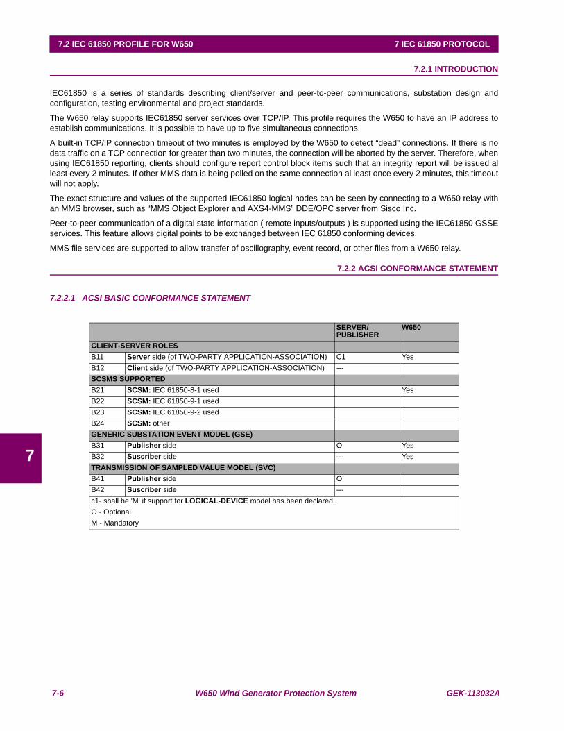
7-6 W650 Wind Generator Protection System GEK-113032A
7.2 IEC 61850 PROFILE FOR W650 7 IEC 61850 PROTOCOL
7
7.2IEC 61850 PROFILE FOR W650 7.2.1 INTRODUCTION
IEC61850 is a series of standards describing client/server and peer-to-peer communications, substation design andconfiguration, testing environmental and project standards.
The W650 relay supports IEC61850 server services over TCP/IP. This profile requires the W650 to have an IP address toestablish communications. It is possible to have up to five simultaneous connections.
A built-in TCP/IP connection timeout of two minutes is employed by the W650 to detect “dead” connections. If there is nodata traffic on a TCP connection for greater than two minutes, the connection will be aborted by the server. Therefore, whenusing IEC61850 reporting, clients should configure report control block items such that an integrity report will be issued alleast every 2 minutes. If other MMS data is being polled on the same connection al least once every 2 minutes, this timeoutwill not apply.
The exact structure and values of the supported IEC61850 logical nodes can be seen by connecting to a W650 relay withan MMS browser, such as “MMS Object Explorer and AXS4-MMS” DDE/OPC server from Sisco Inc.
Peer-to-peer communication of a digital state information ( remote inputs/outputs ) is supported using the IEC61850 GSSEservices. This feature allows digital points to be exchanged between IEC 61850 conforming devices.
MMS file services are supported to allow transfer of oscillography, event record, or other files from a W650 relay.
7.2.2 ACSI CONFORMANCE STATEMENT
7.2.2.1 ACSI BASIC CONFORMANCE STATEMENT
SERVER/PUBLISHER
W650
CLIENT-SERVER ROLESB11 Server side (of TWO-PARTY APPLICATION-ASSOCIATION) C1 YesB12 Client side (of TWO-PARTY APPLICATION-ASSOCIATION) ---SCSMS SUPPORTEDB21 SCSM: IEC 61850-8-1 used Yes B22 SCSM: IEC 61850-9-1 usedB23 SCSM: IEC 61850-9-2 usedB24 SCSM: otherGENERIC SUBSTATION EVENT MODEL (GSE)B31 Publisher side O YesB32 Suscriber side --- YesTRANSMISSION OF SAMPLED VALUE MODEL (SVC)B41 Publisher side OB42 Suscriber side ---c1- shall be 'M' if support for LOGICAL-DEVICE model has been declared.O - OptionalM - Mandatory
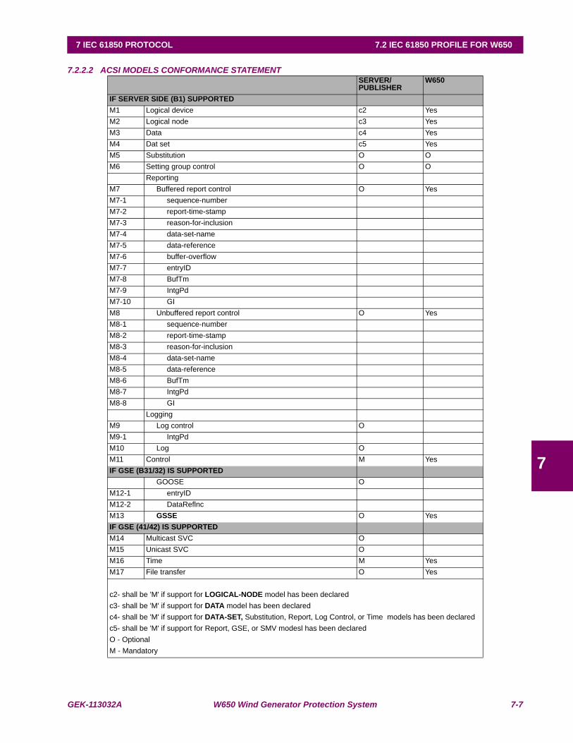
GEK-113032A W650 Wind Generator Protection System 7-7
7 IEC 61850 PROTOCOL 7.2 IEC 61850 PROFILE FOR W650
7
7.2.2.2 ACSI MODELS CONFORMANCE STATEMENTSERVER/PUBLISHER
W650
IF SERVER SIDE (B1) SUPPORTEDM1 Logical device c2 YesM2 Logical node c3 YesM3 Data c4 YesM4 Dat set c5 YesM5 Substitution O OM6 Setting group control O O
ReportingM7 Buffered report control O YesM7-1 sequence-numberM7-2 report-time-stampM7-3 reason-for-inclusionM7-4 data-set-nameM7-5 data-referenceM7-6 buffer-overflowM7-7 entryIDM7-8 BufTmM7-9 IntgPdM7-10 GIM8 Unbuffered report control O YesM8-1 sequence-numberM8-2 report-time-stampM8-3 reason-for-inclusionM8-4 data-set-nameM8-5 data-referenceM8-6 BufTmM8-7 IntgPdM8-8 GI
LoggingM9 Log control OM9-1 IntgPdM10 Log O M11 Control M YesIF GSE (B31/32) IS SUPPORTED
GOOSE O M12-1 entryIDM12-2 DataReflncM13 GSSE O YesIF GSE (41/42) IS SUPPORTEDM14 Multicast SVC OM15 Unicast SVC OM16 Time M YesM17 File transfer O Yes
c2- shall be 'M' if support for LOGICAL-NODE model has been declaredc3- shall be 'M' if support for DATA model has been declaredc4- shall be 'M' if support for DATA-SET, Substitution, Report, Log Control, or Time models has been declaredc5- shall be 'M' if support for Report, GSE, or SMV modesl has been declaredO - OptionalM - Mandatory

7-8 W650 Wind Generator Protection System GEK-113032A
7.2 IEC 61850 PROFILE FOR W650 7 IEC 61850 PROTOCOL
7
7.2.2.3 ACSI SERVICES CONFORMANCE STATEMENT
AA: Aplication Asociations (TP: Two Party / MC: Multicast)
SERVICES AA: TP/MC SERVER/PUBLISH
W650
SERVER (CLAUSE 6)S1 ServerDirectory TP M Yes
APPLICATION ASSOCIATION (CLAUSE 7)S2 Associate M YesS3 Abort M YesS4 Release M Yes
LOGICAL DEVICE (CLAUSE 8)S5 LogicalDeviceDirectory TP M Yes
LOGICAL NODE (CLAUSE 9)S6 LogicalNodeDirectory TP M YesS7 GetAllDataValues TP M Yes
DATA (CLAUSE 10)S8 GetDataValues TP M YesS9 SetDataValues TP O YesS10 GetDataDirectory TP M YesS11 GetDataDefinition TP M Yes
DATA SET (CLAUSE 11)S12 GetDataSetValues TP M YesS13 SetDataSetValues TP OS14 CreateDataSet TP O S15 DeleteDataSet TP O S16 GetDataSetDirectory TP O Yes
SUBSTITUTION (CLAUSE 12)S17 SetDataValues TP M
SETTING GROUP CONTROL (CLAUSE 13)S18 SelectActiveSG TP O S19 SelectEditSG TP O S20 SetSGValues TP O S21 ConfirmEditSGValues TP O S22 GetSGValues TP O S23 GetSGCBValues TP O
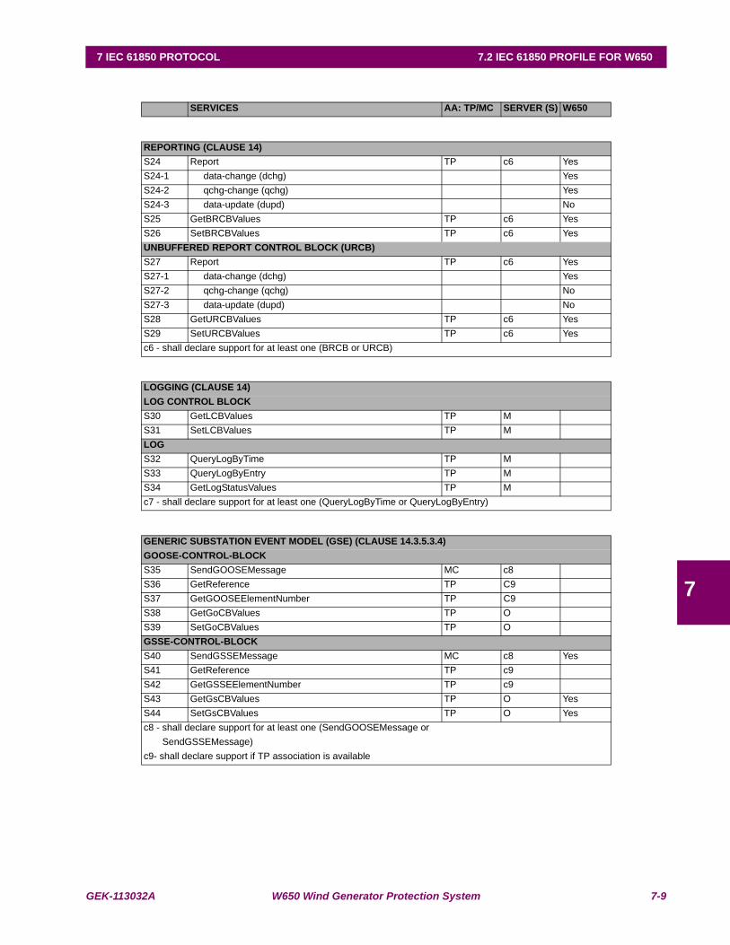
GEK-113032A W650 Wind Generator Protection System 7-9
7 IEC 61850 PROTOCOL 7.2 IEC 61850 PROFILE FOR W650
7
SERVICES AA: TP/MC SERVER (S) W650
REPORTING (CLAUSE 14)S24 Report TP c6 YesS24-1 data-change (dchg) YesS24-2 qchg-change (qchg) YesS24-3 data-update (dupd) NoS25 GetBRCBValues TP c6 YesS26 SetBRCBValues TP c6 YesUNBUFFERED REPORT CONTROL BLOCK (URCB)S27 Report TP c6 YesS27-1 data-change (dchg) YesS27-2 qchg-change (qchg) NoS27-3 data-update (dupd) NoS28 GetURCBValues TP c6 YesS29 SetURCBValues TP c6 Yesc6 - shall declare support for at least one (BRCB or URCB)
LOGGING (CLAUSE 14)LOG CONTROL BLOCKS30 GetLCBValues TP M S31 SetLCBValues TP M LOGS32 QueryLogByTime TP M S33 QueryLogByEntry TP M S34 GetLogStatusValues TP M c7 - shall declare support for at least one (QueryLogByTime or QueryLogByEntry)
GENERIC SUBSTATION EVENT MODEL (GSE) (CLAUSE 14.3.5.3.4)GOOSE-CONTROL-BLOCKS35 SendGOOSEMessage MC c8 S36 GetReference TP C9 S37 GetGOOSEElementNumber TP C9 S38 GetGoCBValues TP O S39 SetGoCBValues TP O GSSE-CONTROL-BLOCKS40 SendGSSEMessage MC c8 YesS41 GetReference TP c9S42 GetGSSEElementNumber TP c9 S43 GetGsCBValues TP O YesS44 SetGsCBValues TP O Yesc8 - shall declare support for at least one (SendGOOSEMessage or SendGSSEMessage)c9- shall declare support if TP association is available
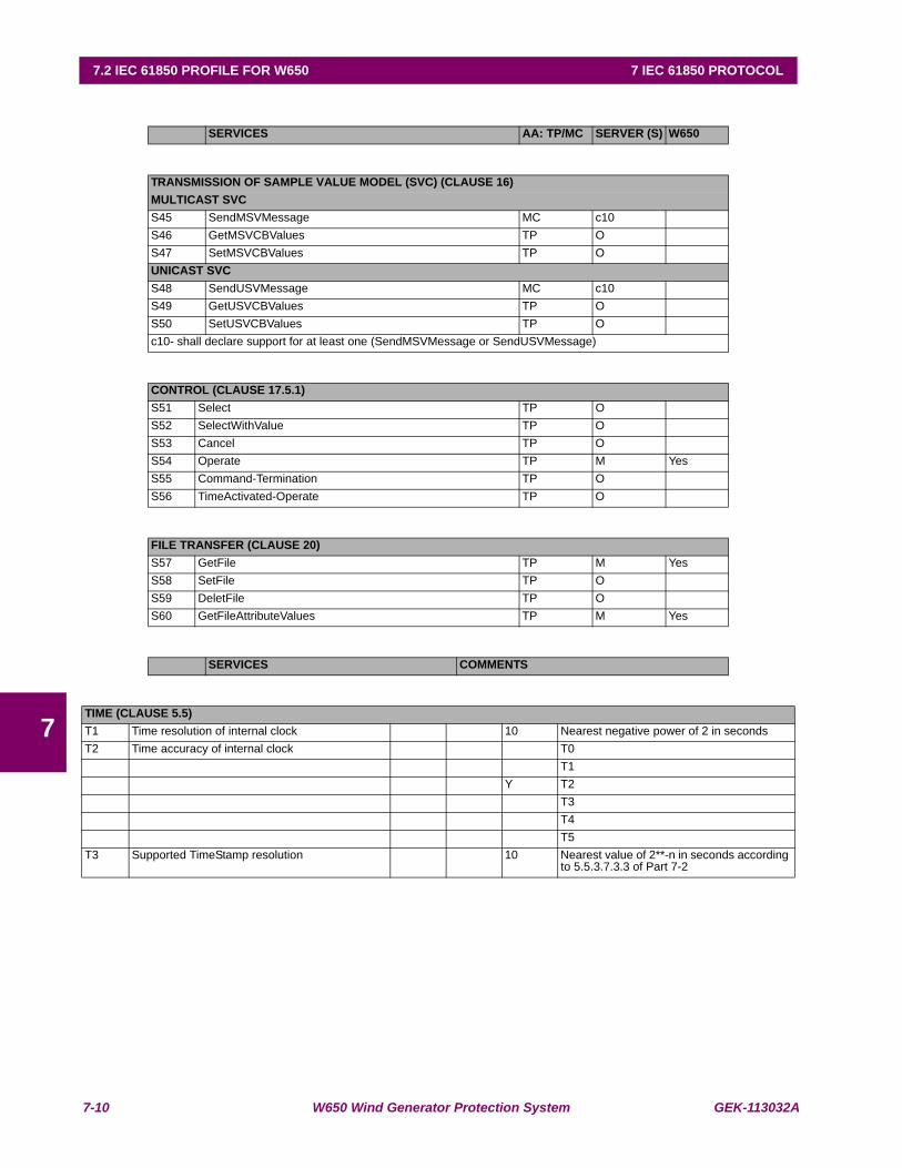
7-10 W650 Wind Generator Protection System GEK-113032A
7.2 IEC 61850 PROFILE FOR W650 7 IEC 61850 PROTOCOL
7
SERVICES AA: TP/MC SERVER (S) W650
TRANSMISSION OF SAMPLE VALUE MODEL (SVC) (CLAUSE 16)MULTICAST SVCS45 SendMSVMessage MC c10S46 GetMSVCBValues TP OS47 SetMSVCBValues TP OUNICAST SVCS48 SendUSVMessage MC c10S49 GetUSVCBValues TP O S50 SetUSVCBValues TP O c10- shall declare support for at least one (SendMSVMessage or SendUSVMessage)
CONTROL (CLAUSE 17.5.1)S51 Select TP OS52 SelectWithValue TP O S53 Cancel TP O S54 Operate TP M YesS55 Command-Termination TP O S56 TimeActivated-Operate TP O
FILE TRANSFER (CLAUSE 20)S57 GetFile TP M YesS58 SetFile TP OS59 DeletFile TP O S60 GetFileAttributeValues TP M Yes
SERVICES COMMENTS
TIME (CLAUSE 5.5)T1 Time resolution of internal clock 10 Nearest negative power of 2 in secondsT2 Time accuracy of internal clock T0
T1Y T2
T3T4T5
T3 Supported TimeStamp resolution 10 Nearest value of 2**-n in seconds according to 5.5.3.7.3.3 of Part 7-2
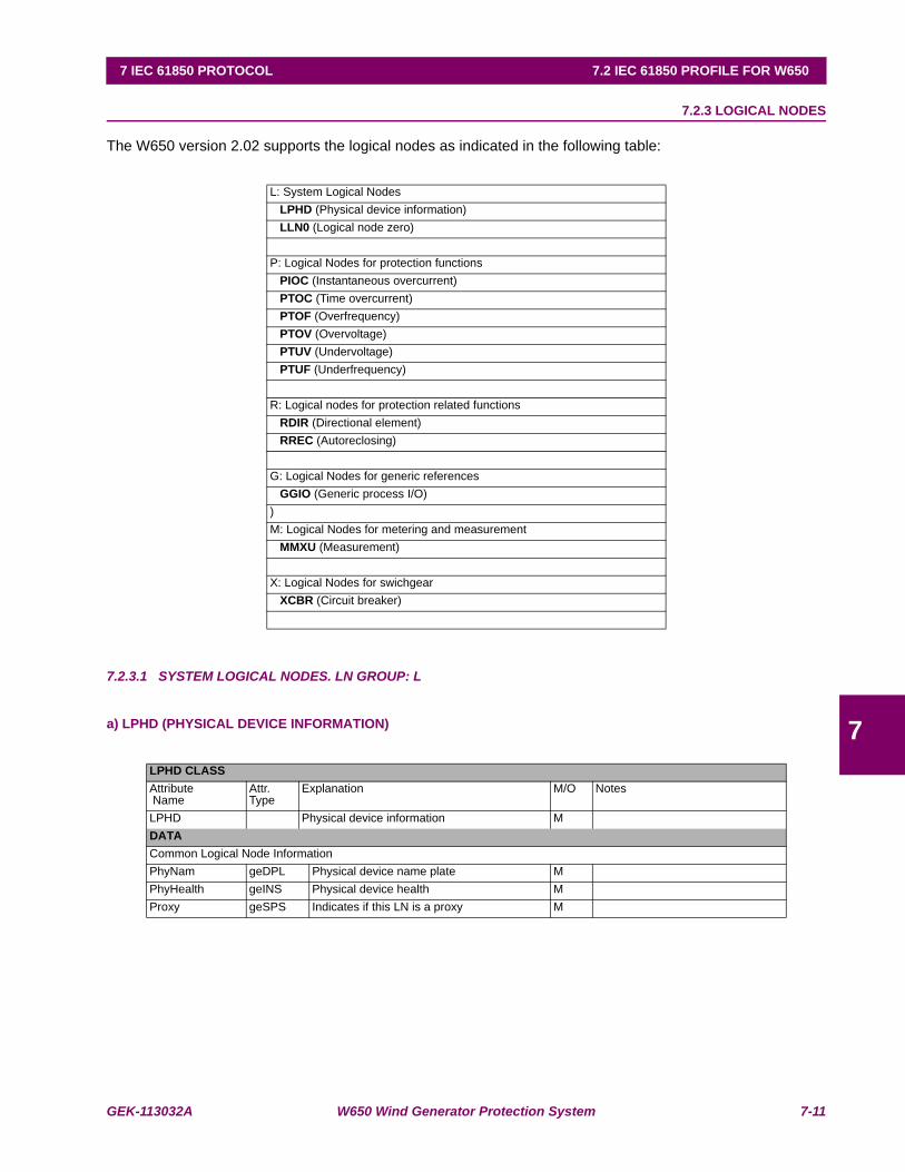
GEK-113032A W650 Wind Generator Protection System 7-11
7 IEC 61850 PROTOCOL 7.2 IEC 61850 PROFILE FOR W650
7
7.2.3 LOGICAL NODES
The W650 version 2.02 supports the logical nodes as indicated in the following table:
7.2.3.1 SYSTEM LOGICAL NODES. LN GROUP: L
a) LPHD (PHYSICAL DEVICE INFORMATION)
L: System Logical Nodes LPHD (Physical device information) LLN0 (Logical node zero)
P: Logical Nodes for protection functions PIOC (Instantaneous overcurrent) PTOC (Time overcurrent) PTOF (Overfrequency) PTOV (Overvoltage) PTUV (Undervoltage) PTUF (Underfrequency)
R: Logical nodes for protection related functions RDIR (Directional element) RREC (Autoreclosing)
G: Logical Nodes for generic references GGIO (Generic process I/O))M: Logical Nodes for metering and measurement MMXU (Measurement)
X: Logical Nodes for swichgear XCBR (Circuit breaker)
LPHD CLASSAttribute Name
Attr. Type
Explanation M/O Notes
LPHD Physical device information MDATACommon Logical Node InformationPhyNam geDPL Physical device name plate MPhyHealth geINS Physical device health MProxy geSPS Indicates if this LN is a proxy M
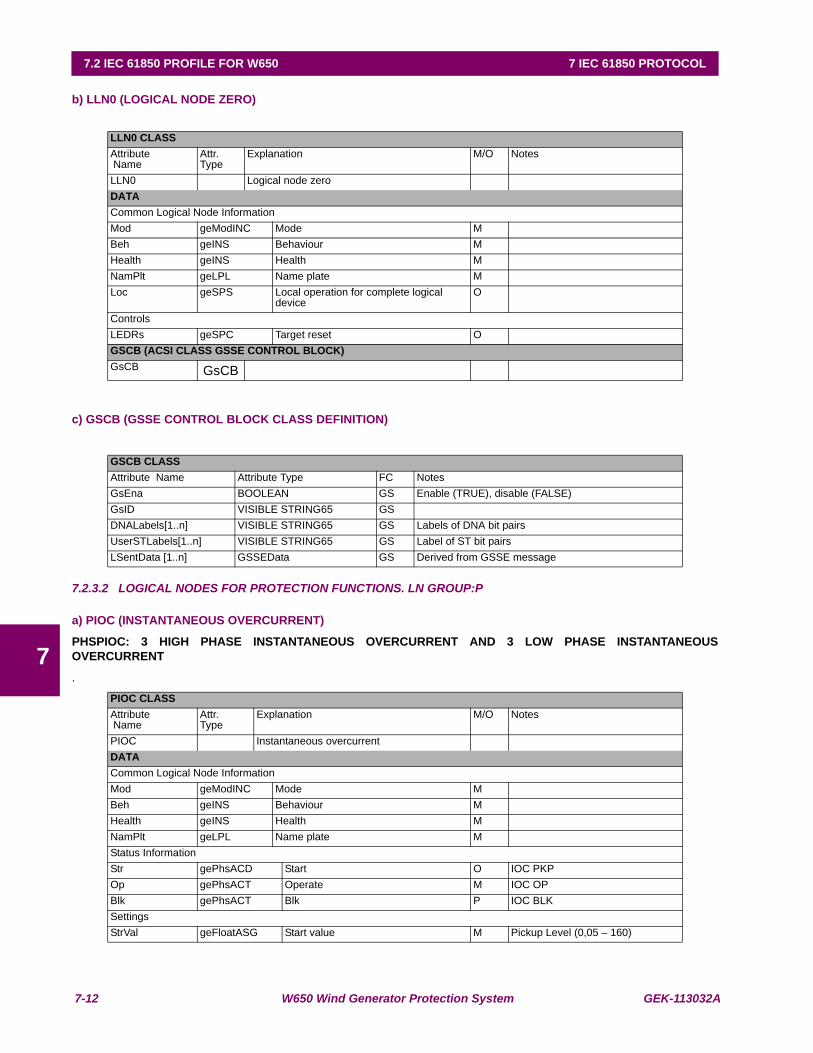
7-12 W650 Wind Generator Protection System GEK-113032A
7.2 IEC 61850 PROFILE FOR W650 7 IEC 61850 PROTOCOL
7
b) LLN0 (LOGICAL NODE ZERO)
c) GSCB (GSSE CONTROL BLOCK CLASS DEFINITION)
7.2.3.2 LOGICAL NODES FOR PROTECTION FUNCTIONS. LN GROUP:P
a) PIOC (INSTANTANEOUS OVERCURRENT)
PHSPIOC: 3 HIGH PHASE INSTANTANEOUS OVERCURRENT AND 3 LOW PHASE INSTANTANEOUSOVERCURRENT
.
LLN0 CLASSAttribute Name
Attr. Type
Explanation M/O Notes
LLN0 Logical node zeroDATACommon Logical Node InformationMod geModINC Mode MBeh geINS Behaviour MHealth geINS Health MNamPlt geLPL Name plate MLoc geSPS Local operation for complete logical
deviceO
ControlsLEDRs geSPC Target reset OGSCB (ACSI CLASS GSSE CONTROL BLOCK)GsCB GsCB
GSCB CLASSAttribute Name Attribute Type FC NotesGsEna BOOLEAN GS Enable (TRUE), disable (FALSE)GsID VISIBLE STRING65 GSDNALabels[1..n] VISIBLE STRING65 GS Labels of DNA bit pairsUserSTLabels[1..n] VISIBLE STRING65 GS Label of ST bit pairsLSentData [1..n] GSSEData GS Derived from GSSE message
PIOC CLASSAttribute Name
Attr. Type
Explanation M/O Notes
PIOC Instantaneous overcurrentDATACommon Logical Node InformationMod geModINC Mode MBeh geINS Behaviour MHealth geINS Health MNamPlt geLPL Name plate MStatus InformationStr gePhsACD Start O IOC PKPOp gePhsACT Operate M IOC OPBlk gePhsACT Blk P IOC BLKSettingsStrVal geFloatASG Start value M Pickup Level (0,05 – 160)
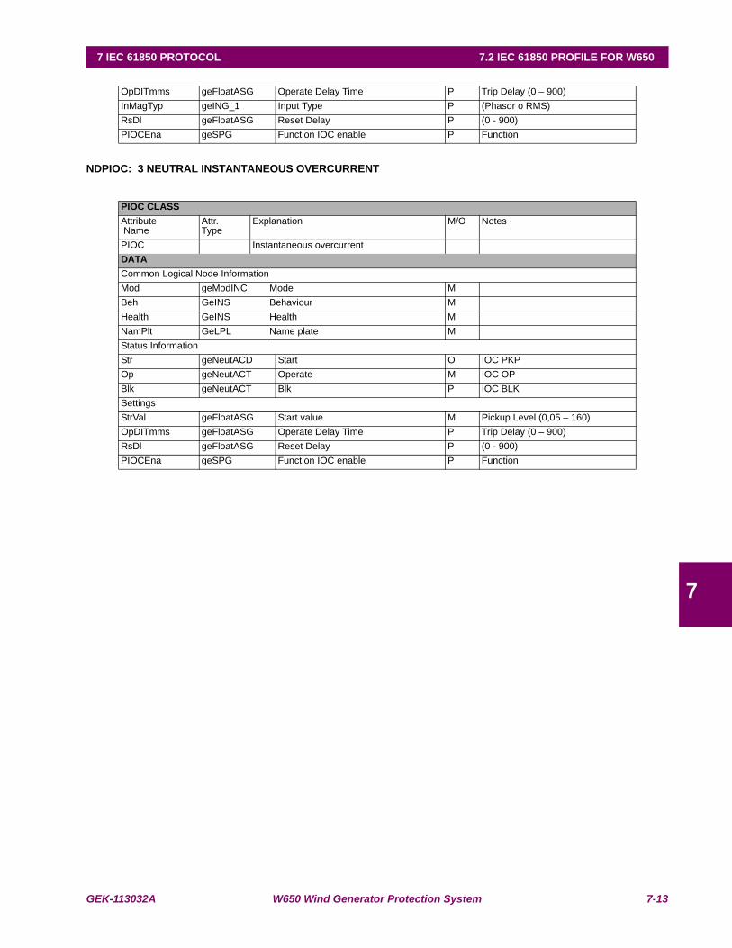
GEK-113032A W650 Wind Generator Protection System 7-13
7 IEC 61850 PROTOCOL 7.2 IEC 61850 PROFILE FOR W650
7
NDPIOC: 3 NEUTRAL INSTANTANEOUS OVERCURRENT
OpDITmms geFloatASG Operate Delay Time P Trip Delay (0 – 900)InMagTyp geING_1 Input Type P (Phasor o RMS)RsDl geFloatASG Reset Delay P (0 - 900)PIOCEna geSPG Function IOC enable P Function
PIOC CLASSAttribute Name
Attr. Type
Explanation M/O Notes
PIOC Instantaneous overcurrentDATACommon Logical Node InformationMod geModINC Mode MBeh GeINS Behaviour MHealth GeINS Health MNamPlt GeLPL Name plate MStatus InformationStr geNeutACD Start O IOC PKPOp geNeutACT Operate M IOC OPBlk geNeutACT Blk P IOC BLKSettingsStrVal geFloatASG Start value M Pickup Level (0,05 – 160)OpDITmms geFloatASG Operate Delay Time P Trip Delay (0 – 900)RsDl geFloatASG Reset Delay P (0 - 900)PIOCEna geSPG Function IOC enable P Function

7-14 W650 Wind Generator Protection System GEK-113032A
7.2 IEC 61850 PROFILE FOR W650 7 IEC 61850 PROTOCOL
7
GNDPIOC: 3 GROUND INSTANTANEOUS OVERCURRENT AND 3 SENS GROUND INSTANTANEOUSOVERCURRENT.
b) 2.2.2 PTOC (TIME OVERCURRENT)
PHSPTOC: 3 HIGH TIME OVERCURRENT AND 3 LOW TIME OVERCURRENT.
PIOC CLASSAttribute Name
Attr. Type
Explanation M/O Notes
PIOC Instantaneous overcurrentDATACommon Logical Node InformationMod geModINC Mode MBeh geINS Behaviour MHealth geINS Health MNamPlt geLPL Name plate MStatus InformationStr geNeutACD Start O IOC PKPOp geNeutACT Operate M IOC OPBlk geNeutACT Blk P IOC BLKSettingsStrVal geFloatASG Start value M Pickup Level (0,05 – 160)OpDITmms geFloatASG Operate Delay Time P Trip Delay (0 – 900)InMagTyp geING_1 Input Type P (Phasor o RMS)RsDl geFloatASG Reset Delay P (0 - 900)PIOCEna geSPG Function IOC enable P Function
PTOC CLASSAttribute Name
Attr. Type
Explanation M/O Notes
PTOC Time overcurrentDATACommon Logical Node InformationMod geModINC Mode MBeh geINS Behaviour MHealth geINS Health MNamPlt geLPL Name plate MStatus InformationStr gePhsACD Start M TOC PKPOp gePhsACT Operate M TOC OPBlk gePhsACT Block P TOC BLKSettingsTmACrv geCURVE Operating curve type M CurveStrVal geFloatASG Start value O Pickup Level (0,05 - 160)TmMult geFloatASG Time dial multiplier O TD Multiplier (0 – 900)RsMod geING_2 Reset Mode P Reset (instantaneous, lineal) InMagTyp geING_1 Input Type P Input (Phasor, RMS) VolRst geSPG Voltage Restraint P (enable, Disable)PTOCEna geSPG Function TOC enable P Function
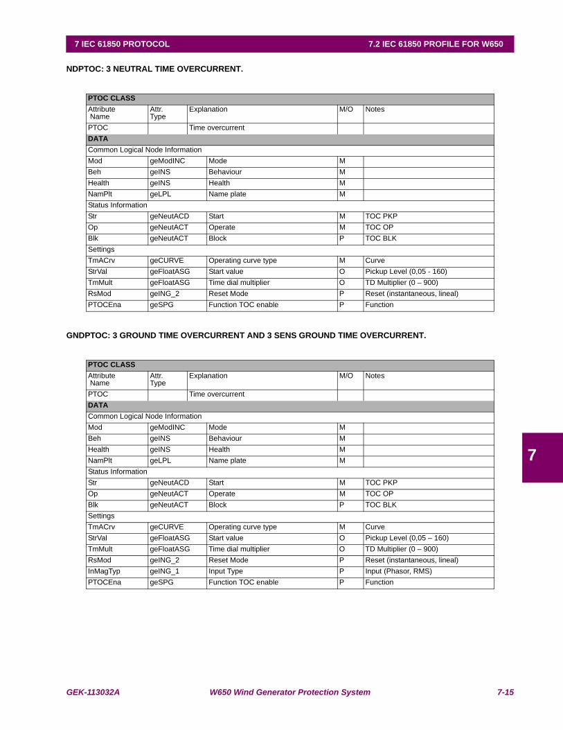
GEK-113032A W650 Wind Generator Protection System 7-15
7 IEC 61850 PROTOCOL 7.2 IEC 61850 PROFILE FOR W650
7
NDPTOC: 3 NEUTRAL TIME OVERCURRENT.
GNDPTOC: 3 GROUND TIME OVERCURRENT AND 3 SENS GROUND TIME OVERCURRENT.
PTOC CLASSAttribute Name
Attr. Type
Explanation M/O Notes
PTOC Time overcurrentDATACommon Logical Node InformationMod geModINC Mode MBeh geINS Behaviour MHealth geINS Health MNamPlt geLPL Name plate MStatus InformationStr geNeutACD Start M TOC PKPOp geNeutACT Operate M TOC OPBlk geNeutACT Block P TOC BLKSettingsTmACrv geCURVE Operating curve type M CurveStrVal geFloatASG Start value O Pickup Level (0,05 - 160)TmMult geFloatASG Time dial multiplier O TD Multiplier (0 – 900)RsMod geING_2 Reset Mode P Reset (instantaneous, lineal) PTOCEna geSPG Function TOC enable P Function
PTOC CLASSAttribute Name
Attr. Type
Explanation M/O Notes
PTOC Time overcurrentDATACommon Logical Node InformationMod geModINC Mode MBeh geINS Behaviour MHealth geINS Health MNamPlt geLPL Name plate MStatus InformationStr geNeutACD Start M TOC PKPOp geNeutACT Operate M TOC OPBlk geNeutACT Block P TOC BLKSettingsTmACrv geCURVE Operating curve type M CurveStrVal geFloatASG Start value O Pickup Level (0,05 – 160)TmMult geFloatASG Time dial multiplier O TD Multiplier (0 – 900)RsMod geING_2 Reset Mode P Reset (instantaneous, lineal) InMagTyp geING_1 Input Type P Input (Phasor, RMS) PTOCEna geSPG Function TOC enable P Function

7-16 W650 Wind Generator Protection System GEK-113032A
7.2 IEC 61850 PROFILE FOR W650 7 IEC 61850 PROTOCOL
7
c) PTOF (OVERFREQUENCY)
4 OVERFREQUENCY NODES
d) PTOV (OVERVOLTAGE)
PHSPTOV: 3 PHASE OVERVOLTAGE.
PTOF CLASSAttribute Name
Attr. Type
Explanation M/O Notes
PTOF OverFrequencyDATACommon Logical Node InformationMod geModINC Mode MBeh geINS Behaviour MHealth geINS Health MNamPlt geLPL Name plate MStatus InformationStr geGeneralACD Start M TOF PKPOp geGeneralACD Operate M TOF OPBlk geGeneralACT Block P TOF BLKSettingsStrVal geFloatASG Start value (frequency) O Pickup Level (20-65)BlkVal geIntASG Voltage Block Value O Minimun Voltage (30-500)OpDlTmms GeFloatASG Operate Delay Time O Trip Delay (0-900)RsDlTmms geFloatASG Reset Delay Time O Reset Delay (0-900)PTOFEna geSPG Function TOF enable P Function (Enable,Disable)
PTOV CLASSAttribute Name
Attr. Type
Explanation M/O Notes
PTOV OvervoltageDATACommon Logical Node InformationMod geModINC Mode MBeh geINS Behaviour MHealth geINS Health MNamPlt geLPL Name plate MStatus InformationStr gePhsACD Start M TOV PKPOp gePhsACT Operate O TOV OPBlk geGeneralACT Block P TOV BLKSettingsStrVal geIntASG Start Value O Pickup Level (3 – 850)OpDlTmms geFloatASG Operate Delay Time O Trip Delay ( 0 – 900 )
RsDlTmms GeFloatASG Reset Delay Time O Reset Delay ( 0 – 900 )OpMod GeING_6 Logic Mode P Logic ( Any, two, all phases )PTOVEna geSPG Function TOV enable P Function
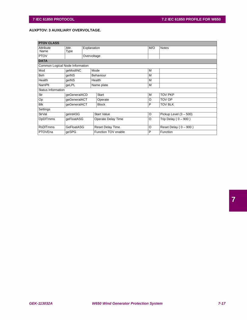
GEK-113032A W650 Wind Generator Protection System 7-17
7 IEC 61850 PROTOCOL 7.2 IEC 61850 PROFILE FOR W650
7
AUXPTOV: 3 AUXILIARY OVERVOLTAGE.
PTOV CLASSAttribute Name
Attr. Type
Explanation M/O Notes
PTOV OvervoltageDATACommon Logical Node InformationMod geModINC Mode MBeh geINS Behaviour MHealth geINS Health MNamPlt geLPL Name plate MStatus InformationStr geGeneralACD Start M TOV PKPOp geGeneralACT Operate O TOV OPBlk geGeneralACT Block P TOV BLKSettingsStrVal geIntASG Start Value O Pickup Level (3 – 500)OpDlTmms geFloatASG Operate Delay Time O Trip Delay ( 0 – 900 )
RsDlTmms GeFloatASG Reset Delay Time O Reset Delay ( 0 – 900 )PTOVEna geSPG Function TOV enable P Function
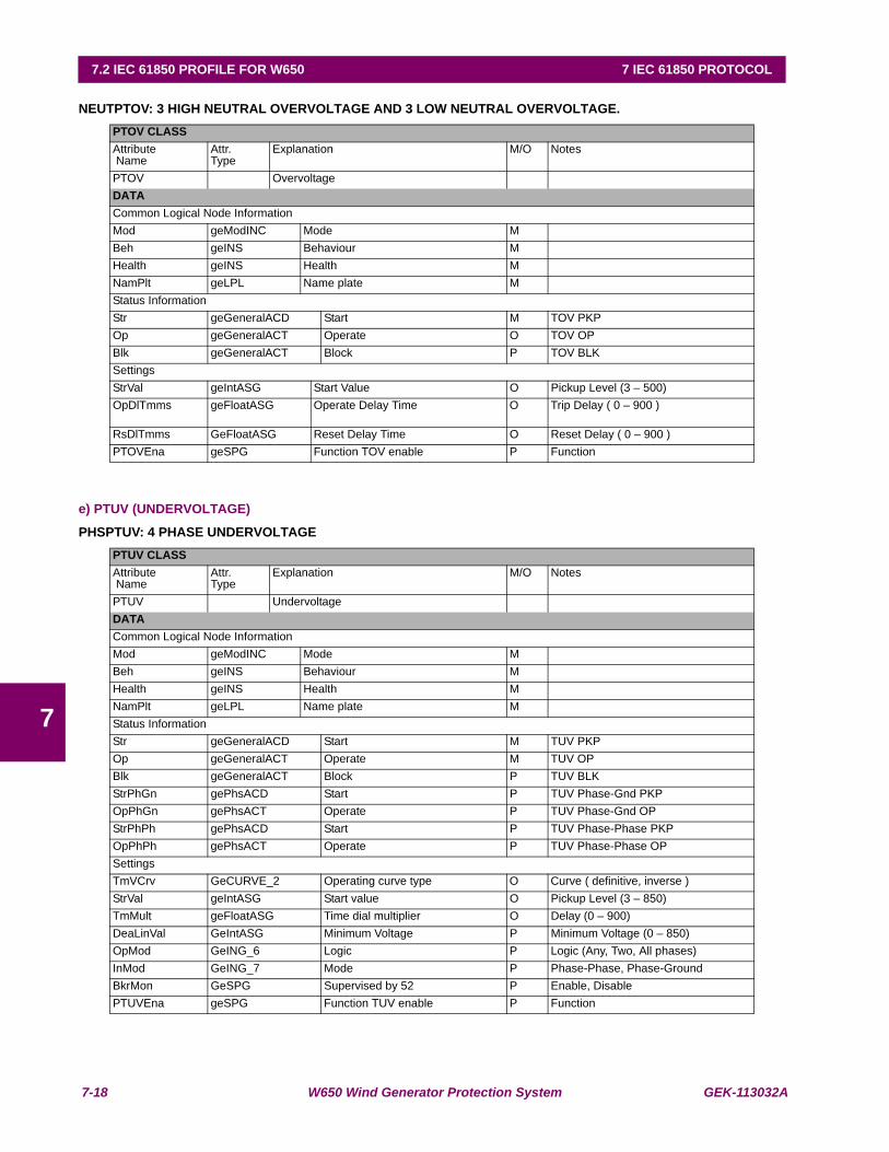
7-18 W650 Wind Generator Protection System GEK-113032A
7.2 IEC 61850 PROFILE FOR W650 7 IEC 61850 PROTOCOL
7
NEUTPTOV: 3 HIGH NEUTRAL OVERVOLTAGE AND 3 LOW NEUTRAL OVERVOLTAGE.
e) PTUV (UNDERVOLTAGE)
PHSPTUV: 4 PHASE UNDERVOLTAGE
PTOV CLASSAttribute Name
Attr. Type
Explanation M/O Notes
PTOV OvervoltageDATACommon Logical Node InformationMod geModINC Mode MBeh geINS Behaviour MHealth geINS Health MNamPlt geLPL Name plate MStatus InformationStr geGeneralACD Start M TOV PKPOp geGeneralACT Operate O TOV OPBlk geGeneralACT Block P TOV BLKSettingsStrVal geIntASG Start Value O Pickup Level (3 – 500)OpDlTmms geFloatASG Operate Delay Time O Trip Delay ( 0 – 900 )
RsDlTmms GeFloatASG Reset Delay Time O Reset Delay ( 0 – 900 )PTOVEna geSPG Function TOV enable P Function
PTUV CLASSAttribute Name
Attr. Type
Explanation M/O Notes
PTUV UndervoltageDATACommon Logical Node InformationMod geModINC Mode MBeh geINS Behaviour MHealth geINS Health MNamPlt geLPL Name plate MStatus InformationStr geGeneralACD Start M TUV PKPOp geGeneralACT Operate M TUV OPBlk geGeneralACT Block P TUV BLKStrPhGn gePhsACD Start P TUV Phase-Gnd PKPOpPhGn gePhsACT Operate P TUV Phase-Gnd OPStrPhPh gePhsACD Start P TUV Phase-Phase PKPOpPhPh gePhsACT Operate P TUV Phase-Phase OPSettingsTmVCrv GeCURVE_2 Operating curve type O Curve ( definitive, inverse )StrVal geIntASG Start value O Pickup Level (3 – 850)TmMult geFloatASG Time dial multiplier O Delay (0 – 900)DeaLinVal GeIntASG Minimum Voltage P Minimum Voltage (0 – 850)OpMod GeING_6 Logic P Logic (Any, Two, All phases)InMod GeING_7 Mode P Phase-Phase, Phase-GroundBkrMon GeSPG Supervised by 52 P Enable, DisablePTUVEna geSPG Function TUV enable P Function
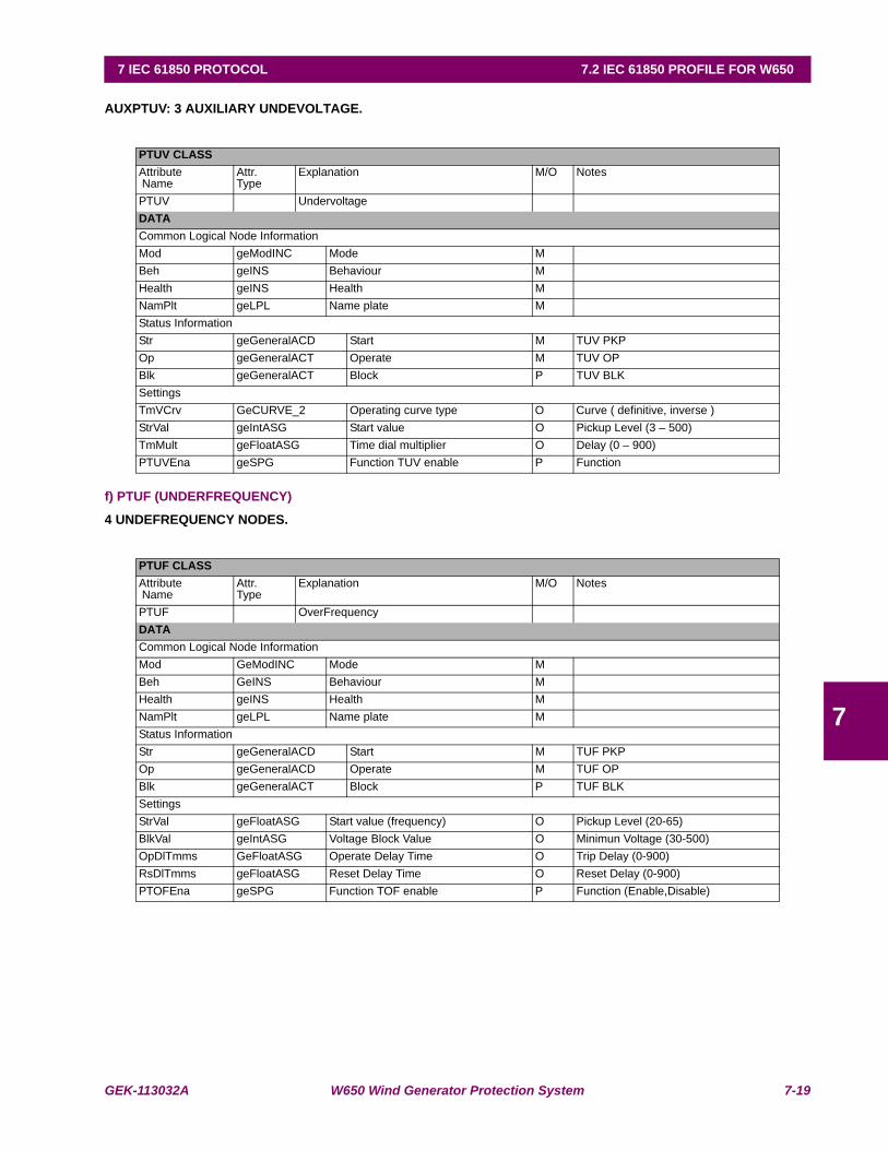
GEK-113032A W650 Wind Generator Protection System 7-19
7 IEC 61850 PROTOCOL 7.2 IEC 61850 PROFILE FOR W650
7
AUXPTUV: 3 AUXILIARY UNDEVOLTAGE.
f) PTUF (UNDERFREQUENCY)
4 UNDEFREQUENCY NODES.
PTUV CLASSAttribute Name
Attr. Type
Explanation M/O Notes
PTUV UndervoltageDATACommon Logical Node InformationMod geModINC Mode MBeh geINS Behaviour MHealth geINS Health MNamPlt geLPL Name plate MStatus InformationStr geGeneralACD Start M TUV PKPOp geGeneralACT Operate M TUV OPBlk geGeneralACT Block P TUV BLKSettingsTmVCrv GeCURVE_2 Operating curve type O Curve ( definitive, inverse )StrVal geIntASG Start value O Pickup Level (3 – 500)TmMult geFloatASG Time dial multiplier O Delay (0 – 900)PTUVEna geSPG Function TUV enable P Function
PTUF CLASSAttribute Name
Attr. Type
Explanation M/O Notes
PTUF OverFrequencyDATACommon Logical Node InformationMod GeModINC Mode MBeh GeINS Behaviour MHealth geINS Health MNamPlt geLPL Name plate MStatus InformationStr geGeneralACD Start M TUF PKPOp geGeneralACD Operate M TUF OPBlk geGeneralACT Block P TUF BLKSettingsStrVal geFloatASG Start value (frequency) O Pickup Level (20-65)BlkVal geIntASG Voltage Block Value O Minimun Voltage (30-500)OpDlTmms GeFloatASG Operate Delay Time O Trip Delay (0-900)RsDlTmms geFloatASG Reset Delay Time O Reset Delay (0-900)PTOFEna geSPG Function TOF enable P Function (Enable,Disable)
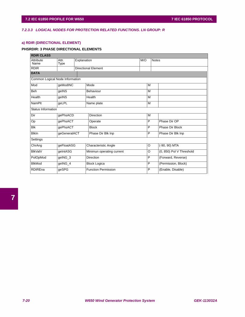
7-20 W650 Wind Generator Protection System GEK-113032A
7.2 IEC 61850 PROFILE FOR W650 7 IEC 61850 PROTOCOL
7
7.2.3.3 LOGICAL NODES FOR PROTECTION RELATED FUNCTIONS. LN GROUP: R
a) RDIR (DIRECTIONAL ELEMENT)
PHSRDIR: 3 PHASE DIRECTIONAL ELEMENTSRDIR CLASSAttribute Name
Attr. Type
Explanation M/O Notes
RDIR Directional ElementDATA
Common Logical Node Information
Mod geModINC Mode M
Beh geINS Behaviour M
Health geINS Health M
NamPlt geLPL Name plate M
Status Information
Dir gePhsACD Direction M
Op gePhsACT Operate P Phase Dir OP
Blk gePhsACT Block P Phase Dir Block
BlkIn geGeneralACT Phase Dir Blk Inp P Phase Dir Blk Inp
Settings
ChrAng geFloatASG Characteristic Angle O (-90, 90) MTA
BlkValV geIntASG Minimun operating current O (0, 850) Pol V Threshold
PolOpMod geING_3 Direction P (Forward, Reverse)
BlkMod geING_4 Block Logica P (Permission, Block)
RDIREna geSPG Function Permission P (Enable, Disable)
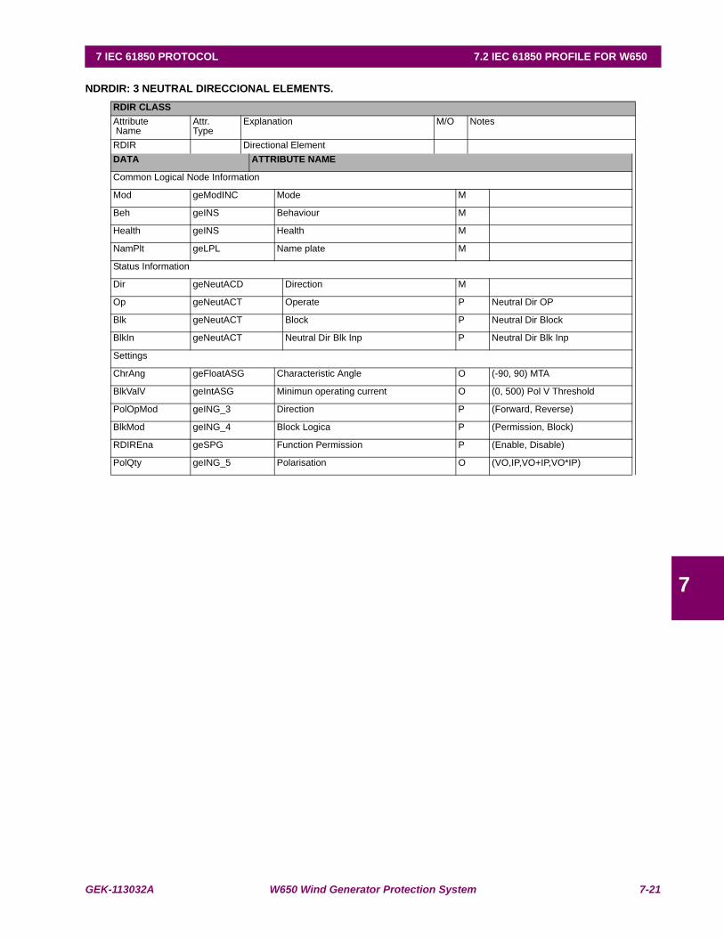
GEK-113032A W650 Wind Generator Protection System 7-21
7 IEC 61850 PROTOCOL 7.2 IEC 61850 PROFILE FOR W650
7
NDRDIR: 3 NEUTRAL DIRECCIONAL ELEMENTS.RDIR CLASSAttribute Name
Attr. Type
Explanation M/O Notes
RDIR Directional ElementDATA ATTRIBUTE NAME
Common Logical Node Information
Mod geModINC Mode M
Beh geINS Behaviour M
Health geINS Health M
NamPlt geLPL Name plate M
Status Information
Dir geNeutACD Direction M
Op geNeutACT Operate P Neutral Dir OP
Blk geNeutACT Block P Neutral Dir Block
BlkIn geNeutACT Neutral Dir Blk Inp P Neutral Dir Blk Inp
Settings
ChrAng geFloatASG Characteristic Angle O (-90, 90) MTA
BlkValV geIntASG Minimun operating current O (0, 500) Pol V Threshold
PolOpMod geING_3 Direction P (Forward, Reverse)
BlkMod geING_4 Block Logica P (Permission, Block)
RDIREna geSPG Function Permission P (Enable, Disable)
PolQty geING_5 Polarisation O (VO,IP,VO+IP,VO*IP)

7-22 W650 Wind Generator Protection System GEK-113032A
7.2 IEC 61850 PROFILE FOR W650 7 IEC 61850 PROTOCOL
7
GNDRDI: 3 GROUND DIRECCIONAL ELEMENTS.RDIR CLASSAttribute Name
Attr. Type
Explanation M/O Notes
RDIR Directional ElementDATA ATTRIBUTE NAME
Common Logical Node Information
Mod geModINC Mode M
Beh geINS Behaviour M
Health geINS Health M
NamPlt geLPL Name plate M
Status Information
Dir geNeutACD Direction M
Op geNeutACT Operate P Ground Dir OP
Blk geNeutACT Block P Ground Dir Block
BlkIn geNeutACT Ground Dir Blk Inp P Ground Dir Blk Inp
Settings
ChrAng geFloatASG Characteristic Angle O (-90, 90) MTA
BlkValV geIntASG Minimun operating current O (0, 500) Pol V Threshold
PolOpMod geING_3 Direction P (Forward, Reverse)
BlkMod geING_4 Block Logica P (Permission, Block)
RDIREna geSPG Function Permission P (Enable, Disable)
PolQty geING_5 Polarisation O (VO,IP,VO+IP,VO*IP)

GEK-113032A W650 Wind Generator Protection System 7-23
7 IEC 61850 PROTOCOL 7.2 IEC 61850 PROFILE FOR W650
7
HSERDIR: 3 SENS DIRECCIONAL ELEMENTS.RDIR CLASSAttribute Name
Attr. Type
Explanation M/O Notes
RDIR Directional ElementDATA Attribute Name
Common Logical Node Information
Mod geModINC Mode M
Beh geINS Behaviour M
Health geINS Health M
NamPlt geLPL Name plate M
Status Information
Dir geGeneralACD Direction M
Op geGeneralACT Operate P Sens Gnd Dir OP
Blk geGeneralACT Block P Sens Gnd Dir Block
BlkIn geGeneralACT Sens Gnd Dir Blk Inp P Sens Gnd Dir Blk Inp
Settings
ChrAng geFloatASG Characteristic Angle O (-90, 90) MTA
BlkValV geIntASG Minimun operating current O (0, 500) Pol V Threshold
PolOpMod geING_3 Direction P (Forward, Reverse)
BlkMod geING_4 Block Logica P (Permission, Block)
RDIREna geSPG Function Permission P (Enable, Disable)

7-24 W650 Wind Generator Protection System GEK-113032A
7.2 IEC 61850 PROFILE FOR W650 7 IEC 61850 PROTOCOL
7
b) RREC (AUTORECLOSING)
RREC CLASSAttribute Name
Attr. Type
Explanation M/O Notes
RREC AutoreclosingDATA ATTRIBUTE NAMECommon Logical Node InformationMod geModINC Mode MBeh geINS Behaviour MHealth geINS Health MControlsBlkRec geSPC Block Reclosing O AR Pulse block, unblock
Status InformationOp geGeneralACT Operate M AR Close BreakerAutoRecSt GeINS_AR Auto Reclosing status M AR StatusAutoRecLO GeINS_AR_LO Auto Reclosing Lockout Status P AR Lockout ModeAutoRecBlk GeINS_AR_Blk Auto Reclosing Block Status P AR Block Mode
SettingsRec1Tms GeFloatASG First Reclose Time O Dead Time 1Rec2Tms GeFloatASG Second Reclose Time O Dead Time 2Rec3Tms GeFloatASG Third Reclose Time O Dead Time 3Rec4Tms GeFloatASG Fourth Reclose Time O Dead Time 4RclTms geFloatASG Reclaim Time O Reclaim TimeMaxNumShots geING Max number of Shots P Max number ShotsRsTms geFloatASG Reclosing --> Ready P Reset TimeHoldTms geFloatASG Cond Check Time P Hold TimeCondEna geSPG Check Cond (Enable, Disable) P Cond PermissionRRECEna geSPG Function Enable, Disable P Function Permission
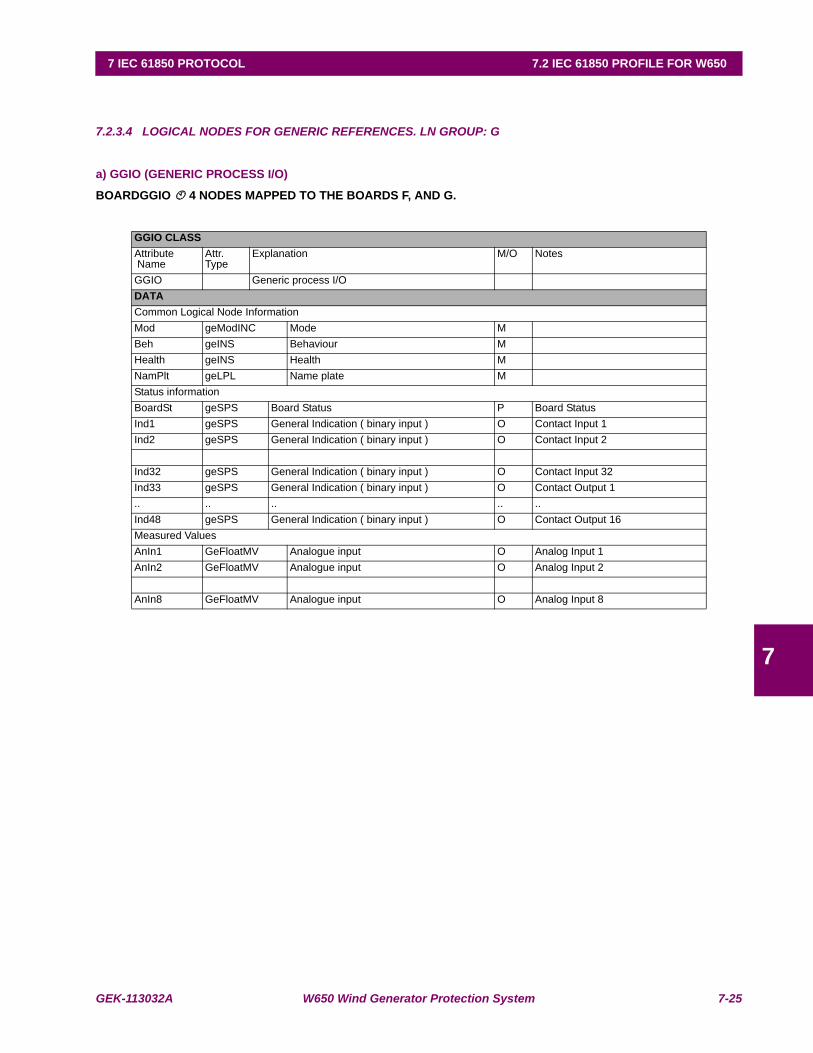
GEK-113032A W650 Wind Generator Protection System 7-25
7 IEC 61850 PROTOCOL 7.2 IEC 61850 PROFILE FOR W650
7
7.2.3.4 LOGICAL NODES FOR GENERIC REFERENCES. LN GROUP: G
a) GGIO (GENERIC PROCESS I/O)
BOARDGGIO 4 NODES MAPPED TO THE BOARDS F, AND G.
GGIO CLASSAttribute Name
Attr. Type
Explanation M/O Notes
GGIO Generic process I/ODATACommon Logical Node InformationMod geModINC Mode MBeh geINS Behaviour MHealth geINS Health MNamPlt geLPL Name plate MStatus informationBoardSt geSPS Board Status P Board StatusInd1 geSPS General Indication ( binary input ) O Contact Input 1Ind2 geSPS General Indication ( binary input ) O Contact Input 2
Ind32 geSPS General Indication ( binary input ) O Contact Input 32Ind33 geSPS General Indication ( binary input ) O Contact Output 1.. .. .. .. ..Ind48 geSPS General Indication ( binary input ) O Contact Output 16Measured ValuesAnIn1 GeFloatMV Analogue input O Analog Input 1AnIn2 GeFloatMV Analogue input O Analog Input 2
AnIn8 GeFloatMV Analogue input O Analog Input 8
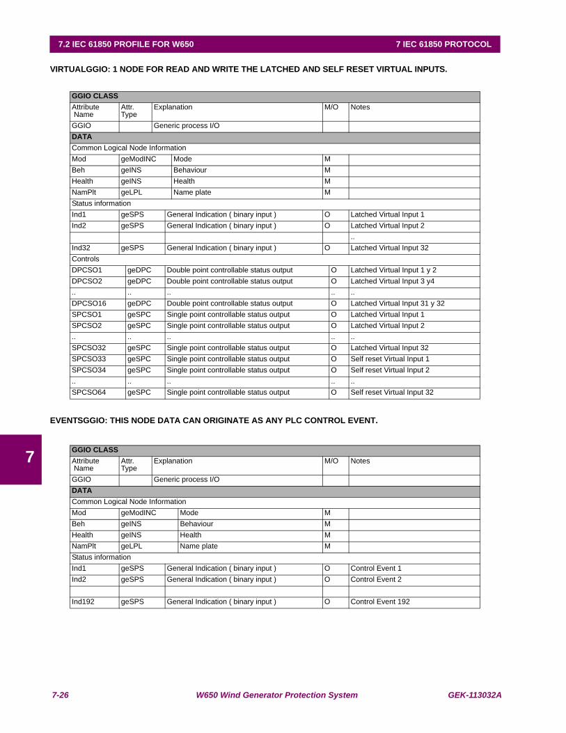
7-26 W650 Wind Generator Protection System GEK-113032A
7.2 IEC 61850 PROFILE FOR W650 7 IEC 61850 PROTOCOL
7
VIRTUALGGIO: 1 NODE FOR READ AND WRITE THE LATCHED AND SELF RESET VIRTUAL INPUTS.
EVENTSGGIO: THIS NODE DATA CAN ORIGINATE AS ANY PLC CONTROL EVENT.
GGIO CLASSAttribute Name
Attr. Type
Explanation M/O Notes
GGIO Generic process I/ODATACommon Logical Node InformationMod geModINC Mode MBeh geINS Behaviour MHealth geINS Health MNamPlt geLPL Name plate MStatus informationInd1 geSPS General Indication ( binary input ) O Latched Virtual Input 1Ind2 geSPS General Indication ( binary input ) O Latched Virtual Input 2
..Ind32 geSPS General Indication ( binary input ) O Latched Virtual Input 32ControlsDPCSO1 geDPC Double point controllable status output O Latched Virtual Input 1 y 2DPCSO2 geDPC Double point controllable status output O Latched Virtual Input 3 y4.. .. .. .. ..DPCSO16 geDPC Double point controllable status output O Latched Virtual Input 31 y 32SPCSO1 geSPC Single point controllable status output O Latched Virtual Input 1SPCSO2 geSPC Single point controllable status output O Latched Virtual Input 2.. .. .. .. ..SPCSO32 geSPC Single point controllable status output O Latched Virtual Input 32SPCSO33 geSPC Single point controllable status output O Self reset Virtual Input 1SPCSO34 geSPC Single point controllable status output O Self reset Virtual Input 2.. .. .. .. ..SPCSO64 geSPC Single point controllable status output O Self reset Virtual Input 32
GGIO CLASSAttribute Name
Attr. Type
Explanation M/O Notes
GGIO Generic process I/ODATACommon Logical Node InformationMod geModINC Mode MBeh geINS Behaviour MHealth geINS Health MNamPlt geLPL Name plate MStatus informationInd1 geSPS General Indication ( binary input ) O Control Event 1Ind2 geSPS General Indication ( binary input ) O Control Event 2
Ind192 geSPS General Indication ( binary input ) O Control Event 192
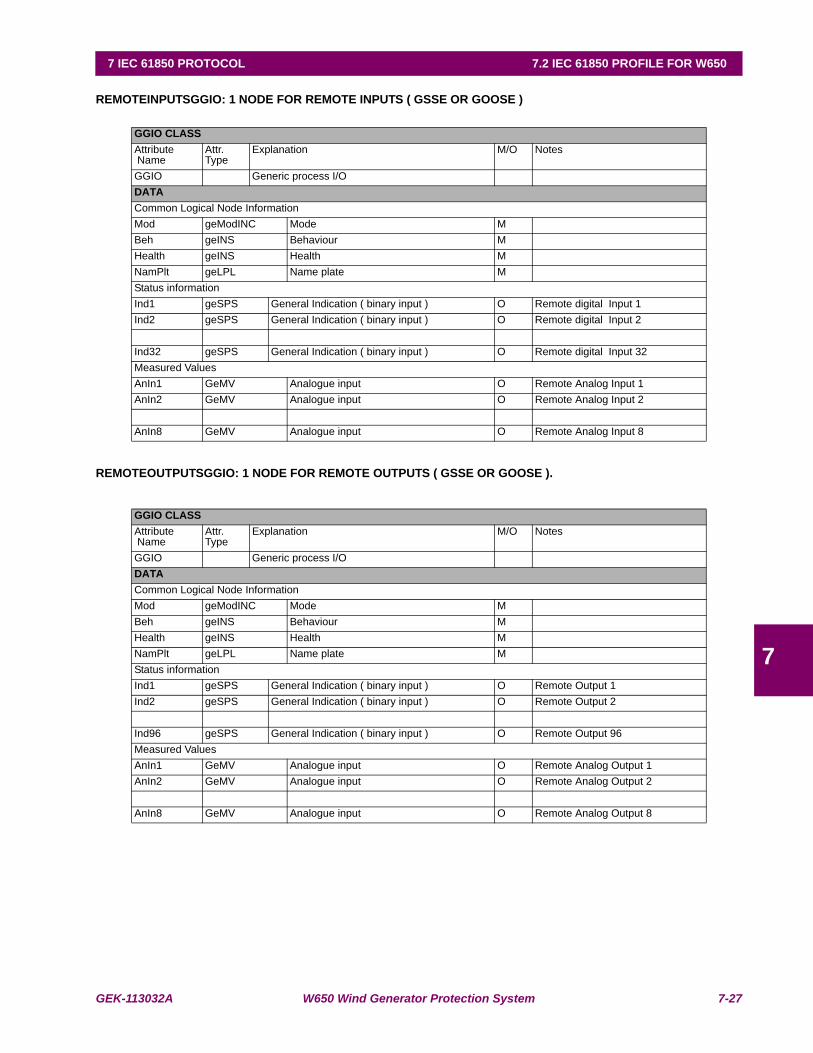
GEK-113032A W650 Wind Generator Protection System 7-27
7 IEC 61850 PROTOCOL 7.2 IEC 61850 PROFILE FOR W650
7
REMOTEINPUTSGGIO: 1 NODE FOR REMOTE INPUTS ( GSSE OR GOOSE )
REMOTEOUTPUTSGGIO: 1 NODE FOR REMOTE OUTPUTS ( GSSE OR GOOSE ).
GGIO CLASSAttribute Name
Attr. Type
Explanation M/O Notes
GGIO Generic process I/ODATACommon Logical Node InformationMod geModINC Mode MBeh geINS Behaviour MHealth geINS Health MNamPlt geLPL Name plate MStatus informationInd1 geSPS General Indication ( binary input ) O Remote digital Input 1Ind2 geSPS General Indication ( binary input ) O Remote digital Input 2
Ind32 geSPS General Indication ( binary input ) O Remote digital Input 32Measured ValuesAnIn1 GeMV Analogue input O Remote Analog Input 1AnIn2 GeMV Analogue input O Remote Analog Input 2
AnIn8 GeMV Analogue input O Remote Analog Input 8
GGIO CLASSAttribute Name
Attr. Type
Explanation M/O Notes
GGIO Generic process I/ODATACommon Logical Node InformationMod geModINC Mode MBeh geINS Behaviour MHealth geINS Health MNamPlt geLPL Name plate MStatus informationInd1 geSPS General Indication ( binary input ) O Remote Output 1Ind2 geSPS General Indication ( binary input ) O Remote Output 2
Ind96 geSPS General Indication ( binary input ) O Remote Output 96Measured ValuesAnIn1 GeMV Analogue input O Remote Analog Output 1AnIn2 GeMV Analogue input O Remote Analog Output 2
AnIn8 GeMV Analogue input O Remote Analog Output 8

7-28 W650 Wind Generator Protection System GEK-113032A
7.2 IEC 61850 PROFILE FOR W650 7 IEC 61850 PROTOCOL
7
7.2.3.5 LOGICAL NODES FOR METERING AND MEASUREMENT. LN GROUP: M
a) MMXU (MEASUREMENT)MMXU CLASSAttribute Name
Attr. Type
Explanation M/O Notes
MMXU MeasurementDATACommon Logical Node InformationMod geModINC Mode MBeh geINS Behaviour MHealth geINS Health MNamPlt geLPL Name plate MMeasured valuesTotW GeIntMV Total active power (P) O Phase Real PwrTotVAr GeIntMV Total reactive power (Q) O Ph Reactive PwrTotVA GeIntMV Total apparent power (S) O Ph Apparent PwrTotPF GeIntMV Average power factor (PF) O 3 Ph Power FactorHz GeIntMV Frequency O FrequencyPPV geIntDEL Phase to phase voltages (VL1L2,...) O Vxx PrimaryPhV geIntPhsWYE Phase to ground voltages (VL1ER, ...) O Vx PrimaryA geIntWYE Phase currents (IL1, ...) O Phasor Primary
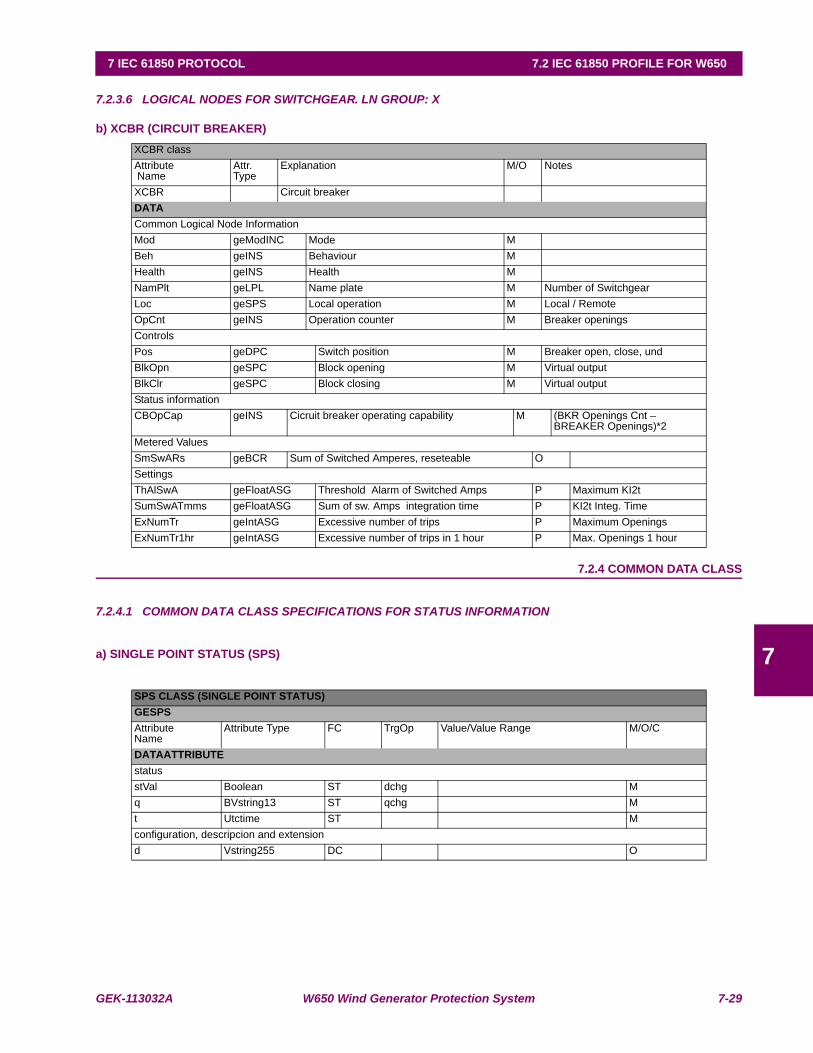
GEK-113032A W650 Wind Generator Protection System 7-29
7 IEC 61850 PROTOCOL 7.2 IEC 61850 PROFILE FOR W650
7
7.2.3.6 LOGICAL NODES FOR SWITCHGEAR. LN GROUP: X
b) XCBR (CIRCUIT BREAKER)
7.2.4 COMMON DATA CLASS
7.2.4.1 COMMON DATA CLASS SPECIFICATIONS FOR STATUS INFORMATION
a) SINGLE POINT STATUS (SPS)
XCBR classAttribute Name
Attr. Type
Explanation M/O Notes
XCBR Circuit breakerDATACommon Logical Node InformationMod geModINC Mode MBeh geINS Behaviour MHealth geINS Health MNamPlt geLPL Name plate M Number of SwitchgearLoc geSPS Local operation M Local / RemoteOpCnt geINS Operation counter M Breaker openingsControls Pos geDPC Switch position M Breaker open, close, undBlkOpn geSPC Block opening M Virtual outputBlkClr geSPC Block closing M Virtual outputStatus informationCBOpCap geINS Cicruit breaker operating capability M (BKR Openings Cnt –
BREAKER Openings)*2Metered ValuesSmSwARs geBCR Sum of Switched Amperes, reseteable OSettingsThAlSwA geFloatASG Threshold Alarm of Switched Amps P Maximum KI2tSumSwATmms geFloatASG Sum of sw. Amps integration time P KI2t Integ. TimeExNumTr geIntASG Excessive number of trips P Maximum OpeningsExNumTr1hr geIntASG Excessive number of trips in 1 hour P Max. Openings 1 hour
SPS CLASS (SINGLE POINT STATUS)GESPSAttributeName
Attribute Type FC TrgOp Value/Value Range M/O/C
DATAATTRIBUTEstatusstVal Boolean ST dchg Mq BVstring13 ST qchg Mt Utctime ST Mconfiguration, descripcion and extensiond Vstring255 DC O
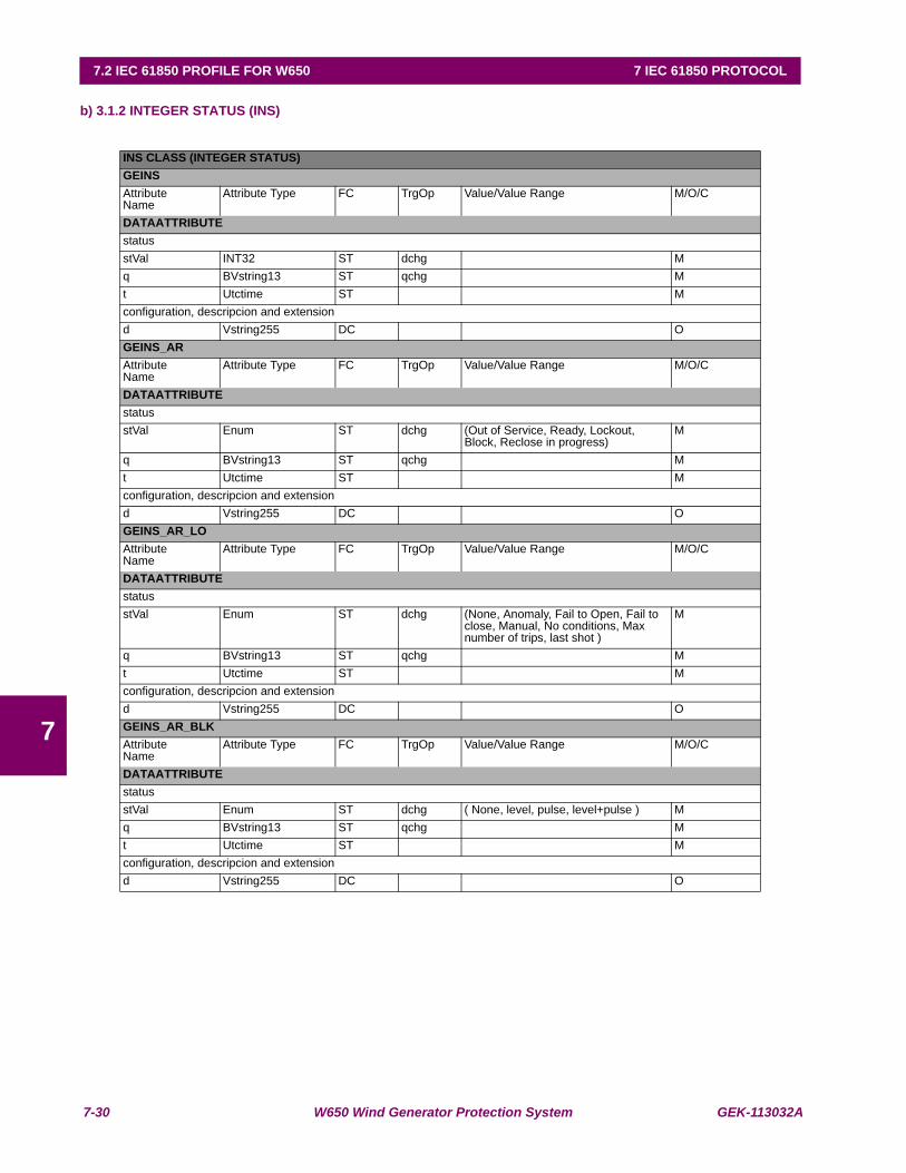
7-30 W650 Wind Generator Protection System GEK-113032A
7.2 IEC 61850 PROFILE FOR W650 7 IEC 61850 PROTOCOL
7
b) 3.1.2 INTEGER STATUS (INS)
INS CLASS (INTEGER STATUS)GEINSAttributeName
Attribute Type FC TrgOp Value/Value Range M/O/C
DATAATTRIBUTEstatusstVal INT32 ST dchg Mq BVstring13 ST qchg Mt Utctime ST Mconfiguration, descripcion and extensiond Vstring255 DC OGEINS_ARAttributeName
Attribute Type FC TrgOp Value/Value Range M/O/C
DATAATTRIBUTEstatusstVal Enum ST dchg (Out of Service, Ready, Lockout,
Block, Reclose in progress)M
q BVstring13 ST qchg Mt Utctime ST Mconfiguration, descripcion and extensiond Vstring255 DC OGEINS_AR_LOAttributeName
Attribute Type FC TrgOp Value/Value Range M/O/C
DATAATTRIBUTEstatusstVal Enum ST dchg (None, Anomaly, Fail to Open, Fail to
close, Manual, No conditions, Max number of trips, last shot )
M
q BVstring13 ST qchg Mt Utctime ST Mconfiguration, descripcion and extensiond Vstring255 DC OGEINS_AR_BLKAttributeName
Attribute Type FC TrgOp Value/Value Range M/O/C
DATAATTRIBUTEstatusstVal Enum ST dchg ( None, level, pulse, level+pulse ) Mq BVstring13 ST qchg Mt Utctime ST Mconfiguration, descripcion and extensiond Vstring255 DC O
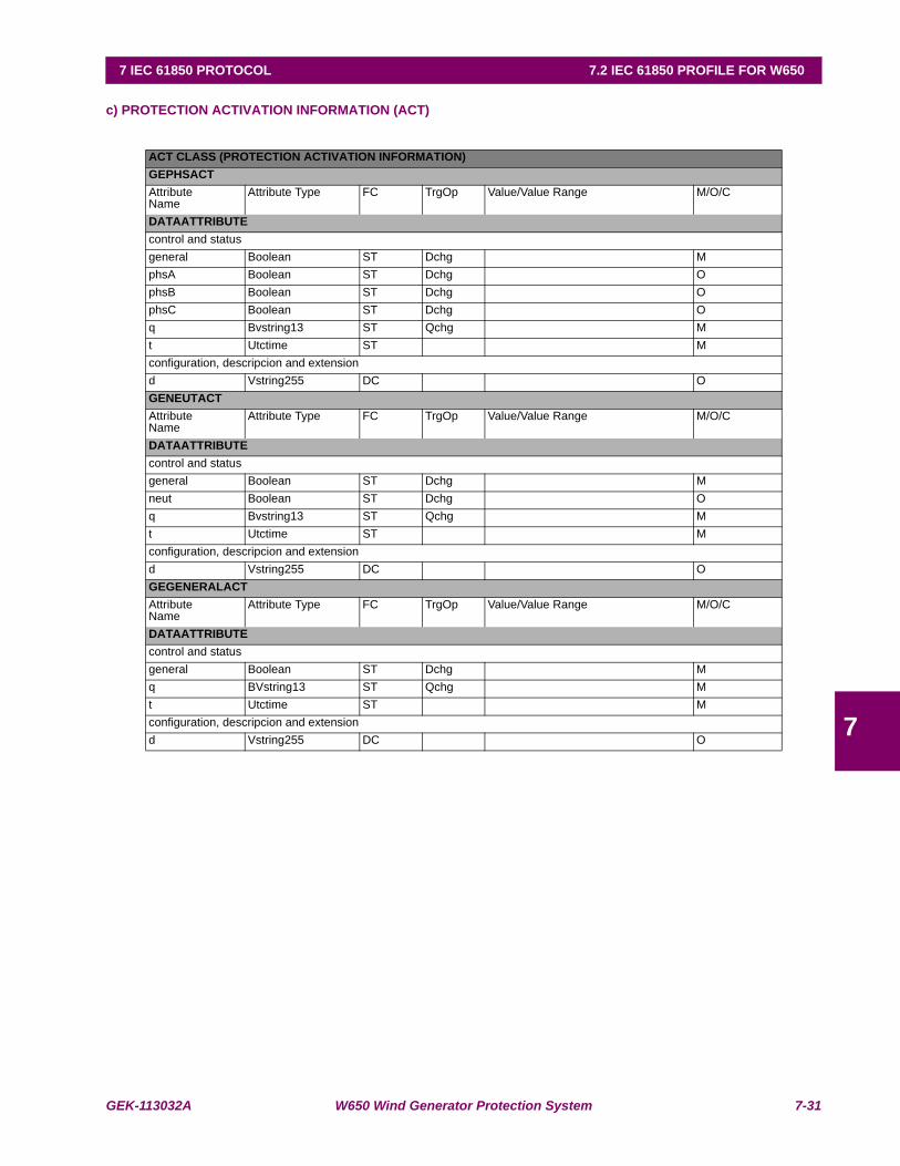
GEK-113032A W650 Wind Generator Protection System 7-31
7 IEC 61850 PROTOCOL 7.2 IEC 61850 PROFILE FOR W650
7
c) PROTECTION ACTIVATION INFORMATION (ACT)
ACT CLASS (PROTECTION ACTIVATION INFORMATION)GEPHSACT AttributeName
Attribute Type FC TrgOp Value/Value Range M/O/C
DATAATTRIBUTEcontrol and statusgeneral Boolean ST Dchg MphsA Boolean ST Dchg OphsB Boolean ST Dchg OphsC Boolean ST Dchg Oq Bvstring13 ST Qchg Mt Utctime ST Mconfiguration, descripcion and extensiond Vstring255 DC OGENEUTACTAttributeName
Attribute Type FC TrgOp Value/Value Range M/O/C
DATAATTRIBUTEcontrol and statusgeneral Boolean ST Dchg Mneut Boolean ST Dchg Oq Bvstring13 ST Qchg Mt Utctime ST Mconfiguration, descripcion and extensiond Vstring255 DC OGEGENERALACT AttributeName
Attribute Type FC TrgOp Value/Value Range M/O/C
DATAATTRIBUTEcontrol and statusgeneral Boolean ST Dchg Mq BVstring13 ST Qchg Mt Utctime ST Mconfiguration, descripcion and extensiond Vstring255 DC O
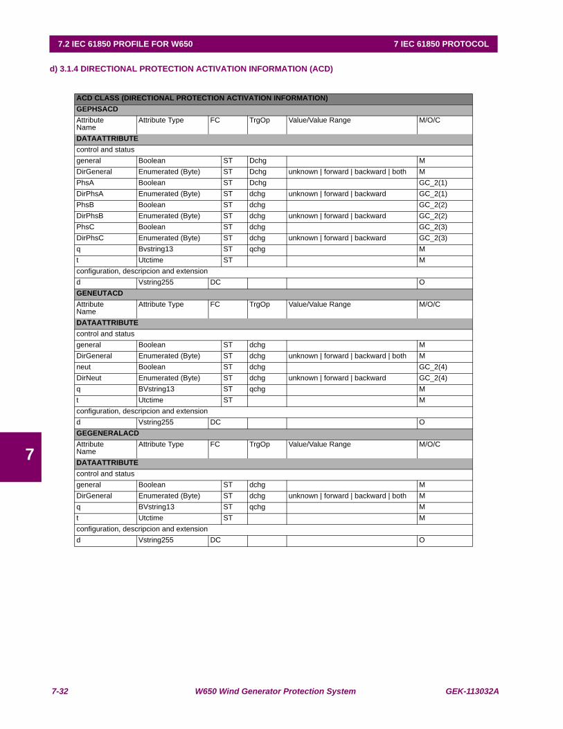
7-32 W650 Wind Generator Protection System GEK-113032A
7.2 IEC 61850 PROFILE FOR W650 7 IEC 61850 PROTOCOL
7
d) 3.1.4 DIRECTIONAL PROTECTION ACTIVATION INFORMATION (ACD)
ACD CLASS (DIRECTIONAL PROTECTION ACTIVATION INFORMATION)GEPHSACDAttributeName
Attribute Type FC TrgOp Value/Value Range M/O/C
DATAATTRIBUTEcontrol and statusgeneral Boolean ST Dchg MDirGeneral Enumerated (Byte) ST Dchg unknown | forward | backward | both MPhsA Boolean ST Dchg GC_2(1)DirPhsA Enumerated (Byte) ST dchg unknown | forward | backward GC_2(1)PhsB Boolean ST dchg GC_2(2)DirPhsB Enumerated (Byte) ST dchg unknown | forward | backward GC_2(2)PhsC Boolean ST dchg GC_2(3)DirPhsC Enumerated (Byte) ST dchg unknown | forward | backward GC_2(3)q Bvstring13 ST qchg Mt Utctime ST Mconfiguration, descripcion and extensiond Vstring255 DC OGENEUTACDAttributeName
Attribute Type FC TrgOp Value/Value Range M/O/C
DATAATTRIBUTEcontrol and statusgeneral Boolean ST dchg MDirGeneral Enumerated (Byte) ST dchg unknown | forward | backward | both Mneut Boolean ST dchg GC_2(4)DirNeut Enumerated (Byte) ST dchg unknown | forward | backward GC_2(4)q BVstring13 ST qchg Mt Utctime ST Mconfiguration, descripcion and extensiond Vstring255 DC OGEGENERALACD AttributeName
Attribute Type FC TrgOp Value/Value Range M/O/C
DATAATTRIBUTEcontrol and statusgeneral Boolean ST dchg MDirGeneral Enumerated (Byte) ST dchg unknown | forward | backward | both Mq BVstring13 ST qchg Mt Utctime ST Mconfiguration, descripcion and extensiond Vstring255 DC O
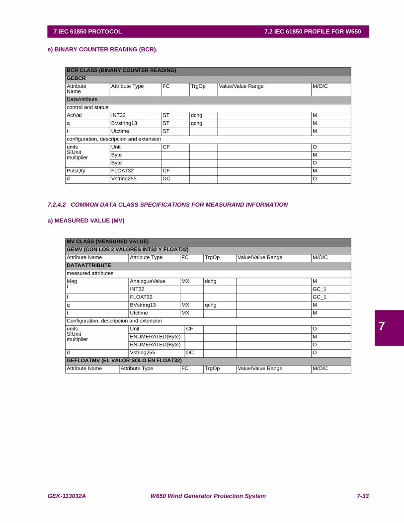
GEK-113032A W650 Wind Generator Protection System 7-33
7 IEC 61850 PROTOCOL 7.2 IEC 61850 PROFILE FOR W650
7
e) BINARY COUNTER READING (BCR).
7.2.4.2 COMMON DATA CLASS SPECIFICATIONS FOR MEASURAND INFORMATION
a) MEASURED VALUE (MV)
BCR CLASS (BINARY COUNTER READING)GEBCRAttributeName
Attribute Type FC TrgOp Value/Value Range M/O/C
DataAttributecontrol and statusActVal INT32 ST dchg Mq BVstring13 ST qchg Mt Utctime ST Mconfiguration, descripcion and extensionunitsSIUnitmultiplier
Unit CF OByte MByte O
PulsQty FLOAT32 CF Md Vstring255 DC O
MV CLASS (MEASURED VALUE)GEMV (CON LOS 2 VALORES INT32 Y FLOAT32)Attribute Name Attribute Type FC TrgOp Value/Value Range M/O/CDATAATTRIBUTEmeasured attributesMagi
AnalogueValue MX dchg MINT32 GC_1
f FLOAT32 GC_1q BVstring13 MX qchg Mt Utctime MX MConfiguration, descripcion and extensionunitsSIUnitmultiplier
Unit CF OENUMERATED(Byte) MENUMERATED(Byte) O
d Vstring255 DC OGEFLOATMV (EL VALOR SOLO EN FLOAT32)Attribute Name Attribute Type FC TrgOp Value/Value Range M/O/C
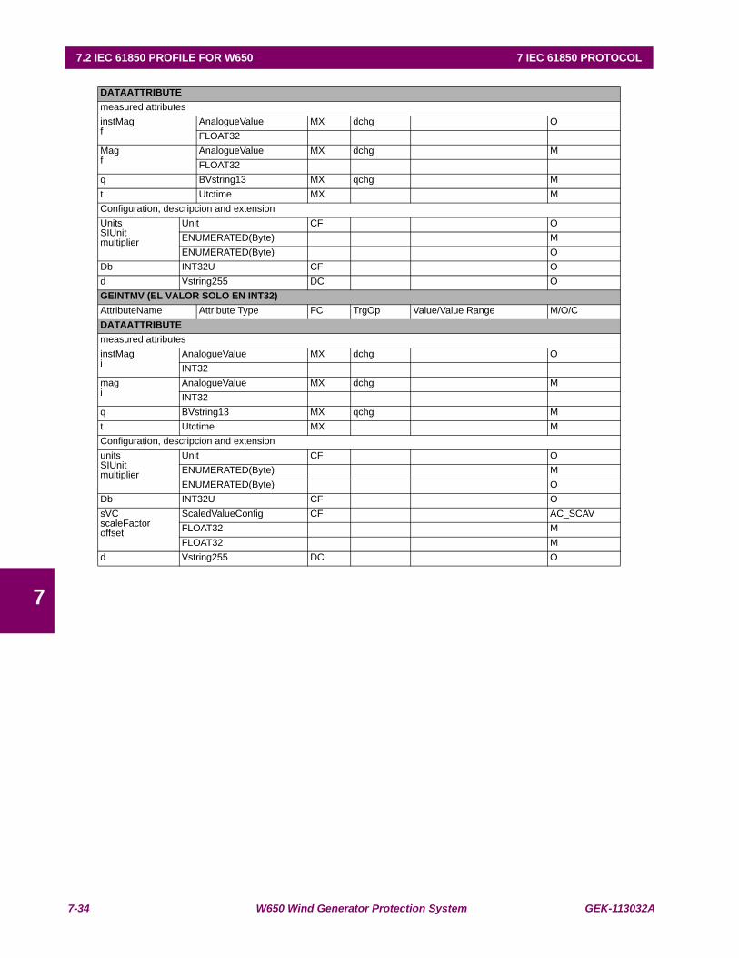
7-34 W650 Wind Generator Protection System GEK-113032A
7.2 IEC 61850 PROFILE FOR W650 7 IEC 61850 PROTOCOL
7
DATAATTRIBUTEmeasured attributesinstMagf
AnalogueValue MX dchg OFLOAT32
Magf
AnalogueValue MX dchg MFLOAT32
q BVstring13 MX qchg Mt Utctime MX MConfiguration, descripcion and extensionUnitsSIUnitmultiplier
Unit CF OENUMERATED(Byte) MENUMERATED(Byte) O
Db INT32U CF Od Vstring255 DC OGEINTMV (EL VALOR SOLO EN INT32)AttributeName Attribute Type FC TrgOp Value/Value Range M/O/CDATAATTRIBUTEmeasured attributesinstMagi
AnalogueValue MX dchg OINT32
magi
AnalogueValue MX dchg MINT32
q BVstring13 MX qchg Mt Utctime MX MConfiguration, descripcion and extensionunitsSIUnitmultiplier
Unit CF OENUMERATED(Byte) MENUMERATED(Byte) O
Db INT32U CF OsVCscaleFactoroffset
ScaledValueConfig CF AC_SCAVFLOAT32 MFLOAT32 M
d Vstring255 DC O
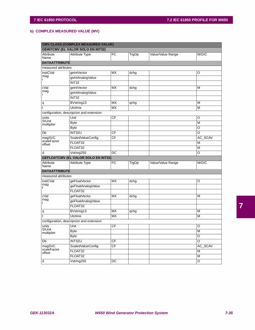
GEK-113032A W650 Wind Generator Protection System 7-35
7 IEC 61850 PROTOCOL 7.2 IEC 61850 PROFILE FOR W650
7
b) COMPLEX MEASURED VALUE (MV)
CMV CLASS (COMPLEX MEASURED VALUE)GEINTCMV (EL VALOR SOLO EN INT32)AttributeName
Attribute Type FC TrgOp Value/Value Range M/O/C
DATAATTRIBUTEmeasured attributesinstCValmagi
geIntVector MX dchg OgeIntAnalogValueINT32
cValmagi
geIntVector MX dchg MgeIntAnalogValueINT32
q BVstring13 MX qchg Mt Utctime MX Mconfiguration, descripcion and extensionunitsSIUnitmultiplier
Unit CF OByte MByte O
Db INT32U CF OmagSVCscaleFactoroffset
ScaledValueConfig CF AC_SCAVFLOAT32 MFLOAT32 M
d Vstring255 DC OGEFLOATCMV (EL VALOR SOLO EN INT32)AttributeName
Attribute Type FC TrgOp Value/Value Range M/O/C
DATAATTRIBUTEmeasured attributesinstCValmagf
geFloatVector MX dchg OgeFloatAnalogValueFLOAT32
cValmagi
geFloatVector MX dchg MgeFloatAnalogValueFLOAT32
q BVstring13 MX qchg Mt Utctime MX Mconfiguration, descripcion and extensionunitsSIUnitmultiplier
Unit CF OByte MByte O
Db INT32U CF OmagSVCscaleFactoroffset
ScaledValueConfig CF AC_SCAVFLOAT32 MFLOAT32 M
d Vstring255 DC O

7-36 W650 Wind Generator Protection System GEK-113032A
7.2 IEC 61850 PROFILE FOR W650 7 IEC 61850 PROTOCOL
7
c) PHASE TO GROUND RELATED MEASURED VALUES OF A THREE PHASE SYSTEM ( WYE )
WYE CLASSGEINTWYEAttributeName
Attribute Type FC TrgOp Value/Value Range M/O/C
DATAPhsA geIntCMV GC_1phsB geIntCMV GC_1phsC geIntCMV GC_1neut geIntCMV GC_1res geIntCMV GC_1configuration, descripcion and extensiond Vstring255 DC OGEFLOATWYEAttributeName
Attribute Type FC TrgOp Value/Value Range M/O/C
DATAphsA geFloatCMV GC_1phsB geFloatCMV GC_1phsC geFloatCMV GC_1neut geFloatCMV GC_1res geFloatCMV GC_1configuration, descripcion and extensiond Vstring255 DC OGEINTPHSWYEAttributeName
Attribute Type FC TrgOp Value/Value Range M/O/C
DATAPhsA geIntCMV GC_1PhsB geIntCMV GC_1PhsC geIntCMV GC_1Res geIntCMV GC_1configuration, descripcion and extensiond Vstring255 DC OGEFLOATPHSWYEAttributeName
Attribute Type FC TrgOp Value/Value Range M/O/C
DATAPhsA geFloatCMV GC_1PhsB geFloatCMV GC_1PhsC geFloatCMV GC_1Res geFloatCMV GC_1configuration, descripcion and extensiond Vstring255 DC O
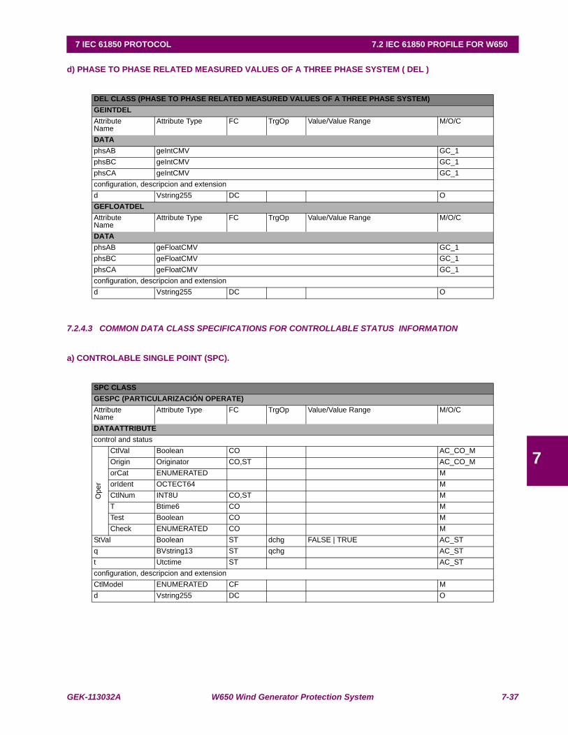
GEK-113032A W650 Wind Generator Protection System 7-37
7 IEC 61850 PROTOCOL 7.2 IEC 61850 PROFILE FOR W650
7
d) PHASE TO PHASE RELATED MEASURED VALUES OF A THREE PHASE SYSTEM ( DEL )
7.2.4.3 COMMON DATA CLASS SPECIFICATIONS FOR CONTROLLABLE STATUS INFORMATION
a) CONTROLABLE SINGLE POINT (SPC).
DEL CLASS (PHASE TO PHASE RELATED MEASURED VALUES OF A THREE PHASE SYSTEM)GEINTDELAttributeName
Attribute Type FC TrgOp Value/Value Range M/O/C
DATAphsAB geIntCMV GC_1phsBC geIntCMV GC_1phsCA geIntCMV GC_1configuration, descripcion and extensiond Vstring255 DC OGEFLOATDELAttributeName
Attribute Type FC TrgOp Value/Value Range M/O/C
DATAphsAB geFloatCMV GC_1phsBC geFloatCMV GC_1phsCA geFloatCMV GC_1configuration, descripcion and extensiond Vstring255 DC O
SPC CLASSGESPC (PARTICULARIZACIÓN OPERATE)AttributeName
Attribute Type FC TrgOp Value/Value Range M/O/C
DATAATTRIBUTEcontrol and status
Ope
r
CtlVal Boolean CO AC_CO_MOrigin Originator CO,ST AC_CO_MorCat ENUMERATED MorIdent OCTECT64 MCtlNum INT8U CO,ST MT Btime6 CO MTest Boolean CO MCheck ENUMERATED CO M
StVal Boolean ST dchg FALSE | TRUE AC_STq BVstring13 ST qchg AC_STt Utctime ST AC_STconfiguration, descripcion and extensionCtlModel ENUMERATED CF Md Vstring255 DC O
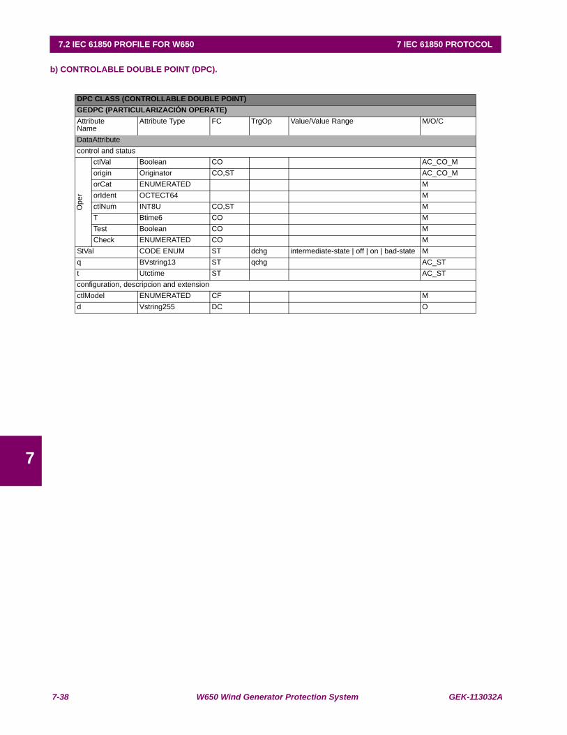
7-38 W650 Wind Generator Protection System GEK-113032A
7.2 IEC 61850 PROFILE FOR W650 7 IEC 61850 PROTOCOL
7
b) CONTROLABLE DOUBLE POINT (DPC).
DPC CLASS (CONTROLLABLE DOUBLE POINT)GEDPC (PARTICULARIZACIÓN OPERATE) AttributeName
Attribute Type FC TrgOp Value/Value Range M/O/C
DataAttributecontrol and status
Ope
r
ctlVal Boolean CO AC_CO_Morigin Originator CO,ST AC_CO_MorCat ENUMERATED MorIdent OCTECT64 MctlNum INT8U CO,ST MT Btime6 CO MTest Boolean CO MCheck ENUMERATED CO M
StVal CODE ENUM ST dchg intermediate-state | off | on | bad-state Mq BVstring13 ST qchg AC_STt Utctime ST AC_STconfiguration, descripcion and extensionctlModel ENUMERATED CF Md Vstring255 DC O
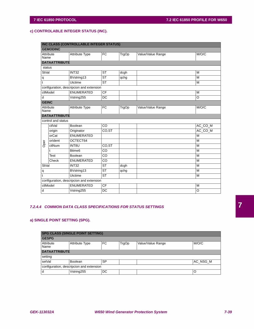
GEK-113032A W650 Wind Generator Protection System 7-39
7 IEC 61850 PROTOCOL 7.2 IEC 61850 PROFILE FOR W650
7
c) CONTROLABLE INTEGER STATUS (INC).
7.2.4.4 COMMON DATA CLASS SPECIFICATIONS FOR STATUS SETTINGS
a) SINGLE POINT SETTING (SPG).
INC CLASS (CONTROLLABLE INTEGER STATUS)GEMODINCAttributeName
Attribute Type FC TrgOp Value/Value Range M/O/C
DATAATTRIBUTE statusStVal INT32 ST dcgh Mq BVstring13 ST qchg Mt Utctime ST Mconfiguration, descripcion and extensionctlModel ENUMERATED CF Md Vstring255 DC OGEINCAttributeName
Attribute Type FC TrgOp Value/Value Range M/O/C
DATAATTRIBUTEcontrol and status
Ope
r
ctlVal Boolean CO AC_CO_Morigin Originator CO,ST AC_CO_MorCat ENUMERATED MorIdent OCTECT64 MctlNum INT8U CO,ST Mt Btime6 CO MTest Boolean CO MCheck ENUMERATED CO M
StVal INT32 ST dcgh Mq BVstring13 ST qchg Mt Utctime ST Mconfiguration, descripcion and extensionctlModel ENUMERATED CF Md Vstring255 DC O
SPG CLASS (SINGLE POINT SETTING)GESPGAttributeName
Attribute Type FC TrgOp Value/Value Range M/O/C
DATAATTRIBUTEsettingsetVal Boolean SP AC_NSG_Mconfiguration, descripcion and extensiond Vstring255 DC O

7-40 W650 Wind Generator Protection System GEK-113032A
7.2 IEC 61850 PROFILE FOR W650 7 IEC 61850 PROTOCOL
7
b) INTEGER STATUS SETTING (ING).
ING CLASS (INTEGER STATUS SETTING)GEINGATTRIBUTENAME
ATTRIBUTE TYPE FC TRGOP VALUE/VALUE RANGE M/O/C
DATAATTRIBUTEsettingsetVal INT32 SP InMagTypEnum AC_NSG_Mconfiguration, descripcion and extensionminVal INT32 CF 0 OmaxVal INT32 CF 900000 OstepSize INT32U CF 10 Od Vstring255 DC OGEING_1ATTRIBUTENAME
ATTRIBUTE TYPE FC TRGOP VALUE/VALUE RANGE M/O/C
DATAATTRIBUTESettingsetVal ENUMERATED SP InMagTypEnum
(Phasor, RMS )M
d Vstring255 DC OGEING_2ATTRIBUTENAME
ATTRIBUTE TYPE FC TRGOP VALUE/VALUE RANGE M/O/C
DATAATTRIBUTESettingsetVal ENUMERATED SP RsModEnum
(Instantaneous, Lineal)M
d Vstring255 DC OGEING_3ATTRIBUTENAME
ATTRIBUTE TYPE FC TRGOP VALUE/VALUE RANGE M/O/C
DATAATTRIBUTESettingsetVal ENUMERATED SP PolOpModEnum
(reverse, forward)M
d Vstring255 DC OGEING_4ATTRIBUTENAME
ATTRIBUTE TYPE FC TRGOP VALUE/VALUE RANGE M/O/C
DATAATTRIBUTESettingsetVal ENUMERATED SP BlkModEnum
(permission, block)M
d Vstring255 DC OGEING_5ATTRIBUTENAME
ATTRIBUTE TYPE FC TRGOP VALUE/VALUE RANGE M/O/C
DATAATTRIBUTESettingsetVal ENUMERATED SP PolQtyEnum
(Vo, Ip, Vo+Ip, Vo*Ip)M
d Vstring255 DC O

GEK-113032A W650 Wind Generator Protection System 7-41
7 IEC 61850 PROTOCOL 7.2 IEC 61850 PROFILE FOR W650
7
7.2.4.5 COMMON DATA CLASS SPECIFICATIONS FOR ANALOGUE SETTINGS
a) ANALOGUE SETTING (ASG).
ING CLASS (INTEGER STATUS SETTING)GEING_6ATTRIBUTENAME
ATTRIBUTE TYPE FC TRGOP VALUE/VALUE RANGE M/O/C
DATAATTRIBUTESettingsetVal ENUMERATED SP OpModEnum
(any, two, all phases )M
d Vstring255 DC OGEING_7AttributeName
Attribute Type FC TrgOp Value/Value Range M/O/C
DATAATTRIBUTESettingsetVal ENUMERATED SP InModEnum
(phase-phase, phase-ground )M
d Vstring255 DC O
ASG CLASS (ANALOGUE SETTING)GEINTASGATTRIBUTENAME
ATTRIBUTE TYPE FC TRGOP
VALUE/VALUE RANGE M/O/C
DATAATTRIBUTEsettingsetMagi
AnalogValue SP AC_NSG_MINT32
configuration, descripcion and extensionunitsSIUnitmultiplier
Unit CF OENUMERATED(Byte) MENUMERATED(Byte) O
minVal INT32 CF OmaxVal INT32 CF OstepSize INT32 CF Od Vstring255 DC OGEFLOATASGAttributeName
Attribute Type FC TrgOp Value/Value Range M/O/C
DATAATTRIBUTEsettingsetMagf
AnalogValue SP AC_NSG_MFLOAT32
configuration, descripcion and extensionunitsSIUnitmultiplier
Unit CF OENUMERATED(Byte) 5 MENUMERATED(Byte) 0 O
minVal FLOAT32 CF 5.e-002 OmaxVal FLOAT32 CF 160 OstepSize FLOAT32 CF 1.e-002 O
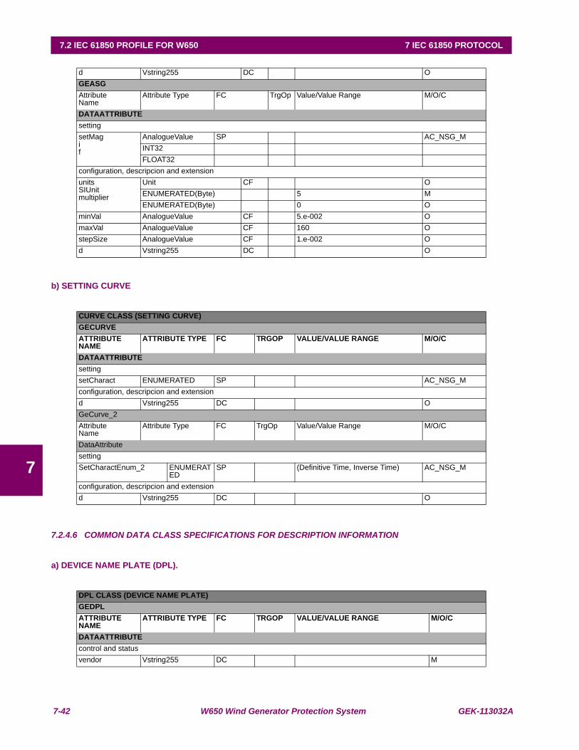
7-42 W650 Wind Generator Protection System GEK-113032A
7.2 IEC 61850 PROFILE FOR W650 7 IEC 61850 PROTOCOL
7
b) SETTING CURVE
7.2.4.6 COMMON DATA CLASS SPECIFICATIONS FOR DESCRIPTION INFORMATION
a) DEVICE NAME PLATE (DPL).
d Vstring255 DC OGEASGAttributeName
Attribute Type FC TrgOp Value/Value Range M/O/C
DATAATTRIBUTEsettingsetMagif
AnalogueValue SP AC_NSG_MINT32FLOAT32
configuration, descripcion and extensionunitsSIUnitmultiplier
Unit CF OENUMERATED(Byte) 5 MENUMERATED(Byte) 0 O
minVal AnalogueValue CF 5.e-002 OmaxVal AnalogueValue CF 160 OstepSize AnalogueValue CF 1.e-002 Od Vstring255 DC O
CURVE CLASS (SETTING CURVE)GECURVEATTRIBUTENAME
ATTRIBUTE TYPE FC TRGOP VALUE/VALUE RANGE M/O/C
DATAATTRIBUTEsettingsetCharact ENUMERATED SP AC_NSG_Mconfiguration, descripcion and extensiond Vstring255 DC OGeCurve_2AttributeName
Attribute Type FC TrgOp Value/Value Range M/O/C
DataAttributesettingSetCharactEnum_2 ENUMERAT
EDSP (Definitive Time, Inverse Time) AC_NSG_M
configuration, descripcion and extensiond Vstring255 DC O
DPL CLASS (DEVICE NAME PLATE)GEDPLATTRIBUTENAME
ATTRIBUTE TYPE FC TRGOP VALUE/VALUE RANGE M/O/C
DATAATTRIBUTEcontrol and statusvendor Vstring255 DC M
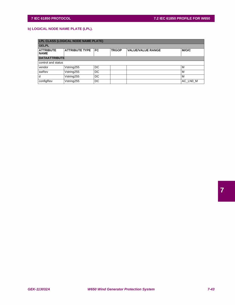
GEK-113032A W650 Wind Generator Protection System 7-43
7 IEC 61850 PROTOCOL 7.2 IEC 61850 PROFILE FOR W650
7
b) LOGICAL NODE NAME PLATE (LPL).
LPL CLASS (LOGICAL NODE NAME PLATE)GELPLATTRIBUTENAME
ATTRIBUTE TYPE FC TRGOP VALUE/VALUE RANGE M/O/C
DATAATTRIBUTEcontrol and statusvendor Vstring255 DC MswRev Vstring255 DC Md Vstring255 DC MconfigRev Vstring255 DC AC_LN0_M

7-44 W650 Wind Generator Protection System GEK-113032A
7.2 IEC 61850 PROFILE FOR W650 7 IEC 61850 PROTOCOL
7
7.2.5 DATASETS
Datasets are used for the Reports. When any element change, this information will be send spontaneously to the clients.
7.2.5.1 MEASUREMENT DATASET.
NAME REFERENCEPhase Real Pwr Value MMXU1$MX$TotW$mag$fPhase Real Pwr quality MMXU1$MX$TotW$qPhase Real Pwr time MMXU1$MX$TotW$tPhase Reactive Pwr Value MMXU1$MX$TotVar$mag$fPhase Reactive Pwr quality MMXU1$MX$TotVar$qPhase Reactive Pwr time MMXU1$MX$TotVar$tPhase Apparent Pwr Value MMXU1$MX$TotVa$mag$fPhase Apparent Pwr quality MMXU1$MX$TotVa$qPhase Apparent Pwr time MMXU1$MX$TotVa$tAverage Power Factor Value MMXU1$MX$TotPF$mag$fAverage Power Factor quality MMXU1$MX$TotPF$qAverage Power Factor time MMXU1$MX$TotPF$tFrequency Value MMXU1$MX$Hz$mag$fFrequency quality MMXU1$MX$Hz$qFrequency time MMXU1$MX$Hz$tPhase A to Phase B Voltage Value MMXU1$MX$PPV$phsAB$cVal$mag$fPhase A to Phase B Voltage quality MMXU1$MX$PPV$phsAB$qPhase A to Phase B Voltage time MMXU1$MX$PPV$phsAB$tPhase B to Phase C Voltage Value MMXU1$MX$PPV$phsBC$cVal$mag$fPhase B to Phase C Voltage quality MMXU1$MX$PPV$phsBC$qPhase B to Phase C Voltage time MMXU1$MX$PPV$phsBC$tPhase C to Phase A Voltage Value MMXU1$MX$PPV$phsCA$cVal$mag$fPhase C to Phase A Voltage quality MMXU1$MX$PPV$phsCA$qPhase C to Phase A Voltage time MMXU1$MX$PPV$phsCA$tPhase A to Ground Voltage Value MMXU1$MX$PhV$phsA$cVal$mag$fPhase A to Ground Voltage quality MMXU1$MX$PhV$phsA$qPhase A to Ground Voltage time MMXU1$MX$PhV$phsA$tPhase B to Ground Voltage Value MMXU1$MX$PhV$phsB$cVal$mag$fPhase B to Ground Voltage quality MMXU1$MX$PhV$phsB$qPhase B to Ground Voltage time MMXU1$MX$PhV$phsB$tPhase C to Ground Voltage Value MMXU1$MX$PhV$phsC$cVal$mag$fPhase C to Ground Voltage quality MMXU1$MX$PhV$phsC$qPhase C to Ground Voltage time MMXU1$MX$PhV$phsC$tNeutral Voltage Value MMXU1$MX$PhV$res$cVal$mag$fNeutral Voltage quality MMXU1$MX$PhV$res$qNeutral Voltage time MMXU1$MX$PhV$res$tPhase A Current Value MMXU1$MX$A$phsA$cVal$mag$fPhase A Current quality MMXU1$MX$A$phsA$qPhase A Current time MMXU1$MX$A$phsA$tPhase B Current Value MMXU1$MX$A$phsB$cVal$mag$fPhase B Current quality MMXU1$MX$A$phsB$qPhase B Current time MMXU1$MX$A$phsB$tPhase C Current Value MMXU1$MX$A$phsC$cVal$mag$fPhase C Current quality MMXU1$MX$A$phsC$qPhase C Current time MMXU1$MX$A$phsC$t
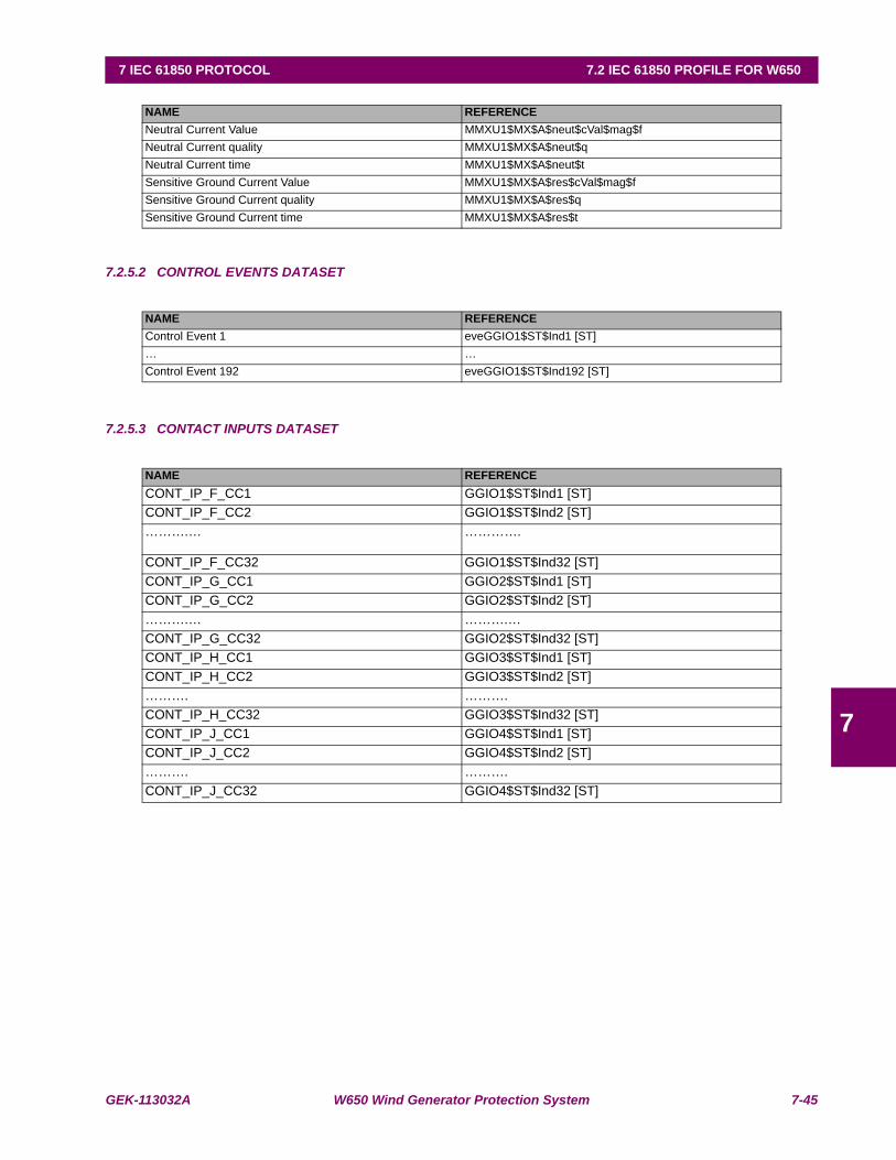
GEK-113032A W650 Wind Generator Protection System 7-45
7 IEC 61850 PROTOCOL 7.2 IEC 61850 PROFILE FOR W650
7
7.2.5.2 CONTROL EVENTS DATASET
7.2.5.3 CONTACT INPUTS DATASET
NAME REFERENCENeutral Current Value MMXU1$MX$A$neut$cVal$mag$fNeutral Current quality MMXU1$MX$A$neut$qNeutral Current time MMXU1$MX$A$neut$tSensitive Ground Current Value MMXU1$MX$A$res$cVal$mag$fSensitive Ground Current quality MMXU1$MX$A$res$qSensitive Ground Current time MMXU1$MX$A$res$t
NAME REFERENCEControl Event 1 eveGGIO1$ST$Ind1 [ST]… …Control Event 192 eveGGIO1$ST$Ind192 [ST]
NAME REFERENCECONT_IP_F_CC1 GGIO1$ST$Ind1 [ST]CONT_IP_F_CC2 GGIO1$ST$Ind2 [ST]……….… ………….
CONT_IP_F_CC32 GGIO1$ST$Ind32 [ST]CONT_IP_G_CC1 GGIO2$ST$Ind1 [ST]CONT_IP_G_CC2 GGIO2$ST$Ind2 [ST]……….… ……….…CONT_IP_G_CC32 GGIO2$ST$Ind32 [ST]CONT_IP_H_CC1 GGIO3$ST$Ind1 [ST]CONT_IP_H_CC2 GGIO3$ST$Ind2 [ST]………. ……….CONT_IP_H_CC32 GGIO3$ST$Ind32 [ST]CONT_IP_J_CC1 GGIO4$ST$Ind1 [ST]CONT_IP_J_CC2 GGIO4$ST$Ind2 [ST]………. ……….CONT_IP_J_CC32 GGIO4$ST$Ind32 [ST]
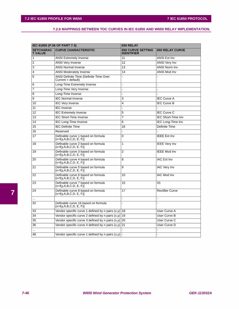
7-46 W650 Wind Generator Protection System GEK-113032A
7.2 IEC 61850 PROFILE FOR W650 7 IEC 61850 PROTOCOL
7
7.2.6 MAPPINGS BETWEEN TOC CURVES IN IEC 61850 AND W650 RELAY IMPLEMENTATION.
IEC 61850 (P.56 OF PART 7-3) 650 RELAYSETCHARACT VALUE
CURVE CHARACTERISTIC 650 CURVE SETTING IDENTIFIER
650 RELAY CURVE
1 ANSI Extremely Inverse 11 ANSI Ext Inv2 ANSI Very Inverse 12 ANSI Very Inv3 ANSI Normal Inverse 13 ANSI Norm Inv4 ANSI Moderately Inverse 14 ANSI Mod Inv5 ANSI Definite Time (Definite Time Over
Current = default)- -
6 Long-Time Extremely Inverse - -7 Long-Time Very Inverse - -8 Long-Time Inverse - -9 IEC Normal Inverse 3 IEC Curve A10 IEC Very Inverse 4 IEC Curve B11 IEC Inverse - -12 IEC Extremely Inverse 5 IEC Curve C13 IEC Short-Time Inverse 7 IEC Short-Time Inv14 IEC Long-Time Inverse 6 IEC Long-Time Inv15 IEC Definite Time 16 Definite Time16 Reserved - -17 Definable curve 1 based on formula
[x=f(y,A,B,C,D, E, F)]0 IEEE Ext Inv
18 Definable curve 2 based on formula [x=f(y,A,B,C,D, E, F)]
1 IEEE Very Inv
19 Definable curve 3 based on formula [x=f(y,A,B,C,D, E, F)]
2 IEEE Mod Inv
20 Definable curve 4 based on formula [x=f(y,A,B,C,D, E, F)]
8 IAC Ext Inv
21 Definable curve 5 based on formula [x=f(y,A,B,C,D, E, F)]
9 IAC Very Inv
22 Definable curve 6 based on formula [x=f(y,A,B,C,D, E, F)]
10 IAC Mod Inv
23 Definable curve 7 based on formula [x=f(y,A,B,C,D, E, F)]
15 I2t
24 Definable curve 8 based on formula [x=f(y,A,B,C,D, E, F)]
17 Rectifier Curve
… - -32 Definable curve 16 based on formula
[x=f(y,A,B,C,D, E, F)]- -
33 Vendor specific curve 1 defined by n pairs (x,y) 18 User Curve A34 Vendor specific curve 2 defined by n pairs (x,y) 19 User Curve B35 Vendor specific curve 3 defined by n pairs (x,y) 20 User Curve C36 Vendor specific curve 4 defined by n pairs (x,y) 21 User Curve D… - -48 Vendor specific curve 1 defined by n pairs (x,y) - -
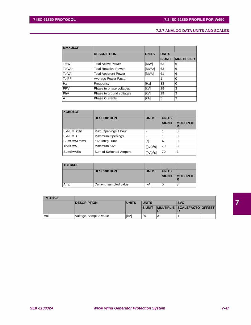
GEK-113032A W650 Wind Generator Protection System 7-47
7 IEC 61850 PROTOCOL 7.2 IEC 61850 PROFILE FOR W650
7
7.2.7 ANALOG DATA UNITS AND SCALES
MMXU$CF
DESCRIPTION UNITS UNITSSIUNIT MULTIPLIER
TotW Total Active Power [MW] 62 6TotVAr Total Reactive Power [MVAr] 63 6TotVA Total Apparent Power [MVA] 61 6TotPF Average Power Factor - 1 0Hz Frequency [Hz] 33 0PPV Phase to phase voltages [kV] 29 3PhV Phase to ground voltages [kV] 29 3A Phase Currents [kA] 5 3
XCBR$CF
DESCRIPTION UNITS UNITSSIUNIT MULTIPLIE
RExNumTr1hr Max. Openings 1 hour - 1 0ExNumTr Maximum Openings - 1 0SumSwATmms KI2t Integ. Time [s] 4 0ThAlSwA Maximum KI2t [(kA)2s] 70 3
SumSwARs Sum of Switched Ampers [(kA)2s] 70 3
TCTR$CF
DESCRIPTION UNITS UNITSSIUNIT MULTIPLIE
RAmp Current, sampled value [kA] 5 3
TVTR$CFDESCRIPTION UNITS UNITS SVC
SIUNIT MULTIPLIER
SCALEFACTOR
OFFSET
Vol Voltage, sampled value [kV] 29 3 1 -

7-48 W650 Wind Generator Protection System GEK-113032A
7.2 IEC 61850 PROFILE FOR W650 7 IEC 61850 PROTOCOL
7

GEK-113032A W650 Wind Generator Protection System 8-1
8 W650 CANOPEN PROFILE 8.1 INTRODUCTION
8
8 W650 CANOPEN PROFILE 8.1INTRODUCTION 8.1.1 DEFINITIONS
This chapter provides an introduction to CANopen Device Profile. For more detailed information please refer to CiA DraftStandard 301 revision 4.02.
a) DEFINITIONS
CAN Controller Area Network
CiA CAN in Automation international users and manufacturers group e.V.
COB Communication Object. (CAN Message) A unit of transportation in a CAN Network. Data must be sent across aNetwork inside a COB.
COB-ID COB-Identifier. Identifies a COB uniquely in a Network. The identifier determines the priority of that COB in theMAC sub-layer too.
ISO International Standardisation Organisation
NMT Network Management. One of the service elements of the CAN Application Layer in the CAN Reference Model.It performs initialisation, configuration and error handling in a CAN network.
PDO Process Data Object
SDO Service Data Object
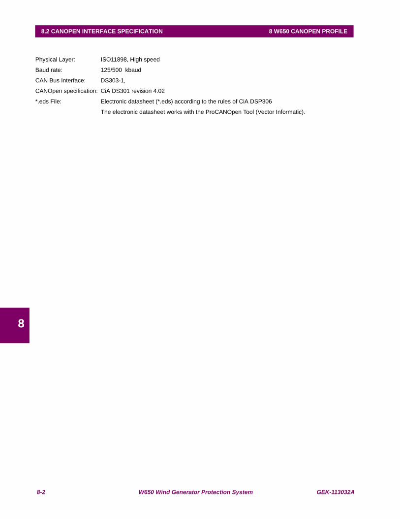
8-2 W650 Wind Generator Protection System GEK-113032A
8.2 CANOPEN INTERFACE SPECIFICATION 8 W650 CANOPEN PROFILE
8
8.2CANOPEN INTERFACE SPECIFICATION
Physical Layer: ISO11898, High speed
Baud rate: 125/500 kbaud
CAN Bus Interface: DS303-1,
CANOpen specification: CiA DS301 revision 4.02
*.eds File: Electronic datasheet (*.eds) according to the rules of CiA DSP306
The electronic datasheet works with the ProCANOpen Tool (Vector Informatic).
GEK-113032A W650 Wind Generator Protection System 8-3
8 W650 CANOPEN PROFILE 8.3 SERVICES
8
8.3SERVICES
Implemented according to CiA Draft Standard 301 (Version 4.02)
These SDO Services are Supported:
• Segmented SDO Upload
• Segmented SDO Download
These SDO Services are Not Supported:
• SDO Block Upload
• SDO Block Download
These NMT Services are Supported:
• Module Control Services
• Bootup Service
• Error Control Services (Node Guarding, Life Guarding, Heartbeat)
LSS Services are Not Supported
SYNC Protocol Supported
TIME Protocol Not Supported
High Resolution Synchronisation Protocol Not Supported
EMERGENCY Object Supported
Dynamic PDO Mapping Supported
Multiplexed PDOs Not Supported
Subindex FFh Not Supported
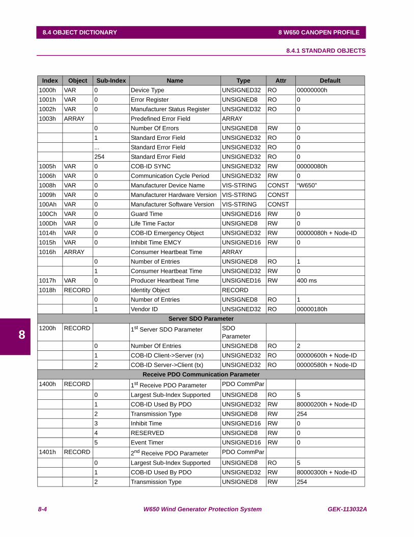
8-4 W650 Wind Generator Protection System GEK-113032A
8.4 OBJECT DICTIONARY 8 W650 CANOPEN PROFILE
8
8.4OBJECT DICTIONARY 8.4.1 STANDARD OBJECTS
Index Object Sub-Index Name Type Attr Default1000h VAR 0 Device Type UNSIGNED32 RO 00000000h1001h VAR 0 Error Register UNSIGNED8 RO 01002h VAR 0 Manufacturer Status Register UNSIGNED32 RO 01003h ARRAY Predefined Error Field ARRAY
0 Number Of Errors UNSIGNED8 RW 01 Standard Error Field UNSIGNED32 RO 0... Standard Error Field UNSIGNED32 RO 0254 Standard Error Field UNSIGNED32 RO 0
1005h VAR 0 COB-ID SYNC UNSIGNED32 RW 00000080h1006h VAR 0 Communication Cycle Period UNSIGNED32 RW 01008h VAR 0 Manufacturer Device Name VIS-STRING CONST “W650”1009h VAR 0 Manufacturer Hardware Version VIS-STRING CONST100Ah VAR 0 Manufacturer Software Version VIS-STRING CONST100Ch VAR 0 Guard Time UNSIGNED16 RW 0100Dh VAR 0 Life Time Factor UNSIGNED8 RW 01014h VAR 0 COB-ID Emergency Object UNSIGNED32 RW 00000080h + Node-ID1015h VAR 0 Inhibit Time EMCY UNSIGNED16 RW 01016h ARRAY Consumer Heartbeat Time ARRAY
0 Number of Entries UNSIGNED8 RO 11 Consumer Heartbeat Time UNSIGNED32 RW 0
1017h VAR 0 Producer Heartbeat Time UNSIGNED16 RW 400 ms1018h RECORD Identity Object RECORD
0 Number of Entries UNSIGNED8 RO 11 Vendor ID UNSIGNED32 RO 00000180h
Server SDO Parameter1200h RECORD 1st Server SDO Parameter SDO
Parameter0 Number Of Entries UNSIGNED8 RO 21 COB-ID Client->Server (rx) UNSIGNED32 RO 00000600h + Node-ID2 COB-ID Server->Client (tx) UNSIGNED32 RO 00000580h + Node-ID
Receive PDO Communication Parameter1400h RECORD 1st Receive PDO Parameter PDO CommPar
0 Largest Sub-Index Supported UNSIGNED8 RO 51 COB-ID Used By PDO UNSIGNED32 RW 80000200h + Node-ID2 Transmission Type UNSIGNED8 RW 2543 Inhibit Time UNSIGNED16 RW 04 RESERVED UNSIGNED8 RW 05 Event Timer UNSIGNED16 RW 0
1401h RECORD 2nd Receive PDO Parameter PDO CommPar
0 Largest Sub-Index Supported UNSIGNED8 RO 51 COB-ID Used By PDO UNSIGNED32 RW 80000300h + Node-ID2 Transmission Type UNSIGNED8 RW 254
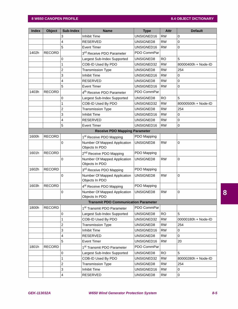
GEK-113032A W650 Wind Generator Protection System 8-5
8 W650 CANOPEN PROFILE 8.4 OBJECT DICTIONARY
8
Index Object Sub-Index Name Type Attr Default3 Inhibit Time UNSIGNED16 RW 04 RESERVED UNSIGNED8 RW 05 Event Timer UNSIGNED16 RW 0
1402h RECORD 3rd Receive PDO Parameter PDO CommPar
0 Largest Sub-Index Supported UNSIGNED8 RO 51 COB-ID Used By PDO UNSIGNED32 RW 80000400h + Node-ID2 Transmission Type UNSIGNED8 RW 2543 Inhibit Time UNSIGNED16 RW 04 RESERVED UNSIGNED8 RW 05 Event Timer UNSIGNED16 RW 0
1403h RECORD 4th Receive PDO Parameter PDO CommPar
0 Largest Sub-Index Supported UNSIGNED8 RO 51 COB-ID Used By PDO UNSIGNED32 RW 80000500h + Node-ID2 Transmission Type UNSIGNED8 RW 2543 Inhibit Time UNSIGNED16 RW 04 RESERVED UNSIGNED8 RW 05 Event Timer UNSIGNED16 RW 0
Receive PDO Mapping Parameter1600h RECORD 1st Receive PDO Mapping PDO Mapping
0 Number Of Mapped Application Objects In PDO
UNSIGNED8 RW 0
1601h RECORD 2nd Receive PDO Mapping PDO Mapping
0 Number Of Mapped Application Objects In PDO
UNSIGNED8 RW 0
1602h RECORD 3rd Receive PDO Mapping PDO Mapping
0 Number Of Mapped Application Objects In PDO
UNSIGNED8 RW 0
1603h RECORD 4st Receive PDO Mapping PDO Mapping
0 Number Of Mapped Application Objects In PDO
UNSIGNED8 RW 0
Transmit PDO Communication Parameter1800h RECORD 1st Transmit PDO Parameter PDO CommPar
0 Largest Sub-Index Supported UNSIGNED8 RO 51 COB-ID Used By PDO UNSIGNED32 RW 00000180h + Node-ID2 Transmission Type UNSIGNED8 RW 2543 Inhibit Time UNSIGNED16 RW 04 RESERVED UNSIGNED8 RW 05 Event Timer UNSIGNED16 RW 20
1801h RECORD 1st Transmit PDO Parameter PDO CommPar
0 Largest Sub-Index Supported UNSIGNED8 RO 51 COB-ID Used By PDO UNSIGNED32 RW 80000280h + Node-ID2 Transmission Type UNSIGNED8 RW 2543 Inhibit Time UNSIGNED16 RW 04 RESERVED UNSIGNED8 RW 0

8-6 W650 Wind Generator Protection System GEK-113032A
8.4 OBJECT DICTIONARY 8 W650 CANOPEN PROFILE
8
Index: Index of object in hex formatObject: Object TypeName: Name of the objectType: Type of variableAttr.: Attribute Rw: Read WriteRo: Read OnlyDefault: Default object value
Index Object Sub-Index Name Type Attr Default5 Event Timer UNSIGNED16 RW 0
1802h RECORD 1st Transmit PDO Parameter PDO CommPar
0 Largest Sub-Index Supported UNSIGNED8 RO 51 COB-ID Used By PDO UNSIGNED32 RW 80000380h + Node-ID2 Transmission Type UNSIGNED8 RW 2543 Inhibit Time UNSIGNED16 RW 04 RESERVED UNSIGNED8 RW 05 Event Timer UNSIGNED16 RW 0
1803h RECORD 1st Transmit PDO Parameter PDO CommPar
0 Largest Sub-Index Supported UNSIGNED8 RO 51 COB-ID Used By PDO UNSIGNED32 RW 80000480h + Node-ID2 Transmission Type UNSIGNED8 RW 2543 Inhibit Time UNSIGNED16 RW 04 RESERVED UNSIGNED8 RW 05 Event Timer UNSIGNED16 RW 0
Transmit PDO Mapping Parameter1A00h RECORD 1st Transmit PDO Mapping PDO Mapping
0 Number Of Mapped Application Objects In PDO
UNSIGNED8 RW 1
1 PDO Mapping For The 1st Application Object To Be Mapped
UNSIGNED32 RW 20000040h
1A01h RECORD 2nd Transmit PDO Mapping PDO Mapping
0 Number Of Mapped Application Objects In PDO
UNSIGNED8 RW 0
1A02h RECORD 3rd Transmit PDO Mapping PDO Mapping
0 Number Of Mapped Application Objects In PDO
UNSIGNED8 RW 0
1A03h RECORD 4th Transmit PDO Mapping PDO Mapping
0 Number Of Mapped Application Objects In PDO
UNSIGNED8 RW 0
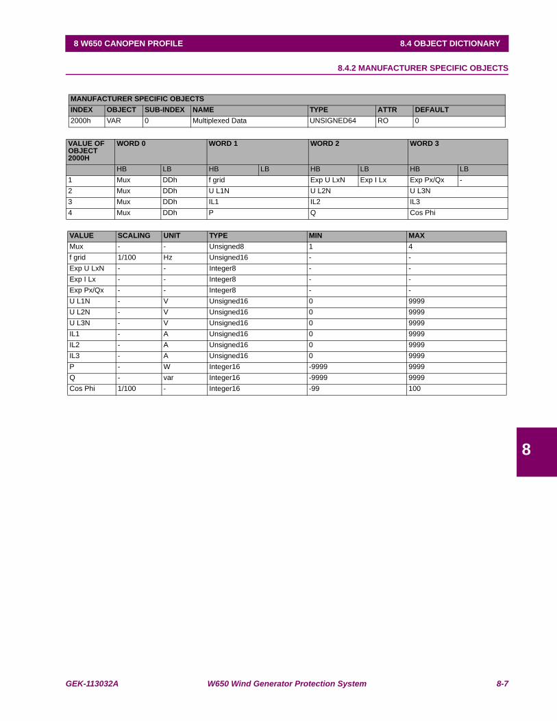
GEK-113032A W650 Wind Generator Protection System 8-7
8 W650 CANOPEN PROFILE 8.4 OBJECT DICTIONARY
8
8.4.2 MANUFACTURER SPECIFIC OBJECTS
MANUFACTURER SPECIFIC OBJECTSINDEX OBJECT SUB-INDEX NAME TYPE ATTR DEFAULT2000h VAR 0 Multiplexed Data UNSIGNED64 RO 0
VALUE OF OBJECT 2000H
WORD 0 WORD 1 WORD 2 WORD 3
HB LB HB LB HB LB HB LB1 Mux DDh f grid Exp U LxN Exp I Lx Exp Px/Qx -2 Mux DDh U L1N U L2N U L3N3 Mux DDh IL1 IL2 IL34 Mux DDh P Q Cos Phi
VALUE SCALING UNIT TYPE MIN MAXMux - - Unsigned8 1 4f grid 1/100 Hz Unsigned16 - -Exp U LxN - - Integer8 - -Exp I Lx - - Integer8 - -Exp Px/Qx - - Integer8 - -U L1N - V Unsigned16 0 9999U L2N - V Unsigned16 0 9999U L3N - V Unsigned16 0 9999IL1 - A Unsigned16 0 9999IL2 - A Unsigned16 0 9999IL3 - A Unsigned16 0 9999P - W Integer16 -9999 9999Q - var Integer16 -9999 9999Cos Phi 1/100 - Integer16 -99 100

8-8 W650 Wind Generator Protection System GEK-113032A
8.4 OBJECT DICTIONARY 8 W650 CANOPEN PROFILE
8

GEK-113032A W650 Wind Generator Protection System 9-1
9 SECURITY 9.1 ADDING USERS
9
9 SECURITY 9.1 ADDING USERS
New users can only be added by users that have Administrator Access (or Admin Rights) . The Enable Security checkbox located in the Security->User Management window must be enabled.
Remember: (In order to add new users and assign user rights )
• must be logged in with Administrator Permission
• and Enable Security checkbox must be enabled
9.1.1 USER RIGHTS
NOTE: Only Administrators have access to the User Management dialog box.Following is a list of all of the User Rights Options available to be granted to users, and their functions.
Table 9–1: USER RIGHTS AND FUNCTIONS
By default, Administrator and Service users are created with "password" as default password.
RIGHT FUNCTION
Delete EntryIf this box is checked when the Administrator exits the User Management dialog box, the program will ask you to confirm the delete and if the Administrator chooses "yes", then the user whose "Delete Entry" box was checked will be permanently deleted from the list.
Admin. WARNING: When this box is checked, the user will become an EnerVista 650 Setup Administrator, therefore receiving all of the Administrative rights.
Actual Values When this box is checked, the user will have the ability to view Actual Values and all records excluding event recorder.
Settings When this box is checked, the user will have access to view and modify Settings (Protection, control, inputs/outputs and calibration).
Commands When this box is checked, the user will be able to use Commands.Event Recorder When this box is checked, the user will have access to use Event Recorder.Force IO When this box is checked, the user will be able to use Force IO application.
Logic Configuration When this box is checked, the user will have the ability to view and modify Relay Configuration and Logic Configuration.
Upgrade When this box is checked, the user will have the ability to upgrade firmware, bootware and to upload and download info files to/from relay.
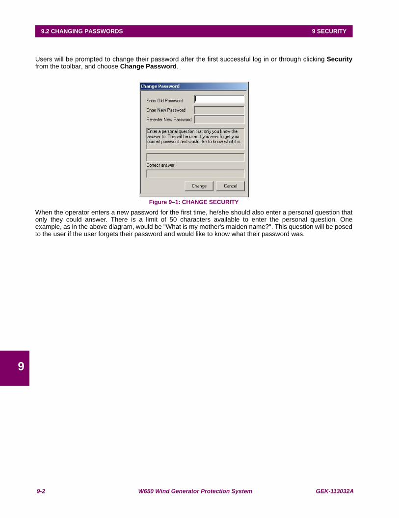
9-2 W650 Wind Generator Protection System GEK-113032A
9.2 CHANGING PASSWORDS 9 SECURITY
9
9.2CHANGING PASSWORDS
Users will be prompted to change their password after the first successful log in or through clicking Securityfrom the toolbar, and choose Change Password.
Figure 9–1: CHANGE SECURITY
When the operator enters a new password for the first time, he/she should also enter a personal question thatonly they could answer. There is a limit of 50 characters available to enter the personal question. Oneexample, as in the above diagram, would be "What is my mother's maiden name?". This question will be posedto the user if the user forgets their password and would like to know what their password was.
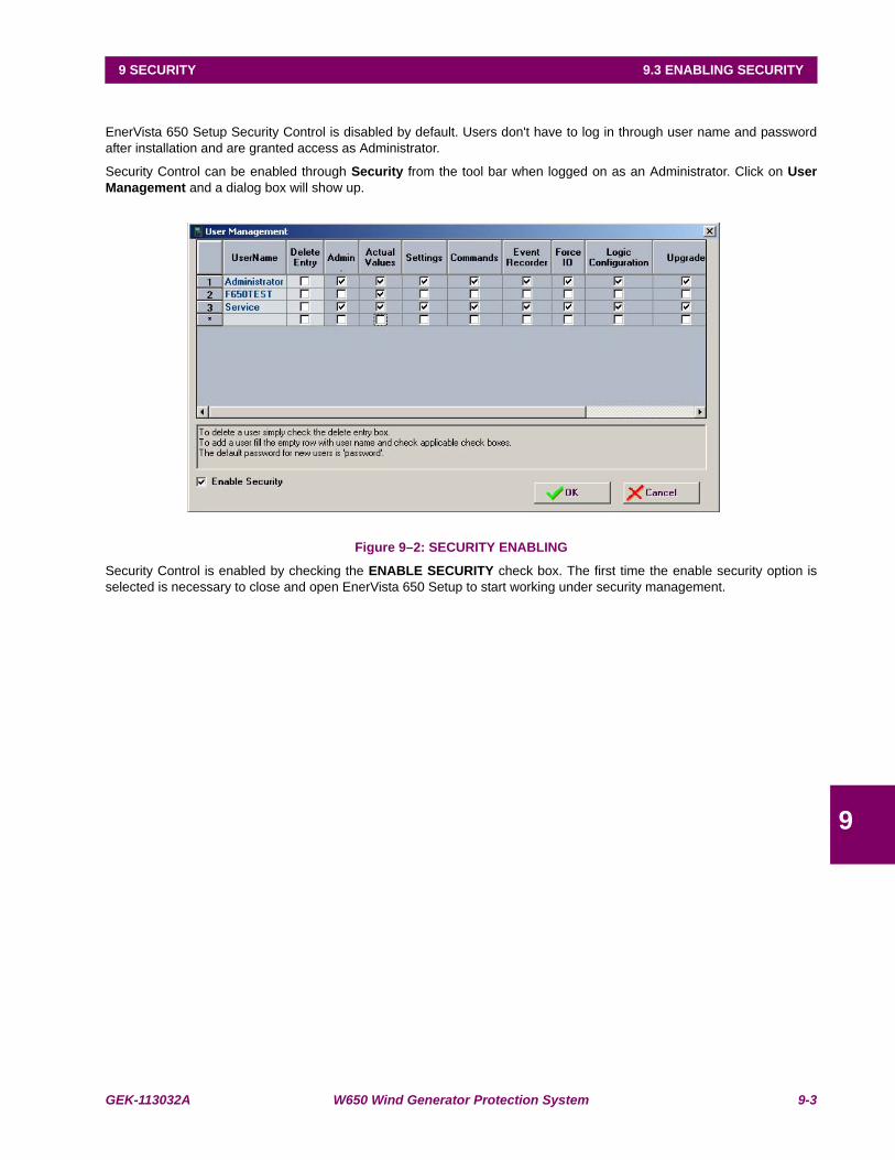
GEK-113032A W650 Wind Generator Protection System 9-3
9 SECURITY 9.3 ENABLING SECURITY
9
9.3ENABLING SECURITYEnerVista 650 Setup Security Control is disabled by default. Users don't have to log in through user name and passwordafter installation and are granted access as Administrator.
Security Control can be enabled through Security from the tool bar when logged on as an Administrator. Click on UserManagement and a dialog box will show up.
Figure 9–2: SECURITY ENABLING
Security Control is enabled by checking the ENABLE SECURITY check box. The first time the enable security option isselected is necessary to close and open EnerVista 650 Setup to start working under security management.
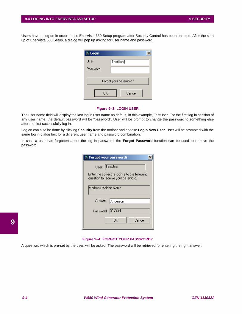
9-4 W650 Wind Generator Protection System GEK-113032A
9.4 LOGING INTO ENERVISTA 650 SETUP 9 SECURITY
9
9.4 LOGING INTO ENERVISTA 650 SETUPUsers have to log on in order to use EnerVista 650 Setup program after Security Control has been enabled. After the startup of EnerVista 650 Setup, a dialog will pop up asking for user name and password.
Figure 9–3: LOGIN USER
The user name field will display the last log in user name as default, in this example, TestUser. For the first log in session ofany user name, the default password will be "password". User will be prompt to change the password to something elseafter the first successfully log in.
Log on can also be done by clicking Security from the toolbar and choose Login New User. User will be prompted with thesame log in dialog box for a different user name and password combination.
In case a user has forgotten about the log in password, the Forgot Password function can be used to retrieve thepassword.
Figure 9–4: FORGOT YOUR PASSWORD?
A question, which is pre-set by the user, will be asked. The password will be retrieved for entering the right answer.

GEK-113032A W650 Wind Generator Protection System 10-1
10 BOOTCODE AND FIRMWARE UPGRADE 10.1 INTRODUCTION
10
10 BOOTCODE AND FIRMWARE UPGRADE 10.1INTRODUCTION
This section explains how to upgrade the W650 boot code and firmware.
The boot code and firmware versions can be seen in the relay main screen: The relay firmware version appears after thetext "W650" (1.20 in the example) with the boot program version (2.20 in the example) followed by “ GENERALELECTRIC”, the relay model and the default front RS232 port communication parameters.
Figure 10–1: MAIN SCREEN
BOOT CODE RELEASE NOTES
It is mandatory to maintain version compatibility between firmware and boot code in the upgrade procedure, otherwise therelay will not start after upgrading.
WARNING
BEFORE PERFORMING THE UPGRADE PROCEDURE CHECK THAT BOOT AND FIRMWARE VERSION MATCH AND CHECK THAT THE ETHERNET CONNECTION BETWEEN RELAY AND PC IS CORRECT (See chapter 10.1.1
COMMUNICATION PARAMETERS)
FIRMWARE AND BOOT VERSIONS COMPATIBILITYFIRMWARE VERSION BOOT VERSION3.02X 4.00
NOTE
A STEP LIST SUMMARY that will allow the user to control the upgrading process is included at the end of this section.It is necessary to read chapter 10 before accomplishing the W650 UPGRADE PROCEDURE.
Be aware that boot program and firmware upgrades will erase all the data contained in the relay, thus it is advisable tosave all the data, oscillography, events, settings and configuration files previously.
NOTE
RELAYS WITH FIBER OPTIC ETHERNET
The upgrade of the boot program (BOOTCODE) must be performed by crossed Ethernet copper cable connected to thePC. It is not necessary to change the internal switch from fiber to RJ45, because the upgrade is made at 10Mb/s.
This does not apply to the firmware upgrade, which can be done either via Ethernet Fiber connection, or through theRJ45 cable connection.

10-2 W650 Wind Generator Protection System GEK-113032A
10.1 INTRODUCTION 10 BOOTCODE AND FIRMWARE UPGRADE
10
10.1.1 COMMUNICATION PARAMETERS
Before proceeding with the upgrade process, the following points should be taken into account:
Type of Ethernet connection:
Upgrade requires Ethernet communications.
It is highly recommended to use a direct connection between the PC and the relay using a crossed-over RJ45 Ethernetcable, instead of using an indirect connection through a hub or switch.
Relay IP address:
It is necessary to assign a valid IP address to the relay in the Ethernet parameters via HMI in the “Product Setup >Communication > Ethernet > Ethernet 1” menu or via EnerVista 650 Setup in “Setpoint > Product Setup>CommunicationSettings > Network (Ethernet) 1” as shown in Table 10–1:
Table 10–1: ETHERNET PARAMETERS
If the relay is connected to an Ethernet network, check that the IP address is unique in order to avoid collisions.
In the case of relay that has upgraded previously its Bootcode (Sections 2), the IP address already has been assigned inthe previous process (see Figure 10–14:).
For example, if the relay settings are:
IP address: 192.168.37.240,
Netmask: 255.255.255.0 and
Gateway: 192.168.37.10.
The computer settings have to follow the pattern:
IP address: 192.168.37.XXX
Netmask: 255.255.255.0 and
Gateway: 192.168.37.10 (if desired).
XXX is a number between 0 and 255 that is not assigned to any other device to avoid collisions.
If there are not TCP/IP settings according to this pattern in the computer, it should be added (in order to communicate withthe relay) following these steps:
PRODUCT SETUP>COMMUNICATION SETTINGS >NETWORK (ETHERNET) 1Name Value Units RangeIP Address Oct1 192 [0 : 255]IP Address Oct2 168 [0 : 255]IP Address Oct3 37 [0 : 255]IP Address Oct4 240 [0 : 255]Netmask Oct1 255 [0 : 255]Netmask Oct2 255 [0 : 255]Netmask Oct3 255 [0 : 255]Netmask Oct4 0 [0 : 255]Gateway IP Oct1 192 [0 : 255]Gateway IP Oct2 168 [0 : 255]Gateway IP Oct3 37 [0 : 255]Gateway IP Oct4 10 [0 : 255]
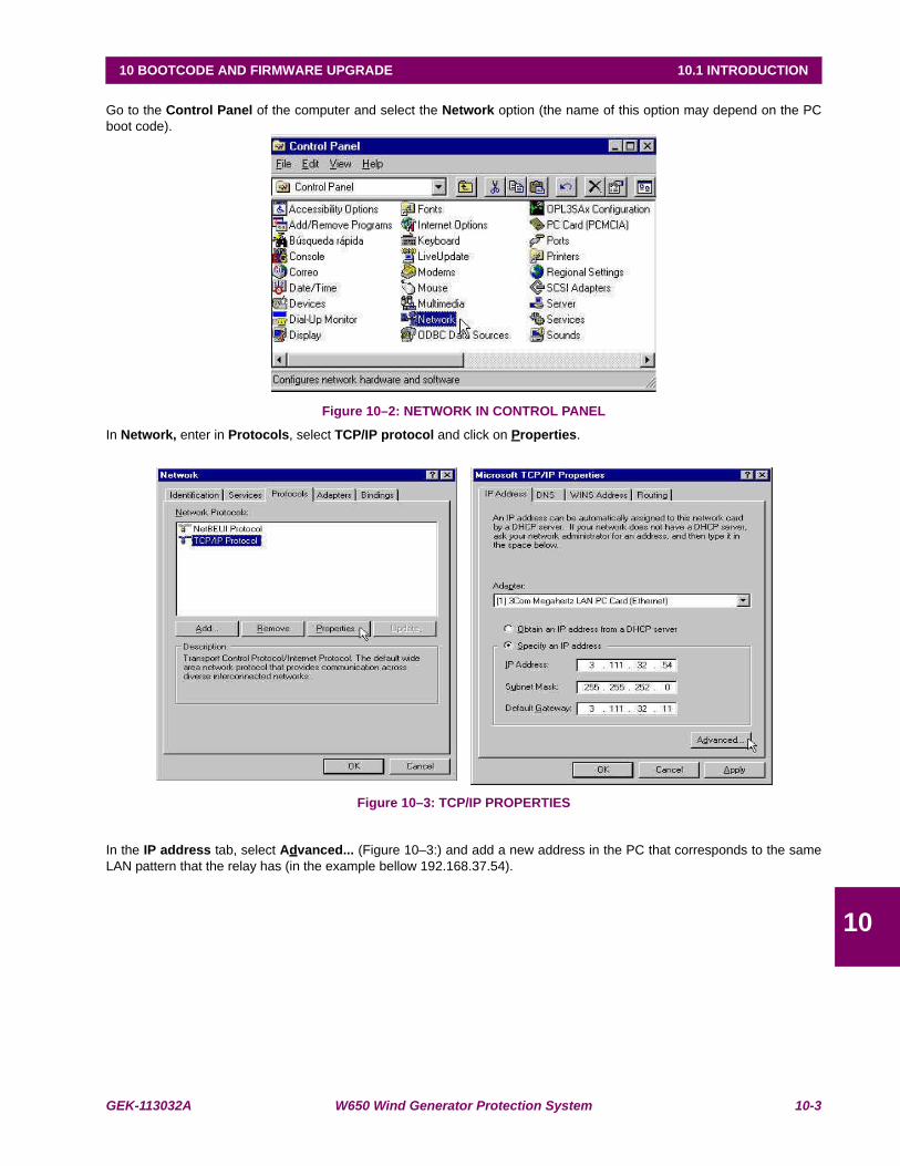
GEK-113032A W650 Wind Generator Protection System 10-3
10 BOOTCODE AND FIRMWARE UPGRADE 10.1 INTRODUCTION
10
Go to the Control Panel of the computer and select the Network option (the name of this option may depend on the PCboot code).
Figure 10–2: NETWORK IN CONTROL PANEL
In Network, enter in Protocols, select TCP/IP protocol and click on Properties.
Figure 10–3: TCP/IP PROPERTIES
In the IP address tab, select Advanced... (Figure 10–3:) and add a new address in the PC that corresponds to the sameLAN pattern that the relay has (in the example bellow 192.168.37.54).

10-4 W650 Wind Generator Protection System GEK-113032A
10.1 INTRODUCTION 10 BOOTCODE AND FIRMWARE UPGRADE
10
Figure 10–4: IP ADDRESS FOR COMPUTER
Windows allows Multihosting, so it permits having as many IP addresses as desired. It is necessary to turn off and on thecomputer to activate the new address that has been assigned to the PC.
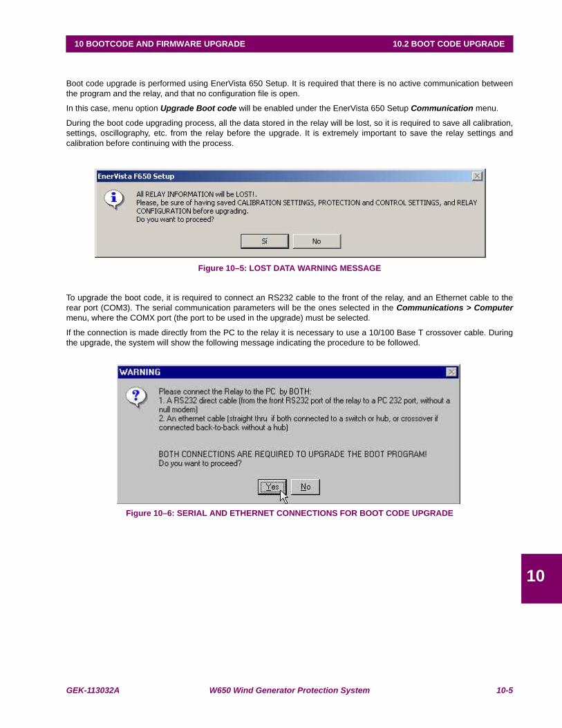
GEK-113032A W650 Wind Generator Protection System 10-5
10 BOOTCODE AND FIRMWARE UPGRADE 10.2 BOOT CODE UPGRADE
10
10.2BOOT CODE UPGRADE
Boot code upgrade is performed using EnerVista 650 Setup. It is required that there is no active communication betweenthe program and the relay, and that no configuration file is open.
In this case, menu option Upgrade Boot code will be enabled under the EnerVista 650 Setup Communication menu.
During the boot code upgrading process, all the data stored in the relay will be lost, so it is required to save all calibration,settings, oscillography, etc. from the relay before the upgrade. It is extremely important to save the relay settings andcalibration before continuing with the process.
Figure 10–5: LOST DATA WARNING MESSAGE
To upgrade the boot code, it is required to connect an RS232 cable to the front of the relay, and an Ethernet cable to therear port (COM3). The serial communication parameters will be the ones selected in the Communications > Computermenu, where the COMX port (the port to be used in the upgrade) must be selected.
If the connection is made directly from the PC to the relay it is necessary to use a 10/100 Base T crossover cable. Duringthe upgrade, the system will show the following message indicating the procedure to be followed.
Figure 10–6: SERIAL AND ETHERNET CONNECTIONS FOR BOOT CODE UPGRADE
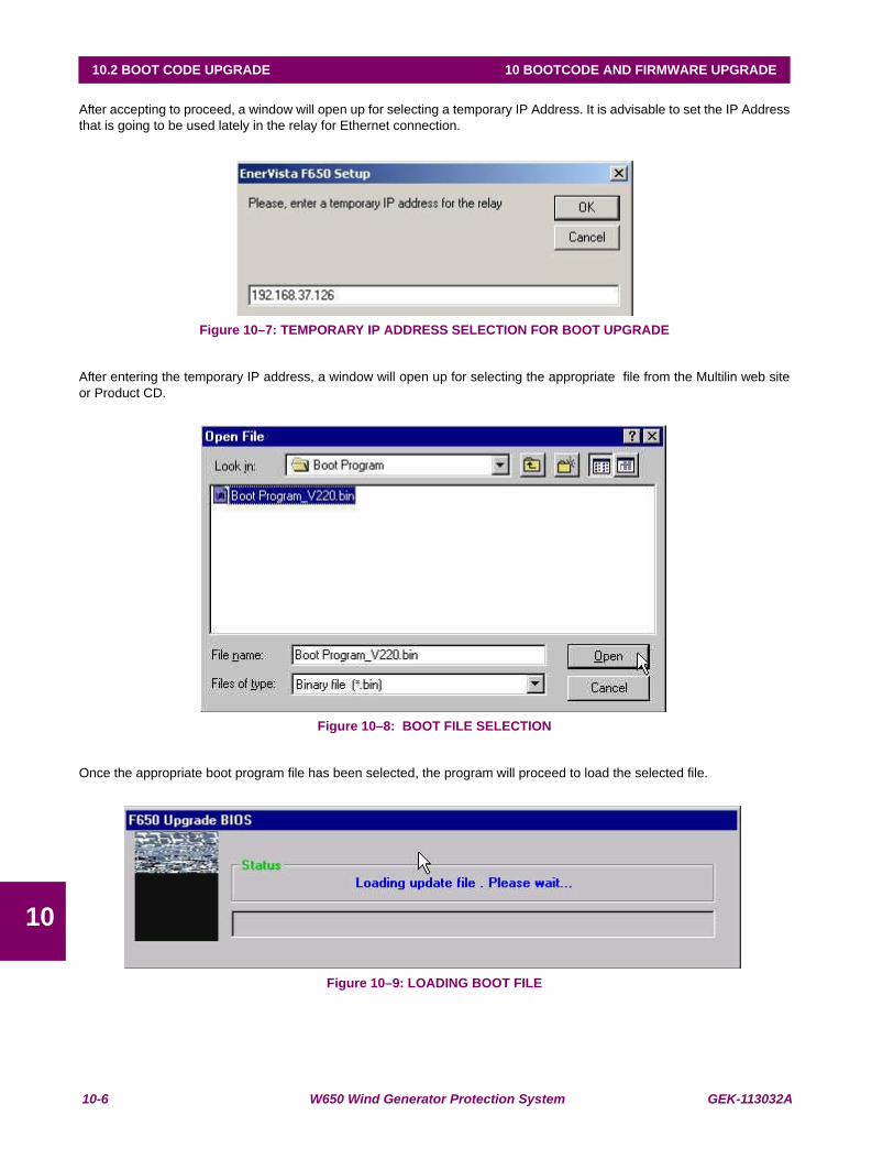
10-6 W650 Wind Generator Protection System GEK-113032A
10.2 BOOT CODE UPGRADE 10 BOOTCODE AND FIRMWARE UPGRADE
10
After accepting to proceed, a window will open up for selecting a temporary IP Address. It is advisable to set the IP Addressthat is going to be used lately in the relay for Ethernet connection.
Figure 10–7: TEMPORARY IP ADDRESS SELECTION FOR BOOT UPGRADE
After entering the temporary IP address, a window will open up for selecting the appropriate file from the Multilin web siteor Product CD.
Figure 10–8: BOOT FILE SELECTION
Once the appropriate boot program file has been selected, the program will proceed to load the selected file.
Figure 10–9: LOADING BOOT FILE
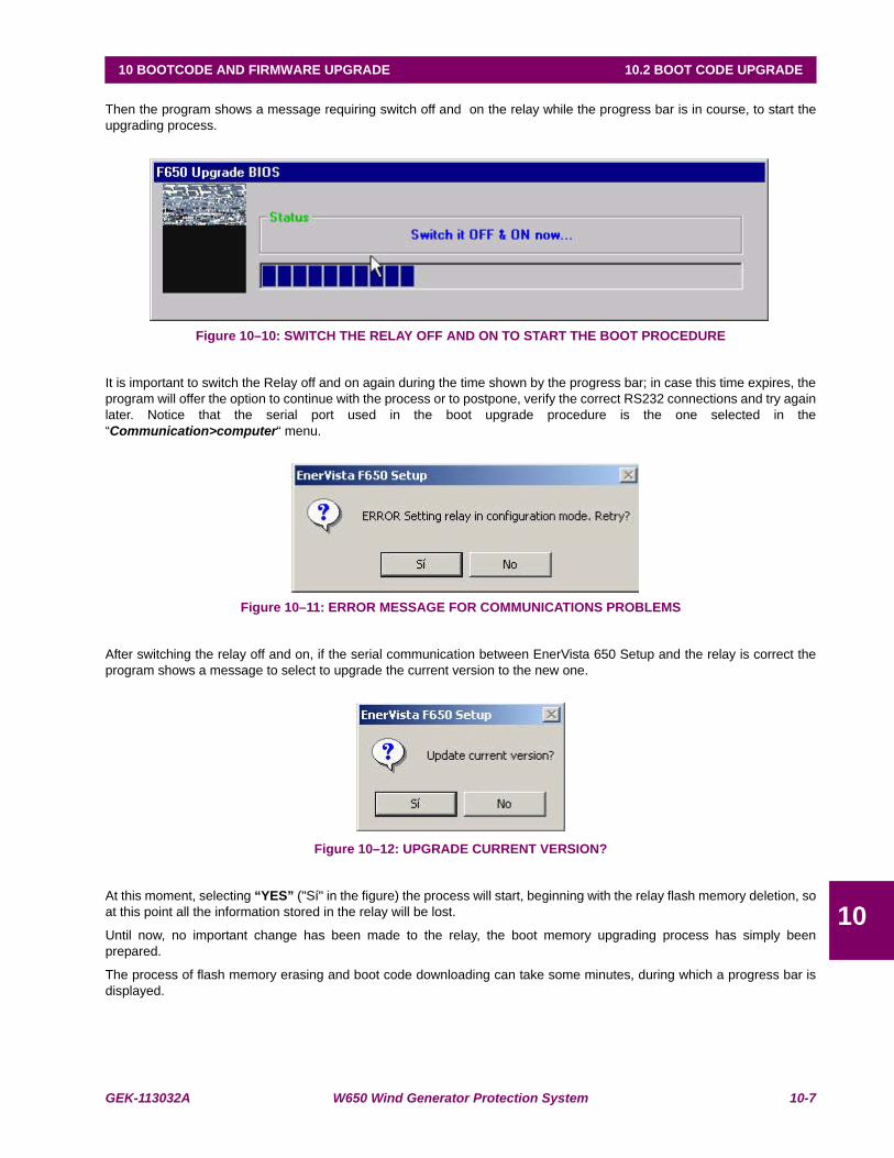
GEK-113032A W650 Wind Generator Protection System 10-7
10 BOOTCODE AND FIRMWARE UPGRADE 10.2 BOOT CODE UPGRADE
10
Then the program shows a message requiring switch off and on the relay while the progress bar is in course, to start theupgrading process.
Figure 10–10: SWITCH THE RELAY OFF AND ON TO START THE BOOT PROCEDURE
It is important to switch the Relay off and on again during the time shown by the progress bar; in case this time expires, theprogram will offer the option to continue with the process or to postpone, verify the correct RS232 connections and try againlater. Notice that the serial port used in the boot upgrade procedure is the one selected in the“Communication>computer“ menu.
Figure 10–11: ERROR MESSAGE FOR COMMUNICATIONS PROBLEMS
After switching the relay off and on, if the serial communication between EnerVista 650 Setup and the relay is correct theprogram shows a message to select to upgrade the current version to the new one.
Figure 10–12: UPGRADE CURRENT VERSION?
At this moment, selecting “YES” ("Sí" in the figure) the process will start, beginning with the relay flash memory deletion, soat this point all the information stored in the relay will be lost.
Until now, no important change has been made to the relay, the boot memory upgrading process has simply beenprepared.
The process of flash memory erasing and boot code downloading can take some minutes, during which a progress bar isdisplayed.
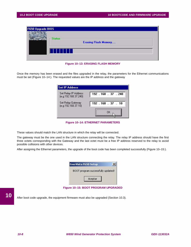
10-8 W650 Wind Generator Protection System GEK-113032A
10.2 BOOT CODE UPGRADE 10 BOOTCODE AND FIRMWARE UPGRADE
10
Figure 10–13: ERASING FLASH MEMORY
Once the memory has been erased and the files upgraded in the relay, the parameters for the Ethernet communicationsmust be set (Figure 10–14:). The requested values are the IP address and the gateway
Figure 10–14: ETHERNET PARAMETERS
These values should match the LAN structure in which the relay will be connected.
The gateway must be the one used in the LAN structure connecting the relay. The relay IP address should have the firstthree octets corresponding with the Gateway and the last octet must be a free IP address reserved to the relay to avoidpossible collisions with other devices.
After assigning the Ethernet parameters, the upgrade of the boot code has been completed successfully (Figure 10–15:).
Figure 10–15: BOOT PROGRAM UPGRADED
After boot code upgrade, the equipment firmware must also be upgraded (Section 10.3).
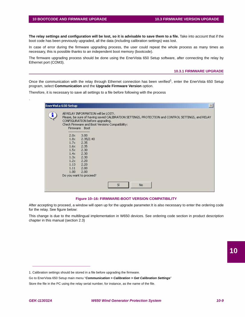
GEK-113032A W650 Wind Generator Protection System 10-9
10 BOOTCODE AND FIRMWARE UPGRADE 10.3 FIRMWARE VERSION UPGRADE
10
10.3FIRMWARE VERSION UPGRADE
The relay settings and configuration will be lost, so it is advisable to save them to a file. Take into account that if theboot code has been previously upgraded, all the data (including calibration settings) was lost.
In case of error during the firmware upgrading process, the user could repeat the whole process as many times asnecessary, this is possible thanks to an independent boot memory (bootcode).
The firmware upgrading process should be done using the EnerVista 650 Setup software, after connecting the relay byEthernet port (COM3).
10.3.1 FIRMWARE UPGRADE
Once the communication with the relay through Ethernet connection has been verified1, enter the EnerVista 650 Setupprogram, select Communication and the Upgrade Firmware Version option.
Therefore, it is necessary to save all settings to a file before following with the process
.
Figure 10–16: FIRMWARE-BOOT VERSION COMPATIBILITY
After accepting to proceed, a window will open up for the upgrade parameter.It is also necessary to enter the ordering codefor the relay. See figure below:
This change is due to the multilingual implementation in W650 devices. See ordering code section in product descriptionchapter in this manual (section 2.3)
1. Calibration settings should be stored in a file before upgrading the firmware.
Go to EnerVista 650 Setup main menu “Communication > Calibration > Get Calibration Settings”
Store the file in the PC using the relay serial number, for instance, as the name of the file.
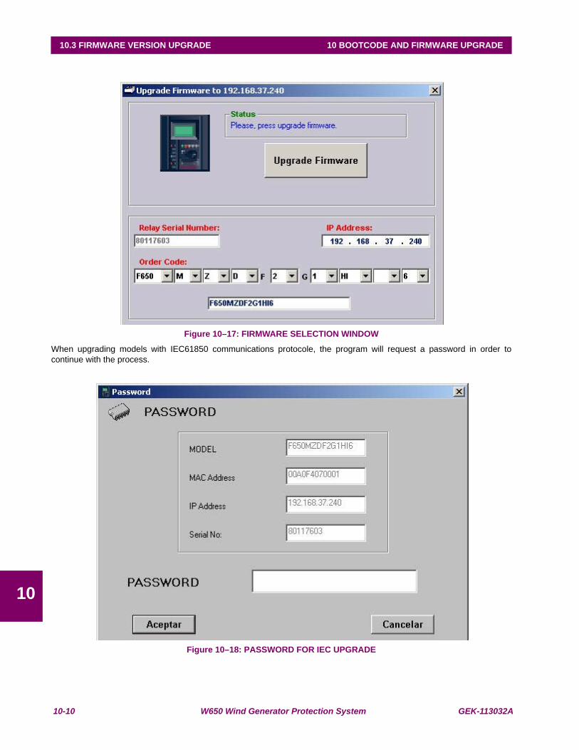
10-10 W650 Wind Generator Protection System GEK-113032A
10.3 FIRMWARE VERSION UPGRADE 10 BOOTCODE AND FIRMWARE UPGRADE
10
Figure 10–17: FIRMWARE SELECTION WINDOW
When upgrading models with IEC61850 communications protocole, the program will request a password in order tocontinue with the process.
Figure 10–18: PASSWORD FOR IEC UPGRADE

GEK-113032A W650 Wind Generator Protection System 10-11
10 BOOTCODE AND FIRMWARE UPGRADE 10.3 FIRMWARE VERSION UPGRADE
10
This password can be obtained placing an order with GE Multilin. The following parameters must be clearly indicated in theorder:
• Unit serial number
• Current model option (before memory upgrade)
• Desired model option (after memory upgrade)
• Unit MAC address (available in the identification label)
Once the upgrade parameters have been entered, press the “Upgrade Firmware” button. When communication has beenestablished, the program will show a message requesting to turn off and back on the relay to continue with the upgradeprocess.
Once the relay has been turned off and on, a new screen allows selecting the folder that contains the firmware upgradefiles (“upgrade.txt” file must be located in this folder). This Upgrade.txt file is located in the folder where the desiredfirmware upgrade files are. This firmware upgrade files can be found in the Multilin web site.
If the files are downloaded from the web, they are compressed in a zip file. It should be decompressed in a temporarydirectory from which the upgrade.txt file will be selected.
Once the Upgrade.txt file is selected, the “Upgrade Firmware” button will be enabled. Press this button to initiate theprocess. During the process, the program displays the files that are being upgraded. When the files transfer is finished, amessage appears informing that it is necessary to wait sometime before resetting the unit, in order to start working with thenew firmware version in the relay. When the whole process has finished a message will be displayed asking to switch theW650 on and off.
At this point, the firmware upgrade procedure is finished and the relay is ready to be powered down and back up to checkthat the firmware has been upgraded properly.
When upgrading the firmware the entire settings and relay configuration are reset to factory default value.
Once the equipment has been properly checked, the W650 is ready to be used.
Remember that calibration settings and configuration must be loaded to the relay. To recover the relay calibration:
Go to EnerVista 650 Setup main menu:
Communication > Calibration > Set calibration Settings to store in the relay the calibration settings if necessary.
File > Config file (*.650) Converter to convert the setting and configuration file *.650 for the relay (if is was in a previousversion format) to the new version (see section 4.1.7.2 in human interfaces in this manual)
File > Send info to relay to send the new settings and configuration file to the unit.
STEP LIST SUMMARY
10.3.2 BOOT CODE UPGRADE (*)
1. INSTALL THE PROPER VERSION OF THE ENERVISTA 650 SETUP PROGRAM.
2. CONNECT ONE RS-232 CABLE IN THE FRONT PORT OF THE RELAY AND ONE ETHERNET CABLE AT THEREAR ETHERNET PORT (CROSSOVER CABLE FOR BACK-TO-BACK CONNECTION AND STRAIGHT-THROUGHETHERNET CABLE FOR HUB OR SWITCH).
3. GET CALIBRATION SETTINGS (AND SAVE IT TO A FILE).
4. SAVE ALL THE DATA FROM THE RELAY (SETTINGS, OSCILLOGRAPHY, EVENTS).
5. FROM THE ENERVISTA 650 SETUP PROGRAM SELECT "Communication > Upgrade Boot Code".
6. FOLLOW THE INDICATIONS OF THE PROGRAM AND SELECT THE BOOT PROGRAM BIN FILE.
7. WHEN REQUIRED BY THE PROGRAM SWITCH OFF AND BACK ON THE RELAY.
Notice that boot program and firmware upgrade will erase all the data contained in the relay, thus it is advisable to save all the data, oscillography, events, settings and configuration files previously.

10-12 W650 Wind Generator Protection System GEK-113032A
10.3 FIRMWARE VERSION UPGRADE 10 BOOTCODE AND FIRMWARE UPGRADE
10
8. CONTINUE WITH THE PROCESS AND SET THE IP ADDRESS AND GATEWAY WHEN REQUIRED.
10.3.3 FIRMWARE UPGRADE (*)
1. INSTALL THE PROPER VERSION OF THE ENERVISTA 650 SETUP PROGRAM.
2. CONNECT ONE ETHERNET CABLE AT THE REAR ETHERNET PORT (CROSSOVER CABLE FOR BACK-TO-BACK CONNECTION AND STRAIGHT-THROUGH ETHERNET CABLE FOR HUB OR SWITCH).
3. SET THE APPROPRIATE IP ADDRESS IN THE RELAY.
4. SET THE APPROPRIATE IP ADDRESS IN THE PC.
5. FROM THE ENERVISTA 650 SETUP PROGRAM SELECT “Communications > Upgrade Software Version”.
6. ENTER THE IP ADDRESS, SERIAL NUMBER AND ORDERING CODE OF THE RELAY TO UPGRADE.
7. WHEN REQUIRED BY THE PROGRAM SWITCH OFF AND BACK ON THE RELAY.
8. LOCATE THE UPGRADE.TXT FILE ACCORDING TO THE MODEL OF THE RELAY.
9. PRESS UPGRADE FIRMWARE AND INITIATE THE UPGRADE PROCESS.
10. TO COMPLETE THE PROCEDURE, SWITCH OFF AND BACK ON THE RELAY WHEN REQUIRED BY THEPROGRAM.
11. SET CALIBRATION SETTINGS (FROM THE PC TO THE RELAY).
12. THE SETTINGS AND CONFIGURATION ARE NOW SET TO FACTORY DEFAULT.
13. SEND THE NEW SETTINGS AND CONFIGURATION FILES TO THE RELAY IF NECESSARY.
(*) The boot code upgrade must be performed using a crossed copper cable (RJ45) connected to the PC. It is notnecessary to modify the internal fiber/cable switch, as the upgrade is carried out at 10 Mb/s, and thus there is not cable/fiber conflict.
This fact does not apply to the firmware upgrade, which can be performed either with the Ethernet fiber connection, or with the cable connection.
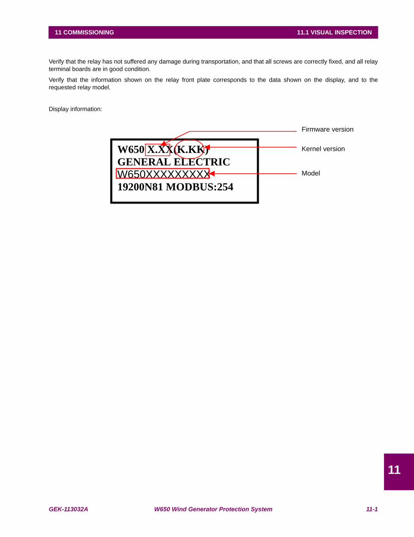
GEK-113032A W650 Wind Generator Protection System 11-1
11 COMMISSIONING 11.1 VISUAL INSPECTION
11
11 COMMISSIONING 11.1VISUAL INSPECTION
Verify that the relay has not suffered any damage during transportation, and that all screws are correctly fixed, and all relayterminal boards are in good condition.
Verify that the information shown on the relay front plate corresponds to the data shown on the display, and to therequested relay model.
Display information:
Firmware version
Kernel version W650 X.XX(K.KK)
GENERAL ELECTRIC
W650XXXXXXXXX19200N81 MODBUS:254
Model

11-2 W650 Wind Generator Protection System GEK-113032A
11.2 GENERAL CONSIDERATIONS ON THE POWER SUPPLY NETWORK 11 COMMISSIONING
11
11.2GENERAL CONSIDERATIONS ON THE POWER SUPPLY NETWORK
All devices running on AC current are affected by frequency. As a non-sine wave is the result of a fundamental wave plus aseries of harmonics from this fundamental wave, we can infer that devices running on AC current are influenced by theapplied waveform.
For a correct testing of relays running on AC current, it is fundamental to use a current and/or voltage senoidal waveform.The pureness of a senoidal wave (lack of harmonics) cannot be expressed specifically for a specific relay. However, anyrelay incorporating sintonized circuits, R-L and R-C circuits, will be affected by non-senoidal waveforms, as in the case ofW650.
These relays respond to the voltage waveform in a different way to the majority of AC current voltmeters. If the powersupply network used for the testing contains wide harmonics, the voltmeter and relay responses will be different.
Relays have been calibrated in factory using a Network of 50 or 60 Hz with a minimum harmonic content. When the relay istested, a power supply network with no harmonics in its waveform must be used.
The ammeters and chronometers used for testing the pickup current and relay operation time must be calibrated and theiraccuracy must be better than the relay’s. The power supply used in the tests must remain stable, mainly in the levels nearthe operation thresholds.
It is important to point out that the accuracy with which the test is performed depends on the network and on theinstruments used. Functional tests performed with unsuitable power supply network and instruments are useful to checkthat the relay operates properly and therefore its operating characteristics are verified in an approximate manner. However,if the relay would be calibrated in these conditions, its operational characteristics would be outside the tolerance rangevalues.
The following sections detail the list of tests for verifying the complete relay functionality.
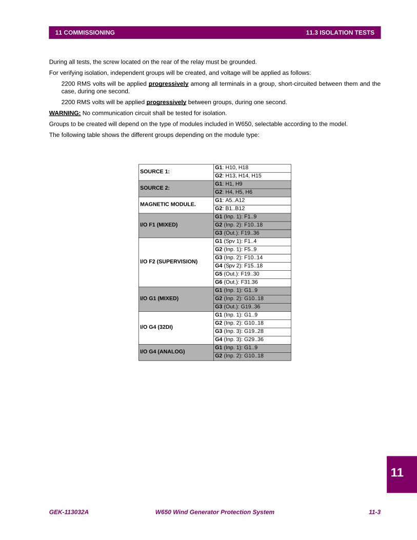
GEK-113032A W650 Wind Generator Protection System 11-3
11 COMMISSIONING 11.3 ISOLATION TESTS
11
11.3ISOLATION TESTS
During all tests, the screw located on the rear of the relay must be grounded.
For verifying isolation, independent groups will be created, and voltage will be applied as follows:
2200 RMS volts will be applied progressively among all terminals in a group, short-circuited between them and thecase, during one second.
2200 RMS volts will be applied progressively between groups, during one second.
WARNING: No communication circuit shall be tested for isolation.
Groups to be created will depend on the type of modules included in W650, selectable according to the model.
The following table shows the different groups depending on the module type:
SOURCE 1:G1: H10, H18G2: H13, H14, H15
SOURCE 2:G1: H1, H9G2: H4, H5, H6
MAGNETIC MODULE.G1: A5..A12G2: B1..B12
I/O F1 (MIXED)G1 (Inp. 1): F1..9G2 (Inp. 2): F10..18G3 (Out.): F19..36
I/O F2 (SUPERVISION)
G1 (Spv 1): F1..4G2 (Inp. 1): F5..9G3 (Inp. 2): F10..14G4 (Spv 2): F15..18G5 (Out.): F19..30G6 (Out.): F31.36
I/O G1 (MIXED)G1 (Inp. 1): G1..9G2 (Inp. 2): G10..18G3 (Out.): G19..36
I/O G4 (32DI)
G1 (Inp. 1): G1..9G2 (Inp. 2): G10..18G3 (Inp. 3): G19..28G4 (Inp. 3): G29..36
I/O G4 (ANALOG)G1 (Inp. 1): G1..9G2 (Inp. 2): G10..18

11-4 W650 Wind Generator Protection System GEK-113032A
11.4 INDICATORS 11 COMMISSIONING
11
11.4INDICATORS
Feed the relay and verify that when commanding a LED reset operation, all LED indicators light up and they are turned offwhen pressing the ESC key for more than 3 seconds.

GEK-113032A W650 Wind Generator Protection System 11-5
11 COMMISSIONING 11.5 POWER SUPPLY TESTING
11
11.5POWER SUPPLY TESTING
Feed the relay with the minimum and maximum voltage. For each voltage value, verify that the alarm relay is activatedwhen there is voltage, and it is deactivated when there is no feed. If the power supply source incorporates AC feed, this testwill be performed also for VAC.
If the relay incorporates a redundant power supply, these tests shall be performed on both power supplies.
Voltage values to be applied will be the ones indicated below according to the relay model:
NOTE: Codes HIR and LOR correspond to a redundant power supply
SUPPLY V MIN. V MAX.
HI/HIR110-250 Vdc120-230 Vac
88 Vdc96 Vac
300 Vdc250 Vac
LO/LOR24-48 Vdc 20 Vdc 57.6 Vdc

11-6 W650 Wind Generator Protection System GEK-113032A
11.6 COMMUNICATIONS 11 COMMISSIONING
11
11.6COMMUNICATIONS
Verify that available communication ports allow communication with the relay.
Ports to be checked are as follows:
Front:RS232
Rear:2 x RS485, 2 x Fiber Optic - Serial, 2 x Fiber Optic - Ethernet, 1 x RJ45 - Ethernet.
A computer with EnerVista 650 Setup software and an appropriate connector must be used.
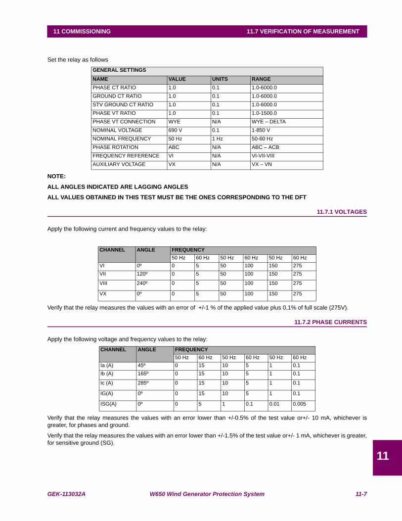
GEK-113032A W650 Wind Generator Protection System 11-7
11 COMMISSIONING 11.7 VERIFICATION OF MEASUREMENT
11
11.7VERIFICATION OF MEASUREMENT
Set the relay as follows
NOTE:
ALL ANGLES INDICATED ARE LAGGING ANGLES
ALL VALUES OBTAINED IN THIS TEST MUST BE THE ONES CORRESPONDING TO THE DFT
11.7.1 VOLTAGES
Apply the following current and frequency values to the relay:
Verify that the relay measures the values with an error of +/-1 % of the applied value plus 0,1% of full scale (275V).
11.7.2 PHASE CURRENTS
Apply the following voltage and frequency values to the relay:
Verify that the relay measures the values with an error lower than +/-0.5% of the test value or+/- 10 mA, whichever isgreater, for phases and ground.
Verify that the relay measures the values with an error lower than +/-1.5% of the test value or+/- 1 mA, whichever is greater,for sensitive ground (SG).
GENERAL SETTINGSNAME VALUE UNITS RANGEPHASE CT RATIO 1.0 0.1 1.0-6000.0GROUND CT RATIO 1.0 0.1 1.0-6000.0STV GROUND CT RATIO 1.0 0.1 1.0-6000.0PHASE VT RATIO 1.0 0.1 1.0-1500.0PHASE VT CONNECTION WYE N/A WYE – DELTANOMINAL VOLTAGE 690 V 0.1 1-850 VNOMINAL FREQUENCY 50 Hz 1 Hz 50-60 HzPHASE ROTATION ABC N/A ABC – ACBFREQUENCY REFERENCE VI N/A VI-VII-VIIIAUXILIARY VOLTAGE VX N/A VX – VN
CHANNEL ANGLE FREQUENCY50 Hz 60 Hz 50 Hz 60 Hz 50 Hz 60 Hz
VI 0º 0 5 50 100 150 275VII 120º 0 5 50 100 150 275
VIII 240º 0 5 50 100 150 275
VX 0º 0 5 50 100 150 275
CHANNEL ANGLE FREQUENCY50 Hz 60 Hz 50 Hz 60 Hz 50 Hz 60 Hz
Ia (A) 45º 0 15 10 5 1 0.1Ib (A) 165º 0 15 10 5 1 0.1
Ic (A) 285º 0 15 10 5 1 0.1
IG(A) 0º 0 15 10 5 1 0.1
ISG(A) 0º 0 5 1 0.1 0.01 0.005
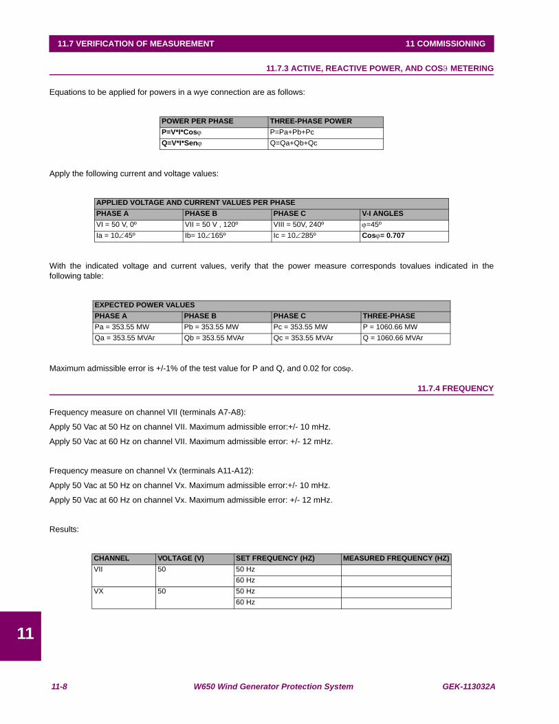
11-8 W650 Wind Generator Protection System GEK-113032A
11.7 VERIFICATION OF MEASUREMENT 11 COMMISSIONING
11
11.7.3 ACTIVE, REACTIVE POWER, AND COSϑ METERING
Equations to be applied for powers in a wye connection are as follows:
Apply the following current and voltage values:
With the indicated voltage and current values, verify that the power measure corresponds tovalues indicated in thefollowing table:
Maximum admissible error is +/-1% of the test value for P and Q, and 0.02 for cosϕ.
11.7.4 FREQUENCY
Frequency measure on channel VII (terminals A7-A8):
Apply 50 Vac at 50 Hz on channel VII. Maximum admissible error:+/- 10 mHz.
Apply 50 Vac at 60 Hz on channel VII. Maximum admissible error: +/- 12 mHz.
Frequency measure on channel Vx (terminals A11-A12):
Apply 50 Vac at 50 Hz on channel Vx. Maximum admissible error:+/- 10 mHz.
Apply 50 Vac at 60 Hz on channel Vx. Maximum admissible error: +/- 12 mHz.
Results:
POWER PER PHASE THREE-PHASE POWERP=V*I*Cosϕ P=Pa+Pb+PcQ=V*I*Senϕ Q=Qa+Qb+Qc
APPLIED VOLTAGE AND CURRENT VALUES PER PHASEPHASE A PHASE B PHASE C V-I ANGLESVI = 50 V, 0º VII = 50 V , 120º VIII = 50V, 240º ϕ=45ºIa = 10∠45º Ib= 10∠165º Ic = 10∠285º Cosϕ= 0.707
EXPECTED POWER VALUESPHASE A PHASE B PHASE C THREE-PHASEPa = 353.55 MW Pb = 353.55 MW Pc = 353.55 MW P = 1060.66 MWQa = 353.55 MVAr Qb = 353.55 MVAr Qc = 353.55 MVAr Q = 1060.66 MVAr
CHANNEL VOLTAGE (V) SET FREQUENCY (HZ) MEASURED FREQUENCY (HZ)VII 50 50 Hz
60 HzVX 50 50 Hz
60 Hz

GEK-113032A W650 Wind Generator Protection System 11-9
11 COMMISSIONING 11.8 INPUTS AND OUTPUTS
11
11.8INPUTS AND OUTPUTS
During all tests, the screw on the rear of the relay must be grounded.
11.8.1 DIGITAL INPUTS
During this test, the user will determine the activation/deactivation points for every input in the relay for the set voltage valueof 30 Volts.
Verify that the error does not exceed +/- 10% (+10% on activation, -10% on deactivation)
Default board settings for the input test can be modified in EnerVista 650 Setup software in:
Settings>Inputs/Outputs>Contact I/O>Board X
X, will be substituted by the corresponding board:
F for board in first slot
G for board in second slot
Test settings for mixed board (type 1:16 inputs and 8 outputs) :
The inputs test is completed by groups of 8 inputs, as this type of board has 2 groups of 8 inputs with the same common.For the first 8 inputs, the voltage threshold setting is determined by Voltage Threshold A. For the next 8 inputs, the settingis Voltage Threshold B. Inputs (or contact converters, CC1 – CC16) must also be set to POSITIVE.
Test settings for mixed board (type 2: 8 digital inputs, 4 blocks for supervision and 8 outputs) :
The inputs test is completed by groups of 4 inputs, as this type of board has 2 groups of 4 inputs with the same common.For the first 4 inputs, the voltage threshold setting is determined by Voltage Threshold A. For the next 4 inputs, the settingis Voltage Threshold B. Inputs (or contact converters, CC1 – CC8) must also be set to POSITIVE.
If the relay incorporates more input modules, this test must also be applied to them.
I/O BOARD TYPE 1 (MIXED)Voltage Threshold A_X 30 VVoltage Threshold B_X 40 VDebounce Time A_X 5 msDebounce Time B_X 5 msInput Type_X_CC1 (CC1) POSITIVE... ...Input Type_X_CC16 (CC16) POSITIVE
I/O BOARD TYPE 2 (SUPERVISION)Voltage Threshold A_X 30 VVoltage Threshold B_X 40 VDebounce Time A_X 5 msDebounce Time B_X 5 msInput Type_X_CC1 (CC1) POSITIVE... ...Input Type_X_CC8 (CC8) POSITIVE
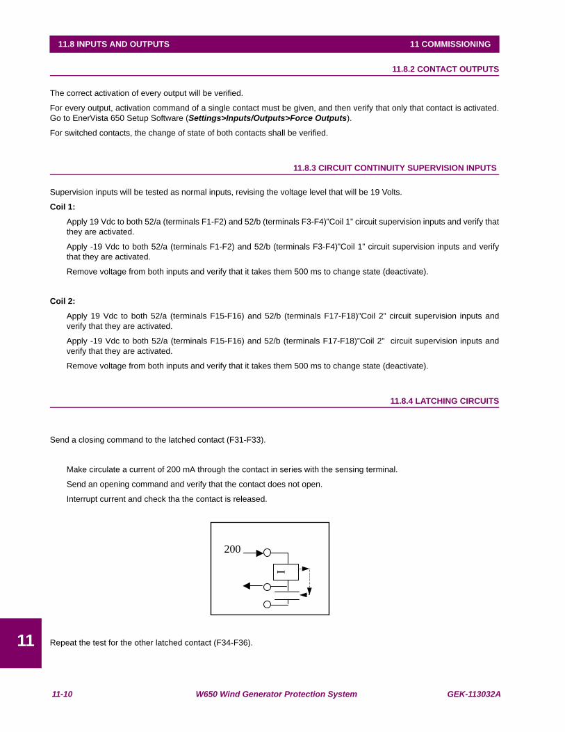
11-10 W650 Wind Generator Protection System GEK-113032A
11.8 INPUTS AND OUTPUTS 11 COMMISSIONING
11
11.8.2 CONTACT OUTPUTS
The correct activation of every output will be verified.
For every output, activation command of a single contact must be given, and then verify that only that contact is activated.Go to EnerVista 650 Setup Software (Settings>Inputs/Outputs>Force Outputs).
For switched contacts, the change of state of both contacts shall be verified.
11.8.3 CIRCUIT CONTINUITY SUPERVISION INPUTS
Supervision inputs will be tested as normal inputs, revising the voltage level that will be 19 Volts.
Coil 1:
Apply 19 Vdc to both 52/a (terminals F1-F2) and 52/b (terminals F3-F4)”Coil 1” circuit supervision inputs and verify thatthey are activated.
Apply -19 Vdc to both 52/a (terminals F1-F2) and 52/b (terminals F3-F4)”Coil 1” circuit supervision inputs and verifythat they are activated.
Remove voltage from both inputs and verify that it takes them 500 ms to change state (deactivate).
Coil 2:
Apply 19 Vdc to both 52/a (terminals F15-F16) and 52/b (terminals F17-F18)”Coil 2” circuit supervision inputs andverify that they are activated.
Apply -19 Vdc to both 52/a (terminals F15-F16) and 52/b (terminals F17-F18)”Coil 2” circuit supervision inputs andverify that they are activated.
Remove voltage from both inputs and verify that it takes them 500 ms to change state (deactivate).
11.8.4 LATCHING CIRCUITS
Send a closing command to the latched contact (F31-F33).
Make circulate a current of 200 mA through the contact in series with the sensing terminal.
Send an opening command and verify that the contact does not open.
Interrupt current and check tha the contact is released.
Repeat the test for the other latched contact (F34-F36).
I
200
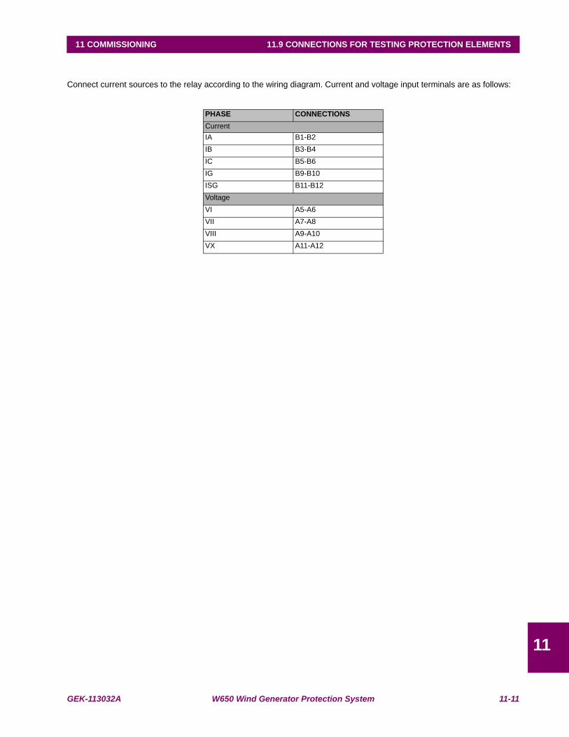
GEK-113032A W650 Wind Generator Protection System 11-11
11 COMMISSIONING 11.9 CONNECTIONS FOR TESTING PROTECTION ELEMENTS
11
11.9CONNECTIONS FOR TESTING PROTECTION ELEMENTS
Connect current sources to the relay according to the wiring diagram. Current and voltage input terminals are as follows:
PHASE CONNECTIONSCurrentIA B1-B2IB B3-B4IC B5-B6IG B9-B10ISG B11-B12VoltageVI A5-A6VII A7-A8VIII A9-A10VX A11-A12
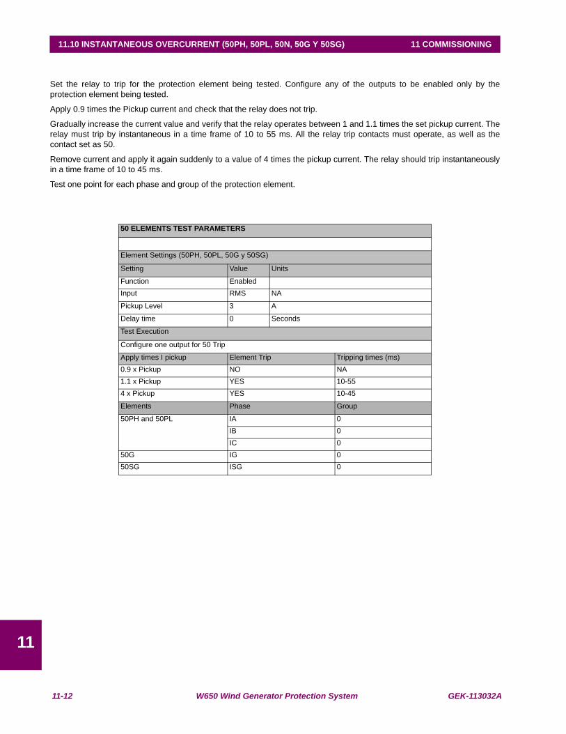
11-12 W650 Wind Generator Protection System GEK-113032A
11.10 INSTANTANEOUS OVERCURRENT (50PH, 50PL, 50N, 50G Y 50SG) 11 COMMISSIONING
11
11.10INSTANTANEOUS OVERCURRENT (50PH, 50PL, 50N, 50G Y 50SG)
Set the relay to trip for the protection element being tested. Configure any of the outputs to be enabled only by theprotection element being tested.
Apply 0.9 times the Pickup current and check that the relay does not trip.
Gradually increase the current value and verify that the relay operates between 1 and 1.1 times the set pickup current. Therelay must trip by instantaneous in a time frame of 10 to 55 ms. All the relay trip contacts must operate, as well as thecontact set as 50.
Remove current and apply it again suddenly to a value of 4 times the pickup current. The relay should trip instantaneouslyin a time frame of 10 to 45 ms.
Test one point for each phase and group of the protection element.
50 ELEMENTS TEST PARAMETERS
Element Settings (50PH, 50PL, 50G y 50SG)
Setting Value Units
Function EnabledInput RMS NA
Pickup Level 3 A
Delay time 0 Seconds
Test Execution
Configure one output for 50 Trip
Apply times I pickup Element Trip Tripping times (ms)0.9 x Pickup NO NA1.1 x Pickup YES 10-554 x Pickup YES 10-45
Elements Phase Group
50PH and 50PL IA 0IB 0IC 0
50G IG 050SG ISG 0
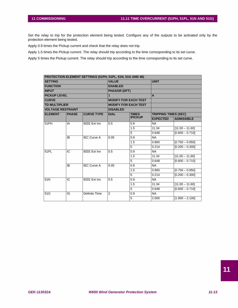
GEK-113032A W650 Wind Generator Protection System 11-13
11 COMMISSIONING 11.11 TIME OVERCURRENT (51PH, 51PL, 51N AND 51G)
11
11.11 TIME OVERCURRENT (51PH, 51PL, 51N AND 51G)
Set the relay to trip for the protection element being tested. Configure any of the outputs to be activated only by theprotection element being tested.
Apply 0.9 times the Pickup current and check that the relay does not trip.
Apply 1.5 times the Pickup current. The relay should trip according to the time corresponding to its set curve.
Apply 5 times the Pickup current. The relay should trip according to the time corresponding to its set curve.
PROTECTION ELEMENT SETTINGS (51PH, 51PL, 51N, 51G AND 46)SETTING VALUE UNITFUNCTION ENABLEDINPUT PHASOR (DFT)PICKUP LEVEL 1 ACURVE MODIFY FOR EACH TESTTD MULTIPLIER MODIFY FOR EACH TESTVOLTAGE RESTRAINT DISABLEDELEMENT PHASE CURVE TYPE DIAL TIMES
IPICKUPTRIPPING TIMES (SEC)EXPECTED ADMISSIBLE
51PH IA IEEE Ext Inv 0.5 0.9 NA1.5 11.34 [11.00 – 11.60]5 0.648 [0.600 – 0.710]
IB IEC Curve A 0.05 0.9 NA1.5 0.860 [0.750 – 0.950]5 0.214 [0.200 – 0.300]
51PL IC IEEE Ext Inv 0.5 0.9 NA1.5 11.34 [11.00 – 11.60]5 0.648 [0.600 – 0.710]
IB IEC Curve A 0.05 0.9 NA1.5 0.860 [0.750 – 0.950]5 0.214 [0.200 – 0.300]
51N IC IEEE Ext Inv 0.5 0.9 NA1.5 11.34 [11.00 – 11.60]5 0.648 [0.600 – 0.710]
51G IG Definite Time 2 0.9 NA5 2.000 [1.900 – 2.100]
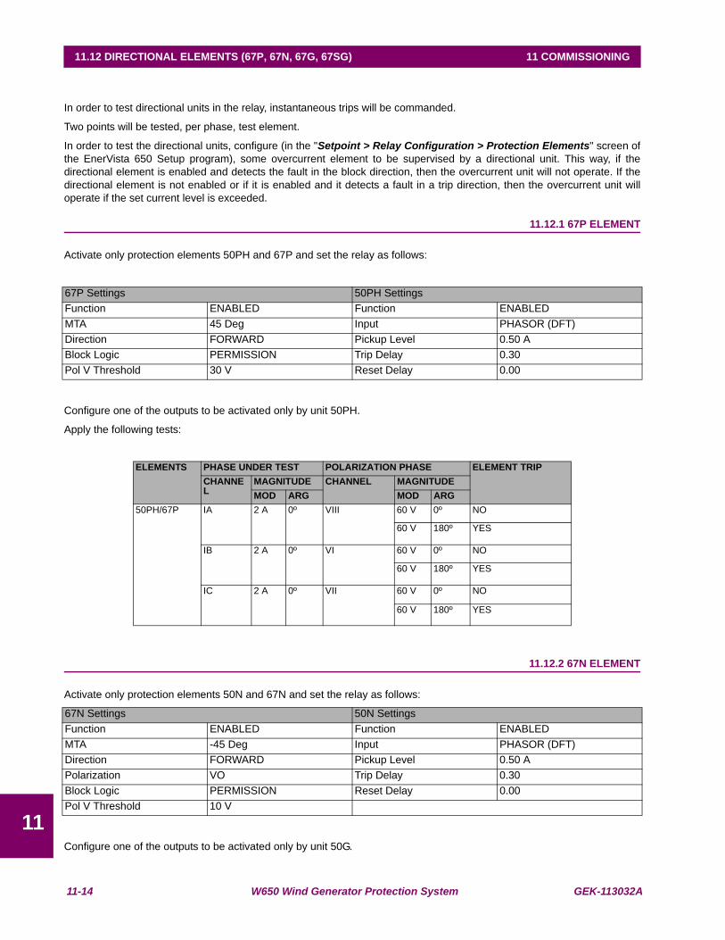
11-14 W650 Wind Generator Protection System GEK-113032A
11.12 DIRECTIONAL ELEMENTS (67P, 67N, 67G, 67SG) 11 COMMISSIONING
11
11.12DIRECTIONAL ELEMENTS (67P, 67N, 67G, 67SG)
In order to test directional units in the relay, instantaneous trips will be commanded.
Two points will be tested, per phase, test element.
In order to test the directional units, configure (in the "Setpoint > Relay Configuration > Protection Elements" screen ofthe EnerVista 650 Setup program), some overcurrent element to be supervised by a directional unit. This way, if thedirectional element is enabled and detects the fault in the block direction, then the overcurrent unit will not operate. If thedirectional element is not enabled or if it is enabled and it detects a fault in a trip direction, then the overcurrent unit willoperate if the set current level is exceeded.
11.12.1 67P ELEMENT
Activate only protection elements 50PH and 67P and set the relay as follows:
Configure one of the outputs to be activated only by unit 50PH.
Apply the following tests:
11.12.2 67N ELEMENT
Activate only protection elements 50N and 67N and set the relay as follows:
Configure one of the outputs to be activated only by unit 50G.
67P Settings 50PH SettingsFunction ENABLED Function ENABLEDMTA 45 Deg Input PHASOR (DFT)Direction FORWARD Pickup Level 0.50 ABlock Logic PERMISSION Trip Delay 0.30Pol V Threshold 30 V Reset Delay 0.00
ELEMENTS PHASE UNDER TEST POLARIZATION PHASE ELEMENT TRIPCHANNEL
MAGNITUDE CHANNEL MAGNITUDEMOD ARG MOD ARG
50PH/67P IA 2 A 0º VIII 60 V 0º NO
60 V 180º YES
IB 2 A 0º VI 60 V 0º NO
60 V 180º YES
IC 2 A 0º VII 60 V 0º NO
60 V 180º YES
67N Settings 50N SettingsFunction ENABLED Function ENABLEDMTA -45 Deg Input PHASOR (DFT)Direction FORWARD Pickup Level 0.50 APolarization VO Trip Delay 0.30Block Logic PERMISSION Reset Delay 0.00Pol V Threshold 10 V
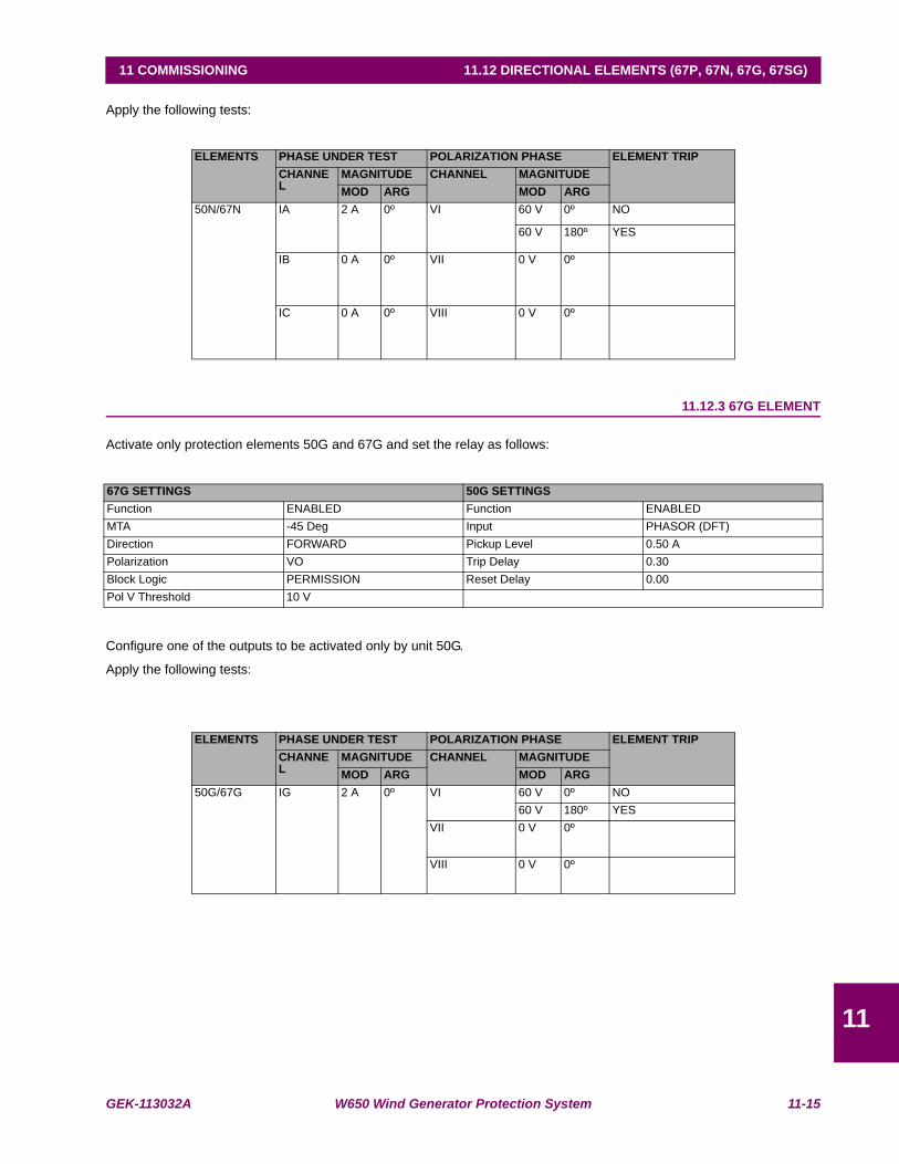
GEK-113032A W650 Wind Generator Protection System 11-15
11 COMMISSIONING 11.12 DIRECTIONAL ELEMENTS (67P, 67N, 67G, 67SG)
11
Apply the following tests:
11.12.3 67G ELEMENT
Activate only protection elements 50G and 67G and set the relay as follows:
Configure one of the outputs to be activated only by unit 50G.
Apply the following tests:
ELEMENTS PHASE UNDER TEST POLARIZATION PHASE ELEMENT TRIPCHANNEL
MAGNITUDE CHANNEL MAGNITUDEMOD ARG MOD ARG
50N/67N IA 2 A 0º VI 60 V 0º NO
60 V 180º YES
IB 0 A 0º VII 0 V 0º
IC 0 A 0º VIII 0 V 0º
67G SETTINGS 50G SETTINGSFunction ENABLED Function ENABLEDMTA -45 Deg Input PHASOR (DFT)Direction FORWARD Pickup Level 0.50 APolarization VO Trip Delay 0.30Block Logic PERMISSION Reset Delay 0.00Pol V Threshold 10 V
ELEMENTS PHASE UNDER TEST POLARIZATION PHASE ELEMENT TRIPCHANNEL
MAGNITUDE CHANNEL MAGNITUDEMOD ARG MOD ARG
50G/67G IG 2 A 0º VI 60 V 0º NO60 V 180º YES
VII 0 V 0º
VIII 0 V 0º
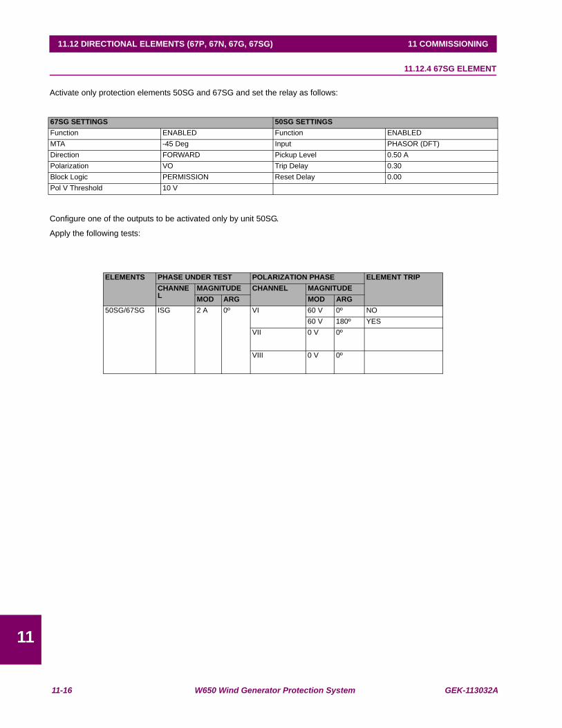
11-16 W650 Wind Generator Protection System GEK-113032A
11.12 DIRECTIONAL ELEMENTS (67P, 67N, 67G, 67SG) 11 COMMISSIONING
11
11.12.4 67SG ELEMENT
Activate only protection elements 50SG and 67SG and set the relay as follows:
Configure one of the outputs to be activated only by unit 50SG.
Apply the following tests:
67SG SETTINGS 50SG SETTINGSFunction ENABLED Function ENABLEDMTA -45 Deg Input PHASOR (DFT)Direction FORWARD Pickup Level 0.50 APolarization VO Trip Delay 0.30Block Logic PERMISSION Reset Delay 0.00Pol V Threshold 10 V
ELEMENTS PHASE UNDER TEST POLARIZATION PHASE ELEMENT TRIPCHANNEL
MAGNITUDE CHANNEL MAGNITUDEMOD ARG MOD ARG
50SG/67SG ISG 2 A 0º VI 60 V 0º NO60 V 180º YES
VII 0 V 0º
VIII 0 V 0º
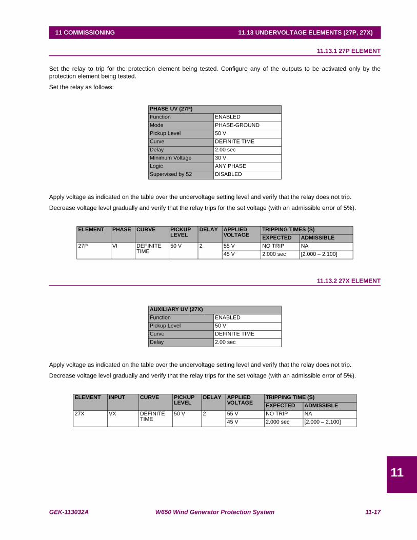
GEK-113032A W650 Wind Generator Protection System 11-17
11 COMMISSIONING 11.13 UNDERVOLTAGE ELEMENTS (27P, 27X)
11
11.13UNDERVOLTAGE ELEMENTS (27P, 27X) 11.13.1 27P ELEMENT
Set the relay to trip for the protection element being tested. Configure any of the outputs to be activated only by theprotection element being tested.
Set the relay as follows:
Apply voltage as indicated on the table over the undervoltage setting level and verify that the relay does not trip.
Decrease voltage level gradually and verify that the relay trips for the set voltage (with an admissible error of 5%).
11.13.2 27X ELEMENT
Apply voltage as indicated on the table over the undervoltage setting level and verify that the relay does not trip.
Decrease voltage level gradually and verify that the relay trips for the set voltage (with an admissible error of 5%).
PHASE UV (27P)Function ENABLEDMode PHASE-GROUNDPickup Level 50 VCurve DEFINITE TIMEDelay 2.00 secMinimum Voltage 30 VLogic ANY PHASESupervised by 52 DISABLED
ELEMENT PHASE CURVE PICKUP LEVEL
DELAY APPLIED VOLTAGE
TRIPPING TIMES (S)EXPECTED ADMISSIBLE
27P VI DEFINITE TIME
50 V 2 55 V NO TRIP NA45 V 2.000 sec [2.000 – 2.100]
AUXILIARY UV (27X)Function ENABLEDPickup Level 50 VCurve DEFINITE TIMEDelay 2.00 sec
ELEMENT INPUT CURVE PICKUP LEVEL
DELAY APPLIED VOLTAGE
TRIPPING TIME (S)EXPECTED ADMISSIBLE
27X VX DEFINITE TIME
50 V 2 55 V NO TRIP NA45 V 2.000 sec [2.000 – 2.100]
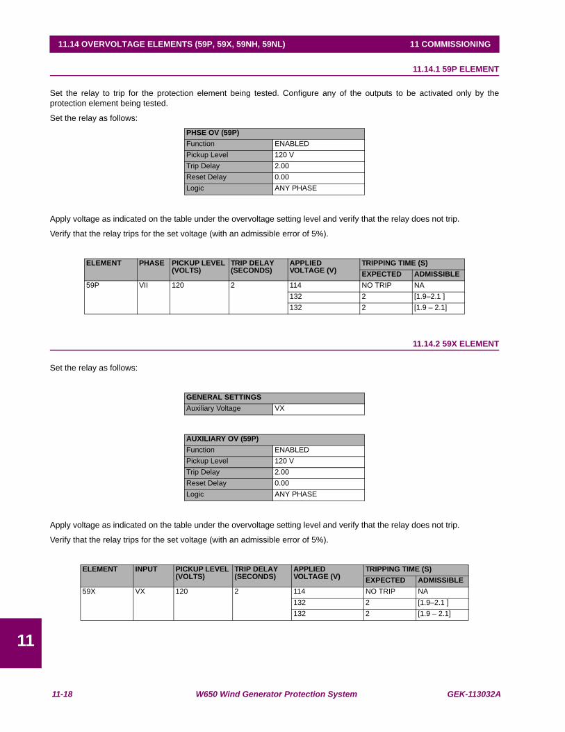
11-18 W650 Wind Generator Protection System GEK-113032A
11.14 OVERVOLTAGE ELEMENTS (59P, 59X, 59NH, 59NL) 11 COMMISSIONING
11
11.14OVERVOLTAGE ELEMENTS (59P, 59X, 59NH, 59NL) 11.14.1 59P ELEMENT
Set the relay to trip for the protection element being tested. Configure any of the outputs to be activated only by theprotection element being tested.
Set the relay as follows:
Apply voltage as indicated on the table under the overvoltage setting level and verify that the relay does not trip.
Verify that the relay trips for the set voltage (with an admissible error of 5%).
11.14.2 59X ELEMENT
Set the relay as follows:
Apply voltage as indicated on the table under the overvoltage setting level and verify that the relay does not trip.
Verify that the relay trips for the set voltage (with an admissible error of 5%).
PHSE OV (59P)Function ENABLEDPickup Level 120 VTrip Delay 2.00Reset Delay 0.00Logic ANY PHASE
ELEMENT PHASE PICKUP LEVEL (VOLTS)
TRIP DELAY(SECONDS)
APPLIED VOLTAGE (V)
TRIPPING TIME (S)EXPECTED ADMISSIBLE
59P VII 120 2 114 NO TRIP NA132 2 [1.9–2.1 ]132 2 [1.9 – 2.1]
GENERAL SETTINGSAuxiliary Voltage VX
AUXILIARY OV (59P)Function ENABLEDPickup Level 120 VTrip Delay 2.00Reset Delay 0.00Logic ANY PHASE
ELEMENT INPUT PICKUP LEVEL (VOLTS)
TRIP DELAY(SECONDS)
APPLIED VOLTAGE (V)
TRIPPING TIME (S)EXPECTED ADMISSIBLE
59X VX 120 2 114 NO TRIP NA132 2 [1.9–2.1 ]132 2 [1.9 – 2.1]

GEK-113032A W650 Wind Generator Protection System 11-19
11 COMMISSIONING 11.14 OVERVOLTAGE ELEMENTS (59P, 59X, 59NH, 59NL)
11
11.14.3 59NH AND 59NL ELEMENTS
Set the relay as follows
Apply voltage as indicated on the table under the overvoltage setting level and verify that the relay does not trip.
Verify that the relay trips for the set voltage (with an admissible error of 5%).
This element can also be tested by applying only phase voltages. For this purpose, it is necessary to set Auxiliary Voltage =VX. In this condition, Vn voltage is calculated as a sum of the phase voltages.
GENERAL SETTINGSAuxiliary Voltage VN
NEUTRAL OV HIGH/LOW (59NH/59NL)Function ENABLEDPickup Level 120 VTrip Delay 2.00Reset Delay 0.00
ELEMENTS INPUT PICKUP LEVEL (VOLTS)
TRIP DELAY(SECONDS)
APPLIED VOLTAGE (V)
TRIPPING TIME (S)EXPECTED ADMISSIBLE
59NH/59NL VX 120 2 114 NO TRIP NA132 2 [1.9–2.1 ]132 2 [1.9 – 2.1]
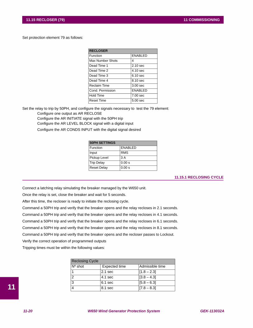
11-20 W650 Wind Generator Protection System GEK-113032A
11.15 RECLOSER (79) 11 COMMISSIONING
11
11.15RECLOSER (79)
Set protection element 79 as follows:
Set the relay to trip by 50PH, and configure the signals necessary to test the 79 element:Configure one output as AR RECLOSEConfigure the AR INITIATE signal with the 50PH tripConfigure the AR LEVEL BLOCK signal with a digital inputConfigure the AR CONDS INPUT with the digital signal desired
11.15.1 RECLOSING CYCLE
Connect a latching relay simulating the breaker managed by the W650 unit.
Once the relay is set, close the breaker and wait for 5 seconds.
After this time, the recloser is ready to initiate the reclosing cycle.
Command a 50PH trip and verify that the breaker opens and the relay recloses in 2.1 seconds.
Command a 50PH trip and verify that the breaker opens and the relay recloses in 4.1 seconds.
Command a 50PH trip and verify that the breaker opens and the relay recloses in 6.1 seconds.
Command a 50PH trip and verify that the breaker opens and the relay recloses in 8.1 seconds.
Command a 50PH trip and verify that the breaker opens and the recloser passes to Lockout.
Verify the correct operation of programmed outputs
Tripping times must be within the following values:
RECLOSERFunction ENABLEDMax Number Shots 4Dead Time 1 2.10 secDead Time 2 4.10 secDead Time 3 6.10 secDead Time 4 8.10 secReclaim Time 3.00 secCond. Permission ENABLEDHold Time 7.00 secReset Time 5.00 sec
50PH SETTINGSFunction ENABLEDInput RMSPickup Level 3 ATrip Delay 0.00 sReset Delay 0.00 s
Reclosing CycleNº shot Expected time Admissible time1 2.1 sec [1.8 – 2.3]2 4.1 sec [3.8 – 4.3]3 6.1 sec [5.8 – 6.3]4 8.1 sec [7.8 – 8.3]

GEK-113032A W650 Wind Generator Protection System 11-21
11 COMMISSIONING 11.15 RECLOSER (79)
11
11.15.2 RECLOSER STATUS
BLOCK
Activate the block input and verify that the recloser is in BLOCK status.
Close the breaker and wait for 5 seconds.
Command a trip and verify that the breaker opens but there is no reclose.
INHIBITION BY RECLOSING CONDITIONS
Close the breaker and wait for 5 seconds.
Command a trip, verify that the breaker opens and wait for the first shot.
Activate the inhibition input and command a new trip.
Verify that the breaker opens, wait for 8 seconds and verify that the relay does not reclose.
11.15.3 EXTERNAL RECLOSE INITIATION
Close the breaker and wait for 5 seconds.
Activate the reclose initiation input and open the breaker, verify that the relay executes the first shot

11-22 W650 Wind Generator Protection System GEK-113032A
11.15 RECLOSER (79) 11 COMMISSIONING
11

GEK-113032A W650 Wind Generator Protection System 12-1
12 APPLICATION EXAMPLES 12.1 EXAMPLE 1: COMMUNICATION & PROTECTION SETTINGS PROCEDURE
1212 APPLICATION EXAMPLES 12.1EXAMPLE 1: COMMUNICATION & PROTECTION SETTINGS PROCEDURE
12.1.1 DESCRIPTION OF THE EXERCISE
The requirements for this setting exercise are:
Communicate the relay via serial cable or Ethernet 10/100 Base T cable using EnerVista 650 Setup program.
Set some Phase Time Overcurrent protection function to operate at 5A , Inverse curve IEC, Dial 0.1
Set some Output contact on board F to be operated and sealed by the operation of the phase TOC.
Set some LED to show the operation of the phase TOC
Set some Operation to reset the output contact after dropout of the phase TOC since the front F1 pushbutton.
Set some Oscillography channel to record the pickup of phase TOC and output contact closing action.
To test the operation of this Phase Time Overcurrent protection
12.1.2 PROCEDURE TO COMMUNICATE WITH THE RELAY
This procedure describes the connection between any Laptop and some W650 relay using the EnerVista 650 SETUPprogram
For any one of these connections check first the communication parameters as follows:
Serial Communication (RS232 front port of the relay)
With the ESC key check on the main front screen the serial communication parameters (Baud rate, parity, data bits, stop bitand ID number).
Connect the serial cable PC-W650
Open the EnerVista 650 SETUP program in the PC and under Communication ⇓ Computer menu check that the serialcommunication parameters displayed are the same read in the front of the relay. Check also that:
Control Type is set to No Control Type
Startup Mode is set toCommunicate with relay
Click ON key.
Ethernet LAN (10/100 Base T rear port of the relay)
In the Laptop choose My PC-Control Panel-Network-Protocols-Protocol TCP/IP-Advance and set in IP Addressscreen the following:
IP Address 192.168.37.126
Netmask 255.255.255.0
In the front of W650 relay and pressing the ESC key display the Main Settings screen.
Move clockwise the rotating knob to choose Change Settings and press down the rotating knob.
Choose Comm Settings and press down the rotating knob.
Choose Network 0 and press down the rotating knob. It will be displayed IP Address OCT 1 and set it according to thefollowing table:
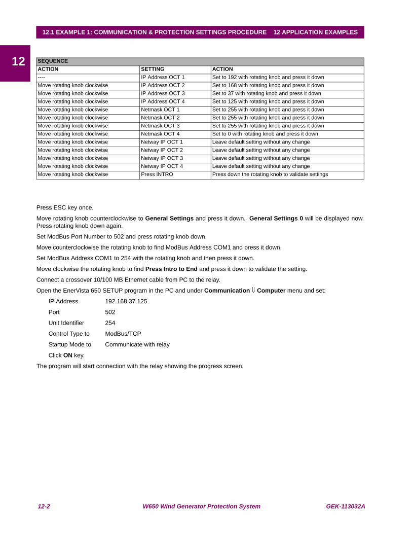
12-2 W650 Wind Generator Protection System GEK-113032A
12.1 EXAMPLE 1: COMMUNICATION & PROTECTION SETTINGS PROCEDURE 12 APPLICATION EXAMPLES
12
Press ESC key once.
Move rotating knob counterclockwise to General Settings and press it down. General Settings 0 will be displayed now.Press rotating knob down again.
Set ModBus Port Number to 502 and press rotating knob down.
Move counterclockwise the rotating knob to find ModBus Address COM1 and press it down.
Set ModBus Address COM1 to 254 with the rotating knob and then press it down.
Move clockwise the rotating knob to find Press Intro to End and press it down to validate the setting.
Connect a crossover 10/100 MB Ethernet cable from PC to the relay.
Open the EnerVista 650 SETUP program in the PC and under Communication ⇓ Computer menu and set:
IP Address 192.168.37.125
Port 502
Unit Identifier 254
Control Type to ModBus/TCP
Startup Mode to Communicate with relay
Click ON key.
The program will start connection with the relay showing the progress screen.
SEQUENCEACTION SETTING ACTION---- IP Address OCT 1 Set to 192 with rotating knob and press it downMove rotating knob clockwise IP Address OCT 2 Set to 168 with rotating knob and press it downMove rotating knob clockwise IP Address OCT 3 Set to 37 with rotating knob and press it downMove rotating knob clockwise IP Address OCT 4 Set to 125 with rotating knob and press it downMove rotating knob clockwise Netmask OCT 1 Set to 255 with rotating knob and press it downMove rotating knob clockwise Netmask OCT 2 Set to 255 with rotating knob and press it downMove rotating knob clockwise Netmask OCT 3 Set to 255 with rotating knob and press it downMove rotating knob clockwise Netmask OCT 4 Set to 0 with rotating knob and press it downMove rotating knob clockwise Netway IP OCT 1 Leave default setting without any changeMove rotating knob clockwise Netway IP OCT 2 Leave default setting without any changeMove rotating knob clockwise Netway IP OCT 3 Leave default setting without any changeMove rotating knob clockwise Netway IP OCT 4 Leave default setting without any changeMove rotating knob clockwise Press INTRO Press down the rotating knob to validate settings
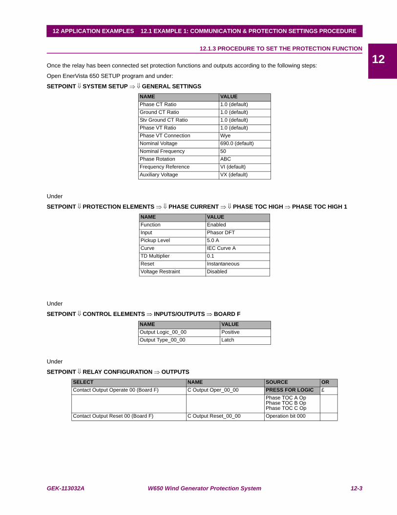
GEK-113032A W650 Wind Generator Protection System 12-3
12 APPLICATION EXAMPLES 12.1 EXAMPLE 1: COMMUNICATION & PROTECTION SETTINGS PROCEDURE
1212.1.3 PROCEDURE TO SET THE PROTECTION FUNCTION
Once the relay has been connected set protection functions and outputs according to the following steps:
Open EnerVista 650 SETUP program and under:
SETPOINT ⇓ SYSTEM SETUP ⇒ ⇓ GENERAL SETTINGS
Under
SETPOINT ⇓ PROTECTION ELEMENTS ⇒ ⇓ PHASE CURRENT ⇒ ⇓ PHASE TOC HIGH ⇒ PHASE TOC HIGH 1
Under
SETPOINT ⇓ CONTROL ELEMENTS ⇒ INPUTS/OUTPUTS ⇒ BOARD F
Under
SETPOINT ⇓ RELAY CONFIGURATION ⇒ OUTPUTS
NAME VALUEPhase CT Ratio 1.0 (default)Ground CT Ratio 1.0 (default)Stv Ground CT Ratio 1.0 (default)Phase VT Ratio 1.0 (default)Phase VT Connection WyeNominal Voltage 690.0 (default)Nominal Frequency 50Phase Rotation ABCFrequency Reference VI (default)Auxiliary Voltage VX (default)
NAME VALUEFunction EnabledInput Phasor DFTPickup Level 5.0 ACurve IEC Curve ATD Multiplier 0.1Reset InstantaneousVoltage Restraint Disabled
NAME VALUEOutput Logic_00_00 PositiveOutput Type_00_00 Latch
SELECT NAME SOURCE ORContact Output Operate 00 (Board F) C Output Oper_00_00 PRESS FOR LOGIC £
Phase TOC A OpPhase TOC B OpPhase TOC C Op
Contact Output Reset 00 (Board F) C Output Reset_00_00 Operation bit 000
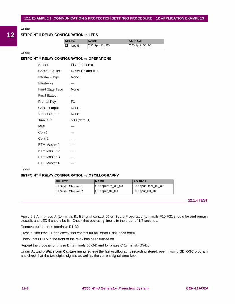
12-4 W650 Wind Generator Protection System GEK-113032A
12.1 EXAMPLE 1: COMMUNICATION & PROTECTION SETTINGS PROCEDURE 12 APPLICATION EXAMPLES
12Under
SETPOINT ⇓ RELAY CONFIGURATION ⇒ LEDS
Under
SETPOINT ⇓ RELAY CONFIGURATION ⇒ OPERATIONS
Select Operation 0
Command Text Reset C Output 00
Interlock Type None
Interlocks ---
Final State Type None
Final States ---
Frontal Key F1
Contact Input None
Virtual Output None
Time Out 500 (default)
MMI ---
Com1 ---
Com 2 ---
ETH-Master 1 ---
ETH Master 2 ---
ETH Master 3 ---
ETH Mastef 4 ---
Under
SETPOINT ⇓ RELAY CONFIGURATION ⇒ OSCILLOGRAPHY
12.1.4 TEST
Apply 7.5 A in phase A (terminals B1-B2) until contact 00 on Board F operates (terminals F19-F21 should be and remainclosed), and LED 5 should be lit. Check that operating time is in the order of 1.7 seconds.
Remove current from terminals B1-B2
Press pushbutton F1 and check that contact 00 on Board F has been open.
Check that LED 5 in the front of the relay has been turned off.
Repeat the process for phase B (terminals B3-B4) and for phase C (terminals B5-B6)
Under Actual ⇓ Waveform Capture menu retrieve the last oscillography recording stored, open it using GE_OSC programand check that the two digital signals as well as the current signal were kept.
SELECT NAME SOURCE Led 5 C Output Op 00 C Output_00_00
SELECT NAME SOURCE Digital Channel 1 C Output Op_00_00 C Output Oper_00_00
Digital Channel 2 C Output_00_00 C Output_00_00

GEK-113032A W650 Wind Generator Protection System 12-5
12 APPLICATION EXAMPLES 12.2 EXAMPLE 2: TOC PROTECTION + RECLOSING SETTINGS PROCEDURE
1212.2EXAMPLE 2: TOC PROTECTION + RECLOSING SETTINGS PROCEDURE
12.2.1 DESCRIPTION OF THE EXERCISE
The purpose of this exercise is to introduce the W650 User about the way to set a protection scheme including:
Trip operation of a phase time overcurrent protection.
Two reclosing shots with successful fault clearing.
Synchronism check action to verify two ends voltage conditions previous to perform each reclosing action.
12.2.2 PROCEDURE TO COMMUNICATE THE RELAY
This procedure is described in Example Nº 1. Therefore check the actual PC communication status to assure a fast andreliable communication with W650 relay.
12.2.3 PROCEDURE TO SET THE PROTECTION FUNCTION
This procedure is fully described in paragraph 13.3 (see Example Nº 1). Therefore it is not necessary to explain it hereagain except about the small modifications required for the actual exercise, as well the additional settings not used untilnow (i.e. recloser and synchrocheck).
Therefore, by having the W650 set like in the previous exercise (paragraph 13), the new settings and changes to be donein the relay to work in a protection-reclosing scheme are:
Under
SETPOINT ⇓ PROTECTION ⇒ ELEMENTS BREAKER ⇒ ⇓ BREAKER SETTINGS
Under
SETPOINT ⇓ CONTROL ELEMENTS ⇒ INPUTS/OUTPUTS ⇒ BOARD F
Under
SETPOINT ⇓ RELAY CONFIGURATION ⇒ PROTECTION ELEMENTS
NAME VALUENumber of Switchgear 1
NAME VALUEOutput Logic_00_00 PositiveVoltage Threshold B_00 80VDebounce Time B_00 10 msInput Type_00_00 (CC1) PositiveDelay Input Time_00_00 (CC1) 0 msOutput Type_00_00 NormalPulse Output Time_00_00 500 ms
SELECT SOURCE ORAR Initiate PRESS FOR LOGIC £
Phase TOC A OpPhase TOC B OpPhase TOC C Op
AR Conds Input Synch Close Perm
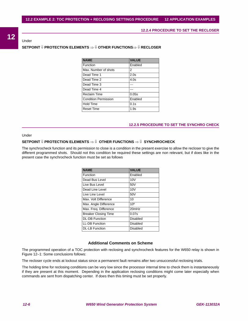
12-6 W650 Wind Generator Protection System GEK-113032A
12.2 EXAMPLE 2: TOC PROTECTION + RECLOSING SETTINGS PROCEDURE 12 APPLICATION EXAMPLES
1212.2.4 PROCEDURE TO SET THE RECLOSER
Under
SETPOINT ⇓ PROTECTION ELEMENTS ⇒ ⇓ OTHER FUNCTIONS⇒ ⇓ RECLOSER
12.2.5 PROCEDURE TO SET THE SYNCHRO CHECK
Under
SETPOINT ⇓ PROTECTION ELEMENTS ⇒ ⇓ OTHER FUNCTIONS ⇒ ⇓ SYNCHROCHECK
The synchrocheck function and its permission to close is a condition in the present exercise to allow the recloser to give thedifferent programmed shots. Should not this condition be required these settings are non relevant, but if does like in thepresent case the synchrocheck function must be set as follows
Additional Comments on SchemeThe programmed operation of a TOC protection with reclosing and synchrocheck features for the W650 relay is shown inFigure 12–1: Some conclusions follows:
The recloser cycle ends at lockout status since a permanent fault remains after two unsuccessful reclosing trials.
The holding time for reclosing conditions can be very low since the processor internal time to check them is instantaneouslyif they are present at this moment. Depending in the application reclosing conditions might come later especially whencommands are sent from dispatching center. If does then this timing must be set properly.
NAME VALUEFunction EnabledMax. Number of shots 2Dead Time 1 2.0sDead Time 2 4.0sDead Time 3 ---Dead Time 4 ---Reclaim Time 0.05sCondition Permission EnabledHold Time 0.1sReset Time 1.9s
NAME VALUEFunction EnabledDead Bus Level 10VLive Bus Level 50VDead Line Level 10VLive Line Level 50VMax. Volt Difference 10Max. Angle Difference 10ºMax. Freq. Difference 20mHzBreaker Closing Time 0.07sDL-DB Function DisabledLL-DB Function DisabledDL-LB Function Disabled
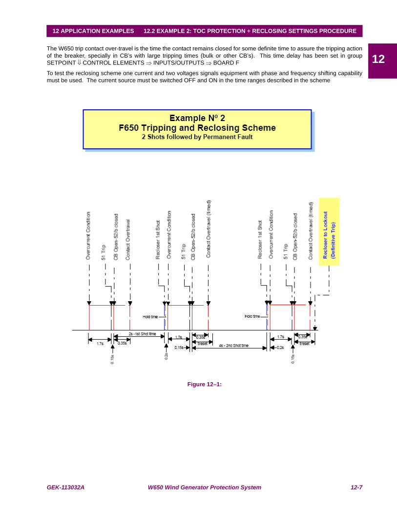
GEK-113032A W650 Wind Generator Protection System 12-7
12 APPLICATION EXAMPLES 12.2 EXAMPLE 2: TOC PROTECTION + RECLOSING SETTINGS PROCEDURE
12The W650 trip contact over-travel is the time the contact remains closed for some definite time to assure the tripping actionof the breaker, specially in CB’s with large tripping times (bulk or other CB’s). This time delay has been set in groupSETPOINT ⇓ CONTROL ELEMENTS ⇒ INPUTS/OUTPUTS ⇒ BOARD F
To test the reclosing scheme one current and two voltages signals equipment with phase and frequency shifting capabilitymust be used. The current source must be switched OFF and ON in the time ranges described in the scheme
Figure 12–1:
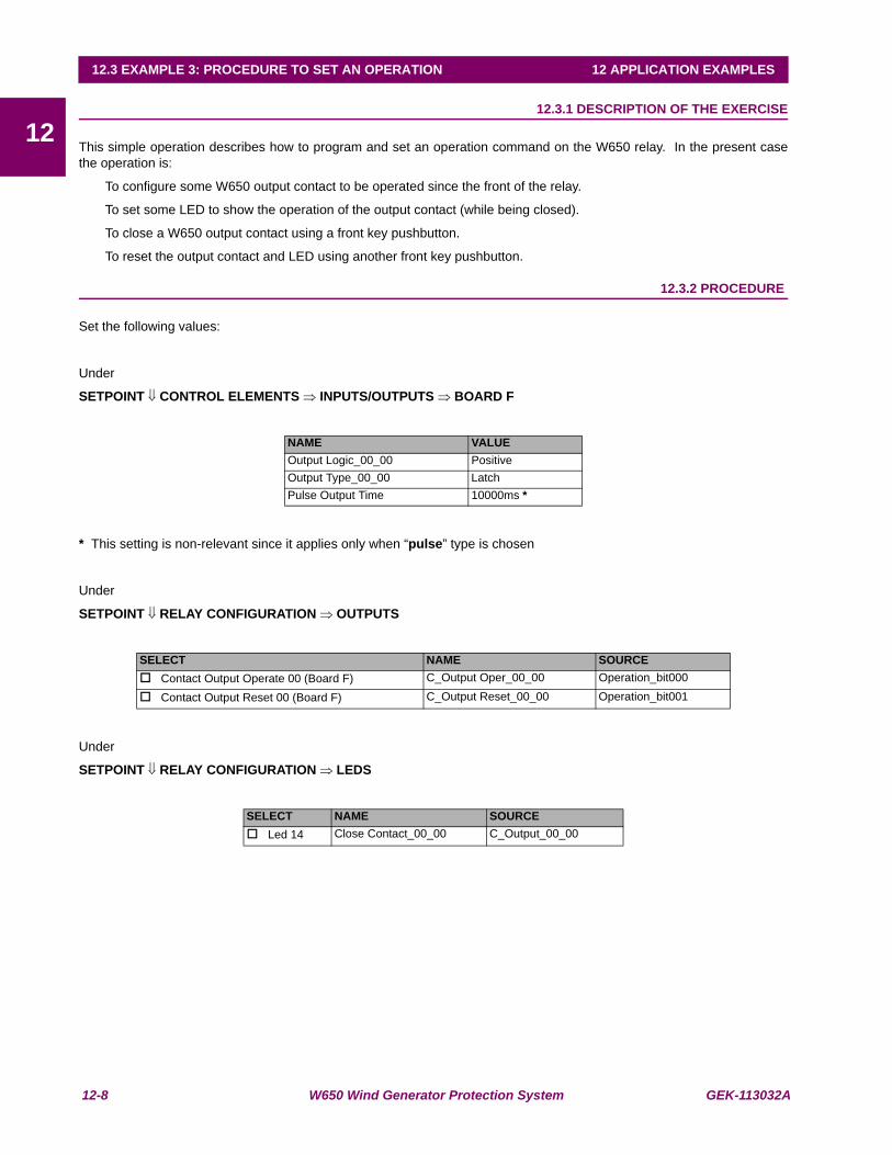
12-8 W650 Wind Generator Protection System GEK-113032A
12.3 EXAMPLE 3: PROCEDURE TO SET AN OPERATION 12 APPLICATION EXAMPLES
1212.3EXAMPLE 3: PROCEDURE TO SET AN OPERATION 12.3.1 DESCRIPTION OF THE EXERCISE
This simple operation describes how to program and set an operation command on the W650 relay. In the present casethe operation is:
To configure some W650 output contact to be operated since the front of the relay.
To set some LED to show the operation of the output contact (while being closed).
To close a W650 output contact using a front key pushbutton.
To reset the output contact and LED using another front key pushbutton.
12.3.2 PROCEDURE
Set the following values:
Under
SETPOINT ⇓ CONTROL ELEMENTS ⇒ INPUTS/OUTPUTS ⇒ BOARD F
* This setting is non-relevant since it applies only when “pulse” type is chosen
Under
SETPOINT ⇓ RELAY CONFIGURATION ⇒ OUTPUTS
Under
SETPOINT ⇓ RELAY CONFIGURATION ⇒ LEDS
NAME VALUEOutput Logic_00_00 PositiveOutput Type_00_00 LatchPulse Output Time 10000ms *
SELECT NAME SOURCE Contact Output Operate 00 (Board F) C_Output Oper_00_00 Operation_bit000
Contact Output Reset 00 (Board F) C_Output Reset_00_00 Operation_bit001
SELECT NAME SOURCE Led 14 Close Contact_00_00 C_Output_00_00

GEK-113032A W650 Wind Generator Protection System 12-9
12 APPLICATION EXAMPLES 12.3 EXAMPLE 3: PROCEDURE TO SET AN OPERATION
12Under
SETPOINT ⇓ RELAY CONFIGURATION ⇒ OPERATIONS
Select Operation 0
Command Text Close C_Output_00_00
Interlock Type None
Interlocks ---
Final State Type None
Final States ---
Frontal Key F2
Contact Input None
Virtual Output None
Time Out 500 (default)
MMI ---
Com1 ---
Com 2 ---
ETH-Master 1 ---
ETH Master 2 ---
ETH Master 3 ---
ETH Mastef 4 ---
In the same window (next rows)
Select Operation 1
Command Text Reset C_Output_00_00
Interlock Type None
Interlocks ---
Final State Type None
Final States ---
Frontal Key F1
Contact Input None
Virtual Output None
Time Out 500 (default)
MMI ---
Com1 ---
Com 2 ---
ETH-Master 1 ---
ETH Master 2 ---
ETH Master 3 ---
ETH Mastef 4 ---

12-10 W650 Wind Generator Protection System GEK-113032A
12.3 EXAMPLE 3: PROCEDURE TO SET AN OPERATION 12 APPLICATION EXAMPLES
1212.3.3 TEST
In the main front screen press F2 key.
A message showing “Press Intro to Confirm Key →F2←” will be displayed.
Press down the rotary knob.
Check that contact_00_00 (board F) has been closed.
Check that the front LED 14th is lit.
In the main front screen press F1 key.
A message showing “Press Intro to Confirm Key →F1←” will be displayed.
Press down the rotary knob.
Check that contact_00_00 (board F) has been opened.
Check that the front LED 14th has been switched off

GEK-113032A W650 Wind Generator Protection System 13-1
13 FREQUENTLY ASKED QUESTIONS 13.1 COMMUNICATIONS
13
13 FREQUENTLY ASKED QUESTIONS 13.1COMMUNICATIONSQ1 Does the W650 support DNP and ModBus over the Ethernet port?
A1 W650 units support both protocols over both the asynchronous serial ports and the Ethernet LAN synchronous portusing TCP/IP and UDP/IP layers over the Ethernet.
Q2 Does this equipment support dual IP access?
A1 Yes, it supports two independent IP addresses in aliasing mode. Those address go in the communications settingsNetwork0 and Network1.
Q3 Is the protocol IEC 870-103 supported by the W650?
A3 At this moment it is not supported.
Q4 Can the W650 be used as a DNP master station?
A4 Not at this moment. It works as a slave IED station for all protocols.
Q5 How many communication ports are included in the W650?
A5 The equipment has 2 different boards, one for asynchronous serial ports and another for a high-speed synchronousEthernet port. The first board has 2 comm ports, COM1 and COM2. COM2 is multiplexed with the front serial RS232port, whereas the COM1 port is completely independent from COM2.
The synchronous LAN port is COM3.
Q6 Are there one or two Ethernet ports?
A6 The equipment has only 1 Ethernet port. For redundant fiber optic versions, redundancy is done at the physical level(fiber optic) but there is just one port.
Q7 How many different communication Ethernet sessions can be opened through the LAN port?
A7 ModBus TCP/IP:4 sockets
DNP TCP/IP:3 sessions
Q8 May I use the cooper 10/100 BaseTX connection included in the basic model with all protocols?
A8 Yes, it may be used with all protocols. In noisy substation environments and/or long distances, it is recommended touse fiber optic options due to much better EMC performance and immunity. For fiber optic models, it is necessary toadjust an internal jumper to use the copper port.
Q9 Remote I/O CAN bus. Does it support DeviceNet protocol?
A9 No it does not support DeviceNet.
Q10 Which functions are available in the relay web server?
A10 Currently, it includes several functions for viewing measures and retrieving information.
Q11 What is the web site user password and name?
A11 The password is: 7169 and user name is: GE

13-2 W650 Wind Generator Protection System GEK-113032A
13.1 COMMUNICATIONS 13 FREQUENTLY ASKED QUESTIONS
13
Q12 May I use URPC to program the relay?
A12 Only oscillography records may be viewed with URPC once downloaded to a file using the ENERVISTA 650 Setupsoftware.
Q13 May I connect URs and W650s to the same Ethernet?
A13 Yes, either in cable as in fiber, or even mix them.
Q14 How do I connect with fiber 10-BASE-FL UR relays with 100-BASE-FX W650 relays?
A14 Take into account that an UR is never connected directly to a W650 (neither two UR nor two W650 with each other)but they are always connected through a hub or switch. The hub or switch where the URs are connected must be10-BASE-FL and the hub or switch for the W650 must be 100-BASE-FX.
Q15 How do I connect with cable 10_BASE-T UR relays with 10/100-BASE-TX W650 relays?
A15 The answer to this question is as described before but also in this case there is an advantage added, because thehub 10-BASE-TX port is able to understand a 10-BASE-T port. This means that a hub 10-BASE-T port may beconnected to an UR or a W650, and a hub 10/100-BASE-TX port may be connected either to an UR or W650.
Q16 What happens with fiber optic connectors compatibility, because the hub that I have has a differentconnector to the one of the W650, although both are 100-BASE-FX?
A16 Just buy fiber cables with the appropriate male connectors. For the UR and W650 side we need the sameconnectors, ST type, for the hub side, the correspondent ones. And in what concerns to the fiber type, it is used thesame for 10 as for 100, it is the 50/125 or 62.5/125 multimode, this last one allows longer distances.
Q17What is the difference between a hub and a switch?
A17 In a repeater type hub (shared hub), one unit talks and the rest listen. If all the units are talking at the same timethere may be collisions in the messages, what may produce certain communication delays.
The switch (switched hub) has very powerful processors and a lot of memory and it is much more expensive thanthe hub. It directs messages to the proper destination avoiding collisions and allowing a much more efficientcommunication.
Q18 Why do we have 10/100 compatibility for cable but not for fiber?
A18 The cable has some advantages that the fiber does not have, and it is that the signal attenuation in short andmedium distances, is worthless and this is truth for low and high frequency signals. By the contrary, the light in onefiber optic is highly attenuated, being much worse in case of high frequencies than in the low ones. The 10-BASE-FLfiber transmission is performed in a wavelength of 850nm, what allows a less expensive electronic than the 1300 nmused in 100-BASE-FX fiber transmission. Using, in both cases, the same glass multimode fiber type, the attenuationto 1300 nm is lower than the 850 nm ones, this way the greater attenuation of the 100 Mbits is compensated. Thereis another fiber standard, the 100-BASE-SX, which uses 850 nm to 100 Mbits, being compatible with the 10-BASE-FL one, although it sacrifices the maximum distance to 300 m. Nowadays, this standard has not had success amongEthernet equipment manufacturers and suppliers.

GEK-113032A W650 Wind Generator Protection System 13-3
13 FREQUENTLY ASKED QUESTIONS 13.2 PROTECTION
13
13.2PROTECTION
Q1 Does the W650 support IRIG-B signals? Which type and accuracy? How many units may be connected tothe same source?
A1 Yes, the W650 includes an IRIG-B input for all models, including the basic ones.
It uses DC level format B. Formats used are B0000, B0002 and B0003.
Actual accuracy is 1 millisecond. Internal sampling rate allows true 1 ms accuracy time tagging.
The input burden is very low. The maximum number of units that may be connected to a generator depends on itsoutput driving capability. Up to 60 units have been successfully connected with equipments commonly used in themarket.
Q2 Does the equipment work with dry inputs in both AC and DC?
A2 The equipment works only with DC inputs.
Inputs should be driven with externally generated DC current. No special 48 Vdc or other outputs are included in theequipment to drive these inputs; therefore, contacts connected to the equipment should be connected to a DCsource.
Q3 Is oscillography programmable?
A3 Yes, the sampling rate is programmable (4, 8, 16, 32 or 64 samples per input). The depth will depend on thesampling rate.
Q4 Do I have to select a different model for 1 or 5 A?
A4 No. The same model is able to work with either /1 A or /5 A rated secondary currents. There are high accuracysensing transformers that allow the use of any current input through the same terminals to reduce the spares andsimplify wiring.
Q5 In my installation, several digital inputs become active when I energize the transformer. How can I reducesensitivity?
A5 By selecting debounce time and/or voltage threshold, the relay may adapt its sensitivity to different applications.Please select the maximum voltage threshold and debounce time (recommended 15 ms) to minimize AC couplingeffects.

13-4 W650 Wind Generator Protection System GEK-113032A
13.3 CONTROL AND HMI 13 FREQUENTLY ASKED QUESTIONS
13
13.3CONTROL AND HMI
Q1 What is the difference between Get/Send info from/to relay and Upload/Download info files to/from relay?
A1 Get/Send are used for settings and configuration storage that although both are in a unique file, are sent separatelyin two times. Upload/Download are used for project or PLC files group storage. These files are thesetting_configuration file source. To operate, the W650 does not need the source files; the Upload/Download tool isdestined to serve as historic file.
Q2 Could I program interlocks?
A2 Yes, via ENERVISTA 650 Setup interlocks may be programmed from very simple to advanced schemes.
Q3 Can we rotate the display 90 degrees to show feeders vertically?
A3 No. The product has been designed to view it in horizontal mode (landscape) due to the following reasons:
It is easier to read the LCD display because it has been designed for horizontal positions.
Compatibility between text display (4x20 characters) and LCD display (16x40 characters or 128x240 pixels).
Refresh speed is better in horizontal than vertical format.
Q4 Do I need a laptop or handheld to program the unit?
A4 No, all main operations can easily be performed with just the incorporated HMI. Handheld or laptops may berequired to download large quantities of information (such as oscillograms, etc.) but they are not mandatory for aconventional user that just needs to change settings, view measurements, states, etc.
Q5 Is there password security for protection and control?
A5 Yes, there are two passwords. An independent password for protection changes and control operations is available.
Q6 Is it possible to have a remote HMI installed in the front of the panel with the rest of the relay in the rearside?
A6 Not in the present version.
Q7 Is it possible to program a default screen for the HMI?
A7 In graphic display versions the user may program a custom screen with the single-line diagram, measurements, etc.In text display models, there is a choice of logo, measurements, or scrolling both screens.
Q8 May I force inputs and outputs to ease commissioning and testing?
A8 Yes.
Q9 How can I disable the rotary knob buzzer?
A9 Press ESC key more than 3 seconds and then press the knob during a short pulse.
Q10 Why do appear strange texts on the display when switching on the relay?
A10 You will have pressed any button and the HMI has entered in a test mode.
The display messages are updated after a few minutes, once the relay has completed the starting sequence.

GEK-113032A W650 Wind Generator Protection System 13-5
13 FREQUENTLY ASKED QUESTIONS 13.4 RELAY CONFIGURATION
13
13.4RELAY CONFIGURATION
Q1 Does the "Service" contact on the Power Supply board cover all possible failures or do I have to create anoutput on the I/O board that includes all the internal errors I can access in the logic?
A1 The power supply ready contact only monitor hardware failures in the power supply, to monitor the internal error ofthe unit it is necessary to configure a virtual output to and the assign it to the device desired (contact output, LED,etc.).
Q2 I set an output contact as "Latched". If I do not set a "reset" condition, will it reset from the "ESC" key?
A2 No, you have to configure the contact output reset signal (in Settings>Relay Configuration>Outputs). The ESCkey only reset the LED indicators.

13-6 W650 Wind Generator Protection System GEK-113032A
13.4 RELAY CONFIGURATION 13 FREQUENTLY ASKED QUESTIONS
13
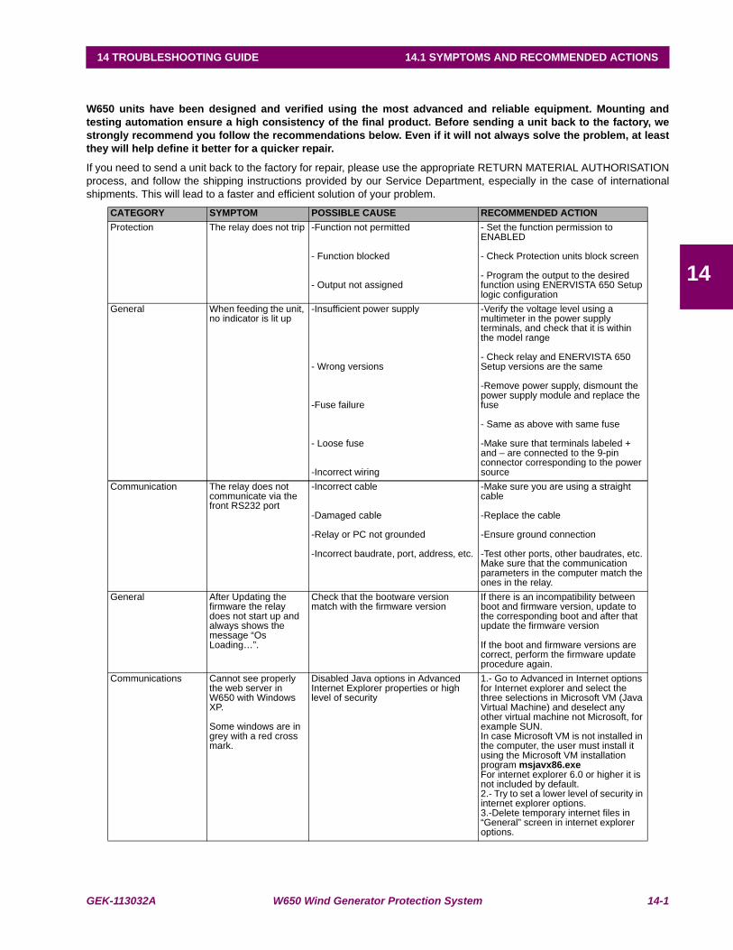
GEK-113032A W650 Wind Generator Protection System 14-1
14 TROUBLESHOOTING GUIDE 14.1 SYMPTOMS AND RECOMMENDED ACTIONS
14
14 TROUBLESHOOTING GUIDE 14.1SYMPTOMS AND RECOMMENDED ACTIONS
W650 units have been designed and verified using the most advanced and reliable equipment. Mounting andtesting automation ensure a high consistency of the final product. Before sending a unit back to the factory, westrongly recommend you follow the recommendations below. Even if it will not always solve the problem, at leastthey will help define it better for a quicker repair.
If you need to send a unit back to the factory for repair, please use the appropriate RETURN MATERIAL AUTHORISATIONprocess, and follow the shipping instructions provided by our Service Department, especially in the case of internationalshipments. This will lead to a faster and efficient solution of your problem.
CATEGORY SYMPTOM POSSIBLE CAUSE RECOMMENDED ACTIONProtection The relay does not trip -Function not permitted
- Function blocked
- Output not assigned
- Set the function permission to ENABLED
- Check Protection units block screen
- Program the output to the desired function using ENERVISTA 650 Setup logic configuration
General When feeding the unit, no indicator is lit up
-Insufficient power supply
- Wrong versions
-Fuse failure
- Loose fuse
-Incorrect wiring
-Verify the voltage level using a multimeter in the power supply terminals, and check that it is within the model range
- Check relay and ENERVISTA 650 Setup versions are the same
-Remove power supply, dismount the power supply module and replace the fuse
- Same as above with same fuse
-Make sure that terminals labeled + and – are connected to the 9-pin connector corresponding to the power source
Communication The relay does not communicate via the front RS232 port
-Incorrect cable
-Damaged cable
-Relay or PC not grounded
-Incorrect baudrate, port, address, etc.
-Make sure you are using a straight cable
-Replace the cable
-Ensure ground connection
-Test other ports, other baudrates, etc. Make sure that the communication parameters in the computer match the ones in the relay.
General After Updating the firmware the relay does not start up and always shows the message “Os Loading…”.
Check that the bootware version match with the firmware version
If there is an incompatibility between boot and firmware version, update to the corresponding boot and after that update the firmware version
If the boot and firmware versions are correct, perform the firmware update procedure again.
Communications Cannot see properly the web server in W650 with Windows XP.
Some windows are in grey with a red cross mark.
Disabled Java options in Advanced Internet Explorer properties or high level of security
1.- Go to Advanced in Internet options for Internet explorer and select the three selections in Microsoft VM (Java Virtual Machine) and deselect any other virtual machine not Microsoft, for example SUN.In case Microsoft VM is not installed in the computer, the user must install it using the Microsoft VM installation program msjavx86.exeFor internet explorer 6.0 or higher it is not included by default.2.- Try to set a lower level of security in internet explorer options.3.-Delete temporary internet files in “General” screen in internet explorer options.

14-2 W650 Wind Generator Protection System GEK-113032A
14.1 SYMPTOMS AND RECOMMENDED ACTIONS 14 TROUBLESHOOTING GUIDE
14
Communication Enervista 650 Setup does not retrieve osc, fault reports and Data Logger files
Bad communication in TFTP using Windows 2000
Disable and Enable the Ethernet connection on Control Panel inside Windows 2000. Try again to retrieve files from relay
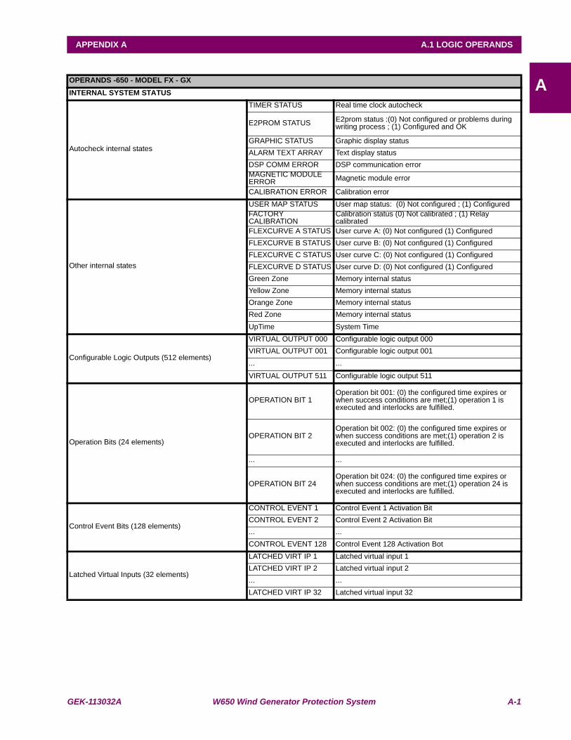
GEK-113032A W650 Wind Generator Protection System A-1
APPENDIX A A.1 LOGIC OPERANDS
AAPPENDIX A LOGIC OPERANDSA.1LOGIC OPERANDSOPERANDS -650 - MODEL FX - GXINTERNAL SYSTEM STATUS
Autocheck internal states
TIMER STATUS Real time clock autocheck
E2PROM STATUS E2prom status :(0) Not configured or problems during writing process ; (1) Configured and OK
GRAPHIC STATUS Graphic display statusALARM TEXT ARRAY Text display statusDSP COMM ERROR DSP communication errorMAGNETIC MODULE ERROR Magnetic module error
CALIBRATION ERROR Calibration error
Other internal states
USER MAP STATUS User map status: (0) Not configured ; (1) ConfiguredFACTORY CALIBRATION
Calibration status (0) Not calibrated ; (1) Relay calibrated
FLEXCURVE A STATUS User curve A: (0) Not configured (1) ConfiguredFLEXCURVE B STATUS User curve B: (0) Not configured (1) ConfiguredFLEXCURVE C STATUS User curve C: (0) Not configured (1) ConfiguredFLEXCURVE D STATUS User curve D: (0) Not configured (1) ConfiguredGreen Zone Memory internal statusYellow Zone Memory internal statusOrange Zone Memory internal statusRed Zone Memory internal statusUpTime System Time
Configurable Logic Outputs (512 elements)
VIRTUAL OUTPUT 000 Configurable logic output 000VIRTUAL OUTPUT 001 Configurable logic output 001... ...
VIRTUAL OUTPUT 511 Configurable logic output 511
Operation Bits (24 elements)
OPERATION BIT 1Operation bit 001: (0) the configured time expires or when success conditions are met;(1) operation 1 is executed and interlocks are fulfilled.
OPERATION BIT 2Operation bit 002: (0) the configured time expires or when success conditions are met;(1) operation 2 is executed and interlocks are fulfilled.
... ...
OPERATION BIT 24Operation bit 024: (0) the configured time expires or when success conditions are met;(1) operation 24 is executed and interlocks are fulfilled.
Control Event Bits (128 elements)
CONTROL EVENT 1 Control Event 1 Activation BitCONTROL EVENT 2 Control Event 2 Activation Bit... ...CONTROL EVENT 128 Control Event 128 Activation Bot
Latched Virtual Inputs (32 elements)
LATCHED VIRT IP 1 Latched virtual input 1LATCHED VIRT IP 2 Latched virtual input 2... ...LATCHED VIRT IP 32 Latched virtual input 32
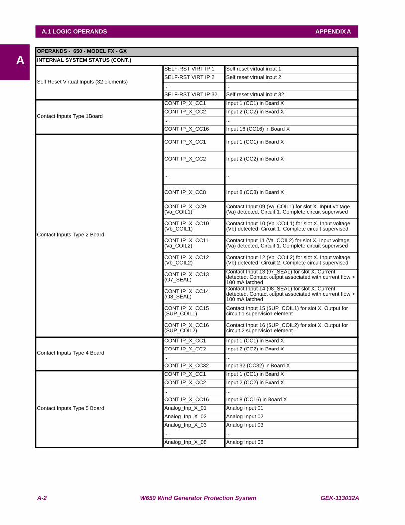
A-2 W650 Wind Generator Protection System GEK-113032A
A.1 LOGIC OPERANDS APPENDIX A
AOPERANDS - 650 - MODEL FX - GXINTERNAL SYSTEM STATUS (CONT.)
Self Reset Virtual Inputs (32 elements)
SELF-RST VIRT IP 1 Self reset virtual input 1SELF-RST VIRT IP 2 Self reset virtual input 2... ...SELF-RST VIRT IP 32 Self reset virtual input 32
Contact Inputs Type 1Board
CONT IP_X_CC1 Input 1 (CC1) in Board XCONT IP_X_CC2 Input 2 (CC2) in Board X... ...CONT IP_X_CC16 Input 16 (CC16) in Board X
Contact Inputs Type 2 Board
CONT IP_X_CC1 Input 1 (CC1) in Board X
CONT IP_X_CC2 Input 2 (CC2) in Board X
... ...
CONT IP_X_CC8 Input 8 (CC8) in Board X
CONT IP_X_CC9 (Va_COIL1)
Contact Input 09 (Va_COIL1) for slot X. Input voltage (Va) detected, Circuit 1. Complete circuit supervised
CONT IP_X_CC10 (Vb_COIL1)
Contact Input 10 (Vb_COIL1) for slot X. Input voltage (Vb) detected, Circuit 1. Complete circuit supervised
CONT IP_X_CC11 (Va_COIL2)
Contact Input 11 (Va_COIL2) for slot X. Input voltage (Va) detected, Circuit 1. Complete circuit supervised
CONT IP_X_CC12 (Vb_COIL2)
Contact Input 12 (Vb_COIL2) for slot X. Input voltage (Vb) detected, Circuit 2. Complete circuit supervised
CONT IP_X_CC13 (O7_SEAL)
Contact Input 13 (07_SEAL) for slot X. Current detected. Contact output associated with current flow > 100 mA latched
CONT IP_X_CC14 (O8_SEAL)
Contact Input 14 (08_SEAL) for slot X. Current detected. Contact output associated with current flow > 100 mA latched
CONT IP_X_CC15 (SUP_COIL1)
Contact Input 15 (SUP_COIL1) for slot X. Output for circuit 1 supervision element
CONT IP_X_CC16 (SUP_COIL2)
Contact Input 16 (SUP_COIL2) for slot X. Output for circuit 2 supervision element
Contact Inputs Type 4 Board
CONT IP_X_CC1 Input 1 (CC1) in Board XCONT IP_X_CC2 Input 2 (CC2) in Board X... ...CONT IP_X_CC32 Input 32 (CC32) in Board X
Contact Inputs Type 5 Board
CONT IP_X_CC1 Input 1 (CC1) in Board XCONT IP_X_CC2 Input 2 (CC2) in Board X... ...CONT IP_X_CC16 Input 8 (CC16) in Board XAnalog_Inp_X_01 Analog Input 01Analog_Inp_X_02 Analog Input 02Analog_Inp_X_03 Analog Input 03... ...Analog_Inp_X_08 Analog Input 08
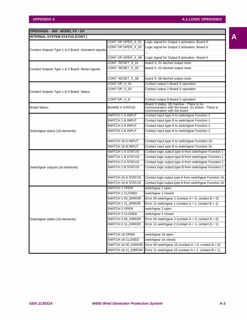
GEK-113032A W650 Wind Generator Protection System A-3
APPENDIX A A.1 LOGIC OPERANDS
AOPERANDS - 650 - MODEL FX - GXINTERNAL SYSTEM STATUS (CONT.)
Contact Outputs Type 1 & 2 Board Activation signals
CONT OP OPER_X_01 Logic signal for Output 1 activation. Board XCONT OP OPER_X_02 Logic signal for Output 2 activation. Board X... ...CONT OP OPER_X_08 Logic signal for Output 8 activation. Board X
Contact Outputs Type 1 & 2 Board Reset signals
CONT RESET_X_01 board X, 01 latched output resetCONT RESET_X_02 board X, 02 latched output reset... ...CONT RESET_X_08 board X, 08 latched output reset
Contact Outputs Type 1 & 2 Board Status
CONT OP_X_01 Contact output 1 Board X operationCONT OP_X_02 Contact output 2 Board X operation... ...CONT OP_X_8 Contact output 8 Board X operation
Board Status BOARD X STATUSBoard X status: (0) Inactive - There is no communication with the board (1) Active - There is communication with the board
Switchgear status (16 elements)
SWITCH 1 A INPUT Contact input type A to switchgear Function 1SWITCH 1 B INPUT Contact input type B to switchgear Function 1SWITCH 2 A INPUT Contact input type A to switchgear Function 2SWITCH 2 B INPUT Contact input type B to switchgear Function 2... ...SWITCH 16 A INPUT Contact input type A to switchgear Function 16SWITCH 16 B INPUT Contact input type B to switchgear Function 16
Switchgear outputs (16 elements)
SWITCH 1 A STATUS Contact logic output type A from switchgear Function 1 SWITCH 1 B STATUS Contact logic output type B from switchgear Function 1 SWITCH 2 A STATUS Contact logic output type A from switchgear Function 2 SWITCH 2 B STATUS Contact logic output type B from switchgear Function 2 ... ...SWITCH 16 A STATUS Contact logic output type A from switchgear Function 16 SWITCH 16 B STATUS Contact logic output type B from switchgear Function 16
Switchgear states (16 elements)
SWITCH 1 OPEN switchgear 1 openSWITCH 1 CLOSED switchgear 1 closedSWITCH 1 00_ERROR Error 00 switchgear 1 (contact A = 0, contact B = 0)SWITCH 1 11_ERROR Error 11 switchgear 1 (contact A = 1, contact B = 1)SWITCH 2 OPEN switchgear 2 openSWITCH 2 CLOSED switchgear 2 closedSWITCH 2 00_ERROR Error 00 switchgear 2 (contact A = 0, contact B = 0)SWITCH 2 11_ERROR Error 11 switchgear 2 (contact A = 1, contact B = 1)... ...SWITCH 16 OPEN switchgear 16 openSWITCH 16 CLOSED switchgear 16 closedSWITCH 16 00_ERROR Error 00 switchgear 16 (contact A = 0, contact B = 0)SWITCH 16 11_ERROR Error 11 switchgear 16 (contact A = 1, contact B = 1)
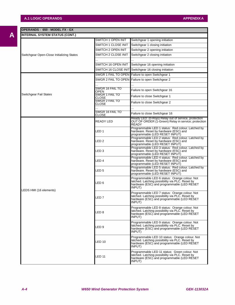
A-4 W650 Wind Generator Protection System GEK-113032A
A.1 LOGIC OPERANDS APPENDIX A
AOPERANDS - 650 - MODEL FX - GXINTERNAL SYSTEM STATUS (CONT.)
Switchgear Open-Close Initializing States
SWITCH 1 OPEN INIT Switchgear 1 opening initiationSWITCH 1 CLOSE INIT Switchgear 1 closing initiationSWITCH 2 OPEN INIT Switchgear 2 opening initiationSWITCH 2 CLOSE INIT Switchgear 2 closing initiation... ...SWITCH 16 OPEN INIT Switchgear 16 opening initiationSWITCH 16 CLOSE INIT Switchgear 16 closing initiation
Switchgear Fail States
SWGR 1 FAIL TO OPEN Failure to open Switchgear 1SWGR 2 FAIL TO OPEN Failure to open Switchgear 2... ...SWGR 16 FAIL TO OPEN Failure to open Switchgear 16SWGR 1 FAIL TO CLOSE Failure to close Switchgear 1SWGR 2 FAIL TO CLOSE Failure to close Switchgear 2
... ...SWGR 16 FAIL TO CLOSE Failure to close Switchgear 16
LEDS HMI (16 elements)
READY LEDReady LED: (0-Rojo) Relay out of service, protection OUT OF ORDER (1-Green) Relay in service; protection READY
LED 1Programmable LED 1 status: Red colour. Latched by hardware. Reset by hardware (ESC) and programmable (LED RESET INPUT)
LED 2Programmable LED 2 status: Red colour. Latched by hardware. Reset by hardware (ESC) and programmable (LED RESET INPUT)
LED 3Programmable LED 3 status: Red colour. Latched by hardware. Reset by hardware (ESC) and programmable (LED RESET INPUT)
LED 4Programmable LED 4 status: Red colour. Latched by hardware. Reset by hardware (ESC) and programmable (LED RESET INPUT)
LED 5Programmable LED 5 status: Red colour. Latched by hardware. Reset by hardware (ESC) and programmable (LED RESET INPUT)
LED 6Programmable LED 6 status: Orange colour. Not latched. Latching possibility via PLC. Reset by hardware (ESC) and programmable (LED RESET INPUT)
LED 7Programmable LED 7 status: Orange colour. Not latched. Latching possibility via PLC. Reset by hardware (ESC) and programmable (LED RESET INPUT)
LED 8Programmable LED 8 status: Orange colour. Not latched. Latching possibility via PLC. Reset by hardware (ESC) and programmable (LED RESET INPUT)
LED 9Programmable LED 9 status: Orange colour. Not latched. Latching possibility via PLC. Reset by hardware (ESC) and programmable (LED RESET INPUT)
LED 10Programmable LED 10 status: Orange colour. Not latched. Latching possibility via PLC. Reset by hardware (ESC) and programmable (LED RESET INPUT)
LED 11Programmable LED 11 status: Green colour. Not latched. Latching possibility via PLC. Reset by hardware (ESC) and programmable (LED RESET INPUT)
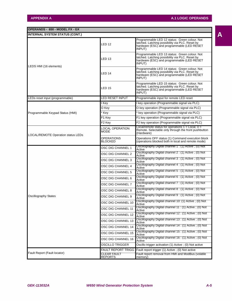
GEK-113032A W650 Wind Generator Protection System A-5
APPENDIX A A.1 LOGIC OPERANDS
AOPERANDS - 650 - MODEL FX - GXINTERNAL SYSTEM STATUS (CONT.)
LEDS HMI (16 elements)
LED 12Programmable LED 12 status: Green colour. Not latched. Latching possibility via PLC. Reset by hardware (ESC) and programmable (LED RESET INPUT)
LED 13Programmable LED 13 status: Green colour. Not latched. Latching possibility via PLC. Reset by hardware (ESC) and programmable (LED RESET INPUT)
LED 14Programmable LED 14 status: Green colour. Not latched. Latching possibility via PLC. Reset by hardware (ESC) and programmable (LED RESET INPUT)
LED 15Programmable LED 15 status: Green colour. Not latched. Latching possibility via PLC. Reset by hardware (ESC) and programmable (LED RESET INPUT)
LEDs reset input (programmable) LED RESET INPUT Programmable input for remote LED reset
Programmable Keypad Status (HMI)
I Key I key operation (Programmable signal via PLC)O Key O key operation (Programmable signal via PLC)* Key * key operation (Programmable signal via PLC)F1 Key F1 key operation (Programmable signal via PLC)F2 Key F2 key operation (Programmable signal via PLC)
LOCAL/REMOTE Operation status LEDs
LOCAL OPERATION MODE
Local/remote status for operations 1 = Local, 0 = Remote. Selectable only through the front pushbutton (Hardware)
OPERATIONS BLOCKED
Operations OFF status (1) Command execution block (operations blocked both in local and remote mode)
Oscillography States
OSC DIG CHANNEL 1 Oscillography Digital channel 1 : (1) Active ; (0) Not Active
OSC DIG CHANNEL 2 Oscillography Digital channel 2 : (1) Active ; (0) Not Active
OSC DIG CHANNEL 3 Oscillography Digital channel 3 : (1) Active ; (0) Not Active
OSC DIG CHANNEL 4 Oscillography Digital channel 4 : (1) Active ; (0) Not Active
OSC DIG CHANNEL 5 Oscillography Digital channel 5 : (1) Active ; (0) Not Active
OSC DIG CHANNEL 6 Oscillography Digital channel 6 : (1) Active ; (0) Not Active
OSC DIG CHANNEL 7 Oscillography Digital channel 7 : (1) Active ; (0) Not Active
OSC DIG CHANNEL 8 Oscillography Digital channel 8 : (1) Active ; (0) Not Active
OSC DIG CHANNEL 9 Oscillography Digital channel 9 : (1) Active ; (0) Not Active
OSC DIG CHANNEL 10 Oscillography Digital channel 10: (1) Active ; (0) Not Active
OSC DIG CHANNEL 11 Oscillography Digital channel 11 : (1) Active ; (0) Not Active
OSC DIG CHANNEL 12 Oscillography Digital channel 12 : (1) Active ; (0) Not Active
OSC DIG CHANNEL 13 Oscillography Digital channel 13 : (1) Active ; (0) Not Active
OSC DIG CHANNEL 14 Oscillography Digital channel 14 : (1) Active ; (0) Not Active
OSC DIG CHANNEL 15 Oscillography Digital channel 15 : (1) Active ; (0) Not Active
OSC DIG CHANNEL 16 Oscillography Digital channel 16 : (1) Active ; (0) Not Active
OSCILLO TRIGGER Oscillo trigger activation (1) Active ; (0) Not active
Fault Report (Fault locator)FAULT REPORT TRIGG Fault report trigger (1) Active ; (0) Not activeCLEAR FAULT REPORTS
Fault report removal from HMI and ModBus (volatile memory)
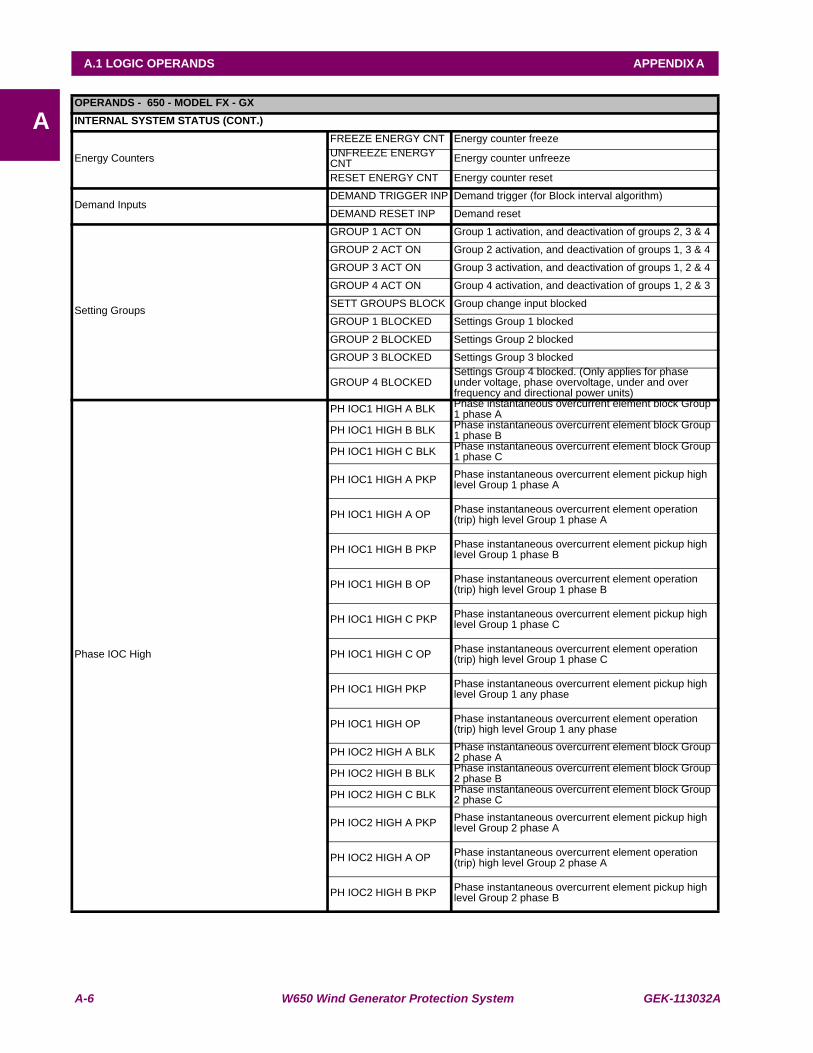
A-6 W650 Wind Generator Protection System GEK-113032A
A.1 LOGIC OPERANDS APPENDIX A
AOPERANDS - 650 - MODEL FX - GXINTERNAL SYSTEM STATUS (CONT.)
Energy Counters
FREEZE ENERGY CNT Energy counter freezeUNFREEZE ENERGY CNT Energy counter unfreeze
RESET ENERGY CNT Energy counter reset
Demand InputsDEMAND TRIGGER INP Demand trigger (for Block interval algorithm)
DEMAND RESET INP Demand reset
Setting Groups
GROUP 1 ACT ON Group 1 activation, and deactivation of groups 2, 3 & 4
GROUP 2 ACT ON Group 2 activation, and deactivation of groups 1, 3 & 4
GROUP 3 ACT ON Group 3 activation, and deactivation of groups 1, 2 & 4
GROUP 4 ACT ON Group 4 activation, and deactivation of groups 1, 2 & 3
SETT GROUPS BLOCK Group change input blocked
GROUP 1 BLOCKED Settings Group 1 blocked
GROUP 2 BLOCKED Settings Group 2 blocked
GROUP 3 BLOCKED Settings Group 3 blocked
GROUP 4 BLOCKEDSettings Group 4 blocked. (Only applies for phase under voltage, phase overvoltage, under and over frequency and directional power units)
Phase IOC High
PH IOC1 HIGH A BLK Phase instantaneous overcurrent element block Group 1 phase A
PH IOC1 HIGH B BLK Phase instantaneous overcurrent element block Group 1 phase B
PH IOC1 HIGH C BLK Phase instantaneous overcurrent element block Group 1 phase C
PH IOC1 HIGH A PKP Phase instantaneous overcurrent element pickup high level Group 1 phase A
PH IOC1 HIGH A OP Phase instantaneous overcurrent element operation (trip) high level Group 1 phase A
PH IOC1 HIGH B PKP Phase instantaneous overcurrent element pickup high level Group 1 phase B
PH IOC1 HIGH B OP Phase instantaneous overcurrent element operation (trip) high level Group 1 phase B
PH IOC1 HIGH C PKP Phase instantaneous overcurrent element pickup high level Group 1 phase C
PH IOC1 HIGH C OP Phase instantaneous overcurrent element operation (trip) high level Group 1 phase C
PH IOC1 HIGH PKP Phase instantaneous overcurrent element pickup high level Group 1 any phase
PH IOC1 HIGH OP Phase instantaneous overcurrent element operation (trip) high level Group 1 any phase
PH IOC2 HIGH A BLK Phase instantaneous overcurrent element block Group 2 phase A
PH IOC2 HIGH B BLK Phase instantaneous overcurrent element block Group 2 phase B
PH IOC2 HIGH C BLK Phase instantaneous overcurrent element block Group 2 phase C
PH IOC2 HIGH A PKP Phase instantaneous overcurrent element pickup high level Group 2 phase A
PH IOC2 HIGH A OP Phase instantaneous overcurrent element operation (trip) high level Group 2 phase A
PH IOC2 HIGH B PKP Phase instantaneous overcurrent element pickup high level Group 2 phase B
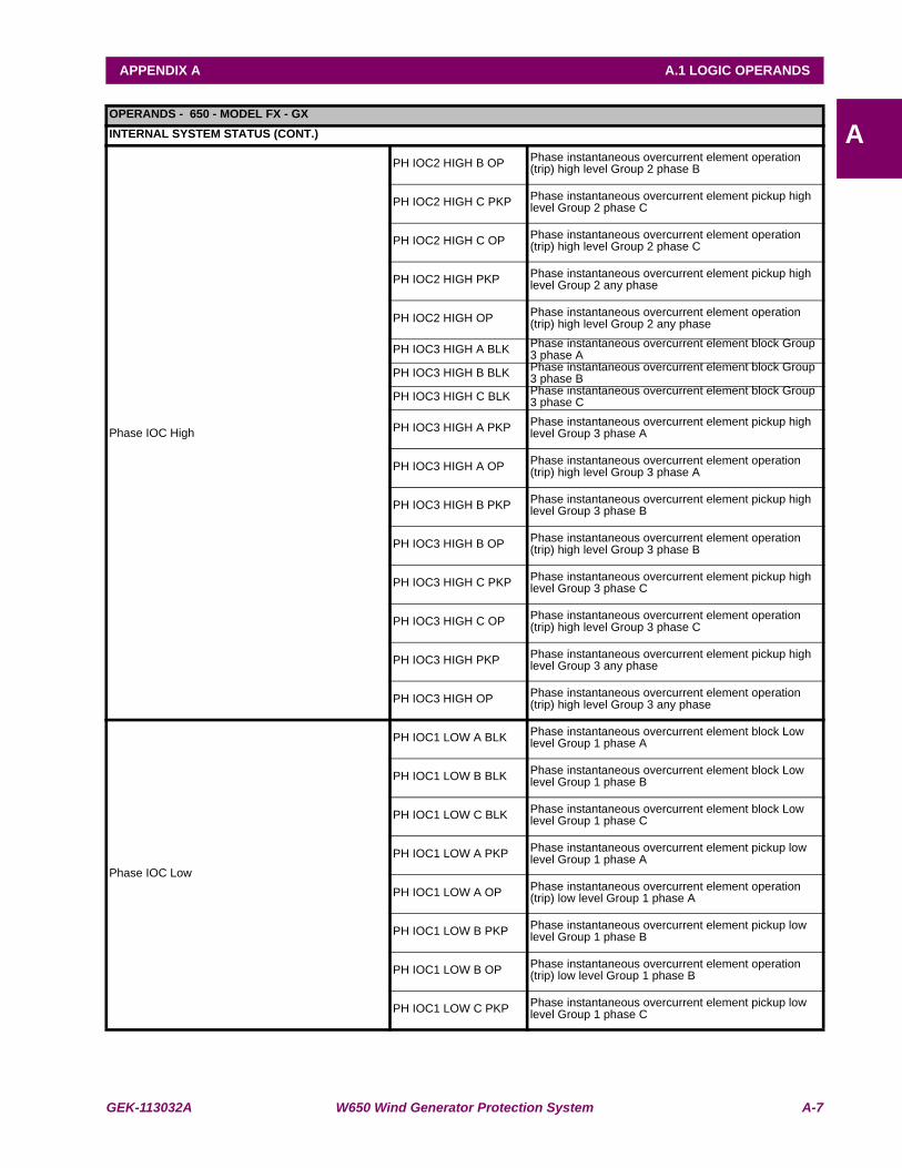
GEK-113032A W650 Wind Generator Protection System A-7
APPENDIX A A.1 LOGIC OPERANDS
AOPERANDS - 650 - MODEL FX - GXINTERNAL SYSTEM STATUS (CONT.)
Phase IOC High
PH IOC2 HIGH B OP Phase instantaneous overcurrent element operation (trip) high level Group 2 phase B
PH IOC2 HIGH C PKP Phase instantaneous overcurrent element pickup high level Group 2 phase C
PH IOC2 HIGH C OP Phase instantaneous overcurrent element operation (trip) high level Group 2 phase C
PH IOC2 HIGH PKP Phase instantaneous overcurrent element pickup high level Group 2 any phase
PH IOC2 HIGH OP Phase instantaneous overcurrent element operation (trip) high level Group 2 any phase
PH IOC3 HIGH A BLK Phase instantaneous overcurrent element block Group 3 phase A
PH IOC3 HIGH B BLK Phase instantaneous overcurrent element block Group 3 phase B
PH IOC3 HIGH C BLK Phase instantaneous overcurrent element block Group 3 phase C
PH IOC3 HIGH A PKP Phase instantaneous overcurrent element pickup high level Group 3 phase A
PH IOC3 HIGH A OP Phase instantaneous overcurrent element operation (trip) high level Group 3 phase A
PH IOC3 HIGH B PKP Phase instantaneous overcurrent element pickup high level Group 3 phase B
PH IOC3 HIGH B OP Phase instantaneous overcurrent element operation (trip) high level Group 3 phase B
PH IOC3 HIGH C PKP Phase instantaneous overcurrent element pickup high level Group 3 phase C
PH IOC3 HIGH C OP Phase instantaneous overcurrent element operation (trip) high level Group 3 phase C
PH IOC3 HIGH PKP Phase instantaneous overcurrent element pickup high level Group 3 any phase
PH IOC3 HIGH OP Phase instantaneous overcurrent element operation (trip) high level Group 3 any phase
Phase IOC Low
PH IOC1 LOW A BLK Phase instantaneous overcurrent element block Low level Group 1 phase A
PH IOC1 LOW B BLK Phase instantaneous overcurrent element block Low level Group 1 phase B
PH IOC1 LOW C BLK Phase instantaneous overcurrent element block Low level Group 1 phase C
PH IOC1 LOW A PKP Phase instantaneous overcurrent element pickup low level Group 1 phase A
PH IOC1 LOW A OP Phase instantaneous overcurrent element operation (trip) low level Group 1 phase A
PH IOC1 LOW B PKP Phase instantaneous overcurrent element pickup low level Group 1 phase B
PH IOC1 LOW B OP Phase instantaneous overcurrent element operation (trip) low level Group 1 phase B
PH IOC1 LOW C PKP Phase instantaneous overcurrent element pickup low level Group 1 phase C
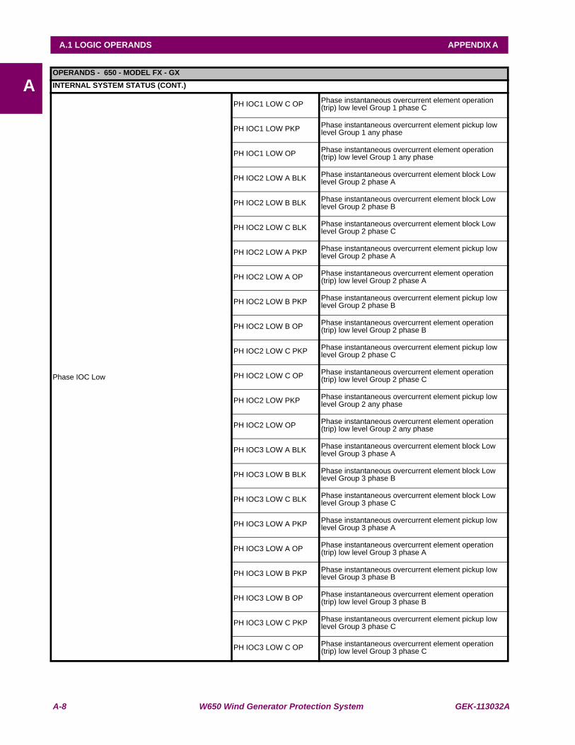
A-8 W650 Wind Generator Protection System GEK-113032A
A.1 LOGIC OPERANDS APPENDIX A
AOPERANDS - 650 - MODEL FX - GXINTERNAL SYSTEM STATUS (CONT.)
Phase IOC Low
PH IOC1 LOW C OP Phase instantaneous overcurrent element operation (trip) low level Group 1 phase C
PH IOC1 LOW PKP Phase instantaneous overcurrent element pickup low level Group 1 any phase
PH IOC1 LOW OP Phase instantaneous overcurrent element operation (trip) low level Group 1 any phase
PH IOC2 LOW A BLK Phase instantaneous overcurrent element block Low level Group 2 phase A
PH IOC2 LOW B BLK Phase instantaneous overcurrent element block Low level Group 2 phase B
PH IOC2 LOW C BLK Phase instantaneous overcurrent element block Low level Group 2 phase C
PH IOC2 LOW A PKP Phase instantaneous overcurrent element pickup low level Group 2 phase A
PH IOC2 LOW A OP Phase instantaneous overcurrent element operation (trip) low level Group 2 phase A
PH IOC2 LOW B PKP Phase instantaneous overcurrent element pickup low level Group 2 phase B
PH IOC2 LOW B OP Phase instantaneous overcurrent element operation (trip) low level Group 2 phase B
PH IOC2 LOW C PKP Phase instantaneous overcurrent element pickup low level Group 2 phase C
PH IOC2 LOW C OP Phase instantaneous overcurrent element operation (trip) low level Group 2 phase C
PH IOC2 LOW PKP Phase instantaneous overcurrent element pickup low level Group 2 any phase
PH IOC2 LOW OP Phase instantaneous overcurrent element operation (trip) low level Group 2 any phase
PH IOC3 LOW A BLK Phase instantaneous overcurrent element block Low level Group 3 phase A
PH IOC3 LOW B BLK Phase instantaneous overcurrent element block Low level Group 3 phase B
PH IOC3 LOW C BLK Phase instantaneous overcurrent element block Low level Group 3 phase C
PH IOC3 LOW A PKP Phase instantaneous overcurrent element pickup low level Group 3 phase A
PH IOC3 LOW A OP Phase instantaneous overcurrent element operation (trip) low level Group 3 phase A
PH IOC3 LOW B PKP Phase instantaneous overcurrent element pickup low level Group 3 phase B
PH IOC3 LOW B OP Phase instantaneous overcurrent element operation (trip) low level Group 3 phase B
PH IOC3 LOW C PKP Phase instantaneous overcurrent element pickup low level Group 3 phase C
PH IOC3 LOW C OP Phase instantaneous overcurrent element operation (trip) low level Group 3 phase C
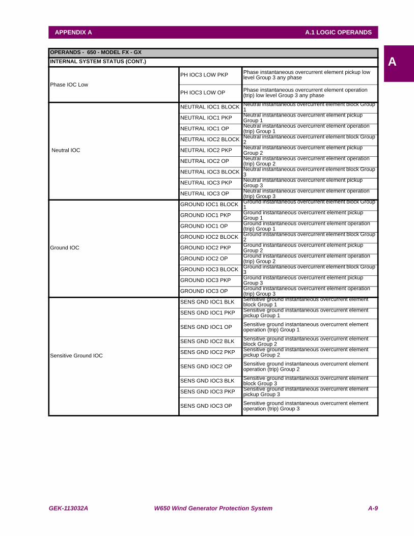
GEK-113032A W650 Wind Generator Protection System A-9
APPENDIX A A.1 LOGIC OPERANDS
AOPERANDS - 650 - MODEL FX - GXINTERNAL SYSTEM STATUS (CONT.)
Phase IOC Low
PH IOC3 LOW PKP Phase instantaneous overcurrent element pickup low level Group 3 any phase
PH IOC3 LOW OP Phase instantaneous overcurrent element operation (trip) low level Group 3 any phase
Neutral IOC
NEUTRAL IOC1 BLOCK Neutral instantaneous overcurrent element block Group 1
NEUTRAL IOC1 PKP Neutral instantaneous overcurrent element pickup Group 1
NEUTRAL IOC1 OP Neutral instantaneous overcurrent element operation (trip) Group 1
NEUTRAL IOC2 BLOCK Neutral instantaneous overcurrent element block Group 2
NEUTRAL IOC2 PKP Neutral instantaneous overcurrent element pickup Group 2
NEUTRAL IOC2 OP Neutral instantaneous overcurrent element operation (trip) Group 2
NEUTRAL IOC3 BLOCK Neutral instantaneous overcurrent element block Group 3
NEUTRAL IOC3 PKP Neutral instantaneous overcurrent element pickup Group 3
NEUTRAL IOC3 OP Neutral instantaneous overcurrent element operation (trip) Group 3
Ground IOC
GROUND IOC1 BLOCK Ground instantaneous overcurrent element block Group 1
GROUND IOC1 PKP Ground instantaneous overcurrent element pickup Group 1
GROUND IOC1 OP Ground instantaneous overcurrent element operation (trip) Group 1
GROUND IOC2 BLOCK Ground instantaneous overcurrent element block Group 2
GROUND IOC2 PKP Ground instantaneous overcurrent element pickup Group 2
GROUND IOC2 OP Ground instantaneous overcurrent element operation (trip) Group 2
GROUND IOC3 BLOCK Ground instantaneous overcurrent element block Group 3
GROUND IOC3 PKP Ground instantaneous overcurrent element pickup Group 3
GROUND IOC3 OP Ground instantaneous overcurrent element operation (trip) Group 3
Sensitive Ground IOC
SENS GND IOC1 BLK Sensitive ground instantaneous overcurrent element block Group 1
SENS GND IOC1 PKP Sensitive ground instantaneous overcurrent element pickup Group 1
SENS GND IOC1 OP Sensitive ground instantaneous overcurrent element operation (trip) Group 1
SENS GND IOC2 BLK Sensitive ground instantaneous overcurrent element block Group 2
SENS GND IOC2 PKP Sensitive ground instantaneous overcurrent element pickup Group 2
SENS GND IOC2 OP Sensitive ground instantaneous overcurrent element operation (trip) Group 2
SENS GND IOC3 BLK Sensitive ground instantaneous overcurrent element block Group 3
SENS GND IOC3 PKP Sensitive ground instantaneous overcurrent element pickup Group 3
SENS GND IOC3 OP Sensitive ground instantaneous overcurrent element operation (trip) Group 3
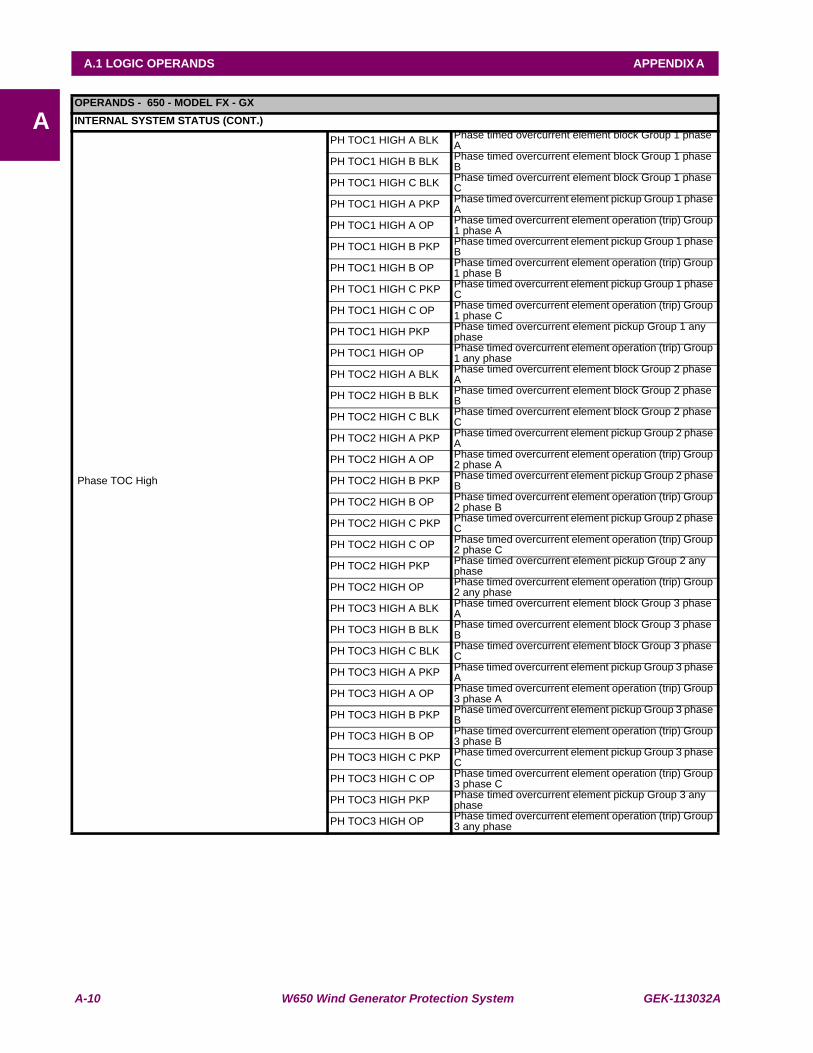
A-10 W650 Wind Generator Protection System GEK-113032A
A.1 LOGIC OPERANDS APPENDIX A
AOPERANDS - 650 - MODEL FX - GXINTERNAL SYSTEM STATUS (CONT.)
Phase TOC High
PH TOC1 HIGH A BLK Phase timed overcurrent element block Group 1 phase A
PH TOC1 HIGH B BLK Phase timed overcurrent element block Group 1 phase B
PH TOC1 HIGH C BLK Phase timed overcurrent element block Group 1 phase C
PH TOC1 HIGH A PKP Phase timed overcurrent element pickup Group 1 phase A
PH TOC1 HIGH A OP Phase timed overcurrent element operation (trip) Group 1 phase A
PH TOC1 HIGH B PKP Phase timed overcurrent element pickup Group 1 phase B
PH TOC1 HIGH B OP Phase timed overcurrent element operation (trip) Group 1 phase B
PH TOC1 HIGH C PKP Phase timed overcurrent element pickup Group 1 phase C
PH TOC1 HIGH C OP Phase timed overcurrent element operation (trip) Group 1 phase C
PH TOC1 HIGH PKP Phase timed overcurrent element pickup Group 1 any phase
PH TOC1 HIGH OP Phase timed overcurrent element operation (trip) Group 1 any phase
PH TOC2 HIGH A BLK Phase timed overcurrent element block Group 2 phase A
PH TOC2 HIGH B BLK Phase timed overcurrent element block Group 2 phase B
PH TOC2 HIGH C BLK Phase timed overcurrent element block Group 2 phase C
PH TOC2 HIGH A PKP Phase timed overcurrent element pickup Group 2 phase A
PH TOC2 HIGH A OP Phase timed overcurrent element operation (trip) Group 2 phase A
PH TOC2 HIGH B PKP Phase timed overcurrent element pickup Group 2 phase B
PH TOC2 HIGH B OP Phase timed overcurrent element operation (trip) Group 2 phase B
PH TOC2 HIGH C PKP Phase timed overcurrent element pickup Group 2 phase C
PH TOC2 HIGH C OP Phase timed overcurrent element operation (trip) Group 2 phase C
PH TOC2 HIGH PKP Phase timed overcurrent element pickup Group 2 any phase
PH TOC2 HIGH OP Phase timed overcurrent element operation (trip) Group 2 any phase
PH TOC3 HIGH A BLK Phase timed overcurrent element block Group 3 phase A
PH TOC3 HIGH B BLK Phase timed overcurrent element block Group 3 phase B
PH TOC3 HIGH C BLK Phase timed overcurrent element block Group 3 phase C
PH TOC3 HIGH A PKP Phase timed overcurrent element pickup Group 3 phase A
PH TOC3 HIGH A OP Phase timed overcurrent element operation (trip) Group 3 phase A
PH TOC3 HIGH B PKP Phase timed overcurrent element pickup Group 3 phase B
PH TOC3 HIGH B OP Phase timed overcurrent element operation (trip) Group 3 phase B
PH TOC3 HIGH C PKP Phase timed overcurrent element pickup Group 3 phase C
PH TOC3 HIGH C OP Phase timed overcurrent element operation (trip) Group 3 phase C
PH TOC3 HIGH PKP Phase timed overcurrent element pickup Group 3 any phase
PH TOC3 HIGH OP Phase timed overcurrent element operation (trip) Group 3 any phase
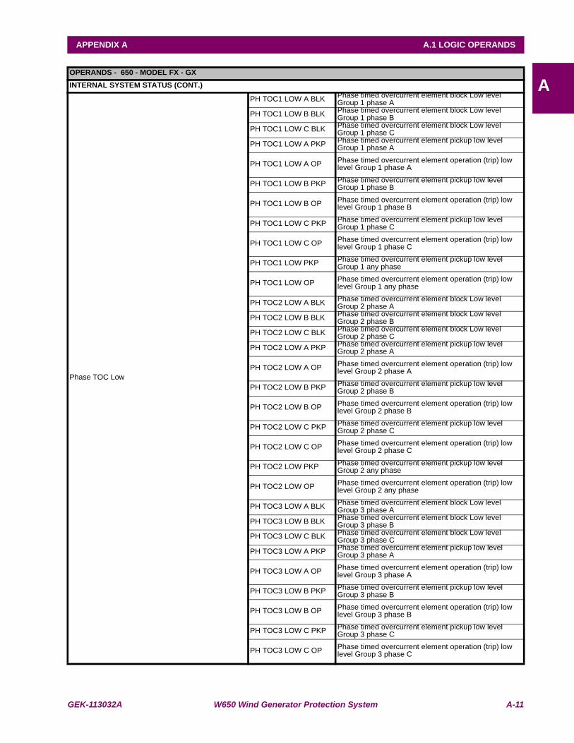
GEK-113032A W650 Wind Generator Protection System A-11
APPENDIX A A.1 LOGIC OPERANDS
AOPERANDS - 650 - MODEL FX - GXINTERNAL SYSTEM STATUS (CONT.)
Phase TOC Low
PH TOC1 LOW A BLK Phase timed overcurrent element block Low level Group 1 phase A
PH TOC1 LOW B BLK Phase timed overcurrent element block Low level Group 1 phase B
PH TOC1 LOW C BLK Phase timed overcurrent element block Low level Group 1 phase C
PH TOC1 LOW A PKP Phase timed overcurrent element pickup low level Group 1 phase A
PH TOC1 LOW A OP Phase timed overcurrent element operation (trip) low level Group 1 phase A
PH TOC1 LOW B PKP Phase timed overcurrent element pickup low level Group 1 phase B
PH TOC1 LOW B OP Phase timed overcurrent element operation (trip) low level Group 1 phase B
PH TOC1 LOW C PKP Phase timed overcurrent element pickup low level Group 1 phase C
PH TOC1 LOW C OP Phase timed overcurrent element operation (trip) low level Group 1 phase C
PH TOC1 LOW PKP Phase timed overcurrent element pickup low level Group 1 any phase
PH TOC1 LOW OP Phase timed overcurrent element operation (trip) low level Group 1 any phase
PH TOC2 LOW A BLK Phase timed overcurrent element block Low level Group 2 phase A
PH TOC2 LOW B BLK Phase timed overcurrent element block Low level Group 2 phase B
PH TOC2 LOW C BLK Phase timed overcurrent element block Low level Group 2 phase C
PH TOC2 LOW A PKP Phase timed overcurrent element pickup low level Group 2 phase A
PH TOC2 LOW A OP Phase timed overcurrent element operation (trip) low level Group 2 phase A
PH TOC2 LOW B PKP Phase timed overcurrent element pickup low level Group 2 phase B
PH TOC2 LOW B OP Phase timed overcurrent element operation (trip) low level Group 2 phase B
PH TOC2 LOW C PKP Phase timed overcurrent element pickup low level Group 2 phase C
PH TOC2 LOW C OP Phase timed overcurrent element operation (trip) low level Group 2 phase C
PH TOC2 LOW PKP Phase timed overcurrent element pickup low level Group 2 any phase
PH TOC2 LOW OP Phase timed overcurrent element operation (trip) low level Group 2 any phase
PH TOC3 LOW A BLK Phase timed overcurrent element block Low level Group 3 phase A
PH TOC3 LOW B BLK Phase timed overcurrent element block Low level Group 3 phase B
PH TOC3 LOW C BLK Phase timed overcurrent element block Low level Group 3 phase C
PH TOC3 LOW A PKP Phase timed overcurrent element pickup low level Group 3 phase A
PH TOC3 LOW A OP Phase timed overcurrent element operation (trip) low level Group 3 phase A
PH TOC3 LOW B PKP Phase timed overcurrent element pickup low level Group 3 phase B
PH TOC3 LOW B OP Phase timed overcurrent element operation (trip) low level Group 3 phase B
PH TOC3 LOW C PKP Phase timed overcurrent element pickup low level Group 3 phase C
PH TOC3 LOW C OP Phase timed overcurrent element operation (trip) low level Group 3 phase C
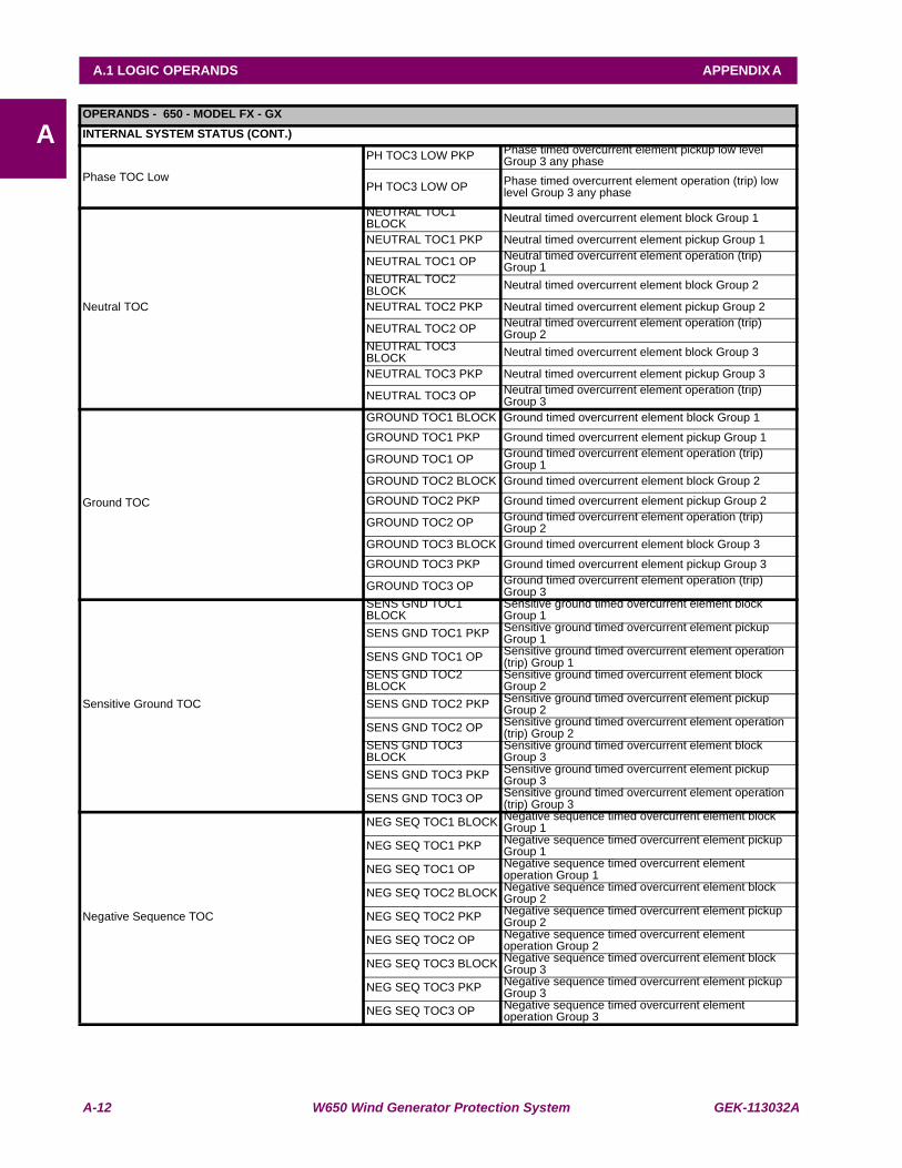
A-12 W650 Wind Generator Protection System GEK-113032A
A.1 LOGIC OPERANDS APPENDIX A
AOPERANDS - 650 - MODEL FX - GXINTERNAL SYSTEM STATUS (CONT.)
Phase TOC Low
PH TOC3 LOW PKP Phase timed overcurrent element pickup low level Group 3 any phase
PH TOC3 LOW OP Phase timed overcurrent element operation (trip) low level Group 3 any phase
Neutral TOC
NEUTRAL TOC1 BLOCK Neutral timed overcurrent element block Group 1
NEUTRAL TOC1 PKP Neutral timed overcurrent element pickup Group 1
NEUTRAL TOC1 OP Neutral timed overcurrent element operation (trip) Group 1
NEUTRAL TOC2 BLOCK Neutral timed overcurrent element block Group 2
NEUTRAL TOC2 PKP Neutral timed overcurrent element pickup Group 2
NEUTRAL TOC2 OP Neutral timed overcurrent element operation (trip) Group 2
NEUTRAL TOC3 BLOCK Neutral timed overcurrent element block Group 3
NEUTRAL TOC3 PKP Neutral timed overcurrent element pickup Group 3
NEUTRAL TOC3 OP Neutral timed overcurrent element operation (trip) Group 3
Ground TOC
GROUND TOC1 BLOCK Ground timed overcurrent element block Group 1
GROUND TOC1 PKP Ground timed overcurrent element pickup Group 1
GROUND TOC1 OP Ground timed overcurrent element operation (trip) Group 1
GROUND TOC2 BLOCK Ground timed overcurrent element block Group 2
GROUND TOC2 PKP Ground timed overcurrent element pickup Group 2
GROUND TOC2 OP Ground timed overcurrent element operation (trip) Group 2
GROUND TOC3 BLOCK Ground timed overcurrent element block Group 3
GROUND TOC3 PKP Ground timed overcurrent element pickup Group 3
GROUND TOC3 OP Ground timed overcurrent element operation (trip) Group 3
Sensitive Ground TOC
SENS GND TOC1 BLOCK
Sensitive ground timed overcurrent element block Group 1
SENS GND TOC1 PKP Sensitive ground timed overcurrent element pickup Group 1
SENS GND TOC1 OP Sensitive ground timed overcurrent element operation (trip) Group 1
SENS GND TOC2 BLOCK
Sensitive ground timed overcurrent element block Group 2
SENS GND TOC2 PKP Sensitive ground timed overcurrent element pickup Group 2
SENS GND TOC2 OP Sensitive ground timed overcurrent element operation (trip) Group 2
SENS GND TOC3 BLOCK
Sensitive ground timed overcurrent element block Group 3
SENS GND TOC3 PKP Sensitive ground timed overcurrent element pickup Group 3
SENS GND TOC3 OP Sensitive ground timed overcurrent element operation (trip) Group 3
Negative Sequence TOC
NEG SEQ TOC1 BLOCK Negative sequence timed overcurrent element block Group 1
NEG SEQ TOC1 PKP Negative sequence timed overcurrent element pickup Group 1
NEG SEQ TOC1 OP Negative sequence timed overcurrent element operation Group 1
NEG SEQ TOC2 BLOCK Negative sequence timed overcurrent element block Group 2
NEG SEQ TOC2 PKP Negative sequence timed overcurrent element pickup Group 2
NEG SEQ TOC2 OP Negative sequence timed overcurrent element operation Group 2
NEG SEQ TOC3 BLOCK Negative sequence timed overcurrent element block Group 3
NEG SEQ TOC3 PKP Negative sequence timed overcurrent element pickup Group 3
NEG SEQ TOC3 OP Negative sequence timed overcurrent element operation Group 3
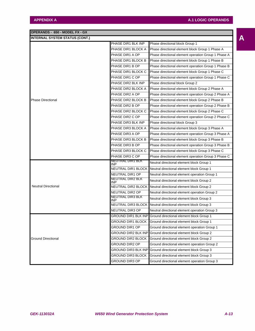
GEK-113032A W650 Wind Generator Protection System A-13
APPENDIX A A.1 LOGIC OPERANDS
AOPERANDS - 650 - MODEL FX - GXINTERNAL SYSTEM STATUS (CONT.)
Phase Directional
PHASE DIR1 BLK INP Phase directional block Group 1
PHASE DIR1 BLOCK A Phase directional element block Group 1 Phase A
PHASE DIR1 A OP Phase directional element operation Group 1 Phase A
PHASE DIR1 BLOCK B Phase directional element block Group 1 Phase B
PHASE DIR1 B OP Phase directional element operation Group 1 Phase B
PHASE DIR1 BLOCK C Phase directional element block Group 1 Phase C
PHASE DIR1 C OP Phase directional element operation Group 1 Phase C
PHASE DIR2 BLK INP Phase directional block Group 2
PHASE DIR2 BLOCK A Phase directional element block Group 2 Phase A
PHASE DIR2 A OP Phase directional element operation Group 2 Phase A
PHASE DIR2 BLOCK B Phase directional element block Group 2 Phase B
PHASE DIR2 B OP Phase directional element operation Group 2 Phase B
PHASE DIR2 BLOCK C Phase directional element block Group 2 Phase C
PHASE DIR2 C OP Phase directional element operation Group 2 Phase C
PHASE DIR3 BLK INP Phase directional block Group 3
PHASE DIR3 BLOCK A Phase directional element block Group 3 Phase A
PHASE DIR3 A OP Phase directional element operation Group 3 Phase A
PHASE DIR3 BLOCK B Phase directional element block Group 3 Phase B
PHASE DIR3 B OP Phase directional element operation Group 3 Phase B
PHASE DIR3 BLOCK C Phase directional element block Group 3 Phase C
PHASE DIR3 C OP Phase directional element operation Group 3 Phase C
Neutral Directional
NEUTRAL DIR1 BLK INP Neutral directional element block Group 1
NEUTRAL DIR1 BLOCK Neutral directional element block Group 1
NEUTRAL DIR1 OP Neutral directional element operation Group 1NEUTRAL DIR2 BLK INP Neutral directional element block Group 2
NEUTRAL DIR2 BLOCK Neutral directional element block Group 2
NEUTRAL DIR2 OP Neutral directional element operation Group 2NEUTRAL DIR3 BLK INP Neutral directional element block Group 3
NEUTRAL DIR3 BLOCK Neutral directional element block Group 3
NEUTRAL DIR3 OP Neutral directional element operation Group 3
Ground Directional
GROUND DIR1 BLK INP Ground directional element block Group 1
GROUND DIR1 BLOCK Ground directional element block Group 1
GROUND DIR1 OP Ground directional element operation Group 1
GROUND DIR2 BLK INP Ground directional element block Group 2
GROUND DIR2 BLOCK Ground directional element block Group 2
GROUND DIR2 OP Ground directional element operation Group 2
GROUND DIR3 BLK INP Ground directional element block Group 3
GROUND DIR3 BLOCK Ground directional element block Group 3
GROUND DIR3 OP Ground directional element operation Group 3
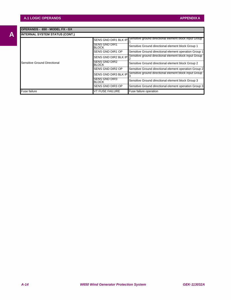
A-14 W650 Wind Generator Protection System GEK-113032A
A.1 LOGIC OPERANDS APPENDIX A
AOPERANDS - 650 - MODEL FX - GXINTERNAL SYSTEM STATUS (CONT.)
Sensitive Ground Directional
SENS GND DIR1 BLK IP Sensitive ground directional element block input Group 1
SENS GND DIR1 BLOCK Sensitive Ground directional element block Group 1
SENS GND DIR1 OP Sensitive Ground directional element operation Group 1
SENS GND DIR2 BLK IP Sensitive ground directional element block input Group 2
SENS GND DIR2 BLOCK Sensitive Ground directional element block Group 2
SENS GND DIR2 OP Sensitive Ground directional element operation Group 2
SENS GND DIR3 BLK IP Sensitive ground directional element block input Group 3
SENS GND DIR3 BLOCK Sensitive Ground directional element block Group 3
SENS GND DIR3 OP Sensitive Ground directional element operation Group 3
Fuse failure VT FUSE FAILURE Fuse failure operation

GEK-113032A W650 Wind Generator Protection System A-15
APPENDIX A A.1 LOGIC OPERANDS
AOPERANDS - 650 - MODEL FX - GXINTERNAL SYSTEM STATUS (CONT.)
Phase UV
PHASE UV1 BLOCK Phase undervoltage element block Group 1
PHASE UV1 A PKP Undervoltage element pickup AG Group 1
PHASE UV1 A OP Undervoltage element operation AG Group 1
PHASE UV1 B PKP Undervoltage element pickup BG Group 1
PHASE UV1 B OP Undervoltage element operation BG Group 1
PHASE UV1 C PKP Undervoltage element pickup CG Group 1
PHASE UV1 C OP Undervoltage element operation CG Group 1
PHASE UV1 AB PKP Undervoltage element pickup AB Group 1
PHASE UV1 AB OP Undervoltage element operation AB Group 1
PHASE UV1 BC PKP Undervoltage element pickup BC Group 1
PHASE UV1 BC OP Undervoltage element operation BC Group 1
PHASE UV1 CA PKP Undervoltage element pickup CA Group 1
PHASE UV1 CA OP Undervoltage element operation CA Group 1
PHASE UV1 PKP Pickup of any of the above mentioned elements
PHASE UV1 OP Operation of any of the above mentioned elements
PHASE UV2 BLOCK Phase undervoltage element block Group 2
PHASE UV2 A PKP Undervoltage element pickup AG Group 2
PHASE UV2 A OP Undervoltage element operation AG Group 2
PHASE UV2 B PKP Undervoltage element pickup BG Group 2
PHASE UV2 B OP Undervoltage element operation BG Group 2
PHASE UV2 C PKP Undervoltage element pickup CG Group 2
PHASE UV2 C OP Undervoltage element operation CG Group 2
PHASE UV2 AB PKP Undervoltage element pickup AB Group 2
PHASE UV2 AB OP Undervoltage element operation AB Group 2
PHASE UV2 BC PKP Undervoltage element pickup BC Group 2
PHASE UV2 BC OP Undervoltage element operation BC Group 2
PHASE UV2 CA PKP Undervoltage element pickup CA Group 2
PHASE UV2 CA OP Undervoltage element operation CA Group 2
PHASE UV2 PKP Pickup of any of the above mentioned elements
PHASE UV2 OP Operation of any of the above mentioned elements
PHASE UV3 BLOCK Phase undervoltage element block Group 3
PHASE UV3 A PKP Undervoltage element pickup AG Group 3
PHASE UV3 A OP Undervoltage element operation AG Group 3
PHASE UV3 B PKP Undervoltage element pickup BG Group 3
PHASE UV3 B OP Undervoltage element operation BG Group 3
PHASE UV3 C PKP Undervoltage element pickup CG Group 3
PHASE UV3 C OP Undervoltage element operation CG Group 3
PHASE UV3 AB PKP Undervoltage element pickup AB Group 3
PHASE UV3 AB OP Undervoltage element operation AB Group 3
PHASE UV3 BC PKP Undervoltage element pickup BC Group 3
PHASE UV3 BC OP Undervoltage element operation BC Group 3
PHASE UV3 CA PKP Undervoltage element pickup CA Group 3
PHASE UV3 CA OP Undervoltage element operation CA Group 3
PHASE UV3 PKP Pickup of any of the above mentioned elements
PHASE UV3 OP Operation of any of the above mentioned elements

A-16 W650 Wind Generator Protection System GEK-113032A
A.1 LOGIC OPERANDS APPENDIX A
AOPERANDS - 650 - MODEL FX - GXINTERNAL SYSTEM STATUS (CONT.)
Phase UV
PHASE UV4 BLOCK Phase undervoltage element block Group 4
PHASE UV4 A PKP Undervoltage element pickup AG Group 4
PHASE UV4 A OP Undervoltage element operation AG Group 4
PHASE UV4 B PKP Undervoltage element pickup BG Group 4
PHASE UV4 B OP Undervoltage element operation BG Group 4
PHASE UV4 C PKP Undervoltage element pickup CG Group 4
PHASE UV4 C OP Undervoltage element operation CG Group 4
PHASE UV4 AB PKP Undervoltage element pickup AB Group 4
PHASE UV4 AB OP Undervoltage element operation AB Group 4
PHASE UV4 BC PKP Undervoltage element pickup BC Group 4
PHASE UV4 BC OP Undervoltage element operation BC Group 4
PHASE UV4 CA PKP Undervoltage element pickup CA Group 4
PHASE UV4 CA OP Undervoltage element operation CA Group 4
PHASE UV4 PKP Pickup of any of the above mentioned elements
PHASE UV4 OP Operation of any of the above mentioned elements
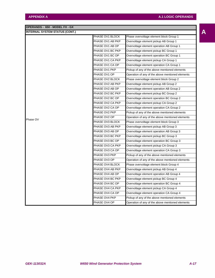
GEK-113032A W650 Wind Generator Protection System A-17
APPENDIX A A.1 LOGIC OPERANDS
AOPERANDS - 650 - MODEL FX - GXINTERNAL SYSTEM STATUS (CONT.)
Phase OV
PHASE OV1 BLOCK Phase overvoltage element block Group 1
PHASE OV1 AB PKP Overvoltage element pickup AB Group 1
PHASE OV1 AB OP Overvoltage element operation AB Group 1
PHASE OV1 BC PKP Overvoltage element pickup BC Group 1
PHASE OV1 BC OP Overvoltage element operation BC Group 1
PHASE OV1 CA PKP Overvoltage element pickup CA Group 1
PHASE OV1 CA OP Overvoltage element operation CA Group 1
PHASE OV1 PKP Pickup of any of the above mentioned elements
PHASE OV1 OP Operation of any of the above mentioned elements
PHASE OV2 BLOCK Phase overvoltage element block Group 2
PHASE OV2 AB PKP Overvoltage element pickup AB Group 2
PHASE OV2 AB OP Overvoltage element operation AB Group 2
PHASE OV2 BC PKP Overvoltage element pickup BC Group 2
PHASE OV2 BC OP Overvoltage element operation BC Group 2
PHASE OV2 CA PKP Overvoltage element pickup CA Group 2
PHASE OV2 CA OP Overvoltage element operation CA Group 2
PHASE OV2 PKP Pickup of any of the above mentioned elements
PHASE OV2 OP Operation of any of the above mentioned elements
PHASE OV3 BLOCK Phase overvoltage element block Group 3
PHASE OV3 AB PKP Overvoltage element pickup AB Group 3
PHASE OV3 AB OP Overvoltage element operation AB Group 3
PHASE OV3 BC PKP Overvoltage element pickup BC Group 3
PHASE OV3 BC OP Overvoltage element operation BC Group 3
PHASE OV3 CA PKP Overvoltage element pickup CA Group 3
PHASE OV3 CA OP Overvoltage element operation CA Group 3
PHASE OV3 PKP Pickup of any of the above mentioned elements
PHASE OV3 OP Operation of any of the above mentioned elements
PHASE OV4 BLOCK Phase overvoltage element block Group 4
PHASE OV4 AB PKP Overvoltage element pickup AB Group 4
PHASE OV4 AB OP Overvoltage element operation AB Group 4
PHASE OV4 BC PKP Overvoltage element pickup BC Group 4
PHASE OV4 BC OP Overvoltage element operation BC Group 4
PHASE OV4 CA PKP Overvoltage element pickup CA Group 4
PHASE OV4 CA OP Overvoltage element operation CA Group 4
PHASE OV4 PKP Pickup of any of the above mentioned elements
PHASE OV4 OP Operation of any of the above mentioned elements
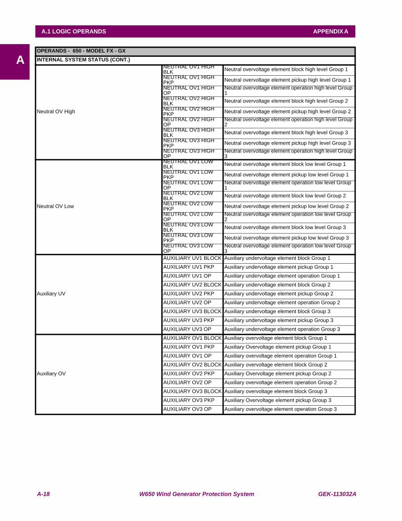
A-18 W650 Wind Generator Protection System GEK-113032A
A.1 LOGIC OPERANDS APPENDIX A
AOPERANDS - 650 - MODEL FX - GXINTERNAL SYSTEM STATUS (CONT.)
Neutral OV High
NEUTRAL OV1 HIGH BLK Neutral overvoltage element block high level Group 1NEUTRAL OV1 HIGH PKP Neutral overvoltage element pickup high level Group 1NEUTRAL OV1 HIGH OP
Neutral overvoltage element operation high level Group 1
NEUTRAL OV2 HIGH BLK Neutral overvoltage element block high level Group 2NEUTRAL OV2 HIGH PKP Neutral overvoltage element pickup high level Group 2NEUTRAL OV2 HIGH OP
Neutral overvoltage element operation high level Group 2
NEUTRAL OV3 HIGH BLK Neutral overvoltage element block high level Group 3NEUTRAL OV3 HIGH PKP Neutral overvoltage element pickup high level Group 3NEUTRAL OV3 HIGH OP
Neutral overvoltage element operation high level Group 3
Neutral OV Low
NEUTRAL OV1 LOW BLK Neutral overvoltage element block low level Group 1NEUTRAL OV1 LOW PKP Neutral overvoltage element pickup low level Group 1NEUTRAL OV1 LOW OP
Neutral overvoltage element operation low level Group 1
NEUTRAL OV2 LOW BLK Neutral overvoltage element block low level Group 2NEUTRAL OV2 LOW PKP Neutral overvoltage element pickup low level Group 2NEUTRAL OV2 LOW OP
Neutral overvoltage element operation low level Group 2
NEUTRAL OV3 LOW BLK Neutral overvoltage element block low level Group 3NEUTRAL OV3 LOW PKP Neutral overvoltage element pickup low level Group 3NEUTRAL OV3 LOW OP
Neutral overvoltage element operation low level Group 3
Auxiliary UV
AUXILIARY UV1 BLOCK Auxiliary undervoltage element block Group 1
AUXILIARY UV1 PKP Auxiliary undervoltage element pickup Group 1
AUXILIARY UV1 OP Auxiliary undervoltage element operation Group 1
AUXILIARY UV2 BLOCK Auxiliary undervoltage element block Group 2
AUXILIARY UV2 PKP Auxiliary undervoltage element pickup Group 2
AUXILIARY UV2 OP Auxiliary undervoltage element operation Group 2
AUXILIARY UV3 BLOCK Auxiliary undervoltage element block Group 3
AUXILIARY UV3 PKP Auxiliary undervoltage element pickup Group 3
AUXILIARY UV3 OP Auxiliary undervoltage element operation Group 3
Auxiliary OV
AUXILIARY OV1 BLOCK Auxiliary overvoltage element block Group 1
AUXILIARY OV1 PKP Auxiliary Overvoltage element pickup Group 1
AUXILIARY OV1 OP Auxiliary overvoltage element operation Group 1
AUXILIARY OV2 BLOCK Auxiliary overvoltage element block Group 2
AUXILIARY OV2 PKP Auxiliary Overvoltage element pickup Group 2
AUXILIARY OV2 OP Auxiliary overvoltage element operation Group 2
AUXILIARY OV3 BLOCK Auxiliary overvoltage element block Group 3
AUXILIARY OV3 PKP Auxiliary Overvoltage element pickup Group 3
AUXILIARY OV3 OP Auxiliary overvoltage element operation Group 3
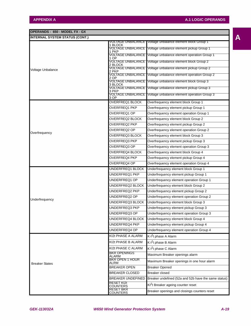
GEK-113032A W650 Wind Generator Protection System A-19
APPENDIX A A.1 LOGIC OPERANDS
AOPERANDS - 650 - MODEL FX - GXINTERNAL SYSTEM STATUS (CONT.)
Voltage Unbalance
VOLTAGE UNBALANCE 1 BLOCK
Voltage unbalance element block Group 1
VOLTAGE UNBALANCE 1 PKP
Voltage unbalance element pickup Group 1
VOLTAGE UNBALANCE 1 OP
Voltage unbalance element operation Group 1
VOLTAGE UNBALANCE 2 BLOCK
Voltage unbalance element block Group 2
VOLTAGE UNBALANCE 2 PKP
Voltage unbalance element pickup Group 2
VOLTAGE UNBALANCE 2 OP
Voltage unbalance element operation Group 2
VOLTAGE UNBALANCE 3 BLOCK
Voltage unbalance element block Group 3
VOLTAGE UNBALANCE 3 PKP
Voltage unbalance element pickup Group 3
VOLTAGE UNBALANCE 3 OP
Voltage unbalance element operation Group 3
Overfrequency
OVERFREQ1 BLOCK Overfrequency element block Group 1
OVERFREQ1 PKP Overfrequency element pickup Group 1
OVERFREQ1 OP Overfrequency element operation Group 1
OVERFREQ2 BLOCK Overfrequency element block Group 2
OVERFREQ2 PKP Overfrequency element pickup Group 2
OVERFREQ2 OP Overfrequency element operation Group 2
OVERFREQ3 BLOCK Overfrequency element block Group 3
OVERFREQ3 PKP Overfrequency element pickup Group 3
OVERFREQ3 OP Overfrequency element operation Group 3
OVERFREQ4 BLOCK Overfrequency element block Group 4
OVERFREQ4 PKP Overfrequency element pickup Group 4
OVERFREQ4 OP Overfrequency element operation Group 4
Underfrequency
UNDERFREQ1 BLOCK Underfrequency element block Group 1
UNDERFREQ1 PKP Underfrequency element pickup Group 1
UNDERFREQ1 OP Underfrequency element operation Group 1
UNDERFREQ2 BLOCK Underfrequency element block Group 2
UNDERFREQ2 PKP Underfrequency element pickup Group 2
UNDERFREQ2 OP Underfrequency element operation Group 2
UNDERFREQ3 BLOCK Underfrequency element block Group 3
UNDERFREQ3 PKP Underfrequency element pickup Group 3
UNDERFREQ3 OP Underfrequency element operation Group 3
UNDERFREQ4 BLOCK Underfrequency element block Group 4
UNDERFREQ4 PKP Underfrequency element pickup Group 4
UNDERFREQ4 OP Underfrequency element operation Group 4
Breaker States
KI2t PHASE A ALARM K·I2t phase A Alarm
KI2t PHASE B ALARM K·I2t phase B Alarm
KI2t PHASE C ALARM K·I2t phase C AlarmBKR OPENINGS ALARM Maximum Breaker openings alarmBKR OPEN 1 HOUR ALRM Maximum Breaker openings in one hour alarm
BREAKER OPEN Breaker Opened
BREAKER CLOSED Breaker closed
BREAKER UNDEFINED Breaker undefined (52a and 52b have the same status) RESET KI2t COUNTERS KI2t Breaker ageing counter reset RESET BKR COUNTERS Breaker openings and closings counters reset

A-20 W650 Wind Generator Protection System GEK-113032A
A.1 LOGIC OPERANDS APPENDIX A
AOPERANDS - 650 - MODEL FX - GXINTERNAL SYSTEM STATUS (CONT.)
Breaker Failure
BKR FAIL INITIATE Breaker failure initiationBKR FAIL NO CURRENT Breaker failure without currentBKR FAIL SUPERVISION Breaker failure 1st level (supervision – retrip)
BKR FAIL HISET Breaker failure 2nd level (high level)
BKR FAIL LOWSET Breaker failure 3rd level (low level)
INTERNAL ARC Internal arc
BKR FAIL 2nd STEP Breaker failure second step
Autorecloser
AR LEVEL BLOCK Recloser element block by level
AR PULSE BLOCK Recloser element block by pulse
AR PULSE UNBLOCK Recloser element unblock by pulse
AR INITIATE Reclose initiate
AR CONDS INPUT Reclose permission condition in input to Function 1 = there are conditions
AR CLOSE BREAKER Closing permission for the recloser
AR OUT OF SERVICE Recloser out of service
AR READY Recloser READY
AR LOCKOUT Recloser in LOCKOUT
AR BLOCK Recloser BLOCKed
AR RCL IN PROGRESS Recloser – Cycle in progress
AR LCK BY ANOMALY Recloser – LOCKOUT by anomaly (reclosing command during cycle in progress)
AR LCK BY FAIL OPEN Recloser – LOCKOUT by failure to open
AR LCK BY FAIL CLOSE Recloser – LOCKOUT by failure to close
AR LCK BY USER Recloser – LOCKOUT by external operation (e.g.: manual opening with cycle in progress)
AR LCK BY CONDS Recloser – LOCKOUT by lack of reclosing conditions
AR LCK BY TRIPS Recloser – LOCKOUT by number of trips
AR LCK BY SHOTS Recloser – LOCKOUT by number of shots
AR BLK AFTER 1 SHOT Recloser – Block after first shot
AR BLK AFTER 2 SHOT Recloser – Block after second shot
AR BLK AFTER 3 SHOT Recloser – Block after third shot
AR BLK AFTER 4 SHOT Recloser – Block after fourth shot
AR BLOCK BY LEVEL Recloser – Block by level
AR BLOCK BY PULSE Recloser – Block by command (pulse)
Default Channel (not used) Default Channel Channel not used
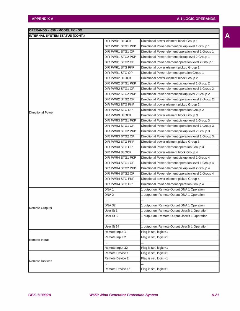
GEK-113032A W650 Wind Generator Protection System A-21
APPENDIX A A.1 LOGIC OPERANDS
AOPERANDS - 650 - MODEL FX - GXINTERNAL SYSTEM STATUS (CONT.)
Directional Power
DIR PWR1 BLOCK Directional power element block Group 1
DIR PWR1 STG1 PKP Directional Power element pickup level 1 Group 1
DIR PWR1 STG1 OP Directional Power element operation level 1 Group 1
DIR PWR1 STG2 PKP Directional Power element pickup level 2 Group 1
DIR PWR1 STG2 OP Directional Power element operation level 2 Group 1
DIR PWR1 STG PKP Directional power element pickup Group 1
DIR PWR1 STG OP Directional Power element operation Group 1
DIR PWR2 BLOCK Directional power element block Group 2
DIR PWR2 STG1 PKP Directional Power element pickup level 1 Group 2
DIR PWR2 STG1 OP Directional Power element operation level 1 Group 2
DIR PWR2 STG2 PKP Directional Power element pickup level 2 Group 2
DIR PWR2 STG2 OP Directional Power element operation level 2 Group 2
DIR PWR2 STG PKP Directional power element pickup Group 2
DIR PWR2 STG OP Directional Power element operation Group 2
DIR PWR3 BLOCK Directional power element block Group 3
DIR PWR3 STG1 PKP Directional Power element pickup level 1 Group 3
DIR PWR3 STG1 OP Directional Power element operation level 1 Group 3
DIR PWR3 STG2 PKP Directional Power element pickup level 2 Group 3
DIR PWR3 STG2 OP Directional Power element operation level 2 Group 3
DIR PWR3 STG PKP Directional power element pickup Group 3
DIR PWR3 STG OP Directional Power element operation Group 3
DIR PWR4 BLOCK Directional power element block Group 4
DIR PWR4 STG1 PKP Directional Power element pickup level 1 Group 4
DIR PWR4 STG1 OP Directional Power element operation level 1 Group 4
DIR PWR4 STG2 PKP Directional Power element pickup level 2 Group 4
DIR PWR4 STG2 OP Directional Power element operation level 2 Group 4
DIR PWR4 STG PKP Directional power element pickup Group 4
DIR PWR4 STG OP Directional Power element operation Group 4
Remote Outputs
DNA 1 1 output on. Remote Output DNA 1 Operation
DNA 2 1 output on. Remote Output DNA 1 Operation
... ...
DNA 32 1 output on. Remote Output DNA 1 Operation
User St 1 1 output on. Remote Output UserSt 1 Operation
User St 2 1 output on. Remote Output UserSt 1 Operation
... ...User St 64 1 output on. Remote Output UserSt 1 Operation
Remote Inputs
Remote Input 1 Flag is set, logic =1
Remote Input 2 Flag is set, logic =1
... ...
Remote Input 32 Flag is set, logic =1
Remote Devices
Remote Device 1 Flag is set, logic =1
Remote Device 2 Flag is set, logic =1
... ...
Remote Device 16 Flag is set, logic =1

A-22 W650 Wind Generator Protection System GEK-113032A
A.1 LOGIC OPERANDS APPENDIX A
A

GEK-113032A W650 Wind Generator Protection System B-1
APPENDIX B B.1 ACCESS TO W650 DATA
B
APPENDIX B MODBUS PROTOCOLB.1 ACCESS TO W650 DATA
This document describes the procedure to read and write data in the W650 relay using ModBus/RTU protocol.
To prevent an existing integration from being affected by versions, a generic database has been created, compatiblebetween versions, with all possible items that a W650 may have, independently from its type or configuration. Thisdatabase describes completely each of these items. This descriptions includes the data type, length, memory position,object version, etc. Moreover, the database will group the different objects by subgroups, such as status and settingsgroups.
Each object has a unique memory position for the whole family. Only after reading the objects of a particular relay, it will bepossible to elaborate its map. This map will only be valid for that particular relay and memory version. From one version toanother the memory positions of existing objects remain fixed, and new objects are assigned new addresses, which againremain the same for following versions.
It is possible to get the Memory Map using EnerVista 650 Setup software, menu:
View, ModBus Memory map

B-2 W650 Wind Generator Protection System GEK-113032A
B.2 MODBUS W650 APPENDIX B
B
B.2MODBUS W650 B.2.1 FUNCTIONS USED
The protocol used is standard ModBus/RTU, so any program or PLC will be able to easily communicate with W650 units.
W650 always works as slave, which means that it never starts the communications. It is always the master who initiatescommunication.
Only one ModBus/RTU functions subgroup are implemented:
• Reading function 3 (or 4).
• Writing function 16.

GEK-113032A W650 Wind Generator Protection System B-3
APPENDIX B B.2 MODBUS W650
B
B.2.2 PHYSICAL LAYER
ModBus/RTU protocol is independent from the hardware. This way, the physical layer may be in different hardwareconfigurations: RS232, RS485, fiber optic or Ethernet.
W650 units incorporate a front RS232 port, two rear RS485 or fiber optic ports, and a 10/100Base T port, and in someconfigurations two 100BaseFX ports. The data flow in any of the configurations is “half-duplex”.
Each data byte is transmitted in an asynchronous way and it is formed by: 1 start bit, 8 data bits, 1 stop bit and 1 parity bit ifprogrammed. Thus you have a 10 or 11-bit data, depending on whether it has parity or not.
The port baud rate and the parity are independent and programmable for each communication port. Any port may beprogrammed to baud rates of: 1200, 2400, 4800, 9600, 19200, 38400, 57600 or 115200. Parity may be pair, impair orwithout parity.
The master must know the client address with which it is going to communicate. No unit will operate after a master requestif the message address is not its own, except it the address is 0, which is the broadcast address. In this case the relay willoperate, but won’t send any reply.
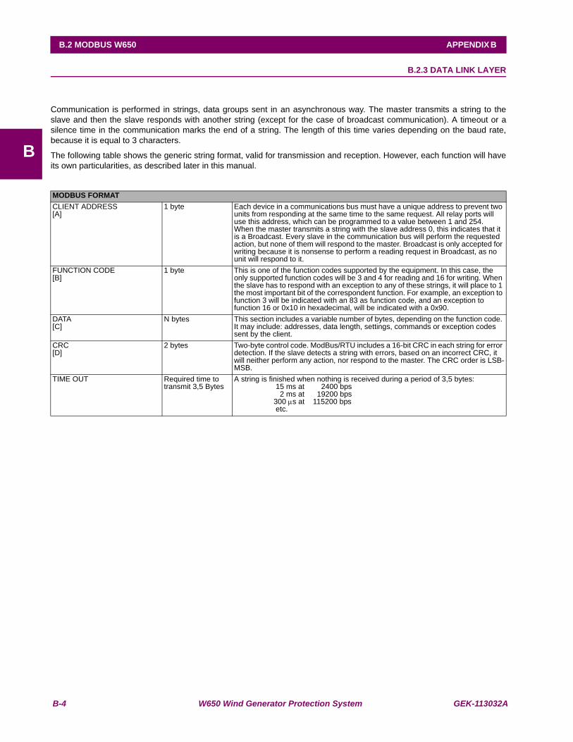
B-4 W650 Wind Generator Protection System GEK-113032A
B.2 MODBUS W650 APPENDIX B
B
B.2.3 DATA LINK LAYER
Communication is performed in strings, data groups sent in an asynchronous way. The master transmits a string to theslave and then the slave responds with another string (except for the case of broadcast communication). A timeout or asilence time in the communication marks the end of a string. The length of this time varies depending on the baud rate,because it is equal to 3 characters.
The following table shows the generic string format, valid for transmission and reception. However, each function will haveits own particularities, as described later in this manual.
MODBUS FORMATCLIENT ADDRESS[A]
1 byte Each device in a communications bus must have a unique address to prevent two units from responding at the same time to the same request. All relay ports will use this address, which can be programmed to a value between 1 and 254.When the master transmits a string with the slave address 0, this indicates that it is a Broadcast. Every slave in the communication bus will perform the requested action, but none of them will respond to the master. Broadcast is only accepted for writing because it is nonsense to perform a reading request in Broadcast, as no unit will respond to it.
FUNCTION CODE[B]
1 byte This is one of the function codes supported by the equipment. In this case, the only supported function codes will be 3 and 4 for reading and 16 for writing. When the slave has to respond with an exception to any of these strings, it will place to 1 the most important bit of the correspondent function. For example, an exception to function 3 will be indicated with an 83 as function code, and an exception to function 16 or 0x10 in hexadecimal, will be indicated with a 0x90.
DATA[C]
N bytes This section includes a variable number of bytes, depending on the function code. It may include: addresses, data length, settings, commands or exception codes sent by the client.
CRC[D]
2 bytes Two-byte control code. ModBus/RTU includes a 16-bit CRC in each string for error detection. If the slave detects a string with errors, based on an incorrect CRC, it will neither perform any action, nor respond to the master. The CRC order is LSB-MSB.
TIME OUT Required time to transmit 3,5 Bytes
A string is finished when nothing is received during a period of 3,5 bytes: 15 ms at 2400 bps 2 ms at 19200 bps 300 μs at 115200 bps etc.
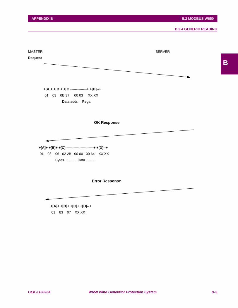
GEK-113032A W650 Wind Generator Protection System B-5
APPENDIX B B.2 MODBUS W650
B
B.2.4 GENERIC READING
MASTER SERVER
Request
+[A]+ +[B]+ +[C]--------------+ +[D]--+
01 03 0B 37 00 03 XX XX
Data addr. Regs.
OK Response
+[A]+ +[B]+ +[C]------------------------+ +[D]--+
01 03 06 02 2B 00 00 00 64 XX XX
Bytes ...........Data ..........
Error Response
+[A]+ +[B]+ +[C]+ +[D]--+
01 83 07 XX XX
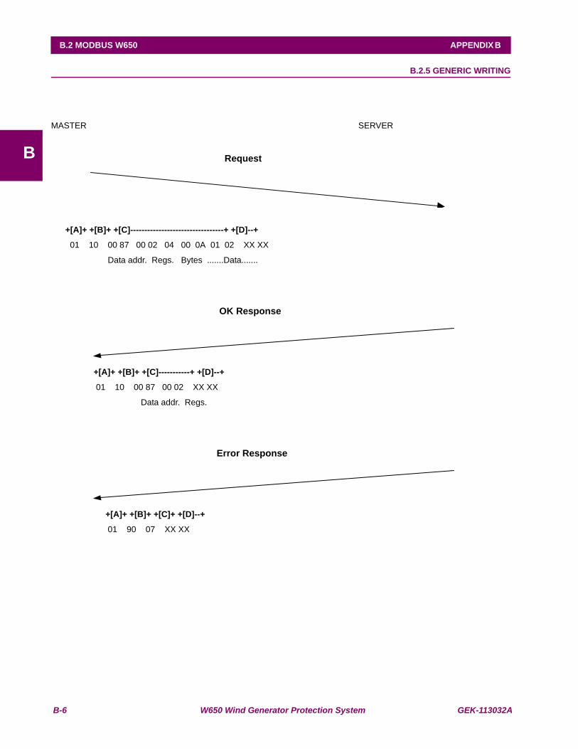
B-6 W650 Wind Generator Protection System GEK-113032A
B.2 MODBUS W650 APPENDIX B
B
B.2.5 GENERIC WRITING
MASTER SERVER
Request
+[A]+ +[B]+ +[C]---------------------------------+ +[D]--+
01 10 00 87 00 02 04 00 0A 01 02 XX XX
Data addr. Regs. Bytes .......Data.......
OK Response
+[A]+ +[B]+ +[C]-----------+ +[D]--+
01 10 00 87 00 02 XX XX
Data addr. Regs.
Error Response
+[A]+ +[B]+ +[C]+ +[D]--+
01 90 07 XX XX
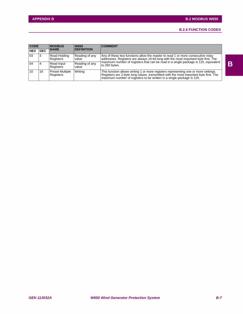
GEK-113032A W650 Wind Generator Protection System B-7
APPENDIX B B.2 MODBUS W650
B
B.2.6 FUNCTION CODES
CODE MODBUS NAME
W650 DEFINITION
COMMENTHEX DEC03 3 Read Holding
RegistersReading of any value
Any of these two functions allow the master to read 1 or more consecutive relay addresses. Registers are always 16-bit long with the most important byte first. The maximum number of registers that can be read in a single package is 125, equivalent to 250 bytes. 04 4 Read Input
RegistersReading of any value
10 16 Preset Multiple Registers
Writing This function allows writing 1 or more registers representing one or more settings. Registers are 2-byte long values, transmitted with the most important byte first. The maximum number of registers to be written in a single package is 125.
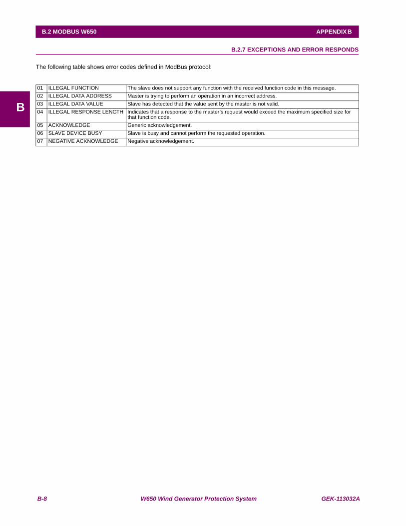
B-8 W650 Wind Generator Protection System GEK-113032A
B.2 MODBUS W650 APPENDIX B
B
B.2.7 EXCEPTIONS AND ERROR RESPONDS
The following table shows error codes defined in ModBus protocol:
01 ILLEGAL FUNCTION The slave does not support any function with the received function code in this message. 02 ILLEGAL DATA ADDRESS Master is trying to perform an operation in an incorrect address. 03 ILLEGAL DATA VALUE Slave has detected that the value sent by the master is not valid. 04 ILLEGAL RESPONSE LENGTH Indicates that a response to the master’s request would exceed the maximum specified size for
that function code. 05 ACKNOWLEDGE Generic acknowledgement.06 SLAVE DEVICE BUSY Slave is busy and cannot perform the requested operation. 07 NEGATIVE ACKNOWLEDGE Negative acknowledgement.
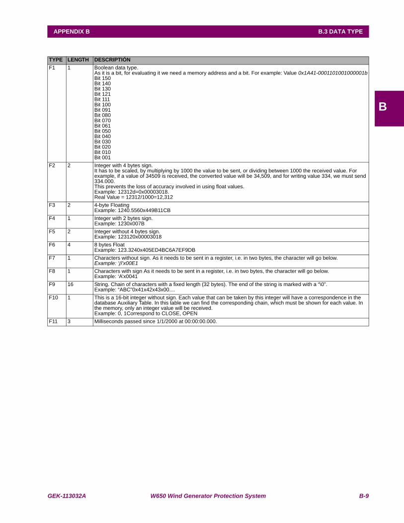
GEK-113032A W650 Wind Generator Protection System B-9
APPENDIX B B.3 DATA TYPE
B
B.3DATA TYPETYPE LENGTH DESCRIPTIÓNF1 1 Boolean data type.
As it is a bit, for evaluating it we need a memory address and a bit. For example: Value 0x1A41-0001101001000001bBit 150Bit 140Bit 130Bit 121Bit 111Bit 100Bit 091Bit 080Bit 070Bit 061Bit 050Bit 040Bit 030Bit 020Bit 010Bit 001
F2 2 Integer with 4 bytes sign.It has to be scaled, by multiplying by 1000 the value to be sent, or dividing between 1000 the received value. For example, if a value of 34509 is received, the converted value will be 34,509, and for writing value 334, we must send 334.000. This prevents the loss of accuracy involved in using float values. Example: 12312d=0x00003018. Real Value = 12312/1000=12,312
F3 2 4-byte FloatingExample: 1240.5560x449B11CB
F4 1 Integer with 2 bytes sign.Example: 1230x007B
F5 2 Integer without 4 bytes sign.Example: 123120x00003018
F6 4 8 bytes FloatExample: 123.3240x405ED4BC6A7EF9DB
F7 1 Characters without sign. As it needs to be sent in a register, i.e. in two bytes, the character will go below.Example: ‘β’x00E1
F8 1 Characters with sign As it needs to be sent in a register, i.e. in two bytes, the character will go below.Example: ‘A’x0041
F9 16 String. Chain of characters with a fixed length (32 bytes). The end of the string is marked with a “\0”.Example: “ABC”0x41x42x43x00....
F10 1 This is a 16-bit integer without sign. Each value that can be taken by this integer will have a correspondence in the database Auxiliary Table. In this table we can find the corresponding chain, which must be shown for each value. In the memory, only an integer value will be received. Example: 0, 1Correspond to CLOSE, OPEN
F11 3 Milliseconds passed since 1/1/2000 at 00:00:00.000.

B-10 W650 Wind Generator Protection System GEK-113032A
B.4 MODBUS APPENDIX APPENDIX B
B
B.4MODBUS APPENDIX B.4.1 DATA MANAGEMENT
The different sizes of data to be managed in ModBus and their functionality make it necessary to manage them in differentways. Depending on the functionality and importance of certain data, the use of ModBus is optimized in time for real timeprocesses, as in the case of events.
Although configuration settings, such as GRAPHIC, PLC equations, TEXTS and ALARM and LEDS configuration, etc. canbe read and written using ModBus protocol, formats are not shown because these are considered important designinformation subject to optimization, expansion and in short to changes. For their management, the user can use EnerVista650 Setup program to manage and format them in a friendly way

GEK-113032A W650 Wind Generator Protection System B-11
APPENDIX B B.4 MODBUS APPENDIX
B
B.4.2 WRITING SETTINGS
The writing process of settings GROUP is formed by two phases: writing of any zone and confirmation. The target is toguarantee the protections functionality and offer versatility for possible legacy programs.
The process of changing protection functionality will almost always involve the change of several settings at the same time,requiring a “time point” for new settings operation. The combination of numbers, enums, etc, which cooperate in fulfill adetermined function is called GROUP
The memory map of a setting GROUP includes: the stored settings at the beginning of its settings zone and a temporaryhole for new settings and confirmation.
When settings are changed, we must write in the selected settings zone, in any order or quantity of written zone, and finally,to give a reference point we must write a register in the last position of the group, (this is called CONFIRMATION by someprotocols).
For safety reasons, there is certain limitation when CONFIRMING settings GROUPS; the time period from the last settingswriting to CONFIRMATION, cannot exceed 15 seconds.

B-12 W650 Wind Generator Protection System GEK-113032A
B.4 MODBUS APPENDIX APPENDIX B
B
B.4.3 SNAP-SHOT EVENTS
Nowadays, event retrieval is completely compatible with UR family. In the W650, the NEW EVENTS concept has beenextended, providing additional functionality. These are the events created after the last request.
Firmware version 1.60 adds a new way of reading snapshot events in binary format. Before this version, the relay sentinformation in ASCII format. The snapshot event retrieval is similar to the ASCII.
a) SNAPSHOT EVENT READING IN ASCII FORMAT
The events capture process is based on the opening and reading of a pseudo-file. This process is made in two steps:
1º.- A writing message in the ‘0xfe00’ address, where desired opening file name is written:
- “EVE .TXT”: to obtain all
- “NEW_EVE.TXT": to obtain events created from the last request of this same file
- “EVE0234 .TXT “: to obtain events starting, for example, from 234 rating
2º.- The second and following ones are messages of reading on 0xff00 address, where 244-byte strings are readfrom the open file. As this process is a request process, if there was a response string with error, the last string can berequested again, by a reading message on 0xff02 address.
The first reading message shows the events format, information is transmitted in the rest of messages. In the same string,the first four bytes indicate the file reading position and the following two bytes form a short with the quantity of useful bytessent (if it is lower than 244, this indicates that it is the last message).
In the second step, many BUSY responds may be produced, because internally the ASCII format file is being created.
b) SNAPSHOT EVENTS READING IN BINARY FORMAT:
Write a message in address 0xfe00 to open the file.
“EVE.BIN”: to read all Snapshot events.
“NEW_EVE.BIN”: to read new events since the last reading of this file.
“EVE0234.BIN”: to read events starting by number 234.
The second and successive messages are read in address 0xff00 in blocks of 250 bytes (4 bytes that indicate the pointvalue to the file, 2 bytes that indicate the number of data sent, and 244 data bytes). If during this process there is an errorresponse, the request can be repeated in address 0xff02 reading 246 bytes (2 bytes that indicate the number of bytes sent,and 244 data bytes).
Each Snapshot event includes:
1º byte: event format code.
N bytes: Event information structured depending on the code
At this moment there is only one format type with code 0. Its structure is as follows:
• -UINT16: event handle.
• -8 bytes: event date and time.
• -29 bytes: event cause. (string finished in null).
• -UINT32: Phasor Ia (scaled to 1000).
• -UINT32: Phasor Ib (scaled to 1000).
• -UINT32: Phasor Ic (scaled to 1000).
• -UINT32: Line Frequency (scaled to 1000).
• -UINT32: Phasor Ig (scaled to 1000).
• -UINT32: Phasor Isg (scaled to 1000).
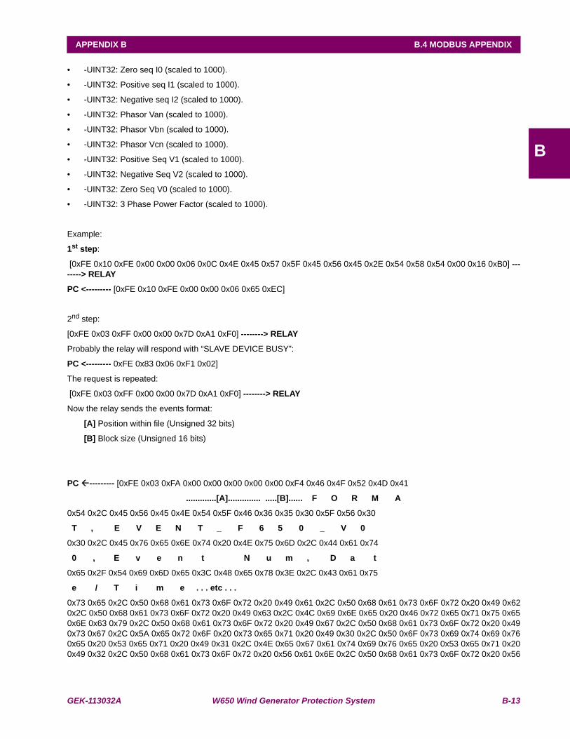
GEK-113032A W650 Wind Generator Protection System B-13
APPENDIX B B.4 MODBUS APPENDIX
B
• -UINT32: Zero seq I0 (scaled to 1000).
• -UINT32: Positive seq I1 (scaled to 1000).
• -UINT32: Negative seq I2 (scaled to 1000).
• -UINT32: Phasor Van (scaled to 1000).
• -UINT32: Phasor Vbn (scaled to 1000).
• -UINT32: Phasor Vcn (scaled to 1000).
• -UINT32: Positive Seq V1 (scaled to 1000).
• -UINT32: Negative Seq V2 (scaled to 1000).
• -UINT32: Zero Seq V0 (scaled to 1000).
• -UINT32: 3 Phase Power Factor (scaled to 1000).
Example:
1st step:
[0xFE 0x10 0xFE 0x00 0x00 0x06 0x0C 0x4E 0x45 0x57 0x5F 0x45 0x56 0x45 0x2E 0x54 0x58 0x54 0x00 0x16 0xB0] --------> RELAY
PC <--------- [0xFE 0x10 0xFE 0x00 0x00 0x06 0x65 0xEC]
2nd step:
[0xFE 0x03 0xFF 0x00 0x00 0x7D 0xA1 0xF0] --------> RELAY
Probably the relay will respond with “SLAVE DEVICE BUSY”:
PC <--------- 0xFE 0x83 0x06 0xF1 0x02]
The request is repeated:
[0xFE 0x03 0xFF 0x00 0x00 0x7D 0xA1 0xF0] --------> RELAY
Now the relay sends the events format:
[A] Position within file (Unsigned 32 bits)
[B] Block size (Unsigned 16 bits)
PC --------- [0xFE 0x03 0xFA 0x00 0x00 0x00 0x00 0x00 0xF4 0x46 0x4F 0x52 0x4D 0x41
.............[A].............. .....[B]...... F O R M A
0x54 0x2C 0x45 0x56 0x45 0x4E 0x54 0x5F 0x46 0x36 0x35 0x30 0x5F 0x56 0x30
T , E V E N T _ F 6 5 0 _ V 0
0x30 0x2C 0x45 0x76 0x65 0x6E 0x74 0x20 0x4E 0x75 0x6D 0x2C 0x44 0x61 0x74
0 , E v e n t N u m , D a t
0x65 0x2F 0x54 0x69 0x6D 0x65 0x3C 0x48 0x65 0x78 0x3E 0x2C 0x43 0x61 0x75
e / T i m e . . . etc . . .
0x73 0x65 0x2C 0x50 0x68 0x61 0x73 0x6F 0x72 0x20 0x49 0x61 0x2C 0x50 0x68 0x61 0x73 0x6F 0x72 0x20 0x49 0x620x2C 0x50 0x68 0x61 0x73 0x6F 0x72 0x20 0x49 0x63 0x2C 0x4C 0x69 0x6E 0x65 0x20 0x46 0x72 0x65 0x71 0x75 0x650x6E 0x63 0x79 0x2C 0x50 0x68 0x61 0x73 0x6F 0x72 0x20 0x49 0x67 0x2C 0x50 0x68 0x61 0x73 0x6F 0x72 0x20 0x490x73 0x67 0x2C 0x5A 0x65 0x72 0x6F 0x20 0x73 0x65 0x71 0x20 0x49 0x30 0x2C 0x50 0x6F 0x73 0x69 0x74 0x69 0x760x65 0x20 0x53 0x65 0x71 0x20 0x49 0x31 0x2C 0x4E 0x65 0x67 0x61 0x74 0x69 0x76 0x65 0x20 0x53 0x65 0x71 0x200x49 0x32 0x2C 0x50 0x68 0x61 0x73 0x6F 0x72 0x20 0x56 0x61 0x6E 0x2C 0x50 0x68 0x61 0x73 0x6F 0x72 0x20 0x56
B-14 W650 Wind Generator Protection System GEK-113032A
B.4 MODBUS APPENDIX APPENDIX B
B
0x62 0x6E 0x2C 0x50 0x68 0x61 0x73 0x6F 0x72 0x20 0x56 0x63 0x6E 0x2C 0x50 0x6F 0x73 0x69 0x74 0x69 0x76 0x650x20 0x53 0x65 0x71 0x20 0x56 0x31 0x2C 0x4E 0x65 0x67 0x61 0x74 0x69 0x76 0x65 0x20 0x53 0x65 0x71 0x20 0x560x32 0x2C 0x5A 0x65 0x72 0x6F 0x20 0x53 0x65 0x71 0x20 0x56 0x30 0x2C 0x33 0x20 0x50 0x68 0x4C 0xF3]
[0xFE 0x03 0xFF 0x00 0x00 0x7D 0xA1 0xF0] ---------> RELAY
PC <--------- [0xFE 0x03 0xFA 0x00 0x00 0x00 0xF4 0x00 0xF4 0x61 0x73 0x65 0x20 0x50 0x6F
0x77 0x65 0x72 0x20 0x46 0x61 0x63 0x74 0x6F 0x72 0x0D 0x0A
CR LF (here the format ends)
0x45 0x56 0x45 0x4E 0x54 0x5F 0x46 0x36 0x35 0x30 0x5F 0x56 0x30 0x30 0x2C 0x35 0x36 0x35
E V E N T _ F 6 5 0 _ V 0 0 , 5 6 5
0 x37 0x2C 0x30 0x30 0x30 0x30 0x30 0x30 0x31 0x36 0x66 0x63 0x39 0x38 0x66
7 , 0 0 0 0 0 0 1 6 f 3 9 8 f
0x34 0x33 0x39 0x2C 0x4C 0x6F 0x63 0x61 0x6C 0x20 0x6D 0x6F 0x64 0x65 0x2C
4 3 9 , l o c a l m o d e ,
0x30 0x2E 0x30 0x30 0x30 0x2C 0x30 0x2E 0x30 0x30 0x31 0x2C 0x30 0x2E 0x30
....
0x30 0x31 0x2C 0x30 0x2E 0x30 0x30 0x30 0x2C 0x30 0x2E 0x30 0x30 0x30 0x2C 0x30 0x2E 0x30 0x30 0x30 0x2C 0x300x2E 0x30 0x30 0x30 0x2C 0x30 0x2E 0x30 0x30 0x30 0x2C 0x30 0x2E 0x30 0x30 0x30 0x2C 0x30 0x2E 0x30 0x30 0x320x2C 0x30 0x2E 0x30 0x30 0x31 0x2C 0x30 0x2E 0x30 0x30 0x32 0x2C 0x30 0x2E 0x30 0x30 0x31 0x2C 0x30 0x2E 0x300x30 0x31 0x2C 0x30 0x2E 0x30 0x30 0x30 0x2C 0x31 0x2E 0x30 0x30 0x30 0x0D 0x0A
CR LF (a line ends)
0x45 0x56 0x45 0x4E 0x54 0x5F 0x46 0x36 0x35 0x30 0x5F 0x56 0x30 0x30 0x2C 0x35 0x36 0x35 0x38 0x2C 0x30 0x300x30 0x30 0x30 0x30 0x31 0x36 0x66 0x63 0x39 0x38 0x66 0x34 0x33 0x39 0x2C 0x28 0x31 0x29 0x56 0x69 0x72 0x740x75 0x61 0x6C 0x20 0x4F 0x75 0x74 0x38 0x39 0x36 0x2C 0x30 0x2E 0x30 0x30 0x30 0x2C 0x30 0x2E 0x30 0x30 0x310x2C 0x30 0x2E 0x30 0x30 0x31 0x2C 0x30 0x2E 0x30 0x30 0x30 0x2C 0x30 0x2E 0x34 0x24]
[0xFE 0x03 0xFF 0x00 0x00 0x7D 0xA1 0xF0] ---------> RELAY
PC <---------[0xFE 0x03 0xFA 0x00 0x00 0x01 0xE8 0x00 0x47 0x30 0x0047 => last string
0x30 0x30 0x2C 0x30 0x2E 0x30 0x30 0x30 0x2C 0x30 0x2E 0x30 0x30 0x30 0x2C 0x30 0x2E 0x30 0x30 0x30 0x2C 0x300x2E 0x30 0x30 0x30 0x2C 0x30 0x2E 0x30 0x30 0x32 0x2C 0x30 0x2E 0x30 0x30 0x31 0x2C 0x30 0x2E 0x30 0x30 0x320x2C 0x30 0x2E 0x30 0x30 0x31 0x2C 0x30 0x2E 0x30 0x30 0x31 0x2C 0x30 0x2E 0x30 0x30 0x30 0x2C 0x31 0x2E 0x300x30 0x30 0x0D 0x0A
CR LF (a line ends)
0x00 0x00 0x30 0x0D 0x0A 0x45 0x56 0x45 0x4E 0x54 0x5F 0x46 0x36 0x35 0x30 0x5F 0x56 0x30 0x30 0x2C 0x33 0x300x39 0x38 0x2C 0x30 0x30 0x30 0x30 0x30 0x30 0x31 0x36 0x65 0x62 0x61 0x33 0x33 0x62 0x62 0x38 0x2C 0x43 0x6F0x6E 0x74 0x61 0x63 0x74 0x20 0x4F 0x75 0x74 0x70 0x75 0x74 0x5F 0x30 0x30 0x5F 0x30 0x30 0x20 0x4F 0x4E 0x2C0x30 0x2E 0x30 0x30 0x30 0x2C 0x30 0x2E 0x30 0x30 0x30 0x2C 0x30 0x2E 0x30 0x30 0x31 0x2C 0x30 0x2E 0x30 0x300x30 0x2C 0x30 0x2E 0x30 0x30 0x31 0x2C 0x30 0x2E 0x30 0x30 0x30 0x2C 0x30 0x2E 0x30 0x30 0x30 0x2C 0x30 0x2E0x30 0x30 0x30 0x2C 0x30 0x2E 0x30 0x30 0x30 0x2C 0x30 0x2E 0x30 0x30 0x31 0x2C 0x30 0x2E 0x30 0x30 0x32 0x2C0x30 0x2E 0x30 0x30 0x30 0x2C 0x30 0x2E 0x30 0x30 0x30 0x2C 0x30 0x2E 0x30 0x30 0x31 0x2C 0x30 0x2E 0x30 0x300x30 0x2C 0x31 0x2E 0x30 0x30 0x30 0x0D 0x0A 0x45 0x56 0x45 0x4E 0x54 0x5F 0x46 0x36 0x35 0x30 0xDB 0xB4]
GEK-113032A W650 Wind Generator Protection System B-15
APPENDIX B B.4 MODBUS APPENDIX
B
B.4.4 OPERATIONS
For executing an Operation, it is necessary to write the bit corresponding to that Operation. For this purpose, there are twomemory records whose bits represent operations. These records are 0xAFFE and 0xAFFF.
Each operation has assigned one bit in the register:
Operation 1: bit 0 ‘0xaffe’
Operation 2: bit 1‘0xaffe’
...
Operation 16: bit 15‘0xaffe’
Operation 17: bit 0‘0xafff’
...
Operation 24: bit 7‘0xafff’
The register format is ‘MOTOROLA’; this means that the first byte arriving is the one with more weight.
Remember that depending on where it communicates the correspondent channel will be activated, which takes part forPLC operations if the operation is successful or not. The operations channels are:
0 - MMI
1 - OPER REMOTE
2 - COM 1- COMUNICACION
3 - COM 2- COMUNICACION
4 - RED 1- COMUNICACION
5 - RED 2- COMUNICACION
6 - RED 3- COMUNICACION
7 - RED 4- COMUNICACIÓN
Example, operation 1 is going to be perform:
[0xFE 0x10 0xAF 0xFE 0x00 0x01 0x02 0x00 0x01 0x68 0xB0] ---------> RELAY
PC <--------- [0xFE 0x10 0xAF 0xFE 0x00 0x01 0x55 0x22] ( ACK (acknowledge) the operation)

B-16 W650 Wind Generator Protection System GEK-113032A
B.5 OUTPUT WRITING APPENDIX B
B
B.5OUTPUT WRITINGRelay contacts writing in the I/O boards are thought to make easy wiring checks. Proceeding as witha file access, with opening, writing and lockout.
If it is a writing to a mixed board (includes 16 inputs and 8 outputs):
1º.- OPEN FILE OF OUTPUTS: writing msg to 0xFE20 of 3 registers with the name: OUTPUT
2º. - DESIRED OUTPUTS WRITING writing message to 0xFF20 of 5 REGISTERS, the first one is the board number(0 or 1) and the restraint ones are the bytes of bits (bits are grouped byte to byte).
3º.- CLOSE FILE OF OUTPUTS: writing msg to 0xFE 28 of 3 registers with the name: OUTPUT
Example, activate the two lower relays to board ‘0’:
1st Opening
[0xFE 0x10 0xFE 0x20 0x00 0x03 0x06 0x4F 0x55 0x54 0x50 0x55 0x54 0xA8 0x42] ---------> RELAY
O U T P U T
PC <---------[0xFE 0x10 0xFE 0x20 0x00 0x03 0xA4 0x25]
2nd Writing
[0xFE 0x10 0xFF 0x20 0x00 0x05 0x0A 0x00 0x00 0x03 0x00 0x00 0x00 0x00 0x00 0x00 0x00
0x0000 0x03
0xAE 0x8D] ---------> RELAY
PC <--------- [0xFE 0x10 0xFF 0x20 0x00 0x05 0x25 0xDB]
3th Lockout:
[0xFE 0x10 0xFE 0x28 0x00 0x03 0x06 0x4F 0x55 0x54 0x50 0x55 0x54 0x29 0xA8] ---------> RELAYPC <--------- [0xFE 0x10 0xFE 0x28 0x00 0x03 0x25 0xE7]
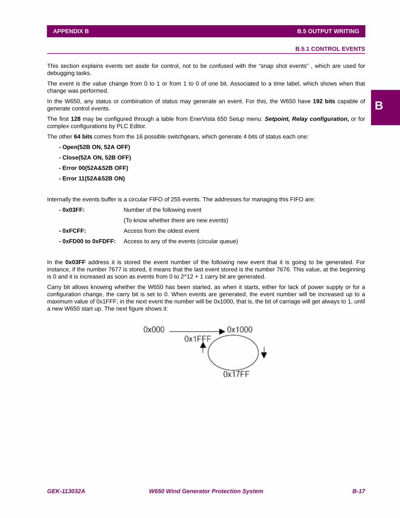
GEK-113032A W650 Wind Generator Protection System B-17
APPENDIX B B.5 OUTPUT WRITING
B
B.5.1 CONTROL EVENTS
This section explains events set aside for control, not to be confused with the “snap shot events” , which are used fordebugging tasks.
The event is the value change from 0 to 1 or from 1 to 0 of one bit. Associated to a time label, which shows when thatchange was performed.
In the W650, any status or combination of status may generate an event. For this, the W650 have 192 bits capable ofgenerate control events.
The first 128 may be configured through a table from EnerVista 650 Setup menu: Setpoint, Relay configuration, or forcomplex configurations by PLC Editor.
The other 64 bits comes from the 16 possible switchgears, which generate 4 bits of status each one:
- Open(52B ON, 52A OFF)
- Close(52A ON, 52B OFF)
- Error 00(52A&52B OFF)
- Error 11(52A&52B ON)
Internally the events buffer is a circular FIFO of 255 events. The addresses for managing this FIFO are:
- 0x03FF: Number of the following event
(To know whether there are new events)
- 0xFCFF: Access from the oldest event
- 0xFD00 to 0xFDFF: Access to any of the events (circular queue)
In the 0x03FF address it is stored the event number of the following new event that it is going to be generated. Forinstance, if the number 7677 is stored, it means that the last event stored is the number 7676. This value, at the beginningis 0 and it is increased as soon as events from 0 to 2^12 + 1 carry bit are generated.
Carry bit allows knowing whether the W650 has been started, as when it starts, either for lack of power supply or for aconfiguration change, the carry bit is set to 0. When events are generated, the event number will be increased up to amaximum value of 0x1FFF; in the next event the number will be 0x1000, that is, the bit of carriage will get always to 1, untila new W650 start up. The next figure shows it:
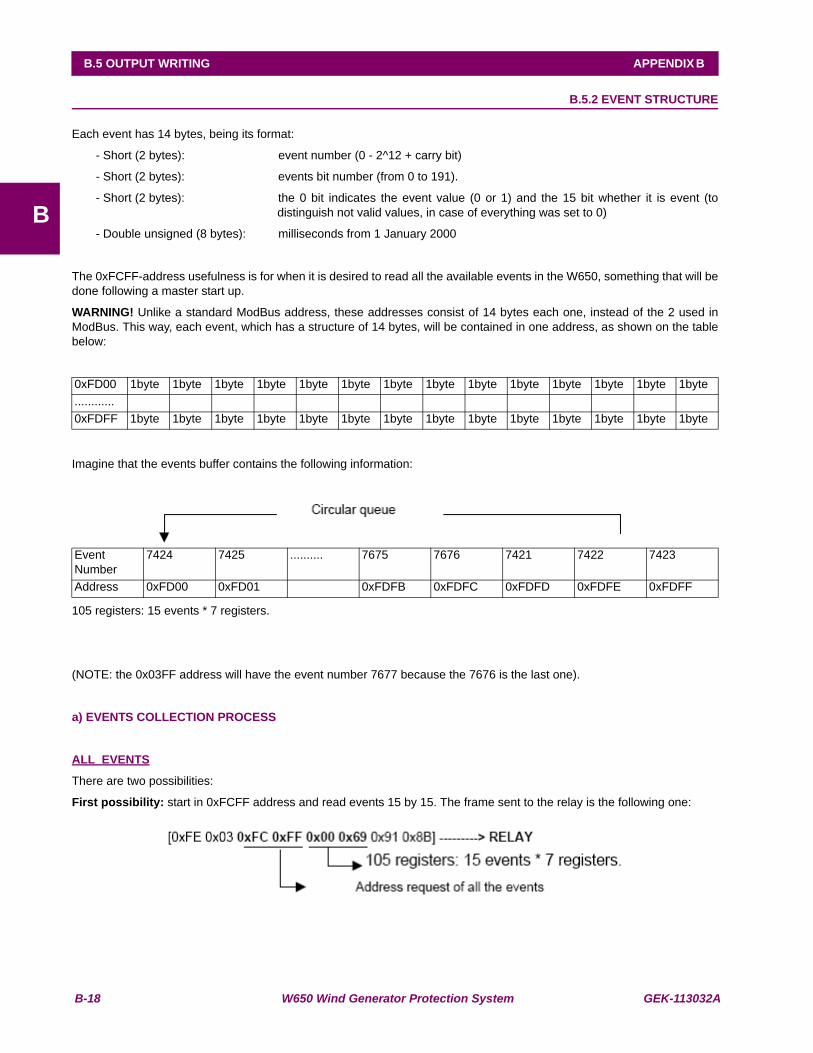
B-18 W650 Wind Generator Protection System GEK-113032A
B.5 OUTPUT WRITING APPENDIX B
B
B.5.2 EVENT STRUCTURE
Each event has 14 bytes, being its format:
- Short (2 bytes): event number (0 - 2^12 + carry bit)
- Short (2 bytes): events bit number (from 0 to 191).
- Short (2 bytes): the 0 bit indicates the event value (0 or 1) and the 15 bit whether it is event (todistinguish not valid values, in case of everything was set to 0)
- Double unsigned (8 bytes): milliseconds from 1 January 2000
The 0xFCFF-address usefulness is for when it is desired to read all the available events in the W650, something that will bedone following a master start up.
WARNING! Unlike a standard ModBus address, these addresses consist of 14 bytes each one, instead of the 2 used inModBus. This way, each event, which has a structure of 14 bytes, will be contained in one address, as shown on the tablebelow:
Imagine that the events buffer contains the following information:
105 registers: 15 events * 7 registers.
(NOTE: the 0x03FF address will have the event number 7677 because the 7676 is the last one).
a) EVENTS COLLECTION PROCESS
ALL EVENTS
There are two possibilities:
First possibility: start in 0xFCFF address and read events 15 by 15. The frame sent to the relay is the following one:
0xFD00 1byte 1byte 1byte 1byte 1byte 1byte 1byte 1byte 1byte 1byte 1byte 1byte 1byte 1byte............0xFDFF 1byte 1byte 1byte 1byte 1byte 1byte 1byte 1byte 1byte 1byte 1byte 1byte 1byte 1byte
EventNumber
7424 7425 .......... 7675 7676 7421 7422 7423
Address 0xFD00 0xFD01 0xFDFB 0xFDFC 0xFDFD 0xFDFE 0xFDFF
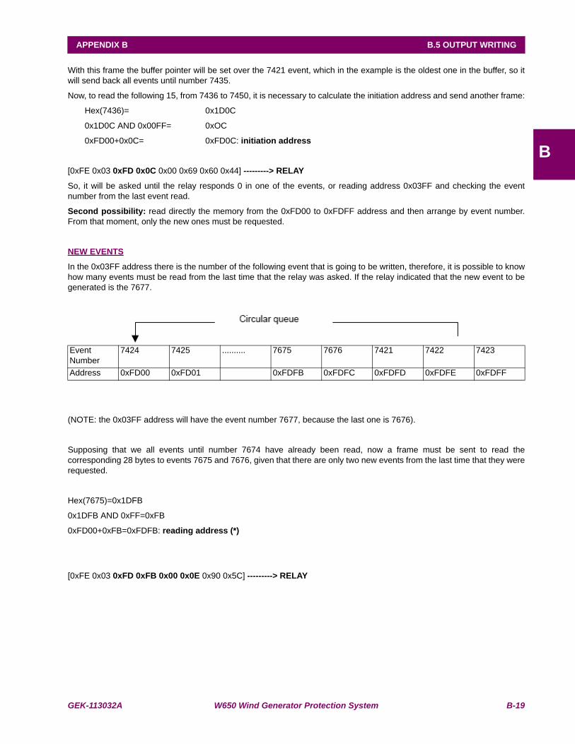
GEK-113032A W650 Wind Generator Protection System B-19
APPENDIX B B.5 OUTPUT WRITING
B
With this frame the buffer pointer will be set over the 7421 event, which in the example is the oldest one in the buffer, so itwill send back all events until number 7435.
Now, to read the following 15, from 7436 to 7450, it is necessary to calculate the initiation address and send another frame:
Hex(7436)= 0x1D0C
0x1D0C AND 0x00FF= 0xOC
0xFD00+0x0C= 0xFD0C: initiation address
[0xFE 0x03 0xFD 0x0C 0x00 0x69 0x60 0x44] ---------> RELAY
So, it will be asked until the relay responds 0 in one of the events, or reading address 0x03FF and checking the eventnumber from the last event read.
Second possibility: read directly the memory from the 0xFD00 to 0xFDFF address and then arrange by event number.From that moment, only the new ones must be requested.
NEW EVENTS
In the 0x03FF address there is the number of the following event that is going to be written, therefore, it is possible to knowhow many events must be read from the last time that the relay was asked. If the relay indicated that the new event to begenerated is the 7677.
(NOTE: the 0x03FF address will have the event number 7677, because the last one is 7676).
Supposing that we all events until number 7674 have already been read, now a frame must be sent to read thecorresponding 28 bytes to events 7675 and 7676, given that there are only two new events from the last time that they wererequested.
Hex(7675)=0x1DFB
0x1DFB AND 0xFF=0xFB
0xFD00+0xFB=0xFDFB: reading address (*)
[0xFE 0x03 0xFD 0xFB 0x00 0x0E 0x90 0x5C] ---------> RELAY
EventNumber
7424 7425 .......... 7675 7676 7421 7422 7423
Address 0xFD00 0xFD01 0xFDFB 0xFDFC 0xFDFD 0xFDFE 0xFDFF

B-20 W650 Wind Generator Protection System GEK-113032A
B.6 EVENTS STATUS REQUEST (ALARMS) APPENDIX B
B
B.6EVENTS STATUS REQUEST (ALARMS)
The necessary data to retrieve events that have been configured as alarms are located in the following addresses:
0xf000: 24 registers, the first 12 indicate the status active/inactive and the last 12 indicate the status ofacknowledged/not acknowledged.
0xf018: 12 event alarm status (active - not active, acknowledged – not acknowledged) registers.
0xf024: date and hour of the event bits starts (groups of 16 dates and hour must be asked for).
To obtain an instantaneous snapshot of all the events and alarms status, the procedure is:
• - Read the head of events FIFO (0x03FF).
• - Read the zones mentioned before.
• - Finally, read the head again to confirm that it has not changed. If it had changed, restart the procedure.
NOTE: The message must request the address and the quantity of bytes indicated in each zone. If other quantity is neededit will not respond with the requested data.

GEK-113032A W650 Wind Generator Protection System B-21
APPENDIX B B.6 EVENTS STATUS REQUEST (ALARMS)
B
B.6.1 CONTROL EVENTS RETRIEVAL FROM THE COMMAND LINE
Starting EnerVista 650 Setup form the command line offers the possibility of transferring control events to a file. For thispurpose, we need to indicate the event number from which event controls are to be retrieved, and the file where they are tobe stored.
Communication can be established via serial communication by specifying the port and access baudrate, or via Ethernetthrough the IP address and communication port. The relay number from which events are to be retrieved must also beindicated.
For executing this Operation, 6 parameters must be written, for both cases, serial communication or Ethernet.

B-22 W650 Wind Generator Protection System GEK-113032A
B.6 EVENTS STATUS REQUEST (ALARMS) APPENDIX B
B
B.6.2 SERIAL COMMUNICATION
W650pc –e event number " File name" –com port: baudrate relay number
E.g.: EnerVista 650 Setup –e 6 “C:\GE Power Management\EnerVista 650 Setup\files\Events\eventos.txt” –com 1:19200254

GEK-113032A W650 Wind Generator Protection System B-23
APPENDIX B B.6 EVENTS STATUS REQUEST (ALARMS)
B
B.6.3 ETHERNET COMMUNICATION
W650pc –e event number " File name" –ip “IP address”: port relay number
E.g.: EnerVista 650 Setup –e 6 “C:\GE Power Management\EnerVista 650 Setup\files\Events \eventos.txt” –ip192.168.37.240:502 254
The created file format will look as follows:
#Event Number, Event Id,Event Text,Event Data Time,Event Value(0,1)#
6,1,Local,09-Sep-2003 17:42:40.782,1
7,1,Local,09-Sep-2003 17:42:43.236,0
8,2,Remote,09-Sep-2003 17:42:43.236,1
B-24 W650 Wind Generator Protection System GEK-113032A
B.6 EVENTS STATUS REQUEST (ALARMS) APPENDIX B
B
B.6.4 ACKNOWLEDGEMENT OF EVENTS (ALARMS)
For acknowledging the alarms we must simply write message to the 0xf324 address with 12 data registers. Each bit meansan event, if we want to acknowledge an alarm, its corresponding bit must be set to ‘1’ (in order within the 192 bits).
NOTE: it must be borne in mind the independence of the acknowledgement condition, for its reading and its change,depending on the communication channel
There are 6 channels:
LOCAL: by MMI or COM-2 (front and rear accessible).
REMOTE: by COM-1
NET 1: nowadays by any net communication
NET 2: (it does not exist in version 1.4x and lower)
NET 3: (it does not exist in version 1.4x and lower)
NET 4: (it does not exist in version 1.4x and lower)

GEK-113032A W650 Wind Generator Protection System B-25
APPENDIX B B.6 EVENTS STATUS REQUEST (ALARMS)
B
B.6.5 VIRTUAL INPUTS WRITING
For forcing Virtual Inputs, a message with 4 indivisible records must be written at address, so that each bit corresponds to aVirtual Input. Values will not be correct if the first 4 records are not written in the same message. The first 32 are LATCHED(internally stored with RAM with battery), and the last 32 are SELF-RST (activated to 1 and deactivated in the next pass bythe PLC).
For reading the status of Virtual Inputs, it is necessary to start with address 0x0083(bit 0x004) up to 0x0087 (bit 0x0200).

B-26 W650 Wind Generator Protection System GEK-113032A
B.6 EVENTS STATUS REQUEST (ALARMS) APPENDIX B
B
B.6.6 USER MAP
W650 units incorporate a powerful feature called ModBus User Map, that allows to read 256 non-consecutive data records(settings and statuses). It is often required for a master computer to interrogate continuously several connected slaverelays. If those values are dispersed along the memory map, reading them may require several transmissions, and thismay cause a communications overload. The User Map can be programmed to get several memory addresses together in ablock of consecutive addresses of the User Map, so that they can be accessible with a single reading operation.
The user Map has two sections:
A record index area (addresses 0x3384 to 0x3483), containing 256 statuses and/or setting record addresses.
A record area (addresses 0xF330 to 0xF42F), containing the values for addresses indicated in the index area.
Data records that are separated in the rest of the memory map can be remapped to an address of an adjacent record in theUser Map area. For programming the map this way, addresses for the required records must be written in the index area.This avoids the need for several reading operations, thus improving data transmission yield.
For instance, if Contact Outputs from Board F (address 0x008B) and Board G (address 0x00B0) values are required, theseaddresses must be mapped as follows:
In address 0x3384, write 0x008B.
In address 0x3385
XXX write 0x00B0.
The reading of records 0xF330 and 0xF331, applying the corresponding bit masks, will provide the required informationabout the two boards Contact Outputs.
NOTE: Only single data can be set in the map, data that are in the memory map and can be read. This feature is not validfor events, waveform records, etc. that are not located in a map address.

GEK-113032A W650 Wind Generator Protection System B-27
APPENDIX B B.6 EVENTS STATUS REQUEST (ALARMS)
B
B.6.7 RETRIEVING OSCILOGRAPHY
In case of not using the quickest download method by FTP , ModBus can be used for downloading oscillography, in thesame way that events (snap-shots). First of all, open file with writing message in 0xfe40, where desired file to open isindicated, it could be:
OSC01.DAT (COMTRADE data file in binary)
OSC02.CFG (COMTRADE configuration file)
OSC01.HDR (COMTRADE header file)
OSC02.DAT
OSC02.HDR
...
For reading the oscillography in several strings, several reading requests must be sent to 0xff40 address . For reading theprevious message a reading petition must be sent to 0xff42 address. The maximum number of bytes to be read in each partis 244.

B-28 W650 Wind Generator Protection System GEK-113032A
B.6 EVENTS STATUS REQUEST (ALARMS) APPENDIX B
B
B.6.8 TIME SYNCHRONIZATION
Time synchronization consists of setting of relay date and time.
It may be supposed that is similar to a usual settings group writing but it has particularities:
- It is a data type very particular because it is made up of other simples.
- Once the data is changed, varies with time, it is a changing setting that can be read.
- It shares the time change with the IRIGB (this has more priority) and with a possible modification from MMI or anotherprotocols.
- In case of the relay gets disconnected from its auxiliary power supply, during some days, the time will remain in achip, feed by a capacitor (it does not need maintenance).
- And last, there are synchronism between the real time chip and the microprocessor time.
Time synchronization is made by a reading message over 0xfff0 address, either with the address of a single relay, if awriting confirmation is desired, or in broadcast, to synchronize several relays simultaneously.
Date/time format is unsigned double (8 bytes) in MOTOROLA format, which indicates the passed milliseconds from 1st ofJanuary 2000.
Reading example:
[0xFE 0x03 0xFF 0xF0 0x00 0x04 0x60 0x21] ---------> RELAY
PC <---------- [0xFE 0x03 0x08 0x00 0x00 0x00 0x17 0x05 0xFA 0xD5 0xBA 0x2D 0x1D]
Synchronism example:
[0xFE 0x10 0xFF 0xF0 0x00 0x04 0x08 0x00 0x00 0x00 0x17 0x9B 0x53 0x3F 0x60 0xA4 0x2B] ---------> RELAY
PC <---------- [0xFE 0x10 0xFF 0xF0 0x00 0x04 0xE5 0xE2]

GEK-113032A W650 Wind Generator Protection System B-29
APPENDIX B B.6 EVENTS STATUS REQUEST (ALARMS)
B
B.6.9 ENQUEUEING MESSAGES
In ModBus protocol, as in other protocols, exists an internal procedure in message reception and transmission.
When a relay gets a string, determined by a silence of 3 or 4 characters, it is queued in a FIFO queue, for a later processingin its own protocol. When the protocol is free of execution, it searches in the queue for strings to respond of the FIFO. Ifthere is such string, it processes it and then it is responded.
Several criteria have been adopted for real time operation:
- Each reading or writing is respond as soon as possible.
- This implies that when settings are changed and respond, a writing request recognition is indicated and then, themodification of internal settings is performed, (PERFORMING IT IN THE SHORTER TIME WITHOUT PROTECTION),and finally, settings are stored in a non-volatile memory device.
NOTE: As the relay is internally a modular system, it is possible that the response of some process is slower than what isexpected by the external program, considering the message as missed and sending again another request. If so, there willbe 2 queued messages and therefore, 2 messages will be responded. For this reason, response message ‘ACK’ must beverified with its request, and special attention must be paid to setting confirmation writings, especially with reference totime-out. EnerVista 650 Setup software is recommended to do the configuration modifications, as this software takes intoaccount all these details.

B-30 W650 Wind Generator Protection System GEK-113032A
B.6 EVENTS STATUS REQUEST (ALARMS) APPENDIX B
B
B.6.10 TRACES AND TROUBLESHOOTING
The tracer is a debugging tool to view the strings in any writing or reading process in ModBus. This tracer is activated in themenu from W650: View, Traces.
With this option enabled, request and response strings will be shown. If, for instance, request and response strings view isdesired, between W650 and the relay, in general settings reading we will do what follows:
1º. - Activate traces, from View, Traces menu
2º. - Open the general settings menu
The screen will display that group settings, on the left side bottom the relay reading request will appear
<0001><06/18/03 12:14:15>[0xFE 0x03 0x21 0x8A 0x00 0x16 0xFB 0xDD]
And on the right the settings response will appear:
0001><06/18/03 12:14:15>[0xFE 0x03 0x2C 0x3F 0x80 0x00 0x00 0x3F 0x80 0x00 0x00 0x3F 0x80 0x00 0x00 0x3F0x80 0x00 0x00 0x00 0x00 0x42 0xC8 0x00 0x00 0x00 0x00 0x00 0x00 0x00 0x00 0x00 0x00 0x00 0x01 0x00 0xFE0x00 0xFE 0x00 0x06 0x00 0x06 0x00 0x00 0x01 0xF6 0xAC 0xB5]
This way, any request or mechanism to obtain information from the relay, can be viewed string by string.
There is another tool for tracing the relay memory: in W650 menu: Communication, Troubleshooting, any reading to anyaddress can be requested, the PC will form the string together with check-sum register.
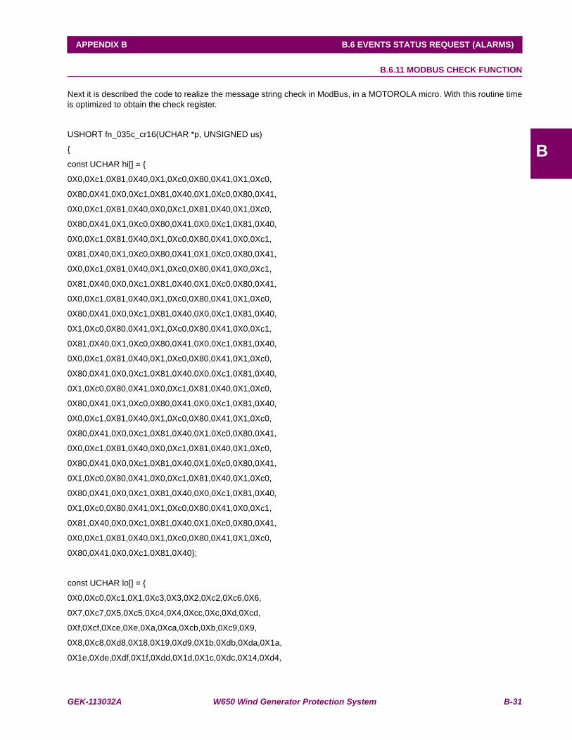
GEK-113032A W650 Wind Generator Protection System B-31
APPENDIX B B.6 EVENTS STATUS REQUEST (ALARMS)
B
B.6.11 MODBUS CHECK FUNCTION
Next it is described the code to realize the message string check in ModBus, in a MOTOROLA micro. With this routine timeis optimized to obtain the check register.
USHORT fn_035c_cr16(UCHAR *p, UNSIGNED us)
{
const UCHAR hi[] = {
0X0,0Xc1,0X81,0X40,0X1,0Xc0,0X80,0X41,0X1,0Xc0,
0X80,0X41,0X0,0Xc1,0X81,0X40,0X1,0Xc0,0X80,0X41,
0X0,0Xc1,0X81,0X40,0X0,0Xc1,0X81,0X40,0X1,0Xc0,
0X80,0X41,0X1,0Xc0,0X80,0X41,0X0,0Xc1,0X81,0X40,
0X0,0Xc1,0X81,0X40,0X1,0Xc0,0X80,0X41,0X0,0Xc1,
0X81,0X40,0X1,0Xc0,0X80,0X41,0X1,0Xc0,0X80,0X41,
0X0,0Xc1,0X81,0X40,0X1,0Xc0,0X80,0X41,0X0,0Xc1,
0X81,0X40,0X0,0Xc1,0X81,0X40,0X1,0Xc0,0X80,0X41,
0X0,0Xc1,0X81,0X40,0X1,0Xc0,0X80,0X41,0X1,0Xc0,
0X80,0X41,0X0,0Xc1,0X81,0X40,0X0,0Xc1,0X81,0X40,
0X1,0Xc0,0X80,0X41,0X1,0Xc0,0X80,0X41,0X0,0Xc1,
0X81,0X40,0X1,0Xc0,0X80,0X41,0X0,0Xc1,0X81,0X40,
0X0,0Xc1,0X81,0X40,0X1,0Xc0,0X80,0X41,0X1,0Xc0,
0X80,0X41,0X0,0Xc1,0X81,0X40,0X0,0Xc1,0X81,0X40,
0X1,0Xc0,0X80,0X41,0X0,0Xc1,0X81,0X40,0X1,0Xc0,
0X80,0X41,0X1,0Xc0,0X80,0X41,0X0,0Xc1,0X81,0X40,
0X0,0Xc1,0X81,0X40,0X1,0Xc0,0X80,0X41,0X1,0Xc0,
0X80,0X41,0X0,0Xc1,0X81,0X40,0X1,0Xc0,0X80,0X41,
0X0,0Xc1,0X81,0X40,0X0,0Xc1,0X81,0X40,0X1,0Xc0,
0X80,0X41,0X0,0Xc1,0X81,0X40,0X1,0Xc0,0X80,0X41,
0X1,0Xc0,0X80,0X41,0X0,0Xc1,0X81,0X40,0X1,0Xc0,
0X80,0X41,0X0,0Xc1,0X81,0X40,0X0,0Xc1,0X81,0X40,
0X1,0Xc0,0X80,0X41,0X1,0Xc0,0X80,0X41,0X0,0Xc1,
0X81,0X40,0X0,0Xc1,0X81,0X40,0X1,0Xc0,0X80,0X41,
0X0,0Xc1,0X81,0X40,0X1,0Xc0,0X80,0X41,0X1,0Xc0,
0X80,0X41,0X0,0Xc1,0X81,0X40};
const UCHAR lo[] = {
0X0,0Xc0,0Xc1,0X1,0Xc3,0X3,0X2,0Xc2,0Xc6,0X6,
0X7,0Xc7,0X5,0Xc5,0Xc4,0X4,0Xcc,0Xc,0Xd,0Xcd,
0Xf,0Xcf,0Xce,0Xe,0Xa,0Xca,0Xcb,0Xb,0Xc9,0X9,
0X8,0Xc8,0Xd8,0X18,0X19,0Xd9,0X1b,0Xdb,0Xda,0X1a,
0X1e,0Xde,0Xdf,0X1f,0Xdd,0X1d,0X1c,0Xdc,0X14,0Xd4,
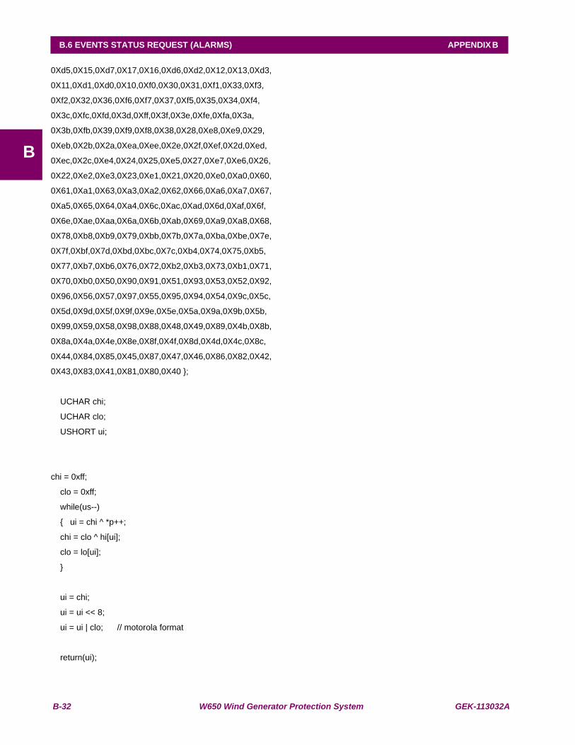
B-32 W650 Wind Generator Protection System GEK-113032A
B.6 EVENTS STATUS REQUEST (ALARMS) APPENDIX B
B
0Xd5,0X15,0Xd7,0X17,0X16,0Xd6,0Xd2,0X12,0X13,0Xd3,
0X11,0Xd1,0Xd0,0X10,0Xf0,0X30,0X31,0Xf1,0X33,0Xf3,
0Xf2,0X32,0X36,0Xf6,0Xf7,0X37,0Xf5,0X35,0X34,0Xf4,
0X3c,0Xfc,0Xfd,0X3d,0Xff,0X3f,0X3e,0Xfe,0Xfa,0X3a,
0X3b,0Xfb,0X39,0Xf9,0Xf8,0X38,0X28,0Xe8,0Xe9,0X29,
0Xeb,0X2b,0X2a,0Xea,0Xee,0X2e,0X2f,0Xef,0X2d,0Xed,
0Xec,0X2c,0Xe4,0X24,0X25,0Xe5,0X27,0Xe7,0Xe6,0X26,
0X22,0Xe2,0Xe3,0X23,0Xe1,0X21,0X20,0Xe0,0Xa0,0X60,
0X61,0Xa1,0X63,0Xa3,0Xa2,0X62,0X66,0Xa6,0Xa7,0X67,
0Xa5,0X65,0X64,0Xa4,0X6c,0Xac,0Xad,0X6d,0Xaf,0X6f,
0X6e,0Xae,0Xaa,0X6a,0X6b,0Xab,0X69,0Xa9,0Xa8,0X68,
0X78,0Xb8,0Xb9,0X79,0Xbb,0X7b,0X7a,0Xba,0Xbe,0X7e,
0X7f,0Xbf,0X7d,0Xbd,0Xbc,0X7c,0Xb4,0X74,0X75,0Xb5,
0X77,0Xb7,0Xb6,0X76,0X72,0Xb2,0Xb3,0X73,0Xb1,0X71,
0X70,0Xb0,0X50,0X90,0X91,0X51,0X93,0X53,0X52,0X92,
0X96,0X56,0X57,0X97,0X55,0X95,0X94,0X54,0X9c,0X5c,
0X5d,0X9d,0X5f,0X9f,0X9e,0X5e,0X5a,0X9a,0X9b,0X5b,
0X99,0X59,0X58,0X98,0X88,0X48,0X49,0X89,0X4b,0X8b,
0X8a,0X4a,0X4e,0X8e,0X8f,0X4f,0X8d,0X4d,0X4c,0X8c,
0X44,0X84,0X85,0X45,0X87,0X47,0X46,0X86,0X82,0X42,
0X43,0X83,0X41,0X81,0X80,0X40 };
UCHAR chi;
UCHAR clo;
USHORT ui;
chi = 0xff;
clo = 0xff;
while(us--)
{ ui = chi ^ *p++;
chi = clo ^ hi[ui];
clo = lo[ui];
}
ui = chi;
ui = ui << 8;
ui = ui | clo; // motorola format
return(ui);
GEK-113032A W650 Wind Generator Protection System B-33
APPENDIX B B.6 EVENTS STATUS REQUEST (ALARMS)
B
}
typedef struct //reading string
{ UCHAR dire;
UCHAR fn; //3 o 4
USHORT mem;
USHORT off;
USHORT check;
} PET_READ;
static PET_READ vpet_read; ------ this is the message (of reading)
And now it is proceed to perform the reading message check:
USHORT xx;
xx = vpet_read.check;
if(fn_035c_cr16( (UCHAR *)&vpet_read, sizeof(PET_READ)-2) == xx)
{ OK }
else
{ko }
If it is INTEL everything works but bytes are interchanged.
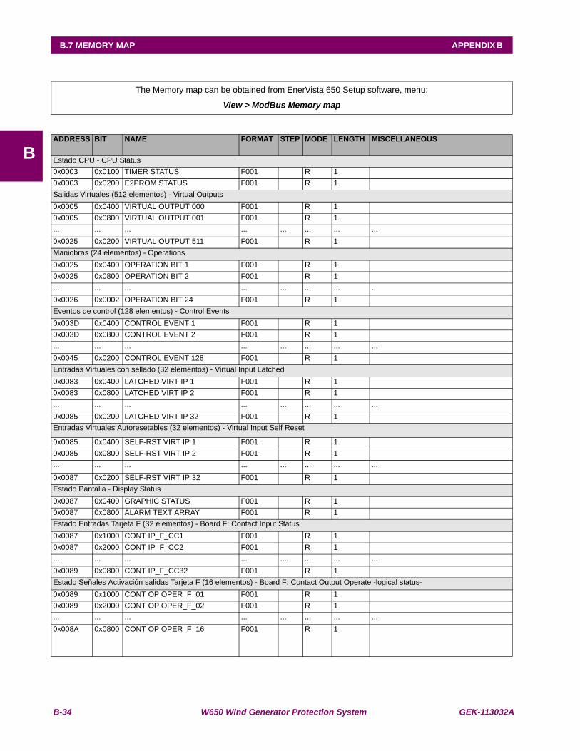
B-34 W650 Wind Generator Protection System GEK-113032A
B.7 MEMORY MAP APPENDIX B
B
B.7MEMORY MAP
The Memory map can be obtained from EnerVista 650 Setup software, menu:
View > ModBus Memory map
ADDRESS BIT NAME FORMAT STEP MODE LENGTH MISCELLANEOUS
Estado CPU - CPU Status0x0003 0x0100 TIMER STATUS F001 R 1 0x0003 0x0200 E2PROM STATUS F001 R 1 Salidas Virtuales (512 elementos) - Virtual Outputs0x0005 0x0400 VIRTUAL OUTPUT 000 F001 R 1 0x0005 0x0800 VIRTUAL OUTPUT 001 F001 R 1 ... ... ... ... ... ... ... ...0x0025 0x0200 VIRTUAL OUTPUT 511 F001 R 1 Maniobras (24 elementos) - Operations0x0025 0x0400 OPERATION BIT 1 F001 R 1 0x0025 0x0800 OPERATION BIT 2 F001 R 1 ... ... ... ... ... ... ... ..0x0026 0x0002 OPERATION BIT 24 F001 R 1 Eventos de control (128 elementos) - Control Events0x003D 0x0400 CONTROL EVENT 1 F001 R 1 0x003D 0x0800 CONTROL EVENT 2 F001 R 1 ... ... ... ... ... ... ... ...0x0045 0x0200 CONTROL EVENT 128 F001 R 1 Entradas Virtuales con sellado (32 elementos) - Virtual Input Latched0x0083 0x0400 LATCHED VIRT IP 1 F001 R 1 0x0083 0x0800 LATCHED VIRT IP 2 F001 R 1 ... ... ... ... ... ... ... ...0x0085 0x0200 LATCHED VIRT IP 32 F001 R 1 Entradas Virtuales Autoresetables (32 elementos) - Virtual Input Self Reset
0x0085 0x0400 SELF-RST VIRT IP 1 F001 R 1 0x0085 0x0800 SELF-RST VIRT IP 2 F001 R 1 ... ... ... ... ... ... ... ...
0x0087 0x0200 SELF-RST VIRT IP 32 F001 R 1 Estado Pantalla - Display Status0x0087 0x0400 GRAPHIC STATUS F001 R 1 0x0087 0x0800 ALARM TEXT ARRAY F001 R 1 Estado Entradas Tarjeta F (32 elementos) - Board F: Contact Input Status0x0087 0x1000 CONT IP_F_CC1 F001 R 1 0x0087 0x2000 CONT IP_F_CC2 F001 R 1 ... ... ... ... .... ... ... ...0x0089 0x0800 CONT IP_F_CC32 F001 R 1 Estado Señales Activación salidas Tarjeta F (16 elementos) - Board F: Contact Output Operate -logical status-0x0089 0x1000 CONT OP OPER_F_01 F001 R 1 0x0089 0x2000 CONT OP OPER_F_02 F001 R 1 ... ... ... ... ... ... ... ...0x008A 0x0800 CONT OP OPER_F_16 F001 R 1
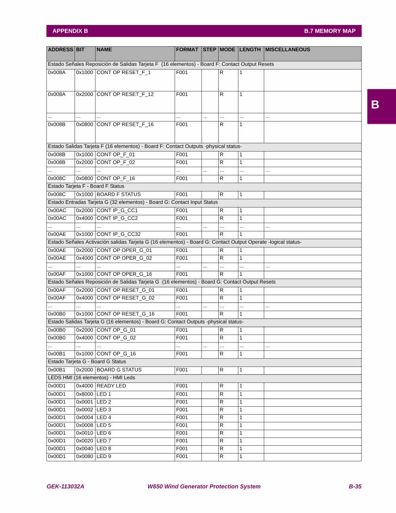
GEK-113032A W650 Wind Generator Protection System B-35
APPENDIX B B.7 MEMORY MAP
B
ADDRESS BIT NAME FORMAT STEP MODE LENGTH MISCELLANEOUS
Estado Señales Reposición de Salidas Tarjeta F (16 elementos) - Board F: Contact Output Resets0x008A 0x1000 CONT OP RESET_F_1 F001 R 1
0x008A 0x2000 CONT OP RESET_F_12 F001 R 1
... ... ... ... ... ... ... ...0x008B 0x0800 CONT OP RESET_F_16 F001 R 1
Estado Salidas Tarjeta F (16 elementos) - Board F: Contact Outputs -physical status-0x008B 0x1000 CONT OP_F_01 F001 R 1 0x008B 0x2000 CONT OP_F_02 F001 R 1 ... ... ... ... ... ... ... ...0x008C 0x0800 CONT OP_F_16 F001 R 1 Estado Tarjeta F - Board F Status0x008C 0x1000 BOARD F STATUS F001 R 1 Estado Entradas Tarjeta G (32 elementos) - Board G: Contact Input Status0x00AC 0x2000 CONT IP_G_CC1 F001 R 1 0x00AC 0x4000 CONT IP_G_CC2 F001 R 1 ... ... ... ... ... ... ... ...0x00AE 0x1000 CONT IP_G_CC32 F001 R 1 Estado Señales Activación salidas Tarjeta G (16 elementos) - Board G: Contact Output Operate -logical status-0x00AE 0x2000 CONT OP OPER_G_01 F001 R 1 0x00AE 0x4000 CONT OP OPER_G_02 F001 R 1 ... ... ... ... ... ... ... ...0x00AF 0x1000 CONT OP OPER_G_16 F001 R 1 Estado Señales Reposición de Salidas Tarjeta G (16 elementos) - Board G: Contact Output Resets0x00AF 0x2000 CONT OP RESET_G_01 F001 R 1 0x00AF 0x4000 CONT OP RESET_G_02 F001 R 1 ... ... ... ... ... ... ... ...0x00B0 0x1000 CONT OP RESET_G_16 F001 R 1 Estado Salidas Tarjeta G (16 elementos) - Board G: Contact Outputs -physical status-0x00B0 0x2000 CONT OP_G_01 F001 R 1 0x00B0 0x4000 CONT OP_G_02 F001 R 1 ... ... ... ... ... ... ... ...0x00B1 0x1000 CONT OP_G_16 F001 R 1 Estado Tarjeta G - Board G Status0x00B1 0x2000 BOARD G STATUS F001 R 1 LEDS HMI (16 elementos) - HMI Leds0x00D1 0x4000 READY LED F001 R 1 0x00D1 0x8000 LED 1 F001 R 1 0x00D1 0x0001 LED 2 F001 R 1 0x00D1 0x0002 LED 3 F001 R 1 0x00D1 0x0004 LED 4 F001 R 1 0x00D1 0x0008 LED 5 F001 R 1 0x00D1 0x0010 LED 6 F001 R 1 0x00D1 0x0020 LED 7 F001 R 1 0x00D1 0x0040 LED 8 F001 R 1 0x00D1 0x0080 LED 9 F001 R 1

B-36 W650 Wind Generator Protection System GEK-113032A
B.7 MEMORY MAP APPENDIX B
B
ADDRESS BIT NAME FORMAT STEP MODE LENGTH MISCELLANEOUS
LEDS HMI (16 elementos) - HMI Leds (cont.)0x00D2 0x0100 LED 10 F001 R 1 0x00D2 0x0200 LED 11 F001 R 1 0x00D2 0x0400 LED 12 F001 R 1 0x00D2 0x0800 LED 13 F001 R 1 0x00D2 0x1000 LED 14 F001 R 1 0x00D2 0x2000 LED 15 F001 R 1 Teclas HMI - HMI Keys0x00D2 0x4000 I Key F001 R 1 0x00D2 0x8000 O Key F001 R 1 0x00D2 0x0001 * Key F001 R 1 0x00D2 0x0002 F1 Key F001 R 1 0x00D2 0x0004 F2 Key F001 R 1 0x00D2 0x0008 LOCAL OPERATION MODE F001 R 1 0x00D2 0x0010 OPERATIONS BLOCKED F001 R 1 Estados Internos - Internal States0x00D2 0x0020 DSP COMM ERROR F001 R 1 0x00D2 0x0040 MAGNETIC MODULE ERROR F001 R 1 Entrada Reset Leds (configurable) -Led reset Input0x00D2 0x0080 LED RESET INPUT F001 R 1 Sobrecorriente instantanea de fases nivel alto - Phase IOC High0x00F2 0x0080 PH IOC1 HIGH A BLK F001 R 1 0x00F3 0x0100 PH IOC1 HIGH B BLK F001 R 1 0x00F3 0x0200 PH IOC1 HIGH C BLK F001 R 1 0x00F3 0x0400 PH IOC1 HIGH A PKP F001 R 1 0x00F3 0x0800 PH IOC1 HIGH A OP F001 R 1 0x00F3 0x1000 PH IOC1 HIGH B PKP F001 R 1 0x00F3 0x2000 PH IOC1 HIGH B OP F001 R 1 0x00F3 0x4000 PH IOC1 HIGH C PKP F001 R 1 0x00F3 0x8000 PH IOC1 HIGH C OP F001 R 1 0x00F3 0x0001 PH IOC1 HIGH PKP F001 R 1 0x00F3 0x0002 PH IOC1 HIGH OP F001 R 1 0x00F8 0x0004 PH IOC2 HIGH A BLK F001 R 1 0x00F8 0x0008 PH IOC2 HIGH B BLK F001 R 1 0x00F8 0x0010 PH IOC2 HIGH C BLK F001 R 1 0x00F8 0x0020 PH IOC2 HIGH A PKP F001 R 1 0x00F8 0x0040 PH IOC2 HIGH A OP F001 R 1 0x00F8 0x0080 PH IOC2 HIGH B PKP F001 R 1 0x00F9 0x0100 PH IOC2 HIGH B OP F001 R 1 0x00F9 0x0200 PH IOC2 HIGH C PKP F001 R 1 0x00F9 0x0400 PH IOC2 HIGH C OP F001 R 1 0x00F9 0x0800 PH IOC2 HIGH PKP F001 R 1 0x00F9 0x1000 PH IOC2 HIGH OP F001 R 1 0x00FE 0x2000 PH IOC3 HIGH A BLK F001 R 1 0x00FE 0x4000 PH IOC3 HIGH B BLK F001 R 1 0x00FE 0x8000 PH IOC3 HIGH C BLK F001 R 1 0x00FE 0x0001 PH IOC3 HIGH A PKP F001 R 1 0x00FE 0x0002 PH IOC3 HIGH A OP F001 R 1 0x00FE 0x0004 PH IOC3 HIGH B PKP F001 R 1 0x00FE 0x0008 PH IOC3 HIGH B OP F001 R 1 0x00FE 0x0010 PH IOC3 HIGH C PKP F001 R 1
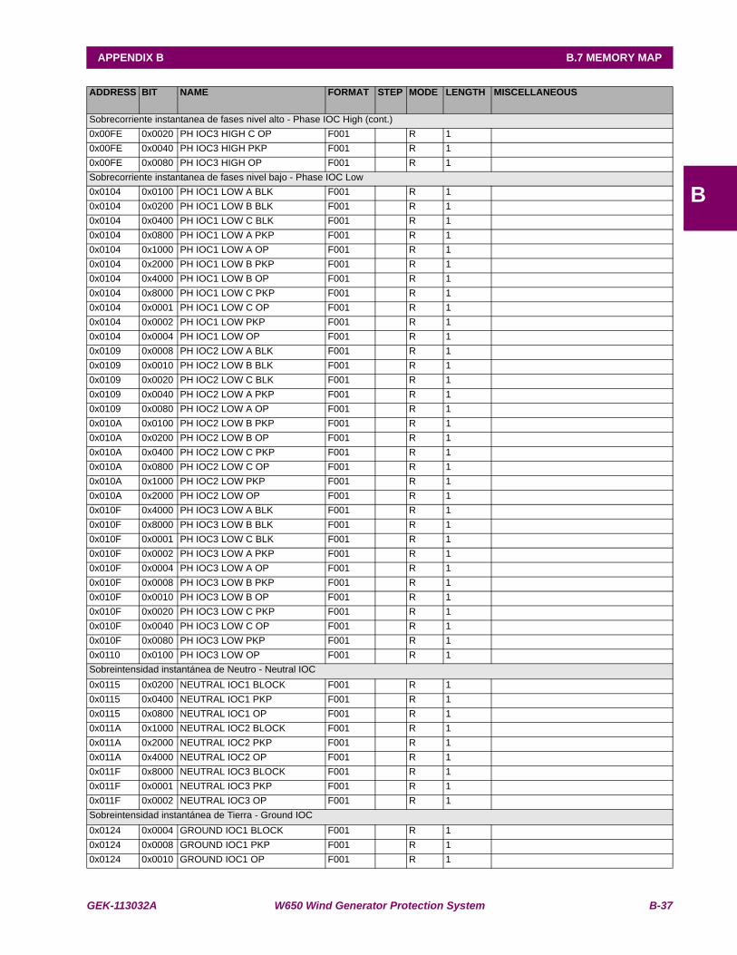
GEK-113032A W650 Wind Generator Protection System B-37
APPENDIX B B.7 MEMORY MAP
B
ADDRESS BIT NAME FORMAT STEP MODE LENGTH MISCELLANEOUS
Sobrecorriente instantanea de fases nivel alto - Phase IOC High (cont.)0x00FE 0x0020 PH IOC3 HIGH C OP F001 R 1 0x00FE 0x0040 PH IOC3 HIGH PKP F001 R 1 0x00FE 0x0080 PH IOC3 HIGH OP F001 R 1 Sobrecorriente instantanea de fases nivel bajo - Phase IOC Low0x0104 0x0100 PH IOC1 LOW A BLK F001 R 1 0x0104 0x0200 PH IOC1 LOW B BLK F001 R 1 0x0104 0x0400 PH IOC1 LOW C BLK F001 R 1 0x0104 0x0800 PH IOC1 LOW A PKP F001 R 1 0x0104 0x1000 PH IOC1 LOW A OP F001 R 1 0x0104 0x2000 PH IOC1 LOW B PKP F001 R 1 0x0104 0x4000 PH IOC1 LOW B OP F001 R 1 0x0104 0x8000 PH IOC1 LOW C PKP F001 R 1 0x0104 0x0001 PH IOC1 LOW C OP F001 R 1 0x0104 0x0002 PH IOC1 LOW PKP F001 R 1 0x0104 0x0004 PH IOC1 LOW OP F001 R 1 0x0109 0x0008 PH IOC2 LOW A BLK F001 R 1 0x0109 0x0010 PH IOC2 LOW B BLK F001 R 1 0x0109 0x0020 PH IOC2 LOW C BLK F001 R 1 0x0109 0x0040 PH IOC2 LOW A PKP F001 R 1 0x0109 0x0080 PH IOC2 LOW A OP F001 R 1 0x010A 0x0100 PH IOC2 LOW B PKP F001 R 1 0x010A 0x0200 PH IOC2 LOW B OP F001 R 1 0x010A 0x0400 PH IOC2 LOW C PKP F001 R 1 0x010A 0x0800 PH IOC2 LOW C OP F001 R 1 0x010A 0x1000 PH IOC2 LOW PKP F001 R 1 0x010A 0x2000 PH IOC2 LOW OP F001 R 1 0x010F 0x4000 PH IOC3 LOW A BLK F001 R 1 0x010F 0x8000 PH IOC3 LOW B BLK F001 R 1 0x010F 0x0001 PH IOC3 LOW C BLK F001 R 1 0x010F 0x0002 PH IOC3 LOW A PKP F001 R 1 0x010F 0x0004 PH IOC3 LOW A OP F001 R 1 0x010F 0x0008 PH IOC3 LOW B PKP F001 R 1 0x010F 0x0010 PH IOC3 LOW B OP F001 R 1 0x010F 0x0020 PH IOC3 LOW C PKP F001 R 1 0x010F 0x0040 PH IOC3 LOW C OP F001 R 1 0x010F 0x0080 PH IOC3 LOW PKP F001 R 1 0x0110 0x0100 PH IOC3 LOW OP F001 R 1 Sobreintensidad instantánea de Neutro - Neutral IOC0x0115 0x0200 NEUTRAL IOC1 BLOCK F001 R 1 0x0115 0x0400 NEUTRAL IOC1 PKP F001 R 1 0x0115 0x0800 NEUTRAL IOC1 OP F001 R 1 0x011A 0x1000 NEUTRAL IOC2 BLOCK F001 R 1 0x011A 0x2000 NEUTRAL IOC2 PKP F001 R 1 0x011A 0x4000 NEUTRAL IOC2 OP F001 R 1 0x011F 0x8000 NEUTRAL IOC3 BLOCK F001 R 1 0x011F 0x0001 NEUTRAL IOC3 PKP F001 R 1 0x011F 0x0002 NEUTRAL IOC3 OP F001 R 1 Sobreintensidad instantánea de Tierra - Ground IOC0x0124 0x0004 GROUND IOC1 BLOCK F001 R 1 0x0124 0x0008 GROUND IOC1 PKP F001 R 1 0x0124 0x0010 GROUND IOC1 OP F001 R 1
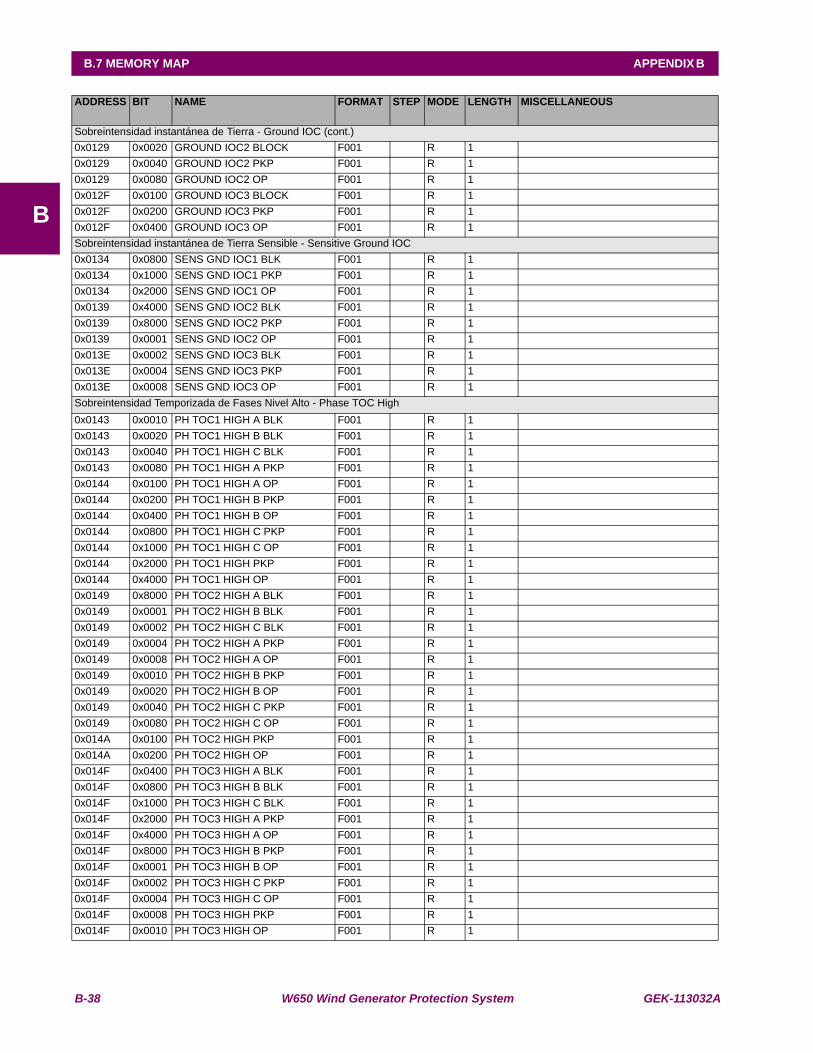
B-38 W650 Wind Generator Protection System GEK-113032A
B.7 MEMORY MAP APPENDIX B
B
ADDRESS BIT NAME FORMAT STEP MODE LENGTH MISCELLANEOUS
Sobreintensidad instantánea de Tierra - Ground IOC (cont.)0x0129 0x0020 GROUND IOC2 BLOCK F001 R 1 0x0129 0x0040 GROUND IOC2 PKP F001 R 1 0x0129 0x0080 GROUND IOC2 OP F001 R 1 0x012F 0x0100 GROUND IOC3 BLOCK F001 R 1 0x012F 0x0200 GROUND IOC3 PKP F001 R 1 0x012F 0x0400 GROUND IOC3 OP F001 R 1 Sobreintensidad instantánea de Tierra Sensible - Sensitive Ground IOC0x0134 0x0800 SENS GND IOC1 BLK F001 R 1 0x0134 0x1000 SENS GND IOC1 PKP F001 R 1 0x0134 0x2000 SENS GND IOC1 OP F001 R 1 0x0139 0x4000 SENS GND IOC2 BLK F001 R 1 0x0139 0x8000 SENS GND IOC2 PKP F001 R 1 0x0139 0x0001 SENS GND IOC2 OP F001 R 1 0x013E 0x0002 SENS GND IOC3 BLK F001 R 1 0x013E 0x0004 SENS GND IOC3 PKP F001 R 1 0x013E 0x0008 SENS GND IOC3 OP F001 R 1 Sobreintensidad Temporizada de Fases Nivel Alto - Phase TOC High0x0143 0x0010 PH TOC1 HIGH A BLK F001 R 1 0x0143 0x0020 PH TOC1 HIGH B BLK F001 R 1 0x0143 0x0040 PH TOC1 HIGH C BLK F001 R 1 0x0143 0x0080 PH TOC1 HIGH A PKP F001 R 1 0x0144 0x0100 PH TOC1 HIGH A OP F001 R 1 0x0144 0x0200 PH TOC1 HIGH B PKP F001 R 1 0x0144 0x0400 PH TOC1 HIGH B OP F001 R 1 0x0144 0x0800 PH TOC1 HIGH C PKP F001 R 1 0x0144 0x1000 PH TOC1 HIGH C OP F001 R 1 0x0144 0x2000 PH TOC1 HIGH PKP F001 R 1 0x0144 0x4000 PH TOC1 HIGH OP F001 R 1 0x0149 0x8000 PH TOC2 HIGH A BLK F001 R 1 0x0149 0x0001 PH TOC2 HIGH B BLK F001 R 1 0x0149 0x0002 PH TOC2 HIGH C BLK F001 R 1 0x0149 0x0004 PH TOC2 HIGH A PKP F001 R 1 0x0149 0x0008 PH TOC2 HIGH A OP F001 R 1 0x0149 0x0010 PH TOC2 HIGH B PKP F001 R 1 0x0149 0x0020 PH TOC2 HIGH B OP F001 R 1 0x0149 0x0040 PH TOC2 HIGH C PKP F001 R 1 0x0149 0x0080 PH TOC2 HIGH C OP F001 R 1 0x014A 0x0100 PH TOC2 HIGH PKP F001 R 1 0x014A 0x0200 PH TOC2 HIGH OP F001 R 1 0x014F 0x0400 PH TOC3 HIGH A BLK F001 R 1 0x014F 0x0800 PH TOC3 HIGH B BLK F001 R 1 0x014F 0x1000 PH TOC3 HIGH C BLK F001 R 1 0x014F 0x2000 PH TOC3 HIGH A PKP F001 R 1 0x014F 0x4000 PH TOC3 HIGH A OP F001 R 1 0x014F 0x8000 PH TOC3 HIGH B PKP F001 R 1 0x014F 0x0001 PH TOC3 HIGH B OP F001 R 1 0x014F 0x0002 PH TOC3 HIGH C PKP F001 R 1 0x014F 0x0004 PH TOC3 HIGH C OP F001 R 1 0x014F 0x0008 PH TOC3 HIGH PKP F001 R 1 0x014F 0x0010 PH TOC3 HIGH OP F001 R 1
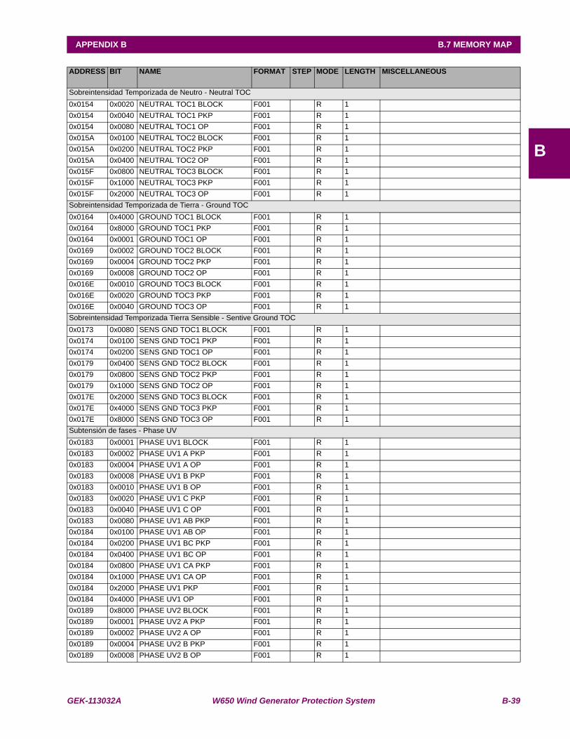
GEK-113032A W650 Wind Generator Protection System B-39
APPENDIX B B.7 MEMORY MAP
B
ADDRESS BIT NAME FORMAT STEP MODE LENGTH MISCELLANEOUS
Sobreintensidad Temporizada de Neutro - Neutral TOC0x0154 0x0020 NEUTRAL TOC1 BLOCK F001 R 1 0x0154 0x0040 NEUTRAL TOC1 PKP F001 R 1 0x0154 0x0080 NEUTRAL TOC1 OP F001 R 1 0x015A 0x0100 NEUTRAL TOC2 BLOCK F001 R 1 0x015A 0x0200 NEUTRAL TOC2 PKP F001 R 1 0x015A 0x0400 NEUTRAL TOC2 OP F001 R 1 0x015F 0x0800 NEUTRAL TOC3 BLOCK F001 R 1 0x015F 0x1000 NEUTRAL TOC3 PKP F001 R 1 0x015F 0x2000 NEUTRAL TOC3 OP F001 R 1 Sobreintensidad Temporizada de Tierra - Ground TOC0x0164 0x4000 GROUND TOC1 BLOCK F001 R 1 0x0164 0x8000 GROUND TOC1 PKP F001 R 1 0x0164 0x0001 GROUND TOC1 OP F001 R 1 0x0169 0x0002 GROUND TOC2 BLOCK F001 R 1 0x0169 0x0004 GROUND TOC2 PKP F001 R 1 0x0169 0x0008 GROUND TOC2 OP F001 R 1 0x016E 0x0010 GROUND TOC3 BLOCK F001 R 1 0x016E 0x0020 GROUND TOC3 PKP F001 R 1 0x016E 0x0040 GROUND TOC3 OP F001 R 1 Sobreintensidad Temporizada Tierra Sensible - Sentive Ground TOC0x0173 0x0080 SENS GND TOC1 BLOCK F001 R 1 0x0174 0x0100 SENS GND TOC1 PKP F001 R 1 0x0174 0x0200 SENS GND TOC1 OP F001 R 1 0x0179 0x0400 SENS GND TOC2 BLOCK F001 R 1 0x0179 0x0800 SENS GND TOC2 PKP F001 R 1 0x0179 0x1000 SENS GND TOC2 OP F001 R 1 0x017E 0x2000 SENS GND TOC3 BLOCK F001 R 1 0x017E 0x4000 SENS GND TOC3 PKP F001 R 1 0x017E 0x8000 SENS GND TOC3 OP F001 R 1 Subtensión de fases - Phase UV0x0183 0x0001 PHASE UV1 BLOCK F001 R 1 0x0183 0x0002 PHASE UV1 A PKP F001 R 1 0x0183 0x0004 PHASE UV1 A OP F001 R 1 0x0183 0x0008 PHASE UV1 B PKP F001 R 1 0x0183 0x0010 PHASE UV1 B OP F001 R 1 0x0183 0x0020 PHASE UV1 C PKP F001 R 1 0x0183 0x0040 PHASE UV1 C OP F001 R 1 0x0183 0x0080 PHASE UV1 AB PKP F001 R 1 0x0184 0x0100 PHASE UV1 AB OP F001 R 1 0x0184 0x0200 PHASE UV1 BC PKP F001 R 1 0x0184 0x0400 PHASE UV1 BC OP F001 R 1 0x0184 0x0800 PHASE UV1 CA PKP F001 R 1 0x0184 0x1000 PHASE UV1 CA OP F001 R 1 0x0184 0x2000 PHASE UV1 PKP F001 R 1 0x0184 0x4000 PHASE UV1 OP F001 R 1 0x0189 0x8000 PHASE UV2 BLOCK F001 R 1 0x0189 0x0001 PHASE UV2 A PKP F001 R 1 0x0189 0x0002 PHASE UV2 A OP F001 R 1 0x0189 0x0004 PHASE UV2 B PKP F001 R 1 0x0189 0x0008 PHASE UV2 B OP F001 R 1
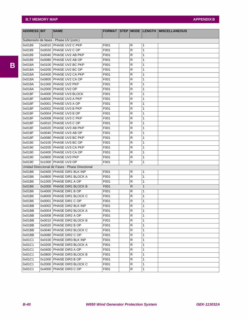
B-40 W650 Wind Generator Protection System GEK-113032A
B.7 MEMORY MAP APPENDIX B
B
ADDRESS BIT NAME FORMAT STEP MODE LENGTH MISCELLANEOUS
Subtensión de fases - Phase UV (cont.)0x0189 0x0010 PHASE UV2 C PKP F001 R 1 0x0189 0x0020 PHASE UV2 C OP F001 R 1 0x0189 0x0040 PHASE UV2 AB PKP F001 R 1 0x0189 0x0080 PHASE UV2 AB OP F001 R 1 0x018A 0x0100 PHASE UV2 BC PKP F001 R 1 0x018A 0x0200 PHASE UV2 BC OP F001 R 1 0x018A 0x0400 PHASE UV2 CA PKP F001 R 1 0x018A 0x0800 PHASE UV2 CA OP F001 R 1 0x018A 0x1000 PHASE UV2 PKP F001 R 1 0x018A 0x2000 PHASE UV2 OP F001 R 1 0x018F 0x4000 PHASE UV3 BLOCK F001 R 1 0x018F 0x8000 PHASE UV3 A PKP F001 R 1 0x018F 0x0001 PHASE UV3 A OP F001 R 1 0x018F 0x0002 PHASE UV3 B PKP F001 R 1 0x018F 0x0004 PHASE UV3 B OP F001 R 1 0x018F 0x0008 PHASE UV3 C PKP F001 R 1 0x018F 0x0010 PHASE UV3 C OP F001 R 1 0x018F 0x0020 PHASE UV3 AB PKP F001 R 1 0x018F 0x0040 PHASE UV3 AB OP F001 R 1 0x018F 0x0080 PHASE UV3 BC PKP F001 R 1 0x0190 0x0100 PHASE UV3 BC OP F001 R 1 0x0190 0x0200 PHASE UV3 CA PKP F001 R 1 0x0190 0x0400 PHASE UV3 CA OP F001 R 1 0x0190 0x0800 PHASE UV3 PKP F001 R 1 0x0190 0x1000 PHASE UV3 OP F001 R 1 Unidad Direccional de Fases - Phase Directional0x01B6 0x0400 PHASE DIR1 BLK INP F001 R 1 0x01B6 0x0800 PHASE DIR1 BLOCK A F001 R 1 0x01B6 0x1000 PHASE DIR1 A OP F001 R 1 0x01B6 0x2000 PHASE DIR1 BLOCK B F001 R 1 0x01B6 0x4000 PHASE DIR1 B OP F001 R 1 0x01B6 0x8000 PHASE DIR1 BLOCK C F001 R 1 0x01B6 0x0001 PHASE DIR1 C OP F001 R 1 0x01BB 0x0002 PHASE DIR2 BLK INP F001 R 1 0x01BB 0x0004 PHASE DIR2 BLOCK A F001 R 1 0x01BB 0x0008 PHASE DIR2 A OP F001 R 1 0x01BB 0x0010 PHASE DIR2 BLOCK B F001 R 1 0x01BB 0x0020 PHASE DIR2 B OP F001 R 1 0x01BB 0x0040 PHASE DIR2 BLOCK C F001 R 1 0x01BB 0x0080 PHASE DIR2 C OP F001 R 1 0x01C1 0x0100 PHASE DIR3 BLK INP F001 R 1 0x01C1 0x0200 PHASE DIR3 BLOCK A F001 R 1 0x01C1 0x0400 PHASE DIR3 A OP F001 R 1 0x01C1 0x0800 PHASE DIR3 BLOCK B F001 R 1 0x01C1 0x1000 PHASE DIR3 B OP F001 R 1 0x01C1 0x2000 PHASE DIR3 BLOCK C F001 R 1 0x01C1 0x4000 PHASE DIR3 C OP F001 R 1

GEK-113032A W650 Wind Generator Protection System B-41
APPENDIX B B.7 MEMORY MAP
B
ADDRESS BIT NAME FORMAT STEP MODE LENGTH MISCELLANEOUS
Unidad Direccional de Neutro - Neutral Directional0x01C6 0x8000 NEUTRAL DIR1 BLK INP F001 R 1 0x01C6 0x0001 NEUTRAL DIR1 BLOCK F001 R 1 0x01C6 0x0002 NEUTRAL DIR1 OP F001 R 1 0x01CB 0x0004 NEUTRAL DIR2 BLK INP F001 R 1 0x01CB 0x0008 NEUTRAL DIR2 BLOCK F001 R 1 0x01CB 0x0010 NEUTRAL DIR2 OP F001 R 1 Unidad Direccional de Neutro - Neutral Directiona (cont.)0x01D0 0x0020 NEUTRAL DIR3 BLK INP F001 R 1 0x01D0 0x0040 NEUTRAL DIR3 BLOCK F001 R 1 0x01D0 0x0080 NEUTRAL DIR3 OP F001 R 1 Unidad Direccional de Tierra - Ground Directional0x01D6 0x0100 GROUND DIR1 BLK INP F001 R 1 0x01D6 0x0200 GROUND DIR1 BLOCK F001 R 1 0x01D6 0x0400 GROUND DIR1 OP F001 R 1 0x01DB 0x0800 GROUND DIR2 BLK INP F001 R 1 0x01DB 0x1000 GROUND DIR2 BLOCK F001 R 1 0x01DB 0x2000 GROUND DIR2 OP F001 R 1 0x01E0 0x4000 GROUND DIR3 BLK INP F001 R 1 0x01E0 0x8000 GROUND DIR3 BLOCK F001 R 1 0x01E0 0x0001 GROUND DIR3 OP F001 R 1 Fallo de Interruptor - Breaker Failure0x01E5 0x0002 BKR FAIL INITIATE F001 R 1 0x01E5 0x0004 BKR FAIL NO CURRENT F001 R 1 0x01E5 0x0008 BKR FAIL SUPERVISION F001 R 1 0x01E5 0x0010 BKR FAIL HISET F001 R 1 0x01E5 0x0020 BKR FAIL LOWSET F001 R 1 0x01E5 0x0040 INTERNAL ARC F001 R 1 0x01E5 0x0080 BKR FAIL 2nd STEP F001 R 1 Fallo de Fusible - Fuse failure0x01EB 0x0100 VT FUSE FAILURE F001 R 1 Reenganchador (bit) - Autorecloser0x01F5 0x0008 AR LEVEL BLOCK F001 R 1 0x01F5 0x0010 AR PULSE BLOCK F001 R 1 0x01F5 0x0020 AR PULSE UNBLOCK F001 R 1 0x01F5 0x0080 AR INITIATE F001 R 1 0x01F6 0x0100 AR CONDS INPUT F001 R 1 0x01F6 0x0200 AR CLOSE BREAKER F001 R 1 0x01F6 0x0400 AR OUT OF SERVICE F001 R 1 0x01F6 0x0800 AR READY F001 R 1 0x01F6 0x1000 AR LOCKOUT F001 R 1 0x01F6 0x2000 AR BLOCK F001 R 1 0x01F6 0x4000 AR RCL IN PROGRESS F001 R 1 0x01F6 0x8000 AR LCK BY ANOMALY F001 R 1 0x01F6 0x0001 AR LCK BY FAIL OPEN F001 R 1 0x01F6 0x0002 AR LCK BY FAIL CLOSE F001 R 1 0x01F6 0x0004 AR LCK BY USER F001 R 1
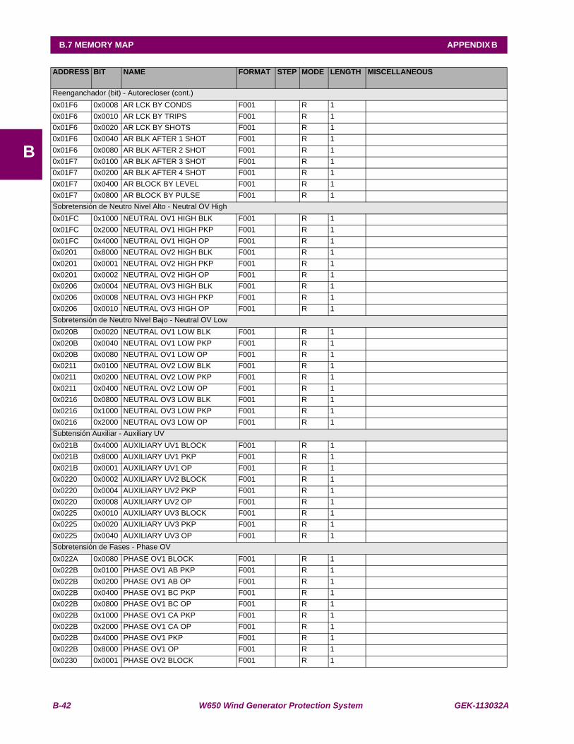
B-42 W650 Wind Generator Protection System GEK-113032A
B.7 MEMORY MAP APPENDIX B
B
ADDRESS BIT NAME FORMAT STEP MODE LENGTH MISCELLANEOUS
Reenganchador (bit) - Autorecloser (cont.)0x01F6 0x0008 AR LCK BY CONDS F001 R 1 0x01F6 0x0010 AR LCK BY TRIPS F001 R 1 0x01F6 0x0020 AR LCK BY SHOTS F001 R 1 0x01F6 0x0040 AR BLK AFTER 1 SHOT F001 R 1 0x01F6 0x0080 AR BLK AFTER 2 SHOT F001 R 1 0x01F7 0x0100 AR BLK AFTER 3 SHOT F001 R 1 0x01F7 0x0200 AR BLK AFTER 4 SHOT F001 R 1 0x01F7 0x0400 AR BLOCK BY LEVEL F001 R 1 0x01F7 0x0800 AR BLOCK BY PULSE F001 R 1 Sobretensión de Neutro Nivel Alto - Neutral OV High0x01FC 0x1000 NEUTRAL OV1 HIGH BLK F001 R 1 0x01FC 0x2000 NEUTRAL OV1 HIGH PKP F001 R 1 0x01FC 0x4000 NEUTRAL OV1 HIGH OP F001 R 1 0x0201 0x8000 NEUTRAL OV2 HIGH BLK F001 R 1 0x0201 0x0001 NEUTRAL OV2 HIGH PKP F001 R 1 0x0201 0x0002 NEUTRAL OV2 HIGH OP F001 R 1 0x0206 0x0004 NEUTRAL OV3 HIGH BLK F001 R 1 0x0206 0x0008 NEUTRAL OV3 HIGH PKP F001 R 1 0x0206 0x0010 NEUTRAL OV3 HIGH OP F001 R 1 Sobretensión de Neutro Nivel Bajo - Neutral OV Low0x020B 0x0020 NEUTRAL OV1 LOW BLK F001 R 1 0x020B 0x0040 NEUTRAL OV1 LOW PKP F001 R 1 0x020B 0x0080 NEUTRAL OV1 LOW OP F001 R 1 0x0211 0x0100 NEUTRAL OV2 LOW BLK F001 R 1 0x0211 0x0200 NEUTRAL OV2 LOW PKP F001 R 1 0x0211 0x0400 NEUTRAL OV2 LOW OP F001 R 1 0x0216 0x0800 NEUTRAL OV3 LOW BLK F001 R 1 0x0216 0x1000 NEUTRAL OV3 LOW PKP F001 R 1 0x0216 0x2000 NEUTRAL OV3 LOW OP F001 R 1 Subtensión Auxiliar - Auxiliary UV0x021B 0x4000 AUXILIARY UV1 BLOCK F001 R 1 0x021B 0x8000 AUXILIARY UV1 PKP F001 R 1 0x021B 0x0001 AUXILIARY UV1 OP F001 R 1 0x0220 0x0002 AUXILIARY UV2 BLOCK F001 R 1 0x0220 0x0004 AUXILIARY UV2 PKP F001 R 1 0x0220 0x0008 AUXILIARY UV2 OP F001 R 1 0x0225 0x0010 AUXILIARY UV3 BLOCK F001 R 1 0x0225 0x0020 AUXILIARY UV3 PKP F001 R 1 0x0225 0x0040 AUXILIARY UV3 OP F001 R 1 Sobretensión de Fases - Phase OV0x022A 0x0080 PHASE OV1 BLOCK F001 R 1 0x022B 0x0100 PHASE OV1 AB PKP F001 R 1 0x022B 0x0200 PHASE OV1 AB OP F001 R 1 0x022B 0x0400 PHASE OV1 BC PKP F001 R 1 0x022B 0x0800 PHASE OV1 BC OP F001 R 1 0x022B 0x1000 PHASE OV1 CA PKP F001 R 1 0x022B 0x2000 PHASE OV1 CA OP F001 R 1 0x022B 0x4000 PHASE OV1 PKP F001 R 1 0x022B 0x8000 PHASE OV1 OP F001 R 1 0x0230 0x0001 PHASE OV2 BLOCK F001 R 1
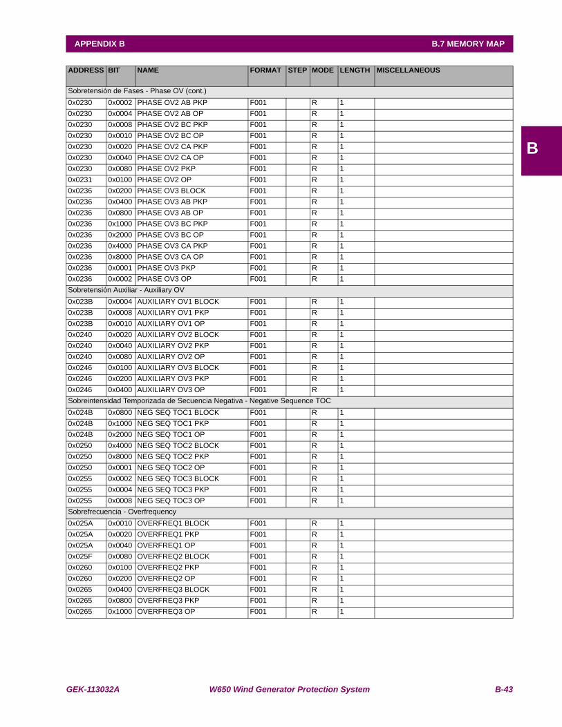
GEK-113032A W650 Wind Generator Protection System B-43
APPENDIX B B.7 MEMORY MAP
B
ADDRESS BIT NAME FORMAT STEP MODE LENGTH MISCELLANEOUS
Sobretensión de Fases - Phase OV (cont.)0x0230 0x0002 PHASE OV2 AB PKP F001 R 1 0x0230 0x0004 PHASE OV2 AB OP F001 R 1 0x0230 0x0008 PHASE OV2 BC PKP F001 R 1 0x0230 0x0010 PHASE OV2 BC OP F001 R 1 0x0230 0x0020 PHASE OV2 CA PKP F001 R 1 0x0230 0x0040 PHASE OV2 CA OP F001 R 1 0x0230 0x0080 PHASE OV2 PKP F001 R 1 0x0231 0x0100 PHASE OV2 OP F001 R 1 0x0236 0x0200 PHASE OV3 BLOCK F001 R 1 0x0236 0x0400 PHASE OV3 AB PKP F001 R 1 0x0236 0x0800 PHASE OV3 AB OP F001 R 1 0x0236 0x1000 PHASE OV3 BC PKP F001 R 1 0x0236 0x2000 PHASE OV3 BC OP F001 R 1 0x0236 0x4000 PHASE OV3 CA PKP F001 R 1 0x0236 0x8000 PHASE OV3 CA OP F001 R 1 0x0236 0x0001 PHASE OV3 PKP F001 R 1 0x0236 0x0002 PHASE OV3 OP F001 R 1 Sobretensión Auxiliar - Auxiliary OV0x023B 0x0004 AUXILIARY OV1 BLOCK F001 R 1 0x023B 0x0008 AUXILIARY OV1 PKP F001 R 1 0x023B 0x0010 AUXILIARY OV1 OP F001 R 1 0x0240 0x0020 AUXILIARY OV2 BLOCK F001 R 1 0x0240 0x0040 AUXILIARY OV2 PKP F001 R 1 0x0240 0x0080 AUXILIARY OV2 OP F001 R 1 0x0246 0x0100 AUXILIARY OV3 BLOCK F001 R 1 0x0246 0x0200 AUXILIARY OV3 PKP F001 R 1 0x0246 0x0400 AUXILIARY OV3 OP F001 R 1 Sobreintensidad Temporizada de Secuencia Negativa - Negative Sequence TOC0x024B 0x0800 NEG SEQ TOC1 BLOCK F001 R 1 0x024B 0x1000 NEG SEQ TOC1 PKP F001 R 1 0x024B 0x2000 NEG SEQ TOC1 OP F001 R 1 0x0250 0x4000 NEG SEQ TOC2 BLOCK F001 R 1 0x0250 0x8000 NEG SEQ TOC2 PKP F001 R 1 0x0250 0x0001 NEG SEQ TOC2 OP F001 R 1 0x0255 0x0002 NEG SEQ TOC3 BLOCK F001 R 1 0x0255 0x0004 NEG SEQ TOC3 PKP F001 R 1 0x0255 0x0008 NEG SEQ TOC3 OP F001 R 1 Sobrefrecuencia - Overfrequency 0x025A 0x0010 OVERFREQ1 BLOCK F001 R 1 0x025A 0x0020 OVERFREQ1 PKP F001 R 1 0x025A 0x0040 OVERFREQ1 OP F001 R 1 0x025F 0x0080 OVERFREQ2 BLOCK F001 R 1 0x0260 0x0100 OVERFREQ2 PKP F001 R 1 0x0260 0x0200 OVERFREQ2 OP F001 R 1 0x0265 0x0400 OVERFREQ3 BLOCK F001 R 1 0x0265 0x0800 OVERFREQ3 PKP F001 R 1 0x0265 0x1000 OVERFREQ3 OP F001 R 1
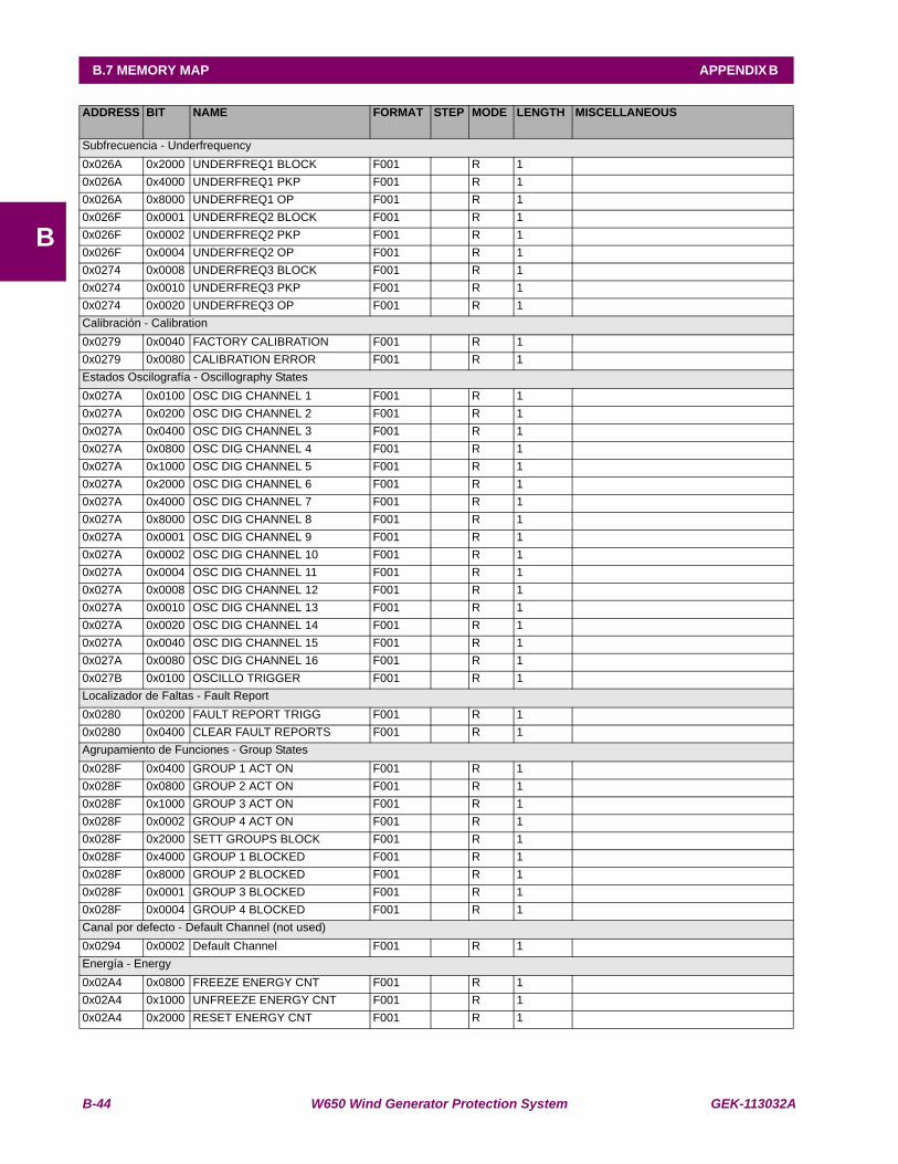
B-44 W650 Wind Generator Protection System GEK-113032A
B.7 MEMORY MAP APPENDIX B
B
ADDRESS BIT NAME FORMAT STEP MODE LENGTH MISCELLANEOUS
Subfrecuencia - Underfrequency 0x026A 0x2000 UNDERFREQ1 BLOCK F001 R 1 0x026A 0x4000 UNDERFREQ1 PKP F001 R 1 0x026A 0x8000 UNDERFREQ1 OP F001 R 1 0x026F 0x0001 UNDERFREQ2 BLOCK F001 R 1 0x026F 0x0002 UNDERFREQ2 PKP F001 R 1 0x026F 0x0004 UNDERFREQ2 OP F001 R 1 0x0274 0x0008 UNDERFREQ3 BLOCK F001 R 1 0x0274 0x0010 UNDERFREQ3 PKP F001 R 1 0x0274 0x0020 UNDERFREQ3 OP F001 R 1 Calibración - Calibration0x0279 0x0040 FACTORY CALIBRATION F001 R 1 0x0279 0x0080 CALIBRATION ERROR F001 R 1 Estados Oscilografía - Oscillography States0x027A 0x0100 OSC DIG CHANNEL 1 F001 R 1 0x027A 0x0200 OSC DIG CHANNEL 2 F001 R 1 0x027A 0x0400 OSC DIG CHANNEL 3 F001 R 1 0x027A 0x0800 OSC DIG CHANNEL 4 F001 R 1 0x027A 0x1000 OSC DIG CHANNEL 5 F001 R 1 0x027A 0x2000 OSC DIG CHANNEL 6 F001 R 1 0x027A 0x4000 OSC DIG CHANNEL 7 F001 R 1 0x027A 0x8000 OSC DIG CHANNEL 8 F001 R 1 0x027A 0x0001 OSC DIG CHANNEL 9 F001 R 1 0x027A 0x0002 OSC DIG CHANNEL 10 F001 R 1 0x027A 0x0004 OSC DIG CHANNEL 11 F001 R 1 0x027A 0x0008 OSC DIG CHANNEL 12 F001 R 1 0x027A 0x0010 OSC DIG CHANNEL 13 F001 R 1 0x027A 0x0020 OSC DIG CHANNEL 14 F001 R 1 0x027A 0x0040 OSC DIG CHANNEL 15 F001 R 1 0x027A 0x0080 OSC DIG CHANNEL 16 F001 R 1 0x027B 0x0100 OSCILLO TRIGGER F001 R 1 Localizador de Faltas - Fault Report0x0280 0x0200 FAULT REPORT TRIGG F001 R 1 0x0280 0x0400 CLEAR FAULT REPORTS F001 R 1 Agrupamiento de Funciones - Group States0x028F 0x0400 GROUP 1 ACT ON F001 R 1 0x028F 0x0800 GROUP 2 ACT ON F001 R 1 0x028F 0x1000 GROUP 3 ACT ON F001 R 1 0x028F 0x0002 GROUP 4 ACT ON F001 R 1 0x028F 0x2000 SETT GROUPS BLOCK F001 R 1 0x028F 0x4000 GROUP 1 BLOCKED F001 R 1 0x028F 0x8000 GROUP 2 BLOCKED F001 R 1 0x028F 0x0001 GROUP 3 BLOCKED F001 R 1 0x028F 0x0004 GROUP 4 BLOCKED F001 R 1 Canal por defecto - Default Channel (not used)0x0294 0x0002 Default Channel F001 R 1 Energía - Energy0x02A4 0x0800 FREEZE ENERGY CNT F001 R 1 0x02A4 0x1000 UNFREEZE ENERGY CNT F001 R 1 0x02A4 0x2000 RESET ENERGY CNT F001 R 1
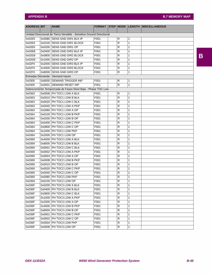
GEK-113032A W650 Wind Generator Protection System B-45
APPENDIX B B.7 MEMORY MAP
B
ADDRESS BIT NAME FORMAT STEP MODE LENGTH MISCELLANEOUS
Unidad Direccional de Tierra Sensible - Sensitive Ground Directional0x02E5 0x0080 SENS GND DIR1 BLK IP F001 R 1 0x02E6 0x0100 SENS GND DIR1 BLOCK F001 R 1 0x02E6 0x0200 SENS GND DIR1 OP F001 R 1 0x02EB 0x0400 SENS GND DIR2 BLK IP F001 R 1 0x02EB 0x0800 SENS GND DIR2 BLOCK F001 R 1 0x02EB 0x1000 SENS GND DIR2 OP F001 R 1 0x02F0 0x2000 SENS GND DIR3 BLK IP F001 R 1 0x02F0 0x4000 SENS GND DIR3 BLOCK F001 R 1 0x02F0 0x8000 SENS GND DIR3 OP F001 R 1 Entradas Demanda - Demand Inputs0x0305 0x8000 DEMAND TRIGGER INP F001 R 1 0x0305 0x0001 DEMAND RESET INP F001 R 1 Sobrecorriente Temporizada de Fases Nivel Bajo - Phase TOC Low0x0363 0x0008 PH TOC1 LOW A BLK F001 R 1 0x0363 0x0010 PH TOC1 LOW B BLK F001 R 1 0x0363 0x0020 PH TOC1 LOW C BLK F001 R 1 0x0363 0x0040 PH TOC1 LOW A PKP F001 R 1 0x0363 0x0080 PH TOC1 LOW A OP F001 R 1 0x0364 0x0100 PH TOC1 LOW B PKP F001 R 1 0x0364 0x0200 PH TOC1 LOW B OP F001 R 1 0x0364 0x0400 PH TOC1 LOW C PKP F001 R 1 0x0364 0x0800 PH TOC1 LOW C OP F001 R 1 0x0364 0x1000 PH TOC1 LOW PKP F001 R 1 0x0364 0x2000 PH TOC1 LOW OP F001 R 1 0x0369 0x4000 PH TOC2 LOW A BLK F001 R 1 0x0369 0x8000 PH TOC2 LOW B BLK F001 R 1 0x0369 0x0001 PH TOC2 LOW C BLK F001 R 1 0x0369 0x0002 PH TOC2 LOW A PKP F001 R 1 0x0369 0x0004 PH TOC2 LOW A OP F001 R 1 0x0369 0x0008 PH TOC2 LOW B PKP F001 R 1 0x0369 0x0010 PH TOC2 LOW B OP F001 R 1 0x0369 0x0020 PH TOC2 LOW C PKP F001 R 1 0x0369 0x0040 PH TOC2 LOW C OP F001 R 1 0x0369 0x0080 PH TOC2 LOW PKP F001 R 1 0x036A 0x0100 PH TOC2 LOW OP F001 R 1 0x036F 0x0200 PH TOC3 LOW A BLK F001 R 1 0x036F 0x0400 PH TOC3 LOW B BLK F001 R 1 0x036F 0x0800 PH TOC3 LOW C BLK F001 R 1 0x036F 0x1000 PH TOC3 LOW A PKP F001 R 1 0x036F 0x2000 PH TOC3 LOW A OP F001 R 1 0x036F 0x4000 PH TOC3 LOW B PKP F001 R 1 0x036F 0x8000 PH TOC3 LOW B OP F001 R 1 0x036F 0x0001 PH TOC3 LOW C PKP F001 R 1 0x036F 0x0002 PH TOC3 LOW C OP F001 R 1 0x036F 0x0004 PH TOC3 LOW PKP F001 R 1 0x036F 0x0008 PH TOC3 LOW OP F001 R 1

B-46 W650 Wind Generator Protection System GEK-113032A
B.7 MEMORY MAP APPENDIX B
B
ADDRESS BIT NAME FORMAT STEP MODE LENGTH MISCELLANEOUS
Contactos Configuración Aparamenta (16 elementos) - Switchgear Contact Configuration States0x0374 0x0010 SWITCH 1 A INPUT F001 R 1 0x0374 0x0020 SWITCH 1 B INPUT F001 R 1 0x0374 0x0040 SWITCH 2 A INPUT F001 R 1 0x0374 0x0080 SWITCH 2 B INPUT F001 R 1 ... ... ... ... ... ... ... ...0x0376 0x0004 SWITCH 16 A INPUT F001 R 1 0x0376 0x0008 SWITCH 16 B INPUT F001 R 1 Estados Contactos Aparamenta (16 elementos) - Switchgear Contact States0x0376 0x0010 SWITCH 1 A STATUS F001 R 1 0x0376 0x0020 SWITCH 1 B STATUS F001 R 1 0x0376 0x0040 SWITCH 2 A STATUS F001 R 1 0x0376 0x0080 SWITCH 2 B STATUS F001 R 1 ... ... ... ... ... ... ... ...0x0378 0x0004 SWITCH 16 A STATUS F001 R 1 0x0378 0x0008 SWITCH 16 B STATUS F001 R 1 Estados Aparamenta (16 elementos) - Switchgear States0x0378 0x0010 SWITCH 1 OPEN F001 R 1 0x0378 0x0020 SWITCH 1 CLOSED F001 R 1 0x0378 0x0040 SWITCH 1 00_ERROR F001 R 1 0x0378 0x0080 SWITCH 1 11_ERROR F001 R 1 0x0379 0x0100 SWITCH 2 OPEN F001 R 1 0x0379 0x0200 SWITCH 2 CLOSED F001 R 1 0x0379 0x0400 SWITCH 2 00_ERROR F001 R 1 0x0379 0x0800 SWITCH 2 11_ERROR F001 R 1 ... ... ... ... ... ... ... ...0x037C 0x0001 SWITCH 16 OPEN F001 R 1 0x037C 0x0002 SWITCH 16 CLOSED F001 R 1 0x037C 0x0004 SWITCH 16 00_ERROR F001 R 1 0x037C 0x0008 SWITCH 16 11_ERROR F001 R 1 Estados Inicio Apertura y Cierre Aparamenta - Switchgear Open-Close Initializing States0x037C 0x0010 SWITCH 1 OPEN INIT F001 R 1 0x037C 0x0020 SWITCH 1 CLOSE INIT F001 R 1 0x037C 0x0040 SWITCH 2 OPEN INIT F001 R 1 0x037C 0x0080 SWITCH 2 CLOSE INIT F001 R 1 ... ... ... ... ... ... ... ...0x037E 0x0004 SWITCH 16 OPEN INIT F001 R 1 0x037E 0x0008 SWITCH 16 CLOSE INIT F001 R 1 Estados Fallo Apertura y Cierre Aparamenta - Switchgear Fail States0x037E 0x0010 SWGR 1 FAIL TO OPEN F001 R 1 0x037E 0x0020 SWGR 2 FAIL TO OPEN F001 R 1 ... ... ... ... ... ... ... ...0x037F 0x0008 SWGR 16 FAIL TO OPEN F001 R 1 0x037F 0x0010 SWGR 1 FAIL TO CLOSE F001 R 1 0x037F 0x0020 SWGR 2 FAIL TO CLOSE F001 R 1 ... ... ... ... ... ... ... ...0x0380 0x0008 SWGR 16 FAIL TO CLOSE F001 R 1
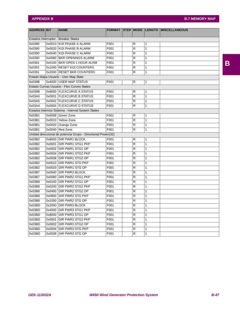
GEK-113032A W650 Wind Generator Protection System B-47
APPENDIX B B.7 MEMORY MAP
B
ADDRESS BIT NAME FORMAT STEP MODE LENGTH MISCELLANEOUS
Estados Interruptor - Breaker States0x0390 0x0010 KI2t PHASE A ALARM F001 R 1 0x0390 0x0020 KI2t PHASE B ALARM F001 R 1 0x0390 0x0040 KI2t PHASE C ALARM F001 R 1 0x0390 0x0080 BKR OPENINGS ALARM F001 R 1 0x0391 0x0100 BKR OPEN 1 HOUR ALRM F001 R 1 0x0391 0x1000 RESET KI2t COUNTERS F001 R 1 0x0391 0x2000 RESET BKR COUNTERS F001 R 1 Estado Mapa Usuario - User Map State0x039B 0x4000 USER MAP STATUS F001 R 1 Estado Curvas Usuario - Flex Curves States0x039B 0x8000 FLEXCURVE A STATUS F001 R 1 0x03A0 0x0001 FLEXCURVE B STATUS F001 R 1 0x03A5 0x0002 FLEXCURVE C STATUS F001 R 1 0x03AA 0x0004 FLEXCURVE D STATUS F001 R 1 Estados Internos Sistema - Internal System States0x03B1 0x0008 Green Zone F001 R 1 0x03B1 0x0010 Yellow Zone F001 R 1 0x03B1 0x0020 Orange Zone F001 R 1 0x03B1 0x0040 Red Zone F001 R 1 Unidad direccional de potencia Grupo - Directional Power(32)0x03B2 0x8000 DIR PWR1 BLOCK F001 R 1 0x03B2 0x0001 DIR PWR1 STG1 PKP F001 R 1 0x03B2 0x0002 DIR PWR1 STG1 OP F001 R 1 0x03B2 0x0004 DIR PWR1 STG2 PKP F001 R 1 0x03B2 0x0008 DIR PWR1 STG2 OP F001 R 1 0x03B2 0x0010 DIR PWR1 STG PKP F001 R 1 0x03B2 0x0020 DIR PWR1 STG OP F001 R 1 0x03B7 0x0040 DIR PWR2 BLOCK F001 R 1 0x03B7 0x0080 DIR PWR2 STG1 PKP F001 R 1 0x03B8 0x0100 DIR PWR2 STG1 OP F001 R 1 0x03B8 0x0200 DIR PWR2 STG2 PKP F001 R 1 0x03B8 0x0400 DIR PWR2 STG2 OP F001 R 1 0x03B8 0x0800 DIR PWR2 STG PKP F001 R 1 0x03B8 0x1000 DIR PWR2 STG OP F001 R 1 0x03BD 0x2000 DIR PWR3 BLOCK F001 R 1 0x03BD 0x4000 DIR PWR3 STG1 PKP F001 R 1 0x03BD 0x8000 DIR PWR3 STG1 OP F001 R 1 0x03BD 0x0001 DIR PWR3 STG2 PKP F001 R 1 0x03BD 0x0002 DIR PWR3 STG2 OP F001 R 1 0x03BD 0x0004 DIR PWR3 STG PKP F001 R 1 0x03BD 0x0008 DIR PWR3 STG OP F001 R 1
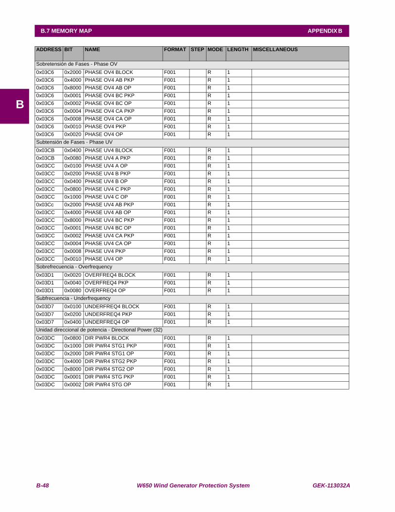
B-48 W650 Wind Generator Protection System GEK-113032A
B.7 MEMORY MAP APPENDIX B
B
ADDRESS BIT NAME FORMAT STEP MODE LENGTH MISCELLANEOUS
Sobretensión de Fases - Phase OV0x03C6 0x2000 PHASE OV4 BLOCK F001 R 1 0x03C6 0x4000 PHASE OV4 AB PKP F001 R 1 0x03C6 0x8000 PHASE OV4 AB OP F001 R 1 0x03C6 0x0001 PHASE OV4 BC PKP F001 R 1 0x03C6 0x0002 PHASE OV4 BC OP F001 R 1 0x03C6 0x0004 PHASE OV4 CA PKP F001 R 1 0x03C6 0x0008 PHASE OV4 CA OP F001 R 1 0x03C6 0x0010 PHASE OV4 PKP F001 R 1 0x03C6 0x0020 PHASE OV4 OP F001 R 1 Subtensión de Fases - Phase UV0x03CB 0x0400 PHASE UV4 BLOCK F001 R 1 0x03CB 0x0080 PHASE UV4 A PKP F001 R 1 0x03CC 0x0100 PHASE UV4 A OP F001 R 1 0x03CC 0x0200 PHASE UV4 B PKP F001 R 1 0x03CC 0x0400 PHASE UV4 B OP F001 R 1 0x03CC 0x0800 PHASE UV4 C PKP F001 R 1 0x03CC 0x1000 PHASE UV4 C OP F001 R 1 0x03Cc 0x2000 PHASE UV4 AB PKP F001 R 1 0x03CC 0x4000 PHASE UV4 AB OP F001 R 1 0x03CC 0x8000 PHASE UV4 BC PKP F001 R 1 0x03CC 0x0001 PHASE UV4 BC OP F001 R 1 0x03CC 0x0002 PHASE UV4 CA PKP F001 R 1 0x03CC 0x0004 PHASE UV4 CA OP F001 R 1 0x03CC 0x0008 PHASE UV4 PKP F001 R 1 0x03CC 0x0010 PHASE UV4 OP F001 R 1 Sobrefrecuencia - Overfrequency0x03D1 0x0020 OVERFREQ4 BLOCK F001 R 1 0x03D1 0x0040 OVERFREQ4 PKP F001 R 1 0x03D1 0x0080 OVERFREQ4 OP F001 R 1 Subfrecuencia - Underfrequency0x03D7 0x0100 UNDERFREQ4 BLOCK F001 R 1 0x03D7 0x0200 UNDERFREQ4 PKP F001 R 1 0x03D7 0x0400 UNDERFREQ4 OP F001 R 1 Unidad direccional de potencia - Directional Power (32)0x03DC 0x0800 DIR PWR4 BLOCK F001 R 1 0x03DC 0x1000 DIR PWR4 STG1 PKP F001 R 1 0x03DC 0x2000 DIR PWR4 STG1 OP F001 R 1 0x03DC 0x4000 DIR PWR4 STG2 PKP F001 R 1 0x03DC 0x8000 DIR PWR4 STG2 OP F001 R 1 0x03DC 0x0001 DIR PWR4 STG PKP F001 R 1 0x03DC 0x0002 DIR PWR4 STG OP F001 R 1
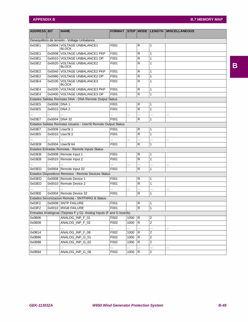
GEK-113032A W650 Wind Generator Protection System B-49
APPENDIX B B.7 MEMORY MAP
B
ADDRESS BIT NAME FORMAT STEP MODE LENGTH MISCELLANEOUS
Desequilibrio de tensión - Voltage Unbalance0x03E1 0x0004 VOLTAGE UNBALANCE1
BLOCKF001 R 1
0x03E1 0x0008 VOLTAGE UNBALANCE1 PKP F001 R 1 0x03E1 0x0010 VOLTAGE UNBALANCE1 OP F001 R 1 0x03E2 0x0020 VOLTAGE UNBALANCE2
BLOCKF001 R 1
0x03E2 0x0040 VOLTAGE UNBALANCE2 PKP F001 R 1 0x03E2 0x0080 VOLTAGE UNBALANCE2 OP F001 R 1 0x03E4 0x0100 VOLTAGE UNBALANCE3
BLOCKF001 R 1
0x03E4 0x0200 VOLTAGE UNBALANCE3 PKP F001 R 1 0x03E4 0x0400 VOLTAGE UNBALANCE3 OP F001 R 1 Estados Salidas Remotas DNA - DNA Remote Output Status0x03E5 0x0008 DNA 1 F001 R 1 0x03E5 0x0010 DNA 2 F001 R 1 ... ... ... ... ... ... ... ...0x03E7 0x0004 DNA 32 F001 R 1 Estados Salidas Remotas Usuario - UserSt Remote Output Status0x03E7 0x0008 UserSt 1 F001 R 1 0x03E5 0x0010 UserSt 2 F001 R 1 ... ... ... ... ... ... ... ...0x03EB 0x0004 UserSt 64 F001 R 1 Estados Entradas Remotas - Remote Inputs Status0x03EB 0x0008 Remote Input 1 F001 R 1 0x03EB 0x0010 Remote Input 2 F001 R 1 ... ... ... ... ... ... ... ...0x03ED 0x0004 Remote Input 32 F001 R 1 Estados Dispositivos Remotos - Remote Devices Status0x03ED 0x0008 Remote Device 1 F001 R 1 0x03ED 0x0010 Remote Device 2 F001 R 1 ... ... ... ... ... ... ... ...0x03EE 0x0004 Remote Device 32 F001 R 1 Estados Sicronizacion Remota - SNTP/IRIG B Status0x03F2 0x0008 SNTP FAILURE F001 R 1 0x03F2 0x0010 IRIGB FAILURE F001 R 1 Entradas Analógicas (Tarjetas F y G)- Analog Inputs (F and G boards)0x0B06 ANALOG_INP_F_01 F002 1000 R 2 0x0B08 ANALOG_INP_F_02 F002 1000 R 2 ... ... ... ... ... ... ...0x0B14 ANALOG_INP_F_08 F002 1000 R 2 0x0B86 ANALOG_INP_G_01 F002 1000 R 2 0x0B88 ANALOG_INP_G_02 F002 1000 R 2 ... ... ... ... ... ... ...0x0B94 ANALOG_INP_G_08 F002 1000 R 2

B-50 W650 Wind Generator Protection System GEK-113032A
B.7 MEMORY MAP APPENDIX B
B
ADDRESS BIT NAME FORMAT STEP MODE LENGTH MISCELLANEOUS
Medidas en Valores Secundarios - Analog measures in Secondary Values0x0C00 Phasor Ia F002 1000 R 2 0x0C02 RMS Ia F002 1000 R 2 0x0C04 Ia Real F002 1000 R 2 0x0C06 Ia Imag F002 1000 R 2 0x0C08 Phasor Ib F002 1000 R 2 0x0C0A RMS Ib F002 1000 R 2 0x0C0C Ib Real F002 1000 R 2 0x0C0E Ib Imag F002 1000 R 2 0x0C10 Phasor Ic F002 1000 R 2 0x0C12 RMS Ic F002 1000 R 2 0x0C14 Ic Real F002 1000 R 2 0x0C16 Ic Imag F002 1000 R 2 0x0C18 Phasor In F002 1000 R 2 0x0C1A In Real F002 1000 R 2 0x0C1C In Imag F002 1000 R 2 0x0C1E Phasor Ig F002 1000 R 2 0x0C20 RMS Ig F002 1000 R 2 0x0C22 Ig Real F002 1000 R 2 0x0C24 Ig Imag F002 1000 R 2 0x0C26 Phasor Isg F002 1000 R 2 0x0C28 RMS Isg F002 1000 R 2 0x0C2A Isg Real F002 1000 R 2 0x0C2C Isg Imag F002 1000 R 2 0x0C2E Zero seq I0 F002 1000 R 2 0x0C30 I0 Real F002 1000 R 2 0x0C32 I0 Imag F002 1000 R 2 0x0C34 Positive Seq I1 F002 1000 R 2 0x0C36 I1 Real F002 1000 R 2 0x0C38 I1 Imag F002 1000 R 2 0x0C3A Negative Seq I2 F002 1000 R 2 0x0C3C I2 Real F002 1000 R 2 0x0C3E I2 Imag F002 1000 R 2 0x0C40 Phasor Vab F002 1000 R 2 0x0C42 Vab Real F002 1000 R 2 0x0C44 Vab Imag F002 1000 R 2 0x0C46 Phasor Vbc F002 1000 R 2 0x0C48 Vbc Real F002 1000 R 2 0x0C4A Vbc Imag F002 1000 R 2 0x0C4C Phasor Vca F002 1000 R 2 0x0C4E Vca Real F002 1000 R 2 0x0C50 Vca Imag F002 1000 R 2 0x0C52 Phasor Van F002 1000 R 2 0x0C54 Va Real F002 1000 R 2 0x0C56 Va Imag F002 1000 R 2 0x0C58 Phasor Vbn F002 1000 R 2 0x0C5A Vb Real F002 1000 R 2 0x0C5C Vb Imag F002 1000 R 2 0x0C5E Phasor Vcn F002 1000 R 2 0x0C60 Vc Real F002 1000 R 2 0x0C62 Vc Imag F002 1000 R 2 0x0C64 Phasor Vn F002 1000 R 2

GEK-113032A W650 Wind Generator Protection System B-51
APPENDIX B B.7 MEMORY MAP
B
ADDRESS BIT NAME FORMAT STEP MODE LENGTH MISCELLANEOUS
Medidas en Valores Secundarios - Analog measures in Secondary Values (Cont.)0x0C66 Vn Real F002 1000 R 2 0x0C68 Vn Imag F002 1000 R 2 0x0C6A Positive Seq V1 F002 1000 R 2 0x0C6C V1 Real F002 1000 R 2 0x0C6E V1 Imag F002 1000 R 2 0x0C70 Negative Seq V2 F002 1000 R 2 0x0C72 V2 Real F002 1000 R 2 0x0C74 V2 Imag F002 1000 R 2 0x0C76 Zero Seq V0 F002 1000 R 2 0x0C78 V0 Real F002 1000 R 2 0x0C7A V0 Imag F002 1000 R 2 0x0C7C Phasor Vx F002 1000 R 2 0x0C7E Vx Real F002 1000 R 2 0x0C80 Vx Imag F002 1000 R 2 0x0C82 Nominal Voltage F002 1000 R 2 0x0C84 VL Real F002 1000 R 2 0x0C86 VL Imag F002 1000 R 2 0x0C88 VBB Real F002 1000 R 2 0x0C8A VBB Imag F002 1000 R 2 0x0C8C Line Voltage F002 1000 R 2 0x0C8E Bus Voltage F002 1000 R 2 0x0C90 Line Frequency F002 1000 R 2 0x0C92 Bus Frequency F002 1000 R 2 0x0C94 Phase A Apparent Pwr F002 1000 R 2 0x0C96 Phase B Apparent Pwr F002 1000 R 2 0x0C98 Phase C Apparent Pwr F002 1000 R 2 0x0C9A Phase A Real Pwr F002 1000 R 2 0x0C9C Phase B Real Pwr F002 1000 R 2 0x0C9E Phase C Real Pwr F002 1000 R 2 0x0CA0 Phase A Reactive Pwr F002 1000 R 2 0x0CA2 Phase B Reactive Pwr F002 1000 R 2 0x0CA4 Phase C Reactive Pwr F002 1000 R 2 0x0CA6 3 Phase Apparent Pwr F002 1000 R 2 0x0CA8 3 Phase Real Pwr F002 1000 R 2 0x0CAA 3 Phase Reactive Pwr F002 1000 R 2 0x0CAC Phase A Power Factor F002 1000 R 2 0x0CAE Phase B Power Factor F002 1000 R 2 0x0CB0 Phase C Power Factor F002 1000 R 2 0x0CB2 3 Phase Power Factor F002 1000 R 2 0x0CB4 CT Ratio F002 1000 R 2 0x0CB6 CT Ratio Ig F002 1000 R 2 0x0CB8 CT Ratio Isg F002 1000 R 2 0x0CBA PT Ratio F002 1000 R 2
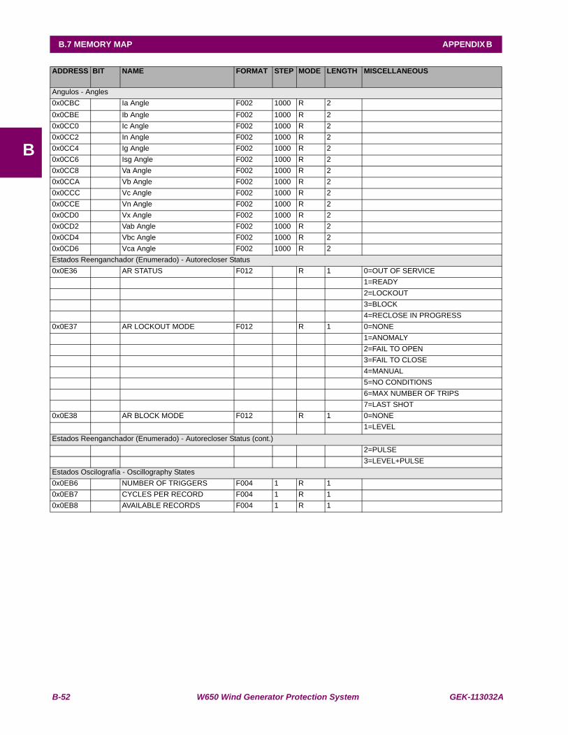
B-52 W650 Wind Generator Protection System GEK-113032A
B.7 MEMORY MAP APPENDIX B
B
ADDRESS BIT NAME FORMAT STEP MODE LENGTH MISCELLANEOUS
Angulos - Angles0x0CBC Ia Angle F002 1000 R 2 0x0CBE Ib Angle F002 1000 R 2 0x0CC0 Ic Angle F002 1000 R 2 0x0CC2 In Angle F002 1000 R 2 0x0CC4 Ig Angle F002 1000 R 2 0x0CC6 Isg Angle F002 1000 R 2 0x0CC8 Va Angle F002 1000 R 2 0x0CCA Vb Angle F002 1000 R 2 0x0CCC Vc Angle F002 1000 R 2 0x0CCE Vn Angle F002 1000 R 2 0x0CD0 Vx Angle F002 1000 R 2 0x0CD2 Vab Angle F002 1000 R 2 0x0CD4 Vbc Angle F002 1000 R 2 0x0CD6 Vca Angle F002 1000 R 2 Estados Reenganchador (Enumerado) - Autorecloser Status0x0E36 AR STATUS F012 R 1 0=OUT OF SERVICE 1=READY 2=LOCKOUT 3=BLOCK 4=RECLOSE IN PROGRESS0x0E37 AR LOCKOUT MODE F012 R 1 0=NONE 1=ANOMALY 2=FAIL TO OPEN 3=FAIL TO CLOSE 4=MANUAL 5=NO CONDITIONS 6=MAX NUMBER OF TRIPS 7=LAST SHOT0x0E38 AR BLOCK MODE F012 R 1 0=NONE 1=LEVELEstados Reenganchador (Enumerado) - Autorecloser Status (cont.) 2=PULSE 3=LEVEL+PULSEEstados Oscilografía - Oscillography States0x0EB6 NUMBER OF TRIGGERS F004 1 R 1 0x0EB7 CYCLES PER RECORD F004 1 R 1 0x0EB8 AVAILABLE RECORDS F004 1 R 1

GEK-113032A W650 Wind Generator Protection System B-53
APPENDIX B B.7 MEMORY MAP
B
ADDRESS BIT NAME FORMAT STEP MODE LENGTH MISCELLANEOUS
Localizador de Faltas - Fault Report0x0EBB FAULT DATE F011 R 3 0x0EBE FAULT TYPE F012 R 1 0=GROUND 1=PHASE 2=3 PH 3=AG 4=ABG 5=AB 6=BG 7=BCG 8=BC 9=CG 10=CAG 11=CA 12=NAF0x0EBF FAULT LOCATION F003 1 R 2 0x0EC1 FAULT REPORT NUMBER F005 1 R 2 Medidas en Valores Primarios - Analog measures in Primary Values0x0EE2 Phasor Ia Primary F002 1000 R 2 0x0EE4 Phasor Ib Primary F002 1000 R 2 0x0EE6 Phasor Ic Primary F002 1000 R 2 0x0EE8 Phasor Ig Primary F002 1000 R 2 0x0EEA Phasor Isg Primary F002 1000 R 2 0x0EEC Phasor In Primary F002 1000 R 2 0x0EEE RMS Ia Primary F002 1000 R 2 0x0EF0 RMS Ib Primary F002 1000 R 2 0x0EF2 RMS Ic Primary F002 1000 R 2 0x0EF4 RMS Ig Primary F002 1000 R 2 0x0EF6 RMS Isg Primary F002 1000 R 2 0x0EF8 I0 Primary F002 1000 R 2 0x0EFA I1 Primary F002 1000 R 2 0x0EFC I2 Primary F002 1000 R 2 0x0EFE V0 Primary F002 1000 R 2 0x0F00 V1 Primary F002 1000 R 2 0x0F02 V2 Primary F002 1000 R 2 0x0F04 Vab Primary F002 1000 R 2 0x0F06 Vbc Primary F002 1000 R 2 0x0F08 Vca Primary F002 1000 R 2 0x0F0A Va Primary F002 1000 R 2 0x0F0C Vb Primary F002 1000 R 2 0x0F0E Vc Primary F002 1000 R 2 0x0F10 Vn Primary F002 1000 R 2 0x0F12 Vx Primary F002 1000 R 2 0x0F14 VBB Primary F002 1000 R 2 0x0F16 VL Primary F002 1000 R 2

B-54 W650 Wind Generator Protection System GEK-113032A
B.7 MEMORY MAP APPENDIX B
B
ADDRESS BIT NAME FORMAT STEP MODE LENGTH MISCELLANEOUS
Medidas en Valores Primarios - Analog measures in Primary Values0x0F18 Phase A Real Pwr F002 1000 R 2 0x0F1A Phase A Reactive Pwr F002 1000 R 2 0x0F1C Phase A Apparent Pwr F002 1000 R 2 0x0F1E Phase B Real Pwr F002 1000 R 2 0x0F20 Phase B Reactive Pwr F002 1000 R 2 0x0F22 Phase B Apparent Pwr F002 1000 R 2 0x0F24 Phase C Real Pwr F002 1000 R 2 0x0F26 Phase C Reactive Pwr F002 1000 R 2 0x0F28 Phase C Apparent Pwr F002 1000 R 2 0x0F2A 3 Phase Real Pwr F002 1000 R 2 0x0F2C 3 Phase Reactive Pwr F002 1000 R 2 0x0F2E 3 Phase Apparent Pwr F002 1000 R 2 0x0F30 Phase A Power Factor F002 1000 R 2 0x0F32 Phase B Power Factor F002 1000 R 2 0x0F34 Phase C Power Factor F002 1000 R 2 0x0F36 3 Phase Power Factor F002 1000 R 2 0x0F38 Line Frequency F002 1000 R 2 0x0F3A Bus Frequency F002 1000 R 2 0x0F3C Positive MWatthour F002 1000 R 2 0x0F3E Negative MWatthour F002 1000 R 2 0x0F40 Positive MVarhour F002 1000 R 2 0x0F42 Negative MVarhour F002 1000 R 2 0x0F44 Pos MWatthour Cnt F002 1000 R 2 0x0F46 Neg MWatthour Cnt F002 1000 R 2 0x0F48 Pos MVarhour Cnt F002 1000 R 2 0x0F4A Neg MVarhour Cnt F002 1000 R 2 Medidas Demanda - Demand measures0x0FAB DEMAND IA F002 1000 R 2 0x0FAD DEMAND IA MAX F002 1000 R 2 0x0FAF DEMAND IA DATE F011 R 3 0x0FB2 DEMAND IB F002 1000 R 2 0x0FB4 DEMAND IB MAX F002 1000 R 2 0x0FB6 DEMAND IB DATE F011 R 3 0x0FB9 DEMAND IC F002 1000 R 2 0x0FBB DEMAND IC MAX F002 1000 R 2 0x0FBD DEMAND IC DATE F011 R 3 0x0FC0 DEMAND IG F002 1000 R 2 0x0FC2 DEMAND IG MAX F002 1000 R 2 0x0FC4 DEMAND IG DATE F011 R 3 0x0FC7 DEMAND ISG F002 1000 R 2 0x0FC9 DEMAND ISG MAX F002 1000 R 2 0x0FCB DEMAND ISG DATE F011 R 3 0x0FCE DEMAND I2 F002 1000 R 2 0x0FD0 DEMAND I2 MAX F002 1000 R 2 0x0FD2 DEMAND I2 DATE F011 R 3 0x0FD5 DEMAND W F002 1000 R 2 0x0FD7 DEMAND W MAX F002 1000 R 2 0x0FD9 DEMAND W DATE F011 R 3 0x0FDC DEMAND VAR PWR F002 1000 R 2 0x0FDE DEMAND VAR MAX F002 1000 R 2
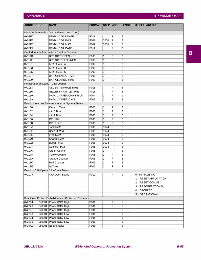
GEK-113032A W650 Wind Generator Protection System B-55
APPENDIX B B.7 MEMORY MAP
B
ADDRESS BIT NAME FORMAT STEP MODE LENGTH MISCELLANEOUS
Medidas Demanda - Demand measures (cont.)0x0FE0 DEMAND VAR DATE F011 R 3 0x0FE3 DEMAND VA PWR F002 1000 R 2 0x0FE5 DEMAND VA MAX F002 1000 R 2 0x0FE7 DEMAND VA DATE F011 R 3 Contadores de Interruptor - Breaker Counters0x111D BREAKER OPENINGS F005 1 R 2 0x111F BREAKER CLOSINGS F005 1 R 2 0x1121 KI2t PHASE A F003 1 R 2 0x1123 KI2t PHASE B F003 1 R 2 0x1125 KI2t PHASE C F003 1 R 2 0x1127 BKR OPENING TIME F003 1 R 2 0x1129 BKR CLOSING TIME F003 1 R 2 Registrador de Datos - Data Logger0x1153 OLDEST SAMPLE TIME F011 R 3 0x1156 NEWEST SAMPLE TIME F011 R 3 0x1159 DATA LOGGER CHANNELS F004 1 R 1 0x115A DATA LOGGER DAYS F003 1 R 2 Estados Internos Sistema - Internal System States0x1160 Kswapd Time F005 1 R 2 0x1162 mtd2 Time F005 1 R 2 0x1164 mtd3 Time F005 1 R 2 0x1166 CPU Rtai F005 1 R 2 0x1168 CPU Linux F005 1 R 2 0x116A Total RAM F005 1024 R 2 0x116C Used DRAM F005 1024 R 2 0x116E Free RAM F005 1024 R 2 0x1170 Shared RAM F005 1024 R 2 0x1172 Buffer RAM F005 1024 R 2 0x1174 Cached RAM F005 1024 R 2 0x1176 Green Counter F005 1 R 2 0x1178 Yellow Counter F005 1 R 2 0x117A Orange Counter F005 1 R 2 0x117C Red Counter F005 1 R 2 0x117E UpTime F005 1 R 2 Estados CANOpen - CANOpen Status0x11C7 CANOpen Status F012 R 1 0= INITIALISING
1 = RESET APPLICATION 2 = RESET COMMS 3 = PREOPERATIONAL 4 = STOPPED 5 = OPERATIONAL
Funciones Protección habilitadas - Protection Summary0x2204 0x0001 Phase IOC1 High F001 R 1 0x2220 0x0001 Phase IOC2 High F001 R 1 0x223C 0x0001 Phase IOC3 High F001 R 1 0x2258 0x0001 Phase IOC1 Low F001 R 1 0x2274 0x0001 Phase IOC2 Low F001 R 1 0x2290 0x0001 Phase IOC3 Low F001 R 1 0x22AC 0x0001 Neutral IOC1 F001 R 1
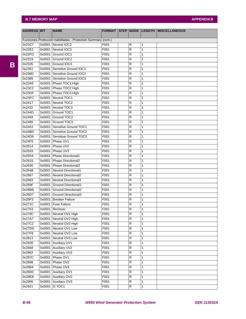
B-56 W650 Wind Generator Protection System GEK-113032A
B.7 MEMORY MAP APPENDIX B
B
ADDRESS BIT NAME FORMAT STEP MODE LENGTH MISCELLANEOUS
Funciones Protección habilitadas - Protection Summary (cont.)0x22C7 0x0001 Neutral IOC2 F001 R 1 0x22E2 0x0001 Neutral IOC3 F001 R 1 0x22FD 0x0001 Ground IOC1 F001 R 1 0x2319 0x0001 Ground IOC2 F001 R 1 0x2335 0x0001 Ground IOC3 F001 R 1 0x2351 0x0001 Sensitive Ground IOC1 F001 R 1 0x236D 0x0001 Sensitive Ground IOC2 F001 R 1 0x2389 0x0001 Sensitive Ground IOC3 F001 R 1 0x23A5 0x0001 Phase TOC1 High F001 R 1 0x23C2 0x0001 Phase TOC2 High F001 R 1 0x23DF 0x0001 Phase TOC3 High F001 R 1 0x23FC 0x0001 Neutral TOC1 F001 R 1 0x2417 0x0001 Neutral TOC2 F001 R 1 0x2432 0x0001 Neutral TOC3 F001 R 1 0x244D 0x0001 Ground TOC1 F001 R 1 0x2469 0x0001 Ground TOC2 F001 R 1 0x2485 0x0001 Ground TOC3 F001 R 1 0x24A1 0x0001 Sensitive Ground TOC1 F001 R 1 0x24BD 0x0001 Sensitive Ground TOC2 F001 R 1 0x24D9 0x0001 Sensitive Ground TOC3 F001 R 1 0x24F5 0x0001 Phase UV1 F001 R 1 0x2514 0x0001 Phase UV2 F001 R 1 0x2533 0x0001 Phase UV3 F001 R 1 0x25FA 0x0001 Phase Directional1 F001 R 1 0x2615 0x0001 Phase Directional2 F001 R 1 0x2630 0x0001 Phase Directional3 F001 R 1 0x264B 0x0001 Neutral Directional1 F001 R 1 0x2667 0x0001 Neutral Directional2 F001 R 1 0x2683 0x0001 Neutral Directional3 F001 R 1 0x269F 0x0001 Ground Directional1 F001 R 1 0x26BB 0x0001 Ground Directional2 F001 R 1 0x26D7 0x0001 Ground Directional3 F001 R 1 0x26F3 0x0001 Breaker Failure F001 R 1 0x271C 0x0001 Fuse Failure F001 R 1 0x2763 0x0001 Recloser F001 R 1 0x278C 0x0001 Neutral OV1 High F001 R 1 0x27A7 0x0001 Neutral OV2 High F001 R 1 0x27C2 0x0001 Neutral OV3 High F001 R 1 0x27DD 0x0001 Neutral OV1 Low F001 R 1 0x27F8 0x0001 Neutral OV2 Low F001 R 1 0x2813 0x0001 Neutral OV3 Low F001 R 1 0x282E 0x0001 Auxiliary UV1 F001 R 1 0x2848 0x0001 Auxiliary UV2 F001 R 1 0x2862 0x0001 Auxiliary UV3 F001 R 1 0x287C 0x0001 Phase OV1 F001 R 1 0x2898 0x0001 Phase OV2 F001 R 1 0x28B4 0x0001 Phase OV3 F001 R 1 0x28D0 0x0001 Auxiliary OV1 F001 R 1 0x28EB 0x0001 Auxiliary OV2 F001 R 1 0x2906 0x0001 Auxiliary OV3 F001 R 1 0x2921 0x0001 I2 TOC1 F001 R 1
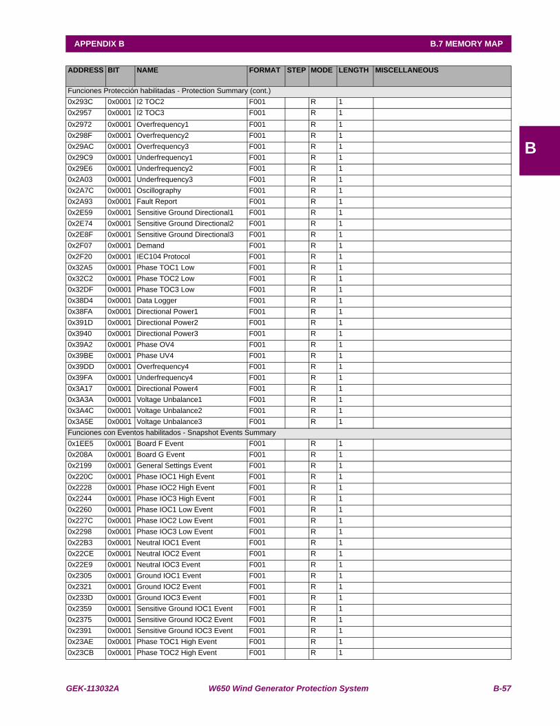
GEK-113032A W650 Wind Generator Protection System B-57
APPENDIX B B.7 MEMORY MAP
B
ADDRESS BIT NAME FORMAT STEP MODE LENGTH MISCELLANEOUS
Funciones Protección habilitadas - Protection Summary (cont.)0x293C 0x0001 I2 TOC2 F001 R 1 0x2957 0x0001 I2 TOC3 F001 R 1 0x2972 0x0001 Overfrequency1 F001 R 1 0x298F 0x0001 Overfrequency2 F001 R 1 0x29AC 0x0001 Overfrequency3 F001 R 1 0x29C9 0x0001 Underfrequency1 F001 R 1 0x29E6 0x0001 Underfrequency2 F001 R 1 0x2A03 0x0001 Underfrequency3 F001 R 1 0x2A7C 0x0001 Oscillography F001 R 1 0x2A93 0x0001 Fault Report F001 R 1 0x2E59 0x0001 Sensitive Ground Directional1 F001 R 1 0x2E74 0x0001 Sensitive Ground Directional2 F001 R 1 0x2E8F 0x0001 Sensitive Ground Directional3 F001 R 1 0x2F07 0x0001 Demand F001 R 1 0x2F20 0x0001 IEC104 Protocol F001 R 1 0x32A5 0x0001 Phase TOC1 Low F001 R 1 0x32C2 0x0001 Phase TOC2 Low F001 R 1 0x32DF 0x0001 Phase TOC3 Low F001 R 1 0x38D4 0x0001 Data Logger F001 R 1 0x38FA 0x0001 Directional Power1 F001 R 1 0x391D 0x0001 Directional Power2 F001 R 1 0x3940 0x0001 Directional Power3 F001 R 1 0x39A2 0x0001 Phase OV4 F001 R 10x39BE 0x0001 Phase UV4 F001 R 10x39DD 0x0001 Overfrequency4 F001 R 10x39FA 0x0001 Underfrequency4 F001 R 10x3A17 0x0001 Directional Power4 F001 R 10x3A3A 0x0001 Voltage Unbalance1 F001 R 10x3A4C 0x0001 Voltage Unbalance2 F001 R 10x3A5E 0x0001 Voltage Unbalance3 F001 R 1Funciones con Eventos habilitados - Snapshot Events Summary0x1EE5 0x0001 Board F Event F001 R 1 0x208A 0x0001 Board G Event F001 R 1 0x2199 0x0001 General Settings Event F001 R 1 0x220C 0x0001 Phase IOC1 High Event F001 R 1 0x2228 0x0001 Phase IOC2 High Event F001 R 1 0x2244 0x0001 Phase IOC3 High Event F001 R 1 0x2260 0x0001 Phase IOC1 Low Event F001 R 1 0x227C 0x0001 Phase IOC2 Low Event F001 R 1 0x2298 0x0001 Phase IOC3 Low Event F001 R 1 0x22B3 0x0001 Neutral IOC1 Event F001 R 1 0x22CE 0x0001 Neutral IOC2 Event F001 R 1 0x22E9 0x0001 Neutral IOC3 Event F001 R 1 0x2305 0x0001 Ground IOC1 Event F001 R 1 0x2321 0x0001 Ground IOC2 Event F001 R 1 0x233D 0x0001 Ground IOC3 Event F001 R 1 0x2359 0x0001 Sensitive Ground IOC1 Event F001 R 1 0x2375 0x0001 Sensitive Ground IOC2 Event F001 R 1 0x2391 0x0001 Sensitive Ground IOC3 Event F001 R 1 0x23AE 0x0001 Phase TOC1 High Event F001 R 1 0x23CB 0x0001 Phase TOC2 High Event F001 R 1
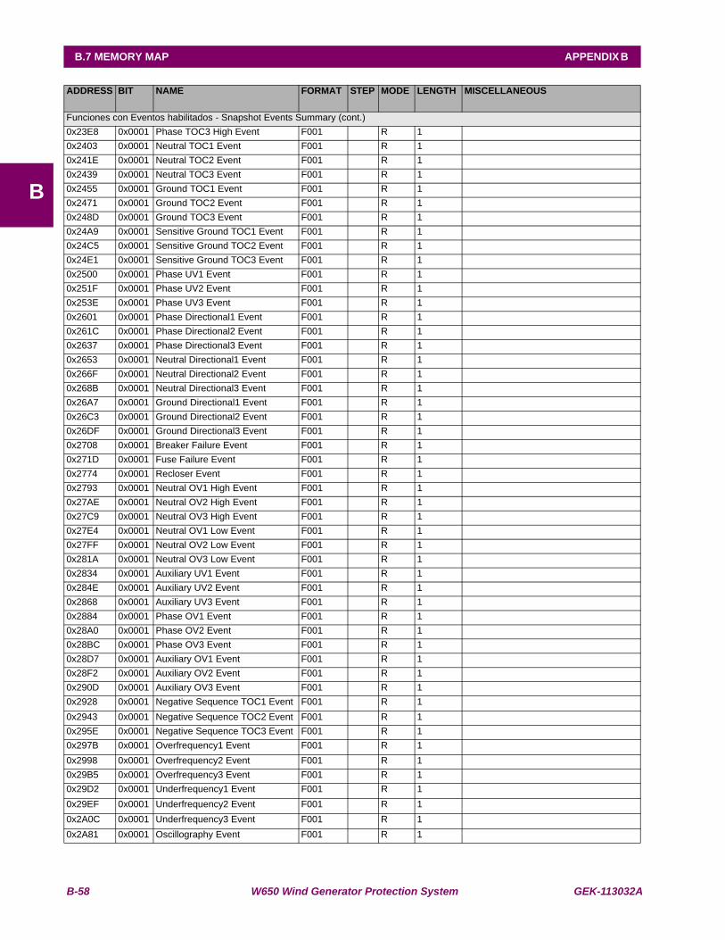
B-58 W650 Wind Generator Protection System GEK-113032A
B.7 MEMORY MAP APPENDIX B
B
ADDRESS BIT NAME FORMAT STEP MODE LENGTH MISCELLANEOUS
Funciones con Eventos habilitados - Snapshot Events Summary (cont.)0x23E8 0x0001 Phase TOC3 High Event F001 R 1 0x2403 0x0001 Neutral TOC1 Event F001 R 1 0x241E 0x0001 Neutral TOC2 Event F001 R 1 0x2439 0x0001 Neutral TOC3 Event F001 R 1 0x2455 0x0001 Ground TOC1 Event F001 R 1 0x2471 0x0001 Ground TOC2 Event F001 R 1 0x248D 0x0001 Ground TOC3 Event F001 R 1 0x24A9 0x0001 Sensitive Ground TOC1 Event F001 R 1 0x24C5 0x0001 Sensitive Ground TOC2 Event F001 R 1 0x24E1 0x0001 Sensitive Ground TOC3 Event F001 R 1 0x2500 0x0001 Phase UV1 Event F001 R 1 0x251F 0x0001 Phase UV2 Event F001 R 1 0x253E 0x0001 Phase UV3 Event F001 R 1 0x2601 0x0001 Phase Directional1 Event F001 R 1 0x261C 0x0001 Phase Directional2 Event F001 R 1 0x2637 0x0001 Phase Directional3 Event F001 R 1 0x2653 0x0001 Neutral Directional1 Event F001 R 1 0x266F 0x0001 Neutral Directional2 Event F001 R 1 0x268B 0x0001 Neutral Directional3 Event F001 R 1 0x26A7 0x0001 Ground Directional1 Event F001 R 1 0x26C3 0x0001 Ground Directional2 Event F001 R 1 0x26DF 0x0001 Ground Directional3 Event F001 R 1 0x2708 0x0001 Breaker Failure Event F001 R 1 0x271D 0x0001 Fuse Failure Event F001 R 1 0x2774 0x0001 Recloser Event F001 R 1 0x2793 0x0001 Neutral OV1 High Event F001 R 1 0x27AE 0x0001 Neutral OV2 High Event F001 R 1 0x27C9 0x0001 Neutral OV3 High Event F001 R 1 0x27E4 0x0001 Neutral OV1 Low Event F001 R 1 0x27FF 0x0001 Neutral OV2 Low Event F001 R 1 0x281A 0x0001 Neutral OV3 Low Event F001 R 1 0x2834 0x0001 Auxiliary UV1 Event F001 R 1 0x284E 0x0001 Auxiliary UV2 Event F001 R 1 0x2868 0x0001 Auxiliary UV3 Event F001 R 1 0x2884 0x0001 Phase OV1 Event F001 R 1 0x28A0 0x0001 Phase OV2 Event F001 R 1 0x28BC 0x0001 Phase OV3 Event F001 R 1 0x28D7 0x0001 Auxiliary OV1 Event F001 R 1 0x28F2 0x0001 Auxiliary OV2 Event F001 R 1 0x290D 0x0001 Auxiliary OV3 Event F001 R 1 0x2928 0x0001 Negative Sequence TOC1 Event F001 R 1 0x2943 0x0001 Negative Sequence TOC2 Event F001 R 1 0x295E 0x0001 Negative Sequence TOC3 Event F001 R 1 0x297B 0x0001 Overfrequency1 Event F001 R 1 0x2998 0x0001 Overfrequency2 Event F001 R 1 0x29B5 0x0001 Overfrequency3 Event F001 R 1 0x29D2 0x0001 Underfrequency1 Event F001 R 1 0x29EF 0x0001 Underfrequency2 Event F001 R 1 0x2A0C 0x0001 Underfrequency3 Event F001 R 1 0x2A81 0x0001 Oscillography Event F001 R 1
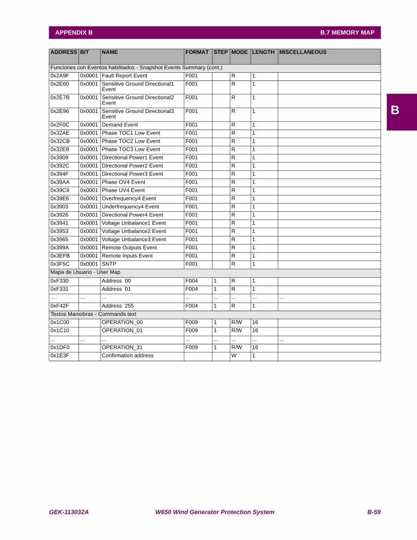
GEK-113032A W650 Wind Generator Protection System B-59
APPENDIX B B.7 MEMORY MAP
B
ADDRESS BIT NAME FORMAT STEP MODE LENGTH MISCELLANEOUS
Funciones con Eventos habilitados - Snapshot Events Summary (cont.)0x2A9F 0x0001 Fault Report Event F001 R 1 0x2E60 0x0001 Sensitive Ground Directional1
EventF001 R 1
0x2E7B 0x0001 Sensitive Ground Directional2 Event
F001 R 1
0x2E96 0x0001 Sensitive Ground Directional3 Event
F001 R 1
0x2F0C 0x0001 Demand Event F001 R 1 0x32AE 0x0001 Phase TOC1 Low Event F001 R 1 0x32CB 0x0001 Phase TOC2 Low Event F001 R 1 0x32E8 0x0001 Phase TOC3 Low Event F001 R 1 0x3909 0x0001 Directional Power1 Event F001 R 1 0x392C 0x0001 Directional Power2 Event F001 R 1 0x394F 0x0001 Directional Power3 Event F001 R 1 0x39AA 0x0001 Phase OV4 Event F001 R 1 0x39C9 0x0001 Phase UV4 Event F001 R 1 0x39E6 0x0001 Overfrequency4 Event F001 R 1 0x3903 0x0001 Underfrequency4 Event F001 R 1 0x3926 0x0001 Directional Power4 Event F001 R 1 0x3941 0x0001 Voltage Unbalance1 Event F001 R 1 0x3953 0x0001 Voltage Unbalance2 Event F001 R 1 0x3965 0x0001 Voltage Unbalance3 Event F001 R 1 0x399A 0x0001 Remote Outputs Event F001 R 1 0x3EFB 0x0001 Remote Inputs Event F001 R 1 0x3F5C 0x0001 SNTP F001 R 1 Mapa de Usuario - User Map0xF330 Address 00 F004 1 R 1 0xF331 Address 01 F004 1 R 1 ... ... ... ... ... ... ... ...0xF42F Address 255 F004 1 R 1 Textos Maniobras - Commands text0x1C00 OPERATION_00 F009 1 R/W 16 0x1C10 OPERATION_01 F009 1 R/W 16 ... ... ... ... ... ... ... ...0x1DF0 OPERATION_31 F009 1 R/W 16 0x1E3F Confirmation address W 1
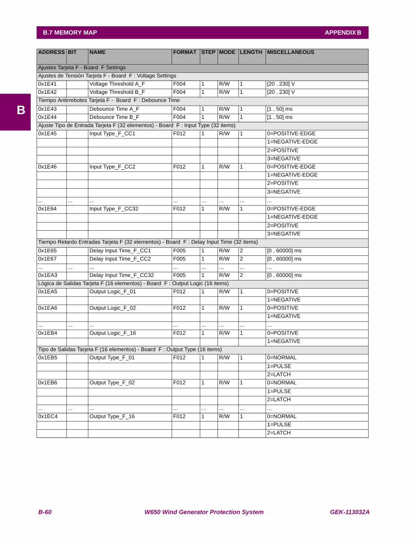
B-60 W650 Wind Generator Protection System GEK-113032A
B.7 MEMORY MAP APPENDIX B
B
ADDRESS BIT NAME FORMAT STEP MODE LENGTH MISCELLANEOUS
Ajustes Tarjeta F - Board F SettingsAjustes de Tensión Tarjeta F - Board F : Voltage Settings0x1E41 Voltage Threshold A_F F004 1 R/W 1 [20 , 230] V0x1E42 Voltage Threshold B_F F004 1 R/W 1 [20 , 230] VTiempo Antirrebotes Tarjeta F - Board F : Debounce Time0x1E43 Debounce Time A_F F004 1 R/W 1 [1 , 50] ms0x1E44 Debounce Time B_F F004 1 R/W 1 [1 , 50] msAjuste Tipo de Entrada Tarjeta F (32 elementos) - Board F : Input Type (32 items)0x1E45 Input Type_F_CC1 F012 1 R/W 1 0=POSITIVE-EDGE 1=NEGATIVE-EDGE 2=POSITIVE 3=NEGATIVE0x1E46 Input Type_F_CC2 F012 1 R/W 1 0=POSITIVE-EDGE 1=NEGATIVE-EDGE 2=POSITIVE 3=NEGATIVE... ... ... ... ... ... ... ...0x1E64 Input Type_F_CC32 F012 1 R/W 1 0=POSITIVE-EDGE 1=NEGATIVE-EDGE 2=POSITIVE 3=NEGATIVETiempo Retardo Entradas Tarjeta F (32 elementos) - Board F : Delay Input Time (32 items)0x1E65 Delay Input Time_F_CC1 F005 1 R/W 2 [0 , 60000] ms0x1E67 Delay Input Time_F_CC2 F005 1 R/W 2 [0 , 60000] ms... ... ... ... ... ... ... ...0x1EA3 Delay Input Time_F_CC32 F005 1 R/W 2 [0 , 60000] msLógica de Salidas Tarjeta F (16 elementos) - Board F : Output Logic (16 items)0x1EA5 Output Logic_F_01 F012 1 R/W 1 0=POSITIVE 1=NEGATIVE0x1EA6 Output Logic_F_02 F012 1 R/W 1 0=POSITIVE 1=NEGATIVE... ... ... ... ... ... ... ...0x1EB4 Output Logic_F_16 F012 1 R/W 1 0=POSITIVE 1=NEGATIVETipo de Salidas Tarjeta F (16 elementos) - Board F : Output Type (16 items)0x1EB5 Output Type_F_01 F012 1 R/W 1 0=NORMAL 1=PULSE 2=LATCH0x1EB6 Output Type_F_02 F012 1 R/W 1 0=NORMAL 1=PULSE 2=LATCH... ... ... ... ... ... ... ...0x1EC4 Output Type_F_16 F012 1 R/W 1 0=NORMAL 1=PULSE 2=LATCH
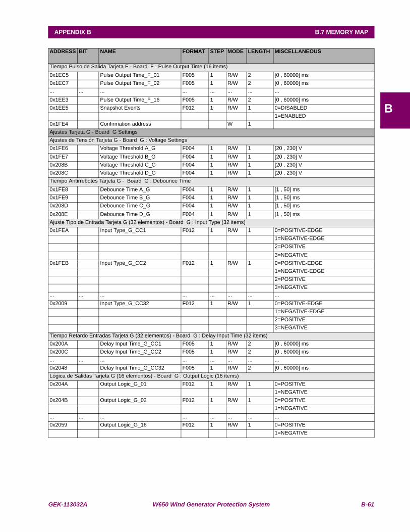
GEK-113032A W650 Wind Generator Protection System B-61
APPENDIX B B.7 MEMORY MAP
B
ADDRESS BIT NAME FORMAT STEP MODE LENGTH MISCELLANEOUS
Tiempo Pulso de Salida Tarjeta F - Board F : Pulse Output Time (16 items)0x1EC5 Pulse Output Time_F_01 F005 1 R/W 2 [0 , 60000] ms0x1EC7 Pulse Output Time_F_02 F005 1 R/W 2 [0 , 60000] ms... ... ... ... ... ... ... ...0x1EE3 Pulse Output Time_F_16 F005 1 R/W 2 [0 , 60000] ms0x1EE5 Snapshot Events F012 1 R/W 1 0=DISABLED 1=ENABLED0x1FE4 Confirmation address W 1 Ajustes Tarjeta G - Board G SettingsAjustes de Tensión Tarjeta G - Board G : Voltage Settings0x1FE6 Voltage Threshold A_G F004 1 R/W 1 [20 , 230] V0x1FE7 Voltage Threshold B_G F004 1 R/W 1 [20 , 230] V0x208B Voltage Threshold C_G F004 1 R/W 1 [20 , 230] V0x208C Voltage Threshold D_G F004 1 R/W 1 [20 , 230] VTiempo Antirrebotes Tarjeta G - Board G : Debounce Time0x1FE8 Debounce Time A_G F004 1 R/W 1 [1 , 50] ms0x1FE9 Debounce Time B_G F004 1 R/W 1 [1 , 50] ms0x208D Debounce Time C_G F004 1 R/W 1 [1 , 50] ms0x208E Debounce Time D_G F004 1 R/W 1 [1 , 50] msAjuste Tipo de Entrada Tarjeta G (32 elementos) - Board G : Input Type (32 items)0x1FEA Input Type_G_CC1 F012 1 R/W 1 0=POSITIVE-EDGE 1=NEGATIVE-EDGE 2=POSITIVE 3=NEGATIVE0x1FEB Input Type_G_CC2 F012 1 R/W 1 0=POSITIVE-EDGE 1=NEGATIVE-EDGE 2=POSITIVE 3=NEGATIVE... ... ... ... ... ... ... ...0x2009 Input Type_G_CC32 F012 1 R/W 1 0=POSITIVE-EDGE 1=NEGATIVE-EDGE 2=POSITIVE 3=NEGATIVETiempo Retardo Entradas Tarjeta G (32 elementos) - Board G : Delay Input Time (32 items)0x200A Delay Input Time_G_CC1 F005 1 R/W 2 [0 , 60000] ms0x200C Delay Input Time_G_CC2 F005 1 R/W 2 [0 , 60000] ms... ... ... ... ... ... ... ...0x2048 Delay Input Time_G_CC32 F005 1 R/W 2 [0 , 60000] msLógica de Salidas Tarjeta G (16 elementos) - Board G : Output Logic (16 items)0x204A Output Logic_G_01 F012 1 R/W 1 0=POSITIVE 1=NEGATIVE0x204B Output Logic_G_02 F012 1 R/W 1 0=POSITIVE 1=NEGATIVE... ... ... ... ... ... ... ...0x2059 Output Logic_G_16 F012 1 R/W 1 0=POSITIVE 1=NEGATIVE
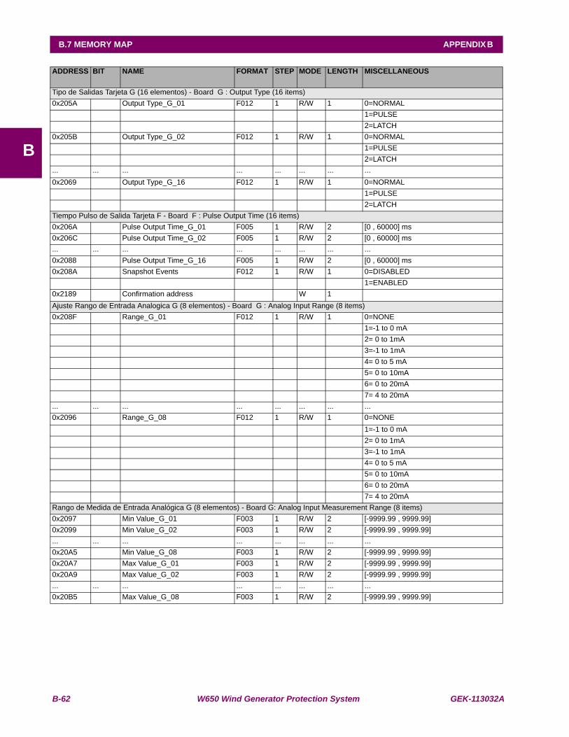
B-62 W650 Wind Generator Protection System GEK-113032A
B.7 MEMORY MAP APPENDIX B
B
ADDRESS BIT NAME FORMAT STEP MODE LENGTH MISCELLANEOUS
Tipo de Salidas Tarjeta G (16 elementos) - Board G : Output Type (16 items)0x205A Output Type_G_01 F012 1 R/W 1 0=NORMAL 1=PULSE 2=LATCH0x205B Output Type_G_02 F012 1 R/W 1 0=NORMAL 1=PULSE 2=LATCH... ... ... ... ... ... ... ...0x2069 Output Type_G_16 F012 1 R/W 1 0=NORMAL 1=PULSE 2=LATCHTiempo Pulso de Salida Tarjeta F - Board F : Pulse Output Time (16 items)0x206A Pulse Output Time_G_01 F005 1 R/W 2 [0 , 60000] ms0x206C Pulse Output Time_G_02 F005 1 R/W 2 [0 , 60000] ms... ... ... ... ... ... ... ...0x2088 Pulse Output Time_G_16 F005 1 R/W 2 [0 , 60000] ms0x208A Snapshot Events F012 1 R/W 1 0=DISABLED 1=ENABLED0x2189 Confirmation address W 1 Ajuste Rango de Entrada Analogica G (8 elementos) - Board G : Analog Input Range (8 items)0x208F Range_G_01 F012 1 R/W 1 0=NONE 1=-1 to 0 mA 2= 0 to 1mA 3=-1 to 1mA 4= 0 to 5 mA 5= 0 to 10mA 6= 0 to 20mA 7= 4 to 20mA... ... ... ... ... ... ... ...0x2096 Range_G_08 F012 1 R/W 1 0=NONE 1=-1 to 0 mA 2= 0 to 1mA 3=-1 to 1mA 4= 0 to 5 mA 5= 0 to 10mA 6= 0 to 20mA 7= 4 to 20mARango de Medida de Entrada Analógica G (8 elementos) - Board G: Analog Input Measurement Range (8 items)0x2097 Min Value_G_01 F003 1 R/W 2 [-9999.99 , 9999.99] 0x2099 Min Value_G_02 F003 1 R/W 2 [-9999.99 , 9999.99] ... ... ... ... ... ... ... ...0x20A5 Min Value_G_08 F003 1 R/W 2 [-9999.99 , 9999.99] 0x20A7 Max Value_G_01 F003 1 R/W 2 [-9999.99 , 9999.99] 0x20A9 Max Value_G_02 F003 1 R/W 2 [-9999.99 , 9999.99] ... ... ... ... ... ... ... ...0x20B5 Max Value_G_08 F003 1 R/W 2 [-9999.99 , 9999.99]
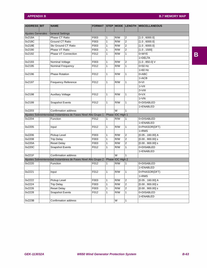
GEK-113032A W650 Wind Generator Protection System B-63
APPENDIX B B.7 MEMORY MAP
B
ADDRESS BIT NAME FORMAT STEP MODE LENGTH MISCELLANEOUS
Ajustes Generales - General Settings0x218A Phase CT Ratio F003 1 R/W 2 [1.0 , 6000.0] 0x218C Ground CT Ratio F003 1 R/W 2 [1.0 , 6000.0] 0x218E Stv Ground CT Ratio F003 1 R/W 2 [1.0 , 6000.0] 0x2190 Phase VT Ratio F003 1 R/W 2 [1.0 , 1500] 0x2192 Phase VT Connection F012 1 R/W 1 0=WYE 1=DELTA0x2193 Nominal Voltage F003 1 R/W 2 [1.0 , 850.0] V0x2195 Nominal Frequency F012 1 R/W 1 0=50 Hz 1=60 Hz0x2196 Phase Rotation F012 1 R/W 1 0=ABC 1=ACB0x2197 Frequency Reference F012 1 R/W 1 0=VI 1=VII 2=VIII0x2198 Auxiliary Voltage F012 1 R/W 1 0=VX 1=VN0x2199 Snapshot Events F012 1 R/W 1 0=DISABLED 1=ENABLED0x2203 Confirmation address W 1 Ajustes Sobreintensidad Instantánea de Fases Nivel Alto Grupo 1 - Phase IOC High 10x2204 Function F012 1 R/W 1 0=DISABLED 1=ENABLED0x2205 Input F012 1 R/W 1 0=PHASOR(DFT) 1=RMS0x2206 Pickup Level F003 1 R/W 2 [0.05 , 160.00] A0x2208 Trip Delay F003 1 R/W 2 [0.00 , 900.00] s0x220A Reset Delay F003 1 R/W 2 [0.00 , 900.00] s0x220C Snapshot Events F012 1 R/W 1 0=DISABLED 1=ENABLED0x221F Confirmation address W 1 Ajustes Sobreintensidad Instantánea de Fases Nivel Alto Grupo 2 - Phase IOC High 20x2220 Function F012 1 R/W 1 0=DISABLED 1=ENABLED0x2221 Input F012 1 R/W 1 0=PHASOR(DFT) 1=RMS0x2222 Pickup Level F003 1 R/W 2 [0.05 , 160.00] A0x2224 Trip Delay F003 1 R/W 2 [0.00 , 900.00] s0x2226 Reset Delay F003 1 R/W 2 [0.00 , 900.00] s0x2228 Snapshot Events F012 1 R/W 1 0=DISABLED 1=ENABLED0x223B Confirmation address W 1
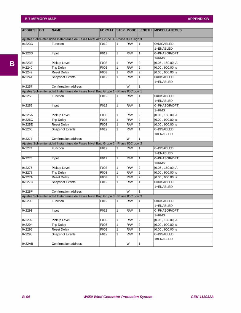
B-64 W650 Wind Generator Protection System GEK-113032A
B.7 MEMORY MAP APPENDIX B
B
ADDRESS BIT NAME FORMAT STEP MODE LENGTH MISCELLANEOUS
Ajustes Sobreintensidad Instantánea de Fases Nivel Alto Grupo 3 - Phase IOC High 30x223C Function F012 1 R/W 1 0=DISABLED 1=ENABLED0x223D Input F012 1 R/W 1 0=PHASOR(DFT) 1=RMS0x223E Pickup Level F003 1 R/W 2 [0.05 , 160.00] A0x2240 Trip Delay F003 1 R/W 2 [0.00 , 900.00] s0x2242 Reset Delay F003 1 R/W 2 [0.00 , 900.00] s0x2244 Snapshot Events F012 1 R/W 1 0=DISABLED 1=ENABLED0x2257 Confirmation address W 1 Ajustes Sobreintensidad Instantánea de Fases Nivel Bajo Grupo 1 - Phase IOC Low 10x2258 Function F012 1 R/W 1 0=DISABLED 1=ENABLED0x2259 Input F012 1 R/W 1 0=PHASOR(DFT) 1=RMS0x225A Pickup Level F003 1 R/W 2 [0.05 , 160.00] A0x225C Trip Delay F003 1 R/W 2 [0.00 , 900.00] s0x225E Reset Delay F003 1 R/W 2 [0.00 , 900.00] s0x2260 Snapshot Events F012 1 R/W 1 0=DISABLED 1=ENABLED0x2273 Confirmation address W 1 Ajustes Sobreintensidad Instantánea de Fases Nivel Bajo Grupo 2 - Phase IOC Low 20x2274 Function F012 1 R/W 1 0=DISABLED 1=ENABLED0x2275 Input F012 1 R/W 1 0=PHASOR(DFT) 1=RMS0x2276 Pickup Level F003 1 R/W 2 [0.05 , 160.00] A0x2278 Trip Delay F003 1 R/W 2 [0.00 , 900.00] s0x227A Reset Delay F003 1 R/W 2 [0.00 , 900.00] s0x227C Snapshot Events F012 1 R/W 1 0=DISABLED 1=ENABLED0x228F Confirmation address W 1 Ajustes Sobreintensidad Instantánea de Fases Nivel Bajo Grupo 3 - Phase IOC Low 30x2290 Function F012 1 R/W 1 0=DISABLED 1=ENABLED0x2291 Input F012 1 R/W 1 0=PHASOR(DFT) 1=RMS0x2292 Pickup Level F003 1 R/W 2 [0.05 , 160.00] A0x2294 Trip Delay F003 1 R/W 2 [0.00 , 900.00] s0x2296 Reset Delay F003 1 R/W 2 [0.00 , 900.00] s0x2298 Snapshot Events F012 1 R/W 1 0=DISABLED 1=ENABLED0x22AB Confirmation address W 1
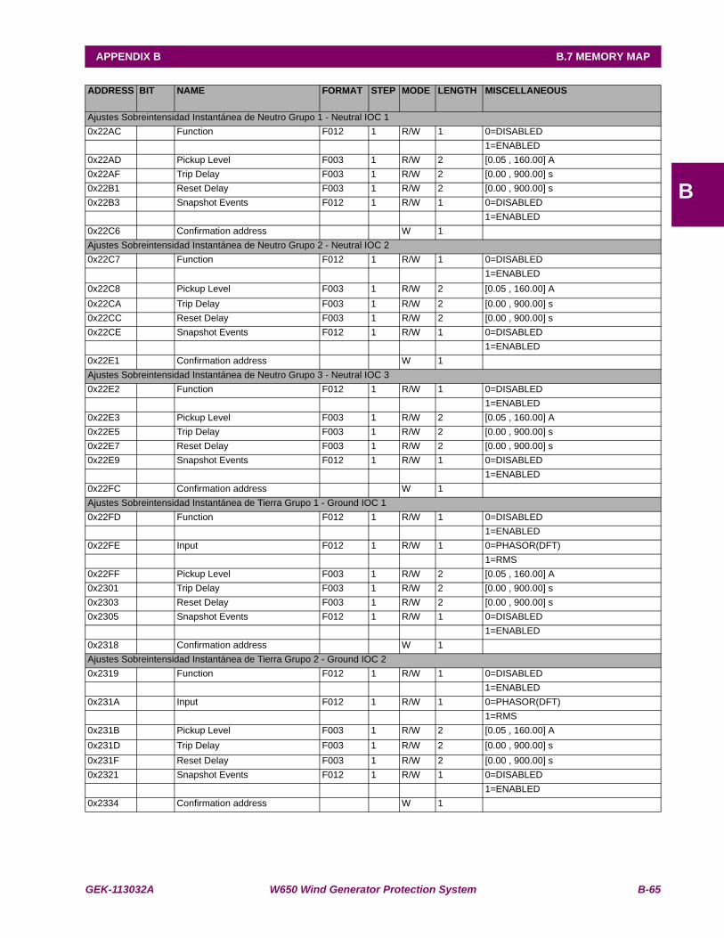
GEK-113032A W650 Wind Generator Protection System B-65
APPENDIX B B.7 MEMORY MAP
B
ADDRESS BIT NAME FORMAT STEP MODE LENGTH MISCELLANEOUS
Ajustes Sobreintensidad Instantánea de Neutro Grupo 1 - Neutral IOC 10x22AC Function F012 1 R/W 1 0=DISABLED 1=ENABLED0x22AD Pickup Level F003 1 R/W 2 [0.05 , 160.00] A0x22AF Trip Delay F003 1 R/W 2 [0.00 , 900.00] s0x22B1 Reset Delay F003 1 R/W 2 [0.00 , 900.00] s0x22B3 Snapshot Events F012 1 R/W 1 0=DISABLED 1=ENABLED0x22C6 Confirmation address W 1 Ajustes Sobreintensidad Instantánea de Neutro Grupo 2 - Neutral IOC 20x22C7 Function F012 1 R/W 1 0=DISABLED 1=ENABLED0x22C8 Pickup Level F003 1 R/W 2 [0.05 , 160.00] A0x22CA Trip Delay F003 1 R/W 2 [0.00 , 900.00] s0x22CC Reset Delay F003 1 R/W 2 [0.00 , 900.00] s0x22CE Snapshot Events F012 1 R/W 1 0=DISABLED 1=ENABLED0x22E1 Confirmation address W 1 Ajustes Sobreintensidad Instantánea de Neutro Grupo 3 - Neutral IOC 30x22E2 Function F012 1 R/W 1 0=DISABLED 1=ENABLED0x22E3 Pickup Level F003 1 R/W 2 [0.05 , 160.00] A0x22E5 Trip Delay F003 1 R/W 2 [0.00 , 900.00] s0x22E7 Reset Delay F003 1 R/W 2 [0.00 , 900.00] s0x22E9 Snapshot Events F012 1 R/W 1 0=DISABLED 1=ENABLED0x22FC Confirmation address W 1 Ajustes Sobreintensidad Instantánea de Tierra Grupo 1 - Ground IOC 10x22FD Function F012 1 R/W 1 0=DISABLED 1=ENABLED0x22FE Input F012 1 R/W 1 0=PHASOR(DFT) 1=RMS0x22FF Pickup Level F003 1 R/W 2 [0.05 , 160.00] A0x2301 Trip Delay F003 1 R/W 2 [0.00 , 900.00] s0x2303 Reset Delay F003 1 R/W 2 [0.00 , 900.00] s0x2305 Snapshot Events F012 1 R/W 1 0=DISABLED 1=ENABLED0x2318 Confirmation address W 1 Ajustes Sobreintensidad Instantánea de Tierra Grupo 2 - Ground IOC 20x2319 Function F012 1 R/W 1 0=DISABLED 1=ENABLED0x231A Input F012 1 R/W 1 0=PHASOR(DFT) 1=RMS0x231B Pickup Level F003 1 R/W 2 [0.05 , 160.00] A0x231D Trip Delay F003 1 R/W 2 [0.00 , 900.00] s0x231F Reset Delay F003 1 R/W 2 [0.00 , 900.00] s0x2321 Snapshot Events F012 1 R/W 1 0=DISABLED 1=ENABLED0x2334 Confirmation address W 1
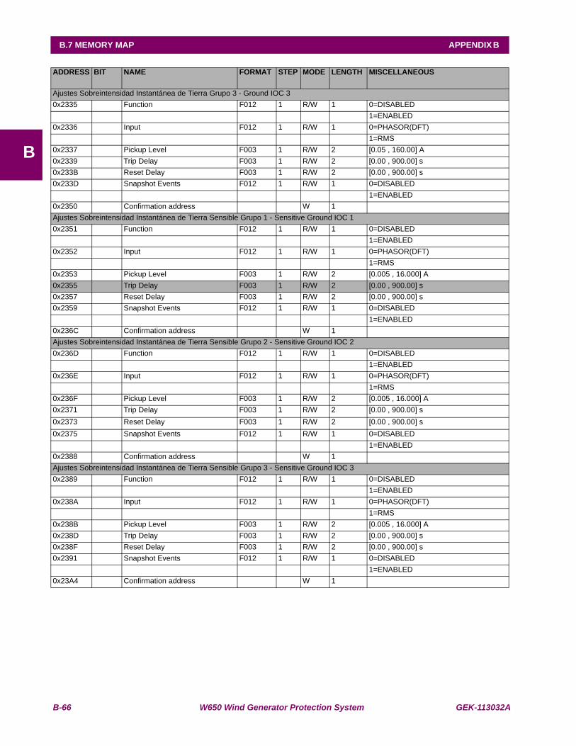
B-66 W650 Wind Generator Protection System GEK-113032A
B.7 MEMORY MAP APPENDIX B
B
ADDRESS BIT NAME FORMAT STEP MODE LENGTH MISCELLANEOUS
Ajustes Sobreintensidad Instantánea de Tierra Grupo 3 - Ground IOC 30x2335 Function F012 1 R/W 1 0=DISABLED 1=ENABLED0x2336 Input F012 1 R/W 1 0=PHASOR(DFT) 1=RMS0x2337 Pickup Level F003 1 R/W 2 [0.05 , 160.00] A0x2339 Trip Delay F003 1 R/W 2 [0.00 , 900.00] s0x233B Reset Delay F003 1 R/W 2 [0.00 , 900.00] s0x233D Snapshot Events F012 1 R/W 1 0=DISABLED 1=ENABLED0x2350 Confirmation address W 1 Ajustes Sobreintensidad Instantánea de Tierra Sensible Grupo 1 - Sensitive Ground IOC 10x2351 Function F012 1 R/W 1 0=DISABLED 1=ENABLED0x2352 Input F012 1 R/W 1 0=PHASOR(DFT) 1=RMS0x2353 Pickup Level F003 1 R/W 2 [0.005 , 16.000] A0x2355 Trip Delay F003 1 R/W 2 [0.00 , 900.00] s0x2357 Reset Delay F003 1 R/W 2 [0.00 , 900.00] s0x2359 Snapshot Events F012 1 R/W 1 0=DISABLED 1=ENABLED0x236C Confirmation address W 1 Ajustes Sobreintensidad Instantánea de Tierra Sensible Grupo 2 - Sensitive Ground IOC 20x236D Function F012 1 R/W 1 0=DISABLED 1=ENABLED0x236E Input F012 1 R/W 1 0=PHASOR(DFT) 1=RMS0x236F Pickup Level F003 1 R/W 2 [0.005 , 16.000] A0x2371 Trip Delay F003 1 R/W 2 [0.00 , 900.00] s0x2373 Reset Delay F003 1 R/W 2 [0.00 , 900.00] s0x2375 Snapshot Events F012 1 R/W 1 0=DISABLED 1=ENABLED0x2388 Confirmation address W 1 Ajustes Sobreintensidad Instantánea de Tierra Sensible Grupo 3 - Sensitive Ground IOC 30x2389 Function F012 1 R/W 1 0=DISABLED 1=ENABLED0x238A Input F012 1 R/W 1 0=PHASOR(DFT) 1=RMS0x238B Pickup Level F003 1 R/W 2 [0.005 , 16.000] A0x238D Trip Delay F003 1 R/W 2 [0.00 , 900.00] s0x238F Reset Delay F003 1 R/W 2 [0.00 , 900.00] s0x2391 Snapshot Events F012 1 R/W 1 0=DISABLED 1=ENABLED0x23A4 Confirmation address W 1

GEK-113032A W650 Wind Generator Protection System B-67
APPENDIX B B.7 MEMORY MAP
B
ADDRESS BIT NAME FORMAT STEP MODE LENGTH MISCELLANEOUS
Ajustes Sobreintensidad Temporizada de Fases Nivel Alto Grupo 1 - Phase TOC High 10x23A5 Function F012 1 R/W 1 0=DISABLED 1=ENABLED0x23A6 Input F012 1 R/W 1 0=PHASOR(DFT) 1=RMS0x23A7 Pickup Level F003 1 R/W 2 [0.05 , 160.00] A0x23A9 Curve F012 1 R/W 1 0=IEEE Ext Inv 1=IEEE Very Inv 2=IEEE Mod Inv 3=IEC Curve A 4=IEC Curve B 5=IEC Curve C 6=IEC Long-Time Inv 7=IEC Short-Time Inv 8=IAC Ext Inv 9=IAC Very Inv 10=IAC Mod Inv 11=ANSI Ext Inv 12=ANSI Very Inv 13=ANSI Norm Inv 14=ANSI Mod Inv 15=I2t 16=Definite Time 17=Rectifier Curve 18=User Curve A 19=User Curve B 20=User Curve C 21=User Curve D0x23AA TD Multiplier F003 1 R/W 2 [0.00 , 900.00] s0x23AC Reset F012 1 R/W 1 0=INSTANTANEOUS 1=LINEAL0x23AD Voltage Restraint F012 1 R/W 1 0=DISABLED 1=ENABLED0x23AE Snapshot Events F012 1 R/W 1 0=DISABLED 1=ENABLED0x23C1 Confirmation address W 1 Ajustes Sobreintensidad Temporizada de Fases Nivel Alto Grupo 2 - Phase TOC High 20x23C2 Function F012 1 R/W 1 0=DISABLED 1=ENABLED0x23C3 Input F012 1 R/W 1 0=PHASOR(DFT) 1=RMS0x23C4 Pickup Level F003 1 R/W 2 [0.05 , 160.00] A0x23C6 Curve F012 1 R/W 1 0=IEEE Ext Inv 1=IEEE Very Inv 2=IEEE Mod Inv 3=IEC Curve A 4=IEC Curve B 5=IEC Curve C 6=IEC Long-Time Inv 7=IEC Short-Time Inv 8=IAC Ext Inv 9=IAC Very Inv
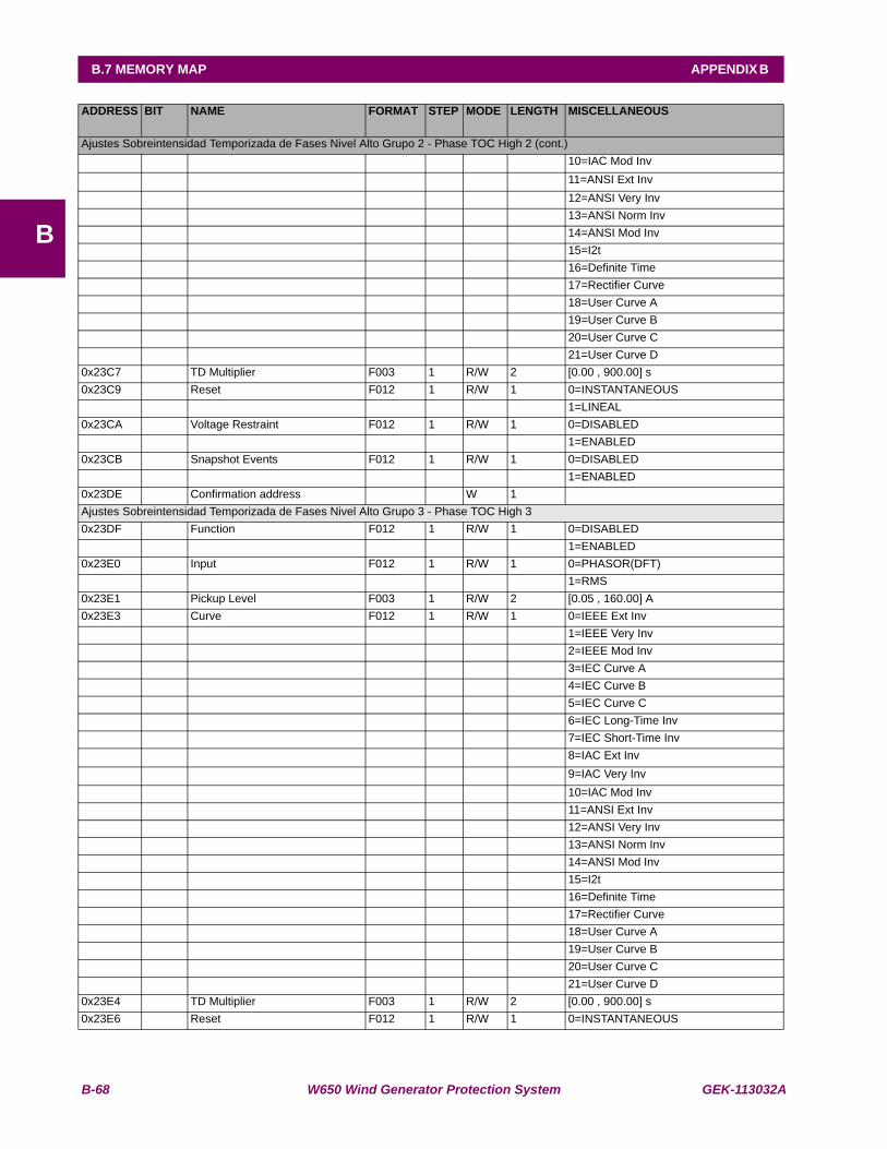
B-68 W650 Wind Generator Protection System GEK-113032A
B.7 MEMORY MAP APPENDIX B
B
ADDRESS BIT NAME FORMAT STEP MODE LENGTH MISCELLANEOUS
Ajustes Sobreintensidad Temporizada de Fases Nivel Alto Grupo 2 - Phase TOC High 2 (cont.) 10=IAC Mod Inv 11=ANSI Ext Inv 12=ANSI Very Inv 13=ANSI Norm Inv 14=ANSI Mod Inv 15=I2t 16=Definite Time 17=Rectifier Curve 18=User Curve A 19=User Curve B 20=User Curve C 21=User Curve D0x23C7 TD Multiplier F003 1 R/W 2 [0.00 , 900.00] s0x23C9 Reset F012 1 R/W 1 0=INSTANTANEOUS 1=LINEAL0x23CA Voltage Restraint F012 1 R/W 1 0=DISABLED 1=ENABLED0x23CB Snapshot Events F012 1 R/W 1 0=DISABLED 1=ENABLED0x23DE Confirmation address W 1 Ajustes Sobreintensidad Temporizada de Fases Nivel Alto Grupo 3 - Phase TOC High 30x23DF Function F012 1 R/W 1 0=DISABLED 1=ENABLED0x23E0 Input F012 1 R/W 1 0=PHASOR(DFT) 1=RMS0x23E1 Pickup Level F003 1 R/W 2 [0.05 , 160.00] A0x23E3 Curve F012 1 R/W 1 0=IEEE Ext Inv 1=IEEE Very Inv 2=IEEE Mod Inv 3=IEC Curve A 4=IEC Curve B 5=IEC Curve C 6=IEC Long-Time Inv 7=IEC Short-Time Inv 8=IAC Ext Inv 9=IAC Very Inv 10=IAC Mod Inv 11=ANSI Ext Inv 12=ANSI Very Inv 13=ANSI Norm Inv 14=ANSI Mod Inv 15=I2t 16=Definite Time 17=Rectifier Curve 18=User Curve A 19=User Curve B 20=User Curve C 21=User Curve D0x23E4 TD Multiplier F003 1 R/W 2 [0.00 , 900.00] s0x23E6 Reset F012 1 R/W 1 0=INSTANTANEOUS
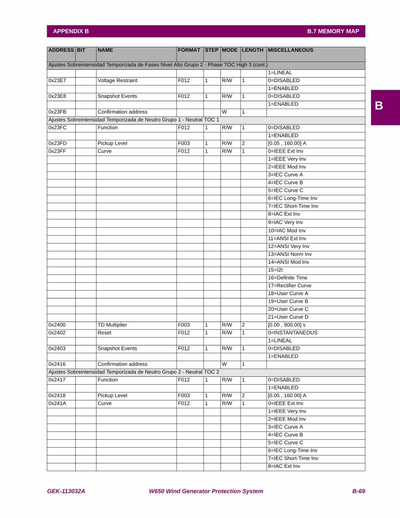
GEK-113032A W650 Wind Generator Protection System B-69
APPENDIX B B.7 MEMORY MAP
B
ADDRESS BIT NAME FORMAT STEP MODE LENGTH MISCELLANEOUS
Ajustes Sobreintensidad Temporizada de Fases Nivel Alto Grupo 2 - Phase TOC High 3 (cont.) 1=LINEAL0x23E7 Voltage Restraint F012 1 R/W 1 0=DISABLED 1=ENABLED0x23E8 Snapshot Events F012 1 R/W 1 0=DISABLED 1=ENABLED0x23FB Confirmation address W 1 Ajustes Sobreintensidad Temporizada de Neutro Grupo 1 - Neutral TOC 1 0x23FC Function F012 1 R/W 1 0=DISABLED 1=ENABLED0x23FD Pickup Level F003 1 R/W 2 [0.05 , 160.00] A0x23FF Curve F012 1 R/W 1 0=IEEE Ext Inv 1=IEEE Very Inv 2=IEEE Mod Inv 3=IEC Curve A 4=IEC Curve B 5=IEC Curve C 6=IEC Long-Time Inv 7=IEC Short-Time Inv 8=IAC Ext Inv 9=IAC Very Inv 10=IAC Mod Inv 11=ANSI Ext Inv 12=ANSI Very Inv 13=ANSI Norm Inv 14=ANSI Mod Inv 15=I2t 16=Definite Time 17=Rectifier Curve 18=User Curve A 19=User Curve B 20=User Curve C 21=User Curve D0x2400 TD Multiplier F003 1 R/W 2 [0.00 , 900.00] s0x2402 Reset F012 1 R/W 1 0=INSTANTANEOUS 1=LINEAL0x2403 Snapshot Events F012 1 R/W 1 0=DISABLED 1=ENABLED0x2416 Confirmation address W 1 Ajustes Sobreintensidad Temporizada de Neutro Grupo 2 - Neutral TOC 20x2417 Function F012 1 R/W 1 0=DISABLED 1=ENABLED0x2418 Pickup Level F003 1 R/W 2 [0.05 , 160.00] A0x241A Curve F012 1 R/W 1 0=IEEE Ext Inv 1=IEEE Very Inv 2=IEEE Mod Inv 3=IEC Curve A 4=IEC Curve B 5=IEC Curve C 6=IEC Long-Time Inv 7=IEC Short-Time Inv 8=IAC Ext Inv

B-70 W650 Wind Generator Protection System GEK-113032A
B.7 MEMORY MAP APPENDIX B
B
ADDRESS BIT NAME FORMAT STEP MODE LENGTH MISCELLANEOUS
Ajustes Sobreintensidad Temporizada de Neutro Grupo 2 - Neutral TOC 2 (cont.) 9=IAC Very Inv 10=IAC Mod Inv 11=ANSI Ext Inv 12=ANSI Very Inv 13=ANSI Norm Inv 14=ANSI Mod Inv 15=I2t 16=Definite Time 17=Rectifier Curve 18=User Curve A 19=User Curve B 20=User Curve C 21=User Curve D0x241B TD Multiplier F003 1 R/W 2 [0.00 , 900.00] s0x241D Reset F012 1 R/W 1 0=INSTANTANEOUS 1=LINEAL0x241E Snapshot Events F012 1 R/W 1 0=DISABLED 1=ENABLED0x2431 Confirmation address W 1 Ajustes Sobreintensidad Temporizada de Neutro Grupo 3 - Neutral TOC 30x2432 Function F012 1 R/W 1 0=DISABLED 1=ENABLED0x2433 Pickup Level F003 1 R/W 2 [0.05 , 160.00] A0x2435 Curve F012 1 R/W 1 0=IEEE Ext Inv 1=IEEE Very Inv 2=IEEE Mod Inv 3=IEC Curve A 4=IEC Curve B 5=IEC Curve C 6=IEC Long-Time Inv 7=IEC Short-Time Inv 8=IAC Ext Inv 9=IAC Very Inv 10=IAC Mod Inv 11=ANSI Ext Inv 12=ANSI Very Inv 13=ANSI Norm Inv 14=ANSI Mod Inv 15=I2t 16=Definite Time 17=Rectifier Curve 18=User Curve A 19=User Curve B 20=User Curve C 21=User Curve D0x2436 TD Multiplier F003 1 R/W 2 [0.00 , 900.00] s0x2438 Reset F012 1 R/W 1 0=INSTANTANEOUS 1=LINEAL0x2439 Snapshot Events F012 1 R/W 1 0=DISABLED 1=ENABLED

GEK-113032A W650 Wind Generator Protection System B-71
APPENDIX B B.7 MEMORY MAP
B
ADDRESS BIT NAME FORMAT STEP MODE LENGTH MISCELLANEOUS
Ajustes Sobreintensidad Temporizada de Neutro Grupo 3 - Neutral TOC 3 (cont.)0x244C Confirmation address W 1 Ajustes Sobreintensidad Temporizada de Tierra Grupo 1 - Ground TOC 10x244D Function F012 1 R/W 1 0=DISABLED 1=ENABLED0x244E Input F012 1 R/W 1 0=PHASOR(DFT) 1=RMS0x244F Pickup Level F003 1 R/W 2 [0.05 , 160.00] A0x2451 Curve F012 1 R/W 1 0=IEEE Ext Inv 1=IEEE Very Inv 2=IEEE Mod Inv 3=IEC Curve A 4=IEC Curve B 5=IEC Curve C 6=IEC Long-Time Inv 7=IEC Short-Time Inv 8=IAC Ext Inv 9=IAC Very Inv 10=IAC Mod Inv 11=ANSI Ext Inv 12=ANSI Very Inv 13=ANSI Norm Inv 14=ANSI Mod Inv 15=I2t 16=Definite Time 17=Rectifier Curve 18=User Curve A 19=User Curve B 20=User Curve C 21=User Curve D0x2452 TD Multiplier F003 1 R/W 2 [0.00 , 900.00] s0x2454 Reset F012 1 R/W 1 0=INSTANTANEOUS 1=LINEAL0x2455 Snapshot Events F012 1 R/W 1 0=DISABLED 1=ENABLED0x2468 Confirmation address W 1 Ajustes Sobreintensidad Temporizada de Tierra Grupo 2 - Ground TOC 20x2469 Function F012 1 R/W 1 0=DISABLED 1=ENABLED0x246A Input F012 1 R/W 1 0=PHASOR(DFT) 1=RMS0x246B Pickup Level F003 1 R/W 2 [0.05 , 160.00] A0x246D Curve F012 1 R/W 1 0=IEEE Ext Inv 1=IEEE Very Inv 2=IEEE Mod Inv 3=IEC Curve A 4=IEC Curve B 5=IEC Curve C 6=IEC Long-Time Inv 7=IEC Short-Time Inv 8=IAC Ext Inv
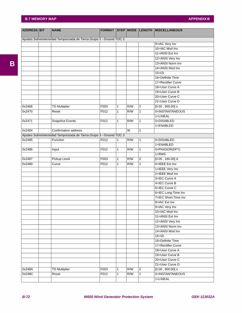
B-72 W650 Wind Generator Protection System GEK-113032A
B.7 MEMORY MAP APPENDIX B
B
ADDRESS BIT NAME FORMAT STEP MODE LENGTH MISCELLANEOUS
Ajustes Sobreintensidad Temporizada de Tierra Grupo 2 - Ground TOC 2 9=IAC Very Inv 10=IAC Mod Inv 11=ANSI Ext Inv 12=ANSI Very Inv 13=ANSI Norm Inv 14=ANSI Mod Inv 15=I2t 16=Definite Time 17=Rectifier Curve 18=User Curve A 19=User Curve B 20=User Curve C 21=User Curve D0x246E TD Multiplier F003 1 R/W 2 [0.00 , 900.00] s0x2470 Reset F012 1 R/W 1 0=INSTANTANEOUS 1=LINEAL0x2471 Snapshot Events F012 1 R/W 1 0=DISABLED 1=ENABLED0x2484 Confirmation address W 1 Ajustes Sobreintensidad Temporizada de Tierra Grupo 3 - Ground TOC 30x2485 Function F012 1 R/W 1 0=DISABLED 1=ENABLED0x2486 Input F012 1 R/W 1 0=PHASOR(DFT) 1=RMS0x2487 Pickup Level F003 1 R/W 2 [0.05 , 160.00] A0x2489 Curve F012 1 R/W 1 0=IEEE Ext Inv 1=IEEE Very Inv 2=IEEE Mod Inv 3=IEC Curve A 4=IEC Curve B 5=IEC Curve C 6=IEC Long-Time Inv 7=IEC Short-Time Inv 8=IAC Ext Inv 9=IAC Very Inv 10=IAC Mod Inv 11=ANSI Ext Inv 12=ANSI Very Inv 13=ANSI Norm Inv 14=ANSI Mod Inv 15=I2t 16=Definite Time 17=Rectifier Curve 18=User Curve A 19=User Curve B 20=User Curve C 21=User Curve D0x248A TD Multiplier F003 1 R/W 2 [0.00 , 900.00] s0x248C Reset F012 1 R/W 1 0=INSTANTANEOUS 1=LINEAL

GEK-113032A W650 Wind Generator Protection System B-73
APPENDIX B B.7 MEMORY MAP
B
ADDRESS BIT NAME FORMAT STEP MODE LENGTH MISCELLANEOUS
Ajustes Sobreintensidad Temporizada de Tierra Grupo 3 - Ground TOC 3 (cont.)0x248D Snapshot Events F012 1 R/W 1 0=DISABLED 1=ENABLED0x24A0 Confirmation address W 1 Ajustes Sobreintensidad Temporizada de Tierra Sensible Grupo 1 - Sensitive Ground TOC 10x24A1 Function F012 1 R/W 1 0=DISABLED 1=ENABLED0x24A2 Input F012 1 R/W 1 0=PHASOR(DFT) 1=RMS0x24A3 Pickup Level F003 1 R/W 2 [0.005 , 16.000] A0x24A5 Curve F012 1 R/W 1 0=IEEE Ext Inv 1=IEEE Very Inv 2=IEEE Mod Inv 3=IEC Curve A 4=IEC Curve B 5=IEC Curve C 6=IEC Long-Time Inv 7=IEC Short-Time Inv 8=IAC Ext Inv 9=IAC Very Inv 10=IAC Mod Inv 11=ANSI Ext Inv 12=ANSI Very Inv 13=ANSI Norm Inv 14=ANSI Mod Inv 15=I2t 16=Definite Time 17=Rectifier Curve 18=User Curve A 19=User Curve B 20=User Curve C 21=User Curve D0x24A6 TD Multiplier F003 1 R/W 2 [0.00 , 900.00] s0x24A8 Reset F012 1 R/W 1 0=INSTANTANEOUS 1=LINEAL0x24A9 Snapshot Events F012 1 R/W 1 0=DISABLED 1=ENABLED0x24BC Confirmation address W 1 Ajustes Sobreintensidad Temporizada de Tierra Sensible Grupo 2 - Sensitive Ground TOC 20x24BD Function F012 1 R/W 1 0=DISABLED 1=ENABLED0x24BE Input F012 1 R/W 1 0=PHASOR(DFT) 1=RMS0x24BF Pickup Level F003 1 R/W 2 [0.005 , 16.000] A0x24C1 Curve F012 1 R/W 1 0=IEEE Ext Inv 1=IEEE Very Inv 2=IEEE Mod Inv 3=IEC Curve A 4=IEC Curve B 5=IEC Curve C 6=IEC Long-Time Inv

B-74 W650 Wind Generator Protection System GEK-113032A
B.7 MEMORY MAP APPENDIX B
B
ADDRESS BIT NAME FORMAT STEP MODE LENGTH MISCELLANEOUS
Ajustes Sobreintensidad Temporizada de Tierra Sensible Grupo 2 - Sensitive Ground TOC 2 (cont.) 7=IEC Short-Time Inv 8=IAC Ext Inv 9=IAC Very Inv 10=IAC Mod Inv 11=ANSI Ext Inv 12=ANSI Very Inv 13=ANSI Norm Inv 14=ANSI Mod Inv 15=I2t 16=Definite Time 17=Rectifier Curve 18=User Curve A 19=User Curve B 20=User Curve C 21=User Curve D0x24C2 TD Multiplier F003 1 R/W 2 [0.00 , 900.00] s0x24C4 Reset F012 1 R/W 1 0=INSTANTANEOUS 1=LINEAL0x24C5 Snapshot Events F012 1 R/W 1 0=DISABLED 1=ENABLED0x24D8 Confirmation address W 1 Ajustes Sobreintensidad Temporizada de Tierra Sensible Grupo 3 - Sensitive Ground TOC 30x24D9 Function F012 1 R/W 1 0=DISABLED 1=ENABLED0x24DA Input F012 1 R/W 1 0=PHASOR(DFT) 1=RMS0x24DB Pickup Level F003 1 R/W 2 [0.005 , 16.000] A0x24DD Curve F012 1 R/W 1 0=IEEE Ext Inv 1=IEEE Very Inv 2=IEEE Mod Inv 3=IEC Curve A 4=IEC Curve B 5=IEC Curve C 6=IEC Long-Time Inv 7=IEC Short-Time Inv 8=IAC Ext Inv 9=IAC Very Inv 10=IAC Mod Inv 11=ANSI Ext Inv 12=ANSI Very Inv 13=ANSI Norm Inv 14=ANSI Mod Inv 15=I2t 16=Definite Time 17=Rectifier Curve 18=User Curve A 19=User Curve B 20=User Curve C 21=User Curve D0x24DE TD Multiplier F003 1 R/W 2 [0.00 , 900.00] s
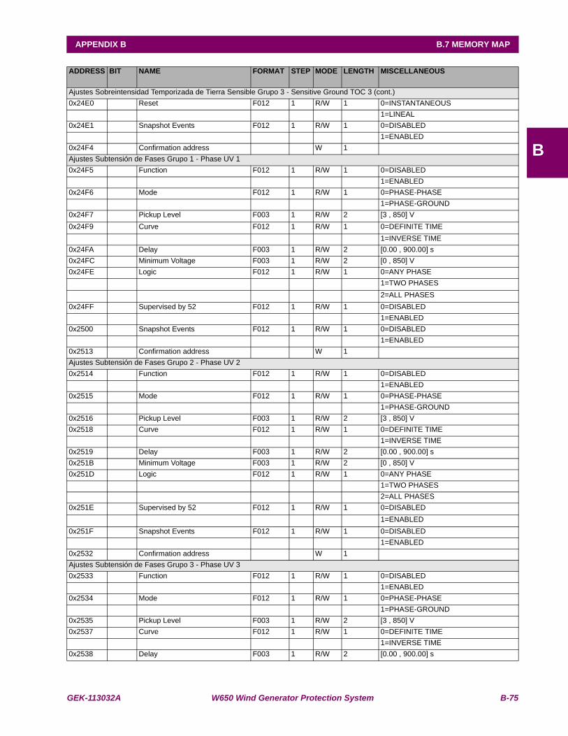
GEK-113032A W650 Wind Generator Protection System B-75
APPENDIX B B.7 MEMORY MAP
B
ADDRESS BIT NAME FORMAT STEP MODE LENGTH MISCELLANEOUS
Ajustes Sobreintensidad Temporizada de Tierra Sensible Grupo 3 - Sensitive Ground TOC 3 (cont.)0x24E0 Reset F012 1 R/W 1 0=INSTANTANEOUS 1=LINEAL0x24E1 Snapshot Events F012 1 R/W 1 0=DISABLED 1=ENABLED0x24F4 Confirmation address W 1 Ajustes Subtensión de Fases Grupo 1 - Phase UV 10x24F5 Function F012 1 R/W 1 0=DISABLED 1=ENABLED0x24F6 Mode F012 1 R/W 1 0=PHASE-PHASE 1=PHASE-GROUND0x24F7 Pickup Level F003 1 R/W 2 [3 , 850] V0x24F9 Curve F012 1 R/W 1 0=DEFINITE TIME 1=INVERSE TIME0x24FA Delay F003 1 R/W 2 [0.00 , 900.00] s0x24FC Minimum Voltage F003 1 R/W 2 [0 , 850] V0x24FE Logic F012 1 R/W 1 0=ANY PHASE 1=TWO PHASES 2=ALL PHASES0x24FF Supervised by 52 F012 1 R/W 1 0=DISABLED 1=ENABLED0x2500 Snapshot Events F012 1 R/W 1 0=DISABLED 1=ENABLED0x2513 Confirmation address W 1 Ajustes Subtensión de Fases Grupo 2 - Phase UV 20x2514 Function F012 1 R/W 1 0=DISABLED 1=ENABLED0x2515 Mode F012 1 R/W 1 0=PHASE-PHASE 1=PHASE-GROUND0x2516 Pickup Level F003 1 R/W 2 [3 , 850] V0x2518 Curve F012 1 R/W 1 0=DEFINITE TIME 1=INVERSE TIME0x2519 Delay F003 1 R/W 2 [0.00 , 900.00] s0x251B Minimum Voltage F003 1 R/W 2 [0 , 850] V0x251D Logic F012 1 R/W 1 0=ANY PHASE 1=TWO PHASES 2=ALL PHASES0x251E Supervised by 52 F012 1 R/W 1 0=DISABLED 1=ENABLED0x251F Snapshot Events F012 1 R/W 1 0=DISABLED 1=ENABLED0x2532 Confirmation address W 1 Ajustes Subtensión de Fases Grupo 3 - Phase UV 30x2533 Function F012 1 R/W 1 0=DISABLED 1=ENABLED0x2534 Mode F012 1 R/W 1 0=PHASE-PHASE 1=PHASE-GROUND0x2535 Pickup Level F003 1 R/W 2 [3 , 850] V0x2537 Curve F012 1 R/W 1 0=DEFINITE TIME 1=INVERSE TIME0x2538 Delay F003 1 R/W 2 [0.00 , 900.00] s
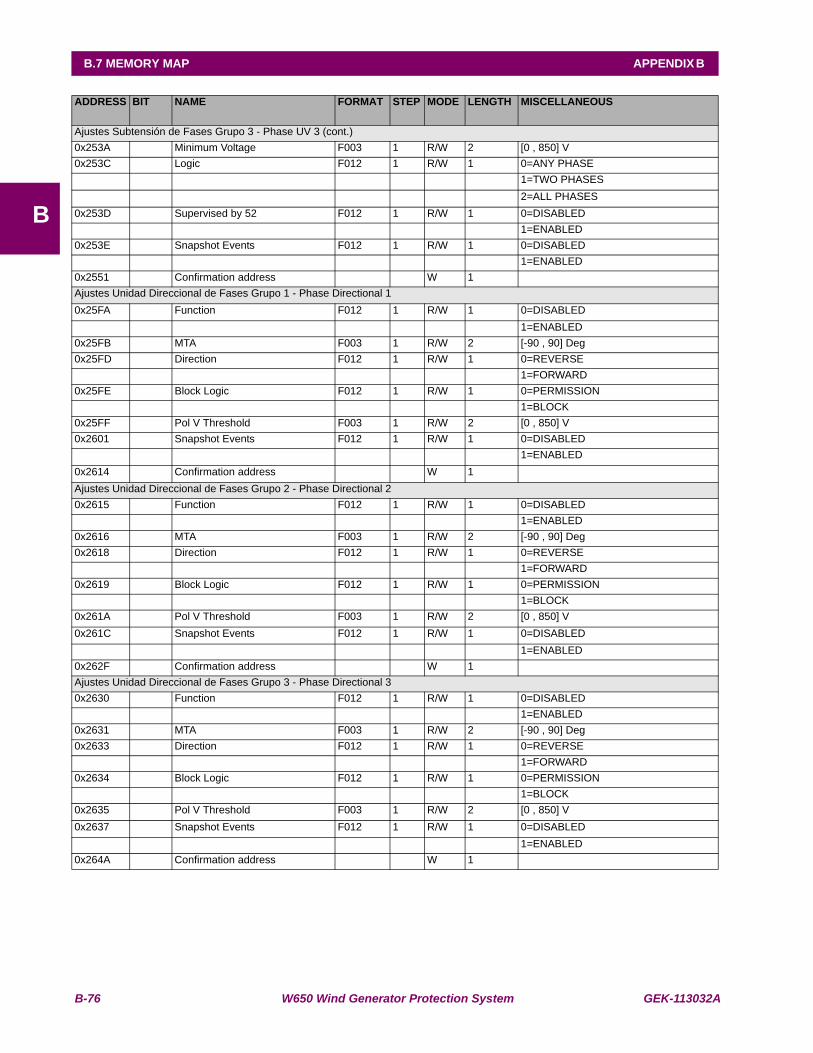
B-76 W650 Wind Generator Protection System GEK-113032A
B.7 MEMORY MAP APPENDIX B
B
ADDRESS BIT NAME FORMAT STEP MODE LENGTH MISCELLANEOUS
Ajustes Subtensión de Fases Grupo 3 - Phase UV 3 (cont.)0x253A Minimum Voltage F003 1 R/W 2 [0 , 850] V0x253C Logic F012 1 R/W 1 0=ANY PHASE 1=TWO PHASES 2=ALL PHASES0x253D Supervised by 52 F012 1 R/W 1 0=DISABLED 1=ENABLED0x253E Snapshot Events F012 1 R/W 1 0=DISABLED 1=ENABLED0x2551 Confirmation address W 1 Ajustes Unidad Direccional de Fases Grupo 1 - Phase Directional 10x25FA Function F012 1 R/W 1 0=DISABLED 1=ENABLED0x25FB MTA F003 1 R/W 2 [-90 , 90] Deg0x25FD Direction F012 1 R/W 1 0=REVERSE 1=FORWARD0x25FE Block Logic F012 1 R/W 1 0=PERMISSION 1=BLOCK0x25FF Pol V Threshold F003 1 R/W 2 [0 , 850] V0x2601 Snapshot Events F012 1 R/W 1 0=DISABLED 1=ENABLED0x2614 Confirmation address W 1 Ajustes Unidad Direccional de Fases Grupo 2 - Phase Directional 20x2615 Function F012 1 R/W 1 0=DISABLED 1=ENABLED0x2616 MTA F003 1 R/W 2 [-90 , 90] Deg0x2618 Direction F012 1 R/W 1 0=REVERSE 1=FORWARD0x2619 Block Logic F012 1 R/W 1 0=PERMISSION 1=BLOCK0x261A Pol V Threshold F003 1 R/W 2 [0 , 850] V0x261C Snapshot Events F012 1 R/W 1 0=DISABLED 1=ENABLED0x262F Confirmation address W 1 Ajustes Unidad Direccional de Fases Grupo 3 - Phase Directional 30x2630 Function F012 1 R/W 1 0=DISABLED 1=ENABLED0x2631 MTA F003 1 R/W 2 [-90 , 90] Deg0x2633 Direction F012 1 R/W 1 0=REVERSE 1=FORWARD0x2634 Block Logic F012 1 R/W 1 0=PERMISSION 1=BLOCK0x2635 Pol V Threshold F003 1 R/W 2 [0 , 850] V0x2637 Snapshot Events F012 1 R/W 1 0=DISABLED 1=ENABLED0x264A Confirmation address W 1
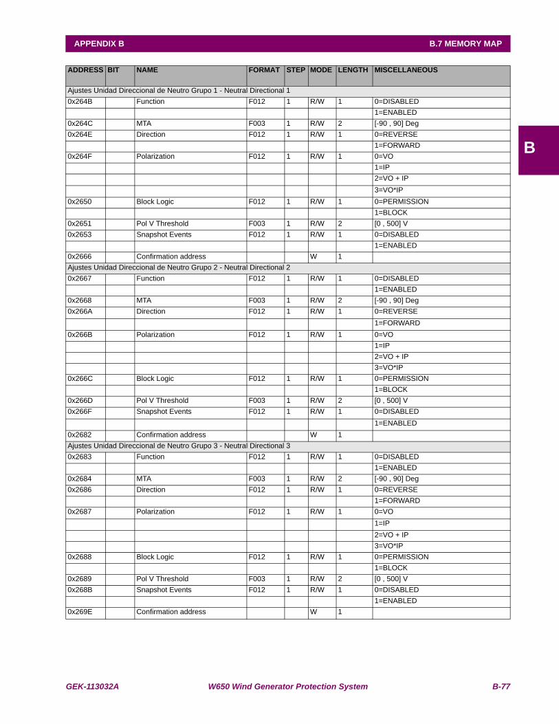
GEK-113032A W650 Wind Generator Protection System B-77
APPENDIX B B.7 MEMORY MAP
B
ADDRESS BIT NAME FORMAT STEP MODE LENGTH MISCELLANEOUS
Ajustes Unidad Direccional de Neutro Grupo 1 - Neutral Directional 10x264B Function F012 1 R/W 1 0=DISABLED 1=ENABLED0x264C MTA F003 1 R/W 2 [-90 , 90] Deg0x264E Direction F012 1 R/W 1 0=REVERSE 1=FORWARD0x264F Polarization F012 1 R/W 1 0=VO 1=IP 2=VO + IP 3=VO*IP0x2650 Block Logic F012 1 R/W 1 0=PERMISSION 1=BLOCK0x2651 Pol V Threshold F003 1 R/W 2 [0 , 500] V0x2653 Snapshot Events F012 1 R/W 1 0=DISABLED 1=ENABLED0x2666 Confirmation address W 1 Ajustes Unidad Direccional de Neutro Grupo 2 - Neutral Directional 20x2667 Function F012 1 R/W 1 0=DISABLED 1=ENABLED0x2668 MTA F003 1 R/W 2 [-90 , 90] Deg0x266A Direction F012 1 R/W 1 0=REVERSE 1=FORWARD0x266B Polarization F012 1 R/W 1 0=VO 1=IP 2=VO + IP 3=VO*IP0x266C Block Logic F012 1 R/W 1 0=PERMISSION 1=BLOCK0x266D Pol V Threshold F003 1 R/W 2 [0 , 500] V0x266F Snapshot Events F012 1 R/W 1 0=DISABLED 1=ENABLED0x2682 Confirmation address W 1 Ajustes Unidad Direccional de Neutro Grupo 3 - Neutral Directional 30x2683 Function F012 1 R/W 1 0=DISABLED 1=ENABLED0x2684 MTA F003 1 R/W 2 [-90 , 90] Deg0x2686 Direction F012 1 R/W 1 0=REVERSE 1=FORWARD0x2687 Polarization F012 1 R/W 1 0=VO 1=IP 2=VO + IP 3=VO*IP0x2688 Block Logic F012 1 R/W 1 0=PERMISSION 1=BLOCK0x2689 Pol V Threshold F003 1 R/W 2 [0 , 500] V0x268B Snapshot Events F012 1 R/W 1 0=DISABLED 1=ENABLED0x269E Confirmation address W 1
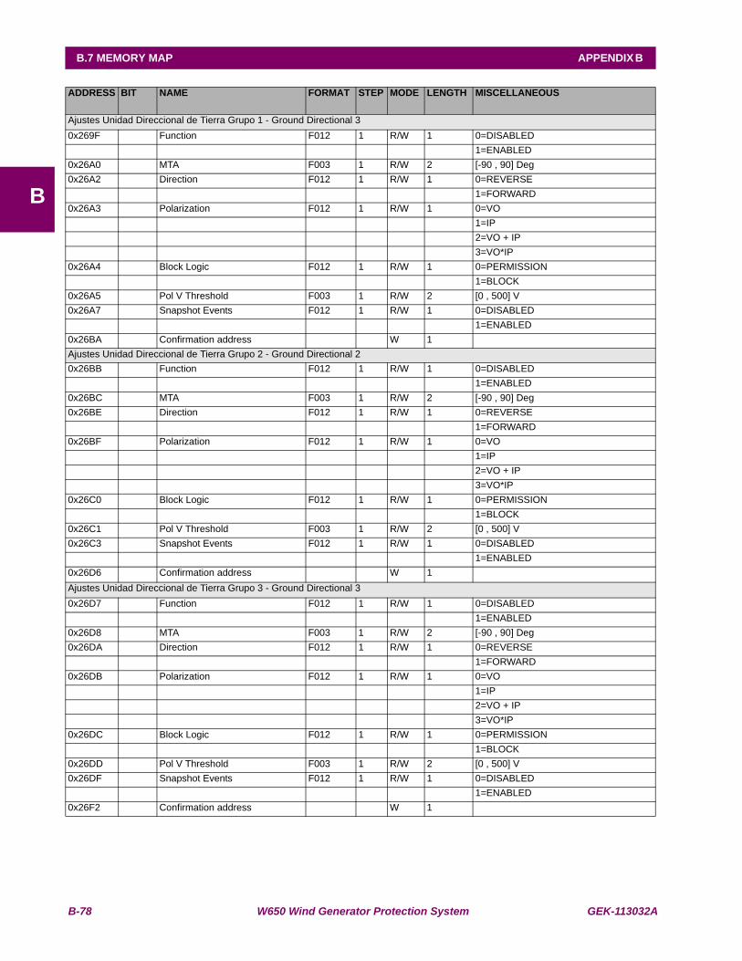
B-78 W650 Wind Generator Protection System GEK-113032A
B.7 MEMORY MAP APPENDIX B
B
ADDRESS BIT NAME FORMAT STEP MODE LENGTH MISCELLANEOUS
Ajustes Unidad Direccional de Tierra Grupo 1 - Ground Directional 30x269F Function F012 1 R/W 1 0=DISABLED 1=ENABLED0x26A0 MTA F003 1 R/W 2 [-90 , 90] Deg0x26A2 Direction F012 1 R/W 1 0=REVERSE 1=FORWARD0x26A3 Polarization F012 1 R/W 1 0=VO 1=IP 2=VO + IP 3=VO*IP0x26A4 Block Logic F012 1 R/W 1 0=PERMISSION 1=BLOCK0x26A5 Pol V Threshold F003 1 R/W 2 [0 , 500] V0x26A7 Snapshot Events F012 1 R/W 1 0=DISABLED 1=ENABLED0x26BA Confirmation address W 1 Ajustes Unidad Direccional de Tierra Grupo 2 - Ground Directional 20x26BB Function F012 1 R/W 1 0=DISABLED 1=ENABLED0x26BC MTA F003 1 R/W 2 [-90 , 90] Deg0x26BE Direction F012 1 R/W 1 0=REVERSE 1=FORWARD0x26BF Polarization F012 1 R/W 1 0=VO 1=IP 2=VO + IP 3=VO*IP0x26C0 Block Logic F012 1 R/W 1 0=PERMISSION 1=BLOCK0x26C1 Pol V Threshold F003 1 R/W 2 [0 , 500] V0x26C3 Snapshot Events F012 1 R/W 1 0=DISABLED 1=ENABLED0x26D6 Confirmation address W 1 Ajustes Unidad Direccional de Tierra Grupo 3 - Ground Directional 30x26D7 Function F012 1 R/W 1 0=DISABLED 1=ENABLED0x26D8 MTA F003 1 R/W 2 [-90 , 90] Deg0x26DA Direction F012 1 R/W 1 0=REVERSE 1=FORWARD0x26DB Polarization F012 1 R/W 1 0=VO 1=IP 2=VO + IP 3=VO*IP0x26DC Block Logic F012 1 R/W 1 0=PERMISSION 1=BLOCK0x26DD Pol V Threshold F003 1 R/W 2 [0 , 500] V0x26DF Snapshot Events F012 1 R/W 1 0=DISABLED 1=ENABLED0x26F2 Confirmation address W 1

GEK-113032A W650 Wind Generator Protection System B-79
APPENDIX B B.7 MEMORY MAP
B
ADDRESS BIT NAME FORMAT STEP MODE LENGTH MISCELLANEOUS
Ajustes Fallo Interruptor - Breaker Failure0x26F3 Function F012 1 R/W 1 0=DISABLED 1=ENABLED0x26F4 Supervision Pickup F003 1 R/W 2 [0.05 , 160.00] A0x26F6 Hiset Pickup F003 1 R/W 2 [0.05 , 160.00] A0x26F8 Lowset Pickup F003 1 R/W 2 [0.05 , 160.00] A0x26FA Internal Arc Pickup F003 1 R/W 2 [0.05 , 160.00] A0x26FC Internal Arc Delay F003 1 R/W 2 [0.00 , 900.00] s0x26FE Supervision Delay F003 1 R/W 2 [0.00 , 900.00] s0x2700 HiSet Delay F003 1 R/W 2 [0.00 , 900.00] s0x2702 LowSet Delay F003 1 R/W 2 [0.00 , 900.00] s0x2704 2nd Step Delay F003 1 R/W 2 [0.00 , 900.00] s0x2706 No Current Delay F003 1 R/W 2 [0.00 , 900.00] s0x2708 Snapshot Events F012 1 R/W 1 0=DISABLED 1=ENABLED0x271B Confirmation address W 1 Ajustes Fallo Fusible - Fuse Failure0x271C Function F012 1 R/W 1 0=DISABLED 1=ENABLED0x271D Snapshot Events F012 1 R/W 1 0=DISABLED 1=ENABLED0x2730 Confirmation address W 1 Ajustes Reenganchador - Recloser0x2763 Function F012 1 R/W 1 0=DISABLED 1=ENABLED0x2764 Max Number Shots F004 1 R/W 1 [1 , 4] 0x2765 Dead Time 1 F003 1 R/W 2 [0.00 , 900.00] s0x2767 Dead Time 2 F003 1 R/W 2 [0.00 , 900.00] s0x2769 Dead Time 3 F003 1 R/W 2 [0.00 , 900.00] s0x276B Dead Time 4 F003 1 R/W 2 [0.00 , 900.00] s0x276D Reclaim Time F003 1 R/W 2 [0.00 , 900.00] s0x276F Cond. Permission F012 1 R/W 1 0=DISABLED 1=ENABLED0x2770 Hold Time F003 1 R/W 2 [0.00 , 900.00] s0x2772 Reset Time F003 1 R/W 2 [0.00 , 900.00] s0x2774 Snapshot Events F012 1 R/W 1 0=DISABLED 1=ENABLED0x278B Confirmation address W 1 Ajustes Sobretensión de Neutro Nivel Alto Grupo 1 - Neutral OV High 10x278C Function F012 1 R/W 1 0=DISABLED 1=ENABLED0x278D Pickup Level F003 1 R/W 2 [3 , 500] V0x278F Trip Delay F003 1 R/W 2 [0.00 , 900.00] s0x2791 Reset Delay F003 1 R/W 2 [0.00 , 900.00] s0x2793 Snapshot Events F012 1 R/W 1 0=DISABLED 1=ENABLED0x27A6 Confirmation address W 1

B-80 W650 Wind Generator Protection System GEK-113032A
B.7 MEMORY MAP APPENDIX B
B
ADDRESS BIT NAME FORMAT STEP MODE LENGTH MISCELLANEOUS
Ajustes Sobretensión de Neutro Nivel Alto Grupo 2 - Neutral OV High 20x27A7 Function F012 1 R/W 1 0=DISABLED 1=ENABLED0x27A8 Pickup Level F003 1 R/W 2 [3 , 500] V0x27AA Trip Delay F003 1 R/W 2 [0.00 , 900.00] s0x27AC Reset Delay F003 1 R/W 2 [0.00 , 900.00] s0x27AE Snapshot Events F012 1 R/W 1 0=DISABLED 1=ENABLED0x27C1 Confirmation address W 1 Ajustes Sobretensión de Neutro Nivel Alto Grupo 3 - Neutral OV High 30x27C2 Function F012 1 R/W 1 0=DISABLED 1=ENABLED0x27C3 Pickup Level F003 1 R/W 2 [3 , 500] V0x27C5 Trip Delay F003 1 R/W 2 [0.00 , 900.00] s0x27C7 Reset Delay F003 1 R/W 2 [0.00 , 900.00] s0x27C9 Snapshot Events F012 1 R/W 1 0=DISABLED 1=ENABLED0x27DC Confirmation address W 1 Ajustes Sobretensión de Neutro Nivel Bajo Grupo 1 - Neutral OV Low 10x27DD Function F012 1 R/W 1 0=DISABLED 1=ENABLED0x27DE Pickup Level F003 1 R/W 2 [3 , 500] V0x27E0 Trip Delay F003 1 R/W 2 [0.00 , 900.00] s0x27E2 Reset Delay F003 1 R/W 2 [0.00 , 900.00] s0x27E4 Snapshot Events F012 1 R/W 1 0=DISABLED 1=ENABLED0x27F7 Confirmation address W 1 Ajustes Sobretensión de Neutro Nivel Bajo Grupo 2 - Neutral OV Low 20x27F8 Function F012 1 R/W 1 0=DISABLED 1=ENABLED0x27F9 Pickup Level F003 1 R/W 2 [3 , 500] V0x27FB Trip Delay F003 1 R/W 2 [0.00 , 900.00] s0x27FD Reset Delay F003 1 R/W 2 [0.00 , 900.00] s0x27FF Snapshot Events F012 1 R/W 1 0=DISABLED 1=ENABLED0x2812 Confirmation address W 1 Ajustes Sobretensión de Neutro Nivel Bajo Grupo 3 - Neutral OV Low 30x2813 Function F012 1 R/W 1 0=DISABLED 1=ENABLED0x2814 Pickup Level F003 1 R/W 2 [3 , 500] V0x2816 Trip Delay F003 1 R/W 2 [0.00 , 900.00] s0x2818 Reset Delay F003 1 R/W 2 [0.00 , 900.00] s0x281A Snapshot Events F012 1 R/W 1 0=DISABLED 1=ENABLED0x282D Confirmation address W 1
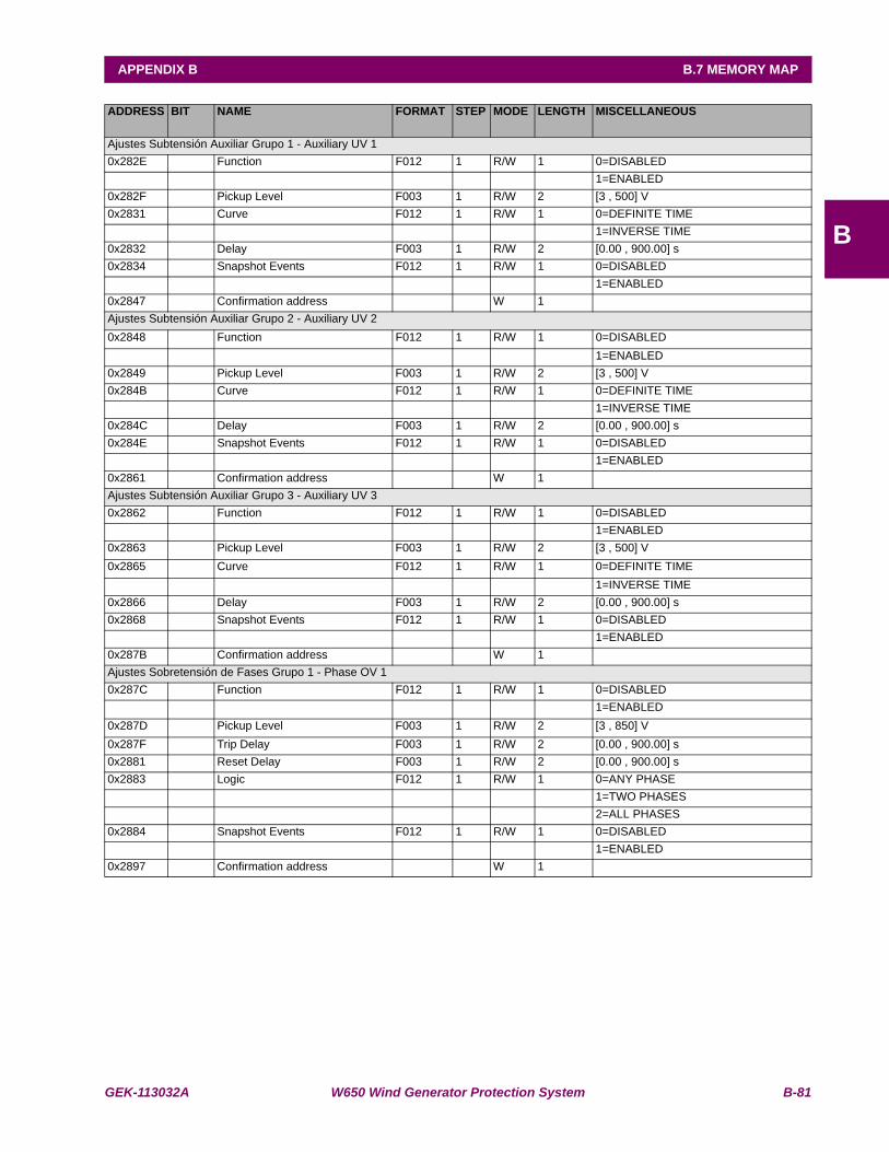
GEK-113032A W650 Wind Generator Protection System B-81
APPENDIX B B.7 MEMORY MAP
B
ADDRESS BIT NAME FORMAT STEP MODE LENGTH MISCELLANEOUS
Ajustes Subtensión Auxiliar Grupo 1 - Auxiliary UV 10x282E Function F012 1 R/W 1 0=DISABLED 1=ENABLED0x282F Pickup Level F003 1 R/W 2 [3 , 500] V0x2831 Curve F012 1 R/W 1 0=DEFINITE TIME 1=INVERSE TIME0x2832 Delay F003 1 R/W 2 [0.00 , 900.00] s0x2834 Snapshot Events F012 1 R/W 1 0=DISABLED 1=ENABLED0x2847 Confirmation address W 1 Ajustes Subtensión Auxiliar Grupo 2 - Auxiliary UV 20x2848 Function F012 1 R/W 1 0=DISABLED 1=ENABLED0x2849 Pickup Level F003 1 R/W 2 [3 , 500] V0x284B Curve F012 1 R/W 1 0=DEFINITE TIME 1=INVERSE TIME0x284C Delay F003 1 R/W 2 [0.00 , 900.00] s0x284E Snapshot Events F012 1 R/W 1 0=DISABLED 1=ENABLED0x2861 Confirmation address W 1 Ajustes Subtensión Auxiliar Grupo 3 - Auxiliary UV 30x2862 Function F012 1 R/W 1 0=DISABLED 1=ENABLED0x2863 Pickup Level F003 1 R/W 2 [3 , 500] V0x2865 Curve F012 1 R/W 1 0=DEFINITE TIME 1=INVERSE TIME0x2866 Delay F003 1 R/W 2 [0.00 , 900.00] s0x2868 Snapshot Events F012 1 R/W 1 0=DISABLED 1=ENABLED0x287B Confirmation address W 1 Ajustes Sobretensión de Fases Grupo 1 - Phase OV 10x287C Function F012 1 R/W 1 0=DISABLED 1=ENABLED0x287D Pickup Level F003 1 R/W 2 [3 , 850] V0x287F Trip Delay F003 1 R/W 2 [0.00 , 900.00] s0x2881 Reset Delay F003 1 R/W 2 [0.00 , 900.00] s0x2883 Logic F012 1 R/W 1 0=ANY PHASE 1=TWO PHASES 2=ALL PHASES0x2884 Snapshot Events F012 1 R/W 1 0=DISABLED 1=ENABLED0x2897 Confirmation address W 1
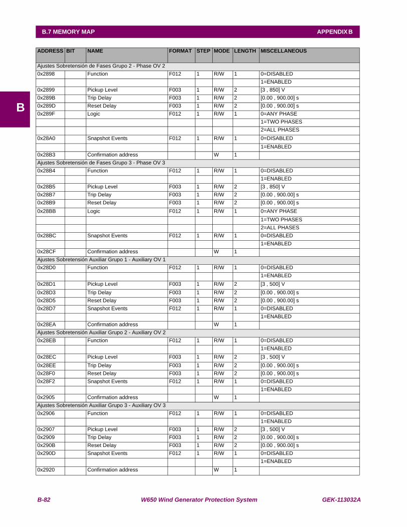
B-82 W650 Wind Generator Protection System GEK-113032A
B.7 MEMORY MAP APPENDIX B
B
ADDRESS BIT NAME FORMAT STEP MODE LENGTH MISCELLANEOUS
Ajustes Sobretensión de Fases Grupo 2 - Phase OV 20x2898 Function F012 1 R/W 1 0=DISABLED 1=ENABLED0x2899 Pickup Level F003 1 R/W 2 [3 , 850] V0x289B Trip Delay F003 1 R/W 2 [0.00 , 900.00] s0x289D Reset Delay F003 1 R/W 2 [0.00 , 900.00] s0x289F Logic F012 1 R/W 1 0=ANY PHASE 1=TWO PHASES 2=ALL PHASES0x28A0 Snapshot Events F012 1 R/W 1 0=DISABLED 1=ENABLED0x28B3 Confirmation address W 1 Ajustes Sobretensión de Fases Grupo 3 - Phase OV 30x28B4 Function F012 1 R/W 1 0=DISABLED 1=ENABLED0x28B5 Pickup Level F003 1 R/W 2 [3 , 850] V0x28B7 Trip Delay F003 1 R/W 2 [0.00 , 900.00] s0x28B9 Reset Delay F003 1 R/W 2 [0.00 , 900.00] s0x28BB Logic F012 1 R/W 1 0=ANY PHASE 1=TWO PHASES 2=ALL PHASES0x28BC Snapshot Events F012 1 R/W 1 0=DISABLED 1=ENABLED0x28CF Confirmation address W 1 Ajustes Sobretensión Auxiliar Grupo 1 - Auxiliary OV 10x28D0 Function F012 1 R/W 1 0=DISABLED 1=ENABLED0x28D1 Pickup Level F003 1 R/W 2 [3 , 500] V0x28D3 Trip Delay F003 1 R/W 2 [0.00 , 900.00] s0x28D5 Reset Delay F003 1 R/W 2 [0.00 , 900.00] s0x28D7 Snapshot Events F012 1 R/W 1 0=DISABLED 1=ENABLED0x28EA Confirmation address W 1 Ajustes Sobretensión Auxiliar Grupo 2 - Auxiliary OV 20x28EB Function F012 1 R/W 1 0=DISABLED 1=ENABLED0x28EC Pickup Level F003 1 R/W 2 [3 , 500] V0x28EE Trip Delay F003 1 R/W 2 [0.00 , 900.00] s0x28F0 Reset Delay F003 1 R/W 2 [0.00 , 900.00] s0x28F2 Snapshot Events F012 1 R/W 1 0=DISABLED 1=ENABLED0x2905 Confirmation address W 1 Ajustes Sobretensión Auxiliar Grupo 3 - Auxiliary OV 30x2906 Function F012 1 R/W 1 0=DISABLED 1=ENABLED0x2907 Pickup Level F003 1 R/W 2 [3 , 500] V0x2909 Trip Delay F003 1 R/W 2 [0.00 , 900.00] s0x290B Reset Delay F003 1 R/W 2 [0.00 , 900.00] s0x290D Snapshot Events F012 1 R/W 1 0=DISABLED 1=ENABLED0x2920 Confirmation address W 1
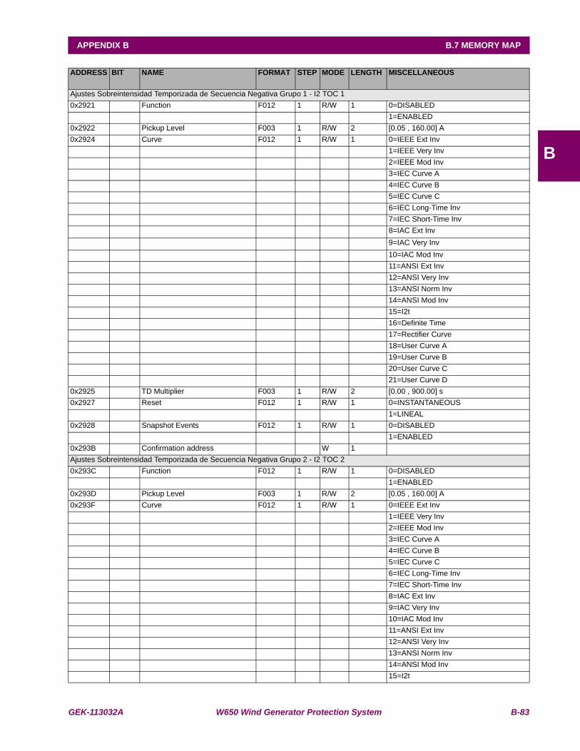
GEK-113032A W650 Wind Generator Protection System B-83
APPENDIX B B.7 MEMORY MAP
B
ADDRESS BIT NAME FORMAT STEP MODE LENGTH MISCELLANEOUS
Ajustes Sobreintensidad Temporizada de Secuencia Negativa Grupo 1 - I2 TOC 10x2921 Function F012 1 R/W 1 0=DISABLED 1=ENABLED0x2922 Pickup Level F003 1 R/W 2 [0.05 , 160.00] A0x2924 Curve F012 1 R/W 1 0=IEEE Ext Inv 1=IEEE Very Inv 2=IEEE Mod Inv 3=IEC Curve A 4=IEC Curve B 5=IEC Curve C 6=IEC Long-Time Inv 7=IEC Short-Time Inv 8=IAC Ext Inv 9=IAC Very Inv 10=IAC Mod Inv 11=ANSI Ext Inv 12=ANSI Very Inv 13=ANSI Norm Inv 14=ANSI Mod Inv 15=I2t 16=Definite Time 17=Rectifier Curve 18=User Curve A 19=User Curve B 20=User Curve C 21=User Curve D0x2925 TD Multiplier F003 1 R/W 2 [0.00 , 900.00] s0x2927 Reset F012 1 R/W 1 0=INSTANTANEOUS 1=LINEAL0x2928 Snapshot Events F012 1 R/W 1 0=DISABLED 1=ENABLED0x293B Confirmation address W 1 Ajustes Sobreintensidad Temporizada de Secuencia Negativa Grupo 2 - I2 TOC 20x293C Function F012 1 R/W 1 0=DISABLED 1=ENABLED0x293D Pickup Level F003 1 R/W 2 [0.05 , 160.00] A0x293F Curve F012 1 R/W 1 0=IEEE Ext Inv 1=IEEE Very Inv 2=IEEE Mod Inv 3=IEC Curve A 4=IEC Curve B 5=IEC Curve C 6=IEC Long-Time Inv 7=IEC Short-Time Inv 8=IAC Ext Inv 9=IAC Very Inv 10=IAC Mod Inv 11=ANSI Ext Inv 12=ANSI Very Inv 13=ANSI Norm Inv 14=ANSI Mod Inv 15=I2t
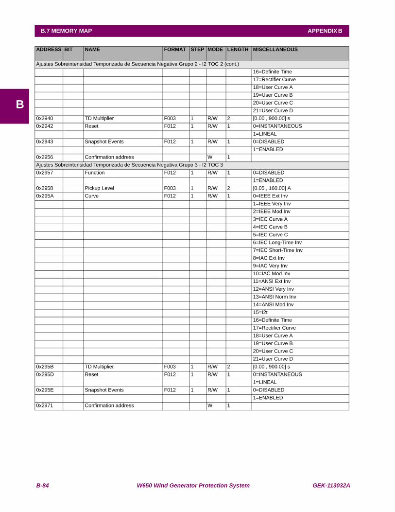
B-84 W650 Wind Generator Protection System GEK-113032A
B.7 MEMORY MAP APPENDIX B
B
ADDRESS BIT NAME FORMAT STEP MODE LENGTH MISCELLANEOUS
Ajustes Sobreintensidad Temporizada de Secuencia Negativa Grupo 2 - I2 TOC 2 (cont.) 16=Definite Time 17=Rectifier Curve 18=User Curve A 19=User Curve B 20=User Curve C 21=User Curve D0x2940 TD Multiplier F003 1 R/W 2 [0.00 , 900.00] s0x2942 Reset F012 1 R/W 1 0=INSTANTANEOUS 1=LINEAL0x2943 Snapshot Events F012 1 R/W 1 0=DISABLED 1=ENABLED0x2956 Confirmation address W 1 Ajustes Sobreintensidad Temporizada de Secuencia Negativa Grupo 3 - I2 TOC 30x2957 Function F012 1 R/W 1 0=DISABLED 1=ENABLED0x2958 Pickup Level F003 1 R/W 2 [0.05 , 160.00] A0x295A Curve F012 1 R/W 1 0=IEEE Ext Inv 1=IEEE Very Inv 2=IEEE Mod Inv 3=IEC Curve A 4=IEC Curve B 5=IEC Curve C 6=IEC Long-Time Inv 7=IEC Short-Time Inv 8=IAC Ext Inv 9=IAC Very Inv 10=IAC Mod Inv 11=ANSI Ext Inv 12=ANSI Very Inv 13=ANSI Norm Inv 14=ANSI Mod Inv 15=I2t 16=Definite Time 17=Rectifier Curve 18=User Curve A 19=User Curve B 20=User Curve C 21=User Curve D0x295B TD Multiplier F003 1 R/W 2 [0.00 , 900.00] s0x295D Reset F012 1 R/W 1 0=INSTANTANEOUS 1=LINEAL0x295E Snapshot Events F012 1 R/W 1 0=DISABLED 1=ENABLED0x2971 Confirmation address W 1
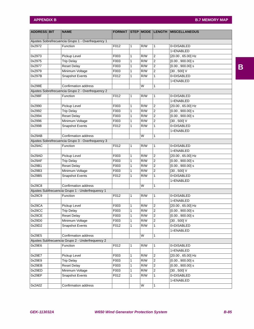
GEK-113032A W650 Wind Generator Protection System B-85
APPENDIX B B.7 MEMORY MAP
B
ADDRESS BIT NAME FORMAT STEP MODE LENGTH MISCELLANEOUS
Ajustes Sobrefrecuencia Grupo 1 - Overfrequency 10x2972 Function F012 1 R/W 1 0=DISABLED 1=ENABLED0x2973 Pickup Level F003 1 R/W 2 [20.00 , 65.00] Hz0x2975 Trip Delay F003 1 R/W 2 [0.00 , 900.00] s0x2977 Reset Delay F003 1 R/W 2 [0.00 , 900.00] s0x2979 Minimum Voltage F003 1 R/W 2 [30 , 500] V0x297B Snapshot Events F012 1 R/W 1 0=DISABLED 1=ENABLED0x298E Confirmation address W 1 Ajustes Sobrefrecuencia Grupo 2 - Overfrequency 20x298F Function F012 1 R/W 1 0=DISABLED 1=ENABLED0x2990 Pickup Level F003 1 R/W 2 [20.00 , 65.00] Hz0x2992 Trip Delay F003 1 R/W 2 [0.00 , 900.00] s0x2994 Reset Delay F003 1 R/W 2 [0.00 , 900.00] s0x2996 Minimum Voltage F003 1 R/W 2 [30 , 500] V0x2998 Snapshot Events F012 1 R/W 1 0=DISABLED 1=ENABLED0x29AB Confirmation address W 1 Ajustes Sobrefrecuencia Grupo 3 - Overfrequency 30x29AC Function F012 1 R/W 1 0=DISABLED 1=ENABLED0x29AD Pickup Level F003 1 R/W 2 [20.00 , 65.00] Hz0x29AF Trip Delay F003 1 R/W 2 [0.00 , 900.00] s0x29B1 Reset Delay F003 1 R/W 2 [0.00 , 900.00] s0x29B3 Minimum Voltage F003 1 R/W 2 [30 , 500] V0x29B5 Snapshot Events F012 1 R/W 1 0=DISABLED 1=ENABLED0x29C8 Confirmation address W 1 Ajustes Subfrecuencia Grupo 1 - Underfrequency 10x29C9 Function F012 1 R/W 1 0=DISABLED 1=ENABLED0x29CA Pickup Level F003 1 R/W 2 [20.00 , 65.00] Hz0x29CC Trip Delay F003 1 R/W 2 [0.00 , 900.00] s0x29CE Reset Delay F003 1 R/W 2 [0.00 , 900.00] s0x29D0 Minimum Voltage F003 1 R/W 2 [30 , 500] V0x29D2 Snapshot Events F012 1 R/W 1 0=DISABLED 1=ENABLED0x29E5 Confirmation address W 1 Ajustes Subfrecuencia Grupo 2 - Underfrequency 20x29E6 Function F012 1 R/W 1 0=DISABLED 1=ENABLED0x29E7 Pickup Level F003 1 R/W 2 [20.00 , 65.00] Hz0x29E9 Trip Delay F003 1 R/W 2 [0.00 , 900.00] s0x29EB Reset Delay F003 1 R/W 2 [0.00 , 900.00] s0x29ED Minimum Voltage F003 1 R/W 2 [30 , 500] V0x29EF Snapshot Events F012 1 R/W 1 0=DISABLED 1=ENABLED0x2A02 Confirmation address W 1
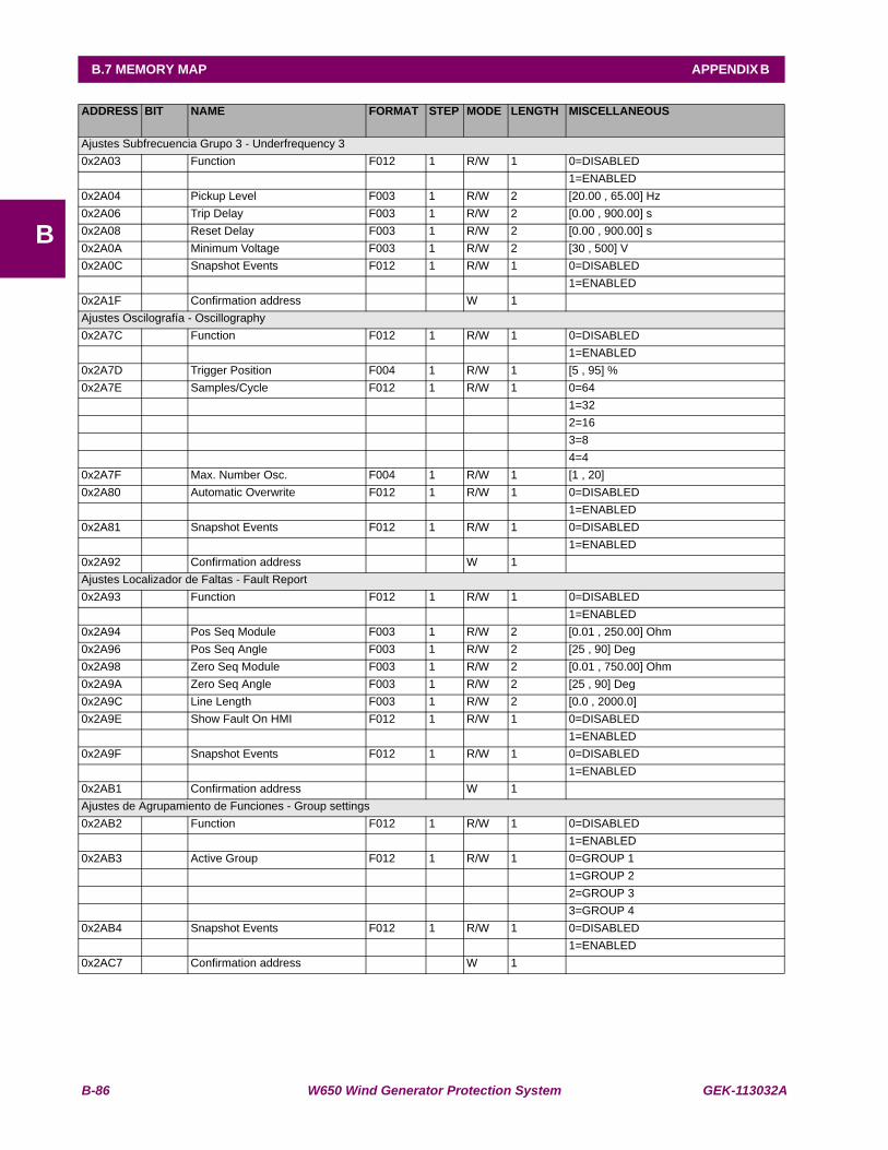
B-86 W650 Wind Generator Protection System GEK-113032A
B.7 MEMORY MAP APPENDIX B
B
ADDRESS BIT NAME FORMAT STEP MODE LENGTH MISCELLANEOUS
Ajustes Subfrecuencia Grupo 3 - Underfrequency 30x2A03 Function F012 1 R/W 1 0=DISABLED 1=ENABLED0x2A04 Pickup Level F003 1 R/W 2 [20.00 , 65.00] Hz0x2A06 Trip Delay F003 1 R/W 2 [0.00 , 900.00] s0x2A08 Reset Delay F003 1 R/W 2 [0.00 , 900.00] s0x2A0A Minimum Voltage F003 1 R/W 2 [30 , 500] V0x2A0C Snapshot Events F012 1 R/W 1 0=DISABLED 1=ENABLED0x2A1F Confirmation address W 1 Ajustes Oscilografía - Oscillography0x2A7C Function F012 1 R/W 1 0=DISABLED 1=ENABLED0x2A7D Trigger Position F004 1 R/W 1 [5 , 95] %0x2A7E Samples/Cycle F012 1 R/W 1 0=64 1=32 2=16 3=8 4=40x2A7F Max. Number Osc. F004 1 R/W 1 [1 , 20] 0x2A80 Automatic Overwrite F012 1 R/W 1 0=DISABLED 1=ENABLED0x2A81 Snapshot Events F012 1 R/W 1 0=DISABLED 1=ENABLED0x2A92 Confirmation address W 1 Ajustes Localizador de Faltas - Fault Report0x2A93 Function F012 1 R/W 1 0=DISABLED 1=ENABLED0x2A94 Pos Seq Module F003 1 R/W 2 [0.01 , 250.00] Ohm0x2A96 Pos Seq Angle F003 1 R/W 2 [25 , 90] Deg0x2A98 Zero Seq Module F003 1 R/W 2 [0.01 , 750.00] Ohm0x2A9A Zero Seq Angle F003 1 R/W 2 [25 , 90] Deg0x2A9C Line Length F003 1 R/W 2 [0.0 , 2000.0] 0x2A9E Show Fault On HMI F012 1 R/W 1 0=DISABLED 1=ENABLED0x2A9F Snapshot Events F012 1 R/W 1 0=DISABLED 1=ENABLED0x2AB1 Confirmation address W 1 Ajustes de Agrupamiento de Funciones - Group settings0x2AB2 Function F012 1 R/W 1 0=DISABLED 1=ENABLED0x2AB3 Active Group F012 1 R/W 1 0=GROUP 1 1=GROUP 2 2=GROUP 3 3=GROUP 40x2AB4 Snapshot Events F012 1 R/W 1 0=DISABLED 1=ENABLED0x2AC7 Confirmation address W 1
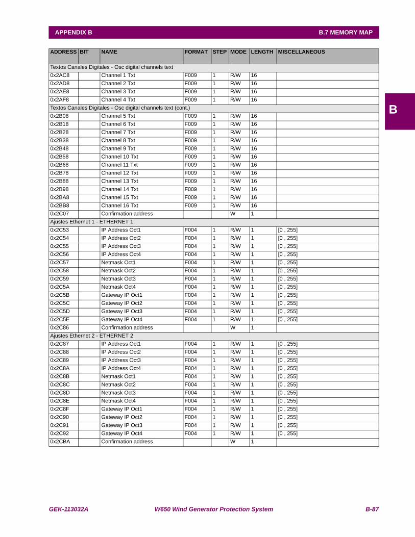
GEK-113032A W650 Wind Generator Protection System B-87
APPENDIX B B.7 MEMORY MAP
B
ADDRESS BIT NAME FORMAT STEP MODE LENGTH MISCELLANEOUS
Textos Canales Digitales - Osc digital channels text0x2AC8 Channel 1 Txt F009 1 R/W 16 0x2AD8 Channel 2 Txt F009 1 R/W 16 0x2AE8 Channel 3 Txt F009 1 R/W 16 0x2AF8 Channel 4 Txt F009 1 R/W 16 Textos Canales Digitales - Osc digital channels text (cont.)0x2B08 Channel 5 Txt F009 1 R/W 16 0x2B18 Channel 6 Txt F009 1 R/W 16 0x2B28 Channel 7 Txt F009 1 R/W 16 0x2B38 Channel 8 Txt F009 1 R/W 16 0x2B48 Channel 9 Txt F009 1 R/W 16 0x2B58 Channel 10 Txt F009 1 R/W 16 0x2B68 Channel 11 Txt F009 1 R/W 16 0x2B78 Channel 12 Txt F009 1 R/W 16 0x2B88 Channel 13 Txt F009 1 R/W 16 0x2B98 Channel 14 Txt F009 1 R/W 16 0x2BA8 Channel 15 Txt F009 1 R/W 16 0x2BB8 Channel 16 Txt F009 1 R/W 16 0x2C07 Confirmation address W 1 Ajustes Ethernet 1 - ETHERNET 10x2C53 IP Address Oct1 F004 1 R/W 1 [0 , 255] 0x2C54 IP Address Oct2 F004 1 R/W 1 [0 , 255] 0x2C55 IP Address Oct3 F004 1 R/W 1 [0 , 255] 0x2C56 IP Address Oct4 F004 1 R/W 1 [0 , 255] 0x2C57 Netmask Oct1 F004 1 R/W 1 [0 , 255] 0x2C58 Netmask Oct2 F004 1 R/W 1 [0 , 255] 0x2C59 Netmask Oct3 F004 1 R/W 1 [0 , 255] 0x2C5A Netmask Oct4 F004 1 R/W 1 [0 , 255] 0x2C5B Gateway IP Oct1 F004 1 R/W 1 [0 , 255] 0x2C5C Gateway IP Oct2 F004 1 R/W 1 [0 , 255] 0x2C5D Gateway IP Oct3 F004 1 R/W 1 [0 , 255] 0x2C5E Gateway IP Oct4 F004 1 R/W 1 [0 , 255] 0x2C86 Confirmation address W 1 Ajustes Ethernet 2 - ETHERNET 20x2C87 IP Address Oct1 F004 1 R/W 1 [0 , 255] 0x2C88 IP Address Oct2 F004 1 R/W 1 [0 , 255] 0x2C89 IP Address Oct3 F004 1 R/W 1 [0 , 255] 0x2C8A IP Address Oct4 F004 1 R/W 1 [0 , 255] 0x2C8B Netmask Oct1 F004 1 R/W 1 [0 , 255] 0x2C8C Netmask Oct2 F004 1 R/W 1 [0 , 255] 0x2C8D Netmask Oct3 F004 1 R/W 1 [0 , 255] 0x2C8E Netmask Oct4 F004 1 R/W 1 [0 , 255] 0x2C8F Gateway IP Oct1 F004 1 R/W 1 [0 , 255] 0x2C90 Gateway IP Oct2 F004 1 R/W 1 [0 , 255] 0x2C91 Gateway IP Oct3 F004 1 R/W 1 [0 , 255] 0x2C92 Gateway IP Oct4 F004 1 R/W 1 [0 , 255] 0x2CBA Confirmation address W 1

B-88 W650 Wind Generator Protection System GEK-113032A
B.7 MEMORY MAP APPENDIX B
B
ADDRESS BIT NAME FORMAT STEP MODE LENGTH MISCELLANEOUS
Ajustes DNP 3.0 Esclavo 1 - DNP 3.0 Slave 10x2CBB Physical Port F012 1 R/W 1 0=NONE 1=COM1 2=COM2 3=NETWORK0x2CBC Address F005 1 R/W 2 [0 , 65534] 0x2CBE IP Addr Client1 Oct1 F004 1 R/W 1 [0 , 255] 0x2CBF IP Addr Client1 Oct2 F004 1 R/W 1 [0 , 255] 0x2CC0 IP Addr Client1 Oct3 F004 1 R/W 1 [0 , 255] 0x2CC1 IP Addr Client1 Oct4 F004 1 R/W 1 [0 , 255] 0x2CC2 IP Addr Client2 Oct1 F004 1 R/W 1 [0 , 255] 0x2CC3 IP Addr Client2 Oct2 F004 1 R/W 1 [0 , 255] 0x2CC4 IP Addr Client2 Oct3 F004 1 R/W 1 [0 , 255] 0x2CC5 IP Addr Client2 Oct4 F004 1 R/W 1 [0 , 255] 0x2CC6 IP Addr Client3 Oct1 F004 1 R/W 1 [0 , 255] 0x2CC7 IP Addr Client3 Oct2 F004 1 R/W 1 [0 , 255] 0x2CC8 IP Addr Client3 Oct3 F004 1 R/W 1 [0 , 255] 0x2CC9 IP Addr Client3 Oct4 F004 1 R/W 1 [0 , 255] 0x2CCA IP Addr Client4 Oct1 F004 1 R/W 1 [0 , 255] 0x2CCB IP Addr Client4 Oct2 F004 1 R/W 1 [0 , 255] 0x2CCC IP Addr Client4 Oct3 F004 1 R/W 1 [0 , 255] 0x2CCD IP Addr Client4 Oct4 F004 1 R/W 1 [0 , 255] 0x2CCE IP Addr Client5 Oct1 F004 1 R/W 1 [0 , 255] 0x2CCF IP Addr Client5 Oct2 F004 1 R/W 1 [0 , 255] 0x2CD0 IP Addr Client5 Oct3 F004 1 R/W 1 [0 , 255] 0x2CD1 IP Addr Client5 Oct4 F004 1 R/W 1 [0 , 255] 0x2CD2 TCP/UDP Port F005 1 R/W 2 [0 , 65535] 0x2CD4 Unsol Resp Function F012 1 R/W 1 0=DISABLED 1=ENABLED0x2CD5 Unsol Resp TimeOut F005 1 R/W 2 [0 , 60] s0x2CD7 Unsol Resp Max Ret F004 1 R/W 1 [0 , 255] 0x2CD8 Unsol Resp Dest Adr F005 1 R/W 2 [0 , 65519] 0x2CDA Current Scale Factor F012 1 R/W 1 0=0.00001 1=0.0001 2=0.001 3=0.01 4=0.1 5=1 6=10 7=100 8=1000 9=100000x2CDB Voltage Scale Factor F012 1 R/W 1 0=0.00001 1=0.0001 2=0.001 3=0.01 4=0.1 5=1 6=10 7=100 8=1000 9=10000

GEK-113032A W650 Wind Generator Protection System B-89
APPENDIX B B.7 MEMORY MAP
B
ADDRESS BIT NAME FORMAT STEP MODE LENGTH MISCELLANEOUS
Ajustes DNP 3.0 Esclavo 1 - DNP 3.0 Slave 1 (cont.)0x2CDC Power Scale Factor F012 1 R/W 1 0=0.00001 1=0.0001 2=0.001 3=0.01 4=0.1 5=1 6=10 7=100 8=1000 9=100000x2CDD Energy Scale Factor F012 1 R/W 1 0=0.00001 1=0.0001 2=0.001 3=0.01 4=0.1 5=1 6=10 7=100 8=1000 9=100000x2CDE Other Scale Factor F012 1 R/W 1 0=0.00001 1=0.0001 2=0.001 3=0.01 4=0.1 5=1 6=10 7=100 8=1000 9=100000x2CDF Current Deadband F005 1 R/W 2 [0 , 65535] 0x2CE1 Voltage Deadband F005 1 R/W 2 [0 , 65535] 0x2CE3 Power Deadband F005 1 R/W 2 [0 , 65535] 0x2CE5 Energy Deadband F005 1 R/W 2 [0 , 65535] 0x2CE7 Other Deadband F005 1 R/W 2 [0 , 65535] 0x2CE9 Msg Fragment Size F005 1 R/W 2 [30 , 2048] 0x2CEB Binary Input Block 1 F012 1 R/W 1 0=NOT USED 1=CTL EVENTS 1-16 2=CTL EVENTS 17-32 3=CTL EVENTS 33-48 4=CTL EVENTS 49-64 5=CTL EVENTS 65-80 6=CTL EVENTS 81-96 7=CTL EVENTS 97-112 8=CTL EVENTS 113-128 9=SWITCHGEAR 1-8 10=SWITCHGEAR 9-160x2CEC Binary Input Block 2 F012 1 R/W 1 0=NOT USED 1=CTL EVENTS 1-16 2=CTL EVENTS 17-32 3=CTL EVENTS 33-48

B-90 W650 Wind Generator Protection System GEK-113032A
B.7 MEMORY MAP APPENDIX B
B
ADDRESS BIT NAME FORMAT STEP MODE LENGTH MISCELLANEOUS
Ajustes DNP 3.0 Esclavo 1 - DNP 3.0 Slave 1 (cont.) 4=CTL EVENTS 49-64 5=CTL EVENTS 65-80 6=CTL EVENTS 81-96 7=CTL EVENTS 97-112 8=CTL EVENTS 113-128 9=SWITCHGEAR 1-8 10=SWITCHGEAR 9-160x2CED Binary Input Block 3 F012 1 R/W 1 0=NOT USED 1=CTL EVENTS 1-16 2=CTL EVENTS 17-32 3=CTL EVENTS 33-48 4=CTL EVENTS 49-64 5=CTL EVENTS 65-80 6=CTL EVENTS 81-96 7=CTL EVENTS 97-112 8=CTL EVENTS 113-128 9=SWITCHGEAR 1-8 10=SWITCHGEAR 9-160x2CEE Binary Input Block 4 F012 1 R/W 1 0=NOT USED 1=CTL EVENTS 1-16 2=CTL EVENTS 17-32 3=CTL EVENTS 33-48 4=CTL EVENTS 49-64 5=CTL EVENTS 65-80 6=CTL EVENTS 81-96 7=CTL EVENTS 97-112 8=CTL EVENTS 113-128 9=SWITCHGEAR 1-8 10=SWITCHGEAR 9-160x2CEF Binary Input Block 5 F012 1 R/W 1 0=NOT USED 1=CTL EVENTS 1-16 2=CTL EVENTS 17-32 3=CTL EVENTS 33-48 4=CTL EVENTS 49-64 5=CTL EVENTS 65-80 6=CTL EVENTS 81-96 7=CTL EVENTS 97-112 8=CTL EVENTS 113-128 9=SWITCHGEAR 1-8 10=SWITCHGEAR 9-160x2CF0 Binary Input Block 6 F012 1 R/W 1 0=NOT USED 1=CTL EVENTS 1-16 2=CTL EVENTS 17-32 3=CTL EVENTS 33-48 4=CTL EVENTS 49-64 5=CTL EVENTS 65-80 6=CTL EVENTS 81-96 7=CTL EVENTS 97-112 8=CTL EVENTS 113-128 9=SWITCHGEAR 1-8 10=SWITCHGEAR 9-16
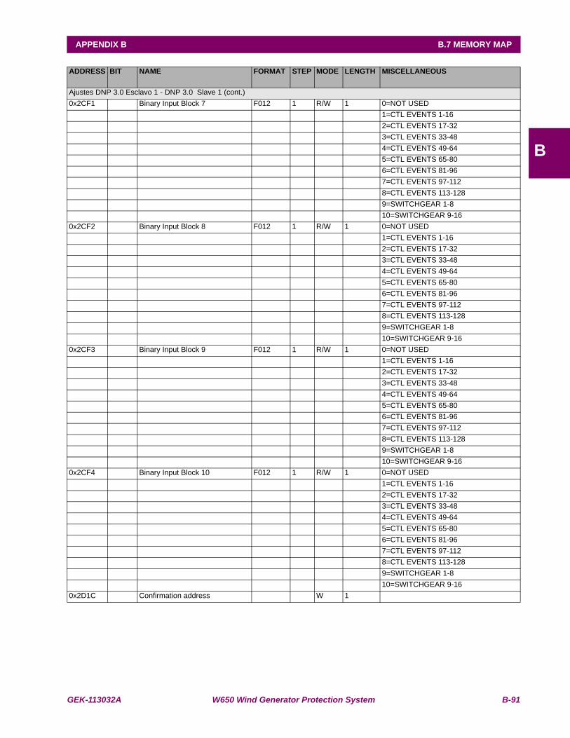
GEK-113032A W650 Wind Generator Protection System B-91
APPENDIX B B.7 MEMORY MAP
B
ADDRESS BIT NAME FORMAT STEP MODE LENGTH MISCELLANEOUS
Ajustes DNP 3.0 Esclavo 1 - DNP 3.0 Slave 1 (cont.)0x2CF1 Binary Input Block 7 F012 1 R/W 1 0=NOT USED 1=CTL EVENTS 1-16 2=CTL EVENTS 17-32 3=CTL EVENTS 33-48 4=CTL EVENTS 49-64 5=CTL EVENTS 65-80 6=CTL EVENTS 81-96 7=CTL EVENTS 97-112 8=CTL EVENTS 113-128 9=SWITCHGEAR 1-8 10=SWITCHGEAR 9-160x2CF2 Binary Input Block 8 F012 1 R/W 1 0=NOT USED 1=CTL EVENTS 1-16 2=CTL EVENTS 17-32 3=CTL EVENTS 33-48 4=CTL EVENTS 49-64 5=CTL EVENTS 65-80 6=CTL EVENTS 81-96 7=CTL EVENTS 97-112 8=CTL EVENTS 113-128 9=SWITCHGEAR 1-8 10=SWITCHGEAR 9-160x2CF3 Binary Input Block 9 F012 1 R/W 1 0=NOT USED 1=CTL EVENTS 1-16 2=CTL EVENTS 17-32 3=CTL EVENTS 33-48 4=CTL EVENTS 49-64 5=CTL EVENTS 65-80 6=CTL EVENTS 81-96 7=CTL EVENTS 97-112 8=CTL EVENTS 113-128 9=SWITCHGEAR 1-8 10=SWITCHGEAR 9-160x2CF4 Binary Input Block 10 F012 1 R/W 1 0=NOT USED 1=CTL EVENTS 1-16 2=CTL EVENTS 17-32 3=CTL EVENTS 33-48 4=CTL EVENTS 49-64 5=CTL EVENTS 65-80 6=CTL EVENTS 81-96 7=CTL EVENTS 97-112 8=CTL EVENTS 113-128 9=SWITCHGEAR 1-8 10=SWITCHGEAR 9-160x2D1C Confirmation address W 1
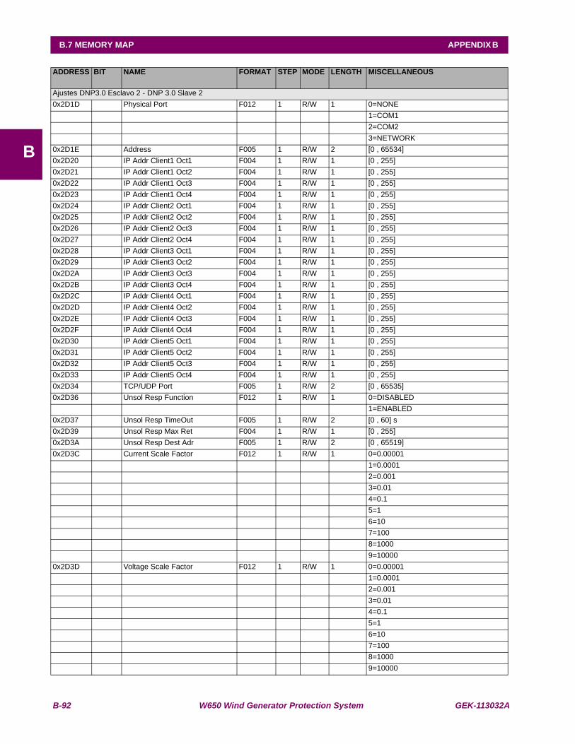
B-92 W650 Wind Generator Protection System GEK-113032A
B.7 MEMORY MAP APPENDIX B
B
ADDRESS BIT NAME FORMAT STEP MODE LENGTH MISCELLANEOUS
Ajustes DNP3.0 Esclavo 2 - DNP 3.0 Slave 20x2D1D Physical Port F012 1 R/W 1 0=NONE 1=COM1 2=COM2 3=NETWORK0x2D1E Address F005 1 R/W 2 [0 , 65534] 0x2D20 IP Addr Client1 Oct1 F004 1 R/W 1 [0 , 255] 0x2D21 IP Addr Client1 Oct2 F004 1 R/W 1 [0 , 255] 0x2D22 IP Addr Client1 Oct3 F004 1 R/W 1 [0 , 255] 0x2D23 IP Addr Client1 Oct4 F004 1 R/W 1 [0 , 255] 0x2D24 IP Addr Client2 Oct1 F004 1 R/W 1 [0 , 255] 0x2D25 IP Addr Client2 Oct2 F004 1 R/W 1 [0 , 255] 0x2D26 IP Addr Client2 Oct3 F004 1 R/W 1 [0 , 255] 0x2D27 IP Addr Client2 Oct4 F004 1 R/W 1 [0 , 255] 0x2D28 IP Addr Client3 Oct1 F004 1 R/W 1 [0 , 255] 0x2D29 IP Addr Client3 Oct2 F004 1 R/W 1 [0 , 255] 0x2D2A IP Addr Client3 Oct3 F004 1 R/W 1 [0 , 255] 0x2D2B IP Addr Client3 Oct4 F004 1 R/W 1 [0 , 255] 0x2D2C IP Addr Client4 Oct1 F004 1 R/W 1 [0 , 255] 0x2D2D IP Addr Client4 Oct2 F004 1 R/W 1 [0 , 255] 0x2D2E IP Addr Client4 Oct3 F004 1 R/W 1 [0 , 255] 0x2D2F IP Addr Client4 Oct4 F004 1 R/W 1 [0 , 255] 0x2D30 IP Addr Client5 Oct1 F004 1 R/W 1 [0 , 255] 0x2D31 IP Addr Client5 Oct2 F004 1 R/W 1 [0 , 255] 0x2D32 IP Addr Client5 Oct3 F004 1 R/W 1 [0 , 255] 0x2D33 IP Addr Client5 Oct4 F004 1 R/W 1 [0 , 255] 0x2D34 TCP/UDP Port F005 1 R/W 2 [0 , 65535] 0x2D36 Unsol Resp Function F012 1 R/W 1 0=DISABLED 1=ENABLED0x2D37 Unsol Resp TimeOut F005 1 R/W 2 [0 , 60] s0x2D39 Unsol Resp Max Ret F004 1 R/W 1 [0 , 255] 0x2D3A Unsol Resp Dest Adr F005 1 R/W 2 [0 , 65519] 0x2D3C Current Scale Factor F012 1 R/W 1 0=0.00001 1=0.0001 2=0.001 3=0.01 4=0.1 5=1 6=10 7=100 8=1000 9=100000x2D3D Voltage Scale Factor F012 1 R/W 1 0=0.00001 1=0.0001 2=0.001 3=0.01 4=0.1 5=1 6=10 7=100 8=1000 9=10000
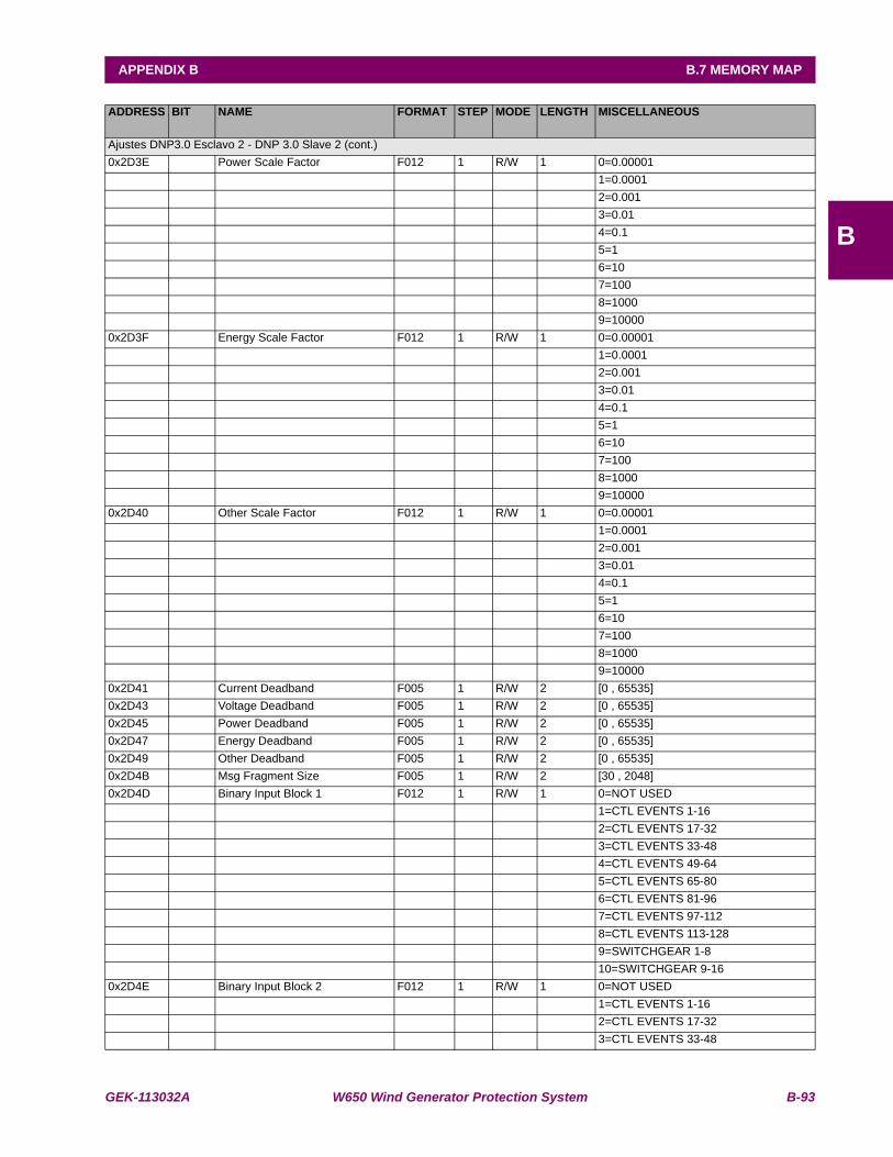
GEK-113032A W650 Wind Generator Protection System B-93
APPENDIX B B.7 MEMORY MAP
B
ADDRESS BIT NAME FORMAT STEP MODE LENGTH MISCELLANEOUS
Ajustes DNP3.0 Esclavo 2 - DNP 3.0 Slave 2 (cont.)0x2D3E Power Scale Factor F012 1 R/W 1 0=0.00001 1=0.0001 2=0.001 3=0.01 4=0.1 5=1 6=10 7=100 8=1000 9=100000x2D3F Energy Scale Factor F012 1 R/W 1 0=0.00001 1=0.0001 2=0.001 3=0.01 4=0.1 5=1 6=10 7=100 8=1000 9=100000x2D40 Other Scale Factor F012 1 R/W 1 0=0.00001 1=0.0001 2=0.001 3=0.01 4=0.1 5=1 6=10 7=100 8=1000 9=100000x2D41 Current Deadband F005 1 R/W 2 [0 , 65535] 0x2D43 Voltage Deadband F005 1 R/W 2 [0 , 65535] 0x2D45 Power Deadband F005 1 R/W 2 [0 , 65535] 0x2D47 Energy Deadband F005 1 R/W 2 [0 , 65535] 0x2D49 Other Deadband F005 1 R/W 2 [0 , 65535] 0x2D4B Msg Fragment Size F005 1 R/W 2 [30 , 2048] 0x2D4D Binary Input Block 1 F012 1 R/W 1 0=NOT USED 1=CTL EVENTS 1-16 2=CTL EVENTS 17-32 3=CTL EVENTS 33-48 4=CTL EVENTS 49-64 5=CTL EVENTS 65-80 6=CTL EVENTS 81-96 7=CTL EVENTS 97-112 8=CTL EVENTS 113-128 9=SWITCHGEAR 1-8 10=SWITCHGEAR 9-160x2D4E Binary Input Block 2 F012 1 R/W 1 0=NOT USED 1=CTL EVENTS 1-16 2=CTL EVENTS 17-32 3=CTL EVENTS 33-48
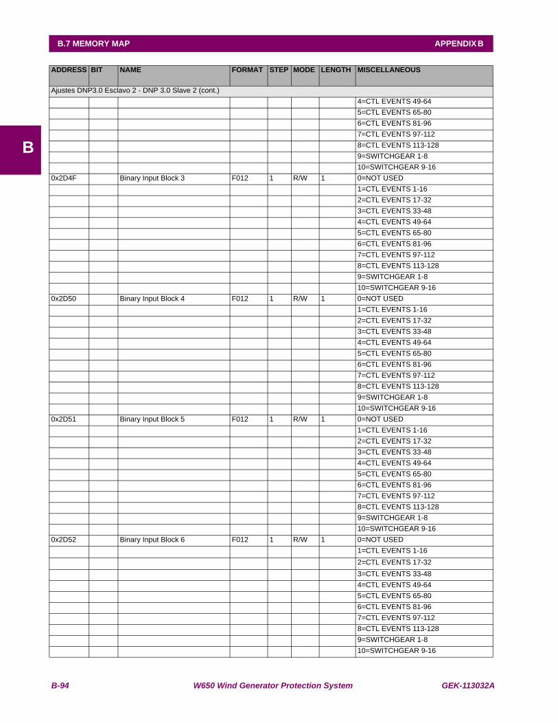
B-94 W650 Wind Generator Protection System GEK-113032A
B.7 MEMORY MAP APPENDIX B
B
ADDRESS BIT NAME FORMAT STEP MODE LENGTH MISCELLANEOUS
Ajustes DNP3.0 Esclavo 2 - DNP 3.0 Slave 2 (cont.) 4=CTL EVENTS 49-64 5=CTL EVENTS 65-80 6=CTL EVENTS 81-96 7=CTL EVENTS 97-112 8=CTL EVENTS 113-128 9=SWITCHGEAR 1-8 10=SWITCHGEAR 9-160x2D4F Binary Input Block 3 F012 1 R/W 1 0=NOT USED 1=CTL EVENTS 1-16 2=CTL EVENTS 17-32 3=CTL EVENTS 33-48 4=CTL EVENTS 49-64 5=CTL EVENTS 65-80 6=CTL EVENTS 81-96 7=CTL EVENTS 97-112 8=CTL EVENTS 113-128 9=SWITCHGEAR 1-8 10=SWITCHGEAR 9-160x2D50 Binary Input Block 4 F012 1 R/W 1 0=NOT USED 1=CTL EVENTS 1-16 2=CTL EVENTS 17-32 3=CTL EVENTS 33-48 4=CTL EVENTS 49-64 5=CTL EVENTS 65-80 6=CTL EVENTS 81-96 7=CTL EVENTS 97-112 8=CTL EVENTS 113-128 9=SWITCHGEAR 1-8 10=SWITCHGEAR 9-160x2D51 Binary Input Block 5 F012 1 R/W 1 0=NOT USED 1=CTL EVENTS 1-16 2=CTL EVENTS 17-32 3=CTL EVENTS 33-48 4=CTL EVENTS 49-64 5=CTL EVENTS 65-80 6=CTL EVENTS 81-96 7=CTL EVENTS 97-112 8=CTL EVENTS 113-128 9=SWITCHGEAR 1-8 10=SWITCHGEAR 9-160x2D52 Binary Input Block 6 F012 1 R/W 1 0=NOT USED 1=CTL EVENTS 1-16 2=CTL EVENTS 17-32 3=CTL EVENTS 33-48 4=CTL EVENTS 49-64 5=CTL EVENTS 65-80 6=CTL EVENTS 81-96 7=CTL EVENTS 97-112 8=CTL EVENTS 113-128 9=SWITCHGEAR 1-8 10=SWITCHGEAR 9-16

GEK-113032A W650 Wind Generator Protection System B-95
APPENDIX B B.7 MEMORY MAP
B
ADDRESS BIT NAME FORMAT STEP MODE LENGTH MISCELLANEOUS
Ajustes DNP3.0 Esclavo 2 - DNP 3.0 Slave 2 (cont.)0x2D53 Binary Input Block 7 F012 1 R/W 1 0=NOT USED 1=CTL EVENTS 1-16 2=CTL EVENTS 17-32 3=CTL EVENTS 33-48 4=CTL EVENTS 49-64 5=CTL EVENTS 65-80 6=CTL EVENTS 81-96 7=CTL EVENTS 97-112 8=CTL EVENTS 113-128 9=SWITCHGEAR 1-8 10=SWITCHGEAR 9-160x2D54 Binary Input Block 8 F012 1 R/W 1 0=NOT USED 1=CTL EVENTS 1-16 2=CTL EVENTS 17-32 3=CTL EVENTS 33-48 4=CTL EVENTS 49-64 5=CTL EVENTS 65-80 6=CTL EVENTS 81-96 7=CTL EVENTS 97-112 8=CTL EVENTS 113-128 9=SWITCHGEAR 1-8 10=SWITCHGEAR 9-160x2D55 Binary Input Block 9 F012 1 R/W 1 0=NOT USED 1=CTL EVENTS 1-16 2=CTL EVENTS 17-32 3=CTL EVENTS 33-48 4=CTL EVENTS 49-64 5=CTL EVENTS 65-80 6=CTL EVENTS 81-96 7=CTL EVENTS 97-112 8=CTL EVENTS 113-128 9=SWITCHGEAR 1-8 10=SWITCHGEAR 9-160x2D56 Binary Input Block 10 F012 1 R/W 1 0=NOT USED 1=CTL EVENTS 1-16 2=CTL EVENTS 17-32 3=CTL EVENTS 33-48 4=CTL EVENTS 49-64 5=CTL EVENTS 65-80 6=CTL EVENTS 81-96 7=CTL EVENTS 97-112 8=CTL EVENTS 113-128 9=SWITCHGEAR 1-8 10=SWITCHGEAR 9-160x2D7E Confirmation address W 1

B-96 W650 Wind Generator Protection System GEK-113032A
B.7 MEMORY MAP APPENDIX B
B
ADDRESS BIT NAME FORMAT STEP MODE LENGTH MISCELLANEOUS
Ajustes DNP 3.0 Esclavo 3 - DNP 3.0 Slave 30x2D7F Physical Port F012 1 R/W 1 0=NONE 1=COM1 2=COM2 3=NETWORK0x2D80 Address F005 1 R/W 2 [0 , 65534] 0x2D82 IP Addr Client1 Oct1 F004 1 R/W 1 [0 , 255] 0x2D83 IP Addr Client1 Oct2 F004 1 R/W 1 [0 , 255] 0x2D84 IP Addr Client1 Oct3 F004 1 R/W 1 [0 , 255] 0x2D85 IP Addr Client1 Oct4 F004 1 R/W 1 [0 , 255] 0x2D86 IP Addr Client2 Oct1 F004 1 R/W 1 [0 , 255] 0x2D87 IP Addr Client2 Oct2 F004 1 R/W 1 [0 , 255] 0x2D88 IP Addr Client2 Oct3 F004 1 R/W 1 [0 , 255] 0x2D89 IP Addr Client2 Oct4 F004 1 R/W 1 [0 , 255] 0x2D8A IP Addr Client3 Oct1 F004 1 R/W 1 [0 , 255] 0x2D8B IP Addr Client3 Oct2 F004 1 R/W 1 [0 , 255] 0x2D8C IP Addr Client3 Oct3 F004 1 R/W 1 [0 , 255] 0x2D8D IP Addr Client3 Oct4 F004 1 R/W 1 [0 , 255] 0x2D8E IP Addr Client4 Oct1 F004 1 R/W 1 [0 , 255] 0x2D8F IP Addr Client4 Oct2 F004 1 R/W 1 [0 , 255] 0x2D90 IP Addr Client4 Oct3 F004 1 R/W 1 [0 , 255] 0x2D91 IP Addr Client4 Oct4 F004 1 R/W 1 [0 , 255] 0x2D92 IP Addr Client5 Oct1 F004 1 R/W 1 [0 , 255] 0x2D93 IP Addr Client5 Oct2 F004 1 R/W 1 [0 , 255] 0x2D94 IP Addr Client5 Oct3 F004 1 R/W 1 [0 , 255] 0x2D95 IP Addr Client5 Oct4 F004 1 R/W 1 [0 , 255] 0x2D96 TCP/UDP Port F005 1 R/W 2 [0 , 65535] 0x2D98 Unsol Resp Function F012 1 R/W 1 0=DISABLED 1=ENABLED0x2D99 Unsol Resp TimeOut F005 1 R/W 2 [0 , 60] s0x2D9B Unsol Resp Max Ret F004 1 R/W 1 [0 , 255] 0x2D9C Unsol Resp Dest Adr F005 1 R/W 2 [0 , 65519] 0x2D9E Current Scale Factor F012 1 R/W 1 0=0.00001 1=0.0001 2=0.001 3=0.01 4=0.1 5=1 6=10 7=100 8=1000 9=100000x2D9F Voltage Scale Factor F012 1 R/W 1 0=0.00001 1=0.0001 2=0.001 3=0.01 4=0.1 5=1 6=10 7=100 8=1000
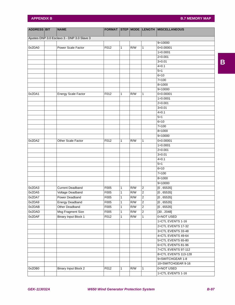
GEK-113032A W650 Wind Generator Protection System B-97
APPENDIX B B.7 MEMORY MAP
B
ADDRESS BIT NAME FORMAT STEP MODE LENGTH MISCELLANEOUS
Ajustes DNP 3.0 Esclavo 3 - DNP 3.0 Slave 3 9=100000x2DA0 Power Scale Factor F012 1 R/W 1 0=0.00001 1=0.0001 2=0.001 3=0.01 4=0.1 5=1 6=10 7=100 8=1000 9=100000x2DA1 Energy Scale Factor F012 1 R/W 1 0=0.00001 1=0.0001 2=0.001 3=0.01 4=0.1 5=1 6=10 7=100 8=1000 9=100000x2DA2 Other Scale Factor F012 1 R/W 1 0=0.00001 1=0.0001 2=0.001 3=0.01 4=0.1 5=1 6=10 7=100 8=1000 9=100000x2DA3 Current Deadband F005 1 R/W 2 [0 , 65535] 0x2DA5 Voltage Deadband F005 1 R/W 2 [0 , 65535] 0x2DA7 Power Deadband F005 1 R/W 2 [0 , 65535] 0x2DA9 Energy Deadband F005 1 R/W 2 [0 , 65535] 0x2DAB Other Deadband F005 1 R/W 2 [0 , 65535] 0x2DAD Msg Fragment Size F005 1 R/W 2 [30 , 2048] 0x2DAF Binary Input Block 1 F012 1 R/W 1 0=NOT USED 1=CTL EVENTS 1-16 2=CTL EVENTS 17-32 3=CTL EVENTS 33-48 4=CTL EVENTS 49-64 5=CTL EVENTS 65-80 6=CTL EVENTS 81-96 7=CTL EVENTS 97-112 8=CTL EVENTS 113-128 9=SWITCHGEAR 1-8 10=SWITCHGEAR 9-160x2DB0 Binary Input Block 2 F012 1 R/W 1 0=NOT USED 1=CTL EVENTS 1-16

B-98 W650 Wind Generator Protection System GEK-113032A
B.7 MEMORY MAP APPENDIX B
B
ADDRESS BIT NAME FORMAT STEP MODE LENGTH MISCELLANEOUS
Ajustes DNP 3.0 Esclavo 3 - DNP 3.0 Slave 3 (cont.) 2=CTL EVENTS 17-32 3=CTL EVENTS 33-48 4=CTL EVENTS 49-64 5=CTL EVENTS 65-80 6=CTL EVENTS 81-96 7=CTL EVENTS 97-112 8=CTL EVENTS 113-128 9=SWITCHGEAR 1-8 10=SWITCHGEAR 9-160x2DB1 Binary Input Block 3 F012 1 R/W 1 0=NOT USED 1=CTL EVENTS 1-16 2=CTL EVENTS 17-32 3=CTL EVENTS 33-48 4=CTL EVENTS 49-64 5=CTL EVENTS 65-80 6=CTL EVENTS 81-96 7=CTL EVENTS 97-112 8=CTL EVENTS 113-128 9=SWITCHGEAR 1-8 10=SWITCHGEAR 9-160x2DB2 Binary Input Block 4 F012 1 R/W 1 0=NOT USED 1=CTL EVENTS 1-16 2=CTL EVENTS 17-32 3=CTL EVENTS 33-48 4=CTL EVENTS 49-64 5=CTL EVENTS 65-80 6=CTL EVENTS 81-96 7=CTL EVENTS 97-112 8=CTL EVENTS 113-128 9=SWITCHGEAR 1-8 10=SWITCHGEAR 9-160x2DB3 Binary Input Block 5 F012 1 R/W 1 0=NOT USED 1=CTL EVENTS 1-16 2=CTL EVENTS 17-32 3=CTL EVENTS 33-48 4=CTL EVENTS 49-64 5=CTL EVENTS 65-80 6=CTL EVENTS 81-96 7=CTL EVENTS 97-112 8=CTL EVENTS 113-128 9=SWITCHGEAR 1-8 10=SWITCHGEAR 9-160x2DB4 Binary Input Block 6 F012 1 R/W 1 0=NOT USED 1=CTL EVENTS 1-16 2=CTL EVENTS 17-32 3=CTL EVENTS 33-48 4=CTL EVENTS 49-64 5=CTL EVENTS 65-80 6=CTL EVENTS 81-96
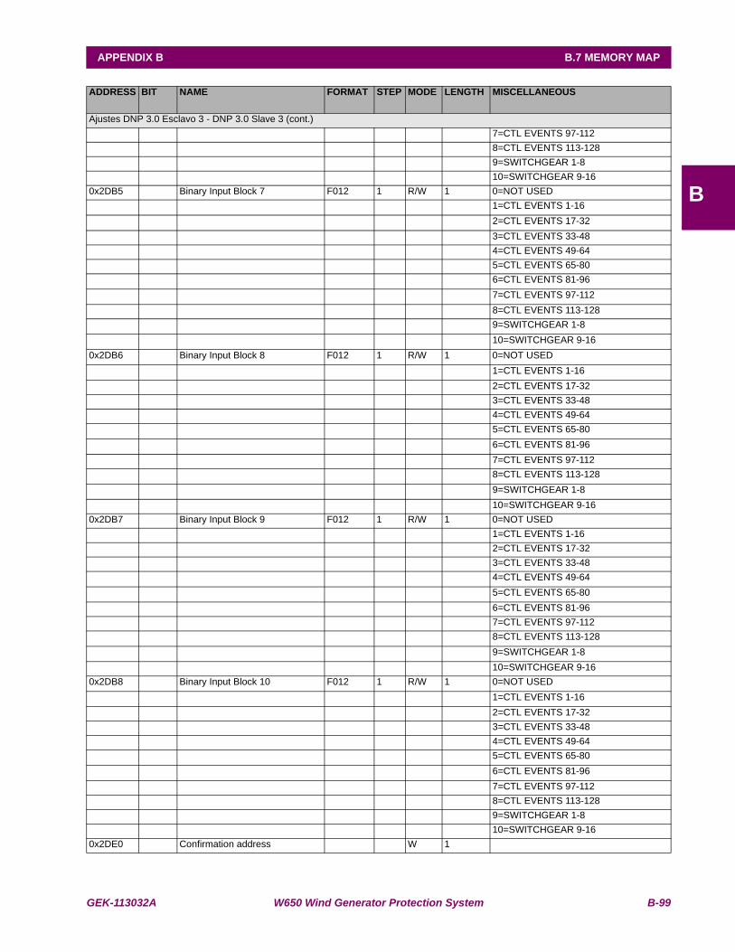
GEK-113032A W650 Wind Generator Protection System B-99
APPENDIX B B.7 MEMORY MAP
B
ADDRESS BIT NAME FORMAT STEP MODE LENGTH MISCELLANEOUS
Ajustes DNP 3.0 Esclavo 3 - DNP 3.0 Slave 3 (cont.) 7=CTL EVENTS 97-112 8=CTL EVENTS 113-128 9=SWITCHGEAR 1-8 10=SWITCHGEAR 9-160x2DB5 Binary Input Block 7 F012 1 R/W 1 0=NOT USED 1=CTL EVENTS 1-16 2=CTL EVENTS 17-32 3=CTL EVENTS 33-48 4=CTL EVENTS 49-64 5=CTL EVENTS 65-80 6=CTL EVENTS 81-96 7=CTL EVENTS 97-112 8=CTL EVENTS 113-128 9=SWITCHGEAR 1-8 10=SWITCHGEAR 9-160x2DB6 Binary Input Block 8 F012 1 R/W 1 0=NOT USED 1=CTL EVENTS 1-16 2=CTL EVENTS 17-32 3=CTL EVENTS 33-48 4=CTL EVENTS 49-64 5=CTL EVENTS 65-80 6=CTL EVENTS 81-96 7=CTL EVENTS 97-112 8=CTL EVENTS 113-128 9=SWITCHGEAR 1-8 10=SWITCHGEAR 9-160x2DB7 Binary Input Block 9 F012 1 R/W 1 0=NOT USED 1=CTL EVENTS 1-16 2=CTL EVENTS 17-32 3=CTL EVENTS 33-48 4=CTL EVENTS 49-64 5=CTL EVENTS 65-80 6=CTL EVENTS 81-96 7=CTL EVENTS 97-112 8=CTL EVENTS 113-128 9=SWITCHGEAR 1-8 10=SWITCHGEAR 9-160x2DB8 Binary Input Block 10 F012 1 R/W 1 0=NOT USED 1=CTL EVENTS 1-16 2=CTL EVENTS 17-32 3=CTL EVENTS 33-48 4=CTL EVENTS 49-64 5=CTL EVENTS 65-80 6=CTL EVENTS 81-96 7=CTL EVENTS 97-112 8=CTL EVENTS 113-128 9=SWITCHGEAR 1-8 10=SWITCHGEAR 9-160x2DE0 Confirmation address W 1
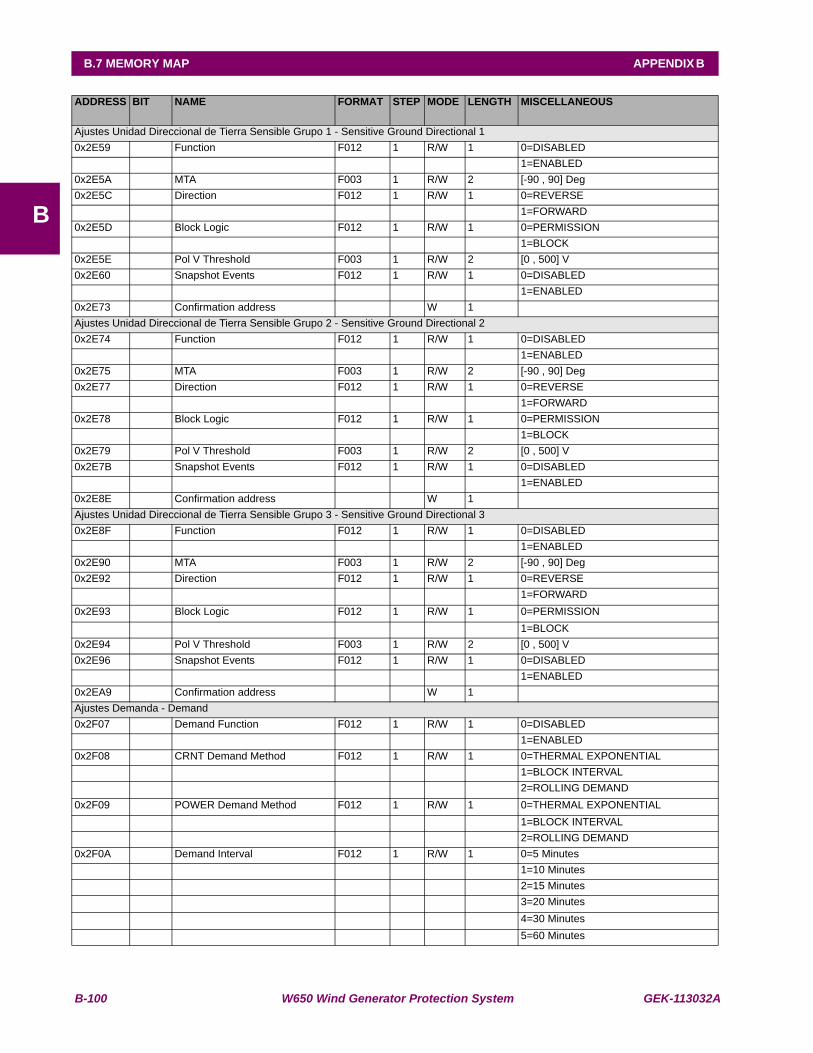
B-100 W650 Wind Generator Protection System GEK-113032A
B.7 MEMORY MAP APPENDIX B
B
ADDRESS BIT NAME FORMAT STEP MODE LENGTH MISCELLANEOUS
Ajustes Unidad Direccional de Tierra Sensible Grupo 1 - Sensitive Ground Directional 10x2E59 Function F012 1 R/W 1 0=DISABLED 1=ENABLED0x2E5A MTA F003 1 R/W 2 [-90 , 90] Deg0x2E5C Direction F012 1 R/W 1 0=REVERSE 1=FORWARD0x2E5D Block Logic F012 1 R/W 1 0=PERMISSION 1=BLOCK0x2E5E Pol V Threshold F003 1 R/W 2 [0 , 500] V0x2E60 Snapshot Events F012 1 R/W 1 0=DISABLED 1=ENABLED0x2E73 Confirmation address W 1 Ajustes Unidad Direccional de Tierra Sensible Grupo 2 - Sensitive Ground Directional 20x2E74 Function F012 1 R/W 1 0=DISABLED 1=ENABLED0x2E75 MTA F003 1 R/W 2 [-90 , 90] Deg0x2E77 Direction F012 1 R/W 1 0=REVERSE 1=FORWARD0x2E78 Block Logic F012 1 R/W 1 0=PERMISSION 1=BLOCK0x2E79 Pol V Threshold F003 1 R/W 2 [0 , 500] V0x2E7B Snapshot Events F012 1 R/W 1 0=DISABLED 1=ENABLED0x2E8E Confirmation address W 1 Ajustes Unidad Direccional de Tierra Sensible Grupo 3 - Sensitive Ground Directional 30x2E8F Function F012 1 R/W 1 0=DISABLED 1=ENABLED0x2E90 MTA F003 1 R/W 2 [-90 , 90] Deg0x2E92 Direction F012 1 R/W 1 0=REVERSE 1=FORWARD0x2E93 Block Logic F012 1 R/W 1 0=PERMISSION 1=BLOCK0x2E94 Pol V Threshold F003 1 R/W 2 [0 , 500] V0x2E96 Snapshot Events F012 1 R/W 1 0=DISABLED 1=ENABLED0x2EA9 Confirmation address W 1 Ajustes Demanda - Demand0x2F07 Demand Function F012 1 R/W 1 0=DISABLED 1=ENABLED0x2F08 CRNT Demand Method F012 1 R/W 1 0=THERMAL EXPONENTIAL 1=BLOCK INTERVAL 2=ROLLING DEMAND0x2F09 POWER Demand Method F012 1 R/W 1 0=THERMAL EXPONENTIAL 1=BLOCK INTERVAL 2=ROLLING DEMAND0x2F0A Demand Interval F012 1 R/W 1 0=5 Minutes 1=10 Minutes 2=15 Minutes 3=20 Minutes 4=30 Minutes 5=60 Minutes
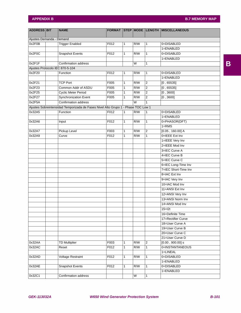
GEK-113032A W650 Wind Generator Protection System B-101
APPENDIX B B.7 MEMORY MAP
B
ADDRESS BIT NAME FORMAT STEP MODE LENGTH MISCELLANEOUS
Ajustes Demanda - Demand0x2F0B Trigger Enabled F012 1 R/W 1 0=DISABLED 1=ENABLED0x2F0C Snapshot Events F012 1 R/W 1 0=DISABLED 1=ENABLED0x2F1F Confirmation address W 1 Ajustes Protocolo IEC 870-5-1040x2F20 Function F012 1 R/W 1 0=DISABLED 1=ENABLED0x2F21 TCP Port F005 1 R/W 2 [0 , 65535] 0x2F23 Common Addr of ASDU F005 1 R/W 2 [0 , 65535] 0x2F25 Cyclic Meter Period F005 1 R/W 2 [0 , 3600] 0x2F27 Synchronization Event F005 1 R/W 2 [0 , 3600] 0x2F5A Confirmation address W 1 Ajustes Sobreintensidad Temporizada de Fases Nivel Alto Grupo 1 - Phase TOC Low 10x32A5 Function F012 1 R/W 1 0=DISABLED 1=ENABLED0x32A6 Input F012 1 R/W 1 0=PHASOR(DFT) 1=RMS0x32A7 Pickup Level F003 1 R/W 2 [0.05 , 160.00] A0x32A9 Curve F012 1 R/W 1 0=IEEE Ext Inv 1=IEEE Very Inv 2=IEEE Mod Inv 3=IEC Curve A 4=IEC Curve B 5=IEC Curve C 6=IEC Long-Time Inv 7=IEC Short-Time Inv 8=IAC Ext Inv 9=IAC Very Inv 10=IAC Mod Inv 11=ANSI Ext Inv 12=ANSI Very Inv 13=ANSI Norm Inv 14=ANSI Mod Inv 15=I2t 16=Definite Time 17=Rectifier Curve 18=User Curve A 19=User Curve B 20=User Curve C 21=User Curve D0x32AA TD Multiplier F003 1 R/W 2 [0.00 , 900.00] s0x32AC Reset F012 1 R/W 1 0=INSTANTANEOUS 1=LINEAL0x32AD Voltage Restraint F012 1 R/W 1 0=DISABLED 1=ENABLED0x32AE Snapshot Events F012 1 R/W 1 0=DISABLED 1=ENABLED0x32C1 Confirmation address W 1
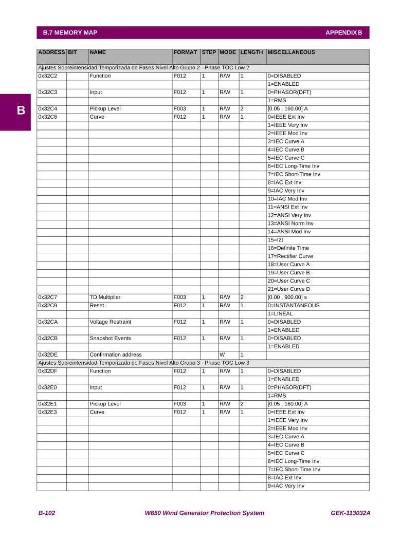
B-102 W650 Wind Generator Protection System GEK-113032A
B.7 MEMORY MAP APPENDIX B
B
ADDRESS BIT NAME FORMAT STEP MODE LENGTH MISCELLANEOUS
Ajustes Sobreintensidad Temporizada de Fases Nivel Alto Grupo 2 - Phase TOC Low 20x32C2 Function F012 1 R/W 1 0=DISABLED 1=ENABLED0x32C3 Input F012 1 R/W 1 0=PHASOR(DFT) 1=RMS0x32C4 Pickup Level F003 1 R/W 2 [0.05 , 160.00] A0x32C6 Curve F012 1 R/W 1 0=IEEE Ext Inv 1=IEEE Very Inv 2=IEEE Mod Inv 3=IEC Curve A 4=IEC Curve B 5=IEC Curve C 6=IEC Long-Time Inv 7=IEC Short-Time Inv 8=IAC Ext Inv 9=IAC Very Inv 10=IAC Mod Inv 11=ANSI Ext Inv 12=ANSI Very Inv 13=ANSI Norm Inv 14=ANSI Mod Inv 15=I2t 16=Definite Time 17=Rectifier Curve 18=User Curve A 19=User Curve B 20=User Curve C 21=User Curve D0x32C7 TD Multiplier F003 1 R/W 2 [0.00 , 900.00] s0x32C9 Reset F012 1 R/W 1 0=INSTANTANEOUS 1=LINEAL0x32CA Voltage Restraint F012 1 R/W 1 0=DISABLED 1=ENABLED0x32CB Snapshot Events F012 1 R/W 1 0=DISABLED 1=ENABLED0x32DE Confirmation address W 1 Ajustes Sobreintensidad Temporizada de Fases Nivel Alto Grupo 3 - Phase TOC Low 30x32DF Function F012 1 R/W 1 0=DISABLED 1=ENABLED0x32E0 Input F012 1 R/W 1 0=PHASOR(DFT) 1=RMS0x32E1 Pickup Level F003 1 R/W 2 [0.05 , 160.00] A0x32E3 Curve F012 1 R/W 1 0=IEEE Ext Inv 1=IEEE Very Inv 2=IEEE Mod Inv 3=IEC Curve A 4=IEC Curve B 5=IEC Curve C 6=IEC Long-Time Inv 7=IEC Short-Time Inv 8=IAC Ext Inv 9=IAC Very Inv

GEK-113032A W650 Wind Generator Protection System B-103
APPENDIX B B.7 MEMORY MAP
B
ADDRESS BIT NAME FORMAT STEP MODE LENGTH MISCELLANEOUS
Ajustes Sobreintensidad Temporizada de Fases Nivel Alto Grupo 3 - Phase TOC Low 3 (cont.) 10=IAC Mod Inv 11=ANSI Ext Inv 12=ANSI Very Inv 13=ANSI Norm Inv 14=ANSI Mod Inv 15=I2t 16=Definite Time 17=Rectifier Curve 18=User Curve A 19=User Curve B 20=User Curve C 21=User Curve D0x32E4 TD Multiplier F003 1 R/W 2 [0.00 , 900.00] s0x32E6 Reset F012 1 R/W 1 0=INSTANTANEOUS 1=LINEAL0x32E7 Voltage Restraint F012 1 R/W 1 0=DISABLED 1=ENABLED0x32E8 Snapshot Events F012 1 R/W 1 0=DISABLED 1=ENABLED0x32FB Confirmation address W 1 Ajustes Aparamenta (16 elementos) - Switchgear (16 items)0x32FC CONTACTS TYPE_01 F012 1 R/W 1 0=52a + 52b 1=52a 2=52b 3=NONE0x32FD CONTACTS TYPE_02 F012 1 R/W 1 0=52a + 52b 1=52a 2=52b 3=NONE... ... ... ... ... ... ... ...0x330B CONTACTS TYPE_16 F012 1 R/W 1 0=52a + 52b 1=52a 2=52b 3=NONE0x330C FAIL TO OPEN 01 t F004 1 R/W 1 [0 , 30000] ms0x330D FAIL TO OPEN 02 t F004 1 R/W 1 [0 , 30000] ms... ... ... ... ... ... ... ...0x331B FAIL TO OPEN 16 t F004 1 R/W 1 [0 , 30000] ms0x331C FAIL TO CLOSE 01 t F004 1 R/W 1 [0 , 30000] ms0x331D FAIL TO CLOSE 02 t F004 1 R/W 1 [0 , 30000] ms... ... ... ... ... ... ... ...0x332B FAIL TO CLOSE 16 t F004 1 R/W 1 [0 , 30000] ms0x332C Snapshot Events SWGR 1 F012 1 R/W 1 0=DISABLED 1=ENABLED0x332D Snapshot Events SWGR 2 F012 1 R/W 1 0=DISABLED 1=ENABLED... ... ... ... ... ... ... ...0x333B Snapshot Events SWGR 16 F012 1 R/W 1 0=DISABLED 1=ENABLED0x334C Confirmation address W 1
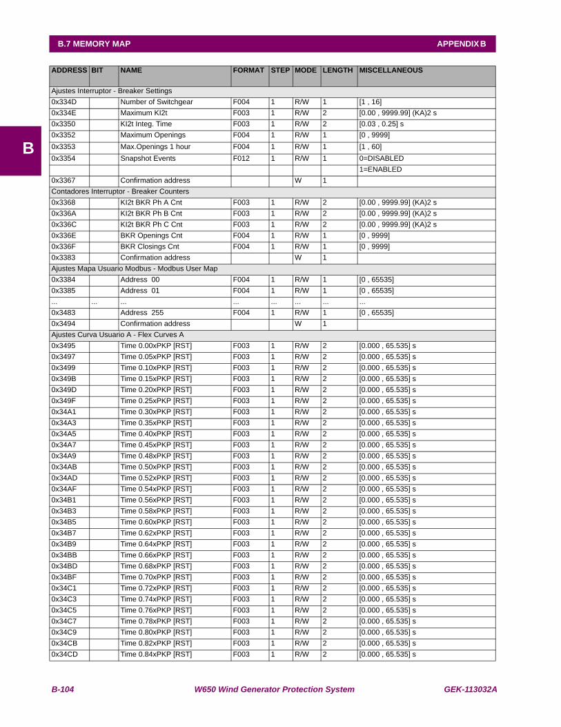
B-104 W650 Wind Generator Protection System GEK-113032A
B.7 MEMORY MAP APPENDIX B
B
ADDRESS BIT NAME FORMAT STEP MODE LENGTH MISCELLANEOUS
Ajustes Interruptor - Breaker Settings0x334D Number of Switchgear F004 1 R/W 1 [1 , 16] 0x334E Maximum KI2t F003 1 R/W 2 [0.00 , 9999.99] (KA)2 s0x3350 KI2t Integ. Time F003 1 R/W 2 [0.03 , 0.25] s0x3352 Maximum Openings F004 1 R/W 1 [0 , 9999] 0x3353 Max.Openings 1 hour F004 1 R/W 1 [1 , 60] 0x3354 Snapshot Events F012 1 R/W 1 0=DISABLED 1=ENABLED0x3367 Confirmation address W 1 Contadores Interruptor - Breaker Counters0x3368 KI2t BKR Ph A Cnt F003 1 R/W 2 [0.00 , 9999.99] (KA)2 s0x336A KI2t BKR Ph B Cnt F003 1 R/W 2 [0.00 , 9999.99] (KA)2 s0x336C KI2t BKR Ph C Cnt F003 1 R/W 2 [0.00 , 9999.99] (KA)2 s0x336E BKR Openings Cnt F004 1 R/W 1 [0 , 9999] 0x336F BKR Closings Cnt F004 1 R/W 1 [0 , 9999] 0x3383 Confirmation address W 1 Ajustes Mapa Usuario Modbus - Modbus User Map0x3384 Address 00 F004 1 R/W 1 [0 , 65535] 0x3385 Address 01 F004 1 R/W 1 [0 , 65535] ... ... ... ... ... ... ... ...0x3483 Address 255 F004 1 R/W 1 [0 , 65535] 0x3494 Confirmation address W 1 Ajustes Curva Usuario A - Flex Curves A0x3495 Time 0.00xPKP [RST] F003 1 R/W 2 [0.000 , 65.535] s0x3497 Time 0.05xPKP [RST] F003 1 R/W 2 [0.000 , 65.535] s0x3499 Time 0.10xPKP [RST] F003 1 R/W 2 [0.000 , 65.535] s0x349B Time 0.15xPKP [RST] F003 1 R/W 2 [0.000 , 65.535] s0x349D Time 0.20xPKP [RST] F003 1 R/W 2 [0.000 , 65.535] s0x349F Time 0.25xPKP [RST] F003 1 R/W 2 [0.000 , 65.535] s0x34A1 Time 0.30xPKP [RST] F003 1 R/W 2 [0.000 , 65.535] s0x34A3 Time 0.35xPKP [RST] F003 1 R/W 2 [0.000 , 65.535] s0x34A5 Time 0.40xPKP [RST] F003 1 R/W 2 [0.000 , 65.535] s0x34A7 Time 0.45xPKP [RST] F003 1 R/W 2 [0.000 , 65.535] s0x34A9 Time 0.48xPKP [RST] F003 1 R/W 2 [0.000 , 65.535] s0x34AB Time 0.50xPKP [RST] F003 1 R/W 2 [0.000 , 65.535] s0x34AD Time 0.52xPKP [RST] F003 1 R/W 2 [0.000 , 65.535] s0x34AF Time 0.54xPKP [RST] F003 1 R/W 2 [0.000 , 65.535] s0x34B1 Time 0.56xPKP [RST] F003 1 R/W 2 [0.000 , 65.535] s0x34B3 Time 0.58xPKP [RST] F003 1 R/W 2 [0.000 , 65.535] s0x34B5 Time 0.60xPKP [RST] F003 1 R/W 2 [0.000 , 65.535] s0x34B7 Time 0.62xPKP [RST] F003 1 R/W 2 [0.000 , 65.535] s0x34B9 Time 0.64xPKP [RST] F003 1 R/W 2 [0.000 , 65.535] s0x34BB Time 0.66xPKP [RST] F003 1 R/W 2 [0.000 , 65.535] s0x34BD Time 0.68xPKP [RST] F003 1 R/W 2 [0.000 , 65.535] s0x34BF Time 0.70xPKP [RST] F003 1 R/W 2 [0.000 , 65.535] s0x34C1 Time 0.72xPKP [RST] F003 1 R/W 2 [0.000 , 65.535] s0x34C3 Time 0.74xPKP [RST] F003 1 R/W 2 [0.000 , 65.535] s0x34C5 Time 0.76xPKP [RST] F003 1 R/W 2 [0.000 , 65.535] s0x34C7 Time 0.78xPKP [RST] F003 1 R/W 2 [0.000 , 65.535] s0x34C9 Time 0.80xPKP [RST] F003 1 R/W 2 [0.000 , 65.535] s0x34CB Time 0.82xPKP [RST] F003 1 R/W 2 [0.000 , 65.535] s0x34CD Time 0.84xPKP [RST] F003 1 R/W 2 [0.000 , 65.535] s
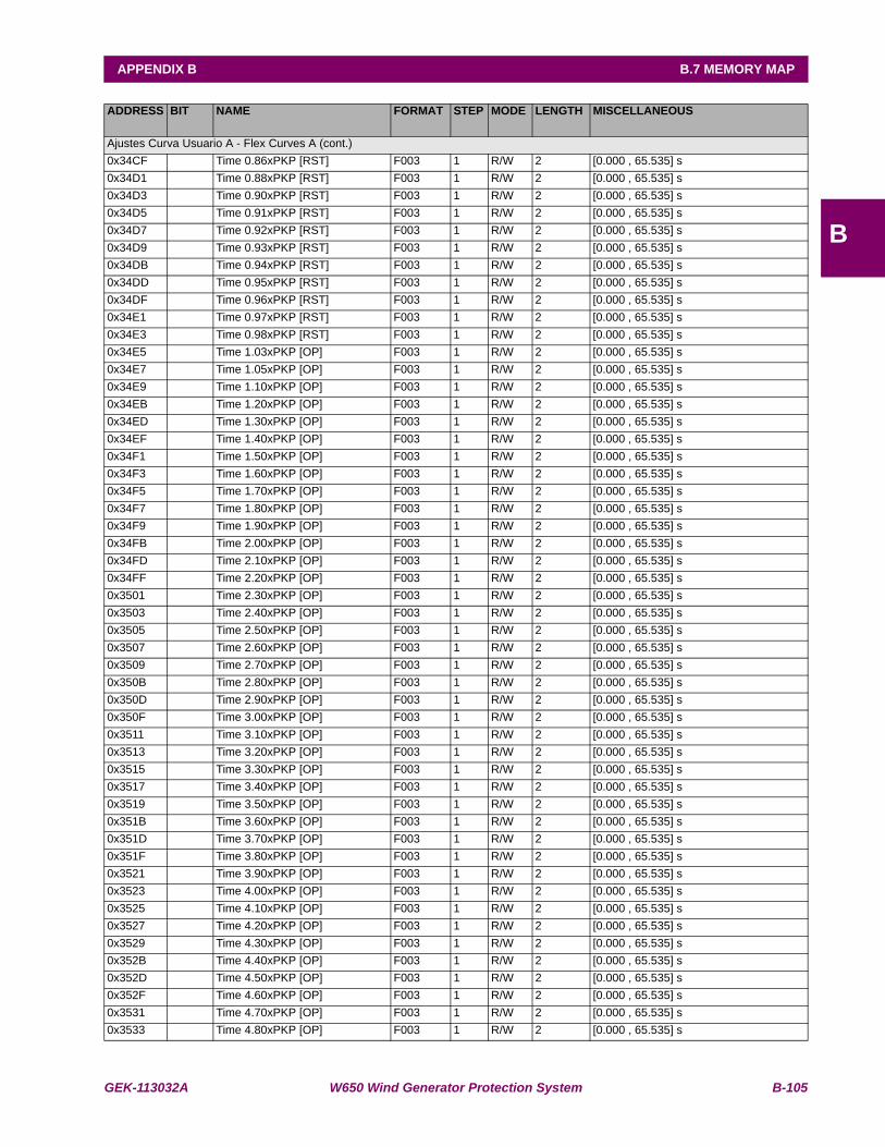
GEK-113032A W650 Wind Generator Protection System B-105
APPENDIX B B.7 MEMORY MAP
B
ADDRESS BIT NAME FORMAT STEP MODE LENGTH MISCELLANEOUS
Ajustes Curva Usuario A - Flex Curves A (cont.)0x34CF Time 0.86xPKP [RST] F003 1 R/W 2 [0.000 , 65.535] s0x34D1 Time 0.88xPKP [RST] F003 1 R/W 2 [0.000 , 65.535] s0x34D3 Time 0.90xPKP [RST] F003 1 R/W 2 [0.000 , 65.535] s0x34D5 Time 0.91xPKP [RST] F003 1 R/W 2 [0.000 , 65.535] s0x34D7 Time 0.92xPKP [RST] F003 1 R/W 2 [0.000 , 65.535] s0x34D9 Time 0.93xPKP [RST] F003 1 R/W 2 [0.000 , 65.535] s0x34DB Time 0.94xPKP [RST] F003 1 R/W 2 [0.000 , 65.535] s0x34DD Time 0.95xPKP [RST] F003 1 R/W 2 [0.000 , 65.535] s0x34DF Time 0.96xPKP [RST] F003 1 R/W 2 [0.000 , 65.535] s0x34E1 Time 0.97xPKP [RST] F003 1 R/W 2 [0.000 , 65.535] s0x34E3 Time 0.98xPKP [RST] F003 1 R/W 2 [0.000 , 65.535] s0x34E5 Time 1.03xPKP [OP] F003 1 R/W 2 [0.000 , 65.535] s0x34E7 Time 1.05xPKP [OP] F003 1 R/W 2 [0.000 , 65.535] s0x34E9 Time 1.10xPKP [OP] F003 1 R/W 2 [0.000 , 65.535] s0x34EB Time 1.20xPKP [OP] F003 1 R/W 2 [0.000 , 65.535] s0x34ED Time 1.30xPKP [OP] F003 1 R/W 2 [0.000 , 65.535] s0x34EF Time 1.40xPKP [OP] F003 1 R/W 2 [0.000 , 65.535] s0x34F1 Time 1.50xPKP [OP] F003 1 R/W 2 [0.000 , 65.535] s0x34F3 Time 1.60xPKP [OP] F003 1 R/W 2 [0.000 , 65.535] s0x34F5 Time 1.70xPKP [OP] F003 1 R/W 2 [0.000 , 65.535] s0x34F7 Time 1.80xPKP [OP] F003 1 R/W 2 [0.000 , 65.535] s0x34F9 Time 1.90xPKP [OP] F003 1 R/W 2 [0.000 , 65.535] s0x34FB Time 2.00xPKP [OP] F003 1 R/W 2 [0.000 , 65.535] s0x34FD Time 2.10xPKP [OP] F003 1 R/W 2 [0.000 , 65.535] s0x34FF Time 2.20xPKP [OP] F003 1 R/W 2 [0.000 , 65.535] s0x3501 Time 2.30xPKP [OP] F003 1 R/W 2 [0.000 , 65.535] s0x3503 Time 2.40xPKP [OP] F003 1 R/W 2 [0.000 , 65.535] s0x3505 Time 2.50xPKP [OP] F003 1 R/W 2 [0.000 , 65.535] s0x3507 Time 2.60xPKP [OP] F003 1 R/W 2 [0.000 , 65.535] s0x3509 Time 2.70xPKP [OP] F003 1 R/W 2 [0.000 , 65.535] s0x350B Time 2.80xPKP [OP] F003 1 R/W 2 [0.000 , 65.535] s0x350D Time 2.90xPKP [OP] F003 1 R/W 2 [0.000 , 65.535] s0x350F Time 3.00xPKP [OP] F003 1 R/W 2 [0.000 , 65.535] s0x3511 Time 3.10xPKP [OP] F003 1 R/W 2 [0.000 , 65.535] s0x3513 Time 3.20xPKP [OP] F003 1 R/W 2 [0.000 , 65.535] s0x3515 Time 3.30xPKP [OP] F003 1 R/W 2 [0.000 , 65.535] s0x3517 Time 3.40xPKP [OP] F003 1 R/W 2 [0.000 , 65.535] s0x3519 Time 3.50xPKP [OP] F003 1 R/W 2 [0.000 , 65.535] s0x351B Time 3.60xPKP [OP] F003 1 R/W 2 [0.000 , 65.535] s0x351D Time 3.70xPKP [OP] F003 1 R/W 2 [0.000 , 65.535] s0x351F Time 3.80xPKP [OP] F003 1 R/W 2 [0.000 , 65.535] s0x3521 Time 3.90xPKP [OP] F003 1 R/W 2 [0.000 , 65.535] s0x3523 Time 4.00xPKP [OP] F003 1 R/W 2 [0.000 , 65.535] s0x3525 Time 4.10xPKP [OP] F003 1 R/W 2 [0.000 , 65.535] s0x3527 Time 4.20xPKP [OP] F003 1 R/W 2 [0.000 , 65.535] s0x3529 Time 4.30xPKP [OP] F003 1 R/W 2 [0.000 , 65.535] s0x352B Time 4.40xPKP [OP] F003 1 R/W 2 [0.000 , 65.535] s0x352D Time 4.50xPKP [OP] F003 1 R/W 2 [0.000 , 65.535] s0x352F Time 4.60xPKP [OP] F003 1 R/W 2 [0.000 , 65.535] s0x3531 Time 4.70xPKP [OP] F003 1 R/W 2 [0.000 , 65.535] s0x3533 Time 4.80xPKP [OP] F003 1 R/W 2 [0.000 , 65.535] s
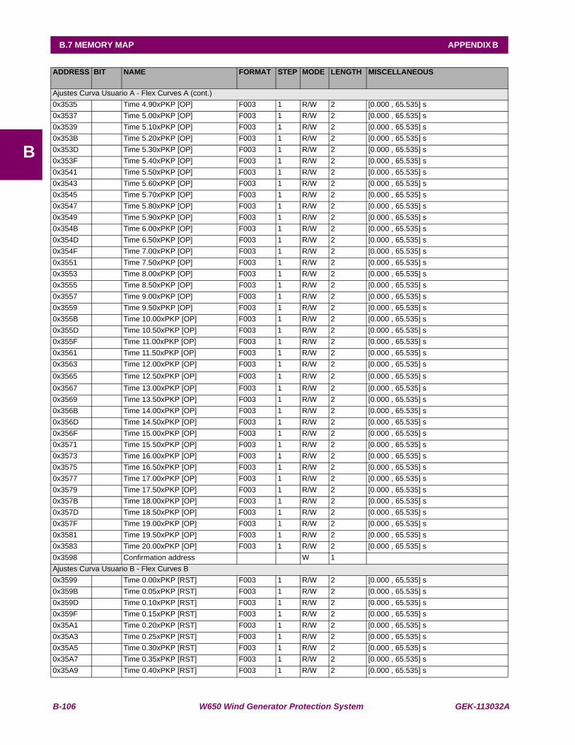
B-106 W650 Wind Generator Protection System GEK-113032A
B.7 MEMORY MAP APPENDIX B
B
ADDRESS BIT NAME FORMAT STEP MODE LENGTH MISCELLANEOUS
Ajustes Curva Usuario A - Flex Curves A (cont.)0x3535 Time 4.90xPKP [OP] F003 1 R/W 2 [0.000 , 65.535] s0x3537 Time 5.00xPKP [OP] F003 1 R/W 2 [0.000 , 65.535] s0x3539 Time 5.10xPKP [OP] F003 1 R/W 2 [0.000 , 65.535] s0x353B Time 5.20xPKP [OP] F003 1 R/W 2 [0.000 , 65.535] s0x353D Time 5.30xPKP [OP] F003 1 R/W 2 [0.000 , 65.535] s0x353F Time 5.40xPKP [OP] F003 1 R/W 2 [0.000 , 65.535] s0x3541 Time 5.50xPKP [OP] F003 1 R/W 2 [0.000 , 65.535] s0x3543 Time 5.60xPKP [OP] F003 1 R/W 2 [0.000 , 65.535] s0x3545 Time 5.70xPKP [OP] F003 1 R/W 2 [0.000 , 65.535] s0x3547 Time 5.80xPKP [OP] F003 1 R/W 2 [0.000 , 65.535] s0x3549 Time 5.90xPKP [OP] F003 1 R/W 2 [0.000 , 65.535] s0x354B Time 6.00xPKP [OP] F003 1 R/W 2 [0.000 , 65.535] s0x354D Time 6.50xPKP [OP] F003 1 R/W 2 [0.000 , 65.535] s0x354F Time 7.00xPKP [OP] F003 1 R/W 2 [0.000 , 65.535] s0x3551 Time 7.50xPKP [OP] F003 1 R/W 2 [0.000 , 65.535] s0x3553 Time 8.00xPKP [OP] F003 1 R/W 2 [0.000 , 65.535] s0x3555 Time 8.50xPKP [OP] F003 1 R/W 2 [0.000 , 65.535] s0x3557 Time 9.00xPKP [OP] F003 1 R/W 2 [0.000 , 65.535] s0x3559 Time 9.50xPKP [OP] F003 1 R/W 2 [0.000 , 65.535] s0x355B Time 10.00xPKP [OP] F003 1 R/W 2 [0.000 , 65.535] s0x355D Time 10.50xPKP [OP] F003 1 R/W 2 [0.000 , 65.535] s0x355F Time 11.00xPKP [OP] F003 1 R/W 2 [0.000 , 65.535] s0x3561 Time 11.50xPKP [OP] F003 1 R/W 2 [0.000 , 65.535] s0x3563 Time 12.00xPKP [OP] F003 1 R/W 2 [0.000 , 65.535] s0x3565 Time 12.50xPKP [OP] F003 1 R/W 2 [0.000 , 65.535] s0x3567 Time 13.00xPKP [OP] F003 1 R/W 2 [0.000 , 65.535] s0x3569 Time 13.50xPKP [OP] F003 1 R/W 2 [0.000 , 65.535] s0x356B Time 14.00xPKP [OP] F003 1 R/W 2 [0.000 , 65.535] s0x356D Time 14.50xPKP [OP] F003 1 R/W 2 [0.000 , 65.535] s0x356F Time 15.00xPKP [OP] F003 1 R/W 2 [0.000 , 65.535] s0x3571 Time 15.50xPKP [OP] F003 1 R/W 2 [0.000 , 65.535] s0x3573 Time 16.00xPKP [OP] F003 1 R/W 2 [0.000 , 65.535] s0x3575 Time 16.50xPKP [OP] F003 1 R/W 2 [0.000 , 65.535] s0x3577 Time 17.00xPKP [OP] F003 1 R/W 2 [0.000 , 65.535] s0x3579 Time 17.50xPKP [OP] F003 1 R/W 2 [0.000 , 65.535] s0x357B Time 18.00xPKP [OP] F003 1 R/W 2 [0.000 , 65.535] s0x357D Time 18.50xPKP [OP] F003 1 R/W 2 [0.000 , 65.535] s0x357F Time 19.00xPKP [OP] F003 1 R/W 2 [0.000 , 65.535] s0x3581 Time 19.50xPKP [OP] F003 1 R/W 2 [0.000 , 65.535] s0x3583 Time 20.00xPKP [OP] F003 1 R/W 2 [0.000 , 65.535] s0x3598 Confirmation address W 1 Ajustes Curva Usuario B - Flex Curves B0x3599 Time 0.00xPKP [RST] F003 1 R/W 2 [0.000 , 65.535] s0x359B Time 0.05xPKP [RST] F003 1 R/W 2 [0.000 , 65.535] s0x359D Time 0.10xPKP [RST] F003 1 R/W 2 [0.000 , 65.535] s0x359F Time 0.15xPKP [RST] F003 1 R/W 2 [0.000 , 65.535] s0x35A1 Time 0.20xPKP [RST] F003 1 R/W 2 [0.000 , 65.535] s0x35A3 Time 0.25xPKP [RST] F003 1 R/W 2 [0.000 , 65.535] s0x35A5 Time 0.30xPKP [RST] F003 1 R/W 2 [0.000 , 65.535] s0x35A7 Time 0.35xPKP [RST] F003 1 R/W 2 [0.000 , 65.535] s0x35A9 Time 0.40xPKP [RST] F003 1 R/W 2 [0.000 , 65.535] s

GEK-113032A W650 Wind Generator Protection System B-107
APPENDIX B B.7 MEMORY MAP
B
ADDRESS BIT NAME FORMAT STEP MODE LENGTH MISCELLANEOUS
Ajustes Curva Usuario B - Flex Curves B (cont.)0x35AB Time 0.45xPKP [RST] F003 1 R/W 2 [0.000 , 65.535] s0x35AD Time 0.48xPKP [RST] F003 1 R/W 2 [0.000 , 65.535] s0x35AF Time 0.50xPKP [RST] F003 1 R/W 2 [0.000 , 65.535] s0x35B1 Time 0.52xPKP [RST] F003 1 R/W 2 [0.000 , 65.535] s0x35B3 Time 0.54xPKP [RST] F003 1 R/W 2 [0.000 , 65.535] s0x35B5 Time 0.56xPKP [RST] F003 1 R/W 2 [0.000 , 65.535] s0x35B7 Time 0.58xPKP [RST] F003 1 R/W 2 [0.000 , 65.535] s0x35B9 Time 0.60xPKP [RST] F003 1 R/W 2 [0.000 , 65.535] s0x35BB Time 0.62xPKP [RST] F003 1 R/W 2 [0.000 , 65.535] s0x35BD Time 0.64xPKP [RST] F003 1 R/W 2 [0.000 , 65.535] s0x35BF Time 0.66xPKP [RST] F003 1 R/W 2 [0.000 , 65.535] s0x35C1 Time 0.68xPKP [RST] F003 1 R/W 2 [0.000 , 65.535] s0x35C3 Time 0.70xPKP [RST] F003 1 R/W 2 [0.000 , 65.535] s0x35C5 Time 0.72xPKP [RST] F003 1 R/W 2 [0.000 , 65.535] s0x35C7 Time 0.74xPKP [RST] F003 1 R/W 2 [0.000 , 65.535] s0x35C9 Time 0.76xPKP [RST] F003 1 R/W 2 [0.000 , 65.535] s0x35CB Time 0.78xPKP [RST] F003 1 R/W 2 [0.000 , 65.535] s0x35CD Time 0.80xPKP [RST] F003 1 R/W 2 [0.000 , 65.535] s0x35CF Time 0.82xPKP [RST] F003 1 R/W 2 [0.000 , 65.535] s0x35D1 Time 0.84xPKP [RST] F003 1 R/W 2 [0.000 , 65.535] s0x35D3 Time 0.86xPKP [RST] F003 1 R/W 2 [0.000 , 65.535] s0x35D5 Time 0.88xPKP [RST] F003 1 R/W 2 [0.000 , 65.535] s0x35D7 Time 0.90xPKP [RST] F003 1 R/W 2 [0.000 , 65.535] s0x35D9 Time 0.91xPKP [RST] F003 1 R/W 2 [0.000 , 65.535] s0x35DB Time 0.92xPKP [RST] F003 1 R/W 2 [0.000 , 65.535] s0x35DD Time 0.93xPKP [RST] F003 1 R/W 2 [0.000 , 65.535] s0x35DF Time 0.94xPKP [RST] F003 1 R/W 2 [0.000 , 65.535] s0x35E1 Time 0.95xPKP [RST] F003 1 R/W 2 [0.000 , 65.535] s0x35E3 Time 0.96xPKP [RST] F003 1 R/W 2 [0.000 , 65.535] s0x35E5 Time 0.97xPKP [RST] F003 1 R/W 2 [0.000 , 65.535] s0x35E7 Time 0.98xPKP [RST] F003 1 R/W 2 [0.000 , 65.535] s0x35E9 Time 1.03xPKP [OP] F003 1 R/W 2 [0.000 , 65.535] s0x35EB Time 1.05xPKP [OP] F003 1 R/W 2 [0.000 , 65.535] s0x35ED Time 1.10xPKP [OP] F003 1 R/W 2 [0.000 , 65.535] s0x35EF Time 1.20xPKP [OP] F003 1 R/W 2 [0.000 , 65.535] s0x35F1 Time 1.30xPKP [OP] F003 1 R/W 2 [0.000 , 65.535] s0x35F3 Time 1.40xPKP [OP] F003 1 R/W 2 [0.000 , 65.535] s0x35F5 Time 1.50xPKP [OP] F003 1 R/W 2 [0.000 , 65.535] s0x35F7 Time 1.60xPKP [OP] F003 1 R/W 2 [0.000 , 65.535] s0x35F9 Time 1.70xPKP [OP] F003 1 R/W 2 [0.000 , 65.535] s0x35FB Time 1.80xPKP [OP] F003 1 R/W 2 [0.000 , 65.535] s0x35FD Time 1.90xPKP [OP] F003 1 R/W 2 [0.000 , 65.535] s0x35FF Time 2.00xPKP [OP] F003 1 R/W 2 [0.000 , 65.535] s0x3601 Time 2.10xPKP [OP] F003 1 R/W 2 [0.000 , 65.535] s0x3603 Time 2.20xPKP [OP] F003 1 R/W 2 [0.000 , 65.535] s0x3605 Time 2.30xPKP [OP] F003 1 R/W 2 [0.000 , 65.535] s0x3607 Time 2.40xPKP [OP] F003 1 R/W 2 [0.000 , 65.535] s0x3609 Time 2.50xPKP [OP] F003 1 R/W 2 [0.000 , 65.535] s0x360B Time 2.60xPKP [OP] F003 1 R/W 2 [0.000 , 65.535] s0x360D Time 2.70xPKP [OP] F003 1 R/W 2 [0.000 , 65.535] s0x360F Time 2.80xPKP [OP] F003 1 R/W 2 [0.000 , 65.535] s
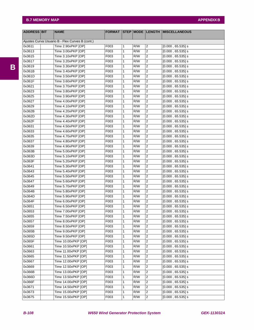
B-108 W650 Wind Generator Protection System GEK-113032A
B.7 MEMORY MAP APPENDIX B
B
ADDRESS BIT NAME FORMAT STEP MODE LENGTH MISCELLANEOUS
Ajustes Curva Usuario B - Flex Curves B (cont.)0x3611 Time 2.90xPKP [OP] F003 1 R/W 2 [0.000 , 65.535] s0x3613 Time 3.00xPKP [OP] F003 1 R/W 2 [0.000 , 65.535] s0x3615 Time 3.10xPKP [OP] F003 1 R/W 2 [0.000 , 65.535] s0x3617 Time 3.20xPKP [OP] F003 1 R/W 2 [0.000 , 65.535] s0x3619 Time 3.30xPKP [OP] F003 1 R/W 2 [0.000 , 65.535] s0x361B Time 3.40xPKP [OP] F003 1 R/W 2 [0.000 , 65.535] s0x361D Time 3.50xPKP [OP] F003 1 R/W 2 [0.000 , 65.535] s0x361F Time 3.60xPKP [OP] F003 1 R/W 2 [0.000 , 65.535] s0x3621 Time 3.70xPKP [OP] F003 1 R/W 2 [0.000 , 65.535] s0x3623 Time 3.80xPKP [OP] F003 1 R/W 2 [0.000 , 65.535] s0x3625 Time 3.90xPKP [OP] F003 1 R/W 2 [0.000 , 65.535] s0x3627 Time 4.00xPKP [OP] F003 1 R/W 2 [0.000 , 65.535] s0x3629 Time 4.10xPKP [OP] F003 1 R/W 2 [0.000 , 65.535] s0x362B Time 4.20xPKP [OP] F003 1 R/W 2 [0.000 , 65.535] s0x362D Time 4.30xPKP [OP] F003 1 R/W 2 [0.000 , 65.535] s0x362F Time 4.40xPKP [OP] F003 1 R/W 2 [0.000 , 65.535] s0x3631 Time 4.50xPKP [OP] F003 1 R/W 2 [0.000 , 65.535] s0x3633 Time 4.60xPKP [OP] F003 1 R/W 2 [0.000 , 65.535] s0x3635 Time 4.70xPKP [OP] F003 1 R/W 2 [0.000 , 65.535] s0x3637 Time 4.80xPKP [OP] F003 1 R/W 2 [0.000 , 65.535] s0x3639 Time 4.90xPKP [OP] F003 1 R/W 2 [0.000 , 65.535] s0x363B Time 5.00xPKP [OP] F003 1 R/W 2 [0.000 , 65.535] s0x363D Time 5.10xPKP [OP] F003 1 R/W 2 [0.000 , 65.535] s0x363F Time 5.20xPKP [OP] F003 1 R/W 2 [0.000 , 65.535] s0x3641 Time 5.30xPKP [OP] F003 1 R/W 2 [0.000 , 65.535] s0x3643 Time 5.40xPKP [OP] F003 1 R/W 2 [0.000 , 65.535] s0x3645 Time 5.50xPKP [OP] F003 1 R/W 2 [0.000 , 65.535] s0x3647 Time 5.60xPKP [OP] F003 1 R/W 2 [0.000 , 65.535] s0x3649 Time 5.70xPKP [OP] F003 1 R/W 2 [0.000 , 65.535] s0x364B Time 5.80xPKP [OP] F003 1 R/W 2 [0.000 , 65.535] s0x364D Time 5.90xPKP [OP] F003 1 R/W 2 [0.000 , 65.535] s0x364F Time 6.00xPKP [OP] F003 1 R/W 2 [0.000 , 65.535] s0x3651 Time 6.50xPKP [OP] F003 1 R/W 2 [0.000 , 65.535] s0x3653 Time 7.00xPKP [OP] F003 1 R/W 2 [0.000 , 65.535] s0x3655 Time 7.50xPKP [OP] F003 1 R/W 2 [0.000 , 65.535] s0x3657 Time 8.00xPKP [OP] F003 1 R/W 2 [0.000 , 65.535] s0x3659 Time 8.50xPKP [OP] F003 1 R/W 2 [0.000 , 65.535] s0x365B Time 9.00xPKP [OP] F003 1 R/W 2 [0.000 , 65.535] s0x365D Time 9.50xPKP [OP] F003 1 R/W 2 [0.000 , 65.535] s0x365F Time 10.00xPKP [OP] F003 1 R/W 2 [0.000 , 65.535] s0x3661 Time 10.50xPKP [OP] F003 1 R/W 2 [0.000 , 65.535] s0x3663 Time 11.00xPKP [OP] F003 1 R/W 2 [0.000 , 65.535] s0x3665 Time 11.50xPKP [OP] F003 1 R/W 2 [0.000 , 65.535] s0x3667 Time 12.00xPKP [OP] F003 1 R/W 2 [0.000 , 65.535] s0x3669 Time 12.50xPKP [OP] F003 1 R/W 2 [0.000 , 65.535] s0x366B Time 13.00xPKP [OP] F003 1 R/W 2 [0.000 , 65.535] s0x366D Time 13.50xPKP [OP] F003 1 R/W 2 [0.000 , 65.535] s0x366F Time 14.00xPKP [OP] F003 1 R/W 2 [0.000 , 65.535] s0x3671 Time 14.50xPKP [OP] F003 1 R/W 2 [0.000 , 65.535] s0x3673 Time 15.00xPKP [OP] F003 1 R/W 2 [0.000 , 65.535] s0x3675 Time 15.50xPKP [OP] F003 1 R/W 2 [0.000 , 65.535] s

GEK-113032A W650 Wind Generator Protection System B-109
APPENDIX B B.7 MEMORY MAP
B
ADDRESS BIT NAME FORMAT STEP MODE LENGTH MISCELLANEOUS
Ajustes Curva Usuario B - Flex Curves B (cont.)0x3677 Time 16.00xPKP [OP] F003 1 R/W 2 [0.000 , 65.535] s0x3679 Time 16.50xPKP [OP] F003 1 R/W 2 [0.000 , 65.535] s0x367B Time 17.00xPKP [OP] F003 1 R/W 2 [0.000 , 65.535] s0x367D Time 17.50xPKP [OP] F003 1 R/W 2 [0.000 , 65.535] s0x367F Time 18.00xPKP [OP] F003 1 R/W 2 [0.000 , 65.535] s0x3681 Time 18.50xPKP [OP] F003 1 R/W 2 [0.000 , 65.535] s0x3683 Time 19.00xPKP [OP] F003 1 R/W 2 [0.000 , 65.535] s0x3685 Time 19.50xPKP [OP] F003 1 R/W 2 [0.000 , 65.535] s0x3687 Time 20.00xPKP [OP] F003 1 R/W 2 [0.000 , 65.535] s0x369C Confirmation address W 1 Ajustes Curva Usuario C - Flex Curves C0x369D Time 0.00xPKP [RST] F003 1 R/W 2 [0.000 , 65.535] s0x369F Time 0.05xPKP [RST] F003 1 R/W 2 [0.000 , 65.535] s0x36A1 Time 0.10xPKP [RST] F003 1 R/W 2 [0.000 , 65.535] s0x36A3 Time 0.15xPKP [RST] F003 1 R/W 2 [0.000 , 65.535] s0x36A5 Time 0.20xPKP [RST] F003 1 R/W 2 [0.000 , 65.535] s0x36A7 Time 0.25xPKP [RST] F003 1 R/W 2 [0.000 , 65.535] s0x36A9 Time 0.30xPKP [RST] F003 1 R/W 2 [0.000 , 65.535] s0x36AB Time 0.35xPKP [RST] F003 1 R/W 2 [0.000 , 65.535] s0x36AD Time 0.40xPKP [RST] F003 1 R/W 2 [0.000 , 65.535] s0x36AF Time 0.45xPKP [RST] F003 1 R/W 2 [0.000 , 65.535] s0x36B1 Time 0.48xPKP [RST] F003 1 R/W 2 [0.000 , 65.535] s0x36B3 Time 0.50xPKP [RST] F003 1 R/W 2 [0.000 , 65.535] s0x36B5 Time 0.52xPKP [RST] F003 1 R/W 2 [0.000 , 65.535] s0x36B7 Time 0.54xPKP [RST] F003 1 R/W 2 [0.000 , 65.535] s0x36B9 Time 0.56xPKP [RST] F003 1 R/W 2 [0.000 , 65.535] s0x36BB Time 0.58xPKP [RST] F003 1 R/W 2 [0.000 , 65.535] s0x36BD Time 0.60xPKP [RST] F003 1 R/W 2 [0.000 , 65.535] s0x36BF Time 0.62xPKP [RST] F003 1 R/W 2 [0.000 , 65.535] s0x36C1 Time 0.64xPKP [RST] F003 1 R/W 2 [0.000 , 65.535] s0x36C3 Time 0.66xPKP [RST] F003 1 R/W 2 [0.000 , 65.535] s0x36C5 Time 0.68xPKP [RST] F003 1 R/W 2 [0.000 , 65.535] s0x36C7 Time 0.70xPKP [RST] F003 1 R/W 2 [0.000 , 65.535] s0x36C9 Time 0.72xPKP [RST] F003 1 R/W 2 [0.000 , 65.535] s0x36CB Time 0.74xPKP [RST] F003 1 R/W 2 [0.000 , 65.535] s0x36CD Time 0.76xPKP [RST] F003 1 R/W 2 [0.000 , 65.535] s0x36CF Time 0.78xPKP [RST] F003 1 R/W 2 [0.000 , 65.535] s0x36D1 Time 0.80xPKP [RST] F003 1 R/W 2 [0.000 , 65.535] s0x36D3 Time 0.82xPKP [RST] F003 1 R/W 2 [0.000 , 65.535] s0x36D5 Time 0.84xPKP [RST] F003 1 R/W 2 [0.000 , 65.535] s0x36D7 Time 0.86xPKP [RST] F003 1 R/W 2 [0.000 , 65.535] s0x36D9 Time 0.88xPKP [RST] F003 1 R/W 2 [0.000 , 65.535] s0x36DB Time 0.90xPKP [RST] F003 1 R/W 2 [0.000 , 65.535] s0x36DD Time 0.91xPKP [RST] F003 1 R/W 2 [0.000 , 65.535] s0x36DF Time 0.92xPKP [RST] F003 1 R/W 2 [0.000 , 65.535] s0x36E1 Time 0.93xPKP [RST] F003 1 R/W 2 [0.000 , 65.535] s0x36E3 Time 0.94xPKP [RST] F003 1 R/W 2 [0.000 , 65.535] s0x36E5 Time 0.95xPKP [RST] F003 1 R/W 2 [0.000 , 65.535] s0x36E7 Time 0.96xPKP [RST] F003 1 R/W 2 [0.000 , 65.535] s0x36E9 Time 0.97xPKP [RST] F003 1 R/W 2 [0.000 , 65.535] s0x36EB Time 0.98xPKP [RST] F003 1 R/W 2 [0.000 , 65.535] s

B-110 W650 Wind Generator Protection System GEK-113032A
B.7 MEMORY MAP APPENDIX B
B
ADDRESS BIT NAME FORMAT STEP MODE LENGTH MISCELLANEOUS
Ajustes Curva Usuario C - Flex Curves C (cont.)0x36ED Time 1.03xPKP [OP] F003 1 R/W 2 [0.000 , 65.535] s0x36EF Time 1.05xPKP [OP] F003 1 R/W 2 [0.000 , 65.535] s0x36F1 Time 1.10xPKP [OP] F003 1 R/W 2 [0.000 , 65.535] s0x36F3 Time 1.20xPKP [OP] F003 1 R/W 2 [0.000 , 65.535] s0x36F5 Time 1.30xPKP [OP] F003 1 R/W 2 [0.000 , 65.535] s0x36F7 Time 1.40xPKP [OP] F003 1 R/W 2 [0.000 , 65.535] s0x36F9 Time 1.50xPKP [OP] F003 1 R/W 2 [0.000 , 65.535] s0x36FB Time 1.60xPKP [OP] F003 1 R/W 2 [0.000 , 65.535] s0x36FD Time 1.70xPKP [OP] F003 1 R/W 2 [0.000 , 65.535] s0x36FF Time 1.80xPKP [OP] F003 1 R/W 2 [0.000 , 65.535] s0x3701 Time 1.90xPKP [OP] F003 1 R/W 2 [0.000 , 65.535] s0x3703 Time 2.00xPKP [OP] F003 1 R/W 2 [0.000 , 65.535] s0x3705 Time 2.10xPKP [OP] F003 1 R/W 2 [0.000 , 65.535] s0x3707 Time 2.20xPKP [OP] F003 1 R/W 2 [0.000 , 65.535] s0x3709 Time 2.30xPKP [OP] F003 1 R/W 2 [0.000 , 65.535] s0x370B Time 2.40xPKP [OP] F003 1 R/W 2 [0.000 , 65.535] s0x370D Time 2.50xPKP [OP] F003 1 R/W 2 [0.000 , 65.535] s0x370F Time 2.60xPKP [OP] F003 1 R/W 2 [0.000 , 65.535] s0x3711 Time 2.70xPKP [OP] F003 1 R/W 2 [0.000 , 65.535] s0x3713 Time 2.80xPKP [OP] F003 1 R/W 2 [0.000 , 65.535] s0x3715 Time 2.90xPKP [OP] F003 1 R/W 2 [0.000 , 65.535] s0x3717 Time 3.00xPKP [OP] F003 1 R/W 2 [0.000 , 65.535] s0x3719 Time 3.10xPKP [OP] F003 1 R/W 2 [0.000 , 65.535] s0x371B Time 3.20xPKP [OP] F003 1 R/W 2 [0.000 , 65.535] s0x371D Time 3.30xPKP [OP] F003 1 R/W 2 [0.000 , 65.535] s0x371F Time 3.40xPKP [OP] F003 1 R/W 2 [0.000 , 65.535] s0x3721 Time 3.50xPKP [OP] F003 1 R/W 2 [0.000 , 65.535] s0x3723 Time 3.60xPKP [OP] F003 1 R/W 2 [0.000 , 65.535] s0x3725 Time 3.70xPKP [OP] F003 1 R/W 2 [0.000 , 65.535] s0x3727 Time 3.80xPKP [OP] F003 1 R/W 2 [0.000 , 65.535] s0x3729 Time 3.90xPKP [OP] F003 1 R/W 2 [0.000 , 65.535] s0x372B Time 4.00xPKP [OP] F003 1 R/W 2 [0.000 , 65.535] s0x372D Time 4.10xPKP [OP] F003 1 R/W 2 [0.000 , 65.535] s0x372F Time 4.20xPKP [OP] F003 1 R/W 2 [0.000 , 65.535] s0x3731 Time 4.30xPKP [OP] F003 1 R/W 2 [0.000 , 65.535] s0x3733 Time 4.40xPKP [OP] F003 1 R/W 2 [0.000 , 65.535] s0x3735 Time 4.50xPKP [OP] F003 1 R/W 2 [0.000 , 65.535] s0x3737 Time 4.60xPKP [OP] F003 1 R/W 2 [0.000 , 65.535] s0x3739 Time 4.70xPKP [OP] F003 1 R/W 2 [0.000 , 65.535] s0x373B Time 4.80xPKP [OP] F003 1 R/W 2 [0.000 , 65.535] s0x373D Time 4.90xPKP [OP] F003 1 R/W 2 [0.000 , 65.535] s0x373F Time 5.00xPKP [OP] F003 1 R/W 2 [0.000 , 65.535] s0x3741 Time 5.10xPKP [OP] F003 1 R/W 2 [0.000 , 65.535] s0x3743 Time 5.20xPKP [OP] F003 1 R/W 2 [0.000 , 65.535] s0x3745 Time 5.30xPKP [OP] F003 1 R/W 2 [0.000 , 65.535] s0x3747 Time 5.40xPKP [OP] F003 1 R/W 2 [0.000 , 65.535] s0x3749 Time 5.50xPKP [OP] F003 1 R/W 2 [0.000 , 65.535] s0x374B Time 5.60xPKP [OP] F003 1 R/W 2 [0.000 , 65.535] s0x374D Time 5.70xPKP [OP] F003 1 R/W 2 [0.000 , 65.535] s0x374F Time 5.80xPKP [OP] F003 1 R/W 2 [0.000 , 65.535] s0x3751 Time 5.90xPKP [OP] F003 1 R/W 2 [0.000 , 65.535] s
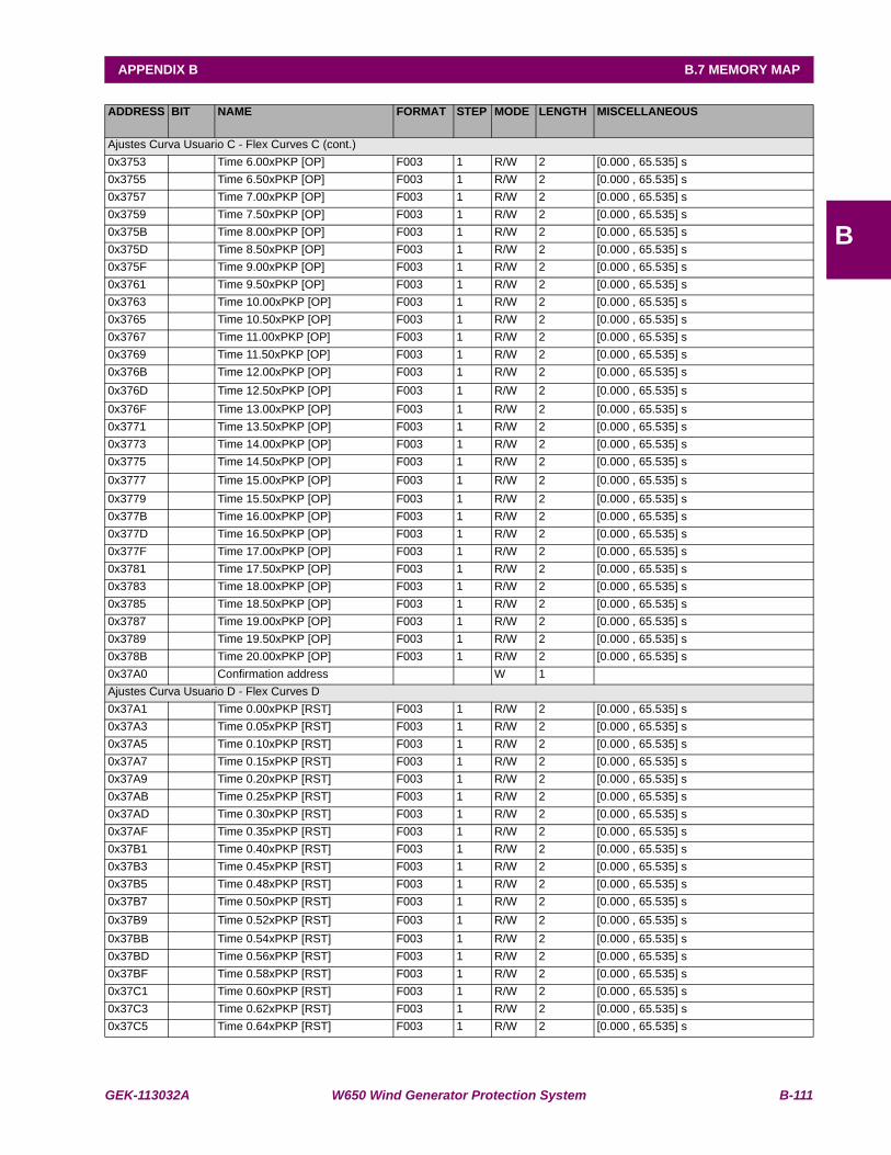
GEK-113032A W650 Wind Generator Protection System B-111
APPENDIX B B.7 MEMORY MAP
B
ADDRESS BIT NAME FORMAT STEP MODE LENGTH MISCELLANEOUS
Ajustes Curva Usuario C - Flex Curves C (cont.)0x3753 Time 6.00xPKP [OP] F003 1 R/W 2 [0.000 , 65.535] s0x3755 Time 6.50xPKP [OP] F003 1 R/W 2 [0.000 , 65.535] s0x3757 Time 7.00xPKP [OP] F003 1 R/W 2 [0.000 , 65.535] s0x3759 Time 7.50xPKP [OP] F003 1 R/W 2 [0.000 , 65.535] s0x375B Time 8.00xPKP [OP] F003 1 R/W 2 [0.000 , 65.535] s0x375D Time 8.50xPKP [OP] F003 1 R/W 2 [0.000 , 65.535] s0x375F Time 9.00xPKP [OP] F003 1 R/W 2 [0.000 , 65.535] s0x3761 Time 9.50xPKP [OP] F003 1 R/W 2 [0.000 , 65.535] s0x3763 Time 10.00xPKP [OP] F003 1 R/W 2 [0.000 , 65.535] s0x3765 Time 10.50xPKP [OP] F003 1 R/W 2 [0.000 , 65.535] s0x3767 Time 11.00xPKP [OP] F003 1 R/W 2 [0.000 , 65.535] s0x3769 Time 11.50xPKP [OP] F003 1 R/W 2 [0.000 , 65.535] s0x376B Time 12.00xPKP [OP] F003 1 R/W 2 [0.000 , 65.535] s0x376D Time 12.50xPKP [OP] F003 1 R/W 2 [0.000 , 65.535] s0x376F Time 13.00xPKP [OP] F003 1 R/W 2 [0.000 , 65.535] s0x3771 Time 13.50xPKP [OP] F003 1 R/W 2 [0.000 , 65.535] s0x3773 Time 14.00xPKP [OP] F003 1 R/W 2 [0.000 , 65.535] s0x3775 Time 14.50xPKP [OP] F003 1 R/W 2 [0.000 , 65.535] s0x3777 Time 15.00xPKP [OP] F003 1 R/W 2 [0.000 , 65.535] s0x3779 Time 15.50xPKP [OP] F003 1 R/W 2 [0.000 , 65.535] s0x377B Time 16.00xPKP [OP] F003 1 R/W 2 [0.000 , 65.535] s0x377D Time 16.50xPKP [OP] F003 1 R/W 2 [0.000 , 65.535] s0x377F Time 17.00xPKP [OP] F003 1 R/W 2 [0.000 , 65.535] s0x3781 Time 17.50xPKP [OP] F003 1 R/W 2 [0.000 , 65.535] s0x3783 Time 18.00xPKP [OP] F003 1 R/W 2 [0.000 , 65.535] s0x3785 Time 18.50xPKP [OP] F003 1 R/W 2 [0.000 , 65.535] s0x3787 Time 19.00xPKP [OP] F003 1 R/W 2 [0.000 , 65.535] s0x3789 Time 19.50xPKP [OP] F003 1 R/W 2 [0.000 , 65.535] s0x378B Time 20.00xPKP [OP] F003 1 R/W 2 [0.000 , 65.535] s0x37A0 Confirmation address W 1 Ajustes Curva Usuario D - Flex Curves D0x37A1 Time 0.00xPKP [RST] F003 1 R/W 2 [0.000 , 65.535] s0x37A3 Time 0.05xPKP [RST] F003 1 R/W 2 [0.000 , 65.535] s0x37A5 Time 0.10xPKP [RST] F003 1 R/W 2 [0.000 , 65.535] s0x37A7 Time 0.15xPKP [RST] F003 1 R/W 2 [0.000 , 65.535] s0x37A9 Time 0.20xPKP [RST] F003 1 R/W 2 [0.000 , 65.535] s0x37AB Time 0.25xPKP [RST] F003 1 R/W 2 [0.000 , 65.535] s0x37AD Time 0.30xPKP [RST] F003 1 R/W 2 [0.000 , 65.535] s0x37AF Time 0.35xPKP [RST] F003 1 R/W 2 [0.000 , 65.535] s0x37B1 Time 0.40xPKP [RST] F003 1 R/W 2 [0.000 , 65.535] s0x37B3 Time 0.45xPKP [RST] F003 1 R/W 2 [0.000 , 65.535] s0x37B5 Time 0.48xPKP [RST] F003 1 R/W 2 [0.000 , 65.535] s0x37B7 Time 0.50xPKP [RST] F003 1 R/W 2 [0.000 , 65.535] s0x37B9 Time 0.52xPKP [RST] F003 1 R/W 2 [0.000 , 65.535] s0x37BB Time 0.54xPKP [RST] F003 1 R/W 2 [0.000 , 65.535] s0x37BD Time 0.56xPKP [RST] F003 1 R/W 2 [0.000 , 65.535] s0x37BF Time 0.58xPKP [RST] F003 1 R/W 2 [0.000 , 65.535] s0x37C1 Time 0.60xPKP [RST] F003 1 R/W 2 [0.000 , 65.535] s0x37C3 Time 0.62xPKP [RST] F003 1 R/W 2 [0.000 , 65.535] s0x37C5 Time 0.64xPKP [RST] F003 1 R/W 2 [0.000 , 65.535] s
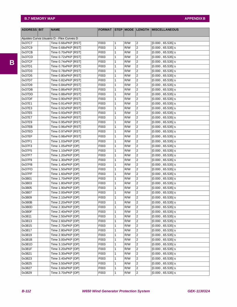
B-112 W650 Wind Generator Protection System GEK-113032A
B.7 MEMORY MAP APPENDIX B
B
ADDRESS BIT NAME FORMAT STEP MODE LENGTH MISCELLANEOUS
Ajustes Curva Usuario D - Flex Curves D0x37C7 Time 0.66xPKP [RST] F003 1 R/W 2 [0.000 , 65.535] s0x37C9 Time 0.68xPKP [RST] F003 1 R/W 2 [0.000 , 65.535] s0x37CB Time 0.70xPKP [RST] F003 1 R/W 2 [0.000 , 65.535] s0x37CD Time 0.72xPKP [RST] F003 1 R/W 2 [0.000 , 65.535] s0x37CF Time 0.74xPKP [RST] F003 1 R/W 2 [0.000 , 65.535] s0x37D1 Time 0.76xPKP [RST] F003 1 R/W 2 [0.000 , 65.535] s0x37D3 Time 0.78xPKP [RST] F003 1 R/W 2 [0.000 , 65.535] s0x37D5 Time 0.80xPKP [RST] F003 1 R/W 2 [0.000 , 65.535] s0x37D7 Time 0.82xPKP [RST] F003 1 R/W 2 [0.000 , 65.535] s0x37D9 Time 0.84xPKP [RST] F003 1 R/W 2 [0.000 , 65.535] s0x37DB Time 0.86xPKP [RST] F003 1 R/W 2 [0.000 , 65.535] s0x37DD Time 0.88xPKP [RST] F003 1 R/W 2 [0.000 , 65.535] s0x37DF Time 0.90xPKP [RST] F003 1 R/W 2 [0.000 , 65.535] s0x37E1 Time 0.91xPKP [RST] F003 1 R/W 2 [0.000 , 65.535] s0x37E3 Time 0.92xPKP [RST] F003 1 R/W 2 [0.000 , 65.535] s0x37E5 Time 0.93xPKP [RST] F003 1 R/W 2 [0.000 , 65.535] s0x37E7 Time 0.94xPKP [RST] F003 1 R/W 2 [0.000 , 65.535] s0x37E9 Time 0.95xPKP [RST] F003 1 R/W 2 [0.000 , 65.535] s0x37EB Time 0.96xPKP [RST] F003 1 R/W 2 [0.000 , 65.535] s0x37ED Time 0.97xPKP [RST] F003 1 R/W 2 [0.000 , 65.535] s0x37EF Time 0.98xPKP [RST] F003 1 R/W 2 [0.000 , 65.535] s0x37F1 Time 1.03xPKP [OP] F003 1 R/W 2 [0.000 , 65.535] s0x37F3 Time 1.05xPKP [OP] F003 1 R/W 2 [0.000 , 65.535] s0x37F5 Time 1.10xPKP [OP] F003 1 R/W 2 [0.000 , 65.535] s0x37F7 Time 1.20xPKP [OP] F003 1 R/W 2 [0.000 , 65.535] s0x37F9 Time 1.30xPKP [OP] F003 1 R/W 2 [0.000 , 65.535] s0x37FB Time 1.40xPKP [OP] F003 1 R/W 2 [0.000 , 65.535] s0x37FD Time 1.50xPKP [OP] F003 1 R/W 2 [0.000 , 65.535] s0x37FF Time 1.60xPKP [OP] F003 1 R/W 2 [0.000 , 65.535] s0x3801 Time 1.70xPKP [OP] F003 1 R/W 2 [0.000 , 65.535] s0x3803 Time 1.80xPKP [OP] F003 1 R/W 2 [0.000 , 65.535] s0x3805 Time 1.90xPKP [OP] F003 1 R/W 2 [0.000 , 65.535] s0x3807 Time 2.00xPKP [OP] F003 1 R/W 2 [0.000 , 65.535] s0x3809 Time 2.10xPKP [OP] F003 1 R/W 2 [0.000 , 65.535] s0x380B Time 2.20xPKP [OP] F003 1 R/W 2 [0.000 , 65.535] s0x380D Time 2.30xPKP [OP] F003 1 R/W 2 [0.000 , 65.535] s0x380F Time 2.40xPKP [OP] F003 1 R/W 2 [0.000 , 65.535] s0x3811 Time 2.50xPKP [OP] F003 1 R/W 2 [0.000 , 65.535] s0x3813 Time 2.60xPKP [OP] F003 1 R/W 2 [0.000 , 65.535] s0x3815 Time 2.70xPKP [OP] F003 1 R/W 2 [0.000 , 65.535] s0x3817 Time 2.80xPKP [OP] F003 1 R/W 2 [0.000 , 65.535] s0x3819 Time 2.90xPKP [OP] F003 1 R/W 2 [0.000 , 65.535] s0x381B Time 3.00xPKP [OP] F003 1 R/W 2 [0.000 , 65.535] s0x381D Time 3.10xPKP [OP] F003 1 R/W 2 [0.000 , 65.535] s0x381F Time 3.20xPKP [OP] F003 1 R/W 2 [0.000 , 65.535] s0x3821 Time 3.30xPKP [OP] F003 1 R/W 2 [0.000 , 65.535] s0x3823 Time 3.40xPKP [OP] F003 1 R/W 2 [0.000 , 65.535] s0x3825 Time 3.50xPKP [OP] F003 1 R/W 2 [0.000 , 65.535] s0x3827 Time 3.60xPKP [OP] F003 1 R/W 2 [0.000 , 65.535] s0x3829 Time 3.70xPKP [OP] F003 1 R/W 2 [0.000 , 65.535] s

GEK-113032A W650 Wind Generator Protection System B-113
APPENDIX B B.7 MEMORY MAP
B
ADDRESS BIT NAME FORMAT STEP MODE LENGTH MISCELLANEOUS
Ajustes Curva Usuario D - Flex Curves D0x382B Time 3.80xPKP [OP] F003 1 R/W 2 [0.000 , 65.535] s0x382D Time 3.90xPKP [OP] F003 1 R/W 2 [0.000 , 65.535] s0x382F Time 4.00xPKP [OP] F003 1 R/W 2 [0.000 , 65.535] s0x3831 Time 4.10xPKP [OP] F003 1 R/W 2 [0.000 , 65.535] s0x3833 Time 4.20xPKP [OP] F003 1 R/W 2 [0.000 , 65.535] s0x3835 Time 4.30xPKP [OP] F003 1 R/W 2 [0.000 , 65.535] s0x3837 Time 4.40xPKP [OP] F003 1 R/W 2 [0.000 , 65.535] s0x3839 Time 4.50xPKP [OP] F003 1 R/W 2 [0.000 , 65.535] s0x383B Time 4.60xPKP [OP] F003 1 R/W 2 [0.000 , 65.535] s0x383D Time 4.70xPKP [OP] F003 1 R/W 2 [0.000 , 65.535] s0x383F Time 4.80xPKP [OP] F003 1 R/W 2 [0.000 , 65.535] s0x3841 Time 4.90xPKP [OP] F003 1 R/W 2 [0.000 , 65.535] s0x3843 Time 5.00xPKP [OP] F003 1 R/W 2 [0.000 , 65.535] s0x3845 Time 5.10xPKP [OP] F003 1 R/W 2 [0.000 , 65.535] s0x3847 Time 5.20xPKP [OP] F003 1 R/W 2 [0.000 , 65.535] s0x3849 Time 5.30xPKP [OP] F003 1 R/W 2 [0.000 , 65.535] s0x384B Time 5.40xPKP [OP] F003 1 R/W 2 [0.000 , 65.535] s0x384D Time 5.50xPKP [OP] F003 1 R/W 2 [0.000 , 65.535] s0x384F Time 5.60xPKP [OP] F003 1 R/W 2 [0.000 , 65.535] s0x3851 Time 5.70xPKP [OP] F003 1 R/W 2 [0.000 , 65.535] s0x3853 Time 5.80xPKP [OP] F003 1 R/W 2 [0.000 , 65.535] s0x3855 Time 5.90xPKP [OP] F003 1 R/W 2 [0.000 , 65.535] s0x3857 Time 6.00xPKP [OP] F003 1 R/W 2 [0.000 , 65.535] s0x3859 Time 6.50xPKP [OP] F003 1 R/W 2 [0.000 , 65.535] s0x385B Time 7.00xPKP [OP] F003 1 R/W 2 [0.000 , 65.535] s0x385D Time 7.50xPKP [OP] F003 1 R/W 2 [0.000 , 65.535] s0x385F Time 8.00xPKP [OP] F003 1 R/W 2 [0.000 , 65.535] s0x3861 Time 8.50xPKP [OP] F003 1 R/W 2 [0.000 , 65.535] s0x3863 Time 9.00xPKP [OP] F003 1 R/W 2 [0.000 , 65.535] s0x3865 Time 9.50xPKP [OP] F003 1 R/W 2 [0.000 , 65.535] s0x3867 Time 10.00xPKP [OP] F003 1 R/W 2 [0.000 , 65.535] s0x3869 Time 10.50xPKP [OP] F003 1 R/W 2 [0.000 , 65.535] s0x386B Time 11.00xPKP [OP] F003 1 R/W 2 [0.000 , 65.535] s0x386D Time 11.50xPKP [OP] F003 1 R/W 2 [0.000 , 65.535] s0x386F Time 12.00xPKP [OP] F003 1 R/W 2 [0.000 , 65.535] s0x3871 Time 12.50xPKP [OP] F003 1 R/W 2 [0.000 , 65.535] s0x3873 Time 13.00xPKP [OP] F003 1 R/W 2 [0.000 , 65.535] s0x3875 Time 13.50xPKP [OP] F003 1 R/W 2 [0.000 , 65.535] s0x3877 Time 14.00xPKP [OP] F003 1 R/W 2 [0.000 , 65.535] s0x3879 Time 14.50xPKP [OP] F003 1 R/W 2 [0.000 , 65.535] s0x387B Time 15.00xPKP [OP] F003 1 R/W 2 [0.000 , 65.535] s0x387D Time 15.50xPKP [OP] F003 1 R/W 2 [0.000 , 65.535] s0x387F Time 16.00xPKP [OP] F003 1 R/W 2 [0.000 , 65.535] s0x3881 Time 16.50xPKP [OP] F003 1 R/W 2 [0.000 , 65.535] s0x3883 Time 17.00xPKP [OP] F003 1 R/W 2 [0.000 , 65.535] s0x3885 Time 17.50xPKP [OP] F003 1 R/W 2 [0.000 , 65.535] s0x3887 Time 18.00xPKP [OP] F003 1 R/W 2 [0.000 , 65.535] s0x3889 Time 18.50xPKP [OP] F003 1 R/W 2 [0.000 , 65.535] s0x388B Time 19.00xPKP [OP] F003 1 R/W 2 [0.000 , 65.535] s0x388D Time 19.50xPKP [OP] F003 1 R/W 2 [0.000 , 65.535] s
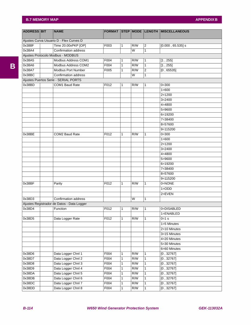
B-114 W650 Wind Generator Protection System GEK-113032A
B.7 MEMORY MAP APPENDIX B
B
ADDRESS BIT NAME FORMAT STEP MODE LENGTH MISCELLANEOUS
Ajustes Curva Usuario D - Flex Curves D0x388F Time 20.00xPKP [OP] F003 1 R/W 2 [0.000 , 65.535] s0x38A4 Confirmation address W 1 Ajustes Protocolo Modbus - MODBUS0x38A5 Modbus Address COM1 F004 1 R/W 1 [1 , 255] 0x38A6 Modbus Address COM2 F004 1 R/W 1 [1 , 255] 0x38A7 Modbus Port Number F005 1 R/W 2 [0 , 65535] 0x38BC Confirmation address W 1 Ajustes Puertos Serie - SERIAL PORTS0x38BD COM1 Baud Rate F012 1 R/W 1 0=300 1=600 2=1200 3=2400 4=4800 5=9600 6=19200 7=38400 8=57600 9=1152000x38BE COM2 Baud Rate F012 1 R/W 1 0=300 1=600 2=1200 3=2400 4=4800 5=9600 6=19200 7=38400 8=57600 9=1152000x38BF Parity F012 1 R/W 1 0=NONE 1=ODD 2=EVEN0x38D3 Confirmation address W 1 Ajustes Registrador de Datos - Data Logger0x38D4 Function F012 1 R/W 1 0=DISABLED 1=ENABLED0x38D5 Data Logger Rate F012 1 R/W 1 0=1 s 1=5 Minutes 2=10 Minutes 3=15 Minutes 4=20 Minutes 5=30 Minutes 6=60 Minutes0x38D6 Data Logger Chnl 1 F004 1 R/W 1 [0 , 32767] 0x38D7 Data Logger Chnl 2 F004 1 R/W 1 [0 , 32767] 0x38D8 Data Logger Chnl 3 F004 1 R/W 1 [0 , 32767] 0x38D9 Data Logger Chnl 4 F004 1 R/W 1 [0 , 32767] 0x38DA Data Logger Chnl 5 F004 1 R/W 1 [0 , 32767] 0x38DB Data Logger Chnl 6 F004 1 R/W 1 [0 , 32767] 0x38DC Data Logger Chnl 7 F004 1 R/W 1 [0 , 32767] 0x38DD Data Logger Chnl 8 F004 1 R/W 1 [0 , 32767]
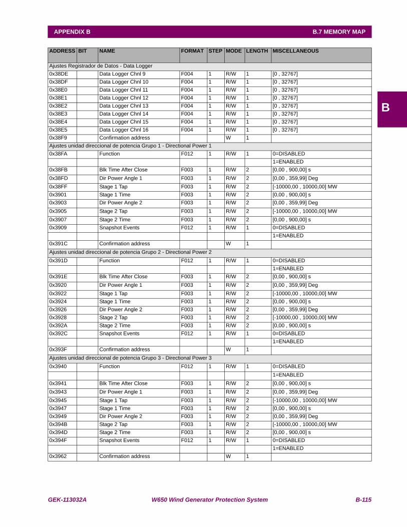
GEK-113032A W650 Wind Generator Protection System B-115
APPENDIX B B.7 MEMORY MAP
B
ADDRESS BIT NAME FORMAT STEP MODE LENGTH MISCELLANEOUS
Ajustes Registrador de Datos - Data Logger0x38DE Data Logger Chnl 9 F004 1 R/W 1 [0 , 32767] 0x38DF Data Logger Chnl 10 F004 1 R/W 1 [0 , 32767] 0x38E0 Data Logger Chnl 11 F004 1 R/W 1 [0 , 32767] 0x38E1 Data Logger Chnl 12 F004 1 R/W 1 [0 , 32767] 0x38E2 Data Logger Chnl 13 F004 1 R/W 1 [0 , 32767] 0x38E3 Data Logger Chnl 14 F004 1 R/W 1 [0 , 32767] 0x38E4 Data Logger Chnl 15 F004 1 R/W 1 [0 , 32767] 0x38E5 Data Logger Chnl 16 F004 1 R/W 1 [0 , 32767] 0x38F9 Confirmation address W 1 Ajustes unidad direccional de potencia Grupo 1 - Directional Power 10x38FA Function F012 1 R/W 1 0=DISABLED 1=ENABLED0x38FB Blk Time After Close F003 1 R/W 2 [0,00 , 900,00] s0x38FD Dir Power Angle 1 F003 1 R/W 2 [0,00 , 359,99] Deg0x38FF Stage 1 Tap F003 1 R/W 2 [-10000,00 , 10000,00] MW0x3901 Stage 1 Time F003 1 R/W 2 [0,00 , 900,00] s0x3903 Dir Power Angle 2 F003 1 R/W 2 [0,00 , 359,99] Deg0x3905 Stage 2 Tap F003 1 R/W 2 [-10000,00 , 10000,00] MW0x3907 Stage 2 Time F003 1 R/W 2 [0,00 , 900,00] s0x3909 Snapshot Events F012 1 R/W 1 0=DISABLED 1=ENABLED0x391C Confirmation address W 1 Ajustes unidad direccional de potencia Grupo 2 - Directional Power 20x391D Function F012 1 R/W 1 0=DISABLED 1=ENABLED0x391E Blk Time After Close F003 1 R/W 2 [0,00 , 900,00] s0x3920 Dir Power Angle 1 F003 1 R/W 2 [0,00 , 359,99] Deg0x3922 Stage 1 Tap F003 1 R/W 2 [-10000,00 , 10000,00] MW0x3924 Stage 1 Time F003 1 R/W 2 [0,00 , 900,00] s0x3926 Dir Power Angle 2 F003 1 R/W 2 [0,00 , 359,99] Deg0x3928 Stage 2 Tap F003 1 R/W 2 [-10000,00 , 10000,00] MW0x392A Stage 2 Time F003 1 R/W 2 [0,00 , 900,00] s0x392C Snapshot Events F012 1 R/W 1 0=DISABLED 1=ENABLED0x393F Confirmation address W 1 Ajustes unidad direccional de potencia Grupo 3 - Directional Power 30x3940 Function F012 1 R/W 1 0=DISABLED 1=ENABLED0x3941 Blk Time After Close F003 1 R/W 2 [0,00 , 900,00] s0x3943 Dir Power Angle 1 F003 1 R/W 2 [0,00 , 359,99] Deg0x3945 Stage 1 Tap F003 1 R/W 2 [-10000,00 , 10000,00] MW0x3947 Stage 1 Time F003 1 R/W 2 [0,00 , 900,00] s0x3949 Dir Power Angle 2 F003 1 R/W 2 [0,00 , 359,99] Deg0x394B Stage 2 Tap F003 1 R/W 2 [-10000,00 , 10000,00] MW0x394D Stage 2 Time F003 1 R/W 2 [0,00 , 900,00] s0x394F Snapshot Events F012 1 R/W 1 0=DISABLED 1=ENABLED0x3962 Confirmation address W 1

B-116 W650 Wind Generator Protection System GEK-113032A
B.7 MEMORY MAP APPENDIX B
B
ADDRESS BIT NAME FORMAT STEP MODE LENGTH MISCELLANEOUS
Ajustes Sobretensión de Fases Grupo 4 - Phase OV 40x39A2 Function F012 1000 R/W 1 0=DISABLED 1=ENABLED0x39A3 Pickup Level F003 1000 R/W 2 [3 , 850] V0x39A5 Trip Delay F003 1000 R/W 2 [0.00 , 900.00] s0x39A7 Reset Delay F003 1000 R/W 2 [0.00 , 900.00] s0x39A9 Logic F012 1000 R/W 1 0=ANY PHASE 1=TWO PHASES
2=ALL PHASES0x39AA Snapshot Events F012 1000 R/W 1 0=DISABLED
1=ENABLED0x39BD Confirmation address W 1 Ajustes Subtensión de Fases Grupo 4 - Phase UV 40x39BE Function F012 1000 R/W 1 0=DISABLED 1=ENABLED0x39BF Mode F012 1000 R/W 1 0=PHASE-PHASE 1=PHASE-GROUND0x39C0 Pickup Level F003 1000 R/W 2 [3 , 850] V0x39C2 Curve F012 1000 R/W 1 0=DEFINITE TIME
1=INVERSE TIME0x39C3 Delay F003 1000 R/W 2 [0.00 , 900.00] s0x39C5 Minimum Voltage F003 1000 R/W 2 [0 , 850] V0x39C7 Logic F012 1000 R/W 1 0=ANY PHASE
1=TWO PHASES 2=ALL PHASES
0x39C8 Supervised by 52 F012 1000 R/W 1 0=DISABLED1=ENABLED
0x39C9 Snapshot Events F012 1000 R/W 1 0=DISABLED1=ENABLED
0x39DC Confirmation address W 1Ajustes Sobrefrecuencia Grupo 4 - Overfrequency 40x39DD Function F012 1000 R/W 1 0=DISABLED 1=ENABLED0x39DE Pickup Level F003 1000 R/W 2 [20.00 , 65.00] Hz0x39E0 Trip Delay F003 1000 R/W 2 [0.00 , 900.00] s0x39E2 Reset Delay F003 1000 R/W 2 [0.00 , 900.00] s0x39E4 Minimum Voltage F003 1000 R/W 2 [30, 500] V0x39E6 Snapshot Events F012 1000 R/W 1 0=DISABLED
1=ENABLED0x39F9 Confirmation address W 1Ajustes Subfrecuencia Grupo 4 - Underfrequency 40x39FA Function F012 1000 R/W 1 0=DISABLED 1=ENABLED0x39FB Pickup Level F003 1000 R/W 2 [20.00 , 65.00] Hz0x39FD Trip Delay F003 1000 R/W 2 [0.00 , 900.00] s0x39FF Reset Delay F003 1000 R/W 2 [0.00 , 900.00] s0x3A01 Minimum Voltage F003 1000 R/W 2 [30, 500] V0x3A03 Snapshot Events F012 1000 R/W 1 0=DISABLED
1=ENABLED0x3A16 Confirmation address W 1
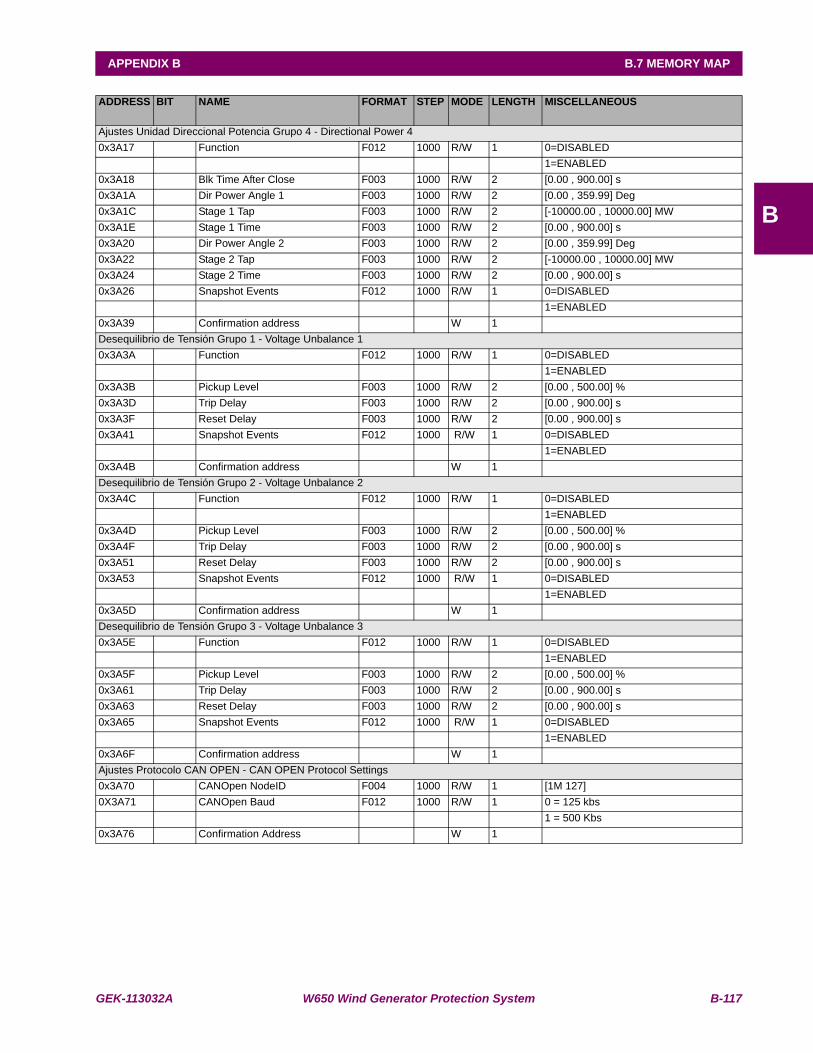
GEK-113032A W650 Wind Generator Protection System B-117
APPENDIX B B.7 MEMORY MAP
B
ADDRESS BIT NAME FORMAT STEP MODE LENGTH MISCELLANEOUS
Ajustes Unidad Direccional Potencia Grupo 4 - Directional Power 40x3A17 Function F012 1000 R/W 1 0=DISABLED 1=ENABLED0x3A18 Blk Time After Close F003 1000 R/W 2 [0.00 , 900.00] s0x3A1A Dir Power Angle 1 F003 1000 R/W 2 [0.00 , 359.99] Deg0x3A1C Stage 1 Tap F003 1000 R/W 2 [-10000.00 , 10000.00] MW0x3A1E Stage 1 Time F003 1000 R/W 2 [0.00 , 900.00] s0x3A20 Dir Power Angle 2 F003 1000 R/W 2 [0.00 , 359.99] Deg0x3A22 Stage 2 Tap F003 1000 R/W 2 [-10000.00 , 10000.00] MW0x3A24 Stage 2 Time F003 1000 R/W 2 [0.00 , 900.00] s0x3A26 Snapshot Events F012 1000 R/W 1 0=DISABLED
1=ENABLED0x3A39 Confirmation address W 1Desequilibrio de Tensión Grupo 1 - Voltage Unbalance 10x3A3A Function F012 1000 R/W 1 0=DISABLED 1=ENABLED0x3A3B Pickup Level F003 1000 R/W 2 [0.00 , 500.00] %0x3A3D Trip Delay F003 1000 R/W 2 [0.00 , 900.00] s0x3A3F Reset Delay F003 1000 R/W 2 [0.00 , 900.00] s0x3A41 Snapshot Events F012 1000 R/W 1 0=DISABLED
1=ENABLED0x3A4B Confirmation address W 1Desequilibrio de Tensión Grupo 2 - Voltage Unbalance 20x3A4C Function F012 1000 R/W 1 0=DISABLED 1=ENABLED0x3A4D Pickup Level F003 1000 R/W 2 [0.00 , 500.00] %0x3A4F Trip Delay F003 1000 R/W 2 [0.00 , 900.00] s0x3A51 Reset Delay F003 1000 R/W 2 [0.00 , 900.00] s0x3A53 Snapshot Events F012 1000 R/W 1 0=DISABLED
1=ENABLED0x3A5D Confirmation address W 1Desequilibrio de Tensión Grupo 3 - Voltage Unbalance 30x3A5E Function F012 1000 R/W 1 0=DISABLED 1=ENABLED0x3A5F Pickup Level F003 1000 R/W 2 [0.00 , 500.00] %0x3A61 Trip Delay F003 1000 R/W 2 [0.00 , 900.00] s0x3A63 Reset Delay F003 1000 R/W 2 [0.00 , 900.00] s0x3A65 Snapshot Events F012 1000 R/W 1 0=DISABLED
1=ENABLED0x3A6F Confirmation address W 1Ajustes Protocolo CAN OPEN - CAN OPEN Protocol Settings0x3A70 CANOpen NodeID F004 1000 R/W 1 [1M 127]0X3A71 CANOpen Baud F012 1000 R/W 1 0 = 125 kbs
1 = 500 Kbs0x3A76 Confirmation Address W 1
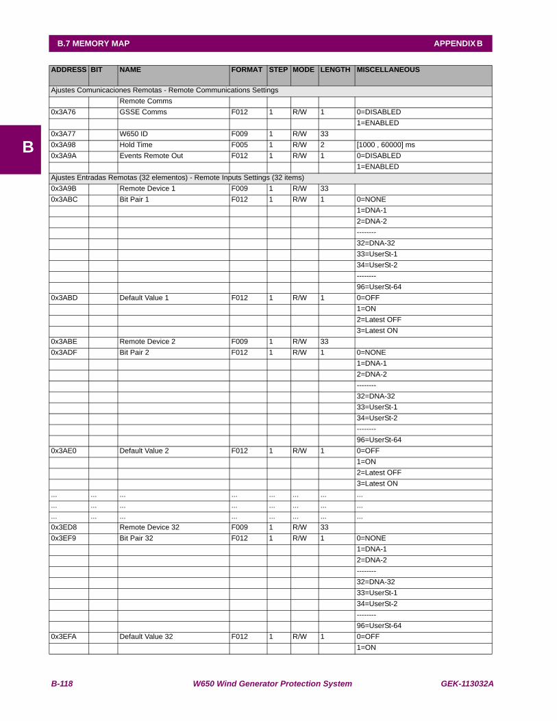
B-118 W650 Wind Generator Protection System GEK-113032A
B.7 MEMORY MAP APPENDIX B
B
ADDRESS BIT NAME FORMAT STEP MODE LENGTH MISCELLANEOUS
Ajustes Comunicaciones Remotas - Remote Communications Settings Remote Comms 0x3A76 GSSE Comms F012 1 R/W 1 0=DISABLED 1=ENABLED0x3A77 W650 ID F009 1 R/W 33 0x3A98 Hold Time F005 1 R/W 2 [1000 , 60000] ms0x3A9A Events Remote Out F012 1 R/W 1 0=DISABLED 1=ENABLEDAjustes Entradas Remotas (32 elementos) - Remote Inputs Settings (32 items)0x3A9B Remote Device 1 F009 1 R/W 33 0x3ABC Bit Pair 1 F012 1 R/W 1 0=NONE 1=DNA-1 2=DNA-2 -------- 32=DNA-32 33=UserSt-1 34=UserSt-2 -------- 96=UserSt-640x3ABD Default Value 1 F012 1 R/W 1 0=OFF 1=ON 2=Latest OFF 3=Latest ON0x3ABE Remote Device 2 F009 1 R/W 33 0x3ADF Bit Pair 2 F012 1 R/W 1 0=NONE 1=DNA-1 2=DNA-2 -------- 32=DNA-32 33=UserSt-1 34=UserSt-2 -------- 96=UserSt-640x3AE0 Default Value 2 F012 1 R/W 1 0=OFF 1=ON 2=Latest OFF 3=Latest ON... ... ... ... ... ... ... ...... ... ... ... ... ... ... ...... ... ... ... ... ... ... ...0x3ED8 Remote Device 32 F009 1 R/W 33 0x3EF9 Bit Pair 32 F012 1 R/W 1 0=NONE 1=DNA-1 2=DNA-2 -------- 32=DNA-32 33=UserSt-1 34=UserSt-2 -------- 96=UserSt-640x3EFA Default Value 32 F012 1 R/W 1 0=OFF 1=ON
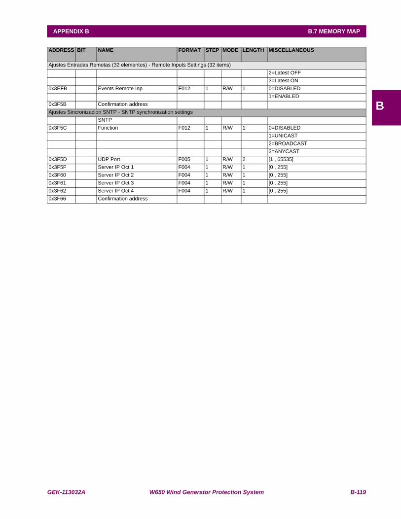
GEK-113032A W650 Wind Generator Protection System B-119
APPENDIX B B.7 MEMORY MAP
B
ADDRESS BIT NAME FORMAT STEP MODE LENGTH MISCELLANEOUS
Ajustes Entradas Remotas (32 elementos) - Remote Inputs Settings (32 items) 2=Latest OFF 3=Latest ON0x3EFB Events Remote Inp F012 1 R/W 1 0=DISABLED 1=ENABLED0x3F5B Confirmation address Ajustes Sincronizacion SNTP - SNTP synchronization settings SNTP 0x3F5C Function F012 1 R/W 1 0=DISABLED 1=UNICAST 2=BROADCAST 3=ANYCAST0x3F5D UDP Port F005 1 R/W 2 [1 , 65535]0x3F5F Server IP Oct 1 F004 1 R/W 1 [0 , 255]0x3F60 Server IP Oct 2 F004 1 R/W 1 [0 , 255]0x3F61 Server IP Oct 3 F004 1 R/W 1 [0 , 255]0x3F62 Server IP Oct 4 F004 1 R/W 1 [0 , 255]0x3F66 Confirmation address
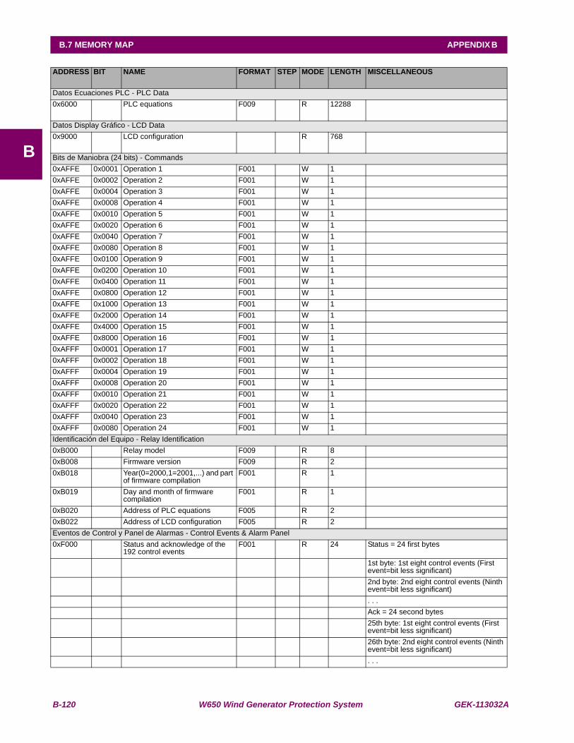
B-120 W650 Wind Generator Protection System GEK-113032A
B.7 MEMORY MAP APPENDIX B
B
ADDRESS BIT NAME FORMAT STEP MODE LENGTH MISCELLANEOUS
Datos Ecuaciones PLC - PLC Data0x6000 PLC equations F009 R 12288
Datos Display Gráfico - LCD Data0x9000 LCD configuration R 768
Bits de Maniobra (24 bits) - Commands0xAFFE 0x0001 Operation 1 F001 W 1 0xAFFE 0x0002 Operation 2 F001 W 1 0xAFFE 0x0004 Operation 3 F001 W 1 0xAFFE 0x0008 Operation 4 F001 W 1 0xAFFE 0x0010 Operation 5 F001 W 1 0xAFFE 0x0020 Operation 6 F001 W 1 0xAFFE 0x0040 Operation 7 F001 W 1 0xAFFE 0x0080 Operation 8 F001 W 1 0xAFFE 0x0100 Operation 9 F001 W 1 0xAFFE 0x0200 Operation 10 F001 W 1 0xAFFE 0x0400 Operation 11 F001 W 1 0xAFFE 0x0800 Operation 12 F001 W 1 0xAFFE 0x1000 Operation 13 F001 W 1 0xAFFE 0x2000 Operation 14 F001 W 1 0xAFFE 0x4000 Operation 15 F001 W 1 0xAFFE 0x8000 Operation 16 F001 W 1 0xAFFF 0x0001 Operation 17 F001 W 1 0xAFFF 0x0002 Operation 18 F001 W 1 0xAFFF 0x0004 Operation 19 F001 W 1 0xAFFF 0x0008 Operation 20 F001 W 1 0xAFFF 0x0010 Operation 21 F001 W 1 0xAFFF 0x0020 Operation 22 F001 W 1 0xAFFF 0x0040 Operation 23 F001 W 1 0xAFFF 0x0080 Operation 24 F001 W 1 Identificación del Equipo - Relay Identification0xB000 Relay model F009 R 8 0xB008 Firmware version F009 R 2 0xB018 Year(0=2000,1=2001,...) and part
of firmware compilationF001 R 1
0xB019 Day and month of firmware compilation
F001 R 1
0xB020 Address of PLC equations F005 R 2 0xB022 Address of LCD configuration F005 R 2 Eventos de Control y Panel de Alarmas - Control Events & Alarm Panel0xF000 Status and acknowledge of the
192 control eventsF001 R 24 Status = 24 first bytes
1st byte: 1st eight control events (First event=bit less significant)
2nd byte: 2nd eight control events (Ninth event=bit less significant)
. . . Ack = 24 second bytes 25th byte: 1st eight control events (First
event=bit less significant) 26th byte: 2nd eight control events (Ninth
event=bit less significant) . . .
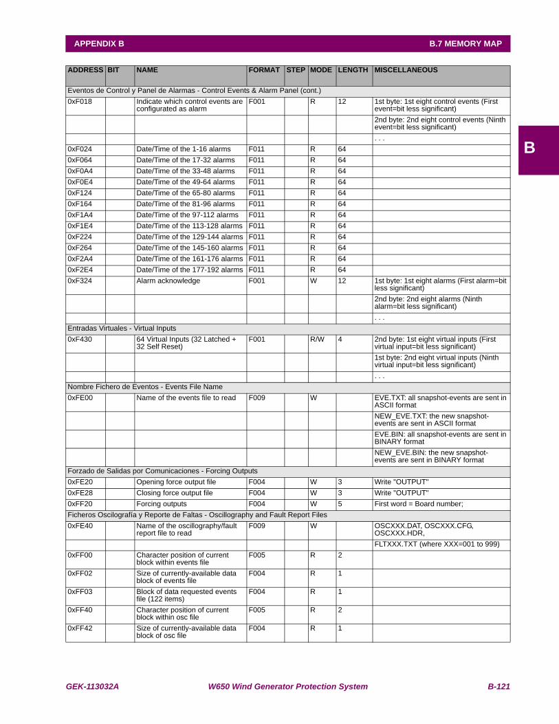
GEK-113032A W650 Wind Generator Protection System B-121
APPENDIX B B.7 MEMORY MAP
B
ADDRESS BIT NAME FORMAT STEP MODE LENGTH MISCELLANEOUS
Eventos de Control y Panel de Alarmas - Control Events & Alarm Panel (cont.)0xF018 Indicate which control events are
configurated as alarmF001 R 12 1st byte: 1st eight control events (First
event=bit less significant) 2nd byte: 2nd eight control events (Ninth
event=bit less significant) . . .0xF024 Date/Time of the 1-16 alarms F011 R 64 0xF064 Date/Time of the 17-32 alarms F011 R 64 0xF0A4 Date/Time of the 33-48 alarms F011 R 64 0xF0E4 Date/Time of the 49-64 alarms F011 R 64 0xF124 Date/Time of the 65-80 alarms F011 R 64 0xF164 Date/Time of the 81-96 alarms F011 R 64 0xF1A4 Date/Time of the 97-112 alarms F011 R 64 0xF1E4 Date/Time of the 113-128 alarms F011 R 64 0xF224 Date/Time of the 129-144 alarms F011 R 64 0xF264 Date/Time of the 145-160 alarms F011 R 64 0xF2A4 Date/Time of the 161-176 alarms F011 R 64 0xF2E4 Date/Time of the 177-192 alarms F011 R 64 0xF324 Alarm acknowledge F001 W 12 1st byte: 1st eight alarms (First alarm=bit
less significant) 2nd byte: 2nd eight alarms (Ninth
alarm=bit less significant) . . .Entradas Virtuales - Virtual Inputs0xF430 64 Virtual Inputs (32 Latched +
32 Self Reset)F001 R/W 4 2nd byte: 1st eight virtual inputs (First
virtual input=bit less significant) 1st byte: 2nd eight virtual inputs (Ninth
virtual input=bit less significant) . . .Nombre Fichero de Eventos - Events File Name0xFE00 Name of the events file to read F009 W EVE.TXT: all snapshot-events are sent in
ASCII format NEW_EVE.TXT: the new snapshot-
events are sent in ASCII format EVE.BIN: all snapshot-events are sent in
BINARY format NEW_EVE.BIN: the new snapshot-
events are sent in BINARY formatForzado de Salidas por Comunicaciones - Forcing Outputs0xFE20 Opening force output file F004 W 3 Write "OUTPUT"0xFE28 Closing force output file F004 W 3 Write "OUTPUT"0xFF20 Forcing outputs F004 W 5 First word = Board number;Ficheros Oscilografía y Reporte de Faltas - Oscillography and Fault Report Files0xFE40 Name of the oscillography/fault
report file to readF009 W OSCXXX.DAT, OSCXXX.CFG,
OSCXXX.HDR, FLTXXX.TXT (where XXX=001 to 999)0xFF00 Character position of current
block within events fileF005 R 2
0xFF02 Size of currently-available data block of events file
F004 R 1
0xFF03 Block of data requested events file (122 items)
F004 R 1
0xFF40 Character position of current block within osc file
F005 R 2
0xFF42 Size of currently-available data block of osc file
F004 R 1

B-122 W650 Wind Generator Protection System GEK-113032A
B.7 MEMORY MAP APPENDIX B
B
ADDRESS BIT NAME FORMAT STEP MODE LENGTH MISCELLANEOUS
Ficheros Oscilografía y Reporte de Faltas - Oscillography and Fault Report Files0xFF43 Block of data requested osc file
(122 items)F004 R 1
Sincronización Horaria - Synchronization0xFFF0 Synchronization (miliseconds
from 01/01/2000)F011 R/W 4
DESCRIPCIÓN FORMATO DE DATOS - FORMATS DESCRIPTION F001 UNSIGNED INT 16 BIT
(BITMASK)
F002 SIGNED INT 32 BIT F003 FLOAT 32 BIT F004 SIGNED INT 16 BIT F005 SIGNED INT 32 BIT F006 DOUBLE 64 BIT F007 UNSIGNED INT 8 BIT F008 SIGNED INT 8 BIT F009 STRING F011 UNSIGNED INT 64 BIT
(MILISECONDS FROM 01/01/2000)
F012 UNSIGNED INT 16 BIT (ENUMERATED)
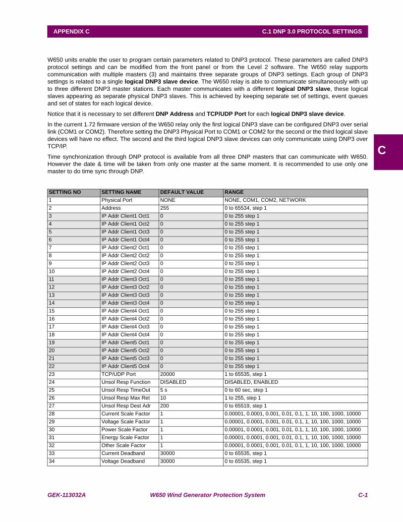
GEK-113032A W650 Wind Generator Protection System C-1
APPENDIX C C.1 DNP 3.0 PROTOCOL SETTINGS
C
APPENDIX C DNP 3.0 PROTOCOL FOR W650C.1DNP 3.0 PROTOCOL SETTINGS
W650 units enable the user to program certain parameters related to DNP3 protocol. These parameters are called DNP3protocol settings and can be modified from the front panel or from the Level 2 software. The W650 relay supportscommunication with multiple masters (3) and maintains three separate groups of DNP3 settings. Each group of DNP3settings is related to a single logical DNP3 slave device. The W650 relay is able to communicate simultaneously with upto three different DNP3 master stations. Each master communicates with a different logical DNP3 slave, these logicalslaves appearing as separate physical DNP3 slaves. This is achieved by keeping separate set of settings, event queuesand set of states for each logical device.
Notice that it is necessary to set different DNP Address and TCP/UDP Port for each logical DNP3 slave device.
In the current 1.72 firmware version of the W650 relay only the first logical DNP3 slave can be configured DNP3 over seriallink (COM1 or COM2). Therefore setting the DNP3 Physical Port to COM1 or COM2 for the second or the third logical slavedevices will have no effect. The second and the third logical DNP3 slave devices can only communicate using DNP3 overTCP/IP.
Time synchronization through DNP protocol is available from all three DNP masters that can communicate with W650.However the date & time will be taken from only one master at the same moment. It is recommended to use only onemaster to do time sync through DNP.
SETTING NO SETTING NAME DEFAULT VALUE RANGE1 Physical Port NONE NONE, COM1, COM2, NETWORK2 Address 255 0 to 65534, step 13 IP Addr Client1 Oct1 0 0 to 255 step 14 IP Addr Client1 Oct2 0 0 to 255 step 15 IP Addr Client1 Oct3 0 0 to 255 step 16 IP Addr Client1 Oct4 0 0 to 255 step 17 IP Addr Client2 Oct1 0 0 to 255 step 18 IP Addr Client2 Oct2 0 0 to 255 step 19 IP Addr Client2 Oct3 0 0 to 255 step 110 IP Addr Client2 Oct4 0 0 to 255 step 111 IP Addr Client3 Oct1 0 0 to 255 step 112 IP Addr Client3 Oct2 0 0 to 255 step 113 IP Addr Client3 Oct3 0 0 to 255 step 114 IP Addr Client3 Oct4 0 0 to 255 step 115 IP Addr Client4 Oct1 0 0 to 255 step 116 IP Addr Client4 Oct2 0 0 to 255 step 117 IP Addr Client4 Oct3 0 0 to 255 step 118 IP Addr Client4 Oct4 0 0 to 255 step 119 IP Addr Client5 Oct1 0 0 to 255 step 120 IP Addr Client5 Oct2 0 0 to 255 step 121 IP Addr Client5 Oct3 0 0 to 255 step 122 IP Addr Client5 Oct4 0 0 to 255 step 123 TCP/UDP Port 20000 1 to 65535, step 124 Unsol Resp Function DISABLED DISABLED, ENABLED25 Unsol Resp TimeOut 5 s 0 to 60 sec, step 126 Unsol Resp Max Ret 10 1 to 255, step 1 27 Unsol Resp Dest Adr 200 0 to 65519, step 128 Current Scale Factor 1 0.00001, 0.0001, 0.001, 0.01, 0.1, 1, 10, 100, 1000, 1000029 Voltage Scale Factor 1 0.00001, 0.0001, 0.001, 0.01, 0.1, 1, 10, 100, 1000, 1000030 Power Scale Factor 1 0.00001, 0.0001, 0.001, 0.01, 0.1, 1, 10, 100, 1000, 1000031 Energy Scale Factor 1 0.00001, 0.0001, 0.001, 0.01, 0.1, 1, 10, 100, 1000, 1000032 Other Scale Factor 1 0.00001, 0.0001, 0.001, 0.01, 0.1, 1, 10, 100, 1000, 1000033 Current Deadband 30000 0 to 65535, step 134 Voltage Deadband 30000 0 to 65535, step 1
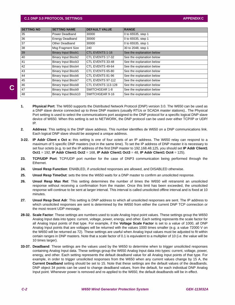
C-2 W650 Wind Generator Protection System GEK-113032A
C.1 DNP 3.0 PROTOCOL SETTINGS APPENDIX C
C
1. Physical Port: The W650 supports the Distributed Network Protocol (DNP) version 3.0. The W650 can be used asa DNP slave device connected up to three DNP masters (usually RTUs or SCADA master stations).. The PhysicalPort setting is used to select the communications port assigned to the DNP protocol for a specific logical DNP slavedevice of W650. When this setting is set to NETWORK, the DNP protocol can be used over either TCP/IP or UDP/IP.
2. Address: This setting is the DNP slave address. This number identifies de W650 on a DNP communications link.Each logical DNP slave should be assigned a unique address.
3-22. IP Addr Client x Oct x: this setting is one of four octets of an IP address. The W650 relay can respond to amaximum of 5 specific DNP masters (not in the same time). To set the IP address of DNP master it is necessary toset four octets (e.g. to set the IP address of the first DNP master to 192.168.48.125, you should set IP Addr Client1Oct1 = 192, IP Addr Client1 Oct2 = 168, IP Addr Client1 Oct3 = 48, IP Addr Client1 Oct4 = 125).
23. TCP/UDP Port: TCP/UDP port number for the case of DNP3 communication being performed through theEthernet.
24. Unsol Resp Function: ENABLED, if unsolicited responses are allowed, and DISABLED otherwise.
25. Unsol Resp TimeOut: sets the time the W650 waits for a DNP master to confirm an unsolicited response.
26. Unsol Resp Max Ret: This setting determines the number of times the W650 will retransmit an unsolicitedresponse without receiving a confirmation from the master. Once this limit has been exceeded, the unsolicitedresponse will continue to be sent at larger interval. This interval is called unsolicited offline interval and is fixed at 10minutes.
27. Unsol Resp Dest Adr: This setting is DNP address to which all unsolicited responses are sent. The IP address towhich unsolicited responses are sent is determined by the W650 from either the current DNP TCP connection orthe most recent UDP message.
28-32. Scale Factor: These settings are numbers used to scale Analog Input point values. These settings group the W650Analog Input data into types: current, voltage, power, energy, and other. Each setting represents the scale factor forall Analog Input points of that type. For example, if the Voltage Scale Factor is set to a value of 1000, all DNPAnalog Input points that are voltages will be returned with the values 1000 times smaller (e.g. a value 72000 V onthe W650 will be returned as 72). These settings are useful when Analog Input values must be adjusted to fit withincertain ranges in DNP masters. Note that a scale factor of 0.1 is equivalent to a multiplier of 10 (i.e. the value will be10 times larger).
33-37. Deadband: These settings are the values used by the W650 to determine when to trigger unsolicited responsescontaining Analog Input data. These settings group the W650 Analog Input data into types: current, voltage, power,energy, and other. Each setting represents the default deadband value for all Analog Input points of that type. Forexample, in order to trigger unsolicited responses from the W650 when any current values change by 15 A, theCurrent Deadband setting should be set to 15. Note that these settings are the default values of the deadbands.DNP object 34 points can be used to change deadband values, from the default, for each individual DNP AnalogInput point. Whenever power is removed and re-applied to the W650, the default deadbands will be in effect.
SETTING NO SETTING NAME DEFAULT VALUE RANGE35 Power Deadband 30000 0 to 65535, step 136 Energy Deadband 30000 0 to 65535, step 137 Other Deadband 30000 0 to 65535, step 138 Msg Fragment Size 240 30 to 2048, step 1 39 Binary Input Block1 CTL EVENTS 1-16 See the explanation below40 Binary Input Block2 CTL EVENTS 17-32 See the explanation below41 Binary Input Block3 CTL EVENTS 33-48 See the explanation below42 Binary Input Block4 CTL EVENTS 49-64 See the explanation below43 Binary Input Block5 CTL EVENTS 65-80 See the explanation below44 Binary Input Block6 CTL EVENTS 81-96 See the explanation below45 Binary Input Block7 CTL EVENTS 97-112 See the explanation below46 Binary Input Block8 CTL EVENTS 113-128 See the explanation below47 Binary Input Block9 SWITCHGEAR 1-8 See the explanation below48 Binary Input Block10 SWITCHGEAR 9-16 See the explanation below

GEK-113032A W650 Wind Generator Protection System C-3
APPENDIX C C.1 DNP 3.0 PROTOCOL SETTINGS
C
38. Msg Fragment Size: This setting determines the size, in bytes, at which message fragmentation occurs. Largefragment sizes allow for more efficient throughput; smaller fragment sizes cause more application layerconfirmations to be necessary which can provide for more robust data transfer over noisy communication channels
39-48. Binary Input Block x: These settings allow customization and change of the size of DNP Binary Inputs point list.The default Binary Inputs point list contains 160 points representing binary states that are configured using“Setpoint->Relay Configuration” menu from the EnerVista 650 Setup program. These 160 binary states aregrouped in 10 blocks of 16 points each. There are 128 bits (8 blocks of 16) called Control Events and 32 bits (2blocks of 16) corresponding to the states of 16 switchgears available in W650 relay. If not all of the 160 points arerequired in the DNP master, a custom Binary Inputs point list can be created by selecting up to 10 blocks of 16points. Each block represents 16 Binary Input points. Block 1 represents Binary Input points 0-15, block 2represents Binary Input points 16- 31, block 3 represents Binary Input points 32-47, etc. The minimum number ofBinary Input points that can be selected is 16 (1 block). If all of the Binary Input Block x settings are set to “NOTUSED”, the default list of 160 points will be in effect. The W650 will form the Binary Inputs points list from theBinary Input Block x settings up to the first occurrence of a setting value “NOT USED”. Permitted values for thesesettings are: NOT USED, CTL EVENTS 1-16, CTL EVENTS 17-32, CTL EVENTS 33-48, CTL EVENTS 49-64, CTLEVENTS 65-80, CTL EVENTS 81-96, CTL EVENTS 97-112, CTL EVENTS 113-128, SWITCHGEAR 1-8,SWITCHGEAR 9-16.
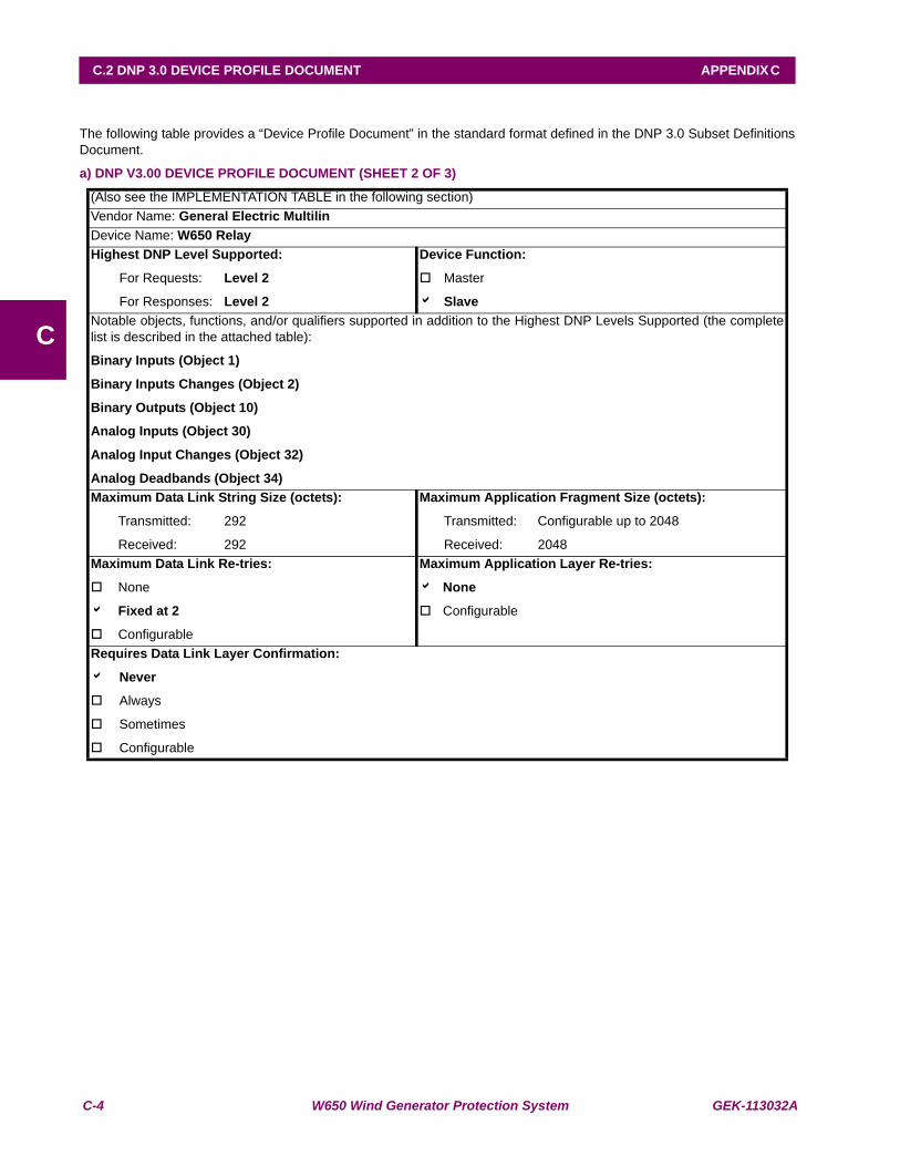
C-4 W650 Wind Generator Protection System GEK-113032A
C.2 DNP 3.0 DEVICE PROFILE DOCUMENT APPENDIX C
C
C.2DNP 3.0 DEVICE PROFILE DOCUMENT
The following table provides a “Device Profile Document” in the standard format defined in the DNP 3.0 Subset DefinitionsDocument.
a) DNP V3.00 DEVICE PROFILE DOCUMENT (SHEET 2 OF 3)
(Also see the IMPLEMENTATION TABLE in the following section)Vendor Name: General Electric MultilinDevice Name: W650 RelayHighest DNP Level Supported:
For Requests: Level 2
For Responses: Level 2
Device Function:
Master
a SlaveNotable objects, functions, and/or qualifiers supported in addition to the Highest DNP Levels Supported (the completelist is described in the attached table):
Binary Inputs (Object 1)
Binary Inputs Changes (Object 2)
Binary Outputs (Object 10)
Analog Inputs (Object 30)
Analog Input Changes (Object 32)
Analog Deadbands (Object 34)Maximum Data Link String Size (octets):
Transmitted: 292
Received: 292
Maximum Application Fragment Size (octets):
Transmitted: Configurable up to 2048
Received: 2048Maximum Data Link Re-tries:
None
a Fixed at 2
Configurable
Maximum Application Layer Re-tries:
a None
Configurable
Requires Data Link Layer Confirmation:
a Never
Always
Sometimes
Configurable
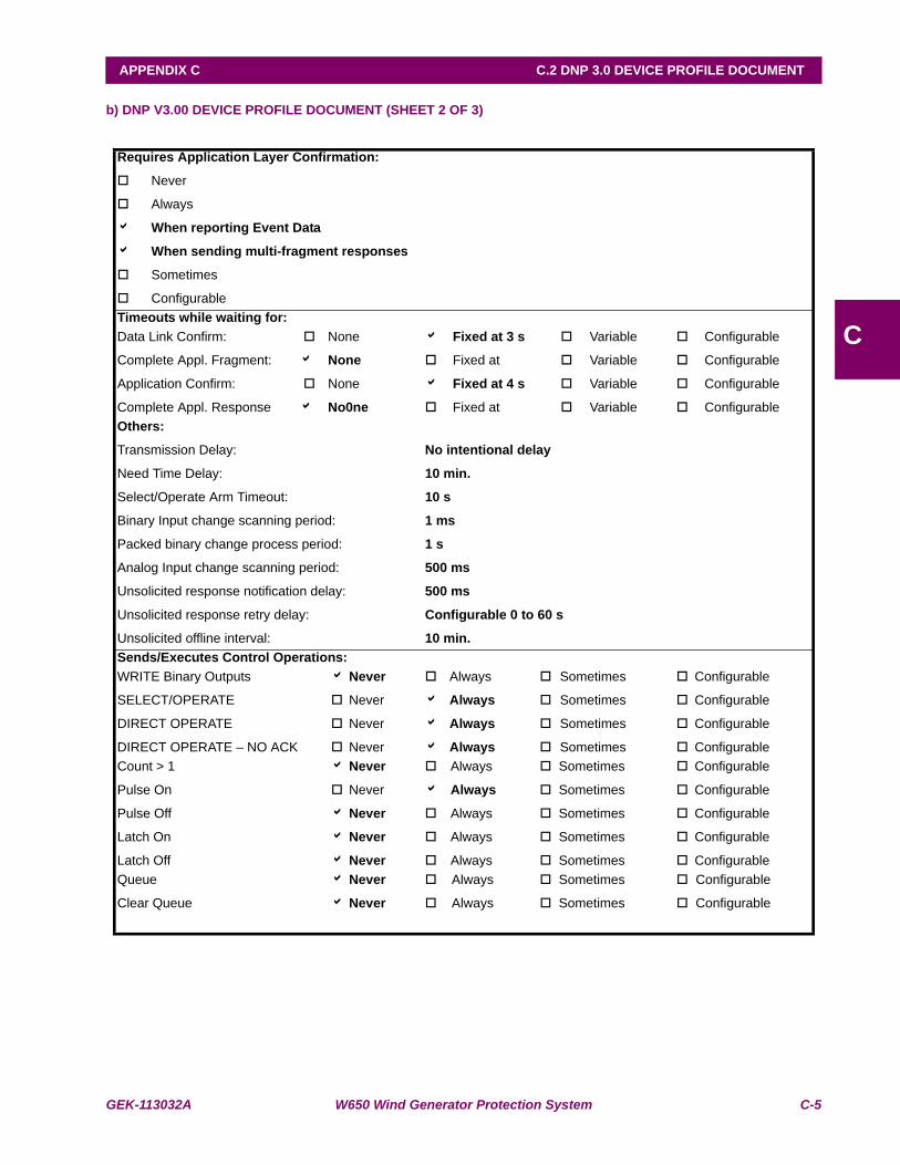
GEK-113032A W650 Wind Generator Protection System C-5
APPENDIX C C.2 DNP 3.0 DEVICE PROFILE DOCUMENT
C
b) DNP V3.00 DEVICE PROFILE DOCUMENT (SHEET 2 OF 3)
Requires Application Layer Confirmation:
Never
Always
a When reporting Event Data
a When sending multi-fragment responses
Sometimes
ConfigurableTimeouts while waiting for:Data Link Confirm:
Complete Appl. Fragment:
Application Confirm:
Complete Appl. Response
None
a None
None
a No0ne
a Fixed at 3 s
Fixed at
a Fixed at 4 s
Fixed at
Variable
Variable
Variable
Variable
Configurable
Configurable
Configurable
ConfigurableOthers:
Transmission Delay:
Need Time Delay:
Select/Operate Arm Timeout:
Binary Input change scanning period:
Packed binary change process period:
Analog Input change scanning period:
Unsolicited response notification delay:
Unsolicited response retry delay:
Unsolicited offline interval:
No intentional delay
10 min.
10 s
1 ms
1 s
500 ms
500 ms
Configurable 0 to 60 s
10 min.Sends/Executes Control Operations:WRITE Binary Outputs
SELECT/OPERATE
DIRECT OPERATE
DIRECT OPERATE – NO ACK
a Never
Never
Never
Never
Always
a Always
a Always
a Always
Sometimes
Sometimes
Sometimes
Sometimes
Configurable
Configurable
Configurable
ConfigurableCount > 1
Pulse On
Pulse Off
Latch On
Latch Off
a Never
Never
a Never
a Never
a Never
Always
a Always
Always
Always
Always
Sometimes
Sometimes
Sometimes
Sometimes
Sometimes
Configurable
Configurable
Configurable
Configurable
ConfigurableQueue
Clear Queue
a Never
a Never
Always
Always
Sometimes
Sometimes
Configurable
Configurable
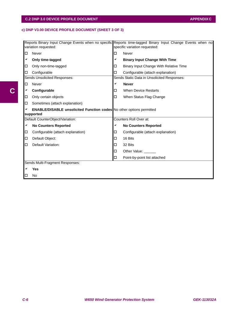
C-6 W650 Wind Generator Protection System GEK-113032A
C.2 DNP 3.0 DEVICE PROFILE DOCUMENT APPENDIX C
C
c) DNP V3.00 DEVICE PROFILE DOCUMENT (SHEET 3 OF 3)
Reports Binary Input Change Events when no specificvariation requested:
Never
a Only time-tagged
Only non-time-tagged
Configurable
Reports time-tagged Binary Input Change Events when nospecific variation requested:
Never
a Binary Input Change With Time
Binary Input Change With Relative Time
Configurable (attach explanation)Sends Unsolicited Responses:
Never
a Configurable
Only certain objects
Sometimes (attach explanation)
a ENABLE/DISABLE unsolicited Function codessupported
Sends Static Data in Unsolicited Responses:
a Never
When Device Restarts
When Status Flag Change
No other options permitted
Default CounterObject/Variation:
a No Counters Reported
Configurable (attach explanation)
Default Object:
Default Variation:
Counters Roll Over at:
a No Counters Reported
Configurable (attach explanation)
16 Bits
32 Bits
Other Value: ______
Point-by-point list attachedSends Multi-Fragment Responses:
a Yes
No
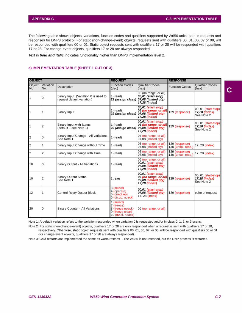
GEK-113032A W650 Wind Generator Protection System C-7
APPENDIX C C.3 IMPLEMENTATION TABLE
C
C.3IMPLEMENTATION TABLE
The following table shows objects, variations, function codes and qualifiers supported by W650 units, both in requests andresponses for DNP3 protocol. For static (non-change-event) objects, requests sent with qualifiers 00, 01, 06, 07 or 08, willbe responded with qualifiers 00 or 01. Static object requests sent with qualifiers 17 or 28 will be responded with qualifiers17 or 28. For change-event objects, qualifiers 17 or 28 are always responded.
Text in bold and italic indicates functionality higher than DNP3 implementation level 2.
a) IMPLEMENTATION TABLE (SHEET 1 OUT OF 3)
Note 1: A default variation refers to the variation responded when variation 0 is requested and/or in class 0, 1, 2, or 3 scans.Note 2: For static (non-change-event) objects, qualifiers 17 or 28 are only responded when a request is sent with qualifiers 17 or 28,
respectively. Otherwise, static object requests sent with qualifiers 00, 01, 06, 07, or 08, will be responded with qualifiers 00 or 01 (for change-event objects, qualifiers 17 or 28 are always responded).
Note 3: Cold restarts are implemented the same as warm restarts – The W650 is not restarted, but the DNP process is restarted.
OBJECT REQUEST RESPONSEObject No.
Variation No. Description Function Codes
(dec)Qualifier Codes (hex) Function Codes Qualifier Codes
(hex)
1 0 Binary Input (Variation 0 is used to request default variation)
1 (read)22 (assign class)
06 (no range, or all)00,01 (start-stop)07,08 (limited qty)17,28 (index)
1 1 Binary Input 1 (read)22 (assign class)
00,01 (start-stop)06 (no range, or all)07,08 (limited qty)17,28 (index)
129 (response)00, 01 (start-stop)17,28 (index)See Note 2
1 2 Binary Input with Status(default – see Note 1)
1 (read)22 (assign class)
00,01 (start-stop)06 (no range, or all)07,08 (limited qty)17,28 (index)
129 (response)00, 01 (start-stop)17,28 (index)See Note 2
2 0 Binary Input Change - All VariationsSee Note 1 1 (read) 06 (no range, or all)
07,08 (limited qty)
2 1 Binary Input Change without Time 1 (read) 06 (no range, or all)07,08 (limited qty)
129 (response) 130 (unsol. resp.) 17, 28 (index)
2 2 Binary Input Change with Time 1 (read) 06 (no range, or all)07,08 (limited qty)
129 (response) 130 (unsol. resp.) 17, 28 (index)
10 0 Binary Output - All Variations 1 (read)06 (no range, or all)00,01 (start-stop)07,08 (limited qty)17,28 (index)
10 2 Binary Output Status See Note 1 1 read
00,01 (start-stop)06 (no range, or all)07,08 (limited qty)17,28 (index)
129 (response)00, 01 (start-stop)17,28 (index)See Note 2
12 1 Control Relay Output Block3 (select)4 (operate)5 (direct op)6 (dir.op, noack)
00,01 (start-stop)07,08 (limited qty)17, 28 (index)
129 (response) echo of request
20 0 Binary Counter - All Variations
1 (select)7 (freeze)8 (freeze noack)9 (freeze clear)10 (frz.cl. noack)
06 (no range, or all)
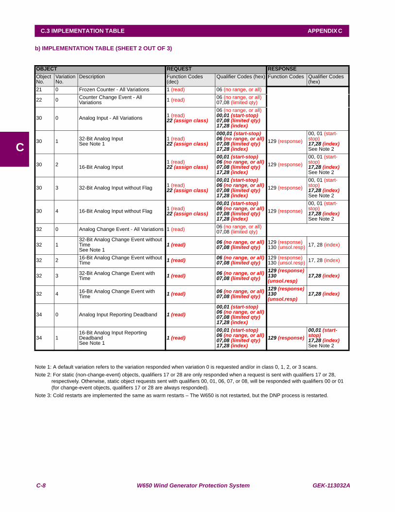
C-8 W650 Wind Generator Protection System GEK-113032A
C.3 IMPLEMENTATION TABLE APPENDIX C
C
b) IMPLEMENTATION TABLE (SHEET 2 OUT OF 3)
Note 1: A default variation refers to the variation responded when variation 0 is requested and/or in class 0, 1, 2, or 3 scans.Note 2: For static (non-change-event) objects, qualifiers 17 or 28 are only responded when a request is sent with qualifiers 17 or 28,
respectively. Otherwise, static object requests sent with qualifiers 00, 01, 06, 07, or 08, will be responded with qualifiers 00 or 01 (for change-event objects, qualifiers 17 or 28 are always responded).
Note 3: Cold restarts are implemented the same as warm restarts – The W650 is not restarted, but the DNP process is restarted.
OBJECT REQUEST RESPONSEObject No.
Variation No.
Description Function Codes (dec)
Qualifier Codes (hex) Function Codes Qualifier Codes (hex)
21 0 Frozen Counter - All Variations 1 (read) 06 (no range, or all)
22 0 Counter Change Event - All Variations 1 (read) 06 (no range, or all)
07,08 (limited qty)
30 0 Analog Input - All Variations 1 (read)22 (assign class)
06 (no range, or all)00,01 (start-stop)07,08 (limited qty)17,28 (index)
30 1 32-Bit Analog Input See Note 1
1 (read)22 (assign class)
000,01 (start-stop)06 (no range, or all)07,08 (limited qty)17,28 (index)
129 (response)00, 01 (start-stop)17,28 (index)See Note 2
30 2 16-Bit Analog Input1 (read)22 (assign class)
00,01 (start-stop)06 (no range, or all)07,08 (limited qty)17,28 (index)
129 (response)00, 01 (start-stop)17,28 (index)See Note 2
30 3 32-Bit Analog Input without Flag 1 (read)22 (assign class)
00,01 (start-stop)06 (no range, or all)07,08 (limited qty)17,28 (index)
129 (response)00, 01 (start-stop)17,28 (index)See Note 2
30 4 16-Bit Analog Input without Flag 1 (read)22 (assign class)
00,01 (start-stop)06 (no range, or all)07,08 (limited qty)17,28 (index)
129 (response)00, 01 (start-stop)17,28 (index)See Note 2
32 0 Analog Change Event - All Variations 1 (read) 06 (no range, or all)07,08 (limited qty)
32 132-Bit Analog Change Event without Time See Note 1
1 (read) 06 (no range, or all)07,08 (limited qty)
129 (response)130 (unsol.resp) 17, 28 (index)
32 2 16-Bit Analog Change Event without Time 1 (read) 06 (no range, or all)
07,08 (limited qty)129 (response)130 (unsol.resp) 17, 28 (index)
32 3 32-Bit Analog Change Event with Time 1 (read) 06 (no range, or all)
07,08 (limited qty)129 (response)130 (unsol.resp)
17,28 (index)
32 4 16-Bit Analog Change Event with Time 1 (read) 06 (no range, or all)
07,08 (limited qty)129 (response)130 (unsol.resp)
17,28 (index)
34 0 Analog Input Reporting Deadband 1 (read)00,01 (start-stop)06 (no range, or all)07,08 (limited qty)17,28 (index)
34 116-Bit Analog Input Reporting Deadband See Note 1
1 (read)00,01 (start-stop)06 (no range, or all)07,08 (limited qty)17,28 (index)
129 (response)00,01 (start-stop)17,28 (index)See Note 2
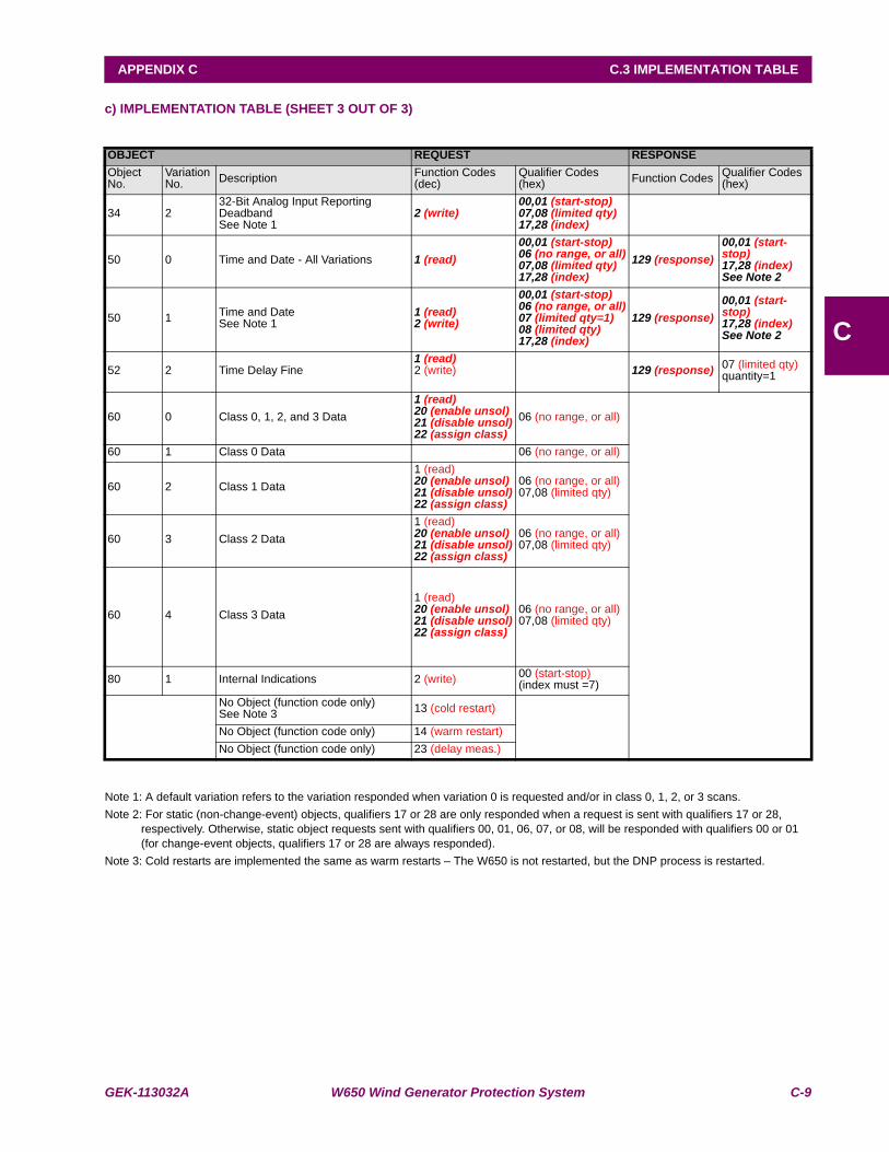
GEK-113032A W650 Wind Generator Protection System C-9
APPENDIX C C.3 IMPLEMENTATION TABLE
C
c) IMPLEMENTATION TABLE (SHEET 3 OUT OF 3)
Note 1: A default variation refers to the variation responded when variation 0 is requested and/or in class 0, 1, 2, or 3 scans.Note 2: For static (non-change-event) objects, qualifiers 17 or 28 are only responded when a request is sent with qualifiers 17 or 28,
respectively. Otherwise, static object requests sent with qualifiers 00, 01, 06, 07, or 08, will be responded with qualifiers 00 or 01 (for change-event objects, qualifiers 17 or 28 are always responded).
Note 3: Cold restarts are implemented the same as warm restarts – The W650 is not restarted, but the DNP process is restarted.
OBJECT REQUEST RESPONSEObject No.
Variation No. Description Function Codes
(dec)Qualifier Codes (hex) Function Codes Qualifier Codes
(hex)
34 232-Bit Analog Input Reporting Deadband See Note 1
2 (write)00,01 (start-stop)07,08 (limited qty)17,28 (index)
50 0 Time and Date - All Variations 1 (read)00,01 (start-stop)06 (no range, or all)07,08 (limited qty)17,28 (index)
129 (response)00,01 (start-stop)17,28 (index)See Note 2
50 1 Time and Date See Note 1
1 (read)2 (write)
00,01 (start-stop)06 (no range, or all)07 (limited qty=1)08 (limited qty)17,28 (index)
129 (response)00,01 (start-stop)17,28 (index)See Note 2
52 2 Time Delay Fine 1 (read)2 (write) 129 (response) 07 (limited qty)
quantity=1
60 0 Class 0, 1, 2, and 3 Data1 (read)20 (enable unsol)21 (disable unsol)22 (assign class)
06 (no range, or all)
60 1 Class 0 Data 06 (no range, or all)
60 2 Class 1 Data1 (read)20 (enable unsol)21 (disable unsol)22 (assign class)
06 (no range, or all)07,08 (limited qty)
60 3 Class 2 Data1 (read)20 (enable unsol)21 (disable unsol)22 (assign class)
06 (no range, or all)07,08 (limited qty)
60 4 Class 3 Data1 (read)20 (enable unsol)21 (disable unsol)22 (assign class)
06 (no range, or all)07,08 (limited qty)
80 1 Internal Indications 2 (write) 00 (start-stop)(index must =7)
No Object (function code only)See Note 3 13 (cold restart)
No Object (function code only) 14 (warm restart)No Object (function code only) 23 (delay meas.)
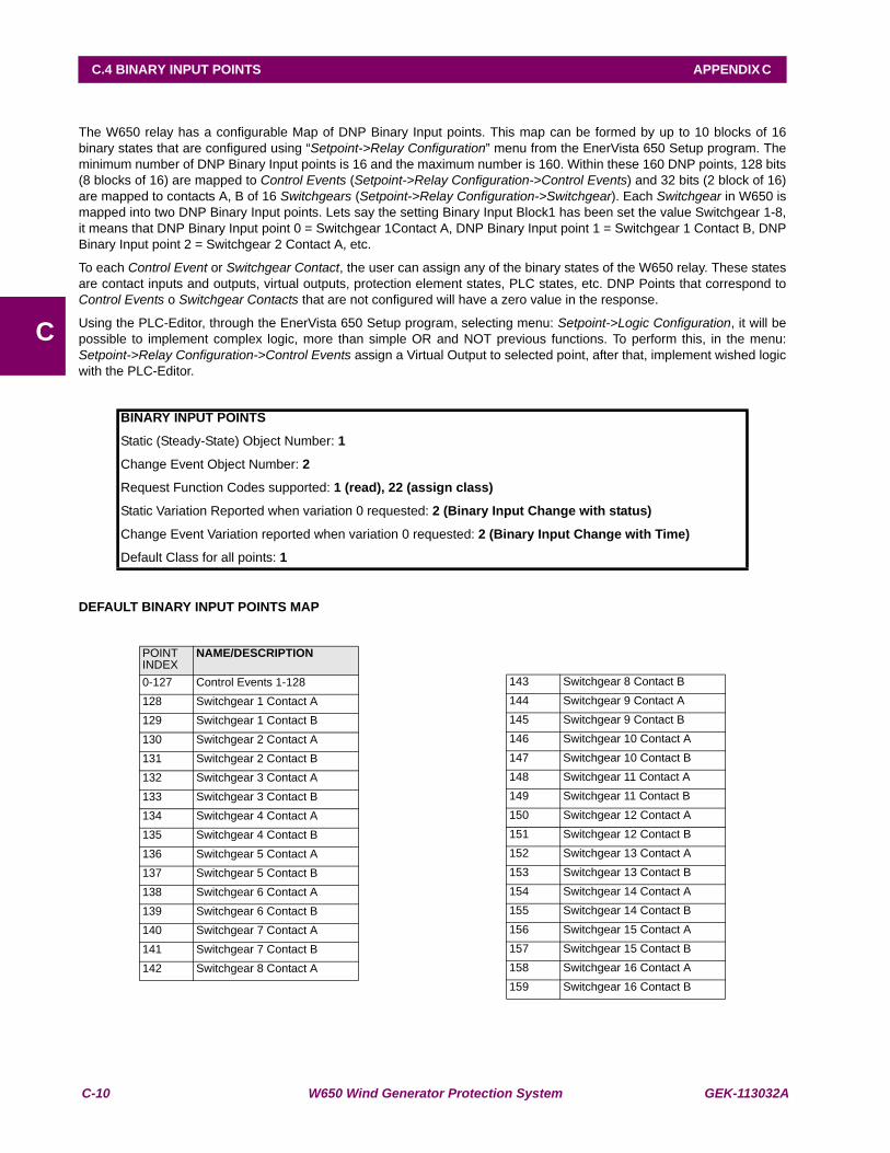
C-10 W650 Wind Generator Protection System GEK-113032A
C.4 BINARY INPUT POINTS APPENDIX C
C
C.4BINARY INPUT POINTS
The W650 relay has a configurable Map of DNP Binary Input points. This map can be formed by up to 10 blocks of 16binary states that are configured using “Setpoint->Relay Configuration” menu from the EnerVista 650 Setup program. Theminimum number of DNP Binary Input points is 16 and the maximum number is 160. Within these 160 DNP points, 128 bits(8 blocks of 16) are mapped to Control Events (Setpoint->Relay Configuration->Control Events) and 32 bits (2 block of 16)are mapped to contacts A, B of 16 Switchgears (Setpoint->Relay Configuration->Switchgear). Each Switchgear in W650 ismapped into two DNP Binary Input points. Lets say the setting Binary Input Block1 has been set the value Switchgear 1-8,it means that DNP Binary Input point 0 = Switchgear 1Contact A, DNP Binary Input point 1 = Switchgear 1 Contact B, DNPBinary Input point 2 = Switchgear 2 Contact A, etc.
To each Control Event or Switchgear Contact, the user can assign any of the binary states of the W650 relay. These statesare contact inputs and outputs, virtual outputs, protection element states, PLC states, etc. DNP Points that correspond toControl Events o Switchgear Contacts that are not configured will have a zero value in the response.
Using the PLC-Editor, through the EnerVista 650 Setup program, selecting menu: Setpoint->Logic Configuration, it will bepossible to implement complex logic, more than simple OR and NOT previous functions. To perform this, in the menu:Setpoint->Relay Configuration->Control Events assign a Virtual Output to selected point, after that, implement wished logicwith the PLC-Editor.
DEFAULT BINARY INPUT POINTS MAP
BINARY INPUT POINTS
Static (Steady-State) Object Number: 1
Change Event Object Number: 2
Request Function Codes supported: 1 (read), 22 (assign class)
Static Variation Reported when variation 0 requested: 2 (Binary Input Change with status)
Change Event Variation reported when variation 0 requested: 2 (Binary Input Change with Time)
Default Class for all points: 1
POINT INDEX
NAME/DESCRIPTION
0-127 Control Events 1-128128 Switchgear 1 Contact A129 Switchgear 1 Contact B130 Switchgear 2 Contact A131 Switchgear 2 Contact B132 Switchgear 3 Contact A133 Switchgear 3 Contact B134 Switchgear 4 Contact A135 Switchgear 4 Contact B136 Switchgear 5 Contact A137 Switchgear 5 Contact B138 Switchgear 6 Contact A139 Switchgear 6 Contact B140 Switchgear 7 Contact A141 Switchgear 7 Contact B142 Switchgear 8 Contact A
143 Switchgear 8 Contact B144 Switchgear 9 Contact A145 Switchgear 9 Contact B146 Switchgear 10 Contact A147 Switchgear 10 Contact B148 Switchgear 11 Contact A149 Switchgear 11 Contact B150 Switchgear 12 Contact A151 Switchgear 12 Contact B152 Switchgear 13 Contact A153 Switchgear 13 Contact B154 Switchgear 14 Contact A155 Switchgear 14 Contact B156 Switchgear 15 Contact A157 Switchgear 15 Contact B158 Switchgear 16 Contact A159 Switchgear 16 Contact B

GEK-113032A W650 Wind Generator Protection System C-11
APPENDIX C C.5 DNP CONFIGURATION EXAMPLES
C
C.5DNP CONFIGURATION EXAMPLES C.5.1 CONFIGURING DNP USER MAP
Imagine that a user wants to configure DNP Binary Inputs Map with 8 Contact Inputs, 8 Protection states, 8 ContactOutputs and 2 Switchgears. This configuration can be done in two steps. In first step the user selects “Setpoint->RelayConfiguration” from the EnerVista 650 Setup program and then configures Control Events bits and Switchgear bits. It isshown in figures 9.1 and 9.2. In the second step the user selects “Setpoint->System Setup->Communication settings->DNP” in order to change DNP Binary Input Block settings. The user set values of the first three Binary Input blocks, BinaryInput Block1 = CTL EVENTS 1-16, Binary Input Block2 = CTL EVENTS 17-32, Binary Input Block3 = SWITCHGEAR 1-8. Itis shown in Configuration of Control Events bits
Figure C–1: CONFIGURATION OF CONTROL EVENTS BITS
Figure C–2: CONFIGURATION OF SWITCHGEAR
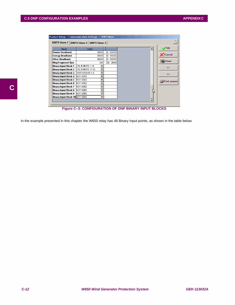
C-12 W650 Wind Generator Protection System GEK-113032A
C.5 DNP CONFIGURATION EXAMPLES APPENDIX C
C
Figure C–3: CONFIGURATION OF DNP BINARY INPUT BLOCKS
In the example presented in this chapter the W650 relay has 48 Binary Input points, as shown in the table below.
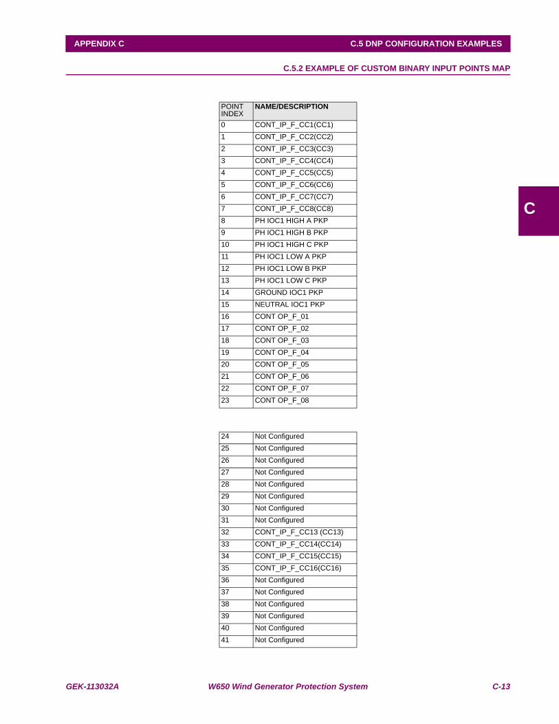
GEK-113032A W650 Wind Generator Protection System C-13
APPENDIX C C.5 DNP CONFIGURATION EXAMPLES
C
C.5.2 EXAMPLE OF CUSTOM BINARY INPUT POINTS MAP
POINT INDEX
NAME/DESCRIPTION
0 CONT_IP_F_CC1(CC1)1 CONT_IP_F_CC2(CC2)2 CONT_IP_F_CC3(CC3)3 CONT_IP_F_CC4(CC4)4 CONT_IP_F_CC5(CC5)5 CONT_IP_F_CC6(CC6)6 CONT_IP_F_CC7(CC7)7 CONT_IP_F_CC8(CC8)8 PH IOC1 HIGH A PKP9 PH IOC1 HIGH B PKP10 PH IOC1 HIGH C PKP11 PH IOC1 LOW A PKP12 PH IOC1 LOW B PKP13 PH IOC1 LOW C PKP14 GROUND IOC1 PKP15 NEUTRAL IOC1 PKP16 CONT OP_F_0117 CONT OP_F_0218 CONT OP_F_0319 CONT OP_F_0420 CONT OP_F_0521 CONT OP_F_0622 CONT OP_F_0723 CONT OP_F_08
24 Not Configured25 Not Configured26 Not Configured27 Not Configured28 Not Configured29 Not Configured30 Not Configured31 Not Configured32 CONT_IP_F_CC13 (CC13)33 CONT_IP_F_CC14(CC14)34 CONT_IP_F_CC15(CC15)35 CONT_IP_F_CC16(CC16)36 Not Configured37 Not Configured38 Not Configured39 Not Configured40 Not Configured41 Not Configured
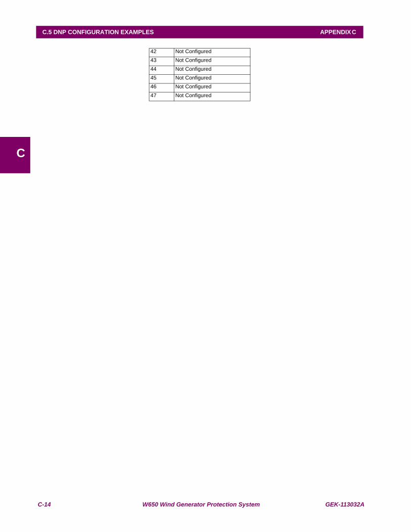
C-14 W650 Wind Generator Protection System GEK-113032A
C.5 DNP CONFIGURATION EXAMPLES APPENDIX C
C
42 Not Configured43 Not Configured44 Not Configured45 Not Configured46 Not Configured47 Not Configured
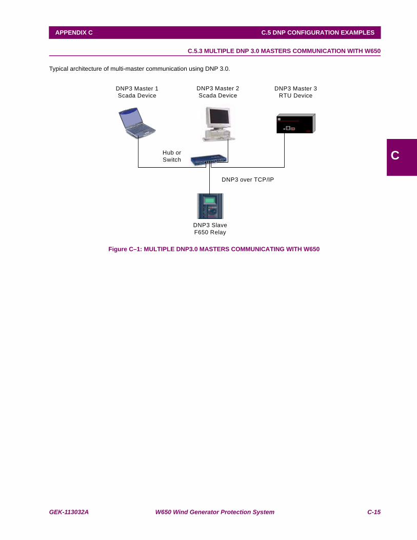
GEK-113032A W650 Wind Generator Protection System C-15
APPENDIX C C.5 DNP CONFIGURATION EXAMPLES
C
C.5.3 MULTIPLE DNP 3.0 MASTERS COMMUNICATION WITH W650
Typical architecture of multi-master communication using DNP 3.0.
Figure C–1: MULTIPLE DNP3.0 MASTERS COMMUNICATING WITH W650
Hub or Switch
DNP3 Master 2Scada Device
DNP3 SlaveF650 Relay
DNP3 over TCP/IP
DNP3 Master 3 RTU Device
DNP3 Master 1 Scada Device
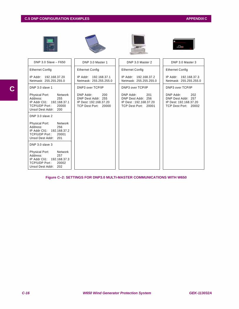
C-16 W650 Wind Generator Protection System GEK-113032A
C.5 DNP CONFIGURATION EXAMPLES APPENDIX C
C
Figure C–2: SETTINGS FOR DNP3.0 MULTI-MASTER COMMUNICATIONS WITH W650
DNP 3.0 Slave – F650
Ethernet Config IP Addr: 192.168.37.20 Netmask: 255.255.255.0
DNP 3.0 slave 1 Physical Port: Network Address: 255 IP Addr Cli1: 192.168.37.1 TCP/UDP Port : 20000 Unsol Dest Addr: 200
DNP 3.0 Master 1
Ethernet Config IP Addr: 192.168.37.1 Netmask: 255.255.255.0
DNP3 over TCP/IP DNP Addr: 200 DNP Dest Addr: 255 IP Dest: 192.168.37.20 TCP Dest Port: 20000
DNP 3.0 Master 2
Ethernet Config IP Addr: 192.168.37.2 Netmask: 255.255.255.0
DNP3 over TCP/IP DNP Addr: 201 DNP Dest Addr: 256 IP Dest : 192.168.37.20 TCP Dest Port: 20001
DNP 3.0 Master 3
Ethernet Config IP Addr: 192.168.37.3 Netmask: 255.255.255.0
DNP3 over TCP/IP DNP Addr: 202 DNP Dest Addr: 257 IP Dest: 192.168.37.20 TCP Dest Port: 20002
DNP 3.0 slave 2 Physical Port: Network Address: 256 IP Addr Cli1: 192.168.37.2 TCP/UDP Port : 20001 Unsol Dest Addr: 201
DNP 3.0 slave 3 Physical Port: Network Address: 257 IP Addr Cli1: 192.168.37.3 TCP/UDP Port : 20002 Unsol Dest Addr: 202
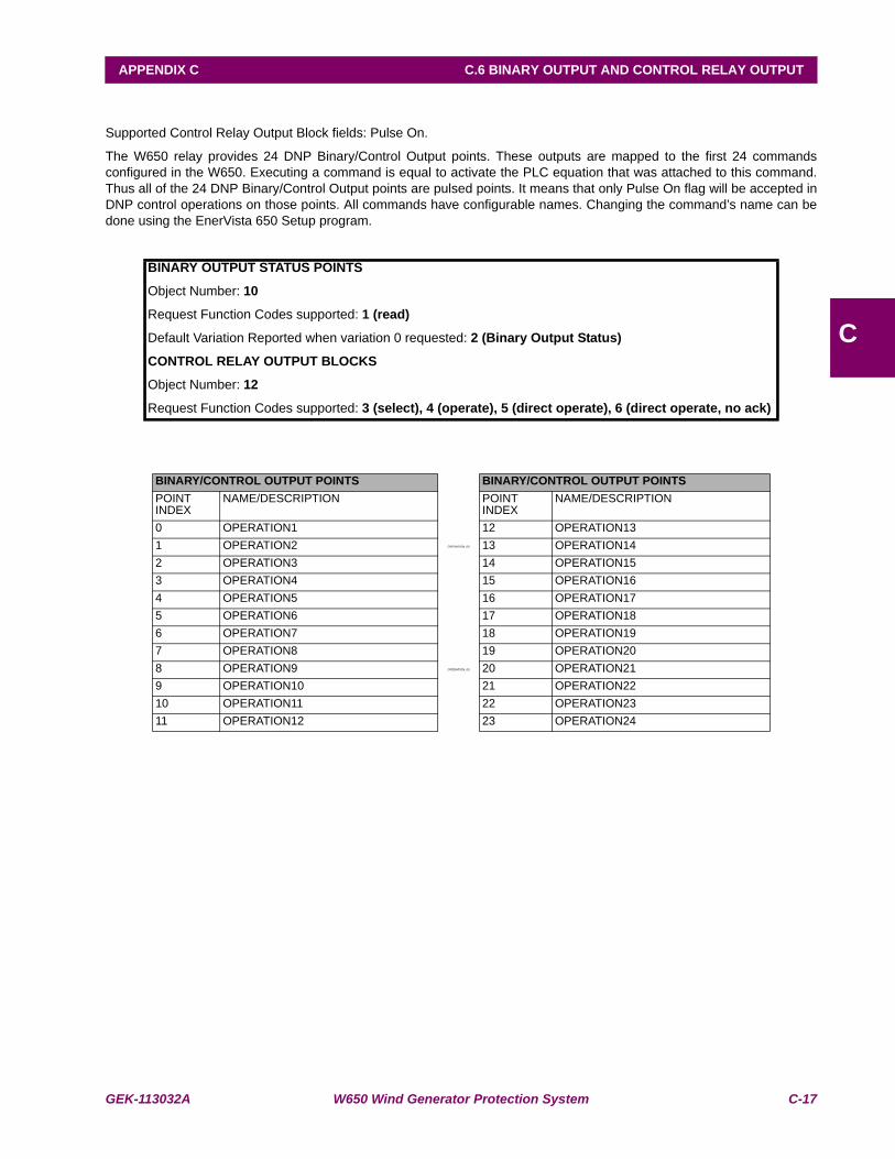
GEK-113032A W650 Wind Generator Protection System C-17
APPENDIX C C.6 BINARY OUTPUT AND CONTROL RELAY OUTPUT
C
C.6BINARY OUTPUT AND CONTROL RELAY OUTPUT
Supported Control Relay Output Block fields: Pulse On.
The W650 relay provides 24 DNP Binary/Control Output points. These outputs are mapped to the first 24 commandsconfigured in the W650. Executing a command is equal to activate the PLC equation that was attached to this command.Thus all of the 24 DNP Binary/Control Output points are pulsed points. It means that only Pulse On flag will be accepted inDNP control operations on those points. All commands have configurable names. Changing the command’s name can bedone using the EnerVista 650 Setup program.
BINARY OUTPUT STATUS POINTS
Object Number: 10
Request Function Codes supported: 1 (read)
Default Variation Reported when variation 0 requested: 2 (Binary Output Status)
CONTROL RELAY OUTPUT BLOCKS
Object Number: 12
Request Function Codes supported: 3 (select), 4 (operate), 5 (direct operate), 6 (direct operate, no ack)
BINARY/CONTROL OUTPUT POINTS BINARY/CONTROL OUTPUT POINTS POINT INDEX
NAME/DESCRIPTION POINT INDEX
NAME/DESCRIPTION
0 OPERATION1 12 OPERATION131 OPERATION2 OPERATION_00 13 OPERATION142 OPERATION3 14 OPERATION153 OPERATION4 15 OPERATION164 OPERATION5 16 OPERATION175 OPERATION6 17 OPERATION186 OPERATION7 18 OPERATION197 OPERATION8 19 OPERATION208 OPERATION9 OPERATION_00 20 OPERATION219 OPERATION10 21 OPERATION2210 OPERATION11 22 OPERATION2311 OPERATION12 23 OPERATION24

C-18 W650 Wind Generator Protection System GEK-113032A
C.7 BINARY COUNTERS APPENDIX C
C
C.7BINARY COUNTERS
Currently there are no Binary Counters in the W650 relay. Nevertheless W650 accepts requests of DNP objects 20 (BinaryCounters), 21 (Frozen Counters) and 22 (Counter Change Events). Function codes “Immediate Freeze”, “Freeze andClear” etc. are accepted and W650 will respond with no objects and the IIN2-1 (Object Unknown) flag set. This behavior isin conformance with DNP Level 2 Implementation (Document 28528: Level 2 DNP 3.00 Implementation).

GEK-113032A W650 Wind Generator Protection System C-19
APPENDIX C C.8 ANALOG INPUTS
C
C.8ANALOG INPUTSIt is important to note that 16-bit and 32-bit variations of Analog Inputs are transmitted through DNPas signed numbers. Even for analog input points that are not valid as negative values, the maximum positive representationis 32767. This is a DNP requirement.
The deadbands for all Analog Input points are in the same units as the Analog Input quantity. For example, an Analog Inputquantity measured in volts has a corresponding deadband in units of volts. This is in conformance with DNP TechnicalBulletin 9809-001 Analog Input Reporting Deadband. The scale factors apply also to deadbands. For example if CurrentScale Factor is set to 0.001, and it is desired that a specific Analog Input point (that is of type current) trigger an event whenits value changes by 1 kA, then the deadband for this point should be set to 1000. Relay settings are available to set defaultdeadband values according to data type. Deadbands for individual Analog Input Points can be set using DNP Object 34.
Units for Analog Input points are as follows:
Current: kA Apparent Power: MVA
Voltage: kV Energy: MWh, Mvarh
Real Power: MW Frequency: Hz
Reactive Power: Mvar Angle: degrees
ANALOG INPUT POINTS
Static (Steady-State) Object Number: 30
Change Event Object Number: 32
Request Function Codes supported: 1 (read), 2 (write, deadbands only), 22 (assign class)
Static Variation Reported when variation 0 requested: 1 (32-Bit Analog Input)
Change Event Variation reported when variation 0 requested: 1 (Analog Change event without Time)
Change Event Scan Rate: defaults to 500ms.
Default Class for all points: 1
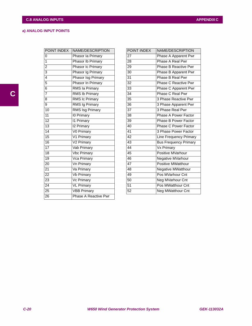
C-20 W650 Wind Generator Protection System GEK-113032A
C.8 ANALOG INPUTS APPENDIX C
C
a) ANALOG INPUT POINTS
POINT INDEX NAME/DESCRIPTION POINT INDEX NAME/DESCRIPTION0 Phasor Ia Primary 27 Phase A Apparent Pwr1 Phasor Ib Primary 28 Phase A Real Pwr2 Phasor Ic Primary 29 Phase B Reactive Pwr3 Phasor Ig Primary 30 Phase B Apparent Pwr4 Phasor Isg Primary 31 Phase B Real Pwr5 Phasor In Primary 32 Phase C Reactive Pwr6 RMS Ia Primary 33 Phase C Apparent Pwr7 RMS Ib Primary 34 Phase C Real Pwr8 RMS Ic Primary 35 3 Phase Reactive Pwr9 RMS Ig Primary 36 3 Phase Apparent Pwr10 RMS Isg Primary 37 3 Phase Real Pwr11 I0 Primary 38 Phase A Power Factor12 I1 Primary 39 Phase B Power Factor13 I2 Primary 40 Phase C Power Factor14 V0 Primary 41 3 Phase Power Factor15 V1 Primary 42 Line Frequency Primary16 V2 Primary 43 Bus Frequency Primary17 Vab Primary 44 Vx Primary18 Vbc Primary 45 Positive MVarhour19 Vca Primary 46 Negative MVarhour20 Vn Primary 47 Positive MWatthour21 Va Primary 48 Negative MWatthour22 Vb Primary 49 Pos MVarhour Cnt23 Vc Primary 50 Neg MVarhour Cnt24 VL Primary 51 Pos MWatthour Cnt25 VBB Primary 52 Neg MWatthour Cnt26 Phase A Reactive Pwr

GEK-113032A W650 Wind Generator Protection System D-1
APPENDIX D D.1 INTRODUCTION
D
APPENDIX D IEC 60870-5-104 PROTOCOLD.1INTRODUCTION
The W650 is an IEC server. Answers to clients request or can send spontaneous Transmission. W650 implementation of60870-5-104 provides analog meterings and states.

D-2 W650 Wind Generator Protection System GEK-113032A
D.2 TECHNICAL DESCRIPTION APPENDIX D
D
D.2TECHNICAL DESCRIPTION
ASDU is the information unit used for data transmission. An ASDU may have data inside or not. The ASDU is encapsulatedin another package of the link layer. ASDU address takes up 2 bytes.
Communication frames can be control or data frames. Control strings do not have ASDU inside.
A frame is consist on 3 parts. (2 of them are not always present):
Link data + [ASDU header+ [ASDU data]]
The data between brackets can be omitted
In IEC104 communication is made by TCP/IP protocols. Actually, it is a TCP communication. The default port is the 2404.The W650 is listening as a server. Only one client is attended at time.
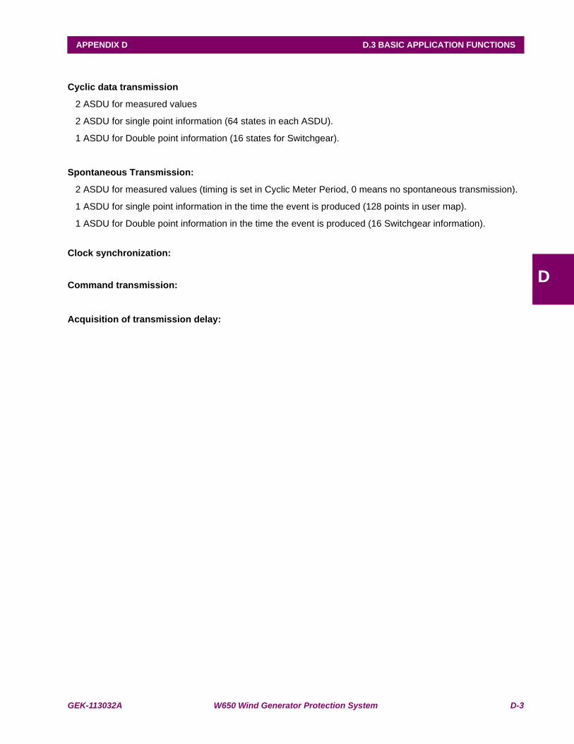
GEK-113032A W650 Wind Generator Protection System D-3
APPENDIX D D.3 BASIC APPLICATION FUNCTIONS
D
D.3BASIC APPLICATION FUNCTIONS
Cyclic data transmission
2 ASDU for measured values
2 ASDU for single point information (64 states in each ASDU).
1 ASDU for Double point information (16 states for Switchgear).
Spontaneous Transmission:
2 ASDU for measured values (timing is set in Cyclic Meter Period, 0 means no spontaneous transmission).
1 ASDU for single point information in the time the event is produced (128 points in user map).
1 ASDU for Double point information in the time the event is produced (16 Switchgear information).
Clock synchronization:
Command transmission:
Acquisition of transmission delay:
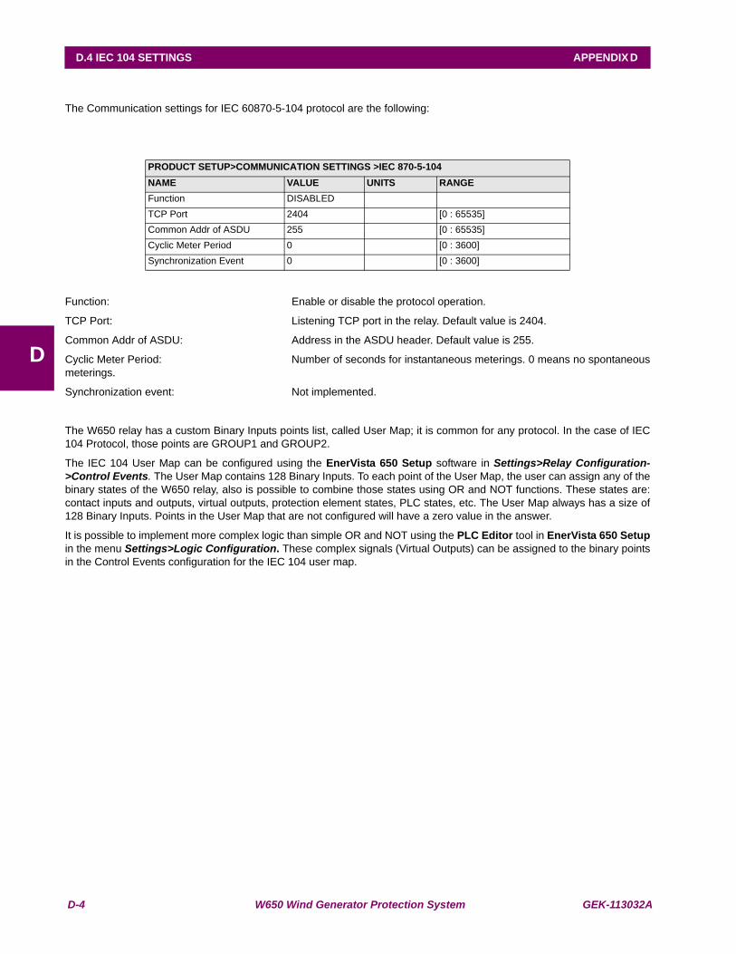
D-4 W650 Wind Generator Protection System GEK-113032A
D.4 IEC 104 SETTINGS APPENDIX D
D
D.4IEC 104 SETTINGSThe Communication settings for IEC 60870-5-104 protocol are the following:
Function: Enable or disable the protocol operation.
TCP Port: Listening TCP port in the relay. Default value is 2404.
Common Addr of ASDU: Address in the ASDU header. Default value is 255.
Cyclic Meter Period: Number of seconds for instantaneous meterings. 0 means no spontaneousmeterings.
Synchronization event: Not implemented.
The W650 relay has a custom Binary Inputs points list, called User Map; it is common for any protocol. In the case of IEC104 Protocol, those points are GROUP1 and GROUP2.
The IEC 104 User Map can be configured using the EnerVista 650 Setup software in Settings>Relay Configuration->Control Events. The User Map contains 128 Binary Inputs. To each point of the User Map, the user can assign any of thebinary states of the W650 relay, also is possible to combine those states using OR and NOT functions. These states are:contact inputs and outputs, virtual outputs, protection element states, PLC states, etc. The User Map always has a size of128 Binary Inputs. Points in the User Map that are not configured will have a zero value in the answer.
It is possible to implement more complex logic than simple OR and NOT using the PLC Editor tool in EnerVista 650 Setupin the menu Settings>Logic Configuration. These complex signals (Virtual Outputs) can be assigned to the binary pointsin the Control Events configuration for the IEC 104 user map.
PRODUCT SETUP>COMMUNICATION SETTINGS >IEC 870-5-104NAME VALUE UNITS RANGEFunction DISABLEDTCP Port 2404 [0 : 65535]Common Addr of ASDU 255 [0 : 65535]Cyclic Meter Period 0 [0 : 3600]Synchronization Event 0 [0 : 3600]
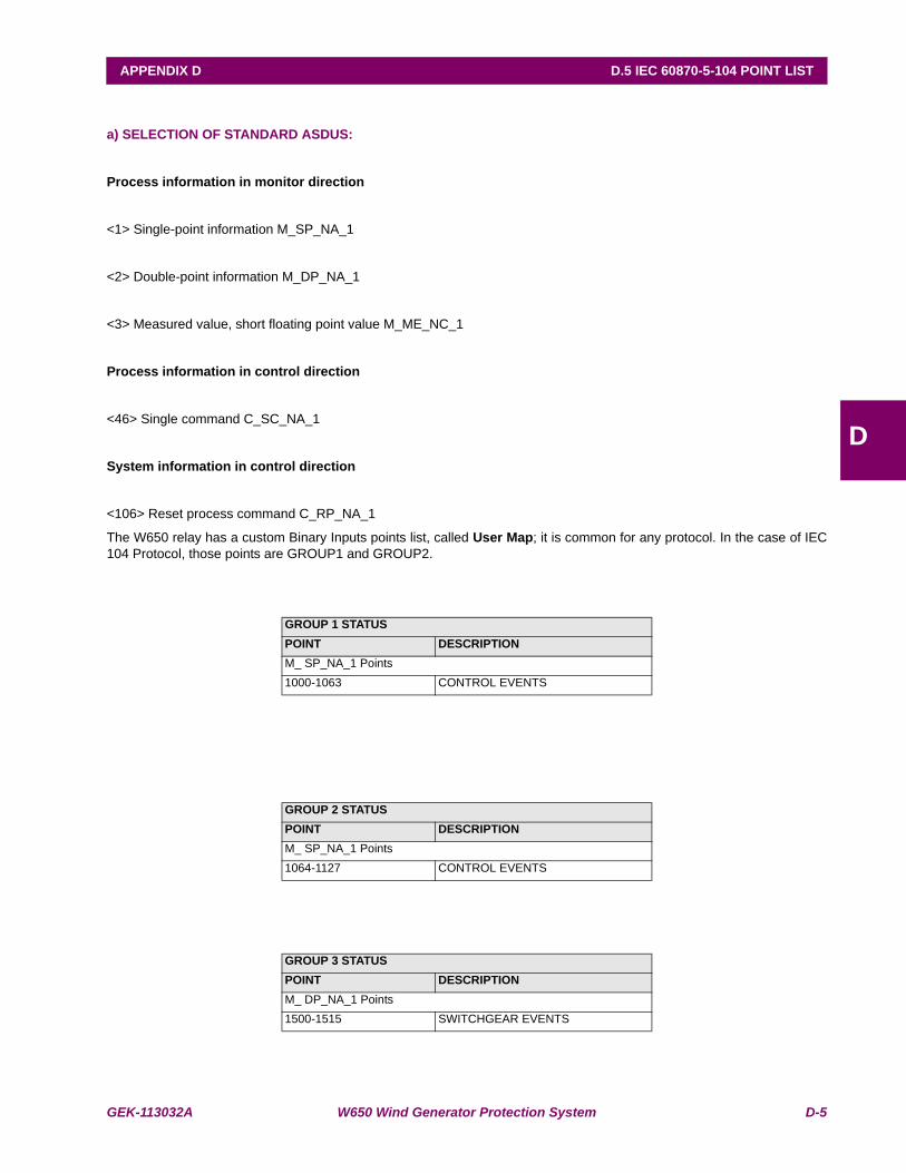
GEK-113032A W650 Wind Generator Protection System D-5
APPENDIX D D.5 IEC 60870-5-104 POINT LIST
D
D.5IEC 60870-5-104 POINT LIST
a) SELECTION OF STANDARD ASDUS:
Process information in monitor direction
<1> Single-point information M_SP_NA_1
<2> Double-point information M_DP_NA_1
<3> Measured value, short floating point value M_ME_NC_1
Process information in control direction
<46> Single command C_SC_NA_1
System information in control direction
<106> Reset process command C_RP_NA_1
The W650 relay has a custom Binary Inputs points list, called User Map; it is common for any protocol. In the case of IEC104 Protocol, those points are GROUP1 and GROUP2.
GROUP 1 STATUSPOINT DESCRIPTIONM_ SP_NA_1 Points1000-1063 CONTROL EVENTS
GROUP 2 STATUSPOINT DESCRIPTIONM_ SP_NA_1 Points1064-1127 CONTROL EVENTS
GROUP 3 STATUSPOINT DESCRIPTIONM_ DP_NA_1 Points1500-1515 SWITCHGEAR EVENTS
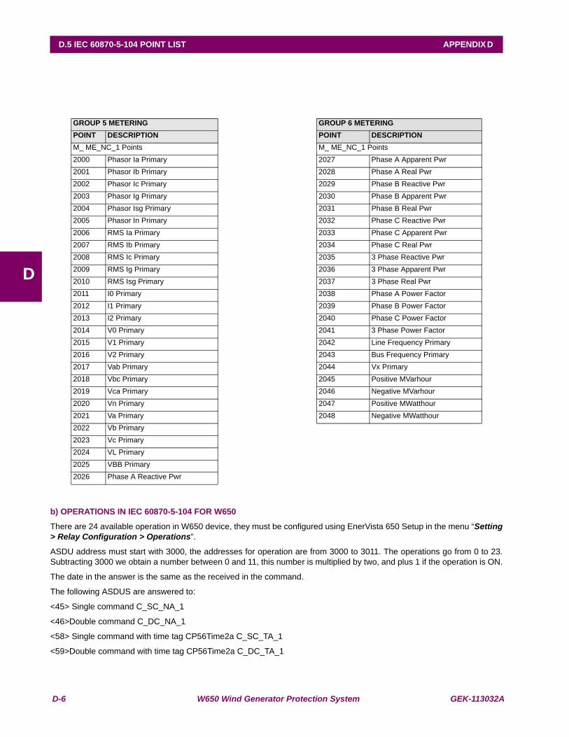
D-6 W650 Wind Generator Protection System GEK-113032A
D.5 IEC 60870-5-104 POINT LIST APPENDIX D
D
b) OPERATIONS IN IEC 60870-5-104 FOR W650
There are 24 available operation in W650 device, they must be configured using EnerVista 650 Setup in the menu “Setting> Relay Configuration > Operations”.
ASDU address must start with 3000, the addresses for operation are from 3000 to 3011. The operations go from 0 to 23.Subtracting 3000 we obtain a number between 0 and 11, this number is multiplied by two, and plus 1 if the operation is ON.
The date in the answer is the same as the received in the command.
The following ASDUS are answered to:
<45> Single command C_SC_NA_1
<46>Double command C_DC_NA_1
<58> Single command with time tag CP56Time2a C_SC_TA_1
<59>Double command with time tag CP56Time2a C_DC_TA_1
GROUP 5 METERING GROUP 6 METERINGPOINT DESCRIPTION POINT DESCRIPTIONM_ ME_NC_1 Points M_ ME_NC_1 Points2000 Phasor Ia Primary 2027 Phase A Apparent Pwr2001 Phasor Ib Primary 2028 Phase A Real Pwr2002 Phasor Ic Primary 2029 Phase B Reactive Pwr2003 Phasor Ig Primary 2030 Phase B Apparent Pwr2004 Phasor Isg Primary 2031 Phase B Real Pwr2005 Phasor In Primary 2032 Phase C Reactive Pwr2006 RMS Ia Primary 2033 Phase C Apparent Pwr2007 RMS Ib Primary 2034 Phase C Real Pwr2008 RMS Ic Primary 2035 3 Phase Reactive Pwr2009 RMS Ig Primary 2036 3 Phase Apparent Pwr2010 RMS Isg Primary 2037 3 Phase Real Pwr2011 I0 Primary 2038 Phase A Power Factor2012 I1 Primary 2039 Phase B Power Factor2013 I2 Primary 2040 Phase C Power Factor2014 V0 Primary 2041 3 Phase Power Factor2015 V1 Primary 2042 Line Frequency Primary2016 V2 Primary 2043 Bus Frequency Primary2017 Vab Primary 2044 Vx Primary2018 Vbc Primary 2045 Positive MVarhour2019 Vca Primary 2046 Negative MVarhour2020 Vn Primary 2047 Positive MWatthour2021 Va Primary 2048 Negative MWatthour2022 Vb Primary2023 Vc Primary2024 VL Primary2025 VBB Primary2026 Phase A Reactive Pwr
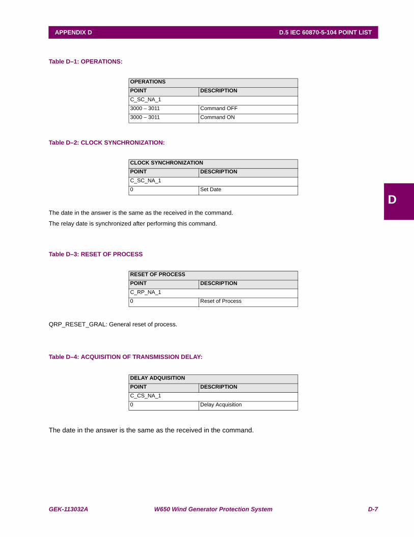
GEK-113032A W650 Wind Generator Protection System D-7
APPENDIX D D.5 IEC 60870-5-104 POINT LIST
D
Table D–1: OPERATIONS:
Table D–2: CLOCK SYNCHRONIZATION:
The date in the answer is the same as the received in the command.
The relay date is synchronized after performing this command.
Table D–3: RESET OF PROCESS
QRP_RESET_GRAL: General reset of process.
Table D–4: ACQUISITION OF TRANSMISSION DELAY:
The date in the answer is the same as the received in the command.
OPERATIONSPOINT DESCRIPTIONC_SC_NA_13000 – 3011 Command OFF3000 – 3011 Command ON
CLOCK SYNCHRONIZATIONPOINT DESCRIPTIONC_SC_NA_10 Set Date
RESET OF PROCESSPOINT DESCRIPTIONC_RP_NA_10 Reset of Process
DELAY ADQUISITIONPOINT DESCRIPTIONC_CS_NA_10 Delay Acquisition

D-8 W650 Wind Generator Protection System GEK-113032A
D.5 IEC 60870-5-104 POINT LIST APPENDIX D
D
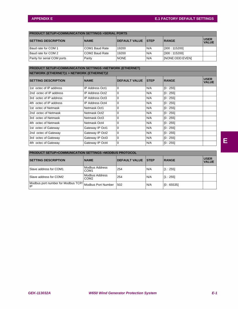
GEK-113032A W650 Wind Generator Protection System E-1
APPENDIX E E.1 FACTORY DEFAULT SETTINGS
E
APPENDIX E FACTORY DEFAULT CONFIGURATIONE.1 FACTORY DEFAULT SETTINGSPRODUCT SETUP>COMMUNICATION SETTINGS >SERIAL PORTS
SETTING DESCRIPTION NAME DEFAULT VALUE STEP RANGE USER VALUE
Baud rate for COM 1 COM1 Baud Rate 19200 N/A [300 : 115200]Baud rate for COM 2 COM2 Baud Rate 19200 N/A [300 : 115200]Parity for serial COM ports Parity NONE N/A [NONE:ODD:EVEN]
PRODUCT SETUP>COMMUNICATION SETTINGS >NETWORK (ETHERNET)NETWORK (ETHERNET)1 > NETWORK (ETHERNET)2
SETTING DESCRIPTION NAME DEFAULT VALUE STEP RANGE USER VALUE
1st octec of IP address IP Address Oct1 0 N/A [0 : 255]2nd octec of IP address IP Address Oct2 0 N/A [0 : 255]3rd octec of IP address IP Address Oct3 0 N/A [0 : 255]4th octec of IP address IP Address Oct4 0 N/A [0 : 255]1st octec of Netmask Netmask Oct1 0 N/A [0 : 255]2nd octec of Netmask Netmask Oct2 0 N/A [0 : 255]3rd octec of Netmask Netmask Oct3 0 N/A [0 : 255]4th octec of Netmask Netmask Oct4 0 N/A [0 : 255]1st octec of Gateway Gateway IP Oct1 0 N/A [0 : 255]2nd octec of Gateway Gateway IP Oct2 0 N/A [0 : 255]3rd octec of Gateway Gateway IP Oct3 0 N/A [0 : 255]4th octec of Gateway Gateway IP Oct4 0 N/A [0 : 255]
PRODUCT SETUP>COMMUNICATION SETTINGS >MODBUS PROTOCOL
SETTING DESCRIPTION NAME DEFAULT VALUE STEP RANGE USER VALUE
Slave address for COM1 Modbus Address COM1 254 N/A [1 : 255]
Slave address for COM2 Modbus Address COM2 254 N/A [1 : 255]
Modbus port number for Modbus TCP/IP Modbus Port Number 502 N/A [0 : 65535]
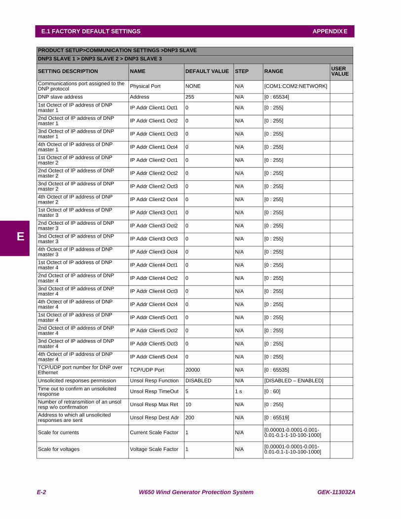
E-2 W650 Wind Generator Protection System GEK-113032A
E.1 FACTORY DEFAULT SETTINGS APPENDIX E
E
PRODUCT SETUP>COMMUNICATION SETTINGS >DNP3 SLAVEDNP3 SLAVE 1 > DNP3 SLAVE 2 > DNP3 SLAVE 3
SETTING DESCRIPTION NAME DEFAULT VALUE STEP RANGE USER VALUE
Communications port assigned to the DNP protocol Physical Port NONE N/A [COM1:COM2:NETWORK]
DNP slave address Address 255 N/A [0 : 65534]1st Octect of IP address of DNP master 1 IP Addr Client1 Oct1 0 N/A [0 : 255]
2nd Octect of IP address of DNP master 1 IP Addr Client1 Oct2 0 N/A [0 : 255]
3nd Octect of IP address of DNP master 1 IP Addr Client1 Oct3 0 N/A [0 : 255]
4th Octect of IP address of DNP master 1 IP Addr Client1 Oct4 0 N/A [0 : 255]
1st Octect of IP address of DNP master 2 IP Addr Client2 Oct1 0 N/A [0 : 255]
2nd Octect of IP address of DNP master 2 IP Addr Client2 Oct2 0 N/A [0 : 255]
3nd Octect of IP address of DNP master 2 IP Addr Client2 Oct3 0 N/A [0 : 255]
4th Octect of IP address of DNP master 2 IP Addr Client2 Oct4 0 N/A [0 : 255]
1st Octect of IP address of DNP master 3 IP Addr Client3 Oct1 0 N/A [0 : 255]
2nd Octect of IP address of DNP master 3 IP Addr Client3 Oct2 0 N/A [0 : 255]
3nd Octect of IP address of DNP master 3 IP Addr Client3 Oct3 0 N/A [0 : 255]
4th Octect of IP address of DNP master 3 IP Addr Client3 Oct4 0 N/A [0 : 255]
1st Octect of IP address of DNP master 4 IP Addr Client4 Oct1 0 N/A [0 : 255]
2nd Octect of IP address of DNP master 4 IP Addr Client4 Oct2 0 N/A [0 : 255]
3nd Octect of IP address of DNP master 4 IP Addr Client4 Oct3 0 N/A [0 : 255]
4th Octect of IP address of DNP master 4 IP Addr Client4 Oct4 0 N/A [0 : 255]
1st Octect of IP address of DNP master 4 IP Addr Client5 Oct1 0 N/A [0 : 255]
2nd Octect of IP address of DNP master 4 IP Addr Client5 Oct2 0 N/A [0 : 255]
3nd Octect of IP address of DNP master 4 IP Addr Client5 Oct3 0 N/A [0 : 255]
4th Octect of IP address of DNP master 4 IP Addr Client5 Oct4 0 N/A [0 : 255]
TCP/UDP port number for DNP over Ethernet TCP/UDP Port 20000 N/A [0 : 65535]
Unsolicited responses permission Unsol Resp Function DISABLED N/A [DISABLED – ENABLED]Time out to confirm an unsolicited response Unsol Resp TimeOut 5 1 s [0 : 60]
Number of retransmition of an unsol resp w/o confirmation Unsol Resp Max Ret 10 N/A [0 : 255]
Address to which all unsolicited responses are sent Unsol Resp Dest Adr 200 N/A [0 : 65519]
Scale for currents Current Scale Factor 1 N/A [0.00001-0.0001-0.001-0.01-0.1-1-10-100-1000]
Scale for voltages Voltage Scale Factor 1 N/A [0.00001-0.0001-0.001-0.01-0.1-1-10-100-1000]
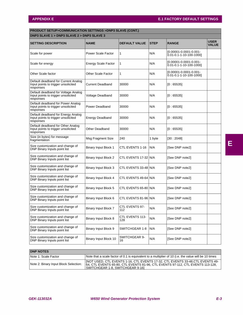
GEK-113032A W650 Wind Generator Protection System E-3
APPENDIX E E.1 FACTORY DEFAULT SETTINGS
E
PRODUCT SETUP>COMMUNICATION SETTINGS >DNP3 SLAVE (CONT.)DNP3 SLAVE 1 > DNP3 SLAVE 2 > DNP3 SLAVE 3
SETTING DESCRIPTION NAME DEFAULT VALUE STEP RANGE USER VALUE
Scale for power Power Scale Factor 1 N/A [0.00001-0.0001-0.001-0.01-0.1-1-10-100-1000]
Scale for energy Energy Scale Factor 1 N/A [0.00001-0.0001-0.001-0.01-0.1-1-10-100-1000]
Other Scale factor Other Scale Factor 1 N/A [0.00001-0.0001-0.001-0.01-0.1-1-10-100-1000]
Default deadband for Current Analog Input points to trigger unsolicited responses
Current Deadband 30000 N/A [0 : 65535]
Default deadband for Voltage Analog Input points to trigger unsolicited responses
Voltage Deadband 30000 N/A [0 : 65535]
Default deadband for Power Analog Input points to trigger unsolicited responses
Power Deadband 30000 N/A [0 : 65535]
Default deadband for Energy Analog Input points to trigger unsolicited responses
Energy Deadband 30000 N/A [0 : 65535]
Default deadband for Other Analog Input points to trigger unsolicited responses
Other Deadband 30000 N/A [0 : 65535]
Size (in bytes) for message fragmentation Msg Fragment Size 240 1 byte [30 : 2048]
Size customization and change of DNP Binary Inputs point list Binary Input Block 1 CTL EVENTS 1-16 N/A [See DNP note2]
Size customization and change of DNP Binary Inputs point list Binary Input Block 2 CTL EVENTS 17-32 N/A [See DNP note2]
Size customization and change of DNP Binary Inputs point list Binary Input Block 3 CTL EVENTS 33-48 N/A [See DNP note2]
Size customization and change of DNP Binary Inputs point list Binary Input Block 4 CTL EVENTS 49-64 N/A [See DNP note2]
Size customization and change of DNP Binary Inputs point list Binary Input Block 5 CTL EVENTS 65-80 N/A [See DNP note2]
Size customization and change of DNP Binary Inputs point list Binary Input Block 6 CTL EVENTS 81-96 N/A [See DNP note2]
Size customization and change of DNP Binary Inputs point list Binary Input Block 7 CTL EVENTS 97-
112 N/A [See DNP note2]
Size customization and change of DNP Binary Inputs point list Binary Input Block 8 CTL EVENTS 113-
128 N/A [See DNP note2]
Size customization and change of DNP Binary Inputs point list Binary Input Block 9 SWITCHGEAR 1-8 N/A [See DNP note2]
Size customization and change of DNP Binary Inputs point list Binary Input Block 10 SWITCHGEAR 9-
16 N/A [See DNP note2]
DNP NOTESNote 1: Scale Factor Note that a scale factor of 0.1 is equivalent to a multiplier of 10 (i.e. the value will be 10 times
Note 2: Binary Input Block Selection:[NOT USED, CTL EVENTS 1-16, CTL EVENTS 17-32, CTL EVENTS 33-48,CTL EVENTS 49-64, CTL EVENTS 65-80, CTL EVENTS 81-96, CTL EVENTS 97-112, CTL EVENTS 113-128, SWITCHGEAR 1-8, SWITCHGEAR 9-16]
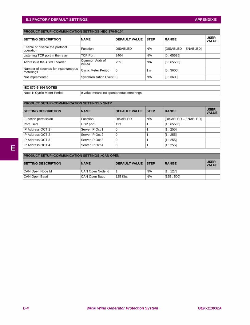
E-4 W650 Wind Generator Protection System GEK-113032A
E.1 FACTORY DEFAULT SETTINGS APPENDIX E
E
PRODUCT SETUP>COMMUNICATION SETTINGS >IEC 870-5-104
SETTING DESCRIPTION NAME DEFAULT VALUE STEP RANGE USER VALUE
Enable or disable the protocol operation Function DISABLED N/A [DISABLED – ENABLED]
Listening TCP port in the relay TCP Port 2404 N/A [0 : 65535]
Address in the ASDU header Common Addr of ASDU 255 N/A [0 : 65535]
Number of seconds for instantaneous meterings Cyclic Meter Period 0 1 s [0 : 3600]
Not implemented Synchronization Event 0 N/A [0 : 3600]
IEC 870-5-104 NOTESNote 1: Cyclic Meter Period 0 value means no spontaneous meterings
PRODUCT SETUP>COMMUNICATION SETTINGS > SNTP
SETTING DESCRIPTION NAME DEFAULT VALUE STEP RANGE USER VALUE
Function permission Function DISABLED N/A [DISABLED – ENABLED]Port used UDP port 123 1 [1 : 65535]IP Address OCT 1 Server IP Oct 1 0 1 [1 : 255]IP Address OCT 2 Server IP Oct 2 0 1 [1 : 255]IP Address OCT 3 Server IP Oct 3 0 1 [1 : 255]IP Address OCT 4 Server IP Oct 4 0 1 [1 : 255]
PRODUCT SETUP>COMMUNICATION SETTINGS >CAN OPEN
SETTING DESCRIPTION NAME DEFAULT VALUE STEP RANGE USER VALUE
CAN Open Node Id CAN Open Node Id 1 N/A [1 : 127]CAN Open Baud CAN Open Baud 125 Kbs N/A [125 : 500]
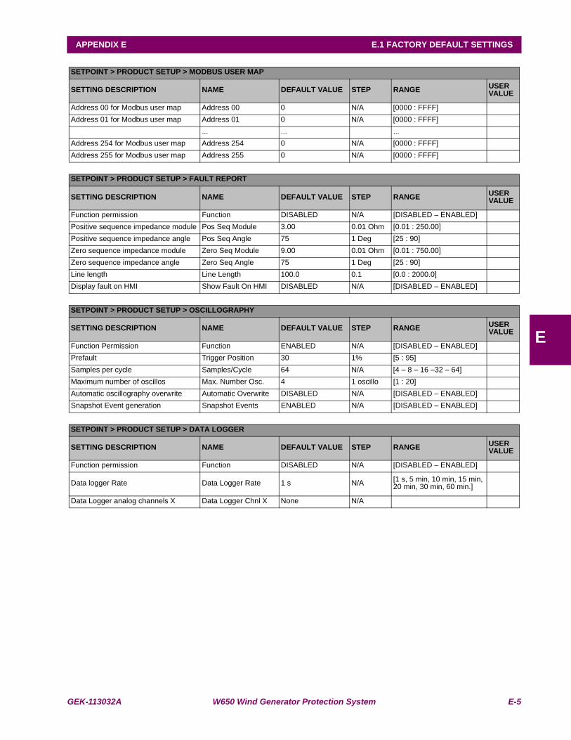
GEK-113032A W650 Wind Generator Protection System E-5
APPENDIX E E.1 FACTORY DEFAULT SETTINGS
E
SETPOINT > PRODUCT SETUP > MODBUS USER MAP
SETTING DESCRIPTION NAME DEFAULT VALUE STEP RANGE USER VALUE
Address 00 for Modbus user map Address 00 0 N/A [0000 : FFFF]Address 01 for Modbus user map Address 01 0 N/A [0000 : FFFF]
... ... ...Address 254 for Modbus user map Address 254 0 N/A [0000 : FFFF]Address 255 for Modbus user map Address 255 0 N/A [0000 : FFFF]
SETPOINT > PRODUCT SETUP > FAULT REPORT
SETTING DESCRIPTION NAME DEFAULT VALUE STEP RANGE USER VALUE
Function permission Function DISABLED N/A [DISABLED – ENABLED]Positive sequence impedance module Pos Seq Module 3.00 0.01 Ohm [0.01 : 250.00]Positive sequence impedance angle Pos Seq Angle 75 1 Deg [25 : 90]Zero sequence impedance module Zero Seq Module 9.00 0.01 Ohm [0.01 : 750.00]Zero sequence impedance angle Zero Seq Angle 75 1 Deg [25 : 90]Line length Line Length 100.0 0.1 [0.0 : 2000.0]Display fault on HMI Show Fault On HMI DISABLED N/A [DISABLED – ENABLED]
SETPOINT > PRODUCT SETUP > OSCILLOGRAPHY
SETTING DESCRIPTION NAME DEFAULT VALUE STEP RANGE USER VALUE
Function Permission Function ENABLED N/A [DISABLED – ENABLED]Prefault Trigger Position 30 1% [5 : 95]Samples per cycle Samples/Cycle 64 N/A [4 – 8 – 16 –32 – 64]Maximum number of oscillos Max. Number Osc. 4 1 oscillo [1 : 20]Automatic oscillography overwrite Automatic Overwrite DISABLED N/A [DISABLED – ENABLED]Snapshot Event generation Snapshot Events ENABLED N/A [DISABLED – ENABLED]
SETPOINT > PRODUCT SETUP > DATA LOGGER
SETTING DESCRIPTION NAME DEFAULT VALUE STEP RANGE USER VALUE
Function permission Function DISABLED N/A [DISABLED – ENABLED]
Data logger Rate Data Logger Rate 1 s N/A [1 s, 5 min, 10 min, 15 min, 20 min, 30 min, 60 min.]
Data Logger analog channels X Data Logger Chnl X None N/A
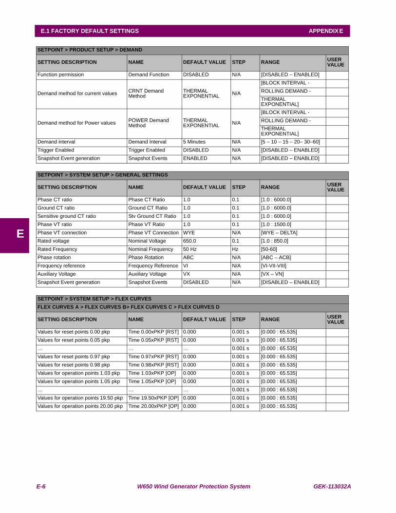
E-6 W650 Wind Generator Protection System GEK-113032A
E.1 FACTORY DEFAULT SETTINGS APPENDIX E
E
SETPOINT > PRODUCT SETUP > DEMAND
SETTING DESCRIPTION NAME DEFAULT VALUE STEP RANGE USER VALUE
Function permission Demand Function DISABLED N/A [DISABLED – ENABLED]
Demand method for current values CRNT Demand Method
THERMAL EXPONENTIAL N/A
[BLOCK INTERVAL -ROLLING DEMAND -THERMAL EXPONENTIAL]
Demand method for Power values POWER Demand Method
THERMAL EXPONENTIAL N/A
[BLOCK INTERVAL -ROLLING DEMAND -THERMAL EXPONENTIAL]
Demand interval Demand Interval 5 Minutes N/A [5 – 10 – 15 – 20– 30–60]Trigger Enabled Trigger Enabled DISABLED N/A [DISABLED – ENABLED]Snapshot Event generation Snapshot Events ENABLED N/A [DISABLED – ENABLED]
SETPOINT > SYSTEM SETUP > GENERAL SETTINGS
SETTING DESCRIPTION NAME DEFAULT VALUE STEP RANGE USER VALUE
Phase CT ratio Phase CT Ratio 1.0 0.1 [1.0 : 6000.0]Ground CT ratio Ground CT Ratio 1.0 0.1 [1.0 : 6000.0]Sensitive ground CT ratio Stv Ground CT Ratio 1.0 0.1 [1.0 : 6000.0]Phase VT ratio Phase VT Ratio 1.0 0.1 [1.0 : 1500.0]Phase VT connection Phase VT Connection WYE N/A [WYE – DELTA]Rated voltage Nominal Voltage 650.0 0.1 [1.0 : 850.0]Rated Frequency Nominal Frequency 50 Hz Hz [50-60]Phase rotation Phase Rotation ABC N/A [ABC – ACB]Frequency reference Frequency Reference VI N/A [VI-VII-VIII]Auxiliary Voltage Auxiliary Voltage VX N/A [VX – VN]Snapshot Event generation Snapshot Events DISABLED N/A [DISABLED – ENABLED]
SETPOINT > SYSTEM SETUP > FLEX CURVESFLEX CURVES A > FLEX CURVES B> FLEX CURVES C > FLEX CURVES D
SETTING DESCRIPTION NAME DEFAULT VALUE STEP RANGE USER VALUE
Values for reset points 0.00 pkp Time 0.00xPKP [RST] 0.000 0.001 s [0.000 : 65.535]Values for reset points 0.05 pkp Time 0.05xPKP [RST] 0.000 0.001 s [0.000 : 65.535]… … … 0.001 s [0.000 : 65.535]Values for reset points 0.97 pkp Time 0.97xPKP [RST] 0.000 0.001 s [0.000 : 65.535]Values for reset points 0.98 pkp Time 0.98xPKP [RST] 0.000 0.001 s [0.000 : 65.535]Values for operation points 1.03 pkp Time 1.03xPKP [OP] 0.000 0.001 s [0.000 : 65.535]Values for operation points 1.05 pkp Time 1.05xPKP [OP] 0.000 0.001 s [0.000 : 65.535]… … … 0.001 s [0.000 : 65.535]Values for operation points 19.50 pkp Time 19.50xPKP [OP] 0.000 0.001 s [0.000 : 65.535]Values for operation points 20.00 pkp Time 20.00xPKP [OP] 0.000 0.001 s [0.000 : 65.535]
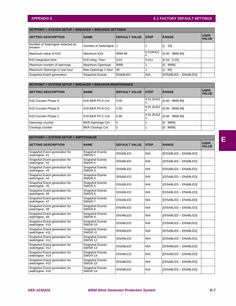
GEK-113032A W650 Wind Generator Protection System E-7
APPENDIX E E.1 FACTORY DEFAULT SETTINGS
E
SETPOINT > SYSTEM SETUP > BREAKER > BREAKER SETTINGS
SETTING DESCRIPTION NAME DEFAULT VALUE STEP RANGE USER VALUE
Number of Switchgear selected as breaker Number of Switchgear 1 1 [1 : 16]
Maximum value of KI2t Maximum KI2t 9999.99 0.01(KA)2 s [0.00 : 9999.99]
KI2t integration time KI2t Integ. Time 0.03 0.01s [0.03 : 0.25]Maximum number of openings Maximum Openings 9999 1 [0 : 9999]Maximum Openings in one hour Max.Openings 1 hour 40 1 [1 : 60]Snapshot Event generation Snapshot Events ENABLED N/A [DISABLED – ENABLED]
SETPOINT > SYSTEM SETUP > BREAKER > BREAKER MAINTENANCE
SETTING DESCRIPTION NAME DEFAULT VALUE STEP RANGE USER VALUE
KI2t Counter Phase A KI2t BKR Ph A Cnt 0.00 0.01 (KA)2 s [0.00 : 9999.99]
KI2t Counter Phase B KI2t BKR Ph B Cnt 0.00 0.01 (KA)2 s [0.00 : 9999.99]
KI2t Counter Phase C KI2t BKR Ph C Cnt 0.00 0.01 (KA)2 s [0.00 : 9999.99]
Openings counter BKR Openings Cnt 0 1 [0 : 9999]Closings counter BKR Closings Cnt 0 1 [0 : 9999]
SETPOINT > SYSTEM SETUP > SWITCHGEAR
SETTING DESCRIPTION NAME DEFAULT VALUE STEP RANGE USER VALUE
Snapshot Event generation for switchgear #1
Snapshot Events SWGR 1 DISABLED N/A [DISABLED – ENABLED]
Snapshot Event generation for switchgear #2
Snapshot Events SWGR 2 DISABLED N/A [DISABLED – ENABLED]
Snapshot Event generation for switchgear #3
Snapshot Events SWGR 3 DISABLED N/A [DISABLED – ENABLED]
Snapshot Event generation for switchgear #4
Snapshot Events SWGR 4 DISABLED N/A [DISABLED – ENABLED]
Snapshot Event generation for switchgear #5
Snapshot Events SWGR 5 DISABLED N/A [DISABLED – ENABLED]
Snapshot Event generation for switchgear #6
Snapshot Events SWGR 6 DISABLED N/A [DISABLED – ENABLED]
Snapshot Event generation for switchgear #7
Snapshot Events SWGR 7 DISABLED N/A [DISABLED – ENABLED]
Snapshot Event generation for switchgear #8
Snapshot Events SWGR 8 DISABLED N/A [DISABLED – ENABLED]
Snapshot Event generation for switchgear #9
Snapshot Events SWGR 9 DISABLED N/A [DISABLED – ENABLED]
Snapshot Event generation for switchgear #10
Snapshot Events SWGR 10 DISABLED N/A [DISABLED – ENABLED]
Snapshot Event generation for switchgear #11
Snapshot Events SWGR 11 DISABLED N/A [DISABLED – ENABLED]
Snapshot Event generation for switchgear #12
Snapshot Events SWGR 12 DISABLED N/A [DISABLED – ENABLED]
Snapshot Event generation for switchgear #13
Snapshot Events SWGR 13 DISABLED N/A [DISABLED – ENABLED]
Snapshot Event generation for switchgear #14
Snapshot Events SWGR 14 DISABLED N/A [DISABLED – ENABLED]
Snapshot Event generation for switchgear #15
Snapshot Events SWGR 15 DISABLED N/A [DISABLED – ENABLED]
Snapshot Event generation for switchgear #16
Snapshot Events SWGR 16 DISABLED N/A [DISABLED – ENABLED]
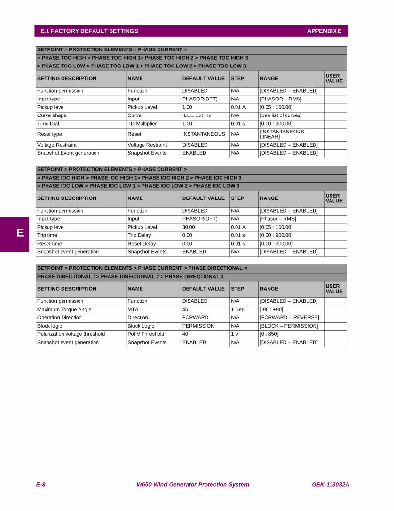
E-8 W650 Wind Generator Protection System GEK-113032A
E.1 FACTORY DEFAULT SETTINGS APPENDIX E
E
SETPOINT > PROTECTION ELEMENTS > PHASE CURRENT >> PHASE TOC HIGH > PHASE TOC HIGH 1> PHASE TOC HIGH 2 > PHASE TOC HIGH 3> PHASE TOC LOW > PHASE TOC LOW 1 > PHASE TOC LOW 2 > PHASE TOC LOW 3
SETTING DESCRIPTION NAME DEFAULT VALUE STEP RANGE USER VALUE
Function permission Function DISABLED N/A [DISABLED – ENABLED]Input type Input PHASOR(DFT) N/A [PHASOR – RMS]Pickup level Pickup Level 1.00 0.01 A [0.05 : 160.00]Curve shape Curve IEEE Ext Inv N/A [See list of curves]Time Dial TD Multiplier 1.00 0.01 s [0.00 : 900.00]
Reset type Reset INSTANTANEOUS N/A [INSTANTANEOUS – LINEAR]
Voltage Restraint Voltage Restraint DISABLED N/A [DISABLED – ENABLED]Snapshot Event generation Snapshot Events ENABLED N/A [DISABLED – ENABLED]
SETPOINT > PROTECTION ELEMENTS > PHASE CURRENT >> PHASE IOC HIGH > PHASE IOC HIGH 1> PHASE IOC HIGH 2 > PHASE IOC HIGH 3> PHASE IOC LOW > PHASE IOC LOW 1 > PHASE IOC LOW 2 > PHASE IOC LOW 3
SETTING DESCRIPTION NAME DEFAULT VALUE STEP RANGE USER VALUE
Function permission Function DISABLED N/A [DISABLED – ENABLED]Input type Input PHASOR(DFT) N/A [Phasor – RMS]Pickup level Pickup Level 30.00 0.01 A [0.05 : 160.00]Trip time Trip Delay 0.00 0.01 s [0.00 : 900.00]Reset time Reset Delay 0.00 0.01 s [0.00 : 900.00]Snapshot event generation Snapshot Events ENABLED N/A [DISABLED – ENABLED]
SETPOINT > PROTECTION ELEMENTS > PHASE CURRENT > PHASE DIRECTIONAL >PHASE DIRECTIONAL 1> PHASE DIRECTIONAL 2 > PHASE DIRECTIONAL 3
SETTING DESCRIPTION NAME DEFAULT VALUE STEP RANGE USER VALUE
Function permission Function DISABLED N/A [DISABLED – ENABLED]Maximum Torque Angle MTA 45 1 Deg [-90 : +90]Operation Direction Direction FORWARD N/A [FORWARD – REVERSE]Block logic Block Logic PERMISSION N/A [BLOCK – PERMISSION]Polarization voltage threshold Pol V Threshold 40 1 V [0 : 850]Snapshot event generation Snapshot Events ENABLED N/A [DISABLED – ENABLED]
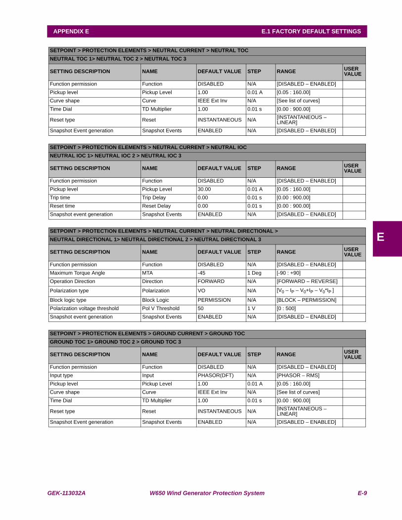
GEK-113032A W650 Wind Generator Protection System E-9
APPENDIX E E.1 FACTORY DEFAULT SETTINGS
E
SETPOINT > PROTECTION ELEMENTS > NEUTRAL CURRENT > NEUTRAL TOCNEUTRAL TOC 1> NEUTRAL TOC 2 > NEUTRAL TOC 3
SETTING DESCRIPTION NAME DEFAULT VALUE STEP RANGE USER VALUE
Function permission Function DISABLED N/A [DISABLED – ENABLED]Pickup level Pickup Level 1.00 0.01 A [0.05 : 160.00]Curve shape Curve IEEE Ext Inv N/A [See list of curves]Time Dial TD Multiplier 1.00 0.01 s [0.00 : 900.00]
Reset type Reset INSTANTANEOUS N/A [INSTANTANEOUS – LINEAR]
Snapshot Event generation Snapshot Events ENABLED N/A [DISABLED – ENABLED]
SETPOINT > PROTECTION ELEMENTS > NEUTRAL CURRENT > NEUTRAL IOCNEUTRAL IOC 1> NEUTRAL IOC 2 > NEUTRAL IOC 3
SETTING DESCRIPTION NAME DEFAULT VALUE STEP RANGE USER VALUE
Function permission Function DISABLED N/A [DISABLED – ENABLED]Pickup level Pickup Level 30.00 0.01 A [0.05 : 160.00]Trip time Trip Delay 0.00 0.01 s [0.00 : 900.00]Reset time Reset Delay 0.00 0.01 s [0.00 : 900.00]Snapshot event generation Snapshot Events ENABLED N/A [DISABLED – ENABLED]
SETPOINT > PROTECTION ELEMENTS > NEUTRAL CURRENT > NEUTRAL DIRECTIONAL >NEUTRAL DIRECTIONAL 1> NEUTRAL DIRECTIONAL 2 > NEUTRAL DIRECTIONAL 3
SETTING DESCRIPTION NAME DEFAULT VALUE STEP RANGE USER VALUE
Function permission Function DISABLED N/A [DISABLED – ENABLED]Maximum Torque Angle MTA -45 1 Deg [-90 : +90]Operation Direction Direction FORWARD N/A [FORWARD – REVERSE]
Polarization type Polarization VO N/A [V0 – IP – V0+IP – V0*IP ]
Block logic type Block Logic PERMISSION N/A [BLOCK – PERMISSION]Polarization voltage threshold Pol V Threshold 50 1 V [0 : 500]Snapshot event generation Snapshot Events ENABLED N/A [DISABLED – ENABLED]
SETPOINT > PROTECTION ELEMENTS > GROUND CURRENT > GROUND TOCGROUND TOC 1> GROUND TOC 2 > GROUND TOC 3
SETTING DESCRIPTION NAME DEFAULT VALUE STEP RANGE USER VALUE
Function permission Function DISABLED N/A [DISABLED – ENABLED]Input type Input PHASOR(DFT) N/A [PHASOR – RMS]Pickup level Pickup Level 1.00 0.01 A [0.05 : 160.00]Curve shape Curve IEEE Ext Inv N/A [See list of curves]Time Dial TD Multiplier 1.00 0.01 s [0.00 : 900.00]
Reset type Reset INSTANTANEOUS N/A [INSTANTANEOUS – LINEAR]
Snapshot Event generation Snapshot Events ENABLED N/A [DISABLED – ENABLED]
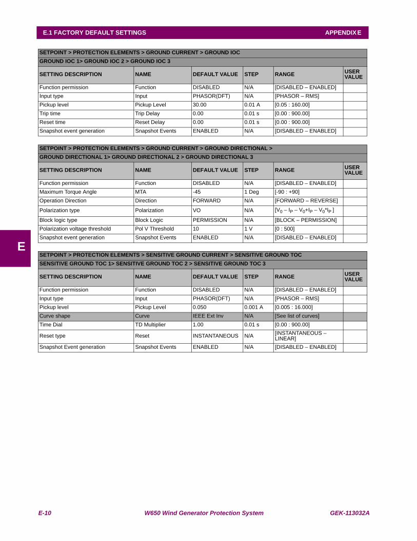
E-10 W650 Wind Generator Protection System GEK-113032A
E.1 FACTORY DEFAULT SETTINGS APPENDIX E
E
SETPOINT > PROTECTION ELEMENTS > GROUND CURRENT > GROUND IOCGROUND IOC 1> GROUND IOC 2 > GROUND IOC 3
SETTING DESCRIPTION NAME DEFAULT VALUE STEP RANGE USER VALUE
Function permission Function DISABLED N/A [DISABLED – ENABLED]Input type Input PHASOR(DFT) N/A [PHASOR – RMS]Pickup level Pickup Level 30.00 0.01 A [0.05 : 160.00]Trip time Trip Delay 0.00 0.01 s [0.00 : 900.00]Reset time Reset Delay 0.00 0.01 s [0.00 : 900.00]Snapshot event generation Snapshot Events ENABLED N/A [DISABLED – ENABLED]
SETPOINT > PROTECTION ELEMENTS > GROUND CURRENT > GROUND DIRECTIONAL >GROUND DIRECTIONAL 1> GROUND DIRECTIONAL 2 > GROUND DIRECTIONAL 3
SETTING DESCRIPTION NAME DEFAULT VALUE STEP RANGE USER VALUE
Function permission Function DISABLED N/A [DISABLED – ENABLED]Maximum Torque Angle MTA -45 1 Deg [-90 : +90]Operation Direction Direction FORWARD N/A [FORWARD – REVERSE]
Polarization type Polarization VO N/A [V0 – IP – V0+IP – V0*IP ]
Block logic type Block Logic PERMISSION N/A [BLOCK – PERMISSION]Polarization voltage threshold Pol V Threshold 10 1 V [0 : 500]Snapshot event generation Snapshot Events ENABLED N/A [DISABLED – ENABLED]
SETPOINT > PROTECTION ELEMENTS > SENSITIVE GROUND CURRENT > SENSITIVE GROUND TOCSENSITIVE GROUND TOC 1> SENSITIVE GROUND TOC 2 > SENSITIVE GROUND TOC 3
SETTING DESCRIPTION NAME DEFAULT VALUE STEP RANGE USER VALUE
Function permission Function DISABLED N/A [DISABLED – ENABLED]Input type Input PHASOR(DFT) N/A [PHASOR – RMS]Pickup level Pickup Level 0.050 0.001 A [0.005 : 16.000]Curve shape Curve IEEE Ext Inv N/A [See list of curves]Time Dial TD Multiplier 1.00 0.01 s [0.00 : 900.00]
Reset type Reset INSTANTANEOUS N/A [INSTANTANEOUS – LINEAR]
Snapshot Event generation Snapshot Events ENABLED N/A [DISABLED – ENABLED]
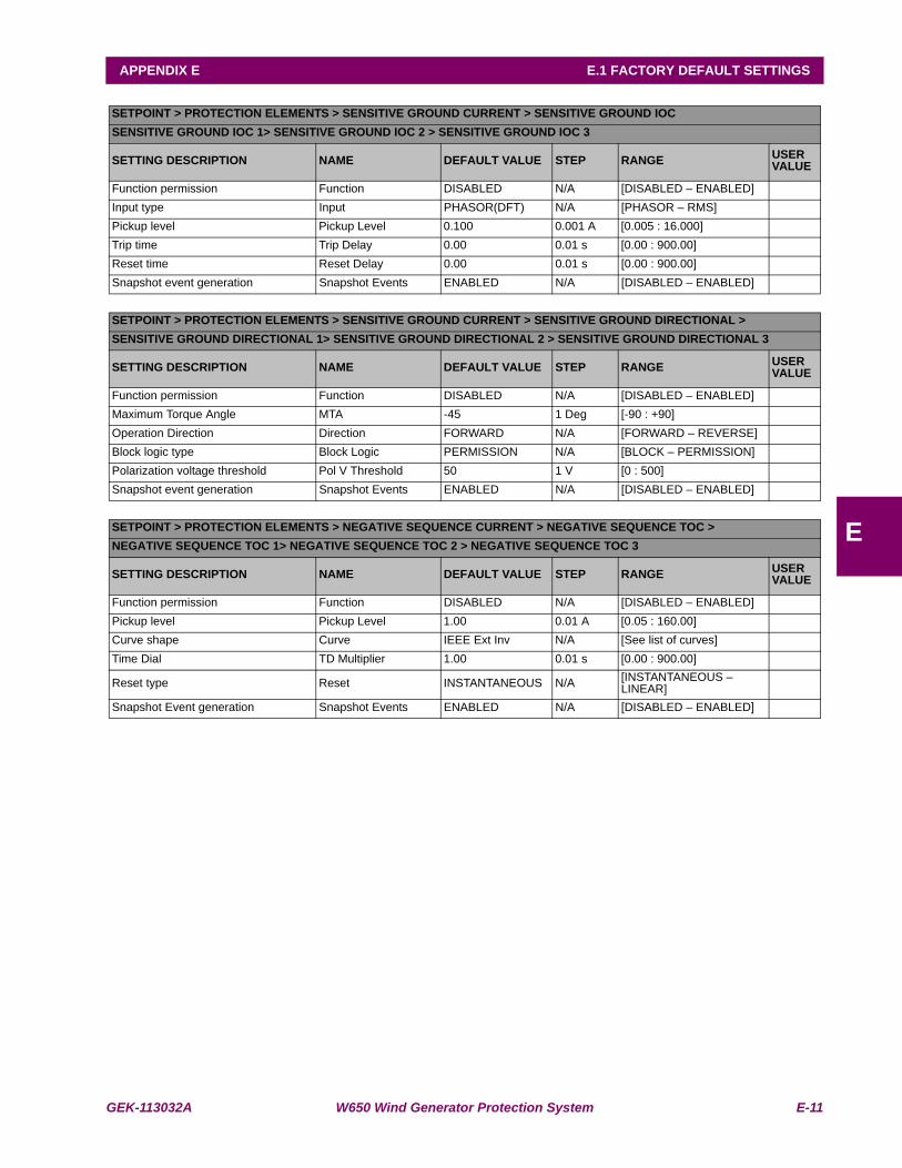
GEK-113032A W650 Wind Generator Protection System E-11
APPENDIX E E.1 FACTORY DEFAULT SETTINGS
E
SETPOINT > PROTECTION ELEMENTS > SENSITIVE GROUND CURRENT > SENSITIVE GROUND IOCSENSITIVE GROUND IOC 1> SENSITIVE GROUND IOC 2 > SENSITIVE GROUND IOC 3
SETTING DESCRIPTION NAME DEFAULT VALUE STEP RANGE USER VALUE
Function permission Function DISABLED N/A [DISABLED – ENABLED]Input type Input PHASOR(DFT) N/A [PHASOR – RMS]Pickup level Pickup Level 0.100 0.001 A [0.005 : 16.000]Trip time Trip Delay 0.00 0.01 s [0.00 : 900.00]Reset time Reset Delay 0.00 0.01 s [0.00 : 900.00]Snapshot event generation Snapshot Events ENABLED N/A [DISABLED – ENABLED]
SETPOINT > PROTECTION ELEMENTS > SENSITIVE GROUND CURRENT > SENSITIVE GROUND DIRECTIONAL >SENSITIVE GROUND DIRECTIONAL 1> SENSITIVE GROUND DIRECTIONAL 2 > SENSITIVE GROUND DIRECTIONAL 3
SETTING DESCRIPTION NAME DEFAULT VALUE STEP RANGE USER VALUE
Function permission Function DISABLED N/A [DISABLED – ENABLED]Maximum Torque Angle MTA -45 1 Deg [-90 : +90]Operation Direction Direction FORWARD N/A [FORWARD – REVERSE]Block logic type Block Logic PERMISSION N/A [BLOCK – PERMISSION]Polarization voltage threshold Pol V Threshold 50 1 V [0 : 500]Snapshot event generation Snapshot Events ENABLED N/A [DISABLED – ENABLED]
SETPOINT > PROTECTION ELEMENTS > NEGATIVE SEQUENCE CURRENT > NEGATIVE SEQUENCE TOC >NEGATIVE SEQUENCE TOC 1> NEGATIVE SEQUENCE TOC 2 > NEGATIVE SEQUENCE TOC 3
SETTING DESCRIPTION NAME DEFAULT VALUE STEP RANGE USER VALUE
Function permission Function DISABLED N/A [DISABLED – ENABLED]Pickup level Pickup Level 1.00 0.01 A [0.05 : 160.00]Curve shape Curve IEEE Ext Inv N/A [See list of curves]Time Dial TD Multiplier 1.00 0.01 s [0.00 : 900.00]
Reset type Reset INSTANTANEOUS N/A [INSTANTANEOUS – LINEAR]
Snapshot Event generation Snapshot Events ENABLED N/A [DISABLED – ENABLED]
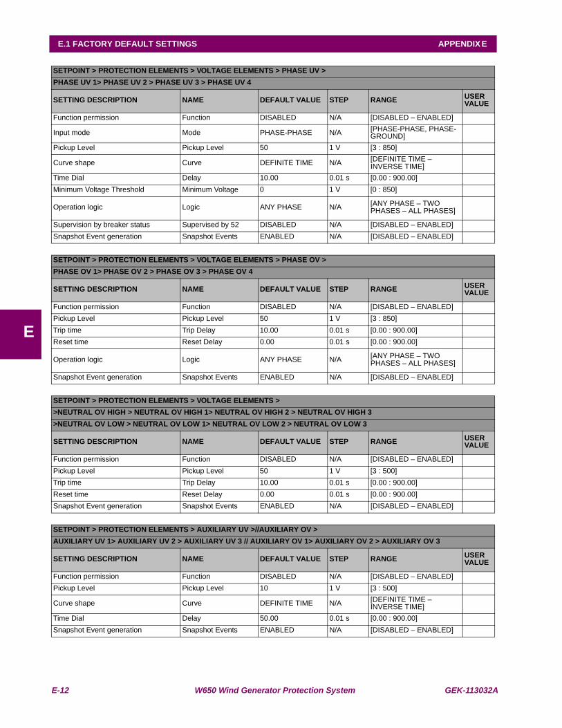
E-12 W650 Wind Generator Protection System GEK-113032A
E.1 FACTORY DEFAULT SETTINGS APPENDIX E
E
SETPOINT > PROTECTION ELEMENTS > VOLTAGE ELEMENTS > PHASE UV >PHASE UV 1> PHASE UV 2 > PHASE UV 3 > PHASE UV 4
SETTING DESCRIPTION NAME DEFAULT VALUE STEP RANGE USER VALUE
Function permission Function DISABLED N/A [DISABLED – ENABLED]
Input mode Mode PHASE-PHASE N/A [PHASE-PHASE, PHASE-GROUND]
Pickup Level Pickup Level 50 1 V [3 : 850]
Curve shape Curve DEFINITE TIME N/A [DEFINITE TIME – INVERSE TIME]
Time Dial Delay 10.00 0.01 s [0.00 : 900.00]Minimum Voltage Threshold Minimum Voltage 0 1 V [0 : 850]
Operation logic Logic ANY PHASE N/A [ANY PHASE – TWO PHASES – ALL PHASES]
Supervision by breaker status Supervised by 52 DISABLED N/A [DISABLED – ENABLED]Snapshot Event generation Snapshot Events ENABLED N/A [DISABLED – ENABLED]
SETPOINT > PROTECTION ELEMENTS > VOLTAGE ELEMENTS > PHASE OV >PHASE OV 1> PHASE OV 2 > PHASE OV 3 > PHASE OV 4
SETTING DESCRIPTION NAME DEFAULT VALUE STEP RANGE USER VALUE
Function permission Function DISABLED N/A [DISABLED – ENABLED]Pickup Level Pickup Level 50 1 V [3 : 850]Trip time Trip Delay 10.00 0.01 s [0.00 : 900.00]Reset time Reset Delay 0.00 0.01 s [0.00 : 900.00]
Operation logic Logic ANY PHASE N/A [ANY PHASE – TWO PHASES – ALL PHASES]
Snapshot Event generation Snapshot Events ENABLED N/A [DISABLED – ENABLED]
SETPOINT > PROTECTION ELEMENTS > VOLTAGE ELEMENTS >>NEUTRAL OV HIGH > NEUTRAL OV HIGH 1> NEUTRAL OV HIGH 2 > NEUTRAL OV HIGH 3>NEUTRAL OV LOW > NEUTRAL OV LOW 1> NEUTRAL OV LOW 2 > NEUTRAL OV LOW 3
SETTING DESCRIPTION NAME DEFAULT VALUE STEP RANGE USER VALUE
Function permission Function DISABLED N/A [DISABLED – ENABLED]Pickup Level Pickup Level 50 1 V [3 : 500]Trip time Trip Delay 10.00 0.01 s [0.00 : 900.00]Reset time Reset Delay 0.00 0.01 s [0.00 : 900.00]Snapshot Event generation Snapshot Events ENABLED N/A [DISABLED – ENABLED]
SETPOINT > PROTECTION ELEMENTS > AUXILIARY UV >//AUXILIARY OV >AUXILIARY UV 1> AUXILIARY UV 2 > AUXILIARY UV 3 // AUXILIARY OV 1> AUXILIARY OV 2 > AUXILIARY OV 3
SETTING DESCRIPTION NAME DEFAULT VALUE STEP RANGE USER VALUE
Function permission Function DISABLED N/A [DISABLED – ENABLED]Pickup Level Pickup Level 10 1 V [3 : 500]
Curve shape Curve DEFINITE TIME N/A [DEFINITE TIME – INVERSE TIME]
Time Dial Delay 50.00 0.01 s [0.00 : 900.00]Snapshot Event generation Snapshot Events ENABLED N/A [DISABLED – ENABLED]
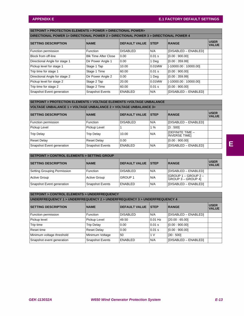
GEK-113032A W650 Wind Generator Protection System E-13
APPENDIX E E.1 FACTORY DEFAULT SETTINGS
E
SETPOINT > PROTECTION ELEMENTS > POWER > DIRECTIONAL POWER>DIRECTIONAL POWER 1> DIRECTIONAL POWER 2 > DIRECTIONAL POWER 3 > DIRECTIONAL POWER 4
SETTING DESCRIPTION NAME DEFAULT VALUE STEP RANGE USER VALUE
Function permission Function DISABLED N/A [DISABLED – ENABLED]Block from off-line Blk Time After Close 0.00 0.01 s [0.00 : 900.00]Directional Angle for stage 1 Dir Power Angle 1 0.00 1 Deg [0.00 : 359.99]Pickup level for stage 1 Stage 1 Tap 10.00 0.01MW [-10000.00 : 10000.00]Trip time for stage 1 Stage 1 Time 60.00 0.01 s [0.00 : 900.00]Directional Angle for stage 2 Dir Power Angle 2 0.00 1 Deg [0.00 : 359.99]Pickup level for stage 2 Stage 2 Tap 20.00 0.01MW [-10000.00 : 10000.00]Trip time for stage 2 Stage 2 Time 60.00 0.01 s [0.00 : 900.00]Snapshot Event generation Snapshot Events ENABLED N/A [DISABLED – ENABLED]
SETPOINT > PROTECTION ELEMENTS > VOLTAGE ELEMENTS >VOLTAGE UNBALANCEVOLTAGE UNBALANCE 1 > VOLTAGE UNBALANCE 2 > VOLTAGE UNBALANCE 3>
SETTING DESCRIPTION NAME DEFAULT VALUE STEP RANGE USER VALUE
Function permission Function DISABLED N/A [DISABLED – ENABLED]Pickup Level Pickup Level 1 1 % [3 : 500]
Trip Delay Trip Delay 10.00 N/A [DEFINITE TIME – INVERSE TIME]
Reset Delay Reset Delay 0.00 [0.00 : 900.00]Snapshot Event generation Snapshot Events ENABLED N/A [DISABLED – ENABLED]
SETPOINT > CONTROL ELEMENTS > SETTING GROUP
SETTING DESCRIPTION NAME DEFAULT VALUE STEP RANGE USER VALUE
Setting Grouping Permission Function DISABLED N/A [DISABLED – ENABLED]
Active Group Active Group GROUP 1 N/A [GROUP 1 – GROUP 2 – GROUP 3 – GROUP 4]
Snapshot Event generation Snapshot Events ENABLED N/A [DISABLED – ENABLED]
SETPOINT > CONTROL ELEMENTS > UNDERFREQUENCYUNDERFREQUENCY 1 > UNDERFREQUENCY 2 > UNDERFREQUENCY 3 > UNDERFREQUENCY 4
SETTING DESCRIPTION NAME DEFAULT VALUE STEP RANGE USER VALUE
Function permission Function DISABLED N/A [DISABLED – ENABLED]Pickup level Pickup Level 49.50 0.01 Hz [20.00 : 65.00]Trip time Trip Delay 0.00 0.01 s [0.00 : 900.00]Reset time Reset Delay 0.00 0.01 s [0.00 : 900.00]Minimum voltage threshold Minimum Voltage 50 1 V [30 : 500]Snapshot event generation Snapshot Events ENABLED N/A [DISABLED – ENABLED]
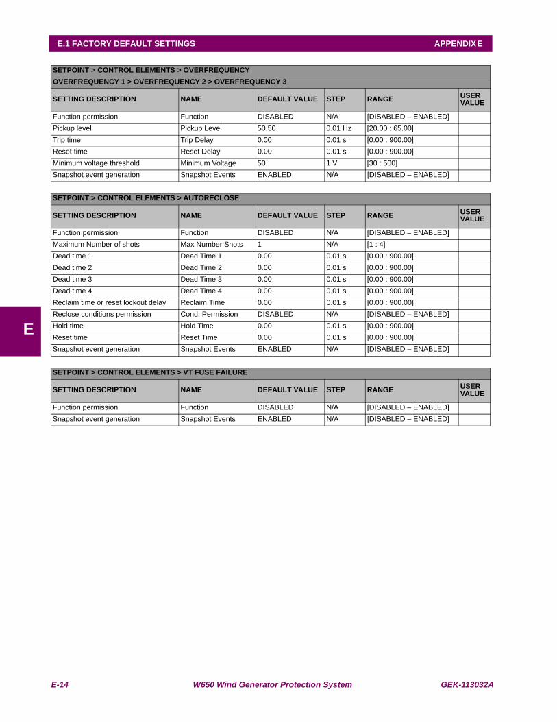
E-14 W650 Wind Generator Protection System GEK-113032A
E.1 FACTORY DEFAULT SETTINGS APPENDIX E
E
SETPOINT > CONTROL ELEMENTS > OVERFREQUENCYOVERFREQUENCY 1 > OVERFREQUENCY 2 > OVERFREQUENCY 3
SETTING DESCRIPTION NAME DEFAULT VALUE STEP RANGE USER VALUE
Function permission Function DISABLED N/A [DISABLED – ENABLED]Pickup level Pickup Level 50.50 0.01 Hz [20.00 : 65.00]Trip time Trip Delay 0.00 0.01 s [0.00 : 900.00]Reset time Reset Delay 0.00 0.01 s [0.00 : 900.00]Minimum voltage threshold Minimum Voltage 50 1 V [30 : 500]Snapshot event generation Snapshot Events ENABLED N/A [DISABLED – ENABLED]
SETPOINT > CONTROL ELEMENTS > AUTORECLOSE
SETTING DESCRIPTION NAME DEFAULT VALUE STEP RANGE USER VALUE
Function permission Function DISABLED N/A [DISABLED – ENABLED]Maximum Number of shots Max Number Shots 1 N/A [1 : 4]Dead time 1 Dead Time 1 0.00 0.01 s [0.00 : 900.00]Dead time 2 Dead Time 2 0.00 0.01 s [0.00 : 900.00]Dead time 3 Dead Time 3 0.00 0.01 s [0.00 : 900.00]Dead time 4 Dead Time 4 0.00 0.01 s [0.00 : 900.00]Reclaim time or reset lockout delay Reclaim Time 0.00 0.01 s [0.00 : 900.00]Reclose conditions permission Cond. Permission DISABLED N/A [DISABLED – ENABLED]Hold time Hold Time 0.00 0.01 s [0.00 : 900.00]Reset time Reset Time 0.00 0.01 s [0.00 : 900.00]Snapshot event generation Snapshot Events ENABLED N/A [DISABLED – ENABLED]
SETPOINT > CONTROL ELEMENTS > VT FUSE FAILURE
SETTING DESCRIPTION NAME DEFAULT VALUE STEP RANGE USER VALUE
Function permission Function DISABLED N/A [DISABLED – ENABLED]Snapshot event generation Snapshot Events ENABLED N/A [DISABLED – ENABLED]
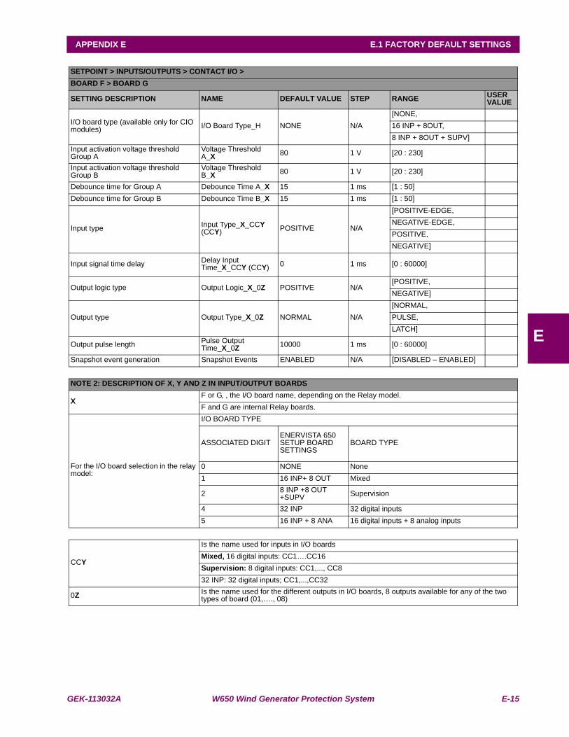
GEK-113032A W650 Wind Generator Protection System E-15
APPENDIX E E.1 FACTORY DEFAULT SETTINGS
E
SETPOINT > INPUTS/OUTPUTS > CONTACT I/O >BOARD F > BOARD G
SETTING DESCRIPTION NAME DEFAULT VALUE STEP RANGE USER VALUE
I/O board type (available only for CIO modules) I/O Board Type_H NONE N/A
[NONE,16 INP + 8OUT,8 INP + 8OUT + SUPV]
Input activation voltage threshold Group A
Voltage Threshold A_X 80 1 V [20 : 230]
Input activation voltage threshold Group B
Voltage Threshold B_X 80 1 V [20 : 230]
Debounce time for Group A Debounce Time A_X 15 1 ms [1 : 50]Debounce time for Group B Debounce Time B_X 15 1 ms [1 : 50]
Input type Input Type_X_CCY (CCY) POSITIVE N/A
[POSITIVE-EDGE,NEGATIVE-EDGE,POSITIVE,NEGATIVE]
Input signal time delay Delay Input Time_X_CCY (CCY) 0 1 ms [0 : 60000]
Output logic type Output Logic_X_0Z POSITIVE N/A[POSITIVE,NEGATIVE]
Output type Output Type_X_0Z NORMAL N/A[NORMAL,PULSE,LATCH]
Output pulse length Pulse Output Time_X_0Z 10000 1 ms [0 : 60000]
Snapshot event generation Snapshot Events ENABLED N/A [DISABLED – ENABLED]
NOTE 2: DESCRIPTION OF X, Y AND Z IN INPUT/OUTPUT BOARDS
X F or G, , the I/O board name, depending on the Relay model.F and G are internal Relay boards.
For the I/O board selection in the relay model:
I/O BOARD TYPE
ASSOCIATED DIGITENERVISTA 650 SETUP BOARD SETTINGS
BOARD TYPE
0 NONE None1 16 INP+ 8 OUT Mixed
2 8 INP +8 OUT +SUPV Supervision
4 32 INP 32 digital inputs5 16 INP + 8 ANA 16 digital inputs + 8 analog inputs
CCY
Is the name used for inputs in I/O boardsMixed, 16 digital inputs: CC1….CC16Supervision: 8 digital inputs: CC1,..., CC832 INP: 32 digital inputs; CC1,...,CC32
0Z Is the name used for the different outputs in I/O boards, 8 outputs available for any of the two types of board (01,…., 08)
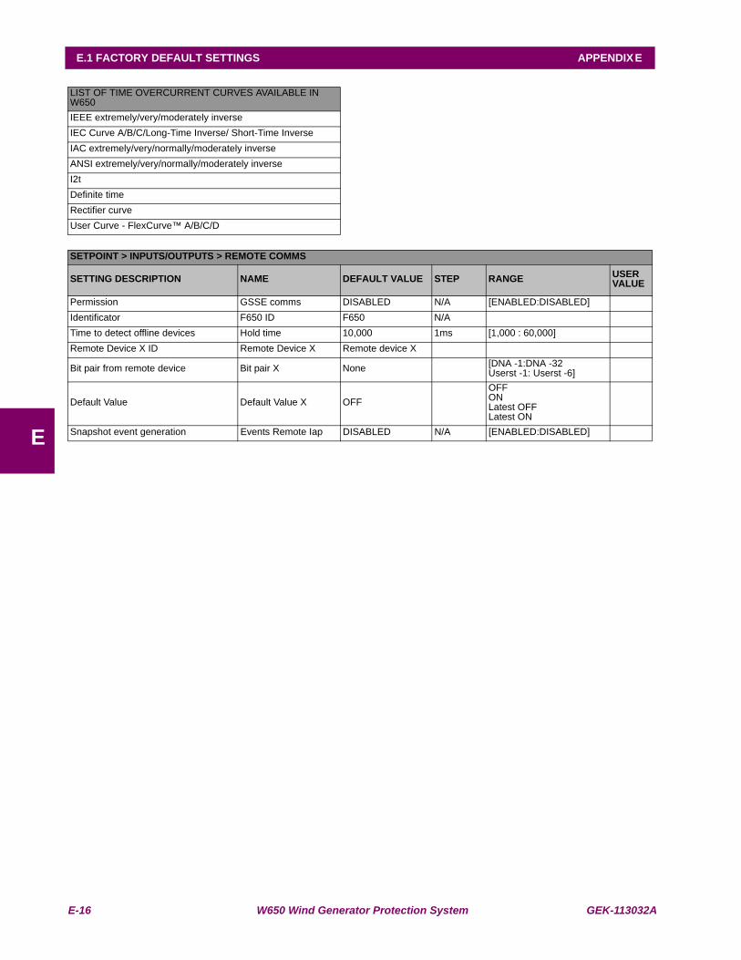
E-16 W650 Wind Generator Protection System GEK-113032A
E.1 FACTORY DEFAULT SETTINGS APPENDIX E
E
LIST OF TIME OVERCURRENT CURVES AVAILABLE IN W650IEEE extremely/very/moderately inverseIEC Curve A/B/C/Long-Time Inverse/ Short-Time InverseIAC extremely/very/normally/moderately inverseANSI extremely/very/normally/moderately inverseI2tDefinite timeRectifier curveUser Curve - FlexCurve™ A/B/C/D
SETPOINT > INPUTS/OUTPUTS > REMOTE COMMS
SETTING DESCRIPTION NAME DEFAULT VALUE STEP RANGE USER VALUE
Permission GSSE comms DISABLED N/A [ENABLED:DISABLED]Identificator F650 ID F650 N/ATime to detect offline devices Hold time 10,000 1ms [1,000 : 60,000]Remote Device X ID Remote Device X Remote device X
Bit pair from remote device Bit pair X None [DNA -1:DNA -32 Userst -1: Userst -6]
Default Value Default Value X OFFOFFONLatest OFFLatest ON
Snapshot event generation Events Remote Iap DISABLED N/A [ENABLED:DISABLED]
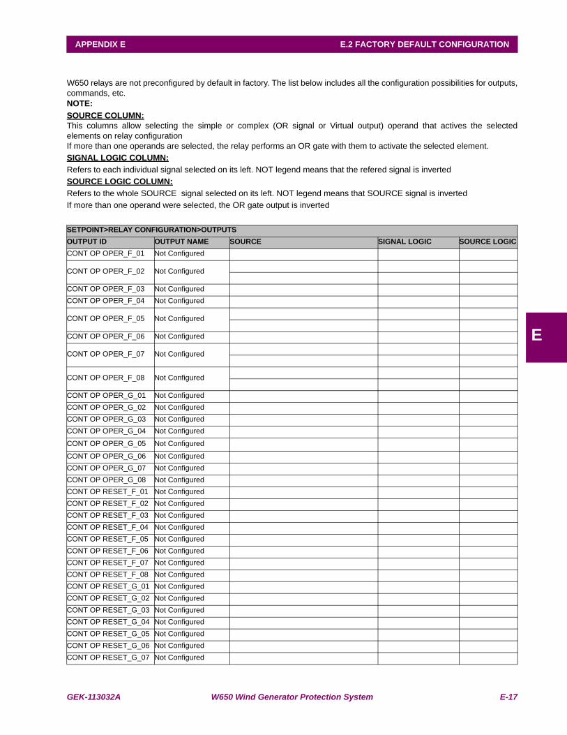
GEK-113032A W650 Wind Generator Protection System E-17
APPENDIX E E.2 FACTORY DEFAULT CONFIGURATION
E
E.2FACTORY DEFAULT CONFIGURATIONW650 relays are not preconfigured by default in factory. The list below includes all the configuration possibilities for outputs,commands, etc.NOTE:SOURCE COLUMN:This columns allow selecting the simple or complex (OR signal or Virtual output) operand that actives the selectedelements on relay configurationIf more than one operands are selected, the relay performs an OR gate with them to activate the selected element.SIGNAL LOGIC COLUMN:Refers to each individual signal selected on its left. NOT legend means that the refered signal is invertedSOURCE LOGIC COLUMN:Refers to the whole SOURCE signal selected on its left. NOT legend means that SOURCE signal is invertedIf more than one operand were selected, the OR gate output is inverted
SETPOINT>RELAY CONFIGURATION>OUTPUTSOUTPUT ID OUTPUT NAME SOURCE SIGNAL LOGIC SOURCE LOGICCONT OP OPER_F_01 Not Configured
CONT OP OPER_F_02 Not Configured
CONT OP OPER_F_03 Not ConfiguredCONT OP OPER_F_04 Not Configured
CONT OP OPER_F_05 Not Configured
CONT OP OPER_F_06 Not Configured
CONT OP OPER_F_07 Not Configured
CONT OP OPER_F_08 Not Configured
CONT OP OPER_G_01 Not ConfiguredCONT OP OPER_G_02 Not ConfiguredCONT OP OPER_G_03 Not ConfiguredCONT OP OPER_G_04 Not Configured
CONT OP OPER_G_05 Not Configured
CONT OP OPER_G_06 Not ConfiguredCONT OP OPER_G_07 Not ConfiguredCONT OP OPER_G_08 Not ConfiguredCONT OP RESET_F_01 Not ConfiguredCONT OP RESET_F_02 Not ConfiguredCONT OP RESET_F_03 Not ConfiguredCONT OP RESET_F_04 Not ConfiguredCONT OP RESET_F_05 Not ConfiguredCONT OP RESET_F_06 Not ConfiguredCONT OP RESET_F_07 Not ConfiguredCONT OP RESET_F_08 Not ConfiguredCONT OP RESET_G_01 Not ConfiguredCONT OP RESET_G_02 Not ConfiguredCONT OP RESET_G_03 Not ConfiguredCONT OP RESET_G_04 Not ConfiguredCONT OP RESET_G_05 Not ConfiguredCONT OP RESET_G_06 Not ConfiguredCONT OP RESET_G_07 Not Configured

E-18 W650 Wind Generator Protection System GEK-113032A
E.2 FACTORY DEFAULT CONFIGURATION APPENDIX E
E
SETPOINT>RELAY CONFIGURATION>LEDS
LED ID LED NAME SOURCE SIGNALLOGIC
SOURCELOGIC
CONT OP RESET_G_08 Not ConfiguredLED01LED02LED03LED04LED05LED06LED07LED08LED09LED10LED11LED12LED13LED14LED15
SETPOINT>RELAY CONFIGURATION>PROTECTION ELEMENTS
PROTECTION ELEMENT SOURCE SIGNALLOGIC
SOURCELOGIC
LED RESET INPUT OPERATION BIT 3PH IOC1 HIGH A BLK GROUP 1 BLOCKEDPH IOC1 HIGH B BLK GROUP 1 BLOCKEDPH IOC1 HIGH C BLK GROUP 1 BLOCKEDPH IOC2 HIGH A BLK GROUP 2 BLOCKEDPH IOC2 HIGH B BLK GROUP 2 BLOCKEDPH IOC2 HIGH C BLK GROUP 2 BLOCKEDPH IOC3 HIGH A BLK GROUP 3 BLOCKEDPH IOC3 HIGH B BLK GROUP 3 BLOCKEDPH IOC3 HIGH C BLK GROUP 3 BLOCKEDPH IOC1 LOW A BLK GROUP 1 BLOCKEDPH IOC1 LOW B BLK GROUP 1 BLOCKEDPH IOC1 LOW C BLK GROUP 1 BLOCKEDPH IOC2 LOW A BLK GROUP 2 BLOCKEDPH IOC2 LOW B BLK GROUP 2 BLOCKEDPH IOC2 LOW C BLK GROUP 2 BLOCKEDPH IOC3 LOW A BLK GROUP 3 BLOCKEDPH IOC3 LOW B BLK GROUP 3 BLOCKED
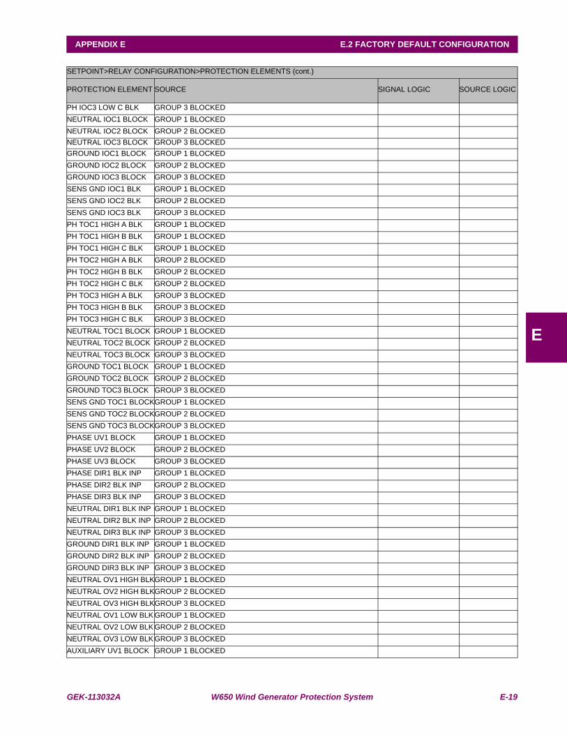
GEK-113032A W650 Wind Generator Protection System E-19
APPENDIX E E.2 FACTORY DEFAULT CONFIGURATION
E
SETPOINT>RELAY CONFIGURATION>PROTECTION ELEMENTS (cont.)
PROTECTION ELEMENT SOURCE SIGNAL LOGIC SOURCE LOGIC
PH IOC3 LOW C BLK GROUP 3 BLOCKEDNEUTRAL IOC1 BLOCK GROUP 1 BLOCKEDNEUTRAL IOC2 BLOCK GROUP 2 BLOCKEDNEUTRAL IOC3 BLOCK GROUP 3 BLOCKEDGROUND IOC1 BLOCK GROUP 1 BLOCKEDGROUND IOC2 BLOCK GROUP 2 BLOCKEDGROUND IOC3 BLOCK GROUP 3 BLOCKEDSENS GND IOC1 BLK GROUP 1 BLOCKEDSENS GND IOC2 BLK GROUP 2 BLOCKEDSENS GND IOC3 BLK GROUP 3 BLOCKEDPH TOC1 HIGH A BLK GROUP 1 BLOCKEDPH TOC1 HIGH B BLK GROUP 1 BLOCKEDPH TOC1 HIGH C BLK GROUP 1 BLOCKEDPH TOC2 HIGH A BLK GROUP 2 BLOCKEDPH TOC2 HIGH B BLK GROUP 2 BLOCKEDPH TOC2 HIGH C BLK GROUP 2 BLOCKEDPH TOC3 HIGH A BLK GROUP 3 BLOCKEDPH TOC3 HIGH B BLK GROUP 3 BLOCKEDPH TOC3 HIGH C BLK GROUP 3 BLOCKEDNEUTRAL TOC1 BLOCK GROUP 1 BLOCKEDNEUTRAL TOC2 BLOCK GROUP 2 BLOCKEDNEUTRAL TOC3 BLOCK GROUP 3 BLOCKEDGROUND TOC1 BLOCK GROUP 1 BLOCKEDGROUND TOC2 BLOCK GROUP 2 BLOCKEDGROUND TOC3 BLOCK GROUP 3 BLOCKEDSENS GND TOC1 BLOCKGROUP 1 BLOCKEDSENS GND TOC2 BLOCKGROUP 2 BLOCKEDSENS GND TOC3 BLOCKGROUP 3 BLOCKEDPHASE UV1 BLOCK GROUP 1 BLOCKEDPHASE UV2 BLOCK GROUP 2 BLOCKEDPHASE UV3 BLOCK GROUP 3 BLOCKEDPHASE DIR1 BLK INP GROUP 1 BLOCKEDPHASE DIR2 BLK INP GROUP 2 BLOCKEDPHASE DIR3 BLK INP GROUP 3 BLOCKEDNEUTRAL DIR1 BLK INP GROUP 1 BLOCKEDNEUTRAL DIR2 BLK INP GROUP 2 BLOCKEDNEUTRAL DIR3 BLK INP GROUP 3 BLOCKEDGROUND DIR1 BLK INP GROUP 1 BLOCKEDGROUND DIR2 BLK INP GROUP 2 BLOCKEDGROUND DIR3 BLK INP GROUP 3 BLOCKEDNEUTRAL OV1 HIGH BLKGROUP 1 BLOCKEDNEUTRAL OV2 HIGH BLKGROUP 2 BLOCKEDNEUTRAL OV3 HIGH BLKGROUP 3 BLOCKEDNEUTRAL OV1 LOW BLK GROUP 1 BLOCKEDNEUTRAL OV2 LOW BLK GROUP 2 BLOCKEDNEUTRAL OV3 LOW BLK GROUP 3 BLOCKEDAUXILIARY UV1 BLOCK GROUP 1 BLOCKED
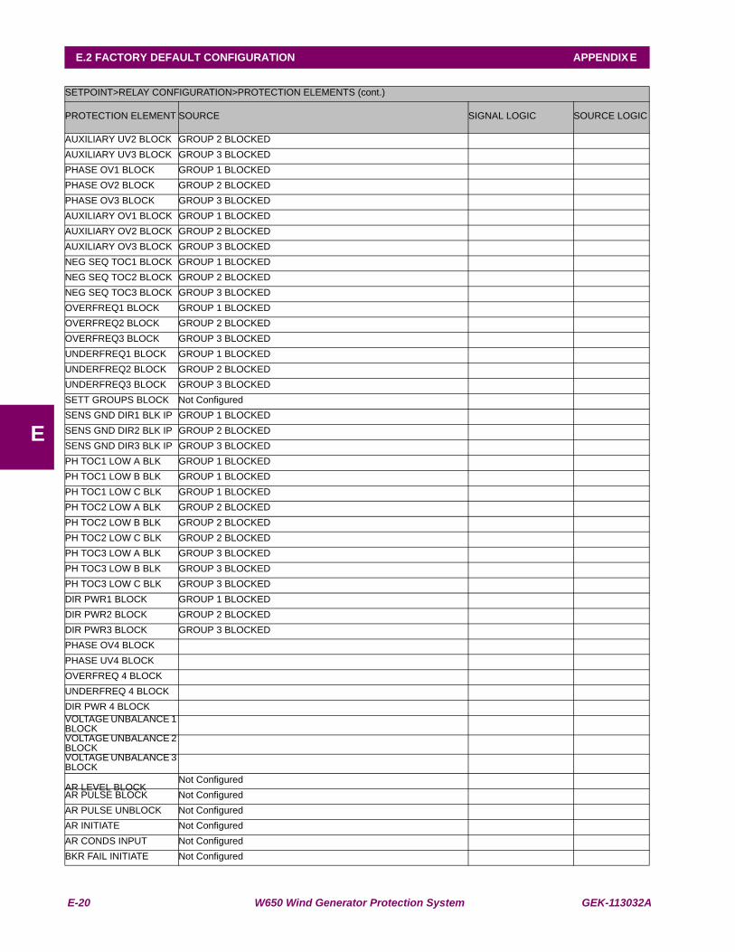
E-20 W650 Wind Generator Protection System GEK-113032A
E.2 FACTORY DEFAULT CONFIGURATION APPENDIX E
E
SETPOINT>RELAY CONFIGURATION>PROTECTION ELEMENTS (cont.)
PROTECTION ELEMENT SOURCE SIGNAL LOGIC SOURCE LOGIC
AUXILIARY UV2 BLOCK GROUP 2 BLOCKEDAUXILIARY UV3 BLOCK GROUP 3 BLOCKEDPHASE OV1 BLOCK GROUP 1 BLOCKEDPHASE OV2 BLOCK GROUP 2 BLOCKEDPHASE OV3 BLOCK GROUP 3 BLOCKEDAUXILIARY OV1 BLOCK GROUP 1 BLOCKEDAUXILIARY OV2 BLOCK GROUP 2 BLOCKEDAUXILIARY OV3 BLOCK GROUP 3 BLOCKEDNEG SEQ TOC1 BLOCK GROUP 1 BLOCKEDNEG SEQ TOC2 BLOCK GROUP 2 BLOCKEDNEG SEQ TOC3 BLOCK GROUP 3 BLOCKEDOVERFREQ1 BLOCK GROUP 1 BLOCKEDOVERFREQ2 BLOCK GROUP 2 BLOCKEDOVERFREQ3 BLOCK GROUP 3 BLOCKEDUNDERFREQ1 BLOCK GROUP 1 BLOCKEDUNDERFREQ2 BLOCK GROUP 2 BLOCKEDUNDERFREQ3 BLOCK GROUP 3 BLOCKEDSETT GROUPS BLOCK Not ConfiguredSENS GND DIR1 BLK IP GROUP 1 BLOCKEDSENS GND DIR2 BLK IP GROUP 2 BLOCKEDSENS GND DIR3 BLK IP GROUP 3 BLOCKEDPH TOC1 LOW A BLK GROUP 1 BLOCKEDPH TOC1 LOW B BLK GROUP 1 BLOCKEDPH TOC1 LOW C BLK GROUP 1 BLOCKEDPH TOC2 LOW A BLK GROUP 2 BLOCKEDPH TOC2 LOW B BLK GROUP 2 BLOCKEDPH TOC2 LOW C BLK GROUP 2 BLOCKEDPH TOC3 LOW A BLK GROUP 3 BLOCKEDPH TOC3 LOW B BLK GROUP 3 BLOCKEDPH TOC3 LOW C BLK GROUP 3 BLOCKEDDIR PWR1 BLOCK GROUP 1 BLOCKEDDIR PWR2 BLOCK GROUP 2 BLOCKEDDIR PWR3 BLOCK GROUP 3 BLOCKEDPHASE OV4 BLOCKPHASE UV4 BLOCKOVERFREQ 4 BLOCKUNDERFREQ 4 BLOCKDIR PWR 4 BLOCKVOLTAGE UNBALANCE 1 BLOCKVOLTAGE UNBALANCE 2 BLOCKVOLTAGE UNBALANCE 3 BLOCK
AR LEVEL BLOCKNot Configured
AR PULSE BLOCK Not ConfiguredAR PULSE UNBLOCK Not ConfiguredAR INITIATE Not ConfiguredAR CONDS INPUT Not ConfiguredBKR FAIL INITIATE Not Configured
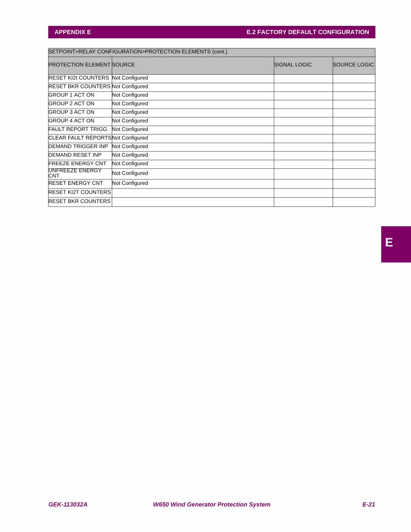
GEK-113032A W650 Wind Generator Protection System E-21
APPENDIX E E.2 FACTORY DEFAULT CONFIGURATION
E
SETPOINT>RELAY CONFIGURATION>PROTECTION ELEMENTS (cont.)
PROTECTION ELEMENT SOURCE SIGNAL LOGIC SOURCE LOGIC
RESET KI2t COUNTERS Not ConfiguredRESET BKR COUNTERS Not ConfiguredGROUP 1 ACT ON Not ConfiguredGROUP 2 ACT ON Not ConfiguredGROUP 3 ACT ON Not ConfiguredGROUP 4 ACT ON Not ConfiguredFAULT REPORT TRIGG Not ConfiguredCLEAR FAULT REPORTSNot ConfiguredDEMAND TRIGGER INP Not ConfiguredDEMAND RESET INP Not ConfiguredFREEZE ENERGY CNT Not ConfiguredUNFREEZE ENERGY CNT Not Configured
RESET ENERGY CNT Not Configured
RESET KI2T COUNTERS
RESET BKR COUNTERS
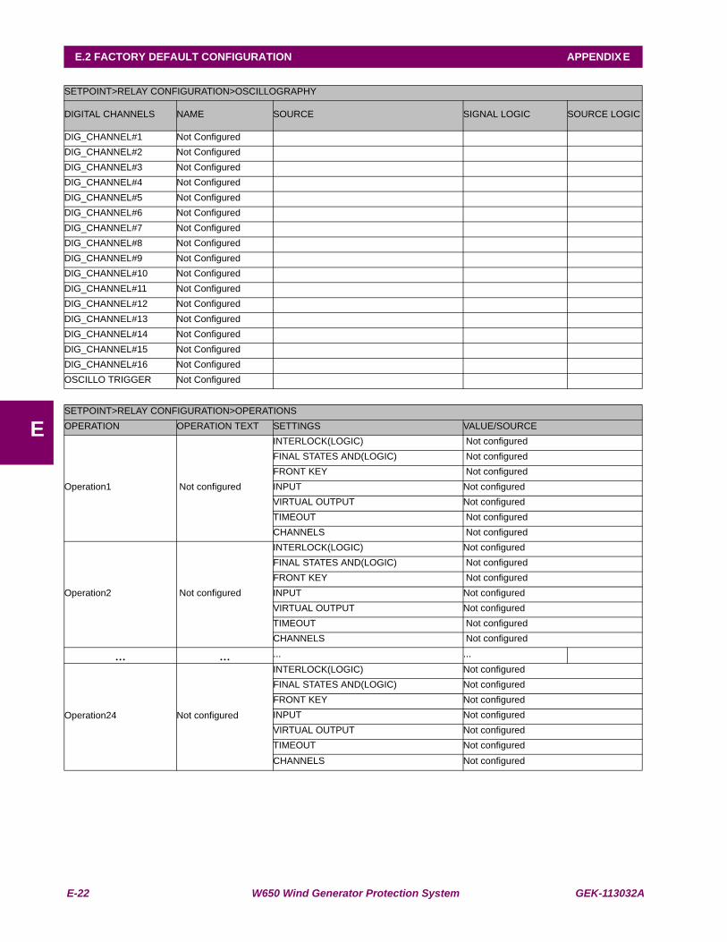
E-22 W650 Wind Generator Protection System GEK-113032A
E.2 FACTORY DEFAULT CONFIGURATION APPENDIX E
E
SETPOINT>RELAY CONFIGURATION>OSCILLOGRAPHY
DIGITAL CHANNELS NAME SOURCE SIGNAL LOGIC SOURCE LOGIC
DIG_CHANNEL#1 Not ConfiguredDIG_CHANNEL#2 Not ConfiguredDIG_CHANNEL#3 Not ConfiguredDIG_CHANNEL#4 Not ConfiguredDIG_CHANNEL#5 Not ConfiguredDIG_CHANNEL#6 Not ConfiguredDIG_CHANNEL#7 Not ConfiguredDIG_CHANNEL#8 Not ConfiguredDIG_CHANNEL#9 Not ConfiguredDIG_CHANNEL#10 Not ConfiguredDIG_CHANNEL#11 Not ConfiguredDIG_CHANNEL#12 Not ConfiguredDIG_CHANNEL#13 Not ConfiguredDIG_CHANNEL#14 Not ConfiguredDIG_CHANNEL#15 Not ConfiguredDIG_CHANNEL#16 Not ConfiguredOSCILLO TRIGGER Not Configured
SETPOINT>RELAY CONFIGURATION>OPERATIONSOPERATION OPERATION TEXT SETTINGS VALUE/SOURCE
Operation1 Not configured
INTERLOCK(LOGIC) Not configuredFINAL STATES AND(LOGIC) Not configuredFRONT KEY Not configuredINPUT Not configuredVIRTUAL OUTPUT Not configuredTIMEOUT Not configuredCHANNELS Not configured
Operation2 Not configured
INTERLOCK(LOGIC) Not configuredFINAL STATES AND(LOGIC) Not configuredFRONT KEY Not configuredINPUT Not configuredVIRTUAL OUTPUT Not configuredTIMEOUT Not configuredCHANNELS Not configured
... ... ... ...
Operation24 Not configured
INTERLOCK(LOGIC) Not configuredFINAL STATES AND(LOGIC) Not configuredFRONT KEY Not configuredINPUT Not configuredVIRTUAL OUTPUT Not configuredTIMEOUT Not configuredCHANNELS Not configured

GEK-113032A W650 Wind Generator Protection System E-23
APPENDIX E E.2 FACTORY DEFAULT CONFIGURATION
E
SETPOINT>RELAY CONFIGURATION>CONTROL EVENTS
EVENT NAME SOURCE SIGNAL LOGIC SOURCE LOGIC
EV1 Not ConfiguredEV2 Not Configured... ...EV128 Not Configured
SETPOINT>RELAY CONFIGURATION>SWITCHGEAR
SWITCHGEAR SETTING VALUE/SOURCE SIGNAL LOGIC SOURCE LOGIC
SWITCHGEAR 1
CONTACTS Not ConfiguredOPENING TIME Not ConfiguredCLOSING TIME Not ConfiguredCONTACT A SOURCE Not ConfiguredCONTACT B SOURCE Not Configured
OPEN TEXT Not ConfiguredALARM Not ConfiguredCLOSED TEXT Not ConfiguredALARM Not ConfiguredERROR 00 TEXT Not ConfiguredALARM Not ConfiguredERROR 11 TEXT Not ConfiguredALARM Not ConfiguredOPENING INIT Not ConfiguredCLOSING INIT Not Configured
SWITCHGEAR 2
CONTACTS Not ConfiguredOPENING TIME Not ConfiguredCLOSING TIME Not ConfiguredCONTACT A SOURCE Not ConfiguredCONTACT B SOURCE Not Configured
OPEN TEXT Not ConfiguredALARM Not ConfiguredCLOSED TEXT Not ConfiguredALARM Not ConfiguredERROR 00 TEXT Not ConfiguredALARM Not ConfiguredERROR 11 TEXT Not ConfiguredALARM Not ConfiguredOPENING INIT Not ConfiguredCLOSING INIT Not Configured
... ... ... ... ...
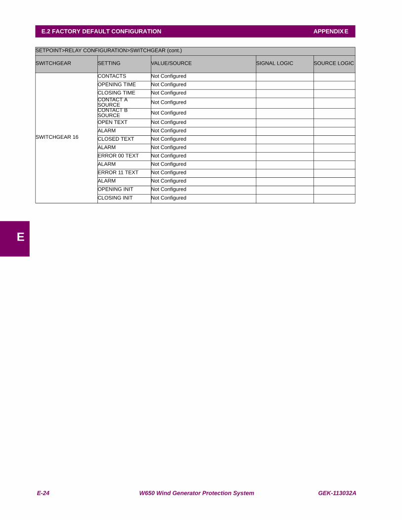
E-24 W650 Wind Generator Protection System GEK-113032A
E.2 FACTORY DEFAULT CONFIGURATION APPENDIX E
E
SETPOINT>RELAY CONFIGURATION>SWITCHGEAR (cont.)
SWITCHGEAR SETTING VALUE/SOURCE SIGNAL LOGIC SOURCE LOGIC
SWITCHGEAR 16
CONTACTS Not ConfiguredOPENING TIME Not ConfiguredCLOSING TIME Not ConfiguredCONTACT A SOURCE Not ConfiguredCONTACT B SOURCE Not Configured
OPEN TEXT Not ConfiguredALARM Not ConfiguredCLOSED TEXT Not ConfiguredALARM Not ConfiguredERROR 00 TEXT Not ConfiguredALARM Not ConfiguredERROR 11 TEXT Not ConfiguredALARM Not ConfiguredOPENING INIT Not ConfiguredCLOSING INIT Not Configured

GEK-113032A W650 Wind Generator Protection System F-1
APPENDIX F F.1 GE MULTILIN WARRANTY
FAPPENDIX F MISCELLANEOUS F.1GE MULTILIN WARRANTY
GE MULTILIN RELAY WARRANTY
GE Power Management, S.A. (GE Multilin) warrants each relay it manufactures to be free from defects inmaterial and workmanship under normal use and service for a period of 24 months from date of shipment fromfactory.
In the event of a failure covered by warranty, GE Multilin will undertake to repair or replace the relay providingthe warrantor determined that it is defective and it is returned with all transportation charges prepaid to anauthorized service center or the factory. Repairs or replacement under warranty will be made without charge.
Warranty shall not apply to any relay, which has been subject to misuse, negligence, accident, incorrectinstallation, or use not in accordance with instructions nor any unit that has been altered outside a GE Multilinauthorized factory outlet.
GE Multilin is not liable for special, indirect or consequential damages or for loss of profit or for expensessustained as a result of a relay malfunction, incorrect application or adjustment.
For complete text of Warranty (including limitations and disclaimers), refer to GE Multilin Standard Conditionsof Sale.

F-2 W650 Wind Generator Protection System GEK-113032A
F.1 GE MULTILIN WARRANTY APPENDIX F
F