Generator Protection & Control System GE Consumer & Industrial ...
639
GE Multilin 215 Anderson Avenue L6E 1B3 Markham, ON -CANADA T (905) 294 6222 F (905) 294 8512 E [email protected] Internet: www.GEMultilin.com Firmware version: 3.74 EnerVista 650 Setup version: 3.76 Copyright © 2008 GE Multilin G650 Generator Protection & Control System Instruction manual GEK-113285A GE Multilin Avda. Pinoa, 10 48170 Zamudio SPAIN T +34 94 485 88 00 F +34 94 485 88 45 E [email protected] g GE Consumer & Industrial Multilin
-
Upload
khangminh22 -
Category
Documents
-
view
1 -
download
0
Transcript of Generator Protection & Control System GE Consumer & Industrial ...
GE Multilin215 Anderson AvenueL6E 1B3 Markham, ON -CANADAT (905) 294 6222 F (905) 294 8512E [email protected]
Internet: www.GEMultilin.com
Firmware version: 3.74EnerVista 650 Setup version: 3.76
Copyright © 2008 GE Multilin
G650Generator Protection & Control
SystemInstruction manual
GEK-113285A
GE MultilinAvda. Pinoa, 1048170 Zamudio SPAINT +34 94 485 88 00 F +34 94 485 88 45E [email protected]
g GE Consumer & IndustrialMultilin
GEK-113285A G650 Generator Protection & Control System 1
TABLE OF CONTENTS
1. GETTING STARTED 1.1 IMPORTANT PROCEDURES1.1.1 CAUTIONS AND WARNINGS ........................................................................... 1-11.1.2 INSPECTION CHECKLIST ................................................................................ 1-41.1.3 SAFETY INSTRUCTIONS ................................................................................. 1-6
1.2 OVERVIEW1.2.1 INTRODUCTION TO 650 FAMILY OF RELAYS ............................................... 1-71.2.2 HARDWARE ARCHITECTURE ......................................................................... 1-71.2.3 SOFTWARE ARCHITECTURE.......................................................................... 1-91.2.4 COMMUNICATIONS ARCHITECTURE ............................................................ 1-9
1.3 ENERVISTA 650 SETUP SOFTWARE1.3.1 SYSTEM REQUIREMENTS ............................................................................ 1-111.3.2 INSTALLATION................................................................................................ 1-111.3.3 CONNECTING ENERVISTA 650 SETUP WITH G650.................................... 1-15
1.4 650 HARDWARE1.4.1 MOUNTING & WIRING.................................................................................... 1-171.4.2 650 COMMUNICATIONS................................................................................. 1-171.4.3 FACEPLATE DISPLAY .................................................................................... 1-181.4.4 MAINTENANCE ............................................................................................... 1-18
2. PRODUCT DESCRIPTION 2.1 OVERVIEW2.1.1 G650 OVERVIEW .............................................................................................. 2-1
2.2 SUMMARY2.2.1 ANSI DEVICE NUMBERS AND FUNCTIONS................................................... 2-32.2.2 OTHER DEVICE FUNCTIONS .......................................................................... 2-4
2.3 ORDERING CODE2.4 TECHNICAL SPECIFICATIONS
2.4.1 PROTECTION ELEMENTS ............................................................................... 2-72.4.2 CONTROL........................................................................................................ 2-172.4.3 MONITORING.................................................................................................. 2-222.4.4 USER-PROGRAMMABLE ELEMENTS........................................................... 2-242.4.5 METERING ...................................................................................................... 2-252.4.6 INPUTS ............................................................................................................ 2-262.4.7 REAL TIME CLOCK......................................................................................... 2-282.4.8 OUTPUTS ........................................................................................................ 2-282.4.9 CONTROL POWER SUPPLY.......................................................................... 2-292.4.10 COMMUNICATIONS........................................................................................ 2-292.4.11 OPTIC FEATURES .......................................................................................... 2-312.4.12 ENVIRONMENTAL CHARACTERISTICS ....................................................... 2-322.4.13 PACKAGING AND WEIGHT............................................................................ 2-322.4.14 TYPE TESTS ................................................................................................... 2-322.4.15 APPROVALS ................................................................................................... 2-32
2.5 EXTERNAL CONNECTIONS
3. HARDWARE 3.1 MODULE DESCRIPTION3.2 POWER SUPPLY3.3 MECHANICAL DESCRIPTION
3.3.1 MOUNTING........................................................................................................ 3-33.3.2 REAR DESCRIPTION........................................................................................ 3-6
3.4 WIRING3.4.1 EXTERNAL CONNECTIONS............................................................................. 3-93.4.2 DIGITAL INPUTS WITH TRIP CIRCUIT SUPERVISION .................................. 3-93.4.3 CABLE/FIBER ETHERNET BOARD................................................................ 3-10
2 G650 Generator Protection & Control System GEK-113285A
TABLE OF CONTENTS
3.5 TRANSCEIVER OPTICAL POWER BUDGET VERSUS LINK LENGTH
4. HUMAN INTERFACES. SETTINGS & ACTUAL VALUES
4.1 ENERVISTA 650 SETUP SOFTWARE INTERFACE4.1.1 INTRODUCTION ................................................................................................4-14.1.2 ENERVISTA 650 SETUP SOFTWARE OVERVIEW..........................................4-14.1.3 MAIN SCREEN...................................................................................................4-34.1.4 COMMUNICATION MENU .................................................................................4-44.1.5 FILE MANAGEMENT .........................................................................................4-64.1.6 ENERVISTA 650 SETUP MENU STRUCTURE...............................................4-104.1.7 FILE MENU OVERVIEW ..................................................................................4-114.1.8 SETPOINT MENU OVERVIEW........................................................................4-154.1.9 ACTUAL VALUES MENU OVERVIEW.............................................................4-234.1.10 OPERATIONS MENU OVERVIEW ..................................................................4-264.1.11 COMMUNICATION MENU OVERVIEW...........................................................4-274.1.12 SECURITY MENU OVERVIEW........................................................................4-304.1.13 VIEW MENU OVERVIEW.................................................................................4-304.1.14 HELP MENU OVERVIEW ................................................................................4-30
4.2 HUMAN MACHINE INTERFACE (HMI)4.2.1 DISPLAY...........................................................................................................4-314.2.2 FRONT LED INDICATORS ..............................................................................4-324.2.3 PUSHBUTTONS...............................................................................................4-324.2.4 FRONT PORT AND COVER SEALING SYSTEM............................................4-334.2.5 TEXT MENUS...................................................................................................4-344.2.6 GRAPHIC DISPLAY .........................................................................................4-52
4.3 WEB SERVER4.3.1 HOME ...............................................................................................................4-614.3.2 SNAPSHOT EVENTS.......................................................................................4-624.3.3 CONTROL EVENTS.........................................................................................4-634.3.4 ALARMS ...........................................................................................................4-644.3.5 OSCILLOGRAPHY ...........................................................................................4-654.3.6 FAULT REPORT ..............................................................................................4-664.3.7 DATA LOGGER................................................................................................4-674.3.8 METERING.......................................................................................................4-68
5. SETTINGS 5.1 OVERVIEW5.1.1 SETTING MAIN MENU.......................................................................................5-1
5.2 PRODUCT SETUP5.2.1 COMMUNICATION SETTINGS..........................................................................5-35.2.2 MODBUS USER MAP ........................................................................................5-65.2.3 FAULT REPORT ................................................................................................5-75.2.4 OSCILLOGRAPHY .............................................................................................5-95.2.5 DATA LOGGER................................................................................................5-125.2.6 DEMAND .........................................................................................................5-14
5.3 SYSTEM SETUP5.3.1 GENERAL SETTINGS......................................................................................5-205.3.2 FLEX CURVES.................................................................................................5-205.3.3 BREAKER.........................................................................................................5-235.3.4 SWITCHGEAR .................................................................................................5-25
5.4 PROTECTION ELEMENTS5.4.1 CHANGE OF SETTING TABLES IN G650 ELEMENTS ..................................5-265.4.2 INVERSE TIME CURVES CHARACTERISTICS..............................................5-305.4.3 PHASE CURRENT ...........................................................................................5-405.4.4 NEUTRAL CURRENT ......................................................................................5-465.4.5 GROUND CURRENT .......................................................................................5-525.4.6 RESTRICTED GROUND FAULT (ONLY FOR ENHANCED MODELS) ..........5-565.4.7 SENSITIVE GROUND CURRENT (ONLY FOR ENHANCED MODELS) ........5-595.4.8 NEGATIVE SEQUENCE CURRENT................................................................5-605.4.9 VOLTAGE ELEMENTS ....................................................................................5-635.4.10 POWER ............................................................................................................5-71
GEK-113285A G650 Generator Protection & Control System 3
TABLE OF CONTENTS
5.5 CONTROL ELEMENTS5.5.1 SETTING GROUP ........................................................................................... 5-775.5.2 UNDERFREQUENCY ELEMENT (81U).......................................................... 5-785.5.3 OVERFREQUENCY ELEMENT (81O) ............................................................ 5-785.5.4 SYNCHRONISM CHECK ELEMENT - SYNCHROCHECK (25) ..................... 5-795.5.5 BREAKER FAILURE ELEMENT (50BF) (ENHANCED MODELS ONLY) ....... 5-885.5.6 VT FUSE FAILURE ELEMENT (VTFF) (ENHANCED MODELS ONLY)......... 5-915.5.7 PULSE COUNTERS ........................................................................................ 5-925.5.8 ANALOG COMPARATORS ............................................................................. 5-945.5.9 FREQUENCY RATE OF CHANGE.................................................................. 5-955.5.10 LOSS OF MAINS (78V) (FOR ENHANCED MODELS) .................................. 5-975.5.11 LOSS OF EXCITATION (40)........................................................................... 5-995.5.12 ACCIDENTAL ENERGIZATION (50/27) ........................................................ 5-101
5.6 INPUTS/OUTPUTS5.6.1 INPUT/OUTPUT PLACEMENT...................................................................... 5-1035.6.2 CONTROL SETTINGS FOR INPUTS/OUTPUTS.......................................... 5-1045.6.3 INPUTS .......................................................................................................... 5-1065.6.4 OUTPUTS ...................................................................................................... 5-1085.6.5 CIRCUIT SUPERVISION AND CONTACT SEAL-IN CIRCUITS ................... 5-1105.6.6 ANALOG BOARDS SPECIFIC SETTINGS ................................................... 5-1205.6.7 VIRTUAL INPUTS.......................................................................................... 5-1205.6.8 VIRTUAL OUTPUTS...................................................................................... 5-121
5.7 TESTING5.7.1 FORCE IO–INPUT TESTING ........................................................................ 5-1225.7.2 FORCE IO–OUTPUT TESTING .................................................................... 5-122
5.8 RELAY CONFIGURATION5.8.1 OUTPUTS ...................................................................................................... 5-1235.8.2 LEDS.............................................................................................................. 5-1255.8.3 OPERATIONS................................................................................................ 5-1265.8.4 PROTECTION ELEMENTS ........................................................................... 5-1305.8.5 OSCILLOGRAPHY ........................................................................................ 5-1325.8.6 CONTROL EVENTS ...................................................................................... 5-1335.8.7 SWITCHGEAR .............................................................................................. 5-1355.8.8 HMI (HUMAN-MACHINE INTERFACE)......................................................... 5-137
5.9 LOGIC CONFIGURATION (PLC EDITOR)5.9.1 INTRODUCTION............................................................................................ 5-1415.9.2 THEORY OF OPERATION ............................................................................ 5-1425.9.3 MAIN MENU................................................................................................... 5-1455.9.4 CONFIGURATION GENERATION ................................................................ 5-1465.9.5 GENERATION OF LIBRARIES ..................................................................... 5-1475.9.6 EXAMPLE OF APPLICATION ....................................................................... 5-148
6. ACTUAL VALUES 6.1 FRONT PANEL6.1.1 LEDS.................................................................................................................. 6-1
6.2 STATUS6.2.1 OPERATION BITS ............................................................................................. 6-26.2.2 BREAKER .......................................................................................................... 6-26.2.3 PROTECTION.................................................................................................... 6-36.2.4 CONTROL ELEMENTS ................................................................................... 6-126.2.5 PROTECTION SUMMARY .............................................................................. 6-196.2.6 SNAPSHOT EVENTS SUMMARY................................................................... 6-226.2.7 MODBUS USER MAP...................................................................................... 6-246.2.8 SWITCHGEAR STATUS.................................................................................. 6-246.2.9 CALIBRATION ................................................................................................. 6-256.2.10 FLEX CURVES ................................................................................................ 6-276.2.11 SYSTEM INFO................................................................................................. 6-276.2.12 RECORD STATUS .......................................................................................... 6-27
6.3 METERING6.3.1 PRIMARY VALUES.......................................................................................... 6-326.3.2 SECONDARY VALUES ................................................................................... 6-366.3.3 PHASOR DIAGRAM ........................................................................................ 6-38
4 G650 Generator Protection & Control System GEK-113285A
TABLE OF CONTENTS
6.3.4 FREQUENCY ...................................................................................................6-38
6.4 INPUTS / OUTPUTS6.4.1 CONTACT INPUTS ..........................................................................................6-396.4.2 CONTACT OUTPUT STATUS..........................................................................6-406.4.3 CONTACT OUTPUT OPERATES ....................................................................6-406.4.4 CONTACT OUTPUT RESETS .........................................................................6-416.4.5 I/O BOARD STATUS ........................................................................................6-426.4.6 VIRTUAL INPUTS ............................................................................................6-426.4.7 VIRTUAL OUTPUTS ........................................................................................6-426.4.8 ANALOG INPUTS.............................................................................................6-43
6.5 RECORDS6.5.1 EVENT RECORDER ........................................................................................6-446.5.2 WAVEFORM CAPTURE ..................................................................................6-466.5.3 FAULT REPORT ..............................................................................................6-476.5.4 DATA LOGGER................................................................................................6-48
7. SECURITY 7.1 ADDING USERS7.1.1 USER RIGHTS ...................................................................................................7-1
7.2 CHANGING PASSWORDS7.3 ENABLING SECURITY7.4 LOGING INTO ENERVISTA 650 SETUP
8. BOOTCODE AND FIRMWARE UPGRADE
8.1 INTRODUCTION8.1.1 COMMUNICATION PARAMETERS...................................................................8-2
8.2 BOOT CODE UPGRADE8.3 FIRMWARE VERSION UPGRADE
8.3.1 FIRMWARE UPGRADE .....................................................................................8-98.3.2 BOOT CODE UPGRADE (*).............................................................................8-118.3.3 FIRMWARE UPGRADE (*)...............................................................................8-12
9. COMMISSIONING 9.1 VISUAL INSPECTION9.2 GENERAL CONSIDERATIONS ON THE POWER SUPPLY NETWORK9.3 ISOLATION TESTS9.4 INDICATORS9.5 POWER SUPPLY TESTING9.6 COMMUNICATIONS9.7 VERIFICATION OF MEASUREMENT
9.7.1 VOLTAGES ........................................................................................................9-79.7.2 PHASE CURRENTS...........................................................................................9-79.7.3 ACTIVE, REACTIVE POWER, AND COSJ METERING ....................................9-89.7.4 FREQUENCY .....................................................................................................9-8
9.8 INPUTS AND OUTPUTS9.8.1 DIGITAL INPUTS................................................................................................9-99.8.2 CONTACT OUTPUTS ......................................................................................9-109.8.3 CIRCUIT CONTINUITY SUPERVISION INPUTS ............................................9-109.8.4 LATCHING CIRCUITS......................................................................................9-10
GEK-113285A G650 Generator Protection & Control System 5
TABLE OF CONTENTS
9.9 CONNECTIONS FOR TESTING PROTECTION ELEMENTS9.10 INSTANTANEOUS OVERCURRENT (50PH, 50N, 50G Y 50SG)9.11 TIME OVERCURRENT (51PH, 51PL, 51N, 51G)9.12 DIRECTIONAL ELEMENTS (67N, 67G)
9.12.1 67N ELEMENT................................................................................................. 9-149.12.2 67G ELEMENT ................................................................................................ 9-15
9.13 UNDERVOLTAGE ELEMENTS (27P, 27X) 9.13.1 27P ELEMENT................................................................................................. 9-169.13.2 27X ELEMENT................................................................................................. 9-16
9.14 OVERVOLTAGE ELEMENTS (59P, 59X, 59NH) 9.14.1 59P ELEMENT................................................................................................. 9-179.14.2 59X ELEMENT................................................................................................. 9-179.14.3 59NH ELEMENT .............................................................................................. 9-189.14.4 47 ELEMENT - NEG SEQ OV ......................................................................... 9-19
9.15 FREQUENCY ELEMENTS (81O/81U)
10. APPLICATION EXAMPLES 10.1 EXAMPLE 1: COMMUNICATION & PROTECTION SETTINGS PROCEDURE
10.1.1 DESCRIPTION OF THE EXERCISE ............................................................... 10-110.1.2 PROCEDURE TO COMMUNICATE WITH THE RELAY................................. 10-110.1.3 PROCEDURE TO SET THE PROTECTION FUNCTION................................ 10-310.1.4 TEST ................................................................................................................ 10-4
10.2 EXAMPLE 2: PROCEDURE TO SET AN OPERATION10.2.1 DESCRIPTION OF THE EXERCISE ............................................................... 10-510.2.2 PROCEDURE ................................................................................................. 10-510.2.3 TEST ................................................................................................................ 10-7
11. FREQUENTLY ASKED QUESTIONS
11.1 COMMUNICATIONS11.2 PROTECTION11.3 CONTROL AND HMI11.4 RELAY CONFIGURATION
12. G650TROUBLESHOOTING GUIDE
12.1 SYMPTOMS AND RECOMMENDED ACTIONS
A. LOGIC OPERANDS A.1 LOGIC OPERANDS
B. MODBUS PROTOCOL B.1 ACCESS TO G650 DATAB.2 MODBUS G650
B.2.1 FUNCTIONS USED ...........................................................................................B-2B.2.2 PHYSICAL LAYER.............................................................................................B-2B.2.3 DATA LINK LAYER............................................................................................B-3B.2.4 GENERIC READING .........................................................................................B-4B.2.5 GENERIC WRITING ..........................................................................................B-5B.2.6 FUNCTION CODES ..........................................................................................B-6B.2.7 EXCEPTIONS AND ERROR RESPONDS ........................................................B-6
6 G650 Generator Protection & Control System GEK-113285A
TABLE OF CONTENTS
B.3 DATA TYPEB.4 MODBUS APPENDIX
B.4.1 DATA MANAGEMENT ...................................................................................... B-8B.4.2 WRITING SETTINGS ........................................................................................ B-8B.4.3 SNAPSHOT EVENTS........................................................................................ B-8B.4.4 OPERATIONS ................................................................................................. B-12
B.5 OUTPUT WRITINGB.5.1 CONTROL EVENTS........................................................................................ B-14B.5.2 EVENT STRUCTURE...................................................................................... B-15
B.6 EVENTS STATUS REQUEST(ALARMS)B.6.1 CONTROL EVENTS RETRIEVAL FROM THE COMMAND LINE ................. B-17B.6.2 SERIAL COMUNICATION............................................................................... B-17B.6.3 ETHERNET COMMUNICATION ..................................................................... B-17B.6.4 ACKNOWLEDGEMENT OF EVENTS (ALARMS)........................................... B-18B.6.5 VIRTUAL INPUTS WRITING........................................................................... B-18B.6.6 USER MAP ...................................................................................................... B-18B.6.7 RETRIEVING OSCILOGRAPHY ..................................................................... B-19B.6.8 TIME SYNCHRONIZATION ............................................................................ B-19B.6.9 ENQUEUEING MESSAGES .......................................................................... B-20B.6.10 TRACES AND TROUBLESHOOTING............................................................. B-20B.6.11 MODBUS CHECK FUNCTION........................................................................ B-21
B.7 MEMORY MAP
C. DNP 3.0 PROTOCOL FOR G650
C.1 DNP 3.0 PROTOCOL SETTINGSC.2 DNP 3.0 DEVICE PROFILE DOCUMENT C.3 IMPLEMENTATION TABLEC.4 BINARY INPUT POINTSC.5 DNP CONFIGURATION EXAMPLES
C.5.1 CONFIGURING DNP USER MAP...................................................................C-11C.5.2 EXAMPLE OF CUSTOM BINARY INPUT POINTS MAP................................C-13C.5.3 MULTIPLE DNP 3.0 MASTERS COMMUNICATION WITH G650 ..................C-15
C.6 BINARY OUTPUT AND CONTROL RELAY OUTPUTC.7 BINARY COUNTERSC.8 ANALOG INPUTS
D. IEC 60870-5-104 PROTOCOL D.1 INTRODUCTIOND.2 TECHNICAL DESCRIPTIOND.3 BASIC APPLICATION FUNCTIONSD.4 IEC 104 SETTINGSD.5 IEC 60870-5-104 POINT LIST
E. FACTORY DEFAULT LOGIC E.1 FACTORY DEFAULT LOGIC
F. FACTORY DEFAULT CONFIGURATION
F.1 FACTORY DEFAULT SETTINGSF.2 FACTORY DEFAULT CONFIGURATION
GEK-113285A G650 Generator Protection & Control System 7
TABLE OF CONTENTS
G. MISCELLANEOUS G.1 GE MULTILIN WARRANTY

8 G650 Generator Protection & Control System GEK-113285A
TABLE OF CONTENTS
GEK-113285A G650 Generator Protection & Control System 1-1
1 GETTING STARTED 1.1 IMPORTANT PROCEDURES
11 GETTING STARTED 1.1IMPORTANT PROCEDURES 1.1.1 CAUTIONS AND WARNINGS
To help ensure years of trouble free operation, please read through the following chapter for information to help guide youthrough the initial installation procedures of your new relay.
BEFORE ATTEMPTING TO INSTALL OR USE THE RELAY, IT IS IMPERATIVE THAT ALL WARNINGS AND CAUTIONSIN THIS MANUAL ARE REVIEWED TO HELP PREVENT PERSONAL INJURY, EQUIPMENT DAMAGE, AND/ORDOWNTIME.
CAUTION: THE OPERATOR OF THIS INSTRUMENT IS ADVISED THAT IF THE EQUIPMENT IS USED IN A MANNERNOT SPECIFIED IN THIS MANUAL, THE PROTECTION PROVIDED BY THE EQUIPMENT MAY BE IMPAIRED.
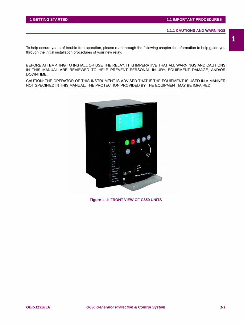
Figure 1–1: FRONT VIEW OF G650 UNITS
1-2 G650 Generator Protection & Control System GEK-113285A
1.1 IMPORTANT PROCEDURES 1 GETTING STARTED
11.1.1.1 COMMUNICATION BOARDS WITHDRAWAL / INSERTION
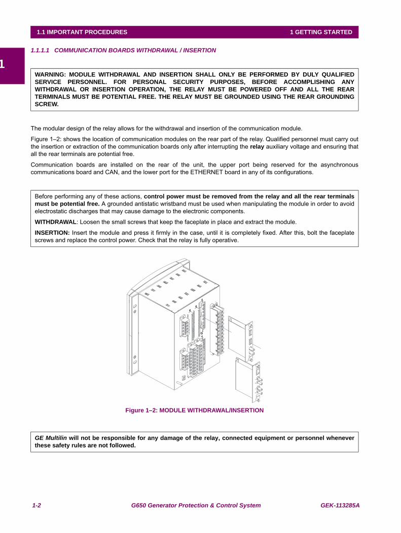
The modular design of the relay allows for the withdrawal and insertion of the communication module.
Figure 1–2: shows the location of communication modules on the rear part of the relay. Qualified personnel must carry outthe insertion or extraction of the communication boards only after interrupting the relay auxiliary voltage and ensuring thatall the rear terminals are potential free.
Communication boards are installed on the rear of the unit, the upper port being reserved for the asynchronouscommunications board and CAN, and the lower port for the ETHERNET board in any of its configurations.
Figure 1–2: MODULE WITHDRAWAL/INSERTION
WARNING: MODULE WITHDRAWAL AND INSERTION SHALL ONLY BE PERFORMED BY DULY QUALIFIEDSERVICE PERSONNEL. FOR PERSONAL SECURITY PURPOSES, BEFORE ACCOMPLISHING ANYWITHDRAWAL OR INSERTION OPERATION, THE RELAY MUST BE POWERED OFF AND ALL THE REARTERMINALS MUST BE POTENTIAL FREE. THE RELAY MUST BE GROUNDED USING THE REAR GROUNDINGSCREW.
Before performing any of these actions, control power must be removed from the relay and all the rear terminalsmust be potential free. A grounded antistatic wristband must be used when manipulating the module in order to avoidelectrostatic discharges that may cause damage to the electronic components.
WITHDRAWAL: Loosen the small screws that keep the faceplate in place and extract the module.
INSERTION: Insert the module and press it firmly in the case, until it is completely fixed. After this, bolt the faceplatescrews and replace the control power. Check that the relay is fully operative.
GE Multilin will not be responsible for any damage of the relay, connected equipment or personnel wheneverthese safety rules are not followed.
GEK-113285A G650 Generator Protection & Control System 1-3
1 GETTING STARTED 1.1 IMPORTANT PROCEDURES
11.1.1.2 MAGNETIC MODULE TERMINALS
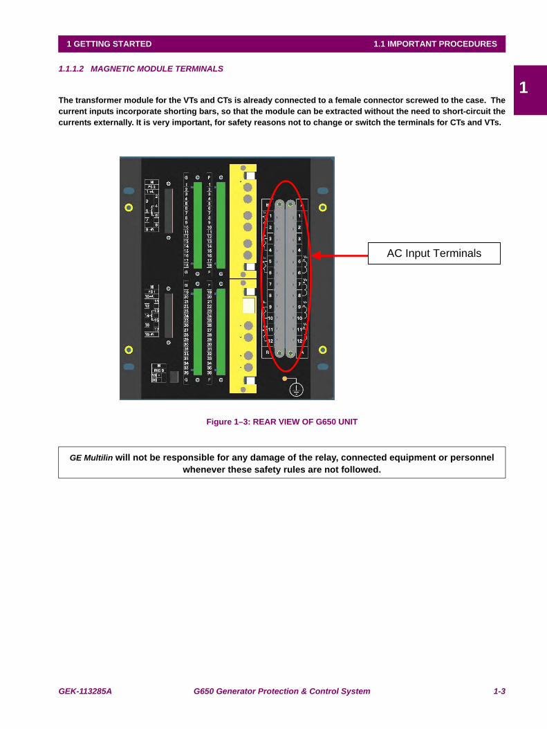
The transformer module for the VTs and CTs is already connected to a female connector screwed to the case. Thecurrent inputs incorporate shorting bars, so that the module can be extracted without the need to short-circuit thecurrents externally. It is very important, for safety reasons not to change or switch the terminals for CTs and VTs.
Figure 1–3: REAR VIEW OF G650 UNIT
GE Multilin will not be responsible for any damage of the relay, connected equipment or personnel whenever these safety rules are not followed.
AC Input Terminals
1-4 G650 Generator Protection & Control System GEK-113285A
1.1 IMPORTANT PROCEDURES 1 GETTING STARTED
11.1.2 INSPECTION CHECKLIST
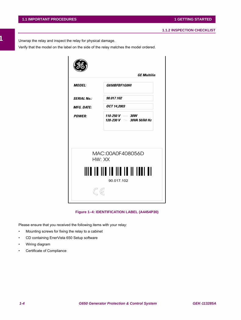
Unwrap the relay and inspect the relay for physical damage.
Verify that the model on the label on the side of the relay matches the model ordered.
Figure 1–4: IDENTIFICATION LABEL (A4454P30)
Please ensure that you received the following items with your relay:
• Mounting screws for fixing the relay to a cabinet
• CD containing EnerVista 650 Setup software
• Wiring diagram
• Certificate of Compliance

GEK-113285A G650 Generator Protection & Control System 1-5
1 GETTING STARTED 1.1 IMPORTANT PROCEDURES
1For product information, instruction manual updates, and the latest software updates, please visit the GE Multilin HomePage www.geindustrial.com/multilin.
Note: If there is any physical damage detected on the relay, or any of the contents listed are missing, pleasecontact GE Multilin immediately at:
EUROPE, MIDDLE EAST AND AFRICA:
GE MULTILIN
Av. Pinoa, 10
48170 Zamudio, Vizcaya (SPAIN)
Tel.: (34) 94-485 88 54, Fax: (34) 94-485 88 38
E-mail: [email protected]
AMERICA, ASIA AND AUSTRALIA:
GE MULTILIN
215, Anderson Avenue
L6E 1B3 Markham, ON (CANADA)
Tel.: +1 905 294 6222, Fax: +1 905 201 2098
E-mail: [email protected]
The information provided herein is not intended to cover all the details of the variations of the equipment, nor doesit take into account the circumstances that may be present in your installation, operating or maintenanceactivities.
Should you wish to receive additional information, or for any particular problem that cannot be solved by referringto the information contained herein, please contact GENERAL ELECTRIC MULTILIN.
1-6 G650 Generator Protection & Control System GEK-113285A
1.1 IMPORTANT PROCEDURES 1 GETTING STARTED
11.1.3 SAFETY INSTRUCTIONS
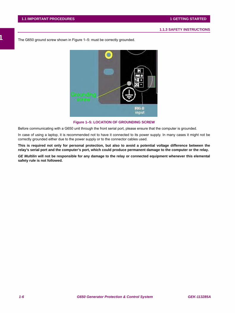
The G650 ground screw shown in Figure 1–5: must be correctly grounded.
Figure 1–5: LOCATION OF GROUNDING SCREW
Before communicating with a G650 unit through the front serial port, please ensure that the computer is grounded.
In case of using a laptop, it is recommended not to have it connected to its power supply. In many cases it might not becorrectly grounded either due to the power supply or to the connector cables used.
This is required not only for personal protection, but also to avoid a potential voltage difference between therelay’s serial port and the computer’s port, which could produce permanent damage to the computer or the relay.
GE Multilin will not be responsible for any damage to the relay or connected equipment whenever this elementalsafety rule is not followed.
GEK-113285A G650 Generator Protection & Control System 1-7
1 GETTING STARTED 1.2 OVERVIEW
11.2OVERVIEW 1.2.1 INTRODUCTION TO 650 FAMILY OF RELAYS
Historically, substation protection, control and metering functions were performed with electromechanical equipment. Thisfirst generation of equipment was gradually replaced by analog electronic equipment (called static devices), most of whichemulated the single-function approach of their electromechanical precursors. Both of these technologies requiredexpensive cabling and auxiliary equipment to produce functioning systems.
Recently, digital electronic equipment has begun to provide protection, control and metering functions. Initially, thisequipment was either single function or had very limited multi-function capability, and did not significantly reduce thecabling and auxiliary equipment required. However, recent digital relays have become quite multi-functional, reducingcabling and auxiliaries significantly. These devices also transfer data to central control facilities and Human MachineInterfaces using electronic communications. The functions performed by these products have become so broad that manyusers prefer the term IED (Intelligent Electronic Device).
It is obvious to station designers that the amount of cabling and auxiliary equipment installed in stations can be even furtherreduced, to 20% to 70% of the levels common in 1990, to achieve large cost reductions. This requires placing even morefunctions within the IEDs.
Users of power equipment are also interested in reducing cost by improving power quality and personnel productivity, andas always, in increasing system reliability and efficiency. These objectives are realized through software which is used toperform functions at both the station and supervisory levels. The use of these systems is growing rapidly.
High speed communications are required to meet the data transfer rates required by modern automatic control andmonitoring systems. In the near future, very high speed communications will be required to perform protection signalling.
IEDs with capabilities outlined above will also provided significantly more power system data than is presently available,enhance operations and maintenance, and permit the use of adaptive system configuration for protection and controlsystems. This new generation of equipment must also be easily incorporated into automation systems, at both the stationand enterprise levels.
1.2.2 HARDWARE ARCHITECTURE
650 family of relays has been designed to meet the goals described above that are appearing nowadays in the environmentof new substations.
The 650 is a digital-based device containing a central processing unit (CPU) that handles multiple types of input and outputsignals. The 650 family can communicate over a local area network (LAN) with an operator interface, a programmingdevice, or another 650 or UR device.
The CPU module contains firmware that provides protection elements in the form of logic algorithms, as well asprogramming logic gates, timers, and latches for control features. It incorporates two internal processors, one for genericuse and a second one dedicated for communications.
Input Elements accept a variety of analog or digital signals from the field. The 650 isolates and converts these signals intologic signals used by the relay.
Output Elements convert and isolate the logic signals generated by the relay into digital signals that can be used to controlfield devices.
1-8 G650 Generator Protection & Control System GEK-113285A
1.2 OVERVIEW 1 GETTING STARTED
1
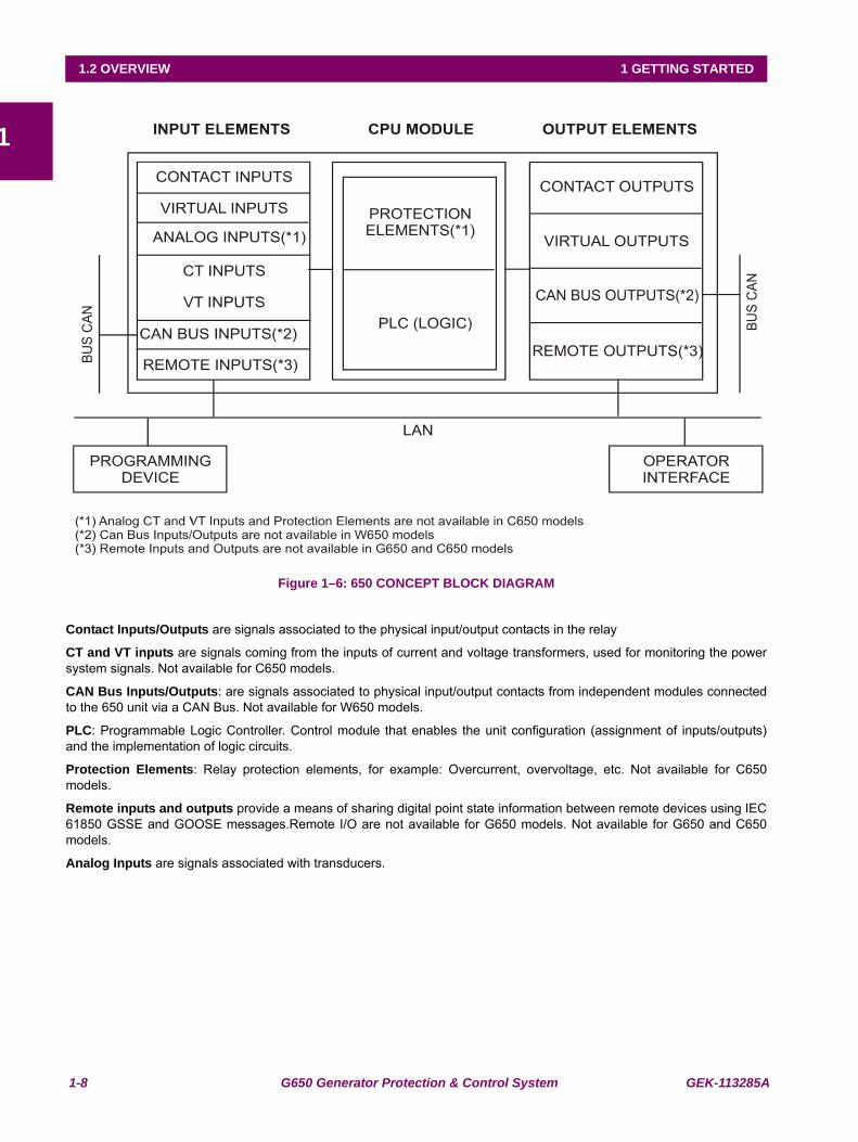
Figure 1–6: 650 CONCEPT BLOCK DIAGRAM
Contact Inputs/Outputs are signals associated to the physical input/output contacts in the relay
CT and VT inputs are signals coming from the inputs of current and voltage transformers, used for monitoring the powersystem signals. Not available for C650 models.
CAN Bus Inputs/Outputs: are signals associated to physical input/output contacts from independent modules connectedto the 650 unit via a CAN Bus. Not available for W650 models.
PLC: Programmable Logic Controller. Control module that enables the unit configuration (assignment of inputs/outputs)and the implementation of logic circuits.
Protection Elements: Relay protection elements, for example: Overcurrent, overvoltage, etc. Not available for C650models.
Remote inputs and outputs provide a means of sharing digital point state information between remote devices using IEC61850 GSSE and GOOSE messages.Remote I/O are not available for G650 models. Not available for G650 and C650models.
Analog Inputs are signals associated with transducers.
GEK-113285A G650 Generator Protection & Control System 1-9
1 GETTING STARTED 1.2 OVERVIEW
11.2.3 SOFTWARE ARCHITECTURE
The firmware (software embedded in the relay) has been designed using object oriented programming techniques (OOP).These techniques are based on the use of objects and classes, and provide the software architecture with the samecharacteristics as the hardware architecture, i.e., modularity, scalability and flexibility.
1.2.4 COMMUNICATIONS ARCHITECTURE
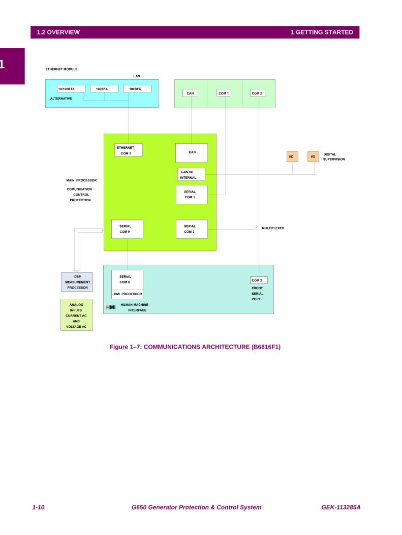
The main processor performs protection, control, and communication functions, incorporating two internal processors, onefor generic use and a second one dedicated for communications.
A dedicated serial port is used for communication between the main processor and the human-machine interface. Theserial connection provides great immunity against electromagnetic disturbances, thus increasing system safety.
All G650 units incorporate an RS232 serial port on the front of the relay. There is also a possibility to incorporate up to twoadditional communication modules on the rear.
One of the modules provides asynchronous serial communications, using different physical media (RS485, plastic or glassfiber optic) depending on the selected model. The module incorporates two identical ports, COM1 and COM2. The COM2port is multiplexed with the front port. Additionally, this module may incorporate a port for CAN BUS communications, usedfor the connection to the Remote CAN BUS I/O module. This feature allows increasing up to 100% the I/O capability, whenthe maximum number of I/Os available inside the relay is not enough for a specific application.
Available options are:
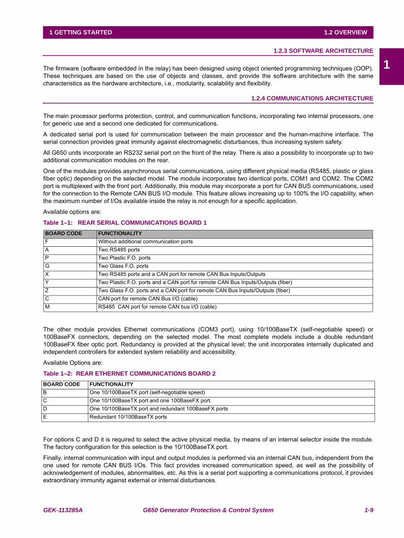
Table 1–1: REAR SERIAL COMMUNICATIONS BOARD 1
The other module provides Ethernet communications (COM3 port), using 10/100BaseTX (self-negotiable speed) or100BaseFX connectors, depending on the selected model. The most complete models include a double redundant100BaseFX fiber optic port. Redundancy is provided at the physical level; the unit incorporates internally duplicated andindependent controllers for extended system reliability and accessibility.
Available Options are:
Table 1–2: REAR ETHERNET COMMUNICATIONS BOARD 2
For options C and D it is required to select the active physical media, by means of an internal selector inside the module.The factory configuration for this selection is the 10/100BaseTX port.
Finally, internal communication with input and output modules is performed via an internal CAN bus, independent from theone used for remote CAN BUS I/Os. This fact provides increased communication speed, as well as the possibility ofacknowledgement of modules, abnormalities, etc. As this is a serial port supporting a communications protocol, it providesextraordinary immunity against external or internal disturbances.
BOARD CODE FUNCTIONALITYF Without additional communication portsA Two RS485 portsP Two Plastic F.O. portsG Two Glass F.O. portsX Two RS485 ports and a CAN port for remote CAN Bus Inputs/Outputs Y Two Plastic F.O. ports and a CAN port for remote CAN Bus Inputs/Outputs (fiber)Z Two Glass F.O. ports and a CAN port for remote CAN Bus Inputs/Outputs (fiber)C CAN port for remote CAN Bus I/O (cable)M RS485 CAN port for remote CAN bus I/O (cable)
BOARD CODE FUNCTIONALITYB One 10/100BaseTX port (self-negotiable speed)C One 10/100BaseTX port and one 100BaseFX port.D One 10/100BaseTX port and redundant 100BaseFX portsE Redundant 10/100BaseTX ports
1-10 G650 Generator Protection & Control System GEK-113285A
1.2 OVERVIEW 1 GETTING STARTED
1
Figure 1–7: COMMUNICATIONS ARCHITECTURE (B6816F1)
GEK-113285A G650 Generator Protection & Control System 1-11
1 GETTING STARTED 1.3 ENERVISTA 650 SETUP SOFTWARE
11.3ENERVISTA 650 SETUP SOFTWARE 1.3.1 SYSTEM REQUIREMENTS
The EnerVista 650 Setup software interface is the preferred method to edit settings and view actual values because the PCmonitor can display more information in a simple comprehensible format.
The following minimum requirements must be met for the EnerVista 650 Setup software to properly operate on a PC:
• Pentium® class or higher processor (Pentium® II 300 MHz or higher recommended)
• Windows® NT 4.0 (Service Pack 3 or higher), Windows® 2000, Windows® XP
• Internet Explorer® 5.0 or higher
• 64 MB of RAM (128 MB recommended)
• 40 MB of available space on system drive and 40 MB of available space on installation drive
• RS232C serial and/or Ethernet port for communications to the relay
1.3.2 INSTALLATION
After ensuring the minimum requirements for using EnerVista 650 Setup are met (see previous section), use the followingprocedure to install the EnerVista 650 Setup from the GE EnerVista CD.
1. Insert the GE EnerVista CD into your CD-ROM drive.
2. Click the Install Now button and follow the installation instructions to install the no-charge EnerVista software.
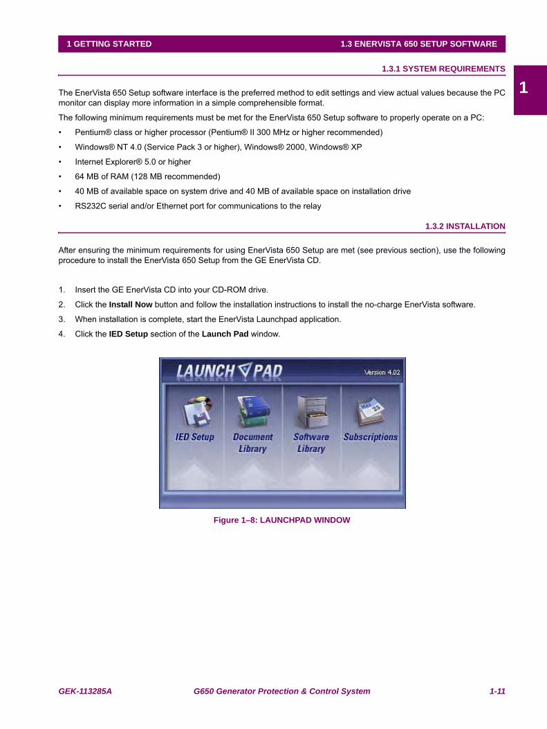
3. When installation is complete, start the EnerVista Launchpad application.
4. Click the IED Setup section of the Launch Pad window.
Figure 1–8: LAUNCHPAD WINDOW
1-12 G650 Generator Protection & Control System GEK-113285A
1.3 ENERVISTA 650 SETUP SOFTWARE 1 GETTING STARTED
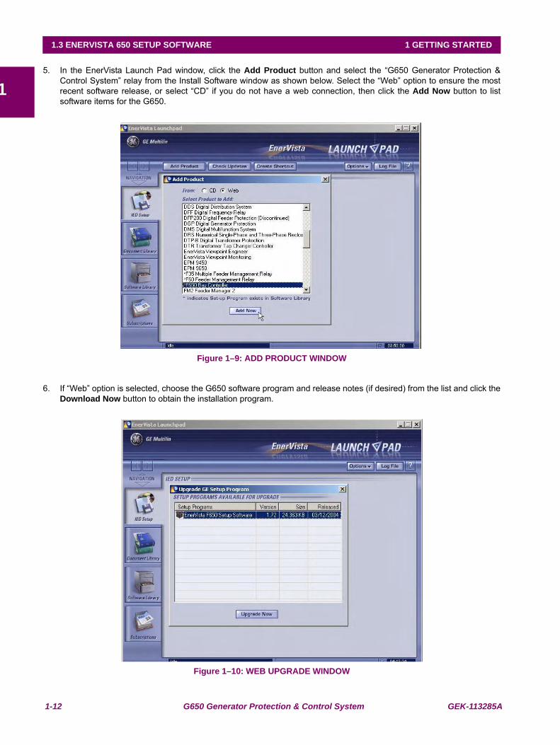
15. In the EnerVista Launch Pad window, click the Add Product button and select the “G650 Generator Protection &
Control System” relay from the Install Software window as shown below. Select the “Web” option to ensure the mostrecent software release, or select “CD” if you do not have a web connection, then click the Add Now button to listsoftware items for the G650.
Figure 1–9: ADD PRODUCT WINDOW
6. If “Web” option is selected, choose the G650 software program and release notes (if desired) from the list and click theDownload Now button to obtain the installation program.
Figure 1–10: WEB UPGRADE WINDOW
GEK-113285A G650 Generator Protection & Control System 1-13
1 GETTING STARTED 1.3 ENERVISTA 650 SETUP SOFTWARE
17. EnerVista Launchpad will obtain the installation program from the Web or CD. Once the download is complete, double-
click the installation program to install the EnerVista 650 Setup software.
8. Select the complete path, including the new directory name, where the EnerVista 650 Setup will be installed.
9. Click on Next to begin the installation. The files will be installed in the directory indicated and the installation programwill automatically create icons and add EnerVista 650 Setup to the Windows start menu.
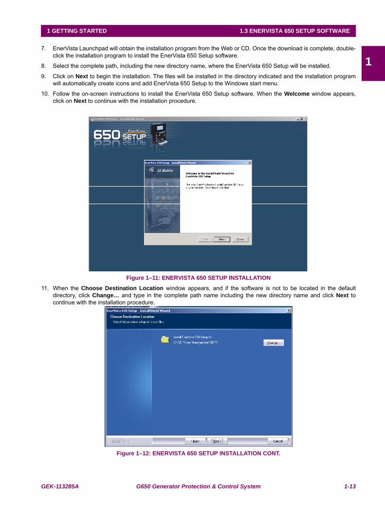
10. Follow the on-screen instructions to install the EnerVista 650 Setup software. When the Welcome window appears,click on Next to continue with the installation procedure.
Figure 1–11: ENERVISTA 650 SETUP INSTALLATION
11. When the Choose Destination Location window appears, and if the software is not to be located in the defaultdirectory, click Change… and type in the complete path name including the new directory name and click Next tocontinue with the installation procedure.
Figure 1–12: ENERVISTA 650 SETUP INSTALLATION CONT.
1-14 G650 Generator Protection & Control System GEK-113285A
1.3 ENERVISTA 650 SETUP SOFTWARE 1 GETTING STARTED
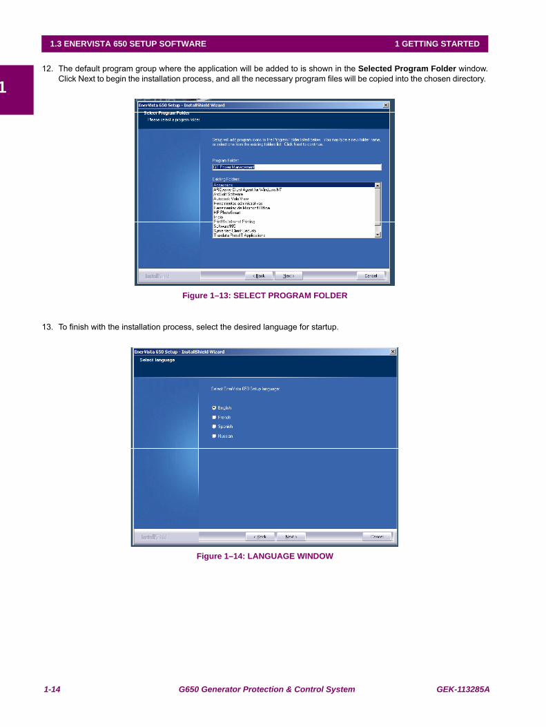
112. The default program group where the application will be added to is shown in the Selected Program Folder window.
Click Next to begin the installation process, and all the necessary program files will be copied into the chosen directory.
Figure 1–13: SELECT PROGRAM FOLDER
13. To finish with the installation process, select the desired language for startup.
Figure 1–14: LANGUAGE WINDOW
GEK-113285A G650 Generator Protection & Control System 1-15
1 GETTING STARTED 1.3 ENERVISTA 650 SETUP SOFTWARE
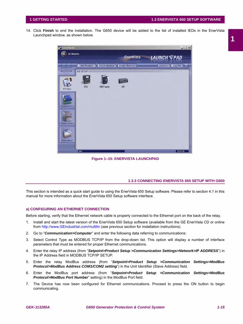
114. Click Finish to end the installation. The G650 device will be added to the list of installed IEDs in the EnerVista
Launchpad window, as shown below.
Figure 1–15: ENERVISTA LAUNCHPAD
1.3.3 CONNECTING ENERVISTA 650 SETUP WITH G650
This section is intended as a quick start guide to using the EnerVista 650 Setup software. Please refer to section 4.1 in thismanual for more information about the EnerVista 650 Setup software interface.
a) CONFIGURING AN ETHERNET CONNECTION
Before starting, verify that the Ethernet network cable is properly connected to the Ethernet port on the back of the relay.
1. Install and start the latest version of the EnerVista 650 Setup software (available from the GE EnerVista CD or onlinefrom http://www.GEindustrial.com/multilin (see previous section for installation instructions).
2. Go to “Communication>Computer” and enter the following data referring to communications:
3. Select Control Type as MODBUS TCP/IP from the drop-down list. This option will display a number of interfaceparameters that must be entered for proper Ethernet communications.
4. Enter the relay IP address (from “Setpoint>Product Setup >Communication Settings>Network>IP ADDRESS”) inthe IP Address field in MODBUS TCP/IP SETUP.
5. Enter the relay ModBus address (from “Setpoint>Product Setup >Communication Settings>ModBusProtocol>ModBus Address COM1/COM2 setting”) in the Unit Identifier (Slave Address) field.
6. Enter the ModBus port address (from “Setpoint>Product Setup >Communication Settings>ModBusProtocol>ModBus Port Number” setting) in the ModBus Port field.
7. The Device has now been configured for Ethernet communications. Proceed to press the ON button to begincommunicating.
1-16 G650 Generator Protection & Control System GEK-113285A
1.3 ENERVISTA 650 SETUP SOFTWARE 1 GETTING STARTED
1 b) CONFIGURING AN RS232 CONNECTION
Before starting, verify that the RS232 serial cable is properly connected to the RS232 port on the front panel of the relay.
1. Install and start the latest version of the EnerVista 650 Setup software (available from the GE EnerVista CD or onlinefrom http://www.GEindustrial.com/multilin (see previous section for installation instructions).
2. Go to “Communication>Computer” and enter the following data referred to communications:
3. Select Control Type as No Control Type from the drop-down list. This option will display a number of interfaceparameters that must be entered for proper serial communications.
4. Enter the relay Slave Address (“Setpoint>Product Setup >Communication Settings>ModBus Protocol” menu) inthe Slave Address field. The default value is 254.
5. Enter the physical communications parameters (Baudrate and parity settings) from the “Setpoint>Product Setup>Communication Settings>Serial Ports” menu, in their respective fields. Default values are 19200 for baudrate andnone for parity.
6. The Device has now been configured for RS232 communications. Proceed to press the ON button to begincommunicating.
GEK-113285A G650 Generator Protection & Control System 1-17
1 GETTING STARTED 1.4 650 HARDWARE
11.4650 HARDWARE 1.4.1 MOUNTING & WIRING
Please refer to Chapter 3. Hardware for detailed mounting and wiring instructions.
1.4.2 650 COMMUNICATIONS
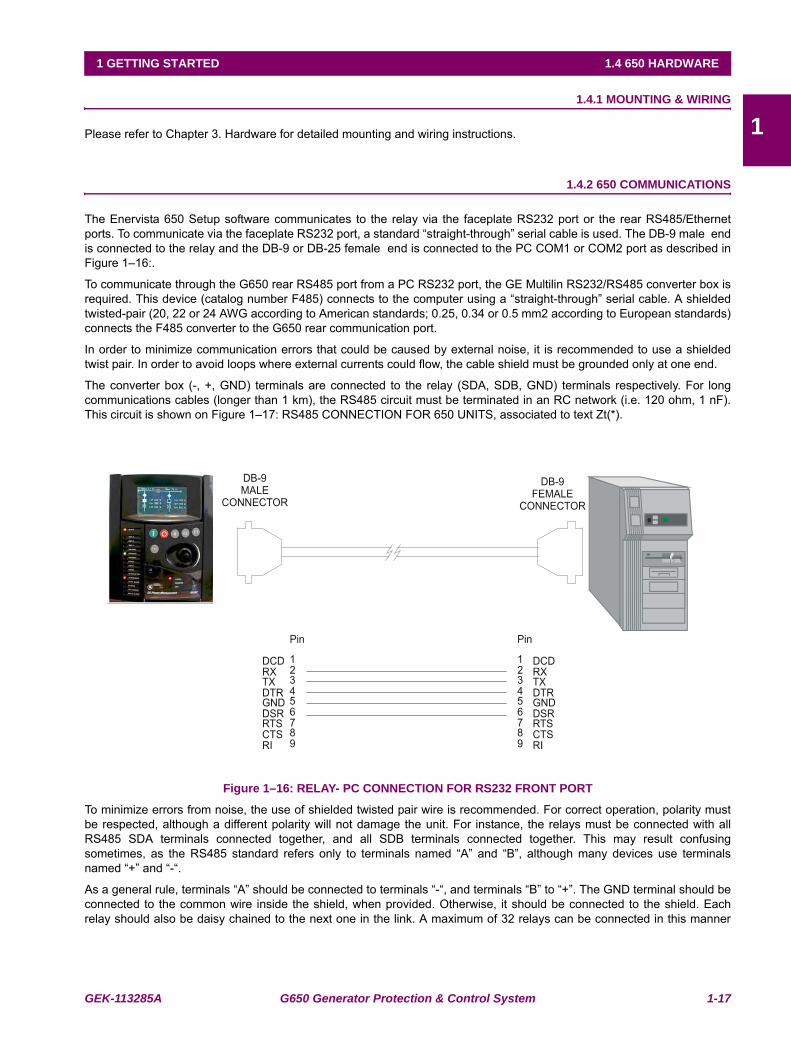
The Enervista 650 Setup software communicates to the relay via the faceplate RS232 port or the rear RS485/Ethernetports. To communicate via the faceplate RS232 port, a standard “straight-through” serial cable is used. The DB-9 male endis connected to the relay and the DB-9 or DB-25 female end is connected to the PC COM1 or COM2 port as described inFigure 1–16:.
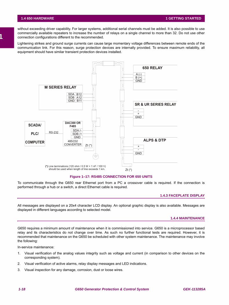
To communicate through the G650 rear RS485 port from a PC RS232 port, the GE Multilin RS232/RS485 converter box isrequired. This device (catalog number F485) connects to the computer using a “straight-through” serial cable. A shieldedtwisted-pair (20, 22 or 24 AWG according to American standards; 0.25, 0.34 or 0.5 mm2 according to European standards)connects the F485 converter to the G650 rear communication port.
In order to minimize communication errors that could be caused by external noise, it is recommended to use a shieldedtwist pair. In order to avoid loops where external currents could flow, the cable shield must be grounded only at one end.
The converter box (-, +, GND) terminals are connected to the relay (SDA, SDB, GND) terminals respectively. For longcommunications cables (longer than 1 km), the RS485 circuit must be terminated in an RC network (i.e. 120 ohm, 1 nF).This circuit is shown on Figure 1–17: RS485 CONNECTION FOR 650 UNITS, associated to text Zt(*).
Figure 1–16: RELAY- PC CONNECTION FOR RS232 FRONT PORT
To minimize errors from noise, the use of shielded twisted pair wire is recommended. For correct operation, polarity mustbe respected, although a different polarity will not damage the unit. For instance, the relays must be connected with allRS485 SDA terminals connected together, and all SDB terminals connected together. This may result confusingsometimes, as the RS485 standard refers only to terminals named “A” and “B”, although many devices use terminalsnamed “+” and “-“.
As a general rule, terminals “A” should be connected to terminals “-“, and terminals “B” to “+”. The GND terminal should beconnected to the common wire inside the shield, when provided. Otherwise, it should be connected to the shield. Eachrelay should also be daisy chained to the next one in the link. A maximum of 32 relays can be connected in this manner
1-18 G650 Generator Protection & Control System GEK-113285A
1.4 650 HARDWARE 1 GETTING STARTED
1without exceeding driver capability. For larger systems, additional serial channels must be added. It is also possible to usecommercially available repeaters to increase the number of relays on a single channel to more than 32. Do not use otherconnection configurations different to the recommended.
Lightening strikes and ground surge currents can cause large momentary voltage differences between remote ends of thecommunication link. For this reason, surge protection devices are internally provided. To ensure maximum reliability, allequipment should have similar transient protection devices installed.
Figure 1–17: RS485 CONNECTION FOR 650 UNITS
To communicate through the G650 rear Ethernet port from a PC a crossover cable is required. If the connection isperformed through a hub or a switch, a direct Ethernet cable is required.
1.4.3 FACEPLATE DISPLAY
All messages are displayed on a 20x4 character LCD display. An optional graphic display is also available. Messages aredisplayed in different languages according to selected model.
1.4.4 MAINTENANCE
G650 requires a minimum amount of maintenance when it is commissioned into service. G650 is a microprocessor basedrelay and its characteristics do not change over time. As such no further functional tests are required. However, it isrecommended that maintenance on the G650 be scheduled with other system maintenance. The maintenance may involvethe following:
In-service maintenance:
1. Visual verification of the analog values integrity such as voltage and current (in comparison to other devices on thecorresponding system).
2. Visual verification of active alarms, relay display messages and LED indications.
3. Visual inspection for any damage, corrosion, dust or loose wires.
GEK-113285A G650 Generator Protection & Control System 1-19
1 GETTING STARTED 1.4 650 HARDWARE
14. Event recorder file download with further event analysis.
Out-of-service maintenance:
1. Check wiring connections for firmness.
2. Analog values (current, voltages, analog inputs) injection test and metering accuracy verification. Calibrated testequipment is required.
3. Protection elements setpoints verification (analog values injection or visual verification of setting file entries againstrelay settings schedule).
4. Contact inputs and outputs verification. This test can be conducted by direct change of state forcing or as part of thesystem functional testing.
5. Visual inspection for any damage, corrosion or dust.
6. Event recorder file download with further events analysis.
Unscheduled maintenance such as during a disturbance causing system interruption:
1. View the event recorder and oscillography or fault report for correct operation of inputs, outputs and elements.
If it is concluded that the relay or one of its modules is of concern, contact GE Multilin or one of its representative for promptservice.

1-20 G650 Generator Protection & Control System GEK-113285A
1.4 650 HARDWARE 1 GETTING STARTED
1
GEK-113285A G650 Generator Protection & Control System 2-1
2 PRODUCT DESCRIPTION 2.1 OVERVIEW
2
2 PRODUCT DESCRIPTION 2.1OVERVIEW 2.1.1 G650 OVERVIEW
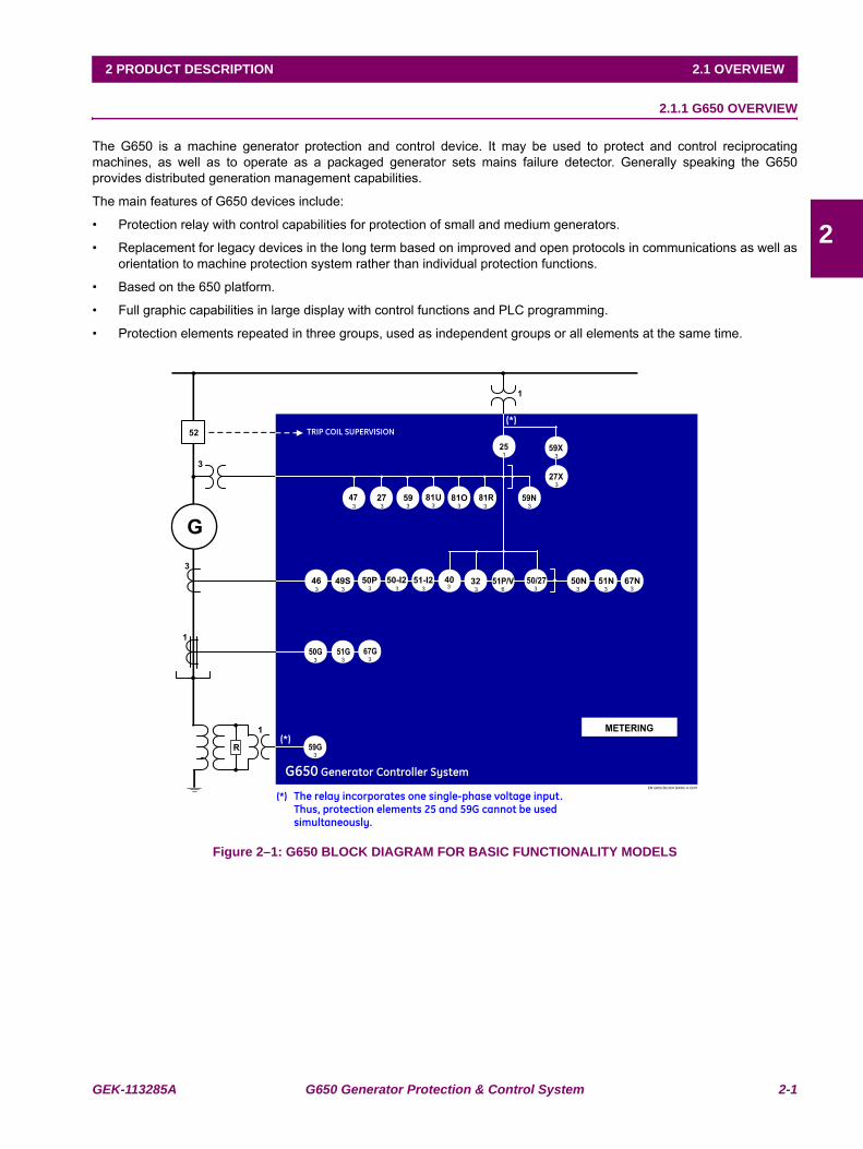
The G650 is a machine generator protection and control device. It may be used to protect and control reciprocatingmachines, as well as to operate as a packaged generator sets mains failure detector. Generally speaking the G650provides distributed generation management capabilities.
The main features of G650 devices include:
• Protection relay with control capabilities for protection of small and medium generators.
• Replacement for legacy devices in the long term based on improved and open protocols in communications as well asorientation to machine protection system rather than individual protection functions.
• Based on the 650 platform.
• Full graphic capabilities in large display with control functions and PLC programming.
• Protection elements repeated in three groups, used as independent groups or all elements at the same time.
Figure 2–1: G650 BLOCK DIAGRAM FOR BASIC FUNCTIONALITY MODELS
2-2 G650 Generator Protection & Control System GEK-113285A
2.1 OVERVIEW 2 PRODUCT DESCRIPTION
2
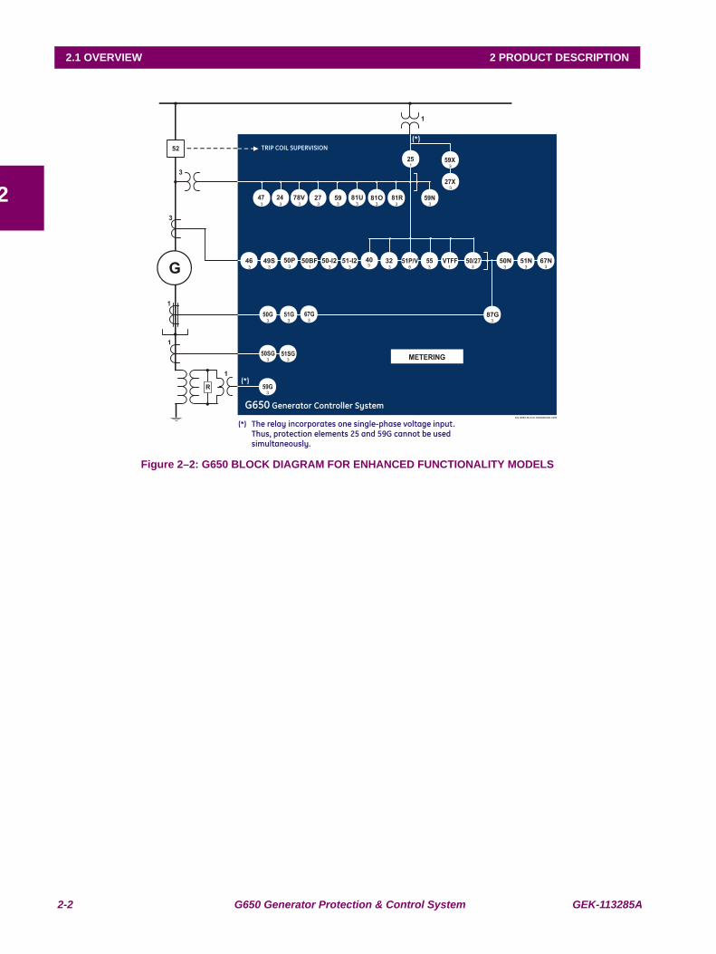
Figure 2–2: G650 BLOCK DIAGRAM FOR ENHANCED FUNCTIONALITY MODELS
GEK-113285A G650 Generator Protection & Control System 2-3
2 PRODUCT DESCRIPTION 2.2 SUMMARY
2
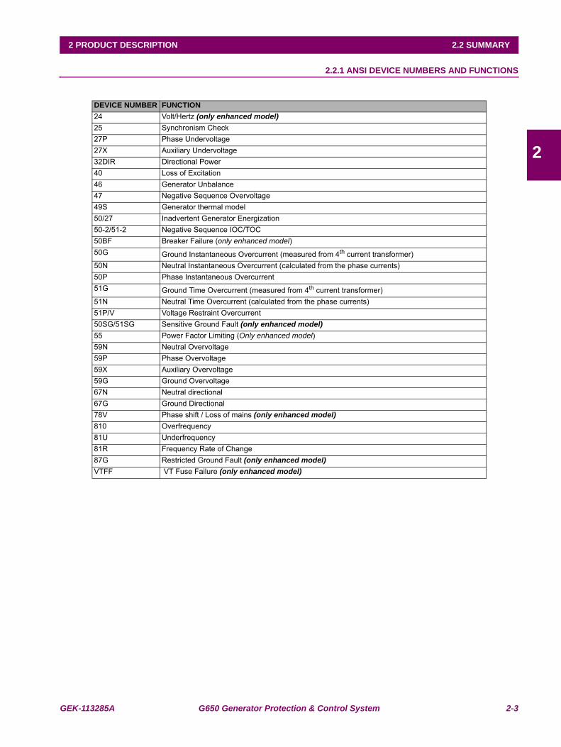
2.2SUMMARY 2.2.1 ANSI DEVICE NUMBERS AND FUNCTIONS
DEVICE NUMBER FUNCTION24 Volt/Hertz (only enhanced model)25 Synchronism Check27P Phase Undervoltage27X Auxiliary Undervoltage32DIR Directional Power40 Loss of Excitation46 Generator Unbalance47 Negative Sequence Overvoltage49S Generator thermal model50/27 Inadvertent Generator Energization50-2/51-2 Negative Sequence IOC/TOC50BF Breaker Failure (only enhanced model)50G Ground Instantaneous Overcurrent (measured from 4th current transformer)50N Neutral Instantaneous Overcurrent (calculated from the phase currents)50P Phase Instantaneous Overcurrent 51G Ground Time Overcurrent (measured from 4th current transformer)51N Neutral Time Overcurrent (calculated from the phase currents)51P/V Voltage Restraint Overcurrent50SG/51SG Sensitive Ground Fault (only enhanced model)55 Power Factor Limiting (Only enhanced model)59N Neutral Overvoltage 59P Phase Overvoltage59X Auxiliary Overvoltage59G Ground Overvoltage67N Neutral directional67G Ground Directional78V Phase shift / Loss of mains (only enhanced model)810 Overfrequency81U Underfrequency81R Frequency Rate of Change87G Restricted Ground Fault (only enhanced model)VTFF VT Fuse Failure (only enhanced model)
2-4 G650 Generator Protection & Control System GEK-113285A
2.2 SUMMARY 2 PRODUCT DESCRIPTION
2
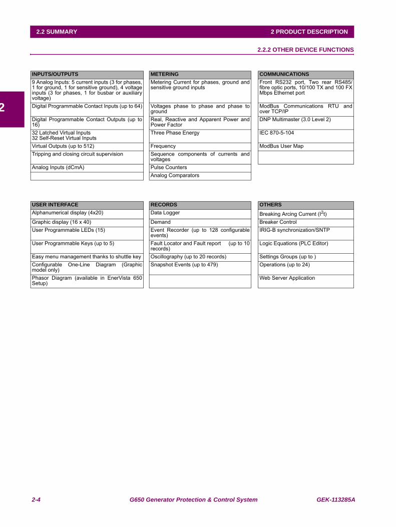
2.2.2 OTHER DEVICE FUNCTIONS
INPUTS/OUTPUTS METERING COMMUNICATIONS9 Analog Inputs: 5 current inputs (3 for phases,1 for ground, 1 for sensitive ground), 4 voltageinputs (3 for phases, 1 for busbar or auxiliaryvoltage)
Metering Current for phases, ground andsensitive ground inputs
Front RS232 port, Two rear RS485/fibre optic ports, 10/100 TX and 100 FXMbps Ethernet port
Digital Programmable Contact Inputs (up to 64) Voltages phase to phase and phase toground
ModBus Communications RTU andover TCP/IP
Digital Programmable Contact Outputs (up to16)
Real, Reactive and Apparent Power andPower Factor
DNP Multimaster (3.0 Level 2)
32 Latched Virtual Inputs32 Self-Reset Virtual Inputs
Three Phase Energy IEC 870-5-104
Virtual Outputs (up to 512) Frequency ModBus User MapTripping and closing circuit supervision Sequence components of currents and
voltagesAnalog Inputs (dCmA) Pulse Counters
Analog Comparators
USER INTERFACE RECORDS OTHERSAlphanumerical display (4x20) Data Logger Breaking Arcing Current (I2t)Graphic display (16 x 40) Demand Breaker ControlUser Programmable LEDs (15) Event Recorder (up to 128 configurable
events)IRIG-B synchronization/SNTP
User Programmable Keys (up to 5) Fault Locator and Fault report (up to 10records)
Logic Equations (PLC Editor)
Easy menu management thanks to shuttle key Oscillography (up to 20 records) Settings Groups (up to )Configurable One-Line Diagram (Graphicmodel only)
Snapshot Events (up to 479) Operations (up to 24)
Phasor Diagram (available in EnerVista 650Setup)
Web Server Application
GEK-113285A G650 Generator Protection & Control System 2-5
2 PRODUCT DESCRIPTION 2.3 ORDERING CODE
2
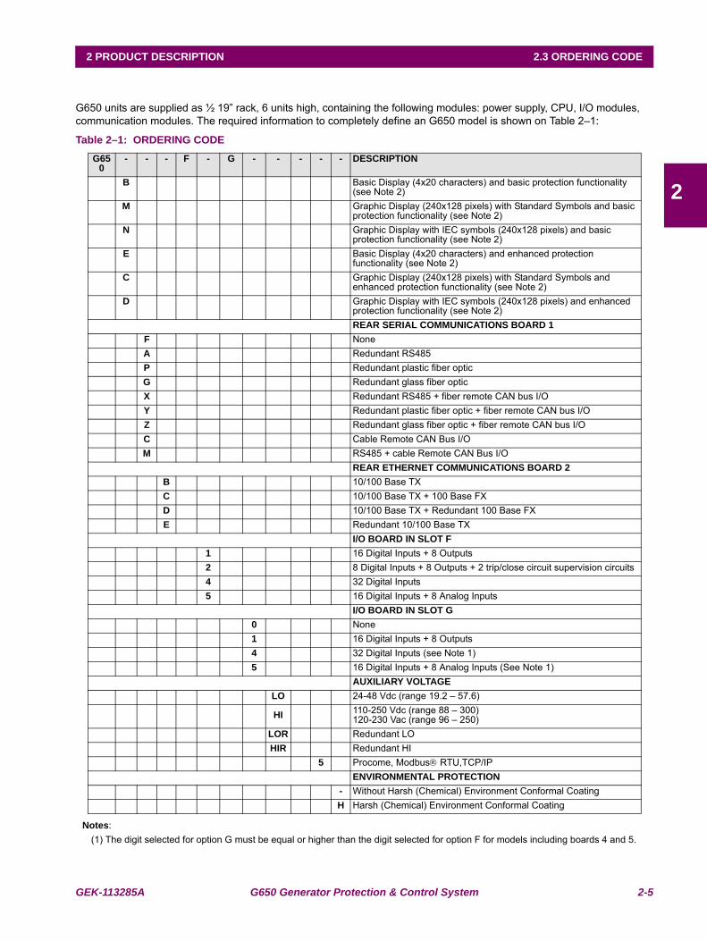
2.3ORDERING CODE
G650 units are supplied as ½ 19” rack, 6 units high, containing the following modules: power supply, CPU, I/O modules, communication modules. The required information to completely define an G650 model is shown on Table 2–1:
Table 2–1: ORDERING CODE
Notes:(1) The digit selected for option G must be equal or higher than the digit selected for option F for models including boards 4 and 5.
G650
- - - F - G - - - - - DESCRIPTION
B Basic Display (4x20 characters) and basic protection functionality (see Note 2)
M Graphic Display (240x128 pixels) with Standard Symbols and basic protection functionality (see Note 2)
N Graphic Display with IEC symbols (240x128 pixels) and basic protection functionality (see Note 2)
E Basic Display (4x20 characters) and enhanced protection functionality (see Note 2)
C Graphic Display (240x128 pixels) with Standard Symbols and enhanced protection functionality (see Note 2)
D Graphic Display with IEC symbols (240x128 pixels) and enhanced protection functionality (see Note 2)REAR SERIAL COMMUNICATIONS BOARD 1
F NoneA Redundant RS485 P Redundant plastic fiber optic G Redundant glass fiber opticX Redundant RS485 + fiber remote CAN bus I/OY Redundant plastic fiber optic + fiber remote CAN bus I/OZ Redundant glass fiber optic + fiber remote CAN bus I/OC Cable Remote CAN Bus I/OM RS485 + cable Remote CAN Bus I/O
REAR ETHERNET COMMUNICATIONS BOARD 2 B 10/100 Base TXC 10/100 Base TX + 100 Base FXD 10/100 Base TX + Redundant 100 Base FXE Redundant 10/100 Base TX
I/O BOARD IN SLOT F1 16 Digital Inputs + 8 Outputs2 8 Digital Inputs + 8 Outputs + 2 trip/close circuit supervision circuits4 32 Digital Inputs5 16 Digital Inputs + 8 Analog Inputs
I/O BOARD IN SLOT G0 None1 16 Digital Inputs + 8 Outputs4 32 Digital Inputs (see Note 1)5 16 Digital Inputs + 8 Analog Inputs (See Note 1)
AUXILIARY VOLTAGELO 24-48 Vdc (range 19.2 – 57.6)
HI 110-250 Vdc (range 88 – 300)120-230 Vac (range 96 – 250)
LOR Redundant LO HIR Redundant HI
5 Procome, Modbus® RTU,TCP/IPENVIRONMENTAL PROTECTION
- Without Harsh (Chemical) Environment Conformal CoatingH Harsh (Chemical) Environment Conformal Coating
2-6 G650 Generator Protection & Control System GEK-113285A
2.3 ORDERING CODE 2 PRODUCT DESCRIPTION
2
F1G5 is a valid selection and F5G1 is and invalid selection. (2) The Protection functionality description for basic and enhanced models is listed in section 2.2.1: ANSI DEVICE NUMBERS AND
FUNCTIONS on page 2–3.
GEK-113285A G650 Generator Protection & Control System 2-7
2 PRODUCT DESCRIPTION 2.4 TECHNICAL SPECIFICATIONS
2
2.4 TECHNICAL SPECIFICATIONS
NOTE: TECHNICAL SPECIFICATIONS ARE SUBJECT TO CHANGE WITHOUT NOTICE
2.4.1 PROTECTION ELEMENTS
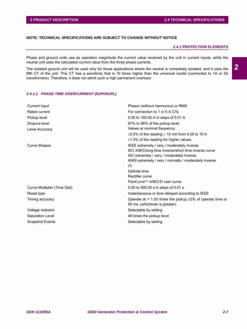
Phase and ground units use as operation magnitude the current value received by the unit in current inputs, while theneutral unit uses the calculated current value from the three phase currents.
The isolated ground unit will be used only for those applications where the neutral is completely isolated, and it uses thefifth CT of the unit. This CT has a sensitivity that is 10 times higher than the universal model (connected to 1A or 5Atransformers). Therefore, it does not admit such a high permanent overload.
2.4.1.1 PHASE TIME OVERCURRENT (51PH/51PL)
Current Input Phasor (without harmonics) or RMSRated current For connection to 1 or 5 A CTs.Pickup level 0.05 to 160.00 A in steps of 0.01 ADropout level 97% to 98% of the pickup levelLevel Accuracy Values at nominal frequency:
±0.5% of the reading ± 10 mA from 0.05 to 10 A±1.5% of the reading for higher values.
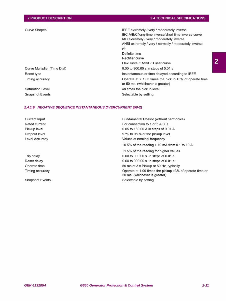
Curve Shapes IEEE extremely / very / moderately inverse IEC A/B/C/long-time inverse/short time inverse curveIAC extremely / very / moderately inverseANSI extremely / very / normally / moderately inverseI2tDefinite timeRectifier curveFlexCurve™ A/B/C/D user curve
Curve Multiplier (Time Dial) 0.00 to 900.00 s in steps of 0.01 sReset type Instantaneous or time delayed according to IEEETiming accuracy Operate at > 1.03 times the pickup ±3% of operate time or
50 ms. (whichever is greater)Voltage restraint Selectable by setting Saturation Level 48 times the pickup levelSnapshot Events Selectable by setting
2-8 G650 Generator Protection & Control System GEK-113285A
2.4 TECHNICAL SPECIFICATIONS 2 PRODUCT DESCRIPTION
2
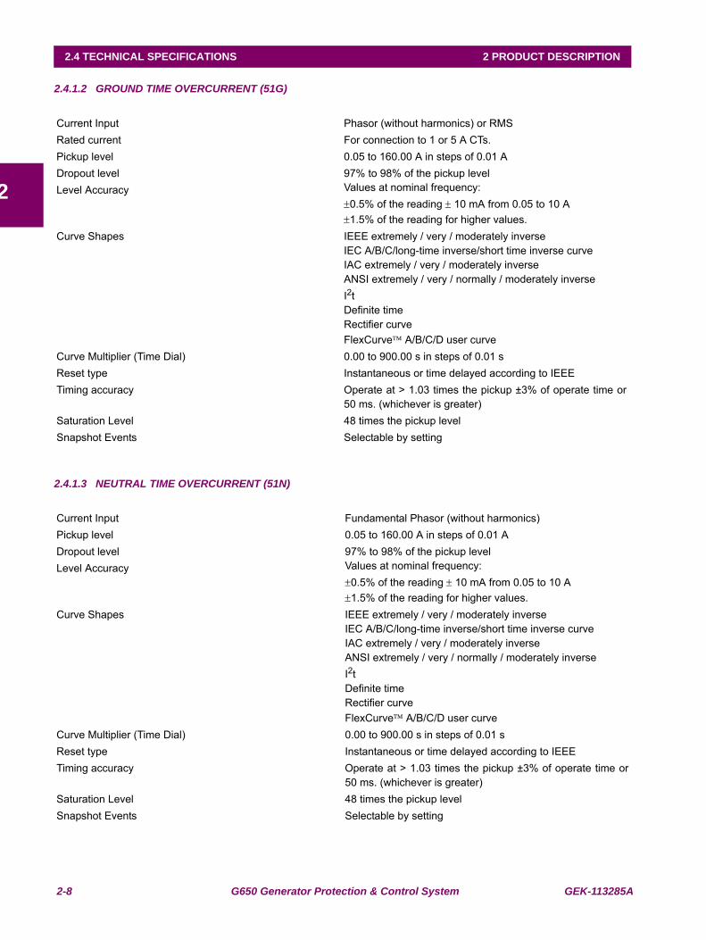
2.4.1.2 GROUND TIME OVERCURRENT (51G)
2.4.1.3 NEUTRAL TIME OVERCURRENT (51N)
Current Input Phasor (without harmonics) or RMSRated current For connection to 1 or 5 A CTs.Pickup level 0.05 to 160.00 A in steps of 0.01 ADropout level 97% to 98% of the pickup levelLevel Accuracy Values at nominal frequency:
±0.5% of the reading ± 10 mA from 0.05 to 10 A±1.5% of the reading for higher values.
Curve Shapes IEEE extremely / very / moderately inverse IEC A/B/C/long-time inverse/short time inverse curveIAC extremely / very / moderately inverseANSI extremely / very / normally / moderately inverseI2tDefinite timeRectifier curveFlexCurve™ A/B/C/D user curve
Curve Multiplier (Time Dial) 0.00 to 900.00 s in steps of 0.01 sReset type Instantaneous or time delayed according to IEEETiming accuracy Operate at > 1.03 times the pickup ±3% of operate time or
50 ms. (whichever is greater)Saturation Level 48 times the pickup levelSnapshot Events Selectable by setting
Current Input Fundamental Phasor (without harmonics)Pickup level 0.05 to 160.00 A in steps of 0.01 ADropout level 97% to 98% of the pickup levelLevel Accuracy Values at nominal frequency:
±0.5% of the reading ± 10 mA from 0.05 to 10 A±1.5% of the reading for higher values.
Curve Shapes IEEE extremely / very / moderately inverse IEC A/B/C/long-time inverse/short time inverse curveIAC extremely / very / moderately inverseANSI extremely / very / normally / moderately inverseI2tDefinite timeRectifier curveFlexCurve™ A/B/C/D user curve
Curve Multiplier (Time Dial) 0.00 to 900.00 s in steps of 0.01 sReset type Instantaneous or time delayed according to IEEETiming accuracy Operate at > 1.03 times the pickup ±3% of operate time or
50 ms. (whichever is greater)Saturation Level 48 times the pickup levelSnapshot Events Selectable by setting
GEK-113285A G650 Generator Protection & Control System 2-9
2 PRODUCT DESCRIPTION 2.4 TECHNICAL SPECIFICATIONS
2
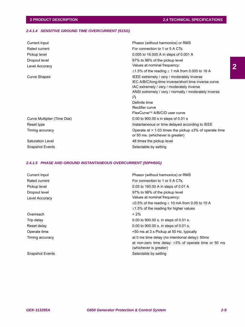
2.4.1.4 SENSITIVE GROUND TIME OVERCURRENT (51SG)
2.4.1.5 PHASE AND GROUND INSTANTANEOUS OVERCURRENT (50PH50G)
Current Input Phasor (without harmonics) or RMSRated current For connection to 1 or 5 A CTs.Pickup level 0.005 to 16.000 A in steps of 0.001 ADropout level 97% to 98% of the pickup levelLevel Accuracy Values at nominal frequency:
±1.5% of the reading ± 1 mA from 0.005 to 16 ACurve Shapes IEEE extremely / very / moderately inverse
IEC A/B/C/long-time inverse/short time inverse curveIAC extremely / very / moderately inverseANSI extremely / very / normally / moderately inverseI2tDefinite timeRectifier curveFlexCurve™ A/B/C/D user curve
Curve Multiplier (Time Dial) 0.00 to 900.00 s in steps of 0.01 sReset type Instantaneous or time delayed according to IEEETiming accuracy Operate at > 1.03 times the pickup ±3% of operate time
or 50 ms. (whichever is greater)Saturation Level 48 times the pickup levelSnapshot Events Selectable by setting
Current Input Phasor (without harmonics) or RMSRated current For connection to 1 or 5 A CTs.Pickup level 0.05 to 160.00 A in steps of 0.01 ADropout level 97% to 98% of the pickup levelLevel Accuracy Values at nominal frequency:
±0.5% of the reading ± 10 mA from 0.05 to 10 A±1.5% of the reading for higher values
Overreach < 2%Trip delay 0.00 to 900.00 s. in steps of 0.01 s.Reset delay 0.00 to 900.00 s. in steps of 0.01 s.Operate time <50 ms at 3 x Pickup at 50 Hz, typicallyTiming accuracy at 0 ms time delay (no intentional delay): 50ms
at non-zero time delay: ±3% of operate time or 50 ms(whichever is greater)
Snapshot Events Selectable by setting
2-10 G650 Generator Protection & Control System GEK-113285A
2.4 TECHNICAL SPECIFICATIONS 2 PRODUCT DESCRIPTION
2
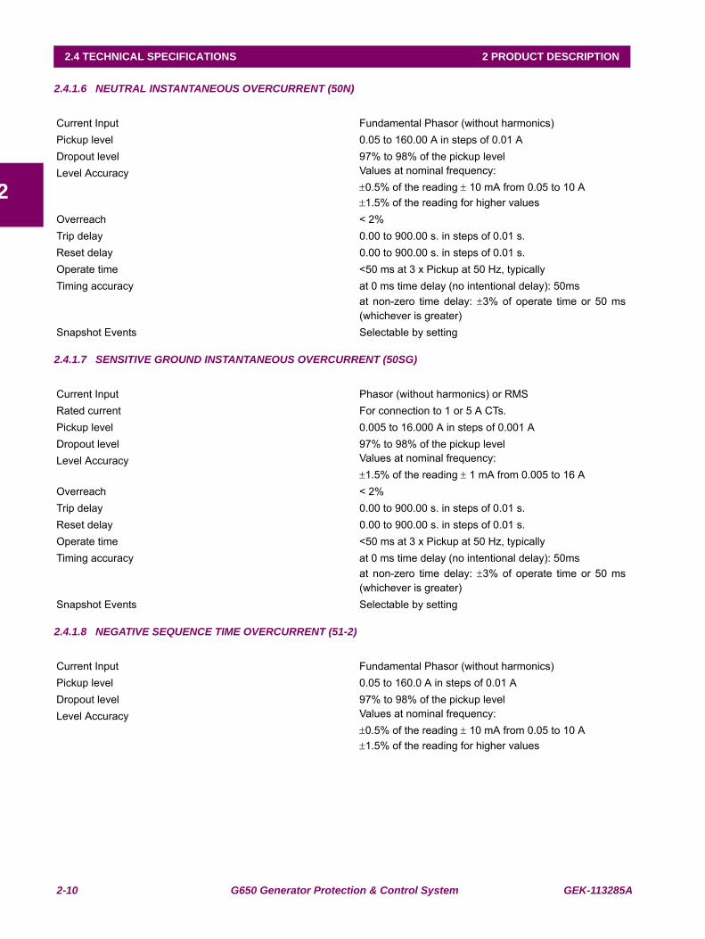
2.4.1.6 NEUTRAL INSTANTANEOUS OVERCURRENT (50N)
2.4.1.7 SENSITIVE GROUND INSTANTANEOUS OVERCURRENT (50SG)
2.4.1.8 NEGATIVE SEQUENCE TIME OVERCURRENT (51-2)
Current Input Fundamental Phasor (without harmonics)Pickup level 0.05 to 160.00 A in steps of 0.01 ADropout level 97% to 98% of the pickup levelLevel Accuracy Values at nominal frequency:
±0.5% of the reading ± 10 mA from 0.05 to 10 A±1.5% of the reading for higher values
Overreach < 2%Trip delay 0.00 to 900.00 s. in steps of 0.01 s.Reset delay 0.00 to 900.00 s. in steps of 0.01 s.Operate time <50 ms at 3 x Pickup at 50 Hz, typicallyTiming accuracy at 0 ms time delay (no intentional delay): 50ms
at non-zero time delay: ±3% of operate time or 50 ms(whichever is greater)
Snapshot Events Selectable by setting
Current Input Phasor (without harmonics) or RMSRated current For connection to 1 or 5 A CTs.Pickup level 0.005 to 16.000 A in steps of 0.001 ADropout level 97% to 98% of the pickup levelLevel Accuracy Values at nominal frequency:
±1.5% of the reading ± 1 mA from 0.005 to 16 AOverreach < 2%Trip delay 0.00 to 900.00 s. in steps of 0.01 s.Reset delay 0.00 to 900.00 s. in steps of 0.01 s.Operate time <50 ms at 3 x Pickup at 50 Hz, typicallyTiming accuracy at 0 ms time delay (no intentional delay): 50ms
at non-zero time delay: ±3% of operate time or 50 ms(whichever is greater)
Snapshot Events Selectable by setting
Current Input Fundamental Phasor (without harmonics)Pickup level 0.05 to 160.0 A in steps of 0.01 ADropout level 97% to 98% of the pickup levelLevel Accuracy Values at nominal frequency:
±0.5% of the reading ± 10 mA from 0.05 to 10 A±1.5% of the reading for higher values
GEK-113285A G650 Generator Protection & Control System 2-11
2 PRODUCT DESCRIPTION 2.4 TECHNICAL SPECIFICATIONS
2
2.4.1.9 NEGATIVE SEQUENCE INSTANTANEOUS OVERCURRENT (50-2)
Curve Shapes IEEE extremely / very / moderately inverse IEC A/B/C/long-time inverse/short time inverse curveIAC extremely / very / moderately inverseANSI extremely / very / normally / moderately inverseI2tDefinite timeRectifier curveFlexCurve™ A/B/C/D user curve
Curve Multiplier (Time Dial) 0.00 to 900.00 s in steps of 0.01 sReset type Instantaneous or time delayed according to IEEETiming accuracy Operate at > 1.03 times the pickup ±3% of operate time
or 50 ms. (whichever is greater)Saturation Level 48 times the pickup levelSnapshot Events Selectable by setting
Current Input Fundamental Phasor (without harmonics)Rated current For connection to 1 or 5 A CTs.Pickup level 0.05 to 160.00 A in steps of 0.01 ADropout level 97% to 98 % of the pickup levelLevel Accuracy Values at nominal frequency
±0.5% of the reading ± 10 mA from 0.1 to 10 A
±1.5% of the reading for higher valuesTrip delay 0.00 to 900.00 s. in steps of 0.01 s.Reset delay 0.00 to 900.00 s. in steps of 0.01 s.Operate time 50 ms at 3 x Pickup at 50 Hz, typicallyTiming accuracy Operate at 1.00 times the pickup ±3% of operate time or
50 ms. (whichever is greater)Snapshot Events Selectable by setting
2-12 G650 Generator Protection & Control System GEK-113285A
2.4 TECHNICAL SPECIFICATIONS 2 PRODUCT DESCRIPTION
2
2.4.1.10 GENERATOR UNBALANCE (46)
2.4.1.11 GROUND DIRECTIONAL (67G)
2.4.1.12 NEUTRAL DIRECTIONAL (67N)
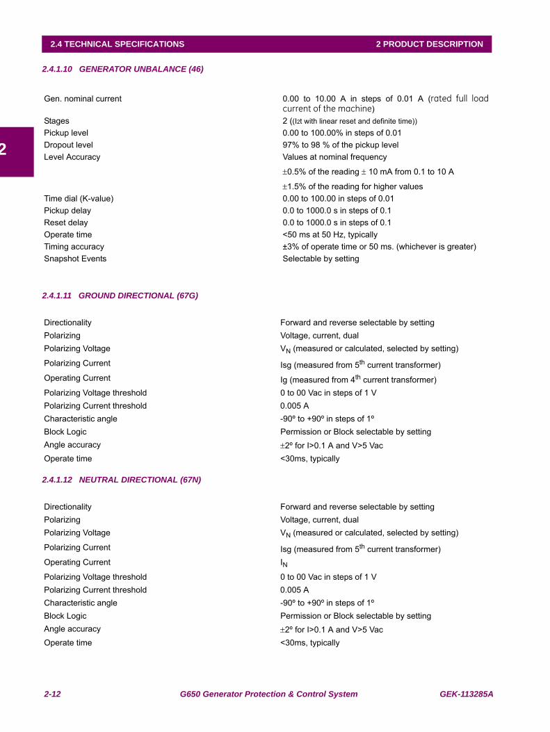
Gen. nominal current 0.00 to 10.00 A in steps of 0.01 A (rated full loadcurrent of the machine)
Stages 2 ((I2t with linear reset and definite time))Pickup level 0.00 to 100.00% in steps of 0.01Dropout level 97% to 98 % of the pickup levelLevel Accuracy Values at nominal frequency
±0.5% of the reading ± 10 mA from 0.1 to 10 A
±1.5% of the reading for higher valuesTime dial (K-value) 0.00 to 100.00 in steps of 0.01Pickup delay 0.0 to 1000.0 s in steps of 0.1Reset delay 0.0 to 1000.0 s in steps of 0.1Operate time <50 ms at 50 Hz, typicallyTiming accuracy ±3% of operate time or 50 ms. (whichever is greater)Snapshot Events Selectable by setting
Directionality Forward and reverse selectable by settingPolarizing Voltage, current, dualPolarizing Voltage VN (measured or calculated, selected by setting)
Polarizing Current Isg (measured from 5th current transformer)Operating Current Ig (measured from 4th current transformer)Polarizing Voltage threshold 0 to 00 Vac in steps of 1 VPolarizing Current threshold 0.005 ACharacteristic angle -90º to +90º in steps of 1ºBlock Logic Permission or Block selectable by settingAngle accuracy ±2º for I>0.1 A and V>5 VacOperate time <30ms, typically
Directionality Forward and reverse selectable by settingPolarizing Voltage, current, dualPolarizing Voltage VN (measured or calculated, selected by setting)
Polarizing Current Isg (measured from 5th current transformer)Operating Current INPolarizing Voltage threshold 0 to 00 Vac in steps of 1 VPolarizing Current threshold 0.005 ACharacteristic angle -90º to +90º in steps of 1ºBlock Logic Permission or Block selectable by settingAngle accuracy ±2º for I>0.1 A and V>5 VacOperate time <30ms, typically
GEK-113285A G650 Generator Protection & Control System 2-13
2 PRODUCT DESCRIPTION 2.4 TECHNICAL SPECIFICATIONS
2
2.4.1.13 GENERATOR THERMAL MODEL (49S)
2.4.1.14 RESTRICTED GROUND FAULT (87G)
2.4.1.15 PHASE OVERVOLTAGE (59P)
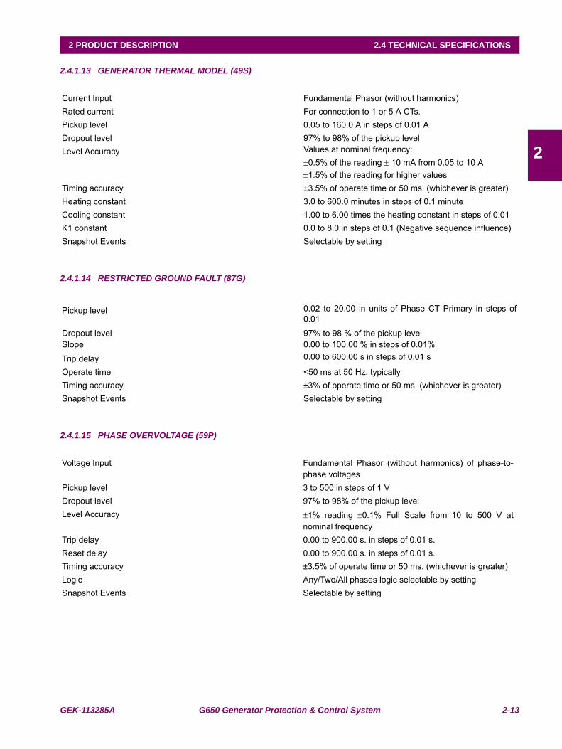
Current Input Fundamental Phasor (without harmonics)Rated current For connection to 1 or 5 A CTs.Pickup level 0.05 to 160.0 A in steps of 0.01 ADropout level 97% to 98% of the pickup levelLevel Accuracy Values at nominal frequency:
±0.5% of the reading ± 10 mA from 0.05 to 10 A±1.5% of the reading for higher values
Timing accuracy ±3.5% of operate time or 50 ms. (whichever is greater)Heating constant 3.0 to 600.0 minutes in steps of 0.1 minuteCooling constant 1.00 to 6.00 times the heating constant in steps of 0.01K1 constant 0.0 to 8.0 in steps of 0.1 (Negative sequence influence)Snapshot Events Selectable by setting
Pickup level 0.02 to 20.00 in units of Phase CT Primary in steps of0.01
Dropout level 97% to 98 % of the pickup levelSlope 0.00 to 100.00 % in steps of 0.01%
Trip delay 0.00 to 600.00 s in steps of 0.01 s
Operate time <50 ms at 50 Hz, typicallyTiming accuracy ±3% of operate time or 50 ms. (whichever is greater)Snapshot Events Selectable by setting
Voltage Input Fundamental Phasor (without harmonics) of phase-to-phase voltages
Pickup level 3 to 500 in steps of 1 VDropout level 97% to 98% of the pickup levelLevel Accuracy ±1% reading ±0.1% Full Scale from 10 to 500 V at
nominal frequencyTrip delay 0.00 to 900.00 s. in steps of 0.01 s.Reset delay 0.00 to 900.00 s. in steps of 0.01 s.Timing accuracy ±3.5% of operate time or 50 ms. (whichever is greater)Logic Any/Two/All phases logic selectable by settingSnapshot Events Selectable by setting
2-14 G650 Generator Protection & Control System GEK-113285A
2.4 TECHNICAL SPECIFICATIONS 2 PRODUCT DESCRIPTION
2
2.4.1.16 PHASE UNDERVOLTAGE (27P)
2.4.1.17 NEUTRAL OVERVOLTAGE (59NH)
2.4.1.18 GROUND OVERVOLTAGE (59G)
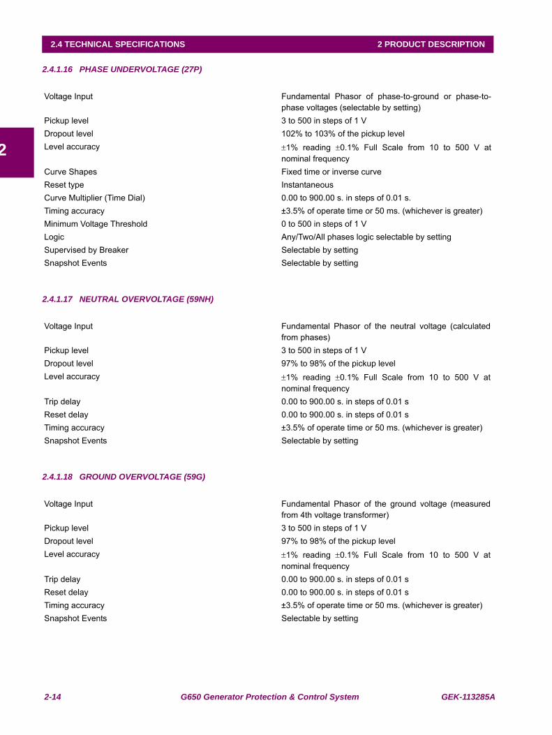
Voltage Input Fundamental Phasor of phase-to-ground or phase-to-phase voltages (selectable by setting)
Pickup level 3 to 500 in steps of 1 VDropout level 102% to 103% of the pickup levelLevel accuracy ±1% reading ±0.1% Full Scale from 10 to 500 V at
nominal frequencyCurve Shapes Fixed time or inverse curveReset type Instantaneous Curve Multiplier (Time Dial) 0.00 to 900.00 s. in steps of 0.01 s.Timing accuracy ±3.5% of operate time or 50 ms. (whichever is greater)Minimum Voltage Threshold 0 to 500 in steps of 1 VLogic Any/Two/All phases logic selectable by settingSupervised by Breaker Selectable by settingSnapshot Events Selectable by setting
Voltage Input Fundamental Phasor of the neutral voltage (calculatedfrom phases)
Pickup level 3 to 500 in steps of 1 VDropout level 97% to 98% of the pickup levelLevel accuracy ±1% reading ±0.1% Full Scale from 10 to 500 V at
nominal frequencyTrip delay 0.00 to 900.00 s. in steps of 0.01 sReset delay 0.00 to 900.00 s. in steps of 0.01 sTiming accuracy ±3.5% of operate time or 50 ms. (whichever is greater)Snapshot Events Selectable by setting
Voltage Input Fundamental Phasor of the ground voltage (measuredfrom 4th voltage transformer)
Pickup level 3 to 500 in steps of 1 VDropout level 97% to 98% of the pickup levelLevel accuracy ±1% reading ±0.1% Full Scale from 10 to 500 V at
nominal frequencyTrip delay 0.00 to 900.00 s. in steps of 0.01 sReset delay 0.00 to 900.00 s. in steps of 0.01 sTiming accuracy ±3.5% of operate time or 50 ms. (whichever is greater)Snapshot Events Selectable by setting
GEK-113285A G650 Generator Protection & Control System 2-15
2 PRODUCT DESCRIPTION 2.4 TECHNICAL SPECIFICATIONS
2
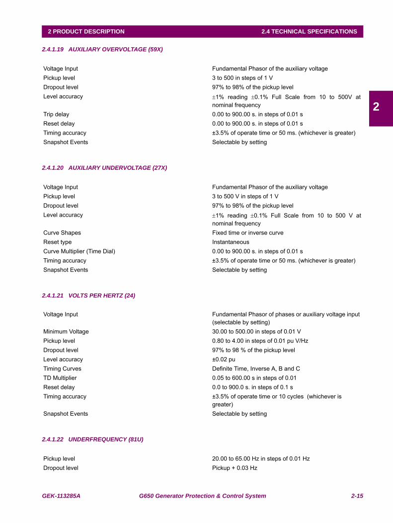
2.4.1.19 AUXILIARY OVERVOLTAGE (59X)
2.4.1.20 AUXILIARY UNDERVOLTAGE (27X)
2.4.1.21 VOLTS PER HERTZ (24)
2.4.1.22 UNDERFREQUENCY (81U)
Voltage Input Fundamental Phasor of the auxiliary voltagePickup level 3 to 500 in steps of 1 VDropout level 97% to 98% of the pickup levelLevel accuracy ±1% reading ±0.1% Full Scale from 10 to 500V at
nominal frequencyTrip delay 0.00 to 900.00 s. in steps of 0.01 sReset delay 0.00 to 900.00 s. in steps of 0.01 sTiming accuracy ±3.5% of operate time or 50 ms. (whichever is greater)Snapshot Events Selectable by setting
Voltage Input Fundamental Phasor of the auxiliary voltagePickup level 3 to 500 V in steps of 1 VDropout level 97% to 98% of the pickup levelLevel accuracy ±1% reading ±0.1% Full Scale from 10 to 500 V at
nominal frequencyCurve Shapes Fixed time or inverse curveReset type Instantaneous Curve Multiplier (Time Dial) 0.00 to 900.00 s. in steps of 0.01 sTiming accuracy ±3.5% of operate time or 50 ms. (whichever is greater)Snapshot Events Selectable by setting
Voltage Input Fundamental Phasor of phases or auxiliary voltage input (selectable by setting)
Minimum Voltage 30.00 to 500.00 in steps of 0.01 VPickup level 0.80 to 4.00 in steps of 0.01 pu V/HzDropout level 97% to 98 % of the pickup levelLevel accuracy ±0.02 puTiming Curves Definite Time, Inverse A, B and CTD Multiplier 0.05 to 600.00 s in steps of 0.01Reset delay 0.0 to 900.0 s. in steps of 0.1 sTiming accuracy ±3.5% of operate time or 10 cycles (whichever is
greater)Snapshot Events Selectable by setting
Pickup level 20.00 to 65.00 Hz in steps of 0.01 HzDropout level Pickup + 0.03 Hz
2-16 G650 Generator Protection & Control System GEK-113285A
2.4 TECHNICAL SPECIFICATIONS 2 PRODUCT DESCRIPTION
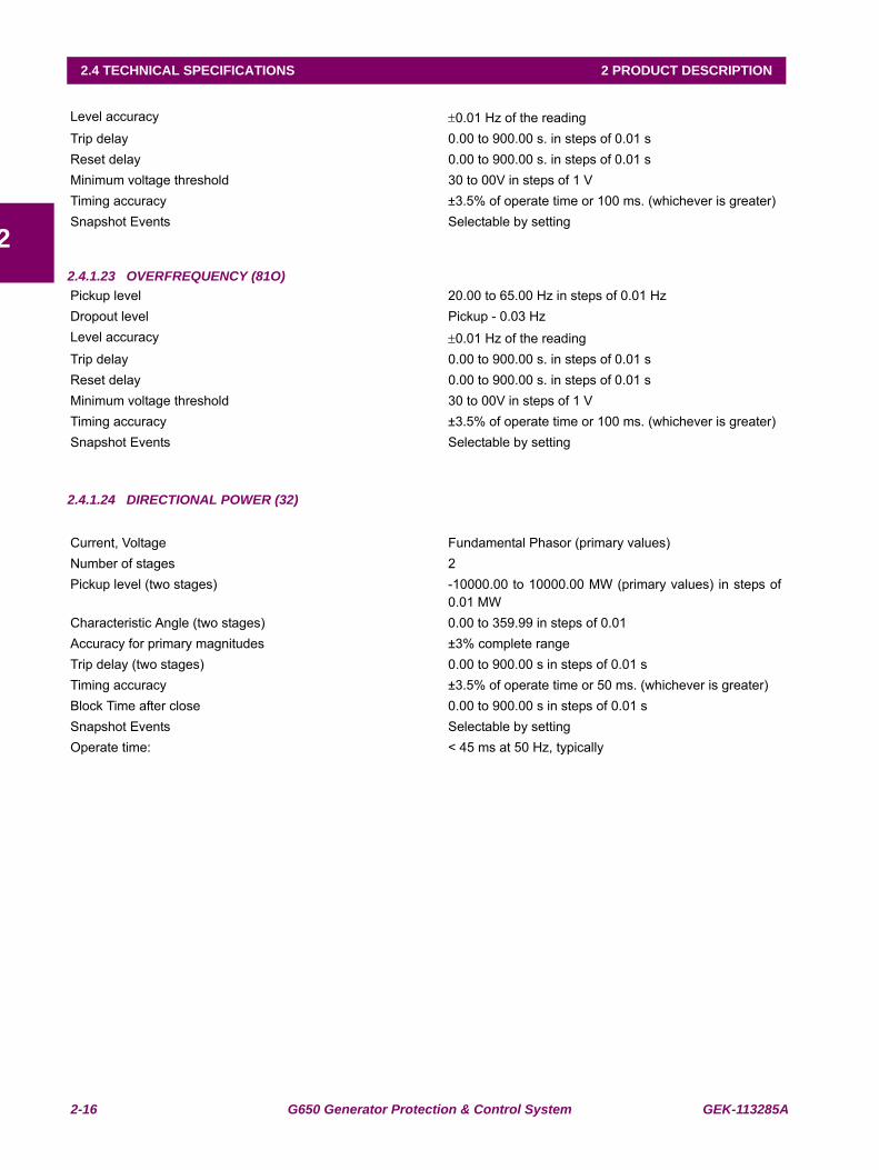
22.4.1.23 OVERFREQUENCY (81O)
2.4.1.24 DIRECTIONAL POWER (32)
Level accuracy ±0.01 Hz of the readingTrip delay 0.00 to 900.00 s. in steps of 0.01 sReset delay 0.00 to 900.00 s. in steps of 0.01 sMinimum voltage threshold 30 to 00V in steps of 1 VTiming accuracy ±3.5% of operate time or 100 ms. (whichever is greater)Snapshot Events Selectable by setting
Pickup level 20.00 to 65.00 Hz in steps of 0.01 HzDropout level Pickup - 0.03 HzLevel accuracy ±0.01 Hz of the readingTrip delay 0.00 to 900.00 s. in steps of 0.01 sReset delay 0.00 to 900.00 s. in steps of 0.01 sMinimum voltage threshold 30 to 00V in steps of 1 VTiming accuracy ±3.5% of operate time or 100 ms. (whichever is greater)Snapshot Events Selectable by setting
Current, Voltage Fundamental Phasor (primary values)Number of stages 2Pickup level (two stages) -10000.00 to 10000.00 MW (primary values) in steps of
0.01 MWCharacteristic Angle (two stages) 0.00 to 359.99 in steps of 0.01Accuracy for primary magnitudes ±3% complete rangeTrip delay (two stages) 0.00 to 900.00 s in steps of 0.01 sTiming accuracy ±3.5% of operate time or 50 ms. (whichever is greater)Block Time after close 0.00 to 900.00 s in steps of 0.01 sSnapshot Events Selectable by settingOperate time: < 45 ms at 50 Hz, typically
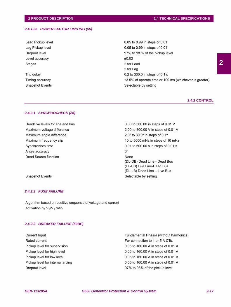
GEK-113285A G650 Generator Protection & Control System 2-17
2 PRODUCT DESCRIPTION 2.4 TECHNICAL SPECIFICATIONS
2
2.4.1.25 POWER FACTOR LIMITING (55)
2.4.2 CONTROL
2.4.2.1 SYNCHROCHECK (25)
2.4.2.2 FUSE FAILURE
2.4.2.3 BREAKER FAILURE (50BF)
Lead Pickup level 0.05 to 0.99 in steps of 0.01Lag Pickup level 0.05 to 0.99 in steps of 0.01Dropout level 97% to 98 % of the pickup levelLevel accuracy ±0.02Stages 2 for Lead
2 for LagTrip delay 0.2 to 300.0 in steps of 0.1 sTiming accuracy ±3.5% of operate time or 100 ms (whichever is greater)Snapshot Events Selectable by setting
Dead/live levels for line and bus 0.00 to 300.00 in steps of 0.01 VMaximum voltage difference 2.00 to 300.00 V in steps of 0.01 VMaximum angle difference 2.0º to 80.0º in steps of 0.1ºMaximum frequency slip 10 to 5000 mHz in steps of 10 mHzSynchronism time 0.01 to 600.00 s in steps of 0.01 sAngle accuracy 3ºDead Source function None
(DL-DB) Dead Line - Dead Bus(LL-DB) Live Line-Dead Bus(DL-LB) Dead Line – Live Bus
Snapshot Events Selectable by setting
Algorithm based on positive sequence of voltage and currentActivation by V2/V1 ratio
Current Input Fundamental Phasor (without harmonics)Rated current For connection to 1 or 5 A CTs.Pickup level for supervision 0.05 to 160.00 A in steps of 0.01 APickup level for high level 0.05 to 160.00 A in steps of 0.01 APickup level for low level 0.05 to 160.00 A in steps of 0.01 APickup level for internal arcing 0.05 to 160.00 A in steps of 0.01 ADropout level 97% to 98% of the pickup level
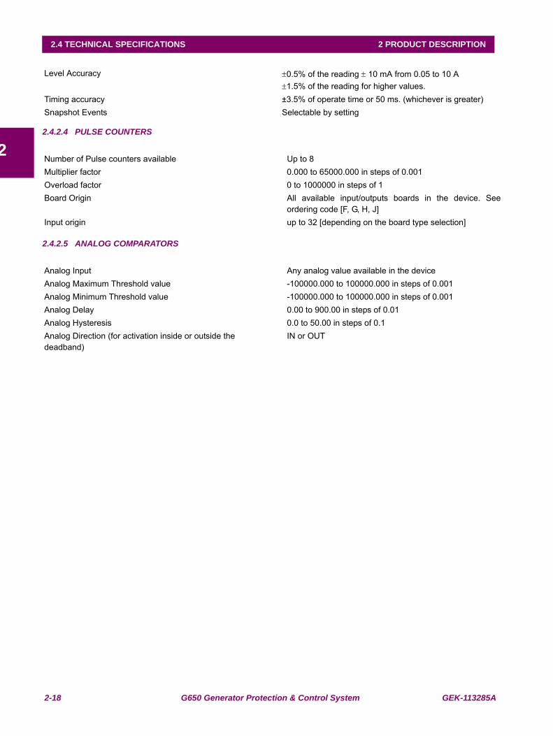
2-18 G650 Generator Protection & Control System GEK-113285A
2.4 TECHNICAL SPECIFICATIONS 2 PRODUCT DESCRIPTION
22.4.2.4 PULSE COUNTERS
2.4.2.5 ANALOG COMPARATORS
Level Accuracy ±0.5% of the reading ± 10 mA from 0.05 to 10 A±1.5% of the reading for higher values.
Timing accuracy ±3.5% of operate time or 50 ms. (whichever is greater)Snapshot Events Selectable by setting
Number of Pulse counters available Up to 8Multiplier factor 0.000 to 65000.000 in steps of 0.001Overload factor 0 to 1000000 in steps of 1 Board Origin All available input/outputs boards in the device. See
ordering code [F, G, H, J]Input origin up to 32 [depending on the board type selection]
Analog Input Any analog value available in the deviceAnalog Maximum Threshold value -100000.000 to 100000.000 in steps of 0.001Analog Minimum Threshold value -100000.000 to 100000.000 in steps of 0.001Analog Delay 0.00 to 900.00 in steps of 0.01Analog Hysteresis 0.0 to 50.00 in steps of 0.1Analog Direction (for activation inside or outside thedeadband)
IN or OUT
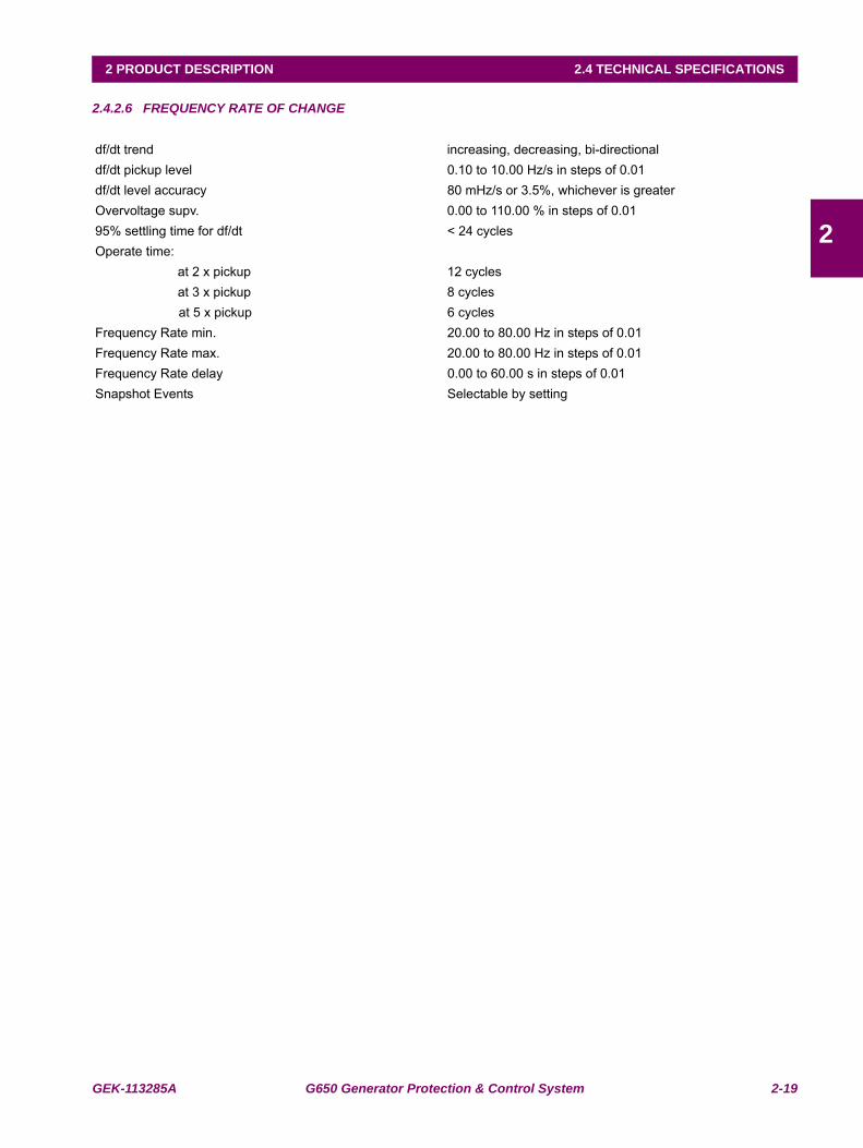
GEK-113285A G650 Generator Protection & Control System 2-19
2 PRODUCT DESCRIPTION 2.4 TECHNICAL SPECIFICATIONS
2
2.4.2.6 FREQUENCY RATE OF CHANGE
df/dt trend increasing, decreasing, bi-directionaldf/dt pickup level 0.10 to 10.00 Hz/s in steps of 0.01df/dt level accuracy 80 mHz/s or 3.5%, whichever is greater Overvoltage supv. 0.00 to 110.00 % in steps of 0.0195% settling time for df/dt < 24 cycles Operate time:
at 2 x pickup 12 cycles at 3 x pickup 8 cycles at 5 x pickup 6 cycles
Frequency Rate min. 20.00 to 80.00 Hz in steps of 0.01 Frequency Rate max. 20.00 to 80.00 Hz in steps of 0.01Frequency Rate delay 0.00 to 60.00 s in steps of 0.01Snapshot Events Selectable by setting
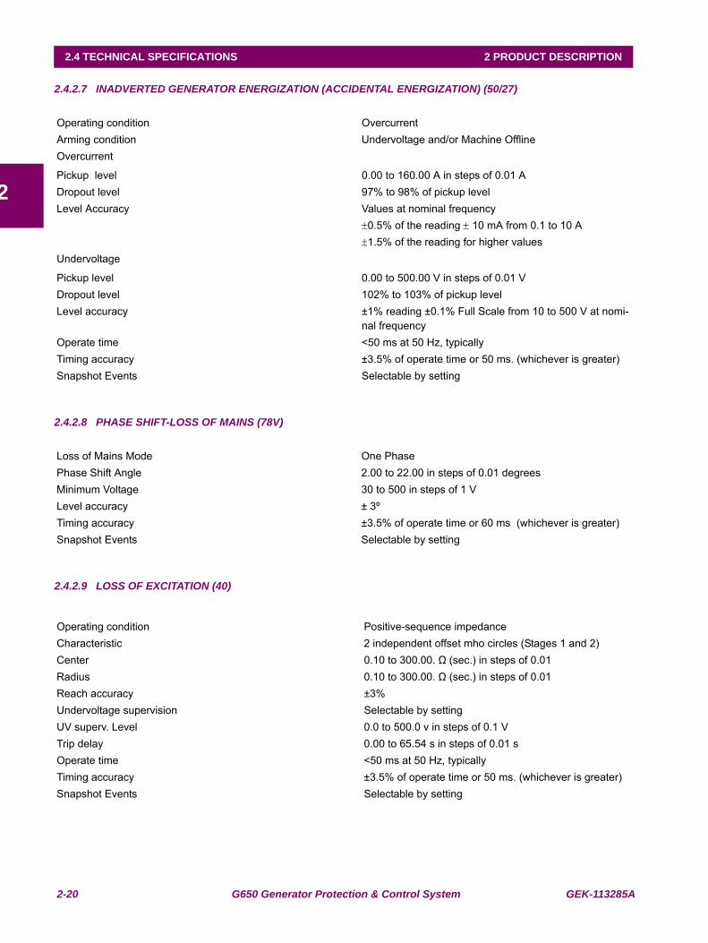
2-20 G650 Generator Protection & Control System GEK-113285A
2.4 TECHNICAL SPECIFICATIONS 2 PRODUCT DESCRIPTION
2
2.4.2.7 INADVERTED GENERATOR ENERGIZATION (ACCIDENTAL ENERGIZATION) (50/27)
2.4.2.8 PHASE SHIFT-LOSS OF MAINS (78V)
2.4.2.9 LOSS OF EXCITATION (40)
Operating condition OvercurrentArming condition Undervoltage and/or Machine OfflineOvercurrent
Pickup level 0.00 to 160.00 A in steps of 0.01 ADropout level 97% to 98% of pickup levelLevel Accuracy Values at nominal frequency
±0.5% of the reading ± 10 mA from 0.1 to 10 A±1.5% of the reading for higher values
Undervoltage
Pickup level 0.00 to 500.00 V in steps of 0.01 VDropout level 102% to 103% of pickup levelLevel accuracy ±1% reading ±0.1% Full Scale from 10 to 500 V at nomi-
nal frequencyOperate time <50 ms at 50 Hz, typicallyTiming accuracy ±3.5% of operate time or 50 ms. (whichever is greater)Snapshot Events Selectable by setting
Loss of Mains Mode One PhasePhase Shift Angle 2.00 to 22.00 in steps of 0.01 degreesMinimum Voltage 30 to 500 in steps of 1 VLevel accuracy ± 3ºTiming accuracy ±3.5% of operate time or 60 ms (whichever is greater)Snapshot Events Selectable by setting
Operating condition Positive-sequence impedanceCharacteristic 2 independent offset mho circles (Stages 1 and 2)Center 0.10 to 300.00. Ω (sec.) in steps of 0.01Radius 0.10 to 300.00. Ω (sec.) in steps of 0.01Reach accuracy ±3%Undervoltage supervision Selectable by setting UV superv. Level 0.0 to 500.0 v in steps of 0.1 VTrip delay 0.00 to 65.54 s in steps of 0.01 sOperate time <50 ms at 50 Hz, typicallyTiming accuracy ±3.5% of operate time or 50 ms. (whichever is greater)Snapshot Events Selectable by setting
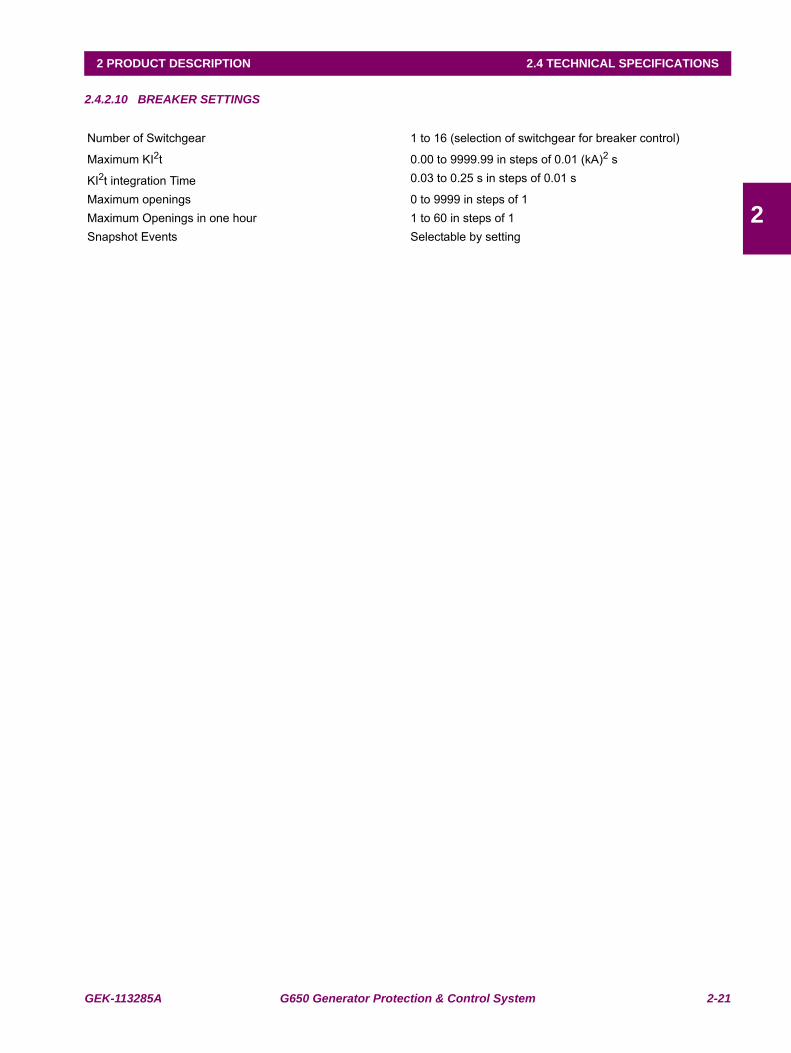
GEK-113285A G650 Generator Protection & Control System 2-21
2 PRODUCT DESCRIPTION 2.4 TECHNICAL SPECIFICATIONS
2
2.4.2.10 BREAKER SETTINGS
Number of Switchgear 1 to 16 (selection of switchgear for breaker control)
Maximum KI2t 0.00 to 9999.99 in steps of 0.01 (kA)2 s
KI2t integration Time 0.03 to 0.25 s in steps of 0.01 s
Maximum openings 0 to 9999 in steps of 1Maximum Openings in one hour 1 to 60 in steps of 1Snapshot Events Selectable by setting
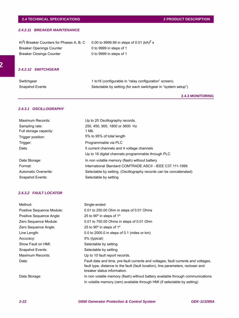
2-22 G650 Generator Protection & Control System GEK-113285A
2.4 TECHNICAL SPECIFICATIONS 2 PRODUCT DESCRIPTION
2
2.4.2.11 BREAKER MAINTENANCE
2.4.2.12 SWITCHGEAR
2.4.3 MONITORING
2.4.3.1 OSCILLOGRAPHY
2.4.3.2 FAULT LOCATOR
KI2t Breaker Counters for Phases A, B, C 0.00 to 9999.99 in steps of 0.01 (kA)2 sBreaker Openings Counter 0 to 9999 in steps of 1Breaker Closings Counter 0 to 9999 in steps of 1
Switchgear 1 to16 (configurable in “relay configuration” screen).Snapshot Events Selectable by setting (for each switchgear in “system setup”)
Maximum Records: Up to 20 Oscillography records.Sampling rate: 250, 450, 900, 1800 or 3600 HzFull storage capacity: 1 Mb
Trigger position: 5% to 95% of total length
Trigger: Programmable via PLCData: 5 current channels and 4 voltage channels
Up to 16 digital channels programmable through PLC
Data Storage: In non volatile memory (flash) without batteryFormat: International Standard COMTRADE ASCII - IEEE C37.111-1999.Automatic Overwrite: Selectable by setting. (Oscillography records can be concatenated)Snapshot Events: Selectable by setting
Method: Single-endedPositive Sequence Module: 0.01 to 250.00 Ohm in steps of 0.01 OhmsPositive Sequence Angle: 25 to 90º in steps of 1ºZero Sequence Module: 0.01 to 750.00 Ohms in steps of 0.01 OhmZero Sequence Angle: 25 to 90º in steps of 1ºLine Length: 0.0 to 2000.0 in steps of 0.1 (miles or km)Accuracy: 5% (typical)Show Fault on HMI: Selectable by settingSnapshot Events: Selectable by settingMaximum Records: Up to 10 fault report records.Data: Fault date and time, pre-fault currents and voltages, fault currents and voltages,
fault type, distance to the fault (fault location), line parameters, recloser and breaker status information.
Data Storage: In non volatile memory (flash) without battery available through communicationsIn volatile memory (ram) available through HMI (if selectable by setting)
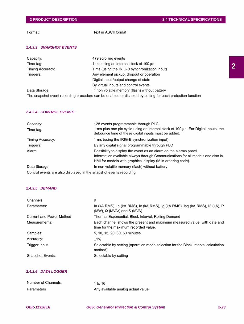
GEK-113285A G650 Generator Protection & Control System 2-23
2 PRODUCT DESCRIPTION 2.4 TECHNICAL SPECIFICATIONS
2
2.4.3.3 SNAPSHOT EVENTS
2.4.3.4 CONTROL EVENTS
2.4.3.5 DEMAND
2.4.3.6 DATA LOGGER
Format: Text in ASCII format
Capacity: 479 scrolling eventsTime-tag 1 ms using an internal clock of 100 μsTiming Accuracy: 1 ms (using the IRIG-B synchronization input)Triggers: Any element pickup, dropout or operation
Digital input /output change of stateBy virtual inputs and control events
Data Storage In non volatile memory (flash) without batteryThe snapshot event recording procedure can be enabled or disabled by setting for each protection function
Capacity: 128 events programmable through PLCTime-tag: 1 ms plus one plc cycle using an internal clock of 100 μs. For Digital Inputs, the
debounce time of these digital inputs must be added.
Timing Accuracy: 1 ms (using the IRIG-B synchronization input)Triggers: By any digital signal programmable through PLC Alarm Possibility to display the event as an alarm on the alarms panel.
Information available always through Communications for all models and also in HMI for models with graphical display (M in ordering code).
Data Storage: In non volatile memory (flash) without batteryControl events are also displayed in the snapshot events recording
Channels: 9Parameters: Ia (kA RMS), Ib (kA RMS), Ic (kA RMS), Ig (kA RMS), Isg (kA RMS), I2 (kA), P
(MW), Q (MVAr) and S (MVA)Current and Power Method Thermal Exponential, Block Interval, Rolling DemandMeasurements: Each channel shows the present and maximum measured value, with date and
time for the maximum recorded value. Samples: 5, 10, 15, 20, 30, 60 minutes.Accuracy: ±1%Trigger Input Selectable by setting (operation mode selection for the Block Interval calculation
method)Snapshot Events: Selectable by setting
Number of Channels: 1 to 16Parameters Any available analog actual value
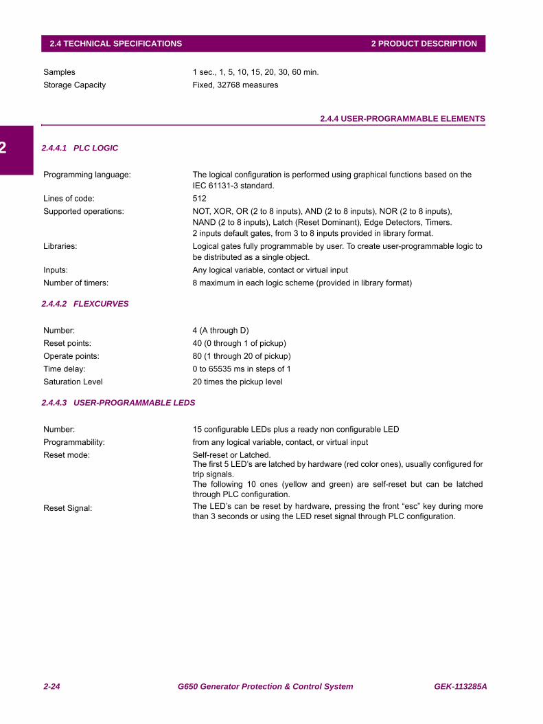
2-24 G650 Generator Protection & Control System GEK-113285A
2.4 TECHNICAL SPECIFICATIONS 2 PRODUCT DESCRIPTION
2
2.4.4 USER-PROGRAMMABLE ELEMENTS
2.4.4.1 PLC LOGIC
2.4.4.2 FLEXCURVES
2.4.4.3 USER-PROGRAMMABLE LEDS
Samples 1 sec., 1, 5, 10, 15, 20, 30, 60 min.Storage Capacity Fixed, 32768 measures
Programming language: The logical configuration is performed using graphical functions based on the IEC 61131-3 standard.
Lines of code: 512Supported operations: NOT, XOR, OR (2 to 8 inputs), AND (2 to 8 inputs), NOR (2 to 8 inputs),
NAND (2 to 8 inputs), Latch (Reset Dominant), Edge Detectors, Timers.2 inputs default gates, from 3 to 8 inputs provided in library format.
Libraries: Logical gates fully programmable by user. To create user-programmable logic tobe distributed as a single object.
Inputs: Any logical variable, contact or virtual inputNumber of timers: 8 maximum in each logic scheme (provided in library format)
Number: 4 (A through D)Reset points: 40 (0 through 1 of pickup)Operate points: 80 (1 through 20 of pickup)Time delay: 0 to 65535 ms in steps of 1Saturation Level 20 times the pickup level
Number: 15 configurable LEDs plus a ready non configurable LEDProgrammability: from any logical variable, contact, or virtual inputReset mode: Self-reset or Latched.
The first 5 LED’s are latched by hardware (red color ones), usually configured fortrip signals.The following 10 ones (yellow and green) are self-reset but can be latchedthrough PLC configuration.
Reset Signal: The LED’s can be reset by hardware, pressing the front “esc” key during morethan 3 seconds or using the LED reset signal through PLC configuration.
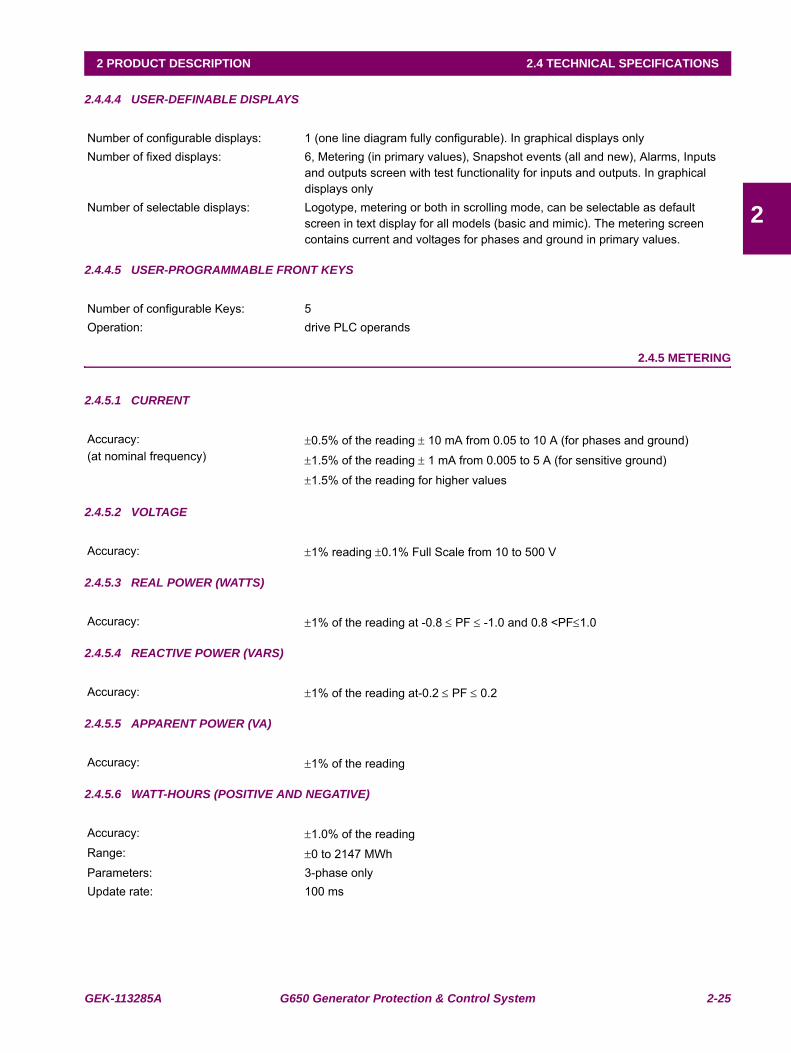
GEK-113285A G650 Generator Protection & Control System 2-25
2 PRODUCT DESCRIPTION 2.4 TECHNICAL SPECIFICATIONS
2
2.4.4.4 USER-DEFINABLE DISPLAYS
2.4.4.5 USER-PROGRAMMABLE FRONT KEYS
2.4.5 METERING
2.4.5.1 CURRENT
2.4.5.2 VOLTAGE
2.4.5.3 REAL POWER (WATTS)
2.4.5.4 REACTIVE POWER (VARS)
2.4.5.5 APPARENT POWER (VA)
2.4.5.6 WATT-HOURS (POSITIVE AND NEGATIVE)
Number of configurable displays: 1 (one line diagram fully configurable). In graphical displays onlyNumber of fixed displays: 6, Metering (in primary values), Snapshot events (all and new), Alarms, Inputs
and outputs screen with test functionality for inputs and outputs. In graphical displays only
Number of selectable displays: Logotype, metering or both in scrolling mode, can be selectable as default screen in text display for all models (basic and mimic). The metering screen contains current and voltages for phases and ground in primary values.
Number of configurable Keys: 5Operation: drive PLC operands
Accuracy: ±0.5% of the reading ± 10 mA from 0.05 to 10 A (for phases and ground)(at nominal frequency) ±1.5% of the reading ± 1 mA from 0.005 to 5 A (for sensitive ground)
±1.5% of the reading for higher values
Accuracy: ±1% reading ±0.1% Full Scale from 10 to 500 V
Accuracy: ±1% of the reading at -0.8 ≤ PF ≤ -1.0 and 0.8 <PF≤1.0
Accuracy: ±1% of the reading at-0.2 ≤ PF ≤ 0.2
Accuracy: ±1% of the reading
Accuracy: ±1.0% of the readingRange: ±0 to 2147 MWhParameters: 3-phase onlyUpdate rate: 100 ms
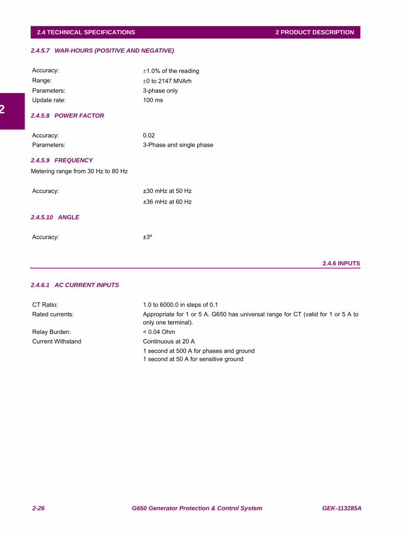
2-26 G650 Generator Protection & Control System GEK-113285A
2.4 TECHNICAL SPECIFICATIONS 2 PRODUCT DESCRIPTION
2
2.4.5.7 WAR-HOURS (POSITIVE AND NEGATIVE)
2.4.5.8 POWER FACTOR
2.4.5.9 FREQUENCY
Metering range from 30 Hz to 80 Hz
2.4.5.10 ANGLE
2.4.6 INPUTS
2.4.6.1 AC CURRENT INPUTS
Accuracy: ±1.0% of the readingRange: ±0 to 2147 MVArhParameters: 3-phase onlyUpdate rate: 100 ms
Accuracy: 0.02Parameters: 3-Phase and single phase
Accuracy: ±30 mHz at 50 Hz
±36 mHz at 60 Hz
Accuracy: ±3º
CT Ratio: 1.0 to 6000.0 in steps of 0.1Rated currents: Appropriate for 1 or 5 A. G650 has universal range for CT (valid for 1 or 5 A to
only one terminal).Relay Burden: < 0.04 OhmCurrent Withstand Continuous at 20 A
1 second at 500 A for phases and ground1 second at 50 A for sensitive ground
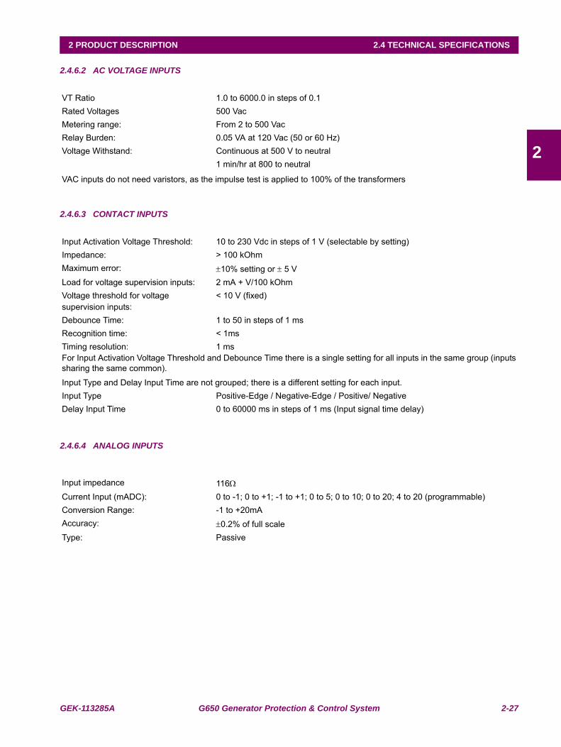
GEK-113285A G650 Generator Protection & Control System 2-27
2 PRODUCT DESCRIPTION 2.4 TECHNICAL SPECIFICATIONS
2
2.4.6.2 AC VOLTAGE INPUTS
2.4.6.3 CONTACT INPUTS
2.4.6.4 ANALOG INPUTS
VT Ratio 1.0 to 6000.0 in steps of 0.1Rated Voltages 500 VacMetering range: From 2 to 500 VacRelay Burden: 0.05 VA at 120 Vac (50 or 60 Hz)Voltage Withstand: Continuous at 500 V to neutral
1 min/hr at 800 to neutral
VAC inputs do not need varistors, as the impulse test is applied to 100% of the transformers
Input Activation Voltage Threshold: 10 to 230 Vdc in steps of 1 V (selectable by setting)Impedance: > 100 kOhmMaximum error: ±10% setting or ± 5 VLoad for voltage supervision inputs: 2 mA + V/100 kOhmVoltage threshold for voltage supervision inputs:
< 10 V (fixed)
Debounce Time: 1 to 50 in steps of 1 msRecognition time: < 1msTiming resolution: 1 msFor Input Activation Voltage Threshold and Debounce Time there is a single setting for all inputs in the same group (inputssharing the same common).
Input Type and Delay Input Time are not grouped; there is a different setting for each input.Input Type Positive-Edge / Negative-Edge / Positive/ NegativeDelay Input Time 0 to 60000 ms in steps of 1 ms (Input signal time delay)
Input impedance 116Ω
Current Input (mADC): 0 to -1; 0 to +1; -1 to +1; 0 to 5; 0 to 10; 0 to 20; 4 to 20 (programmable)Conversion Range: -1 to +20mAAccuracy: ±0.2% of full scaleType: Passive
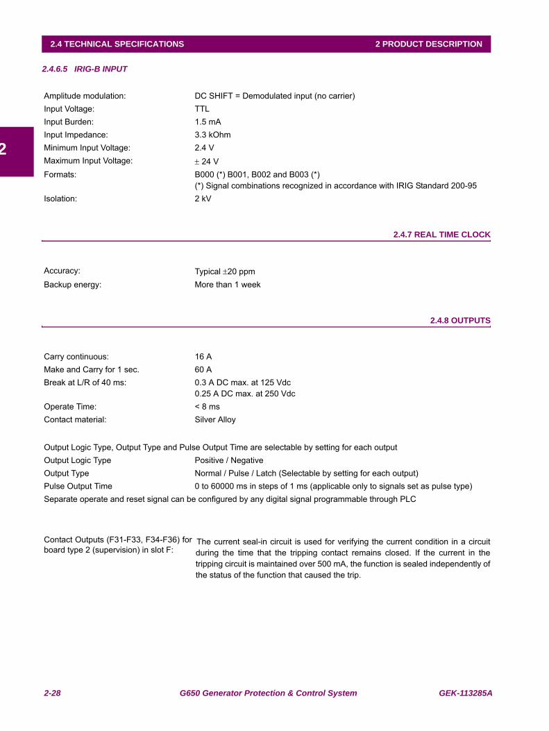
2-28 G650 Generator Protection & Control System GEK-113285A
2.4 TECHNICAL SPECIFICATIONS 2 PRODUCT DESCRIPTION
2
2.4.6.5 IRIG-B INPUT
2.4.7 REAL TIME CLOCK
2.4.8 OUTPUTS
Amplitude modulation: DC SHIFT = Demodulated input (no carrier) Input Voltage: TTLInput Burden: 1.5 mAInput Impedance: 3.3 kOhmMinimum Input Voltage: 2.4 VMaximum Input Voltage: ± 24 VFormats: B000 (*) B001, B002 and B003 (*)
(*) Signal combinations recognized in accordance with IRIG Standard 200-95Isolation: 2 kV
Accuracy: Typical ±20 ppmBackup energy: More than 1 week
Carry continuous: 16 AMake and Carry for 1 sec. 60 ABreak at L/R of 40 ms: 0.3 A DC max. at 125 Vdc
0.25 A DC max. at 250 VdcOperate Time: < 8 msContact material: Silver Alloy
Output Logic Type, Output Type and Pulse Output Time are selectable by setting for each outputOutput Logic Type Positive / NegativeOutput Type Normal / Pulse / Latch (Selectable by setting for each output)Pulse Output Time 0 to 60000 ms in steps of 1 ms (applicable only to signals set as pulse type)Separate operate and reset signal can be configured by any digital signal programmable through PLC
Contact Outputs (F31-F33, F34-F36) forboard type 2 (supervision) in slot F:
The current seal-in circuit is used for verifying the current condition in a circuitduring the time that the tripping contact remains closed. If the current in thetripping circuit is maintained over 500 mA, the function is sealed independently ofthe status of the function that caused the trip.
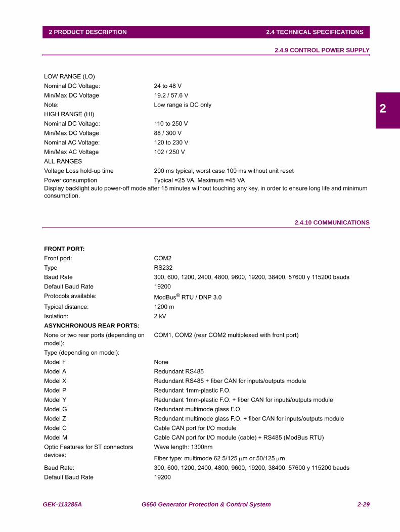
GEK-113285A G650 Generator Protection & Control System 2-29
2 PRODUCT DESCRIPTION 2.4 TECHNICAL SPECIFICATIONS
2
2.4.9 CONTROL POWER SUPPLY
2.4.10 COMMUNICATIONS
LOW RANGE (LO)Nominal DC Voltage: 24 to 48 VMin/Max DC Voltage 19.2 / 57.6 VNote: Low range is DC onlyHIGH RANGE (HI)Nominal DC Voltage: 110 to 250 VMin/Max DC Voltage 88 / 300 VNominal AC Voltage: 120 to 230 VMin/Max AC Voltage 102 / 250 VALL RANGESVoltage Loss hold-up time 200 ms typical, worst case 100 ms without unit resetPower consumption Typical =25 VA, Maximum =45 VADisplay backlight auto power-off mode after 15 minutes without touching any key, in order to ensure long life and minimumconsumption.
FRONT PORT:Front port: COM2Type RS232Baud Rate 300, 600, 1200, 2400, 4800, 9600, 19200, 38400, 57600 y 115200 baudsDefault Baud Rate 19200Protocols available: ModBus® RTU / DNP 3.0Typical distance: 1200 mIsolation: 2 kVASYNCHRONOUS REAR PORTS:None or two rear ports (depending on model):
COM1, COM2 (rear COM2 multiplexed with front port)
Type (depending on model):Model F NoneModel A Redundant RS485Model X Redundant RS485 + fiber CAN for inputs/outputs module Model P Redundant 1mm-plastic F.O.Model Y Redundant 1mm-plastic F.O. + fiber CAN for inputs/outputs module Model G Redundant multimode glass F.O. Model Z Redundant multimode glass F.O. + fiber CAN for inputs/outputs module Model C Cable CAN port for I/O moduleModel M Cable CAN port for I/O module (cable) + RS485 (ModBus RTU)Optic Features for ST connectors devices:
Wave length: 1300nm
Fiber type: multimode 62.5/125 μm or 50/125 μmBaud Rate: 300, 600, 1200, 2400, 4800, 9600, 19200, 38400, 57600 y 115200 baudsDefault Baud Rate 19200
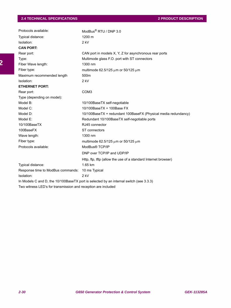
2-30 G650 Generator Protection & Control System GEK-113285A
2.4 TECHNICAL SPECIFICATIONS 2 PRODUCT DESCRIPTION
2
Protocols available: ModBus® RTU / DNP 3.0Typical distance: 1200 mIsolation: 2 kVCAN PORT: Rear port: CAN port in models X, Y, Z for asynchronous rear portsType: Multimode glass F.O. port with ST connectorsFiber Wave length: 1300 nmFiber type: multimode 62.5/125 μm or 50/125 μmMaximum recommended length 500mIsolation: 2 kVETHERNET PORT:Rear port: COM3Type (depending on model):Model B: 10/100BaseTX self-negotiableModel C: 10/100BaseTX + 100Base FX Model D: 10/100BaseTX + redundant 100BaseFX (Physical media redundancy)Model E: Redundant 10/100BaseTX self-negotiable ports10/100BaseTX RJ45 connector100BaseFX ST connectorsWave length: 1300 nmFiber type: multimode 62.5/125 μm or 50/125 μmProtocols available: ModBus® TCP/IP
DNP over TCP/IP and UDP/IP
Http, ftp, tftp (allow the use of a standard Internet browser)Typical distance: 1.65 kmResponse time to ModBus commands: 10 ms TypicalIsolation: 2 kVIn Models C and D, the 10/100BaseTX port is selected by an internal switch (see 3.3.3)Two witness LED’s for transmission and reception are included
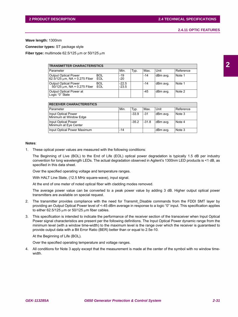
GEK-113285A G650 Generator Protection & Control System 2-31
2 PRODUCT DESCRIPTION 2.4 TECHNICAL SPECIFICATIONS
2
2.4.11 OPTIC FEATURES
Wave length: 1300nm
Connector types: ST package style
Fiber type: multimode 62.5/125 μm or 50/125 μm
Notes:
1. These optical power values are measured with the following conditions:
The Beginning of Live (BOL) to the End of Life (EOL) optical power degradation is typically 1.5 dB per industryconvention for long wavelength LEDs. The actual degradation observed in Agilent’s 1300nm LED products is <1 dB, asspecified in this data sheet.
Over the specified operating voltage and temperature ranges.
With HALT Line State, (12.5 MHz square-wave), input signal.
At the end of one meter of noted optical fiber with cladding modes removed.
The average power value can be converted to a peak power value by adding 3 dB. Higher output optical powertransmitters are available on special request.
2. The transmitter provides compliance with the need for Transmit_Disable commands from the FDDI SMT layer byproviding an Output Optical Power level of <-45 dBm average in response to a logic “0” input. This specification appliesto either 62.5/125 μm or 50/125 μm fiber cables.
3. This specification is intended to indicate the performance of the receiver section of the transceiver when Input OpticalPower signal characteristics are present per the following definitions. The Input Optical Power dynamic range from theminimum level (with a window time-width) to the maximum level is the range over which the receiver is guaranteed toprovide output data with a Bit Error Ratio (BER) better than or equal to 2.5e-10.
At the Beginning of Life (BOL).
Over the specified operating temperature and voltage ranges.
4. All conditions for Note 3 apply except that the measurement is made at the center of the symbol with no window time-width.
TRANSMITTER CHARACTERISTICSParameter Min. Typ. Max. Unit ReferenceOutput Optical Power BOL62.5/125 μm, NA = 0.275 Fiber EOL
-19-20
-14 dBm avg. Note 1
Output Optical Power BOL 50/125 μm, NA = 0.275 Fiber EOL
-22.5-23.5
-14 dBm avg. Note 1
Output Optical Power atLogic “0” State
-45 dBm avg. Note 2
RECEIVER CHARACTERISTICSParameter Min. Typ. Max. Unit ReferenceInput Optical PowerMinimum at Window Edge
-33.9 -31 dBm avg. Note 3
Input Optical PowerMinimum at Eye Center
-35.2 -31.8 dBm avg. Note 4
Input Optical Power Maximum -14 dBm avg. Note 3
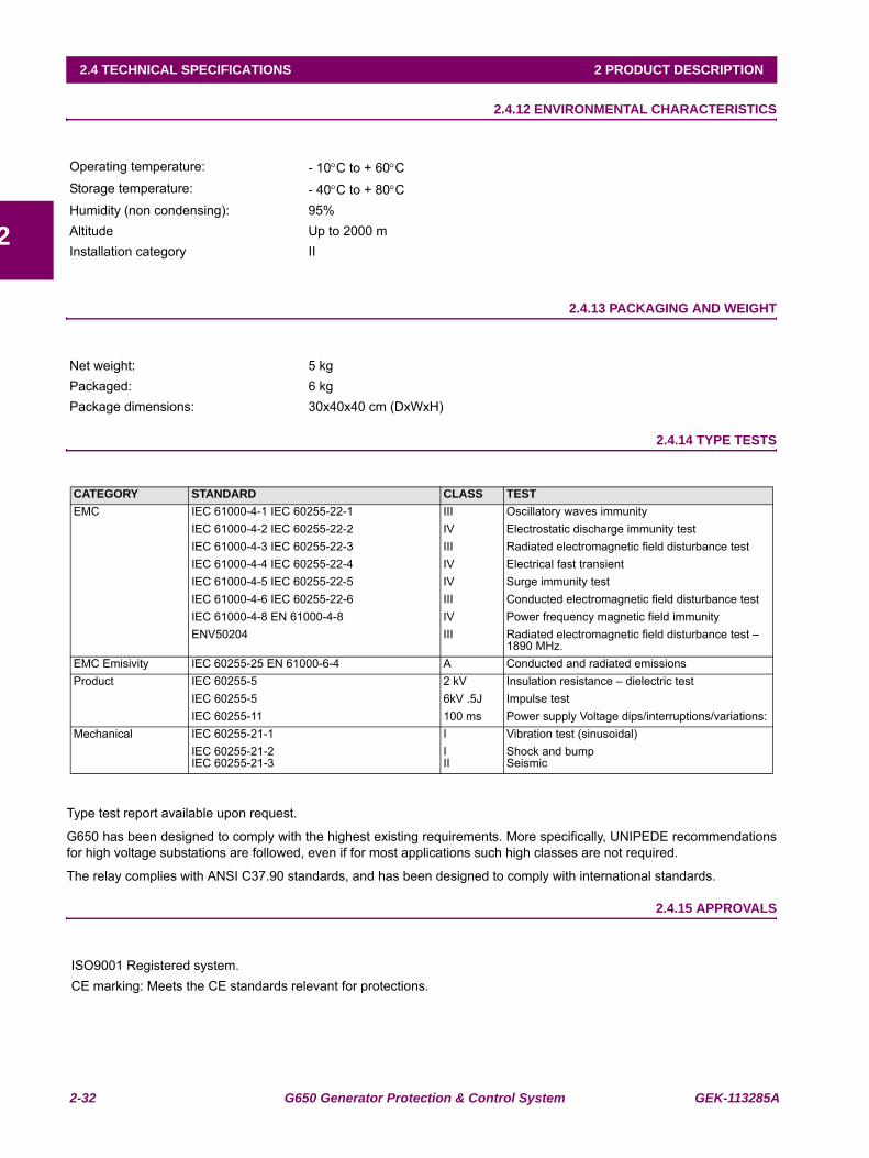
2-32 G650 Generator Protection & Control System GEK-113285A
2.4 TECHNICAL SPECIFICATIONS 2 PRODUCT DESCRIPTION
2
2.4.12 ENVIRONMENTAL CHARACTERISTICS
2.4.13 PACKAGING AND WEIGHT
2.4.14 TYPE TESTS
Type test report available upon request.
G650 has been designed to comply with the highest existing requirements. More specifically, UNIPEDE recommendationsfor high voltage substations are followed, even if for most applications such high classes are not required.
The relay complies with ANSI C37.90 standards, and has been designed to comply with international standards.
2.4.15 APPROVALS
Operating temperature: - 10°C to + 60°CStorage temperature: - 40°C to + 80°CHumidity (non condensing): 95%Altitude Up to 2000 mInstallation category II
Net weight: 5 kgPackaged: 6 kgPackage dimensions: 30x40x40 cm (DxWxH)
CATEGORY STANDARD CLASS TESTEMC IEC 61000-4-1 IEC 60255-22-1 III Oscillatory waves immunity
IEC 61000-4-2 IEC 60255-22-2 IV Electrostatic discharge immunity testIEC 61000-4-3 IEC 60255-22-3 III Radiated electromagnetic field disturbance testIEC 61000-4-4 IEC 60255-22-4 IV Electrical fast transientIEC 61000-4-5 IEC 60255-22-5 IV Surge immunity testIEC 61000-4-6 IEC 60255-22-6 III Conducted electromagnetic field disturbance testIEC 61000-4-8 EN 61000-4-8 IV Power frequency magnetic field immunityENV50204 III Radiated electromagnetic field disturbance test –
1890 MHz.EMC Emisivity IEC 60255-25 EN 61000-6-4 A Conducted and radiated emissionsProduct IEC 60255-5 2 kV Insulation resistance – dielectric test
IEC 60255-5 6kV .5J Impulse testIEC 60255-11 100 ms Power supply Voltage dips/interruptions/variations:
Mechanical IEC 60255-21-1 I Vibration test (sinusoidal)IEC 60255-21-2IEC 60255-21-3
III
Shock and bump Seismic
ISO9001 Registered system.CE marking: Meets the CE standards relevant for protections.
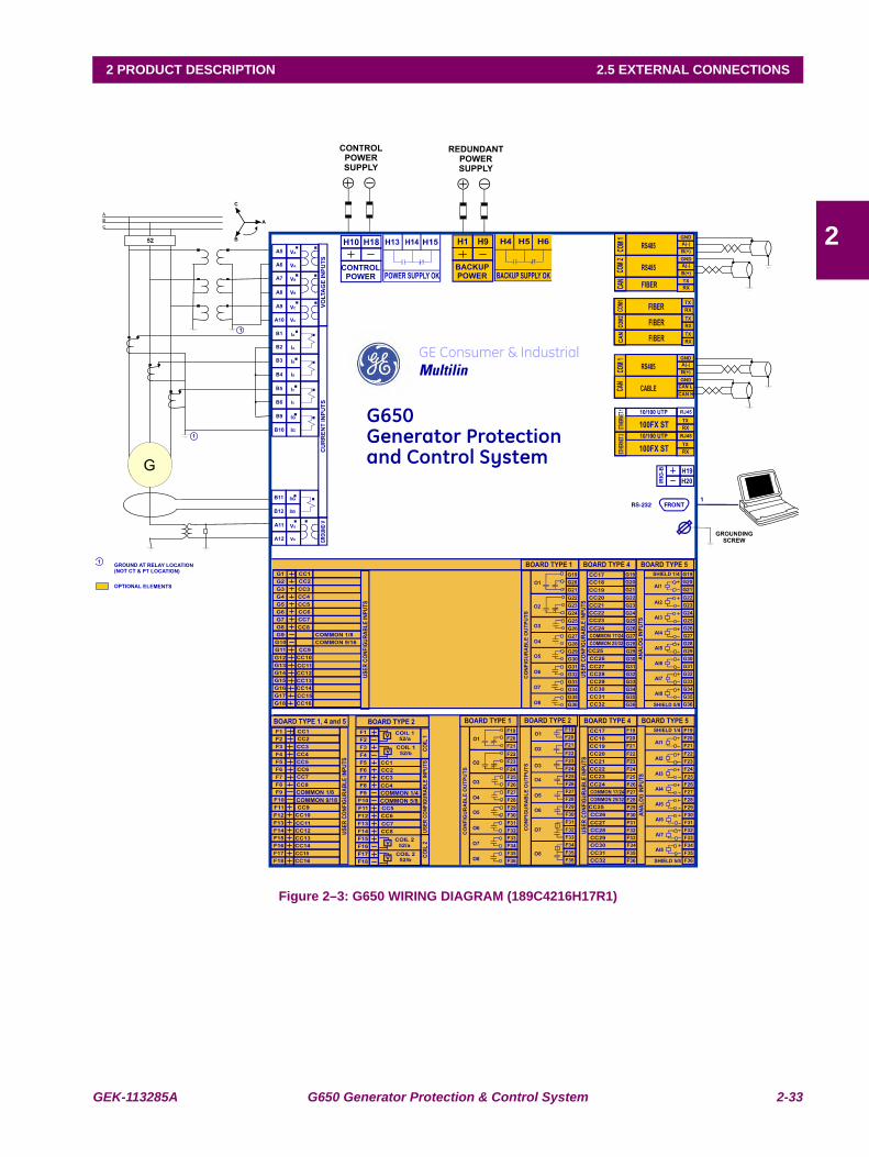
GEK-113285A G650 Generator Protection & Control System 2-33
2 PRODUCT DESCRIPTION 2.5 EXTERNAL CONNECTIONS
2
2.5EXTERNAL CONNECTIONS
Figure 2–3: G650 WIRING DIAGRAM (189C4216H17R1)
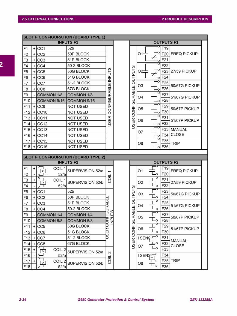
2-34 G650 Generator Protection & Control System GEK-113285A
2.5 EXTERNAL CONNECTIONS 2 PRODUCT DESCRIPTION
2
F1 + CC1 52b F19F2 + CC2 50P BLOCK F20F3 + CC3 51P BLOCK F21F4 + CC4 50-2 BLOCK F22F5 + CC5 50G BLOCK F23F6 + CC6 51G BLOCK F24F7 + CC7 51-2 BLOCK F25F8 + CC8 67G BLOCK F26F9 - COMMON 1/8 COMMON 1/8 F27F10 - COMMON 9/16 COMMON 9/16 F28F11 + CC9 NOT USED F29F12 + CC10 NOT USED F30F13 + CC11 NOT USED F31F14 + CC12 NOT USED F32F15 + CC13 NOT USED F33F16 + CC14 NOT USED F34F17 + CC15 NOT USED F35F18 + CC16 NOT USED F36
F1 + COIL 1 F19F2 - 52/a F20F3 + COIL 1 F21F4 - 52/b F22F5 + CC1 52b F23F6 + CC2 50P BLOCK F24F7 + CC3 51P BLOCK F25F8 + CC4 50-2 BLOCK F26F9 - COMMON 1/4 COMMON 1/4 F27F10 - COMMON 5/8 COMMON 5/8 F28F11 + CC5 50G BLOCK F29F12 + CC6 51G BLOCK F30F13 + CC7 51-2 BLOCK I SENS F31F14 + CC8 67G BLOCK F32F15 + COIL 2 F33F16 - 52/a I SENS F34F17 + COIL 2 F35F18 - 52/b F36
INPUTS F1 OUTPUTS F1
US
ER
CO
NFI
GU
RA
BLE
INP
UTS
US
ER
CO
NFI
GU
RA
BLE
OU
TPU
TS
O1 FREQ PICKUP
O2 27/59 PICKUP
O3 50/67G PICKUP
O4 51/67G PICKUP
O5 50/67P PICKUP
O6 51/67P PICKUP
O7 MANUAL CLOSE
O8 TRIP
SLOT F CONFIGURATION (BOARD TYPE 2)INPUTS F2 OUTPUTS F2
CO
IL 1
US
ER
CO
NFI
GU
RA
BLE
OU
TPU
TS
O1 FREQ PICKUP
US
ER
CO
NFI
GU
RA
BLE
IN
PU
TS
O3 50/67G PICKUP
O4 51/67G PICKUP
O5 50/67P PICKUP
MANUAL CLOSEO7
O2 27/59 PICKUP
SLOT F CONFIGURATION (BOARD TYPE 1)
CO
IL 2
TRIPO8
SUPERVISION 52/a
SUPERVISION 52/b
SUPERVISION 52/a
SUPERVISION 52/b
O6 51/67P PICKUP
VV
VV
II
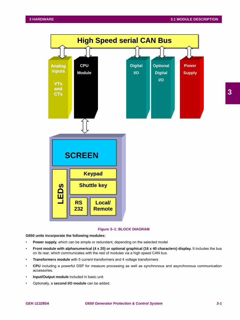
GEK-113285A G650 Generator Protection & Control System 3-1
3 HARDWARE 3.1 MODULE DESCRIPTION
3
3 HARDWARE 3.1MODULE DESCRIPTION
Figure 3–1: BLOCK DIAGRAM
G650 units incorporate the following modules:
• Power supply, which can be simple or redundant, depending on the selected model
• Front module with alphanumerical (4 x 20) or optional graphical (16 x 40 characters) display. It includes the buson its rear, which communicates with the rest of modules via a high speed CAN bus.
• Transformers module with 5 current transformers and 4 voltage transformers
• CPU including a powerful DSP for measure processing as well as synchronous and asynchronous communicationaccessories.
• Input/Output module included in basic unit
• Optionally, a second I/O module can be added.
HHiigghh SSppeeeedd sseerriiaall CCAANN BBuuss
AAnnaalloogg
iinnppuuttss
VVTTss
aanndd
CCTTss
CPU
Module
Digital
I/O
Power
Supply
Optional
Digital
I/O
SShhuuttttllee kkeeyy
LLooccaall//
RReemmoottee
LLEE
DDss
SCREEN
KKeeyyppaadd
RRSS
223322
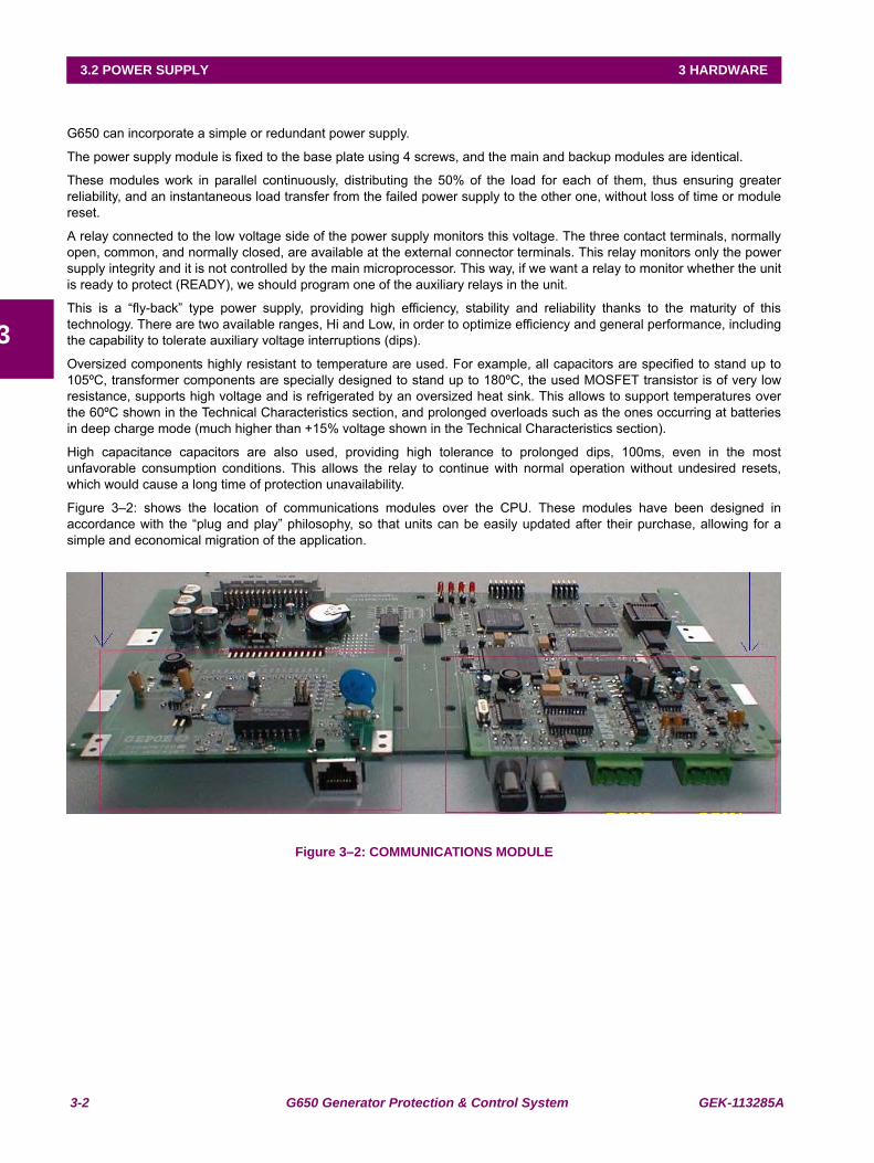
3-2 G650 Generator Protection & Control System GEK-113285A
3.2 POWER SUPPLY 3 HARDWARE
3
3.2POWER SUPPLY
G650 can incorporate a simple or redundant power supply.
The power supply module is fixed to the base plate using 4 screws, and the main and backup modules are identical.
These modules work in parallel continuously, distributing the 50% of the load for each of them, thus ensuring greaterreliability, and an instantaneous load transfer from the failed power supply to the other one, without loss of time or modulereset.
A relay connected to the low voltage side of the power supply monitors this voltage. The three contact terminals, normallyopen, common, and normally closed, are available at the external connector terminals. This relay monitors only the powersupply integrity and it is not controlled by the main microprocessor. This way, if we want a relay to monitor whether the unitis ready to protect (READY), we should program one of the auxiliary relays in the unit.
This is a “fly-back” type power supply, providing high efficiency, stability and reliability thanks to the maturity of thistechnology. There are two available ranges, Hi and Low, in order to optimize efficiency and general performance, includingthe capability to tolerate auxiliary voltage interruptions (dips).
Oversized components highly resistant to temperature are used. For example, all capacitors are specified to stand up to105ºC, transformer components are specially designed to stand up to 180ºC, the used MOSFET transistor is of very lowresistance, supports high voltage and is refrigerated by an oversized heat sink. This allows to support temperatures overthe 60ºC shown in the Technical Characteristics section, and prolonged overloads such as the ones occurring at batteriesin deep charge mode (much higher than +15% voltage shown in the Technical Characteristics section).
High capacitance capacitors are also used, providing high tolerance to prolonged dips, 100ms, even in the mostunfavorable consumption conditions. This allows the relay to continue with normal operation without undesired resets,which would cause a long time of protection unavailability.
Figure 3–2: shows the location of communications modules over the CPU. These modules have been designed inaccordance with the “plug and play” philosophy, so that units can be easily updated after their purchase, allowing for asimple and economical migration of the application.
Figure 3–2: COMMUNICATIONS MODULE
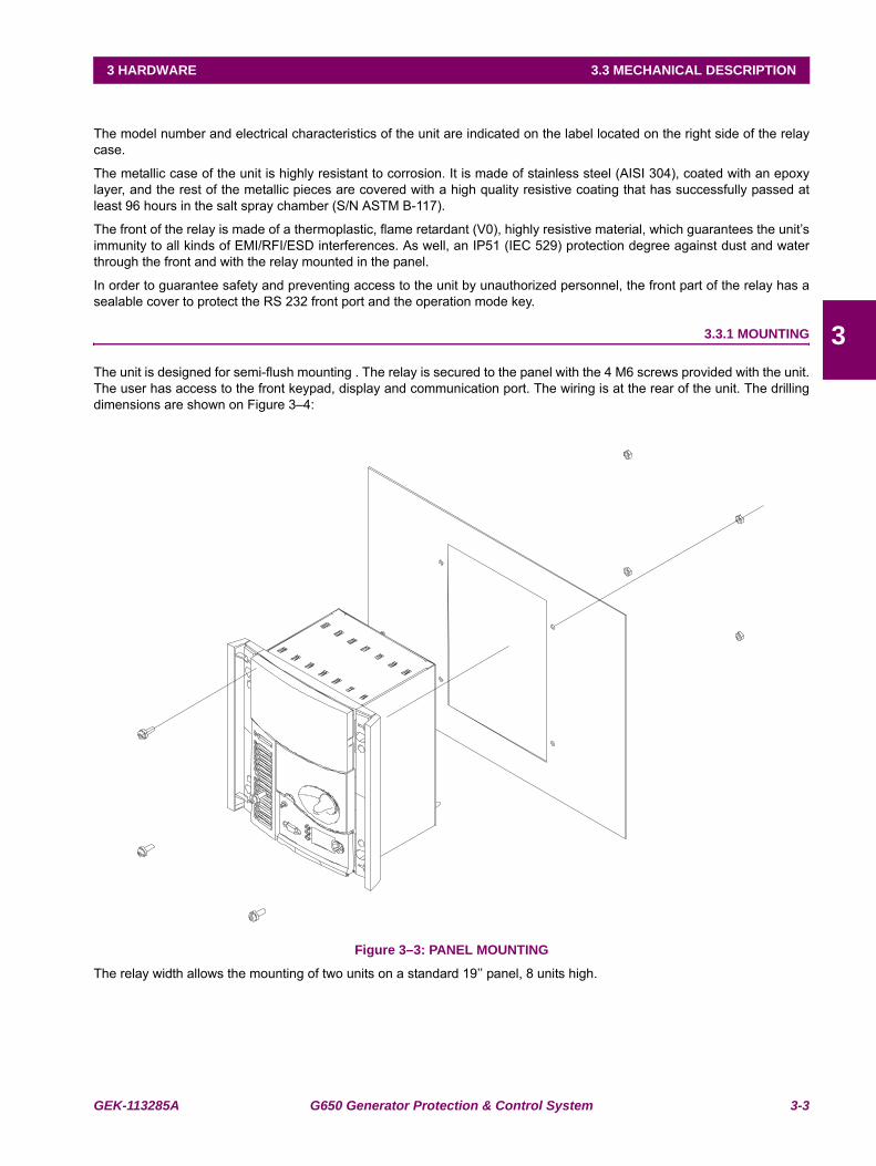
GEK-113285A G650 Generator Protection & Control System 3-3
3 HARDWARE 3.3 MECHANICAL DESCRIPTION
3
3.3MECHANICAL DESCRIPTION
The model number and electrical characteristics of the unit are indicated on the label located on the right side of the relaycase.
The metallic case of the unit is highly resistant to corrosion. It is made of stainless steel (AISI 304), coated with an epoxylayer, and the rest of the metallic pieces are covered with a high quality resistive coating that has successfully passed atleast 96 hours in the salt spray chamber (S/N ASTM B-117).
The front of the relay is made of a thermoplastic, flame retardant (V0), highly resistive material, which guarantees the unit’simmunity to all kinds of EMI/RFI/ESD interferences. As well, an IP51 (IEC 529) protection degree against dust and waterthrough the front and with the relay mounted in the panel.
In order to guarantee safety and preventing access to the unit by unauthorized personnel, the front part of the relay has asealable cover to protect the RS 232 front port and the operation mode key.
3.3.1 MOUNTING
The unit is designed for semi-flush mounting . The relay is secured to the panel with the 4 M6 screws provided with the unit.The user has access to the front keypad, display and communication port. The wiring is at the rear of the unit. The drillingdimensions are shown on Figure 3–4:
Figure 3–3: PANEL MOUNTING
The relay width allows the mounting of two units on a standard 19’’ panel, 8 units high.
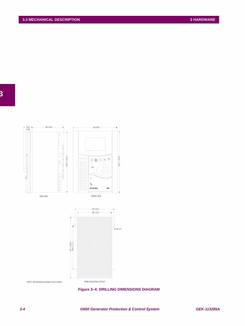
3-4 G650 Generator Protection & Control System GEK-113285A
3.3 MECHANICAL DESCRIPTION 3 HARDWARE
3
Figure 3–4: DRILLING DIMENSIONS DIAGRAM
NOTE: All dimensions are shown in mm ( inches ).
ESC
F1F2*
237 ( 9,30 )169 ( 6,65 )(1,38)
266,7
(10,5
0)
260,7
(10,2
6)
FRONT VIEWSIDE VIEW
GE Multilin 650
186 ( 7,32 )
210 ( 8,27 )
190,5
(7,5
)26
3(1
0,36)
4x O7 ( ,27 )
PANEL MOUNTING CUTOUT
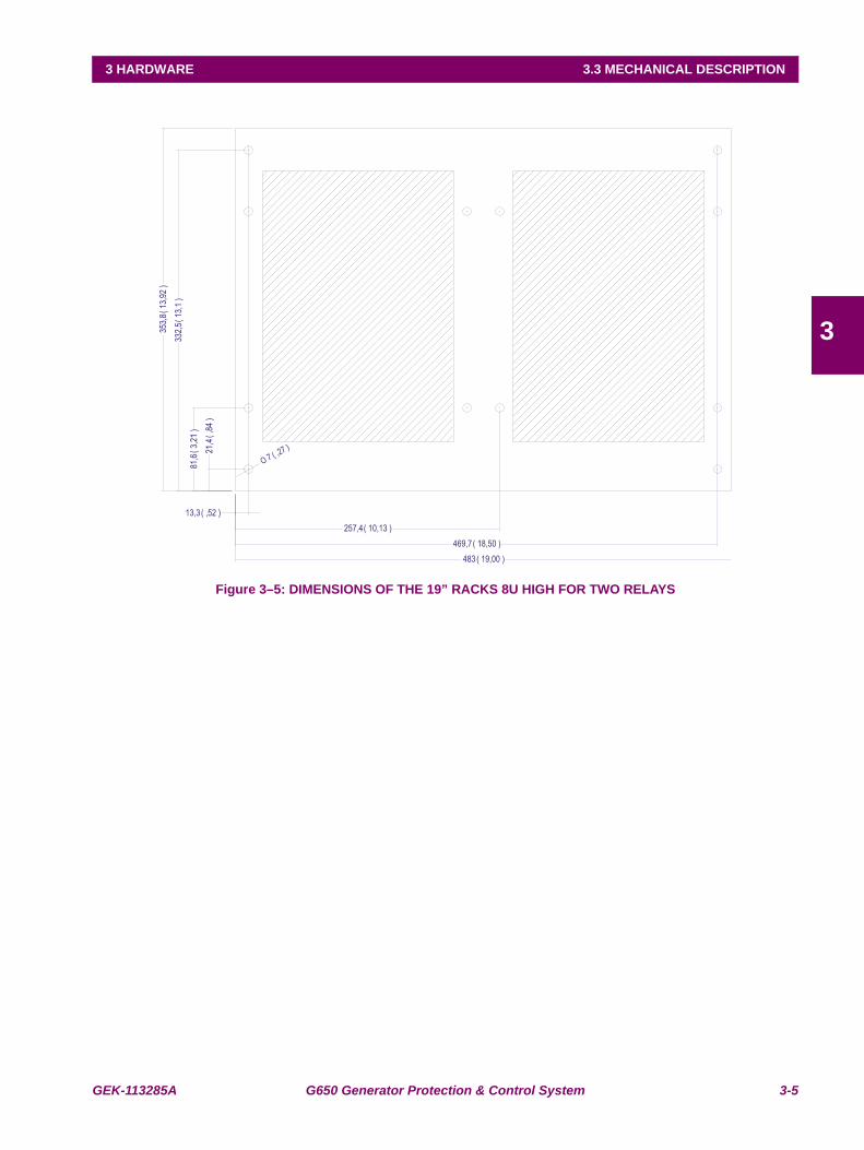
GEK-113285A G650 Generator Protection & Control System 3-5
3 HARDWARE 3.3 MECHANICAL DESCRIPTION
3
Figure 3–5: DIMENSIONS OF THE 19” RACKS 8U HIGH FOR TWO RELAYS
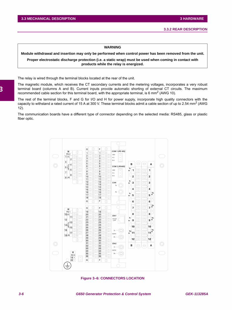
3-6 G650 Generator Protection & Control System GEK-113285A
3.3 MECHANICAL DESCRIPTION 3 HARDWARE
3
3.3.2 REAR DESCRIPTION
The relay is wired through the terminal blocks located at the rear of the unit.
The magnetic module, which receives the CT secondary currents and the metering voltages, incorporates a very robustterminal board (columns A and B). Current inputs provide automatic shorting of external CT circuits. The maximumrecommended cable section for this terminal board, with the appropriate terminal, is 6 mm2 (AWG 10).
The rest of the terminal blocks, F and G for I/O and H for power supply, incorporate high quality connectors with thecapacity to withstand a rated current of 15 A at 300 V. These terminal blocks admit a cable section of up to 2.54 mm2 (AWG12).
The communication boards have a different type of connector depending on the selected media: RS485, glass or plasticfiber optic.
Figure 3–6: CONNECTORS LOCATION
WARNING
Module withdrawal and insertion may only be performed when control power has been removed from the unit.
Proper electrostatic discharge protection (i.e. a static wrap) must be used when coming in contact with products while the relay is energized.
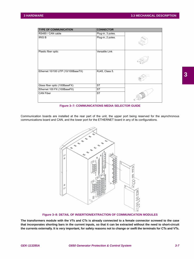
GEK-113285A G650 Generator Protection & Control System 3-7
3 HARDWARE 3.3 MECHANICAL DESCRIPTION
3
Figure 3–7: COMMUNICATIONS MEDIA SELECTOR GUIDE
Communication boards are installed at the rear part of the unit, the upper port being reserved for the asynchronouscommunications board and CAN, and the lower port for the ETHERNET board in any of its configurations.
Figure 3–8: DETAIL OF INSERTION/EXTRACTION OF COMMUNICATION MODULES
The transformers module with the VTs and CTs is already connected to a female connector screwed to the casethat incorporates shorting bars in the current inputs, so that it can be extracted without the need to short-circuitthe currents externally. It is very important, for safety reasons not to change or swift the terminals for CTs and VTs.
TYPE OF COMMUNICATION CONNECTORRS485 / CAN cable Plug-in, 3 poles.IRIG B Plug-in, 2 poles.
Plastic fiber optic Versatile Link
Ethernet 10/100 UTP (10/100BaseTX) RJ45, Class 5.
Glass fiber optic (100BaseFX) STEthernet 100 FX (100BaseFX) STCAN Fiber ST
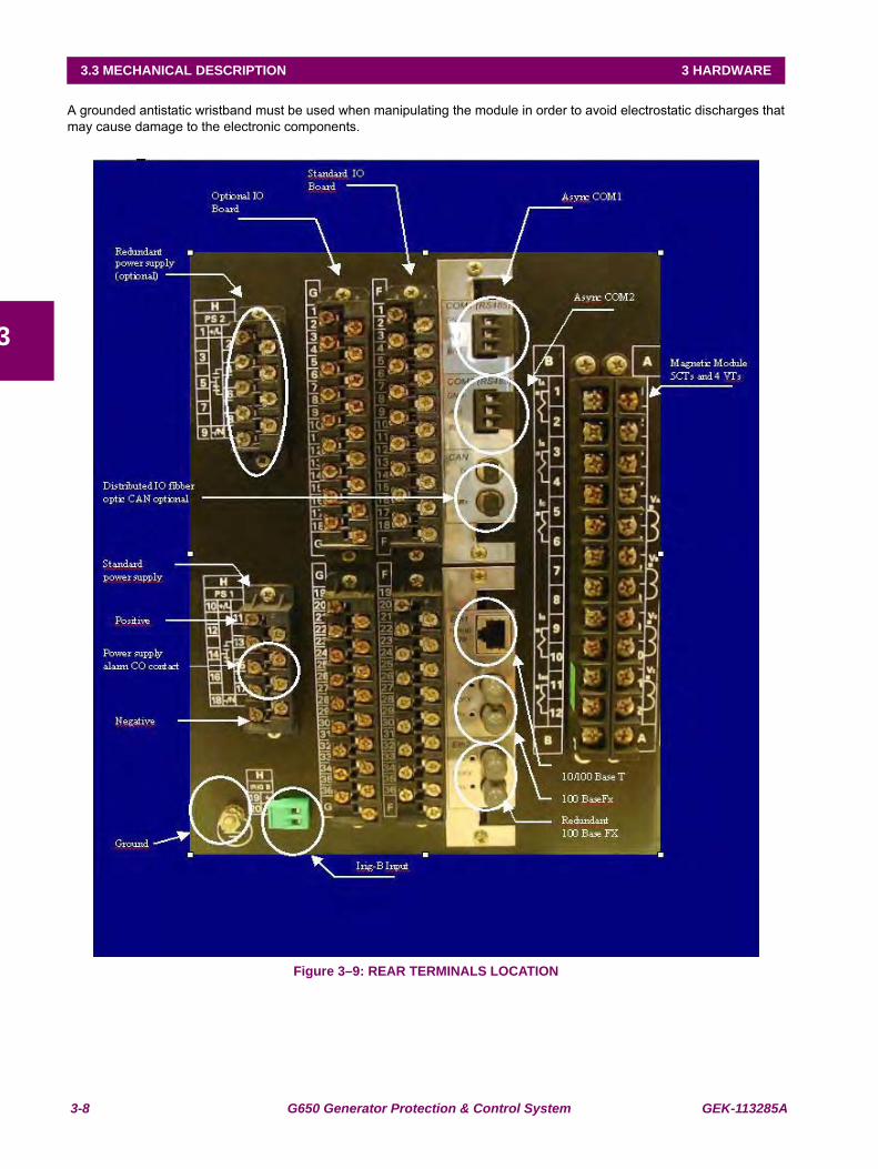
3-8 G650 Generator Protection & Control System GEK-113285A
3.3 MECHANICAL DESCRIPTION 3 HARDWARE
3
A grounded antistatic wristband must be used when manipulating the module in order to avoid electrostatic discharges thatmay cause damage to the electronic components.
Figure 3–9: REAR TERMINALS LOCATION
GEK-113285A G650 Generator Protection & Control System 3-9
3 HARDWARE 3.4 WIRING
3
3.4WIRING 3.4.1 EXTERNAL CONNECTIONS
G650 units can hold different options for F module:
Option 1: Board with 16 digital inputs and 8 outputs.
Option 2: Board with 8 digital inputs, 4 circuit supervision inputs, 6 conventional outputs, and two current sensingoutputs
Option 4: Board with 32 digital inputs.
Option 5: Board with 16 digital inputs and 8 analog inputs.
For slot G there are four different options:
Option 0: No board
Option 1: Board with 16 digital inputs and 8 outputs.
Option 4: Board with 32 digital inputs.
Option 5: Board with 16 digital inputs and 8 analog inputs.
The number selected for slot G must be equal or higher than the number selected for option F for models including boards4 and 5.
3.4.2 DIGITAL INPUTS WITH TRIP CIRCUIT SUPERVISION
The Option 2 I/O board includes two groups of 4 inputs with one common, in terminals F9 to F10. It also includes 6 auxiliaryoutputs, in terminals F19 to F30 with normally open contacts and two current sensing (latching) outputs (F31-F33 and F34-F36).
Besides, there are 2 groups of inputs for trip circuit supervision. The first group includes two isolated digital inputs, terminalsF1-F2 and F3-F4. The second group, symmetrical and identical to the first, is formed by isolated voltage inputs F15-F16and F17-F18.
Using voltage detectors and current sensing, it is possible to implement several trip or close circuit supervision schemes, aswell as protection of the unit output contact.
In order to implement these schemes, it is not necessary to perform any setting in the unit. Internal functions arealways operative. The detailed description of trip circuit supervision is included in chapter 5 in this manual.
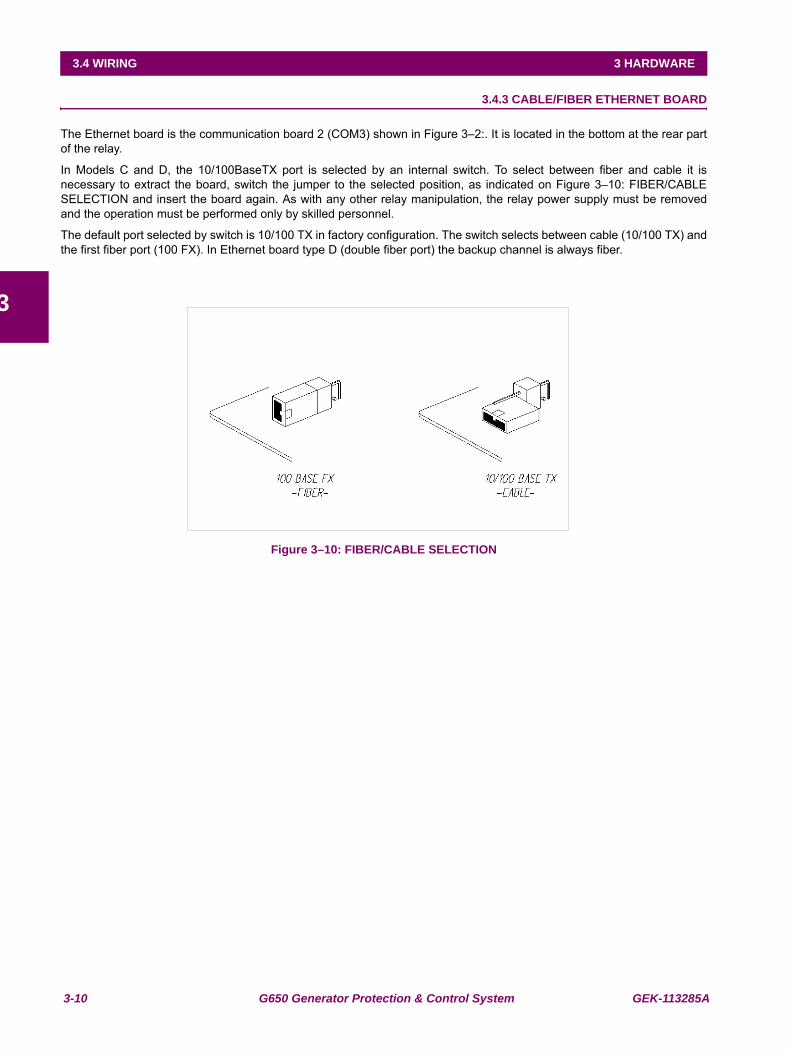
3-10 G650 Generator Protection & Control System GEK-113285A
3.4 WIRING 3 HARDWARE
3
3.4.3 CABLE/FIBER ETHERNET BOARD
The Ethernet board is the communication board 2 (COM3) shown in Figure 3–2:. It is located in the bottom at the rear partof the relay.
In Models C and D, the 10/100BaseTX port is selected by an internal switch. To select between fiber and cable it isnecessary to extract the board, switch the jumper to the selected position, as indicated on Figure 3–10: FIBER/CABLESELECTION and insert the board again. As with any other relay manipulation, the relay power supply must be removedand the operation must be performed only by skilled personnel.
The default port selected by switch is 10/100 TX in factory configuration. The switch selects between cable (10/100 TX) andthe first fiber port (100 FX). In Ethernet board type D (double fiber port) the backup channel is always fiber.
Figure 3–10: FIBER/CABLE SELECTION
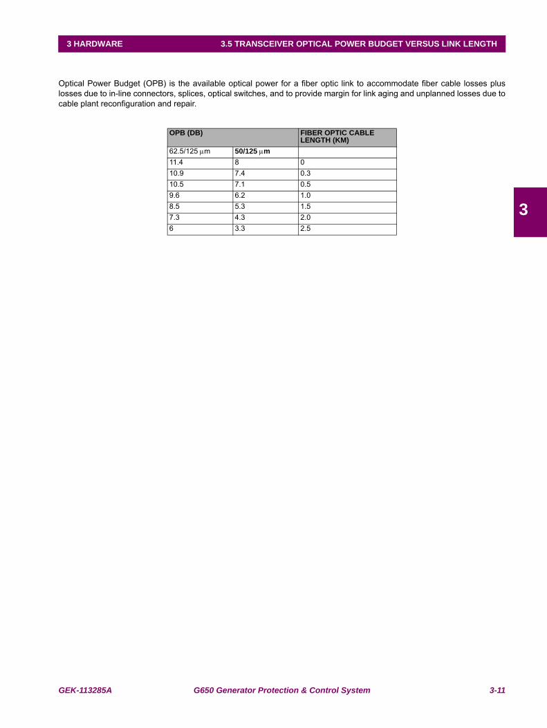
GEK-113285A G650 Generator Protection & Control System 3-11
3 HARDWARE 3.5 TRANSCEIVER OPTICAL POWER BUDGET VERSUS LINK LENGTH
3
3.5TRANSCEIVER OPTICAL POWER BUDGET VERSUS LINK LENGTH
Optical Power Budget (OPB) is the available optical power for a fiber optic link to accommodate fiber cable losses pluslosses due to in-line connectors, splices, optical switches, and to provide margin for link aging and unplanned losses due tocable plant reconfiguration and repair.
OPB (DB) FIBER OPTIC CABLE LENGTH (KM)
62.5/125 μm 50/125 μm11.4 8 010.9 7.4 0.310.5 7.1 0.59.6 6.2 1.08.5 5.3 1.57.3 4.3 2.06 3.3 2.5

3-12 G650 Generator Protection & Control System GEK-113285A
3.5 TRANSCEIVER OPTICAL POWER BUDGET VERSUS LINK LENGTH 3 HARDWARE
3
GEK-113285A G650 Generator Protection & Control System 4-1
4 HUMAN INTERFACES. SETTINGS & ACTUAL VALUES 4.1 ENERVISTA 650 SETUP SOFTWARE INTERFACE
4
4 HUMAN INTERFACES. SETTINGS & ACTUAL VALUES 4.1ENERVISTA 650 SETUP SOFTWARE INTERFACE
4.1.1 INTRODUCTION
The EnerVista 650 Setup software provides a graphical user interface (GUI) as one of two human interfaces to a 650device. The alternate human interface is implemented via the device’s faceplate keypad and display (see Human MachineInterface section in this chapter).
The EnerVista 650 Setup software provides a single facility to configure, monitor, maintain, and trouble-shoot the operationof relay functions, connected over local or wide area communication networks. It can be used while disconnected (i.e.offline) or connected (i.e. on-line) to a 650 device. In off-line mode, settings files can be created for eventual downloading tothe device. In on-line mode, you can communicate with the device in real-time.
The EnerVista 650 Setup software, provided with every G650 relay, can be run from any computer supporting MicrosoftWindows® 95, 98, NT, 2000, ME, and XP. This chapter provides a summary of the basic EnerVista 650 Setup softwareinterface features. The EnerVista 650 Setup Help File provides details for getting started and using the EnerVista 650Setup software interface.
4.1.2 ENERVISTA 650 SETUP SOFTWARE OVERVIEW
This software package uses ModBus protocol, and it is designed to communicate with a single relay at a time. GE offersdifferent communication software packages, such as GE-POWER, which can be used to communicate simultaneously withseveral relays.
EnerVista 650 Setup software provides an easy way to configure, monitor and manage all G650 features.
4.1.2.1 ENGAGING A DEVICE
The EnerVista 650 Setup software may be used in on-line mode (relay connected) to directly communicate with a 650device.
4.1.2.2 USING SETTINGS FILES
The EnerVista 650 Setup software interface supports three ways of handling changes to relay settings:
1. In off-line mode (relay disconnected) to create or edit relay settings files for later download to communicating relays.
2. While connected to a communicating relay to directly modify any relay settings via relay data view windows, and thensave the settings to the relay.
3. You can create/edit settings files and then write them to the relay while the interface is connected to the relay.
Settings files are organized on the basis of file names assigned by the user. A settings file contains data pertaining to thefollowing types of relay settings:
•Product Setup
•System Setup
•Protection Elements
•Control Elements
•Inputs/Outputs
•Relay Configuration
•Logic Configuration
4.1.2.3 VIEWING ACTUAL VALUES
You can view real-time relay data such as input/output status and measured parameters.

4-2 G650 Generator Protection & Control System GEK-113285A
4.1 ENERVISTA 650 SETUP SOFTWARE INTERFACE 4 HUMAN INTERFACES. SETTINGS & ACTUAL VALUES
4
4.1.2.4 VIEWING TRIGGERED EVENTS
While the interface is in either on-line or off-line mode, you can view and analyze data generated by triggered specifiedparameters, via one of the following:
• Event Recorder facility: The event recorder captures contextual data associated with the last 479 events, listed inchronological order from most recent to oldest.
• Oscillography facility: The oscillography waveform traces and digital states are used to provide a visual display ofpower system and relay operation data captured during specific triggered events.
4.1.2.5 FIRMWARE UPGRADES
The firmware of a G650 device can be upgraded, locally or remotely, via the EnerVista 650 Setup software. Thecorresponding instructions are provided by the EnerVista 650 Setup Help file under the topic “Upgrading Firmware”.
Modbus addresses assigned to firmware modules, features, settings, and corresponding data items (i.e. default values,minimum/maximum values, data type, and item size) may change slightly from version to version of firmware.
The addresses are rearranged when new features are added or existing features are enhanced or modified.
4.1.2.6 ONE LINE DIAGRAMS
You can configure an one line diagram (bay mimic) to be used in relays with graphical display.
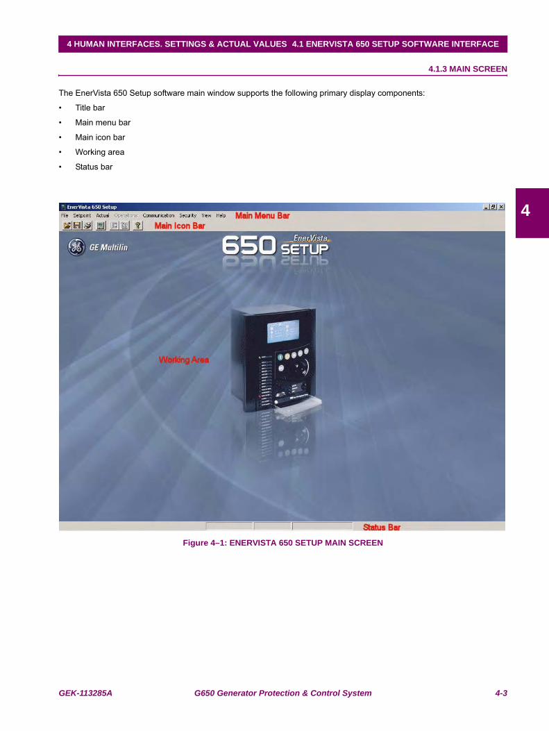
GEK-113285A G650 Generator Protection & Control System 4-3
4 HUMAN INTERFACES. SETTINGS & ACTUAL VALUES 4.1 ENERVISTA 650 SETUP SOFTWARE INTERFACE
4
4.1.3 MAIN SCREEN
The EnerVista 650 Setup software main window supports the following primary display components:
• Title bar
• Main menu bar
• Main icon bar
• Working area
• Status bar
Figure 4–1: ENERVISTA 650 SETUP MAIN SCREEN
Working Area
Title
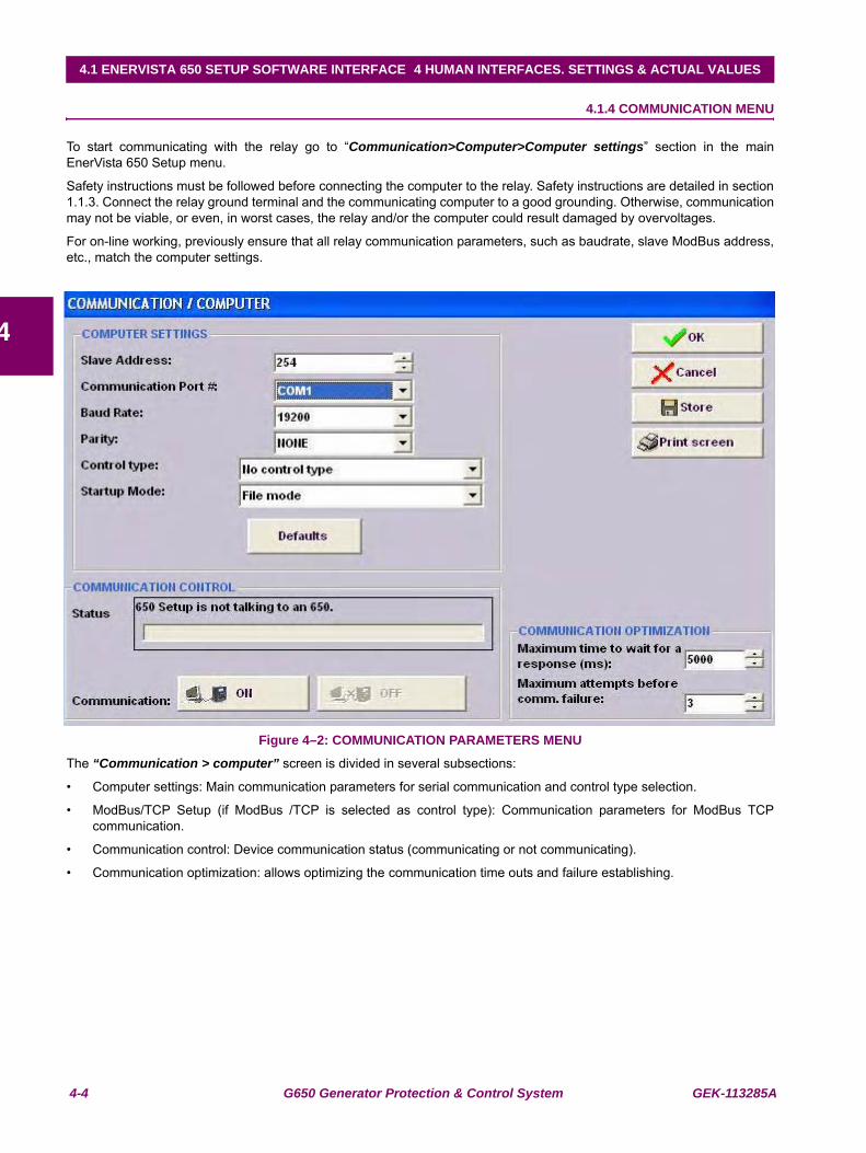
4-4 G650 Generator Protection & Control System GEK-113285A
4.1 ENERVISTA 650 SETUP SOFTWARE INTERFACE 4 HUMAN INTERFACES. SETTINGS & ACTUAL VALUES
4
4.1.4 COMMUNICATION MENU
To start communicating with the relay go to “Communication>Computer>Computer settings” section in the mainEnerVista 650 Setup menu.
Safety instructions must be followed before connecting the computer to the relay. Safety instructions are detailed in section1.1.3. Connect the relay ground terminal and the communicating computer to a good grounding. Otherwise, communicationmay not be viable, or even, in worst cases, the relay and/or the computer could result damaged by overvoltages.
For on-line working, previously ensure that all relay communication parameters, such as baudrate, slave ModBus address,etc., match the computer settings.
Figure 4–2: COMMUNICATION PARAMETERS MENU
The “Communication > computer” screen is divided in several subsections:
• Computer settings: Main communication parameters for serial communication and control type selection.
• ModBus/TCP Setup (if ModBus /TCP is selected as control type): Communication parameters for ModBus TCPcommunication.
• Communication control: Device communication status (communicating or not communicating).
• Communication optimization: allows optimizing the communication time outs and failure establishing.
GEK-113285A G650 Generator Protection & Control System 4-5
4 HUMAN INTERFACES. SETTINGS & ACTUAL VALUES 4.1 ENERVISTA 650 SETUP SOFTWARE INTERFACE
4
4.1.4.1 COMPUTER SETTINGS:
Shows the communication parameters necessary in order to establish communication with the unit. Such as slave address,communication port, baud rate, parity, control type and startup mode.
Baud rate, parity, data bits, stop bits and ModBus slave address for com2 (RS232 front port and second serial port in therear communication board) are displayed in the default text logotype main screen.
ModBus Slave Address: ModBus addresses used for serial and Ethernet communication.
Communication ports: port used in the computer for serial communication.
Baud Rate: Baud rate for serial communication (from 1200 up to 115200 bauds in EnerVista 650 Setup, from 300 to115200 in relay).
Parity: parity for serial communication. None, odd or even can be selected.
Control Type: The available control modes are:
• No Control Type, this option selects the serial communication mode, for use with serial communication ports (frontport, RS485, or plastic or glass fiber optic).
• MODBUS/TCP, this option selects ModBus TCP/IP communication mode, for communication through the Ethernetport. In this case, the top right window will show the typical parameters to be programmed; IP address, port addressand unit identifier in the MODBUS TCP SETUP section.
• MODEM, this option displays the parameter to set in case of using a modem for the communication, such as Phonenumber, Time out (sec.), init. command, type of dialing (tones or pulses).
4.1.4.2 COMMUNICATION CONTROL:
Located at the bottom of the screen, it shows the status of the communication with the relay. With relay not communicating,a message “650 Setup is not talking to an 650” will be shown and ON button will be enable. Pressing this button, 650 Setupstart communicating with the relay.
With relay communicating a message “650 Setup is now talking to an 650” will be shown and OFF will be enable. Pressingthis button, communications between relay and PC will be closed.
4.1.4.3 COMMUNICATION OPTIMIZATION:
The parameters shown on the bottom right window (Communication optimization) can improve communication, although itis recommended to leave the default values indicated by the EnerVista 650 Setup. These parameters are the maximumtime to wait for a response in the relay (in ms) and the maximum attempts to perform before assuming communicationsfailure.
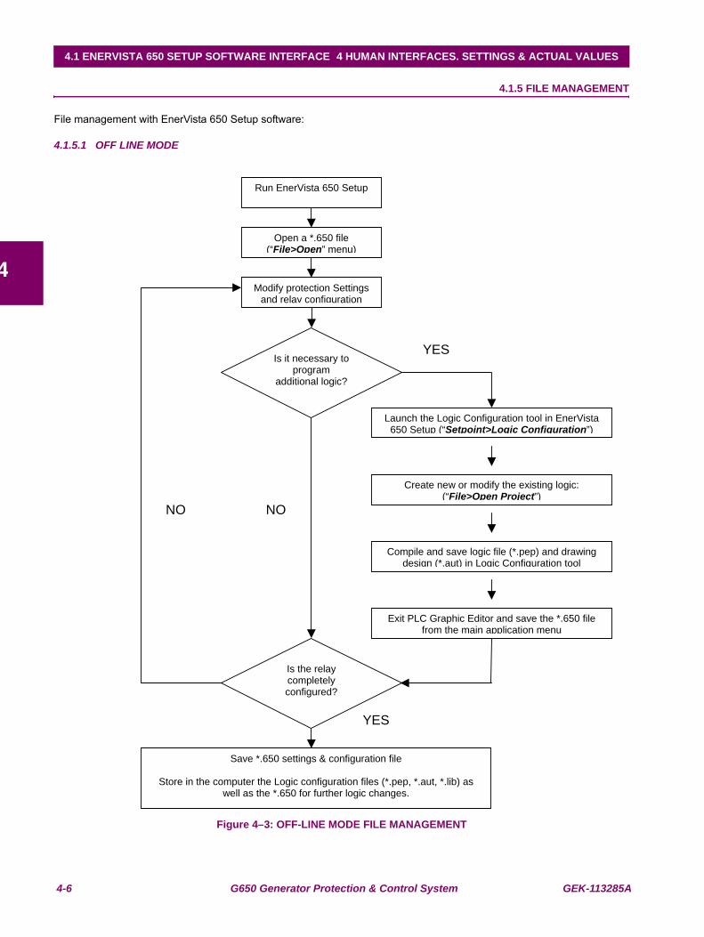
4-6 G650 Generator Protection & Control System GEK-113285A
4.1 ENERVISTA 650 SETUP SOFTWARE INTERFACE 4 HUMAN INTERFACES. SETTINGS & ACTUAL VALUES
4
4.1.5 FILE MANAGEMENT
File management with EnerVista 650 Setup software:
4.1.5.1 OFF LINE MODE
Figure 4–3: OFF-LINE MODE FILE MANAGEMENT
Run EnerVista 650 Setup
Open a *.650 file (“File>Open” menu)
Modify protection Settings and relay configuration
Is it necessary to program
additional logic?
Launch the Logic Configuration tool in EnerVista 650 Setup (“Setpoint>Logic Configuration”)
Create new or modify the existing logic: (“File>Open Project”)
Compile and save logic file (*.pep) and drawing design (*.aut) in Logic Configuration tool
Exit PLC Graphic Editor and save the *.650 file from the main application menu
Is the relay completely configured?
Save *.650 settings & configuration file
Store in the computer the Logic configuration files (*.pep, *.aut, *.lib) as well as the *.650 for further logic changes.
YES
YES
NO NO
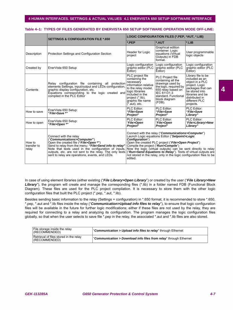
GEK-113285A G650 Generator Protection & Control System 4-7
4 HUMAN INTERFACES. SETTINGS & ACTUAL VALUES 4.1 ENERVISTA 650 SETUP SOFTWARE INTERFACE
4
Table 4–1: TYPES OF FILES GENERATED BY ENERVISTA 650 SETUP SOFTWARE OPERATION MODE OFF-LINE:
In case of using element libraries (either existing (“File Library>Open Library”) or created by the user (“File Library>NewLibrary”), the program will create and manage the corresponding files (*.lib) in a folder named FDB (Functional BlockDiagram). These files are used for the PLC project compilation. It is necessary to store them with the other logicconfiguration files that built the PLC project (*.pep, *.aut, *.lib).
Besides sending basic information to the relay (Settings + configuration) in *.650 format, it is recommended to store *.650,*.pep, *.aut and *.lib files inside the relay (“Communication>Upload info files to relay”), to ensure that logic configurationfiles will be available in the future for further logic modifications; either if these files are not used by the relay, they arerequired for connecting to a relay and analyzing its configuration. The program manages the logic configuration filesglobally, so that when the user selects to save file *.pep in the relay, the associated *.aut and *.lib files are also stored.
SETTINGS & CONFIGURATION FILE *.650LOGIC CONFIGURATION FILES (*.PEP, *AUT, *.LIB)
*.PEP *.AUT *.LIB
Description Protection Settings and Configuration Section Header for Logic project
Graphical edition container. Logic equations (Virtual Outputs) in FDB format.
User programmable logic objects
Created by EnerVista 650 SetupLogic configuration graphic editor (PLC Editor)
Logic configuration graphic editor (PLC Editor)
Logic configuration graphic editor (PLC Editor)
Contents
Relay configuration file containing all protectionelements Settings, input/output and LEDs configuration,graphic display configuration, etc.Equations corresponding to the logic created andcompiled in the PLC Editor
PLC project file containing the necessary information relative to the relay model, logic libraries included in the project (*.lib), graphic file name (*.aut), etc.
PLC Project file containing all the drawings used by the logic, required by 650 relay based on IEC 61131-3 standard. Functional block diagram (FDB).
Library file to be included as an object in a PLC project. Logic packages that can be stored into libraries and be distributed in different PLC projects.
How to save EnerVista 650 Setup:“File>Save *”
PLC Editor:“File>Save Project”
PLC Editor:“File>Save Project”
PLC Editor: “File>Save Library”
How to open EnerVista 650 Setup:“File>Open *”
PLC Editor:“File>Open Project”
PLC Editor:“File>Open Project”
PLC Editor:“File>Library>New Library”
How to transfer to relay
Connect with the relay (“Communications>Computer”)Open the created file (“File>Open *”)Send to relay from the menu: “File>Send info to relay”Note that texts used in the configuration of inputs,outputs, etc. are not sent to the relay. The only textssent to relay are operations, events, and LEDs.
Connect with the relay (“Communications>Computer”)Launch Logic equations Editor (“Setpoint>Logic Configuration”)Open the created PLC project (“File>Open Project”)Compile the project (“Run>Compile”)Now the logic (virtual outputs) can be sent directly to relay(“Run>Send Equations to Relay”). Texts of virtual outputs arenot stored in the relay, only in the logic configuration files to beedited.
File storage inside the relay (RECOMMENDED) “Communication > Upload info files to relay” through Ethernet
Retrieval of files stored in the relay (RECOMMENDED) “Communication > Download info files from relay” through Ethernet
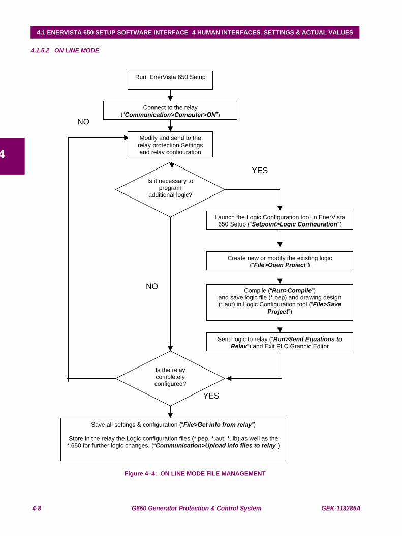
4-8 G650 Generator Protection & Control System GEK-113285A
4.1 ENERVISTA 650 SETUP SOFTWARE INTERFACE 4 HUMAN INTERFACES. SETTINGS & ACTUAL VALUES
4
4.1.5.2 ON LINE MODE
Figure 4–4: ON LINE MODE FILE MANAGEMENT
NO
Run EnerVista 650 Setup
Connect to the relay (“Communication>Computer>ON”)
Modify and send to the relay protection Settings and relay configuration
Is it necessary to program
additional logic?
Launch the Logic Configuration tool in EnerVista 650 Setup (“Setpoint>Logic Configuration”)
Create new or modify the existing logic (“File>Open Project”)
Compile (“Run>Compile”)and save logic file (*.pep) and drawing design (*.aut) in Logic Configuration tool (“File>Save
Project”)
Send logic to relay (“Run>Send Equations to Relay”) and Exit PLC Graphic Editor
Is the relay completely configured?
Save all settings & configuration (“File>Get info from relay”)
Store in the relay the Logic configuration files (*.pep, *.aut, *.lib) as well as the
*.650 for further logic changes. (“Communication>Upload info files to relay”)
NO
YES
YES
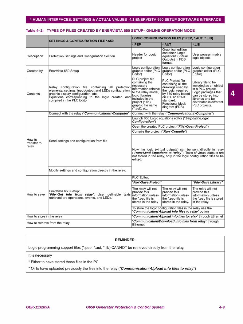
GEK-113285A G650 Generator Protection & Control System 4-9
4 HUMAN INTERFACES. SETTINGS & ACTUAL VALUES 4.1 ENERVISTA 650 SETUP SOFTWARE INTERFACE
4
Table 4–2: TYPES OF FILES CREATED BY ENERVISTA 650 SETUP– ONLINE OPERATION MODE
SETTINGS & CONFIGURATION FILE *.650LOGIC CONFIGURATION FILES (*.PEP, *.AUT, *.LIB)
*.PEP *.AUT *.LIB
Description Protection Settings and Configuration Section Header for Logic project
Graphical edition container. Logic equations (Virtual Outputs) in FDB format.
User programmable logic objects
Created by EnerVista 650 SetupLogic configuration graphic editor (PLC Editor)
Logic configuration graphic editor (PLC Editor)
Logic configuration graphic editor (PLC Editor)
Contents
Relay configuration file containing all protectionelements, settings, input/output and LEDs configuration,graphic display configuration, etc.Equations corresponding to the logic created andcompiled in the PLC Editor
PLC project file containing the necessary information relative to the relay model, logic libraries included in the project (*.lib), graphic file name (*.aut), etc.
PLC Project file containing all the drawings used by the logic, required by 650 relay based on IEC 61131-3 standard. Functional block diagram (FDB).
Library file to be included as an object in a PLC project. Logic packages that can be stored into libraries and be distributed in different PLC projects.
How to transfer to relay
Connect with the relay (“Communications>Computer”) Connect with the relay (“Communications>Computer”)
Send settings and configuration from file
Launch 650 Logic equations editor (“Setpoint>Logic Configuration”)Open the created PLC project (“File>Open Project”)Compile the project (“Run>Compile”)
Now the logic (virtual outputs) can be sent directly to relay(“Run>Send Equations to Relay”). Texts of virtual outputs arenot stored in the relay, only in the logic configuration files to beedited.
Modify settings and configuration directly in the relay:
How to saveEnerVista 650 Setup:“File>Get info from relay”. User definable textsretrieved are operations, events, and LEDs.
PLC Editor:“File>Save Project” “File>Save Library”
The relay will not provide this information unless the *.pep file is stored in the relay
The relay will not provide this information unless the *.pep file is stored in the relay.
The relay will not provide this information unless the *.pep file is stored in the relay.
To store the logic configuration files in the relay use the “Communication>Upload info files to relay” option
How to store in the relay “Communication>Upload info files to relay” through Ethernet
How to retrieve from the relay “Communication/Download info files from relay” through Ethernet
REMINDER:
Logic programming support files (*.pep, *.aut, *.lib) CANNOT be retrieved directly from the relay.
It is necessary
* Either to have stored these files in the PC
* Or to have uploaded previously the files into the relay (“Communication>Upload info files to relay”)
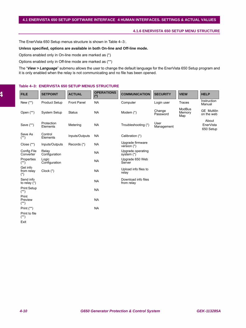
4-10 G650 Generator Protection & Control System GEK-113285A
4.1 ENERVISTA 650 SETUP SOFTWARE INTERFACE 4 HUMAN INTERFACES. SETTINGS & ACTUAL VALUES
4
4.1.6 ENERVISTA 650 SETUP MENU STRUCTURE
The EnerVista 650 Setup menus structure is shown in Table 4–3:.
Unless specified, options are available in both On-line and Off-line mode.
Options enabled only in On-line mode are marked as (*)
Options enabled only in Off-line mode are marked as (**)
The “View > Language” submenu allows the user to change the default language for the EnerVista 650 Setup program andit is only enabled when the relay is not communicating and no file has been opened.
Table 4–3: ENERVISTA 650 SETUP MENUS STRUCTURE
FILE SETPOINT ACTUAL OPERATIONS(*) COMMUNICATION SECURITY VIEW HELP
New (**) Product Setup Front Panel NA Computer Login user Traces Instruction Manual
Open (**) System Setup Status NA Modem (*) Change Password
ModBus Memory Map
GE Multilinon the web
Save (**) Protection Elements Metering NA Troubleshooting (*) User
Management
About EnerVista 650 Setup
Save As (**)
Control Elements Inputs/Outputs NA Calibration (*)
Close (**) Inputs/Outputs Records (*) NA Upgrade firmware version (*)
Config File Converter
Relay Configuration NA Upgrade operating
system (*)Properties (**)
Logic Configuration NA Upgrade 650 Web
ServerGet info from relay (*)
Clock (*) NA Upload info files to relay
Send info to relay (*) NA Download info files
from relayPrint Setup (**) NA
Print Preview (**)
NA
Print (**) NAPrint to file (**)Exit
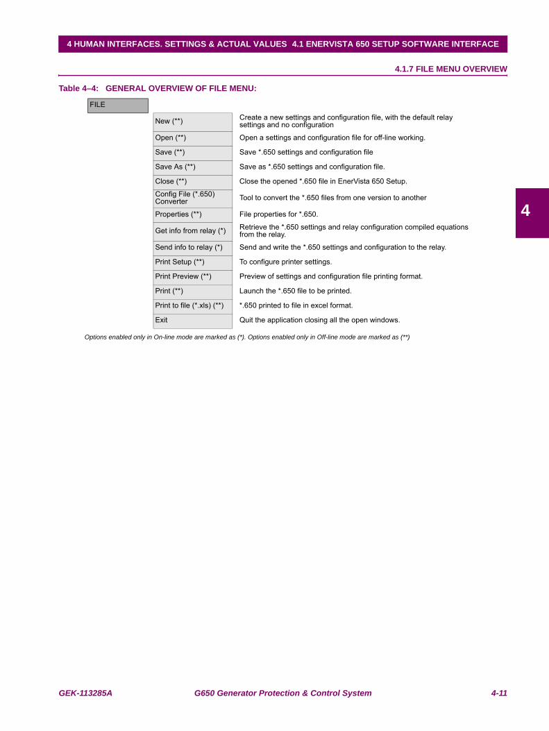
GEK-113285A G650 Generator Protection & Control System 4-11
4 HUMAN INTERFACES. SETTINGS & ACTUAL VALUES 4.1 ENERVISTA 650 SETUP SOFTWARE INTERFACE
4
4.1.7 FILE MENU OVERVIEW
Table 4–4: GENERAL OVERVIEW OF FILE MENU:
Options enabled only in On-line mode are marked as (*). Options enabled only in Off-line mode are marked as (**)
FILE
New (**) Create a new settings and configuration file, with the default relay settings and no configuration
Open (**) Open a settings and configuration file for off-line working.
Save (**) Save *.650 settings and configuration file
Save As (**) Save as *.650 settings and configuration file.
Close (**) Close the opened *.650 file in EnerVista 650 Setup.
Config File (*.650) Converter Tool to convert the *.650 files from one version to another
Properties (**) File properties for *.650.
Get info from relay (*) Retrieve the *.650 settings and relay configuration compiled equations from the relay.
Send info to relay (*) Send and write the *.650 settings and configuration to the relay.
Print Setup (**) To configure printer settings.
Print Preview (**) Preview of settings and configuration file printing format.
Print (**) Launch the *.650 file to be printed.
Print to file (*.xls) (**) *.650 printed to file in excel format.
Exit Quit the application closing all the open windows.
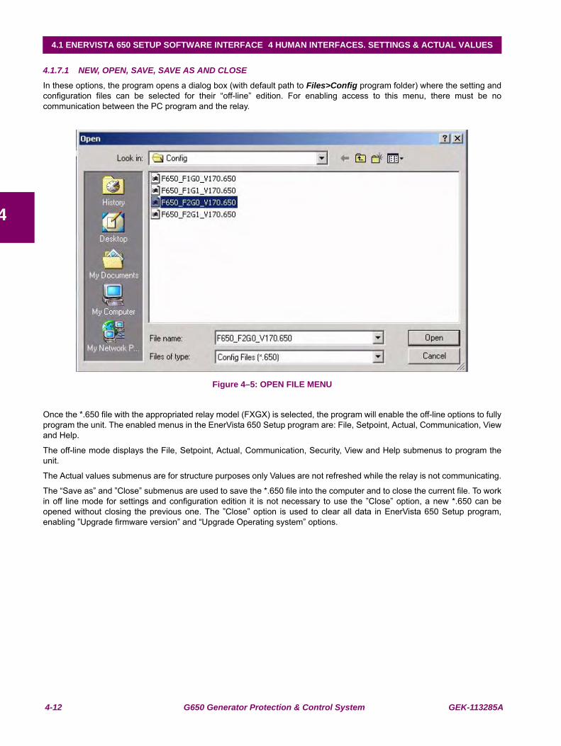
4-12 G650 Generator Protection & Control System GEK-113285A
4.1 ENERVISTA 650 SETUP SOFTWARE INTERFACE 4 HUMAN INTERFACES. SETTINGS & ACTUAL VALUES
4
4.1.7.1 NEW, OPEN, SAVE, SAVE AS AND CLOSE
In these options, the program opens a dialog box (with default path to Files>Config program folder) where the setting andconfiguration files can be selected for their “off-line” edition. For enabling access to this menu, there must be nocommunication between the PC program and the relay.
Figure 4–5: OPEN FILE MENU
Once the *.650 file with the appropriated relay model (FXGX) is selected, the program will enable the off-line options to fullyprogram the unit. The enabled menus in the EnerVista 650 Setup program are: File, Setpoint, Actual, Communication, Viewand Help.
The off-line mode displays the File, Setpoint, Actual, Communication, Security, View and Help submenus to program theunit.
The Actual values submenus are for structure purposes only Values are not refreshed while the relay is not communicating.
The “Save as” and ”Close” submenus are used to save the *.650 file into the computer and to close the current file. To workin off line mode for settings and configuration edition it is not necessary to use the ”Close” option, a new *.650 can beopened without closing the previous one. The ”Close” option is used to clear all data in EnerVista 650 Setup program,enabling ”Upgrade firmware version” and “Upgrade Operating system” options.
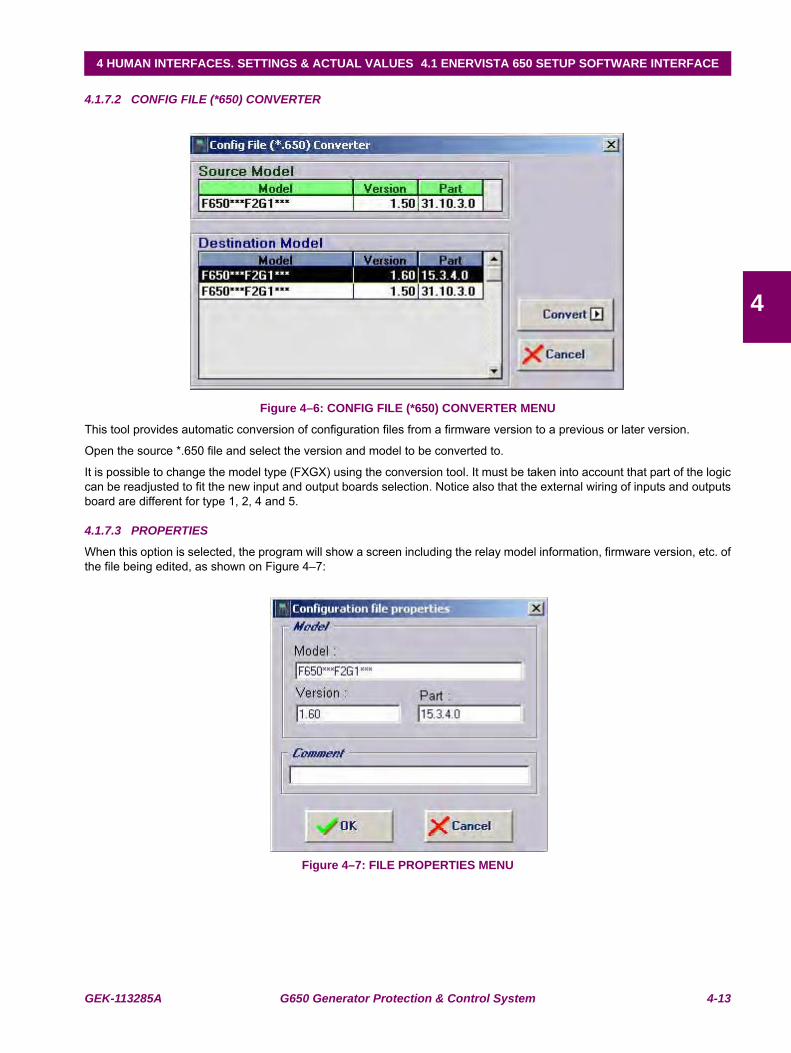
GEK-113285A G650 Generator Protection & Control System 4-13
4 HUMAN INTERFACES. SETTINGS & ACTUAL VALUES 4.1 ENERVISTA 650 SETUP SOFTWARE INTERFACE
4
4.1.7.2 CONFIG FILE (*650) CONVERTER
Figure 4–6: CONFIG FILE (*650) CONVERTER MENU
This tool provides automatic conversion of configuration files from a firmware version to a previous or later version.
Open the source *.650 file and select the version and model to be converted to.
It is possible to change the model type (FXGX) using the conversion tool. It must be taken into account that part of the logiccan be readjusted to fit the new input and output boards selection. Notice also that the external wiring of inputs and outputsboard are different for type 1, 2, 4 and 5.
4.1.7.3 PROPERTIES
When this option is selected, the program will show a screen including the relay model information, firmware version, etc. ofthe file being edited, as shown on Figure 4–7:
Figure 4–7: FILE PROPERTIES MENU
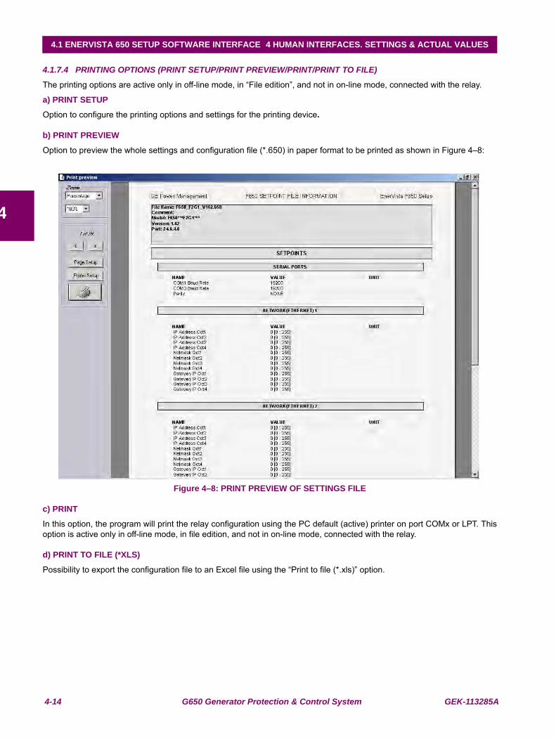
4-14 G650 Generator Protection & Control System GEK-113285A
4.1 ENERVISTA 650 SETUP SOFTWARE INTERFACE 4 HUMAN INTERFACES. SETTINGS & ACTUAL VALUES
4
4.1.7.4 PRINTING OPTIONS (PRINT SETUP/PRINT PREVIEW/PRINT/PRINT TO FILE)
The printing options are active only in off-line mode, in “File edition”, and not in on-line mode, connected with the relay.
a) PRINT SETUP
Option to configure the printing options and settings for the printing device.
b) PRINT PREVIEW
Option to preview the whole settings and configuration file (*.650) in paper format to be printed as shown in Figure 4–8:
Figure 4–8: PRINT PREVIEW OF SETTINGS FILE
c) PRINT
In this option, the program will print the relay configuration using the PC default (active) printer on port COMx or LPT. Thisoption is active only in off-line mode, in file edition, and not in on-line mode, connected with the relay.
d) PRINT TO FILE (*XLS)
Possibility to export the configuration file to an Excel file using the “Print to file (*.xls)” option.
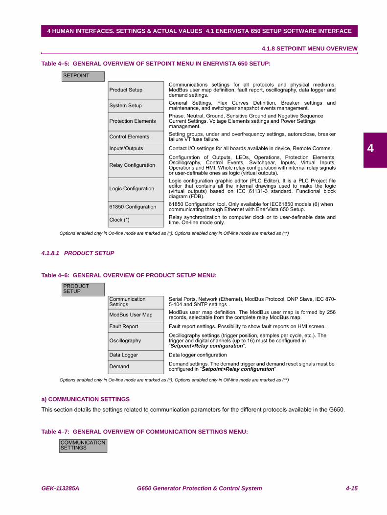
GEK-113285A G650 Generator Protection & Control System 4-15
4 HUMAN INTERFACES. SETTINGS & ACTUAL VALUES 4.1 ENERVISTA 650 SETUP SOFTWARE INTERFACE
4
4.1.8 SETPOINT MENU OVERVIEW
Table 4–5: GENERAL OVERVIEW OF SETPOINT MENU IN ENERVISTA 650 SETUP:
Options enabled only in On-line mode are marked as (*). Options enabled only in Off-line mode are marked as (**)
4.1.8.1 PRODUCT SETUP
Table 4–6: GENERAL OVERVIEW OF PRODUCT SETUP MENU:
Options enabled only in On-line mode are marked as (*). Options enabled only in Off-line mode are marked as (**)
a) COMMUNICATION SETTINGS
This section details the settings related to communication parameters for the different protocols available in the G650.
Table 4–7: GENERAL OVERVIEW OF COMMUNICATION SETTINGS MENU:
SETPOINT
Product SetupCommunications settings for all protocols and physical mediums.ModBus user map definition, fault report, oscillography, data logger anddemand settings.
System Setup General Settings, Flex Curves Definition, Breaker settings andmaintenance, and switchgear snapshot events management.
Protection ElementsPhase, Neutral, Ground, Sensitive Ground and Negative Sequence Current Settings. Voltage Elements settings and Power Settings management.
Control Elements Setting groups, under and overfrequency settings, autoreclose, breakerfailure VT fuse failure.
Inputs/Outputs Contact I/O settings for all boards available in device, Remote Comms.
Relay ConfigurationConfiguration of Outputs, LEDs, Operations, Protection Elements,Oscillography, Control Events, Switchgear, Inputs, Virtual Inputs,Operations and HMI. Whole relay configuration with internal relay signalsor user-definable ones as logic (virtual outputs).
Logic ConfigurationLogic configuration graphic editor (PLC Editor). It is a PLC Project fileeditor that contains all the internal drawings used to make the logic(virtual outputs) based on IEC 61131-3 standard. Functional blockdiagram (FDB).
61850 Configuration 61850 Configuration tool. Only available for IEC61850 models (6) when communicating through Ethernet with EnerVista 650 Setup.
Clock (*) Relay synchronization to computer clock or to user-definable date andtime. On-line mode only.
PRODUCT SETUP
Communication Settings
Serial Ports, Network (Ethernet), ModBus Protocol, DNP Slave, IEC 870-5-104 and SNTP settings .
ModBus User Map ModBus user map definition. The ModBus user map is formed by 256records, selectable from the complete relay ModBus map.
Fault Report Fault report settings. Possibility to show fault reports on HMI screen.
OscillographyOscillography settings (trigger position, samples per cycle, etc.). The trigger and digital channels (up to 16) must be configured in “Setpoint>Relay configuration”.
Data Logger Data logger configuration
Demand Demand settings. The demand trigger and demand reset signals must be configured in “Setpoint>Relay configuration”
COMMUNICATION SETTINGS
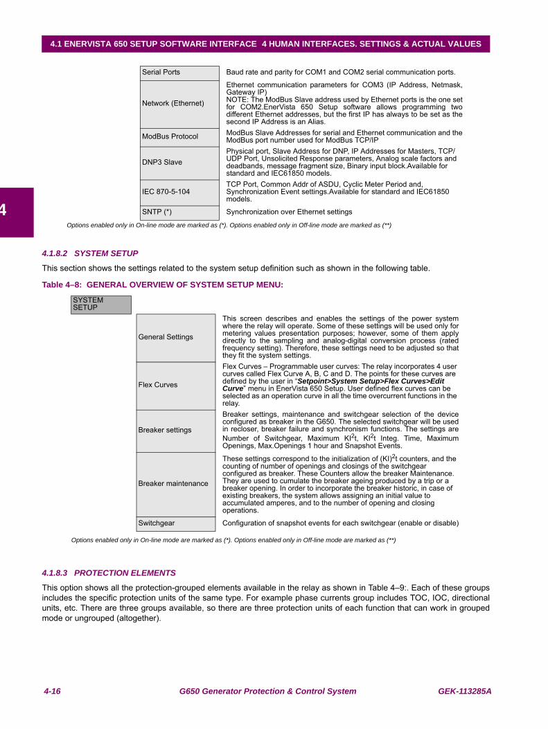
4-16 G650 Generator Protection & Control System GEK-113285A
4.1 ENERVISTA 650 SETUP SOFTWARE INTERFACE 4 HUMAN INTERFACES. SETTINGS & ACTUAL VALUES
4Options enabled only in On-line mode are marked as (*). Options enabled only in Off-line mode are marked as (**)
4.1.8.2 SYSTEM SETUP
This section shows the settings related to the system setup definition such as shown in the following table.
Table 4–8: GENERAL OVERVIEW OF SYSTEM SETUP MENU:
Options enabled only in On-line mode are marked as (*). Options enabled only in Off-line mode are marked as (**)
4.1.8.3 PROTECTION ELEMENTS
This option shows all the protection-grouped elements available in the relay as shown in Table 4–9:. Each of these groupsincludes the specific protection units of the same type. For example phase currents group includes TOC, IOC, directionalunits, etc. There are three groups available, so there are three protection units of each function that can work in groupedmode or ungrouped (altogether).
Serial Ports Baud rate and parity for COM1 and COM2 serial communication ports.
Network (Ethernet)
Ethernet communication parameters for COM3 (IP Address, Netmask,Gateway IP)NOTE: The ModBus Slave address used by Ethernet ports is the one setfor COM2.EnerVista 650 Setup software allows programming twodifferent Ethernet addresses, but the first IP has always to be set as thesecond IP Address is an Alias.
ModBus Protocol ModBus Slave Addresses for serial and Ethernet communication and theModBus port number used for ModBus TCP/IP
DNP3 SlavePhysical port, Slave Address for DNP, IP Addresses for Masters, TCP/UDP Port, Unsolicited Response parameters, Analog scale factors and deadbands, message fragment size, Binary input block.Available for standard and IEC61850 models.
IEC 870-5-104 TCP Port, Common Addr of ASDU, Cyclic Meter Period and, Synchronization Event settings.Available for standard and IEC61850 models.
SNTP (*) Synchronization over Ethernet settings
SYSTEM SETUP
General Settings
This screen describes and enables the settings of the power systemwhere the relay will operate. Some of these settings will be used only formetering values presentation purposes; however, some of them applydirectly to the sampling and analog-digital conversion process (ratedfrequency setting). Therefore, these settings need to be adjusted so thatthey fit the system settings.
Flex Curves
Flex Curves – Programmable user curves: The relay incorporates 4 user curves called Flex Curve A, B, C and D. The points for these curves are defined by the user in “Setpoint>System Setup>Flex Curves>Edit Curve” menu in EnerVista 650 Setup. User defined flex curves can be selected as an operation curve in all the time overcurrent functions in the relay.
Breaker settings
Breaker settings, maintenance and switchgear selection of the deviceconfigured as breaker in the G650. The selected switchgear will be usedin recloser, breaker failure and synchronism functions. The settings areNumber of Switchgear, Maximum KI2t, KI2t Integ. Time, MaximumOpenings, Max.Openings 1 hour and Snapshot Events.
Breaker maintenance
These settings correspond to the initialization of (KI)2t counters, and the counting of number of openings and closings of the switchgear configured as breaker. These Counters allow the breaker Maintenance. They are used to cumulate the breaker ageing produced by a trip or a breaker opening. In order to incorporate the breaker historic, in case of existing breakers, the system allows assigning an initial value to accumulated amperes, and to the number of opening and closing operations.
Switchgear Configuration of snapshot events for each switchgear (enable or disable)
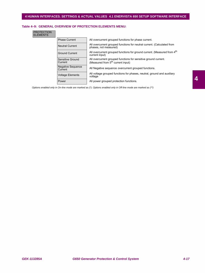
GEK-113285A G650 Generator Protection & Control System 4-17
4 HUMAN INTERFACES. SETTINGS & ACTUAL VALUES 4.1 ENERVISTA 650 SETUP SOFTWARE INTERFACE
4
Table 4–9: GENERAL OVERVIEW OF PROTECTION ELEMENTS MENU:
Options enabled only in On-line mode are marked as (*). Options enabled only in Off-line mode are marked as (**)
PROTECTION ELEMENTS
Phase Current All overcurrent grouped functions for phase current.
Neutral Current All overcurrent grouped functions for neutral current. (Calculated from phases, not measured)
Ground Current All overcurrent grouped functions for ground current. (Measured from 4th current input)
Sensitive Ground Current
All overcurrent grouped functions for sensitive ground current. (Measured from 5th current input)
Negative Sequence Current All Negative sequence overcurrent grouped functions.
Voltage Elements All voltage grouped functions for phases, neutral, ground and auxiliary voltage
Power All power grouped protection functions.
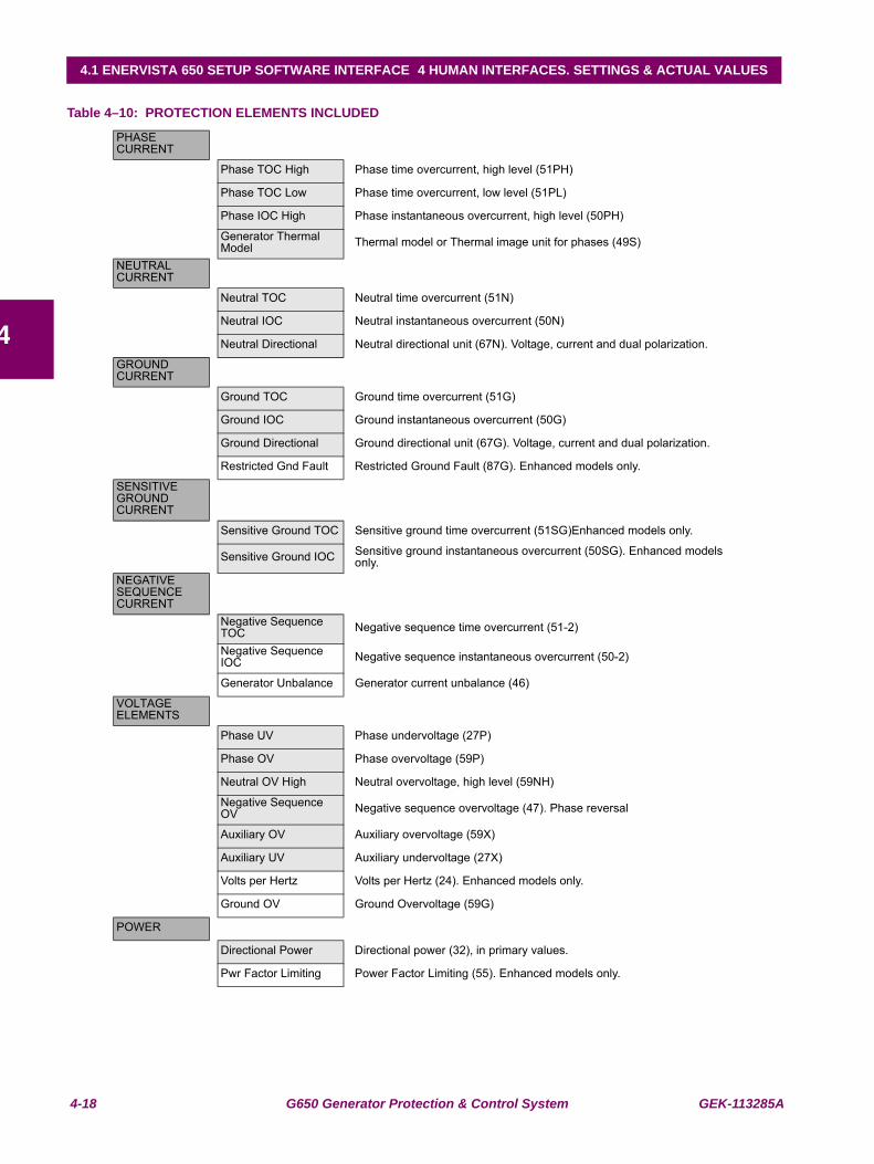
4-18 G650 Generator Protection & Control System GEK-113285A
4.1 ENERVISTA 650 SETUP SOFTWARE INTERFACE 4 HUMAN INTERFACES. SETTINGS & ACTUAL VALUES
4
Table 4–10: PROTECTION ELEMENTS INCLUDED
PHASE CURRENT
Phase TOC High Phase time overcurrent, high level (51PH)
Phase TOC Low Phase time overcurrent, low level (51PL)
Phase IOC High Phase instantaneous overcurrent, high level (50PH)
Generator Thermal Model Thermal model or Thermal image unit for phases (49S)
NEUTRAL CURRENT
Neutral TOC Neutral time overcurrent (51N)
Neutral IOC Neutral instantaneous overcurrent (50N)
Neutral Directional Neutral directional unit (67N). Voltage, current and dual polarization.
GROUND CURRENT
Ground TOC Ground time overcurrent (51G)
Ground IOC Ground instantaneous overcurrent (50G)
Ground Directional Ground directional unit (67G). Voltage, current and dual polarization.
Restricted Gnd Fault Restricted Ground Fault (87G). Enhanced models only.
SENSITIVE GROUND CURRENT
Sensitive Ground TOC Sensitive ground time overcurrent (51SG)Enhanced models only.
Sensitive Ground IOC Sensitive ground instantaneous overcurrent (50SG). Enhanced models only.
NEGATIVE SEQUENCE CURRENT
Negative Sequence TOC Negative sequence time overcurrent (51-2)
Negative Sequence IOC Negative sequence instantaneous overcurrent (50-2)
Generator Unbalance Generator current unbalance (46)
VOLTAGE ELEMENTS
Phase UV Phase undervoltage (27P)
Phase OV Phase overvoltage (59P)
Neutral OV High Neutral overvoltage, high level (59NH)
Negative Sequence OV Negative sequence overvoltage (47). Phase reversal
Auxiliary OV Auxiliary overvoltage (59X)
Auxiliary UV Auxiliary undervoltage (27X)
Volts per Hertz Volts per Hertz (24). Enhanced models only.
Ground OV Ground Overvoltage (59G)
POWER
Directional Power Directional power (32), in primary values.
Pwr Factor Limiting Power Factor Limiting (55). Enhanced models only.
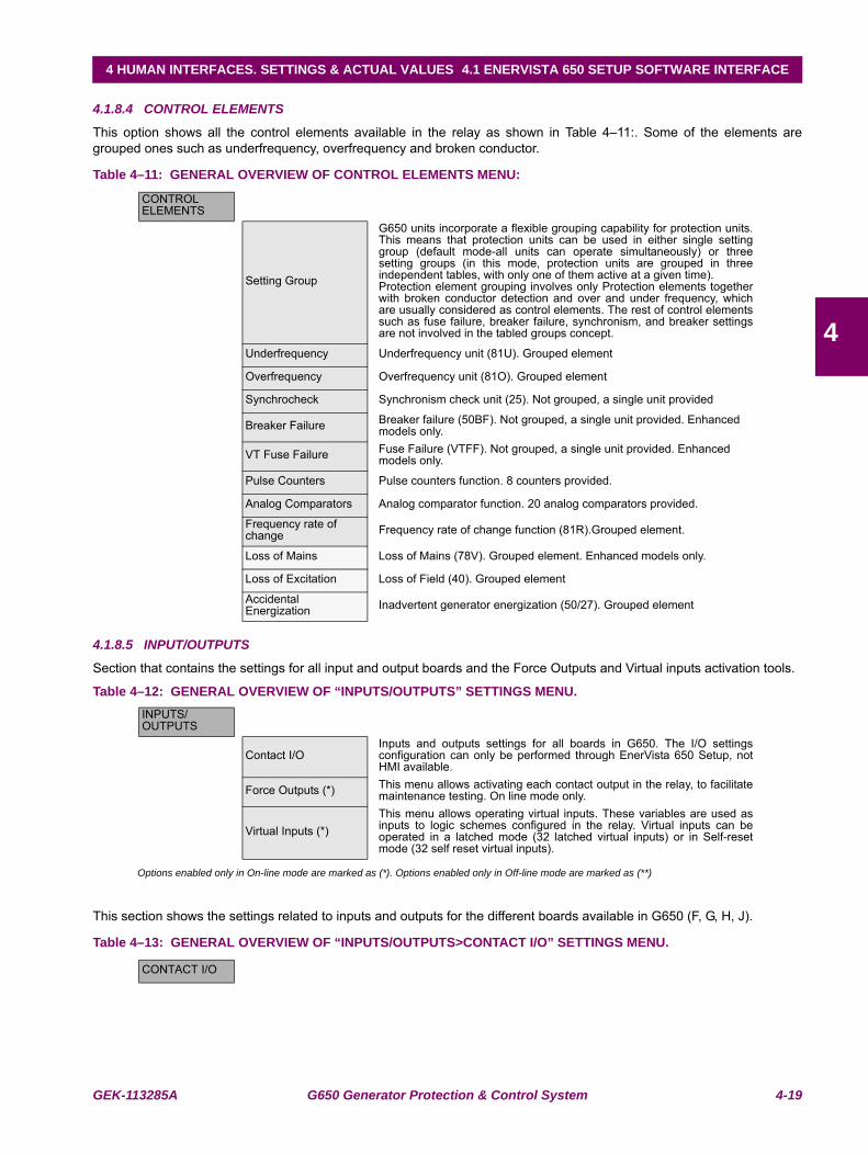
GEK-113285A G650 Generator Protection & Control System 4-19
4 HUMAN INTERFACES. SETTINGS & ACTUAL VALUES 4.1 ENERVISTA 650 SETUP SOFTWARE INTERFACE
4
4.1.8.4 CONTROL ELEMENTS
This option shows all the control elements available in the relay as shown in Table 4–11:. Some of the elements aregrouped ones such as underfrequency, overfrequency and broken conductor.
Table 4–11: GENERAL OVERVIEW OF CONTROL ELEMENTS MENU:
4.1.8.5 INPUT/OUTPUTS
Section that contains the settings for all input and output boards and the Force Outputs and Virtual inputs activation tools.
Table 4–12: GENERAL OVERVIEW OF “INPUTS/OUTPUTS” SETTINGS MENU.
Options enabled only in On-line mode are marked as (*). Options enabled only in Off-line mode are marked as (**)
This section shows the settings related to inputs and outputs for the different boards available in G650 (F, G, H, J).
Table 4–13: GENERAL OVERVIEW OF “INPUTS/OUTPUTS>CONTACT I/O” SETTINGS MENU.
CONTROL ELEMENTS
Setting Group
G650 units incorporate a flexible grouping capability for protection units.This means that protection units can be used in either single settinggroup (default mode-all units can operate simultaneously) or threesetting groups (in this mode, protection units are grouped in threeindependent tables, with only one of them active at a given time).Protection element grouping involves only Protection elements togetherwith broken conductor detection and over and under frequency, whichare usually considered as control elements. The rest of control elementssuch as fuse failure, breaker failure, synchronism, and breaker settingsare not involved in the tabled groups concept.
Underfrequency Underfrequency unit (81U). Grouped element
Overfrequency Overfrequency unit (81O). Grouped element
Synchrocheck Synchronism check unit (25). Not grouped, a single unit provided
Breaker Failure Breaker failure (50BF). Not grouped, a single unit provided. Enhanced models only.
VT Fuse Failure Fuse Failure (VTFF). Not grouped, a single unit provided. Enhanced models only.
Pulse Counters Pulse counters function. 8 counters provided.
Analog Comparators Analog comparator function. 20 analog comparators provided.
Frequency rate of change Frequency rate of change function (81R).Grouped element.
Loss of Mains Loss of Mains (78V). Grouped element. Enhanced models only.
Loss of Excitation Loss of Field (40). Grouped element
Accidental Energization Inadvertent generator energization (50/27). Grouped element
INPUTS/OUTPUTS
Contact I/OInputs and outputs settings for all boards in G650. The I/O settingsconfiguration can only be performed through EnerVista 650 Setup, notHMI available.
Force Outputs (*) This menu allows activating each contact output in the relay, to facilitatemaintenance testing. On line mode only.
Virtual Inputs (*)This menu allows operating virtual inputs. These variables are used asinputs to logic schemes configured in the relay. Virtual inputs can beoperated in a latched mode (32 latched virtual inputs) or in Self-resetmode (32 self reset virtual inputs).
CONTACT I/O
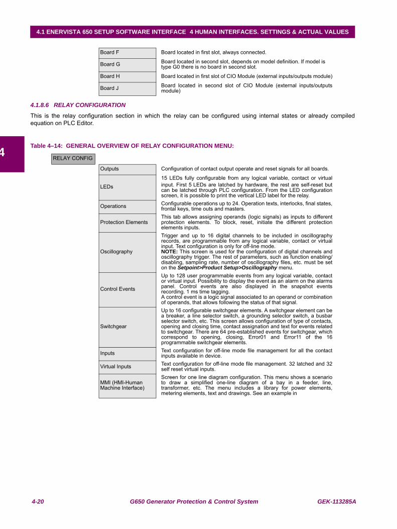
4-20 G650 Generator Protection & Control System GEK-113285A
4.1 ENERVISTA 650 SETUP SOFTWARE INTERFACE 4 HUMAN INTERFACES. SETTINGS & ACTUAL VALUES
4
4.1.8.6 RELAY CONFIGURATION
This is the relay configuration section in which the relay can be configured using internal states or already compiledequation on PLC Editor.
Table 4–14: GENERAL OVERVIEW OF RELAY CONFIGURATION MENU:
Board F Board located in first slot, always connected.
Board G Board located in second slot, depends on model definition. If model is type G0 there is no board in second slot.
Board H Board located in first slot of CIO Module (external inputs/outputs module)
Board J Board located in second slot of CIO Module (external inputs/outputsmodule)
RELAY CONFIG
Outputs Configuration of contact output operate and reset signals for all boards.
LEDs15 LEDs fully configurable from any logical variable, contact or virtualinput. First 5 LEDs are latched by hardware, the rest are self-reset butcan be latched through PLC configuration. From the LED configurationscreen, it is possible to print the vertical LED label for the relay.
Operations Configurable operations up to 24. Operation texts, interlocks, final states,frontal keys, time outs and masters.
Protection ElementsThis tab allows assigning operands (logic signals) as inputs to differentprotection elements. To block, reset, initiate the different protectionelements inputs.
Oscillography
Trigger and up to 16 digital channels to be included in oscillographyrecords, are programmable from any logical variable, contact or virtualinput. Text configuration is only for off-line mode.NOTE: This screen is used for the configuration of digital channels andoscillography trigger. The rest of parameters, such as function enabling/disabling, sampling rate, number of oscillography files, etc. must be seton the Setpoint>Product Setup>Oscillography menu.
Control Events
Up to 128 user programmable events from any logical variable, contactor virtual input. Possibility to display the event as an alarm on the alarmspanel. Control events are also displayed in the snapshot eventsrecording. 1 ms time tagging.A control event is a logic signal associated to an operand or combinationof operands, that allows following the status of that signal.
Switchgear
Up to 16 configurable switchgear elements. A switchgear element can bea breaker, a line selector switch, a grounding selector switch, a busbarselector switch, etc. This screen allows configuration of type of contacts,opening and closing time, contact assignation and text for events relatedto switchgear. There are 64 pre-established events for switchgear, whichcorrespond to opening, closing, Error01 and Error11 of the 16programmable switchgear elements.
Inputs Text configuration for off-line mode file management for all the contactinputs available in device.
Virtual Inputs Text configuration for off-line mode file management. 32 latched and 32self reset virtual inputs.
MMI (HMI-Human Machine Interface)
Screen for one line diagram configuration. This menu shows a scenarioto draw a simplified one-line diagram of a bay in a feeder, line,transformer, etc. The menu includes a library for power elements,metering elements, text and drawings. See an example in
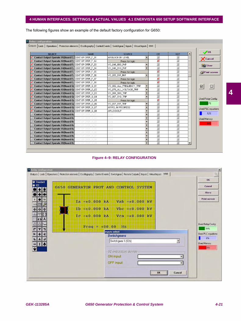
GEK-113285A G650 Generator Protection & Control System 4-21
4 HUMAN INTERFACES. SETTINGS & ACTUAL VALUES 4.1 ENERVISTA 650 SETUP SOFTWARE INTERFACE
4
The following figures show an example of the default factory configuration for G650:
Figure 4–9: RELAY CONFIGURATION
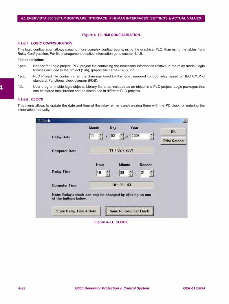
4-22 G650 Generator Protection & Control System GEK-113285A
4.1 ENERVISTA 650 SETUP SOFTWARE INTERFACE 4 HUMAN INTERFACES. SETTINGS & ACTUAL VALUES
4
Figure 4–10: HMI CONFIGURATION
4.1.8.7 LOGIC CONFIGURATION
This logic configuration allows creating more complex configurations, using the graphical PLC, than using the tables fromRelay Configuration. For file management detailed information go to section 4.1.5.
File description:
*.pep: Header for Logic project: PLC project file containing the necessary information relative to the relay model, logiclibraries included in the project (*.lib), graphic file name (*.aut), etc.
*.aut: PLC Project file containing all the drawings used by the logic, required by 650 relay based on IEC 61131-3standard. Functional block diagram (FDB).
*.lib: User programmable logic objects: Library file to be included as an object in a PLC project. Logic packages thatcan be stored into libraries and be distributed in different PLC projects.
4.1.8.8 CLOCK
This menu allows to update the date and time of the relay, either synchronizing them with the PC clock, or entering theinformation manually.
Figure 4–11: CLOCK
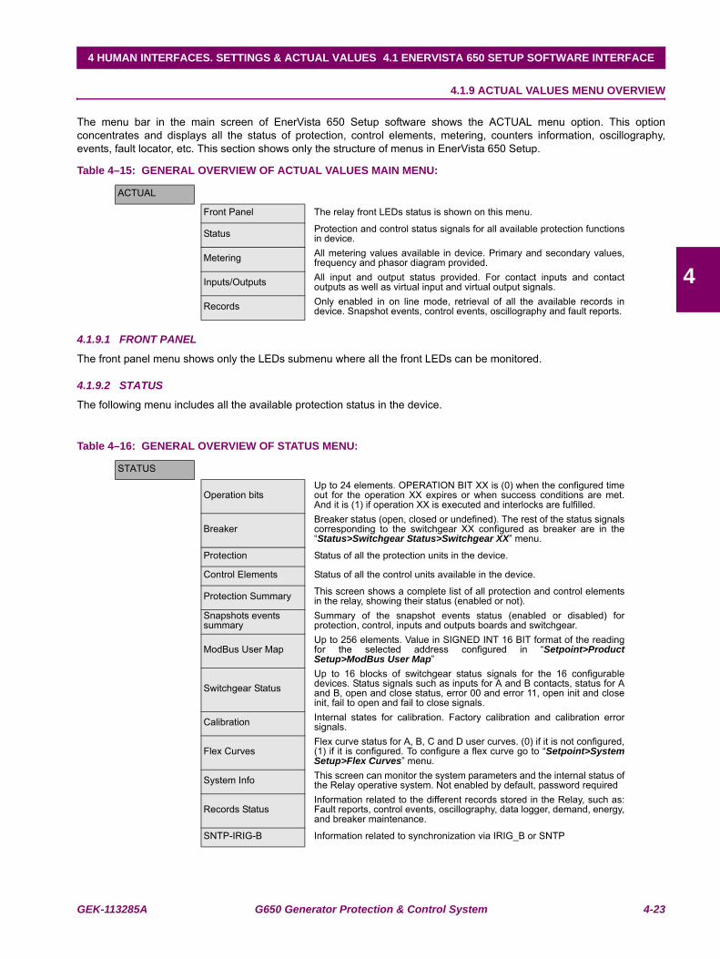
GEK-113285A G650 Generator Protection & Control System 4-23
4 HUMAN INTERFACES. SETTINGS & ACTUAL VALUES 4.1 ENERVISTA 650 SETUP SOFTWARE INTERFACE
4
4.1.9 ACTUAL VALUES MENU OVERVIEW
The menu bar in the main screen of EnerVista 650 Setup software shows the ACTUAL menu option. This optionconcentrates and displays all the status of protection, control elements, metering, counters information, oscillography,events, fault locator, etc. This section shows only the structure of menus in EnerVista 650 Setup.
Table 4–15: GENERAL OVERVIEW OF ACTUAL VALUES MAIN MENU:
4.1.9.1 FRONT PANEL
The front panel menu shows only the LEDs submenu where all the front LEDs can be monitored.
4.1.9.2 STATUS
The following menu includes all the available protection status in the device.
Table 4–16: GENERAL OVERVIEW OF STATUS MENU:
ACTUAL
Front Panel The relay front LEDs status is shown on this menu.
Status Protection and control status signals for all available protection functionsin device.
Metering All metering values available in device. Primary and secondary values,frequency and phasor diagram provided.
Inputs/Outputs All input and output status provided. For contact inputs and contactoutputs as well as virtual input and virtual output signals.
Records Only enabled in on line mode, retrieval of all the available records indevice. Snapshot events, control events, oscillography and fault reports.
STATUS
Operation bitsUp to 24 elements. OPERATION BIT XX is (0) when the configured timeout for the operation XX expires or when success conditions are met.And it is (1) if operation XX is executed and interlocks are fulfilled.
BreakerBreaker status (open, closed or undefined). The rest of the status signalscorresponding to the switchgear XX configured as breaker are in the“Status>Switchgear Status>Switchgear XX” menu.
Protection Status of all the protection units in the device.
Control Elements Status of all the control units available in the device.
Protection Summary This screen shows a complete list of all protection and control elementsin the relay, showing their status (enabled or not).
Snapshots events summary
Summary of the snapshot events status (enabled or disabled) forprotection, control, inputs and outputs boards and switchgear.
ModBus User MapUp to 256 elements. Value in SIGNED INT 16 BIT format of the readingfor the selected address configured in “Setpoint>ProductSetup>ModBus User Map”
Switchgear StatusUp to 16 blocks of switchgear status signals for the 16 configurabledevices. Status signals such as inputs for A and B contacts, status for Aand B, open and close status, error 00 and error 11, open init and closeinit, fail to open and fail to close signals.
Calibration Internal states for calibration. Factory calibration and calibration errorsignals.
Flex CurvesFlex curve status for A, B, C and D user curves. (0) if it is not configured,(1) if it is configured. To configure a flex curve go to “Setpoint>SystemSetup>Flex Curves” menu.
System Info This screen can monitor the system parameters and the internal status ofthe Relay operative system. Not enabled by default, password required
Records StatusInformation related to the different records stored in the Relay, such as:Fault reports, control events, oscillography, data logger, demand, energy,and breaker maintenance.
SNTP-IRIG-B Information related to synchronization via IRIG_B or SNTP
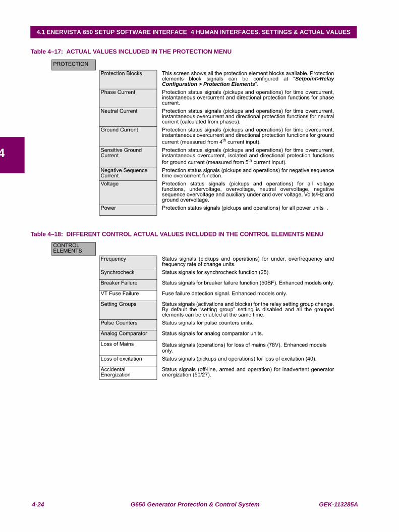
4-24 G650 Generator Protection & Control System GEK-113285A
4.1 ENERVISTA 650 SETUP SOFTWARE INTERFACE 4 HUMAN INTERFACES. SETTINGS & ACTUAL VALUES
4
Table 4–17: ACTUAL VALUES INCLUDED IN THE PROTECTION MENU
Table 4–18: DIFFERENT CONTROL ACTUAL VALUES INCLUDED IN THE CONTROL ELEMENTS MENU
PROTECTION
Protection Blocks This screen shows all the protection element blocks available. Protectionelements block signals can be configured at “Setpoint>RelayConfiguration > Protection Elements”.
Phase Current Protection status signals (pickups and operations) for time overcurrent,instantaneous overcurrent and directional protection functions for phasecurrent.
Neutral Current Protection status signals (pickups and operations) for time overcurrent,instantaneous overcurrent and directional protection functions for neutralcurrent (calculated from phases).
Ground Current Protection status signals (pickups and operations) for time overcurrent,instantaneous overcurrent and directional protection functions for groundcurrent (measured from 4th current input).
Sensitive Ground Current
Protection status signals (pickups and operations) for time overcurrent,instantaneous overcurrent, isolated and directional protection functionsfor ground current (measured from 5th current input).
Negative Sequence Current
Protection status signals (pickups and operations) for negative sequencetime overcurrent function.
Voltage Protection status signals (pickups and operations) for all voltagefunctions, undervoltage, overvoltage, neutral overvoltage, negativesequence overvoltage and auxiliary under and over voltage, Volts/Hz andground overvoltage.
Power Protection status signals (pickups and operations) for all power units .
CONTROL ELEMENTS
Frequency Status signals (pickups and operations) for under, overfrequency andfrequency rate of change units.
Synchrocheck Status signals for synchrocheck function (25).
Breaker Failure Status signals for breaker failure function (50BF). Enhanced models only.
VT Fuse Failure Fuse failure detection signal. Enhanced models only.
Setting Groups Status signals (activations and blocks) for the relay setting group change.By default the “setting group” setting is disabled and all the groupedelements can be enabled at the same time.
Pulse Counters Status signals for pulse counters units.
Analog Comparator Status signals for analog comparator units.
Loss of Mains Status signals (operations) for loss of mains (78V). Enhanced models only.
Loss of excitation Status signals (pickups and operations) for loss of excitation (40).
Accidental Energization
Status signals (off-line, armed and operation) for inadvertent generatorenergization (50/27).
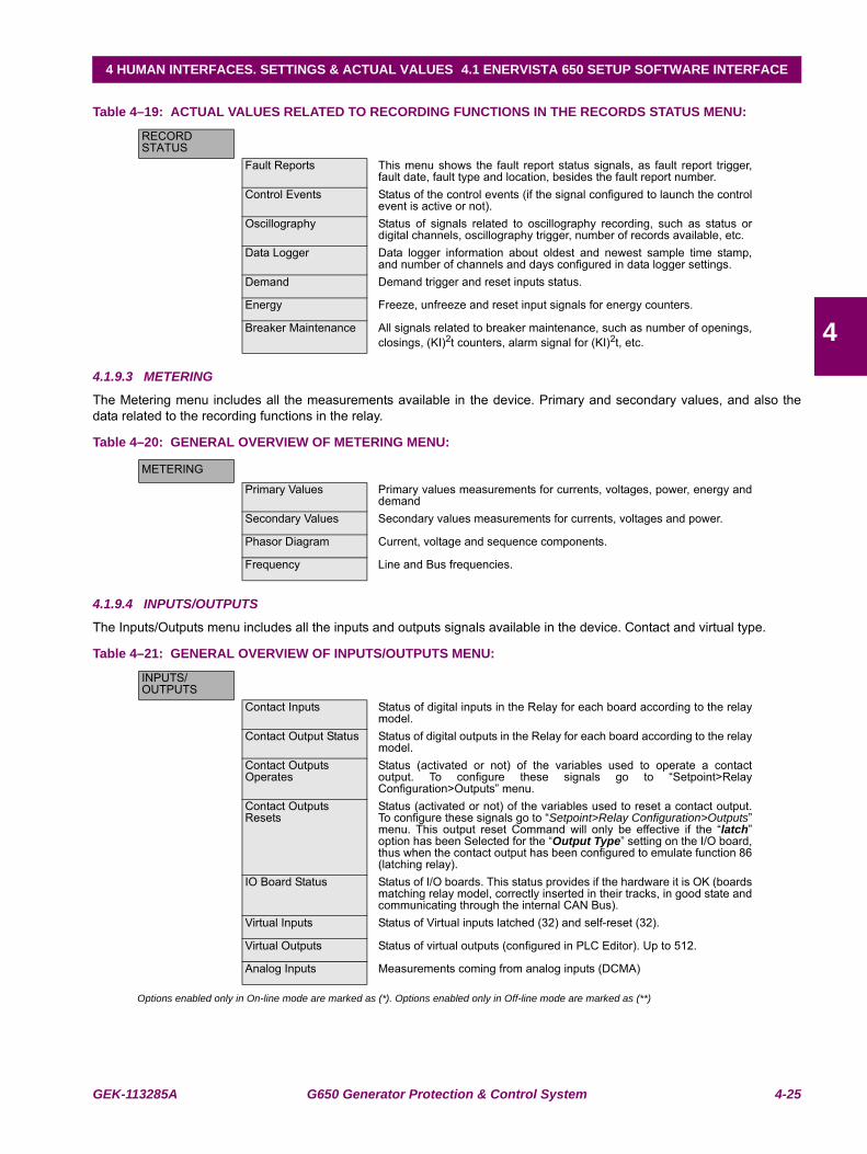
GEK-113285A G650 Generator Protection & Control System 4-25
4 HUMAN INTERFACES. SETTINGS & ACTUAL VALUES 4.1 ENERVISTA 650 SETUP SOFTWARE INTERFACE
4
Table 4–19: ACTUAL VALUES RELATED TO RECORDING FUNCTIONS IN THE RECORDS STATUS MENU:
4.1.9.3 METERING
The Metering menu includes all the measurements available in the device. Primary and secondary values, and also thedata related to the recording functions in the relay.
Table 4–20: GENERAL OVERVIEW OF METERING MENU:
4.1.9.4 INPUTS/OUTPUTS
The Inputs/Outputs menu includes all the inputs and outputs signals available in the device. Contact and virtual type.
Table 4–21: GENERAL OVERVIEW OF INPUTS/OUTPUTS MENU:
Options enabled only in On-line mode are marked as (*). Options enabled only in Off-line mode are marked as (**)
RECORD STATUS
Fault Reports This menu shows the fault report status signals, as fault report trigger,fault date, fault type and location, besides the fault report number.
Control Events Status of the control events (if the signal configured to launch the controlevent is active or not).
Oscillography Status of signals related to oscillography recording, such as status ordigital channels, oscillography trigger, number of records available, etc.
Data Logger Data logger information about oldest and newest sample time stamp,and number of channels and days configured in data logger settings.
Demand Demand trigger and reset inputs status.
Energy Freeze, unfreeze and reset input signals for energy counters.
Breaker Maintenance All signals related to breaker maintenance, such as number of openings,closings, (KI)2t counters, alarm signal for (KI)2t, etc.
METERING
Primary Values Primary values measurements for currents, voltages, power, energy anddemand
Secondary Values Secondary values measurements for currents, voltages and power.
Phasor Diagram Current, voltage and sequence components.
Frequency Line and Bus frequencies.
INPUTS/OUTPUTS
Contact Inputs Status of digital inputs in the Relay for each board according to the relaymodel.
Contact Output Status Status of digital outputs in the Relay for each board according to the relaymodel.
Contact Outputs Operates
Status (activated or not) of the variables used to operate a contactoutput. To configure these signals go to “Setpoint>RelayConfiguration>Outputs” menu.
Contact Outputs Resets
Status (activated or not) of the variables used to reset a contact output.To configure these signals go to “Setpoint>Relay Configuration>Outputs”menu. This output reset Command will only be effective if the “latch”option has been Selected for the “Output Type” setting on the I/O board,thus when the contact output has been configured to emulate function 86(latching relay).
IO Board Status Status of I/O boards. This status provides if the hardware it is OK (boardsmatching relay model, correctly inserted in their tracks, in good state andcommunicating through the internal CAN Bus).
Virtual Inputs Status of Virtual inputs latched (32) and self-reset (32).
Virtual Outputs Status of virtual outputs (configured in PLC Editor). Up to 512.
Analog Inputs Measurements coming from analog inputs (DCMA)
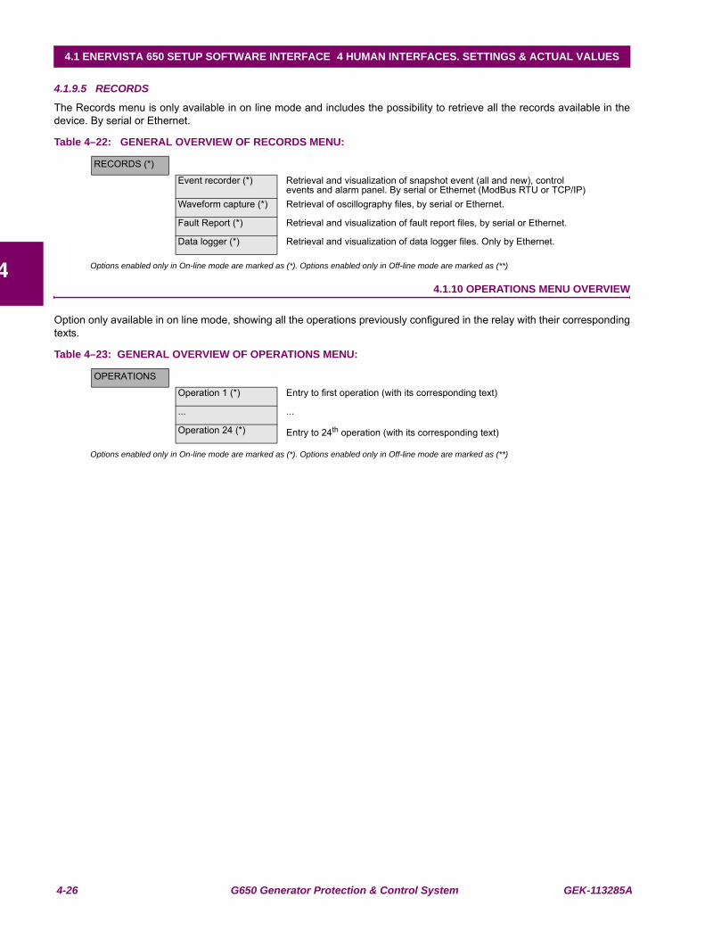
4-26 G650 Generator Protection & Control System GEK-113285A
4.1 ENERVISTA 650 SETUP SOFTWARE INTERFACE 4 HUMAN INTERFACES. SETTINGS & ACTUAL VALUES
4
4.1.9.5 RECORDS
The Records menu is only available in on line mode and includes the possibility to retrieve all the records available in thedevice. By serial or Ethernet.
Table 4–22: GENERAL OVERVIEW OF RECORDS MENU:
Options enabled only in On-line mode are marked as (*). Options enabled only in Off-line mode are marked as (**)
4.1.10 OPERATIONS MENU OVERVIEW
Option only available in on line mode, showing all the operations previously configured in the relay with their correspondingtexts.
Table 4–23: GENERAL OVERVIEW OF OPERATIONS MENU:
Options enabled only in On-line mode are marked as (*). Options enabled only in Off-line mode are marked as (**)
RECORDS (*)
Event recorder (*) Retrieval and visualization of snapshot event (all and new), control events and alarm panel. By serial or Ethernet (ModBus RTU or TCP/IP)
Waveform capture (*) Retrieval of oscillography files, by serial or Ethernet.
Fault Report (*) Retrieval and visualization of fault report files, by serial or Ethernet.
Data logger (*) Retrieval and visualization of data logger files. Only by Ethernet.
OPERATIONS
Operation 1 (*) Entry to first operation (with its corresponding text)
... ...
Operation 24 (*) Entry to 24th operation (with its corresponding text)
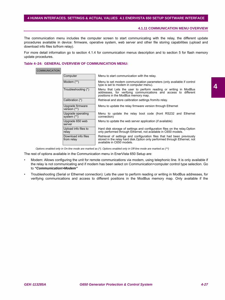
GEK-113285A G650 Generator Protection & Control System 4-27
4 HUMAN INTERFACES. SETTINGS & ACTUAL VALUES 4.1 ENERVISTA 650 SETUP SOFTWARE INTERFACE
4
4.1.11 COMMUNICATION MENU OVERVIEW
The communication menu includes the computer screen to start communicating with the relay, the different updateprocedures available in device: firmware, operative system, web server and other file storing capabilities (upload anddownload info files to/from relay).
For more detail information go to section 4.1.4 for communication menus description and to section 5 for flash memoryupdate procedures.
Table 4–24: GENERAL OVERVIEW OF COMMUNICATION MENU:
Options enabled only in On-line mode are marked as (*). Options enabled only in Off-line mode are marked as (**)
The rest of options available in the Communication menu in EnerVista 650 Setup are:
• Modem: Allows configuring the unit for remote communications via modem, using telephonic line. It is only available ifthe relay is not communicating and if modem has been select on Communication>computer control type selection. Goto “Communication>Modem”
• Troubleshooting (Serial or Ethernet connection): Lets the user to perform reading or writing in ModBus addresses, forverifying communications and access to different positions in the ModBus memory map. Only available if the
COMMUNICATION
Computer Menu to start communication with the relay.
Modem (**) Menu to set modem communication parameters (only available if controltype is set to modem in computer menu).
Troubleshooting (*) Menu that Lets the user to perform reading or writing in ModBusaddresses, for verifying communications and access to differentpositions in the ModBus memory map.
Calibration (*) Retrieval and store calibration settings from/to relay.
Upgrade firmware version (**)
Menu to update the relay firmware version through Ethernet
Upgrade operating system (**)
Menu to update the relay boot code (front RS232 and Ethernetconnection)
Upgrade 650 web server
Menu to update the web server application (if available)
Upload info files to relay
Hard disk storage of settings and configuration files on the relay.Optiononly performed through Ethernet, not available in C650 models.
Download info files from relay
Retrieval of settings and configuration files that had been previouslystored in the relay hard disk.Option only performed through Ethernet, notavailable in C650 models.
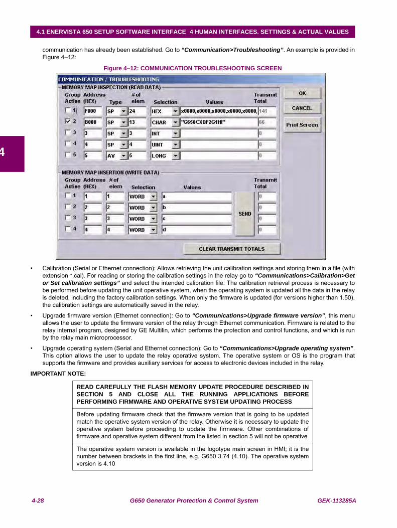
4-28 G650 Generator Protection & Control System GEK-113285A
4.1 ENERVISTA 650 SETUP SOFTWARE INTERFACE 4 HUMAN INTERFACES. SETTINGS & ACTUAL VALUES
4
communication has already been established. Go to “Communication>Troubleshooting”. An example is provided inFigure 4–12:
Figure 4–12: COMMUNICATION TROUBLESHOOTING SCREEN
• Calibration (Serial or Ethernet connection): Allows retrieving the unit calibration settings and storing them in a file (withextension *.cal). For reading or storing the calibration settings in the relay go to “Communications>Calibration>Getor Set calibration settings” and select the intended calibration file. The calibration retrieval process is necessary tobe performed before updating the unit operative system, when the operating system is updated all the data in the relayis deleted, including the factory calibration settings. When only the firmware is updated (for versions higher than 1.50),the calibration settings are automatically saved in the relay.
• Upgrade firmware version (Ethernet connection): Go to “Communications>Upgrade firmware version”, this menuallows the user to update the firmware version of the relay through Ethernet communication. Firmware is related to therelay internal program, designed by GE Multilin, which performs the protection and control functions, and which is runby the relay main microprocessor.
• Upgrade operating system (Serial and Ethernet connection): Go to “Communications>Upgrade operating system”.This option allows the user to update the relay operative system. The operative system or OS is the program thatsupports the firmware and provides auxiliary services for access to electronic devices included in the relay.
IMPORTANT NOTE:
READ CAREFULLY THE FLASH MEMORY UPDATE PROCEDURE DESCRIBED INSECTION 5 AND CLOSE ALL THE RUNNING APPLICATIONS BEFOREPERFORMING FIRMWARE AND OPERATIVE SYSTEM UPDATING PROCESS
Before updating firmware check that the firmware version that is going to be updatedmatch the operative system version of the relay. Otherwise it is necessary to update theoperative system before proceeding to update the firmware. Other combinations offirmware and operative system different from the listed in section 5 will not be operative
The operative system version is available in the logotype main screen in HMI; it is thenumber between brackets in the first line, e.g. G650 3.74 (4.10). The operative systemversion is 4.10
GEK-113285A G650 Generator Protection & Control System 4-29
4 HUMAN INTERFACES. SETTINGS & ACTUAL VALUES 4.1 ENERVISTA 650 SETUP SOFTWARE INTERFACE
4
Thanks to the use of a double flash memory, one with the Bootcode startup program and the operative system, and asecond one with the application program (firmware), a high reliability is guaranteed when updating the unit firmware, aseven if the case of a communication breakdown during the firmware upgrade process, we can retry the process for anunlimited number of times.
• Upgrade 650 web server (Ethernet connection): Go to “Communications> Upgrade 650 web server”. The relay webserver application can be updated to further versions (if available) using this menu without modifying the relayoperative system.Upload info files to relay (Ethernet connection): Go to “Communications>Upload info files torelay”. This functionality is used to store setting files (*.650) inside the relay, as well as auxiliary files used by theprogrammable logic graphical editor (*.pep, *.aut, *.lib).
• Download info files from relay (Ethernet connection): Go to “Communications>Download info files from relay”.This functionality is used for retrieving the files (*.650 and *.pep, *.aut, *.lib) that have been previously stored in therelay flash memory.
Important Note:
*.650 files contain protection, control settings, relay configuration and compiled logicequations. This file can be retrieved from the relay, using the “File>Get info fromrelay” option in EnerVista 650 Setup (through serial or Ethernet communication).“File>Send info to relay” option stores this *.650 file in the relay.
*.pep, *.aut and *.lib files contain the logic configuration projects necessary to modify thelogic (virtual outputs) in the relay. These files can be stored in the relay, using the“Communication>Upload info files to relay” option in EnerVista 650 Setup (throughEthernet communication). They can be retrieved using “Communication>Downloadinfo files to relay” option in EnerVista 650 Setup program (Ethernet communication).Take into account that the *.pep, *.aut and library files are necessary to modify the PLClogic (virtual outputs). Without these files setting and configuration can be modified butnot logic equations (virtual outputs). It is advisable to use the“Communication>Upload info files to relay” option to store these logic configurationfiles into the relay.
It is important to distinguish between “Send / Get info to relay” and “Upload /Download info files to/from relay”. “File>Send/Get info to relay” sends/getssettings and configuration and compiled logic equation to/from the relay (*.650 format),and the relay automatically starts working with the new settings once they are stored.“Communications>Upload/Download info files to relay“, stores/retrieves in therelay hard disk: settings, configuration and compiled logic equations (*.650) besides thePLC files (*.pep, *.aut, *.lib). This is only a physical storage (file backup).
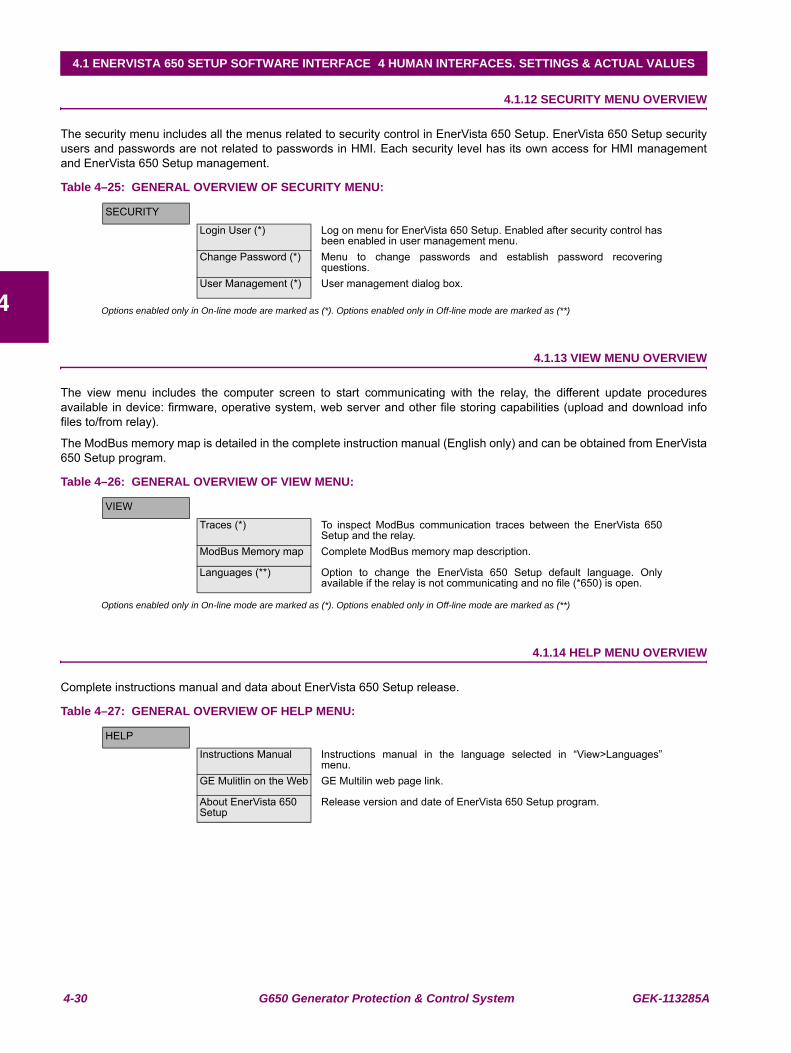
4-30 G650 Generator Protection & Control System GEK-113285A
4.1 ENERVISTA 650 SETUP SOFTWARE INTERFACE 4 HUMAN INTERFACES. SETTINGS & ACTUAL VALUES
4
4.1.12 SECURITY MENU OVERVIEW
The security menu includes all the menus related to security control in EnerVista 650 Setup. EnerVista 650 Setup securityusers and passwords are not related to passwords in HMI. Each security level has its own access for HMI managementand EnerVista 650 Setup management.
Table 4–25: GENERAL OVERVIEW OF SECURITY MENU:
Options enabled only in On-line mode are marked as (*). Options enabled only in Off-line mode are marked as (**)
4.1.13 VIEW MENU OVERVIEW
The view menu includes the computer screen to start communicating with the relay, the different update proceduresavailable in device: firmware, operative system, web server and other file storing capabilities (upload and download infofiles to/from relay).
The ModBus memory map is detailed in the complete instruction manual (English only) and can be obtained from EnerVista650 Setup program.
Table 4–26: GENERAL OVERVIEW OF VIEW MENU:
Options enabled only in On-line mode are marked as (*). Options enabled only in Off-line mode are marked as (**)
4.1.14 HELP MENU OVERVIEW
Complete instructions manual and data about EnerVista 650 Setup release.
Table 4–27: GENERAL OVERVIEW OF HELP MENU:
SECURITY
Login User (*) Log on menu for EnerVista 650 Setup. Enabled after security control hasbeen enabled in user management menu.
Change Password (*) Menu to change passwords and establish password recoveringquestions.
User Management (*) User management dialog box.
VIEW
Traces (*) To inspect ModBus communication traces between the EnerVista 650Setup and the relay.
ModBus Memory map Complete ModBus memory map description.
Languages (**) Option to change the EnerVista 650 Setup default language. Onlyavailable if the relay is not communicating and no file (*650) is open.
HELP
Instructions Manual Instructions manual in the language selected in “View>Languages”menu.
GE Mulitlin on the Web GE Multilin web page link.
About EnerVista 650 Setup
Release version and date of EnerVista 650 Setup program.
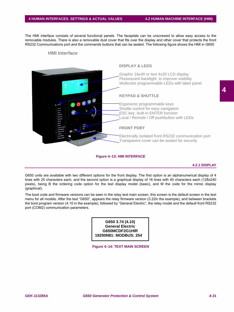
GEK-113285A G650 Generator Protection & Control System 4-31
4 HUMAN INTERFACES. SETTINGS & ACTUAL VALUES 4.2 HUMAN MACHINE INTERFACE (HMI)
4
4.2 HUMAN MACHINE INTERFACE (HMI)T
The HMI interface consists of several functional panels. The faceplate can be unscrewed to allow easy access to theremovable modules. There is also a removable dust cover that fits over the display and other cover that protects the frontRS232 Communications port and the commands buttons that can be sealed. The following figure shows the HMI in G650
Figure 4–13: HMI INTERFACE
4.2.1 DISPLAY
G650 units are available with two different options for the front display. The first option is an alphanumerical display of 4lines with 20 characters each, and the second option is a graphical display of 16 lines with 40 characters each (128x240pixels), being B the ordering code option for the text display model (basic), and M the code for the mimic display(graphical).
The boot code and firmware versions can be seen in the relay text main screen, this screen is the default screen in the textmenu for all models: After the text “G650”, appears the relay firmware version (3.22in the example), and between bracketsthe boot program version (4.10 in the example), followed by “General Electric”, the relay model and the default front RS232port (COM2) communication parameters.
Figure 4–14: TEXT MAIN SCREEN
Ergonomic programmable keys Shuttle control for easy navigation ESC key, built-in ENTER function and audio feedback Local / Remote / Off pushbutton with LEDs
HMI Interface
Graphic 16x40 or text 4x20 LCD display Fluorescent backlight to improve visibility Multicolor programmable LEDs with label panel
DISPLAY & LEDS
KEYPAD & SHUTTLE
Electrically isolated front RS232 communication port Transparent cover can be sealed for security
FRONT PORT
G650 3.74 (4.10) General Electric
G650MCDF2G1HIR 19200N81: MODBUS: 254
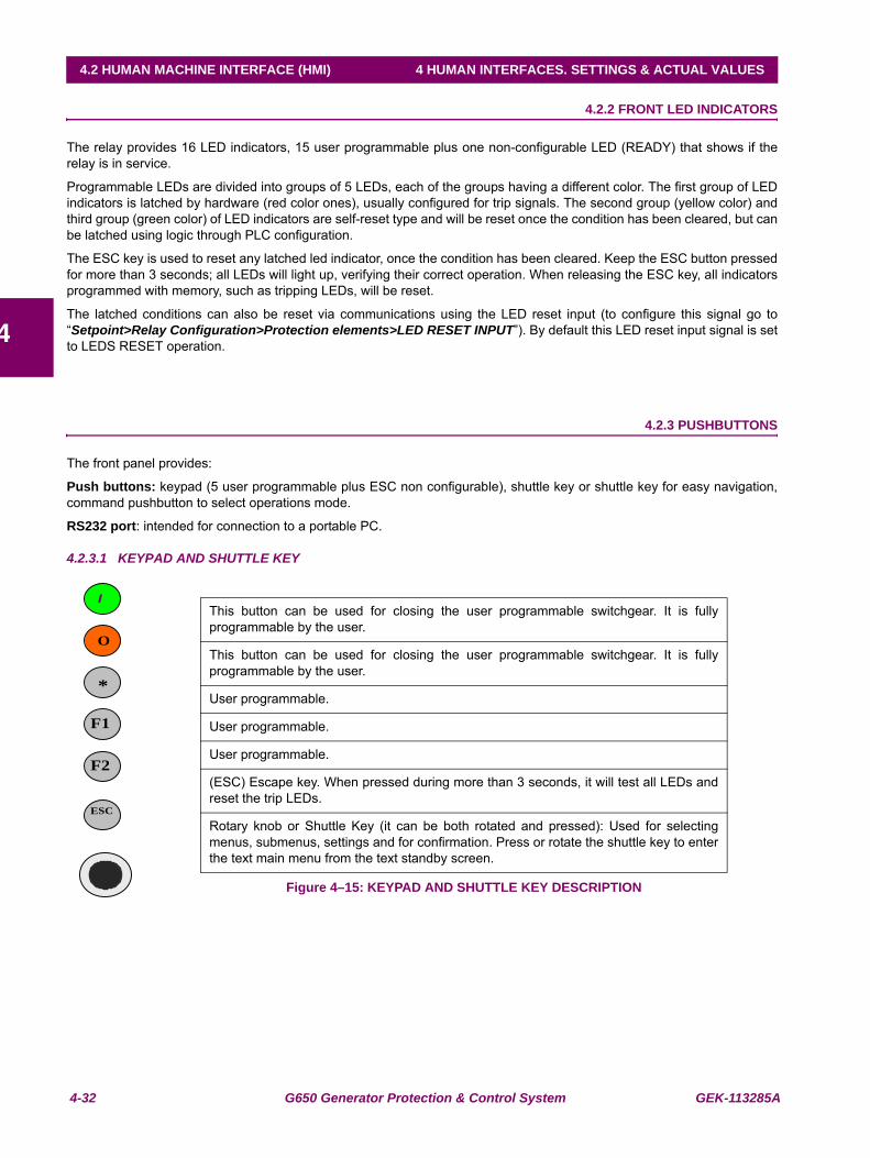
4-32 G650 Generator Protection & Control System GEK-113285A
4.2 HUMAN MACHINE INTERFACE (HMI) 4 HUMAN INTERFACES. SETTINGS & ACTUAL VALUES
4
4.2.2 FRONT LED INDICATORS
The relay provides 16 LED indicators, 15 user programmable plus one non-configurable LED (READY) that shows if therelay is in service.
Programmable LEDs are divided into groups of 5 LEDs, each of the groups having a different color. The first group of LEDindicators is latched by hardware (red color ones), usually configured for trip signals. The second group (yellow color) andthird group (green color) of LED indicators are self-reset type and will be reset once the condition has been cleared, but canbe latched using logic through PLC configuration.
The ESC key is used to reset any latched led indicator, once the condition has been cleared. Keep the ESC button pressedfor more than 3 seconds; all LEDs will light up, verifying their correct operation. When releasing the ESC key, all indicatorsprogrammed with memory, such as tripping LEDs, will be reset.
The latched conditions can also be reset via communications using the LED reset input (to configure this signal go to“Setpoint>Relay Configuration>Protection elements>LED RESET INPUT”). By default this LED reset input signal is setto LEDS RESET operation.
4.2.3 PUSHBUTTONS
The front panel provides:
Push buttons: keypad (5 user programmable plus ESC non configurable), shuttle key or shuttle key for easy navigation,command pushbutton to select operations mode.
RS232 port: intended for connection to a portable PC.
4.2.3.1 KEYPAD AND SHUTTLE KEY
Figure 4–15: KEYPAD AND SHUTTLE KEY DESCRIPTION
This button can be used for closing the user programmable switchgear. It is fullyprogrammable by the user.
This button can be used for closing the user programmable switchgear. It is fullyprogrammable by the user.
User programmable.
User programmable.
User programmable.
(ESC) Escape key. When pressed during more than 3 seconds, it will test all LEDs andreset the trip LEDs.
Rotary knob or Shuttle Key (it can be both rotated and pressed): Used for selectingmenus, submenus, settings and for confirmation. Press or rotate the shuttle key to enterthe text main menu from the text standby screen.
O
*
F1
I
F2
ESC
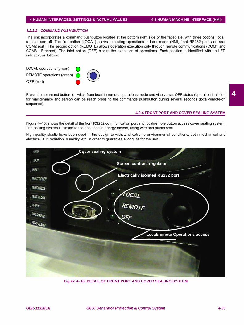
GEK-113285A G650 Generator Protection & Control System 4-33
4 HUMAN INTERFACES. SETTINGS & ACTUAL VALUES 4.2 HUMAN MACHINE INTERFACE (HMI)
4
4.2.3.2 COMMAND PUSH BUTTON
The unit incorporates a command pushbutton located at the bottom right side of the faceplate, with three options: local,remote, and off. The first option (LOCAL) allows executing operations in local mode (HMI, front RS232 port, and rearCOM2 port). The second option (REMOTE) allows operation execution only through remote communications (COM1 andCOM3 - Ethernet). The third option (OFF) blocks the execution of operations. Each position is identified with an LEDindicator, as follows:
LOCAL operations (green)
REMOTE operations (green)
OFF (red)
Press the command button to switch from local to remote operations mode and vice versa. OFF status (operation inhibitedfor maintenance and safety) can be reach pressing the commands pushbutton during several seconds (local-remote-offsequence).
4.2.4 FRONT PORT AND COVER SEALING SYSTEM
Figure 4–16: shows the detail of the front RS232 communication port and local/remote button access cover sealing system.The sealing system is similar to the one used in energy meters, using wire and plumb seal.
High quality plastic have been used in the design to withstand extreme environmental conditions, both mechanical andelectrical, sun radiation, humidity, etc. in order to guarantee a long life for the unit.
Figure 4–16: DETAIL OF FRONT PORT AND COVER SEALING SYSTEM
Screen contrast regulator
Cover sealing system
Electrically isolated RS232 port
Local/remote Operations access
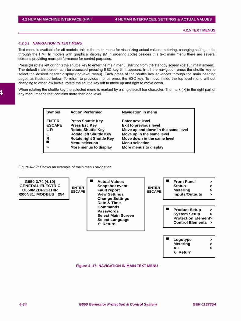
4-34 G650 Generator Protection & Control System GEK-113285A
4.2 HUMAN MACHINE INTERFACE (HMI) 4 HUMAN INTERFACES. SETTINGS & ACTUAL VALUES
4
4.2.5 TEXT MENUS
4.2.5.1 NAVIGATION IN TEXT MENU
Text menu is available for all models, this is the main menu for visualizing actual values, metering, changing settings, etc.through the HMI. In models with graphical display (M in ordering code) besides this text main menu there are severalscreens providing more performance for control purposes.
Press (or rotate left or right) the shuttle key to enter the main menu, starting from the standby screen (default main screen).The default main screen can be accessed pressing ESC key till it appears. In all the navigation press the shuttle key toselect the desired header display (top-level menu). Each press of the shuttle key advances through the main headingpages as illustrated below. To return to previous menus press the ESC key. To move inside the top-level menu withoutchanging to other low levels, rotate the shuttle key left to move up and right to move down.
When rotating the shuttle key the selected menu is marked by a single scroll bar character. The mark (>) in the right part ofany menu means that contains more than one level.
Figure 4–17: Shows an example of main menu navigation:
Figure 4–17: NAVIGATION IN MAIN TEXT MENU
Symbol Action Performed Navigation in menu
ENTER Press Shuttle Key Enter next level ESCAPE Press Esc Key Exit to previous level L-R Rotate Shuttle Key Move up and down in the same level L Rotate left Shuttle Key Move up in the same level R Rotate right Shuttle Key Move down in the same level
Menu selection Menu selection > More menus to display More menus to display
G650 3.74 (4.10) GENERAL ELECTRIC
G650MZDF2G1HIR 9200N81: MODBUS : 254
Actual Values Snapshot event Fault report View Settings Change Settings Date & Time Commands Passwords Select Main Screen Select Language
Return
Front Panel > Status > Metering > Inputs/Outputs >
Product Setup > System Setup > Protection Element> Control Elements >
Logotype > Metering > All >
Return
ENTERESCAPE
ENTERESCAPE
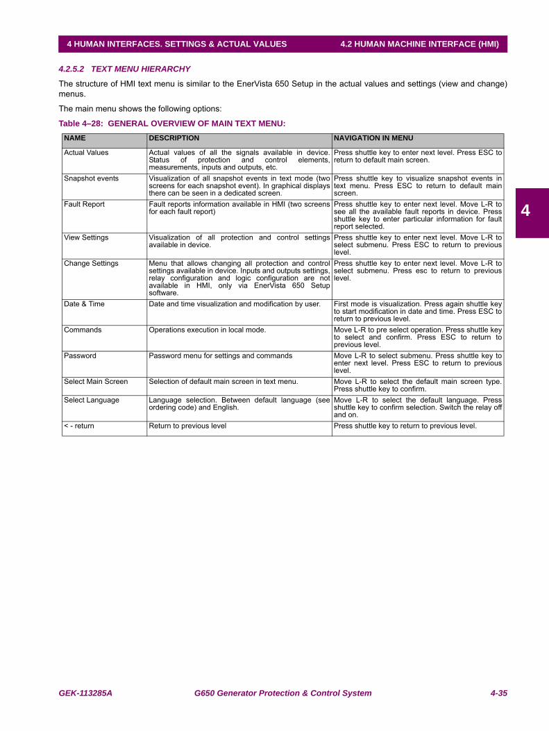
GEK-113285A G650 Generator Protection & Control System 4-35
4 HUMAN INTERFACES. SETTINGS & ACTUAL VALUES 4.2 HUMAN MACHINE INTERFACE (HMI)
4
4.2.5.2 TEXT MENU HIERARCHY
The structure of HMI text menu is similar to the EnerVista 650 Setup in the actual values and settings (view and change)menus.
The main menu shows the following options:
Table 4–28: GENERAL OVERVIEW OF MAIN TEXT MENU:NAME DESCRIPTION NAVIGATION IN MENU
Actual Values Actual values of all the signals available in device.Status of protection and control elements,measurements, inputs and outputs, etc.
Press shuttle key to enter next level. Press ESC toreturn to default main screen.
Snapshot events Visualization of all snapshot events in text mode (twoscreens for each snapshot event). In graphical displaysthere can be seen in a dedicated screen.
Press shuttle key to visualize snapshot events intext menu. Press ESC to return to default mainscreen.
Fault Report Fault reports information available in HMI (two screensfor each fault report)
Press shuttle key to enter next level. Move L-R tosee all the available fault reports in device. Pressshuttle key to enter particular information for faultreport selected.
View Settings Visualization of all protection and control settingsavailable in device.
Press shuttle key to enter next level. Move L-R toselect submenu. Press ESC to return to previouslevel.
Change Settings Menu that allows changing all protection and controlsettings available in device. Inputs and outputs settings,relay configuration and logic configuration are notavailable in HMI, only via EnerVista 650 Setupsoftware.
Press shuttle key to enter next level. Move L-R toselect submenu. Press esc to return to previouslevel.
Date & Time Date and time visualization and modification by user. First mode is visualization. Press again shuttle keyto start modification in date and time. Press ESC toreturn to previous level.
Commands Operations execution in local mode. Move L-R to pre select operation. Press shuttle keyto select and confirm. Press ESC to return toprevious level.
Password Password menu for settings and commands Move L-R to select submenu. Press shuttle key toenter next level. Press ESC to return to previouslevel.
Select Main Screen Selection of default main screen in text menu. Move L-R to select the default main screen type.Press shuttle key to confirm.
Select Language Language selection. Between default language (seeordering code) and English.
Move L-R to select the default language. Pressshuttle key to confirm selection. Switch the relay offand on.
< - return Return to previous level Press shuttle key to return to previous level.
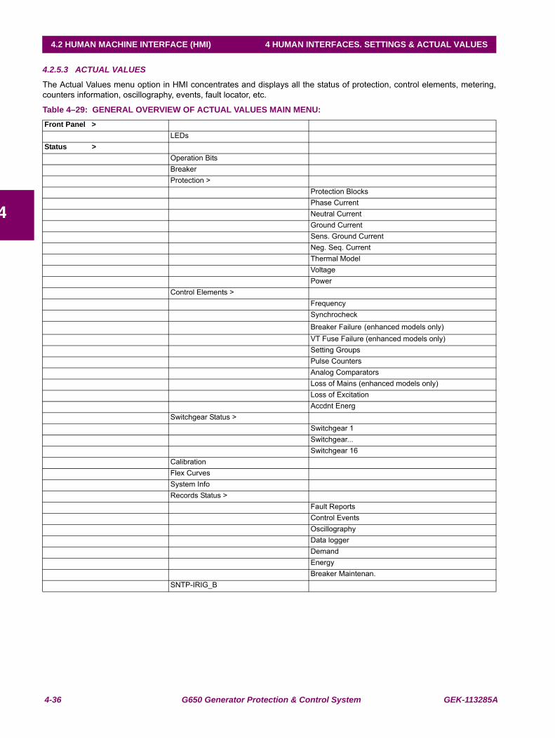
4-36 G650 Generator Protection & Control System GEK-113285A
4.2 HUMAN MACHINE INTERFACE (HMI) 4 HUMAN INTERFACES. SETTINGS & ACTUAL VALUES
4
4.2.5.3 ACTUAL VALUES
The Actual Values menu option in HMI concentrates and displays all the status of protection, control elements, metering,counters information, oscillography, events, fault locator, etc.
Table 4–29: GENERAL OVERVIEW OF ACTUAL VALUES MAIN MENU:Front Panel >
LEDsStatus >
Operation BitsBreakerProtection >
Protection BlocksPhase CurrentNeutral CurrentGround CurrentSens. Ground CurrentNeg. Seq. CurrentThermal ModelVoltagePower
Control Elements >FrequencySynchrocheck
Breaker Failure (enhanced models only)VT Fuse Failure (enhanced models only)Setting GroupsPulse CountersAnalog ComparatorsLoss of Mains (enhanced models only)Loss of ExcitationAccdnt Energ
Switchgear Status >Switchgear 1Switchgear...Switchgear 16
CalibrationFlex CurvesSystem InfoRecords Status >
Fault ReportsControl EventsOscillographyData loggerDemandEnergyBreaker Maintenan.
SNTP-IRIG_B
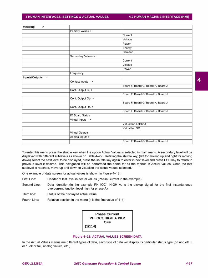
GEK-113285A G650 Generator Protection & Control System 4-37
4 HUMAN INTERFACES. SETTINGS & ACTUAL VALUES 4.2 HUMAN MACHINE INTERFACE (HMI)
4
To enter this menu press the shuttle key when the option Actual Values is selected in main menu. A secondary level will bedisplayed with different sublevels as shown on Table 4–29:. Rotating the shuttle key, (left for moving up and right for movingdown) select the next level to be displayed, press the shuttle key again to enter in next level and press ESC key to return toprevious level if desired. This navigation will be performed the same for all the menus in Actual Values. Once the lastsublevel is reached, move up and down to visualize the actual values selected.
One example of data screen for actual values is shown in Figure 4–18:.
First Line: Header of last level in actual values (Phase Current in the example)
Second Line: Data identifier (in the example PH IOC1 HIGH A, is the pickup signal for the first instantaneousovercurrent function level high for phase A).
Third line: Status of the displayed actual value.
Fourth Line: Relative position in the menu (it is the first value of 114)
Figure 4–18: ACTUAL VALUES SCREEN DATA
In the Actual Values menus are different types of data, each type of data will display its particular status type (on and off, 0or 1, ok or fail, analog values, etc.)
Metering >Primary Values >
CurrentVoltagePowerEnergyDemand
Secondary Values >CurrentVoltagePower
FrequencyInputs/Outputs >
Contact Inputs >Board F/ Board G/ Board H/ Board J
Cont. Output St. >Board F/ Board G/ Board H/ Board J
Cont. Output Op. >Board F/ Board G/ Board H/ Board J
Cont. Output Rs. >Board F/ Board G/ Board H/ Board J
IO Board StatusVirtual Inputs >
Virtual Inp.LatchedVirtual Inp.SR
Virtual OutputsAnalog Inputs >
Board F/ Board G/ Board H/ Board J
Phase Current PH IOC1 HIGH A PKP
OFF(1/114)
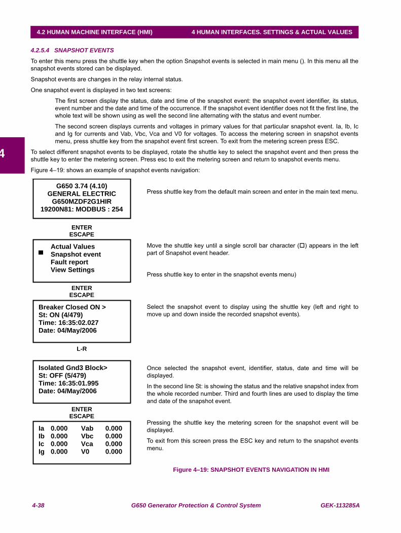
4-38 G650 Generator Protection & Control System GEK-113285A
4.2 HUMAN MACHINE INTERFACE (HMI) 4 HUMAN INTERFACES. SETTINGS & ACTUAL VALUES
4
4.2.5.4 SNAPSHOT EVENTS
To enter this menu press the shuttle key when the option Snapshot events is selected in main menu (). In this menu all thesnapshot events stored can be displayed.
Snapshot events are changes in the relay internal status.
One snapshot event is displayed in two text screens:
The first screen display the status, date and time of the snapshot event: the snapshot event identifier, its status,event number and the date and time of the occurrence. If the snapshot event identifier does not fit the first line, thewhole text will be shown using as well the second line alternating with the status and event number.
The second screen displays currents and voltages in primary values for that particular snapshot event. Ia, Ib, Icand Ig for currents and Vab, Vbc, Vca and V0 for voltages. To access the metering screen in snapshot eventsmenu, press shuttle key from the snapshot event first screen. To exit from the metering screen press ESC.
To select different snapshot events to be displayed, rotate the shuttle key to select the snapshot event and then press theshuttle key to enter the metering screen. Press esc to exit the metering screen and return to snapshot events menu.
Figure 4–19: shows an example of snapshot events navigation:
Press shuttle key from the default main screen and enter in the main text menu.
Move the shuttle key until a single scroll bar character ( ) appears in the leftpart of Snapshot event header.
Press shuttle key to enter in the snapshot events menu)
Select the snapshot event to display using the shuttle key (left and right tomove up and down inside the recorded snapshot events).
Once selected the snapshot event, identifier, status, date and time will bedisplayed.
In the second line St: is showing the status and the relative snapshot index fromthe whole recorded number. Third and fourth lines are used to display the timeand date of the snapshot event.
Pressing the shuttle key the metering screen for the snapshot event will bedisplayed.
To exit from this screen press the ESC key and return to the snapshot eventsmenu.
Figure 4–19: SNAPSHOT EVENTS NAVIGATION IN HMI
19200N81: MODBUS : 254
Actual Values Snapshot event
Fault report View Settings
ENTERESCAPE
Breaker Closed ON > St: ON (4/479) Time: 16:35:02.027 Date: 04/May/2006
ENTERESCAPE
Isolated Gnd3 Block> St: OFF (5/479) Time: 16:35:01.995 Date: 04/May/2006
L-R
Ia 0.000 Vab 0.000Ib 0.000 Vbc 0.000Ic 0.000 Vca 0.000Ig 0.000 V0 0.000
ENTERESCAPE
G650 3.74 (4.10) GENERAL ELECTRIC
G650MZDF2G1HIR 19200N81: MODBUS : 254
Actual Values Snapshot event
Fault report View Settings
ENTERESCAPE
Breaker Closed ON > St: ON (4/479) Time: 16:35:02.027 Date: 04/May/2006
ENTERESCAPE
Isolated Gnd3 Block> St: OFF (5/479) Time: 16:35:01.995 Date: 04/May/2006
L-R
Ia 0.000 Vab 0.000Ib 0.000 Vbc 0.000Ic 0.000 Vca 0.000Ig 0.000 V0 0.000
ENTERESCAPE
GEK-113285A G650 Generator Protection & Control System 4-39
4 HUMAN INTERFACES. SETTINGS & ACTUAL VALUES 4.2 HUMAN MACHINE INTERFACE (HMI)
4
4.2.5.5 FAULT REPORT
To enter this menu press the shuttle key when the option Fault report is selected in main menu (). This menu displaysinformation about the last ten faults recorded in the relay.
The Relay HMI allows two types of visualization for the fault reports stored in the Relay:
1. Showing the fault warning messages in the text display when the fault is produced. This option has to be enabledby setting. To change from the HMI go to the menu “Change Settings >Product Setup > Fault Report > ShowFault On HMI” and enable it.
2.Only saving and allowing viewing the information from the last ten faults recorded in the relay.
In the first option, when a fault occurs a warning message is displayed, including information about the fault in two screens,one with general fault information, and a second one with the measured values in the moment of the fault.
The fault-warning message must be acknowledged by the user; this means that the user must press the shuttle key for thisscreen to disappear, The HMI will not allow to perform any other operation until the screen is acknowledged. In the event ofseveral consecutive faults, the HMI will always show the most recent fault, and the user will need to acknowledge all ofthem, up to a maximum of ten faults.
In the second option, viewing the fault reports in the menu available in the HMI, the Fault Report menu in the main textscreen must be accessed by pressing the shuttle key. The display will show the information about the last ten faultsproduced, and both the general information and the metering screens can be viewed for each fault. Displayed informationstarts in the most recent fault, and the user can switch to another fault by rotating the shuttle key.
Displayed information is stored in the relay volatile memory, so if the relay is turned off this information will be lost, as wellas if a “Clear Fault Report” command is executed. However, fault reports stored in the relay non-volatile memory will remainafter the Fault reset, and they can be obtained from the relay using EnerVista 650 Setup software, at the“Actual>Records>Fault report” menu.
If there is no fault report available through the display, the relay will show a “Fault report not available” message.
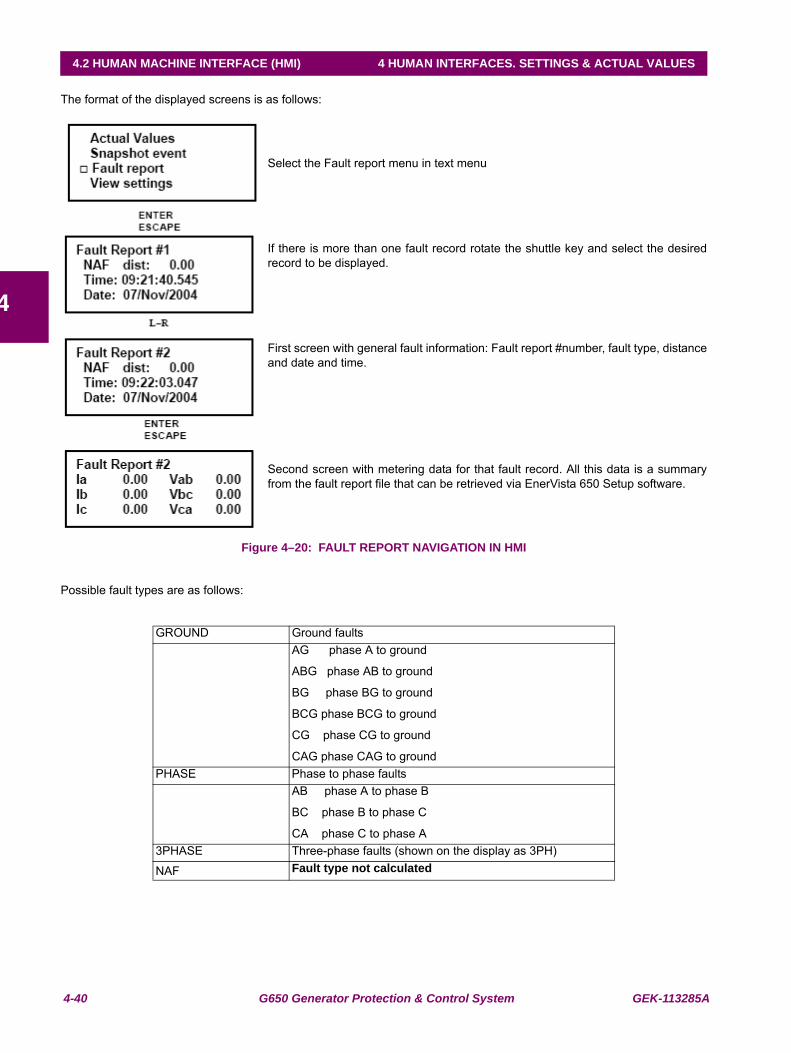
4-40 G650 Generator Protection & Control System GEK-113285A
4.2 HUMAN MACHINE INTERFACE (HMI) 4 HUMAN INTERFACES. SETTINGS & ACTUAL VALUES
4
The format of the displayed screens is as follows:
Select the Fault report menu in text menu
If there is more than one fault record rotate the shuttle key and select the desiredrecord to be displayed.
First screen with general fault information: Fault report #number, fault type, distanceand date and time.
Second screen with metering data for that fault record. All this data is a summaryfrom the fault report file that can be retrieved via EnerVista 650 Setup software.
Figure 4–20: FAULT REPORT NAVIGATION IN HMI
Possible fault types are as follows:
GROUND Ground faultsAG phase A to ground
ABG phase AB to ground
BG phase BG to ground
BCG phase BCG to ground
CG phase CG to ground
CAG phase CAG to groundPHASE Phase to phase faults
AB phase A to phase B
BC phase B to phase C
CA phase C to phase A3PHASE Three-phase faults (shown on the display as 3PH)
NAF Fault type not calculated
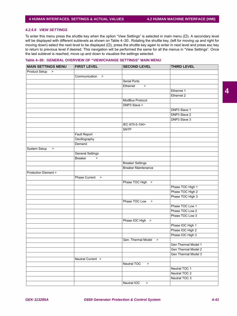
GEK-113285A G650 Generator Protection & Control System 4-41
4 HUMAN INTERFACES. SETTINGS & ACTUAL VALUES 4.2 HUMAN MACHINE INTERFACE (HMI)
4
4.2.5.6 VIEW SETTINGS
To enter this menu press the shuttle key when the option “View Settings” is selected in main menu ( ). A secondary levelwill be displayed with different sublevels as shown on Table 4–30:. Rotating the shuttle key, (left for moving up and right formoving down) select the next level to be displayed ( ), press the shuttle key again to enter in next level and press esc keyto return to previous level if desired. This navigation will be performed the same for all the menus in “View Settings”. Oncethe last sublevel is reached, move up and down to visualize the settings selected.
Table 4–30: GENERAL OVERVIEW OF “VIEW/CHANGE SETTINGS” MAIN MENU
MAIN SETTINGS MENU FIRST LEVEL SECOND LEVEL THIRD LEVELProduct Setup >
Communication >Serial PortsEthernet >
Ethernet 1Ethernet 2
ModBus ProtocolDNP3 Slave >
DNP3 Slave 1DNP3 Slave 2DNP3 Slave 3
IEC 870-5-104>SNTP
Fault ReportOscillographyDemand
System Setup >General SettingsBreaker >
Breaker SettingsBreaker Maintenance
Protection Element >Phase Current >
Phase TOC High >Phase TOC High 1Phase TOC High 2Phase TOC High 3
Phase TOC Low >Phase TOC Low 1Phase TOC Low 2Phase TOC Low 3
Phase IOC High >Phase IOC High 1Phase IOC High 2Phase IOC High 3
Gen. Thermal Model >Gen Thermal Model 1Gen Thermal Model 2Gen Thermal Model 3
Neutral Current >Neutral TOC >
Neutral TOC 1Neutral TOC 2Neutral TOC 3
Neutral IOC >
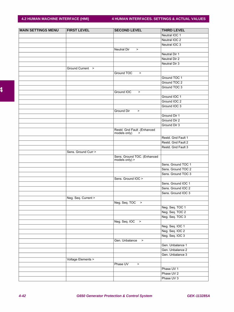
4-42 G650 Generator Protection & Control System GEK-113285A
4.2 HUMAN MACHINE INTERFACE (HMI) 4 HUMAN INTERFACES. SETTINGS & ACTUAL VALUES
4
Neutral IOC 1Neutral IOC 2Neutral IOC 3
Neutral Dir >Neutral Dir 1Neutral Dir 2Neutral Dir 3
Ground Current >Ground TOC >
Ground TOC 1Ground TOC 2Ground TOC 3
Ground IOC >Ground IOC 1Ground IOC 2Ground IOC 3
Ground Dir >Ground Dir 1Ground Dir 2Ground Dir 3
Restd. Gnd Fault .(Enhanced models only) >
Restd. Gnd Fault 1Restd. Gnd Fault 2Restd. Gnd Fault 3
Sens. Ground Curr >Sens. Ground TOC. (Enhanced models only) >
Sens. Ground TOC 1Sens. Ground TOC 2Sens. Ground TOC 3
Sens. Ground IOC >Sens. Ground IOC 1Sens. Ground IOC 2Sens. Ground IOC 3
Neg. Seq. Current >Neg. Seq. TOC >
Neg. Seq. TOC 1Neg. Seq. TOC 2Neg. Seq. TOC 3
Neg. Seq. IOC >Neg. Seq. IOC 1Neg. Seq. IOC 2Neg. Seq. IOC 3
Gen. Unbalance >Gen. Unbalance 1Gen. Unbalance 2Gen. Unbalance 3
Voltage Elements >Phase UV >
Phase UV 1Phase UV 2Phase UV 3
MAIN SETTINGS MENU FIRST LEVEL SECOND LEVEL THIRD LEVEL
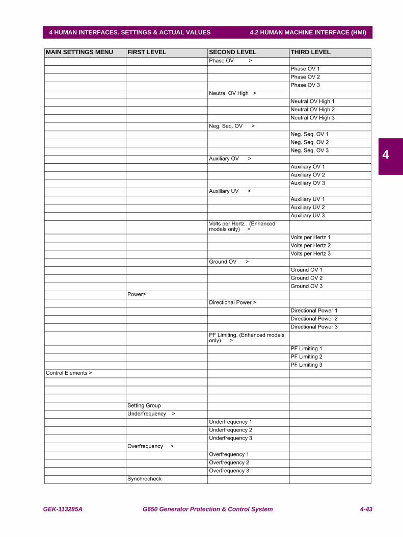
GEK-113285A G650 Generator Protection & Control System 4-43
4 HUMAN INTERFACES. SETTINGS & ACTUAL VALUES 4.2 HUMAN MACHINE INTERFACE (HMI)
4
Phase OV >Phase OV 1Phase OV 2Phase OV 3
Neutral OV High >Neutral OV High 1Neutral OV High 2Neutral OV High 3
Neg. Seq. OV >Neg. Seq. OV 1Neg. Seq. OV 2Neg. Seq. OV 3
Auxiliary OV >Auxiliary OV 1Auxiliary OV 2Auxiliary OV 3
Auxiliary UV >Auxiliary UV 1Auxiliary UV 2Auxiliary UV 3
Volts per Hertz . (Enhanced models only) >
Volts per Hertz 1Volts per Hertz 2Volts per Hertz 3
Ground OV >Ground OV 1Ground OV 2Ground OV 3
Power>Directional Power >
Directional Power 1Directional Power 2Directional Power 3
PF Limiting. (Enhanced models only) >
PF Limiting 1PF Limiting 2PF Limiting 3
Control Elements >
Setting GroupUnderfrequency >
Underfrequency 1Underfrequency 2Underfrequency 3
Overfrequency >Overfrequency 1Overfrequency 2Overfrequency 3
Synchrocheck
MAIN SETTINGS MENU FIRST LEVEL SECOND LEVEL THIRD LEVEL
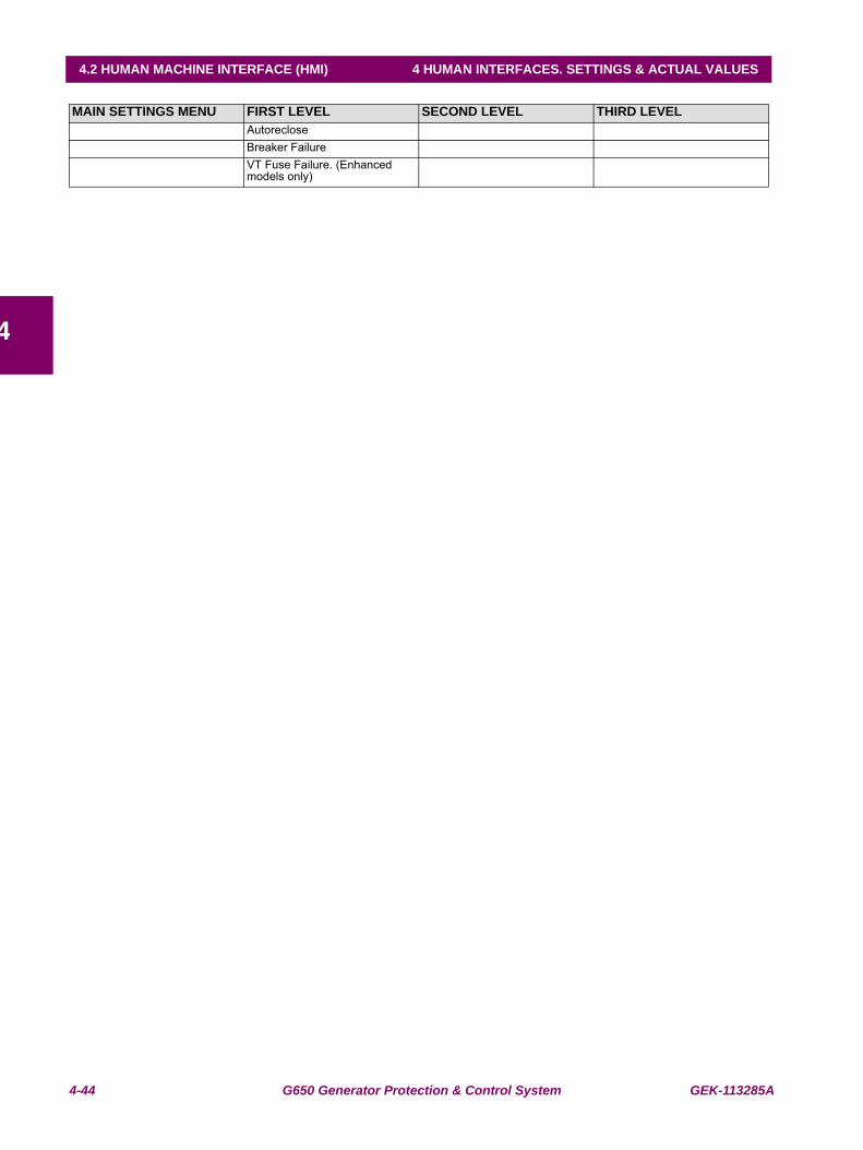
4-44 G650 Generator Protection & Control System GEK-113285A
4.2 HUMAN MACHINE INTERFACE (HMI) 4 HUMAN INTERFACES. SETTINGS & ACTUAL VALUES
4
AutorecloseBreaker FailureVT Fuse Failure. (Enhanced models only)
MAIN SETTINGS MENU FIRST LEVEL SECOND LEVEL THIRD LEVEL
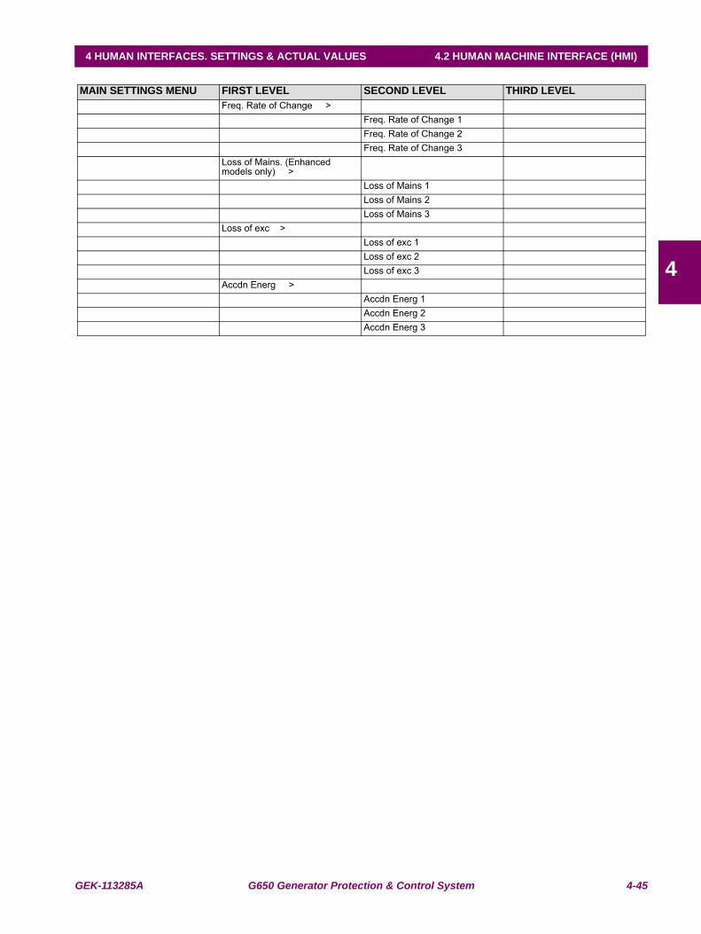
GEK-113285A G650 Generator Protection & Control System 4-45
4 HUMAN INTERFACES. SETTINGS & ACTUAL VALUES 4.2 HUMAN MACHINE INTERFACE (HMI)
4
Freq. Rate of Change >Freq. Rate of Change 1Freq. Rate of Change 2Freq. Rate of Change 3
Loss of Mains. (Enhanced models only) >
Loss of Mains 1Loss of Mains 2Loss of Mains 3
Loss of exc >Loss of exc 1Loss of exc 2Loss of exc 3
Accdn Energ >Accdn Energ 1Accdn Energ 2Accdn Energ 3
MAIN SETTINGS MENU FIRST LEVEL SECOND LEVEL THIRD LEVEL
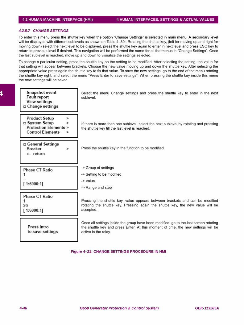
4-46 G650 Generator Protection & Control System GEK-113285A
4.2 HUMAN MACHINE INTERFACE (HMI) 4 HUMAN INTERFACES. SETTINGS & ACTUAL VALUES
4
4.2.5.7 CHANGE SETTINGS
To enter this menu press the shuttle key when the option “Change Settings” is selected in main menu. A secondary levelwill be displayed with different sublevels as shown on Table 4–30:. Rotating the shuttle key, (left for moving up and right formoving down) select the next level to be displayed, press the shuttle key again to enter in next level and press ESC key toreturn to previous level if desired. This navigation will be performed the same for all the menus in “Change Settings”. Oncethe last sublevel is reached, move up and down to visualize the settings selected.
To change a particular setting, press the shuttle key on the setting to be modified. After selecting the setting, the value forthat setting will appear between brackets. Choose the new value moving up and down the shuttle key. After selecting theappropriate value press again the shuttle key to fix that value. To save the new settings, go to the end of the menu rotatingthe shuttle key right, and select the menu “Press Enter to save settings”. When pressing the shuttle key inside this menuthe new settings will be saved.
Select the menu Change settings and press the shuttle key to enter in the nextsublevel.
If there is more than one sublevel, select the next sublevel by rotating and pressingthe shuttle key till the last level is reached.
Press the shuttle key in the function to be modified
-> Group of settings
-> Setting to be modified
-> Value
-> Range and step
Pressing the shuttle key, value appears between brackets and can be modifiedrotating the shuttle key. Pressing again the shuttle key, the new value will beaccepted.
Once all settings inside the group have been modified, go to the last screen rotatingthe shuttle key and press Enter. At this moment of time, the new settings will beactive in the relay.
Figure 4–21: CHANGE SETTINGS PROCEDURE IN HMI
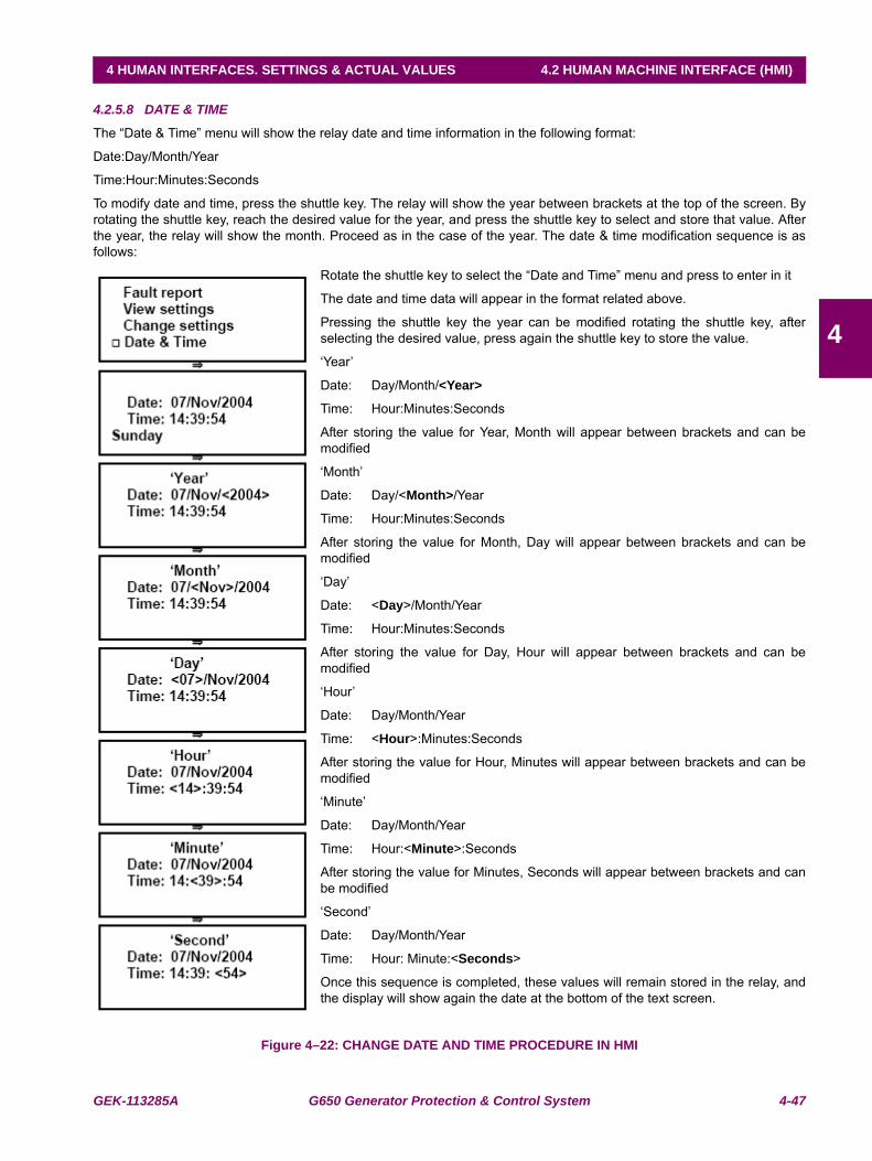
GEK-113285A G650 Generator Protection & Control System 4-47
4 HUMAN INTERFACES. SETTINGS & ACTUAL VALUES 4.2 HUMAN MACHINE INTERFACE (HMI)
4
4.2.5.8 DATE & TIME
The “Date & Time” menu will show the relay date and time information in the following format:
Date:Day/Month/Year
Time:Hour:Minutes:Seconds
To modify date and time, press the shuttle key. The relay will show the year between brackets at the top of the screen. Byrotating the shuttle key, reach the desired value for the year, and press the shuttle key to select and store that value. Afterthe year, the relay will show the month. Proceed as in the case of the year. The date & time modification sequence is asfollows:
Rotate the shuttle key to select the “Date and Time” menu and press to enter in it
The date and time data will appear in the format related above.
Pressing the shuttle key the year can be modified rotating the shuttle key, afterselecting the desired value, press again the shuttle key to store the value.
‘Year’
Date: Day/Month/<Year>
Time: Hour:Minutes:Seconds
After storing the value for Year, Month will appear between brackets and can bemodified
‘Month’
Date: Day/<Month>/Year
Time: Hour:Minutes:Seconds
After storing the value for Month, Day will appear between brackets and can bemodified
‘Day’
Date: <Day>/Month/Year
Time: Hour:Minutes:Seconds
After storing the value for Day, Hour will appear between brackets and can bemodified
‘Hour’
Date: Day/Month/Year
Time: <Hour>:Minutes:Seconds
After storing the value for Hour, Minutes will appear between brackets and can bemodified
‘Minute’
Date: Day/Month/Year
Time: Hour:<Minute>:Seconds
After storing the value for Minutes, Seconds will appear between brackets and canbe modified
‘Second’
Date: Day/Month/Year
Time: Hour: Minute:<Seconds>
Once this sequence is completed, these values will remain stored in the relay, andthe display will show again the date at the bottom of the text screen.
Figure 4–22: CHANGE DATE AND TIME PROCEDURE IN HMI
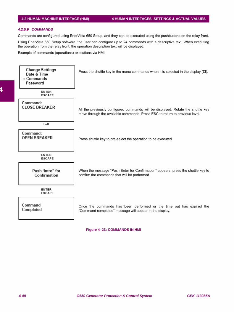
4-48 G650 Generator Protection & Control System GEK-113285A
4.2 HUMAN MACHINE INTERFACE (HMI) 4 HUMAN INTERFACES. SETTINGS & ACTUAL VALUES
4
4.2.5.9 COMMANDS
Commands are configured using EnerVista 650 Setup, and they can be executed using the pushbuttons on the relay front.
Using EnerVista 650 Setup software, the user can configure up to 24 commands with a descriptive text. When executingthe operation from the relay front, the operation description text will be displayed.
Example of commands (operations) executions via HMI
Press the shuttle key in the menu commands when it is selected in the display ( ).
All the previously configured commands will be displayed. Rotate the shuttle keymove through the available commands. Press ESC to return to previous level.
Press shuttle key to pre-select the operation to be executed
When the message “Push Enter for Confirmation” appears, press the shuttle key toconfirm the commands that will be performed.
Once the commands has been performed or the time out has expired the“Command completed” message will appear in the display.
Figure 4–23: COMMANDS IN HMI
GEK-113285A G650 Generator Protection & Control System 4-49
4 HUMAN INTERFACES. SETTINGS & ACTUAL VALUES 4.2 HUMAN MACHINE INTERFACE (HMI)
4
4.2.5.10 PASSWORDS
G650 units incorporate independent passwords for protection and control, in order to prevent unauthorized keypad anddisplay access to the relay.
Settings Password:
This password allows restricting access to settings changes in the relay protection elements.
Commands Password:
This password is required for executing operation commands through the keypad and display.
If the Commands Password is activated, when the user tries to execute an operation, the relay will request this password,and in case of using the single-line diagram for graphical display models, all objects will not be operational until thispassword is entered, either logging in Login Pwd Commands, or entering the password in the Commands menu.
Relay settings view, measures, and other monitored information are not password-protected, and they can be accessed byall users.
Access to the password menu is located at the Password option in the relay text menu. This menu includes the followingoptions:
"Login Pwd Settings"
"Logout Pwd Settings"
"Change Pwd Settings"
"Login Pwd Commands"
"Logout Pwd Commands"
"Change Pwd Commands"
"Forgot Password?"
Among the available options in this menu, there are three types of functionality:
Login: For entering the password, either for settings or commands, and enable access to settingsor commands. Once entering the password the relay is no longer password protected, andaccess is enabled to settings modification or commands execution.
Logout: Once the necessary setting changes or operation commands have been executed, theuser can log out, so that the relay is password protected again.
Change: This menu allows setting or modifying the desired password.
Forgot Password: This menu provides the encrypted password, so that it can be recovered if the user loses orforgets it.
Passwords are restricted for Settings change and Commands execution. To password-protect the relay, it is first necessaryto set the desired password, using the corresponding “Change Pwd...” menu. The default password is 0000. This passwordprovides access to the whole relay functionality.
Once a new password has been set, the user must log in to access the protected functionality; otherwise, the relay willrequest the password when trying to change settings or execute commands. Once the password is entered the relay isunprotected (as if the user had logged in), and the user must log out to protect again the relay.
a) PASSWORD RANGE
The valid range for G650 passwords is a number from 0000 to 9999.
The default password is 0000, which provides access to the whole relay functionality. This is the default option for enablingrelay use without using passwords.
4-50 G650 Generator Protection & Control System GEK-113285A
4.2 HUMAN MACHINE INTERFACE (HMI) 4 HUMAN INTERFACES. SETTINGS & ACTUAL VALUES
4
b) ENTERING THE PASSWORD (LOGIN PWD)
This operation is the same for both the settings and commands passwords. The only difference will be the access menu.For entering the password, the user must access the Login menus inside the Password menu.
Login Pwd Settings or Login Pwd Commands:
The relay requests the password with the following message on the screen:
Setting passwd.
Login: < 1000 >
For entering the desired password, the user must rotate the shuttle key to the left (decrease) or to the right (increase), andestablish the desired number. Once entered, the selected password between brackets has been entered, the relay willshow the message “Processing passwd. Wait...”. If the password is correct, the relay will allow access to the settingschange or command execution. It is not necessary to enter the password every time a change is to be performed. The relaywill request the password 15 minutes after the last keypad action has taken place. This period of time is the same that takesthe relay to turn off the display backlighting.
c) LOGGING OUT (LOGOUT PWD)
To disable access to settings and commands, the user must logout.
Logout Pwd Settings or Logout Pwd Commands:
For safety reasons, if the user does not log out, the relay will do it automatically 15 minutes after the last keypadaction.
d) CHANGING THE PASSWORD (CHANGE PWD COMMANDS)
To set a password in the relay, both for settings and commands, the corresponding menu must be accessed inside thePassword menu:
Change Pwd Settings or Change Pwd Commands:
To modify the password, the user must first introduce the existing password; if the relay has the default factory password,this would be 0000.
For modifying the password, the relay requests the existing password with the following message:
(Setting or Command) passwd.
Login: < 0000 >
Once the entered password has been acknowledged, the new password must be entered:
(Setting o Command) passwd.
New passwd: < 1000 >
Once the new password has been entered, the relay returns to the general Passwords menu.
e) PASSWORD RECOVERY (FORGOT PASSWORD?)
If the relay passwords need to be recovered, the “Forgot Password?” menu must be accessed. This menu is the lastoption inside the text Passwords menu.
This menu will show two passwords, which correspond to the encrypted protection settings, and commands passwords, asshown in the following example:
Cod Settings: [35c0]
Cod Commands: [35c0]
<Push Enter>
In order to obtain the decoded password from the encrypted codes provided by the relay, it is necessary to contact GEMultilin and provide these encrypted codes.
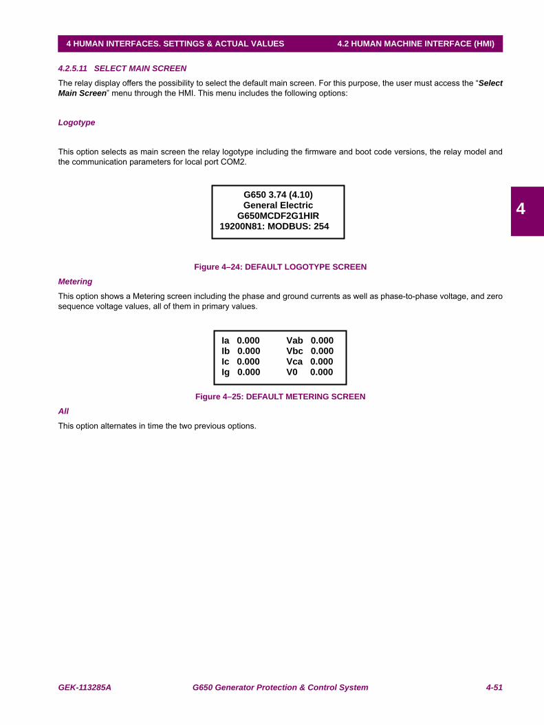
GEK-113285A G650 Generator Protection & Control System 4-51
4 HUMAN INTERFACES. SETTINGS & ACTUAL VALUES 4.2 HUMAN MACHINE INTERFACE (HMI)
4
4.2.5.11 SELECT MAIN SCREEN
The relay display offers the possibility to select the default main screen. For this purpose, the user must access the “SelectMain Screen” menu through the HMI. This menu includes the following options:
Logotype
This option selects as main screen the relay logotype including the firmware and boot code versions, the relay model andthe communication parameters for local port COM2.
Figure 4–24: DEFAULT LOGOTYPE SCREEN
Metering
This option shows a Metering screen including the phase and ground currents as well as phase-to-phase voltage, and zerosequence voltage values, all of them in primary values.
Figure 4–25: DEFAULT METERING SCREEN
All
This option alternates in time the two previous options.
G650 3.74 (4.10) General Electric
G650MCDF2G1HIR 19200N81: MODBUS: 254
Ia 0.000 Vab 0.000Ib 0.000 Vbc 0.000Ic 0.000 Vca 0.000 Ig 0.000 V0 0.000
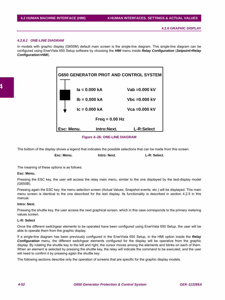
4-52 G650 Generator Protection & Control System GEK-113285A
4.2 HUMAN MACHINE INTERFACE (HMI) 4 HUMAN INTERFACES. SETTINGS & ACTUAL VALUES
4
4.2.6 GRAPHIC DISPLAY
4.2.6.1 ONE-LINE DIAGRAM
In models with graphic display (G650M) default main screen is the single-line diagram. This single-line diagram can beconfigured using EnerVista 650 Setup software by choosing the HMI menu inside Relay Configuration (Setpoint>RelayConfiguration>HMI).
Figure 4–26: ONE-LINE DIAGRAM
The bottom of the display shows a legend that indicates the possible selections that can be made from this screen.
Esc: Menu. Intro: Next. L-R: Select.
The meaning of these options is as follows:
Esc: Menu.
Pressing the ESC key, the user will access the relay main menu, similar to the one displayed by the text-display model(G650B).
Pressing again the ESC key; the menu selection screen (Actual Values, Snapshot events, etc.) will be displayed. This mainmenu screen is identical to the one described for the text display. Its functionality is described in section 4.2.5 in thismanual.
Intro: Next.
Pressing the shuttle key, the user access the next graphical screen, which in this case corresponds to the primary meteringvalues screen.
L-R: Select
Once the different switchgear elements to be operated have been configured using EnerVista 650 Setup, the user will beable to operate them from the graphic display.
If a single-line diagram has been previously configured in the EnerVista 650 Setup, in the HMI option inside the RelayConfiguration menu, the different switchgear elements configured for the display will be operative from the graphicdisplay. By rotating the shuttle key to the left and right, the cursor moves among the elements and blinks on each of them.When an element is selected by pressing the shuttle key, the relay will indicate the command to be executed, and the userwill need to confirm it by pressing again the shuttle key.
The following sections describe only the operation of screens that are specific for the graphic display models.
G650 GENERATOR PROT AND CONTROL SYSTEM
Ia = 0.000 kA Vab =0.000 kV
Ib = 0.000 kA Vbc =0.000 kV
Ic = 0.000 kA Vca =0.000 kV
Freq = 0.00 Hz
Esc: Menu. Intro:Next. L-R:Select
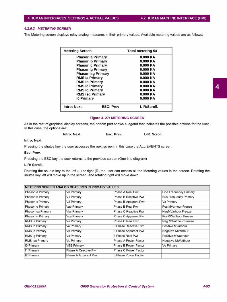
GEK-113285A G650 Generator Protection & Control System 4-53
4 HUMAN INTERFACES. SETTINGS & ACTUAL VALUES 4.2 HUMAN MACHINE INTERFACE (HMI)
4
4.2.6.2 METERING SCREEN
The Metering screen displays relay analog measures in their primary values. Available metering values are as follows:
Figure 4–27: METERING SCREEN
As in the rest of graphical display screens, the bottom part shows a legend that indicates the possible options for the user.In this case, the options are:
Intro: Next. Esc: Prev. L-R: Scroll.
Intro: Next.
Pressing the shuttle key the user accesses the next screen, in this case the ALL EVENTS screen.
Esc: Prev.
Pressing the ESC key the user returns to the previous screen (One-line diagram)
L-R: Scroll.
Rotating the shuttle key to the left (L) or right (R) the user can access all the Metering values in the screen. Rotating theshuttle key left will move up in the screen, and rotating right will move down.
METERING SCREEN ANALOG MEASURES IN PRIMARY VALUESPhasor Ia Primary V0 Primary Phase A Real Pwr Line Frequency PrimaryPhasor Ib Primary V1 Primary Phase B Reactive Pwr Bus Frequency PrimaryPhasor Ic Primary V2 Primary Phase B Apparent Pwr Vx PrimaryPhasor Ig Primary Vab Primary Phase B Real Pwr Pos MVarhour FreezePhasor Isg Primary Vbc Primary Phase C Reactive Pwr NegMVarhour FreezePhasor In Primary Vca Primary Phase C Apparent Pwr PosMWatthour FreezeRMS Ia Primary Vn Primary Phase C Real Pwr Neg MWatthour FreezeRMS Ib Primary Va Primary 3 Phase Reactive Pwr Positive MVarhour RMS Ic Primary Vb Primary 3 Phase Apparent Pwr Negative MVarhour RMS Ig Primary Vc Primary 3 Phase Real Pwr Positive MWatthourRMS Isg Primary VL Primary Phase A Power Factor Negative MWatthour I0 Primary VBB Primary Phase B Power Factor Vg PrimaryI1 Primary Phase A Reactive Pwr Phase C Power FactorI2 Primary Phase A Apparent Pwr 3 Phase Power Factor
Metering Screen. Total metering 54
Phasor Ia Primary 0.000 KA Phasor Ib Primary 0.000 KA Phasor Ic Primary 0.000 KA Phasor Ig Primary 0.000 KA Phasor Isg Primary 0.000 KA RMS Ia Primary 0.000 KA RMS Ib Primary 0.000 KA RMS Ic Primary 0.000 KA RMS Ig Primary 0.000 KA RMS Isg Primary 0.000 KA
I0 Primary 0.000 KA
Intro: Next. ESC: Prev L-R:Scroll.
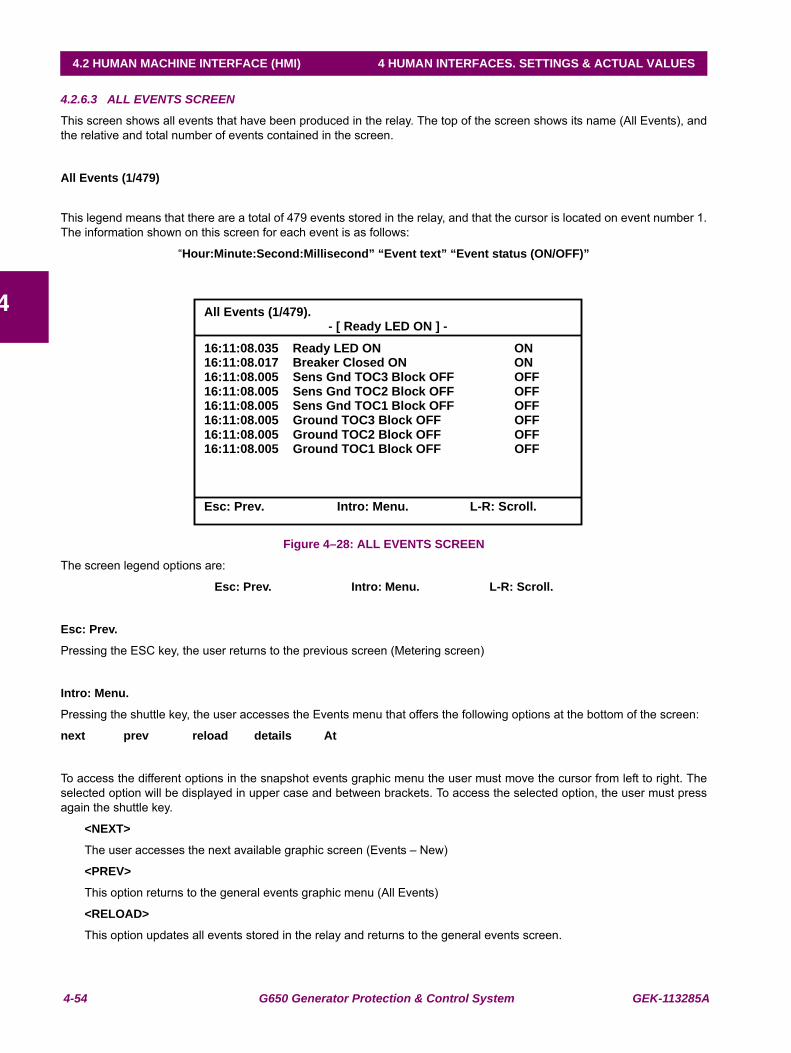
4-54 G650 Generator Protection & Control System GEK-113285A
4.2 HUMAN MACHINE INTERFACE (HMI) 4 HUMAN INTERFACES. SETTINGS & ACTUAL VALUES
4
4.2.6.3 ALL EVENTS SCREEN
This screen shows all events that have been produced in the relay. The top of the screen shows its name (All Events), andthe relative and total number of events contained in the screen.
All Events (1/479)
This legend means that there are a total of 479 events stored in the relay, and that the cursor is located on event number 1.The information shown on this screen for each event is as follows:
“Hour:Minute:Second:Millisecond” “Event text” “Event status (ON/OFF)”
Figure 4–28: ALL EVENTS SCREEN
The screen legend options are:
Esc: Prev. Intro: Menu. L-R: Scroll.
Esc: Prev.
Pressing the ESC key, the user returns to the previous screen (Metering screen)
Intro: Menu.
Pressing the shuttle key, the user accesses the Events menu that offers the following options at the bottom of the screen:
next prev reload details At
To access the different options in the snapshot events graphic menu the user must move the cursor from left to right. Theselected option will be displayed in upper case and between brackets. To access the selected option, the user must pressagain the shuttle key.
<NEXT>
The user accesses the next available graphic screen (Events – New)
<PREV>
This option returns to the general events graphic menu (All Events)
<RELOAD>
This option updates all events stored in the relay and returns to the general events screen.
All Events (1/479).- [ Ready LED ON ] -
16:11:08.035 Ready LED ON ON 16:11:08.017 Breaker Closed ON ON 16:11:08.005 Sens Gnd TOC3 Block OFF OFF 16:11:08.005 Sens Gnd TOC2 Block OFF OFF 16:11:08.005 Sens Gnd TOC1 Block OFF OFF 16:11:08.005 Ground TOC3 Block OFF OFF 16:11:08.005 Ground TOC2 Block OFF OFF 16:11:08.005 Ground TOC1 Block OFF OFF
Esc: Prev. Intro: Menu. L-R: Scroll.
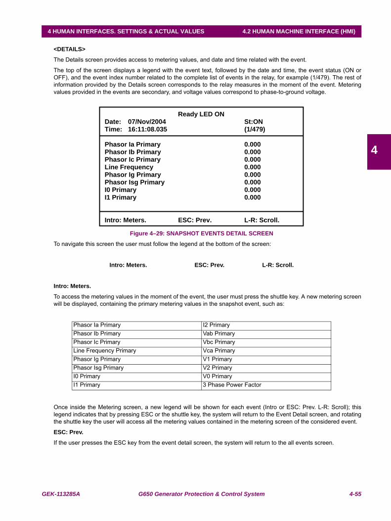
GEK-113285A G650 Generator Protection & Control System 4-55
4 HUMAN INTERFACES. SETTINGS & ACTUAL VALUES 4.2 HUMAN MACHINE INTERFACE (HMI)
4
<DETAILS>
The Details screen provides access to metering values, and date and time related with the event.
The top of the screen displays a legend with the event text, followed by the date and time, the event status (ON orOFF), and the event index number related to the complete list of events in the relay, for example (1/479). The rest ofinformation provided by the Details screen corresponds to the relay measures in the moment of the event. Meteringvalues provided in the events are secondary, and voltage values correspond to phase-to-ground voltage.
Figure 4–29: SNAPSHOT EVENTS DETAIL SCREEN
To navigate this screen the user must follow the legend at the bottom of the screen:
Intro: Meters. ESC: Prev. L-R: Scroll.
Intro: Meters.
To access the metering values in the moment of the event, the user must press the shuttle key. A new metering screenwill be displayed, containing the primary metering values in the snapshot event, such as:
Once inside the Metering screen, a new legend will be shown for each event (Intro or ESC: Prev. L-R: Scroll); thislegend indicates that by pressing ESC or the shuttle key, the system will return to the Event Detail screen, and rotatingthe shuttle key the user will access all the metering values contained in the metering screen of the considered event.
ESC: Prev.
If the user presses the ESC key from the event detail screen, the system will return to the all events screen.
Phasor Ia Primary I2 PrimaryPhasor Ib Primary Vab PrimaryPhasor Ic Primary Vbc Primary Line Frequency Primary Vca PrimaryPhasor Ig Primary V1 PrimaryPhasor Isg Primary V2 PrimaryI0 Primary V0 PrimaryI1 Primary 3 Phase Power Factor
Ready LED ON Date: 07/Nov/2004 St:ON Time: 16:11:08.035 (1/479)
Phasor Ia Primary 0.000 Phasor Ib Primary 0.000 Phasor Ic Primary 0.000 Line Frequency 0.000 Phasor Ig Primary 0.000 Phasor Isg Primary 0.000 I0 Primary 0.000 I1 Primary 0.000
Intro: Meters. ESC: Prev. L-R: Scroll.

4-56 G650 Generator Protection & Control System GEK-113285A
4.2 HUMAN MACHINE INTERFACE (HMI) 4 HUMAN INTERFACES. SETTINGS & ACTUAL VALUES
4
L-R: Scroll.
Rotating the shuttle key left (L) or right (R) moves among all the events contained in the all events screen, allowing apreview of the details for each of them.
<AT>
When this option is selected, the system marks the event where the cursor is located. A relative time stamp isperformed, in such a way that the selected event, marked with an asterisk (*) between the time and the event name isset with a relative time of 00:00:00:000 on the top line of the event screen, together with its relative index, and the restof events in the screen will show a date/time that relates to the marked event. This operation mode allows a quickinspection of the relative time passed between several events, which is very useful for analyzing events in the field.The corresponding legend to this relative event-marking screen is as follows:
Esc: Out At. Intro: Tag event.
Esc: Out At.
The relative event marking is eliminated and the system returns to the general events screen.
Intro: Tag event.
If the user places the cursor on a different event by rotating the shuttle key left or right, pressing the shuttle keywill change the relative mark to that new event.
4.2.6.4 NEW EVENTS SCREEN
This screen shows the new events that have been produced in the relay since the last time the New Events screen wasread. The top of the screen shows a “New Events” legend, and the relative and total number of events contained.
Navigation through the different menus in this New Events screen is similar to the one described in the previous section forAll Events. The main difference is that in the case of new events it is necessary to select the RELOAD submenu to updatethe screen with new events that have been produced, while in the All Events screen, this refreshment is automatic.
After the new events have been read, if the user selects again the Reload menu, the system will show a <No new eventsavailable.> message, indicating that there are no more new events available since the last reading.
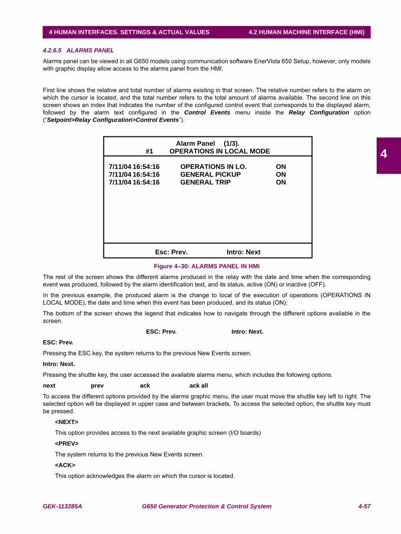
GEK-113285A G650 Generator Protection & Control System 4-57
4 HUMAN INTERFACES. SETTINGS & ACTUAL VALUES 4.2 HUMAN MACHINE INTERFACE (HMI)
4
4.2.6.5 ALARMS PANEL
Alarms panel can be viewed in all G650 models using communication software EnerVista 650 Setup, however, only modelswith graphic display allow access to the alarms panel from the HMI.
First line shows the relative and total number of alarms existing in that screen. The relative number refers to the alarm onwhich the cursor is located, and the total number refers to the total amount of alarms available. The second line on thisscreen shows an index that indicates the number of the configured control event that corresponds to the displayed alarm,followed by the alarm text configured in the Control Events menu inside the Relay Configuration option(“Setpoint>Relay Configuration>Control Events”).
Figure 4–30: ALARMS PANEL IN HMI
The rest of the screen shows the different alarms produced in the relay with the date and time when the correspondingevent was produced, followed by the alarm identification text, and its status, active (ON) or inactive (OFF).
In the previous example, the produced alarm is the change to local of the execution of operations (OPERATIONS INLOCAL MODE), the date and time when this event has been produced, and its status (ON):
The bottom of the screen shows the legend that indicates how to navigate through the different options available in thescreen.
ESC: Prev. Intro: Next.
ESC: Prev.
Pressing the ESC key, the system returns to the previous New Events screen.
Intro: Next.
Pressing the shuttle key, the user accessed the available alarms menu, which includes the following options.
next prev ack ack all
To access the different options provided by the alarms graphic menu, the user must move the shuttle key left to right. Theselected option will be displayed in upper case and between brackets. To access the selected option, the shuttle key mustbe pressed.
<NEXT>
This option provides access to the next available graphic screen (I/O boards)
<PREV>
The system returns to the previous New Events screen.
<ACK>
This option acknowledges the alarm on which the cursor is located.
Alarm Panel (1/3). #1 OPERATIONS IN LOCAL MODE
7/11/04 16:54:16 OPERATIONS IN LO. ON 7/11/04 16:54:16 GENERAL PICKUP ON 7/11/04 16:54:16 GENERAL TRIP ON
Esc: Prev. Intro: Next
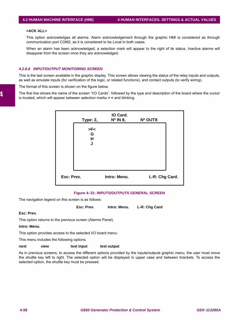
4-58 G650 Generator Protection & Control System GEK-113285A
4.2 HUMAN MACHINE INTERFACE (HMI) 4 HUMAN INTERFACES. SETTINGS & ACTUAL VALUES
4
<ACK ALL>
This option acknowledges all alarms. Alarm acknowledgement through the graphic HMI is considered as throughcommunication port COM2, as it is considered to be Local in both cases.
When an alarm has been acknowledged, a selection mark will appear to the right of its status. Inactive alarms willdisappear from the screen once they are acknowledged.
4.2.6.6 INPUT/OUTPUT MONITORING SCREEN
This is the last screen available in the graphic display. This screen allows viewing the status of the relay inputs and outputs,as well as emulate inputs (for verification of the logic, or related functions), and contact outputs (to verify wiring).
The format of this screen is shown on the figure below.
The first line shows the name of the screen “I/O Cards”, followed by the type and description of the board where the cursoris located, which will appear between selection marks > < and blinking.
Figure 4–31: INPUTS/OUTPUTS GENERAL SCREEN
The navigation legend on this screen is as follows:
Esc: Prev. Intro: Menu. L-R: Chg CardEsc: Prev.
This option returns to the previous screen (Alarms Panel).
Intro: Menu.
This option provides access to the selected I/O board menu:
This menu includes the following options.
next view test input test output
As in previous screens, to access the different options provided by the inputs/outputs graphic menu, the user must movethe shuttle key left to right. The selected option will be displayed in upper case and between brackets. To access theselected option, the shuttle key must be pressed.
IO Card. Type: 2, Nº IN 8, Nº OUT 8
>F< G H J
Esc: Prev. Intro: Menu. L-R: Chg Card.
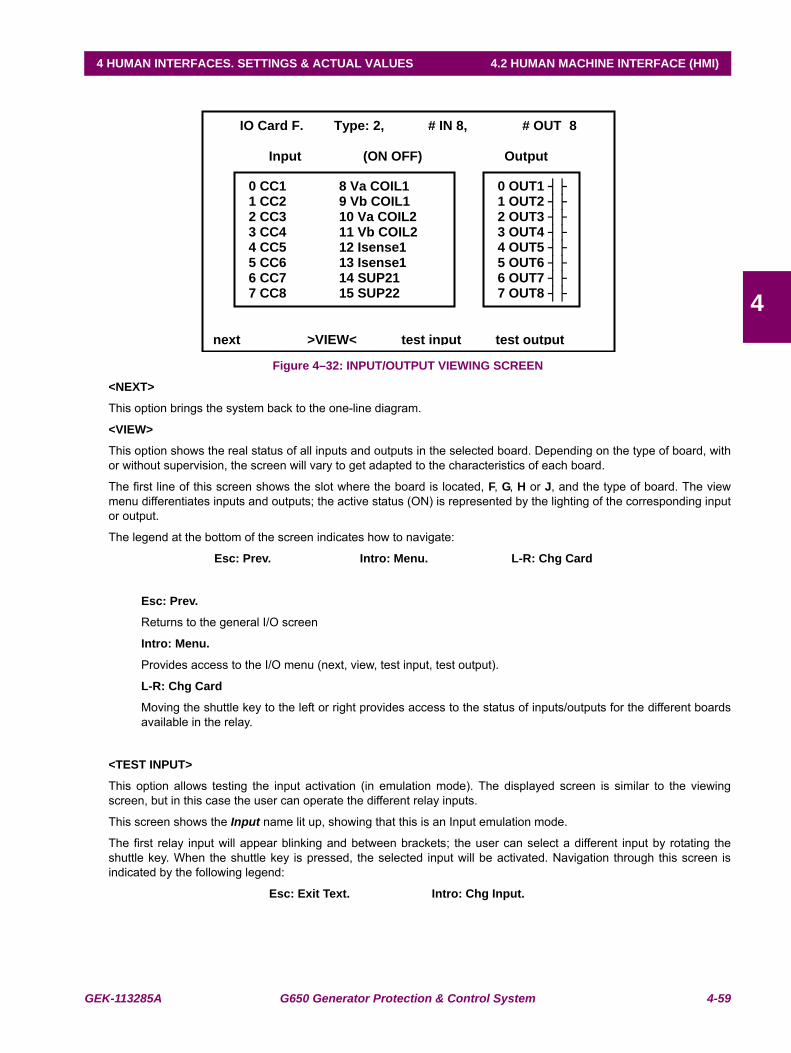
GEK-113285A G650 Generator Protection & Control System 4-59
4 HUMAN INTERFACES. SETTINGS & ACTUAL VALUES 4.2 HUMAN MACHINE INTERFACE (HMI)
4
Figure 4–32: INPUT/OUTPUT VIEWING SCREEN
<NEXT>
This option brings the system back to the one-line diagram.
<VIEW>
This option shows the real status of all inputs and outputs in the selected board. Depending on the type of board, withor without supervision, the screen will vary to get adapted to the characteristics of each board.
The first line of this screen shows the slot where the board is located, F, G, H or J, and the type of board. The viewmenu differentiates inputs and outputs; the active status (ON) is represented by the lighting of the corresponding inputor output.
The legend at the bottom of the screen indicates how to navigate:
Esc: Prev. Intro: Menu. L-R: Chg Card
Esc: Prev.
Returns to the general I/O screen
Intro: Menu.
Provides access to the I/O menu (next, view, test input, test output).
L-R: Chg Card
Moving the shuttle key to the left or right provides access to the status of inputs/outputs for the different boardsavailable in the relay.
<TEST INPUT>
This option allows testing the input activation (in emulation mode). The displayed screen is similar to the viewingscreen, but in this case the user can operate the different relay inputs.
This screen shows the Input name lit up, showing that this is an Input emulation mode.
The first relay input will appear blinking and between brackets; the user can select a different input by rotating theshuttle key. When the shuttle key is pressed, the selected input will be activated. Navigation through this screen isindicated by the following legend:
Esc: Exit Text. Intro: Chg Input.
IO Card F. Type: 2, # IN 8, # OUT 8
Input (ON OFF) Output
next >VIEW< test input test output
0 CC1 8 Va COIL1 1 CC2 9 Vb COIL1 2 CC3 10 Va COIL2 3 CC4 11 Vb COIL2 4 CC5 12 Isense1 5 CC6 13 Isense1 6 CC7 14 SUP21 7 CC8 15 SUP22
0 OUT1 1 OUT2 2 OUT3 3 OUT4 4 OUT5 5 OUT6 6 OUT7 7 OUT8
4-60 G650 Generator Protection & Control System GEK-113285A
4.2 HUMAN MACHINE INTERFACE (HMI) 4 HUMAN INTERFACES. SETTINGS & ACTUAL VALUES
4
Esc: Exit Text.
The ESC option returns to the general I/O board menu.
Intro: Chg Input.
Pressing the shuttle key on the blinking input, this input will be activated in emulation mode.
Note: input emulation can only be executed through the TEST INPUT tool on the graphic display.
<TEST OUTPUT>
This option allows testing the output activation in emulation mode. The displayed screen is similar to the viewingscreen, but in this case the user can operate the different relay contact outputs to test the wiring.
This screen shows the Output name lit up, showing that this is an output emulation mode.
The first relay output will appear blinking and between brackets; the user can select a different output by rotating theshuttle key. When the shuttle key is pressed, the selected output will be activated. Navigation through this screen isindicated by the following legend:
Esc: Exit Text. Intro: Chg Output.
Esc: Exit Text.
The ESC option returns to the general I/O board menu.
Intro: Chg Output.
Pressing the shuttle key on the blinking output, this output will be activated in emulation mode.
Note: Output emulation can be executed through the TEST OUTPUT tool on the graphic display, and alsothrough communications using EnerVista 650 Setup software for all G650 models.
L-R: Chg Card
Rotating the shuttle key allows to change the selected I/O board in the main I/O screen.
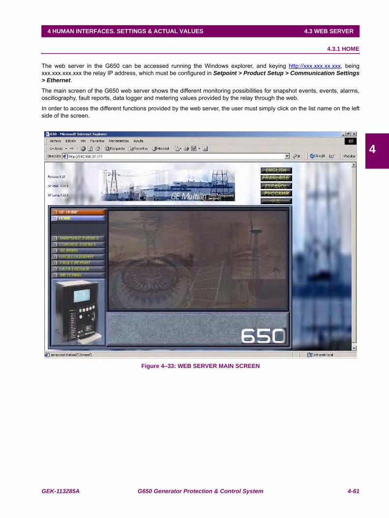
GEK-113285A G650 Generator Protection & Control System 4-61
4 HUMAN INTERFACES. SETTINGS & ACTUAL VALUES 4.3 WEB SERVER
4
4.3 WEB SERVER 4.3.1 HOME
The web server in the G650 can be accessed running the Windows explorer, and keying http://xxx.xxx.xx.xxx, beingxxx.xxx.xxx.xxx the relay IP address, which must be configured in Setpoint > Product Setup > Communication Settings> Ethernet.
The main screen of the G650 web server shows the different monitoring possibilities for snapshot events, events, alarms,oscillography, fault reports, data logger and metering values provided by the relay through the web.
In order to access the different functions provided by the web server, the user must simply click on the list name on the leftside of the screen.
Figure 4–33: WEB SERVER MAIN SCREEN
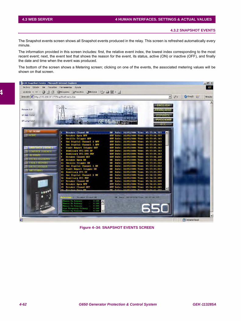
4-62 G650 Generator Protection & Control System GEK-113285A
4.3 WEB SERVER 4 HUMAN INTERFACES. SETTINGS & ACTUAL VALUES
4
4.3.2 SNAPSHOT EVENTS
The Snapshot events screen shows all Snapshot events produced in the relay. This screen is refreshed automatically everyminute.
The information provided in this screen includes: first, the relative event index, the lowest index corresponding to the mostrecent event; next, the event text that shows the reason for the event, its status, active (ON) or inactive (OFF), and finallythe date and time when the event was produced.
The bottom of the screen shows a Metering screen; clicking on one of the events, the associated metering values will beshown on that screen.
Figure 4–34: SNAPSHOT EVENTS SCREEN
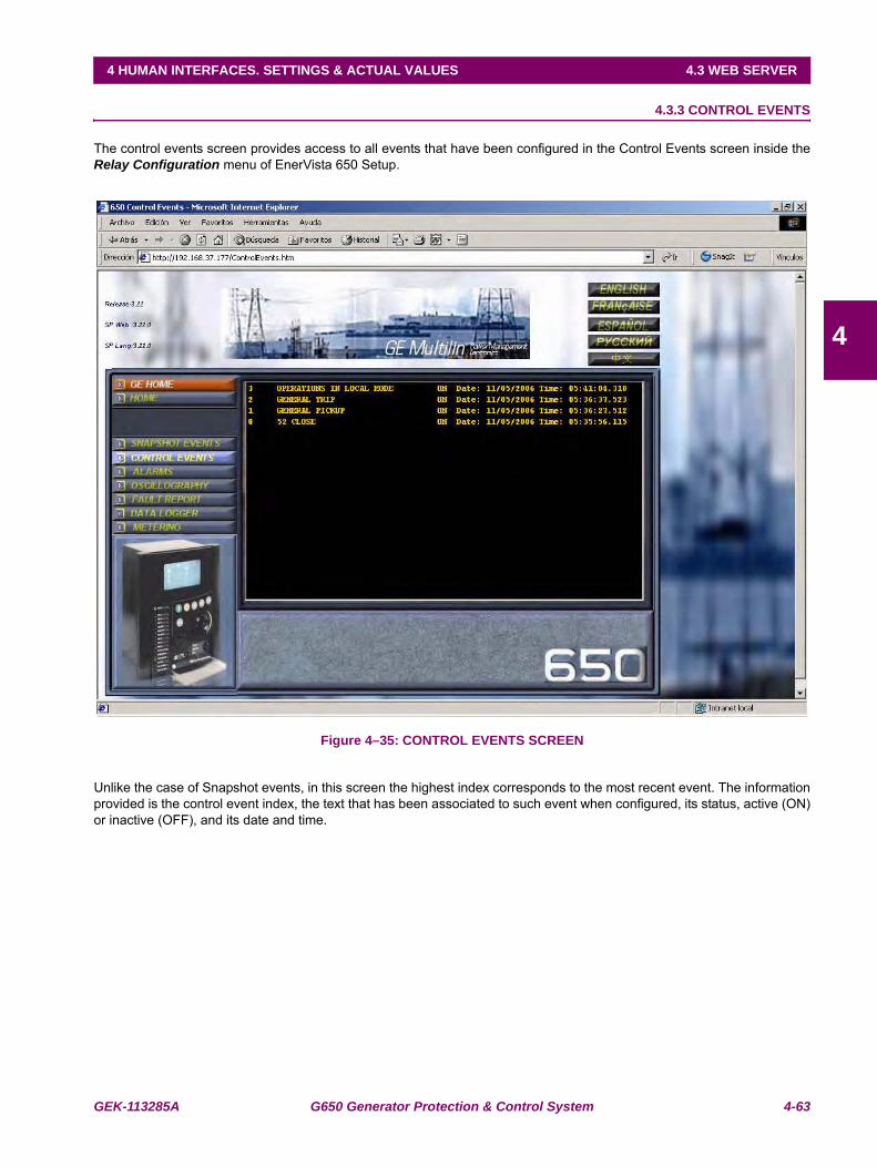
GEK-113285A G650 Generator Protection & Control System 4-63
4 HUMAN INTERFACES. SETTINGS & ACTUAL VALUES 4.3 WEB SERVER
4
4.3.3 CONTROL EVENTS
The control events screen provides access to all events that have been configured in the Control Events screen inside theRelay Configuration menu of EnerVista 650 Setup.
Figure 4–35: CONTROL EVENTS SCREEN
Unlike the case of Snapshot events, in this screen the highest index corresponds to the most recent event. The informationprovided is the control event index, the text that has been associated to such event when configured, its status, active (ON)or inactive (OFF), and its date and time.
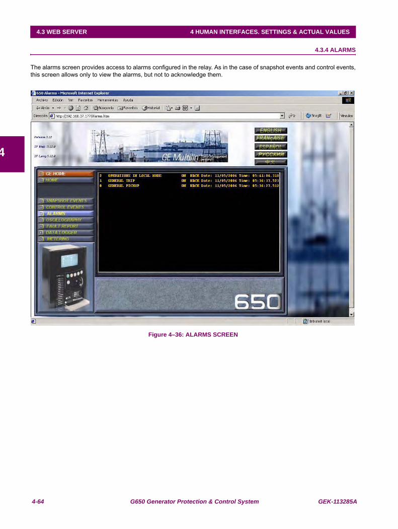
4-64 G650 Generator Protection & Control System GEK-113285A
4.3 WEB SERVER 4 HUMAN INTERFACES. SETTINGS & ACTUAL VALUES
4
4.3.4 ALARMS
The alarms screen provides access to alarms configured in the relay. As in the case of snapshot events and control events,this screen allows only to view the alarms, but not to acknowledge them.
Figure 4–36: ALARMS SCREEN
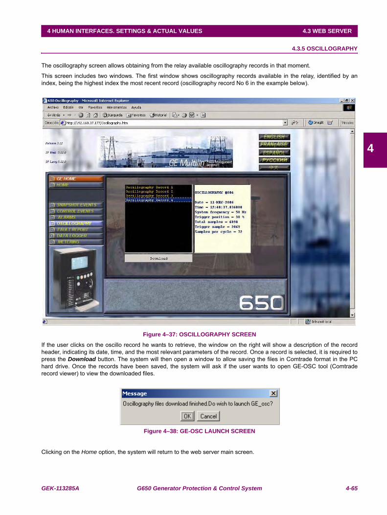
GEK-113285A G650 Generator Protection & Control System 4-65
4 HUMAN INTERFACES. SETTINGS & ACTUAL VALUES 4.3 WEB SERVER
4
4.3.5 OSCILLOGRAPHY
The oscillography screen allows obtaining from the relay available oscillography records in that moment.
This screen includes two windows. The first window shows oscillography records available in the relay, identified by anindex, being the highest index the most recent record (oscillography record No 6 in the example below).
Figure 4–37: OSCILLOGRAPHY SCREEN
If the user clicks on the oscillo record he wants to retrieve, the window on the right will show a description of the recordheader, indicating its date, time, and the most relevant parameters of the record. Once a record is selected, it is required topress the Download button. The system will then open a window to allow saving the files in Comtrade format in the PChard drive. Once the records have been saved, the system will ask if the user wants to open GE-OSC tool (Comtraderecord viewer) to view the downloaded files.
Figure 4–38: GE-OSC LAUNCH SCREEN
Clicking on the Home option, the system will return to the web server main screen.
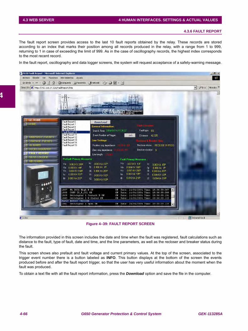
4-66 G650 Generator Protection & Control System GEK-113285A
4.3 WEB SERVER 4 HUMAN INTERFACES. SETTINGS & ACTUAL VALUES
4
4.3.6 FAULT REPORT
The fault report screen provides access to the last 10 fault reports obtained by the relay. These records are storedaccording to an index that marks their position among all records produced in the relay, with a range from 1 to 999,returning to 1 in case of exceeding the limit of 999. As in the case of oscillography records, the highest index correspondsto the most recent record.
In the fault report, oscillography and data logger screens, the system will request acceptance of a safety-warning message.
Figure 4–39: FAULT REPORT SCREEN
The information provided in this screen includes the date and time when the fault was registered, fault calculations such asdistance to the fault, type of fault, date and time, and the line parameters, as well as the recloser and breaker status duringthe fault.
This screen shows also prefault and fault voltage and current primary values. At the top of the screen, associated to thetrigger event number there is a button labeled as INFO. This button displays at the bottom of the screen the eventsproduced before and after the fault report trigger, so that the user has very useful information about the moment when thefault was produced.
To obtain a text file with all the fault report information, press the Download option and save the file in the computer.
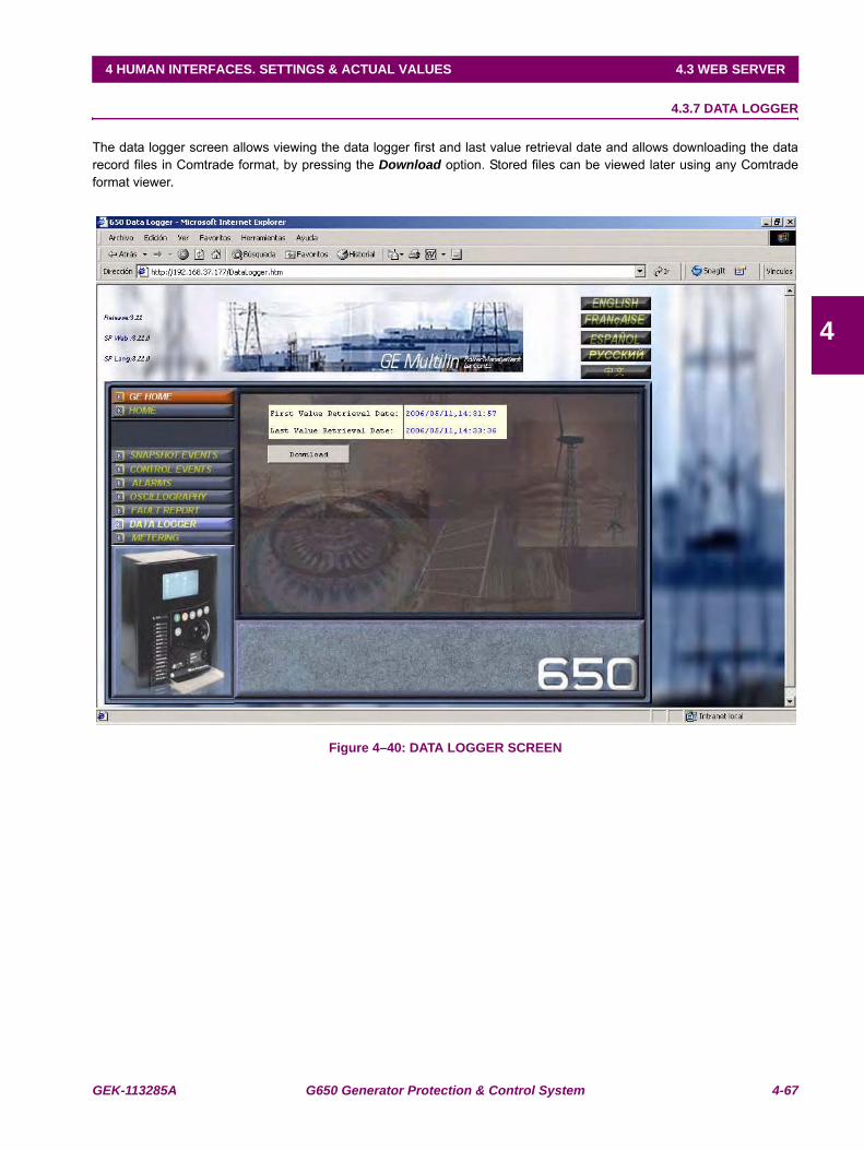
GEK-113285A G650 Generator Protection & Control System 4-67
4 HUMAN INTERFACES. SETTINGS & ACTUAL VALUES 4.3 WEB SERVER
4
4.3.7 DATA LOGGER
The data logger screen allows viewing the data logger first and last value retrieval date and allows downloading the datarecord files in Comtrade format, by pressing the Download option. Stored files can be viewed later using any Comtradeformat viewer.
Figure 4–40: DATA LOGGER SCREEN
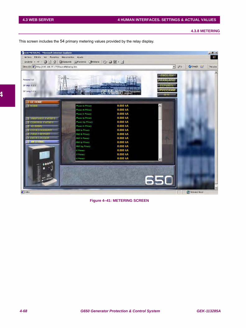
4-68 G650 Generator Protection & Control System GEK-113285A
4.3 WEB SERVER 4 HUMAN INTERFACES. SETTINGS & ACTUAL VALUES
4
4.3.8 METERING
This screen includes the 54 primary metering values provided by the relay display.
Figure 4–41: METERING SCREEN
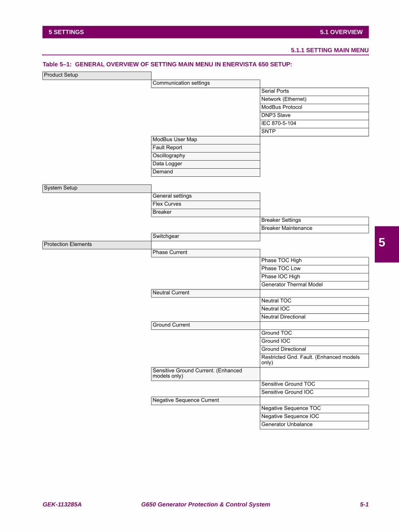
GEK-113285A G650 Generator Protection & Control System 5-1
5 SETTINGS 5.1 OVERVIEW
5
5 SETTINGS 5.1OVERVIEW 5.1.1 SETTING MAIN MENU
Table 5–1: GENERAL OVERVIEW OF SETTING MAIN MENU IN ENERVISTA 650 SETUP:Product Setup
Communication settingsSerial PortsNetwork (Ethernet)ModBus ProtocolDNP3 Slave IEC 870-5-104SNTP
ModBus User MapFault ReportOscillographyData LoggerDemand
System SetupGeneral settingsFlex CurvesBreaker
Breaker SettingsBreaker Maintenance
SwitchgearProtection Elements
Phase CurrentPhase TOC HighPhase TOC LowPhase IOC HighGenerator Thermal Model
Neutral CurrentNeutral TOCNeutral IOCNeutral Directional
Ground CurrentGround TOCGround IOCGround DirectionalRestricted Gnd. Fault. (Enhanced models only)
Sensitive Ground Current. (Enhanced models only)
Sensitive Ground TOCSensitive Ground IOC
Negative Sequence CurrentNegative Sequence TOCNegative Sequence IOCGenerator Unbalance
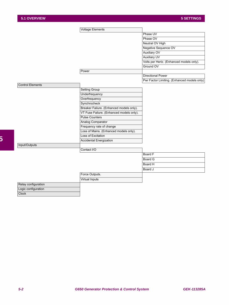
5-2 G650 Generator Protection & Control System GEK-113285A
5.1 OVERVIEW 5 SETTINGS
5
Voltage ElementsPhase UVPhase OVNeutral OV HighNegative Sequence OVAuxiliary OVAuxiliary UVVolts per Hertz. (Enhanced models only).Ground OV
PowerDirectional PowerPwr Factor Limiting. (Enhanced models only)
Control ElementsSetting GroupUnderfrequencyOverfrequencySynchrocheckBreaker Failure. (Enhanced models only).VT Fuse Failure. (Enhanced models only).Pulse CountersAnalog ComparatorFrequency rate of changeLoss of Mains. (Enhanced models only).Loss of ExcitationAccidental Energization
Input/OutputsContact I/O
Board FBoard GBoard HBoard J
Force Outputs.Virtual Inputs
Relay configurationLogic configurationClock
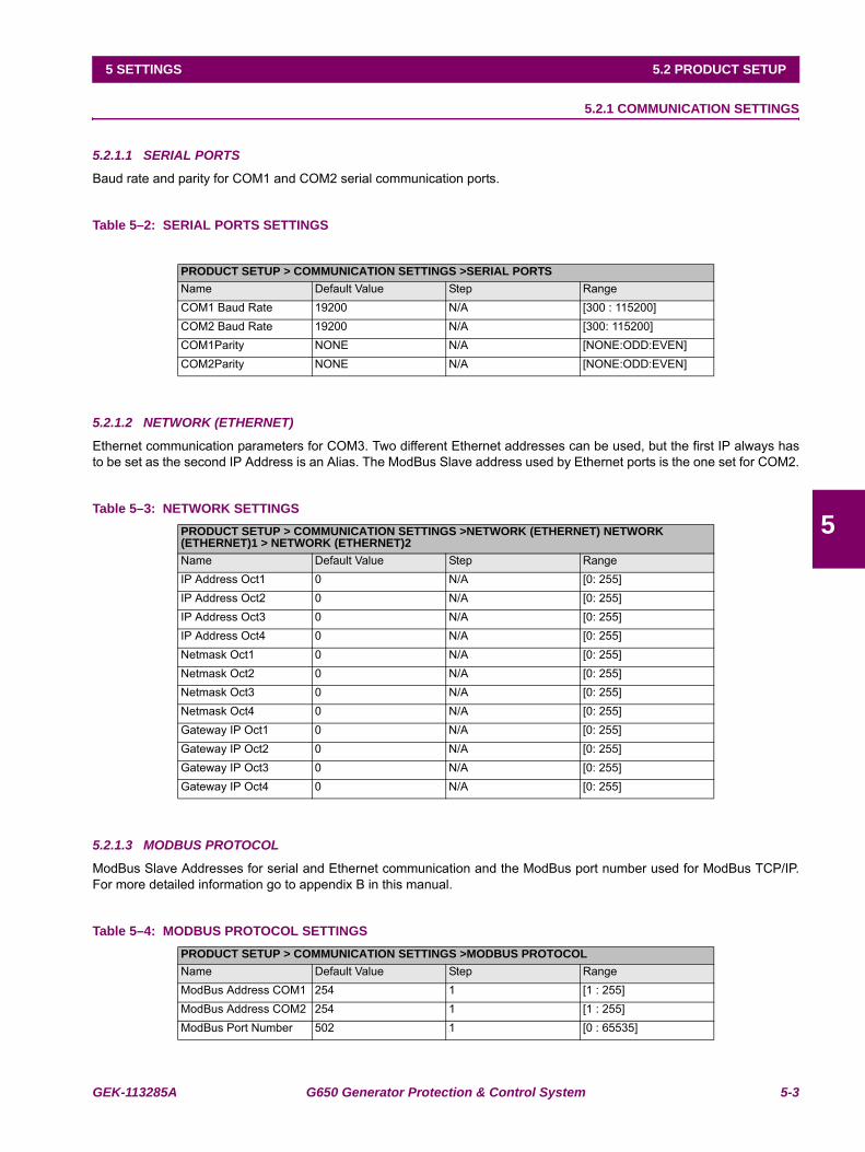
GEK-113285A G650 Generator Protection & Control System 5-3
5 SETTINGS 5.2 PRODUCT SETUP
5
5.2PRODUCT SETUP 5.2.1 COMMUNICATION SETTINGS
5.2.1.1 SERIAL PORTS
Baud rate and parity for COM1 and COM2 serial communication ports.
Table 5–2: SERIAL PORTS SETTINGS
5.2.1.2 NETWORK (ETHERNET)
Ethernet communication parameters for COM3. Two different Ethernet addresses can be used, but the first IP always hasto be set as the second IP Address is an Alias. The ModBus Slave address used by Ethernet ports is the one set for COM2.
Table 5–3: NETWORK SETTINGS
5.2.1.3 MODBUS PROTOCOL
ModBus Slave Addresses for serial and Ethernet communication and the ModBus port number used for ModBus TCP/IP.For more detailed information go to appendix B in this manual.
Table 5–4: MODBUS PROTOCOL SETTINGS
PRODUCT SETUP > COMMUNICATION SETTINGS >SERIAL PORTSName Default Value Step RangeCOM1 Baud Rate 19200 N/A [300 : 115200]COM2 Baud Rate 19200 N/A [300: 115200]COM1Parity NONE N/A [NONE:ODD:EVEN]COM2Parity NONE N/A [NONE:ODD:EVEN]
PRODUCT SETUP > COMMUNICATION SETTINGS >NETWORK (ETHERNET) NETWORK (ETHERNET)1 > NETWORK (ETHERNET)2Name Default Value Step RangeIP Address Oct1 0 N/A [0: 255]IP Address Oct2 0 N/A [0: 255]IP Address Oct3 0 N/A [0: 255]IP Address Oct4 0 N/A [0: 255]Netmask Oct1 0 N/A [0: 255]Netmask Oct2 0 N/A [0: 255]Netmask Oct3 0 N/A [0: 255]Netmask Oct4 0 N/A [0: 255]Gateway IP Oct1 0 N/A [0: 255]Gateway IP Oct2 0 N/A [0: 255]Gateway IP Oct3 0 N/A [0: 255]Gateway IP Oct4 0 N/A [0: 255]
PRODUCT SETUP > COMMUNICATION SETTINGS >MODBUS PROTOCOLName Default Value Step RangeModBus Address COM1 254 1 [1 : 255]ModBus Address COM2 254 1 [1 : 255]ModBus Port Number 502 1 [0 : 65535]
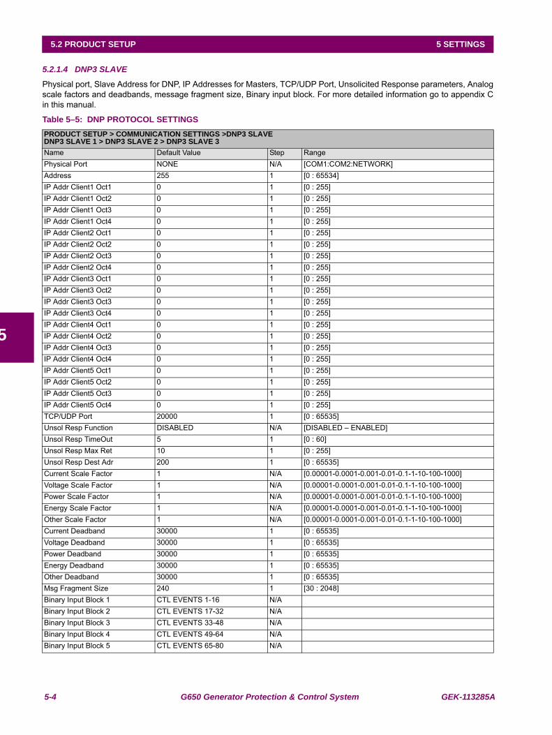
5-4 G650 Generator Protection & Control System GEK-113285A
5.2 PRODUCT SETUP 5 SETTINGS
5
5.2.1.4 DNP3 SLAVE
Physical port, Slave Address for DNP, IP Addresses for Masters, TCP/UDP Port, Unsolicited Response parameters, Analogscale factors and deadbands, message fragment size, Binary input block. For more detailed information go to appendix Cin this manual.
Table 5–5: DNP PROTOCOL SETTINGSPRODUCT SETUP > COMMUNICATION SETTINGS >DNP3 SLAVEDNP3 SLAVE 1 > DNP3 SLAVE 2 > DNP3 SLAVE 3Name Default Value Step RangePhysical Port NONE N/A [COM1:COM2:NETWORK]Address 255 1 [0 : 65534]IP Addr Client1 Oct1 0 1 [0 : 255]IP Addr Client1 Oct2 0 1 [0 : 255]IP Addr Client1 Oct3 0 1 [0 : 255]IP Addr Client1 Oct4 0 1 [0 : 255]IP Addr Client2 Oct1 0 1 [0 : 255]IP Addr Client2 Oct2 0 1 [0 : 255]IP Addr Client2 Oct3 0 1 [0 : 255]IP Addr Client2 Oct4 0 1 [0 : 255]IP Addr Client3 Oct1 0 1 [0 : 255]IP Addr Client3 Oct2 0 1 [0 : 255]IP Addr Client3 Oct3 0 1 [0 : 255]IP Addr Client3 Oct4 0 1 [0 : 255]IP Addr Client4 Oct1 0 1 [0 : 255]IP Addr Client4 Oct2 0 1 [0 : 255]IP Addr Client4 Oct3 0 1 [0 : 255]IP Addr Client4 Oct4 0 1 [0 : 255]IP Addr Client5 Oct1 0 1 [0 : 255]IP Addr Client5 Oct2 0 1 [0 : 255]IP Addr Client5 Oct3 0 1 [0 : 255]IP Addr Client5 Oct4 0 1 [0 : 255]TCP/UDP Port 20000 1 [0 : 65535]Unsol Resp Function DISABLED N/A [DISABLED – ENABLED]Unsol Resp TimeOut 5 1 [0 : 60]Unsol Resp Max Ret 10 1 [0 : 255]Unsol Resp Dest Adr 200 1 [0 : 65535]Current Scale Factor 1 N/A [0.00001-0.0001-0.001-0.01-0.1-1-10-100-1000]Voltage Scale Factor 1 N/A [0.00001-0.0001-0.001-0.01-0.1-1-10-100-1000]Power Scale Factor 1 N/A [0.00001-0.0001-0.001-0.01-0.1-1-10-100-1000]Energy Scale Factor 1 N/A [0.00001-0.0001-0.001-0.01-0.1-1-10-100-1000]Other Scale Factor 1 N/A [0.00001-0.0001-0.001-0.01-0.1-1-10-100-1000]Current Deadband 30000 1 [0 : 65535]Voltage Deadband 30000 1 [0 : 65535]Power Deadband 30000 1 [0 : 65535]Energy Deadband 30000 1 [0 : 65535]Other Deadband 30000 1 [0 : 65535]Msg Fragment Size 240 1 [30 : 2048]Binary Input Block 1 CTL EVENTS 1-16 N/ABinary Input Block 2 CTL EVENTS 17-32 N/ABinary Input Block 3 CTL EVENTS 33-48 N/ABinary Input Block 4 CTL EVENTS 49-64 N/ABinary Input Block 5 CTL EVENTS 65-80 N/A
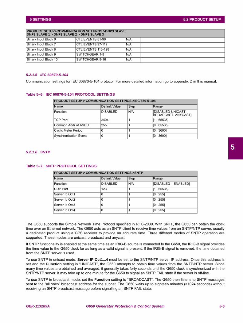
GEK-113285A G650 Generator Protection & Control System 5-5
5 SETTINGS 5.2 PRODUCT SETUP
5
5.2.1.5 IEC 60870-5-104
Communication settings for IEC 60870-5-104 protocol. For more detailed information go to appendix D in this manual.
Table 5–6: IEC 60870-5-104 PROTOCOL SETTINGS
5.2.1.6 SNTP
Table 5–7: SNTP PROTOCOL SETTINGS
The G650 supports the Simple Network Time Protocol specified in RFC-2030. With SNTP, the G650 can obtain the clocktime over an Ethernet network. The G650 acts as an SNTP client to receive time values from an SNTP/NTP server, usuallya dedicated product using a GPS receiver to provide an accurate time. Three different modes of SNTP operation aresupported. These modes are unicast, broadcast and anycast.
If SNTP functionality is enabled at the same time as an IRIG-B source is connected to the G650, the IRIG-B signal providesthe time value to the G650 clock for as long as a valid signal is present. If the IRIG-B signal is removed, the time obtainedfrom the SNTP server is used.
To use SNTP in unicast mode, Server IP Oct1...4 must be set to the SNTP/NTP server IP address. Once this address isset and the Function setting is “UNICAST”, the G650 attempts to obtain time values from the SNTP/NTP server. Sincemany time values are obtained and averaged, it generally takes forty seconds until the G650 clock is synchronized with theSNTP/NTP server. It may take up to one minute for the G650 to signal an SNTP FAIL state if the server is off-line.
To use SNTP in broadcast mode, set the Function setting to “BROADCAST”. The G650 then listens to SNTP messagessent to the “all ones” broadcast address for the subnet. The G650 waits up to eighteen minutes (>1024 seconds) withoutreceiving an SNTP broadcast message before signalling an SNTP FAIL state.
PRODUCT SETUP>COMMUNICATION SETTINGS >DNP3 SLAVEDNP3 SLAVE 1 > DNP3 SLAVE 2 > DNP3 SLAVE 3Binary Input Block 6 CTL EVENTS 81-96 N/ABinary Input Block 7 CTL EVENTS 97-112 N/ABinary Input Block 8 CTL EVENTS 113-128 N/ABinary Input Block 9 SWITCHGEAR 1-8 N/ABinary Input Block 10 SWITCHGEAR 9-16 N/A
PRODUCT SETUP > COMMUNICATION SETTINGS >IEC 870-5-104Name Default Value Step RangeFunction DISABLED N/A [DISABLED-UNICAST–
BROADCAST- ANYCAST]TCP Port 2404 1 [1 : 65535]Common Addr of ASDU 255 1 [0 : 65535]Cyclic Meter Period 0 1 [0 : 3600]Synchronization Event 0 1 [0 : 3600]
PRODUCT SETUP > COMMUNICATION SETTINGS >SNTPName Default Value Step RangeFunction DISABLED N/A [DISABLED – ENABLED]UDP Port 123 1 [1 : 65535]Server Ip Oct1 0 1 [0 : 255]Server Ip Oct2 0 1 [0 : 255]Server Ip Oct3 0 1 [0 : 255]Server Ip Oct4 0 1 [0 : 255]
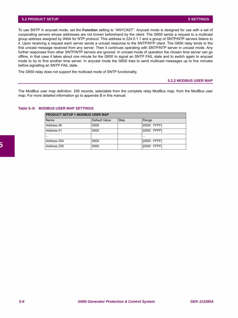
5-6 G650 Generator Protection & Control System GEK-113285A
5.2 PRODUCT SETUP 5 SETTINGS
5
To use SNTP in anycast mode, set the Function setting to “ANYCAST”. Anycast mode is designed for use with a set ofcooperating servers whose addresses are not known beforehand by the client. The G650 sends a request to a multicastgroup address assigned by IANA for NTP protocol. This address is 224.0.1.1 and a group of SNTP/NTP servers listens toit. Upon receiving a request each server sends a unicast response to the SNTP/NTP client. The G650 relay binds to thefirst unicast message received from any server. Then it continues operating with SNTP/NTP server in unicast mode. Anyfurther responses from other SNTP/NTP servers are ignored. In unicast mode of operation the chosen time server can gooffline, in that case it takes about one minute for the G650 to signal an SNTP FAIL state and to switch again to anycastmode to try to find another time server. In anycast mode the G650 tries to send multicast messages up to five minutesbefore signalling an SNTP FAIL state.
The G650 relay does not support the multicast mode of SNTP functionality.
5.2.2 MODBUS USER MAP
The ModBus user map definition. 256 records, selectable from the complete relay ModBus map, from the ModBus usermap. For more detailed information go to appendix B in this manual.
Table 5–8: MODBUS USER MAP SETTINGSPRODUCT SETUP > MODBUS USER MAPName Default Value Step RangeAddress 00 0000 [0000 : FFFF]Address 01 0000 [0000 : FFFF]... ...Address 254 0000 [0000 : FFFF]Address 255 0000 [0000 : FFFF]
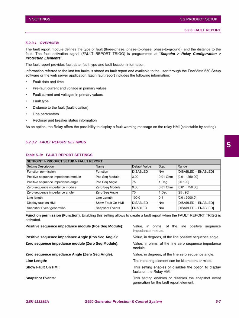
GEK-113285A G650 Generator Protection & Control System 5-7
5 SETTINGS 5.2 PRODUCT SETUP
5
5.2.3 FAULT REPORT
5.2.3.1 OVERVIEW
The fault report module defines the type of fault (three-phase, phase-to-phase, phase-to-ground), and the distance to thefault. The fault activation signal (FAULT REPORT TRIGG) is programmed at “Setpoint > Relay Configuration >Protection Elements”.
The fault report provides fault date, fault type and fault location information.
Information referred to the last ten faults is stored as fault report and available to the user through the EnerVista 650 Setupsoftware or the web server application. Each fault report includes the following information:
• Fault date and time
• Pre-fault current and voltage in primary values
• Fault current and voltages in primary values
• Fault type
• Distance to the fault (fault location)
• Line parameters
• Recloser and breaker status information
As an option, the Relay offers the possibility to display a fault-warning message on the relay HMI (selectable by setting).
5.2.3.2 FAULT REPORT SETTINGS
Table 5–9: FAULT REPORT SETTINGS
Function permission (Function): Enabling this setting allows to create a fault report when the FAULT REPORT TRIGG isactivated.
Positive sequence impedance module (Pos Seq Module): Value, in ohms, of the line positive sequenceimpedance module.
Positive sequence impedance Angle (Pos Seq Angle): Value, in degrees, of the line positive sequence angle.
Zero sequence impedance module (Zero Seq Module): Value, in ohms, of the line zero sequence impedancemodule.
Zero sequence impedance Angle (Zero Seq Angle): Value, in degrees, of the line zero sequence angle.
Line Length: The metering element can be kilometers or miles.
Show Fault On HMI: This setting enables or disables the option to displayfaults on the Relay HMI.
Snapshot Events: This setting enables or disables the snapshot eventgeneration for the fault report element.
SETPOINT > PRODUCT SETUP > FAULT REPORTSetting Description Name Default Value Step RangeFunction permission Function DISABLED N/A [DISABLED – ENABLED]Positive sequence impedance module Pos Seq Module 3.00 0.01 Ohm [0.01 : 250.00]Positive sequence impedance angle Pos Seq Angle 75 1 Deg [25 : 90]Zero sequence impedance module Zero Seq Module 9.00 0.01 Ohm [0.01 : 750.00]Zero sequence impedance angle Zero Seq Angle 75 1 Deg [25 : 90]Line length Line Length 100.0 0.1 [0.0 : 2000.0]Display fault on HMI Show Fault On HMI DISABLED N/A [DISABLED – ENABLED]Snapshot Event generation Snapshot Events ENABLED N/A [DISABLED – ENABLED]
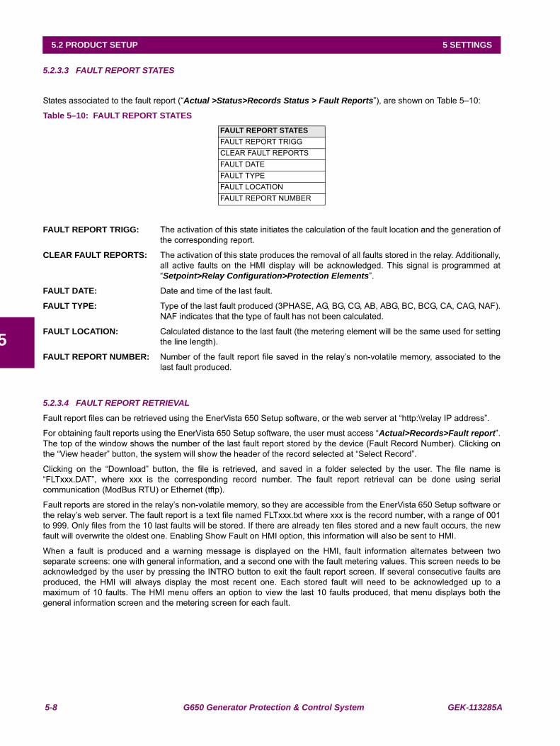
5-8 G650 Generator Protection & Control System GEK-113285A
5.2 PRODUCT SETUP 5 SETTINGS
5
5.2.3.3 FAULT REPORT STATES
States associated to the fault report (“Actual >Status>Records Status > Fault Reports”), are shown on Table 5–10:
Table 5–10: FAULT REPORT STATES
FAULT REPORT TRIGG: The activation of this state initiates the calculation of the fault location and the generation ofthe corresponding report.
CLEAR FAULT REPORTS: The activation of this state produces the removal of all faults stored in the relay. Additionally,all active faults on the HMI display will be acknowledged. This signal is programmed at“Setpoint>Relay Configuration>Protection Elements”.
FAULT DATE: Date and time of the last fault.
FAULT TYPE: Type of the last fault produced (3PHASE, AG, BG, CG, AB, ABG, BC, BCG, CA, CAG, NAF).NAF indicates that the type of fault has not been calculated.
FAULT LOCATION: Calculated distance to the last fault (the metering element will be the same used for settingthe line length).
FAULT REPORT NUMBER: Number of the fault report file saved in the relay’s non-volatile memory, associated to thelast fault produced.
5.2.3.4 FAULT REPORT RETRIEVAL
Fault report files can be retrieved using the EnerVista 650 Setup software, or the web server at “http:\\relay IP address”.
For obtaining fault reports using the EnerVista 650 Setup software, the user must access “Actual>Records>Fault report”.The top of the window shows the number of the last fault report stored by the device (Fault Record Number). Clicking onthe “View header” button, the system will show the header of the record selected at “Select Record”.
Clicking on the “Download” button, the file is retrieved, and saved in a folder selected by the user. The file name is“FLTxxx.DAT”, where xxx is the corresponding record number. The fault report retrieval can be done using serialcommunication (ModBus RTU) or Ethernet (tftp).
Fault reports are stored in the relay’s non-volatile memory, so they are accessible from the EnerVista 650 Setup software orthe relay’s web server. The fault report is a text file named FLTxxx.txt where xxx is the record number, with a range of 001to 999. Only files from the 10 last faults will be stored. If there are already ten files stored and a new fault occurs, the newfault will overwrite the oldest one. Enabling Show Fault on HMI option, this information will also be sent to HMI.
When a fault is produced and a warning message is displayed on the HMI, fault information alternates between twoseparate screens: one with general information, and a second one with the fault metering values. This screen needs to beacknowledged by the user by pressing the INTRO button to exit the fault report screen. If several consecutive faults areproduced, the HMI will always display the most recent one. Each stored fault will need to be acknowledged up to amaximum of 10 faults. The HMI menu offers an option to view the last 10 faults produced, that menu displays both thegeneral information screen and the metering screen for each fault.
FAULT REPORT STATESFAULT REPORT TRIGGCLEAR FAULT REPORTSFAULT DATEFAULT TYPEFAULT LOCATIONFAULT REPORT NUMBER
GEK-113285A G650 Generator Protection & Control System 5-9
5 SETTINGS 5.2 PRODUCT SETUP
5
5.2.4 OSCILLOGRAPHY
5.2.4.1 OVERVIEW
G650 elements allocate 1-Mbyte of memory for storing oscillography records. These oscillography records are stored innon-volatile memory.
Oscillography records are stored in COMTRADE ASCII - IEEE C37.111-1999 standard format.
The oscillography module is in charge of storing the instantaneous values of the 9 analog signals and the 16 programmabledigital signals at Setpoint > Relay Configuration > Oscillography in fault conditions (OSCILLO TRIGGER signalactivation).
All oscillography records store all analog signals (fixed) plus 16 digital signals (programmable). The order of storage in thecase of analog signals is as follows:
Analog 1 IA channel.
Analog 2 IB channel.
Analog 3 IC channel.
Analog 4 IG channel.
Analog 5 ISG channel.
Analog 6 VA or VAB channel, depending on the selected configuration (Wye or Delta, at “Setpoint>System Setup >General Settings > Serial VT Connection”).
Analog 7 VB or VBC channel, depending on the selected configuration (Wye or Delta, at “Setpoint>System Setup >General settings > Phase VT Connection”).
Analog 8 VC or VCA channel, depending on the selected configuration (Wye or Delta, at “Setpoint>System Setup >General settings>Phase VT Connection”).
Analog 9 VN or VX channel, depending on the selected configuration (zero sequence measured, or busbar voltage, at“Setpoint>System Setup>General settings>Auxiliary Voltage”).
The 16 digital channels and the oscillography trigger signal are programmable using the EnerVista 650 Setup software atSetpoint > Relay configuration > Oscillography. Each digital channel can be associated to a single status or to a logicstatus. In this last case, the logic must be configured using the PLC Editor tool, at Setpoint > Logic Configuration insideEnerVista 650 Setup, and its output must be associated to a virtual output. This virtual output is then associated to a digitalchannel. The oscillography trigger signal can be a single status or a configured logic. The relay’s default configurationassociates the oscillography trigger to Virtual Output 83, which corresponds to the logic associated to the general trip ofprotection elements.
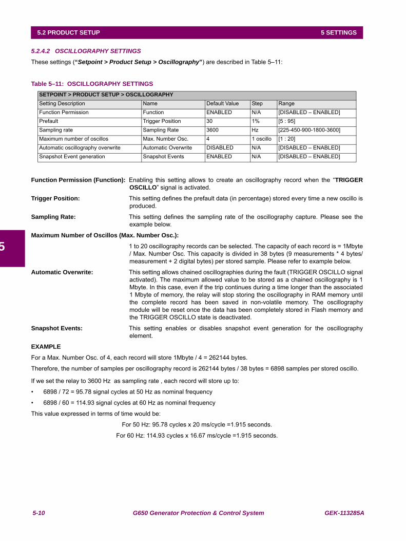
5-10 G650 Generator Protection & Control System GEK-113285A
5.2 PRODUCT SETUP 5 SETTINGS
5
5.2.4.2 OSCILLOGRAPHY SETTINGS
These settings (“Setpoint > Product Setup > Oscillography”) are described in Table 5–11:
Table 5–11: OSCILLOGRAPHY SETTINGS
Function Permission (Function): Enabling this setting allows to create an oscillography record when the “TRIGGEROSCILLO” signal is activated.
Trigger Position: This setting defines the prefault data (in percentage) stored every time a new oscillo isproduced.
Sampling Rate: This setting defines the sampling rate of the oscillography capture. Please see theexample below.
Maximum Number of Oscillos (Max. Number Osc.):
1 to 20 oscillography records can be selected. The capacity of each record is = 1Mbyte/ Max. Number Osc. This capacity is divided in 38 bytes (9 measurements * 4 bytes/measurement + 2 digital bytes) per stored sample. Please refer to example below.
Automatic Overwrite: This setting allows chained oscillographies during the fault (TRIGGER OSCILLO signalactivated). The maximum allowed value to be stored as a chained oscillography is 1Mbyte. In this case, even if the trip continues during a time longer than the associated1 Mbyte of memory, the relay will stop storing the oscillography in RAM memory untilthe complete record has been saved in non-volatile memory. The oscillographymodule will be reset once the data has been completely stored in Flash memory andthe TRIGGER OSCILLO state is deactivated.
Snapshot Events: This setting enables or disables snapshot event generation for the oscillographyelement.
EXAMPLE
For a Max. Number Osc. of 4, each record will store 1Mbyte / 4 = 262144 bytes.
Therefore, the number of samples per oscillography record is 262144 bytes / 38 bytes = 6898 samples per stored oscillo.
If we set the relay to 3600 Hz as sampling rate , each record will store up to:
• 6898 / 72 = 95.78 signal cycles at 50 Hz as nominal frequency
• 6898 / 60 = 114.93 signal cycles at 60 Hz as nominal frequency
This value expressed in terms of time would be:
For 50 Hz: 95.78 cycles x 20 ms/cycle =1.915 seconds.
For 60 Hz: 114.93 cycles x 16.67 ms/cycle =1.915 seconds.
SETPOINT > PRODUCT SETUP > OSCILLOGRAPHYSetting Description Name Default Value Step RangeFunction Permission Function ENABLED N/A [DISABLED – ENABLED]Prefault Trigger Position 30 1% [5 : 95]Sampling rate Sampling Rate 3600 Hz [225-450-900-1800-3600]Maximum number of oscillos Max. Number Osc. 4 1 oscillo [1 : 20]Automatic oscillography overwrite Automatic Overwrite DISABLED N/A [DISABLED – ENABLED]Snapshot Event generation Snapshot Events ENABLED N/A [DISABLED – ENABLED]
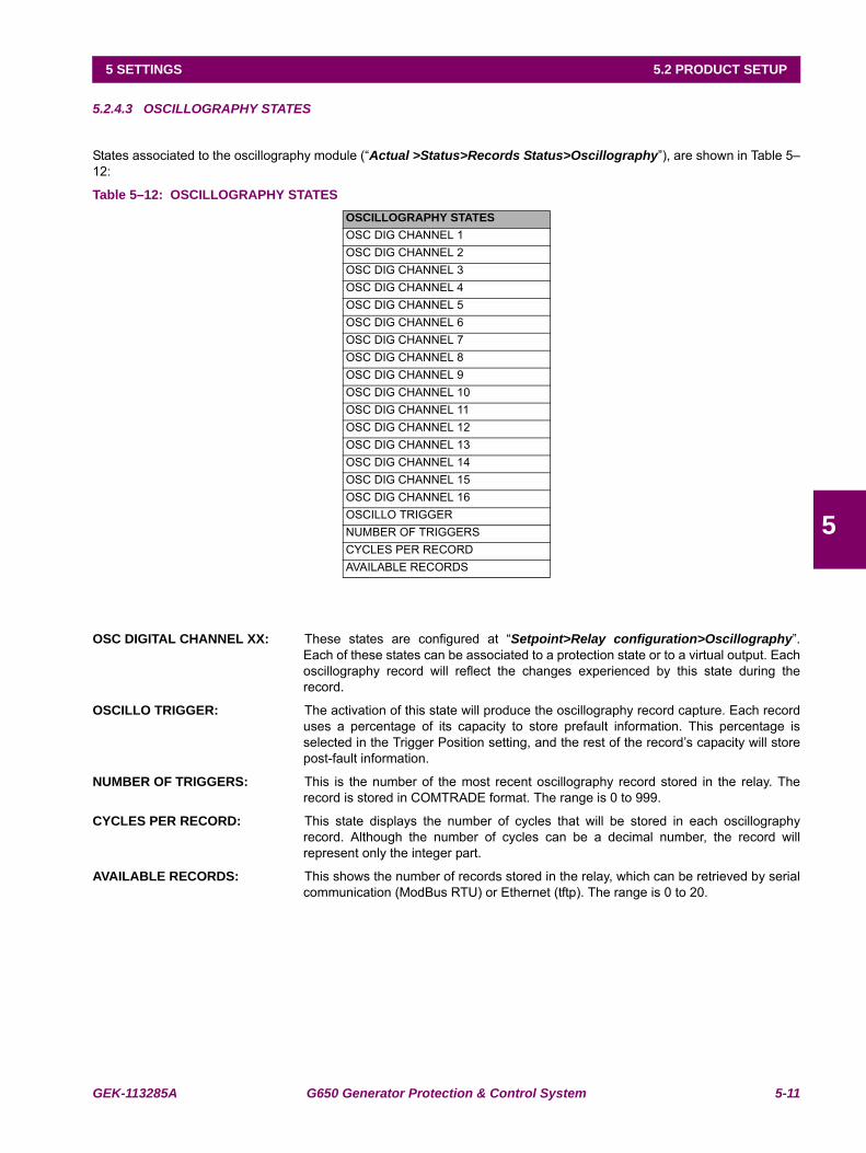
GEK-113285A G650 Generator Protection & Control System 5-11
5 SETTINGS 5.2 PRODUCT SETUP
5
5.2.4.3 OSCILLOGRAPHY STATES
States associated to the oscillography module (“Actual >Status>Records Status>Oscillography”), are shown in Table 5–12:
Table 5–12: OSCILLOGRAPHY STATES
OSC DIGITAL CHANNEL XX: These states are configured at “Setpoint>Relay configuration>Oscillography”.Each of these states can be associated to a protection state or to a virtual output. Eachoscillography record will reflect the changes experienced by this state during therecord.
OSCILLO TRIGGER: The activation of this state will produce the oscillography record capture. Each recorduses a percentage of its capacity to store prefault information. This percentage isselected in the Trigger Position setting, and the rest of the record’s capacity will storepost-fault information.
NUMBER OF TRIGGERS: This is the number of the most recent oscillography record stored in the relay. Therecord is stored in COMTRADE format. The range is 0 to 999.
CYCLES PER RECORD: This state displays the number of cycles that will be stored in each oscillographyrecord. Although the number of cycles can be a decimal number, the record willrepresent only the integer part.
AVAILABLE RECORDS: This shows the number of records stored in the relay, which can be retrieved by serialcommunication (ModBus RTU) or Ethernet (tftp). The range is 0 to 20.
OSCILLOGRAPHY STATESOSC DIG CHANNEL 1OSC DIG CHANNEL 2OSC DIG CHANNEL 3OSC DIG CHANNEL 4OSC DIG CHANNEL 5OSC DIG CHANNEL 6OSC DIG CHANNEL 7OSC DIG CHANNEL 8OSC DIG CHANNEL 9OSC DIG CHANNEL 10OSC DIG CHANNEL 11OSC DIG CHANNEL 12OSC DIG CHANNEL 13OSC DIG CHANNEL 14OSC DIG CHANNEL 15OSC DIG CHANNEL 16OSCILLO TRIGGERNUMBER OF TRIGGERSCYCLES PER RECORDAVAILABLE RECORDS
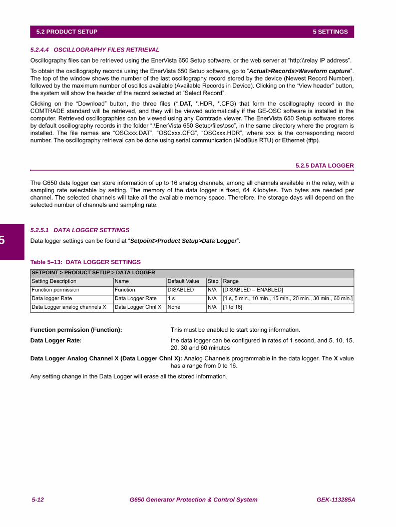
5-12 G650 Generator Protection & Control System GEK-113285A
5.2 PRODUCT SETUP 5 SETTINGS
5
5.2.4.4 OSCILLOGRAPHY FILES RETRIEVAL
Oscillography files can be retrieved using the EnerVista 650 Setup software, or the web server at “http:\\relay IP address”.
To obtain the oscillography records using the EnerVista 650 Setup software, go to “Actual>Records>Waveform capture”.The top of the window shows the number of the last oscillography record stored by the device (Newest Record Number),followed by the maximum number of oscillos available (Available Records in Device). Clicking on the “View header” button,the system will show the header of the record selected at “Select Record”.
Clicking on the “Download” button, the three files (*.DAT, *.HDR, *.CFG) that form the oscillography record in theCOMTRADE standard will be retrieved, and they will be viewed automatically if the GE-OSC software is installed in thecomputer. Retrieved oscillographies can be viewed using any Comtrade viewer. The EnerVista 650 Setup software storesby default oscillography records in the folder “.\EnerVista 650 Setup\files\osc”, in the same directory where the program isinstalled. The file names are “OSCxxx.DAT”, “OSCxxx.CFG”, “OSCxxx.HDR”, where xxx is the corresponding recordnumber. The oscillography retrieval can be done using serial communication (ModBus RTU) or Ethernet (tftp).
5.2.5 DATA LOGGER
The G650 data logger can store information of up to 16 analog channels, among all channels available in the relay, with asampling rate selectable by setting. The memory of the data logger is fixed, 64 Kilobytes. Two bytes are needed perchannel. The selected channels will take all the available memory space. Therefore, the storage days will depend on theselected number of channels and sampling rate.
5.2.5.1 DATA LOGGER SETTINGS
Data logger settings can be found at “Setpoint>Product Setup>Data Logger”.
Table 5–13: DATA LOGGER SETTINGS
Function permission (Function): This must be enabled to start storing information.
Data Logger Rate: the data logger can be configured in rates of 1 second, and 5, 10, 15,20, 30 and 60 minutes
Data Logger Analog Channel X (Data Logger Chnl X): Analog Channels programmable in the data logger. The X valuehas a range from 0 to 16.
Any setting change in the Data Logger will erase all the stored information.
SETPOINT > PRODUCT SETUP > DATA LOGGERSetting Description Name Default Value Step RangeFunction permission Function DISABLED N/A [DISABLED – ENABLED]Data logger Rate Data Logger Rate 1 s N/A [1 s, 5 min., 10 min., 15 min., 20 min., 30 min., 60 min.]Data Logger analog channels X Data Logger Chnl X None N/A [1 to 16]
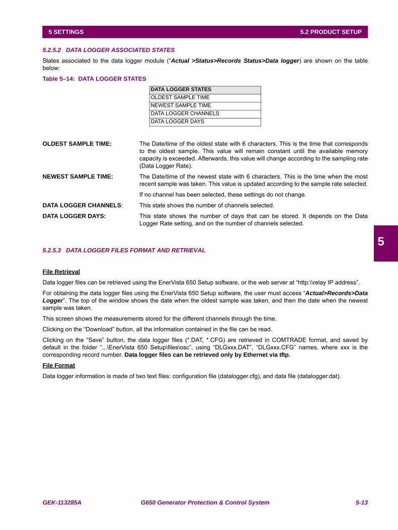
GEK-113285A G650 Generator Protection & Control System 5-13
5 SETTINGS 5.2 PRODUCT SETUP
5
5.2.5.2 DATA LOGGER ASSOCIATED STATES
States associated to the data logger module (“Actual >Status>Records Status>Data logger) are shown on the tablebelow:
Table 5–14: DATA LOGGER STATES
OLDEST SAMPLE TIME: The Date/time of the oldest state with 6 characters. This is the time that correspondsto the oldest sample. This value will remain constant until the available memorycapacity is exceeded. Afterwards, this value will change according to the sampling rate(Data Logger Rate).
NEWEST SAMPLE TIME: The Date/time of the newest state with 6 characters. This is the time when the mostrecent sample was taken. This value is updated according to the sample rate selected.
If no channel has been selected, these settings do not change.
DATA LOGGER CHANNELS: This state shows the number of channels selected.
DATA LOGGER DAYS: This state shows the number of days that can be stored. It depends on the DataLogger Rate setting, and on the number of channels selected.
5.2.5.3 DATA LOGGER FILES FORMAT AND RETRIEVAL
File Retrieval
Data logger files can be retrieved using the EnerVista 650 Setup software, or the web server at “http:\\relay IP address”.
For obtaining the data logger files using the EnerVista 650 Setup software, the user must access “Actual>Records>DataLogger”. The top of the window shows the date when the oldest sample was taken, and then the date when the newestsample was taken.
This screen shows the measurements stored for the different channels through the time.
Clicking on the “Download” button, all the information contained in the file can be read.
Clicking on the “Save” button, the data logger files (*.DAT, *.CFG) are retrieved in COMTRADE format, and saved bydefault in the folder “...\EnerVista 650 Setup\files\osc”, using “DLGxxx.DAT”, “DLGxxx.CFG” names, where xxx is thecorresponding record number. Data logger files can be retrieved only by Ethernet via tftp.
File Format
Data logger information is made of two text files: configuration file (datalogger.cfg), and data file (datalogger.dat).
DATA LOGGER STATESOLDEST SAMPLE TIMENEWEST SAMPLE TIMEDATA LOGGER CHANNELSDATA LOGGER DAYS
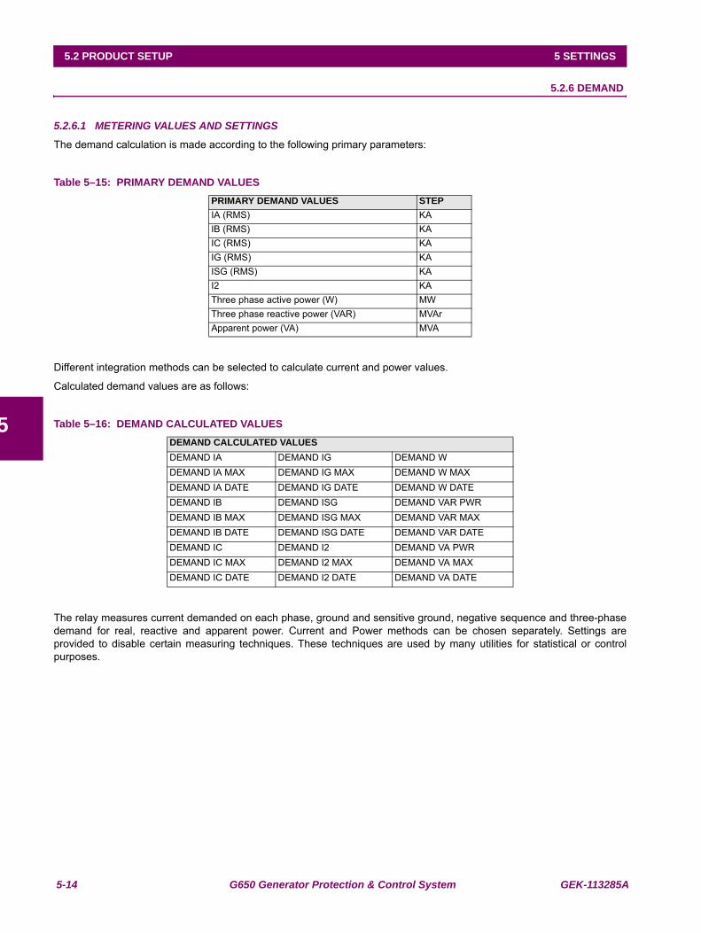
5-14 G650 Generator Protection & Control System GEK-113285A
5.2 PRODUCT SETUP 5 SETTINGS
5
5.2.6 DEMAND
5.2.6.1 METERING VALUES AND SETTINGS
The demand calculation is made according to the following primary parameters:
Table 5–15: PRIMARY DEMAND VALUES
Different integration methods can be selected to calculate current and power values.
Calculated demand values are as follows:
Table 5–16: DEMAND CALCULATED VALUES
The relay measures current demanded on each phase, ground and sensitive ground, negative sequence and three-phasedemand for real, reactive and apparent power. Current and Power methods can be chosen separately. Settings areprovided to disable certain measuring techniques. These techniques are used by many utilities for statistical or controlpurposes.
PRIMARY DEMAND VALUES STEPIA (RMS) KAIB (RMS) KAIC (RMS) KAIG (RMS) KAISG (RMS) KAI2 KAThree phase active power (W) MWThree phase reactive power (VAR) MVArApparent power (VA) MVA
DEMAND CALCULATED VALUESDEMAND IA DEMAND IG DEMAND WDEMAND IA MAX DEMAND IG MAX DEMAND W MAXDEMAND IA DATE DEMAND IG DATE DEMAND W DATEDEMAND IB DEMAND ISG DEMAND VAR PWRDEMAND IB MAX DEMAND ISG MAX DEMAND VAR MAXDEMAND IB DATE DEMAND ISG DATE DEMAND VAR DATEDEMAND IC DEMAND I2 DEMAND VA PWRDEMAND IC MAX DEMAND I2 MAX DEMAND VA MAXDEMAND IC DATE DEMAND I2 DATE DEMAND VA DATE
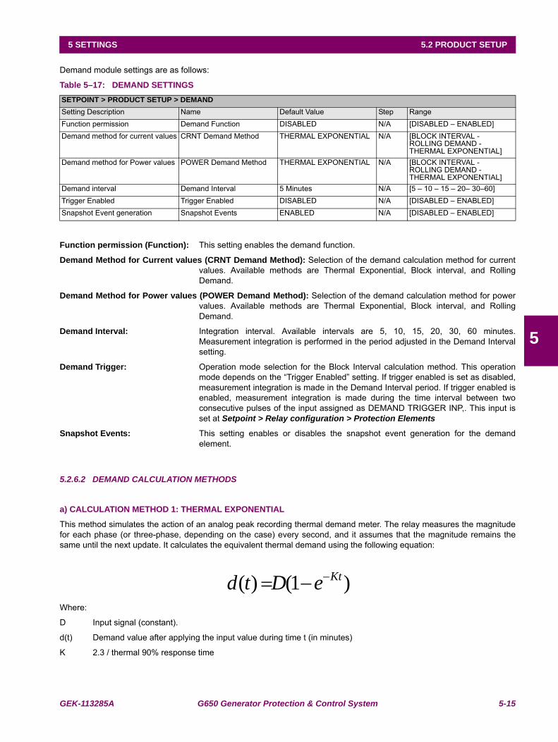
GEK-113285A G650 Generator Protection & Control System 5-15
5 SETTINGS 5.2 PRODUCT SETUP
5
Demand module settings are as follows:
Table 5–17: DEMAND SETTINGS
Function permission (Function): This setting enables the demand function.
Demand Method for Current values (CRNT Demand Method): Selection of the demand calculation method for currentvalues. Available methods are Thermal Exponential, Block interval, and RollingDemand.
Demand Method for Power values (POWER Demand Method): Selection of the demand calculation method for powervalues. Available methods are Thermal Exponential, Block interval, and RollingDemand.
Demand Interval: Integration interval. Available intervals are 5, 10, 15, 20, 30, 60 minutes.Measurement integration is performed in the period adjusted in the Demand Intervalsetting.
Demand Trigger: Operation mode selection for the Block Interval calculation method. This operationmode depends on the “Trigger Enabled” setting. If trigger enabled is set as disabled,measurement integration is made in the Demand Interval period. If trigger enabled isenabled, measurement integration is made during the time interval between twoconsecutive pulses of the input assigned as DEMAND TRIGGER INP,. This input isset at Setpoint > Relay configuration > Protection Elements
Snapshot Events: This setting enables or disables the snapshot event generation for the demandelement.
5.2.6.2 DEMAND CALCULATION METHODS
a) CALCULATION METHOD 1: THERMAL EXPONENTIAL
This method simulates the action of an analog peak recording thermal demand meter. The relay measures the magnitudefor each phase (or three-phase, depending on the case) every second, and it assumes that the magnitude remains thesame until the next update. It calculates the equivalent thermal demand using the following equation:
Where:
D Input signal (constant).
d(t) Demand value after applying the input value during time t (in minutes)
K 2.3 / thermal 90% response time
SETPOINT > PRODUCT SETUP > DEMANDSetting Description Name Default Value Step RangeFunction permission Demand Function DISABLED N/A [DISABLED – ENABLED]Demand method for current values CRNT Demand Method THERMAL EXPONENTIAL N/A [BLOCK INTERVAL -
ROLLING DEMAND -THERMAL EXPONENTIAL]
Demand method for Power values POWER Demand Method THERMAL EXPONENTIAL N/A [BLOCK INTERVAL -ROLLING DEMAND -THERMAL EXPONENTIAL]
Demand interval Demand Interval 5 Minutes N/A [5 – 10 – 15 – 20– 30–60]Trigger Enabled Trigger Enabled DISABLED N/A [DISABLED – ENABLED]Snapshot Event generation Snapshot Events ENABLED N/A [DISABLED – ENABLED]
)1()( KteDtd −−=
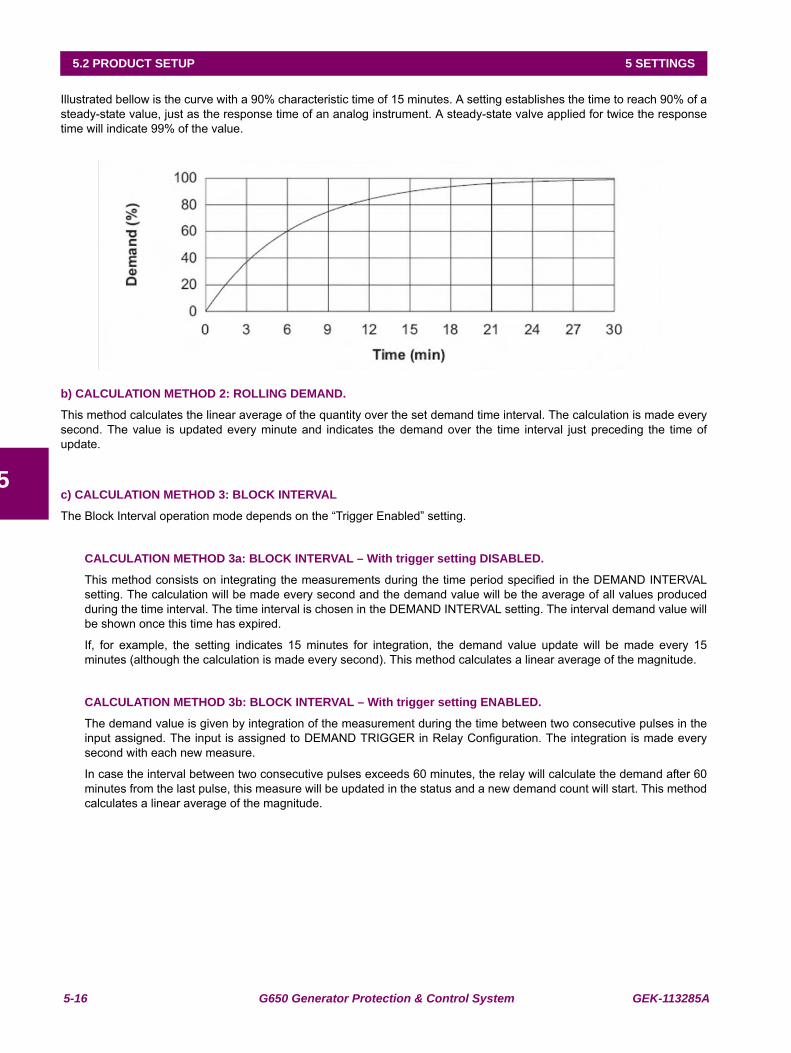
5-16 G650 Generator Protection & Control System GEK-113285A
5.2 PRODUCT SETUP 5 SETTINGS
5
Illustrated bellow is the curve with a 90% characteristic time of 15 minutes. A setting establishes the time to reach 90% of asteady-state value, just as the response time of an analog instrument. A steady-state valve applied for twice the responsetime will indicate 99% of the value.
b) CALCULATION METHOD 2: ROLLING DEMAND.
This method calculates the linear average of the quantity over the set demand time interval. The calculation is made everysecond. The value is updated every minute and indicates the demand over the time interval just preceding the time ofupdate.
c) CALCULATION METHOD 3: BLOCK INTERVAL
The Block Interval operation mode depends on the “Trigger Enabled” setting.
CALCULATION METHOD 3a: BLOCK INTERVAL – With trigger setting DISABLED.
This method consists on integrating the measurements during the time period specified in the DEMAND INTERVALsetting. The calculation will be made every second and the demand value will be the average of all values producedduring the time interval. The time interval is chosen in the DEMAND INTERVAL setting. The interval demand value willbe shown once this time has expired.
If, for example, the setting indicates 15 minutes for integration, the demand value update will be made every 15minutes (although the calculation is made every second). This method calculates a linear average of the magnitude.
CALCULATION METHOD 3b: BLOCK INTERVAL – With trigger setting ENABLED.
The demand value is given by integration of the measurement during the time between two consecutive pulses in theinput assigned. The input is assigned to DEMAND TRIGGER in Relay Configuration. The integration is made everysecond with each new measure.
In case the interval between two consecutive pulses exceeds 60 minutes, the relay will calculate the demand after 60minutes from the last pulse, this measure will be updated in the status and a new demand count will start. This methodcalculates a linear average of the magnitude.
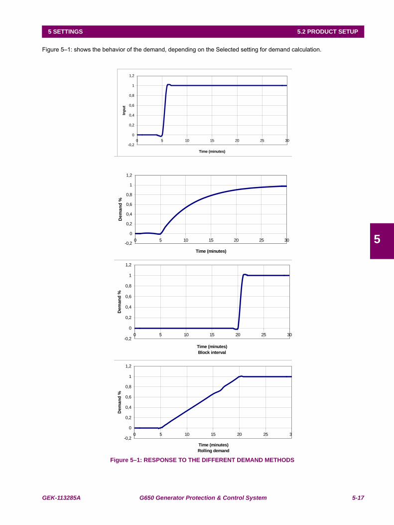
GEK-113285A G650 Generator Protection & Control System 5-17
5 SETTINGS 5.2 PRODUCT SETUP
5
Figure 5–1: shows the behavior of the demand, depending on the Selected setting for demand calculation.
Figure 5–1: RESPONSE TO THE DIFFERENT DEMAND METHODS
-0,2
0
0,2
0,4
0,6
0,8
1
1,2
0 5 10 15 20 25 30
Time (minutes)
Inp
ut
-0,2
0
0,2
0,4
0,6
0,8
1
1,2
0 5 10 15 20 25 3
Time (minutes)
Rolling demand
De
ma
nd
%
-0,2
0
0,2
0,4
0,6
0,8
1
1,2
0 5 10 15 20 25 30
Time (minutes)
Block interval
De
ma
nd
%
-0,2
0
0,2
0,4
0,6
0,8
1
1,2
0 5 10 15 20 25 30
Time (minutes)
De
ma
nd
%
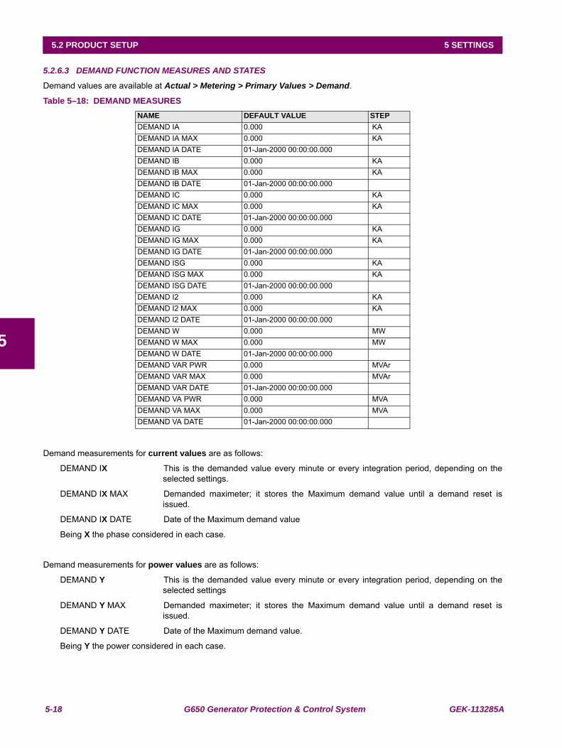
5-18 G650 Generator Protection & Control System GEK-113285A
5.2 PRODUCT SETUP 5 SETTINGS
5
5.2.6.3 DEMAND FUNCTION MEASURES AND STATES
Demand values are available at Actual > Metering > Primary Values > Demand.
Table 5–18: DEMAND MEASURES
Demand measurements for current values are as follows:
DEMAND IX This is the demanded value every minute or every integration period, depending on theselected settings.
DEMAND IX MAX Demanded maximeter; it stores the Maximum demand value until a demand reset isissued.
DEMAND IX DATE Date of the Maximum demand value
Being X the phase considered in each case.
Demand measurements for power values are as follows:
DEMAND Y This is the demanded value every minute or every integration period, depending on theselected settings
DEMAND Y MAX Demanded maximeter; it stores the Maximum demand value until a demand reset isissued.
DEMAND Y DATE Date of the Maximum demand value.
Being Y the power considered in each case.
NAME DEFAULT VALUE STEPDEMAND IA 0.000 KADEMAND IA MAX 0.000 KADEMAND IA DATE 01-Jan-2000 00:00:00.000DEMAND IB 0.000 KADEMAND IB MAX 0.000 KADEMAND IB DATE 01-Jan-2000 00:00:00.000DEMAND IC 0.000 KADEMAND IC MAX 0.000 KADEMAND IC DATE 01-Jan-2000 00:00:00.000DEMAND IG 0.000 KADEMAND IG MAX 0.000 KADEMAND IG DATE 01-Jan-2000 00:00:00.000DEMAND ISG 0.000 KADEMAND ISG MAX 0.000 KADEMAND ISG DATE 01-Jan-2000 00:00:00.000DEMAND I2 0.000 KADEMAND I2 MAX 0.000 KADEMAND I2 DATE 01-Jan-2000 00:00:00.000DEMAND W 0.000 MWDEMAND W MAX 0.000 MWDEMAND W DATE 01-Jan-2000 00:00:00.000DEMAND VAR PWR 0.000 MVArDEMAND VAR MAX 0.000 MVArDEMAND VAR DATE 01-Jan-2000 00:00:00.000DEMAND VA PWR 0.000 MVADEMAND VA MAX 0.000 MVADEMAND VA DATE 01-Jan-2000 00:00:00.000
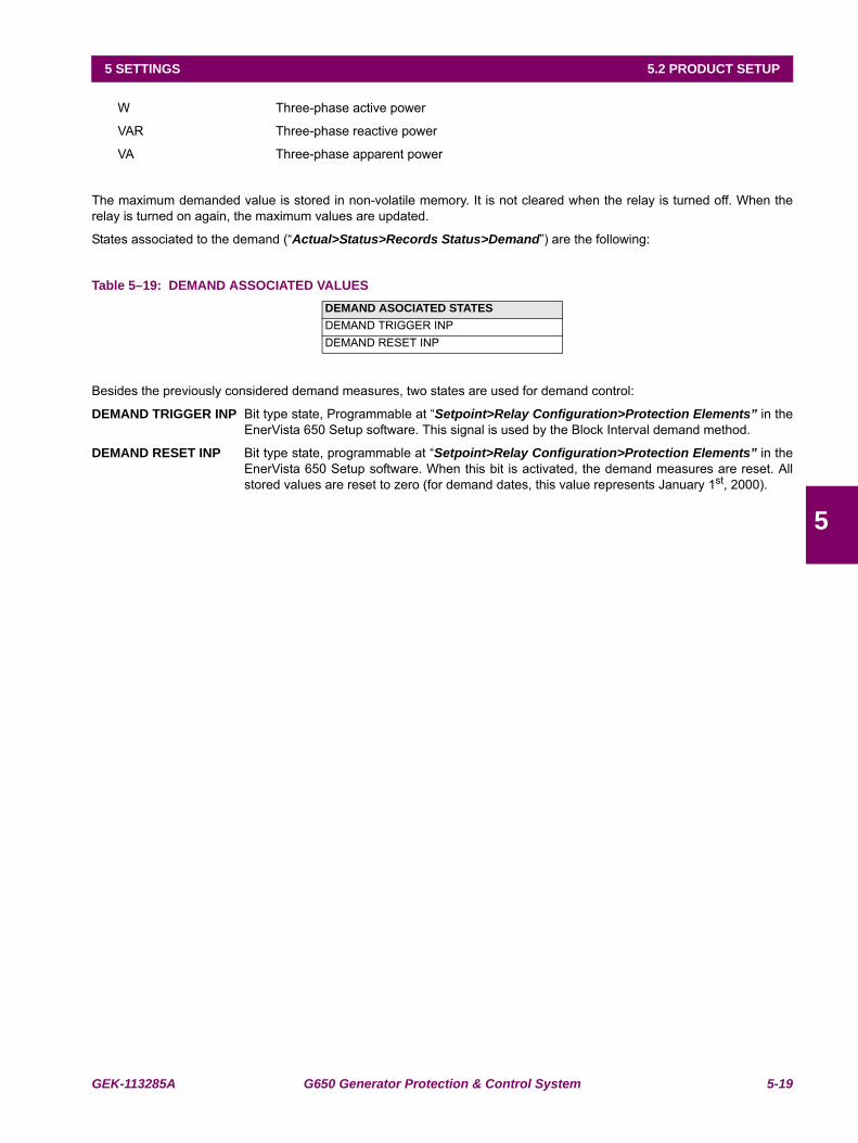
GEK-113285A G650 Generator Protection & Control System 5-19
5 SETTINGS 5.2 PRODUCT SETUP
5
W Three-phase active power
VAR Three-phase reactive power
VA Three-phase apparent power
The maximum demanded value is stored in non-volatile memory. It is not cleared when the relay is turned off. When therelay is turned on again, the maximum values are updated.
States associated to the demand (“Actual>Status>Records Status>Demand”) are the following:
Table 5–19: DEMAND ASSOCIATED VALUES
Besides the previously considered demand measures, two states are used for demand control:
DEMAND TRIGGER INP Bit type state, Programmable at “Setpoint>Relay Configuration>Protection Elements” in theEnerVista 650 Setup software. This signal is used by the Block Interval demand method.
DEMAND RESET INP Bit type state, programmable at “Setpoint>Relay Configuration>Protection Elements” in theEnerVista 650 Setup software. When this bit is activated, the demand measures are reset. Allstored values are reset to zero (for demand dates, this value represents January 1st, 2000).
DEMAND ASOCIATED STATESDEMAND TRIGGER INPDEMAND RESET INP
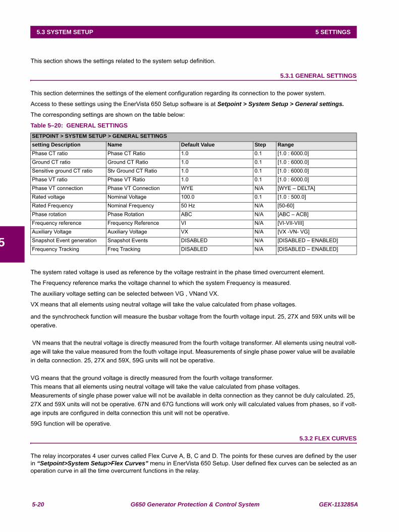
5-20 G650 Generator Protection & Control System GEK-113285A
5.3 SYSTEM SETUP 5 SETTINGS
5
5.3SYSTEM SETUP
This section shows the settings related to the system setup definition.
5.3.1 GENERAL SETTINGS
This section determines the settings of the element configuration regarding its connection to the power system.
Access to these settings using the EnerVista 650 Setup software is at Setpoint > System Setup > General settings.
The corresponding settings are shown on the table below:
Table 5–20: GENERAL SETTINGS
The system rated voltage is used as reference by the voltage restraint in the phase timed overcurrent element.
The Frequency reference marks the voltage channel to which the system Frequency is measured.
The auxiliary voltage setting can be selected between VG , VNand VX.
VX means that all elements using neutral voltage will take the value calculated from phase voltages.
and the synchrocheck function will measure the busbar voltage from the fourth voltage input. 25, 27X and 59X units will be operative.
VN means that the neutral voltage is directly measured from the fourth voltage transformer. All elements using neutral volt-age will take the value measured from the fouth voltage input. Measurements of single phase power value will be available in delta connection. 25, 27X and 59X, 59G units will not be operative.
VG means that the ground voltage is directly measured from the fourth voltage transformer.This means that all elements using neutral voltage will take the value calculated from phase voltages.Measurements of single phase power value will not be available in delta connection as they cannot be duly calculated. 25, 27X and 59X units will not be operative. 67N and 67G functions will work only will calculated values from phases, so if volt-age inputs are configured in delta connection this unit will not be operative.
59G function will be operative.
5.3.2 FLEX CURVES
The relay incorporates 4 user curves called Flex Curve A, B, C and D. The points for these curves are defined by the userin “Setpoint>System Setup>Flex Curves” menu in EnerVista 650 Setup. User defined flex curves can be selected as anoperation curve in all the time overcurrent functions in the relay.
SETPOINT > SYSTEM SETUP > GENERAL SETTINGSsetting Description Name Default Value Step RangePhase CT ratio Phase CT Ratio 1.0 0.1 [1.0 : 6000.0]Ground CT ratio Ground CT Ratio 1.0 0.1 [1.0 : 6000.0]Sensitive ground CT ratio Stv Ground CT Ratio 1.0 0.1 [1.0 : 6000.0]Phase VT ratio Phase VT Ratio 1.0 0.1 [1.0 : 6000.0]Phase VT connection Phase VT Connection WYE N/A [WYE – DELTA]Rated voltage Nominal Voltage 100.0 0.1 [1.0 : 500.0]Rated Frequency Nominal Frequency 50 Hz N/A [50-60]Phase rotation Phase Rotation ABC N/A [ABC – ACB]Frequency reference Frequency Reference VI N/A [VI-VII-VIII]Auxiliary Voltage Auxiliary Voltage VX N/A [VX -VN- VG]Snapshot Event generation Snapshot Events DISABLED N/A [DISABLED – ENABLED]Frequency Tracking Freq Tracking DISABLED N/A [DISABLED – ENABLED]

GEK-113285A G650 Generator Protection & Control System 5-21
5 SETTINGS 5.3 SYSTEM SETUP
5
In the flex curves menu there are 120 points to define a user curve. 40 points for reset (from 0 to 0.98 times the pickupvalue) and 80 for operate (from 1.03 to 20 times the pickup).
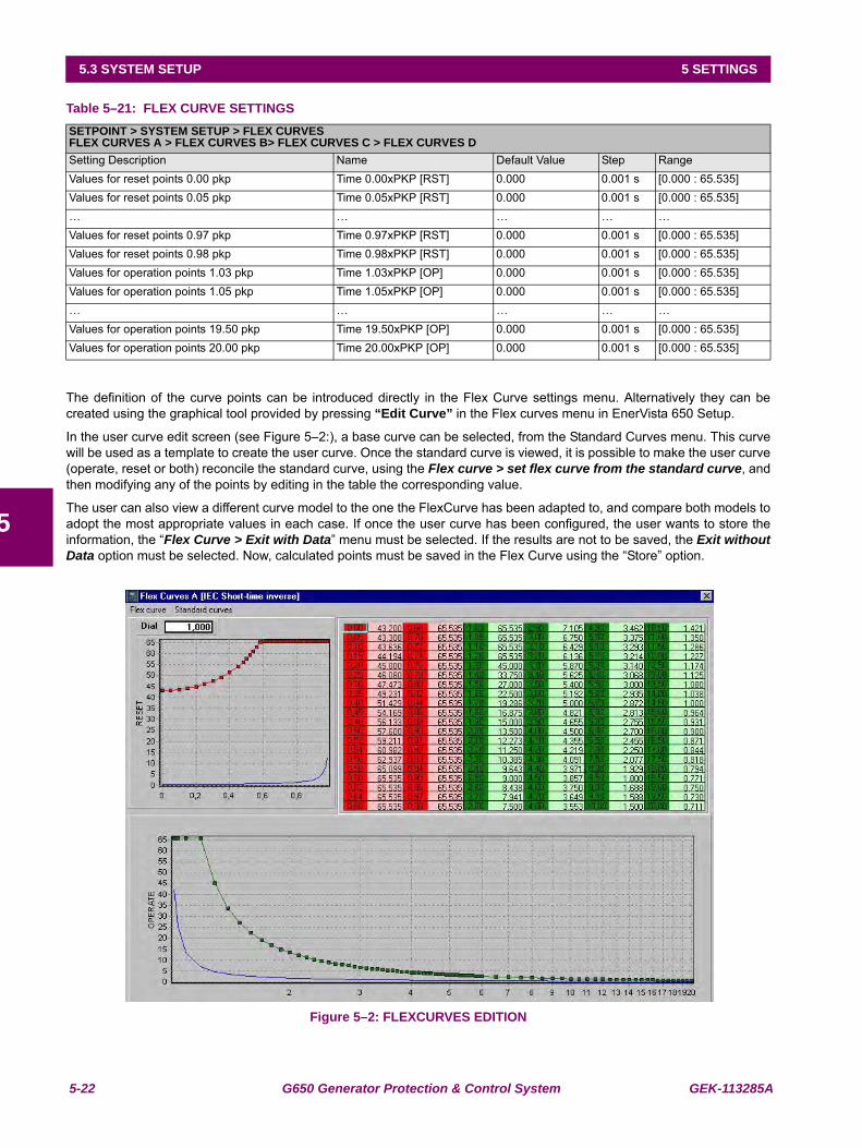
5-22 G650 Generator Protection & Control System GEK-113285A
5.3 SYSTEM SETUP 5 SETTINGS
5
Table 5–21: FLEX CURVE SETTINGS
The definition of the curve points can be introduced directly in the Flex Curve settings menu. Alternatively they can becreated using the graphical tool provided by pressing “Edit Curve” in the Flex curves menu in EnerVista 650 Setup.
In the user curve edit screen (see Figure 5–2:), a base curve can be selected, from the Standard Curves menu. This curvewill be used as a template to create the user curve. Once the standard curve is viewed, it is possible to make the user curve(operate, reset or both) reconcile the standard curve, using the Flex curve > set flex curve from the standard curve, andthen modifying any of the points by editing in the table the corresponding value.
The user can also view a different curve model to the one the FlexCurve has been adapted to, and compare both models toadopt the most appropriate values in each case. If once the user curve has been configured, the user wants to store theinformation, the “Flex Curve > Exit with Data” menu must be selected. If the results are not to be saved, the Exit withoutData option must be selected. Now, calculated points must be saved in the Flex Curve using the “Store” option.
Figure 5–2: FLEXCURVES EDITION
SETPOINT > SYSTEM SETUP > FLEX CURVESFLEX CURVES A > FLEX CURVES B> FLEX CURVES C > FLEX CURVES DSetting Description Name Default Value Step RangeValues for reset points 0.00 pkp Time 0.00xPKP [RST] 0.000 0.001 s [0.000 : 65.535]Values for reset points 0.05 pkp Time 0.05xPKP [RST] 0.000 0.001 s [0.000 : 65.535]… … … … …Values for reset points 0.97 pkp Time 0.97xPKP [RST] 0.000 0.001 s [0.000 : 65.535]Values for reset points 0.98 pkp Time 0.98xPKP [RST] 0.000 0.001 s [0.000 : 65.535]Values for operation points 1.03 pkp Time 1.03xPKP [OP] 0.000 0.001 s [0.000 : 65.535]Values for operation points 1.05 pkp Time 1.05xPKP [OP] 0.000 0.001 s [0.000 : 65.535]… … … … …Values for operation points 19.50 pkp Time 19.50xPKP [OP] 0.000 0.001 s [0.000 : 65.535]Values for operation points 20.00 pkp Time 20.00xPKP [OP] 0.000 0.001 s [0.000 : 65.535]
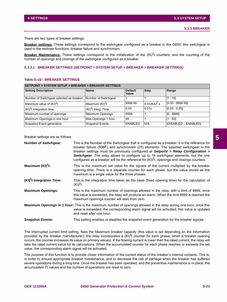
GEK-113285A G650 Generator Protection & Control System 5-23
5 SETTINGS 5.3 SYSTEM SETUP
5
5.3.3 BREAKER
There are two types of breaker settings:
Breaker settings: These settings correspond to the switchgear configured as a breaker in the G650; this switchgear isused in the recloser functions, breaker failure and synchronism.
Breaker Maintenance: These settings correspond to the initialization of the (KI)2t counters, and the counting of thenumber of openings and closings of the switchgear configured as a breaker.
5.3.3.1 BREAKER SETTINGS (SETPOINT > SYSTEM SETUP > BREAKER > BREAKER SETTINGS)
Table 5–22: BREAKER SETTINGS
Breaker settings are as follows:
Number of switchgear: This is the Number of the Switchgear that is configured as a breaker. It is the reference forbreaker failure (50BF) and synchronism (25) elements. The selected switchgear in thebreaker settings must be previously configured at Setpoint > Relay Configuration >Switchgear. The relay allows to configure up to 16 switchgear elements, but the oneconfigured as a breaker will be the reference for (KI)2t, openings and closings counters.
Maximum (KI)2t: This is the maximum set value for the square of the current multiplied by the breakeropening time. There is a separate counter for each phase, but the value stored as themaximum is a single value for the three phases.
(KI)2t Integration Time: This is the integration time taken as the base (fixed opening time) for the calculation of(KI)2t.
Maximum Openings: This is the maximum number of openings allowed in the relay, with a limit of 9999; oncethis value is exceeded, the relay will produce an alarm. When the limit 9999 is reached themaximum openings counter will start from zero.
Maximum Openings in 1 hour: This is the maximum number of openings allowed in the relay during one hour; once thisvalue is exceeded, the corresponding alarm signal will be activated; this value is updatedand reset after one hour.
Snapshot Events: This setting enables or disables the snapshot event generation for the breaker signals.
The interrupted current limit setting, fixes the Maximum breaker capacity (this value is set depending on the informationprovided by the breaker manufacturer); the relay incorporates a (KI)2t counter for each phase, when a breaker openingoccurs, the counter increases its value (in primary values). If the flowing current is lower than the rated current, the relay willtake the rated current value for its calculations. When the accumulated counter for each phase reaches or exceeds the setvalue, the corresponding alarm signal will be activated.
The purpose of this function is to provide closer information of the current status of the breaker’s internal contacts. This is,in order to ensure appropriate breaker maintenance, and to decrease the risk of damage when the breaker has sufferedsevere operations during a long time. Once the breaker has been operated, and the preventive maintenance is in place, theaccumulated I2t values and the number of operations are reset to zero.
SETPOINT > SYSTEM SETUP > BREAKER > BREAKER SETTINGSSetting Description Name Default
ValueStep Range
Number of Switchgear selected as breaker Number of Switchgear 1 1 [1 : 16]
Maximum value of (KI)2t Maximum (KI)2t 9999.99 0.01(KA)2 s [0.00 : 9999.99]
(KI)2t integration time (KI)2t Integ. Time 0.03 0.01s [0.03 : 0.25]
Maximum number of openings Maximum Openings 9999 1 [0 : 9999]Maximum Openings in one hour Max.Openings 1 hour 40 1 [1 : 60]Snapshot Event generation Snapshot Events ENABLED N/A [DISABLED – ENABLED]
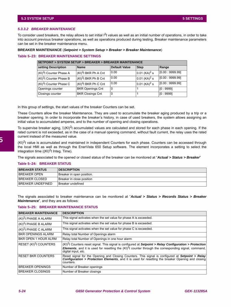
5-24 G650 Generator Protection & Control System GEK-113285A
5.3 SYSTEM SETUP 5 SETTINGS
5
5.3.3.2 BREAKER MAINTENANCE
To consider used breakers, the relay allows to set initial I2t values as well as an initial number of operations, in order to takeinto account previous breaker operations, as well as operations produced during testing. Breaker maintenance parameterscan be set in the breaker maintenance menu.
BREAKER MAINTENANCE (Setpoint > System Setup > Breaker > Breaker Maintenance)
Table 5–23: BREAKER MAINTENANCE SETTINGS
In this group of settings, the start values of the breaker Counters can be set.
These Counters allow the breaker Maintenance. They are used to accumulate the breaker aging produced by a trip or abreaker opening. In order to incorporate the breaker’s history, in case of used breakers, the system allows assigning aninitial value to accumulated amperes, and to the number of opening and closing operations.
To supervise breaker aging, Σ(KI)2t accumulated values are calculated and stored for each phase in each opening. If therated current is not exceeded, as in the case of a manual opening command, without fault current, the relay uses the ratedcurrent instead of the measured value.
(KI)2t value is accumulated and maintained in independent Counters for each phase. Counters can be accessed throughthe local HMI as well as through the EnerVista 650 Setup software. The element incorporates a setting to select theintegration time ((KI)2t Integ. Time).
The signals associated to the opened or closed status of the breaker can be monitored at “Actual > Status > Breaker”
Table 5–24: BREAKER STATUS
The signals associated to breaker maintenance can be monitored at “Actual > Status > Records Status > BreakerMaintenance”, and they are as follows:
Table 5–25: BREAKER MAINTENANCE STATUS
SETPOINT > SYSTEM SETUP > BREAKER > BREAKER MAINTENANCEsetting Description Name Default Value Step Range
(KI)2t Counter Phase A (KI)2t BKR Ph A Cnt 0.00 0.01 (KA)2 s [0.00 : 9999.99]
(KI)2t Counter Phase B (KI)2t BKR Ph B Cnt 0.00 0.01 (KA)2 s [0.00 : 9999.99]
(KI)2t Counter Phase C (KI)2t BKR Ph C Cnt 0.00 0.01 (KA)2 s [0.00 : 9999.99]
Openings counter BKR Openings Cnt 0 1 [0 : 9999]Closings counter BKR Closings Cnt 0 1 [0 : 9999]
BREAKER STATUS DESCRIPTIONBREAKER OPEN Breaker in open position.BREAKER CLOSED Breaker in close positionBREAKER UNDEFINED Breaker undefined
BREAKER MAINTENANCE DESCRIPTION
(KI)2t PHASE A ALARM This signal activates when the set value for phase A is exceeded.
(KI)2t PHASE B ALARM This signal activates when the set value for phase B is exceeded.
(KI)2t PHASE C ALARM This signal activates when the set value for phase C is exceeded.
BKR OPENINGS ALARM Relay total Number of Openings alarm BKR OPEN 1 HOUR ALRM Relay total Number of Openings in one hour alarm
RESET (KI)2t COUNTERS (KI)2t Counters reset signal. This signal is configured at Setpoint > Relay Configuration > ProtectionElements, and it is used for resetting the (KI)2t counter through the corresponding signal, command,digital input, etc.
RESET BKR COUNTERS Reset signal for the Opening and Closing Counters. This signal is configured at Setpoint > RelayConfiguration > Protection Elements, and it is used for resetting the breaker Opening and closingcounters.
BREAKER OPENINGS Number of Breaker openingsBREAKER CLOSINGS Number of Breaker closings
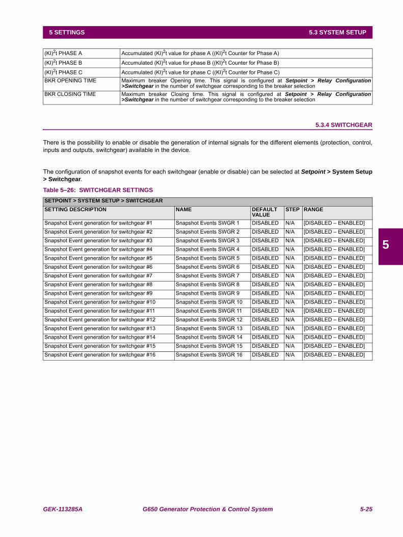
GEK-113285A G650 Generator Protection & Control System 5-25
5 SETTINGS 5.3 SYSTEM SETUP
5
5.3.4 SWITCHGEAR
There is the possibility to enable or disable the generation of internal signals for the different elements (protection, control,inputs and outputs, switchgear) available in the device.
The configuration of snapshot events for each switchgear (enable or disable) can be selected at Setpoint > System Setup> Switchgear.
Table 5–26: SWITCHGEAR SETTINGS
(KI)2t PHASE A Accumulated (KI)2t value for phase A ((KI)2t Counter for Phase A)
(KI)2t PHASE B Accumulated (KI)2t value for phase B ((KI)2t Counter for Phase B)
(KI)2t PHASE C Accumulated (KI)2t value for phase C ((KI)2t Counter for Phase C)BKR OPENING TIME Maximum breaker Opening time. This signal is configured at Setpoint > Relay Configuration
>Switchgear in the number of switchgear corresponding to the breaker selection BKR CLOSING TIME Maximum breaker Closing time. This signal is configured at Setpoint > Relay Configuration
>Switchgear in the number of switchgear corresponding to the breaker selection
SETPOINT > SYSTEM SETUP > SWITCHGEARSETTING DESCRIPTION NAME DEFAULT
VALUESTEP RANGE
Snapshot Event generation for switchgear #1 Snapshot Events SWGR 1 DISABLED N/A [DISABLED – ENABLED]Snapshot Event generation for switchgear #2 Snapshot Events SWGR 2 DISABLED N/A [DISABLED – ENABLED]Snapshot Event generation for switchgear #3 Snapshot Events SWGR 3 DISABLED N/A [DISABLED – ENABLED]Snapshot Event generation for switchgear #4 Snapshot Events SWGR 4 DISABLED N/A [DISABLED – ENABLED]Snapshot Event generation for switchgear #5 Snapshot Events SWGR 5 DISABLED N/A [DISABLED – ENABLED]Snapshot Event generation for switchgear #6 Snapshot Events SWGR 6 DISABLED N/A [DISABLED – ENABLED]Snapshot Event generation for switchgear #7 Snapshot Events SWGR 7 DISABLED N/A [DISABLED – ENABLED]Snapshot Event generation for switchgear #8 Snapshot Events SWGR 8 DISABLED N/A [DISABLED – ENABLED]Snapshot Event generation for switchgear #9 Snapshot Events SWGR 9 DISABLED N/A [DISABLED – ENABLED]Snapshot Event generation for switchgear #10 Snapshot Events SWGR 10 DISABLED N/A [DISABLED – ENABLED]Snapshot Event generation for switchgear #11 Snapshot Events SWGR 11 DISABLED N/A [DISABLED – ENABLED]Snapshot Event generation for switchgear #12 Snapshot Events SWGR 12 DISABLED N/A [DISABLED – ENABLED]Snapshot Event generation for switchgear #13 Snapshot Events SWGR 13 DISABLED N/A [DISABLED – ENABLED]Snapshot Event generation for switchgear #14 Snapshot Events SWGR 14 DISABLED N/A [DISABLED – ENABLED]Snapshot Event generation for switchgear #15 Snapshot Events SWGR 15 DISABLED N/A [DISABLED – ENABLED]Snapshot Event generation for switchgear #16 Snapshot Events SWGR 16 DISABLED N/A [DISABLED – ENABLED]
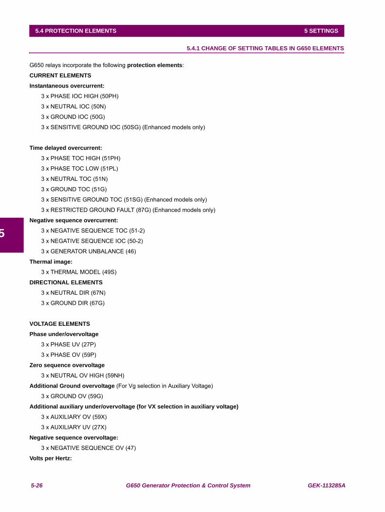
5-26 G650 Generator Protection & Control System GEK-113285A
5.4 PROTECTION ELEMENTS 5 SETTINGS
5
5.4PROTECTION ELEMENTS 5.4.1 CHANGE OF SETTING TABLES IN G650 ELEMENTS
G650 relays incorporate the following protection elements:
CURRENT ELEMENTS
Instantaneous overcurrent:
3 x PHASE IOC HIGH (50PH)
3 x NEUTRAL IOC (50N)
3 x GROUND IOC (50G)
3 x SENSITIVE GROUND IOC (50SG) (Enhanced models only)
Time delayed overcurrent:
3 x PHASE TOC HIGH (51PH)
3 x PHASE TOC LOW (51PL)
3 x NEUTRAL TOC (51N)
3 x GROUND TOC (51G)
3 x SENSITIVE GROUND TOC (51SG) (Enhanced models only)
3 x RESTRICTED GROUND FAULT (87G) (Enhanced models only)
Negative sequence overcurrent:
3 x NEGATIVE SEQUENCE TOC (51-2)
3 x NEGATIVE SEQUENCE IOC (50-2)
3 x GENERATOR UNBALANCE (46)
Thermal image:
3 x THERMAL MODEL (49S)
DIRECTIONAL ELEMENTS
3 x NEUTRAL DIR (67N)
3 x GROUND DIR (67G)
VOLTAGE ELEMENTS
Phase under/overvoltage
3 x PHASE UV (27P)
3 x PHASE OV (59P)
Zero sequence overvoltage
3 x NEUTRAL OV HIGH (59NH)
Additional Ground overvoltage (For Vg selection in Auxiliary Voltage)
3 x GROUND OV (59G)
Additional auxiliary under/overvoltage (for VX selection in auxiliary voltage)
3 x AUXILIARY OV (59X)
3 x AUXILIARY UV (27X)
Negative sequence overvoltage:
3 x NEGATIVE SEQUENCE OV (47)
Volts per Hertz:
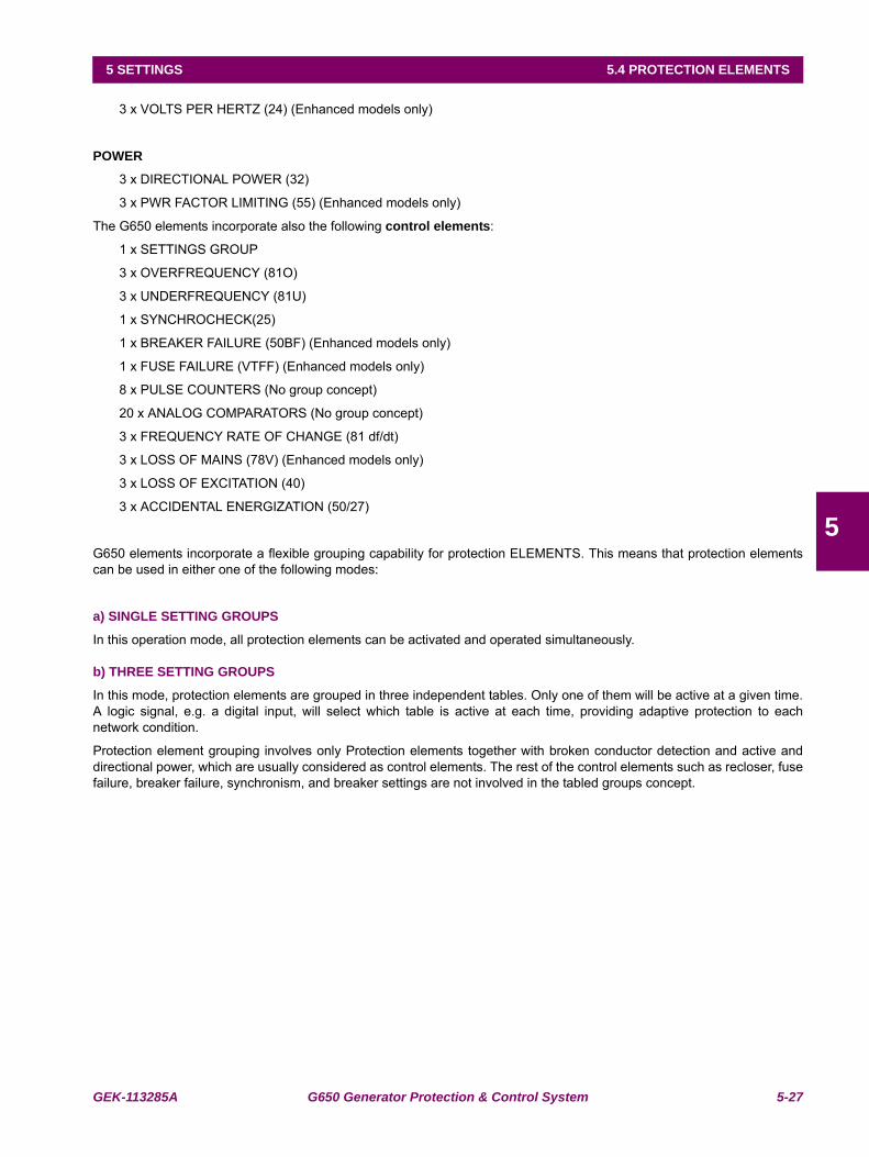
GEK-113285A G650 Generator Protection & Control System 5-27
5 SETTINGS 5.4 PROTECTION ELEMENTS
5
3 x VOLTS PER HERTZ (24) (Enhanced models only)
POWER
3 x DIRECTIONAL POWER (32)
3 x PWR FACTOR LIMITING (55) (Enhanced models only)
The G650 elements incorporate also the following control elements:
1 x SETTINGS GROUP
3 x OVERFREQUENCY (81O)
3 x UNDERFREQUENCY (81U)
1 x SYNCHROCHECK(25)
1 x BREAKER FAILURE (50BF) (Enhanced models only)
1 x FUSE FAILURE (VTFF) (Enhanced models only)
8 x PULSE COUNTERS (No group concept)
20 x ANALOG COMPARATORS (No group concept)
3 x FREQUENCY RATE OF CHANGE (81 df/dt)
3 x LOSS OF MAINS (78V) (Enhanced models only)
3 x LOSS OF EXCITATION (40)
3 x ACCIDENTAL ENERGIZATION (50/27)
G650 elements incorporate a flexible grouping capability for protection ELEMENTS. This means that protection elementscan be used in either one of the following modes:
a) SINGLE SETTING GROUPS
In this operation mode, all protection elements can be activated and operated simultaneously.
b) THREE SETTING GROUPS
In this mode, protection elements are grouped in three independent tables. Only one of them will be active at a given time.A logic signal, e.g. a digital input, will select which table is active at each time, providing adaptive protection to eachnetwork condition.
Protection element grouping involves only Protection elements together with broken conductor detection and active anddirectional power, which are usually considered as control elements. The rest of the control elements such as recloser, fusefailure, breaker failure, synchronism, and breaker settings are not involved in the tabled groups concept.
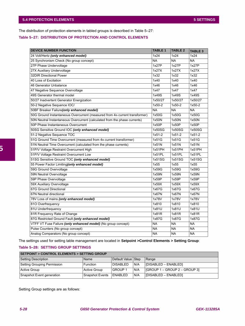
5-28 G650 Generator Protection & Control System GEK-113285A
5.4 PROTECTION ELEMENTS 5 SETTINGS
5
The distribution of protection elements in tabled groups is described in Table 5–27:
Table 5–27: DISTRIBUTION OF PROTECTION AND CONTROL ELEMENTS
The settings used for setting table management are located in Setpoint >Control Elements > Setting Group:
Table 5–28: SETTING GROUP SETTINGS
Setting Group settings are as follows:
DEVICE NUMBER FUNCTION TABLE 1 TABLE 2 TABLE 324 Volt/Hertz (only enhanced model) 1x24 1x24 1x2425 Synchronism Check (No group concept) NA NA NA27P Phase Undervoltage 1x27P 1x27P 1x27P27X Auxiliary Undervoltage 1x27X 1x27X 1x27X32DIR Directional Power 1x32 1x32 1x3240 Loss of Excitation 1x40 1x40 1x4046 Generator Unbalance 1x46 1x46 1x4647 Negative Sequence Overvoltage 1x47 1x47 1x4749S Generator thermal model 1x49S 1x49S 1x49S50/27 Inadvertent Generator Energization 1x50/27 1x50/27 1x50/2750-2 Negative Sequence IOC/ 1x50-2 1x50-2 1x50-250BF Breaker Failure(only enhanced model) NA NA NA50G Ground Instantaneous Overcurrent (measured from 4th current transformer) 1x50G 1x50G 1x50G50N Neutral Instantaneous Overcurrent (calculated from the phase currents) 1x50N 1x50N 1x50N50P Phase Instantaneous Overcurrent 1x50P 1x50P 1x50P50SG Sensitive Ground IOC (only enhanced model) 1x50SG 1x50SG 1x50SG51-2 Negative Sequence TOC 1x51-2 1x51-2 1x51-251G Ground Time Overcurrent (measured from 4th current transformer) 1x51G 1x51G 1x51G51N Neutral Time Overcurrent (calculated from the phase currents) 1x51N 1x51N 1x51N51P/V Voltage Restraint Overcurrent High 1x51PH 1x51PH 1x51PH51P/V Voltage Restraint Overcurrent Low 1x51PL 1x51PL 1x51PL51SG Sensitive Ground TOC (only enhanced model) 1x51SG 1x51SG 1x51SG55 Power Factor Limiting(only enhanced model) 1x55 1x55 1x5559G Ground Overvoltage 1x59G 1x59G 1x59G59N Neutral Overvoltage 1x59N 1x59N 1x59N59P Phase Overvoltage 1x59P 1x59P 1x59P59X Auxiliary Overvoltage 1x59X 1x59X 1x59X67G Ground Directional 1x67G 1x67G 1x67G67N Neutral directional 1x67N 1x67N 1x67N78V Loss of mains (only enhanced model) 1x78V 1x78V 1x78V81O Overfrequency 1x810 1x810 1x81081U Underfrequency 1x81U 1x81U 1x81U81R Frequency Rate of Change 1x81R 1x81R 1x81R87G Restricted Ground Fault (only enhanced model) 1x87G 1x87G 1x87GVTFF VT Fuse Failure (only enhanced model) (No group concept) NA NA NAPulse Counters (No group concept) NA NA NAAnalog Comparators (No group concept) NA NA NA
SETPOINT > CONTROL ELEMENTS > SETTING GROUPSetting Description Name Default Value Step RangeSetting Grouping Permission Function DISABLED N/A [DISABLED – ENABLED]Active Group Active Group GROUP 1 N/A [GROUP 1 – GROUP 2 – GROUP 3]Snapshot Event generation Snapshot Events ENABLED N/A [DISABLED – ENABLED]
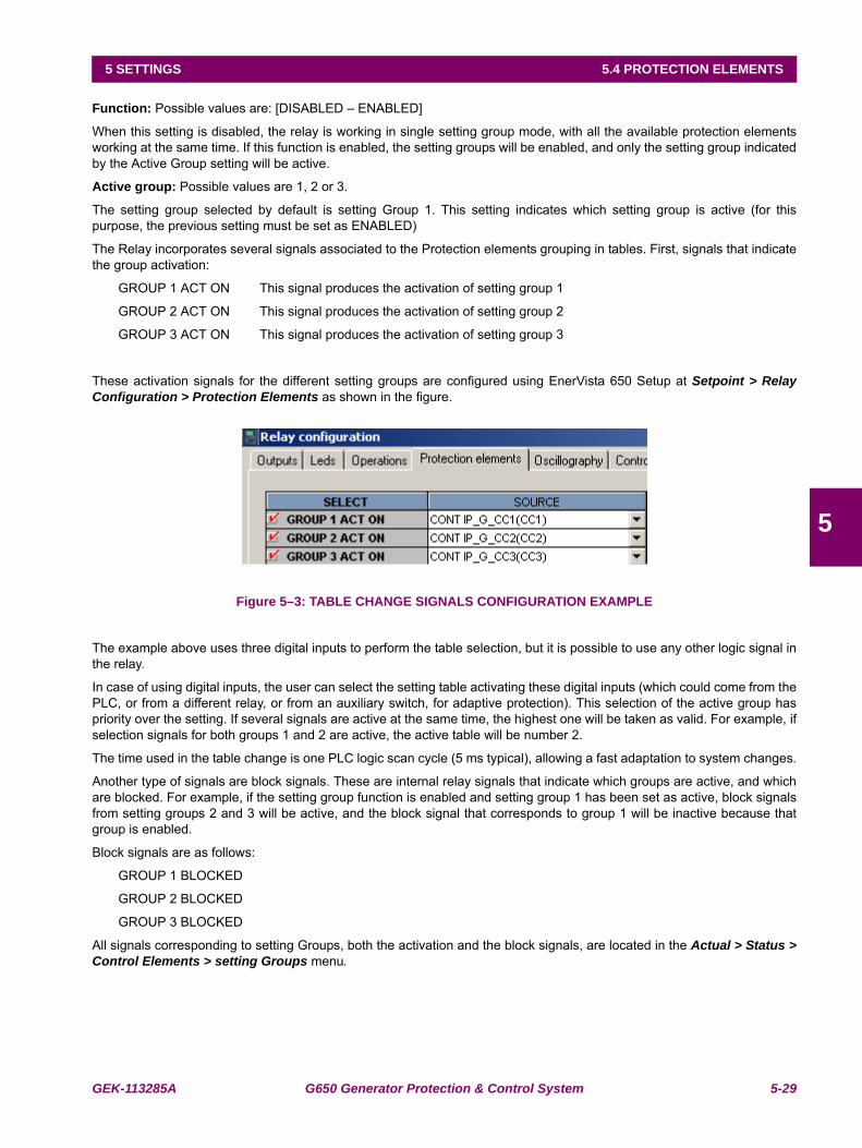
GEK-113285A G650 Generator Protection & Control System 5-29
5 SETTINGS 5.4 PROTECTION ELEMENTS
5
Function: Possible values are: [DISABLED – ENABLED]
When this setting is disabled, the relay is working in single setting group mode, with all the available protection elementsworking at the same time. If this function is enabled, the setting groups will be enabled, and only the setting group indicatedby the Active Group setting will be active.
Active group: Possible values are 1, 2 or 3.
The setting group selected by default is setting Group 1. This setting indicates which setting group is active (for thispurpose, the previous setting must be set as ENABLED)
The Relay incorporates several signals associated to the Protection elements grouping in tables. First, signals that indicatethe group activation:
GROUP 1 ACT ON This signal produces the activation of setting group 1
GROUP 2 ACT ON This signal produces the activation of setting group 2
GROUP 3 ACT ON This signal produces the activation of setting group 3
These activation signals for the different setting groups are configured using EnerVista 650 Setup at Setpoint > RelayConfiguration > Protection Elements as shown in the figure.
Figure 5–3: TABLE CHANGE SIGNALS CONFIGURATION EXAMPLE
The example above uses three digital inputs to perform the table selection, but it is possible to use any other logic signal inthe relay.
In case of using digital inputs, the user can select the setting table activating these digital inputs (which could come from thePLC, or from a different relay, or from an auxiliary switch, for adaptive protection). This selection of the active group haspriority over the setting. If several signals are active at the same time, the highest one will be taken as valid. For example, ifselection signals for both groups 1 and 2 are active, the active table will be number 2.
The time used in the table change is one PLC logic scan cycle (5 ms typical), allowing a fast adaptation to system changes.
Another type of signals are block signals. These are internal relay signals that indicate which groups are active, and whichare blocked. For example, if the setting group function is enabled and setting group 1 has been set as active, block signalsfrom setting groups 2 and 3 will be active, and the block signal that corresponds to group 1 will be inactive because thatgroup is enabled.
Block signals are as follows:
GROUP 1 BLOCKED
GROUP 2 BLOCKED
GROUP 3 BLOCKED
All signals corresponding to setting Groups, both the activation and the block signals, are located in the Actual > Status >Control Elements > setting Groups menu.
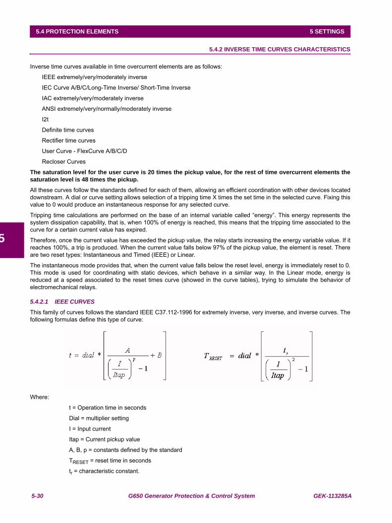
5-30 G650 Generator Protection & Control System GEK-113285A
5.4 PROTECTION ELEMENTS 5 SETTINGS
5
5.4.2 INVERSE TIME CURVES CHARACTERISTICS
Inverse time curves available in time overcurrent elements are as follows:
IEEE extremely/very/moderately inverse
IEC Curve A/B/C/Long-Time Inverse/ Short-Time Inverse
IAC extremely/very/moderately inverse
ANSI extremely/very/normally/moderately inverse
I2t
Definite time curves
Rectifier time curves
User Curve - FlexCurve A/B/C/D
Recloser Curves
The saturation level for the user curve is 20 times the pickup value, for the rest of time overcurrent elements thesaturation level is 48 times the pickup.
All these curves follow the standards defined for each of them, allowing an efficient coordination with other devices locateddownstream. A dial or curve setting allows selection of a tripping time X times the set time in the selected curve. Fixing thisvalue to 0 would produce an instantaneous response for any selected curve.
Tripping time calculations are performed on the base of an internal variable called “energy”. This energy represents thesystem dissipation capability, that is, when 100% of energy is reached, this means that the tripping time associated to thecurve for a certain current value has expired.
Therefore, once the current value has exceeded the pickup value, the relay starts increasing the energy variable value. If itreaches 100%, a trip is produced. When the current value falls below 97% of the pickup value, the element is reset. Thereare two reset types: Instantaneous and Timed (IEEE) or Linear.
The instantaneous mode provides that, when the current value falls below the reset level, energy is immediately reset to 0.This mode is used for coordinating with static devices, which behave in a similar way. In the Linear mode, energy isreduced at a speed associated to the reset times curve (showed in the curve tables), trying to simulate the behavior ofelectromechanical relays.
5.4.2.1 IEEE CURVES
This family of curves follows the standard IEEE C37.112-1996 for extremely inverse, very inverse, and inverse curves. Thefollowing formulas define this type of curve:
Where:
t = Operation time in seconds
Dial = multiplier setting
I = Input current
Itap = Current pickup value
A, B, p = constants defined by the standard
TRESET = reset time in seconds
tr = characteristic constant.

GEK-113285A G650 Generator Protection & Control System 5-31
5 SETTINGS 5.4 PROTECTION ELEMENTS
5
Table 5–29: CONSTANTS FOR IEEE CURVES
Table 5–30: TRIPPING TIME IN SECONDS FOR IEEE CURVES
IEEE CURVE SHAPE NAME A B P TRIEEE Extremely Inverse IEEE Ext Inv 28.2 0.1217 2.0000 29.1IEEE Very Inverse IEEE Very Inv 19.61 0.491 2.0000 21.6IEEE Inverse IEEE Mod Inv 0.0515 0.1140 0.0200 4.85
DIAL CURRENT (I/ITAP)1.5 2.0 3.0 4.0 5.0 6.0 7.0 8.0 9.0 10.0
IEEE Extremely Inverse0.5 11.341 4.761 1.823 1.001 0.648 0.464 0.355 0.285 0.237 0.2031.0 22.682 9.522 3.647 2.002 1.297 0.927 0.709 0.569 0.474 0.4072.0 45.363 19.043 7.293 4.003 2.593 1.855 1.418 1.139 0.948 0.8134.0 90.727 38.087 14.587 8.007 5.187 3.710 2.837 2.277 1.897 1.6266.0 136.090 57.130 21.880 12.010 7.780 5.564 4.255 3.416 2.845 2.4398.0 181.454 76.174 29.174 16.014 10.374 7.419 5.674 4.555 3.794 3.25210.0 226.817 95.217 36.467 20.017 12.967 9.274 7.092 5.693 4.742 4.065IEEE Very Inverse0.5 8.090 3.514 1.471 0.899 0.654 0.526 0.450 0.401 0.368 0.3451.0 16.179 7.028 2.942 1.798 1.308 1.051 0.900 0.802 0.736 0.6892.0 32.358 14.055 5.885 3.597 2.616 2.103 1.799 1.605 1.472 1.3784.0 64.716 28.111 11.769 7.193 5.232 4.205 3.598 3.209 2.945 2.7566.0 97.074 42.166 17.654 10.790 7.849 6.308 5.397 4.814 4.417 4.1348.0 129.432 56.221 23.538 14.387 10.465 8.410 7.196 6.418 5.889 5.51310.0 161.790 70.277 29.423 17.983 13.081 10.513 8.995 8.023 7.361 6.891IEEE Inverse0.5 3.220 1.902 1.216 0.973 0.844 0.763 0.706 0.663 0.630 0.6031.0 6.439 3.803 2.432 1.946 1.688 1.526 1.412 1.327 1.260 1.2072.0 12.878 7.606 4.864 3.892 3.377 3.051 2.823 2.653 2.521 2.4144.0 25.756 15.213 9.729 7.783 6.753 6.102 5.647 5.307 5.041 4.8276.0 38.634 22.819 14.593 11.675 10.130 9.153 8.470 7.960 7.562 7.2418.0 51.512 30.426 19.458 15.567 13.507 12.204 11.294 10.614 10.083 9.65410.0 64.390 38.032 24.322 19.458 16.883 15.255 14.117 13.267 12.604 12.068
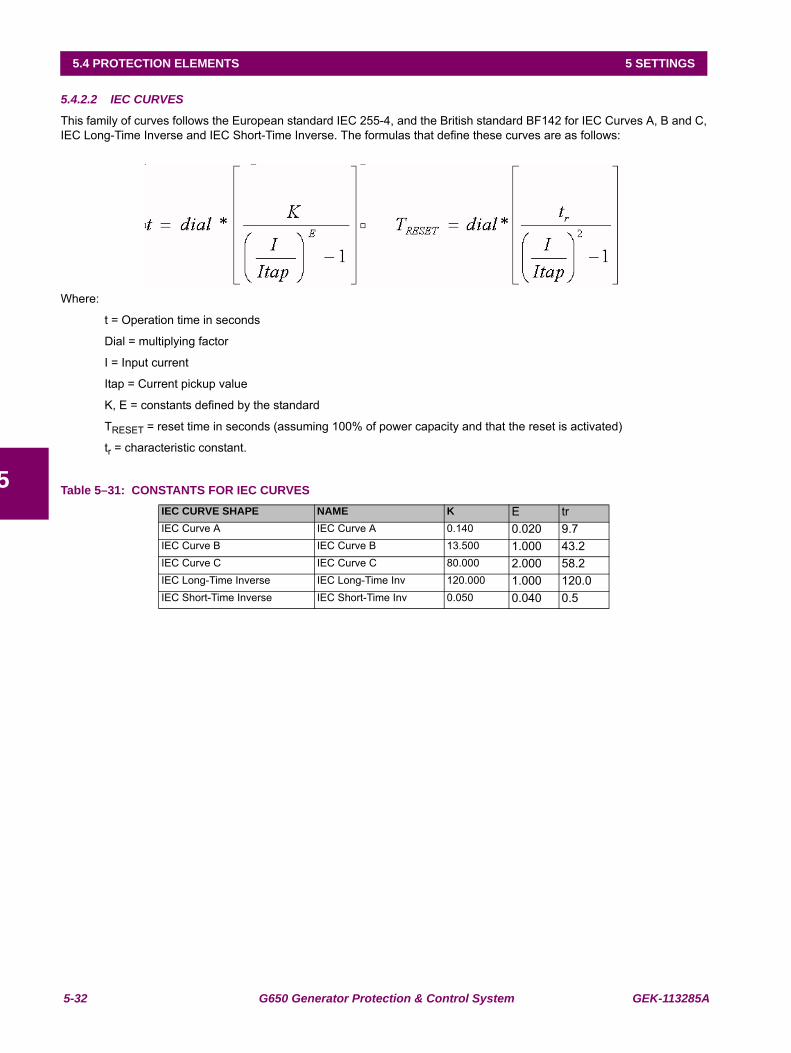
5-32 G650 Generator Protection & Control System GEK-113285A
5.4 PROTECTION ELEMENTS 5 SETTINGS
5
5.4.2.2 IEC CURVES
This family of curves follows the European standard IEC 255-4, and the British standard BF142 for IEC Curves A, B and C,IEC Long-Time Inverse and IEC Short-Time Inverse. The formulas that define these curves are as follows:
Where:
t = Operation time in seconds
Dial = multiplying factor
I = Input current
Itap = Current pickup value
K, E = constants defined by the standard
TRESET = reset time in seconds (assuming 100% of power capacity and that the reset is activated)
tr = characteristic constant.
Table 5–31: CONSTANTS FOR IEC CURVESIEC CURVE SHAPE NAME K E trIEC Curve A IEC Curve A 0.140 0.020 9.7IEC Curve B IEC Curve B 13.500 1.000 43.2IEC Curve C IEC Curve C 80.000 2.000 58.2IEC Long-Time Inverse IEC Long-Time Inv 120.000 1.000 120.0IEC Short-Time Inverse IEC Short-Time Inv 0.050 0.040 0.5
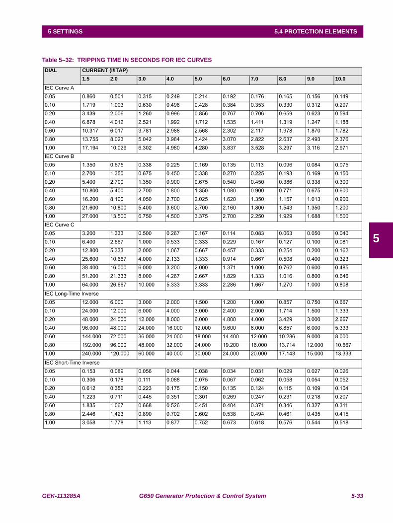
GEK-113285A G650 Generator Protection & Control System 5-33
5 SETTINGS 5.4 PROTECTION ELEMENTS
5
Table 5–32: TRIPPING TIME IN SECONDS FOR IEC CURVESDIAL CURRENT (I/ITAP)
1.5 2.0 3.0 4.0 5.0 6.0 7.0 8.0 9.0 10.0IEC Curve A0.05 0.860 0.501 0.315 0.249 0.214 0.192 0.176 0.165 0.156 0.1490.10 1.719 1.003 0.630 0.498 0.428 0.384 0.353 0.330 0.312 0.2970.20 3.439 2.006 1.260 0.996 0.856 0.767 0.706 0.659 0.623 0.5940.40 6.878 4.012 2.521 1.992 1.712 1.535 1.411 1.319 1.247 1.1880.60 10.317 6.017 3.781 2.988 2.568 2.302 2.117 1.978 1.870 1.7820.80 13.755 8.023 5.042 3.984 3.424 3.070 2.822 2.637 2.493 2.3761.00 17.194 10.029 6.302 4.980 4.280 3.837 3.528 3.297 3.116 2.971IEC Curve B0.05 1.350 0.675 0.338 0.225 0.169 0.135 0.113 0.096 0.084 0.0750.10 2.700 1.350 0.675 0.450 0.338 0.270 0.225 0.193 0.169 0.1500.20 5.400 2.700 1.350 0.900 0.675 0.540 0.450 0.386 0.338 0.3000.40 10.800 5.400 2.700 1.800 1.350 1.080 0.900 0.771 0.675 0.6000.60 16.200 8.100 4.050 2.700 2.025 1.620 1.350 1.157 1.013 0.9000.80 21.600 10.800 5.400 3.600 2.700 2.160 1.800 1.543 1.350 1.2001.00 27.000 13.500 6.750 4.500 3.375 2.700 2.250 1.929 1.688 1.500IEC Curve C0.05 3.200 1.333 0.500 0.267 0.167 0.114 0.083 0.063 0.050 0.0400.10 6.400 2.667 1.000 0.533 0.333 0.229 0.167 0.127 0.100 0.0810.20 12.800 5.333 2.000 1.067 0.667 0.457 0.333 0.254 0.200 0.1620.40 25.600 10.667 4.000 2.133 1.333 0.914 0.667 0.508 0.400 0.3230.60 38.400 16.000 6.000 3.200 2.000 1.371 1.000 0.762 0.600 0.4850.80 51.200 21.333 8.000 4.267 2.667 1.829 1.333 1.016 0.800 0.6461.00 64.000 26.667 10.000 5.333 3.333 2.286 1.667 1.270 1.000 0.808
IEC Long-Time Inverse0.05 12.000 6.000 3.000 2.000 1.500 1.200 1.000 0.857 0.750 0.6670.10 24.000 12.000 6.000 4.000 3.000 2.400 2.000 1.714 1.500 1.3330.20 48.000 24.000 12.000 8.000 6.000 4.800 4.000 3.429 3.000 2.6670.40 96.000 48.000 24.000 16.000 12.000 9.600 8.000 6.857 6.000 5.3330.60 144.000 72.000 36.000 24.000 18.000 14.400 12.000 10.286 9.000 8.0000.80 192.000 96.000 48.000 32.000 24.000 19.200 16.000 13.714 12.000 10.6671.00 240.000 120.000 60.000 40.000 30.000 24.000 20.000 17.143 15.000 13.333
IEC Short-Time Inverse0.05 0.153 0.089 0.056 0.044 0.038 0.034 0.031 0.029 0.027 0.0260.10 0.306 0.178 0.111 0.088 0.075 0.067 0.062 0.058 0.054 0.0520.20 0.612 0.356 0.223 0.175 0.150 0.135 0.124 0.115 0.109 0.1040.40 1.223 0.711 0.445 0.351 0.301 0.269 0.247 0.231 0.218 0.2070.60 1.835 1.067 0.668 0.526 0.451 0.404 0.371 0.346 0.327 0.3110.80 2.446 1.423 0.890 0.702 0.602 0.538 0.494 0.461 0.435 0.4151.00 3.058 1.778 1.113 0.877 0.752 0.673 0.618 0.576 0.544 0.518
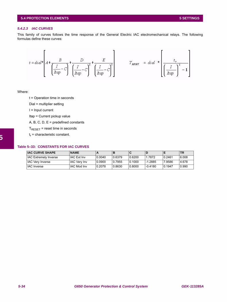
5-34 G650 Generator Protection & Control System GEK-113285A
5.4 PROTECTION ELEMENTS 5 SETTINGS
5
5.4.2.3 IAC CURVES
This family of curves follows the time response of the General Electric IAC electromechanical relays. The followingformulas define these curves:
Where:
t = Operation time in seconds
Dial = multiplier setting
I = Input current
Itap = Current pickup value
A, B, C, D, E = predefined constants
TRESET = reset time in seconds
tr = characteristic constant.
Table 5–33: CONSTANTS FOR IAC CURVESIAC CURVE SHAPE NAME A B C D E TRIAC Extremely Inverse IAC Ext Inv 0.0040 0.6379 0.6200 1.7872 0.2461 6.008IAC Very Inverse IAC Very Inv 0.0900 0.7955 0.1000 -1.2885 7.9586 4.678IAC Inverse IAC Mod Inv 0.2078 0.8630 0.8000 -0.4180 0.1947 0.990
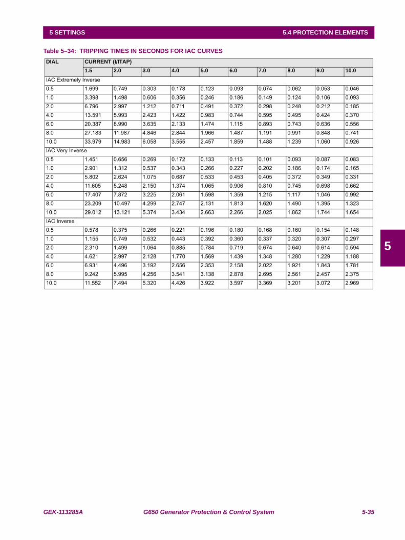
GEK-113285A G650 Generator Protection & Control System 5-35
5 SETTINGS 5.4 PROTECTION ELEMENTS
5
Table 5–34: TRIPPING TIMES IN SECONDS FOR IAC CURVES DIAL CURRENT (I/ITAP)
1.5 2.0 3.0 4.0 5.0 6.0 7.0 8.0 9.0 10.0IAC Extremely Inverse0.5 1.699 0.749 0.303 0.178 0.123 0.093 0.074 0.062 0.053 0.0461.0 3.398 1.498 0.606 0.356 0.246 0.186 0.149 0.124 0.106 0.0932.0 6.796 2.997 1.212 0.711 0.491 0.372 0.298 0.248 0.212 0.1854.0 13.591 5.993 2.423 1.422 0.983 0.744 0.595 0.495 0.424 0.3706.0 20.387 8.990 3.635 2.133 1.474 1.115 0.893 0.743 0.636 0.5568.0 27.183 11.987 4.846 2.844 1.966 1.487 1.191 0.991 0.848 0.74110.0 33.979 14.983 6.058 3.555 2.457 1.859 1.488 1.239 1.060 0.926IAC Very Inverse0.5 1.451 0.656 0.269 0.172 0.133 0.113 0.101 0.093 0.087 0.0831.0 2.901 1.312 0.537 0.343 0.266 0.227 0.202 0.186 0.174 0.1652.0 5.802 2.624 1.075 0.687 0.533 0.453 0.405 0.372 0.349 0.3314.0 11.605 5.248 2.150 1.374 1.065 0.906 0.810 0.745 0.698 0.6626.0 17.407 7.872 3.225 2.061 1.598 1.359 1.215 1.117 1.046 0.9928.0 23.209 10.497 4.299 2.747 2.131 1.813 1.620 1.490 1.395 1.32310.0 29.012 13.121 5.374 3.434 2.663 2.266 2.025 1.862 1.744 1.654IAC Inverse0.5 0.578 0.375 0.266 0.221 0.196 0.180 0.168 0.160 0.154 0.1481.0 1.155 0.749 0.532 0.443 0.392 0.360 0.337 0.320 0.307 0.2972.0 2.310 1.499 1.064 0.885 0.784 0.719 0.674 0.640 0.614 0.5944.0 4.621 2.997 2.128 1.770 1.569 1.439 1.348 1.280 1.229 1.1886.0 6.931 4.496 3.192 2.656 2.353 2.158 2.022 1.921 1.843 1.7818.0 9.242 5.995 4.256 3.541 3.138 2.878 2.695 2.561 2.457 2.37510.0 11.552 7.494 5.320 4.426 3.922 3.597 3.369 3.201 3.072 2.969
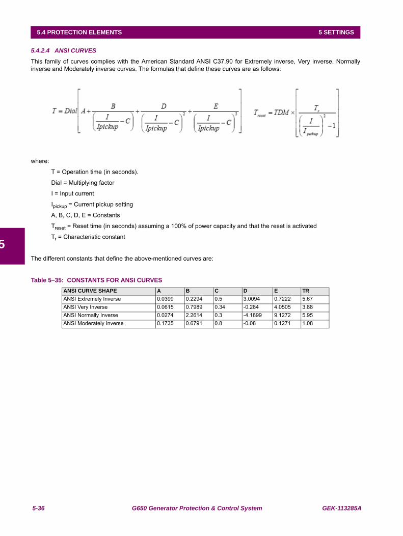
5-36 G650 Generator Protection & Control System GEK-113285A
5.4 PROTECTION ELEMENTS 5 SETTINGS
5
5.4.2.4 ANSI CURVES
This family of curves complies with the American Standard ANSI C37.90 for Extremely inverse, Very inverse, Normallyinverse and Moderately inverse curves. The formulas that define these curves are as follows:
where:
T = Operation time (in seconds).
Dial = Multiplying factor
I = Input current
Ipickup = Current pickup setting
A, B, C, D, E = Constants
Treset = Reset time (in seconds) assuming a 100% of power capacity and that the reset is activated
Tr = Characteristic constant
The different constants that define the above-mentioned curves are:
Table 5–35: CONSTANTS FOR ANSI CURVESANSI CURVE SHAPE A B C D E TRANSI Extremely Inverse 0.0399 0.2294 0.5 3.0094 0.7222 5.67ANSI Very Inverse 0.0615 0.7989 0.34 -0.284 4.0505 3.88ANSI Normally Inverse 0.0274 2.2614 0.3 -4.1899 9.1272 5.95ANSI Moderately Inverse 0.1735 0.6791 0.8 -0.08 0.1271 1.08
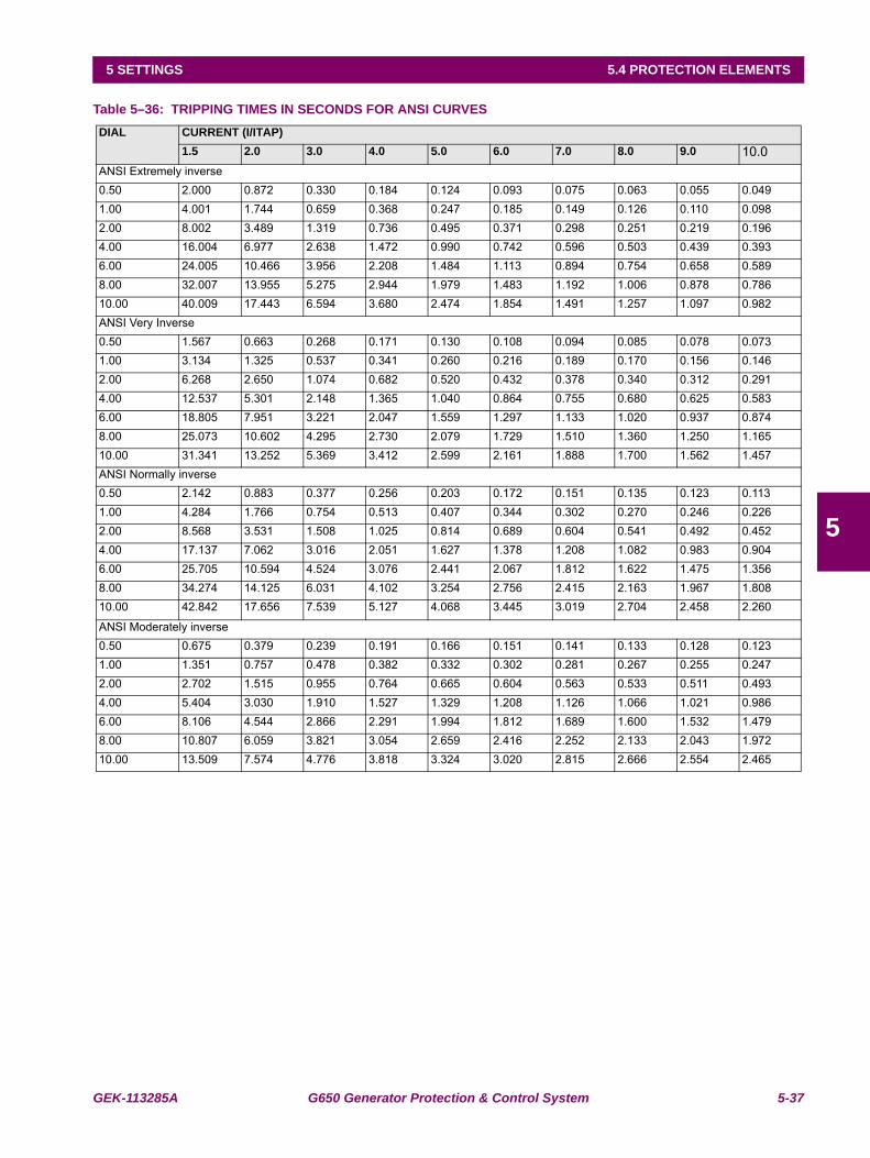
GEK-113285A G650 Generator Protection & Control System 5-37
5 SETTINGS 5.4 PROTECTION ELEMENTS
5
Table 5–36: TRIPPING TIMES IN SECONDS FOR ANSI CURVESDIAL CURRENT (I/ITAP)
1.5 2.0 3.0 4.0 5.0 6.0 7.0 8.0 9.0 10.0ANSI Extremely inverse0.50 2.000 0.872 0.330 0.184 0.124 0.093 0.075 0.063 0.055 0.0491.00 4.001 1.744 0.659 0.368 0.247 0.185 0.149 0.126 0.110 0.0982.00 8.002 3.489 1.319 0.736 0.495 0.371 0.298 0.251 0.219 0.1964.00 16.004 6.977 2.638 1.472 0.990 0.742 0.596 0.503 0.439 0.3936.00 24.005 10.466 3.956 2.208 1.484 1.113 0.894 0.754 0.658 0.5898.00 32.007 13.955 5.275 2.944 1.979 1.483 1.192 1.006 0.878 0.78610.00 40.009 17.443 6.594 3.680 2.474 1.854 1.491 1.257 1.097 0.982ANSI Very Inverse0.50 1.567 0.663 0.268 0.171 0.130 0.108 0.094 0.085 0.078 0.0731.00 3.134 1.325 0.537 0.341 0.260 0.216 0.189 0.170 0.156 0.1462.00 6.268 2.650 1.074 0.682 0.520 0.432 0.378 0.340 0.312 0.2914.00 12.537 5.301 2.148 1.365 1.040 0.864 0.755 0.680 0.625 0.5836.00 18.805 7.951 3.221 2.047 1.559 1.297 1.133 1.020 0.937 0.8748.00 25.073 10.602 4.295 2.730 2.079 1.729 1.510 1.360 1.250 1.16510.00 31.341 13.252 5.369 3.412 2.599 2.161 1.888 1.700 1.562 1.457ANSI Normally inverse0.50 2.142 0.883 0.377 0.256 0.203 0.172 0.151 0.135 0.123 0.1131.00 4.284 1.766 0.754 0.513 0.407 0.344 0.302 0.270 0.246 0.2262.00 8.568 3.531 1.508 1.025 0.814 0.689 0.604 0.541 0.492 0.4524.00 17.137 7.062 3.016 2.051 1.627 1.378 1.208 1.082 0.983 0.9046.00 25.705 10.594 4.524 3.076 2.441 2.067 1.812 1.622 1.475 1.3568.00 34.274 14.125 6.031 4.102 3.254 2.756 2.415 2.163 1.967 1.80810.00 42.842 17.656 7.539 5.127 4.068 3.445 3.019 2.704 2.458 2.260
ANSI Moderately inverse0.50 0.675 0.379 0.239 0.191 0.166 0.151 0.141 0.133 0.128 0.1231.00 1.351 0.757 0.478 0.382 0.332 0.302 0.281 0.267 0.255 0.2472.00 2.702 1.515 0.955 0.764 0.665 0.604 0.563 0.533 0.511 0.4934.00 5.404 3.030 1.910 1.527 1.329 1.208 1.126 1.066 1.021 0.9866.00 8.106 4.544 2.866 2.291 1.994 1.812 1.689 1.600 1.532 1.4798.00 10.807 6.059 3.821 3.054 2.659 2.416 2.252 2.133 2.043 1.97210.00 13.509 7.574 4.776 3.818 3.324 3.020 2.815 2.666 2.554 2.465
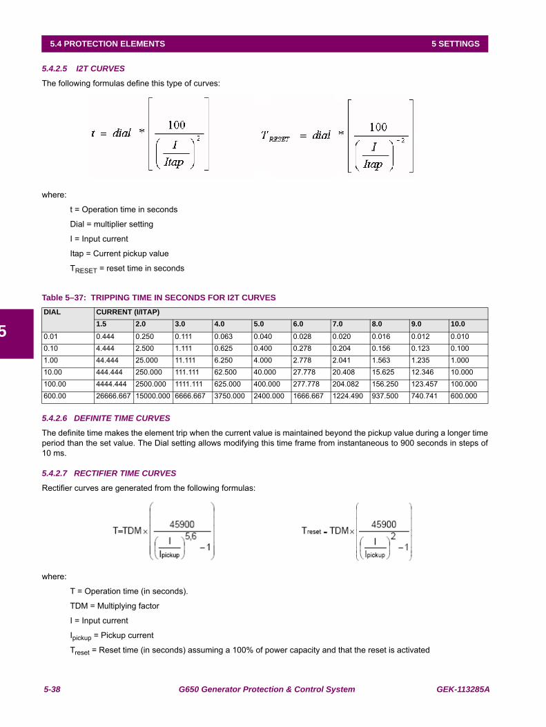
5-38 G650 Generator Protection & Control System GEK-113285A
5.4 PROTECTION ELEMENTS 5 SETTINGS
5
5.4.2.5 I2T CURVES
The following formulas define this type of curves:
where:
t = Operation time in seconds
Dial = multiplier setting
I = Input current
Itap = Current pickup value
TRESET = reset time in seconds
Table 5–37: TRIPPING TIME IN SECONDS FOR I2T CURVES
5.4.2.6 DEFINITE TIME CURVES
The definite time makes the element trip when the current value is maintained beyond the pickup value during a longer timeperiod than the set value. The Dial setting allows modifying this time frame from instantaneous to 900 seconds in steps of10 ms.
5.4.2.7 RECTIFIER TIME CURVES
Rectifier curves are generated from the following formulas:
where:
T = Operation time (in seconds).
TDM = Multiplying factor
I = Input current
Ipickup = Pickup current
Treset = Reset time (in seconds) assuming a 100% of power capacity and that the reset is activated
DIAL CURRENT (I/ITAP)1.5 2.0 3.0 4.0 5.0 6.0 7.0 8.0 9.0 10.0
0.01 0.444 0.250 0.111 0.063 0.040 0.028 0.020 0.016 0.012 0.0100.10 4.444 2.500 1.111 0.625 0.400 0.278 0.204 0.156 0.123 0.1001.00 44.444 25.000 11.111 6.250 4.000 2.778 2.041 1.563 1.235 1.00010.00 444.444 250.000 111.111 62.500 40.000 27.778 20.408 15.625 12.346 10.000100.00 4444.444 2500.000 1111.111 625.000 400.000 277.778 204.082 156.250 123.457 100.000600.00 26666.667 15000.000 6666.667 3750.000 2400.000 1666.667 1224.490 937.500 740.741 600.000
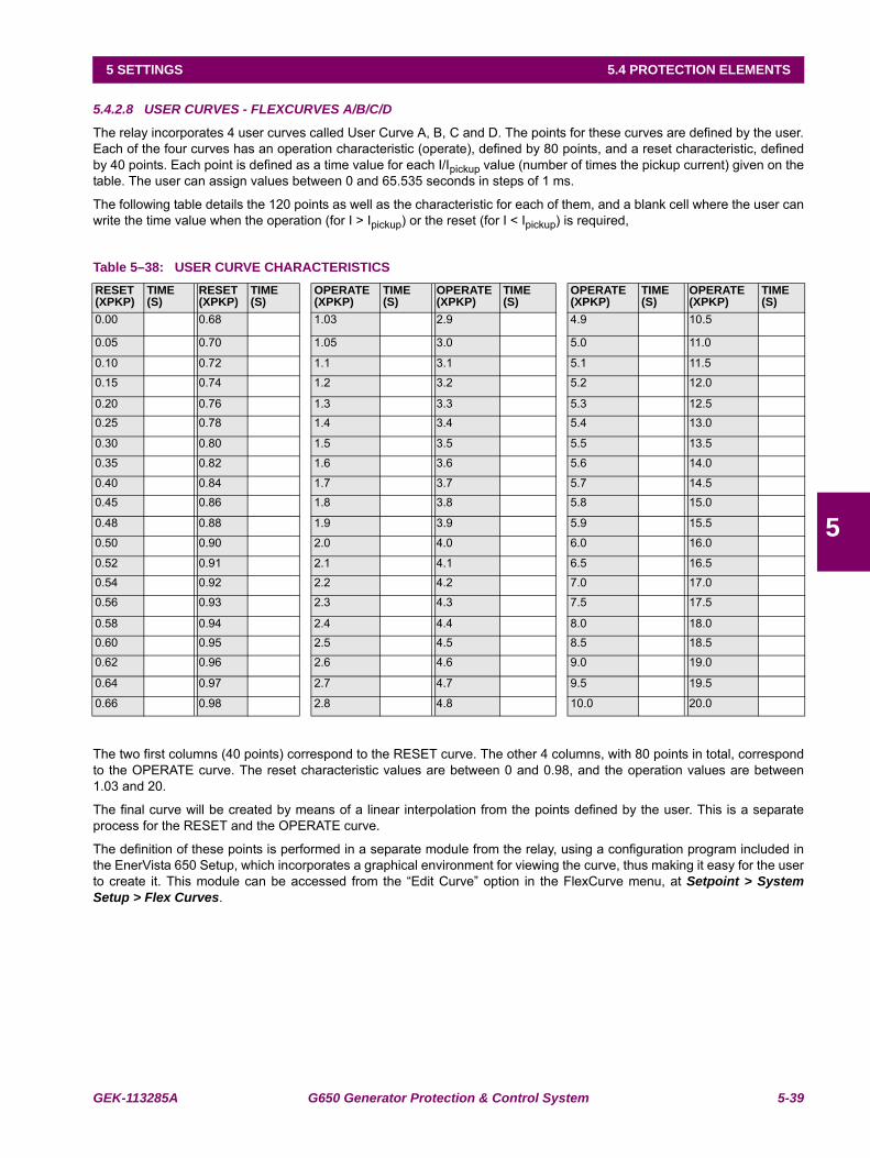
GEK-113285A G650 Generator Protection & Control System 5-39
5 SETTINGS 5.4 PROTECTION ELEMENTS
5
5.4.2.8 USER CURVES - FLEXCURVES A/B/C/D
The relay incorporates 4 user curves called User Curve A, B, C and D. The points for these curves are defined by the user.Each of the four curves has an operation characteristic (operate), defined by 80 points, and a reset characteristic, definedby 40 points. Each point is defined as a time value for each I/Ipickup value (number of times the pickup current) given on thetable. The user can assign values between 0 and 65.535 seconds in steps of 1 ms.
The following table details the 120 points as well as the characteristic for each of them, and a blank cell where the user canwrite the time value when the operation (for I > Ipickup) or the reset (for I < Ipickup) is required,
Table 5–38: USER CURVE CHARACTERISTICS
The two first columns (40 points) correspond to the RESET curve. The other 4 columns, with 80 points in total, correspondto the OPERATE curve. The reset characteristic values are between 0 and 0.98, and the operation values are between1.03 and 20.
The final curve will be created by means of a linear interpolation from the points defined by the user. This is a separateprocess for the RESET and the OPERATE curve.
The definition of these points is performed in a separate module from the relay, using a configuration program included inthe EnerVista 650 Setup, which incorporates a graphical environment for viewing the curve, thus making it easy for the userto create it. This module can be accessed from the “Edit Curve” option in the FlexCurve menu, at Setpoint > SystemSetup > Flex Curves.
RESET (XPKP)
TIME(S)
RESET(XPKP)
TIME(S)
OPERATE(XPKP)
TIME(S)
OPERATE(XPKP)
TIME(S)
OPERATE(XPKP)
TIME(S)
OPERATE(XPKP)
TIME(S)
0.00 0.68 1.03 2.9 4.9 10.5
0.05 0.70 1.05 3.0 5.0 11.0
0.10 0.72 1.1 3.1 5.1 11.5
0.15 0.74 1.2 3.2 5.2 12.0
0.20 0.76 1.3 3.3 5.3 12.50.25 0.78 1.4 3.4 5.4 13.0
0.30 0.80 1.5 3.5 5.5 13.5
0.35 0.82 1.6 3.6 5.6 14.0
0.40 0.84 1.7 3.7 5.7 14.50.45 0.86 1.8 3.8 5.8 15.0
0.48 0.88 1.9 3.9 5.9 15.5
0.50 0.90 2.0 4.0 6.0 16.0
0.52 0.91 2.1 4.1 6.5 16.5
0.54 0.92 2.2 4.2 7.0 17.0
0.56 0.93 2.3 4.3 7.5 17.5
0.58 0.94 2.4 4.4 8.0 18.00.60 0.95 2.5 4.5 8.5 18.5
0.62 0.96 2.6 4.6 9.0 19.0
0.64 0.97 2.7 4.7 9.5 19.5
0.66 0.98 2.8 4.8 10.0 20.0
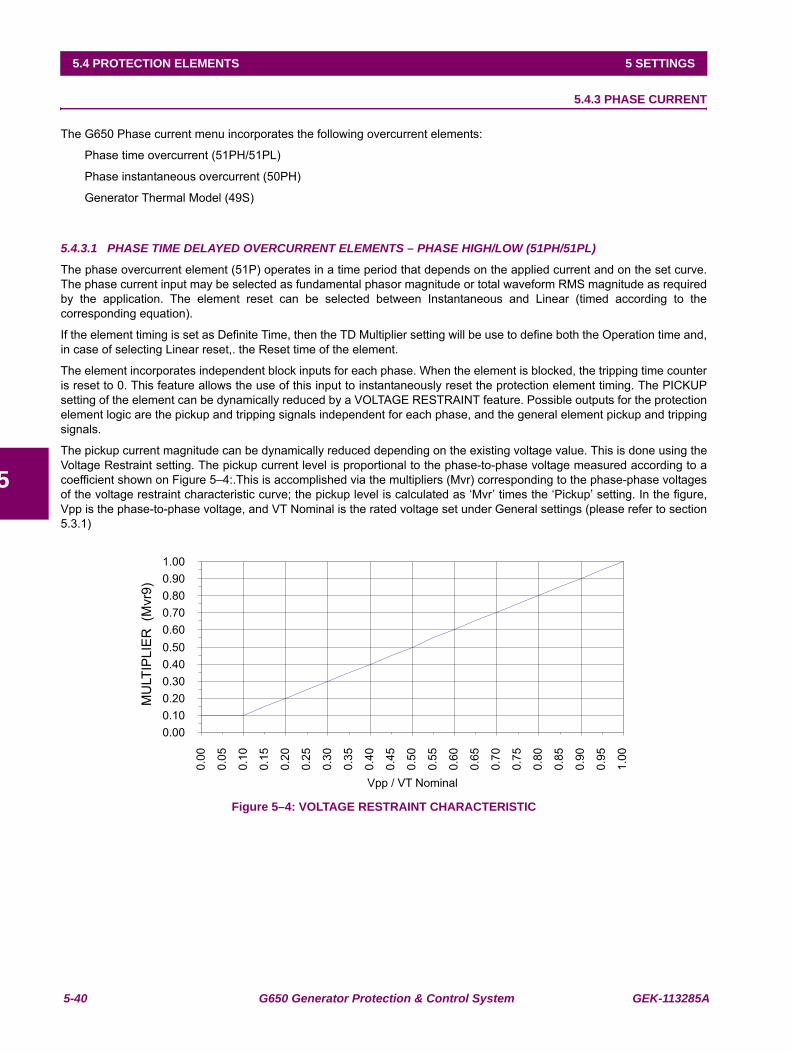
5-40 G650 Generator Protection & Control System GEK-113285A
5.4 PROTECTION ELEMENTS 5 SETTINGS
5
5.4.3 PHASE CURRENT
The G650 Phase current menu incorporates the following overcurrent elements:
Phase time overcurrent (51PH/51PL)
Phase instantaneous overcurrent (50PH)
Generator Thermal Model (49S)
5.4.3.1 PHASE TIME DELAYED OVERCURRENT ELEMENTS – PHASE HIGH/LOW (51PH/51PL)
The phase overcurrent element (51P) operates in a time period that depends on the applied current and on the set curve.The phase current input may be selected as fundamental phasor magnitude or total waveform RMS magnitude as requiredby the application. The element reset can be selected between Instantaneous and Linear (timed according to thecorresponding equation).
If the element timing is set as Definite Time, then the TD Multiplier setting will be use to define both the Operation time and,in case of selecting Linear reset,. the Reset time of the element.
The element incorporates independent block inputs for each phase. When the element is blocked, the tripping time counteris reset to 0. This feature allows the use of this input to instantaneously reset the protection element timing. The PICKUPsetting of the element can be dynamically reduced by a VOLTAGE RESTRAINT feature. Possible outputs for the protectionelement logic are the pickup and tripping signals independent for each phase, and the general element pickup and trippingsignals.
The pickup current magnitude can be dynamically reduced depending on the existing voltage value. This is done using theVoltage Restraint setting. The pickup current level is proportional to the phase-to-phase voltage measured according to acoefficient shown on Figure 5–4:.This is accomplished via the multipliers (Mvr) corresponding to the phase-phase voltagesof the voltage restraint characteristic curve; the pickup level is calculated as ‘Mvr’ times the ‘Pickup’ setting. In the figure,Vpp is the phase-to-phase voltage, and VT Nominal is the rated voltage set under General settings (please refer to section5.3.1)
Figure 5–4: VOLTAGE RESTRAINT CHARACTERISTIC
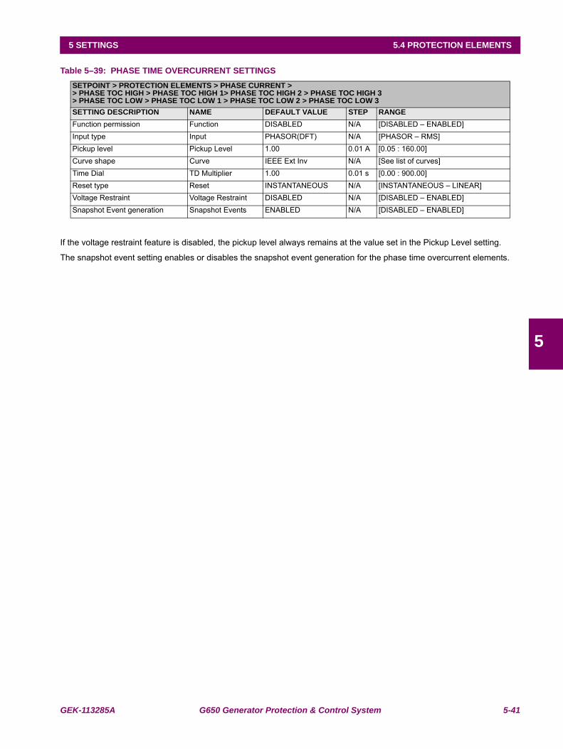
GEK-113285A G650 Generator Protection & Control System 5-41
5 SETTINGS 5.4 PROTECTION ELEMENTS
5
Table 5–39: PHASE TIME OVERCURRENT SETTINGS
If the voltage restraint feature is disabled, the pickup level always remains at the value set in the Pickup Level setting.
The snapshot event setting enables or disables the snapshot event generation for the phase time overcurrent elements.
SETPOINT > PROTECTION ELEMENTS > PHASE CURRENT >> PHASE TOC HIGH > PHASE TOC HIGH 1> PHASE TOC HIGH 2 > PHASE TOC HIGH 3> PHASE TOC LOW > PHASE TOC LOW 1 > PHASE TOC LOW 2 > PHASE TOC LOW 3SETTING DESCRIPTION NAME DEFAULT VALUE STEP RANGEFunction permission Function DISABLED N/A [DISABLED – ENABLED]Input type Input PHASOR(DFT) N/A [PHASOR – RMS]Pickup level Pickup Level 1.00 0.01 A [0.05 : 160.00]Curve shape Curve IEEE Ext Inv N/A [See list of curves]Time Dial TD Multiplier 1.00 0.01 s [0.00 : 900.00]Reset type Reset INSTANTANEOUS N/A [INSTANTANEOUS – LINEAR]Voltage Restraint Voltage Restraint DISABLED N/A [DISABLED – ENABLED]Snapshot Event generation Snapshot Events ENABLED N/A [DISABLED – ENABLED]
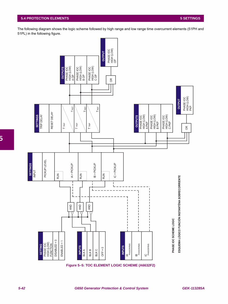
5-42 G650 Generator Protection & Control System GEK-113285A
5.4 PROTECTION ELEMENTS 5 SETTINGS
5
The following diagram shows the logic scheme followed by high range and low range time overcurrent elements (51PH and51PL) in the following figure.
Figure 5–5: TOC ELEMENT LOGIC SCHEME (A6632F2)
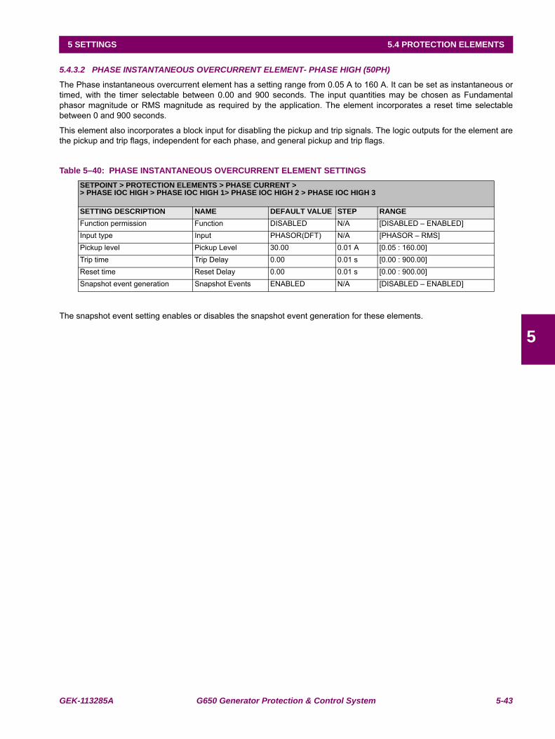
GEK-113285A G650 Generator Protection & Control System 5-43
5 SETTINGS 5.4 PROTECTION ELEMENTS
5
5.4.3.2 PHASE INSTANTANEOUS OVERCURRENT ELEMENT- PHASE HIGH (50PH)
The Phase instantaneous overcurrent element has a setting range from 0.05 A to 160 A. It can be set as instantaneous ortimed, with the timer selectable between 0.00 and 900 seconds. The input quantities may be chosen as Fundamentalphasor magnitude or RMS magnitude as required by the application. The element incorporates a reset time selectablebetween 0 and 900 seconds.
This element also incorporates a block input for disabling the pickup and trip signals. The logic outputs for the element arethe pickup and trip flags, independent for each phase, and general pickup and trip flags.
Table 5–40: PHASE INSTANTANEOUS OVERCURRENT ELEMENT SETTINGS
The snapshot event setting enables or disables the snapshot event generation for these elements.
SETPOINT > PROTECTION ELEMENTS > PHASE CURRENT >> PHASE IOC HIGH > PHASE IOC HIGH 1> PHASE IOC HIGH 2 > PHASE IOC HIGH 3
SETTING DESCRIPTION NAME DEFAULT VALUE STEP RANGEFunction permission Function DISABLED N/A [DISABLED – ENABLED]Input type Input PHASOR(DFT) N/A [PHASOR – RMS]Pickup level Pickup Level 30.00 0.01 A [0.05 : 160.00]Trip time Trip Delay 0.00 0.01 s [0.00 : 900.00]Reset time Reset Delay 0.00 0.01 s [0.00 : 900.00]Snapshot event generation Snapshot Events ENABLED N/A [DISABLED – ENABLED]
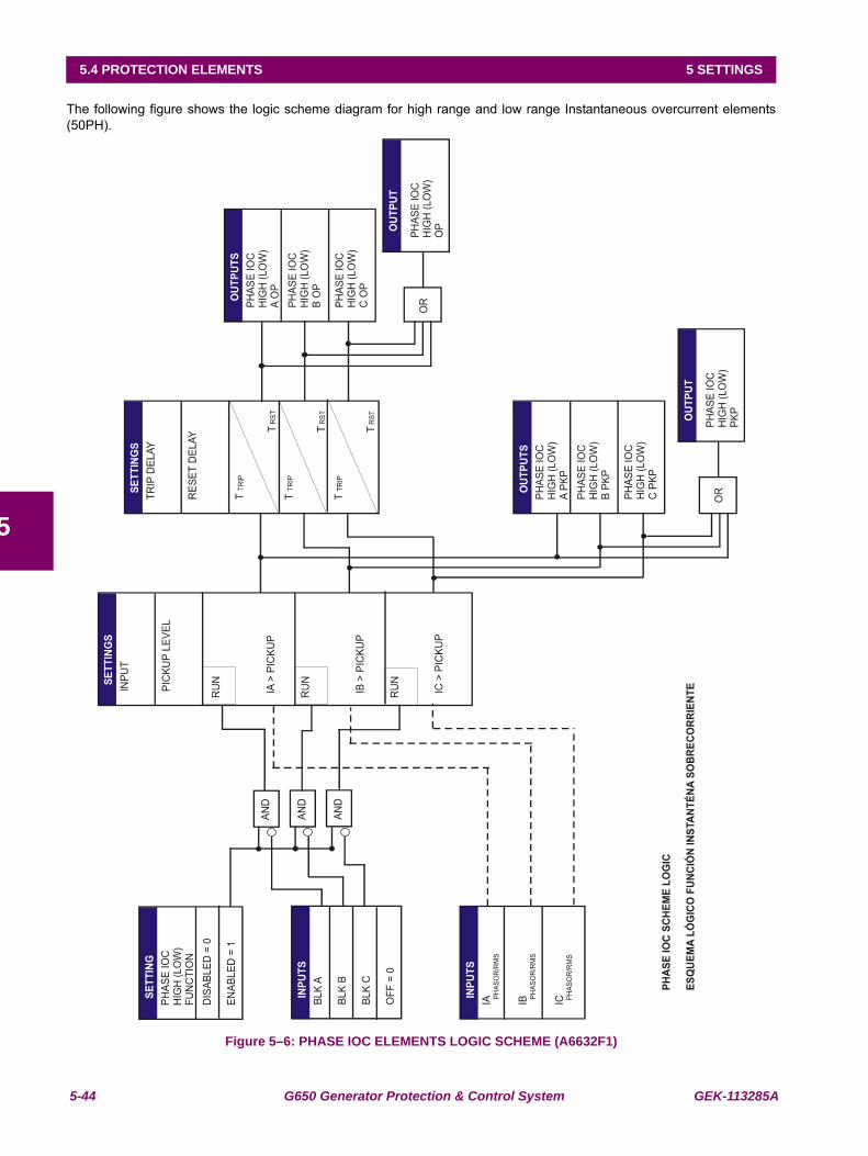
5-44 G650 Generator Protection & Control System GEK-113285A
5.4 PROTECTION ELEMENTS 5 SETTINGS
5
The following figure shows the logic scheme diagram for high range and low range Instantaneous overcurrent elements(50PH).
Figure 5–6: PHASE IOC ELEMENTS LOGIC SCHEME (A6632F1)
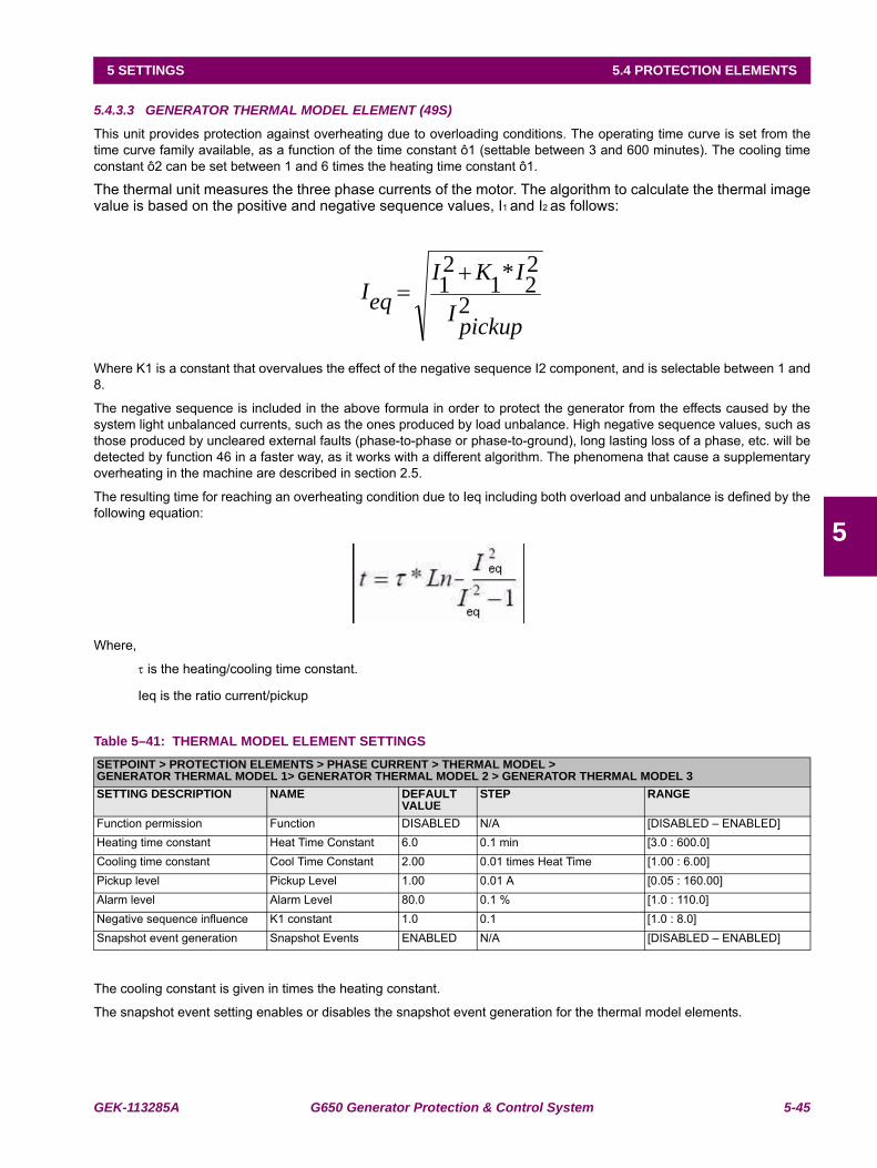
GEK-113285A G650 Generator Protection & Control System 5-45
5 SETTINGS 5.4 PROTECTION ELEMENTS
5
5.4.3.3 GENERATOR THERMAL MODEL ELEMENT (49S)
This unit provides protection against overheating due to overloading conditions. The operating time curve is set from thetime curve family available, as a function of the time constant ô1 (settable between 3 and 600 minutes). The cooling timeconstant ô2 can be set between 1 and 6 times the heating time constant ô1.
The thermal unit measures the three phase currents of the motor. The algorithm to calculate the thermal imagevalue is based on the positive and negative sequence values, I1 and I2 as follows:
Where K1 is a constant that overvalues the effect of the negative sequence I2 component, and is selectable between 1 and8.
The negative sequence is included in the above formula in order to protect the generator from the effects caused by thesystem light unbalanced currents, such as the ones produced by load unbalance. High negative sequence values, such asthose produced by uncleared external faults (phase-to-phase or phase-to-ground), long lasting loss of a phase, etc. will bedetected by function 46 in a faster way, as it works with a different algorithm. The phenomena that cause a supplementaryoverheating in the machine are described in section 2.5.
The resulting time for reaching an overheating condition due to Ieq including both overload and unbalance is defined by thefollowing equation:
Where,
τ is the heating/cooling time constant.
Ieq is the ratio current/pickup
Table 5–41: THERMAL MODEL ELEMENT SETTINGS
The cooling constant is given in times the heating constant.
The snapshot event setting enables or disables the snapshot event generation for the thermal model elements.
SETPOINT > PROTECTION ELEMENTS > PHASE CURRENT > THERMAL MODEL >GENERATOR THERMAL MODEL 1> GENERATOR THERMAL MODEL 2 > GENERATOR THERMAL MODEL 3SETTING DESCRIPTION NAME DEFAULT
VALUESTEP RANGE
Function permission Function DISABLED N/A [DISABLED – ENABLED]Heating time constant Heat Time Constant 6.0 0.1 min [3.0 : 600.0]Cooling time constant Cool Time Constant 2.00 0.01 times Heat Time [1.00 : 6.00]Pickup level Pickup Level 1.00 0.01 A [0.05 : 160.00]Alarm level Alarm Level 80.0 0.1 % [1.0 : 110.0]Negative sequence influence K1 constant 1.0 0.1 [1.0 : 8.0]Snapshot event generation Snapshot Events ENABLED N/A [DISABLED – ENABLED]
2
22*1
21
pickupI
IKIeqI
+=
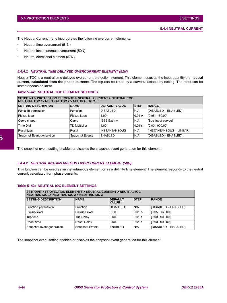
5-46 G650 Generator Protection & Control System GEK-113285A
5.4 PROTECTION ELEMENTS 5 SETTINGS
5
5.4.4 NEUTRAL CURRENT
The Neutral Current menu incorporates the following overcurrent elements:
• Neutral time overcurrent (51N)
• Neutral instantaneous overcurrent (50N)
• Neutral directional element (67N)
5.4.4.1 NEUTRAL TIME DELAYED OVERCURRENT ELEMENT (51N)
Neutral TOC is a neutral time delayed overcurrent protection element. This element uses as the input quantity the neutralcurrent, calculated from the phase currents. The trip can be timed by a curve selectable by setting. The reset can beinstantaneous or linear.
Table 5–42: NEUTRAL TOC ELEMENT SETTINGS
The snapshot event setting enables or disables the snapshot event generation for this element.
5.4.4.2 NEUTRAL INSTANTANEOUS OVERCURRENT ELEMENT (50N)
This function can be used as an instantaneous element or as a definite time element. The element responds to the neutralcurrent, calculated from phase currents.
Table 5–43: NEUTRAL IOC ELEMENT SETTINGS
The snapshot event setting enables or disables the snapshot event generation for this element.
SETPOINT > PROTECTION ELEMENTS > NEUTRAL CURRENT > NEUTRAL TOCNEUTRAL TOC 1> NEUTRAL TOC 2 > NEUTRAL TOC 3SETTING DESCRIPTION NAME DEFAULT VALUE STEP RANGEFunction permission Function DISABLED N/A [DISABLED – ENABLED]Pickup level Pickup Level 1.00 0.01 A [0.05 : 160.00]Curve shape Curve IEEE Ext Inv N/A [See list of curves]Time Dial TD Multiplier 1.00 0.01 s [0.00 : 900.00]Reset type Reset INSTANTANEOUS N/A [INSTANTANEOUS – LINEAR]Snapshot Event generation Snapshot Events ENABLED N/A [DISABLED – ENABLED]
SETPOINT > PROTECTION ELEMENTS > NEUTRAL CURRENT > NEUTRAL IOCNEUTRAL IOC 1> NEUTRAL IOC 2 > NEUTRAL IOC 3SETTING DESCRIPTION NAME DEFAULT
VALUESTEP RANGE
Function permission Function DISABLED N/A [DISABLED – ENABLED]Pickup level Pickup Level 30.00 0.01 A [0.05 : 160.00]Trip time Trip Delay 0.00 0.01 s [0.00 : 900.00]Reset time Reset Delay 0.00 0.01 s [0.00 : 900.00]Snapshot event generation Snapshot Events ENABLED N/A [DISABLED – ENABLED]
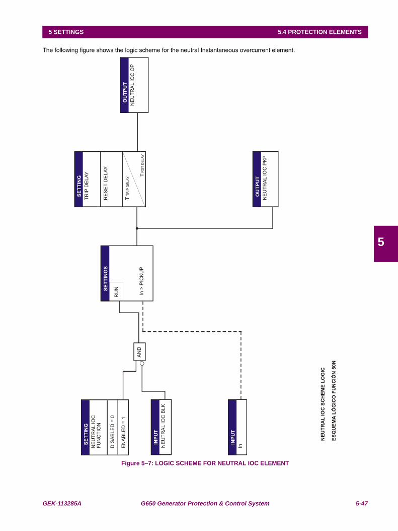
GEK-113285A G650 Generator Protection & Control System 5-47
5 SETTINGS 5.4 PROTECTION ELEMENTS
5
The following figure shows the logic scheme for the neutral Instantaneous overcurrent element.
Figure 5–7: LOGIC SCHEME FOR NEUTRAL IOC ELEMENT
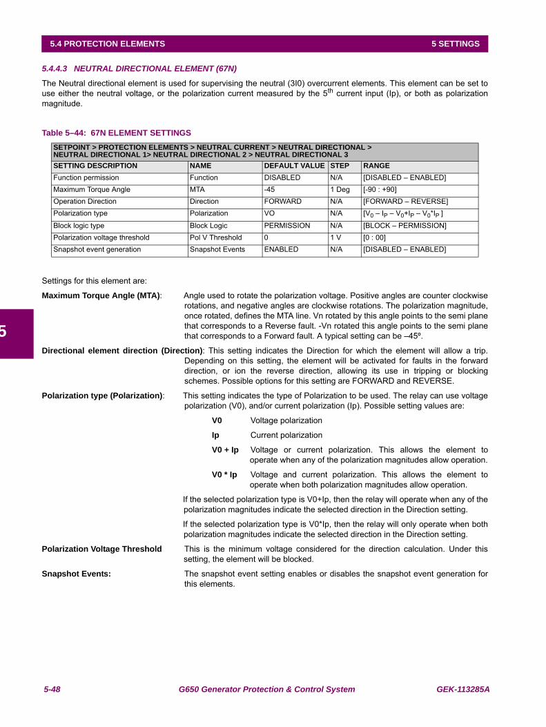
5-48 G650 Generator Protection & Control System GEK-113285A
5.4 PROTECTION ELEMENTS 5 SETTINGS
5
5.4.4.3 NEUTRAL DIRECTIONAL ELEMENT (67N)
The Neutral directional element is used for supervising the neutral (3I0) overcurrent elements. This element can be set touse either the neutral voltage, or the polarization current measured by the 5th current input (Ip), or both as polarizationmagnitude.
Table 5–44: 67N ELEMENT SETTINGS
Settings for this element are:
Maximum Torque Angle (MTA): Angle used to rotate the polarization voltage. Positive angles are counter clockwiserotations, and negative angles are clockwise rotations. The polarization magnitude,once rotated, defines the MTA line. Vn rotated by this angle points to the semi planethat corresponds to a Reverse fault. -Vn rotated this angle points to the semi planethat corresponds to a Forward fault. A typical setting can be –45º.
Directional element direction (Direction): This setting indicates the Direction for which the element will allow a trip.Depending on this setting, the element will be activated for faults in the forwarddirection, or ion the reverse direction, allowing its use in tripping or blockingschemes. Possible options for this setting are FORWARD and REVERSE.
Polarization type (Polarization): This setting indicates the type of Polarization to be used. The relay can use voltagepolarization (V0), and/or current polarization (Ip). Possible setting values are:
V0 Voltage polarization
Ip Current polarization
V0 + Ip Voltage or current polarization. This allows the element tooperate when any of the polarization magnitudes allow operation.
V0 * Ip Voltage and current polarization. This allows the element tooperate when both polarization magnitudes allow operation.
If the selected polarization type is V0+Ip, then the relay will operate when any of thepolarization magnitudes indicate the selected direction in the Direction setting.
If the selected polarization type is V0*Ip, then the relay will only operate when bothpolarization magnitudes indicate the selected direction in the Direction setting.
Polarization Voltage Threshold This is the minimum voltage considered for the direction calculation. Under thissetting, the element will be blocked.
Snapshot Events: The snapshot event setting enables or disables the snapshot event generation forthis elements.
SETPOINT > PROTECTION ELEMENTS > NEUTRAL CURRENT > NEUTRAL DIRECTIONAL >NEUTRAL DIRECTIONAL 1> NEUTRAL DIRECTIONAL 2 > NEUTRAL DIRECTIONAL 3SETTING DESCRIPTION NAME DEFAULT VALUE STEP RANGEFunction permission Function DISABLED N/A [DISABLED – ENABLED]Maximum Torque Angle MTA -45 1 Deg [-90 : +90]Operation Direction Direction FORWARD N/A [FORWARD – REVERSE]Polarization type Polarization VO N/A [V0 – IP – V0+IP – V0*IP ]
Block logic type Block Logic PERMISSION N/A [BLOCK – PERMISSION]Polarization voltage threshold Pol V Threshold 0 1 V [0 : 00]Snapshot event generation Snapshot Events ENABLED N/A [DISABLED – ENABLED]
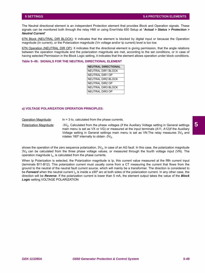
GEK-113285A G650 Generator Protection & Control System 5-49
5 SETTINGS 5.4 PROTECTION ELEMENTS
5
The Neutral directional element is an independent Protection element that provides Block and Operation signals. Thesesignals can be monitored both through the relay HMI or using EnerVista 650 Setup at “Actual > Status > Protection >Neutral Current”
67N Block (NEUTRAL DIR BLOCK): It indicates that the element is blocked by digital input or because the Operationmagnitude (In current), or the Polarization magnitude (Vn voltage and/or Ip current) level is too low.
67N Operation (NEUTRAL DIR OP): It indicates that the directional element is giving permission, that the angle relationsbetween the operation magnitude and the polarization magnitude are met, according to the set conditions, or in case ofhaving selected Permission in the Block Logic setting, it indicates that the element allows operation under block conditions.
Table 5–45: SIGNALS FOR THE NEUTRAL DIRECTIONAL ELEMENT
a) VOLTAGE POLARIZATION OPERATION PRINCIPLES:
Operation Magnitude: In = 3·Io, calculated from the phase currents.
Polarization Magnitude: -3V0. Calculated from the phase voltages (if the Auxiliary Voltage setting in General settingsmain menu is set as VX or VG) or measured at the input terminals (A11, A12)if the AuxiliaryVoltage setting in General settings main menu is set as VN.The relay measures 3V0 androtates 180º internally to obtain -3V0.
shows the operation of the zero sequence polarization, 3V0, in case of an AG fault. In this case, the polarization magnitude3V0 can be calculated from the three phase voltage values, or measured through the fourth voltage input (VN). Theoperation magnitude In, is calculated from the phase currents.
When Ip Polarization is selected, the Polarization magnitude is Ip, this current value measured at the fifth current input(terminals B11-B12). This polarization current must usually come from a CT measuring the current that flows from theground to the neutral of the neutral fault current source, which will mainly be a transformer. The direction is considered tobe Forward when the neutral current In is inside a ±90º arc at both sides of the polarization current. In any other case, thedirection will be Reverse. If the polarization current is lower than 5 mA, the element output takes the value of the BlockLogic setting.VOLTAGE POLARIZATION
NEUTRAL DIRECTIONAL NEUTRAL DIR1 BLOCKNEUTRAL DIR1 OPNEUTRAL DIR2 BLOCKNEUTRAL DIR2 OPNEUTRAL DIR3 BLOCKNEUTRAL DIR3 OP
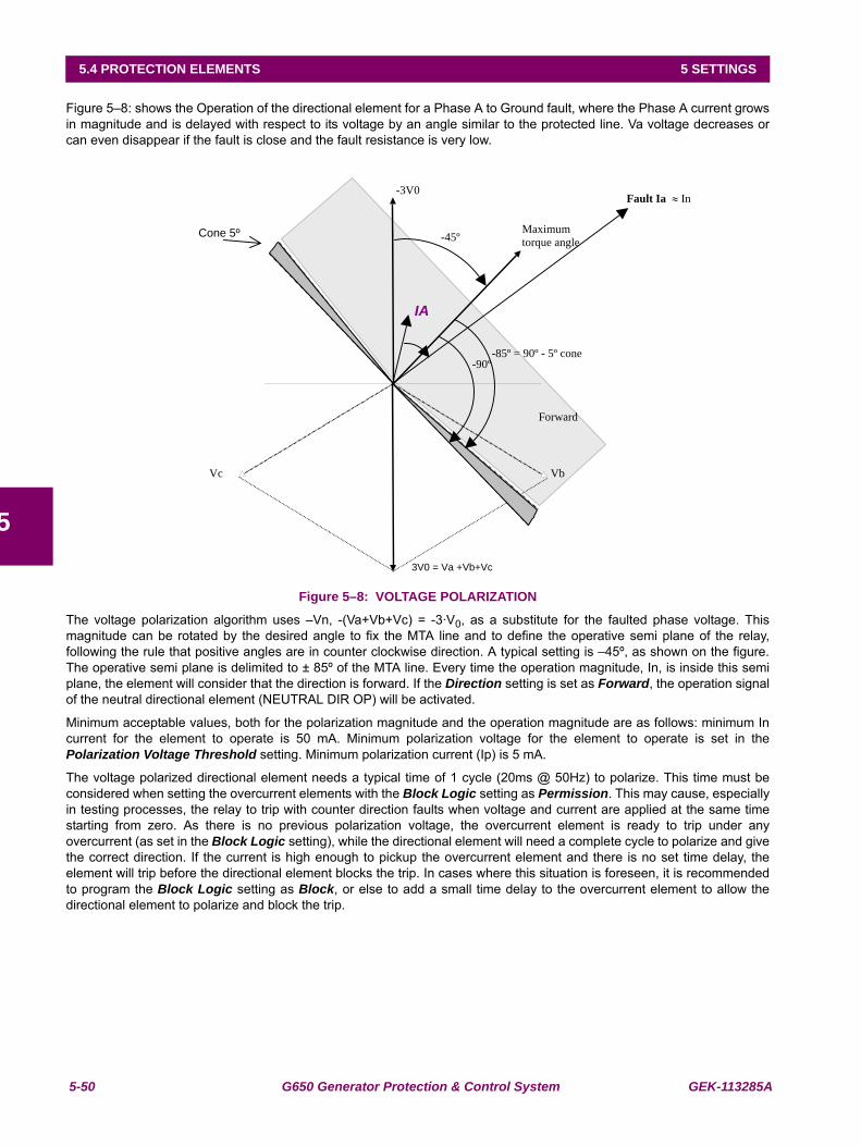
5-50 G650 Generator Protection & Control System GEK-113285A
5.4 PROTECTION ELEMENTS 5 SETTINGS
5
Figure 5–8: shows the Operation of the directional element for a Phase A to Ground fault, where the Phase A current growsin magnitude and is delayed with respect to its voltage by an angle similar to the protected line. Va voltage decreases orcan even disappear if the fault is close and the fault resistance is very low.
Figure 5–8: VOLTAGE POLARIZATION
The voltage polarization algorithm uses –Vn, -(Va+Vb+Vc) = -3·V0, as a substitute for the faulted phase voltage. Thismagnitude can be rotated by the desired angle to fix the MTA line and to define the operative semi plane of the relay,following the rule that positive angles are in counter clockwise direction. A typical setting is –45º, as shown on the figure.The operative semi plane is delimited to ± 85º of the MTA line. Every time the operation magnitude, In, is inside this semiplane, the element will consider that the direction is forward. If the Direction setting is set as Forward, the operation signalof the neutral directional element (NEUTRAL DIR OP) will be activated.
Minimum acceptable values, both for the polarization magnitude and the operation magnitude are as follows: minimum Incurrent for the element to operate is 50 mA. Minimum polarization voltage for the element to operate is set in thePolarization Voltage Threshold setting. Minimum polarization current (Ip) is 5 mA.
The voltage polarized directional element needs a typical time of 1 cycle (20ms @ 50Hz) to polarize. This time must beconsidered when setting the overcurrent elements with the Block Logic setting as Permission. This may cause, especiallyin testing processes, the relay to trip with counter direction faults when voltage and current are applied at the same timestarting from zero. As there is no previous polarization voltage, the overcurrent element is ready to trip under anyovercurrent (as set in the Block Logic setting), while the directional element will need a complete cycle to polarize and givethe correct direction. If the current is high enough to pickup the overcurrent element and there is no set time delay, theelement will trip before the directional element blocks the trip. In cases where this situation is foreseen, it is recommendedto program the Block Logic setting as Block, or else to add a small time delay to the overcurrent element to allow thedirectional element to polarize and block the trip.
VbVc
-3V0
3V0 = Va +Vb+Vc
-45º Maximum
torque angleCone 5º
Forward
IA
Fault Ia In
-85º = 90º - 5º cone -90º
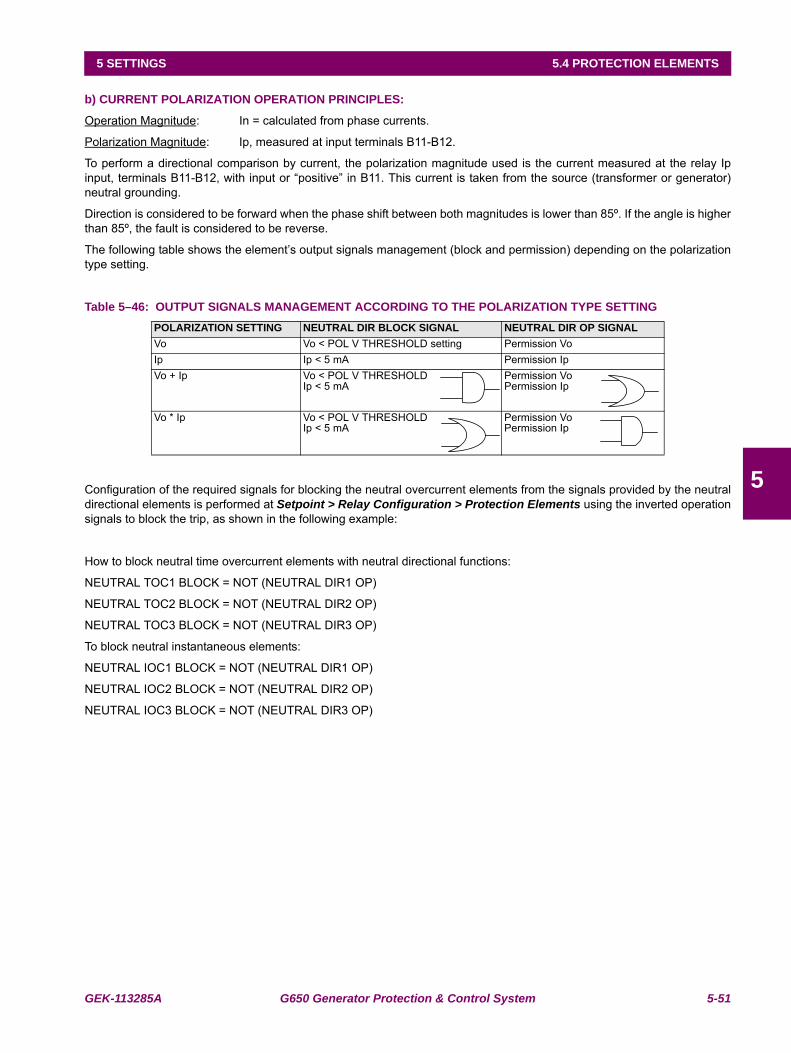
GEK-113285A G650 Generator Protection & Control System 5-51
5 SETTINGS 5.4 PROTECTION ELEMENTS
5
b) CURRENT POLARIZATION OPERATION PRINCIPLES:
Operation Magnitude: In = calculated from phase currents.
Polarization Magnitude: Ip, measured at input terminals B11-B12.
To perform a directional comparison by current, the polarization magnitude used is the current measured at the relay Ipinput, terminals B11-B12, with input or “positive” in B11. This current is taken from the source (transformer or generator)neutral grounding.
Direction is considered to be forward when the phase shift between both magnitudes is lower than 85º. If the angle is higherthan 85º, the fault is considered to be reverse.
The following table shows the element’s output signals management (block and permission) depending on the polarizationtype setting.
Table 5–46: OUTPUT SIGNALS MANAGEMENT ACCORDING TO THE POLARIZATION TYPE SETTING
Configuration of the required signals for blocking the neutral overcurrent elements from the signals provided by the neutraldirectional elements is performed at Setpoint > Relay Configuration > Protection Elements using the inverted operationsignals to block the trip, as shown in the following example:
How to block neutral time overcurrent elements with neutral directional functions:
NEUTRAL TOC1 BLOCK = NOT (NEUTRAL DIR1 OP)
NEUTRAL TOC2 BLOCK = NOT (NEUTRAL DIR2 OP)
NEUTRAL TOC3 BLOCK = NOT (NEUTRAL DIR3 OP)
To block neutral instantaneous elements:
NEUTRAL IOC1 BLOCK = NOT (NEUTRAL DIR1 OP)
NEUTRAL IOC2 BLOCK = NOT (NEUTRAL DIR2 OP)
NEUTRAL IOC3 BLOCK = NOT (NEUTRAL DIR3 OP)
POLARIZATION SETTING NEUTRAL DIR BLOCK SIGNAL NEUTRAL DIR OP SIGNALVo Vo < POL V THRESHOLD setting Permission VoIp Ip < 5 mA Permission IpVo + Ip Vo < POL V THRESHOLD
Ip < 5 mAPermission VoPermission Ip
Vo * Ip Vo < POL V THRESHOLDIp < 5 mA
Permission VoPermission Ip
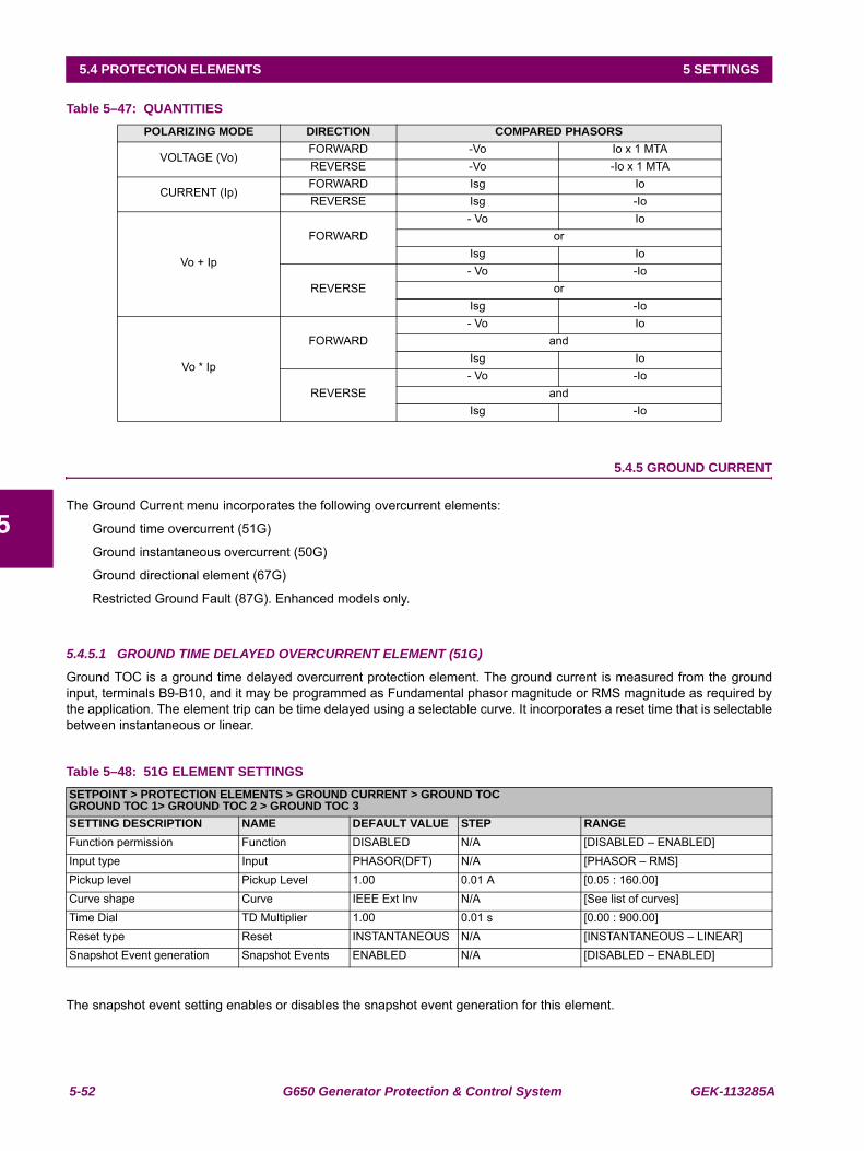
5-52 G650 Generator Protection & Control System GEK-113285A
5.4 PROTECTION ELEMENTS 5 SETTINGS
5
Table 5–47: QUANTITIES
5.4.5 GROUND CURRENT
The Ground Current menu incorporates the following overcurrent elements:
Ground time overcurrent (51G)
Ground instantaneous overcurrent (50G)
Ground directional element (67G)
Restricted Ground Fault (87G). Enhanced models only.
5.4.5.1 GROUND TIME DELAYED OVERCURRENT ELEMENT (51G)
Ground TOC is a ground time delayed overcurrent protection element. The ground current is measured from the groundinput, terminals B9-B10, and it may be programmed as Fundamental phasor magnitude or RMS magnitude as required bythe application. The element trip can be time delayed using a selectable curve. It incorporates a reset time that is selectablebetween instantaneous or linear.
Table 5–48: 51G ELEMENT SETTINGS
The snapshot event setting enables or disables the snapshot event generation for this element.
POLARIZING MODE DIRECTION COMPARED PHASORS
VOLTAGE (Vo)FORWARD -Vo Io x 1 MTAREVERSE -Vo -Io x 1 MTA
CURRENT (Ip)FORWARD Isg IoREVERSE Isg -Io
Vo + Ip
FORWARD- Vo Io
orIsg Io
REVERSE- Vo -Io
orIsg -Io
Vo * Ip
FORWARD- Vo Io
andIsg Io
REVERSE- Vo -Io
andIsg -Io
SETPOINT > PROTECTION ELEMENTS > GROUND CURRENT > GROUND TOCGROUND TOC 1> GROUND TOC 2 > GROUND TOC 3SETTING DESCRIPTION NAME DEFAULT VALUE STEP RANGEFunction permission Function DISABLED N/A [DISABLED – ENABLED]Input type Input PHASOR(DFT) N/A [PHASOR – RMS]Pickup level Pickup Level 1.00 0.01 A [0.05 : 160.00]Curve shape Curve IEEE Ext Inv N/A [See list of curves]Time Dial TD Multiplier 1.00 0.01 s [0.00 : 900.00]Reset type Reset INSTANTANEOUS N/A [INSTANTANEOUS – LINEAR]Snapshot Event generation Snapshot Events ENABLED N/A [DISABLED – ENABLED]
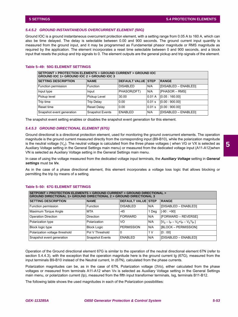
GEK-113285A G650 Generator Protection & Control System 5-53
5 SETTINGS 5.4 PROTECTION ELEMENTS
5
5.4.5.2 GROUND INSTANTANEOUS OVERCURRENT ELEMENT (50G)
Ground IOC is a ground instantaneous overcurrent protection element, with a setting range from 0.05 A to 160 A, which canalso be time delayed. The delay is selectable between 0.00 and 900 seconds. The ground current input quantity ismeasured from the ground input, and it may be programmed as Fundamental phasor magnitude or RMS magnitude asrequired by the application. The element incorporates a reset time selectable between 0 and 900 seconds, and a blockinput that resets the pickup and trip signals to 0. The element outputs are the general pickup and trip signals of the element.
Table 5–49: 50G ELEMENT SETTINGS
The snapshot event setting enables or disables the snapshot event generation for this element.
5.4.5.3 GROUND DIRECTIONAL ELEMENT (67G)
Ground directional is a directional protection element, used for monitoring the ground overcurrent elements. The operationmagnitude is the ground current measured directly from the corresponding input (B9-B10), while the polarization magnitudeis the neutral voltage (Vn). The neutral voltage is calculated from the three phase voltages ( when VG or VX is selected asAuxiliary Voltage setting in the General Settings main menu) or measured from the dedicated voltage input (A11-A12)whenVN is selected as Auxiliary Voltage setting in the General Settings main menu.
In case of using the voltage measured from the dedicated voltage input terminals, the Auxiliary Voltage setting in Generalsettings must be VN.
As in the case of a phase directional element, this element incorporates a voltage loss logic that allows blocking orpermitting the trip by means of a setting.
Table 5–50: 67G ELEMENT SETTINGS
Operation of the Ground directional element 67G is similar to the operation of the neutral directional element 67N (refer tosection 5.4.4.3), with the exception that the operation magnitude here is the ground current Ig (67G), measured from theinput terminals B9-B10 instead of the Neutral current, In (67N), calculated from the phase currents.
Polarization magnitudes can be, as in the case of 67N, Polarization voltage (3Vo), either calculated from the phasevoltages or measured from terminals A11-A12 when VN is selected as Auxiliary Voltage setting in the General Settingsmain menu, or polarization current (Ip), measured from the fifth input transformer terminals, Isg, terminals B11-B12.
The following table shows the used magnitudes in each of the Polarization possibilities:
SETPOINT > PROTECTION ELEMENTS > GROUND CURRENT > GROUND IOCGROUND IOC 1> GROUND IOC 2 > GROUND IOC 3SETTING DESCRIPTION NAME DEFAULT VALUE STEP RANGEFunction permission Function DISABLED N/A [DISABLED – ENABLED]Input type Input PHASOR(DFT) N/A [PHASOR – RMS]Pickup level Pickup Level 30.00 0.01 A [0.05 : 160.00]Trip time Trip Delay 0.00 0.01 s [0.00 : 900.00]Reset time Reset Delay 0.00 0.01 s [0.00 : 900.00]Snapshot event generation Snapshot Events ENABLED N/A [DISABLED – ENABLED]
SETPOINT > PROTECTION ELEMENTS > GROUND CURRENT > GROUND DIRECTIONAL >GROUND DIRECTIONAL 1> GROUND DIRECTIONAL 2 > GROUND DIRECTIONAL 3SETTING DESCRIPTION NAME DEFAULT VALUE STEP RANGEFunction permission Function DISABLED N/A [DISABLED – ENABLED]Maximum Torque Angle MTA -45 1 Deg [-90 : +90]Operation Direction Direction FORWARD N/A [FORWARD – REVERSE]Polarization type Polarization VO N/A [V0 – IP – V0+IP – V0*IP ]
Block logic type Block Logic PERMISSION N/A [BLOCK – PERMISSION]Polarization voltage threshold Pol V Threshold 0 1 V [0 : 00]Snapshot event generation Snapshot Events ENABLED N/A [DISABLED – ENABLED]
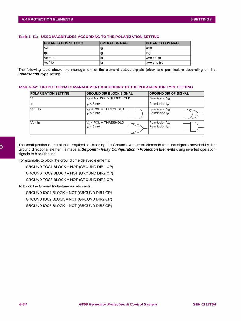
5-54 G650 Generator Protection & Control System GEK-113285A
5.4 PROTECTION ELEMENTS 5 SETTINGS
5
Table 5–51: USED MAGNITUDES ACCORDING TO THE POLARIZATION SETTING
The following table shows the management of the element output signals (block and permission) depending on thePolarization Type setting.
Table 5–52: OUTPUT SIGNALS MANAGEMENT ACCORDING TO THE POLARIZATION TYPE SETTING
The configuration of the signals required for blocking the Ground overcurrent elements from the signals provided by theGround directional element is made at Setpoint > Relay Configuration > Protection Elements using inverted operationsignals to block the trip.
For example, to block the ground time delayed elements:
GROUND TOC1 BLOCK = NOT (GROUND DIR1 OP)
GROUND TOC2 BLOCK = NOT (GROUND DIR2 OP)
GROUND TOC3 BLOCK = NOT (GROUND DIR3 OP)
To block the Ground Instantaneous elements:
GROUND IOC1 BLOCK = NOT (GROUND DIR1 OP)
GROUND IOC2 BLOCK = NOT (GROUND DIR2 OP)
GROUND IOC3 BLOCK = NOT (GROUND DIR3 OP)
POLARIZATION SETTING OPERATION MAG. POLARIZATION MAG.Vo Ig 3V0Ip Ig IsgVo + Ip Ig 3V0 or IsgVo * Ip Ig 3V0 and Isg
POLARIZATION SETTING GROUND DIR BLOCK SIGNAL GROUND DIR OP SIGNALVo V0 < Ajs. POL V THRESHOLD Permission V0
Ip IP < 5 mA Permission IPVo + Ip V0 < POL V THRESHOLD
IP < 5 mAPermission V0Permission IP
Vo * Ip V0 < POL V THRESHOLDIP < 5 mA
Permission V0Permission IP
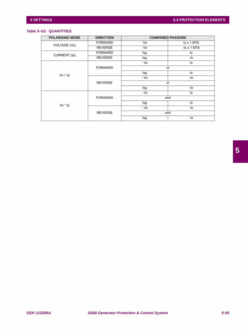
GEK-113285A G650 Generator Protection & Control System 5-55
5 SETTINGS 5.4 PROTECTION ELEMENTS
5
Table 5–53: QUANTITIESPOLARIZING MODE DIRECTION COMPARED PHASORS
VOLTAGE (Vo)FORWARD -Vo Io x 1 MTAREVERSE -Vo -Io x 1 MTA
CURRENT (Ip)FORWARD Isg IoREVERSE Isg -Io
Vo + Ip
FORWARD- Vo Io
orIsg Io
REVERSE- Vo -Io
orIsg -Io
Vo * Ip
FORWARD- Vo Io
andIsg Io
REVERSE- Vo -Io
andIsg -Io
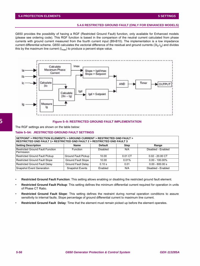
5-56 G650 Generator Protection & Control System GEK-113285A
5.4 PROTECTION ELEMENTS 5 SETTINGS
5
5.4.6 RESTRICTED GROUND FAULT (ONLY FOR ENHANCED MODELS)
G650 provides the possibility of having a RGF (Restricted Ground Fault) function, only available for Enhanced models(please see ordering code). This RGF function is based in the comparison of the neutral current calculated from phasecurrents with ground current measured from the fourth current input (B9-B10). The implementation is a low impedancecurrent differential scheme. G650 calculates the vectorial difference of the residual and ground currents (3I0-Ig) and dividesthis by the maximum line current (Imax) to produce a percent slope value.
Figure 5–9: RESTRICTED GROUND FAULT IMPLEMENTATION
The RGF settings are shown on the table below:
Table 5–54: .RESTRICTED GROUND FAULT SETTINGS
• Restricted Ground Fault Function: This setting allows enabling or disabling the restricted ground fault element.
• Restricted Ground Fault Pickup: This setting defines the minimum differential current required for operation in unitsof Phase CT Ratio.
• Restricted Ground Fault Slope: This setting defines the restraint during normal operation conditions to assuresensitivity to internal faults. Slope percentage of ground differential current to maximum line current.
• Restricted Ground Fault Delay: Time that the element must remain picked up before the element operates.
SETPOINT > PROTECTION ELEMENTS > GROUND CURRENT > RESTRICTED GND FAULT >RESTRICTED GND FAULT 1> RESTRICTED GND FAULT 2 > RESTRICTED GND FAULT 3Setting Description Name Default Step RangeRestricted Ground Fault Function Permission
Function Disabled N/A Disabled - Enabled
Restricted Ground Fault Pickup Ground Fault Pickup 10.00 0.01 CT 0.02 - 20.00 CTRestricted Ground Fault Slope Ground Fault Slope 10.00 0.01% 0.00 - 100.00%Restricted Ground Fault Delay Ground Fault Delay 0.10 s 0.01 0.00 - 600.00 sSnapshot Event Generation Snapshot Events Enabled N/A Disabled - Enabled
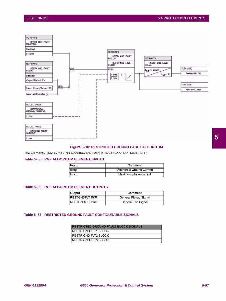
GEK-113285A G650 Generator Protection & Control System 5-57
5 SETTINGS 5.4 PROTECTION ELEMENTS
5
Figure 5–10: RESTRICTED GROUND FAULT ALGORITHM
The elements used in the 87G algorithm are listed in Table 5–55: and Table 5–56:
Table 5–55: RGF ALGORITHM ELEMENT INPUTS
Table 5–56: RGF ALGORITHM ELEMENT OUTPUTS
Table 5–57: RESTRICTED GROUND FAULT CONFIGURABLE SIGNALS
Input CommentIdiffg Differential Ground CurrentImax Maximum phase current
Output CommentRESTGNDFLT PKP General Pickup SignalRESTGNDFLT PKP General Trip Signal
RESTRICTED GROUND FAULT BLOCK SIGNALSRESTR GND FLT1 BLOCKRESTR GND FLT2 BLOCKRESTR GND FLT3 BLOCK
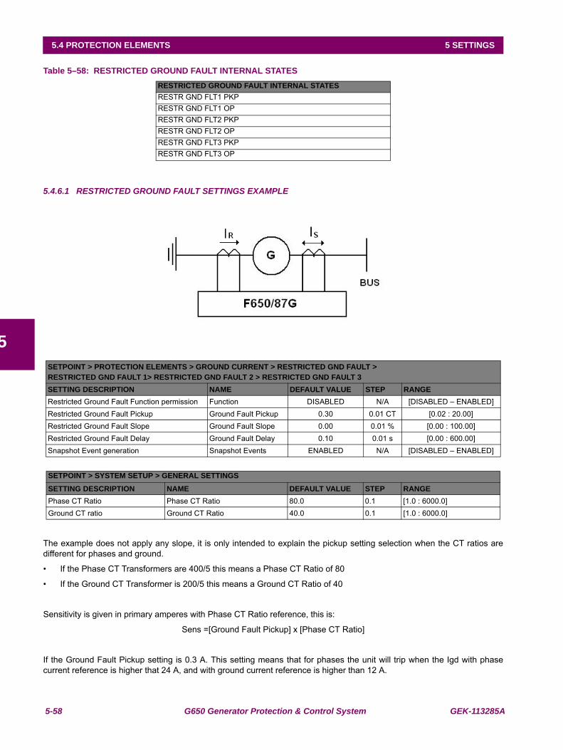
5-58 G650 Generator Protection & Control System GEK-113285A
5.4 PROTECTION ELEMENTS 5 SETTINGS
5
Table 5–58: RESTRICTED GROUND FAULT INTERNAL STATES
5.4.6.1 RESTRICTED GROUND FAULT SETTINGS EXAMPLE
The example does not apply any slope, it is only intended to explain the pickup setting selection when the CT ratios aredifferent for phases and ground.
• If the Phase CT Transformers are 400/5 this means a Phase CT Ratio of 80
• If the Ground CT Transformer is 200/5 this means a Ground CT Ratio of 40
Sensitivity is given in primary amperes with Phase CT Ratio reference, this is:
Sens =[Ground Fault Pickup] x [Phase CT Ratio]
If the Ground Fault Pickup setting is 0.3 A. This setting means that for phases the unit will trip when the Igd with phasecurrent reference is higher that 24 A, and with ground current reference is higher than 12 A.
RESTRICTED GROUND FAULT INTERNAL STATESRESTR GND FLT1 PKPRESTR GND FLT1 OPRESTR GND FLT2 PKPRESTR GND FLT2 OPRESTR GND FLT3 PKPRESTR GND FLT3 OP
SETPOINT > PROTECTION ELEMENTS > GROUND CURRENT > RESTRICTED GND FAULT >RESTRICTED GND FAULT 1> RESTRICTED GND FAULT 2 > RESTRICTED GND FAULT 3SETTING DESCRIPTION NAME DEFAULT VALUE STEP RANGERestricted Ground Fault Function permission Function DISABLED N/A [DISABLED – ENABLED]Restricted Ground Fault Pickup Ground Fault Pickup 0.30 0.01 CT [0.02 : 20.00]Restricted Ground Fault Slope Ground Fault Slope 0.00 0.01 % [0.00 : 100.00]Restricted Ground Fault Delay Ground Fault Delay 0.10 0.01 s [0.00 : 600.00]Snapshot Event generation Snapshot Events ENABLED N/A [DISABLED – ENABLED]
SETPOINT > SYSTEM SETUP > GENERAL SETTINGS
SETTING DESCRIPTION NAME DEFAULT VALUE STEP RANGEPhase CT Ratio Phase CT Ratio 80.0 0.1 [1.0 : 6000.0]Ground CT ratio Ground CT Ratio 40.0 0.1 [1.0 : 6000.0]
GEK-113285A G650 Generator Protection & Control System 5-59
5 SETTINGS 5.4 PROTECTION ELEMENTS
5
5.4.7 SENSITIVE GROUND CURRENT (ONLY FOR ENHANCED MODELS)
The G650 Sensitive ground Current menu incorporates the following overcurrent elements:
• Sensitive ground time overcurrent (51SG)
• Sensitive ground instantaneous overcurrent (50SG)
5.4.7.1 SENSITIVE GROUND TIME DELAYED OVERCURRENT ELEMENT (51SG)
Sensitive Ground TOC is a sensitive ground time delayed overcurrent protection element with a setting range 0.005A to16A. The sensitive ground current input quantity is measured from the sensitive ground input, terminals B11-B12, and itmay be programmed as fundamental phasor magnitude or RMS magnitude as required by the application. The element tripcan be time delayed using a selectable curve. And it incorporates a reset time selectable between instantaneous or linear.
Table 5–59: 51SG ELEMENT SETTINGS
The snapshot event setting enables or disables the snapshot event generation for this element.
5.4.7.2 SENSITIVE GROUND INSTANTANEOUS OVERCURRENT ELEMENT (50SG)
50SG is a sensitive ground instantaneous overcurrent protection element, with a setting range from 0.005 A to 16.00 A,which can also be time delayed, with a delay selectable between 0 and 900 seconds. The ground current input quantity ismeasured from the sensitive ground input, and it may be programmed as fundamental phasor magnitude or RMSmagnitude as required by the application. The element incorporates a reset time selectable between 0 and 900 seconds,and a block input that resets the pickup and trip signals to 0. The element outputs are the general pickup and trip signals ofthe element.
Table 5–60: 50SG ELEMENT SETTINGS
The snapshot event setting enables or disables the snapshot event generation for this element.
SETPOINT > PROTECTION ELEMENTS > SENSITIVE GROUND CURRENT > SENSITIVE GROUND TOCSENSITIVE GROUND TOC 1> SENSITIVE GROUND TOC 2 > SENSITIVE GROUND TOC 3SETTING DESCRIPTION NAME DEFAULT VALUE STEP RANGEFunction permission Function DISABLED N/A [DISABLED – ENABLED]Input type Input PHASOR(DFT) N/A [PHASOR – RMS]Pickup level Pickup Level 0.050 0.001 A [0.005 : 16.000]Curve shape Curve IEEE Ext Inv N/A [See list of curves]Time Dial TD Multiplier 1.00 0.01 s [0.00 : 900.00]Reset type Reset INSTANTANEOUS N/A [INSTANTANEOUS – LINEAR]Snapshot Event generation Snapshot Events ENABLED N/A [DISABLED – ENABLED]
SETPOINT > PROTECTION ELEMENTS > SENSITIVE GROUND CURRENT > SENSITIVE GROUND IOCSENSITIVE GROUND IOC 1> SENSITIVE GROUND IOC 2 > SENSITIVE GROUND IOC 3SETTING DESCRIPTION NAME DEFAULT VALUE STEP RANGEFunction permission Function DISABLED N/A [DISABLED – ENABLED]Input type Input PHASOR(DFT) N/A [PHASOR – RMS]Pickup level Pickup Level 0.100 0.001 A [0.005 : 16.000]Trip time Trip Delay 0.00 0.01 s [0.00 : 900.00]Reset time Reset Delay 0.00 0.01 s [0.00 : 900.00]Snapshot event generation Snapshot Events ENABLED N/A [DISABLED – ENABLED]
5-60 G650 Generator Protection & Control System GEK-113285A
5.4 PROTECTION ELEMENTS 5 SETTINGS
5
5.4.8 NEGATIVE SEQUENCE CURRENT
The Negative sequence menu incorporates the following elements:
• Negative sequence time overcurrent (51-2)
• Negative sequence instantaneous overcurrent (50-2)
• Generator unbalance (46)
5.4.8.1 NEGATIVE SEQUENCE OVERCURRENT ELEMENT (51-2)
Negative Sequence TOC is an overcurrent protection element that uses the fundamental phasor of the negative sequencecurrent as input magnitude, calculated from the phase currents. This element can be used for detecting load unbalance inthe system, and for open phase conditions (fallen or broken conductor). The trip can be time delayed by a curve selectableby setting. The reset can be instantaneous or linear.
Table 5–61: NEGATIVE SEQUENCE TOC ELEMENT SETTINGS
The snapshot event setting enables or disables the snapshot event generation for this element.
5.4.8.2 NEGATIVE SEQUENCE INSTANTANEOUS OVERCURRENT ELEMENT (50-2)
Negative Sequence IOC is an overcurrent protection element that uses the fundamental phasor of the negative sequencecurrent as input magnitude, calculated from the phase currents. This element can be used for detecting load unbalance inthe system, and for open phase conditions (fallen or broken conductor). The trip time can be selected as instantaneous ortimed, with the timer selectable between 0.00 and 900 seconds. The element incorporates a reset time selectable between0 and 900 seconds.
Table 5–62: NEGATIVE SEQUENCE IOC ELEMENT SETTINGS
The snapshot event setting enables or disables the snapshot event generation for this element.
SETPOINT > PROTECTION ELEMENTS > NEGATIVE SEQUENCE CURRENT > NEGATIVE SEQUENCE TOC >NEGATIVE SEQUENCE TOC 1> NEGATIVE SEQUENCE TOC 2 > NEGATIVE SEQUENCE TOC 3SETTING DESCRIPTION NAME DEFAULT VALUE STEP RANGEFunction permission Function DISABLED N/A [DISABLED – ENABLED]Pickup level Pickup Level 1.00 0.01 A [0.05 : 160.00]Curve shape Curve IEEE Ext Inv N/A [See list of curves]Time Dial TD Multiplier 1.00 0.01 s [0.00 : 900.00]Reset type Reset INSTANTANEOUS N/A [INSTANTANEOUS – LINEAR]Snapshot Event generation Snapshot Events ENABLED N/A [DISABLED – ENABLED]
SETPOINT > PROTECTION ELEMENTS > NEGATIVE SEQUENCE CURRENT > NEGATIVE SEQUENCE IOC >NEGATIVE SEQUENCE IOC 1> NEGATIVE SEQUENCE IOC 2 > NEGATIVE SEQUENCE IOC 3SETTING DESCRIPTION NAME DEFAULT VALUE STEP RANGEFunction permission Function DISABLED N/A [DISABLED – ENABLED]Pickup level Pickup Level 30.00 0.01 A [0.05 : 160.00]Trip time Trip delay 0.00 s 0.01 s [0.00 : 900.00]Reset time Reset delay 0.00 s 0.01 s [0.00 : 900.00]Snapshot Event generation Snapshot Events ENABLED N/A [DISABLED – ENABLED]
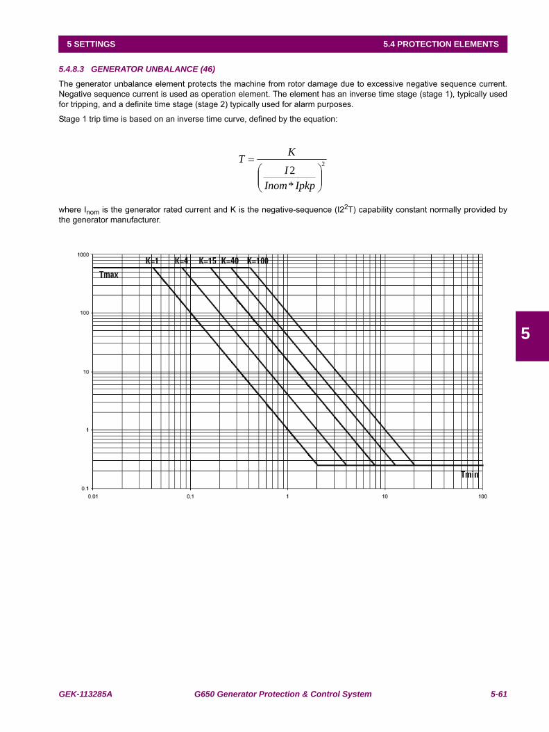
GEK-113285A G650 Generator Protection & Control System 5-61
5 SETTINGS 5.4 PROTECTION ELEMENTS
5
5.4.8.3 GENERATOR UNBALANCE (46)
The generator unbalance element protects the machine from rotor damage due to excessive negative sequence current.Negative sequence current is used as operation element. The element has an inverse time stage (stage 1), typically usedfor tripping, and a definite time stage (stage 2) typically used for alarm purposes.
Stage 1 trip time is based on an inverse time curve, defined by the equation:
where Inom is the generator rated current and K is the negative-sequence (I22T) capability constant normally provided bythe generator manufacturer.
2
*2
⎟⎟⎠
⎞⎜⎜⎝
⎛=
IpkpInomI
KT
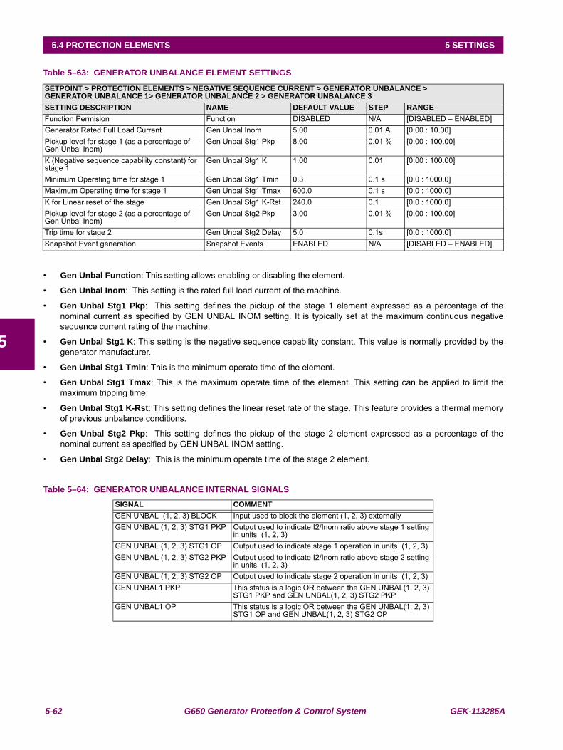
5-62 G650 Generator Protection & Control System GEK-113285A
5.4 PROTECTION ELEMENTS 5 SETTINGS
5
Table 5–63: GENERATOR UNBALANCE ELEMENT SETTINGS
• Gen Unbal Function: This setting allows enabling or disabling the element.
• Gen Unbal Inom: This setting is the rated full load current of the machine.
• Gen Unbal Stg1 Pkp: This setting defines the pickup of the stage 1 element expressed as a percentage of thenominal current as specified by GEN UNBAL INOM setting. It is typically set at the maximum continuous negativesequence current rating of the machine.
• Gen Unbal Stg1 K: This setting is the negative sequence capability constant. This value is normally provided by thegenerator manufacturer.
• Gen Unbal Stg1 Tmin: This is the minimum operate time of the element.
• Gen Unbal Stg1 Tmax: This is the maximum operate time of the element. This setting can be applied to limit themaximum tripping time.
• Gen Unbal Stg1 K-Rst: This setting defines the linear reset rate of the stage. This feature provides a thermal memoryof previous unbalance conditions.
• Gen Unbal Stg2 Pkp: This setting defines the pickup of the stage 2 element expressed as a percentage of thenominal current as specified by GEN UNBAL INOM setting.
• Gen Unbal Stg2 Delay: This is the minimum operate time of the stage 2 element.
Table 5–64: GENERATOR UNBALANCE INTERNAL SIGNALS
SETPOINT > PROTECTION ELEMENTS > NEGATIVE SEQUENCE CURRENT > GENERATOR UNBALANCE >GENERATOR UNBALANCE 1> GENERATOR UNBALANCE 2 > GENERATOR UNBALANCE 3SETTING DESCRIPTION NAME DEFAULT VALUE STEP RANGEFunction Permision Function DISABLED N/A [DISABLED – ENABLED]Generator Rated Full Load Current Gen Unbal Inom 5.00 0.01 A [0.00 : 10.00]Pickup level for stage 1 (as a percentage of Gen Unbal Inom)
Gen Unbal Stg1 Pkp 8.00 0.01 % [0.00 : 100.00]
K (Negative sequence capability constant) for stage 1
Gen Unbal Stg1 K 1.00 0.01 [0.00 : 100.00]
Minimum Operating time for stage 1 Gen Unbal Stg1 Tmin 0.3 0.1 s [0.0 : 1000.0]Maximum Operating time for stage 1 Gen Unbal Stg1 Tmax 600.0 0.1 s [0.0 : 1000.0]K for Linear reset of the stage Gen Unbal Stg1 K-Rst 240.0 0.1 [0.0 : 1000.0]Pickup level for stage 2 (as a percentage of Gen Unbal Inom)
Gen Unbal Stg2 Pkp 3.00 0.01 % [0.00 : 100.00]
Trip time for stage 2 Gen Unbal Stg2 Delay 5.0 0.1s [0.0 : 1000.0]Snapshot Event generation Snapshot Events ENABLED N/A [DISABLED – ENABLED]
SIGNAL COMMENTGEN UNBAL (1, 2, 3) BLOCK Input used to block the element (1, 2, 3) externallyGEN UNBAL (1, 2, 3) STG1 PKP Output used to indicate I2/Inom ratio above stage 1 setting
in units (1, 2, 3) GEN UNBAL (1, 2, 3) STG1 OP Output used to indicate stage 1 operation in units (1, 2, 3)GEN UNBAL (1, 2, 3) STG2 PKP Output used to indicate I2/Inom ratio above stage 2 setting
in units (1, 2, 3)GEN UNBAL (1, 2, 3) STG2 OP Output used to indicate stage 2 operation in units (1, 2, 3)GEN UNBAL1 PKP This status is a logic OR between the GEN UNBAL(1, 2, 3)
STG1 PKP and GEN UNBAL(1, 2, 3) STG2 PKPGEN UNBAL1 OP This status is a logic OR between the GEN UNBAL(1, 2, 3)
STG1 OP and GEN UNBAL(1, 2, 3) STG2 OP
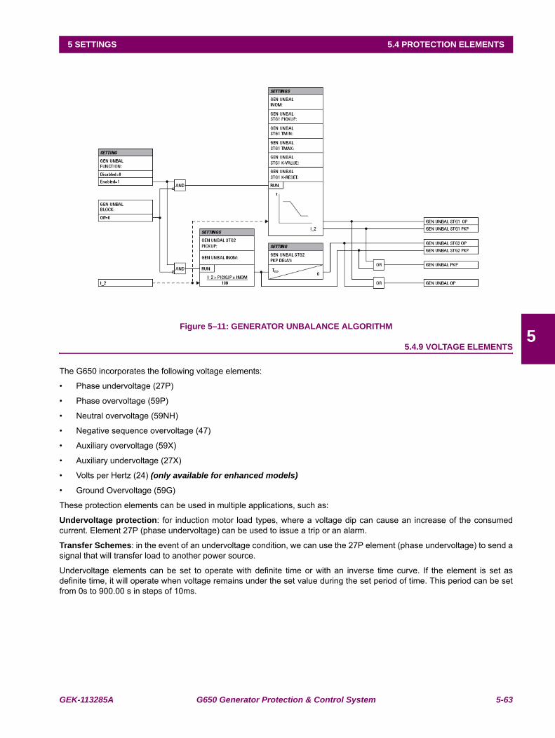
GEK-113285A G650 Generator Protection & Control System 5-63
5 SETTINGS 5.4 PROTECTION ELEMENTS
5Figure 5–11: GENERATOR UNBALANCE ALGORITHM
5.4.9 VOLTAGE ELEMENTS
The G650 incorporates the following voltage elements:
• Phase undervoltage (27P)
• Phase overvoltage (59P)
• Neutral overvoltage (59NH)
• Negative sequence overvoltage (47)
• Auxiliary overvoltage (59X)
• Auxiliary undervoltage (27X)
• Volts per Hertz (24) (only available for enhanced models)
• Ground Overvoltage (59G)
These protection elements can be used in multiple applications, such as:
Undervoltage protection: for induction motor load types, where a voltage dip can cause an increase of the consumedcurrent. Element 27P (phase undervoltage) can be used to issue a trip or an alarm.
Transfer Schemes: in the event of an undervoltage condition, we can use the 27P element (phase undervoltage) to send asignal that will transfer load to another power source.
Undervoltage elements can be set to operate with definite time or with an inverse time curve. If the element is set asdefinite time, it will operate when voltage remains under the set value during the set period of time. This period can be setfrom 0s to 900.00 s in steps of 10ms.
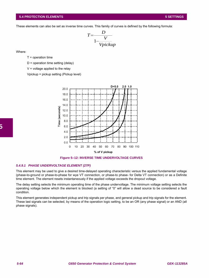
5-64 G650 Generator Protection & Control System GEK-113285A
5.4 PROTECTION ELEMENTS 5 SETTINGS
5
These elements can also be set as inverse time curves. This family of curves is defined by the following formula:
Where:
T = operation time
D = operation time setting (delay)
V = voltage applied to the relay
Vpickup = pickup setting (Pickup level)
Figure 5–12: INVERSE TIME UNDERVOLTAGE CURVES
5.4.9.1 PHASE UNDERVOLTAGE ELEMENT (27P)
This element may be used to give a desired time-delayed operating characteristic versus the applied fundamental voltage(phase-to-ground or phase-to-phase for wye VT connection, or phase-to phase- for Delta VT connection) or as a Definitetime element. The element resets instantaneously if the applied voltage exceeds the dropout voltage.
The delay setting selects the minimum operating time of the phase undervoltage. The minimum voltage setting selects theoperating voltage below which the element is blocked (a setting of “0” will allow a dead source to be considered a faultcondition.
This element generates independent pickup and trip signals per phase, and general pickup and trip signals for the element.These last signals can be selected, by means of the operation logic setting, to be an OR (any phase signal) or an AND (allphase signals).
VpickupV
DT−
=1
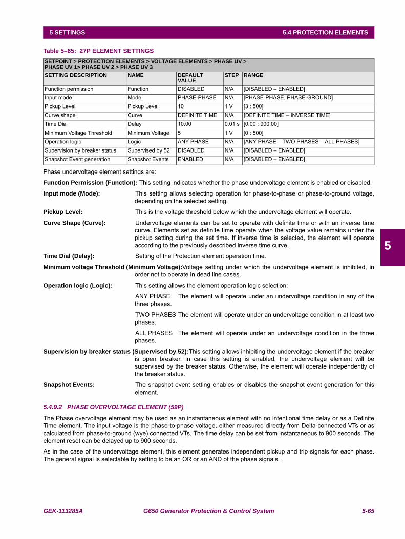
GEK-113285A G650 Generator Protection & Control System 5-65
5 SETTINGS 5.4 PROTECTION ELEMENTS
5
Table 5–65: 27P ELEMENT SETTINGS
Phase undervoltage element settings are:
Function Permission (Function): This setting indicates whether the phase undervoltage element is enabled or disabled.
Input mode (Mode): This setting allows selecting operation for phase-to-phase or phase-to-ground voltage,depending on the selected setting.
Pickup Level: This is the voltage threshold below which the undervoltage element will operate.
Curve Shape (Curve): Undervoltage elements can be set to operate with definite time or with an inverse timecurve. Elements set as definite time operate when the voltage value remains under thepickup setting during the set time. If inverse time is selected, the element will operateaccording to the previously described inverse time curve.
Time Dial (Delay): Setting of the Protection element operation time.
Minimum voltage Threshold (Minimum Voltage):Voltage setting under which the undervoltage element is inhibited, inorder not to operate in dead line cases.
Operation logic (Logic): This setting allows the element operation logic selection:
ANY PHASE The element will operate under an undervoltage condition in any of thethree phases.
TWO PHASES The element will operate under an undervoltage condition in at least twophases.
ALL PHASES The element will operate under an undervoltage condition in the threephases.
Supervision by breaker status (Supervised by 52):This setting allows inhibiting the undervoltage element if the breakeris open breaker. In case this setting is enabled, the undervoltage element will besupervised by the breaker status. Otherwise, the element will operate independently ofthe breaker status.
Snapshot Events: The snapshot event setting enables or disables the snapshot event generation for thiselement.
5.4.9.2 PHASE OVERVOLTAGE ELEMENT (59P)
The Phase overvoltage element may be used as an instantaneous element with no intentional time delay or as a DefiniteTime element. The input voltage is the phase-to-phase voltage, either measured directly from Delta-connected VTs or ascalculated from phase-to-ground (wye) connected VTs. The time delay can be set from instantaneous to 900 seconds. Theelement reset can be delayed up to 900 seconds.
As in the case of the undervoltage element, this element generates independent pickup and trip signals for each phase.The general signal is selectable by setting to be an OR or an AND of the phase signals.
SETPOINT > PROTECTION ELEMENTS > VOLTAGE ELEMENTS > PHASE UV >PHASE UV 1> PHASE UV 2 > PHASE UV 3SETTING DESCRIPTION NAME DEFAULT
VALUESTEP RANGE
Function permission Function DISABLED N/A [DISABLED – ENABLED]Input mode Mode PHASE-PHASE N/A [PHASE-PHASE, PHASE-GROUND]Pickup Level Pickup Level 10 1 V [3 : 500]Curve shape Curve DEFINITE TIME N/A [DEFINITE TIME – INVERSE TIME]Time Dial Delay 10.00 0.01 s [0.00 : 900.00]Minimum Voltage Threshold Minimum Voltage 5 1 V [0 : 500]Operation logic Logic ANY PHASE N/A [ANY PHASE – TWO PHASES – ALL PHASES]Supervision by breaker status Supervised by 52 DISABLED N/A [DISABLED – ENABLED]Snapshot Event generation Snapshot Events ENABLED N/A [DISABLED – ENABLED]
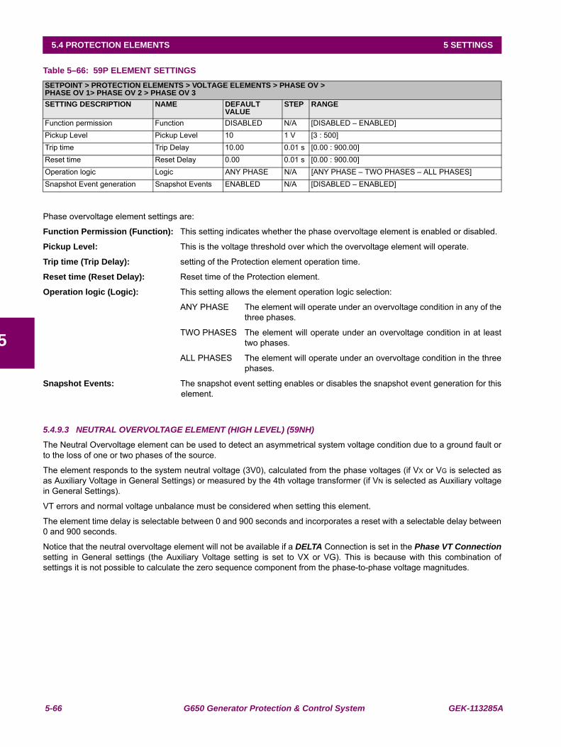
5-66 G650 Generator Protection & Control System GEK-113285A
5.4 PROTECTION ELEMENTS 5 SETTINGS
5
Table 5–66: 59P ELEMENT SETTINGS
Phase overvoltage element settings are:
Function Permission (Function): This setting indicates whether the phase overvoltage element is enabled or disabled.
Pickup Level: This is the voltage threshold over which the overvoltage element will operate.
Trip time (Trip Delay): setting of the Protection element operation time.
Reset time (Reset Delay): Reset time of the Protection element.
Operation logic (Logic): This setting allows the element operation logic selection:
ANY PHASE The element will operate under an overvoltage condition in any of thethree phases.
TWO PHASES The element will operate under an overvoltage condition in at leasttwo phases.
ALL PHASES The element will operate under an overvoltage condition in the threephases.
Snapshot Events: The snapshot event setting enables or disables the snapshot event generation for thiselement.
5.4.9.3 NEUTRAL OVERVOLTAGE ELEMENT (HIGH LEVEL) (59NH)
The Neutral Overvoltage element can be used to detect an asymmetrical system voltage condition due to a ground fault orto the loss of one or two phases of the source.
The element responds to the system neutral voltage (3V0), calculated from the phase voltages (if VX or VG is selected asas Auxiliary Voltage in General Settings) or measured by the 4th voltage transformer (if VN is selected as Auxiliary voltagein General Settings).
VT errors and normal voltage unbalance must be considered when setting this element.
The element time delay is selectable between 0 and 900 seconds and incorporates a reset with a selectable delay between0 and 900 seconds.
Notice that the neutral overvoltage element will not be available if a DELTA Connection is set in the Phase VT Connectionsetting in General settings (the Auxiliary Voltage setting is set to VX or VG). This is because with this combination ofsettings it is not possible to calculate the zero sequence component from the phase-to-phase voltage magnitudes.
SETPOINT > PROTECTION ELEMENTS > VOLTAGE ELEMENTS > PHASE OV >PHASE OV 1> PHASE OV 2 > PHASE OV 3SETTING DESCRIPTION NAME DEFAULT
VALUESTEP RANGE
Function permission Function DISABLED N/A [DISABLED – ENABLED]Pickup Level Pickup Level 10 1 V [3 : 500]Trip time Trip Delay 10.00 0.01 s [0.00 : 900.00]Reset time Reset Delay 0.00 0.01 s [0.00 : 900.00]Operation logic Logic ANY PHASE N/A [ANY PHASE – TWO PHASES – ALL PHASES]Snapshot Event generation Snapshot Events ENABLED N/A [DISABLED – ENABLED]
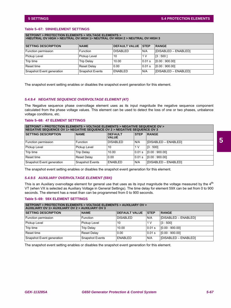
GEK-113285A G650 Generator Protection & Control System 5-67
5 SETTINGS 5.4 PROTECTION ELEMENTS
5
Table 5–67: 59NHELEMENT SETTINGS
The snapshot event setting enables or disables the snapshot event generation for this element.
5.4.9.4 NEGATIVE SEQUENCE OVERVOLTAGE ELEMENT (47)
The Negative sequence phase overvoltage element uses as its input magnitude the negative sequence componentcalculated from the phase voltage values. This element can be used to detect the loss of one or two phases, unbalancevoltage conditions, etc.
Table 5–68: 47 ELEMENT SETTINGS
The snapshot event setting enables or disables the snapshot event generation for this element.
5.4.9.5 AUXILIARY OVERVOLTAGE ELEMENT (59X)
This is an Auxiliary overvoltage element for general use that uses as its input magnitude the voltage measured by the 4th
VT (when VX is selected as Auxiliary Voltage in General Settings). The time delay for element 59X can be set from 0 to 900seconds. The element has a reset than can be programmed from 0 to 900 seconds.
Table 5–69: 59X ELEMENT SETTINGS
The snapshot event setting enables or disables the snapshot event generation for this element.
SETPOINT > PROTECTION ELEMENTS > VOLTAGE ELEMENTS >>NEUTRAL OV HIGH > NEUTRAL OV HIGH 1> NEUTRAL OV HIGH 2 > NEUTRAL OV HIGH 3
SETTING DESCRIPTION NAME DEFAULT VALUE STEP RANGEFunction permission Function DISABLED N/A [DISABLED – ENABLED]Pickup Level Pickup Level 10 1 V [3 : 500 ]Trip time Trip Delay 10.00 0.01 s [0.00 : 900.00]Reset time Reset Delay 0.00 0.01 s [0.00 : 900.00]Snapshot Event generation Snapshot Events ENABLED N/A [DISABLED – ENABLED]
SETPOINT > PROTECTION ELEMENTS > VOLTAGE ELEMENTS > NEGATIVE SEQUENCE OV >NEGATIVE SEQUENCE OV 1> NEGATIVE SEQUENCE OV 2 > NEGATIVE SEQUENCE OV 3SETTING DESCRIPTION NAME DEFAULT
VALUESTEP RANGE
Function permission Function DISABLED N/A [DISABLED – ENABLED]Pickup Level Pickup Level 10 1 V [3 : 500]Trip time Trip Delay 10.00 0.01 s [0.00 : 900.00]Reset time Reset Delay 0.00 0.01 s [0.00 : 900.00]Snapshot Event generation Snapshot Events ENABLED N/A [DISABLED – ENABLED]
SETPOINT > PROTECTION ELEMENTS > VOLTAGE ELEMENTS > AUXILIARY OV >AUXILIARY OV 1> AUXILIARY OV 2 > AUXILIARY OV 3SETTING DESCRIPTION NAME DEFAULT VALUE STEP RANGEFunction permission Function DISABLED N/A [DISABLED – ENABLED]Pickup Level Pickup Level 10 1 V [3 : 500]Trip time Trip Delay 10.00 0.01 s [0.00 : 900.00]Reset time Reset Delay 0.00 0.01 s [0.00 : 900.00]Snapshot Event generation Snapshot Events ENABLED N/A [DISABLED – ENABLED]
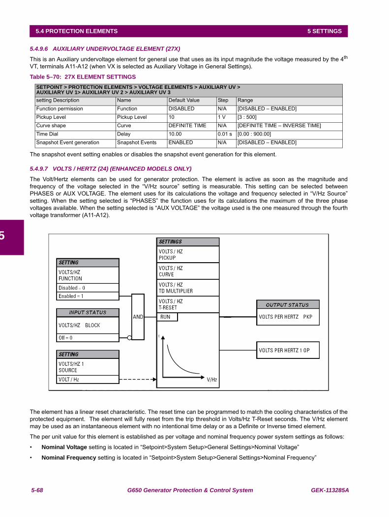
5-68 G650 Generator Protection & Control System GEK-113285A
5.4 PROTECTION ELEMENTS 5 SETTINGS
5
5.4.9.6 AUXILIARY UNDERVOLTAGE ELEMENT (27X)
This is an Auxiliary undervoltage element for general use that uses as its input magnitude the voltage measured by the 4th
VT, terminals A11-A12 (when VX is selected as Auxiliary Voltage in General Settings).
Table 5–70: 27X ELEMENT SETTINGS
The snapshot event setting enables or disables the snapshot event generation for this element.
5.4.9.7 VOLTS / HERTZ (24) (ENHANCED MODELS ONLY)
The Volt/Hertz elements can be used for generator protection. The element is active as soon as the magnitude andfrequency of the voltage selected in the “V/Hz source” setting is measurable. This setting can be selected betweenPHASES or AUX VOLTAGE. The element uses for its calculations the voltage and frequency selected in “V/Hz Source”setting. When the setting selected is “PHASES” the function uses for its calculations the maximum of the three phasevoltages available. When the setting selected is “AUX VOLTAGE” the voltage used is the one measured through the fourthvoltage transformer (A11-A12).
The element has a linear reset characteristic. The reset time can be programmed to match the cooling characteristics of theprotected equipment. The element will fully reset from the trip threshold in Volts/Hz T-Reset seconds. The V/Hz elementmay be used as an instantaneous element with no intentional time delay or as a Definite or Inverse timed element.
The per unit value for this element is established as per voltage and nominal frequency power system settings as follows:
• Nominal Voltage setting is located in “Setpoint>System Setup>General Settings>Nominal Voltage”
• Nominal Frequency setting is located in “Setpoint>System Setup>General Settings>Nominal Frequency”
SETPOINT > PROTECTION ELEMENTS > VOLTAGE ELEMENTS > AUXILIARY UV >AUXILIARY UV 1> AUXILIARY UV 2 > AUXILIARY UV 3setting Description Name Default Value Step RangeFunction permission Function DISABLED N/A [DISABLED – ENABLED]Pickup Level Pickup Level 10 1 V [3 : 500]Curve shape Curve DEFINITE TIME N/A [DEFINITE TIME – INVERSE TIME]Time Dial Delay 10.00 0.01 s [0.00 : 900.00]Snapshot Event generation Snapshot Events ENABLED N/A [DISABLED – ENABLED]
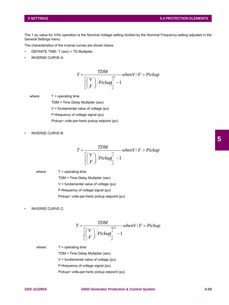
GEK-113285A G650 Generator Protection & Control System 5-69
5 SETTINGS 5.4 PROTECTION ELEMENTS
5
The 1 pu value for V/Hz operation is the Nominal Voltage setting divided by the Nominal Frequency setting adjusted in theGeneral Settings menu.
The characteristics of the inverse curves are shown below:
• DEFINITE TIME: T (sec) = TD Multiplier.
• INVERSE CURVE A:
where: T = operating time
TDM = Time Delay Multiplier (sec)
V = fundamental value of voltage (pu)
F=frequency of voltage signal (pu)
Pickup= volts-per-hertz pickup setpoint (pu)
• INVERSE CURVE B:
where: T = operating time
TDM = Time Delay Multiplier (sec)
V = fundamental value of voltage (pu)
F=frequency of voltage signal (pu)
Pickup= volts-per-hertz pickup setpoint (pu)
• INVERSE CURVE C:
where: T = operating time
TDM = Time Delay Multiplier (sec)
V = fundamental value of voltage (pu)
F=frequency of voltage signal (pu)
Pickup= volts-per-hertz pickup setpoint (pu)
PickupFwhenV
PickupFV
TDMT >
−⎥⎦
⎤⎢⎣
⎡⎟⎠⎞
⎜⎝⎛
= /
12
PickupFwhenV
PickupFV
TDMT >
−⎥⎦
⎤⎢⎣
⎡⎟⎠⎞
⎜⎝⎛
= /
1
PickupFwhenV
PickupFV
TDMT >
−⎥⎦
⎤⎢⎣
⎡⎟⎠⎞
⎜⎝⎛
= /
15.0
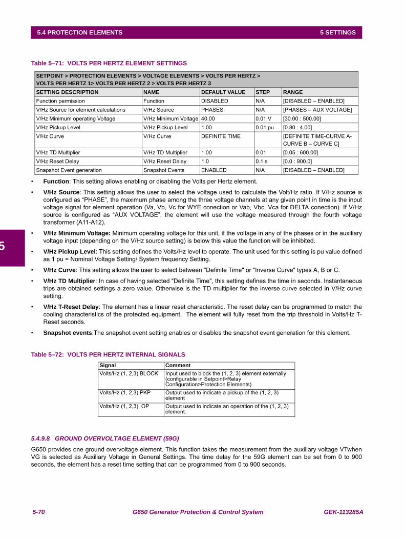
5-70 G650 Generator Protection & Control System GEK-113285A
5.4 PROTECTION ELEMENTS 5 SETTINGS
5
Table 5–71: VOLTS PER HERTZ ELEMENT SETTINGS
• Function: This setting allows enabling or disabling the Volts per Hertz element.
• V/Hz Source: This setting allows the user to select the voltage used to calculate the Volt/Hz ratio. If V/Hz source isconfigured as “PHASE”, the maximum phase among the three voltage channels at any given point in time is the inputvoltage signal for element operation (Va, Vb, Vc for WYE conection or Vab, Vbc, Vca for DELTA conection). If V/Hzsource is configured as “AUX VOLTAGE”, the element will use the voltage measured through the fourth voltagetransformer (A11-A12).
• V/Hz Minimum Voltage: Minimum operating voltage for this unit, if the voltage in any of the phases or in the auxiliaryvoltage input (depending on the V/Hz source setting) is below this value the function will be inhibited.
• V/Hz Pickup Level: This setting defines the Volts/Hz level to operate. The unit used for this setting is pu value definedas 1 pu = Nominal Voltage Setting/ System frequency Setting.
• V/Hz Curve: This setting allows the user to select between "Definite Time" or "Inverse Curve" types A, B or C.
• V/Hz TD Multiplier: In case of having selected "Definite Time", this setting defines the time in seconds. Instantaneoustrips are obtained settings a zero value. Otherwise is the TD multiplier for the inverse curve selected in V/Hz curvesetting.
• V/Hz T-Reset Delay: The element has a linear reset characteristic. The reset delay can be programmed to match thecooling characteristics of the protected equipment. The element will fully reset from the trip threshold in Volts/Hz T-Reset seconds.
• Snapshot events:The snapshot event setting enables or disables the snapshot event generation for this element.
Table 5–72: VOLTS PER HERTZ INTERNAL SIGNALS
5.4.9.8 GROUND OVERVOLTAGE ELEMENT (59G)
G650 provides one ground overvoltage element. This function takes the measurement from the auxiliary voltage VTwhenVG is selected as Auxiliary Voltage in General Settings. The time delay for the 59G element can be set from 0 to 900seconds, the element has a reset time setting that can be programmed from 0 to 900 seconds.
SETPOINT > PROTECTION ELEMENTS > VOLTAGE ELEMENTS > VOLTS PER HERTZ >VOLTS PER HERTZ 1> VOLTS PER HERTZ 2 > VOLTS PER HERTZ 3SETTING DESCRIPTION NAME DEFAULT VALUE STEP RANGEFunction permission Function DISABLED N/A [DISABLED – ENABLED]V/Hz Source for element calculations V/Hz Source PHASES N/A [PHASES – AUX VOLTAGE]V/Hz Minimum operating Voltage V/Hz Minimum Voltage 40.00 0.01 V [30.00 : 500.00]V/Hz Pickup Level V/Hz Pickup Level 1.00 0.01 pu [0.80 : 4.00]V/Hz Curve V/Hz Curve DEFINITE TIME [DEFINITE TIME-CURVE A-
CURVE B – CURVE C]V/Hz TD Multiplier V/Hz TD Multiplier 1.00 0.01 [0.05 : 600.00]V/Hz Reset Delay V/Hz Reset Delay 1.0 0.1 s [0.0 : 900.0]Snapshot Event generation Snapshot Events ENABLED N/A [DISABLED – ENABLED]
Signal CommentVolts/Hz (1, 2,3) BLOCK Input used to block the (1, 2, 3) element externally
(configurable in Setpoint>Relay Configuration>Protection Elements)
Volts/Hz (1, 2,3) PKP Output used to indicate a pickup of the (1, 2, 3) element
Volts/Hz (1, 2,3) OP Output used to indicate an operation of the (1, 2, 3) element.
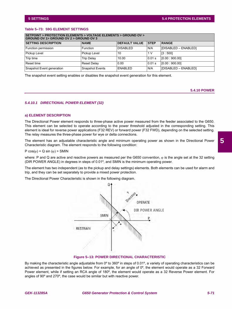
GEK-113285A G650 Generator Protection & Control System 5-71
5 SETTINGS 5.4 PROTECTION ELEMENTS
5
Table 5–73: 59G ELEMENT SETTINGS
The snapshot event setting enables or disables the snapshot event generation for this element.
5.4.10 POWER
5.4.10.1 DIRECTIONAL POWER ELEMENT (32)
a) ELEMENT DESCRIPTION
The Directional Power element responds to three-phase active power measured from the feeder associated to the G650.This element can be selected to operate according to the power threshold adjusted in the corresponding setting. Thiselement is ideal for reverse power applications (F32 REV) or forward power (F32 FWD), depending on the selected setting.The relay measures the three-phase power for wye or delta connections.
The element has an adjustable characteristic angle and minimum operating power as shown in the Directional PowerCharacteristic diagram. The element responds to the following condition:
P cos(ϕ) + Q sin (ϕ) > SMIN
where: P and Q are active and reactive powers as measured per the G650 convention, ϕ is the angle set at the 32 setting(DIR POWER ANGLE) in degrees in steps of 0.01º, and SMIN is the minimum operating power.
The element has two independent (as to the pickup and delay settings) elements. Both elements can be used for alarm andtrip, and they can be set separately to provide a mixed power protection.
The Directional Power Characteristic is shown in the following diagram.
Figure 5–13: POWER DIRECTIONAL CHARACTERISTIC
By making the characteristic angle adjustable from 0º to 360º in steps of 0.01º, a variety of operating characteristics can beachieved as presented in the figures below. For example, for an angle of 0º, the element would operate as a 32 ForwardPower element, while if setting an RCA angle of 180º, the element would operate as a 32 Reverse Power element. Forangles of 90º and 270º, the case would be similar but with reactive power.
SETPOINT > PROTECTION ELEMENTS > VOLTAGE ELEMENTS > GROUND OV >GROUND OV 1> GROUND OV 2 > GROUND OV 3SETTING DESCRIPTION NAME DEFAULT VALUE STEP RANGEFunction permission Function DISABLED N/A [DISABLED – ENABLED]Pickup Level Pickup Level 10 1 V [3 : 500]Trip time Trip Delay 10.00 0.01 s [0.00 : 900.00]Reset time Reset Delay 0.00 0.01 s [0.00 : 900.00]Snapshot Event generation Snapshot Events ENABLED N/A [DISABLED – ENABLED]
DIR POWER ANGLE
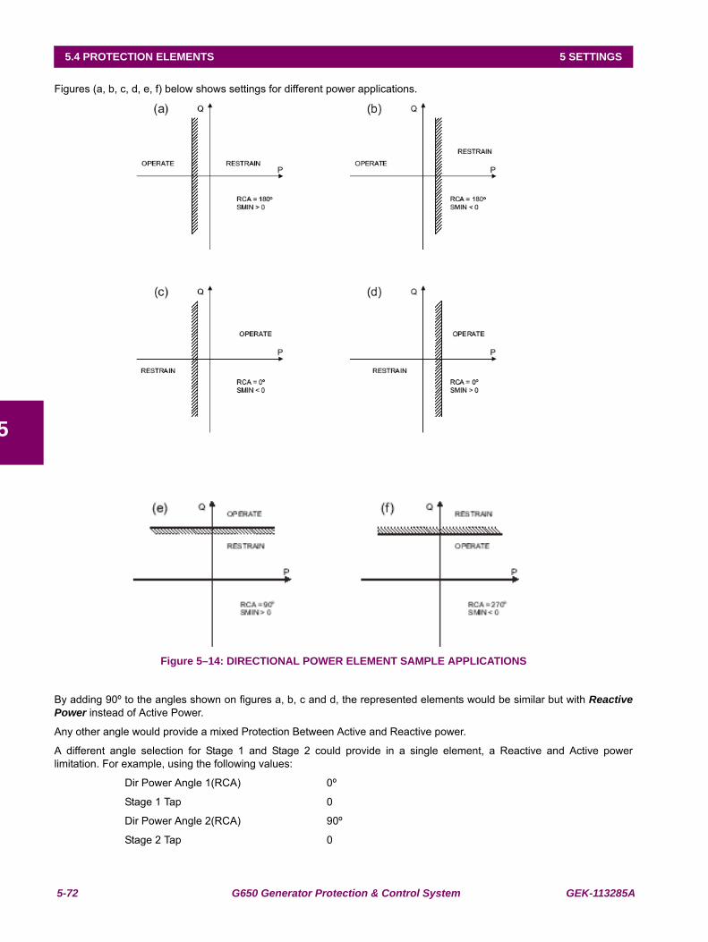
5-72 G650 Generator Protection & Control System GEK-113285A
5.4 PROTECTION ELEMENTS 5 SETTINGS
5
Figures (a, b, c, d, e, f) below shows settings for different power applications.
Figure 5–14: DIRECTIONAL POWER ELEMENT SAMPLE APPLICATIONS
By adding 90º to the angles shown on figures a, b, c and d, the represented elements would be similar but with ReactivePower instead of Active Power.
Any other angle would provide a mixed Protection Between Active and Reactive power.
A different angle selection for Stage 1 and Stage 2 could provide in a single element, a Reactive and Active powerlimitation. For example, using the following values:
Dir Power Angle 1(RCA) 0º
Stage 1 Tap 0
Dir Power Angle 2(RCA) 90º
Stage 2 Tap 0
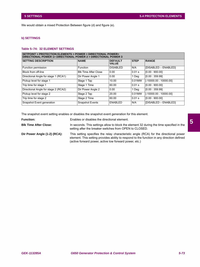
GEK-113285A G650 Generator Protection & Control System 5-73
5 SETTINGS 5.4 PROTECTION ELEMENTS
5
We would obtain a mixed Protection Between figure (d) and figure (e).
b) SETTINGS
Table 5–74: 32 ELEMENT SETTINGS
The snapshot event setting enables or disables the snapshot event generation for this element.
Function: Enables or disables the directional element.
Blk Time After Close: In seconds. This settings allow to block the element 32 during the time specified in thesetting after the breaker switches from OPEN to CLOSED.
Dir Power Angle (1-2) (RCA): This setting specifies the relay characteristic angle (RCA) for the directional powerelement. This setting provides ability to respond to the function in any direction defined(active forward power, active low forward power, etc.)
SETPOINT > PROTECTION ELEMENTS > POWER > DIRECTIONAL POWER>DIRECTIONAL POWER 1> DIRECTIONAL POWER 2 > DIRECTIONAL POWER 3SETTING DESCRIPTION NAME DEFAULT
VALUESTEP RANGE
Function permission Function DISABLED N/A [DISABLED – ENABLED]Block from off-line Blk Time After Close 0.00 0.01 s [0.00 : 900.00]Directional Angle for stage 1 (RCA1) Dir Power Angle 1 0.00 1 Deg [0.00 : 359.99]Pickup level for stage 1 Stage 1 Tap 10.00 0.01MW [-10000.00 : 10000.00]Trip time for stage 1 Stage 1 Time 60.00 0.01 s [0.00 : 900.00]Directional Angle for stage 2 (RCA2) Dir Power Angle 2 0.00 1 Deg [0.00 : 359.99]Pickup level for stage 2 Stage 2 Tap 20.00 0.01MW [-10000.00 : 10000.00]Trip time for stage 2 Stage 2 Time 60.00 0.01 s [0.00 : 900.00]Snapshot Event generation Snapshot Events ENABLED N/A [DISABLED – ENABLED]
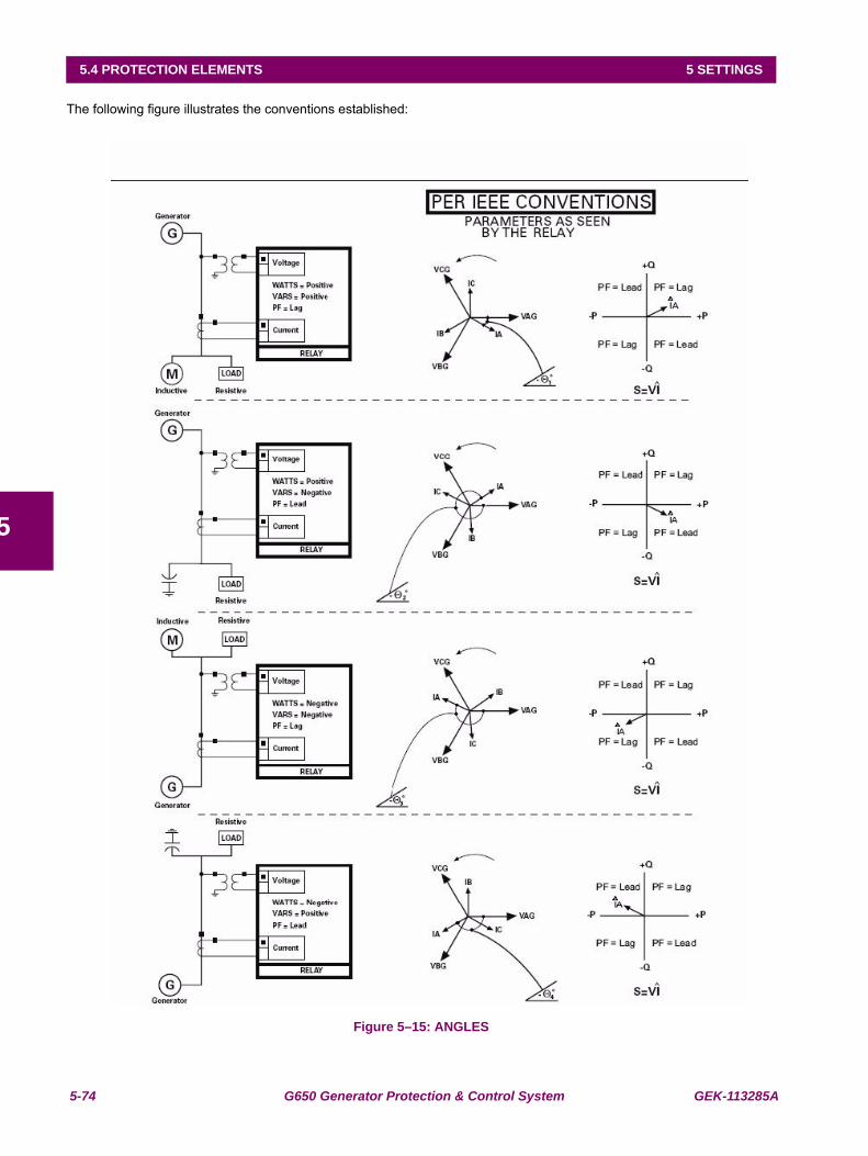
5-74 G650 Generator Protection & Control System GEK-113285A
5.4 PROTECTION ELEMENTS 5 SETTINGS
5
The following figure illustrates the conventions established:
Figure 5–15: ANGLES
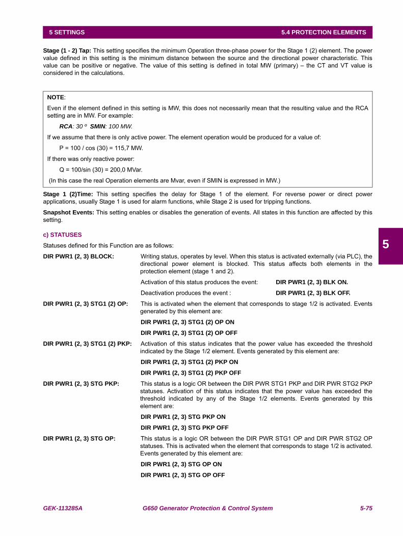
GEK-113285A G650 Generator Protection & Control System 5-75
5 SETTINGS 5.4 PROTECTION ELEMENTS
5
Stage (1 - 2) Tap: This setting specifies the minimum Operation three-phase power for the Stage 1 (2) element. The powervalue defined in this setting is the minimum distance between the source and the directional power characteristic. Thisvalue can be positive or negative. The value of this setting is defined in total MW (primary) – the CT and VT value isconsidered in the calculations.
Stage 1 (2)Time: This setting specifies the delay for Stage 1 of the element. For reverse power or direct powerapplications, usually Stage 1 is used for alarm functions, while Stage 2 is used for tripping functions.
Snapshot Events: This setting enables or disables the generation of events. All states in this function are affected by thissetting.
c) STATUSES
Statuses defined for this Function are as follows:
DIR PWR1 (2, 3) BLOCK: Writing status, operates by level. When this status is activated externally (via PLC), thedirectional power element is blocked. This status affects both elements in theprotection element (stage 1 and 2).
Activation of this status produces the event: DIR PWR1 (2, 3) BLK ON.
Deactivation produces the event : DIR PWR1 (2, 3) BLK OFF.
DIR PWR1 (2, 3) STG1 (2) OP: This is activated when the element that corresponds to stage 1/2 is activated. Eventsgenerated by this element are:
DIR PWR1 (2, 3) STG1 (2) OP ON
DIR PWR1 (2, 3) STG1 (2) OP OFF
DIR PWR1 (2, 3) STG1 (2) PKP: Activation of this status indicates that the power value has exceeded the thresholdindicated by the Stage 1/2 element. Events generated by this element are:
DIR PWR1 (2, 3) STG1 (2) PKP ON
DIR PWR1 (2, 3) STG1 (2) PKP OFF
DIR PWR1 (2, 3) STG PKP: This status is a logic OR between the DIR PWR STG1 PKP and DIR PWR STG2 PKPstatuses. Activation of this status indicates that the power value has exceeded thethreshold indicated by any of the Stage 1/2 elements. Events generated by thiselement are:
DIR PWR1 (2, 3) STG PKP ON
DIR PWR1 (2, 3) STG PKP OFF
DIR PWR1 (2, 3) STG OP: This status is a logic OR between the DIR PWR STG1 OP and DIR PWR STG2 OPstatuses. This is activated when the element that corresponds to stage 1/2 is activated.Events generated by this element are:
DIR PWR1 (2, 3) STG OP ON
DIR PWR1 (2, 3) STG OP OFF
NOTE:
Even if the element defined in this setting is MW, this does not necessarily mean that the resulting value and the RCAsetting are in MW. For example:
RCA: 30 º SMIN: 100 MW.
If we assume that there is only active power. The element operation would be produced for a value of:
P = 100 / cos (30) = 115,7 MW.
If there was only reactive power:
Q = 100/sin (30) = 200,0 MVar.
(In this case the real Operation elements are Mvar, even if SMIN is expressed in MW.)
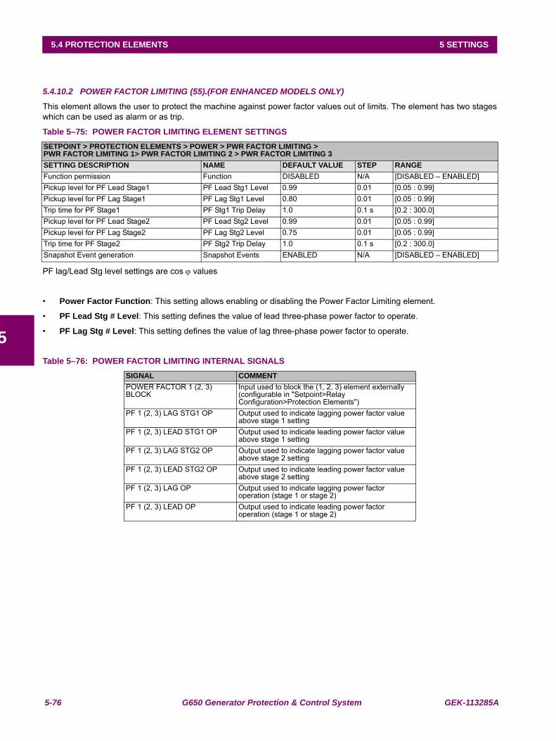
5-76 G650 Generator Protection & Control System GEK-113285A
5.4 PROTECTION ELEMENTS 5 SETTINGS
5
5.4.10.2 POWER FACTOR LIMITING (55).(FOR ENHANCED MODELS ONLY)
This element allows the user to protect the machine against power factor values out of limits. The element has two stageswhich can be used as alarm or as trip.
Table 5–75: POWER FACTOR LIMITING ELEMENT SETTINGS
PF lag/Lead Stg level settings are cos ϕ values
• Power Factor Function: This setting allows enabling or disabling the Power Factor Limiting element.
• PF Lead Stg # Level: This setting defines the value of lead three-phase power factor to operate.
• PF Lag Stg # Level: This setting defines the value of lag three-phase power factor to operate.
Table 5–76: POWER FACTOR LIMITING INTERNAL SIGNALS
SETPOINT > PROTECTION ELEMENTS > POWER > PWR FACTOR LIMITING >PWR FACTOR LIMITING 1> PWR FACTOR LIMITING 2 > PWR FACTOR LIMITING 3SETTING DESCRIPTION NAME DEFAULT VALUE STEP RANGEFunction permission Function DISABLED N/A [DISABLED – ENABLED]Pickup level for PF Lead Stage1 PF Lead Stg1 Level 0.99 0.01 [0.05 : 0.99]Pickup level for PF Lag Stage1 PF Lag Stg1 Level 0.80 0.01 [0.05 : 0.99]Trip time for PF Stage1 PF Stg1 Trip Delay 1.0 0.1 s [0.2 : 300.0]Pickup level for PF Lead Stage2 PF Lead Stg2 Level 0.99 0.01 [0.05 : 0.99]Pickup level for PF Lag Stage2 PF Lag Stg2 Level 0.75 0.01 [0.05 : 0.99]Trip time for PF Stage2 PF Stg2 Trip Delay 1.0 0.1 s [0.2 : 300.0]Snapshot Event generation Snapshot Events ENABLED N/A [DISABLED – ENABLED]
SIGNAL COMMENTPOWER FACTOR 1 (2, 3) BLOCK
Input used to block the (1, 2, 3) element externally (configurable in "Setpoint>Relay Configuration>Protection Elements")
PF 1 (2, 3) LAG STG1 OP Output used to indicate lagging power factor value above stage 1 setting
PF 1 (2, 3) LEAD STG1 OP Output used to indicate leading power factor value above stage 1 setting
PF 1 (2, 3) LAG STG2 OP Output used to indicate lagging power factor value above stage 2 setting
PF 1 (2, 3) LEAD STG2 OP Output used to indicate leading power factor value above stage 2 setting
PF 1 (2, 3) LAG OP Output used to indicate lagging power factor operation (stage 1 or stage 2)
PF 1 (2, 3) LEAD OP Output used to indicate leading power factor operation (stage 1 or stage 2)
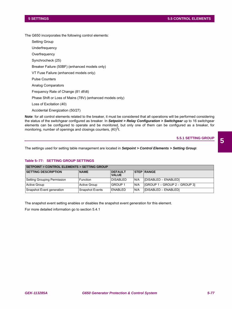
GEK-113285A G650 Generator Protection & Control System 5-77
5 SETTINGS 5.5 CONTROL ELEMENTS
5
5.5CONTROL ELEMENTS
The G650 incorporates the following control elements:
Setting Group
Underfrequency
Overfrequency
Synchrocheck (25)
Breaker Failure (50BF) (enhanced models only)
VT Fuse Failure (enhanced models only)
Pulse Counters
Analog Comparators
Frequency Rate of Change (81 df/dt)
Phase Shift or Loss of Mains (78V) (enhanced models only)
Loss of Excitation (40)
Accidental Energization (50/27)
Note: for all control elements related to the breaker, it must be considered that all operations will be performed consideringthe status of the switchgear configured as breaker. In Setpoint > Relay Configuration > Switchgear up to 16 switchgearelements can be configured to operate and be monitored, but only one of them can be configured as a breaker, formonitoring, number of openings and closings counters, (KI)2t.
5.5.1 SETTING GROUP
The settings used for setting table management are located in Setpoint > Control Elements > Setting Group:
Table 5–77: SETTING GROUP SETTINGS
The snapshot event setting enables or disables the snapshot event generation for this element.
For more detailed information go to section 5.4.1
SETPOINT > CONTROL ELEMENTS > SETTING GROUPSETTING DESCRIPTION NAME DEFAULT
VALUESTEP RANGE
Setting Grouping Permission Function DISABLED N/A [DISABLED – ENABLED]Active Group Active Group GROUP 1 N/A [GROUP 1 – GROUP 2 – GROUP 3]Snapshot Event generation Snapshot Events ENABLED N/A [DISABLED – ENABLED]
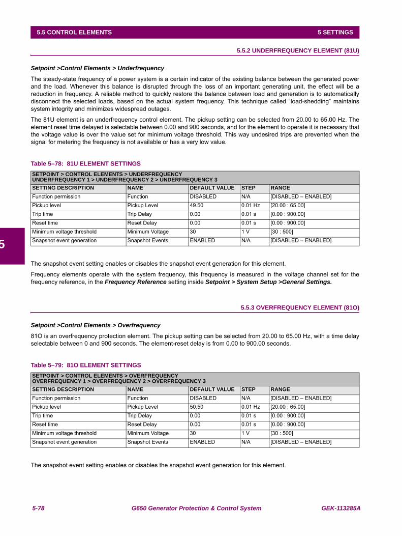
5-78 G650 Generator Protection & Control System GEK-113285A
5.5 CONTROL ELEMENTS 5 SETTINGS
5
5.5.2 UNDERFREQUENCY ELEMENT (81U)
Setpoint >Control Elements > Underfrequency
The steady-state frequency of a power system is a certain indicator of the existing balance between the generated powerand the load. Whenever this balance is disrupted through the loss of an important generating unit, the effect will be areduction in frequency. A reliable method to quickly restore the balance between load and generation is to automaticallydisconnect the selected loads, based on the actual system frequency. This technique called “load-shedding” maintainssystem integrity and minimizes widespread outages.
The 81U element is an underfrequency control element. The pickup setting can be selected from 20.00 to 65.00 Hz. Theelement reset time delayed is selectable between 0.00 and 900 seconds, and for the element to operate it is necessary thatthe voltage value is over the value set for minimum voltage threshold. This way undesired trips are prevented when thesignal for metering the frequency is not available or has a very low value.
Table 5–78: 81U ELEMENT SETTINGS
The snapshot event setting enables or disables the snapshot event generation for this element.
Frequency elements operate with the system frequency, this frequency is measured in the voltage channel set for thefrequency reference, in the Frequency Reference setting inside Setpoint > System Setup >General Settings.
5.5.3 OVERFREQUENCY ELEMENT (81O)
Setpoint >Control Elements > Overfrequency
81O is an overfrequency protection element. The pickup setting can be selected from 20.00 to 65.00 Hz, with a time delayselectable between 0 and 900 seconds. The element-reset delay is from 0.00 to 900.00 seconds.
Table 5–79: 81O ELEMENT SETTINGS
The snapshot event setting enables or disables the snapshot event generation for this element.
SETPOINT > CONTROL ELEMENTS > UNDERFREQUENCYUNDERFREQUENCY 1 > UNDERFREQUENCY 2 > UNDERFREQUENCY 3SETTING DESCRIPTION NAME DEFAULT VALUE STEP RANGEFunction permission Function DISABLED N/A [DISABLED – ENABLED]Pickup level Pickup Level 49.50 0.01 Hz [20.00 : 65.00]Trip time Trip Delay 0.00 0.01 s [0.00 : 900.00]Reset time Reset Delay 0.00 0.01 s [0.00 : 900.00]Minimum voltage threshold Minimum Voltage 30 1 V [30 : 500]Snapshot event generation Snapshot Events ENABLED N/A [DISABLED – ENABLED]
SETPOINT > CONTROL ELEMENTS > OVERFREQUENCYOVERFREQUENCY 1 > OVERFREQUENCY 2 > OVERFREQUENCY 3SETTING DESCRIPTION NAME DEFAULT VALUE STEP RANGEFunction permission Function DISABLED N/A [DISABLED – ENABLED]Pickup level Pickup Level 50.50 0.01 Hz [20.00 : 65.00]Trip time Trip Delay 0.00 0.01 s [0.00 : 900.00]Reset time Reset Delay 0.00 0.01 s [0.00 : 900.00]Minimum voltage threshold Minimum Voltage 30 1 V [30 : 500]Snapshot event generation Snapshot Events ENABLED N/A [DISABLED – ENABLED]
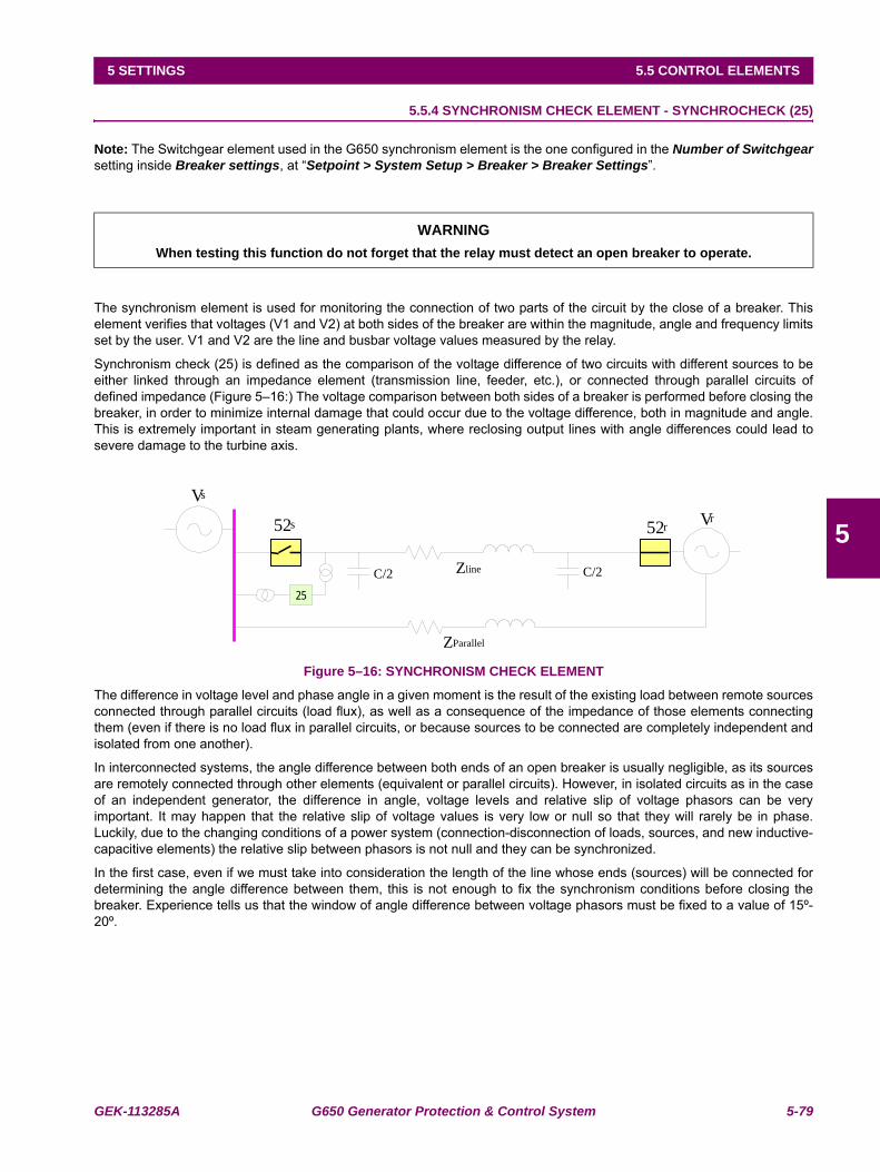
GEK-113285A G650 Generator Protection & Control System 5-79
5 SETTINGS 5.5 CONTROL ELEMENTS
5
5.5.4 SYNCHRONISM CHECK ELEMENT - SYNCHROCHECK (25)
Note: The Switchgear element used in the G650 synchronism element is the one configured in the Number of Switchgearsetting inside Breaker settings, at “Setpoint > System Setup > Breaker > Breaker Settings”.
The synchronism element is used for monitoring the connection of two parts of the circuit by the close of a breaker. Thiselement verifies that voltages (V1 and V2) at both sides of the breaker are within the magnitude, angle and frequency limitsset by the user. V1 and V2 are the line and busbar voltage values measured by the relay.
Synchronism check (25) is defined as the comparison of the voltage difference of two circuits with different sources to beeither linked through an impedance element (transmission line, feeder, etc.), or connected through parallel circuits ofdefined impedance (Figure 5–16:) The voltage comparison between both sides of a breaker is performed before closing thebreaker, in order to minimize internal damage that could occur due to the voltage difference, both in magnitude and angle.This is extremely important in steam generating plants, where reclosing output lines with angle differences could lead tosevere damage to the turbine axis.
Figure 5–16: SYNCHRONISM CHECK ELEMENT
The difference in voltage level and phase angle in a given moment is the result of the existing load between remote sourcesconnected through parallel circuits (load flux), as well as a consequence of the impedance of those elements connectingthem (even if there is no load flux in parallel circuits, or because sources to be connected are completely independent andisolated from one another).
In interconnected systems, the angle difference between both ends of an open breaker is usually negligible, as its sourcesare remotely connected through other elements (equivalent or parallel circuits). However, in isolated circuits as in the caseof an independent generator, the difference in angle, voltage levels and relative slip of voltage phasors can be veryimportant. It may happen that the relative slip of voltage values is very low or null so that they will rarely be in phase.Luckily, due to the changing conditions of a power system (connection-disconnection of loads, sources, and new inductive-capacitive elements) the relative slip between phasors is not null and they can be synchronized.
In the first case, even if we must take into consideration the length of the line whose ends (sources) will be connected fordetermining the angle difference between them, this is not enough to fix the synchronism conditions before closing thebreaker. Experience tells us that the window of angle difference between voltage phasors must be fixed to a value of 15º-20º.
WARNINGWhen testing this function do not forget that the relay must detect an open breaker to operate.
Vs
Vr
C/2ZlineC/2
25
ZParallel
52s 52r
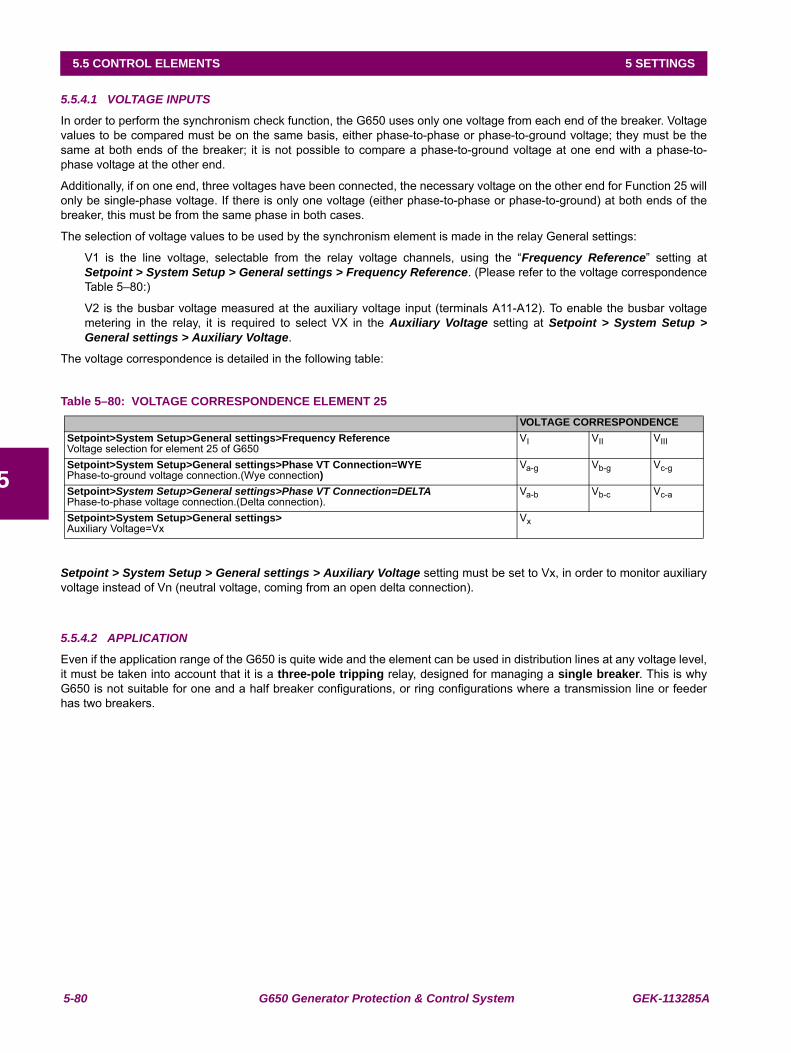
5-80 G650 Generator Protection & Control System GEK-113285A
5.5 CONTROL ELEMENTS 5 SETTINGS
5
5.5.4.1 VOLTAGE INPUTS
In order to perform the synchronism check function, the G650 uses only one voltage from each end of the breaker. Voltagevalues to be compared must be on the same basis, either phase-to-phase or phase-to-ground voltage; they must be thesame at both ends of the breaker; it is not possible to compare a phase-to-ground voltage at one end with a phase-to-phase voltage at the other end.
Additionally, if on one end, three voltages have been connected, the necessary voltage on the other end for Function 25 willonly be single-phase voltage. If there is only one voltage (either phase-to-phase or phase-to-ground) at both ends of thebreaker, this must be from the same phase in both cases.
The selection of voltage values to be used by the synchronism element is made in the relay General settings:
V1 is the line voltage, selectable from the relay voltage channels, using the “Frequency Reference” setting atSetpoint > System Setup > General settings > Frequency Reference. (Please refer to the voltage correspondenceTable 5–80:)
V2 is the busbar voltage measured at the auxiliary voltage input (terminals A11-A12). To enable the busbar voltagemetering in the relay, it is required to select VX in the Auxiliary Voltage setting at Setpoint > System Setup >General settings > Auxiliary Voltage.
The voltage correspondence is detailed in the following table:
Table 5–80: VOLTAGE CORRESPONDENCE ELEMENT 25
Setpoint > System Setup > General settings > Auxiliary Voltage setting must be set to Vx, in order to monitor auxiliaryvoltage instead of Vn (neutral voltage, coming from an open delta connection).
5.5.4.2 APPLICATION
Even if the application range of the G650 is quite wide and the element can be used in distribution lines at any voltage level,it must be taken into account that it is a three-pole tripping relay, designed for managing a single breaker. This is whyG650 is not suitable for one and a half breaker configurations, or ring configurations where a transmission line or feederhas two breakers.
VOLTAGE CORRESPONDENCESetpoint>System Setup>General settings>Frequency ReferenceVoltage selection for element 25 of G650
VI VII VIII
Setpoint>System Setup>General settings>Phase VT Connection=WYEPhase-to-ground voltage connection.(Wye connection)
Va-g Vb-g Vc-g
Setpoint>System Setup>General settings>Phase VT Connection=DELTA Phase-to-phase voltage connection.(Delta connection).
Va-b Vb-c Vc-a
Setpoint>System Setup>General settings> Auxiliary Voltage=Vx
Vx
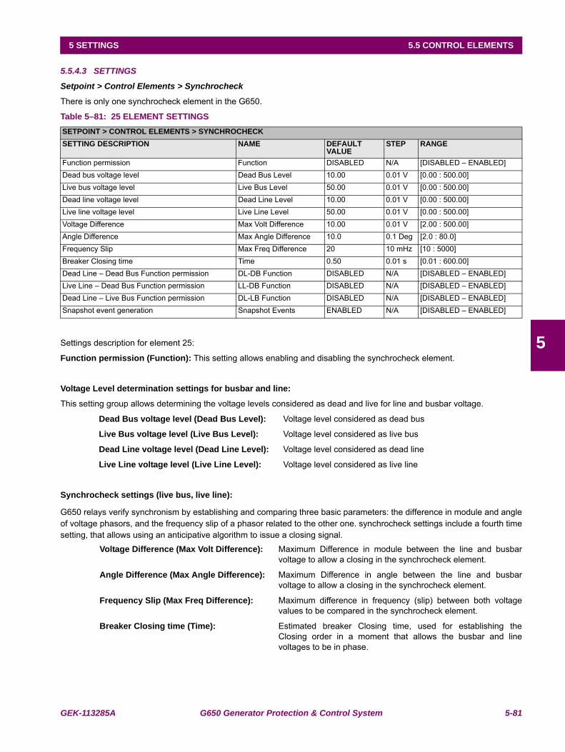
GEK-113285A G650 Generator Protection & Control System 5-81
5 SETTINGS 5.5 CONTROL ELEMENTS
5
5.5.4.3 SETTINGS
Setpoint > Control Elements > Synchrocheck
There is only one synchrocheck element in the G650.
Table 5–81: 25 ELEMENT SETTINGS
Settings description for element 25:
Function permission (Function): This setting allows enabling and disabling the synchrocheck element.
Voltage Level determination settings for busbar and line:
This setting group allows determining the voltage levels considered as dead and live for line and busbar voltage.
Dead Bus voltage level (Dead Bus Level): Voltage level considered as dead bus
Live Bus voltage level (Live Bus Level): Voltage level considered as live bus
Dead Line voltage level (Dead Line Level): Voltage level considered as dead line
Live Line voltage level (Live Line Level): Voltage level considered as live line
Synchrocheck settings (live bus, live line):
G650 relays verify synchronism by establishing and comparing three basic parameters: the difference in module and angleof voltage phasors, and the frequency slip of a phasor related to the other one. synchrocheck settings include a fourth timesetting, that allows using an anticipative algorithm to issue a closing signal.
Voltage Difference (Max Volt Difference): Maximum Difference in module between the line and busbarvoltage to allow a closing in the synchrocheck element.
Angle Difference (Max Angle Difference): Maximum Difference in angle between the line and busbarvoltage to allow a closing in the synchrocheck element.
Frequency Slip (Max Freq Difference): Maximum difference in frequency (slip) between both voltagevalues to be compared in the synchrocheck element.
Breaker Closing time (Time): Estimated breaker Closing time, used for establishing theClosing order in a moment that allows the busbar and linevoltages to be in phase.
SETPOINT > CONTROL ELEMENTS > SYNCHROCHECKSETTING DESCRIPTION NAME DEFAULT
VALUESTEP RANGE
Function permission Function DISABLED N/A [DISABLED – ENABLED]Dead bus voltage level Dead Bus Level 10.00 0.01 V [0.00 : 500.00]Live bus voltage level Live Bus Level 50.00 0.01 V [0.00 : 500.00]Dead line voltage level Dead Line Level 10.00 0.01 V [0.00 : 500.00]Live line voltage level Live Line Level 50.00 0.01 V [0.00 : 500.00]Voltage Difference Max Volt Difference 10.00 0.01 V [2.00 : 500.00]Angle Difference Max Angle Difference 10.0 0.1 Deg [2.0 : 80.0]Frequency Slip Max Freq Difference 20 10 mHz [10 : 5000]Breaker Closing time Time 0.50 0.01 s [0.01 : 600.00]Dead Line – Dead Bus Function permission DL-DB Function DISABLED N/A [DISABLED – ENABLED]Live Line – Dead Bus Function permission LL-DB Function DISABLED N/A [DISABLED – ENABLED]Dead Line – Live Bus Function permission DL-LB Function DISABLED N/A [DISABLED – ENABLED]Snapshot event generation Snapshot Events ENABLED N/A [DISABLED – ENABLED]
5-82 G650 Generator Protection & Control System GEK-113285A
5.5 CONTROL ELEMENTS 5 SETTINGS
5
This time is considered if the relative slip is higher than 5 mHz; in this case, an anticipative algorithm isexecuted to calculate the closing signal with the necessary advance for the breaker effective Closing to beproduced when voltages are in phase. In case the frequency slip is high (higher than 5 Hz) and it is notpossible to obtain a closing in phase, the used algorithm ensures that the voltage difference in the momentof the closing is lower than the set voltage (Max Voltage Difference).
Note: Take into account that the value of related settings "Frequency Slip (Max Freq Difference)" multiplied by"Breaker Closing time (Time)" must no be higher than 1. If that value is higher, that means that is necessary more thanone cycle to perform a close signal. In that case the relay will give the close signal only in the remain time. This functiondepend on the voltage difference, the angle difference, the frequency difference and the synchronism time to perform aclose signal:
Angle = 360 x Time x Max Freq Difference < 360º and Time x Max Freq Difference < 1
Closing permission logic settings:In case that the voltage at one or both ends of the breaker is null, the synchronism element cannot establish the necessaryparameters to give closing conditions, and therefore it does not issue synchronism permission. For those situations wherethe user wants to enable the closing permission in a condition of loss of one or both voltages at both ends of the breaker,G650 elements incorporate closing permission logics for the cases of: dead line-dead bus, live line-dead bus and dead line-live bus.
Dead line- Dead Bus Function permission (DL-DB Function): Enabling this Function allows issuing aClosing permission signal in dead line and dead bus Condition (without voltage at both sides of the breaker).
Live line- Dead Bus Function permission (LL-DB Function): Enabling this Function allows to issue aClosing permission signal in live line and dead bus Condition (without voltage at the sides of the breaker thatcorresponds to the busbar voltage)
Dead line- Live Bus Function permission (DL-LB Function): Enabling this Function allows issuing aClosing permission signal in live line and dead bus Condition (without voltage at the sides of the breaker thatcorresponds to the line voltage).
Snapshot event: The snapshot event setting enables or disables the snapshot event generation for this element.
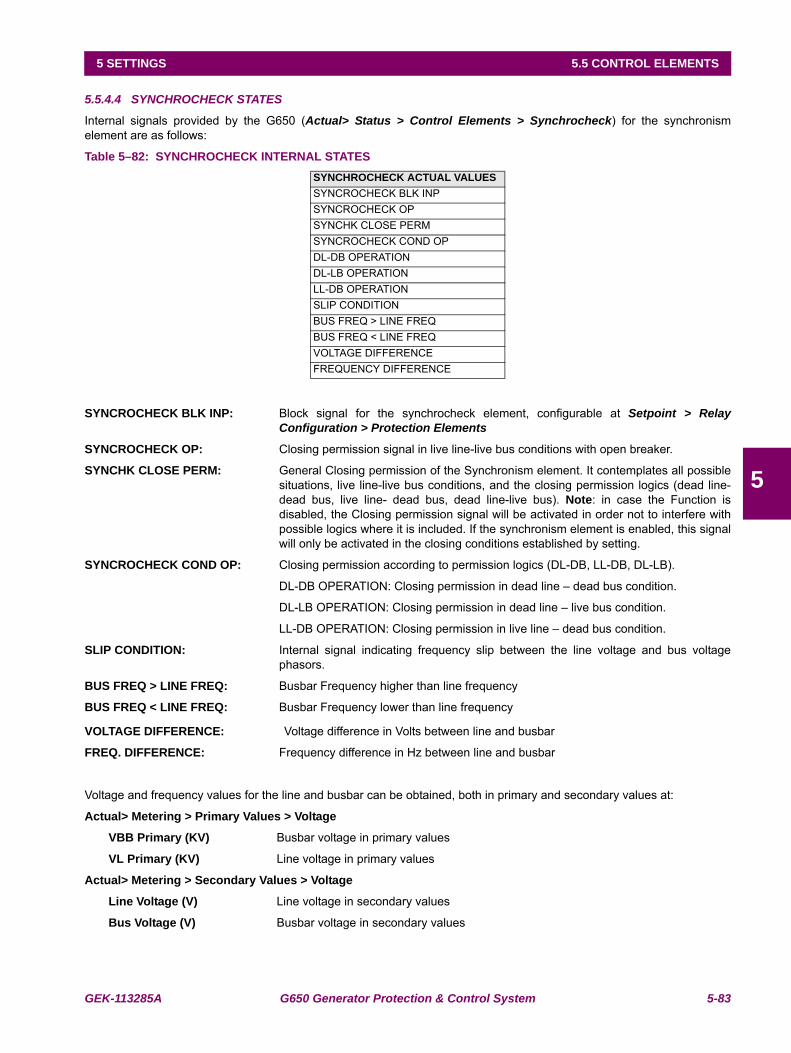
GEK-113285A G650 Generator Protection & Control System 5-83
5 SETTINGS 5.5 CONTROL ELEMENTS
5
5.5.4.4 SYNCHROCHECK STATES
Internal signals provided by the G650 (Actual> Status > Control Elements > Synchrocheck) for the synchronismelement are as follows:
Table 5–82: SYNCHROCHECK INTERNAL STATES
SYNCROCHECK BLK INP: Block signal for the synchrocheck element, configurable at Setpoint > RelayConfiguration > Protection Elements
SYNCROCHECK OP: Closing permission signal in live line-live bus conditions with open breaker.
SYNCHK CLOSE PERM: General Closing permission of the Synchronism element. It contemplates all possiblesituations, live line-live bus conditions, and the closing permission logics (dead line-dead bus, live line- dead bus, dead line-live bus). Note: in case the Function isdisabled, the Closing permission signal will be activated in order not to interfere withpossible logics where it is included. If the synchronism element is enabled, this signalwill only be activated in the closing conditions established by setting.
SYNCROCHECK COND OP: Closing permission according to permission logics (DL-DB, LL-DB, DL-LB).
DL-DB OPERATION: Closing permission in dead line – dead bus condition.
DL-LB OPERATION: Closing permission in dead line – live bus condition.
LL-DB OPERATION: Closing permission in live line – dead bus condition.
SLIP CONDITION: Internal signal indicating frequency slip between the line voltage and bus voltagephasors.
BUS FREQ > LINE FREQ: Busbar Frequency higher than line frequency
BUS FREQ < LINE FREQ: Busbar Frequency lower than line frequency
VOLTAGE DIFFERENCE: Voltage difference in Volts between line and busbar
FREQ. DIFFERENCE: Frequency difference in Hz between line and busbar
Voltage and frequency values for the line and busbar can be obtained, both in primary and secondary values at:
Actual> Metering > Primary Values > Voltage
VBB Primary (KV) Busbar voltage in primary values
VL Primary (KV) Line voltage in primary values
Actual> Metering > Secondary Values > Voltage
Line Voltage (V) Line voltage in secondary values
Bus Voltage (V) Busbar voltage in secondary values
SYNCHROCHECK ACTUAL VALUESSYNCROCHECK BLK INPSYNCROCHECK OPSYNCHK CLOSE PERMSYNCROCHECK COND OPDL-DB OPERATIONDL-LB OPERATIONLL-DB OPERATIONSLIP CONDITIONBUS FREQ > LINE FREQBUS FREQ < LINE FREQVOLTAGE DIFFERENCEFREQUENCY DIFFERENCE
5-84 G650 Generator Protection & Control System GEK-113285A
5.5 CONTROL ELEMENTS 5 SETTINGS
5
Actual> Metering > Frequency
Line Frequency (Hz) Line frequency in Hz
Bus Frequency (Hz) Bus frequency in Hz
The voltage angles can be obtained in primary metering values (Actual> Metering > Primary Values > Voltage), being theline voltage angle, the one that corresponds to the voltage set in the frequency reference in General settings (please referto the voltage correspondence table (Table 5–80:), and the angle of the busbar voltage the one that corresponds to VxAngle, when the Auxiliary Voltage setting as been selected as VX.
5.5.4.5 ALGORITHM
G650 elements perform the synchronism check by basically establishing and comparing three parameters:
Module difference of voltage phasors ΔV (V)
Phase angle of voltage phasors Δϕ (º)
Frequency slip between two phasors S (Hz)
These parameters are continuously determined and managed once that element 25 has been enabled by setting,and in open breaker conditions. It is necessary to consider that all calculations are made once the open breakercondition is detected; if the breaker is closed or undefined, the synchronism element will not issue a closing permissionsignal, even when closing conditions are met.
If voltage on one side of the breaker to be closed is null, the synchronism element cannot establish the synchronism check,and therefore it will not issue synchronism permission. For these cases, usual in breaker maintenance situations, or in newinstallations where voltage might not be present, but the breaker operation needs to be verified, G650 elements incorporateclosing permission logics for situations of:
Dead Line – Dead Bus (DL-DB)
Live Line – Dead Bus (LL-DB)
Dead Line – Live Bus (DL-LB)
In order to establish the closing permission signal, the first parameter used by the algorithm is the difference in magnitudebetween line and bus voltages, and afterwards, the angle difference and frequency slip are verified.
Voltage Difference ΔV
Comparing the voltage values for line voltage (V1) and busbar voltage (V2) at both sides of the breaker, the relay candetermine the synchronism situation of the element (see Table 5–83:).
Being:
V1 line voltage
V2 bus voltage
VL Minimum acceptable voltage by setting to establish synchronism conditions (dead line and bus levels).
VH Appropriate voltage to establish synchronism conditions, configured by setting (live line and bus levels).
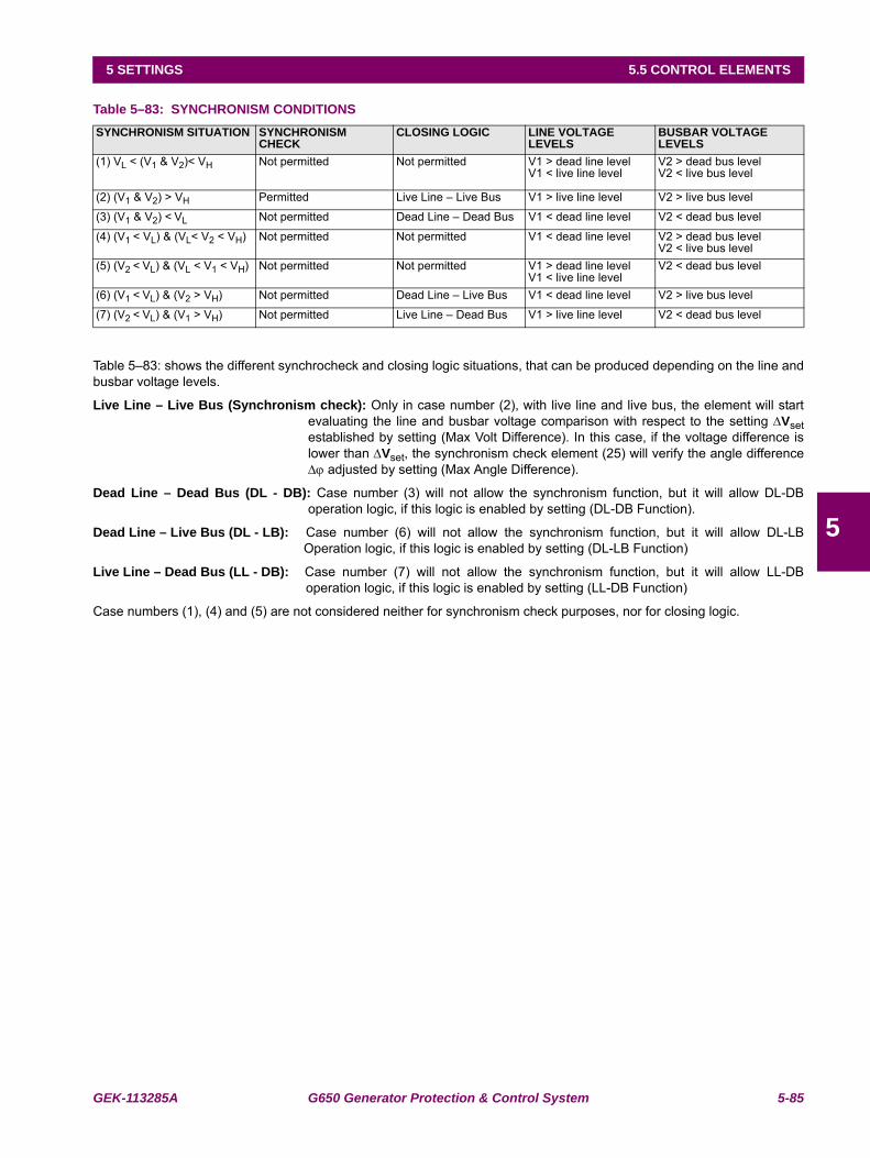
GEK-113285A G650 Generator Protection & Control System 5-85
5 SETTINGS 5.5 CONTROL ELEMENTS
5
Table 5–83: SYNCHRONISM CONDITIONS
Table 5–83: shows the different synchrocheck and closing logic situations, that can be produced depending on the line andbusbar voltage levels.
Live Line – Live Bus (Synchronism check): Only in case number (2), with live line and live bus, the element will startevaluating the line and busbar voltage comparison with respect to the setting ΔVsetestablished by setting (Max Volt Difference). In this case, if the voltage difference islower than ΔVset, the synchronism check element (25) will verify the angle differenceΔϕ adjusted by setting (Max Angle Difference).
Dead Line – Dead Bus (DL - DB): Case number (3) will not allow the synchronism function, but it will allow DL-DBoperation logic, if this logic is enabled by setting (DL-DB Function).
Dead Line – Live Bus (DL - LB): Case number (6) will not allow the synchronism function, but it will allow DL-LBOperation logic, if this logic is enabled by setting (DL-LB Function)
Live Line – Dead Bus (LL - DB): Case number (7) will not allow the synchronism function, but it will allow LL-DBoperation logic, if this logic is enabled by setting (LL-DB Function)
Case numbers (1), (4) and (5) are not considered neither for synchronism check purposes, nor for closing logic.
SYNCHRONISM SITUATION SYNCHRONISM CHECK
CLOSING LOGIC LINE VOLTAGE LEVELS
BUSBAR VOLTAGE LEVELS
(1) VL < (V1 & V2)< VH Not permitted Not permitted V1 > dead line levelV1 < live line level
V2 > dead bus levelV2 < live bus level
(2) (V1 & V2) > VH Permitted Live Line – Live Bus V1 > live line level V2 > live bus level
(3) (V1 & V2) < VL Not permitted Dead Line – Dead Bus V1 < dead line level V2 < dead bus level
(4) (V1 < VL) & (VL< V2 < VH) Not permitted Not permitted V1 < dead line level V2 > dead bus levelV2 < live bus level
(5) (V2 < VL) & (VL < V1 < VH) Not permitted Not permitted V1 > dead line levelV1 < live line level
V2 < dead bus level
(6) (V1 < VL) & (V2 > VH) Not permitted Dead Line – Live Bus V1 < dead line level V2 > live bus level
(7) (V2 < VL) & (V1 > VH) Not permitted Live Line – Dead Bus V1 > live line level V2 < dead bus level
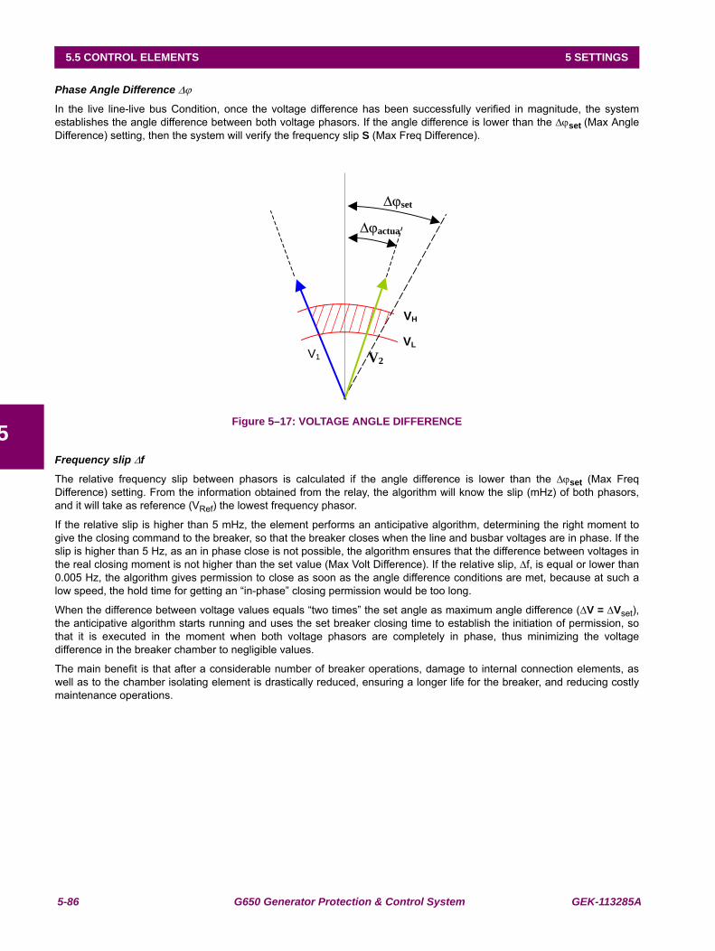
5-86 G650 Generator Protection & Control System GEK-113285A
5.5 CONTROL ELEMENTS 5 SETTINGS
5
Phase Angle Difference Δϕ
In the live line-live bus Condition, once the voltage difference has been successfully verified in magnitude, the systemestablishes the angle difference between both voltage phasors. If the angle difference is lower than the Δϕset (Max AngleDifference) setting, then the system will verify the frequency slip S (Max Freq Difference).
Figure 5–17: VOLTAGE ANGLE DIFFERENCE
Frequency slip Δf
The relative frequency slip between phasors is calculated if the angle difference is lower than the Δϕset (Max FreqDifference) setting. From the information obtained from the relay, the algorithm will know the slip (mHz) of both phasors,and it will take as reference (VRef) the lowest frequency phasor.
If the relative slip is higher than 5 mHz, the element performs an anticipative algorithm, determining the right moment togive the closing command to the breaker, so that the breaker closes when the line and busbar voltages are in phase. If theslip is higher than 5 Hz, as an in phase close is not possible, the algorithm ensures that the difference between voltages inthe real closing moment is not higher than the set value (Max Volt Difference). If the relative slip, Δf, is equal or lower than0.005 Hz, the algorithm gives permission to close as soon as the angle difference conditions are met, because at such alow speed, the hold time for getting an “in-phase” closing permission would be too long.
When the difference between voltage values equals “two times” the set angle as maximum angle difference (ΔV = ΔVset),the anticipative algorithm starts running and uses the set breaker closing time to establish the initiation of permission, sothat it is executed in the moment when both voltage phasors are completely in phase, thus minimizing the voltagedifference in the breaker chamber to negligible values.
The main benefit is that after a considerable number of breaker operations, damage to internal connection elements, aswell as to the chamber isolating element is drastically reduced, ensuring a longer life for the breaker, and reducing costlymaintenance operations.
V1 V2
VH
actua
VL
set
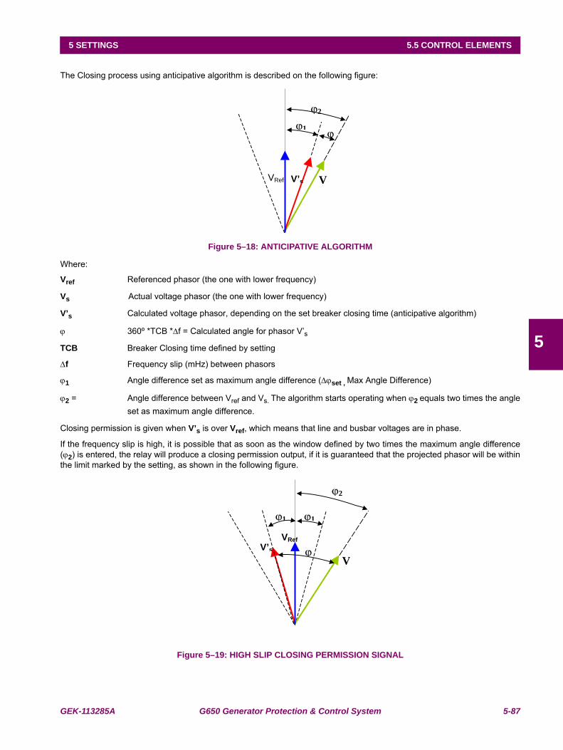
GEK-113285A G650 Generator Protection & Control System 5-87
5 SETTINGS 5.5 CONTROL ELEMENTS
5
The Closing process using anticipative algorithm is described on the following figure:
Figure 5–18: ANTICIPATIVE ALGORITHM
Where:
Vref Referenced phasor (the one with lower frequency)
Vs Actual voltage phasor (the one with lower frequency)
V’s Calculated voltage phasor, depending on the set breaker closing time (anticipative algorithm)
ϕ 360º *TCB *Δf = Calculated angle for phasor V’s
TCB Breaker Closing time defined by setting
Δf Frequency slip (mHz) between phasors
ϕ1 Angle difference set as maximum angle difference (Δϕset , Max Angle Difference)
ϕ2 = Angle difference between Vref and Vs. The algorithm starts operating when ϕ2 equals two times the angleset as maximum angle difference.
Closing permission is given when V’s is over Vref, which means that line and busbar voltages are in phase.
If the frequency slip is high, it is possible that as soon as the window defined by two times the maximum angle difference(ϕ2) is entered, the relay will produce a closing permission output, if it is guaranteed that the projected phasor will be withinthe limit marked by the setting, as shown in the following figure.
Figure 5–19: HIGH SLIP CLOSING PERMISSION SIGNAL
VRef V
1
2
V’s
VRef
V
1
2
V’s
1

5-88 G650 Generator Protection & Control System GEK-113285A
5.5 CONTROL ELEMENTS 5 SETTINGS
5
5.5.5 BREAKER FAILURE ELEMENT (50BF) (ENHANCED MODELS ONLY)
Note: The Switchgear element used in the Breaker Failure element is the one configured in the Number of Switchgearsetting, inside Breaker settings at Setpoint > Protection Elements > Breaker > Breaker settings
The breaker failure element is used to determine when a trip command sent to a breaker has not been executed within aselectable delay. Most commonly it is a failure to open from the tripped breaker. In the event of a breaker failure, the 50BFelement must issue a signal that will trip the rest of breakers connected at that time to the same busbar, and that canprovide fault current.
Comparing the current measured by the Relay with a setting level makes breaker failure detection. If after receiving abreaker initiate signal, the current level is maintained over the set level for a time period longer than the set time, thisindicates that the breaker that has received the opening command has not been able to open and clear the fault. The relaywould issue the corresponding breaker failure signal.
G650 elements incorporate 2 levels of current and time, together with a trip without current element, and an internal arcdetection element.
The breaker failure Initiate signal is configured at Setpoint > Relay Configuration > Protection Elements. In the BRKFAILURE INITIATE input, the user must select the desired signal for the breaker failure initiation.
The following table describes the breaker failure element settings: Setpoint > Control Elements > Breaker Failure
Table 5–84: 50BF ELEMENT SETTINGS
Settings description for breaker failure element:
Function permission (Function): This setting allows enabling and disabling the 50BF element
Supervision or retrip pickup level (Supervision Pickup): Supervision level pickup current threshold
Hiset pickup level (Hiset Pickup): High-level pickup current threshold.
Lowset pickup level (Loset Pickup): Low level pickup current threshold.
Internal arc pickup level (Internal Arc Pickup): Internal arc element pickup current threshold.
Internal arc time delay (Internal Arc Delay): Time delay applied to the internal arc element
Supervision or Retrip time delay (Supervision Delay): Time delay applied to the supervision or retrip element.
High-level time delay (Hiset Delay): Time delay applied to the high level element.
Low-level time delay (Lowset Delay): Time delay applied to the low level element.
2nd step time delay (2nd Step Delay): Time delay applied to the breaker failure second step.
No current element time delay (No Current Delay): Time delay applied to the trip without current element.
SETPOINT > CONTROL ELEMENTS > BREAKER FAILURESETTING DESCRIPTION NAME DEFAULT VALUE STEP RANGEFunction permission Function DISABLED N/A [DISABLED – ENABLED]Supervision (retrip) pickup level Supervision Pickup 1.00 0.01 A [0.05 : 160.00]Hiset pickup level Hiset Pickup 5.00 0.01 A [0.05 : 160.00]Lowset pickup level Lowset Pickup 2.00 0.01 A [0.05 : 160.00]Internal arc pickup level Internal Arc Pickup 0.10 0.01 A [0.05 : 160.00]Internal arc time delay Internal Arc Delay 10.00 0.01 s [0.00 : 900.00]Retrip time delay Supervision Delay 10.00 0.01 s [0.00 : 900.00]Hiset time delay HiSet Delay 10.00 0.01 s [0.00 : 900.00]Lowset time delay LowSet Delay 10.00 0.01 s [0.00 : 900.00]Second stage time delay 2nd Step Delay 10.00 0.01 s [0.00 : 900.00]WITHOUT current element time delay No Current Delay 10.00 0.01 s [0.00 : 900.00]Snapshot event generation Snapshot Events ENABLED N/A [DISABLED – ENABLED]
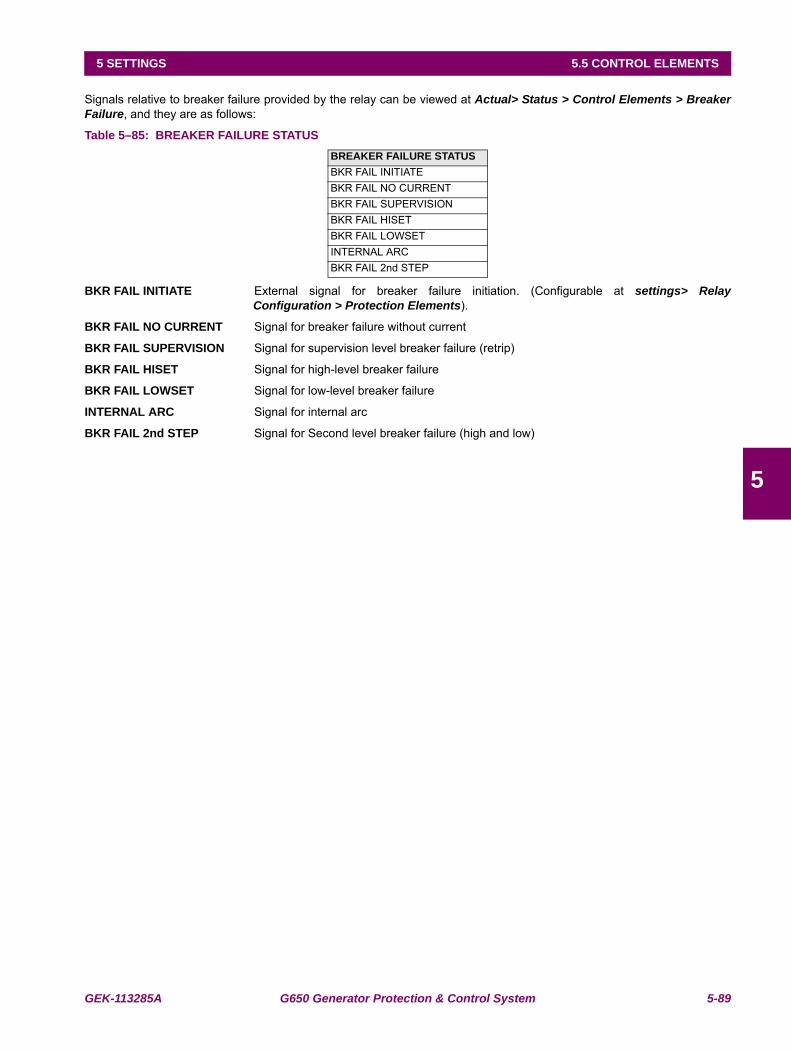
GEK-113285A G650 Generator Protection & Control System 5-89
5 SETTINGS 5.5 CONTROL ELEMENTS
5
Signals relative to breaker failure provided by the relay can be viewed at Actual> Status > Control Elements > BreakerFailure, and they are as follows:
Table 5–85: BREAKER FAILURE STATUS
BKR FAIL INITIATE External signal for breaker failure initiation. (Configurable at settings> RelayConfiguration > Protection Elements).
BKR FAIL NO CURRENT Signal for breaker failure without current
BKR FAIL SUPERVISION Signal for supervision level breaker failure (retrip)
BKR FAIL HISET Signal for high-level breaker failure
BKR FAIL LOWSET Signal for low-level breaker failure
INTERNAL ARC Signal for internal arc
BKR FAIL 2nd STEP Signal for Second level breaker failure (high and low)
BREAKER FAILURE STATUSBKR FAIL INITIATEBKR FAIL NO CURRENTBKR FAIL SUPERVISIONBKR FAIL HISETBKR FAIL LOWSETINTERNAL ARCBKR FAIL 2nd STEP
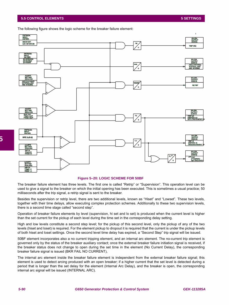
5-90 G650 Generator Protection & Control System GEK-113285A
5.5 CONTROL ELEMENTS 5 SETTINGS
5
The following figure shows the logic scheme for the breaker failure element:
Figure 5–20: LOGIC SCHEME FOR 50BF
The breaker failure element has three levels. The first one is called “Retrip” or “Supervision”. This operation level can beused to give a signal to the breaker on which the initial opening has been executed. This is sometimes a usual practice; 50milliseconds after the trip signal, a retrip signal is sent to the breaker.
Besides the supervision or retrip level, there are two additional levels, known as “Hiset” and “Lowset”. These two levels,together with their time delays, allow executing complex protection schemes. Additionally to these two supervision levels,there is a second time stage called “second step”.
Operation of breaker failure elements by level (supervision, hi set and lo set) is produced when the current level is higherthan the set current for the pickup of each level during the time set in the corresponding delay setting.
High and low levels constitute a second step level; for the pickup of this second level, only the pickup of any of the twolevels (hiset and loset) is required. For the element pickup to dropout it is required that the current is under the pickup levelsof both hiset and loset settings. Once the second level time delay has expired, a “Second Step” trip signal will be issued.
50BF element incorporates also a no current tripping element, and an internal arc element. The no-current trip element isgoverned only by the status of the breaker auxiliary contact; once the external breaker failure initiation signal is received, ifthe breaker status does not change to open during the set time in the element (No Current Delay), the correspondingbreaker failure signal is issued (BKR FAIL NO CURRENT),
The internal arc element inside the breaker failure element is independent from the external breaker failure signal; thiselement is used to detect arcing produced with an open breaker; if a higher current that the set level is detected during aperiod that is longer than the set delay for the element (Internal Arc Delay), and the breaker is open, the correspondinginternal arc signal will be issued (INTERNAL ARC).
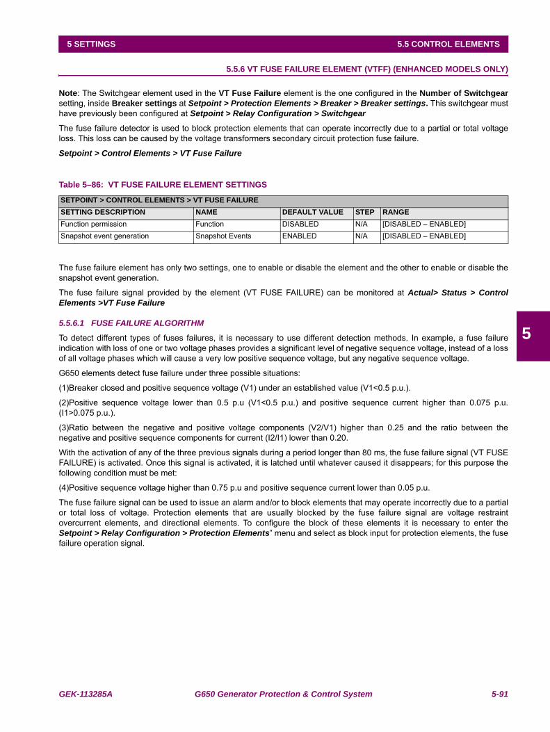
GEK-113285A G650 Generator Protection & Control System 5-91
5 SETTINGS 5.5 CONTROL ELEMENTS
5
5.5.6 VT FUSE FAILURE ELEMENT (VTFF) (ENHANCED MODELS ONLY)
Note: The Switchgear element used in the VT Fuse Failure element is the one configured in the Number of Switchgearsetting, inside Breaker settings at Setpoint > Protection Elements > Breaker > Breaker settings. This switchgear musthave previously been configured at Setpoint > Relay Configuration > Switchgear
The fuse failure detector is used to block protection elements that can operate incorrectly due to a partial or total voltageloss. This loss can be caused by the voltage transformers secondary circuit protection fuse failure.
Setpoint > Control Elements > VT Fuse Failure
Table 5–86: VT FUSE FAILURE ELEMENT SETTINGS
The fuse failure element has only two settings, one to enable or disable the element and the other to enable or disable thesnapshot event generation.
The fuse failure signal provided by the element (VT FUSE FAILURE) can be monitored at Actual> Status > ControlElements >VT Fuse Failure
5.5.6.1 FUSE FAILURE ALGORITHM
To detect different types of fuses failures, it is necessary to use different detection methods. In example, a fuse failureindication with loss of one or two voltage phases provides a significant level of negative sequence voltage, instead of a lossof all voltage phases which will cause a very low positive sequence voltage, but any negative sequence voltage.
G650 elements detect fuse failure under three possible situations:
(1)Breaker closed and positive sequence voltage (V1) under an established value (V1<0.5 p.u.).
(2)Positive sequence voltage lower than 0.5 p.u (V1<0.5 p.u.) and positive sequence current higher than 0.075 p.u.(I1>0.075 p.u.).
(3)Ratio between the negative and positive voltage components (V2/V1) higher than 0.25 and the ratio between thenegative and positive sequence components for current (I2/I1) lower than 0.20.
With the activation of any of the three previous signals during a period longer than 80 ms, the fuse failure signal (VT FUSEFAILURE) is activated. Once this signal is activated, it is latched until whatever caused it disappears; for this purpose thefollowing condition must be met:
(4)Positive sequence voltage higher than 0.75 p.u and positive sequence current lower than 0.05 p.u.
The fuse failure signal can be used to issue an alarm and/or to block elements that may operate incorrectly due to a partialor total loss of voltage. Protection elements that are usually blocked by the fuse failure signal are voltage restraintovercurrent elements, and directional elements. To configure the block of these elements it is necessary to enter theSetpoint > Relay Configuration > Protection Elements” menu and select as block input for protection elements, the fusefailure operation signal.
SETPOINT > CONTROL ELEMENTS > VT FUSE FAILURESETTING DESCRIPTION NAME DEFAULT VALUE STEP RANGEFunction permission Function DISABLED N/A [DISABLED – ENABLED]Snapshot event generation Snapshot Events ENABLED N/A [DISABLED – ENABLED]
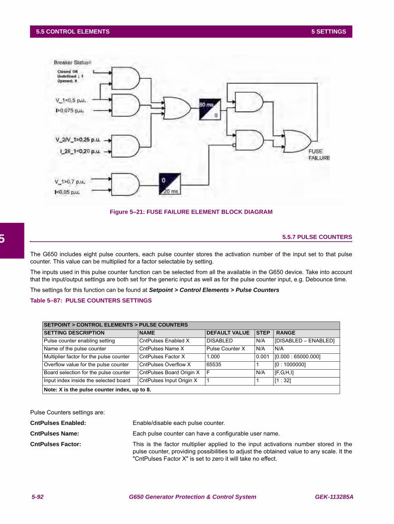
5-92 G650 Generator Protection & Control System GEK-113285A
5.5 CONTROL ELEMENTS 5 SETTINGS
5
Figure 5–21: FUSE FAILURE ELEMENT BLOCK DIAGRAM
5.5.7 PULSE COUNTERS
The G650 includes eight pulse counters, each pulse counter stores the activation number of the input set to that pulsecounter. This value can be multiplied for a factor selectable by setting.
The inputs used in this pulse counter function can be selected from all the available in the G650 device. Take into accountthat the input/output settings are both set for the generic input as well as for the pulse counter input, e.g. Debounce time.
The settings for this function can be found at Setpoint > Control Elements > Pulse Counters
Table 5–87: PULSE COUNTERS SETTINGS
Pulse Counters settings are:
CntPulses Enabled: Enable/disable each pulse counter.
CntPulses Name: Each pulse counter can have a configurable user name.
CntPulses Factor: This is the factor multiplier applied to the input activations number stored in thepulse counter, providing possibilities to adjust the obtained value to any scale. It the"CntPulses Factor X" is set to zero it will take no effect.
SETPOINT > CONTROL ELEMENTS > PULSE COUNTERSSETTING DESCRIPTION NAME DEFAULT VALUE STEP RANGEPulse counter enabling setting CntPulses Enabled X DISABLED N/A [DISABLED – ENABLED]Name of the pulse counter CntPulses Name X Pulse Counter X N/A N/AMultiplier factor for the pulse counter CntPulses Factor X 1.000 0.001 [0.000 : 65000.000]Overflow value for the pulse counter CntPulses Overflow X 65535 1 [0 : 1000000]Board selection for the pulse counter CntPulses Board Origin X F N/A [F,G,H,I]Input index inside the selected board CntPulses Input Origin X 1 1 [1 : 32]
Note: X is the pulse counter index, up to 8.
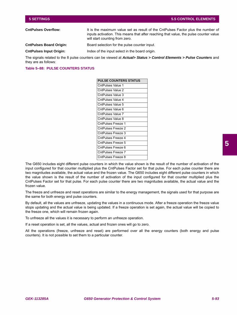
GEK-113285A G650 Generator Protection & Control System 5-93
5 SETTINGS 5.5 CONTROL ELEMENTS
5
CntPulses Overflow: It is the maximum value set as result of the CntPulses Factor plus the number ofinputs activation. This means that after reaching that value, the pulse counter valuewill start counting from zero.
CntPulses Board Origin: Board selection for the pulse counter input.
CntPulses Input Origin: Index of the input select in the board origin.
The signals related to the 8 pulse counters can be viewed at Actual> Status > Control Elements > Pulse Counters andthey are as follows:
Table 5–88: PULSE COUNTERS STATUS
The G650 includes eight different pulse counters in which the value shown is the result of the number of activation of theinput configured for that counter multiplied plus the CntPulses Factor set for that pulse. For each pulse counter there aretwo magnitudes available, the actual value and the frozen value. The G650 includes eight different pulse counters in whichthe value shown is the result of the number of activation of the input configured for that counter multiplied plus theCntPulses Factor set for that pulse. For each pulse counter there are two magnitudes available, the actual value and thefrozen value.
The freeze and unfreeze and reset operations are similar to the energy management, the signals used for that purpose arethe same for both energy and pulse counters.
By default, all the values are unfreeze, updating the values in a continuous mode. After a freeze operation the freeze valuestops updating and the actual value is being updated. If a freeze operation is set again, the actual value will be copied tothe freeze one, which will remain frozen again.
To unfreeze all the values it is necessary to perform an unfreeze operation.
If a reset operation is set, all the values, actual and frozen ones will go to zero.
All the operations (freeze, unfreeze and reset) are performed over all the energy counters (both energy and pulsecounters). It is not possible to set them to a particular counter.
PULSE COUNTERS STATUSCntPulses Value 1CntPulses Value 2CntPulses Value 3CntPulses Value 4CntPulses Value 5CntPulses Value 6CntPulses Value 7CntPulses Value 8CntPulses Freeze 1CntPulses Freeze 2CntPulses Freeze 3CntPulses Freeze 4CntPulses Freeze 5CntPulses Freeze 6CntPulses Freeze 7CntPulses Freeze 8
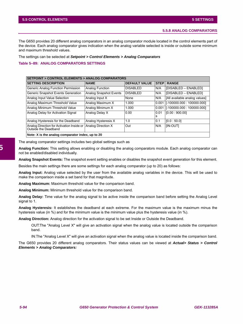
5-94 G650 Generator Protection & Control System GEK-113285A
5.5 CONTROL ELEMENTS 5 SETTINGS
5
5.5.8 ANALOG COMPARATORS
The G650 provides 20 different analog comparators in an analog comparator module located in the control elements part ofthe device. Each analog comparator gives indication when the analog variable selected is inside or outside some minimumand maximum threshold values.
The settings can be selected at Setpoint > Control Elements > Analog Comparators
Table 5–89: ANALOG COMPARATORS SETTINGS
The analog comparator settings includes two global settings such as
Analog Function: This setting allows enabling or disabling the analog comparators module. Each analog comparator cannot be enabled/disabled individually.
Analog Snapshot Events: The snapshot event setting enables or disables the snapshot event generation for this element.
Besides the main settings there are some settings for each analog comparator (up to 20) as follows:
Analog Input: Analog value selected by the user from the available analog variables in the device. This will be used tomake the comparison inside a set band for that magnitude.
Analog Maximum: Maximum threshold value for the comparison band.
Analog Minimum: Minimum threshold value for the comparison band.
Analog Delay: Time value for the analog signal to be active inside the comparison band before setting the Analog Levelsignal to 1.
Analog Hysteresis: It establishes the deadband at each extreme. For the maximum value is the maximum minus thehysteresis value (in %) and for the minimum value is the minimum value plus the hysteresis value (in %).
Analog Direction: Analog direction for the activation signal to be set Inside or Outside the Deadband.
OUT:The "Analog Level X" will give an activation signal when the analog value is located outside the comparisonband.
IN:The "Analog Level X" will give an activation signal when the analog value is located inside the comparison band.
The G650 provides 20 different analog comparators. Their status values can be viewed at Actual> Status > ControlElements > Analog Comparators:
SETPOINT > CONTROL ELEMENTS > ANALOG COMPARATORSSETTING DESCRIPTION NAME DEFAULT VALUE STEP RANGEGeneric Analog Function Permission Analog Function DISABLED N/A [DISABLED – ENABLED]Generic Snapshot Events Generation Analog Snapshot Events DISABLED N/A [DISABLED – ENABLED]Analog Input Value Selection Analog Input X None N/A [All available analog values]Analog Maximum Threshold Value Analog Maximum X 1.000 0.001 [-100000.000 : 100000.000]Analog Minimum Threshold Value Analog Minimum X 1.000 0.001 [-100000.000 : 100000.000]Analog Delay for Activation Signal Analog Delay X 0.00 0.01
s[0.00 : 900.00]
Analog Hysteresis for the Deadband Analog Hysteresis X 1.0 0.1 [0.0 : 50.0]Analog Direction for Activation Inside or Outside the Deadband
Analog Direction X Out N/A [IN-OUT]
Note: X is the analog comparator index, up to 20
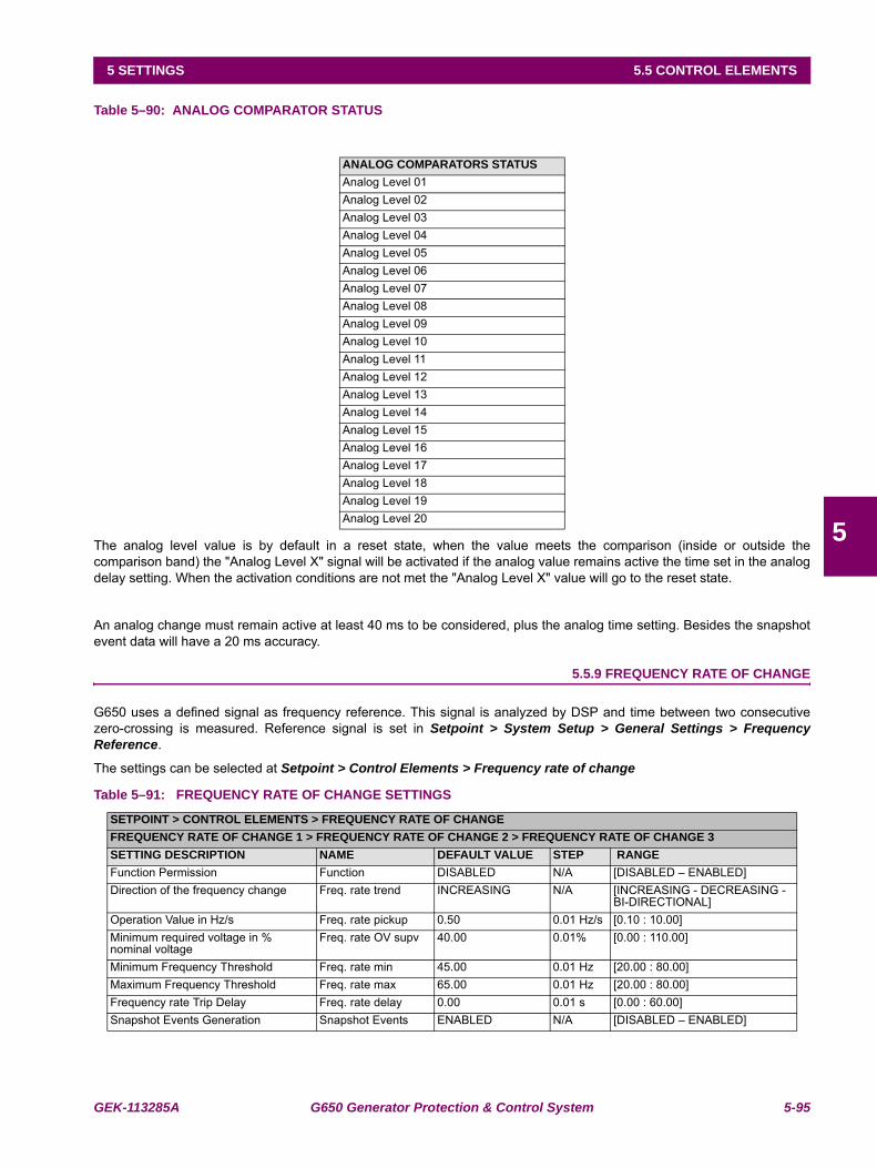
GEK-113285A G650 Generator Protection & Control System 5-95
5 SETTINGS 5.5 CONTROL ELEMENTS
5
Table 5–90: ANALOG COMPARATOR STATUS
The analog level value is by default in a reset state, when the value meets the comparison (inside or outside thecomparison band) the "Analog Level X" signal will be activated if the analog value remains active the time set in the analogdelay setting. When the activation conditions are not met the "Analog Level X" value will go to the reset state.
An analog change must remain active at least 40 ms to be considered, plus the analog time setting. Besides the snapshotevent data will have a 20 ms accuracy.
5.5.9 FREQUENCY RATE OF CHANGE
G650 uses a defined signal as frequency reference. This signal is analyzed by DSP and time between two consecutivezero-crossing is measured. Reference signal is set in Setpoint > System Setup > General Settings > FrequencyReference.
The settings can be selected at Setpoint > Control Elements > Frequency rate of change
Table 5–91: FREQUENCY RATE OF CHANGE SETTINGS
ANALOG COMPARATORS STATUSAnalog Level 01Analog Level 02Analog Level 03Analog Level 04Analog Level 05Analog Level 06Analog Level 07Analog Level 08Analog Level 09Analog Level 10Analog Level 11Analog Level 12Analog Level 13Analog Level 14Analog Level 15Analog Level 16Analog Level 17Analog Level 18Analog Level 19Analog Level 20
SETPOINT > CONTROL ELEMENTS > FREQUENCY RATE OF CHANGEFREQUENCY RATE OF CHANGE 1 > FREQUENCY RATE OF CHANGE 2 > FREQUENCY RATE OF CHANGE 3SETTING DESCRIPTION NAME DEFAULT VALUE STEP RANGEFunction Permission Function DISABLED N/A [DISABLED – ENABLED]Direction of the frequency change Freq. rate trend INCREASING N/A [INCREASING - DECREASING -
BI-DIRECTIONAL]Operation Value in Hz/s Freq. rate pickup 0.50 0.01 Hz/s [0.10 : 10.00]Minimum required voltage in % nominal voltage
Freq. rate OV supv 40.00 0.01% [0.00 : 110.00]
Minimum Frequency Threshold Freq. rate min 45.00 0.01 Hz [20.00 : 80.00]Maximum Frequency Threshold Freq. rate max 65.00 0.01 Hz [20.00 : 80.00]Frequency rate Trip Delay Freq. rate delay 0.00 0.01 s [0.00 : 60.00]Snapshot Events Generation Snapshot Events ENABLED N/A [DISABLED – ENABLED]
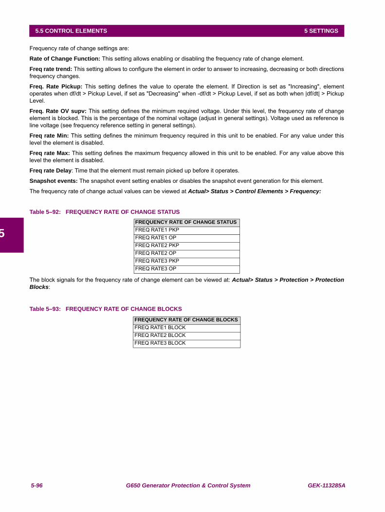
5-96 G650 Generator Protection & Control System GEK-113285A
5.5 CONTROL ELEMENTS 5 SETTINGS
5
Frequency rate of change settings are:
Rate of Change Function: This setting allows enabling or disabling the frequency rate of change element.
Freq rate trend: This setting allows to configure the element in order to answer to increasing, decreasing or both directionsfrequency changes.
Freq. Rate Pickup: This setting defines the value to operate the element. If Direction is set as "Increasing", elementoperates when df/dt > Pickup Level, if set as "Decreasing" when -df/dt > Pickup Level, if set as both when |df/dt| > PickupLevel.
Freq. Rate OV supv: This setting defines the minimum required voltage. Under this level, the frequency rate of changeelement is blocked. This is the percentage of the nominal voltage (adjust in general settings). Voltage used as reference isline voltage (see frequency reference setting in general settings).
Freq rate Min: This setting defines the minimum frequency required in this unit to be enabled. For any value under thislevel the element is disabled.
Freq rate Max: This setting defines the maximum frequency allowed in this unit to be enabled. For any value above thislevel the element is disabled.
Freq rate Delay: Time that the element must remain picked up before it operates.
Snapshot events: The snapshot event setting enables or disables the snapshot event generation for this element.
The frequency rate of change actual values can be viewed at Actual> Status > Control Elements > Frequency:
Table 5–92: FREQUENCY RATE OF CHANGE STATUS
The block signals for the frequency rate of change element can be viewed at: Actual> Status > Protection > ProtectionBlocks:
Table 5–93: FREQUENCY RATE OF CHANGE BLOCKS
FREQUENCY RATE OF CHANGE STATUSFREQ RATE1 PKPFREQ RATE1 OPFREQ RATE2 PKPFREQ RATE2 OPFREQ RATE3 PKPFREQ RATE3 OP
FREQUENCY RATE OF CHANGE BLOCKSFREQ RATE1 BLOCKFREQ RATE2 BLOCKFREQ RATE3 BLOCK
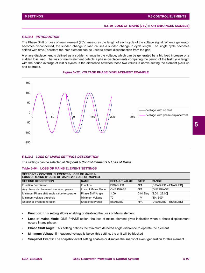
GEK-113285A G650 Generator Protection & Control System 5-97
5 SETTINGS 5.5 CONTROL ELEMENTS
5
5.5.10 LOSS OF MAINS (78V) (FOR ENHANCED MODELS)
5.5.10.1 INTRODUCTION
The Phase Shift or Loss of main element (78V) measures the length of each cycle of the voltage signal. When a generatorbecomes disconnected, the sudden change in load causes a sudden change in cycle length. The single cycle becomesshifted with time.Therefore the 78V element can be used to detect disconnection from the grid.
A phase displacement is defined as a sudden change in the voltage, which can be generated by a big load increase or asudden loss load. The loss of mains element detects a phase displacements comparing the period of the last cycle lengthwith the period average of last N cycles. If the difference between these two values is above setting the element picks upand operates.
Figure 5–22: VOLTAGE PHASE DISPLACEMENT EXAMPLE
5.5.10.2 LOSS OF MAINS SETTINGS DESCRIPTION
The settings can be selected at Setpoint > Control Elements > Loss of Mains
Table 5–94: LOSS OF MAINS ELEMENT SETTINGS
• Function: This setting allows enabling or disabling the Loss of Mains element.
• Loss of mains Mode: ONE PHASE option: the loss of mains element gives indication when a phase displacementoccurs in any phase..
• Phase Shift Angle: This setting defines the minimum detected angle difference to operate the element.
• Minimum Voltage: If measured voltage is below this setting, the unit will be blocked
• Snapshot Events: The snapshot event setting enables or disables the snapshot event generation for this element.
SETPOINT > CONTROL ELEMENTS > LOSS OF MAINS >LOSS OF MAINS 1> LOSS OF MAINS 2 > LOSS OF MAINS 3SETTING DESCRIPTION NAME DEFAULT VALUE STEP RANGEFunction Permission Function DISABLED N/A [DISABLED – ENABLED]Any phase displacement mode to operate Loss of Mains Mode ONE PHASE N/A [ONE PHASE]Minimum Phase shift angle value to operate Phase Shift Angle 1.00 0.01 Deg [2.00 : 22.00]Minimum voltage threshold Minimum Voltage 70 1 V [30 : 500]Snapshot Event generation Snapshot Events ENABLED N/A [DISABLED – ENABLED]
-150
-100
-50
0
50
100
150
0 50 100 150 200 250
Voltage w ith no fault
Voltage w ith phase displacement
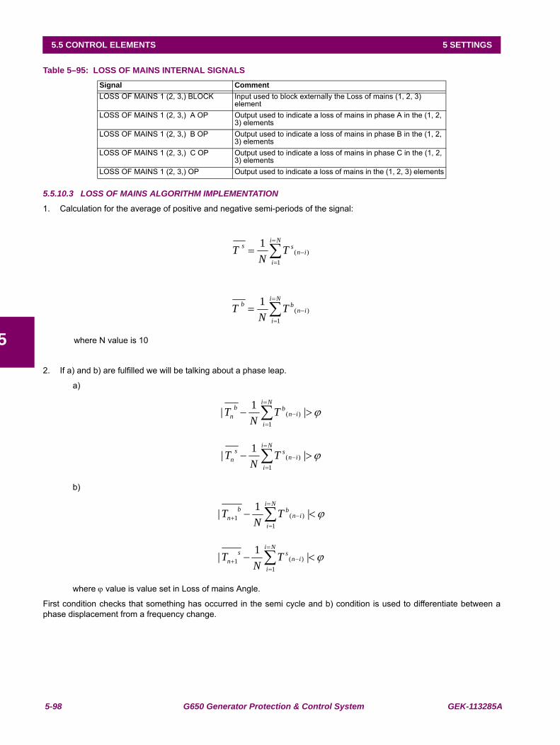
5-98 G650 Generator Protection & Control System GEK-113285A
5.5 CONTROL ELEMENTS 5 SETTINGS
5
Table 5–95: LOSS OF MAINS INTERNAL SIGNALS
5.5.10.3 LOSS OF MAINS ALGORITHM IMPLEMENTATION
1. Calculation for the average of positive and negative semi-periods of the signal:
where N value is 10
2. If a) and b) are fulfilled we will be talking about a phase leap.
a)
b)
where ϕ value is value set in Loss of mains Angle.
First condition checks that something has occurred in the semi cycle and b) condition is used to differentiate between aphase displacement from a frequency change.
Signal CommentLOSS OF MAINS 1 (2, 3,) BLOCK Input used to block externally the Loss of mains (1, 2, 3)
elementLOSS OF MAINS 1 (2, 3,) A OP Output used to indicate a loss of mains in phase A in the (1, 2,
3) elementsLOSS OF MAINS 1 (2, 3,) B OP Output used to indicate a loss of mains in phase B in the (1, 2,
3) elementsLOSS OF MAINS 1 (2, 3,) C OP Output used to indicate a loss of mains in phase C in the (1, 2,
3) elementsLOSS OF MAINS 1 (2, 3,) OP Output used to indicate a loss of mains in the (1, 2, 3) elements
∑=
=
−=Ni
iin
ss TN
T1
)(1
∑=
=
−=Ni
iin
bb TN
T1
)(1
ϕ>− ∑=
=
− |1|1
)(
Ni
iin
bbn T
NT
ϕ>− ∑=
=
− |1|1
)(
Ni
iin
ssn T
NT
ϕ<− ∑=
=
−+ |1|1
)(1
Ni
iin
bbn T
NT
ϕ<− ∑=
=
−+ |1|1
)(1
Ni
iin
ssn T
NT
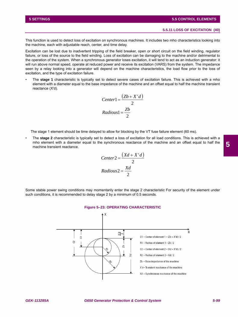
GEK-113285A G650 Generator Protection & Control System 5-99
5 SETTINGS 5.5 CONTROL ELEMENTS
5
5.5.11 LOSS OF EXCITATION (40)
This function is used to detect loss of excitation on synchronous machines. It includes two mho characteristics looking intothe machine, each with adjustable reach, center, and time delay.
Excitation can be lost due to inadvertent tripping of the field breaker, open or short circuit on the field winding, regulatorfailure, or loss of the source to the field winding. Loss of excitation can be damaging to the machine and/or detrimental tothe operation of the system. When a synchronous generator loses excitation, it will tend to act as an induction generator: itwill run above normal speed, operate at reduced power and receive its excitation (VARS) from the system. The impedanceseen by a relay looking into a generator will depend on the machine characteristics, the load flow prior to the loss ofexcitation, and the type of excitation failure.
• The stage 1 characteristic is typically set to detect severe cases of excitation failure. This is achieved with a mhoelement with a diameter equal to the base impedance of the machine and an offset equal to half the machine transientreactance (X'd).
The stage 1 element should be time delayed to allow for blocking by the VT fuse failure element (60 ms).
• The stage 2 characteristic is typically set to detect a loss of excitation for all load conditions. This is achieved with amho element with a diameter equal to the synchronous reactance of the machine and an offset equal to half themachine transient reactance.
Some stable power swing conditions may momentarily enter the stage 2 characteristic For security of the element undersuch conditions, it is recommended to delay stage 2 by a minimum of 0.5 seconds.
Figure 5–23: OPERATING CHARACTERISTIC
( )
21
2'1
ZbRadious
dXZbCenter
=
+=
( )
22
2'2
XdRadious
dXXdCenter
=
+=
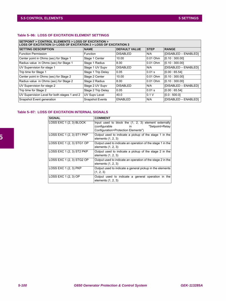
5-100 G650 Generator Protection & Control System GEK-113285A
5.5 CONTROL ELEMENTS 5 SETTINGS
5
Table 5–96: LOSS OF EXCITATION ELEMENT SETTINGS
Table 5–97: LOSS OF EXCITATION INTERNAL SIGNALS
SETPOINT > CONTROL ELEMENTS > LOSS OF EXCITATION >LOSS OF EXCITATION 1> LOSS OF EXCITATION 2 > LOSS OF EXCITATION 3SETTING DESCRIPTION NAME DEFAULT VALUE STEP RANGEFunction Permission Function DISABLED N/A [DISABLED – ENABLED]Center point in Ohms (sec) for Stage 1 Stage 1 Center 10.00 0.01 Ohm [0.10 : 300.00]Radius value in Ohms (sec) for Stage 1 Stage 1 Radius 8.00 0.01 Ohm [0.10 : 300.00]UV Supervision for stage 1 Stage 1 UV Supv DISABLED N/A [DISABLED – ENABLED]Trip time for Stage 1 Stage 1 Trip Delay 0.05 0.01 s [0.00 : 65.54]Center point in Ohms (sec) for Stage 2 Stage 2 Center 10.00 0.01 Ohm [0.10 : 300.00]Radius value in Ohms (sec) for Stage 2 Stage 2 Radius 8.00 0.01 Ohm [0.10 : 300.00]UV Supervision for stage 2 Stage 2 UV Supv DISABLED N/A [DISABLED – ENABLED]Trip time for Stage 2 Stage 2 Trip Delay 0.05 0.01 s [0.00 : 65.54]UV Supervision Level for both stages 1 and 2 UV Supv Level 40.0 0.1 V [0.0 : 500.0]Snapshot Event generation Snapshot Events ENABLED N/A [DISABLED – ENABLED]
SIGNAL COMMENTLOSS EXC 1 (2, 3) BLOCK Input used to block the (1, 2, 3) element externally
(configurable in "Setpoint>RelayConfiguration>Protection Elements")
LOSS EXC 1 (2, 3) ST1 PKP Output used to indicate a pickup of the stage 1 in theelements (1, 2, 3)
LOSS EXC 1 (2, 3) STG1 OP Output used to indicate an operation of the stage 1 in theelements (1, 2, 3)
LOSS EXC 1 (2, 3) ST2 PKP Output used to indicate a pickup of the stage 2 in theelements (1, 2, 3)
LOSS EXC 1 (2, 3) STG2 OP Output used to indicate an operation of the stage 2 in theelements (1, 2, 3)
LOSS EXC 1 (2, 3) PKP Output used to indicate a general pickup in the elements(1, 2, 3)
LOSS EXC 1 (2, 3) OP Output used to indicate a general operation in theelements (1, 2, 3)
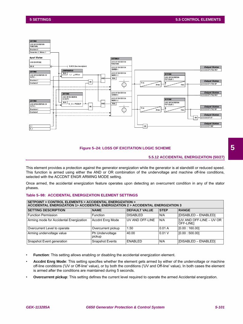
GEK-113285A G650 Generator Protection & Control System 5-101
5 SETTINGS 5.5 CONTROL ELEMENTS
5Figure 5–24: LOSS OF EXCITATION LOGIC SCHEME
5.5.12 ACCIDENTAL ENERGIZATION (50/27)
This element provides a protection against the generator energization while the generator is at standstill or reduced speed.This function is armed using either the AND or OR combination of the undervoltage and machine off-line conditions,selected with the ACCDNT ENGR ARMING MODE setting.
Once armed, the accidental energization feature operates upon detecting an overcurrent condition in any of the statorphases.
Table 5–98: ACCIDENTAL ENERGIZATION ELEMENT SETTINGS
• Function: This setting allows enabling or disabling the accidental energization element.
• Accdnt Enrg Mode: This setting specifies whether the element gets armed by either of the undervoltage or machineoff-line conditions ('UV or Off-line' value), or by both the conditions ('UV and Off-line' value). In both cases the elementis armed after the conditions are maintained during 5 seconds.
• Overcurrent pickup: This setting defines the current level required to operate the armed Accidental energization.
SETPOINT > CONTROL ELEMENTS > ACCIDENTAL ENERGIZATION >ACCIDENTAL ENERGIZATION 1> ACCIDENTAL ENERGIZATION 2 > ACCIDENTAL ENERGIZATION 3SETTING DESCRIPTION NAME DEFAULT VALUE STEP RANGEFunction Permission Function DISABLED N/A [DISABLED – ENABLED]Arming mode for Accidental Energization Accdnt Enrg Mode UV AND OFF-LINE N/A [UV AND OFF-LINE – UV OR
OFF-LINE]Overcurrent Level to operate Overcurrent pickup 1.50 0.01 A [0.00 : 160.00]Arming undervoltage value Ph Undervoltage
pickup40.00 0.01 V [0.00 : 500.00]
Snapshot Event generation Snapshot Events ENABLED N/A [DISABLED – ENABLED]
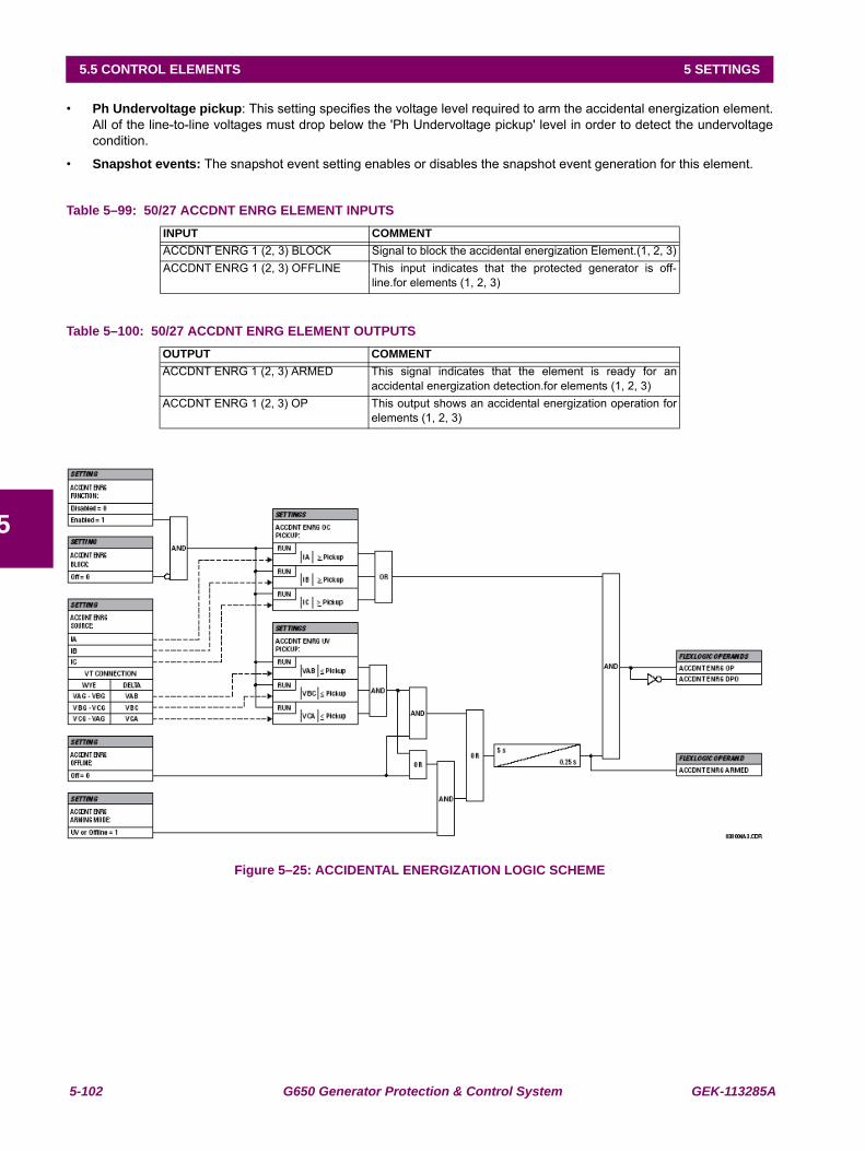
5-102 G650 Generator Protection & Control System GEK-113285A
5.5 CONTROL ELEMENTS 5 SETTINGS
5
• Ph Undervoltage pickup: This setting specifies the voltage level required to arm the accidental energization element.All of the line-to-line voltages must drop below the 'Ph Undervoltage pickup' level in order to detect the undervoltagecondition.
• Snapshot events: The snapshot event setting enables or disables the snapshot event generation for this element.
Table 5–99: 50/27 ACCDNT ENRG ELEMENT INPUTS
Table 5–100: 50/27 ACCDNT ENRG ELEMENT OUTPUTS
Figure 5–25: ACCIDENTAL ENERGIZATION LOGIC SCHEME
INPUT COMMENTACCDNT ENRG 1 (2, 3) BLOCK Signal to block the accidental energization Element.(1, 2, 3)ACCDNT ENRG 1 (2, 3) OFFLINE This input indicates that the protected generator is off-
line.for elements (1, 2, 3)
OUTPUT COMMENTACCDNT ENRG 1 (2, 3) ARMED This signal indicates that the element is ready for an
accidental energization detection.for elements (1, 2, 3)ACCDNT ENRG 1 (2, 3) OP This output shows an accidental energization operation for
elements (1, 2, 3)
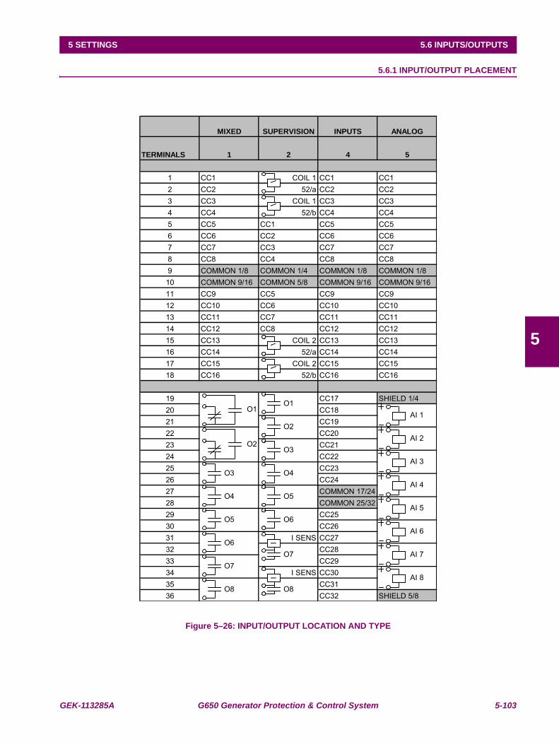
GEK-113285A G650 Generator Protection & Control System 5-103
5 SETTINGS 5.6 INPUTS/OUTPUTS
5
5.6INPUTS/OUTPUTS 5.6.1 INPUT/OUTPUT PLACEMENT
Figure 5–26: INPUT/OUTPUT LOCATION AND TYPE
MIXED SUPERVISION INPUTS ANALOG
TERMINALS 1 2 4 5
1 CC1 COIL 1 CC1 CC12 CC2 52/a CC2 CC23 CC3 COIL 1 CC3 CC34 CC4 52/b CC4 CC45 CC5 CC1 CC5 CC56 CC6 CC2 CC6 CC67 CC7 CC3 CC7 CC78 CC8 CC4 CC8 CC89 COMMON 1/8 COMMON 1/4 COMMON 1/8 COMMON 1/810 COMMON 9/16 COMMON 5/8 COMMON 9/16 COMMON 9/1611 CC9 CC5 CC9 CC912 CC10 CC6 CC10 CC1013 CC11 CC7 CC11 CC1114 CC12 CC8 CC12 CC1215 CC13 COIL 2 CC13 CC1316 CC14 52/a CC14 CC1417 CC15 COIL 2 CC15 CC1518 CC16 52/b CC16 CC16
19 CC17 SHIELD 1/420 CC1821 CC1922 CC2023 CC2124 CC2225 CC2326 CC2427 COMMON 17/2428 COMMON 25/3229 CC2530 CC2631 I SENS CC2732 CC2833 CC2934 I SENS CC3035 CC3136 CC32 SHIELD 5/8
O1O1
AI 1O2
O2 AI 2
O3 AI 3
O3 O4 AI 4
O4 O5 AI 5
O5 O6 AI 6
O6O7 AI 7
O7 AI 8
O8 O8
VV
VVV
VI
II
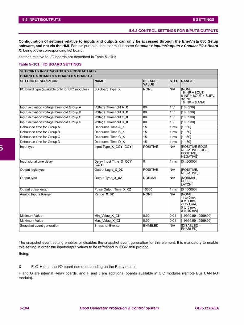
5-104 G650 Generator Protection & Control System GEK-113285A
5.6 INPUTS/OUTPUTS 5 SETTINGS
5
5.6.2 CONTROL SETTINGS FOR INPUTS/OUTPUTS
Configuration of settings relative to inputs and outputs can only be accessed through the EnerVista 650 Setupsoftware, and not via the HMI. For this purpose, the user must access Setpoint > Inputs/Outputs > Contact I/O > BoardX, being X the corresponding I/O board.
settings relative to I/O boards are described in Table 5–101:
Table 5–101: I/O BOARD SETTINGS
The snapshot event setting enables or disables the snapshot event generation for this element. It is mandatory to enablethis setting in order the input/output values to be refreshed in IEC61850 protocol.Being:
X F, G, H or J, the I/O board name, depending on the Relay model.
F and G are internal Relay boards, and H and J are additional boards available in CIO modules (remote Bus CAN I/Omodule).
SETPOINT > INPUTS/OUTPUTS > CONTACT I/O >BOARD F > BOARD G > BOARD H > BOARD JSETTING DESCRIPTION NAME DEFAULT
VALUESTEP RANGE
I/O board type (available only for CIO modules) I/O Board Type_X NONE N/A [NONE,16 INP + 8OUT,8 INP + 8OUT + SUPV,32 INP16 INP + 8 ANA]
Input activation voltage threshold Group A Voltage Threshold A_X 80 1 V [10 : 230]Input activation voltage threshold Group B Voltage Threshold B_X 80 1 V [10 : 230]Input activation voltage threshold Group C Voltage Threshold C_X 80 1 V [10 : 230]Input activation voltage threshold Group D Voltage Threshold D_X 80 1 V [10 : 230]Debounce time for Group A Debounce Time A_X 15 1 ms [1 : 50]Debounce time for Group B Debounce Time B_X 15 1 ms [1 : 50]Debounce time for Group C Debounce Time C_X 15 1 ms [1 : 50]Debounce time for Group D Debounce Time D_X 15 1 ms [1 : 50]Input type Input Type_X_CCY (CCY) POSITIVE N/A [POSITIVE-EDGE,
NEGATIVE-EDGE,POSITIVE,NEGATIVE]
Input signal time delay Delay Input Time_X_CCY (CCY)
0 1 ms [0 : 60000]
Output logic type Output Logic_X_0Z POSITIVE N/A [POSITIVE,NEGATIVE]
Output type Output Type_X_0Z NORMAL N/A [NORMAL,PULSE,LATCH]
Output pulse length Pulse Output Time_X_0Z 10000 1 ms [0 : 60000]Analog Inputs Range Range_X_0Z NONE N/A [NONE,
-1 to 0mA,0 to 1 mA,-1 to 1 mA,0 to 5 mA,0 to 10 mA]
Minimum Value Min_Value_X_0Z 0.00 0.01 [ -9999.99 : 9999.99]Maximum Value Max_Value_X_0Z 0.00 0.01 [ -9999.99 : 9999.99]Snapshot event generation Snapshot Events ENABLED N/A [DISABLED –
ENABLED]
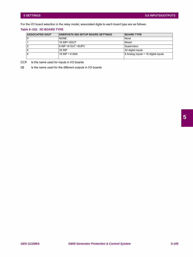
GEK-113285A G650 Generator Protection & Control System 5-105
5 SETTINGS 5.6 INPUTS/OUTPUTS
5
For the I/O board selection in the relay model, associated digits to each board type are as follows:
Table 5–102: I/O BOARD TYPE
CCY Is the name used for inputs in I/O boards
0Z Is the name used for the different outputs in I/O boards
ASSOCIATED DIGIT ENERVISTA 650 SETUP BOARD SETTINGS BOARD TYPE0 NONE None 1 16 INP+ 8OUT Mixed 2 8 INP +8 OUT +SUPV Supervision 4 32 INP 32 digital inputs 5 16 INP + 8 ANA 8 Analog Inputs + 16 digital inputs
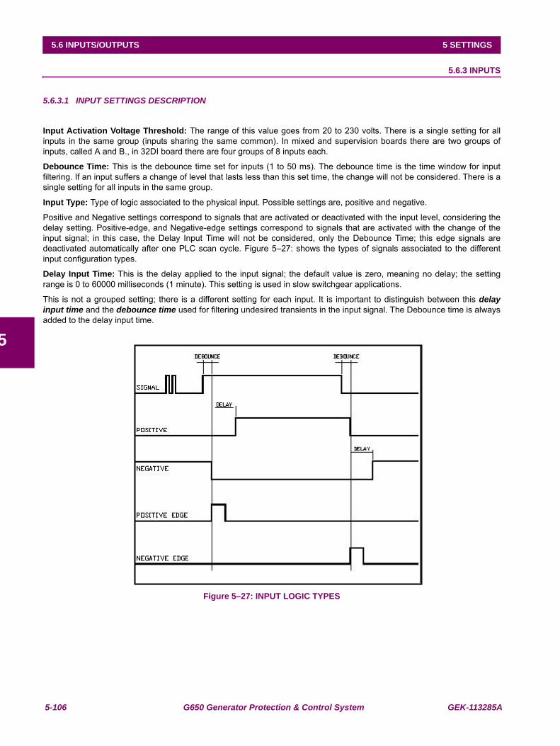
5-106 G650 Generator Protection & Control System GEK-113285A
5.6 INPUTS/OUTPUTS 5 SETTINGS
5
5.6.3 INPUTS
5.6.3.1 INPUT SETTINGS DESCRIPTION
Input Activation Voltage Threshold: The range of this value goes from 20 to 230 volts. There is a single setting for allinputs in the same group (inputs sharing the same common). In mixed and supervision boards there are two groups ofinputs, called A and B., in 32DI board there are four groups of 8 inputs each.
Debounce Time: This is the debounce time set for inputs (1 to 50 ms). The debounce time is the time window for inputfiltering. If an input suffers a change of level that lasts less than this set time, the change will not be considered. There is asingle setting for all inputs in the same group.
Input Type: Type of logic associated to the physical input. Possible settings are, positive and negative.
Positive and Negative settings correspond to signals that are activated or deactivated with the input level, considering thedelay setting. Positive-edge, and Negative-edge settings correspond to signals that are activated with the change of theinput signal; in this case, the Delay Input Time will not be considered, only the Debounce Time; this edge signals aredeactivated automatically after one PLC scan cycle. Figure 5–27: shows the types of signals associated to the differentinput configuration types.
Delay Input Time: This is the delay applied to the input signal; the default value is zero, meaning no delay; the settingrange is 0 to 60000 milliseconds (1 minute). This setting is used in slow switchgear applications.
This is not a grouped setting; there is a different setting for each input. It is important to distinguish between this delayinput time and the debounce time used for filtering undesired transients in the input signal. The Debounce time is alwaysadded to the delay input time.
Figure 5–27: INPUT LOGIC TYPES
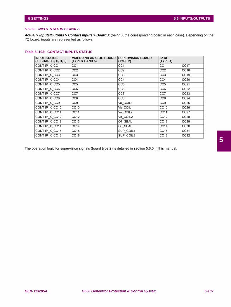
GEK-113285A G650 Generator Protection & Control System 5-107
5 SETTINGS 5.6 INPUTS/OUTPUTS
5
5.6.3.2 INPUT STATUS SIGNALS
Actual > Inputs/Outputs > Contact inputs > Board X (being X the corresponding board in each case). Depending on theI/O board, inputs are represented as follows:
Table 5–103: CONTACT INPUTS STATUS
The operation logic for supervision signals (board type 2) is detailed in section 5.6.5 in this manual.
INPUT STATUS(X: BOARD F, G, H, J)
MIXED AND ANALOG BOARD(TYPES 1 AND 5)
SUPERVISION BOARD(TYPE 2)
32 DI(TYPE 4)
CONT IP_X_CC1 CC1 CC1 CC1 CC17CONT IP_X_CC2 CC2 CC2 CC2 CC18CONT IP_X_CC3 CC3 CC3 CC3 CC19CONT IP_X_CC4 CC4 CC4 CC4 CC20CONT IP_X_CC5 CC5 CC5 CC5 CC21CONT IP_X_CC6 CC6 CC6 CC6 CC22CONT IP_X_CC7 CC7 CC7 CC7 CC23CONT IP_X_CC8 CC8 CC8 CC8 CC24CONT IP_X_CC9 CC9 Va_COIL1 CC9 CC25CONT IP_X_CC10 CC10 Vb_COIL1 CC10 CC26CONT IP_X_CC11 CC11 Va_COIL2 CC11 CC27CONT IP_X_CC12 CC12 Vb_COIL2 CC12 CC28CONT IP_X_CC13 CC13 O7_SEAL CC13 CC29CONT IP_X_CC14 CC14 O8_SEAL CC14 CC30CONT IP_X_CC15 CC15 SUP_COIL1 CC15 CC31CONT IP_X_CC16 CC16 SUP_COIL2 CC16 CC32
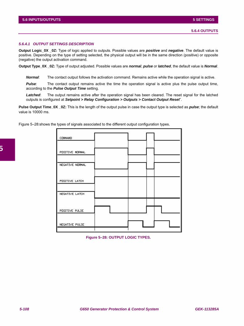
5-108 G650 Generator Protection & Control System GEK-113285A
5.6 INPUTS/OUTPUTS 5 SETTINGS
5
5.6.4 OUTPUTS
5.6.4.1 OUTPUT SETTINGS DESCRIPTION
Output Logic_0X _0Z: Type of logic applied to outputs. Possible values are positive and negative. The default value ispositive. Depending on the type of setting selected, the physical output will be in the same direction (positive) or opposite(negative) the output activation command.
Output Type_0X _0Z: Type of output adjusted. Possible values are normal, pulse or latched, the default value is Normal.
Normal: The contact output follows the activation command. Remains active while the operation signal is active.
Pulse: The contact output remains active the time the operation signal is active plus the pulse output time,according to the Pulse Output Time setting.
Latched: The output remains active after the operation signal has been cleared. The reset signal for the latchedoutputs is configured at Setpoint > Relay Configuration > Outputs > Contact Output Reset”.
Pulse Output Time_0X _0Z: This is the length of the output pulse in case the output type is selected as pulse; the defaultvalue is 10000 ms.
Figure 5–28:shows the types of signals associated to the different output configuration types.
Figure 5–28: OUTPUT LOGIC TYPES.
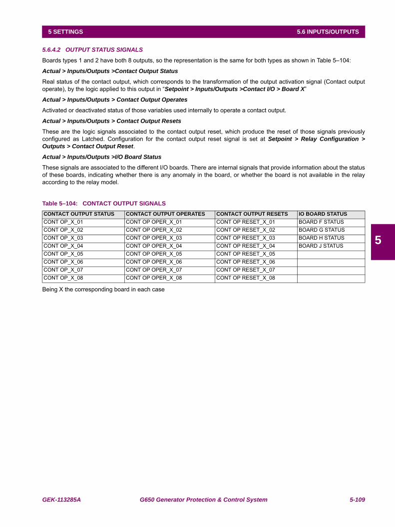
GEK-113285A G650 Generator Protection & Control System 5-109
5 SETTINGS 5.6 INPUTS/OUTPUTS
5
5.6.4.2 OUTPUT STATUS SIGNALS
Boards types 1 and 2 have both 8 outputs, so the representation is the same for both types as shown in Table 5–104:
Actual > Inputs/Outputs >Contact Output Status
Real status of the contact output, which corresponds to the transformation of the output activation signal (Contact outputoperate), by the logic applied to this output in “Setpoint > Inputs/Outputs >Contact I/O > Board X”
Actual > Inputs/Outputs > Contact Output Operates
Activated or deactivated status of those variables used internally to operate a contact output.
Actual > Inputs/Outputs > Contact Output Resets
These are the logic signals associated to the contact output reset, which produce the reset of those signals previouslyconfigured as Latched. Configuration for the contact output reset signal is set at Setpoint > Relay Configuration >Outputs > Contact Output Reset.
Actual > Inputs/Outputs >I/O Board Status
These signals are associated to the different I/O boards. There are internal signals that provide information about the statusof these boards, indicating whether there is any anomaly in the board, or whether the board is not available in the relayaccording to the relay model.
Table 5–104: CONTACT OUTPUT SIGNALS
Being X the corresponding board in each case
CONTACT OUTPUT STATUS CONTACT OUTPUT OPERATES CONTACT OUTPUT RESETS IO BOARD STATUSCONT OP_X_01 CONT OP OPER_X_01 CONT OP RESET_X_01 BOARD F STATUSCONT OP_X_02 CONT OP OPER_X_02 CONT OP RESET_X_02 BOARD G STATUSCONT OP_X_03 CONT OP OPER_X_03 CONT OP RESET_X_03 BOARD H STATUSCONT OP_X_04 CONT OP OPER_X_04 CONT OP RESET_X_04 BOARD J STATUSCONT OP_X_05 CONT OP OPER_X_05 CONT OP RESET_X_05CONT OP_X_06 CONT OP OPER_X_06 CONT OP RESET_X_06CONT OP_X_07 CONT OP OPER_X_07 CONT OP RESET_X_07CONT OP_X_08 CONT OP OPER_X_08 CONT OP RESET_X_08
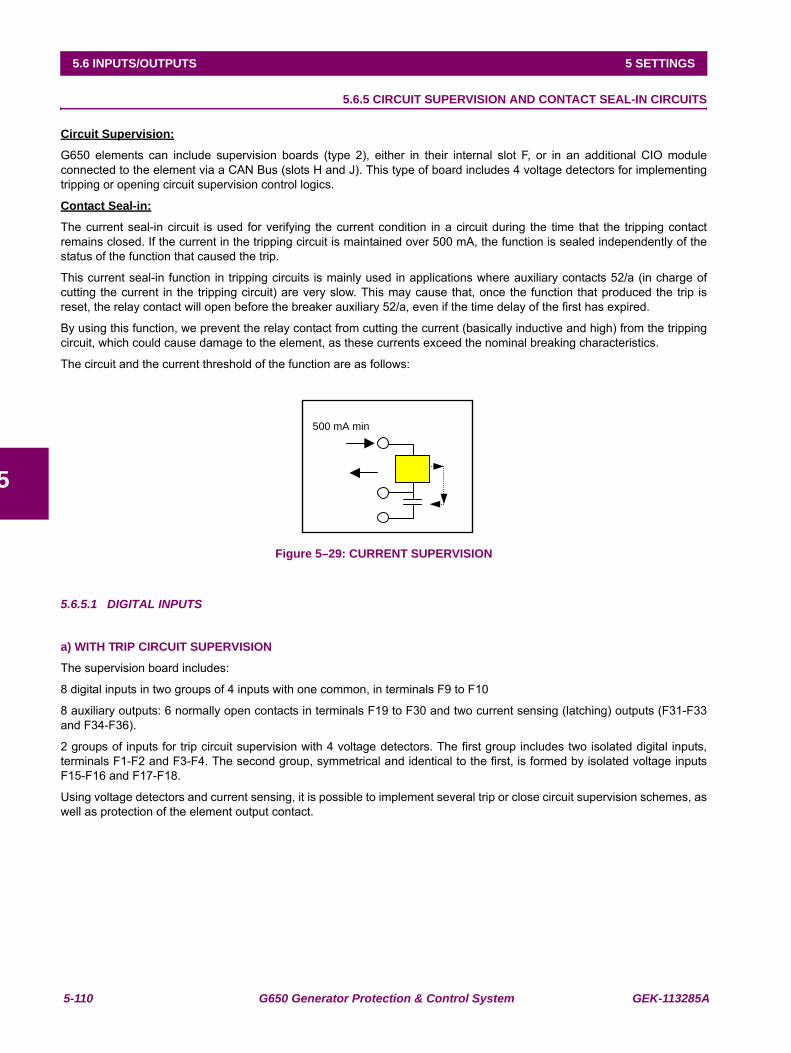
5-110 G650 Generator Protection & Control System GEK-113285A
5.6 INPUTS/OUTPUTS 5 SETTINGS
5
5.6.5 CIRCUIT SUPERVISION AND CONTACT SEAL-IN CIRCUITS
Circuit Supervision:
G650 elements can include supervision boards (type 2), either in their internal slot F, or in an additional CIO moduleconnected to the element via a CAN Bus (slots H and J). This type of board includes 4 voltage detectors for implementingtripping or opening circuit supervision control logics.
Contact Seal-in:
The current seal-in circuit is used for verifying the current condition in a circuit during the time that the tripping contactremains closed. If the current in the tripping circuit is maintained over 500 mA, the function is sealed independently of thestatus of the function that caused the trip.
This current seal-in function in tripping circuits is mainly used in applications where auxiliary contacts 52/a (in charge ofcutting the current in the tripping circuit) are very slow. This may cause that, once the function that produced the trip isreset, the relay contact will open before the breaker auxiliary 52/a, even if the time delay of the first has expired.
By using this function, we prevent the relay contact from cutting the current (basically inductive and high) from the trippingcircuit, which could cause damage to the element, as these currents exceed the nominal breaking characteristics.
The circuit and the current threshold of the function are as follows:
Figure 5–29: CURRENT SUPERVISION
5.6.5.1 DIGITAL INPUTS
a) WITH TRIP CIRCUIT SUPERVISION
The supervision board includes:
8 digital inputs in two groups of 4 inputs with one common, in terminals F9 to F10
8 auxiliary outputs: 6 normally open contacts in terminals F19 to F30 and two current sensing (latching) outputs (F31-F33and F34-F36).
2 groups of inputs for trip circuit supervision with 4 voltage detectors. The first group includes two isolated digital inputs,terminals F1-F2 and F3-F4. The second group, symmetrical and identical to the first, is formed by isolated voltage inputsF15-F16 and F17-F18.
Using voltage detectors and current sensing, it is possible to implement several trip or close circuit supervision schemes, aswell as protection of the element output contact.
500 mA min
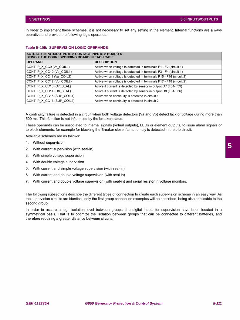
GEK-113285A G650 Generator Protection & Control System 5-111
5 SETTINGS 5.6 INPUTS/OUTPUTS
5
In order to implement these schemes, it is not necessary to set any setting in the element. Internal functions are alwaysoperative and provide the following logic operands:
Table 5–105: SUPERVISION LOGIC OPERANDS
A continuity failure is detected in a circuit when both voltage detectors (Va and Vb) detect lack of voltage during more than500 ms. This function is not influenced by the breaker status.
These operands can be associated to internal signals (virtual outputs), LEDs or element outputs, to issue alarm signals orto block elements, for example for blocking the Breaker close if an anomaly is detected in the trip circuit.
Available schemes are as follows:
1. Without supervision
2. With current supervision (with seal-in)
3. With simple voltage supervision
4. With double voltage supervision
5. With current and simple voltage supervision (with seal-in)
6. With current and double voltage supervision (with seal-in)
7. With current and double voltage supervision (with seal-in) and serial resistor in voltage monitors.
The following subsections describe the different types of connection to create each supervision scheme in an easy way. Asthe supervision circuits are identical, only the first group connection examples will be described, being also applicable to thesecond group.
In order to assure a high isolation level between groups, the digital inputs for supervision have been located in asymmetrical basis. That is to optimize the isolation between groups that can be connected to different batteries, andtherefore requiring a greater distance between circuits.
ACTUAL > INPUTS/OUTPUTS > CONTACT INPUTS > BOARD XBEING X THE CORRESPONDING BOARD IN EACH CASEOPERAND DESCRIPTIONCONT IP_X_CC9 (Va_COIL1) Active when voltage is detected in terminals F1 - F2 (circuit 1)CONT IP_X_CC10 (Vb_COIL1) Active when voltage is detected in terminals F3 - F4 (circuit 1)CONT IP_X_CC11 (Va_COIL2) Active when voltage is detected in terminals F15 - F16 (circuit 2)CONT IP_X_CC12 (Vb_COIL2) Active when voltage is detected in terminals F17 - F18 (circuit 2)CONT IP_X_CC13 (O7_SEAL) Active if current is detected by sensor in output O7 (F31-F33)CONT IP_X_CC14 (O8_SEAL) Active if current is detected by sensor in output O8 (F34-F36)CONT IP_X_CC15 (SUP_COIL1) Active when continuity is detected in circuit 1CONT IP_X_CC16 (SUP_COIL2) Active when continuity is detected in circuit 2
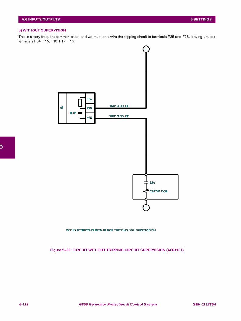
5-112 G650 Generator Protection & Control System GEK-113285A
5.6 INPUTS/OUTPUTS 5 SETTINGS
5
b) WITHOUT SUPERVISION
This is a very frequent common case, and we must only wire the tripping circuit to terminals F35 and F36, leaving unusedterminals F34, F15, F16, F17, F18.
Figure 5–30: CIRCUIT WITHOUT TRIPPING CIRCUIT SUPERVISION (A6631F1)
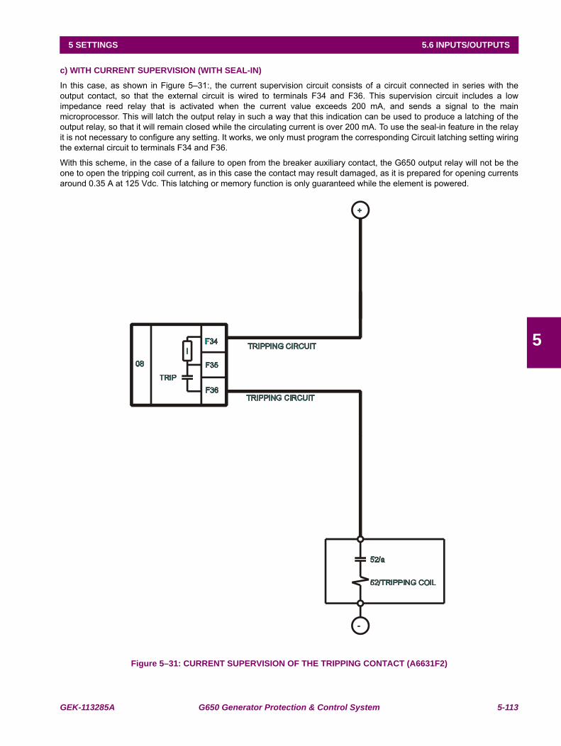
GEK-113285A G650 Generator Protection & Control System 5-113
5 SETTINGS 5.6 INPUTS/OUTPUTS
5
c) WITH CURRENT SUPERVISION (WITH SEAL-IN)
In this case, as shown in Figure 5–31:, the current supervision circuit consists of a circuit connected in series with theoutput contact, so that the external circuit is wired to terminals F34 and F36. This supervision circuit includes a lowimpedance reed relay that is activated when the current value exceeds 200 mA, and sends a signal to the mainmicroprocessor. This will latch the output relay in such a way that this indication can be used to produce a latching of theoutput relay, so that it will remain closed while the circulating current is over 200 mA. To use the seal-in feature in the relayit is not necessary to configure any setting. It works, we only must program the corresponding Circuit latching setting wiringthe external circuit to terminals F34 and F36.
With this scheme, in the case of a failure to open from the breaker auxiliary contact, the G650 output relay will not be theone to open the tripping coil current, as in this case the contact may result damaged, as it is prepared for opening currentsaround 0.35 A at 125 Vdc. This latching or memory function is only guaranteed while the element is powered.
Figure 5–31: CURRENT SUPERVISION OF THE TRIPPING CONTACT (A6631F2)
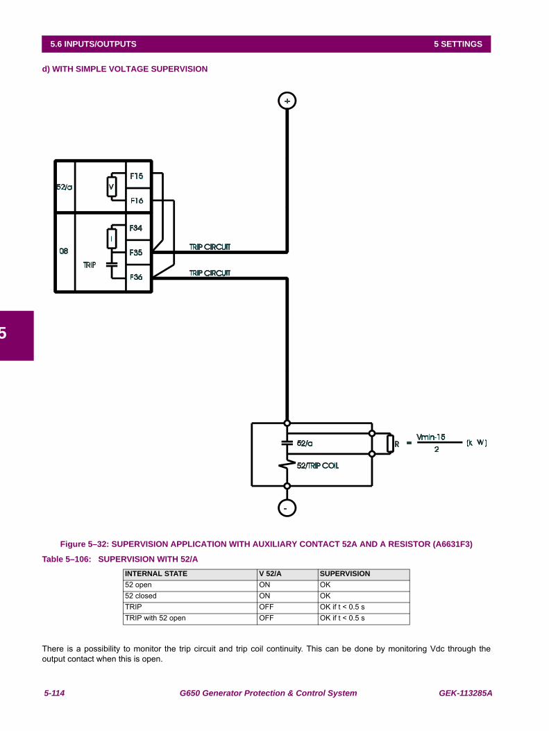
5-114 G650 Generator Protection & Control System GEK-113285A
5.6 INPUTS/OUTPUTS 5 SETTINGS
5
d) WITH SIMPLE VOLTAGE SUPERVISION
Figure 5–32: SUPERVISION APPLICATION WITH AUXILIARY CONTACT 52A AND A RESISTOR (A6631F3)
Table 5–106: SUPERVISION WITH 52/A
There is a possibility to monitor the trip circuit and trip coil continuity. This can be done by monitoring Vdc through theoutput contact when this is open.
INTERNAL STATE V 52/A SUPERVISION52 open ON OK52 closed ON OKTRIP OFF OK if t < 0.5 sTRIP with 52 open OFF OK if t < 0.5 s
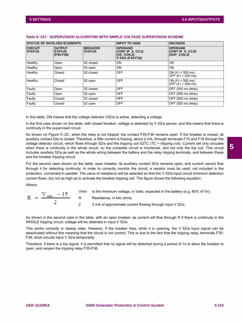
GEK-113285A G650 Generator Protection & Control System 5-115
5 SETTINGS 5.6 INPUTS/OUTPUTS
5
Table 5–107: SUPERVISION ALGORITHM WITH SIMPLE VOLTAGE SUPERVISION SCHEME
In this table, ON means that the voltage detector V52/a is active, detecting a voltage.
In the first case shown on the table, with closed breaker, voltage is detected by V 52/a sensor, and this means that there iscontinuity in the supervised circuit.
As shown on Figure 5–32:, when the relay is not tripped, trip contact F35-F36 remains open. If the breaker is closed, itsauxiliary contact 52a is closed. Therefore, a little current is flowing, about 2 mA, through terminals F15 and F16 through thevoltage detector circuit, which flows through 52/a and the tripping coil 52TC (TC = tripping coil). Current will only circulatewhen there is continuity in the whole circuit, so the complete circuit is monitored, and not only the trip coil. This circuitincludes auxiliary 52/a as well as the whole wiring between the battery and the relay tripping terminals, and between theseand the breaker tripping circuit.
For the second case shown on the table, open breaker, its auxiliary contact 52/a remains open, and current cannot flowthrough it for detecting continuity. In order to correctly monitor the circuit, a resistor must be used, not included in theprotection, connected in parallel. The value of resistance will be selected so that the V 52/a input circuit minimum detectioncurrent flows, but not as high as to activate the breaker-tripping coil. The figure shows the following equation:
Where:
Vmin Is the minimum voltage, in Volts, expected in the battery (e.g. 80% of Vn)
R Resistance, in kilo ohms.
2 2 mA of approximate current flowing through input V 52/a
As shown in the second case in the table, with an open breaker, as current will flow through R if there is continuity in theWHOLE tripping circuit, voltage will be detected in input V 52/a.
This works correctly in steady state. However, if the breaker trips, while it is opening, the V 52/a input signal can bedeactivated without this meaning that the circuit is not correct. This is due to the fact that the tripping relay, terminals F35-F36, short circuits input V 52/a temporarily.
Therefore, if there is a trip signal, it is permitted that no signal will be detected during a period of 1s to allow the breaker toopen, and reopen the tripping relay F35-F36.
STATUS OF INVOLVED ELEMENTS INPUT TO G650 DECISIONCIRCUITSTATUS
OUTPUTSTATUS(F35-F36)
BREAKERSTATUS
OPERANDCONT IP_X_CC11(VA_COIL2)V 52/A (F15-F16)
OPERANDCONT IP_X_CC16(SUP_COIL2)
Healthy Open 52 closed ON ONHealthy Open 52 open ON ONHealthy Closed 52 closed OFF ON (if t < 500 ms)
OFF (if t > 500 ms)Healthy Closed 52 open OFF ON (if t < 500 ms)
OFF (if t > 500 ms)Faulty Open 52 closed OFF OFF (500 ms delay)Faulty Open 52 open OFF OFF (500 ms delay)Faulty Closed 52 closed OFF OFF (500 ms delay)Faulty Closed 52 open OFF OFF (500 ms delay)
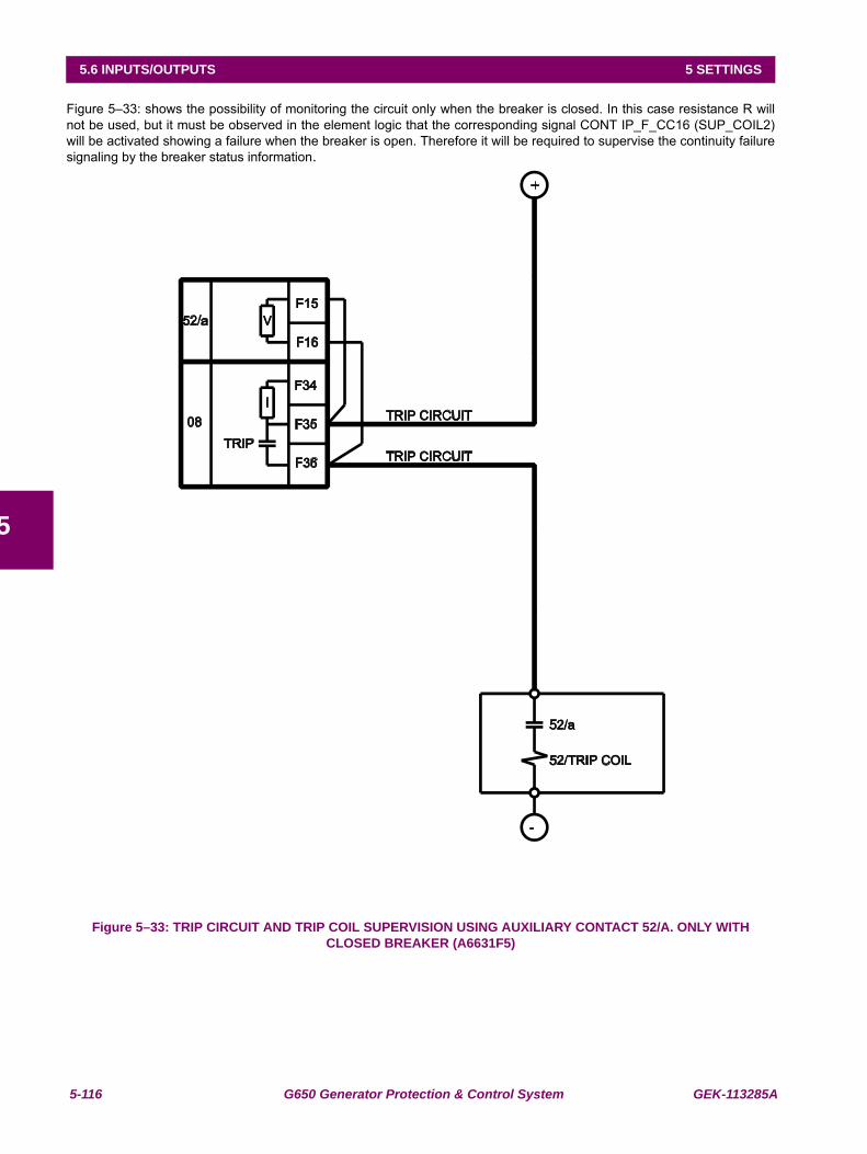
5-116 G650 Generator Protection & Control System GEK-113285A
5.6 INPUTS/OUTPUTS 5 SETTINGS
5
Figure 5–33: shows the possibility of monitoring the circuit only when the breaker is closed. In this case resistance R willnot be used, but it must be observed in the element logic that the corresponding signal CONT IP_F_CC16 (SUP_COIL2)will be activated showing a failure when the breaker is open. Therefore it will be required to supervise the continuity failuresignaling by the breaker status information.
Figure 5–33: TRIP CIRCUIT AND TRIP COIL SUPERVISION USING AUXILIARY CONTACT 52/A. ONLY WITH CLOSED BREAKER (A6631F5)
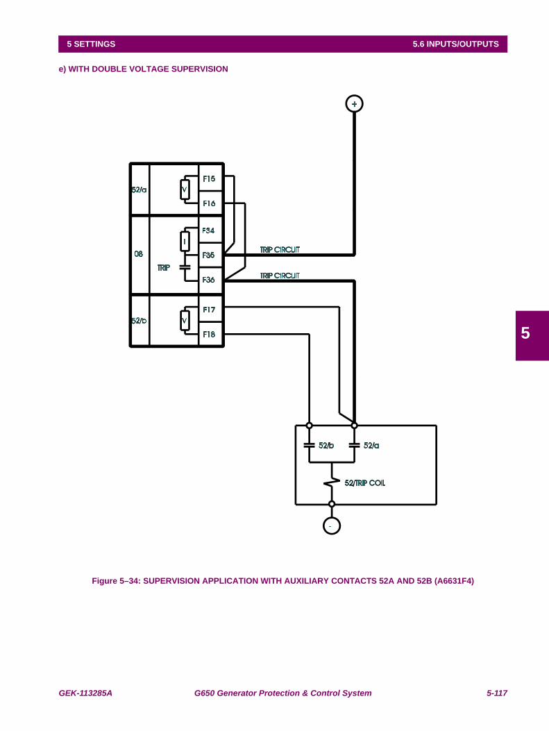
GEK-113285A G650 Generator Protection & Control System 5-117
5 SETTINGS 5.6 INPUTS/OUTPUTS
5
e) WITH DOUBLE VOLTAGE SUPERVISION
Figure 5–34: SUPERVISION APPLICATION WITH AUXILIARY CONTACTS 52A AND 52B (A6631F4)
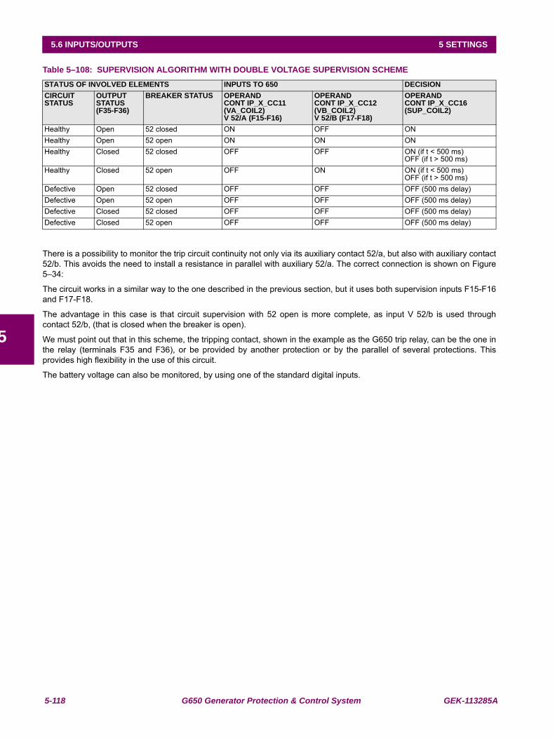
5-118 G650 Generator Protection & Control System GEK-113285A
5.6 INPUTS/OUTPUTS 5 SETTINGS
5
Table 5–108: SUPERVISION ALGORITHM WITH DOUBLE VOLTAGE SUPERVISION SCHEME
There is a possibility to monitor the trip circuit continuity not only via its auxiliary contact 52/a, but also with auxiliary contact52/b. This avoids the need to install a resistance in parallel with auxiliary 52/a. The correct connection is shown on Figure5–34:
The circuit works in a similar way to the one described in the previous section, but it uses both supervision inputs F15-F16and F17-F18.
The advantage in this case is that circuit supervision with 52 open is more complete, as input V 52/b is used throughcontact 52/b, (that is closed when the breaker is open).
We must point out that in this scheme, the tripping contact, shown in the example as the G650 trip relay, can be the one inthe relay (terminals F35 and F36), or be provided by another protection or by the parallel of several protections. Thisprovides high flexibility in the use of this circuit.
The battery voltage can also be monitored, by using one of the standard digital inputs.
STATUS OF INVOLVED ELEMENTS INPUTS TO 650 DECISIONCIRCUIT STATUS
OUTPUT STATUS(F35-F36)
BREAKER STATUS OPERANDCONT IP_X_CC11(VA_COIL2)V 52/A (F15-F16)
OPERANDCONT IP_X_CC12 (VB_COIL2)V 52/B (F17-F18)
OPERANDCONT IP_X_CC16(SUP_COIL2)
Healthy Open 52 closed ON OFF ONHealthy Open 52 open ON ON ONHealthy Closed 52 closed OFF OFF ON (if t < 500 ms)
OFF (if t > 500 ms)Healthy Closed 52 open OFF ON ON (if t < 500 ms)
OFF (if t > 500 ms)Defective Open 52 closed OFF OFF OFF (500 ms delay)Defective Open 52 open OFF OFF OFF (500 ms delay)Defective Closed 52 closed OFF OFF OFF (500 ms delay)Defective Closed 52 open OFF OFF OFF (500 ms delay)
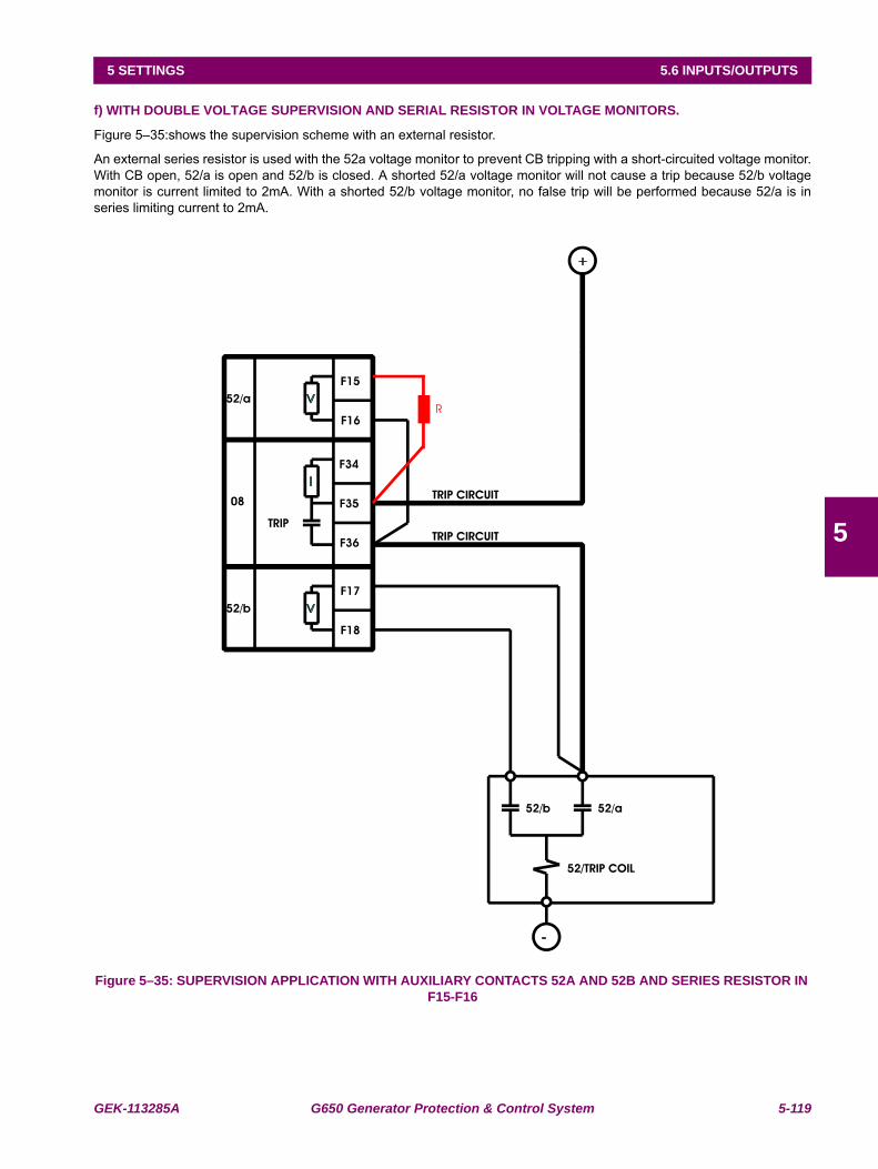
GEK-113285A G650 Generator Protection & Control System 5-119
5 SETTINGS 5.6 INPUTS/OUTPUTS
5
f) WITH DOUBLE VOLTAGE SUPERVISION AND SERIAL RESISTOR IN VOLTAGE MONITORS.
Figure 5–35:shows the supervision scheme with an external resistor.
An external series resistor is used with the 52a voltage monitor to prevent CB tripping with a short-circuited voltage monitor.With CB open, 52/a is open and 52/b is closed. A shorted 52/a voltage monitor will not cause a trip because 52/b voltagemonitor is current limited to 2mA. With a shorted 52/b voltage monitor, no false trip will be performed because 52/a is inseries limiting current to 2mA.
Figure 5–35: SUPERVISION APPLICATION WITH AUXILIARY CONTACTS 52A AND 52B AND SERIES RESISTOR IN F15-F16
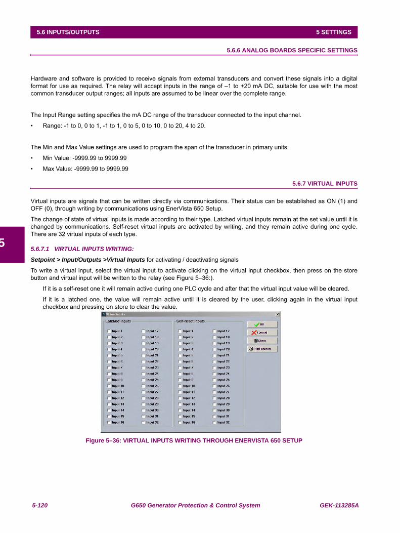
5-120 G650 Generator Protection & Control System GEK-113285A
5.6 INPUTS/OUTPUTS 5 SETTINGS
5
5.6.6 ANALOG BOARDS SPECIFIC SETTINGS
Hardware and software is provided to receive signals from external transducers and convert these signals into a digitalformat for use as required. The relay will accept inputs in the range of –1 to +20 mA DC, suitable for use with the mostcommon transducer output ranges; all inputs are assumed to be linear over the complete range.
The Input Range setting specifies the mA DC range of the transducer connected to the input channel.
• Range: -1 to 0, 0 to 1, -1 to 1, 0 to 5, 0 to 10, 0 to 20, 4 to 20.
The Min and Max Value settings are used to program the span of the transducer in primary units.
• Min Value: -9999.99 to 9999.99
• Max Value: -9999.99 to 9999.99
5.6.7 VIRTUAL INPUTS
Virtual inputs are signals that can be written directly via communications. Their status can be established as ON (1) andOFF (0), through writing by communications using EnerVista 650 Setup.
The change of state of virtual inputs is made according to their type. Latched virtual inputs remain at the set value until it ischanged by communications. Self-reset virtual inputs are activated by writing, and they remain active during one cycle.There are 32 virtual inputs of each type.
5.6.7.1 VIRTUAL INPUTS WRITING:
Setpoint > Input/Outputs >Virtual Inputs for activating / deactivating signals
To write a virtual input, select the virtual input to activate clicking on the virtual input checkbox, then press on the storebutton and virtual input will be written to the relay (see Figure 5–36:).
If it is a self-reset one it will remain active during one PLC cycle and after that the virtual input value will be cleared.
If it is a latched one, the value will remain active until it is cleared by the user, clicking again in the virtual inputcheckbox and pressing on store to clear the value.
Figure 5–36: VIRTUAL INPUTS WRITING THROUGH ENERVISTA 650 SETUP
GEK-113285A G650 Generator Protection & Control System 5-121
5 SETTINGS 5.6 INPUTS/OUTPUTS
5
5.6.7.2 VIRTUAL INPUTS STATUS MONITORING:
Actual > Inputs/Outputs > Virtual Inputs > Virtual Input Latched > Virtual Input Self-Reset
Table 5–109: VIRTUAL INPUTS STATUS
Text assignment for virtual input is made at Setpoint > Relay Configuration > Virtual Inputs. It should be taken intoaccount that the text assigned for virtual inputs in the relay configuration screen are only for file management, they are notsent to the relay.
5.6.8 VIRTUAL OUTPUTS
There are 512 virtual outputs that may be assigned via Logic configuration. If not assigned, the output will be forced to OFF(Logic 0). An ID may be assigned to each virtual output. Virtual outputs are resolved in each pass through the evaluation ofthe logic equations. For more detailed information see chapters 5.8 and 5.9 in this manual.
VIRTUAL INPUTS LATCHED VIRTUAL INPUTS SELF-RESETLATCHED VIRT IP 1 SELF-RST VIRT IP 1LATCHED VIRT IP 2 SELF-RST VIRT IP 2… …LATCHED VIRT IP 32 SELF-RST VIRT IP 32
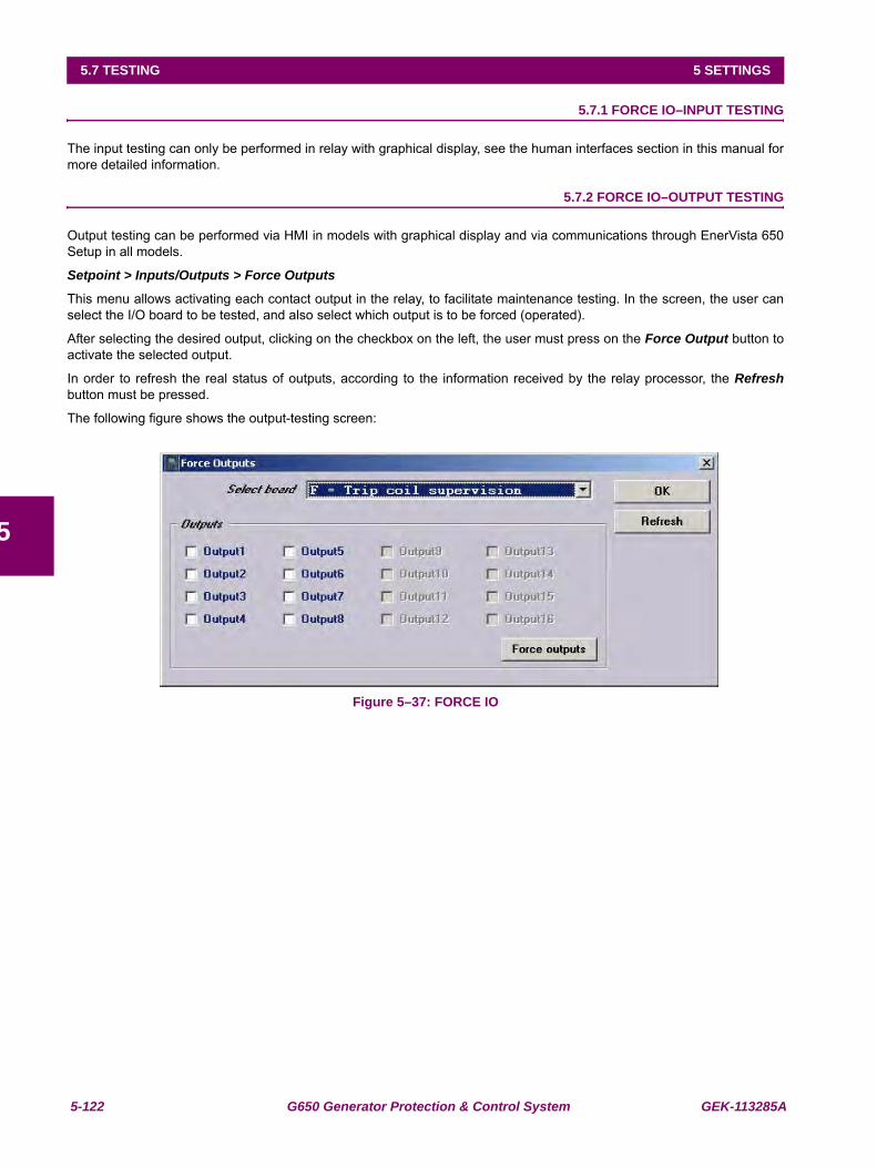
5-122 G650 Generator Protection & Control System GEK-113285A
5.7 TESTING 5 SETTINGS
5
5.7TESTING 5.7.1 FORCE IO–INPUT TESTING
The input testing can only be performed in relay with graphical display, see the human interfaces section in this manual formore detailed information.
5.7.2 FORCE IO–OUTPUT TESTING
Output testing can be performed via HMI in models with graphical display and via communications through EnerVista 650Setup in all models.
Setpoint > Inputs/Outputs > Force Outputs
This menu allows activating each contact output in the relay, to facilitate maintenance testing. In the screen, the user canselect the I/O board to be tested, and also select which output is to be forced (operated).
After selecting the desired output, clicking on the checkbox on the left, the user must press on the Force Output button toactivate the selected output.
In order to refresh the real status of outputs, according to the information received by the relay processor, the Refreshbutton must be pressed.
The following figure shows the output-testing screen:
Figure 5–37: FORCE IO
GEK-113285A G650 Generator Protection & Control System 5-123
5 SETTINGS 5.8 RELAY CONFIGURATION
5
5.8RELAY CONFIGURATION
Setpoint > Relay Configuration
This is the relay configuration section in which the relay can be configured (all input/output and LEDs configuration,protection elements signals, graphic display configuration, etc.) using internal states or already compiled equation on PLCEditor (see section 5.9).
5.8.1 OUTPUTS
Configuration of contact output operates and reset signals for all boards available in the device:
To configure any output it is necessary to select the output to be configured, clicking on the checkbox in the select columnand choose the logic operand in the source column. Simple logics can be performed on this screen, using the “or” and “not”columns, for more complex logics go to the logic configuration tool to create the virtual outputs and afterwards select it inthe source column.
The different options available in this screen are the following:
• Select checkbox enables each output. The output must be enabled before modifying any other setting on that output
• Name setting for defining identification for the output.
• Source setting for defining a function, logic, remote input, digital input, etc. that will activate the contact.
• OR checkbox for configuring the output operation by activation of any of the indicated signals. The element performsan OR of the signals, and its output produces operation.
• NOT checkbox for inverting or not the configured logic.
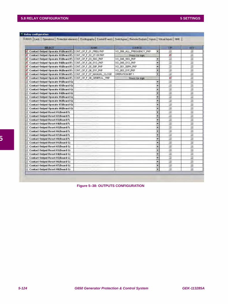
5-124 G650 Generator Protection & Control System GEK-113285A
5.8 RELAY CONFIGURATION 5 SETTINGS
5
Figure 5–38: OUTPUTS CONFIGURATION
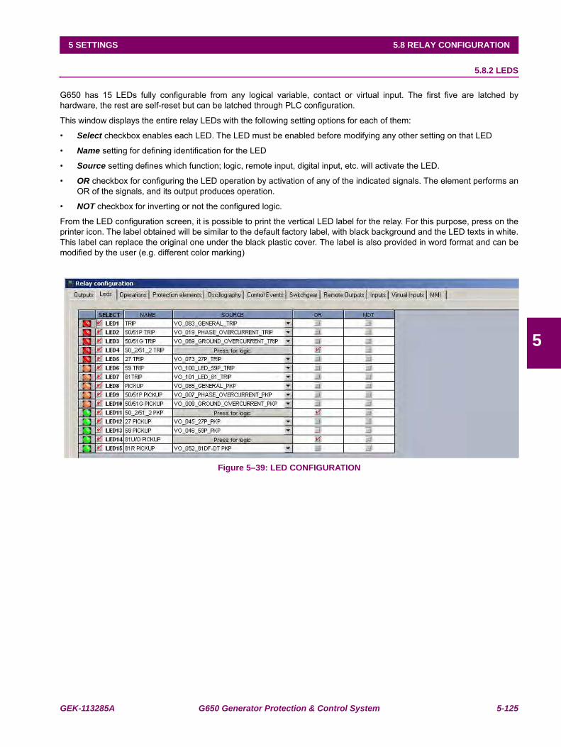
GEK-113285A G650 Generator Protection & Control System 5-125
5 SETTINGS 5.8 RELAY CONFIGURATION
5
5.8.2 LEDS
G650 has 15 LEDs fully configurable from any logical variable, contact or virtual input. The first five are latched byhardware, the rest are self-reset but can be latched through PLC configuration.
This window displays the entire relay LEDs with the following setting options for each of them:
• Select checkbox enables each LED. The LED must be enabled before modifying any other setting on that LED
• Name setting for defining identification for the LED
• Source setting defines which function; logic, remote input, digital input, etc. will activate the LED.
• OR checkbox for configuring the LED operation by activation of any of the indicated signals. The element performs anOR of the signals, and its output produces operation.
• NOT checkbox for inverting or not the configured logic.
From the LED configuration screen, it is possible to print the vertical LED label for the relay. For this purpose, press on theprinter icon. The label obtained will be similar to the default factory label, with black background and the LED texts in white.This label can replace the original one under the black plastic cover. The label is also provided in word format and can bemodified by the user (e.g. different color marking)
Figure 5–39: LED CONFIGURATION
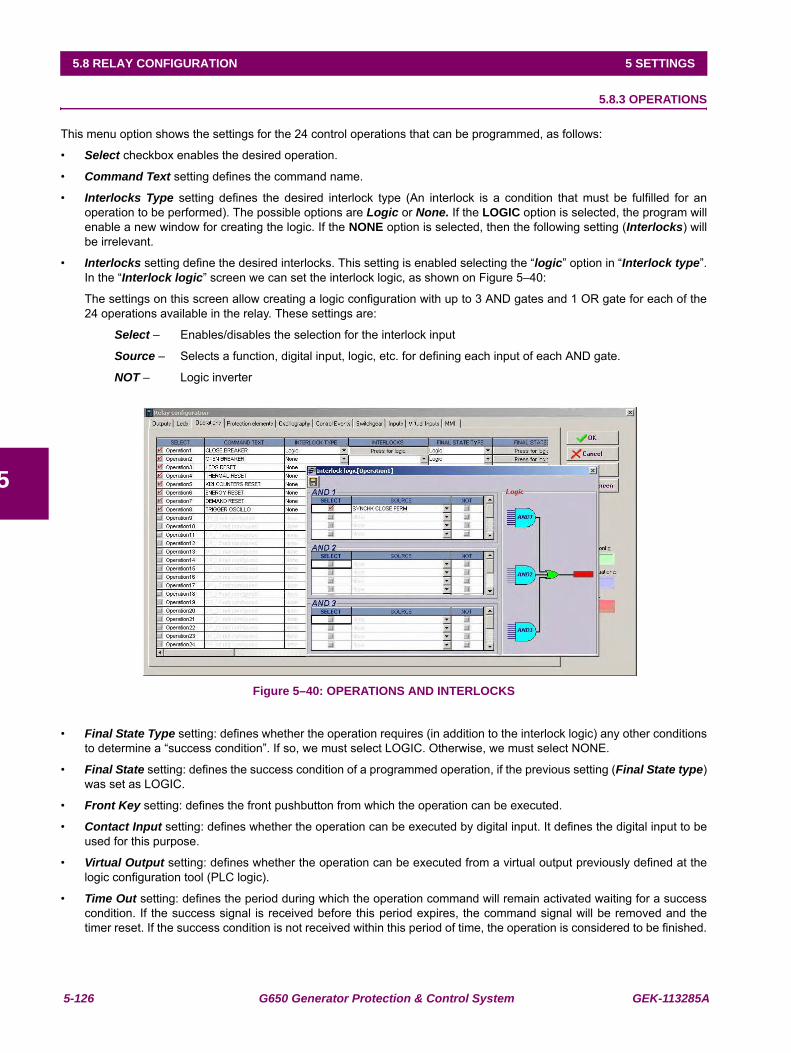
5-126 G650 Generator Protection & Control System GEK-113285A
5.8 RELAY CONFIGURATION 5 SETTINGS
5
5.8.3 OPERATIONS
This menu option shows the settings for the 24 control operations that can be programmed, as follows:
• Select checkbox enables the desired operation.
• Command Text setting defines the command name.
• Interlocks Type setting defines the desired interlock type (An interlock is a condition that must be fulfilled for anoperation to be performed). The possible options are Logic or None. If the LOGIC option is selected, the program willenable a new window for creating the logic. If the NONE option is selected, then the following setting (Interlocks) willbe irrelevant.
• Interlocks setting define the desired interlocks. This setting is enabled selecting the “logic” option in “Interlock type”.In the “Interlock logic” screen we can set the interlock logic, as shown on Figure 5–40:
The settings on this screen allow creating a logic configuration with up to 3 AND gates and 1 OR gate for each of the24 operations available in the relay. These settings are:
Select – Enables/disables the selection for the interlock input
Source – Selects a function, digital input, logic, etc. for defining each input of each AND gate.
NOT – Logic inverter
Figure 5–40: OPERATIONS AND INTERLOCKS
• Final State Type setting: defines whether the operation requires (in addition to the interlock logic) any other conditionsto determine a “success condition”. If so, we must select LOGIC. Otherwise, we must select NONE.
• Final State setting: defines the success condition of a programmed operation, if the previous setting (Final State type)was set as LOGIC.
• Front Key setting: defines the front pushbutton from which the operation can be executed.
• Contact Input setting: defines whether the operation can be executed by digital input. It defines the digital input to beused for this purpose.
• Virtual Output setting: defines whether the operation can be executed from a virtual output previously defined at thelogic configuration tool (PLC logic).
• Time Out setting: defines the period during which the operation command will remain activated waiting for a successcondition. If the success signal is received before this period expires, the command signal will be removed and thetimer reset. If the success condition is not received within this period of time, the operation is considered to be finished.
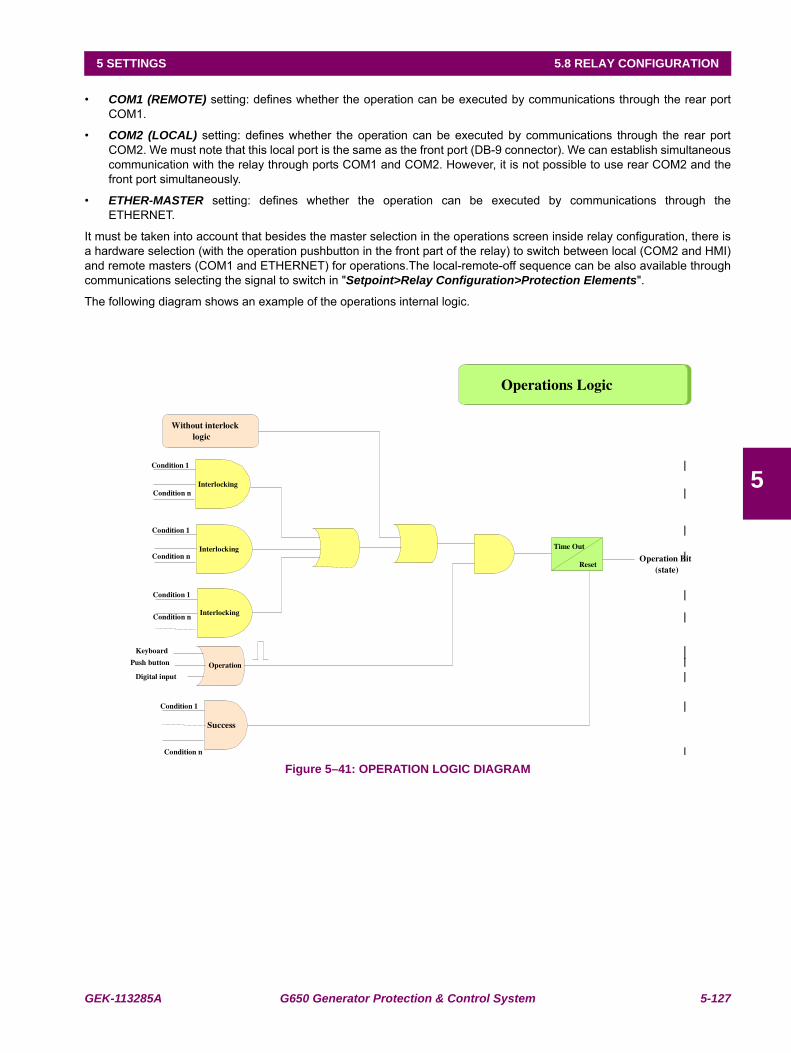
GEK-113285A G650 Generator Protection & Control System 5-127
5 SETTINGS 5.8 RELAY CONFIGURATION
5
• COM1 (REMOTE) setting: defines whether the operation can be executed by communications through the rear portCOM1.
• COM2 (LOCAL) setting: defines whether the operation can be executed by communications through the rear portCOM2. We must note that this local port is the same as the front port (DB-9 connector). We can establish simultaneouscommunication with the relay through ports COM1 and COM2. However, it is not possible to use rear COM2 and thefront port simultaneously.
• ETHER-MASTER setting: defines whether the operation can be executed by communications through theETHERNET.
It must be taken into account that besides the master selection in the operations screen inside relay configuration, there isa hardware selection (with the operation pushbutton in the front part of the relay) to switch between local (COM2 and HMI)and remote masters (COM1 and ETHERNET) for operations.The local-remote-off sequence can be also available throughcommunications selecting the signal to switch in "Setpoint>Relay Configuration>Protection Elements".
The following diagram shows an example of the operations internal logic.
Figure 5–41: OPERATION LOGIC DIAGRAM
Condition 1
Condition n
Condition 1
Condition n
Success
Operation
Keyboard
Push button
Digital input
Operation Bit(state)
Condition 1
Condition nInterlocking
Without interlocklogic
Interlocking
Interlocking
Operations Logic
Time Out
Reset
Condition 1
Condition n
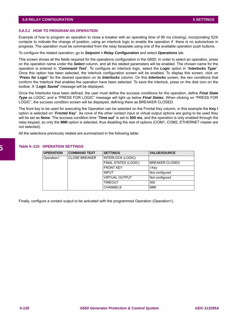
5-128 G650 Generator Protection & Control System GEK-113285A
5.8 RELAY CONFIGURATION 5 SETTINGS
5
5.8.3.1 HOW TO PROGRAM AN OPERATION
Example of how to program an operation to close a breaker with an operating time of 90 ms (closing), incorporating 52/bcontacts to indicate the change of position, using an interlock logic to enable the operation if there is no autoreclose inprogress. The operation must be commanded from the relay faceplate using one of the available operation push buttons.
To configure the related operation, go to Setpoint > Relay Configuration and select Operations tab.
This screen shows all the fields required for the operations configuration in the G650. In order to select an operation, presson the operation name under the Select column, and all the related parameters will be enabled. The chosen name for theoperation is entered in “Command Text”. To configure an interlock logic, select the Logic option in “Interlocks Type”.Once this option has been selected, the interlock configuration screen will be enabled. To display this screen, click on“Press for Logic” for the desired operation on its Interlocks column. On this Interlocks screen, the two conditions thatconform the Interlock that enables the operation have been selected. To save the interlock, press on the disk icon on thetoolbar. A “Logic Saved” message will be displayed.
Once the Interlocks have been defined, the user must define the success conditions for the operation, define Final StateType as LOGIC, and a “PRESS FOR LOGIC” message will light up below Final States. When clicking on “PRESS FORLOGIC”, the success condition screen will be displayed, defining there as BREAKER CLOSED.
The front key to be used for executing the Operation can be selected on the Frontal Key column, in this example the Key Ioption is selected on “Frontal Key”. As none of the other contact input or virtual output options are going to be used theywill be set as None. The success condition time “Time out” is set to 500 ms, and the operation is only enabled through therelay keypad, so only the MMI option is selected, thus disabling the rest of options (COM1, COM2, ETHERNET master arenot selected).
All the selections previously related are summarized in the following table:
Table 5–110: OPERATION SETTINGS
Finally, configure a contact output to be activated with the programmed Operation (Operation1).
OPERATION COMMAND TEXT SETTINGS VALUE/SOURCEOperation1 CLOSE BREAKER INTERLOCK (LOGIC)
FINAL STATES (LOGIC) BREAKER CLOSEDFRONT KEY I KeyINPUT Not configuredVIRTUAL OUTPUT Not configuredTIMEOUT 500CHANNELS MMI
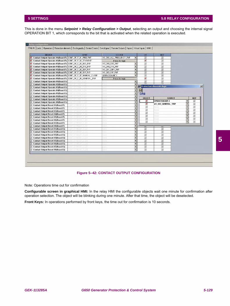
GEK-113285A G650 Generator Protection & Control System 5-129
5 SETTINGS 5.8 RELAY CONFIGURATION
5
This is done in the menu Setpoint > Relay Configuration > Output, selecting an output and choosing the internal signalOPERATION BIT 1, which corresponds to the bit that is activated when the related operation is executed.
Figure 5–42: CONTACT OUTPUT CONFIGURATION
Note: Operations time out for confirmation
Configurable screen in graphical HMI: In the relay HMI the configurable objects wait one minute for confirmation afteroperation selection. The object will be blinking during one minute. After that time, the object will be deselected.
Front Keys: In operations performed by front keys, the time out for confirmation is 10 seconds.
5-130 G650 Generator Protection & Control System GEK-113285A
5.8 RELAY CONFIGURATION 5 SETTINGS
5
5.8.4 PROTECTION ELEMENTS
This tab allows assigning operands (logic signals) as inputs to different protection elements. This way, the user assignsetc. In this screen we can also configure a logic signal to perform the LED reset by communications.
The settings are as follows:
• Select checkbox enables/disables the selection.
• Source setting defines the operand that performs the function indicated in the SELECT column. NOT setting invertsthe block signal.
• NOT setting for inverting the logic signal.
• OR checkbox to select a group of operands instead of a single one. The relay performs an OR of the signals, and itsoutput produces the operation.
The following figure shows this screen:
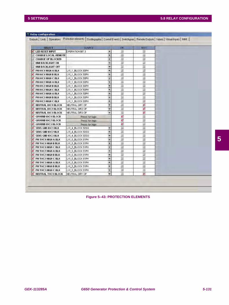
GEK-113285A G650 Generator Protection & Control System 5-131
5 SETTINGS 5.8 RELAY CONFIGURATION
5
Figure 5–43: PROTECTION ELEMENTS
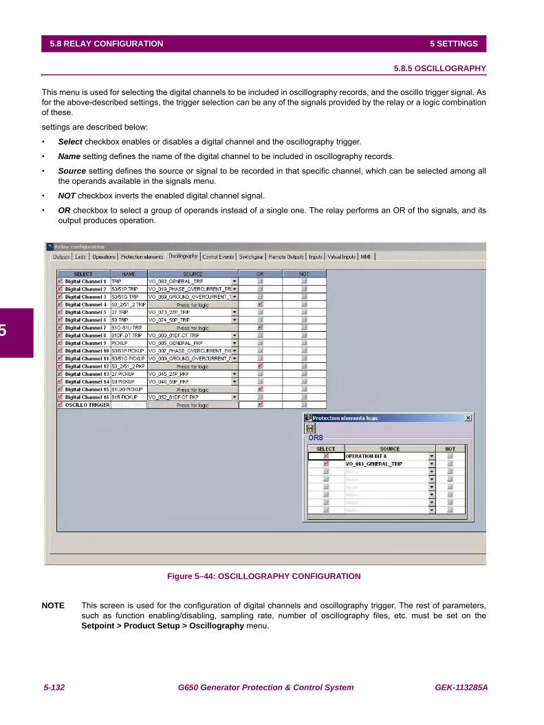
5-132 G650 Generator Protection & Control System GEK-113285A
5.8 RELAY CONFIGURATION 5 SETTINGS
5
5.8.5 OSCILLOGRAPHY
This menu is used for selecting the digital channels to be included in oscillography records, and the oscillo trigger signal. Asfor the above-described settings, the trigger selection can be any of the signals provided by the relay or a logic combinationof these.
settings are described below:
• Select checkbox enables or disables a digital channel and the oscillography trigger.
• Name setting defines the name of the digital channel to be included in oscillography records.
• Source setting defines the source or signal to be recorded in that specific channel, which can be selected among allthe operands available in the signals menu.
• NOT checkbox inverts the enabled digital channel signal.
• OR checkbox to select a group of operands instead of a single one. The relay performs an OR of the signals, and itsoutput produces operation.
Figure 5–44: OSCILLOGRAPHY CONFIGURATION
NOTE This screen is used for the configuration of digital channels and oscillography trigger. The rest of parameters,such as function enabling/disabling, sampling rate, number of oscillography files, etc. must be set on theSetpoint > Product Setup > Oscillography menu.
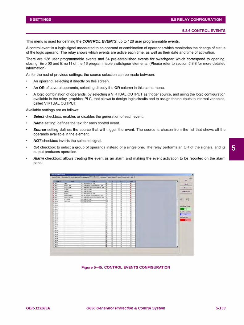
GEK-113285A G650 Generator Protection & Control System 5-133
5 SETTINGS 5.8 RELAY CONFIGURATION
5
5.8.6 CONTROL EVENTS
This menu is used for defining the CONTROL EVENTS, up to 128 user programmable events.
A control event is a logic signal associated to an operand or combination of operands which monitories the change of statusof the logic operand. The relay shows which events are active each time, as well as their date and time of activation.
There are 128 user programmable events and 64 pre-established events for switchgear, which correspond to opening,closing, Error00 and Error11 of the 16 programmable switchgear elements. (Please refer to section 5.8.8 for more detailedinformation).
As for the rest of previous settings, the source selection can be made between:
• An operand, selecting it directly on this screen.
• An OR of several operands, selecting directly the OR column in this same menu.
• A logic combination of operands, by selecting a VIRTUAL OUTPUT as trigger source, and using the logic configurationavailable in the relay, graphical PLC, that allows to design logic circuits and to assign their outputs to internal variables,called VIRTUAL OUTPUT.
Available settings are as follows:
• Select checkbox: enables or disables the generation of each event.
• Name setting: defines the text for each control event.
• Source setting defines the source that will trigger the event. The source is chosen from the list that shows all theoperands available in the element.
• NOT checkbox inverts the selected signal.
• OR checkbox to select a group of operands instead of a single one. The relay performs an OR of the signals, and itsoutput produces operation.
• Alarm checkbox: allows treating the event as an alarm and making the event activation to be reported on the alarmpanel.
Figure 5–45: CONTROL EVENTS CONFIGURATION
5-134 G650 Generator Protection & Control System GEK-113285A
5.8 RELAY CONFIGURATION 5 SETTINGS
5
The Alarm panel can be displayed in:
HMI screen for models with graphical display.
EnerVista 650 Setup: Actual>Event Recorder>Alarm Panel for all models.
Web Server application: http://xxx. xxx. xxx. xxx /Alarms.htm for all models.
If the event is not selected as an alarm, it can be viewed as an event at:
HMI screen for all models in snapshot event screen (with default text).
EnerVista 650 Setup: Actual>Event Recorder> Control Events for all models.
Web Server application: http://xxx.xxx.xxx.xxx/ControlEvents.htm for all models.
Alarm management in G650:The relay can manage alarms in from three different masters, local, remote COM1, remote Ethernet. The alarms can beactive or not active and can be acknowledged or not acknowledged. As shown in the following table:
Table 5–111: ALARM MANAGEMENT
ACTIVE status is shown on the display (relay HMI), showing an ON label on the right of the alarm. The PC will show thealarm text in red color.
ACKNOWLEDGED: Operation acknowledgement can be performed from three independent channels: MMI-COM2 (local),COM1 (remote) and COM3 (Ethernet). Inactive alarms disappear from the HMI when being acknowledged.
HMI: Acknowledged status is shown on the HMI with a selection mark on the right of the ON label.
EnerVista 650 Setup: the acknowledged status is shown by a check mark to the left of the Operation name.
ALARM STATUS MASTER MANAGEMENTACTIVE - NOT ACTIVE ALL MASTERSACKNOWLEDGED - NOT ACKNOWLEDGED LOCAL REMOTE
COM2 & HMI COM1 ETHERNET
GEK-113285A G650 Generator Protection & Control System 5-135
5 SETTINGS 5.8 RELAY CONFIGURATION
5
5.8.7 SWITCHGEAR
This menu is used for defining the SWITCHGEAR elements to be controlled by the relay. A switchgear element can be abreaker, a line selector switch, a grounding selector switch, a busbar selector switch, etc. It is possible to define up to 16switchgear elements. The settings are as follows:
• Select checkbox: enables or disables the control of a new switchgear element
• Contacts setting: allows selecting which type of contact is used for monitoring the status (open/closed) of the element.The selection can be: 52a (contact type A, showing the same status as the represented element), 52b (opposite statusto the represented element), 52a+52b (both types of contacts are used), NONE (no status monitoring).
• Opening Time setting: defines the maximum opening time of an element. It is used for issuing an opening time failuresignal if the element opening is not produced within this time.
• Closing Time setting: defines the maximum closing time of an element. It is used for issuing a closing time failuresignal if the element closing is not produced within this time.
• Contact A checkbox: allows selecting which operand or combination of operands activate the type A contact status.Usually it will be an input contact wired to type A contact of the element (Breaker/selector switch). This column and thenext two columns are only active if the selected contact type in the Contacts column is 52a or 52a+52b.
• OR checkbox: selects a group of operands instead of a single one. The relay performs and OR of the signals, and itsoutput produces operation.
• NOT checkbox inverts the status of the signal selected in column Contact A.
• Contact B checkbox: allows selecting which operand or combination of operands activates the type B contact status.Usually it will be an input contact wired to type B contact of the element (Breaker/selector switch). This column and thenext two columns are only active if the selected contact type in the Contacts column is 52b or 52a+52b.
•OR checkbox selects a group of operands instead of a single one. The relay performs OR of the signals, and itsoutput produces operation.
•NOT checkbox inverts the status of the signal selected in column Contact B.
• Open text setting: allows associating a text to the control event associated to the element opening.
• Close text setting: allows associating a text to the control event associated to the element closing.
• Error 00 text setting: in case of using double contact for the switchgear element status (52a+52b), this setting allowsto associate a text to the Error00 internal status, this means, when both contacts are inactive during a period longerthan the associated to the opening or closing Operation, depending on which Operation is being performed.
• Error 11 text setting: in case of using double contact for the switchgear element status (52a+52b), this setting allowsto associate a text to the Error11 internal status, this means, when both contacts are active during a period longer thanthe associated to the opening or closing Operation, depending on which Operation is being performed.
• ALARM setting: enables the issue of an alarm in the event of a close, open, 00-type, 11-type error. If it is configured asan alarm.
• Opening init setting: this setting selects which operand or combination of operands indicate the initiation of anopening operation, in order to allow the follow up of the operation and generate the corresponding alarms if theoperation is not successful. The operation bit signal used to launch the opening init must be configured in theoperations tab inside relay configuration.
• Closing init setting: this setting selects which operand or combination of operands indicate the initiation of a closingoperation, in order to allow the follow up of the operation and generate the corresponding alarms if the operation is notsuccessful. The operation bit signal used to launch the opening init must be configured in the operations tab insiderelay configuration.
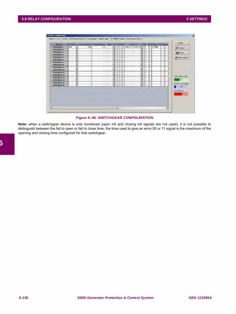
5-136 G650 Generator Protection & Control System GEK-113285A
5.8 RELAY CONFIGURATION 5 SETTINGS
5
Figure 5–46: SWITCHGEAR CONFIGURATION
Note: when a switchgear device is only monitored (open init and closing init signals are not used), it is not possible todistinguish between the fail to open or fail to close time, the time used to give an error 00 or 11 signal is the maximum of theopening and closing time configured for that switchgear.
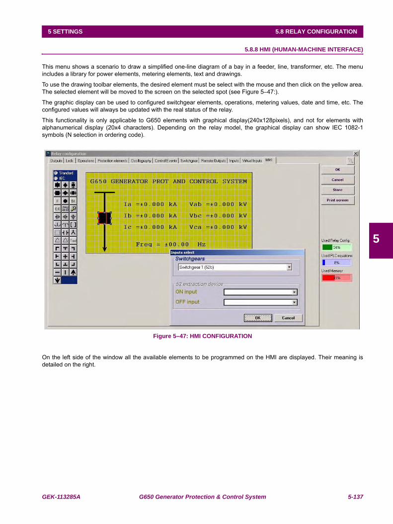
GEK-113285A G650 Generator Protection & Control System 5-137
5 SETTINGS 5.8 RELAY CONFIGURATION
5
5.8.8 HMI (HUMAN-MACHINE INTERFACE)
This menu shows a scenario to draw a simplified one-line diagram of a bay in a feeder, line, transformer, etc. The menuincludes a library for power elements, metering elements, text and drawings.
To use the drawing toolbar elements, the desired element must be select with the mouse and then click on the yellow area.The selected element will be moved to the screen on the selected spot (see Figure 5–47:).
The graphic display can be used to configured switchgear elements, operations, metering values, date and time, etc. Theconfigured values will always be updated with the real status of the relay.
This functionality is only applicable to G650 elements with graphical display(240x128pixels), and not for elements withalphanumerical display (20x4 characters). Depending on the relay model, the graphical display can show IEC 1082-1symbols (N selection in ordering code).
Figure 5–47: HMI CONFIGURATION
On the left side of the window all the available elements to be programmed on the HMI are displayed. Their meaning isdetailed on the right.
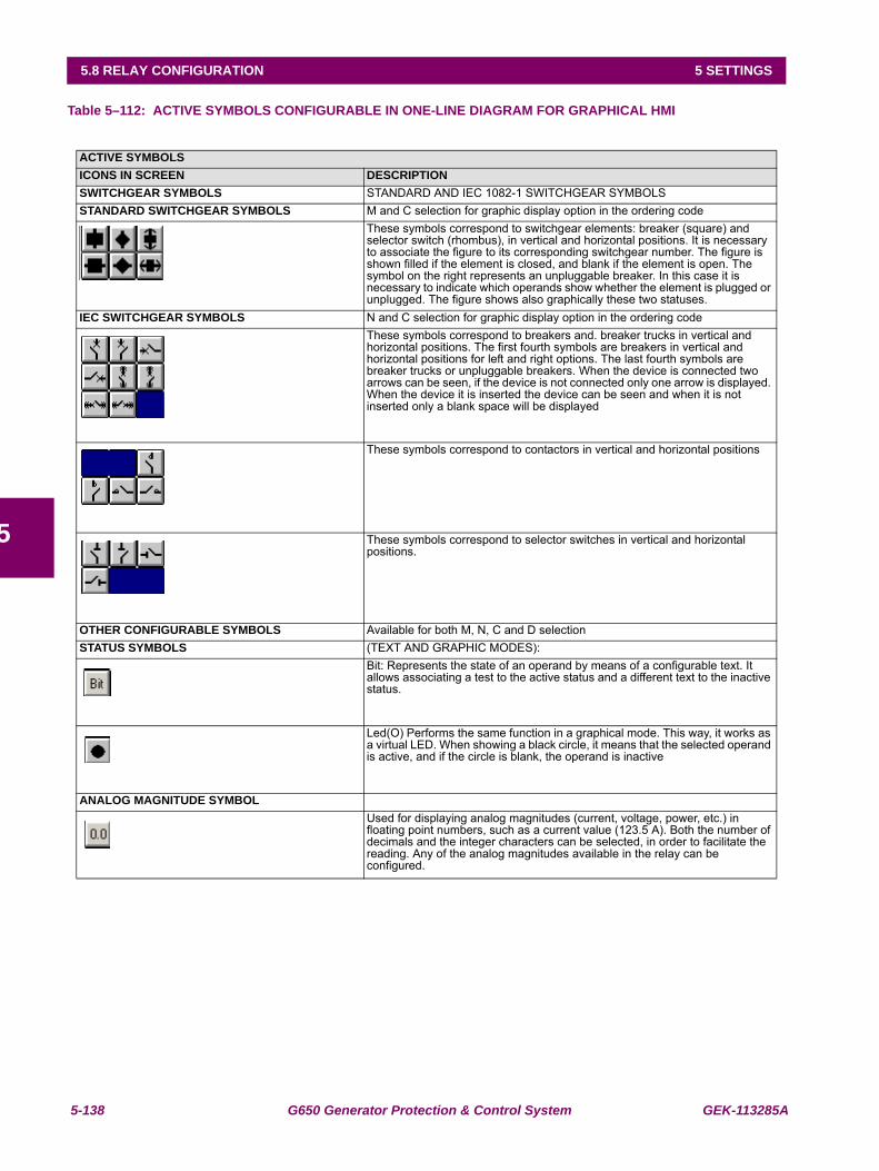
5-138 G650 Generator Protection & Control System GEK-113285A
5.8 RELAY CONFIGURATION 5 SETTINGS
5
Table 5–112: ACTIVE SYMBOLS CONFIGURABLE IN ONE-LINE DIAGRAM FOR GRAPHICAL HMI
ACTIVE SYMBOLSICONS IN SCREEN DESCRIPTIONSWITCHGEAR SYMBOLS STANDARD AND IEC 1082-1 SWITCHGEAR SYMBOLSSTANDARD SWITCHGEAR SYMBOLS M and C selection for graphic display option in the ordering code
These symbols correspond to switchgear elements: breaker (square) and selector switch (rhombus), in vertical and horizontal positions. It is necessary to associate the figure to its corresponding switchgear number. The figure is shown filled if the element is closed, and blank if the element is open. The symbol on the right represents an unpluggable breaker. In this case it is necessary to indicate which operands show whether the element is plugged or unplugged. The figure shows also graphically these two statuses.
IEC SWITCHGEAR SYMBOLS N and C selection for graphic display option in the ordering codeThese symbols correspond to breakers and. breaker trucks in vertical and horizontal positions. The first fourth symbols are breakers in vertical and horizontal positions for left and right options. The last fourth symbols are breaker trucks or unpluggable breakers. When the device is connected two arrows can be seen, if the device is not connected only one arrow is displayed. When the device it is inserted the device can be seen and when it is not inserted only a blank space will be displayed
These symbols correspond to contactors in vertical and horizontal positions
These symbols correspond to selector switches in vertical and horizontal positions.
OTHER CONFIGURABLE SYMBOLS Available for both M, N, C and D selectionSTATUS SYMBOLS (TEXT AND GRAPHIC MODES):
Bit: Represents the state of an operand by means of a configurable text. It allows associating a test to the active status and a different text to the inactive status.
Led(O) Performs the same function in a graphical mode. This way, it works as a virtual LED. When showing a black circle, it means that the selected operand is active, and if the circle is blank, the operand is inactive
ANALOG MAGNITUDE SYMBOLUsed for displaying analog magnitudes (current, voltage, power, etc.) in floating point numbers, such as a current value (123.5 A). Both the number of decimals and the integer characters can be selected, in order to facilitate the reading. Any of the analog magnitudes available in the relay can be configured.
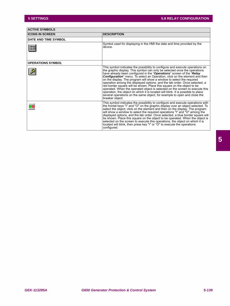
GEK-113285A G650 Generator Protection & Control System 5-139
5 SETTINGS 5.8 RELAY CONFIGURATION
5
ACTIVE SYMBOLSICONS IN SCREEN DESCRIPTION
DATE AND TIME SYMBOLSymbol used for displaying in the HMI the date and time provided by the device.
OPERATIONS SYMBOLThis symbol indicates the possibility to configure and execute operations on the graphic display. This symbol can only be selected once the operations have already been configured in the “Operations” screen of the “Relay Configuration” menu. To select an Operation, click on the element and then on the display. The program will show a window to select the required operation among the displayed options, and the tab order. Once selected, a red border square will be shown. Place this square on the object to be operated. When the operated object is selected on the screen to execute this operation, the object on which it is located will blink. It is possible to place several operations on the same object, for example to open and close the breaker object. This symbol indicates the possibility to configure and execute operations with the frontal keys "I" and "O" on the graphic display over an object selected. To select the object, click on the element and then on the display. The program will show a window to select the required operations "I" and "O" among the displayed options, and the tab order. Once selected, a blue border square will be shown. Place this square on the object to be operated. When the object is selected on the screen to execute this operations, the object on which it is located will blink, then press key "I" or "O" to execute the operations configured.
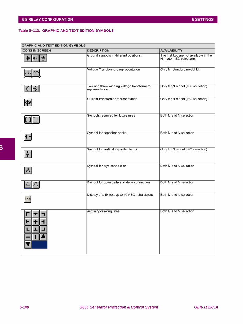
5-140 G650 Generator Protection & Control System GEK-113285A
5.8 RELAY CONFIGURATION 5 SETTINGS
5
Table 5–113: GRAPHIC AND TEXT EDITION SYMBOLS
GRAPHIC AND TEXT EDITION SYMBOLSICONS IN SCREEN DESCRIPTION AVAILABILITY
Ground symbols in different positions. The first two are not available in the N model (IEC selection).
Voltage Transformers representation Only for standard model M.
Two and three winding voltage transformers representation.
Only for N model (IEC selection)
Current transformer representation Only for N model (IEC selection).
Symbols reserved for future uses Both M and N selection
Symbol for capacitor banks. Both M and N selection
Symbol for vertical capacitor banks. Only for N model (IEC selection).
Symbol for wye connection Both M and N selection
Symbol for open delta and delta connection Both M and N selection
Display of a fix text up to 40 ASCII characters Both M and N selection
Auxiliary drawing lines Both M and N selection
GEK-113285A G650 Generator Protection & Control System 5-141
5 SETTINGS 5.9 LOGIC CONFIGURATION (PLC EDITOR)
5
5.9LOGIC CONFIGURATION (PLC EDITOR)
Setpoint > Logic Configuration
The G650 logic allows setting the relay logic configuration using a sophisticated and complete program based on standardIEC 61131-3, with block diagrams, which is described in this section.
5.9.1 INTRODUCTION
The logic configuration (or PLC Editor) tool is a graphical design tool that allows the G650 built complex logic diagram in aneasy way using different logic functions.
The logical configuration is performed using graphical functions based on the IEC 61131-3 standard.
• This standard defines five basic ways of programming:
•Sequential Function Chart (SFC).
•Instruction List (IL).
•Structured Text (ST).
•Ladder Diagram (LD).
•Function Block Diagram (FBD).
Out of these five methods, FBD has been chosen because it allows for graphical configurations that are morecomprehensive. This method provides the possibility of grouping several basic functions inside a single function (hereoncalled libraries), achieving higher modularity and clarity in the design.
Please take note of the following remarks:
The first equation entered in the PLC can never be a timer
Analog elements (analog comparators, etc,) are not implemented.
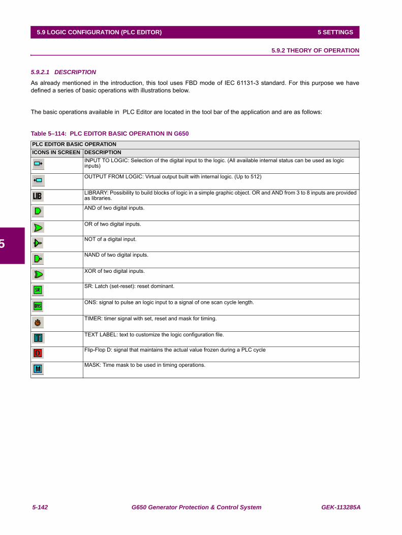
5-142 G650 Generator Protection & Control System GEK-113285A
5.9 LOGIC CONFIGURATION (PLC EDITOR) 5 SETTINGS
5
5.9.2 THEORY OF OPERATION
5.9.2.1 DESCRIPTION
As already mentioned in the introduction, this tool uses FBD mode of IEC 61131-3 standard. For this purpose we havedefined a series of basic operations with illustrations below.
The basic operations available in PLC Editor are located in the tool bar of the application and are as follows:
Table 5–114: PLC EDITOR BASIC OPERATION IN G650PLC EDITOR BASIC OPERATION ICONS IN SCREEN DESCRIPTION
INPUT TO LOGIC: Selection of the digital input to the logic. (All available internal status can be used as logic inputs)
OUTPUT FROM LOGIC: Virtual output built with internal logic. (Up to 512)
LIBRARY: Possibility to build blocks of logic in a simple graphic object. OR and AND from 3 to 8 inputs are provided as libraries.
AND of two digital inputs.
OR of two digital inputs.
NOT of a digital input.
NAND of two digital inputs.
XOR of two digital inputs.
SR: Latch (set-reset): reset dominant.
ONS: signal to pulse an logic input to a signal of one scan cycle length.
TIMER: timer signal with set, reset and mask for timing.
TEXT LABEL: text to customize the logic configuration file.
Flip-Flop D: signal that maintains the actual value frozen during a PLC cycle
MASK: Time mask to be used in timing operations.
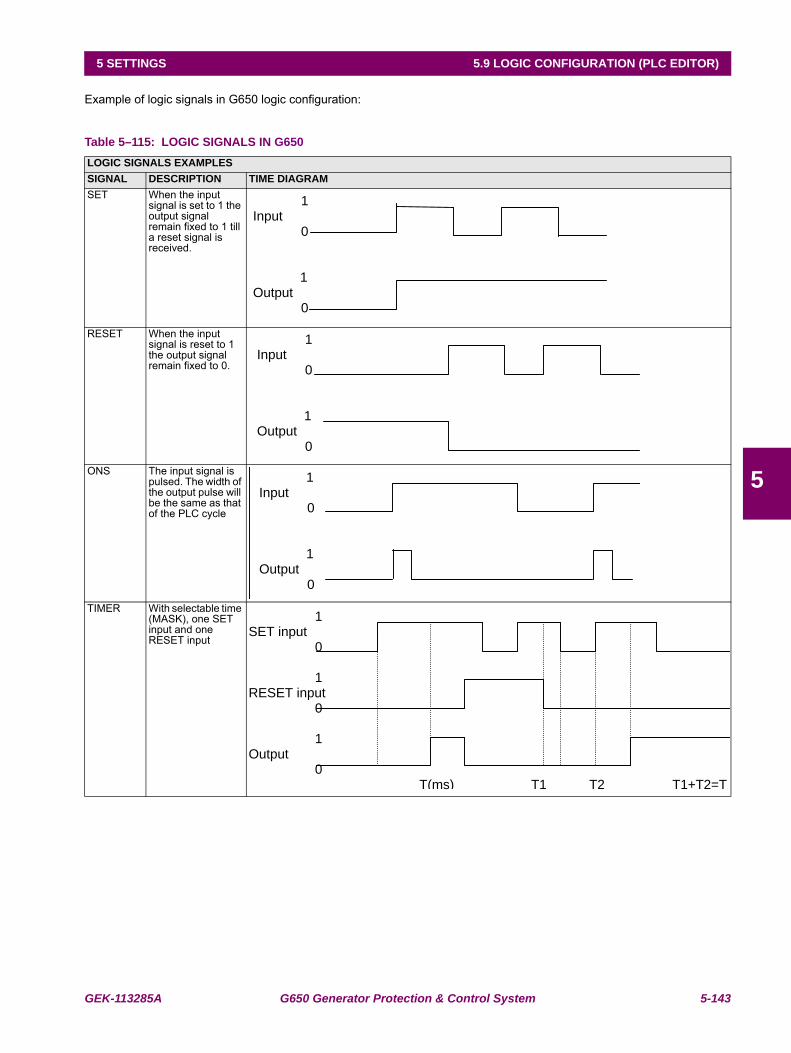
GEK-113285A G650 Generator Protection & Control System 5-143
5 SETTINGS 5.9 LOGIC CONFIGURATION (PLC EDITOR)
5
Example of logic signals in G650 logic configuration:
Table 5–115: LOGIC SIGNALS IN G650LOGIC SIGNALS EXAMPLESSIGNAL DESCRIPTION TIME DIAGRAMSET When the input
signal is set to 1 the output signal remain fixed to 1 till a reset signal is received.
RESET When the input signal is reset to 1 the output signal remain fixed to 0.
ONS The input signal is pulsed. The width of the output pulse will be the same as that of the PLC cycle
TIMER With selectable time (MASK), one SET input and one RESET input
1 Input 0
1 Output 0
1 Input 0
1 Output 0
1Input 0
1 Output 0
1 SET input
0
1 RESET input
0
1 Output
0 T(ms) T1 T2 T1+T2=T
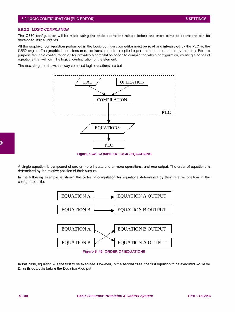
5-144 G650 Generator Protection & Control System GEK-113285A
5.9 LOGIC CONFIGURATION (PLC EDITOR) 5 SETTINGS
5
5.9.2.2 LOGIC COMPILATION
The G650 configuration will be made using the basic operations related before and more complex operations can bedeveloped inside libraries.
All the graphical configuration performed in the Logic configuration editor must be read and interpreted by the PLC as theG650 engine. The graphical equations must be translated into compiled equations to be understood by the relay. For thispurpose the logic configuration editor provides a compilation option to compile the whole configuration, creating a series ofequations that will form the logical configuration of the element.
The next diagram shows the way compiled logic equations are built.
Figure 5–48: COMPILED LOGIC EQUATIONS
A single equation is composed of one or more inputs, one or more operations, and one output. The order of equations isdetermined by the relative position of their outputs.
In the following example is shown the order of compilation for equations determined by their relative position in theconfiguration file:
Figure 5–49: ORDER OF EQUATIONS
In this case, equation A is the first to be executed. However, in the second case, the first equation to be executed would beB, as its output is before the Equation A output.
EQUATIONS
PLC
PLC
DAT OPERATION
COMPILATION
EQUATION A EQUATION A OUTPUT
EQUATION B EQUATION B OUTPUT
EQUATION A EQUATION B OUTPUT
EQUATION B EQUATION A OUTPUT

GEK-113285A G650 Generator Protection & Control System 5-145
5 SETTINGS 5.9 LOGIC CONFIGURATION (PLC EDITOR)
5
5.9.3 MAIN MENU
The PLC Editor tool (Setpoint > Logic Configuration) provides a main menu with different submenus (File, Project, Edit,Run, View, and Window) that allows the user to built customized logic for the G650 devices.
5.9.3.1 FILE MENU
The FILE menu includes the following options:
New Project: allows to create a new project that will include the files of the logic configuration
Open Project: opens an existing project.
Close Project: closes the currently open project.
Save Project and Save Project as: saves the open project.
Save Automatic Function &
Save Automatic Function As: Saves the file of the active project.
Library: Gives access to the libraries sub-menus, where new libraries can be created andexisting ones can be modified and saved.
Print: Prints the active configuration file.
Preview: Preview of the document before printing.
Exit: The system closes all open projects and exits the application.
5.9.3.2 PROJECT MENU
The Project menu includes the following options:
Project Explorer: Displays a window where we see a tree structure with the files contained in theproject.
Insert library: Inserts a library in the active automatic function.
5.9.3.3 EDIT MENU
The Edit menu includes the following options:
Undo: Undoes the last modification in the active function.
Redo: Remakes the last modification.
Cut: Cuts one or more logic operations.
Copy: Copies one or more logic operations.
Paste: Pastes one or more logic operations.
Find: Looks for a logic operation in the project.
Copy as Bitmap: Copies the active automatic function to the clipboard in picture format.
View Clipboard: Launches the clipboard viewer application.
5.9.3.4 RUN MENU
The RUN menu includes the following options:
Configuration: Not valid in the current application (for analog operations still not available)
Compile: Compiles the configuration functions to generate the equations that will be interpretedby the 650 PLC.
Send Equations to Relay
5-146 G650 Generator Protection & Control System GEK-113285A
5.9 LOGIC CONFIGURATION (PLC EDITOR) 5 SETTINGS
5
5.9.3.5 VIEW MENU
The VIEW menu includes the following options:
Log: Displays in one screen the status name and time stamp of the digital statusesconfigured in the PLC logic (still not available).
Debug-Release window: Displays the values for the different project inputs, outputs, and variables (still notavailable).
Equations: Displays the equations resulting from the compilation.
Grid: Shows or hides the form grid where the configuration functions are developed. Italso aligns the different objects to the grid.
Zoom: Allows selecting the percentage of zoom in the application.
Rectangle Zoom (Zoom rectangular): Allows zooming the Selected rectangle.
5.9.4 CONFIGURATION GENERATION
5.9.4.1 CREATE A NEW PROJECT
Clicking on the “File > New Project” menu option, a new PLC project is open, where the user can program the desiredautomatism. An automatism can be formed by one or more equations.
5.9.4.2 CREATE EQUATION
A single equation can be formed by one or more inputs, one or more operations, and one output.
The order of equations is determined by the relative position of their respective outputs, this order being downward.
To link the output of an equation with the input of another equation, an internal variable (virtual output) must be used.
The virtual output is used as an input to the second equation.
5.9.4.3 ADD AN INPUT TO AN AUTOMATISM
Using the mouse click on the button that represents the inputs in the toolbar at the top of the screen. A logic input can beany of the available digital internal status provided by the relay. Such as protection status, contact inputs, contact outputs, I/O status, other protection status, front keys, LEDs, operation bits, virtual inputs and virtual outputs.
5.9.4.4 ADD AN OUTPUT TO AN AUTOMATISM
Using the mouse click on the button that represents the outputs in the toolbar at the top of the screen. The logic outputs arealways virtual outputs (up to 512 configurable signals).
5.9.4.5 ADD A DIGITAL OPERATION
Press on any of the digital operations in the toolbar at the top of the screen, and then click on the window background.Afterward a box with the selected digital operation will be displayed and the inputs and outputs much be connected to thelogic box as explained before.
5.9.4.6 LINK INPUTS, OUTPUTS AND OPERATIONS
The user can link the different graphic objects clicking on an object output and dragging to the input of another graphicobject. Graphic objects available in the PLC configuration are digital objects.
There is a series of restrictions when performing connections:
It is not possible to auto-link an object; the output of a certain object cannot be linked to its input;
There can only be one input per object input;
RESET and SET outputs must be internal variables or outputs.
We must take into account that as the timer is a digital operation that operates as an analog, there must only be a singleinternal variable or digital input in the timer input.
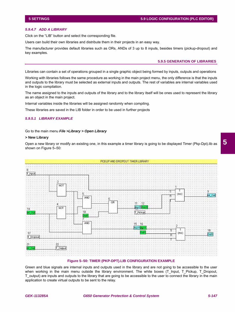
GEK-113285A G650 Generator Protection & Control System 5-147
5 SETTINGS 5.9 LOGIC CONFIGURATION (PLC EDITOR)
5
5.9.4.7 ADD A LIBRARY
Click on the “LIB” button and select the corresponding file.
Users can build their own libraries and distribute them in their projects in an easy way.
The manufacturer provides default libraries such as ORs, ANDs of 3 up to 8 inputs, besides timers (pickup-dropout) andkey examples.
5.9.5 GENERATION OF LIBRARIES
Libraries can contain a set of operations grouped in a single graphic object being formed by inputs, outputs and operations
Working with libraries follows the same procedure as working in the main project menu, the only difference is that the inputsand outputs to the library must be selected as external inputs and outputs. The rest of variables are internal variables usedin the logic compilation.
The name assigned to the inputs and outputs of the library and to the library itself will be ones used to represent the libraryas an object in the main project.
Internal variables inside the libraries will be assigned randomly when compiling.
These libraries are saved in the LIB folder in order to be used in further projects
5.9.5.1 LIBRARY EXAMPLE
Go to the main menu File >Library > Open Library
> New Library
Open a new library or modify an existing one, in this example a timer library is going to be displayed Timer (Pkp-Dpt).lib asshown on Figure 5–50:
Figure 5–50: TIMER (PKP-DPT).LIB CONFIGURATION EXAMPLE
Green and blue signals are internal inputs and outputs used in the library and are not going to be accessible to the userwhen working in the main menu outside the library environment. The white boxes (T_Input, T_Pickup, T_Dropout,T_output) are inputs and outputs to the library that are going to be accessible to the user to connect the library in the mainapplication to create virtual outputs to be sent to the relay.
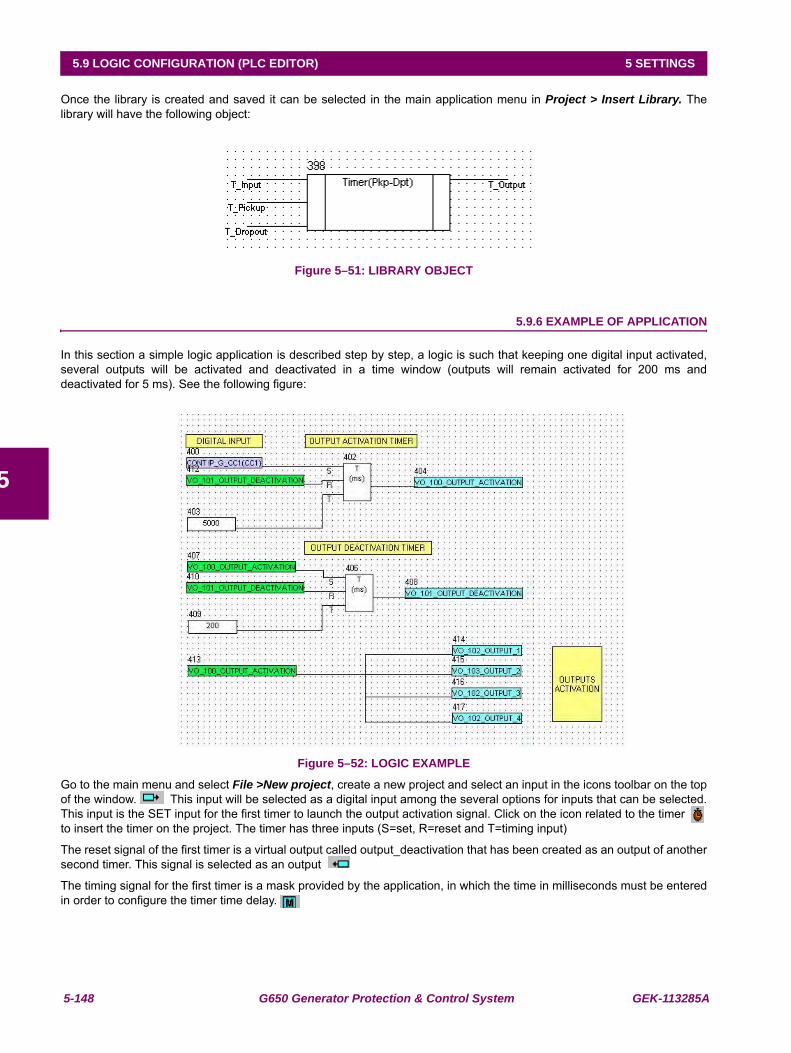
5-148 G650 Generator Protection & Control System GEK-113285A
5.9 LOGIC CONFIGURATION (PLC EDITOR) 5 SETTINGS
5
Once the library is created and saved it can be selected in the main application menu in Project > Insert Library. Thelibrary will have the following object:
Figure 5–51: LIBRARY OBJECT
5.9.6 EXAMPLE OF APPLICATION
In this section a simple logic application is described step by step, a logic is such that keeping one digital input activated,several outputs will be activated and deactivated in a time window (outputs will remain activated for 200 ms anddeactivated for 5 ms). See the following figure:
Figure 5–52: LOGIC EXAMPLE
Go to the main menu and select File >New project, create a new project and select an input in the icons toolbar on the topof the window. This input will be selected as a digital input among the several options for inputs that can be selected.This input is the SET input for the first timer to launch the output activation signal. Click on the icon related to the timer to insert the timer on the project. The timer has three inputs (S=set, R=reset and T=timing input)
The reset signal of the first timer is a virtual output called output_deactivation that has been created as an output of anothersecond timer. This signal is selected as an output
The timing signal for the first timer is a mask provided by the application, in which the time in milliseconds must be enteredin order to configure the timer time delay.
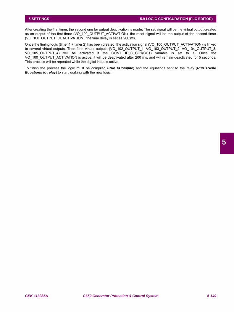
GEK-113285A G650 Generator Protection & Control System 5-149
5 SETTINGS 5.9 LOGIC CONFIGURATION (PLC EDITOR)
5
After creating the first timer, the second one for output deactivation is made. The set signal will be the virtual output createdas an output of the first timer (VO_100_OUTPUT_ACTIVATION), the reset signal will be the output of the second timer(VO_100_OUTPUT_DEACTIVATION), the time delay is set as 200 ms.
Once the timing logic (timer 1 + timer 2) has been created, the activation signal (VO_100_OUTPUT_ACTIVATION) is linkedto several virtual outputs. Therefore, virtual outputs (VO_102_OUTPUT_1, VO_103_OUTPUT_2, VO_104_OUTPUT_3,VO_105_OUTPUT_4) will be activated if the CONT IP_G_CC1(CC1) variable is set to 1. Once theVO_100_OUTPUT_ACTIVATION is active, it will be deactivated after 200 ms, and will remain deactivated for 5 seconds.This process will be repeated while the digital input is active.
To finish the process the logic must be compiled (Run >Compile) and the equations sent to the relay (Run >SendEquations to relay) to start working with the new logic.
5-150 G650 Generator Protection & Control System GEK-113285A
5.9 LOGIC CONFIGURATION (PLC EDITOR) 5 SETTINGS
5
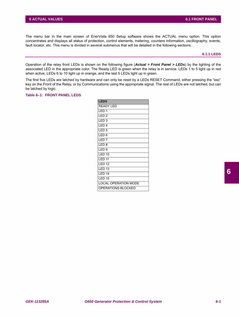
GEK-113285A G650 Generator Protection & Control System 6-1
6 ACTUAL VALUES 6.1 FRONT PANEL
6
6 ACTUAL VALUES 6.1FRONT PANEL
The menu bar in the main screen of EnerVista 650 Setup software shows the ACTUAL menu option. This optionconcentrates and displays all status of protection, control elements, metering, counters information, oscillography, events,fault locator, etc. This menu is divided in several submenus that will be detailed in the following sections.
6.1.1 LEDS
Operation of the relay front LEDs is shown on the following figure (Actual > Front Panel > LEDs) by the lighting of theassociated LED in the appropriate color. The Ready LED is green when the relay is in service. LEDs 1 to 5 light up in redwhen active, LEDs 6 to 10 light up in orange, and the last 5 LEDs light up in green.
The first five LEDs are latched by hardware and can only be reset by a LEDs RESET Command, either pressing the “esc”key on the Front of the Relay, or by Communications using the appropriate signal. The rest of LEDs are not latched, but canbe latched by logic.
Table 6–1: FRONT PANEL LEDSLEDSREADY LEDLED 1LED 2LED 3LED 4LED 5LED 6LED 7LED 8LED 9LED 10LED 11LED 12LED 13LED 14LED 15LOCAL OPERATION MODEOPERATIONS BLOCKED
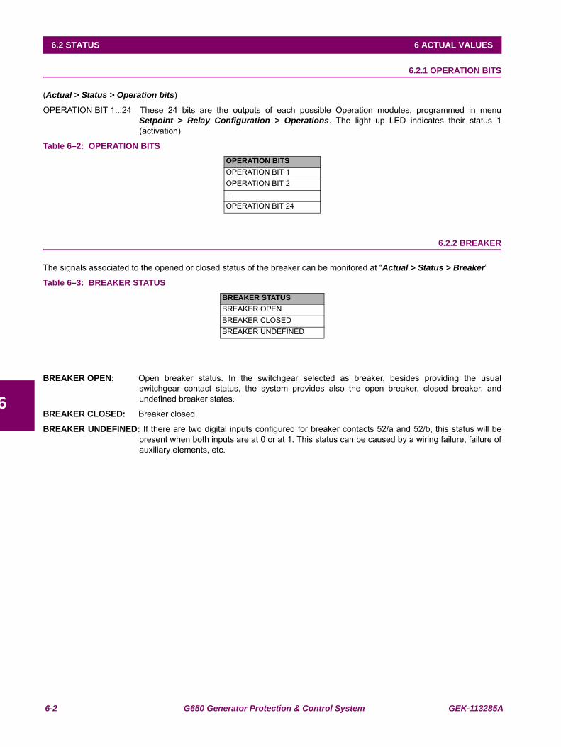
6-2 G650 Generator Protection & Control System GEK-113285A
6.2 STATUS 6 ACTUAL VALUES
6
6.2STATUS 6.2.1 OPERATION BITS
(Actual > Status > Operation bits)
OPERATION BIT 1...24 These 24 bits are the outputs of each possible Operation modules, programmed in menuSetpoint > Relay Configuration > Operations. The light up LED indicates their status 1(activation)
Table 6–2: OPERATION BITS
6.2.2 BREAKER
The signals associated to the opened or closed status of the breaker can be monitored at “Actual > Status > Breaker”
Table 6–3: BREAKER STATUS
BREAKER OPEN: Open breaker status. In the switchgear selected as breaker, besides providing the usualswitchgear contact status, the system provides also the open breaker, closed breaker, andundefined breaker states.
BREAKER CLOSED: Breaker closed.
BREAKER UNDEFINED: If there are two digital inputs configured for breaker contacts 52/a and 52/b, this status will bepresent when both inputs are at 0 or at 1. This status can be caused by a wiring failure, failure ofauxiliary elements, etc.
OPERATION BITSOPERATION BIT 1OPERATION BIT 2…OPERATION BIT 24
BREAKER STATUSBREAKER OPENBREAKER CLOSEDBREAKER UNDEFINED
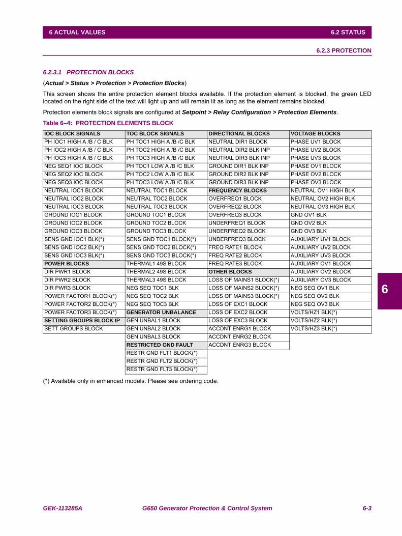
GEK-113285A G650 Generator Protection & Control System 6-3
6 ACTUAL VALUES 6.2 STATUS
6
6.2.3 PROTECTION
6.2.3.1 PROTECTION BLOCKS
(Actual > Status > Protection > Protection Blocks)
This screen shows the entire protection element blocks available. If the protection element is blocked, the green LEDlocated on the right side of the text will light up and will remain lit as long as the element remains blocked.
Protection elements block signals are configured at Setpoint > Relay Configuration > Protection Elements.
Table 6–4: PROTECTION ELEMENTS BLOCK
(*) Available only in enhanced models. Please see ordering code.
IOC BLOCK SIGNALS TOC BLOCK SIGNALS DIRECTIONAL BLOCKS VOLTAGE BLOCKSPH IOC1 HIGH A /B / C BLK PH TOC1 HIGH A /B /C BLK NEUTRAL DIR1 BLOCK PHASE UV1 BLOCKPH IOC2 HIGH A /B / C BLK PH TOC2 HIGH A /B /C BLK NEUTRAL DIR2 BLK INP PHASE UV2 BLOCKPH IOC3 HIGH A /B / C BLK PH TOC3 HIGH A /B /C BLK NEUTRAL DIR3 BLK INP PHASE UV3 BLOCKNEG SEQ1 IOC BLOCK PH TOC1 LOW A /B /C BLK GROUND DIR1 BLK INP PHASE OV1 BLOCKNEG SEQ2 IOC BLOCK PH TOC2 LOW A /B /C BLK GROUND DIR2 BLK INP PHASE OV2 BLOCKNEG SEQ3 IOC BLOCK PH TOC3 LOW A /B /C BLK GROUND DIR3 BLK INP PHASE OV3 BLOCKNEUTRAL IOC1 BLOCK NEUTRAL TOC1 BLOCK FREQUENCY BLOCKS NEUTRAL OV1 HIGH BLKNEUTRAL IOC2 BLOCK NEUTRAL TOC2 BLOCK OVERFREQ1 BLOCK NEUTRAL OV2 HIGH BLKNEUTRAL IOC3 BLOCK NEUTRAL TOC3 BLOCK OVERFREQ2 BLOCK NEUTRAL OV3 HIGH BLKGROUND IOC1 BLOCK GROUND TOC1 BLOCK OVERFREQ3 BLOCK GND OV1 BLKGROUND IOC2 BLOCK GROUND TOC2 BLOCK UNDERFREQ1 BLOCK GND OV2 BLKGROUND IOC3 BLOCK GROUND TOC3 BLOCK UNDERFREQ2 BLOCK GND OV3 BLKSENS GND IOC1 BLK(*) SENS GND TOC1 BLOCK(*) UNDERFREQ3 BLOCK AUXILIARY UV1 BLOCKSENS GND IOC2 BLK(*) SENS GND TOC2 BLOCK(*) FREQ RATE1 BLOCK AUXILIARY UV2 BLOCKSENS GND IOC3 BLK(*) SENS GND TOC3 BLOCK(*) FREQ RATE2 BLOCK AUXILIARY UV3 BLOCKPOWER BLOCKS THERMAL1 49S BLOCK FREQ RATE3 BLOCK AUXILIARY OV1 BLOCKDIR PWR1 BLOCK THERMAL2 49S BLOCK OTHER BLOCKS AUXILIARY OV2 BLOCKDIR PWR2 BLOCK THERMAL3 49S BLOCK LOSS OF MAINS1 BLOCK(*) AUXILIARY OV3 BLOCKDIR PWR3 BLOCK NEG SEQ TOC1 BLK LOSS OF MAINS2 BLOCK(*) NEG SEQ OV1 BLKPOWER FACTOR1 BLOCK(*) NEG SEQ TOC2 BLK LOSS OF MAINS3 BLOCK(*) NEG SEQ OV2 BLKPOWER FACTOR2 BLOCK(*) NEG SEQ TOC3 BLK LOSS OF EXC1 BLOCK NEG SEQ OV3 BLKPOWER FACTOR3 BLOCK(*) GENERATOR UNBALANCE LOSS OF EXC2 BLOCK VOLTS/HZ1 BLK(*)SETTING GROUPS BLOCK IP GEN UNBAL1 BLOCK LOSS OF EXC3 BLOCK VOLTS/HZ2 BLK(*)SETT GROUPS BLOCK GEN UNBAL2 BLOCK ACCDNT ENRG1 BLOCK VOLTS/HZ3 BLK(*)
GEN UNBAL3 BLOCK ACCDNT ENRG2 BLOCKRESTRICTED GND FAULT ACCDNT ENRG3 BLOCKRESTR GND FLT1 BLOCK(*)RESTR GND FLT2 BLOCK(*)RESTR GND FLT3 BLOCK(*)
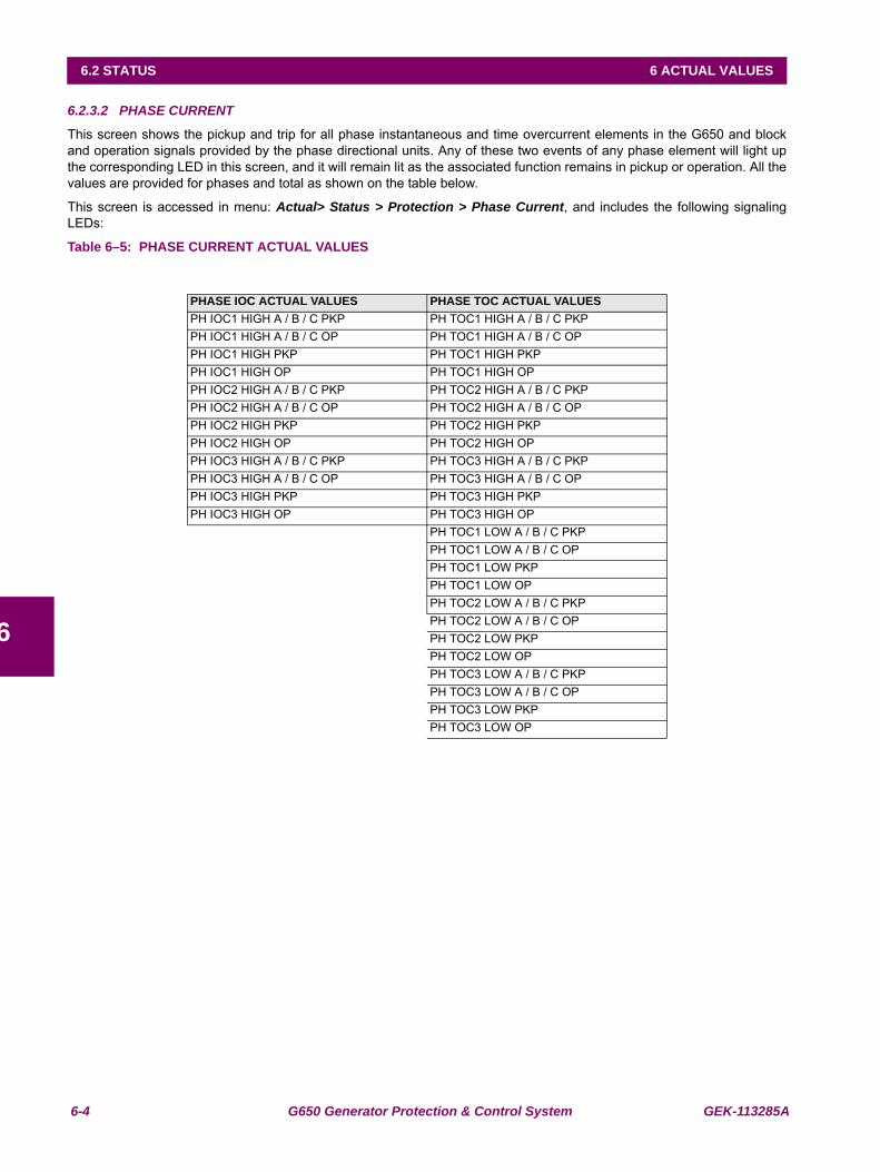
6-4 G650 Generator Protection & Control System GEK-113285A
6.2 STATUS 6 ACTUAL VALUES
6
6.2.3.2 PHASE CURRENT
This screen shows the pickup and trip for all phase instantaneous and time overcurrent elements in the G650 and blockand operation signals provided by the phase directional units. Any of these two events of any phase element will light upthe corresponding LED in this screen, and it will remain lit as the associated function remains in pickup or operation. All thevalues are provided for phases and total as shown on the table below.
This screen is accessed in menu: Actual> Status > Protection > Phase Current, and includes the following signalingLEDs:
Table 6–5: PHASE CURRENT ACTUAL VALUES
PHASE IOC ACTUAL VALUES PHASE TOC ACTUAL VALUESPH IOC1 HIGH A / B / C PKP PH TOC1 HIGH A / B / C PKPPH IOC1 HIGH A / B / C OP PH TOC1 HIGH A / B / C OPPH IOC1 HIGH PKP PH TOC1 HIGH PKPPH IOC1 HIGH OP PH TOC1 HIGH OPPH IOC2 HIGH A / B / C PKP PH TOC2 HIGH A / B / C PKPPH IOC2 HIGH A / B / C OP PH TOC2 HIGH A / B / C OPPH IOC2 HIGH PKP PH TOC2 HIGH PKPPH IOC2 HIGH OP PH TOC2 HIGH OPPH IOC3 HIGH A / B / C PKP PH TOC3 HIGH A / B / C PKPPH IOC3 HIGH A / B / C OP PH TOC3 HIGH A / B / C OPPH IOC3 HIGH PKP PH TOC3 HIGH PKPPH IOC3 HIGH OP PH TOC3 HIGH OP
PH TOC1 LOW A / B / C PKPPH TOC1 LOW A / B / C OPPH TOC1 LOW PKPPH TOC1 LOW OPPH TOC2 LOW A / B / C PKPPH TOC2 LOW A / B / C OPPH TOC2 LOW PKPPH TOC2 LOW OPPH TOC3 LOW A / B / C PKPPH TOC3 LOW A / B / C OPPH TOC3 LOW PKPPH TOC3 LOW OP
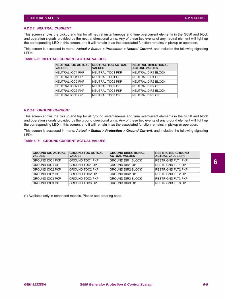
GEK-113285A G650 Generator Protection & Control System 6-5
6 ACTUAL VALUES 6.2 STATUS
6
6.2.3.3 NEUTRAL CURRENT
This screen shows the pickup and trip for all neutral instantaneous and time overcurrent elements in the G650 and blockand operation signals provided by the neutral directional units. Any of these two events of any neutral element will light upthe corresponding LED in this screen, and it will remain lit as the associated function remains in pickup or operation.
This screen is accessed in menu: Actual > Status > Protection > Neutral Current, and includes the following signalingLEDs:
Table 6–6: NEUTRAL CURRENT ACTUAL VALUES
6.2.3.4 GROUND CURRENT
This screen shows the pickup and trip for all ground instantaneous and time overcurrent elements in the G650 and blockand operation signals provided by the ground directional units. Any of these two events of any ground element will light upthe corresponding LED in this screen, and it will remain lit as the associated function remains in pickup or operation.
This screen is accessed in menu: Actual > Status > Protection > Ground Current, and includes the following signalingLEDs:
Table 6–7: GROUND CURRENT ACTUAL VALUES
(*) Available only in enhanced models. Please see ordering code.
NEUTRAL IOC ACTUAL VALUES
NEUTRAL TOC ACTUAL VALUES
NEUTRAL DIRECTIONAL ACTUAL VALUES
NEUTRAL IOC1 PKP NEUTRAL TOC1 PKP NEUTRAL DIR1 BLOCKNEUTRAL IOC1 OP NEUTRAL TOC1 OP NEUTRAL DIR1 OPNEUTRAL IOC2 PKP NEUTRAL TOC2 PKP NEUTRAL DIR2 BLOCKNEUTRAL IOC2 OP NEUTRAL TOC2 OP NEUTRAL DIR2 OPNEUTRAL IOC3 PKP NEUTRAL TOC3 PKP NEUTRAL DIR3 BLOCKNEUTRAL IOC3 OP NEUTRAL TOC3 OP NEUTRAL DIR3 OP
GROUND IOC ACTUAL VALUES
GROUND TOC ACTUAL VALUES
GROUND DIRECTIONAL ACTUAL VALUES
RESTRICTED GROUND ACTUAL VALUES (*)
GROUND IOC1 PKP GROUND TOC1 PKP GROUND DIR1 BLOCK RESTR GND FLT1 PKPGROUND IOC1 OP GROUND TOC1 OP GROUND DIR1 OP RESTR GND FLT1 OPGROUND IOC2 PKP GROUND TOC2 PKP GROUND DIR2 BLOCK RESTR GND FLT2 PKPGROUND IOC2 OP GROUND TOC2 OP GROUND DIR2 OP RESTR GND FLT2 OPGROUND IOC3 PKP GROUND TOC3 PKP GROUND DIR3 BLOCK RESTR GND FLT3 PKPGROUND IOC3 OP GROUND TOC3 OP GROUND DIR3 OP RESTR GND FLT3 OP
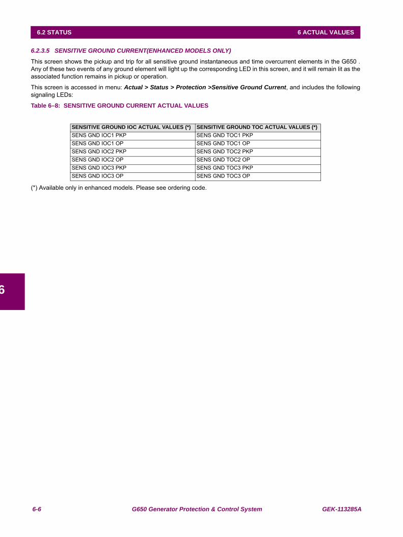
6-6 G650 Generator Protection & Control System GEK-113285A
6.2 STATUS 6 ACTUAL VALUES
6
6.2.3.5 SENSITIVE GROUND CURRENT(ENHANCED MODELS ONLY)
This screen shows the pickup and trip for all sensitive ground instantaneous and time overcurrent elements in the G650 .Any of these two events of any ground element will light up the corresponding LED in this screen, and it will remain lit as theassociated function remains in pickup or operation.
This screen is accessed in menu: Actual > Status > Protection >Sensitive Ground Current, and includes the followingsignaling LEDs:
Table 6–8: SENSITIVE GROUND CURRENT ACTUAL VALUES
(*) Available only in enhanced models. Please see ordering code.
SENSITIVE GROUND IOC ACTUAL VALUES (*) SENSITIVE GROUND TOC ACTUAL VALUES (*)SENS GND IOC1 PKP SENS GND TOC1 PKPSENS GND IOC1 OP SENS GND TOC1 OPSENS GND IOC2 PKP SENS GND TOC2 PKPSENS GND IOC2 OP SENS GND TOC2 OPSENS GND IOC3 PKP SENS GND TOC3 PKPSENS GND IOC3 OP SENS GND TOC3 OP
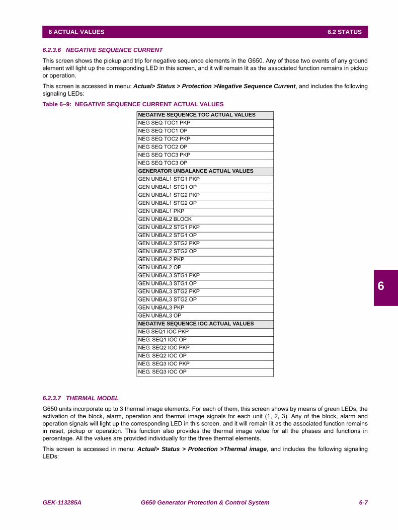
GEK-113285A G650 Generator Protection & Control System 6-7
6 ACTUAL VALUES 6.2 STATUS
6
6.2.3.6 NEGATIVE SEQUENCE CURRENT
This screen shows the pickup and trip for negative sequence elements in the G650. Any of these two events of any groundelement will light up the corresponding LED in this screen, and it will remain lit as the associated function remains in pickupor operation.
This screen is accessed in menu: Actual> Status > Protection >Negative Sequence Current, and includes the followingsignaling LEDs:
Table 6–9: NEGATIVE SEQUENCE CURRENT ACTUAL VALUES
6.2.3.7 THERMAL MODEL
G650 units incorporate up to 3 thermal image elements. For each of them, this screen shows by means of green LEDs, theactivation of the block, alarm, operation and thermal image signals for each unit (1, 2, 3). Any of the block, alarm andoperation signals will light up the corresponding LED in this screen, and it will remain lit as the associated function remainsin reset, pickup or operation. This function also provides the thermal image value for all the phases and functions inpercentage. All the values are provided individually for the three thermal elements.
This screen is accessed in menu: Actual> Status > Protection >Thermal image, and includes the following signalingLEDs:
NEGATIVE SEQUENCE TOC ACTUAL VALUESNEG SEQ TOC1 PKPNEG SEQ TOC1 OPNEG SEQ TOC2 PKPNEG SEQ TOC2 OPNEG SEQ TOC3 PKPNEG SEQ TOC3 OPGENERATOR UNBALANCE ACTUAL VALUESGEN UNBAL1 STG1 PKPGEN UNBAL1 STG1 OPGEN UNBAL1 STG2 PKPGEN UNBAL1 STG2 OPGEN UNBAL1 PKPGEN UNBAL2 BLOCKGEN UNBAL2 STG1 PKPGEN UNBAL2 STG1 OPGEN UNBAL2 STG2 PKPGEN UNBAL2 STG2 OPGEN UNBAL2 PKPGEN UNBAL2 OPGEN UNBAL3 STG1 PKPGEN UNBAL3 STG1 OPGEN UNBAL3 STG2 PKPGEN UNBAL3 STG2 OPGEN UNBAL3 PKPGEN UNBAL3 OPNEGATIVE SEQUENCE IOC ACTUAL VALUESNEG SEQ1 IOC PKPNEG. SEQ1 IOC OPNEG. SEQ2 IOC PKPNEG. SEQ2 IOC OPNEG. SEQ3 IOC PKPNEG. SEQ3 IOC OP
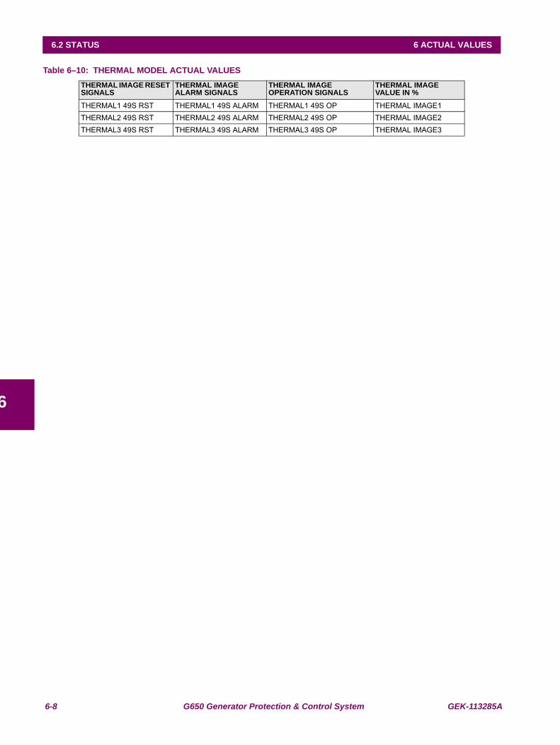
6-8 G650 Generator Protection & Control System GEK-113285A
6.2 STATUS 6 ACTUAL VALUES
6
Table 6–10: THERMAL MODEL ACTUAL VALUES THERMAL IMAGE RESET SIGNALS
THERMAL IMAGE ALARM SIGNALS
THERMAL IMAGE OPERATION SIGNALS
THERMAL IMAGE VALUE IN %
THERMAL1 49S RST THERMAL1 49S ALARM THERMAL1 49S OP THERMAL IMAGE1THERMAL2 49S RST THERMAL2 49S ALARM THERMAL2 49S OP THERMAL IMAGE2THERMAL3 49S RST THERMAL3 49S ALARM THERMAL3 49S OP THERMAL IMAGE3
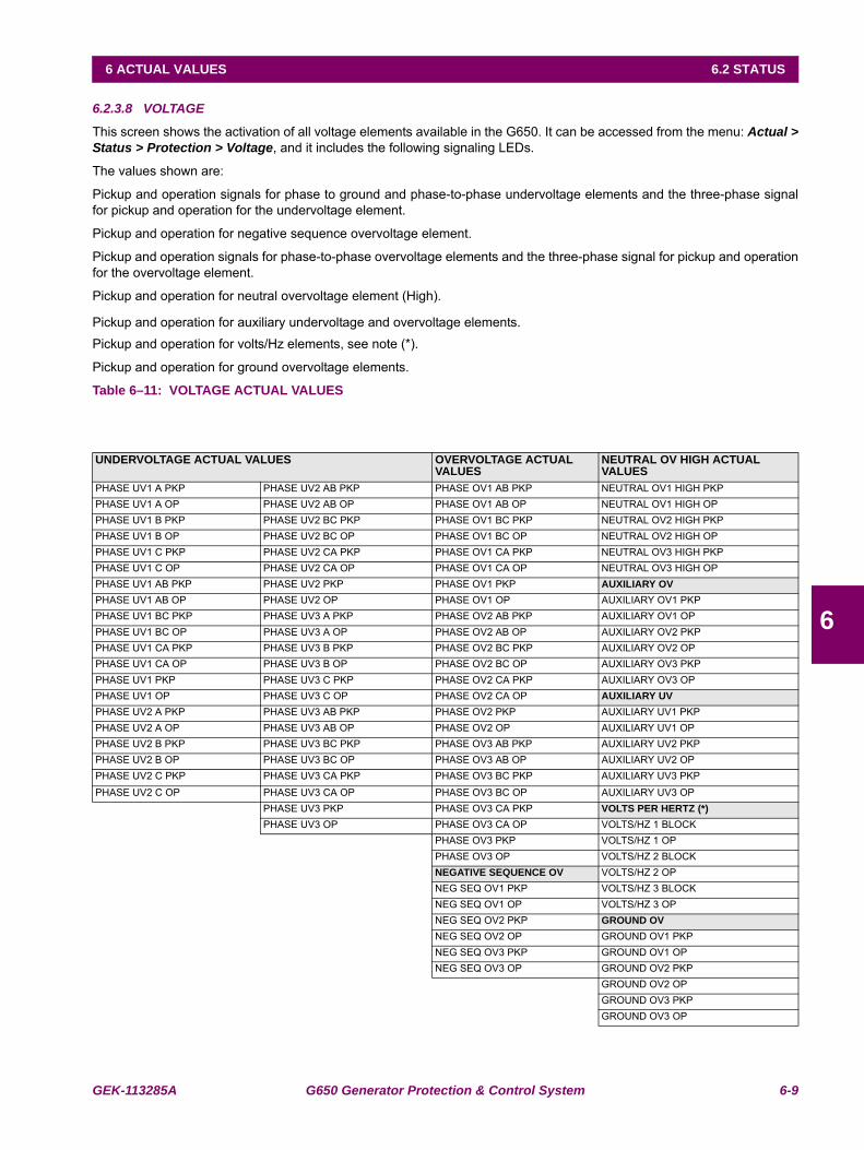
GEK-113285A G650 Generator Protection & Control System 6-9
6 ACTUAL VALUES 6.2 STATUS
6
6.2.3.8 VOLTAGE
This screen shows the activation of all voltage elements available in the G650. It can be accessed from the menu: Actual >Status > Protection > Voltage, and it includes the following signaling LEDs.
The values shown are:
Pickup and operation signals for phase to ground and phase-to-phase undervoltage elements and the three-phase signalfor pickup and operation for the undervoltage element.
Pickup and operation for negative sequence overvoltage element.
Pickup and operation signals for phase-to-phase overvoltage elements and the three-phase signal for pickup and operationfor the overvoltage element.
Pickup and operation for neutral overvoltage element (High).
Pickup and operation for auxiliary undervoltage and overvoltage elements.Pickup and operation for volts/Hz elements, see note (*).
Pickup and operation for ground overvoltage elements.
Table 6–11: VOLTAGE ACTUAL VALUES
UNDERVOLTAGE ACTUAL VALUES OVERVOLTAGE ACTUAL VALUES
NEUTRAL OV HIGH ACTUAL VALUES
PHASE UV1 A PKP PHASE UV2 AB PKP PHASE OV1 AB PKP NEUTRAL OV1 HIGH PKPPHASE UV1 A OP PHASE UV2 AB OP PHASE OV1 AB OP NEUTRAL OV1 HIGH OPPHASE UV1 B PKP PHASE UV2 BC PKP PHASE OV1 BC PKP NEUTRAL OV2 HIGH PKPPHASE UV1 B OP PHASE UV2 BC OP PHASE OV1 BC OP NEUTRAL OV2 HIGH OPPHASE UV1 C PKP PHASE UV2 CA PKP PHASE OV1 CA PKP NEUTRAL OV3 HIGH PKPPHASE UV1 C OP PHASE UV2 CA OP PHASE OV1 CA OP NEUTRAL OV3 HIGH OPPHASE UV1 AB PKP PHASE UV2 PKP PHASE OV1 PKP AUXILIARY OVPHASE UV1 AB OP PHASE UV2 OP PHASE OV1 OP AUXILIARY OV1 PKPPHASE UV1 BC PKP PHASE UV3 A PKP PHASE OV2 AB PKP AUXILIARY OV1 OPPHASE UV1 BC OP PHASE UV3 A OP PHASE OV2 AB OP AUXILIARY OV2 PKPPHASE UV1 CA PKP PHASE UV3 B PKP PHASE OV2 BC PKP AUXILIARY OV2 OPPHASE UV1 CA OP PHASE UV3 B OP PHASE OV2 BC OP AUXILIARY OV3 PKPPHASE UV1 PKP PHASE UV3 C PKP PHASE OV2 CA PKP AUXILIARY OV3 OPPHASE UV1 OP PHASE UV3 C OP PHASE OV2 CA OP AUXILIARY UVPHASE UV2 A PKP PHASE UV3 AB PKP PHASE OV2 PKP AUXILIARY UV1 PKPPHASE UV2 A OP PHASE UV3 AB OP PHASE OV2 OP AUXILIARY UV1 OPPHASE UV2 B PKP PHASE UV3 BC PKP PHASE OV3 AB PKP AUXILIARY UV2 PKPPHASE UV2 B OP PHASE UV3 BC OP PHASE OV3 AB OP AUXILIARY UV2 OPPHASE UV2 C PKP PHASE UV3 CA PKP PHASE OV3 BC PKP AUXILIARY UV3 PKPPHASE UV2 C OP PHASE UV3 CA OP PHASE OV3 BC OP AUXILIARY UV3 OP
PHASE UV3 PKP PHASE OV3 CA PKP VOLTS PER HERTZ (*)PHASE UV3 OP PHASE OV3 CA OP VOLTS/HZ 1 BLOCK
PHASE OV3 PKP VOLTS/HZ 1 OPPHASE OV3 OP VOLTS/HZ 2 BLOCK NEGATIVE SEQUENCE OV VOLTS/HZ 2 OPNEG SEQ OV1 PKP VOLTS/HZ 3 BLOCKNEG SEQ OV1 OP VOLTS/HZ 3 OPNEG SEQ OV2 PKP GROUND OVNEG SEQ OV2 OP GROUND OV1 PKPNEG SEQ OV3 PKP GROUND OV1 OPNEG SEQ OV3 OP GROUND OV2 PKP
GROUND OV2 OPGROUND OV3 PKPGROUND OV3 OP
6-10 G650 Generator Protection & Control System GEK-113285A
6.2 STATUS 6 ACTUAL VALUES
6
Note (*): Only available for enhanced models (see ordering code)
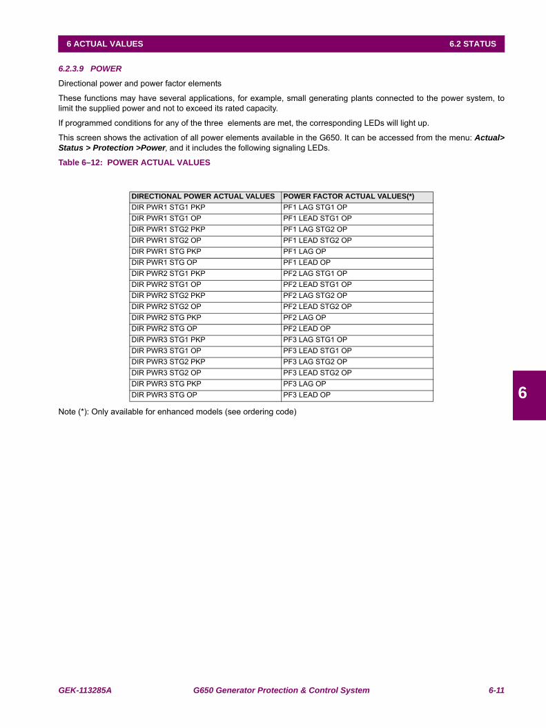
GEK-113285A G650 Generator Protection & Control System 6-11
6 ACTUAL VALUES 6.2 STATUS
6
6.2.3.9 POWER
Directional power and power factor elements
These functions may have several applications, for example, small generating plants connected to the power system, tolimit the supplied power and not to exceed its rated capacity.
If programmed conditions for any of the three elements are met, the corresponding LEDs will light up.
This screen shows the activation of all power elements available in the G650. It can be accessed from the menu: Actual>Status > Protection >Power, and it includes the following signaling LEDs.
Table 6–12: POWER ACTUAL VALUES
Note (*): Only available for enhanced models (see ordering code)
DIRECTIONAL POWER ACTUAL VALUES POWER FACTOR ACTUAL VALUES(*)DIR PWR1 STG1 PKP PF1 LAG STG1 OPDIR PWR1 STG1 OP PF1 LEAD STG1 OPDIR PWR1 STG2 PKP PF1 LAG STG2 OPDIR PWR1 STG2 OP PF1 LEAD STG2 OPDIR PWR1 STG PKP PF1 LAG OPDIR PWR1 STG OP PF1 LEAD OPDIR PWR2 STG1 PKP PF2 LAG STG1 OPDIR PWR2 STG1 OP PF2 LEAD STG1 OPDIR PWR2 STG2 PKP PF2 LAG STG2 OPDIR PWR2 STG2 OP PF2 LEAD STG2 OPDIR PWR2 STG PKP PF2 LAG OPDIR PWR2 STG OP PF2 LEAD OPDIR PWR3 STG1 PKP PF3 LAG STG1 OPDIR PWR3 STG1 OP PF3 LEAD STG1 OPDIR PWR3 STG2 PKP PF3 LAG STG2 OPDIR PWR3 STG2 OP PF3 LEAD STG2 OPDIR PWR3 STG PKP PF3 LAG OPDIR PWR3 STG OP PF3 LEAD OP
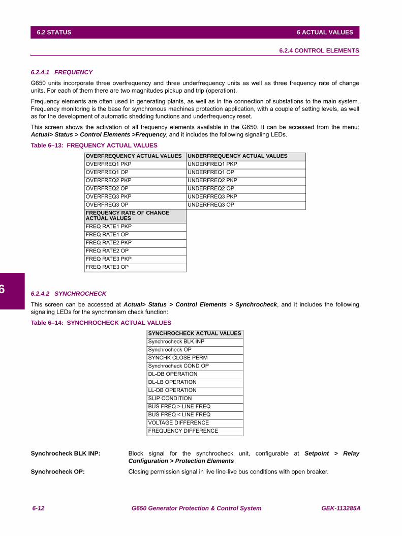
6-12 G650 Generator Protection & Control System GEK-113285A
6.2 STATUS 6 ACTUAL VALUES
6
6.2.4 CONTROL ELEMENTS
6.2.4.1 FREQUENCY
G650 units incorporate three overfrequency and three underfrequency units as well as three frequency rate of changeunits. For each of them there are two magnitudes pickup and trip (operation).
Frequency elements are often used in generating plants, as well as in the connection of substations to the main system.Frequency monitoring is the base for synchronous machines protection application, with a couple of setting levels, as wellas for the development of automatic shedding functions and underfrequency reset.
This screen shows the activation of all frequency elements available in the G650. It can be accessed from the menu:Actual> Status > Control Elements >Frequency, and it includes the following signaling LEDs.
Table 6–13: FREQUENCY ACTUAL VALUES
6.2.4.2 SYNCHROCHECK
This screen can be accessed at Actual> Status > Control Elements > Synchrocheck, and it includes the followingsignaling LEDs for the synchronism check function:
Table 6–14: SYNCHROCHECK ACTUAL VALUES
Synchrocheck BLK INP: Block signal for the synchrocheck unit, configurable at Setpoint > RelayConfiguration > Protection Elements
Synchrocheck OP: Closing permission signal in live line-live bus conditions with open breaker.
OVERFREQUENCY ACTUAL VALUES UNDERFREQUENCY ACTUAL VALUESOVERFREQ1 PKP UNDERFREQ1 PKPOVERFREQ1 OP UNDERFREQ1 OPOVERFREQ2 PKP UNDERFREQ2 PKPOVERFREQ2 OP UNDERFREQ2 OPOVERFREQ3 PKP UNDERFREQ3 PKPOVERFREQ3 OP UNDERFREQ3 OPFREQUENCY RATE OF CHANGE ACTUAL VALUESFREQ RATE1 PKPFREQ RATE1 OPFREQ RATE2 PKPFREQ RATE2 OPFREQ RATE3 PKPFREQ RATE3 OP
SYNCHROCHECK ACTUAL VALUESSynchrocheck BLK INPSynchrocheck OPSYNCHK CLOSE PERMSynchrocheck COND OPDL-DB OPERATIONDL-LB OPERATIONLL-DB OPERATIONSLIP CONDITIONBUS FREQ > LINE FREQBUS FREQ < LINE FREQVOLTAGE DIFFERENCEFREQUENCY DIFFERENCE
GEK-113285A G650 Generator Protection & Control System 6-13
6 ACTUAL VALUES 6.2 STATUS
6
SYNCHK CLOSE PERM: General Closing permission of the Synchronism unit. It contemplates all possiblesituations, live line-live bus conditions, and the closing permission logics (dead line-dead bus, live line- dead bus, dead line-live bus). Note: in case the Function isdisabled, the Closing permission signal will be activated in order not to interfere withpossible logics where it is included. If the synchronism unit is enabled, this signal willonly be activated in the closing conditions established by setting.
Synchrocheck COND OP: Closing permission according to permission logics (DL-DB, LL-DB, DL-LB).
DL-DB OPERATION: Closing permission in dead line – dead bus condition.
DL-LB OPERATION: Closing permission in dead line – live bus condition.
LL-DB OPERATION: Closing permission in live line – dead bus condition.
SLIP CONDITION: Internal signal indicating frequency slip between the line voltage and bus voltagephasors.
BUS FREQ > LINE FREQ: Busbar Frequency higher than line frequency
BUS FREQ < LINE FREQ: Busbar Frequency lower than line frequency
VOLTAGE DIFFERENCE: Voltage difference between the line and the busbar in volts (secondary values), onlyavailable if the Synchrocheck element is enabled.
FREQ. DIFFERENCE: Frequency difference between the line and the busbar in Hz, only available if theSynchrocheck element is enabled.
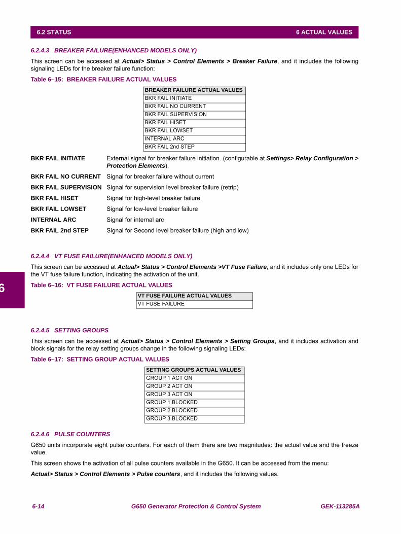
6-14 G650 Generator Protection & Control System GEK-113285A
6.2 STATUS 6 ACTUAL VALUES
6
6.2.4.3 BREAKER FAILURE(ENHANCED MODELS ONLY)
This screen can be accessed at Actual> Status > Control Elements > Breaker Failure, and it includes the followingsignaling LEDs for the breaker failure function:
Table 6–15: BREAKER FAILURE ACTUAL VALUES
BKR FAIL INITIATE External signal for breaker failure initiation. (configurable at Settings> Relay Configuration >Protection Elements).
BKR FAIL NO CURRENT Signal for breaker failure without current
BKR FAIL SUPERVISION Signal for supervision level breaker failure (retrip)
BKR FAIL HISET Signal for high-level breaker failure
BKR FAIL LOWSET Signal for low-level breaker failure
INTERNAL ARC Signal for internal arc
BKR FAIL 2nd STEP Signal for Second level breaker failure (high and low)
6.2.4.4 VT FUSE FAILURE(ENHANCED MODELS ONLY)
This screen can be accessed at Actual> Status > Control Elements >VT Fuse Failure, and it includes only one LEDs forthe VT fuse failure function, indicating the activation of the unit.
Table 6–16: VT FUSE FAILURE ACTUAL VALUES
6.2.4.5 SETTING GROUPS
This screen can be accessed at Actual> Status > Control Elements > Setting Groups, and it includes activation andblock signals for the relay setting groups change in the following signaling LEDs:
Table 6–17: SETTING GROUP ACTUAL VALUES
6.2.4.6 PULSE COUNTERS
G650 units incorporate eight pulse counters. For each of them there are two magnitudes: the actual value and the freezevalue.
This screen shows the activation of all pulse counters available in the G650. It can be accessed from the menu:
Actual> Status > Control Elements > Pulse counters, and it includes the following values.
BREAKER FAILURE ACTUAL VALUESBKR FAIL INITIATEBKR FAIL NO CURRENTBKR FAIL SUPERVISIONBKR FAIL HISETBKR FAIL LOWSETINTERNAL ARCBKR FAIL 2nd STEP
VT FUSE FAILURE ACTUAL VALUESVT FUSE FAILURE
SETTING GROUPS ACTUAL VALUESGROUP 1 ACT ONGROUP 2 ACT ONGROUP 3 ACT ONGROUP 1 BLOCKEDGROUP 2 BLOCKEDGROUP 3 BLOCKED
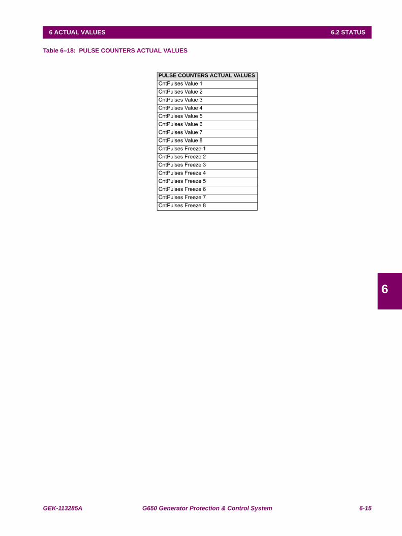
GEK-113285A G650 Generator Protection & Control System 6-15
6 ACTUAL VALUES 6.2 STATUS
6
Table 6–18: PULSE COUNTERS ACTUAL VALUES
PULSE COUNTERS ACTUAL VALUESCntPulses Value 1CntPulses Value 2CntPulses Value 3CntPulses Value 4CntPulses Value 5CntPulses Value 6CntPulses Value 7CntPulses Value 8CntPulses Freeze 1CntPulses Freeze 2CntPulses Freeze 3CntPulses Freeze 4CntPulses Freeze 5CntPulses Freeze 6CntPulses Freeze 7CntPulses Freeze 8
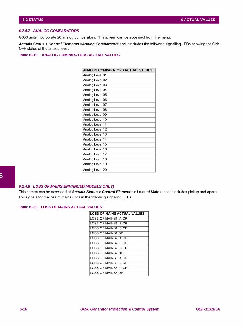
6-16 G650 Generator Protection & Control System GEK-113285A
6.2 STATUS 6 ACTUAL VALUES
6
6.2.4.7 ANALOG COMPARATORS
G650 units incorporate 20 analog comparators. This screen can be accessed from the menu:
Actual> Status > Control Elements >Analog Comparators and it includes the following signalling LEDs showing the ON/OFF status of the analog level.
Table 6–19: ANALOG COMPARATORS ACTUAL VALUES
6.2.4.8 LOSS OF MAINS(ENHANCED MODELS ONLY)This screen can be accessed at Actual> Status > Control Elements > Loss of Mains, and it includes pickup and opera-tion signals for the loss of mains units in the following signaling LEDs:
Table 6–20: LOSS OF MAINS ACTUAL VALUES
ANALOG COMPARATORS ACTUAL VALUESAnalog Level 01Analog Level 02Analog Level 03Analog Level 04Analog Level 05Analog Level 06Analog Level 07Analog Level 08Analog Level 09Analog Level 10Analog Level 11Analog Level 12Analog Level 13Analog Level 14Analog Level 15Analog Level 16Analog Level 17Analog Level 18Analog Level 19
Analog Level 20
LOSS OF MAINS ACTUAL VALUESLOSS OF MAINS1 A OPLOSS OF MAINS1 B OPLOSS OF MAINS1 C OPLOSS OF MAINS1 OPLOSS OF MAINS2 A OPLOSS OF MAINS2 B OPLOSS OF MAINS2 C OPLOSS OF MAINS2 OPLOSS OF MAINS3 A OPLOSS OF MAINS3 B OPLOSS OF MAINS3 C OPLOSS OF MAINS3 OP
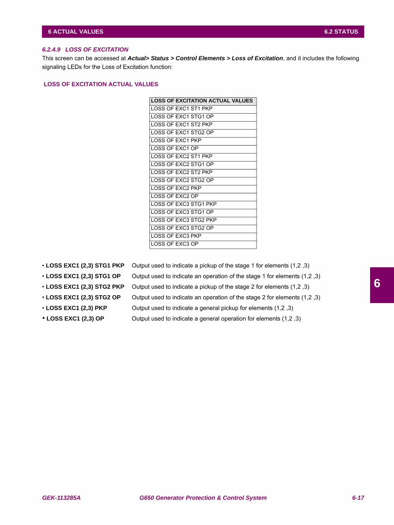
GEK-113285A G650 Generator Protection & Control System 6-17
6 ACTUAL VALUES 6.2 STATUS
6
6.2.4.9 LOSS OF EXCITATIONThis screen can be accessed at Actual> Status > Control Elements > Loss of Excitation, and it includes the following signaling LEDs for the Loss of Excitation function:
LOSS OF EXCITATION ACTUAL VALUES
• LOSS EXC1 (2,3) STG1 PKP Output used to indicate a pickup of the stage 1 for elements (1,2 ,3)
• LOSS EXC1 (2,3) STG1 OP Output used to indicate an operation of the stage 1 for elements (1,2 ,3)
• LOSS EXC1 (2,3) STG2 PKP Output used to indicate a pickup of the stage 2 for elements (1,2 ,3)
• LOSS EXC1 (2,3) STG2 OP Output used to indicate an operation of the stage 2 for elements (1,2 ,3)
• LOSS EXC1 (2,3) PKP Output used to indicate a general pickup for elements (1,2 ,3)
• LOSS EXC1 (2,3) OP Output used to indicate a general operation for elements (1,2 ,3)
LOSS OF EXCITATION ACTUAL VALUESLOSS OF EXC1 ST1 PKPLOSS OF EXC1 STG1 OPLOSS OF EXC1 ST2 PKPLOSS OF EXC1 STG2 OPLOSS OF EXC1 PKPLOSS OF EXC1 OPLOSS OF EXC2 ST1 PKPLOSS OF EXC2 STG1 OPLOSS OF EXC2 ST2 PKPLOSS OF EXC2 STG2 OPLOSS OF EXC2 PKPLOSS OF EXC2 OPLOSS OF EXC3 STG1 PKPLOSS OF EXC3 STG1 OPLOSS OF EXC3 STG2 PKPLOSS OF EXC3 STG2 OPLOSS OF EXC3 PKPLOSS OF EXC3 OP
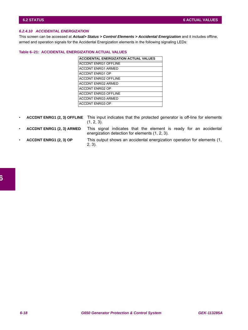
6-18 G650 Generator Protection & Control System GEK-113285A
6.2 STATUS 6 ACTUAL VALUES
6
6.2.4.10 ACCIDENTAL ENERGIZATIONThis screen can be accessed at Actual> Status > Control Elements > Accidental Energization and it includes offline, armed and operation signals for the Accidental Energization elements in the following signaling LEDs:
Table 6–21: ACCIDENTAL ENERGIZATION ACTUAL VALUES
• ACCDNT ENRG1 (2, 3) OFFLINE This input indicates that the protected generator is off-line for elements(1, 2, 3).
• ACCDNT ENRG1 (2, 3) ARMED This signal indicates that the element is ready for an accidentalenergization detection for elements (1, 2, 3).
• ACCDNT ENRG1 (2, 3) OP This output shows an accidental energization operation for elements (1,2, 3).
ACCIDENTAL ENERGIZATION ACTUAL VALUESACCDNT ENRG1 OFFLINEACCDNT ENRG1 ARMEDACCDNT ENRG1 OPACCDNT ENRG2 OFFLINEACCDNT ENRG2 ARMEDACCDNT ENRG2 OPACCDNT ENRG3 OFFLINEACCDNT ENRG3 ARMEDACCDNT ENRG3 OP
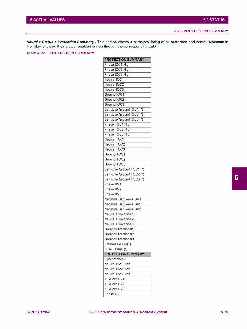
GEK-113285A G650 Generator Protection & Control System 6-19
6 ACTUAL VALUES 6.2 STATUS
6
6.2.5 PROTECTION SUMMARY
Actual > Status > Protection Summary . This screen shows a complete listing of all protection and control elements inthe relay, showing their status (enabled or not) through the corresponding LED.
Table 6–22: PROTECTION SUMMARYPROTECTION SUMMARYPhase IOC1 HighPhase IOC2 HighPhase IOC3 HighNeutral IOC1Neutral IOC2Neutral IOC3Ground IOC1Ground IOC2Ground IOC3Sensitive Ground IOC1 (*)Sensitive Ground IOC2 (*)Sensitive Ground IOC3 (*)Phase TOC1 HighPhase TOC2 HighPhase TOC3 HighNeutral TOC1Neutral TOC2Neutral TOC3Ground TOC1Ground TOC2Ground TOC3Sensitive Ground TOC1 (*)Sensitive Ground TOC2 (*)Sensitive Ground TOC3 (*)Phase UV1Phase UV2Phase UV3Negative Sequence OV1Negative Sequence OV2Negative Sequence OV3Neutral Directional1Neutral Directional2Neutral Directional3Ground Directional1Ground Directional2Ground Directional3Breaker Failure(*)Fuse Failure (*)PROTECTION SUMMARYSynchrocheckNeutral OV1 HighNeutral OV2 HighNeutral OV3 HighAuxiliary UV1Auxiliary UV2Auxiliary UV3Phase OV1
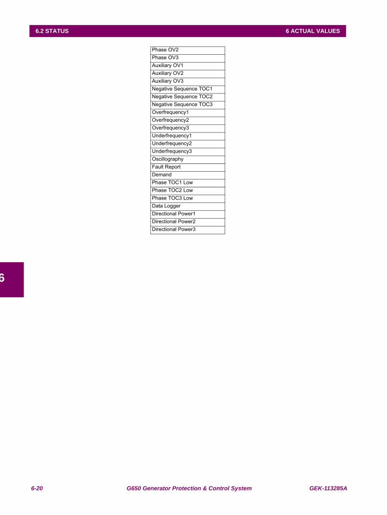
6-20 G650 Generator Protection & Control System GEK-113285A
6.2 STATUS 6 ACTUAL VALUES
6
Phase OV2Phase OV3Auxiliary OV1Auxiliary OV2Auxiliary OV3Negative Sequence TOC1Negative Sequence TOC2Negative Sequence TOC3Overfrequency1Overfrequency2Overfrequency3Underfrequency1Underfrequency2Underfrequency3OscillographyFault ReportDemandPhase TOC1 LowPhase TOC2 LowPhase TOC3 LowData LoggerDirectional Power1Directional Power2Directional Power3
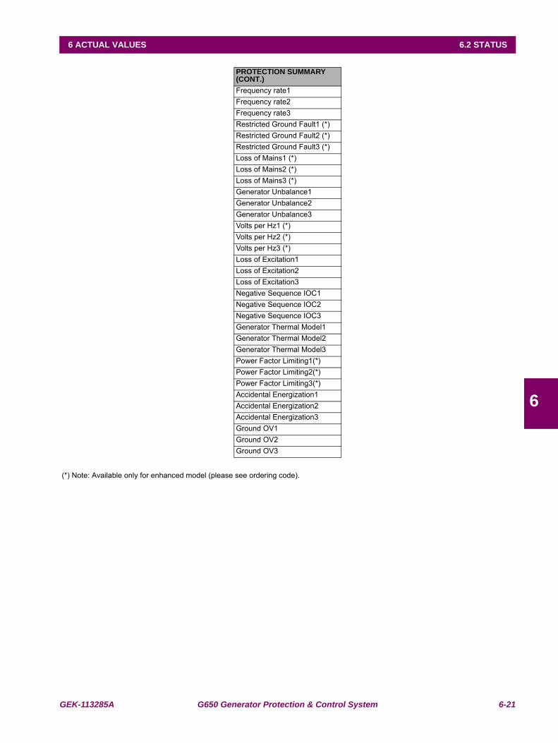
GEK-113285A G650 Generator Protection & Control System 6-21
6 ACTUAL VALUES 6.2 STATUS
6
(*) Note: Available only for enhanced model (please see ordering code).
PROTECTION SUMMARY (CONT.)Frequency rate1Frequency rate2Frequency rate3Restricted Ground Fault1 (*)Restricted Ground Fault2 (*)Restricted Ground Fault3 (*)Loss of Mains1 (*)Loss of Mains2 (*)Loss of Mains3 (*)Generator Unbalance1Generator Unbalance2Generator Unbalance3Volts per Hz1 (*)Volts per Hz2 (*)Volts per Hz3 (*)Loss of Excitation1Loss of Excitation2Loss of Excitation3Negative Sequence IOC1Negative Sequence IOC2Negative Sequence IOC3Generator Thermal Model1Generator Thermal Model2Generator Thermal Model3Power Factor Limiting1(*)Power Factor Limiting2(*)Power Factor Limiting3(*)Accidental Energization1Accidental Energization2Accidental Energization3Ground OV1Ground OV2Ground OV3
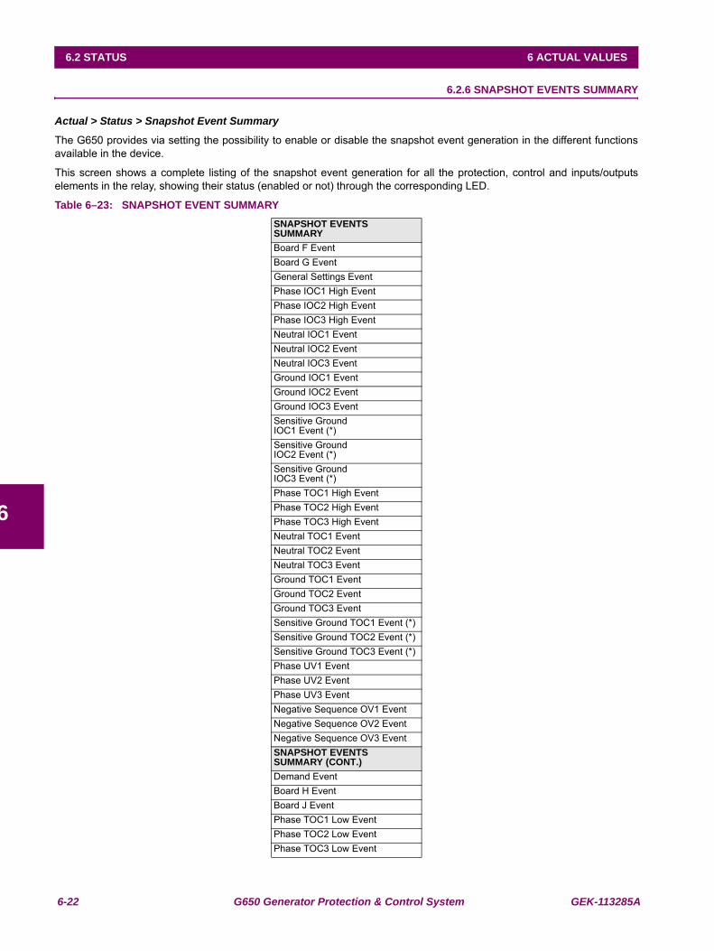
6-22 G650 Generator Protection & Control System GEK-113285A
6.2 STATUS 6 ACTUAL VALUES
6
6.2.6 SNAPSHOT EVENTS SUMMARY
Actual > Status > Snapshot Event Summary
The G650 provides via setting the possibility to enable or disable the snapshot event generation in the different functionsavailable in the device.
This screen shows a complete listing of the snapshot event generation for all the protection, control and inputs/outputselements in the relay, showing their status (enabled or not) through the corresponding LED.
Table 6–23: SNAPSHOT EVENT SUMMARYSNAPSHOT EVENTS SUMMARYBoard F EventBoard G EventGeneral Settings EventPhase IOC1 High EventPhase IOC2 High EventPhase IOC3 High EventNeutral IOC1 EventNeutral IOC2 EventNeutral IOC3 EventGround IOC1 EventGround IOC2 EventGround IOC3 EventSensitive Ground IOC1 Event (*)Sensitive Ground IOC2 Event (*)Sensitive Ground IOC3 Event (*)Phase TOC1 High EventPhase TOC2 High EventPhase TOC3 High EventNeutral TOC1 EventNeutral TOC2 EventNeutral TOC3 EventGround TOC1 EventGround TOC2 EventGround TOC3 EventSensitive Ground TOC1 Event (*)Sensitive Ground TOC2 Event (*)Sensitive Ground TOC3 Event (*)Phase UV1 EventPhase UV2 EventPhase UV3 EventNegative Sequence OV1 EventNegative Sequence OV2 EventNegative Sequence OV3 EventSNAPSHOT EVENTS SUMMARY (CONT.)Demand EventBoard H EventBoard J EventPhase TOC1 Low EventPhase TOC2 Low EventPhase TOC3 Low Event

GEK-113285A G650 Generator Protection & Control System 6-23
6 ACTUAL VALUES 6.2 STATUS
6
Switchgear1 EventSwitchgear2 EventSwitchgear3 EventSwitchgear4 EventSwitchgear5 EventSwitchgear6 EventSwitchgear7 EventSwitchgear8 EventSwitchgear9 EventSwitchgear10 EventSwitchgear11 EventSwitchgear12 EventSwitchgear13 EventSwitchgear14 EventSwitchgear15 EventSwitchgear16 EventBreaker Settings EventDirectional Power1 EventDirectional Power2 EventDirectional Power3 EventAnalog Comparators EventFrequency rate1 EventFrequency rate2 EventFrequency rate3 EventRestricted Ground Fault1 Event (*)Restricted Ground Fault2 Event (*)Restricted Ground Fault3 Event (*)Loss of Mains1 Event (*)Loss of Mains2 Event (*)Loss of Mains3 Event (*)Generator Unbalance1 EventGenerator Unbalance2 EventGenerator Unbalance3 EventVolts per Hertz1 Event (*)Volts per Hertz2 Event (*)Volts per Hertz3 Event (*)Loss of Excitation1 EventLoss of Excitation2 EventLoss of Excitation3 EventNegative Sequence IOC1 EventNegative Sequence IOC2 EventNegative Sequence IOC3 EventGenerator Thermal Model1 EventGenerator Thermal Model2 EventGenerator Thermal Model3 EventPwr Factor Limiting1 Event(*)Pwr Factor Limiting2 Event(*)Pwr Factor Limiting3 Event(*)Accidental Energization1 EventAccidental Energization2 EventAccidental Energization3 EventGround OV1 Event
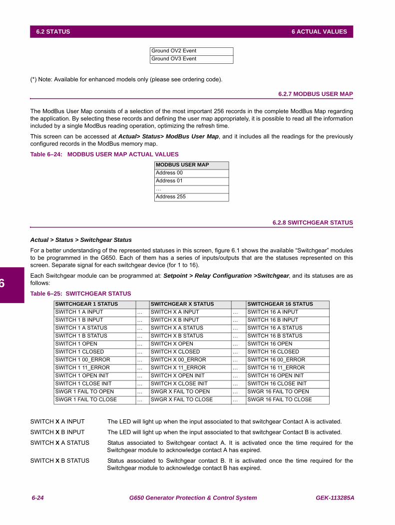
6-24 G650 Generator Protection & Control System GEK-113285A
6.2 STATUS 6 ACTUAL VALUES
6
(*) Note: Available for enhanced models only (please see ordering code).
6.2.7 MODBUS USER MAP
The ModBus User Map consists of a selection of the most important 256 records in the complete ModBus Map regardingthe application. By selecting these records and defining the user map appropriately, it is possible to read all the informationincluded by a single ModBus reading operation, optimizing the refresh time.
This screen can be accessed at Actual> Status> ModBus User Map, and it includes all the readings for the previouslyconfigured records in the ModBus memory map.
Table 6–24: MODBUS USER MAP ACTUAL VALUES
6.2.8 SWITCHGEAR STATUS
Actual > Status > Switchgear Status
For a better understanding of the represented statuses in this screen, figure 6.1 shows the available “Switchgear” modulesto be programmed in the G650. Each of them has a series of inputs/outputs that are the statuses represented on thisscreen. Separate signal for each switchgear device (for 1 to 16).
Each Switchgear module can be programmed at: Setpoint > Relay Configuration >Switchgear, and its statuses are asfollows:
Table 6–25: SWITCHGEAR STATUS
SWITCH X A INPUT The LED will light up when the input associated to that switchgear Contact A is activated.
SWITCH X B INPUT The LED will light up when the input associated to that switchgear Contact B is activated.
SWITCH X A STATUS Status associated to Switchgear contact A. It is activated once the time required for theSwitchgear module to acknowledge contact A has expired.
SWITCH X B STATUS Status associated to Switchgear contact B. It is activated once the time required for theSwitchgear module to acknowledge contact B has expired.
Ground OV2 EventGround OV3 Event
MODBUS USER MAP Address 00Address 01…Address 255
SWITCHGEAR 1 STATUS SWITCHGEAR X STATUS SWITCHGEAR 16 STATUSSWITCH 1 A INPUT … SWITCH X A INPUT … SWITCH 16 A INPUTSWITCH 1 B INPUT … SWITCH X B INPUT … SWITCH 16 B INPUTSWITCH 1 A STATUS … SWITCH X A STATUS … SWITCH 16 A STATUSSWITCH 1 B STATUS … SWITCH X B STATUS … SWITCH 16 B STATUSSWITCH 1 OPEN … SWITCH X OPEN … SWITCH 16 OPENSWITCH 1 CLOSED … SWITCH X CLOSED … SWITCH 16 CLOSEDSWITCH 1 00_ERROR … SWITCH X 00_ERROR … SWITCH 16 00_ERRORSWITCH 1 11_ERROR … SWITCH X 11_ERROR … SWITCH 16 11_ERRORSWITCH 1 OPEN INIT … SWITCH X OPEN INIT … SWITCH 16 OPEN INITSWITCH 1 CLOSE INIT … SWITCH X CLOSE INIT … SWITCH 16 CLOSE INITSWGR 1 FAIL TO OPEN … SWGR X FAIL TO OPEN … SWGR 16 FAIL TO OPENSWGR 1 FAIL TO CLOSE … SWGR X FAIL TO CLOSE … SWGR 16 FAIL TO CLOSE
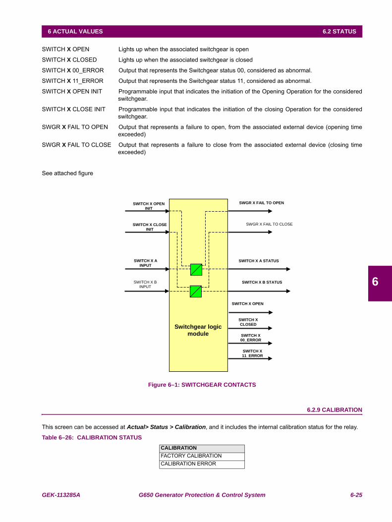
GEK-113285A G650 Generator Protection & Control System 6-25
6 ACTUAL VALUES 6.2 STATUS
6
SWITCH X OPEN Lights up when the associated switchgear is open
SWITCH X CLOSED Lights up when the associated switchgear is closed
SWITCH X 00_ERROR Output that represents the Switchgear status 00, considered as abnormal.
SWITCH X 11_ERROR Output that represents the Switchgear status 11, considered as abnormal.
SWITCH X OPEN INIT Programmable input that indicates the initiation of the Opening Operation for the consideredswitchgear.
SWITCH X CLOSE INIT Programmable input that indicates the initiation of the closing Operation for the consideredswitchgear.
SWGR X FAIL TO OPEN Output that represents a failure to open, from the associated external device (opening timeexceeded)
SWGR X FAIL TO CLOSE Output that represents a failure to close from the associated external device (closing timeexceeded)
See attached figure
Figure 6–1: SWITCHGEAR CONTACTS
6.2.9 CALIBRATION
This screen can be accessed at Actual> Status > Calibration, and it includes the internal calibration status for the relay.
Table 6–26: CALIBRATION STATUSCALIBRATIONFACTORY CALIBRATIONCALIBRATION ERROR
SWGR X FAIL TO OPEN
SWGR X FAIL TO CLOSE
SWITCH X OPEN
INIT
SWITCH X CLOSE
INIT
SWITCH X B INPUT
SWITCH X A STATUS SWITCH X A
INPUT
SWITCH X B STATUS
SWITCH X OPEN
SWITCH X
CLOSED
SWITCH X 00_ERROR
SWITCH X 11_ERROR
Switchgear logic
module
6-26 G650 Generator Protection & Control System GEK-113285A
6.2 STATUS 6 ACTUAL VALUES
6
FACTORY CALIBRATION: This value will be active when the relay calibration settings are the default values (nocalibration).
CALIBRATION ERROR: Error shown when there is a problem in the calibration settings (wrong values).

GEK-113285A G650 Generator Protection & Control System 6-27
6 ACTUAL VALUES 6.2 STATUS
6
6.2.10 FLEX CURVES
This screen can be accessed at Actual> Status > Flex Curves, and it includes the internal flex curves status.
If the LED associated to the FlexCurve status is lit up, this indicates that the user curve has been configured with newvalues (not default values).
Table 6–27: FLEX CURVES STATUS
6.2.11 SYSTEM INFO
This screen can be accessed at Actual> Status > System Info. It can monitor the system parameters and the internalstatus of the Relay operative system.
6.2.12 RECORD STATUS
This screen shows part of the information related to the different records stored in the Relay, such as:
6.2.12.1 FAULT REPORTS
Actual> Status > Records Status > Fault Reports
Table 6–28: FAULT REPORT STATUS
FAULT REPORT TRIGG: This signal indicates whether the signal that initiates the calculation of the distance to the faulthas been activated.
CLEAR FAULT REPORTS: This signal indicates the reset of fault reports.
FAULT DATE: Date and time of the last fault produced in the relay. In format (Day/Month/yearHour:minutes:seconds.milliseconds)
FAULT TYPE: Type of the last fault produced in the Relay (phase to ground, phase to phase, three-phase,etc).
FAULT LOCATION: Location of the last fault produced in the relay.
FAULT REPORT NUMBER: Number of fault reports available in the relay (ten is the maximum number of recordssupported by the relay).
FLEX CURVES STATUSFLEXCURVE A STATUSFLEXCURVE B STATUSFLEXCURVE C STATUSFLEXCURVE D STATUS
FAULT REPORT STATUSFAULT REPORT TRIGGCLEAR FAULT REPORTSFAULT DATEFAULT TYPEFAULT LOCATIONFAULT REPORT NUMBER
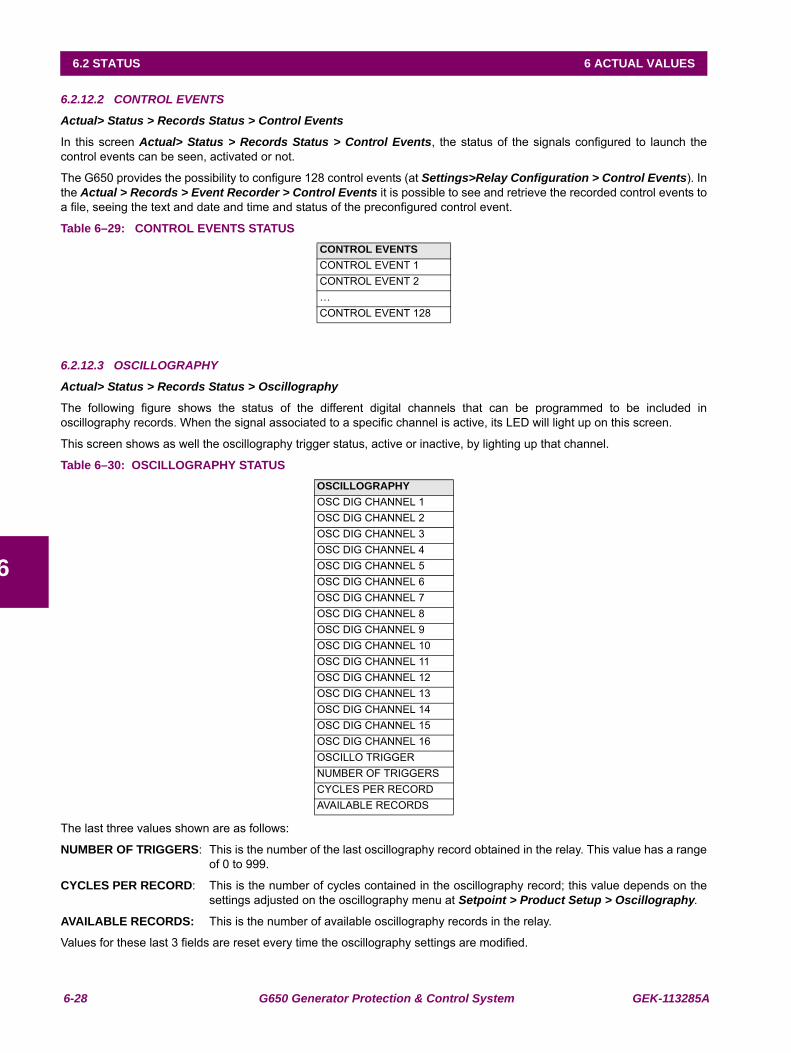
6-28 G650 Generator Protection & Control System GEK-113285A
6.2 STATUS 6 ACTUAL VALUES
6
6.2.12.2 CONTROL EVENTS
Actual> Status > Records Status > Control Events
In this screen Actual> Status > Records Status > Control Events, the status of the signals configured to launch thecontrol events can be seen, activated or not.
The G650 provides the possibility to configure 128 control events (at Settings>Relay Configuration > Control Events). Inthe Actual > Records > Event Recorder > Control Events it is possible to see and retrieve the recorded control events toa file, seeing the text and date and time and status of the preconfigured control event.
Table 6–29: CONTROL EVENTS STATUS
6.2.12.3 OSCILLOGRAPHY
Actual> Status > Records Status > Oscillography
The following figure shows the status of the different digital channels that can be programmed to be included inoscillography records. When the signal associated to a specific channel is active, its LED will light up on this screen.
This screen shows as well the oscillography trigger status, active or inactive, by lighting up that channel.
Table 6–30: OSCILLOGRAPHY STATUS
The last three values shown are as follows:
NUMBER OF TRIGGERS: This is the number of the last oscillography record obtained in the relay. This value has a rangeof 0 to 999.
CYCLES PER RECORD: This is the number of cycles contained in the oscillography record; this value depends on thesettings adjusted on the oscillography menu at Setpoint > Product Setup > Oscillography.
AVAILABLE RECORDS: This is the number of available oscillography records in the relay.
Values for these last 3 fields are reset every time the oscillography settings are modified.
CONTROL EVENTSCONTROL EVENT 1CONTROL EVENT 2…CONTROL EVENT 128
OSCILLOGRAPHYOSC DIG CHANNEL 1OSC DIG CHANNEL 2OSC DIG CHANNEL 3OSC DIG CHANNEL 4OSC DIG CHANNEL 5OSC DIG CHANNEL 6OSC DIG CHANNEL 7OSC DIG CHANNEL 8OSC DIG CHANNEL 9OSC DIG CHANNEL 10OSC DIG CHANNEL 11OSC DIG CHANNEL 12OSC DIG CHANNEL 13OSC DIG CHANNEL 14OSC DIG CHANNEL 15OSC DIG CHANNEL 16OSCILLO TRIGGERNUMBER OF TRIGGERSCYCLES PER RECORDAVAILABLE RECORDS
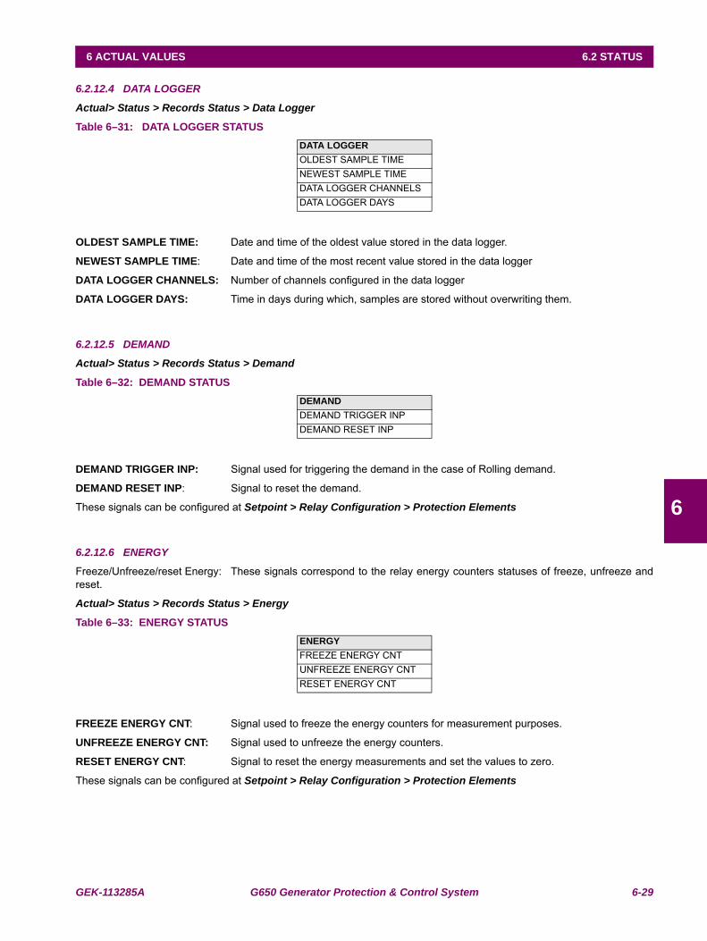
GEK-113285A G650 Generator Protection & Control System 6-29
6 ACTUAL VALUES 6.2 STATUS
6
6.2.12.4 DATA LOGGER
Actual> Status > Records Status > Data Logger
Table 6–31: DATA LOGGER STATUS
OLDEST SAMPLE TIME: Date and time of the oldest value stored in the data logger.
NEWEST SAMPLE TIME: Date and time of the most recent value stored in the data logger
DATA LOGGER CHANNELS: Number of channels configured in the data logger
DATA LOGGER DAYS: Time in days during which, samples are stored without overwriting them.
6.2.12.5 DEMAND
Actual> Status > Records Status > Demand
Table 6–32: DEMAND STATUS
DEMAND TRIGGER INP: Signal used for triggering the demand in the case of Rolling demand.
DEMAND RESET INP: Signal to reset the demand.
These signals can be configured at Setpoint > Relay Configuration > Protection Elements
6.2.12.6 ENERGY
Freeze/Unfreeze/reset Energy: These signals correspond to the relay energy counters statuses of freeze, unfreeze andreset.
Actual> Status > Records Status > Energy
Table 6–33: ENERGY STATUS
FREEZE ENERGY CNT: Signal used to freeze the energy counters for measurement purposes.
UNFREEZE ENERGY CNT: Signal used to unfreeze the energy counters.
RESET ENERGY CNT: Signal to reset the energy measurements and set the values to zero.
These signals can be configured at Setpoint > Relay Configuration > Protection Elements
DATA LOGGEROLDEST SAMPLE TIMENEWEST SAMPLE TIMEDATA LOGGER CHANNELSDATA LOGGER DAYS
DEMAND DEMAND TRIGGER INPDEMAND RESET INP
ENERGYFREEZE ENERGY CNTUNFREEZE ENERGY CNTRESET ENERGY CNT
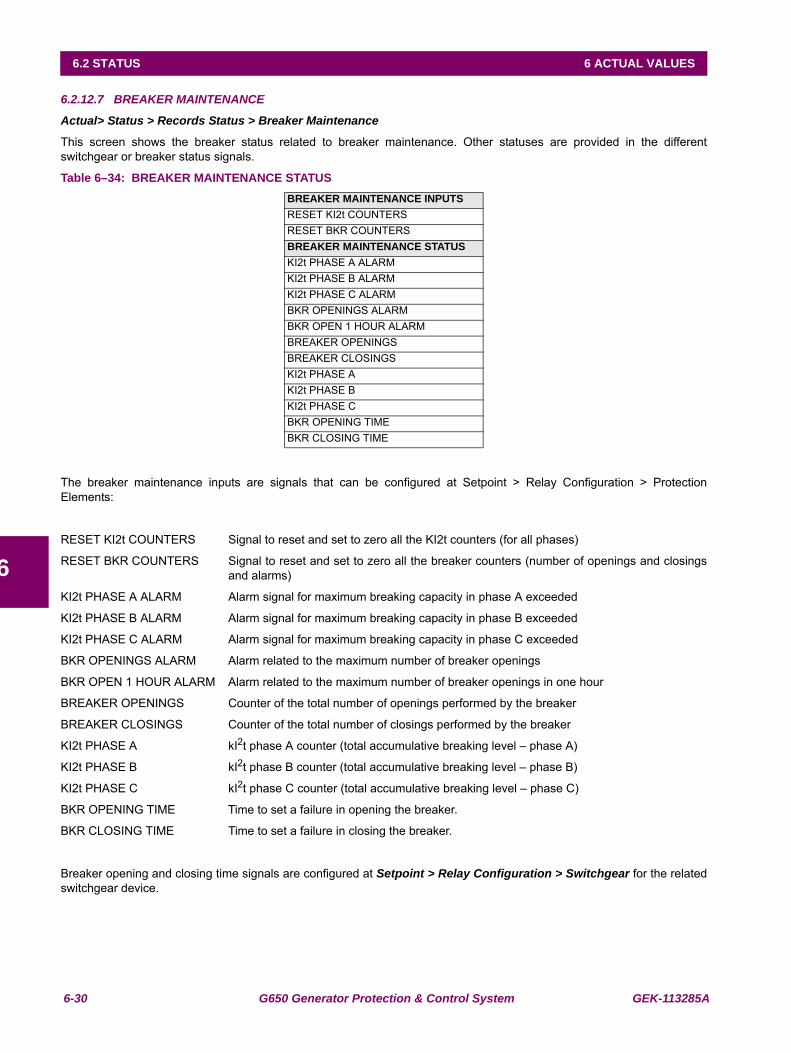
6-30 G650 Generator Protection & Control System GEK-113285A
6.2 STATUS 6 ACTUAL VALUES
6
6.2.12.7 BREAKER MAINTENANCE
Actual> Status > Records Status > Breaker Maintenance
This screen shows the breaker status related to breaker maintenance. Other statuses are provided in the differentswitchgear or breaker status signals.
Table 6–34: BREAKER MAINTENANCE STATUS
The breaker maintenance inputs are signals that can be configured at Setpoint > Relay Configuration > ProtectionElements:
RESET KI2t COUNTERS Signal to reset and set to zero all the KI2t counters (for all phases)
RESET BKR COUNTERS Signal to reset and set to zero all the breaker counters (number of openings and closingsand alarms)
KI2t PHASE A ALARM Alarm signal for maximum breaking capacity in phase A exceeded
KI2t PHASE B ALARM Alarm signal for maximum breaking capacity in phase B exceeded
KI2t PHASE C ALARM Alarm signal for maximum breaking capacity in phase C exceeded
BKR OPENINGS ALARM Alarm related to the maximum number of breaker openings
BKR OPEN 1 HOUR ALARM Alarm related to the maximum number of breaker openings in one hour
BREAKER OPENINGS Counter of the total number of openings performed by the breaker
BREAKER CLOSINGS Counter of the total number of closings performed by the breaker
KI2t PHASE A kI2t phase A counter (total accumulative breaking level – phase A)
KI2t PHASE B kI2t phase B counter (total accumulative breaking level – phase B)
KI2t PHASE C kI2t phase C counter (total accumulative breaking level – phase C)
BKR OPENING TIME Time to set a failure in opening the breaker.
BKR CLOSING TIME Time to set a failure in closing the breaker.
Breaker opening and closing time signals are configured at Setpoint > Relay Configuration > Switchgear for the relatedswitchgear device.
BREAKER MAINTENANCE INPUTSRESET KI2t COUNTERSRESET BKR COUNTERSBREAKER MAINTENANCE STATUSKI2t PHASE A ALARMKI2t PHASE B ALARMKI2t PHASE C ALARMBKR OPENINGS ALARMBKR OPEN 1 HOUR ALARMBREAKER OPENINGSBREAKER CLOSINGSKI2t PHASE AKI2t PHASE BKI2t PHASE CBKR OPENING TIMEBKR CLOSING TIME
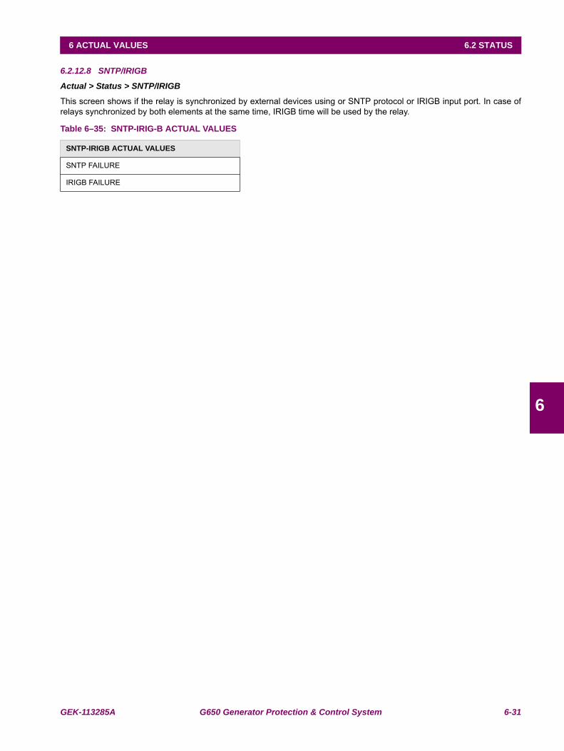
GEK-113285A G650 Generator Protection & Control System 6-31
6 ACTUAL VALUES 6.2 STATUS
6
6.2.12.8 SNTP/IRIGB
Actual > Status > SNTP/IRIGB
This screen shows if the relay is synchronized by external devices using or SNTP protocol or IRIGB input port. In case ofrelays synchronized by both elements at the same time, IRIGB time will be used by the relay.
Table 6–35: SNTP-IRIG-B ACTUAL VALUES
SNTP-IRIGB ACTUAL VALUES
SNTP FAILURE
IRIGB FAILURE
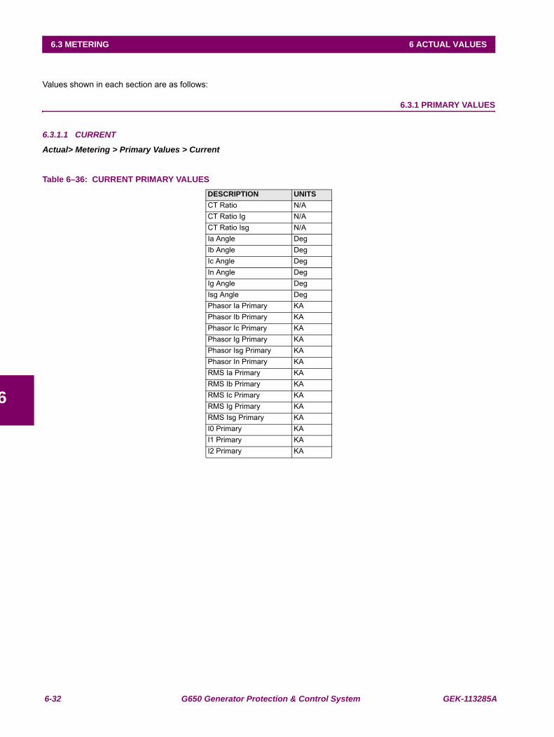
6-32 G650 Generator Protection & Control System GEK-113285A
6.3 METERING 6 ACTUAL VALUES
6
6.3METERING
Values shown in each section are as follows:
6.3.1 PRIMARY VALUES
6.3.1.1 CURRENT
Actual> Metering > Primary Values > Current
Table 6–36: CURRENT PRIMARY VALUESDESCRIPTION UNITSCT Ratio N/ACT Ratio Ig N/ACT Ratio Isg N/AIa Angle DegIb Angle DegIc Angle DegIn Angle DegIg Angle DegIsg Angle DegPhasor Ia Primary KAPhasor Ib Primary KAPhasor Ic Primary KAPhasor Ig Primary KAPhasor Isg Primary KAPhasor In Primary KARMS Ia Primary KARMS Ib Primary KARMS Ic Primary KARMS Ig Primary KARMS Isg Primary KAI0 Primary KAI1 Primary KAI2 Primary KA
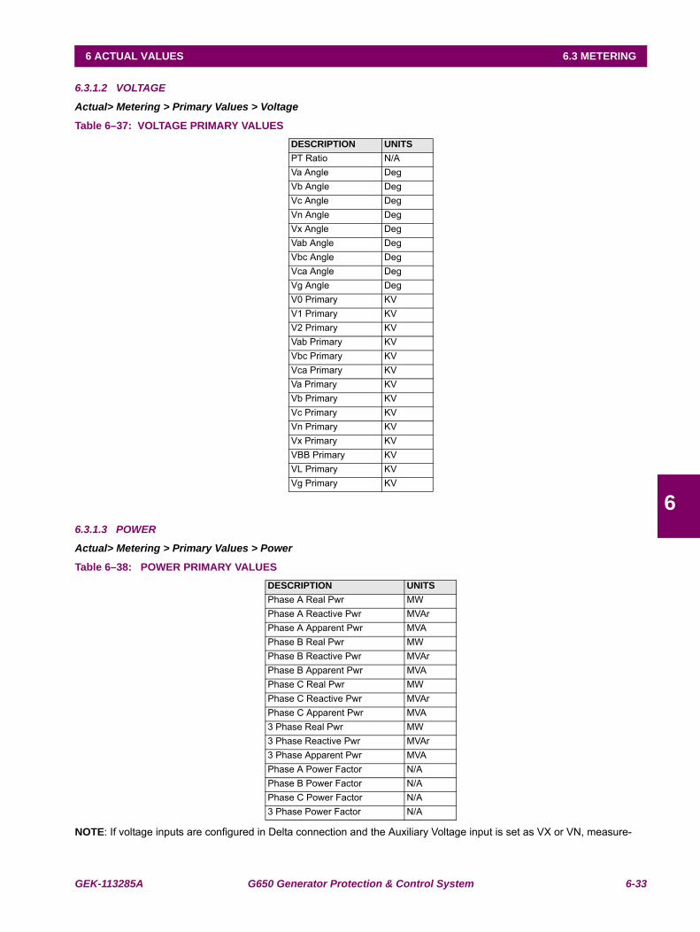
GEK-113285A G650 Generator Protection & Control System 6-33
6 ACTUAL VALUES 6.3 METERING
6
6.3.1.2 VOLTAGE
Actual> Metering > Primary Values > Voltage
Table 6–37: VOLTAGE PRIMARY VALUES
6.3.1.3 POWER
Actual> Metering > Primary Values > Power
Table 6–38: POWER PRIMARY VALUES
NOTE: If voltage inputs are configured in Delta connection and the Auxiliary Voltage input is set as VX or VN, measure-
DESCRIPTION UNITSPT Ratio N/AVa Angle DegVb Angle DegVc Angle DegVn Angle DegVx Angle DegVab Angle DegVbc Angle DegVca Angle DegVg Angle DegV0 Primary KVV1 Primary KVV2 Primary KVVab Primary KVVbc Primary KVVca Primary KVVa Primary KVVb Primary KVVc Primary KVVn Primary KVVx Primary KVVBB Primary KVVL Primary KVVg Primary KV
DESCRIPTION UNITSPhase A Real Pwr MWPhase A Reactive Pwr MVArPhase A Apparent Pwr MVAPhase B Real Pwr MWPhase B Reactive Pwr MVArPhase B Apparent Pwr MVAPhase C Real Pwr MWPhase C Reactive Pwr MVArPhase C Apparent Pwr MVA3 Phase Real Pwr MW3 Phase Reactive Pwr MVAr3 Phase Apparent Pwr MVAPhase A Power Factor N/APhase B Power Factor N/APhase C Power Factor N/A3 Phase Power Factor N/A
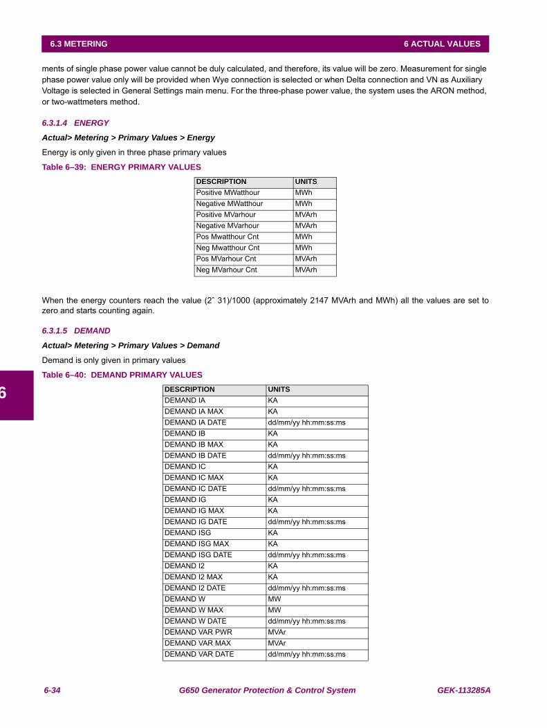
6-34 G650 Generator Protection & Control System GEK-113285A
6.3 METERING 6 ACTUAL VALUES
6
ments of single phase power value cannot be duly calculated, and therefore, its value will be zero. Measurement for single phase power value only will be provided when Wye connection is selected or when Delta connection and VN as Auxiliary Voltage is selected in General Settings main menu. For the three-phase power value, the system uses the ARON method, or two-wattmeters method.
6.3.1.4 ENERGY
Actual> Metering > Primary Values > Energy
Energy is only given in three phase primary values
Table 6–39: ENERGY PRIMARY VALUES
When the energy counters reach the value (2ˆ 31)/1000 (approximately 2147 MVArh and MWh) all the values are set tozero and starts counting again.
6.3.1.5 DEMAND
Actual> Metering > Primary Values > Demand
Demand is only given in primary values
Table 6–40: DEMAND PRIMARY VALUES
DESCRIPTION UNITSPositive MWatthour MWhNegative MWatthour MWhPositive MVarhour MVArhNegative MVarhour MVArhPos Mwatthour Cnt MWhNeg Mwatthour Cnt MWhPos MVarhour Cnt MVArhNeg MVarhour Cnt MVArh
DESCRIPTION UNITSDEMAND IA KADEMAND IA MAX KADEMAND IA DATE dd/mm/yy hh:mm:ss:msDEMAND IB KADEMAND IB MAX KADEMAND IB DATE dd/mm/yy hh:mm:ss:msDEMAND IC KADEMAND IC MAX KADEMAND IC DATE dd/mm/yy hh:mm:ss:msDEMAND IG KADEMAND IG MAX KADEMAND IG DATE dd/mm/yy hh:mm:ss:msDEMAND ISG KADEMAND ISG MAX KADEMAND ISG DATE dd/mm/yy hh:mm:ss:msDEMAND I2 KADEMAND I2 MAX KADEMAND I2 DATE dd/mm/yy hh:mm:ss:msDEMAND W MWDEMAND W MAX MWDEMAND W DATE dd/mm/yy hh:mm:ss:msDEMAND VAR PWR MVArDEMAND VAR MAX MVArDEMAND VAR DATE dd/mm/yy hh:mm:ss:ms
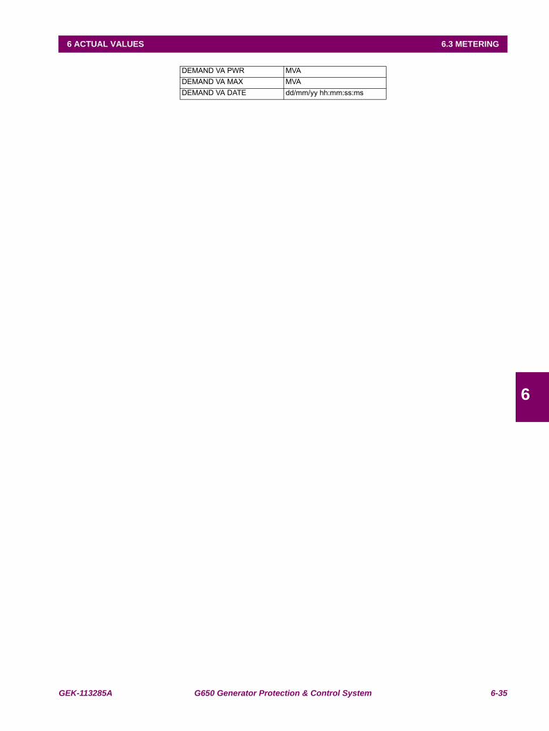
GEK-113285A G650 Generator Protection & Control System 6-35
6 ACTUAL VALUES 6.3 METERING
6
DEMAND VA PWR MVADEMAND VA MAX MVADEMAND VA DATE dd/mm/yy hh:mm:ss:ms
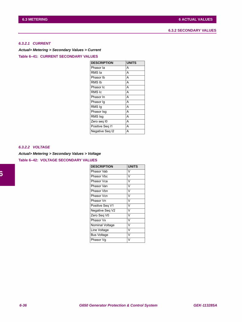
6-36 G650 Generator Protection & Control System GEK-113285A
6.3 METERING 6 ACTUAL VALUES
6
6.3.2 SECONDARY VALUES
6.3.2.1 CURRENT
Actual> Metering > Secondary Values > Current
Table 6–41: CURRENT SECONDARY VALUES
6.3.2.2 VOLTAGE
Actual> Metering > Secondary Values > Voltage
Table 6–42: VOLTAGE SECONDARY VALUES
DESCRIPTION UNITSPhasor Ia ARMS Ia APhasor Ib ARMS Ib APhasor Ic ARMS Ic APhasor In APhasor Ig ARMS Ig APhasor Isg ARMS Isg AZero seq I0 APositive Seq I1 ANegative Seq I2 A
DESCRIPTION UNITSPhasor Vab VPhasor Vbc VPhasor Vca VPhasor Van VPhasor Vbn VPhasor Vcn VPhasor Vn VPositive Seq V1 VNegative Seq V2 VZero Seq V0 VPhasor Vx VNominal Voltage VLine Voltage VBus Voltage VPhasor Vg V
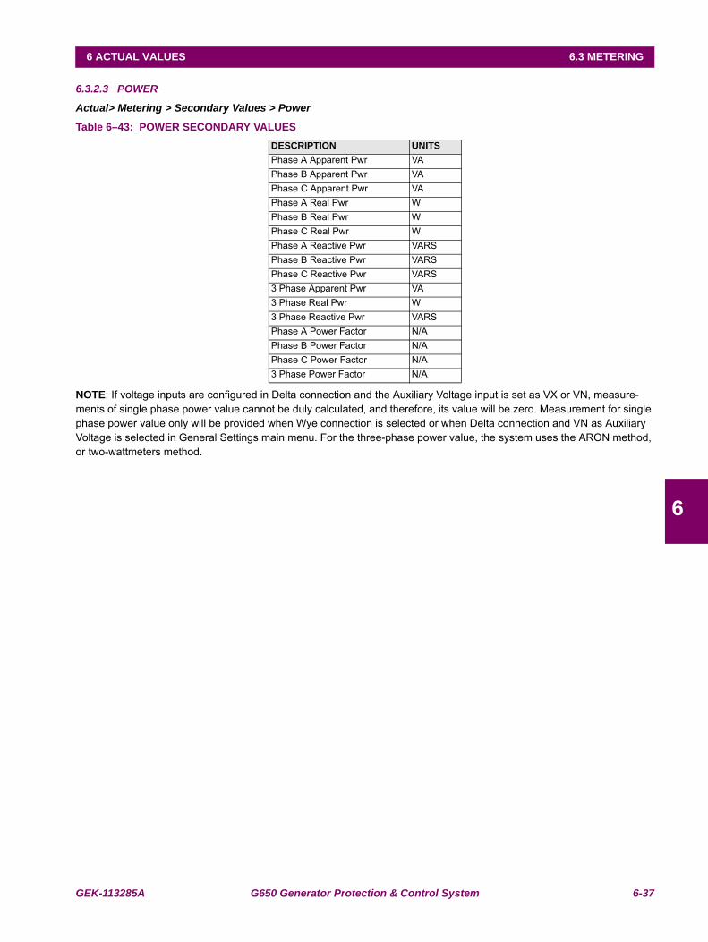
GEK-113285A G650 Generator Protection & Control System 6-37
6 ACTUAL VALUES 6.3 METERING
6
6.3.2.3 POWER
Actual> Metering > Secondary Values > Power
Table 6–43: POWER SECONDARY VALUES
NOTE: If voltage inputs are configured in Delta connection and the Auxiliary Voltage input is set as VX or VN, measure-ments of single phase power value cannot be duly calculated, and therefore, its value will be zero. Measurement for single phase power value only will be provided when Wye connection is selected or when Delta connection and VN as Auxiliary Voltage is selected in General Settings main menu. For the three-phase power value, the system uses the ARON method, or two-wattmeters method.
DESCRIPTION UNITSPhase A Apparent Pwr VAPhase B Apparent Pwr VAPhase C Apparent Pwr VAPhase A Real Pwr WPhase B Real Pwr WPhase C Real Pwr WPhase A Reactive Pwr VARSPhase B Reactive Pwr VARSPhase C Reactive Pwr VARS3 Phase Apparent Pwr VA3 Phase Real Pwr W3 Phase Reactive Pwr VARSPhase A Power Factor N/APhase B Power Factor N/APhase C Power Factor N/A3 Phase Power Factor N/A
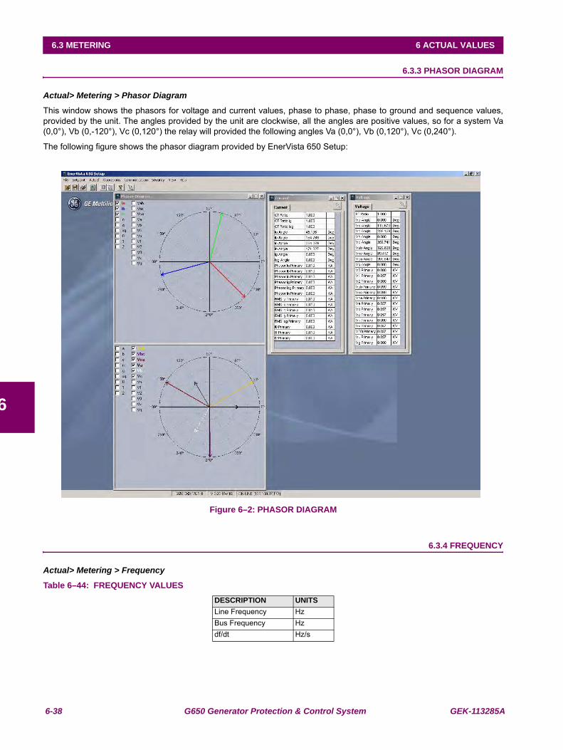
6-38 G650 Generator Protection & Control System GEK-113285A
6.3 METERING 6 ACTUAL VALUES
6
6.3.3 PHASOR DIAGRAM
Actual> Metering > Phasor Diagram
This window shows the phasors for voltage and current values, phase to phase, phase to ground and sequence values,provided by the unit. The angles provided by the unit are clockwise, all the angles are positive values, so for a system Va(0,0°), Vb (0,-120°), Vc (0,120°) the relay will provided the following angles Va (0,0°), Vb (0,120°), Vc (0,240°).
The following figure shows the phasor diagram provided by EnerVista 650 Setup:
Figure 6–2: PHASOR DIAGRAM
6.3.4 FREQUENCY
Actual> Metering > Frequency
Table 6–44: FREQUENCY VALUESDESCRIPTION UNITSLine Frequency HzBus Frequency Hzdf/dt Hz/s
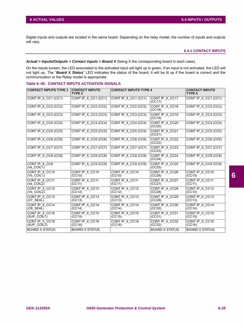
GEK-113285A G650 Generator Protection & Control System 6-39
6 ACTUAL VALUES 6.4 INPUTS / OUTPUTS
6
6.4INPUTS / OUTPUTS
Digital inputs and outputs are located in the same board. Depending on the relay model, the number of inputs and outputswill vary.
6.4.1 CONTACT INPUTS
Actual > Inputs/Outputs > Contact inputs > Board X (being X the corresponding board in each case).
On the inputs screen, the LED associated to the activated input will light up in green, if an input is not activated, the LED willnot light up. The “Board X Status” LED indicates the status of the board; it will be lit up if the board is correct and thecommunication or the Relay model is appropriate.
Table 6–45: CONTACT INPUTS ACTIVATION SIGNALSCONTACT INPUTS TYPE 1 CONTACT INPUTS
TYPE 2CONTACT INPUTS TYPE 4 CONTACT INPUTS
TYPE 5CONT IP_X_CC1 (CC1) CONT IP_X_CC1 (CC1) CONT IP_X_CC1 (CC1) CONT IP_X_CC17
(CC17)CONT IP_X_CC1 (CC1)
CONT IP_X_CC2 (CC2) CONT IP_X_CC2 (CC2) CONT IP_X_CC2 (CC2) CONT IP_X_CC18 (CC18)
CONT IP_X_CC2 (CC2)
CONT IP_X_CC3 (CC3) CONT IP_X_CC3 (CC3) CONT IP_X_CC3 (CC3) CONT IP_X_CC19 (CC19)
CONT IP_X_CC3 (CC3)
CONT IP_X_CC4 (CC4) CONT IP_X_CC4 (CC4) CONT IP_X_CC4 (CC4) CONT IP_X_CC20 (CC20)
CONT IP_X_CC4 (CC4)
CONT IP_X_CC5 (CC5) CONT IP_X_CC5 (CC5) CONT IP_X_CC5 (CC5) CONT IP_X_CC21 (CC21)
CONT IP_X_CC5 (CC5)
CONT IP_X_CC6 (CC6) CONT IP_X_CC6 (CC6) CONT IP_X_CC6 (CC6) CONT IP_X_CC22 (CC22)
CONT IP_X_CC6 (CC6)
CONT IP_X_CC7 (CC7) CONT IP_X_CC7 (CC7) CONT IP_X_CC7 (CC7) CONT IP_X_CC23 (CC23)
CONT IP_X_CC7 (CC7)
CONT IP_X_CC8 (CC8) CONT IP_X_CC8 (CC8) CONT IP_X_CC8 (CC8) CONT IP_X_CC24 (CC24)
CONT IP_X_CC8 (CC8)
CONT IP_X_CC9 (Va_COIL1)
CONT IP_X_CC9 (CC9) CONT IP_X_CC9 (CC9) CONT IP_X_CC25 (CC25)
CONT IP_X_CC9 (CC9)
CONT IP_X_CC10 (Vb_COIL1)
CONT IP_X_CC10 (CC10)
CONT IP_X_CC10 (CC10)
CONT IP_X_CC26 (CC26)
CONT IP_X_CC10 (CC10)
CONT IP_X_CC11 (Va_COIL2)
CONT IP_X_CC11 (CC11)
CONT IP_X_CC11 (CC11)
CONT IP_X_CC27 (CC27)
CONT IP_X_CC11 (CC11)
CONT IP_X_CC12 (Vb_COIL2)
CONT IP_X_CC12 (CC12)
CONT IP_X_CC12 (CC12)
CONT IP_X_CC28 (CC28)
CONT IP_X_CC12 (CC12)
CONT IP_X_CC13 (O7_SEAL)
CONT IP_X_CC13 (CC13)
CONT IP_X_CC13 (CC13)
CONT IP_X_CC29 (CC29)
CONT IP_X_CC13 (CC13)
CONT IP_X_CC14 (O8_SEAL)
CONT IP_X_CC14 (CC14)
CONT IP_X_CC14 (CC14)
CONT IP_X_CC30 (CC30)
CONT IP_X_CC14 (CC14)
CONT IP_X_CC15 (SUP_COIL1)
CONT IP_X_CC15 (CC15)
CONT IP_X_CC15 (CC15)
CONT IP_X_CC31 (CC31)
CONT IP_X_CC15 (CC15)
CONT IP_X_CC16 (SUP_COIL2)
CONT IP_X_CC16 (CC16)
CONT IP_X_CC16 (CC16)
CONT IP_X_CC32 (CC32)
CONT IP_X_CC16 (CC16)
BOARD X STATUS BOARD X STATUS BOARD X STATUS BOARD X STATUS
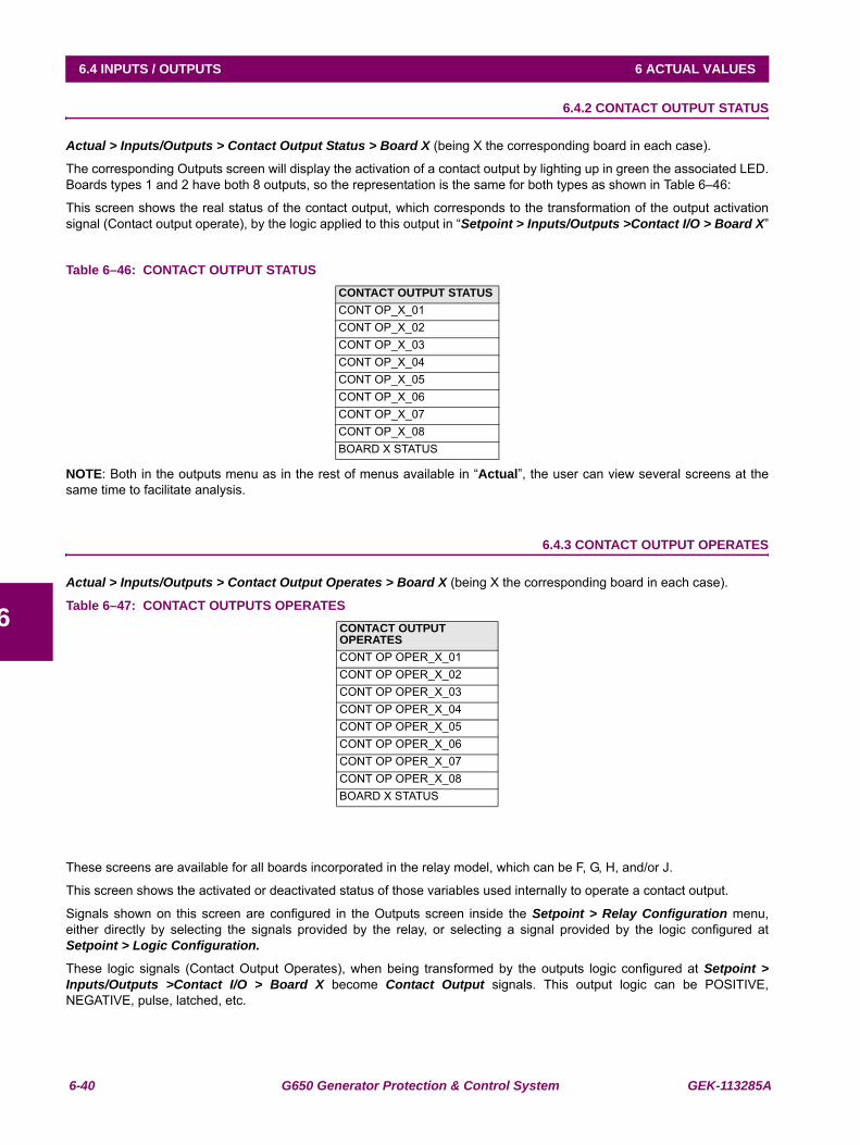
6-40 G650 Generator Protection & Control System GEK-113285A
6.4 INPUTS / OUTPUTS 6 ACTUAL VALUES
6
6.4.2 CONTACT OUTPUT STATUS
Actual > Inputs/Outputs > Contact Output Status > Board X (being X the corresponding board in each case).
The corresponding Outputs screen will display the activation of a contact output by lighting up in green the associated LED.Boards types 1 and 2 have both 8 outputs, so the representation is the same for both types as shown in Table 6–46:
This screen shows the real status of the contact output, which corresponds to the transformation of the output activationsignal (Contact output operate), by the logic applied to this output in “Setpoint > Inputs/Outputs >Contact I/O > Board X”
Table 6–46: CONTACT OUTPUT STATUS
NOTE: Both in the outputs menu as in the rest of menus available in “Actual”, the user can view several screens at thesame time to facilitate analysis.
6.4.3 CONTACT OUTPUT OPERATES
Actual > Inputs/Outputs > Contact Output Operates > Board X (being X the corresponding board in each case).
Table 6–47: CONTACT OUTPUTS OPERATES
These screens are available for all boards incorporated in the relay model, which can be F, G, H, and/or J.
This screen shows the activated or deactivated status of those variables used internally to operate a contact output.
Signals shown on this screen are configured in the Outputs screen inside the Setpoint > Relay Configuration menu,either directly by selecting the signals provided by the relay, or selecting a signal provided by the logic configured atSetpoint > Logic Configuration.
These logic signals (Contact Output Operates), when being transformed by the outputs logic configured at Setpoint >Inputs/Outputs >Contact I/O > Board X become Contact Output signals. This output logic can be POSITIVE,NEGATIVE, pulse, latched, etc.
CONTACT OUTPUT STATUSCONT OP_X_01CONT OP_X_02CONT OP_X_03CONT OP_X_04CONT OP_X_05CONT OP_X_06CONT OP_X_07CONT OP_X_08BOARD X STATUS
CONTACT OUTPUT OPERATESCONT OP OPER_X_01CONT OP OPER_X_02CONT OP OPER_X_03CONT OP OPER_X_04CONT OP OPER_X_05CONT OP OPER_X_06CONT OP OPER_X_07CONT OP OPER_X_08BOARD X STATUS
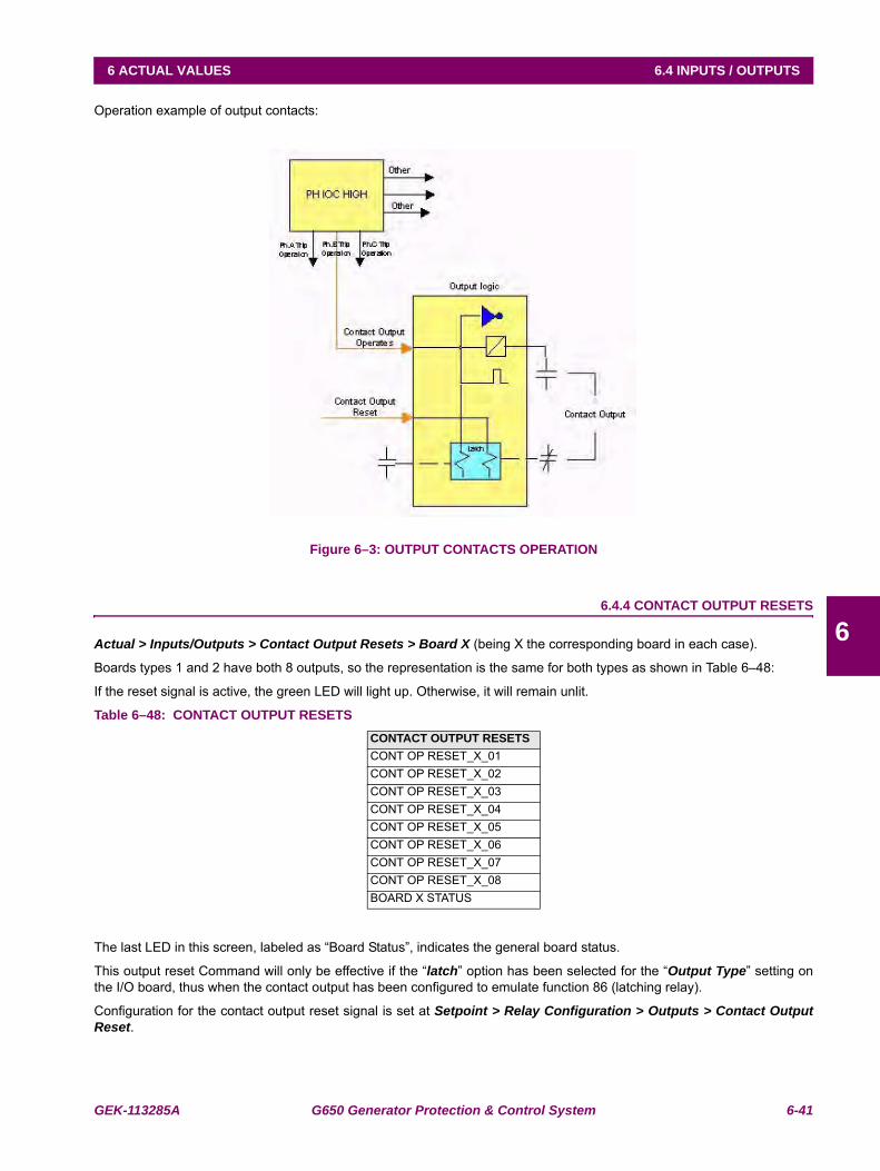
GEK-113285A G650 Generator Protection & Control System 6-41
6 ACTUAL VALUES 6.4 INPUTS / OUTPUTS
6
Operation example of output contacts:
Figure 6–3: OUTPUT CONTACTS OPERATION
6.4.4 CONTACT OUTPUT RESETS
Actual > Inputs/Outputs > Contact Output Resets > Board X (being X the corresponding board in each case).
Boards types 1 and 2 have both 8 outputs, so the representation is the same for both types as shown in Table 6–48:
If the reset signal is active, the green LED will light up. Otherwise, it will remain unlit.
Table 6–48: CONTACT OUTPUT RESETS
The last LED in this screen, labeled as “Board Status”, indicates the general board status.
This output reset Command will only be effective if the “latch” option has been selected for the “Output Type” setting onthe I/O board, thus when the contact output has been configured to emulate function 86 (latching relay).
Configuration for the contact output reset signal is set at Setpoint > Relay Configuration > Outputs > Contact OutputReset.
CONTACT OUTPUT RESETSCONT OP RESET_X_01CONT OP RESET_X_02CONT OP RESET_X_03CONT OP RESET_X_04CONT OP RESET_X_05CONT OP RESET_X_06CONT OP RESET_X_07CONT OP RESET_X_08BOARD X STATUS
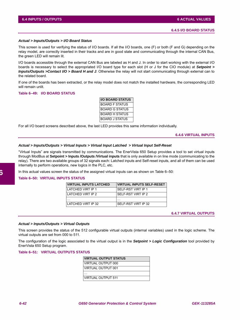
6-42 G650 Generator Protection & Control System GEK-113285A
6.4 INPUTS / OUTPUTS 6 ACTUAL VALUES
6
6.4.5 I/O BOARD STATUS
Actual > Inputs/Outputs > I/O Board Status
This screen is used for verifying the status of I/O boards. If all the I/O boards, one (F) or both (F and G) depending on therelay model, are correctly inserted in their tracks and are in good state and communicating through the internal CAN Bus,the green LED will remain lit.
I/O boards accessible through the external CAN Bus are labeled as H and J. In order to start working with the external I/Oboards is necessary to select the appropriated I/O board type for each slot (H or J for the CIO module) at Setpoint >Inputs/Outputs >Contact I/O > Board H and J. Otherwise the relay will not start communicating through external can tothe related board.
If one of the boards has been extracted, or the relay model does not match the installed hardware, the corresponding LEDwill remain unlit.
Table 6–49: I/O BOARD STATUS
For all I/O board screens described above, the last LED provides this same information individually.
6.4.6 VIRTUAL INPUTS
Actual > Inputs/Outputs > Virtual Inputs > Virtual Input Latched > Virtual Input Self-Reset
“Virtual Inputs” are signals transmitted by communications. The EnerVista 650 Setup provides a tool to set virtual inputsthrough ModBus at Setpoint > Inputs /Outputs /Virtual inputs that is only available in on line mode (communicating to therelay). There are two available groups of 32 signals each: Latched inputs and Self-reset inputs, and all of them can be usedinternally to perform operations, new logics in the PLC, etc.
In this actual values screen the status of the assigned virtual inputs can as shown on Table 6–50:
Table 6–50: VIRTUAL INPUTS STATUS
6.4.7 VIRTUAL OUTPUTS
Actual > Inputs/Outputs > Virtual Outputs
This screen provides the status of the 512 configurable virtual outputs (internal variables) used in the logic scheme. Thevirtual outputs are set from 000 to 511.
The configuration of the logic associated to the virtual output is in the Setpoint > Logic Configuration tool provided byEnerVista 650 Setup program.
Table 6–51: VIRTUAL OUTPUTS STATUS
I/O BOARD STATUSBOARD F STATUSBOARD G STATUSBOARD H STATUSBOARD J STATUS
VIRTUAL INPUTS LATCHED VIRTUAL INPUTS SELF-RESETLATCHED VIRT IP 1 SELF-RST VIRT IP 1LATCHED VIRT IP 2 SELF-RST VIRT IP 2… …LATCHED VIRT IP 32 SELF-RST VIRT IP 32
VIRTUAL OUTPUT STATUSVIRTUAL OUTPUT 000VIRTUAL OUTPUT 001…VIRTUAL OUTPUT 511
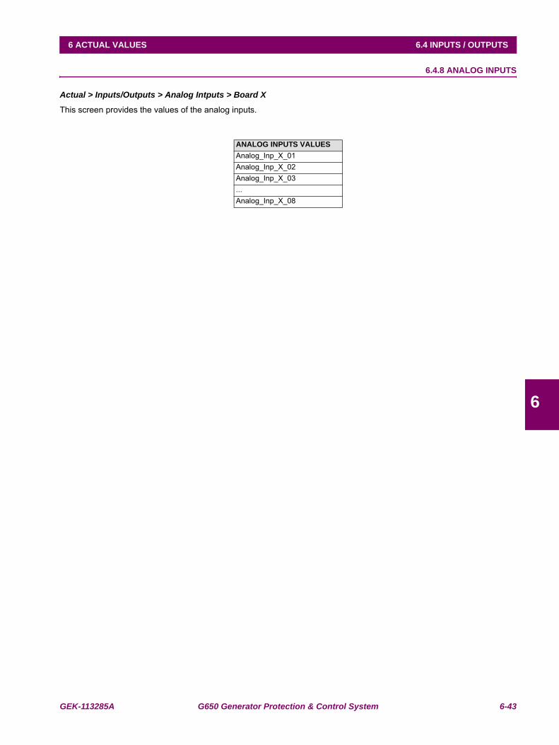
GEK-113285A G650 Generator Protection & Control System 6-43
6 ACTUAL VALUES 6.4 INPUTS / OUTPUTS
6
6.4.8 ANALOG INPUTS
Actual > Inputs/Outputs > Analog Intputs > Board X
This screen provides the values of the analog inputs.
ANALOG INPUTS VALUESAnalog_Inp_X_01Analog_Inp_X_02Analog_Inp_X_03...Analog_Inp_X_08
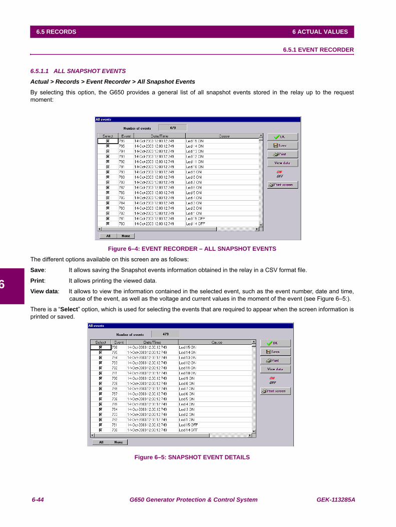
6-44 G650 Generator Protection & Control System GEK-113285A
6.5 RECORDS 6 ACTUAL VALUES
6
6.5RECORDS 6.5.1 EVENT RECORDER
6.5.1.1 ALL SNAPSHOT EVENTS
Actual > Records > Event Recorder > All Snapshot Events
By selecting this option, the G650 provides a general list of all snapshot events stored in the relay up to the requestmoment:
Figure 6–4: EVENT RECORDER – ALL SNAPSHOT EVENTS
The different options available on this screen are as follows:
Save: It allows saving the Snapshot events information obtained in the relay in a CSV format file.
Print: It allows printing the viewed data.
View data: It allows to view the information contained in the selected event, such as the event number, date and time,cause of the event, as well as the voltage and current values in the moment of the event (see Figure 6–5:).
There is a “Select” option, which is used for selecting the events that are required to appear when the screen information isprinted or saved.
Figure 6–5: SNAPSHOT EVENT DETAILS
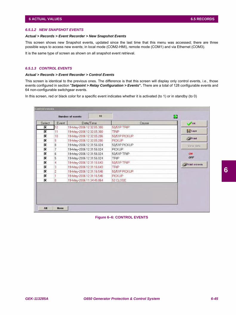
GEK-113285A G650 Generator Protection & Control System 6-45
6 ACTUAL VALUES 6.5 RECORDS
6
6.5.1.2 NEW SNAPSHOT EVENTS
Actual > Records > Event Recorder > New Snapshot Events
This screen shows new Snapshot events, updated since the last time that this menu was accessed; there are threepossible ways to access new events; in local mode (COM2-HMI), remote mode (COM1) and via Ethernet (COM3).
It is the same type of screen as shown on all snapshot event retrieval.
6.5.1.3 CONTROL EVENTS
Actual > Records > Event Recorder > Control Events
This screen is identical to the previous ones. The difference is that this screen will display only control events, i.e., thoseevents configured in section "Setpoint > Relay Configuration > Events". There are a total of 128 configurable events and64 non-configurable switchgear events.
In this screen, red or black color for a specific event indicates whether it is activated (to 1) or in standby (to 0)
Figure 6–6: CONTROL EVENTS
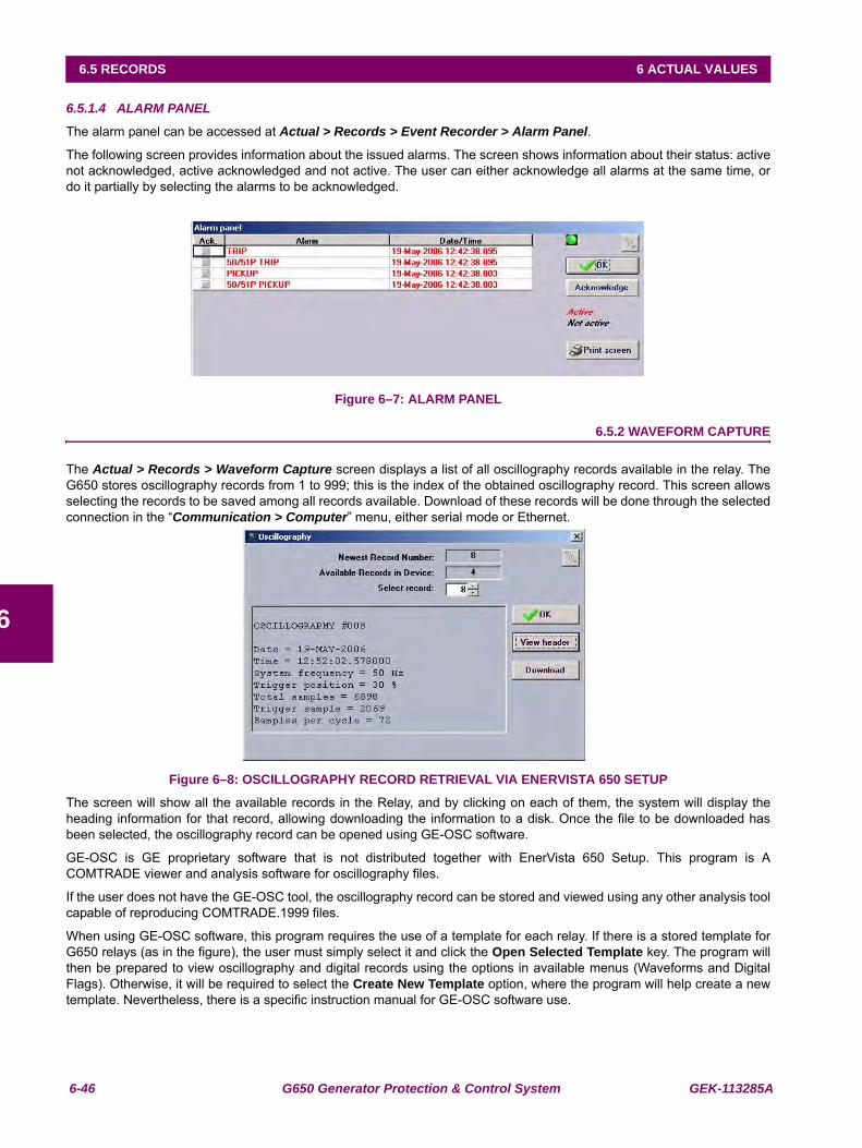
6-46 G650 Generator Protection & Control System GEK-113285A
6.5 RECORDS 6 ACTUAL VALUES
6
6.5.1.4 ALARM PANEL
The alarm panel can be accessed at Actual > Records > Event Recorder > Alarm Panel.
The following screen provides information about the issued alarms. The screen shows information about their status: activenot acknowledged, active acknowledged and not active. The user can either acknowledge all alarms at the same time, ordo it partially by selecting the alarms to be acknowledged.
Figure 6–7: ALARM PANEL
6.5.2 WAVEFORM CAPTURE
The Actual > Records > Waveform Capture screen displays a list of all oscillography records available in the relay. TheG650 stores oscillography records from 1 to 999; this is the index of the obtained oscillography record. This screen allowsselecting the records to be saved among all records available. Download of these records will be done through the selectedconnection in the “Communication > Computer” menu, either serial mode or Ethernet.
Figure 6–8: OSCILLOGRAPHY RECORD RETRIEVAL VIA ENERVISTA 650 SETUP
The screen will show all the available records in the Relay, and by clicking on each of them, the system will display theheading information for that record, allowing downloading the information to a disk. Once the file to be downloaded hasbeen selected, the oscillography record can be opened using GE-OSC software.
GE-OSC is GE proprietary software that is not distributed together with EnerVista 650 Setup. This program is ACOMTRADE viewer and analysis software for oscillography files.
If the user does not have the GE-OSC tool, the oscillography record can be stored and viewed using any other analysis toolcapable of reproducing COMTRADE.1999 files.
When using GE-OSC software, this program requires the use of a template for each relay. If there is a stored template forG650 relays (as in the figure), the user must simply select it and click the Open Selected Template key. The program willthen be prepared to view oscillography and digital records using the options in available menus (Waveforms and DigitalFlags). Otherwise, it will be required to select the Create New Template option, where the program will help create a newtemplate. Nevertheless, there is a specific instruction manual for GE-OSC software use.
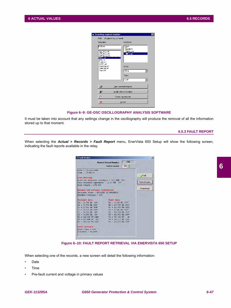
GEK-113285A G650 Generator Protection & Control System 6-47
6 ACTUAL VALUES 6.5 RECORDS
6
Figure 6–9: GE-OSC OSCILLOGRAPHY ANALYSIS SOFTWARE
It must be taken into account that any settings change in the oscillography will produce the removal of all the informationstored up to that moment.
6.5.3 FAULT REPORT
When selecting the Actual > Records > Fault Report menu, EnerVista 650 Setup will show the following screen,indicating the fault reports available in the relay.
Figure 6–10: FAULT REPORT RETRIEVAL VIA ENERVISTA 650 SETUP
When selecting one of the records, a new screen will detail the following information:
• Date
• Time
• Pre-fault current and voltage in primary values
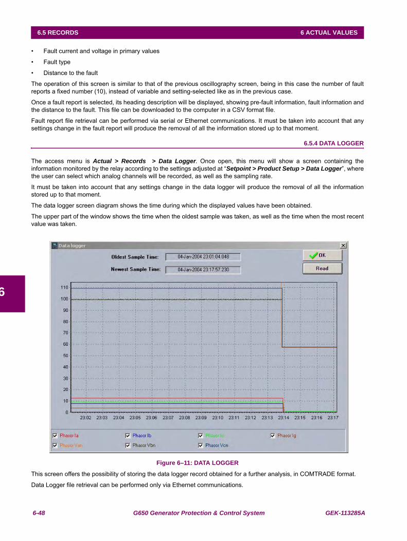
6-48 G650 Generator Protection & Control System GEK-113285A
6.5 RECORDS 6 ACTUAL VALUES
6
• Fault current and voltage in primary values
• Fault type
• Distance to the fault
The operation of this screen is similar to that of the previous oscillography screen, being in this case the number of faultreports a fixed number (10), instead of variable and setting-selected like as in the previous case.
Once a fault report is selected, its heading description will be displayed, showing pre-fault information, fault information andthe distance to the fault. This file can be downloaded to the computer in a CSV format file.
Fault report file retrieval can be performed via serial or Ethernet communications. It must be taken into account that anysettings change in the fault report will produce the removal of all the information stored up to that moment.
6.5.4 DATA LOGGER
The access menu is Actual > Records > Data Logger. Once open, this menu will show a screen containing theinformation monitored by the relay according to the settings adjusted at “Setpoint > Product Setup > Data Logger”, wherethe user can select which analog channels will be recorded, as well as the sampling rate.
It must be taken into account that any settings change in the data logger will produce the removal of all the informationstored up to that moment.
The data logger screen diagram shows the time during which the displayed values have been obtained.
The upper part of the window shows the time when the oldest sample was taken, as well as the time when the most recentvalue was taken.
Figure 6–11: DATA LOGGER
This screen offers the possibility of storing the data logger record obtained for a further analysis, in COMTRADE format.
Data Logger file retrieval can be performed only via Ethernet communications.
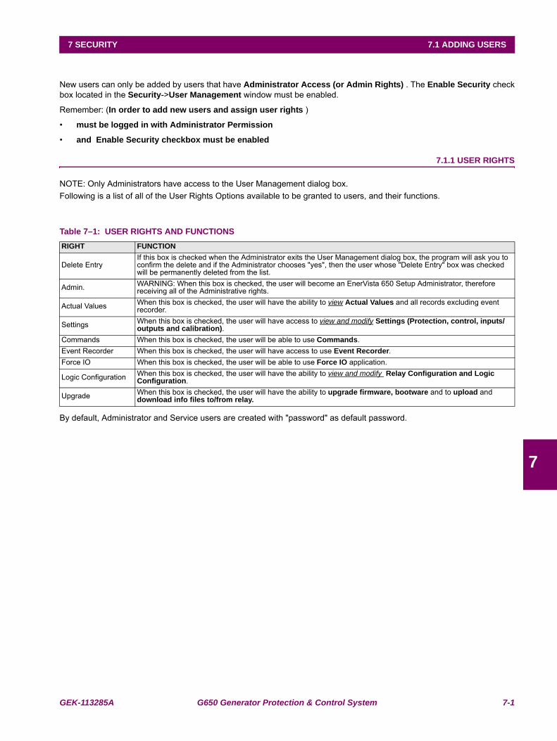
GEK-113285A G650 Generator Protection & Control System 7-1
7 SECURITY 7.1 ADDING USERS
7
7 SECURITY 7.1 ADDING USERS
New users can only be added by users that have Administrator Access (or Admin Rights) . The Enable Security checkbox located in the Security->User Management window must be enabled.
Remember: (In order to add new users and assign user rights )
• must be logged in with Administrator Permission
• and Enable Security checkbox must be enabled
7.1.1 USER RIGHTS
NOTE: Only Administrators have access to the User Management dialog box.Following is a list of all of the User Rights Options available to be granted to users, and their functions.
Table 7–1: USER RIGHTS AND FUNCTIONS
By default, Administrator and Service users are created with "password" as default password.
RIGHT FUNCTION
Delete EntryIf this box is checked when the Administrator exits the User Management dialog box, the program will ask you to confirm the delete and if the Administrator chooses "yes", then the user whose "Delete Entry" box was checked will be permanently deleted from the list.
Admin. WARNING: When this box is checked, the user will become an EnerVista 650 Setup Administrator, therefore receiving all of the Administrative rights.
Actual Values When this box is checked, the user will have the ability to view Actual Values and all records excluding event recorder.
Settings When this box is checked, the user will have access to view and modify Settings (Protection, control, inputs/outputs and calibration).
Commands When this box is checked, the user will be able to use Commands.Event Recorder When this box is checked, the user will have access to use Event Recorder.Force IO When this box is checked, the user will be able to use Force IO application.
Logic Configuration When this box is checked, the user will have the ability to view and modify Relay Configuration and Logic Configuration.
Upgrade When this box is checked, the user will have the ability to upgrade firmware, bootware and to upload and download info files to/from relay.
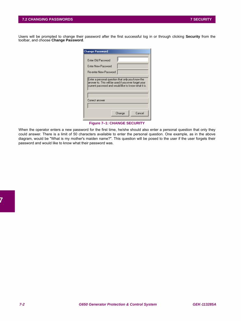
7-2 G650 Generator Protection & Control System GEK-113285A
7.2 CHANGING PASSWORDS 7 SECURITY
7
7.2CHANGING PASSWORDSUsers will be prompted to change their password after the first successful log in or through clicking Security from thetoolbar, and choose Change Password.
Figure 7–1: CHANGE SECURITY
When the operator enters a new password for the first time, he/she should also enter a personal question that only theycould answer. There is a limit of 50 characters available to enter the personal question. One example, as in the abovediagram, would be "What is my mother's maiden name?". This question will be posed to the user if the user forgets theirpassword and would like to know what their password was.
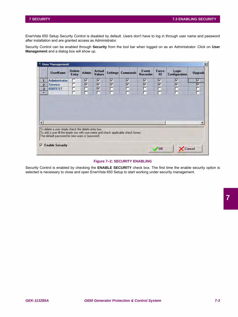
GEK-113285A G650 Generator Protection & Control System 7-3
7 SECURITY 7.3 ENABLING SECURITY
7
7.3ENABLING SECURITYEnerVista 650 Setup Security Control is disabled by default. Users don't have to log in through user name and passwordafter installation and are granted access as Administrator.
Security Control can be enabled through Security from the tool bar when logged on as an Administrator. Click on UserManagement and a dialog box will show up.
Figure 7–2: SECURITY ENABLING
Security Control is enabled by checking the ENABLE SECURITY check box. The first time the enable security option isselected is necessary to close and open EnerVista 650 Setup to start working under security management.
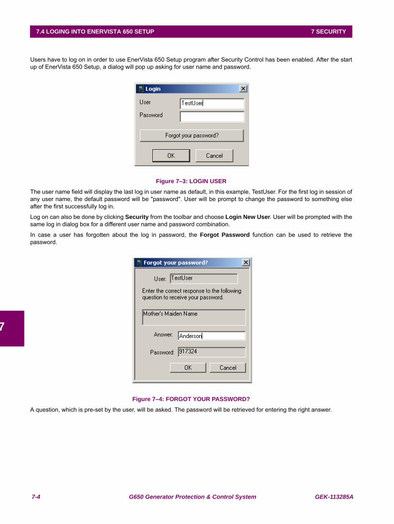
7-4 G650 Generator Protection & Control System GEK-113285A
7.4 LOGING INTO ENERVISTA 650 SETUP 7 SECURITY
7
7.4LOGING INTO ENERVISTA 650 SETUPUsers have to log on in order to use EnerVista 650 Setup program after Security Control has been enabled. After the startup of EnerVista 650 Setup, a dialog will pop up asking for user name and password.
Figure 7–3: LOGIN USER
The user name field will display the last log in user name as default, in this example, TestUser. For the first log in session ofany user name, the default password will be "password". User will be prompt to change the password to something elseafter the first successfully log in.
Log on can also be done by clicking Security from the toolbar and choose Login New User. User will be prompted with thesame log in dialog box for a different user name and password combination.
In case a user has forgotten about the log in password, the Forgot Password function can be used to retrieve thepassword.
Figure 7–4: FORGOT YOUR PASSWORD?
A question, which is pre-set by the user, will be asked. The password will be retrieved for entering the right answer.
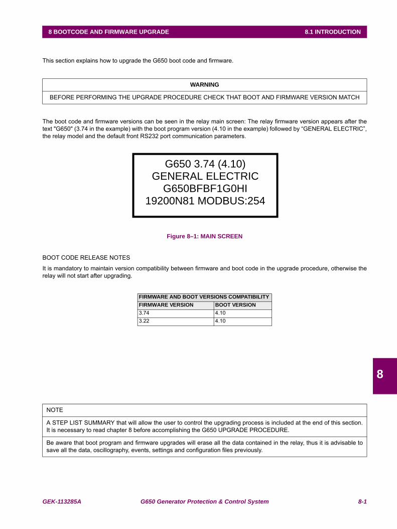
GEK-113285A G650 Generator Protection & Control System 8-1
8 BOOTCODE AND FIRMWARE UPGRADE 8.1 INTRODUCTION
8
8 BOOTCODE AND FIRMWARE UPGRADE 8.1INTRODUCTION
This section explains how to upgrade the G650 boot code and firmware.
The boot code and firmware versions can be seen in the relay main screen: The relay firmware version appears after thetext "G650" (3.74 in the example) with the boot program version (4.10 in the example) followed by “GENERAL ELECTRIC”,the relay model and the default front RS232 port communication parameters.
Figure 8–1: MAIN SCREEN
BOOT CODE RELEASE NOTES
It is mandatory to maintain version compatibility between firmware and boot code in the upgrade procedure, otherwise therelay will not start after upgrading.
WARNING
BEFORE PERFORMING THE UPGRADE PROCEDURE CHECK THAT BOOT AND FIRMWARE VERSION MATCH
FIRMWARE AND BOOT VERSIONS COMPATIBILITYFIRMWARE VERSION BOOT VERSION3.74 4.103.22 4.10
NOTE
A STEP LIST SUMMARY that will allow the user to control the upgrading process is included at the end of this section.It is necessary to read chapter 8 before accomplishing the G650 UPGRADE PROCEDURE.
Be aware that boot program and firmware upgrades will erase all the data contained in the relay, thus it is advisable tosave all the data, oscillography, events, settings and configuration files previously.
G650 3.74 (4.10) GENERAL ELECTRIC
G650BFBF1G0HI19200N81 MODBUS:254
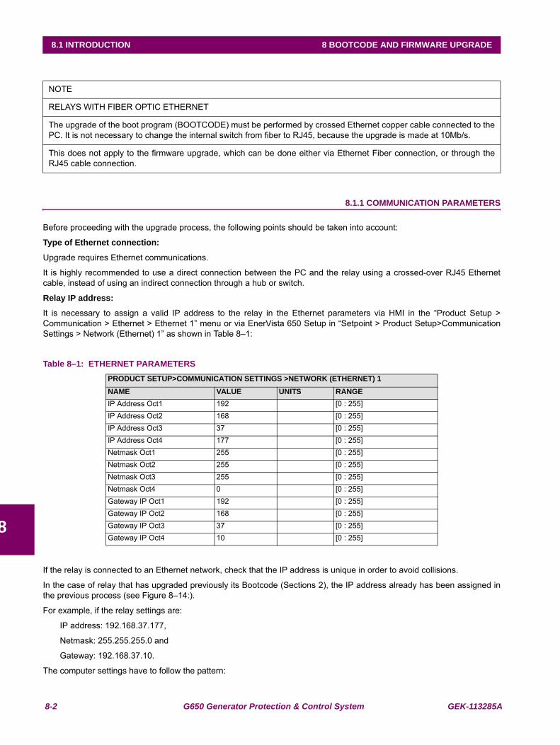
8-2 G650 Generator Protection & Control System GEK-113285A
8.1 INTRODUCTION 8 BOOTCODE AND FIRMWARE UPGRADE
8
8.1.1 COMMUNICATION PARAMETERS
Before proceeding with the upgrade process, the following points should be taken into account:
Type of Ethernet connection:
Upgrade requires Ethernet communications.
It is highly recommended to use a direct connection between the PC and the relay using a crossed-over RJ45 Ethernetcable, instead of using an indirect connection through a hub or switch.
Relay IP address:
It is necessary to assign a valid IP address to the relay in the Ethernet parameters via HMI in the “Product Setup >Communication > Ethernet > Ethernet 1” menu or via EnerVista 650 Setup in “Setpoint > Product Setup>CommunicationSettings > Network (Ethernet) 1” as shown in Table 8–1:
Table 8–1: ETHERNET PARAMETERS
If the relay is connected to an Ethernet network, check that the IP address is unique in order to avoid collisions.
In the case of relay that has upgraded previously its Bootcode (Sections 2), the IP address already has been assigned inthe previous process (see Figure 8–14:).
For example, if the relay settings are:
IP address: 192.168.37.177,
Netmask: 255.255.255.0 and
Gateway: 192.168.37.10.
The computer settings have to follow the pattern:
NOTE
RELAYS WITH FIBER OPTIC ETHERNET
The upgrade of the boot program (BOOTCODE) must be performed by crossed Ethernet copper cable connected to thePC. It is not necessary to change the internal switch from fiber to RJ45, because the upgrade is made at 10Mb/s.
This does not apply to the firmware upgrade, which can be done either via Ethernet Fiber connection, or through theRJ45 cable connection.
PRODUCT SETUP>COMMUNICATION SETTINGS >NETWORK (ETHERNET) 1NAME VALUE UNITS RANGEIP Address Oct1 192 [0 : 255]IP Address Oct2 168 [0 : 255]IP Address Oct3 37 [0 : 255]IP Address Oct4 177 [0 : 255]Netmask Oct1 255 [0 : 255]Netmask Oct2 255 [0 : 255]Netmask Oct3 255 [0 : 255]Netmask Oct4 0 [0 : 255]Gateway IP Oct1 192 [0 : 255]Gateway IP Oct2 168 [0 : 255]Gateway IP Oct3 37 [0 : 255]Gateway IP Oct4 10 [0 : 255]
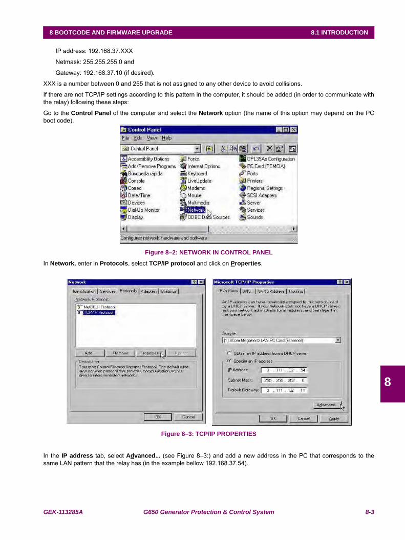
GEK-113285A G650 Generator Protection & Control System 8-3
8 BOOTCODE AND FIRMWARE UPGRADE 8.1 INTRODUCTION
8
IP address: 192.168.37.XXX
Netmask: 255.255.255.0 and
Gateway: 192.168.37.10 (if desired).
XXX is a number between 0 and 255 that is not assigned to any other device to avoid collisions.
If there are not TCP/IP settings according to this pattern in the computer, it should be added (in order to communicate withthe relay) following these steps:
Go to the Control Panel of the computer and select the Network option (the name of this option may depend on the PCboot code).
Figure 8–2: NETWORK IN CONTROL PANEL
In Network, enter in Protocols, select TCP/IP protocol and click on Properties.
Figure 8–3: TCP/IP PROPERTIES
In the IP address tab, select Advanced... (see Figure 8–3:) and add a new address in the PC that corresponds to thesame LAN pattern that the relay has (in the example bellow 192.168.37.54).
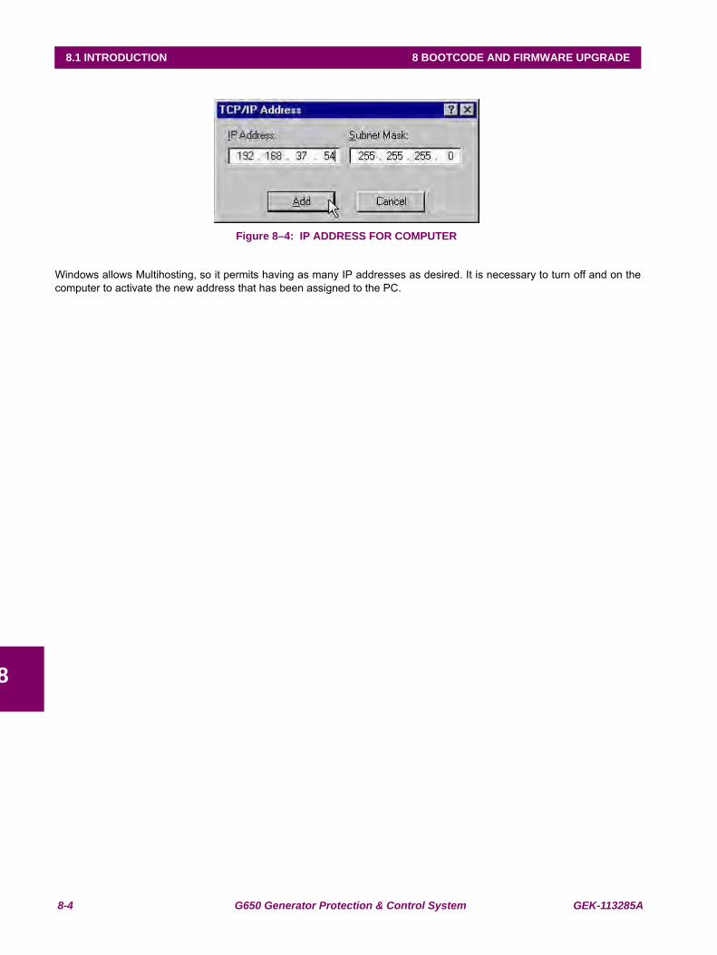
8-4 G650 Generator Protection & Control System GEK-113285A
8.1 INTRODUCTION 8 BOOTCODE AND FIRMWARE UPGRADE
8
Figure 8–4: IP ADDRESS FOR COMPUTER
Windows allows Multihosting, so it permits having as many IP addresses as desired. It is necessary to turn off and on thecomputer to activate the new address that has been assigned to the PC.
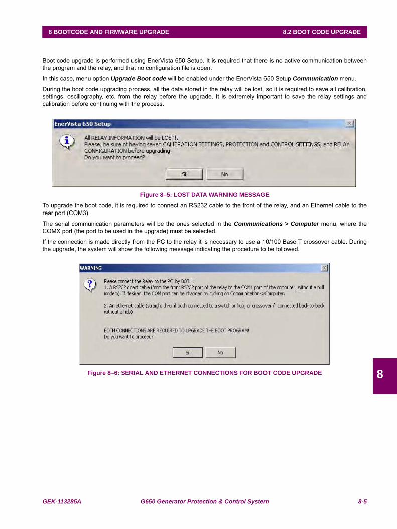
GEK-113285A G650 Generator Protection & Control System 8-5
8 BOOTCODE AND FIRMWARE UPGRADE 8.2 BOOT CODE UPGRADE
8
8.2BOOT CODE UPGRADE
Boot code upgrade is performed using EnerVista 650 Setup. It is required that there is no active communication betweenthe program and the relay, and that no configuration file is open.
In this case, menu option Upgrade Boot code will be enabled under the EnerVista 650 Setup Communication menu.
During the boot code upgrading process, all the data stored in the relay will be lost, so it is required to save all calibration,settings, oscillography, etc. from the relay before the upgrade. It is extremely important to save the relay settings andcalibration before continuing with the process.
Figure 8–5: LOST DATA WARNING MESSAGE
To upgrade the boot code, it is required to connect an RS232 cable to the front of the relay, and an Ethernet cable to therear port (COM3).
The serial communication parameters will be the ones selected in the Communications > Computer menu, where theCOMX port (the port to be used in the upgrade) must be selected.
If the connection is made directly from the PC to the relay it is necessary to use a 10/100 Base T crossover cable. Duringthe upgrade, the system will show the following message indicating the procedure to be followed.
Figure 8–6: SERIAL AND ETHERNET CONNECTIONS FOR BOOT CODE UPGRADE
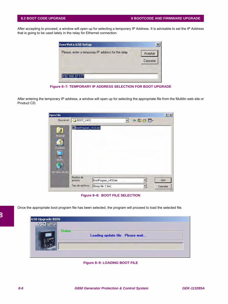
8-6 G650 Generator Protection & Control System GEK-113285A
8.2 BOOT CODE UPGRADE 8 BOOTCODE AND FIRMWARE UPGRADE
8
After accepting to proceed, a window will open up for selecting a temporary IP Address. It is advisable to set the IP Addressthat is going to be used lately in the relay for Ethernet connection.
Figure 8–7: TEMPORARY IP ADDRESS SELECTION FOR BOOT UPGRADE
After entering the temporary IP address, a window will open up for selecting the appropriate file from the Multilin web site orProduct CD.
Figure 8–8: BOOT FILE SELECTION
Once the appropriate boot program file has been selected, the program will proceed to load the selected file.
Figure 8–9: LOADING BOOT FILE
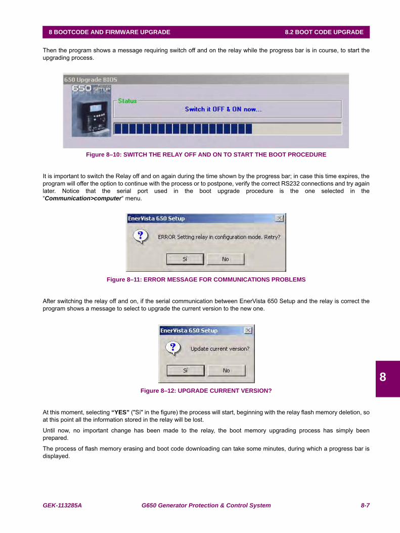
GEK-113285A G650 Generator Protection & Control System 8-7
8 BOOTCODE AND FIRMWARE UPGRADE 8.2 BOOT CODE UPGRADE
8
Then the program shows a message requiring switch off and on the relay while the progress bar is in course, to start theupgrading process.
Figure 8–10: SWITCH THE RELAY OFF AND ON TO START THE BOOT PROCEDURE
It is important to switch the Relay off and on again during the time shown by the progress bar; in case this time expires, theprogram will offer the option to continue with the process or to postpone, verify the correct RS232 connections and try againlater. Notice that the serial port used in the boot upgrade procedure is the one selected in the“Communication>computer“ menu.
Figure 8–11: ERROR MESSAGE FOR COMMUNICATIONS PROBLEMS
After switching the relay off and on, if the serial communication between EnerVista 650 Setup and the relay is correct theprogram shows a message to select to upgrade the current version to the new one.
Figure 8–12: UPGRADE CURRENT VERSION?
At this moment, selecting “YES” ("Sí" in the figure) the process will start, beginning with the relay flash memory deletion, soat this point all the information stored in the relay will be lost.
Until now, no important change has been made to the relay, the boot memory upgrading process has simply beenprepared.
The process of flash memory erasing and boot code downloading can take some minutes, during which a progress bar isdisplayed.
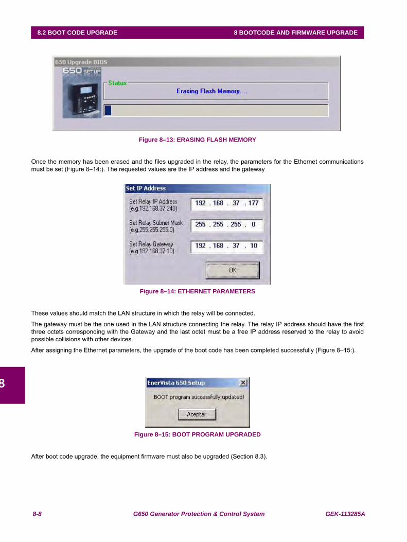
8-8 G650 Generator Protection & Control System GEK-113285A
8.2 BOOT CODE UPGRADE 8 BOOTCODE AND FIRMWARE UPGRADE
8
Figure 8–13: ERASING FLASH MEMORY
Once the memory has been erased and the files upgraded in the relay, the parameters for the Ethernet communicationsmust be set (Figure 8–14:). The requested values are the IP address and the gateway
Figure 8–14: ETHERNET PARAMETERS
These values should match the LAN structure in which the relay will be connected.
The gateway must be the one used in the LAN structure connecting the relay. The relay IP address should have the firstthree octets corresponding with the Gateway and the last octet must be a free IP address reserved to the relay to avoidpossible collisions with other devices.
After assigning the Ethernet parameters, the upgrade of the boot code has been completed successfully (Figure 8–15:).
Figure 8–15: BOOT PROGRAM UPGRADED
After boot code upgrade, the equipment firmware must also be upgraded (Section 8.3).
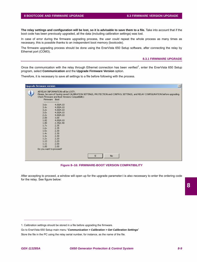
GEK-113285A G650 Generator Protection & Control System 8-9
8 BOOTCODE AND FIRMWARE UPGRADE 8.3 FIRMWARE VERSION UPGRADE
8
8.3FIRMWARE VERSION UPGRADE
The relay settings and configuration will be lost, so it is advisable to save them to a file. Take into account that if theboot code has been previously upgraded, all the data (including calibration settings) was lost.
In case of error during the firmware upgrading process, the user could repeat the whole process as many times asnecessary, this is possible thanks to an independent boot memory (bootcode).
The firmware upgrading process should be done using the EnerVista 650 Setup software, after connecting the relay byEthernet port (COM3).
8.3.1 FIRMWARE UPGRADE
Once the communication with the relay through Ethernet connection has been verified1, enter the EnerVista 650 Setupprogram, select Communication and the Upgrade Firmware Version option.
Therefore, it is necessary to save all settings to a file before following with the process.
Figure 8–16: FIRMWARE-BOOT VERSION COMPATIBILITY
After accepting to proceed, a window will open up for the upgrade parameter.t is also necessary to enter the ordering codefor the relay. See figure below:
1. Calibration settings should be stored in a file before upgrading the firmware.
Go to EnerVista 650 Setup main menu “Communication > Calibration > Get Calibration Settings”
Store the file in the PC using the relay serial number, for instance, as the name of the file.
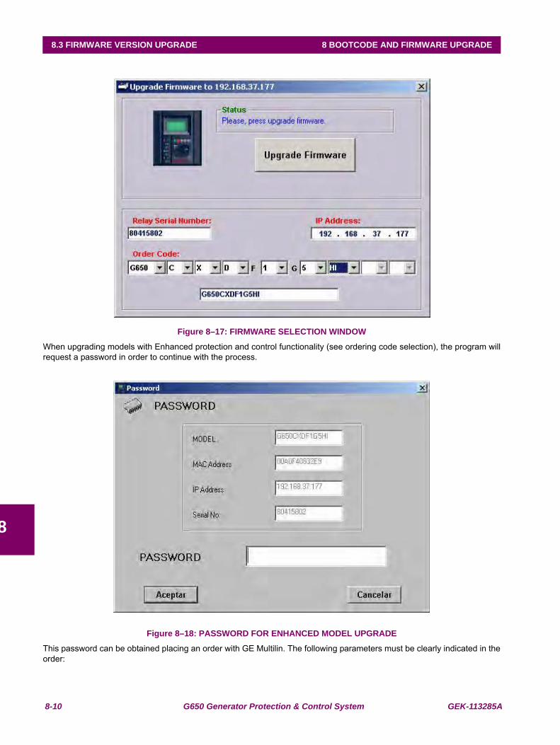
8-10 G650 Generator Protection & Control System GEK-113285A
8.3 FIRMWARE VERSION UPGRADE 8 BOOTCODE AND FIRMWARE UPGRADE
8
Figure 8–17: FIRMWARE SELECTION WINDOW
When upgrading models with Enhanced protection and control functionality (see ordering code selection), the program willrequest a password in order to continue with the process.
Figure 8–18: PASSWORD FOR ENHANCED MODEL UPGRADE
This password can be obtained placing an order with GE Multilin. The following parameters must be clearly indicated in theorder:

GEK-113285A G650 Generator Protection & Control System 8-11
8 BOOTCODE AND FIRMWARE UPGRADE 8.3 FIRMWARE VERSION UPGRADE
8
• Unit serial number
• Current model option (before memory upgrade)
• Desired model option (after memory upgrade)
• Unit MAC address (available in the identification label)
Once the upgrade parameters have been entered, press the “Upgrade Firmware” button. When communication has beenestablished, the program will show a message requesting to turn off and back on the relay to continue with the upgradeprocess.
Once the relay has been turned off and on, a new screen allows selecting the folder that contains the firmware upgradefiles (“upgrade.txt” file must be located in this folder). This Upgrade.txt file is located in the folder where the desiredfirmware upgrade files are. This firmware upgrade files can be found in the Multilin web site.
If the files are downloaded from the web, they are compressed in a zip file. It should be decompressed in a temporarydirectory from which the upgrade.txt file will be selected.
Once the Upgrade.txt file is selected, the “Upgrade Firmware” button will be enabled. Press this button to initiate theprocess. During the process, the program displays the files that are being upgraded. When the files transfer is finished, amessage appears informing that it is necessary to wait sometime before resetting the unit, in order to start working with thenew firmware version in the relay. When the whole process has finished a message will be displayed asking to switch theG650 on and off.
At this point, the firmware upgrade procedure is finished and the relay is ready to be powered down and back up to checkthat the firmware has been upgraded properly.
When upgrading the firmware the entire settings and relay configuration are reset to factory default value.
Once the equipment has been properly checked, the G650 is ready to be used.
Remember that calibration settings and configuration must be loaded to the relay. To recover the relay calibration:
Go to EnerVista 650 Setup main menu:
Communication > Calibration > Set calibration Settings to store in the relay the calibration settings if necessary.
For firmware versions 3.20 and higher ones, it is advisable to calibrate the offset in order to avoid measurement errors inRMS values. Go to Communication > Calibration > Offset calibration to recalibrate the offset in the relay if necessary (ifRMS values do not show zero with zero inyection). To calibrate the offset the values for currents and voltages must be zero.
File > Config file (*.650) Converter to convert the setting and configuration file *.650 for the relay (if is was in a previousversion format) to the new version (see section 3.1.7.2 in human interfaces in this manual)
File > Send info to relay to send the new settings and configuration file to the unit.
STEP LIST SUMMARY
8.3.2 BOOT CODE UPGRADE (*)
1. INSTALL THE PROPER VERSION OF THE ENERVISTA 650 SETUP PROGRAM.
2. CONNECT ONE RS-232CABLE IN THE FRONT PORT OF THE RELAY AND ONE ETHERNET CABLE AT THEREAR ETHERNET PORT (CROSSOVER CABLE FOR BACK-TO-BACK CONNECTION AND STRAIGHT-THROUGHETHERNET CABLE FOR HUB OR SWITCH) .
3. GET CALIBRATION SETTINGS (AND SAVE IT TO A FILE).
4. SAVE ALL THE DATA FROM THE RELAY (SETTINGS, OSCILLOGRAPHY, EVENTS).
5. FROM THE ENERVISTA 650 SETUP PROGRAM SELECT "Communication > Upgrade Boot Code".
Notice that boot program and firmware upgrade will erase all the data contained in the relay, thus it is advisable to save all the data, oscillography, events, settings and configuration files previously.
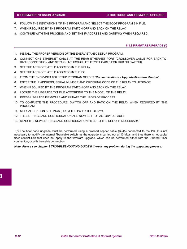
8-12 G650 Generator Protection & Control System GEK-113285A
8.3 FIRMWARE VERSION UPGRADE 8 BOOTCODE AND FIRMWARE UPGRADE
8
6. FOLLOW THE INDICATIONS OF THE PROGRAM AND SELECT THE BOOT PROGRAM BIN FILE.
7. WHEN REQUIRED BY THE PROGRAM SWITCH OFF AND BACK ON THE RELAY.
8. CONTINUE WITH THE PROCESS AND SET THE IP ADDRESS AND GATEWAY WHEN REQUIRED.
8.3.3 FIRMWARE UPGRADE (*)
1. INSTALL THE PROPER VERSION OF THE ENERVISTA 650 SETUP PROGRAM.
2. CONNECT ONE ETHERNET CABLE AT THE REAR ETHERNET PORT (CROSSOVER CABLE FOR BACK-TO-BACK CONNECTION AND STRAIGHT-THROUGH ETHERNET CABLE FOR HUB OR SWITCH).
3. SET THE APPROPRIATE IP ADDRESS IN THE RELAY.
4. SET THE APPROPRIATE IP ADDRESS IN THE PC.
5. FROM THE ENERVISTA 650 SETUP PROGRAM SELECT “Communications > Upgrade Firmware Version”.
6. ENTER THE IP ADDRESS, SERIAL NUMBER AND ORDERING CODE OF THE RELAY TO UPGRADE.
7. WHEN REQUIRED BY THE PROGRAM SWITCH OFF AND BACK ON THE RELAY.
8. LOCATE THE UPGRADE.TXT FILE ACCORDING TO THE MODEL OF THE RELAY.
9. PRESS UPGRADE FIRMWARE AND INITIATE THE UPGRADE PROCESS.
10. TO COMPLETE THE PROCEDURE, SWITCH OFF AND BACK ON THE RELAY WHEN REQUIRED BY THEPROGRAM.
11. SET CALIBRATION SETTINGS (FROM THE PC TO THE RELAY).
12. THE SETTINGS AND CONFIGURATION ARE NOW SET TO FACTORY DEFAULT.
13. SEND THE NEW SETTINGS AND CONFIGURATION FILES TO THE RELAY IF NECESSARY.
(*) The boot code upgrade must be performed using a crossed copper cable (RJ45) connected to the PC. It is notnecessary to modify the internal fiber/cable switch, as the upgrade is carried out at 10 Mb/s, and thus there is not cable/fiber conflict.This fact does not apply to the firmware upgrade, which can be performed either with the Ethernet fiberconnection, or with the cable connection.
Note: Please see chapter 8 TROUBLESHOOTING GUIDE if there is any problem during the upgrading process.
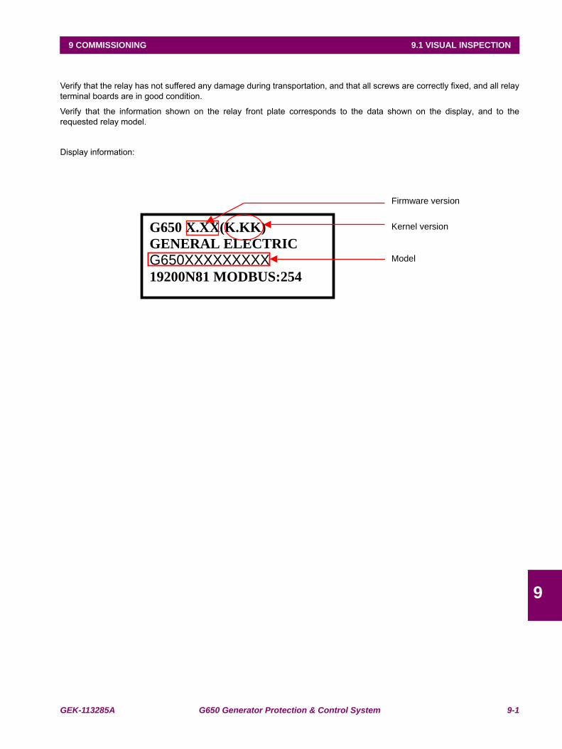
GEK-113285A G650 Generator Protection & Control System 9-1
9 COMMISSIONING 9.1 VISUAL INSPECTION
9
9 COMMISSIONING 9.1VISUAL INSPECTION
Verify that the relay has not suffered any damage during transportation, and that all screws are correctly fixed, and all relayterminal boards are in good condition.
Verify that the information shown on the relay front plate corresponds to the data shown on the display, and to therequested relay model.
Display information:
Firmware version
Kernel version G650 X.XX(K.KK)
GENERAL ELECTRIC
G650XXXXXXXXX 19200N81 MODBUS:254
Model

9-2 G650 Generator Protection & Control System GEK-113285A
9.2 GENERAL CONSIDERATIONS ON THE POWER SUPPLY NETWORK 9 COMMISSIONING
9
9.2GENERAL CONSIDERATIONS ON THE POWER SUPPLY NETWORK
All devices running on AC current are affected by frequency. As a non-sine wave is the result of a fundamental wave plus aseries of harmonics from this fundamental wave, we can infer that devices running on AC current are influenced by theapplied waveform.
For a correct testing of relays running on AC current, it is fundamental to use a current and/or voltage senoidal waveform.The pureness of a senoidal wave (lack of harmonics) cannot be expressed specifically for a specific relay. However, anyrelay incorporating sintonized circuits, R-L and R-C circuits, will be affected by non-senoidal waveforms, as in the case ofG650.
These relays respond to the voltage waveform in a different way to the majority of AC current voltmeters. If the powersupply network used for the testing contains wide harmonics, the voltmeter and relay responses will be different.
Relays have been calibrated in factory using a Network of 50 or 60 Hz with a minimum harmonic content. When the relay istested, a power supply network with no harmonics in its waveform must be used.
The ammeters and chronometers used for testing the pickup current and relay operation time must be calibrated and theiraccuracy must be better than the relay’s. The power supply used in the tests must remain stable, mainly in the levels nearthe operation thresholds.
It is important to point out that the accuracy with which the test is performed depends on the network and on theinstruments used. Functional tests performed with unsuitable power supply network and instruments are useful to checkthat the relay operates properly and therefore its operating characteristics are verified in an approximate manner. However,if the relay would be calibrated in these conditions, its operational characteristics would be outside the tolerance rangevalues.
The following sections detail the list of tests for verifying the complete relay functionality.
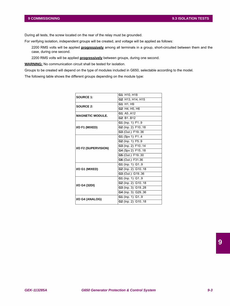
GEK-113285A G650 Generator Protection & Control System 9-3
9 COMMISSIONING 9.3 ISOLATION TESTS
9
9.3ISOLATION TESTS
During all tests, the screw located on the rear of the relay must be grounded.
For verifying isolation, independent groups will be created, and voltage will be applied as follows:
2200 RMS volts will be applied progressively among all terminals in a group, short-circuited between them and thecase, during one second.
2200 RMS volts will be applied progressively between groups, during one second.
WARNING: No communication circuit shall be tested for isolation.
Groups to be created will depend on the type of modules included in G650, selectable according to the model.
The following table shows the different groups depending on the module type:
SOURCE 1:G1: H10, H18G2: H13, H14, H15
SOURCE 2:G1: H1, H9G2: H4, H5, H6
MAGNETIC MODULE.G1: A5..A12G2: B1..B12
I/O F1 (MIXED)G1 (Inp. 1): F1..9G2 (Inp. 2): F10..18G3 (Out.): F19..36
I/O F2 (SUPERVISION)
G1 (Spv 1): F1..4G2 (Inp. 1): F5..9G3 (Inp. 2): F10..14G4 (Spv 2): F15..18G5 (Out.): F19..30G6 (Out.): F31.36
I/O G1 (MIXED)G1 (Inp. 1): G1..9G2 (Inp. 2): G10..18G3 (Out.): G19..36
I/O G4 (32DI)
G1 (Inp. 1): G1..9G2 (Inp. 2): G10..18G3 (Inp. 3): G19..28G4 (Inp. 3): G29..36
I/O G4 (ANALOG)G1 (Inp. 1): G1..9G2 (Inp. 2): G10..18
9-4 G650 Generator Protection & Control System GEK-113285A
9.4 INDICATORS 9 COMMISSIONING
9
9.4INDICATORS
Feed the relay and verify that when commanding a LED reset operation, all LED indicators light up and they are turned offwhen pressing the ESC key for more than 3 seconds.
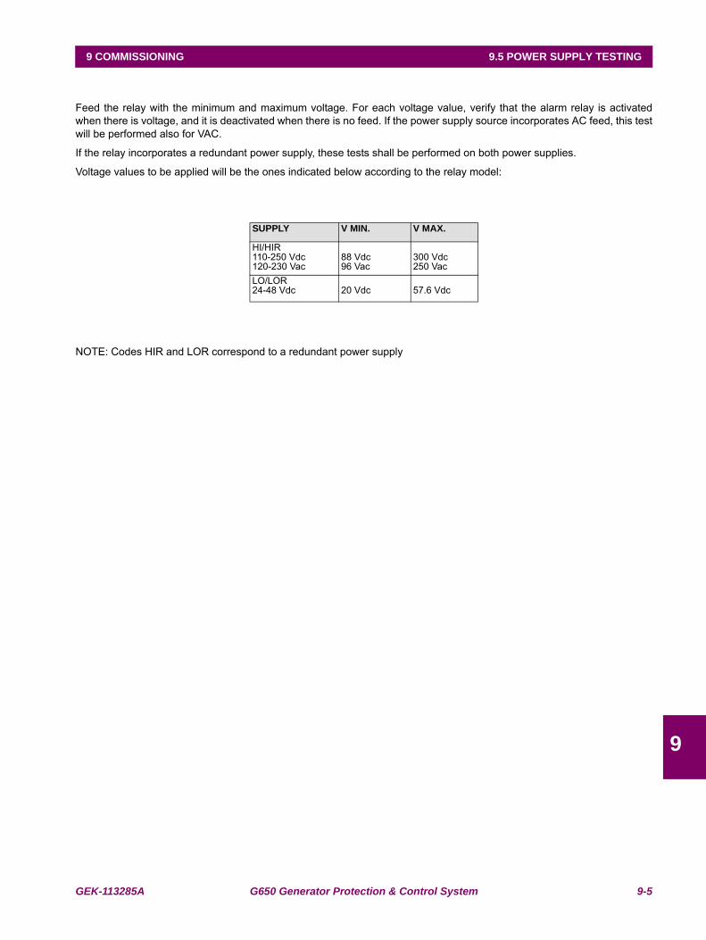
GEK-113285A G650 Generator Protection & Control System 9-5
9 COMMISSIONING 9.5 POWER SUPPLY TESTING
9
9.5POWER SUPPLY TESTING
Feed the relay with the minimum and maximum voltage. For each voltage value, verify that the alarm relay is activatedwhen there is voltage, and it is deactivated when there is no feed. If the power supply source incorporates AC feed, this testwill be performed also for VAC.
If the relay incorporates a redundant power supply, these tests shall be performed on both power supplies.
Voltage values to be applied will be the ones indicated below according to the relay model:
NOTE: Codes HIR and LOR correspond to a redundant power supply
SUPPLY V MIN. V MAX.
HI/HIR110-250 Vdc120-230 Vac
88 Vdc96 Vac
300 Vdc250 Vac
LO/LOR24-48 Vdc 20 Vdc 57.6 Vdc
9-6 G650 Generator Protection & Control System GEK-113285A
9.6 COMMUNICATIONS 9 COMMISSIONING
9
9.6COMMUNICATIONS
Verify that available communication ports allow communication with the relay.
Ports to be checked are as follows:
Front:RS232
Rear:2 x RS485, 2 x Fiber Optic - Serial, 2 x Fiber Optic - Ethernet, 1 x RJ45 - Ethernet .
A computer with EnerVista 650 Setup software and an appropriate connector must be used.
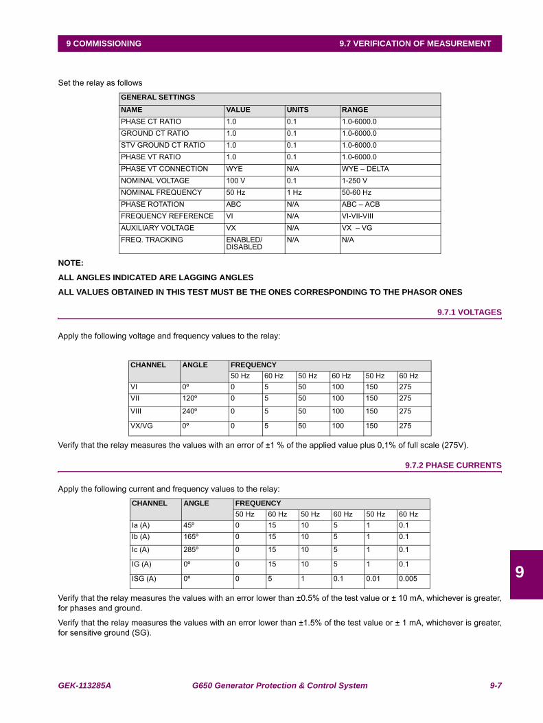
GEK-113285A G650 Generator Protection & Control System 9-7
9 COMMISSIONING 9.7 VERIFICATION OF MEASUREMENT
9
9.7VERIFICATION OF MEASUREMENT
Set the relay as follows
NOTE:
ALL ANGLES INDICATED ARE LAGGING ANGLES
ALL VALUES OBTAINED IN THIS TEST MUST BE THE ONES CORRESPONDING TO THE PHASOR ONES
9.7.1 VOLTAGES
Apply the following voltage and frequency values to the relay:
Verify that the relay measures the values with an error of ±1 % of the applied value plus 0,1% of full scale (275V).
9.7.2 PHASE CURRENTS
Apply the following current and frequency values to the relay:
Verify that the relay measures the values with an error lower than ±0.5% of the test value or ± 10 mA, whichever is greater,for phases and ground.
Verify that the relay measures the values with an error lower than ±1.5% of the test value or ± 1 mA, whichever is greater,for sensitive ground (SG).
GENERAL SETTINGSNAME VALUE UNITS RANGEPHASE CT RATIO 1.0 0.1 1.0-6000.0GROUND CT RATIO 1.0 0.1 1.0-6000.0STV GROUND CT RATIO 1.0 0.1 1.0-6000.0PHASE VT RATIO 1.0 0.1 1.0-6000.0PHASE VT CONNECTION WYE N/A WYE – DELTANOMINAL VOLTAGE 100 V 0.1 1-250 VNOMINAL FREQUENCY 50 Hz 1 Hz 50-60 HzPHASE ROTATION ABC N/A ABC – ACBFREQUENCY REFERENCE VI N/A VI-VII-VIIIAUXILIARY VOLTAGE VX N/A VX – VGFREQ. TRACKING ENABLED/
DISABLEDN/A N/A
CHANNEL ANGLE FREQUENCY50 Hz 60 Hz 50 Hz 60 Hz 50 Hz 60 Hz
VI 0º 0 5 50 100 150 275VII 120º 0 5 50 100 150 275
VIII 240º 0 5 50 100 150 275
VX/VG 0º 0 5 50 100 150 275
CHANNEL ANGLE FREQUENCY50 Hz 60 Hz 50 Hz 60 Hz 50 Hz 60 Hz
Ia (A) 45º 0 15 10 5 1 0.1Ib (A) 165º 0 15 10 5 1 0.1
Ic (A) 285º 0 15 10 5 1 0.1
IG (A) 0º 0 15 10 5 1 0.1
ISG (A) 0º 0 5 1 0.1 0.01 0.005
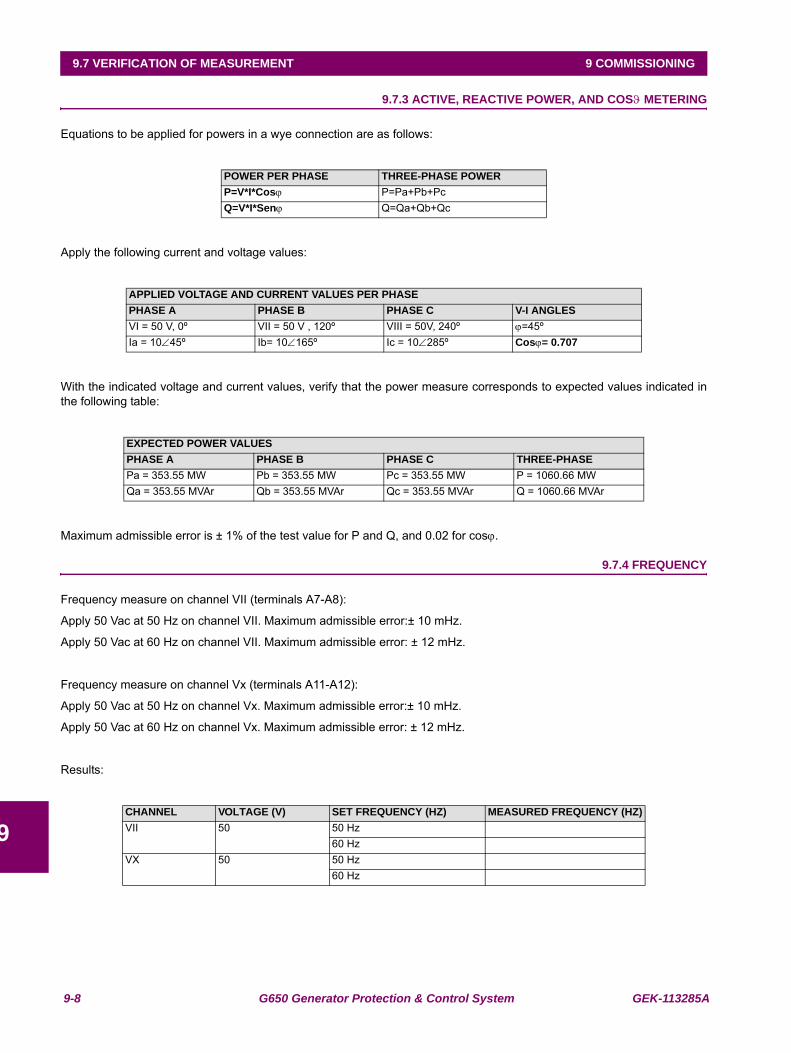
9-8 G650 Generator Protection & Control System GEK-113285A
9.7 VERIFICATION OF MEASUREMENT 9 COMMISSIONING
9
9.7.3 ACTIVE, REACTIVE POWER, AND COSϑ METERING
Equations to be applied for powers in a wye connection are as follows:
Apply the following current and voltage values:
With the indicated voltage and current values, verify that the power measure corresponds to expected values indicated inthe following table:
Maximum admissible error is ± 1% of the test value for P and Q, and 0.02 for cosϕ.
9.7.4 FREQUENCY
Frequency measure on channel VII (terminals A7-A8):
Apply 50 Vac at 50 Hz on channel VII. Maximum admissible error:± 10 mHz.
Apply 50 Vac at 60 Hz on channel VII. Maximum admissible error: ± 12 mHz.
Frequency measure on channel Vx (terminals A11-A12):
Apply 50 Vac at 50 Hz on channel Vx. Maximum admissible error:± 10 mHz.
Apply 50 Vac at 60 Hz on channel Vx. Maximum admissible error: ± 12 mHz.
Results:
POWER PER PHASE THREE-PHASE POWERP=V*I*Cosϕ P=Pa+Pb+PcQ=V*I*Senϕ Q=Qa+Qb+Qc
APPLIED VOLTAGE AND CURRENT VALUES PER PHASEPHASE A PHASE B PHASE C V-I ANGLESVI = 50 V, 0º VII = 50 V , 120º VIII = 50V, 240º ϕ=45ºIa = 10∠45º Ib= 10∠165º Ic = 10∠285º Cosϕ= 0.707
EXPECTED POWER VALUESPHASE A PHASE B PHASE C THREE-PHASEPa = 353.55 MW Pb = 353.55 MW Pc = 353.55 MW P = 1060.66 MWQa = 353.55 MVAr Qb = 353.55 MVAr Qc = 353.55 MVAr Q = 1060.66 MVAr
CHANNEL VOLTAGE (V) SET FREQUENCY (HZ) MEASURED FREQUENCY (HZ)VII 50 50 Hz
60 HzVX 50 50 Hz
60 Hz
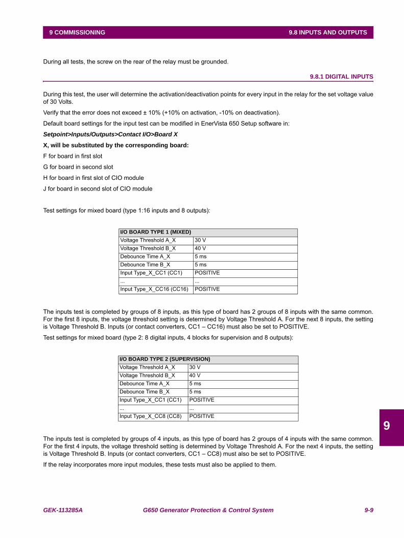
GEK-113285A G650 Generator Protection & Control System 9-9
9 COMMISSIONING 9.8 INPUTS AND OUTPUTS
9
9.8INPUTS AND OUTPUTS
During all tests, the screw on the rear of the relay must be grounded.
9.8.1 DIGITAL INPUTS
During this test, the user will determine the activation/deactivation points for every input in the relay for the set voltage valueof 30 Volts.
Verify that the error does not exceed ± 10% (+10% on activation, -10% on deactivation).
Default board settings for the input test can be modified in EnerVista 650 Setup software in:
Setpoint>Inputs/Outputs>Contact I/O>Board X
X, will be substituted by the corresponding board:
F for board in first slot
G for board in second slot
H for board in first slot of CIO module
J for board in second slot of CIO module
Test settings for mixed board (type 1:16 inputs and 8 outputs):
The inputs test is completed by groups of 8 inputs, as this type of board has 2 groups of 8 inputs with the same common.For the first 8 inputs, the voltage threshold setting is determined by Voltage Threshold A. For the next 8 inputs, the settingis Voltage Threshold B. Inputs (or contact converters, CC1 – CC16) must also be set to POSITIVE.
Test settings for mixed board (type 2: 8 digital inputs, 4 blocks for supervision and 8 outputs):
The inputs test is completed by groups of 4 inputs, as this type of board has 2 groups of 4 inputs with the same common.For the first 4 inputs, the voltage threshold setting is determined by Voltage Threshold A. For the next 4 inputs, the settingis Voltage Threshold B. Inputs (or contact converters, CC1 – CC8) must also be set to POSITIVE.
If the relay incorporates more input modules, these tests must also be applied to them.
I/O BOARD TYPE 1 (MIXED)Voltage Threshold A_X 30 VVoltage Threshold B_X 40 VDebounce Time A_X 5 msDebounce Time B_X 5 msInput Type_X_CC1 (CC1) POSITIVE... ...Input Type_X_CC16 (CC16) POSITIVE
I/O BOARD TYPE 2 (SUPERVISION)Voltage Threshold A_X 30 VVoltage Threshold B_X 40 VDebounce Time A_X 5 msDebounce Time B_X 5 msInput Type_X_CC1 (CC1) POSITIVE... ...Input Type_X_CC8 (CC8) POSITIVE
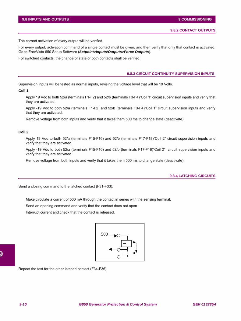
9-10 G650 Generator Protection & Control System GEK-113285A
9.8 INPUTS AND OUTPUTS 9 COMMISSIONING
9
9.8.2 CONTACT OUTPUTS
The correct activation of every output will be verified.
For every output, activation command of a single contact must be given, and then verify that only that contact is activated.Go to EnerVista 650 Setup Software (Setpoint>Inputs/Outputs>Force Outputs).
For switched contacts, the change of state of both contacts shall be verified.
9.8.3 CIRCUIT CONTINUITY SUPERVISION INPUTS
Supervision inputs will be tested as normal inputs, revising the voltage level that will be 19 Volts.
Coil 1:
Apply 19 Vdc to both 52/a (terminals F1-F2) and 52/b (terminals F3-F4)”Coil 1” circuit supervision inputs and verify thatthey are activated.
Apply -19 Vdc to both 52/a (terminals F1-F2) and 52/b (terminals F3-F4)”Coil 1” circuit supervision inputs and verifythat they are activated.
Remove voltage from both inputs and verify that it takes them 500 ms to change state (deactivate).
Coil 2:
Apply 19 Vdc to both 52/a (terminals F15-F16) and 52/b (terminals F17-F18)”Coil 2” circuit supervision inputs andverify that they are activated.
Apply -19 Vdc to both 52/a (terminals F15-F16) and 52/b (terminals F17-F18)”Coil 2” circuit supervision inputs andverify that they are activated.
Remove voltage from both inputs and verify that it takes them 500 ms to change state (deactivate).
9.8.4 LATCHING CIRCUITS
Send a closing command to the latched contact (F31-F33).
Make circulate a current of 500 mA through the contact in series with the sensing terminal.
Send an opening command and verify that the contact does not open.
Interrupt current and check that the contact is released.
Repeat the test for the other latched contact (F34-F36).
I
500
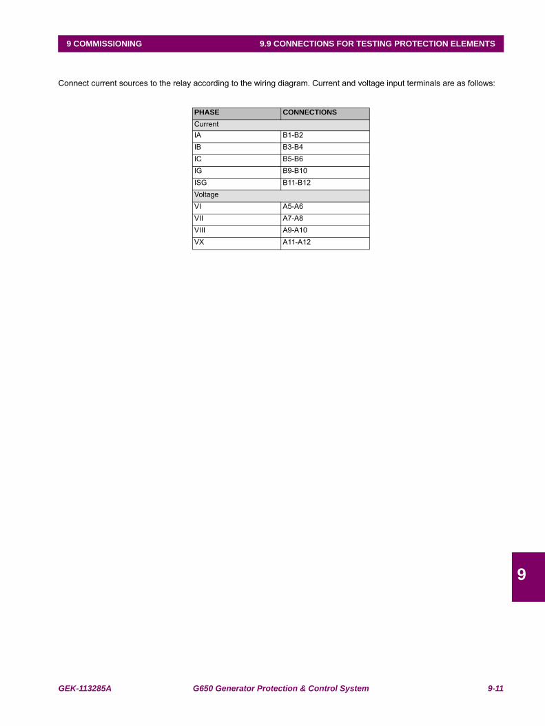
GEK-113285A G650 Generator Protection & Control System 9-11
9 COMMISSIONING 9.9 CONNECTIONS FOR TESTING PROTECTION ELEMENTS
9
9.9CONNECTIONS FOR TESTING PROTECTION ELEMENTS
Connect current sources to the relay according to the wiring diagram. Current and voltage input terminals are as follows:
PHASE CONNECTIONSCurrentIA B1-B2IB B3-B4IC B5-B6IG B9-B10ISG B11-B12VoltageVI A5-A6VII A7-A8VIII A9-A10VX A11-A12
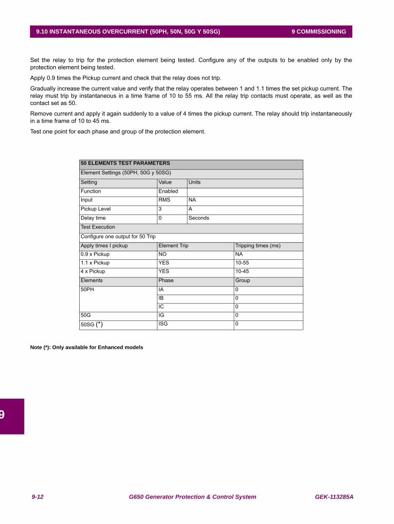
9-12 G650 Generator Protection & Control System GEK-113285A
9.10 INSTANTANEOUS OVERCURRENT (50PH, 50N, 50G Y 50SG) 9 COMMISSIONING
9
9.10INSTANTANEOUS OVERCURRENT (50PH, 50N, 50G Y 50SG)
Set the relay to trip for the protection element being tested. Configure any of the outputs to be enabled only by theprotection element being tested.
Apply 0.9 times the Pickup current and check that the relay does not trip.
Gradually increase the current value and verify that the relay operates between 1 and 1.1 times the set pickup current. Therelay must trip by instantaneous in a time frame of 10 to 55 ms. All the relay trip contacts must operate, as well as thecontact set as 50.
Remove current and apply it again suddenly to a value of 4 times the pickup current. The relay should trip instantaneouslyin a time frame of 10 to 45 ms.
Test one point for each phase and group of the protection element.
Note (*): Only available for Enhanced models
50 ELEMENTS TEST PARAMETERS
Element Settings (50PH, 50G y 50SG)
Setting Value Units
Function EnabledInput RMS NA
Pickup Level 3 A
Delay time 0 Seconds
Test Execution
Configure one output for 50 Trip
Apply times I pickup Element Trip Tripping times (ms)0.9 x Pickup NO NA1.1 x Pickup YES 10-554 x Pickup YES 10-45
Elements Phase Group
50PH IA 0IB 0IC 0
50G IG 0
50SG (*) ISG 0
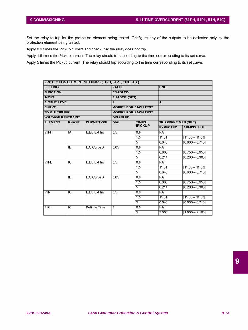
GEK-113285A G650 Generator Protection & Control System 9-13
9 COMMISSIONING 9.11 TIME OVERCURRENT (51PH, 51PL, 51N, 51G)
9
9.11 TIME OVERCURRENT (51PH, 51PL, 51N, 51G)
Set the relay to trip for the protection element being tested. Configure any of the outputs to be activated only by theprotection element being tested.
Apply 0.9 times the Pickup current and check that the relay does not trip.
Apply 1.5 times the Pickup current. The relay should trip according to the time corresponding to its set curve.
Apply 5 times the Pickup current. The relay should trip according to the time corresponding to its set curve.
PROTECTION ELEMENT SETTINGS (51PH, 51PL, 51N, 51G )SETTING VALUE UNITFUNCTION ENABLEDINPUT PHASOR (DFT)PICKUP LEVEL 1 ACURVE MODIFY FOR EACH TESTTD MULTIPLIER MODIFY FOR EACH TESTVOLTAGE RESTRAINT DISABLEDELEMENT PHASE CURVE TYPE DIAL TIMES
IPICKUPTRIPPING TIMES (SEC)EXPECTED ADMISSIBLE
51PH IA IEEE Ext Inv 0.5 0.9 NA1.5 11.34 [11.00 – 11.60]5 0.648 [0.600 – 0.710]
IB IEC Curve A 0.05 0.9 NA1.5 0.860 [0.750 – 0.950]5 0.214 [0.200 – 0.300]
51PL IC IEEE Ext Inv 0.5 0.9 NA1.5 11.34 [11.00 – 11.60]5 0.648 [0.600 – 0.710]
IB IEC Curve A 0.05 0.9 NA1.5 0.860 [0.750 – 0.950]5 0.214 [0.200 – 0.300]
51N IC IEEE Ext Inv 0.5 0.9 NA1.5 11.34 [11.00 – 11.60]5 0.648 [0.600 – 0.710]
51G IG Definite Time 2 0.9 NA5 2.000 [1.900 – 2.100]
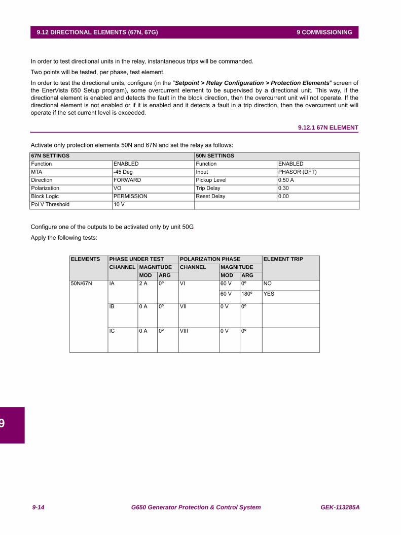
9-14 G650 Generator Protection & Control System GEK-113285A
9.12 DIRECTIONAL ELEMENTS (67N, 67G) 9 COMMISSIONING
9
9.12DIRECTIONAL ELEMENTS (67N, 67G)
In order to test directional units in the relay, instantaneous trips will be commanded.
Two points will be tested, per phase, test element.
In order to test the directional units, configure (in the "Setpoint > Relay Configuration > Protection Elements" screen ofthe EnerVista 650 Setup program), some overcurrent element to be supervised by a directional unit. This way, if thedirectional element is enabled and detects the fault in the block direction, then the overcurrent unit will not operate. If thedirectional element is not enabled or if it is enabled and it detects a fault in a trip direction, then the overcurrent unit willoperate if the set current level is exceeded.
9.12.1 67N ELEMENT
Activate only protection elements 50N and 67N and set the relay as follows:
Configure one of the outputs to be activated only by unit 50G.
Apply the following tests:
67N SETTINGS 50N SETTINGSFunction ENABLED Function ENABLEDMTA -45 Deg Input PHASOR (DFT)Direction FORWARD Pickup Level 0.50 APolarization VO Trip Delay 0.30Block Logic PERMISSION Reset Delay 0.00Pol V Threshold 10 V
ELEMENTS PHASE UNDER TEST POLARIZATION PHASE ELEMENT TRIPCHANNEL MAGNITUDE CHANNEL MAGNITUDE
MOD ARG MOD ARG50N/67N IA 2 A 0º VI 60 V 0º NO
60 V 180º YES
IB 0 A 0º VII 0 V 0º
IC 0 A 0º VIII 0 V 0º
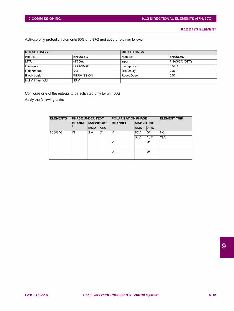
GEK-113285A G650 Generator Protection & Control System 9-15
9 COMMISSIONING 9.12 DIRECTIONAL ELEMENTS (67N, 67G)
9
9.12.2 67G ELEMENT
Activate only protection elements 50G and 67G and set the relay as follows:
Configure one of the outputs to be activated only by unit 50G.
Apply the following tests:
67G SETTINGS 50G SETTINGSFunction ENABLED Function ENABLEDMTA -45 Deg Input PHASOR (DFT)Direction FORWARD Pickup Level 0.50 APolarization VO Trip Delay 0.30Block Logic PERMISSION Reset Delay 0.00Pol V Threshold 10 V
ELEMENTS PHASE UNDER TEST POLARIZATION PHASE ELEMENT TRIPCHANNEL
MAGNITUDE CHANNEL MAGNITUDEMOD ARG MOD ARG
50G/67G IG 2 A 0º VI 60V 0º NO60V 180º YES
VII 0º
VIII 0º
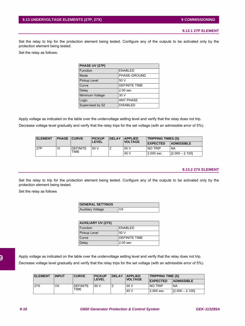
9-16 G650 Generator Protection & Control System GEK-113285A
9.13 UNDERVOLTAGE ELEMENTS (27P, 27X) 9 COMMISSIONING
9
9.13UNDERVOLTAGE ELEMENTS (27P, 27X) 9.13.1 27P ELEMENT
Set the relay to trip for the protection element being tested. Configure any of the outputs to be activated only by theprotection element being tested.
Set the relay as follows:
Apply voltage as indicated on the table over the undervoltage setting level and verify that the relay does not trip.
Decrease voltage level gradually and verify that the relay trips for the set voltage (with an admissible error of 5%).
9.13.2 27X ELEMENT
Set the relay to trip for the protection element being tested. Configure any of the outputs to be activated only by theprotection element being tested.
Set the relay as follows
Apply voltage as indicated on the table over the undervoltage setting level and verify that the relay does not trip.
Decrease voltage level gradually and verify that the relay trips for the set voltage (with an admissible error of 5%).
PHASE UV (27P)Function ENABLEDMode PHASE-GROUNDPickup Level 50 VCurve DEFINITE TIMEDelay 2.00 secMinimum Voltage 30 VLogic ANY PHASESupervised by 52 DISABLED
ELEMENT PHASE CURVE PICKUP LEVEL
DELAY APPLIED VOLTAGE
TRIPPING TIMES (S)EXPECTED ADMISSIBLE
27P VI DEFINITE TIME
50 V 2 55 V NO TRIP NA45 V 2.000 sec [2.000 – 2.100]
GENERAL SETTINGSAuxiliary Voltage VX
AUXILIARY UV (27X)Function ENABLEDPickup Level 50 VCurve DEFINITE TIMEDelay 2.00 sec
ELEMENT INPUT CURVE PICKUP LEVEL
DELAY APPLIED VOLTAGE
TRIPPING TIME (S)EXPECTED ADMISSIBLE
27X VX DEFINITE TIME
50 V 2 55 V NO TRIP NA45 V 2.000 sec [2.000 – 2.100]
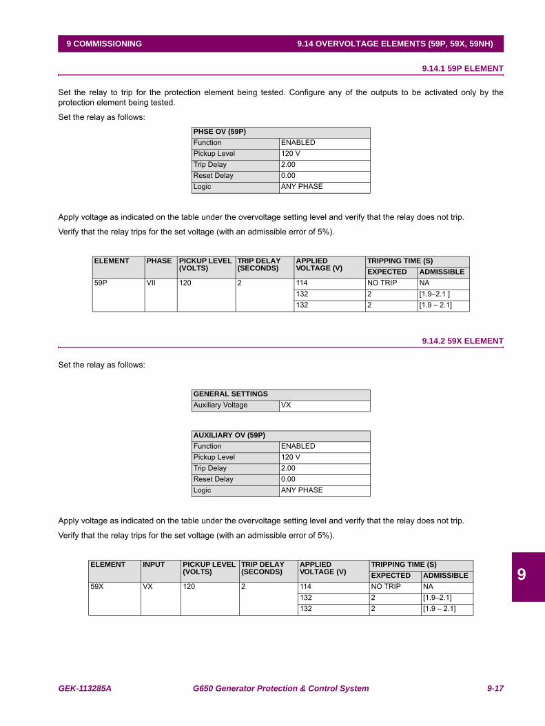
GEK-113285A G650 Generator Protection & Control System 9-17
9 COMMISSIONING 9.14 OVERVOLTAGE ELEMENTS (59P, 59X, 59NH)
9
9.14OVERVOLTAGE ELEMENTS (59P, 59X, 59NH) 9.14.1 59P ELEMENT
Set the relay to trip for the protection element being tested. Configure any of the outputs to be activated only by theprotection element being tested.
Set the relay as follows:
Apply voltage as indicated on the table under the overvoltage setting level and verify that the relay does not trip.
Verify that the relay trips for the set voltage (with an admissible error of 5%).
9.14.2 59X ELEMENT
Set the relay as follows:
Apply voltage as indicated on the table under the overvoltage setting level and verify that the relay does not trip.
Verify that the relay trips for the set voltage (with an admissible error of 5%).
PHSE OV (59P)Function ENABLEDPickup Level 120 VTrip Delay 2.00Reset Delay 0.00Logic ANY PHASE
ELEMENT PHASE PICKUP LEVEL (VOLTS)
TRIP DELAY(SECONDS)
APPLIED VOLTAGE (V)
TRIPPING TIME (S)EXPECTED ADMISSIBLE
59P VII 120 2 114 NO TRIP NA132 2 [1.9–2.1 ]132 2 [1.9 – 2.1]
GENERAL SETTINGSAuxiliary Voltage VX
AUXILIARY OV (59P)Function ENABLEDPickup Level 120 VTrip Delay 2.00Reset Delay 0.00Logic ANY PHASE
ELEMENT INPUT PICKUP LEVEL (VOLTS)
TRIP DELAY(SECONDS)
APPLIED VOLTAGE (V)
TRIPPING TIME (S)EXPECTED ADMISSIBLE
59X VX 120 2 114 NO TRIP NA132 2 [1.9–2.1]132 2 [1.9 – 2.1]
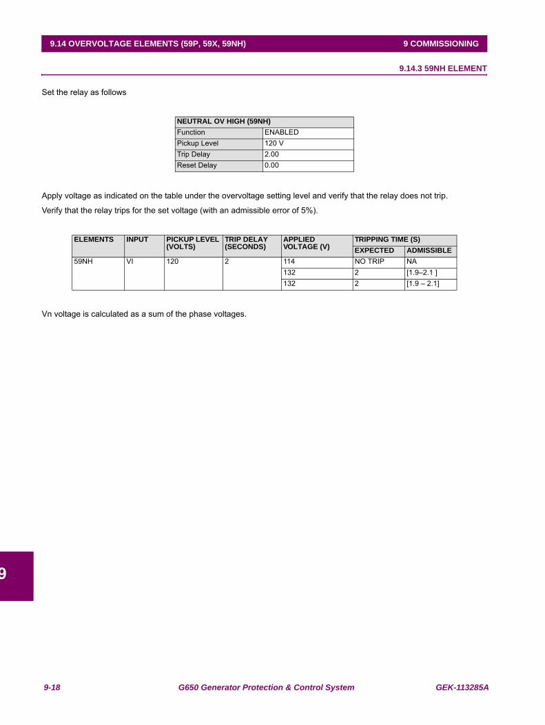
9-18 G650 Generator Protection & Control System GEK-113285A
9.14 OVERVOLTAGE ELEMENTS (59P, 59X, 59NH) 9 COMMISSIONING
9
9.14.3 59NH ELEMENT
Set the relay as follows
Apply voltage as indicated on the table under the overvoltage setting level and verify that the relay does not trip.
Verify that the relay trips for the set voltage (with an admissible error of 5%).
Vn voltage is calculated as a sum of the phase voltages.
NEUTRAL OV HIGH (59NH)Function ENABLEDPickup Level 120 VTrip Delay 2.00Reset Delay 0.00
ELEMENTS INPUT PICKUP LEVEL (VOLTS)
TRIP DELAY(SECONDS)
APPLIED VOLTAGE (V)
TRIPPING TIME (S)EXPECTED ADMISSIBLE
59NH VI 120 2 114 NO TRIP NA132 2 [1.9–2.1 ]132 2 [1.9 – 2.1]
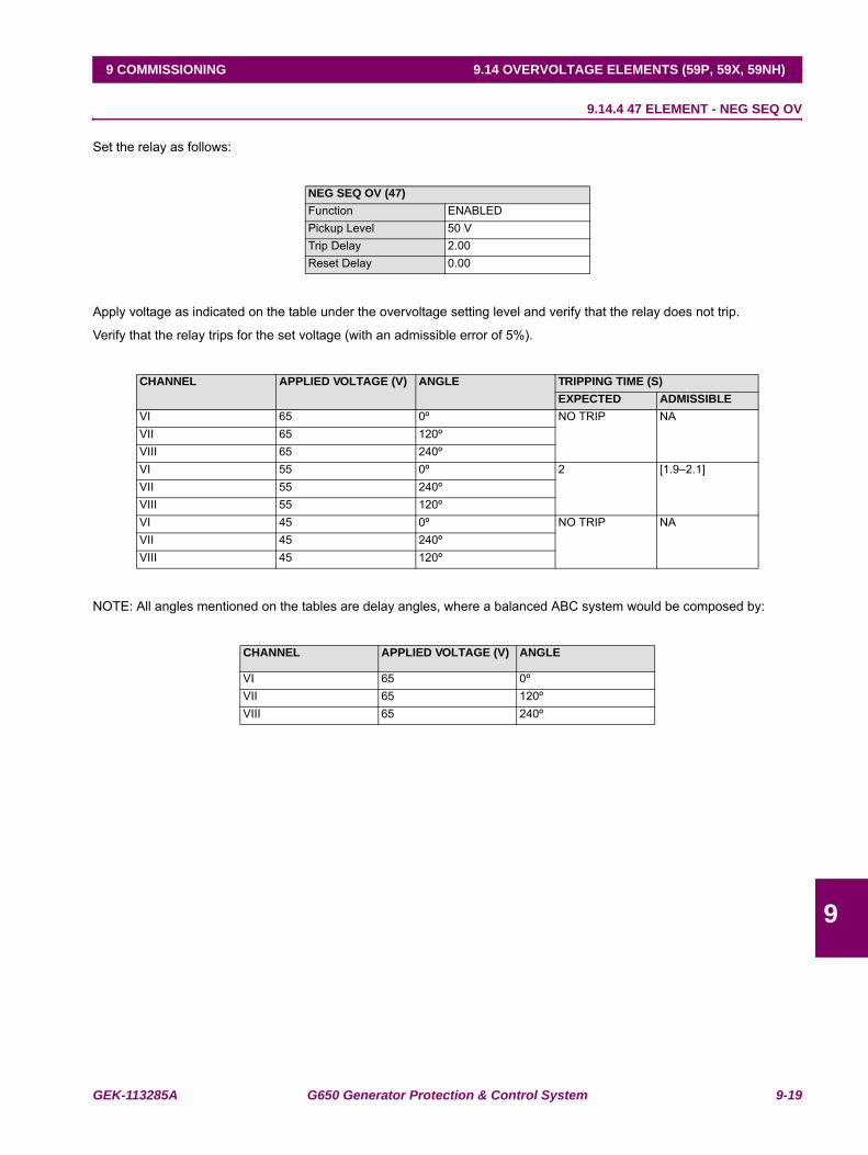
GEK-113285A G650 Generator Protection & Control System 9-19
9 COMMISSIONING 9.14 OVERVOLTAGE ELEMENTS (59P, 59X, 59NH)
9
9.14.4 47 ELEMENT - NEG SEQ OV
Set the relay as follows:
Apply voltage as indicated on the table under the overvoltage setting level and verify that the relay does not trip.
Verify that the relay trips for the set voltage (with an admissible error of 5%).
NOTE: All angles mentioned on the tables are delay angles, where a balanced ABC system would be composed by:
NEG SEQ OV (47)Function ENABLEDPickup Level 50 VTrip Delay 2.00Reset Delay 0.00
CHANNEL APPLIED VOLTAGE (V) ANGLE TRIPPING TIME (S)EXPECTED ADMISSIBLE
VI 65 0º NO TRIP NAVII 65 120ºVIII 65 240ºVI 55 0º 2 [1.9–2.1]VII 55 240ºVIII 55 120ºVI 45 0º NO TRIP NAVII 45 240ºVIII 45 120º
CHANNEL APPLIED VOLTAGE (V) ANGLE
VI 65 0ºVII 65 120ºVIII 65 240º
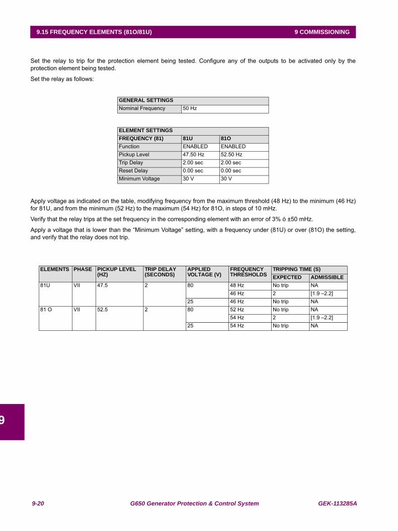
9-20 G650 Generator Protection & Control System GEK-113285A
9.15 FREQUENCY ELEMENTS (81O/81U) 9 COMMISSIONING
9
9.15 FREQUENCY ELEMENTS (81O/81U)
Set the relay to trip for the protection element being tested. Configure any of the outputs to be activated only by theprotection element being tested.
Set the relay as follows:
Apply voltage as indicated on the table, modifying frequency from the maximum threshold (48 Hz) to the minimum (46 Hz)for 81U, and from the minimum (52 Hz) to the maximum (54 Hz) for 81O, in steps of 10 mHz.
Verify that the relay trips at the set frequency in the corresponding element with an error of 3% ó ±50 mHz.
Apply a voltage that is lower than the “Minimum Voltage” setting, with a frequency under (81U) or over (81O) the setting,and verify that the relay does not trip.
GENERAL SETTINGSNominal Frequency 50 Hz
ELEMENT SETTINGSFREQUENCY (81) 81U 81OFunction ENABLED ENABLEDPickup Level 47.50 Hz 52.50 HzTrip Delay 2.00 sec 2.00 secReset Delay 0.00 sec 0.00 secMinimum Voltage 30 V 30 V
ELEMENTS PHASE PICKUP LEVEL (HZ)
TRIP DELAY(SECONDS)
APPLIED VOLTAGE (V)
FREQUENCY THRESHOLDS
TRIPPING TIME (S)EXPECTED ADMISSIBLE
81U VII 47.5 2 80 48 Hz No trip NA46 Hz 2 [1.9 –2.2]
25 46 Hz No trip NA81 O VII 52.5 2 80 52 Hz No trip NA
54 Hz 2 [1.9 –2.2]25 54 Hz No trip NA
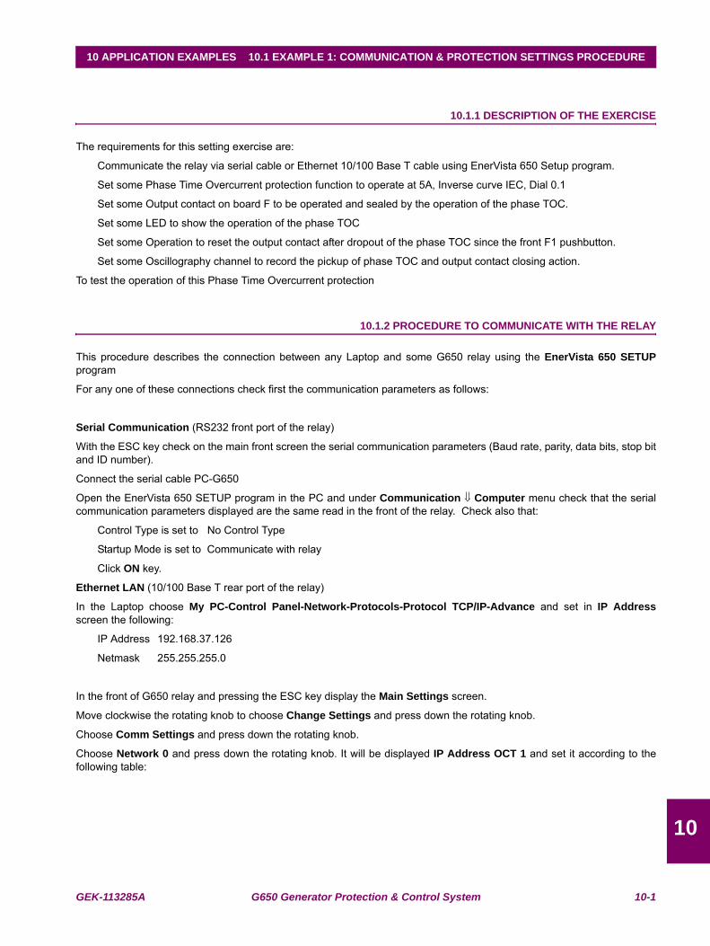
GEK-113285A G650 Generator Protection & Control System 10-1
10 APPLICATION EXAMPLES 10.1 EXAMPLE 1: COMMUNICATION & PROTECTION SETTINGS PROCEDURE
10
10 APPLICATION EXAMPLES 10.1EXAMPLE 1: COMMUNICATION & PROTECTION SETTINGS PROCEDURE
10.1.1 DESCRIPTION OF THE EXERCISE
The requirements for this setting exercise are:
Communicate the relay via serial cable or Ethernet 10/100 Base T cable using EnerVista 650 Setup program.
Set some Phase Time Overcurrent protection function to operate at 5A, Inverse curve IEC, Dial 0.1
Set some Output contact on board F to be operated and sealed by the operation of the phase TOC.
Set some LED to show the operation of the phase TOC
Set some Operation to reset the output contact after dropout of the phase TOC since the front F1 pushbutton.
Set some Oscillography channel to record the pickup of phase TOC and output contact closing action.
To test the operation of this Phase Time Overcurrent protection
10.1.2 PROCEDURE TO COMMUNICATE WITH THE RELAY
This procedure describes the connection between any Laptop and some G650 relay using the EnerVista 650 SETUPprogram
For any one of these connections check first the communication parameters as follows:
Serial Communication (RS232 front port of the relay)
With the ESC key check on the main front screen the serial communication parameters (Baud rate, parity, data bits, stop bitand ID number).
Connect the serial cable PC-G650
Open the EnerVista 650 SETUP program in the PC and under Communication ⇓ Computer menu check that the serialcommunication parameters displayed are the same read in the front of the relay. Check also that:
Control Type is set to No Control Type
Startup Mode is set to Communicate with relay
Click ON key.
Ethernet LAN (10/100 Base T rear port of the relay)
In the Laptop choose My PC-Control Panel-Network-Protocols-Protocol TCP/IP-Advance and set in IP Addressscreen the following:
IP Address 192.168.37.126
Netmask 255.255.255.0
In the front of G650 relay and pressing the ESC key display the Main Settings screen.
Move clockwise the rotating knob to choose Change Settings and press down the rotating knob.
Choose Comm Settings and press down the rotating knob.
Choose Network 0 and press down the rotating knob. It will be displayed IP Address OCT 1 and set it according to thefollowing table:

10-2 G650 Generator Protection & Control System GEK-113285A
10.1 EXAMPLE 1: COMMUNICATION & PROTECTION SETTINGS PROCEDURE 10 APPLICATION EXAMPLES
10
Press ESC key once.
Move rotating knob counterclockwise to General Settings and press it down. General Settings 0 will be displayed now.Press rotating knob down again.
Set ModBus Port Number to 502 and press rotating knob down.
Move counterclockwise the rotating knob to find ModBus Address COM1 and press it down.
Set ModBus Address COM1 to 254 with the rotating knob and then press it down.
Move clockwise the rotating knob to find Press Intro to End and press it down to validate the setting.
Connect a crossover 10/100 MB Ethernet cable from PC to the relay.
Open the EnerVista 650 SETUP program in the PC and under Communication ⇓ Computer menu and set:
IP Address 192.168.37.125
Port 502
Unit Identifier 254
Control Type to ModBus/TCP
Startup Mode to Communicate with relay
Click ON key.
The program will start connection with the relay showing the progress screen.
SEQUENCEACTION SETTING ACTION---- IP Address OCT 1 Set to 192 with rotating knob and press it downMove rotating knob clockwise IP Address OCT 2 Set to 168 with rotating knob and press it downMove rotating knob clockwise IP Address OCT 3 Set to 37 with rotating knob and press it downMove rotating knob clockwise IP Address OCT 4 Set to 125 with rotating knob and press it downMove rotating knob clockwise Netmask OCT 1 Set to 255 with rotating knob and press it downMove rotating knob clockwise Netmask OCT 2 Set to 255 with rotating knob and press it downMove rotating knob clockwise Netmask OCT 3 Set to 255 with rotating knob and press it downMove rotating knob clockwise Netmask OCT 4 Set to 0 with rotating knob and press it downMove rotating knob clockwise Netway IP OCT 1 Leave default setting without any changeMove rotating knob clockwise Netway IP OCT 2 Leave default setting without any changeMove rotating knob clockwise Netway IP OCT 3 Leave default setting without any changeMove rotating knob clockwise Netway IP OCT 4 Leave default setting without any changeMove rotating knob clockwise Press INTRO Press down the rotating knob to validate settings
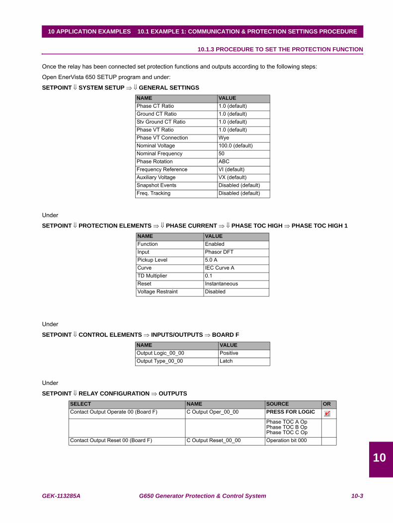
GEK-113285A G650 Generator Protection & Control System 10-3
10 APPLICATION EXAMPLES 10.1 EXAMPLE 1: COMMUNICATION & PROTECTION SETTINGS PROCEDURE
10
10.1.3 PROCEDURE TO SET THE PROTECTION FUNCTION
Once the relay has been connected set protection functions and outputs according to the following steps:
Open EnerVista 650 SETUP program and under:
SETPOINT ⇓ SYSTEM SETUP ⇒ ⇓ GENERAL SETTINGS
Under
SETPOINT ⇓ PROTECTION ELEMENTS ⇒ ⇓ PHASE CURRENT ⇒ ⇓ PHASE TOC HIGH ⇒ PHASE TOC HIGH 1
Under
SETPOINT ⇓ CONTROL ELEMENTS ⇒ INPUTS/OUTPUTS ⇒ BOARD F
Under
SETPOINT ⇓ RELAY CONFIGURATION ⇒ OUTPUTS
NAME VALUEPhase CT Ratio 1.0 (default)Ground CT Ratio 1.0 (default)Stv Ground CT Ratio 1.0 (default)Phase VT Ratio 1.0 (default)Phase VT Connection WyeNominal Voltage 100.0 (default)Nominal Frequency 50Phase Rotation ABCFrequency Reference VI (default)Auxiliary Voltage VX (default)Snapshot Events Disabled (default)Freq. Tracking Disabled (default)
NAME VALUEFunction EnabledInput Phasor DFTPickup Level 5.0 ACurve IEC Curve ATD Multiplier 0.1Reset InstantaneousVoltage Restraint Disabled
NAME VALUEOutput Logic_00_00 PositiveOutput Type_00_00 Latch
SELECT NAME SOURCE ORContact Output Operate 00 (Board F) C Output Oper_00_00 PRESS FOR LOGIC
Phase TOC A OpPhase TOC B OpPhase TOC C Op
Contact Output Reset 00 (Board F) C Output Reset_00_00 Operation bit 000
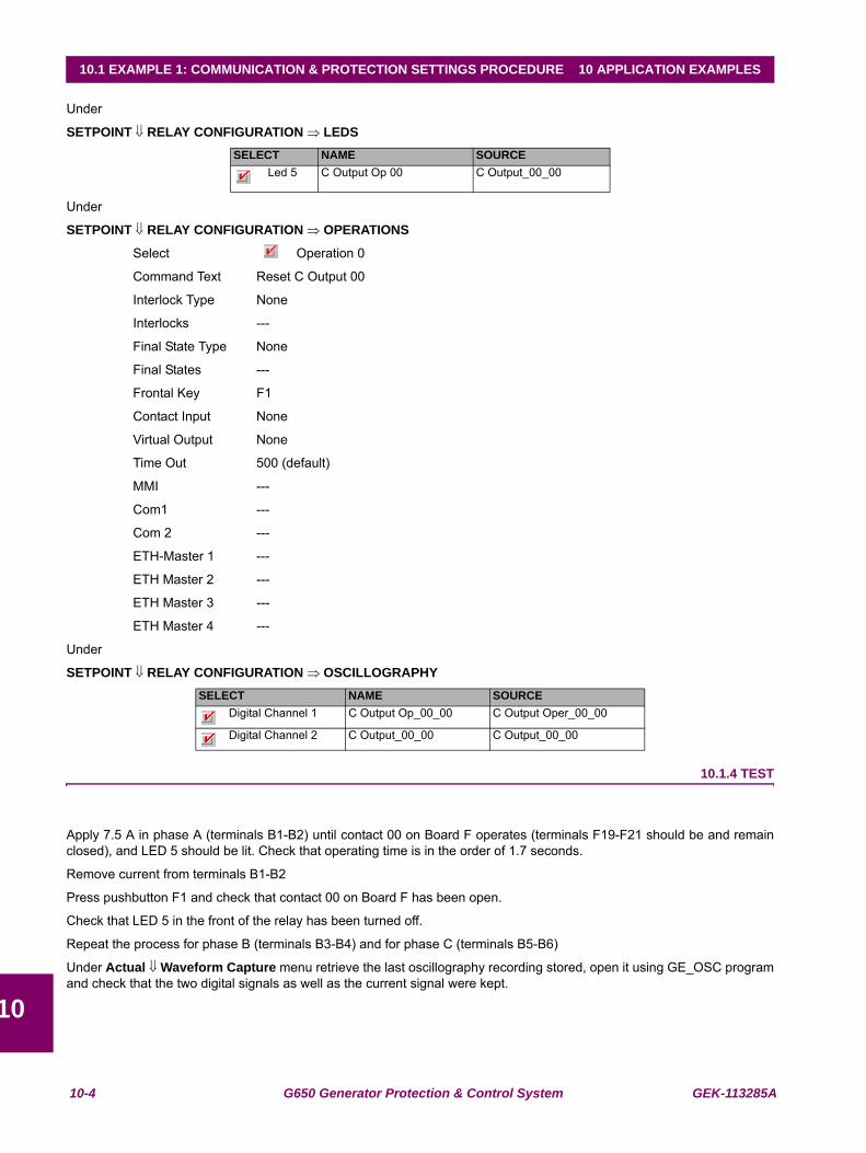
10-4 G650 Generator Protection & Control System GEK-113285A
10.1 EXAMPLE 1: COMMUNICATION & PROTECTION SETTINGS PROCEDURE 10 APPLICATION EXAMPLES
10
Under
SETPOINT ⇓ RELAY CONFIGURATION ⇒ LEDS
Under
SETPOINT ⇓ RELAY CONFIGURATION ⇒ OPERATIONS
Select Operation 0
Command Text Reset C Output 00
Interlock Type None
Interlocks ---
Final State Type None
Final States ---
Frontal Key F1
Contact Input None
Virtual Output None
Time Out 500 (default)
MMI ---
Com1 ---
Com 2 ---
ETH-Master 1 ---
ETH Master 2 ---
ETH Master 3 ---
ETH Master 4 ---
Under
SETPOINT ⇓ RELAY CONFIGURATION ⇒ OSCILLOGRAPHY
10.1.4 TEST
Apply 7.5 A in phase A (terminals B1-B2) until contact 00 on Board F operates (terminals F19-F21 should be and remainclosed), and LED 5 should be lit. Check that operating time is in the order of 1.7 seconds.
Remove current from terminals B1-B2
Press pushbutton F1 and check that contact 00 on Board F has been open.
Check that LED 5 in the front of the relay has been turned off.
Repeat the process for phase B (terminals B3-B4) and for phase C (terminals B5-B6)
Under Actual ⇓ Waveform Capture menu retrieve the last oscillography recording stored, open it using GE_OSC programand check that the two digital signals as well as the current signal were kept.
SELECT NAME SOURCE Led 5 C Output Op 00 C Output_00_00
SELECT NAME SOURCEDigital Channel 1 C Output Op_00_00 C Output Oper_00_00
Digital Channel 2 C Output_00_00 C Output_00_00
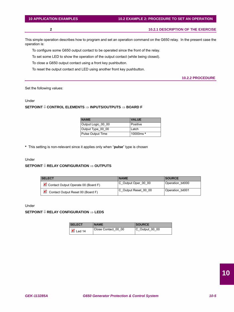
GEK-113285A G650 Generator Protection & Control System 10-5
10 APPLICATION EXAMPLES 10.2 EXAMPLE 2: PROCEDURE TO SET AN OPERATION
10
10.2EXAMPLE 2: PROCEDURE TO SET AN OPERATION 10.2.1 DESCRIPTION OF THE EXERCISE
This simple operation describes how to program and set an operation command on the G650 relay. In the present case theoperation is:
To configure some G650 output contact to be operated since the front of the relay.
To set some LED to show the operation of the output contact (while being closed).
To close a G650 output contact using a front key pushbutton.
To reset the output contact and LED using another front key pushbutton.
10.2.2 PROCEDURE
Set the following values:
Under
SETPOINT ⇓ CONTROL ELEMENTS ⇒ INPUTS/OUTPUTS ⇒ BOARD F
* This setting is non-relevant since it applies only when “pulse” type is chosen
Under
SETPOINT ⇓ RELAY CONFIGURATION ⇒ OUTPUTS
Under
SETPOINT ⇓ RELAY CONFIGURATION ⇒ LEDS
NAME VALUEOutput Logic_00_00 PositiveOutput Type_00_00 LatchPulse Output Time 10000ms *
SELECT NAME SOURCE
Contact Output Operate 00 (Board F) C_Output Oper_00_00 Operation_bit000
Contact Output Reset 00 (Board F) C_Output Reset_00_00 Operation_bit001
SELECT NAME SOURCE
Led 14 Close Contact_00_00 C_Output_00_00
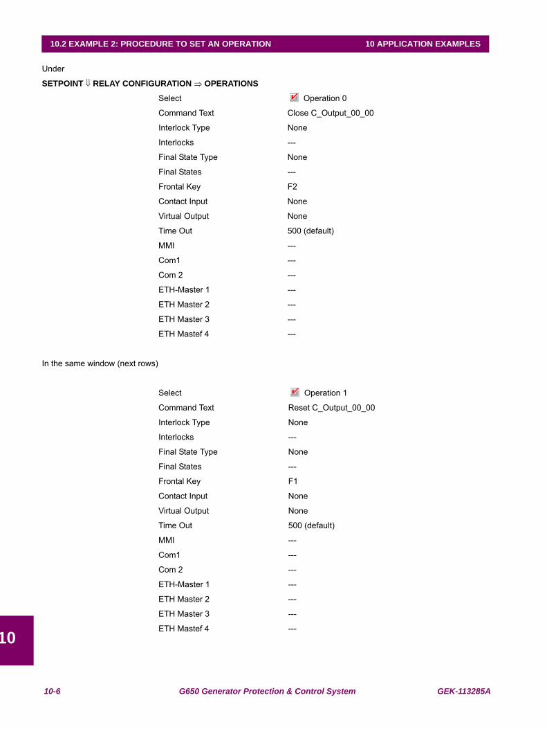
10-6 G650 Generator Protection & Control System GEK-113285A
10.2 EXAMPLE 2: PROCEDURE TO SET AN OPERATION 10 APPLICATION EXAMPLES
10
Under
SETPOINT ⇓ RELAY CONFIGURATION ⇒ OPERATIONS
Select Operation 0
Command Text Close C_Output_00_00
Interlock Type None
Interlocks ---
Final State Type None
Final States ---
Frontal Key F2
Contact Input None
Virtual Output None
Time Out 500 (default)
MMI ---
Com1 ---
Com 2 ---
ETH-Master 1 ---
ETH Master 2 ---
ETH Master 3 ---
ETH Mastef 4 ---
In the same window (next rows)
Select Operation 1
Command Text Reset C_Output_00_00
Interlock Type None
Interlocks ---
Final State Type None
Final States ---
Frontal Key F1
Contact Input None
Virtual Output None
Time Out 500 (default)
MMI ---
Com1 ---
Com 2 ---
ETH-Master 1 ---
ETH Master 2 ---
ETH Master 3 ---
ETH Mastef 4 ---
GEK-113285A G650 Generator Protection & Control System 10-7
10 APPLICATION EXAMPLES 10.2 EXAMPLE 2: PROCEDURE TO SET AN OPERATION
10
10.2.3 TEST
In the main front screen press F2 key.
A message showing “Press Intro to Confirm Key →F2←” will be displayed.
Press down the rotary knob.
Check that contact_00_00 (board F) has been closed.
Check that the front LED 14th is lit.
In the main front screen press F1 key.
A message showing “Press Intro to Confirm Key →F1←” will be displayed.
Press down the rotary knob.
Check that contact_00_00 (board F) has been opened.
Check that the front LED 14th has been switched off
10-8 G650 Generator Protection & Control System GEK-113285A
10.2 EXAMPLE 2: PROCEDURE TO SET AN OPERATION 10 APPLICATION EXAMPLES
10
GEK-113285A G650 Generator Protection & Control System 11-1
11 FREQUENTLY ASKED QUESTIONS 11.1 COMMUNICATIONS
1111 FREQUENTLY ASKED QUESTIONS 11.1COMMUNICATIONSQ1. Does the G650 support DNP and ModBus over the Ethernet port?
A1. G650 units support both protocols over both the asynchronous serial ports and the Ethernet LAN synchronous portusing TCP/IP and UDP/IP layers over the Ethernet.
Q2. Does this equipment support dual IP access?
A2. Yes, it supports two independent IP addresses in aliasing mode. Those address go in the communications settingsNetwork0 and Network1.
Q3. Is the protocol IEC 870-103 supported by the G650?
A3. At this moment it is not supported.
Q4. Can the G650 be used as a DNP master station?
A4. Not at this moment. It works as a slave IED station for all protocols.
Q5. How many communication ports are included in the G650?
A5. The equipment has 2 different boards, one for asynchronous serial ports and another for a high-speed synchronousEthernet port. The first board has 2 comm ports, COM1 and COM2. COM2 is multiplexed with the front serial RS232port, whereas the COM1 port is completely independent from COM2.
The synchronous LAN port is COM3.
Q6. Are there one or two Ethernet ports?
A6. The equipment has only 1 Ethernet port. For redundant fiber optic versions, redundancy is done at the physical level(fiber optic) but there is just one port.
Q7. How many different communication Ethernet sessions can be opened through the LAN port?
A7. ModBus TCP/IP:4 sockets
DNP TCP/IP:3 sessions
Q8. May I use the cooper 10/100 BaseTX connection included in the basic model with all protocols?
A8. Yes, it may be used with all protocols. In noisy substation environments and/or long distances, it is recommended touse fiber optic options due to much better EMC performance and immunity. For fiber optic models, it is necessary toadjust an internal jumper to use the copper port.
Q9. Remote I/O CAN bus. Does it support DeviceNet protocol?
A9. No it does not support DeviceNet.
Q10. Which functions are available in the relay web server?
A10. Currently, it includes several functions for viewing measures and retrieving information.
Q11. Q11 May I use URPC to program the relay?
A11. Only oscillography records may be viewed with URPC once downloaded to a file using the ENERVISTA 650 Setupsoftware.
11-2 G650 Generator Protection & Control System GEK-113285A
11.1 COMMUNICATIONS 11 FREQUENTLY ASKED QUESTIONS
11Q12. May I connect URs and G650s to the same Ethernet?
A12. Yes, either in cable as in fiber, or even mix them.
Q13. How do I connect with fiber 10-BASE-FL UR relays with 100-BASE-FX G650 relays?
A13. Take into account that an UR is never connected directly to a G650 (neither two UR nor two G650 with each other)but they are always connected through a hub or switch. The hub or switch where the URs are connected must be10-BASE-FL and the hub or switch for the G650 must be 100-BASE-FX.
Q14. How do I connect with cable 10_BASE-T UR relays with 10/100-BASE-TX G650 relays?
A14. The answer to this question is as described before but also in this case there is an advantage added, because thehub 10-BASE-TX port is able to understand a 10-BASE-T port. This means that a hub 10-BASE-T port may beconnected to an UR or a G650, and a hub 10/100-BASE-TX port may be connected either to an UR or G650.
Q15. What happens with fiber optic connectors compatibility, because the hub that I have has a differentconnector to the one of the G650, although both are 100-BASE-FX?
A15. Just buy fiber cables with the appropriate male connectors. For the UR and G650 side we need the sameconnectors, ST type, for the hub side, the correspondent ones. And in what concerns to the fiber type, it is used thesame for 10 as for 100, it is the 50/125 or 62.5/125 multimode, this last one allows longer distances.
Q16. What is the difference between a hub and a switch?
A16. In a repeater type hub (shared hub), one unit talks and the rest listen. If all the units are talking at the same timethere may be collisions in the messages, what may produce certain communication delays.
The switch (switched hub) has very powerful processors and a lot of memory and it is much more expensive thanthe hub. It directs messages to the proper destination avoiding collisions and allowing a much more efficientcommunication.
Q17. Why do we have 10/100 compatibility for cable but not for fiber?
A17. The cable has some advantages that the fiber does not have, and it is that the signal attenuation in short andmedium distances, is worthless and this is truth for low and high frequency signals. By the contrary, the light in onefiber optic is highly attenuated, being much worse in case of high frequencies than in the low ones. The 10-BASE-FLfiber transmission is performed in a wavelength of 850nm, what allows a less expensive electronic than the 1300 nmused in 100-BASE-FX fiber transmission. Using, in both cases, the same glass multimode fiber type, the attenuationto 1300 nm is lower than the 850 nm ones, this way the greater attenuation of the 100 Mbits is compensated. Thereis another fiber standard, the 100-BASE-SX, which uses 850 nm to 100 Mbits, being compatible with the 10-BASE-FL one, although it sacrifices the maximum distance to 300 m. Nowadays, this standard has not had success amongEthernet equipment manufacturers and suppliers.
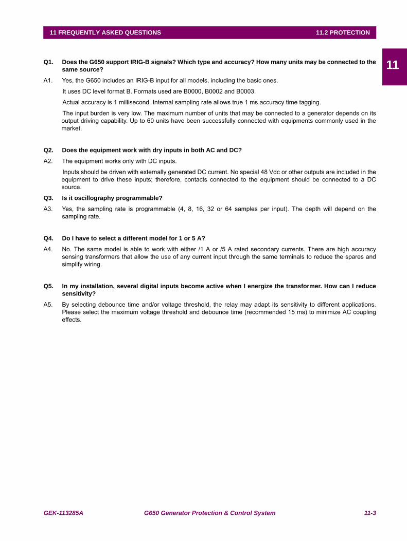
GEK-113285A G650 Generator Protection & Control System 11-3
11 FREQUENTLY ASKED QUESTIONS 11.2 PROTECTION
1111.2PROTECTION
Q1. Does the G650 support IRIG-B signals? Which type and accuracy? How many units may be connected to thesame source?
A1. Yes, the G650 includes an IRIG-B input for all models, including the basic ones.
It uses DC level format B. Formats used are B0000, B0002 and B0003.
Actual accuracy is 1 millisecond. Internal sampling rate allows true 1 ms accuracy time tagging.
The input burden is very low. The maximum number of units that may be connected to a generator depends on itsoutput driving capability. Up to 60 units have been successfully connected with equipments commonly used in themarket.
Q2. Does the equipment work with dry inputs in both AC and DC?
A2. The equipment works only with DC inputs.
Inputs should be driven with externally generated DC current. No special 48 Vdc or other outputs are included in theequipment to drive these inputs; therefore, contacts connected to the equipment should be connected to a DCsource.
Q3. Is it oscillography programmable?
A3. Yes, the sampling rate is programmable (4, 8, 16, 32 or 64 samples per input). The depth will depend on thesampling rate.
Q4. Do I have to select a different model for 1 or 5 A?
A4. No. The same model is able to work with either /1 A or /5 A rated secondary currents. There are high accuracysensing transformers that allow the use of any current input through the same terminals to reduce the spares andsimplify wiring.
Q5. In my installation, several digital inputs become active when I energize the transformer. How can I reducesensitivity?
A5. By selecting debounce time and/or voltage threshold, the relay may adapt its sensitivity to different applications.Please select the maximum voltage threshold and debounce time (recommended 15 ms) to minimize AC couplingeffects.
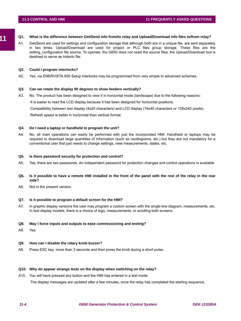
11-4 G650 Generator Protection & Control System GEK-113285A
11.3 CONTROL AND HMI 11 FREQUENTLY ASKED QUESTIONS
1111.3CONTROL AND HMI
Q1. What is the difference between Get/Send info from/to relay and Upload/Download info files to/from relay?
A1. Get/Send are used for settings and configuration storage that although both are in a unique file, are sent separatelyin two times. Upload/Download are used for project or PLC files group storage. These files are thesetting_configuration file source. To operate, the G650 does not need the source files; the Upload/Download tool isdestined to serve as historic file.
Q2. Could I program interlocks?
A2. Yes, via ENERVISTA 650 Setup interlocks may be programmed from very simple to advanced schemes.
Q3. Can we rotate the display 90 degrees to show feeders vertically?
A3. No. The product has been designed to view it in horizontal mode (landscape) due to the following reasons:
It is easier to read the LCD display because it has been designed for horizontal positions.
Compatibility between text display (4x20 characters) and LCD display (16x40 characters or 128x240 pixels).
Refresh speed is better in horizontal than vertical format.
Q4. Do I need a laptop or handheld to program the unit?
A4. No, all main operations can easily be performed with just the incorporated HMI. Handheld or laptops may berequired to download large quantities of information (such as oscillograms, etc.) but they are not mandatory for aconventional user that just needs to change settings, view measurements, states, etc.
Q5. Is there password security for protection and control?
A5. Yes, there are two passwords. An independent password for protection changes and control operations is available
Q6. Is it possible to have a remote HMI installed in the front of the panel with the rest of the relay in the rearside?
A6. Not in the present version.
Q7. Is it possible to program a default screen for the HMI?
A7. In graphic display versions the user may program a custom screen with the single-line diagram, measurements, etc.In text display models, there is a choice of logo, measurements, or scrolling both screens.
Q8. May I force inputs and outputs to ease commissioning and testing?
A8. Yes.
Q9. How can I disable the rotary knob buzzer?
A9. Press ESC key more than 3 seconds and then press the knob during a short pulse.
Q10. Why do appear strange texts on the display when switching on the relay?
A10. You will have pressed any button and the HMI has entered in a test mode.
The display messages are updated after a few minutes, once the relay has completed the starting sequence.
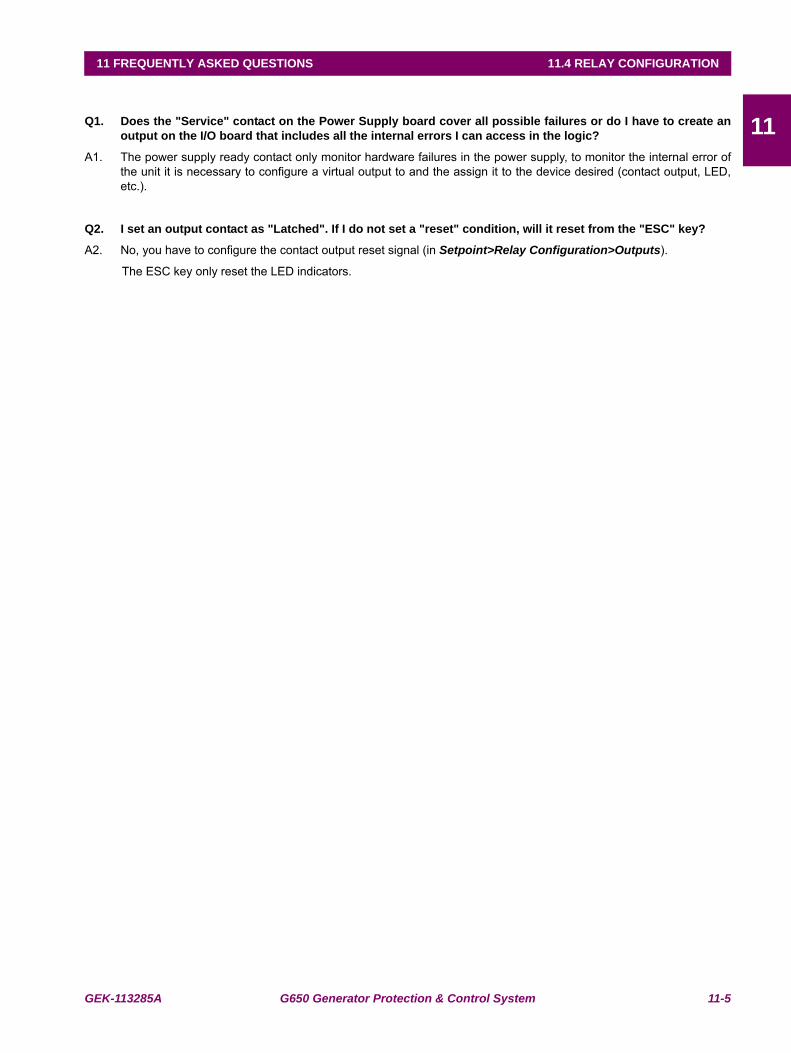
GEK-113285A G650 Generator Protection & Control System 11-5
11 FREQUENTLY ASKED QUESTIONS 11.4 RELAY CONFIGURATION
1111.4RELAY CONFIGURATION
Q1. Does the "Service" contact on the Power Supply board cover all possible failures or do I have to create anoutput on the I/O board that includes all the internal errors I can access in the logic?
A1. The power supply ready contact only monitor hardware failures in the power supply, to monitor the internal error ofthe unit it is necessary to configure a virtual output to and the assign it to the device desired (contact output, LED,etc.).
Q2. I set an output contact as "Latched". If I do not set a "reset" condition, will it reset from the "ESC" key?
A2. No, you have to configure the contact output reset signal (in Setpoint>Relay Configuration>Outputs).
The ESC key only reset the LED indicators.

11-6 G650 Generator Protection & Control System GEK-113285A
11.4 RELAY CONFIGURATION 11 FREQUENTLY ASKED QUESTIONS
11
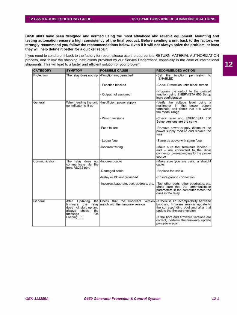
GEK-113285A G650 Generator Protection & Control System 12-1
12 G650TROUBLESHOOTING GUIDE 12.1 SYMPTOMS AND RECOMMENDED ACTIONS
12
12 G650TROUBLESHOOTING GUIDE 12.1SYMPTOMS AND RECOMMENDED ACTIONS
G650 units have been designed and verified using the most advanced and reliable equipment. Mounting andtesting automation ensure a high consistency of the final product. Before sending a unit back to the factory, westrongly recommend you follow the recommendations below. Even if it will not always solve the problem, at leastthey will help define it better for a quicker repair.
If you need to send a unit back to the factory for repair, please use the appropriate RETURN MATERIAL AUTHORIZATIONprocess, and follow the shipping instructions provided by our Service Department, especially in the case of internationalshipments. This will lead to a faster and efficient solution of your problem.
CATEGORY SYMPTOM POSSIBLE CAUSE RECOMMENDED ACTIONProtection The relay does not trip -Function not permitted
- Function blocked
- Output not assigned
-Set the function permission toENABLED
-Check Protection units block screen
-Program the output to the desiredfunction using ENERVISTA 650 Setuplogic configuration
General When feeding the unit,no indicator is lit up
-Insufficient power supply
- Wrong versions
-Fuse failure
- Loose fuse
-Incorrect wiring
-Verify the voltage level using amultimeter in the power supplyterminals, and check that it is withinthe model range
-Check relay and ENERVISTA 650Setup versions are the same
-Remove power supply, dismount thepower supply module and replace thefuse
-Same as above with same fuse
-Make sure that terminals labeled +and – are connected to the 9-pinconnector corresponding to the powersource
Communication The relay does notcommunicate via thefront RS232 port
-Incorrect cable
-Damaged cable
-Relay or PC not grounded
-Incorrect baudrate, port, address, etc.
-Make sure you are using a straightcable
-Replace the cable
-Ensure ground connection
-Test other ports, other baudrates, etc.Make sure that the communicationparameters in the computer match theones in the relay.
General After Updating thefirmware the relaydoes not start up andalways shows themessage “OsLoading…”.
Check that the bootware versionmatch with the firmware version
-If there is an incompatibility betweenboot and firmware version, update tothe corresponding boot and after thatupdate the firmware version
-If the boot and firmware versions arecorrect, perform the firmware updateprocedure again.
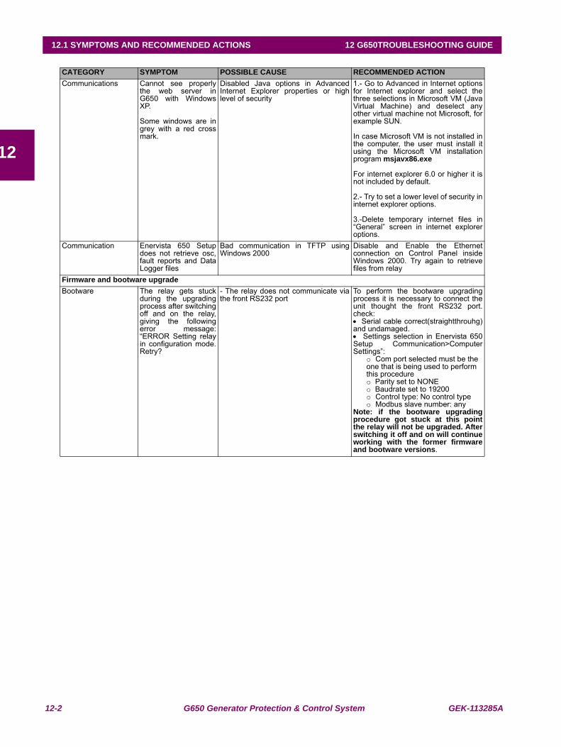
12-2 G650 Generator Protection & Control System GEK-113285A
12.1 SYMPTOMS AND RECOMMENDED ACTIONS 12 G650TROUBLESHOOTING GUIDE
12
CATEGORY SYMPTOM POSSIBLE CAUSE RECOMMENDED ACTIONCommunications Cannot see properly
the web server inG650 with WindowsXP.
Some windows are ingrey with a red crossmark.
Disabled Java options in AdvancedInternet Explorer properties or highlevel of security
1.- Go to Advanced in Internet optionsfor Internet explorer and select thethree selections in Microsoft VM (JavaVirtual Machine) and deselect anyother virtual machine not Microsoft, forexample SUN.
In case Microsoft VM is not installed inthe computer, the user must install itusing the Microsoft VM installationprogram msjavx86.exe
For internet explorer 6.0 or higher it isnot included by default.
2.- Try to set a lower level of security ininternet explorer options.
3.-Delete temporary internet files in“General” screen in internet exploreroptions.
Communication Enervista 650 Setupdoes not retrieve osc,fault reports and DataLogger files
Bad communication in TFTP usingWindows 2000
Disable and Enable the Ethernetconnection on Control Panel insideWindows 2000. Try again to retrievefiles from relay
Firmware and bootware upgradeBootware The relay gets stuck
during the upgradingprocess after switchingoff and on the relay,giving the followingerror message:“ERROR Setting relayin configuration mode.Retry?
- The relay does not communicate viathe front RS232 port
To perform the bootware upgradingprocess it is necessary to connect theunit thought the front RS232 port.check:• Serial cable correct(straightthrouhg)and undamaged.• Settings selection in Enervista 650Setup Communication>ComputerSettings”:
o Com port selected must be the one that is being used to perform this procedureo Parity set to NONEo Baudrate set to 19200 o Control type: No control typeo Modbus slave number: any
Note: if the bootware upgradingprocedure got stuck at this pointthe relay will not be upgraded. Afterswitching it off and on will continueworking with the former firmwareand bootware versions.
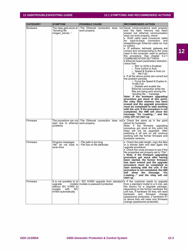
GEK-113285A G650 Generator Protection & Control System 12-3
12 G650TROUBLESHOOTING GUIDE 12.1 SYMPTOMS AND RECOMMENDED ACTIONS
12
CATEGORY SYMPTOM POSSIBLE CAUSE RECOMMENDED ACTIONBootware The relay gets stuck at
“Sending file imagen_kernel...”
-The Ethernet connection does notwork properly.
Serial communications work properlyand the flash memory has beenerased but ethernet communicationdoes not work properly, check:• RJ45 cable used (crossover cablefor back-to-back connection andstraightthrough Ethernet cable for hubor switch)• IP address, netmask, gateway arecorrect and corresponding to the onesused in the computer used to performthe procedure. See chapter 5.2.1COMMUNICATION SETTINGS• Ethernet board parameters selection,check that:
o 802.1p QOS is Enabledo Flow control is Autoo Speed & Duplex is Auto (or 10 Mb Full)
• If all the above points are correct butthe problem persists:
o Force the Speed & Duplex to 10 Mb Fullo Disable and enable the Ethernet connection while the files are being sent (during the “sending file...” message
Note: if the bootware upgradingprocedure got stuck at this point,the relay flash memory has beenerased and the upgrade proceduremust be completed to start workingwith the unit. If the procedure is notcompleted, the HMI will show themessage “Os Loading...” and therelay will not start up.
Firmware The procedure can notstart due to ethernetproblems
-The Ethernet connection does notwork properly.
• Check the same as in the pointabove for bootware.Note: if the firmware upgradingprocedure got stuck at this point therelay will not be upgraded. Afterswitching it off and on will continueworking with the former firmware andbootware versions.
Firmware Program messages“file” do not exist inlocal drive
- File path is too long- File has no file attributes
• Check the path length, copy the filesin a shorter path and start again theupgrade procedure.• Check the unzip process to see if thefile properties are properly set to “File”.• Note: if the firmware upgradingprocedure got stuck after havingbeen started, the former firmwarehas been erased and the upgradeprocedure must be completed tostart working with the unit. If theprocedure is not completed, the HMIwill show the message “OsLoading...” and the relay will notstart up.
Firmware It is not possible to toupgrade modelswithout IEC 61850 tomodels with IEC61850 automatically
- IEC 61850 upgrade from standardmodels is password protected.
• If the customer wants to upgradefrom a standard model to a 6 one, askthe factory for a Upgrade package,depending on the former hardware theunit has, if hardware 00 they will needhardware and firmware change(passwored protected), if hardware 01or above they will need only firmwarechange (passwored protected).
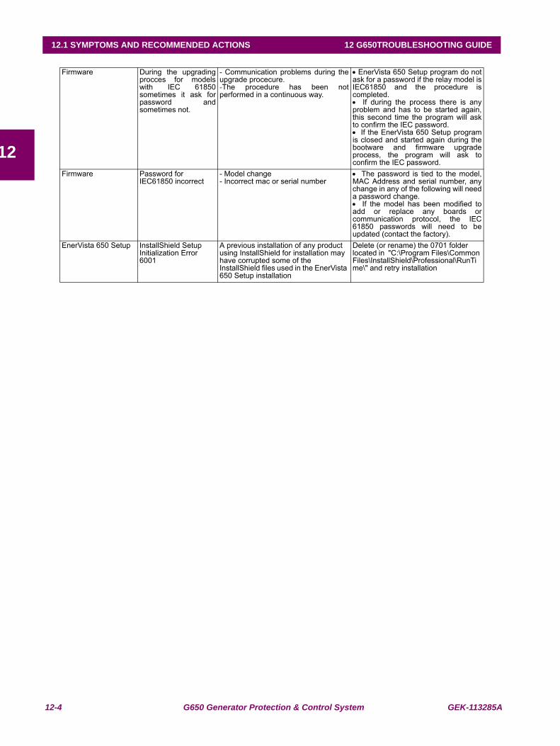
12-4 G650 Generator Protection & Control System GEK-113285A
12.1 SYMPTOMS AND RECOMMENDED ACTIONS 12 G650TROUBLESHOOTING GUIDE
12
Firmware During the upgradingprocces for modelswith IEC 61850sometimes it ask forpassword andsometimes not.
- Communication problems during theupgrade procecure.-The procedure has been notperformed in a continuous way.
• EnerVista 650 Setup program do notask for a password if the relay model isIEC61850 and the procedure iscompleted.• If during the process there is anyproblem and has to be started again,this second time the program will askto confirm the IEC password.• If the EnerVista 650 Setup programis closed and started again during thebootware and firmware upgradeprocess, the program will ask toconfirm the IEC password.
Firmware Password for IEC61850 incorrect
- Model change- Incorrect mac or serial number
• The password is tied to the model,MAC Address and serial number, anychange in any of the following will needa password change.• If the model has been modified toadd or replace any boards orcommunication protocol, the IEC61850 passwords will need to beupdated (contact the factory).
EnerVista 650 Setup InstallShield Setup Initialization Error 6001
A previous installation of any product using InstallShield for installation may have corrupted some of the InstallShield files used in the EnerVista 650 Setup installation
Delete (or rename) the 0701 folder located in "C:\Program Files\Common Files\InstallShield\Professional\RunTime\" and retry installation
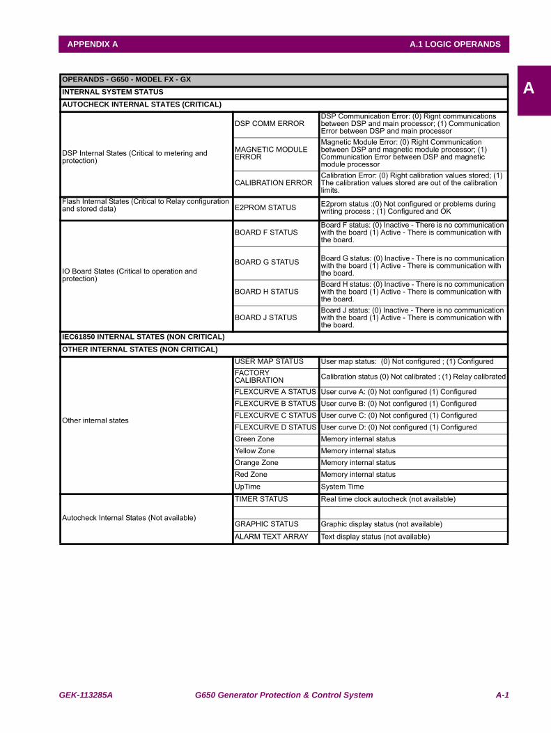
GEK-113285A G650 Generator Protection & Control System A-1
APPENDIX A A.1 LOGIC OPERANDS
AAPPENDIX A LOGIC OPERANDSA.1LOGIC OPERANDSOPERANDS - G650 - MODEL FX - GXINTERNAL SYSTEM STATUSAUTOCHECK INTERNAL STATES (CRITICAL)
DSP Internal States (Critical to metering and protection)
DSP COMM ERRORDSP Communication Error: (0) Rignt communications between DSP and main processor; (1) Communication Error between DSP and main processor
MAGNETIC MODULE ERROR
Magnetic Module Error: (0) Right Communication between DSP and magnetic module processor; (1) Communication Error between DSP and magnetic module processor
CALIBRATION ERRORCalibration Error: (0) Right calibration values stored; (1) The calibration values stored are out of the calibration limits.
Flash Internal States (Critical to Relay configuration and stored data) E2PROM STATUS E2prom status :(0) Not configured or problems during
writing process ; (1) Configured and OK
IO Board States (Critical to operation and protection)
BOARD F STATUSBoard F status: (0) Inactive - There is no communication with the board (1) Active - There is communication with the board.
BOARD G STATUS Board G status: (0) Inactive - There is no communication with the board (1) Active - There is communication with the board.
BOARD H STATUSBoard H status: (0) Inactive - There is no communication with the board (1) Active - There is communication with the board.
BOARD J STATUSBoard J status: (0) Inactive - There is no communication with the board (1) Active - There is communication with the board.
IEC61850 INTERNAL STATES (NON CRITICAL)OTHER INTERNAL STATES (NON CRITICAL)
Other internal states
USER MAP STATUS User map status: (0) Not configured ; (1) ConfiguredFACTORY CALIBRATION Calibration status (0) Not calibrated ; (1) Relay calibrated
FLEXCURVE A STATUS User curve A: (0) Not configured (1) ConfiguredFLEXCURVE B STATUS User curve B: (0) Not configured (1) ConfiguredFLEXCURVE C STATUS User curve C: (0) Not configured (1) ConfiguredFLEXCURVE D STATUS User curve D: (0) Not configured (1) ConfiguredGreen Zone Memory internal statusYellow Zone Memory internal statusOrange Zone Memory internal statusRed Zone Memory internal statusUpTime System Time
Autocheck Internal States (Not available)
TIMER STATUS Real time clock autocheck (not available)
GRAPHIC STATUS Graphic display status (not available)
ALARM TEXT ARRAY Text display status (not available)
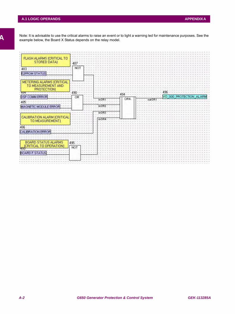
A-2 G650 Generator Protection & Control System GEK-113285A
A.1 LOGIC OPERANDS APPENDIX A
A Note: It is advisable to use the critical alarms to raise an event or to light a warning led for maintenance purposes. See theexample below, the Board X Status depends on the relay model.
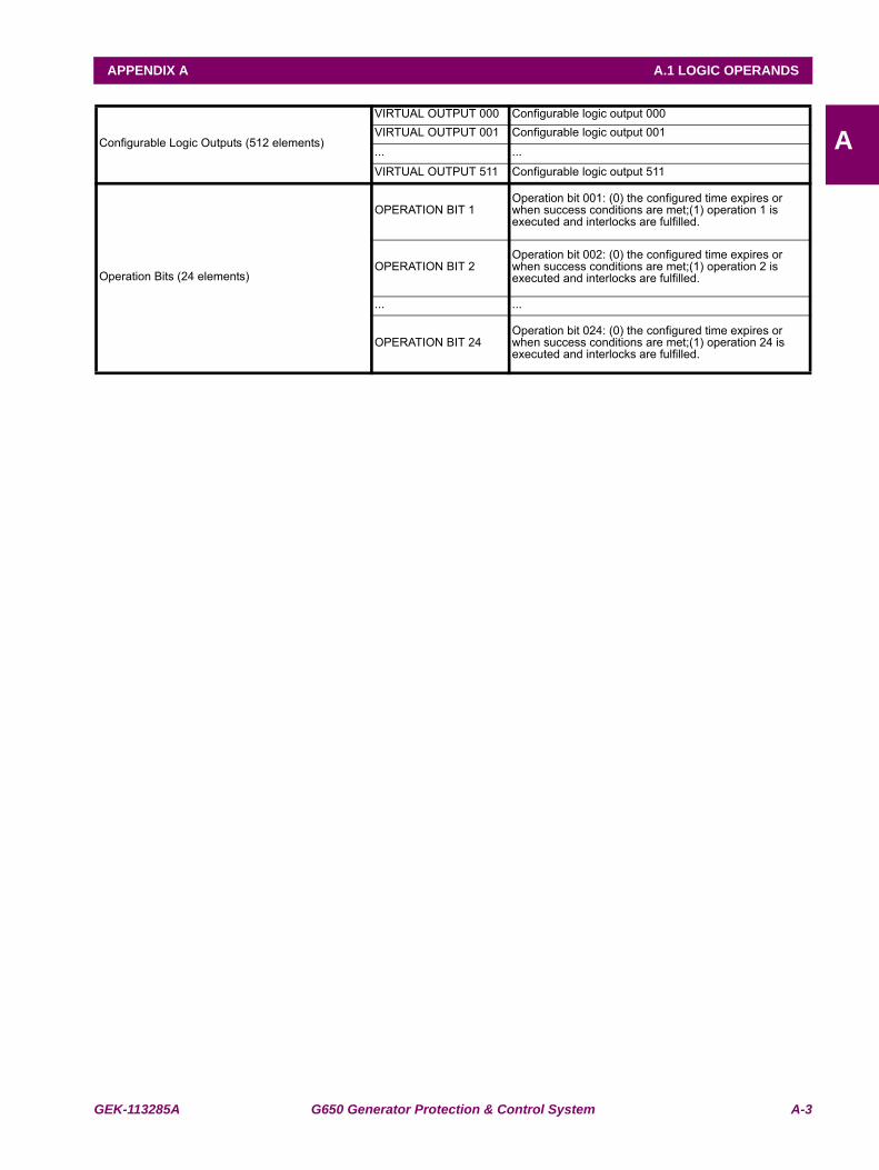
GEK-113285A G650 Generator Protection & Control System A-3
APPENDIX A A.1 LOGIC OPERANDS
AConfigurable Logic Outputs (512 elements)
VIRTUAL OUTPUT 000 Configurable logic output 000VIRTUAL OUTPUT 001 Configurable logic output 001... ...
VIRTUAL OUTPUT 511 Configurable logic output 511
Operation Bits (24 elements)
OPERATION BIT 1Operation bit 001: (0) the configured time expires or when success conditions are met;(1) operation 1 is executed and interlocks are fulfilled.
OPERATION BIT 2Operation bit 002: (0) the configured time expires or when success conditions are met;(1) operation 2 is executed and interlocks are fulfilled.
... ...
OPERATION BIT 24Operation bit 024: (0) the configured time expires or when success conditions are met;(1) operation 24 is executed and interlocks are fulfilled.
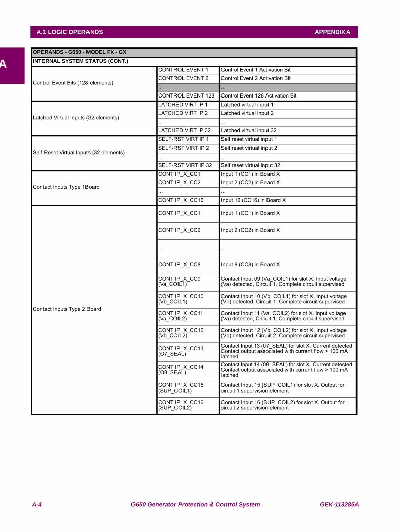
A-4 G650 Generator Protection & Control System GEK-113285A
A.1 LOGIC OPERANDS APPENDIX A
AOPERANDS - G650 - MODEL FX - GXINTERNAL SYSTEM STATUS (CONT.)
Control Event Bits (128 elements)
CONTROL EVENT 1 Control Event 1 Activation BitCONTROL EVENT 2 Control Event 2 Activation Bit... ...CONTROL EVENT 128 Control Event 128 Activation Bit
Latched Virtual Inputs (32 elements)
LATCHED VIRT IP 1 Latched virtual input 1LATCHED VIRT IP 2 Latched virtual input 2... ...LATCHED VIRT IP 32 Latched virtual input 32
Self Reset Virtual Inputs (32 elements)
SELF-RST VIRT IP 1 Self reset virtual input 1SELF-RST VIRT IP 2 Self reset virtual input 2... ...SELF-RST VIRT IP 32 Self reset virtual input 32
Contact Inputs Type 1Board
CONT IP_X_CC1 Input 1 (CC1) in Board XCONT IP_X_CC2 Input 2 (CC2) in Board X... ...CONT IP_X_CC16 Input 16 (CC16) in Board X
Contact Inputs Type 2 Board
CONT IP_X_CC1 Input 1 (CC1) in Board X
CONT IP_X_CC2 Input 2 (CC2) in Board X
... ...
CONT IP_X_CC8 Input 8 (CC8) in Board X
CONT IP_X_CC9 (Va_COIL1)
Contact Input 09 (Va_COIL1) for slot X. Input voltage (Va) detected, Circuit 1. Complete circuit supervised
CONT IP_X_CC10 (Vb_COIL1)
Contact Input 10 (Vb_COIL1) for slot X. Input voltage (Vb) detected, Circuit 1. Complete circuit supervised
CONT IP_X_CC11 (Va_COIL2)
Contact Input 11 (Va_COIL2) for slot X. Input voltage (Va) detected, Circuit 1. Complete circuit supervised
CONT IP_X_CC12 (Vb_COIL2)
Contact Input 12 (Vb_COIL2) for slot X. Input voltage (Vb) detected, Circuit 2. Complete circuit supervised
CONT IP_X_CC13 (O7_SEAL)
Contact Input 13 (07_SEAL) for slot X. Current detected. Contact output associated with current flow > 100 mA latched
CONT IP_X_CC14 (O8_SEAL)
Contact Input 14 (08_SEAL) for slot X. Current detected. Contact output associated with current flow > 100 mA latched
CONT IP_X_CC15 (SUP_COIL1)
Contact Input 15 (SUP_COIL1) for slot X. Output for circuit 1 supervision element
CONT IP_X_CC16 (SUP_COIL2)
Contact Input 16 (SUP_COIL2) for slot X. Output for circuit 2 supervision element
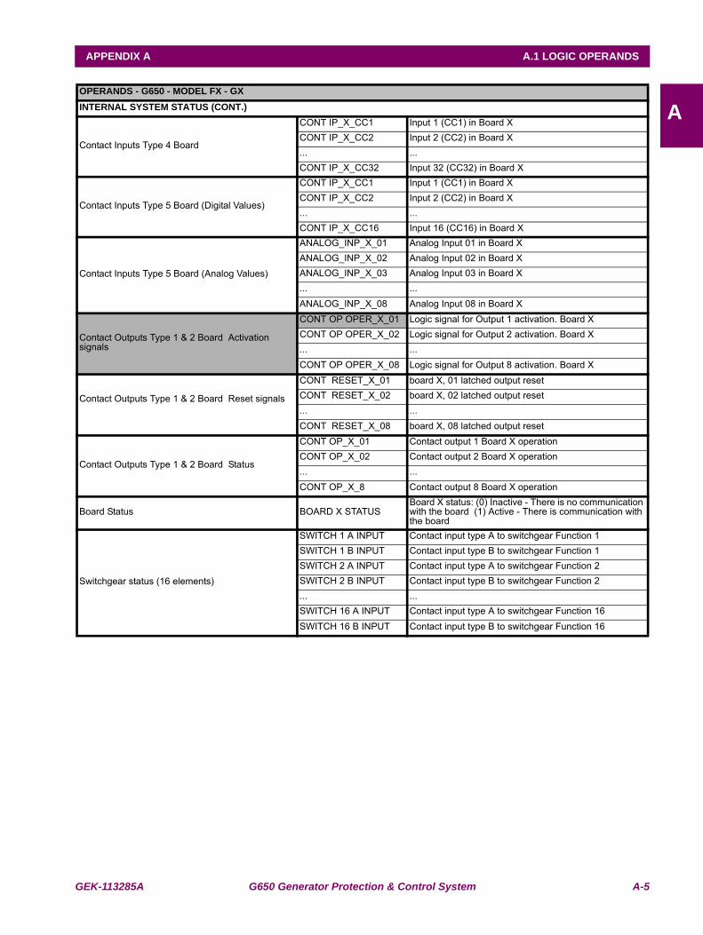
GEK-113285A G650 Generator Protection & Control System A-5
APPENDIX A A.1 LOGIC OPERANDS
AOPERANDS - G650 - MODEL FX - GXINTERNAL SYSTEM STATUS (CONT.)
Contact Inputs Type 4 Board
CONT IP_X_CC1 Input 1 (CC1) in Board XCONT IP_X_CC2 Input 2 (CC2) in Board X... ...CONT IP_X_CC32 Input 32 (CC32) in Board X
Contact Inputs Type 5 Board (Digital Values)
CONT IP_X_CC1 Input 1 (CC1) in Board XCONT IP_X_CC2 Input 2 (CC2) in Board X... ...CONT IP_X_CC16 Input 16 (CC16) in Board X
Contact Inputs Type 5 Board (Analog Values)
ANALOG_INP_X_01 Analog Input 01 in Board XANALOG_INP_X_02 Analog Input 02 in Board XANALOG_INP_X_03 Analog Input 03 in Board X... ...ANALOG_INP_X_08 Analog Input 08 in Board X
Contact Outputs Type 1 & 2 Board Activation signals
CONT OP OPER_X_01 Logic signal for Output 1 activation. Board XCONT OP OPER_X_02 Logic signal for Output 2 activation. Board X... ...CONT OP OPER_X_08 Logic signal for Output 8 activation. Board X
Contact Outputs Type 1 & 2 Board Reset signals
CONT RESET_X_01 board X, 01 latched output resetCONT RESET_X_02 board X, 02 latched output reset... ...CONT RESET_X_08 board X, 08 latched output reset
Contact Outputs Type 1 & 2 Board Status
CONT OP_X_01 Contact output 1 Board X operationCONT OP_X_02 Contact output 2 Board X operation... ...CONT OP_X_8 Contact output 8 Board X operation
Board Status BOARD X STATUSBoard X status: (0) Inactive - There is no communication with the board (1) Active - There is communication with the board
Switchgear status (16 elements)
SWITCH 1 A INPUT Contact input type A to switchgear Function 1SWITCH 1 B INPUT Contact input type B to switchgear Function 1SWITCH 2 A INPUT Contact input type A to switchgear Function 2SWITCH 2 B INPUT Contact input type B to switchgear Function 2... ...SWITCH 16 A INPUT Contact input type A to switchgear Function 16SWITCH 16 B INPUT Contact input type B to switchgear Function 16
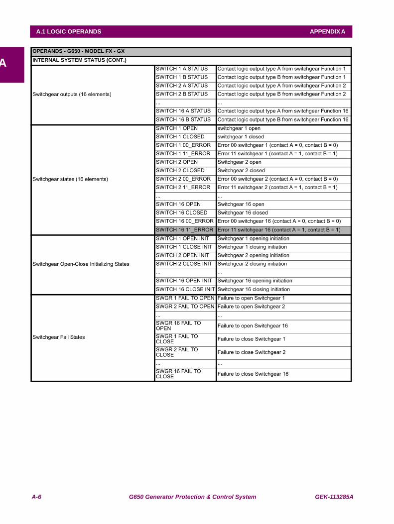
A-6 G650 Generator Protection & Control System GEK-113285A
A.1 LOGIC OPERANDS APPENDIX A
AOPERANDS - G650 - MODEL FX - GXINTERNAL SYSTEM STATUS (CONT.)
Switchgear outputs (16 elements)
SWITCH 1 A STATUS Contact logic output type A from switchgear Function 1 SWITCH 1 B STATUS Contact logic output type B from switchgear Function 1 SWITCH 2 A STATUS Contact logic output type A from switchgear Function 2 SWITCH 2 B STATUS Contact logic output type B from switchgear Function 2 ... ...SWITCH 16 A STATUS Contact logic output type A from switchgear Function 16 SWITCH 16 B STATUS Contact logic output type B from switchgear Function 16
Switchgear states (16 elements)
SWITCH 1 OPEN switchgear 1 openSWITCH 1 CLOSED switchgear 1 closedSWITCH 1 00_ERROR Error 00 switchgear 1 (contact A = 0, contact B = 0)SWITCH 1 11_ERROR Error 11 switchgear 1 (contact A = 1, contact B = 1)SWITCH 2 OPEN Switchgear 2 openSWITCH 2 CLOSED Switchgear 2 closedSWITCH 2 00_ERROR Error 00 switchgear 2 (contact A = 0, contact B = 0)SWITCH 2 11_ERROR Error 11 switchgear 2 (contact A = 1, contact B = 1)... ...SWITCH 16 OPEN Switchgear 16 openSWITCH 16 CLOSED Switchgear 16 closedSWITCH 16 00_ERROR Error 00 switchgear 16 (contact A = 0, contact B = 0)SWITCH 16 11_ERROR Error 11 switchgear 16 (contact A = 1, contact B = 1)
Switchgear Open-Close Initializing States
SWITCH 1 OPEN INIT Switchgear 1 opening initiationSWITCH 1 CLOSE INIT Switchgear 1 closing initiationSWITCH 2 OPEN INIT Switchgear 2 opening initiationSWITCH 2 CLOSE INIT Switchgear 2 closing initiation... ...SWITCH 16 OPEN INIT Switchgear 16 opening initiationSWITCH 16 CLOSE INIT Switchgear 16 closing initiation
Switchgear Fail States
SWGR 1 FAIL TO OPEN Failure to open Switchgear 1SWGR 2 FAIL TO OPEN Failure to open Switchgear 2... ...SWGR 16 FAIL TO OPEN Failure to open Switchgear 16
SWGR 1 FAIL TO CLOSE Failure to close Switchgear 1
SWGR 2 FAIL TO CLOSE Failure to close Switchgear 2
... ...SWGR 16 FAIL TO CLOSE Failure to close Switchgear 16
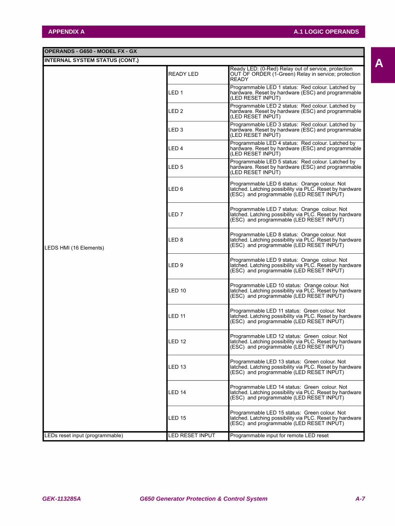
GEK-113285A G650 Generator Protection & Control System A-7
APPENDIX A A.1 LOGIC OPERANDS
AOPERANDS - G650 - MODEL FX - GXINTERNAL SYSTEM STATUS (CONT.)
LEDS HMI (16 Elements)
READY LEDReady LED: (0-Red) Relay out of service, protection OUT OF ORDER (1-Green) Relay in service; protection READY
LED 1Programmable LED 1 status: Red colour. Latched by hardware. Reset by hardware (ESC) and programmable (LED RESET INPUT)
LED 2Programmable LED 2 status: Red colour. Latched by hardware. Reset by hardware (ESC) and programmable (LED RESET INPUT)
LED 3Programmable LED 3 status: Red colour. Latched by hardware. Reset by hardware (ESC) and programmable (LED RESET INPUT)
LED 4Programmable LED 4 status: Red colour. Latched by hardware. Reset by hardware (ESC) and programmable (LED RESET INPUT)
LED 5Programmable LED 5 status: Red colour. Latched by hardware. Reset by hardware (ESC) and programmable (LED RESET INPUT)
LED 6Programmable LED 6 status: Orange colour. Not latched. Latching possibility via PLC. Reset by hardware (ESC) and programmable (LED RESET INPUT)
LED 7Programmable LED 7 status: Orange colour. Not latched. Latching possibility via PLC. Reset by hardware (ESC) and programmable (LED RESET INPUT)
LED 8Programmable LED 8 status: Orange colour. Not latched. Latching possibility via PLC. Reset by hardware (ESC) and programmable (LED RESET INPUT)
LED 9Programmable LED 9 status: Orange colour. Not latched. Latching possibility via PLC. Reset by hardware (ESC) and programmable (LED RESET INPUT)
LED 10Programmable LED 10 status: Orange colour. Not latched. Latching possibility via PLC. Reset by hardware (ESC) and programmable (LED RESET INPUT)
LED 11Programmable LED 11 status: Green colour. Not latched. Latching possibility via PLC. Reset by hardware (ESC) and programmable (LED RESET INPUT)
LED 12Programmable LED 12 status: Green colour. Not latched. Latching possibility via PLC. Reset by hardware (ESC) and programmable (LED RESET INPUT)
LED 13Programmable LED 13 status: Green colour. Not latched. Latching possibility via PLC. Reset by hardware (ESC) and programmable (LED RESET INPUT)
LED 14Programmable LED 14 status: Green colour. Not latched. Latching possibility via PLC. Reset by hardware (ESC) and programmable (LED RESET INPUT)
LED 15Programmable LED 15 status: Green colour. Not latched. Latching possibility via PLC. Reset by hardware (ESC) and programmable (LED RESET INPUT)
LEDs reset input (programmable) LED RESET INPUT Programmable input for remote LED reset
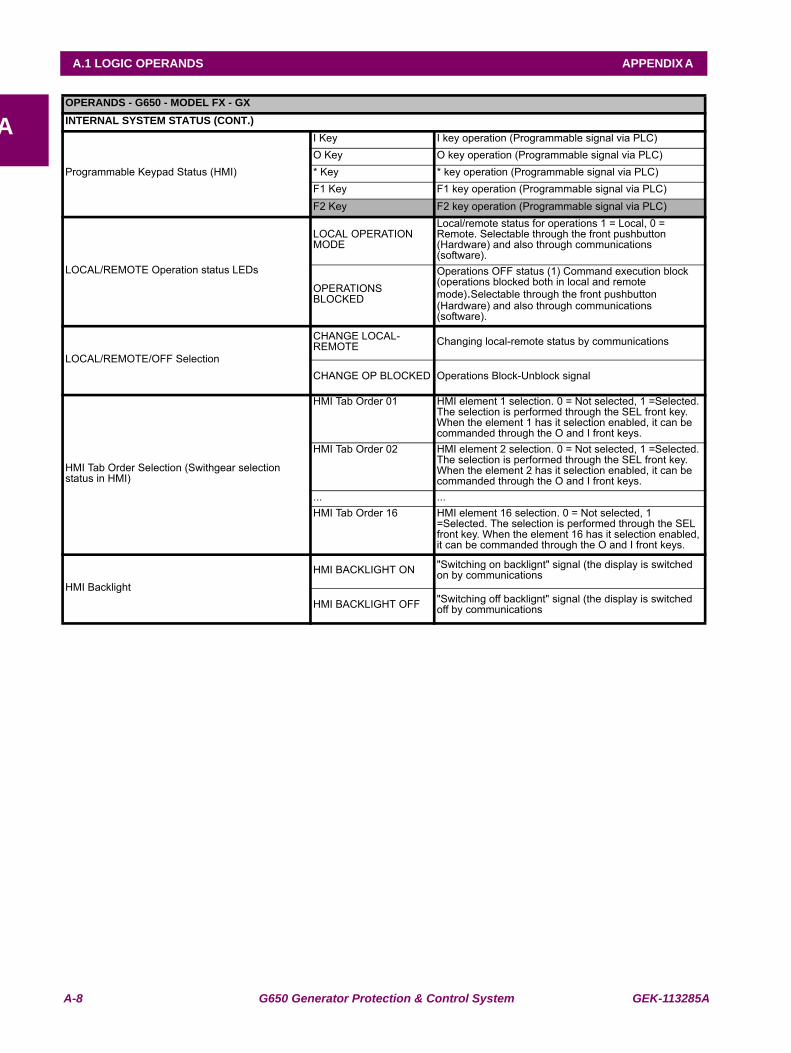
A-8 G650 Generator Protection & Control System GEK-113285A
A.1 LOGIC OPERANDS APPENDIX A
AOPERANDS - G650 - MODEL FX - GXINTERNAL SYSTEM STATUS (CONT.)
I Key I key operation (Programmable signal via PLC)O Key O key operation (Programmable signal via PLC)
Programmable Keypad Status (HMI) * Key * key operation (Programmable signal via PLC)F1 Key F1 key operation (Programmable signal via PLC)F2 Key F2 key operation (Programmable signal via PLC)
LOCAL/REMOTE Operation status LEDs
LOCAL OPERATION MODE
Local/remote status for operations 1 = Local, 0 = Remote. Selectable through the front pushbutton (Hardware) and also through communications (software).
OPERATIONS BLOCKED
Operations OFF status (1) Command execution block (operations blocked both in local and remote mode).Selectable through the front pushbutton (Hardware) and also through communications (software).
LOCAL/REMOTE/OFF Selection
CHANGE LOCAL-REMOTE Changing local-remote status by communications
CHANGE OP BLOCKED Operations Block-Unblock signal
HMI Tab Order Selection (Swithgear selection status in HMI)
HMI Tab Order 01 HMI element 1 selection. 0 = Not selected, 1 =Selected. The selection is performed through the SEL front key. When the element 1 has it selection enabled, it can be commanded through the O and I front keys.
HMI Tab Order 02 HMI element 2 selection. 0 = Not selected, 1 =Selected. The selection is performed through the SEL front key. When the element 2 has it selection enabled, it can be commanded through the O and I front keys.
... ...HMI Tab Order 16 HMI element 16 selection. 0 = Not selected, 1
=Selected. The selection is performed through the SEL front key. When the element 16 has it selection enabled, it can be commanded through the O and I front keys.
HMI BacklightHMI BACKLIGHT ON "Switching on backlignt" signal (the display is switched
on by communications
HMI BACKLIGHT OFF "Switching off backlignt" signal (the display is switched off by communications
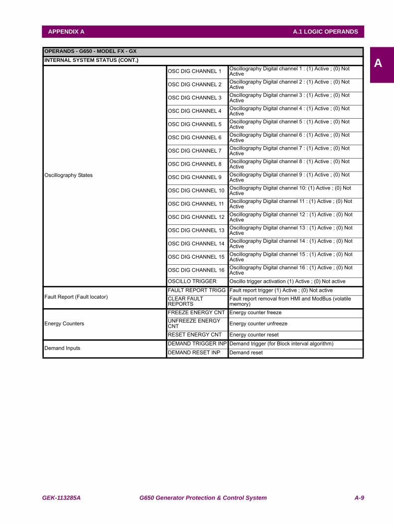
GEK-113285A G650 Generator Protection & Control System A-9
APPENDIX A A.1 LOGIC OPERANDS
AOPERANDS - G650 - MODEL FX - GXINTERNAL SYSTEM STATUS (CONT.)
Oscillography States
OSC DIG CHANNEL 1 Oscillography Digital channel 1 : (1) Active ; (0) Not Active
OSC DIG CHANNEL 2 Oscillography Digital channel 2 : (1) Active ; (0) Not Active
OSC DIG CHANNEL 3 Oscillography Digital channel 3 : (1) Active ; (0) Not Active
OSC DIG CHANNEL 4 Oscillography Digital channel 4 : (1) Active ; (0) Not Active
OSC DIG CHANNEL 5 Oscillography Digital channel 5 : (1) Active ; (0) Not Active
OSC DIG CHANNEL 6 Oscillography Digital channel 6 : (1) Active ; (0) Not Active
OSC DIG CHANNEL 7 Oscillography Digital channel 7 : (1) Active ; (0) Not Active
OSC DIG CHANNEL 8 Oscillography Digital channel 8 : (1) Active ; (0) Not Active
OSC DIG CHANNEL 9 Oscillography Digital channel 9 : (1) Active ; (0) Not Active
OSC DIG CHANNEL 10 Oscillography Digital channel 10: (1) Active ; (0) Not Active
OSC DIG CHANNEL 11 Oscillography Digital channel 11 : (1) Active ; (0) Not Active
OSC DIG CHANNEL 12 Oscillography Digital channel 12 : (1) Active ; (0) Not Active
OSC DIG CHANNEL 13 Oscillography Digital channel 13 : (1) Active ; (0) Not Active
OSC DIG CHANNEL 14 Oscillography Digital channel 14 : (1) Active ; (0) Not Active
OSC DIG CHANNEL 15 Oscillography Digital channel 15 : (1) Active ; (0) Not Active
OSC DIG CHANNEL 16 Oscillography Digital channel 16 : (1) Active ; (0) Not Active
OSCILLO TRIGGER Oscillo trigger activation (1) Active ; (0) Not active
Fault Report (Fault locator)FAULT REPORT TRIGG Fault report trigger (1) Active ; (0) Not activeCLEAR FAULT REPORTS
Fault report removal from HMI and ModBus (volatile memory)
Energy Counters
FREEZE ENERGY CNT Energy counter freezeUNFREEZE ENERGY CNT Energy counter unfreeze
RESET ENERGY CNT Energy counter reset
Demand InputsDEMAND TRIGGER INP Demand trigger (for Block interval algorithm)
DEMAND RESET INP Demand reset
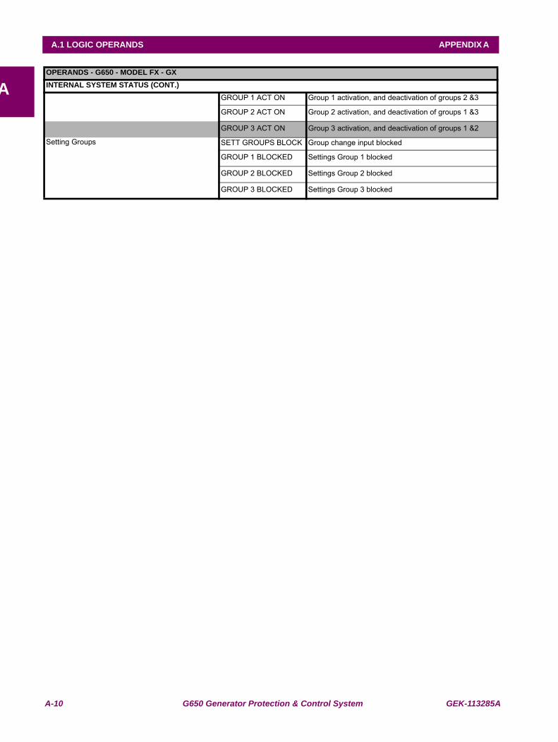
A-10 G650 Generator Protection & Control System GEK-113285A
A.1 LOGIC OPERANDS APPENDIX A
AOPERANDS - G650 - MODEL FX - GXINTERNAL SYSTEM STATUS (CONT.)
GROUP 1 ACT ON Group 1 activation, and deactivation of groups 2 &3
GROUP 2 ACT ON Group 2 activation, and deactivation of groups 1 &3
GROUP 3 ACT ON Group 3 activation, and deactivation of groups 1 &2
Setting Groups SETT GROUPS BLOCK Group change input blocked
GROUP 1 BLOCKED Settings Group 1 blocked
GROUP 2 BLOCKED Settings Group 2 blocked
GROUP 3 BLOCKED Settings Group 3 blocked
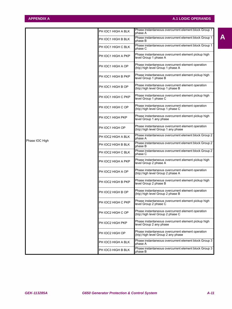
GEK-113285A G650 Generator Protection & Control System A-11
APPENDIX A A.1 LOGIC OPERANDS
A
Phase IOC High
PH IOC1 HIGH A BLK Phase instantaneous overcurrent element block Group 1 phase A
PH IOC1 HIGH B BLK Phase instantaneous overcurrent element block Group 1 phase B
PH IOC1 HIGH C BLK Phase instantaneous overcurrent element block Group 1 phase C
PH IOC1 HIGH A PKP Phase instantaneous overcurrent element pickup high level Group 1 phase A
PH IOC1 HIGH A OP Phase instantaneous overcurrent element operation (trip) high level Group 1 phase A
PH IOC1 HIGH B PKP Phase instantaneous overcurrent element pickup high level Group 1 phase B
PH IOC1 HIGH B OP Phase instantaneous overcurrent element operation (trip) high level Group 1 phase B
PH IOC1 HIGH C PKP Phase instantaneous overcurrent element pickup high level Group 1 phase C
PH IOC1 HIGH C OP Phase instantaneous overcurrent element operation (trip) high level Group 1 phase C
PH IOC1 HIGH PKP Phase instantaneous overcurrent element pickup high level Group 1 any phase
PH IOC1 HIGH OP Phase instantaneous overcurrent element operation (trip) high level Group 1 any phase
PH IOC2 HIGH A BLK Phase instantaneous overcurrent element block Group 2 phase A
PH IOC2 HIGH B BLK Phase instantaneous overcurrent element block Group 2 phase B
PH IOC2 HIGH C BLK Phase instantaneous overcurrent element block Group 2 phase C
PH IOC2 HIGH A PKP Phase instantaneous overcurrent element pickup high level Group 2 phase A
PH IOC2 HIGH A OP Phase instantaneous overcurrent element operation (trip) high level Group 2 phase A
PH IOC2 HIGH B PKP Phase instantaneous overcurrent element pickup high level Group 2 phase B
PH IOC2 HIGH B OP Phase instantaneous overcurrent element operation (trip) high level Group 2 phase B
PH IOC2 HIGH C PKP Phase instantaneous overcurrent element pickup high level Group 2 phase C
PH IOC2 HIGH C OP Phase instantaneous overcurrent element operation (trip) high level Group 2 phase C
PH IOC2 HIGH PKP Phase instantaneous overcurrent element pickup high level Group 2 any phase
PH IOC2 HIGH OP Phase instantaneous overcurrent element operation (trip) high level Group 2 any phase
PH IOC3 HIGH A BLK Phase instantaneous overcurrent element block Group 3 phase A
PH IOC3 HIGH B BLK Phase instantaneous overcurrent element block Group 3 phase B
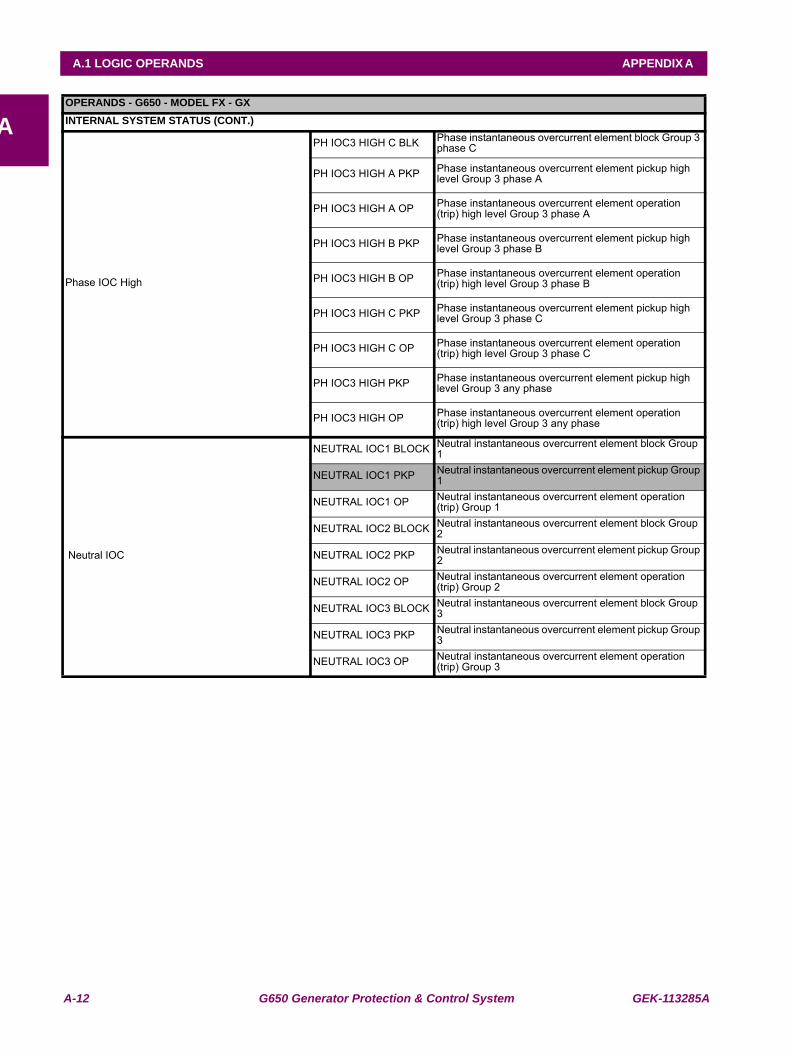
A-12 G650 Generator Protection & Control System GEK-113285A
A.1 LOGIC OPERANDS APPENDIX A
AOPERANDS - G650 - MODEL FX - GXINTERNAL SYSTEM STATUS (CONT.)
Phase IOC High
PH IOC3 HIGH C BLK Phase instantaneous overcurrent element block Group 3 phase C
PH IOC3 HIGH A PKP Phase instantaneous overcurrent element pickup high level Group 3 phase A
PH IOC3 HIGH A OP Phase instantaneous overcurrent element operation (trip) high level Group 3 phase A
PH IOC3 HIGH B PKP Phase instantaneous overcurrent element pickup high level Group 3 phase B
PH IOC3 HIGH B OP Phase instantaneous overcurrent element operation (trip) high level Group 3 phase B
PH IOC3 HIGH C PKP Phase instantaneous overcurrent element pickup high level Group 3 phase C
PH IOC3 HIGH C OP Phase instantaneous overcurrent element operation (trip) high level Group 3 phase C
PH IOC3 HIGH PKP Phase instantaneous overcurrent element pickup high level Group 3 any phase
PH IOC3 HIGH OP Phase instantaneous overcurrent element operation (trip) high level Group 3 any phase
Neutral IOC
NEUTRAL IOC1 BLOCK Neutral instantaneous overcurrent element block Group 1
NEUTRAL IOC1 PKP Neutral instantaneous overcurrent element pickup Group 1
NEUTRAL IOC1 OP Neutral instantaneous overcurrent element operation (trip) Group 1
NEUTRAL IOC2 BLOCK Neutral instantaneous overcurrent element block Group 2
NEUTRAL IOC2 PKP Neutral instantaneous overcurrent element pickup Group 2
NEUTRAL IOC2 OP Neutral instantaneous overcurrent element operation (trip) Group 2
NEUTRAL IOC3 BLOCK Neutral instantaneous overcurrent element block Group 3
NEUTRAL IOC3 PKP Neutral instantaneous overcurrent element pickup Group 3
NEUTRAL IOC3 OP Neutral instantaneous overcurrent element operation (trip) Group 3
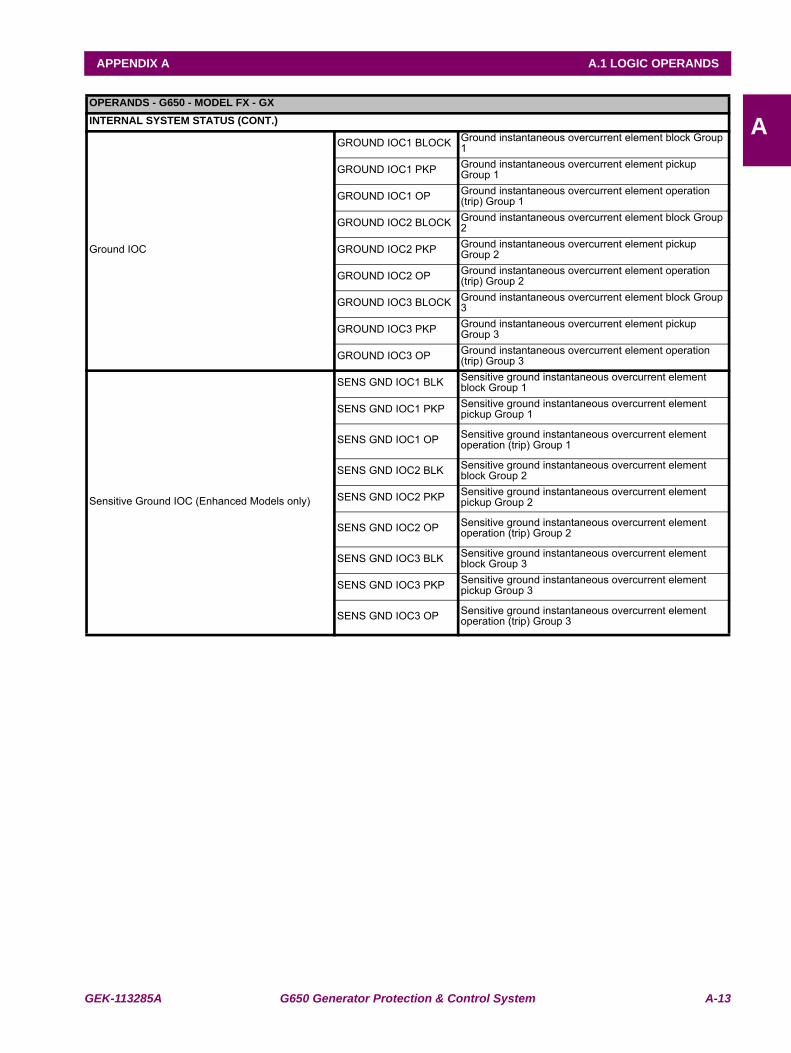
GEK-113285A G650 Generator Protection & Control System A-13
APPENDIX A A.1 LOGIC OPERANDS
AOPERANDS - G650 - MODEL FX - GXINTERNAL SYSTEM STATUS (CONT.)
Ground IOC
GROUND IOC1 BLOCK Ground instantaneous overcurrent element block Group 1
GROUND IOC1 PKP Ground instantaneous overcurrent element pickup Group 1
GROUND IOC1 OP Ground instantaneous overcurrent element operation (trip) Group 1
GROUND IOC2 BLOCK Ground instantaneous overcurrent element block Group 2
GROUND IOC2 PKP Ground instantaneous overcurrent element pickup Group 2
GROUND IOC2 OP Ground instantaneous overcurrent element operation (trip) Group 2
GROUND IOC3 BLOCK Ground instantaneous overcurrent element block Group 3
GROUND IOC3 PKP Ground instantaneous overcurrent element pickup Group 3
GROUND IOC3 OP Ground instantaneous overcurrent element operation (trip) Group 3
Sensitive Ground IOC (Enhanced Models only)
SENS GND IOC1 BLK Sensitive ground instantaneous overcurrent element block Group 1
SENS GND IOC1 PKP Sensitive ground instantaneous overcurrent element pickup Group 1
SENS GND IOC1 OP Sensitive ground instantaneous overcurrent element operation (trip) Group 1
SENS GND IOC2 BLK Sensitive ground instantaneous overcurrent element block Group 2
SENS GND IOC2 PKP Sensitive ground instantaneous overcurrent element pickup Group 2
SENS GND IOC2 OP Sensitive ground instantaneous overcurrent element operation (trip) Group 2
SENS GND IOC3 BLK Sensitive ground instantaneous overcurrent element block Group 3
SENS GND IOC3 PKP Sensitive ground instantaneous overcurrent element pickup Group 3
SENS GND IOC3 OP Sensitive ground instantaneous overcurrent element operation (trip) Group 3
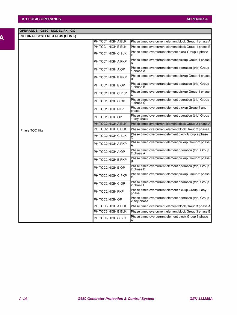
A-14 G650 Generator Protection & Control System GEK-113285A
A.1 LOGIC OPERANDS APPENDIX A
AOPERANDS - G650 - MODEL FX - GXINTERNAL SYSTEM STATUS (CONT.)
Phase TOC High
PH TOC1 HIGH A BLK Phase timed overcurrent element block Group 1 phase A
PH TOC1 HIGH B BLK Phase timed overcurrent element block Group 1 phase B
PH TOC1 HIGH C BLK Phase timed overcurrent element block Group 1 phase C
PH TOC1 HIGH A PKP Phase timed overcurrent element pickup Group 1 phase A
PH TOC1 HIGH A OP Phase timed overcurrent element operation (trip) Group 1 phase A
PH TOC1 HIGH B PKP Phase timed overcurrent element pickup Group 1 phase B
PH TOC1 HIGH B OP Phase timed overcurrent element operation (trip) Group 1 phase B
PH TOC1 HIGH C PKP Phase timed overcurrent element pickup Group 1 phase C
PH TOC1 HIGH C OP Phase timed overcurrent element operation (trip) Group 1 phase C
PH TOC1 HIGH PKP Phase timed overcurrent element pickup Group 1 any phase
PH TOC1 HIGH OP Phase timed overcurrent element operation (trip) Group 1 any phase
PH TOC2 HIGH A BLK Phase timed overcurrent element block Group 2 phase A
PH TOC2 HIGH B BLK Phase timed overcurrent element block Group 2 phase B
PH TOC2 HIGH C BLK Phase timed overcurrent element block Group 2 phase C
PH TOC2 HIGH A PKP Phase timed overcurrent element pickup Group 2 phase A
PH TOC2 HIGH A OP Phase timed overcurrent element operation (trip) Group 2 phase A
PH TOC2 HIGH B PKP Phase timed overcurrent element pickup Group 2 phase B
PH TOC2 HIGH B OP Phase timed overcurrent element operation (trip) Group 2 phase B
PH TOC2 HIGH C PKP Phase timed overcurrent element pickup Group 2 phase C
PH TOC2 HIGH C OP Phase timed overcurrent element operation (trip) Group 2 phase C
PH TOC2 HIGH PKP Phase timed overcurrent element pickup Group 2 any phase
PH TOC2 HIGH OP Phase timed overcurrent element operation (trip) Group 2 any phase
PH TOC3 HIGH A BLK Phase timed overcurrent element block Group 3 phase A
PH TOC3 HIGH B BLK Phase timed overcurrent element block Group 3 phase B
PH TOC3 HIGH C BLK Phase timed overcurrent element block Group 3 phase C
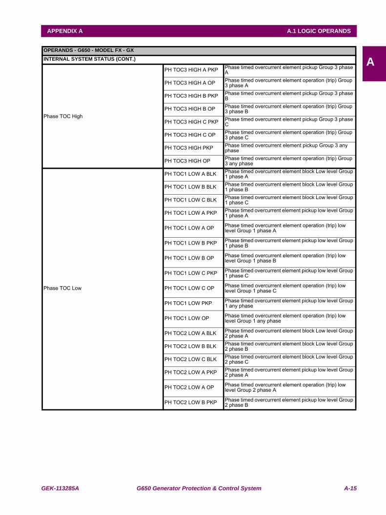
GEK-113285A G650 Generator Protection & Control System A-15
APPENDIX A A.1 LOGIC OPERANDS
AOPERANDS - G650 - MODEL FX - GXINTERNAL SYSTEM STATUS (CONT.)
Phase TOC High
PH TOC3 HIGH A PKP Phase timed overcurrent element pickup Group 3 phase A
PH TOC3 HIGH A OP Phase timed overcurrent element operation (trip) Group 3 phase A
PH TOC3 HIGH B PKP Phase timed overcurrent element pickup Group 3 phase B
PH TOC3 HIGH B OP Phase timed overcurrent element operation (trip) Group 3 phase B
PH TOC3 HIGH C PKP Phase timed overcurrent element pickup Group 3 phase C
PH TOC3 HIGH C OP Phase timed overcurrent element operation (trip) Group 3 phase C
PH TOC3 HIGH PKP Phase timed overcurrent element pickup Group 3 any phase
PH TOC3 HIGH OP Phase timed overcurrent element operation (trip) Group 3 any phase
Phase TOC Low
PH TOC1 LOW A BLK Phase timed overcurrent element block Low level Group 1 phase A
PH TOC1 LOW B BLK Phase timed overcurrent element block Low level Group 1 phase B
PH TOC1 LOW C BLK Phase timed overcurrent element block Low level Group 1 phase C
PH TOC1 LOW A PKP Phase timed overcurrent element pickup low level Group 1 phase A
PH TOC1 LOW A OP Phase timed overcurrent element operation (trip) low level Group 1 phase A
PH TOC1 LOW B PKP Phase timed overcurrent element pickup low level Group 1 phase B
PH TOC1 LOW B OP Phase timed overcurrent element operation (trip) low level Group 1 phase B
PH TOC1 LOW C PKP Phase timed overcurrent element pickup low level Group 1 phase C
PH TOC1 LOW C OP Phase timed overcurrent element operation (trip) low level Group 1 phase C
PH TOC1 LOW PKP Phase timed overcurrent element pickup low level Group 1 any phase
PH TOC1 LOW OP Phase timed overcurrent element operation (trip) low level Group 1 any phase
PH TOC2 LOW A BLK Phase timed overcurrent element block Low level Group 2 phase A
PH TOC2 LOW B BLK Phase timed overcurrent element block Low level Group 2 phase B
PH TOC2 LOW C BLK Phase timed overcurrent element block Low level Group 2 phase C
PH TOC2 LOW A PKP Phase timed overcurrent element pickup low level Group 2 phase A
PH TOC2 LOW A OP Phase timed overcurrent element operation (trip) low level Group 2 phase A
PH TOC2 LOW B PKP Phase timed overcurrent element pickup low level Group 2 phase B
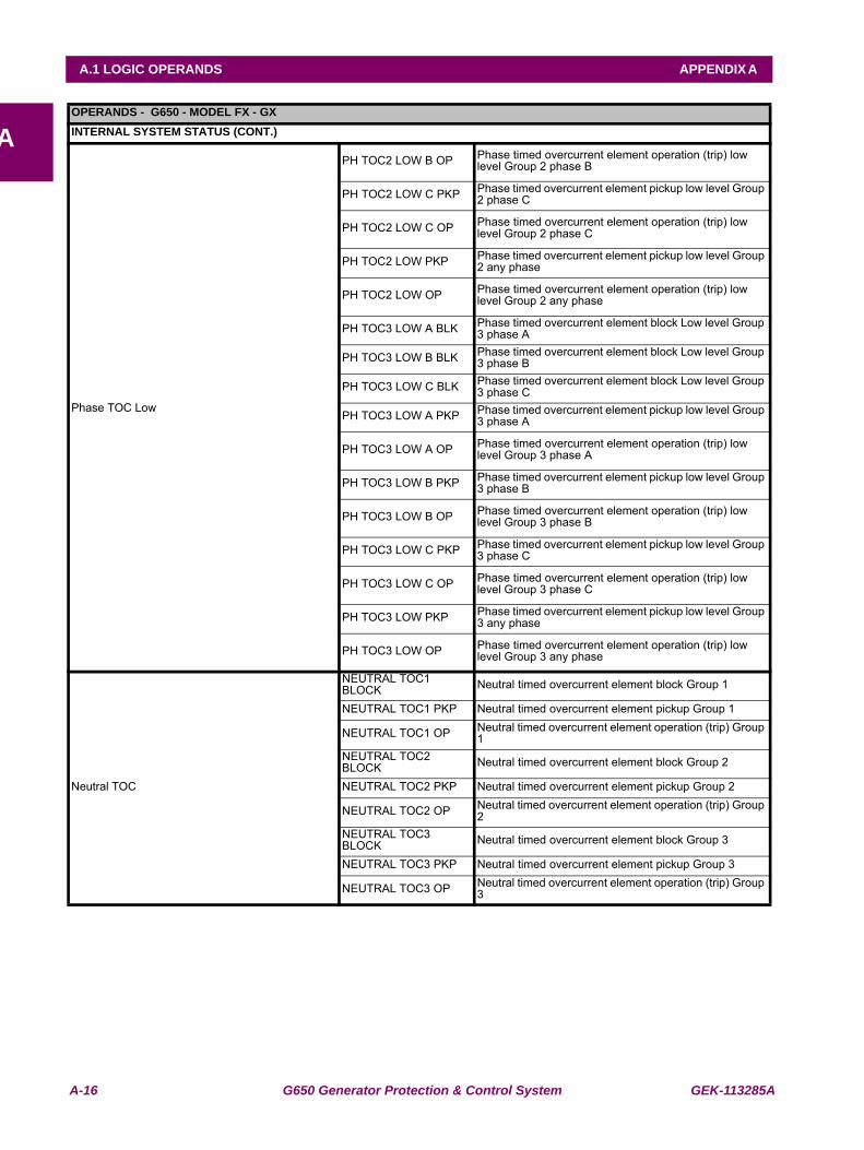
A-16 G650 Generator Protection & Control System GEK-113285A
A.1 LOGIC OPERANDS APPENDIX A
AOPERANDS - G650 - MODEL FX - GXINTERNAL SYSTEM STATUS (CONT.)
Phase TOC Low
PH TOC2 LOW B OP Phase timed overcurrent element operation (trip) low level Group 2 phase B
PH TOC2 LOW C PKP Phase timed overcurrent element pickup low level Group 2 phase C
PH TOC2 LOW C OP Phase timed overcurrent element operation (trip) low level Group 2 phase C
PH TOC2 LOW PKP Phase timed overcurrent element pickup low level Group 2 any phase
PH TOC2 LOW OP Phase timed overcurrent element operation (trip) low level Group 2 any phase
PH TOC3 LOW A BLK Phase timed overcurrent element block Low level Group 3 phase A
PH TOC3 LOW B BLK Phase timed overcurrent element block Low level Group 3 phase B
PH TOC3 LOW C BLK Phase timed overcurrent element block Low level Group 3 phase C
PH TOC3 LOW A PKP Phase timed overcurrent element pickup low level Group 3 phase A
PH TOC3 LOW A OP Phase timed overcurrent element operation (trip) low level Group 3 phase A
PH TOC3 LOW B PKP Phase timed overcurrent element pickup low level Group 3 phase B
PH TOC3 LOW B OP Phase timed overcurrent element operation (trip) low level Group 3 phase B
PH TOC3 LOW C PKP Phase timed overcurrent element pickup low level Group 3 phase C
PH TOC3 LOW C OP Phase timed overcurrent element operation (trip) low level Group 3 phase C
PH TOC3 LOW PKP Phase timed overcurrent element pickup low level Group 3 any phase
PH TOC3 LOW OP Phase timed overcurrent element operation (trip) low level Group 3 any phase
Neutral TOC
NEUTRAL TOC1 BLOCK Neutral timed overcurrent element block Group 1
NEUTRAL TOC1 PKP Neutral timed overcurrent element pickup Group 1
NEUTRAL TOC1 OP Neutral timed overcurrent element operation (trip) Group 1
NEUTRAL TOC2 BLOCK Neutral timed overcurrent element block Group 2
NEUTRAL TOC2 PKP Neutral timed overcurrent element pickup Group 2
NEUTRAL TOC2 OP Neutral timed overcurrent element operation (trip) Group 2
NEUTRAL TOC3 BLOCK Neutral timed overcurrent element block Group 3
NEUTRAL TOC3 PKP Neutral timed overcurrent element pickup Group 3
NEUTRAL TOC3 OP Neutral timed overcurrent element operation (trip) Group 3
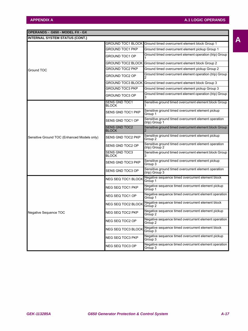
GEK-113285A G650 Generator Protection & Control System A-17
APPENDIX A A.1 LOGIC OPERANDS
AOPERANDS - G650 - MODEL FX - GXINTERNAL SYSTEM STATUS (CONT.)
Ground TOC
GROUND TOC1 BLOCK Ground timed overcurrent element block Group 1
GROUND TOC1 PKP Ground timed overcurrent element pickup Group 1
GROUND TOC1 OP Ground timed overcurrent element operation (trip) Group 1
GROUND TOC2 BLOCK Ground timed overcurrent element block Group 2
GROUND TOC2 PKP Ground timed overcurrent element pickup Group 2
GROUND TOC2 OP Ground timed overcurrent element operation (trip) Group 2
GROUND TOC3 BLOCK Ground timed overcurrent element block Group 3
GROUND TOC3 PKP Ground timed overcurrent element pickup Group 3
GROUND TOC3 OP Ground timed overcurrent element operation (trip) Group 3
Sensitive Ground TOC (Enhanced Models only)
SENS GND TOC1 BLOCK
Sensitive ground timed overcurrent element block Group 1
SENS GND TOC1 PKP Sensitive ground timed overcurrent element pickup Group 1
SENS GND TOC1 OP Sensitive ground timed overcurrent element operation (trip) Group 1
SENS GND TOC2 BLOCK
Sensitive ground timed overcurrent element block Group 2
SENS GND TOC2 PKP Sensitive ground timed overcurrent element pickup Group 2
SENS GND TOC2 OP Sensitive ground timed overcurrent element operation (trip) Group 2
SENS GND TOC3 BLOCK
Sensitive ground timed overcurrent element block Group 3
SENS GND TOC3 PKP Sensitive ground timed overcurrent element pickup Group 3
SENS GND TOC3 OP Sensitive ground timed overcurrent element operation (trip) Group 3
Negative Sequence TOC
NEG SEQ TOC1 BLOCK Negative sequence timed overcurrent element block Group 1
NEG SEQ TOC1 PKP Negative sequence timed overcurrent element pickup Group 1
NEG SEQ TOC1 OP Negative sequence timed overcurrent element operation Group 1
NEG SEQ TOC2 BLOCK Negative sequence timed overcurrent element block Group 2
NEG SEQ TOC2 PKP Negative sequence timed overcurrent element pickup Group 2
NEG SEQ TOC2 OP Negative sequence timed overcurrent element operation Group 2
NEG SEQ TOC3 BLOCK Negative sequence timed overcurrent element block Group 3
NEG SEQ TOC3 PKP Negative sequence timed overcurrent element pickup Group 3
NEG SEQ TOC3 OP Negative sequence timed overcurrent element operation Group 3
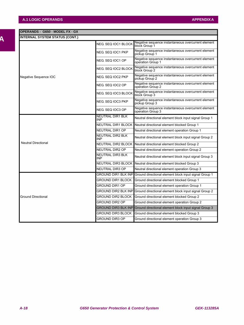
A-18 G650 Generator Protection & Control System GEK-113285A
A.1 LOGIC OPERANDS APPENDIX A
AOPERANDS - G650 - MODEL FX - GXINTERNAL SYSTEM STATUS (CONT.)
Negative Sequence IOC
NEG. SEQ IOC1 BLOCK Negative sequence instantaneous overcurrent element block Group 1
NEG. SEQ IOC1 PKP Negative sequence instantaneous overcurrent element pickup Group 1
NEG. SEQ IOC1 OP Negative sequence instantaneous overcurrent element operation Group 1
NEG. SEQ IOC2 BLOCK Negative sequence instantaneous overcurrent element block Group 2
NEG. SEQ IOC2 PKP Negative sequence instantaneous overcurrent element pickup Group 2
NEG. SEQ IOC2 OP Negative sequence instantaneous overcurrent element operation Group 2
NEG. SEQ IOC3 BLOCK Negative sequence instantaneous overcurrent element block Group 3
NEG. SEQ IOC3 PKP Negative sequence instantaneous overcurrent element pickup Group 3
NEG. SEQ IOC3 OP Negative sequence instantaneous overcurrent element operation Group 3
Neutral Directional
NEUTRAL DIR1 BLK INP Neutral directional element block input signal Group 1
NEUTRAL DIR1 BLOCK Neutral directional element blocked Group 1
NEUTRAL DIR1 OP Neutral directional element operation Group 1NEUTRAL DIR2 BLK INP Neutral directional element block input signal Group 2
NEUTRAL DIR2 BLOCK Neutral directional element blocked Group 2
NEUTRAL DIR2 OP Neutral directional element operation Group 2NEUTRAL DIR3 BLK INP Neutral directional element block input signal Group 3
NEUTRAL DIR3 BLOCK Neutral directional element blocked Group 3
NEUTRAL DIR3 OP Neutral directional element operation Group 3
Ground Directional
GROUND DIR1 BLK INP Ground directional element block input signal Group 1
GROUND DIR1 BLOCK Ground directional element blocked Group 1
GROUND DIR1 OP Ground directional element operation Group 1
GROUND DIR2 BLK INP Ground directional element block input signal Group 2
GROUND DIR2 BLOCK Ground directional element blocked Group 2
GROUND DIR2 OP Ground directional element operation Group 2
GROUND DIR3 BLK INP Ground directional element block input signal Group 3
GROUND DIR3 BLOCK Ground directional element blocked Group 3
GROUND DIR3 OP Ground directional element operation Group 3
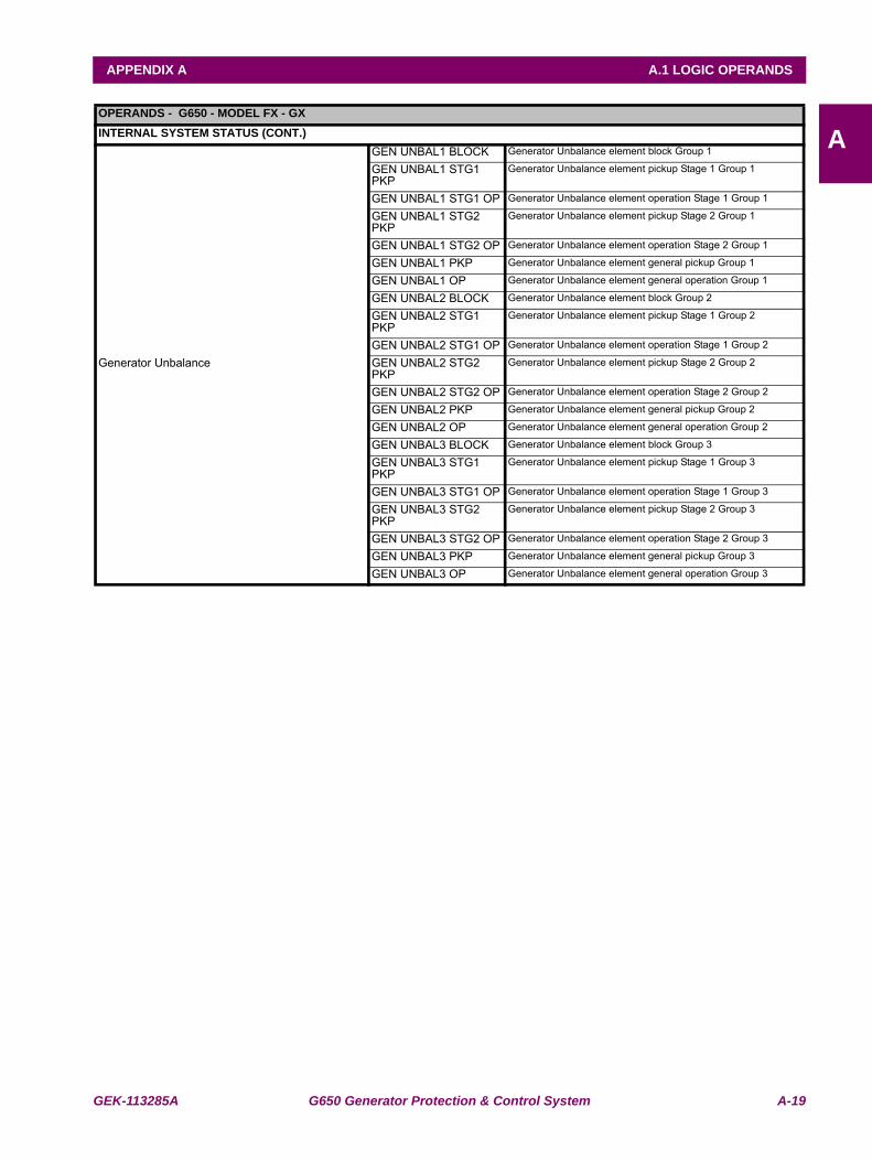
GEK-113285A G650 Generator Protection & Control System A-19
APPENDIX A A.1 LOGIC OPERANDS
AOPERANDS - G650 - MODEL FX - GXINTERNAL SYSTEM STATUS (CONT.)
Generator Unbalance
GEN UNBAL1 BLOCK Generator Unbalance element block Group 1
GEN UNBAL1 STG1 PKP
Generator Unbalance element pickup Stage 1 Group 1
GEN UNBAL1 STG1 OP Generator Unbalance element operation Stage 1 Group 1
GEN UNBAL1 STG2 PKP
Generator Unbalance element pickup Stage 2 Group 1
GEN UNBAL1 STG2 OP Generator Unbalance element operation Stage 2 Group 1
GEN UNBAL1 PKP Generator Unbalance element general pickup Group 1
GEN UNBAL1 OP Generator Unbalance element general operation Group 1
GEN UNBAL2 BLOCK Generator Unbalance element block Group 2
GEN UNBAL2 STG1 PKP
Generator Unbalance element pickup Stage 1 Group 2
GEN UNBAL2 STG1 OP Generator Unbalance element operation Stage 1 Group 2
GEN UNBAL2 STG2 PKP
Generator Unbalance element pickup Stage 2 Group 2
GEN UNBAL2 STG2 OP Generator Unbalance element operation Stage 2 Group 2
GEN UNBAL2 PKP Generator Unbalance element general pickup Group 2
GEN UNBAL2 OP Generator Unbalance element general operation Group 2
GEN UNBAL3 BLOCK Generator Unbalance element block Group 3
GEN UNBAL3 STG1 PKP
Generator Unbalance element pickup Stage 1 Group 3
GEN UNBAL3 STG1 OP Generator Unbalance element operation Stage 1 Group 3
GEN UNBAL3 STG2 PKP
Generator Unbalance element pickup Stage 2 Group 3
GEN UNBAL3 STG2 OP Generator Unbalance element operation Stage 2 Group 3
GEN UNBAL3 PKP Generator Unbalance element general pickup Group 3
GEN UNBAL3 OP Generator Unbalance element general operation Group 3
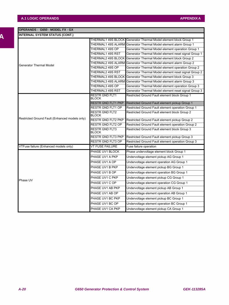
A-20 G650 Generator Protection & Control System GEK-113285A
A.1 LOGIC OPERANDS APPENDIX A
AOPERANDS - G650 - MODEL FX - GXINTERNAL SYSTEM STATUS (CONT.)
Generator Thermal Model
THERMAL1 49S BLOCK Generator Thermal Model element block Group 1THERMAL1 49S ALARM Generator Thermal Model element alarm Group 1THERMAL1 49S OP Generator Thermal Model element operation Group 1THERMAL1 49S RST Generator Thermal Model element reset signal Group 1THERMAL2 49S BLOCK Generator Thermal Model element block Group 2THERMAL2 49S ALARM Generator Thermal Model element alarm Group 2THERMAL2 49S OP Generator Thermal Model element operation Group 2THERMAL2 49S RST Generator Thermal Model element reset signal Group 2THERMAL3 49S BLOCK Generator Thermal Model element block Group 3THERMAL3 49S ALARM Generator Thermal Model element alarm Group 3THERMAL3 49S OP Generator Thermal Model element operation Group 3THERMAL3 49S RST Generator Thermal Model element reset signal Group 3
Restricted Ground Fault (Enhanced models only)
RESTR GND FLT1 BLOCK
Restricted Ground Fault element block Group 1
RESTR GND FLT1 PKP Restricted Ground Fault element pickup Group 1RESTR GND FLT1 OP Restricted Ground Fault element operation Group 1RESTR GND FLT2 BLOCK
Restricted Ground Fault element block Group 2
RESTR GND FLT2 PKP Restricted Ground Fault element pickup Group 2RESTR GND FLT2 OP Restricted Ground Fault element operation Group 2RESTR GND FLT3 BLOCK
Restricted Ground Fault element block Group 3
RESTR GND FLT3 PKP Restricted Ground Fault element pickup Group 3RESTR GND FLT3 OP Restricted Ground Fault element operation Group 3
VTFuse failure (Enhanced models only) VT FUSE FAILURE Fuse failure operation
Phase UV
PHASE UV1 BLOCK Phase undervoltage element block Group 1
PHASE UV1 A PKP Undervoltage element pickup AG Group 1
PHASE UV1 A OP Undervoltage element operation AG Group 1
PHASE UV1 B PKP Undervoltage element pickup BG Group 1
PHASE UV1 B OP Undervoltage element operation BG Group 1
PHASE UV1 C PKP Undervoltage element pickup CG Group 1
PHASE UV1 C OP Undervoltage element operation CG Group 1
PHASE UV1 AB PKP Undervoltage element pickup AB Group 1
PHASE UV1 AB OP Undervoltage element operation AB Group 1
PHASE UV1 BC PKP Undervoltage element pickup BC Group 1
PHASE UV1 BC OP Undervoltage element operation BC Group 1
PHASE UV1 CA PKP Undervoltage element pickup CA Group 1
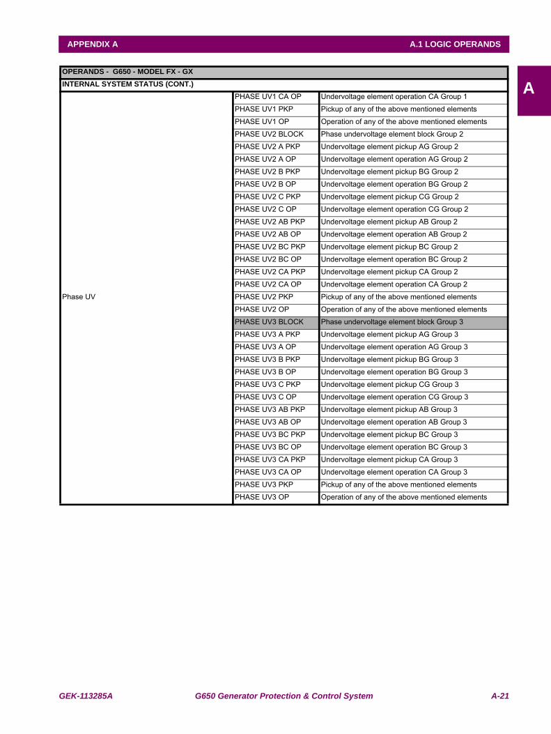
GEK-113285A G650 Generator Protection & Control System A-21
APPENDIX A A.1 LOGIC OPERANDS
AOPERANDS - G650 - MODEL FX - GXINTERNAL SYSTEM STATUS (CONT.)
Phase UV
PHASE UV1 CA OP Undervoltage element operation CA Group 1
PHASE UV1 PKP Pickup of any of the above mentioned elements
PHASE UV1 OP Operation of any of the above mentioned elements
PHASE UV2 BLOCK Phase undervoltage element block Group 2
PHASE UV2 A PKP Undervoltage element pickup AG Group 2
PHASE UV2 A OP Undervoltage element operation AG Group 2
PHASE UV2 B PKP Undervoltage element pickup BG Group 2
PHASE UV2 B OP Undervoltage element operation BG Group 2
PHASE UV2 C PKP Undervoltage element pickup CG Group 2
PHASE UV2 C OP Undervoltage element operation CG Group 2
PHASE UV2 AB PKP Undervoltage element pickup AB Group 2
PHASE UV2 AB OP Undervoltage element operation AB Group 2
PHASE UV2 BC PKP Undervoltage element pickup BC Group 2
PHASE UV2 BC OP Undervoltage element operation BC Group 2
PHASE UV2 CA PKP Undervoltage element pickup CA Group 2
PHASE UV2 CA OP Undervoltage element operation CA Group 2
PHASE UV2 PKP Pickup of any of the above mentioned elements
PHASE UV2 OP Operation of any of the above mentioned elements
PHASE UV3 BLOCK Phase undervoltage element block Group 3
PHASE UV3 A PKP Undervoltage element pickup AG Group 3
PHASE UV3 A OP Undervoltage element operation AG Group 3
PHASE UV3 B PKP Undervoltage element pickup BG Group 3
PHASE UV3 B OP Undervoltage element operation BG Group 3
PHASE UV3 C PKP Undervoltage element pickup CG Group 3
PHASE UV3 C OP Undervoltage element operation CG Group 3
PHASE UV3 AB PKP Undervoltage element pickup AB Group 3
PHASE UV3 AB OP Undervoltage element operation AB Group 3
PHASE UV3 BC PKP Undervoltage element pickup BC Group 3
PHASE UV3 BC OP Undervoltage element operation BC Group 3
PHASE UV3 CA PKP Undervoltage element pickup CA Group 3
PHASE UV3 CA OP Undervoltage element operation CA Group 3
PHASE UV3 PKP Pickup of any of the above mentioned elements
PHASE UV3 OP Operation of any of the above mentioned elements
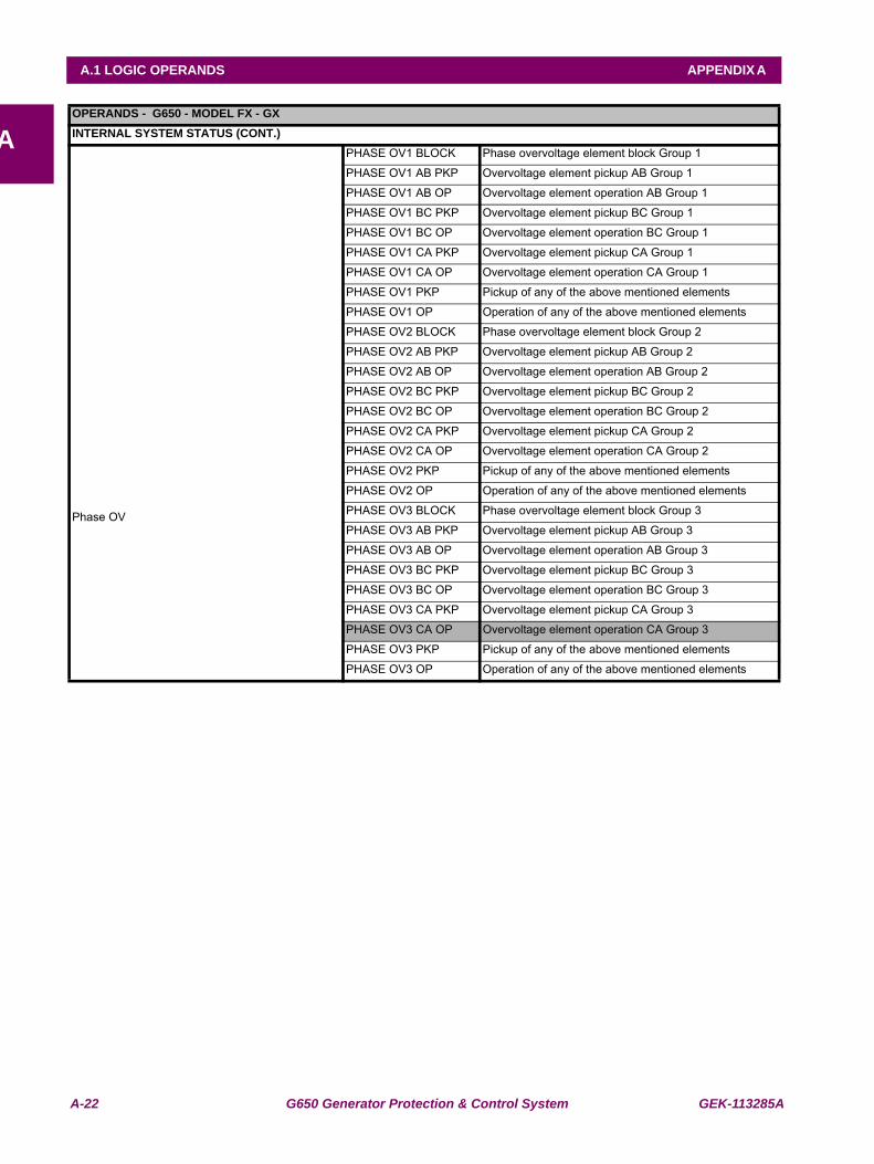
A-22 G650 Generator Protection & Control System GEK-113285A
A.1 LOGIC OPERANDS APPENDIX A
AOPERANDS - G650 - MODEL FX - GXINTERNAL SYSTEM STATUS (CONT.)
Phase OV
PHASE OV1 BLOCK Phase overvoltage element block Group 1
PHASE OV1 AB PKP Overvoltage element pickup AB Group 1
PHASE OV1 AB OP Overvoltage element operation AB Group 1
PHASE OV1 BC PKP Overvoltage element pickup BC Group 1
PHASE OV1 BC OP Overvoltage element operation BC Group 1
PHASE OV1 CA PKP Overvoltage element pickup CA Group 1
PHASE OV1 CA OP Overvoltage element operation CA Group 1
PHASE OV1 PKP Pickup of any of the above mentioned elements
PHASE OV1 OP Operation of any of the above mentioned elements
PHASE OV2 BLOCK Phase overvoltage element block Group 2
PHASE OV2 AB PKP Overvoltage element pickup AB Group 2
PHASE OV2 AB OP Overvoltage element operation AB Group 2
PHASE OV2 BC PKP Overvoltage element pickup BC Group 2
PHASE OV2 BC OP Overvoltage element operation BC Group 2
PHASE OV2 CA PKP Overvoltage element pickup CA Group 2
PHASE OV2 CA OP Overvoltage element operation CA Group 2
PHASE OV2 PKP Pickup of any of the above mentioned elements
PHASE OV2 OP Operation of any of the above mentioned elements
PHASE OV3 BLOCK Phase overvoltage element block Group 3
PHASE OV3 AB PKP Overvoltage element pickup AB Group 3
PHASE OV3 AB OP Overvoltage element operation AB Group 3
PHASE OV3 BC PKP Overvoltage element pickup BC Group 3
PHASE OV3 BC OP Overvoltage element operation BC Group 3
PHASE OV3 CA PKP Overvoltage element pickup CA Group 3
PHASE OV3 CA OP Overvoltage element operation CA Group 3
PHASE OV3 PKP Pickup of any of the above mentioned elements
PHASE OV3 OP Operation of any of the above mentioned elements
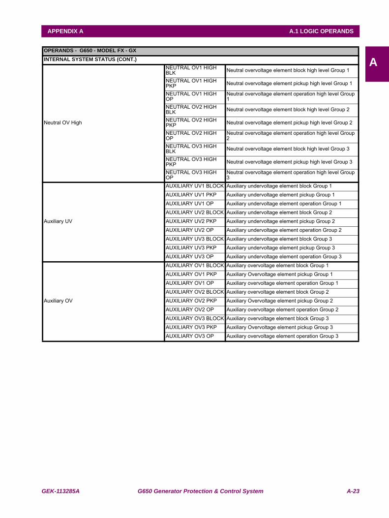
GEK-113285A G650 Generator Protection & Control System A-23
APPENDIX A A.1 LOGIC OPERANDS
AOPERANDS - G650 - MODEL FX - GXINTERNAL SYSTEM STATUS (CONT.)
Neutral OV High
NEUTRAL OV1 HIGH BLK Neutral overvoltage element block high level Group 1
NEUTRAL OV1 HIGH PKP Neutral overvoltage element pickup high level Group 1
NEUTRAL OV1 HIGH OP
Neutral overvoltage element operation high level Group 1
NEUTRAL OV2 HIGH BLK Neutral overvoltage element block high level Group 2
NEUTRAL OV2 HIGH PKP Neutral overvoltage element pickup high level Group 2
NEUTRAL OV2 HIGH OP
Neutral overvoltage element operation high level Group 2
NEUTRAL OV3 HIGH BLK Neutral overvoltage element block high level Group 3
NEUTRAL OV3 HIGH PKP Neutral overvoltage element pickup high level Group 3
NEUTRAL OV3 HIGH OP
Neutral overvoltage element operation high level Group 3
Auxiliary UV
AUXILIARY UV1 BLOCK Auxiliary undervoltage element block Group 1
AUXILIARY UV1 PKP Auxiliary undervoltage element pickup Group 1
AUXILIARY UV1 OP Auxiliary undervoltage element operation Group 1
AUXILIARY UV2 BLOCK Auxiliary undervoltage element block Group 2
AUXILIARY UV2 PKP Auxiliary undervoltage element pickup Group 2
AUXILIARY UV2 OP Auxiliary undervoltage element operation Group 2
AUXILIARY UV3 BLOCK Auxiliary undervoltage element block Group 3
AUXILIARY UV3 PKP Auxiliary undervoltage element pickup Group 3
AUXILIARY UV3 OP Auxiliary undervoltage element operation Group 3
Auxiliary OV
AUXILIARY OV1 BLOCK Auxiliary overvoltage element block Group 1
AUXILIARY OV1 PKP Auxiliary Overvoltage element pickup Group 1
AUXILIARY OV1 OP Auxiliary overvoltage element operation Group 1
AUXILIARY OV2 BLOCK Auxiliary overvoltage element block Group 2
AUXILIARY OV2 PKP Auxiliary Overvoltage element pickup Group 2
AUXILIARY OV2 OP Auxiliary overvoltage element operation Group 2
AUXILIARY OV3 BLOCK Auxiliary overvoltage element block Group 3
AUXILIARY OV3 PKP Auxiliary Overvoltage element pickup Group 3
AUXILIARY OV3 OP Auxiliary overvoltage element operation Group 3
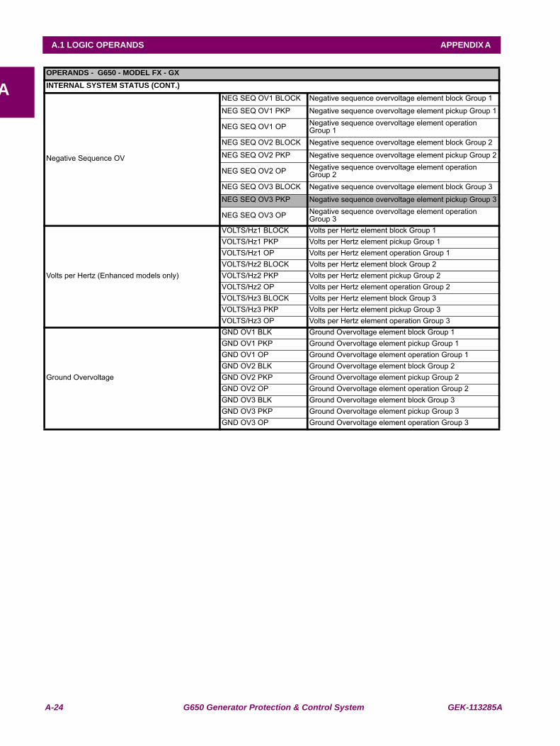
A-24 G650 Generator Protection & Control System GEK-113285A
A.1 LOGIC OPERANDS APPENDIX A
AOPERANDS - G650 - MODEL FX - GXINTERNAL SYSTEM STATUS (CONT.)
Negative Sequence OV
NEG SEQ OV1 BLOCK Negative sequence overvoltage element block Group 1
NEG SEQ OV1 PKP Negative sequence overvoltage element pickup Group 1
NEG SEQ OV1 OP Negative sequence overvoltage element operation Group 1
NEG SEQ OV2 BLOCK Negative sequence overvoltage element block Group 2
NEG SEQ OV2 PKP Negative sequence overvoltage element pickup Group 2
NEG SEQ OV2 OP Negative sequence overvoltage element operation Group 2
NEG SEQ OV3 BLOCK Negative sequence overvoltage element block Group 3
NEG SEQ OV3 PKP Negative sequence overvoltage element pickup Group 3
NEG SEQ OV3 OP Negative sequence overvoltage element operation Group 3
Volts per Hertz (Enhanced models only)
VOLTS/Hz1 BLOCK Volts per Hertz element block Group 1VOLTS/Hz1 PKP Volts per Hertz element pickup Group 1VOLTS/Hz1 OP Volts per Hertz element operation Group 1VOLTS/Hz2 BLOCK Volts per Hertz element block Group 2VOLTS/Hz2 PKP Volts per Hertz element pickup Group 2VOLTS/Hz2 OP Volts per Hertz element operation Group 2VOLTS/Hz3 BLOCK Volts per Hertz element block Group 3VOLTS/Hz3 PKP Volts per Hertz element pickup Group 3VOLTS/Hz3 OP Volts per Hertz element operation Group 3
Ground Overvoltage
GND OV1 BLK Ground Overvoltage element block Group 1GND OV1 PKP Ground Overvoltage element pickup Group 1GND OV1 OP Ground Overvoltage element operation Group 1GND OV2 BLK Ground Overvoltage element block Group 2GND OV2 PKP Ground Overvoltage element pickup Group 2GND OV2 OP Ground Overvoltage element operation Group 2GND OV3 BLK Ground Overvoltage element block Group 3GND OV3 PKP Ground Overvoltage element pickup Group 3GND OV3 OP Ground Overvoltage element operation Group 3
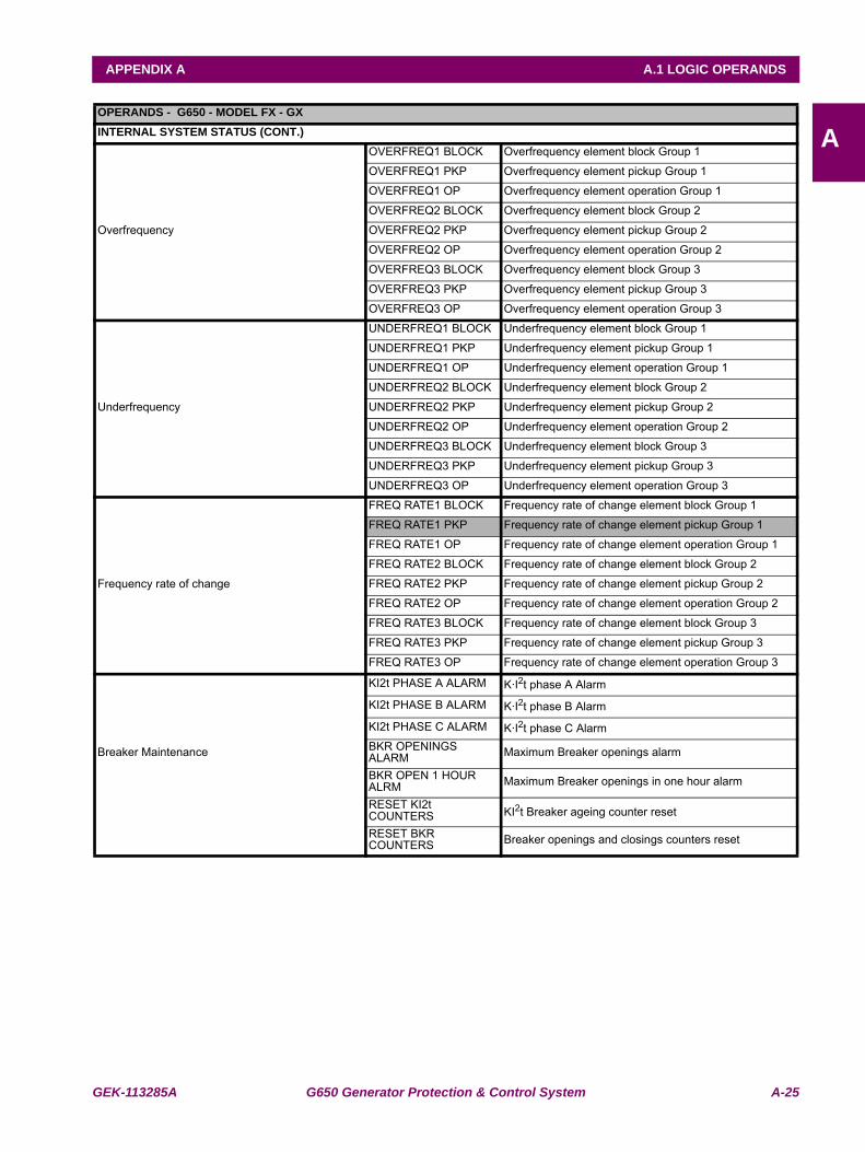
GEK-113285A G650 Generator Protection & Control System A-25
APPENDIX A A.1 LOGIC OPERANDS
AOPERANDS - G650 - MODEL FX - GXINTERNAL SYSTEM STATUS (CONT.)
Overfrequency
OVERFREQ1 BLOCK Overfrequency element block Group 1
OVERFREQ1 PKP Overfrequency element pickup Group 1
OVERFREQ1 OP Overfrequency element operation Group 1
OVERFREQ2 BLOCK Overfrequency element block Group 2
OVERFREQ2 PKP Overfrequency element pickup Group 2
OVERFREQ2 OP Overfrequency element operation Group 2
OVERFREQ3 BLOCK Overfrequency element block Group 3
OVERFREQ3 PKP Overfrequency element pickup Group 3
OVERFREQ3 OP Overfrequency element operation Group 3
Underfrequency
UNDERFREQ1 BLOCK Underfrequency element block Group 1
UNDERFREQ1 PKP Underfrequency element pickup Group 1
UNDERFREQ1 OP Underfrequency element operation Group 1
UNDERFREQ2 BLOCK Underfrequency element block Group 2
UNDERFREQ2 PKP Underfrequency element pickup Group 2
UNDERFREQ2 OP Underfrequency element operation Group 2
UNDERFREQ3 BLOCK Underfrequency element block Group 3
UNDERFREQ3 PKP Underfrequency element pickup Group 3
UNDERFREQ3 OP Underfrequency element operation Group 3
Frequency rate of change
FREQ RATE1 BLOCK Frequency rate of change element block Group 1
FREQ RATE1 PKP Frequency rate of change element pickup Group 1
FREQ RATE1 OP Frequency rate of change element operation Group 1
FREQ RATE2 BLOCK Frequency rate of change element block Group 2
FREQ RATE2 PKP Frequency rate of change element pickup Group 2
FREQ RATE2 OP Frequency rate of change element operation Group 2
FREQ RATE3 BLOCK Frequency rate of change element block Group 3
FREQ RATE3 PKP Frequency rate of change element pickup Group 3
FREQ RATE3 OP Frequency rate of change element operation Group 3
KI2t PHASE A ALARM K·I2t phase A Alarm
KI2t PHASE B ALARM K·I2t phase B Alarm
KI2t PHASE C ALARM K·I2t phase C Alarm
Breaker Maintenance BKR OPENINGS ALARM Maximum Breaker openings alarm
BKR OPEN 1 HOUR ALRM Maximum Breaker openings in one hour alarm
RESET KI2t COUNTERS KI2t Breaker ageing counter reset
RESET BKR COUNTERS Breaker openings and closings counters reset
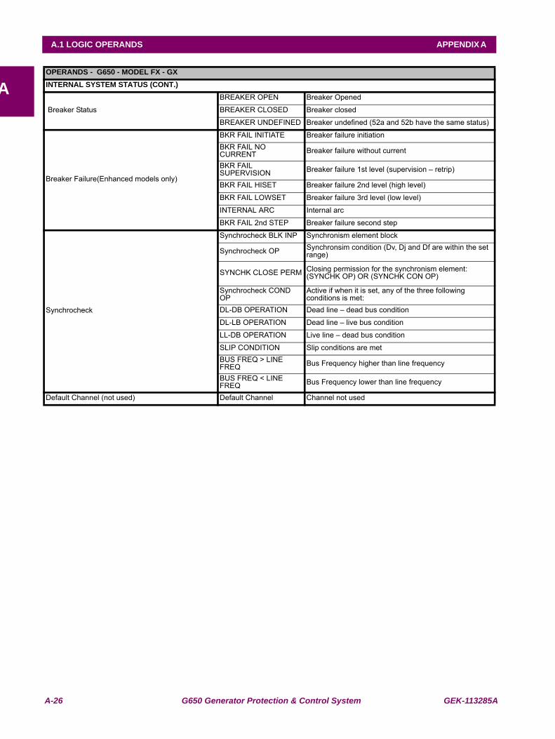
A-26 G650 Generator Protection & Control System GEK-113285A
A.1 LOGIC OPERANDS APPENDIX A
AOPERANDS - G650 - MODEL FX - GXINTERNAL SYSTEM STATUS (CONT.)
Breaker Status
BREAKER OPEN Breaker Opened
BREAKER CLOSED Breaker closed
BREAKER UNDEFINED Breaker undefined (52a and 52b have the same status)
Breaker Failure(Enhanced models only)
BKR FAIL INITIATE Breaker failure initiationBKR FAIL NO CURRENT Breaker failure without current
BKR FAIL SUPERVISION Breaker failure 1st level (supervision – retrip)
BKR FAIL HISET Breaker failure 2nd level (high level)
BKR FAIL LOWSET Breaker failure 3rd level (low level)
INTERNAL ARC Internal arc
BKR FAIL 2nd STEP Breaker failure second step
Synchrocheck
Synchrocheck BLK INP Synchronism element block
Synchrocheck OP Synchronsim condition (Dv, Dj and Df are within the set range)
SYNCHK CLOSE PERM Closing permission for the synchronism element: (SYNCHK OP) OR (SYNCHK CON OP)
Synchrocheck COND OP
Active if when it is set, any of the three following conditions is met:
DL-DB OPERATION Dead line – dead bus condition
DL-LB OPERATION Dead line – live bus condition
LL-DB OPERATION Live line – dead bus condition
SLIP CONDITION Slip conditions are metBUS FREQ > LINE FREQ Bus Frequency higher than line frequency
BUS FREQ < LINE FREQ Bus Frequency lower than line frequency
Default Channel (not used) Default Channel Channel not used
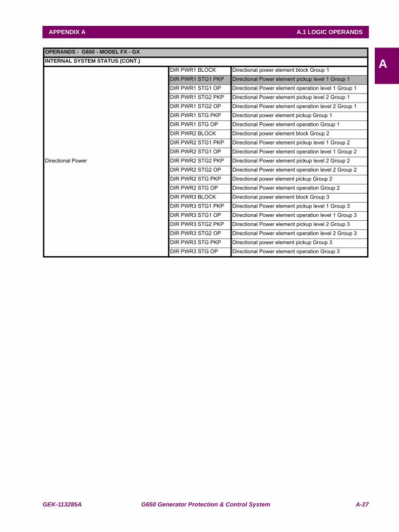
GEK-113285A G650 Generator Protection & Control System A-27
APPENDIX A A.1 LOGIC OPERANDS
AOPERANDS - G650 - MODEL FX - GXINTERNAL SYSTEM STATUS (CONT.)
Directional Power
DIR PWR1 BLOCK Directional power element block Group 1
DIR PWR1 STG1 PKP Directional Power element pickup level 1 Group 1
DIR PWR1 STG1 OP Directional Power element operation level 1 Group 1
DIR PWR1 STG2 PKP Directional Power element pickup level 2 Group 1
DIR PWR1 STG2 OP Directional Power element operation level 2 Group 1
DIR PWR1 STG PKP Directional power element pickup Group 1
DIR PWR1 STG OP Directional Power element operation Group 1
DIR PWR2 BLOCK Directional power element block Group 2
DIR PWR2 STG1 PKP Directional Power element pickup level 1 Group 2
DIR PWR2 STG1 OP Directional Power element operation level 1 Group 2
DIR PWR2 STG2 PKP Directional Power element pickup level 2 Group 2
DIR PWR2 STG2 OP Directional Power element operation level 2 Group 2
DIR PWR2 STG PKP Directional power element pickup Group 2
DIR PWR2 STG OP Directional Power element operation Group 2
DIR PWR3 BLOCK Directional power element block Group 3
DIR PWR3 STG1 PKP Directional Power element pickup level 1 Group 3
DIR PWR3 STG1 OP Directional Power element operation level 1 Group 3
DIR PWR3 STG2 PKP Directional Power element pickup level 2 Group 3
DIR PWR3 STG2 OP Directional Power element operation level 2 Group 3
DIR PWR3 STG PKP Directional power element pickup Group 3
DIR PWR3 STG OP Directional Power element operation Group 3
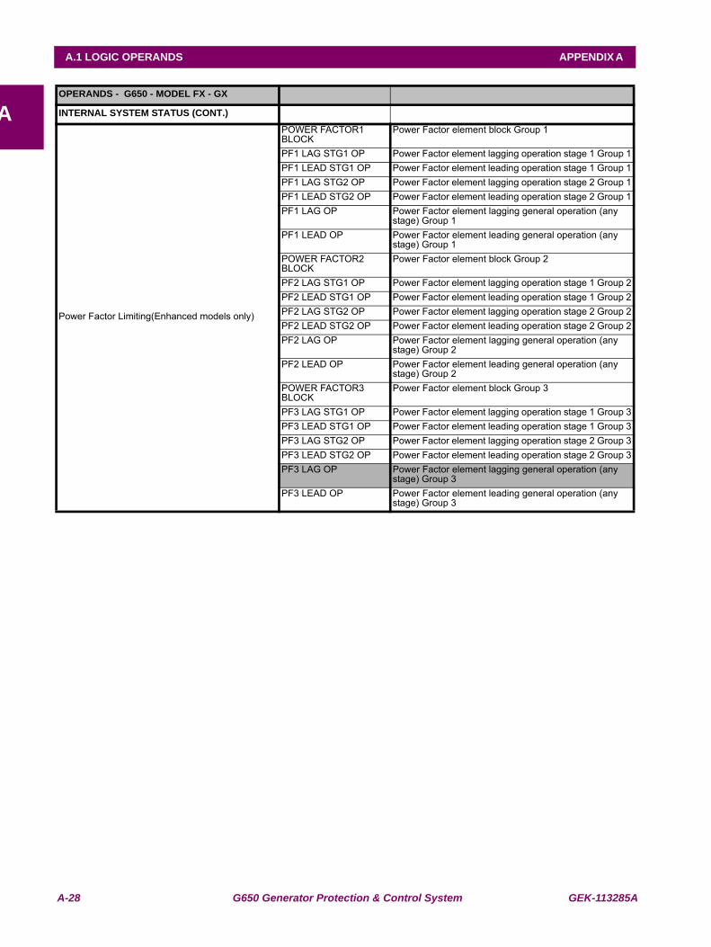
A-28 G650 Generator Protection & Control System GEK-113285A
A.1 LOGIC OPERANDS APPENDIX A
AOPERANDS - G650 - MODEL FX - GX
INTERNAL SYSTEM STATUS (CONT.)
Power Factor Limiting(Enhanced models only)
POWER FACTOR1 BLOCK
Power Factor element block Group 1
PF1 LAG STG1 OP Power Factor element lagging operation stage 1 Group 1PF1 LEAD STG1 OP Power Factor element leading operation stage 1 Group 1PF1 LAG STG2 OP Power Factor element lagging operation stage 2 Group 1PF1 LEAD STG2 OP Power Factor element leading operation stage 2 Group 1PF1 LAG OP Power Factor element lagging general operation (any
stage) Group 1PF1 LEAD OP Power Factor element leading general operation (any
stage) Group 1POWER FACTOR2 BLOCK
Power Factor element block Group 2
PF2 LAG STG1 OP Power Factor element lagging operation stage 1 Group 2PF2 LEAD STG1 OP Power Factor element leading operation stage 1 Group 2PF2 LAG STG2 OP Power Factor element lagging operation stage 2 Group 2PF2 LEAD STG2 OP Power Factor element leading operation stage 2 Group 2PF2 LAG OP Power Factor element lagging general operation (any
stage) Group 2PF2 LEAD OP Power Factor element leading general operation (any
stage) Group 2POWER FACTOR3 BLOCK
Power Factor element block Group 3
PF3 LAG STG1 OP Power Factor element lagging operation stage 1 Group 3PF3 LEAD STG1 OP Power Factor element leading operation stage 1 Group 3PF3 LAG STG2 OP Power Factor element lagging operation stage 2 Group 3PF3 LEAD STG2 OP Power Factor element leading operation stage 2 Group 3PF3 LAG OP Power Factor element lagging general operation (any
stage) Group 3PF3 LEAD OP Power Factor element leading general operation (any
stage) Group 3
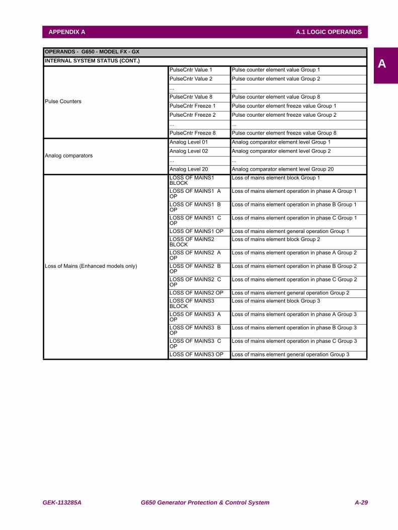
GEK-113285A G650 Generator Protection & Control System A-29
APPENDIX A A.1 LOGIC OPERANDS
AOPERANDS - G650 - MODEL FX - GXINTERNAL SYSTEM STATUS (CONT.)
Pulse Counters
PulseCntr Value 1 Pulse counter element value Group 1
PulseCntr Value 2 Pulse counter element value Group 2
... ...
PulseCntr Value 8 Pulse counter element value Group 8
PulseCntr Freeze 1 Pulse counter element freeze value Group 1
PulseCntr Freeze 2 Pulse counter element freeze value Group 2
... ...
PulseCntr Freeze 8 Pulse counter element freeze value Group 8
Analog comparators
Analog Level 01 Analog comparator element level Group 1
Analog Level 02 Analog comparator element level Group 2
... ...
Analog Level 20 Analog comparator element level Group 20
Loss of Mains (Enhanced models only)
LOSS OF MAINS1 BLOCK
Loss of mains element block Group 1
LOSS OF MAINS1 A OP
Loss of mains element operation in phase A Group 1
LOSS OF MAINS1 B OP
Loss of mains element operation in phase B Group 1
LOSS OF MAINS1 C OP
Loss of mains element operation in phase C Group 1
LOSS OF MAINS1 OP Loss of mains element general operation Group 1LOSS OF MAINS2 BLOCK
Loss of mains element block Group 2
LOSS OF MAINS2 A OP
Loss of mains element operation in phase A Group 2
LOSS OF MAINS2 B OP
Loss of mains element operation in phase B Group 2
LOSS OF MAINS2 C OP
Loss of mains element operation in phase C Group 2
LOSS OF MAINS2 OP Loss of mains element general operation Group 2LOSS OF MAINS3 BLOCK
Loss of mains element block Group 3
LOSS OF MAINS3 A OP
Loss of mains element operation in phase A Group 3
LOSS OF MAINS3 B OP
Loss of mains element operation in phase B Group 3
LOSS OF MAINS3 C OP
Loss of mains element operation in phase C Group 3
LOSS OF MAINS3 OP Loss of mains element general operation Group 3
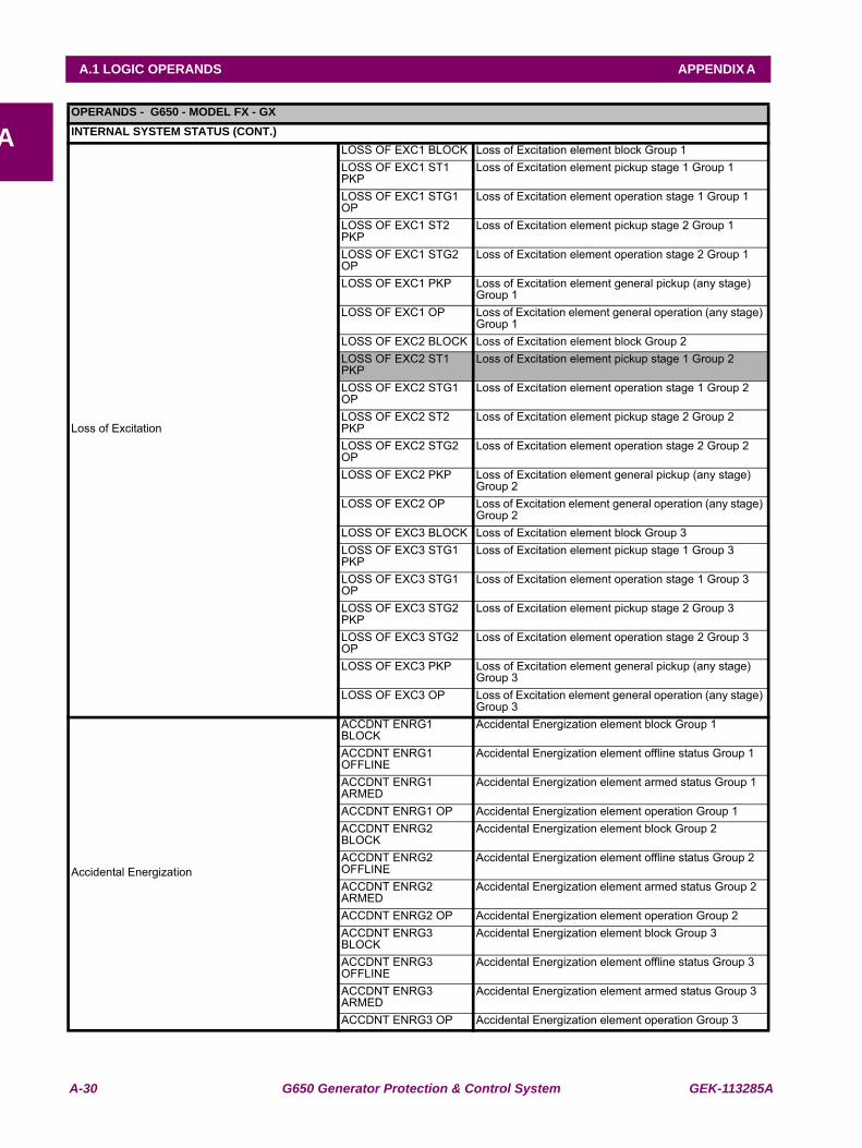
A-30 G650 Generator Protection & Control System GEK-113285A
A.1 LOGIC OPERANDS APPENDIX A
AOPERANDS - G650 - MODEL FX - GXINTERNAL SYSTEM STATUS (CONT.)
Loss of Excitation
LOSS OF EXC1 BLOCK Loss of Excitation element block Group 1LOSS OF EXC1 ST1 PKP
Loss of Excitation element pickup stage 1 Group 1
LOSS OF EXC1 STG1 OP
Loss of Excitation element operation stage 1 Group 1
LOSS OF EXC1 ST2 PKP
Loss of Excitation element pickup stage 2 Group 1
LOSS OF EXC1 STG2 OP
Loss of Excitation element operation stage 2 Group 1
LOSS OF EXC1 PKP Loss of Excitation element general pickup (any stage) Group 1
LOSS OF EXC1 OP Loss of Excitation element general operation (any stage) Group 1
LOSS OF EXC2 BLOCK Loss of Excitation element block Group 2LOSS OF EXC2 ST1 PKP
Loss of Excitation element pickup stage 1 Group 2
LOSS OF EXC2 STG1 OP
Loss of Excitation element operation stage 1 Group 2
LOSS OF EXC2 ST2 PKP
Loss of Excitation element pickup stage 2 Group 2
LOSS OF EXC2 STG2 OP
Loss of Excitation element operation stage 2 Group 2
LOSS OF EXC2 PKP Loss of Excitation element general pickup (any stage) Group 2
LOSS OF EXC2 OP Loss of Excitation element general operation (any stage) Group 2
LOSS OF EXC3 BLOCK Loss of Excitation element block Group 3LOSS OF EXC3 STG1 PKP
Loss of Excitation element pickup stage 1 Group 3
LOSS OF EXC3 STG1 OP
Loss of Excitation element operation stage 1 Group 3
LOSS OF EXC3 STG2 PKP
Loss of Excitation element pickup stage 2 Group 3
LOSS OF EXC3 STG2 OP
Loss of Excitation element operation stage 2 Group 3
LOSS OF EXC3 PKP Loss of Excitation element general pickup (any stage) Group 3
LOSS OF EXC3 OP Loss of Excitation element general operation (any stage) Group 3
Accidental Energization
ACCDNT ENRG1 BLOCK
Accidental Energization element block Group 1
ACCDNT ENRG1 OFFLINE
Accidental Energization element offline status Group 1
ACCDNT ENRG1 ARMED
Accidental Energization element armed status Group 1
ACCDNT ENRG1 OP Accidental Energization element operation Group 1ACCDNT ENRG2 BLOCK
Accidental Energization element block Group 2
ACCDNT ENRG2 OFFLINE
Accidental Energization element offline status Group 2
ACCDNT ENRG2 ARMED
Accidental Energization element armed status Group 2
ACCDNT ENRG2 OP Accidental Energization element operation Group 2ACCDNT ENRG3 BLOCK
Accidental Energization element block Group 3
ACCDNT ENRG3 OFFLINE
Accidental Energization element offline status Group 3
ACCDNT ENRG3 ARMED
Accidental Energization element armed status Group 3
ACCDNT ENRG3 OP Accidental Energization element operation Group 3
GEK-113285A G650 Generator Protection & Control System A-31
APPENDIX A A.1 LOGIC OPERANDS
A

A-32 G650 Generator Protection & Control System GEK-113285A
A.1 LOGIC OPERANDS APPENDIX A
A
GEK-113285A G650 Generator Protection & Control System B-1
APPENDIX B B.1 ACCESS TO G650 DATA
B
APPENDIX B MODBUS PROTOCOLB.1 ACCESS TO G650 DATA
This document describes the procedure to read and write data in the G650 relay using ModBus/RTU protocol.
To prevent an existing integration from being affected by versions, a generic database has been created, compatiblebetween versions, with all possible items that a G650 may have, independently from its type or configuration. Thisdatabase describes completely each of these items. This descriptions includes the data type, length, memory position,object version, etc. Moreover, the database will group the different objects by subgroups, such as status and settingsgroups.
Each object has a unique memory position for the whole family. Only after reading the objects of a particular relay, it will bepossible to elaborate its map. This map will only be valid for that particular relay and memory version. From one version toanother the memory positions of existing objects remain fixed, and new objects are assigned new addresses, which againremain the same for following versions.
It is possible to get the Memory Map using EnerVista 650 Setup software, menu:View > ModBus Memory map
B-2 G650 Generator Protection & Control System GEK-113285A
B.2 MODBUS G650 APPENDIX B
B
B.2MODBUS G650 B.2.1 FUNCTIONS USED
The protocol used is standard ModBus/RTU, so any program or PLC will be able to easily communicate with G650 units.
G650 always works as slave, which means that it never starts the communications. It is always the master who initiatescommunication.
Only one ModBus/RTU functions subgroup are implemented:
• Reading function 3 (or 4).
• Writing function 16.
B.2.2 PHYSICAL LAYER
ModBus/RTU protocol is independent from the hardware. This way, the physical layer may be in different hardwareconfigurations: RS232, RS485, fiber optic or Ethernet.
G650 units incorporate a front RS232 port, two rear RS485 or fiber optic ports, and a 10/100Base T port, and in someconfigurations two 100BaseFX ports. The data flow in any of the configurations is “half-duplex”.
Each data byte is transmitted in an asynchronous way and it is formed by: 1 start bit, 8 data bits, 1 stop bit and 1 parity bit ifprogrammed. Thus you have a 10 or 11-bit data, depending on whether it has parity or not.
The port baud rate and the parity are independent and programmable for each communication port. Any port may beprogrammed to baud rates of: 1200, 2400, 4800, 9600, 19200, 38400, 57600 or 115200. Parity may be pair, impair orwithout parity.
The master must know the client address with which it is going to communicate. No unit will operate after a master requestif the message address is not its own, except it the address is 0, which is the broadcast address. In this case the relay willoperate, but won’t send any reply.
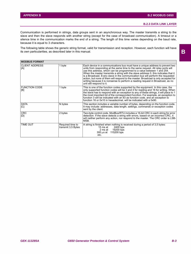
GEK-113285A G650 Generator Protection & Control System B-3
APPENDIX B B.2 MODBUS G650
B
B.2.3 DATA LINK LAYER
Communication is performed in strings, data groups sent in an asynchronous way. The master transmits a string to theslave and then the slave responds with another string (except for the case of broadcast communication). A timeout or asilence time in the communication marks the end of a string. The length of this time varies depending on the baud rate,because it is equal to 3 characters.
The following table shows the generic string format, valid for transmission and reception. However, each function will haveits own particularities, as described later in this manual.
MODBUS FORMATCLIENT ADDRESS[A]
1 byte Each device in a communications bus must have a unique address to prevent two units from responding at the same time to the same request. All relay ports will use this address, which can be programmed to a value between 1 and 254.When the master transmits a string with the slave address 0, this indicates that it is a Broadcast. Every slave in the communication bus will perform the requested action, but none of them will respond to the master. Broadcast is only accepted for writing because it is nonsense to perform a reading request in Broadcast, as no unit will respond to it.
FUNCTION CODE[B]
1 byte This is one of the function codes supported by the equipment. In this case, the only supported function codes will be 3 and 4 for reading and 16 for writing. When the slave has to respond with an exception to any of these strings, it will place to 1 the most important bit of the correspondent function. For example, an exception to function 3 will be indicated with an 83 as function code, and an exception to function 16 or 0x10 in hexadecimal, will be indicated with a 0x90.
DATA[C]
N bytes This section includes a variable number of bytes, depending on the function code. It may include: addresses, data length, settings, commands or exception codes sent by the client.
CRC[D]
2 bytes Two-byte control code. ModBus/RTU includes a 16-bit CRC in each string for error detection. If the slave detects a string with errors, based on an incorrect CRC, it will neither perform any action, nor respond to the master. The CRC order is LSB-MSB.
TIME OUT Required time to transmit 3,5 Bytes
A string is finished when nothing is received during a period of 3,5 bytes: 15 ms at 2400 bps 2 ms at 19200 bps 300 μs at 115200 bps etc.
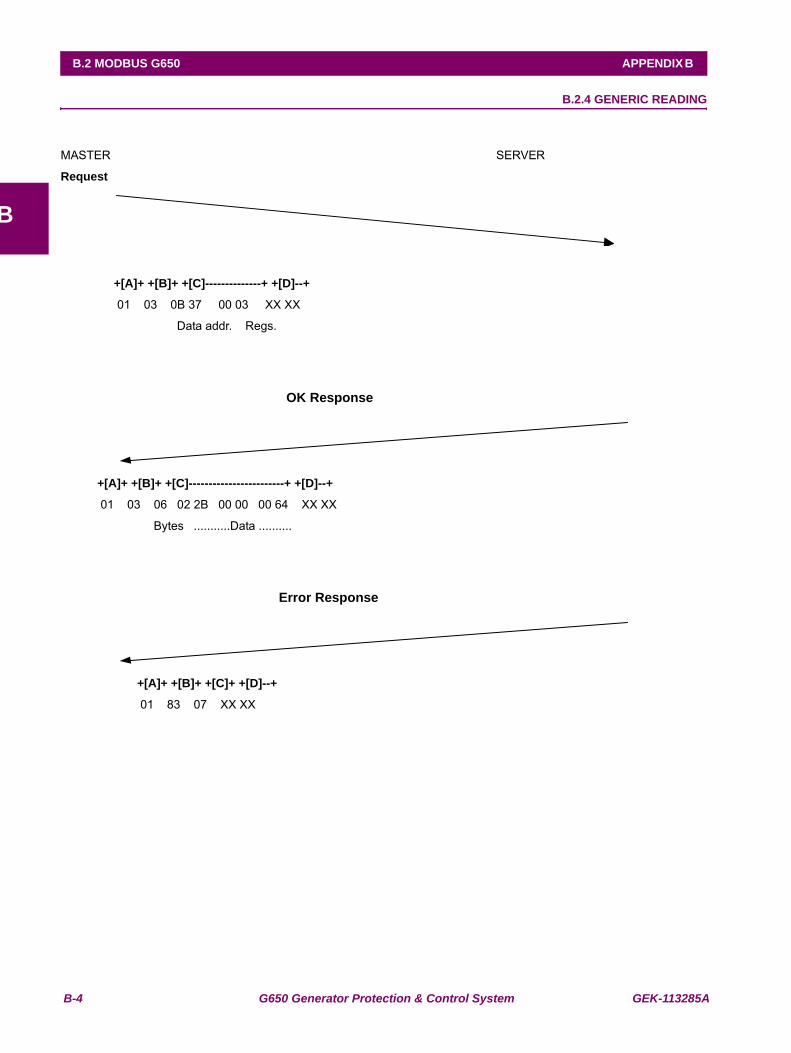
B-4 G650 Generator Protection & Control System GEK-113285A
B.2 MODBUS G650 APPENDIX B
B
B.2.4 GENERIC READING
MASTER SERVER
Request
+[A]+ +[B]+ +[C]--------------+ +[D]--+
01 03 0B 37 00 03 XX XX
Data addr. Regs.
OK Response
+[A]+ +[B]+ +[C]------------------------+ +[D]--+
01 03 06 02 2B 00 00 00 64 XX XX
Bytes ...........Data ..........
Error Response
+[A]+ +[B]+ +[C]+ +[D]--+
01 83 07 XX XX
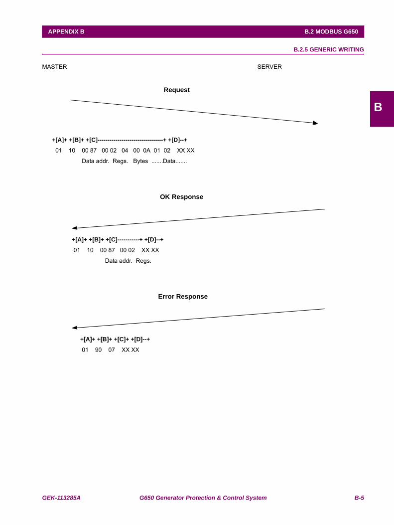
GEK-113285A G650 Generator Protection & Control System B-5
APPENDIX B B.2 MODBUS G650
B
B.2.5 GENERIC WRITING
MASTER SERVER
Request
+[A]+ +[B]+ +[C]---------------------------------+ +[D]--+
01 10 00 87 00 02 04 00 0A 01 02 XX XX
Data addr. Regs. Bytes .......Data.......
OK Response
+[A]+ +[B]+ +[C]-----------+ +[D]--+
01 10 00 87 00 02 XX XX
Data addr. Regs.
Error Response
+[A]+ +[B]+ +[C]+ +[D]--+
01 90 07 XX XX
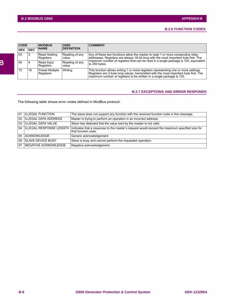
B-6 G650 Generator Protection & Control System GEK-113285A
B.2 MODBUS G650 APPENDIX B
B
B.2.6 FUNCTION CODES
B.2.7 EXCEPTIONS AND ERROR RESPONDS
The following table shows error codes defined in ModBus protocol:
CODE MODBUS NAME
G650 DEFINITION
COMMENTHEX DEC03 3 Read Holding
RegistersReading of any value
Any of these two functions allow the master to read 1 or more consecutive relay addresses. Registers are always 16-bit long with the most important byte first. The maximum number of registers that can be read in a single package is 125, equivalent to 250 bytes. 04 4 Read Input
RegistersReading of any value
10 16 Preset Multiple Registers
Writing This function allows writing 1 or more registers representing one or more settings. Registers are 2-byte long values, transmitted with the most important byte first. The maximum number of registers to be written in a single package is 125.
01 ILLEGAL FUNCTION The slave does not support any function with the received function code in this message. 02 ILLEGAL DATA ADDRESS Master is trying to perform an operation in an incorrect address. 03 ILLEGAL DATA VALUE Slave has detected that the value sent by the master is not valid. 04 ILLEGAL RESPONSE LENGTH Indicates that a response to the master’s request would exceed the maximum specified size for
that function code. 05 ACKNOWLEDGE Generic acknowledgement.06 SLAVE DEVICE BUSY Slave is busy and cannot perform the requested operation. 07 NEGATIVE ACKNOWLEDGE Negative acknowledgement.
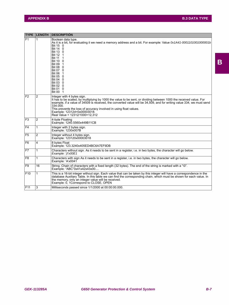
GEK-113285A G650 Generator Protection & Control System B-7
APPENDIX B B.3 DATA TYPE
B
B.3DATA TYPETYPE LENGTH DESCRIPTIÓNF1 1 Boolean data type.
As it is a bit, for evaluating it we need a memory address and a bit. For example: Value 0x1A41-0001101001000001bBit 15 0Bit 14 0Bit 13 0Bit 12 1Bit 11 1Bit 10 0Bit 09 1Bit 08 0Bit 07 0Bit 06 1Bit 05 0Bit 04 0Bit 03 0Bit 02 0Bit 01 0Bit 00 1
F2 2 Integer with 4 bytes sign.It has to be scaled, by multiplying by 1000 the value to be sent, or dividing between 1000 the received value. For example, if a value of 34509 is received, the converted value will be 34,509, and for writing value 334, we must send 334.000. This prevents the loss of accuracy involved in using float values. Example: 12312d=0x00003018. Real Value = 12312/1000=12,312
F3 2 4-byte FloatingExample: 1240.5560x449B11CB
F4 1 Integer with 2 bytes sign.Example: 1230x007B
F5 2 Integer without 4 bytes sign.Example: 123120x00003018
F6 4 8 bytes FloatExample: 123.3240x405ED4BC6A7EF9DB
F7 1 Characters without sign. As it needs to be sent in a register, i.e. in two bytes, the character will go below.Example: ‘β’x00E1
F8 1 Characters with sign As it needs to be sent in a register, i.e. in two bytes, the character will go below.Example: ‘A’x0041
F9 16 String. Chain of characters with a fixed length (32 bytes). The end of the string is marked with a “\0”.Example: “ABC”0x41x42x43x00....
F10 1 This is a 16-bit integer without sign. Each value that can be taken by this integer will have a correspondence in the database Auxiliary Table. In this table we can find the corresponding chain, which must be shown for each value. In the memory, only an integer value will be received. Example: 0, 1Correspond to CLOSE, OPEN
F11 3 Milliseconds passed since 1/1/2000 at 00:00:00.000.
B-8 G650 Generator Protection & Control System GEK-113285A
B.4 MODBUS APPENDIX APPENDIX B
B
B.4MODBUS APPENDIX B.4.1 DATA MANAGEMENT
The different sizes of data to be managed in ModBus and their functionality make it necessary to manage them in differentways. Depending on the functionality and importance of certain data, the use of ModBus is optimized in time for real timeprocesses, as in the case of events.
Although configuration settings, such as GRAPHIC, PLC equations, TEXTS and ALARM and LEDS configuration, etc. canbe read and written using ModBus protocol, formats are not shown because these are considered important designinformation subject to optimization, expansion and in short to changes. For their management, the user can use EnerVista650 Setup program to manage and format them in a friendly way
B.4.2 WRITING SETTINGS
The writing process of settings GROUP is formed by two phases: writing of any zone and confirmation. The target is toguarantee the protections functionality and offer versatility for possible legacy programs.
The process of changing protection functionality will almost always involve the change of several settings at the same time,requiring a “time point” for new settings operation. The combination of numbers, enums, etc, which cooperate in fulfill adetermined function is called GROUP.
The memory map of a setting GROUP includes: the stored settings at the beginning of its settings zone and a temporaryhole for new settings and confirmation.
When settings are changed, we must write in the selected settings zone, in any order or quantity of written zone, and finally,to give a reference point we must write a register in the last position of the group, (this is called CONFIRMATION by someprotocols).
For safety reasons, there is certain limitation when CONFIRMING settings GROUPS; the time period from the last settingswriting to CONFIRMATION, cannot exceed 15 seconds.
B.4.3 SNAPSHOT EVENTS
Nowadays, event retrieval is completely compatible with UR family. In the G650, the NEW EVENTS concept has beenextended, providing additional functionality. These are the events created after the last request.
a) SNAPSHOT EVENT READING IN ASCII FORMAT
The events capture process is based on the opening and reading of a pseudo-file. This process is made in two steps:
1º.- A writing message in the ‘0xfe00’ address, where desired opening file name is written:
- “EVE .TXT”: to obtain all
- “NEW_EVE.TXT": to obtain events created from the last request of this same file
- “EVE0234 .TXT “: to obtain events starting, for example, from 234 rating
2º.- The second and following ones are messages of reading on 0xff00 address, where 244-byte strings are readfrom the open file. As this process is a request process, if there was a response string with error, the last string can berequested again, by a reading message on 0xff02 address.
The first reading message shows the events format, information is transmitted in the rest of messages. In the same string,the first four bytes indicate the file reading position and the following two bytes form a short with the quantity of useful bytessent (if it is lower than 244, this indicates that it is the last message).
In the second step, many BUSY responds may be produced, because internally the ASCII format file is being created.
b) SNAPSHOT EVENTS READING IN BINARY FORMAT:
Write a message in address 0xfe00 to open the file.
GEK-113285A G650 Generator Protection & Control System B-9
APPENDIX B B.4 MODBUS APPENDIX
B
“EVE.BIN”: to read all Snapshot events.
“NEW_EVE.BIN”: to read new events since the last reading of this file.
“EVE0234.BIN”: to read events starting by number 234.
The second and successive messages are read in address 0xff00 in blocks of 250 bytes (4 bytes that indicate the pointvalue to the file, 2 bytes that indicate the number of data sent, and 244 data bytes). If during this process there is an errorresponse, the request can be repeated in address 0xff02 reading 246 bytes (2 bytes that indicate the number of bytes sent,and 244 data bytes).
Each Snapshot event includes:
1º byte: event format code.
N bytes: Event information structured depending on the code
At this moment there is only one format type with code 0. Its structure is as follows:
• -UINT16: event handle.
• -8 bytes: event date and time.
• -29 bytes: event cause. (string finished in null).
• -UINT32: Phasor Ia (scaled to 1000).
• -UINT32: Phasor Ib (scaled to 1000).
• -UINT32: Phasor Ic (scaled to 1000).
• -UINT32: Line Frequency (scaled to 1000).
• -UINT32: Phasor Ig (scaled to 1000).
• -UINT32: Phasor Isg (scaled to 1000).
• -UINT32: Zero seq I0 (scaled to 1000).
• -UINT32: Positive seq I1 (scaled to 1000).
• -UINT32: Negative seq I2 (scaled to 1000).
• -UINT32: Phasor Van (scaled to 1000).
• -UINT32: Phasor Vbn (scaled to 1000).
• -UINT32: Phasor Vcn (scaled to 1000).
• -UINT32: Positive Seq V1 (scaled to 1000).
• -UINT32: Negative Seq V2 (scaled to 1000).
• -UINT32: Zero Seq V0 (scaled to 1000).
• -UINT32: 3 Phase Power Factor (scaled to 1000).
Example:
1st step:
[0xFE 0x10 0xFE 0x00 0x00 0x06 0x0C 0x4E 0x45 0x57 0x5F 0x45 0x56 0x45 0x2E 0x54 0x58 0x54 0x00 0x16 0xB0] --------> RELAY
PC <--------- [0xFE 0x10 0xFE 0x00 0x00 0x06 0x65 0xEC]
2nd step:
[0xFE 0x03 0xFF 0x00 0x00 0x7D 0xA1 0xF0] --------> RELAY
Probably the relay will respond with “SLAVE DEVICE BUSY”:
PC <--------- 0xFE 0x83 0x06 0xF1 0x02]
The request is repeated:
[0xFE 0x03 0xFF 0x00 0x00 0x7D 0xA1 0xF0] --------> RELAY
B-10 G650 Generator Protection & Control System GEK-113285A
B.4 MODBUS APPENDIX APPENDIX B
B
Now the relay sends the events format:
[A] Position within file (Unsigned 32 bits)
[B] Block size (Unsigned 16 bits)
PC --------- [0xFE 0x03 0xFA 0x00 0x00 0x00 0x00 0x00 0xF4 0x46 0x4F 0x52 0x4D 0x41
.............[A].............. .....[B]...... F O R M A
0x54 0x2C 0x45 0x56 0x45 0x4E 0x54 0x5F 0x46 0x36 0x35 0x30 0x5F 0x56 0x30
T , E V E N T _ F 6 5 0 _ V 0
0x30 0x2C 0x45 0x76 0x65 0x6E 0x74 0x20 0x4E 0x75 0x6D 0x2C 0x44 0x61 0x74
0 , E v e n t N u m , D a t
0x65 0x2F 0x54 0x69 0x6D 0x65 0x3C 0x48 0x65 0x78 0x3E 0x2C 0x43 0x61 0x75
e / T i m e . . . etc . . .
0x73 0x65 0x2C 0x50 0x68 0x61 0x73 0x6F 0x72 0x20 0x49 0x61 0x2C 0x50 0x68 0x61 0x73 0x6F 0x72 0x20 0x49 0x620x2C 0x50 0x68 0x61 0x73 0x6F 0x72 0x20 0x49 0x63 0x2C 0x4C 0x69 0x6E 0x65 0x20 0x46 0x72 0x65 0x71 0x75 0x650x6E 0x63 0x79 0x2C 0x50 0x68 0x61 0x73 0x6F 0x72 0x20 0x49 0x67 0x2C 0x50 0x68 0x61 0x73 0x6F 0x72 0x20 0x490x73 0x67 0x2C 0x5A 0x65 0x72 0x6F 0x20 0x73 0x65 0x71 0x20 0x49 0x30 0x2C 0x50 0x6F 0x73 0x69 0x74 0x69 0x760x65 0x20 0x53 0x65 0x71 0x20 0x49 0x31 0x2C 0x4E 0x65 0x67 0x61 0x74 0x69 0x76 0x65 0x20 0x53 0x65 0x71 0x200x49 0x32 0x2C 0x50 0x68 0x61 0x73 0x6F 0x72 0x20 0x56 0x61 0x6E 0x2C 0x50 0x68 0x61 0x73 0x6F 0x72 0x20 0x560x62 0x6E 0x2C 0x50 0x68 0x61 0x73 0x6F 0x72 0x20 0x56 0x63 0x6E 0x2C 0x50 0x6F 0x73 0x69 0x74 0x69 0x76 0x650x20 0x53 0x65 0x71 0x20 0x56 0x31 0x2C 0x4E 0x65 0x67 0x61 0x74 0x69 0x76 0x65 0x20 0x53 0x65 0x71 0x20 0x560x32 0x2C 0x5A 0x65 0x72 0x6F 0x20 0x53 0x65 0x71 0x20 0x56 0x30 0x2C 0x33 0x20 0x50 0x68 0x4C 0xF3]
[0xFE 0x03 0xFF 0x00 0x00 0x7D 0xA1 0xF0] ---------> RELAY
PC <--------- [0xFE 0x03 0xFA 0x00 0x00 0x00 0xF4 0x00 0xF4 0x61 0x73 0x65 0x20 0x50 0x6F
0x77 0x65 0x72 0x20 0x46 0x61 0x63 0x74 0x6F 0x72 0x0D 0x0A
CR LF (here the format ends)
0x45 0x56 0x45 0x4E 0x54 0x5F 0x46 0x36 0x35 0x30 0x5F 0x56 0x30 0x30 0x2C 0x35 0x36 0x35
E V E N T _ F 6 5 0 _ V 0 0 , 5 6 5
0 x37 0x2C 0x30 0x30 0x30 0x30 0x30 0x30 0x31 0x36 0x66 0x63 0x39 0x38 0x66
7 , 0 0 0 0 0 0 1 6 f 3 9 8 f
0x34 0x33 0x39 0x2C 0x4C 0x6F 0x63 0x61 0x6C 0x20 0x6D 0x6F 0x64 0x65 0x2C
4 3 9 , l o c a l m o d e ,
0x30 0x2E 0x30 0x30 0x30 0x2C 0x30 0x2E 0x30 0x30 0x31 0x2C 0x30 0x2E 0x30
....
0x30 0x31 0x2C 0x30 0x2E 0x30 0x30 0x30 0x2C 0x30 0x2E 0x30 0x30 0x30 0x2C 0x30 0x2E 0x30 0x30 0x30 0x2C 0x300x2E 0x30 0x30 0x30 0x2C 0x30 0x2E 0x30 0x30 0x30 0x2C 0x30 0x2E 0x30 0x30 0x30 0x2C 0x30 0x2E 0x30 0x30 0x320x2C 0x30 0x2E 0x30 0x30 0x31 0x2C 0x30 0x2E 0x30 0x30 0x32 0x2C 0x30 0x2E 0x30 0x30 0x31 0x2C 0x30 0x2E 0x300x30 0x31 0x2C 0x30 0x2E 0x30 0x30 0x30 0x2C 0x31 0x2E 0x30 0x30 0x30 0x0D 0x0A
CR LF (a line ends)
GEK-113285A G650 Generator Protection & Control System B-11
APPENDIX B B.4 MODBUS APPENDIX
B
0x45 0x56 0x45 0x4E 0x54 0x5F 0x46 0x36 0x35 0x30 0x5F 0x56 0x30 0x30 0x2C 0x35 0x36 0x35 0x38 0x2C 0x30 0x300x30 0x30 0x30 0x30 0x31 0x36 0x66 0x63 0x39 0x38 0x66 0x34 0x33 0x39 0x2C 0x28 0x31 0x29 0x56 0x69 0x72 0x740x75 0x61 0x6C 0x20 0x4F 0x75 0x74 0x38 0x39 0x36 0x2C 0x30 0x2E 0x30 0x30 0x30 0x2C 0x30 0x2E 0x30 0x30 0x310x2C 0x30 0x2E 0x30 0x30 0x31 0x2C 0x30 0x2E 0x30 0x30 0x30 0x2C 0x30 0x2E 0x34 0x24]
[0xFE 0x03 0xFF 0x00 0x00 0x7D 0xA1 0xF0] ---------> RELAY
PC <---------[0xFE 0x03 0xFA 0x00 0x00 0x01 0xE8 0x00 0x47 0x30 0x0047 => last string
0x30 0x30 0x2C 0x30 0x2E 0x30 0x30 0x30 0x2C 0x30 0x2E 0x30 0x30 0x30 0x2C 0x30 0x2E 0x30 0x30 0x30 0x2C 0x300x2E 0x30 0x30 0x30 0x2C 0x30 0x2E 0x30 0x30 0x32 0x2C 0x30 0x2E 0x30 0x30 0x31 0x2C 0x30 0x2E 0x30 0x30 0x320x2C 0x30 0x2E 0x30 0x30 0x31 0x2C 0x30 0x2E 0x30 0x30 0x31 0x2C 0x30 0x2E 0x30 0x30 0x30 0x2C 0x31 0x2E 0x300x30 0x30 0x0D 0x0A
CR LF (a line ends)
0x00 0x00 0x30 0x0D 0x0A 0x45 0x56 0x45 0x4E 0x54 0x5F 0x46 0x36 0x35 0x30 0x5F 0x56 0x30 0x30 0x2C 0x33 0x300x39 0x38 0x2C 0x30 0x30 0x30 0x30 0x30 0x30 0x31 0x36 0x65 0x62 0x61 0x33 0x33 0x62 0x62 0x38 0x2C 0x43 0x6F0x6E 0x74 0x61 0x63 0x74 0x20 0x4F 0x75 0x74 0x70 0x75 0x74 0x5F 0x30 0x30 0x5F 0x30 0x30 0x20 0x4F 0x4E 0x2C0x30 0x2E 0x30 0x30 0x30 0x2C 0x30 0x2E 0x30 0x30 0x30 0x2C 0x30 0x2E 0x30 0x30 0x31 0x2C 0x30 0x2E 0x30 0x300x30 0x2C 0x30 0x2E 0x30 0x30 0x31 0x2C 0x30 0x2E 0x30 0x30 0x30 0x2C 0x30 0x2E 0x30 0x30 0x30 0x2C 0x30 0x2E0x30 0x30 0x30 0x2C 0x30 0x2E 0x30 0x30 0x30 0x2C 0x30 0x2E 0x30 0x30 0x31 0x2C 0x30 0x2E 0x30 0x30 0x32 0x2C0x30 0x2E 0x30 0x30 0x30 0x2C 0x30 0x2E 0x30 0x30 0x30 0x2C 0x30 0x2E 0x30 0x30 0x31 0x2C 0x30 0x2E 0x30 0x300x30 0x2C 0x31 0x2E 0x30 0x30 0x30 0x0D 0x0A 0x45 0x56 0x45 0x4E 0x54 0x5F 0x46 0x36 0x35 0x30 0xDB 0xB4]
B-12 G650 Generator Protection & Control System GEK-113285A
B.4 MODBUS APPENDIX APPENDIX B
B
B.4.4 OPERATIONS
For executing an Operation, it is necessary to write the bit corresponding to that Operation. For this purpose, there are twomemory records whose bits represent operations. These records are 0xAFFE and 0xAFFF.
Each operation has assigned one bit in the register:
Operation 1: bit 0 ‘0xaffe’
Operation 2: bit 1‘0xaffe’
...
Operation 16: bit 15‘0xaffe’
Operation 17: bit 0‘0xafff’
...
Operation 24: bit 7‘0xafff’
The register format is ‘MOTOROLA’; this means that the first byte arriving is the one with more weight.
Remember that depending on where it communicates the correspondent channel will be activated, which takes part forPLC operations if the operation is successful or not. The operations channels are:
0 - MMI
1 - OPER REMOTE
2 - COM 1- COMMUNICATION
3 - COM 2- COMMUNICATION
4 - RED 1- COMMUNICATION
5 - RED 2- COMMUNICATION
6 - RED 3- COMMUNICATION
7 - RED 4- COMMUNICATION
Example, operation 1 is going to be perform:
[0xFE 0x10 0xAF 0xFE 0x00 0x01 0x02 0x00 0x01 0x68 0xB0] ---------> RELAY
PC <--------- [0xFE 0x10 0xAF 0xFE 0x00 0x01 0x55 0x22] (ACK (acknowledge) the operation)
GEK-113285A G650 Generator Protection & Control System B-13
APPENDIX B B.5 OUTPUT WRITING
B
B.5OUTPUT WRITING
Relay contacts writing in the I/O boards are thought to make easy wiring checks. Proceeding as with a file access, withopening, writing and lockout.
If it is a writing to a mixed board (includes 16 inputs and 8 outputs):
1º.- OPEN FILE OF OUTPUTS: writing msg to 0xFE20 of 3 registers with the name: OUTPUT
2º.- DESIRED OUTPUTS WRITING writing message to 0xFF20 of 5 REGISTERS, the first one is the board number (0or 1) and the restraint ones are the bytes of bits (bits are grouped byte to byte).
3º.- CLOSE FILE OF OUTPUTS: writing msg to 0xFE 28 of 3 registers with the name: OUTPUT
Example, activate the two lower relays to board ‘0’:
1st Opening
[0xFE 0x10 0xFE 0x20 0x00 0x03 0x06 0x4F 0x55 0x54 0x50 0x55 0x54 0xA8 0x42] ---------> RELAY
O U T P U T
PC <---------[0xFE 0x10 0xFE 0x20 0x00 0x03 0xA4 0x25]
2nd Writing
[0xFE 0x10 0xFF 0x20 0x00 0x05 0x0A 0x00 0x00 0x03 0x00 0x00 0x00 0x00 0x00 0x00 0x00
0x0000 0x03
0xAE 0x8D] ---------> RELAY
PC <--------- [0xFE 0x10 0xFF 0x20 0x00 0x05 0x25 0xDB]
3th Lockout:
[0xFE 0x10 0xFE 0x28 0x00 0x03 0x06 0x4F 0x55 0x54 0x50 0x55 0x54 0x29 0xA8] ---------> RELAYPC <--------- [0xFE 0x10 0xFE 0x28 0x00 0x03 0x25 0xE7]
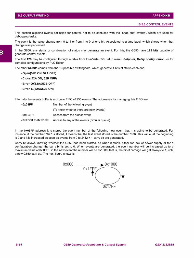
B-14 G650 Generator Protection & Control System GEK-113285A
B.5 OUTPUT WRITING APPENDIX B
B
B.5.1 CONTROL EVENTS
This section explains events set aside for control, not to be confused with the “snap shot events", which are used fordebugging tasks.
The event is the value change from 0 to 1 or from 1 to 0 of one bit. Associated to a time label, which shows when thatchange was performed.
In the G650, any status or combination of status may generate an event. For this, the G650 have 192 bits capable ofgenerate control events.
The first 128 may be configured through a table from EnerVista 650 Setup menu: Setpoint, Relay configuration, or forcomplex configurations by PLC Editor.
The other 64 bits comes from the 16 possible switchgears, which generate 4 bits of status each one:
- Open(52B ON, 52A OFF)
- Close(52A ON, 52B OFF)
- Error 00(52A&52B OFF)
- Error 11(52A&52B ON)
Internally the events buffer is a circular FIFO of 255 events. The addresses for managing this FIFO are:
- 0x03FF: Number of the following event
(To know whether there are new events)
- 0xFCFF: Access from the oldest event
- 0xFD00 to 0xFDFF: Access to any of the events (circular queue)
In the 0x03FF address it is stored the event number of the following new event that it is going to be generated. Forinstance, if the number 7677 is stored, it means that the last event stored is the number 7676. This value, at the beginningis 0 and it is increased as soon as events from 0 to 2^12 + 1 carry bit are generated.
Carry bit allows knowing whether the G650 has been started, as when it starts, either for lack of power supply or for aconfiguration change, the carry bit is set to 0. When events are generated, the event number will be increased up to amaximum value of 0x1FFF; in the next event the number will be 0x1000, that is, the bit of carriage will get always to 1, untila new G650 start up. The next figure shows it:
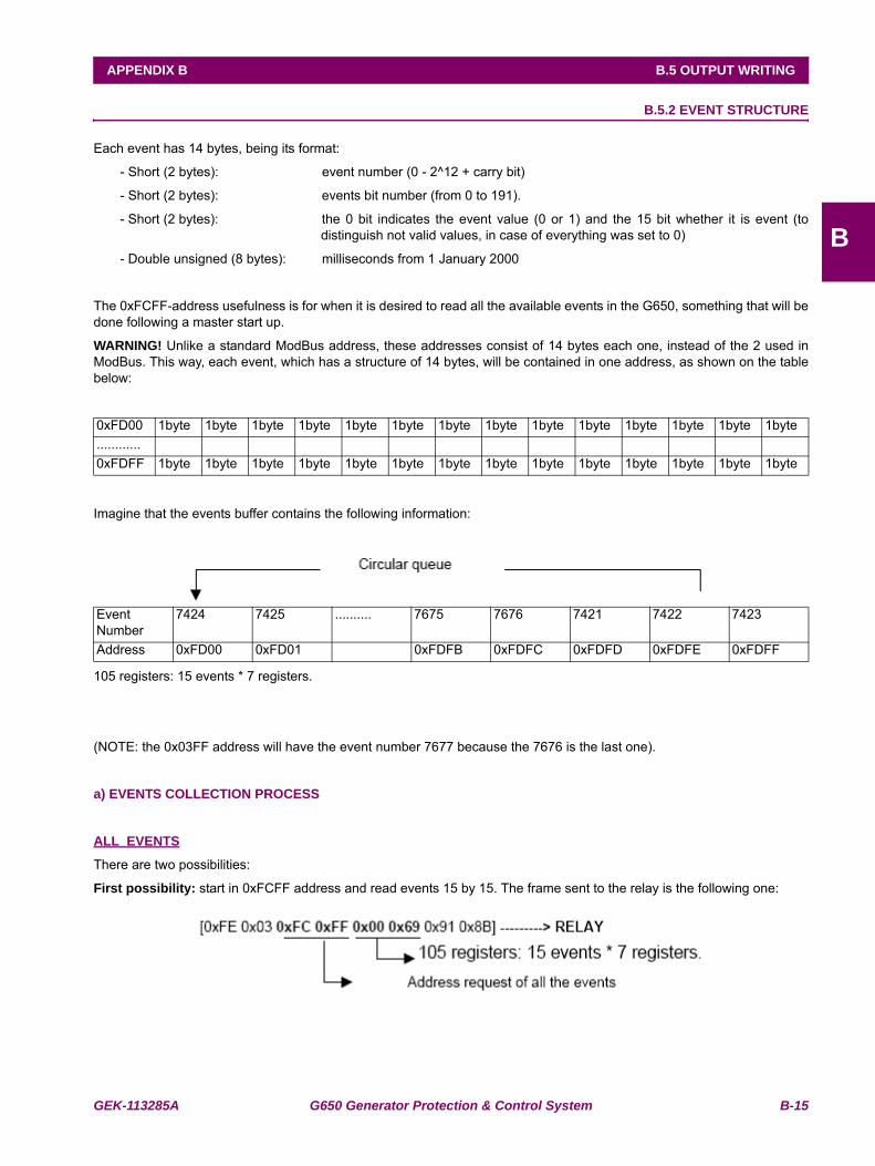
GEK-113285A G650 Generator Protection & Control System B-15
APPENDIX B B.5 OUTPUT WRITING
B
B.5.2 EVENT STRUCTURE
Each event has 14 bytes, being its format:
- Short (2 bytes): event number (0 - 2^12 + carry bit)
- Short (2 bytes): events bit number (from 0 to 191).
- Short (2 bytes): the 0 bit indicates the event value (0 or 1) and the 15 bit whether it is event (todistinguish not valid values, in case of everything was set to 0)
- Double unsigned (8 bytes): milliseconds from 1 January 2000
The 0xFCFF-address usefulness is for when it is desired to read all the available events in the G650, something that will bedone following a master start up.
WARNING! Unlike a standard ModBus address, these addresses consist of 14 bytes each one, instead of the 2 used inModBus. This way, each event, which has a structure of 14 bytes, will be contained in one address, as shown on the tablebelow:
Imagine that the events buffer contains the following information:
105 registers: 15 events * 7 registers.
(NOTE: the 0x03FF address will have the event number 7677 because the 7676 is the last one).
a) EVENTS COLLECTION PROCESS
ALL EVENTS
There are two possibilities:
First possibility: start in 0xFCFF address and read events 15 by 15. The frame sent to the relay is the following one:
0xFD00 1byte 1byte 1byte 1byte 1byte 1byte 1byte 1byte 1byte 1byte 1byte 1byte 1byte 1byte............0xFDFF 1byte 1byte 1byte 1byte 1byte 1byte 1byte 1byte 1byte 1byte 1byte 1byte 1byte 1byte
EventNumber
7424 7425 .......... 7675 7676 7421 7422 7423
Address 0xFD00 0xFD01 0xFDFB 0xFDFC 0xFDFD 0xFDFE 0xFDFF
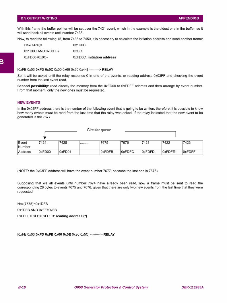
B-16 G650 Generator Protection & Control System GEK-113285A
B.5 OUTPUT WRITING APPENDIX B
B
With this frame the buffer pointer will be set over the 7421 event, which in the example is the oldest one in the buffer, so itwill send back all events until number 7435.
Now, to read the following 15, from 7436 to 7450, it is necessary to calculate the initiation address and send another frame:
Hex(7436)= 0x1D0C
0x1D0C AND 0x00FF= 0xOC
0xFD00+0x0C= 0xFD0C: initiation address
[0xFE 0x03 0xFD 0x0C 0x00 0x69 0x60 0x44] ---------> RELAY
So, it will be asked until the relay responds 0 in one of the events, or reading address 0x03FF and checking the eventnumber from the last event read.
Second possibility: read directly the memory from the 0xFD00 to 0xFDFF address and then arrange by event number.From that moment, only the new ones must be requested.
NEW EVENTS
In the 0x03FF address there is the number of the following event that is going to be written, therefore, it is possible to knowhow many events must be read from the last time that the relay was asked. If the relay indicated that the new event to begenerated is the 7677.
(NOTE: the 0x03FF address will have the event number 7677, because the last one is 7676).
Supposing that we all events until number 7674 have already been read, now a frame must be sent to read thecorresponding 28 bytes to events 7675 and 7676, given that there are only two new events from the last time that they wererequested.
Hex(7675)=0x1DFB
0x1DFB AND 0xFF=0xFB
0xFD00+0xFB=0xFDFB: reading address (*)
[0xFE 0x03 0xFD 0xFB 0x00 0x0E 0x90 0x5C] ---------> RELAY
EventNumber
7424 7425 .......... 7675 7676 7421 7422 7423
Address 0xFD00 0xFD01 0xFDFB 0xFDFC 0xFDFD 0xFDFE 0xFDFF
GEK-113285A G650 Generator Protection & Control System B-17
APPENDIX B B.6 EVENTS STATUS REQUEST(ALARMS)
B
B.6EVENTS STATUS REQUEST(ALARMS)
The necessary data to retrieve events that have been configured as alarms are located in the following addresses:
0xf000: 24 registers, the first 12 indicate the status active/inactive and the last 12 indicate the status ofacknowledged/not acknowledged.
0xf018: 12 event alarm status (active - not active, acknowledged – not acknowledged) registers.
0xf024: date and hour of the event bits starts (groups of 16 dates and hour must be asked for).
To obtain an instantaneous snapshot of all the events and alarms status, the procedure is:
• - Read the head of events FIFO (0x03FF).
• - Read the zones mentioned before.
• - Finally, read the head again to confirm that it has not changed. If it had changed, restart the procedure.
NOTE: The message must request the address and the quantity of bytes indicated in each zone. If other quantity is neededit will not respond with the requested data.
B.6.1 CONTROL EVENTS RETRIEVAL FROM THE COMMAND LINE
Starting EnerVista 650 Setup form the command line offers the possibility of transferring control events to a file. For thispurpose, we need to indicate the event number from which event controls are to be retrieved, and the file where they are tobe stored.
Communication can be established via serial communication by specifying the port and access baudrate, or via Ethernetthrough the IP address and communication port. The relay number from which events are to be retrieved must also beindicated.
For executing this Operation, 6 parameters must be written, for both cases, serial communication or Ethernet.
B.6.2 SERIAL COMUNICATION
EnerVista 650 Setup –e event number " File name" –com port: baudrate relay number
E.g.: EnerVista 650 Setup –e 6 “C:\GE Power Management\EnerVista 650 Setup\files\Events\eventos.txt” –com 1:19200254
B.6.3 ETHERNET COMMUNICATION
EnerVista 650 Setup –e event number " File name" –ip “IP address”: port relay number
E.g.: EnerVista 650 Setup –e 6 “C:\GE Power Management\EnerVista 650 Setup\files\Events \eventos.txt” –ip192.168.37.240:502 254
The created file format will look as follows:
#Event Number, Event Id,Event Text,Event Data Time,Event Value(0,1)#
6,1,Local,09-Sep-2003 17:42:40.782,1
7,1,Local,09-Sep-2003 17:42:43.236,0
8,2,Remote,09-Sep-2003 17:42:43.236,1
B-18 G650 Generator Protection & Control System GEK-113285A
B.6 EVENTS STATUS REQUEST(ALARMS) APPENDIX B
B
B.6.4 ACKNOWLEDGEMENT OF EVENTS (ALARMS)
For acknowledging the alarms we must simply write message to the 0xf324 address with 12 data registers. Each bit meansan event, if we want to acknowledge an alarm, its corresponding bit must be set to ‘1’ (in order within the 192 bits).
NOTE: it must be borne in mind the independence of the acknowledgement condition, for its reading and its change,depending on the communication channel
There are 6 channels:
LOCAL: by MMI or COM-2 (front and rear accessible).
REMOTE: by COM-1
NET 1: nowadays by any net communication
NET 2: (it does not exist in version 1.4x and lower)
NET 3: (it does not exist in version 1.4x and lower)
NET 4: (it does not exist in version 1.4x and lower)
B.6.5 VIRTUAL INPUTS WRITING
For forcing Virtual Inputs, a message with 4 indivisible records must be written at address, so that each bit corresponds to aVirtual Input. Values will not be correct if the first 4 records are not written in the same message. The first 32 are LATCHED(internally stored with RAM with battery), and the last 32 are SELF-RST (activated to 1 and deactivated in the next pass bythe PLC).
For reading the status of Virtual Inputs, it is necessary to start with address 0x0083(bit 0x004) up to 0x0087 (bit 0x0200).
B.6.6 USER MAP
G650 units incorporate a powerful feature called ModBus User Map, that allows to read 256 non-consecutive data records(settings and statuses). It is often required for a master computer to interrogate continuously several connected slaverelays. If those values are dispersed along the memory map, reading them may require several transmissions, and this maycause a communications overload. The User Map can be programmed to get several memory addresses together in ablock of consecutive addresses of the User Map, so that they can be accessible with a single reading operation.
The user Map has two sections:
A record index area (addresses 0x3384 to 0x3483), containing 256 statuses and/or setting record addresses.
A record area (addresses 0xF330 to 0xF42F), containing the values for addresses indicated in the index area.
Data records that are separated in the rest of the memory map can be remapped to an address of an adjacent record in theUser Map area. For programming the map this way, addresses for the required records must be written in the index area.This avoids the need for several reading operations, thus improving data transmission yield.
For instance, if Contact Outputs from Board F (address 0x008B) and Board G (address 0x00B0) values are required, theseaddresses must be mapped as follows:
In address 0x3384, write 0x008B.
In address 0x3385 XXX write 0x00B0.
The reading of records 0xF330 and 0xF331, applying the corresponding bit masks, will provide the required informationabout the two boards Contact Outputs.
NOTE: Only single data can be set in the map, data that are in the memory map and can be read. This feature is not validfor events, waveform records, etc. that are not located in a map address.
GEK-113285A G650 Generator Protection & Control System B-19
APPENDIX B B.6 EVENTS STATUS REQUEST(ALARMS)
B
B.6.7 RETRIEVING OSCILOGRAPHY
In case of not using the quickest download method by FTP, ModBus can be used for downloading oscillography, in thesame way that events (snap-shots). First of all, open file with writing message in 0xfe40, where desired file to open isindicated, it could be:
OSC01.DAT (COMTRADE data file in binary)
OSC02.CFG (COMTRADE configuration file)
OSC01.HDR (COMTRADE header file)
OSC02.DAT
OSC02.HDR
...
For reading the oscillography in several strings, several reading requests must be sent to 0xff40 address . For reading theprevious message a reading petition must be sent to 0xff42 address. The maximum number of bytes to be read in each partis 244.
B.6.8 TIME SYNCHRONIZATION
Time synchronization consists of setting of relay date and time.
It may be supposed that is similar to a usual settings group writing but it has particularities:
- It is a data type very particular because it is made up of other simples.
- Once the data is changed, varies with time, it is a changing setting that can be read.
- It shares the time change with the IRIGB (this has more priority) and with a possible modification from MMI or anotherprotocols.
- In case of the relay gets disconnected from its auxiliary power supply, during some days, the time will remain in achip, feed by a capacitor (it does not need maintenance).
- And last, there are synchronism between the real time chip and the microprocessor time.
Time synchronization is made by a reading message over 0xfff0 address, either with the address of a single relay, if awriting confirmation is desired, or in broadcast, to synchronize several relays simultaneously.
Date/time format is unsigned double (8 bytes) in MOTOROLA format, which indicates the passed milliseconds from 1st ofJanuary 2000.
Reading example:
[0xFE 0x03 0xFF 0xF0 0x00 0x04 0x60 0x21] ---------> RELAY
PC <---------- [0xFE 0x03 0x08 0x00 0x00 0x00 0x17 0x05 0xFA 0xD5 0xBA 0x2D 0x1D]
Synchronism example:
[0xFE 0x10 0xFF 0xF0 0x00 0x04 0x08 0x00 0x00 0x00 0x17 0x9B 0x53 0x3F 0x60 0xA4 0x2B] ---------> RELAY
PC <---------- [0xFE 0x10 0xFF 0xF0 0x00 0x04 0xE5 0xE2]

B-20 G650 Generator Protection & Control System GEK-113285A
B.6 EVENTS STATUS REQUEST(ALARMS) APPENDIX B
B
B.6.9 ENQUEUEING MESSAGES
In ModBus protocol, as in other protocols, exists an internal procedure in message reception and transmission.
When a relay gets a string, determined by a silence of 3 or 4 characters, it is queued in a FIFO queue, for a later processingin its own protocol. When the protocol is free of execution, it searches in the queue for strings to respond of the FIFO. Ifthere is such string, it processes it and then it is responded.
Several criteria have been adopted for real time operation:
- Each reading or writing is respond as soon as possible.
- This implies that when settings are changed and respond, a writing request recognition is indicated and then, themodification of internal settings is performed, (PERFORMING IT IN THE SHORTER TIME WITHOUT PROTECTION),and finally, settings are stored in a non-volatile memory device.
NOTE: As the relay is internally a modular system, it is possible that the response of some process is slower than what isexpected by the external program, considering the message as missed and sending again another request. If so, there willbe 2 queued messages and therefore, 2 messages will be responded. For this reason, response message ‘ACK’ must beverified with its request, and special attention must be paid to setting confirmation writings, especially with reference totime-out. EnerVista 650 Setup software is recommended to do the configuration modifications, as this software takes intoaccount all these details.
B.6.10 TRACES AND TROUBLESHOOTING
The tracer is a debugging tool to view the strings in any writing or reading process in ModBus. This tracer is activated in themenu from EnerVista 650 Setup: View, Traces.
With this option enabled, request and response strings will be shown. If, for instance, request and response strings view isdesired, between G650 and the relay, in general settings reading we will do what follows:
1º. - Activate traces, from View, Traces menu
2º. - Open the general settings menu
The screen will display that group settings, on the left side bottom the relay reading request will appear
<0001><06/18/03 12:14:15>[0xFE 0x03 0x21 0x8A 0x00 0x16 0xFB 0xDD]
And on the right the settings response will appear:
0001><06/18/03 12:14:15>[0xFE 0x03 0x2C 0x3F 0x80 0x00 0x00 0x3F 0x80 0x00 0x00 0x3F 0x80 0x00 0x00 0x3F0x80 0x00 0x00 0x00 0x00 0x42 0xC8 0x00 0x00 0x00 0x00 0x00 0x00 0x00 0x00 0x00 0x00 0x00 0x01 0x00 0xFE0x00 0xFE 0x00 0x06 0x00 0x06 0x00 0x00 0x01 0xF6 0xAC 0xB5]
This way, any request or mechanism to obtain information from the relay, can be viewed string by string.
There is another tool for tracing the relay memory: in EnerVista 650 Setup menu: Communication, Troubleshooting, anyreading to any address can be requested, the PC will form the string together with check-sum register.
GEK-113285A G650 Generator Protection & Control System B-21
APPENDIX B B.6 EVENTS STATUS REQUEST(ALARMS)
B
B.6.11 MODBUS CHECK FUNCTION
Next it is described the code to realize the message string check in ModBus, in a MOTOROLA micro. With this routine timeis optimized to obtain the check register.
USHORT fn_035c_cr16(UCHAR *p, UNSIGNED us)
const UCHAR hi[] =
0X0,0Xc1,0X81,0X40,0X1,0Xc0,0X80,0X41,0X1,0Xc0,
0X80,0X41,0X0,0Xc1,0X81,0X40,0X1,0Xc0,0X80,0X41,
0X0,0Xc1,0X81,0X40,0X0,0Xc1,0X81,0X40,0X1,0Xc0,
0X80,0X41,0X1,0Xc0,0X80,0X41,0X0,0Xc1,0X81,0X40,
0X0,0Xc1,0X81,0X40,0X1,0Xc0,0X80,0X41,0X0,0Xc1,
0X81,0X40,0X1,0Xc0,0X80,0X41,0X1,0Xc0,0X80,0X41,
0X0,0Xc1,0X81,0X40,0X1,0Xc0,0X80,0X41,0X0,0Xc1,
0X81,0X40,0X0,0Xc1,0X81,0X40,0X1,0Xc0,0X80,0X41,
0X0,0Xc1,0X81,0X40,0X1,0Xc0,0X80,0X41,0X1,0Xc0,
0X80,0X41,0X0,0Xc1,0X81,0X40,0X0,0Xc1,0X81,0X40,
0X1,0Xc0,0X80,0X41,0X1,0Xc0,0X80,0X41,0X0,0Xc1,
0X81,0X40,0X1,0Xc0,0X80,0X41,0X0,0Xc1,0X81,0X40,
0X0,0Xc1,0X81,0X40,0X1,0Xc0,0X80,0X41,0X1,0Xc0,
0X80,0X41,0X0,0Xc1,0X81,0X40,0X0,0Xc1,0X81,0X40,
0X1,0Xc0,0X80,0X41,0X0,0Xc1,0X81,0X40,0X1,0Xc0,
0X80,0X41,0X1,0Xc0,0X80,0X41,0X0,0Xc1,0X81,0X40,
0X0,0Xc1,0X81,0X40,0X1,0Xc0,0X80,0X41,0X1,0Xc0,
0X80,0X41,0X0,0Xc1,0X81,0X40,0X1,0Xc0,0X80,0X41,
0X0,0Xc1,0X81,0X40,0X0,0Xc1,0X81,0X40,0X1,0Xc0,
0X80,0X41,0X0,0Xc1,0X81,0X40,0X1,0Xc0,0X80,0X41,
0X1,0Xc0,0X80,0X41,0X0,0Xc1,0X81,0X40,0X1,0Xc0,
0X80,0X41,0X0,0Xc1,0X81,0X40,0X0,0Xc1,0X81,0X40,
0X1,0Xc0,0X80,0X41,0X1,0Xc0,0X80,0X41,0X0,0Xc1,
0X81,0X40,0X0,0Xc1,0X81,0X40,0X1,0Xc0,0X80,0X41,
0X0,0Xc1,0X81,0X40,0X1,0Xc0,0X80,0X41,0X1,0Xc0,
0X80,0X41,0X0,0Xc1,0X81,0X40;
const UCHAR lo[] =
0X0,0Xc0,0Xc1,0X1,0Xc3,0X3,0X2,0Xc2,0Xc6,0X6,
0X7,0Xc7,0X5,0Xc5,0Xc4,0X4,0Xcc,0Xc,0Xd,0Xcd,
0Xf,0Xcf,0Xce,0Xe,0Xa,0Xca,0Xcb,0Xb,0Xc9,0X9,
0X8,0Xc8,0Xd8,0X18,0X19,0Xd9,0X1b,0Xdb,0Xda,0X1a,
0X1e,0Xde,0Xdf,0X1f,0Xdd,0X1d,0X1c,0Xdc,0X14,0Xd4,
B-22 G650 Generator Protection & Control System GEK-113285A
B.6 EVENTS STATUS REQUEST(ALARMS) APPENDIX B
B
0Xd5,0X15,0Xd7,0X17,0X16,0Xd6,0Xd2,0X12,0X13,0Xd3,
0X11,0Xd1,0Xd0,0X10,0Xf0,0X30,0X31,0Xf1,0X33,0Xf3,
0Xf2,0X32,0X36,0Xf6,0Xf7,0X37,0Xf5,0X35,0X34,0Xf4,
0X3c,0Xfc,0Xfd,0X3d,0Xff,0X3f,0X3e,0Xfe,0Xfa,0X3a,
0X3b,0Xfb,0X39,0Xf9,0Xf8,0X38,0X28,0Xe8,0Xe9,0X29,
0Xeb,0X2b,0X2a,0Xea,0Xee,0X2e,0X2f,0Xef,0X2d,0Xed,
0Xec,0X2c,0Xe4,0X24,0X25,0Xe5,0X27,0Xe7,0Xe6,0X26,
0X22,0Xe2,0Xe3,0X23,0Xe1,0X21,0X20,0Xe0,0Xa0,0X60,
0X61,0Xa1,0X63,0Xa3,0Xa2,0X62,0X66,0Xa6,0Xa7,0X67,
0Xa5,0X65,0X64,0Xa4,0X6c,0Xac,0Xad,0X6d,0Xaf,0X6f,
0X6e,0Xae,0Xaa,0X6a,0X6b,0Xab,0X69,0Xa9,0Xa8,0X68,
0X78,0Xb8,0Xb9,0X79,0Xbb,0X7b,0X7a,0Xba,0Xbe,0X7e,
0X7f,0Xbf,0X7d,0Xbd,0Xbc,0X7c,0Xb4,0X74,0X75,0Xb5,
0X77,0Xb7,0Xb6,0X76,0X72,0Xb2,0Xb3,0X73,0Xb1,0X71,
0X70,0Xb0,0X50,0X90,0X91,0X51,0X93,0X53,0X52,0X92,
0X96,0X56,0X57,0X97,0X55,0X95,0X94,0X54,0X9c,0X5c,
0X5d,0X9d,0X5f,0X9f,0X9e,0X5e,0X5a,0X9a,0X9b,0X5b,
0X99,0X59,0X58,0X98,0X88,0X48,0X49,0X89,0X4b,0X8b,
0X8a,0X4a,0X4e,0X8e,0X8f,0X4f,0X8d,0X4d,0X4c,0X8c,
0X44,0X84,0X85,0X45,0X87,0X47,0X46,0X86,0X82,0X42,
0X43,0X83,0X41,0X81,0X80,0X40 ;
UCHAR chi;
UCHAR clo;
USHORT ui;
chi = 0xff;
clo = 0xff;
while(us--)
ui = chi ^ *p++;
chi = clo ^ hi[ui];
clo = lo[ui];
ui = chi;
ui = ui << 8;
ui = ui | clo; // motorola format
return(ui);
GEK-113285A G650 Generator Protection & Control System B-23
APPENDIX B B.6 EVENTS STATUS REQUEST(ALARMS)
B
typedef struct //reading string
UCHAR dire;
UCHAR fn; //3 o 4
USHORT mem;
USHORT off;
USHORT check;
PET_READ;
static PET_READ vpet_read; ------ this is the message (of reading)
And now it is proceed to perform the reading message check:
USHORT xx;
xx = vpet_read.check;
if(fn_035c_cr16( (UCHAR *)&vpet_read, sizeof(PET_READ)-2) == xx)
OK
else
ko
If it is INTEL everything works but bytes are interchanged.
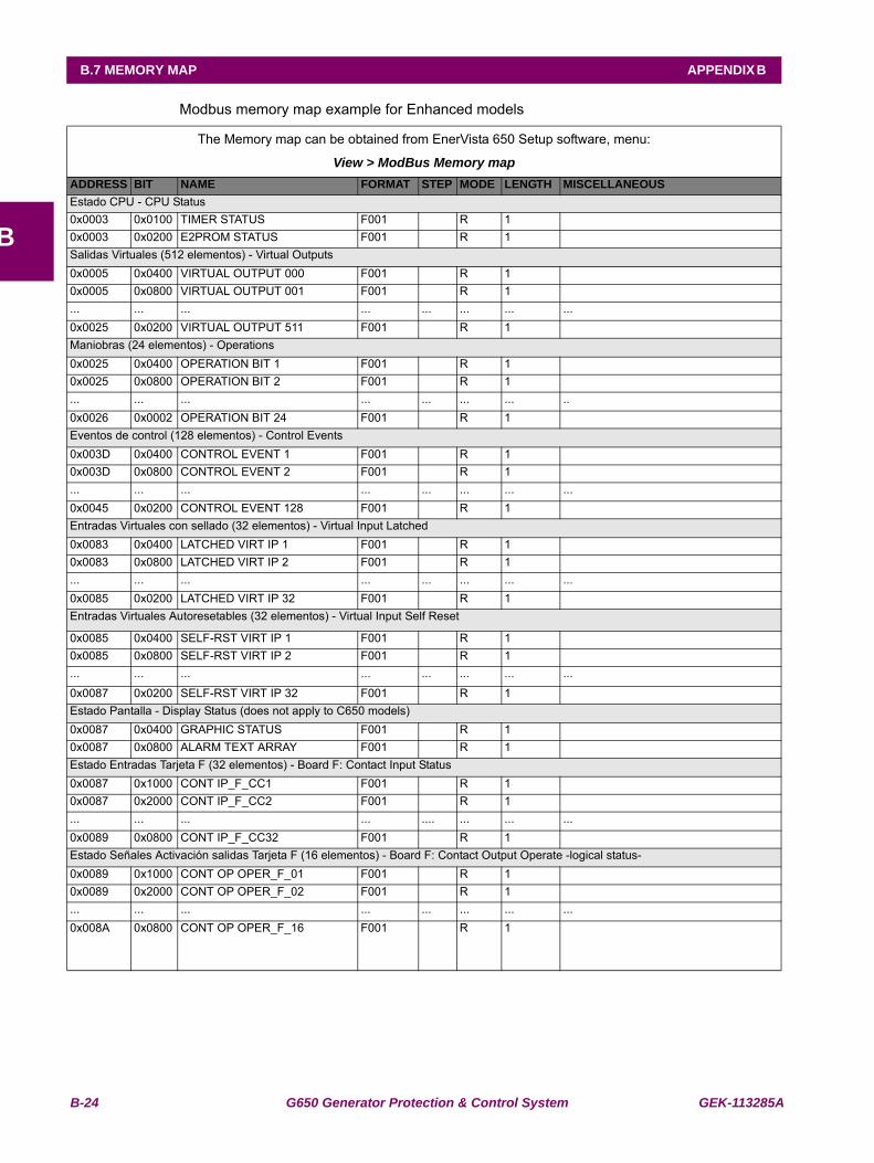
B-24 G650 Generator Protection & Control System GEK-113285A
B.7 MEMORY MAP APPENDIX B
B
B.7MEMORY MAPModbus memory map example for Enhanced models
The Memory map can be obtained from EnerVista 650 Setup software, menu:
View > ModBus Memory mapADDRESS BIT NAME FORMAT STEP MODE LENGTH MISCELLANEOUSEstado CPU - CPU Status0x0003 0x0100 TIMER STATUS F001 R 1 0x0003 0x0200 E2PROM STATUS F001 R 1 Salidas Virtuales (512 elementos) - Virtual Outputs0x0005 0x0400 VIRTUAL OUTPUT 000 F001 R 1 0x0005 0x0800 VIRTUAL OUTPUT 001 F001 R 1 ... ... ... ... ... ... ... ...0x0025 0x0200 VIRTUAL OUTPUT 511 F001 R 1 Maniobras (24 elementos) - Operations0x0025 0x0400 OPERATION BIT 1 F001 R 1 0x0025 0x0800 OPERATION BIT 2 F001 R 1 ... ... ... ... ... ... ... ..0x0026 0x0002 OPERATION BIT 24 F001 R 1 Eventos de control (128 elementos) - Control Events0x003D 0x0400 CONTROL EVENT 1 F001 R 1 0x003D 0x0800 CONTROL EVENT 2 F001 R 1 ... ... ... ... ... ... ... ...0x0045 0x0200 CONTROL EVENT 128 F001 R 1 Entradas Virtuales con sellado (32 elementos) - Virtual Input Latched0x0083 0x0400 LATCHED VIRT IP 1 F001 R 1 0x0083 0x0800 LATCHED VIRT IP 2 F001 R 1 ... ... ... ... ... ... ... ...0x0085 0x0200 LATCHED VIRT IP 32 F001 R 1 Entradas Virtuales Autoresetables (32 elementos) - Virtual Input Self Reset
0x0085 0x0400 SELF-RST VIRT IP 1 F001 R 1 0x0085 0x0800 SELF-RST VIRT IP 2 F001 R 1 ... ... ... ... ... ... ... ...
0x0087 0x0200 SELF-RST VIRT IP 32 F001 R 1 Estado Pantalla - Display Status (does not apply to C650 models)0x0087 0x0400 GRAPHIC STATUS F001 R 1 0x0087 0x0800 ALARM TEXT ARRAY F001 R 1 Estado Entradas Tarjeta F (32 elementos) - Board F: Contact Input Status0x0087 0x1000 CONT IP_F_CC1 F001 R 1 0x0087 0x2000 CONT IP_F_CC2 F001 R 1 ... ... ... ... .... ... ... ...0x0089 0x0800 CONT IP_F_CC32 F001 R 1 Estado Señales Activación salidas Tarjeta F (16 elementos) - Board F: Contact Output Operate -logical status-0x0089 0x1000 CONT OP OPER_F_01 F001 R 1 0x0089 0x2000 CONT OP OPER_F_02 F001 R 1 ... ... ... ... ... ... ... ...0x008A 0x0800 CONT OP OPER_F_16 F001 R 1
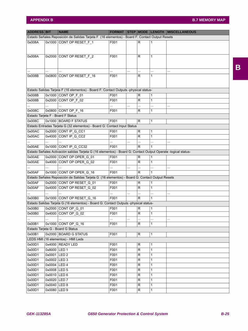
GEK-113285A G650 Generator Protection & Control System B-25
APPENDIX B B.7 MEMORY MAP
B
Estado Señales Reposición de Salidas Tarjeta F (16 elementos) - Board F: Contact Output Resets0x008A 0x1000 CONT OP RESET_F_1 F001 R 1
0x008A 0x2000 CONT OP RESET_F_2 F001 R 1
... ... ... ... ... ... ... ...0x008B 0x0800 CONT OP RESET_F_16 F001 R 1
Estado Salidas Tarjeta F (16 elementos) - Board F: Contact Outputs -physical status-0x008B 0x1000 CONT OP_F_01 F001 R 1 0x008B 0x2000 CONT OP_F_02 F001 R 1 ... ... ... ... ... ... ... ...0x008C 0x0800 CONT OP_F_16 F001 R 1 Estado Tarjeta F - Board F Status0x008C 0x1000 BOARD F STATUS F001 R 1 Estado Entradas Tarjeta G (32 elementos) - Board G: Contact Input Status0x00AC 0x2000 CONT IP_G_CC1 F001 R 1 0x00AC 0x4000 CONT IP_G_CC2 F001 R 1 ... ... ... ... ... ... ... ...0x00AE 0x1000 CONT IP_G_CC32 F001 R 1 Estado Señales Activación salidas Tarjeta G (16 elementos) - Board G: Contact Output Operate -logical status-0x00AE 0x2000 CONT OP OPER_G_01 F001 R 1 0x00AE 0x4000 CONT OP OPER_G_02 F001 R 1 ... ... ... ... ... ... ... ...0x00AF 0x1000 CONT OP OPER_G_16 F001 R 1 Estado Señales Reposición de Salidas Tarjeta G (16 elementos) - Board G: Contact Output Resets0x00AF 0x2000 CONT OP RESET_G_01 F001 R 1 0x00AF 0x4000 CONT OP RESET_G_02 F001 R 1 ... ... ... ... ... ... ... ...0x00B0 0x1000 CONT OP RESET_G_16 F001 R 1 Estado Salidas Tarjeta G (16 elementos) - Board G: Contact Outputs -physical status-0x00B0 0x2000 CONT OP_G_01 F001 R 1 0x00B0 0x4000 CONT OP_G_02 F001 R 1 ... ... ... ... ... ... ... ...0x00B1 0x1000 CONT OP_G_16 F001 R 1 Estado Tarjeta G - Board G Status0x00B1 0x2000 BOARD G STATUS F001 R 1 LEDS HMI (16 elementos) - HMI Leds0x00D1 0x4000 READY LED F001 R 1 0x00D1 0x8000 LED 1 F001 R 1 0x00D1 0x0001 LED 2 F001 R 1 0x00D1 0x0002 LED 3 F001 R 1 0x00D1 0x0004 LED 4 F001 R 1 0x00D1 0x0008 LED 5 F001 R 1 0x00D1 0x0010 LED 6 F001 R 1 0x00D1 0x0020 LED 7 F001 R 1 0x00D1 0x0040 LED 8 F001 R 1 0x00D1 0x0080 LED 9 F001 R 1
ADDRESS BIT NAME FORMAT STEP MODE LENGTH MISCELLANEOUS
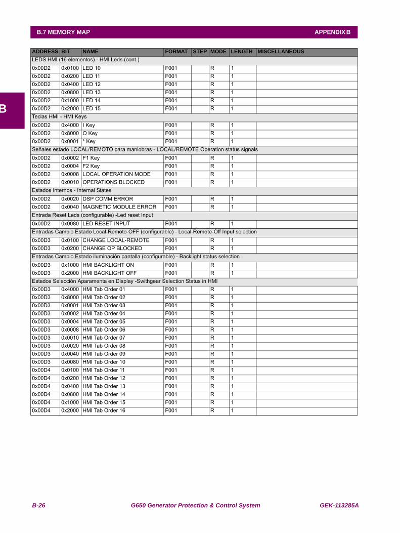
B-26 G650 Generator Protection & Control System GEK-113285A
B.7 MEMORY MAP APPENDIX B
B
LEDS HMI (16 elementos) - HMI Leds (cont.)0x00D2 0x0100 LED 10 F001 R 1 0x00D2 0x0200 LED 11 F001 R 1 0x00D2 0x0400 LED 12 F001 R 1 0x00D2 0x0800 LED 13 F001 R 1 0x00D2 0x1000 LED 14 F001 R 1 0x00D2 0x2000 LED 15 F001 R 1 Teclas HMI - HMI Keys0x00D2 0x4000 I Key F001 R 1 0x00D2 0x8000 O Key F001 R 1 0x00D2 0x0001 * Key F001 R 1 Señales estado LOCAL/REMOTO para maniobras - LOCAL/REMOTE Operation status signals0x00D2 0x0002 F1 Key F001 R 1 0x00D2 0x0004 F2 Key F001 R 1 0x00D2 0x0008 LOCAL OPERATION MODE F001 R 1 0x00D2 0x0010 OPERATIONS BLOCKED F001 R 1 Estados Internos - Internal States0x00D2 0x0020 DSP COMM ERROR F001 R 1 0x00D2 0x0040 MAGNETIC MODULE ERROR F001 R 1 Entrada Reset Leds (configurable) -Led reset Input0x00D2 0x0080 LED RESET INPUT F001 R 1 Entradas Cambio Estado Local-Remoto-OFF (configurable) - Local-Remote-Off Input selection0x00D3 0x0100 CHANGE LOCAL-REMOTE F001 R 1 0x00D3 0x0200 CHANGE OP BLOCKED F001 R 1 Entradas Cambio Estado iluminación pantalla (configurable) - Backlight status selection0x00D3 0x1000 HMI BACKLIGHT ON F001 R 1 0x00D3 0x2000 HMI BACKLIGHT OFF F001 R 1 Estados Selección Aparamenta en Display -Swithgear Selection Status in HMI0x00D3 0x4000 HMI Tab Order 01 F001 R 10x00D3 0x8000 HMI Tab Order 02 F001 R 10x00D3 0x0001 HMI Tab Order 03 F001 R 10x00D3 0x0002 HMI Tab Order 04 F001 R 10x00D3 0x0004 HMI Tab Order 05 F001 R 10x00D3 0x0008 HMI Tab Order 06 F001 R 10x00D3 0x0010 HMI Tab Order 07 F001 R 10x00D3 0x0020 HMI Tab Order 08 F001 R 10x00D3 0x0040 HMI Tab Order 09 F001 R 10x00D3 0x0080 HMI Tab Order 10 F001 R 10x00D4 0x0100 HMI Tab Order 11 F001 R 10x00D4 0x0200 HMI Tab Order 12 F001 R 10x00D4 0x0400 HMI Tab Order 13 F001 R 10x00D4 0x0800 HMI Tab Order 14 F001 R 10x00D4 0x1000 HMI Tab Order 15 F001 R 10x00D4 0x2000 HMI Tab Order 16 F001 R 1
ADDRESS BIT NAME FORMAT STEP MODE LENGTH MISCELLANEOUS
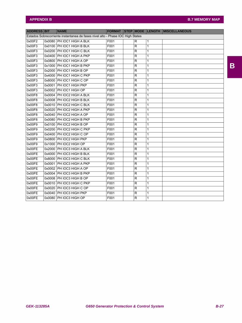
GEK-113285A G650 Generator Protection & Control System B-27
APPENDIX B B.7 MEMORY MAP
B
Estados Sobrecorriente instantanea de fases nivel alto - Phase IOC High States0x00F2 0x0080 PH IOC1 HIGH A BLK F001 R 1 0x00F3 0x0100 PH IOC1 HIGH B BLK F001 R 1 0x00F3 0x0200 PH IOC1 HIGH C BLK F001 R 1 0x00F3 0x0400 PH IOC1 HIGH A PKP F001 R 1 0x00F3 0x0800 PH IOC1 HIGH A OP F001 R 1 0x00F3 0x1000 PH IOC1 HIGH B PKP F001 R 1 0x00F3 0x2000 PH IOC1 HIGH B OP F001 R 1 0x00F3 0x4000 PH IOC1 HIGH C PKP F001 R 1 0x00F3 0x8000 PH IOC1 HIGH C OP F001 R 1 0x00F3 0x0001 PH IOC1 HIGH PKP F001 R 1 0x00F3 0x0002 PH IOC1 HIGH OP F001 R 1 0x00F8 0x0004 PH IOC2 HIGH A BLK F001 R 1 0x00F8 0x0008 PH IOC2 HIGH B BLK F001 R 1 0x00F8 0x0010 PH IOC2 HIGH C BLK F001 R 1 0x00F8 0x0020 PH IOC2 HIGH A PKP F001 R 1 0x00F8 0x0040 PH IOC2 HIGH A OP F001 R 1 0x00F8 0x0080 PH IOC2 HIGH B PKP F001 R 1 0x00F9 0x0100 PH IOC2 HIGH B OP F001 R 1 0x00F9 0x0200 PH IOC2 HIGH C PKP F001 R 1 0x00F9 0x0400 PH IOC2 HIGH C OP F001 R 1 0x00F9 0x0800 PH IOC2 HIGH PKP F001 R 1 0x00F9 0x1000 PH IOC2 HIGH OP F001 R 1 0x00FE 0x2000 PH IOC3 HIGH A BLK F001 R 1 0x00FE 0x4000 PH IOC3 HIGH B BLK F001 R 1 0x00FE 0x8000 PH IOC3 HIGH C BLK F001 R 1 0x00FE 0x0001 PH IOC3 HIGH A PKP F001 R 1 0x00FE 0x0002 PH IOC3 HIGH A OP F001 R 1 0x00FE 0x0004 PH IOC3 HIGH B PKP F001 R 1 0x00FE 0x0008 PH IOC3 HIGH B OP F001 R 1 0x00FE 0x0010 PH IOC3 HIGH C PKP F001 R 1 0x00FE 0x0020 PH IOC3 HIGH C OP F001 R 1 0x00FE 0x0040 PH IOC3 HIGH PKP F001 R 1 0x00FE 0x0080 PH IOC3 HIGH OP F001 R 1
ADDRESS BIT NAME FORMAT STEP MODE LENGTH MISCELLANEOUS
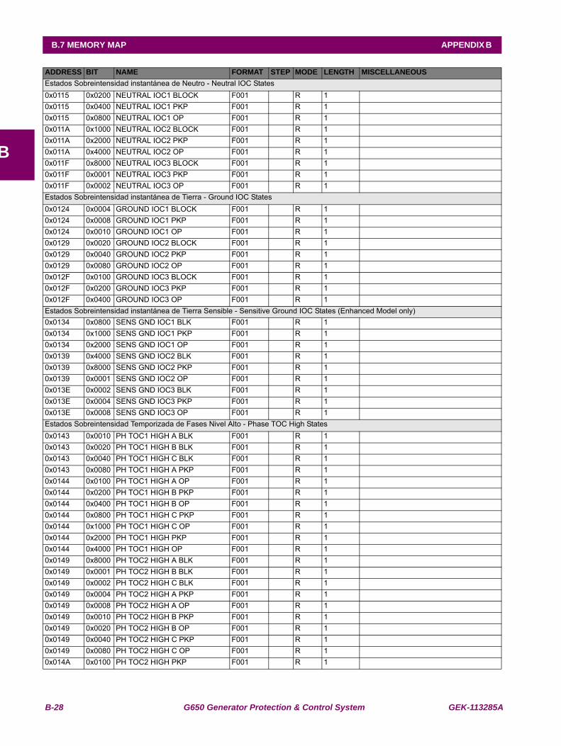
B-28 G650 Generator Protection & Control System GEK-113285A
B.7 MEMORY MAP APPENDIX B
B
Estados Sobreintensidad instantánea de Neutro - Neutral IOC States0x0115 0x0200 NEUTRAL IOC1 BLOCK F001 R 1 0x0115 0x0400 NEUTRAL IOC1 PKP F001 R 1 0x0115 0x0800 NEUTRAL IOC1 OP F001 R 1 0x011A 0x1000 NEUTRAL IOC2 BLOCK F001 R 1 0x011A 0x2000 NEUTRAL IOC2 PKP F001 R 1 0x011A 0x4000 NEUTRAL IOC2 OP F001 R 1 0x011F 0x8000 NEUTRAL IOC3 BLOCK F001 R 1 0x011F 0x0001 NEUTRAL IOC3 PKP F001 R 1 0x011F 0x0002 NEUTRAL IOC3 OP F001 R 1 Estados Sobreintensidad instantánea de Tierra - Ground IOC States0x0124 0x0004 GROUND IOC1 BLOCK F001 R 1 0x0124 0x0008 GROUND IOC1 PKP F001 R 1 0x0124 0x0010 GROUND IOC1 OP F001 R 1 0x0129 0x0020 GROUND IOC2 BLOCK F001 R 1 0x0129 0x0040 GROUND IOC2 PKP F001 R 1 0x0129 0x0080 GROUND IOC2 OP F001 R 1 0x012F 0x0100 GROUND IOC3 BLOCK F001 R 1 0x012F 0x0200 GROUND IOC3 PKP F001 R 1 0x012F 0x0400 GROUND IOC3 OP F001 R 1 Estados Sobreintensidad instantánea de Tierra Sensible - Sensitive Ground IOC States (Enhanced Model only)0x0134 0x0800 SENS GND IOC1 BLK F001 R 1 0x0134 0x1000 SENS GND IOC1 PKP F001 R 1 0x0134 0x2000 SENS GND IOC1 OP F001 R 1 0x0139 0x4000 SENS GND IOC2 BLK F001 R 1 0x0139 0x8000 SENS GND IOC2 PKP F001 R 1 0x0139 0x0001 SENS GND IOC2 OP F001 R 1 0x013E 0x0002 SENS GND IOC3 BLK F001 R 1 0x013E 0x0004 SENS GND IOC3 PKP F001 R 1 0x013E 0x0008 SENS GND IOC3 OP F001 R 1 Estados Sobreintensidad Temporizada de Fases Nivel Alto - Phase TOC High States0x0143 0x0010 PH TOC1 HIGH A BLK F001 R 1 0x0143 0x0020 PH TOC1 HIGH B BLK F001 R 1 0x0143 0x0040 PH TOC1 HIGH C BLK F001 R 1 0x0143 0x0080 PH TOC1 HIGH A PKP F001 R 1 0x0144 0x0100 PH TOC1 HIGH A OP F001 R 1 0x0144 0x0200 PH TOC1 HIGH B PKP F001 R 1 0x0144 0x0400 PH TOC1 HIGH B OP F001 R 1 0x0144 0x0800 PH TOC1 HIGH C PKP F001 R 1 0x0144 0x1000 PH TOC1 HIGH C OP F001 R 1 0x0144 0x2000 PH TOC1 HIGH PKP F001 R 1 0x0144 0x4000 PH TOC1 HIGH OP F001 R 1 0x0149 0x8000 PH TOC2 HIGH A BLK F001 R 1 0x0149 0x0001 PH TOC2 HIGH B BLK F001 R 1 0x0149 0x0002 PH TOC2 HIGH C BLK F001 R 1 0x0149 0x0004 PH TOC2 HIGH A PKP F001 R 1 0x0149 0x0008 PH TOC2 HIGH A OP F001 R 1 0x0149 0x0010 PH TOC2 HIGH B PKP F001 R 1 0x0149 0x0020 PH TOC2 HIGH B OP F001 R 1 0x0149 0x0040 PH TOC2 HIGH C PKP F001 R 1 0x0149 0x0080 PH TOC2 HIGH C OP F001 R 1 0x014A 0x0100 PH TOC2 HIGH PKP F001 R 1
ADDRESS BIT NAME FORMAT STEP MODE LENGTH MISCELLANEOUS
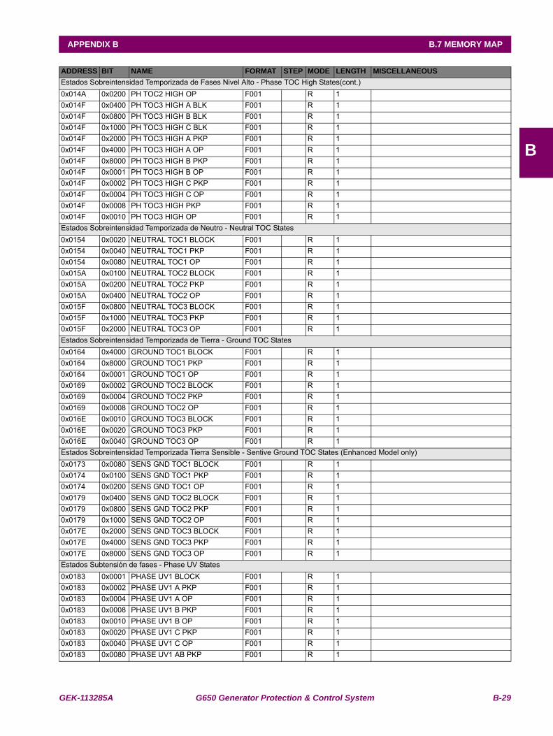
GEK-113285A G650 Generator Protection & Control System B-29
APPENDIX B B.7 MEMORY MAP
B
Estados Sobreintensidad Temporizada de Fases Nivel Alto - Phase TOC High States(cont.)0x014A 0x0200 PH TOC2 HIGH OP F001 R 1 0x014F 0x0400 PH TOC3 HIGH A BLK F001 R 1 0x014F 0x0800 PH TOC3 HIGH B BLK F001 R 1 0x014F 0x1000 PH TOC3 HIGH C BLK F001 R 1 0x014F 0x2000 PH TOC3 HIGH A PKP F001 R 1 0x014F 0x4000 PH TOC3 HIGH A OP F001 R 1 0x014F 0x8000 PH TOC3 HIGH B PKP F001 R 1 0x014F 0x0001 PH TOC3 HIGH B OP F001 R 1 0x014F 0x0002 PH TOC3 HIGH C PKP F001 R 1 0x014F 0x0004 PH TOC3 HIGH C OP F001 R 1 0x014F 0x0008 PH TOC3 HIGH PKP F001 R 1 0x014F 0x0010 PH TOC3 HIGH OP F001 R 1 Estados Sobreintensidad Temporizada de Neutro - Neutral TOC States0x0154 0x0020 NEUTRAL TOC1 BLOCK F001 R 1 0x0154 0x0040 NEUTRAL TOC1 PKP F001 R 1 0x0154 0x0080 NEUTRAL TOC1 OP F001 R 1 0x015A 0x0100 NEUTRAL TOC2 BLOCK F001 R 1 0x015A 0x0200 NEUTRAL TOC2 PKP F001 R 1 0x015A 0x0400 NEUTRAL TOC2 OP F001 R 1 0x015F 0x0800 NEUTRAL TOC3 BLOCK F001 R 1 0x015F 0x1000 NEUTRAL TOC3 PKP F001 R 1 0x015F 0x2000 NEUTRAL TOC3 OP F001 R 1 Estados Sobreintensidad Temporizada de Tierra - Ground TOC States0x0164 0x4000 GROUND TOC1 BLOCK F001 R 1 0x0164 0x8000 GROUND TOC1 PKP F001 R 1 0x0164 0x0001 GROUND TOC1 OP F001 R 1 0x0169 0x0002 GROUND TOC2 BLOCK F001 R 1 0x0169 0x0004 GROUND TOC2 PKP F001 R 1 0x0169 0x0008 GROUND TOC2 OP F001 R 1 0x016E 0x0010 GROUND TOC3 BLOCK F001 R 1 0x016E 0x0020 GROUND TOC3 PKP F001 R 1 0x016E 0x0040 GROUND TOC3 OP F001 R 1 Estados Sobreintensidad Temporizada Tierra Sensible - Sentive Ground TOC States (Enhanced Model only)0x0173 0x0080 SENS GND TOC1 BLOCK F001 R 1 0x0174 0x0100 SENS GND TOC1 PKP F001 R 1 0x0174 0x0200 SENS GND TOC1 OP F001 R 1 0x0179 0x0400 SENS GND TOC2 BLOCK F001 R 1 0x0179 0x0800 SENS GND TOC2 PKP F001 R 1 0x0179 0x1000 SENS GND TOC2 OP F001 R 1 0x017E 0x2000 SENS GND TOC3 BLOCK F001 R 1 0x017E 0x4000 SENS GND TOC3 PKP F001 R 1 0x017E 0x8000 SENS GND TOC3 OP F001 R 1 Estados Subtensión de fases - Phase UV States0x0183 0x0001 PHASE UV1 BLOCK F001 R 1 0x0183 0x0002 PHASE UV1 A PKP F001 R 1 0x0183 0x0004 PHASE UV1 A OP F001 R 1 0x0183 0x0008 PHASE UV1 B PKP F001 R 1 0x0183 0x0010 PHASE UV1 B OP F001 R 1 0x0183 0x0020 PHASE UV1 C PKP F001 R 1 0x0183 0x0040 PHASE UV1 C OP F001 R 1 0x0183 0x0080 PHASE UV1 AB PKP F001 R 1
ADDRESS BIT NAME FORMAT STEP MODE LENGTH MISCELLANEOUS
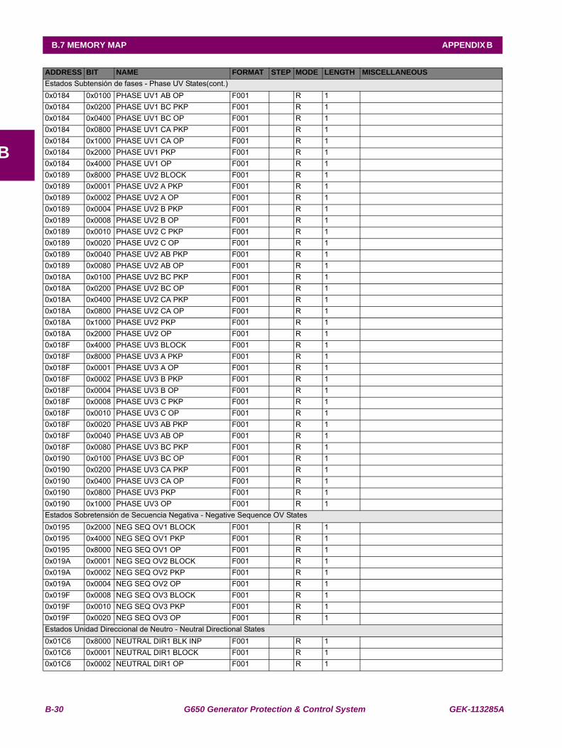
B-30 G650 Generator Protection & Control System GEK-113285A
B.7 MEMORY MAP APPENDIX B
B
Estados Subtensión de fases - Phase UV States(cont.)0x0184 0x0100 PHASE UV1 AB OP F001 R 1 0x0184 0x0200 PHASE UV1 BC PKP F001 R 1 0x0184 0x0400 PHASE UV1 BC OP F001 R 1 0x0184 0x0800 PHASE UV1 CA PKP F001 R 1 0x0184 0x1000 PHASE UV1 CA OP F001 R 1 0x0184 0x2000 PHASE UV1 PKP F001 R 1 0x0184 0x4000 PHASE UV1 OP F001 R 1 0x0189 0x8000 PHASE UV2 BLOCK F001 R 1 0x0189 0x0001 PHASE UV2 A PKP F001 R 1 0x0189 0x0002 PHASE UV2 A OP F001 R 1 0x0189 0x0004 PHASE UV2 B PKP F001 R 1 0x0189 0x0008 PHASE UV2 B OP F001 R 1 0x0189 0x0010 PHASE UV2 C PKP F001 R 1 0x0189 0x0020 PHASE UV2 C OP F001 R 1 0x0189 0x0040 PHASE UV2 AB PKP F001 R 1 0x0189 0x0080 PHASE UV2 AB OP F001 R 1 0x018A 0x0100 PHASE UV2 BC PKP F001 R 1 0x018A 0x0200 PHASE UV2 BC OP F001 R 1 0x018A 0x0400 PHASE UV2 CA PKP F001 R 1 0x018A 0x0800 PHASE UV2 CA OP F001 R 1 0x018A 0x1000 PHASE UV2 PKP F001 R 1 0x018A 0x2000 PHASE UV2 OP F001 R 1 0x018F 0x4000 PHASE UV3 BLOCK F001 R 1 0x018F 0x8000 PHASE UV3 A PKP F001 R 1 0x018F 0x0001 PHASE UV3 A OP F001 R 1 0x018F 0x0002 PHASE UV3 B PKP F001 R 1 0x018F 0x0004 PHASE UV3 B OP F001 R 1 0x018F 0x0008 PHASE UV3 C PKP F001 R 1 0x018F 0x0010 PHASE UV3 C OP F001 R 1 0x018F 0x0020 PHASE UV3 AB PKP F001 R 1 0x018F 0x0040 PHASE UV3 AB OP F001 R 1 0x018F 0x0080 PHASE UV3 BC PKP F001 R 1 0x0190 0x0100 PHASE UV3 BC OP F001 R 1 0x0190 0x0200 PHASE UV3 CA PKP F001 R 1 0x0190 0x0400 PHASE UV3 CA OP F001 R 1 0x0190 0x0800 PHASE UV3 PKP F001 R 1 0x0190 0x1000 PHASE UV3 OP F001 R 1 Estados Sobretensión de Secuencia Negativa - Negative Sequence OV States0x0195 0x2000 NEG SEQ OV1 BLOCK F001 R 1 0x0195 0x4000 NEG SEQ OV1 PKP F001 R 1 0x0195 0x8000 NEG SEQ OV1 OP F001 R 1 0x019A 0x0001 NEG SEQ OV2 BLOCK F001 R 1 0x019A 0x0002 NEG SEQ OV2 PKP F001 R 1 0x019A 0x0004 NEG SEQ OV2 OP F001 R 1 0x019F 0x0008 NEG SEQ OV3 BLOCK F001 R 1 0x019F 0x0010 NEG SEQ OV3 PKP F001 R 1 0x019F 0x0020 NEG SEQ OV3 OP F001 R 1 Estados Unidad Direccional de Neutro - Neutral Directional States0x01C6 0x8000 NEUTRAL DIR1 BLK INP F001 R 1 0x01C6 0x0001 NEUTRAL DIR1 BLOCK F001 R 1 0x01C6 0x0002 NEUTRAL DIR1 OP F001 R 1
ADDRESS BIT NAME FORMAT STEP MODE LENGTH MISCELLANEOUS
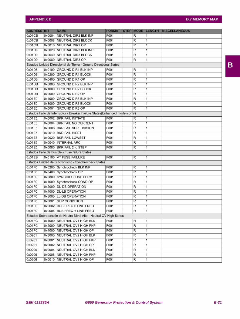
GEK-113285A G650 Generator Protection & Control System B-31
APPENDIX B B.7 MEMORY MAP
B
0x01CB 0x0004 NEUTRAL DIR2 BLK INP F001 R 1 0x01CB 0x0008 NEUTRAL DIR2 BLOCK F001 R 1 0x01CB 0x0010 NEUTRAL DIR2 OP F001 R 1 0x01D0 0x0020 NEUTRAL DIR3 BLK INP F001 R 1 0x01D0 0x0040 NEUTRAL DIR3 BLOCK F001 R 1 0x01D0 0x0080 NEUTRAL DIR3 OP F001 R 1 Estados Unidad Direccional de Tierra - Ground Directional States0x01D6 0x0100 GROUND DIR1 BLK INP F001 R 1 0x01D6 0x0200 GROUND DIR1 BLOCK F001 R 1 0x01D6 0x0400 GROUND DIR1 OP F001 R 1 0x01DB 0x0800 GROUND DIR2 BLK INP F001 R 1 0x01DB 0x1000 GROUND DIR2 BLOCK F001 R 1 0x01DB 0x2000 GROUND DIR2 OP F001 R 1 0x01E0 0x4000 GROUND DIR3 BLK INP F001 R 1 0x01E0 0x8000 GROUND DIR3 BLOCK F001 R 1 0x01E0 0x0001 GROUND DIR3 OP F001 R 1 Estados Fallo de Interruptor - Breaker Failure States(Enhanced models only)0x01E5 0x0002 BKR FAIL INITIATE F001 R 1 0x01E5 0x0004 BKR FAIL NO CURRENT F001 R 1 0x01E5 0x0008 BKR FAIL SUPERVISION F001 R 1 0x01E5 0x0010 BKR FAIL HISET F001 R 1 0x01E5 0x0020 BKR FAIL LOWSET F001 R 1 0x01E5 0x0040 INTERNAL ARC F001 R 1 0x01E5 0x0080 BKR FAIL 2nd STEP F001 R 1 Estados Fallo de Fusible - Fuse failure States0x01EB 0x0100 VT FUSE FAILURE F001 R 1 Estados Unidad de Sincronismo - Synchrocheck States0x01F0 0x0200 Synchrocheck BLK INP F001 R 1 0x01F0 0x0400 Synchrocheck OP F001 R 1 0x01F0 0x0800 SYNCHK CLOSE PERM F001 R 1 0x01F0 0x1000 Synchrocheck COND OP F001 R 1 0x01F0 0x2000 DL-DB OPERATION F001 R 1 0x01F0 0x4000 DL-LB OPERATION F001 R 1 0x01F0 0x8000 LL-DB OPERATION F001 R 1 0x01F0 0x0001 SLIP CONDITION F001 R 1 0x01F0 0x0002 BUS FREQ > LINE FREQ F001 R 1 0x01F0 0x0004 BUS FREQ < LINE FREQ F001 R 1 Estados Sobretensión de Neutro Nivel Alto - Neutral OV High States0x01FC 0x1000 NEUTRAL OV1 HIGH BLK F001 R 1 0x01FC 0x2000 NEUTRAL OV1 HIGH PKP F001 R 1 0x01FC 0x4000 NEUTRAL OV1 HIGH OP F001 R 1 0x0201 0x8000 NEUTRAL OV2 HIGH BLK F001 R 1 0x0201 0x0001 NEUTRAL OV2 HIGH PKP F001 R 1 0x0201 0x0002 NEUTRAL OV2 HIGH OP F001 R 1 0x0206 0x0004 NEUTRAL OV3 HIGH BLK F001 R 1 0x0206 0x0008 NEUTRAL OV3 HIGH PKP F001 R 1 0x0206 0x0010 NEUTRAL OV3 HIGH OP F001 R 1
ADDRESS BIT NAME FORMAT STEP MODE LENGTH MISCELLANEOUS
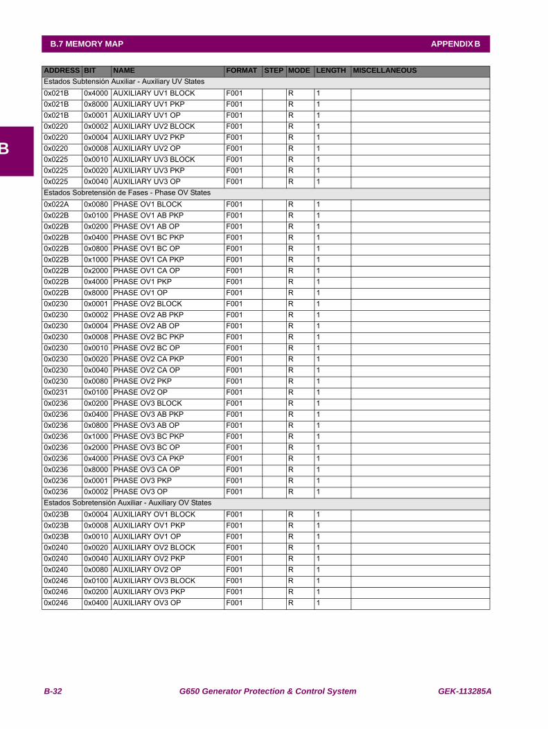
B-32 G650 Generator Protection & Control System GEK-113285A
B.7 MEMORY MAP APPENDIX B
B
Estados Subtensión Auxiliar - Auxiliary UV States0x021B 0x4000 AUXILIARY UV1 BLOCK F001 R 1 0x021B 0x8000 AUXILIARY UV1 PKP F001 R 1 0x021B 0x0001 AUXILIARY UV1 OP F001 R 1 0x0220 0x0002 AUXILIARY UV2 BLOCK F001 R 1 0x0220 0x0004 AUXILIARY UV2 PKP F001 R 1 0x0220 0x0008 AUXILIARY UV2 OP F001 R 1 0x0225 0x0010 AUXILIARY UV3 BLOCK F001 R 1 0x0225 0x0020 AUXILIARY UV3 PKP F001 R 1 0x0225 0x0040 AUXILIARY UV3 OP F001 R 1 Estados Sobretensión de Fases - Phase OV States0x022A 0x0080 PHASE OV1 BLOCK F001 R 1 0x022B 0x0100 PHASE OV1 AB PKP F001 R 1 0x022B 0x0200 PHASE OV1 AB OP F001 R 1 0x022B 0x0400 PHASE OV1 BC PKP F001 R 1 0x022B 0x0800 PHASE OV1 BC OP F001 R 1 0x022B 0x1000 PHASE OV1 CA PKP F001 R 1 0x022B 0x2000 PHASE OV1 CA OP F001 R 1 0x022B 0x4000 PHASE OV1 PKP F001 R 1 0x022B 0x8000 PHASE OV1 OP F001 R 1 0x0230 0x0001 PHASE OV2 BLOCK F001 R 1 0x0230 0x0002 PHASE OV2 AB PKP F001 R 1 0x0230 0x0004 PHASE OV2 AB OP F001 R 1 0x0230 0x0008 PHASE OV2 BC PKP F001 R 1 0x0230 0x0010 PHASE OV2 BC OP F001 R 1 0x0230 0x0020 PHASE OV2 CA PKP F001 R 1 0x0230 0x0040 PHASE OV2 CA OP F001 R 1 0x0230 0x0080 PHASE OV2 PKP F001 R 1 0x0231 0x0100 PHASE OV2 OP F001 R 1 0x0236 0x0200 PHASE OV3 BLOCK F001 R 1 0x0236 0x0400 PHASE OV3 AB PKP F001 R 1 0x0236 0x0800 PHASE OV3 AB OP F001 R 1 0x0236 0x1000 PHASE OV3 BC PKP F001 R 1 0x0236 0x2000 PHASE OV3 BC OP F001 R 1 0x0236 0x4000 PHASE OV3 CA PKP F001 R 1 0x0236 0x8000 PHASE OV3 CA OP F001 R 1 0x0236 0x0001 PHASE OV3 PKP F001 R 1 0x0236 0x0002 PHASE OV3 OP F001 R 1 Estados Sobretensión Auxiliar - Auxiliary OV States0x023B 0x0004 AUXILIARY OV1 BLOCK F001 R 1 0x023B 0x0008 AUXILIARY OV1 PKP F001 R 1 0x023B 0x0010 AUXILIARY OV1 OP F001 R 1 0x0240 0x0020 AUXILIARY OV2 BLOCK F001 R 1 0x0240 0x0040 AUXILIARY OV2 PKP F001 R 1 0x0240 0x0080 AUXILIARY OV2 OP F001 R 1 0x0246 0x0100 AUXILIARY OV3 BLOCK F001 R 1 0x0246 0x0200 AUXILIARY OV3 PKP F001 R 1 0x0246 0x0400 AUXILIARY OV3 OP F001 R 1
ADDRESS BIT NAME FORMAT STEP MODE LENGTH MISCELLANEOUS
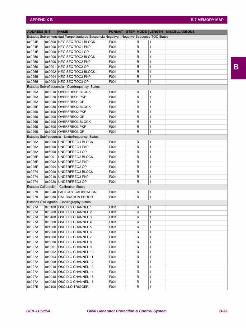
GEK-113285A G650 Generator Protection & Control System B-33
APPENDIX B B.7 MEMORY MAP
B
Estados Sobreintensidad Temporizada de Secuencia Negativa - Negative Sequence TOC States0x024B 0x0800 NEG SEQ TOC1 BLOCK F001 R 1 0x024B 0x1000 NEG SEQ TOC1 PKP F001 R 1 0x024B 0x2000 NEG SEQ TOC1 OP F001 R 1 0x0250 0x4000 NEG SEQ TOC2 BLOCK F001 R 1 0x0250 0x8000 NEG SEQ TOC2 PKP F001 R 1 0x0250 0x0001 NEG SEQ TOC2 OP F001 R 1 0x0255 0x0002 NEG SEQ TOC3 BLOCK F001 R 1 0x0255 0x0004 NEG SEQ TOC3 PKP F001 R 1 0x0255 0x0008 NEG SEQ TOC3 OP F001 R 1 Estados Sobrefrecuencia - Overfrequency States0x025A 0x0010 OVERFREQ1 BLOCK F001 R 1 0x025A 0x0020 OVERFREQ1 PKP F001 R 1 0x025A 0x0040 OVERFREQ1 OP F001 R 1 0x025F 0x0080 OVERFREQ2 BLOCK F001 R 1 0x0260 0x0100 OVERFREQ2 PKP F001 R 1 0x0260 0x0200 OVERFREQ2 OP F001 R 1 0x0265 0x0400 OVERFREQ3 BLOCK F001 R 1 0x0265 0x0800 OVERFREQ3 PKP F001 R 1 0x0265 0x1000 OVERFREQ3 OP F001 R 1 Estados Subfrecuencia - Underfrequency States0x026A 0x2000 UNDERFREQ1 BLOCK F001 R 1 0x026A 0x4000 UNDERFREQ1 PKP F001 R 1 0x026A 0x8000 UNDERFREQ1 OP F001 R 1 0x026F 0x0001 UNDERFREQ2 BLOCK F001 R 1 0x026F 0x0002 UNDERFREQ2 PKP F001 R 1 0x026F 0x0004 UNDERFREQ2 OP F001 R 1 0x0274 0x0008 UNDERFREQ3 BLOCK F001 R 1 0x0274 0x0010 UNDERFREQ3 PKP F001 R 1 0x0274 0x0020 UNDERFREQ3 OP F001 R 1 Estados Calibración - Calibration States0x0279 0x0040 FACTORY CALIBRATION F001 R 1 0x0279 0x0080 CALIBRATION ERROR F001 R 1 Estados Oscilografía - Oscillography States0x027A 0x0100 OSC DIG CHANNEL 1 F001 R 1 0x027A 0x0200 OSC DIG CHANNEL 2 F001 R 1 0x027A 0x0400 OSC DIG CHANNEL 3 F001 R 1 0x027A 0x0800 OSC DIG CHANNEL 4 F001 R 1 0x027A 0x1000 OSC DIG CHANNEL 5 F001 R 1 0x027A 0x2000 OSC DIG CHANNEL 6 F001 R 1 0x027A 0x4000 OSC DIG CHANNEL 7 F001 R 1 0x027A 0x8000 OSC DIG CHANNEL 8 F001 R 1 0x027A 0x0001 OSC DIG CHANNEL 9 F001 R 1 0x027A 0x0002 OSC DIG CHANNEL 10 F001 R 1 0x027A 0x0004 OSC DIG CHANNEL 11 F001 R 1 0x027A 0x0008 OSC DIG CHANNEL 12 F001 R 1 0x027A 0x0010 OSC DIG CHANNEL 13 F001 R 1 0x027A 0x0020 OSC DIG CHANNEL 14 F001 R 1 0x027A 0x0040 OSC DIG CHANNEL 15 F001 R 1 0x027A 0x0080 OSC DIG CHANNEL 16 F001 R 1 0x027B 0x0100 OSCILLO TRIGGER F001 R 1
ADDRESS BIT NAME FORMAT STEP MODE LENGTH MISCELLANEOUS
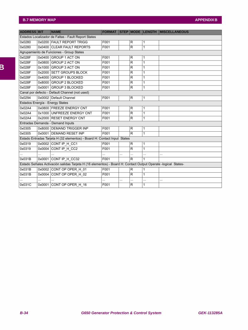
B-34 G650 Generator Protection & Control System GEK-113285A
B.7 MEMORY MAP APPENDIX B
B
Estados Localizador de Faltas - Fault Report States0x0280 0x0200 FAULT REPORT TRIGG F001 R 1 0x0280 0x0400 CLEAR FAULT REPORTS F001 R 1 Agrupamiento de Funciones - Group States0x028F 0x0400 GROUP 1 ACT ON F001 R 1 0x028F 0x0800 GROUP 2 ACT ON F001 R 1 0x028F 0x1000 GROUP 3 ACT ON F001 R 1 0x028F 0x2000 SETT GROUPS BLOCK F001 R 1 0x028F 0x4000 GROUP 1 BLOCKED F001 R 1 0x028F 0x8000 GROUP 2 BLOCKED F001 R 1 0x028F 0x0001 GROUP 3 BLOCKED F001 R 1 Canal por defecto - Default Channel (not used)0x0294 0x0002 Default Channel F001 R 1 Estados Energía - Energy States0x02A4 0x0800 FREEZE ENERGY CNT F001 R 1 0x02A4 0x1000 UNFREEZE ENERGY CNT F001 R 1 0x02A4 0x2000 RESET ENERGY CNT F001 R 1 Entradas Demanda - Demand Inputs0x0305 0x8000 DEMAND TRIGGER INP F001 R 1 0x0305 0x0001 DEMAND RESET INP F001 R 1 Estado Entradas Tarjeta H (32 elementos) - Board H: Contact Input States0x0319 0x0002 CONT IP_H_CC1 F001 R 1 0x0319 0x0004 CONT IP_H_CC2 F001 R 1 ... ... ... ... ... ... ... ...0x031B 0x0001 CONT IP_H_CC32 F001 R 1 Estado Señales Activación salidas Tarjeta H (16 elementos) - Board H: Contact Output Operate -logical States-0x031B 0x0002 CONT OP OPER_H_01 F001 R 1 0x031B 0x0004 CONT OP OPER_H_02 F001 R 1 ... ... ... ... ... ... ... ...0x031C 0x0001 CONT OP OPER_H_16 F001 R 1
ADDRESS BIT NAME FORMAT STEP MODE LENGTH MISCELLANEOUS
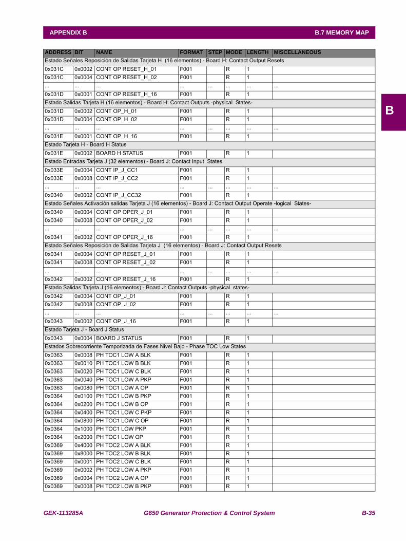
GEK-113285A G650 Generator Protection & Control System B-35
APPENDIX B B.7 MEMORY MAP
B
Estado Señales Reposición de Salidas Tarjeta H (16 elementos) - Board H: Contact Output Resets0x031C 0x0002 CONT OP RESET_H_01 F001 R 1 0x031C 0x0004 CONT OP RESET_H_02 F001 R 1 ... ... ... ... ... ... ... ...0x031D 0x0001 CONT OP RESET_H_16 F001 R 1 Estado Salidas Tarjeta H (16 elementos) - Board H: Contact Outputs -physical States-0x031D 0x0002 CONT OP_H_01 F001 R 1 0x031D 0x0004 CONT OP_H_02 F001 R 1 ... ... ... ... ... ... ... ...0x031E 0x0001 CONT OP_H_16 F001 R 1 Estado Tarjeta H - Board H Status0x031E 0x0002 BOARD H STATUS F001 R 1 Estado Entradas Tarjeta J (32 elementos) - Board J: Contact Input States0x033E 0x0004 CONT IP_J_CC1 F001 R 1 0x033E 0x0008 CONT IP_J_CC2 F001 R 1 ... ... ... ... ... ... ... ...0x0340 0x0002 CONT IP_J_CC32 F001 R 1 Estado Señales Activación salidas Tarjeta J (16 elementos) - Board J: Contact Output Operate -logical States-0x0340 0x0004 CONT OP OPER_J_01 F001 R 1 0x0340 0x0008 CONT OP OPER_J_02 F001 R 1 ... ... ... ... ... ... ... ...0x0341 0x0002 CONT OP OPER_J_16 F001 R 1 Estado Señales Reposición de Salidas Tarjeta J (16 elementos) - Board J: Contact Output Resets0x0341 0x0004 CONT OP RESET_J_01 F001 R 1 0x0341 0x0008 CONT OP RESET_J_02 F001 R 1 ... ... ... ... ... ... ... ...0x0342 0x0002 CONT OP RESET_J_16 F001 R 1 Estado Salidas Tarjeta J (16 elementos) - Board J: Contact Outputs -physical states-0x0342 0x0004 CONT OP_J_01 F001 R 1 0x0342 0x0008 CONT OP_J_02 F001 R 1 ... ... ... ... ... ... ... ...0x0343 0x0002 CONT OP_J_16 F001 R 1 Estado Tarjeta J - Board J Status0x0343 0x0004 BOARD J STATUS F001 R 1 Estados Sobrecorriente Temporizada de Fases Nivel Bajo - Phase TOC Low States0x0363 0x0008 PH TOC1 LOW A BLK F001 R 1 0x0363 0x0010 PH TOC1 LOW B BLK F001 R 1 0x0363 0x0020 PH TOC1 LOW C BLK F001 R 1 0x0363 0x0040 PH TOC1 LOW A PKP F001 R 1 0x0363 0x0080 PH TOC1 LOW A OP F001 R 1 0x0364 0x0100 PH TOC1 LOW B PKP F001 R 1 0x0364 0x0200 PH TOC1 LOW B OP F001 R 1 0x0364 0x0400 PH TOC1 LOW C PKP F001 R 1 0x0364 0x0800 PH TOC1 LOW C OP F001 R 1 0x0364 0x1000 PH TOC1 LOW PKP F001 R 1 0x0364 0x2000 PH TOC1 LOW OP F001 R 1 0x0369 0x4000 PH TOC2 LOW A BLK F001 R 1 0x0369 0x8000 PH TOC2 LOW B BLK F001 R 1 0x0369 0x0001 PH TOC2 LOW C BLK F001 R 1 0x0369 0x0002 PH TOC2 LOW A PKP F001 R 1 0x0369 0x0004 PH TOC2 LOW A OP F001 R 1 0x0369 0x0008 PH TOC2 LOW B PKP F001 R 1
ADDRESS BIT NAME FORMAT STEP MODE LENGTH MISCELLANEOUS
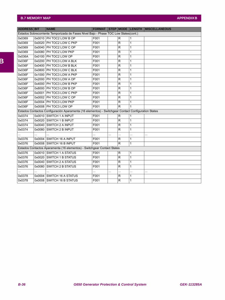
B-36 G650 Generator Protection & Control System GEK-113285A
B.7 MEMORY MAP APPENDIX B
B
Estados Sobrecorriente Temporizada de Fases Nivel Bajo - Phase TOC Low States(cont.)0x0369 0x0010 PH TOC2 LOW B OP F001 R 1 0x0369 0x0020 PH TOC2 LOW C PKP F001 R 1 0x0369 0x0040 PH TOC2 LOW C OP F001 R 1 0x0369 0x0080 PH TOC2 LOW PKP F001 R 1 0x036A 0x0100 PH TOC2 LOW OP F001 R 1 0x036F 0x0200 PH TOC3 LOW A BLK F001 R 1 0x036F 0x0400 PH TOC3 LOW B BLK F001 R 1 0x036F 0x0800 PH TOC3 LOW C BLK F001 R 1 0x036F 0x1000 PH TOC3 LOW A PKP F001 R 1 0x036F 0x2000 PH TOC3 LOW A OP F001 R 1 0x036F 0x4000 PH TOC3 LOW B PKP F001 R 1 0x036F 0x8000 PH TOC3 LOW B OP F001 R 1 0x036F 0x0001 PH TOC3 LOW C PKP F001 R 1 0x036F 0x0002 PH TOC3 LOW C OP F001 R 1 0x036F 0x0004 PH TOC3 LOW PKP F001 R 1 0x036F 0x0008 PH TOC3 LOW OP F001 R 1 Estados Contactos Configuración Aparamenta (16 elementos) - Switchgear Contact Configuration States0x0374 0x0010 SWITCH 1 A INPUT F001 R 1 0x0374 0x0020 SWITCH 1 B INPUT F001 R 1 0x0374 0x0040 SWITCH 2 A INPUT F001 R 1 0x0374 0x0080 SWITCH 2 B INPUT F001 R 1 ... ... ... ... ... ... ... ...0x0376 0x0004 SWITCH 16 A INPUT F001 R 1 0x0376 0x0008 SWITCH 16 B INPUT F001 R 1 Estados Contactos Aparamenta (16 elementos) - Switchgear Contact States0x0376 0x0010 SWITCH 1 A STATUS F001 R 1 0x0376 0x0020 SWITCH 1 B STATUS F001 R 1 0x0376 0x0040 SWITCH 2 A STATUS F001 R 1 0x0376 0x0080 SWITCH 2 B STATUS F001 R 1 ... ... ... ... ... ... ... ...0x0378 0x0004 SWITCH 16 A STATUS F001 R 1 0x0378 0x0008 SWITCH 16 B STATUS F001 R 1
ADDRESS BIT NAME FORMAT STEP MODE LENGTH MISCELLANEOUS
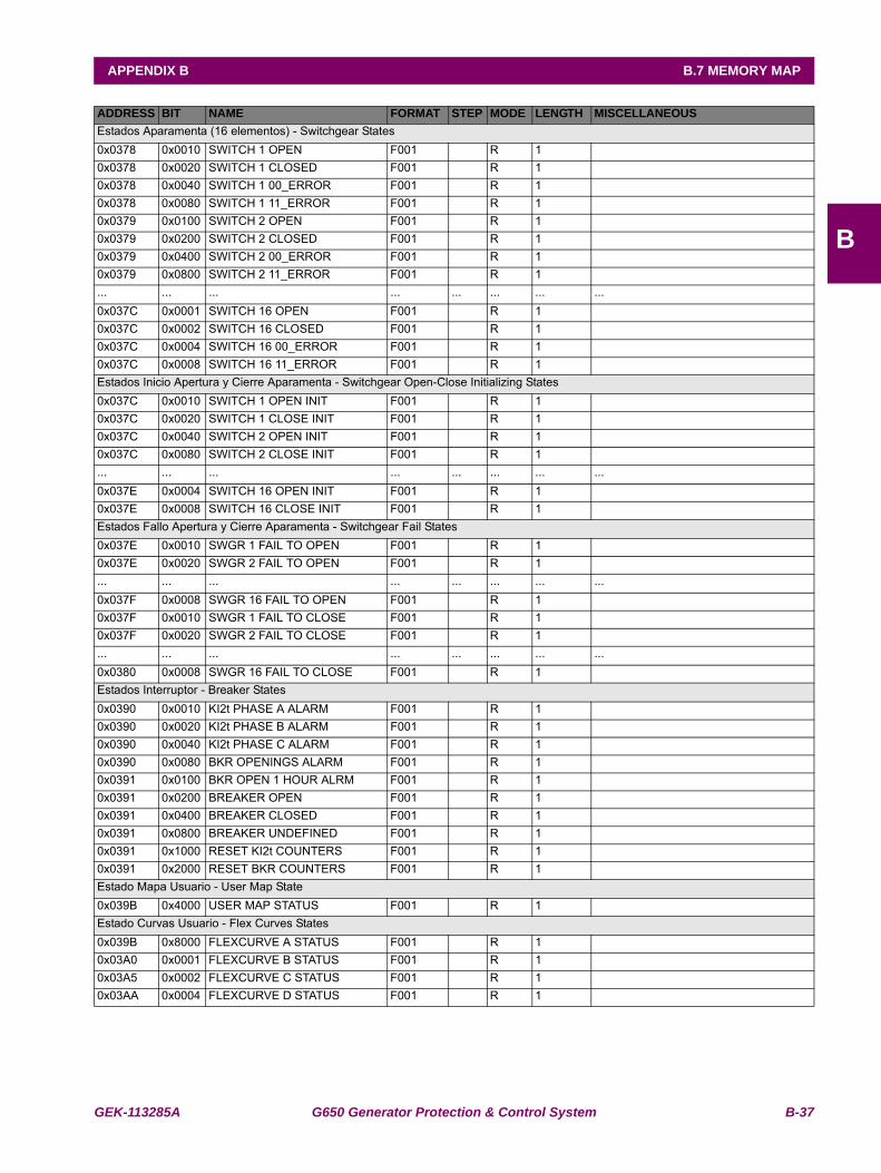
GEK-113285A G650 Generator Protection & Control System B-37
APPENDIX B B.7 MEMORY MAP
B
Estados Aparamenta (16 elementos) - Switchgear States0x0378 0x0010 SWITCH 1 OPEN F001 R 1 0x0378 0x0020 SWITCH 1 CLOSED F001 R 1 0x0378 0x0040 SWITCH 1 00_ERROR F001 R 1 0x0378 0x0080 SWITCH 1 11_ERROR F001 R 1 0x0379 0x0100 SWITCH 2 OPEN F001 R 1 0x0379 0x0200 SWITCH 2 CLOSED F001 R 1 0x0379 0x0400 SWITCH 2 00_ERROR F001 R 1 0x0379 0x0800 SWITCH 2 11_ERROR F001 R 1 ... ... ... ... ... ... ... ...0x037C 0x0001 SWITCH 16 OPEN F001 R 1 0x037C 0x0002 SWITCH 16 CLOSED F001 R 1 0x037C 0x0004 SWITCH 16 00_ERROR F001 R 1 0x037C 0x0008 SWITCH 16 11_ERROR F001 R 1 Estados Inicio Apertura y Cierre Aparamenta - Switchgear Open-Close Initializing States0x037C 0x0010 SWITCH 1 OPEN INIT F001 R 1 0x037C 0x0020 SWITCH 1 CLOSE INIT F001 R 1 0x037C 0x0040 SWITCH 2 OPEN INIT F001 R 1 0x037C 0x0080 SWITCH 2 CLOSE INIT F001 R 1 ... ... ... ... ... ... ... ...0x037E 0x0004 SWITCH 16 OPEN INIT F001 R 1 0x037E 0x0008 SWITCH 16 CLOSE INIT F001 R 1 Estados Fallo Apertura y Cierre Aparamenta - Switchgear Fail States0x037E 0x0010 SWGR 1 FAIL TO OPEN F001 R 1 0x037E 0x0020 SWGR 2 FAIL TO OPEN F001 R 1 ... ... ... ... ... ... ... ...0x037F 0x0008 SWGR 16 FAIL TO OPEN F001 R 1 0x037F 0x0010 SWGR 1 FAIL TO CLOSE F001 R 1 0x037F 0x0020 SWGR 2 FAIL TO CLOSE F001 R 1 ... ... ... ... ... ... ... ...0x0380 0x0008 SWGR 16 FAIL TO CLOSE F001 R 1 Estados Interruptor - Breaker States0x0390 0x0010 KI2t PHASE A ALARM F001 R 1 0x0390 0x0020 KI2t PHASE B ALARM F001 R 1 0x0390 0x0040 KI2t PHASE C ALARM F001 R 1 0x0390 0x0080 BKR OPENINGS ALARM F001 R 1 0x0391 0x0100 BKR OPEN 1 HOUR ALRM F001 R 1 0x0391 0x0200 BREAKER OPEN F001 R 10x0391 0x0400 BREAKER CLOSED F001 R 10x0391 0x0800 BREAKER UNDEFINED F001 R 10x0391 0x1000 RESET KI2t COUNTERS F001 R 1 0x0391 0x2000 RESET BKR COUNTERS F001 R 1 Estado Mapa Usuario - User Map State0x039B 0x4000 USER MAP STATUS F001 R 1 Estado Curvas Usuario - Flex Curves States0x039B 0x8000 FLEXCURVE A STATUS F001 R 1 0x03A0 0x0001 FLEXCURVE B STATUS F001 R 1 0x03A5 0x0002 FLEXCURVE C STATUS F001 R 1 0x03AA 0x0004 FLEXCURVE D STATUS F001 R 1
ADDRESS BIT NAME FORMAT STEP MODE LENGTH MISCELLANEOUS
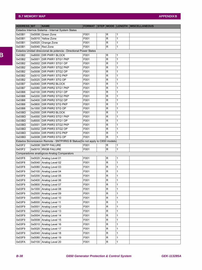
B-38 G650 Generator Protection & Control System GEK-113285A
B.7 MEMORY MAP APPENDIX B
B
Estados Internos Sistema - Internal System States0x03B1 0x0008 Green Zone F001 R 1 0x03B1 0x0010 Yellow Zone F001 R 1 0x03B1 0x0020 Orange Zone F001 R 1 0x03B1 0x0040 Red Zone F001 R 1 Estados Unidad direccional de potencia - Directional Power States0x03B2 0x8000 DIR PWR1 BLOCK F001 R 1 0x03B2 0x0001 DIR PWR1 STG1 PKP F001 R 1 0x03B2 0x0002 DIR PWR1 STG1 OP F001 R 1 0x03B2 0x0004 DIR PWR1 STG2 PKP F001 R 1 0x03B2 0x0008 DIR PWR1 STG2 OP F001 R 1 0x03B2 0x0010 DIR PWR1 STG PKP F001 R 1 0x03B2 0x0020 DIR PWR1 STG OP F001 R 1 0x03B7 0x0040 DIR PWR2 BLOCK F001 R 1 0x03B7 0x0080 DIR PWR2 STG1 PKP F001 R 1 0x03B8 0x0100 DIR PWR2 STG1 OP F001 R 1 0x03B8 0x0200 DIR PWR2 STG2 PKP F001 R 1 0x03B8 0x0400 DIR PWR2 STG2 OP F001 R 1 0x03B8 0x0800 DIR PWR2 STG PKP F001 R 1 0x03B8 0x1000 DIR PWR2 STG OP F001 R 1 0x03BD 0x2000 DIR PWR3 BLOCK F001 R 1 0x03BD 0x4000 DIR PWR3 STG1 PKP F001 R 1 0x03BD 0x8000 DIR PWR3 STG1 OP F001 R 1 0x03BD 0x0001 DIR PWR3 STG2 PKP F001 R 1 0x03BD 0x0002 DIR PWR3 STG2 OP F001 R 1 0x03BD 0x0004 DIR PWR3 STG PKP F001 R 1 0x03BD 0x0008 DIR PWR3 STG OP F001 R 1 Estados Sicronizacion Remota - SNTP/IRIG B Status(Do not apply to C650 models)0x03F2 0x0008 SNTP FAILURE F001 R 1 0x03F2 0x0010 IRIGB FAILURE F001 R 1 Comparadores analógicos-Analog Comparators
0x03F8 0x0020 Analog Level 01 F001 R 10x03F8 0x0040 Analog Level 02 F001 R 10x03F8 0x0080 Analog Level 03 F001 R 10x03F9 0x0100 Analog Level 04 F001 R 10x03F9 0x0200 Analog Level 05 F001 R 10x03F9 0x0400 Analog Level 06 F001 R 10x03F9 0x0800 Analog Level 07 F001 R 10x03F9 0x1000 Analog Level 08 F001 R 10x03F9 0x2000 Analog Level 09 F001 R 10x03F9 0x4000 Analog Level 10 F001 R 10x03F9 0x8000 Analog Level 11 F001 R 10x03F9 0x0001 Analog Level 12 F001 R 10x03F9 0x0002 Analog Level 13 F001 R 10x03F9 0x0004 Analog Level 14 F001 R 10x03F9 0x0008 Analog Level 15 F001 R 10x03F9 0x0010 Analog Level 16 F001 R 10x03F9 0x0020 Analog Level 17 F001 R 10x03F9 0x0040 Analog Level 18 F001 R 10x03F9 0x0080 Analog Level 19 F001 R 10x03FA 0x0100 Analog Level 20 F001 R 1
ADDRESS BIT NAME FORMAT STEP MODE LENGTH MISCELLANEOUS
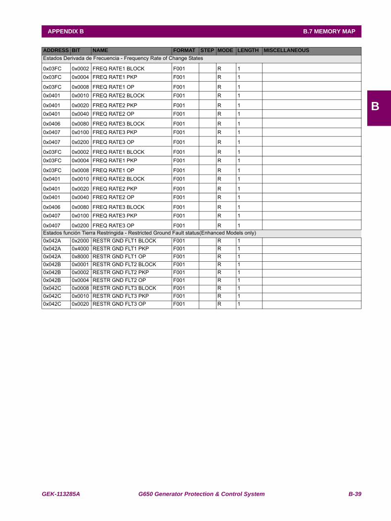
GEK-113285A G650 Generator Protection & Control System B-39
APPENDIX B B.7 MEMORY MAP
B
Estados Derivada de Frecuencia - Frequency Rate of Change States
0x03FC 0x0002 FREQ RATE1 BLOCK F001 R 10x03FC 0x0004 FREQ RATE1 PKP F001 R 1
0x03FC 0x0008 FREQ RATE1 OP F001 R 10x0401 0x0010 FREQ RATE2 BLOCK F001 R 1
0x0401 0x0020 FREQ RATE2 PKP F001 R 10x0401 0x0040 FREQ RATE2 OP F001 R 1
0x0406 0x0080 FREQ RATE3 BLOCK F001 R 10x0407 0x0100 FREQ RATE3 PKP F001 R 1
0x0407 0x0200 FREQ RATE3 OP F001 R 1
0x03FC 0x0002 FREQ RATE1 BLOCK F001 R 10x03FC 0x0004 FREQ RATE1 PKP F001 R 1
0x03FC 0x0008 FREQ RATE1 OP F001 R 10x0401 0x0010 FREQ RATE2 BLOCK F001 R 1
0x0401 0x0020 FREQ RATE2 PKP F001 R 10x0401 0x0040 FREQ RATE2 OP F001 R 1
0x0406 0x0080 FREQ RATE3 BLOCK F001 R 10x0407 0x0100 FREQ RATE3 PKP F001 R 1
0x0407 0x0200 FREQ RATE3 OP F001 R 1Estados función Tierra Restringida - Restricted Ground Fault status(Enhanced Models only)0x042A 0x2000 RESTR GND FLT1 BLOCK F001 R 10x042A 0x4000 RESTR GND FLT1 PKP F001 R 10x042A 0x8000 RESTR GND FLT1 OP F001 R 10x042B 0x0001 RESTR GND FLT2 BLOCK F001 R 10x042B 0x0002 RESTR GND FLT2 PKP F001 R 10x042B 0x0004 RESTR GND FLT2 OP F001 R 10x042C 0x0008 RESTR GND FLT3 BLOCK F001 R 10x042C 0x0010 RESTR GND FLT3 PKP F001 R 10x042C 0x0020 RESTR GND FLT3 OP F001 R 1
ADDRESS BIT NAME FORMAT STEP MODE LENGTH MISCELLANEOUS
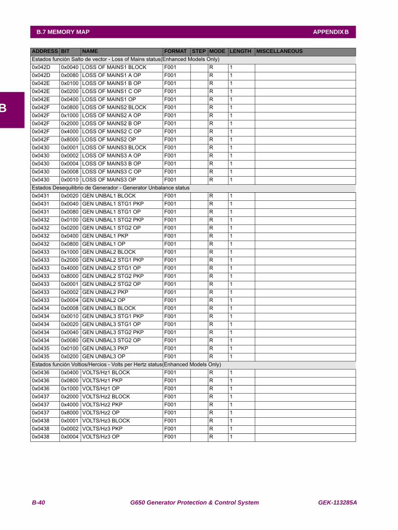
B-40 G650 Generator Protection & Control System GEK-113285A
B.7 MEMORY MAP APPENDIX B
B
Estados función Salto de vector - Loss of Mains status(Enhanced Models Only)0x042D 0x0040 LOSS OF MAINS1 BLOCK F001 R 10x042D 0x0080 LOSS OF MAINS1 A OP F001 R 10x042E 0x0100 LOSS OF MAINS1 B OP F001 R 10x042E 0x0200 LOSS OF MAINS1 C OP F001 R 10x042E 0x0400 LOSS OF MAINS1 OP F001 R 10x042F 0x0800 LOSS OF MAINS2 BLOCK F001 R 10x042F 0x1000 LOSS OF MAINS2 A OP F001 R 10x042F 0x2000 LOSS OF MAINS2 B OP F001 R 10x042F 0x4000 LOSS OF MAINS2 C OP F001 R 10x042F 0x8000 LOSS OF MAINS2 OP F001 R 10x0430 0x0001 LOSS OF MAINS3 BLOCK F001 R 10x0430 0x0002 LOSS OF MAINS3 A OP F001 R 10x0430 0x0004 LOSS OF MAINS3 B OP F001 R 10x0430 0x0008 LOSS OF MAINS3 C OP F001 R 10x0430 0x0010 LOSS OF MAINS3 OP F001 R 1Estados Desequilibrio de Generador - Generator Unbalance status0x0431 0x0020 GEN UNBAL1 BLOCK F001 R 10x0431 0x0040 GEN UNBAL1 STG1 PKP F001 R 10x0431 0x0080 GEN UNBAL1 STG1 OP F001 R 10x0432 0x0100 GEN UNBAL1 STG2 PKP F001 R 10x0432 0x0200 GEN UNBAL1 STG2 OP F001 R 10x0432 0x0400 GEN UNBAL1 PKP F001 R 10x0432 0x0800 GEN UNBAL1 OP F001 R 10x0433 0x1000 GEN UNBAL2 BLOCK F001 R 10x0433 0x2000 GEN UNBAL2 STG1 PKP F001 R 10x0433 0x4000 GEN UNBAL2 STG1 OP F001 R 10x0433 0x8000 GEN UNBAL2 STG2 PKP F001 R 10x0433 0x0001 GEN UNBAL2 STG2 OP F001 R 10x0433 0x0002 GEN UNBAL2 PKP F001 R 10x0433 0x0004 GEN UNBAL2 OP F001 R 10x0434 0x0008 GEN UNBAL3 BLOCK F001 R 10x0434 0x0010 GEN UNBAL3 STG1 PKP F001 R 10x0434 0x0020 GEN UNBAL3 STG1 OP F001 R 10x0434 0x0040 GEN UNBAL3 STG2 PKP F001 R 10x0434 0x0080 GEN UNBAL3 STG2 OP F001 R 10x0435 0x0100 GEN UNBAL3 PKP F001 R 10x0435 0x0200 GEN UNBAL3 OP F001 R 1Estados función Voltios/Hercios - Volts per Hertz status(Enhanced Models Only)0x0436 0x0400 VOLTS/Hz1 BLOCK F001 R 10x0436 0x0800 VOLTS/Hz1 PKP F001 R 10x0436 0x1000 VOLTS/Hz1 OP F001 R 10x0437 0x2000 VOLTS/Hz2 BLOCK F001 R 10x0437 0x4000 VOLTS/Hz2 PKP F001 R 10x0437 0x8000 VOLTS/Hz2 OP F001 R 10x0438 0x0001 VOLTS/Hz3 BLOCK F001 R 10x0438 0x0002 VOLTS/Hz3 PKP F001 R 10x0438 0x0004 VOLTS/Hz3 OP F001 R 1
ADDRESS BIT NAME FORMAT STEP MODE LENGTH MISCELLANEOUS

GEK-113285A G650 Generator Protection & Control System B-41
APPENDIX B B.7 MEMORY MAP
B
Estados Pérdida Excitación - Loss of Excitation status0x0439 0x0008 LOSS OF EXC1 BLOCK F001 R 10x0439 0x0010 LOSS OF EXC1 ST1 PKP F001 R 10x0439 0x0020 LOSS OF EXC1 STG1 OP F001 R 10x0439 0x0040 LOSS OF EXC1 ST2 PKP F001 R 10x0439 0x0080 LOSS OF EXC1 STG2 OP F001 R 10x043A 0x0100 LOSS OF EXC1 PKP F001 R 10x043A 0x0200 LOSS OF EXC1 OP F001 R 10x043B 0x0400 LOSS OF EXC2 BLOCK F001 R 10x043B 0x0800 LOSS OF EXC2 ST1 PKP F001 R 10x043B 0x1000 LOSS OF EXC2 STG1 OP F001 R 10x043B 0x2000 LOSS OF EXC2 ST2 PKP F001 R 10x043B 0x4000 LOSS OF EXC2 STG2 OP F001 R 10x043B 0x8000 LOSS OF EXC2 PKP F001 R 10x043B 0x0001 LOSS OF EXC2 OP F001 R 10x043C 0x0002 LOSS OF EXC3 BLOCK F001 R 10x043C 0x0004 LOSS OF EXC3 STG1 PKP F001 R 10x043C 0x0008 LOSS OF EXC3 STG1 OP F001 R 10x043C 0x0010 LOSS OF EXC3 STG2 PKP F001 R 10x043C 0x0020 LOSS OF EXC3 STG2 OP F001 R 10x043C 0x0040 LOSS OF EXC3 PKP F001 R 10x043C 0x0080 LOSS OF EXC3 OP F001 R 1Estados Sobreintensidad Temporizada Sequencia Negativa - Negative Sequence IOC status0x043E 0x0100 NEG. SEQ1 IOC BLOCK F001 R 10x043E 0x0200 NEG. SEQ1 IOC PKP F001 R 10x043E 0x0400 NEG. SEQ1 IOC OP F001 R 10x043F 0x0800 NEG. SEQ2 IOC BLOCK F001 R 10x043F 0x1000 NEG. SEQ2 IOC PKP F001 R 10x043F 0x2000 NEG. SEQ2 IOC OP F001 R 10x0440 0x4000 NEG. SEQ3 IOC BLOCK F001 R 10x0440 0x8000 NEG. SEQ3 IOC PKP F001 R 10x0440 0x0001 NEG. SEQ3 IOC OP F001 R 1Estados Imagen Térmica Generador - Generator Thermal Model status0x0441 0x0002 THERMAL1 49S BLOCK F001 R 10x0441 0x0004 THERMAL1 49S ALARM F001 R 10x0441 0x0008 THERMAL1 49S OP F001 R 10x0441 0x0010 THERMAL1 49S RST F001 R 10x0442 0x0020 THERMAL2 49S BLOCK F001 R 10x0442 0x0040 THERMAL2 49S ALARM F001 R 10x0442 0x0080 THERMAL2 49S OP F001 R 10x0443 0x0100 THERMAL2 49S RST F001 R 10x0444 0x0200 THERMAL3 49S BLOCK F001 R 10x0444 0x0400 THERMAL3 49S ALARM F001 R 10x0444 0x0800 THERMAL3 49S OP F001 R 10x0444 0x1000 THERMAL3 49S RST F001 R 1Estados Limitador Factor Potencia - Power Factor Limiting status(Enhanced Models Only)0x0445 0x2000 POWER FACTOR1 BLOCK F001 R 10x0445 0x4000 PF1 LAG STG1 OP F001 R 10x0445 0x8000 PF1 LEAD STG1 OP F001 R 10x0445 0x0001 PF1 LAG STG2 OP F001 R 10x0445 0x0002 PF1 LEAD STG2 OP F001 R 10x0445 0x0004 PF1 LAG OP F001 R 10x0445 0x0008 PF1 LEAD OP F001 R 1
ADDRESS BIT NAME FORMAT STEP MODE LENGTH MISCELLANEOUS
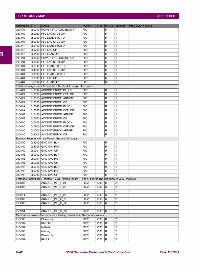
B-42 G650 Generator Protection & Control System GEK-113285A
B.7 MEMORY MAP APPENDIX B
B
0x0446 0x0010 POWER FACTOR2 BLOCK F001 R 10x0446 0x0020 PF2 LAG STG1 OP F001 R 10x0446 0x0040 PF2 LEAD STG1 OP F001 R 10x0446 0x0080 PF2 LAG STG2 OP F001 R 10x0447 0x0100 PF2 LEAD STG2 OP F001 R 10x0447 0x0200 PF2 LAG OP F001 R 10x0447 0x0400 PF2 LEAD OP F001 R 10x0448 0x0800 POWER FACTOR3 BLOCK F001 R 10x0448 0x1000 PF3 LAG STG1 OP F001 R 10x0448 0x2000 PF3 LEAD STG1 OP F001 R 10x0448 0x4000 PF3 LAG STG2 OP F001 R 10x0448 0x8000 PF3 LEAD STG2 OP F001 R 10x0448 0x0001 PF3 LAG OP F001 R 10x0448 0x0002 PF3 LEAD OP F001 R 1Estados Energización Accidental - Accidental Energization status0x0449 0x0004 ACCDNT ENRG1 BLOCK F001 R 10x0449 0x0008 ACCDNT ENRG1 OFFLINE F001 R 10x0449 0x0010 ACCDNT ENRG1 ARMED F001 R 10x0449 0x0020 ACCDNT ENRG1 OP F001 R 10x044A 0x0040 ACCDNT ENRG2 BLOCK F001 R 10x044A 0x0080 ACCDNT ENRG2 OFFLINE F001 R 10x044B 0x0100 ACCDNT ENRG2 ARMED F001 R 10x044B 0x0200 ACCDNT ENRG2 OP F001 R 10x044C 0x0400 ACCDNT ENRG3 BLOCK F001 R 10x044C 0x0800 ACCDNT ENRG3 OFFLINE F001 R 10x044C 0x1000 ACCDNT ENRG3 ARMED F001 R 10x044C 0x2000 ACCDNT ENRG3 OP F001 R 1Estados Sobretención de Tierra - Ground OV status0x044D 0x4000 GND OV1 BLK F001 R 10x044D 0x8000 GND OV1 PKP F001 R 10x044D 0x0001 GND OV1 OP F001 R 10x044E 0x0002 GND OV2 BLK F001 R 10x044E 0x0004 GND OV2 PKP F001 R 10x044E 0x0008 GND OV2 OP F001 R 10x044F 0x0010 GND OV3 BLK F001 R 10x044F 0x0020 GND OV3 PKP F001 R 10x044F 0x0040 GND OV3 OP F001 R 1Entradas Analógicas (Tarjetas F y G)- Analog Inputs (F and G boards)(Do not apply to C650 models)0x0B06 ANALOG_INP_F_01 F002 1000 R 2 0x0B08 ANALOG_INP_F_02 F002 1000 R 2 ... ... ... ... ... ... ...0x0B14 ANALOG_INP_F_08 F002 1000 R 2 0x0B86 ANALOG_INP_G_01 F002 1000 R 2 0x0B88 ANALOG_INP_G_02 F002 1000 R 2 ... ... ... ... ... ... ...0x0B94 ANALOG_INP_G_08 F002 1000 R 2 Medidas en Valores Secundarios - Analog measures in Secondary Values0x0C00 Phasor Ia F002 1000 R 2 0x0C02 RMS Ia F002 1000 R 2 0x0C04 Ia Real F002 1000 R 2 0x0C06 Ia Imag F002 1000 R 2 0x0C08 Phasor Ib F002 1000 R 2 0x0C0A RMS Ib F002 1000 R 2
ADDRESS BIT NAME FORMAT STEP MODE LENGTH MISCELLANEOUS
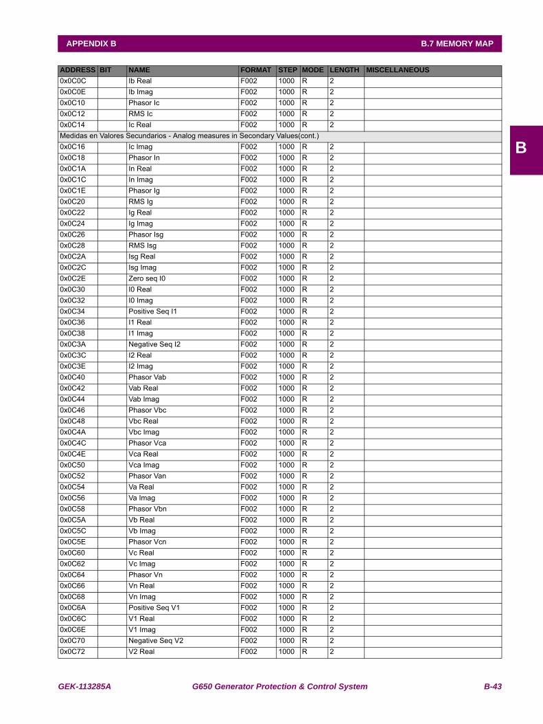
GEK-113285A G650 Generator Protection & Control System B-43
APPENDIX B B.7 MEMORY MAP
B
0x0C0C Ib Real F002 1000 R 2 0x0C0E Ib Imag F002 1000 R 2 0x0C10 Phasor Ic F002 1000 R 2 0x0C12 RMS Ic F002 1000 R 2 0x0C14 Ic Real F002 1000 R 2 Medidas en Valores Secundarios - Analog measures in Secondary Values(cont.)0x0C16 Ic Imag F002 1000 R 2 0x0C18 Phasor In F002 1000 R 2 0x0C1A In Real F002 1000 R 2 0x0C1C In Imag F002 1000 R 2 0x0C1E Phasor Ig F002 1000 R 2 0x0C20 RMS Ig F002 1000 R 2 0x0C22 Ig Real F002 1000 R 2 0x0C24 Ig Imag F002 1000 R 2 0x0C26 Phasor Isg F002 1000 R 2 0x0C28 RMS Isg F002 1000 R 2 0x0C2A Isg Real F002 1000 R 2 0x0C2C Isg Imag F002 1000 R 2 0x0C2E Zero seq I0 F002 1000 R 2 0x0C30 I0 Real F002 1000 R 2 0x0C32 I0 Imag F002 1000 R 2 0x0C34 Positive Seq I1 F002 1000 R 2 0x0C36 I1 Real F002 1000 R 2 0x0C38 I1 Imag F002 1000 R 2 0x0C3A Negative Seq I2 F002 1000 R 2 0x0C3C I2 Real F002 1000 R 2 0x0C3E I2 Imag F002 1000 R 2 0x0C40 Phasor Vab F002 1000 R 2 0x0C42 Vab Real F002 1000 R 2 0x0C44 Vab Imag F002 1000 R 2 0x0C46 Phasor Vbc F002 1000 R 2 0x0C48 Vbc Real F002 1000 R 2 0x0C4A Vbc Imag F002 1000 R 2 0x0C4C Phasor Vca F002 1000 R 2 0x0C4E Vca Real F002 1000 R 2 0x0C50 Vca Imag F002 1000 R 2 0x0C52 Phasor Van F002 1000 R 2 0x0C54 Va Real F002 1000 R 2 0x0C56 Va Imag F002 1000 R 2 0x0C58 Phasor Vbn F002 1000 R 2 0x0C5A Vb Real F002 1000 R 2 0x0C5C Vb Imag F002 1000 R 2 0x0C5E Phasor Vcn F002 1000 R 2 0x0C60 Vc Real F002 1000 R 2 0x0C62 Vc Imag F002 1000 R 2 0x0C64 Phasor Vn F002 1000 R 2 0x0C66 Vn Real F002 1000 R 2 0x0C68 Vn Imag F002 1000 R 2 0x0C6A Positive Seq V1 F002 1000 R 2 0x0C6C V1 Real F002 1000 R 2 0x0C6E V1 Imag F002 1000 R 2 0x0C70 Negative Seq V2 F002 1000 R 2 0x0C72 V2 Real F002 1000 R 2
ADDRESS BIT NAME FORMAT STEP MODE LENGTH MISCELLANEOUS
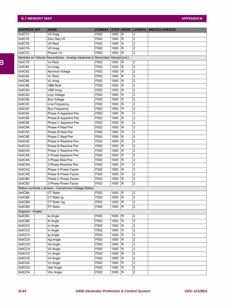
B-44 G650 Generator Protection & Control System GEK-113285A
B.7 MEMORY MAP APPENDIX B
B
0x0C74 V2 Imag F002 1000 R 2 0x0C76 Zero Seq V0 F002 1000 R 2 0x0C78 V0 Real F002 1000 R 2 0x0C7A V0 Imag F002 1000 R 2 0x0C7C Phasor Vx F002 1000 R 2 Medidas en Valores Secundarios - Analog measures in Secondary Values(cont.)0x0C7E Vx Real F002 1000 R 2 0x0C80 Vx Imag F002 1000 R 2 0x0C82 Nominal Voltage F002 1000 R 2 0x0C84 VL Real F002 1000 R 2 0x0C86 VL Imag F002 1000 R 2 0x0C88 VBB Real F002 1000 R 2 0x0C8A VBB Imag F002 1000 R 2 0x0C8C Line Voltage F002 1000 R 2 0x0C8E Bus Voltage F002 1000 R 2 0x0C90 Line Frequency F002 1000 R 2 0x0C92 Bus Frequency F002 1000 R 2 0x0C94 Phase A Apparent Pwr F002 1000 R 2 0x0C96 Phase B Apparent Pwr F002 1000 R 2 0x0C98 Phase C Apparent Pwr F002 1000 R 2 0x0C9A Phase A Real Pwr F002 1000 R 2 0x0C9C Phase B Real Pwr F002 1000 R 2 0x0C9E Phase C Real Pwr F002 1000 R 2 0x0CA0 Phase A Reactive Pwr F002 1000 R 2 0x0CA2 Phase B Reactive Pwr F002 1000 R 2 0x0CA4 Phase C Reactive Pwr F002 1000 R 2 0x0CA6 3 Phase Apparent Pwr F002 1000 R 2 0x0CA8 3 Phase Real Pwr F002 1000 R 2 0x0CAA 3 Phase Reactive Pwr F002 1000 R 2 0x0CAC Phase A Power Factor F002 1000 R 2 0x0CAE Phase B Power Factor F002 1000 R 2 0x0CB0 Phase C Power Factor F002 1000 R 2 0x0CB2 3 Phase Power Factor F002 1000 R 2 Ratios corriente y tensión - Current and Voltage Ratios0x0CB4 CT Ratio F002 1000 R 2 0x0CB6 CT Ratio Ig F002 1000 R 2 0x0CB8 CT Ratio Isg F002 1000 R 2 0x0CBA PT Ratio F002 1000 R 2 Angulos - Angles0x0CBC Ia Angle F002 1000 R 2 0x0CBE Ib Angle F002 1000 R 2 0x0CC0 Ic Angle F002 1000 R 2 0x0CC2 In Angle F002 1000 R 2 0x0CC4 Ig Angle F002 1000 R 2 0x0CC6 Isg Angle F002 1000 R 2 0x0CC8 Va Angle F002 1000 R 2 0x0CCA Vb Angle F002 1000 R 2 0x0CCC Vc Angle F002 1000 R 2 0x0CCE Vn Angle F002 1000 R 2 0x0CD0 Vx Angle F002 1000 R 2 0x0CD2 Vab Angle F002 1000 R 2 0x0CD4 Vbc Angle F002 1000 R 2
ADDRESS BIT NAME FORMAT STEP MODE LENGTH MISCELLANEOUS
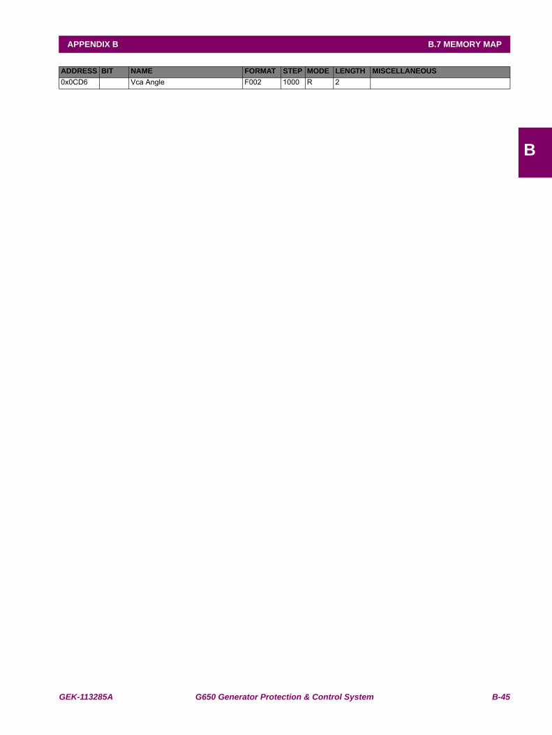
GEK-113285A G650 Generator Protection & Control System B-45
APPENDIX B B.7 MEMORY MAP
B
0x0CD6 Vca Angle F002 1000 R 2 ADDRESS BIT NAME FORMAT STEP MODE LENGTH MISCELLANEOUS
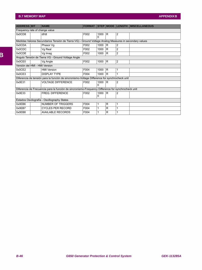
B-46 G650 Generator Protection & Control System GEK-113285A
B.7 MEMORY MAP APPENDIX B
B
Frequency rate of change value0x0CD8 df/dt F002 1000
0R 2
Medidas Valores Secundarios Tensión de Tierra VG) - Ground Voltage Analog Measures in secondary values0x0CDA Phasor Vg F002 1000 R 20x0CDC Vg Real F002 1000 R 20x0CDE Vg Imag F002 1000 R 2Ángulo Tensión de Tierra VG - Ground Voltage Angle0x0CE0 Vg Angle F002 1000 R 2Versión del HMI - HMI Version0x0CE2 HMI Version F004 1000 R 1 0x0CE3 DISPLAY TYPE F004 1000 R 1Diferencia de tensión para la función de sincronismo-Voltage Difference for synchrocheck unit0x0E31 VOLTAGE DIFFERENCE F002 1000
0R 2
Diferencia de Frecuencia para la función de sincronismo-Frequency Difference for synchrocheck unit0x0E33 FREQ. DIFFERENCE F002 1000
0R 2
Estados Oscilografía - Oscillography States0x0EB6 NUMBER OF TRIGGERS F004 1 R 1 0x0EB7 CYCLES PER RECORD F004 1 R 1 0x0EB8 AVAILABLE RECORDS F004 1 R 1
ADDRESS BIT NAME FORMAT STEP MODE LENGTH MISCELLANEOUS
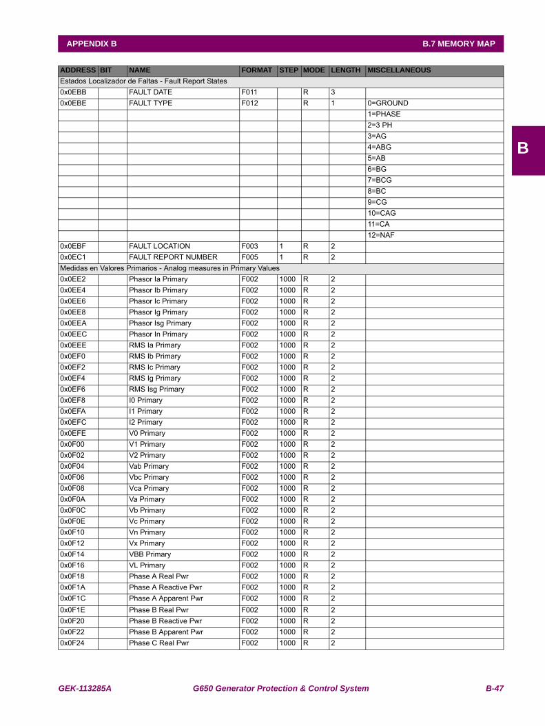
GEK-113285A G650 Generator Protection & Control System B-47
APPENDIX B B.7 MEMORY MAP
B
Estados Localizador de Faltas - Fault Report States0x0EBB FAULT DATE F011 R 3 0x0EBE FAULT TYPE F012 R 1 0=GROUND 1=PHASE 2=3 PH 3=AG 4=ABG 5=AB 6=BG 7=BCG 8=BC 9=CG 10=CAG 11=CA 12=NAF0x0EBF FAULT LOCATION F003 1 R 2 0x0EC1 FAULT REPORT NUMBER F005 1 R 2 Medidas en Valores Primarios - Analog measures in Primary Values0x0EE2 Phasor Ia Primary F002 1000 R 2 0x0EE4 Phasor Ib Primary F002 1000 R 2 0x0EE6 Phasor Ic Primary F002 1000 R 2 0x0EE8 Phasor Ig Primary F002 1000 R 2 0x0EEA Phasor Isg Primary F002 1000 R 2 0x0EEC Phasor In Primary F002 1000 R 2 0x0EEE RMS Ia Primary F002 1000 R 2 0x0EF0 RMS Ib Primary F002 1000 R 2 0x0EF2 RMS Ic Primary F002 1000 R 2 0x0EF4 RMS Ig Primary F002 1000 R 2 0x0EF6 RMS Isg Primary F002 1000 R 2 0x0EF8 I0 Primary F002 1000 R 2 0x0EFA I1 Primary F002 1000 R 2 0x0EFC I2 Primary F002 1000 R 2 0x0EFE V0 Primary F002 1000 R 2 0x0F00 V1 Primary F002 1000 R 2 0x0F02 V2 Primary F002 1000 R 2 0x0F04 Vab Primary F002 1000 R 2 0x0F06 Vbc Primary F002 1000 R 2 0x0F08 Vca Primary F002 1000 R 2 0x0F0A Va Primary F002 1000 R 2 0x0F0C Vb Primary F002 1000 R 2 0x0F0E Vc Primary F002 1000 R 2 0x0F10 Vn Primary F002 1000 R 2 0x0F12 Vx Primary F002 1000 R 2 0x0F14 VBB Primary F002 1000 R 2 0x0F16 VL Primary F002 1000 R 2 0x0F18 Phase A Real Pwr F002 1000 R 2 0x0F1A Phase A Reactive Pwr F002 1000 R 2 0x0F1C Phase A Apparent Pwr F002 1000 R 2 0x0F1E Phase B Real Pwr F002 1000 R 2 0x0F20 Phase B Reactive Pwr F002 1000 R 2 0x0F22 Phase B Apparent Pwr F002 1000 R 2 0x0F24 Phase C Real Pwr F002 1000 R 2
ADDRESS BIT NAME FORMAT STEP MODE LENGTH MISCELLANEOUS
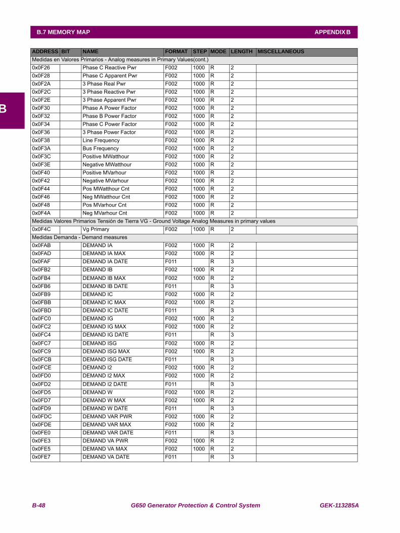
B-48 G650 Generator Protection & Control System GEK-113285A
B.7 MEMORY MAP APPENDIX B
B
Medidas en Valores Primarios - Analog measures in Primary Values(cont.)0x0F26 Phase C Reactive Pwr F002 1000 R 2 0x0F28 Phase C Apparent Pwr F002 1000 R 2 0x0F2A 3 Phase Real Pwr F002 1000 R 2 0x0F2C 3 Phase Reactive Pwr F002 1000 R 2 0x0F2E 3 Phase Apparent Pwr F002 1000 R 2 0x0F30 Phase A Power Factor F002 1000 R 2 0x0F32 Phase B Power Factor F002 1000 R 2 0x0F34 Phase C Power Factor F002 1000 R 2 0x0F36 3 Phase Power Factor F002 1000 R 2 0x0F38 Line Frequency F002 1000 R 2 0x0F3A Bus Frequency F002 1000 R 2 0x0F3C Positive MWatthour F002 1000 R 2 0x0F3E Negative MWatthour F002 1000 R 2 0x0F40 Positive MVarhour F002 1000 R 2 0x0F42 Negative MVarhour F002 1000 R 2 0x0F44 Pos MWatthour Cnt F002 1000 R 2 0x0F46 Neg MWatthour Cnt F002 1000 R 2 0x0F48 Pos MVarhour Cnt F002 1000 R 2 0x0F4A Neg MVarhour Cnt F002 1000 R 2 Medidas Valores Primarios Tensión de Tierra VG - Ground Voltage Analog Measures in primary values0x0F4C Vg Primary F002 1000 R 2Medidas Demanda - Demand measures0x0FAB DEMAND IA F002 1000 R 2 0x0FAD DEMAND IA MAX F002 1000 R 2 0x0FAF DEMAND IA DATE F011 R 3 0x0FB2 DEMAND IB F002 1000 R 2 0x0FB4 DEMAND IB MAX F002 1000 R 2 0x0FB6 DEMAND IB DATE F011 R 3 0x0FB9 DEMAND IC F002 1000 R 2 0x0FBB DEMAND IC MAX F002 1000 R 2 0x0FBD DEMAND IC DATE F011 R 3 0x0FC0 DEMAND IG F002 1000 R 2 0x0FC2 DEMAND IG MAX F002 1000 R 2 0x0FC4 DEMAND IG DATE F011 R 3 0x0FC7 DEMAND ISG F002 1000 R 2 0x0FC9 DEMAND ISG MAX F002 1000 R 2 0x0FCB DEMAND ISG DATE F011 R 3 0x0FCE DEMAND I2 F002 1000 R 2 0x0FD0 DEMAND I2 MAX F002 1000 R 2 0x0FD2 DEMAND I2 DATE F011 R 3 0x0FD5 DEMAND W F002 1000 R 2 0x0FD7 DEMAND W MAX F002 1000 R 2 0x0FD9 DEMAND W DATE F011 R 3 0x0FDC DEMAND VAR PWR F002 1000 R 2 0x0FDE DEMAND VAR MAX F002 1000 R 2 0x0FE0 DEMAND VAR DATE F011 R 3 0x0FE3 DEMAND VA PWR F002 1000 R 2 0x0FE5 DEMAND VA MAX F002 1000 R 2 0x0FE7 DEMAND VA DATE F011 R 3
ADDRESS BIT NAME FORMAT STEP MODE LENGTH MISCELLANEOUS
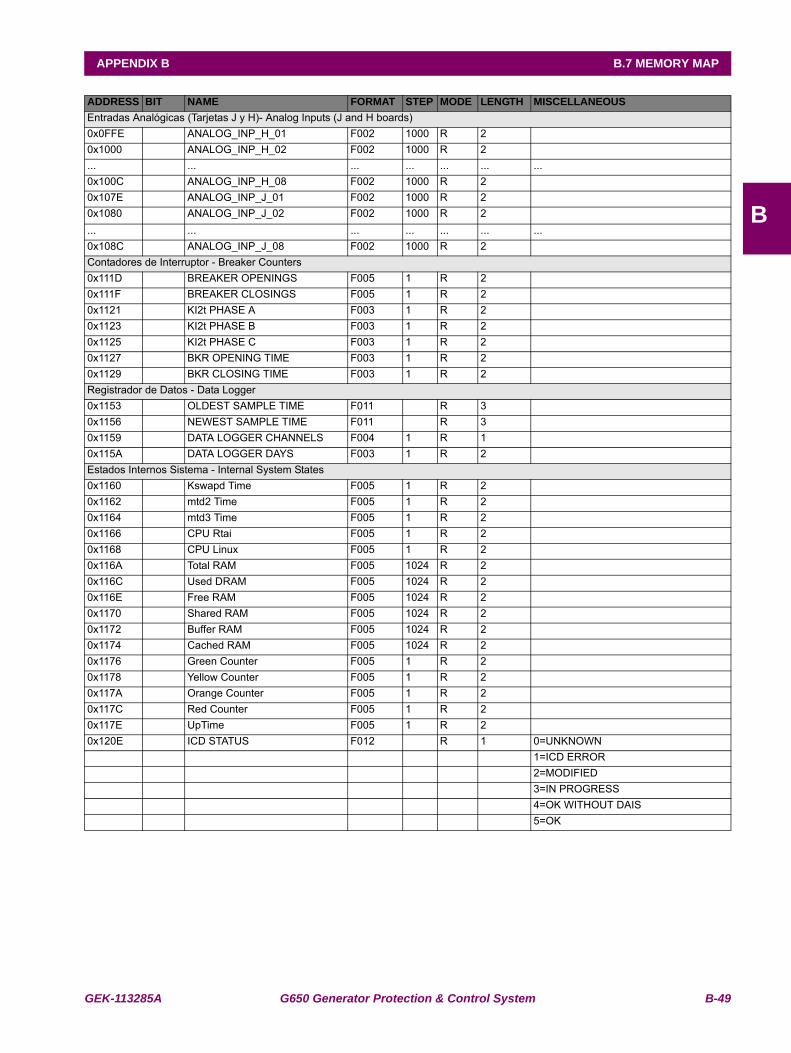
GEK-113285A G650 Generator Protection & Control System B-49
APPENDIX B B.7 MEMORY MAP
B
Entradas Analógicas (Tarjetas J y H)- Analog Inputs (J and H boards)0x0FFE ANALOG_INP_H_01 F002 1000 R 2 0x1000 ANALOG_INP_H_02 F002 1000 R 2 ... ... ... ... ... ... ...0x100C ANALOG_INP_H_08 F002 1000 R 2 0x107E ANALOG_INP_J_01 F002 1000 R 2 0x1080 ANALOG_INP_J_02 F002 1000 R 2 ... ... ... ... ... ... ...0x108C ANALOG_INP_J_08 F002 1000 R 2 Contadores de Interruptor - Breaker Counters0x111D BREAKER OPENINGS F005 1 R 2 0x111F BREAKER CLOSINGS F005 1 R 2 0x1121 KI2t PHASE A F003 1 R 2 0x1123 KI2t PHASE B F003 1 R 2 0x1125 KI2t PHASE C F003 1 R 2 0x1127 BKR OPENING TIME F003 1 R 2 0x1129 BKR CLOSING TIME F003 1 R 2 Registrador de Datos - Data Logger0x1153 OLDEST SAMPLE TIME F011 R 3 0x1156 NEWEST SAMPLE TIME F011 R 3 0x1159 DATA LOGGER CHANNELS F004 1 R 1 0x115A DATA LOGGER DAYS F003 1 R 2 Estados Internos Sistema - Internal System States0x1160 Kswapd Time F005 1 R 2 0x1162 mtd2 Time F005 1 R 2 0x1164 mtd3 Time F005 1 R 2 0x1166 CPU Rtai F005 1 R 2 0x1168 CPU Linux F005 1 R 2 0x116A Total RAM F005 1024 R 2 0x116C Used DRAM F005 1024 R 2 0x116E Free RAM F005 1024 R 2 0x1170 Shared RAM F005 1024 R 2 0x1172 Buffer RAM F005 1024 R 2 0x1174 Cached RAM F005 1024 R 2 0x1176 Green Counter F005 1 R 2 0x1178 Yellow Counter F005 1 R 2 0x117A Orange Counter F005 1 R 2 0x117C Red Counter F005 1 R 2 0x117E UpTime F005 1 R 2 0x120E ICD STATUS F012 R 1 0=UNKNOWN
1=ICD ERROR2=MODIFIED3=IN PROGRESS4=OK WITHOUT DAIS5=OK
ADDRESS BIT NAME FORMAT STEP MODE LENGTH MISCELLANEOUS
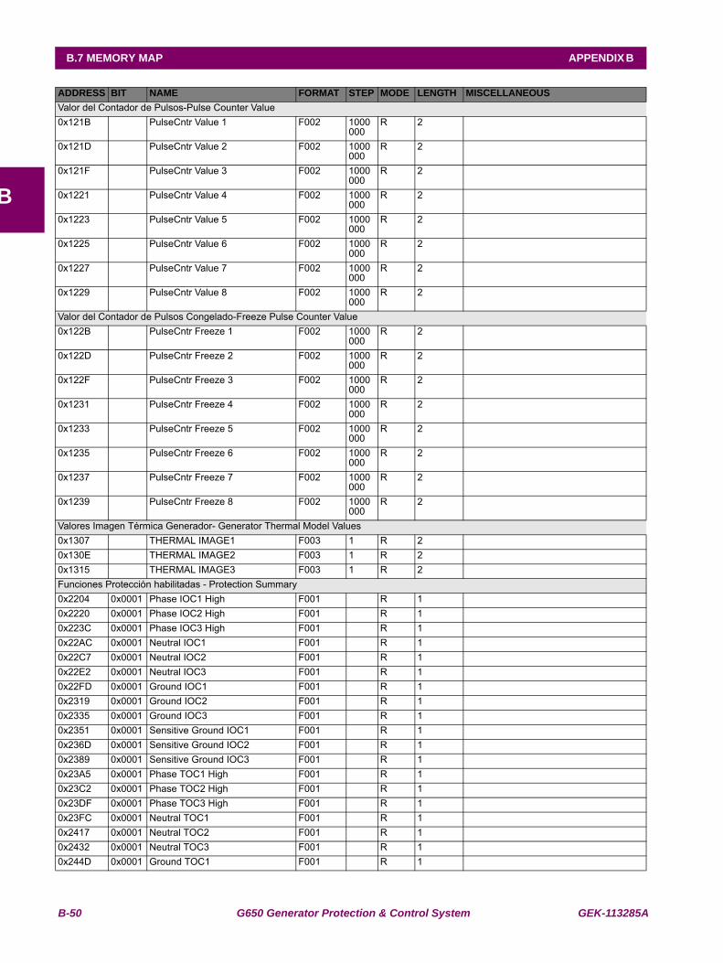
B-50 G650 Generator Protection & Control System GEK-113285A
B.7 MEMORY MAP APPENDIX B
B
Valor del Contador de Pulsos-Pulse Counter Value0x121B PulseCntr Value 1 F002 1000
000R 2
0x121D PulseCntr Value 2 F002 1000000
R 2
0x121F PulseCntr Value 3 F002 1000000
R 2
0x1221 PulseCntr Value 4 F002 1000000
R 2
0x1223 PulseCntr Value 5 F002 1000000
R 2
0x1225 PulseCntr Value 6 F002 1000000
R 2
0x1227 PulseCntr Value 7 F002 1000000
R 2
0x1229 PulseCntr Value 8 F002 1000000
R 2
Valor del Contador de Pulsos Congelado-Freeze Pulse Counter Value0x122B PulseCntr Freeze 1 F002 1000
000R 2
0x122D PulseCntr Freeze 2 F002 1000000
R 2
0x122F PulseCntr Freeze 3 F002 1000000
R 2
0x1231 PulseCntr Freeze 4 F002 1000000
R 2
0x1233 PulseCntr Freeze 5 F002 1000000
R 2
0x1235 PulseCntr Freeze 6 F002 1000000
R 2
0x1237 PulseCntr Freeze 7 F002 1000000
R 2
0x1239 PulseCntr Freeze 8 F002 1000000
R 2
Valores Imagen Térmica Generador- Generator Thermal Model Values0x1307 THERMAL IMAGE1 F003 1 R 20x130E THERMAL IMAGE2 F003 1 R 20x1315 THERMAL IMAGE3 F003 1 R 2Funciones Protección habilitadas - Protection Summary0x2204 0x0001 Phase IOC1 High F001 R 10x2220 0x0001 Phase IOC2 High F001 R 10x223C 0x0001 Phase IOC3 High F001 R 10x22AC 0x0001 Neutral IOC1 F001 R 10x22C7 0x0001 Neutral IOC2 F001 R 10x22E2 0x0001 Neutral IOC3 F001 R 10x22FD 0x0001 Ground IOC1 F001 R 10x2319 0x0001 Ground IOC2 F001 R 10x2335 0x0001 Ground IOC3 F001 R 10x2351 0x0001 Sensitive Ground IOC1 F001 R 10x236D 0x0001 Sensitive Ground IOC2 F001 R 10x2389 0x0001 Sensitive Ground IOC3 F001 R 10x23A5 0x0001 Phase TOC1 High F001 R 10x23C2 0x0001 Phase TOC2 High F001 R 10x23DF 0x0001 Phase TOC3 High F001 R 10x23FC 0x0001 Neutral TOC1 F001 R 10x2417 0x0001 Neutral TOC2 F001 R 10x2432 0x0001 Neutral TOC3 F001 R 10x244D 0x0001 Ground TOC1 F001 R 1
ADDRESS BIT NAME FORMAT STEP MODE LENGTH MISCELLANEOUS
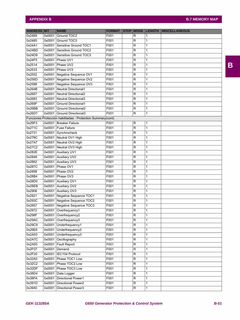
GEK-113285A G650 Generator Protection & Control System B-51
APPENDIX B B.7 MEMORY MAP
B
0x2469 0x0001 Ground TOC2 F001 R 10x2485 0x0001 Ground TOC3 F001 R 10x24A1 0x0001 Sensitive Ground TOC1 F001 R 10x24BD 0x0001 Sensitive Ground TOC2 F001 R 10x24D9 0x0001 Sensitive Ground TOC3 F001 R 10x24F5 0x0001 Phase UV1 F001 R 10x2514 0x0001 Phase UV2 F001 R 10x2533 0x0001 Phase UV3 F001 R 10x2552 0x0001 Negative Sequence OV1 F001 R 10x256D 0x0001 Negative Sequence OV2 F001 R 10x2588 0x0001 Negative Sequence OV3 F001 R 10x264B 0x0001 Neutral Directional1 F001 R 10x2667 0x0001 Neutral Directional2 F001 R 10x2683 0x0001 Neutral Directional3 F001 R 10x269F 0x0001 Ground Directional1 F001 R 10x26BB 0x0001 Ground Directional2 F001 R 10x26D7 0x0001 Ground Directional3 F001 R 1Funciones Protección habilitadas - Protection Summary(cont)0x26F3 0x0001 Breaker Failure F001 R 10x271C 0x0001 Fuse Failure F001 R 10x2731 0x0001 Synchrocheck F001 R 10x278C 0x0001 Neutral OV1 High F001 R 10x27A7 0x0001 Neutral OV2 High F001 R 10x27C2 0x0001 Neutral OV3 High F001 R 10x282E 0x0001 Auxiliary UV1 F001 R 10x2848 0x0001 Auxiliary UV2 F001 R 10x2862 0x0001 Auxiliary UV3 F001 R 10x287C 0x0001 Phase OV1 F001 R 10x2898 0x0001 Phase OV2 F001 R 10x28B4 0x0001 Phase OV3 F001 R 10x28D0 0x0001 Auxiliary OV1 F001 R 10x28EB 0x0001 Auxiliary OV2 F001 R 10x2906 0x0001 Auxiliary OV3 F001 R 10x2921 0x0001 Negative Sequence TOC1 F001 R 10x293C 0x0001 Negative Sequence TOC2 F001 R 10x2957 0x0001 Negative Sequence TOC3 F001 R 10x2972 0x0001 Overfrequency1 F001 R 10x298F 0x0001 Overfrequency2 F001 R 10x29AC 0x0001 Overfrequency3 F001 R 10x29C9 0x0001 Underfrequency1 F001 R 10x29E6 0x0001 Underfrequency2 F001 R 10x2A03 0x0001 Underfrequency3 F001 R 10x2A7C 0x0001 Oscillography F001 R 10x2A93 0x0001 Fault Report F001 R 10x2F07 0x0001 Demand F001 R 10x2F20 0x0001 IEC104 Protocol F001 R 10x32A5 0x0001 Phase TOC1 Low F001 R 10x32C2 0x0001 Phase TOC2 Low F001 R 10x32DF 0x0001 Phase TOC3 Low F001 R 10x38D4 0x0001 Data Logger F001 R 10x38FA 0x0001 Directional Power1 F001 R 10x391D 0x0001 Directional Power2 F001 R 10x3940 0x0001 Directional Power3 F001 R 1
ADDRESS BIT NAME FORMAT STEP MODE LENGTH MISCELLANEOUS
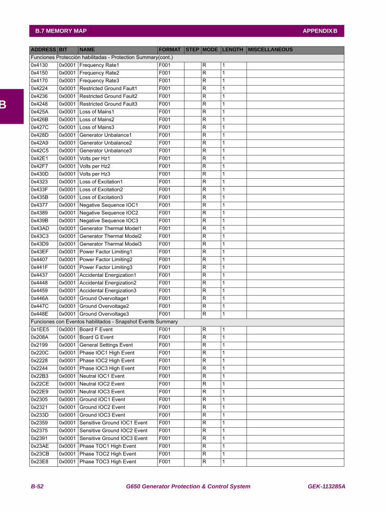
B-52 G650 Generator Protection & Control System GEK-113285A
B.7 MEMORY MAP APPENDIX B
B
Funciones Protección habilitadas - Protection Summary(cont.)0x4130 0x0001 Frequency Rate1 F001 R 10x4150 0x0001 Frequency Rate2 F001 R 10x4170 0x0001 Frequency Rate3 F001 R 10x4224 0x0001 Restricted Ground Fault1 F001 R 10x4236 0x0001 Restricted Ground Fault2 F001 R 10x4248 0x0001 Restricted Ground Fault3 F001 R 10x425A 0x0001 Loss of Mains1 F001 R 10x426B 0x0001 Loss of Mains2 F001 R 10x427C 0x0001 Loss of Mains3 F001 R 10x428D 0x0001 Generator Unbalance1 F001 R 10x42A9 0x0001 Generator Unbalance2 F001 R 10x42C5 0x0001 Generator Unbalance3 F001 R 10x42E1 0x0001 Volts per Hz1 F001 R 10x42F7 0x0001 Volts per Hz2 F001 R 10x430D 0x0001 Volts per Hz3 F001 R 10x4323 0x0001 Loss of Excitation1 F001 R 10x433F 0x0001 Loss of Excitation2 F001 R 10x435B 0x0001 Loss of Excitation3 F001 R 10x4377 0x0001 Negative Sequence IOC1 F001 R 10x4389 0x0001 Negative Sequence IOC2 F001 R 10x439B 0x0001 Negative Sequence IOC3 F001 R 10x43AD 0x0001 Generator Thermal Model1 F001 R 10x43C3 0x0001 Generator Thermal Model2 F001 R 10x43D9 0x0001 Generator Thermal Model3 F001 R 10x43EF 0x0001 Power Factor Limiting1 F001 R 10x4407 0x0001 Power Factor Limiting2 F001 R 10x441F 0x0001 Power Factor Limiting3 F001 R 10x4437 0x0001 Accidental Energization1 F001 R 10x4448 0x0001 Accidental Energization2 F001 R 10x4459 0x0001 Accidental Energization3 F001 R 10x446A 0x0001 Ground Overvoltage1 F001 R 10x447C 0x0001 Ground Overvoltage2 F001 R 10x448E 0x0001 Ground Overvoltage3 F001 R 1Funciones con Eventos habilitados - Snapshot Events Summary0x1EE5 0x0001 Board F Event F001 R 10x208A 0x0001 Board G Event F001 R 10x2199 0x0001 General Settings Event F001 R 10x220C 0x0001 Phase IOC1 High Event F001 R 10x2228 0x0001 Phase IOC2 High Event F001 R 10x2244 0x0001 Phase IOC3 High Event F001 R 10x22B3 0x0001 Neutral IOC1 Event F001 R 10x22CE 0x0001 Neutral IOC2 Event F001 R 10x22E9 0x0001 Neutral IOC3 Event F001 R 10x2305 0x0001 Ground IOC1 Event F001 R 10x2321 0x0001 Ground IOC2 Event F001 R 10x233D 0x0001 Ground IOC3 Event F001 R 10x2359 0x0001 Sensitive Ground IOC1 Event F001 R 10x2375 0x0001 Sensitive Ground IOC2 Event F001 R 10x2391 0x0001 Sensitive Ground IOC3 Event F001 R 10x23AE 0x0001 Phase TOC1 High Event F001 R 10x23CB 0x0001 Phase TOC2 High Event F001 R 10x23E8 0x0001 Phase TOC3 High Event F001 R 1
ADDRESS BIT NAME FORMAT STEP MODE LENGTH MISCELLANEOUS
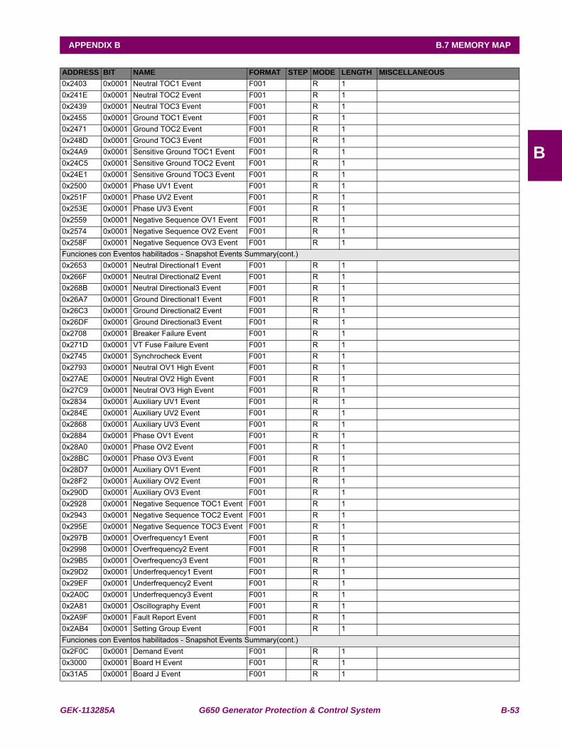
GEK-113285A G650 Generator Protection & Control System B-53
APPENDIX B B.7 MEMORY MAP
B
0x2403 0x0001 Neutral TOC1 Event F001 R 10x241E 0x0001 Neutral TOC2 Event F001 R 10x2439 0x0001 Neutral TOC3 Event F001 R 10x2455 0x0001 Ground TOC1 Event F001 R 10x2471 0x0001 Ground TOC2 Event F001 R 10x248D 0x0001 Ground TOC3 Event F001 R 10x24A9 0x0001 Sensitive Ground TOC1 Event F001 R 10x24C5 0x0001 Sensitive Ground TOC2 Event F001 R 10x24E1 0x0001 Sensitive Ground TOC3 Event F001 R 10x2500 0x0001 Phase UV1 Event F001 R 10x251F 0x0001 Phase UV2 Event F001 R 10x253E 0x0001 Phase UV3 Event F001 R 10x2559 0x0001 Negative Sequence OV1 Event F001 R 10x2574 0x0001 Negative Sequence OV2 Event F001 R 10x258F 0x0001 Negative Sequence OV3 Event F001 R 1Funciones con Eventos habilitados - Snapshot Events Summary(cont.)0x2653 0x0001 Neutral Directional1 Event F001 R 10x266F 0x0001 Neutral Directional2 Event F001 R 10x268B 0x0001 Neutral Directional3 Event F001 R 10x26A7 0x0001 Ground Directional1 Event F001 R 10x26C3 0x0001 Ground Directional2 Event F001 R 10x26DF 0x0001 Ground Directional3 Event F001 R 10x2708 0x0001 Breaker Failure Event F001 R 10x271D 0x0001 VT Fuse Failure Event F001 R 10x2745 0x0001 Synchrocheck Event F001 R 10x2793 0x0001 Neutral OV1 High Event F001 R 10x27AE 0x0001 Neutral OV2 High Event F001 R 10x27C9 0x0001 Neutral OV3 High Event F001 R 10x2834 0x0001 Auxiliary UV1 Event F001 R 10x284E 0x0001 Auxiliary UV2 Event F001 R 10x2868 0x0001 Auxiliary UV3 Event F001 R 10x2884 0x0001 Phase OV1 Event F001 R 10x28A0 0x0001 Phase OV2 Event F001 R 10x28BC 0x0001 Phase OV3 Event F001 R 10x28D7 0x0001 Auxiliary OV1 Event F001 R 10x28F2 0x0001 Auxiliary OV2 Event F001 R 10x290D 0x0001 Auxiliary OV3 Event F001 R 10x2928 0x0001 Negative Sequence TOC1 Event F001 R 10x2943 0x0001 Negative Sequence TOC2 Event F001 R 10x295E 0x0001 Negative Sequence TOC3 Event F001 R 10x297B 0x0001 Overfrequency1 Event F001 R 10x2998 0x0001 Overfrequency2 Event F001 R 10x29B5 0x0001 Overfrequency3 Event F001 R 10x29D2 0x0001 Underfrequency1 Event F001 R 10x29EF 0x0001 Underfrequency2 Event F001 R 10x2A0C 0x0001 Underfrequency3 Event F001 R 10x2A81 0x0001 Oscillography Event F001 R 10x2A9F 0x0001 Fault Report Event F001 R 10x2AB4 0x0001 Setting Group Event F001 R 1Funciones con Eventos habilitados - Snapshot Events Summary(cont.)0x2F0C 0x0001 Demand Event F001 R 10x3000 0x0001 Board H Event F001 R 10x31A5 0x0001 Board J Event F001 R 1
ADDRESS BIT NAME FORMAT STEP MODE LENGTH MISCELLANEOUS
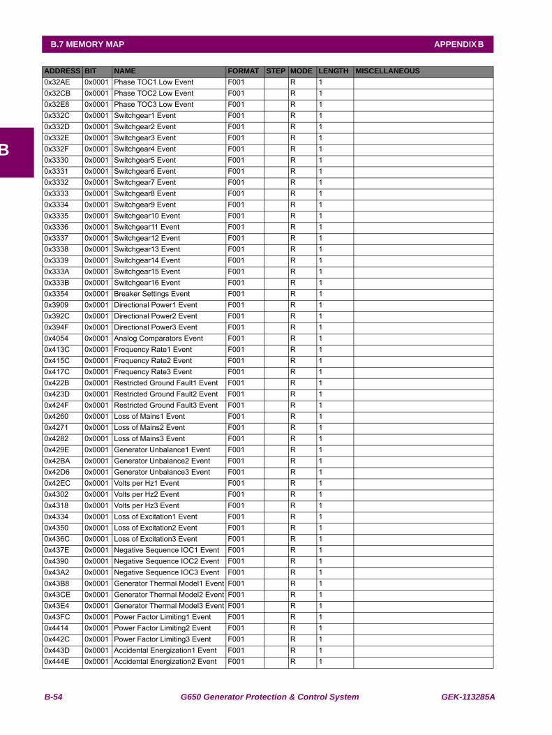
B-54 G650 Generator Protection & Control System GEK-113285A
B.7 MEMORY MAP APPENDIX B
B
0x32AE 0x0001 Phase TOC1 Low Event F001 R 10x32CB 0x0001 Phase TOC2 Low Event F001 R 10x32E8 0x0001 Phase TOC3 Low Event F001 R 10x332C 0x0001 Switchgear1 Event F001 R 10x332D 0x0001 Switchgear2 Event F001 R 10x332E 0x0001 Switchgear3 Event F001 R 10x332F 0x0001 Switchgear4 Event F001 R 10x3330 0x0001 Switchgear5 Event F001 R 10x3331 0x0001 Switchgear6 Event F001 R 10x3332 0x0001 Switchgear7 Event F001 R 10x3333 0x0001 Switchgear8 Event F001 R 10x3334 0x0001 Switchgear9 Event F001 R 10x3335 0x0001 Switchgear10 Event F001 R 10x3336 0x0001 Switchgear11 Event F001 R 10x3337 0x0001 Switchgear12 Event F001 R 10x3338 0x0001 Switchgear13 Event F001 R 10x3339 0x0001 Switchgear14 Event F001 R 10x333A 0x0001 Switchgear15 Event F001 R 10x333B 0x0001 Switchgear16 Event F001 R 10x3354 0x0001 Breaker Settings Event F001 R 10x3909 0x0001 Directional Power1 Event F001 R 10x392C 0x0001 Directional Power2 Event F001 R 10x394F 0x0001 Directional Power3 Event F001 R 10x4054 0x0001 Analog Comparators Event F001 R 10x413C 0x0001 Frequency Rate1 Event F001 R 10x415C 0x0001 Frequency Rate2 Event F001 R 10x417C 0x0001 Frequency Rate3 Event F001 R 10x422B 0x0001 Restricted Ground Fault1 Event F001 R 10x423D 0x0001 Restricted Ground Fault2 Event F001 R 10x424F 0x0001 Restricted Ground Fault3 Event F001 R 10x4260 0x0001 Loss of Mains1 Event F001 R 10x4271 0x0001 Loss of Mains2 Event F001 R 10x4282 0x0001 Loss of Mains3 Event F001 R 10x429E 0x0001 Generator Unbalance1 Event F001 R 10x42BA 0x0001 Generator Unbalance2 Event F001 R 10x42D6 0x0001 Generator Unbalance3 Event F001 R 10x42EC 0x0001 Volts per Hz1 Event F001 R 10x4302 0x0001 Volts per Hz2 Event F001 R 10x4318 0x0001 Volts per Hz3 Event F001 R 10x4334 0x0001 Loss of Excitation1 Event F001 R 10x4350 0x0001 Loss of Excitation2 Event F001 R 10x436C 0x0001 Loss of Excitation3 Event F001 R 10x437E 0x0001 Negative Sequence IOC1 Event F001 R 10x4390 0x0001 Negative Sequence IOC2 Event F001 R 10x43A2 0x0001 Negative Sequence IOC3 Event F001 R 10x43B8 0x0001 Generator Thermal Model1 Event F001 R 10x43CE 0x0001 Generator Thermal Model2 Event F001 R 10x43E4 0x0001 Generator Thermal Model3 Event F001 R 10x43FC 0x0001 Power Factor Limiting1 Event F001 R 10x4414 0x0001 Power Factor Limiting2 Event F001 R 10x442C 0x0001 Power Factor Limiting3 Event F001 R 10x443D 0x0001 Accidental Energization1 Event F001 R 10x444E 0x0001 Accidental Energization2 Event F001 R 1
ADDRESS BIT NAME FORMAT STEP MODE LENGTH MISCELLANEOUS
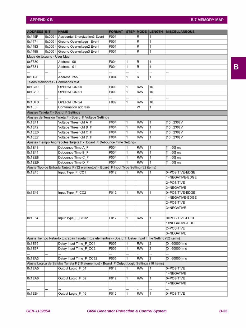
GEK-113285A G650 Generator Protection & Control System B-55
APPENDIX B B.7 MEMORY MAP
B
0x445F 0x0001 Accidental Energization3 Event F001 R 10x4471 0x0001 Ground Overvoltage1 Event F001 R 10x4483 0x0001 Ground Overvoltage2 Event F001 R 10x4495 0x0001 Ground Overvoltage3 Event F001 R 1Mapa de Usuario - User Map0xF330 Address 00 F004 1 R 1 0xF331 Address 01 F004 1 R 1 ... ... ... ... ... ... ... ...0xF42F Address 255 F004 1 R 1 Textos Maniobras - Commands text0x1C00 OPERATION 00 F009 1 R/W 16 0x1C10 OPERATION 01 F009 1 R/W 16 ... ... ... ... ... ... ... ...0x1DF0 OPERATION 24 F009 1 R/W 16 0x1E3F Confirmation address W 1 Ajustes Tarjeta F - Board F SettingsAjustes de Tensión Tarjeta F - Board F Voltage Settings0x1E41 Voltage Threshold A_F F004 1 R/W 1 [10 , 230] V0x1E42 Voltage Threshold B_F F004 1 R/W 1 [10 , 230] V0x1EE6 Voltage Threshold C_F F004 1 R/W 1 [10 , 230] V0x1EE7 Voltage Threshold D_F F004 1 R/W 1 [10 , 230] VAjustes Tiempo Antirrebotes Tarjeta F - Board F Debounce Time Settings0x1E43 Debounce Time A_F F004 1 R/W 1 [1 , 50] ms0x1E44 Debounce Time B_F F004 1 R/W 1 [1 , 50] ms0x1EE8 Debounce Time C_F F004 1 R/W 1 [1 , 50] ms0x1EE9 Debounce Time D_F F004 1 R/W 1 [1 , 50] msAjuste Tipo de Entrada Tarjeta F (32 elementos) - Board F Input Type Setting (32 items)0x1E45 Input Type_F_CC1 F012 1 R/W 1 0=POSITIVE-EDGE 1=NEGATIVE-EDGE 2=POSITIVE 3=NEGATIVE0x1E46 Input Type_F_CC2 F012 1 R/W 1 0=POSITIVE-EDGE 1=NEGATIVE-EDGE 2=POSITIVE 3=NEGATIVE... ... ... ... ... ... ... ...0x1E64 Input Type_F_CC32 F012 1 R/W 1 0=POSITIVE-EDGE 1=NEGATIVE-EDGE 2=POSITIVE 3=NEGATIVEAjuste Tiempo Retardo Entradas Tarjeta F (32 elementos) - Board F Delay Input Time Setting (32 items)0x1E65 Delay Input Time_F_CC1 F005 1 R/W 2 [0 , 60000] ms0x1E67 Delay Input Time_F_CC2 F005 1 R/W 2 [0 , 60000] ms... ... ... ... ... ... ... ...0x1EA3 Delay Input Time_F_CC32 F005 1 R/W 2 [0 , 60000] msAjuste Lógica de Salidas Tarjeta F (16 elementos) - Board F Output Logic Settings (16 items)0x1EA5 Output Logic_F_01 F012 1 R/W 1 0=POSITIVE 1=NEGATIVE0x1EA6 Output Logic_F_02 F012 1 R/W 1 0=POSITIVE 1=NEGATIVE... ... ... ... ... ... ... ...0x1EB4 Output Logic_F_16 F012 1 R/W 1 0=POSITIVE
ADDRESS BIT NAME FORMAT STEP MODE LENGTH MISCELLANEOUS
B-56 G650 Generator Protection & Control System GEK-113285A
B.7 MEMORY MAP APPENDIX B
B
1=NEGATIVEADDRESS BIT NAME FORMAT STEP MODE LENGTH MISCELLANEOUS
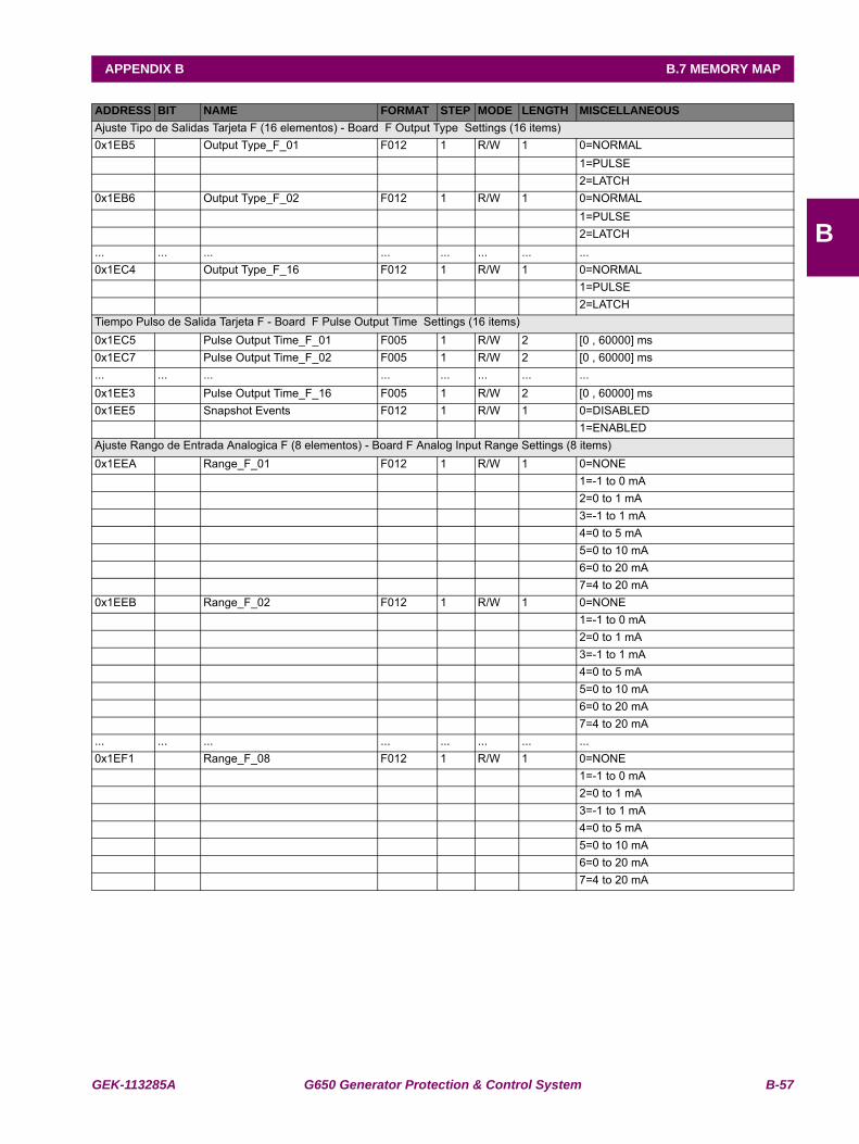
GEK-113285A G650 Generator Protection & Control System B-57
APPENDIX B B.7 MEMORY MAP
B
Ajuste Tipo de Salidas Tarjeta F (16 elementos) - Board F Output Type Settings (16 items)0x1EB5 Output Type_F_01 F012 1 R/W 1 0=NORMAL 1=PULSE 2=LATCH0x1EB6 Output Type_F_02 F012 1 R/W 1 0=NORMAL 1=PULSE 2=LATCH... ... ... ... ... ... ... ...0x1EC4 Output Type_F_16 F012 1 R/W 1 0=NORMAL 1=PULSE 2=LATCHTiempo Pulso de Salida Tarjeta F - Board F Pulse Output Time Settings (16 items)0x1EC5 Pulse Output Time_F_01 F005 1 R/W 2 [0 , 60000] ms0x1EC7 Pulse Output Time_F_02 F005 1 R/W 2 [0 , 60000] ms... ... ... ... ... ... ... ...0x1EE3 Pulse Output Time_F_16 F005 1 R/W 2 [0 , 60000] ms0x1EE5 Snapshot Events F012 1 R/W 1 0=DISABLED 1=ENABLEDAjuste Rango de Entrada Analogica F (8 elementos) - Board F Analog Input Range Settings (8 items)0x1EEA Range_F_01 F012 1 R/W 1 0=NONE
1=-1 to 0 mA2=0 to 1 mA3=-1 to 1 mA4=0 to 5 mA5=0 to 10 mA6=0 to 20 mA7=4 to 20 mA
0x1EEB Range_F_02 F012 1 R/W 1 0=NONE1=-1 to 0 mA2=0 to 1 mA3=-1 to 1 mA4=0 to 5 mA5=0 to 10 mA6=0 to 20 mA7=4 to 20 mA
... ... ... ... ... ... ... ...0x1EF1 Range_F_08 F012 1 R/W 1 0=NONE
1=-1 to 0 mA2=0 to 1 mA3=-1 to 1 mA4=0 to 5 mA5=0 to 10 mA6=0 to 20 mA7=4 to 20 mA
ADDRESS BIT NAME FORMAT STEP MODE LENGTH MISCELLANEOUS
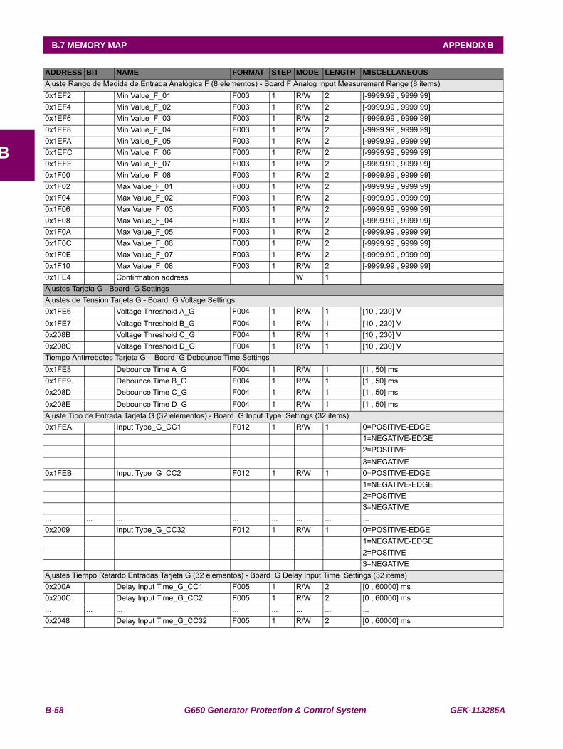
B-58 G650 Generator Protection & Control System GEK-113285A
B.7 MEMORY MAP APPENDIX B
B
Ajuste Rango de Medida de Entrada Analógica F (8 elementos) - Board F Analog Input Measurement Range (8 items)0x1EF2 Min Value_F_01 F003 1 R/W 2 [-9999.99 , 9999.99] 0x1EF4 Min Value_F_02 F003 1 R/W 2 [-9999.99 , 9999.99] 0x1EF6 Min Value_F_03 F003 1 R/W 2 [-9999.99 , 9999.99] 0x1EF8 Min Value_F_04 F003 1 R/W 2 [-9999.99 , 9999.99] 0x1EFA Min Value_F_05 F003 1 R/W 2 [-9999.99 , 9999.99] 0x1EFC Min Value_F_06 F003 1 R/W 2 [-9999.99 , 9999.99] 0x1EFE Min Value_F_07 F003 1 R/W 2 [-9999.99 , 9999.99] 0x1F00 Min Value_F_08 F003 1 R/W 2 [-9999.99 , 9999.99] 0x1F02 Max Value_F_01 F003 1 R/W 2 [-9999.99 , 9999.99] 0x1F04 Max Value_F_02 F003 1 R/W 2 [-9999.99 , 9999.99] 0x1F06 Max Value_F_03 F003 1 R/W 2 [-9999.99 , 9999.99] 0x1F08 Max Value_F_04 F003 1 R/W 2 [-9999.99 , 9999.99] 0x1F0A Max Value_F_05 F003 1 R/W 2 [-9999.99 , 9999.99] 0x1F0C Max Value_F_06 F003 1 R/W 2 [-9999.99 , 9999.99] 0x1F0E Max Value_F_07 F003 1 R/W 2 [-9999.99 , 9999.99] 0x1F10 Max Value_F_08 F003 1 R/W 2 [-9999.99 , 9999.99] 0x1FE4 Confirmation address W 1 Ajustes Tarjeta G - Board G SettingsAjustes de Tensión Tarjeta G - Board G Voltage Settings0x1FE6 Voltage Threshold A_G F004 1 R/W 1 [10 , 230] V0x1FE7 Voltage Threshold B_G F004 1 R/W 1 [10 , 230] V0x208B Voltage Threshold C_G F004 1 R/W 1 [10 , 230] V0x208C Voltage Threshold D_G F004 1 R/W 1 [10 , 230] VTiempo Antirrebotes Tarjeta G - Board G Debounce Time Settings 0x1FE8 Debounce Time A_G F004 1 R/W 1 [1 , 50] ms0x1FE9 Debounce Time B_G F004 1 R/W 1 [1 , 50] ms0x208D Debounce Time C_G F004 1 R/W 1 [1 , 50] ms0x208E Debounce Time D_G F004 1 R/W 1 [1 , 50] msAjuste Tipo de Entrada Tarjeta G (32 elementos) - Board G Input Type Settings (32 items)0x1FEA Input Type_G_CC1 F012 1 R/W 1 0=POSITIVE-EDGE 1=NEGATIVE-EDGE 2=POSITIVE 3=NEGATIVE0x1FEB Input Type_G_CC2 F012 1 R/W 1 0=POSITIVE-EDGE 1=NEGATIVE-EDGE 2=POSITIVE 3=NEGATIVE... ... ... ... ... ... ... ...0x2009 Input Type_G_CC32 F012 1 R/W 1 0=POSITIVE-EDGE 1=NEGATIVE-EDGE 2=POSITIVE 3=NEGATIVEAjustes Tiempo Retardo Entradas Tarjeta G (32 elementos) - Board G Delay Input Time Settings (32 items)0x200A Delay Input Time_G_CC1 F005 1 R/W 2 [0 , 60000] ms0x200C Delay Input Time_G_CC2 F005 1 R/W 2 [0 , 60000] ms... ... ... ... ... ... ... ...0x2048 Delay Input Time_G_CC32 F005 1 R/W 2 [0 , 60000] ms
ADDRESS BIT NAME FORMAT STEP MODE LENGTH MISCELLANEOUS
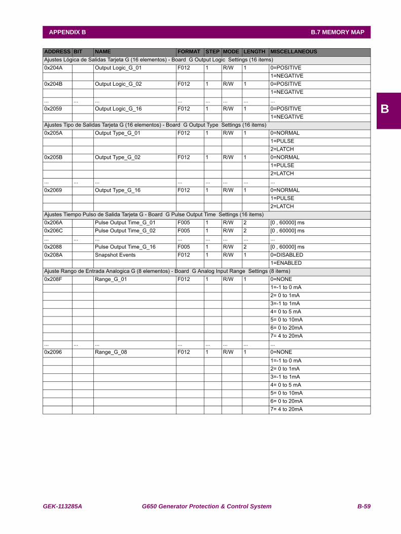
GEK-113285A G650 Generator Protection & Control System B-59
APPENDIX B B.7 MEMORY MAP
B
Ajustes Lógica de Salidas Tarjeta G (16 elementos) - Board G Output Logic Settings (16 items)0x204A Output Logic_G_01 F012 1 R/W 1 0=POSITIVE 1=NEGATIVE0x204B Output Logic_G_02 F012 1 R/W 1 0=POSITIVE 1=NEGATIVE... ... ... ... ... ... ... ...0x2059 Output Logic_G_16 F012 1 R/W 1 0=POSITIVE 1=NEGATIVEAjustes Tipo de Salidas Tarjeta G (16 elementos) - Board G Output Type Settings (16 items)0x205A Output Type_G_01 F012 1 R/W 1 0=NORMAL 1=PULSE 2=LATCH0x205B Output Type_G_02 F012 1 R/W 1 0=NORMAL 1=PULSE 2=LATCH... ... ... ... ... ... ... ...0x2069 Output Type_G_16 F012 1 R/W 1 0=NORMAL 1=PULSE 2=LATCHAjustes Tiempo Pulso de Salida Tarjeta G - Board G Pulse Output Time Settings (16 items)0x206A Pulse Output Time_G_01 F005 1 R/W 2 [0 , 60000] ms0x206C Pulse Output Time_G_02 F005 1 R/W 2 [0 , 60000] ms... ... ... ... ... ... ... ...0x2088 Pulse Output Time_G_16 F005 1 R/W 2 [0 , 60000] ms0x208A Snapshot Events F012 1 R/W 1 0=DISABLED 1=ENABLEDAjuste Rango de Entrada Analogica G (8 elementos) - Board G Analog Input Range Settings (8 items)0x208F Range_G_01 F012 1 R/W 1 0=NONE 1=-1 to 0 mA 2= 0 to 1mA 3=-1 to 1mA 4= 0 to 5 mA 5= 0 to 10mA 6= 0 to 20mA 7= 4 to 20mA... ... ... ... ... ... ... ...0x2096 Range_G_08 F012 1 R/W 1 0=NONE 1=-1 to 0 mA 2= 0 to 1mA 3=-1 to 1mA 4= 0 to 5 mA 5= 0 to 10mA 6= 0 to 20mA 7= 4 to 20mA
ADDRESS BIT NAME FORMAT STEP MODE LENGTH MISCELLANEOUS
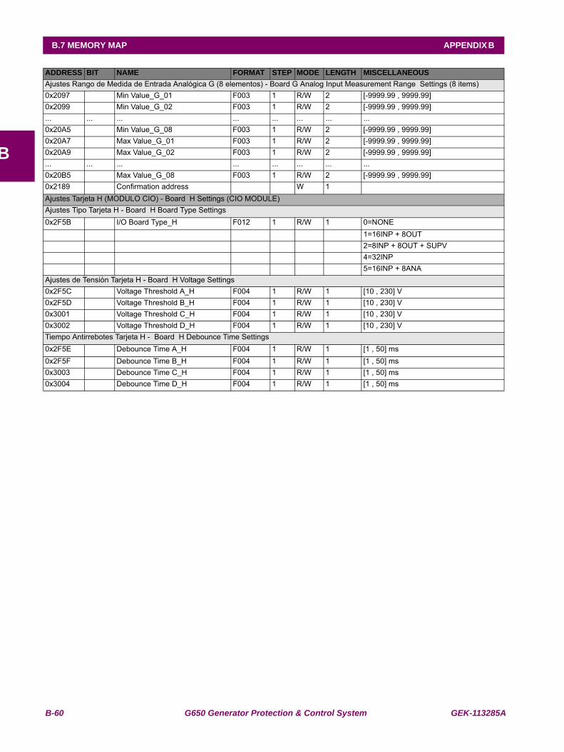
B-60 G650 Generator Protection & Control System GEK-113285A
B.7 MEMORY MAP APPENDIX B
B
Ajustes Rango de Medida de Entrada Analógica G (8 elementos) - Board G Analog Input Measurement Range Settings (8 items)0x2097 Min Value_G_01 F003 1 R/W 2 [-9999.99 , 9999.99] 0x2099 Min Value_G_02 F003 1 R/W 2 [-9999.99 , 9999.99] ... ... ... ... ... ... ... ...0x20A5 Min Value_G_08 F003 1 R/W 2 [-9999.99 , 9999.99] 0x20A7 Max Value_G_01 F003 1 R/W 2 [-9999.99 , 9999.99] 0x20A9 Max Value_G_02 F003 1 R/W 2 [-9999.99 , 9999.99] ... ... ... ... ... ... ... ...0x20B5 Max Value_G_08 F003 1 R/W 2 [-9999.99 , 9999.99] 0x2189 Confirmation address W 1 Ajustes Tarjeta H (MODULO CIO) - Board H Settings (CIO MODULE)Ajustes Tipo Tarjeta H - Board H Board Type Settings0x2F5B I/O Board Type_H F012 1 R/W 1 0=NONE 1=16INP + 8OUT 2=8INP + 8OUT + SUPV 4=32INP 5=16INP + 8ANAAjustes de Tensión Tarjeta H - Board H Voltage Settings0x2F5C Voltage Threshold A_H F004 1 R/W 1 [10 , 230] V0x2F5D Voltage Threshold B_H F004 1 R/W 1 [10 , 230] V0x3001 Voltage Threshold C_H F004 1 R/W 1 [10 , 230] V0x3002 Voltage Threshold D_H F004 1 R/W 1 [10 , 230] VTiempo Antirrebotes Tarjeta H - Board H Debounce Time Settings0x2F5E Debounce Time A_H F004 1 R/W 1 [1 , 50] ms0x2F5F Debounce Time B_H F004 1 R/W 1 [1 , 50] ms0x3003 Debounce Time C_H F004 1 R/W 1 [1 , 50] ms0x3004 Debounce Time D_H F004 1 R/W 1 [1 , 50] ms
ADDRESS BIT NAME FORMAT STEP MODE LENGTH MISCELLANEOUS

GEK-113285A G650 Generator Protection & Control System B-61
APPENDIX B B.7 MEMORY MAP
B
Ajuste Tipo de Entrada Tarjeta H (32 elementos) - Board H Input Type Settings (32 items)0x2F60 Input Type_H_CC1 F012 1 R/W 1 0=POSITIVE-EDGE 1=NEGATIVE-EDGE 2=POSITIVE 3=NEGATIVE0x2F61 Input Type_H_CC2 F012 1 R/W 1 0=POSITIVE-EDGE 1=NEGATIVE-EDGE 2=POSITIVE 3=NEGATIVE... ... ... ... ... ... ... ...0x2F7F Input Type_H_CC32 F012 1 R/W 1 0=POSITIVE-EDGE 1=NEGATIVE-EDGE 2=POSITIVE 3=NEGATIVEAjuste Tiempo Retardo Entradas Tarjeta H (32 elementos) - Board H Delay Input Time Settings (32 items)0x2F80 Delay Input Time_H_CC1 F005 1 R/W 2 [0 , 60000] ms0x2F82 Delay Input Time_H_CC2 F005 1 R/W 2 [0 , 60000] ms... ... ... ... ... ... ... ...0x2FBE Delay Input Time_H_CC32 F005 1 R/W 2 [0 , 60000] msAjuste Lógica de Salidas Tarjeta H (16 elementos) - Board H Output Logic Settings (16 items)0x2FC0 Output Logic_H_01 F012 1 R/W 1 0=POSITIVE 1=NEGATIVE0x2FC1 Output Logic_H_02 F012 1 R/W 1 0=POSITIVE 1=NEGATIVE... ... ... ... ... ... ... ...0x2FCF Output Logic_H_16 F012 1 R/W 1 0=POSITIVE 1=NEGATIVEAjuste Tipo de Salidas Tarjeta H (16 elementos) - Board H Output Type Settings (16 items)0x2FD0 Output Type_H_01 F012 1 R/W 1 0=NORMAL 1=PULSE 2=LATCH0x2FD1 Output Type_H_02 F012 1 R/W 1 0=NORMAL 1=PULSE 2=LATCH... ... ... ... ... ... ... ...0x2FDF Output Type_H_16 F012 1 R/W 1 0=NORMAL 1=PULSE 2=LATCHAjuste Tiempo Pulso de Salida Tarjeta H - Board H Pulse Output Time Settings (16 items)0x2FE0 Pulse Output Time_H_01 F005 1 R/W 2 [0 , 60000] ms0x2FE2 Pulse Output Time_H_02 F005 1 R/W 2 [0 , 60000] ms... ... ... ... ... ... ... ...0x2FFE Pulse Output Time_H_16 F005 1 R/W 2 [0 , 60000] ms0x3000 Snapshot Events F012 1 R/W 1 0=DISABLED 1=ENABLED
ADDRESS BIT NAME FORMAT STEP MODE LENGTH MISCELLANEOUS
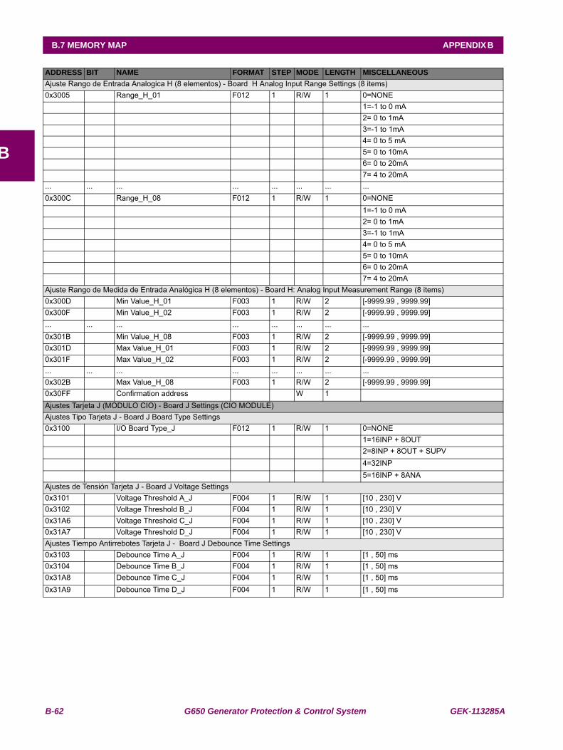
B-62 G650 Generator Protection & Control System GEK-113285A
B.7 MEMORY MAP APPENDIX B
B
Ajuste Rango de Entrada Analogica H (8 elementos) - Board H Analog Input Range Settings (8 items)0x3005 Range_H_01 F012 1 R/W 1 0=NONE 1=-1 to 0 mA 2= 0 to 1mA 3=-1 to 1mA 4= 0 to 5 mA 5= 0 to 10mA 6= 0 to 20mA 7= 4 to 20mA... ... ... ... ... ... ... ...0x300C Range_H_08 F012 1 R/W 1 0=NONE 1=-1 to 0 mA 2= 0 to 1mA 3=-1 to 1mA 4= 0 to 5 mA 5= 0 to 10mA 6= 0 to 20mA 7= 4 to 20mAAjuste Rango de Medida de Entrada Analógica H (8 elementos) - Board H: Analog Input Measurement Range (8 items)0x300D Min Value_H_01 F003 1 R/W 2 [-9999.99 , 9999.99] 0x300F Min Value_H_02 F003 1 R/W 2 [-9999.99 , 9999.99] ... ... ... ... ... ... ... ...0x301B Min Value_H_08 F003 1 R/W 2 [-9999.99 , 9999.99] 0x301D Max Value_H_01 F003 1 R/W 2 [-9999.99 , 9999.99] 0x301F Max Value_H_02 F003 1 R/W 2 [-9999.99 , 9999.99] ... ... ... ... ... ... ... ...0x302B Max Value_H_08 F003 1 R/W 2 [-9999.99 , 9999.99] 0x30FF Confirmation address W 1 Ajustes Tarjeta J (MODULO CIO) - Board J Settings (CIO MODULE)Ajustes Tipo Tarjeta J - Board J Board Type Settings0x3100 I/O Board Type_J F012 1 R/W 1 0=NONE 1=16INP + 8OUT 2=8INP + 8OUT + SUPV 4=32INP 5=16INP + 8ANAAjustes de Tensión Tarjeta J - Board J Voltage Settings0x3101 Voltage Threshold A_J F004 1 R/W 1 [10 , 230] V0x3102 Voltage Threshold B_J F004 1 R/W 1 [10 , 230] V0x31A6 Voltage Threshold C_J F004 1 R/W 1 [10 , 230] V0x31A7 Voltage Threshold D_J F004 1 R/W 1 [10 , 230] VAjustes Tiempo Antirrebotes Tarjeta J - Board J Debounce Time Settings0x3103 Debounce Time A_J F004 1 R/W 1 [1 , 50] ms0x3104 Debounce Time B_J F004 1 R/W 1 [1 , 50] ms0x31A8 Debounce Time C_J F004 1 R/W 1 [1 , 50] ms0x31A9 Debounce Time D_J F004 1 R/W 1 [1 , 50] ms
ADDRESS BIT NAME FORMAT STEP MODE LENGTH MISCELLANEOUS
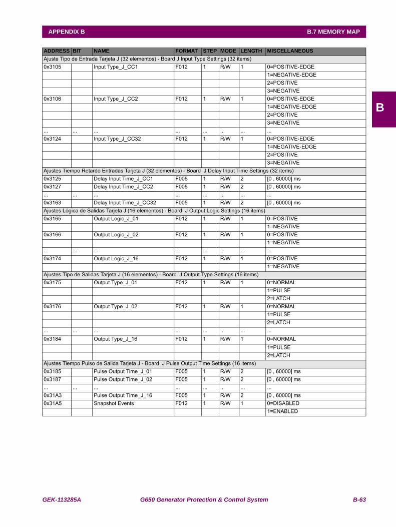
GEK-113285A G650 Generator Protection & Control System B-63
APPENDIX B B.7 MEMORY MAP
B
Ajuste Tipo de Entrada Tarjeta J (32 elementos) - Board J Input Type Settings (32 items)0x3105 Input Type_J_CC1 F012 1 R/W 1 0=POSITIVE-EDGE 1=NEGATIVE-EDGE 2=POSITIVE 3=NEGATIVE0x3106 Input Type_J_CC2 F012 1 R/W 1 0=POSITIVE-EDGE 1=NEGATIVE-EDGE 2=POSITIVE 3=NEGATIVE... ... ... ... ... ... ... ...0x3124 Input Type_J_CC32 F012 1 R/W 1 0=POSITIVE-EDGE 1=NEGATIVE-EDGE 2=POSITIVE 3=NEGATIVEAjustes Tiempo Retardo Entradas Tarjeta J (32 elementos) - Board J Delay Input Time Settings (32 items)0x3125 Delay Input Time_J_CC1 F005 1 R/W 2 [0 , 60000] ms0x3127 Delay Input Time_J_CC2 F005 1 R/W 2 [0 , 60000] ms... ... ... ... ... ... ... ...0x3163 Delay Input Time_J_CC32 F005 1 R/W 2 [0 , 60000] msAjustes Lógica de Salidas Tarjeta J (16 elementos) - Board J Output Logic Settings (16 items)0x3165 Output Logic_J_01 F012 1 R/W 1 0=POSITIVE 1=NEGATIVE0x3166 Output Logic_J_02 F012 1 R/W 1 0=POSITIVE 1=NEGATIVE... ... ... ... ... ... ... ...0x3174 Output Logic_J_16 F012 1 R/W 1 0=POSITIVE 1=NEGATIVEAjustes Tipo de Salidas Tarjeta J (16 elementos) - Board J Output Type Settings (16 items)0x3175 Output Type_J_01 F012 1 R/W 1 0=NORMAL 1=PULSE 2=LATCH0x3176 Output Type_J_02 F012 1 R/W 1 0=NORMAL 1=PULSE 2=LATCH... ... ... ... ... ... ... ...0x3184 Output Type_J_16 F012 1 R/W 1 0=NORMAL 1=PULSE 2=LATCHAjustes Tiempo Pulso de Salida Tarjeta J - Board J Pulse Output Time Settings (16 items)0x3185 Pulse Output Time_J_01 F005 1 R/W 2 [0 , 60000] ms0x3187 Pulse Output Time_J_02 F005 1 R/W 2 [0 , 60000] ms... ... ... ... ... ... ... ...0x31A3 Pulse Output Time_J_16 F005 1 R/W 2 [0 , 60000] ms0x31A5 Snapshot Events F012 1 R/W 1 0=DISABLED 1=ENABLED
ADDRESS BIT NAME FORMAT STEP MODE LENGTH MISCELLANEOUS
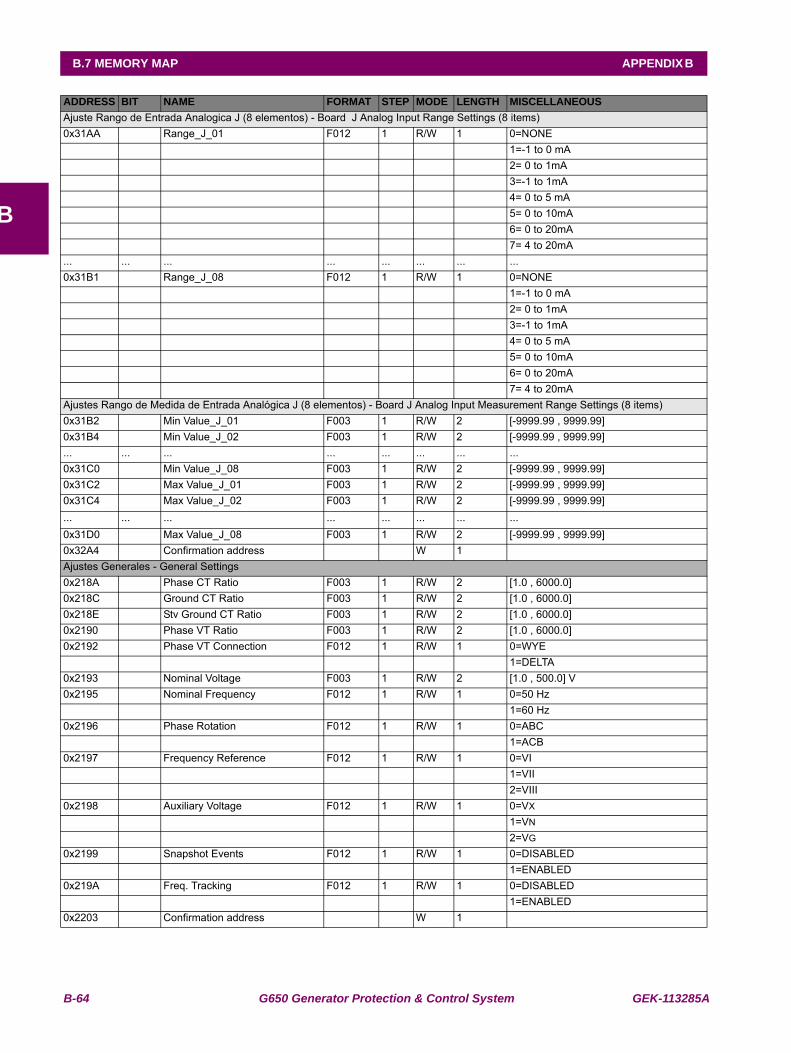
B-64 G650 Generator Protection & Control System GEK-113285A
B.7 MEMORY MAP APPENDIX B
B
Ajuste Rango de Entrada Analogica J (8 elementos) - Board J Analog Input Range Settings (8 items)0x31AA Range_J_01 F012 1 R/W 1 0=NONE 1=-1 to 0 mA 2= 0 to 1mA 3=-1 to 1mA 4= 0 to 5 mA 5= 0 to 10mA 6= 0 to 20mA 7= 4 to 20mA... ... ... ... ... ... ... ...0x31B1 Range_J_08 F012 1 R/W 1 0=NONE 1=-1 to 0 mA 2= 0 to 1mA 3=-1 to 1mA 4= 0 to 5 mA 5= 0 to 10mA 6= 0 to 20mA 7= 4 to 20mAAjustes Rango de Medida de Entrada Analógica J (8 elementos) - Board J Analog Input Measurement Range Settings (8 items)0x31B2 Min Value_J_01 F003 1 R/W 2 [-9999.99 , 9999.99] 0x31B4 Min Value_J_02 F003 1 R/W 2 [-9999.99 , 9999.99] ... ... ... ... ... ... ... ...0x31C0 Min Value_J_08 F003 1 R/W 2 [-9999.99 , 9999.99] 0x31C2 Max Value_J_01 F003 1 R/W 2 [-9999.99 , 9999.99] 0x31C4 Max Value_J_02 F003 1 R/W 2 [-9999.99 , 9999.99] ... ... ... ... ... ... ... ...0x31D0 Max Value_J_08 F003 1 R/W 2 [-9999.99 , 9999.99] 0x32A4 Confirmation address W 1 Ajustes Generales - General Settings0x218A Phase CT Ratio F003 1 R/W 2 [1.0 , 6000.0] 0x218C Ground CT Ratio F003 1 R/W 2 [1.0 , 6000.0] 0x218E Stv Ground CT Ratio F003 1 R/W 2 [1.0 , 6000.0] 0x2190 Phase VT Ratio F003 1 R/W 2 [1.0 , 6000.0] 0x2192 Phase VT Connection F012 1 R/W 1 0=WYE 1=DELTA0x2193 Nominal Voltage F003 1 R/W 2 [1.0 , 500.0] V0x2195 Nominal Frequency F012 1 R/W 1 0=50 Hz 1=60 Hz0x2196 Phase Rotation F012 1 R/W 1 0=ABC 1=ACB0x2197 Frequency Reference F012 1 R/W 1 0=VI 1=VII 2=VIII0x2198 Auxiliary Voltage F012 1 R/W 1 0=VX
1=VN
2=VG
0x2199 Snapshot Events F012 1 R/W 1 0=DISABLED 1=ENABLED0x219A Freq. Tracking F012 1 R/W 1 0=DISABLED 1=ENABLED0x2203 Confirmation address W 1
ADDRESS BIT NAME FORMAT STEP MODE LENGTH MISCELLANEOUS
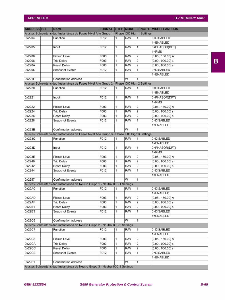
GEK-113285A G650 Generator Protection & Control System B-65
APPENDIX B B.7 MEMORY MAP
B
Ajustes Sobreintensidad Instantánea de Fases Nivel Alto Grupo 1 - Phase IOC High 1 Settings0x2204 Function F012 1 R/W 1 0=DISABLED 1=ENABLED0x2205 Input F012 1 R/W 1 0=PHASOR(DFT) 1=RMS0x2206 Pickup Level F003 1 R/W 2 [0.05 , 160.00] A0x2208 Trip Delay F003 1 R/W 2 [0.00 , 900.00] s0x220A Reset Delay F003 1 R/W 2 [0.00 , 900.00] s0x220C Snapshot Events F012 1 R/W 1 0=DISABLED 1=ENABLED0x221F Confirmation address W 1 Ajustes Sobreintensidad Instantánea de Fases Nivel Alto Grupo 2 - Phase IOC High 2 Settings0x2220 Function F012 1 R/W 1 0=DISABLED 1=ENABLED0x2221 Input F012 1 R/W 1 0=PHASOR(DFT) 1=RMS0x2222 Pickup Level F003 1 R/W 2 [0.05 , 160.00] A0x2224 Trip Delay F003 1 R/W 2 [0.00 , 900.00] s0x2226 Reset Delay F003 1 R/W 2 [0.00 , 900.00] s0x2228 Snapshot Events F012 1 R/W 1 0=DISABLED 1=ENABLED0x223B Confirmation address W 1 Ajustes Sobreintensidad Instantánea de Fases Nivel Alto Grupo 3 - Phase IOC High 3 Settings0x223C Function F012 1 R/W 1 0=DISABLED 1=ENABLED0x223D Input F012 1 R/W 1 0=PHASOR(DFT) 1=RMS0x223E Pickup Level F003 1 R/W 2 [0.05 , 160.00] A0x2240 Trip Delay F003 1 R/W 2 [0.00 , 900.00] s0x2242 Reset Delay F003 1 R/W 2 [0.00 , 900.00] s0x2244 Snapshot Events F012 1 R/W 1 0=DISABLED 1=ENABLED0x2257 Confirmation address W 1 Ajustes Sobreintensidad Instantánea de Neutro Grupo 1 - Neutral IOC 1 Settings0x22AC Function F012 1 R/W 1 0=DISABLED 1=ENABLED0x22AD Pickup Level F003 1 R/W 2 [0.05 , 160.00] A0x22AF Trip Delay F003 1 R/W 2 [0.00 , 900.00] s0x22B1 Reset Delay F003 1 R/W 2 [0.00 , 900.00] s0x22B3 Snapshot Events F012 1 R/W 1 0=DISABLED 1=ENABLED0x22C6 Confirmation address W 1 Ajustes Sobreintensidad Instantánea de Neutro Grupo 2 - Neutral IOC 2 Settings0x22C7 Function F012 1 R/W 1 0=DISABLED 1=ENABLED0x22C8 Pickup Level F003 1 R/W 2 [0.05 , 160.00] A0x22CA Trip Delay F003 1 R/W 2 [0.00 , 900.00] s0x22CC Reset Delay F003 1 R/W 2 [0.00 , 900.00] s0x22CE Snapshot Events F012 1 R/W 1 0=DISABLED 1=ENABLED0x22E1 Confirmation address W 1 Ajustes Sobreintensidad Instantánea de Neutro Grupo 3 - Neutral IOC 3 Settings
ADDRESS BIT NAME FORMAT STEP MODE LENGTH MISCELLANEOUS
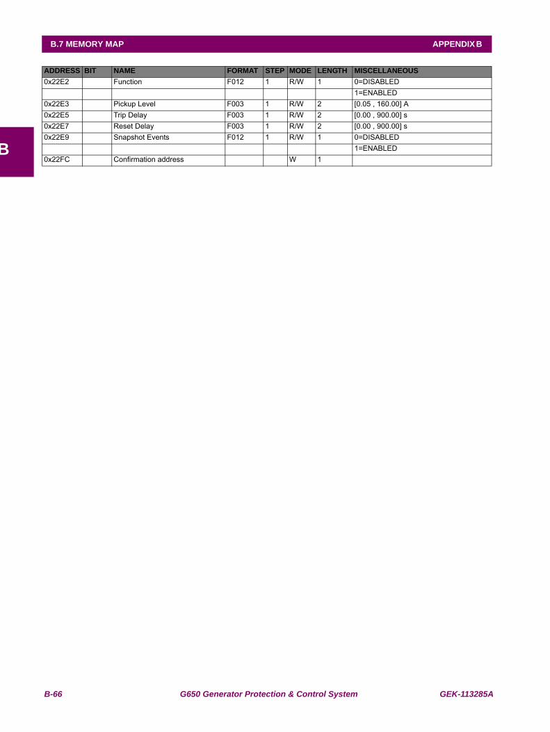
B-66 G650 Generator Protection & Control System GEK-113285A
B.7 MEMORY MAP APPENDIX B
B
0x22E2 Function F012 1 R/W 1 0=DISABLED 1=ENABLED0x22E3 Pickup Level F003 1 R/W 2 [0.05 , 160.00] A0x22E5 Trip Delay F003 1 R/W 2 [0.00 , 900.00] s0x22E7 Reset Delay F003 1 R/W 2 [0.00 , 900.00] s0x22E9 Snapshot Events F012 1 R/W 1 0=DISABLED 1=ENABLED0x22FC Confirmation address W 1
ADDRESS BIT NAME FORMAT STEP MODE LENGTH MISCELLANEOUS
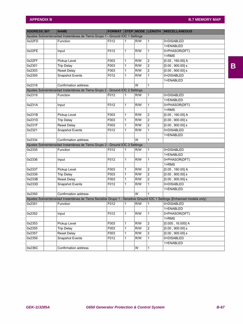
GEK-113285A G650 Generator Protection & Control System B-67
APPENDIX B B.7 MEMORY MAP
B
Ajustes Sobreintensidad Instantánea de Tierra Grupo 1 - Ground IOC 1 Settings0x22FD Function F012 1 R/W 1 0=DISABLED 1=ENABLED0x22FE Input F012 1 R/W 1 0=PHASOR(DFT) 1=RMS0x22FF Pickup Level F003 1 R/W 2 [0.05 , 160.00] A0x2301 Trip Delay F003 1 R/W 2 [0.00 , 900.00] s0x2303 Reset Delay F003 1 R/W 2 [0.00 , 900.00] s0x2305 Snapshot Events F012 1 R/W 1 0=DISABLED 1=ENABLED0x2318 Confirmation address W 1 Ajustes Sobreintensidad Instantánea de Tierra Grupo 2 - Ground IOC 2 Settings0x2319 Function F012 1 R/W 1 0=DISABLED 1=ENABLED0x231A Input F012 1 R/W 1 0=PHASOR(DFT) 1=RMS0x231B Pickup Level F003 1 R/W 2 [0.05 , 160.00] A0x231D Trip Delay F003 1 R/W 2 [0.00 , 900.00] s0x231F Reset Delay F003 1 R/W 2 [0.00 , 900.00] s0x2321 Snapshot Events F012 1 R/W 1 0=DISABLED 1=ENABLED0x2334 Confirmation address W 1 Ajustes Sobreintensidad Instantánea de Tierra Grupo 3 - Ground IOC 3 Settings0x2335 Function F012 1 R/W 1 0=DISABLED 1=ENABLED0x2336 Input F012 1 R/W 1 0=PHASOR(DFT) 1=RMS0x2337 Pickup Level F003 1 R/W 2 [0.05 , 160.00] A0x2339 Trip Delay F003 1 R/W 2 [0.00 , 900.00] s0x233B Reset Delay F003 1 R/W 2 [0.00 , 900.00] s0x233D Snapshot Events F012 1 R/W 1 0=DISABLED 1=ENABLED0x2350 Confirmation address W 1 Ajustes Sobreintensidad Instantánea de Tierra Sensible Grupo 1 - Sensitive Ground IOC 1 Settings (Enhanced models only)0x2351 Function F012 1 R/W 1 0=DISABLED 1=ENABLED0x2352 Input F012 1 R/W 1 0=PHASOR(DFT) 1=RMS0x2353 Pickup Level F003 1 R/W 2 [0.005 , 16.000] A0x2355 Trip Delay F003 1 R/W 2 [0.00 , 900.00] s0x2357 Reset Delay F003 1 R/W 2 [0.00 , 900.00] s0x2359 Snapshot Events F012 1 R/W 1 0=DISABLED 1=ENABLED0x236C Confirmation address W 1
ADDRESS BIT NAME FORMAT STEP MODE LENGTH MISCELLANEOUS
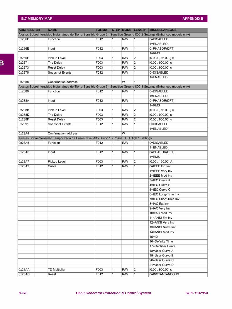
B-68 G650 Generator Protection & Control System GEK-113285A
B.7 MEMORY MAP APPENDIX B
B
Ajustes Sobreintensidad Instantánea de Tierra Sensible Grupo 2 - Sensitive Ground IOC 2 Settings (Enhanced models only)0x236D Function F012 1 R/W 1 0=DISABLED 1=ENABLED0x236E Input F012 1 R/W 1 0=PHASOR(DFT) 1=RMS0x236F Pickup Level F003 1 R/W 2 [0.005 , 16.000] A0x2371 Trip Delay F003 1 R/W 2 [0.00 , 900.00] s0x2373 Reset Delay F003 1 R/W 2 [0.00 , 900.00] s0x2375 Snapshot Events F012 1 R/W 1 0=DISABLED 1=ENABLED0x2388 Confirmation address W 1 Ajustes Sobreintensidad Instantánea de Tierra Sensible Grupo 3 - Sensitive Ground IOC 3 Settings (Enhanced models only)0x2389 Function F012 1 R/W 1 0=DISABLED 1=ENABLED0x238A Input F012 1 R/W 1 0=PHASOR(DFT) 1=RMS0x238B Pickup Level F003 1 R/W 2 [0.005 , 16.000] A0x238D Trip Delay F003 1 R/W 2 [0.00 , 900.00] s0x238F Reset Delay F003 1 R/W 2 [0.00 , 900.00] s0x2391 Snapshot Events F012 1 R/W 1 0=DISABLED 1=ENABLED0x23A4 Confirmation address W 1 Ajustes Sobreintensidad Temporizada de Fases Nivel Alto Grupo 1 - Phase TOC High 1 Settings0x23A5 Function F012 1 R/W 1 0=DISABLED 1=ENABLED0x23A6 Input F012 1 R/W 1 0=PHASOR(DFT) 1=RMS0x23A7 Pickup Level F003 1 R/W 2 [0.05 , 160.00] A0x23A9 Curve F012 1 R/W 1 0=IEEE Ext Inv 1=IEEE Very Inv 2=IEEE Mod Inv 3=IEC Curve A 4=IEC Curve B 5=IEC Curve C 6=IEC Long-Time Inv 7=IEC Short-Time Inv 8=IAC Ext Inv 9=IAC Very Inv 10=IAC Mod Inv 11=ANSI Ext Inv 12=ANSI Very Inv 13=ANSI Norm Inv 14=ANSI Mod Inv 15=I2t 16=Definite Time 17=Rectifier Curve 18=User Curve A 19=User Curve B 20=User Curve C 21=User Curve D0x23AA TD Multiplier F003 1 R/W 2 [0.00 , 900.00] s0x23AC Reset F012 1 R/W 1 0=INSTANTANEOUS
ADDRESS BIT NAME FORMAT STEP MODE LENGTH MISCELLANEOUS
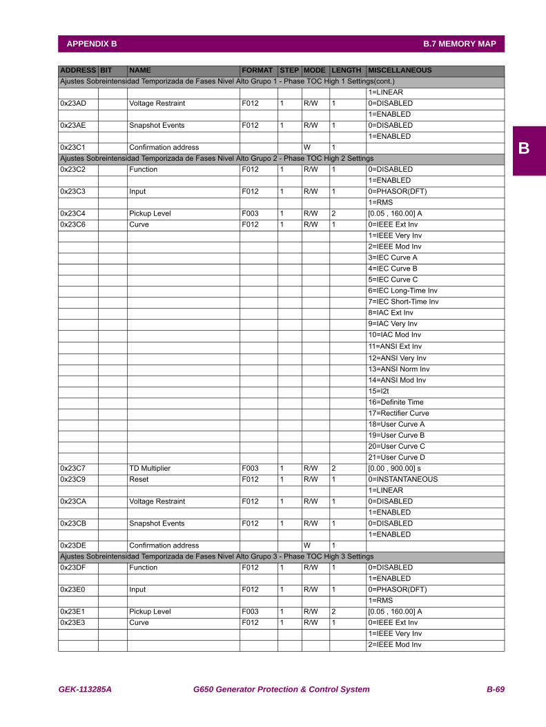
GEK-113285A G650 Generator Protection & Control System B-69
APPENDIX B B.7 MEMORY MAP
B
Ajustes Sobreintensidad Temporizada de Fases Nivel Alto Grupo 1 - Phase TOC High 1 Settings(cont.) 1=LINEAR0x23AD Voltage Restraint F012 1 R/W 1 0=DISABLED 1=ENABLED0x23AE Snapshot Events F012 1 R/W 1 0=DISABLED 1=ENABLED0x23C1 Confirmation address W 1 Ajustes Sobreintensidad Temporizada de Fases Nivel Alto Grupo 2 - Phase TOC High 2 Settings0x23C2 Function F012 1 R/W 1 0=DISABLED 1=ENABLED0x23C3 Input F012 1 R/W 1 0=PHASOR(DFT) 1=RMS0x23C4 Pickup Level F003 1 R/W 2 [0.05 , 160.00] A0x23C6 Curve F012 1 R/W 1 0=IEEE Ext Inv 1=IEEE Very Inv 2=IEEE Mod Inv 3=IEC Curve A 4=IEC Curve B 5=IEC Curve C 6=IEC Long-Time Inv 7=IEC Short-Time Inv 8=IAC Ext Inv 9=IAC Very Inv 10=IAC Mod Inv 11=ANSI Ext Inv 12=ANSI Very Inv 13=ANSI Norm Inv 14=ANSI Mod Inv 15=I2t 16=Definite Time 17=Rectifier Curve 18=User Curve A 19=User Curve B 20=User Curve C 21=User Curve D0x23C7 TD Multiplier F003 1 R/W 2 [0.00 , 900.00] s0x23C9 Reset F012 1 R/W 1 0=INSTANTANEOUS 1=LINEAR0x23CA Voltage Restraint F012 1 R/W 1 0=DISABLED 1=ENABLED0x23CB Snapshot Events F012 1 R/W 1 0=DISABLED 1=ENABLED0x23DE Confirmation address W 1 Ajustes Sobreintensidad Temporizada de Fases Nivel Alto Grupo 3 - Phase TOC High 3 Settings0x23DF Function F012 1 R/W 1 0=DISABLED 1=ENABLED0x23E0 Input F012 1 R/W 1 0=PHASOR(DFT) 1=RMS0x23E1 Pickup Level F003 1 R/W 2 [0.05 , 160.00] A0x23E3 Curve F012 1 R/W 1 0=IEEE Ext Inv 1=IEEE Very Inv 2=IEEE Mod Inv
ADDRESS BIT NAME FORMAT STEP MODE LENGTH MISCELLANEOUS
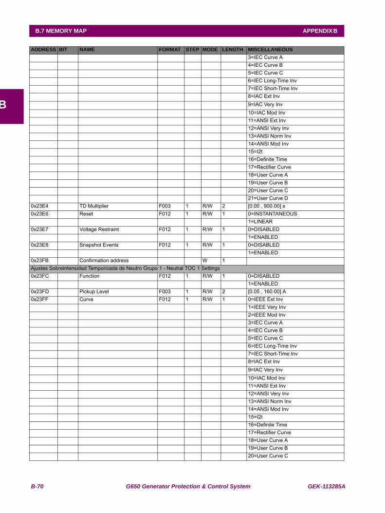
B-70 G650 Generator Protection & Control System GEK-113285A
B.7 MEMORY MAP APPENDIX B
B
3=IEC Curve A 4=IEC Curve B 5=IEC Curve C 6=IEC Long-Time Inv 7=IEC Short-Time Inv 8=IAC Ext Inv 9=IAC Very Inv 10=IAC Mod Inv 11=ANSI Ext Inv 12=ANSI Very Inv 13=ANSI Norm Inv 14=ANSI Mod Inv 15=I2t 16=Definite Time 17=Rectifier Curve 18=User Curve A 19=User Curve B 20=User Curve C 21=User Curve D0x23E4 TD Multiplier F003 1 R/W 2 [0.00 , 900.00] s0x23E6 Reset F012 1 R/W 1 0=INSTANTANEOUS 1=LINEAR0x23E7 Voltage Restraint F012 1 R/W 1 0=DISABLED 1=ENABLED0x23E8 Snapshot Events F012 1 R/W 1 0=DISABLED 1=ENABLED0x23FB Confirmation address W 1 Ajustes Sobreintensidad Temporizada de Neutro Grupo 1 - Neutral TOC 1 Settings0x23FC Function F012 1 R/W 1 0=DISABLED 1=ENABLED0x23FD Pickup Level F003 1 R/W 2 [0.05 , 160.00] A0x23FF Curve F012 1 R/W 1 0=IEEE Ext Inv 1=IEEE Very Inv 2=IEEE Mod Inv 3=IEC Curve A 4=IEC Curve B 5=IEC Curve C 6=IEC Long-Time Inv 7=IEC Short-Time Inv 8=IAC Ext Inv 9=IAC Very Inv 10=IAC Mod Inv 11=ANSI Ext Inv 12=ANSI Very Inv 13=ANSI Norm Inv 14=ANSI Mod Inv 15=I2t 16=Definite Time 17=Rectifier Curve 18=User Curve A 19=User Curve B 20=User Curve C
ADDRESS BIT NAME FORMAT STEP MODE LENGTH MISCELLANEOUS
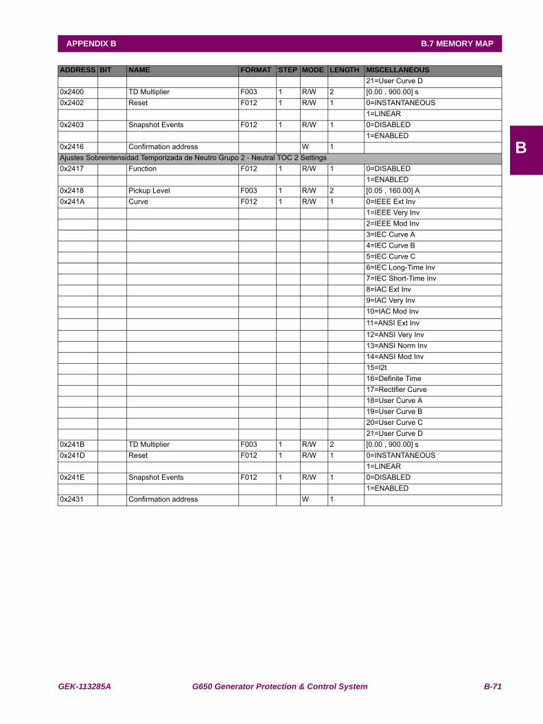
GEK-113285A G650 Generator Protection & Control System B-71
APPENDIX B B.7 MEMORY MAP
B
21=User Curve D0x2400 TD Multiplier F003 1 R/W 2 [0.00 , 900.00] s0x2402 Reset F012 1 R/W 1 0=INSTANTANEOUS 1=LINEAR0x2403 Snapshot Events F012 1 R/W 1 0=DISABLED 1=ENABLED0x2416 Confirmation address W 1 Ajustes Sobreintensidad Temporizada de Neutro Grupo 2 - Neutral TOC 2 Settings0x2417 Function F012 1 R/W 1 0=DISABLED 1=ENABLED0x2418 Pickup Level F003 1 R/W 2 [0.05 , 160.00] A0x241A Curve F012 1 R/W 1 0=IEEE Ext Inv 1=IEEE Very Inv 2=IEEE Mod Inv 3=IEC Curve A 4=IEC Curve B 5=IEC Curve C 6=IEC Long-Time Inv 7=IEC Short-Time Inv 8=IAC Ext Inv 9=IAC Very Inv 10=IAC Mod Inv 11=ANSI Ext Inv 12=ANSI Very Inv 13=ANSI Norm Inv 14=ANSI Mod Inv 15=I2t 16=Definite Time 17=Rectifier Curve 18=User Curve A 19=User Curve B 20=User Curve C 21=User Curve D0x241B TD Multiplier F003 1 R/W 2 [0.00 , 900.00] s0x241D Reset F012 1 R/W 1 0=INSTANTANEOUS 1=LINEAR0x241E Snapshot Events F012 1 R/W 1 0=DISABLED 1=ENABLED0x2431 Confirmation address W 1
ADDRESS BIT NAME FORMAT STEP MODE LENGTH MISCELLANEOUS
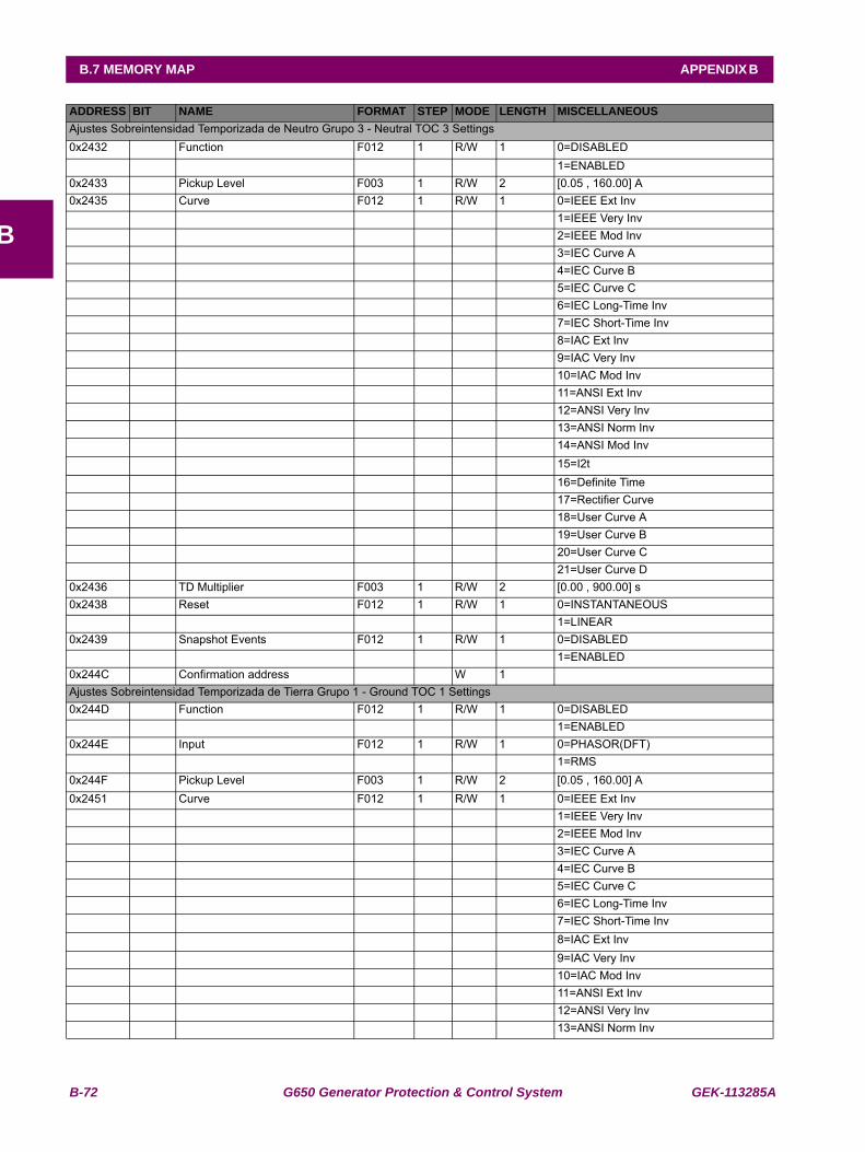
B-72 G650 Generator Protection & Control System GEK-113285A
B.7 MEMORY MAP APPENDIX B
B
Ajustes Sobreintensidad Temporizada de Neutro Grupo 3 - Neutral TOC 3 Settings0x2432 Function F012 1 R/W 1 0=DISABLED 1=ENABLED0x2433 Pickup Level F003 1 R/W 2 [0.05 , 160.00] A0x2435 Curve F012 1 R/W 1 0=IEEE Ext Inv 1=IEEE Very Inv 2=IEEE Mod Inv 3=IEC Curve A 4=IEC Curve B 5=IEC Curve C 6=IEC Long-Time Inv 7=IEC Short-Time Inv 8=IAC Ext Inv 9=IAC Very Inv 10=IAC Mod Inv 11=ANSI Ext Inv 12=ANSI Very Inv 13=ANSI Norm Inv 14=ANSI Mod Inv 15=I2t 16=Definite Time 17=Rectifier Curve 18=User Curve A 19=User Curve B 20=User Curve C 21=User Curve D0x2436 TD Multiplier F003 1 R/W 2 [0.00 , 900.00] s0x2438 Reset F012 1 R/W 1 0=INSTANTANEOUS 1=LINEAR0x2439 Snapshot Events F012 1 R/W 1 0=DISABLED 1=ENABLED0x244C Confirmation address W 1 Ajustes Sobreintensidad Temporizada de Tierra Grupo 1 - Ground TOC 1 Settings0x244D Function F012 1 R/W 1 0=DISABLED 1=ENABLED0x244E Input F012 1 R/W 1 0=PHASOR(DFT) 1=RMS0x244F Pickup Level F003 1 R/W 2 [0.05 , 160.00] A0x2451 Curve F012 1 R/W 1 0=IEEE Ext Inv 1=IEEE Very Inv 2=IEEE Mod Inv 3=IEC Curve A 4=IEC Curve B 5=IEC Curve C 6=IEC Long-Time Inv 7=IEC Short-Time Inv 8=IAC Ext Inv 9=IAC Very Inv 10=IAC Mod Inv 11=ANSI Ext Inv 12=ANSI Very Inv 13=ANSI Norm Inv
ADDRESS BIT NAME FORMAT STEP MODE LENGTH MISCELLANEOUS

GEK-113285A G650 Generator Protection & Control System B-73
APPENDIX B B.7 MEMORY MAP
B
Ajustes Sobreintensidad Temporizada de Tierra Grupo 1 - Ground TOC 1 Settings(cont.) 14=ANSI Mod Inv 15=I2t 16=Definite Time 17=Rectifier Curve 18=User Curve A 19=User Curve B 20=User Curve C 21=User Curve D0x2452 TD Multiplier F003 1 R/W 2 [0.00 , 900.00] s0x2454 Reset F012 1 R/W 1 0=INSTANTANEOUS 1=LINEAR0x2455 Snapshot Events F012 1 R/W 1 0=DISABLED 1=ENABLED0x2468 Confirmation address W 1 Ajustes Sobreintensidad Temporizada de Tierra Grupo 2 - Ground TOC 2 Settings0x2469 Function F012 1 R/W 1 0=DISABLED 1=ENABLED0x246A Input F012 1 R/W 1 0=PHASOR(DFT) 1=RMS0x246B Pickup Level F003 1 R/W 2 [0.05 , 160.00] A0x246D Curve F012 1 R/W 1 0=IEEE Ext Inv 1=IEEE Very Inv 2=IEEE Mod Inv 3=IEC Curve A 4=IEC Curve B 5=IEC Curve C 6=IEC Long-Time Inv 7=IEC Short-Time Inv 8=IAC Ext Inv 9=IAC Very Inv 10=IAC Mod Inv 11=ANSI Ext Inv 12=ANSI Very Inv 13=ANSI Norm Inv 14=ANSI Mod Inv 15=I2t 16=Definite Time 17=Rectifier Curve 18=User Curve A 19=User Curve B 20=User Curve C 21=User Curve D0x246E TD Multiplier F003 1 R/W 2 [0.00 , 900.00] s0x2470 Reset F012 1 R/W 1 0=INSTANTANEOUS 1=LINEAR0x2471 Snapshot Events F012 1 R/W 1 0=DISABLED 1=ENABLED0x2484 Confirmation address W 1
ADDRESS BIT NAME FORMAT STEP MODE LENGTH MISCELLANEOUS
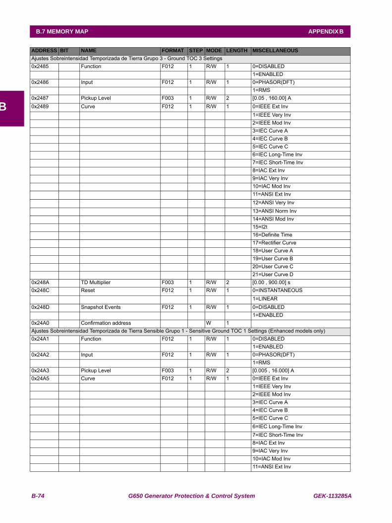
B-74 G650 Generator Protection & Control System GEK-113285A
B.7 MEMORY MAP APPENDIX B
B
Ajustes Sobreintensidad Temporizada de Tierra Grupo 3 - Ground TOC 3 Settings0x2485 Function F012 1 R/W 1 0=DISABLED 1=ENABLED0x2486 Input F012 1 R/W 1 0=PHASOR(DFT) 1=RMS0x2487 Pickup Level F003 1 R/W 2 [0.05 , 160.00] A0x2489 Curve F012 1 R/W 1 0=IEEE Ext Inv 1=IEEE Very Inv 2=IEEE Mod Inv 3=IEC Curve A 4=IEC Curve B 5=IEC Curve C 6=IEC Long-Time Inv 7=IEC Short-Time Inv 8=IAC Ext Inv 9=IAC Very Inv 10=IAC Mod Inv 11=ANSI Ext Inv 12=ANSI Very Inv 13=ANSI Norm Inv 14=ANSI Mod Inv 15=I2t 16=Definite Time 17=Rectifier Curve 18=User Curve A 19=User Curve B 20=User Curve C 21=User Curve D0x248A TD Multiplier F003 1 R/W 2 [0.00 , 900.00] s0x248C Reset F012 1 R/W 1 0=INSTANTANEOUS 1=LINEAR0x248D Snapshot Events F012 1 R/W 1 0=DISABLED 1=ENABLED0x24A0 Confirmation address W 1 Ajustes Sobreintensidad Temporizada de Tierra Sensible Grupo 1 - Sensitive Ground TOC 1 Settings (Enhanced models only)0x24A1 Function F012 1 R/W 1 0=DISABLED 1=ENABLED0x24A2 Input F012 1 R/W 1 0=PHASOR(DFT) 1=RMS0x24A3 Pickup Level F003 1 R/W 2 [0.005 , 16.000] A0x24A5 Curve F012 1 R/W 1 0=IEEE Ext Inv 1=IEEE Very Inv 2=IEEE Mod Inv 3=IEC Curve A 4=IEC Curve B 5=IEC Curve C 6=IEC Long-Time Inv 7=IEC Short-Time Inv 8=IAC Ext Inv 9=IAC Very Inv 10=IAC Mod Inv 11=ANSI Ext Inv
ADDRESS BIT NAME FORMAT STEP MODE LENGTH MISCELLANEOUS
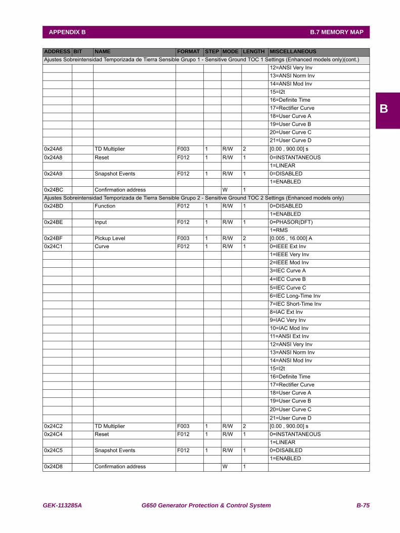
GEK-113285A G650 Generator Protection & Control System B-75
APPENDIX B B.7 MEMORY MAP
B
Ajustes Sobreintensidad Temporizada de Tierra Sensible Grupo 1 - Sensitive Ground TOC 1 Settings (Enhanced models only)(cont.) 12=ANSI Very Inv 13=ANSI Norm Inv 14=ANSI Mod Inv 15=I2t 16=Definite Time 17=Rectifier Curve 18=User Curve A 19=User Curve B 20=User Curve C 21=User Curve D0x24A6 TD Multiplier F003 1 R/W 2 [0.00 , 900.00] s0x24A8 Reset F012 1 R/W 1 0=INSTANTANEOUS 1=LINEAR0x24A9 Snapshot Events F012 1 R/W 1 0=DISABLED 1=ENABLED0x24BC Confirmation address W 1 Ajustes Sobreintensidad Temporizada de Tierra Sensible Grupo 2 - Sensitive Ground TOC 2 Settings (Enhanced models only)0x24BD Function F012 1 R/W 1 0=DISABLED 1=ENABLED0x24BE Input F012 1 R/W 1 0=PHASOR(DFT) 1=RMS0x24BF Pickup Level F003 1 R/W 2 [0.005 , 16.000] A0x24C1 Curve F012 1 R/W 1 0=IEEE Ext Inv 1=IEEE Very Inv 2=IEEE Mod Inv 3=IEC Curve A 4=IEC Curve B 5=IEC Curve C 6=IEC Long-Time Inv 7=IEC Short-Time Inv 8=IAC Ext Inv 9=IAC Very Inv 10=IAC Mod Inv 11=ANSI Ext Inv 12=ANSI Very Inv 13=ANSI Norm Inv 14=ANSI Mod Inv 15=I2t 16=Definite Time 17=Rectifier Curve 18=User Curve A 19=User Curve B 20=User Curve C 21=User Curve D0x24C2 TD Multiplier F003 1 R/W 2 [0.00 , 900.00] s0x24C4 Reset F012 1 R/W 1 0=INSTANTANEOUS 1=LINEAR0x24C5 Snapshot Events F012 1 R/W 1 0=DISABLED 1=ENABLED0x24D8 Confirmation address W 1
ADDRESS BIT NAME FORMAT STEP MODE LENGTH MISCELLANEOUS
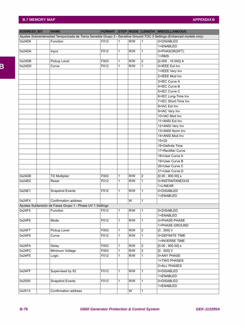
B-76 G650 Generator Protection & Control System GEK-113285A
B.7 MEMORY MAP APPENDIX B
B
Ajustes Sobreintensidad Temporizada de Tierra Sensible Grupo 3 - Sensitive Ground TOC 3 Settings (Enhanced models only)0x24D9 Function F012 1 R/W 1 0=DISABLED 1=ENABLED0x24DA Input F012 1 R/W 1 0=PHASOR(DFT) 1=RMS0x24DB Pickup Level F003 1 R/W 2 [0.005 , 16.000] A0x24DD Curve F012 1 R/W 1 0=IEEE Ext Inv 1=IEEE Very Inv 2=IEEE Mod Inv 3=IEC Curve A 4=IEC Curve B 5=IEC Curve C 6=IEC Long-Time Inv 7=IEC Short-Time Inv 8=IAC Ext Inv 9=IAC Very Inv 10=IAC Mod Inv 11=ANSI Ext Inv 12=ANSI Very Inv 13=ANSI Norm Inv 14=ANSI Mod Inv 15=I2t 16=Definite Time 17=Rectifier Curve 18=User Curve A 19=User Curve B 20=User Curve C 21=User Curve D0x24DE TD Multiplier F003 1 R/W 2 [0.00 , 900.00] s0x24E0 Reset F012 1 R/W 1 0=INSTANTANEOUS 1=LINEAR0x24E1 Snapshot Events F012 1 R/W 1 0=DISABLED 1=ENABLED0x24F4 Confirmation address W 1 Ajustes Subtensión de Fases Grupo 1 - Phase UV 1 Settings0x24F5 Function F012 1 R/W 1 0=DISABLED 1=ENABLED0x24F6 Mode F012 1 R/W 1 0=PHASE-PHASE 1=PHASE-GROUND0x24F7 Pickup Level F003 1 R/W 2 [3 , 500] V0x24F9 Curve F012 1 R/W 1 0=DEFINITE TIME 1=INVERSE TIME0x24FA Delay F003 1 R/W 2 [0.00 , 900.00] s0x24FC Minimum Voltage F003 1 R/W 2 [0 , 500] V0x24FE Logic F012 1 R/W 1 0=ANY PHASE 1=TWO PHASES 2=ALL PHASES0x24FF Supervised by 52 F012 1 R/W 1 0=DISABLED 1=ENABLED0x2500 Snapshot Events F012 1 R/W 1 0=DISABLED 1=ENABLED0x2513 Confirmation address W 1
ADDRESS BIT NAME FORMAT STEP MODE LENGTH MISCELLANEOUS
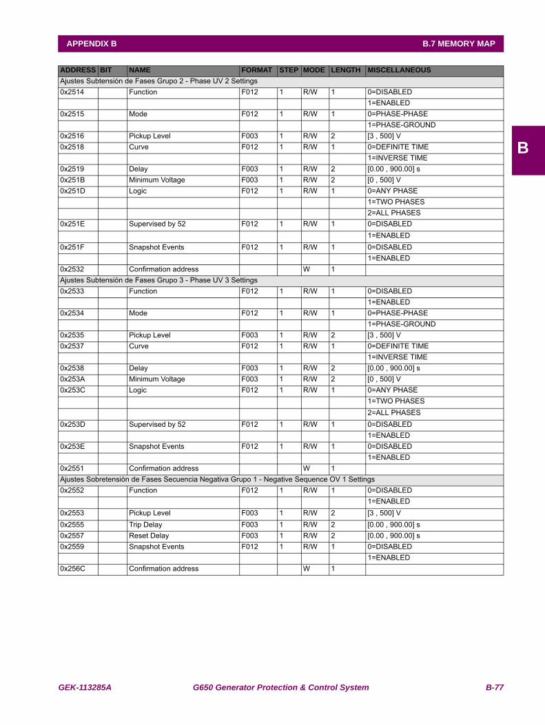
GEK-113285A G650 Generator Protection & Control System B-77
APPENDIX B B.7 MEMORY MAP
B
Ajustes Subtensión de Fases Grupo 2 - Phase UV 2 Settings0x2514 Function F012 1 R/W 1 0=DISABLED 1=ENABLED0x2515 Mode F012 1 R/W 1 0=PHASE-PHASE 1=PHASE-GROUND0x2516 Pickup Level F003 1 R/W 2 [3 , 500] V0x2518 Curve F012 1 R/W 1 0=DEFINITE TIME 1=INVERSE TIME0x2519 Delay F003 1 R/W 2 [0.00 , 900.00] s0x251B Minimum Voltage F003 1 R/W 2 [0 , 500] V0x251D Logic F012 1 R/W 1 0=ANY PHASE 1=TWO PHASES 2=ALL PHASES0x251E Supervised by 52 F012 1 R/W 1 0=DISABLED 1=ENABLED0x251F Snapshot Events F012 1 R/W 1 0=DISABLED 1=ENABLED0x2532 Confirmation address W 1 Ajustes Subtensión de Fases Grupo 3 - Phase UV 3 Settings0x2533 Function F012 1 R/W 1 0=DISABLED 1=ENABLED0x2534 Mode F012 1 R/W 1 0=PHASE-PHASE 1=PHASE-GROUND0x2535 Pickup Level F003 1 R/W 2 [3 , 500] V0x2537 Curve F012 1 R/W 1 0=DEFINITE TIME 1=INVERSE TIME0x2538 Delay F003 1 R/W 2 [0.00 , 900.00] s0x253A Minimum Voltage F003 1 R/W 2 [0 , 500] V0x253C Logic F012 1 R/W 1 0=ANY PHASE 1=TWO PHASES 2=ALL PHASES0x253D Supervised by 52 F012 1 R/W 1 0=DISABLED 1=ENABLED0x253E Snapshot Events F012 1 R/W 1 0=DISABLED 1=ENABLED0x2551 Confirmation address W 1 Ajustes Sobretensión de Fases Secuencia Negativa Grupo 1 - Negative Sequence OV 1 Settings0x2552 Function F012 1 R/W 1 0=DISABLED 1=ENABLED0x2553 Pickup Level F003 1 R/W 2 [3 , 500] V0x2555 Trip Delay F003 1 R/W 2 [0.00 , 900.00] s0x2557 Reset Delay F003 1 R/W 2 [0.00 , 900.00] s0x2559 Snapshot Events F012 1 R/W 1 0=DISABLED 1=ENABLED0x256C Confirmation address W 1
ADDRESS BIT NAME FORMAT STEP MODE LENGTH MISCELLANEOUS
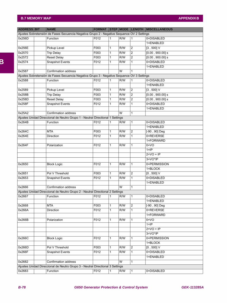
B-78 G650 Generator Protection & Control System GEK-113285A
B.7 MEMORY MAP APPENDIX B
B
Ajustes Sobretensión de Fases Secuencia Negativa Grupo 2 - Negative Sequence OV 2 Settings0x256D Function F012 1 R/W 1 0=DISABLED 1=ENABLED0x256E Pickup Level F003 1 R/W 2 [3 , 500] V0x2570 Trip Delay F003 1 R/W 2 [0.00 , 900.00] s0x2572 Reset Delay F003 1 R/W 2 [0.00 , 900.00] s0x2574 Snapshot Events F012 1 R/W 1 0=DISABLED 1=ENABLED0x2587 Confirmation address W 1 Ajustes Sobretensión de Fases Secuencia Negativa Grupo 3 - Negative Sequence OV 3 Settings0x2588 Function F012 1 R/W 1 0=DISABLED 1=ENABLED0x2589 Pickup Level F003 1 R/W 2 [3 , 500] V0x258B Trip Delay F003 1 R/W 2 [0.00 , 900.00] s0x258D Reset Delay F003 1 R/W 2 [0.00 , 900.00] s0x258F Snapshot Events F012 1 R/W 1 0=DISABLED 1=ENABLED0x25A2 Confirmation address W 1 Ajustes Unidad Direccional de Neutro Grupo 1 - Neutral Directional 1 Settings0x264B Function F012 1 R/W 1 0=DISABLED 1=ENABLED0x264C MTA F003 1 R/W 2 [-90 , 90] Deg0x264E Direction F012 1 R/W 1 0=REVERSE 1=FORWARD0x264F Polarization F012 1 R/W 1 0=VO 1=IP 2=VO + IP 3=VO*IP0x2650 Block Logic F012 1 R/W 1 0=PERMISSION 1=BLOCK0x2651 Pol V Threshold F003 1 R/W 2 [0 , 500] V0x2653 Snapshot Events F012 1 R/W 1 0=DISABLED 1=ENABLED0x2666 Confirmation address W 1 Ajustes Unidad Direccional de Neutro Grupo 2 - Neutral Directional 2 Settings0x2667 Function F012 1 R/W 1 0=DISABLED 1=ENABLED0x2668 MTA F003 1 R/W 2 [-90 , 90] Deg0x266A Direction F012 1 R/W 1 0=REVERSE 1=FORWARD0x266B Polarization F012 1 R/W 1 0=VO 1=IP 2=VO + IP 3=VO*IP0x266C Block Logic F012 1 R/W 1 0=PERMISSION 1=BLOCK0x266D Pol V Threshold F003 1 R/W 2 [0 , 500] V0x266F Snapshot Events F012 1 R/W 1 0=DISABLED 1=ENABLED0x2682 Confirmation address W 1 Ajustes Unidad Direccional de Neutro Grupo 3 - Neutral Directional 3 Settings0x2683 Function F012 1 R/W 1 0=DISABLED
ADDRESS BIT NAME FORMAT STEP MODE LENGTH MISCELLANEOUS
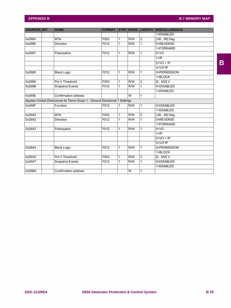
GEK-113285A G650 Generator Protection & Control System B-79
APPENDIX B B.7 MEMORY MAP
B
1=ENABLED0x2684 MTA F003 1 R/W 2 [-90 , 90] Deg0x2686 Direction F012 1 R/W 1 0=REVERSE 1=FORWARD0x2687 Polarization F012 1 R/W 1 0=VO 1=IP 2=VO + IP 3=VO*IP0x2688 Block Logic F012 1 R/W 1 0=PERMISSION 1=BLOCK0x2689 Pol V Threshold F003 1 R/W 2 [0 , 500] V0x268B Snapshot Events F012 1 R/W 1 0=DISABLED 1=ENABLED0x269E Confirmation address W 1 Ajustes Unidad Direccional de Tierra Grupo 1 - Ground Directional 1 Settings0x269F Function F012 1 R/W 1 0=DISABLED 1=ENABLED0x26A0 MTA F003 1 R/W 2 [-90 , 90] Deg0x26A2 Direction F012 1 R/W 1 0=REVERSE 1=FORWARD0x26A3 Polarization F012 1 R/W 1 0=VO 1=IP 2=VO + IP 3=VO*IP0x26A4 Block Logic F012 1 R/W 1 0=PERMISSION 1=BLOCK0x26A5 Pol V Threshold F003 1 R/W 2 [0 , 500] V0x26A7 Snapshot Events F012 1 R/W 1 0=DISABLED 1=ENABLED0x26BA Confirmation address W 1
ADDRESS BIT NAME FORMAT STEP MODE LENGTH MISCELLANEOUS
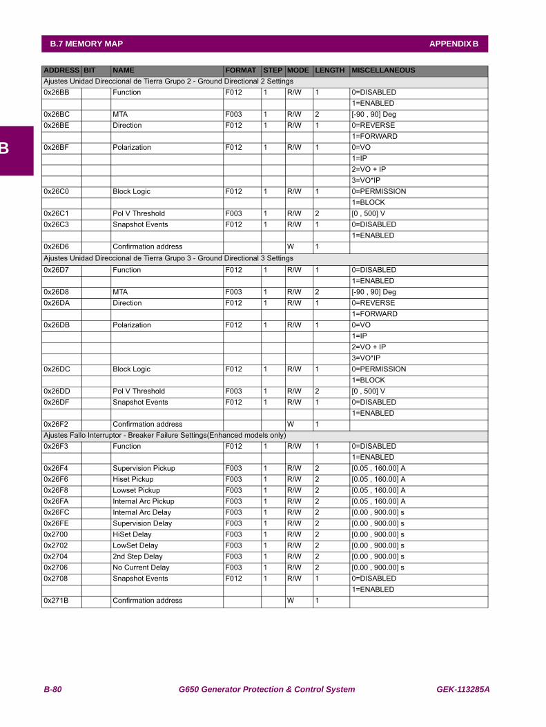
B-80 G650 Generator Protection & Control System GEK-113285A
B.7 MEMORY MAP APPENDIX B
B
Ajustes Unidad Direccional de Tierra Grupo 2 - Ground Directional 2 Settings0x26BB Function F012 1 R/W 1 0=DISABLED 1=ENABLED0x26BC MTA F003 1 R/W 2 [-90 , 90] Deg0x26BE Direction F012 1 R/W 1 0=REVERSE 1=FORWARD0x26BF Polarization F012 1 R/W 1 0=VO 1=IP 2=VO + IP 3=VO*IP0x26C0 Block Logic F012 1 R/W 1 0=PERMISSION 1=BLOCK0x26C1 Pol V Threshold F003 1 R/W 2 [0 , 500] V0x26C3 Snapshot Events F012 1 R/W 1 0=DISABLED 1=ENABLED0x26D6 Confirmation address W 1 Ajustes Unidad Direccional de Tierra Grupo 3 - Ground Directional 3 Settings0x26D7 Function F012 1 R/W 1 0=DISABLED 1=ENABLED0x26D8 MTA F003 1 R/W 2 [-90 , 90] Deg0x26DA Direction F012 1 R/W 1 0=REVERSE 1=FORWARD0x26DB Polarization F012 1 R/W 1 0=VO 1=IP 2=VO + IP 3=VO*IP0x26DC Block Logic F012 1 R/W 1 0=PERMISSION 1=BLOCK0x26DD Pol V Threshold F003 1 R/W 2 [0 , 500] V0x26DF Snapshot Events F012 1 R/W 1 0=DISABLED 1=ENABLED0x26F2 Confirmation address W 1 Ajustes Fallo Interruptor - Breaker Failure Settings(Enhanced models only)0x26F3 Function F012 1 R/W 1 0=DISABLED 1=ENABLED0x26F4 Supervision Pickup F003 1 R/W 2 [0.05 , 160.00] A0x26F6 Hiset Pickup F003 1 R/W 2 [0.05 , 160.00] A0x26F8 Lowset Pickup F003 1 R/W 2 [0.05 , 160.00] A0x26FA Internal Arc Pickup F003 1 R/W 2 [0.05 , 160.00] A0x26FC Internal Arc Delay F003 1 R/W 2 [0.00 , 900.00] s0x26FE Supervision Delay F003 1 R/W 2 [0.00 , 900.00] s0x2700 HiSet Delay F003 1 R/W 2 [0.00 , 900.00] s0x2702 LowSet Delay F003 1 R/W 2 [0.00 , 900.00] s0x2704 2nd Step Delay F003 1 R/W 2 [0.00 , 900.00] s0x2706 No Current Delay F003 1 R/W 2 [0.00 , 900.00] s0x2708 Snapshot Events F012 1 R/W 1 0=DISABLED 1=ENABLED0x271B Confirmation address W 1
ADDRESS BIT NAME FORMAT STEP MODE LENGTH MISCELLANEOUS
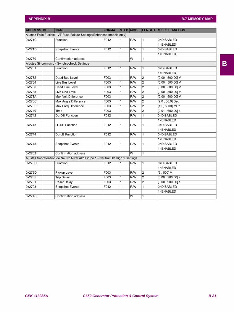
GEK-113285A G650 Generator Protection & Control System B-81
APPENDIX B B.7 MEMORY MAP
B
Ajustes Fallo Fusible - VT Fuse Failure Settings(Enhanced models only)0x271C Function F012 1 R/W 1 0=DISABLED 1=ENABLED0x271D Snapshot Events F012 1 R/W 1 0=DISABLED 1=ENABLED0x2730 Confirmation address W 1 Ajustes Sincronismo - Synchrocheck Settings0x2731 Function F012 1 R/W 1 0=DISABLED 1=ENABLED0x2732 Dead Bus Level F003 1 R/W 2 [0.00 , 500.00] V0x2734 Live Bus Level F003 1 R/W 2 [0.00 , 500.00] V0x2736 Dead Line Level F003 1 R/W 2 [0.00 , 500.00] V0x2738 Live Line Level F003 1 R/W 2 [0.00 , 500.00] V0x273A Max Volt Difference F003 1 R/W 2 [2.00 , 500.00] V0x273C Max Angle Difference F003 1 R/W 2 [2.0 , 80.0] Deg0x273E Max Freq Difference F003 1 R/W 2 [10 , 5000] mHz0x2740 Time F003 1 R/W 2 [0.01 , 600.00] s0x2742 DL-DB Function F012 1 R/W 1 0=DISABLED 1=ENABLED0x2743 LL-DB Function F012 1 R/W 1 0=DISABLED 1=ENABLED0x2744 DL-LB Function F012 1 R/W 1 0=DISABLED 1=ENABLED0x2745 Snapshot Events F012 1 R/W 1 0=DISABLED 1=ENABLED0x2762 Confirmation address W 1 Ajustes Sobretensión de Neutro Nivel Alto Grupo 1 - Neutral OV High 1 Settings0x278C Function F012 1 R/W 1 0=DISABLED 1=ENABLED0x278D Pickup Level F003 1 R/W 2 [3 , 500] V0x278F Trip Delay F003 1 R/W 2 [0.00 , 900.00] s0x2791 Reset Delay F003 1 R/W 2 [0.00 , 900.00] s0x2793 Snapshot Events F012 1 R/W 1 0=DISABLED 1=ENABLED0x27A6 Confirmation address W 1
ADDRESS BIT NAME FORMAT STEP MODE LENGTH MISCELLANEOUS
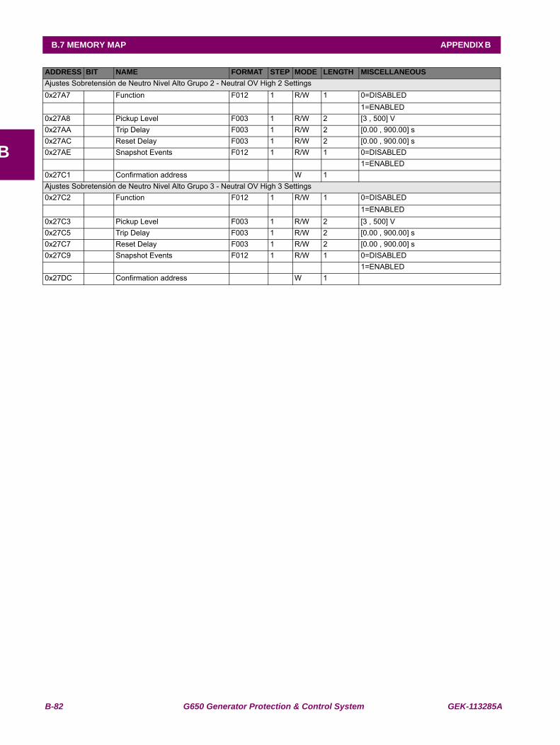
B-82 G650 Generator Protection & Control System GEK-113285A
B.7 MEMORY MAP APPENDIX B
B
Ajustes Sobretensión de Neutro Nivel Alto Grupo 2 - Neutral OV High 2 Settings0x27A7 Function F012 1 R/W 1 0=DISABLED 1=ENABLED0x27A8 Pickup Level F003 1 R/W 2 [3 , 500] V0x27AA Trip Delay F003 1 R/W 2 [0.00 , 900.00] s0x27AC Reset Delay F003 1 R/W 2 [0.00 , 900.00] s0x27AE Snapshot Events F012 1 R/W 1 0=DISABLED 1=ENABLED0x27C1 Confirmation address W 1 Ajustes Sobretensión de Neutro Nivel Alto Grupo 3 - Neutral OV High 3 Settings0x27C2 Function F012 1 R/W 1 0=DISABLED 1=ENABLED0x27C3 Pickup Level F003 1 R/W 2 [3 , 500] V0x27C5 Trip Delay F003 1 R/W 2 [0.00 , 900.00] s0x27C7 Reset Delay F003 1 R/W 2 [0.00 , 900.00] s0x27C9 Snapshot Events F012 1 R/W 1 0=DISABLED 1=ENABLED0x27DC Confirmation address W 1
ADDRESS BIT NAME FORMAT STEP MODE LENGTH MISCELLANEOUS

GEK-113285A G650 Generator Protection & Control System B-83
APPENDIX B B.7 MEMORY MAP
B
Ajustes Subtensión Auxiliar Grupo 1 - Auxiliary UV 1 Settings0x282E Function F012 1 R/W 1 0=DISABLED 1=ENABLED0x282F Pickup Level F003 1 R/W 2 [3 , 500] V0x2831 Curve F012 1 R/W 1 0=DEFINITE TIME 1=INVERSE TIME0x2832 Delay F003 1 R/W 2 [0.00 , 900.00] s0x2834 Snapshot Events F012 1 R/W 1 0=DISABLED 1=ENABLED0x2847 Confirmation address W 1 Ajustes Subtensión Auxiliar Grupo 2 - Auxiliary UV 2 Settings0x2848 Function F012 1 R/W 1 0=DISABLED 1=ENABLED0x2849 Pickup Level F003 1 R/W 2 [3 , 500] V0x284B Curve F012 1 R/W 1 0=DEFINITE TIME 1=INVERSE TIME0x284C Delay F003 1 R/W 2 [0.00 , 900.00] s0x284E Snapshot Events F012 1 R/W 1 0=DISABLED 1=ENABLED0x2861 Confirmation address W 1 Ajustes Subtensión Auxiliar Grupo 3 - Auxiliary UV 3 Settings0x2862 Function F012 1 R/W 1 0=DISABLED 1=ENABLED0x2863 Pickup Level F003 1 R/W 2 [3 , 500] V0x2865 Curve F012 1 R/W 1 0=DEFINITE TIME 1=INVERSE TIME0x2866 Delay F003 1 R/W 2 [0.00 , 900.00] s0x2868 Snapshot Events F012 1 R/W 1 0=DISABLED 1=ENABLED0x287B Confirmation address W 1 Ajustes Sobretensión de Fases Grupo 1 - Phase OV 1 Settings0x287C Function F012 1 R/W 1 0=DISABLED 1=ENABLED0x287D Pickup Level F003 1 R/W 2 [3 , 500] V0x287F Trip Delay F003 1 R/W 2 [0.00 , 900.00] s0x2881 Reset Delay F003 1 R/W 2 [0.00 , 900.00] s0x2883 Logic F012 1 R/W 1 0=ANY PHASE 1=TWO PHASES 2=ALL PHASES0x2884 Snapshot Events F012 1 R/W 1 0=DISABLED 1=ENABLED0x2897 Confirmation address W 1
ADDRESS BIT NAME FORMAT STEP MODE LENGTH MISCELLANEOUS
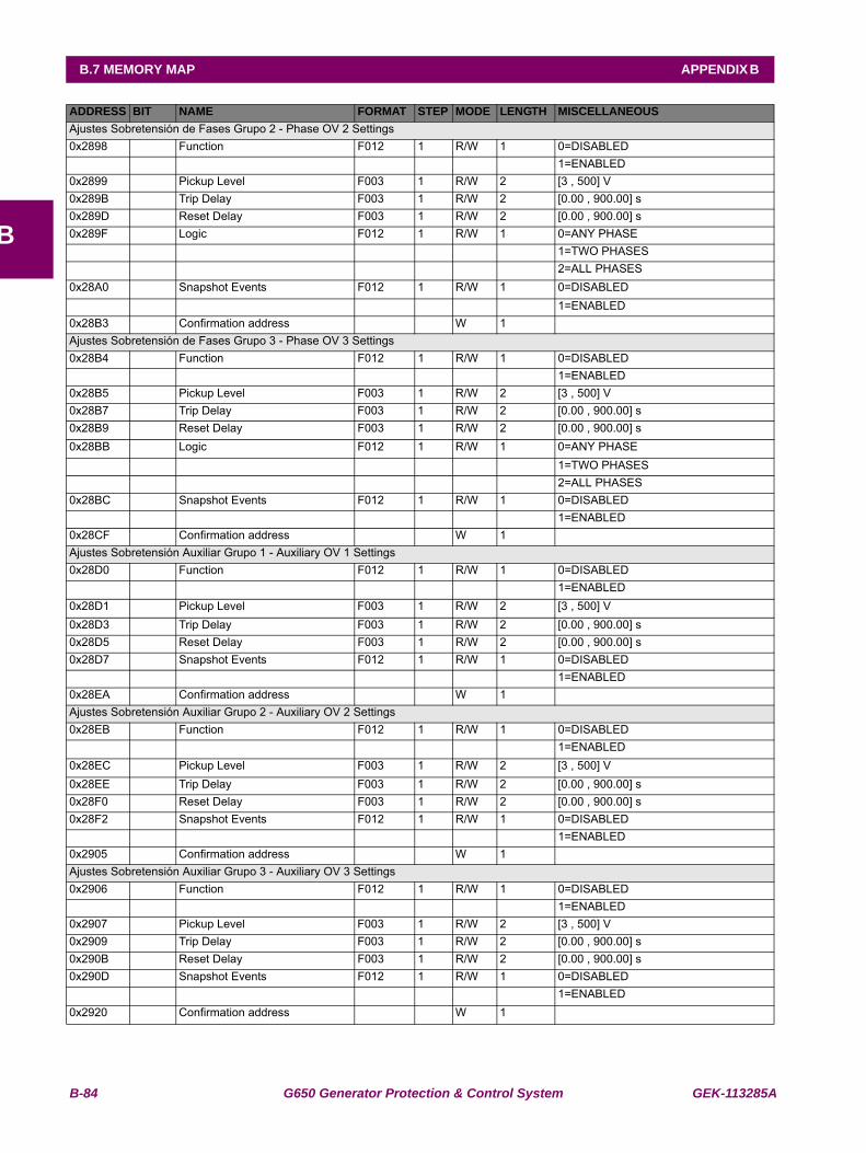
B-84 G650 Generator Protection & Control System GEK-113285A
B.7 MEMORY MAP APPENDIX B
B
Ajustes Sobretensión de Fases Grupo 2 - Phase OV 2 Settings0x2898 Function F012 1 R/W 1 0=DISABLED 1=ENABLED0x2899 Pickup Level F003 1 R/W 2 [3 , 500] V0x289B Trip Delay F003 1 R/W 2 [0.00 , 900.00] s0x289D Reset Delay F003 1 R/W 2 [0.00 , 900.00] s0x289F Logic F012 1 R/W 1 0=ANY PHASE 1=TWO PHASES 2=ALL PHASES0x28A0 Snapshot Events F012 1 R/W 1 0=DISABLED 1=ENABLED0x28B3 Confirmation address W 1 Ajustes Sobretensión de Fases Grupo 3 - Phase OV 3 Settings0x28B4 Function F012 1 R/W 1 0=DISABLED 1=ENABLED0x28B5 Pickup Level F003 1 R/W 2 [3 , 500] V0x28B7 Trip Delay F003 1 R/W 2 [0.00 , 900.00] s0x28B9 Reset Delay F003 1 R/W 2 [0.00 , 900.00] s0x28BB Logic F012 1 R/W 1 0=ANY PHASE 1=TWO PHASES 2=ALL PHASES0x28BC Snapshot Events F012 1 R/W 1 0=DISABLED 1=ENABLED0x28CF Confirmation address W 1 Ajustes Sobretensión Auxiliar Grupo 1 - Auxiliary OV 1 Settings0x28D0 Function F012 1 R/W 1 0=DISABLED 1=ENABLED0x28D1 Pickup Level F003 1 R/W 2 [3 , 500] V0x28D3 Trip Delay F003 1 R/W 2 [0.00 , 900.00] s0x28D5 Reset Delay F003 1 R/W 2 [0.00 , 900.00] s0x28D7 Snapshot Events F012 1 R/W 1 0=DISABLED 1=ENABLED0x28EA Confirmation address W 1 Ajustes Sobretensión Auxiliar Grupo 2 - Auxiliary OV 2 Settings0x28EB Function F012 1 R/W 1 0=DISABLED 1=ENABLED0x28EC Pickup Level F003 1 R/W 2 [3 , 500] V0x28EE Trip Delay F003 1 R/W 2 [0.00 , 900.00] s0x28F0 Reset Delay F003 1 R/W 2 [0.00 , 900.00] s0x28F2 Snapshot Events F012 1 R/W 1 0=DISABLED 1=ENABLED0x2905 Confirmation address W 1 Ajustes Sobretensión Auxiliar Grupo 3 - Auxiliary OV 3 Settings0x2906 Function F012 1 R/W 1 0=DISABLED 1=ENABLED0x2907 Pickup Level F003 1 R/W 2 [3 , 500] V0x2909 Trip Delay F003 1 R/W 2 [0.00 , 900.00] s0x290B Reset Delay F003 1 R/W 2 [0.00 , 900.00] s0x290D Snapshot Events F012 1 R/W 1 0=DISABLED 1=ENABLED0x2920 Confirmation address W 1
ADDRESS BIT NAME FORMAT STEP MODE LENGTH MISCELLANEOUS
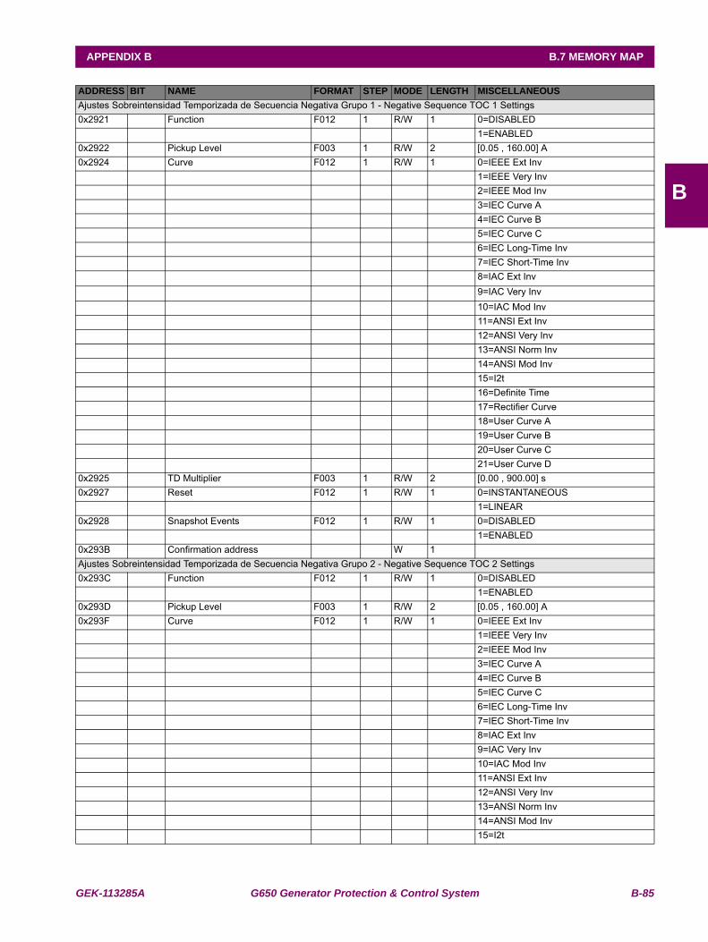
GEK-113285A G650 Generator Protection & Control System B-85
APPENDIX B B.7 MEMORY MAP
B
Ajustes Sobreintensidad Temporizada de Secuencia Negativa Grupo 1 - Negative Sequence TOC 1 Settings0x2921 Function F012 1 R/W 1 0=DISABLED 1=ENABLED0x2922 Pickup Level F003 1 R/W 2 [0.05 , 160.00] A0x2924 Curve F012 1 R/W 1 0=IEEE Ext Inv 1=IEEE Very Inv 2=IEEE Mod Inv 3=IEC Curve A 4=IEC Curve B 5=IEC Curve C 6=IEC Long-Time Inv 7=IEC Short-Time Inv 8=IAC Ext Inv 9=IAC Very Inv 10=IAC Mod Inv 11=ANSI Ext Inv 12=ANSI Very Inv 13=ANSI Norm Inv 14=ANSI Mod Inv 15=I2t 16=Definite Time 17=Rectifier Curve 18=User Curve A 19=User Curve B 20=User Curve C 21=User Curve D0x2925 TD Multiplier F003 1 R/W 2 [0.00 , 900.00] s0x2927 Reset F012 1 R/W 1 0=INSTANTANEOUS 1=LINEAR0x2928 Snapshot Events F012 1 R/W 1 0=DISABLED 1=ENABLED0x293B Confirmation address W 1 Ajustes Sobreintensidad Temporizada de Secuencia Negativa Grupo 2 - Negative Sequence TOC 2 Settings0x293C Function F012 1 R/W 1 0=DISABLED 1=ENABLED0x293D Pickup Level F003 1 R/W 2 [0.05 , 160.00] A0x293F Curve F012 1 R/W 1 0=IEEE Ext Inv 1=IEEE Very Inv 2=IEEE Mod Inv 3=IEC Curve A 4=IEC Curve B 5=IEC Curve C 6=IEC Long-Time Inv 7=IEC Short-Time Inv 8=IAC Ext Inv 9=IAC Very Inv 10=IAC Mod Inv 11=ANSI Ext Inv 12=ANSI Very Inv 13=ANSI Norm Inv 14=ANSI Mod Inv 15=I2t
ADDRESS BIT NAME FORMAT STEP MODE LENGTH MISCELLANEOUS
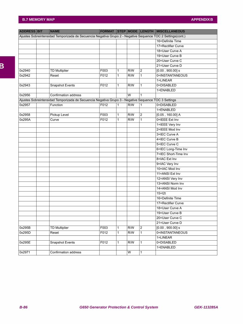
B-86 G650 Generator Protection & Control System GEK-113285A
B.7 MEMORY MAP APPENDIX B
B
Ajustes Sobreintensidad Temporizada de Secuencia Negativa Grupo 2 - Negative Sequence TOC 2 Settings(cont.) 16=Definite Time 17=Rectifier Curve 18=User Curve A 19=User Curve B 20=User Curve C 21=User Curve D0x2940 TD Multiplier F003 1 R/W 2 [0.00 , 900.00] s0x2942 Reset F012 1 R/W 1 0=INSTANTANEOUS 1=LINEAR0x2943 Snapshot Events F012 1 R/W 1 0=DISABLED 1=ENABLED0x2956 Confirmation address W 1 Ajustes Sobreintensidad Temporizada de Secuencia Negativa Grupo 3 - Negative Sequence TOC 3 Settings0x2957 Function F012 1 R/W 1 0=DISABLED 1=ENABLED0x2958 Pickup Level F003 1 R/W 2 [0.05 , 160.00] A0x295A Curve F012 1 R/W 1 0=IEEE Ext Inv 1=IEEE Very Inv 2=IEEE Mod Inv 3=IEC Curve A 4=IEC Curve B 5=IEC Curve C 6=IEC Long-Time Inv 7=IEC Short-Time Inv 8=IAC Ext Inv 9=IAC Very Inv 10=IAC Mod Inv 11=ANSI Ext Inv 12=ANSI Very Inv 13=ANSI Norm Inv 14=ANSI Mod Inv 15=I2t 16=Definite Time 17=Rectifier Curve 18=User Curve A 19=User Curve B 20=User Curve C 21=User Curve D0x295B TD Multiplier F003 1 R/W 2 [0.00 , 900.00] s0x295D Reset F012 1 R/W 1 0=INSTANTANEOUS 1=LINEAR0x295E Snapshot Events F012 1 R/W 1 0=DISABLED 1=ENABLED0x2971 Confirmation address W 1
ADDRESS BIT NAME FORMAT STEP MODE LENGTH MISCELLANEOUS
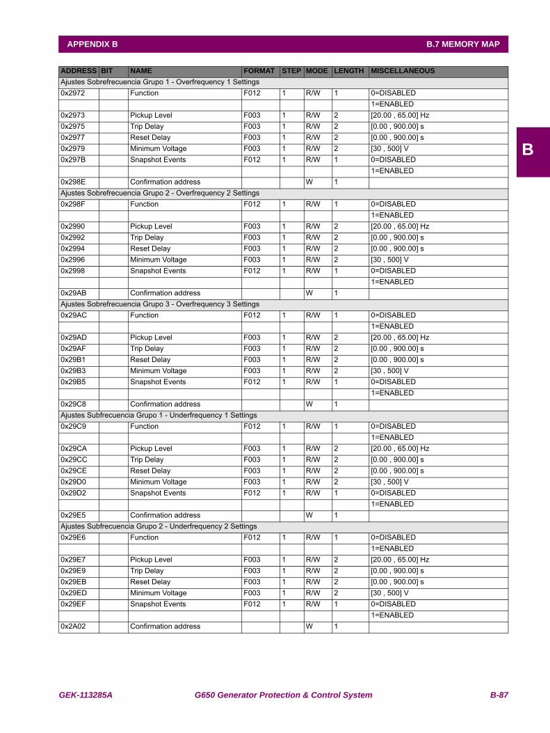
GEK-113285A G650 Generator Protection & Control System B-87
APPENDIX B B.7 MEMORY MAP
B
Ajustes Sobrefrecuencia Grupo 1 - Overfrequency 1 Settings0x2972 Function F012 1 R/W 1 0=DISABLED 1=ENABLED0x2973 Pickup Level F003 1 R/W 2 [20.00 , 65.00] Hz0x2975 Trip Delay F003 1 R/W 2 [0.00 , 900.00] s0x2977 Reset Delay F003 1 R/W 2 [0.00 , 900.00] s0x2979 Minimum Voltage F003 1 R/W 2 [30 , 500] V0x297B Snapshot Events F012 1 R/W 1 0=DISABLED 1=ENABLED0x298E Confirmation address W 1 Ajustes Sobrefrecuencia Grupo 2 - Overfrequency 2 Settings0x298F Function F012 1 R/W 1 0=DISABLED 1=ENABLED0x2990 Pickup Level F003 1 R/W 2 [20.00 , 65.00] Hz0x2992 Trip Delay F003 1 R/W 2 [0.00 , 900.00] s0x2994 Reset Delay F003 1 R/W 2 [0.00 , 900.00] s0x2996 Minimum Voltage F003 1 R/W 2 [30 , 500] V0x2998 Snapshot Events F012 1 R/W 1 0=DISABLED 1=ENABLED0x29AB Confirmation address W 1 Ajustes Sobrefrecuencia Grupo 3 - Overfrequency 3 Settings0x29AC Function F012 1 R/W 1 0=DISABLED 1=ENABLED0x29AD Pickup Level F003 1 R/W 2 [20.00 , 65.00] Hz0x29AF Trip Delay F003 1 R/W 2 [0.00 , 900.00] s0x29B1 Reset Delay F003 1 R/W 2 [0.00 , 900.00] s0x29B3 Minimum Voltage F003 1 R/W 2 [30 , 500] V0x29B5 Snapshot Events F012 1 R/W 1 0=DISABLED 1=ENABLED0x29C8 Confirmation address W 1 Ajustes Subfrecuencia Grupo 1 - Underfrequency 1 Settings0x29C9 Function F012 1 R/W 1 0=DISABLED 1=ENABLED0x29CA Pickup Level F003 1 R/W 2 [20.00 , 65.00] Hz0x29CC Trip Delay F003 1 R/W 2 [0.00 , 900.00] s0x29CE Reset Delay F003 1 R/W 2 [0.00 , 900.00] s0x29D0 Minimum Voltage F003 1 R/W 2 [30 , 500] V0x29D2 Snapshot Events F012 1 R/W 1 0=DISABLED 1=ENABLED0x29E5 Confirmation address W 1 Ajustes Subfrecuencia Grupo 2 - Underfrequency 2 Settings0x29E6 Function F012 1 R/W 1 0=DISABLED 1=ENABLED0x29E7 Pickup Level F003 1 R/W 2 [20.00 , 65.00] Hz0x29E9 Trip Delay F003 1 R/W 2 [0.00 , 900.00] s0x29EB Reset Delay F003 1 R/W 2 [0.00 , 900.00] s0x29ED Minimum Voltage F003 1 R/W 2 [30 , 500] V0x29EF Snapshot Events F012 1 R/W 1 0=DISABLED 1=ENABLED0x2A02 Confirmation address W 1
ADDRESS BIT NAME FORMAT STEP MODE LENGTH MISCELLANEOUS
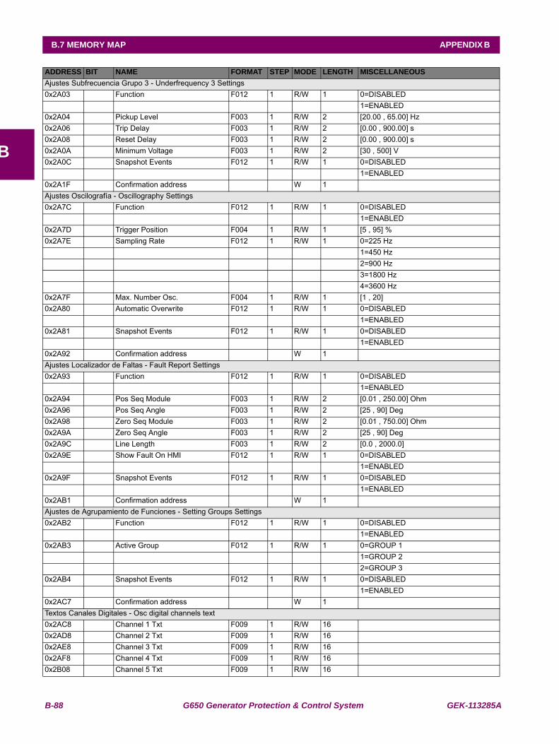
B-88 G650 Generator Protection & Control System GEK-113285A
B.7 MEMORY MAP APPENDIX B
B
Ajustes Subfrecuencia Grupo 3 - Underfrequency 3 Settings0x2A03 Function F012 1 R/W 1 0=DISABLED 1=ENABLED0x2A04 Pickup Level F003 1 R/W 2 [20.00 , 65.00] Hz0x2A06 Trip Delay F003 1 R/W 2 [0.00 , 900.00] s0x2A08 Reset Delay F003 1 R/W 2 [0.00 , 900.00] s0x2A0A Minimum Voltage F003 1 R/W 2 [30 , 500] V0x2A0C Snapshot Events F012 1 R/W 1 0=DISABLED 1=ENABLED0x2A1F Confirmation address W 1 Ajustes Oscilografía - Oscillography Settings0x2A7C Function F012 1 R/W 1 0=DISABLED 1=ENABLED0x2A7D Trigger Position F004 1 R/W 1 [5 , 95] %0x2A7E Sampling Rate F012 1 R/W 1 0=225 Hz 1=450 Hz 2=900 Hz 3=1800 Hz 4=3600 Hz0x2A7F Max. Number Osc. F004 1 R/W 1 [1 , 20] 0x2A80 Automatic Overwrite F012 1 R/W 1 0=DISABLED 1=ENABLED0x2A81 Snapshot Events F012 1 R/W 1 0=DISABLED 1=ENABLED0x2A92 Confirmation address W 1 Ajustes Localizador de Faltas - Fault Report Settings0x2A93 Function F012 1 R/W 1 0=DISABLED 1=ENABLED0x2A94 Pos Seq Module F003 1 R/W 2 [0.01 , 250.00] Ohm0x2A96 Pos Seq Angle F003 1 R/W 2 [25 , 90] Deg0x2A98 Zero Seq Module F003 1 R/W 2 [0.01 , 750.00] Ohm0x2A9A Zero Seq Angle F003 1 R/W 2 [25 , 90] Deg0x2A9C Line Length F003 1 R/W 2 [0.0 , 2000.0] 0x2A9E Show Fault On HMI F012 1 R/W 1 0=DISABLED 1=ENABLED0x2A9F Snapshot Events F012 1 R/W 1 0=DISABLED 1=ENABLED0x2AB1 Confirmation address W 1 Ajustes de Agrupamiento de Funciones - Setting Groups Settings0x2AB2 Function F012 1 R/W 1 0=DISABLED 1=ENABLED0x2AB3 Active Group F012 1 R/W 1 0=GROUP 1 1=GROUP 2 2=GROUP 30x2AB4 Snapshot Events F012 1 R/W 1 0=DISABLED 1=ENABLED0x2AC7 Confirmation address W 1 Textos Canales Digitales - Osc digital channels text0x2AC8 Channel 1 Txt F009 1 R/W 16 0x2AD8 Channel 2 Txt F009 1 R/W 16 0x2AE8 Channel 3 Txt F009 1 R/W 16 0x2AF8 Channel 4 Txt F009 1 R/W 16 0x2B08 Channel 5 Txt F009 1 R/W 16
ADDRESS BIT NAME FORMAT STEP MODE LENGTH MISCELLANEOUS
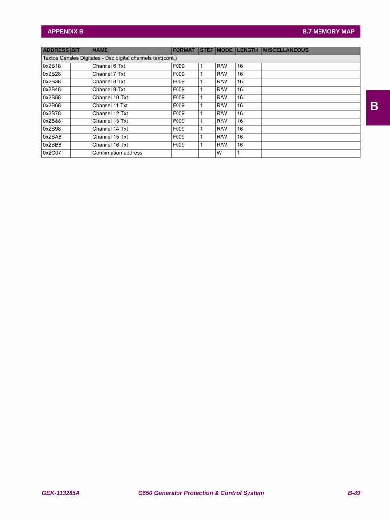
GEK-113285A G650 Generator Protection & Control System B-89
APPENDIX B B.7 MEMORY MAP
B
Textos Canales Digitales - Osc digital channels text(cont.)0x2B18 Channel 6 Txt F009 1 R/W 16 0x2B28 Channel 7 Txt F009 1 R/W 16 0x2B38 Channel 8 Txt F009 1 R/W 16 0x2B48 Channel 9 Txt F009 1 R/W 16 0x2B58 Channel 10 Txt F009 1 R/W 16 0x2B68 Channel 11 Txt F009 1 R/W 16 0x2B78 Channel 12 Txt F009 1 R/W 16 0x2B88 Channel 13 Txt F009 1 R/W 16 0x2B98 Channel 14 Txt F009 1 R/W 16 0x2BA8 Channel 15 Txt F009 1 R/W 16 0x2BB8 Channel 16 Txt F009 1 R/W 16 0x2C07 Confirmation address W 1
ADDRESS BIT NAME FORMAT STEP MODE LENGTH MISCELLANEOUS
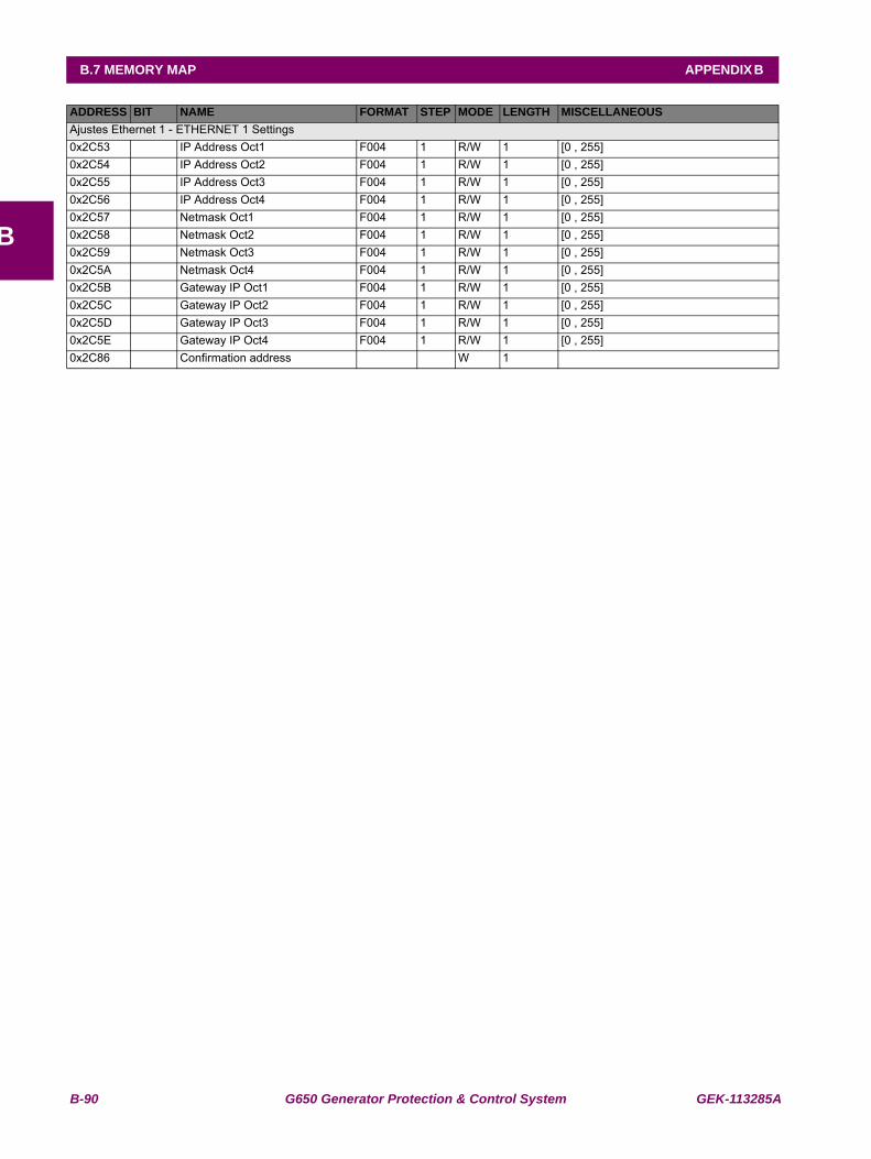
B-90 G650 Generator Protection & Control System GEK-113285A
B.7 MEMORY MAP APPENDIX B
B
Ajustes Ethernet 1 - ETHERNET 1 Settings0x2C53 IP Address Oct1 F004 1 R/W 1 [0 , 255] 0x2C54 IP Address Oct2 F004 1 R/W 1 [0 , 255] 0x2C55 IP Address Oct3 F004 1 R/W 1 [0 , 255] 0x2C56 IP Address Oct4 F004 1 R/W 1 [0 , 255] 0x2C57 Netmask Oct1 F004 1 R/W 1 [0 , 255] 0x2C58 Netmask Oct2 F004 1 R/W 1 [0 , 255] 0x2C59 Netmask Oct3 F004 1 R/W 1 [0 , 255] 0x2C5A Netmask Oct4 F004 1 R/W 1 [0 , 255] 0x2C5B Gateway IP Oct1 F004 1 R/W 1 [0 , 255] 0x2C5C Gateway IP Oct2 F004 1 R/W 1 [0 , 255] 0x2C5D Gateway IP Oct3 F004 1 R/W 1 [0 , 255] 0x2C5E Gateway IP Oct4 F004 1 R/W 1 [0 , 255] 0x2C86 Confirmation address W 1
ADDRESS BIT NAME FORMAT STEP MODE LENGTH MISCELLANEOUS
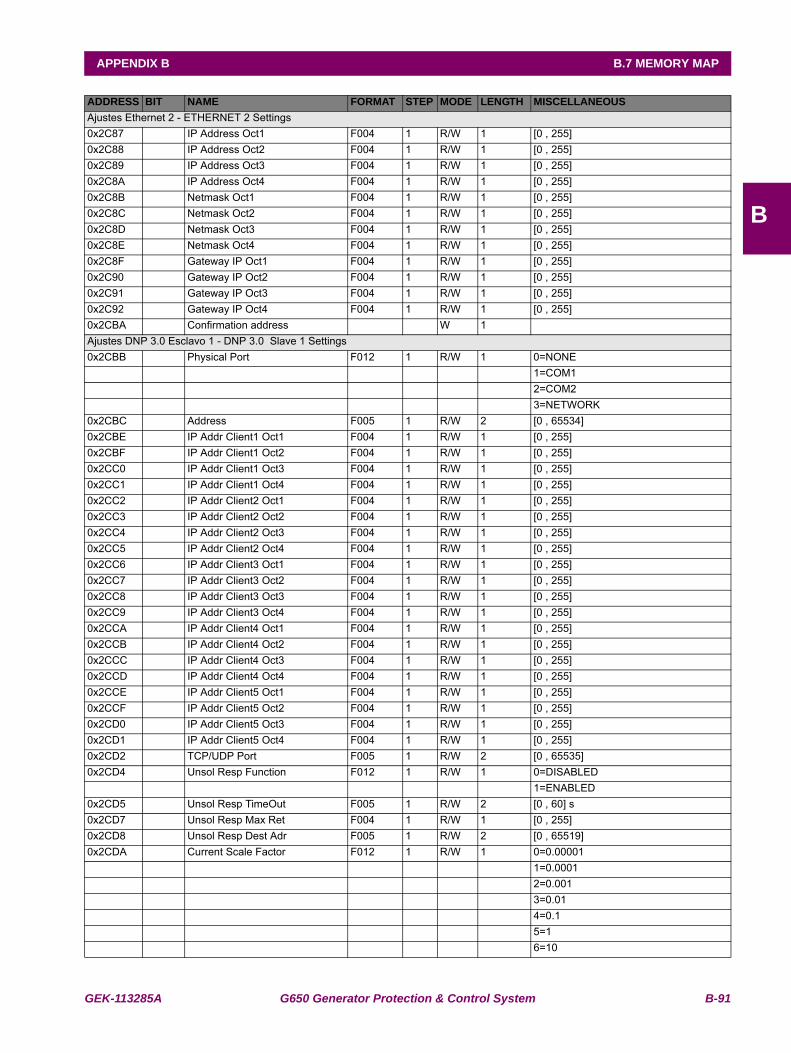
GEK-113285A G650 Generator Protection & Control System B-91
APPENDIX B B.7 MEMORY MAP
B
Ajustes Ethernet 2 - ETHERNET 2 Settings0x2C87 IP Address Oct1 F004 1 R/W 1 [0 , 255] 0x2C88 IP Address Oct2 F004 1 R/W 1 [0 , 255] 0x2C89 IP Address Oct3 F004 1 R/W 1 [0 , 255] 0x2C8A IP Address Oct4 F004 1 R/W 1 [0 , 255] 0x2C8B Netmask Oct1 F004 1 R/W 1 [0 , 255] 0x2C8C Netmask Oct2 F004 1 R/W 1 [0 , 255] 0x2C8D Netmask Oct3 F004 1 R/W 1 [0 , 255] 0x2C8E Netmask Oct4 F004 1 R/W 1 [0 , 255] 0x2C8F Gateway IP Oct1 F004 1 R/W 1 [0 , 255] 0x2C90 Gateway IP Oct2 F004 1 R/W 1 [0 , 255] 0x2C91 Gateway IP Oct3 F004 1 R/W 1 [0 , 255] 0x2C92 Gateway IP Oct4 F004 1 R/W 1 [0 , 255] 0x2CBA Confirmation address W 1 Ajustes DNP 3.0 Esclavo 1 - DNP 3.0 Slave 1 Settings0x2CBB Physical Port F012 1 R/W 1 0=NONE 1=COM1 2=COM2 3=NETWORK0x2CBC Address F005 1 R/W 2 [0 , 65534] 0x2CBE IP Addr Client1 Oct1 F004 1 R/W 1 [0 , 255] 0x2CBF IP Addr Client1 Oct2 F004 1 R/W 1 [0 , 255] 0x2CC0 IP Addr Client1 Oct3 F004 1 R/W 1 [0 , 255] 0x2CC1 IP Addr Client1 Oct4 F004 1 R/W 1 [0 , 255] 0x2CC2 IP Addr Client2 Oct1 F004 1 R/W 1 [0 , 255] 0x2CC3 IP Addr Client2 Oct2 F004 1 R/W 1 [0 , 255] 0x2CC4 IP Addr Client2 Oct3 F004 1 R/W 1 [0 , 255] 0x2CC5 IP Addr Client2 Oct4 F004 1 R/W 1 [0 , 255] 0x2CC6 IP Addr Client3 Oct1 F004 1 R/W 1 [0 , 255] 0x2CC7 IP Addr Client3 Oct2 F004 1 R/W 1 [0 , 255] 0x2CC8 IP Addr Client3 Oct3 F004 1 R/W 1 [0 , 255] 0x2CC9 IP Addr Client3 Oct4 F004 1 R/W 1 [0 , 255] 0x2CCA IP Addr Client4 Oct1 F004 1 R/W 1 [0 , 255] 0x2CCB IP Addr Client4 Oct2 F004 1 R/W 1 [0 , 255] 0x2CCC IP Addr Client4 Oct3 F004 1 R/W 1 [0 , 255] 0x2CCD IP Addr Client4 Oct4 F004 1 R/W 1 [0 , 255] 0x2CCE IP Addr Client5 Oct1 F004 1 R/W 1 [0 , 255] 0x2CCF IP Addr Client5 Oct2 F004 1 R/W 1 [0 , 255] 0x2CD0 IP Addr Client5 Oct3 F004 1 R/W 1 [0 , 255] 0x2CD1 IP Addr Client5 Oct4 F004 1 R/W 1 [0 , 255] 0x2CD2 TCP/UDP Port F005 1 R/W 2 [0 , 65535] 0x2CD4 Unsol Resp Function F012 1 R/W 1 0=DISABLED 1=ENABLED0x2CD5 Unsol Resp TimeOut F005 1 R/W 2 [0 , 60] s0x2CD7 Unsol Resp Max Ret F004 1 R/W 1 [0 , 255] 0x2CD8 Unsol Resp Dest Adr F005 1 R/W 2 [0 , 65519] 0x2CDA Current Scale Factor F012 1 R/W 1 0=0.00001 1=0.0001 2=0.001 3=0.01 4=0.1 5=1 6=10
ADDRESS BIT NAME FORMAT STEP MODE LENGTH MISCELLANEOUS
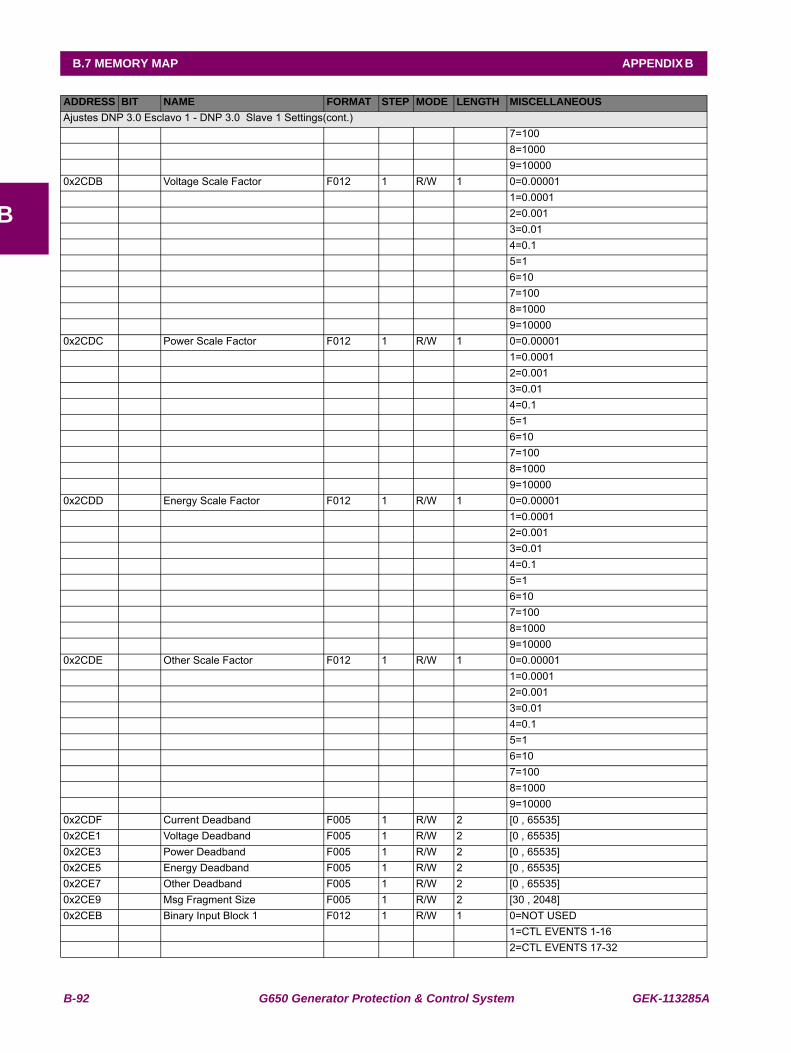
B-92 G650 Generator Protection & Control System GEK-113285A
B.7 MEMORY MAP APPENDIX B
B
Ajustes DNP 3.0 Esclavo 1 - DNP 3.0 Slave 1 Settings(cont.) 7=100 8=1000 9=100000x2CDB Voltage Scale Factor F012 1 R/W 1 0=0.00001 1=0.0001 2=0.001 3=0.01 4=0.1 5=1 6=10 7=100 8=1000 9=100000x2CDC Power Scale Factor F012 1 R/W 1 0=0.00001 1=0.0001 2=0.001 3=0.01 4=0.1 5=1 6=10 7=100 8=1000 9=100000x2CDD Energy Scale Factor F012 1 R/W 1 0=0.00001 1=0.0001 2=0.001 3=0.01 4=0.1 5=1 6=10 7=100 8=1000 9=100000x2CDE Other Scale Factor F012 1 R/W 1 0=0.00001 1=0.0001 2=0.001 3=0.01 4=0.1 5=1 6=10 7=100 8=1000 9=100000x2CDF Current Deadband F005 1 R/W 2 [0 , 65535] 0x2CE1 Voltage Deadband F005 1 R/W 2 [0 , 65535] 0x2CE3 Power Deadband F005 1 R/W 2 [0 , 65535] 0x2CE5 Energy Deadband F005 1 R/W 2 [0 , 65535] 0x2CE7 Other Deadband F005 1 R/W 2 [0 , 65535] 0x2CE9 Msg Fragment Size F005 1 R/W 2 [30 , 2048] 0x2CEB Binary Input Block 1 F012 1 R/W 1 0=NOT USED 1=CTL EVENTS 1-16 2=CTL EVENTS 17-32
ADDRESS BIT NAME FORMAT STEP MODE LENGTH MISCELLANEOUS

GEK-113285A G650 Generator Protection & Control System B-93
APPENDIX B B.7 MEMORY MAP
B
Ajustes DNP 3.0 Esclavo 1 - DNP 3.0 Slave 1 Settings(cont.) 3=CTL EVENTS 33-48 4=CTL EVENTS 49-64 5=CTL EVENTS 65-80 6=CTL EVENTS 81-96 7=CTL EVENTS 97-112 8=CTL EVENTS 113-128 9=SWITCHGEAR 1-8 10=SWITCHGEAR 9-160x2CEC Binary Input Block 2 F012 1 R/W 1 0=NOT USED 1=CTL EVENTS 1-16 2=CTL EVENTS 17-32 3=CTL EVENTS 33-48 4=CTL EVENTS 49-64 5=CTL EVENTS 65-80 6=CTL EVENTS 81-96 7=CTL EVENTS 97-112 8=CTL EVENTS 113-128 9=SWITCHGEAR 1-8 10=SWITCHGEAR 9-160x2CED Binary Input Block 3 F012 1 R/W 1 0=NOT USED 1=CTL EVENTS 1-16 2=CTL EVENTS 17-32 3=CTL EVENTS 33-48 4=CTL EVENTS 49-64 5=CTL EVENTS 65-80 6=CTL EVENTS 81-96 7=CTL EVENTS 97-112 8=CTL EVENTS 113-128 9=SWITCHGEAR 1-8 10=SWITCHGEAR 9-160x2CEE Binary Input Block 4 F012 1 R/W 1 0=NOT USED 1=CTL EVENTS 1-16 2=CTL EVENTS 17-32 3=CTL EVENTS 33-48 4=CTL EVENTS 49-64 5=CTL EVENTS 65-80 6=CTL EVENTS 81-96 7=CTL EVENTS 97-112 8=CTL EVENTS 113-128 9=SWITCHGEAR 1-8 10=SWITCHGEAR 9-160x2CEF Binary Input Block 5 F012 1 R/W 1 0=NOT USED 1=CTL EVENTS 1-16 2=CTL EVENTS 17-32 3=CTL EVENTS 33-48 4=CTL EVENTS 49-64 5=CTL EVENTS 65-80 6=CTL EVENTS 81-96 7=CTL EVENTS 97-112 8=CTL EVENTS 113-128 9=SWITCHGEAR 1-8 10=SWITCHGEAR 9-16
ADDRESS BIT NAME FORMAT STEP MODE LENGTH MISCELLANEOUS
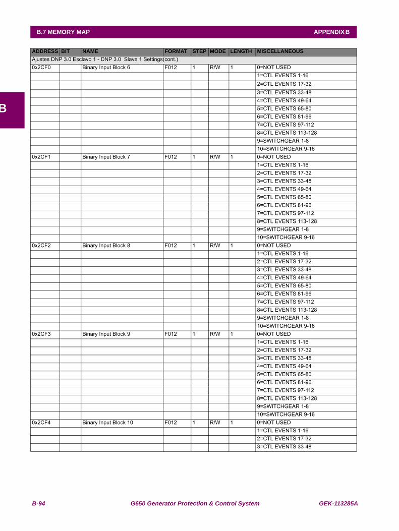
B-94 G650 Generator Protection & Control System GEK-113285A
B.7 MEMORY MAP APPENDIX B
B
Ajustes DNP 3.0 Esclavo 1 - DNP 3.0 Slave 1 Settings(cont.)0x2CF0 Binary Input Block 6 F012 1 R/W 1 0=NOT USED 1=CTL EVENTS 1-16 2=CTL EVENTS 17-32 3=CTL EVENTS 33-48 4=CTL EVENTS 49-64 5=CTL EVENTS 65-80 6=CTL EVENTS 81-96 7=CTL EVENTS 97-112 8=CTL EVENTS 113-128 9=SWITCHGEAR 1-8 10=SWITCHGEAR 9-160x2CF1 Binary Input Block 7 F012 1 R/W 1 0=NOT USED 1=CTL EVENTS 1-16 2=CTL EVENTS 17-32 3=CTL EVENTS 33-48 4=CTL EVENTS 49-64 5=CTL EVENTS 65-80 6=CTL EVENTS 81-96 7=CTL EVENTS 97-112 8=CTL EVENTS 113-128 9=SWITCHGEAR 1-8 10=SWITCHGEAR 9-160x2CF2 Binary Input Block 8 F012 1 R/W 1 0=NOT USED 1=CTL EVENTS 1-16 2=CTL EVENTS 17-32 3=CTL EVENTS 33-48 4=CTL EVENTS 49-64 5=CTL EVENTS 65-80 6=CTL EVENTS 81-96 7=CTL EVENTS 97-112 8=CTL EVENTS 113-128 9=SWITCHGEAR 1-8 10=SWITCHGEAR 9-160x2CF3 Binary Input Block 9 F012 1 R/W 1 0=NOT USED 1=CTL EVENTS 1-16 2=CTL EVENTS 17-32 3=CTL EVENTS 33-48 4=CTL EVENTS 49-64 5=CTL EVENTS 65-80 6=CTL EVENTS 81-96 7=CTL EVENTS 97-112 8=CTL EVENTS 113-128 9=SWITCHGEAR 1-8 10=SWITCHGEAR 9-160x2CF4 Binary Input Block 10 F012 1 R/W 1 0=NOT USED 1=CTL EVENTS 1-16 2=CTL EVENTS 17-32 3=CTL EVENTS 33-48
ADDRESS BIT NAME FORMAT STEP MODE LENGTH MISCELLANEOUS
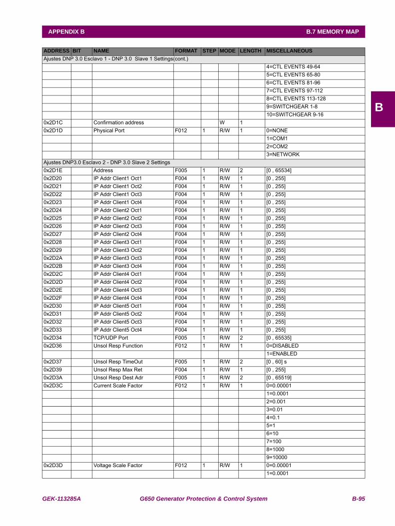
GEK-113285A G650 Generator Protection & Control System B-95
APPENDIX B B.7 MEMORY MAP
B
Ajustes DNP 3.0 Esclavo 1 - DNP 3.0 Slave 1 Settings(cont.) 4=CTL EVENTS 49-64 5=CTL EVENTS 65-80 6=CTL EVENTS 81-96 7=CTL EVENTS 97-112 8=CTL EVENTS 113-128 9=SWITCHGEAR 1-8 10=SWITCHGEAR 9-160x2D1C Confirmation address W 1 0x2D1D Physical Port F012 1 R/W 1 0=NONE 1=COM1 2=COM2 3=NETWORKAjustes DNP3.0 Esclavo 2 - DNP 3.0 Slave 2 Settings0x2D1E Address F005 1 R/W 2 [0 , 65534] 0x2D20 IP Addr Client1 Oct1 F004 1 R/W 1 [0 , 255] 0x2D21 IP Addr Client1 Oct2 F004 1 R/W 1 [0 , 255] 0x2D22 IP Addr Client1 Oct3 F004 1 R/W 1 [0 , 255] 0x2D23 IP Addr Client1 Oct4 F004 1 R/W 1 [0 , 255] 0x2D24 IP Addr Client2 Oct1 F004 1 R/W 1 [0 , 255] 0x2D25 IP Addr Client2 Oct2 F004 1 R/W 1 [0 , 255] 0x2D26 IP Addr Client2 Oct3 F004 1 R/W 1 [0 , 255] 0x2D27 IP Addr Client2 Oct4 F004 1 R/W 1 [0 , 255] 0x2D28 IP Addr Client3 Oct1 F004 1 R/W 1 [0 , 255] 0x2D29 IP Addr Client3 Oct2 F004 1 R/W 1 [0 , 255] 0x2D2A IP Addr Client3 Oct3 F004 1 R/W 1 [0 , 255] 0x2D2B IP Addr Client3 Oct4 F004 1 R/W 1 [0 , 255] 0x2D2C IP Addr Client4 Oct1 F004 1 R/W 1 [0 , 255] 0x2D2D IP Addr Client4 Oct2 F004 1 R/W 1 [0 , 255] 0x2D2E IP Addr Client4 Oct3 F004 1 R/W 1 [0 , 255] 0x2D2F IP Addr Client4 Oct4 F004 1 R/W 1 [0 , 255] 0x2D30 IP Addr Client5 Oct1 F004 1 R/W 1 [0 , 255] 0x2D31 IP Addr Client5 Oct2 F004 1 R/W 1 [0 , 255] 0x2D32 IP Addr Client5 Oct3 F004 1 R/W 1 [0 , 255] 0x2D33 IP Addr Client5 Oct4 F004 1 R/W 1 [0 , 255] 0x2D34 TCP/UDP Port F005 1 R/W 2 [0 , 65535] 0x2D36 Unsol Resp Function F012 1 R/W 1 0=DISABLED 1=ENABLED0x2D37 Unsol Resp TimeOut F005 1 R/W 2 [0 , 60] s0x2D39 Unsol Resp Max Ret F004 1 R/W 1 [0 , 255] 0x2D3A Unsol Resp Dest Adr F005 1 R/W 2 [0 , 65519] 0x2D3C Current Scale Factor F012 1 R/W 1 0=0.00001 1=0.0001 2=0.001 3=0.01 4=0.1 5=1 6=10 7=100 8=1000 9=100000x2D3D Voltage Scale Factor F012 1 R/W 1 0=0.00001 1=0.0001
ADDRESS BIT NAME FORMAT STEP MODE LENGTH MISCELLANEOUS
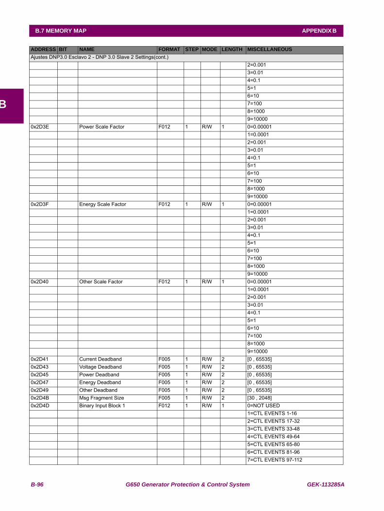
B-96 G650 Generator Protection & Control System GEK-113285A
B.7 MEMORY MAP APPENDIX B
B
Ajustes DNP3.0 Esclavo 2 - DNP 3.0 Slave 2 Settings(cont.) 2=0.001 3=0.01 4=0.1 5=1 6=10 7=100 8=1000 9=100000x2D3E Power Scale Factor F012 1 R/W 1 0=0.00001 1=0.0001 2=0.001 3=0.01 4=0.1 5=1 6=10 7=100 8=1000 9=100000x2D3F Energy Scale Factor F012 1 R/W 1 0=0.00001 1=0.0001 2=0.001 3=0.01 4=0.1 5=1 6=10 7=100 8=1000 9=100000x2D40 Other Scale Factor F012 1 R/W 1 0=0.00001 1=0.0001 2=0.001 3=0.01 4=0.1 5=1 6=10 7=100 8=1000 9=100000x2D41 Current Deadband F005 1 R/W 2 [0 , 65535] 0x2D43 Voltage Deadband F005 1 R/W 2 [0 , 65535] 0x2D45 Power Deadband F005 1 R/W 2 [0 , 65535] 0x2D47 Energy Deadband F005 1 R/W 2 [0 , 65535] 0x2D49 Other Deadband F005 1 R/W 2 [0 , 65535] 0x2D4B Msg Fragment Size F005 1 R/W 2 [30 , 2048] 0x2D4D Binary Input Block 1 F012 1 R/W 1 0=NOT USED 1=CTL EVENTS 1-16 2=CTL EVENTS 17-32 3=CTL EVENTS 33-48 4=CTL EVENTS 49-64 5=CTL EVENTS 65-80 6=CTL EVENTS 81-96 7=CTL EVENTS 97-112
ADDRESS BIT NAME FORMAT STEP MODE LENGTH MISCELLANEOUS

GEK-113285A G650 Generator Protection & Control System B-97
APPENDIX B B.7 MEMORY MAP
B
Ajustes DNP3.0 Esclavo 2 - DNP 3.0 Slave 2 (cont.) 8=CTL EVENTS 113-128 9=SWITCHGEAR 1-8 10=SWITCHGEAR 9-160x2D4E Binary Input Block 2 F012 1 R/W 1 0=NOT USED 1=CTL EVENTS 1-16 2=CTL EVENTS 17-32 3=CTL EVENTS 33-48 4=CTL EVENTS 49-64 5=CTL EVENTS 65-80 6=CTL EVENTS 81-96 7=CTL EVENTS 97-112 8=CTL EVENTS 113-128 9=SWITCHGEAR 1-8 10=SWITCHGEAR 9-160x2D4F Binary Input Block 3 F012 1 R/W 1 0=NOT USED 1=CTL EVENTS 1-16 2=CTL EVENTS 17-32 3=CTL EVENTS 33-48 4=CTL EVENTS 49-64 5=CTL EVENTS 65-80 6=CTL EVENTS 81-96 7=CTL EVENTS 97-112 8=CTL EVENTS 113-128 9=SWITCHGEAR 1-8 10=SWITCHGEAR 9-160x2D50 Binary Input Block 4 F012 1 R/W 1 0=NOT USED 1=CTL EVENTS 1-16 2=CTL EVENTS 17-32 3=CTL EVENTS 33-48 4=CTL EVENTS 49-64 5=CTL EVENTS 65-80 6=CTL EVENTS 81-96 7=CTL EVENTS 97-112 8=CTL EVENTS 113-128 9=SWITCHGEAR 1-8 10=SWITCHGEAR 9-160x2D51 Binary Input Block 5 F012 1 R/W 1 0=NOT USED 1=CTL EVENTS 1-16 2=CTL EVENTS 17-32 3=CTL EVENTS 33-48 4=CTL EVENTS 49-64 5=CTL EVENTS 65-80 6=CTL EVENTS 81-96 7=CTL EVENTS 97-112 8=CTL EVENTS 113-128 9=SWITCHGEAR 1-8 10=SWITCHGEAR 9-160x2D52 Binary Input Block 6 F012 1 R/W 1 0=NOT USED 1=CTL EVENTS 1-16 2=CTL EVENTS 17-32 3=CTL EVENTS 33-48
ADDRESS BIT NAME FORMAT STEP MODE LENGTH MISCELLANEOUS
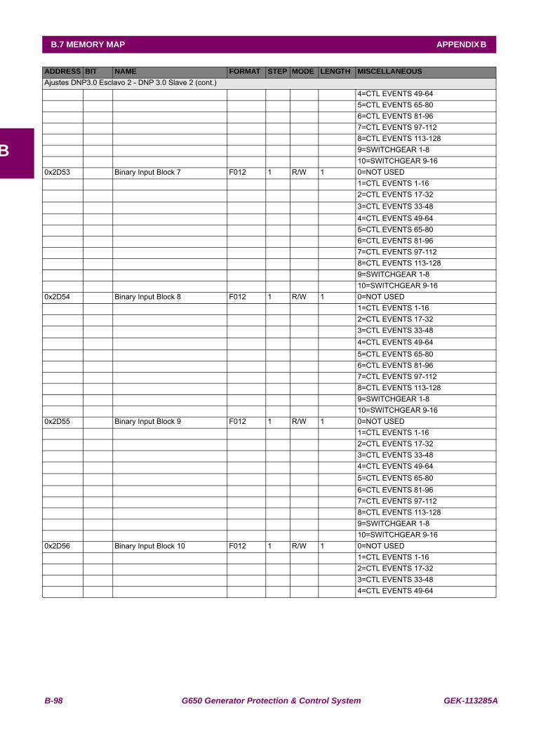
B-98 G650 Generator Protection & Control System GEK-113285A
B.7 MEMORY MAP APPENDIX B
B
Ajustes DNP3.0 Esclavo 2 - DNP 3.0 Slave 2 (cont.) 4=CTL EVENTS 49-64 5=CTL EVENTS 65-80 6=CTL EVENTS 81-96 7=CTL EVENTS 97-112 8=CTL EVENTS 113-128 9=SWITCHGEAR 1-8 10=SWITCHGEAR 9-160x2D53 Binary Input Block 7 F012 1 R/W 1 0=NOT USED 1=CTL EVENTS 1-16 2=CTL EVENTS 17-32 3=CTL EVENTS 33-48 4=CTL EVENTS 49-64 5=CTL EVENTS 65-80 6=CTL EVENTS 81-96 7=CTL EVENTS 97-112 8=CTL EVENTS 113-128 9=SWITCHGEAR 1-8 10=SWITCHGEAR 9-160x2D54 Binary Input Block 8 F012 1 R/W 1 0=NOT USED 1=CTL EVENTS 1-16 2=CTL EVENTS 17-32 3=CTL EVENTS 33-48 4=CTL EVENTS 49-64 5=CTL EVENTS 65-80 6=CTL EVENTS 81-96 7=CTL EVENTS 97-112 8=CTL EVENTS 113-128 9=SWITCHGEAR 1-8 10=SWITCHGEAR 9-160x2D55 Binary Input Block 9 F012 1 R/W 1 0=NOT USED 1=CTL EVENTS 1-16 2=CTL EVENTS 17-32 3=CTL EVENTS 33-48 4=CTL EVENTS 49-64 5=CTL EVENTS 65-80 6=CTL EVENTS 81-96 7=CTL EVENTS 97-112 8=CTL EVENTS 113-128 9=SWITCHGEAR 1-8 10=SWITCHGEAR 9-160x2D56 Binary Input Block 10 F012 1 R/W 1 0=NOT USED 1=CTL EVENTS 1-16 2=CTL EVENTS 17-32 3=CTL EVENTS 33-48 4=CTL EVENTS 49-64
ADDRESS BIT NAME FORMAT STEP MODE LENGTH MISCELLANEOUS
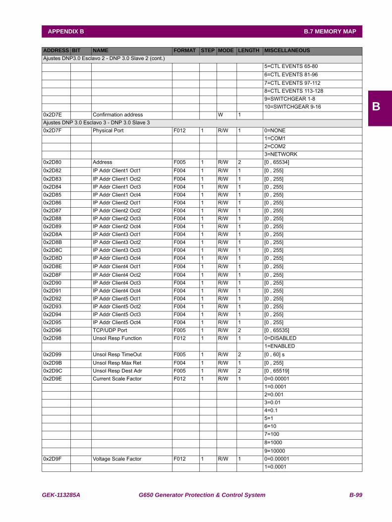
GEK-113285A G650 Generator Protection & Control System B-99
APPENDIX B B.7 MEMORY MAP
B
Ajustes DNP3.0 Esclavo 2 - DNP 3.0 Slave 2 (cont.) 5=CTL EVENTS 65-80 6=CTL EVENTS 81-96 7=CTL EVENTS 97-112 8=CTL EVENTS 113-128 9=SWITCHGEAR 1-8 10=SWITCHGEAR 9-160x2D7E Confirmation address W 1 Ajustes DNP 3.0 Esclavo 3 - DNP 3.0 Slave 30x2D7F Physical Port F012 1 R/W 1 0=NONE 1=COM1 2=COM2 3=NETWORK0x2D80 Address F005 1 R/W 2 [0 , 65534] 0x2D82 IP Addr Client1 Oct1 F004 1 R/W 1 [0 , 255] 0x2D83 IP Addr Client1 Oct2 F004 1 R/W 1 [0 , 255] 0x2D84 IP Addr Client1 Oct3 F004 1 R/W 1 [0 , 255] 0x2D85 IP Addr Client1 Oct4 F004 1 R/W 1 [0 , 255] 0x2D86 IP Addr Client2 Oct1 F004 1 R/W 1 [0 , 255] 0x2D87 IP Addr Client2 Oct2 F004 1 R/W 1 [0 , 255] 0x2D88 IP Addr Client2 Oct3 F004 1 R/W 1 [0 , 255] 0x2D89 IP Addr Client2 Oct4 F004 1 R/W 1 [0 , 255] 0x2D8A IP Addr Client3 Oct1 F004 1 R/W 1 [0 , 255] 0x2D8B IP Addr Client3 Oct2 F004 1 R/W 1 [0 , 255] 0x2D8C IP Addr Client3 Oct3 F004 1 R/W 1 [0 , 255] 0x2D8D IP Addr Client3 Oct4 F004 1 R/W 1 [0 , 255] 0x2D8E IP Addr Client4 Oct1 F004 1 R/W 1 [0 , 255] 0x2D8F IP Addr Client4 Oct2 F004 1 R/W 1 [0 , 255] 0x2D90 IP Addr Client4 Oct3 F004 1 R/W 1 [0 , 255] 0x2D91 IP Addr Client4 Oct4 F004 1 R/W 1 [0 , 255] 0x2D92 IP Addr Client5 Oct1 F004 1 R/W 1 [0 , 255] 0x2D93 IP Addr Client5 Oct2 F004 1 R/W 1 [0 , 255] 0x2D94 IP Addr Client5 Oct3 F004 1 R/W 1 [0 , 255] 0x2D95 IP Addr Client5 Oct4 F004 1 R/W 1 [0 , 255] 0x2D96 TCP/UDP Port F005 1 R/W 2 [0 , 65535] 0x2D98 Unsol Resp Function F012 1 R/W 1 0=DISABLED 1=ENABLED0x2D99 Unsol Resp TimeOut F005 1 R/W 2 [0 , 60] s0x2D9B Unsol Resp Max Ret F004 1 R/W 1 [0 , 255] 0x2D9C Unsol Resp Dest Adr F005 1 R/W 2 [0 , 65519] 0x2D9E Current Scale Factor F012 1 R/W 1 0=0.00001 1=0.0001 2=0.001 3=0.01 4=0.1 5=1 6=10 7=100 8=1000 9=100000x2D9F Voltage Scale Factor F012 1 R/W 1 0=0.00001 1=0.0001
ADDRESS BIT NAME FORMAT STEP MODE LENGTH MISCELLANEOUS

B-100 G650 Generator Protection & Control System GEK-113285A
B.7 MEMORY MAP APPENDIX B
B
Ajustes DNP 3.0 Esclavo 3 - DNP 3.0 Slave 3(cont.) 2=0.001 3=0.01 4=0.1 5=1 6=10 7=100 8=1000 9=100000x2DA0 Power Scale Factor F012 1 R/W 1 0=0.00001 1=0.0001 2=0.001 3=0.01 4=0.1 5=1 6=10 7=100 8=1000 9=100000x2DA1 Energy Scale Factor F012 1 R/W 1 0=0.00001 1=0.0001 2=0.001 3=0.01 4=0.1 5=1 6=10 7=100 8=1000 9=100000x2DA2 Other Scale Factor F012 1 R/W 1 0=0.00001 1=0.0001 2=0.001 3=0.01 4=0.1 5=1 6=10 7=100 8=1000 9=100000x2DA3 Current Deadband F005 1 R/W 2 [0 , 65535] 0x2DA5 Voltage Deadband F005 1 R/W 2 [0 , 65535] 0x2DA7 Power Deadband F005 1 R/W 2 [0 , 65535] 0x2DA9 Energy Deadband F005 1 R/W 2 [0 , 65535] 0x2DAB Other Deadband F005 1 R/W 2 [0 , 65535] 0x2DAD Msg Fragment Size F005 1 R/W 2 [30 , 2048] 0x2DAF Binary Input Block 1 F012 1 R/W 1 0=NOT USED 1=CTL EVENTS 1-16 2=CTL EVENTS 17-32 3=CTL EVENTS 33-48 4=CTL EVENTS 49-64 5=CTL EVENTS 65-80 6=CTL EVENTS 81-96
ADDRESS BIT NAME FORMAT STEP MODE LENGTH MISCELLANEOUS
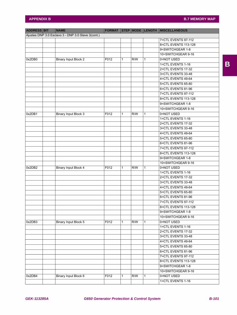
GEK-113285A G650 Generator Protection & Control System B-101
APPENDIX B B.7 MEMORY MAP
B
Ajustes DNP 3.0 Esclavo 3 - DNP 3.0 Slave 3(cont.) 7=CTL EVENTS 97-112 8=CTL EVENTS 113-128 9=SWITCHGEAR 1-8 10=SWITCHGEAR 9-160x2DB0 Binary Input Block 2 F012 1 R/W 1 0=NOT USED 1=CTL EVENTS 1-16 2=CTL EVENTS 17-32 3=CTL EVENTS 33-48 4=CTL EVENTS 49-64 5=CTL EVENTS 65-80 6=CTL EVENTS 81-96 7=CTL EVENTS 97-112 8=CTL EVENTS 113-128 9=SWITCHGEAR 1-8 10=SWITCHGEAR 9-160x2DB1 Binary Input Block 3 F012 1 R/W 1 0=NOT USED 1=CTL EVENTS 1-16 2=CTL EVENTS 17-32 3=CTL EVENTS 33-48 4=CTL EVENTS 49-64 5=CTL EVENTS 65-80 6=CTL EVENTS 81-96 7=CTL EVENTS 97-112 8=CTL EVENTS 113-128 9=SWITCHGEAR 1-8 10=SWITCHGEAR 9-160x2DB2 Binary Input Block 4 F012 1 R/W 1 0=NOT USED 1=CTL EVENTS 1-16 2=CTL EVENTS 17-32 3=CTL EVENTS 33-48 4=CTL EVENTS 49-64 5=CTL EVENTS 65-80 6=CTL EVENTS 81-96 7=CTL EVENTS 97-112 8=CTL EVENTS 113-128 9=SWITCHGEAR 1-8 10=SWITCHGEAR 9-160x2DB3 Binary Input Block 5 F012 1 R/W 1 0=NOT USED 1=CTL EVENTS 1-16 2=CTL EVENTS 17-32 3=CTL EVENTS 33-48 4=CTL EVENTS 49-64 5=CTL EVENTS 65-80 6=CTL EVENTS 81-96 7=CTL EVENTS 97-112 8=CTL EVENTS 113-128 9=SWITCHGEAR 1-8 10=SWITCHGEAR 9-160x2DB4 Binary Input Block 6 F012 1 R/W 1 0=NOT USED 1=CTL EVENTS 1-16
ADDRESS BIT NAME FORMAT STEP MODE LENGTH MISCELLANEOUS
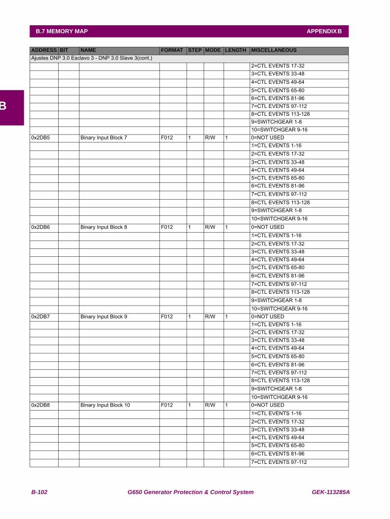
B-102 G650 Generator Protection & Control System GEK-113285A
B.7 MEMORY MAP APPENDIX B
B
Ajustes DNP 3.0 Esclavo 3 - DNP 3.0 Slave 3(cont.) 2=CTL EVENTS 17-32 3=CTL EVENTS 33-48 4=CTL EVENTS 49-64 5=CTL EVENTS 65-80 6=CTL EVENTS 81-96 7=CTL EVENTS 97-112 8=CTL EVENTS 113-128 9=SWITCHGEAR 1-8 10=SWITCHGEAR 9-160x2DB5 Binary Input Block 7 F012 1 R/W 1 0=NOT USED 1=CTL EVENTS 1-16 2=CTL EVENTS 17-32 3=CTL EVENTS 33-48 4=CTL EVENTS 49-64 5=CTL EVENTS 65-80 6=CTL EVENTS 81-96 7=CTL EVENTS 97-112 8=CTL EVENTS 113-128 9=SWITCHGEAR 1-8 10=SWITCHGEAR 9-160x2DB6 Binary Input Block 8 F012 1 R/W 1 0=NOT USED 1=CTL EVENTS 1-16 2=CTL EVENTS 17-32 3=CTL EVENTS 33-48 4=CTL EVENTS 49-64 5=CTL EVENTS 65-80 6=CTL EVENTS 81-96 7=CTL EVENTS 97-112 8=CTL EVENTS 113-128 9=SWITCHGEAR 1-8 10=SWITCHGEAR 9-160x2DB7 Binary Input Block 9 F012 1 R/W 1 0=NOT USED 1=CTL EVENTS 1-16 2=CTL EVENTS 17-32 3=CTL EVENTS 33-48 4=CTL EVENTS 49-64 5=CTL EVENTS 65-80 6=CTL EVENTS 81-96 7=CTL EVENTS 97-112 8=CTL EVENTS 113-128 9=SWITCHGEAR 1-8 10=SWITCHGEAR 9-160x2DB8 Binary Input Block 10 F012 1 R/W 1 0=NOT USED 1=CTL EVENTS 1-16 2=CTL EVENTS 17-32 3=CTL EVENTS 33-48 4=CTL EVENTS 49-64 5=CTL EVENTS 65-80 6=CTL EVENTS 81-96 7=CTL EVENTS 97-112
ADDRESS BIT NAME FORMAT STEP MODE LENGTH MISCELLANEOUS
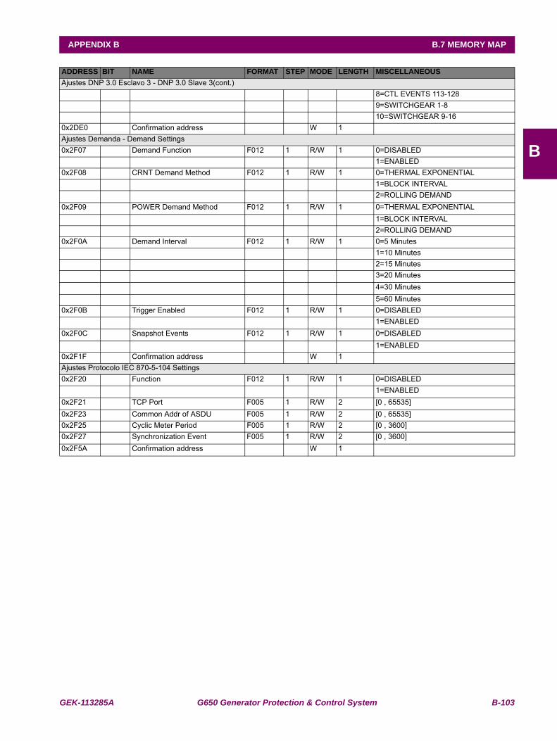
GEK-113285A G650 Generator Protection & Control System B-103
APPENDIX B B.7 MEMORY MAP
B
Ajustes DNP 3.0 Esclavo 3 - DNP 3.0 Slave 3(cont.) 8=CTL EVENTS 113-128 9=SWITCHGEAR 1-8 10=SWITCHGEAR 9-160x2DE0 Confirmation address W 1 Ajustes Demanda - Demand Settings0x2F07 Demand Function F012 1 R/W 1 0=DISABLED 1=ENABLED0x2F08 CRNT Demand Method F012 1 R/W 1 0=THERMAL EXPONENTIAL 1=BLOCK INTERVAL 2=ROLLING DEMAND0x2F09 POWER Demand Method F012 1 R/W 1 0=THERMAL EXPONENTIAL 1=BLOCK INTERVAL 2=ROLLING DEMAND0x2F0A Demand Interval F012 1 R/W 1 0=5 Minutes 1=10 Minutes 2=15 Minutes 3=20 Minutes 4=30 Minutes 5=60 Minutes0x2F0B Trigger Enabled F012 1 R/W 1 0=DISABLED 1=ENABLED0x2F0C Snapshot Events F012 1 R/W 1 0=DISABLED 1=ENABLED0x2F1F Confirmation address W 1 Ajustes Protocolo IEC 870-5-104 Settings0x2F20 Function F012 1 R/W 1 0=DISABLED 1=ENABLED0x2F21 TCP Port F005 1 R/W 2 [0 , 65535] 0x2F23 Common Addr of ASDU F005 1 R/W 2 [0 , 65535] 0x2F25 Cyclic Meter Period F005 1 R/W 2 [0 , 3600] 0x2F27 Synchronization Event F005 1 R/W 2 [0 , 3600] 0x2F5A Confirmation address W 1
ADDRESS BIT NAME FORMAT STEP MODE LENGTH MISCELLANEOUS
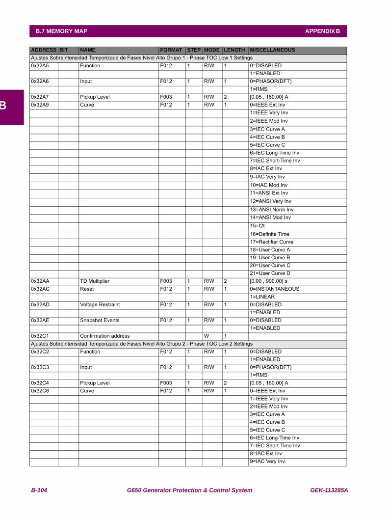
B-104 G650 Generator Protection & Control System GEK-113285A
B.7 MEMORY MAP APPENDIX B
B
Ajustes Sobreintensidad Temporizada de Fases Nivel Alto Grupo 1 - Phase TOC Low 1 Settings0x32A5 Function F012 1 R/W 1 0=DISABLED 1=ENABLED0x32A6 Input F012 1 R/W 1 0=PHASOR(DFT) 1=RMS0x32A7 Pickup Level F003 1 R/W 2 [0.05 , 160.00] A0x32A9 Curve F012 1 R/W 1 0=IEEE Ext Inv 1=IEEE Very Inv 2=IEEE Mod Inv 3=IEC Curve A 4=IEC Curve B 5=IEC Curve C 6=IEC Long-Time Inv 7=IEC Short-Time Inv 8=IAC Ext Inv 9=IAC Very Inv 10=IAC Mod Inv 11=ANSI Ext Inv 12=ANSI Very Inv 13=ANSI Norm Inv 14=ANSI Mod Inv 15=I2t 16=Definite Time 17=Rectifier Curve 18=User Curve A 19=User Curve B 20=User Curve C 21=User Curve D0x32AA TD Multiplier F003 1 R/W 2 [0.00 , 900.00] s0x32AC Reset F012 1 R/W 1 0=INSTANTANEOUS 1=LINEAR0x32AD Voltage Restraint F012 1 R/W 1 0=DISABLED 1=ENABLED0x32AE Snapshot Events F012 1 R/W 1 0=DISABLED 1=ENABLED0x32C1 Confirmation address W 1 Ajustes Sobreintensidad Temporizada de Fases Nivel Alto Grupo 2 - Phase TOC Low 2 Settings0x32C2 Function F012 1 R/W 1 0=DISABLED 1=ENABLED0x32C3 Input F012 1 R/W 1 0=PHASOR(DFT) 1=RMS0x32C4 Pickup Level F003 1 R/W 2 [0.05 , 160.00] A0x32C6 Curve F012 1 R/W 1 0=IEEE Ext Inv 1=IEEE Very Inv 2=IEEE Mod Inv 3=IEC Curve A 4=IEC Curve B 5=IEC Curve C 6=IEC Long-Time Inv 7=IEC Short-Time Inv 8=IAC Ext Inv 9=IAC Very Inv
ADDRESS BIT NAME FORMAT STEP MODE LENGTH MISCELLANEOUS
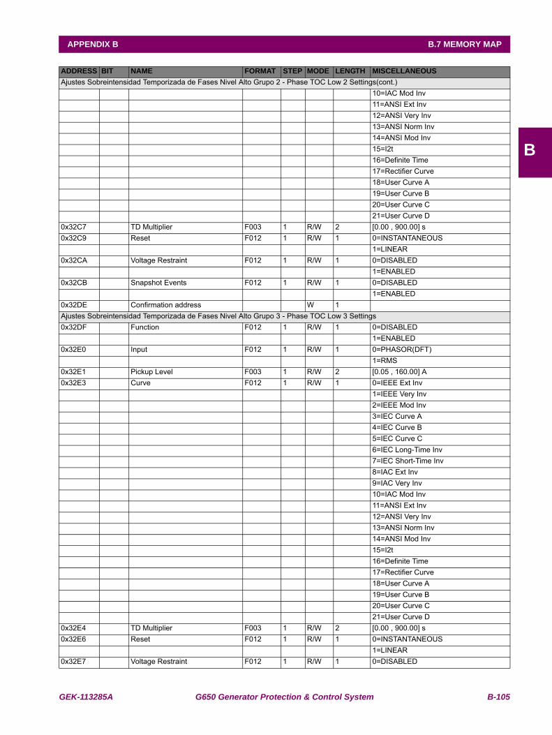
GEK-113285A G650 Generator Protection & Control System B-105
APPENDIX B B.7 MEMORY MAP
B
Ajustes Sobreintensidad Temporizada de Fases Nivel Alto Grupo 2 - Phase TOC Low 2 Settings(cont.) 10=IAC Mod Inv 11=ANSI Ext Inv 12=ANSI Very Inv 13=ANSI Norm Inv 14=ANSI Mod Inv 15=I2t 16=Definite Time 17=Rectifier Curve 18=User Curve A 19=User Curve B 20=User Curve C 21=User Curve D0x32C7 TD Multiplier F003 1 R/W 2 [0.00 , 900.00] s0x32C9 Reset F012 1 R/W 1 0=INSTANTANEOUS 1=LINEAR0x32CA Voltage Restraint F012 1 R/W 1 0=DISABLED 1=ENABLED0x32CB Snapshot Events F012 1 R/W 1 0=DISABLED 1=ENABLED0x32DE Confirmation address W 1 Ajustes Sobreintensidad Temporizada de Fases Nivel Alto Grupo 3 - Phase TOC Low 3 Settings0x32DF Function F012 1 R/W 1 0=DISABLED 1=ENABLED0x32E0 Input F012 1 R/W 1 0=PHASOR(DFT) 1=RMS0x32E1 Pickup Level F003 1 R/W 2 [0.05 , 160.00] A0x32E3 Curve F012 1 R/W 1 0=IEEE Ext Inv 1=IEEE Very Inv 2=IEEE Mod Inv 3=IEC Curve A 4=IEC Curve B 5=IEC Curve C 6=IEC Long-Time Inv 7=IEC Short-Time Inv 8=IAC Ext Inv 9=IAC Very Inv 10=IAC Mod Inv 11=ANSI Ext Inv 12=ANSI Very Inv 13=ANSI Norm Inv 14=ANSI Mod Inv 15=I2t 16=Definite Time 17=Rectifier Curve 18=User Curve A 19=User Curve B 20=User Curve C 21=User Curve D0x32E4 TD Multiplier F003 1 R/W 2 [0.00 , 900.00] s0x32E6 Reset F012 1 R/W 1 0=INSTANTANEOUS 1=LINEAR0x32E7 Voltage Restraint F012 1 R/W 1 0=DISABLED
ADDRESS BIT NAME FORMAT STEP MODE LENGTH MISCELLANEOUS
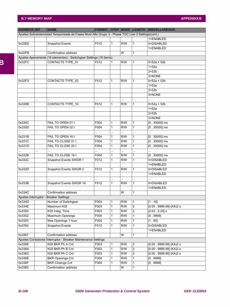
B-106 G650 Generator Protection & Control System GEK-113285A
B.7 MEMORY MAP APPENDIX B
B
Ajustes Sobreintensidad Temporizada de Fases Nivel Alto Grupo 3 - Phase TOC Low 3 Settings(cont.) 1=ENABLED0x32E8 Snapshot Events F012 1 R/W 1 0=DISABLED 1=ENABLED0x32FB Confirmation address W 1 Ajustes Aparamenta (16 elementos) - Switchgear Settings (16 items)0x32FC CONTACTS TYPE_01 F012 1 R/W 1 0=52a + 52b 1=52a 2=52b 3=NONE0x32FD CONTACTS TYPE_02 F012 1 R/W 1 0=52a + 52b 1=52a 2=52b 3=NONE... ... ... ... ... ... ... ...0x330B CONTACTS TYPE_16 F012 1 R/W 1 0=52a + 52b 1=52a 2=52b 3=NONE0x330C FAIL TO OPEN 01 t F004 1 R/W 1 [0 , 30000] ms0x330D FAIL TO OPEN 02 t F004 1 R/W 1 [0 , 30000] ms... ... ... ... ... ... ... ...0x331B FAIL TO OPEN 16 t F004 1 R/W 1 [0 , 30000] ms0x331C FAIL TO CLOSE 01 t F004 1 R/W 1 [0 , 30000] ms0x331D FAIL TO CLOSE 02 t F004 1 R/W 1 [0 , 30000] ms... ... ... ... ... ... ... ...0x332B FAIL TO CLOSE 16 t F004 1 R/W 1 [0 , 30000] ms0x332C Snapshot Events SWGR 1 F012 1 R/W 1 0=DISABLED 1=ENABLED0x332D Snapshot Events SWGR 2 F012 1 R/W 1 0=DISABLED 1=ENABLED... ... ... ... ... ... ... ...0x333B Snapshot Events SWGR 16 F012 1 R/W 1 0=DISABLED 1=ENABLED0x334C Confirmation address W 1 Ajustes Interruptor - Breaker Settings0x334D Number of Switchgear F004 1 R/W 1 [1 , 16] 0x334E Maximum KI2t F003 1 R/W 2 [0.00 , 9999.99] (KA)2 s0x3350 KI2t Integ. Time F003 1 R/W 2 [0.03 , 0.25] s0x3352 Maximum Openings F004 1 R/W 1 [0 , 9999] 0x3353 Max.Openings 1 hour F004 1 R/W 1 [1 , 60] 0x3354 Snapshot Events F012 1 R/W 1 0=DISABLED 1=ENABLED0x3367 Confirmation address W 1 Ajustes Contadores Interruptor - Breaker Maintenance Settings0x3368 KI2t BKR Ph A Cnt F003 1 R/W 2 [0.00 , 9999.99] (KA)2 s0x336A KI2t BKR Ph B Cnt F003 1 R/W 2 [0.00 , 9999.99] (KA)2 s0x336C KI2t BKR Ph C Cnt F003 1 R/W 2 [0.00 , 9999.99] (KA)2 s0x336E BKR Openings Cnt F004 1 R/W 1 [0 , 9999] 0x336F BKR Closings Cnt F004 1 R/W 1 [0 , 9999] 0x3383 Confirmation address W 1
ADDRESS BIT NAME FORMAT STEP MODE LENGTH MISCELLANEOUS
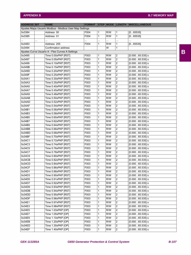
GEK-113285A G650 Generator Protection & Control System B-107
APPENDIX B B.7 MEMORY MAP
B
Ajustes Mapa Usuario Modbus - Modbus User Map Settings0x3384 Address 00 F004 1 R/W 1 [0 , 65535] 0x3385 Address 01 F004 1 R/W 1 [0 , 65535] ... ... ... ... ... ... ... ...0x3483 Address 255 F004 1 R/W 1 [0 , 65535] 0x3494 Confirmation address W 1 Ajustes Curva Usuario A - Flex Curves A Settings0x3495 Time 0.00xPKP [RST] F003 1 R/W 2 [0.000 , 65.535] s0x3497 Time 0.05xPKP [RST] F003 1 R/W 2 [0.000 , 65.535] s0x3499 Time 0.10xPKP [RST] F003 1 R/W 2 [0.000 , 65.535] s0x349B Time 0.15xPKP [RST] F003 1 R/W 2 [0.000 , 65.535] s0x349D Time 0.20xPKP [RST] F003 1 R/W 2 [0.000 , 65.535] s0x349F Time 0.25xPKP [RST] F003 1 R/W 2 [0.000 , 65.535] s0x34A1 Time 0.30xPKP [RST] F003 1 R/W 2 [0.000 , 65.535] s0x34A3 Time 0.35xPKP [RST] F003 1 R/W 2 [0.000 , 65.535] s0x34A5 Time 0.40xPKP [RST] F003 1 R/W 2 [0.000 , 65.535] s0x34A7 Time 0.45xPKP [RST] F003 1 R/W 2 [0.000 , 65.535] s0x34A9 Time 0.48xPKP [RST] F003 1 R/W 2 [0.000 , 65.535] s0x34AB Time 0.50xPKP [RST] F003 1 R/W 2 [0.000 , 65.535] s0x34AD Time 0.52xPKP [RST] F003 1 R/W 2 [0.000 , 65.535] s0x34AF Time 0.54xPKP [RST] F003 1 R/W 2 [0.000 , 65.535] s0x34B1 Time 0.56xPKP [RST] F003 1 R/W 2 [0.000 , 65.535] s0x34B3 Time 0.58xPKP [RST] F003 1 R/W 2 [0.000 , 65.535] s0x34B5 Time 0.60xPKP [RST] F003 1 R/W 2 [0.000 , 65.535] s0x34B7 Time 0.62xPKP [RST] F003 1 R/W 2 [0.000 , 65.535] s0x34B9 Time 0.64xPKP [RST] F003 1 R/W 2 [0.000 , 65.535] s0x34BB Time 0.66xPKP [RST] F003 1 R/W 2 [0.000 , 65.535] s0x34BD Time 0.68xPKP [RST] F003 1 R/W 2 [0.000 , 65.535] s0x34BF Time 0.70xPKP [RST] F003 1 R/W 2 [0.000 , 65.535] s0x34C1 Time 0.72xPKP [RST] F003 1 R/W 2 [0.000 , 65.535] s0x34C3 Time 0.74xPKP [RST] F003 1 R/W 2 [0.000 , 65.535] s0x34C5 Time 0.76xPKP [RST] F003 1 R/W 2 [0.000 , 65.535] s0x34C7 Time 0.78xPKP [RST] F003 1 R/W 2 [0.000 , 65.535] s0x34C9 Time 0.80xPKP [RST] F003 1 R/W 2 [0.000 , 65.535] s0x34CB Time 0.82xPKP [RST] F003 1 R/W 2 [0.000 , 65.535] s0x34CD Time 0.84xPKP [RST] F003 1 R/W 2 [0.000 , 65.535] s0x34CF Time 0.86xPKP [RST] F003 1 R/W 2 [0.000 , 65.535] s0x34D1 Time 0.88xPKP [RST] F003 1 R/W 2 [0.000 , 65.535] s0x34D3 Time 0.90xPKP [RST] F003 1 R/W 2 [0.000 , 65.535] s0x34D5 Time 0.91xPKP [RST] F003 1 R/W 2 [0.000 , 65.535] s0x34D7 Time 0.92xPKP [RST] F003 1 R/W 2 [0.000 , 65.535] s0x34D9 Time 0.93xPKP [RST] F003 1 R/W 2 [0.000 , 65.535] s0x34DB Time 0.94xPKP [RST] F003 1 R/W 2 [0.000 , 65.535] s0x34DD Time 0.95xPKP [RST] F003 1 R/W 2 [0.000 , 65.535] s0x34DF Time 0.96xPKP [RST] F003 1 R/W 2 [0.000 , 65.535] s0x34E1 Time 0.97xPKP [RST] F003 1 R/W 2 [0.000 , 65.535] s0x34E3 Time 0.98xPKP [RST] F003 1 R/W 2 [0.000 , 65.535] s0x34E5 Time 1.03xPKP [OP] F003 1 R/W 2 [0.000 , 65.535] s0x34E7 Time 1.05xPKP [OP] F003 1 R/W 2 [0.000 , 65.535] s0x34E9 Time 1.10xPKP [OP] F003 1 R/W 2 [0.000 , 65.535] s0x34EB Time 1.20xPKP [OP] F003 1 R/W 2 [0.000 , 65.535] s0x34ED Time 1.30xPKP [OP] F003 1 R/W 2 [0.000 , 65.535] s0x34EF Time 1.40xPKP [OP] F003 1 R/W 2 [0.000 , 65.535] s
ADDRESS BIT NAME FORMAT STEP MODE LENGTH MISCELLANEOUS

B-108 G650 Generator Protection & Control System GEK-113285A
B.7 MEMORY MAP APPENDIX B
B
Ajustes Curva Usuario A - Flex Curves A Settings(cont.)0x34F1 Time 1.50xPKP [OP] F003 1 R/W 2 [0.000 , 65.535] s0x34F3 Time 1.60xPKP [OP] F003 1 R/W 2 [0.000 , 65.535] s0x34F5 Time 1.70xPKP [OP] F003 1 R/W 2 [0.000 , 65.535] s0x34F7 Time 1.80xPKP [OP] F003 1 R/W 2 [0.000 , 65.535] s0x34F9 Time 1.90xPKP [OP] F003 1 R/W 2 [0.000 , 65.535] s0x34FB Time 2.00xPKP [OP] F003 1 R/W 2 [0.000 , 65.535] s0x34FD Time 2.10xPKP [OP] F003 1 R/W 2 [0.000 , 65.535] s0x34FF Time 2.20xPKP [OP] F003 1 R/W 2 [0.000 , 65.535] s0x3501 Time 2.30xPKP [OP] F003 1 R/W 2 [0.000 , 65.535] s0x3503 Time 2.40xPKP [OP] F003 1 R/W 2 [0.000 , 65.535] s0x3505 Time 2.50xPKP [OP] F003 1 R/W 2 [0.000 , 65.535] s0x3507 Time 2.60xPKP [OP] F003 1 R/W 2 [0.000 , 65.535] s0x3509 Time 2.70xPKP [OP] F003 1 R/W 2 [0.000 , 65.535] s0x350B Time 2.80xPKP [OP] F003 1 R/W 2 [0.000 , 65.535] s0x350D Time 2.90xPKP [OP] F003 1 R/W 2 [0.000 , 65.535] s0x350F Time 3.00xPKP [OP] F003 1 R/W 2 [0.000 , 65.535] s0x3511 Time 3.10xPKP [OP] F003 1 R/W 2 [0.000 , 65.535] s0x3513 Time 3.20xPKP [OP] F003 1 R/W 2 [0.000 , 65.535] s0x3515 Time 3.30xPKP [OP] F003 1 R/W 2 [0.000 , 65.535] s0x3517 Time 3.40xPKP [OP] F003 1 R/W 2 [0.000 , 65.535] s0x3519 Time 3.50xPKP [OP] F003 1 R/W 2 [0.000 , 65.535] s0x351B Time 3.60xPKP [OP] F003 1 R/W 2 [0.000 , 65.535] s0x351D Time 3.70xPKP [OP] F003 1 R/W 2 [0.000 , 65.535] s0x351F Time 3.80xPKP [OP] F003 1 R/W 2 [0.000 , 65.535] s0x3521 Time 3.90xPKP [OP] F003 1 R/W 2 [0.000 , 65.535] s0x3523 Time 4.00xPKP [OP] F003 1 R/W 2 [0.000 , 65.535] s0x3525 Time 4.10xPKP [OP] F003 1 R/W 2 [0.000 , 65.535] s0x3527 Time 4.20xPKP [OP] F003 1 R/W 2 [0.000 , 65.535] s0x3529 Time 4.30xPKP [OP] F003 1 R/W 2 [0.000 , 65.535] s0x352B Time 4.40xPKP [OP] F003 1 R/W 2 [0.000 , 65.535] s0x352D Time 4.50xPKP [OP] F003 1 R/W 2 [0.000 , 65.535] s0x352F Time 4.60xPKP [OP] F003 1 R/W 2 [0.000 , 65.535] s0x3531 Time 4.70xPKP [OP] F003 1 R/W 2 [0.000 , 65.535] s0x3533 Time 4.80xPKP [OP] F003 1 R/W 2 [0.000 , 65.535] s0x3535 Time 4.90xPKP [OP] F003 1 R/W 2 [0.000 , 65.535] s0x3537 Time 5.00xPKP [OP] F003 1 R/W 2 [0.000 , 65.535] s0x3539 Time 5.10xPKP [OP] F003 1 R/W 2 [0.000 , 65.535] s0x353B Time 5.20xPKP [OP] F003 1 R/W 2 [0.000 , 65.535] s0x353D Time 5.30xPKP [OP] F003 1 R/W 2 [0.000 , 65.535] s0x353F Time 5.40xPKP [OP] F003 1 R/W 2 [0.000 , 65.535] s0x3541 Time 5.50xPKP [OP] F003 1 R/W 2 [0.000 , 65.535] s0x3543 Time 5.60xPKP [OP] F003 1 R/W 2 [0.000 , 65.535] s0x3545 Time 5.70xPKP [OP] F003 1 R/W 2 [0.000 , 65.535] s0x3547 Time 5.80xPKP [OP] F003 1 R/W 2 [0.000 , 65.535] s0x3549 Time 5.90xPKP [OP] F003 1 R/W 2 [0.000 , 65.535] s0x354B Time 6.00xPKP [OP] F003 1 R/W 2 [0.000 , 65.535] s0x354D Time 6.50xPKP [OP] F003 1 R/W 2 [0.000 , 65.535] s0x354F Time 7.00xPKP [OP] F003 1 R/W 2 [0.000 , 65.535] s0x3551 Time 7.50xPKP [OP] F003 1 R/W 2 [0.000 , 65.535] s0x3553 Time 8.00xPKP [OP] F003 1 R/W 2 [0.000 , 65.535] s0x3555 Time 8.50xPKP [OP] F003 1 R/W 2 [0.000 , 65.535] s0x3557 Time 9.00xPKP [OP] F003 1 R/W 2 [0.000 , 65.535] s
ADDRESS BIT NAME FORMAT STEP MODE LENGTH MISCELLANEOUS

GEK-113285A G650 Generator Protection & Control System B-109
APPENDIX B B.7 MEMORY MAP
B
Ajustes Curva Usuario A - Flex Curves A Settings(cont.)0x3559 Time 9.50xPKP [OP] F003 1 R/W 2 [0.000 , 65.535] s0x355B Time 10.00xPKP [OP] F003 1 R/W 2 [0.000 , 65.535] s0x355D Time 10.50xPKP [OP] F003 1 R/W 2 [0.000 , 65.535] s0x355F Time 11.00xPKP [OP] F003 1 R/W 2 [0.000 , 65.535] s0x3561 Time 11.50xPKP [OP] F003 1 R/W 2 [0.000 , 65.535] s0x3563 Time 12.00xPKP [OP] F003 1 R/W 2 [0.000 , 65.535] s0x3565 Time 12.50xPKP [OP] F003 1 R/W 2 [0.000 , 65.535] s0x3567 Time 13.00xPKP [OP] F003 1 R/W 2 [0.000 , 65.535] s0x3569 Time 13.50xPKP [OP] F003 1 R/W 2 [0.000 , 65.535] s0x356B Time 14.00xPKP [OP] F003 1 R/W 2 [0.000 , 65.535] s0x356D Time 14.50xPKP [OP] F003 1 R/W 2 [0.000 , 65.535] s0x356F Time 15.00xPKP [OP] F003 1 R/W 2 [0.000 , 65.535] s0x3571 Time 15.50xPKP [OP] F003 1 R/W 2 [0.000 , 65.535] s0x3573 Time 16.00xPKP [OP] F003 1 R/W 2 [0.000 , 65.535] s0x3575 Time 16.50xPKP [OP] F003 1 R/W 2 [0.000 , 65.535] s0x3577 Time 17.00xPKP [OP] F003 1 R/W 2 [0.000 , 65.535] s0x3579 Time 17.50xPKP [OP] F003 1 R/W 2 [0.000 , 65.535] s0x357B Time 18.00xPKP [OP] F003 1 R/W 2 [0.000 , 65.535] s0x357D Time 18.50xPKP [OP] F003 1 R/W 2 [0.000 , 65.535] s0x357F Time 19.00xPKP [OP] F003 1 R/W 2 [0.000 , 65.535] s0x3581 Time 19.50xPKP [OP] F003 1 R/W 2 [0.000 , 65.535] s0x3583 Time 20.00xPKP [OP] F003 1 R/W 2 [0.000 , 65.535] s0x3598 Confirmation address W 1 Ajustes Curva Usuario B - Flex Curves B Settings0x3599 Time 0.00xPKP [RST] F003 1 R/W 2 [0.000 , 65.535] s0x359B Time 0.05xPKP [RST] F003 1 R/W 2 [0.000 , 65.535] s0x359D Time 0.10xPKP [RST] F003 1 R/W 2 [0.000 , 65.535] s0x359F Time 0.15xPKP [RST] F003 1 R/W 2 [0.000 , 65.535] s0x35A1 Time 0.20xPKP [RST] F003 1 R/W 2 [0.000 , 65.535] s0x35A3 Time 0.25xPKP [RST] F003 1 R/W 2 [0.000 , 65.535] s0x35A5 Time 0.30xPKP [RST] F003 1 R/W 2 [0.000 , 65.535] s0x35A7 Time 0.35xPKP [RST] F003 1 R/W 2 [0.000 , 65.535] s0x35A9 Time 0.40xPKP [RST] F003 1 R/W 2 [0.000 , 65.535] s0x35AB Time 0.45xPKP [RST] F003 1 R/W 2 [0.000 , 65.535] s0x35AD Time 0.48xPKP [RST] F003 1 R/W 2 [0.000 , 65.535] s0x35AF Time 0.50xPKP [RST] F003 1 R/W 2 [0.000 , 65.535] s0x35B1 Time 0.52xPKP [RST] F003 1 R/W 2 [0.000 , 65.535] s0x35B3 Time 0.54xPKP [RST] F003 1 R/W 2 [0.000 , 65.535] s0x35B5 Time 0.56xPKP [RST] F003 1 R/W 2 [0.000 , 65.535] s0x35B7 Time 0.58xPKP [RST] F003 1 R/W 2 [0.000 , 65.535] s0x35B9 Time 0.60xPKP [RST] F003 1 R/W 2 [0.000 , 65.535] s0x35BB Time 0.62xPKP [RST] F003 1 R/W 2 [0.000 , 65.535] s0x35BD Time 0.64xPKP [RST] F003 1 R/W 2 [0.000 , 65.535] s0x35BF Time 0.66xPKP [RST] F003 1 R/W 2 [0.000 , 65.535] s0x35C1 Time 0.68xPKP [RST] F003 1 R/W 2 [0.000 , 65.535] s0x35C3 Time 0.70xPKP [RST] F003 1 R/W 2 [0.000 , 65.535] s0x35C5 Time 0.72xPKP [RST] F003 1 R/W 2 [0.000 , 65.535] s0x35C7 Time 0.74xPKP [RST] F003 1 R/W 2 [0.000 , 65.535] s0x35C9 Time 0.76xPKP [RST] F003 1 R/W 2 [0.000 , 65.535] s0x35CB Time 0.78xPKP [RST] F003 1 R/W 2 [0.000 , 65.535] s0x35CD Time 0.80xPKP [RST] F003 1 R/W 2 [0.000 , 65.535] s
ADDRESS BIT NAME FORMAT STEP MODE LENGTH MISCELLANEOUS
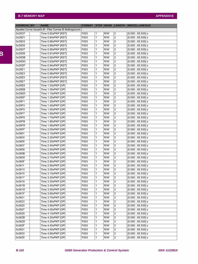
B-110 G650 Generator Protection & Control System GEK-113285A
B.7 MEMORY MAP APPENDIX B
B
Ajustes Curva Usuario B - Flex Curves B Settings(cont.)0x35CF Time 0.82xPKP [RST] F003 1 R/W 2 [0.000 , 65.535] s0x35D1 Time 0.84xPKP [RST] F003 1 R/W 2 [0.000 , 65.535] s0x35D3 Time 0.86xPKP [RST] F003 1 R/W 2 [0.000 , 65.535] s0x35D5 Time 0.88xPKP [RST] F003 1 R/W 2 [0.000 , 65.535] s0x35D7 Time 0.90xPKP [RST] F003 1 R/W 2 [0.000 , 65.535] s0x35D9 Time 0.91xPKP [RST] F003 1 R/W 2 [0.000 , 65.535] s0x35DB Time 0.92xPKP [RST] F003 1 R/W 2 [0.000 , 65.535] s0x35DD Time 0.93xPKP [RST] F003 1 R/W 2 [0.000 , 65.535] s0x35DF Time 0.94xPKP [RST] F003 1 R/W 2 [0.000 , 65.535] s0x35E1 Time 0.95xPKP [RST] F003 1 R/W 2 [0.000 , 65.535] s0x35E3 Time 0.96xPKP [RST] F003 1 R/W 2 [0.000 , 65.535] s0x35E5 Time 0.97xPKP [RST] F003 1 R/W 2 [0.000 , 65.535] s0x35E7 Time 0.98xPKP [RST] F003 1 R/W 2 [0.000 , 65.535] s0x35E9 Time 1.03xPKP [OP] F003 1 R/W 2 [0.000 , 65.535] s0x35EB Time 1.05xPKP [OP] F003 1 R/W 2 [0.000 , 65.535] s0x35ED Time 1.10xPKP [OP] F003 1 R/W 2 [0.000 , 65.535] s0x35EF Time 1.20xPKP [OP] F003 1 R/W 2 [0.000 , 65.535] s0x35F1 Time 1.30xPKP [OP] F003 1 R/W 2 [0.000 , 65.535] s0x35F3 Time 1.40xPKP [OP] F003 1 R/W 2 [0.000 , 65.535] s0x35F5 Time 1.50xPKP [OP] F003 1 R/W 2 [0.000 , 65.535] s0x35F7 Time 1.60xPKP [OP] F003 1 R/W 2 [0.000 , 65.535] s0x35F9 Time 1.70xPKP [OP] F003 1 R/W 2 [0.000 , 65.535] s0x35FB Time 1.80xPKP [OP] F003 1 R/W 2 [0.000 , 65.535] s0x35FD Time 1.90xPKP [OP] F003 1 R/W 2 [0.000 , 65.535] s0x35FF Time 2.00xPKP [OP] F003 1 R/W 2 [0.000 , 65.535] s0x3601 Time 2.10xPKP [OP] F003 1 R/W 2 [0.000 , 65.535] s0x3603 Time 2.20xPKP [OP] F003 1 R/W 2 [0.000 , 65.535] s0x3605 Time 2.30xPKP [OP] F003 1 R/W 2 [0.000 , 65.535] s0x3607 Time 2.40xPKP [OP] F003 1 R/W 2 [0.000 , 65.535] s0x3609 Time 2.50xPKP [OP] F003 1 R/W 2 [0.000 , 65.535] s0x360B Time 2.60xPKP [OP] F003 1 R/W 2 [0.000 , 65.535] s0x360D Time 2.70xPKP [OP] F003 1 R/W 2 [0.000 , 65.535] s0x360F Time 2.80xPKP [OP] F003 1 R/W 2 [0.000 , 65.535] s0x3611 Time 2.90xPKP [OP] F003 1 R/W 2 [0.000 , 65.535] s0x3613 Time 3.00xPKP [OP] F003 1 R/W 2 [0.000 , 65.535] s0x3615 Time 3.10xPKP [OP] F003 1 R/W 2 [0.000 , 65.535] s0x3617 Time 3.20xPKP [OP] F003 1 R/W 2 [0.000 , 65.535] s0x3619 Time 3.30xPKP [OP] F003 1 R/W 2 [0.000 , 65.535] s0x361B Time 3.40xPKP [OP] F003 1 R/W 2 [0.000 , 65.535] s0x361D Time 3.50xPKP [OP] F003 1 R/W 2 [0.000 , 65.535] s0x361F Time 3.60xPKP [OP] F003 1 R/W 2 [0.000 , 65.535] s0x3621 Time 3.70xPKP [OP] F003 1 R/W 2 [0.000 , 65.535] s0x3623 Time 3.80xPKP [OP] F003 1 R/W 2 [0.000 , 65.535] s0x3625 Time 3.90xPKP [OP] F003 1 R/W 2 [0.000 , 65.535] s0x3627 Time 4.00xPKP [OP] F003 1 R/W 2 [0.000 , 65.535] s0x3629 Time 4.10xPKP [OP] F003 1 R/W 2 [0.000 , 65.535] s0x362B Time 4.20xPKP [OP] F003 1 R/W 2 [0.000 , 65.535] s0x362D Time 4.30xPKP [OP] F003 1 R/W 2 [0.000 , 65.535] s0x362F Time 4.40xPKP [OP] F003 1 R/W 2 [0.000 , 65.535] s0x3631 Time 4.50xPKP [OP] F003 1 R/W 2 [0.000 , 65.535] s0x3633 Time 4.60xPKP [OP] F003 1 R/W 2 [0.000 , 65.535] s0x3635 Time 4.70xPKP [OP] F003 1 R/W 2 [0.000 , 65.535] s
ADDRESS BIT NAME FORMAT STEP MODE LENGTH MISCELLANEOUS

GEK-113285A G650 Generator Protection & Control System B-111
APPENDIX B B.7 MEMORY MAP
B
Ajustes Curva Usuario B - Flex Curves B Settings(cont.)0x3637 Time 4.80xPKP [OP] F003 1 R/W 2 [0.000 , 65.535] s0x3639 Time 4.90xPKP [OP] F003 1 R/W 2 [0.000 , 65.535] s0x363B Time 5.00xPKP [OP] F003 1 R/W 2 [0.000 , 65.535] s0x363D Time 5.10xPKP [OP] F003 1 R/W 2 [0.000 , 65.535] s0x363F Time 5.20xPKP [OP] F003 1 R/W 2 [0.000 , 65.535] s0x3641 Time 5.30xPKP [OP] F003 1 R/W 2 [0.000 , 65.535] s0x3643 Time 5.40xPKP [OP] F003 1 R/W 2 [0.000 , 65.535] s0x3645 Time 5.50xPKP [OP] F003 1 R/W 2 [0.000 , 65.535] s0x3647 Time 5.60xPKP [OP] F003 1 R/W 2 [0.000 , 65.535] s0x3649 Time 5.70xPKP [OP] F003 1 R/W 2 [0.000 , 65.535] s0x364B Time 5.80xPKP [OP] F003 1 R/W 2 [0.000 , 65.535] s0x364D Time 5.90xPKP [OP] F003 1 R/W 2 [0.000 , 65.535] s0x364F Time 6.00xPKP [OP] F003 1 R/W 2 [0.000 , 65.535] s0x3651 Time 6.50xPKP [OP] F003 1 R/W 2 [0.000 , 65.535] s0x3653 Time 7.00xPKP [OP] F003 1 R/W 2 [0.000 , 65.535] s0x3655 Time 7.50xPKP [OP] F003 1 R/W 2 [0.000 , 65.535] s0x3657 Time 8.00xPKP [OP] F003 1 R/W 2 [0.000 , 65.535] s0x3659 Time 8.50xPKP [OP] F003 1 R/W 2 [0.000 , 65.535] s0x365B Time 9.00xPKP [OP] F003 1 R/W 2 [0.000 , 65.535] s0x365D Time 9.50xPKP [OP] F003 1 R/W 2 [0.000 , 65.535] s0x365F Time 10.00xPKP [OP] F003 1 R/W 2 [0.000 , 65.535] s0x3661 Time 10.50xPKP [OP] F003 1 R/W 2 [0.000 , 65.535] s0x3663 Time 11.00xPKP [OP] F003 1 R/W 2 [0.000 , 65.535] s0x3665 Time 11.50xPKP [OP] F003 1 R/W 2 [0.000 , 65.535] s0x3667 Time 12.00xPKP [OP] F003 1 R/W 2 [0.000 , 65.535] s0x3669 Time 12.50xPKP [OP] F003 1 R/W 2 [0.000 , 65.535] s0x366B Time 13.00xPKP [OP] F003 1 R/W 2 [0.000 , 65.535] s0x366D Time 13.50xPKP [OP] F003 1 R/W 2 [0.000 , 65.535] s0x366F Time 14.00xPKP [OP] F003 1 R/W 2 [0.000 , 65.535] s0x3671 Time 14.50xPKP [OP] F003 1 R/W 2 [0.000 , 65.535] s0x3673 Time 15.00xPKP [OP] F003 1 R/W 2 [0.000 , 65.535] s0x3675 Time 15.50xPKP [OP] F003 1 R/W 2 [0.000 , 65.535] s0x3677 Time 16.00xPKP [OP] F003 1 R/W 2 [0.000 , 65.535] s0x3679 Time 16.50xPKP [OP] F003 1 R/W 2 [0.000 , 65.535] s0x367B Time 17.00xPKP [OP] F003 1 R/W 2 [0.000 , 65.535] s0x367D Time 17.50xPKP [OP] F003 1 R/W 2 [0.000 , 65.535] s0x367F Time 18.00xPKP [OP] F003 1 R/W 2 [0.000 , 65.535] s0x3681 Time 18.50xPKP [OP] F003 1 R/W 2 [0.000 , 65.535] s0x3683 Time 19.00xPKP [OP] F003 1 R/W 2 [0.000 , 65.535] s0x3685 Time 19.50xPKP [OP] F003 1 R/W 2 [0.000 , 65.535] s0x3687 Time 20.00xPKP [OP] F003 1 R/W 2 [0.000 , 65.535] s0x369C Confirmation address W 1 Ajustes Curva Usuario C - Flex Curves C0x369D Time 0.00xPKP [RST] F003 1 R/W 2 [0.000 , 65.535] s0x369F Time 0.05xPKP [RST] F003 1 R/W 2 [0.000 , 65.535] s0x36A1 Time 0.10xPKP [RST] F003 1 R/W 2 [0.000 , 65.535] s0x36A3 Time 0.15xPKP [RST] F003 1 R/W 2 [0.000 , 65.535] s0x36A5 Time 0.20xPKP [RST] F003 1 R/W 2 [0.000 , 65.535] s0x36A7 Time 0.25xPKP [RST] F003 1 R/W 2 [0.000 , 65.535] s0x36A9 Time 0.30xPKP [RST] F003 1 R/W 2 [0.000 , 65.535] s0x36AB Time 0.35xPKP [RST] F003 1 R/W 2 [0.000 , 65.535] s
ADDRESS BIT NAME FORMAT STEP MODE LENGTH MISCELLANEOUS

B-112 G650 Generator Protection & Control System GEK-113285A
B.7 MEMORY MAP APPENDIX B
B
Ajustes Curva Usuario C - Flex Curves C(cont.)0x36AD Time 0.40xPKP [RST] F003 1 R/W 2 [0.000 , 65.535] s0x36AF Time 0.45xPKP [RST] F003 1 R/W 2 [0.000 , 65.535] s0x36B1 Time 0.48xPKP [RST] F003 1 R/W 2 [0.000 , 65.535] s0x36B3 Time 0.50xPKP [RST] F003 1 R/W 2 [0.000 , 65.535] s0x36B5 Time 0.52xPKP [RST] F003 1 R/W 2 [0.000 , 65.535] s0x36B7 Time 0.54xPKP [RST] F003 1 R/W 2 [0.000 , 65.535] s0x36B9 Time 0.56xPKP [RST] F003 1 R/W 2 [0.000 , 65.535] s0x36BB Time 0.58xPKP [RST] F003 1 R/W 2 [0.000 , 65.535] s0x36BD Time 0.60xPKP [RST] F003 1 R/W 2 [0.000 , 65.535] s0x36BF Time 0.62xPKP [RST] F003 1 R/W 2 [0.000 , 65.535] s0x36C1 Time 0.64xPKP [RST] F003 1 R/W 2 [0.000 , 65.535] s0x36C3 Time 0.66xPKP [RST] F003 1 R/W 2 [0.000 , 65.535] s0x36C5 Time 0.68xPKP [RST] F003 1 R/W 2 [0.000 , 65.535] s0x36C7 Time 0.70xPKP [RST] F003 1 R/W 2 [0.000 , 65.535] s0x36C9 Time 0.72xPKP [RST] F003 1 R/W 2 [0.000 , 65.535] s0x36CB Time 0.74xPKP [RST] F003 1 R/W 2 [0.000 , 65.535] s0x36CD Time 0.76xPKP [RST] F003 1 R/W 2 [0.000 , 65.535] s0x36CF Time 0.78xPKP [RST] F003 1 R/W 2 [0.000 , 65.535] s0x36D1 Time 0.80xPKP [RST] F003 1 R/W 2 [0.000 , 65.535] s0x36D3 Time 0.82xPKP [RST] F003 1 R/W 2 [0.000 , 65.535] s0x36D5 Time 0.84xPKP [RST] F003 1 R/W 2 [0.000 , 65.535] s0x36D7 Time 0.86xPKP [RST] F003 1 R/W 2 [0.000 , 65.535] s0x36D9 Time 0.88xPKP [RST] F003 1 R/W 2 [0.000 , 65.535] s0x36DB Time 0.90xPKP [RST] F003 1 R/W 2 [0.000 , 65.535] s0x36DD Time 0.91xPKP [RST] F003 1 R/W 2 [0.000 , 65.535] s0x36DF Time 0.92xPKP [RST] F003 1 R/W 2 [0.000 , 65.535] s0x36E1 Time 0.93xPKP [RST] F003 1 R/W 2 [0.000 , 65.535] s0x36E3 Time 0.94xPKP [RST] F003 1 R/W 2 [0.000 , 65.535] s0x36E5 Time 0.95xPKP [RST] F003 1 R/W 2 [0.000 , 65.535] s0x36E7 Time 0.96xPKP [RST] F003 1 R/W 2 [0.000 , 65.535] s0x36E9 Time 0.97xPKP [RST] F003 1 R/W 2 [0.000 , 65.535] s0x36EB Time 0.98xPKP [RST] F003 1 R/W 2 [0.000 , 65.535] s0x36ED Time 1.03xPKP [OP] F003 1 R/W 2 [0.000 , 65.535] s0x36EF Time 1.05xPKP [OP] F003 1 R/W 2 [0.000 , 65.535] s0x36F1 Time 1.10xPKP [OP] F003 1 R/W 2 [0.000 , 65.535] s0x36F3 Time 1.20xPKP [OP] F003 1 R/W 2 [0.000 , 65.535] s0x36F5 Time 1.30xPKP [OP] F003 1 R/W 2 [0.000 , 65.535] s0x36F7 Time 1.40xPKP [OP] F003 1 R/W 2 [0.000 , 65.535] s0x36F9 Time 1.50xPKP [OP] F003 1 R/W 2 [0.000 , 65.535] s0x36FB Time 1.60xPKP [OP] F003 1 R/W 2 [0.000 , 65.535] s0x36FD Time 1.70xPKP [OP] F003 1 R/W 2 [0.000 , 65.535] s0x36FF Time 1.80xPKP [OP] F003 1 R/W 2 [0.000 , 65.535] s0x3701 Time 1.90xPKP [OP] F003 1 R/W 2 [0.000 , 65.535] s0x3703 Time 2.00xPKP [OP] F003 1 R/W 2 [0.000 , 65.535] s0x3705 Time 2.10xPKP [OP] F003 1 R/W 2 [0.000 , 65.535] s0x3707 Time 2.20xPKP [OP] F003 1 R/W 2 [0.000 , 65.535] s0x3709 Time 2.30xPKP [OP] F003 1 R/W 2 [0.000 , 65.535] s0x370B Time 2.40xPKP [OP] F003 1 R/W 2 [0.000 , 65.535] s0x370D Time 2.50xPKP [OP] F003 1 R/W 2 [0.000 , 65.535] s0x370F Time 2.60xPKP [OP] F003 1 R/W 2 [0.000 , 65.535] s0x3711 Time 2.70xPKP [OP] F003 1 R/W 2 [0.000 , 65.535] s0x3713 Time 2.80xPKP [OP] F003 1 R/W 2 [0.000 , 65.535] s
ADDRESS BIT NAME FORMAT STEP MODE LENGTH MISCELLANEOUS

GEK-113285A G650 Generator Protection & Control System B-113
APPENDIX B B.7 MEMORY MAP
B
Ajustes Curva Usuario C - Flex Curves C(cont.)0x3715 Time 2.90xPKP [OP] F003 1 R/W 2 [0.000 , 65.535] s0x3717 Time 3.00xPKP [OP] F003 1 R/W 2 [0.000 , 65.535] s0x3719 Time 3.10xPKP [OP] F003 1 R/W 2 [0.000 , 65.535] s0x371B Time 3.20xPKP [OP] F003 1 R/W 2 [0.000 , 65.535] s0x371D Time 3.30xPKP [OP] F003 1 R/W 2 [0.000 , 65.535] s0x371F Time 3.40xPKP [OP] F003 1 R/W 2 [0.000 , 65.535] s0x3721 Time 3.50xPKP [OP] F003 1 R/W 2 [0.000 , 65.535] s0x3723 Time 3.60xPKP [OP] F003 1 R/W 2 [0.000 , 65.535] s0x3725 Time 3.70xPKP [OP] F003 1 R/W 2 [0.000 , 65.535] s0x3727 Time 3.80xPKP [OP] F003 1 R/W 2 [0.000 , 65.535] s0x3729 Time 3.90xPKP [OP] F003 1 R/W 2 [0.000 , 65.535] s0x372B Time 4.00xPKP [OP] F003 1 R/W 2 [0.000 , 65.535] s0x372D Time 4.10xPKP [OP] F003 1 R/W 2 [0.000 , 65.535] s0x372F Time 4.20xPKP [OP] F003 1 R/W 2 [0.000 , 65.535] s0x3731 Time 4.30xPKP [OP] F003 1 R/W 2 [0.000 , 65.535] s0x3733 Time 4.40xPKP [OP] F003 1 R/W 2 [0.000 , 65.535] s0x3735 Time 4.50xPKP [OP] F003 1 R/W 2 [0.000 , 65.535] s0x3737 Time 4.60xPKP [OP] F003 1 R/W 2 [0.000 , 65.535] s0x3739 Time 4.70xPKP [OP] F003 1 R/W 2 [0.000 , 65.535] s0x373B Time 4.80xPKP [OP] F003 1 R/W 2 [0.000 , 65.535] s0x373D Time 4.90xPKP [OP] F003 1 R/W 2 [0.000 , 65.535] s0x373F Time 5.00xPKP [OP] F003 1 R/W 2 [0.000 , 65.535] s0x3741 Time 5.10xPKP [OP] F003 1 R/W 2 [0.000 , 65.535] s0x3743 Time 5.20xPKP [OP] F003 1 R/W 2 [0.000 , 65.535] s0x3745 Time 5.30xPKP [OP] F003 1 R/W 2 [0.000 , 65.535] s0x3747 Time 5.40xPKP [OP] F003 1 R/W 2 [0.000 , 65.535] s0x3749 Time 5.50xPKP [OP] F003 1 R/W 2 [0.000 , 65.535] s0x374B Time 5.60xPKP [OP] F003 1 R/W 2 [0.000 , 65.535] s0x374D Time 5.70xPKP [OP] F003 1 R/W 2 [0.000 , 65.535] s0x374F Time 5.80xPKP [OP] F003 1 R/W 2 [0.000 , 65.535] s0x3751 Time 5.90xPKP [OP] F003 1 R/W 2 [0.000 , 65.535] s0x3753 Time 6.00xPKP [OP] F003 1 R/W 2 [0.000 , 65.535] s0x3755 Time 6.50xPKP [OP] F003 1 R/W 2 [0.000 , 65.535] s0x3757 Time 7.00xPKP [OP] F003 1 R/W 2 [0.000 , 65.535] s0x3759 Time 7.50xPKP [OP] F003 1 R/W 2 [0.000 , 65.535] s0x375B Time 8.00xPKP [OP] F003 1 R/W 2 [0.000 , 65.535] s0x375D Time 8.50xPKP [OP] F003 1 R/W 2 [0.000 , 65.535] s0x375F Time 9.00xPKP [OP] F003 1 R/W 2 [0.000 , 65.535] s0x3761 Time 9.50xPKP [OP] F003 1 R/W 2 [0.000 , 65.535] s0x3763 Time 10.00xPKP [OP] F003 1 R/W 2 [0.000 , 65.535] s0x3765 Time 10.50xPKP [OP] F003 1 R/W 2 [0.000 , 65.535] s0x3767 Time 11.00xPKP [OP] F003 1 R/W 2 [0.000 , 65.535] s0x3769 Time 11.50xPKP [OP] F003 1 R/W 2 [0.000 , 65.535] s0x376B Time 12.00xPKP [OP] F003 1 R/W 2 [0.000 , 65.535] s0x376D Time 12.50xPKP [OP] F003 1 R/W 2 [0.000 , 65.535] s0x376F Time 13.00xPKP [OP] F003 1 R/W 2 [0.000 , 65.535] s0x3771 Time 13.50xPKP [OP] F003 1 R/W 2 [0.000 , 65.535] s0x3773 Time 14.00xPKP [OP] F003 1 R/W 2 [0.000 , 65.535] s0x3775 Time 14.50xPKP [OP] F003 1 R/W 2 [0.000 , 65.535] s0x3777 Time 15.00xPKP [OP] F003 1 R/W 2 [0.000 , 65.535] s0x3779 Time 15.50xPKP [OP] F003 1 R/W 2 [0.000 , 65.535] s
ADDRESS BIT NAME FORMAT STEP MODE LENGTH MISCELLANEOUS

B-114 G650 Generator Protection & Control System GEK-113285A
B.7 MEMORY MAP APPENDIX B
B
Ajustes Curva Usuario C - Flex Curves C(cont.)0x377B Time 16.00xPKP [OP] F003 1 R/W 2 [0.000 , 65.535] s0x377D Time 16.50xPKP [OP] F003 1 R/W 2 [0.000 , 65.535] s0x377F Time 17.00xPKP [OP] F003 1 R/W 2 [0.000 , 65.535] s0x3781 Time 17.50xPKP [OP] F003 1 R/W 2 [0.000 , 65.535] s0x3783 Time 18.00xPKP [OP] F003 1 R/W 2 [0.000 , 65.535] s0x3785 Time 18.50xPKP [OP] F003 1 R/W 2 [0.000 , 65.535] s0x3787 Time 19.00xPKP [OP] F003 1 R/W 2 [0.000 , 65.535] s0x3789 Time 19.50xPKP [OP] F003 1 R/W 2 [0.000 , 65.535] s0x378B Time 20.00xPKP [OP] F003 1 R/W 2 [0.000 , 65.535] s0x37A0 Confirmation address W 1 Ajustes Curva Usuario D - Flex Curves D0x37A1 Time 0.00xPKP [RST] F003 1 R/W 2 [0.000 , 65.535] s0x37A3 Time 0.05xPKP [RST] F003 1 R/W 2 [0.000 , 65.535] s0x37A5 Time 0.10xPKP [RST] F003 1 R/W 2 [0.000 , 65.535] s0x37A7 Time 0.15xPKP [RST] F003 1 R/W 2 [0.000 , 65.535] s0x37A9 Time 0.20xPKP [RST] F003 1 R/W 2 [0.000 , 65.535] s0x37AB Time 0.25xPKP [RST] F003 1 R/W 2 [0.000 , 65.535] s0x37AD Time 0.30xPKP [RST] F003 1 R/W 2 [0.000 , 65.535] s0x37AF Time 0.35xPKP [RST] F003 1 R/W 2 [0.000 , 65.535] s0x37B1 Time 0.40xPKP [RST] F003 1 R/W 2 [0.000 , 65.535] s0x37B3 Time 0.45xPKP [RST] F003 1 R/W 2 [0.000 , 65.535] s0x37B5 Time 0.48xPKP [RST] F003 1 R/W 2 [0.000 , 65.535] s0x37B7 Time 0.50xPKP [RST] F003 1 R/W 2 [0.000 , 65.535] s0x37B9 Time 0.52xPKP [RST] F003 1 R/W 2 [0.000 , 65.535] s0x37BB Time 0.54xPKP [RST] F003 1 R/W 2 [0.000 , 65.535] s0x37BD Time 0.56xPKP [RST] F003 1 R/W 2 [0.000 , 65.535] s0x37BF Time 0.58xPKP [RST] F003 1 R/W 2 [0.000 , 65.535] s0x37C1 Time 0.60xPKP [RST] F003 1 R/W 2 [0.000 , 65.535] s0x37C3 Time 0.62xPKP [RST] F003 1 R/W 2 [0.000 , 65.535] s0x37C5 Time 0.64xPKP [RST] F003 1 R/W 2 [0.000 , 65.535] s0x37C7 Time 0.66xPKP [RST] F003 1 R/W 2 [0.000 , 65.535] s0x37C9 Time 0.68xPKP [RST] F003 1 R/W 2 [0.000 , 65.535] s0x37CB Time 0.70xPKP [RST] F003 1 R/W 2 [0.000 , 65.535] s0x37CD Time 0.72xPKP [RST] F003 1 R/W 2 [0.000 , 65.535] s0x37CF Time 0.74xPKP [RST] F003 1 R/W 2 [0.000 , 65.535] s0x37D1 Time 0.76xPKP [RST] F003 1 R/W 2 [0.000 , 65.535] s0x37D3 Time 0.78xPKP [RST] F003 1 R/W 2 [0.000 , 65.535] s0x37D5 Time 0.80xPKP [RST] F003 1 R/W 2 [0.000 , 65.535] s0x37D7 Time 0.82xPKP [RST] F003 1 R/W 2 [0.000 , 65.535] s0x37D9 Time 0.84xPKP [RST] F003 1 R/W 2 [0.000 , 65.535] s0x37DB Time 0.86xPKP [RST] F003 1 R/W 2 [0.000 , 65.535] s0x37DD Time 0.88xPKP [RST] F003 1 R/W 2 [0.000 , 65.535] s0x37DF Time 0.90xPKP [RST] F003 1 R/W 2 [0.000 , 65.535] s0x37E1 Time 0.91xPKP [RST] F003 1 R/W 2 [0.000 , 65.535] s0x37E3 Time 0.92xPKP [RST] F003 1 R/W 2 [0.000 , 65.535] s0x37E5 Time 0.93xPKP [RST] F003 1 R/W 2 [0.000 , 65.535] s0x37E7 Time 0.94xPKP [RST] F003 1 R/W 2 [0.000 , 65.535] s0x37E9 Time 0.95xPKP [RST] F003 1 R/W 2 [0.000 , 65.535] s0x37EB Time 0.96xPKP [RST] F003 1 R/W 2 [0.000 , 65.535] s0x37ED Time 0.97xPKP [RST] F003 1 R/W 2 [0.000 , 65.535] s0x37EF Time 0.98xPKP [RST] F003 1 R/W 2 [0.000 , 65.535] s
ADDRESS BIT NAME FORMAT STEP MODE LENGTH MISCELLANEOUS
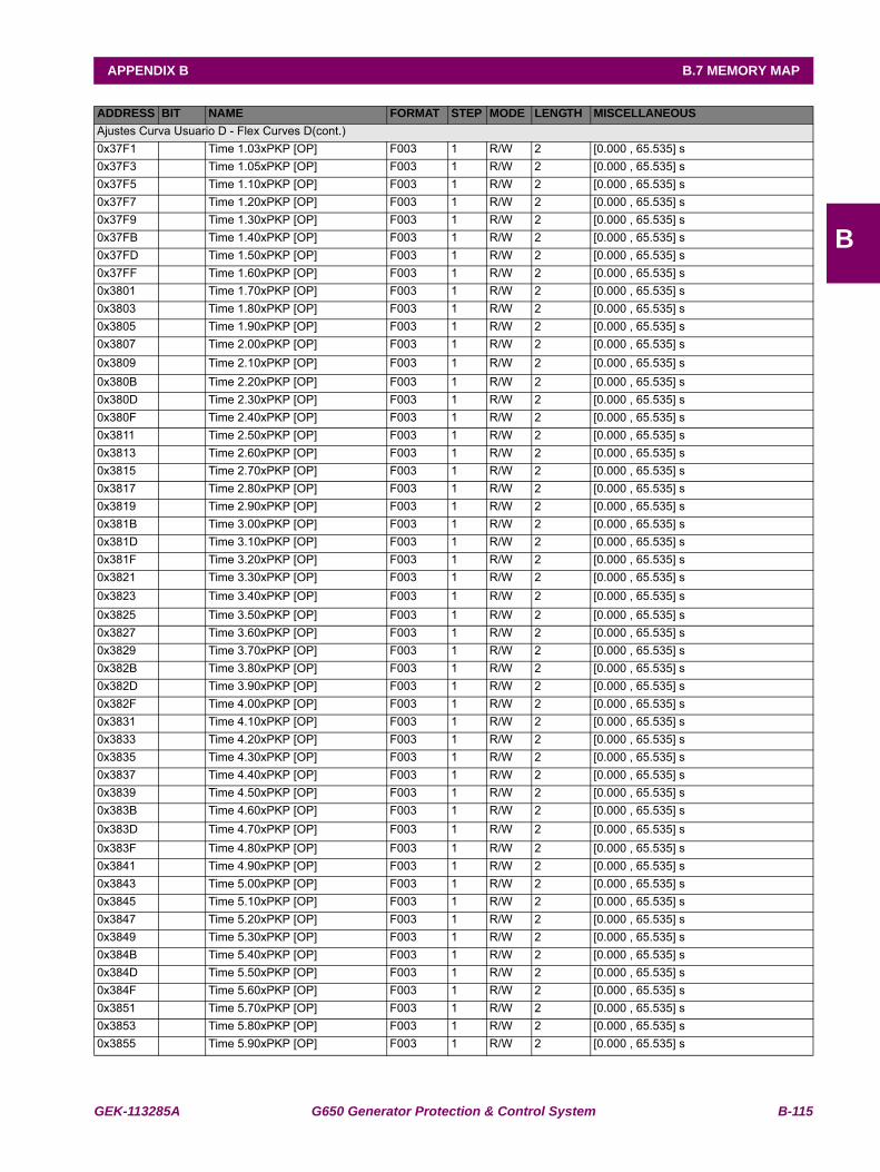
GEK-113285A G650 Generator Protection & Control System B-115
APPENDIX B B.7 MEMORY MAP
B
Ajustes Curva Usuario D - Flex Curves D(cont.)0x37F1 Time 1.03xPKP [OP] F003 1 R/W 2 [0.000 , 65.535] s0x37F3 Time 1.05xPKP [OP] F003 1 R/W 2 [0.000 , 65.535] s0x37F5 Time 1.10xPKP [OP] F003 1 R/W 2 [0.000 , 65.535] s0x37F7 Time 1.20xPKP [OP] F003 1 R/W 2 [0.000 , 65.535] s0x37F9 Time 1.30xPKP [OP] F003 1 R/W 2 [0.000 , 65.535] s0x37FB Time 1.40xPKP [OP] F003 1 R/W 2 [0.000 , 65.535] s0x37FD Time 1.50xPKP [OP] F003 1 R/W 2 [0.000 , 65.535] s0x37FF Time 1.60xPKP [OP] F003 1 R/W 2 [0.000 , 65.535] s0x3801 Time 1.70xPKP [OP] F003 1 R/W 2 [0.000 , 65.535] s0x3803 Time 1.80xPKP [OP] F003 1 R/W 2 [0.000 , 65.535] s0x3805 Time 1.90xPKP [OP] F003 1 R/W 2 [0.000 , 65.535] s0x3807 Time 2.00xPKP [OP] F003 1 R/W 2 [0.000 , 65.535] s0x3809 Time 2.10xPKP [OP] F003 1 R/W 2 [0.000 , 65.535] s0x380B Time 2.20xPKP [OP] F003 1 R/W 2 [0.000 , 65.535] s0x380D Time 2.30xPKP [OP] F003 1 R/W 2 [0.000 , 65.535] s0x380F Time 2.40xPKP [OP] F003 1 R/W 2 [0.000 , 65.535] s0x3811 Time 2.50xPKP [OP] F003 1 R/W 2 [0.000 , 65.535] s0x3813 Time 2.60xPKP [OP] F003 1 R/W 2 [0.000 , 65.535] s0x3815 Time 2.70xPKP [OP] F003 1 R/W 2 [0.000 , 65.535] s0x3817 Time 2.80xPKP [OP] F003 1 R/W 2 [0.000 , 65.535] s0x3819 Time 2.90xPKP [OP] F003 1 R/W 2 [0.000 , 65.535] s0x381B Time 3.00xPKP [OP] F003 1 R/W 2 [0.000 , 65.535] s0x381D Time 3.10xPKP [OP] F003 1 R/W 2 [0.000 , 65.535] s0x381F Time 3.20xPKP [OP] F003 1 R/W 2 [0.000 , 65.535] s0x3821 Time 3.30xPKP [OP] F003 1 R/W 2 [0.000 , 65.535] s0x3823 Time 3.40xPKP [OP] F003 1 R/W 2 [0.000 , 65.535] s0x3825 Time 3.50xPKP [OP] F003 1 R/W 2 [0.000 , 65.535] s0x3827 Time 3.60xPKP [OP] F003 1 R/W 2 [0.000 , 65.535] s0x3829 Time 3.70xPKP [OP] F003 1 R/W 2 [0.000 , 65.535] s0x382B Time 3.80xPKP [OP] F003 1 R/W 2 [0.000 , 65.535] s0x382D Time 3.90xPKP [OP] F003 1 R/W 2 [0.000 , 65.535] s0x382F Time 4.00xPKP [OP] F003 1 R/W 2 [0.000 , 65.535] s0x3831 Time 4.10xPKP [OP] F003 1 R/W 2 [0.000 , 65.535] s0x3833 Time 4.20xPKP [OP] F003 1 R/W 2 [0.000 , 65.535] s0x3835 Time 4.30xPKP [OP] F003 1 R/W 2 [0.000 , 65.535] s0x3837 Time 4.40xPKP [OP] F003 1 R/W 2 [0.000 , 65.535] s0x3839 Time 4.50xPKP [OP] F003 1 R/W 2 [0.000 , 65.535] s0x383B Time 4.60xPKP [OP] F003 1 R/W 2 [0.000 , 65.535] s0x383D Time 4.70xPKP [OP] F003 1 R/W 2 [0.000 , 65.535] s0x383F Time 4.80xPKP [OP] F003 1 R/W 2 [0.000 , 65.535] s0x3841 Time 4.90xPKP [OP] F003 1 R/W 2 [0.000 , 65.535] s0x3843 Time 5.00xPKP [OP] F003 1 R/W 2 [0.000 , 65.535] s0x3845 Time 5.10xPKP [OP] F003 1 R/W 2 [0.000 , 65.535] s0x3847 Time 5.20xPKP [OP] F003 1 R/W 2 [0.000 , 65.535] s0x3849 Time 5.30xPKP [OP] F003 1 R/W 2 [0.000 , 65.535] s0x384B Time 5.40xPKP [OP] F003 1 R/W 2 [0.000 , 65.535] s0x384D Time 5.50xPKP [OP] F003 1 R/W 2 [0.000 , 65.535] s0x384F Time 5.60xPKP [OP] F003 1 R/W 2 [0.000 , 65.535] s0x3851 Time 5.70xPKP [OP] F003 1 R/W 2 [0.000 , 65.535] s0x3853 Time 5.80xPKP [OP] F003 1 R/W 2 [0.000 , 65.535] s0x3855 Time 5.90xPKP [OP] F003 1 R/W 2 [0.000 , 65.535] s
ADDRESS BIT NAME FORMAT STEP MODE LENGTH MISCELLANEOUS
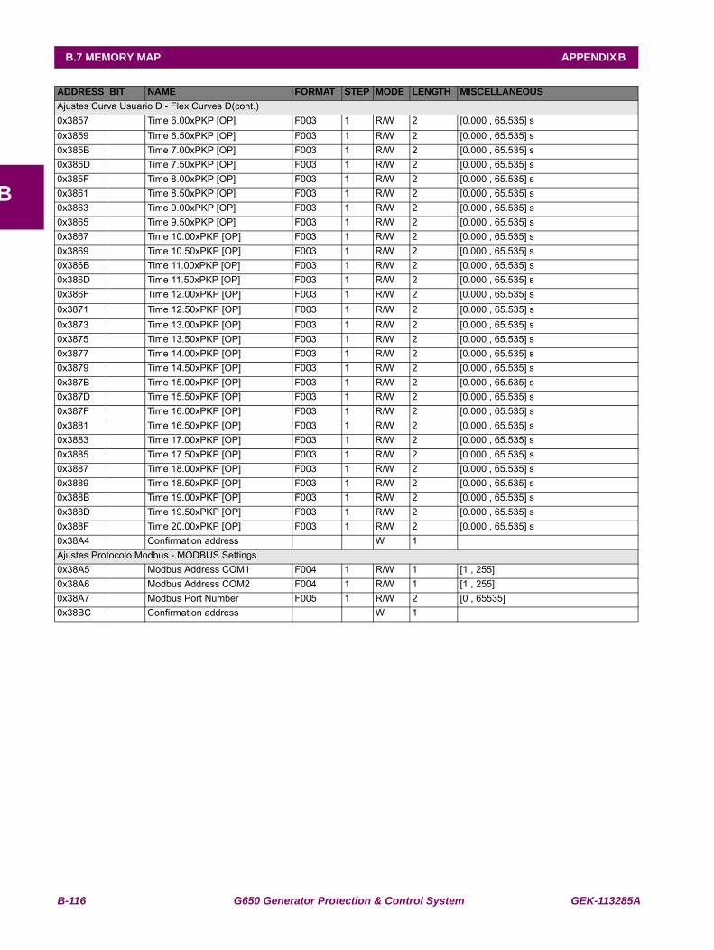
B-116 G650 Generator Protection & Control System GEK-113285A
B.7 MEMORY MAP APPENDIX B
B
Ajustes Curva Usuario D - Flex Curves D(cont.)0x3857 Time 6.00xPKP [OP] F003 1 R/W 2 [0.000 , 65.535] s0x3859 Time 6.50xPKP [OP] F003 1 R/W 2 [0.000 , 65.535] s0x385B Time 7.00xPKP [OP] F003 1 R/W 2 [0.000 , 65.535] s0x385D Time 7.50xPKP [OP] F003 1 R/W 2 [0.000 , 65.535] s0x385F Time 8.00xPKP [OP] F003 1 R/W 2 [0.000 , 65.535] s0x3861 Time 8.50xPKP [OP] F003 1 R/W 2 [0.000 , 65.535] s0x3863 Time 9.00xPKP [OP] F003 1 R/W 2 [0.000 , 65.535] s0x3865 Time 9.50xPKP [OP] F003 1 R/W 2 [0.000 , 65.535] s0x3867 Time 10.00xPKP [OP] F003 1 R/W 2 [0.000 , 65.535] s0x3869 Time 10.50xPKP [OP] F003 1 R/W 2 [0.000 , 65.535] s0x386B Time 11.00xPKP [OP] F003 1 R/W 2 [0.000 , 65.535] s0x386D Time 11.50xPKP [OP] F003 1 R/W 2 [0.000 , 65.535] s0x386F Time 12.00xPKP [OP] F003 1 R/W 2 [0.000 , 65.535] s0x3871 Time 12.50xPKP [OP] F003 1 R/W 2 [0.000 , 65.535] s0x3873 Time 13.00xPKP [OP] F003 1 R/W 2 [0.000 , 65.535] s0x3875 Time 13.50xPKP [OP] F003 1 R/W 2 [0.000 , 65.535] s0x3877 Time 14.00xPKP [OP] F003 1 R/W 2 [0.000 , 65.535] s0x3879 Time 14.50xPKP [OP] F003 1 R/W 2 [0.000 , 65.535] s0x387B Time 15.00xPKP [OP] F003 1 R/W 2 [0.000 , 65.535] s0x387D Time 15.50xPKP [OP] F003 1 R/W 2 [0.000 , 65.535] s0x387F Time 16.00xPKP [OP] F003 1 R/W 2 [0.000 , 65.535] s0x3881 Time 16.50xPKP [OP] F003 1 R/W 2 [0.000 , 65.535] s0x3883 Time 17.00xPKP [OP] F003 1 R/W 2 [0.000 , 65.535] s0x3885 Time 17.50xPKP [OP] F003 1 R/W 2 [0.000 , 65.535] s0x3887 Time 18.00xPKP [OP] F003 1 R/W 2 [0.000 , 65.535] s0x3889 Time 18.50xPKP [OP] F003 1 R/W 2 [0.000 , 65.535] s0x388B Time 19.00xPKP [OP] F003 1 R/W 2 [0.000 , 65.535] s0x388D Time 19.50xPKP [OP] F003 1 R/W 2 [0.000 , 65.535] s0x388F Time 20.00xPKP [OP] F003 1 R/W 2 [0.000 , 65.535] s0x38A4 Confirmation address W 1 Ajustes Protocolo Modbus - MODBUS Settings0x38A5 Modbus Address COM1 F004 1 R/W 1 [1 , 255] 0x38A6 Modbus Address COM2 F004 1 R/W 1 [1 , 255] 0x38A7 Modbus Port Number F005 1 R/W 2 [0 , 65535] 0x38BC Confirmation address W 1
ADDRESS BIT NAME FORMAT STEP MODE LENGTH MISCELLANEOUS
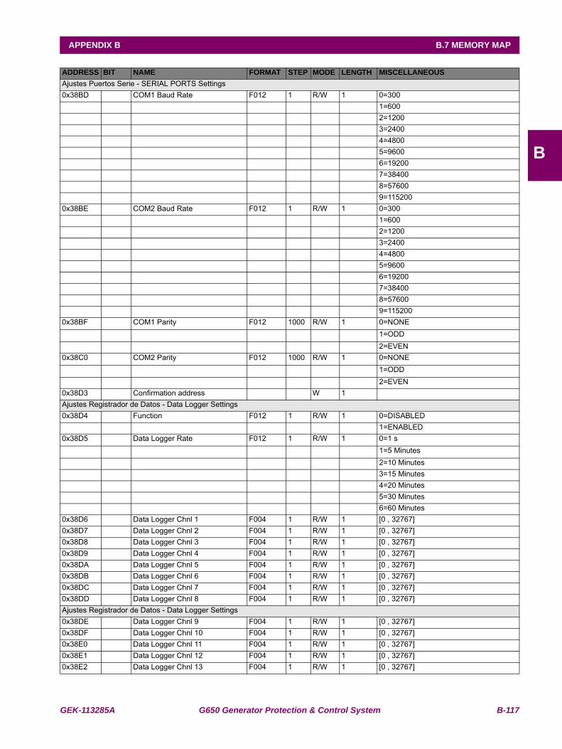
GEK-113285A G650 Generator Protection & Control System B-117
APPENDIX B B.7 MEMORY MAP
B
Ajustes Puertos Serie - SERIAL PORTS Settings0x38BD COM1 Baud Rate F012 1 R/W 1 0=300 1=600 2=1200 3=2400 4=4800 5=9600 6=19200 7=38400 8=57600 9=1152000x38BE COM2 Baud Rate F012 1 R/W 1 0=300 1=600 2=1200 3=2400 4=4800 5=9600 6=19200 7=38400 8=57600 9=1152000x38BF COM1 Parity F012 1000 R/W 1 0=NONE 1=ODD 2=EVEN0x38C0 COM2 Parity F012 1000 R/W 1 0=NONE 1=ODD 2=EVEN0x38D3 Confirmation address W 1 Ajustes Registrador de Datos - Data Logger Settings0x38D4 Function F012 1 R/W 1 0=DISABLED 1=ENABLED0x38D5 Data Logger Rate F012 1 R/W 1 0=1 s 1=5 Minutes 2=10 Minutes 3=15 Minutes 4=20 Minutes 5=30 Minutes 6=60 Minutes0x38D6 Data Logger Chnl 1 F004 1 R/W 1 [0 , 32767] 0x38D7 Data Logger Chnl 2 F004 1 R/W 1 [0 , 32767] 0x38D8 Data Logger Chnl 3 F004 1 R/W 1 [0 , 32767] 0x38D9 Data Logger Chnl 4 F004 1 R/W 1 [0 , 32767] 0x38DA Data Logger Chnl 5 F004 1 R/W 1 [0 , 32767] 0x38DB Data Logger Chnl 6 F004 1 R/W 1 [0 , 32767] 0x38DC Data Logger Chnl 7 F004 1 R/W 1 [0 , 32767] 0x38DD Data Logger Chnl 8 F004 1 R/W 1 [0 , 32767] Ajustes Registrador de Datos - Data Logger Settings0x38DE Data Logger Chnl 9 F004 1 R/W 1 [0 , 32767] 0x38DF Data Logger Chnl 10 F004 1 R/W 1 [0 , 32767] 0x38E0 Data Logger Chnl 11 F004 1 R/W 1 [0 , 32767] 0x38E1 Data Logger Chnl 12 F004 1 R/W 1 [0 , 32767] 0x38E2 Data Logger Chnl 13 F004 1 R/W 1 [0 , 32767]
ADDRESS BIT NAME FORMAT STEP MODE LENGTH MISCELLANEOUS
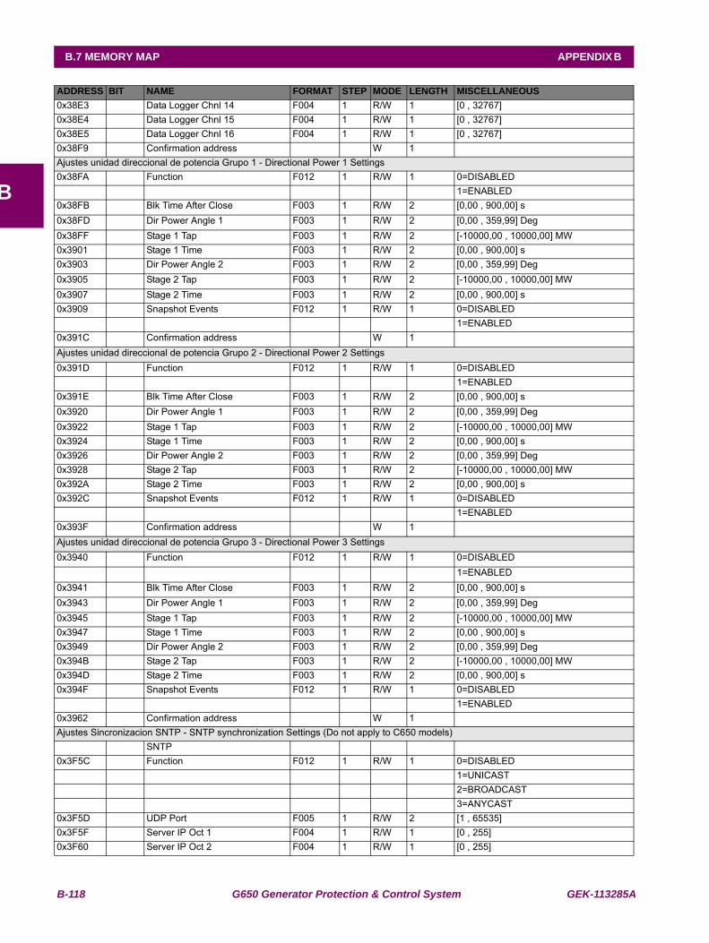
B-118 G650 Generator Protection & Control System GEK-113285A
B.7 MEMORY MAP APPENDIX B
B
0x38E3 Data Logger Chnl 14 F004 1 R/W 1 [0 , 32767] 0x38E4 Data Logger Chnl 15 F004 1 R/W 1 [0 , 32767] 0x38E5 Data Logger Chnl 16 F004 1 R/W 1 [0 , 32767] 0x38F9 Confirmation address W 1 Ajustes unidad direccional de potencia Grupo 1 - Directional Power 1 Settings0x38FA Function F012 1 R/W 1 0=DISABLED 1=ENABLED0x38FB Blk Time After Close F003 1 R/W 2 [0,00 , 900,00] s0x38FD Dir Power Angle 1 F003 1 R/W 2 [0,00 , 359,99] Deg0x38FF Stage 1 Tap F003 1 R/W 2 [-10000,00 , 10000,00] MW0x3901 Stage 1 Time F003 1 R/W 2 [0,00 , 900,00] s0x3903 Dir Power Angle 2 F003 1 R/W 2 [0,00 , 359,99] Deg0x3905 Stage 2 Tap F003 1 R/W 2 [-10000,00 , 10000,00] MW0x3907 Stage 2 Time F003 1 R/W 2 [0,00 , 900,00] s0x3909 Snapshot Events F012 1 R/W 1 0=DISABLED 1=ENABLED0x391C Confirmation address W 1 Ajustes unidad direccional de potencia Grupo 2 - Directional Power 2 Settings0x391D Function F012 1 R/W 1 0=DISABLED 1=ENABLED0x391E Blk Time After Close F003 1 R/W 2 [0,00 , 900,00] s0x3920 Dir Power Angle 1 F003 1 R/W 2 [0,00 , 359,99] Deg0x3922 Stage 1 Tap F003 1 R/W 2 [-10000,00 , 10000,00] MW0x3924 Stage 1 Time F003 1 R/W 2 [0,00 , 900,00] s0x3926 Dir Power Angle 2 F003 1 R/W 2 [0,00 , 359,99] Deg0x3928 Stage 2 Tap F003 1 R/W 2 [-10000,00 , 10000,00] MW0x392A Stage 2 Time F003 1 R/W 2 [0,00 , 900,00] s0x392C Snapshot Events F012 1 R/W 1 0=DISABLED 1=ENABLED0x393F Confirmation address W 1 Ajustes unidad direccional de potencia Grupo 3 - Directional Power 3 Settings0x3940 Function F012 1 R/W 1 0=DISABLED 1=ENABLED0x3941 Blk Time After Close F003 1 R/W 2 [0,00 , 900,00] s0x3943 Dir Power Angle 1 F003 1 R/W 2 [0,00 , 359,99] Deg0x3945 Stage 1 Tap F003 1 R/W 2 [-10000,00 , 10000,00] MW0x3947 Stage 1 Time F003 1 R/W 2 [0,00 , 900,00] s0x3949 Dir Power Angle 2 F003 1 R/W 2 [0,00 , 359,99] Deg0x394B Stage 2 Tap F003 1 R/W 2 [-10000,00 , 10000,00] MW0x394D Stage 2 Time F003 1 R/W 2 [0,00 , 900,00] s0x394F Snapshot Events F012 1 R/W 1 0=DISABLED 1=ENABLED0x3962 Confirmation address W 1 Ajustes Sincronizacion SNTP - SNTP synchronization Settings (Do not apply to C650 models) SNTP 0x3F5C Function F012 1 R/W 1 0=DISABLED 1=UNICAST 2=BROADCAST 3=ANYCAST0x3F5D UDP Port F005 1 R/W 2 [1 , 65535]0x3F5F Server IP Oct 1 F004 1 R/W 1 [0 , 255]0x3F60 Server IP Oct 2 F004 1 R/W 1 [0 , 255]
ADDRESS BIT NAME FORMAT STEP MODE LENGTH MISCELLANEOUS
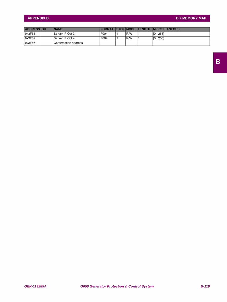
GEK-113285A G650 Generator Protection & Control System B-119
APPENDIX B B.7 MEMORY MAP
B
0x3F61 Server IP Oct 3 F004 1 R/W 1 [0 , 255]0x3F62 Server IP Oct 4 F004 1 R/W 1 [0 , 255]0x3F66 Confirmation address
ADDRESS BIT NAME FORMAT STEP MODE LENGTH MISCELLANEOUS

B-120 G650 Generator Protection & Control System GEK-113285A
B.7 MEMORY MAP APPENDIX B
B
Contador de Pulsos-Pulse Counters0x3F88 PulseCntr Enabled 1 F012 1,000 R/W 1 0=DISABLED
1=ENABLED
0x3F89 PulseCntr Name 1 F009 1,000 R/W 16
0x3F99 PulseCntr Factor 1 F003 1,000 R/W 2 [0.000 , 65000.000]
0x3F9B PulseCntr Overflow 1 F005 1,000 R/W 2 [0 , 1000000]
0x3F9D PulseCntr Board Origin 1 F012 1,000 R/W 1 0=F
1=G
2=H
3=J
0x3F9E PulseCntr Input Origin 1 F004 1,000 R/W 1 [1 , 32]
0x3F9F PulseCntr Enabled 2 F012 1,000 R/W 1 0=DISABLED
1=ENABLED
0x3FA0 PulseCntr Name 2 F009 1,000 R/W 16
0x3FB0 PulseCntr Factor 2 F003 1,000 R/W 2 [0.000 , 65000.000]
0x3FB2 PulseCntr Overflow 2 F005 1,000 R/W 2 [0 , 1000000]
0x3FB4 PulseCntr Board Origin 2 F012 1,000 R/W 1 0=F
1=G
2=H
3=J
0x3FB5 PulseCntr Input Origin 2 F004 1,000 R/W 1 [1 , 32]
0x3FB6 PulseCntr Enabled 3 F012 1,000 R/W 1 0=DISABLED
1=ENABLED
0x3FB7 PulseCntr Name 3 F009 1,000 R/W 16
0x3FC7 PulseCntr Factor 3 F003 1,000 R/W 2 [0.000 , 65000.000]
0x3FC9 PulseCntr Overflow 3 F005 1,000 R/W 2 [0 , 1000000]
0x3FCB PulseCntr Board Origin 3 F012 1,000 R/W 1 0=F
1=G
2=H
3=J
0x3FCC PulseCntr Input Origin 3 F004 1,000 R/W 1 [1 , 32]
0x3FCD PulseCntr Enabled 4 F012 1,000 R/W 1 0=DISABLED
1=ENABLED
0x3FCE PulseCntr Name 4 F009 1,000 R/W 16
0x3FDE PulseCntr Factor 4 F003 1,000 R/W 2 [0.000 , 65000.000]
0x3FE0 PulseCntr Overflow 4 F005 1,000 R/W 2 [0 , 1000000]
0x3FE2 PulseCntr Board Origin 4 F012 1,000 R/W 1 0=F
1=G
2=H
3=J
0x3FE3 PulseCntr Input Origin 4 F004 1,000 R/W 1 [1 , 32]
0x3FE4 PulseCntr Enabled 5 F012 1,000 R/W 1 0=DISABLED
1=ENABLED
ADDRESS BIT NAME FORMAT STEP MODE LENGTH MISCELLANEOUS
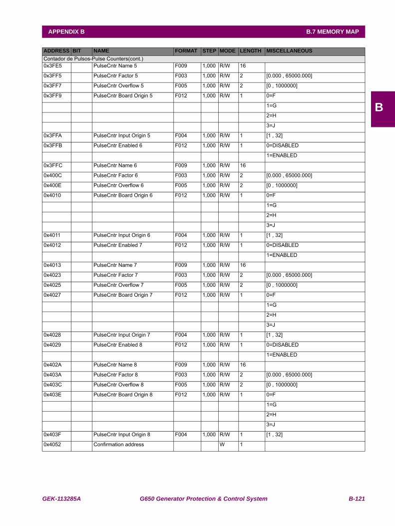
GEK-113285A G650 Generator Protection & Control System B-121
APPENDIX B B.7 MEMORY MAP
B
Contador de Pulsos-Pulse Counters(cont.)0x3FE5 PulseCntr Name 5 F009 1,000 R/W 16
0x3FF5 PulseCntr Factor 5 F003 1,000 R/W 2 [0.000 , 65000.000]
0x3FF7 PulseCntr Overflow 5 F005 1,000 R/W 2 [0 , 1000000]
0x3FF9 PulseCntr Board Origin 5 F012 1,000 R/W 1 0=F
1=G
2=H
3=J
0x3FFA PulseCntr Input Origin 5 F004 1,000 R/W 1 [1 , 32]
0x3FFB PulseCntr Enabled 6 F012 1,000 R/W 1 0=DISABLED
1=ENABLED
0x3FFC PulseCntr Name 6 F009 1,000 R/W 16
0x400C PulseCntr Factor 6 F003 1,000 R/W 2 [0.000 , 65000.000]
0x400E PulseCntr Overflow 6 F005 1,000 R/W 2 [0 , 1000000]
0x4010 PulseCntr Board Origin 6 F012 1,000 R/W 1 0=F
1=G
2=H
3=J
0x4011 PulseCntr Input Origin 6 F004 1,000 R/W 1 [1 , 32]
0x4012 PulseCntr Enabled 7 F012 1,000 R/W 1 0=DISABLED
1=ENABLED
0x4013 PulseCntr Name 7 F009 1,000 R/W 16
0x4023 PulseCntr Factor 7 F003 1,000 R/W 2 [0.000 , 65000.000]
0x4025 PulseCntr Overflow 7 F005 1,000 R/W 2 [0 , 1000000]
0x4027 PulseCntr Board Origin 7 F012 1,000 R/W 1 0=F
1=G
2=H
3=J
0x4028 PulseCntr Input Origin 7 F004 1,000 R/W 1 [1 , 32]
0x4029 PulseCntr Enabled 8 F012 1,000 R/W 1 0=DISABLED
1=ENABLED
0x402A PulseCntr Name 8 F009 1,000 R/W 16
0x403A PulseCntr Factor 8 F003 1,000 R/W 2 [0.000 , 65000.000]
0x403C PulseCntr Overflow 8 F005 1,000 R/W 2 [0 , 1000000]
0x403E PulseCntr Board Origin 8 F012 1,000 R/W 1 0=F
1=G
2=H
3=J
0x403F PulseCntr Input Origin 8 F004 1,000 R/W 1 [1 , 32]
0x4052 Confirmation address W 1
ADDRESS BIT NAME FORMAT STEP MODE LENGTH MISCELLANEOUS
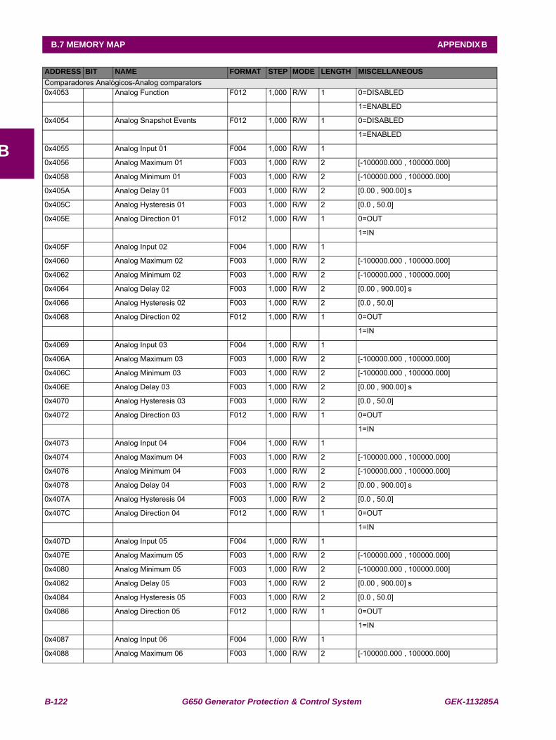
B-122 G650 Generator Protection & Control System GEK-113285A
B.7 MEMORY MAP APPENDIX B
B
Comparadores Analógicos-Analog comparators0x4053 Analog Function F012 1,000 R/W 1 0=DISABLED
1=ENABLED
0x4054 Analog Snapshot Events F012 1,000 R/W 1 0=DISABLED
1=ENABLED
0x4055 Analog Input 01 F004 1,000 R/W 1
0x4056 Analog Maximum 01 F003 1,000 R/W 2 [-100000.000 , 100000.000]
0x4058 Analog Minimum 01 F003 1,000 R/W 2 [-100000.000 , 100000.000]
0x405A Analog Delay 01 F003 1,000 R/W 2 [0.00 , 900.00] s
0x405C Analog Hysteresis 01 F003 1,000 R/W 2 [0.0 , 50.0]
0x405E Analog Direction 01 F012 1,000 R/W 1 0=OUT
1=IN
0x405F Analog Input 02 F004 1,000 R/W 1
0x4060 Analog Maximum 02 F003 1,000 R/W 2 [-100000.000 , 100000.000]
0x4062 Analog Minimum 02 F003 1,000 R/W 2 [-100000.000 , 100000.000]
0x4064 Analog Delay 02 F003 1,000 R/W 2 [0.00 , 900.00] s
0x4066 Analog Hysteresis 02 F003 1,000 R/W 2 [0.0 , 50.0]
0x4068 Analog Direction 02 F012 1,000 R/W 1 0=OUT
1=IN
0x4069 Analog Input 03 F004 1,000 R/W 1
0x406A Analog Maximum 03 F003 1,000 R/W 2 [-100000.000 , 100000.000]
0x406C Analog Minimum 03 F003 1,000 R/W 2 [-100000.000 , 100000.000]
0x406E Analog Delay 03 F003 1,000 R/W 2 [0.00 , 900.00] s
0x4070 Analog Hysteresis 03 F003 1,000 R/W 2 [0.0 , 50.0]
0x4072 Analog Direction 03 F012 1,000 R/W 1 0=OUT
1=IN
0x4073 Analog Input 04 F004 1,000 R/W 1
0x4074 Analog Maximum 04 F003 1,000 R/W 2 [-100000.000 , 100000.000]
0x4076 Analog Minimum 04 F003 1,000 R/W 2 [-100000.000 , 100000.000]
0x4078 Analog Delay 04 F003 1,000 R/W 2 [0.00 , 900.00] s
0x407A Analog Hysteresis 04 F003 1,000 R/W 2 [0.0 , 50.0]
0x407C Analog Direction 04 F012 1,000 R/W 1 0=OUT
1=IN
0x407D Analog Input 05 F004 1,000 R/W 1
0x407E Analog Maximum 05 F003 1,000 R/W 2 [-100000.000 , 100000.000]
0x4080 Analog Minimum 05 F003 1,000 R/W 2 [-100000.000 , 100000.000]
0x4082 Analog Delay 05 F003 1,000 R/W 2 [0.00 , 900.00] s
0x4084 Analog Hysteresis 05 F003 1,000 R/W 2 [0.0 , 50.0]
0x4086 Analog Direction 05 F012 1,000 R/W 1 0=OUT
1=IN
0x4087 Analog Input 06 F004 1,000 R/W 1
0x4088 Analog Maximum 06 F003 1,000 R/W 2 [-100000.000 , 100000.000]
ADDRESS BIT NAME FORMAT STEP MODE LENGTH MISCELLANEOUS
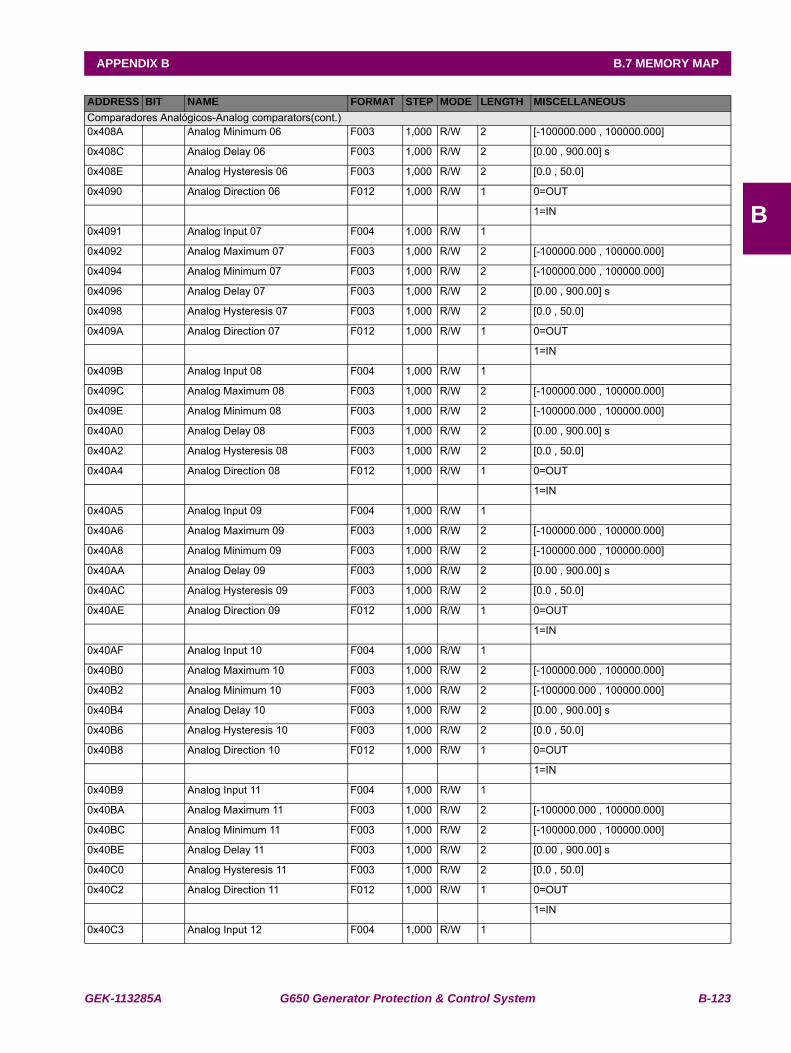
GEK-113285A G650 Generator Protection & Control System B-123
APPENDIX B B.7 MEMORY MAP
B
Comparadores Analógicos-Analog comparators(cont.)0x408A Analog Minimum 06 F003 1,000 R/W 2 [-100000.000 , 100000.000]
0x408C Analog Delay 06 F003 1,000 R/W 2 [0.00 , 900.00] s
0x408E Analog Hysteresis 06 F003 1,000 R/W 2 [0.0 , 50.0]
0x4090 Analog Direction 06 F012 1,000 R/W 1 0=OUT
1=IN
0x4091 Analog Input 07 F004 1,000 R/W 1
0x4092 Analog Maximum 07 F003 1,000 R/W 2 [-100000.000 , 100000.000]
0x4094 Analog Minimum 07 F003 1,000 R/W 2 [-100000.000 , 100000.000]
0x4096 Analog Delay 07 F003 1,000 R/W 2 [0.00 , 900.00] s
0x4098 Analog Hysteresis 07 F003 1,000 R/W 2 [0.0 , 50.0]
0x409A Analog Direction 07 F012 1,000 R/W 1 0=OUT
1=IN
0x409B Analog Input 08 F004 1,000 R/W 1
0x409C Analog Maximum 08 F003 1,000 R/W 2 [-100000.000 , 100000.000]
0x409E Analog Minimum 08 F003 1,000 R/W 2 [-100000.000 , 100000.000]
0x40A0 Analog Delay 08 F003 1,000 R/W 2 [0.00 , 900.00] s
0x40A2 Analog Hysteresis 08 F003 1,000 R/W 2 [0.0 , 50.0]
0x40A4 Analog Direction 08 F012 1,000 R/W 1 0=OUT
1=IN
0x40A5 Analog Input 09 F004 1,000 R/W 1
0x40A6 Analog Maximum 09 F003 1,000 R/W 2 [-100000.000 , 100000.000]
0x40A8 Analog Minimum 09 F003 1,000 R/W 2 [-100000.000 , 100000.000]
0x40AA Analog Delay 09 F003 1,000 R/W 2 [0.00 , 900.00] s
0x40AC Analog Hysteresis 09 F003 1,000 R/W 2 [0.0 , 50.0]
0x40AE Analog Direction 09 F012 1,000 R/W 1 0=OUT
1=IN
0x40AF Analog Input 10 F004 1,000 R/W 1
0x40B0 Analog Maximum 10 F003 1,000 R/W 2 [-100000.000 , 100000.000]
0x40B2 Analog Minimum 10 F003 1,000 R/W 2 [-100000.000 , 100000.000]
0x40B4 Analog Delay 10 F003 1,000 R/W 2 [0.00 , 900.00] s
0x40B6 Analog Hysteresis 10 F003 1,000 R/W 2 [0.0 , 50.0]
0x40B8 Analog Direction 10 F012 1,000 R/W 1 0=OUT
1=IN
0x40B9 Analog Input 11 F004 1,000 R/W 1
0x40BA Analog Maximum 11 F003 1,000 R/W 2 [-100000.000 , 100000.000]
0x40BC Analog Minimum 11 F003 1,000 R/W 2 [-100000.000 , 100000.000]
0x40BE Analog Delay 11 F003 1,000 R/W 2 [0.00 , 900.00] s
0x40C0 Analog Hysteresis 11 F003 1,000 R/W 2 [0.0 , 50.0]
0x40C2 Analog Direction 11 F012 1,000 R/W 1 0=OUT
1=IN
0x40C3 Analog Input 12 F004 1,000 R/W 1
ADDRESS BIT NAME FORMAT STEP MODE LENGTH MISCELLANEOUS
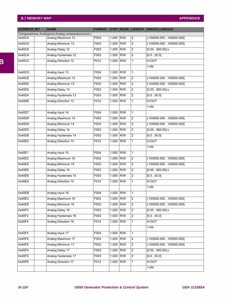
B-124 G650 Generator Protection & Control System GEK-113285A
B.7 MEMORY MAP APPENDIX B
B
Comparadores Analógicos-Analog comparators(cont.)0x40C4 Analog Maximum 12 F003 1,000 R/W 2 [-100000.000 , 100000.000]
0x40C6 Analog Minimum 12 F003 1,000 R/W 2 [-100000.000 , 100000.000]
0x40C8 Analog Delay 12 F003 1,000 R/W 2 [0.00 , 900.00] s
0x40CA Analog Hysteresis 12 F003 1,000 R/W 2 [0.0 , 50.0]
0x40CC Analog Direction 12 F012 1,000 R/W 1 0=OUT
1=IN
0x40CD Analog Input 13 F004 1,000 R/W 1
0x40CE Analog Maximum 13 F003 1,000 R/W 2 [-100000.000 , 100000.000]
0x40D0 Analog Minimum 13 F003 1,000 R/W 2 [-100000.000 , 100000.000]
0x40D2 Analog Delay 13 F003 1,000 R/W 2 [0.00 , 900.00] s
0x40D4 Analog Hysteresis 13 F003 1,000 R/W 2 [0.0 , 50.0]
0x40D6 Analog Direction 13 F012 1,000 R/W 1 0=OUT
1=IN
0x40D7 Analog Input 14 F004 1,000 R/W 1
0x40D8 Analog Maximum 14 F003 1,000 R/W 2 [-100000.000 , 100000.000]
0x40DA Analog Minimum 14 F003 1,000 R/W 2 [-100000.000 , 100000.000]
0x40DC Analog Delay 14 F003 1,000 R/W 2 [0.00 , 900.00] s
0x40DE Analog Hysteresis 14 F003 1,000 R/W 2 [0.0 , 50.0]
0x40E0 Analog Direction 14 F012 1,000 R/W 1 0=OUT
1=IN
0x40E1 Analog Input 15 F004 1,000 R/W 1
0x40E2 Analog Maximum 15 F003 1,000 R/W 2 [-100000.000 , 100000.000]
0x40E4 Analog Minimum 15 F003 1,000 R/W 2 [-100000.000 , 100000.000]
0x40E6 Analog Delay 15 F003 1,000 R/W 2 [0.00 , 900.00] s
0x40E8 Analog Hysteresis 15 F003 1,000 R/W 2 [0.0 , 50.0]
0x40EA Analog Direction 15 F012 1,000 R/W 1 0=OUT
1=IN
0x40EB Analog Input 16 F004 1,000 R/W 1
0x40EC Analog Maximum 16 F003 1,000 R/W 2 [-100000.000 , 100000.000]
0x40EE Analog Minimum 16 F003 1,000 R/W 2 [-100000.000 , 100000.000]
0x40F0 Analog Delay 16 F003 1,000 R/W 2 [0.00 , 900.00] s
0x40F2 Analog Hysteresis 16 F003 1,000 R/W 2 [0.0 , 50.0]
0x40F4 Analog Direction 16 F012 1,000 R/W 1 0=OUT
1=IN
0x40F5 Analog Input 17 F004 1,000 R/W 1
0x40F6 Analog Maximum 17 F003 1,000 R/W 2 [-100000.000 , 100000.000]
0x40F8 Analog Minimum 17 F003 1,000 R/W 2 [-100000.000 , 100000.000]
0x40FA Analog Delay 17 F003 1,000 R/W 2 [0.00 , 900.00] s
0x40FC Analog Hysteresis 17 F003 1,000 R/W 2 [0.0 , 50.0]
0x40FE Analog Direction 17 F012 1,000 R/W 1 0=OUT
1=IN
ADDRESS BIT NAME FORMAT STEP MODE LENGTH MISCELLANEOUS
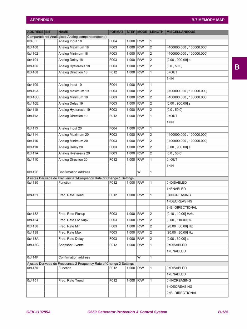
GEK-113285A G650 Generator Protection & Control System B-125
APPENDIX B B.7 MEMORY MAP
B
Comparadores Analógicos-Analog comparators(cont.)0x40FF Analog Input 18 F004 1,000 R/W 1
0x4100 Analog Maximum 18 F003 1,000 R/W 2 [-100000.000 , 100000.000]
0x4102 Analog Minimum 18 F003 1,000 R/W 2 [-100000.000 , 100000.000]
0x4104 Analog Delay 18 F003 1,000 R/W 2 [0.00 , 900.00] s
0x4106 Analog Hysteresis 18 F003 1,000 R/W 2 [0.0 , 50.0]
0x4108 Analog Direction 18 F012 1,000 R/W 1 0=OUT
1=IN
0x4109 Analog Input 19 F004 1,000 R/W 1
0x410A Analog Maximum 19 F003 1,000 R/W 2 [-100000.000 , 100000.000]
0x410C Analog Minimum 19 F003 1,000 R/W 2 [-100000.000 , 100000.000]
0x410E Analog Delay 19 F003 1,000 R/W 2 [0.00 , 900.00] s
0x4110 Analog Hysteresis 19 F003 1,000 R/W 2 [0.0 , 50.0]
0x4112 Analog Direction 19 F012 1,000 R/W 1 0=OUT
1=IN
0x4113 Analog Input 20 F004 1,000 R/W 1
0x4114 Analog Maximum 20 F003 1,000 R/W 2 [-100000.000 , 100000.000]
0x4116 Analog Minimum 20 F003 1,000 R/W 2 [-100000.000 , 100000.000]
0x4118 Analog Delay 20 F003 1,000 R/W 2 [0.00 , 900.00] s
0x411A Analog Hysteresis 20 F003 1,000 R/W 2 [0.0 , 50.0]
0x411C Analog Direction 20 F012 1,000 R/W 1 0=OUT
1=IN
0x412F Confirmation address W 1
Ajustes Derivada de Frecuencia 1-Frequency Rate of Change 1 Settings0x4130 Function F012 1,000 R/W 1 0=DISABLED
1=ENABLED
0x4131 Freq. Rate Trend F012 1,000 R/W 1 0=INCREASING
1=DECREASING
2=BI-DIRECTIONAL
0x4132 Freq. Rate Pickup F003 1,000 R/W 2 [0.10 , 10.00] Hz/s
0x4134 Freq. Rate OV Supv F003 1,000 R/W 2 [0.00 , 110.00] %
0x4136 Freq. Rate Min F003 1,000 R/W 2 [20.00 , 80.00] Hz
0x4138 Freq. Rate Max F003 1,000 R/W 2 [20.00 , 80.00] Hz
0x413A Freq. Rate Delay F003 1,000 R/W 2 [0.00 , 60.00] s
0x413C Snapshot Events F012 1,000 R/W 1 0=DISABLED
1=ENABLED
0x414F Confirmation address W 1
Ajustes Derivada de Frecuencia 2-Frequency Rate of Change 2 Settings0x4150 Function F012 1,000 R/W 1 0=DISABLED
1=ENABLED
0x4151 Freq. Rate Trend F012 1,000 R/W 1 0=INCREASING
1=DECREASING
2=BI-DIRECTIONAL
ADDRESS BIT NAME FORMAT STEP MODE LENGTH MISCELLANEOUS
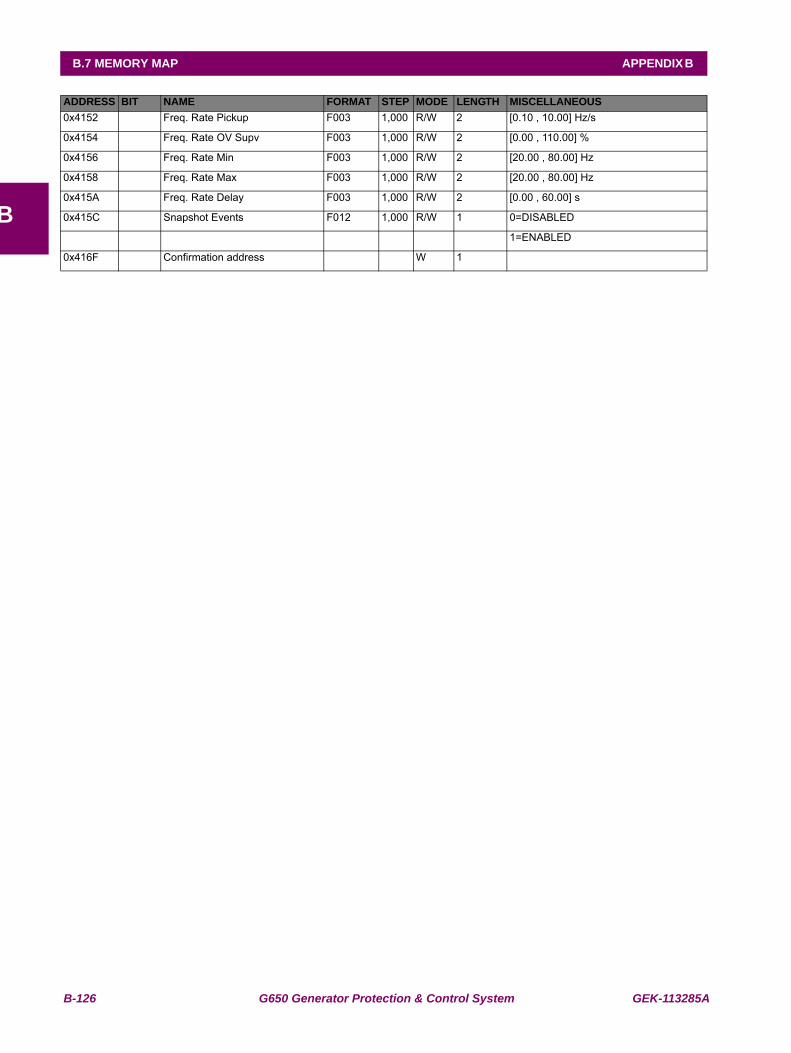
B-126 G650 Generator Protection & Control System GEK-113285A
B.7 MEMORY MAP APPENDIX B
B
0x4152 Freq. Rate Pickup F003 1,000 R/W 2 [0.10 , 10.00] Hz/s
0x4154 Freq. Rate OV Supv F003 1,000 R/W 2 [0.00 , 110.00] %
0x4156 Freq. Rate Min F003 1,000 R/W 2 [20.00 , 80.00] Hz
0x4158 Freq. Rate Max F003 1,000 R/W 2 [20.00 , 80.00] Hz
0x415A Freq. Rate Delay F003 1,000 R/W 2 [0.00 , 60.00] s
0x415C Snapshot Events F012 1,000 R/W 1 0=DISABLED
1=ENABLED
0x416F Confirmation address W 1
ADDRESS BIT NAME FORMAT STEP MODE LENGTH MISCELLANEOUS
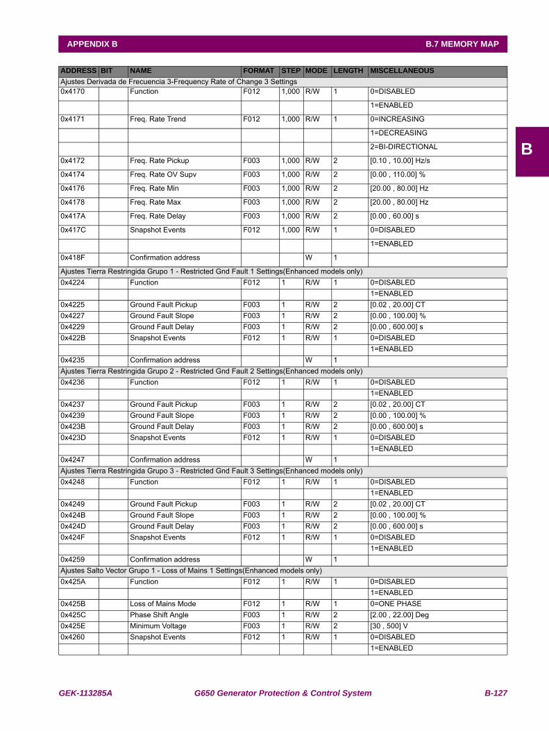
GEK-113285A G650 Generator Protection & Control System B-127
APPENDIX B B.7 MEMORY MAP
B
Ajustes Derivada de Frecuencia 3-Frequency Rate of Change 3 Settings0x4170 Function F012 1,000 R/W 1 0=DISABLED
1=ENABLED
0x4171 Freq. Rate Trend F012 1,000 R/W 1 0=INCREASING
1=DECREASING
2=BI-DIRECTIONAL
0x4172 Freq. Rate Pickup F003 1,000 R/W 2 [0.10 , 10.00] Hz/s
0x4174 Freq. Rate OV Supv F003 1,000 R/W 2 [0.00 , 110.00] %
0x4176 Freq. Rate Min F003 1,000 R/W 2 [20.00 , 80.00] Hz
0x4178 Freq. Rate Max F003 1,000 R/W 2 [20.00 , 80.00] Hz
0x417A Freq. Rate Delay F003 1,000 R/W 2 [0.00 , 60.00] s
0x417C Snapshot Events F012 1,000 R/W 1 0=DISABLED
1=ENABLED
0x418F Confirmation address W 1
Ajustes Tierra Restringida Grupo 1 - Restricted Gnd Fault 1 Settings(Enhanced models only)0x4224 Function F012 1 R/W 1 0=DISABLED
1=ENABLED0x4225 Ground Fault Pickup F003 1 R/W 2 [0.02 , 20.00] CT0x4227 Ground Fault Slope F003 1 R/W 2 [0.00 , 100.00] %0x4229 Ground Fault Delay F003 1 R/W 2 [0.00 , 600.00] s0x422B Snapshot Events F012 1 R/W 1 0=DISABLED
1=ENABLED0x4235 Confirmation address W 1Ajustes Tierra Restringida Grupo 2 - Restricted Gnd Fault 2 Settings(Enhanced models only)0x4236 Function F012 1 R/W 1 0=DISABLED
1=ENABLED0x4237 Ground Fault Pickup F003 1 R/W 2 [0.02 , 20.00] CT0x4239 Ground Fault Slope F003 1 R/W 2 [0.00 , 100.00] %0x423B Ground Fault Delay F003 1 R/W 2 [0.00 , 600.00] s0x423D Snapshot Events F012 1 R/W 1 0=DISABLED
1=ENABLED0x4247 Confirmation address W 1Ajustes Tierra Restringida Grupo 3 - Restricted Gnd Fault 3 Settings(Enhanced models only)0x4248 Function F012 1 R/W 1 0=DISABLED
1=ENABLED0x4249 Ground Fault Pickup F003 1 R/W 2 [0.02 , 20.00] CT0x424B Ground Fault Slope F003 1 R/W 2 [0.00 , 100.00] %0x424D Ground Fault Delay F003 1 R/W 2 [0.00 , 600.00] s0x424F Snapshot Events F012 1 R/W 1 0=DISABLED
1=ENABLED0x4259 Confirmation address W 1Ajustes Salto Vector Grupo 1 - Loss of Mains 1 Settings(Enhanced models only)0x425A Function F012 1 R/W 1 0=DISABLED
1=ENABLED0x425B Loss of Mains Mode F012 1 R/W 1 0=ONE PHASE0x425C Phase Shift Angle F003 1 R/W 2 [2.00 , 22.00] Deg0x425E Minimum Voltage F003 1 R/W 2 [30 , 500] V0x4260 Snapshot Events F012 1 R/W 1 0=DISABLED
1=ENABLED
ADDRESS BIT NAME FORMAT STEP MODE LENGTH MISCELLANEOUS
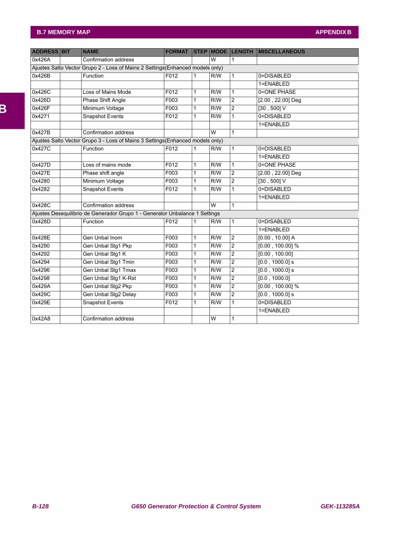
B-128 G650 Generator Protection & Control System GEK-113285A
B.7 MEMORY MAP APPENDIX B
B
0x426A Confirmation address W 1Ajustes Salto Vector Grupo 2 - Loss of Mains 2 Settings(Enhanced models only)0x426B Function F012 1 R/W 1 0=DISABLED
1=ENABLED0x426C Loss of Mains Mode F012 1 R/W 1 0=ONE PHASE0x426D Phase Shift Angle F003 1 R/W 2 [2.00 , 22.00] Deg0x426F Minimum Voltage F003 1 R/W 2 [30 , 500] V0x4271 Snapshot Events F012 1 R/W 1 0=DISABLED
1=ENABLED0x427B Confirmation address W 1Ajustes Salto Vector Grupo 3 - Loss of Mains 3 Settings(Enhanced models only)0x427C Function F012 1 R/W 1 0=DISABLED
1=ENABLED0x427D Loss of mains mode F012 1 R/W 1 0=ONE PHASE0x427E Phase shift angle F003 1 R/W 2 [2.00 , 22.00] Deg0x4280 Minimum Voltage F003 1 R/W 2 [30 , 500] V0x4282 Snapshot Events F012 1 R/W 1 0=DISABLED
1=ENABLED0x428C Confirmation address W 1Ajustes Desequilibrio de Generador Grupo 1 - Generator Unbalance 1 Settings0x428D Function F012 1 R/W 1 0=DISABLED
1=ENABLED0x428E Gen Unbal Inom F003 1 R/W 2 [0.00 , 10.00] A0x4290 Gen Unbal Stg1 Pkp F003 1 R/W 2 [0.00 , 100.00] %0x4292 Gen Unbal Stg1 K F003 1 R/W 2 [0.00 , 100.00] 0x4294 Gen Unbal Stg1 Tmin F003 1 R/W 2 [0.0 , 1000.0] s0x4296 Gen Unbal Stg1 Tmax F003 1 R/W 2 [0.0 , 1000.0] s0x4298 Gen Unbal Stg1 K-Rst F003 1 R/W 2 [0.0 , 1000.0] 0x429A Gen Unbal Stg2 Pkp F003 1 R/W 2 [0.00 , 100.00] %0x429C Gen Unbal Stg2 Delay F003 1 R/W 2 [0.0 , 1000.0] s0x429E Snapshot Events F012 1 R/W 1 0=DISABLED
1=ENABLED0x42A8 Confirmation address W 1
ADDRESS BIT NAME FORMAT STEP MODE LENGTH MISCELLANEOUS
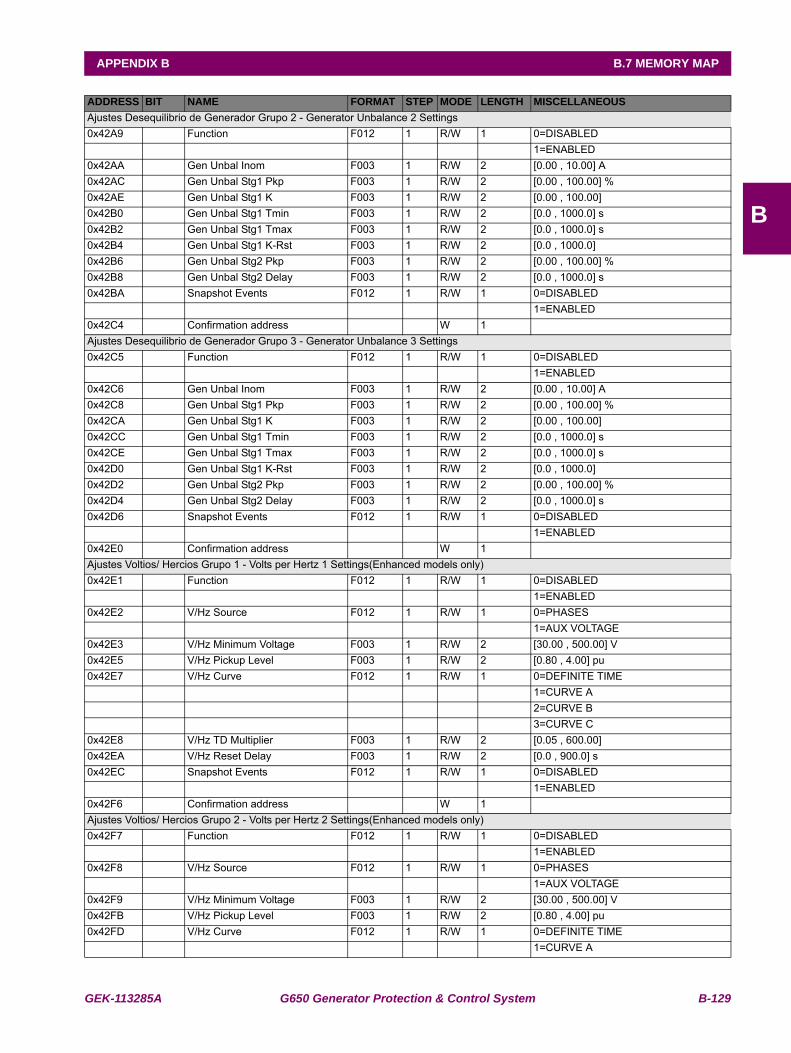
GEK-113285A G650 Generator Protection & Control System B-129
APPENDIX B B.7 MEMORY MAP
B
Ajustes Desequilibrio de Generador Grupo 2 - Generator Unbalance 2 Settings0x42A9 Function F012 1 R/W 1 0=DISABLED
1=ENABLED0x42AA Gen Unbal Inom F003 1 R/W 2 [0.00 , 10.00] A0x42AC Gen Unbal Stg1 Pkp F003 1 R/W 2 [0.00 , 100.00] %0x42AE Gen Unbal Stg1 K F003 1 R/W 2 [0.00 , 100.00] 0x42B0 Gen Unbal Stg1 Tmin F003 1 R/W 2 [0.0 , 1000.0] s0x42B2 Gen Unbal Stg1 Tmax F003 1 R/W 2 [0.0 , 1000.0] s0x42B4 Gen Unbal Stg1 K-Rst F003 1 R/W 2 [0.0 , 1000.0] 0x42B6 Gen Unbal Stg2 Pkp F003 1 R/W 2 [0.00 , 100.00] %0x42B8 Gen Unbal Stg2 Delay F003 1 R/W 2 [0.0 , 1000.0] s0x42BA Snapshot Events F012 1 R/W 1 0=DISABLED
1=ENABLED0x42C4 Confirmation address W 1Ajustes Desequilibrio de Generador Grupo 3 - Generator Unbalance 3 Settings0x42C5 Function F012 1 R/W 1 0=DISABLED
1=ENABLED0x42C6 Gen Unbal Inom F003 1 R/W 2 [0.00 , 10.00] A0x42C8 Gen Unbal Stg1 Pkp F003 1 R/W 2 [0.00 , 100.00] %0x42CA Gen Unbal Stg1 K F003 1 R/W 2 [0.00 , 100.00] 0x42CC Gen Unbal Stg1 Tmin F003 1 R/W 2 [0.0 , 1000.0] s0x42CE Gen Unbal Stg1 Tmax F003 1 R/W 2 [0.0 , 1000.0] s0x42D0 Gen Unbal Stg1 K-Rst F003 1 R/W 2 [0.0 , 1000.0] 0x42D2 Gen Unbal Stg2 Pkp F003 1 R/W 2 [0.00 , 100.00] %0x42D4 Gen Unbal Stg2 Delay F003 1 R/W 2 [0.0 , 1000.0] s0x42D6 Snapshot Events F012 1 R/W 1 0=DISABLED
1=ENABLED0x42E0 Confirmation address W 1Ajustes Voltios/ Hercios Grupo 1 - Volts per Hertz 1 Settings(Enhanced models only)0x42E1 Function F012 1 R/W 1 0=DISABLED
1=ENABLED0x42E2 V/Hz Source F012 1 R/W 1 0=PHASES
1=AUX VOLTAGE0x42E3 V/Hz Minimum Voltage F003 1 R/W 2 [30.00 , 500.00] V0x42E5 V/Hz Pickup Level F003 1 R/W 2 [0.80 , 4.00] pu0x42E7 V/Hz Curve F012 1 R/W 1 0=DEFINITE TIME
1=CURVE A2=CURVE B3=CURVE C
0x42E8 V/Hz TD Multiplier F003 1 R/W 2 [0.05 , 600.00] 0x42EA V/Hz Reset Delay F003 1 R/W 2 [0.0 , 900.0] s0x42EC Snapshot Events F012 1 R/W 1 0=DISABLED
1=ENABLED0x42F6 Confirmation address W 1Ajustes Voltios/ Hercios Grupo 2 - Volts per Hertz 2 Settings(Enhanced models only)0x42F7 Function F012 1 R/W 1 0=DISABLED
1=ENABLED0x42F8 V/Hz Source F012 1 R/W 1 0=PHASES
1=AUX VOLTAGE0x42F9 V/Hz Minimum Voltage F003 1 R/W 2 [30.00 , 500.00] V0x42FB V/Hz Pickup Level F003 1 R/W 2 [0.80 , 4.00] pu0x42FD V/Hz Curve F012 1 R/W 1 0=DEFINITE TIME
1=CURVE A
ADDRESS BIT NAME FORMAT STEP MODE LENGTH MISCELLANEOUS
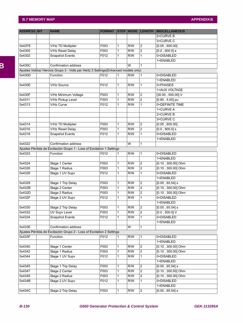
B-130 G650 Generator Protection & Control System GEK-113285A
B.7 MEMORY MAP APPENDIX B
B
2=CURVE B3=CURVE C
0x42FE V/Hz TD Multiplier F003 1 R/W 2 [0.05 , 600.00] 0x4300 V/Hz Reset Delay F003 1 R/W 2 [0.0 , 900.0] s0x4302 Snapshot Events F012 1 R/W 1 0=DISABLED
1=ENABLED0x430C Confirmation address W 1Ajustes Voltios/ Hercios Grupo 3 - Volts per Hertz 3 Settings(Enhanced models only)0x430D Function F012 1 R/W 1 0=DISABLED
1=ENABLED0x430E V/Hz Source F012 1 R/W 1 0=PHASES
1=AUX VOLTAGE0x430F V/Hz Minimum Voltage F003 1 R/W 2 [30.00 , 500.00] V0x4311 V/Hz Pickup Level F003 1 R/W 2 [0.80 , 4.00] pu0x4313 V/Hz Curve F012 1 R/W 1 0=DEFINITE TIME
1=CURVE A2=CURVE B3=CURVE C
0x4314 V/Hz TD Multiplier F003 1 R/W 2 [0.05 , 600.00] 0x4316 V/Hz Reset Delay F003 1 R/W 2 [0.0 , 900.0] s0x4318 Snapshot Events F012 1 R/W 1 0=DISABLED
1=ENABLED0x4322 Confirmation address W 1Ajustes Pérdida de Excitación Grupo 1 - Loss of Excitation 1 Settings0x4323 Function F012 1 R/W 1 0=DISABLED
1=ENABLED0x4324 Stage 1 Center F003 1 R/W 2 [0.10 , 300.00] Ohm0x4326 Stage 1 Radius F003 1 R/W 2 [0.10 , 300.00] Ohm0x4328 Stage 1 UV Supv F012 1 R/W 1 0=DISABLED
1=ENABLED0x4329 Stage 1 Trip Delay F003 1 R/W 2 [0.00 , 65.54] s0x432B Stage 2 Center F003 1 R/W 2 [0.10 , 300.00] Ohm0x432D Stage 2 Radius F003 1 R/W 2 [0.10 , 300.00] Ohm0x432F Stage 2 UV Supv F012 1 R/W 1 0=DISABLED
1=ENABLED0x4330 Stage 2 Trip Delay F003 1 R/W 2 [0.00 , 65.54] s0x4332 UV Supv Level F003 1 R/W 2 [0.0 , 500.0] V0x4334 Snapshot Events F012 1 R/W 1 0=DISABLED
1=ENABLED0x433E Confirmation address W 1Ajustes Pérdida de Excitación Grupo 2 - Loss of Excitation 2 Settings0x433F Function F012 1 R/W 1 0=DISABLED
1=ENABLED0x4340 Stage 1 Center F003 1 R/W 2 [0.10 , 300.00] Ohm0x4342 Stage 1 Radius F003 1 R/W 2 [0.10 , 300.00] Ohm0x4344 Stage 1 UV Supv F012 1 R/W 1 0=DISABLED
1=ENABLED0x4345 Stage 1 Trip Delay F003 1 R/W 2 [0.00 , 65.54] s0x4347 Stage 2 Center F003 1 R/W 2 [0.10 , 300.00] Ohm0x4349 Stage 2 Radius F003 1 R/W 2 [0.10 , 300.00] Ohm0x434B Stage 2 UV Supv F012 1 R/W 1 0=DISABLED
1=ENABLED0x434C Stage 2 Trip Delay F003 1 R/W 2 [0.00 , 65.54] s
ADDRESS BIT NAME FORMAT STEP MODE LENGTH MISCELLANEOUS
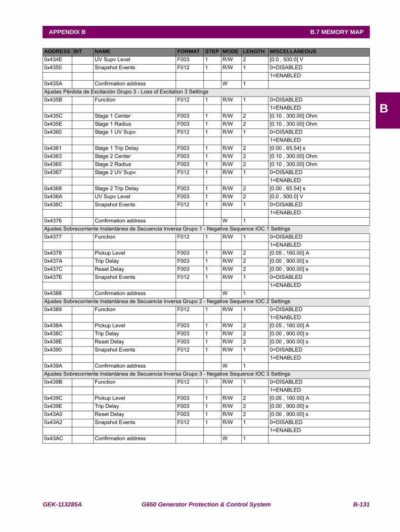
GEK-113285A G650 Generator Protection & Control System B-131
APPENDIX B B.7 MEMORY MAP
B
0x434E UV Supv Level F003 1 R/W 2 [0.0 , 500.0] V0x4350 Snapshot Events F012 1 R/W 1 0=DISABLED
1=ENABLED0x435A Confirmation address W 1Ajustes Pérdida de Excitación Grupo 3 - Loss of Excitation 3 Settings0x435B Function F012 1 R/W 1 0=DISABLED
1=ENABLED0x435C Stage 1 Center F003 1 R/W 2 [0.10 , 300.00] Ohm0x435E Stage 1 Radius F003 1 R/W 2 [0.10 , 300.00] Ohm0x4360 Stage 1 UV Supv F012 1 R/W 1 0=DISABLED
1=ENABLED0x4361 Stage 1 Trip Delay F003 1 R/W 2 [0.00 , 65.54] s0x4363 Stage 2 Center F003 1 R/W 2 [0.10 , 300.00] Ohm0x4365 Stage 2 Radius F003 1 R/W 2 [0.10 , 300.00] Ohm0x4367 Stage 2 UV Supv F012 1 R/W 1 0=DISABLED
1=ENABLED0x4368 Stage 2 Trip Delay F003 1 R/W 2 [0.00 , 65.54] s0x436A UV Supv Level F003 1 R/W 2 [0.0 , 500.0] V0x436C Snapshot Events F012 1 R/W 1 0=DISABLED
1=ENABLED0x4376 Confirmation address W 1Ajustes Sobrecorriente Instantánea de Secuencia Inversa Grupo 1 - Negative Sequence IOC 1 Settings0x4377 Function F012 1 R/W 1 0=DISABLED
1=ENABLED0x4378 Pickup Level F003 1 R/W 2 [0.05 , 160.00] A0x437A Trip Delay F003 1 R/W 2 [0.00 , 900.00] s0x437C Reset Delay F003 1 R/W 2 [0.00 , 900.00] s0x437E Snapshot Events F012 1 R/W 1 0=DISABLED
1=ENABLED0x4388 Confirmation address W 1Ajustes Sobrecorriente Instantánea de Secuencia Inversa Grupo 2 - Negative Sequence IOC 2 Settings0x4389 Function F012 1 R/W 1 0=DISABLED
1=ENABLED0x438A Pickup Level F003 1 R/W 2 [0.05 , 160.00] A0x438C Trip Delay F003 1 R/W 2 [0.00 , 900.00] s0x438E Reset Delay F003 1 R/W 2 [0.00 , 900.00] s0x4390 Snapshot Events F012 1 R/W 1 0=DISABLED
1=ENABLED0x439A Confirmation address W 1Ajustes Sobrecorriente Instantánea de Secuencia Inversa Grupo 3 - Negative Sequence IOC 3 Settings0x439B Function F012 1 R/W 1 0=DISABLED
1=ENABLED0x439C Pickup Level F003 1 R/W 2 [0.05 , 160.00] A0x439E Trip Delay F003 1 R/W 2 [0.00 , 900.00] s0x43A0 Reset Delay F003 1 R/W 2 [0.00 , 900.00] s0x43A2 Snapshot Events F012 1 R/W 1 0=DISABLED
1=ENABLED0x43AC Confirmation address W 1
ADDRESS BIT NAME FORMAT STEP MODE LENGTH MISCELLANEOUS
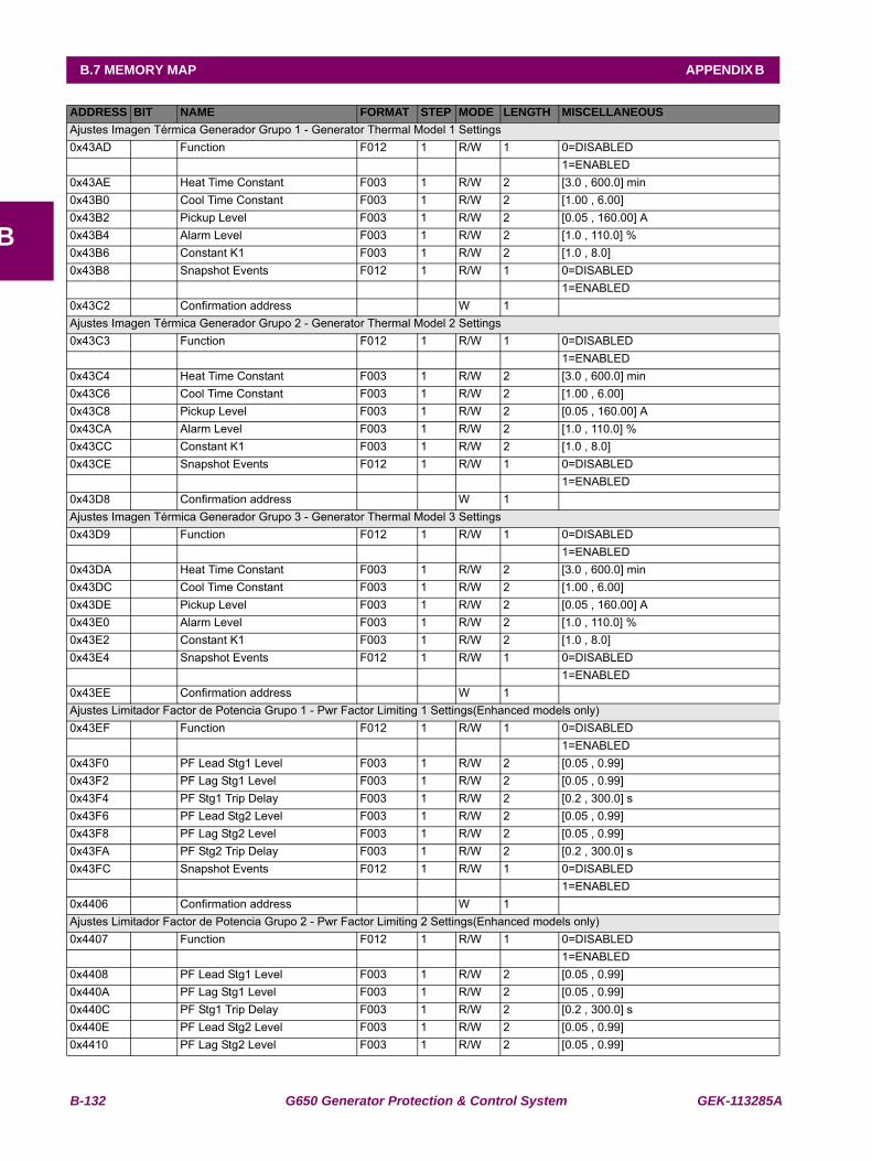
B-132 G650 Generator Protection & Control System GEK-113285A
B.7 MEMORY MAP APPENDIX B
B
Ajustes Imagen Térmica Generador Grupo 1 - Generator Thermal Model 1 Settings0x43AD Function F012 1 R/W 1 0=DISABLED
1=ENABLED0x43AE Heat Time Constant F003 1 R/W 2 [3.0 , 600.0] min0x43B0 Cool Time Constant F003 1 R/W 2 [1.00 , 6.00] 0x43B2 Pickup Level F003 1 R/W 2 [0.05 , 160.00] A0x43B4 Alarm Level F003 1 R/W 2 [1.0 , 110.0] %0x43B6 Constant K1 F003 1 R/W 2 [1.0 , 8.0] 0x43B8 Snapshot Events F012 1 R/W 1 0=DISABLED
1=ENABLED0x43C2 Confirmation address W 1Ajustes Imagen Térmica Generador Grupo 2 - Generator Thermal Model 2 Settings0x43C3 Function F012 1 R/W 1 0=DISABLED
1=ENABLED0x43C4 Heat Time Constant F003 1 R/W 2 [3.0 , 600.0] min0x43C6 Cool Time Constant F003 1 R/W 2 [1.00 , 6.00] 0x43C8 Pickup Level F003 1 R/W 2 [0.05 , 160.00] A0x43CA Alarm Level F003 1 R/W 2 [1.0 , 110.0] %0x43CC Constant K1 F003 1 R/W 2 [1.0 , 8.0] 0x43CE Snapshot Events F012 1 R/W 1 0=DISABLED
1=ENABLED0x43D8 Confirmation address W 1Ajustes Imagen Térmica Generador Grupo 3 - Generator Thermal Model 3 Settings0x43D9 Function F012 1 R/W 1 0=DISABLED
1=ENABLED0x43DA Heat Time Constant F003 1 R/W 2 [3.0 , 600.0] min0x43DC Cool Time Constant F003 1 R/W 2 [1.00 , 6.00] 0x43DE Pickup Level F003 1 R/W 2 [0.05 , 160.00] A0x43E0 Alarm Level F003 1 R/W 2 [1.0 , 110.0] %0x43E2 Constant K1 F003 1 R/W 2 [1.0 , 8.0] 0x43E4 Snapshot Events F012 1 R/W 1 0=DISABLED
1=ENABLED0x43EE Confirmation address W 1Ajustes Limitador Factor de Potencia Grupo 1 - Pwr Factor Limiting 1 Settings(Enhanced models only)0x43EF Function F012 1 R/W 1 0=DISABLED
1=ENABLED0x43F0 PF Lead Stg1 Level F003 1 R/W 2 [0.05 , 0.99] 0x43F2 PF Lag Stg1 Level F003 1 R/W 2 [0.05 , 0.99] 0x43F4 PF Stg1 Trip Delay F003 1 R/W 2 [0.2 , 300.0] s0x43F6 PF Lead Stg2 Level F003 1 R/W 2 [0.05 , 0.99] 0x43F8 PF Lag Stg2 Level F003 1 R/W 2 [0.05 , 0.99] 0x43FA PF Stg2 Trip Delay F003 1 R/W 2 [0.2 , 300.0] s0x43FC Snapshot Events F012 1 R/W 1 0=DISABLED
1=ENABLED0x4406 Confirmation address W 1Ajustes Limitador Factor de Potencia Grupo 2 - Pwr Factor Limiting 2 Settings(Enhanced models only)0x4407 Function F012 1 R/W 1 0=DISABLED
1=ENABLED0x4408 PF Lead Stg1 Level F003 1 R/W 2 [0.05 , 0.99] 0x440A PF Lag Stg1 Level F003 1 R/W 2 [0.05 , 0.99] 0x440C PF Stg1 Trip Delay F003 1 R/W 2 [0.2 , 300.0] s0x440E PF Lead Stg2 Level F003 1 R/W 2 [0.05 , 0.99] 0x4410 PF Lag Stg2 Level F003 1 R/W 2 [0.05 , 0.99]
ADDRESS BIT NAME FORMAT STEP MODE LENGTH MISCELLANEOUS
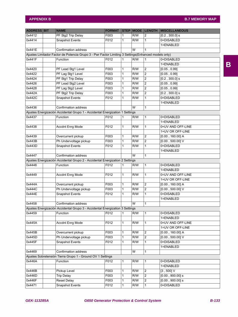
GEK-113285A G650 Generator Protection & Control System B-133
APPENDIX B B.7 MEMORY MAP
B
0x4412 PF Stg2 Trip Delay F003 1 R/W 2 [0.2 , 300.0] s0x4414 Snapshot Events F012 1 R/W 1 0=DISABLED
1=ENABLED0x441E Confirmation address W 1Ajustes Limitador Factor de Potencia Grupo 3 - Pwr Factor Limiting 3 Settings(Enhanced models only)0x441F Function F012 1 R/W 1 0=DISABLED
1=ENABLED0x4420 PF Lead Stg1 Level F003 1 R/W 2 [0.05 , 0.99] 0x4422 PF Lag Stg1 Level F003 1 R/W 2 [0.05 , 0.99] 0x4424 PF Stg1 Trip Delay F003 1 R/W 2 [0.2 , 300.0] s0x4426 PF Lead Stg2 Level F003 1 R/W 2 [0.05 , 0.99] 0x4428 PF Lag Stg2 Level F003 1 R/W 2 [0.05 , 0.99] 0x442A PF Stg2 Trip Delay F003 1 R/W 2 [0.2 , 300.0] s0x442C Snapshot Events F012 1 R/W 1 0=DISABLED
1=ENABLED0x4436 Confirmation address W 1Ajustes Energización Accidental Grupo 1 - Accidental Energization 1 Settings0x4437 Function F012 1 R/W 1 0=DISABLED
1=ENABLED0x4438 Accdnt Enrg Mode F012 1 R/W 1 0=UV AND OFF-LINE
1=UV OR OFF-LINE0x4439 Overcurrent pickup F003 1 R/W 2 [0.00 , 160.00] A0x443B Ph Undervoltage pickup F003 1 R/W 2 [0.00 , 500.00] V0x443D Snapshot Events F012 1 R/W 1 0=DISABLED
1=ENABLED0x4447 Confirmation address W 1Ajustes Energización Accidental Grupo 2 - Accidental Energization 2 Settings0x4448 Function F012 1 R/W 1 0=DISABLED
1=ENABLED0x4449 Accdnt Enrg Mode F012 1 R/W 1 0=UV AND OFF-LINE
1=UV OR OFF-LINE0x444A Overcurrent pickup F003 1 R/W 2 [0.00 , 160.00] A0x444C Ph Undervoltage pickup F003 1 R/W 2 [0.00 , 500.00] V0x444E Snapshot Events F012 1 R/W 1 0=DISABLED
1=ENABLED0x4458 Confirmation address W 1Ajustes Energización Accidental Grupo 3 - Accidental Energization 3 Settings0x4459 Function F012 1 R/W 1 0=DISABLED
1=ENABLED0x445A Accdnt Enrg Mode F012 1 R/W 1 0=UV AND OFF-LINE
1=UV OR OFF-LINE0x445B Overcurrent pickup F003 1 R/W 2 [0.00 , 160.00] A0x445D Ph Undervoltage pickup F003 1 R/W 2 [0.00 , 500.00] V0x445F Snapshot Events F012 1 R/W 1 0=DISABLED
1=ENABLED0x4469 Confirmation address W 1Ajustes Sobretensión Tierra Grupo 1 - Ground OV 1 Settings0x446A Function F012 1 R/W 1 0=DISABLED
1=ENABLED0x446B Pickup Level F003 1 R/W 2 [3 , 500] V0x446D Trip Delay F003 1 R/W 2 [0.00 , 900.00] s0x446F Reset Delay F003 1 R/W 2 [0.00 , 900.00] s0x4471 Snapshot Events F012 1 R/W 1 0=DISABLED
ADDRESS BIT NAME FORMAT STEP MODE LENGTH MISCELLANEOUS
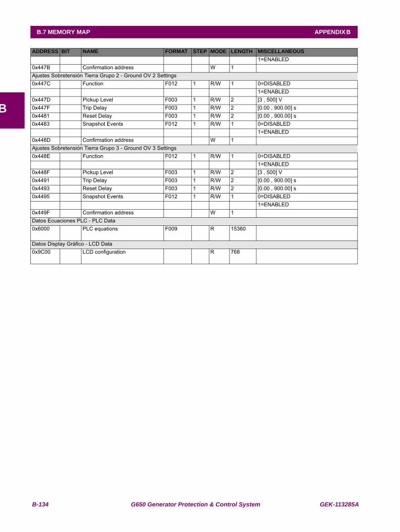
B-134 G650 Generator Protection & Control System GEK-113285A
B.7 MEMORY MAP APPENDIX B
B
1=ENABLED0x447B Confirmation address W 1Ajustes Sobretensión Tierra Grupo 2 - Ground OV 2 Settings0x447C Function F012 1 R/W 1 0=DISABLED
1=ENABLED0x447D Pickup Level F003 1 R/W 2 [3 , 500] V0x447F Trip Delay F003 1 R/W 2 [0.00 , 900.00] s0x4481 Reset Delay F003 1 R/W 2 [0.00 , 900.00] s0x4483 Snapshot Events F012 1 R/W 1 0=DISABLED
1=ENABLED0x448D Confirmation address W 1Ajustes Sobretensión Tierra Grupo 3 - Ground OV 3 Settings0x448E Function F012 1 R/W 1 0=DISABLED
1=ENABLED0x448F Pickup Level F003 1 R/W 2 [3 , 500] V0x4491 Trip Delay F003 1 R/W 2 [0.00 , 900.00] s0x4493 Reset Delay F003 1 R/W 2 [0.00 , 900.00] s0x4495 Snapshot Events F012 1 R/W 1 0=DISABLED
1=ENABLED0x449F Confirmation address W 1Datos Ecuaciones PLC - PLC Data0x6000 PLC equations F009 R 15360
Datos Display Gráfico - LCD Data0x9C00 LCD configuration R 768
ADDRESS BIT NAME FORMAT STEP MODE LENGTH MISCELLANEOUS
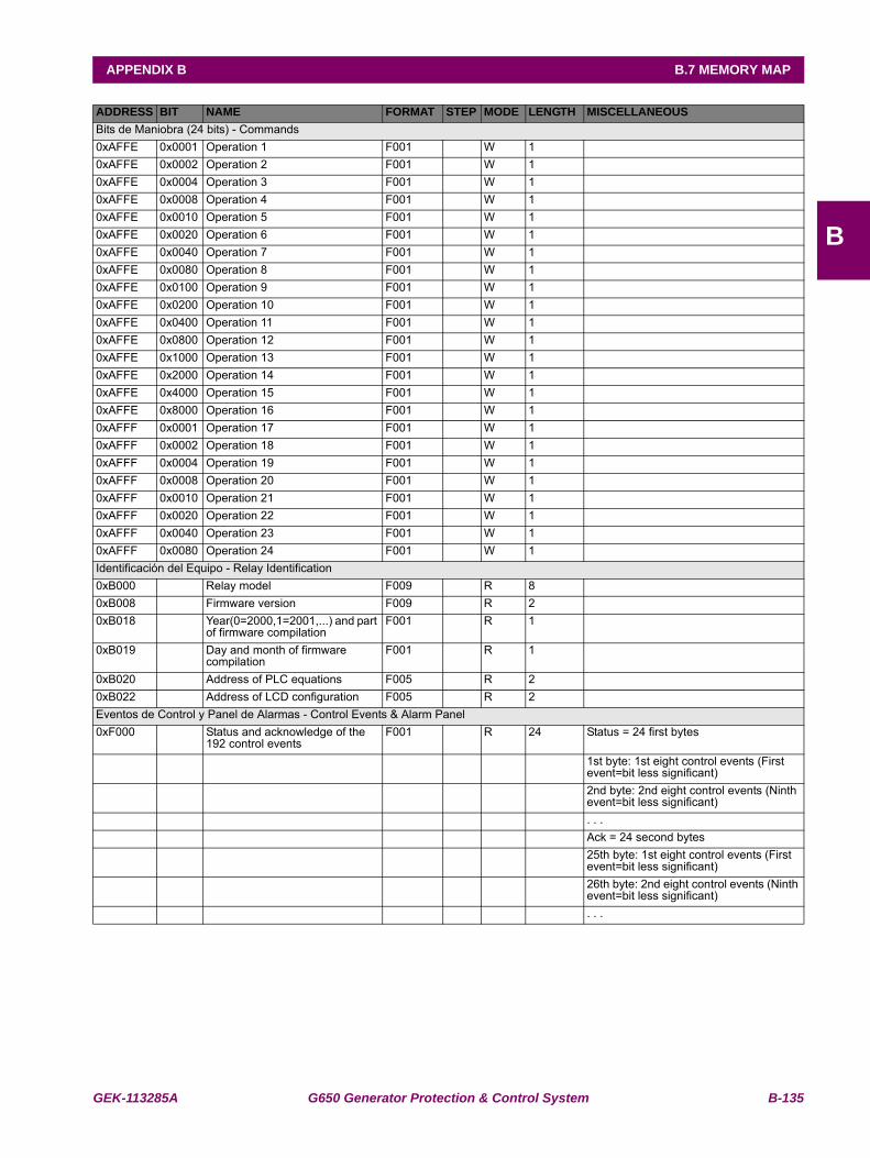
GEK-113285A G650 Generator Protection & Control System B-135
APPENDIX B B.7 MEMORY MAP
B
Bits de Maniobra (24 bits) - Commands0xAFFE 0x0001 Operation 1 F001 W 1 0xAFFE 0x0002 Operation 2 F001 W 1 0xAFFE 0x0004 Operation 3 F001 W 1 0xAFFE 0x0008 Operation 4 F001 W 1 0xAFFE 0x0010 Operation 5 F001 W 1 0xAFFE 0x0020 Operation 6 F001 W 1 0xAFFE 0x0040 Operation 7 F001 W 1 0xAFFE 0x0080 Operation 8 F001 W 1 0xAFFE 0x0100 Operation 9 F001 W 1 0xAFFE 0x0200 Operation 10 F001 W 1 0xAFFE 0x0400 Operation 11 F001 W 1 0xAFFE 0x0800 Operation 12 F001 W 1 0xAFFE 0x1000 Operation 13 F001 W 1 0xAFFE 0x2000 Operation 14 F001 W 1 0xAFFE 0x4000 Operation 15 F001 W 1 0xAFFE 0x8000 Operation 16 F001 W 1 0xAFFF 0x0001 Operation 17 F001 W 1 0xAFFF 0x0002 Operation 18 F001 W 1 0xAFFF 0x0004 Operation 19 F001 W 1 0xAFFF 0x0008 Operation 20 F001 W 1 0xAFFF 0x0010 Operation 21 F001 W 1 0xAFFF 0x0020 Operation 22 F001 W 1 0xAFFF 0x0040 Operation 23 F001 W 1 0xAFFF 0x0080 Operation 24 F001 W 1 Identificación del Equipo - Relay Identification0xB000 Relay model F009 R 8 0xB008 Firmware version F009 R 2 0xB018 Year(0=2000,1=2001,...) and part
of firmware compilationF001 R 1
0xB019 Day and month of firmware compilation
F001 R 1
0xB020 Address of PLC equations F005 R 2 0xB022 Address of LCD configuration F005 R 2 Eventos de Control y Panel de Alarmas - Control Events & Alarm Panel0xF000 Status and acknowledge of the
192 control eventsF001 R 24 Status = 24 first bytes
1st byte: 1st eight control events (First event=bit less significant)
2nd byte: 2nd eight control events (Ninth event=bit less significant)
. . . Ack = 24 second bytes 25th byte: 1st eight control events (First
event=bit less significant) 26th byte: 2nd eight control events (Ninth
event=bit less significant) . . .
ADDRESS BIT NAME FORMAT STEP MODE LENGTH MISCELLANEOUS
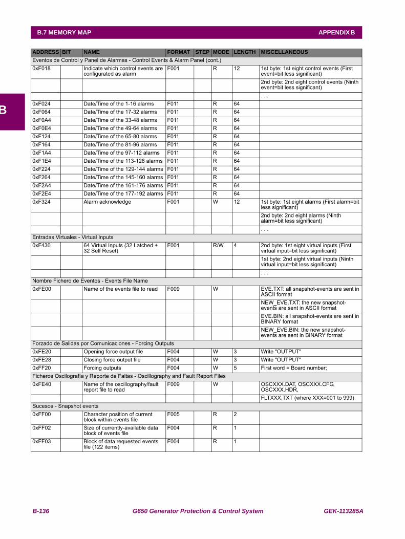
B-136 G650 Generator Protection & Control System GEK-113285A
B.7 MEMORY MAP APPENDIX B
B
Eventos de Control y Panel de Alarmas - Control Events & Alarm Panel (cont.)0xF018 Indicate which control events are
configurated as alarmF001 R 12 1st byte: 1st eight control events (First
event=bit less significant) 2nd byte: 2nd eight control events (Ninth
event=bit less significant) . . .0xF024 Date/Time of the 1-16 alarms F011 R 64 0xF064 Date/Time of the 17-32 alarms F011 R 64 0xF0A4 Date/Time of the 33-48 alarms F011 R 64 0xF0E4 Date/Time of the 49-64 alarms F011 R 64 0xF124 Date/Time of the 65-80 alarms F011 R 64 0xF164 Date/Time of the 81-96 alarms F011 R 64 0xF1A4 Date/Time of the 97-112 alarms F011 R 64 0xF1E4 Date/Time of the 113-128 alarms F011 R 64 0xF224 Date/Time of the 129-144 alarms F011 R 64 0xF264 Date/Time of the 145-160 alarms F011 R 64 0xF2A4 Date/Time of the 161-176 alarms F011 R 64 0xF2E4 Date/Time of the 177-192 alarms F011 R 64 0xF324 Alarm acknowledge F001 W 12 1st byte: 1st eight alarms (First alarm=bit
less significant) 2nd byte: 2nd eight alarms (Ninth
alarm=bit less significant) . . .Entradas Virtuales - Virtual Inputs0xF430 64 Virtual Inputs (32 Latched +
32 Self Reset)F001 R/W 4 2nd byte: 1st eight virtual inputs (First
virtual input=bit less significant) 1st byte: 2nd eight virtual inputs (Ninth
virtual input=bit less significant) . . .Nombre Fichero de Eventos - Events File Name0xFE00 Name of the events file to read F009 W EVE.TXT: all snapshot-events are sent in
ASCII format NEW_EVE.TXT: the new snapshot-
events are sent in ASCII format EVE.BIN: all snapshot-events are sent in
BINARY format NEW_EVE.BIN: the new snapshot-
events are sent in BINARY formatForzado de Salidas por Comunicaciones - Forcing Outputs0xFE20 Opening force output file F004 W 3 Write "OUTPUT"0xFE28 Closing force output file F004 W 3 Write "OUTPUT"0xFF20 Forcing outputs F004 W 5 First word = Board number;Ficheros Oscilografía y Reporte de Faltas - Oscillography and Fault Report Files0xFE40 Name of the oscillography/fault
report file to readF009 W OSCXXX.DAT, OSCXXX.CFG,
OSCXXX.HDR, FLTXXX.TXT (where XXX=001 to 999)Sucesos - Snapshot events0xFF00 Character position of current
block within events fileF005 R 2
0xFF02 Size of currently-available data block of events file
F004 R 1
0xFF03 Block of data requested events file (122 items)
F004 R 1
ADDRESS BIT NAME FORMAT STEP MODE LENGTH MISCELLANEOUS
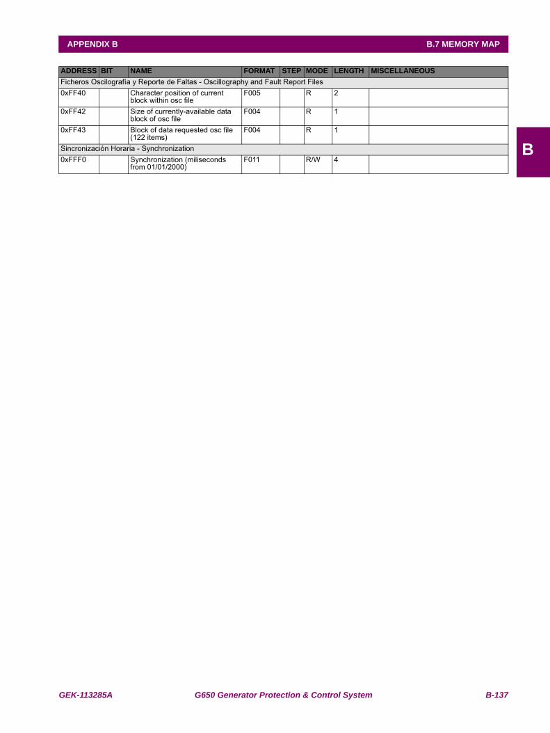
GEK-113285A G650 Generator Protection & Control System B-137
APPENDIX B B.7 MEMORY MAP
B
Ficheros Oscilografía y Reporte de Faltas - Oscillography and Fault Report Files0xFF40 Character position of current
block within osc fileF005 R 2
0xFF42 Size of currently-available data block of osc file
F004 R 1
0xFF43 Block of data requested osc file (122 items)
F004 R 1
Sincronización Horaria - Synchronization0xFFF0 Synchronization (miliseconds
from 01/01/2000)F011 R/W 4
ADDRESS BIT NAME FORMAT STEP MODE LENGTH MISCELLANEOUS
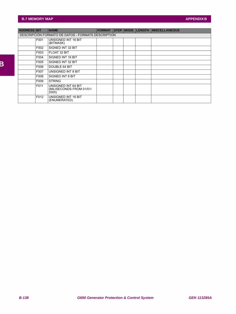
B-138 G650 Generator Protection & Control System GEK-113285A
B.7 MEMORY MAP APPENDIX B
B
DESCRIPCIÓN FORMATO DE DATOS - FORMATS DESCRIPTION F001 UNSIGNED INT 16 BIT
(BITMASK)
F002 SIGNED INT 32 BIT F003 FLOAT 32 BIT F004 SIGNED INT 16 BIT F005 SIGNED INT 32 BIT F006 DOUBLE 64 BIT F007 UNSIGNED INT 8 BIT F008 SIGNED INT 8 BIT F009 STRING F011 UNSIGNED INT 64 BIT
(MILISECONDS FROM 01/01/2000)
F012 UNSIGNED INT 16 BIT (ENUMERATED)
ADDRESS BIT NAME FORMAT STEP MODE LENGTH MISCELLANEOUS
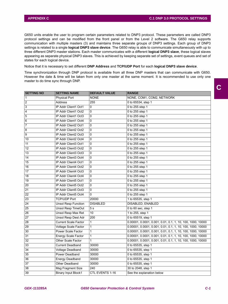
GEK-113285A G650 Generator Protection & Control System C-1
APPENDIX C C.1 DNP 3.0 PROTOCOL SETTINGS
C
APPENDIX C DNP 3.0 PROTOCOL FOR G650C.1DNP 3.0 PROTOCOL SETTINGS
G650 units enable the user to program certain parameters related to DNP3 protocol. These parameters are called DNP3protocol settings and can be modified from the front panel or from the Level 2 software. The G650 relay supportscommunication with multiple masters (3) and maintains three separate groups of DNP3 settings. Each group of DNP3settings is related to a single logical DNP3 slave device. The G650 relay is able to communicate simultaneously with up tothree different DNP3 master stations. Each master communicates with a different logical DNP3 slave, these logical slavesappearing as separate physical DNP3 slaves. This is achieved by keeping separate set of settings, event queues and set ofstates for each logical device.
Notice that it is necessary to set different DNP Address and TCP/UDP Port for each logical DNP3 slave device.
Time synchronization through DNP protocol is available from all three DNP masters that can communicate with G650.However the date & time will be taken from only one master at the same moment. It is recommended to use only onemaster to do time sync through DNP.
SETTING NO SETTING NAME DEFAULT VALUE RANGE1 Physical Port NONE NONE, COM1, COM2, NETWORK2 Address 255 0 to 65534, step 13 IP Addr Client1 Oct1 0 0 to 255 step 14 IP Addr Client1 Oct2 0 0 to 255 step 15 IP Addr Client1 Oct3 0 0 to 255 step 16 IP Addr Client1 Oct4 0 0 to 255 step 17 IP Addr Client2 Oct1 0 0 to 255 step 18 IP Addr Client2 Oct2 0 0 to 255 step 19 IP Addr Client2 Oct3 0 0 to 255 step 110 IP Addr Client2 Oct4 0 0 to 255 step 111 IP Addr Client3 Oct1 0 0 to 255 step 112 IP Addr Client3 Oct2 0 0 to 255 step 113 IP Addr Client3 Oct3 0 0 to 255 step 114 IP Addr Client3 Oct4 0 0 to 255 step 115 IP Addr Client4 Oct1 0 0 to 255 step 116 IP Addr Client4 Oct2 0 0 to 255 step 117 IP Addr Client4 Oct3 0 0 to 255 step 118 IP Addr Client4 Oct4 0 0 to 255 step 119 IP Addr Client5 Oct1 0 0 to 255 step 120 IP Addr Client5 Oct2 0 0 to 255 step 121 IP Addr Client5 Oct3 0 0 to 255 step 122 IP Addr Client5 Oct4 0 0 to 255 step 123 TCP/UDP Port 20000 1 to 65535, step 124 Unsol Resp Function DISABLED DISABLED, ENABLED25 Unsol Resp TimeOut 5 s 0 to 60 sec, step 126 Unsol Resp Max Ret 10 1 to 255, step 1 27 Unsol Resp Dest Adr 200 0 to 65519, step 128 Current Scale Factor 1 0.00001, 0.0001, 0.001, 0.01, 0.1, 1, 10, 100, 1000, 1000029 Voltage Scale Factor 1 0.00001, 0.0001, 0.001, 0.01, 0.1, 1, 10, 100, 1000, 1000030 Power Scale Factor 1 0.00001, 0.0001, 0.001, 0.01, 0.1, 1, 10, 100, 1000, 1000031 Energy Scale Factor 1 0.00001, 0.0001, 0.001, 0.01, 0.1, 1, 10, 100, 1000, 1000032 Other Scale Factor 1 0.00001, 0.0001, 0.001, 0.01, 0.1, 1, 10, 100, 1000, 1000033 Current Deadband 30000 0 to 65535, step 134 Voltage Deadband 30000 0 to 65535, step 135 Power Deadband 30000 0 to 65535, step 136 Energy Deadband 30000 0 to 65535, step 137 Other Deadband 30000 0 to 65535, step 138 Msg Fragment Size 240 30 to 2048, step 1 39 Binary Input Block1 CTL EVENTS 1-16 See the explanation below
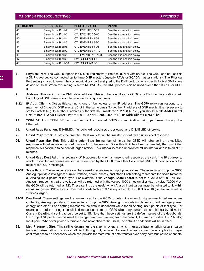
C-2 G650 Generator Protection & Control System GEK-113285A
C.1 DNP 3.0 PROTOCOL SETTINGS APPENDIX C
C1. Physical Port: The G650 supports the Distributed Network Protocol (DNP) version 3.0. The G650 can be used as
a DNP slave device connected up to three DNP masters (usually RTUs or SCADA master stations). The PhysicalPort setting is used to select the communications port assigned to the DNP protocol for a specific logical DNP slavedevice of G650. When this setting is set to NETWORK, the DNP protocol can be used over either TCP/IP or UDP/IP.
2. Address: This setting is the DNP slave address. This number identifies de G650 on a DNP communications link.Each logical DNP slave should be assigned a unique address.
3-22. IP Addr Client x Oct x: this setting is one of four octets of an IP address. The G650 relay can respond to amaximum of 5 specific DNP masters (not in the same time). To set the IP address of DNP master it is necessary toset four octets (e.g. to set the IP address of the first DNP master to 192.168.48.125, you should set IP Addr Client1Oct1 = 192, IP Addr Client1 Oct2 = 168, IP Addr Client1 Oct3 = 48, IP Addr Client1 Oct4 = 125).
23. TCP/UDP Port: TCP/UDP port number for the case of DNP3 communication being performed through theEthernet.
24. Unsol Resp Function: ENABLED, if unsolicited responses are allowed, and DISABLED otherwise.
25. Unsol Resp TimeOut: sets the time the G650 waits for a DNP master to confirm an unsolicited response.
26. Unsol Resp Max Ret: This setting determines the number of times the G650 will retransmit an unsolicitedresponse without receiving a confirmation from the master. Once this limit has been exceeded, the unsolicitedresponse will continue to be sent at larger interval. This interval is called unsolicited offline interval and is fixed at 10minutes.
27. Unsol Resp Dest Adr: This setting is DNP address to which all unsolicited responses are sent. The IP address towhich unsolicited responses are sent is determined by the G650 from either the current DNP TCP connection or themost recent UDP message.
28-32. Scale Factor: These settings are numbers used to scale Analog Input point values. These settings group the G650Analog Input data into types: current, voltage, power, energy, and other. Each setting represents the scale factor forall Analog Input points of that type. For example, if the Voltage Scale Factor is set to a value of 1000, all DNPAnalog Input points that are voltages will be returned with the values 1000 times smaller (e.g. a value 72000 V onthe G650 will be returned as 72). These settings are useful when Analog Input values must be adjusted to fit withincertain ranges in DNP masters. Note that a scale factor of 0.1 is equivalent to a multiplier of 10 (i.e. the value will be10 times larger).
33-37. Deadband: These settings are the values used by the G650 to determine when to trigger unsolicited responsescontaining Analog Input data. These settings group the G650 Analog Input data into types: current, voltage, power,energy, and other. Each setting represents the default deadband value for all Analog Input points of that type. Forexample, in order to trigger unsolicited responses from the G650 when any current values change by 15 A, theCurrent Deadband setting should be set to 15. Note that these settings are the default values of the deadbands.DNP object 34 points can be used to change deadband values, from the default, for each individual DNP AnalogInput point. Whenever power is removed and re-applied to the G650, the default deadbands will be in effect.
38. Msg Fragment Size: This setting determines the size, in bytes, at which message fragmentation occurs. Largefragment sizes allow for more efficient throughput; smaller fragment sizes cause more application layerconfirmations to be necessary which can provide for more robust data transfer over noisy communication channels
SETTING NO SETTING NAME DEFAULT VALUE RANGE40 Binary Input Block2 CTL EVENTS 17-32 See the explanation below41 Binary Input Block3 CTL EVENTS 33-48 See the explanation below42 Binary Input Block4 CTL EVENTS 49-64 See the explanation below43 Binary Input Block5 CTL EVENTS 65-80 See the explanation below44 Binary Input Block6 CTL EVENTS 81-96 See the explanation below45 Binary Input Block7 CTL EVENTS 97-112 See the explanation below46 Binary Input Block8 CTL EVENTS 113-128 See the explanation below47 Binary Input Block9 SWITCHGEAR 1-8 See the explanation below48 Binary Input Block10 SWITCHGEAR 9-16 See the explanation below
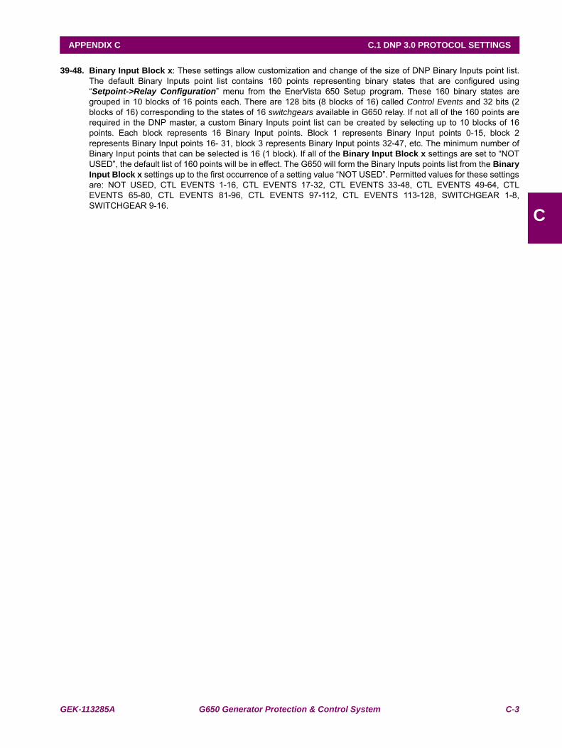
GEK-113285A G650 Generator Protection & Control System C-3
APPENDIX C C.1 DNP 3.0 PROTOCOL SETTINGS
C
39-48. Binary Input Block x: These settings allow customization and change of the size of DNP Binary Inputs point list.The default Binary Inputs point list contains 160 points representing binary states that are configured using“Setpoint->Relay Configuration” menu from the EnerVista 650 Setup program. These 160 binary states aregrouped in 10 blocks of 16 points each. There are 128 bits (8 blocks of 16) called Control Events and 32 bits (2blocks of 16) corresponding to the states of 16 switchgears available in G650 relay. If not all of the 160 points arerequired in the DNP master, a custom Binary Inputs point list can be created by selecting up to 10 blocks of 16points. Each block represents 16 Binary Input points. Block 1 represents Binary Input points 0-15, block 2represents Binary Input points 16- 31, block 3 represents Binary Input points 32-47, etc. The minimum number ofBinary Input points that can be selected is 16 (1 block). If all of the Binary Input Block x settings are set to “NOTUSED”, the default list of 160 points will be in effect. The G650 will form the Binary Inputs points list from the BinaryInput Block x settings up to the first occurrence of a setting value “NOT USED”. Permitted values for these settingsare: NOT USED, CTL EVENTS 1-16, CTL EVENTS 17-32, CTL EVENTS 33-48, CTL EVENTS 49-64, CTLEVENTS 65-80, CTL EVENTS 81-96, CTL EVENTS 97-112, CTL EVENTS 113-128, SWITCHGEAR 1-8,SWITCHGEAR 9-16.
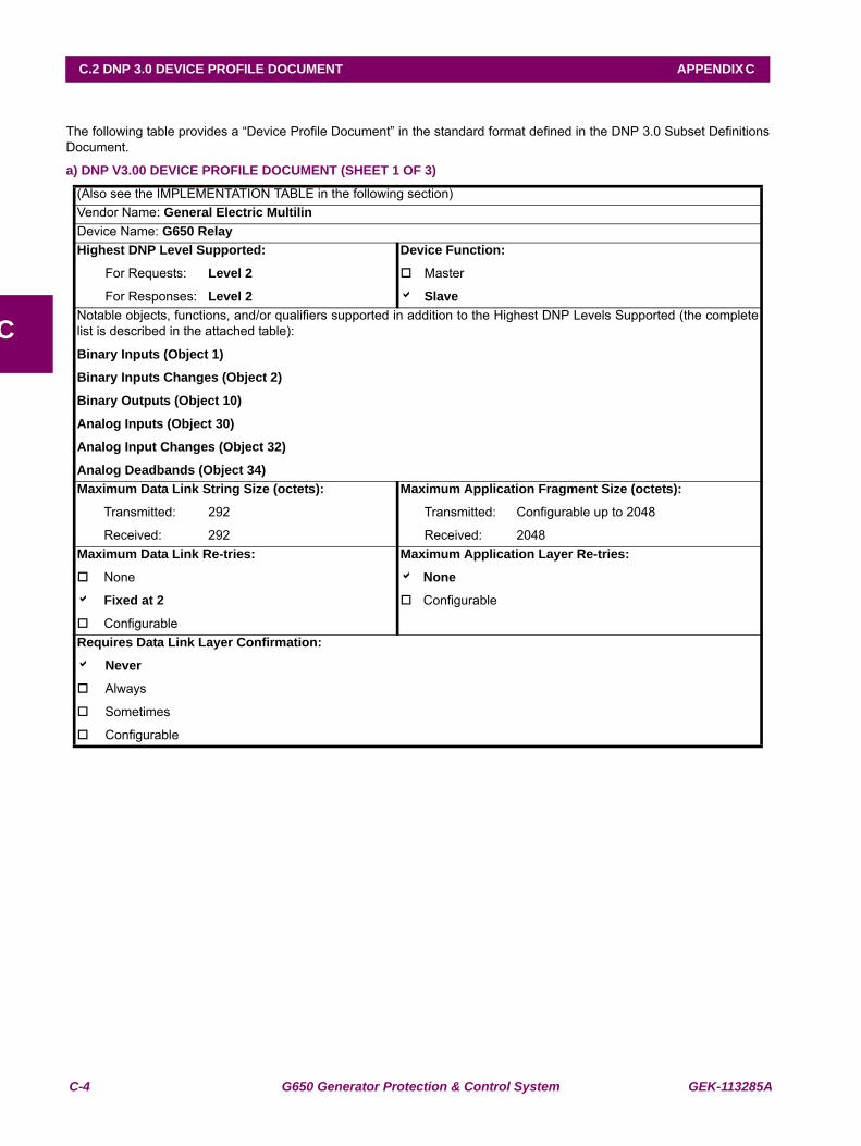
C-4 G650 Generator Protection & Control System GEK-113285A
C.2 DNP 3.0 DEVICE PROFILE DOCUMENT APPENDIX C
C
C.2DNP 3.0 DEVICE PROFILE DOCUMENT
The following table provides a “Device Profile Document” in the standard format defined in the DNP 3.0 Subset DefinitionsDocument.
a) DNP V3.00 DEVICE PROFILE DOCUMENT (SHEET 1 OF 3)
(Also see the IMPLEMENTATION TABLE in the following section)Vendor Name: General Electric MultilinDevice Name: G650 RelayHighest DNP Level Supported:
For Requests: Level 2
For Responses: Level 2
Device Function:
Master
a SlaveNotable objects, functions, and/or qualifiers supported in addition to the Highest DNP Levels Supported (the completelist is described in the attached table):
Binary Inputs (Object 1)
Binary Inputs Changes (Object 2)
Binary Outputs (Object 10)
Analog Inputs (Object 30)
Analog Input Changes (Object 32)
Analog Deadbands (Object 34)Maximum Data Link String Size (octets):
Transmitted: 292
Received: 292
Maximum Application Fragment Size (octets):
Transmitted: Configurable up to 2048
Received: 2048Maximum Data Link Re-tries:
None
a Fixed at 2
Configurable
Maximum Application Layer Re-tries:
a None
Configurable
Requires Data Link Layer Confirmation:
a Never
Always
Sometimes
Configurable
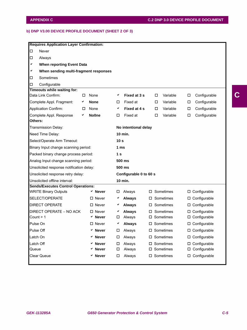
GEK-113285A G650 Generator Protection & Control System C-5
APPENDIX C C.2 DNP 3.0 DEVICE PROFILE DOCUMENT
C
b) DNP V3.00 DEVICE PROFILE DOCUMENT (SHEET 2 OF 3)
Requires Application Layer Confirmation:
Never
Always
a When reporting Event Data
a When sending multi-fragment responses
Sometimes
ConfigurableTimeouts while waiting for:Data Link Confirm:
Complete Appl. Fragment:
Application Confirm:
Complete Appl. Response
None
a None
None
a No0ne
a Fixed at 3 s
Fixed at
a Fixed at 4 s
Fixed at
Variable
Variable
Variable
Variable
Configurable
Configurable
Configurable
ConfigurableOthers:
Transmission Delay:
Need Time Delay:
Select/Operate Arm Timeout:
Binary Input change scanning period:
Packed binary change process period:
Analog Input change scanning period:
Unsolicited response notification delay:
Unsolicited response retry delay:
Unsolicited offline interval:
No intentional delay
10 min.
10 s
1 ms
1 s
500 ms
500 ms
Configurable 0 to 60 s
10 min.Sends/Executes Control Operations:WRITE Binary Outputs
SELECT/OPERATE
DIRECT OPERATE
DIRECT OPERATE – NO ACK
a Never
Never
Never
Never
Always
a Always
a Always
a Always
Sometimes
Sometimes
Sometimes
Sometimes
Configurable
Configurable
Configurable
ConfigurableCount > 1
Pulse On
Pulse Off
Latch On
Latch Off
a Never
Never
a Never
a Never
a Never
Always
a Always
Always
Always
Always
Sometimes
Sometimes
Sometimes
Sometimes
Sometimes
Configurable
Configurable
Configurable
Configurable
ConfigurableQueue
Clear Queue
a Never
a Never
Always
Always
Sometimes
Sometimes
Configurable
Configurable
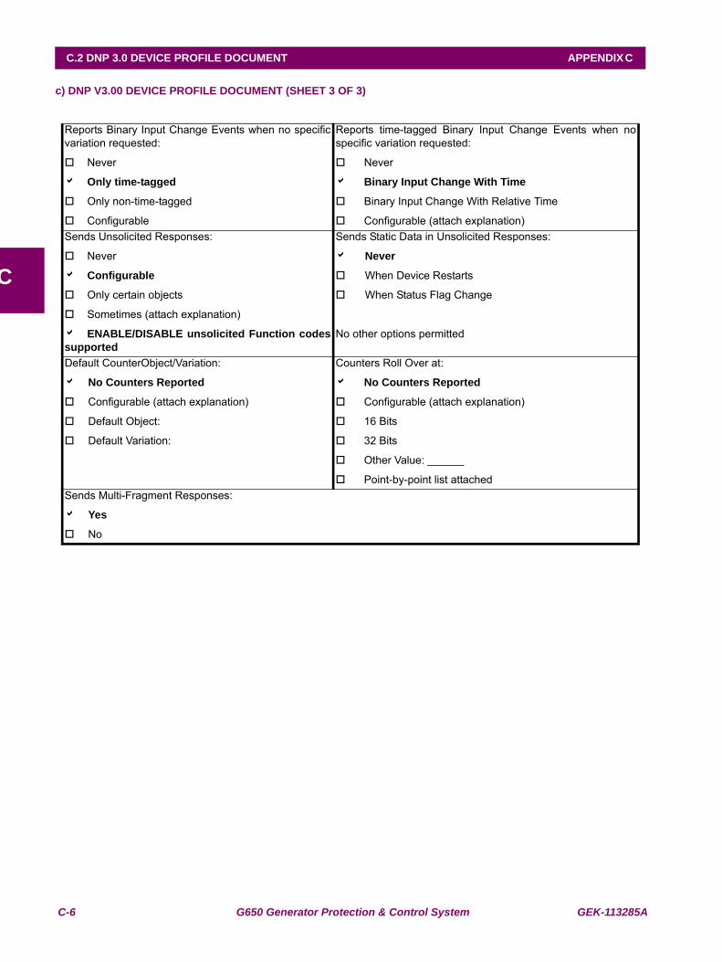
C-6 G650 Generator Protection & Control System GEK-113285A
C.2 DNP 3.0 DEVICE PROFILE DOCUMENT APPENDIX C
C
c) DNP V3.00 DEVICE PROFILE DOCUMENT (SHEET 3 OF 3)
Reports Binary Input Change Events when no specificvariation requested:
Never
a Only time-tagged
Only non-time-tagged
Configurable
Reports time-tagged Binary Input Change Events when nospecific variation requested:
Never
a Binary Input Change With Time
Binary Input Change With Relative Time
Configurable (attach explanation)Sends Unsolicited Responses:
Never
a Configurable
Only certain objects
Sometimes (attach explanation)
a ENABLE/DISABLE unsolicited Function codessupported
Sends Static Data in Unsolicited Responses:
a Never
When Device Restarts
When Status Flag Change
No other options permitted
Default CounterObject/Variation:
a No Counters Reported
Configurable (attach explanation)
Default Object:
Default Variation:
Counters Roll Over at:
a No Counters Reported
Configurable (attach explanation)
16 Bits
32 Bits
Other Value: ______
Point-by-point list attachedSends Multi-Fragment Responses:
a Yes
No
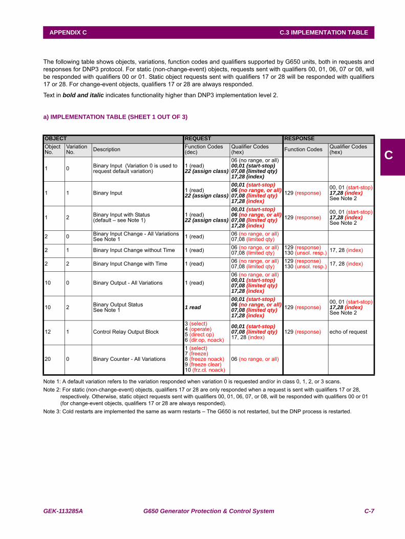
GEK-113285A G650 Generator Protection & Control System C-7
APPENDIX C C.3 IMPLEMENTATION TABLE
C
C.3IMPLEMENTATION TABLE
The following table shows objects, variations, function codes and qualifiers supported by G650 units, both in requests andresponses for DNP3 protocol. For static (non-change-event) objects, requests sent with qualifiers 00, 01, 06, 07 or 08, willbe responded with qualifiers 00 or 01. Static object requests sent with qualifiers 17 or 28 will be responded with qualifiers17 or 28. For change-event objects, qualifiers 17 or 28 are always responded.
Text in bold and italic indicates functionality higher than DNP3 implementation level 2.
a) IMPLEMENTATION TABLE (SHEET 1 OUT OF 3)
Note 1: A default variation refers to the variation responded when variation 0 is requested and/or in class 0, 1, 2, or 3 scans.Note 2: For static (non-change-event) objects, qualifiers 17 or 28 are only responded when a request is sent with qualifiers 17 or 28,
respectively. Otherwise, static object requests sent with qualifiers 00, 01, 06, 07, or 08, will be responded with qualifiers 00 or 01 (for change-event objects, qualifiers 17 or 28 are always responded).
Note 3: Cold restarts are implemented the same as warm restarts – The G650 is not restarted, but the DNP process is restarted.
OBJECT REQUEST RESPONSEObject No.
Variation No. Description Function Codes
(dec)Qualifier Codes (hex) Function Codes Qualifier Codes
(hex)
1 0 Binary Input (Variation 0 is used to request default variation)
1 (read)22 (assign class)
06 (no range, or all)00,01 (start-stop)07,08 (limited qty)17,28 (index)
1 1 Binary Input 1 (read)22 (assign class)
00,01 (start-stop)06 (no range, or all)07,08 (limited qty)17,28 (index)
129 (response)00, 01 (start-stop)17,28 (index)See Note 2
1 2 Binary Input with Status(default – see Note 1)
1 (read)22 (assign class)
00,01 (start-stop)06 (no range, or all)07,08 (limited qty)17,28 (index)
129 (response)00, 01 (start-stop)17,28 (index)See Note 2
2 0 Binary Input Change - All VariationsSee Note 1 1 (read) 06 (no range, or all)
07,08 (limited qty)
2 1 Binary Input Change without Time 1 (read) 06 (no range, or all)07,08 (limited qty)
129 (response) 130 (unsol. resp.) 17, 28 (index)
2 2 Binary Input Change with Time 1 (read) 06 (no range, or all)07,08 (limited qty)
129 (response) 130 (unsol. resp.) 17, 28 (index)
10 0 Binary Output - All Variations 1 (read)06 (no range, or all)00,01 (start-stop)07,08 (limited qty)17,28 (index)
10 2 Binary Output Status See Note 1 1 read
00,01 (start-stop)06 (no range, or all)07,08 (limited qty)17,28 (index)
129 (response)00, 01 (start-stop)17,28 (index)See Note 2
12 1 Control Relay Output Block3 (select)4 (operate)5 (direct op)6 (dir.op, noack)
00,01 (start-stop)07,08 (limited qty)17, 28 (index)
129 (response) echo of request
20 0 Binary Counter - All Variations
1 (select)7 (freeze)8 (freeze noack)9 (freeze clear)10 (frz.cl. noack)
06 (no range, or all)
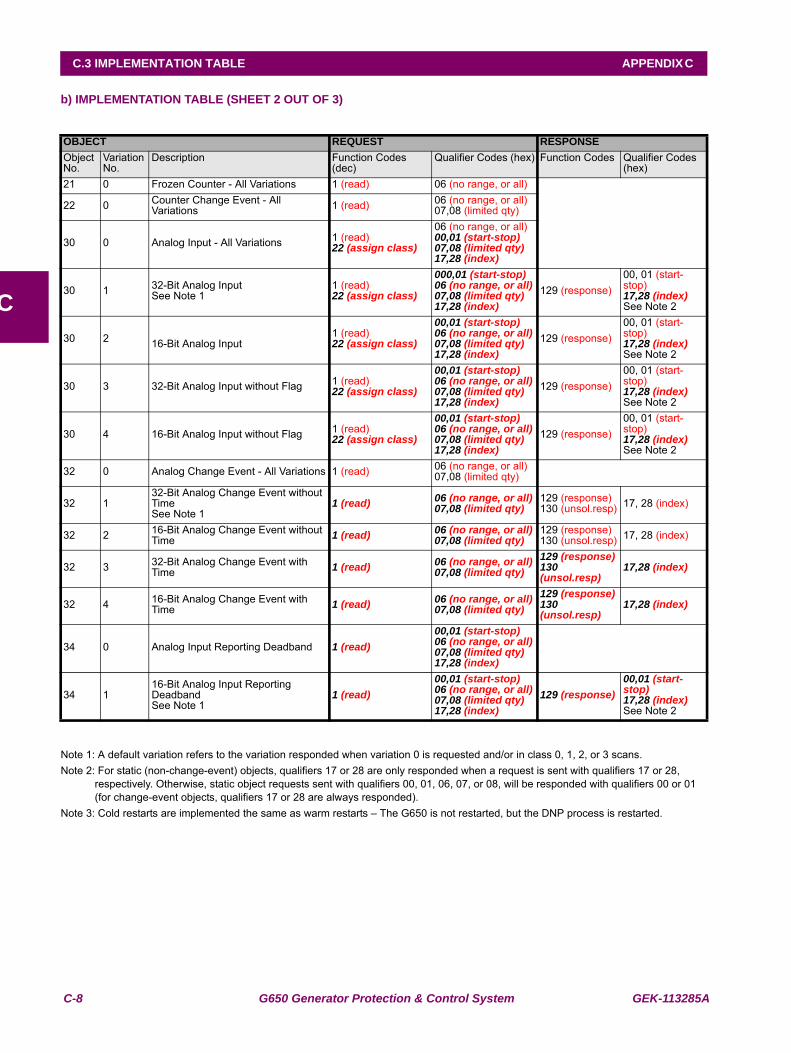
C-8 G650 Generator Protection & Control System GEK-113285A
C.3 IMPLEMENTATION TABLE APPENDIX C
C
b) IMPLEMENTATION TABLE (SHEET 2 OUT OF 3)
Note 1: A default variation refers to the variation responded when variation 0 is requested and/or in class 0, 1, 2, or 3 scans.Note 2: For static (non-change-event) objects, qualifiers 17 or 28 are only responded when a request is sent with qualifiers 17 or 28,
respectively. Otherwise, static object requests sent with qualifiers 00, 01, 06, 07, or 08, will be responded with qualifiers 00 or 01 (for change-event objects, qualifiers 17 or 28 are always responded).
Note 3: Cold restarts are implemented the same as warm restarts – The G650 is not restarted, but the DNP process is restarted.
OBJECT REQUEST RESPONSEObject No.
Variation No.
Description Function Codes (dec)
Qualifier Codes (hex) Function Codes Qualifier Codes (hex)
21 0 Frozen Counter - All Variations 1 (read) 06 (no range, or all)
22 0 Counter Change Event - All Variations 1 (read) 06 (no range, or all)
07,08 (limited qty)
30 0 Analog Input - All Variations 1 (read)22 (assign class)
06 (no range, or all)00,01 (start-stop)07,08 (limited qty)17,28 (index)
30 1 32-Bit Analog Input See Note 1
1 (read)22 (assign class)
000,01 (start-stop)06 (no range, or all)07,08 (limited qty)17,28 (index)
129 (response)00, 01 (start-stop)17,28 (index)See Note 2
30 2 16-Bit Analog Input1 (read)22 (assign class)
00,01 (start-stop)06 (no range, or all)07,08 (limited qty)17,28 (index)
129 (response)00, 01 (start-stop)17,28 (index)See Note 2
30 3 32-Bit Analog Input without Flag 1 (read)22 (assign class)
00,01 (start-stop)06 (no range, or all)07,08 (limited qty)17,28 (index)
129 (response)00, 01 (start-stop)17,28 (index)See Note 2
30 4 16-Bit Analog Input without Flag 1 (read)22 (assign class)
00,01 (start-stop)06 (no range, or all)07,08 (limited qty)17,28 (index)
129 (response)00, 01 (start-stop)17,28 (index)See Note 2
32 0 Analog Change Event - All Variations 1 (read) 06 (no range, or all)07,08 (limited qty)
32 132-Bit Analog Change Event without Time See Note 1
1 (read) 06 (no range, or all)07,08 (limited qty)
129 (response)130 (unsol.resp) 17, 28 (index)
32 2 16-Bit Analog Change Event without Time 1 (read) 06 (no range, or all)
07,08 (limited qty)129 (response)130 (unsol.resp) 17, 28 (index)
32 3 32-Bit Analog Change Event with Time 1 (read) 06 (no range, or all)
07,08 (limited qty)129 (response)130 (unsol.resp)
17,28 (index)
32 4 16-Bit Analog Change Event with Time 1 (read) 06 (no range, or all)
07,08 (limited qty)129 (response)130 (unsol.resp)
17,28 (index)
34 0 Analog Input Reporting Deadband 1 (read)00,01 (start-stop)06 (no range, or all)07,08 (limited qty)17,28 (index)
34 116-Bit Analog Input Reporting Deadband See Note 1
1 (read)00,01 (start-stop)06 (no range, or all)07,08 (limited qty)17,28 (index)
129 (response)00,01 (start-stop)17,28 (index)See Note 2
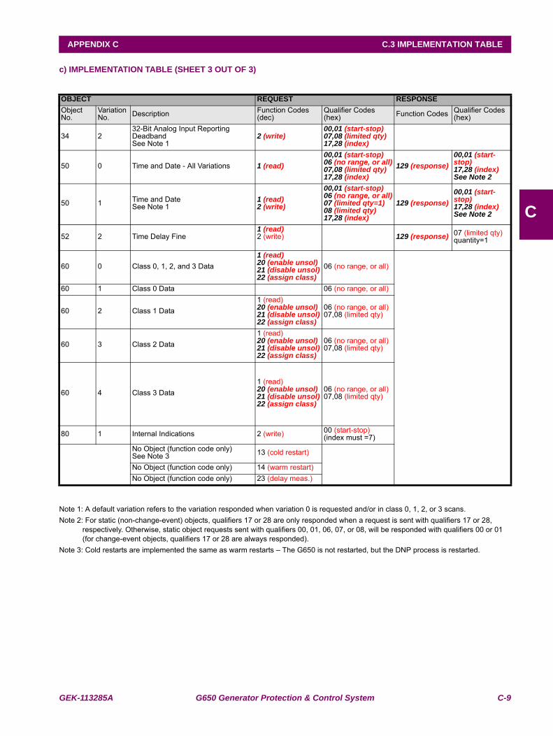
GEK-113285A G650 Generator Protection & Control System C-9
APPENDIX C C.3 IMPLEMENTATION TABLE
C
c) IMPLEMENTATION TABLE (SHEET 3 OUT OF 3)
Note 1: A default variation refers to the variation responded when variation 0 is requested and/or in class 0, 1, 2, or 3 scans.Note 2: For static (non-change-event) objects, qualifiers 17 or 28 are only responded when a request is sent with qualifiers 17 or 28,
respectively. Otherwise, static object requests sent with qualifiers 00, 01, 06, 07, or 08, will be responded with qualifiers 00 or 01 (for change-event objects, qualifiers 17 or 28 are always responded).
Note 3: Cold restarts are implemented the same as warm restarts – The G650 is not restarted, but the DNP process is restarted.
OBJECT REQUEST RESPONSEObject No.
Variation No. Description Function Codes
(dec)Qualifier Codes (hex) Function Codes Qualifier Codes
(hex)
34 232-Bit Analog Input Reporting Deadband See Note 1
2 (write)00,01 (start-stop)07,08 (limited qty)17,28 (index)
50 0 Time and Date - All Variations 1 (read)00,01 (start-stop)06 (no range, or all)07,08 (limited qty)17,28 (index)
129 (response)00,01 (start-stop)17,28 (index)See Note 2
50 1 Time and Date See Note 1
1 (read)2 (write)
00,01 (start-stop)06 (no range, or all)07 (limited qty=1)08 (limited qty)17,28 (index)
129 (response)00,01 (start-stop)17,28 (index)See Note 2
52 2 Time Delay Fine 1 (read)2 (write) 129 (response) 07 (limited qty)
quantity=1
60 0 Class 0, 1, 2, and 3 Data1 (read)20 (enable unsol)21 (disable unsol)22 (assign class)
06 (no range, or all)
60 1 Class 0 Data 06 (no range, or all)
60 2 Class 1 Data1 (read)20 (enable unsol)21 (disable unsol)22 (assign class)
06 (no range, or all)07,08 (limited qty)
60 3 Class 2 Data1 (read)20 (enable unsol)21 (disable unsol)22 (assign class)
06 (no range, or all)07,08 (limited qty)
60 4 Class 3 Data1 (read)20 (enable unsol)21 (disable unsol)22 (assign class)
06 (no range, or all)07,08 (limited qty)
80 1 Internal Indications 2 (write) 00 (start-stop)(index must =7)
No Object (function code only)See Note 3 13 (cold restart)
No Object (function code only) 14 (warm restart)No Object (function code only) 23 (delay meas.)
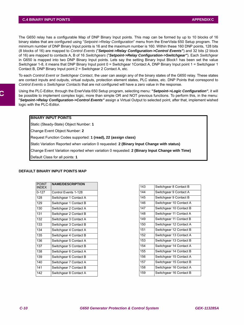
C-10 G650 Generator Protection & Control System GEK-113285A
C.4 BINARY INPUT POINTS APPENDIX C
C
C.4BINARY INPUT POINTS
The G650 relay has a configurable Map of DNP Binary Input points. This map can be formed by up to 10 blocks of 16binary states that are configured using “Setpoint->Relay Configuration” menu from the EnerVista 650 Setup program. Theminimum number of DNP Binary Input points is 16 and the maximum number is 160. Within these 160 DNP points, 128 bits(8 blocks of 16) are mapped to Control Events ("Setpoint->Relay Configuration->Control Events") and 32 bits (2 blockof 16) are mapped to contacts A, B of 16 Switchgears ("Setpoint->Relay Configuration->Switchgear"). Each Switchgearin G650 is mapped into two DNP Binary Input points. Lets say the setting Binary Input Block1 has been set the valueSwitchgear 1-8, it means that DNP Binary Input point 0 = Switchgear 1Contact A, DNP Binary Input point 1 = Switchgear 1Contact B, DNP Binary Input point 2 = Switchgear 2 Contact A, etc.
To each Control Event or Switchgear Contact, the user can assign any of the binary states of the G650 relay. These statesare contact inputs and outputs, virtual outputs, protection element states, PLC states, etc. DNP Points that correspond toControl Events o Switchgear Contacts that are not configured will have a zero value in the response.
Using the PLC-Editor, through the EnerVista 650 Setup program, selecting menu: "Setpoint->Logic Configuration", it willbe possible to implement complex logic, more than simple OR and NOT previous functions. To perform this, in the menu:"Setpoint->Relay Configuration->Control Events" assign a Virtual Output to selected point, after that, implement wishedlogic with the PLC-Editor.
DEFAULT BINARY INPUT POINTS MAP
BINARY INPUT POINTS
Static (Steady-State) Object Number: 1
Change Event Object Number: 2
Request Function Codes supported: 1 (read), 22 (assign class)
Static Variation Reported when variation 0 requested: 2 (Binary Input Change with status)
Change Event Variation reported when variation 0 requested: 2 (Binary Input Change with Time)
Default Class for all points: 1
POINT INDEX
NAME/DESCRIPTION
0-127 Control Events 1-128128 Switchgear 1 Contact A129 Switchgear 1 Contact B130 Switchgear 2 Contact A131 Switchgear 2 Contact B132 Switchgear 3 Contact A133 Switchgear 3 Contact B134 Switchgear 4 Contact A135 Switchgear 4 Contact B136 Switchgear 5 Contact A137 Switchgear 5 Contact B138 Switchgear 6 Contact A139 Switchgear 6 Contact B140 Switchgear 7 Contact A141 Switchgear 7 Contact B142 Switchgear 8 Contact A
143 Switchgear 8 Contact B144 Switchgear 9 Contact A145 Switchgear 9 Contact B146 Switchgear 10 Contact A147 Switchgear 10 Contact B148 Switchgear 11 Contact A149 Switchgear 11 Contact B150 Switchgear 12 Contact A151 Switchgear 12 Contact B152 Switchgear 13 Contact A153 Switchgear 13 Contact B154 Switchgear 14 Contact A155 Switchgear 14 Contact B156 Switchgear 15 Contact A157 Switchgear 15 Contact B158 Switchgear 16 Contact A159 Switchgear 16 Contact B
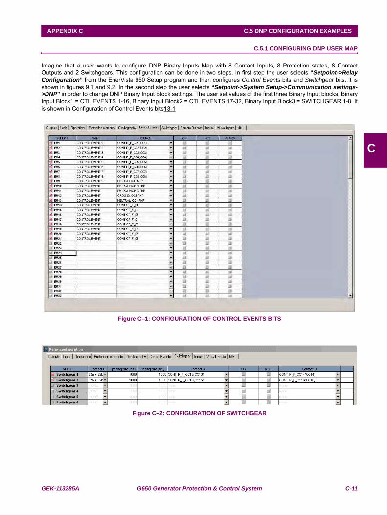
GEK-113285A G650 Generator Protection & Control System C-11
APPENDIX C C.5 DNP CONFIGURATION EXAMPLES
C
C.5DNP CONFIGURATION EXAMPLES C.5.1 CONFIGURING DNP USER MAP
Imagine that a user wants to configure DNP Binary Inputs Map with 8 Contact Inputs, 8 Protection states, 8 ContactOutputs and 2 Switchgears. This configuration can be done in two steps. In first step the user selects “Setpoint->RelayConfiguration” from the EnerVista 650 Setup program and then configures Control Events bits and Switchgear bits. It isshown in figures 9.1 and 9.2. In the second step the user selects “Setpoint->System Setup->Communication settings->DNP” in order to change DNP Binary Input Block settings. The user set values of the first three Binary Input blocks, BinaryInput Block1 = CTL EVENTS 1-16, Binary Input Block2 = CTL EVENTS 17-32, Binary Input Block3 = SWITCHGEAR 1-8. Itis shown in Configuration of Control Events bits13-1
Figure C–1: CONFIGURATION OF CONTROL EVENTS BITS
Figure C–2: CONFIGURATION OF SWITCHGEAR
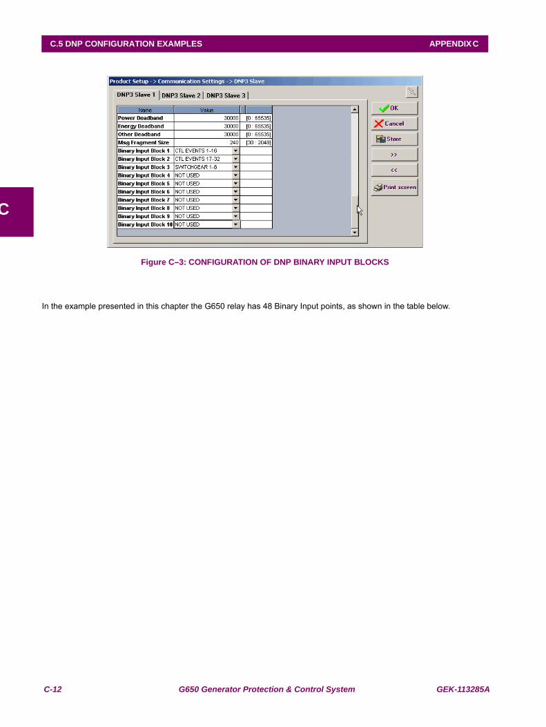
C-12 G650 Generator Protection & Control System GEK-113285A
C.5 DNP CONFIGURATION EXAMPLES APPENDIX C
C
Figure C–3: CONFIGURATION OF DNP BINARY INPUT BLOCKS
In the example presented in this chapter the G650 relay has 48 Binary Input points, as shown in the table below.
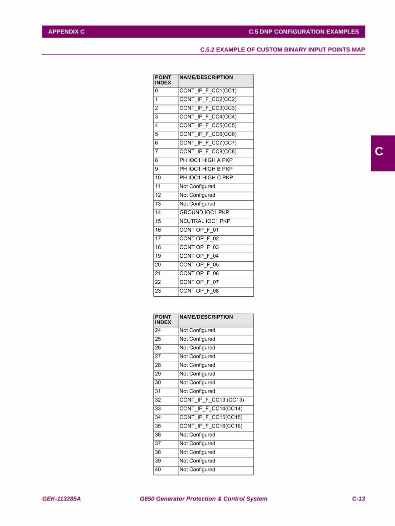
GEK-113285A G650 Generator Protection & Control System C-13
APPENDIX C C.5 DNP CONFIGURATION EXAMPLES
C
C.5.2 EXAMPLE OF CUSTOM BINARY INPUT POINTS MAP
POINT INDEX
NAME/DESCRIPTION
0 CONT_IP_F_CC1(CC1)1 CONT_IP_F_CC2(CC2)2 CONT_IP_F_CC3(CC3)3 CONT_IP_F_CC4(CC4)4 CONT_IP_F_CC5(CC5)5 CONT_IP_F_CC6(CC6)6 CONT_IP_F_CC7(CC7)7 CONT_IP_F_CC8(CC8)8 PH IOC1 HIGH A PKP9 PH IOC1 HIGH B PKP10 PH IOC1 HIGH C PKP11 Not Configured12 Not Configured13 Not Configured14 GROUND IOC1 PKP15 NEUTRAL IOC1 PKP16 CONT OP_F_0117 CONT OP_F_0218 CONT OP_F_0319 CONT OP_F_0420 CONT OP_F_0521 CONT OP_F_0622 CONT OP_F_0723 CONT OP_F_08
POINT INDEX
NAME/DESCRIPTION
24 Not Configured25 Not Configured26 Not Configured27 Not Configured28 Not Configured29 Not Configured30 Not Configured31 Not Configured32 CONT_IP_F_CC13 (CC13)33 CONT_IP_F_CC14(CC14)34 CONT_IP_F_CC15(CC15)35 CONT_IP_F_CC16(CC16)36 Not Configured37 Not Configured38 Not Configured39 Not Configured40 Not Configured
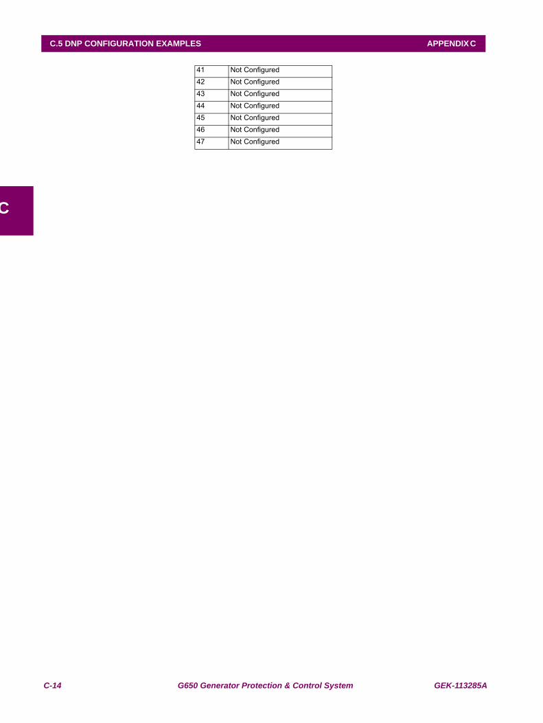
C-14 G650 Generator Protection & Control System GEK-113285A
C.5 DNP CONFIGURATION EXAMPLES APPENDIX C
C
41 Not Configured42 Not Configured43 Not Configured44 Not Configured45 Not Configured46 Not Configured47 Not Configured
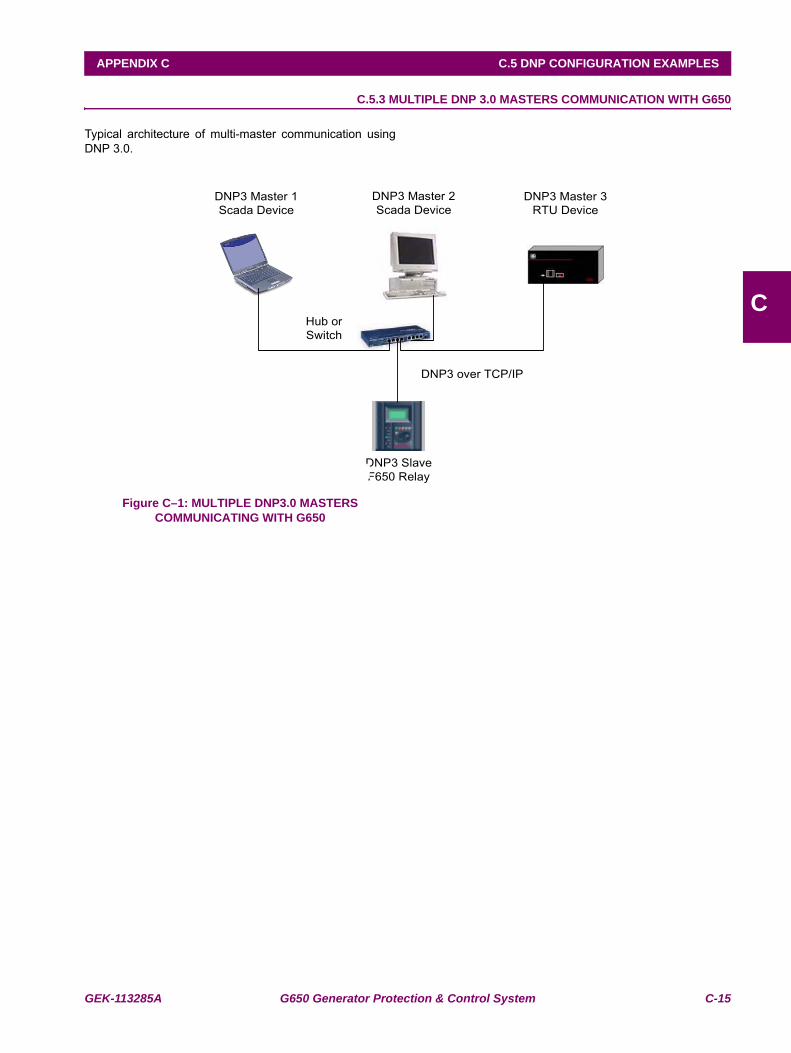
GEK-113285A G650 Generator Protection & Control System C-15
APPENDIX C C.5 DNP CONFIGURATION EXAMPLES
C
C.5.3 MULTIPLE DNP 3.0 MASTERS COMMUNICATION WITH G650
Typical architecture of multi-master communication usingDNP 3.0.
Figure C–1: MULTIPLE DNP3.0 MASTERS COMMUNICATING WITH G650
Hub or Switch
DNP3 Master 2Scada Device
DNP3 SlaveF650 Relay
DNP3 over TCP/IP
DNP3 Master 3 RTU Device
DNP3 Master 1 Scada Device
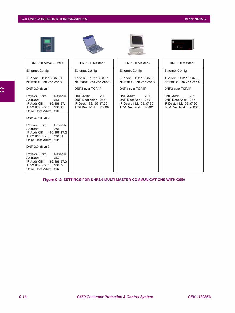
C-16 G650 Generator Protection & Control System GEK-113285A
C.5 DNP CONFIGURATION EXAMPLES APPENDIX C
C
Figure C–2: SETTINGS FOR DNP3.0 MULTI-MASTER COMMUNICATIONS WITH G650
DNP 3.0 Slave – F650
Ethernet Config IP Addr: 192.168.37.20 Netmask: 255.255.255.0
DNP 3.0 slave 1 Physical Port: Network Address: 255 IP Addr Cli1: 192.168.37.1 TCP/UDP Port : 20000 Unsol Dest Addr: 200
DNP 3.0 Master 1
Ethernet Config IP Addr: 192.168.37.1 Netmask: 255.255.255.0
DNP3 over TCP/IP DNP Addr: 200 DNP Dest Addr: 255 IP Dest: 192.168.37.20 TCP Dest Port: 20000
DNP 3.0 Master 2
Ethernet Config IP Addr: 192.168.37.2 Netmask: 255.255.255.0
DNP3 over TCP/IP DNP Addr: 201 DNP Dest Addr: 256 IP Dest : 192.168.37.20 TCP Dest Port: 20001
DNP 3.0 Master 3
Ethernet Config IP Addr: 192.168.37.3 Netmask: 255.255.255.0
DNP3 over TCP/IP DNP Addr: 202 DNP Dest Addr: 257 IP Dest: 192.168.37.20 TCP Dest Port: 20002
DNP 3.0 slave 2 Physical Port: Network Address: 256 IP Addr Cli1: 192.168.37.2 TCP/UDP Port : 20001 Unsol Dest Addr: 201
DNP 3.0 slave 3 Physical Port: Network Address: 257 IP Addr Cli1: 192.168.37.3 TCP/UDP Port : 20002 Unsol Dest Addr: 202
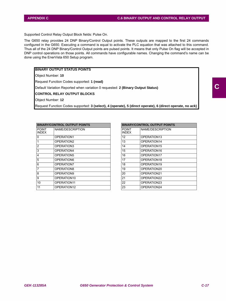
GEK-113285A G650 Generator Protection & Control System C-17
APPENDIX C C.6 BINARY OUTPUT AND CONTROL RELAY OUTPUT
C
C.6BINARY OUTPUT AND CONTROL RELAY OUTPUT
Supported Control Relay Output Block fields: Pulse On.
The G650 relay provides 24 DNP Binary/Control Output points. These outputs are mapped to the first 24 commandsconfigured in the G650. Executing a command is equal to activate the PLC equation that was attached to this command.Thus all of the 24 DNP Binary/Control Output points are pulsed points. It means that only Pulse On flag will be accepted inDNP control operations on those points. All commands have configurable names. Changing the command’s name can bedone using the EnerVista 650 Setup program.
BINARY OUTPUT STATUS POINTS
Object Number: 10
Request Function Codes supported: 1 (read)
Default Variation Reported when variation 0 requested: 2 (Binary Output Status)
CONTROL RELAY OUTPUT BLOCKS
Object Number: 12
Request Function Codes supported: 3 (select), 4 (operate), 5 (direct operate), 6 (direct operate, no ack)
BINARY/CONTROL OUTPUT POINTS BINARY/CONTROL OUTPUT POINTS POINT INDEX
NAME/DESCRIPTION POINT INDEX
NAME/DESCRIPTION
0 OPERATION1 12 OPERATION131 OPERATION2 13 OPERATION142 OPERATION3 14 OPERATION153 OPERATION4 15 OPERATION164 OPERATION5 16 OPERATION175 OPERATION6 17 OPERATION186 OPERATION7 18 OPERATION197 OPERATION8 19 OPERATION208 OPERATION9 20 OPERATION219 OPERATION10 21 OPERATION2210 OPERATION11 22 OPERATION2311 OPERATION12 23 OPERATION24
C-18 G650 Generator Protection & Control System GEK-113285A
C.7 BINARY COUNTERS APPENDIX C
C
C.7BINARY COUNTERS
Currently there are no Binary Counters in the G650 relay. Nevertheless G650 accepts requests of DNP objects 20 (BinaryCounters), 21 (Frozen Counters) and 22 (Counter Change Events). Function codes “Immediate Freeze”, “Freeze andClear” etc. are accepted and G650 will respond with no objects and the IIN2-1 (Object Unknown) flag set. This behaviour isin conformance with DNP Level 2 Implementation (Document 28528: Level 2 DNP 3.00 Implementation).
GEK-113285A G650 Generator Protection & Control System C-19
APPENDIX C C.8 ANALOG INPUTS
C
C.8ANALOG INPUTS
It is important to note that 16-bit and 32-bit variations of Analog Inputs are transmitted through DNP as signed numbers.Even for analog input points that are not valid as negative values, the maximum positive representation is 32767. This is aDNP requirement.
The deadbands for all Analog Input points are in the same units as the Analog Input quantity. For example, an Analog Inputquantity measured in volts has a corresponding deadband in units of volts. This is in conformance with DNP TechnicalBulletin 9809-001 Analog Input Reporting Deadband. The scale factors apply also to deadbands. For example if CurrentScale Factor is set to 0.001, and it is desired that a specific Analog Input point (that is of type current) trigger an event whenits value changes by 1 kA, then the deadband for this point should be set to 1000. Relay settings are available to set defaultdeadband values according to data type. Deadbands for individual Analog Input Points can be set using DNP Object 34.
Units for Analog Input points are as follows:
Current: kA Apparent Power: MVA
Voltage: kV Energy: MWh, Mvarh
Real Power: MW Frequency: Hz
Reactive Power: Mvar Angle: degrees
ANALOG INPUT POINTS
Static (Steady-State) Object Number: 30
Change Event Object Number: 32
Request Function Codes supported: 1 (read), 2 (write, deadbands only), 22 (assign class)
Static Variation Reported when variation 0 requested: 1 (32-Bit Analog Input)
Change Event Variation reported when variation 0 requested: 1 (Analog Change event without Time)
Change Event Scan Rate: defaults to 500ms.
Default Class for all points: 1
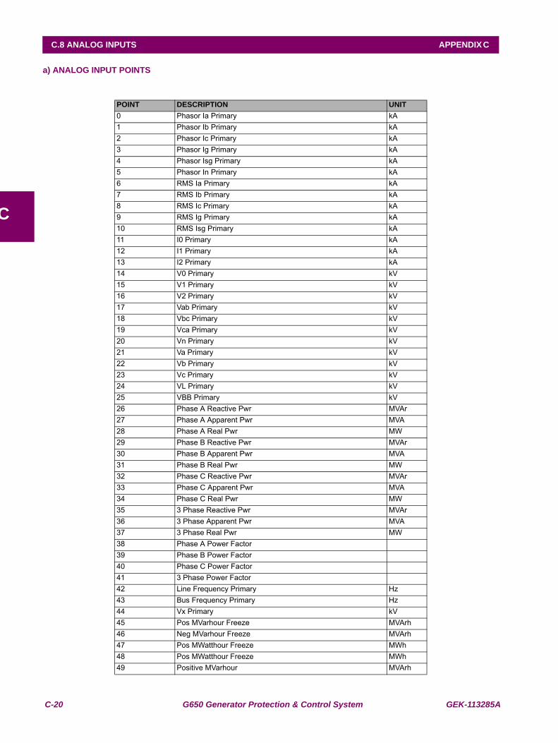
C-20 G650 Generator Protection & Control System GEK-113285A
C.8 ANALOG INPUTS APPENDIX C
C
a) ANALOG INPUT POINTS
POINT DESCRIPTION UNIT0 Phasor Ia Primary kA1 Phasor Ib Primary kA2 Phasor Ic Primary kA3 Phasor Ig Primary kA4 Phasor Isg Primary kA5 Phasor In Primary kA6 RMS Ia Primary kA7 RMS Ib Primary kA8 RMS Ic Primary kA9 RMS Ig Primary kA10 RMS Isg Primary kA11 I0 Primary kA12 I1 Primary kA13 I2 Primary kA14 V0 Primary kV15 V1 Primary kV16 V2 Primary kV17 Vab Primary kV18 Vbc Primary kV19 Vca Primary kV20 Vn Primary kV21 Va Primary kV22 Vb Primary kV23 Vc Primary kV24 VL Primary kV25 VBB Primary kV26 Phase A Reactive Pwr MVAr27 Phase A Apparent Pwr MVA28 Phase A Real Pwr MW29 Phase B Reactive Pwr MVAr30 Phase B Apparent Pwr MVA31 Phase B Real Pwr MW32 Phase C Reactive Pwr MVAr33 Phase C Apparent Pwr MVA34 Phase C Real Pwr MW35 3 Phase Reactive Pwr MVAr36 3 Phase Apparent Pwr MVA37 3 Phase Real Pwr MW38 Phase A Power Factor 39 Phase B Power Factor 40 Phase C Power Factor 41 3 Phase Power Factor 42 Line Frequency Primary Hz43 Bus Frequency Primary Hz44 Vx Primary kV45 Pos MVarhour Freeze MVArh46 Neg MVarhour Freeze MVArh47 Pos MWatthour Freeze MWh48 Pos MWatthour Freeze MWh49 Positive MVarhour MVArh
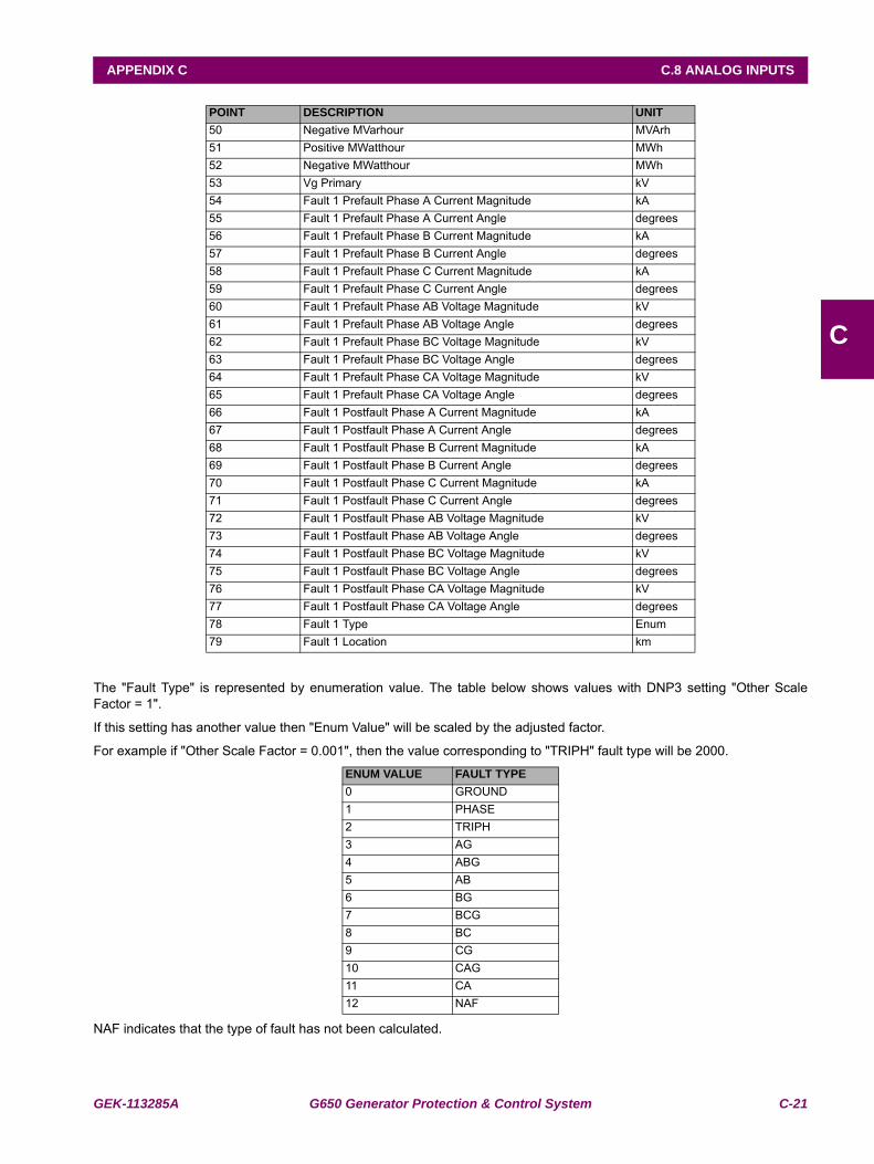
GEK-113285A G650 Generator Protection & Control System C-21
APPENDIX C C.8 ANALOG INPUTS
C
The "Fault Type" is represented by enumeration value. The table below shows values with DNP3 setting "Other ScaleFactor = 1". If this setting has another value then "Enum Value" will be scaled by the adjusted factor.
For example if "Other Scale Factor = 0.001", then the value corresponding to "TRIPH" fault type will be 2000.
NAF indicates that the type of fault has not been calculated.
POINT DESCRIPTION UNIT50 Negative MVarhour MVArh51 Positive MWatthour MWh52 Negative MWatthour MWh53 Vg Primary kV54 Fault 1 Prefault Phase A Current Magnitude kA55 Fault 1 Prefault Phase A Current Angle degrees56 Fault 1 Prefault Phase B Current Magnitude kA57 Fault 1 Prefault Phase B Current Angle degrees58 Fault 1 Prefault Phase C Current Magnitude kA59 Fault 1 Prefault Phase C Current Angle degrees60 Fault 1 Prefault Phase AB Voltage Magnitude kV61 Fault 1 Prefault Phase AB Voltage Angle degrees62 Fault 1 Prefault Phase BC Voltage Magnitude kV63 Fault 1 Prefault Phase BC Voltage Angle degrees64 Fault 1 Prefault Phase CA Voltage Magnitude kV65 Fault 1 Prefault Phase CA Voltage Angle degrees66 Fault 1 Postfault Phase A Current Magnitude kA67 Fault 1 Postfault Phase A Current Angle degrees68 Fault 1 Postfault Phase B Current Magnitude kA69 Fault 1 Postfault Phase B Current Angle degrees70 Fault 1 Postfault Phase C Current Magnitude kA71 Fault 1 Postfault Phase C Current Angle degrees72 Fault 1 Postfault Phase AB Voltage Magnitude kV73 Fault 1 Postfault Phase AB Voltage Angle degrees74 Fault 1 Postfault Phase BC Voltage Magnitude kV75 Fault 1 Postfault Phase BC Voltage Angle degrees76 Fault 1 Postfault Phase CA Voltage Magnitude kV77 Fault 1 Postfault Phase CA Voltage Angle degrees78 Fault 1 Type Enum79 Fault 1 Location km
ENUM VALUE FAULT TYPE0 GROUND1 PHASE2 TRIPH3 AG4 ABG5 AB6 BG7 BCG8 BC9 CG10 CAG11 CA12 NAF
C-22 G650 Generator Protection & Control System GEK-113285A
C.8 ANALOG INPUTS APPENDIX C
C
GEK-113285A G650 Generator Protection & Control System D-1
APPENDIX D D.1 INTRODUCTION
D
APPENDIX D IEC 60870-5-104 PROTOCOLD.1INTRODUCTION
The G650 is an IEC server. Answers to clients request or can send spontaneous Transmission. G650 implementation of60870-5-104 provides analog meterings and states.
D-2 G650 Generator Protection & Control System GEK-113285A
D.2 TECHNICAL DESCRIPTION APPENDIX D
D
D.2TECHNICAL DESCRIPTION
ASDU is the information unit used for data transmission. An ASDU may have data inside or not. The ASDU is encapsulatedin another package of the link layer. ASDU address takes up 2 bytes.
Communication frames can be control or data frames. Control strings do not have ASDU inside.
A frame is consist on 3 parts. (2 of them are not always present):
Link data + [ASDU header+ [ASDU data]]
The data between brackets can be omitted
In IEC104 communication is made by TCP/IP protocols. Actually, it is a TCP communication. The default port is the 2404.The G650 is listening as a server. Only one client is attended at time.
GEK-113285A G650 Generator Protection & Control System D-3
APPENDIX D D.3 BASIC APPLICATION FUNCTIONS
D
D.3BASIC APPLICATION FUNCTIONS
Cyclic data transmission
2 ASDU for measured values
2 ASDU for single point information (64 states in each ASDU).
1 ASDU for Double point information (16 states for Switchgear).
Spontaneous Transmission:
2 ASDU for measured values (timing is set in Cyclic Meter Period, 0 means no spontaneous transmission).
1 ASDU for single point information in the time the event is produced (128 points in user map).
1 ASDU for Double point information in the time the event is produced (16 Switchgear information).
Clock synchronization
Command transmission
Acquisition of transmission delay
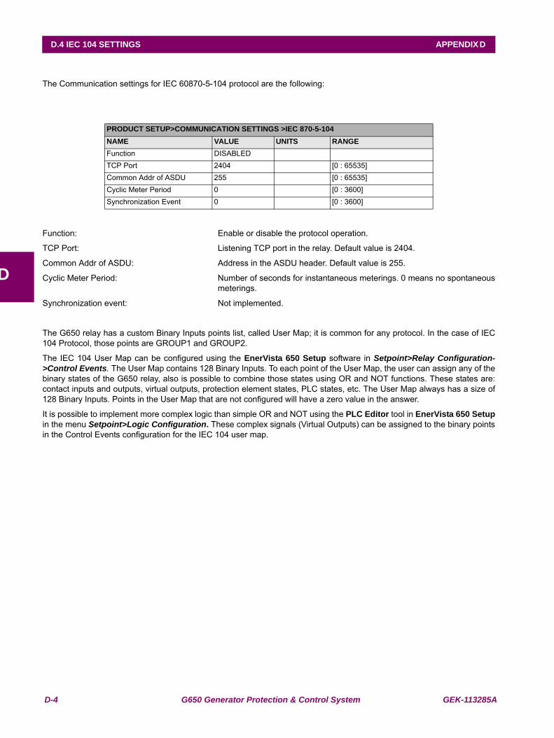
D-4 G650 Generator Protection & Control System GEK-113285A
D.4 IEC 104 SETTINGS APPENDIX D
D
D.4IEC 104 SETTINGSThe Communication settings for IEC 60870-5-104 protocol are the following:
Function: Enable or disable the protocol operation.
TCP Port: Listening TCP port in the relay. Default value is 2404.
Common Addr of ASDU: Address in the ASDU header. Default value is 255.
Cyclic Meter Period: Number of seconds for instantaneous meterings. 0 means no spontaneousmeterings.
Synchronization event: Not implemented.
The G650 relay has a custom Binary Inputs points list, called User Map; it is common for any protocol. In the case of IEC104 Protocol, those points are GROUP1 and GROUP2.
The IEC 104 User Map can be configured using the EnerVista 650 Setup software in Setpoint>Relay Configuration->Control Events. The User Map contains 128 Binary Inputs. To each point of the User Map, the user can assign any of thebinary states of the G650 relay, also is possible to combine those states using OR and NOT functions. These states are:contact inputs and outputs, virtual outputs, protection element states, PLC states, etc. The User Map always has a size of128 Binary Inputs. Points in the User Map that are not configured will have a zero value in the answer.
It is possible to implement more complex logic than simple OR and NOT using the PLC Editor tool in EnerVista 650 Setupin the menu Setpoint>Logic Configuration. These complex signals (Virtual Outputs) can be assigned to the binary pointsin the Control Events configuration for the IEC 104 user map.
PRODUCT SETUP>COMMUNICATION SETTINGS >IEC 870-5-104NAME VALUE UNITS RANGEFunction DISABLEDTCP Port 2404 [0 : 65535]Common Addr of ASDU 255 [0 : 65535]Cyclic Meter Period 0 [0 : 3600]Synchronization Event 0 [0 : 3600]
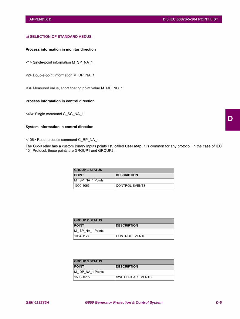
GEK-113285A G650 Generator Protection & Control System D-5
APPENDIX D D.5 IEC 60870-5-104 POINT LIST
D
D.5IEC 60870-5-104 POINT LIST
a) SELECTION OF STANDARD ASDUS:
Process information in monitor direction
<1> Single-point information M_SP_NA_1
<2> Double-point information M_DP_NA_1
<3> Measured value, short floating point value M_ME_NC_1
Process information in control direction
<46> Single command C_SC_NA_1
System information in control direction
<106> Reset process command C_RP_NA_1
The G650 relay has a custom Binary Inputs points list, called User Map; it is common for any protocol. In the case of IEC104 Protocol, those points are GROUP1 and GROUP2.
GROUP 1 STATUSPOINT DESCRIPTIONM_ SP_NA_1 Points1000-1063 CONTROL EVENTS
GROUP 2 STATUSPOINT DESCRIPTIONM_ SP_NA_1 Points1064-1127 CONTROL EVENTS
GROUP 3 STATUSPOINT DESCRIPTIONM_ DP_NA_1 Points1500-1515 SWITCHGEAR EVENTS
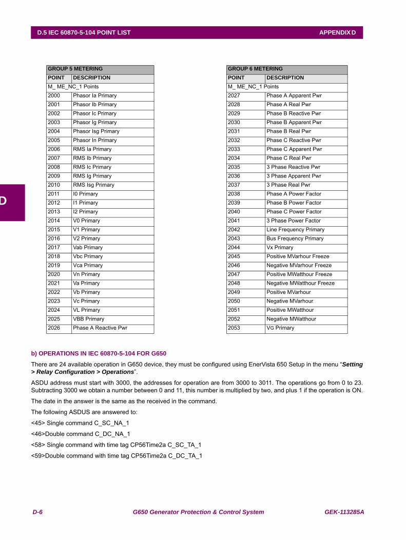
D-6 G650 Generator Protection & Control System GEK-113285A
D.5 IEC 60870-5-104 POINT LIST APPENDIX D
D
b) OPERATIONS IN IEC 60870-5-104 FOR G650
There are 24 available operation in G650 device, they must be configured using EnerVista 650 Setup in the menu “Setting> Relay Configuration > Operations”.
ASDU address must start with 3000, the addresses for operation are from 3000 to 3011. The operations go from 0 to 23.Subtracting 3000 we obtain a number between 0 and 11, this number is multiplied by two, and plus 1 if the operation is ON.
The date in the answer is the same as the received in the command.
The following ASDUS are answered to:
<45> Single command C_SC_NA_1
<46>Double command C_DC_NA_1
<58> Single command with time tag CP56Time2a C_SC_TA_1
<59>Double command with time tag CP56Time2a C_DC_TA_1
GROUP 5 METERING GROUP 6 METERINGPOINT DESCRIPTION POINT DESCRIPTIONM_ ME_NC_1 Points M_ ME_NC_1 Points2000 Phasor Ia Primary 2027 Phase A Apparent Pwr2001 Phasor Ib Primary 2028 Phase A Real Pwr2002 Phasor Ic Primary 2029 Phase B Reactive Pwr2003 Phasor Ig Primary 2030 Phase B Apparent Pwr2004 Phasor Isg Primary 2031 Phase B Real Pwr2005 Phasor In Primary 2032 Phase C Reactive Pwr2006 RMS Ia Primary 2033 Phase C Apparent Pwr2007 RMS Ib Primary 2034 Phase C Real Pwr2008 RMS Ic Primary 2035 3 Phase Reactive Pwr2009 RMS Ig Primary 2036 3 Phase Apparent Pwr2010 RMS Isg Primary 2037 3 Phase Real Pwr2011 I0 Primary 2038 Phase A Power Factor2012 I1 Primary 2039 Phase B Power Factor2013 I2 Primary 2040 Phase C Power Factor2014 V0 Primary 2041 3 Phase Power Factor2015 V1 Primary 2042 Line Frequency Primary2016 V2 Primary 2043 Bus Frequency Primary2017 Vab Primary 2044 Vx Primary2018 Vbc Primary 2045 Positive MVarhour Freeze2019 Vca Primary 2046 Negative MVarhour Freeze2020 Vn Primary 2047 Positive MWatthour Freeze2021 Va Primary 2048 Negative MWatthour Freeze2022 Vb Primary 2049 Positive MVarhour2023 Vc Primary 2050 Negative MVarhour2024 VL Primary 2051 Positive MWatthour2025 VBB Primary 2052 Negative MWatthour2026 Phase A Reactive Pwr 2053 VG Primary
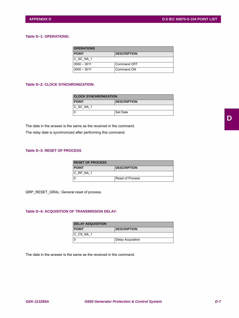
GEK-113285A G650 Generator Protection & Control System D-7
APPENDIX D D.5 IEC 60870-5-104 POINT LIST
D
Table D–1: OPERATIONS:
Table D–2: CLOCK SYNCHRONIZATION:
The date in the answer is the same as the received in the command.
The relay date is synchronized after performing this command.
Table D–3: RESET OF PROCESS
QRP_RESET_GRAL: General reset of process.
Table D–4: ACQUISITION OF TRANSMISSION DELAY:
The date in the answer is the same as the received in the command.
OPERATIONSPOINT DESCRIPTIONC_SC_NA_13000 – 3011 Command OFF3000 – 3011 Command ON
CLOCK SYNCHRONIZATIONPOINT DESCRIPTIONC_SC_NA_10 Set Date
RESET OF PROCESSPOINT DESCRIPTIONC_RP_NA_10 Reset of Process
DELAY ADQUISITIONPOINT DESCRIPTIONC_CS_NA_10 Delay Acquisition
D-8 G650 Generator Protection & Control System GEK-113285A
D.5 IEC 60870-5-104 POINT LIST APPENDIX D
D
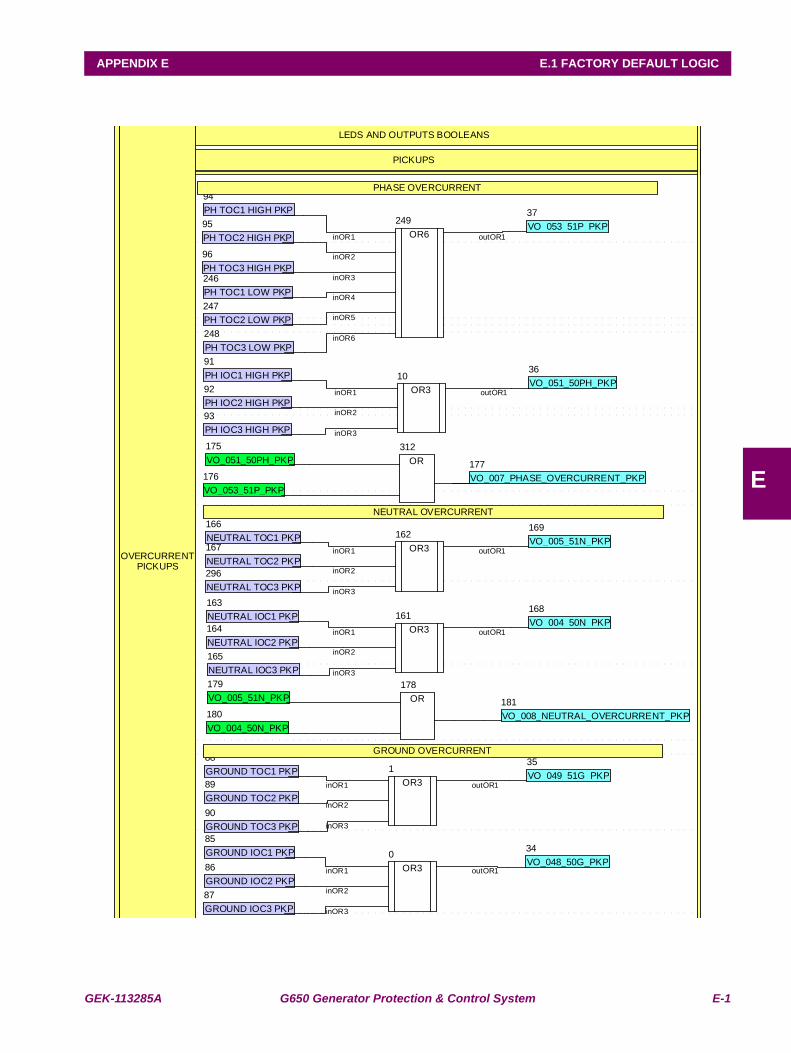
GEK-113285A G650 Generator Protection & Control System E-1
APPENDIX E E.1 FACTORY DEFAULT LOGIC
E
APPENDIX E FACTORY DEFAULT LOGICE.1 FACTORY DEFAULT LOGIC
OR3
0
OR3
1
inOR1
inOR2
inOR3
outOR1
inOR1
inOR2
inOR3
outOR1
OR3
10
LEDS AND OUTPUTS BOOLEANS
PICKUPS
inOR1
inOR2
inOR3
outOR1
VO_048_50G_PKP
34
VO_049_51G_PKP
35
VO_051_50PH_PKP
36
VO_053_51P_PKP
37
GROUND IOC1 PKP
85
GROUND IOC2 PKP
86
GROUND IOC3 PKP
87
GROUND TOC1 PKP
88
GROUND TOC2 PKP
89
GROUND TOC3 PKP
90
PH IOC1 HIGH PKP
91
PH IOC2 HIGH PKP
92
PH IOC3 HIGH PKP
93
PH TOC1 HIGH PKP
94
PH TOC2 HIGH PKP
95
PH TOC3 HIGH PKP
96
OR3
161
OR3
162
NEUTRAL IOC1 PKP
163
NEUTRAL IOC2 PKP
164
NEUTRAL IOC3 PKP
165
NEUTRAL TOC1 PKP
166
NEUTRAL TOC2 PKP
167
VO_004_50N_PKP
168
VO_005_51N_PKP
169
VO_051_50PH_PKP
175
VO_053_51P_PKP
176 VO_007_PHASE_OVERCURRENT_PKP
177
OR
178
VO_005_51N_PKP
179
VO_004_50N_PKP
180 VO_008_NEUTRAL_OVERCURRENT_PKP
181
inOR1
inOR2
inOR3
outOR1
inOR1
inOR2
inOR3
outOR1
PH TOC1 LOW PKP
246
PH TOC2 LOW PKP
247
PH TOC3 LOW PKP
248
OR6
249
OVERCURRENTPICKUPS
NEUTRAL TOC3 PKP
296
OR
312
inOR1
inOR2
inOR3
inOR4
inOR5
inOR6
PHASE OVERCURRENT
NEUTRAL OVERCURRENT
outOR1
GROUND OVERCURRENT
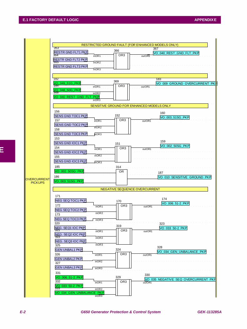
E-2 G650 Generator Protection & Control System GEK-113285A
E.1 FACTORY DEFAULT LOGIC APPENDIX E
E OR3
151
OR3
152
SENS GND IOC1 PKP
153
SENS GND IOC2 PKP
154
SENS GND IOC3 PKP
155
SENS GND TOC1 PKP
156
SENS GND TOC2 PKP
157
SENS GND TOC3 PKP
158
VO_002_50SG_PKP
159
VO_003_51SG_PKP
160
inOR1
OR3
inOR2
170
inOR3
NEG SEQ TOC1 PKP
171
NEG SEQ TOC2 PKP
outOR1
172
NEG SEQ TOC3 PKP
inOR1
173
VO_006_51-2_PKP
inOR2
174
inOR3
outOR1
VO_049_51G_PKP
182
VO_009_GROUND_OVERCURRENT_PKP
183
VO_048_50G_PKP
184
VO_002_50SG_PKP
185
VO_003_51SG_PKP
186 VO_010_SENSITIVE_GROUND_PKP
187
inOR1
inOR2
inOR3
outOR1
SENSITIVE GROUND FOR ENHANCED MODELS ONLY
OR
314
NEGATIVE SEQUENCE OVERCURRENT
OR3
319NEG. SEQ1 IOC PKP
320
NEG. SEQ2 IOC PKP
321
NEG. SEQ3 IOC PKP
322
VO_033_50-2_PKP
323
OR3
324GEN UNBAL1 PKP
325
GEN UNBAL2 PKP
326
GEN UNBAL3 PKP
327
VO_034_GEN_UNBALANCE_PKP
328
OR3
329VO_035_NEGATIVE_SEQ_OVERCURRENT_PKP
330VO_006_51-2_PKP
331
VO_033_50-2_PKP
332
VO_034_GEN_UNBALANCE_PKP
333
inOR1
inOR2
inOR3
outOR1
inOR1
RESTR GND FLT1 PKP
inOR2
inOR3
363
outOR1
RESTR GND FLT2 PKP
364
RESTR GND FLT3 PKP
365
OR3
366VO_040_REST_GND_FLT_PKP
367
VO_040_REST_GND_FLT_PKP
inOR1
inOR2
368
inOR3
OR3
outOR1
369
RESTRICTED GROUND FAULT (FOR ENHANCED MODELS ONLY)
OVERCURRENTPICKUPS
inOR1
inOR2
inOR3
outOR1
inOR1
inOR2
inOR3
outOR1
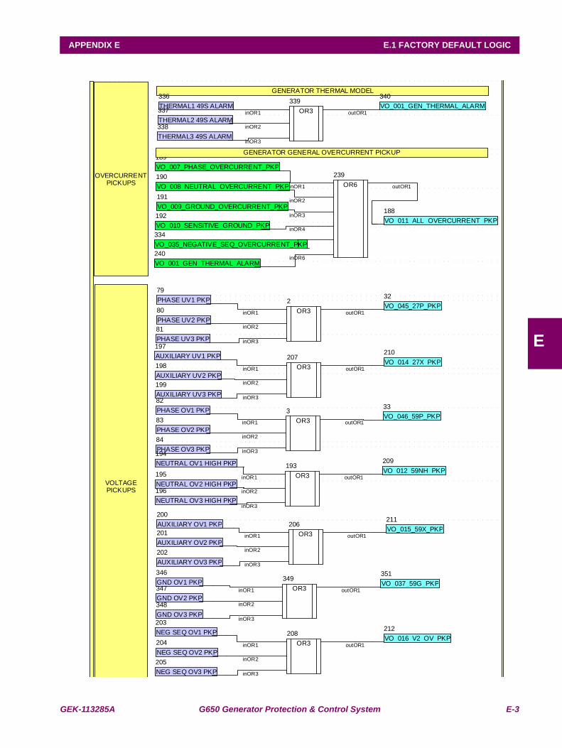
GEK-113285A G650 Generator Protection & Control System E-3
APPENDIX E E.1 FACTORY DEFAULT LOGIC
E
OR3
2
OR3
3
inOR1
inOR2
inOR3
outOR1
inOR1
inOR2
inOR3
outOR1
OVERCURRENTPICKUPS
VO_045_27P_PKP
32
VO_046_59P_PKP
33
PHASE UV1 PKP
79
PHASE UV2 PKP
80
PHASE UV3 PKP
81
PHASE OV1 PKP
82
PHASE OV2 PKP
83
PHASE OV3 PKP
84
VO_011_ALL_OVERCURRENT_PKP
188
VO_007_PHASE_OVERCURRENT_PKP
189
VO_008_NEUTRAL_OVERCURRENT_PKP
190
VO_009_GROUND_OVERCURRENT_PKP
191
VO_010_SENSITIVE_GROUND_PKP
192
OR3
193NEUTRAL OV1 HIGH PKP
194
NEUTRAL OV2 HIGH PKP
195
NEUTRAL OV3 HIGH PKP
196
AUXILIARY UV1 PKP
197
AUXILIARY UV2 PKP
198
AUXILIARY UV3 PKP
199
AUXILIARY OV1 PKP
200
AUXILIARY OV2 PKP
201
AUXILIARY OV3 PKP
202
NEG SEQ OV1 PKP
203
NEG SEQ OV2 PKP
204
NEG SEQ OV3 PKP
205
OR3
206
OR3
207
OR3
208
VO_012_59NH_PKP
209
VO_014_27X_PKP
210
VO_015_59X_PKP
211
VO_016_V2_OV_PKP
212
OR6
inOR1
inOR2
inOR3
239
outOR1
VO_001_GEN_THERMAL_ALARM
240
inOR1
inOR2
inOR3
outOR1
inOR1
inOR2
inOR3
outOR1
inOR1
inOR2
inOR3
outOR1
inOR1
inOR2
inOR3
inOR4
inOR5
inOR6
outOR1
VO_035_NEGATIVE_SEQ_OVERCURRENT_PKP
334
GENERATOR THERMAL MODEL
THERMAL1 49S ALARM
336
THERMAL2 49S ALARM
337
THERMAL3 49S ALARM
338
OR3
339VO_001_GEN_THERMAL_ALARM
340
GENERATOR GENERAL OVERCURRENT PICKUP
GND OV1 PKP
346
GND OV2 PKP
347
GND OV3 PKP
348
OR3
349VO_037_59G_PKP
351
inOR1
inOR2
inOR3
outOR1
inOR1
inOR2
inOR3
outOR1
VOLTAGEPICKUPS
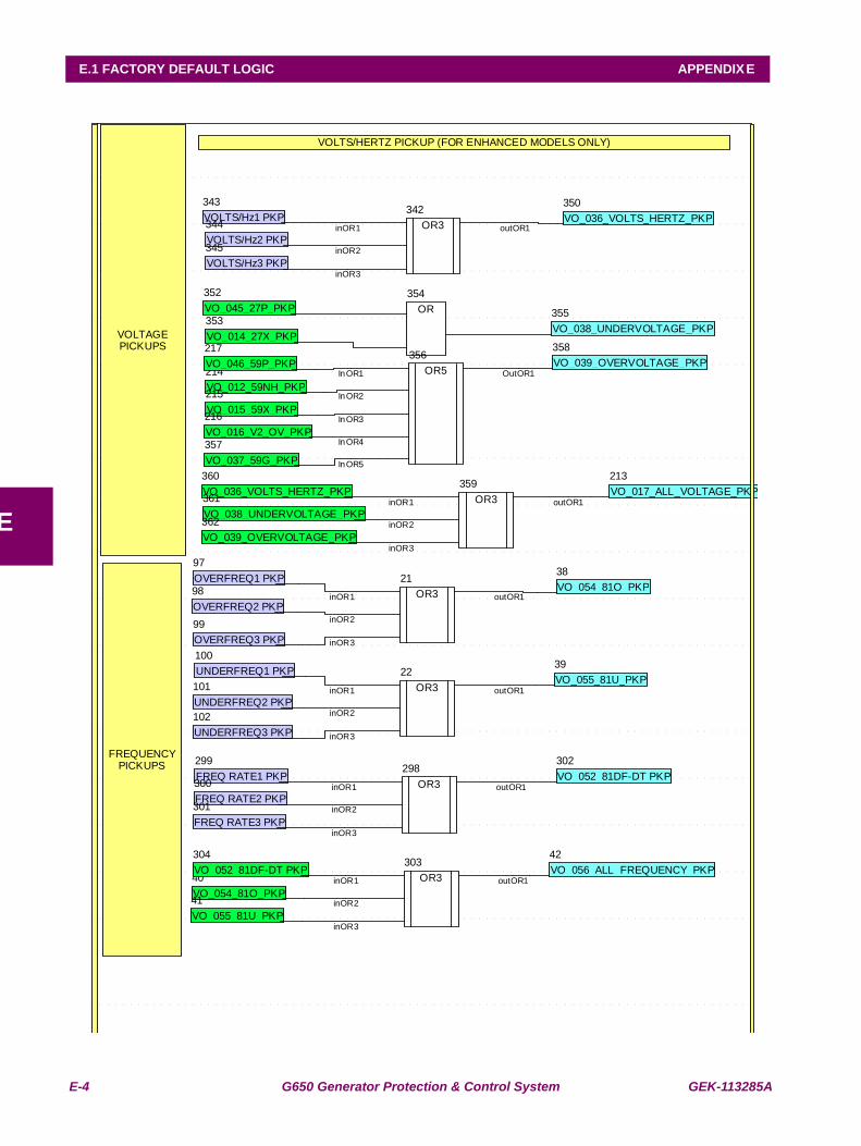
E-4 G650 Generator Protection & Control System GEK-113285A
E.1 FACTORY DEFAULT LOGIC APPENDIX E
E
VOLTAGEPICKUPS
OR3
21
OR3
22
FREQUENCYPICKUPS
VO_054_81O_PKP
38
VO_055_81U_PKP
39
VO_054_81O_PKP
40
VO_055_81U_PKP
inOR1
41
inOR2
VO_056_ALL_FREQUENCY_PKP
inOR3
42
outOR1
inOR1
inOR2
inOR3
outOR1
OVERFREQ1 PKP
97
OVERFREQ2 PKP
98
OVERFREQ3 PKP
99
UNDERFREQ1 PKP
100
UNDERFREQ2 PKP
101
UNDERFREQ3 PKP
102
VO_017_ALL_VOLTAGE_PKP
213
VO_012_59NH_PKP
214
VO_015_59X_PKP
215
VO_016_V2_OV_PKP
216
VO_046_59P_PKP
217
OR3
298FREQ RATE1 PKP
299
FREQ RATE2 PKP
300
FREQ RATE3 PKP
301
VO_052_81DF-DT PKP
302
OR3
303VO_052_81DF-DT PKP
304
OR3
342VOLTS/Hz1 PKP
343
VOLTS/Hz2 PKP
344
VOLTS/Hz3 PKP
345
inOR1
inOR2
inOR1
inOR3
outOR1
inOR2
inOR3
outOR1
VO_036_VOLTS_HERTZ_PKP
350
VO_045_27P_PKP
352
VO_014_27X_PKP
353OR
354
VO_038_UNDERVOLTAGE_PKP
355
OR5
356
VO_037_59G_PKP
357
VO_039_OVERVOLTAGE_PKP
358
OR3
359VO_036_VOLTS_HERTZ_PKP
360
VO_038_UNDERVOLTAGE_PKP
361
VO_039_OVERVOLTAGE_PKP
362
inOR1
inOR2
inOR3
outOR1
InOR1
InOR2
InOR3
InOR4
InOR5
OutOR1
inOR1
inOR2
inOR3
outOR1
VOLTS/HERTZ PICKUP (FOR ENHANCED MODELS ONLY)
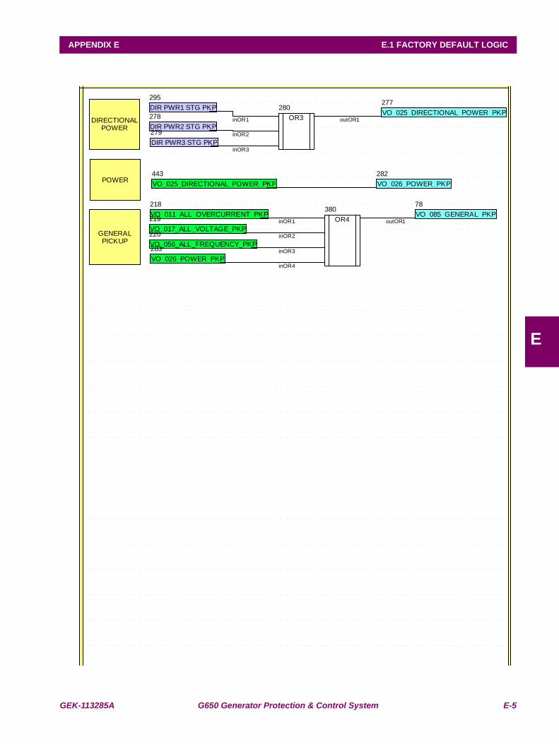
GEK-113285A G650 Generator Protection & Control System E-5
APPENDIX E E.1 FACTORY DEFAULT LOGIC
E
VO_085_GENERAL_PKP
78
VO_011_ALL_OVERCURRENT_PKP
218
VO_017_ALL_VOLTAGE_PKP
219
VO_056_ALL_FREQUENCY_PKP
220GENERALPICKUP
DIRECTIONALPOWER
VO_025_DIRECTIONAL_POWER_PKP
277
DIR PWR2 STG PKP
278
DIR PWR3 STG PKP
279
OR3
280
POWERVO_026_POWER_PKP
282
VO_026_POWER_PKP
283
DIR PWR1 STG PKP
295
inOR1
inOR2
inOR3
outOR1
OR4
380
inOR1
inOR2
inOR3
inOR4
outOR1
VO_025_DIRECTIONAL_POWER_PKP
443
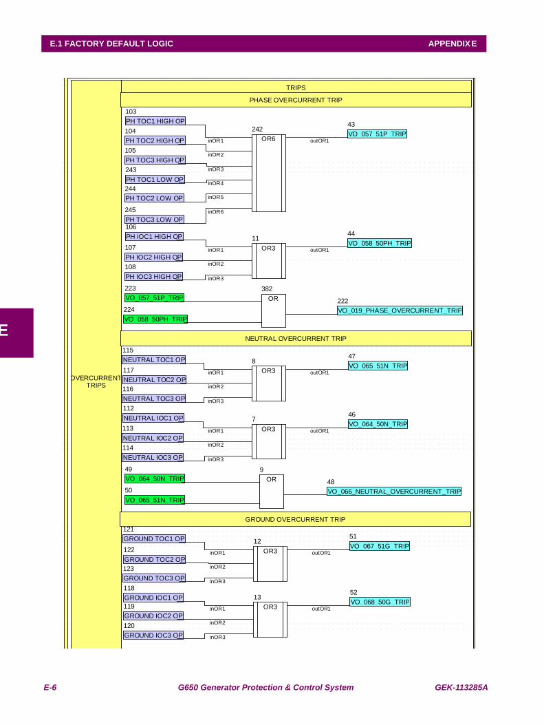
E-6 G650 Generator Protection & Control System GEK-113285A
E.1 FACTORY DEFAULT LOGIC APPENDIX E
E
OR3
7
OR3
8
OR
9
OR3
11
OR3
12
OR3
13
TRIPS
inOR1
OVERCURRENTTRIPS
inOR2
inOR3
outOR1
inOR1
inOR2
inOR3
outOR1
inOR1
inOR2
inOR3
outOR1
inOR1
inOR2
inOR3
outOR1
inOR1
inOR2
inOR3
outOR1
VO_057_51P_TRIP
43
VO_058_50PH_TRIP
44
VO_064_50N_TRIP
46
VO_065_51N_TRIP
47
VO_066_NEUTRAL_OVERCURRENT_TRIP
48VO_064_50N_TRIP
49
VO_065_51N_TRIP
50
VO_067_51G_TRIP
51
VO_068_50G_TRIP
52
PH TOC1 HIGH OP
103
PH TOC2 HIGH OP
104
PH TOC3 HIGH OP
105
PH IOC1 HIGH OP
106
PH IOC2 HIGH OP
107
PH IOC3 HIGH OP
108
NEUTRAL IOC1 OP
112
NEUTRAL IOC2 OP
113
NEUTRAL IOC3 OP
114
NEUTRAL TOC1 OP
115
NEUTRAL TOC3 OP
116
NEUTRAL TOC2 OP
117
GROUND IOC1 OP
118
GROUND IOC2 OP
119
GROUND IOC3 OP
120
GROUND TOC1 OP
121
GROUND TOC2 OP
122
GROUND TOC3 OP
123
VO_019_PHASE_OVERCURRENT_TRIP
222VO_057_51P_TRIP
223
VO_058_50PH_TRIP
224
OR6
242
PH TOC1 LOW OP
243
PH TOC2 LOW OP
244
PH TOC3 LOW OP
245
inOR1
inOR2
inOR3
inOR4
inOR5
inOR6
outOR1
PHASE OVERCURRENT TRIP
OR
382
NEUTRAL OVERCURRENT TRIP
GROUND OVERCURRENT TRIP
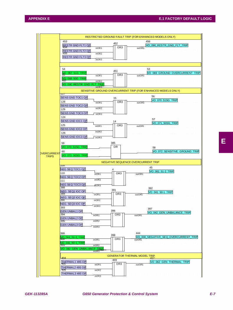
GEK-113285A G650 Generator Protection & Control System E-7
APPENDIX E E.1 FACTORY DEFAULT LOGIC
E
OR3
4
inOR1
inOR2
inOR3
outOR1
OR3
14
OR3
15
inOR1
inOR2
inOR3
outOR1
inOR1
inOR2
inOR3
outOR1
VO_061_51-2_TRIP
45
VO_069_GROUND_OVERCURRENT_TRIP
53
VO_067_51G_TRIP
54
VO_068_50G_TRIP
55
VO_070_51SG_TRIP
56
VO_071_50SG_TRIP
57
VO_072_SENSITIVE_GROUND_TRIP
58VO_070_51SG_TRIP
59
VO_071_50SG_TRIP
60
NEG SEQ TOC1 OP
109
NEG SEQ TOC2 OP
110
NEG SEQ TOC3 OP
111
SENS GND IOC1 OP
124
SENS GND IOC2 OP
125
SENS GND IOC3 OP
126
SENS GND TOC1 OP
127
SENS GND TOC2 OP
128
SENS GND TOC3 OP
129
OVERCURRENTTRIPS
OR
385
SENSITIVE GROUND OVERCURRENT TRIP (FOR ENHANCED MODELS ONLY)
NEGATIVE SEQUENCE OVERCURRENT TRIP
NEG. SEQ1 IOC OP
388
NEG. SEQ2 IOC OP
389
NEG. SEQ3 IOC OP
390
OR3
391VO_041_50-1_TRIP
392
GEN UNBAL1 OP
393
GEN UNBAL2 OP
394
GEN UNBAL3 OP
395
OR3
396VO_042_GEN_UNBALANCE_TRIP
397
OR3
398VO_061_51-2_TRIP
399
VO_041_50-1_TRIP
400
VO_042_GEN_UNBALANCE_TRIP
401
GENERATOR THERMAL MODEL TRIP
OR3
inOR1
inOR2
inOR3
403
outOR1
THERMAL1 49S OP
404
THERMAL2 49S OP
405
THERMAL3 49S OP
406
inOR1
inOR2
inOR3
outOR1
inOR1
inOR2
inOR3
outOR1
VO_062_GEN_THERMAL_TRIP
417
inOR1
inOR2
inOR3
outOR1
VO_000_NEGATIVE_SEQ_OVERCURRENT_TRIP
444
OR3
451
inOR1
inOR2
inOR3
outOR1
OR3
452
inOR1
inOR2
inOR3
outOR1RESTR GND FLT1 OP
453
RESTR GND FLT2 OP
454
RESTR GND FLT3 OP
455
VO_090_RESTR_GND_FLT_TRIP
456
VO_090_RESTR_GND_FLT_TRIP
457
RESTRICTED GROUND FAULT TRIP (FOR ENHANCED MODELS ONLY)
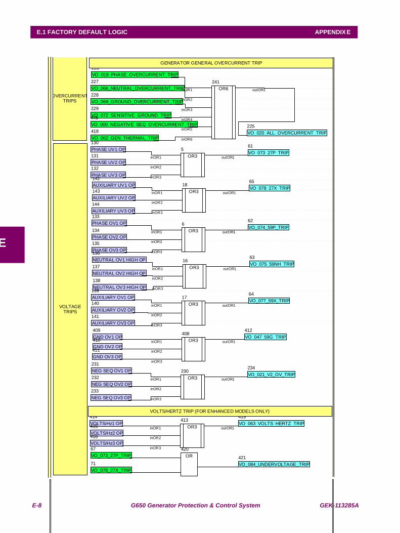
E-8 G650 Generator Protection & Control System GEK-113285A
E.1 FACTORY DEFAULT LOGIC APPENDIX E
E
OR3
5
OR3
6
inOR1
inOR2
inOR3
outOR1
OR3
16
inOR1
OR3
inOR2
inOR3
outOR1
17
OR3
18
VOLTAGETRIPS
inOR1
inOR2
inOR3
outOR1
inOR1
inOR2
inOR3
outOR1
inOR1
inOR2
inOR3
outOR1
VO_073_27P_TRIP
61
VO_074_59P_TRIP
62
VO_075_59NH_TRIP
63
VO_077_59X_TRIP
64
VO_078_27X_TRIP
65
VO_073_27P_TRIP
67
VO_078_27X_TRIP
71
PHASE UV1 OP
130
PHASE UV2 OP
131
PHASE UV3 OP
132
PHASE OV1 OP
133
PHASE OV2 OP
134
PHASE OV3 OP
135
NEUTRAL OV1 HIGH OP
136
NEUTRAL OV2 HIGH OP
137
NEUTRAL OV3 HIGH OP
138
AUXILIARY OV1 OP
139
AUXILIARY OV2 OP
140
AUXILIARY OV3 OP
141
AUXILIARY UV1 OP
142
AUXILIARY UV2 OP
143
AUXILIARY UV3 OP
144
VO_020_ALL_OVERCURRENT_TRIP
225
VO_019_PHASE_OVERCURRENT_TRIP
226
VO_066_NEUTRAL_OVERCURRENT_TRIP
227
VO_069_GROUND_OVERCURRENT_TRIP
228
VO_072_SENSITIVE_GROUND_TRIP
229
OR3
230NEG SEQ OV1 OP
231
NEG SEQ OV2 OP
232
NEG SEQ OV3 OP
233
VO_021_V2_OV_TRIP
234
OR6
241
inOR1
inOR2
inOR3
outOR1
inOR1
inOR2
inOR3
inOR4
inOR5
inOR6
outOR1
GENERATOR GENERAL OVERCURRENT TRIP
OR3
408GND OV1 OP
409
GND OV2 OP
410
GND OV3 OP
411
VO_047_59G_TRIP
412
OR3
413VOLTS/Hz1 OP
414
VOLTS/Hz2 OP
415
VOLTS/Hz3 OP
416
VO_062_GEN_THERMAL_TRIP
418
VO_063_VOLTS_HERTZ_TRIP
419
OR
420
VO_084_UNDERVOLTAGE_TRIP
421
inOR1
inOR2
inOR3
outOR1
inOR1
inOR2
inOR3
outOR1
VO_000_NEGATIVE_SEQ_OVERCURRENT_TRIP
445
OVERCURRENTTRIPS
VOLTS/HERTZ TRIP (FOR ENHANCED MODELS ONLY)
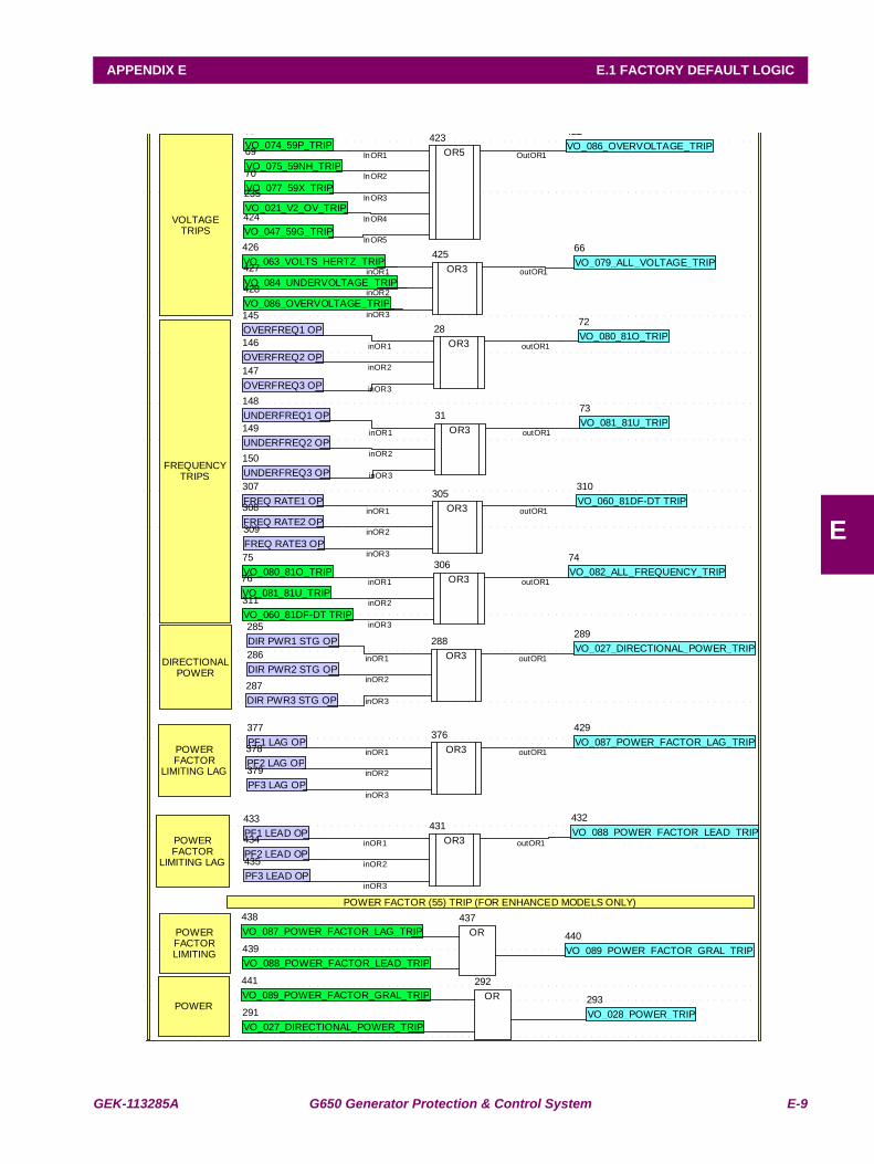
GEK-113285A G650 Generator Protection & Control System E-9
APPENDIX E E.1 FACTORY DEFAULT LOGIC
E
OR3
28
FREQUENCYTRIPS
OR3
31
inOR1
inOR2
inOR3
outOR1
inOR1
inOR2
inOR3
outOR1
VO_079_ALL_VOLTAGE_TRIP
66
VO_074_59P_TRIP
68
VO_075_59NH_TRIP
69
VO_077_59X_TRIP
70
VO_080_81O_TRIP
72
VO_081_81U_TRIP
73
VO_082_ALL_FREQUENCY_TRIP
74
VO_080_81O_TRIP
75
VO_081_81U_TRIP
76
OVERFREQ1 OP
145
OVERFREQ2 OP
146
OVERFREQ3 OP
147
UNDERFREQ1 OP
148
UNDERFREQ2 OP
149
UNDERFREQ3 OP
150
VO_021_V2_OV_TRIP
235
DIRECTIONALPOWER
DIR PWR1 STG OP
285
DIR PWR2 STG OP
286
DIR PWR3 STG OP
287
OR3
288VO_027_DIRECTIONAL_POWER_TRIP
289
POWER
VO_027_DIRECTIONAL_POWER_TRIP
291
OR
292
VO_028_POWER_TRIP
293
OR3
305
OR3
306
FREQ RATE1 OP
307
FREQ RATE2 OP
308
FREQ RATE3 OP
309
VO_060_81DF-DT TRIP
310
VO_060_81DF-DT TRIP
311
inOR1
inOR2
inOR3
outOR1
inOR1
inOR2
inOR3
outOR1
inOR1
inOR2
inOR3
outOR1
POWERFACTOR
LIMITING LAG
OR3
376PF1 LAG OP
377
PF2 LAG OP
378
PF3 LAG OP
379
inOR1
inOR2
inOR3
outOR1
VO_086_OVERVOLTAGE_TRIP
422
OR5
423
VO_047_59G_TRIP
424
OR3
425VO_063_VOLTS_HERTZ_TRIP
426
VO_084_UNDERVOLTAGE_TRIP
InOR1
427
InOR2
VO_086_OVERVOLTAGE_TRIP
InOR3
InOR4
InOR5
428
OutOR1
VO_087_POWER_FACTOR_LAG_TRIP
429
POWERFACTOR
LIMITING LAG
OR3
inOR1
inOR2
431
inOR3
VO_088_POWER_FACTOR_LEAD_TRIP
outOR1
432
PF1 LEAD OP
433
PF2 LEAD OP
434
PF3 LEAD OP
435
POWERFACTORLIMITING
OR
437
VO_087_POWER_FACTOR_LAG_TRIP
inOR1
inOR2
438
inOR3
VO_088_POWER_FACTOR_LEAD_TRIP
outOR1
439 VO_089_POWER_FACTOR_GRAL_TRIP
440
VO_089_POWER_FACTOR_GRAL_TRIP
441
VOLTAGETRIPS
POWER FACTOR (55) TRIP (FOR ENHANCED MODELS ONLY)
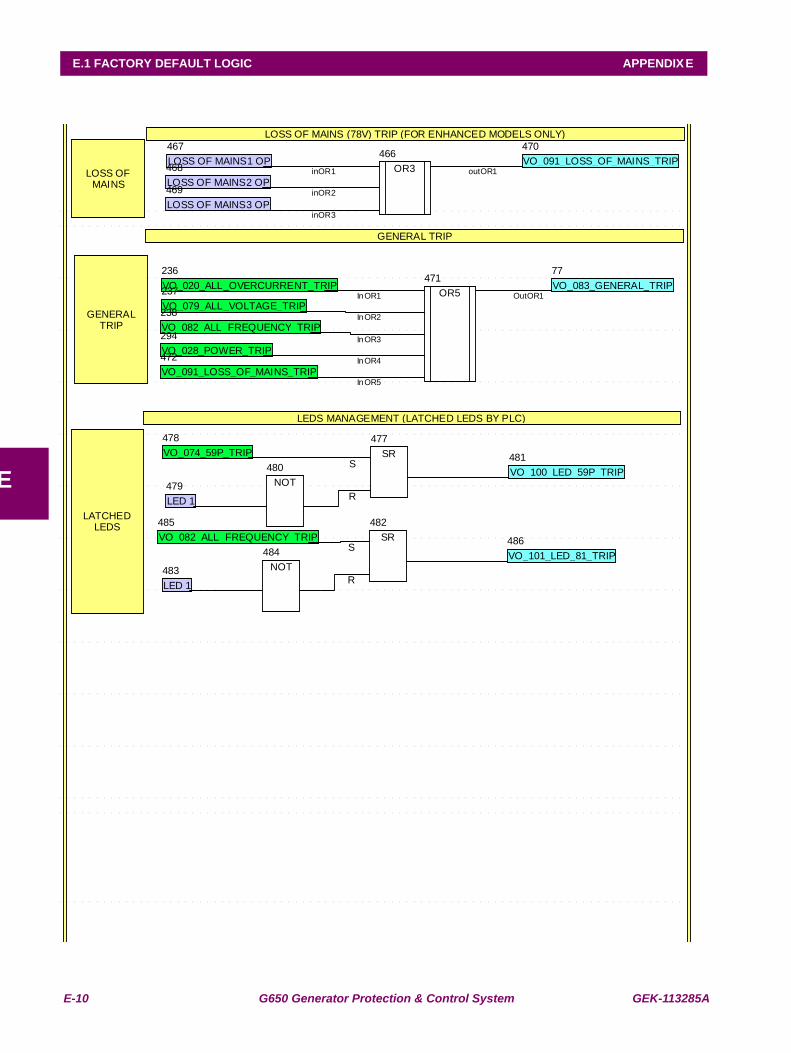
E-10 G650 Generator Protection & Control System GEK-113285A
E.1 FACTORY DEFAULT LOGIC APPENDIX E
E
VO_083_GENERAL_TRIP
77
VO_020_ALL_OVERCURRENT_TRIP
236
VO_079_ALL_VOLTAGE_TRIP
237
VO_082_ALL_FREQUENCY_TRIP
238
VO_028_POWER_TRIP
294
GENERALTRIP
LOSS OF MAINS (78V) TRIP (FOR ENHANCED MODELS ONLY)
LOSS OFMAINS
OR3
466
inOR1
inOR2
inOR3
outOR1LOSS OF MAINS1 OP
467
LOSS OF MAINS2 OP
468
LOSS OF MAINS3 OP
469
VO_091_LOSS_OF_MAINS_TRIP
470
OR5InOR1
InOR2
InOR3
InOR4
InOR5
OutOR1
471
VO_091_LOSS_OF_MAINS_TRIP
472
GENERAL TRIP
LEDS MANAGEMENT (LATCHED LEDS BY PLC)
LATCHEDLEDS
SRS
R
477
VO_074_59P_TRIP
478
LED 1
479 NOT
480 VO_100_LED_59P_TRIP
481
SR
482
LED 1
483 NOT
484 S
R
VO_082_ALL_FREQUENCY_TRIP
485
VO_101_LED_81_TRIP
486
GEK-113285A G650 Generator Protection & Control System E-11
APPENDIX E E.1 FACTORY DEFAULT LOGIC
E

E-12 G650 Generator Protection & Control System GEK-113285A
E.1 FACTORY DEFAULT LOGIC APPENDIX E
E
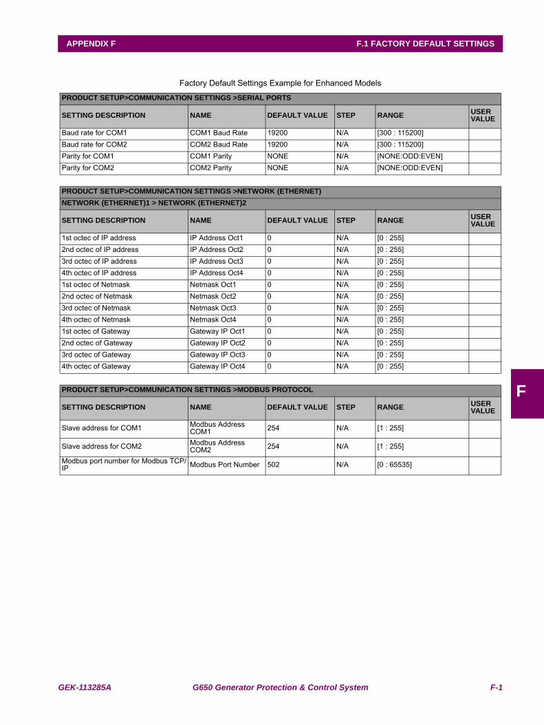
GEK-113285A G650 Generator Protection & Control System F-1
APPENDIX F F.1 FACTORY DEFAULT SETTINGS
F
APPENDIX F FACTORY DEFAULT CONFIGURATIONF.1 FACTORY DEFAULT SETTINGS
Factory Default Settings Example for Enhanced Models
PRODUCT SETUP>COMMUNICATION SETTINGS >SERIAL PORTS
SETTING DESCRIPTION NAME DEFAULT VALUE STEP RANGE USER VALUE
Baud rate for COM1 COM1 Baud Rate 19200 N/A [300 : 115200]Baud rate for COM2 COM2 Baud Rate 19200 N/A [300 : 115200]Parity for COM1 COM1 Parity NONE N/A [NONE:ODD:EVEN]Parity for COM2 COM2 Parity NONE N/A [NONE:ODD:EVEN]
PRODUCT SETUP>COMMUNICATION SETTINGS >NETWORK (ETHERNET)NETWORK (ETHERNET)1 > NETWORK (ETHERNET)2
SETTING DESCRIPTION NAME DEFAULT VALUE STEP RANGE USER VALUE
1st octec of IP address IP Address Oct1 0 N/A [0 : 255]2nd octec of IP address IP Address Oct2 0 N/A [0 : 255]3rd octec of IP address IP Address Oct3 0 N/A [0 : 255]4th octec of IP address IP Address Oct4 0 N/A [0 : 255]1st octec of Netmask Netmask Oct1 0 N/A [0 : 255]2nd octec of Netmask Netmask Oct2 0 N/A [0 : 255]3rd octec of Netmask Netmask Oct3 0 N/A [0 : 255]4th octec of Netmask Netmask Oct4 0 N/A [0 : 255]1st octec of Gateway Gateway IP Oct1 0 N/A [0 : 255]2nd octec of Gateway Gateway IP Oct2 0 N/A [0 : 255]3rd octec of Gateway Gateway IP Oct3 0 N/A [0 : 255]4th octec of Gateway Gateway IP Oct4 0 N/A [0 : 255]
PRODUCT SETUP>COMMUNICATION SETTINGS >MODBUS PROTOCOL
SETTING DESCRIPTION NAME DEFAULT VALUE STEP RANGE USER VALUE
Slave address for COM1 Modbus Address COM1 254 N/A [1 : 255]
Slave address for COM2 Modbus Address COM2 254 N/A [1 : 255]
Modbus port number for Modbus TCP/IP Modbus Port Number 502 N/A [0 : 65535]
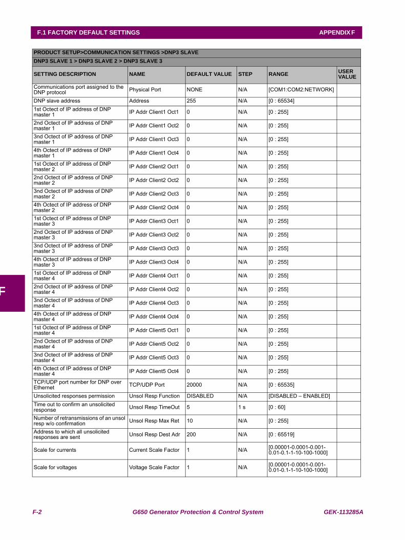
F-2 G650 Generator Protection & Control System GEK-113285A
F.1 FACTORY DEFAULT SETTINGS APPENDIX F
F
PRODUCT SETUP>COMMUNICATION SETTINGS >DNP3 SLAVEDNP3 SLAVE 1 > DNP3 SLAVE 2 > DNP3 SLAVE 3
SETTING DESCRIPTION NAME DEFAULT VALUE STEP RANGE USER VALUE
Communications port assigned to the DNP protocol Physical Port NONE N/A [COM1:COM2:NETWORK]
DNP slave address Address 255 N/A [0 : 65534]1st Octect of IP address of DNP master 1 IP Addr Client1 Oct1 0 N/A [0 : 255]
2nd Octect of IP address of DNP master 1 IP Addr Client1 Oct2 0 N/A [0 : 255]
3nd Octect of IP address of DNP master 1 IP Addr Client1 Oct3 0 N/A [0 : 255]
4th Octect of IP address of DNP master 1 IP Addr Client1 Oct4 0 N/A [0 : 255]
1st Octect of IP address of DNP master 2 IP Addr Client2 Oct1 0 N/A [0 : 255]
2nd Octect of IP address of DNP master 2 IP Addr Client2 Oct2 0 N/A [0 : 255]
3nd Octect of IP address of DNP master 2 IP Addr Client2 Oct3 0 N/A [0 : 255]
4th Octect of IP address of DNP master 2 IP Addr Client2 Oct4 0 N/A [0 : 255]
1st Octect of IP address of DNP master 3 IP Addr Client3 Oct1 0 N/A [0 : 255]
2nd Octect of IP address of DNP master 3 IP Addr Client3 Oct2 0 N/A [0 : 255]
3nd Octect of IP address of DNP master 3 IP Addr Client3 Oct3 0 N/A [0 : 255]
4th Octect of IP address of DNP master 3 IP Addr Client3 Oct4 0 N/A [0 : 255]
1st Octect of IP address of DNP master 4 IP Addr Client4 Oct1 0 N/A [0 : 255]
2nd Octect of IP address of DNP master 4 IP Addr Client4 Oct2 0 N/A [0 : 255]
3nd Octect of IP address of DNP master 4 IP Addr Client4 Oct3 0 N/A [0 : 255]
4th Octect of IP address of DNP master 4 IP Addr Client4 Oct4 0 N/A [0 : 255]
1st Octect of IP address of DNP master 4 IP Addr Client5 Oct1 0 N/A [0 : 255]
2nd Octect of IP address of DNP master 4 IP Addr Client5 Oct2 0 N/A [0 : 255]
3nd Octect of IP address of DNP master 4 IP Addr Client5 Oct3 0 N/A [0 : 255]
4th Octect of IP address of DNP master 4 IP Addr Client5 Oct4 0 N/A [0 : 255]
TCP/UDP port number for DNP over Ethernet TCP/UDP Port 20000 N/A [0 : 65535]
Unsolicited responses permission Unsol Resp Function DISABLED N/A [DISABLED – ENABLED]Time out to confirm an unsolicited response Unsol Resp TimeOut 5 1 s [0 : 60]
Number of retransmissions of an unsol resp w/o confirmation Unsol Resp Max Ret 10 N/A [0 : 255]
Address to which all unsolicited responses are sent Unsol Resp Dest Adr 200 N/A [0 : 65519]
Scale for currents Current Scale Factor 1 N/A [0.00001-0.0001-0.001-0.01-0.1-1-10-100-1000]
Scale for voltages Voltage Scale Factor 1 N/A [0.00001-0.0001-0.001-0.01-0.1-1-10-100-1000]
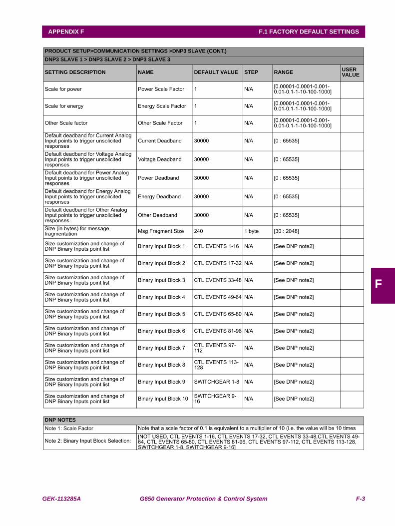
GEK-113285A G650 Generator Protection & Control System F-3
APPENDIX F F.1 FACTORY DEFAULT SETTINGS
F
PRODUCT SETUP>COMMUNICATION SETTINGS >DNP3 SLAVE (CONT.)DNP3 SLAVE 1 > DNP3 SLAVE 2 > DNP3 SLAVE 3
SETTING DESCRIPTION NAME DEFAULT VALUE STEP RANGE USER VALUE
Scale for power Power Scale Factor 1 N/A [0.00001-0.0001-0.001-0.01-0.1-1-10-100-1000]
Scale for energy Energy Scale Factor 1 N/A [0.00001-0.0001-0.001-0.01-0.1-1-10-100-1000]
Other Scale factor Other Scale Factor 1 N/A [0.00001-0.0001-0.001-0.01-0.1-1-10-100-1000]
Default deadband for Current Analog Input points to trigger unsolicited responses
Current Deadband 30000 N/A [0 : 65535]
Default deadband for Voltage Analog Input points to trigger unsolicited responses
Voltage Deadband 30000 N/A [0 : 65535]
Default deadband for Power Analog Input points to trigger unsolicited responses
Power Deadband 30000 N/A [0 : 65535]
Default deadband for Energy Analog Input points to trigger unsolicited responses
Energy Deadband 30000 N/A [0 : 65535]
Default deadband for Other Analog Input points to trigger unsolicited responses
Other Deadband 30000 N/A [0 : 65535]
Size (in bytes) for message fragmentation Msg Fragment Size 240 1 byte [30 : 2048]
Size customization and change of DNP Binary Inputs point list Binary Input Block 1 CTL EVENTS 1-16 N/A [See DNP note2]
Size customization and change of DNP Binary Inputs point list Binary Input Block 2 CTL EVENTS 17-32 N/A [See DNP note2]
Size customization and change of DNP Binary Inputs point list Binary Input Block 3 CTL EVENTS 33-48 N/A [See DNP note2]
Size customization and change of DNP Binary Inputs point list Binary Input Block 4 CTL EVENTS 49-64 N/A [See DNP note2]
Size customization and change of DNP Binary Inputs point list Binary Input Block 5 CTL EVENTS 65-80 N/A [See DNP note2]
Size customization and change of DNP Binary Inputs point list Binary Input Block 6 CTL EVENTS 81-96 N/A [See DNP note2]
Size customization and change of DNP Binary Inputs point list Binary Input Block 7 CTL EVENTS 97-
112 N/A [See DNP note2]
Size customization and change of DNP Binary Inputs point list Binary Input Block 8 CTL EVENTS 113-
128 N/A [See DNP note2]
Size customization and change of DNP Binary Inputs point list Binary Input Block 9 SWITCHGEAR 1-8 N/A [See DNP note2]
Size customization and change of DNP Binary Inputs point list Binary Input Block 10 SWITCHGEAR 9-
16 N/A [See DNP note2]
DNP NOTESNote 1: Scale Factor Note that a scale factor of 0.1 is equivalent to a multiplier of 10 (i.e. the value will be 10 times
Note 2: Binary Input Block Selection:[NOT USED, CTL EVENTS 1-16, CTL EVENTS 17-32, CTL EVENTS 33-48,CTL EVENTS 49-64, CTL EVENTS 65-80, CTL EVENTS 81-96, CTL EVENTS 97-112, CTL EVENTS 113-128, SWITCHGEAR 1-8, SWITCHGEAR 9-16]
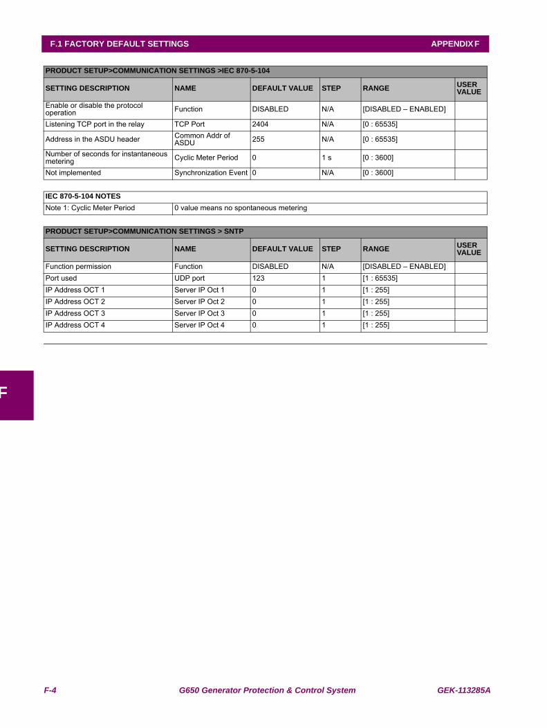
F-4 G650 Generator Protection & Control System GEK-113285A
F.1 FACTORY DEFAULT SETTINGS APPENDIX F
F
PRODUCT SETUP>COMMUNICATION SETTINGS >IEC 870-5-104
SETTING DESCRIPTION NAME DEFAULT VALUE STEP RANGE USER VALUE
Enable or disable the protocol operation Function DISABLED N/A [DISABLED – ENABLED]
Listening TCP port in the relay TCP Port 2404 N/A [0 : 65535]
Address in the ASDU header Common Addr of ASDU 255 N/A [0 : 65535]
Number of seconds for instantaneous metering Cyclic Meter Period 0 1 s [0 : 3600]
Not implemented Synchronization Event 0 N/A [0 : 3600]
IEC 870-5-104 NOTESNote 1: Cyclic Meter Period 0 value means no spontaneous metering
PRODUCT SETUP>COMMUNICATION SETTINGS > SNTP
SETTING DESCRIPTION NAME DEFAULT VALUE STEP RANGE USER VALUE
Function permission Function DISABLED N/A [DISABLED – ENABLED]Port used UDP port 123 1 [1 : 65535]IP Address OCT 1 Server IP Oct 1 0 1 [1 : 255]IP Address OCT 2 Server IP Oct 2 0 1 [1 : 255]IP Address OCT 3 Server IP Oct 3 0 1 [1 : 255]IP Address OCT 4 Server IP Oct 4 0 1 [1 : 255]
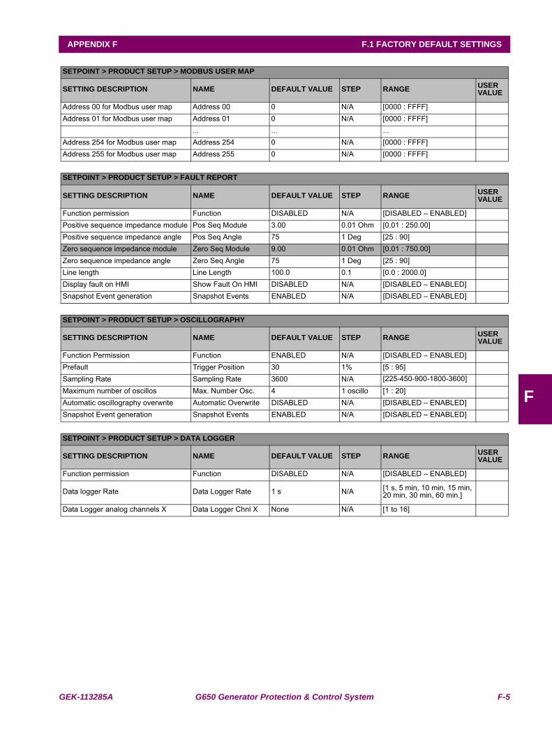
GEK-113285A G650 Generator Protection & Control System F-5
APPENDIX F F.1 FACTORY DEFAULT SETTINGS
F
SETPOINT > PRODUCT SETUP > MODBUS USER MAP
SETTING DESCRIPTION NAME DEFAULT VALUE STEP RANGE USER VALUE
Address 00 for Modbus user map Address 00 0 N/A [0000 : FFFF]Address 01 for Modbus user map Address 01 0 N/A [0000 : FFFF]
... ... ...Address 254 for Modbus user map Address 254 0 N/A [0000 : FFFF]Address 255 for Modbus user map Address 255 0 N/A [0000 : FFFF]
SETPOINT > PRODUCT SETUP > FAULT REPORT
SETTING DESCRIPTION NAME DEFAULT VALUE STEP RANGE USER VALUE
Function permission Function DISABLED N/A [DISABLED – ENABLED]Positive sequence impedance module Pos Seq Module 3.00 0.01 Ohm [0.01 : 250.00]Positive sequence impedance angle Pos Seq Angle 75 1 Deg [25 : 90]Zero sequence impedance module Zero Seq Module 9.00 0.01 Ohm [0.01 : 750.00]Zero sequence impedance angle Zero Seq Angle 75 1 Deg [25 : 90]Line length Line Length 100.0 0.1 [0.0 : 2000.0]Display fault on HMI Show Fault On HMI DISABLED N/A [DISABLED – ENABLED]Snapshot Event generation Snapshot Events ENABLED N/A [DISABLED – ENABLED]
SETPOINT > PRODUCT SETUP > OSCILLOGRAPHY
SETTING DESCRIPTION NAME DEFAULT VALUE STEP RANGE USER VALUE
Function Permission Function ENABLED N/A [DISABLED – ENABLED]Prefault Trigger Position 30 1% [5 : 95]Sampling Rate Sampling Rate 3600 N/A [225-450-900-1800-3600]Maximum number of oscillos Max. Number Osc. 4 1 oscillo [1 : 20]Automatic oscillography overwrite Automatic Overwrite DISABLED N/A [DISABLED – ENABLED]Snapshot Event generation Snapshot Events ENABLED N/A [DISABLED – ENABLED]
SETPOINT > PRODUCT SETUP > DATA LOGGER
SETTING DESCRIPTION NAME DEFAULT VALUE STEP RANGE USER VALUE
Function permission Function DISABLED N/A [DISABLED – ENABLED]
Data logger Rate Data Logger Rate 1 s N/A [1 s, 5 min, 10 min, 15 min, 20 min, 30 min, 60 min.]
Data Logger analog channels X Data Logger Chnl X None N/A [1 to 16]
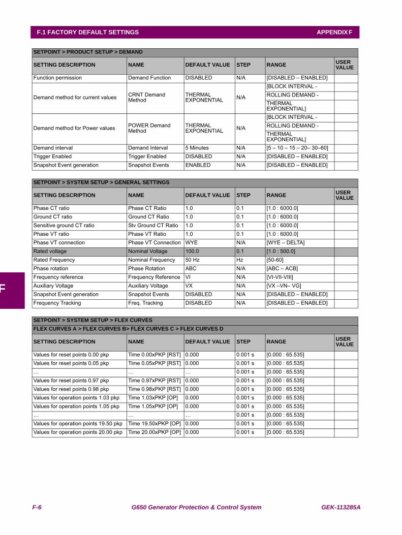
F-6 G650 Generator Protection & Control System GEK-113285A
F.1 FACTORY DEFAULT SETTINGS APPENDIX F
F
SETPOINT > PRODUCT SETUP > DEMAND
SETTING DESCRIPTION NAME DEFAULT VALUE STEP RANGE USER VALUE
Function permission Demand Function DISABLED N/A [DISABLED – ENABLED]
Demand method for current values CRNT Demand Method
THERMAL EXPONENTIAL N/A
[BLOCK INTERVAL -ROLLING DEMAND -THERMAL EXPONENTIAL]
Demand method for Power values POWER Demand Method
THERMAL EXPONENTIAL N/A
[BLOCK INTERVAL -ROLLING DEMAND -THERMAL EXPONENTIAL]
Demand interval Demand Interval 5 Minutes N/A [5 – 10 – 15 – 20– 30–60]Trigger Enabled Trigger Enabled DISABLED N/A [DISABLED – ENABLED]Snapshot Event generation Snapshot Events ENABLED N/A [DISABLED – ENABLED]
SETPOINT > SYSTEM SETUP > GENERAL SETTINGS
SETTING DESCRIPTION NAME DEFAULT VALUE STEP RANGE USER VALUE
Phase CT ratio Phase CT Ratio 1.0 0.1 [1.0 : 6000.0]Ground CT ratio Ground CT Ratio 1.0 0.1 [1.0 : 6000.0]Sensitive ground CT ratio Stv Ground CT Ratio 1.0 0.1 [1.0 : 6000.0]Phase VT ratio Phase VT Ratio 1.0 0.1 [1.0 : 6000.0]Phase VT connection Phase VT Connection WYE N/A [WYE – DELTA]Rated voltage Nominal Voltage 100.0 0.1 [1.0 : 500.0]Rated Frequency Nominal Frequency 50 Hz Hz [50-60]Phase rotation Phase Rotation ABC N/A [ABC – ACB]Frequency reference Frequency Reference VI N/A [VI-VII-VIII]Auxiliary Voltage Auxiliary Voltage VX N/A [VX –VN– VG]Snapshot Event generation Snapshot Events DISABLED N/A [DISABLED – ENABLED]Frequency Tracking Freq. Tracking DISABLED N/A [DISABLED – ENABLED]
SETPOINT > SYSTEM SETUP > FLEX CURVESFLEX CURVES A > FLEX CURVES B> FLEX CURVES C > FLEX CURVES D
SETTING DESCRIPTION NAME DEFAULT VALUE STEP RANGE USER VALUE
Values for reset points 0.00 pkp Time 0.00xPKP [RST] 0.000 0.001 s [0.000 : 65.535]Values for reset points 0.05 pkp Time 0.05xPKP [RST] 0.000 0.001 s [0.000 : 65.535]… … … 0.001 s [0.000 : 65.535]Values for reset points 0.97 pkp Time 0.97xPKP [RST] 0.000 0.001 s [0.000 : 65.535]Values for reset points 0.98 pkp Time 0.98xPKP [RST] 0.000 0.001 s [0.000 : 65.535]Values for operation points 1.03 pkp Time 1.03xPKP [OP] 0.000 0.001 s [0.000 : 65.535]Values for operation points 1.05 pkp Time 1.05xPKP [OP] 0.000 0.001 s [0.000 : 65.535]… … … 0.001 s [0.000 : 65.535]Values for operation points 19.50 pkp Time 19.50xPKP [OP] 0.000 0.001 s [0.000 : 65.535]Values for operation points 20.00 pkp Time 20.00xPKP [OP] 0.000 0.001 s [0.000 : 65.535]
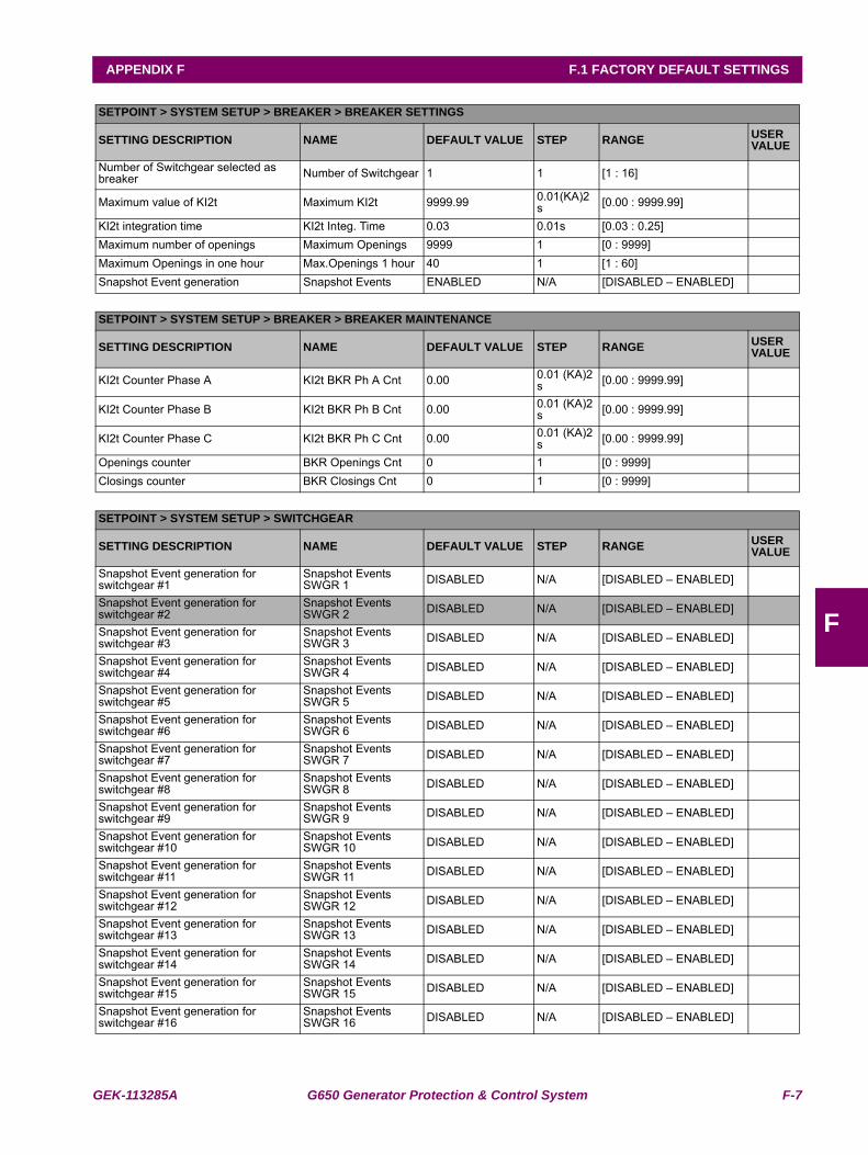
GEK-113285A G650 Generator Protection & Control System F-7
APPENDIX F F.1 FACTORY DEFAULT SETTINGS
F
SETPOINT > SYSTEM SETUP > BREAKER > BREAKER SETTINGS
SETTING DESCRIPTION NAME DEFAULT VALUE STEP RANGE USER VALUE
Number of Switchgear selected as breaker Number of Switchgear 1 1 [1 : 16]
Maximum value of KI2t Maximum KI2t 9999.99 0.01(KA)2 s [0.00 : 9999.99]
KI2t integration time KI2t Integ. Time 0.03 0.01s [0.03 : 0.25]Maximum number of openings Maximum Openings 9999 1 [0 : 9999]Maximum Openings in one hour Max.Openings 1 hour 40 1 [1 : 60]Snapshot Event generation Snapshot Events ENABLED N/A [DISABLED – ENABLED]
SETPOINT > SYSTEM SETUP > BREAKER > BREAKER MAINTENANCE
SETTING DESCRIPTION NAME DEFAULT VALUE STEP RANGE USER VALUE
KI2t Counter Phase A KI2t BKR Ph A Cnt 0.00 0.01 (KA)2 s [0.00 : 9999.99]
KI2t Counter Phase B KI2t BKR Ph B Cnt 0.00 0.01 (KA)2 s [0.00 : 9999.99]
KI2t Counter Phase C KI2t BKR Ph C Cnt 0.00 0.01 (KA)2 s [0.00 : 9999.99]
Openings counter BKR Openings Cnt 0 1 [0 : 9999]Closings counter BKR Closings Cnt 0 1 [0 : 9999]
SETPOINT > SYSTEM SETUP > SWITCHGEAR
SETTING DESCRIPTION NAME DEFAULT VALUE STEP RANGE USER VALUE
Snapshot Event generation for switchgear #1
Snapshot Events SWGR 1 DISABLED N/A [DISABLED – ENABLED]
Snapshot Event generation for switchgear #2
Snapshot Events SWGR 2 DISABLED N/A [DISABLED – ENABLED]
Snapshot Event generation for switchgear #3
Snapshot Events SWGR 3 DISABLED N/A [DISABLED – ENABLED]
Snapshot Event generation for switchgear #4
Snapshot Events SWGR 4 DISABLED N/A [DISABLED – ENABLED]
Snapshot Event generation for switchgear #5
Snapshot Events SWGR 5 DISABLED N/A [DISABLED – ENABLED]
Snapshot Event generation for switchgear #6
Snapshot Events SWGR 6 DISABLED N/A [DISABLED – ENABLED]
Snapshot Event generation for switchgear #7
Snapshot Events SWGR 7 DISABLED N/A [DISABLED – ENABLED]
Snapshot Event generation for switchgear #8
Snapshot Events SWGR 8 DISABLED N/A [DISABLED – ENABLED]
Snapshot Event generation for switchgear #9
Snapshot Events SWGR 9 DISABLED N/A [DISABLED – ENABLED]
Snapshot Event generation for switchgear #10
Snapshot Events SWGR 10 DISABLED N/A [DISABLED – ENABLED]
Snapshot Event generation for switchgear #11
Snapshot Events SWGR 11 DISABLED N/A [DISABLED – ENABLED]
Snapshot Event generation for switchgear #12
Snapshot Events SWGR 12 DISABLED N/A [DISABLED – ENABLED]
Snapshot Event generation for switchgear #13
Snapshot Events SWGR 13 DISABLED N/A [DISABLED – ENABLED]
Snapshot Event generation for switchgear #14
Snapshot Events SWGR 14 DISABLED N/A [DISABLED – ENABLED]
Snapshot Event generation for switchgear #15
Snapshot Events SWGR 15 DISABLED N/A [DISABLED – ENABLED]
Snapshot Event generation for switchgear #16
Snapshot Events SWGR 16 DISABLED N/A [DISABLED – ENABLED]
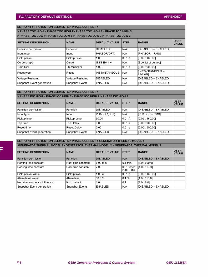
F-8 G650 Generator Protection & Control System GEK-113285A
F.1 FACTORY DEFAULT SETTINGS APPENDIX F
F
SETPOINT > PROTECTION ELEMENTS > PHASE CURRENT >> PHASE TOC HIGH > PHASE TOC HIGH 1> PHASE TOC HIGH 2 > PHASE TOC HIGH 3> PHASE TOC LOW > PHASE TOC LOW 1 > PHASE TOC LOW 2 > PHASE TOC LOW 3
SETTING DESCRIPTION NAME DEFAULT VALUE STEP RANGE USER VALUE
Function permission Function DISABLED N/A [DISABLED – ENABLED]Input type Input PHASOR(DFT) N/A [PHASOR – RMS]Pickup level Pickup Level 1.00 0.01 A [0.05 : 160.00]Curve shape Curve IEEE Ext Inv N/A [See list of curves]Time Dial TD Multiplier 1.00 0.01 s [0.00 : 900.00]
Reset type Reset INSTANTANEOUS N/A [INSTANTANEOUS – LINEAR]
Voltage Restraint Voltage Restraint DISABLED N/A [DISABLED – ENABLED]Snapshot Event generation Snapshot Events ENABLED N/A [DISABLED – ENABLED]
SETPOINT > PROTECTION ELEMENTS > PHASE CURRENT >> PHASE IOC HIGH > PHASE IOC HIGH 1> PHASE IOC HIGH 2 > PHASE IOC HIGH 3
SETTING DESCRIPTION NAME DEFAULT VALUE STEP RANGE USER VALUE
Function permission Function DISABLED N/A [DISABLED – ENABLED]Input type Input PHASOR(DFT) N/A [PHASOR – RMS]Pickup level Pickup Level 30.00 0.01 A [0.05 : 160.00]Trip time Trip Delay 0.00 0.01 s [0.00 : 900.00]Reset time Reset Delay 0.00 0.01 s [0.00 : 900.00]Snapshot event generation Snapshot Events ENABLED N/A [DISABLED – ENABLED]
SETPOINT > PROTECTION ELEMENTS > PHASE CURRENT > GENERATOR THERMAL MODEL > GENERATOR THERMAL MODEL 1> GENERATOR THERMAL MODEL 2 > GENERATOR THERMAL MODEL 3
SETTING DESCRIPTION NAME DEFAULT VALUE STEP RANGE USER VALUE
Function permission Function DISABLED N/A [DISABLED – ENABLED]Heating time constant Heat time constant 6.00 min 0.1 min [3.0 : 600.0]Cooling time constant Cool time constant 2.00 0.01 times
Heat Time[1.00 : 6.00]
Pickup level value Pickup level 1.00 A 0.01 A [0.05 : 160.00]Alarm level value Alarm level 80.0 % 0.1 % [1.0 : 110.0]Negative sequence influence K1 constant 1.0 0.1 [1.0 : 8.0]Snapshot Event generation Snapshot Events ENABLED N/A [DISABLED – ENABLED]
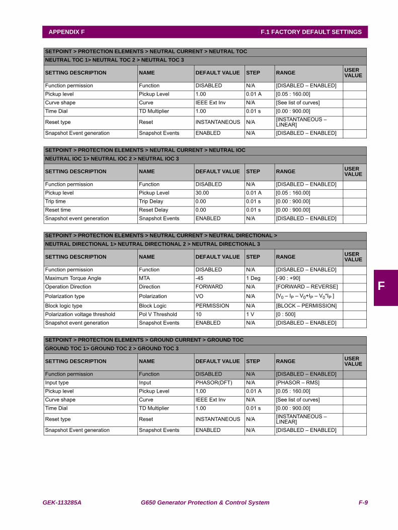
GEK-113285A G650 Generator Protection & Control System F-9
APPENDIX F F.1 FACTORY DEFAULT SETTINGS
F
SETPOINT > PROTECTION ELEMENTS > NEUTRAL CURRENT > NEUTRAL TOCNEUTRAL TOC 1> NEUTRAL TOC 2 > NEUTRAL TOC 3
SETTING DESCRIPTION NAME DEFAULT VALUE STEP RANGE USER VALUE
Function permission Function DISABLED N/A [DISABLED – ENABLED]Pickup level Pickup Level 1.00 0.01 A [0.05 : 160.00]Curve shape Curve IEEE Ext Inv N/A [See list of curves]Time Dial TD Multiplier 1.00 0.01 s [0.00 : 900.00]
Reset type Reset INSTANTANEOUS N/A [INSTANTANEOUS – LINEAR]
Snapshot Event generation Snapshot Events ENABLED N/A [DISABLED – ENABLED]
SETPOINT > PROTECTION ELEMENTS > NEUTRAL CURRENT > NEUTRAL IOCNEUTRAL IOC 1> NEUTRAL IOC 2 > NEUTRAL IOC 3
SETTING DESCRIPTION NAME DEFAULT VALUE STEP RANGE USER VALUE
Function permission Function DISABLED N/A [DISABLED – ENABLED]Pickup level Pickup Level 30.00 0.01 A [0.05 : 160.00]Trip time Trip Delay 0.00 0.01 s [0.00 : 900.00]Reset time Reset Delay 0.00 0.01 s [0.00 : 900.00]Snapshot event generation Snapshot Events ENABLED N/A [DISABLED – ENABLED]
SETPOINT > PROTECTION ELEMENTS > NEUTRAL CURRENT > NEUTRAL DIRECTIONAL >NEUTRAL DIRECTIONAL 1> NEUTRAL DIRECTIONAL 2 > NEUTRAL DIRECTIONAL 3
SETTING DESCRIPTION NAME DEFAULT VALUE STEP RANGE USER VALUE
Function permission Function DISABLED N/A [DISABLED – ENABLED]Maximum Torque Angle MTA -45 1 Deg [-90 : +90]Operation Direction Direction FORWARD N/A [FORWARD – REVERSE]
Polarization type Polarization VO N/A [V0 – IP – V0+IP – V0*IP ]
Block logic type Block Logic PERMISSION N/A [BLOCK – PERMISSION]Polarization voltage threshold Pol V Threshold 10 1 V [0 : 500]Snapshot event generation Snapshot Events ENABLED N/A [DISABLED – ENABLED]
SETPOINT > PROTECTION ELEMENTS > GROUND CURRENT > GROUND TOCGROUND TOC 1> GROUND TOC 2 > GROUND TOC 3
SETTING DESCRIPTION NAME DEFAULT VALUE STEP RANGE USER VALUE
Function permission Function DISABLED N/A [DISABLED – ENABLED]Input type Input PHASOR(DFT) N/A [PHASOR – RMS]Pickup level Pickup Level 1.00 0.01 A [0.05 : 160.00]Curve shape Curve IEEE Ext Inv N/A [See list of curves]Time Dial TD Multiplier 1.00 0.01 s [0.00 : 900.00]
Reset type Reset INSTANTANEOUS N/A [INSTANTANEOUS – LINEAR]
Snapshot Event generation Snapshot Events ENABLED N/A [DISABLED – ENABLED]
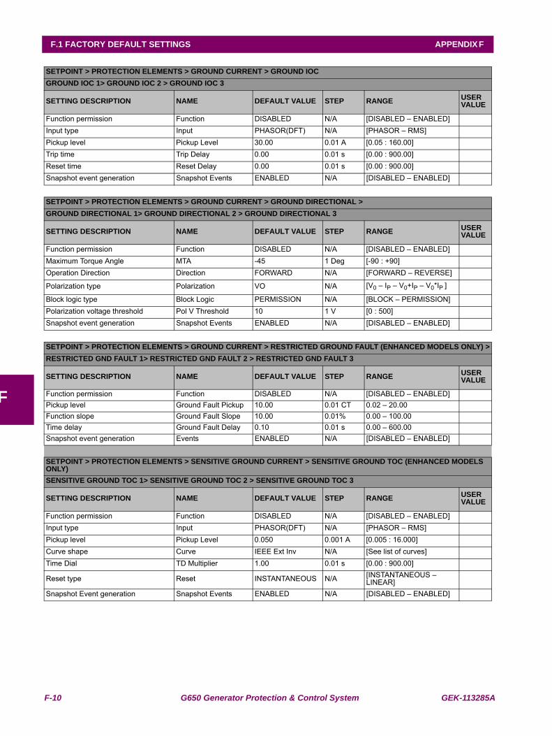
F-10 G650 Generator Protection & Control System GEK-113285A
F.1 FACTORY DEFAULT SETTINGS APPENDIX F
F
SETPOINT > PROTECTION ELEMENTS > GROUND CURRENT > GROUND IOCGROUND IOC 1> GROUND IOC 2 > GROUND IOC 3
SETTING DESCRIPTION NAME DEFAULT VALUE STEP RANGE USER VALUE
Function permission Function DISABLED N/A [DISABLED – ENABLED]Input type Input PHASOR(DFT) N/A [PHASOR – RMS]Pickup level Pickup Level 30.00 0.01 A [0.05 : 160.00]Trip time Trip Delay 0.00 0.01 s [0.00 : 900.00]Reset time Reset Delay 0.00 0.01 s [0.00 : 900.00]Snapshot event generation Snapshot Events ENABLED N/A [DISABLED – ENABLED]
SETPOINT > PROTECTION ELEMENTS > GROUND CURRENT > GROUND DIRECTIONAL >GROUND DIRECTIONAL 1> GROUND DIRECTIONAL 2 > GROUND DIRECTIONAL 3
SETTING DESCRIPTION NAME DEFAULT VALUE STEP RANGE USER VALUE
Function permission Function DISABLED N/A [DISABLED – ENABLED]Maximum Torque Angle MTA -45 1 Deg [-90 : +90]Operation Direction Direction FORWARD N/A [FORWARD – REVERSE]
Polarization type Polarization VO N/A [V0 – IP – V0+IP – V0*IP ]
Block logic type Block Logic PERMISSION N/A [BLOCK – PERMISSION]Polarization voltage threshold Pol V Threshold 10 1 V [0 : 500]Snapshot event generation Snapshot Events ENABLED N/A [DISABLED – ENABLED]
SETPOINT > PROTECTION ELEMENTS > GROUND CURRENT > RESTRICTED GROUND FAULT (ENHANCED MODELS ONLY) >RESTRICTED GND FAULT 1> RESTRICTED GND FAULT 2 > RESTRICTED GND FAULT 3
SETTING DESCRIPTION NAME DEFAULT VALUE STEP RANGE USER VALUE
Function permission Function DISABLED N/A [DISABLED – ENABLED]Pickup level Ground Fault Pickup 10.00 0.01 CT 0.02 – 20.00Function slope Ground Fault Slope 10.00 0.01% 0.00 – 100.00 Time delay Ground Fault Delay 0.10 0.01 s 0.00 – 600.00Snapshot event generation Events ENABLED N/A [DISABLED – ENABLED]
SETPOINT > PROTECTION ELEMENTS > SENSITIVE GROUND CURRENT > SENSITIVE GROUND TOC (ENHANCED MODELS ONLY) SENSITIVE GROUND TOC 1> SENSITIVE GROUND TOC 2 > SENSITIVE GROUND TOC 3
SETTING DESCRIPTION NAME DEFAULT VALUE STEP RANGE USER VALUE
Function permission Function DISABLED N/A [DISABLED – ENABLED]Input type Input PHASOR(DFT) N/A [PHASOR – RMS]Pickup level Pickup Level 0.050 0.001 A [0.005 : 16.000]Curve shape Curve IEEE Ext Inv N/A [See list of curves]Time Dial TD Multiplier 1.00 0.01 s [0.00 : 900.00]
Reset type Reset INSTANTANEOUS N/A [INSTANTANEOUS – LINEAR]
Snapshot Event generation Snapshot Events ENABLED N/A [DISABLED – ENABLED]
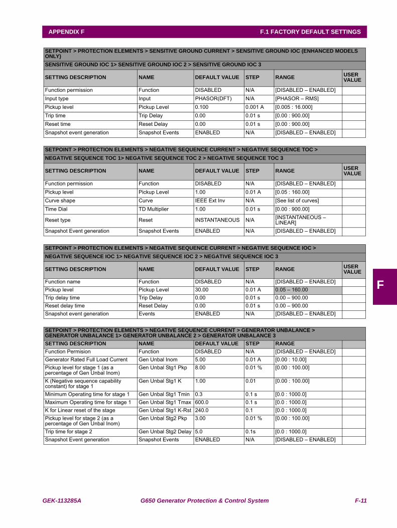
GEK-113285A G650 Generator Protection & Control System F-11
APPENDIX F F.1 FACTORY DEFAULT SETTINGS
F
SETPOINT > PROTECTION ELEMENTS > SENSITIVE GROUND CURRENT > SENSITIVE GROUND IOC (ENHANCED MODELS ONLY) SENSITIVE GROUND IOC 1> SENSITIVE GROUND IOC 2 > SENSITIVE GROUND IOC 3
SETTING DESCRIPTION NAME DEFAULT VALUE STEP RANGE USER VALUE
Function permission Function DISABLED N/A [DISABLED – ENABLED]Input type Input PHASOR(DFT) N/A [PHASOR – RMS]Pickup level Pickup Level 0.100 0.001 A [0.005 : 16.000]Trip time Trip Delay 0.00 0.01 s [0.00 : 900.00]Reset time Reset Delay 0.00 0.01 s [0.00 : 900.00]Snapshot event generation Snapshot Events ENABLED N/A [DISABLED – ENABLED]
SETPOINT > PROTECTION ELEMENTS > NEGATIVE SEQUENCE CURRENT > NEGATIVE SEQUENCE TOC >NEGATIVE SEQUENCE TOC 1> NEGATIVE SEQUENCE TOC 2 > NEGATIVE SEQUENCE TOC 3
SETTING DESCRIPTION NAME DEFAULT VALUE STEP RANGE USER VALUE
Function permission Function DISABLED N/A [DISABLED – ENABLED]Pickup level Pickup Level 1.00 0.01 A [0.05 : 160.00]Curve shape Curve IEEE Ext Inv N/A [See list of curves]Time Dial TD Multiplier 1.00 0.01 s [0.00 : 900.00]
Reset type Reset INSTANTANEOUS N/A [INSTANTANEOUS – LINEAR]
Snapshot Event generation Snapshot Events ENABLED N/A [DISABLED – ENABLED]
SETPOINT > PROTECTION ELEMENTS > NEGATIVE SEQUENCE CURRENT > NEGATIVE SEQUENCE IOC >NEGATIVE SEQUENCE IOC 1> NEGATIVE SEQUENCE IOC 2 > NEGATIVE SEQUENCE IOC 3
SETTING DESCRIPTION NAME DEFAULT VALUE STEP RANGE USER VALUE
Function name Function DISABLED N/A [DISABLED – ENABLED]Pickup level Pickup Level 30.00 0.01 A 0.05 – 160.00Trip delay time Trip Delay 0.00 0.01 s 0.00 – 900.00Reset delay time Reset Delay 0.00 0.01 s 0.00 – 900.00Snapshot event generation Events ENABLED N/A [DISABLED – ENABLED]
SETPOINT > PROTECTION ELEMENTS > NEGATIVE SEQUENCE CURRENT > GENERATOR UNBALANCE >GENERATOR UNBALANCE 1> GENERATOR UNBALANCE 2 > GENERATOR UNBALANCE 3SETTING DESCRIPTION NAME DEFAULT VALUE STEP RANGEFunction Permision Function DISABLED N/A [DISABLED – ENABLED]Generator Rated Full Load Current Gen Unbal Inom 5.00 0.01 A [0.00 : 10.00]Pickup level for stage 1 (as a percentage of Gen Unbal Inom)
Gen Unbal Stg1 Pkp 8.00 0.01 % [0.00 : 100.00]
K (Negative sequence capability constant) for stage 1
Gen Unbal Stg1 K 1.00 0.01 [0.00 : 100.00]
Minimum Operating time for stage 1 Gen Unbal Stg1 Tmin 0.3 0.1 s [0.0 : 1000.0]Maximum Operating time for stage 1 Gen Unbal Stg1 Tmax 600.0 0.1 s [0.0 : 1000.0]K for Linear reset of the stage Gen Unbal Stg1 K-Rst 240.0 0.1 [0.0 : 1000.0]Pickup level for stage 2 (as a percentage of Gen Unbal Inom)
Gen Unbal Stg2 Pkp 3.00 0.01 % [0.00 : 100.00]
Trip time for stage 2 Gen Unbal Stg2 Delay 5.0 0.1s [0.0 : 1000.0]Snapshot Event generation Snapshot Events ENABLED N/A [DISABLED – ENABLED]
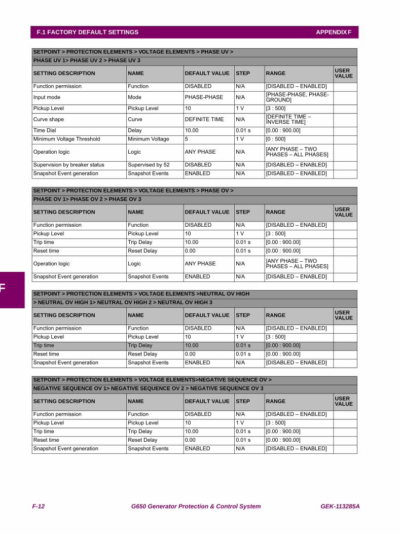
F-12 G650 Generator Protection & Control System GEK-113285A
F.1 FACTORY DEFAULT SETTINGS APPENDIX F
F
SETPOINT > PROTECTION ELEMENTS > VOLTAGE ELEMENTS > PHASE UV >PHASE UV 1> PHASE UV 2 > PHASE UV 3
SETTING DESCRIPTION NAME DEFAULT VALUE STEP RANGE USER VALUE
Function permission Function DISABLED N/A [DISABLED – ENABLED]
Input mode Mode PHASE-PHASE N/A [PHASE-PHASE, PHASE-GROUND]
Pickup Level Pickup Level 10 1 V [3 : 500]
Curve shape Curve DEFINITE TIME N/A [DEFINITE TIME – INVERSE TIME]
Time Dial Delay 10.00 0.01 s [0.00 : 900.00]Minimum Voltage Threshold Minimum Voltage 5 1 V [0 : 500]
Operation logic Logic ANY PHASE N/A [ANY PHASE – TWO PHASES – ALL PHASES]
Supervision by breaker status Supervised by 52 DISABLED N/A [DISABLED – ENABLED]Snapshot Event generation Snapshot Events ENABLED N/A [DISABLED – ENABLED]
SETPOINT > PROTECTION ELEMENTS > VOLTAGE ELEMENTS > PHASE OV >PHASE OV 1> PHASE OV 2 > PHASE OV 3
SETTING DESCRIPTION NAME DEFAULT VALUE STEP RANGE USER VALUE
Function permission Function DISABLED N/A [DISABLED – ENABLED]Pickup Level Pickup Level 10 1 V [3 : 500]Trip time Trip Delay 10.00 0.01 s [0.00 : 900.00]Reset time Reset Delay 0.00 0.01 s [0.00 : 900.00]
Operation logic Logic ANY PHASE N/A [ANY PHASE – TWO PHASES – ALL PHASES]
Snapshot Event generation Snapshot Events ENABLED N/A [DISABLED – ENABLED]
SETPOINT > PROTECTION ELEMENTS > VOLTAGE ELEMENTS >NEUTRAL OV HIGH> NEUTRAL OV HIGH 1> NEUTRAL OV HIGH 2 > NEUTRAL OV HIGH 3
SETTING DESCRIPTION NAME DEFAULT VALUE STEP RANGE USER VALUE
Function permission Function DISABLED N/A [DISABLED – ENABLED]Pickup Level Pickup Level 10 1 V [3 : 500]Trip time Trip Delay 10.00 0.01 s [0.00 : 900.00]Reset time Reset Delay 0.00 0.01 s [0.00 : 900.00]Snapshot Event generation Snapshot Events ENABLED N/A [DISABLED – ENABLED]
SETPOINT > PROTECTION ELEMENTS > VOLTAGE ELEMENTS>NEGATIVE SEQUENCE OV >NEGATIVE SEQUENCE OV 1> NEGATIVE SEQUENCE OV 2 > NEGATIVE SEQUENCE OV 3
SETTING DESCRIPTION NAME DEFAULT VALUE STEP RANGE USER VALUE
Function permission Function DISABLED N/A [DISABLED – ENABLED]Pickup Level Pickup Level 10 1 V [3 : 500]Trip time Trip Delay 10.00 0.01 s [0.00 : 900.00]Reset time Reset Delay 0.00 0.01 s [0.00 : 900.00]Snapshot Event generation Snapshot Events ENABLED N/A [DISABLED – ENABLED]
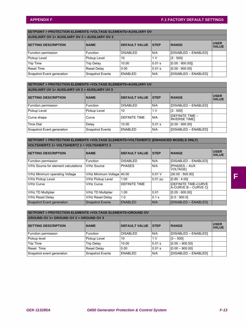
GEK-113285A G650 Generator Protection & Control System F-13
APPENDIX F F.1 FACTORY DEFAULT SETTINGS
F
SETPOINT > PROTECTION ELEMENTS >VOLTAGE ELEMENTS>AUXILIARY OVAUXILIARY OV 1> AUXILIARY OV 2 > AUXILIARY OV 3
SETTING DESCRIPTION NAME DEFAULT VALUE STEP RANGE USER VALUE
Function permission Function DISABLED N/A [DISABLED – ENABLED]Pickup Level Pickup Level 10 1 V [3 : 500]Trip Time Trip Delay 10.00 0.01 s [0.00 : 900.00]]Reset Time Reset Delay 0.00 0.01 s [0.00 : 900.00]Snapshot Event generation Snapshot Events ENABLED N/A [DISABLED – ENABLED]
SETPOINT > PROTECTION ELEMENTS >VOLTAGE ELEMENTS>AUXILIARY UVAUXILIARY UV 1> AUXILIARY UV 2 > AUXILIARY UV 3
SETTING DESCRIPTION NAME DEFAULT VALUE STEP RANGE USER VALUE
Function permission Function DISABLED N/A [DISABLED – ENABLED]Pickup Level Pickup Level 10 1 V [3 : 500]
Curve shape Curve DEFINITE TIME N/A [DEFINITE TIME – INVERSE TIME]
Time Dial Delay 10.00 0.01 s [0.00 : 900.00]Snapshot Event generation Snapshot Events ENABLED N/A [DISABLED – ENABLED]
SETPOINT > PROTECTION ELEMENTS >VOLTAGE ELEMENTS>VOLTS/HERTZ (ENHANCED MODELS ONLY)VOLTS/HERTZ 1> VOLTS/HERTZ 2 > VOLTS/HERTZ 3
SETTING DESCRIPTION NAME DEFAULT VALUE STEP RANGE USER VALUE
Function permission Function DISABLED N/A [DISABLED – ENABLED]V/Hz Source for element calculations V/Hz Source PHASES N/A [PHASES – AUX
VOLTAGE]V/Hz Minimum operating Voltage V/Hz Minimum Voltage 40.00 0.01 V [30.00 : 500.00]V/Hz Pickup Level V/Hz Pickup Level 1.00 0.01 pu [0.80 : 4.00]V/Hz Curve V/Hz Curve DEFINITE TIME [DEFINITE TIME-CURVE
A-CURVE B – CURVE C]V/Hz TD Multiplier V/Hz TD Multiplier 1.00 0.01 [0.05 : 600.00]V/Hz Reset Delay V/Hz Reset Delay 1.0 0.1 s [0.0 : 900.0]Snapshot Event generation Snapshot Events ENABLED N/A [DISABLED – ENABLED]
SETPOINT > PROTECTION ELEMENTS >VOLTAGE ELEMENTS>GROUND OVGROUND OV 1> GROUND OV 2 > GROUND OV 3
SETTING DESCRIPTION NAME DEFAULT VALUE STEP RANGE USER VALUE
Function permission Function DISABLED N/A [DISABLED – ENABLED]Pickup level Pickup Level 10 1 V [3 – 500]Trip Time Trip Delay 10.00 0.01 s [0.00 – 900.00]Reset Time Reset Delay 0.00 0.01 s [0.00 – 900.00]Snapshot event generation Snapshot Events ENABLED N/A [DISABLED – ENABLED]
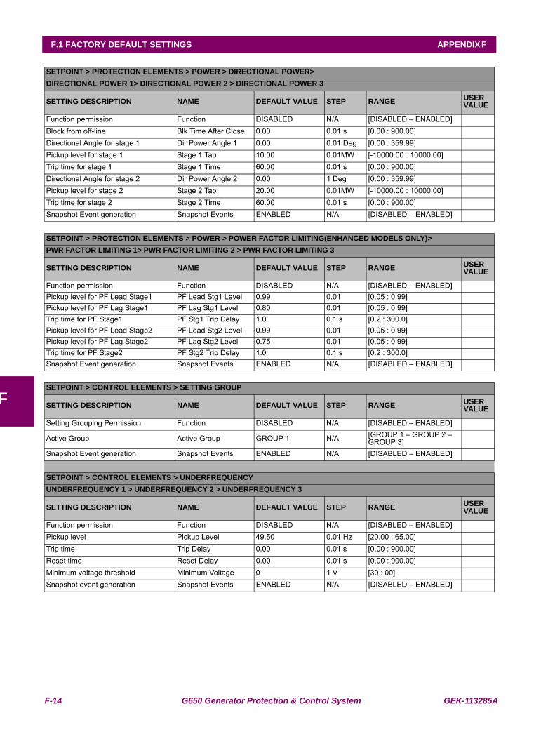
F-14 G650 Generator Protection & Control System GEK-113285A
F.1 FACTORY DEFAULT SETTINGS APPENDIX F
F
SETPOINT > PROTECTION ELEMENTS > POWER > DIRECTIONAL POWER>DIRECTIONAL POWER 1> DIRECTIONAL POWER 2 > DIRECTIONAL POWER 3
SETTING DESCRIPTION NAME DEFAULT VALUE STEP RANGE USER VALUE
Function permission Function DISABLED N/A [DISABLED – ENABLED]Block from off-line Blk Time After Close 0.00 0.01 s [0.00 : 900.00]Directional Angle for stage 1 Dir Power Angle 1 0.00 0.01 Deg [0.00 : 359.99]Pickup level for stage 1 Stage 1 Tap 10.00 0.01MW [-10000.00 : 10000.00]Trip time for stage 1 Stage 1 Time 60.00 0.01 s [0.00 : 900.00]Directional Angle for stage 2 Dir Power Angle 2 0.00 1 Deg [0.00 : 359.99]Pickup level for stage 2 Stage 2 Tap 20.00 0.01MW [-10000.00 : 10000.00]Trip time for stage 2 Stage 2 Time 60.00 0.01 s [0.00 : 900.00]Snapshot Event generation Snapshot Events ENABLED N/A [DISABLED – ENABLED]
SETPOINT > PROTECTION ELEMENTS > POWER > POWER FACTOR LIMITING(ENHANCED MODELS ONLY)>PWR FACTOR LIMITING 1> PWR FACTOR LIMITING 2 > PWR FACTOR LIMITING 3
SETTING DESCRIPTION NAME DEFAULT VALUE STEP RANGE USER VALUE
Function permission Function DISABLED N/A [DISABLED – ENABLED]Pickup level for PF Lead Stage1 PF Lead Stg1 Level 0.99 0.01 [0.05 : 0.99]Pickup level for PF Lag Stage1 PF Lag Stg1 Level 0.80 0.01 [0.05 : 0.99]Trip time for PF Stage1 PF Stg1 Trip Delay 1.0 0.1 s [0.2 : 300.0]Pickup level for PF Lead Stage2 PF Lead Stg2 Level 0.99 0.01 [0.05 : 0.99]Pickup level for PF Lag Stage2 PF Lag Stg2 Level 0.75 0.01 [0.05 : 0.99]Trip time for PF Stage2 PF Stg2 Trip Delay 1.0 0.1 s [0.2 : 300.0]Snapshot Event generation Snapshot Events ENABLED N/A [DISABLED – ENABLED]
SETPOINT > CONTROL ELEMENTS > SETTING GROUP
SETTING DESCRIPTION NAME DEFAULT VALUE STEP RANGE USER VALUE
Setting Grouping Permission Function DISABLED N/A [DISABLED – ENABLED]
Active Group Active Group GROUP 1 N/A [GROUP 1 – GROUP 2 – GROUP 3]
Snapshot Event generation Snapshot Events ENABLED N/A [DISABLED – ENABLED]
SETPOINT > CONTROL ELEMENTS > UNDERFREQUENCYUNDERFREQUENCY 1 > UNDERFREQUENCY 2 > UNDERFREQUENCY 3
SETTING DESCRIPTION NAME DEFAULT VALUE STEP RANGE USER VALUE
Function permission Function DISABLED N/A [DISABLED – ENABLED]Pickup level Pickup Level 49.50 0.01 Hz [20.00 : 65.00]Trip time Trip Delay 0.00 0.01 s [0.00 : 900.00]Reset time Reset Delay 0.00 0.01 s [0.00 : 900.00]Minimum voltage threshold Minimum Voltage 0 1 V [30 : 00]Snapshot event generation Snapshot Events ENABLED N/A [DISABLED – ENABLED]
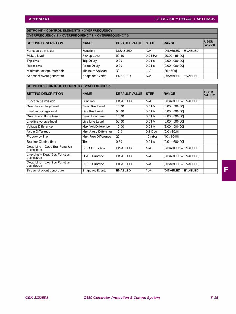
GEK-113285A G650 Generator Protection & Control System F-15
APPENDIX F F.1 FACTORY DEFAULT SETTINGS
F
SETPOINT > CONTROL ELEMENTS > OVERFREQUENCYOVERFREQUENCY 1 > OVERFREQUENCY 2 > OVERFREQUENCY 3
SETTING DESCRIPTION NAME DEFAULT VALUE STEP RANGE USER VALUE
Function permission Function DISABLED N/A [DISABLED – ENABLED]Pickup level Pickup Level 50.50 0.01 Hz [20.00 : 65.00]Trip time Trip Delay 0.00 0.01 s [0.00 : 900.00]Reset time Reset Delay 0.00 0.01 s [0.00 : 900.00]Minimum voltage threshold Minimum Voltage 30 1 V [30 : 500]Snapshot event generation Snapshot Events ENABLED N/A [DISABLED – ENABLED]
SETPOINT > CONTROL ELEMENTS > SYNCHROCHECK
SETTING DESCRIPTION NAME DEFAULT VALUE STEP RANGE USER VALUE
Function permission Function DISABLED N/A [DISABLED – ENABLED]Dead bus voltage level Dead Bus Level 10.00 0.01 V [0.00 : 500.00]Live bus voltage level Live Bus Level 50.00 0.01 V [0.00 : 500.00]Dead line voltage level Dead Line Level 10.00 0.01 V [0.00 : 500.00]Live line voltage level Live Line Level 50.00 0.01 V [0.00 : 500.00]Voltage Difference Max Volt Difference 10.00 0.01 V [2.00 : 500.00]Angle Difference Max Angle Difference 10.0 0.1 Deg [2.0 : 80.0]Frequency Slip Max Freq Difference 20 10 mHz [10 : 5000]Breaker Closing time Time 0.50 0.01 s [0.01 : 600.00]Dead Line – Dead Bus Function permission DL-DB Function DISABLED N/A [DISABLED – ENABLED]
Live Line – Dead Bus Function permission LL-DB Function DISABLED N/A [DISABLED – ENABLED]
Dead Line – Live Bus Function permission DL-LB Function DISABLED N/A [DISABLED – ENABLED]
Snapshot event generation Snapshot Events ENABLED N/A [DISABLED – ENABLED]
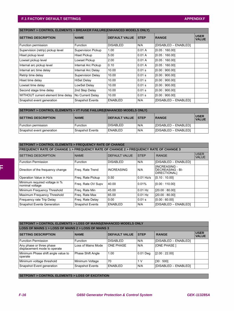
F-16 G650 Generator Protection & Control System GEK-113285A
F.1 FACTORY DEFAULT SETTINGS APPENDIX F
F
SETPOINT > CONTROL ELEMENTS > BREAKER FAILURE(ENHANCED MODELS ONLY)
SETTING DESCRIPTION NAME DEFAULT VALUE STEP RANGE USER VALUE
Function permission Function DISABLED N/A [DISABLED – ENABLED]Supervision (retrip) pickup level Supervision Pickup 1.00 0.01 A [0.05 : 160.00]Hiset pickup level Hiset Pickup 5.00 0.01 A [0.05 : 160.00]Lowset pickup level Lowset Pickup 2.00 0.01 A [0.05 : 160.00]Internal arc pickup level Internal Arc Pickup 0.10 0.01 A [0.05 : 160.00]Internal arc time delay Internal Arc Delay 10.00 0.01 s [0.00 : 900.00]Retrip time delay Supervision Delay 10.00 0.01 s [0.00 : 900.00]Hiset time delay HiSet Delay 10.00 0.01 s [0.00 : 900.00]Lowset time delay LowSet Delay 10.00 0.01 s [0.00 : 900.00]Second stage time delay 2nd Step Delay 10.00 0.01 s [0.00 : 900.00]WITHOUT current element time delay No Current Delay 10.00 0.01 s [0.00 : 900.00]Snapshot event generation Snapshot Events ENABLED N/A [DISABLED – ENABLED]
SETPOINT > CONTROL ELEMENTS > VT FUSE FAILURE(ENHANCED MODELS ONLY)
SETTING DESCRIPTION NAME DEFAULT VALUE STEP RANGE USER VALUE
Function permission Function DISABLED N/A [DISABLED – ENABLED]Snapshot event generation Snapshot Events ENABLED N/A [DISABLED – ENABLED]
SETPOINT > CONTROL ELEMENTS > FREQUENCY RATE OF CHANGEFREQUENCY RATE OF CHANGE 1 > FREQUENCY RATE OF CHANGE 2 > FREQUENCY RATE OF CHANGE 3
SETTING DESCRIPTION NAME DEFAULT VALUE STEP RANGE USER VALUE
Function Permission Function DISABLED N/A [DISABLED – ENABLED]
Direction of the frequency change Freq. Rate Trend INCREASING N/A[INCREASING - DECREASING - BI-DIRECTIONAL]
Operation Value in Hz/s Freq. Rate Pickup 0.50 0.01 Hz/s [0.10 : 10.00]Minimum required voltage in % nominal voltage Freq. Rate OV Supv 40.00 0.01% [0.00 : 110.00]
Minimum Frequency Threshold Freq. Rate Min 45.00 0.01 Hz [20.00 : 80.00]Maximum Frequency Threshold Freq. Rate Max 65.00 0.01 Hz [20.00 : 80.00]Frequency rate Trip Delay Freq. Rate Delay 0.00 0.01 s [0.00 : 60.00]Snapshot Events Generation Snapshot Events ENABLED N/A [DISABLED – ENABLED]
SETPOINT > CONTROL ELEMENTS > LOSS OF MAINS(ENHANCED MODELS ONLYLOSS OF MAINS 1 > LOSS OF MAINS 2 > LOSS OF MAINS 3
SETTING DESCRIPTION NAME DEFAULT VALUE STEP RANGE USER VALUE
Function Permission Function DISABLED N/A [DISABLED – ENABLED]Any phase or three phase displacement mode to operate
Loss of Mains Mode ONE PHASE N/A [ONE PHASE ]
Minimum Phase shift angle value to operate
Phase Shift Angle 1.00 0.01 Deg [2.00 : 22.00]
Minimum voltage threshold Minimum Voltage 70 1 V [30 : 500]Snapshot Event generation Snapshot Events ENABLED N/A [DISABLED – ENABLED]
SETPOINT > CONTROL ELEMENTS > LOSS OF EXCITATION
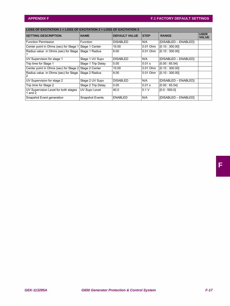
GEK-113285A G650 Generator Protection & Control System F-17
APPENDIX F F.1 FACTORY DEFAULT SETTINGS
F
LOSS OF EXCITATION 1 > LOSS OF EXCITATION 2 > LOSS OF EXCITATION 3
SETTING DESCRIPTION NAME DEFAULT VALUE STEP RANGE USER VALUE
Function Permission Function DISABLED N/A [DISABLED – ENABLED]Center point in Ohms (sec) for Stage 1 Stage 1 Center 10.00 0.01 Ohm [0.10 : 300.00]Radius value in Ohms (sec) for Stage 1
Stage 1 Radius 8.00 0.01 Ohm [0.10 : 300.00]
UV Supervision for stage 1 Stage 1 UV Supv DISABLED N/A [DISABLED – ENABLED]Trip time for Stage 1 Stage 1 Trip Delay 0.05 0.01 s [0.00 : 65.54]Center point in Ohms (sec) for Stage 2 Stage 2 Center 10.00 0.01 Ohm [0.10 : 300.00]Radius value in Ohms (sec) for Stage 2
Stage 2 Radius 8.00 0.01 Ohm [0.10 : 300.00]
UV Supervision for stage 2 Stage 2 UV Supv DISABLED N/A [DISABLED – ENABLED]Trip time for Stage 2 Stage 2 Trip Delay 0.05 0.01 s [0.00 : 65.54]UV Supervision Level for both stages 1 and 2
UV Supv Level 40.0 0.1 V [0.0 : 500.0]
Snapshot Event generation Snapshot Events ENABLED N/A [DISABLED – ENABLED]
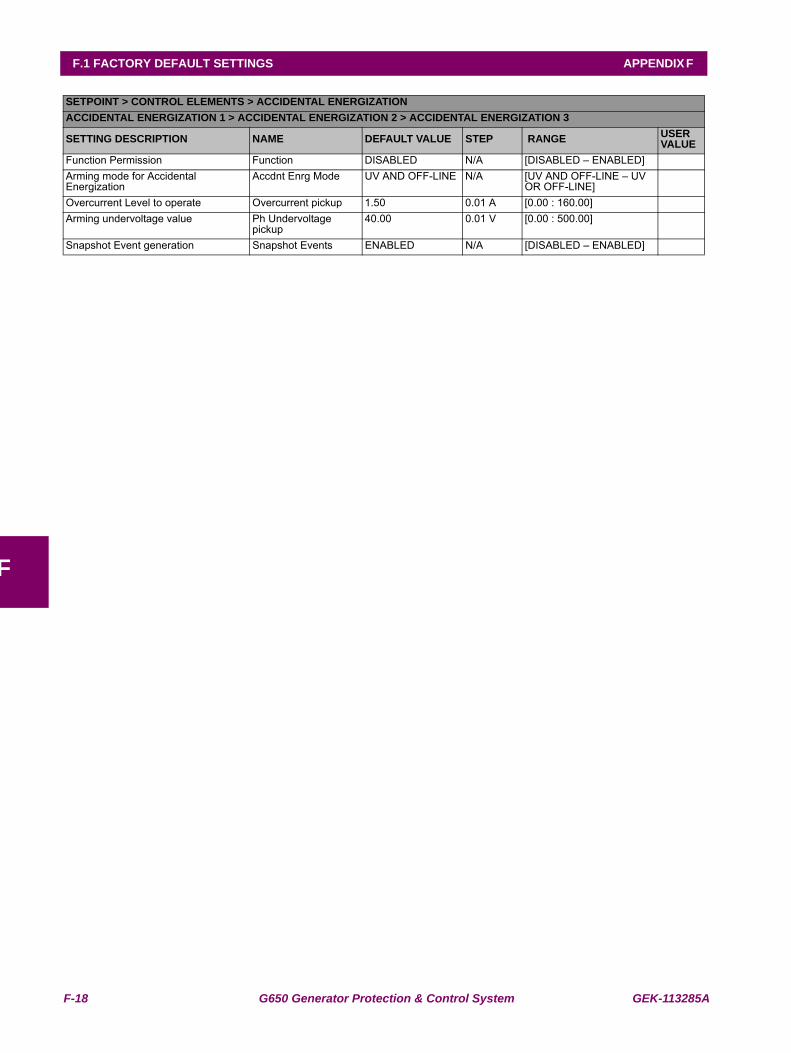
F-18 G650 Generator Protection & Control System GEK-113285A
F.1 FACTORY DEFAULT SETTINGS APPENDIX F
F
SETPOINT > CONTROL ELEMENTS > ACCIDENTAL ENERGIZATIONACCIDENTAL ENERGIZATION 1 > ACCIDENTAL ENERGIZATION 2 > ACCIDENTAL ENERGIZATION 3
SETTING DESCRIPTION NAME DEFAULT VALUE STEP RANGE USER VALUE
Function Permission Function DISABLED N/A [DISABLED – ENABLED]Arming mode for Accidental Energization
Accdnt Enrg Mode UV AND OFF-LINE N/A [UV AND OFF-LINE – UV OR OFF-LINE]
Overcurrent Level to operate Overcurrent pickup 1.50 0.01 A [0.00 : 160.00]Arming undervoltage value Ph Undervoltage
pickup40.00 0.01 V [0.00 : 500.00]
Snapshot Event generation Snapshot Events ENABLED N/A [DISABLED – ENABLED]
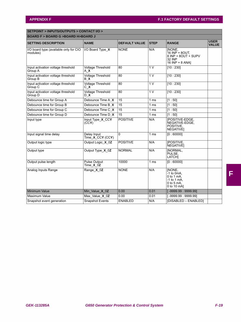
GEK-113285A G650 Generator Protection & Control System F-19
APPENDIX F F.1 FACTORY DEFAULT SETTINGS
F
SETPOINT > INPUTS/OUTPUTS > CONTACT I/O >BOARD F > BOARD G >BOARD H>BOARD J
SETTING DESCRIPTION NAME DEFAULT VALUE STEP RANGE USER VALUE
I/O board type (available only for CIO modules)
I/O Board Type_X NONE N/A [NONE,16 INP + 8OUT,8 INP + 8OUT + SUPV32 INP16 INP + 8 ANA]
Input activation voltage threshold Group A
Voltage Threshold A_X
80 1 V [10 : 230]
Input activation voltage threshold Group B
Voltage Threshold B_X
80 1 V [10 : 230]
Input activation voltage threshold Group C
Voltage Threshold C_X
80 1 V [10 : 230]
Input activation voltage threshold Group D
Voltage Threshold D_X
80 1 V [10 : 230]
Debounce time for Group A Debounce Time A_X 15 1 ms [1 : 50]Debounce time for Group B Debounce Time B_X 15 1 ms [1 : 50]Debounce time for Group C Debounce Time C_X 15 1 ms [1 : 50]Debounce time for Group D Debounce Time D_X 15 1 ms [1 : 50]Input type Input Type_X_CCY
(CCY)POSITIVE N/A [POSITIVE-EDGE,
NEGATIVE-EDGE,POSITIVE,NEGATIVE]
Input signal time delay Delay Input Time_X_CCY (CCY)
0 1 ms [0 : 60000]
Output logic type Output Logic_X_0Z POSITIVE N/A [POSITIVE,NEGATIVE]
Output type Output Type_X_0Z NORMAL N/A [NORMAL,PULSE,LATCH]
Output pulse length Pulse Output Time_X_0Z
10000 1 ms [0 : 60000]
Analog Inputs Range Range_X_0Z NONE N/A [NONE,-1 to 0mA,0 to 1 mA,-1 to 1 mA,0 to 5 mA,0 to 10 mA]
Minimum Value Min_Value_X_0Z 0.00 0.01 [ -9999.99 : 9999.99]Maximum Value Max_Value_X_0Z 0.00 0.01 [ -9999.99 : 9999.99]Snapshot event generation Snapshot Events ENABLED N/A [DISABLED – ENABLED]
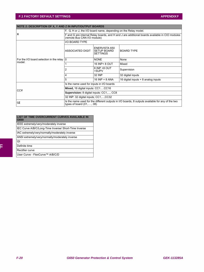
F-20 G650 Generator Protection & Control System GEK-113285A
F.1 FACTORY DEFAULT SETTINGS APPENDIX F
F
NOTE 2: DESCRIPTION OF X, Y AND Z IN INPUT/OUTPUT BOARDS
X F, G, H or J, the I/O board name, depending on the Relay model.F and G are internal Relay boards, and H and J are additional boards available in CIO modules (remote Bus CAN I/O module)
For the I/O board selection in the relay model:
I/O BOARD TYPE
ASSOCIATED DIGITENERVISTA 650 SETUP BOARD SETTINGS
BOARD TYPE
0 NONE None1 16 INP+ 8 OUT Mixed
2 8 INP +8 OUT +SUPV Supervision
4 32 INP 32 digital inputs 5 16 INP + 8 ANA 16 digital inputs + 8 analog inputs
CCY
Is the name used for inputs in I/O boardsMixed, 16 digital inputs: CC1….CC16Supervision: 8 digital inputs: CC1,..., CC832 INP: 32 digital inputs; CC1,...,CC32
0Z Is the name used for the different outputs in I/O boards, 8 outputs available for any of the two types of board (01,…., 08)
LIST OF TIME OVERCURRENT CURVES AVAILABLE IN G650IEEE extremely/very/moderately inverseIEC Curve A/B/C/Long-Time Inverse/ Short-Time InverseIAC extremely/very/normally/moderately inverseANSI extremely/very/normally/moderately inverseI2tDefinite timeRectifier curveUser Curve - FlexCurve™ A/B/C/D
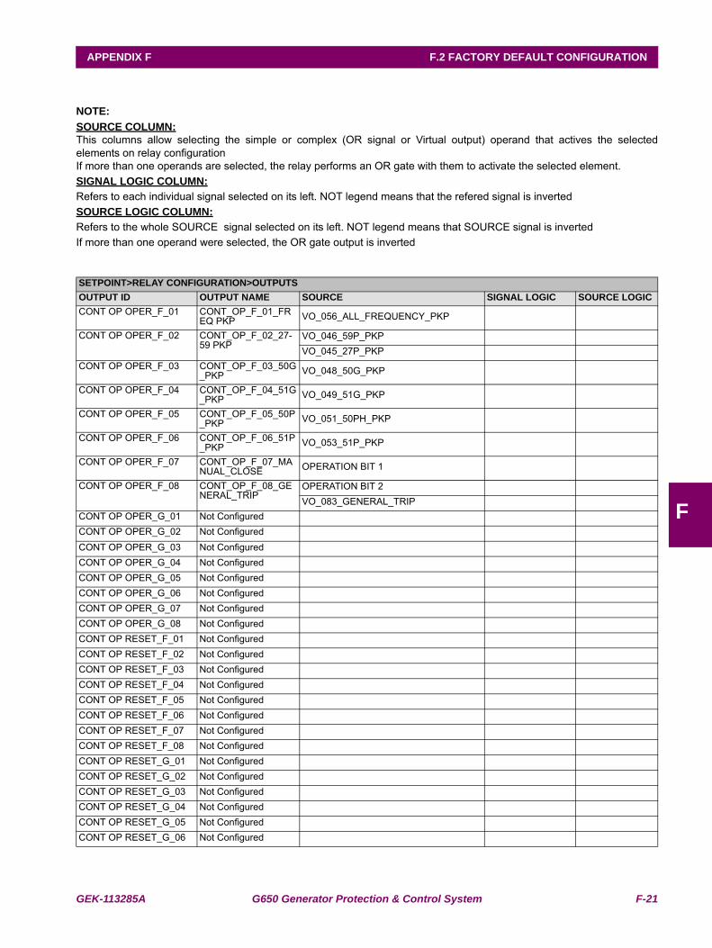
GEK-113285A G650 Generator Protection & Control System F-21
APPENDIX F F.2 FACTORY DEFAULT CONFIGURATION
F
F.2FACTORY DEFAULT CONFIGURATION
NOTE:SOURCE COLUMN:This columns allow selecting the simple or complex (OR signal or Virtual output) operand that actives the selectedelements on relay configurationIf more than one operands are selected, the relay performs an OR gate with them to activate the selected element.SIGNAL LOGIC COLUMN:Refers to each individual signal selected on its left. NOT legend means that the refered signal is invertedSOURCE LOGIC COLUMN:Refers to the whole SOURCE signal selected on its left. NOT legend means that SOURCE signal is invertedIf more than one operand were selected, the OR gate output is inverted
SETPOINT>RELAY CONFIGURATION>OUTPUTSOUTPUT ID OUTPUT NAME SOURCE SIGNAL LOGIC SOURCE LOGICCONT OP OPER_F_01 CONT_OP_F_01_FR
EQ PKP VO_056_ALL_FREQUENCY_PKP
CONT OP OPER_F_02 CONT_OP_F_02_27-59 PKP
VO_046_59P_PKPVO_045_27P_PKP
CONT OP OPER_F_03 CONT_OP_F_03_50G_PKP VO_048_50G_PKP
CONT OP OPER_F_04 CONT_OP_F_04_51G_PKP VO_049_51G_PKP
CONT OP OPER_F_05 CONT_OP_F_05_50P_PKP VO_051_50PH_PKP
CONT OP OPER_F_06 CONT_OP_F_06_51P_PKP VO_053_51P_PKP
CONT OP OPER_F_07 CONT_OP_F_07_MANUAL_CLOSE OPERATION BIT 1
CONT OP OPER_F_08 CONT_OP_F_08_GENERAL_TRIP
OPERATION BIT 2VO_083_GENERAL_TRIP
CONT OP OPER_G_01 Not ConfiguredCONT OP OPER_G_02 Not ConfiguredCONT OP OPER_G_03 Not ConfiguredCONT OP OPER_G_04 Not ConfiguredCONT OP OPER_G_05 Not ConfiguredCONT OP OPER_G_06 Not ConfiguredCONT OP OPER_G_07 Not ConfiguredCONT OP OPER_G_08 Not ConfiguredCONT OP RESET_F_01 Not ConfiguredCONT OP RESET_F_02 Not ConfiguredCONT OP RESET_F_03 Not ConfiguredCONT OP RESET_F_04 Not ConfiguredCONT OP RESET_F_05 Not ConfiguredCONT OP RESET_F_06 Not ConfiguredCONT OP RESET_F_07 Not ConfiguredCONT OP RESET_F_08 Not ConfiguredCONT OP RESET_G_01 Not ConfiguredCONT OP RESET_G_02 Not ConfiguredCONT OP RESET_G_03 Not ConfiguredCONT OP RESET_G_04 Not ConfiguredCONT OP RESET_G_05 Not ConfiguredCONT OP RESET_G_06 Not Configured
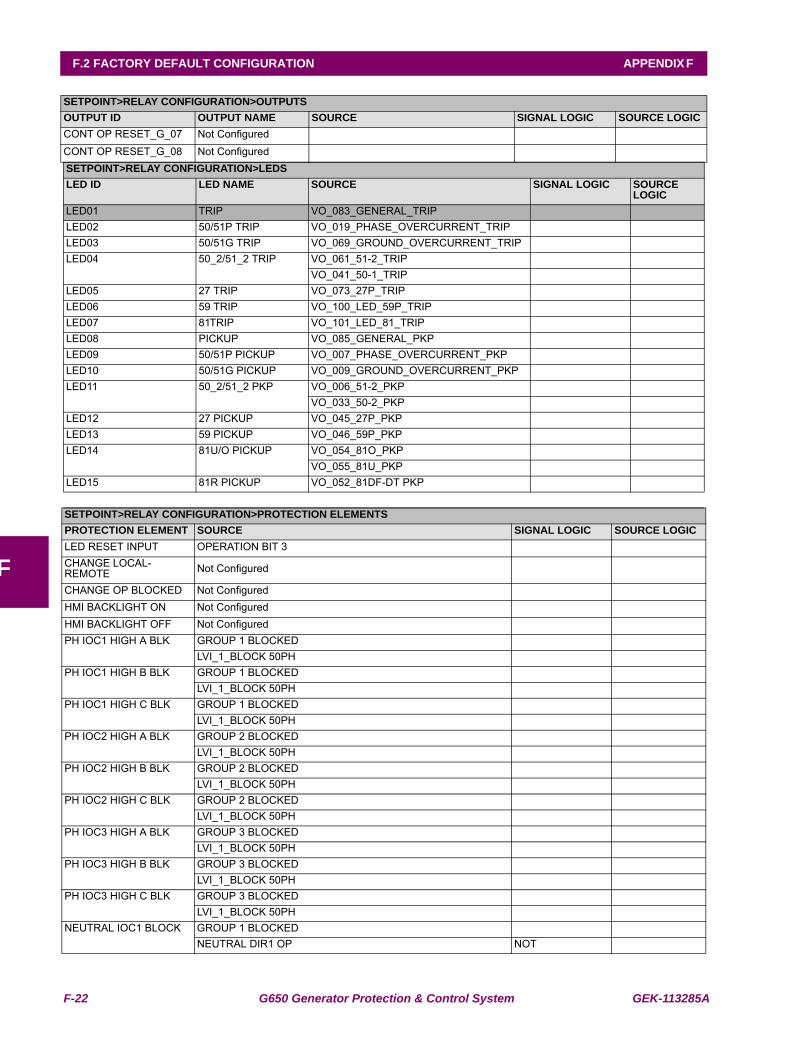
F-22 G650 Generator Protection & Control System GEK-113285A
F.2 FACTORY DEFAULT CONFIGURATION APPENDIX F
F
CONT OP RESET_G_07 Not ConfiguredCONT OP RESET_G_08 Not ConfiguredSETPOINT>RELAY CONFIGURATION>LEDSLED ID LED NAME SOURCE SIGNAL LOGIC SOURCE
LOGICLED01 TRIP VO_083_GENERAL_TRIPLED02 50/51P TRIP VO_019_PHASE_OVERCURRENT_TRIPLED03 50/51G TRIP VO_069_GROUND_OVERCURRENT_TRIPLED04 50_2/51_2 TRIP VO_061_51-2_TRIP
VO_041_50-1_TRIPLED05 27 TRIP VO_073_27P_TRIPLED06 59 TRIP VO_100_LED_59P_TRIPLED07 81TRIP VO_101_LED_81_TRIPLED08 PICKUP VO_085_GENERAL_PKPLED09 50/51P PICKUP VO_007_PHASE_OVERCURRENT_PKPLED10 50/51G PICKUP VO_009_GROUND_OVERCURRENT_PKPLED11 50_2/51_2 PKP VO_006_51-2_PKP
VO_033_50-2_PKPLED12 27 PICKUP VO_045_27P_PKPLED13 59 PICKUP VO_046_59P_PKPLED14 81U/O PICKUP VO_054_81O_PKP
VO_055_81U_PKPLED15 81R PICKUP VO_052_81DF-DT PKP
SETPOINT>RELAY CONFIGURATION>PROTECTION ELEMENTSPROTECTION ELEMENT SOURCE SIGNAL LOGIC SOURCE LOGICLED RESET INPUT OPERATION BIT 3CHANGE LOCAL-REMOTE Not Configured
CHANGE OP BLOCKED Not ConfiguredHMI BACKLIGHT ON Not ConfiguredHMI BACKLIGHT OFF Not ConfiguredPH IOC1 HIGH A BLK GROUP 1 BLOCKED
LVI_1_BLOCK 50PHPH IOC1 HIGH B BLK GROUP 1 BLOCKED
LVI_1_BLOCK 50PHPH IOC1 HIGH C BLK GROUP 1 BLOCKED
LVI_1_BLOCK 50PHPH IOC2 HIGH A BLK GROUP 2 BLOCKED
LVI_1_BLOCK 50PHPH IOC2 HIGH B BLK GROUP 2 BLOCKED
LVI_1_BLOCK 50PHPH IOC2 HIGH C BLK GROUP 2 BLOCKED
LVI_1_BLOCK 50PHPH IOC3 HIGH A BLK GROUP 3 BLOCKED
LVI_1_BLOCK 50PHPH IOC3 HIGH B BLK GROUP 3 BLOCKED
LVI_1_BLOCK 50PHPH IOC3 HIGH C BLK GROUP 3 BLOCKED
LVI_1_BLOCK 50PHNEUTRAL IOC1 BLOCK GROUP 1 BLOCKED
NEUTRAL DIR1 OP NOT
SETPOINT>RELAY CONFIGURATION>OUTPUTSOUTPUT ID OUTPUT NAME SOURCE SIGNAL LOGIC SOURCE LOGIC
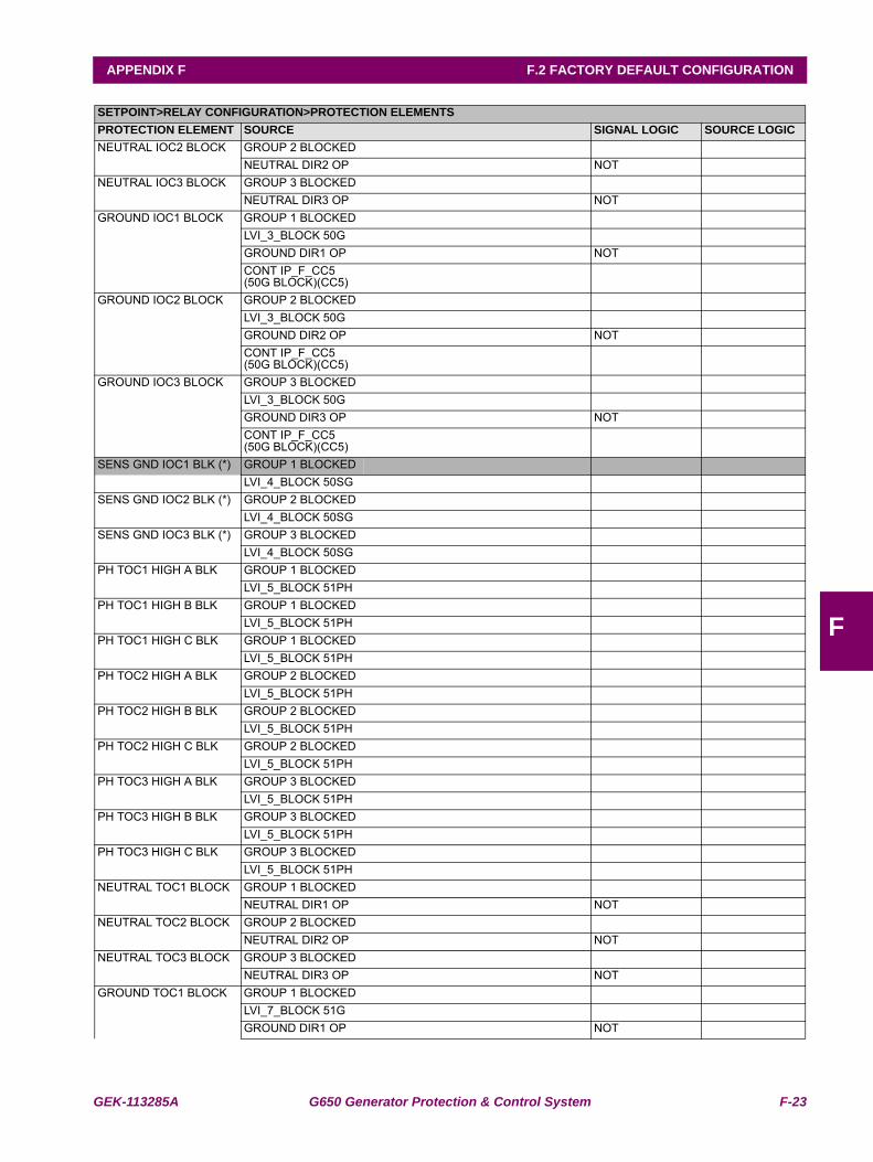
GEK-113285A G650 Generator Protection & Control System F-23
APPENDIX F F.2 FACTORY DEFAULT CONFIGURATION
F
NEUTRAL IOC2 BLOCK GROUP 2 BLOCKEDNEUTRAL DIR2 OP NOT
NEUTRAL IOC3 BLOCK GROUP 3 BLOCKEDNEUTRAL DIR3 OP NOT
GROUND IOC1 BLOCK GROUP 1 BLOCKEDLVI_3_BLOCK 50GGROUND DIR1 OP NOTCONT IP_F_CC5 (50G BLOCK)(CC5)
GROUND IOC2 BLOCK GROUP 2 BLOCKEDLVI_3_BLOCK 50GGROUND DIR2 OP NOTCONT IP_F_CC5 (50G BLOCK)(CC5)
GROUND IOC3 BLOCK GROUP 3 BLOCKEDLVI_3_BLOCK 50GGROUND DIR3 OP NOTCONT IP_F_CC5 (50G BLOCK)(CC5)
SENS GND IOC1 BLK (*) GROUP 1 BLOCKEDLVI_4_BLOCK 50SG
SENS GND IOC2 BLK (*) GROUP 2 BLOCKEDLVI_4_BLOCK 50SG
SENS GND IOC3 BLK (*) GROUP 3 BLOCKEDLVI_4_BLOCK 50SG
PH TOC1 HIGH A BLK GROUP 1 BLOCKEDLVI_5_BLOCK 51PH
PH TOC1 HIGH B BLK GROUP 1 BLOCKEDLVI_5_BLOCK 51PH
PH TOC1 HIGH C BLK GROUP 1 BLOCKEDLVI_5_BLOCK 51PH
PH TOC2 HIGH A BLK GROUP 2 BLOCKEDLVI_5_BLOCK 51PH
PH TOC2 HIGH B BLK GROUP 2 BLOCKEDLVI_5_BLOCK 51PH
PH TOC2 HIGH C BLK GROUP 2 BLOCKEDLVI_5_BLOCK 51PH
PH TOC3 HIGH A BLK GROUP 3 BLOCKEDLVI_5_BLOCK 51PH
PH TOC3 HIGH B BLK GROUP 3 BLOCKEDLVI_5_BLOCK 51PH
PH TOC3 HIGH C BLK GROUP 3 BLOCKEDLVI_5_BLOCK 51PH
NEUTRAL TOC1 BLOCK GROUP 1 BLOCKEDNEUTRAL DIR1 OP NOT
NEUTRAL TOC2 BLOCK GROUP 2 BLOCKEDNEUTRAL DIR2 OP NOT
NEUTRAL TOC3 BLOCK GROUP 3 BLOCKEDNEUTRAL DIR3 OP NOT
GROUND TOC1 BLOCK GROUP 1 BLOCKEDLVI_7_BLOCK 51GGROUND DIR1 OP NOT
SETPOINT>RELAY CONFIGURATION>PROTECTION ELEMENTSPROTECTION ELEMENT SOURCE SIGNAL LOGIC SOURCE LOGIC
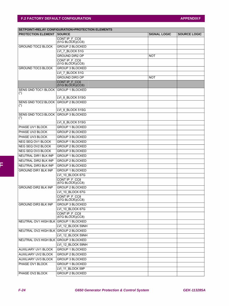
F-24 G650 Generator Protection & Control System GEK-113285A
F.2 FACTORY DEFAULT CONFIGURATION APPENDIX F
F
CONT IP_F_CC6 (51G BLOCK)(CC6)
GROUND TOC2 BLOCK GROUP 2 BLOCKEDLVI_7_BLOCK 51GGROUND DIR2 OP NOTCONT IP_F_CC6 (51G BLOCK)(CC6)
GROUND TOC3 BLOCK GROUP 3 BLOCKEDLVI_7_BLOCK 51GGROUND DIR3 OP NOTCONT IP_F_CC6 (51G BLOCK)(CC6)
SENS GND TOC1 BLOCK (*)
GROUP 1 BLOCKED
LVI_8_BLOCK 51SGSENS GND TOC2 BLOCK (*)
GROUP 2 BLOCKED
LVI_8_BLOCK 51SGSENS GND TOC3 BLOCK (*)
GROUP 3 BLOCKED
LVI_8_BLOCK 51SGPHASE UV1 BLOCK GROUP 1 BLOCKEDPHASE UV2 BLOCK GROUP 2 BLOCKEDPHASE UV3 BLOCK GROUP 3 BLOCKEDNEG SEQ OV1 BLOCK GROUP 1 BLOCKEDNEG SEQ OV2 BLOCK GROUP 2 BLOCKEDNEG SEQ OV3 BLOCK GROUP 3 BLOCKEDNEUTRAL DIR1 BLK INP GROUP 1 BLOCKEDNEUTRAL DIR2 BLK INP GROUP 2 BLOCKEDNEUTRAL DIR3 BLK INP GROUP 3 BLOCKEDGROUND DIR1 BLK INP GROUP 1 BLOCKED
LVI_10_BLOCK 67GCONT IP_F_CC8 (67G BLOCK)(CC8)
GROUND DIR2 BLK INP GROUP 2 BLOCKEDLVI_10_BLOCK 67GCONT IP_F_CC8 (67G BLOCK)(CC8)
GROUND DIR3 BLK INP GROUP 3 BLOCKEDLVI_10_BLOCK 67GCONT IP_F_CC8 (67G BLOCK)(CC8)
NEUTRAL OV1 HIGH BLK GROUP 1 BLOCKEDLVI_12_BLOCK 59NH
NEUTRAL OV2 HIGH BLK GROUP 2 BLOCKEDLVI_12_BLOCK 59NH
NEUTRAL OV3 HIGH BLK GROUP 3 BLOCKEDLVI_12_BLOCK 59NH
AUXILIARY UV1 BLOCK GROUP 1 BLOCKEDAUXILIARY UV2 BLOCK GROUP 2 BLOCKEDAUXILIARY UV3 BLOCK GROUP 3 BLOCKEDPHASE OV1 BLOCK GROUP 1 BLOCKED
LVI_11_BLOCK 59PPHASE OV2 BLOCK GROUP 2 BLOCKED
SETPOINT>RELAY CONFIGURATION>PROTECTION ELEMENTSPROTECTION ELEMENT SOURCE SIGNAL LOGIC SOURCE LOGIC
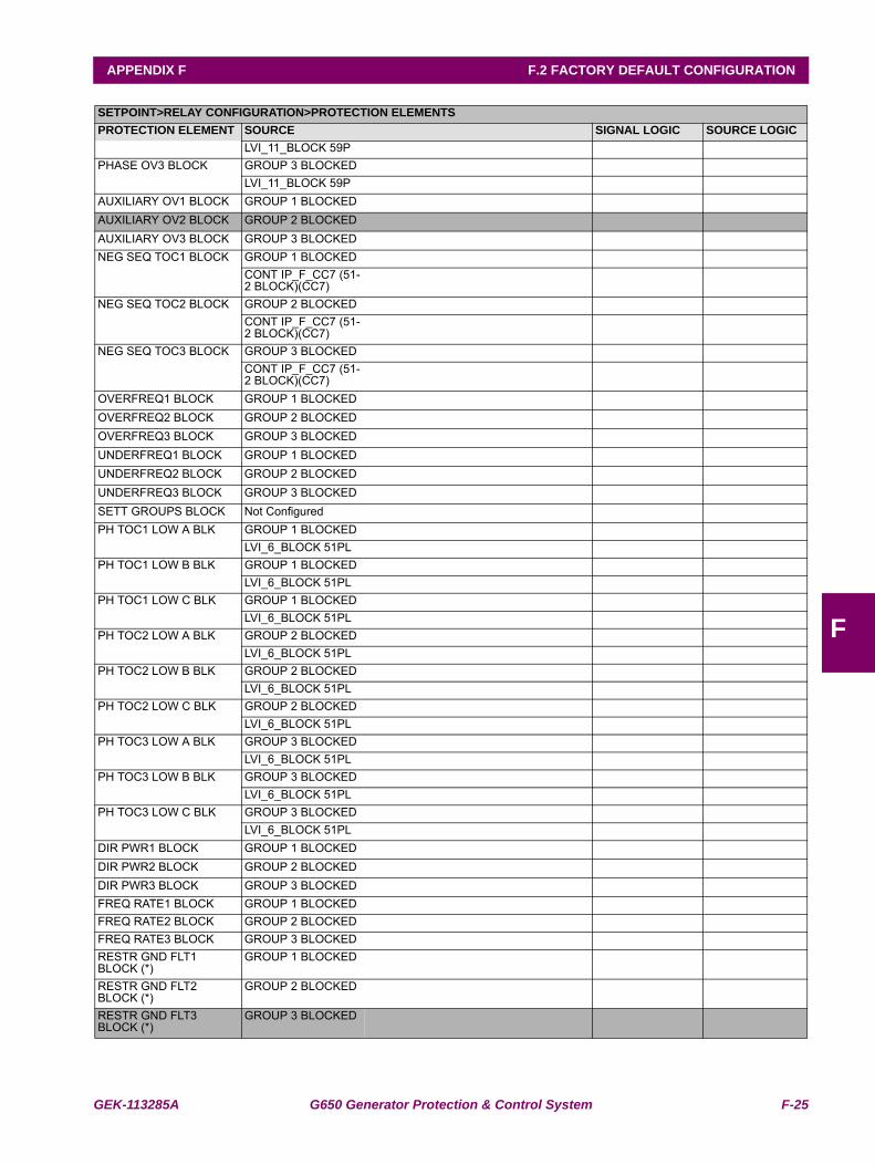
GEK-113285A G650 Generator Protection & Control System F-25
APPENDIX F F.2 FACTORY DEFAULT CONFIGURATION
F
LVI_11_BLOCK 59PPHASE OV3 BLOCK GROUP 3 BLOCKED
LVI_11_BLOCK 59PAUXILIARY OV1 BLOCK GROUP 1 BLOCKEDAUXILIARY OV2 BLOCK GROUP 2 BLOCKEDAUXILIARY OV3 BLOCK GROUP 3 BLOCKEDNEG SEQ TOC1 BLOCK GROUP 1 BLOCKED
CONT IP_F_CC7 (51-2 BLOCK)(CC7)
NEG SEQ TOC2 BLOCK GROUP 2 BLOCKEDCONT IP_F_CC7 (51-2 BLOCK)(CC7)
NEG SEQ TOC3 BLOCK GROUP 3 BLOCKEDCONT IP_F_CC7 (51-2 BLOCK)(CC7)
OVERFREQ1 BLOCK GROUP 1 BLOCKEDOVERFREQ2 BLOCK GROUP 2 BLOCKEDOVERFREQ3 BLOCK GROUP 3 BLOCKEDUNDERFREQ1 BLOCK GROUP 1 BLOCKEDUNDERFREQ2 BLOCK GROUP 2 BLOCKEDUNDERFREQ3 BLOCK GROUP 3 BLOCKEDSETT GROUPS BLOCK Not ConfiguredPH TOC1 LOW A BLK GROUP 1 BLOCKED
LVI_6_BLOCK 51PLPH TOC1 LOW B BLK GROUP 1 BLOCKED
LVI_6_BLOCK 51PLPH TOC1 LOW C BLK GROUP 1 BLOCKED
LVI_6_BLOCK 51PLPH TOC2 LOW A BLK GROUP 2 BLOCKED
LVI_6_BLOCK 51PLPH TOC2 LOW B BLK GROUP 2 BLOCKED
LVI_6_BLOCK 51PLPH TOC2 LOW C BLK GROUP 2 BLOCKED
LVI_6_BLOCK 51PLPH TOC3 LOW A BLK GROUP 3 BLOCKED
LVI_6_BLOCK 51PLPH TOC3 LOW B BLK GROUP 3 BLOCKED
LVI_6_BLOCK 51PLPH TOC3 LOW C BLK GROUP 3 BLOCKED
LVI_6_BLOCK 51PLDIR PWR1 BLOCK GROUP 1 BLOCKEDDIR PWR2 BLOCK GROUP 2 BLOCKEDDIR PWR3 BLOCK GROUP 3 BLOCKEDFREQ RATE1 BLOCK GROUP 1 BLOCKEDFREQ RATE2 BLOCK GROUP 2 BLOCKEDFREQ RATE3 BLOCK GROUP 3 BLOCKEDRESTR GND FLT1 BLOCK (*)
GROUP 1 BLOCKED
RESTR GND FLT2 BLOCK (*)
GROUP 2 BLOCKED
RESTR GND FLT3 BLOCK (*)
GROUP 3 BLOCKED
SETPOINT>RELAY CONFIGURATION>PROTECTION ELEMENTSPROTECTION ELEMENT SOURCE SIGNAL LOGIC SOURCE LOGIC
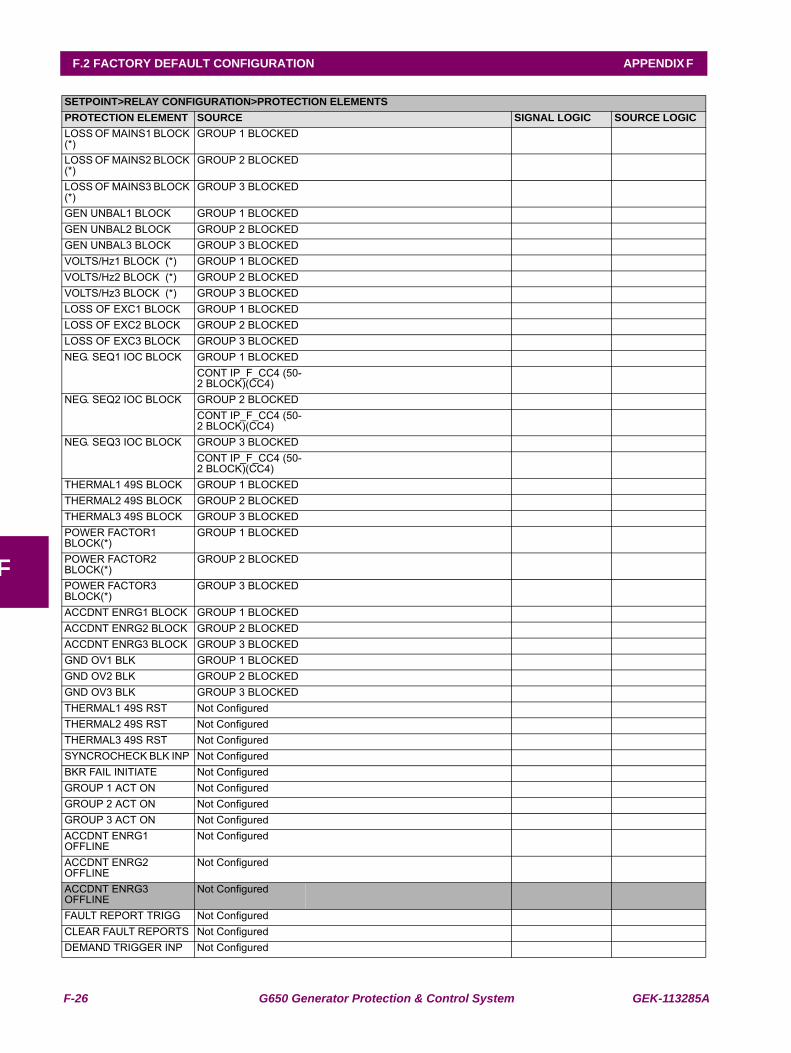
F-26 G650 Generator Protection & Control System GEK-113285A
F.2 FACTORY DEFAULT CONFIGURATION APPENDIX F
F
LOSS OF MAINS1 BLOCK (*)
GROUP 1 BLOCKED
LOSS OF MAINS2 BLOCK (*)
GROUP 2 BLOCKED
LOSS OF MAINS3 BLOCK (*)
GROUP 3 BLOCKED
GEN UNBAL1 BLOCK GROUP 1 BLOCKEDGEN UNBAL2 BLOCK GROUP 2 BLOCKEDGEN UNBAL3 BLOCK GROUP 3 BLOCKEDVOLTS/Hz1 BLOCK (*) GROUP 1 BLOCKEDVOLTS/Hz2 BLOCK (*) GROUP 2 BLOCKEDVOLTS/Hz3 BLOCK (*) GROUP 3 BLOCKEDLOSS OF EXC1 BLOCK GROUP 1 BLOCKEDLOSS OF EXC2 BLOCK GROUP 2 BLOCKEDLOSS OF EXC3 BLOCK GROUP 3 BLOCKEDNEG. SEQ1 IOC BLOCK GROUP 1 BLOCKED
CONT IP_F_CC4 (50-2 BLOCK)(CC4)
NEG. SEQ2 IOC BLOCK GROUP 2 BLOCKEDCONT IP_F_CC4 (50-2 BLOCK)(CC4)
NEG. SEQ3 IOC BLOCK GROUP 3 BLOCKEDCONT IP_F_CC4 (50-2 BLOCK)(CC4)
THERMAL1 49S BLOCK GROUP 1 BLOCKEDTHERMAL2 49S BLOCK GROUP 2 BLOCKEDTHERMAL3 49S BLOCK GROUP 3 BLOCKEDPOWER FACTOR1 BLOCK(*)
GROUP 1 BLOCKED
POWER FACTOR2 BLOCK(*)
GROUP 2 BLOCKED
POWER FACTOR3 BLOCK(*)
GROUP 3 BLOCKED
ACCDNT ENRG1 BLOCK GROUP 1 BLOCKEDACCDNT ENRG2 BLOCK GROUP 2 BLOCKEDACCDNT ENRG3 BLOCK GROUP 3 BLOCKEDGND OV1 BLK GROUP 1 BLOCKEDGND OV2 BLK GROUP 2 BLOCKEDGND OV3 BLK GROUP 3 BLOCKEDTHERMAL1 49S RST Not ConfiguredTHERMAL2 49S RST Not ConfiguredTHERMAL3 49S RST Not ConfiguredSYNCROCHECK BLK INP Not ConfiguredBKR FAIL INITIATE Not ConfiguredGROUP 1 ACT ON Not ConfiguredGROUP 2 ACT ON Not ConfiguredGROUP 3 ACT ON Not ConfiguredACCDNT ENRG1 OFFLINE
Not Configured
ACCDNT ENRG2 OFFLINE
Not Configured
ACCDNT ENRG3 OFFLINE
Not Configured
FAULT REPORT TRIGG Not ConfiguredCLEAR FAULT REPORTS Not ConfiguredDEMAND TRIGGER INP Not Configured
SETPOINT>RELAY CONFIGURATION>PROTECTION ELEMENTSPROTECTION ELEMENT SOURCE SIGNAL LOGIC SOURCE LOGIC
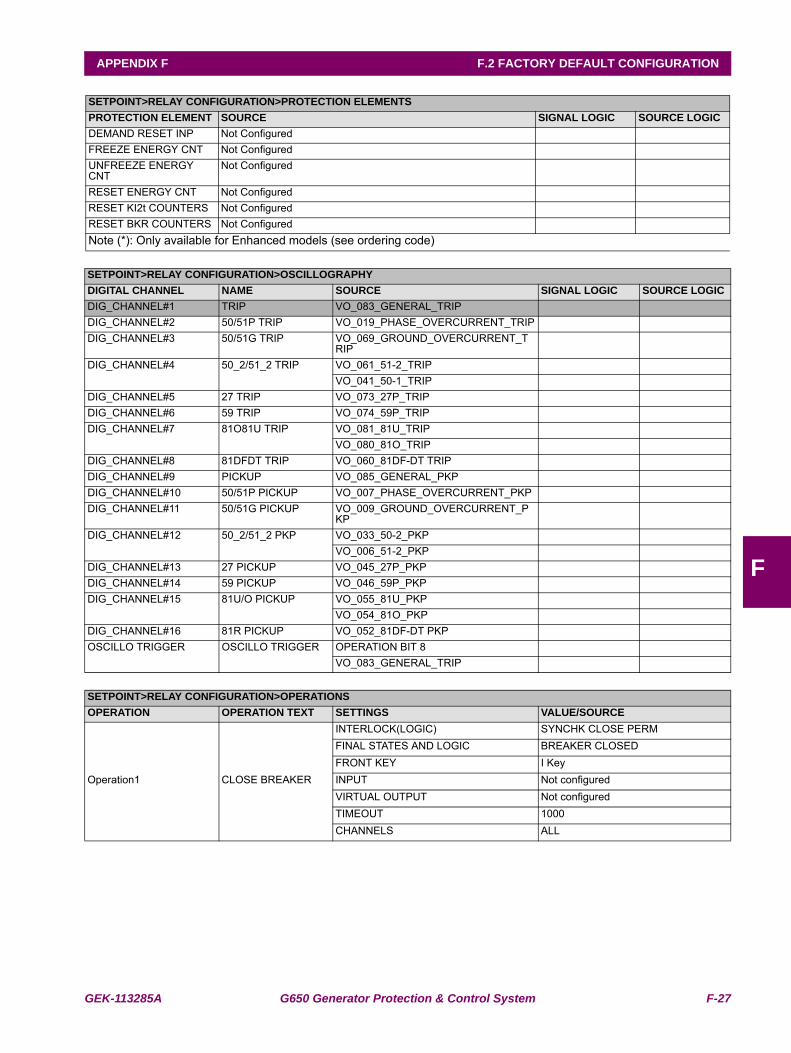
GEK-113285A G650 Generator Protection & Control System F-27
APPENDIX F F.2 FACTORY DEFAULT CONFIGURATION
F
DEMAND RESET INP Not ConfiguredFREEZE ENERGY CNT Not ConfiguredUNFREEZE ENERGY CNT
Not Configured
RESET ENERGY CNT Not ConfiguredRESET KI2t COUNTERS Not ConfiguredRESET BKR COUNTERS Not ConfiguredNote (*): Only available for Enhanced models (see ordering code)
SETPOINT>RELAY CONFIGURATION>OSCILLOGRAPHYDIGITAL CHANNEL NAME SOURCE SIGNAL LOGIC SOURCE LOGICDIG_CHANNEL#1 TRIP VO_083_GENERAL_TRIPDIG_CHANNEL#2 50/51P TRIP VO_019_PHASE_OVERCURRENT_TRIPDIG_CHANNEL#3 50/51G TRIP VO_069_GROUND_OVERCURRENT_T
RIPDIG_CHANNEL#4 50_2/51_2 TRIP VO_061_51-2_TRIP
VO_041_50-1_TRIPDIG_CHANNEL#5 27 TRIP VO_073_27P_TRIPDIG_CHANNEL#6 59 TRIP VO_074_59P_TRIPDIG_CHANNEL#7 81O81U TRIP VO_081_81U_TRIP
VO_080_81O_TRIPDIG_CHANNEL#8 81DFDT TRIP VO_060_81DF-DT TRIPDIG_CHANNEL#9 PICKUP VO_085_GENERAL_PKPDIG_CHANNEL#10 50/51P PICKUP VO_007_PHASE_OVERCURRENT_PKPDIG_CHANNEL#11 50/51G PICKUP VO_009_GROUND_OVERCURRENT_P
KPDIG_CHANNEL#12 50_2/51_2 PKP VO_033_50-2_PKP
VO_006_51-2_PKPDIG_CHANNEL#13 27 PICKUP VO_045_27P_PKPDIG_CHANNEL#14 59 PICKUP VO_046_59P_PKPDIG_CHANNEL#15 81U/O PICKUP VO_055_81U_PKP
VO_054_81O_PKPDIG_CHANNEL#16 81R PICKUP VO_052_81DF-DT PKPOSCILLO TRIGGER OSCILLO TRIGGER OPERATION BIT 8
VO_083_GENERAL_TRIP
SETPOINT>RELAY CONFIGURATION>OPERATIONSOPERATION OPERATION TEXT SETTINGS VALUE/SOURCE
Operation1 CLOSE BREAKER
INTERLOCK(LOGIC) SYNCHK CLOSE PERM FINAL STATES AND LOGIC BREAKER CLOSED FRONT KEY I Key INPUT Not configuredVIRTUAL OUTPUT Not configuredTIMEOUT 1000 CHANNELS ALL
SETPOINT>RELAY CONFIGURATION>PROTECTION ELEMENTSPROTECTION ELEMENT SOURCE SIGNAL LOGIC SOURCE LOGIC
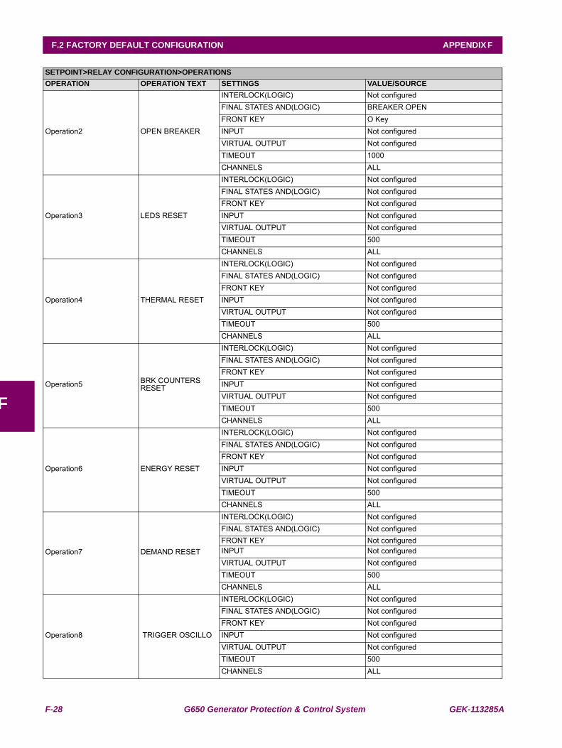
F-28 G650 Generator Protection & Control System GEK-113285A
F.2 FACTORY DEFAULT CONFIGURATION APPENDIX F
F
Operation2 OPEN BREAKER
INTERLOCK(LOGIC) Not configuredFINAL STATES AND(LOGIC) BREAKER OPEN FRONT KEY O Key INPUT Not configuredVIRTUAL OUTPUT Not configuredTIMEOUT 1000 CHANNELS ALL
Operation3 LEDS RESET
INTERLOCK(LOGIC) Not configuredFINAL STATES AND(LOGIC) Not configuredFRONT KEY Not configuredINPUT Not configuredVIRTUAL OUTPUT Not configuredTIMEOUT 500CHANNELS ALL
Operation4 THERMAL RESET
INTERLOCK(LOGIC) Not configuredFINAL STATES AND(LOGIC) Not configuredFRONT KEY Not configuredINPUT Not configuredVIRTUAL OUTPUT Not configuredTIMEOUT 500CHANNELS ALL
Operation5 BRK COUNTERS RESET
INTERLOCK(LOGIC) Not configuredFINAL STATES AND(LOGIC) Not configuredFRONT KEY Not configuredINPUT Not configuredVIRTUAL OUTPUT Not configuredTIMEOUT 500CHANNELS ALL
Operation6 ENERGY RESET
INTERLOCK(LOGIC) Not configuredFINAL STATES AND(LOGIC) Not configuredFRONT KEY Not configuredINPUT Not configuredVIRTUAL OUTPUT Not configuredTIMEOUT 500CHANNELS ALL
Operation7 DEMAND RESET
INTERLOCK(LOGIC) Not configuredFINAL STATES AND(LOGIC) Not configuredFRONT KEY Not configuredINPUT Not configuredVIRTUAL OUTPUT Not configuredTIMEOUT 500CHANNELS ALL
Operation8 TRIGGER OSCILLO
INTERLOCK(LOGIC) Not configuredFINAL STATES AND(LOGIC) Not configuredFRONT KEY Not configuredINPUT Not configuredVIRTUAL OUTPUT Not configuredTIMEOUT 500CHANNELS ALL
SETPOINT>RELAY CONFIGURATION>OPERATIONSOPERATION OPERATION TEXT SETTINGS VALUE/SOURCE
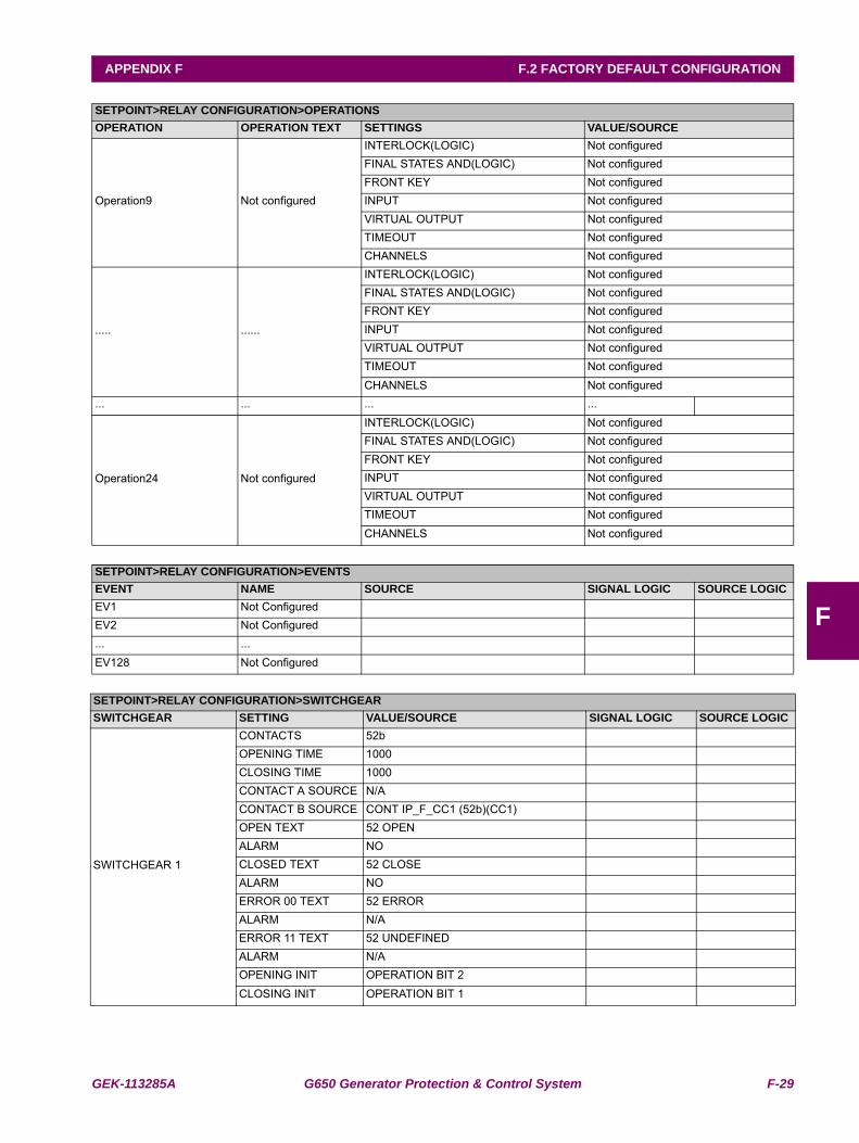
GEK-113285A G650 Generator Protection & Control System F-29
APPENDIX F F.2 FACTORY DEFAULT CONFIGURATION
F
Operation9 Not configured
INTERLOCK(LOGIC) Not configuredFINAL STATES AND(LOGIC) Not configuredFRONT KEY Not configuredINPUT Not configuredVIRTUAL OUTPUT Not configuredTIMEOUT Not configuredCHANNELS Not configured
..... ......
INTERLOCK(LOGIC) Not configuredFINAL STATES AND(LOGIC) Not configuredFRONT KEY Not configuredINPUT Not configuredVIRTUAL OUTPUT Not configuredTIMEOUT Not configuredCHANNELS Not configured
... ... ... ...
Operation24 Not configured
INTERLOCK(LOGIC) Not configuredFINAL STATES AND(LOGIC) Not configuredFRONT KEY Not configuredINPUT Not configuredVIRTUAL OUTPUT Not configuredTIMEOUT Not configuredCHANNELS Not configured
SETPOINT>RELAY CONFIGURATION>EVENTSEVENT NAME SOURCE SIGNAL LOGIC SOURCE LOGICEV1 Not ConfiguredEV2 Not Configured... ...EV128 Not Configured
SETPOINT>RELAY CONFIGURATION>SWITCHGEARSWITCHGEAR SETTING VALUE/SOURCE SIGNAL LOGIC SOURCE LOGIC
SWITCHGEAR 1
CONTACTS 52bOPENING TIME 1000CLOSING TIME 1000CONTACT A SOURCE N/ACONTACT B SOURCE CONT IP_F_CC1 (52b)(CC1)OPEN TEXT 52 OPENALARM NOCLOSED TEXT 52 CLOSEALARM NOERROR 00 TEXT 52 ERRORALARM N/AERROR 11 TEXT 52 UNDEFINEDALARM N/AOPENING INIT OPERATION BIT 2CLOSING INIT OPERATION BIT 1
SETPOINT>RELAY CONFIGURATION>OPERATIONSOPERATION OPERATION TEXT SETTINGS VALUE/SOURCE
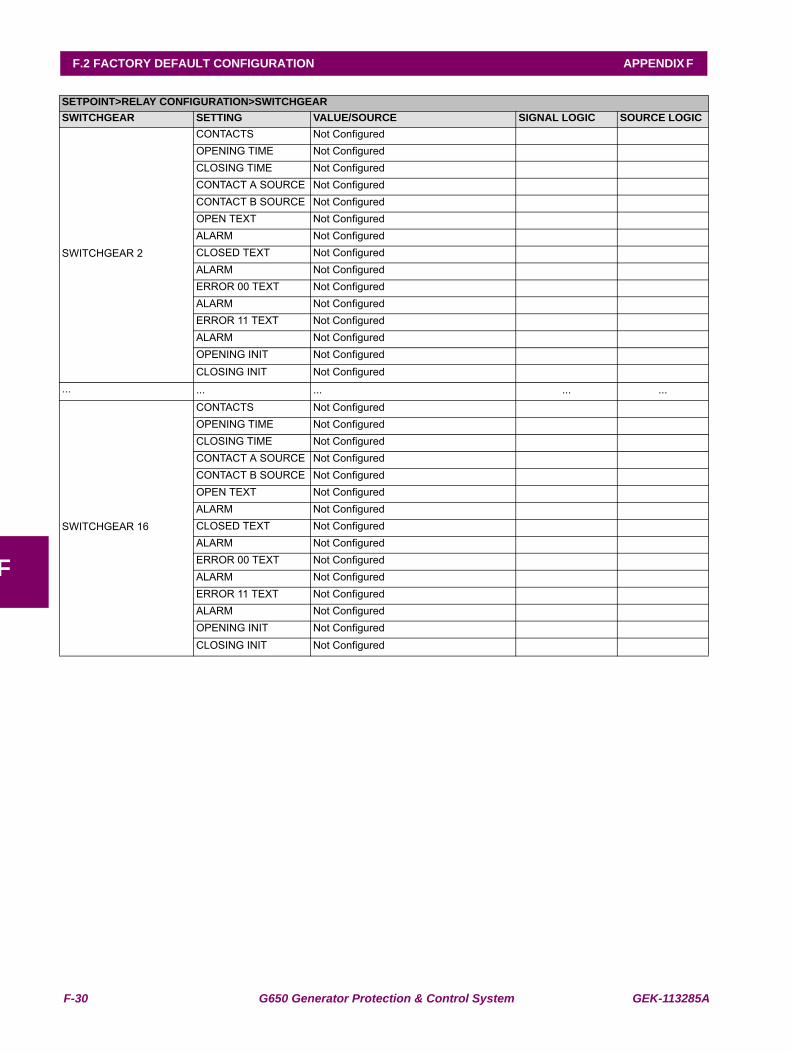
F-30 G650 Generator Protection & Control System GEK-113285A
F.2 FACTORY DEFAULT CONFIGURATION APPENDIX F
F
SWITCHGEAR 2
CONTACTS Not ConfiguredOPENING TIME Not ConfiguredCLOSING TIME Not ConfiguredCONTACT A SOURCE Not ConfiguredCONTACT B SOURCE Not ConfiguredOPEN TEXT Not ConfiguredALARM Not ConfiguredCLOSED TEXT Not ConfiguredALARM Not ConfiguredERROR 00 TEXT Not ConfiguredALARM Not ConfiguredERROR 11 TEXT Not ConfiguredALARM Not ConfiguredOPENING INIT Not ConfiguredCLOSING INIT Not Configured
... ... ... ... ...
SWITCHGEAR 16
CONTACTS Not ConfiguredOPENING TIME Not ConfiguredCLOSING TIME Not ConfiguredCONTACT A SOURCE Not ConfiguredCONTACT B SOURCE Not ConfiguredOPEN TEXT Not ConfiguredALARM Not ConfiguredCLOSED TEXT Not ConfiguredALARM Not ConfiguredERROR 00 TEXT Not ConfiguredALARM Not ConfiguredERROR 11 TEXT Not ConfiguredALARM Not ConfiguredOPENING INIT Not ConfiguredCLOSING INIT Not Configured
SETPOINT>RELAY CONFIGURATION>SWITCHGEARSWITCHGEAR SETTING VALUE/SOURCE SIGNAL LOGIC SOURCE LOGIC
GEK-113285A G650 Generator Protection & Control System G-1
APPENDIX G G.1 GE MULTILIN WARRANTY
G
APPENDIX G MISCELLANEOUS G.1GE MULTILIN WARRANTY
GE MULTILIN RELAY WARRANTY
GE Power Management, S.A. (GE Multilin) warrants each relay it manufactures to be free from defects inmaterial and workmanship under normal use and service for a period of 24 months from date of shipment fromfactory.
In the event of a failure covered by warranty, GE Multilin will undertake to repair or replace the relay providingthe warrantor determined that it is defective and it is returned with all transportation charges prepaid to anauthorized service center or the factory. Repairs or replacement under warranty will be made without charge.
Warranty shall not apply to any relay, which has been subject to misuse, negligence, accident, incorrectinstallation, or use not in accordance with instructions nor any unit that has been altered outside a GE Multilinauthorized factory outlet.
GE Multilin is not liable for special, indirect or consequential damages or for loss of profit or for expensessustained as a result of a relay malfunction, incorrect application or adjustment.
For complete text of Warranty (including limitations and disclaimers), refer to GE Multilin Standard Conditionsof Sale.
G-2 G650 Generator Protection & Control System GEK-113285A
G.1 GE MULTILIN WARRANTY APPENDIX G
G