An AC-AC Converter for Doubly Fed Induction Generator Driven By Wind Turbine
9
International Journal of Scientific and Research Publications, Volume 4, Issue 12, December 2014 1 ISSN 2250-3153 An AC-AC Converter for Doubly Fed Induction Generator Driven By Wind Turbine Chetan S. Rawal * , Dr. Anwar M. Mulla ** * Postgraduate Student in Power System from Department of Electrical Engineering, ** PG Guide, PHD in High Voltage Engineering from Department of Electrical Engineering.. Annasaheb Dange College of Engineering and Technology, Ashta, Sangli, Maharashtra, India Abstract- This paper deals with a DFIG model employing nine switches AC/AC converter. As compared to the conventional DFIG employing Back to Back power converter the nine switch converter requires fewer switches and gate drive circuits. Therefore proposed topology results in reduction of installation area and cost. The nine switch converter DFIG is applied to the wind turbine and integrated with the grid. The results reveal that even though change in wind speed occurred, the generator terminal voltage and frequency remain same. The generator output power follows the wind speed and delivers the more power to the grid. Index Terms- DFIG (Doubly Fed Induction Generator), RSC (Rotor Side Converter), GSC (Grid Side Converter), PWM (Pulse Width Modulator), Nine Switch Converter I. INTRODUCTION s conventional energy sources are going to be depleted very soon, wind power is the most reliable and developed renewable energy source over past decades. The WECS utilizing variable speed variable pitch wind turbine with DFIG is the most popular in the wind power industry especially for multi megawatt size. The power converters being utilized in the DFIG play very important role in maintaining the constant voltage and frequency. Harmonics will be A certainly produced whenever converter parts are being used. However presence of this harmonic level can be reduced by reducing the size of the converter. Hence there is need to reduce the size of the power converters in the Doubly Fed Induction Generators system in order to reduce the harmonics produced. Usually in the conventional DFIG system totally 12 number of switches are being utilized i.e. six number of switches for rectification and another six number of switches for invertification. Hence there is need to minimize the number of switches by developing a new model which must consist of less number of switches as compared to conventional Back to Back converter. So by developing new less number of switches being utilized converter the cost and space requirement of power converters can be reduced. The main reason for the popularity of the doubly fed induction generators connected to the national networks is their ability to supply power at constant voltage and frequency while the rotor speed varies [2]. And the power converters being used in the DFIG system are not required to convert the full rated generation power as in the singly fed induction generator power converters requiring conversion of full generated power. It handles only 25-30 % of rated generation power i.e. the slip power in the rotor circuit and remaining power is directly fed to the grid from the stator part [1]. www.ijsrp.org
Transcript of An AC-AC Converter for Doubly Fed Induction Generator Driven By Wind Turbine

International Journal of Scientific and Research Publications, Volume 4, Issue 12, December 20141
ISSN 2250-3153
An AC-AC Converter for Doubly FedInduction Generator Driven By Wind
TurbineChetan S. Rawal*, Dr. Anwar M. Mulla**
*Postgraduate Student in Power System from Department of Electrical Engineering,** PG Guide, PHD in High Voltage Engineering from Department of Electrical Engineering.. Annasaheb Dange College of Engineering and Technology, Ashta, Sangli, Maharashtra, India
Abstract- This paper deals with a DFIG modelemploying nine switches AC/AC converter. Ascompared to the conventional DFIG employingBack to Back power converter the nineswitch converter requires fewer switchesand gate drive circuits. Therefore proposedtopology results in reduction ofinstallation area and cost. The nine switchconverter DFIG is applied to the windturbine and integrated with the grid. Theresults reveal that even though change inwind speed occurred, the generator terminalvoltage and frequency remain same. Thegenerator output power follows the windspeed and delivers the more power to thegrid.
Index Terms- DFIG (Doubly Fed InductionGenerator), RSC (Rotor Side Converter), GSC(Grid Side Converter), PWM (Pulse WidthModulator), Nine Switch Converter
I. INTRODUCTIONs conventional energy sources are goingto be depleted very soon, wind power is
the most reliable and developed renewableenergy source over past decades. The WECSutilizing variable speed variable pitchwind turbine with DFIG is the most popularin the wind power industry especially formulti megawatt size. The power convertersbeing utilized in the DFIG play veryimportant role in maintaining the constantvoltage and frequency. Harmonics will be
A
certainly produced whenever converter partsare being used. However presence of thisharmonic level can be reduced by reducingthe size of the converter. Hence there isneed to reduce the size of the powerconverters in the Doubly Fed InductionGenerators system in order to reduce theharmonics produced. Usually in theconventional DFIG system totally 12 numberof switches are being utilized i.e. sixnumber of switches for rectification andanother six number of switches forinvertification. Hence there is need tominimize the number of switches bydeveloping a new model which must consistof less number of switches as compared toconventional Back to Back converter. So bydeveloping new less number of switchesbeing utilized converter the cost and spacerequirement of power converters can bereduced. The main reason for the popularityof the doubly fed induction generatorsconnected to the national networks is theirability to supply power at constant voltageand frequency while the rotor speed varies[2]. And the power converters being used inthe DFIG system are not required to convertthe full rated generation power as in thesingly fed induction generator powerconverters requiring conversion of fullgenerated power. It handles only 25-30 % ofrated generation power i.e. the slip powerin the rotor circuit and remaining power isdirectly fed to the grid from the statorpart [1].
www.ijsrp.org
International Journal of Scientific and Research Publications, Volume 4, Issue 12, December 20142
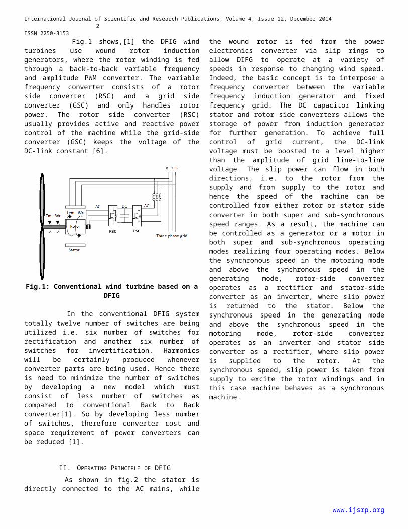
ISSN 2250-3153 Fig.1 shows,[1] the DFIG windturbines use wound rotor inductiongenerators, where the rotor winding is fedthrough a back-to-back variable frequencyand amplitude PWM converter. The variablefrequency converter consists of a rotorside converter (RSC) and a grid sideconverter (GSC) and only handles rotorpower. The rotor side converter (RSC)usually provides active and reactive powercontrol of the machine while the grid-sideconverter (GSC) keeps the voltage of theDC-link constant [6].
Fig.1: Conventional wind turbine based on aDFIG
In the conventional DFIG systemtotally twelve number of switches are beingutilized i.e. six number of switches forrectification and another six number ofswitches for invertification. Harmonicswill be certainly produced wheneverconverter parts are being used. Hence thereis need to minimize the number of switchesby developing a new model which mustconsist of less number of switches ascompared to conventional Back to Backconverter[1]. So by developing less numberof switches, therefore converter cost andspace requirement of power converters canbe reduced [1].
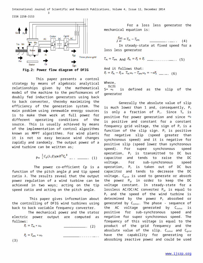
II. OPERATING PRINCIPLE OF DFIG As shown in fig.2 the stator isdirectly connected to the AC mains, while
the wound rotor is fed from the powerelectronics converter via slip rings toallow DIFG to operate at a variety ofspeeds in response to changing wind speed.Indeed, the basic concept is to interpose afrequency converter between the variablefrequency induction generator and fixedfrequency grid. The DC capacitor linkingstator and rotor side converters allows thestorage of power from induction generatorfor further generation. To achieve fullcontrol of grid current, the DC-linkvoltage must be boosted to a level higherthan the amplitude of grid line-to-linevoltage. The slip power can flow in bothdirections, i.e. to the rotor from thesupply and from supply to the rotor andhence the speed of the machine can becontrolled from either rotor or stator sideconverter in both super and sub-synchronousspeed ranges. As a result, the machine canbe controlled as a generator or a motor inboth super and sub-synchronous operatingmodes realizing four operating modes. Belowthe synchronous speed in the motoring modeand above the synchronous speed in thegenerating mode, rotor-side converteroperates as a rectifier and stator-sideconverter as an inverter, where slip poweris returned to the stator. Below thesynchronous speed in the generating modeand above the synchronous speed in themotoring mode, rotor-side converteroperates as an inverter and stator sideconverter as a rectifier, where slip poweris supplied to the rotor. At thesynchronous speed, slip power is taken fromsupply to excite the rotor windings and inthis case machine behaves as a synchronousmachine.
www.ijsrp.org
International Journal of Scientific and Research Publications, Volume 4, Issue 12, December 20143
ISSN 2250-3153
Fig.2: Power flow diagram of DFIG
This paper presents a controlstrategy by means of algebraic analyticalrelationships given by the mathematicalmodel of the machine to the performances ofdoubly fed induction generators using backto back converter, thereby maximizing theefficiency of the generation system. Themain problem using renewable energy sourcesis to make them work at full power fordifferent operating conditions of thesource. This is usually achieved by meansof the implementation of control algorithmsknown as MPPT algorithms. For wind plantsit is not so easy because wind changesrapidly and randomly. The output power of awind turbine can be written as;
P= ….. ……………. (1)
The power co-efficient Cp is afunction of the pitch angle 𝜷 and tip speedratio 𝜆. The results reveal that the outputpower regulation of a wind turbine can beachieved in two ways; acting on the tipspeed ratio and acting on the pitch angle.
This paper gives information aboutthe controlling of DFIG wind turbines usingback to back variable frequency converter. The mechanical power and the statorelectric power output are computed asfollows:
……………………………. (2)
…………………….......…..(3)
For a loss less generator themechanical equation is:
J ……………………..…….. (4) In steady-state at fixed speed for aloss less generator
And ………........…….. (5)
And it follows that:= …….…. (6)
Where,S= is defined as the slip of thegenerator
Generally the absolute value of slipis much lower than 1 and, consequently, Pr
is only a fraction of Ps. Since Tm ispositive for power generation and since is positive and constant for a constantfrequency grid voltage, the sign of Pr is afunction of the slip sign. Pr is positivefor negative slip (speed greater thansynchronous speed) and it is negative forpositive slip (speed lower than synchronousspeed). For super synchronous speedoperation, Pr is transmitted to DC buscapacitor and tends to raise the DCvoltage. For sub-synchronous speedoperation, Pr is taken out of DC buscapacitor and tends to decrease the DCvoltage. Cgrid is used to generate or absorbthe power Pgc in order to keep the DCvoltage constant. In steady-state for alossless AC/DC/AC converter Pgc is equal toPr and the speed of the wind turbine isdetermined by the power Pr absorbed orgenerated by Crotor. The phase - sequence ofthe AC voltage generated by Crotor ispositive for sub-synchronous speed andnegative for super synchronous speed. Thefrequency of this voltage is equal to theproduct of the grid frequency and theabsolute value of the slip. Crotor and Cgrid
have the capability for generating orabsorbing reactive power and could be used
www.ijsrp.org

International Journal of Scientific and Research Publications, Volume 4, Issue 12, December 20144
ISSN 2250-3153 to control the reactive power or thevoltage at the grid terminals.
A. Steady State Characteristics The steady state equivalent circuitof DFIG is shown in below fig.2.A
Fig.2.A: Steady state equivalent circuit ofDFIG
To obtain the torque equation fromthe equivalent circuit, we can simplify thesteady state induction motor circuit bymoving to the stator terminal .The rotorcurrent is expressed as;
……………………………. (7)
The electrical torque Te, from thepower balance across the stator to rotorgap, can be calculated from;
………………………...………(8)
Where the power supplied or absorbedby the controllable source injectingvoltage into the rotor circuit, that is therotor active power, can be calculatedfrom
……………………………… (9)
..………………………………… (10)
III. OPERATION OF NINE SWITCH CONVERTER As shown in Fig.1.2 [5], theproposed converter has three legs withthree switches per leg. The middle switchin each of phase legs is shared byrectifier and inverter, therefore count of
switches reduces. In this topology, theconverter input and output voltages can beindependently controlled although themiddle switch in each leg is shared by therectifier and inverter. Table.1 indicatesthe switching states. Here the converterhas only three valid switching states perphase and VAR, VXR are the voltage at nodes Aand X with respect to the negative dc linkR respectively. For the convenience it is consideredthat x, y, z are the input nodes of theconverter and A, B, C are the output nodes.Modulation waveform to switching algorithmis the carrier based PWM control method fora nine-switch converter [3]-[8]. There aretwo reference signals for every phase. Theprinciple of switching algorithm for upperand lower switches is obtained for theconditions given below: Condition 1: Se1>C then SAO is onCondition 2: Se2<C then SAI is on
Table.1: Switching states and converteroutput voltages
Mode ONSwitches
Input and Output nodevoltages
1 SAO, SAM VAR=Vdc , VXR=Vdc
2 SAM, SAI VAR=0, VXR=03 SAO, SAI VAR=Vdc, VXR=0
Se1 and Se2 can be expressed as:Se1= …………. (11)Se2= ……………... (12)
Where, , is the output and inputfrequency respectively. , are themodulation index and , are the offsetof output and input references signalsrespectively. In this topology x, y, z areconnected to the grid and lower switches(SAI, SBI, SCI) operate as a rectifier or GridSide Converter. A, B, C are connected tothe rotor, therefore upper switches (SAO,
www.ijsrp.org

International Journal of Scientific and Research Publications, Volume 4, Issue 12, December 20145
ISSN 2250-3153 SBO, SCO) operate as an inverter or RotorSide Converter.
IV. CONTROL OF NINE SWITCH CONVERTER In the DFIG based wind turbinesrotor current regulation on the stator fluxoriented reference frame. Therefore the daxis is aligned with the stator fluxlinkage vector λs , namely, λs=λds andλqs=0. This results in followingrelationships [6]:
………………………………. (13)
……………………....……. (14)
…………………...…….…. (15)
………...………… (16)
…..…….. (17)
..... (18)
Where,
…………….………..…….(19)
………....…….........…(20)
Equation (14) shows that the DFIGelectrical torque can depends on , as aresult the rotor speed , can be controlledby regulating . Equation (15) indicatesthat the Qs can be controlled by regulatingthe , therefore, the reference values of
and can be determined from Qs and regulation. Fig.4 shows the overall vectorcontrol scheme of the Rotor Side Converter(RSC). The instantaneous three-phase rotorcurrent is transformed to d-q
components and in the stator – fluxoriented reference frame. Then and arecompared with their reference signals (
) to generate the error signals,which are passed through two PI controllersto form the voltage signals and .These two voltage signals are compensatedby the corresponding cross coupling terms (
and ) to form the d-q voltage signals and . Where and are assumed as:
………………………… (21)
) ..………….. (22)
They are then used by the carrierbased PWM method to generate MOSFET gatecontrol signals of the RSC. The objective of the GSC is to keepthe DC link voltage constant regardless ofthe magnitude and direction of the rotorpower. The control of DC link voltage, and DFIG stator terminals voltage, Vs, areachieved by current regulation on asynchronously rotating reference frame. Theoutput voltage signals and from thecurrent controllers are used by the carrierbased PWM algorithm to switch the grid sideof nine-switch converter. Figure 4.1 showsthe overall vector control scheme of theGrid Side Converter [6].
Fig.4: Overall vector control of RSC
www.ijsrp.org

International Journal of Scientific and Research Publications, Volume 4, Issue 12, December 20146
ISSN 2250-3153
Fig.4.1: Overall vector control of GSC
V. SIMULATION MODELSA. Simulation of overall pulse generation Fig.16 shows the overall pulsegeneration model for nine switch converter.As mentioned earlier the nine switchconverter model consists of three legs andeach consisting of three switches. Fig.16shows how the pulses have been generatedfor all the three leg MOSFET switches. Forall the nine switches, voltage signalsgenerated from the Rotor Side Converter andGrid Side Converter are compared with thecarrier wave signal and an appropriate gatepulse is generated.
Fig.5.A: Simulation model of overall pulsegeneration
B. Simulation of nine switch converter Fig.17 shows the simulation model ofnine switch converter. It consists oftotally three legs, each leg consisting ofthree switches. Then total number ofswitches is nine. The above six switchesact as Rectifier i.e. the conversion ofAC/DC and the below six switches act asInverter i.e. the conversion of DC/AC. Thepulses for all the MOSFET gates aregenerated using the voltage signalsgenerated from RSC and GSC comparing withthe carrier wave signal.
www.ijsrp.org

International Journal of Scientific and Research Publications, Volume 4, Issue 12, December 20147
ISSN 2250-3153
Fig.5.B: Simulation model of nine switchconverter
VI. SIMULATION RESULTS The DFIG parameters are given inTable 2.
Table.2: Parameters of the DFIG simulated
Rated Power 2MWStatorVoltage
690V
Rs 0.0108puRr 0.0121pu (referred
to the stator)Lm 3.362puLs 0.102puLr 0.11pu (referred to
the stator)Number ofpole pairs
2
In order to evaluate the dynamicperformance of the proposed DFIG, suddenvariation in the wind speed is made.
A. Generator output power Fig.6.A shows the generator outputpower. It is observed that when the windspeed is increased at 12 sec, the poweroutput of the generator also slightlyincreased. In means the generator output
power follows the wind speed and deliversmore power to the grid whenever wind speedincreases
Fig.6.A: Generator output power
B. Stator output reactive power Fig.6.B shows the stator outputreactive power. At 12 sec there is suddenvariation in the wind speed i.e. initiallywind blowing at 12m/s increased to 15m/s at12 sec. The reference value of reactivepower is set to zero and stator reactivepower produced by generator is tried tokeep around zero. In the above figure it isobserved that at the time of wind speedchange the reactive power generated bystator is maintained constant around zero.
Fig.6.B: Stator output reactive power
C. Generator terminal voltage
www.ijsrp.org

International Journal of Scientific and Research Publications, Volume 4, Issue 12, December 20148
ISSN 2250-3153 Fig.6.C shows the stator each phaseoutput voltage. It is observed that,initially when the wind is blowing at 12m/s stator terminal each phase voltage isaround 690 volts. Then at 12 sec, when windspeed changes to 15m/s the magnitude ofstator output each phase voltage is notaffected and is maintained almost constanti.e. around 690 volts. It meansirrespective of the wind speed changes androtor speed variation the stator outputeach voltage remains almost constant inorder to make it possible to integrate thewind turbine generated power with the grid.This is one of the very essentialcontrolling aspects in doubly fed inductiongenerators achieved through nine switchconverter.
Fig.6.C: Generator terminal voltages
D. Generator terminal current Fig.6.D shows the each phasegenerator terminal current. We know thatwhen wind speed increases the powerdelivered to the grid also increases. Asstator terminal voltage is going to remainconstant during wind changes, the currentdrawn by the grid increases in order toincrease the power delivered to the grid.It can be observed in Fig.22 that whenthere is sudden change in the wind speed at12 sec the magnitude of each phase statoroutput current increases slightly. Statoroutput terminal each phase voltage andcurrent are in phase. It means that thegenerator is operating approximately at itsunity power factor.
Fig.6.D: Generator terminal current
E. Generator rotor speed Fig.6.E shows the generator rotorspeed. It is observed that before the stepchange in wind speed occurred i.e. windblowing at 12m/s, the rotor is rotating at0.55pu but when the wind speed increases to15m/s the rotor speed also increases. Aftera fraction of second the rotor speed againgains its steady state at 0.67pu. FromFig.21 and 23 it can be clearly observedthat even though there is change in rotorspeed in course of time period because ofchange in wind speed the stator terminaleach phase output voltages remains almostconstant. From Fig.19 and 23 it is clearthat the power delivered to the grid fromthe generator increases with increase inrotor speed because of change in windspeed.
Fig.6.E: Generator rotor speed
VII. CONCLUSION This thesis presented a DFIG modelemploying new nine switches AC/ACconverter. As compared to the conventional
www.ijsrp.org

International Journal of Scientific and Research Publications, Volume 4, Issue 12, December 20149
ISSN 2250-3153 DFIG employing Back to Back power converterthe new nine switch converter requiresfewer switches and gate drive circuits.Therefore proposed topology results inreduction of installation area and cost.The new nine switch converter DFIG isapplied to the wind turbine and integratedwith the grid. The results reveal that eventhough change in wind speed occurred, thegenerator terminal voltage and frequencyremain same. The generator output powerfollows the wind speed and delivers themore power to the grid. It means proposedDFIG will operate according to controlstrategies aims in the wind speed suddenvariations
REFERENCES[1] “MOHAMMAD RREZA BENAI , ALI REZA DEHGHANZADEH’’.
“WIND FARM BASED DOUBLY FED INDUCTION GENERATORUSING A NOVEL AC /AC CONVERTER 2011 IEEE
[2] L.PIEGARI, R.RIZZO, P.TRICALI, “OPTIMIZED DESIGN OFA BACK TO BACK ROTOR SIDE CONVERTER FOR DOUBLY FEDINDUCTION GENERATOR EQUIPPED WIND TURBINES”, IEEE
TRANSACTION ON POWER ELECTRONICS, 2009.[3] Congwei Lu, Bin Wu, Navid Zargari, David Xu, “A
Novel Nine Switch PWM Rectifier-Inverter TopologyFor Three Phase UPS Applications”, EuropeanConference On Power Electronics Applications,Sep.2007..
[4] T. Kominami, Y. Fujimoto, “ A Novel Nine SwitchInverter For Independent Control Of Two Three
Phase Loads”, Industry ApplicationsConference,PP,2346-2350, 2007.
[5] Nayeem Rahmat Ullah , “Variable Speed WindTurbines For Power System Stability Enhancement“ IEEE 2007.
[6] Lie Xu, : Coordinated Control of DFIG’s Rotor andGrid Side Converters During Network Unbalance,”IEEE Trans. On Power Electronics, Vol. 23, No. 3,pp. 1041-1049, May 2008.
[7] Congwei Liu, Bin Wu, Navid Zargari, David Xu, “ANovel Nine-Switch PWM Rectifier-Inverter Topologyfor Three-Phase UPS Applications,” EuropeanConference On Power Electronics Applications, Sep.2007.
[8] Seyed Mohammad DehghanDehnavi, Mustafa Mohamadian,Ali Yazdani, Farhad Ashrafzadeh, “Space VectorModulation for Nine-Switch Converters,” IEEE Trans.On Power Electronics, Vol. 25, No. 6, pp. 1488-1496, June 2010.
AUTHORSFirst Author – Chetan S. Rawal, Postgraduate Student in Power System , Annasaheb Dange College Of Engineering and Technology, Ashta, Sangli, Maharashtra, India, [email protected] Author – Dr. Anwar M. Mulla, PG Guide, PHD in High Voltage Engineering fromDepartment of Electrical Engineering.., Annasaheb Dange College Of Engineering and Technology, Ashta, Sangli, Maharashtra, India
www.ijsrp.org