FPGA-based adaptive dynamic sliding-mode neural control for a brushless DC motor
13
Asian Journal of Control, Vol. 13, No. 6, pp. 845 857, November 2011 Published online 3 August 2010 in Wiley Online Library (wileyonlinelibrary.com) DOI: 10.1002/asjc.272 FPGA-BASED ADAPTIVE DYNAMIC SLIDING-MODE NEURAL CONTROL FOR A BRUSHLESS DC MOTOR Jang-Zern Tsai, Chun-Fei Hsu, Chien-Jung Chiu, and Kai-Lin Peng ABSTRACT In the adaptive neural control design, since the number of hidden neurons is finite for real-time applications, the approximation errors introduced by the neural network cannot be inevitable. To ensure the stability of the adap- tive neural control system, a switching compensator is designed to dispel the approximation error. However, it will lead to substantial chattering in the control effort. In this paper, an adaptive dynamic sliding-mode neural control (ADSNC) system composed of a neural controller and a fuzzy compensator is proposed to tackle this problem. The neural controller, using a radial basis function neural network, is the main controller and the fuzzy compensator is designed to eliminate the approximation error introduced by the neural controller. Moreover, a proportional-integral-type adaptation learning algo- rithm is developed based on the Lyapunov function; thus not only the system stability can be guaranteed but also the convergence of the tracking error and controller parameters can speed up. Finally, the proposed ADSNC system is implemented based on a field programmable gate array chip for low-cost and high-performance industrial applications and is applied to control a brushless DC (BLDC) motor to show its effectiveness. The experimental results demon- strate the proposed ADSNC scheme can achieve favorable control performance without encountering chattering phenomena. Key Words: Adaptive control, neural control, sliding-mode control, BLDC motor. I. INTRODUCTION It is well known that the major advantage of sliding-mode control (SMC) systems is their Manuscript received August 27, 2009; revised January 13, 2010; accepted June 1, 2010. Jang-Zern Tsai and Chien-Jung Chiu are with the Department of Electrical Engineering, National Central University, Jung- Li 320, Taiwan, (e-mail: [email protected]; intel@ms63. hinet.net). Chun-Fei Hsu (corresponding author) and Kai-Lin Peng are with the Department of Electrical Engineering, Chung Hua University, Hsinchu 300, Taiwan, Republic of China (e-mail: [email protected]; [email protected]). The authors appreciate the partial financial support from the National Science Council of Republic of China under grant NSC 97-2221-E-216-029. The authors would like to express their gratitude to the reviewers for their valuable comments and suggestions. insensitivity to parameter variations and external distur- bance once the system trajectory reaches and stays on the sliding surface [1]. However, the SMC strategy has drawbacks associated with the large control chattering caused by a switching function in the control law. It may wear coupled mechanisms and excite unstable system dynamics. A common solution to improve the chattering is to replace the switching function with the saturation function; however, an indefinite steady-state error is caused depending on the selection of the boundary layer [2]. To tackle this problem, among several kinds of SMC systems, the dynamic sliding-mode control (DSMC) system is an effective control scheme for eliminating chattering [3, 4]. The additional dynamics can be considered as compensators designed for improving sliding-mode stability. Due to DSMC using the integration method to obtain the practical control effort, the chattering phenomenon can 2010 John Wiley and Sons Asia Pte Ltd and Chinese Automatic Control Society
-
Upload
independent -
Category
Documents
-
view
0 -
download
0
Transcript of FPGA-based adaptive dynamic sliding-mode neural control for a brushless DC motor

Asian Journal of Control, Vol. 13, No. 6, pp. 845 857, November 2011Published online 3 August 2010 in Wiley Online Library (wileyonlinelibrary.com) DOI: 10.1002/asjc.272
FPGA-BASED ADAPTIVE DYNAMIC SLIDING-MODE NEURAL
CONTROL FOR A BRUSHLESS DC MOTOR
Jang-Zern Tsai, Chun-Fei Hsu, Chien-Jung Chiu, and Kai-Lin Peng
ABSTRACT
In the adaptive neural control design, since the number of hidden neuronsis finite for real-time applications, the approximation errors introduced bythe neural network cannot be inevitable. To ensure the stability of the adap-tive neural control system, a switching compensator is designed to dispelthe approximation error. However, it will lead to substantial chattering in thecontrol effort. In this paper, an adaptive dynamic sliding-mode neural control(ADSNC) system composed of a neural controller and a fuzzy compensatoris proposed to tackle this problem. The neural controller, using a radial basisfunction neural network, is the main controller and the fuzzy compensatoris designed to eliminate the approximation error introduced by the neuralcontroller. Moreover, a proportional-integral-type adaptation learning algo-rithm is developed based on the Lyapunov function; thus not only the systemstability can be guaranteed but also the convergence of the tracking error andcontroller parameters can speed up. Finally, the proposed ADSNC system isimplemented based on a field programmable gate array chip for low-cost andhigh-performance industrial applications and is applied to control a brushlessDC (BLDC) motor to show its effectiveness. The experimental results demon-strate the proposed ADSNC scheme can achieve favorable control performancewithout encountering chattering phenomena.
Key Words: Adaptive control, neural control, sliding-mode control, BLDCmotor.
I. INTRODUCTION
It is well known that the major advantageof sliding-mode control (SMC) systems is their
Manuscript received August 27, 2009; revised January 13,2010; accepted June 1, 2010.Jang-Zern Tsai and Chien-Jung Chiu are with the Department
of Electrical Engineering, National Central University, Jung-Li 320, Taiwan, (e-mail: [email protected]; [email protected]).Chun-Fei Hsu (corresponding author) and Kai-Lin Peng are
with the Department of Electrical Engineering, Chung HuaUniversity, Hsinchu 300, Taiwan, Republic of China (e-mail:[email protected]; [email protected]).The authors appreciate the partial financial support from the
National Science Council of Republic of China under grantNSC 97-2221-E-216-029. The authors would like to expresstheir gratitude to the reviewers for their valuable commentsand suggestions.
insensitivity to parameter variations and external distur-bance once the system trajectory reaches and stays onthe sliding surface [1]. However, the SMC strategy hasdrawbacks associated with the large control chatteringcaused by a switching function in the control law. Itmay wear coupled mechanisms and excite unstablesystem dynamics. A common solution to improvethe chattering is to replace the switching functionwith the saturation function; however, an indefinitesteady-state error is caused depending on the selectionof the boundary layer [2]. To tackle this problem,among several kinds of SMC systems, the dynamicsliding-mode control (DSMC) system is an effectivecontrol scheme for eliminating chattering [3, 4]. Theadditional dynamics can be considered as compensatorsdesigned for improving sliding-mode stability. Dueto DSMC using the integration method to obtain thepractical control effort, the chattering phenomenon can
q 2010 John Wiley and Sons Asia Pte Ltd and Chinese Automatic Control Society

846 Asian Journal of Control, Vol. 13, No. 6, pp. 845 857, November 2011
be improved effectively. Similar to SMC, a switchingfunction is also necessary in DSMC. For the systemto operate in this state of sliding mode, the frequencyof switching must be quite high (theoretically infi-nite). However, the switching function is not easy toimplement due to physical limitations.
Moreover, since the dynamic characteristic ofcontrol plants are nonlinear and the precise models aredifficult to obtain, the model-based control approachessuch as SMC and DSMC are difficult to implement.During the past two decades, many intelligent controlschemes have been developed without the need toknow the system dynamics [5–19]. Self-learning is anessential property of these intelligent control schemes[5–9, 13, 14, 19]. Their most useful property is theability of neural networks and fuzzy systems to approx-imate arbitrary linear or nonlinear mapping throughlearning. Some of these online learning algorithms arebased on the backpropagation learning algorithm, andsome are based on the Lyapunov stability theorem.Chen et al. [18] use the genetic algorithm to tunethe controller parameters. Stability is another essen-tial property of these intelligent control schemes[5, 6, 10–12, 15–17]. The stability analysis of the time-delayed systems has been explored. Most of these dealwith the stability analysis based on T-S fuzzy systems.A stability condition is derived by applying the linearmatrix inequality theory.
Since the number of hidden neurons is finite,the approximation errors introduced by the neuralnetwork cannot be inevitable. To ensure the stabilityof the adaptive neural control, a compensator couldbe designed to dispel the approximation error. Themost frequently used compensator is the switchingcompensator [8, 9]. However, it will cause chatteringphenomena to wear the bearing mechanism. To reducethe chattering phenomenon, the switching functioncan be replaced by a saturation function. Since thechattering is reduced by this method, an indefinitesteady-state error is caused depending on the selec-tion of the boundary layer [9]. A tradeoff problembetween chattering and control accuracy arises, and thesaturation compensator cannot guarantee the systemstability.
To tackle this problem, an approximation errorbound estimation mechanism is examined to estimatethe bound of approximation error so the chatteringphenomenon of the control effort can be reduced [8].However, the adaptive law for the estimation approx-imation error bound will make it go to infinity.Some researchers use a fuzzy system to estimate theapproximation error; however, the fuzzy rules arepre-constructed by a time-consuming trial-and-error
tuning procedure [20].Wai proposed a fuzzy uncertaintyobserver to remedy the chattering phenomena [21]. Theadaptive algorithm derived in the sense of the Lyapunovstability theorem is utilized to adjust the fuzzy param-eter; however, it needs to know the system dynamics,and the convergence speed of the controller parameteris slow Some robust adaptive neural controllers havebeen proposed to attenuate the effects of the approxima-tion error without any chattering phenomena [22, 23].A better tracking performance can be achieved whenthe specified attenuation level is smaller. However, thecontrol effort may lead to a large control signal as theattenuation level is increased.
Because the radial basis function neural network(RBFNN) has a simple structure, the convergencespeed of RBFNN has become faster than a conventionalneural network [5]. The RBFNN has similar features asthe fuzzy system in the following: (i) The output valueis obtained using a weighted sum method; (ii) Thenumber of hidden neurons in the RBFNN is identicalto the number of if-then rules in the fuzzy system; and(iii) The receptive field functions in RBFNN are similarto the membership functions of the premise part in thefuzzy system. As a result, there has been considerableinterest in exploring the applications of RBFNN todeal with unknown nonlinear control systems [24–27].Though these RBFNN-based adaptive control systemsnot only can guarantee the system’s stability but alsocan tune the controller parameters online, they used anintegral-type adaptation learning algorithm which mayresult in slow learning speed.
A field-programmable gate array (FPGA) incorpo-rates the design of a gate array and the programmabilityof a programmable logic device. It consists of thou-sands of logic gates, some of which are combined toform a configurable logic block thereby simplifyinghigh-level circuit design. All the internal logic elementsand control procedures of the FPGA are executedcontinuously and simultaneously [28]. If the controlalgorithm is executed sequentially using software in adigital signal processor (DSP) or personal computer(PC) the minimum execution time is limited. Therefore,the execution time of the FPGA is faster than either aDSP or PC. The circuits and algorithms can be devel-oped in a very high speed integrated circuit hardwaredescription language. This method is as flexible asany software solution [28]. Many researchers adoptedthe FPGA chip to implement the controller to allowpossible low-cost and high-performance industrialapplications [29–32].
In this paper, an adaptive dynamic sliding-modeneural control (ADSNC) system composed of a neuralcontroller and a fuzzy compensator is proposed. The
q 2010 John Wiley and Sons Asia Pte Ltd and Chinese Automatic Control Society

J.-Z. Tsai et al.: FPGA-based Adaptive Dynamic Sliding-Mode Neural Control for a BLDC Motor 847
neural controller is the main controller, and the fuzzycompensator is designed to completely remove thechattering phenomena. A dynamic sliding surfaceis proposed to reduce the chattering phenomenon,and a proportional-integral-type adaptation learningalgorithm is utilized to tune the controller parametersonline to guarantee system stability. Compared with thetraditional integral-type adaptation learning algorithmin [24–27], the proportional-integral-type adapta-tion learning algorithm possesses the advantages offaster convergence of the tracking error and controllerparameters. Finally, the proposed ADSNC system isimplemented based on an FPGA chip for low-cost andhigh-performance industrial applications and is appliedto control a brushless DC (BLDC) motor to showits effectiveness. The experimental results verify thesystem stabilization, favorable tracking performanceand that all chattering phenomena can be removed bythe proposed ADSNC system.
II. PROBLEM FORMULATION
The BLDC motor utilizes an electronicallycontrolled commutation system instead of the mechan-ical commutation system used in conventional brushmotors. It has the advantages of simple construction,high torque capability, small inertia, low noise andlong life operation [33]. Because of these merits, it hasbeen applied in home appliances, electrical vehicles,advanced manufacturing systems, consumer appliancesetc. The mechanical equation of a brushless DC motorcan be simplified as [33, 34]
J �(t)+B�(t)=Te(t) (1)
where J is the moment of inertia; B is the dampingcoefficient; �(t) is the position; and Te(t) denotes theelectric torque defined as
Te(t)=Kt iq(t) (2)
where Kt is the torque constant and iq(t) is the torquecurrent. Then, the BLDC motor can be represented inthe following form
�(t)= f (�, t)+gu(t) (3)
where f (�, t)=− BJ �(t), g= Kt
J is a constant controlgain and u(t)= iq(t) is the control effort. Rewriting (3),the nominal model of the BLDC motor can be repre-sented as
�(t)= fn(�, t)+gnu(t) (4)
where fn(�, t) and gn are the mapping representingthe nominal behavior of f (�, t) and g, respectively. If
system uncertainties occur and the external disturbanceis added, the system dynamic is modified as
�(t) = [ fn(�, t)+� f (t)]+(gn+�g)u(t)+d(t)
= fn(�, t)+gnu(t)+w(t) (5)
where � f (t) and �g denote the system uncertain-ties; d(t) is the external disturbance; and w(t) iscalled the lumped uncertainty, defined as w(t)=� f (t)+�gu(t)+d(t), with the assumption |w|≤Wsmcin which Wsmc is a given positive constant.
2.1 SMC system design
The control objective of the BLDC motor is tofind a control law so the rotor position �(t) can trackthe position command �c(t) closely. Define the trackingerror as
e(t)=�c(t)−�(t). (6)
A sliding surface is defined as
s(t)= e(t)+a1e(t)+a2
∫ t
0e(�)d� (7)
where a1 and a2 are positive constants. Differentiating(7) with respect to time and using (5) and (6) obtain
s(t) = e(t)+a1e(t)+a2e(t)
= �c(t)− fn(�, t)−gnu(t)−w(t)
+a1e(t)+a2e(t). (8)
The control law of SMC is given as [1, 2]usmc(t) = g−1
n [− fn(�, t)+ �c(t)+a1e(t)+a2e(t)
+Wsmc sgn(s(t))] (9)
where sgn(·) is the sign function. Substituting (9) into(6) and using (8) yields
s(t)=−w(t)−Wsmc sgn(s(t)). (10)
An important concept of SMC is to make the systemsatisfy the reaching condition and guarantee the slidingcondition. Consider the candidate Lyapunov function inthe following form as
V1(t)= 12 s
2(t). (11)
Differentiating (11) with respect to time and using (10)obtains
V1(t) = s(t) s(t)
= −w(t)s(t)−Wsmc|s(t)|
q 2010 John Wiley and Sons Asia Pte Ltd and Chinese Automatic Control Society

848 Asian Journal of Control, Vol. 13, No. 6, pp. 845 857, November 2011
≤ |w(t)| |s(t)|−Wsmc|s(t)|= −(Wsmc−|w(t)|)|s(t)|≤0. (12)
In summary, the control law of SMC in (9) can guar-antee system stability in the sense of the Lyapunovtheorem [1, 2]. However, a conservative control lawwith large control gain Wsmc is usually considered,but any unnecessary jumping movement between theswitching surfaces may produce and cause a largeamount of chattering. The chattering phenomena willwear the bearing mechanism and excite the unmodelleddynamics. Moreover, the switching function is not easyto implement due to the physical limitations on theactuators used in the plants.
2.2 DSMC system design
To reduce the chattering phenomenon, a DSMCsystem is considered with the dynamic sliding surfacedefined as
�(t)= s(t)+b1s(t)+b2
∫ t
0s(�)d� (13)
where b1 and b2 are positive constants. Differentiating(13) with respect to time and using (7) and (8) obtains
�(t) = s(t)+b1s(t)+b2s(t)
= �c(t)− fn(�, t)−gnu(t)−w(t)+(a1
+b1)e(t)+(a2+a1b1+b2)e(t)
+(a2b1+a1b2)e(t)+a2b2
∫ t
0e(�)d�
= �c(t)− fn(�, t)−gnu(t)−w(t)+c1e(t)
+c2e(t)+c3e(t)+c4
∫ t
0e(�)d� (14)
where c1=a1+b1, c2=a2+a1b1+b2, c3=a2b1+a1b2and c4=a2b2. The control law of DSMC is given as
udsmc(t) =∫ t
0udsmc(�)d� (15)
udsmc(t) = g−1n [− fn(�, t)+�c(t)+c1e(t)+c2e(t)
+c3e(t)+c4
∫ t
0e(�)d�
+Wdsmc sgn(�(t))] (16)
where Wdsmc is a given positive constant with theassumption |w(t)|≤Wdsmc. Substituting (16) into (14)yields
�(t)= w(t)−Wdsmc sgn(�(t)). (17)
Consider the candidate Lyapunov function in thefollowing form as
V2(t)= 12�
2(t). (18)
Differentiating (18) with respect to time and using (17)obtains
V2(t) = �(t) �(t)
= −w(t)�(t)−Wdsmc|�(t)|≤ |w(t)| |�(t)|−Wdsmc|�(t)|= −(Wdsmc−|w(t)|)|�(t)|≤0. (19)
If the dynamic sliding surface �(t)= s(t)+b1s(t)+b2s(t)=0, then the sliding surface s(t)=0 for alltime. Moreover, if s(t)= e(t)+a1e(t)+a2e(t)=0, bychoosing the values a1 and a2 properly, the desiredsystem dynamics such as rise time, overshoot andsetting time can be easily designed by the second-ordersystem. Then, the control law of DSMC in (16) canguarantee the stability in the sense of the Lyapunovtheorem [1]. However, similar to the SMC system,a switching function is necessary in DSMC controllaw, meaning the bounds of the uncertainty have tobe known. However, in the most practical systems,the bounds of the uncertainty are difficult to obtainaccurately.
III. DESIGN OF ADSNC
The adaptive dynamic sliding-mode neural control(ADSNC) system is proposed as shown in Fig. 1, wherethe controller output is defined as
uadsnc= ˙unc+ ˙u f c. (20)
The neural controller ˙unc uses a RBFNN to approximatethe DSMC controller udsmc(t) in (16), and the fuzzy
BLDCmotor
(3)
neuralcontroller
(A3)
adaptivelaw
(25)~(28)
fuzzycompensator
(B9)
θ
θ
u
adaptive dynamic sliding-mode neural control
+−
++
m ˆ,ˆ,ˆ,ˆ
estimationlaw(35)
r
slidingsurface
(7)
sdynamicslidingsurface
(13)
ς u u ue+−
Fig. 1. The block diagram of the ADSNC system for a BLDCmotor.
q 2010 John Wiley and Sons Asia Pte Ltd and Chinese Automatic Control Society
J.-Z. Tsai et al.: FPGA-based Adaptive Dynamic Sliding-Mode Neural Control for a BLDC Motor 849
compensator ˙u f c uses a fuzzy system to compensate theapproximation error introduced by the neural controller.The properties of the RBFNN and fuzzy system can befound in Appendixes A and B, respectively. Substituting(20) into (14) and using (16), yields
�=gn(udsmc− ˙unc− ˙u f c)−w−W sgn(�). (21)
Using the approximation property of RBFNN in (A11),(21) can be rewritten as
� = gn(�I aTI u−�P a
TP u+mTAa+ rTBa
+ε− ˙u f c)−w−W sgn(�). (22)
To prove the stability of the ADSNC system, define aLyapunov function candidate in the following form
V3=1
2�2+gn
(�I2aTI aI+
1
2�mmT m+ 1
2��rT r
)(23)
where �� and �c are the learning rates with positiveconstants. Differentiating (23) with respect to time andusing (22) obtains
V3 = ��+gn�I aTI
˙aI+ gn�m
mT ˙m+ gn��rT ˙r
= �[gn(�I aTI /−�P aTP /+mTAa+ rTBa
+ε− ˙u f c)−w−W sgn(�)]
+gn�I aTI
˙aI+ gn�m
mT ˙m+ gn��rT ˙r
= gn�I aTI (�/+ ˙aI)+gnmT
(�Aa+
˙m�m
)
+ ˙mT
(�Ba+
˙m��
)−�gn�P a
Tp /
+gn�(ε− ˙u f c)−w�−W |�|. (24)
If the parameter adaptive laws are selected as
aP = �/ (25)
˙aI = −˙aI=�/ (26)
˙m= − ˙m=�m�Aa (27)
˙r=− ˙m= ���Ba (28)
and using the fuzzy compensator in (B9), then (24) canbe rewritten as
V3 = −gn�P aTp ap+gn[�ε−r�(w1−w3)]−w�−W |�|
= −gn�P aTp ap+gn(�ε−r |�| |w1−w3|)−w�−W |�|
≤ −gn�P aTp ap+gn(|�| |ε|− r |�| |w1−w3|)
+|w| |�|−W |�|≤ gn|�|(|ε|− r |w1−w3|)
= −gn|�| |w1−w3|(r−( |ε|
|w1−w3|)
. (29)
If the following inequality
r>|ε|
|w1−w3| (30)
holds, then the sliding condition V3≤0 can be satisfied.Owing to the unknown lumped uncertainties, the valuer cannot be exactly obtained in advance for practicalapplications. According to (30), there is an ideal valuer∗ as follows to achieve the minimum value and matchthe sliding condition:
r∗ = |ε||w1−w3| +� (31)
here � is a positive constant. Thus, an adaptive algo-rithm is utilized to estimate the ideal value of r∗, andits estimated error is defined as
r =r∗− r (32)
where r is the estimated value of the optimal value ofr∗. Then, define a new Lyapunov function candidate inthe following form
V4 = 1
2�2+gn
(�I2aTI aI+
1
2�mmT m+ 1
2��
˙mTr
+ 1
2�rr2)
(33)
where �r is the learning rate with a positive constant.Differentiating (33) with respect to time and using (22)and (25)–(28) obtains
V4 = ��+gn�I aTI
˙aI+ gn�m
mT ˙m+ gn��
˙mT ˙m+ gn�r
r ˙r
= gn�I aTI (�/+ ˙aI)+gnmT
(�Aa+
˙m�m
)
+ ˙mT
(�Ba+
˙m��
)−�gn�P a
Tp u
+gn�(ε− ˙u f c)−w�−W |�|+ gn�r
r ˙r
q 2010 John Wiley and Sons Asia Pte Ltd and Chinese Automatic Control Society

850 Asian Journal of Control, Vol. 13, No. 6, pp. 845 857, November 2011
= −gn�P aTp ap+gn�(ε−˙u f c)−w�−W |�|+gn
�rr ˙r
≤ gn�(ε− ˙u f c)+ gn�r
r ˙r
≤ gn[|�| |ε|− r�(w1−w3)]+ gn�r
r ˙r
= gn[|�| |ε|− r�(w1−w3)+r∗�(w1−w3)
−r∗�(w1−w3)]+ gn�r
r ˙r
= gn[|�| |ε|+r�(w1−w3)−r∗�(w1−w3)]+gn�r
r ˙r
= gnr
[�(w1−w3)+ 1
�r˙r]
+gn(|�| |ε|−r∗|�| |w1−w3|). (34)
Choose the rule estimation laws as
˙r =−˙r =−�r�(w1−w3) (35)
and using (31), (34) becomes
V4 ≤ gn[|�| |ε|−|�|(|ε|+� |w1−w3|)]= −�gn|�| |w1−w3|≤0. (36)
Since V4(�, aI,m, ˙m, r , t) is negative semidefinite[V4(�, aI,m, ˙m, r , t)≤V4(�, aI,m, ˙m, r ,0)], it implies�(t), aI, m, ˙m and r are bounded. Let the func-tion �(�)≡�gn|�| |w1−w3|≤−V4(�, aI,m, ˙m, r , t),and integrate the function �(t) with respect to timeobtaining∫ t
0�(�)d� ≤ V4(�, aI,m, r, r ,0)
−V4(�, aI,m, ˙m, r , t). (37)
Because V4(�, aI,m, ˙m, r ,0) is bounded, and V4(�, aI,m, ˙m, r , t) is not increasing and bounded, the followingresult can be obtained
limt→∞
∫ t
0�(�)d�<∞. (38)
Since �(t) is bounded, �(t) is uniformly continuous.By Barbalat’s Lemma [1], it shows limt→∞ �(t)=0.It implies �(t) will converge to zero as t→∞. If thedynamic sliding surface �(t)=0, then s(t)+b1s(t)+b2∫ t0 s(�)d�=0. When b1 and b2 are chosen to corre-
spond to the coefficients of a Hurwitz polynomial,then it implies limt→∞ s(t)=0. Similarly, if the sliding
surface s(t)= e(t)+a1e(t)+a2∫ t0 e(�)d�=0, it implies
limt→∞ e(t)=0 when a1 and a2 are chosen to corre-spond to the coefficients of a Hurwitz polynomial. Asa result, the stability of the proposed ADSNC systemcan be guaranteed.
In the following, the design steps of the ADSNCsystem are summarized as follows:
Step 1: The tracking error e(t), the sliding surfaces(t) and the dynamic sliding surface �(t) are given in(6), (7) and (13), respectively.
Step 2: The neural controller ˙unc is given in (A3)with the adaptive laws (25)–(28).
Step 3: The fuzzy compensator ˙u f c is given in(B9) with the adaptive law (35).
Step 4: The control law is given in (20).Step 5: Return to Step 1.
IV. EXPERIMENTAL RESULTS
FPGA is a fast prototyping IC component. Thiskind of IC incorporates the design of a gate array andthe programmability of a programmable logic device.The advantage of a controller implemented by FPGAincludes shorter development cycles, lower cost, smallsize, fast system execute speed, and high flexibility [28].The Quartus II software is the development tool forprogrammable logic devices. The Nios II processor isa configurable, versatile, RISC embedded processor. Itcan be embedded into Altera FPGA, and allow designersto integrate peripheral circuits and processors in thesame chip. Additionally, the PC-developed algorithmand C language program can be rapidly migrated to theNios II processor to shorten the system developmentcycle [28].
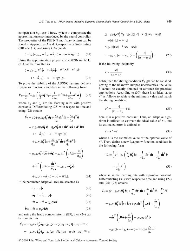
The experimental setup is shown in Fig. 2. Thisstudy used the Altera Stratix II series FPGA chip, andthe Altera Quartus II software (Altera, City, Country),and the verilog hardware description language wasused to implement the hardware control system. Theproposed control algorithm is realized in the NiosII programming interface. The software flowchart ofthe control algorithm is shown in Fig. 3. In the mainprogram, the initialization of controller parameters ispreceded. Next, the interruption interval for the inter-ruption service routine (ISR) with a 1msec samplingrate is set. Then, the controller sample times can begoverned by the built-in timer which generates periodicinterruptions. The BLDC motor system offers highperformance and simple operation from a compactdriver and motor [35]. To illustrate the effectivenessof the proposed design method, the adaptive fuzzy
q 2010 John Wiley and Sons Asia Pte Ltd and Chinese Automatic Control Society
J.-Z. Tsai et al.: FPGA-based Adaptive Dynamic Sliding-Mode Neural Control for a BLDC Motor 851
BLDC motor
AlteraFPGAboard
D/A converter & angle detector
BLDC motordriver
oscilloscope
Fig. 2. The experimental setup.
main
parameterinitialization
I/O and interruptsinitialization
1 msectrigger on?
read motor’s position value
call controlalgorithm
1 msectrigger off
end
ISR
1 msectrigger on
reset timercounter
end
Yes
No
end control?
No
Yes
controlalgorithm
calculate thetracking error
calculate thecontroller output
update the control parameter
end
Fig. 3. The software flowchart of the control algorithm.
neural network control (AFNNC) with the switchingcompensator [8], H∞ adaptive fuzzy control [22],adaptive sliding-mode control (ASMC) with the fuzzyuncertainty observer [21] and the proposed ADSNCare compared.
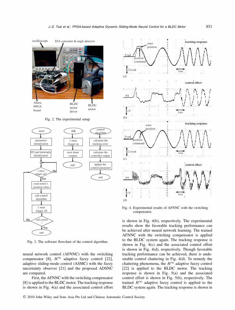
First, the AFNNC with the switching compensator[8] is applied to the BLDCmotor. The tracking responseis shown in Fig. 4(a) and the associated control effort
1sec2 rad
rotorposition
position command
0 rad
tracking response
0A
control effect
1sec1V
1sec2 rad
rotorposition
position command
0 rad
tracking response
0A
control effect
1sec1V
(c)
(d)
(b)
(a)
Fig. 4. Experimental results of AFNNC with the switchingcompensator.
is shown in Fig. 4(b), respectively. The experimentalresults show the favorable tracking performance canbe achieved after neural network learning. The trainedAFNNC with the switching compensator is appliedto the BLDC system again. The tracking response isshown in Fig. 4(c) and the associated control effortis shown in Fig. 4(d), respectively. Though favorabletracking performance can be achieved, there is unde-sirable control chattering in Fig. 4(d). To remedy thechattering phenomena, the H∞ adaptive fuzzy control[22] is applied to the BLDC motor. The trackingresponse is shown in Fig. 5(a) and the associatedcontrol effort is shown in Fig. 5(b), respectively. Thetrained H∞ adaptive fuzzy control is applied to theBLDC system again. The tracking response is shown in
q 2010 John Wiley and Sons Asia Pte Ltd and Chinese Automatic Control Society

852 Asian Journal of Control, Vol. 13, No. 6, pp. 845 857, November 2011
1sec2 rad
rotorposition
position command
0 rad
tracking response
(a)
0A
control effect
1sec1V
(b)
1sec2 rad
rotorposition
position command
0 rad
tracking response
(c)
0A
control effect
1sec1V
(d)
Fig. 5. Experimental results of H∞ adaptive fuzzy control.
Fig. 5(c) and the associated control effort is shown inFig. 5(d), respectively. From the experimental results,though the H∞ adaptive fuzzy control can achievetracking performances and there are no chatteringphenomena in the control efforts, the control effort maylead to a large control signal as the attenuation level isincreased.
Then, the ASMC with the fuzzy uncertaintyobserver [21] is applied to the BLDC motor. Thetracking response is shown in Fig. 6(a) and the associ-ated control effort is shown in Fig. 6(b), respectively.For the trained ASMC with the fuzzy uncertaintyobserver, the tracking response is shown in Fig. 6(c)and the associated control effort is shown in Fig. 6(d),
1sec2 rad
rotorposition
position command
0 rad
tracking response
(a)
0A
control effect
1sec1V
(b)
1sec2 rad
rotorposition
position command
0 rad
tracking response
(c)
0A
control effect
1sec1V
(d)
Fig. 6. Experimental results of ASMC with the fuzzyuncertainty observer.
respectively. The experimental results show there areno chattering phenomena in the control effort andperfect tracking response can be obtained; however,it needs to know the nominal model of the BLDCmotor, and the convergence of the controller parameteris slow Finally, the proposed ADSNC is applied tothe BLDC motor. It should be emphasized that theproposed ADSNC scheme does not need to know thesystem dynamics of the BLDC motor. For practicalimplementation, the controller parameters can be tunedby the adaptive laws online. The control parameters areselected as a1=b1=2; a2=b2=1; �P =5; �I =20; and�m =�� =�r =0.002. All gains are chosen to achievegood transient control performance in the experiment
q 2010 John Wiley and Sons Asia Pte Ltd and Chinese Automatic Control Society

J.-Z. Tsai et al.: FPGA-based Adaptive Dynamic Sliding-Mode Neural Control for a BLDC Motor 853
1sec2 rad
rotorposition
position command
0 rad
tracking response
(a)
0A
control effect
1sec1V
(b)
1sec2 rad
rotorposition
position command
0 rad
tracking response
(c)
0A
control effect
1sec1V
(d)
Fig. 7. Experimental results of ADSNC system.
considering the requirement of stability and possibleoperating conditions. The tracking response is shownin Fig. 7(a) and the associated control effort is shownin Fig. 7(b), respectively. The experimental resultsshow the rapid convergence of the controller param-eter and tracking error converge. Further, the trainedADSNC is applied to the BLDC system again. Thetracking response is shown in Fig. 7(c) and the associ-ated control effort is shown in Fig. 7(d), respectively.It shows the favorable control performance withoutany chattering phenomena occurring. In summary,the proposed ADSNC system is more suitable forcontrol of the BLDC motor than other control methods.Additionally, the performance comparison is made
as shown in Table I, which shows that the proposedADSNC system can achieve better tracking controlperformance with the price of a little larger computa-tional load.
V. CONCLUSIONS
In this paper, an adaptive dynamic sliding-modeneural control (ADSNC) with a proportional-integral-type adaptation learning algorithm is proposed for abrushless DC (BLDC) motor. The proposed ADSNCsystem is composed of a neural controller and a fuzzycompensator. The stability is proven by the Lyapunovfunction with the online parameter tuning laws given toadjust the controller parameters. The hardware imple-mentation of the ADSNC scheme is developed on afield programmable gate array chip in a real-time mode.Some experimental results show the effectiveness of theproposed ADSNC system.
The main contributions of this paper are: (i)a learning algorithm in a proportional-integral-typeform can achieve better tracking performance thanthe conventional learning algorithm in an integral-type form; (ii) the fuzzy compensator can guaranteesystem stability and it does not result in any chatteringphenomena; (iii) the successful applications of ADSNCto control a BLDC motor—the proposed ADSNCmethodology can be easily extended to other motors;(iv) since the proposed ADSNC system is a model-freedesign scheme, it can be extended to other objects suchas chaotic system, wing-rock motion system, roboticsystem etc; (v) the FPGA implementation consumesless power, in terms of core IC power consumptionand especially in terms of the board-level powerconsumption, than the PC and DSP implementation.
APPENDIX A
Radial basis function neural network (RBFNN)has gained much popularity due to their ability toapproximate complex nonlinear mappings directlyfrom the input-output data with a simple topologicalstructure. The RBFNN differs from the neural networkwith sigmoid activation functions utilizing basis func-tions. The output of RBFNN with N hidden neurons isgiven by [5]
˙unc=N∑
k=1�kk(‖�−mk‖, �k) (A1)
q 2010 John Wiley and Sons Asia Pte Ltd and Chinese Automatic Control Society

854 Asian Journal of Control, Vol. 13, No. 6, pp. 845 857, November 2011
Table I. Controller characteristic comparison.
Self-learning System Stability Chattering ConvergenceController ability dynamics analysis phenomena speed
AFNNC with the switchingcompensator [8]
Yes model-free yes serious Slow
H∞ adaptive fuzzy control [22] Yes model-free yes none SlowASMC with the fuzzy uncertaintyobserver [21]
Yes model-based yes none Fast
ADSNC Yes model-free yes none Fast
where mk and �k are the center and width of RBFNN,respectively; �k represents the connection weightsbetween the hidden layer and output layer; and krepresents the firing weight of the k-th hidden neurongiven as
k =exp
[− (�−mk)
2
�2k
]. (A2)
Define the vectors m and r collecting all parametersof the hidden layer as m=[m1, m2, . . . , mN ]T andr=[�1, �2, . . . , �N ]T . The output represents in a vectorform as
˙unc= aT /(�,m, r) (A3)
where a=[�1 �2, . . . , �N ]T and u=[1 2, . . . , N ]T .Assume an optimal RBFNN can approximate theDSMC controller udsmc as [5]
udsmc=a∗Tu∗(�,m∗,r∗)+� (A4)
where � is the approximation error; a∗ and u∗ are theoptimal parameter vectors of a and u, respectively; andm∗ and r∗ are the optimal parameter vectors of m andr, respectively. Define the estimation error as
˙u = udsmc− ˙unc=a∗Tu∗− aT u+�
= aT u+ aT u+ aT u+� (A5)
where a=a∗− a and u=u∗−u. Then, the Taylorexpansion linearization technique is employed to trans-form the nonlinear function into a partially linear form,so [9]u=AT m+BT ˙m+h (A6)
where m=m∗−m; ˙m=r∗−r; A=[ �1�m · · · �N
�m ]|m=m;
B=[ �1�r · · · �N
�r ]|r=r, and h is the high order terms of
expansion. Substitute (A6) into (A5) to obtain
˙u = aT u+ aT (AT m+BT ˙m+h)+ aT u+�
= aT u+mTAa+ ˙mTBa+ aTh+ aT u+� (A7)
in which aTAT m=mTAa and aTBT ˙m= ˙mTBa are
used since they are scalars. To speed up the convergenceof RBFNN learning, the optimal parameter vector a∗ isdecomposed into two parts as [36]a∗ =�Pa
∗P+�Ia
∗I (A8)
where �P and �I are positive constants, and a∗P and a∗I
are the proportional and integral terms of a∗, respec-tively, and a∗I =∫ t
0 a∗P d�. The estimation parameter
vector a is decomposed into two parts as
a=�P aP+�I aI (A9)
where aP and aI are the proportional and integral termsof a, respectively; and aI=
∫ t0 aP d�. Thus, a can be
expressed as
a=�I aI−�P aP+�Pa∗P (A10)
where aI=a∗I − aI. Substituting (A10) into (A7) obtains
˙u = (�I aI−�P aP+�Pa∗P)T u+mTAa+ ˙mT
Ba
+aTh+ aT u+�
= �I aTI u−�P a
TP u+mTAa+ ˙mT
Ba+ε (A11)
where the uncertain term ε=�Pa∗TP u+aTh+uT u+�.
APPENDIX B
Assume the fuzzy system has three fuzzy rules ina rule base as given in the following form [21, 37]
Rule 1 : If � is PE, then ˙u f c is P (B1)
q 2010 John Wiley and Sons Asia Pte Ltd and Chinese Automatic Control Society

J.-Z. Tsai et al.: FPGA-based Adaptive Dynamic Sliding-Mode Neural Control for a BLDC Motor 855
Rule 2 : If � is ZO, then ˙u f c is Z (B2)
Rule 3 : If � is NE, then ˙u f c is N (B3)
where the triangular-typed functions and singletonsare used to define the membership functions of IF-partand THEN-part, respectively. The defuzzification ofthe output is accomplished by the center-of-gravitymethod [37]
˙u f c=∑3
i=1 riwi∑3i=1wi
=r1w1+r2w2+r3w3 (B4)
where 0≤w1≤1, 0≤w2≤1 and 0≤w3≤1 are thefiring strengths of rules 1, 2, and 3, respectively; andthe relation w1+w2+w3=1 is valid according to thespecial case of the triangular membership function-based fuzzy system. To reduce the computation loading,let r1= r , r2=0 and r3=−r . Therefore, for any valueof input x , only one of four conditions will occuras [21]:Condition 1: Only rule 1 is triggered (�>�a,w1=1,w2=w3=0)
˙u f c=r1= r . (B5)
Condition 2: Rules 1 and 2 are triggered simultaneously.(0<�≤�a,0<w1,w2≤1,w3=0)
˙u f c=r1w1= rw1. (B6)
Condition 3: Rules 2 and 3 are triggered simultaneously.(�b<�≤0,w1=0,0<w2,w3≤1)
˙u f c=r3w3=−rw3. (B7)
Condition 4: Only rule 3 is triggered. (�≤�b,w1=w2=0,w3=1)
˙u f c=r3=−r . (B8)
Then, the (B5)–(B8) can be rewritten as
˙u f c= r(w1−w3). (B9)
Moreover, it can be seen that [21]�(w1−w3)=|�| |(w1−w3)|≥0. (B10)
REFERENCES
1. Slotine, J. J. E. and W. P. Li, Applied NonlinearControl, Prentice-Hall, Englewood Cliffs, NJ(1991).
2. Utkin, V. I., Sliding Modes and theirs Applicationsin Variable Structure Systems, MIR Editors,Moscow, Russia (1978).
3. Parra-Vega, V., S. Arimoto, Y. H. Liu, G. Hirzinger,and P. Akella, “Dynamic sliding PID controlfor tracking of robot manipulators: theory andexperiments,” IEEE Trans. Robot. Autom., Vol. 19,No. 6, pp. 967–976 (2003).
4. Koshkouei, A. J., K. J. Burnham, andA. S. I. Zinober, “Dynamic sliding mode controldesign,” IEE Proc. Control Theory Appl., Vol. 152,No. 45, pp. 392–396 (2005).
5. Lin, C. T. and C. S. G. Lee, Neural Fuzzy Systems:A Neuro-Fuzzy Synergism to Intelligent Systems,Prentice-Hall, Englewood Cliffs, NJ (1996).
6. Omidvar, O. and D. L. Elliott, Neural Systems forControl, Academic Press, Boston, USA (1997).
7. Chien, C. J. and L. C. Fu, “An iterative learningcontrol of nonlinear systems using neural networkdesign,” Asian J. Control, Vol. 4, No. 1, pp. 21–39(2002).
8. Park, J. H., S. J. Seo, and G. T. Park, “Robustadaptive fuzzy controller for nonlinear system usingestimation of bounds for approximation errors,”Fuzzy Set Syst., Vol. 133, No. 1, pp. 19–36 (2003).
9. Lin, C. M. and C. F. Hsu, “Neural network hybridcontrol for antilock braking systems,” IEEE Trans.Neural Netw., Vol. 14, No. 2, pp. 351–359 (2003).
10. Hsiao, F. H., J. D. Hwang, C. W. Chen, and Z.R. Tsai, “Robust stabilization of nonlinear multipletime-delay large-scale systems via decentralizedfuzzy control,” IEEE Trans. Fuzzy Syst., Vol. 13,No. 1, pp. 152–163 (2005).
11. Wang, R. J., “Control law for quadratic stabilizationof perturbed fuzzy time-delay large-scale systemsvia LMI,” Asian J. Control, Vol. 8, No. 4, pp. 359–371 (2006).
12. Hsiao, F. H., S. D. Xu, C. Y. Lin, Y. J. Chou,and Y. C. Chen, “Decentralized stabilization of H-infinity fuzzy control for nonlinear multiple time-delay interconnected systems,” Asian J. Control,Vol. 9, No. 1, pp. 104–110 (2007).
13. Tsai, C. C., M. B. Chen, and S. C. Lin, “Robusttracking control for a wheeled mobile manipulatorwith dual arms using hybrid sliding-mode neuralnetwork,” Asian J. Control, Vol. 9, No. 4, pp.377–389 (2007).
14. Hsu, C. F., “Self-organizing adaptive fuzzy neuralcontrol for a class of nonlinear systems,” IEEETrans. Neural Netw., Vol. 18, No. 4, pp. 1232–1241(2007).
15. Yeh, K., C. Y. Chen, and C. W. Chen, “Robustnessdesign of time-delay fuzzy systems using fuzzyLyapunov method,” Appl. Math. Comput., Vol. 250,No. 2, pp. 568–577 (2008).
q 2010 John Wiley and Sons Asia Pte Ltd and Chinese Automatic Control Society

856 Asian Journal of Control, Vol. 13, No. 6, pp. 845 857, November 2011
16. Hsiao, F. H., S. D. Xu, C. Y. Lin, and Z. R. Tsai,“Robustness design of fuzzy control for nonlinearmultiple time-delay large-scale systems via neural-network-based approach,” IEEE Trans. Syst. ManCybern. Part B, Vol. 38, No. 1, pp. 244–251 (2008).
17. Zhang, B. L., G. Y. Tang, and D. Yue, “Optimaldisturbance rejection control for singularlyperturbed composite systems with time-delay,”Asian J. Control, Vol. 11, No. 3, pp. 327–335(2009).
18. Chen, P. C., C. W. Chen, and C. L. Chiang,“GA-based modified adaptive fuzzy sliding modecontroller for nonlinear systems,” Expert Syst.Appl., Vol. 36, No. 3, pp. 5872–5879 (2009).
19. Hsu, C. F., “Intelligent position tracking controlfor LCM drive using stable online self-constructingrecurrent neural network controller with boundarchitecture,” Control Eng. Practice, Vol. 17, No. 6,pp. 714–722 (2009).
20. Lin, F. J., D. H. Wang, and P. K. Huang, “FPGA-based fuzzy sliding-mode control for a linearinduction motor drive,” IEE Proc., Electr. PowerAppl., Vol. 152, No. 5, pp. 1137–1148 (2005).
21. Wai, R. J., “Fuzzy sliding-mode control usingadaptive tuning technique,” IEEE Trans. Ind.Electron., Vol. 54, No. 1, pp. 586–594 (2007).
22. Chen, B. S. and C. H. Lee, “H∞ tracking design ofuncertain nonlinear SISO systems: adaptive fuzzyapproach,” IEEE Trans. Fuzzy Syst., Vol. 4, No. 1,pp. 32–43 (1996).
23. Hsu, C. F., C. M. Lin, and T. T. Lee, “Waveletadaptive backstepping control for a class ofnonlinear systems,” IEEE Trans. Neural Netw., Vol.17, No. 5, pp. 1175–1183 (2006).
24. Seshagiri, S. and H. K. Khail, “Output feedbackcontrol of nonlinear systems using RBF neuralnetworks,” IEEE Trans. Neural Netw., Vol. 11,No. 1, pp. 69–79 (2000).
25. Li, Y., S. Qiang, X. Zhuang, and O. Kaynak,“Robust and adaptive backstepping control fornonlinear systems using RBF neural networks,”IEEE Trans. Neural Netw., Vol. 15, No. 3, pp. 693–701 (2004).
26. Kumarawadu, S. and T. T. Lee, “Neuroadaptivecombined lateral and longitudinal control ofhighway vehicles using RBF networks,” IEEETrans. Intell. Transp. Syst., Vol. 7, No. 4, pp. 500–512 (2006).
27. Zhao, T., “RBFN-based decentralized adaptivecontrol of a class of large-scale non-affine nonlinearsystems,” Neural Comput. Appl., Vol. 17, No. 4, pp.357–364 (2008).
28. ALTERA. [Online] Available at: http://www.altera.com/.
29. Kung, Y. S. and M. H. Tsai, “FPGA-based speedcontrol IC for PMSM drive with adaptive fuzzycontrol,” IEEE Trans. Power Electr., Vol. 22, No. 6,pp. 2476–2486 (2007).
30. Shao, X. and D. Sun, “ Development of a new robotcontroller architecture with FPGA-based IC designfor improvedhigh-speedperformance,” IEEE Trans.Ind. Inform., Vol. 3, No. 4, pp. 312–321 (2007).
31. Lin, C. M., C. F. Hsu, and C. M. Chung, “RCMAC-based adaptive control design for brushless DCmotors,” Neural Comput. Appl., Vol. 18, No. 7, pp.781–790 (2009).
32. Lin, F. J., Y. C. Hung, and S. Y. Chen, “FPGA-based computed force control system using Elmanneural network for linear ultrasonic motor,” IEEETrans. Ind. Electron., Vol. 56, No. 4, pp. 1238–1253(2009).
33. Dote, Y. and S. Kinoshita, Brushless Servomotors:Fundamentals and Applications, Clarendon Press,Oxford, UK (1990).
34. Rubaai, A., D. Ricketts, and M. D. Kankam,“Development and implementation of an adaptivefuzzy-neural-network controller for brushlessdrives,” IEEE Trans. Ind. Appl., Vol. 38, No. 2,pp. 441–447 (2002).
35. Oriental Motor. [Online] Available at: http://www.orientalmotor.com/.
36. Hsu, C. F., C. M. Chung, C. M. Lin, and C. Y.Hsu, “Adaptive CMAC neural control of chaoticsystems with a PI-type learning algorithm,” ExpertSyst. Appl., Vol. 36, No. 9, pp. 11836–11843 (2009).
37. Timothy, J. R., Fuzzy Logic with EngineeringApplication, Mc-Graw Hill, New York, USA(1995).
Jang-Zern Tsai is an AssistantProfessor of Electrical Engi-neering in National CentralUniversity, Jung-Li City, Taiwan.He received the BS degree in Elec-trical Engineering from NationalCentral University, Taiwan, theMS degree in Electrical Engi-neering from National Tsing HuaUniversity, Taiwan, and the PhD
degree in Electrical Engineering from the Universityof Wisconsin-Madison, Wisconsin, USA. His currentresearch interests include biochip design, biomedicalinstrumentation, biomedical signal processing, andwireless sensor networking.
q 2010 John Wiley and Sons Asia Pte Ltd and Chinese Automatic Control Society
J.-Z. Tsai et al.: FPGA-based Adaptive Dynamic Sliding-Mode Neural Control for a BLDC Motor 857
Chun-Fei Hsu received the BS,MS, and PhD degrees in Elec-trical Engineering from Yuan ZeUniversity, Taiwan, in 1997, 1999and 2002, respectively. After grad-uation, he joined the Depart-ment of Electrical and ControlEngineering, National Chiao TungUniversity, Taiwan. During 2002–2003, he was doing post-doctoral
research about intelligent transportation system. Hejoined the faculty of the Department of ElectricalEngineering, Chung Hua University, Taiwan, in 2007and is currently an Assistant Professor of ElectricalEngineering. His research interests include servomotordrives, adaptive control, flight control and intelli-gent control using fuzzy system and neural networktechnologies. His biography was listed in Who’sWho (Marquis Who’s Who) in 2008–2010. Dr. Hsureceived the Young Automatic Control EngineeringAward in 2007 from the Chinese Automatic ControlSociety, and he was the recipient of the OutstandingResearch Award in 2009 from the Chung HuaUniversity.
Chien-Jung Chiu received hisBS in Electrical Engineering, in1991 from Feng Chia University,Taiwan. He then earned the MSdegree in Electrical Engineering,in 1994 from Chung Hua Univer-sity, Taiwan. His master studyfocused on chip and circuit designof RFID. He is currently a PhDstudent in the Department of Elec-
trical Engineering, National Central University, Taiwan.His current research interests include digital IC design,intelligent control, and wireless sensor networks.
Kai-Lin Peng received the BS andMS degree from the Departmentof Electrical Engineering at ChungHua University, Hsinchu, Taiwan,in 2005 and 2009, respectively. Hisresearch interests include servo-motor drives, adaptive control, andfuzzy control.
q 2010 John Wiley and Sons Asia Pte Ltd and Chinese Automatic Control Society