ROOF FANS WDJ, WDJV - Juwent
17
ROOF FANS WDJ, WDJV Szymański, Nowakowski General Partnership 31 Lubelska Str., 08-500 Ryki phone +48 81 883 56 00, fax +48 81 883 56 09 POLAND I. CONTACTS II. ORIGINAL INSTRUCTION MANUAL III. WARRANTY TERMS AND CONDITIONS IV. UNIT STARTUP REPORT V. INSPECTION AND MAINTENANCE DOCUMENT VI. SERVICE NOTIFICATION VII. LIST OF SUBASSEMBLIES INSTALLED IN THE UNIT Please read this instruction manual carefully before beginning any work. RYKI 2015 ISSUE 1 EN
-
Upload
khangminh22 -
Category
Documents
-
view
0 -
download
0
Transcript of ROOF FANS WDJ, WDJV - Juwent

ROOF FANSWDJ, WDJV
Szymański, Nowakowski General Partnership31 Lubelska Str., 08-500 Ryki
phone +48 81 883 56 00, fax +48 81 883 56 09POLAND
I. CONTACTSII. ORIGINAL INSTRUCTION MANUALIII. WARRANTY TERMS AND CONDITIONSIV. UNIT STARTUP REPORTV. INSPECTION AND MAINTENANCE DOCUMENTVI. SERVICE NOTIFICATIONVII. LIST OF SUBASSEMBLIES INSTALLED IN THE UNIT
Please read this instruction manual carefully before beginning any work.
RYKI 2015ISSUE 1 EN

2 www.juwent.com.pl
I. CONTACTS
Szymański, Nowakowski General Partnership31 Lubelska Str., 08-500 Ryki
POLAND
phone +48 81 883 56 00, fax +48 81 883 56 [email protected]
Export departmentmob.+48 502 087 841 mob.+48 664 465 243 [email protected]

3www.juwent.com.pl
ROOF FANSWDJ, WDJV size 17,5 to 22,5
II. ORIGINAL INSTRUCTION MANUAL

4 www.juwent.com.pl
TABLE OF CONTENTS1. INTENDED USE 5
2. DEVICE DESCRIPTION 5
3. DESIGNATIONS 5
4. TECHNICAL DATA 5
5. ADDITIONAL EQUIPMENT 6
6. TRANSPORT 7
7. SAFETY RECOMMENDATIONS 7
8. INSTALLATION 8
9. ELECTRICAL INSTALLATION 8
10. AUTOMATION ELEMENTS 9
11. DEVICE COMMISSIONING 12
12. REPAIR, MAINTENANCE AND WITHDRAWAL FROM USE 12
13. REMOVING MALFUNCTIONS 13
14. INFORMATION 13

5www.juwent.com.pl
1. INTENDED USEWDJ and WDJV roof fans are used for removing the air from production halls, warehouses, retail pavilions, shops, offices, single family houses, etc. The used air being removed can be polluted with dusts within the limit values as specified by the environment protection regulations
The air being removed by the fan should not have humidity greater than 90% and dust content above 5mg/m3. The temperature of the air being removed cannot be more than 55OC.
Use of the fans in explosion-hazard atmosphere is not admissible.
The fans are suitable for operation with impeller vertical rotation axis, and the air is being removed in the vertical direction.The fans are adapted for mounting on roof bases or damping roof bases.
2. DEVICE DESCRIPTIONSeries of WDJ and WDJV fan types include 4 sizes for each type.The fans comprise the following:
» high-efficient radial impeller made of plastic with the single phase (1~230V) motor placed inside the impeller; » carrying plate made of galvanized steel sheets (only WDJ); » carrying plate made of polyester-glass laminate (WDJ and WDJV); » cover made of plastic (for WDJ); » shield plate made of polyester-glass laminate (for WDJV).
3. DESIGNATIONSRoof fan
Type WDJ; WDJV
Size 17,5; 19; 22; 22,5
4. TECHNICAL DATA
Fan size Ød [mm]
ØD1* [mm]
ØD2** [mm]
A[mm]
B[mm]
H1*[mm]
H2**[mm]
WDJWeight [kg]
WDJV Weight [kg]
WDJ(V)-17,5 125 440 350 367 330 245 156 4 3,5WDJ(V)-19 125 495 350 367 330 260 156 5 3,5WDJ(V)-22 155 495 371 367 330 270 189 5 4,5
WDJ(V)-22,5 146 615 420 367 330 340 209 6 5,5
* - dimension applicable for WDJ fans ** - dimension applicable for WDJV fans

6 www.juwent.com.pl
Ambient parameters for the fan and the motor (for all sizes)
Air temperature range Max. air humidity Max. dust contentMotor parameters
IP Insulation classup to + 55OC 90% 5 mg/m3 44 F
Fan operating noise level
Fan type Speed [rpm]
Noise level [dB(A)] for WDJ fan type at the distance of 1m
Noise level [dB(A)] for WDJ fan type at the distance of 1m
at the air outlet side*
at the air inlet side**
at the air outlet side*
at the air inlet side**
WDJ(V)-17,5 2350 57 56 62 58WDJ(V)-19 2500 59 58 65 60WDJ(V)-22 2100 62 61 67 63
WDJ(V)-22,5 2500 65 63 71 65
*Operating noise level in dB(A) – acoustic pressure level at the air outlet side, in the free field with taking into consideration the directional factor Q=2 and at the distance of 1 m from the fan.** Operating noise level in dB(A) – acoustic pressure level at the air inlet side with taking into consideration the accommodation absorption ability of the compartment A=100m2, directional coefficient Q=2 and from distance of 1m from the air inlet to the fan.
5. ADDITIONAL EQUIPMENTFor roof fans WDJ and WDJV additional equipment can be delivered:
» universal bases » additional elements
Fan size Roof base sizeAdditional elements
Assembly plate
Self-closing damper Inlet diffuser Flexible
connectorWDJ(V)-17,5 PU-1 PUT-1 PM-1 SWD-1 DW-1 KEO-1WDJ(V)-19 PU-1 PUT-1 PM-1 SWD-1 DW-1 KEO-1WDJ(V)-22 PU-1 PUT-1 PM-1 SWD-1 DW-1 KEO-1
WDJ(V)-22,5 PU-1 PUT-1 PM-1 SWD-1 DW-1 KEO-1
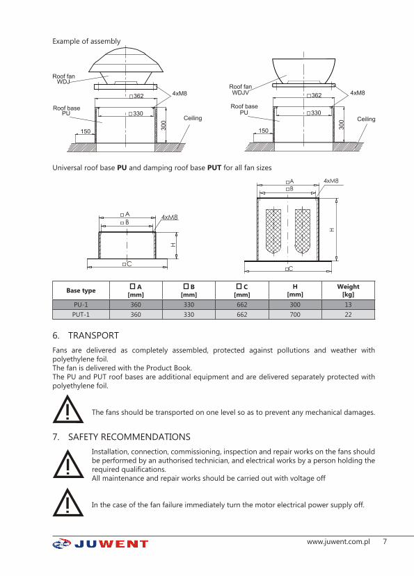
WDJ and WDJV fans can be settled on PU or PUT universal bases.The PUT roof bases are intended for mounting the fans, and at the same time, for reducing the operational noise level of the fans transmitted through the air inlet.Damping inserts are made of non-flammable damping plates (fire resistance class A2) – not moisture-absorbent – housed inside the enclosure made of galvanized steel sheet.The PU and PUT roof bases are made of galvanized steel sheet with insulating plate inside.For connecting the fan to the base use M8 bolts and washers with rubber gasket (not included in the delivery).Before fixing the fan on the base apply a self-adhesive gasket 15x4 on the base edge.Mount the base on the roof in accordance with relevant construction guidelines.Due to low operational noise level of WDJ and WDJV fans, the PUT universal damping bases are applied only in exceptional cases.
7www.juwent.com.pl
Example of assembly
Universal roof base PU and damping roof base PUT for all fan sizes
Base type A[mm]
B[mm]
C[mm]
H[mm]
Weight[kg]
PU-1 360 330 662 300 13PUT-1 360 330 662 700 22
6. TRANSPORTFans are delivered as completely assembled, protected against pollutions and weather with polyethylene foil.The fan is delivered with the Product Book.The PU and PUT roof bases are additional equipment and are delivered separately protected with polyethylene foil.
The fans should be transported on one level so as to prevent any mechanical damages.
7. SAFETY RECOMMENDATIONSInstallation, connection, commissioning, inspection and repair works on the fans should be performed by an authorised technician, and electrical works by a person holding the required qualifications.All maintenance and repair works should be carried out with voltage off
In the case of the fan failure immediately turn the motor electrical power supply off.

8 www.juwent.com.pl
The fan can only work with properly operating electrical protection devices. It must be uninterruptedly connected to the electrical installation fitted with protection terminal, residual-current device and service switch.
Use original spare parts only.
Due to its design, the device does not emit any hazardous radiation. Despite the fact that the device has been designed and manufactured in accordance with the standards valid as for the moment of the manufacture start, probability of injury and damage to health when using the device is unavoidable. This probability is related to frequency of using, cleaning and repairing the device, presence of persons within the danger area, and not respecting the safety rules as set out in the instruction. Severity of the bodily injury and deterioration of health is dependant on numerous conditions which can be foreseen partially only by considering them when designing the device and by providing descriptions and warnings in the instruction manual.Therefore residual risk is present if recommendations and instructions are not respected by the operator.
8. INSTALLATIONThe fans are bolted on roof bases, ventilation ducts or damping roof bases.The fans should be installed upright.
Installation of the fan and additional equipment should conform to the construction design covering the manner of placing and the fan whilst taking into consideration strength of the roof structure and tightness of the roofing.
Connection ducts ate the fan suction side should have their own supports and mountings.
9. ELECTRICAL INSTALLATION Connections of electrical installation and power supply to the fans must be carried out in accordance with relevant construction standards and regulations.
Electrical connections to the fans can only be carried out by an authorized electrician familiar with the instruction manual.
Before connecting make sure that the voltage and frequency rating of the power supply are in accordance with the data given on the fans data plates. Otherwise, do not connect the device.
The fans are equipped with single-phase motors (1~230V/50Hz) which should be power-supplied with the voltage from the main switchgear fitted with main circuit-breaker and differential protection. The electrical connection of the fan itself should be carried out taking into account the service switch located directly by the fan, as well as the overload and short-circuit protection inside the power supply/control box.
Warning! Make sure to provide the required motor protections, otherwise the warranty is void.Insert the power cord of the fan motor into the terminal box and fix it on protective grate or supports of the fan with cable ties. Electrical connection of the motor must be in accordance with electrical diagrams provided in the terminal box.Example of electrical diagram - Fig. 1.

9www.juwent.com.pl
DESIGNATIONS FOR DIAGRAMS:PT - Motor overcurrent protection K - ContactorPZ - Control button ON PW - Control button OFFB1, B2 - Fuses WS - Service switchPE - Protection terminal
Fig. 1 Electrical connection and control diagram for WDJ-... and WDJV-... fans
10. AUTOMATION ELEMENTSThe fan can be fitted with the following:
1. Power supply/control boxesHermetically enclosed for surface mounting, (equipped with: main switch, overcurrent and short-circuit breakers, signal lamps). The boxes should be mounted on a wall in a location from where the devices can be operated easily.Single control box enables control of a group of fans. The power supply 230V/50Hz of the power supply/control box should be delivered by the main switchgear fitted with main circuit-breaker and differential protection.In the case of an order including the delivery of the fans fitted with the box, additional electrical diagram for the fans and the box are also supplied.
2. Transformer speed controllersARW 5-step transformer speed controllers (1~230V/50Hz) enable air flow control. Individual rotational speed steps are selected manually. The controller should be supplied with voltage from the main switchgear equipped with the main switch, differential protection and thermal and short-circuit protection.

10 www.juwent.com.pl
Controller type ARW-1,2Voltage[V] 230
IP 30Height [mm] 123Width [mm] 77Depth [mm] 71
PE-L1-N input voltage (230V AC)PE,U1,U2 output control voltage
3. TP OR TPP ROOM THERMOSTATTP room thermostat (on-off) enables setting the required temperature with the hand wheel in the room within the range of 8…30OC, whereas TPP room thermostat (on-off) enables setting the required temperature on LCD display in the room within the range of 8…35OC in the day and night mode.
Supply voltage 24..250V AC
Measurement range 8...+30OC
Connector rated load 6(2)A
Protection level IP 30 lub IP 65
L-Y1 heatingL-Y2 cooling
Supply voltage 2 baterie 1,5V
Measurement range 5...+30OC
Connector rated load 5(2)A
Protection level IP30
Q11-Q14 heatingQ11-Q12 cooling

11www.juwent.com.pl
4. TZ air pollution thermostatTZ Air Pollution Thermostat is used in diffuserilation systems for the removal of odorants and gases from air, including cigarette smoke, sweat, kitchen odours, carbon monoxide, methane, ethane, acetone, methanol, etc. TZ Air Pollution Thermostat is recommended for use in rooms with a variable concentration of people and/or odorant as it optimises the time required to exchange the air in the room and maintains the air quality.
Supply voltage 230V
Connector rated load 8(6)A
Protection level IP30
L-Y1 fan control output
5. WS serwice switchWS service switch is used to switch the fan motor off for the period of servicing and maintenance. The WS service switch is a safety element that prevents the fan motor from accidental switch-on during in the course of servicing and maintenance
Type WS-3
Poles 3-poles
Supply voltage cirquit switch single and three phase
Rated continuous current 25A
Protection level IP65

12 www.juwent.com.pl
11. DEVICE COMMISSIONINGCommissioning of the fan should be carried out by properly qualified personnel only. Before the commissioning check the following:
» the fan for correct mounting, » the electrical connection for correct execution according to electrical diagram, » the enclosure for the presence of any foreign particles, » the impeller for free rotation without rubbing the fan inlet funnel.
Once the above works are completed, turn the fan on and observe if there is no vibrations and noise emitted by the impeller. Moreover, during the first commissioning of the fan it is advisable to measure the starting current consumed by the motor. If the current is lower than the rated current, the fan can be considered fit for further use.During the first commissioning it is advisable to measure basic flow parameters of the fan, such as volumetric flow rate and static pressure for the fan suction.
If any problems and disturbances arise during the commissioning, switch the power off and contact the supplier or the JUWENT service department.
12. REPAIR, MAINTENANCE AND WITHDRAWAL FROM USEThe fans are intended for continuous operation.At least once a year check the condition of the fan motor (the motor bearings require no regular lubrication) and, if necessary, remove the defects found according to the motor manufacturer instructions.Depending on the degree of air pollution, and no less than once a year, clean the fan impeller from any dust and dirt.Clean the fan with a damp cloth and do not use any aggressive cleaning agents.
All maintenance and repair works should be carried out with voltage off.
Use of high-pressure washers is not admissible.
Once the device is withdrawn from use, handle it to a proper waste treatment plant.

13www.juwent.com.pl
13. REMOVING MALFUNCTIONSDescription of malfunction Possible causes of malfunction Measures of prevention/removal
Fan won’t workIncorrect connection to power supply Check for proper connection to power supply.Locked impeller Remove cause of lockingDamaged motor Report at JUWENT service department
Low fan perfor-mance
Incorrect impeller rotational direction (not in accor-dance with marking on fan enclosure) Change polarity of power supply connection
Contaminated fan inlet grate Clean inlet grate
Fan high vibrations
Incorrect fan - roof base or roof base - fan connec-tion. Check for correct connections
Contaminated or damaged impellerRemove impeller contaminations.Report any impeller damages at JUWENT service depart-ment
Fan operates with excess noise, knocks
Plays on connections between fan elements or on connection between fan and roof base
Remove plays on connections by tightening bolts and screws
Rubbing between impeller and enclosureReport at JUWENT service department
Damaged motor bearings
Activation of mo-tor overload pro-tections
Damaged or worn bearings.Damaged motor windings (break, overheat).Damaged circuit-breaker or protection system.
Report at JUWENT service department
Incorrectly set protection relay.Loss of one of supply phases Check electrical installation and protection systems
14. INFORMATIONAs to all issues concerning the roof fan please contact JUWENT Production Plant or our Representatives
14 www.juwent.com.pl
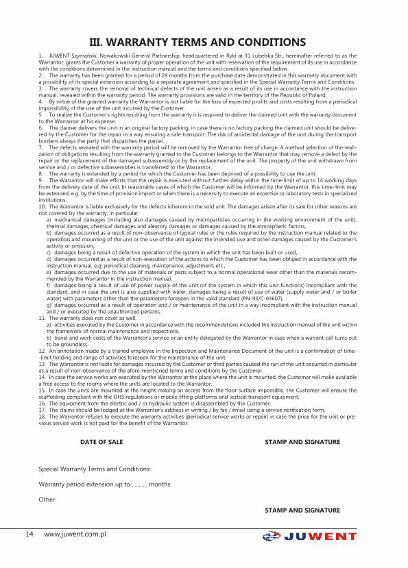
III. WARRANTY TERMS AND CONDITIONS1. JUWENT Szymański, Nowakowski General Partnership, headquartered in Ryki at 31 Lubelska Str., hereinafter referred to as the Warrantor, grants the Customer a warranty of proper operation of the unit with reservation of the requirement of its use in accordance with the conditions determined in the instruction manual and the terms and conditions specified below.2. The warranty has been granted for a period of 24 months from the purchase date demonstrated in this warranty document with a possibility of its special extension according to a separate agreement and specified in the Special Warranty Terms and Conditions.3. The warranty covers the removal of technical defects of the unit arisen as a result of its use in accordance with the instruction manual, revealed within the warranty period. The warranty provisions are valid in the territory of the Republic of Poland.4. By virtue of the granted warranty the Warrantor is not liable for the loss of expected profits and costs resulting from a periodical impossibility of the use of the unit incurred by the Customer.5. To realize the Customer’s rights resulting from the warranty it is required to deliver the claimed unit with the warranty document to the Warrantor at his expense.6. The claimer delivers the unit in an original factory packing, in case there is no factory packing the claimed unit should be delive-red by the Customer for the repair in a way ensuring a safe transport. The risk of accidental damage of the unit during the transport burdens always the party that dispatches the parcel.7. The defects revealed with the warranty period will be removed by the Warrantor free of charge. A method selection of the reali-zation of obligations resulting from the warranty granted to the Customer belongs to the Warrantor that may remove a defect by the repair or the replacement of the damaged subassembly or by the replacement of the unit. The property of the unit withdrawn from service and / or defective subassemblies is transferred to the Warrantor.8. The warranty is extended by a period for which the Customer has been deprived of a possibility to use the unit.9. The Warrantor will make efforts that the repair is executed without further delay within the time-limit of up to 14 working days from the delivery date of the unit. In reasonable cases of which the Customer will be informed by the Warrantor, this time-limit may be extended, e.g. by the time of provision import or when there is a necessity to execute an expertise or laboratory tests in specialized institutions.10. The Warrantor is liable exclusively for the defects inherent in the sold unit. The damages arisen after its sale for other reasons are not covered by the warranty, in particular:
a) mechanical damages (including also damages caused by microparticles occurring in the working environment of the unit), thermal damages, chemical damages and aleatory damages or damages caused by the atmospheric factors,b) damages occurred as a result of non-observance of typical rules or the rules required by the instruction manual related to the operation and mounting of the unit or the use of the unit against the intended use and other damages caused by the Customer’s activity or omission,c) damages being a result of defective operation of the system in which the unit has been built or used,d) damages occurred as a result of non-execution of the actions to which the Customer has been obliged in accordance with the instruction manual, e.g. periodical cleaning, maintenance, adjustment, etc.,e) damages occurred due to the use of materials or parts subject to a normal operational wear other than the materials recom-mended by the Warrantor in the instruction manual,f) damages being a result of use of power supply of the unit (of the system in which this unit functions) incompliant with the standard, and in case the unit is also supplied with water, damages being a result of use of water (supply water and / or boiler water) with parameters other than the parameters foreseen in the valid standard (PN-93/C-04607),g) damages occurred as a result of operation and / or maintenance of the unit in a way incompliant with the instruction manual and / or executed by the unauthorized persons.
11. The warranty does not cover as well:a) activities executed by the Customer in accordance with the recommendations included the instruction manual of the unit within the framework of normal maintenance and inspections,b) travel and work costs of the Warrantor’s service or an entity delegated by the Warrantor in case when a warrant call turns out to be groundless.
12. An annotation made by a trained employee in the Inspection and Maintenance Document of the unit is a confirmation of time--limit holding and range of activities foreseen for the maintenance of the unit.13. The Warrantor is not liable for damages incurred by the Customer or third parties caused the run of the unit occurred in particular as a result of non-observance of the afore-mentioned terms and conditions by the Customer.14. In case the service works are executed by the Warrantor at the place where the unit is mounted, the Customer will make available a free access to the rooms where the units are located to the Warrantor.15. In case the units are mounted at the height making an access from the floor surface impossible, the Customer will ensure the scaffolding compliant with the OHS regulations or mobile lifting platforms and vertical transport equipment.16. The equipment from the electric and / or hydraulic system is disassembled by the Customer.17. The claims should be lodged at the Warrantor’s address in writing / by fax / email using a service notification form.18. The Warrantor refuses to execute the warranty activities (periodical service works or repair) in case the price for the unit or pre-vious service work is not paid for the benefit of the Warrantor.
DATE OF SALE STAMP AND SIGNATURE
Special Warranty Terms and Conditions:
Warranty period extension up to ........... months.
Other:STAMP AND SIGNATURE

15www.juwent.com.pl
TYPE OF UNIT:
FACTORY NUMER:
YEAR OF PRODUCTION:
IV. UNIT STARTUP REPORTDate of startup
Executor of startupstamp / name and signature
Motorcurrent
[A]
User’s representativestamp / name and signature Remarks
V. INSPECTION AND MAINTENANCE DOCUMENTDate of
inspectionExecutor of inspection
stamp / name and signature Service activity range Remarks
* Inspection of the unit in accordance with the section “Repair and Maintenance” in the instruction manual

16 www.juwent.com.pl
VI. SERVICE NOTIFICATION
Date:
Notification type WARRANTY POST-WARRANTY PAID
Unit’s user (name)
Contact person
User’s address
Phone, fax. and email
Type of unit
Factory No.
Year of production
Startup executed by
Description of defect:
NOTE: AFTER COPYING AND FILLING IN SEND THE NOTIFICATION BY FAX OR EMAIL TOGETHER WITH A COPY OF THE STARTUP REPORT.JUWENT Company accepts notifications filled legibly and completely.When the lodged claim is not justified, the claimer will be burdened with service costs.
Date of warranty issue Order No. (company’s stamp)
......................................................... ...........................
17www.juwent.com.pl
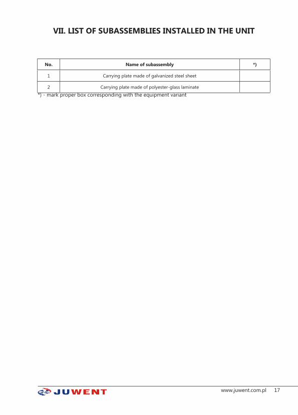
VII. LIST OF SUBASSEMBLIES INSTALLED IN THE UNIT
No. Name of subassembly *)
1 Carrying plate made of galvanized steel sheet
2 Carrying plate made of polyester-glass laminate*) - mark proper box corresponding with the equipment variant