
ROOF DRA I NAGE
12
133 ROOF DRA I NAGE (fu.om a paper by Schartz and Culligan, 19761 I NTKO1)U C’T I ON ‘lhe number of reports of substantial damage to stock and installa- tions in buildings as a result of the inadequate capacity of roof drainage facilities suggests that closer attention should be paid to the provision of waterproofing and storm-water control systems. The inconvenience of water flowing in and the resulting need to redecorate often detract from the prestige value of buildings and reduce the rate of return on the investment concerned. Where high intensity rainfalls are experienced frequently it would appear acceptable to size eaves gutters so that they became periodically surcharged, provided of course that excess water can safely be dis- charged clear of the building. Internal or valley gutters or flat roofs should, however, be designed in such a manner that the consequences of functional failure are taken into account. The sizing of components can be rationally assessed only on the basis of a full consideration of the economic, hydrologic and hydraulic factors. Steel-framed buildings with sloping roofs usually have gutters that are not integral with the roof so that a surcharge results in an over- [low ot the gutters. Concrete buildings, on the other hand, generally have horizontal or slightly sloping roofs and the problems that arise are due to the penetration of water through flaws in waterproofing membranes or inadequate flashing. The high cost of ensuring lasting protection of flat roofs against moisture penetration is such that it is generally not wise to rely on ;I reduction of peak €lows by roof-ponding (Fig. 8.1), a practice which in America has occasionally been enforced on property owners in order to reduce the surcharge on existing overloaded stormwater collection systems in the streets (Poertner, 1973). .In low and medium rainfall areas there seems little doubt that pro- vision for storage is not warranted and most designers regard peak re- duction by detention simply as an additional safety margin. Should it be decided to investigate the effect of storage then Fig. 8.2 after Pagan (1975) can be used to yield a preliminary estimate of the re- duction likely to be achieved. Some suggestions for waterproofing regulations are contained in a paper by Lardieri (1975) on flood proofing.
-
Upload
khangminh22 -
Category
Documents
-
view
0 -
download
0
Transcript of ROOF DRA I NAGE

133
ROOF DRA I NAGE
( f u . o m a p a p e r b y Schartz and Culligan, 1 9 7 6 1
I N T K O 1 ) U C’T I ON
‘lhe number of reports of substantial damage to stock and installa-
tions in buildings as a result of the inadequate capacity of roof
drainage facilities suggests that closer attention should be paid to
the provision of waterproofing and storm-water control systems. The
inconvenience of water flowing in and the resulting need to redecorate
often detract from the prestige value of buildings and reduce the rate
of return on the investment concerned.
Where high intensity rainfalls a r e experienced frequently it would
a p p e a r acceptable to size eaves gutters so that they became periodically
surcharged, provided of course that excess water can safely be dis-
charged clear of the building. Internal or valley gutters or flat roofs
should, however, b e designed in such a manner that the consequences
of functional failure are taken into account. The sizing of components
can be rationally assessed only on the basis o f a full consideration
of the economic, hydrologic and hydraulic factors.
Steel-framed buildings with sloping roofs usually have gutters that
are not integral with the roof so that a surcharge results in an over-
[low o t the gutters. Concrete buildings, on the other hand, generally
have horizontal or slightly sloping r o o f s and the problems that arise
are due to the penetration of water through flaws in waterproofing
membranes or inadequate flashing.
The high cost of ensuring lasting protection of flat roofs against
moisture penetration is such that it is generally not wise to rely on
;I reduction of peak €lows by roof-ponding (Fig. 8 . 1 ) , a practice which
in America has occasionally been enforced on property owners in order
to reduce the surcharge on existing overloaded stormwater collection
systems in the streets (Poertner, 1973).
.In low and medium rainfall areas there seems little doubt that pro-
vision for storage is not warranted and most designers regard peak re-
duction by detention simply as an additional safety margin. Should it
be decided to investigate the effect of storage then Fig. 8.2 after
Pagan ( 1 9 7 5 ) can be used to yield a preliminary estimate of the re-
duction likely to be achieved. Some suggestions for waterproofing
regulations are contained in a paper by Lardieri ( 1 9 7 5 ) on flood
proofing.

134
P L A N
S t r a i n e r
E L E V A T I O N
H a l f Round
Fig. 8.1 R a i n f a l l Detention P o n d i n g Ring for Flat Roofs

135
PEAK STORAGE IN CUBIC METRES / PEAK INFLOW IN m3/r
Fig. 8.2 Discharge attenuation due to storage (after Pagan, 1 9 7 5 1
It is practice in places to place downpipes in the centre of the
columns of reinforced concrete buildings. This leads to certain diffi-
culties in that the capacity of a down-pipe almost invariably depends
on the design of its inlet. The concentration of beam or slab steel
required at the top of a column often precludes the use of a hopper
at that point. It may thererore be worth considering American practice
of placing downpipes entirely clear of the columns.
In large buildings stormwater can be discharged internally into large
conduits or culverts below ground level. An alternative approach some-
times adopted for large steel-framed industrial buildings is to place
outlets at regular intervals in the floor o f gutters and to collect
the discharge from them in a suspended closed sloping launder or col-
lector pipe which discharges at the perimeter of the building.
In 1973 the Division of Building Research of the CSIRO in Australia
published a paper by Martin (1973) entitled ' R o o f Drainage'. The paper
presents a method of design which is essentially a modified version
of a series of research digests published over a decade or more by the
Building Research Station in England. The methods were adapted for
Australian conditions where rainfall intensities are generally far
higher than those o f the United Kingdom. In addition, Martin investi-
gated certain aspects such as the influence of slope on gutter capacity.
In April 1974 the British Standards Institution (BSI) issued a com-
prehensive code of practice which deals with the drainage o r r o o f s and
also of paved areas. Design procedures are given together with helpful
nctes on the practical considerations of the choice and disposition o f
elements of a drainage system. Special mention is made of the effects
o f mining subsidence. The publication contains diagrams giving roof

136
a r e a s s e r v e d by r a i n w a t e r p i p e s a n d g u t t e r s f o r d e s i g n i n t e n s i t i e s
of 7 5 mm/h. The d i a g r a m s may, h o w e v e r , b e m o d i f i e d f o r o t h e r i n t e n s i t i e s
GUTTER CAPACITY
Optimum proportions of rectangular gutters
The d e p t h o f a v a l l e y g u t t e r i s g e n e r a l l y l i m i t e d by s t r u c t u r a l con-
s i d e r a t i o n s s u c h a s t h e s i z e o f p u r l i n s o r by o t h e r s p a c e l i m i t a t i o n s
b u t i t i s c o n s i d e r e d i n s t r u c t i v e t o a s c e r t a i n t h e opt imum p r o p o r t i o n s
o f a l e v e l box g u t t e r d i s c h a r g i n g f r e e l y a t o n e e n d .
By a p p l i c a t i o n o f t h e momentum p r i n c i p l e i t c a n r e a d i l y b e shown t h a t
i f f r i c t i o n e f f e c t s a r e i g n o r e d t h e maximum d e p t h y a t t h e u p s t r e a m
e n d o f a l e v e l box g u t t e r i s f i t imes t h e c r i t i c a l d e p t h h c ( t h a t is
y = 1 . 7 3 h ) . T h i s t h e o r e t i c a l r e l a t i o n s h i p h o l d s r e g a r d l e s s of t h e
l e n g t h o f g u t t e r . C
When f r i c t i o n a l l o s s e s a r e i n c l u d e d t h e n a n a n a l y s i s s i m i l a r t o t h a t
d e v e l o p e d by H i n d s ( 1 9 2 6 ) f o r s i d e - c h a n n e l s p i l l w a y s i n d i c a t e s t h a t
t h e maximum d e p t h f o r t h e n o r m a l r a n g e o f g u t t e r l e n g t h s v a r i e s f r o m
a b o u t 1 . 8 t o 2 . 1 t i m e s t h e c r i t i c a l d e p t h .
I n CP 308 (HSI , 1 9 7 4 ) a v a l u e o f t w i c e t h e c r i t i c a l d e p t h is a d v o -
c a t e d f o r d e s i g n p u r p o s e s . I f t h e r a t i o o f maximum d e p t h t o c r i t i c a l
d e p t h c a n b e a c c e p t e d a s b e i n g c o n s t a n t t h e n i t c a n r e a d i l y b e shown
t h a t when a f l a t me ta l s h e e t o f w i d t h W is t o b e b e n t i n t o a r e c t a n -
g u l a r h o r i z o n t a l g u t t e r o f a n y l e n g t h t h e n i f a n a l l o w a n c e i s made f o r
f r e e b o a r d a n d l i p s , t h e r e m a i n d e r o f t h e s h e e t s h o u l d b e b e n t i n s u c h
a way t h a t t h e maximum d e p t h o f f l o w y i s t h r e e q u a r t e r s o f t h e g u t t e r
w i d t h b . Any o t h e r p r o p o r t i o n would i m p l y t h a t t h e c a p a c i t y o f t h e
g u t t e r i s l e s s t h a n t h e opt imum f o r t h e m a t e r i a l e m p l o y e d a n d t h e c o n -
s t r a i n t s s p e c i f i e d . I f t h e w i d t h o f a r e c t a n g u l a r g u t t e r is c h o s e n t o
be n o t l e s s t h a n 300mm i n o r d e r t o f a c i l i t a t e m a i n t e n a n c e i t f o l l o w s
t h a t f o r f l o w s l e s s t h a n 0 . 0 3 5 m 3 / s i t i s n o t f e a s i b l e t o m a i n t a i n
opt imum p r o p o r t i o n s .
I € a s t r i p o f m e t a l i s b e n t i n t o a r e c t a n g u l a r g u t t e r i n s u c h a way
t h a t t h e maximum d e p t h o f f l o w i s o n e h a l f o f t h e w i d t h t h e n f o r s p a -
t i a l l y v a r i e d f l o w t h e maximum d i s c h a r g e w i l l b e a b o u t f i v e p e r c e n t
l e s s t h a n t h a t o f a g u t t e r w i t h opt imum p r o p o r t i o n s .
F i g . 8 . 3 shows t h e w i d t h o f g u t t e r n e e d e d f o r a maximum d e p t h t o
w i d t h r a t i o o f b o t h 0 . 7 5 a n d 0.S a n d a l l o w s t h e d e s i g n e r t o s e l e c t a
s u i t a b l y s i z e d g u t t e r f o r v a r i o u s r a i n f a l l i n t e n s i t i e s . I t m u s t b e
b o r n e i n mind t h a t t h e d i a g r a m i s v a l i d o n l y i f t h e w a t e r a t t h e o u t -
l e t d i s c h a r g e s f r e e l y , s a y i n t o a r a i n w a t e r h e a d .

137
Fig. 8.3 Graph for design of level gutters
S l o p i n g g u t t e r s
Sloping gutters carry more than horizontal gutters but unless the
gutter is steep the additional discharge can generally be regarded only
as an extra safety margin. Martin (1973) published a graph showing
that when the slope of a drainage channel is about 2" the discharge capacity is doubled. If the flow should become supercritical then
special care would have to be taken because water flowing supercriti-
cally would not readily negotiate bends.
A comprehensive computer analysis of flow in variously shaped hori-
zontal gutters from 3 to 25 m long, established the effect o f gutter
length on maximum flow depth. Using the Hinds momentum equation it was
found that the following empirical relationships accurately predict
discharge capacity:
For r e c t a n g u l a r g u t t e r s :
0 ~ 0 . 0 5 = 1.429 (y b0.6?)1.614 (8.1)
where Q is the discharge in m 3 / s , y, b and L are maximum flow depth,
gutter width and gutter length respectively (all in meters). For t r a p e z o i d a l g u t t e r s :
Q = 0 . 6 9 7 ( A @ 0 . 2 5 L 3 3 8 1 -~
(b '" ')
138
where Q is the discharge in m 3 / s , A is the cross-sectional area of the
gutter in mz, b is the bottom width in m , and @ is the side slope in
radians measured from the horizontal. For trapezoidal gutters the maxi-
mum depth including an allowance for freeboard can be taken to be
approximately 2.3 times the critical depth.
For h a l f - r o u n d gutters:
'To take account of length effects the Building Research equation
should be modified to read as follows:
0. 8433AL2 Q = 2 . 2 h -____ 1, 0.4 7
where (1 is the discharge in m 3 / s , A is the cross-sectional area of the
gutter in m 2 and L the gutter length in metres.
Box r e c e i v e r s : Where possible gutters should discharge freely into a box-receiver,
the depth of which can be selected so as to match the use of a downpipe
of convenient size. The receiver should be at least as wide as the
maximum gutter width and should according to CP 308 be long enough to
prevent the flow from overshooting the box. The horizontal distance
m travelled by a particle leaving a horizontal gutter is given by the
equation m = 2 6 where y is the depth of flow at the outlet and n the
vertical drop of the particle.
If one assumes that the jet is not to strike the far wall of the re-
ceiving box then the box could turn out to be unduly long and when
loaded have a total mass of several hundred kilograms or more. It is
therefore suggested that for large buildings the box be limited in size
by the introduction of baffles even if the impact force has to be
catered for in the structural design. 'The importance of placing the
downpipe asymmetrically to prevent swirl which decreases effectiveness
is worthy of note. External boxes should be provided with overflow
weirs.
FLAT ROOFS
Flat roofs should have a slightly sloping upper surface to shed water
to drains or outlets and it is recommended that ponding be minimized
to restrict the ingress of water through waterproofing membranes that
might for some reason have suffered damage. The depth of water on the
roof will depend mainly on critical depth at overflow and thus a gutter
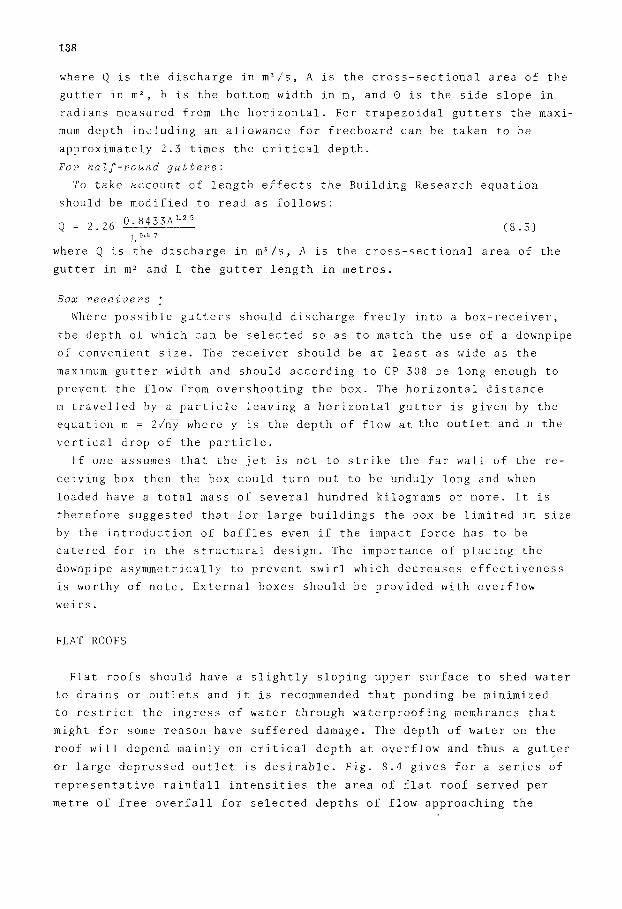
or large depressed outlet is desirable. Fig. 8.4 gives for a series of
representative rainfall intensities the area of flat roof served per
metre of free overfall for selected depths of flow approaching the
139
brink. For a limiting depth of 20 mm the critical depth would be 13.3 mm
The design of the downpipe and its inlet would have to be taken into
account in establishing the depth of water likely to occur on the roof
and this aspect is dealt with separately.
01 Irn 2oQ m AREA OF FLAT RCQF SERVED PER METRE OF OVERFLOW WEJR
LENGTH l m z l
Fig. 8.4 Area of roof f o r unit length of free overfall available
DOWNPIPES
Martin ( 1 9 7 3 ) found in Australia that the optimum size of downpipes
to serve a gutter is given by the rule that the cross-sectional area of
the downpipe should be half the cross-sectional area of the gutter. The
rule is advocated by him as it has been found satisfactory in practice.
Application of the rule presupposes, however, that a rain-water head of
suificient depth is available to avoid surcharge at the upper end of
the gutter. Care must therefore be exercised in applying the rule. The
British Code quite rightly lays stress on the design of the inlet and
indicates that the size of the downpipe may be reduced once the water
has entered it effectively.
For downpipes fed by flat areas and not gutters Martin limits the
effective velocity to 1 . 7 8 m/s and produces a diagram (Fig. 8.5) which
gives a n indication of the roof area served by downpipes for various
intensities of rainfall. It is important, however, to note that the
capacity of a downpipe is normally controlled by inlet conditions and
designers should avoid making the error of selecting a down-pipe size

140
from the chart without ensuring that the water build-up at the entrance
to the pipe necessary to feed the pipe at the design rate of flow can
safely be accommodated. It should perhaps be emphasized that downpipes
seldom run full. In fact, when the water reaches its maximum velocity
in a vertical stack the pipe usually runs only about one-quarter full.
Thus, down-pipes could be reduced in size but not without causing con-
siderable noise and vibration due to pneumatic effects.
Fig. 8.5 Preliminary downpipe selection graph (inlet conditions to be checked)
Dawson and Kalinske (1939) showed that for ordinary plumbing stacks
the maximum velocity is attained in about 3 to 6 m of fall. It follows
that for multi-storied buildings the water velocity at ground-level
would be no greater than that for a two-storey building. The maximum
velocity measured in experimental stacks was of the order of 7 m/s
and therefore Martin's rule of sizing downpipes by assuming that the
nominal velocity based on the full cross-sectional area is 1.78 m/s
appears reasonable.
Fig. 8.5 and the inlet designed to provide sufficient head to ensure
that the water enters without causing distress elsewhere.
The size of a downpipe fed by a gutter should also be selected from

141
I n Z e t c o n d i t i o n s for d o w n p i p e s
For a pipe flush with a flat roof or gutter floor the weir formula
Q = klhY2 ( 8 . 4 )
is applicable for low flows (i.e. when the head h on the weir overflow
is less than about one-third of the diameter). For greater heads the
orifice relationship
Q = k2h1" ( 8 . 5 1
is applicable. In these formulae Q is the discharge in m3/s, h is the
head in metres and k l and k S are appropriate constants.
If conical outlets are used then the origin of the orifice equation
for the pipe entrance is below the roof or gutter level and as the dis-
charge increases the control may shift to a lower level. If a protec-
tive grill is used due allowance should be made for its presence. Fig.
8.6 illustrates the concepts involved and it is immediately apparent
from the figure that the design of an inlet is by no means a straight-
forward matter.
Fig. 8.6 Diagram showing method of determination of inlet control
If the downpipe is fed by a level rectangular gutter then (if surcharge
is to be avoided) the depth of flow in the gutter at the outlet should
not exceed 80 percent of the depth at the upstream end. For design pur-
poses the more conservative rule that the water depth at the outlet
should not be more than 50 percent of the effective gutter depth is
recommended. If, on the other hand, the downpipe is fed directly from
a flat roof then the approach head should be limited to about 25 mm
and this severely restricts the discharge.
142
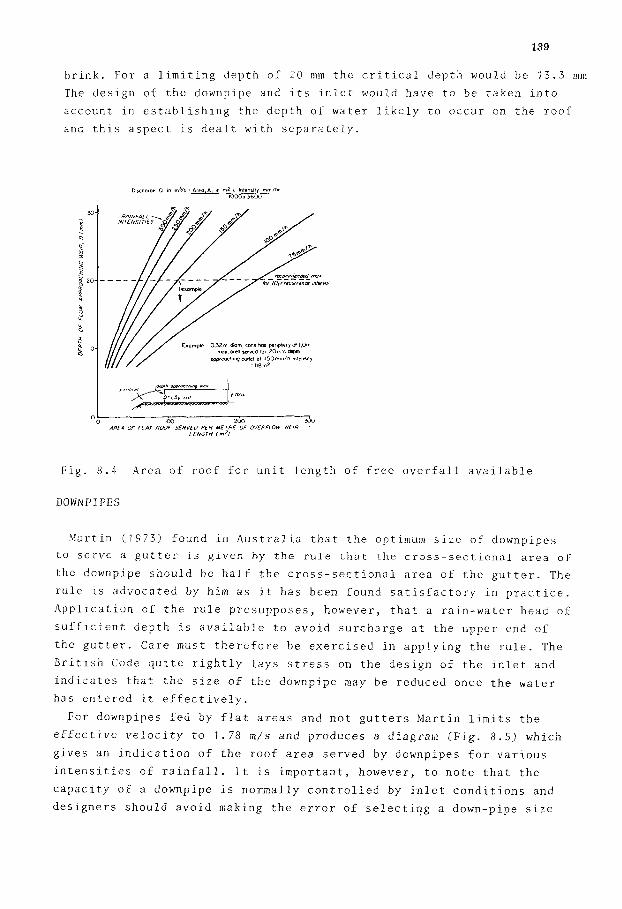
Calculations, supplemented by some laboratory tests for selected
sizes, indicate that the chart given as Fig. 8.7 can be used for inlet
design. Similar reasoning may be applied to ascertain the depth of
water required in receiving boxes.
300rnai
I *5r"0" ORIFICE CONTROL 0 * 0 . 6 F G
Fig. 8.7 Inlet design diagram
A useful technique for the design of conical outlets and tapers is to
plot orifice relationships on a transparent overlay and then to slide
the overlay vertically over a diagram such as Fig. 8.7 to establish
optimum conditions.
A grill in a conical outlet acts as a control for low discharges ard
as an obstruction for larger discharges. Generally the open area of
the grill is about 7 5 percent of the gross area A, and the head loss
can b e approximated by taking half the velocity head at each vena-
contracta. 'The total effective area is then about 60 percent of the
75 percent mentioned above. Thus, the head loss, h, across the grill,
mcy be approximated by the expression

143
where Q i s t h e d i s c h a r g e i n m 3 / s and A 1 t h e g r o s s g r i l l a r e a i n mz.
F i g . 8 . 8 may be u s e d for t h e f i n a l s e l e c t i o n of downpipe s i z e de-
pending on t h e v a l u e o f a v a i l a b l e h e a d . Where r e c e i v e r s a r e u s e d t h e
d e p t h o f r e c e i v e r r e q u i r e d f o r a s e l e c t e d downpipe d i a m e t e r may be
d e t e r m i n e d from t h e d i ag ram.
F i g . 8 . 8 Downpipe s e l e c t i o n for d i f f e r e n t a v a i l a b l e h e a d s
RE F E RE NC E S
B r i t i s h S t a n d a r d s I n s t i t u t i o n , 1974. Code o f P r a c t i c e f o r d r a i n a g e o f
Dawson, F . M . , and K a l i n s k e , A . A . , 1939. Repor t on h y d r a u l i c s and r o o f s and paved a r e a s , CP 3 0 8 , London.
p n e u m a t i c s o f t h e p lumbing d r a i n a g e s y s t e m s , T e c h n i c a l B u l l e t i n No. 2 . N a t i o n a l A s s o c i a t i o n o f P lumbing , H e a t i n g , C o o l i n g C o n t r a c t o r s , Washington DC, 38pp.
Hinds , J . , 1 9 2 6 . S i d e c h a n n e l s p i l l w a y s , T r a n s . , ASCE, 89, p 881-927. L a r d i e r i , A . C . , S e p t . 1975. Flood p r o o f i n g r e g u l a t i o n s f o r b u i l d i n g
c o d e s , P r o c . ASCE, 1 0 1 (HY9), ~ 1 1 5 5 - 1 1 6 9 M a r t i n , K.G., 1973. Roof d r a i n a g e , D i v i s i o n o f B u i l d i n g R e s e a r c h ,
T e c h n i c a l Pape r (Second S e r i e s ) No. l,CSIRO, A u s t r a l i a , 16pp.

144
Pagan, A . G . , Oc t . 1 9 7 5 . U s e f u l n e s s o f t h e s t o r a g e p a r a m e t e r , C i v . Eng.
P o e r t n e r , H . G . , 1 9 7 3 . B e t t e r S t o r m d r a i n a g e f a c i l i t i e s - a t l o w e r c o s t , Civ Eng, ASCE, 4 5 ( l o ) , p 67-70
S c h w a r t z , H . I . a n d C u l l i g a n , P . T . , Aug. 1 9 7 6 . Roof D r a i n a g e o f l a r g e b u i l d i n g s i n S o u t h A f r i c a . T r a n s . S .A. I n s t n . C i v i l E n g r s . , 1 8 ( 8 ) , p 1 7 1 - 1 7 6 . D i s c u s s i o n March , 1 9 7 7 .
ASCE, 45 ( l o ) , p 82-83 .