RAIN WATER ROOF CATCHMENT SYSTEM - CMP CoWASH ...
61
RURAL WATER SUPPLY AND ENVIRONMENTAL PROGRAMME IN AMHARE REGION C:\ Yoh Rainwater roof catchment system 1 THE FEDERAL DEMOCRATIC THE REPUBLIC OF FINLAND REPUBLIC OF ETHIOPIA MINISTRY OF ECONOMIC MINISTRY FOR FOREIGN DEVELOPMENT & COOPERATION AFFAIRS BUREAU OF PLANNING AND DEPARTMENT OF ECONOMIC DEVELOPMENT INTERNATIONAL AMHARA NATIONAL REGIONAL DEVELOPMENT COOPERATION STATE THE RURAL WATER SUPPLY AND ENVIRONMENTAL PROGRAMME, AMHARA REGION DESIGN and CONSTRUCTION MANUAL on RAIN WATER ROOF CATCHMENT SYSTEM For HUMAN USE Prepared by: Yohannes Melaku Water Supply Development Advisor November 26/2002 Bahir Dar 183
-
Upload
khangminh22 -
Category
Documents
-
view
1 -
download
0
Transcript of RAIN WATER ROOF CATCHMENT SYSTEM - CMP CoWASH ...

RURAL WATER SUPPLY AND ENVIRONMENTAL PROGRAMME
IN AMHARE REGION
C:\ Yoh Rainwater roof catchment system 1
THE FEDERAL DEMOCRATIC THE REPUBLIC OF FINLAND
REPUBLIC OF ETHIOPIA
MINISTRY OF ECONOMIC MINISTRY FOR FOREIGN
DEVELOPMENT & COOPERATION AFFAIRS
BUREAU OF PLANNING AND DEPARTMENT OF
ECONOMIC DEVELOPMENT INTERNATIONAL
AMHARA NATIONAL REGIONAL DEVELOPMENT COOPERATION
STATE
THE RURAL WATER SUPPLY AND ENVIRONMENTAL
PROGRAMME, AMHARA REGION
DESIGN and CONSTRUCTION MANUAL on
RAIN WATER ROOF CATCHMENT SYSTEM
For HUMAN USE
Prepared by:
Yohannes Melaku
Water Supply Development Advisor
November 26/2002
Bahir Dar
183
RURAL WATER SUPPLY AND ENVIRONMENTAL PROGRAMME
IN AMHARE REGION
C:\ Yoh Rainwater roof catchment system 2
TABLE OF CONTENTS
Title Page
1. INTRODUCTION 5
1.1 General 5
1.2 Advantages and disadvantages of rainwater harvesting system 6
1.3 The feasibility of rainwater catchment system 6
2. CALCULATION OF DOMESTIC WATER DEMAND AND QUANTITY
OF RAINWATER FROM ROOF CATCHMENT SYSTEM 9
2.1 Estimating domestic water demand 9
2.2 Calculating potential rainwater supply from roof by estimating runoff 10
2.2.1 Different types of roof shapes and their suitability for rainwater roof
catchment system. 10
2.2.2 Effect of roof finish on rainwater roof catchment system 11
2.2.3 Runoff coefficient (C) 11
2.2.4 Average (mean) annual rainfall (R) 12
3. RAINWATER ROOF CATCHMENT SYSTEM COMPONENTS AND
DESIGN PROCEDURE OF THE CATCHMENT SYSTEM 14
3.1 Components of rainwater roof catchments system 14
3.2 Design procedures of rainwater roof catchments system 14
3.3 Determining the size of storage tank and types of rainwater storage tanks 15
3.3 1 Determining capacity of reservoir (storage tank) 15
3.3.2 Types of rainwater storage tanks 20
3.4 Gutters and dawn pipes 20
3.4.1 Calculation of gutter and down pipe dimension (sizing) 22
3.5 Water point (tap point) for collecting stored rainwater for use 24
3.6 Possible arrangements of storage tank for rainwater roof catchments system 24
3.7 Common problems with roof catchments system design 26
4 QUALITY OF WATER FROM RAINWATER ROOF CATCHMENT
SYSTEM 27
4.1 Rainwater quality 27
4.2 Protecting rainwater quality 27
4.2.1 Good design, operation and maintenance 27
4.2.2 First/foul flush system 29
4.2.3 Hygiene education and monitoring 32
4.3 Treatment of stored rainwater 32
RURAL WATER SUPPLY AND ENVIRONMENTAL PROGRAMME
IN AMHARE REGION
C:\ Yoh Rainwater roof catchment system 3
5. CONSTRUCTION OF FERRO-CEMENT TANK (RESERVOIR) 34
5.1 History of Ferro-cement 34
5.2 Commonly used sizes of ferro-cement tanks 34
5.3 Construction procedure of ferro-cement tank. 35
5.4 Repair of ferro-cement tanks (reservoirs). 51
6. DESIGN EXAMPLE OF RAINWATER ROOF CATCHMENT SYSTEM 55
6.1 Design data 55
6.2 Runoff calculation 55
6.3 Calculation of water requirement 55
6.4 Determination of reservoir capacity (size) 56
6.5 Determination of gutters and down pipes size 57
6.6 Tap points 58
6.7 Design drawings 58

RURAL WATER SUPPLY AND ENVIRONMENTAL PROGRAMME
IN AMHARE REGION
C:\ Yoh Rainwater roof catchment system 4
LIST OF TABLES
Table 2.1 Water demand for different beneficiary categories (liters/person/day)
Table 2.2 Runoff coefficient for different roof catchment finishes
Table 3.1 Dimension of different gutters having half round shape
Table 3.2 Dimension of different gutters having rectangular shape
Table 5.1 Dimensions of ferro-cement tanks
LIST OF FIGURES
Figure 2.1 Different types of roof shapes for rainwater roof catchment system
Figure 3.1 Step by step graphical method to determine appropriate storage requirement
for maximizing rainwater supply
Figure 3.2 A graphical method to determine rainwater tank storage requirements for a
constant water demand in two markedly different rainfall regimes
Figure 3.3 Examples of different gutter systems
Figure 3.4 Possible arrangements of storage tank for rainwater roof catchment system
Figure 3.5 Examples of good and poor roof catchment systems
Figure 4.1 Different types of first/foul flush system designs
Figure 5.1 to Figure 5.20 Construction procedures of ferro-cement tank (reservoir)
Figure 5.21 Plan of 20 muc capacity freeo-cement reservoir where the pot rest is below
the ground level.
Figure 5.22 Plan of 20 muc capacity freeo-cement reservoir where the pot rest is above
the ground level.
Figure 5.23 and Figure 5.24 Maintenance (repair) of ferro-cement tanks
Figure 6.1 Design drawing for roof catchment design example
RURAL WATER SUPPLY AND ENVIRONMENTAL PROGRAMME
IN AMHARE REGION
C:\ Yoh Rainwater roof catchment system 5
1. INTRODUCTION
1.1 General
It is well known that the most common sources of water for human use are ground water,
surface water and rain water.
Rain water harvesting means the direct collection of rainwater from roofs and other
purpose built catchments (ground or rock catchments) for either human or agricultural
use (livestock consumption, nurseries and irrigation).
The contribution of rainwater can make to a water supply will depend on the reliability,
regularity and quantity of the rainfall in an area. In wet seasons, directly collected
rainwater can provide an important source of drinking water. Rainwater can be collected
by:
• The family – roof collection.
• Institution – roof and surface collection at clinics, hospitals, feeding centers,
schools, churches.
• The community – ponds, small storage reservoirs.
Based on the type of catchments from where rainwater is collected, rainwater harvesting
is divided in to two, namely ground catchments and roof catchment.
1. Ground catchment – it is a general term describing all systems, which uses the
ground surface as a catchemnt area. These includes natural, treated and covered
surfaces, cement or tarmac covered surfaces such as roads, pavements, and suitable
rock outcrops (rock catchment). Ground catchments are used where suitable roof
surface is not available. The main advantage of using the ground as catchment surface
is that water can be collected from a large area. This is particularly advantageous in
areas of low rainfall.
The main disadvantage in using the ground as a collection surface is that the water supply
can easily become contaminated, and since it can only be stored below the surface it is
generally less convenient to withdraw water for use. Although ground catchment systems
are sometimes used to collect rainwater for drinking purposes, it is strongly
recommended, where possible that this water should be boiled, chlorinated, or at least
passed through a slow sand filter before being consumed. For non domestic purposes,
however, the water is generally suitable.
2. Roof catchment- it is the most common type of catchment used for harvesting
rainfall. Corrugated iron sheet, concrete, plastic and tiles roof all make good roof
catchemnt surface. Roof catchemnt systems offer a simple and fairly inexpensive
method of providing water to individual homes and institutions. Roofs can be adapted
with pipes and gutters to trap water and transport it in to a water roof reservoir.
RURAL WATER SUPPLY AND ENVIRONMENTAL PROGRAMME
IN AMHARE REGION
C:\ Yoh Rainwater roof catchment system 6
Roof runoff from buildings is usually of a higher quality than surface (ground) runoff and
can often be used without treatment as the elevation of roofs protects them from
contamination and damage which is common to ground catchments. It requires minimum
maintenance, gutters and downpipes must be cleaned often to prevent clogging and
contamination. Hence our focus in this design manual will be on the design of rainwater
roof catchment system for human use.
The rainfall pattern in Ethiopia comprises a 3-4 month long rains varying between May
and October and 8-9 months of relatively little rain a part from 1-2 months of small rains
at different periods and intensity dependent on the area of the country. Since it would
require 5 mcu of storage to provide for an average family (5 family members) for a
period of 50 days without replenishment, it is unlikely that rainwater harvesting will be a
viable sole supply alternative on an individual family basis in many, if any,
circumstances.
Rainwater harvesting can however provide a careful supplemental supply of high quality
in many circumstances and may be particularly useful in mixing with alternative supplies
in those areas where poor quality of other supply exist.
1. 2 Advantages and disadvantages of rainwater roof catchment system.
The advantage of rainwater collection system over other water supply schemes are:-
• The quality of rainwater is high
• The system is independent, therefore, suitable for scattered settlements
• Local materials and craftsmanship can be used in rainwater system construction
• No energy costs are needed to run the system
• Ease of maintenance by the owner
• Can be constructed in the yard of the user if the house has a suitable roof.
Some disadvantages or limitations are:-
• The high initial capital cost may prevent a family from buying a system.
Arrangements for grant and low interest loans may have to be made.
• The water available is limited by rainfall and roof area. Supplementary water
sources may be needed. For long dry seasons, the required storage volume may be
too high.
• Mineral - free water has a flat taste while people may prefer the taste of mineral -
rich water.
• Mineral-free water may cause nutrition deficiencies in people who are already on
mineral - deficit diets.
1.3 The feasibility of rainwater roof catchment system
The initial step in planning and developing a rainwater roof catchment system involves
an appraisal of the feasibility of the system. The feasibility can be determined in light of
technical, economic, social, environmental and gender issues.

RURAL WATER SUPPLY AND ENVIRONMENTAL PROGRAMME
IN AMHARE REGION
C:\ Yoh Rainwater roof catchment system 7
Technical Issues
The initial consideration of the feasibility of the rainwater roof catchment system
concerns water availability as compared to its use or demand. The yield or supply of the
system depends on how many rainfalls during the years and the availability of the
rainfalls. The demand imposed on the community depends on water use. In household
water is used for drinking, cleaning, cooking and washing. In rural developing areas each
person may use between 15 - 30 liters/person/day.
Reliable rainfall data are required when determining the supply from the system. Rainfall
data for a minimum of 10 years period is preferable. The information can be obtained
from the government meteorological office, from an agricultural ministry, from
university or from an air port and similar other organization that might have the data. If
rainfall data for a particular region is not available, data can be obtained from the closest
station related to the particular region in question.
The next steep involves estimating the total demand and comparing it with the supply
possible from the rainwater catchment area. If the supply exceeds the demand, the
rainwater roof catchment system is feasible from technical point of view, based on total
maximum supply over a period of the year.
If the supply is less than the demand, then possible solutions include increasing the
catchment area or reducing the demand for rainwater. For example, use the rain water for
drinking and cooking only, and obtain water required for cleaning and washing from
another source (well, river, etc,)
Economic Issues
The rainwater roof catchment system must be economically feasible to the households.
Costs of the proposed rainwater roof catchment system must be evaluated and compared
with the costs of alternative water supply improvement. Costs of catchment and storage
depend on what existing structures can be used and the local prices of additional building
materials. Though the system is economically feasible it must also be affordable to the
household. If the use of rainwater roof catchment system is to be widespread in a
region/an area, financing the tanks should be available from the donors to the community.
The value of rainwater rises with increased distance to or in accessibility of other water
sources. This means that if rainwater becomes the only source, its value is extremely
high. This high investment in a large reservoir becomes cheaper in relation to the value of
water.
Social Issues
Once it has been tentatively established that it is technically and economically feasible to
construct the rainwater roof catchment system, the next step involves the social and
community assessment. This step is critical to the success of the catchment scheme.

RURAL WATER SUPPLY AND ENVIRONMENTAL PROGRAMME
IN AMHARE REGION
C:\ Yoh Rainwater roof catchment system 8
Social issues relate to the needs, perceptions, desires, beliefs, experience and existing
practices of the community. For any rainwater catchment system project to succeed,
whether at household or across a whole region, it must address the real felt need within a
community and be socially acceptable. Further more, not only should be affordable, but
people must accept and willing to pay for it.
The project developer must determine the extent of community needs. This must be done
in light of traditional practices within the community. The role of women and children in
carrying water and the amount of time spent in this activity should be examined. The
engineer should collect information on existing catchment technologies and discuss with
the community the usefulness of water supplied by a roof system. Users should be
informed of the palatability (having good taste and acceptability for drinking) of the
rainwater. The community’s need for communal versus individual catchemnt system
should be evaluated.
The project engineer must also compile a resource inventory of local skills, materials and
experience that can be used in rainwater roof catchment system. Materials, which are
easy to obtain by local people who know how to work with the materials, will result in a
roof system that is cheap and simple to build and repair. An appropriate resource
inventory checklist includes availability and cost of materials and constriction skills.
Eventually the community members will decide if they are willing to participate in the
project and the amount of time and money households are willing to commit to the
project.
Environmental and Gender Issues
In addition to technical, economic and social issues environmental and gender issues
need to be considered in designing a sustainable rainwater roof catchment system.
In general, before designing a rainwater system the following questions should be given
attention.
1. For which purpose is the rainwater harvesting to be used?
2. What is the likely consumption of water by the users?
3. What amount of water can be harvested?
4. What is the rainfall pattern, and how is rainfall distributed during the year?
5. Which construction materials are available?
6. What is the cost of the system construction?
7. By how much can costs of construction be reduced by community contribution?
Answers to the above questions will lead to a decision on the size and type of the
reservoir to be constructed. Compromises must be made on the basis of the answers.
RURAL WATER SUPPLY AND ENVIRONMENTAL PROGRAMME
IN AMHARE REGION
C:\ Yoh Rainwater roof catchment system 9
2. CALCULATION OF DOMESTIC WATER DEMAND AND QUANTITY OF
RAINWATER FROM ROOF CATCHMENT SYSTEM
2.1 Estimating domestic water demand
Worldwide, levels of domestic water consumption may vary widely from less than 5
liters/person/day in many of the poorest communities in developing countries to 1000
liters/person /day or more for the very richest communities in developed countries.
Domestic water demand include all water used in and around the home for the following
essential purposes:
• Drinking
• Food preparation and cooking
• Personal hygiene (washing hands and body)
• Toilet flushing (where flush toilets are used)
• Washing cloths and cleaning
• Washing pots, pans and other utensils.
Additional domestic water used may include:
• Watering gardens
• Watering animals
• Washing vehicles
• Water for construction
• Recreational uses (swimming pool).
In most case, properly designed household roof catchemnt systems can normally meet
domestic demand for essential purposes. In cases where rainfall is low or roof and tank
size is small, systems needs to meet at least the first three or two essential purposes of
domestic water demand.
Based on the above explanation, in determining the household consumptive use,
standards have been developed by WHO and adapted to local conditions. In Table 2.1
below suggested figures have been presented for use in rural areas where minimal water
is currently available at household level.
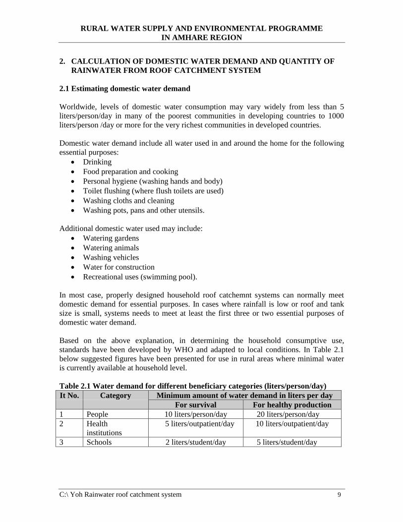
Table 2.1 Water demand for different beneficiary categories (liters/person/day)
It No. Category Minimum amount of water demand in liters per day
For survival For healthy production
1 People 10 liters/person/day 20 liters/person/day
2 Health
institutions
5 liters/outpatient/day 10 liters/outpatient/day
3 Schools 2 liters/student/day 5 liters/student/day
RURAL WATER SUPPLY AND ENVIRONMENTAL PROGRAMME
IN AMHARE REGION
C:\ Yoh Rainwater roof catchment system 10
The following formula is used in estimating the total daily water demand.
Total daily water demand (liters) = Daily water demand (liters/person/day) x Number of
people to be served by the system (Formula 2.1)
If we want to calculate the water required for certain number of days, use the following
formula.
Total Demand water demand (liters) = Daily water demand (liters/person/day) x
Number of people to be served by the system x
Number of days for which the water is required (Formula 2.2)
2.2 Calculating potential rainwater supply from roof by estimating runoff
The size of supply of rainwater roof catchment system depends on the amount of rainfall
in the area, the area of the roof catchemnt from which the water is to be collected and its
runoff coefficient (a function of the type roof finish). For a roof or sloping catchment it is
the horizontal plan area which should be measured and used in the calculation of
rainwater supply.
An estimate of the approximate, mean annual runoff from a given roof catchment can be
obtained using the following formula:
Supply (S) = Rainfall ( R) x Roof area ( A) x Runnoff coefficient ( C) (Formula 2.3)
Where: S = Mean annual rainwater supply in liters (l)
R = Mean annual rainfall of the area in millimeters (mm)
A = Catchment (roof) area in square meters from which rainwater is to be collected (m2)
C = Runoff coefficient
2.2.1 Different types of roof shapes and their suitability for rainwater roof
catchment system.
The shape of any given catchment area has a considerable influence on the catchemnt
possibilities, therefore, different types of roofs provide different catchment possibilities.
Out of the most common roof types shown in Figure 2.1, the single pitch roof is the most
appropriate for roof water harvesting, since the entire roof area can be drained in to a
single gutter on the lower side and one or two downpipes can be provided depending on
the area.
A more difficult roof for roof water catchment is tent roof. It requires a gutter on each
side and at least two dawn pipes on opposite corners. If a tent roof is large enough, it
could be drained in to four tanks located at each corner of the house. The hip roof is not
very efficient either, since it also needs gutter as all round the building.
RURAL WATER SUPPLY AND ENVIRONMENTAL PROGRAMME
IN AMHARE REGION
C:\ Yoh Rainwater roof catchment system 11
Flat roofs can be used for catchments if they are furnished with an edge, keeping the
water on the slab until it has drained through the gutter or down pipe. However, using flat
roof for rainwater harvesting is not very efficient because of the extended runoff time and
the evaporation loses. One way to improve the catchment is to provide the slab with a
slopping cement screed.
The most useful roofs are the single and double pitch roofs. The double pitch roof offers
many advantages.
2.2.2 Effect of roof finish on rainwater roof catchment system
Not all materials used in roofing finishes are equally good, but the most commonly used
materials, corrugated/ galvanized iron sheets, concrete, plastic sheets are very suitable for
rainwater catchment. Likewise thatch roofs can be used, but can discolor water and give
it unpleasant taste hence it is less efficient. To see the effect on the amount and quality of
water from different types of roof finishes see Table 2.2 below.
2.2.3 Runoff coefficient ( C)
Runoff coefficient is the ratio of the volume of water which runs off a surface to the
volume of rainwater which falls on the surface.
The runoff coefficient is not a constant factor instead its value is highly variable and
depends on catchment specific factors (type of roof finish) and the construction quality of
the roof catchment system.
Based on some studies conducted on different roof finishes the following values of runoff
coefficients shown in Table 2.2 below are proposed to be used in estimating of runoff
from different roof finish surfaces. The runoff coefficients takes in to account any loses
due to leakage, evaporation, overflow and wind effects.
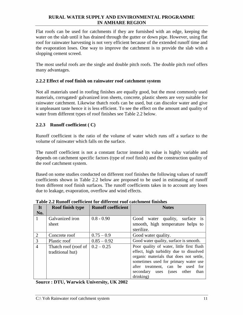
Table 2.2 Runoff coefficient for different roof catchment finishes
It
No.
Roof finish type Runoff coefficient Notes
1 Galvanized iron
sheet
0.8 - 0.90 Good water quality, surface is
smooth, high temperature helps to
sterilize.
2 Concrete roof 0.75 – 0.9 Good water quality.
3 Plastic roof 0.85 – 0.92 Good water quality, surface is smooth.
4 Thatch roof (roof of
traditional hut)
0.2 – 0.25 Poor quality of water, little first flush
effect, high turbidity due to dissolved
organic materials that does not settle,
sometimes used for primary water use
after treatment, can be used for
secondary uses (uses other than
drinking)
Source : DTU, Warwick University, UK 2002

RURAL WATER SUPPLY AND ENVIRONMENTAL PROGRAMME
IN AMHARE REGION
C:\ Yoh Rainwater roof catchment system 12
From the above table, we can see that thatched roofs (roofs cover in traditional hut) are
not preferable for rainwater harvesting from points of views of quantity and the quality of
water to be collected from the roofs.
The runoff values in the above table are suggested assuming the system (roof, gutter and
downpipe system) is well constructed. If the roof catchment system is not well
constructed the coefficients can be even lower than the above values and much water may
be wasted without usage.
2.2.4 Average (mean) annual rainfall (R)
The amount of rainwater collected by a given rain gauge in 24 hours is called daily
rainfall, and the amount collected in one year is known as annual rainfall. This annual
rainfall at a given station should be recorded over a number of years, minimum of 10
years. For example, in India, this rainfall cycle period is taken to be about 35 years. The
mean of the annual rainfalls over a period of say minimum 10 years or so is, therefore,
known as average (mean) annual rainfall at a given station.
To calculate the volume of rain water, which can be harvested, the mean annual rainfall
figures is commonly used. Mean annual rainfall is the statistical average calculated on the
basis of measured rainfall over many years, minimum of 10 years. It has to be understood
that there is no guarantee that the calculated amount will be achieved, but there is 95%
likelihood that this amount can be expected (that is, with the average rainfall value is to
be maintained for 95 percent of the time, but with failures during drought periods for 5
percent of the time). It can happen that the mean annual can not be expected. It can
certainly happen the other way round that considerably more rainfalls than the mean
annual. This makes the calculation of the storage capacity rather difficult. However, the
mean annual is generally accepted as the basis for calculating the volume of rainwater to
be collected.
The information on mean annual rainfall can be obtained from the government
meteorological office, from an agricultural ministry, from university or from an air port
and similar other organization that might have the data. If rainfall data for a particular
region is not available, data can be obtained from the closest station, and related to the
particular region in question.

RURAL WATER SUPPLY AND ENVIRONMENTAL PROGRAMME
IN AMHARE REGION
C:\ Yoh Rainwater roof catchment system 13
RURAL WATER SUPPLY AND ENVIRONMENTAL PROGRAMME
IN AMHARE REGION
C:\ Yoh Rainwater roof catchment system 14
3. RAINWATER ROOF CATCHMENT SYSTEM COMPONENTS AND
DESIGN PROCEDURE OF THE CATCHMENT SYSTEM
3.1 Components of rainwater roof catchment system
In general every rainwater catchment system consists of a number of components mainly:
• A catchment surface where the rainwater runoff is collected (either ground or roof).
• Storage reservoirs large enough to store and supply water throughout any gap
between sufficient rainfall events. If that gap is a few days, the storage volume can be
quite small. If the gap between rain events is a ‘dry season’ of several months, the
storage volume has to be several thousands liters depending upon the productive use
of which the water is put.
• A delivery system for transporting the water from the catchemnt to the storage
reservoir (channel, pipes, downpipes, gutters etc.)
• In addition systems always need some form of extraction device to take the water
from the roof storage reservoir (a tap, rope and bucket, or pump).
In particular the most important components of rainwater roof harvesting system are:
- A collection surface (roof)
- Gutters to receive water from the roof area.
- Downpipes to transport water from the gutter to the reservoir.
- Reservoirs with all the necessary fittings for storage of rainwater.
- Pipe connecting reservoirs with water taps.
- Water taps.
3.2 Design procedures of rainwater roof catchment system
In order to select the storage available to households or small group of houses or
institutions (to design a suitable rainwater roof catchment system), the following steps are
recommended to be followed:
Step 1. Obtain average annual rainfall data for the area for 10 years (minimum).
Step 2. Select the type and size of roof catchment that is available to the users.
Step 3. Decide on the type and number of the beneficiaries of the rainwater system
(community members, students, patients etc.).
Step 4. Decide for what purpose the rain water system is to be used (for drinking,
cooking, cloth washing etc.) and also determine the required per capita demand
Step 5. Calculate the total water demand required by the beneficiaries yearly or monthly
(Formula 2.2)
Step 6. Calculate the amount of rainwater per months or per year that can be collected
from the available catchment area/roof area (Use formula 2.3).
Step 7. Compare water available from the roof catchment and the water requirement of
the beneficiaries.
RURAL WATER SUPPLY AND ENVIRONMENTAL PROGRAMME
IN AMHARE REGION
C:\ Yoh Rainwater roof catchment system 15
When comparing, if there is more water supply from the roof catchement at the end of the
year than the beneficiaries demand, the design is considered suitable. If the amount of
rainwater stored (supply) is less than the total water requirement of the beneficiaries, then
take possible solutions include increasing the catchment area or reducing the demand for
rainwater. For example use the rainwater for drinking and cooking only, and obtain water
required for cleaning and washing from another source (well, river, etc,)
Step 8. Determine the required capacity of the reservoir.
Step 9 Select the type of reservoir to be constructed and the dimensions of the reservoir
(height, internal and external diameter etc.).
Step 10 Select on the type and dimensions of the gutters and downpipes required.
Step 11 Show construction drawings with details.
3.3 Determining the size of storage tank and types of rainwater storage tanks
For most rainwater catchemnt systems, the storage tank represents the single greatest
cost. This is especially true for roof catchemnt systems where an existing roof structure
provides a free catchemnt system. The choice of a suitable tank design to match an
existing catchemnt and local conditions is very important, and careful consideration
should be given to selecting the right one. As well as having the appropriate volume with
respect to the catchment area, rainfall conditions and demand, it should have a functional,
durable and cost-effective design. There are a number of key requirements for effective
tank design listed below.
• A functional and water tight design
• A solid, secure cover to keep out insects, dirt and sunshine
• A screened inlet pipe
• A screened overflow pipe
• A drainage (washout) pipe which will aid cleaning the tank
• A manhole (and ideally a ladder) to allow access for cleaning
• An extraction system that does not contaminate the water, E.g. tap/pump
• A soak away pit to prevent spilt water-forming puddles near the tank
• A maximum water height of 2 meters to prevent high water pressure (unless
additional reinforcement is used in the walls and foundation).
Other features might include:
• A device to indicate the amount of water in the tank
• A sediment trap, tipping bucket or other foul-flush mechanism (for removing the
first rain a dry period)
• A lock on the tap.
3. 3.1 Determining capacity of reservoir (storage tank)
Water storage capacity is required to balance out the differences between rainwater
supply and household demand. If the rainwater supply exceeds demand in any given
months, storage is needed to allow this water to be carried over and used in a future
months when demand exceeds supply. For rainwater system to provide a total year round
RURAL WATER SUPPLY AND ENVIRONMENTAL PROGRAMME
IN AMHARE REGION
C:\ Yoh Rainwater roof catchment system 16
water supply, two conditions must be met. First, the total rainwater supply must exceed
the total demand. Secondly, there must be sufficient storage capacity to allow enough
surplus water collected in wetter periods to be carried over to meet the demand in drier
periods. The storage capacity required in any situation, therefore, can be determined by
balancing the inflow to the tank (rainwater collected) against the outflows (rainwater
used).
Therefore if rainwater is found to be the only source of water, rainfall patterns must be
studied carefully and the capacity of the reservoir is to be calculated on the following
methods.
A) Dry season demand versus supply method
This is the simplest approach to system design but is relevant only in areas where distinct
dry seasons exist. In this approach, the tank is designed to accommodate the necessary
water demand throughout the dry season. The dry season is taken as the period during
which there is no significant rainfall and hence no inflow to the tank is expected. If the
daily household water demand is 100 liters and the dry season lasts for 120 days, the tank
with a capacity of at least 12000 liters would be required. While this method is easy to
calculate and provides a rough estimate of storage volume requirements, it does not take
into account variations between different years, such as the occurrence of drought years.
This method also centrally ignores rainfall input and the capacity of the catchemnt to
deliver the runoff necessary to fill the storage tank. If the method it to be used it is
important that some crude estimate of the available roof runoff is made to ensure that the
sufficient rainwater to fill the tank. This technique does, however, have some advantages.
It can be used in the absence of any rainfall, data and is easily understandable by
laypersons. These points are especially relevant where designing systems in the remote
areas of developing countries where obtaining reliable rainfall data can be difficult.
B) Graphical method
Another simple method which can be used to estimate the most appropriate storage tank
capacity for maximizing supply is to represent monthly/weekly or daily roof runoff and
water consumption graphically. The method will give a reasonable estimation of the
storage requirements, but daily or weekly data should be used for a more accurate
assessment, especially for climates with year round rainfall.
The basic steps that have to be followed are:
1. Obtain average rainfall for the area for minimum of 10 years (preferably on daily
weekly or monthly basis).
2. Select the type of catchment and the area of catchment that is available to the users.
3. Calculate the amount of runoff for each month. It is to be determined by multiplying
the average monthly rainfall by the horizontal area covered by the roof, and then
multiply by the runoff coefficient.
4. Determine the water demand required by the beneficiaries for each month. (For the
sake of simplicity uniform consumption of water per month may be used).

RURAL WATER SUPPLY AND ENVIRONMENTAL PROGRAMME
IN AMHARE REGION
C:\ Yoh Rainwater roof catchment system 17
5. Plot a bar graph of mean, monthly runoff calculated in step 3 with runoff as vertical
axis and months as horizontal axis. Note when plotting the graphs of such kind, it is
important to start at the left hand side with the beginning of the rainy season, when
the tank is assumed to be empty, so that the way in which the water level rises during
the rains is clearly illustrated.
6. Plot a cumulative roof runoff graph, by summing the monthly runoff totals.
7. Add a dotted line on the cumulative roof runoff graph showing cumulative water use
(water withdrawn or water demand). The greatest difference between the cumulative
roof runoff curve and the cumulative water use line is equal to the storage capacity of
the tank.
This approach is illustrated in Figure 3.3 below. For the illustration, the monthly roof
runoff totals one might expect from a 100 msq catchments in a semi arid region with
mean annual rainfall of 550 mm and a five month dry season are used.
When expected monthly volume of water have been estimated in this way, the figures are
plotted on a diagram such as Figure 3.3. In this diagram, each calculated monthly total is
added to the total for previous months so as to represent, by an approximate, stepped
form a graph, the way in which water levels in a cistern would rise through the year if
none were drawn off and used. In Figure 3.3, the dry season is from May to September.
In these months very little water enters the tank then, so the line on the diagram remains
almost horizontal.
When plotting the graphs of such kind, it is important to start at the left hand side with
the beginning of the rainy season, when the tanks is assumed to be empty, so that the way
in which the water level rises during the rains is clearly illustrated. In Figure 3.3, the
graph begins in October, which is the first month of really heavy rainfall.
Usually it is assumed that people, will take the same amount of water from the tank each
day throughout the year. This is unrealistic because consumption varies greatly with the
seasons, and according to whether water from other sources is being used. However, for
the sake of simplicity by assuming a constant rate of consumption, we get a rough
indication of the system’s capabilities.
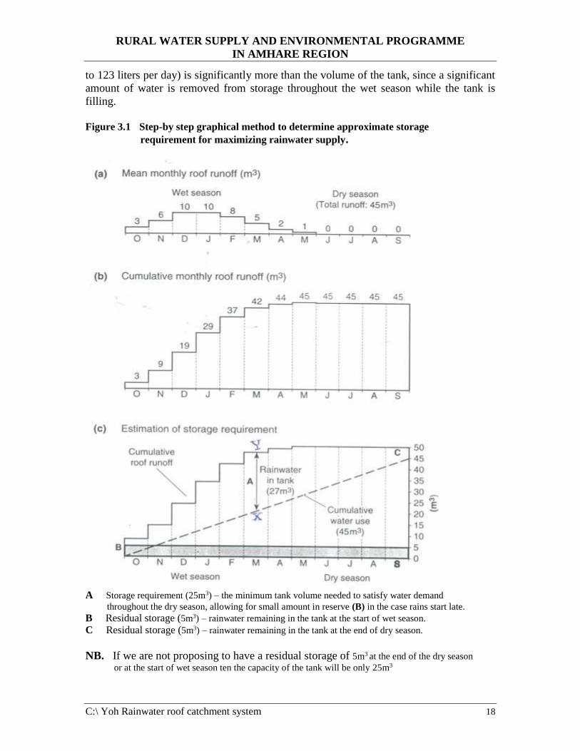
Again referring to Figure 3.3, the total amount of water running off the roof in a year of
average rainfall is recorded as about 45 mcu, so theoretically, if their tank is of adequate
size, the owner of the roof could ration themselves so as to use all this water in 365 days
at withdrawals of 123 liters each day. This steady rate of use is represented by the straight
line A-B. At point B, where this line meets the stepped line representing rainwater
entering the system, the tank has been emptied, though it should be filled again almost
immediately with the onset of the new rainy season.
However at point X, where the two lines are farthest apart, the tank is fuller than at any
time. A distance separating the two lines, X-Y, then represents a volume of 27 mcu,
which is thus an estimate of the capacity of the tank if it is to provide 123 liters daily
ration. Note, however, that the commulative water use of 45 mcu for the year (equivalent
RURAL WATER SUPPLY AND ENVIRONMENTAL PROGRAMME
IN AMHARE REGION
C:\ Yoh Rainwater roof catchment system 18
to 123 liters per day) is significantly more than the volume of the tank, since a significant
amount of water is removed from storage throughout the wet season while the tank is
filling.
Figure 3.1 Step-by step graphical method to determine approximate storage
requirement for maximizing rainwater supply.
A Storage requirement (25m3) – the minimum tank volume needed to satisfy water demand
throughout the dry season, allowing for small amount in reserve (B) in the case rains start late.
B Residual storage (5m3) – rainwater remaining in the tank at the start of wet season.
C Residual storage (5m3) – rainwater remaining in the tank at the end of dry season.
NB. If we are not proposing to have a residual storage of 5m3 at the end of the dry season
or at the start of wet season ten the capacity of the tank will be only 25m3

RURAL WATER SUPPLY AND ENVIRONMENTAL PROGRAMME
IN AMHARE REGION
C:\ Yoh Rainwater roof catchment system 19
For two locations having equal mean annual rainfall but with different rainfall pattern for
different months, the capacities of the storage tank vary and are illustrated as follows.
Although mean monthly data are easy to use, a more accurate graphical data involves the
analysis of cumulative daily rainfall data. Figure 3.4 shows two graphs indicating
cumulative roof runoff from a 100msq roof in two hypothetical locations with very
different rainfall patterns. In both cases, the mean annual rainfall is 1000 mm and a
runoff coefficient of 0.8 is assumed. The roof runoff is shown as a cumulative total for
each month (stepped line) while the water consumption is shown as a continuous line A-
B assuming a regular consumption rate of 220 liters/day (80 mcu/365 days). In this case,
the line X-Y represents the storage capacity required in order to guarantee the maximum
level of supply of 220 liters per day in a normal year. For location 1, the longest dry
period is only one month, but for location 2 a six-month dry season is experienced. It is
clear by comparing the two that for a greater storage volume is required to provide a
constant year round supply when there is a prolonged dry season, 50mcu for location 2,
compared to 20mcu for location 1. Of course, since no year is normal, the supply will
vary and may have to be rationed slightly in drier years, or severely during drought
periods if a continuous supply is to be maintained. If rationing is introduced during the
dry season, or if alternative water sources can be used during this period, the storage
requirement can be greatly reduced. In practice in areas with low or seasonal
precipitation, rainwater is often used for drinking and cooking purposes only, and this
greatly reduces both the storage requirements and the cost of the system.

RURAL WATER SUPPLY AND ENVIRONMENTAL PROGRAMME
IN AMHARE REGION
C:\ Yoh Rainwater roof catchment system 20
C) Where the rainfall is extremely unevenly distributed with frequent drought
periods
Where the rainfall is extremely unevenly distributed with frequent drought periods, a
reservoir should be as large as possible, based on the maximum rainfall (to collect all the
yearly demand of the beneficiaries or all the water falling in the roof area whichever is
critical). In this case the size of the tank will be larger and expensive but still economical
after taking all other factors in to account (if rainwater is the only source to the
community).
3.3.2 Types of rainwater storage tanks
Storage of rainwater can be provided by:
• Locally produced clay pots (locally known as Insera)
• Concrete well rings, set on a concrete base and with cement mortars sealing the
joints (like the concrete cylinders used for well lining)
• Ferro - cement water tanks
• Steel water tanks
• Masonry made tanks
• PVC (plastic) made tanks
• Reinforced concert tanks
• Reinforced brickwork tanks.
The selection of the different types of tanks mainly depends on the availability of
construction materials in the area to construct the type of reservoir, availability of skilled
labor, the required capacity of the tank and the amount of budget allocated for the
rainwater roof catchemnt system.
3.4 Gutters and dawnpipes
Gutters and downpipes are the most commonly used systems for transporting rainwater
from roof catchment to the storage tank.
A carefully designed and constructed gutter and downpipe system is essential for any
roof catchment system to function effectively.
The gutter and downpipe systems are critical to any rainwater roof catchment systems,
yet they are frequently the weak link, which results in poor system efficiency. Broken
gutters often lead to little or no water reaching the tank. Regular gutter maintenance is
therefore, essential, gutters and downpipes need to be thoroughly inspected, and minor
repairs and cleaning conducted at least once in a year.
A common method for excluding leaves and othre debris entering the tank is to place a
coarse, 5 mm or smaller wire mesh over the top of the slightly raised downpipe inlet at
the end of the gutter. If used this material must be checked regularly to ensure it is not
blocked.

RURAL WATER SUPPLY AND ENVIRONMENTAL PROGRAMME
IN AMHARE REGION
C:\ Yoh Rainwater roof catchment system 21
Guttering will be made from:
• Purpose made pre-formed plastic
• Half section of pipe
• Galvanized steel roofing sheet, cut in to strips and formed in to a U-over a pipe or
bent in to a V- shape
• Wooden planks, sealed at the joints
• Split bamboo.
Guttering is usually fixed to building just below the roof and catches the water as it falls
from the roof. Gutters must be placed 3 cm inwards from the edge of the roof to catch the
back-drop of water from light intensity rainfall.
The efficiency of any rainwater catchemnt depends on a greater extent on the gutter and
down pipes. Qualified plumbers work is demanded to fix gutters for roof catchment.
Large roofs especially need precise workmanship. Often workers are seen using ladders,
rather than scaffolding, but precise gutter fixing cannot be achieved without a scaffold on
the overall length of the eave.
A common mistake observed in the under dimensioning of the gutter bracket or not
strongly fixing the gutter with strong bracket. It has to be kept in mind that during heavy
downpours gutters can suddenly be filled with water and their weight might increase up
to 40 kg/m. To avoid deformation or even collapse of gutters, gutter fixing brackets must
be strong enough and spaced at distances not exceeding 1 meters.
In rainwater catchment system down pipes often channel the water over long distances
(from one globe side to the other) with a slope of sometimes only 1%. In all these cases
they are not working as down pipes but rather as covered channels. As a result the down
pipes sometimes develop a weight similar to the gutters and must therefore be securely
fixed to the wall.
Reservoirs at public buildings are often large and, so as not to block the passage,
sometimes constructed at more than 2 meters away from the building. In such cases the
down pipe must be supported at least at an interval of 1 meters length of the down pipe.

RURAL WATER SUPPLY AND ENVIRONMENTAL PROGRAMME
IN AMHARE REGION
C:\ Yoh Rainwater roof catchment system 22
3.4.1 Calculation of gutter and downpipe dimension (sizing)
Gutter and downpipe sizing is the critical element of the design of any roof catchemnt
system. Large quantities of runoff may be lost during heavy storms if gutters are too
small and, therefore, overflow. The capacity of gutters will depend upon the cross
sectional area of the gutter and the amount of rainfalls in the roof.
As a general rule the gutter dimensions for catchment areas of different sizes, a useful
rule of thumb is to make sure that there is at least 1 cm2 of gutter cross - section for every
1 m2 of roof area. To avoid overflow during heavy downpours, it makes sense to provide
a greater gutter capacity. The gutter must be of a sufficient size to discharge water to the
tank without any overflow in the gutter. The figures shown in Table 3.1 and Table 3.2
can be used as a guide for sizing gutters and downpipes.
One thing, which should be given emphasis in the design of gutters, is the slope of gutter
to be fixed. Preferably, gutters should slope towards the tank and downpipe entrance with
a slope of not less than 1% (a fall of 10 mm for 1000 mm length of gutter) to eliminate
the chance of gutter blockage from leaves or other debris as these are more easily flushed
out and to avoid standing water.
In normal house construction, downpipes cross section are sometimes smaller than those
of gutters as it is assumed that since they are normally vertical, water will pass through
them faster than through gutters. In roof catchement systems, however, downpipes should
have similar dimensions to gutters. This is because the downpipes are often not vertical
and usually acts as channels to convey water from the end of the gutter into the tank.
In order to avoid standing water and prevent blockage by leaves, downpipes should have
a minimum slope of 1% (a fall of about 10 mm for 1000mm length of downpipe) towards
the inlet of storage tank.
Table 3.1 Dimension of different gutters having half round shape
It.
No.
Catchment
area/roof area in
msq
Gutter
diameter in
mm
Cross sectional
area of gutter in
sq.cm
Thickness of sheet
in mm if the gutter
to be made of
galvanized iron
sheet
1 Up to 25 80 25 0.65
2 25 – 40 105 43 0.65
3 40 – 60 127 63 0.7
4 60 – 100 153 92 0.7
5 100 – 150 192 145 0.7
6 150 – 250 250 245 0.8

RURAL WATER SUPPLY AND ENVIRONMENTAL PROGRAMME
IN AMHARE REGION
C:\ Yoh Rainwater roof catchment system 23
Table 3.2 Dimension of different gutters having rectangular shape
It.
No.
Catchment
area/roof area in
msq
Gutter size in
mm
Cross
sectional
area of gutter
in sq.cm
Thickness of sheet
in mm if the gutter
to be made of
galvanized iron
sheet
Height
in mm
Width
in mm
1 Up to 30 41 65 27 0.65
2 30 – 40 51 85 43 0.65
3 40 – 100 75 112 84 0.7
4 100 – 150 90 140 126 0.7
5 150 – 250 115 190 219 0.8
6 250 – 450 180 225 405 0.8
Example 3.1. Determine the cross sectional area of gutters for a catchment area of 8 m x
30 m = 240 msq.
Solution 1.
Using the general rule, for every 1 msq of roof area the minimum cross-section of gutter
and downpipe is 240 sq.cm.
Solution 2
According to Table 3.1, for a roof area of 240 msq, you can choose a gutter of half-round
shape, inner diameter 250 mm or
Following Table 3.2, you can choose rectangular gutter, height 115 mm, width 190 mm.

RURAL WATER SUPPLY AND ENVIRONMENTAL PROGRAMME
IN AMHARE REGION
C:\ Yoh Rainwater roof catchment system 24
3.5 Water point (tap point) for collecting stored rainwater for use
Water taps for collecting water from the rainwater roof catchemnt system must be
provided at convenient location for use by the beneficiaries. Very often water tap on the
rainwater roof catchment system is built in to the tank wall.
When installing water taps on tanks, the following two conditions should be satisfied.
- Wastage of storage capacity called ‘ dead storage’ should be avoided.
- The height of the tap point should have sufficient height for a bucket /pot to be placed
under the tap
In order to satisfy the above two conditions, the following alternative methods are
recommended to be used.
1. The outlet pipe (tap point) to be placed at a level not more than 5 cm from the floor
slab of the tank and the point for placing the bucket/pot be situated at 60 cm below
the tank floor slab level (below ground level). See Figure 5.21.
2. The foundation (floor slab) of the tank can be located at about 60 cm above ground
level and the outlet pipe or tap position is installed at a maximum height of 5 cm
above the tank floor. See Figure 5.22.
The number of taps to be used depends on the number of beneficiaries of the system and
is decided based on this.
The other possibility of drawing water from the tank for use is that outlet pipe can be
installed in the tank wall and can be connected to different public (water points)
constructed at different locations.
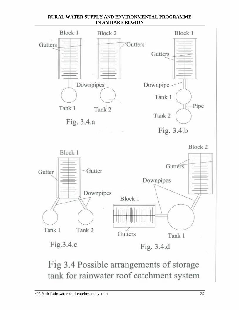
3.6 Possible arrangements of storage tank for rainwater roof catchment system.
The arrangements of the tanks and the size of one tank is very important in determining
the location, number of tanks, and the size of one tank required for a rainwater roof
harvesting system. Out of the different possibilities of arranging tanks, the following are
the most commonly used ones.
1. Storage tank for each block. See Figure 3.4.a
2. Two tanks placed next to each other and connected by an over flow pipe for draining
the overflow from the first tank to the second. See Figure 3.4.b
3. Two tanks located at each of the gable side, collecting water from each gutter. See
Figure 3.4.c
4. One tank for more than one block of a building. See Figure 3.4.d
RURAL WATER SUPPLY AND ENVIRONMENTAL PROGRAMME
IN AMHARE REGION
C:\ Yoh Rainwater roof catchment system 25

RURAL WATER SUPPLY AND ENVIRONMENTAL PROGRAMME
IN AMHARE REGION
C:\ Yoh Rainwater roof catchment system 26
3.7 Common problems with roof catchment system design
Many roof catchment systems are poorly designed. Common mistakes include:
• Gutters that are horizontal or sloping away from the tanks
• Overflow pipes placed well below the top of the tank
• Outlet taps high above the base of the tank
• Downpipes leading to wastage
• Only part of the roof area being used.
The following diagram in Figure 3.5 compares a good and bad roof catchment system.
The poorly designed system is much less efficient than the good one. Less than a quarter
of the roof area is being effectively utilized, and only half of the storage capacity. This is
based on the real example observed in some countries.
Therefore, when constructing a roof water catchment system, the above mentioned
common mistakes should be avoided.

RURAL WATER SUPPLY AND ENVIRONMENTAL PROGRAMME
IN AMHARE REGION
C:\ Yoh Rainwater roof catchment system 27
4. QUALITY OF RAINWATER FROM ROOF CATCHMENT SYSTEM
4.1 Rainwater quality
The quality of rainwater used for domestic supply is of vital importance because, in most
cases, it is used untreated for drinking. The issue of water quality is a complex and
sometimes controversial one, mainly because rainwater does not always meet WHO
drinking water standard especially with respect to bacteriological water quality. The same
however is true for many improved rural water sources in much of the developing world.
Only where water is being provided for larger settlements in systematic treatment and
water quality monitoring common and even here water quality standards may vary
considerably. For more smaller and remote settlements, especially in developing
countries, treatment is both impractical and often unrealistically expensive. For such
settlements across the world, the emphasis remains on providing and maintaining any sort
of improved water source as hundreds of million people still remain unserved.
Generally while rainwater quality will not always match WHO water quality standard,
when compared with most unprotected traditional water sources, rainwater from well
maintained roof catchment usually represents a considerable improvement and is
generally safe to drink without treatment.
4.2 Protecting rainwater quality
4.2.1 Good design, operation and maintenance
The best initial step to protect water quality is to ensure good system design and proper
operation and maintenance. A part from tank cleaning and keeping the gutter and
downpipes clear.
It has been carefully demonstrated that, if careful measures are taken, roof catchment can
provide rainwater clean enough to drink. To achieve this, a certain design features must
be incorporated and other criteria met.
A study was carried out recently at the Indian Institute of Technology in Delhi, India, to
determine the quality of rainwater from domestic rainwater harvesting systems. The
major conclusions reached are as follows:
a) Generally, the physico-chamical quality of water in terms of color, odor, taste, pH,
total dissolved solids (TDS) and total hardness (TH), meet the prescribed standards.
Occasionally pH has been reported to be low (acidic) or high (alkaline).
b) Toxic metals and toxic chemicals are reported only in rare cases and may arise from
material used for the roof or atmospheric pollutants adsorbed on dust.
c) Most of materials used for storage tanks e.g. cement, iron, wood and plastics do not
generally affect the physico-chemical quality, with a few exceptions.
d) The physico-chemical parameters can be tested easily by using available field kits.

RURAL WATER SUPPLY AND ENVIRONMENTAL PROGRAMME
IN AMHARE REGION
C:\ Yoh Rainwater roof catchment system 28
e) The main problem with the quality of stored water in design of roof water harvesting
system lies with its bacteriological quality. The following are the main issues.
• Dust from the soil, and droppings of birds and animals can also be the source
of contamination by the above bacteria.
• In any case where first flush eliminating devices are absent, all the indicator
bacteria are generally present in water samples in numbers beyond what is
acceptable by any standards. Higher temperature reached by a metallic roof
due to solar heating may lead to reduction in bacteria.
• From the health point of view, it is important to clean the gutter from time to
time and ensure that water does not stagnate. This leads mosquitoes breeding.
• Tree hanging in the vicinity, definitely enhances that possibility of
contamination due to increased access of the roof to birds and animals.
• On storage, generally due to limitation of nutrients, bacterial count falls.
Different indicator bacteria under study decay over 7 – 20 days depending on
the initial amount of bacteria, nutrient availability and other storage
conditions.
• Mosquito breeding generally occurs if mosquitoes are already available in the
vicinity of storage. Water quality deteriorates with the bearding of mosquito.
The only way to prevent mosquito in the tank is by covering the openings by
appropriate screens. Thus the basic conclusion from the study, substantiated
by actual experimentation under the project are that design of rainwater
harvesting must be designed, taking the following in to consideration:
a) Convenient first flush device must be integrated. Roughly, the first flush to be taken
may be 2 mm rainfall and the volume is obtained by multiplying this by the area of
the roof.
b) Wire mesh should cover all inlets to prevent any insects, toads, snakes, mosquitoes,
small animals or birds entering the tank.
c) It is preferable to allow water to stand for some time before drawing. The bacterial
count is more at the bottom. Hence the water may be drawn from a higher level, e.g.
withdrawing water from an overflow system may be useful. Thus, instead of one tank
of large capacity, more tanks in a series may be used, but increase in total cost has to
be considered.
d) Some rapid testing methods are useful in the field for indicating presence of
bacteriological contamination. The safest method of treatment for domestic use is
boiling.
e) The roof surface should be smooth and any moss, lichens or other vegetation
removed, including branches from over-hanging trees, since these provide sanctuary
for birds and access for rats and other animals to the catchemnt surface, where
defection could contaminate the rainwater runoff.
f) Taps or draw off pipes in roof tanks should be at least 5 cm above the tank floor, this
allows any debris entering the tank to settle on the bottom where, provided it remains
undistributed, it should not adversely affect water quality.
g) Roof guttering should slope evenly towards the downpipe to avoid stagnation of
water.
h) The tank must be covered and all light must be excluded to prevent the growth of
algae and micro-organisms.

RURAL WATER SUPPLY AND ENVIRONMENTAL PROGRAMME
IN AMHARE REGION
C:\ Yoh Rainwater roof catchment system 29
i) Tanks, gutters, downpipes, screens and all system components should be inspected
and cleaned annually if possible. A tank floor slopping towards a sump and washout
pipe can greatly aid tank cleaning. A well fitting manhole to allow access is essential.
j) Water should not, if possible, be consumed directly from the tank without treatment
for the first few days following major rainfall.
k) Water from other sources should not be mixed with that in the tank.
Immediately following heavy rainfall, the quality of water in the tank may be lowered
due to any debris washed into the tank or stirred up from the bottom which may take
some time to settle out. It is appropriate, therefore, to avoid drinking water directly from
the tank for few days. Contrary to popular myth, however, rather than becoming stale
(smelling and testing bad) with extended storage, rainwater quality usually improves.
This is because bacteria and pathogens gradually die off during the first several days of
storage. For this process to occur, however, it is essential that both light and organic
matter be excluded from the tank. Any light getting into the tank will allow algal growth,
and organic matter will provide nutrients enabling bacteria and other micro-organisms to
survive. In such situation, the stored water may become stale and unpalatable.
4.2.2 First/foul flush system
The simple operation and maintenance of rainwater catchment systems is one of the most
attractive aspects of the technology. The amount of maintenance required for roof
catchemnt system is limited to the annual cleaning of the tank, regular inspection of the
gutters and downpipes, and the removal of any leaves, dirt or any other matter from the
roof.
These debris, dirt, dust and bird droppings will collect on the roof of a building or other
collection area and when the first rains arrive after a dry period, this unwanted matter
would be washed into the tank. This will cause contamination of the water and the quality
will be reduced. Many roof water harvesting systems therefore incorporate a system for
diverting this ‘first flush’ water so that it does not enter the tank.
There are a number of simple systems that are commonly used for diverting the first flush
and also a number of other, slightly more complex, arrangements. Based on experience, it
is recommended that if any kind of first/foul flush design is to be used, it should be very
simple, and easily maintained systems be used, as these are more likely to be repaired if
failure occurs. Examples of simpler systems include:
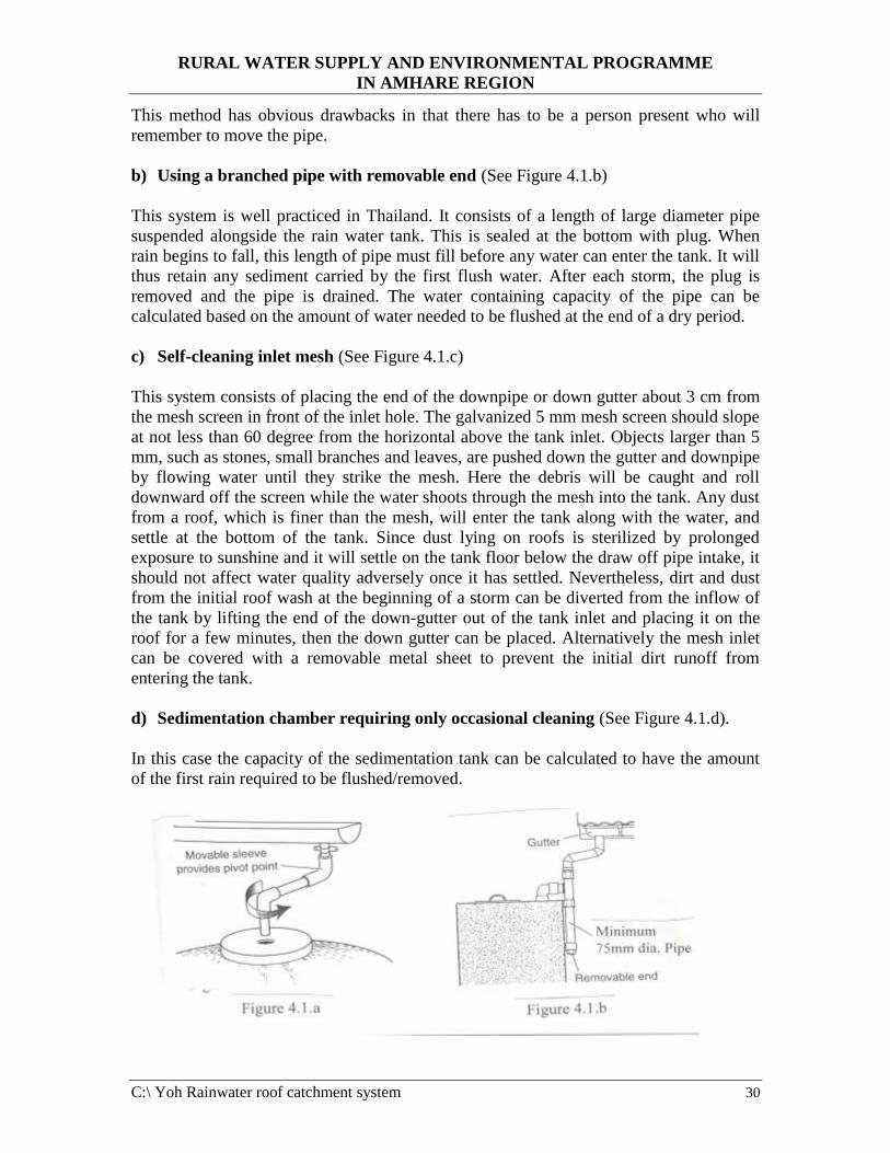
a) Movable downpipe for diverting the runoff from the season's first down-pour
(see Figure 4.1.a)
The simpler and more convenient method of cleaning the roof is to detach the downpipe
(inlet to tank) from the tank before the start of the first major downpour, to allow the
initial rainfall to wash the roof and allow the first flush to run to waste for several
minutes until the roof is clean and then replaced again once the initial first flush has been
diverted. The method is more appropriate in regions with distinct wet and dry seasons.
RURAL WATER SUPPLY AND ENVIRONMENTAL PROGRAMME
IN AMHARE REGION
C:\ Yoh Rainwater roof catchment system 30
This method has obvious drawbacks in that there has to be a person present who will
remember to move the pipe.
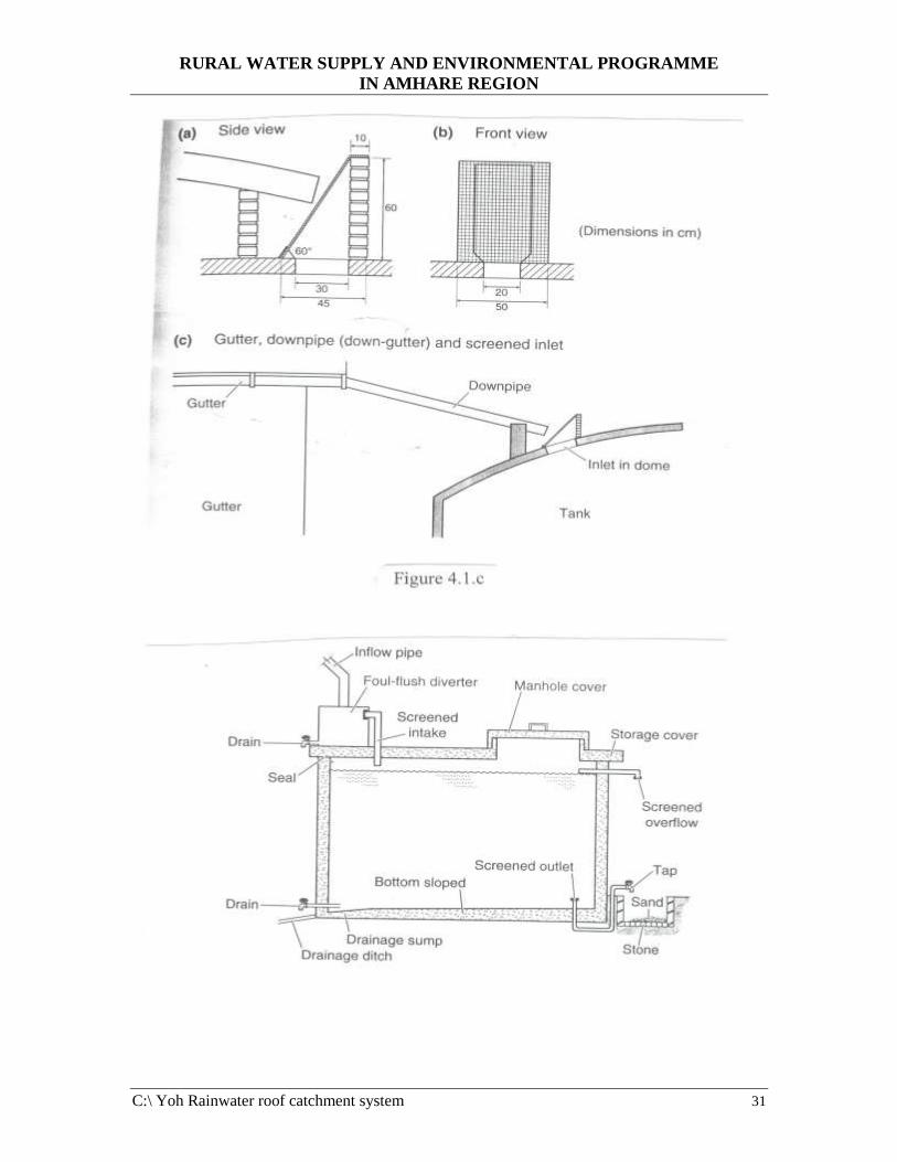
b) Using a branched pipe with removable end (See Figure 4.1.b)
This system is well practiced in Thailand. It consists of a length of large diameter pipe
suspended alongside the rain water tank. This is sealed at the bottom with plug. When
rain begins to fall, this length of pipe must fill before any water can enter the tank. It will
thus retain any sediment carried by the first flush water. After each storm, the plug is
removed and the pipe is drained. The water containing capacity of the pipe can be
calculated based on the amount of water needed to be flushed at the end of a dry period.
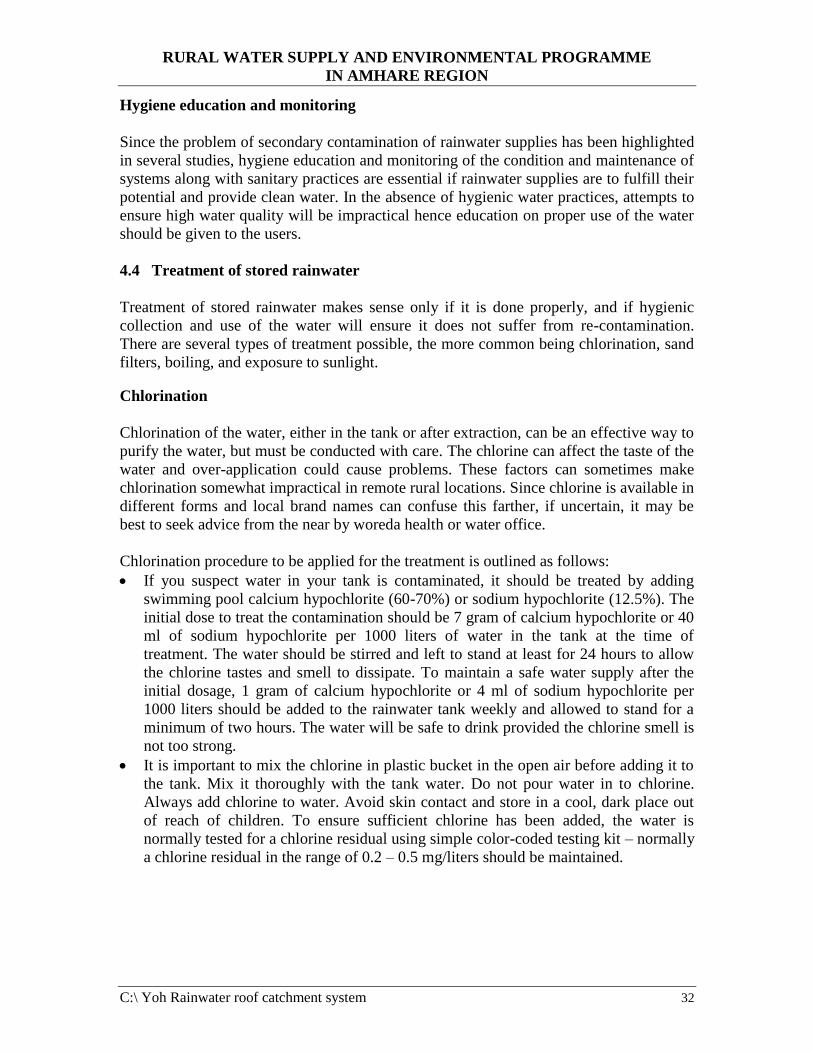
c) Self-cleaning inlet mesh (See Figure 4.1.c)
This system consists of placing the end of the downpipe or down gutter about 3 cm from
the mesh screen in front of the inlet hole. The galvanized 5 mm mesh screen should slope
at not less than 60 degree from the horizontal above the tank inlet. Objects larger than 5
mm, such as stones, small branches and leaves, are pushed down the gutter and downpipe
by flowing water until they strike the mesh. Here the debris will be caught and roll
downward off the screen while the water shoots through the mesh into the tank. Any dust
from a roof, which is finer than the mesh, will enter the tank along with the water, and
settle at the bottom of the tank. Since dust lying on roofs is sterilized by prolonged
exposure to sunshine and it will settle on the tank floor below the draw off pipe intake, it
should not affect water quality adversely once it has settled. Nevertheless, dirt and dust
from the initial roof wash at the beginning of a storm can be diverted from the inflow of
the tank by lifting the end of the down-gutter out of the tank inlet and placing it on the
roof for a few minutes, then the down gutter can be placed. Alternatively the mesh inlet
can be covered with a removable metal sheet to prevent the initial dirt runoff from
entering the tank.
d) Sedimentation chamber requiring only occasional cleaning (See Figure 4.1.d).
In this case the capacity of the sedimentation tank can be calculated to have the amount
of the first rain required to be flushed/removed.
RURAL WATER SUPPLY AND ENVIRONMENTAL PROGRAMME
IN AMHARE REGION
C:\ Yoh Rainwater roof catchment system 31
RURAL WATER SUPPLY AND ENVIRONMENTAL PROGRAMME
IN AMHARE REGION
C:\ Yoh Rainwater roof catchment system 32
Hygiene education and monitoring
Since the problem of secondary contamination of rainwater supplies has been highlighted
in several studies, hygiene education and monitoring of the condition and maintenance of
systems along with sanitary practices are essential if rainwater supplies are to fulfill their
potential and provide clean water. In the absence of hygienic water practices, attempts to
ensure high water quality will be impractical hence education on proper use of the water
should be given to the users.
4.4 Treatment of stored rainwater
Treatment of stored rainwater makes sense only if it is done properly, and if hygienic
collection and use of the water will ensure it does not suffer from re-contamination.
There are several types of treatment possible, the more common being chlorination, sand
filters, boiling, and exposure to sunlight.
Chlorination
Chlorination of the water, either in the tank or after extraction, can be an effective way to
purify the water, but must be conducted with care. The chlorine can affect the taste of the
water and over-application could cause problems. These factors can sometimes make
chlorination somewhat impractical in remote rural locations. Since chlorine is available in
different forms and local brand names can confuse this farther, if uncertain, it may be
best to seek advice from the near by woreda health or water office.
Chlorination procedure to be applied for the treatment is outlined as follows:
• If you suspect water in your tank is contaminated, it should be treated by adding
swimming pool calcium hypochlorite (60-70%) or sodium hypochlorite (12.5%). The
initial dose to treat the contamination should be 7 gram of calcium hypochlorite or 40
ml of sodium hypochlorite per 1000 liters of water in the tank at the time of
treatment. The water should be stirred and left to stand at least for 24 hours to allow
the chlorine tastes and smell to dissipate. To maintain a safe water supply after the
initial dosage, 1 gram of calcium hypochlorite or 4 ml of sodium hypochlorite per
1000 liters should be added to the rainwater tank weekly and allowed to stand for a
minimum of two hours. The water will be safe to drink provided the chlorine smell is
not too strong.
• It is important to mix the chlorine in plastic bucket in the open air before adding it to
the tank. Mix it thoroughly with the tank water. Do not pour water in to chlorine.
Always add chlorine to water. Avoid skin contact and store in a cool, dark place out
of reach of children. To ensure sufficient chlorine has been added, the water is
normally tested for a chlorine residual using simple color-coded testing kit – normally
a chlorine residual in the range of 0.2 – 0.5 mg/liters should be maintained.

RURAL WATER SUPPLY AND ENVIRONMENTAL PROGRAMME
IN AMHARE REGION
C:\ Yoh Rainwater roof catchment system 33
Boiling
Although boiling water thoroughly for two or three minutes normally ensures it is free
from any harmful bacteria or pathogens, it is not always a practical option. Boiling
requires a lot of energy which, in areas where fuel is scarce or expensive, may be a
problem, and waiting for the water to cool is also tiresome.
Exposure to sunlight
Another way to kill many of the harmful bacteria in water is to put it in clear glass or
plastic bottles and place it in direct sunlight for several hours. This technique has
undergone extensive subsequent field tests. The process works in two ways: bacteria and
micro-organisms are killed both by exposure to direct radiation and, if heated sufficiently,
by water temperature exceeding 70oC. This latter effect can be increased by painting half
of the bottle black to increase solar radiation absorption. To be effective in using this
method, the water should not be too turbulent or excessively contaminated.

RURAL WATER SUPPLY AND ENVIRONMENTAL PROGRAMME
IN AMHARE REGION
C:\ Yoh Rainwater roof catchment system 34
5. CONSTRUCTION OF FERRO-CEMENT TANK (RESERVOIR)
5.1 History of ferro-cement
Ferro-cement is a construction method provided by applying cement mortar composed of
a fine aggregate (sand) and cement onto wire reinforcement and/or wire mesh using
plaster techniques.
Ferro-cement was first developed by a Frenchman, Joseph Monier as early as 1887. The
technology has been used in a variety of constructions including boat building. Its use in
water tank construction is a relatively recent phenomenon and really took off only in the
1950s and 1960s.
Its high labor input requirement really makes ferro-cement most appropriate in countries
with cheap skilled labor. Cracks in ferro-cement tanks can be repaired fairly easily and
leaks can be sealed by using different techniques.
5.2 Commonly used sizes of ferro-cement tanks
Although the technology is possible to build surface tanks with volumes of over 100 m3
or more, most of the tanks built in some countries have been less than 20 mcu in volume.
The success of the technology on larger capacities of tanks varies from country to country
or region to region (more success was reported in Asian countries) which stems form a
variety of reasons, in particular, problems with the level of skills and workmanship.
The technology also has been used in our country for some semi urban water supply
schemes and the capacity of the tanks constructed in most cases is in the range of 20 to 50
muc, therefore till the construction of tanks using this technology is widely spread and
proven that the necessary skill is well developed, it is proposed to use this technology for
tanks having capacities less than 50 mcu. For capacities more than 50 mcu, reinforced
concrete or masonry made tanks are recommended to be used.
Table 5.1 Dimensions of ferro-cement tanks
It.
No.
Dimension Capacity of the ferro-cement tank
10 mcu 20 mcu 30 mcu 40 mcu
1 Internal diameter in
meters
2.66 3.76 4.68 5.34
2 Foundation slab
diameter in meters
3.02 4.1 5.04 5.7
3 Diameter of the
mesh circle for the
tank wall in meters
2.72 3.82 4.74 5.4
4 External diameter of
the tank wall in
2.76 3.86 4.78 5.44
RURAL WATER SUPPLY AND ENVIRONMENTAL PROGRAMME
IN AMHARE REGION
C:\ Yoh Rainwater roof catchment system 35
meters
5 Height of the
structure excluding
the dome in meters
1.8 1.8 1.9 1.9
6 Height of the dome
in meters
0.25 0.45 0.5 0.6
7 Height of the
structure including
the dome in meters
2.05 2.25 2.4 2.5
8 Level of overflow
pipe in meters
1.7 1.7 1.8 1.8
9 Mesh circumference
including 200 mm
overlap in meters
9 12.4 15.3 17.4
5.3 Construction procedure of ferro-cement tank
The construction procedure of different capacities of ferro-cement tanks to be constructed
above the ground level is discussed below.
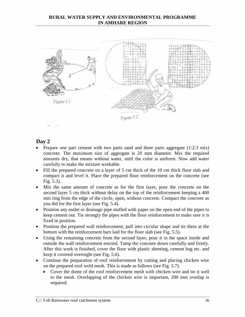
Day 1 • Excavate a shallow circular level foundation, 100 mm deep having a diameter equal
to the diameter of the tank floor (see Fig. 5.1).
• Within the diameter of the tank floor remove all topsoil. If the depth of the topsoil
is more than 100 mm, you have to refill with hardcore and the refill must be well
compacted.
• Note that no foundation should be made on top soil which is loose/unstable
because the tank can crack
• Prepare a mesh of 6 mm diameter steel reinforcement bars spaced 15 cm center to
center in both directions for the floor slab reinforcement. Tie each mesh with binding
wire so as to keep the 15 cm spacing between bars constant (see Fig. 5.2).
• Prepare the wall reinforcement from 6 mm diameter bars spaced 15 cm center to
center and forming a mesh. The bars are prepared to make a cylinder with good
circular shape. Tie the meshed bars together with binding wire as you did for the floor
slab reinforcement. Bend the vertical bars of the meshed wall reinforcement at the
bottom alternatively inwards and outwards, forming right angles (90 degree). Bend
the top of these vertical bars inwards at an angle of 45 degree.
• Prepare the roof reinforcement from of 6 mm diameter bars spaced 15 cm center to
center to form a mesh. The mesh is to have a dome shape and the height of the dome
for different capacities of reservoirs is shown in Table 5.1. For example for reservoir
capacity of 20 mcu, the roof slab is to be made as follows.
• The reinforcement is made by marking the circle of the roof slab dimension in
your preparation area. Put an upright hollow concrete block of about 450 mm high
for support at the center of the circle. The roof has to be a dome shape, so the
cement block marks the highest point of the dome. Cut the reinforcement bars as
required and tie the bars together with binding wire to form the mesh.
RURAL WATER SUPPLY AND ENVIRONMENTAL PROGRAMME
IN AMHARE REGION
C:\ Yoh Rainwater roof catchment system 36
Day 2 • Prepare one part cement with two parts sand and three parts aggregate (1:2:3 mix)
concrete. The maximum size of aggregate is 20 mm diameter. Mix the required
amounts dry, that means without water, until the color is uniform. Now add water
carefully to make the mixture workable.
• Fill the prepared concrete on a layer of 5 cm thick of the 10 cm thick floor slab and
compact it and level it. Place the prepared floor reinforcement on the concrete (see
Fig. 5.3).
• Mix the same amount of concrete as for the first layer, pour the concrete on the
second layer 5 cm thick without delay on the top of the reinforcement keeping a 400
mm ring from the edge of the circle, open, without concrete. Compact the concrete as
you did for the first layer (see Fig. 5.4).
• Position any outlet or drainage pipe stuffed with paper on the open end of the pipes to
keep cement out. Tie strongly the pipes with the floor reinforcement to make sure it is
fixed in position.
• Position the prepared wall reinforcement, pull into circular shape and tie them at the
bottom with the reinforcement bars laid for the floor slab (see Fig. 5.5).
• Using the remaining concrete from the second layer, pour it in the space inside and
outside the wall reinforcement erected. Tamp the concrete down carefully and firmly.
After this work is finished, cover the floor with plastic sheeting, cement bag etc. and
keep it covered overnight (see Fig. 5.6).
• Continue the preparation of roof reinforcement by cutting and placing chicken wire
on the prepared roof weld mesh. This is made as follows (see Fig. 5.7).
• Cover the dome of the roof reinforcement mesh with chicken wire and tie it well
to the mesh. Overlapping of the chicken wire is important, 200 mm overlap is
required.

RURAL WATER SUPPLY AND ENVIRONMENTAL PROGRAMME
IN AMHARE REGION
C:\ Yoh Rainwater roof catchment system 37

RURAL WATER SUPPLY AND ENVIRONMENTAL PROGRAMME
IN AMHARE REGION
C:\ Yoh Rainwater roof catchment system 38
Day 3 • Keep the concrete wet throughout the day by splashing water on it every three hours.
• Prepare the wall for plastering.
• Before you start plastering, remember that the entire first coat of the tank must be
plastered in one day. It is not possible to keep the unfinished plaster overnight.
Where one - day - old plaster is joined with the fresh plaster, leaking will occur.
Make sure you have enough labor for mixing the plaster and carrying it to
plasterers. If necessary have two plasterers and start on two opposite sides of the
tank wall.
• Warp the outside of the wall reinforcement mesh with one layer of chicken wire,
from the top to the concrete floor. Take the roll of the chicken wire and push the
top long edge over the free vertical mesh. While continuing to encircle the
cylinder, keep pulling the chicken wire tight in both vertical and horizontal
direction (see Fig. 5.8). Try to do this job with three people, one carrying the roll
and pulling the wire, one fixing it with prepared short pieces of binding wire on
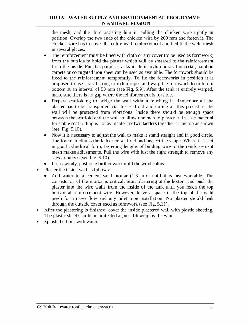
RURAL WATER SUPPLY AND ENVIRONMENTAL PROGRAMME
IN AMHARE REGION
C:\ Yoh Rainwater roof catchment system 39
the mesh, and the third assisting him in pulling the chicken wire tightly in
position. Overlap the two ends of the chicken wire by 200 mm and fasten it. The
chicken wire has to cover the entire wall reinforcement and tied to the weld mesh
in several places.
• The reinforcement must be lined with cloth or any cover (to be used as formwork)
from the outside to hold the plaster which will be smeared to the reinforcement
from the inside. For this purpose sacks made of nylon or sisal material, bamboo
carpets or corrugated iron sheet can be used as available. The formwork should be
fixed to the reinforcement temporarily. To fix the formworks in position it is
proposed to use a sisal string or nylon ropes and warp the formwork from top to
bottom at an interval of 50 mm (see Fig. 5.9). After the tank is entirely warped,
make sure there is no gap where the reinforcement is feasible.
• Prepare scaffolding to bridge the wall without touching it. Remember all the
plaster has to be transported via this scaffold and during all this procedure the
wall will be protected from vibrations. Inside there should be enough space
between the scaffold and the wall to allow one man to plaster it. In case material
for stable scaffolding is not available, fix two ladders together at the top as shown
(see Fig. 5.10).
• Now it is necessary to adjust the wall to make it stand straight and in good circle.
The foreman climbs the ladder or scaffold and inspect the shape. Where it is not
in good cylindrical form, fastening lengths of binding wire to the reinforcement
mesh makes adjustments. Pull the wire with just the right strength to remove any
sags or bulges (see Fig. 5.10).
• If it is windy, postpone further work until the wind calms.
• Plaster the inside wall as follows:
• Add water to a cement sand mortar (1:3 mix) until it is just workable. The
consistency of the mortar is critical. Start plastering at the bottom and push the
plaster into the wire walls from the inside of the tank until you reach the top
horizontal reinforcement wire. However, leave a space in the top of the weld
mesh for an overflow and any inlet pipe installation. No plaster should leak
through the outside cover used as formwork (see Fig. 5.11).
• After the plastering is finished, cover the inside plastered wall with plastic sheeting.
The plastic sheet should be protected against blowing by the wind.
• Splash the floor with water.
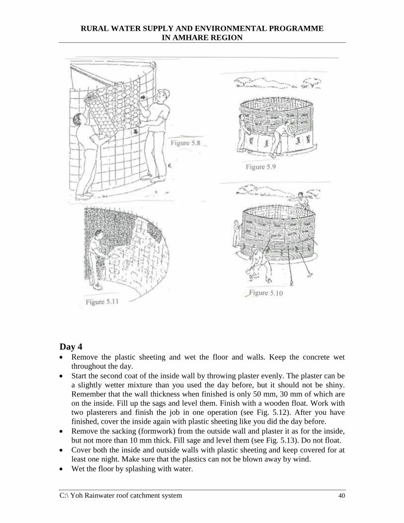
RURAL WATER SUPPLY AND ENVIRONMENTAL PROGRAMME
IN AMHARE REGION
C:\ Yoh Rainwater roof catchment system 40
Day 4 • Remove the plastic sheeting and wet the floor and walls. Keep the concrete wet
throughout the day.
• Start the second coat of the inside wall by throwing plaster evenly. The plaster can be
a slightly wetter mixture than you used the day before, but it should not be shiny.
Remember that the wall thickness when finished is only 50 mm, 30 mm of which are
on the inside. Fill up the sags and level them. Finish with a wooden float. Work with
two plasterers and finish the job in one operation (see Fig. 5.12). After you have
finished, cover the inside again with plastic sheeting like you did the day before.
• Remove the sacking (formwork) from the outside wall and plaster it as for the inside,
but not more than 10 mm thick. Fill sage and level them (see Fig. 5.13). Do not float.
• Cover both the inside and outside walls with plastic sheeting and keep covered for at
least one night. Make sure that the plastics can not be blown away by wind.
• Wet the floor by splashing with water.
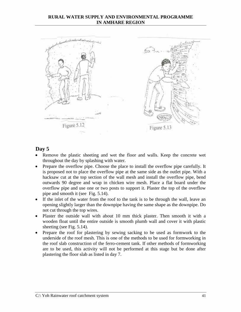
RURAL WATER SUPPLY AND ENVIRONMENTAL PROGRAMME
IN AMHARE REGION
C:\ Yoh Rainwater roof catchment system 41
Day 5 • Remove the plastic sheeting and wet the floor and walls. Keep the concrete wet
throughout the day by splashing with water.
• Prepare the overflow pipe. Choose the place to install the overflow pipe carefully. It
is proposed not to place the overflow pipe at the same side as the outlet pipe. With a
hacksaw cut at the top section of the wall mesh and install the overflow pipe, bend
outwards 90 degree and wrap in chicken wire mesh. Place a flat board under the
overflow pipe and use one or two posts to support it. Plaster the top of the overflow
pipe and smooth it (see Fig. 5.14).
• If the inlet of the water from the roof to the tank is to be through the wall, leave an
opening slightly larger than the downpipe having the same shape as the downpipe. Do
not cut through the top wires.
• Plaster the outside wall with about 10 mm thick plaster. Then smooth it with a
wooden float until the entire outside is smooth plumb wall and cover it with plastic
sheeting (see Fig. 5.14).
• Prepare the roof for plastering by sewing sacking to be used as formwork to the
underside of the roof mesh. This is one of the methods to be used for formworking in
the roof slab construction of the ferro-cement tank. If other methods of formworking
are to be used, this activity will not be performed at this stage but be done after
plastering the floor slab as listed in day 7.
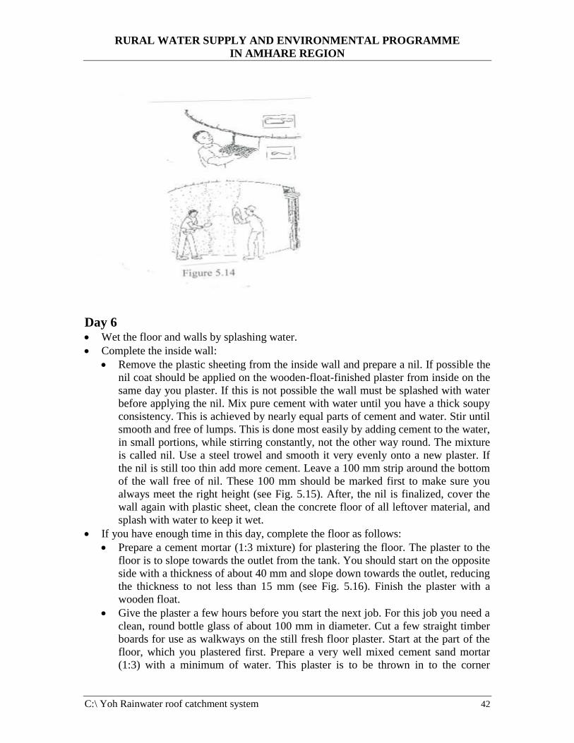
RURAL WATER SUPPLY AND ENVIRONMENTAL PROGRAMME
IN AMHARE REGION
C:\ Yoh Rainwater roof catchment system 42
Day 6 • Wet the floor and walls by splashing water.
• Complete the inside wall:
• Remove the plastic sheeting from the inside wall and prepare a nil. If possible the
nil coat should be applied on the wooden-float-finished plaster from inside on the
same day you plaster. If this is not possible the wall must be splashed with water
before applying the nil. Mix pure cement with water until you have a thick soupy
consistency. This is achieved by nearly equal parts of cement and water. Stir until
smooth and free of lumps. This is done most easily by adding cement to the water,
in small portions, while stirring constantly, not the other way round. The mixture
is called nil. Use a steel trowel and smooth it very evenly onto a new plaster. If
the nil is still too thin add more cement. Leave a 100 mm strip around the bottom
of the wall free of nil. These 100 mm should be marked first to make sure you
always meet the right height (see Fig. 5.15). After, the nil is finalized, cover the
wall again with plastic sheet, clean the concrete floor of all leftover material, and
splash with water to keep it wet.
• If you have enough time in this day, complete the floor as follows:
• Prepare a cement mortar (1:3 mixture) for plastering the floor. The plaster to the
floor is to slope towards the outlet from the tank. You should start on the opposite
side with a thickness of about 40 mm and slope down towards the outlet, reducing
the thickness to not less than 15 mm (see Fig. 5.16). Finish the plaster with a
wooden float.
• Give the plaster a few hours before you start the next job. For this job you need a
clean, round bottle glass of about 100 mm in diameter. Cut a few straight timber
boards for use as walkways on the still fresh floor plaster. Start at the part of the
floor, which you plastered first. Prepare a very well mixed cement sand mortar
(1:3) with a minimum of water. This plaster is to be thrown in to the corner
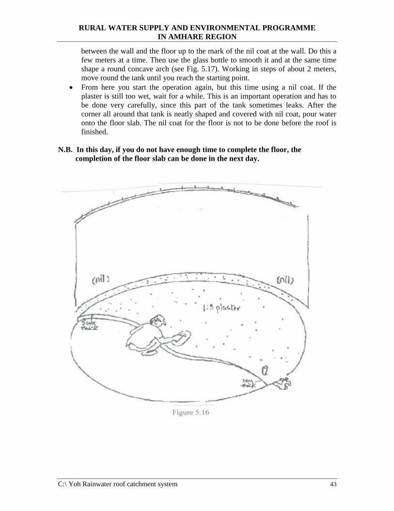
RURAL WATER SUPPLY AND ENVIRONMENTAL PROGRAMME
IN AMHARE REGION
C:\ Yoh Rainwater roof catchment system 43
between the wall and the floor up to the mark of the nil coat at the wall. Do this a
few meters at a time. Then use the glass bottle to smooth it and at the same time
shape a round concave arch (see Fig. 5.17). Working in steps of about 2 meters,
move round the tank until you reach the starting point.
• From here you start the operation again, but this time using a nil coat. If the
plaster is still too wet, wait for a while. This is an important operation and has to
be done very carefully, since this part of the tank sometimes leaks. After the
corner all around that tank is neatly shaped and covered with nil coat, pour water
onto the floor slab. The nil coat for the floor is not to be done before the roof is
finished.
N.B. In this day, if you do not have enough time to complete the floor, the
completion of the floor slab can be done in the next day.
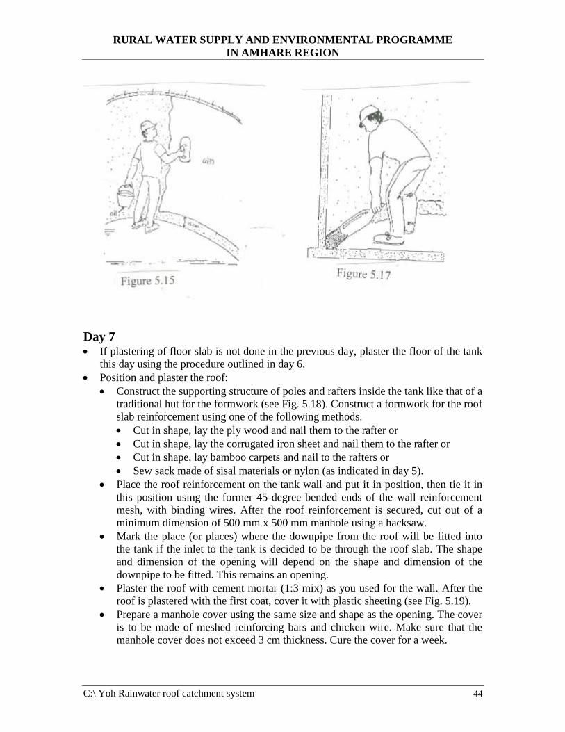
RURAL WATER SUPPLY AND ENVIRONMENTAL PROGRAMME
IN AMHARE REGION
C:\ Yoh Rainwater roof catchment system 44
Day 7 • If plastering of floor slab is not done in the previous day, plaster the floor of the tank
this day using the procedure outlined in day 6.
• Position and plaster the roof:
• Construct the supporting structure of poles and rafters inside the tank like that of a
traditional hut for the formwork (see Fig. 5.18). Construct a formwork for the roof
slab reinforcement using one of the following methods.
• Cut in shape, lay the ply wood and nail them to the rafter or
• Cut in shape, lay the corrugated iron sheet and nail them to the rafter or
• Cut in shape, lay bamboo carpets and nail to the rafters or
• Sew sack made of sisal materials or nylon (as indicated in day 5).
• Place the roof reinforcement on the tank wall and put it in position, then tie it in
this position using the former 45-degree bended ends of the wall reinforcement
mesh, with binding wires. After the roof reinforcement is secured, cut out of a
minimum dimension of 500 mm x 500 mm manhole using a hacksaw.
• Mark the place (or places) where the downpipe from the roof will be fitted into
the tank if the inlet to the tank is decided to be through the roof slab. The shape
and dimension of the opening will depend on the shape and dimension of the
downpipe to be fitted. This remains an opening.
• Plaster the roof with cement mortar (1:3 mix) as you used for the wall. After the
roof is plastered with the first coat, cover it with plastic sheeting (see Fig. 5.19).
• Prepare a manhole cover using the same size and shape as the opening. The cover
is to be made of meshed reinforcing bars and chicken wire. Make sure that the
manhole cover does not exceed 3 cm thickness. Cure the cover for a week.
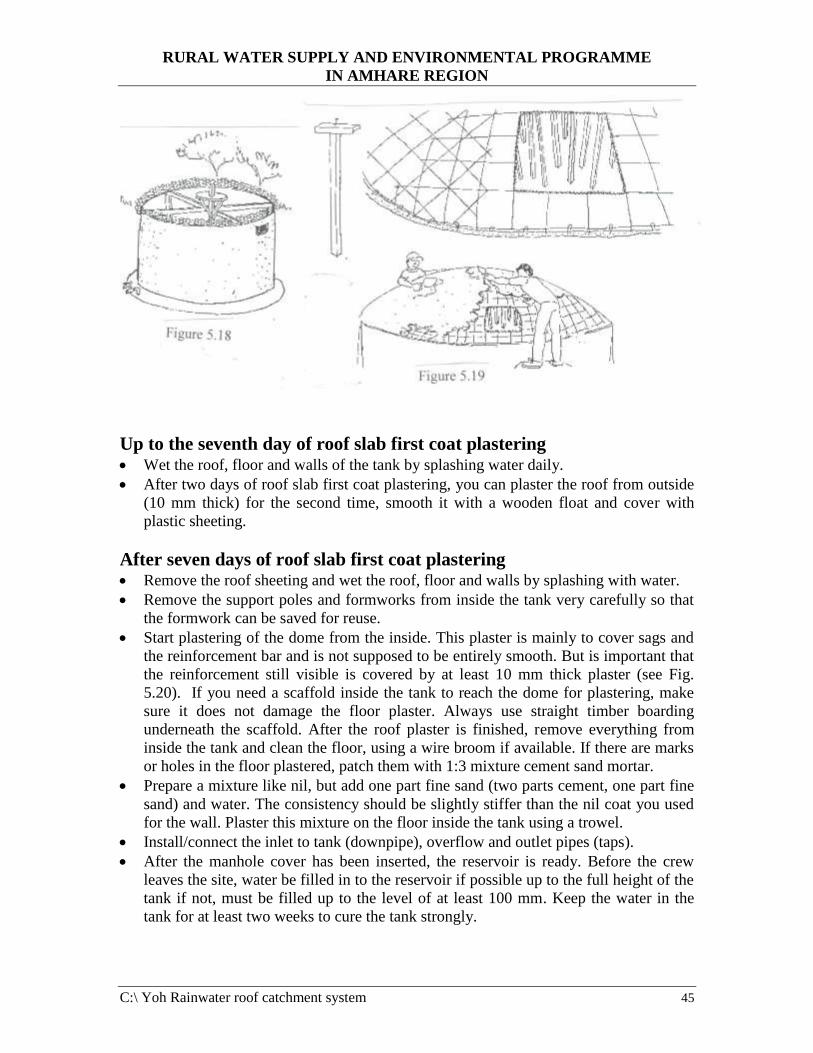
RURAL WATER SUPPLY AND ENVIRONMENTAL PROGRAMME
IN AMHARE REGION
C:\ Yoh Rainwater roof catchment system 45
Up to the seventh day of roof slab first coat plastering • Wet the roof, floor and walls of the tank by splashing water daily.
• After two days of roof slab first coat plastering, you can plaster the roof from outside
(10 mm thick) for the second time, smooth it with a wooden float and cover with
plastic sheeting.
After seven days of roof slab first coat plastering • Remove the roof sheeting and wet the roof, floor and walls by splashing with water.
• Remove the support poles and formworks from inside the tank very carefully so that
the formwork can be saved for reuse.
• Start plastering of the dome from the inside. This plaster is mainly to cover sags and
the reinforcement bar and is not supposed to be entirely smooth. But is important that
the reinforcement still visible is covered by at least 10 mm thick plaster (see Fig.
5.20). If you need a scaffold inside the tank to reach the dome for plastering, make
sure it does not damage the floor plaster. Always use straight timber boarding
underneath the scaffold. After the roof plaster is finished, remove everything from
inside the tank and clean the floor, using a wire broom if available. If there are marks
or holes in the floor plastered, patch them with 1:3 mixture cement sand mortar.
• Prepare a mixture like nil, but add one part fine sand (two parts cement, one part fine
sand) and water. The consistency should be slightly stiffer than the nil coat you used
for the wall. Plaster this mixture on the floor inside the tank using a trowel.
• Install/connect the inlet to tank (downpipe), overflow and outlet pipes (taps).
• After the manhole cover has been inserted, the reservoir is ready. Before the crew
leaves the site, water be filled in to the reservoir if possible up to the full height of the
tank if not, must be filled up to the level of at least 100 mm. Keep the water in the
tank for at least two weeks to cure the tank strongly.
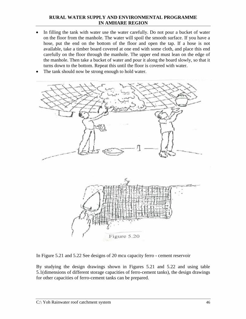
RURAL WATER SUPPLY AND ENVIRONMENTAL PROGRAMME
IN AMHARE REGION
C:\ Yoh Rainwater roof catchment system 46
• In filling the tank with water use the water carefully. Do not pour a bucket of water
on the floor from the manhole. The water will spoil the smooth surface. If you have a
hose, put the end on the bottom of the floor and open the tap. If a hose is not
available, take a timber board covered at one end with some cloth, and place this end
carefully on the floor through the manhole. The upper end must lean on the edge of
the manhole. Then take a bucket of water and pour it along the board slowly, so that it
turns down to the bottom. Repeat this until the floor is covered with water.
• The tank should now be strong enough to hold water.
In Figure 5.21 and 5.22 See designs of 20 mcu capacity ferro - cement reservoir
By studying the design drawings shown in Figures 5.21 and 5.22 and using table
5.1(dimensions of different storage capacities of ferro-cement tanks), the design drawings
for other capacities of ferro-cement tanks can be prepared.
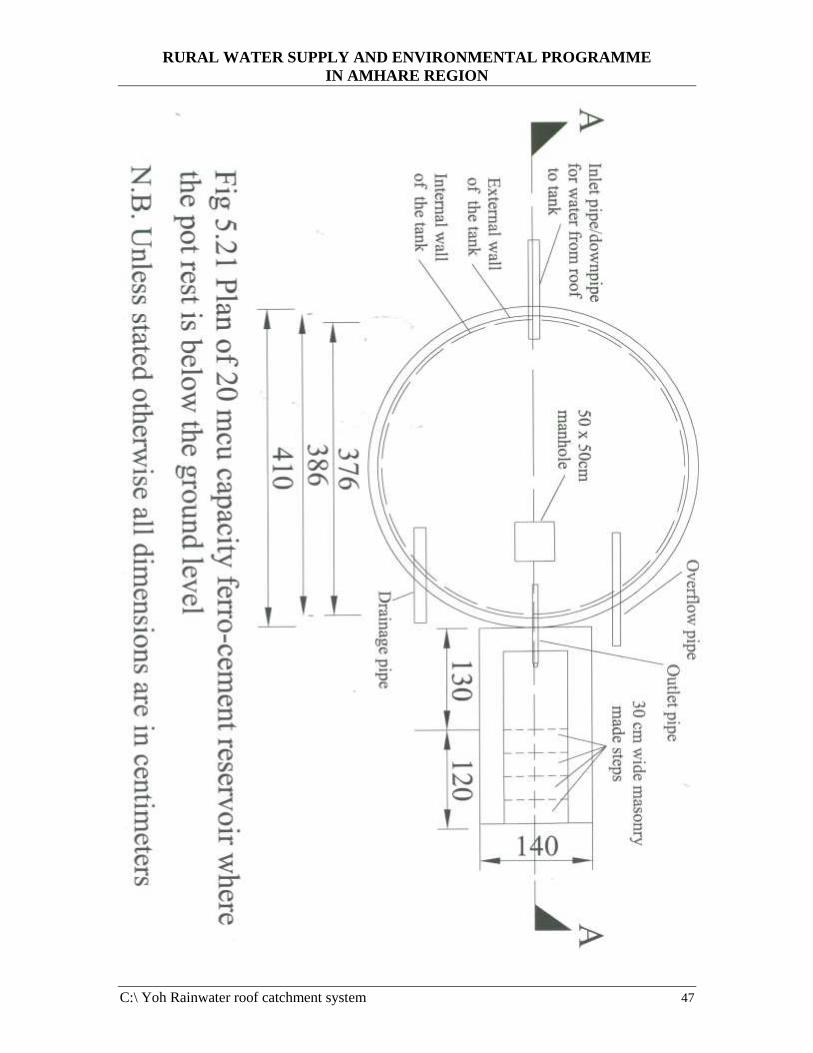
RURAL WATER SUPPLY AND ENVIRONMENTAL PROGRAMME
IN AMHARE REGION
C:\ Yoh Rainwater roof catchment system 47
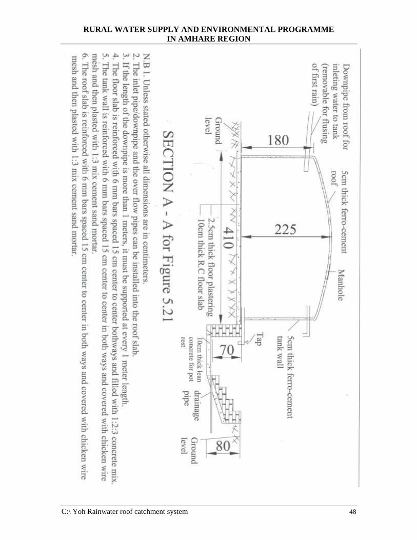
RURAL WATER SUPPLY AND ENVIRONMENTAL PROGRAMME
IN AMHARE REGION
C:\ Yoh Rainwater roof catchment system 48
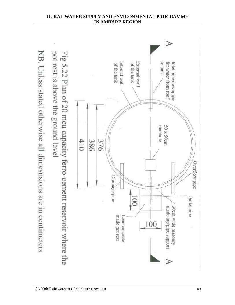
RURAL WATER SUPPLY AND ENVIRONMENTAL PROGRAMME
IN AMHARE REGION
C:\ Yoh Rainwater roof catchment system 49
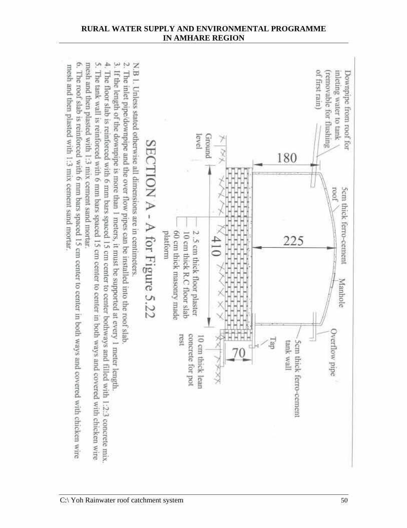
RURAL WATER SUPPLY AND ENVIRONMENTAL PROGRAMME
IN AMHARE REGION
C:\ Yoh Rainwater roof catchment system 50

RURAL WATER SUPPLY AND ENVIRONMENTAL PROGRAMME
IN AMHARE REGION
C:\ Yoh Rainwater roof catchment system 51
5.4 Repair of ferro -cement tanks (reservoirs)
Repairing ferro-cement tank is easy but should not encourage poor quality of work. If the
structure is constructed using good quality of materials, good workmanship and cured as
described in the construction procedure, then leaks are likely to occur. Small leaks which
create only a wet stain need not be attended to, since they will close after some time.
Only leaks where water flows out to be repaired.
The possibility of repairing leaking tanks depend on several factors, including:
• Being able to locate the point of leakage
• The size of the leak
• Whether the leak is above or below the level of water in the tank.
Usually, locating leaks in the walls of surface (above the ground constructed) tanks is
straightforward – unless these are in the tank floor. The repair system to be used for
leaking tanks will depend on whether the tank is in use, meaning leak occurs on the part
of the tank filled with water or in the upper part of the wall where the ferro-cment is
rather dry.
a) Tank repair method on dry surfaces
If the area of the tank-requiring repair is dry the repair method to be used is as follows:
• Chisel out the damaged area around the leak, wet the whole area thoroughly by
splashing with several times from inside and outside until an area of at least half a
square meter is moist, and apply new mortar (with the same cement: sand ratio as the
original) with a trowel and the surface smoothened (trowel finish). A coat of nil can
be applied the next day and the patch covered with plastic sheeting and cured for at
least three weeks. For this method of repair see Figure 5.23 in the next page.

RURAL WATER SUPPLY AND ENVIRONMENTAL PROGRAMME
IN AMHARE REGION
C:\ Yoh Rainwater roof catchment system 52
In most tanks, small leaks are generally much easier to rapier than large ones. If a leak
appears if tank is eventually filled with rainwater, it is more appropriate to consume the
water than drain it to repair the leak. Two different methods of sealing an already filled
reservoir from the outside can be tried, provided the material needed is available.
However, there is no guarantee that these methods, will seal the tank, but since they do
not affect professional repair, they might be tried if large amounts of water are at risk.
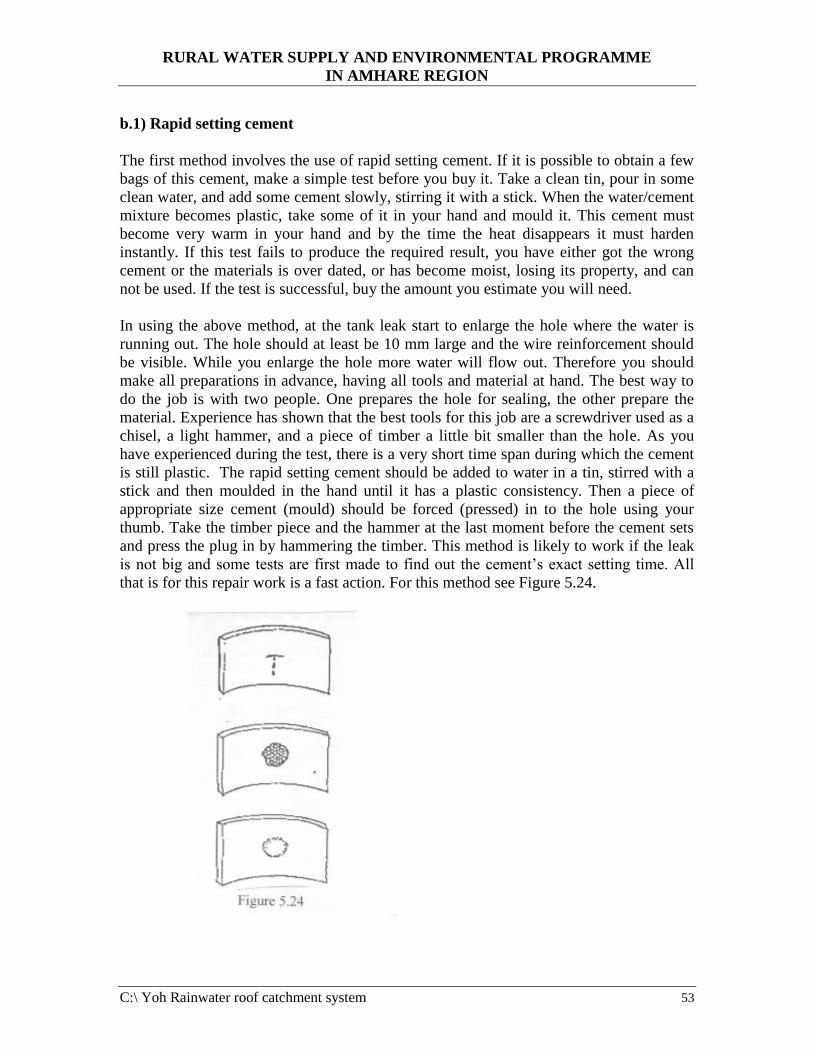
RURAL WATER SUPPLY AND ENVIRONMENTAL PROGRAMME
IN AMHARE REGION
C:\ Yoh Rainwater roof catchment system 53
b.1) Rapid setting cement
The first method involves the use of rapid setting cement. If it is possible to obtain a few
bags of this cement, make a simple test before you buy it. Take a clean tin, pour in some
clean water, and add some cement slowly, stirring it with a stick. When the water/cement
mixture becomes plastic, take some of it in your hand and mould it. This cement must
become very warm in your hand and by the time the heat disappears it must harden
instantly. If this test fails to produce the required result, you have either got the wrong
cement or the materials is over dated, or has become moist, losing its property, and can
not be used. If the test is successful, buy the amount you estimate you will need.
In using the above method, at the tank leak start to enlarge the hole where the water is
running out. The hole should at least be 10 mm large and the wire reinforcement should
be visible. While you enlarge the hole more water will flow out. Therefore you should
make all preparations in advance, having all tools and material at hand. The best way to
do the job is with two people. One prepares the hole for sealing, the other prepare the
material. Experience has shown that the best tools for this job are a screwdriver used as a
chisel, a light hammer, and a piece of timber a little bit smaller than the hole. As you
have experienced during the test, there is a very short time span during which the cement
is still plastic. The rapid setting cement should be added to water in a tin, stirred with a
stick and then moulded in the hand until it has a plastic consistency. Then a piece of
appropriate size cement (mould) should be forced (pressed) in to the hole using your
thumb. Take the timber piece and the hammer at the last moment before the cement sets
and press the plug in by hammering the timber. This method is likely to work if the leak
is not big and some tests are first made to find out the cement’s exact setting time. All
that is for this repair work is a fast action. For this method see Figure 5.24.

RURAL WATER SUPPLY AND ENVIRONMENTAL PROGRAMME
IN AMHARE REGION
C:\ Yoh Rainwater roof catchment system 54
b.2) Sodium silicate
The second method requires the application of sodium silicate to the leak. Sodium silicate
is a clear viscous liquid, which hardens on contact with air. This can be applied to a leak
if the water flows out without pressure. In using this method first sanding down the wall
around the leak with sandpaper to achieve a slightly rough surface of the cement wall.
Open the bottle or container with sodium silicate only when you have completed
preparations, since this chemical hardens on contact with the air. Use a spatula or a thin
metal sheet to apply it, using the same technique as described for the nil coat. The sodium
silicate should cover an area slightly larger than the leak. This method has often been
used with much success.
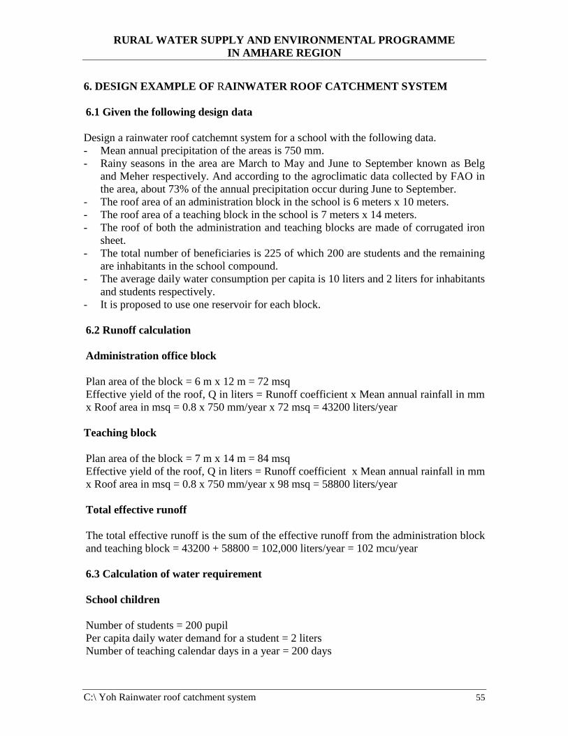
RURAL WATER SUPPLY AND ENVIRONMENTAL PROGRAMME
IN AMHARE REGION
C:\ Yoh Rainwater roof catchment system 55
6. DESIGN EXAMPLE OF RAINWATER ROOF CATCHMENT SYSTEM
6.1 Given the following design data
Design a rainwater roof catchemnt system for a school with the following data.
- Mean annual precipitation of the areas is 750 mm.
- Rainy seasons in the area are March to May and June to September known as Belg
and Meher respectively. And according to the agroclimatic data collected by FAO in
the area, about 73% of the annual precipitation occur during June to September.
- The roof area of an administration block in the school is 6 meters x 10 meters.
- The roof area of a teaching block in the school is 7 meters x 14 meters.
- The roof of both the administration and teaching blocks are made of corrugated iron
sheet.
- The total number of beneficiaries is 225 of which 200 are students and the remaining
are inhabitants in the school compound.
- The average daily water consumption per capita is 10 liters and 2 liters for inhabitants
and students respectively.
- It is proposed to use one reservoir for each block.
6.2 Runoff calculation
Administration office block
Plan area of the block = 6 m x 12 m = 72 msq
Effective yield of the roof, Q in liters = Runoff coefficient x Mean annual rainfall in mm
x Roof area in msq = 0.8 x 750 mm/year x 72 msq = 43200 liters/year
Teaching block
Plan area of the block = 7 m x 14 m = 84 msq
Effective yield of the roof, Q in liters = Runoff coefficient x Mean annual rainfall in mm
x Roof area in msq = 0.8 x 750 mm/year x 98 msq = 58800 liters/year
Total effective runoff
The total effective runoff is the sum of the effective runoff from the administration block
and teaching block = 43200 + 58800 = 102,000 liters/year = 102 mcu/year
6.3 Calculation of water requirement
School children
Number of students = 200 pupil
Per capita daily water demand for a student = 2 liters
Number of teaching calendar days in a year = 200 days
RURAL WATER SUPPLY AND ENVIRONMENTAL PROGRAMME
IN AMHARE REGION
C:\ Yoh Rainwater roof catchment system 56
Water demand for students, Q = 200 students x 2 liters/student/day x 200 days = 80000
liters/year = 180 mcu/year
To calculate the water requirement per month = 80 mcu/6.67 months = 12 mcu/month
NB. 6.67 months are calculated based on that there are 30 days in one month hence 6.67
months are present in 200 days.
Community beneficiaries.
Number of inhabitants = 25 people
Per capita daily water demand for a person = 10 liters
Water demand for inhabitants, Q = 25 inhabitants x 10 liters/person/day x 365 days =
91250 liters/year = 91.25 mcu/year
To calculate the water requirement per month = 91.25 mcu/12 months = 7.6 mcu/month
Total water requirement
The total volume of water required = Water required for students + Water required for
inhabitants = 100 mcu/year + 91.25 mcu/year = 171.25 mcu/year
Please note that the total effective runoff from the administration blocks and from the
teaching block = 43.2 mcu + 58.8 mcu = 102 mcu/year. Though the design criteria was
set deliberately considering only the water usage for drinking and cooking purposes,
there is still a deficit of 69.25 mcu of water to satisfy the whole requirements of the
beneficiaries. However, it is important to bear in mind that the scheme is not intended to
supply the whole population but it is to supplement the usual water shortage occurring
during the dry seasons from ponds, and hence, improve the health condition of the
beneficiaries to a certain level.
Moreover, it is believed that the scheme will have a great impact and role on community
awareness towards the use of other alternative water sources such as rainwater other than
the traditional ponds and may encourage the beneficiaries to similar replication of the
roof water harvesting individually or on group basis. Therefore, rather than abandoning
the construction of the system, it is recommended to implement it hence the design is
completed as follows.
6.4 Determination of reservoir capacity (size)
According to the agroclimatological data collected by FAO, of the area, about 73% of the
annual precipitation occur during June to September. Therefore, the sizes of reservoirs
were considered in order to accumulate about 73% of the annual precipitation. And the
remaining 27 % of the precipitation which will fall during March to May will fill the part
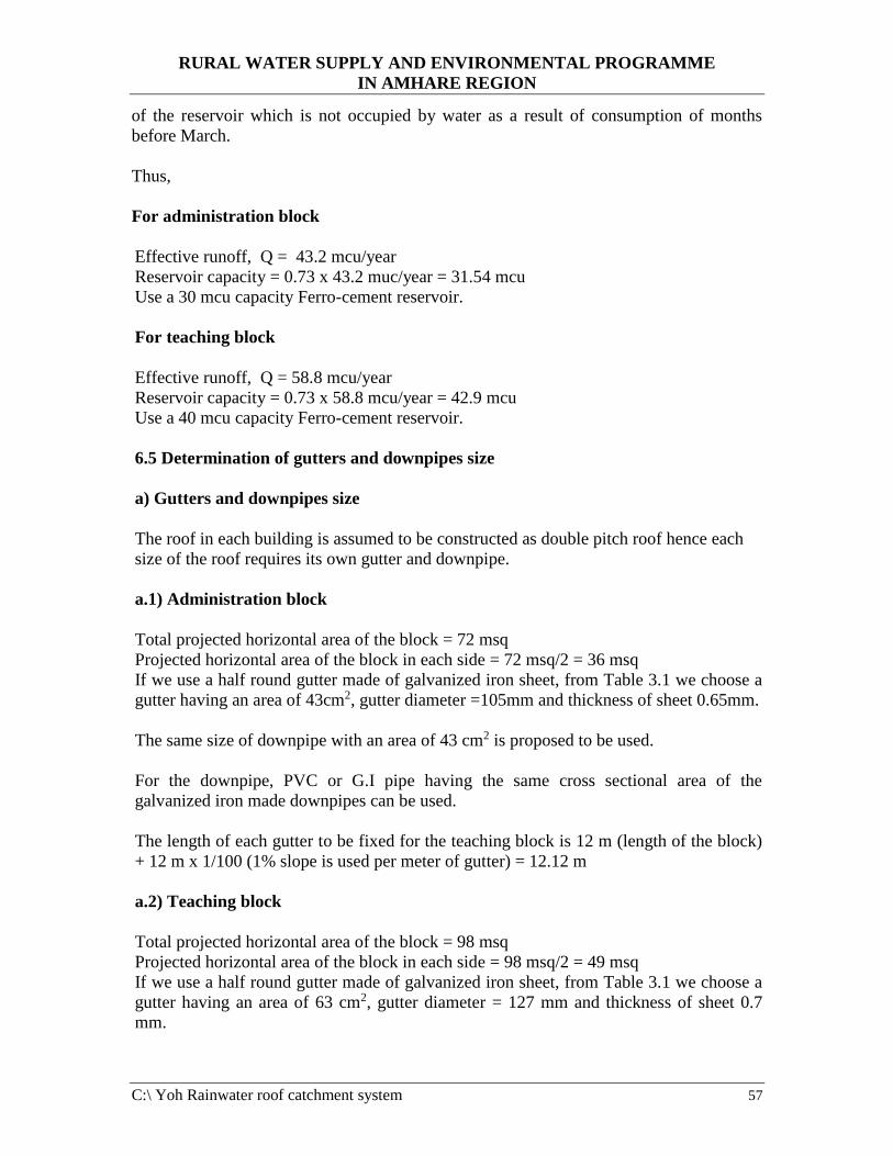
RURAL WATER SUPPLY AND ENVIRONMENTAL PROGRAMME
IN AMHARE REGION
C:\ Yoh Rainwater roof catchment system 57
of the reservoir which is not occupied by water as a result of consumption of months
before March.
Thus,
For administration block
Effective runoff, Q = 43.2 mcu/year
Reservoir capacity = 0.73 x 43.2 muc/year = 31.54 mcu
Use a 30 mcu capacity Ferro-cement reservoir.
For teaching block
Effective runoff, Q = 58.8 mcu/year
Reservoir capacity = 0.73 x 58.8 mcu/year = 42.9 mcu
Use a 40 mcu capacity Ferro-cement reservoir.
6.5 Determination of gutters and downpipes size
a) Gutters and downpipes size
The roof in each building is assumed to be constructed as double pitch roof hence each
size of the roof requires its own gutter and downpipe.
a.1) Administration block
Total projected horizontal area of the block = 72 msq
Projected horizontal area of the block in each side = 72 msq/2 = 36 msq
If we use a half round gutter made of galvanized iron sheet, from Table 3.1 we choose a
gutter having an area of 43cm2, gutter diameter =105mm and thickness of sheet 0.65mm.
The same size of downpipe with an area of 43 cm2 is proposed to be used.
For the downpipe, PVC or G.I pipe having the same cross sectional area of the
galvanized iron made downpipes can be used.
The length of each gutter to be fixed for the teaching block is 12 m (length of the block)
+ 12 m x 1/100 (1% slope is used per meter of gutter) = 12.12 m
a.2) Teaching block
Total projected horizontal area of the block = 98 msq
Projected horizontal area of the block in each side = 98 msq/2 = 49 msq
If we use a half round gutter made of galvanized iron sheet, from Table 3.1 we choose a
gutter having an area of 63 cm2, gutter diameter = 127 mm and thickness of sheet 0.7
mm.

RURAL WATER SUPPLY AND ENVIRONMENTAL PROGRAMME
IN AMHARE REGION
C:\ Yoh Rainwater roof catchment system 58
The length of each gutter to be fixed for the teaching block is 14 m (length of the block)
+ 14m x 1/100 (1% slope is sued per meter of gutter) = 14.14 m
The same size of downpipe with an area of 63 cm2 is proposed to be used.
For the downpipe, PVC or G.I pipe having the same cross sectional area of the
galvanized iron made downpipes can be used
b) Fixing of gutters and downpipes
The gutter is required to be fixed/laid at minimal slope of 1% (1 cm per 1 meter length of
gutter) towards the entrance of the downpipe to avoid standing water due to debris, bird
droppings, dusts etc. Also, the distance from the roof drip to the top of the gutter would
be mot more than 40 mm in order to minimize excessive loss of water from wind effect.
The downpipe is also required to be fixed/laid at minimal slope of 1% (1 cm per 1 meter
length of downpipe) from the end of the gutter towards the inlet to the tank. The length
of the downpipe depends on the location of the tank.
For example, if the location of the reservoir is proposed to be at a distance of 2 meters
from the edge of the building, then the minimum length of the downpipe = 2 m + 2m x
1/100 = 2.02 meters.
6.6 Tap points
Tap points need to be located at convenient location for use by the beneficiaries. If it had
been only for community use, we would have installed only one tap for each reservoir as
one tap can supply 150 to 200 beneficiaries per day as per the design criteria being used
in our country.
Here since the beneficiaries are mainly students which have only 15 minutes break in
each morning and afternoon session hence not to create a load in faucets, it is
recommended to install two taps (¾” faucets) in each reservoir so that 50 students can use
per tap.
For sake of convenience by students use, it is recommended to excavate 60 cm below the
tank level and construct the tap point/pot rest point. Or if the height of the roof of the
building allows, we can construct 60 cm high masonry/concrete made platform and
construct the reservoir on the platform so that enough height is provided for students use
or pot rest.
6.7 Design Drawings
The layout of the design is shown in Figure 6.1.
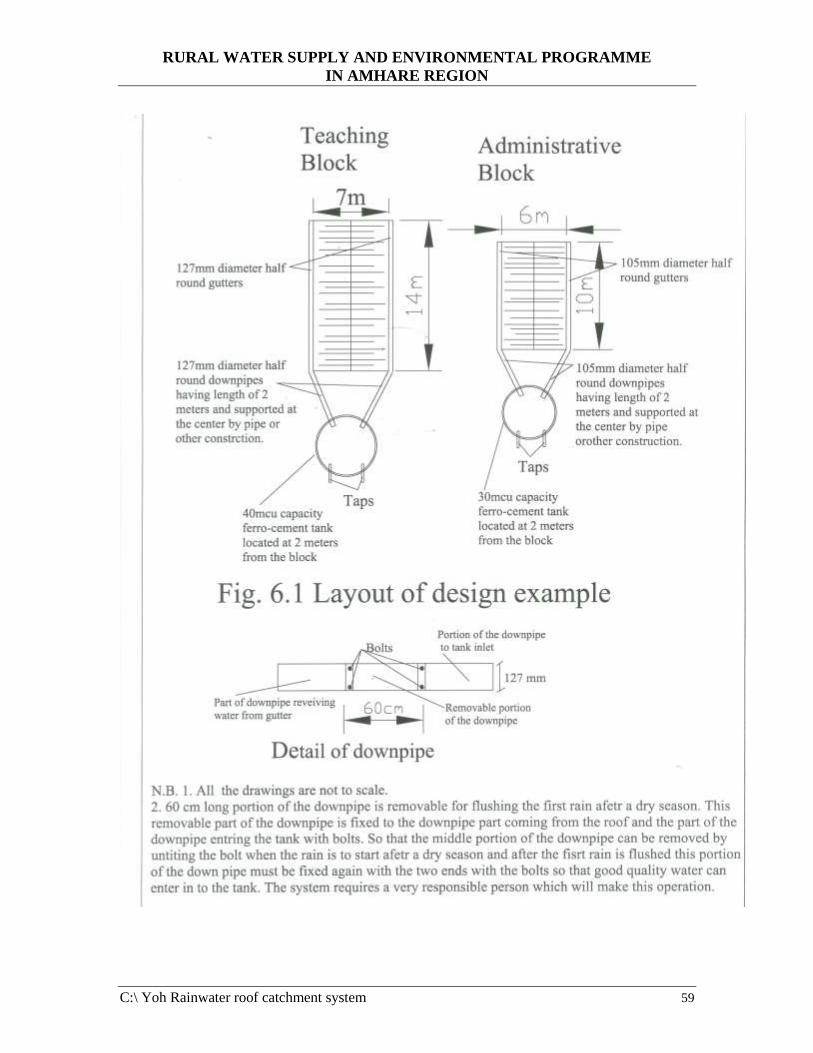
RURAL WATER SUPPLY AND ENVIRONMENTAL PROGRAMME
IN AMHARE REGION
C:\ Yoh Rainwater roof catchment system 59
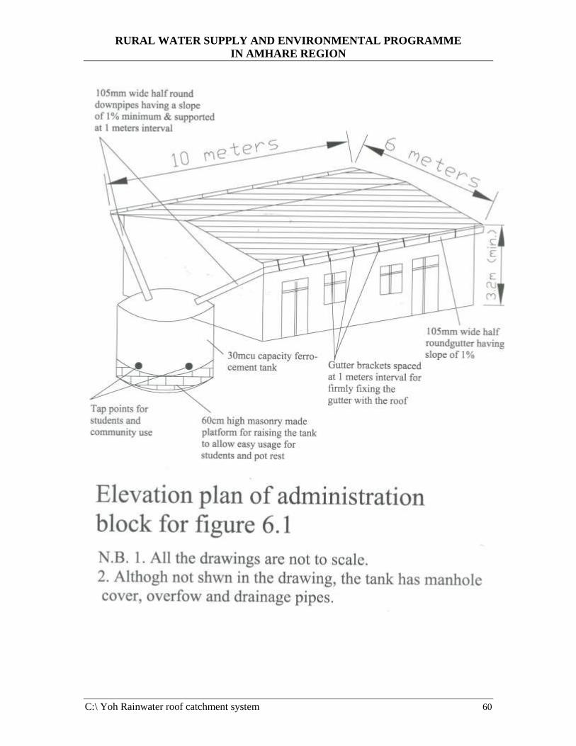
RURAL WATER SUPPLY AND ENVIRONMENTAL PROGRAMME
IN AMHARE REGION
C:\ Yoh Rainwater roof catchment system 60

RURAL WATER SUPPLY AND ENVIRONMENTAL PROGRAMME
IN AMHARE REGION
C:\ Yoh Rainwater roof catchment system 61
REFERENCES
Arnold Pacey and Adrain Cullis, 1986. “Rainwater harvesting”. The collection of rainfall
and runoff in rural areas.
Jan Davis and Robert Lambert, 1995. “Engineering in Emergencies”. A practical guide
for relief workers.
John Gould and Erik Nissen-Petersen, 1999. “Rainwater Catchment System for Domestic
Supply”. Design, construction and implementation.
“ETHIOPIA: Small - Scale Rainwater Harvesting Technologies “. Report on assessment
of experience, June/July 2002.
Erik Nissen – Petersen, Dr. Michael. Nairobi, 1990. “Harvesting Rainwater in Semi -
Arid Africa”