Community Center & Vehicle Storage Building Roof ...
129
CONTRACT, SPECIFICATIONS, PROPOSAL & BONDS FOR Community Center & Vehicle Storage Building Roof Replacements Submitted By ________________________________________ Street ________________________________________________ City _____________________ State ________ Zip____________ Phone _________________________________ Fax _____________________________________ E-Mail ___________________________________ Burgess & Niple, Inc. Ashley Williston, PE, Project Manager 100 W. Erie Street Painesville, OH 44077 440.354.9700 Chris Campbell, Public Works Director Public Works Department 10231 Ravenna Road, Twinsburg, Ohio 44087 Phone 330.963.6212 1
-
Upload
khangminh22 -
Category
Documents
-
view
0 -
download
0
Transcript of Community Center & Vehicle Storage Building Roof ...
CONTRACT, SPECIFICATIONS, PROPOSAL & BONDS
FOR
Community Center &
Vehicle Storage Building
Roof Replacements
Submitted By ________________________________________
Street ________________________________________________
City _____________________ State ________ Zip____________
Phone _________________________________
Fax _____________________________________
E-Mail ___________________________________
Burgess & Niple, Inc.
Ashley Williston, PE, Project Manager
100 W. Erie Street
Painesville, OH 44077
440.354.9700
Chris Campbell, Public Works Director Public Works Department
10231 Ravenna Road, Twinsburg, Ohio 44087
Phone 330.963.6212
1

TABLE OF CONTENTS
Description Page Table of Contents 2 Legal Notice 3 Scope of Work 4-5 Opinion of Probable Construction Cost 5 Instructions to Bidders General Requirements & Conditions 6 Bid Proper 6 Certified Check or Bid Bond 6 Non-Collusion Affidavit 6 Bidders Signature 6 Tax Exemption 7 Award and Execution of Contract General Requirements and Conditions 7 Maintenance Bond 7 Performance Bond and Payment Bond 7 Insurance 7 Worker's Compensation 8 Wage Scale and Labor 8 Sub-Contractors / Service Providers 8 Equal Employment Opportunity 9 Award of Contract 9 Payments 9 Change Order 10 Dispute Resolution Process 10 Commencement of Project 11 Time Extensions 11 Safety Requirements 11 Technical Specifications 12-106 Bid Documents
Prices to Include 107 -108 Bid Proposal Sheet 109 Non-Collusion Affidavit 110 Qualifications of Bidder Affidavit 111-112 Bidder’s Signature and Ownership 113 List of Sub-Contractors & Suppliers 114 Release & Hold Harmless 115
Contract Documents Performance Bond 116 Payment Bond 117-118 Two-Year Maintenance Bond 119 Certificate of Personal Property Taxes 120 Contract Agreement Acknowledgement / Agreement for Contractor 121-123
Prevailing Wage Documents 124 2

LEGAL NOTICE
Sealed bids will be received at the Office of the Clerk of Council of the City of Twinsburg, Ohio,
10075 Ravenna Road, Twinsburg, Ohio 44087, until 9:00 A.M. on the 10th day of May, 2021 for
furnishing of:
Labor, materials and equipment necessary to complete the “Community Center & Vehicle
Storage Building Roof Replacements” in accordance with the plans and specifications now on file
in the office of said Clerk.
Plans, specifications and contract books can only be obtained from the City of Twinsburg City Hall,
10075 Ravenna Road, Twinsburg, Ohio 44087, (330) 425-7161. A non-refundable deposit of Fifty
Dollars ($50.00) is required by the City. Make checks payable to the City of Twinsburg.
Each bidder is required to furnish with its proposal a Bid Guaranty and Contract Bond in
accordance with Section 153.54 of the Ohio Revised Code. Bid security furnished in Bond form,
shall be issued by a Surety Company or Corporation licensed in the State of Ohio to provide said
surety. The sum equal to ten percent (10%) of amount bid, payable to the City of Twinsburg as a
guarantee that if the bid is accepted, a contract will be entered into and its performance properly
secured.
Each proposal must contain the full name of the party or parties submitting the proposal and all
persons interested therein. The owner intends and requires that this project be substantially
completed no later than 180 days from the issuance of the “Notice to Proceed”.
Bidders must comply with the prevailing wage rates on Public Improvements in Summit County
and the City of Twinsburg, Ohio as determined by the Ohio Department of Commerce, Bureau of
Wage and Hour Administration, 614.644.2239.
The right is reserved by the City of Twinsburg to reject any and all bids.
Shannon Collins
Clerk of Council
Publish: 4/20/21 & 4/27/21
cc: Akron Beacon Journal
3

SCOPE OF WORK
The work included in this project generally consists of removal and replacement of the membrane
roofs at the Community Center and Vehicle Storage Building at the Wastewater Treatment Plant
per the drawings and specifications. While the City may elect to award both the Community Center
and Vehicle Storage buildings to one contractor, separate monthly pay applications for each project
are required.
The Community Center scope, Contract A, includes replacing the existing TPO membrane roof,
insulation and other associated components (which consists of 5 areas with a total of approximately
6,500 square feet of roof). The new roof is a single ply membrane roof assembly with a new access
hatch and equipment curbs. The new roof will be installed on the existing plywood roof deck.
Portions of the existing deck may need to be replaced if in poor condition; an allowance is included
in the bid documents and the actual quantity and cost will be adjusted by change order. Overflow
drains and new primary drains will be added, and the new roof assembly is designed to provide
positive draining to existing and new drains.
The Vehicle Storage Building, Contract B, scope includes replacing the existing membrane roof,
insulation and other associated components (with a total of approximately 4,500 square feet of
roof). The new roof is anticipated to be a single ply membrane roof assembly with a new access
hatch and drainage modifications. The new roof will be installed on the existing metal deck.
Portions of the existing deck may need to be repaired after the existing membrane roof is removed;
an allowance is included in the bid documents and the actual quantity and cost will be adjusted by
change order.
There is no pre- bid meeting for this project. Site visits are strongly encouraged and can be
scheduled by calling 330-963-6260. The address for the Twinsburg Community Center is
10260 Ravenna Road, Twinsburg OH 44087. The address for the Twinsburg WWTP is
10231 Ravenna Road, Twinsburg OH 44087.
Prospective bidders may address inquires by e-mail to [email protected].
Questions received less than 96 hours prior to the opening of Bids may not be answered.
The Contractor shall only have one designated superintendent assigned to this project who shall
be on site daily, for the duration of the project, until substantial completion is accepted by the City.
This person shall have full knowledge of the Contract, authority to execute orders or directions of
the Engineer, supervise all work performed by sub-contractors and service providers, responsible
for making sure the project site is secure and that the site is inspected daily, including weekends
and holidays and to verify the work zones are secure and has a safe and clear passage at all times.
They must be available at all times to receive telephone calls regarding the current status of this
project and questions from the Inspector/Engineer. The “Twinsburg Community Center Roof
Replacement” and “Twinsburg Vehicle Storage Building Roof Replacement” shall be substantially
completed after 180 days from notice to proceed.
4

COVID-19 Protocols must be followed at all times. Masks must be worn by all contractors and
sub-contractors. Sign in and Sign out forms shall be kept on the job site. Anyone with a temperature
over 100.4 is not permitted on the job site until they are symptom free for 24 hours without
medication. Anyone exposed to COVID-19 or tests positive for COVID-19 is not permitted on the
job site until they receive a negative COVID-19 test. Contractors shall sanitize any surfaces or
doors used at the beginning and end of each work day with CDC approved sanitizers.
The Contractor is required to complete all items on the Punch List at the end of the project, within
fourteen calendar days after its acceptance by said Contractor. They shall also provide a written
notice of disagreement to the Engineer within five calendar days explaining Punch List Items being
objected to by their Company. These objections will be reviewed and responded to by the
Engineer. City will take affirmative action when Punch List items remain incomplete after thirty
days has expired. The Engineering Department and the City Inspector will perform a final walk-
thru and prepare this Punch List prior to City acceptance.
The Contractor awarded this Contract must perform work amounting to at least fifty percent of the
Contract Amount. The Contractor is required to work every week day, Monday thru Friday,
minimum 40 hours per week, until substantial completion, weather permitting. Time Extensions
to the Contract Completion Date due to weather conditions, shall be submitted to the Engineer for
review to determine if additional time is warranted. Deliveries of material and construction
equipment shall not take place before/after the hours noted below.
Construction Hours: Mon. – Fri. (7:30 A.M. to 7 P.M.)
Contractor to comply with COT 509.11 regarding construction noise.
All work performed throughout the project shall be resident & business friendly and the
construction area shall be maintained in a clean and orderly manner. Contractor shall monitor his
daily/weekly operations to prevent unnecessary inconveniences and hardships to the
community center or wastewater treatment plant operations/public.
The City retains the right to consult directly with all sub-contractors, suppliers and service
providers on this project on behalf of the interests of its residents and the public and to insure
their proper payments for labor and/or materials provided. The Opinion of Probable
Construction Cost is $432,000 for the Community Center Roof Replacement and
$240,000 for the Vehicle Storage Building Roof Replacement.
5

Instructions to Bidders:
General Requirements and Conditions:
Bids shall be submitted upon the standard bid proposal forms furnished herewith, in accordance
with the standard specifications. The bidder shall return this Bid Book, Specifications, Proposal
Forms, etc. complete intact, not remove any part here from or open the bindings. The City will
declare a Bid non-responsive and ineligible for award when a Contractor submits an unbalanced
bid according to City review.
Bid Proper:
The bidder is required to fill in the gross sum of the total(s) in the "Total Amount Bid" on the bid
page.
Certified Check or Bid Bond:
Each bidder shall be required to submit a certified check, a cashier's check on a solvent bank, or
a surety bond payable to the City of Twinsburg in the amount of ten percent (10%) of the amount
bid as bid security.
Non-collusion Affidavit:
The proposal shall include the proper execution of the included Non-collusion Affidavit.
Bidder's Signature:
The bidder shall complete and sign the bid form pages set forth for that purpose. Proposals must
be sealed and addressed and delivered to:
Clerk of Council – City of Twinsburg
10075 Ravenna Road, Twinsburg, Ohio 44087
the envelope shall be marked:
“Community Center & Vehicle Storage Building Roof Replacements”
In the center with the bidders name & address
in the upper left hand corner.
Bids to be opened:
May 10, 2021 at 9:00 A.M., Local Time
6

Tax Exemption:
The City is exempt from federal excise and transportation taxes and Ohio state sales tax. Prices
quoted should not include federal excise or transportation or Ohio state sales taxes. Tax
exemption certificates covering such excise or sales taxes will be furnished whenever necessary.
The transportation tax is not applicable on any purchase consigned to the City and no tax
exemption certificate is required. If for any reason a contemplated purchase would not be tax
exempt, this fact will be indicated in the General Specifications, and such taxes may be included
in the price of shown as a separate item in the Bid.
Award and Execution of Contract:
General Requirements and Conditions:
In general the successful Bidder shall sign and execute four (4) copies of the Contract Agreement
on the forms provided, include with each copy the certificate of compliance from the Industrial
Commission the State of Ohio Worker's Compensation Certificate, the Certificate of Insurance of
bodily injury, public liability and property damage in the amounts specified, the Maintenance
Bond and Performance Bond. The City of Twinsburg has established a Drug-Free Workplace
Program which will govern this project.
Maintenance Bond:
In addition to the standard performance bond enclosed, a two-year maintenance bond, in the
amount of 10% of this contract, shall be required of the successful bidder. The two-year term of
this guarantee shall begin on the date of final acceptance of this improvement and shall guarantee
that this improvement will remain in good condition for and during the entire period of
guarantee. If at any time before or during said period of guarantee any defects or omissions
become apparent in the work or if it becomes apparent that any of the work is not in accordance
with the requirements, or that outstanding Punch List items are not corrected within thirty
calendar days after City acceptance of project, or if any work constructed under this contract
requires repairs due to defects in materials or workmanship, or for any other cause which may be
attributed to the work which is being done or has been done by the Contractor, the City will send
written notification, stating all unresolved issues, to the contractor’s bonding company and the
contractor. Should the contractor not begin making a diligent effort in correcting all defects after
seven calendar days have expired, the City will begin making said corrections as soon as possible
at the expense of the Contractor and/or Bonding Company.
Performance Bond and Payment Bond:
The successful bidder must within ten (10) days after he has received notice of the award to him
and before entering into contract, furnish bonds on the enclosed forms and as approved by the
City in amounts equal to the estimated cost of construction.
Insurance:
The City shall require proof from the successful bidder, a Certificate of Insurance showing that
he is fully protected against all possible contingencies of public liability, property damage,
vehicle liability, etc., in the minimum coverage of $1,000,000.00 for each person, $1,000,000.00
each accident and $1,000,000.00 coverage of property damage each accident including
7

completed operations. City shall be named as secondary insured. All claims filed by motorists
for damages sustained by vehicles traveling through the construction areas shall be acted on in a
timely manner and status provided to the Engineering Department. Contractor is responsible in
keeping the roadway surfaces free and clear of all hazards and obstructions for vehicular traffic
both day and night and be held financially responsible for all claims arising from construction
debris contributing to damage of vehicles or bodily injury and fully comply with ODOT Item
107.13. All property damage sustained by residents resulting from a breakage, interruption or
backup of an underground utility or sewer must be handled in an expedient manner acceptable to
the City based upon the severity of the damages sustained and if serious health issues exist which
would prevent the house from being occupied. Contractor shall provide temporary residence to
affected homeowners until acceptable living conditions are restored in their house.
Worker's Compensation
The City shall require proof of compliance of the successful bidder with the State of Ohio,
Department of The Industrial Commission & Bureau of Worker's Compensation.
Wage Scale and Labor
The minimum wage to be paid to all labor employed on this contract shall be in accordance with
the latest "Schedule of Prevailing Hourly Wage Rates" ascertained and determined by the Ohio
Department of Labor wage decision applicable to this project. Copies shall be attached to and be
a part of the contract. A list of all employees working on this project must be provided to the
City. Prevailing Wage Notification To Employee forms must be completed for every employee
working on this project and submitted to the City with the first pay estimate and subsequent
estimates. Employee forms must be attached to the invoice for payment. At our discretion, the
City can perform unscheduled onsite visits to verify hourly wages and job classifications of all
workers on this project without any interference from the Contractor.
Sub-Contractors/Service Providers
The Bidder shall state on the Proposal the names of all sub-contractors proposed and the cost for
their services. All work not assigned to a sub-contractor shall be assumed by the City to be
performed by the Bidder. The successful Bidder shall not subcontract work totaling more than
50% of the total Contract. Contractor must submit a written request to change a sub-contractor
for review and approval after the bids are opened.
The City reserves the right to approve all proposed sub-contractors by the Bidder, including
Service Providers. If the City, after due investigation, rejects the use of a proposed sub-
contractor, the successful Bidder may either submit an acceptable substitution without increase
in bid price or decline substitution and withdraw his bid without sacrificing his bid security. Any
listed sub-contractor to whom the City does not make written objection prior to award of the
Contract, shall be deemed acceptable to City. Requests for changes of sub-contractor by the
successful bidder after the award shall be subject to the City’s written approval and shall not
change the Contract prices.
8

Equal Employment Opportunity:
Contractor will not discriminate against any employee or applicant for employment because of
race, religion, color, sex, national origin, disability, age, veteran status or ancestry. Contractor
shall ensure that applicants for employment are considered for employment and that employees
are treated during employment, without regard to their race, religion, color, sex, national origin,
disability, age, veteran status or ancestry. Contractor will incorporate the requirements of this
paragraph in all of its respective contracts for any of the work prescribed herein (other than
subcontracts for standard commercial supplies or raw materials), and Contractor will require all
of its subcontractors for any part of such work to incorporate such requirements in all
subcontracts for such work.
Award of Contract:
The City reserves the right to award the contract within 60 calendar days after the opening of
proposals to the most responsive and best bidder. This will be determined by appropriate bids,
financial stability of company, similar experience and references, past performance and/or
outstanding issues on former projects. Signed contract books with bond shall be delivered to the
City within fourteen calendar days of written authorization of acceptance, or the successful
bidder will forfeit the Bid Guaranty to the City.
Payments:
In addition to and in variation with the standard general provision of the specifications, no partial
payments will be made for stored materials until such materials are incorporated in the work.
Partial payments will be made at ninety percent of the value of the work in place on a monthly
basis and must be accompanied by an original Invoice (City Format) signed by the
Superintendent and the Inspector. Additional required documentation includes original invoice in
Excel - electronic format, Prevailing Wage Notification To Employee Forms, certified payrolls
for his company as well as all sub-contractors and proof of payment to sub-contractors and
suppliers for that month (Copies of Invoices/Checks), private written agreements with property
owners and Superintendents Time Sheet.
No partial payment will be made for any work found to be unacceptable or not in conformance
with specifications. If partial payment is made for defective or non-performed work unknown to
the City and later such work becomes known, the amount of payment made will be deducted
from the next payment made by the City to the contractor. The Contractor must perform all work
described under Lump Sum Items and verified by the Inspector to receive full payment thereof.
Failure to complete all such lump sum work stated in the specification will result in a reduction
to be determined by the City and will be final and non-negotiable.
The Contractor shall provide proof of payment to all sub-contractors, suppliers and service
providers at the end of each month. Lump Sum items will be paid monthly at an amount to be
determined by the City, and must be completed in their entirety for full payment at end of
project. The Contractor shall submit his final invoice/closeout documents within 30 calendar
days of City acceptance of work to minimize the time retainage is held by the City and excess
administration and inspection fees being charged. The City retains the right to consult directly
with all sub-contractors, suppliers and service providers on this project on behalf of the interests
of its residents and the public.
9

Change Order:
This governs when no price is included in the contract covering unforeseen work not
contemplated by the contract. The City has the right to require the Contractor to perform this
extra work in an expeditious manner. In the event the price to be paid for such work and/or
materials cannot be agreed upon using one of the following methods, the City will determine the
price which shall be allowed therefore, and when so determined, such price shall be final and
binding upon both parties hereto. All requests by the Contractor for a change in material,
manufacturer, change in scope of a Bid Item or interim completion date must be submitted to the
Engineer in writing for review and approval. Payment for extra work will be determined by one
of the following methods selected by the Public Works Director or his duly authorized agents at
the initial cost request:
By a supplemental schedule of prices based upon and comparable to the prices contained in the
Contractor’s original bid and incorporated into a price.
By a lump sum proposal from the Contractor, when requested by the Public Works Director.
Time & material basis with all labor/equipment time tracked and verified by City Inspector and
copies of all invoices for materials used or rented equipment using City Forms included.
All Change Orders involving work by a sub-contractor will require an original invoice from
them. If the change order or claim will increase the contract price, it will be necessary for the
change order/claim to be forwarded to Public Works Department of the City for review. Any
change resulting in increasing the Contract amount awarded must be approved by Ordinance by
City Council.
Dispute Resolution Process:
In the event of a dispute in any manner relating to or arising out of the Agreement, the parties
shall confer and negotiate in good faith within ten (10) days after the dispute arises to attempt to
resolve the dispute. The City’s Project Manager shall work together to initially attempt to resolve
the dispute with the Contractor.
If an agreement is not reached, the dispute may be appealed to the City’s Public Works Director.
If through these steps a party fails to negotiate, or if the parties are unable to resolve the dispute,
then an appeal to the Mayor’s Office can be made.
If parties still are at an impasse. Notice of the legal action shall be filed in writing with the other
party to this Agreement and with the Summit County Courts. The filing shall be made within a
reasonable time after the claim; dispute or other matter in question has arisen. In no event shall
the demand be made after the date when institution or legal or equitable proceedings based on
such claim, dispute or other matter in question would be barred by the applicable statute of
limitations. The award rendered shall be final, and judgment may be entered upon it in
accordance with applicable law in any court having jurisdiction.
10
Commencement of Project:
The City will schedule a pre-construction meeting with the Contractor (owner) at which
time their construction schedule, previously submitted, will be discussed. The
superintendent for this project must attend. The Contractor must be registered with the City at
this time. They shall also submit a list of all their sub-contractors for this project. The City will
issue a notice to proceed after all required documents stated herein, construction schedule, etc.
are submitted and determined satisfactory.
All contractors and sub-contractors must register with the City Building Department for each
calendar year prior to their working within the City limits, and sign the Release & Hold
Harmless Page in Contract and provide Prevailing Wage documents, etc. to receive payment for
their work. City will not pay for any work performed by a non-registered Contractor or Sub-
Contractor. All sub-contractors must register before Contract work begins.
The Public Works Department will perform a final walk-thru and prepare this punch list prior to
City acceptance. The Contractor is required to complete all items on the Punch List at the end of
the project, within fourteen calendar days, after receiving it via E-Mail.
Time Extensions:
The Contractor must submit written requests for extensions of time due to weather that delayed
items of work on the critical path at the end of each month. The Engineer will extend the project
completion date one (1) work day (eight hours) for each lost work day caused by weather that
reduced production by more than one half on work items on the critical path. Contractor cannot
make a claim for a weather day based on forecasted weather which does not develop or is of a
lesser impact. Working at least five hours will not constitute a weather day for a time extension.
City Inspector will verify all alleged claims based on Inspection reports and weather conditions.
Safety Requirements:
The contractor shall conform to all safety laws; namely OSHA General Industry Standards (CFR
Parts 1900-1910) and OSHA Construction Standards (CFR Part 1926), Ohio Industrial
Commission, Ohio Revised Code and City Ordinance No. 112-2004.
Contractor will also comply with all City requests regarding the safety to the residents and the
general public regarding site conditions, sewer excavations, storage of materials and the parking
of construction equipment.
11

Technical Specifications Division 1 – General Requirements General Requirements 01 00 00 Work Restrictions 01 14 00 Project Meetings 01 31 19 CPM Schedules 01 32 16 Preconstruction Audiovisual Recording 01 32 34 Submittals 01 33 00 Materials and Equipment 01 60 00 Division 2 – Existing Conditions Selective Demolition 02 41 19 Division 5 – Metals Pipe and Tube Railings 05 52 13 Division 6 – Wood, Plastics, and Composites Rough Carpentry 06 10 00 Division 7 – Thermal and Moisture Protection Ethylene-Propylene-Diene-Monomer (EPDM) Roofing 07 53 23 Flashing and Sheet Metal 07 60 00 Manufactured Roof Specialties 07 71 00 Roof Accessories 07 72 00 Joint Sealants 07 92 00
12

SECTION 01 00 00
GENERAL REQUIREMENTS
PART 1 - GENERAL
1.1 RELATED DOCUMENTS
A. General. Drawings and general provisions of the Contract, including General and Supplementary Conditions and Division 1 specification sections, apply to this section.
1.2 DESCRIPTION OF WORK
A. Description. The Contractor shall provide the labor, tools, equipment, and materials necessary to complete the work in accordance with the drawings and as specified herein. In case of conflict between the plans and specifications, the plans shall govern. Additionally, figure dimensions on plans shall govern over scale dimensions, and detailed plans shall govern over general plans.
1.3 QUALITY ASSURANCE
A. Codes and Standards. Perform all work in compliance with current applicable requirements of governing agencies having jurisdiction.
B. Testing Laboratory. Engage a testing laboratory acceptable to the Engineer/Architect to perform inspection and tests when required.
1.4 PERMITS
A. Building Permit. Document submittals are being made to the City of Twinsburg Building Department. It shall be the Contractor’s responsibility to obtain the appropriate building, excavating, and haul road permits and approvals. The permit fees for the project will be waived.
1.5 CONTRACTOR REGISTRATION. Contractor is required to be a registered General Contractor with the City of Twinsburg. Fees for registration are applicable.
1.6 SUBMITTALS
A. General. Furnish samples, manufacturer's product data, test reports, and materials certifications as required for materials when required.
B. Notification. The Contractor shall give the Engineer and the Owner 72 hours’ notice (excluding Saturdays, Sundays, and legal holidays) as to when the actual construction is to begin so that all affected parties may be notified.
1.7 JOB CONDITIONS
A. Confine operations to areas within Contract limits indicated. Portions of the site beyond areas in which construction operations are indicated are not to be disturbed. Limit use of the premises to construction activities in areas indicated. Work shall be confined to public rights-of-way and easements.
13

B. Keep driveways and entrances clear and available to the property Owner at all times. Do not use these areas for parking or storage of materials. Schedule deliveries to minimize space and time requirements for storage of materials and equipment on-site.
C. Burial of Waste Materials. Waste materials shall not be buried within the project site.
D. Security. The Contractor shall be responsible for site security.
1.8 DELIVERY, STORAGE, AND HANDLING
A. Material. Material delivery and storage location shall be coordinated with the Owner. Storage and handling of materials and equipment shall be per manufacturer’s requirements.
1.9 SPECIAL WARRANTY
Not used.
1.10 CONTRACTOR USE OF PREMISES
A. General. Limit construction activities to the area immediately adjacent to the work area.
B. Keep driveways and entrances serving the premises clear and available to the Owner and the Owner’s employees at all times. Do not use these areas for parking or storage of materials. Schedule deliveries to minimize space and time requirements for storage of materials and equipment on-site.
PART 2 - PRODUCTS (Not applicable)
PART 3 - EXECUTION
3.1 CONSTRUCTION COORDINATION. The Contractor will coordinate the construction scheduling and construction activities with the Engineer and the Owner.
A. The General Contractor shall coordinate the work of all subcontractors, crafts, and trades engaged in the Work. The General Contractor shall develop and have a final responsibility with respect to coordination of the Work and in developing and enforcing the schedule as specified in Section 01 32 16 and herein.
B. The Contractor and subcontractor shall coordinate installation of materials and equipment so as to not interfere with the Work of other contractors or subcontractors. Where interferences are anticipated, they shall be brought to the attention of the General Contractor for resolution, which shall be subject to approval by the Engineer.
C. No extra compensation will be allowed to cover the cost of removing piping, conduit, ducts, etc.; or equipment due to a lack of coordination or communication between the Contractor or subcontractors.
14

3.2 CONSTRUCTION SCHEDULING. The Contractor will be required to submit to the Engineer, in writing, his proposed construction schedule and sequencing for the project. No construction shall commence until review of the Contractor’s proposal by the Engineer and Owner. Approval will be given for proposed sequences only, and shall not cause the Engineer or Owner to accept any responsibility for the actual work in progress. Included herein is information pertaining to the general sequence of construction and necessary considerations. Contractor shall be responsible for his submitted sequencing of construction. Also see Section 01 14 00 Work Restrictions and Section 01 32 16 CPM Schedules.
3.3 USE OF OWNER FORCES. The Contractor shall provide all labor, services, materials, equipment, proper and necessary to complete the work required by the Contract. It is expressly understood and agreed by the Contractor as a part of this Contract that no Owner services, materials, equipment, labor, or property shall be used for this project without the express written permission of the Owner. The Contractor shall reimburse the Owner for any and all such services, materials, equipment, and property used. The Contractor further agrees that such unauthorized use of Owner employees shall result in the immediate termination of this Contract.
3.4 SAFETY. Safety requirements shall be in accordance with the General Conditions and the Occupational Safety and Health Act of 1970, U.S. Department of Labor. The Contractor is required to provide additional provisions for the safety of children in areas of work. These provisions require that the work area shall be fenced; and open excavations, open manholes or similar hazards shall not be left unattended. Excavations shall be secured at night and all equipment and supplies moved to a secured area.
3.5 SITE EROSION CONTROL. The Contractor shall provide site erosion control to prevent runoff water from the site to carry sand, silt, dirt, etc., into any storm sewer or drainage channel. Method of control shall be presented in writing to the Engineer/Architect for review before proceeding with any disturbing activity.
3.6 ACCESS TO FACILITIES. The Contractor shall minimize the amount of ground area required for his equipment. The Contractor shall not obstruct access to buildings, and shall maintain traffic at all times.
3.7 NOISE, DUST AND ODOR CONTROL. The Contractor's construction activities shall be conducted to minimize all unnecessary noise, dust, and odors. The use of oil or other materials which may cause tracking shall not be permitted.
3.8 PROTECTION OF FACILITIES. The Contractor shall exercise extreme caution within and adjacent to his work areas so as not to damage existing above ground and underground facilities. The Contractor shall assume all responsibility for the protection of any existing facility to remain in service. Any facilities that are damaged due to the Contractor’s operations shall be repaired or replaced by the Contractor to original condition at no expense to the Owner.
3.9 PROTECTION OF TREES. In noted areas, special attention shall be given to the trees which exist in the proximity of the proposed construction. The Contractor shall provide the labor, tools, equipment, and materials necessary to protect the integrity of each tree from damage during the performance of the contracted work. Any trees that are damaged due to the Contractor’s operations shall be repaired or replaced at no expense by the Contractor to the satisfaction of the Owner.
15

3.10 EXISTING UTILITIES AND STRUCTURES. Where existing utilities and structures are indicated as being in the line of the proposed improvement, the Contractor shall expose them, as directed by the Engineer/Architect. This work is to be done sufficiently in advance of the construction operations to permit adjustments in line or grade, if required, to eliminate interferences. Existing pipes or conduits crossing the trench, or otherwise exposed, shall be adequately braced and supported to prevent trench settlement from disrupting the line or grade of the pipe or conduit, all in accordance with the directions of the Engineer/Architect. Utility services broken or damaged shall be repaired at once to avoid inconvenience to customers and utility owners. Temporary arrangements, as approved by the Engineer/Architect, may be used until any damaged items can be permanently repaired. All items damaged or destroyed by construction and subsequently repaired must be properly maintained by the Contractor. Where is it necessary to relocate an existing utility or structure, the work shall be done in such a manner as is necessary to restore it to a condition equal to that of the original facility. No such relocation shall be done until approval is received from the authority responsible for the utility or structure being changed. If an interference is encountered at grade with utilities or structures not shown on the plans or otherwise indicated, the authorized elimination of the interference shall be paid for in accordance with the Changes in Contract Price of the General Conditions.
3.11 UTILITY NOTIFICATION. The Contractor shall at least two (2) working days, excluding Saturdays, Sundays, and Legal Holidays, prior to construction in the area of the utility, notify the Ohio Utilities Protection Service (OUPS) 1-800-362-2764. The Contractor shall directly notify all utilities not contacted by OUPS two (2) working days prior to commencing work.
3.12 CONTRACTOR’S UTILITY NEEDS
A. Construction Power. The Contractor shall coordinate power needs during Construction with the Owner.
B. Water. The Owner shall provide water to the Contractor for construction use at no cost to the Contractor.
C. Sanitary Facilities. Suitable portable facilities for the use of all persons employed on the construction site shall be provided, maintained, and paid for by the Contractor. The sanitary conveniences shall be properly screened from public observation. The Contractor shall obey and enforce such other sanitary regulations and orders and shall take such precautions against infectious diseases as may be deemed necessary by the Engineer/Architect and/or the Owner.
3.13 CLEAN-UP. All debris rubble, unusable materials, and items not salvaged by the Owner shall become the property of the Contractor and shall be removed from the site.
3.14 SITE REPAIR. The Contractor shall be responsible for restoring to its previous condition all site areas damaged during construction.
3.15 PRESERVATION OF PROPERTY CORNERS AND SURVEY MARKERS. The Contractor shall preserve all cornerstones, iron pins, monuments, or any other type of land monument. He shall have all land monuments in the proximity of the work referenced. He shall replace destroyed or damaged monuments and shall furnish a certification by a registered surveyor that the monuments have been restored.
END OF SECTION
16
SECTION 01 14 00
WORK RESTRICTIONS
PART 1 - GENERAL
1.1 RELATED DOCUMENTS
A. General. Drawings and general provisions of Contract, including General and Supplementary Conditions, Division 1, and all related specification sections, apply to this section.
1.2 DESCRIPTION OF WORK
A. Scope of Work. The Contractor shall provide the labor, materials, tools, and equipment necessary, temporary or permanent, required to construct the project and improvements in accordance with the drawings and specifications, including the work restrictions specified herein.
B. Purpose. The purpose of this section is to identify certain specific issues, constraints, and concerns that need to be accounted for in the preparation of construction sequences and schedules for the project and in the implementation of the improvements proposed herein.
1.3 QUALITY ASSURANCE
A. Codes and Standards. Perform all work in compliance with all federal, state, and local codes.
1.4 SUBMITTALS
A. Construction Schedule. The Contractor is required to prepare a projected construction schedule for the entire construction operation. See Section 01 00 00 "General Requirements" and Section 01 32 16 "CPM Schedules."
B. Written Notice. Prior to any cut-in, the Contractor shall submit written notice to the Engineer/Architect 72 hours in advance, requesting consent to proceed with cutting, including:
1. Identification of project. 2. Description of affected work and work areas of the facility.
3. Effect on other work and on structural integrity and safety of the project.
4. Description of the proposed work including:
a. Scope of connection. b. Contractor and trades to execute work. c. Products proposed to be used. d. Extent of refinishing. e. Schedule of operations including required downtime for any of
the Owner’s facilities, starting time, duration, and completion.
17
C. Construction Staging Area. The Contractor shall prepare and submit to the Owner and Engineer/Architect a site plan showing the proposed construction staging area for approval.
1.5 JOB CONDITIONS
A. General Requirements. It is imperative that existing facilities remain functional during this construction to the extent that the present (preconstruction) facilities will not be reduced.
B. Work Times. See Scope of Work for allowable work times.
C. Construction Staging Area. The Contractor shall construct and maintain a construction staging area. Area developed and maintained shall be suitable in size to meet the needs of all subcontractors involved with the project. Construction staging area shall be returned to original condition by the Contractor following the completion of the project. Returning areas to original condition shall include removal of all roadway materials, discing of soil, regrading, and seeding.
D. Coordination. The Contractor shall be responsible for coordinating and scheduling the activities of all subcontractors, and utility work forces with the Owner.
1. The Contractor shall coordinate installation of materials and equipment so as to not interfere with the work of other subcontractors. Where interferences are anticipated, they shall be brought to the attention of the Contractor for resolution, which shall be subject to approval by the Engineer/Architect.
2. No extra compensation will be allowed to cover the cost of removing piping, conduit, ducts, etc., or equipment due to a lack of coordination or communication between the Contractor and subcontractors.
E. Specific Requirements
1. The Contractor shall meet with the Engineer/Architect and Owner to determine which systems or facilities must be maintained in use or operation. Also determine possible hours and time use or service may be interrupted.
2. The Owner shall have the authority to stop or prohibit work which would interfere with or jeopardize the continuous and reliable operation of the facility.
3. Specific Contractor constraints, restrictions, and responsibilities are listed in Part 3 – Execution.
1.6 DELIVERY, STORAGE, AND HANDLING
Not used.
1.7 SPECIAL WARRANTY
Not used.
18

1.8 CONTRACTOR USE OF PREMISES
A. General. Limit construction activities to the area immediately adjacent to the proposed improvements.
B. Keep driveways and entrances clear and available to the Owner, public traffic, and emergency traffic in accordance with the requirements defined in Part 3 – Execution. Do not obstruct routes with parking or storage of materials and schedule deliveries to minimize space and timer requirements on the site.
C. Work shall be coordinated with normal daily uses and services.
D. Contractor shall maintain the work areas safe and clean.
E. Disposal of waste materials. Waste materials shall be disposed of as per state, federal, and local regulations.
PART 2 - PRODUCTS
Not applicable. PART 3 - EXECUTION
3.1 EXAMINATION
A. Site Verification. The Contractor shall confirm and verify all requirements, conditions, dimensions, and time intervals prior to beginning actual construction in any given area and that the conditions have not changed since preparation, submission, and approval of the sequence of construction. If, in the Contractor’s judgment, the proposed work is incompatible or incomplete, the Contractor shall notify the Owner and Engineer/Architect prior to commencing the connection.
3.2 PREPARATION
A. Safety. All required or appropriate safety measures, methods, devices, or equipment shall be available and in place prior to beginning any construction.
B. Permits. All required permits and approvals shall be on-site at the time of beginning construction.
3.3 REQUIREMENTS
A. Sequences and Interferences. Since alterations, additions, and tie-ins are included in this work, the Contractor shall take any and all steps necessary to minimize the impact of this interference.
When avoidance of interference is impractical by the above methods, the Contractor shall take the following additional steps:
1. The Contractor shall schedule his work so as to minimize the time
interval and/or frequency that any critical facility or component is out of service.
19

2. The Contractor shall coordinate all labor, materials, and equipment to be
on the site at the start of a shutdown.
3. The Contractor shall work continuously (24 hours per day, 7 days per week) until service is restored.
4. The Contractor shall schedule his work to correspond with minimum
demands (flows) on any system. This may include weekend or evening work.
5. The Contractor shall coordinate with and notify the Owner a minimum of
48 hours in advance of a shutdown so that the Owner can make the necessary preparations.
B. Constraints and Restrictions.
1. Construction traffic and major component deliveries shall comply with any specific time periods identified at the Pre-Construction Meeting. No traffic back-up on Ravenna Road will be permitted.
C. Contractor Responsibilities.
1. Contractor shall keep haul routes clean. They shall be inspected daily and cleaned if necessary.
2. Contractor shall inspect and maintain the erosion and sediment control devices in accordance with the specifications.
3. Contractor shall adhere to all OSHA construction safety requirements. 4. Contractor shall adhere to all OEPA requirements.
3.4 DEMONSTRATION
A. Records and Responsibility. The Contractor shall maintain all approved schedules, sequences of construction, copies of communications of all coordination, and other information as required at the construction site. A single point of coordination shall be designated in one responsible individual by the Contractor.
END OF SECTION
20

SECTION 01 31 19
PROJECT MEETINGS
PART 1 - GENERAL
1.1 RELATED DOCUMENTS
A. General. Drawings and general provisions of the Contract, including General and Supplementary Conditions and other Division 1 specification sections, apply to this section.
1.2 DESCRIPTION OF WORK
A. General. The Contractor shall provide the labor and materials necessary to attend and participate in project meetings in accordance with the plans and as specified herein.
B. Conferences and Meetings. This section specifies administrative and procedural requirements for project meetings including but not limited to:
1. Preconstruction conference.
1.3 QUALITY ASSURANCE
Not used.
1.4 SUBMITTALS. After each meeting date, the Engineer/Architect shall distribute copies of minutes of the meeting to each party present and to other parties who should have been present.
1.5 JOB CONDITIONS
Not used.
1.6 DELIVERY, STORAGE, AND HANDLING
Not used.
1.7 SPECIAL WARRANTY
Not used. PART 2 - PRODUCTS
Not applicable.
21

PART 3 - EXECUTION
3.1 PRECONSTRUCTION CONFERENCE
A. Schedule. The Engineer/Architect will schedule and conduct a preconstruction conference and organizational meeting at the project site or other convenient location after execution of the agreement and prior to commencement of construction activities. No work shall commence prior to the meeting.
B. Attendees. The Owner, Engineer/Architect and their consultants, the Contractor and their superintendents, major subcontractors, manufacturers, suppliers, and other concerned parties shall each be represented at the conference by persons familiar with and authorized to conclude matters relating to the work.
C. Agenda. Discuss items of significance that could affect progress including such topics as:
1. Tentative construction schedule. 2. Critical work sequencing. 3. Designation of responsible personnel. 4. Procedures for processing field decisions and Change Orders. 5. Procedures for processing Applications for Payment. 6. Prevailing Wages 7. Distribution of Contract Documents. 8. Submittal of shop drawings, product data, and samples. 9. Preparation of record documents. 10. Use of the premises. 11. Office, work, and storage areas. 12. Equipment deliveries and priorities. 13. Site safety. 14. Security. 15. Housekeeping. 16. Working hours Others as appropriate.
D. Schedule Updating. The Contractor shall revise the construction schedule
throughout the project where revisions to the schedule have been made or recognized and issue the revised schedule to the Owner and Engineer/Architect.
END OF SECTION
22

SECTION 01 32 16
CPM SCHEDULES
PART 1 - GENERAL
1.1 RELATED DOCUMENTS
A. General. Drawings and general provisions of the Contract, including General and Supplementary Conditions, Division 1, and all related specification sections, apply to this section.
1.2 DESCRIPTION OF WORK
A. Scope of Work. Perform the work necessary to provide the Critical Path Method (CPM) schedules for all work in accordance with the drawings and as specified herein.
B. Requirements. This section specifies administrative and procedural requirements for the CPM of scheduling and reporting progress of the work.
1. Refer to General Conditions and the Agreement for definitions and specific dates of Contract Time.
2. In case of multiple Contractors, the General Contractor shall prepare the CPM schedules. All other Contractors must submit and coordinate activities.
1.3 QUALITY ASSURANCE
A. Consultant. Retain a Consultant to provide CPM scheduling services, including planning, evaluating, and reporting.
1. The Consultant shall be a recognized specialist, expert in the CPM of scheduling and reporting, and acceptable to the Engineer/Architect.
2. The Consultant shall have computer facilities available with sufficient capacity to process detailed network diagrams within 48 hours of a request.
B. In-House Option. The requirement to retain a Consultant may be waived if the
Contractor can demonstrate that:
1. The Contractor has the computer equipment required to produce CPM network diagrams.
2. The Contractor employs skilled personnel who are experienced in CPM scheduling and reporting techniques.
C. Program. Use a computer software program for network analysis that has been
developed specifically to manage CPM construction schedules and is acceptable.
D. Standards. Comply with procedures contained in "The Use of CPM in Construction - A Manual for General Contractors and the Construction Industry," published by The Associated General Contractors of America.
23

1.4 SUBMITTALS
Not used.
1.5 JOB CONDITIONS
Not used.
1.6 DELIVERY, STORAGE, AND HANDLING
Not used.
1.7 SPECIAL WARRANTY
Not used.
1.8 DEFINITIONS
A. Critical Path Method. CPM is a construction scheduling technique using network analysis diagrams to plan and organize construction activities in an orderly manner along the critical path.
B. Network. A network diagram is a graphic representation showing the relationship of activities and events in the correct sequences required to complete the project within the Contract Time.
C. Activity. An activity is any single identifiable step in the project. It depends upon and cannot begin until completion of all preceding activities.
1. Critical activities are activities with no (zero) float time and are, therefore, operations that determine the critical path and control project completion.
D. Event. An event is the starting or ending point of an activity and occurs only
when all preceding activities have been completed.
E. Float Time. The amount of time available for a given activity in excess of its estimated duration. It represents the amount of leeway available in scheduling an activity. All float time belongs to the Owner.
1. Free float is the amount of time an activity can be delayed without adversely affecting the early start of the following activity.
2. Total float is the amount of time an activity can be delayed without adversely affecting overall time for project completion.
PART 2 - PRODUCTS
2.1 CPM SCHEDULE
A. General. Prepare a CPM schedule in accordance with Part 3 of this section. The CPM schedule shall include a complete listing of all abbreviations and symbols utilized within the CPM schedule.
24

PART 3 - EXECUTION
3.1 CPM SCHEDULE
A. General. Prepare a CPM Construction Schedule using the network analysis diagram system known as the Critical Path Method (CPM) following procedures outlined in "The Use of CPM in Construction - A Manual for General Contractors and the Construction Industry," as published by The Associated General Contractors of America.
1. Follow the steps necessary to complete development of the network diagram in sufficient time so that the CPM schedule can be submitted and accepted for use before the first progress payment.
2. Conduct educational workshops to train and inform key project personnel, including subcontractors' personnel, in proper methods of providing data and using CPM schedule information.
3. Establish procedures for monitoring and updating the CPM schedule and for reporting progress. Use "one working day" as the unit of time.
B. CPM Schedule Preparation. Prepare a listing of all activities involved in the
project; include every activity having a bearing on the time required to complete the work. Provide the best data available for generation of the network diagram and CPM schedule.
1. Indicate the estimated time duration, sequence requirements, and relationship of each activity in relation to other activities.
2. Indicate estimated times for the following activities to be performed:
a. Preparation and processing of submittals. b. Temporary construction services and facilities. c. Purchase of materials. d. Delivery. e. Fabrication. f. Installation. g. Start-ups. h. Operational demonstration. i. Training. j. Preconstruction conference.
C. Processing. Enter prepared data on the processing system. Process data to
produce output data or a computer-drawn time-scaled network based on calendar days. Draw network by hand if the equipment is unable to do so. Revise data, reorganize activity sequences, and reproduce as often as necessary to produce the best possible CPM construction schedule within the limitations of Contract Time.
25

D. Format. Display the full network on a single sheet of stable transparency, or other reproducible media, of sufficient width to show data clearly for the entire construction period.
1. Mark the critical path. Locate the critical path near the center of the network; locate paths with the most float near the edges.
2. Subnetworks on separate sheets are permissible for activities clearly off the critical path.
E. Initial Issue. Prepare the initial issue of the CPM Schedule network diagram
from a listing of straight "early-start total-float" sort. Identify critical activities. Prepare tabulated reports to show the following:
1. Contractor or subcontractor and work or activity. 2. Principal events of that activity. 3. Early and late start dates. 4. Early and late finish dates. 5. Activity duration in working days. 6. Total float or slack.
F. Submittal and Distribution. Submit the initial issue of the network for
acceptance. When authorized, distribute copies to the Engineer/Architect (three copies), Owner, principal subcontractors and suppliers or fabricators, and others identified by the Contractor with a need-to-know-schedule responsibility.
1. Post copies in the project meeting rooms and temporary field office. 2. When revisions are made, distribute updated schedules to the same
parties and post in the same locations. Delete parties from distribution when they have completed their assigned portion of the work and are no longer involved in performance of construction activities.
3. Submit copies of each computer-produced report (listing).
G. Schedule Updating. Revise the schedule immediately after revisions have been recognized or made. Issue the updated schedule to the Owner and Engineer/Architect.
END OF SECTION
26

SECTION 01 32 34
PRECONSTRUCTION AUDIOVISUAL RECORDING PART 1 - GENERAL
1.1 RELATED DOCUMENTS
A. General. Drawings and general provisions of Contract, including General and Supplementary Conditions and other Division 1 specification sections, apply to this section.
1.2 DESCRIPTION OF WORK
A. General. Provide the labor, tools, equipment, and materials necessary to furnish the audiovisual recording as specified herein.
1.3 QUALITY ASSURANCE
A. Codes and Standards. Perform all work in providing the audiovisual recording in compliance with applicable requirements of governing agencies having jurisdiction.
1.4 SUBMITTALS
A. General
1. Submit all submittals in accordance with the Division 1 Submittal Requirements and the requirements within this specification section.
B. Submittal Package No. 1 – DVDs
1. DVD. Label all DVDs with project information in an acceptable manner. Information on labels shall include the following:
a. DVD number. b. Project title. c. Location of project. d. Month and year of coverage. e. DVDs must be marked as sets (Engineer set, Owner set,
Contractor set). f. Quick reference list of the contents of the DVD.
1.5 JOB CONDITIONS
A. Recording. Record each area and submit DVDs before mobilization begins. All recording shall be witnessed unless waived in writing.
B. Visual Inspection. Prior to recording, investigate all areas visually with notation made of features not readily visible by recording methods. This would include, but not be limited to, culverts (size, type, condition) and manholes that may be partially buried. Record all measurements made during the inspection.
27

1.6 DELIVERY, STORAGE, AND HANDLING
Not used.
1.7 SPECIAL WARRANTY
Not used. PART 2 - PRODUCTS
2.1 MATERIALS
A. Equipment
1. DVD. DVDs shall be original, previously unrecorded, blank DVDs. If duplicate copies are required by the Owner, all copies shall be limited to direct copies of the original DVD and marked as such.
2. Camera/Camcorder. The camera/camcorder shall have the following
features:
a. Color. b. High-resolution, digital recording. c. 1/4-inch, 1/3-inch, or 1/2-inch charged coupled device imaging
systems. d. Optical Stabilization. No electronic stabilization. e. 20X minimum optical magnification. f. NTSC 525 lines resolution/60 fields/30 frames per second. g. Minimum illumination capabilities of at least 3 lux.
3. Portable DVD Player. The portable DVD player, when used in
conjunction with a separate color video camera, shall be alternating current (ac) or battery operated.
4. Wheeled Vehicles. Clearly mark vehicles used for recording purposes
with company's name and telephone number. Vehicles shall incorporate signs, flaggers, and lights as needed for safety purposes.
PART 3 - EXECUTION
3.1 VIDEO INFORMATION
A. Audio. Begin each DVD with an audio tract that includes the current date, project name, municipality, and general location.
B. Date and Time. Display the month, day, year, hours, minutes, seconds, and location on all video recording.
3.2 COVERAGE
A. General. Recording shall include, but not be limited to:
1. Existing roof and adjacent roofs that are to remain. 2. Existing pavement.
28

3. Driveways and aprons. 4. Sidewalks. 5. Curbs. 6. Landscaping. 7. Shrubs. 8. Trees. 9. Fences. 10. Visible utilities. 11. All buildings (interior and exterior) located within the zone of influence
of construction. Of particular concern are existing faults, fractures, defects, or other imperfections.
3.3 RECORDING CONDITIONS
A. Visibility. Record during times of good visibility. Do not record outside during the following conditions unless otherwise authorized:
1. Darkness. 2. During periods of visible precipitation. 3. When the ground area is covered with snow, leaves, or debris.
B. Lighting. In order to produce the proper detail and perspective, use adequate
auxiliary lighting to fill in shadow areas, utility poles, road signs, and other such objects, as well as other conditions requiring artificial illumination.
C. Rate of Speed. Do not exceed an average rate of speed of 50 feet per minute during recording. Panning rates and zoom-in/zoom-out rates shall not exceed 10 percent over a 3-second interval.
D. Distance. When conventional wheeled vehicles are used for recording, the distance from the camera lens to the ground shall not be under 8 feet.
END OF SECTION
29

THIS PAGE INTENTIONALLY LEFT BLANK
30
SECTION 01 33 00 SUBMITTALS PART 1 - GENERAL
1.1 RELATED DOCUMENTS
A. General. Drawings and general provisions of the Contract, including General and Supplementary Conditions, Division 1, and all related specification sections, apply to this section.
1.2 DESCRIPTION OF WORK
A. Scope of Work. Provide all labor and materials necessary to furnish the submittals as specified.
1.3 QUALITY ASSURANCE
A. Verification. The Contractor shall verify the correctness and completeness of all submittals prior to forwarding same to the Engineer/Architect for review. Contractor shall not make submittals to the Engineer/Architect that do not comply with the Contract Documents. Cost to review any submittal more than twice will be deducted from Contractor's monthly estimates and final payments.
B. Approval. Each submittal shall bear the Contractor's approval stamp, signature, and date of approval. The approval stamp shall state that the submittal is in accordance with the Contract Documents. The Contractor shall also identify any deviations in the submittal from the drawings and/or specifications.
1.4 SUBMITTALS
A. General. Provide the following as required by each individual section of the specifications.
1. Shop drawings.
2. Product data.
3. Samples.
4. Operation and Maintenance (O&M) manuals.
5. Personnel qualifications.
6. Operator training/lesson plans.
7. Installation/inspection data.
8. Performance test reports.
9. Product/material certifications.
31

10. Others including: a. Special warranties. b. Special tools/repair parts lists. c. Project record documents. d. Construction schedules.
1.5 JOB CONDITIONS
A. Schedule. All submittals shall be submitted in a timely manner and in conformance with the schedule for shop drawings and samples.
1.6 DELIVERY, STORAGE, AND HANDLING
A. Delivery. The following minimum number of submittals will be required for each of the following:
1. Shop Drawings 8
2. Product Data 8
3. Samples or Mock-ups 3
4. O&M Manuals 6
5. Personnel Qualifications 6
6. Operator Training/Lesson Plans 6
7. Installation/Inspection Data 6
8. Performance Test Reports 6 9. Product/Material Certifications 6
10. Other
a. Special Warranties 6 b. Special Tools/Repair Parts Lists 6 c. Project Record Documents 1
B. Storage. The Contractor shall maintain and make available to the
Engineer/Architect, at the job site, a complete file of all approved submittals as part of the project record documents.
C. Handling. All submittals marked "Revise and Resubmit" or "Return for Corrections" shall be corrected as soon as possible by the Contractor, subcontractor, supplier, or manufacturer and returned to the Engineer/Architect by the Contractor in the same manner as outlined above.
1.7 SPECIAL WARRANTY
Not used.
32

PART 2 - PRODUCTS
2.1 SHOP DRAWINGS. A shop drawing is a detailed representation of the work to be performed including material and equipment layout, fabrication drawings, system and electrical schematic diagrams, equipment and material schedules, and installation details. Shop drawings show materials, equipment, systems, and installations accurately and in such detail as to indicate all pertinent features and connections and to demonstrate compliance with the Contract Documents.
A. Example. The following submittal documents are some examples of items categorized as shop drawings:
1. Equipment/Material Layout Drawings. Include plot plans, plant site maps, equipment location plans, equipment and material layout plans and sectional views, connection detail drawings, and similar drawings showing the incorporation of materials and equipment into the work. They shall show, to scale, the physical layout, including elevations, plant grid coordinates, dimensions to new/existing structures, and other items of the work, and shall include dimensions, labeling, notes, legends, bills of materials, and all other information required to graphically describe the proposed work.
B. System Schematics and Diagrams
1. These include schematic representations of systems and equipment in a manner which shows the relative relationship of the components within the system and interconnections or interfaces with other systems or equipment.
2. These systems shall be shown on the most appropriate type and format of
schematic diagram. Diagrams shall identify all equipment and other components. Indications shall be provided of system features such as flow directions, flow ranges, component sizes, capacities, settings, interlocks, component identification, and component or subsystem function.
3. Various types of systems for which schematic diagrams shall be required
include:
a. Process Piping Systems. b. Plumbing and Utility Piping Systems. c. Heating and Air Conditioning Systems. d. Ventilating Systems. e. Pneumatic Systems. f. Hydraulic Systems. g. Conveying Systems. h. Process and Chemical Feed Equipment Systems. i. Electrical Distribution Systems. j. Control Systems. k. Alarm Systems. l. Communication Systems.
33
4. In some instances it may be appropriate to combine multiple types of system schematics onto a single drawing. In general, this practice would be appropriate for simple, self-contained systems and the adjacent subsystems and when required to clearly show system functionality.
C. Quality of Shop Drawings and Submittal Information
1. Standard Units. All dimensions, weights, calculations, and similar numerical expressions shall be provided in United States standard units.
2. Originals. Shop drawings and submittal information shall be generated,
drawn, or produced by the Contractor or its subcontractor or suppliers. Reproductions of partial (or complete) versions of the Contract Documents, plans, sections, details, schematics, specification pages, etc., from the Contract Documents shall not be acceptable. All shop drawings and submittal information shall be complete and detailed so as to clearly describe the equipment to be furnished. The requirements include complete component descriptions; verifications of all materials of construction; component weights; anchor bolt layout drawings; dimension drawings, including all options and accessories shown in their installed location(s); painting and coating information; metal finish designations; shipping and handling instructions; storage instructions; installation instructions; specific operating requirements such as electrical service, water and/or air volumes and pressures, drains, etc.; operating curves; special supports and braces; shop and field welding information; and all other such information necessary to define the exact nature and extent of the products being submitted. Equipment submitted with electrical components or controls shall include similarly detailed information, including enclosure type, materials, size and mounting, component data, wire sizes, wire numbering, point-to-point wiring diagrams, functional descriptions, control circuits, etc.
3. Identification. All submittal related documents shall be properly
identified via a specific title, descriptions, date, and drawing or page number, and shall be arranged in a logical order to best present the submittal information. Whenever possible, submittal indexes shall be provided. Identification shall include the following:
a. Manufacturer's name and drawing number. b. Submittal date and revision number, if applicable. c. Contract identification and specification section. d. Drawing scale and orientation. e. Submittal page number or sequence of pages.
4. Verification. Where existing conditions or structures exist, field
verification of dimensions, elevations, clearances, etc., shall be made. The submittal shall not be accepted for review until such verified data is clearly indicated on the submittal drawings and so identified.
5. Legends. All submittal diagrams, drawings, schematics, etc., shall
include complete keys, legends or similar explanation as to the graphics,
34

and symbols and abbreviations used. In general, all graphics, symbols, abbreviations, and equipment nomenclature used for a submittal shall duplicate those used on the Contract Drawings in order to avoid confusion or misinterpretation.
2.2 PRODUCT DATA
A. General. Product data is submittal information that fully describes the item to be incorporated into the work. Product data shall include:
1. Catalog cut-sheets. 2. General descriptive bulletins/brochures/specifications. 3. Materials of construction data. 4. Finish/treatment data. 5. Equipment/material weight/loading data. 6. Power/utility requirements. 7. Engineering design data, calculations, and system analyses. 8. Digital system documentation. 9. Other information specifically called for under the sections of Divisions
1 through 44 shall be included in this category.
B. Complete Details. All product data shall include sufficient detail for the Engineer/Architect to fully review and evaluate the product or equipment and to determine compliance with each feature and condition required.
2.3 O&M MANUALS
A. Operational and Maintenance Information. Information shall be submitted to provide the Engineer/Architect with information regarding the incorporation of the equipment into the work and with functional data to evaluate equipment operation. This information shall include:
1. Operation Sequence Descriptions. These shall be complete, detailed written descriptions of the operating sequence of all control systems and operations in all modes. The descriptions shall be specifically prepared for this work and shall be fully referenced to control diagrams and system components. The descriptions shall include start-up and shut-down procedures and operations under manual, automatic, and emergency (alarm) conditions and any alternate operating modes. Descriptions of system reactions and sequencing including the operation of switches, lights, timers, relays, contacts, valves, motors, and equipment components shall be included. Interlock functions shall be fully described including system safety functions.
2. Software/Programming Documentation. This documentation shall be referenced to the Operating Sequence Descriptions and shall include flow charts, program source codes listings, and documentation ladder diagrams with detailed descriptions for each rung for the software provided. Information shall be provided to instruct and to familiarize the operator and shall be reviewed with the system programming to enable a step-by-step evaluation of the program. Notations, remarks, and labeling shall be provided on the program source code listing to indicate the program operation and function. Any additional narrative description of
35

the program operation shall be provided to fully describe the system parameters and functionality in a clear and logical manner.
3. Manufacturer's Instructions. This shall include instruction for storage, installation, routine preventive maintenance, and lubrication. This data shall include instructions that describe the proper procedure for moving, supporting, and anchoring of equipment, including tolerances for settings and adjustment. Also included shall be the storage requirements and procedures to protect products prior to installation, and once installed, prior to start-up/periods of prolonged shut-down; and proper storage of repair parts.
4. Warranties and Guarantees. This shall include equipment manufacturer's warranties and any special warranties as specified in individual sections.
2.4 PERSONNEL QUALIFICATIONS
A. General. These qualification statements and information pertain to personnel and entities employed in the prosecution of the work. Where specifically called for by the Contract Documents, qualifications of the following are to be provided:
1. Contractor's employees. 2. Manufacturers. 3. Manufacturer's representatives. 4. Fabrication/installation subcontractors. 5. Vendors/suppliers. 6. Testing/certification laboratories. 7. Design engineer/technicians. 8. Other inspectors, installers, and training personnel.
B. Specific Information. As applicable or as specified to demonstrate proper
qualifications, the following information regarding the proposed personnel or entity shall be provided:
1. Education/training.
2. Company employment history.
3. Experience.
a. Similar work or projects. b. Related work.
4. References.
5. Certifications or licenses.
Stated qualifications shall be pertinent to the specific task for which
qualifications are requested.
36

2.5 OPERATOR TRAINING/LESSON PLANS
A. Instructional Materials. Operator training data shall include all instructional materials and copies of audio/visual aids.
B. Lessons and Schedules. Lesson plans contain a statement of the instructional objectives of the training, a training outline and agenda, audio/visual requirements, a listing of proposed training materials to be used, and desired schedule dates and times.
2.6 INSTALLATION/INSPECTION DATA
A. Installation. Installation data includes instruction provided by the manufacturer of the product or equipment which indicates its recommendations for handling, methods and sequencing of installation, and installation conditions. The instructions shall include installation tolerances, clearance requirements, restrictions, anchoring orientation, required adjustments, all conditions affecting proper adjustments, and all conditions affecting proper installation and connections to adjacent work. Also included are demolition information, painting application data, Contractor equipment data, and notifications of conditions detrimental to the proposed installation.
B. Inspection. Inspection data includes inspection procedures and results of field or factory inspections of products, equipment, or systems. Within this type of submittal information are factory witness test procedures, schedules and reports, field installation logs and reports, installation alignment reports, and similar data.
2.7 PERFORMANCE REPORTS/TEST DATA
A. Performance. Performance reports are the reports on the operation of equipment of systems to demonstrate compliance with specified operating parameters. Included are operations demonstration requests, logs and reports, report forms, life cycle data, start-up and testing plans, and verification of operating descriptions.
B. Testing. Test data is the information leading to or resulting from tests performed on materials, equipment, or systems either installed, at the manufacturer's facilities, or in testing laboratories. This also includes data on testing equipment. Examples of test data include all information, test arrangement, drawings, illustrations, diagrams, curve plots, graphs, and other data which substantiates or establishes a material or product characteristic, quality, or other trait as a result of performing test required by the Contract Documents.
2.8 PRODUCT/MATERIAL CERTIFICATIONS. These include signed certificates or declarations by the Contractor, supplier, manufacturer, testing laboratory, or recognized certification agency which document that materials and product composition or construction comply with specified requirements and stated reference standards.
2.9 OTHER. These include special warranties, special tools/repair parts list, project record documents, drawings, reports, data, and information required by the Contract Documents which do not logically fall into the submittal types defined above.
37
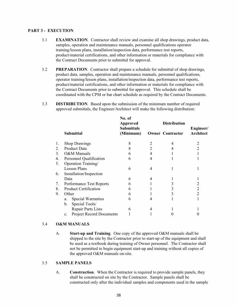
PART 3 - EXECUTION
3.1 EXAMINATION. Contractor shall review and examine all shop drawings, product data, samples, operation and maintenance manuals, personnel qualifications operator training/lesson plans, installation/inspection data, performance test reports, product/material certifications, and other information or materials for compliance with the Contract Documents prior to submittal for approval.
3.2 PREPARATION. Contractor shall prepare a schedule for submittal of shop drawings, product data, samples, operation and maintenance manuals, personnel qualifications, operator training/lesson plans, installation/inspection data, performance test reports, product/material certifications, and other information or materials for compliance with the Contract Documents prior to submittal for approval. This schedule shall be coordinated with the CPM or bar chart schedule as required by the Contract Documents.
3.3 DISTRIBUTION. Based upon the submission of the minimum number of required approved submittals, the Engineer/Architect will make the following distribution:
No. of Approved Distribution Submittals Engineer/ Submittal (Minimum) Owner Contractor Architect 1. Shop Drawings 8 2 4 2 2. Product Data 8 2 4 2 3. O&M Manuals 6 4 1 1 4. Personnel Qualification 6 4 1 1 5. Operation Training/ Lesson Plans 6 4 1 1 6. Installation/Inspection Data 6 4 1 1 7. Performance Test Reports 6 1 3 2 8. Product Certification 6 1 3 2 9. Other 6 1 3 2 a. Special Warranties 6 4 1 1 b. Special Tools/ Repair Parts Lists 6 4 1 1 c. Project Record Documents 1 1 0 0
3.4 O&M MANUALS
A. Start-up and Training. One copy of the approved O&M manuals shall be shipped to the site by the Contractor prior to start-up of the equipment and shall be used as a textbook during training of Owner personnel. The Contractor shall not be permitted to begin equipment start-up and training without all copies of the approved O&M manuals on-site.
3.5 SAMPLE PANELS
A. Construction. When the Contractor is required to provide sample panels, they shall be constructed on site by the Contractor. Sample panels shall be constructed only after the individual samples and components used in the sample
38

panel have been noted as conforming with Contract Documents by the Engineer/Architect. If a sample panel does not conform to the Contract requirements, Contractor shall construct additional ones until conformance is achieved.
B. Storage. Contractor shall store and protect large samples and mock-ups until the Project is completed, then properly dispose of off site.
3.6 SAMPLES FOR TESTS
A. Contractor shall furnish such samples of material as may be required for examination and test. All samples of materials for tests shall be taken according to standard methods or as provided in the Contract Documents.
3.7 ENGINEER/ARCHITECT'S ACTION
A. General. Except for submittals for record, information or similar purposes, where action and return is required or requested, the Engineer/Architect will review each submittal, mark to indicate action taken, and return promptly.
1. Compliance with specified characteristics is the Contractor's responsibility.
B. Action Stamp. The Engineer/Architect will stamp each submittal with a
uniform, self-explanatory action stamp. The stamp will be appropriately marked, as follows, to indicate the action taken:
1. Final Unrestricted Release. Where submittals are marked "Approved" that part of the work covered by the submittal may proceed provided it complies with requirements of the Contract Documents; final acceptance will depend upon that compliance.
2. Final-But-Restricted Release. When submittals are marked "Approved
as Noted," that part of the work covered by the submittal may proceed provided it complies with notations or corrections on the submittal and requirements of the Contract Documents; final acceptance will depend on that compliance.
3. Returned for Resubmittal. When submittal is marked "Not Approved"
and/or "Revise and Resubmit," do not proceed with that part of the work covered by the submittal, including purchasing, fabrication, delivery, or other activity. Revise or prepare a new submittal in accordance with the notations; resubmit without delay. Repeat if necessary to obtain a different action mark.
a. Do not permit submittals marked "Not Approved" and/or
"Revise and Resubmit" to be used at the project site or elsewhere where work is in progress.
END OF SECTION
39

THIS PAGE INTENTIONALLY LEFT BLANK
40

SECTION 01 60 00
MATERIALS AND EQUIPMENT
PART 1 - GENERAL
1.1 RELATED DOCUMENTS
A. General. Drawings and general provisions of the Contract, including General and Supplementary Conditions, Division 1, and all related specification sections, apply to this section.
1.2 DESCRIPTION OF WORK
A. Scope of Work. Transport and handle materials and equipment in accordance with the manufacturer's recommendations and requirements of Contract Documents. Make all arrangements for transportation, delivery, storage, and handling of equipment and materials required for prosecution and completion of the work.
1.3 QUALITY ASSURANCE
Not used.
1.4 SUBMITTALS
Not used.
1.5 JOB CONDITIONS
Not used.
1.6 DELIVERY, STORAGE, AND HANDLING
A. Delivery. Deliver shipments of materials and equipment to the site only during regular working hours. Shipments shall be addressed and consigned to the proper party giving name of Contract, street number, and city. Shipments shall not be delivered to the Owner or Owner's Representative, except as otherwise directed. Transportation shall be in accordance with Part 3 of this section.
B. Storage and Handling
1. Store, handle, and protect materials in accordance with the manufacturer's recommendations and the requirements of Part 3 of this section.
2. Maintain equipment in an undeteriorated and fully serviceable condition and as specified in Part 3 of this section.
1.7 SPECIAL WARRANTY
Not used.
41

PART 2 - PRODUCTS
Not applicable. PART 3 - EXECUTION
3.1 TRANSPORTATION
A. General. Arrange deliveries of products in accordance with the construction schedule and in ample time to facilitate inspection prior to installation.
B. Coordination
1. Coordinate deliveries to avoid conflict with work and conditions at site and to accommodate the following: a. Work of other contractors. b. Limitations of storage space. c. Availability of equipment and personnel for handling products. d. Owner's use of premises.
2. Do not have products delivered to project site until related shop drawings
have been approved.
3. Do not have products delivered to site until required storage facilities have been provided.
4. Have products delivered to site in manufacturer's original, unopened,
labeled containers. Keep Engineer/Architect informed of delivery of all equipment to be incorporated in the work.
C. Inspection
1. Immediately upon delivery, inspect shipment to ensure that: a. Product complies with requirements of Contract Documents and
reviewed submittals. b. Quantities are correct. c. Containers and packages are intact and labels are legible. d. Products are properly protected and undamaged.
3.2 HANDLING
A. Methods
1. Provide equipment and personnel necessary to handle products without soiling or damaging products or packaging.
2. Lift heavy components only at designated lifting points. 3. Handle materials and equipment at all times in a safe manner and as
recommended by manufacturer or supplier so that no damage will occur to them.
4. Do not drop, roll, or skid products off delivery vehicles. Hand carry or use suitable materials handling equipment.
42

5. Keep interiors completely free of dirt and foreign matter.
3.3 STORAGE AND PROTECTION
A. General
1. Make all arrangements and provisions necessary for the storage of materials and equipment.
2. Place all excavated materials, construction equipment, and materials and equipment to be incorporated into the work so as not to damage anything.
3. Keep materials and equipment neatly and compactly stored in locations that will cause a minimum of inconvenience to other contractors, public travel, adjoining owners, tenants, and occupants.
4. Arrange storage in a manner to provide easy access for inspection.
B. Storage Areas
1. Areas available on the construction site for storage of material and equipment shall be as approved by the Owner.
2. Store materials and equipment which are to become the property of the Owner in a way to facilitate their inspection and ensure preservation of the quality and fitness of the work, including proper protection against damage by freezing and moisture.
3. Lawns or other private property shall not be used for storage purposes without written permission of the Owner in control of such premises.
4. Restore all storage areas to their original condition.
C. Storage Methods
1. Do not open manufacturer's containers until the time of installation unless recommended by the manufacturer or otherwise specified.
2. All storage methods shall follow manufacturers’ recommendations.
D. Inspection
1. Regularly inspect stored products to ensure that:
a. State of storage facilities is adequate to provide required conditions.
b. Required environmental conditions are maintained on continuous basis.
c. Products exposed to elements are not adversely affected.
2. The Contractor shall be fully responsible for loss or damage to stored materials and equipment.
END OF SECTION
43

THIS PAGE INTENTIONALLY LEFT BLANK
44

SECTION 02 41 19
SELECTIVE DEMOLITION
PART 1 - GENERAL
1.1 RELATED DOCUMENTS. Drawings and general provisions of Contract, including General and Supplementary Conditions and Division 1 specification sections, apply to this section.
1.2 DESCRIPTION OF WORK. Provide the labor, tools, equipment, and materials necessary to perform selective demolition in accordance with the plans and specifications.
A. Removal and Disposal. This section requires the selective removal and subsequent off-site disposal of the following:
1. Remove of roofing and roof mounted items. 2. Removal and protection of existing fixtures, materials, and equipment
items indicated as "salvage" or to be reinstalled.
B. Related Work Specified Elsewhere
1. Patching is included within the respective sections of specifications, including removal of materials for reuse and incorporation into remodeling or new construction.
1.3 QUALITY ASSURANCE (Not used)
1.4 SUBMITTALS. Submit the following submittal packages in accordance with the Division 1 Submittal Requirements and the requirements within this specification section.
A. Submittal Package No. 1 – Demolition Schedule and Documentation
1. Package Contents. a. Schedule indicating proposed sequence of operations for
selective demolition work to Owner's Representative for review prior to start of work. Include coordination for shutoff, capping, and continuation of utility services as required, together with details for dust and noise control protection.
1) Provide detailed sequence of demolition and removal
work to ensure uninterrupted progress of Owner's on-site operations.
2) Coordinate with Owner's continuing occupation of portions of existing building and with Owner's partial occupancy of completed new addition.
45

b. Photographs of existing conditions of structure surfaces, equipment, and adjacent improvements that might be misconstrued as damage related to removal operations. Document location where each photograph is taken and date. File with Owner's Representative prior to start of work.
c. Elevation control survey of existing adjacent structures.
1.5 JOB CONDITIONS
A. Occupancy
1. Owner will occupy portions of the building immediately adjacent to areas of selective demolition.
2. Conduct selective demolition work in manner that will minimize need for disruption of Owner's normal operations.
3. Provide minimum of 72 hours' advance notice to Owner of demolition activities that will affect Owner's normal operations.
4. Other restrictions related to the disruption to the Owner and restrictions on the Contractor's work are shown or listed below.
B. Condition of Structures
1. Owner assumes no responsibility for actual condition of items or structures to be demolished.
2. Conditions existing at time of inspection for bidding purposes will be maintained by Owner insofar as practicable.
3. However, minor variations within structure may occur by Owner's removal and salvage operations prior to start of selective demolition work.
C. Partial Demolition and Removal
1. Remove items indicated to be removed but of salvageable value from structure as work progresses.
2. Transport salvaged items from site as they are removed. 3. Do not store or sell removed items on-site.
D. Protection. Provide temporary barricades and other forms of protection to
protect Owner's personnel and general public from injury due to selective demolition work.
1. Provide protective measures as required to provide free and safe passage of Owner's personnel and general public to occupied portions of building.
2. Erect temporary covered passageways as required by authorities having jurisdiction.
3. Provide interior and exterior shoring, bracing, or support to prevent movement, settlement, or collapse of adjacent facilities or work to remain, and uncontrolled collapse of structure or element to be demolished.
46

4. Protect from damage existing finish work that is to remain in place and becomes exposed during demolition operations.
5. Protect floors with suitable coverings when necessary. 6. Construct temporary insulated dustproof partitions where required to
separate areas where noisy or extensive dirt or dust operations are performed. Equip partitions with dustproof doors and security locks.
7. Provide temporary weather protection between demolition and removal of existing construction on exterior surfaces and installation of new construction to ensure that no water leakage or damage occurs to structure or interior areas of existing building.
8. Remove protection at completion of work.
E. Damage. Promptly repair damage caused to adjacent facilities by demolition work.
F. Traffic
1. Conduct selective demolition operations and debris removal to ensure minimum interference with roads, streets, walks, and other adjacent occupied or used facilities.
2. Do not close, block, or otherwise obstruct streets, walks, or other occupied or used facilities without written permission from authorities having jurisdiction.
3. Provide alternate routes around closed or obstructed traffic ways if required by governing regulations.
G. Flame Cutting. Do not use cutting torches for removal until work area is
cleared of flammable materials. At concealed spaces, such as interior of ducts and pipe spaces, verify condition of hidden space before starting flame-cutting operations. Maintain portable fire-suppression devices during flame-cutting operations.
H. Utility Services
1. Maintain existing utilities indicated to remain in service and protect them against damage during demolition operations.
2. Do not interrupt utilities serving occupied or used facilities, except when authorized in writing by authorities having jurisdiction.
3. Provide temporary services during interruptions to existing utilities, as acceptable to governing authorities.
4. Maintain fire protection services during selective demolition operations.
I. Environmental Controls
1. Use water sprinkling, temporary enclosures, and other methods to limit dust and dirt migration.
2. Comply with governing regulations pertaining to environmental protection.
3. Do not use water when it may create hazardous or objectionable conditions such as ice, flooding, and pollution.
47

1.6 DELIVERY, STORAGE, AND HANDLING (Not used)
1.7 SPECIAL WARRANTY (Not used)
PART 2 - PRODUCTS (Not applicable)
PART 3 - EXECUTION
3.1 PREPARATION
A. General. Provide interior and exterior shoring, bracing, or support to prevent movement, settlement, or collapse of areas to be demolished and adjacent facilities to remain.
1. Cease operations and notify Owner's Representative immediately if safety of structure appears to be endangered. Take precautions to support structure until determination is made for continuing operations.
2. Cover and protect furniture, equipment, and fixtures from soilage or
damage when demolition work is performed in areas where such items have not been removed.
3. Erect and maintain dustproof partitions and closures as required to
prevent spread of dust or fumes to occupied portions of the building.
a. Where selective demolition occurs immediately adjacent to occupied portions of the building, construct dustproof partitions of minimum 4-inch studs, 5/8-inch drywall (joints taped) on occupied side, 1/2-inch fire-retardant plywood on demolition side. Fill partition cavity with sound deadening insulation.
b. Provide weatherproof closures for exterior openings resulting from demolition work.
4. Locate, identify, stub off, and disconnect utility services that are not
indicated to remain.
5. Provide bypass connections as necessary to maintain continuity of service to occupied areas of building. Provide minimum of 72 hours' advance notice to Owner if shutdown of service is necessary during changeover.
3.2 DEMOLITION
A. General. Perform selective demolition work in a systematic manner. Use such methods as required to complete work shown in accordance with demolition schedule and governing regulations.
1. Demolish concrete and masonry in small sections. Cut concrete and masonry at junctures with construction to remain using power-driven masonry saw or hand tools; do not use power-driven impact tools.
48

2. Promptly remove debris and locate demolition equipment to avoid imposing excessive loads on supporting walls, floors, or framing.
3. Provide services for effective air and water pollution controls as required by local authorities having jurisdiction.
4. Demolish foundation walls and belowgrade concrete slabs. Demolish and remove belowgrade wood or metal construction.
5. Cut off piles 1 foot below finished grade. 6. Remove all exposed reinforcing steel unless noted otherwise. 7. For slabs, use removal methods that will not crack or structurally disturb
adjacent slabs or partitions. Use power saw where possible. Saw-cut a minimum of 3 inches deep around perimeter of portions of slabs to be removed.
8. Completely fill belowgrade areas and voids resulting from demolition work as specified in Section 31 23 00 "Excavation, Backfill, and Embankment."
B. Miscellaneous
1. If unanticipated mechanical, electrical, or structural elements that conflict with intended function or design are encountered, investigate and measure both nature and extent of the conflict.
2. Submit report to Owner's Representative in written, accurate detail. 3. Pending receipt of directive from Owner's Representative, rearrange
selective demolition schedule as necessary to continue overall job progress without undue delay.
3.3 SALVAGED MATERIALS
A. Salvaged Items
1. Where shown as incorporated in new construction or "Salvage - Deliver to Owner," carefully remove indicated items, clean, package to prevent damage, store, and promptly turn over to Owner.
2. Obtain receipt. 3. Historic artifacts, including cornerstones and their contents,
commemorative plaques and tablets, antiques, and other articles of historic significance, remain property of Owner.
4. Notify Owner's Representative if such items are encountered and obtain acceptance regarding method of removal and salvage for Owner.
3.4 DISPOSAL OF DEMOLISHED MATERIALS. Remove from building site debris,
rubbish, and other materials resulting from demolition operations. Transport and legally dispose of off-site.
A. Hazardous materials encountered during demolition operations, comply with applicable regulations, laws, and ordinances concerning removal, handling, and protection against exposure or environmental pollution.
B. Do not burn removed materials on project site.
49

3.5 CLEANUP AND REPAIR
A. General
1. Upon completion of demolition work, remove tools, equipment, and demolished materials from site.
2. Remove protections and leave interior areas broom clean. 3. Repair demolition performed in excess of that required. 4. Return elements of construction and surfaces to remain to condition
existing prior to start of operations. 5. Repair adjacent construction or surfaces soiled or damaged by selective
demolition work.
END OF SECTION
50

SECTION 05 52 13
PIPE AND TUBE RAILINGS
PART 1 - GENERAL
1.1 RELATED DOCUMENTS. Drawings and general provisions of Contract, including General and Supplementary Conditions and Division 1 specification sections, apply to this section.
1.2 DESCRIPTION OF WORK. Provide the labor, tools, equipment, and materials necessary to furnish and install the pipe and tube railings in accordance with the plans and specifications.
A. This section includes the following:
1. Steel pipe portable roof safety railing systems.
1.3 QUALITY ASSURANCE
A. Single-Source Responsibility. Obtain handrails and railing systems of each type and material from a single manufacturer.
B. Engineering Responsibility. Engineer handrails and railing systems by professional engineer legally authorized to practice in jurisdiction where project is located.
1.4 SUBMITTALS. Submit the following in accordance with the Division 1 Submittal Requirements and the requirements within this specification section.
A. Submittal Package No. 1 – Product Data and Shop Drawings
1. Product data for each type of product specified.
2. Shop drawings showing fabrication and installation of handrails and railings including plans, elevations, sections, details of components, and attachments to other units of work.
a. Where installed products are indicated to comply with certain
design loadings, include structural computations, material properties, and other information needed for structural analysis that has been signed and sealed by a qualified professional engineer responsible for their preparation.
3. Product test reports from and based on tests performed by qualified
independent testing laboratory evidencing compliance of railing components and systems with requirements based on comprehensive testing of current products.
4. Test reports from independent testing laboratory evidencing compliance
of handrails and railing systems with ASTM E 985.
51
5. Qualification data for firms and persons specified in "Quality Assurance"
article to demonstrate their capabilities and experience. Include list of completed projects with project names, addresses, names of Engineer/Architects and Owners, plus other information specified.
B. Submittal Package No. 2 – Samples
1. Samples for initial selection purposes in form of manufacturer's color charts showing full range of colors available for those units with factory applied color finishes.
2. Samples for verification purposes of each type of exposed finish
required, prepared on components indicated below that are of the same thickness and metal indicated for final unit of work. Where finishes involve normal color and texture variations, include sample sets showing full range of variations expected.
a. 6-inch-long sections of each distinctly different linear railing
member including handrails, top rails, posts, and balusters. b. Fittings and brackets. c. Welded connections.
1.5 JOB CONDITIONS
A. Field Measurements
1. Where handrails and railings are indicated to fit to other construction, check actual dimensions of other construction by accurate field measurements before fabrication; show recorded measurements on final shop drawings.
2. Where field measurements cannot be made without delaying the work, guarantee dimensions and proceed with fabrication of products without field measurements.
3. Coordinate other construction to ensure that actual dimensions correspond to guaranteed dimensions.
1.6 DELIVERY, STORAGE, AND HANDLING. In accordance with Section 01 60 00.
1.7 SPECIAL WARRANTY.
Not used.
1.8 DEFINITIONS. Definitions in American Society for Testing and Materials (ASTM) E 985 for railing related terms apply to this section.
1.9 SYSTEM PERFORMANCE REQUIREMENTS
A. Delegated Design: Structural Performance of Handrails and Railing Systems. Design, fabricate, and install handrails and railing systems to withstand the following structural loads without exceeding the allowable design working
52

stress of the materials for handrails, railing systems, anchors, and connections. Apply each load to produce the maximum stress in each of the respective components comprising handrails and railing systems.
1. Top Rail of rail Systems. Capable of withstanding the following loads applied as indicated:
a. Concentrated load of 200 pounds applied at any point and in any
direction. b. Uniform load of 50 pounds per foot applied horizontally at the
required guardrail height and a simultaneous uniform load of 100 pounds per foot applied vertically downward at the top of the guardrail.
c. Concentrated load need not be assumed to act concurrently with uniform loads.
2. Infill Area of Guardrail Systems. Capable of withstanding a horizontal
concentrated load of 200 pounds applied to 1 square foot (sf) at any point in the system including panels, intermediate rails, balusters, or other elements composing the infill area. Concentrated load need not be assumed to act concurrently with loads on top rails of railing systems in determining stress on guard.
B. Control of Corrosion. Prevent galvanic action and other forms of corrosion by
insulating metals and other materials from direct contact with incompatible materials.
C. Thermal Movements. Allow for thermal movement resulting from the following maximum change (range) in ambient temperature of 120 degrees Fahrenheit (° F.) in the design, fabrication, and installation of handrails and railings to prevent buckling, opening up of joints, overstressing of components, connections and other detrimental effects. Base design calculation on actual material surface temperature range of 180° F. due to both solar heat gain and nighttime sky heat loss.
PART 2 - PRODUCTS
2.1 MANUFACTURERS. Subject to compliance with requirements, manufacturers offering handrails and railing systems that may be incorporated in the work include but are not limited to the following:
A. Steel Portable and Wall Mounted Roof Safety Railing Systems
1. Safety Rail Company LLC – Basis of Design. 2. Blue Water Manufacturing, Para Rail Guardrail System 3. Kee Safety, Inc., KeeGuard 4. Flexible Lifeline Systems, FlexGuard
53

2.2 METALS
A. General. Provide metal forms and types that comply with requirements of referenced standards and that are free from surface blemishes where exposed to view in the finished unit. Exposed-to-view surfaces exhibiting pitting, seam marks, roller marks, stains, discolorations, or other imperfections on finished units are not acceptable.
B. Steel. Galvanized steel coating recommended by railing manufacturer.
C. Brackets, Flanges, and Anchors. Cast or formed metal of the same type
material and finish as supported rails, unless otherwise indicated.
2.3 WELDING MATERIALS, FASTENERS, AND ANCHORS
A. Welding Electrodes and Filler Metal. Provide type and alloy of filler metal and electrodes as recommended by producer of metal to be welded and as required for color match, strength, and compatibility in fabricated items.
B. Fasteners for Anchoring Railings to Other Construction. Select fasteners of the type, grade, and class required to produce connections that are suitable for anchoring railing to other types of construction indicated and capable of withstanding design loadings.
1. For aluminum railings, provide fasteners fabricated from Type 304 stainless steel.
C. Fasteners for Interconnecting Railing Components
1. Use fasteners of same basic metal as the fastened metal, unless otherwise indicated.
2. Do not use metals that are corrosive or incompatible with materials joined.
3. Provide concealed fasteners for interconnection of handrail and railing components and for their attachment to other work, except where otherwise indicated.
4. Provide Phillips flat-head machine screws for exposed fasteners, unless otherwise indicated.
FABRICATION
D. General. Fabricate handrails and railing systems to comply with requirements indicated for design, dimensions, details, finish, and member sizes, including wall thickness of hollow members, post spacings, and anchorage, but not less than those required to support structural loads.
E. Railing Systems
1. Preassemble railing systems in shop to greatest extent possible to minimize field splicing and assembly.
54

2. Disassemble units only as necessary for shipping and handling limitations.
3. Clearly mark units for reassembly and coordinated installation. 4. Use connections that maintain structural value of joined pieces. 5. Clearly mark units for reassembly and coordinated installation.
F. Form changes in direction of railing members as follows:
1. By insertion of prefabricated elbow fittings. 2. By radius bends of radius indicated. 3. By mitering at elbow bends. 4. By bending. 5. By any method indicated above, applicable to change of direction
involved.
G. Form simple and compound curves by bending pipe in jigs to produce uniform curvature for each repetitive configuration required; maintain cylindrical cross section of pipe throughout entire bend without buckling, twisting, cracking, or otherwise deforming exposed surfaces of pipe.
H. Welded Connections. Fabricate railing systems and handrails for connection of members by welding. For connections made during fabrication, weld corners and seams continuously to comply with the following:
1. Use materials and methods that minimize distortion and develop strength and corrosion resistance of base metals.
2. Obtain fusion without undercut or overlap. 3. Remove welding flux immediately. 4. At tee and cross intersections, notch ends of intersecting members to fit
contour of pipe to which end is joined and weld all around. 5. At exposed connections, finish exposed welds and surfaces smooth and
blended so that no roughness shows after finishing and contour of welded surface matches those adjacent.
6. Use welded connections only where non welded connections are not feasible for structural or other approved reasons.
I. Nonwelded Connections
1. Fabricate railing systems and handrails for connection of members by means of railing manufacturer's standard concealed mechanical fasteners and fittings unless otherwise indicated.
2. Fabricate members and fittings to produce flush, smooth, rigid, hairline joints.
3. Fabricate splice joints for field connection using epoxy structural adhesive where this represents manufacturer's standard splicing method.
J. Roof Safety Rail System.
1. Provide bases with pads to protect roof surface from damage for portable railings. Coordinate with roofing manufacturer.
55

2.4 FINISHES, GENERAL
A. Comply with National Association of Architectural Metals Manufacturers (NAAMM) "Metal Finishes Manual" for recommendations relative to application and designations of finishes.
B. Protect mechanical finishes on exposed surfaces from damage by application of strippable, temporary protective covering prior to shipment.
C. Appearance of Finished Work
1. Variations in appearance of abutting or adjacent pieces are acceptable if they are within 1/2 of the range of approved samples.
2. Noticeable variations in the same piece are not acceptable. 3. Variations in appearance of other components are acceptable if they are
within range of approved samples and they are assembled or installed to minimize contrast.
PART 3 - EXECUTION
3.1 PREPARATION. Coordinate setting drawings, diagrams, templates, instructions, and directions for installation of anchorages, such as sleeves, concrete inserts, anchor bolts, and miscellaneous items having integral anchors that are to be embedded in concrete as masonry construction. Coordinate delivery of such items to project site.
3.2 INSTALLATION, GENERAL
A. Fit exposed connections accurately together to form tight, hairline joints.
B. Install self-supporting freestanding railing systems to comply with railing manufacturer's instructions.
3.3 PROTECTION
A. Protect finishes of railing systems and handrails from damage during construction period by use of temporary protective coverings approved by railing manufacturer. Remove protective covering at time of Substantial Completion.
B. Restore finishes damaged during installation and construction period so that no evidence remains of correction work. Return items that cannot be refinished in the field to the shop; make required alterations and refinish entire unit or provide new units.
END OF SECTION
56
SECTION 06 10 00
ROUGH CARPENTRY
PART 1 - GENERAL
1.1 RELATED DOCUMENTS
A. General. Drawings and general provisions of the Contract, including General and Supplementary Conditions, Division 1, and all related specification sections, apply to this section.
1.2 DESCRIPTION OF WORK
A. Scope of Work. The Contractor shall provide all labor, materials, tools, and equipment necessary to construct rough carpentry in accordance with the plans and as specified herein.
B. Work Included. This section includes the following:
1. Wood grounds, nailers, blocking, and shims if needed at openings.
1.3 QUALITY ASSURANCE
A. Codes. Perform all work in compliance with all federal, state, and local codes.
B. Standards. Materials and workmanship shall be in accordance with the following standards:
1. AF&PA – American Forest & Paper Association. 2. AHA - American Hardwood Association. 3. AISI - American Iron and Steel Institute. 4. ALSC - American Lumber Standards Committee. 5. ANSI - American National Standards Institute. 6. APA - American Plywood Association. 7. ASTM - American Society for Testing and Materials. 8. AWPA - American Wood Preservers Association. 9. AWPB - American Wood Preservers Bureau. 10. Federal Specifications. 11. SPIB - Southern Pine Inspection Bureau. 12. UL - Underwriters' Laboratories, Inc.
C. Regulatory Agencies. Perform all work in compliance with the requirements of
the following regulatory agencies:
1. ADA - Americans with Disabilities Act. 2. NFPA - National Fire Protection Association. 3. OSHA - Occupational Safety and Health Administration.
57

1.4 SUBMITTALS
A. General. Submit the following in accordance with Conditions of Contract and Division 1 specification sections.
B. Wood Treatment Data. Submit wood treatment data as follows including chemical treatment manufacturer's instructions for handling, storing, installing, and finishing of treated material:
1. For each type of preservative-treated wood product include certification by treating plant stating type of preservative solution and pressure process used, net amount of preservative retained, and compliance with applicable standards.
2. For waterborne-treated products include statement that moisture content of treated materials was reduced to levels indicated prior to shipment to project site.
C. Warranties. Submit copies of warranty of chemical treatment manufacturer for
each type of treatment.
1.5 JOB CONDITIONS
A. Coordination/Interfacing. Coordinate with all other trades to prevent delays, errors, and omissions.
B. Environmental Requirements. Follow manufacturer's instructions for limitations of specified materials with regard to exposure to climatic conditions.
1.6 DELIVERY, STORAGE, AND HANDLING
A. Delivery and Storage. Keep materials under cover and dry. Protect against exposure to weather and contact with damp or wet surfaces. Stack lumber as well as plywood and other panels; provide for air circulation within and around stacks and under temporary coverings including polyethylene and similar materials.
1. For lumber and plywood pressure-treated with waterborne chemicals, place spacers between each bundle to provide air circulation.
1.7 SPECIAL WARRANTY
A. Chemical Treatment Warranty. Manufacturer's written warranty for each type of chemical treatment required for the project.
1.8 DEFINITIONS
A. Rough carpentry includes carpentry work not specified as part of other sections and generally not exposed, unless otherwise specified.
58

PART 2 - PRODUCTS
2.1 LUMBER, GENERAL
A. Lumber Standards. Furnish lumber manufactured to comply with PS 20 "American Softwood Lumber Standard" and with applicable grading rules of inspection agencies certified by ALSC's Board of Review.
B. Inspection Agencies. Inspection agencies and the abbreviations used to reference them with lumber grades and species include the following:
1. SPIB - Southern Pine Inspection Bureau.
C. Grade Stamps. Provide lumber with each piece factory marked with grade stamp of inspection agency evidencing compliance with grading rule requirements and identifying grading agency, grade, species, moisture content at time of surfacing, and mill.
D. Nominal Sizes. Nominal sizes are indicated, except as shown by detail dimensions. Provide actual sizes as required by PS 20, for moisture content specified for each use.
1. Provide seasoned lumber with 19 percent maximum moisture content at time of dressing and shipment for sizes 2 inches or less in nominal thickness, unless otherwise indicated.
2.2 DIMENSION LUMBER
A. Light Framing. For light framing (2 to 4 inches thick, 2 to 4 inches wide), provide the following grade and species:
1. Standard grade. 2. Southern Pine graded under SPIB rules.
2.3 BOARDS
A. Exposed Boards. Where boards will be exposed in the finished work, provide the following:
1. Moisture Content. 19 percent maximum, S-DRY or KD-19.
B. Concealed Boards. Where boards will be concealed by other work, provide lumber of 19 percent maximum moisture content (S-DRY or KD-19) and of following species and grade:
1. Southern Pine No. 2 Boards per SPIB rules.
C. Board Sizes. Provide sizes indicated.
59

2.4 MISCELLANEOUS LUMBER
A. General. Provide lumber for support or attachment of other construction including cant strips, bucks, nailers, blocking, furring, grounds, stripping, and similar members.
B. Size and Shape. Fabricate miscellaneous lumber from dimension lumber of sizes indicated and into shapes shown.
C. Moisture Content. Nineteen percent maximum for lumber items not specified to receive wood preservative treatment.
D. Grade. Standard grade light framing size lumber or No. 2 Boards per SPIB rules.
2.5 FASTENERS
A. General. Provide fasteners of size and type indicated that comply with requirements specified in this article for material and manufacture.
1. Provide fasteners with a hot dip zinc coating per ASTM A 153.
B. Nails, Wire, Brads, and Staples. FS FF-N-105.
C. Power Driven Fasteners. National Evaluation Report NER-272.
D. Wood Screws. ANSI B18.6.1.
E. Lag Bolts. ANSI B18.2.1.
F. Bolts. Steel bolts complying with ASTM A 307, Grade A; with ASTM A 563 hex nuts and where indicated, flat washers.
2.6 PRESERVATIVE WOOD TREATMENT BY PRESSURE PROCESS
A. General. Where lumber or plywood is indicated as preservative-treated wood or is specified herein to be treated, comply with applicable requirements of AWPA Standards C2 (Lumber) and C9 (Plywood). Mark each treated item with the AWPB or SPIB Quality Mark Requirements.
B. Aboveground Items. Pressure-treat aboveground items with waterborne preservatives to a minimum retention of 0.25 pound per cubic foot (pcf). For interior uses, after treatment, kiln dry lumber and plywood to a maximum moisture content, respectively, of 19 percent and 15 percent. Treat indicated items and the following.
1. Wood cants, nailers, curbs, equipment support bases, blocking, stripping, and similar members in connection with roofing, flashing, vapor barriers, and waterproofing.
2. Wood sills, sleepers, blocking, furring, stripping, and similar concealed members in contact with masonry or concrete.
60

C. Members in Contact with Ground. Pressure-treat wood members in contact with the ground or fresh water with waterborne preservatives to a minimum retention of 0.40 pcf.
D. Fabrication. Complete fabrication of treated items prior to treatment, where possible. If cut after treatment, coat cut surfaces to comply with AWPA M4. Inspect each piece of lumber or plywood after drying and discard damaged or defective pieces.
PART 3 - EXECUTION
3.1 INSTALLATION, GENERAL
A. Unusable Material. Discard units of material with defects that impair quality of rough carpentry construction and that are too small to use in fabricating rough carpentry with minimum joints or optimum joint arrangement.
B. Setting Rough Carpentry. Set rough carpentry to required levels and lines, with members plumb and true to line and cut and fitted.
C. Fitting Rough Carpentry. Fit rough carpentry to other construction; scribe and cope as required for accurate fit. Correlate location of furring, nailers, blocking, grounds, and similar supports to allow attachment of other construction.
D. Securement. Securely attach rough carpentry work to substrate by anchoring and fastening as indicated.
E. Nailing Exposed Carpentry. Countersink nail heads on exposed carpentry work and fill holes.
F. Nails. Use common wire nails, unless otherwise indicated. Use finishing nails for finish work. Select fasteners of size that will not penetrate members where opposite side will be exposed to view or will receive finish materials. Make tight connections between members. Install fasteners without splitting of wood; predrill as required.
3.2 WOOD GROUNDS, NAILERS, BLOCKING, AND SLEEPERS
A. General. Install wood grounds, nailers, blocking, and sleepers where shown and where required for screeding or attachment of other work. Form to shapes as shown and cut as required for true line and level of work to be attached. Coordinate location with other work involved.
B. Attachment. Attach to substrates as required to support applied loading. Countersink bolts and nuts flush with surfaces, unless otherwise indicated. Build into masonry during installation of masonry work. Where possible, anchor to formwork before concrete placement.
61

3.3 DEMONSTRATION
A. General. Prior to commencement of the installation and/or application of interior and/or exterior finishes, the Contractor shall demonstrate to representatives of the Engineer/Architect (and/or Owner) that all framing and other rough carpentry members are installed at the indicated spacing, are of the indicated size and grade, and are fastened with the required anchors and fasteners, and that no members have been damaged during handling, fabrication, or installation.
1. Correct all noted deficiencies to the satisfaction of the Engineer/Architect's representative prior to commencing with finish work.
2. Demonstration and corrective measures may be phased to allow commencement of finish work according to the approved Construction Schedule.
END OF SECTION
62
SECTION 07 53 23
ETHYLENE-PROPYLENE-DIENE-MONOMER (EPDM) ROOFING
PART 1 - GENERAL
1.1 RELATED DOCUMENTS
A. Drawings and general provisions of the Contract, including General and Supplementary Conditions and Division 01 Specification Sections, apply to this Section.
1.2 SUMMARY
A. Section Includes:
1. Adhered ethylene-propylene-diene-monomer (EPDM) roofing system. 2. Vapor retarder. 3. Roof insulation.
B. Related Requirements:
1. Section 06 10 00 "Rough Carpentry" for wood nailers and blocking.
1.3 DEFINITIONS
A. Roofing Terminology: Definitions in ASTM D 1079 and glossary of NRCA's "The NRCA Roofing and Waterproofing Manual" apply to work of this Section.
1.4 PREINSTALLATION MEETINGS
A. Preinstallation Roofing Conference: Conduct conference at Project site.
1. Meet with Owner, Engineer/Architect, Owner's insurer if applicable, testing and inspecting agency representative, Contractor, roofing system manufacturer's representative, deck Installer, and installers whose work interfaces with or affects roofing, including installers of roof accessories and roof-mounted equipment.
2. Review methods and procedures related to roofing installation, including manufacturer's written instructions.
3. Review and finalize construction schedule, and verify availability of materials, Installer's personnel, equipment, and facilities needed to make progress and avoid delays.
4. Examine deck substrate conditions and finishes for compliance with requirements, including flatness and fastening.
5. Review structural loading limitations of roof deck during and after roofing. 6. Review base flashings, special roofing details, roof drainage, roof penetrations,
equipment curbs, and condition of other construction that affects roofing system.
63

7. Review governing regulations and requirements for insurance and certificates if applicable.
8. Review temporary protection requirements for roofing system during and after installation.
9. Review roof observation and repair procedures after roofing installation.
1.5 ACTION SUBMITTALS
A. Product Data: For each type of product.
B. Shop Drawings: For roofing system. Include plans, elevations, sections, details, and attachments to other work, including: 1. Base flashings and membrane terminations. 2. Roof plan showing orientation of roof deck and orientation of roofing. 3. Insulation fastening patterns for corner, perimeter, and field-of-roof locations.
1.6 INFORMATIONAL SUBMITTALS
A. Qualification Data: For Installer and manufacturer.
B. Manufacturer Certificates: Signed by roofing manufacturer certifying that roofing system complies with requirements specified in "Performance Requirements" Article. 1. Submit evidence of complying with performance requirements.
C. Product Test Reports: For components of roofing system, tests performed by manufacturer and witnessed by a qualified testing agency.
D. Research/Evaluation Reports: For components of roofing system, from ICC-ES.
E. Field quality-control reports.
F. Sample Warranties: For manufacturer's special warranties.
1.7 CLOSEOUT SUBMITTALS
A. Maintenance Data: For roofing system to include in maintenance manuals.
1.8 QUALITY ASSURANCE
A. Manufacturer Qualifications: A qualified manufacturer that is capable of producing a roofing system identical to that used for this Project.
B. Installer Qualifications: A qualified firm that is approved, authorized, or licensed by roofing system manufacturer to install manufacturer's product and that is eligible to receive manufacturer's special warranty.
64

1.9 DELIVERY, STORAGE, AND HANDLING
A. Deliver roofing materials to Project site in original containers with seals unbroken and labeled with manufacturer's name, product brand name and type, date of manufacture, approval or listing agency markings, and directions for storing and mixing with other components.
B. Store liquid materials in their original undamaged containers in a clean, dry, protected location and within the temperature range required by roofing system manufacturer. Protect stored liquid material from direct sunlight.
1. Discard and legally dispose of liquid material that cannot be applied within its stated shelf life.
C. Protect roof insulation materials from physical damage and from deterioration by sunlight, moisture, soiling, and other sources. Store in a dry location. Comply with insulation manufacturer's written instructions for handling, storing, and protecting during installation.
D. Handle and store roofing materials, and place equipment in a manner to avoid permanent deflection of deck.
1.10 FIELD CONDITIONS
A. Weather Limitations: Proceed with installation only when existing and forecasted weather conditions permit roofing system to be installed according to manufacturer's written instructions and warranty requirements.
1.11 WARRANTY
A. Special Warranty: Manufacturer agrees to repair or replace components of roofing system that fail in materials or workmanship within specified warranty period.
1. Special warranty includes membrane roofing, base flashings, roof insulation, fasteners, cover boards, roofing accessories, walkway products and other components of roofing system.
2. Warranty Period: 20 years from date of Substantial Completion.
B. Special Project Warranty: Submit roofing Installer's warranty, on warranty form at end of this Section, signed by Installer, covering Work of this Section, including all components of roofing system such as membrane roofing, base flashing, roof insulation, fasteners, cover boards, substrate boards, vapor retarders, and walkway products, for the following warranty period:
1. Warranty Period: Two years from date of Substantial Completion.
65

PART 2 - PRODUCTS
2.1 MANUFACTURERS
A. Source Limitations: Obtain components including roof insulation and fasteners for roofing system from same manufacturer as membrane roofing or manufacturer approved by membrane roofing manufacturer.
2.2 PERFORMANCE REQUIREMENTS
A. General Performance: Installed roofing and base flashings shall withstand specified uplift pressures, thermally induced movement, and exposure to weather without failure due to defective manufacture, fabrication, installation, or other defects in construction. Roofing and base flashings shall remain watertight.
1. Accelerated Weathering: Roofing system shall withstand 2000 hours of exposure when tested according to ASTM G 152, ASTM G 154, or ASTM G 155.
2. Impact Resistance: Roofing system shall resist impact damage when tested according to ASTM D 3746 or ASTM D 4272.
B. Material Compatibility: Roofing materials shall be compatible with one another and adjacent materials under conditions of service and application required, as demonstrated by roofing manufacturer based on testing and field experience.
C. FM Global Listing: Roofing, base flashings, and component materials shall comply with requirements in FM Global 4450 or FM Global 4470 as part of a roofing system, and shall be listed in FM Global's "RoofNav" for Class 1 or noncombustible construction, as applicable. Identify materials with FM Global markings.
1. Fire/Windstorm Classification: Class 1A-90. 2. Hail-Resistance Rating: SH.
D. Exterior Fire-Test Exposure: ASTM E 108 or UL 790, Class A; for application and roof slopes indicated; testing by a qualified testing agency. Identify products with appropriate markings of applicable testing agency.
2.3 EPDM ROOFING
A. EPDM: ASTM D 4637, Type I, nonreinforced, uniform, flexible EPDM sheet.
1. Subject to compliance with the requirements, provide products by one of the following manufacturers.
a. Carlisle SynTec b. Firestone Building Products c. Johns Manville (Basis of Design) d. Mule-Hide Products
2. Thickness: 60 mils (1.5 mm), nominal.
66

3. Exposed Face Color: Black.
2.4 AUXILIARY ROOFING MATERIALS
A. General: Auxiliary materials recommended by roofing system manufacturer for intended use and compatible with roofing.
1. Liquid-type auxiliary materials shall comply with VOC limits of authorities having jurisdiction.
B. Sheet Flashing: 60-mil- (1.5-mm-) thick EPDM, partially cured or cured, according to application.
C. Bonding Adhesive: Manufacturer's standard.
D. Seaming Material: Single-component, butyl splicing adhesive and splice cleaner or manufacturer's standard, synthetic-rubber polymer primer and 3-inch- (75-mm-) wide minimum, butyl splice tape with release film.
E. Lap Sealant: Manufacturer's standard, single-component sealant, colored to match membrane roofing].
F. Water Cutoff Mastic: Manufacturer's standard butyl mastic sealant.
G. Metal Termination Bars: Manufacturer's standard, predrilled stainless-steel or aluminum bars, approximately 1 by 1/8 inch (25 by 3 mm) thick; with anchors.
H. Metal Battens: Manufacturer's standard, aluminum-zinc-alloy-coated or zinc-coated steel sheet, approximately 1 inch wide by 0.05 inch thick (25 mm wide by 1.3 mm thick), prepunched.
I. Fasteners: Factory-coated steel fasteners and metal or plastic plates complying with corrosion-resistance provisions in FM Global 4470, designed for fastening membrane to substrate, and acceptable to roofing system manufacturer.
J. Miscellaneous Accessories: Provide pourable sealers, preformed cone and vent sheet flashings, molded pipe boot flashings, preformed inside and outside corner sheet flashings, reinforced EPDM securement strips, T-joint covers, in-seam sealants, termination reglets, cover strips, and other accessories.
2.5 VAPOR RETARDER
A. Self-Adhering-Sheet Vapor Retarder: ASTM D 1970, polyethylene film laminated to layer of rubberized asphalt adhesive, minimum 40-mil- (1.0-mm-) total thickness; maximum permeance rating of 0.1 perm (6 ng/Pa x s x sq. m); cold applied, with slip-resisting surface and release paper backing. Provide primer when recommended by vapor-retarder manufacturer.
67

2.6 ROOF INSULATION
A. General: Preformed roof insulation boards manufactured or approved by EPDM roofing manufacturer, selected from manufacturer's standard sizes suitable for application, of thicknesses indicated.
B. Polyisocyanurate Board Insulation: ASTM C 1289, Type II, Class 1, Grade 2, felt or glass-fiber mat facer on both major surfaces.
C. Provide preformed saddles, crickets, tapered edge strips, and other insulation shapes where indicated for sloping to drain. Fabricate to slopes indicated.
D. Gypsum Cover Board. Securock Roof Board Primed, DensDeck Roof Board with Eonic Technology, Or Approved Equal.
1. Qualities: Nonstructural, noncombustible, homogenous composition panel. 2. Board Size: Four by eight feet (4’x8’). 3. Thickness: One half (1/2) inch. 4. R-Value: .5 5. Compliances: UL. WH or FM listed under Roofing Systems. 6. Manufacturer: USG, Georgia-Pacific (GP), Or Approved Equal
2.7 INSULATION ACCESSORIES
A. General: Roof insulation accessories recommended by insulation manufacturer for intended use and compatibility with roofing.
B. Fasteners: Factory-coated steel fasteners and metal or plastic plates complying with corrosion-resistance provisions in FM Global 4470, designed for fastening roof insulation and cover boards to substrate, and acceptable to roofing system manufacturer.
2.8 WALKWAYS
A. Flexible Walkways: Factory-formed, nonporous, heavy-duty, solid-rubber, slip-resisting, surface-textured walkway pads or rolls, approximately 3/16 inch (5 mm) thick and acceptable to roofing system manufacturer.
PART 3 - EXECUTION
3.1 EXAMINATION
A. Examine substrates, areas, and conditions, with Installer present, for compliance with requirements and other conditions affecting performance of the Work:
1. Verify that roof openings and penetrations are in place and curbs are set and braced.
2. Verify that wood blocking and nailers are securely anchored to roof deck at penetrations and terminations and that nailers match thicknesses of insulation.
68

3. Verify that concrete substrate is visibly dry and free of moisture. Test for capillary moisture by plastic sheet method according to ASTM D 4263.
4. Verify that compounds that will impair adhesion of roofing components to roof deck have been removed.
B. Proceed with installation only after unsatisfactory conditions have been corrected.
3.2 PREPARATION
A. Clean substrate of dust, debris, moisture, and other substances detrimental to roofing installation according to roofing system manufacturer's written instructions. Remove sharp projections.
B. Prevent materials from spilling or migrating onto surfaces of other construction.
3.3 ROOFING INSTALLATION, GENERAL
A. Install roofing system according to roofing system manufacturer's written instructions.
B. Complete terminations and base flashings and provide temporary seals to prevent water from entering completed sections of roofing system at the end of the workday or when rain is forecast. Remove and discard temporary seals before beginning work on adjoining roofing.
3.4 VAPOR-RETARDER INSTALLATION
A. Self-Adhering-Sheet Vapor Retarder: Prime substrate if required by manufacturer. Install self-adhering-sheet vapor retarder over area to receive vapor retarder, side and end lapping each sheet a minimum of 3-1/2 inches (90 mm) and 6 inches (150 mm), respectively. Seal laps by rolling.
B. Completely seal vapor retarder at terminations, obstructions, and penetrations to prevent air movement into roofing system.
3.5 INSULATION INSTALLATION
A. Coordinate installing roofing system components so insulation is not exposed to precipitation or left exposed at the end of the workday.
B. Comply with roofing system and insulation manufacturer's written instructions for installing roof insulation.
C. Install insulation under area of roofing to achieve required thickness. Where overall insulation thickness is 2.7 inches (68 mm) or greater, install two or more layers with joints of each succeeding layer staggered from joints of previous layer a minimum of 6 inches (150 mm) in each direction.
69

D. Trim surface of insulation where necessary so completed surface is flush and does not restrict flow of water.
E. Install insulation with long joints of insulation in a continuous straight line with end joints staggered between rows, abutting edges and ends between boards. Fill gaps exceeding 1/4 inch (6 mm) with insulation.
1. Cut and fit insulation within 1/4 inch (6 mm) of nailers, projections, and penetrations.
F. Mechanically Fastened and Adhered Insulation: Install insulation and secure to deck using mechanical fasteners specifically designed and sized for fastening specified board-type roof insulation to deck type and set insulation in a uniform coverage of full-spread insulation adhesive, firmly pressing and maintaining insulation in place.
1. Fasten and adhere insulation according to requirements in FM Global's "RoofNav" for specified Windstorm Resistance Classification.
3.6 ADHERED MEMBRANE ROOFING INSTALLATION
A. Adhere roofing over area to receive roofing according to membrane roofing system manufacturer's written instructions. Unroll membrane roofing and allow to relax before installing.
B. Start installation of roofing in presence of roofing system manufacturer's technical personnel.
C. Accurately align roofing, and maintain uniform side and end laps of minimum dimensions required by manufacturer. Stagger end laps.
D. Bonding Adhesive: Apply to substrate and underside of roofing at rate required by manufacturer, and allow to partially dry before installing roofing. Do not apply to splice area of roofing.
E. In addition to adhering, mechanically fasten roofing securely at terminations, penetrations, and perimeters.
F. Apply roofing with side laps shingled with slope of roof deck where possible.
G. Adhesive Seam Installation: Clean both faces of splice areas, apply splicing cement, and firmly roll side and end laps of overlapping roofing according to manufacturer's written instructions to ensure a watertight seam installation. Apply lap sealant and seal exposed edges of roofing terminations.
1. Apply a continuous bead of in-seam sealant before closing splice if required by roofing system manufacturer.
H. Tape Seam Installation: Clean and prime both faces of splice areas, apply splice tape, and firmly roll side and end laps of overlapping roofing according to manufacturer's
70

written instructions to ensure a watertight seam installation. Apply lap sealant and seal exposed edges of roofing terminations.
I. Repair tears, voids, and lapped seams in roofing that do not comply with requirements.
J. Spread sealant or mastic bed over deck-drain flange at roof drains, and securely seal membrane roofing in place with clamping ring.
3.7 BASE FLASHING INSTALLATION
A. Install sheet flashings and preformed flashing accessories, and adhere to substrates according to roofing system manufacturer's written instructions.
B. Apply bonding adhesive to substrate and underside of sheet flashing at required rate, and allow to partially dry. Do not apply to seam area of flashing.
C. Flash penetrations and field-formed inside and outside corners with cured or uncured sheet flashing.
D. Clean splice areas, apply splicing cement, and firmly roll side and end laps of overlapping sheets to ensure a watertight seam installation. Apply lap sealant and seal exposed edges of sheet flashing terminations.
E. Terminate and seal top of sheet flashings and mechanically anchor to substrate through termination bars.
3.8 WALKWAY INSTALLATION
A. Flexible Walkways: Install walkway products in locations indicated. Adhere walkway products to substrate with compatible adhesive according to roofing system manufacturer's written instructions.
3.9 FIELD QUALITY CONTROL
A. Testing Agency: Engage a qualified testing agency to inspect substrate conditions, surface preparation, membrane application, flashings, protection, and drainage components, and to furnish reports to Architect.
B. Final Roof Inspection: Arrange for roofing system manufacturer's technical personnel to inspect roofing installation on completion.
C. Repair or remove and replace components of roofing system where inspections indicate that they do not comply with specified requirements.
D. Additional testing and inspecting, at Contractor's expense, will be performed to determine if replaced or additional work complies with specified requirements.
71

3.10 PROTECTING AND CLEANING
A. Protect membrane roofing system from damage and wear during remainder of construction period. When remaining construction does not affect or endanger roofing, inspect roofing for deterioration and damage, describing its nature and extent in a written report, with copies to Architect and Owner.
B. Correct deficiencies in or remove membrane roofing system that does not comply with requirements, repair substrates, and repair or reinstall membrane roofing system to a condition free of damage and deterioration at time of Substantial Completion and according to warranty requirements.
C. Clean overspray and spillage from adjacent construction using cleaning agents and procedures recommended by manufacturer of affected construction.
3.11 ROOFING INSTALLER'S WARRANTY
A. Warranty.
WHEREAS _______________________________ of ___________________________, herein called the "Roofing Installer," has performed roofing and associated work ("work") on the following project:
1. Owner: 2. Address: 3. Building Name/Type: 4. Address: 5. Area of Work: 6. Acceptance Date: _________________. 7. Warranty Period: 8. Expiration Date: __________________.
AND WHEREAS Roofing Installer has contracted (either directly with Owner or indirectly as a subcontractor) to warrant said work against leaks and faulty or defective materials and workmanship for designated Warranty Period,
NOW THEREFORE Roofing Installer hereby warrants, subject to terms and conditions herein set forth, that during Warranty Period he will, at his own cost and expense, make or cause to be made such repairs to or replacements of said work as are necessary to correct faulty and defective work and as are necessary to maintain said work in a watertight condition.
This Warranty is made subject to the following terms and conditions:
1. Specifically excluded from this Warranty are damages to work and other parts of the building, and to building contents, caused by:
a. lightning; b. peak gust wind speed exceeding 105 mph; c. fire;
72

d. failure of roofing system substrate, including cracking, settlement, excessive deflection, deterioration, and decomposition;
e. faulty construction of parapet walls, copings, chimneys, skylights, vents, equipment supports, and other edge conditions and penetrations of the work;
f. vapor condensation on bottom of roofing; and g. activity on roofing by others, including construction contractors,
maintenance personnel, other persons, and animals, whether authorized or unauthorized by Owner.
2. When work has been damaged by any of foregoing causes, Warranty shall be null and void until such damage has been repaired by Roofing Installer and until cost and expense thereof have been paid by Owner or by another responsible party so designated.
3. Roofing Installer is responsible for damage to work covered by this Warranty but is not liable for consequential damages to building or building contents resulting from leaks or faults or defects of work.
4. During Warranty Period, if Owner allows alteration of work by anyone other than Roofing Installer, including cutting, patching, and maintenance in connection with penetrations, attachment of other work, and positioning of anything on roof, this Warranty shall become null and void on date of said alterations, but only to the extent said alterations affect work covered by this Warranty. If Owner engages Roofing Installer to perform said alterations, Warranty shall not become null and void unless Roofing Installer, before starting said work, shall have notified Owner in writing, showing reasonable cause for claim, that said alterations would likely damage or deteriorate work, thereby reasonably justifying a limitation or termination of this Warranty.
5. During Warranty Period, if original use of roof is changed and it becomes used for, but was not originally specified for, a promenade, work deck, spray-cooled surface, flooded basin, or other use or service more severe than originally specified, this Warranty shall become null and void on date of said change, but only to the extent said change affects work covered by this Warranty.
6. Owner shall promptly notify Roofing Installer of observed, known, or suspected leaks, defects, or deterioration and shall afford reasonable opportunity for Roofing Installer to inspect work and to examine evidence of such leaks, defects, or deterioration.
7. This Warranty is recognized to be the only warranty of Roofing Installer on said work and shall not operate to restrict or cut off Owner from other remedies and resources lawfully available to Owner in cases of roofing failure. Specifically, this Warranty shall not operate to relieve Roofing Installer of responsibility for performance of original work according to requirements of the Contract Documents, regardless of whether Contract was a contract directly with Owner or a subcontract with Owner's General Contractor.
IN WITNESS THEREOF, this instrument has been duly executed this ___________ day of ___________________, ________________.
Authorized Signature: _______________________________________. Name: ______________________________________. Title: _______________________________________.
END OF SECTION
73

THIS PAGE INTENTIONALLY LEFT BLANK
74

SECTION 07 60 00
FLASHING AND SHEET METAL
PART 1 - GENERAL
1.1 RELATED DOCUMENTS
A. General. Drawings and general provisions of Contract, including General and Supplementary Conditions and Division 1 specification sections, apply to work of this section.
1.2 DESCRIPTION OF WORK
A. General. The Contractor shall provide the labor, tools, equipment, and materials necessary to furnish and install flashing and sheet metal in accordance with the plans and as specified herein.
B. This section includes the following:
1. Metal counterflashing and base flashing (if any). 2. Metal wall flashing and expansion joints. 3. Built-in metal valleys, gutters, and scuppers. 4. Gutters and downspouts (rain drainage). 5. Exposed metal trim/fascia units. 6. Miscellaneous sheet metal accessories. 7. Elastic flashing. 8. Elastic roof/wall expansion joint systems. 9. Laminated and composition flashing.
C. Integral masonry flashings are specified as masonry work in sections of
Division 4.
D. Roofing accessories installed integral with roofing membrane are specified in roofing system sections as roofing work.
E. Roof accessory units of pre-manufactured, set-on type are specified in Division 7 section "Roof Accessories."
1.3 QUALITY ASSURANCE
A. Codes and Standards. Perform all work to furnish and install the flashing and sheet metal in compliance with applicable requirements of governing agencies having jurisdiction and in accordance with these plans and as specified herein.
1.4 SUBMITTALS
A. Transmittals. Furnish manufacturer's product data, test reports, and material certifications as required.
75

B. Submit the following in accordance with Conditions of Contract and Division 1 specification sections.
1. Product Data, Flashing, Sheet Metal, and Accessories. Manufacturer's technical product data, installation instructions and general recommendations for each specified sheet material and fabricated product.
2. Samples of the following flashing, sheet metal, and accessory items:
a. 8-inch-square samples of specified sheet materials to be exposed
as finished surfaces.
1.5 JOB CONDITIONS
A. Coordinate work of this section with interfacing and adjoining work for proper sequencing of each installation. Ensure best possible weather resistance and durability of work and protection of materials and finishes.
1.6 DELIVERY, STORAGE, AND HANDLING
Not used.
1.7 SPECIAL WARRANTY
Not used. PART 2 - PRODUCTS
2.1 SHEET METAL FLASHING AND TRIM MATERIALS
A. Zinc Coated Steel. Commercial quality with 0.20 percent copper, American Society for Testing and Materials (ASTM) A 526 except ASTM A 527 for lock forming, G90 hot dip galvanized, mill phosphatized where indicated for painting; 0.0359 inch thick (20 gauge) except as otherwise indicated.
B. Sheet Aluminum. ASTM B 209, alloy 3003, temper H14, AA-C22A41 clear anodized finish; 0.032 inch thick (20 gauge) except as otherwise indicated.
C. Extruded Aluminum. Manufacturer's standard extrusions of sizes and profiles indicated, 60063-T52, AA-C22A41 clear anodized finish; 0.080 inch minimum thickness for primary legs of extrusions.
2.2 FLEXIBLE SHEET MEMBRANE FLASHING
A. Elastic Sheet Flashing/Membrane. Nonreinforced flexible, black elastic sheet flashing of 50 to 65 mils thickness and complying with the following:
1. Shore A Hardness (ASTM D 2240). 50 to 70. 2. Tensile Strength (ASTM D 412). 1,200 pounds per square inch (psi). 3. Tear Resistance (ASTM D 624, Die C). 20 pounds per linear inch. 4. Ultimate elongation (ASTM D 412). 250 percent.
76
5. Low Temperature Brittleness (ASTM D 746). -30 degrees Fahrenheit (o F.) (-35 degrees Celsius [o C]).
6. Resistance to Ozone Aging (ASTM D 1149). No cracks for 10 percent elongated sample for 100 hours in 50 parts per hundred million (pphm) (50.5 millipascal [mPa]) ozone at 104o F. (70o C.).
7. Resistance to Heat Aging (ASTM D 573). Maximum hardness increase of 15 points, elongation reduction of 40 percent, and tensile strength reduction of 30 percent, for 70 hours at 212o F. (100o C.).
B. Acceptable Products
1. Neoprene synthetic rubber sheet. 2. Butyl synthetic rubber sheet. 3. EPDM synthetic rubber sheet.
2.3 LAMINATED COMPOSITION SHEET FLASHING
A. Copper/Paper Flashing. 3-ounce copper sheet laminated between two sheets of bituminous impregnated creped Kraft paper or saturated fabric.
B. Available Products. Subject to compliance with requirements, products that may be incorporated in the Work include, but are not limited to, the following:
1. Afco Products, Inc.; Cop-A-Bond Duplex. 2. Phoenix Building Products, Inc.; Duplex Cop-R Flash. 3. York Manufacturing, Inc.; Cop-R-Tex Duplex.
C. Miscellaneous Materials and Accessories
D. Solder. For use with steel or copper, provide 50-50 tin/lead solder (ASTM B 32), with rosin flux.
E. Fasteners. Same metal as flashing/sheet metal or other noncorrosive metal as recommended by sheet manufacturer. Match finish of exposed heads with material being fastened.
F. Bituminous Coating. SSPC - Paint 12, solvent type bituminous mastic, nominally free of sulfur, compounded for 15 mil dry film thickness per coat.
G. Mastic Sealant. Polyisobutylene; non-hardening, non-skinning, nondrying, nonmigrating sealant.
H. Elastomeric Sealant. Generic type recommended by manufacturer of metal and fabricator of components being sealed and complying with requirements for joint sealants as specified in Division 7 section "Joint Sealers."
I. Epoxy Seam Sealer. Two part noncorrosive metal seam cementing compound, recommended by metal manufacturer for exterior/interior nonmoving joints including riveted joints.
J. Adhesives. Type recommended by flashing sheet manufacturer for waterproof/weather resistant seaming and adhesive application of flashing sheet.
77

K. Paper Slip Sheet. 5-pound rosin sized building paper.
L. Polyethylene Underlayment. Minimum 6-mil carbonated polyethylene film resistant to decay when tested in accordance with ASTM E 154.
M. Reglets. Metal or plastic units of type and profile indicated, compatible with flashing indicated, noncorrosive.
N. Metal Accessories. Provide sheet metal clips, straps, anchoring devices, and similar accessory units as required for installation of work, matching or compatible with material being installed, noncorrosive, size and gauge required for performance.
O. Cast Iron Drainage Boots. Grey iron castings of size and pattern indicated, ASTM A 48, bituminous shop coated.
P. Gutter and Conductor Head Guards. 20 gauge bronze or nonmagnetic stainless steel mesh or fabricated units, with selvaged edges and noncorrosive fasteners. Select materials for compatibility with gutters and downspouts.
Q. Elastic Flashing Filler. Closed cell polyethylene or other soft closed cell material recommended by elastic flashing manufacturer as filler under flashing loops to ensure movement with minimum stress on flashing sheet.
R. Roofing Cement. ASTM D 2822, asphaltic.
2.4 FABRICATED UNITS
A. General Metal Fabrication. Shop fabricate work to greatest extent possible. Comply with details shown and with applicable requirements of Sheet Metal and Air Conditioning Contractors' National Association (SMACNA) "Architectural Sheet Metal Manual" and other recognized industry practices. Fabricate for waterproof and weather resistant performance, with expansion provisions for running work, sufficient to permanently prevent leakage, damage, or deterioration of the work. Form work to fit substrates. Comply with material manufacturer instructions and recommendations for forming material. Form exposed sheet metal work without excessive oil canning, buckling, and tool marks, true to line and levels indicated, with exposed edges folded back to form hems.
B. Seams. Fabricate nonmoving seams in sheet metal with flat lock seams. For metal other than aluminum, tin edges to be seamed, form seams, and solder. Form aluminum seams with epoxy seam sealer; rivet joints for additional strength where required.
C. Expansion Provisions. Where lapped or bayonet type expansion provisions in work cannot be used or would not be sufficiently water/weatherproof, form expansion joints of intermeshing hooked flanges, not less than 1 inch deep, filled with mastic sealant (concealed within joints).
78

D. Sealant Joints. Where movable, non-expansion type joints are indicated or required for proper performance of work, form metal to provide for proper installation of elastomeric sealant, in compliance with SMACNA standards.
E. Separations. Provide for separation of metal from non-compatible metal or corrosive substrates by coating concealed surfaces at locations of contact, with bituminous coating or other permanent separation as recommended by manufacturer/fabricator.
F. Aluminum Extrusion Units. Fabricate extruded aluminum running units with formed or extruded aluminum joint covers for installation behind main members where possible. Fabricate mitered and welded corner units.
G. Shop Finish, Rain Drainage. Provide manufacturer's standard baked-on white acrylic shop finish on sheet metal rain drainage units (gutters, downspouts, and similar exposed units); 1.0-mil dry film thickness.
2.5 ELASTIC EXPANSION JOINTS
A. General. Provide factory fabricated units of size and profile indicated, complete with prefabricated corner units, intersection units, and splicing materials. Provide complete with elastic sheet flashing forming the primary joint membrane, in a supported, "bellows" arrangement designed for securement to both sides of expansion joints. Underside of bellows insulated with adhesively applied, flexible, closed cell rubber or plastic not less than 3/8 inch thick.
B. Type. Metal flanged edges, 3 to 4 inches wide, formed to profiles as indicated to fit curbs and designed for nailing to curb substrate. Provide metal flanges in the following thicknesses:
1. Zinc-Coated Steel. 0.0179 inch (26 gauge). 2. Aluminum. 0.032 inch.
C. Looped Bellows Width. 5 to 6 inches, exclusive of flanges.
D. Available Manufacturers. Subject to compliance with requirements, manufacturers offering products that may be incorporated in the work include, but are not limited to, the following:
1. Afco Products, Inc. 2. Celotex Corporation. 3. International Permalite/Roofing Components Group. 4. Manville/Roofing Systems Division. 5. Phoenix Building Products, Inc. 6. York Manufacturing, Inc.
PART 3 - EXECUTION
3.1 INSTALLATION REQUIREMENTS
A. General. Except as otherwise indicated, comply with manufacturer's installation instructions and recommendations and with SMACNA "Architectural Sheet
79
Metal Manual." Anchor units of work securely in place by methods indicated, providing for thermal expansion of metal units; conceal fasteners where possible, and set units true to line and level as indicated. Install work with laps, joints, and seams that will be permanently watertight and weatherproof.
B. Underlayment. Where stainless steel or aluminum is to be installed directly on cementitious or wood substrates, install a slip sheet of red rosin paper and a course of polyethylene underlayment.
C. Bed flanges of work in a thick coat of bituminous roofing cement where required for waterproof performance.
D. Install reglets to receive counterflashing in manner and by methods indicated. Where shown in concrete, furnish reglets to trades of concrete work for installation as work of Division 3 sections. Where shown in masonry, furnish reglets to trades of masonry work, for installation as work of Division 4 sections.
E. Install counterflashing in reglets, either by snap-in seal arrangement or by welding in place for anchorage and filling reglet with mastic or elastomeric sealant, as indicated and depending on degree of sealant exposure.
F. Install elastic flashing in accordance with manufacturer's recommendations. Where required, provide for movement at joints by forming loops or bellows in width of flashing. Locate cover or filler strips at joints to facilitate complete drainage of water from flashing. Seam adjacent flashing sheets with adhesive, seal and anchor edges in accordance with manufacturer's recommendations.
G. Nail flanges of expansion joint units to curb nailers, at maximum spacing of 6 inches on center (o.c.). Fabricate seams at joints between units with minimum 3-inch overlap, to form a continuous, waterproof system.
3.2 CLEANING AND PROTECTION
A. Clean exposed metal surfaces, removing substances that might cause corrosion of metal or deterioration of finishes.
B. Protection. Advise Contractor of required procedures for surveillance and protection of flashings and sheet metal work during construction to ensure that work will be without damage or deterioration other than natural weathering at time of Substantial Completion.
END OF SECTION
80

SECTION 07 71 00
MANUFACTURED ROOF SPECIALTIES
PART 1 - GENERAL
1.1 RELATED DOCUMENTS
A. General. Drawings and general provisions of Contract, including General and Supplementary Conditions and Division 1 specification sections, apply to this section.
1.2 DESCRIPTION OF WORK
A. General. The Contractor shall provide the labor, tools, equipment, and materials necessary to furnish and install manufactured roof specialties in accordance with the plans and as specified herein.
B. This section includes the following:
1. Aluminum coping. 2. Elastic bellows-type roof expansion joint cover.
C. Related Sections. The following sections contain requirements that relate to this
section:
1. Division 7 section "Roof Accessories" for the following work:
a. Roof hatches.
2. Division 7 section "Flashing and Sheet Metal" for the following work:
a. Metal flashing and counter flashing. b. Elastic flashing. c. Roof and wall expansion joints.
3. Roofing accessories installed integral with roofing membrane are
specified in roofing system sections as roofing work.
1.3 QUALITY ASSURANCE
A. Codes and Standards. Perform all work to furnish and install manufactured roof specialties in compliance with applicable requirements of governing agencies having jurisdiction and in accordance with these plans and as specified herein.
1.4 SUBMITTALS
A. Submit the following in accordance with Conditions of Contract and Division 1 specification sections.
81

1. Product data including manufacturer's technical data, installation instructions and general recommendations for each product specified. Include data substantiating that materials and performance comply with requirements.
2. Samples for initial selection purposes in form of manufacturer's sample
finishes showing full range of colors and textures available for those units with factory applied color finishes.
1.5 JOB CONDITIONS
A. Coordinate work of this section with adjoining work for proper sequencing of each installation to ensure best possible weather resistance and protection of materials and finishes against damage.
1.6 DELIVERY, STORAGE, AND HANDLING
A. Not used.
1.7 SPECIAL WARRANTY
A. Special warranty. All components shall be included with the roofing system warranty and shall be a single-source 20 Year Edge-to-Edge warranty provided by one manufacturer. Warranty shall include the roof systems, flashing, and the transition between all systems.
PART 2 - PRODUCTS
2.1 MATERIALS
A. Aluminum Extrusions. Alloy and temper recommended by manufacturer for use intended and as required for proper application of finish indicated but not less than the strength and durability properties specified in ASTM B 221 for 6063-T5.
B. Aluminum Sheet. Alloy and temper recommended by manufacturer for use intended and as required for proper application of finish indicated but with not less than the strength and durability properties specified in American Society for Testing and Materials (ASTM) B 209 for 5005-H15.
2.2 MISCELLANEOUS ITEMS
A. Exposed Fasteners. Stainless steel, nonmagnetic, of type and size standard with manufacturer for product and application indicated. Match finish of exposed heads with material being fastened.
B. Concealed Fasteners. Same metal as item fastened or other noncorrosive metal as recommended by manufacturer.
82

C. Mastic Sealant. Polyisobutylene; nonhardening, nonskinning, nondrying, nonmigrating sealant.
D. Foam Rubber Seal. Manufacturer's standard foam.
E. Adhesives. Type recommended by manufacturer for substrate and project
conditions, and formulated to withstand minimum 60 pounds per square foot (psf) uplift force.
2.3 ALUMINUM COPING
A. Interlocking Multipart Coping System. Manufacturer's standard system consisting of coping formed from aluminum sheet to profile and of thickness indicated, 22-gauge minimum, zinc-coated steel anchor plate or cleat located at coping joint, and formed aluminum gutter chair or gutter/splice plate or compression pad/gutter; with prefabricated inside and outside corners, miters welded before finishing; without exposed fasteners.
1. Thickness of Coping. 0.050 inch.
2. Available Products. Subject to compliance with requirements, products which may be incorporated in the work include, but are not limited to, the following:
a. Type AP Standard Coping; Architectural Products Co. b. Rapid-Loc Coping; Atas Aluminum Corp. c. Splice-Lock Coping Cover System; Cheney Flashing Co. d. Permasnap Coping; W. P. Hickman Co. e. Neo-Lock Coping; Merchant and Evans Industries, Inc. f. Snap-Lok Coping; MM Systems Corp. g. Pac-Loc Coping; Petersen Aluminum Corp. h. Garland Roofing Products.
B. Premanufactured Snap On Flash-less Fascia. Manufacturer’s standard system.
1. Thickness of Coping: 0.05 2. Available Products: Aluminum R-Mer Force Flass-less Snap-On Fascia
Cover and Splice Plate, or approved equal.
2.4 ROOF-EDGE DRAINAGE SYSTEMS
A. Gutters. Manufactured in uniform section lengths not exceeding 12 feet, with matching corner units, ends, outlet tubes, and other accessories. Elevate back edge at least 1 inch above front edge. Furnish flat-stock gutter straps, gutter brackets, expansion joints, and expansion-joint covers fabricated from same metal as gutters.
1. Aluminum Sheet: 0.040 inch thick.
83

2. Gutter Profile: As indicated according to SMACNA's "Architectural Sheet Metal Manual."
3. Corners: Factory mitered mechanically clinched and sealed watertight. 4. Gutter Supports: Gutter brackets with finish matching the gutters.
B. Downspouts. Plain rectangular complete with mitered elbows, manufactured from the following exposed metal. Furnish with metal hangers, from same material as downspouts, and anchors.
1. Formed Aluminum: 0.040 inch thick.
2.5 ELASTIC, BELLOWS-TYPE EXPANSION JOINT COVERS
A. General. Provide units fabricated specifically for required applications (roof to roof. Provide prefabricated corner units, joint intersection units, splicing units, adhesives, coatings, and other components as recommended by joint unit manufacturer for a complete installation.
B. Metal Flanged Elastic Sheet Joint System. Provide units consisting of exposed elastic sheet over foam bellows, securely anchored at both edges to 3- to 4-inch-wide sheet metal nailing flanges, either plain or angle formed to fit curbs as required. Bellows insulated from below with adhesively applied, closed cell, flexible, rubber or plastic insulation not less than 5/16 inch thick, adhered to elastic sheet.
1. Elastic Sheet. EPDM, 60 mils.
2. Elastic Sheet Width. 5 to 6 inches between flanges.
3. Metal Flanges. Aluminum, minimum 0.032-inch thickness.
4. Available Products. Subject to compliance with requirements, products that may be incorporated in the work include but are not limited to the following: a. Expansion Joint Shields; Celotex Corp. b. Metalastic; International Permalite, Inc. c. Expand-O-Flash; Manville Sales Corp. d. Rufseal; MM Systems Corp. e. Pate Expansion Joint Cover; The Pate Co. f. Superflash; York Manufacturing, Inc.
2.6 FABRICATION
A. General. Provide items designed and fabricated to fit applications indicated and to perform optimally with respect to weather resistance, water tightness, durability, strength, and uniform appearance.
84

B. Expansion Provisions. Fabricate running lengths to allow controlled expansion not only for movement of metal components in relationship to one another but also to adjoining dissimilar materials, including flashing and roofing membrane materials, in a manner sufficient to prevent water leakage, deformation or damage.
2.7 ALUMINUM FINISHES
A. General. Comply with AMP 501 "Finishes for Aluminum" and AMP 505 "Applied Coatings" for finish designations and application recommendations, except as otherwise indicated. For components which are assembled or welded in factory, apply finish after fabrication is completed.
1. Provide colors or color matches as indicated or, if not indicated, as selected by Engineer/Architect from manufacturer's standard colors.
PART 3 - EXECUTION
3.1 INSTALLATION
A. General. Comply with manufacturer's written installation instructions and recommendations. Coordinate with installation of roof deck and other substrates to receive work of this section, with vapor retarders, roof insulation, roofing membrane, flashing, and wall construction; as required to ensure that each element of the work performs properly, and that combined elements are waterproof and weathertight. Anchor products included in this section securely to structural substrates, adequate to withstand lateral and thermal stresses as well as inward and outward loading pressures.
B. Isolation. Where metal surfaces of units are installed in contact with dissimilar metal or corrosive substrates, including wood, apply bituminous coating on concealed metal surfaces, or provide other permanent separation as recommended by aluminum producer.
3.2 ROOF-EDGE SPECIALTIES INSTALLATION
A. General. Install cleats, cants, and other anchoring and attachment accessories and devices with concealed fasteners.
B. Installation. Anchor roof edgings with manufacturer's required devices, fasteners, and fastener spacing to meet performance requirements.
3.3 ROOF-EDGE DRAINAGE-SYSTEM INSTALLATION
A. General. Install components to produce a complete roof-edge drainage system according to manufacturer's written instructions. Coordinate installation of roof perimeter flashing with installation of roof-edge drainage system.
B. Gutters. Join and seal gutter lengths. Allow for thermal expansion. Attach gutters to firmly anchored gutter supports spaced not more than 12 inches apart. Attach ends with rivets and seal with sealant to make watertight. Slope to
85

downspouts. Reduce spacing as required by the gutter metal manufacturer to meet performance requirements.
1. Install gutter with expansion joints at locations indicated but not exceeding 50 feet apart. Install expansion-joint caps.
C. Downspouts. Join sections with manufacturer's standard telescoping joints. Provide hangers with fasteners designed to hold downspouts securely to walls and 1 inch away from walls; locate fasteners at top and bottom and at approximately 60 inches o.c.
1. Provide elbows at base of downspouts at grade to direct water away from building.
3.4 CLEANING AND PROTECTION
A. Clean exposed metal surfaces in accordance with manufacturer's instructions. Touch-up damaged metal coatings.
B. Protection. Provide protective measures as required to ensure that work of this section will be without damage or deterioration at time of substantial completion.
END OF SECTION
86

SECTION 07 72 00
ROOF ACCESSORIES
PART 1 - GENERAL
1.1 RELATED DOCUMENTS
A. General. Drawings and general provisions of the Contract, including General and Supplementary Conditions and Division 1 specification sections, apply to this section.
1.2 DESCRIPTION OF WORK
A. General. The Contractor shall provide the labor, tools, equipment, and materials necessary to furnish and install the roof accessories in accordance with the plans and as specified herein.
B. This section includes the following:
1. Roof hatches. 2. Roof Curbs
C. Related Sections. The following sections contain requirements that relate to this
section:
1. Division 6 section "Rough Carpentry" for roof deck and nailers. 2. Division 7 section for roofing types and roofing accessories included as
part of roofing work. 3. Division 7 section "Manufactured Roof Specialties" for fascia, coping,
gravel stops, and roof expansion joint covers. 4. Division 7 section "Flashing and Sheet Metal" for metal flashing.
1.3 QUALITY ASSURANCE
A. Codes and Standards. Perform all work to furnish and install the roof accessories in compliance with applicable requirements of governing agencies having jurisdiction and in accordance with these plans and as specified herein.
B. Standards. Comply with the following:
1. Sheet Metal and Air Conditioning Contractors' National Association (SMACNA) "Architectural Sheet Metal Manual" details for fabrication of units, including flanges and cap flashing to coordinate with type of roofing indicated.
2. National Roof Contractor's Association (NRCA) "Roofing and Waterproofing Manual" details for installation of units.
3. National Fire Protection Association (NFPA) 204M for smoke and heat vent design constraints, operation, and location.
87

1.4 SUBMITTALS
A. Transmittals. Furnish manufacturer's product data, test reports, and material certifications as required.
B. Submit the following according to Conditions of Contract and Division 1 specification sections.
1. Product data for each type of product specified. Submit manufacturer's detailed technical product data, installation instructions and recommendations, including details of construction relative to materials, dimensions of individual components, profiles, and finishes.
2. Shop drawings showing fabrication and installation of each roof accessory specified including fully dimensioned plans, elevations, sections, details of components, and attachments to other units of work. Also show layout, anchorage details, rough-in requirements, and conditions on the roof or for other accessories.
3. Samples for initial selection purposes in the form of manufacturer's color charts showing full range of colors, textures, shapes, and sizes available for each type of roof accessory indicated.
1.5 JOB CONDITIONS
Not used.
1.6 DELIVERY, STORAGE, AND HANDLING
Not used.
1.7 SPECIAL WARRANTY
Not used. PART 2 - PRODUCTS
2.1 MANUFACTURERS
A. Available Manufacturers. Subject to compliance with requirements, manufacturers offering products that may be incorporated in the work include, but are not limited to, the following:
1. Roof Hatches.
a. Babcock-Davis Hatchways, Inc. b. Bilco Co. c. ThyCurb Div./ThyBar Corp.
B. Available Manufacturers. Subject to compliance with requirements, manufacturers offering products that may be incorporated in the work include, but are not limited to, the following:
1. Roof Curbs.
88

a. Babcock-Davis Hatchways, Inc. b. Bilco Co. c. ThyCurb Div./ThyBar Corp.
2.2 MATERIALS, GENERAL
A. Aluminum Sheets. ASTM B 209 for Alclad alloy 3005H25 or alloy and temper required to suit forming operations with mill finish, unless indicated otherwise.
B. Extruded Aluminum. ASTM B 221 alloy 6063-T52 or alloy and temper required to suit structural and finish requirements. Mill finish, unless indicated otherwise.
C. Insulation. Manufacturer's standard rigid or semi-rigid glass fiber board of thickness indicated.
D. Wood Nailers. Softwood lumber, pressure treated with water borne preservatives for above ground use, complying with AWPA C2; not less than 1-1/2 inches thick.
E. Fasteners. Same metal as metals being fastened, or nonmagnetic stainless steel or other noncorrosive metal as recommended by manufacturer. Match finish of exposed fasteners with finish of material being fastened.
1. Where removal of exterior exposed fasteners affords access to building, provide nonremovable fastener heads.
F. Gaskets. Manufacturer's standard tubular or fingered design of neoprene or
polyvinyl chloride (PVC), or block design of sponge neoprene.
G. Elastomeric Sealant. Generic type recommended by unit manufacturer that is compatible with joint surfaces; ASTM C 920, Type S, Grade NS, Class 25, and Uses NT, G, and, A.
2.3 FINISHES
A. General. Comply with NAAMM "Metal Finishes Manual" for recommendations on applying and designating finishes.
B. Finish designations prefixed by Aluminum Association (AA) conform to the system for designating aluminum finishes established by the AA.
C. Class I, Color Anodized Finish. AA-M12C22A42/A44 (Mechanical Finish: as fabricated, nonspecular; Chemical Finish: etched, medium matte; Anodic Coating: Class I Architectural, film thicker than 0.7 mil with integral color or electrolytically deposited color) complying with AAMA 606.1 or AAMA 608.1.
1. Color. As selected by Engineer/Architect from within standard industry colors and color density range.
89

2.4 ROOF HATCHES
A. General. Fabricate units to withstand 40 lbf psf external loading and 20 pounds per square foot internal loading pressure. Frame with a minimum 9-inch-high, integral curb, double-wall construction, with a minimum 1-inch insulation, cant strips and cap flashing (roofing counterflashing), with welded or sealed mechanical corner joints. Option to include a built-in, self-drainage feature that eliminates water accumulation on the up-slope side of curb. Provide double wall cover (lid) construction with 1inch insulation core. Provide gasketing and equip corrosion resistant or hot dip galvanized hardware including pintle hinges, hold open devices, exterior padlock hasps, and both interior and exterior latch handles.
B. Type. Double leaf for equipment access.
1. Size: As indicated on drawings.
C. Material. Aluminum, sheets and extrusions.
2.5 ROOF CURBS
A. General. Internally reinforced roof-curb units capable of supporting superimposed live and dead loads, including equipment loads and other construction indicated on Drawings, bearing continuously on roof structure, and capable of meeting performance requirements; with welded or mechanically fastened and sealed corner joints, straight sides and integrally formed deck-mounting flange at perimeter bottom.
B. Type. Double wall insulated.
1. Size: 18” high unless otherwise noted on drawings.
C. Material. Aluminum, sheets and extrusions.
PART 3 - EXECUTION
3.1 INSTALLATION
A. General. Comply with manufacturer's instructions and recommendations. Coordinate with installation of roof deck and other substrates to receive accessory units, vapor barriers, roof insulation, roofing and flashing, as required, to ensure that each element of the work performs properly and that combined elements are waterproof and weathertight. Anchor units securely to supporting structural substrates, adequate to withstand lateral and thermal stresses, as well as inward and outward loading pressures.
1. Except as otherwise indicated, install roof accessory items according to construction details of NRCA "Roofing and Waterproofing Manual."
90

B. Isolation. Where metal surfaces of units are to be installed in contact with incompatible metal or corrosive substrates, including wood, apply bituminous coating on concealed metal surfaces, or provide other permanent separation.
C. Flange Seals. Unless otherwise indicated, set flanges of accessory units in a thick bed of roofing cement to form a seal.
D. Cap Flashing. Where cap flashing is required as component of accessory, install to provide adequate waterproof overlap with roofing or roof flashing (as counterflashing). Seal with thick bead of mastic sealant, except where overlap is indicated to be left open for ventilation.
E. Operational Units. Test-operate units with operable components. Clean and lubricate joints and hardware. Adjust for proper operation.
3.2 CLEANING AND PROTECTION
A. Clean exposed metal and plastic surfaces according to manufacturer's instructions. Touch up damaged metal coatings.
END OF SECTION
91

THIS PAGE INTENTIONALLY LEFT BLANK
92

SECTION 07 92 00 JOINT SEALANTS PART 1 - GENERAL
1.1 RELATED DOCUMENTS
A. General. Drawings and general provisions of Contract, including General and Supplementary Conditions, Division 1, and all related specification sections, apply to this section.
1.2 DESCRIPTION OF WORK
A. General. The Contractor shall provide all labor, materials, tools, and equipment necessary to furnish and apply joint sealants in accordance with the plans and as specified herein.
B. Work Included. This section includes joint sealants for the following locations:
1. Exterior joints in vertical surfaces and nontraffic horizontal surfaces as indicated below:
a. Control and expansion joints in cast-in-place concrete. b. Control and expansion joints in unit masonry. c. Joints between different materials listed above. d. Perimeter joints between materials listed above and frames of
doors and windows. e. Control and expansion joints in ceiling and overhead surfaces. f. Other joints as indicated.
2. Exterior joints in horizontal traffic surfaces as indicated below:
a. Control, expansion, and isolation joints in cast-in-place concrete
slabs. b. Joints between different materials listed above. c. Other joints as indicated.
3. Interior joints in vertical surfaces and horizontal nontraffic surfaces as
indicated below:
a. Control and expansion joints on exposed interior surfaces of exterior walls.
b. Perimeter joints of exterior openings where indicated. c. Joints between tops of nonload bearing unit masonry walls and
underside of cast-in-place concrete slabs and beams. d. Vertical control joints on exposed surfaces of interior unit
masonry and concrete walls and partitions. e. Joints on underside of precast beams and planks.
93

f. Perimeter joints between interior wall surfaces and frames of interior doors, windows, and elevator entrances.
g. Perimeter joints of toilet fixtures. h. Other joints as indicated.
4. Interior joints in horizontal traffic surfaces as indicated below:
a. Control and expansion joints in cast-in-place concrete slabs. b. Control and expansion joints in tile flooring. c. Other joints as indicated.
C. Related Sections. The following sections contain requirements that relate to this
section:
1. Division 7 section "Flashing and Sheet Metal" for sealing joints related to flashing and sheet metal for roofing.
2. Division 8 "Glass and Glazing" for sealants used in glazing.
1.3 QUALITY ASSURANCE
A. Codes. Perform all work in compliance with all federal, state, and local codes.
B. Standards. Materials and workmanship shall be in accordance with the following standards:
1. AAMA - American Architectural Manufacturers Association. 2. ASTM - American Society for Testing and Materials. 3. FS - Federal Specifications.
C. Regulatory Agencies. Perform all work in compliance with the requirements of
the following regulatory agencies:
1. ADA - Americans with Disabilities Act. 2. OSHA - Occupational Safety and Health Administration.
D. Installer Qualifications. Engage an experienced installer who has completed
joint sealant applications similar in material, design, and extent to that indicated for project that have resulted in construction with a record of successful in service performance.
E. Testing Laboratory Qualifications. To qualify for acceptance, an independent testing laboratory must demonstrate to Engineer/Architect's satisfaction, based on evaluation of laboratory submitted criteria conforming to ASTM E 699, that it has the experience and capability to conduct satisfactorily the testing indicated without delaying progress of the work.
F. Single-Source Responsibility for Joint Sealant Materials. Obtain joint sealant materials from a single manufacturer for each different product required.
94

G. Preconstruction Compatibility and Adhesion Testing. Submit to joint sealant manufacturers samples of materials that will contact or affect joint sealants for compatibility and adhesion testing as indicated below:
1. Use test methods standard with manufacturer to determine if priming and other specific joint preparation techniques are required to obtain rapid, optimum adhesion of joint sealants to joint substrates.
2. Submit not less than nine pieces of each type of material, including joint substrates, shims, joint sealant backings, secondary seals, and miscellaneous materials.
3. Schedule sufficient time for testing and analysis of results to prevent delay in the progress of the work.
4. Investigate materials failing compatibility or adhesion tests and obtain joint sealant manufacturer's written recommendations for corrective measures, including use of specially formulated primers.
5. Testing will not be required when joint sealant manufacturer is able to submit joint preparation data required above that are acceptable to Engineer/Architect and are based on previous testing of current sealant products for adhesion to, and compatibility with, joint substrates and other materials matching those submitted.
H. Product Testing. Provide comprehensive test data for each type of joint sealant
based on tests conducted by a qualified independent testing laboratory on current product formulations within a 24-month period preceding date of Contractor's submittal of test results to Engineer/Architect.
1. Test elastomeric sealants for compliance with requirements specified by reference to ASTM C 920. Include test results for hardness, stain resistance, adhesion and cohesion under cyclic movement (per ASTM C 719), low temperature flexibility, modulus of elasticity at 100 percent strain, effects of heat aging, and effects of accelerated weathering.
2. Include test results performed on joint sealants after they have cured for 1 year.
I. Preconstruction Field Testing. Prior to installation of joint sealants, field test
their adhesion to joint substrates as follows:
1. Locate test joints where indicated or, if not indicated, as directed by Engineer/Architect.
2. Conduct field tests for each application indicated below:
a. Each type of elastomeric sealant and joint substrate indicated. b. Each type of nonelastomeric sealant and joint substrate
indicated.
3. Notify Engineer/Architect 1 week in advance of the dates and times when field test will be performed.
4. Test Method. Test joint sealants by hand pull method described below:
95

a. Install joint sealants in 5-foot joint lengths using same materials and methods for joint preparation and joint sealant installation required for completed work. Allow sealants to cure fully before testing.
b. Make knife cuts horizontally from one side of joint to the other followed by two vertical cuts approximately 2 inches long at side of joint and meeting horizontal cut at top of 2-inch cuts. Place a mark 1 inch from top of 2-inch piece.
c. Use fingers to grasp 2-inch piece of sealant just above 1-inch mark; pull firmly down at a 90-degree angle or more while holding a ruler along side of sealant. Pull sealant out of joint to the distance recommended by sealant manufacturer for testing adhesive capability, but not less than that equaling specified maximum movement capability in extension; hold this position for 10 seconds.
5. Report whether or not sealant in joint connected to pulled out portion
failed to adhere to joint substrates or tore cohesively. Include data on pull distance used to test each type of product and joint substrate.
6. Evaluation of Field Test Results. Sealants not evidencing adhesive failure from testing, in absence of other indications of noncompliance with requirements, will be considered satisfactory. Do not use sealants that fail to adhere to joint substrates during testing.
1.4 SUBMITTALS
A. General. Submit the following in accordance with Conditions of Contract and Division 1 specification sections.
1. Product data from manufacturers for each joint sealant product required.
a. Certification by joint sealant manufacturer that sealants plus the primers and cleaners required for sealant installation comply with local regulations controlling use of volatile organic compounds (VOC).
2. Samples for initial selection purposes in form of manufacturer's standard
bead samples, consisting of strips of actual products showing full range of colors available, for each product exposed to view.
3. Certificates from manufacturers of joint sealants attesting that their products comply with specification requirements and are suitable for the use indicated.
4. Qualification data complying with requirements specified in "Quality Assurance" article. Include list of completed projects with project names addresses, names of Engineer/Architects and Owners, plus other information specified.
5. Compatibility and adhesion test reports from elastomeric sealant manufacturer indicating that materials forming joint substrates and joint sealant backings have been tested for compatibility and adhesion with
96

joint sealants. Include sealant manufacturer's interpretation of test results relative to sealant performance and recommendations for primers and substrate preparation needed to obtain adhesion.
6. Product test reports for each type of joint sealants indicated, evidencing compliance with requirements specified.
7. Preconstruction field test reports indicating which products and joint preparation methods demonstrate acceptable adhesion to joint substrates.
1.5 JOB CONDITIONS
A. Coordination - Interfacing. Coordinate with all other trades to prevent delays, errors, and omissions.
B. Environmental Conditions. Do not proceed with installation of joint sealants under the following conditions:
1. When ambient and substrate temperature conditions are outside the limits permitted by joint sealant manufacturer or below 40 degrees Fahrenheit (o F.) (4.4 degrees Celsius [o C.]).
2. When joint substrates are wet.
C. Joint Width Conditions. Do not proceed with installation of joint sealants where joint widths are less than allowed by joint sealant manufacturer for application indicated.
D. Joint Substrate Conditions. Do not proceed with installation of joint sealants until contaminants capable of interfering with their adhesion are removed from joint substrates.
1.6 DELIVERY, STORAGE, AND HANDLING
A. Delivery. Deliver materials to project site in original unopened containers or bundles with labels indicating manufacturer, product name and designation, color, expiration period for use, pot life, curing time, and mixing instructions for multicomponent materials.
B. Storage and Handling. Store and handle materials in compliance with manufacturer's recommendations to prevent their deterioration or damage due to moisture, high or low temperatures, contaminants, or other causes.
1.7 SPECIAL WARRANTY
A. Special Installer's Warranty: Installer's standard form in which Installer agrees to repair or replace elastomeric joint sealants that do not comply with performance and other requirements specified in this Section within specified warranty period.
1. Warranty Period: Two years from date of Substantial Completion.
B. Special Manufacturer's Warranty: Manufacturer's standard form in which elastomeric sealant manufacturer agrees to furnish elastomeric joint sealants to
97

repair or replace those that do not comply with performance and other requirements specified in this Section within specified warranty period.
1. Warranty Period: Three years from date of Substantial Completion.
C. Special warranties specified in this Article exclude deterioration or failure of elastomeric joint sealants from the following:
1. Movement of the structure resulting in stresses on the sealant exceeding sealant manufacturer's written specifications for sealant elongation and compression caused by structural settlement or errors attributable to design or construction.
2. Disintegration of joint substrates from natural causes exceeding design specifications.
3. Mechanical damage caused by individuals, tools, or other outside agents. 4. Changes in sealant appearance caused by accumulation of dirt or other
atmospheric contaminants.
1.8 SYSTEM PERFORMANCE REQUIREMENTS
A. General. Provide elastomeric joint sealants that have been produced and installed to establish and to maintain watertight and airtight continuous seals without causing staining or deterioration of joint substrates.
B. Interior Applications. Provide joint sealants for interior applications that have been produced and installed to establish and maintain airtight continuous seals that are water resistant and cause no staining or deterioration of joint substrates.
1.9 SEQUENCING AND SCHEDULING
A. General. Sequence installation of joint sealants to occur not less than 21 nor more than 30 days after completion of waterproofing, unless otherwise indicated.
PART 2 - PRODUCTS
2.1 MATERIALS, GENERAL
A. Compatibility. Provide joint sealants, joint fillers, and other related materials that are compatible with one another and with joint substrates under conditions of service and application, as demonstrated by sealant manufacturer based on testing and field experience.
B. Colors. Provide color of exposed joint sealants to comply with the following:
1. Provide selections made by Engineer/Architect from manufacturer's full range of standard colors for products of type indicated.
98

2.2 ELASTOMERIC JOINT SEALANTS
A. Elastomeric Sealant Standard. Provide manufacturer's standard chemically curing elastomeric sealants that comply with ASTM C 920 and other requirements indicated on each Elastomeric Joint Sealant Data Sheet at end of this section, including those requirements referencing ASTM C 920 classifications for Type, Grade, Class, and Uses.
1. Additional Movement Capability. Where additional movement capability is specified in Elastomeric Joint Sealant Data Sheet, provide products with the capability, when tested for adhesion and cohesion under maximum cyclic movement per ASTM C 719, to withstand the specified percentage change in the joint width existing at time of installation and remain in compliance with other requirements of ASTM C 920 for Uses indicated.
B. Available Products. Subject to compliance with requirements, elastomeric
sealants that may be incorporated in the work include, but are not limited to, the products specified in the applicable paragraphs below.
2.3 SOLVENT RELEASE CURING JOINT SEALANTS
A. Acrylic Sealant. Manufacturer's standard one part, nonsag, solvent release curing acrylic terpolymer sealant complying with AAMA 808.3 or FS TT-S-00230 or both, with capability when tested for adhesion and cohesion under maximum cyclic movement per ASTM C 719, to withstand the following percentage change in joint width existing at time of application and remain adhered to joint substrates indicated for project without failing cohesively:
1. 12-1/2 percent movement in both extension and compression for a total of 25 percent.
B. Butyl Sealant. Manufacturer's standard one part, nonsag, solvent release curing,
polymerized butyl sealant complying with ASTM C 1085 and formulated with minimum of 75 percent solids to be nonstaining, paintable, and have a tack free time of 24 hours or less.
C. Pigmented Narrow Joint Sealant. Manufacturer's standard, solvent release curing, pigmented synthetic rubber sealant complying with AAMA 803.3 and formulated for sealing joints 3/16 inch or smaller in width.
D. Available Products. Subject to compliance with requirements, solvent release curing joint sealants that may be incorporated in the work include, but are not limited to, the following:
1. Acrylic Sealant.
a. 60+Unicrylic, Pecora Corp. b. PTI 738, Protective Treatments, Inc. c. PTI 767, Protective Treatments, Inc. d. Mono, Tremco, Inc.
99

2. Butyl Sealant.
a. BC-158, Pecora Corp. b. PTI 757, Protective Treatments, Inc. c. Sonneborn Multipurpose Sealant, Sonneborn Building Products
Div., ChemRex, Inc. d. Tremco Butyl Sealant, Tremco, Inc.
3. Pigmented Narrow Joint Sealant.
a. PTI 200, Protective Treatments, Inc.
2.4 LATEX JOINT SEALANTS
A. General. Provide manufacturer's standard one part, nonsag, mildew resistant, paintable latex sealant of formulation indicated that is recommended for exposed applications on interior and protected exterior locations and that accommodates indicated percentage change in joint width existing at time of installation without failing either adhesively or cohesively.
B. Acrylic Emulsion Sealant. Provide product complying with ASTM C 834 that accommodates joint movement of not more than 5 percent in both extension and compression for a total of 10 percent.
C. Silicone Emulsion Sealant. Provide product complying with ASTM C 834 and, except for weight loss measured per ASTM C 792, with ASTM C 920 that accommodates joint movement of not more than 25 percent in both extension and compression for a total of 50 percent.
D. Available Products. Subject to compliance with requirements, latex joint sealants that may be incorporated in the work include, but are not limited to, the following:
1. Acrylic Emulsion Sealant.
a. Bostik Findley; Chem-Calk 600. b. Pecora Corporation; AC-20+. c. Schnee-Morehead, Inc.; SM 8200. d. Sonneborn, Division of ChemRex Inc.; Sonolac. e. Tremco; Tremflex 834.
2. Silicone Emulsion Sealant.
a. "Trade Mate Paintable Glazing Sealant," Dow Corning Corp.
2.5 TAPE SEALANTS
A. Tape Sealant. Manufacturer's standard, solvent free, butyl based tape sealant with a solids content of 100 percent formulated to be nonstaining, paintable, and nonmigrating in contact with nonporous surfaces with or without reinforcement thread to prevent stretch and packaged on rolls with a release paper on one side.
100

B. Available Products. Subject to compliance with requirements, tape sealants that may be incorporated in the work include, but are not limited to, the following:
1. Extru-Seal Tape, Pecora Corp. 2. Shim-Seal Tape, Pecora Corp. 3. PTI 606, Protective Treatments, Inc. 4. Tremco 440 Tape, Tremco, Inc. 5. MBT-35, Tremco, Inc.
2.6 PREFORMED FOAM SEALANTS
A. Preformed Foam Sealants. Manufacturer's standard preformed, precompressed, impregnated open cell foam sealant manufactured from high density urethane foam impregnated with a nondrying, water repellent agent; factory produced in precompressed sizes and in roll or stick form to fit joint widths indicated and to develop a watertight and airtight seal when compressed to the degree specified by manufacturer; and complying with the following requirements:
1. Properties. Permanently elastic, mildew resistant, nonmigratory, nonstaining, and compatible with joint substrates and other joint sealants.
2. Impregnating Agent. Manufacturer's standard. 3. Density. Manufacturer's standard. 4. Backing. None. 5. Backing. Pressure sensitive adhesive factory-applied to one side with
protective wrapping. 6. Available Products. Subject to compliance with requirements, preformed
foam sealants that may be incorporated in the work include, but are not limited to, the following:
a. Emseal, Emseal Corp. b. Emseal Greyflex, Emseal Corp. c. Wil-Seal 150, Wil-Seal Construction Foams Div., Illbruck. d. Wil-Seal 250, Wil-Seal Construction Foams Div., Illbruck.
2.7 JOINT SEALANT BACKING
A. General. Provide sealant backings of material and type that are nonstaining; are compatible with joint substrates, sealants, primers and other joint fillers; and are approved for applications indicated by sealant manufacturer based on field experience and laboratory testing.
B. Plastic Foam Joint Fillers. Preformed, compressible, resilient, nonstaining, nonwaxing, nonextruding strips of flexible plastic foam of material indicated below and of size, shape, and density to control sealant depth and otherwise contribute to producing optimum sealant performance:
1. Open cell polyurethane foam. 2. Closed cell polyethylene foam, nonabsorbent to liquid water and gas,
nonoutgassing in unruptured state. 3. Proprietary, reticulated, closed cell polymeric foam, nonoutgassing, with
a density of 2.5 pcf and tensile strength of 35 pounds per square inch
101

(psi) per ASTM D 1623, and with water absorption less than 0.02 gms/cc per ASTM C 1083.
4. Any material indicated above.
C. Elastomeric Tubing Joint Fillers. Neoprene, butyl, EPDM, or silicone tubing complying with ASTM D 1056, nonabsorbent to water and gas, capable of remaining resilient at temperatures down to -26o F. (-32o C.). Provide products with low compression set and of size and shape to provide a secondary seal, to control sealant depth, and otherwise contribute to optimum sealant performance.
D. Bond Breaker Tape. Polyethylene tape or other plastic tape as recommended by sealant manufacturer for preventing sealant from adhering to rigid, inflexible joint filler materials or joint surfaces at back of joint where such adhesion would result in sealant failure. Provide self-adhesive tape where applicable.
2.8 MISCELLANEOUS MATERIALS
A. Primer. Material recommended by joint sealant manufacturer where required for adhesion of sealant to joint substrates indicated, as determined from preconstruction joint sealant substrate tests and field tests.
B. Cleaners for Nonporous Surfaces. Chemical cleaners acceptable to manufacturers of sealants and sealant backing materials, free of oily residues or other substances capable of staining or harming in any way joint substrates and adjacent nonporous surfaces, and formulated to promote optimum adhesion of sealants with joint substrates.
C. Masking Tape. Nonstaining, nonabsorbent material compatible with joint sealants and surfaces adjacent to joints.
PART 3 - EXECUTION
3.1 EXAMINATION
A. General. Examine joints indicated to receive joint sealants, with Installer present, for compliance with requirements for joint configuration, installation tolerances, and other conditions affecting joint sealant performance. Do not proceed with installation of joint sealants until unsatisfactory conditions have been corrected.
3.2 PREPARATION
A. Surface Cleaning of Joints. Clean out joints immediately before installing joint sealants to comply with recommendations of joint sealant manufacturer and the following requirements:
1. Remove all foreign material from joint substrates that could interfere with adhesion of joint sealant, including dust, paints (except for permanent, protective coatings tested and approved for sealant adhesion and compatibility by sealant manufacturer), old joint sealants, oil, grease, waterproofing, water repellents, water, surface dirt, and frost.
102

2. Clean concrete, masonry, unglazed surfaces of ceramic tile, and similar porous joint substrate surfaces by brushing, grinding, blast cleaning, mechanical abrading, or a combination of these methods to produce a clean, sound substrate capable of developing optimum bond with joint sealants. Remove loose particles remaining from above cleaning operations by vacuuming or blowing out joints with oil free compressed air.
3. Remove laitance and form release agents from concrete. 4. Clean metal, glass, porcelain enamel, glazed surfaces of ceramic tile, and
other nonporous surfaces with chemical cleaners or other means that do not stain, harm substrates, or leave residues capable of interfering with adhesion of joint sealants.
B. Joint Priming. Prime joint substrates where indicated or where recommended
by joint sealant manufacturer based on preconstruction joint sealant substrate tests or prior experience. Apply primer to comply with joint sealant manufacturer's recommendations. Confine primers to areas of joint sealant bond; do not allow spillage or migration onto adjoining surfaces.
C. Masking Tape. Use masking tape where required to prevent contact of sealant with adjoining surfaces that otherwise would be permanently stained or damaged by such contact or by cleaning methods required to remove sealant smears. Remove tape immediately after tooling without disturbing joint seal.
3.3 INSTALLATION OF JOINT SEALANTS
A. General. Comply with joint sealant manufacturer's printed installation instructions applicable to products and applications indicated, except where more stringent requirements apply.
B. Sealant Installation Standard. Comply with recommendations of ASTM C 1193 for use of joint sealants as applicable to materials, applications, and conditions indicated.
C. Acoustical Sealant Application Standard. Comply with recommendations of ASTM C 919 for use of joint sealants in acoustical applications as applicable to materials, applications, and conditions indicated.
D. Installation of Sealant Backings. Install sealant backings to comply with the following requirements:
1. Install joint fillers of type indicated to provide support of sealants during
application and at position required to produce the cross sectional shapes and depths of installed sealants relative to joint widths that allow optimum sealant movement capability.
a. Do not leave gaps between ends of joint fillers. b. Do not stretch, twist, puncture, or tear joint fillers. c. Remove absorbent joint fillers that have become wet prior to
sealant application and replace with dry material.
103

2. Install bond breaker tape between sealants where backer rods are not
used between sealants and joint fillers or back of joints.
E. Installation of Sealants. Install sealants by proven techniques that result in sealants directly contacting and fully wetting joint substrates, completely filling recesses provided for each joint configuration, and providing uniform, cross sectional shapes and depths relative to joint widths that allow optimum sealant movement capability. Install sealants at the same time sealant backings are installed.
F. Tooling of Nonsag Sealants. Immediately after sealant application and prior to time skinning or curing begins, tool sealants to form smooth, uniform beads of configuration indicated, to eliminate air pockets, and to ensure contact and adhesion of sealant with sides of joint. Remove excess sealants from surfaces adjacent to joint. Do not use tooling agents that discolor sealants or adjacent surfaces or are not approved by sealant manufacturer.
1. Provide concave joint configuration per Figure 5A in ASTM C 1193, unless otherwise indicated.
2. Provide flush joint configuration, per Figure 5B in ASTM C 1193, where indicated.
a. Use masking tape to protect adjacent surfaces of recessed tooled
joints.
3. Provide recessed joint configuration, per Figure 5C in ASTM C 1193, of recess depth and at locations indicated.
G. Installation of Preformed Foam Sealants. Install each length of sealant
immediately after removing protective wrapping, taking care not to pull or stretch material, and to comply with sealant manufacturer's directions for installation methods, materials, and tools that produce seal continuity at ends, turns, and intersections of joints. For applications at low ambient temperatures where expansion of sealant requires acceleration to produce seal, apply heat to sealant in conformance with sealant manufacturer's recommendations.
3.4 CLEANING
A. General. Clean off excess sealants or sealant smears adjacent to joints as work progresses by methods and with cleaning materials approved by manufacturers of joint sealants and of products in which joints occur.
3.5 PROTECTION
A. General. Protect joint sealants during and after curing period from contact with contaminating substances or from damage resulting from construction operations or other causes so that they are without deterioration or damage at time of Substantial Completion. If, despite such protection, damage or deterioration occurs, cut out and remove damaged or deteriorated joint sealants immediately so
104

that and installations with repaired areas are indistinguishable from original work.
3.6 DEMONSTRATION
A. General. Prior to final acceptance, the Contractor shall demonstrate to representatives of the Engineer/Architect (and/or Owner) that the in-place joint sealants are equal to the quality and appearance of the accepted mock-ups.
END OF SECTION
105

THIS PAGE INTENTIONALLY LEFT BLANK
106

PRICES TO INCLUDE
City of Twinsburg
Community Center
Roof Replacement
Contract A
Item 1 – Community Center Roof Replacement, Complete. This item shall include all necessary
labor, vehicles, materials, equipment, mobilization, power, notifications, coordination, and all
other related work, fees, items and expenses, whether specifically or not, required for completing
the Community Center Roof Replacement, as described in the drawings, specifications, General
Conditions, and other documents included or referenced in the Contract Documents.
Payment will be made on a lump sum basis, in accordance with the General Conditions.
Item 2 – Miscellaneous Allowance for Deck Repair. This item shall include a lump sum
allowance of $25,000 for payment as required due to changes in conditions or revisions based on
actual field conditions. This item is over and above what is described in the Contract Documents
and payment must be based on written proposals approved by the Owner. All costs associated
with this item shall be paid for on a time & material (T&M) basis per individual/task submitted
by the Contractor to the Owner for approval.
The allowance shall be adjusted by Change Order if the final cost is more or less than the
allowance.
107

PRICES TO INCLUDE
City of Twinsburg
Vehicle Storage Building
Roof Replacement
Contract B
Item 1 – Vehicle Storage Building Roof Replacement, Complete. This item shall include all
necessary labor, vehicles, materials, equipment, mobilization, power, notifications, coordination,
and all other related work, fees, items and expenses, whether specifically or not, required for
completing the Vehicle Storage Building Roof Replacement, as described in the drawings,
specifications, General Conditions, and other documents included or referenced in the Contract
Documents.
Payment will be made on a lump sum basis, in accordance with the General Conditions.
Item 2 – Miscellaneous Allowance for Deck Repair. This item shall include a lump sum
allowance of $10,000 for payment as required due to changes in conditions or revisions based on
actual field conditions. This item is over and above what is described in the Contract Documents
and payment must be based on written proposals approved by the Owner. All costs associated
with this item shall be paid for on a time & material (T&M) basis per individual/task submitted
by the Contractor to the Owner for approval.
The allowance shall be adjusted by Change Order if the final cost is more or less than the
allowance.
108

TO THE CITY OF TWINSBURG:
The undersigned, having full knowledge of the site, plans, Contract restrictions and
specifications for the following improvements and the conditions of this proposal, hereby agrees
to furnish all services, labor, materials and equipment necessary to complete the entire project,
according to the plans, specifications, interim/project completion dates, following all work
procedures and all time restrictions listed on various construction activity.
I hereby certify that all Bid Items are a true and realistic price making this bid Mathematically
Balanced according to the City.
The successful bidder shall submit within 15 days of award of Contract A and/or B, a detailed
schedule of the lump sum bid to be used only as a basis for determining progress payments. The
schedule shall equal the lump sum bid and shall be in a form and sufficient detail to correctly
represent a reasonable apportionment of the lump sum satisfying the Engineer.
I further accept all liquidated damages in the amount of $500.00 per day imposed by the City
for failing to follow all requirements and specifications regarding work items and for each day
over an interim completion date and the project completion date.
Community Center Roof Replacement: CONTRACT “A”
Bid Completion Date: See Legal Notice & Scope of Work
and Dollars
( )
Vehicle Storage Building Roof Replacement: CONTRACT “B”
Bid Completion Date: See Legal Notice & Scope of Work
and Dollars
( )
109
NON-COLLUSION AFFIDAVIT
(Bidders must complete this page)
STATE OF OHIO
COUNTY OF
SS:
being first duly sworn, deposes and says that he is
(sole owner, a partner, president, sec., etc.)
of , the party making the foregoing proposal or bid; that such
bid is genuine and not collusive or sham; that said bidder has not concluded, conspired, connived
or agreed, directly or indirectly, with any bidder or person, to put a sham bid, or that such other
person shall refrain from bidding and has not in any manner, directly or indirectly sought by
agreement or collusion, or communication or conference, with any person, to fix the bid price of
affiant or any other bidder, or to fix any overhead, profit or cost element of said price of that of
any other bidder, or to secure any advantage against THE CITY OF TWINSBURG or any person
or persons interested in the proposed contract; and that all statements contained in said proposal
or bid are true; and further, that such bidder has not, directly or indirectly submitted this bid, or
the contents thereof, or divulged information or date relative to any association or to any member
or agent thereof.
________________________________________________
(affiant)
Sworn to and subscribed before me
this _____ day of ___________________________, 2021.
________________________________________________
NOTARY PUBLIC
_______________________COUNTY, OHIO
My commission expires:
(SEAL) ____________________________________, __________
110

QUALIFICATIONS OF BIDDER AFFIDAVIT
(Bidders Must Complete This Section)
I, , do hereby certify that
bidder of Contract For
Is a responsible bidder by all items stated in Qualifications of Bidders as follows:
To be considered Responsible, a Bidder Must:
1. Maintain a permanent place of business.
2. Have adequate equipment to do the work properly and expeditiously.
3. Have suitable financial status to meet obligations incident to the work (a “Financial Statement
of Bidder must be filed with each Bid).
4. Have had experience on projects of similar character and magnitude. An Experience Sheet
must be filed with each Bid on forms provided in the Contract.
5. Not to be in debt to the City of Twinsburg or involved in litigation with the City.
6. Have been in the construction business for at least eight years under the above stated Company
name performing this form of construction work.
7. Not have been disqualified from any public project by having been found to be not responsible.
8. Not have had a performance bond cancelled or had a claim paid or successfully adjudicated
against the Bidder on a performance bond.
9. Not have been fined or had penalties imposed as a result of untimeliness in completing a
project, except that if a Bidder voluntarily agreed to pay said fines and/or penalties, such
cooperation may negate any disqualification this condition.
10. Not have been found in default of any material term or condition of any contract or failed to
complete any project in accordance with contract requirements.
11. Not have been found to have violated any employment discrimination law.
12. Not have been found to have committed an unfair labor practice or any other labor law
violation (e.g., FLSA, FMLA).
13. Not have been found to have violated the workers compensation law and must be a complying
employer under the Workers Compensation Laws of the State of Ohio.
14. Not have been found to have violated either State of Federal prevailing wage laws.
15. Not have been found to have committed more than one willful or repeated OSHA violation in
the last five years.
16. Not have failed to file any required tax returns of failed to pay any required taxes to any
governmental entity.
17. Be enrolled in the Ohio Bureau of Workers Compensation Drug-Free Workplace Program or a
similar program approved by the Bureau of Workers Compensation. Said program shall include a
written substance abuse policy, drug/alcohol educational awareness, substance testing and
assistance for all employees; and training for the supervisors of contractors and subcontractors.
18. Have a written safety/health program that includes training, inspections and a complaint
procedure.
111

19. Have at least four satisfactory references from the most recently completed projects of similar
size, scope and cost.
20. Currently employ, or have a reliable source for hiring, sufficient qualified, skilled, safety
trained workers to perform the project.
21. Not have a restriction imposed by another community on high level management personnel or
superintendent preventing work privileges or involvement on a project.
22. Not have had any professional licenses, permits, or certificates suspended or revoked.
23. Not have been convicted of a criminal offense in connection with obtaining, attempting to
obtain, and/or performing any public or private contract.
24. Not have been convicted of a felony, embezzlement, theft, forgery, bribery, falsification or
destruction of records, making false statements under oath or by affidavit, tax evasion and
receiving/selling stolen property.
25. Not having filed bankruptcy or financial reorganization within the last eight years.
26. Not having been denied bonding by a surety/insurance company within the last eight years.
27. Not having a claim against your bonding company within the last five years. (Provide letter
from bonding company for verification)
28. Not have any outstanding issues with the City on Past Projects whatsoever or providing proof
of payments to suppliers and/or sub-contractors as stated in Contract.
Any of the above items requiring submission of information for clarification/explanation must be
submitted with this document. Any false statement discovered by the City will disqualify Bidder from this
Contract and be subject to making false statements on an Affidavit to obtain public work.
______________________________________________________
Sworn to and subscribed in my presence this ____ day of ____________________, 2021.
______________________________________
Notary Public
The above affidavit must be executed and sworn to by the officer or agent of the Contractor or
subcontractor. This affidavit must be submitted to the owner (public authority) as part of the
Contractor’s bid documents.
112

BIDDER'S SIGNATURE AND OWNERSHIP
(Bidders must complete this page)
On acceptance of the proposal for said work
does hereby bind this day
of , 2021 to enter into a written contract with the CITY OF TWINSBURG
within thirty (30) days from date of notice of award.
IF AN INDIVIDUAL, SIGN BELOW:
_____________________________________ ________________________________________
IF AN INDIVIDUAL DOING BUSINESS UNDER A TRADE NAME, SIGN BELOW:
_____________________________________ ________________________________________
(Trade Name) (Post Office Address)
_____________________________________________Sole Owner
By: __________________________________________
IF A PARTNERSHIP, SIGN BELOW:
_____________________________________ ________________________________________
(Name of Partnership) (Post Office Address)
By:___________________________________________
_____________________________________ ________________________________________
(Partner) (Post Office Address)
_____________________________________ ________________________________________
(Partner) (Post Office Address)
IF A JOINT BID, SIGN BELOW:
_____________________________________ ________________________________________
(Name) (Name)
By:__________________________________By:______________________________________
_____________________________________ ________________________________________
(Post Office Address) (Post Office Address)
IF A CORPORATION, SIGN BELOW:
, incorporated under the laws of the
State of .
By:
113

List of Sub-Contractors/ Suppliers/ Service Providers
(Bidders must complete this page)
The Contractor shall list all Sub-Contractors & Material Suppliers they intend to use on this project, including
their business address and business phone. Also the type and amount of work to be performed must be stated.
Name:
Address:
Type of Work:
Amount of Work:
DUNS Number:
Name:
Address:
Type of Work:
Amount of Work:
DUNS Number:
Name:
Address:
Type of Work:
Amount of Work:
DUNS Number:
Name:
Address:
Type of Work:
Amount of Work:
DUNS Number:
Name:
Address:
Type of Work:
Amount of Work:
DUNS Number:
Name:
Address:
Type of Work:
Amount of Work:
DUNS Number:
Name:
Address:
Type of Work:
Amount of Work:
DUNS Number:
114

RELEASE AND HOLD HARMLESS
(Prevailing Wages)
The undersigned, , and the undersigned subcontractors who shall
(Bidder's Name)
be performing work on the project hereby jointly and severally agree to defend, indemnify and save
harmless the City of Twinsburg, Ohio, its officers, agents and employees from all fines, charges, penalties,
claims, demands, well founded in law, by reason or noncompliance with Prevailing Wage Laws as set
forth in Chapter 4115 of the Ohio Revised Code, and a sum sufficient to cover aforesaid charges or claims
may be retained by the City from moneys due or to become due to the bidder under this contract, until
such charges or claims have been discharged or satisfactorily secured.
Bidder's Signature:
Date:
Subcontractors:
Subcontractors Name Signature Date
Subcontractors Name Signature Date
Subcontractors Name Signature Date
Subcontractors Name Signature Date
Subcontractors Name Signature Date
Subcontractors Name Signature Date
Subcontractors Name Signature Date
All Subcontractors providing labor, materials or service to the General Contractor, must sign this form
prior to their working on this project, and for their services to be paid to the G.C.
115
PERFORMANCE BOND
KNOW ALL MEN BY THESE PRESENTS THAT WE,
as Principal and as Surety,
are held and firmly bound unto the CITY OF TWINSBURG in the sum of
and
for the payment of which, well and truly to be
made, we do hereby jointly and severally bind ourselves, our heirs, successors, administrators, executors,
legal representatives and assigns by these presents.
THE CONDITIONS OF THIS OBLIGATION ARE SUCH THAT, whereas the above named
Principal, did on the day of A.D. 2021, enter in the agreement hereto
attached with the CITY OF TWINSBURG, OHIO, which said agreement shall well and truly execute all
and singular terms, conditions and requirements of the plans, specifications and contract, and shall
indemnify and save harmless the CITY OF TWINSBURG, OHIO, from all suits and expense over and
above the expense covered in the contract price for royalties or infringements on patents that may be
involved in the construction of the appliances contracted for, or any of the parts thereof, or in the use of
said appliance or any of the parts thereafter and if said Party of the Second Part shall defend at is proper
cost and expense any and all suits and actions of any kind whatsoever that may be brought against the
Party of the First Part by reason of the use of said appliances or any of the parts thereof, and further shall
indemnify and save harmless the Party of the First Part from all liens, charges, demands, loss, cost and
damages of any kind or nature whatsoever including claims for material and labor furnished and
performed for and upon the work specified in said agreement, then the obligation shall be void, otherwise
it shall be in full force and virtue in law, we agreeing and hereby consenting that the parties to the
foregoing agreement may, from time to time and as of the work and of the said agreement, which in the
judgment of said Parties, do not materially increase the liabilities thereon, without consulting the Surety
hereto and without, in any way affecting their liability thereon.
WITNESS OUR SIGNATURE: this ________ day of _____________________________, 2021
WITNESS:
BY
WITNESS:
BY
NOTE: Surety attorney power authorizing signatures of Surety herein, to be attached.
Bond No. ____________
116

PAYMENT BOND
KNOW ALL MEN BY THESE PRESENTS: that
(Name of Contractor)
(Address of Contractor)
a , hereinafter called Principal,
(Corp., Partnership or Individual)
and
(Name of Surety)
(Address of Surety)
hereinafter called Surety, are held and firmly bound unto the CITY OF TWINSBURG, OHIO, 10075
Ravenna Road, Twinsburg, Ohio, 44087, hereinafter call OWNER, in the penal sum
of and
in lawful money of the United States, for the payment of which
sum well and truly to be made, we bind ourselves, successors, and assigns, jointly and severally, firmly by
these presents.
THE CONDITION OF THIS OBLIGATION is such that whereas, the Principal entered into a
certain contract with the OWNER, dated the day of , 2021, a copy of
which is attached hereto and made a part hereof for the construction of:
CITY OF TWINSBURG, OHIO
“Community Center and Vehicle Storage Building Roof Replacements”
NOW, THEREFORE, if the Principal shall promptly make payment to all persons, firms,
SUBCONTRACTORS, and corporations furnishing materials for or performing labor in the prosecution
of the WORK provided for in such contract, and any authorized extension or modification thereof,
including all amounts due for materials, lubricants, oil, gasoline, coal and coke, repairs on machinery,
equipment and tools, consumed or used in connection with the construction of such WORK, and all
insurance premiums on said WORK, and for all labor, performed in such WORK whether by
SUBCONTRACTOR or otherwise, then this obligation shall be void; otherwise to remain in full force
and effect.
117

PROVIDED FURTHER, that the said Surety for value received hereby stipulates and agrees that no
change, extension of time, alternation of addition to the terms of the contract or to the WORK to be
performed thereunder or the SPECIFICATIONS accompanying the same in any wise affect its obligation
on this BOND, and it does hereby waive notice of any such change, extension of time alternation or
addition to the terms of the contract or to the WORK or to the SPECIFICATIONS.
PROVIDED FURTHER, that no final settlement between the OWNER and the CONTRACTOR shall
abridge the right of any beneficiary hereunder, whose claim may be unsatisfied.
IN WITNESS WHEREOF, this instrument is executed this _____ day of_________________, 2021.
(Principal)
ATTEST:
By: ____________________________________
(Principal)
(SEAL) Title:
(Address)
(Witness as to Principal)
(Address)
ATTEST:
(Surety)
(SEAL)
By:
(Witness as to Surety) (Attorney-in-fact)
(Address) (Address)
NOTE: Date of BOND must not be prior to date of Contract. If CONTRACTOR is Partnership, all
partners should execute BOND.
118
TWO-YEAR MAINTENANCE BOND
KNOW ALL MEN BY THESE PRESENTS, that we
as Contractors, and
as Surety are held and firmly bound unto the City of Twinsburg, Ohio as Obligee in the penal sum of
and
for the payment of which, well and truly be made, we
hereby jointly and severally bind ourselves, our heirs, executors, administrators, successors and assigns.
WHEREAS, the Contractor entered into a contractor dated ________________, 2021 with the obligee for
the “______________________________________ Project” in accordance with the Contract Drawings,
Plans and Specifications of the Obligee; and,
WHEREAS, the Specifications pertaining to said work require that the same shall be free from all defects
caused by inferior material or the result of poor workmanship for the period of two (2) years from the date
of written acceptance by the City.
NOW, THEREFORE, if the said Principal shall in all things observe the guarantee described in the
foregoing paragraph and shall protect and indemnify said Obligee from and against any and all loss, costs,
attorney's fees and expense, and expense of whatsoever kind and character which said Obligee shall
sustain by reason of the failure of said Principal to faithfully observe the guarantee hereinbefore described,
then this obligation shall be void; otherwise the same shall be and remain in full force and effect.
Signed, Sealed and Dated this ________ day of ____________________________, 2021.
_____________________________________ _______________________________________
(Contractor) (Name of Surety)
_____________________________________ By____________________________________
(By & Title) (Officer of Surety)
Attest: ________________________________ Attest: _________________________________
(Witness) (Officer of Surety)
_______________________________________
Address
_______________________________________
Telephone No.
______________________________________
119

CERTIFICATION OF PERSONAL PROPERTY TAX
State of Ohio ) s.s.
County of )
Before me, a Notary Public, in and for said County and State, personally
appeared who, being duly sworn that he/she
(Name)
is the owner or an officer of
(Company)
and having been awarded a public contract let by competitive bid, and that by this statement, says that at
this time neither he/she nor the corporation is charged with any delinquent personal property taxes on the
general list of personal property of any county, or that the attached hereto is a list of all delinquent
personal property taxes charged against him/her or the corporation.
(Name of Company)
By: _______________________________________
Sworn to before me and signed in my presence this ____ day of _______________________, 2021.
___________________________________________
(Notary Public)
This certification is in compliance with Section 5719.042 of the Ohio Revised Code, which requires a
certification of delinquent personal property tax by any successful prior to the execution of the contract of
a political subdivision and in the event there are any due and unpaid delinquent taxes, a copy of this
statement shall be transmitted to the County Treasurer within thirty (30) days.
120

AGREEMENT
This Agreement, entered into by and between the City of Twinsburg, a municipal corporation, located in
Summit County, Ohio, hereinafter referred to at times as "City" and _______________________,
hereinafter referred to at all times as "Contractor".
WITNESSETH
WHEREAS, the Clerk of the City, duly authorized by Council of the City of Twinsburg, Ohio, advertised
for bids for the "_________________________ Project" in accordance with the plans and specifications
for said work, prepared by Chris Campbell, Public Works Director, and on file in the office of the Clerk;
and
WHEREAS, certain bids were received by the Clerk pursuant to the aforesaid authority of Twinsburg,
Ohio, for the aforestated purpose, and the City has determined that the bid by
___________________________________ was the lowest and best bid submitted therefor; and
WHEREAS, it is the mutual desire of the parties to consummate the improvement pursuant to the plans
and specifications prepared by Chris Campbell, Public Works Director, and on file in the office of the
Clerk, the advertisement for bids and/or the proposal, as well as the bid and/or proposal submitted by
____________________________________ for said improvement therefore.
In consideration of the premises, the covenants and promises of the parties hereto which are set forth
herein, said parties have agreed and do hereby agree as follows:
1. The Contractor agrees to complete the "_____________________________ Project" in
the City of Twinsburg, Ohio in accordance with the plans and specifications prepared by
Chris Campbell, Public Works Director, and on file in the office of the Clerk, the
advertisement for bids for said improvement as well as the bid and/or proposal of the
Contractor submitted for the improvement.
2. The City agrees to pay to the Contractor for the said work in accordance with the terms and
conditions specified in the bid or proposal of the Contractor submitted to the City.
3. It is further mutually agreed that the plans and specifications prepared by Chris Campbell,
Public Works Director, and on file in the office of the Clerk, the advertisement for bids,
the bid and/or proposal of the Contractor submitted for the
"_____________________________ Project" in the City of Twinsburg, Ohio, the
instructions to bidders, the affidavit, performance bond, the Contractor's certificate of
having Workman's Compensation insurance with the State of Ohio, the Contractor's proof
of property damage and liability insurance in a suitable amount are incorporated, and by
reference hereto, made a part of this agreement as though fully rewritten herein.
121

IN WITNESS WHEREOF, the City of Twinsburg, by its Mayor Ted Yates, and its Clerk, Shannon
Collins and
(Contractor)
by its
have hereunto set their hands and seal this _________day of _________________________, 2021.
WITNESSETH: THE CITY OF TWINSBURG
___________________________________ By______________________________________
Ted Yates, Mayor
___________________________________ By______________________________________
Shannon Collins, Clerk of Council
WITNESSETH: THE CONTRACTOR
___________________________________ By______________________________________
___________________________________
FISCAL OFFICER'S CERTIFICATE
Date: ___________________
It is hereby certified that the amount ($ ) required to meet the
contract, agreement, obligation, payment of expenditure, for the above has been lawfully appropriated
or authorized or directed for such purpose, and is in the City Treasury or in the process of collection to
the credit of ___________________________________Funds, free from any obligation or
certificates now outstanding.
___________________________________
Sarah Buccigross, Finance Director
The foregoing is approved as to legal form.
_____________________________________
David Maistros, Law Director
122

ACKNOWLEDGEMENT/AGREEMENT FOR CONTRACTORS
I have read and understand the Safety and Health requirements of the City of Twinsburg and agree to abide
by them during the course of our work of this project job site. I understand that abiding by these rules and
policies is a condition of the contract and that the City or the City’s authorized representative, can halt
work on the project and/or remove us from the site for any infractions of it. City will be held harmless for
any and all claims arising from loss of production/profit/materials due to Contractor failing to follow all
safety requirements stated herein.
I further understand that, with the complex issues involved in coordinating work on a MULTI-
EMPLOYER site, that all safety and health issues must be closely supervised. I will be responsible for,
not only my work area, but any other areas which I or my subcontractors control and have other
contractors exposed to hazardous and unsafe site conditions.
PROJECT
COMPANY
REPRESENTATIVE
SIGNATURE
TITLE
DATE
Please have this form notarized and sealed before returning to the City of Twinsburg.
123

Affidavit Of Compliance
PREVAILING WAGES
I, ______________________________________________________________________________ (Name of person signing affidavit) (Title)
do hereby certify that the wages paid to all employees of
_______________________________________________________________________________ (Company Name)
for all hours worked on the
______________________________________________________________________________ (Project name and location)
project, during the period from ___________________ to ___________________ are in (Project Dates)
compliance with prevailing wage requirements of Chapter 4115 of the Ohio Revised Code. I further
certify that no rebates or deductions have been or will be made, directly or indirectly, from any wages
paid in connection with this project, other than those provided by law.
___________________________________________________ (Signature of Officer or Agent)
Sworn to and subscribed in my presence this ___________________ day of ___________________,
20_______.
___________________________________________________ (Notary Public)
The above affidavit must be executed and sworn to by the officer or agent of the contractor or subcontractor who supervises the payment of employees. This affidavit must be submitted to the owner (public authority) before the surety is released or final payment due under the terms of the contract is made.
LAW1003
124

CERTIFIED PAYROLL REPORT
Employer Name & Address
Check if subcontractor
Name of General / Prime Contractor Project Name & Location Contracting Public Authority
Week Ending Payroll #
Page_______Of________
Project Number
1. Employee Name, Addressand Social Security Number
2.WorkClass
3. Hours Worked - Day & Date4.ProjectTotal Hrs.
5.BaseRate
6.ProjectGross
7. Fringes: Cash Approved Plans Cash & Approved Plans
8. TotalHoursAll Jobs
9. TotalGrossAll Jobs
10.TaxesWithheld
11.OtherDeducts
12.NETPaid
OT
OT
OT
OT
OT
OT
OT
OT
ST
ST
ST
ST
ST
ST
ST
ST
Date_________________My signature on this form signifies that I pay, or supervise the payment of the employees shown above. I am certifying: 1) That during the pay period reported on thisform, all hours worked on this project have been paid at the appropriate prevailing wage rate for the class of work done. 2) That the fringe benefits have been paid as indicated above. 3) That norebates or deductions have been or will be made, directly or indirectly from the total wages earned, other than permissable deductions as defined in the Ohio Revised Code Chapter 4115.4) That apprentices are registered with the U.S. Department of Labor, Bureau of Apprenticeship and Training. The willful falsification of any of the above statements may subject the contractor orsubcontractor to civil or criminal prosecution.
Name and Title __________________________ Signature __________________________
H&W Pens Vac App Other
125

126

127

128

129