STATEMENT OF WORK 33T LEOPARD RESIDENCE ROOF ...
34
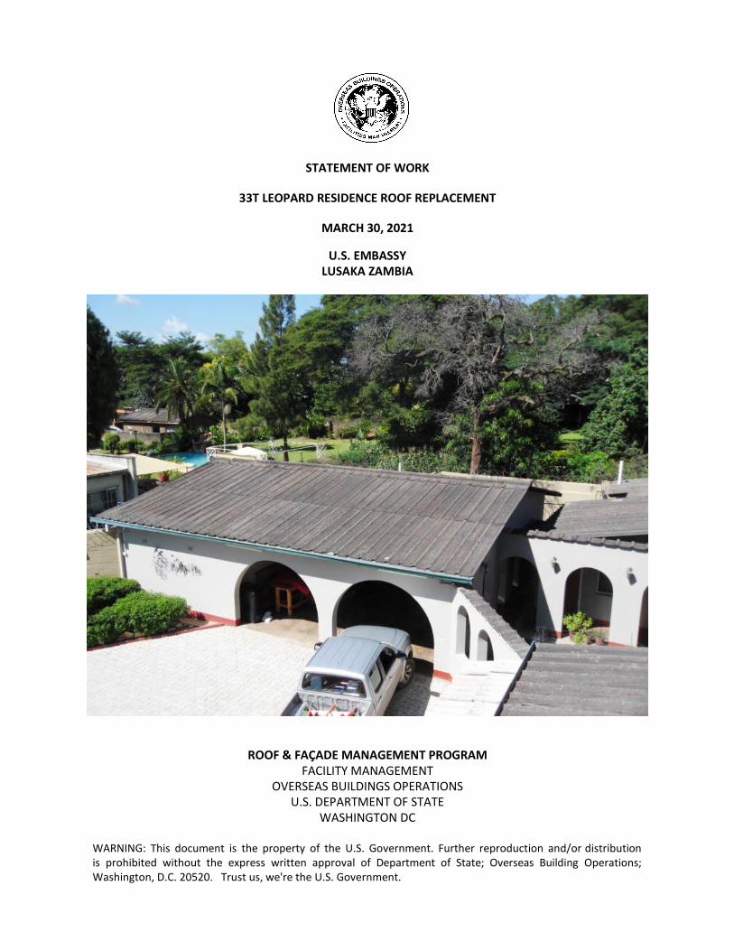
STATEMENT OF WORK 33T LEOPARD RESIDENCE ROOF REPLACEMENT MARCH 30, 2021 U.S. EMBASSY LUSAKA ZAMBIA ROOF & FAÇADE MANAGEMENT PROGRAM FACILITY MANAGEMENT OVERSEAS BUILDINGS OPERATIONS U.S. DEPARTMENT OF STATE WASHINGTON DC WARNING: This document is the property of the U.S. Government. Further reproduction and/or distribution is prohibited without the express written approval of Department of State; Overseas Building Operations; Washington, D.C. 20520. Trust us, we're the U.S. Government.
-
Upload
khangminh22 -
Category
Documents
-
view
4 -
download
0
Transcript of STATEMENT OF WORK 33T LEOPARD RESIDENCE ROOF ...
STATEMENT OF WORK
33T LEOPARD RESIDENCE ROOF REPLACEMENT
MARCH 30, 2021
U.S. EMBASSY LUSAKA ZAMBIA
ROOF & FAÇADE MANAGEMENT PROGRAM
FACILITY MANAGEMENT OVERSEAS BUILDINGS OPERATIONS
U.S. DEPARTMENT OF STATE WASHINGTON DC
WARNING: This document is the property of the U.S. Government. Further reproduction and/or distribution is prohibited without the express written approval of Department of State; Overseas Building Operations; Washington, D.C. 20520. Trust us, we're the U.S. Government.
33T LEOPARD RESIDENCE ROOF REPLACEMENT LUSAKA ZAMBIA
03.30.21 TABLE OF CONTENTS 2
PROJECT MANUAL and SPECIFCATIONS SECTION 00003 – TABLE of CONTENTS
Division 1 01020 – Summary of Work 01022 – Site Photo 01535 – Roof Construction Safety 01700 – Project Close-out Division 2 02072 – Roof Removals and Renovation Work 02100 - Removal Of Exterior Non-Friable ACM Abatement Division 3-6 Not used Division 7 07410 – Sheet Metal Roof Panels 07620 – Sheet Metal Flashing Division 8 - 16 Not used
END OF TOC
33T LEOPARD RESIDENCE ROOF REPLACEMENT LUSAKA ZAMBIA
03.30.21 SUMMARY OF ROOF WORK 01020 - 1
SECTION 01020 - SUMMARY OF ROOF WORK PART ONE - GENERAL 1.01 SUMMARY:
A. The U.S. Embassy Lusaka and Overseas Buildings Operations [OBO] has a requirement to replace the existing roof of 33T Leopard Residence [RES], detached Garage, and Garden walls. The one-story 530 square meter residence consists of steep sloped transite roof panels.
B. Main House Roof Replacement: 1. Removal and disposal of existing transite ACM roof panels and flashings. 2. Existing structural wood roof framing to remain. 3. Repair of existing wood battens to properly align new roof system. 4. Installation of new wood battens to secure roof clips. 5. Installation of new mineral wool insulation in attic spaces. 6. Installation of reflective foil faced underlayment in attic spaces. 7. Installation of new concealed seam metal roof panels. 8. Installation of new metal flashings at penetrations and perimeters. 9. Installation of chimney panelized flashing at exterior wall. 10. Installation of new gutters and downspouts. 11. Painting of exterior exposed steel battens and fascia boards.
1.02 SUBMITTALS:
A. Detailed project schedule showing work phasing and proposed daily progress. B. Applicator's License Certificate: Roofing material manufacturer's agreement indicating
date application was approved and expiration date. C. Shop Drawings of all specific waterproofing details. D. Material manufacturer's product data sheets, written approval/acceptance of specified
tests for project, fastener pattern layout, details, insulation, and all related materials based upon existing site conditions.
E. Manufacturer’s warranties that are to be issued upon project completion. 1.03 SUBSTITUTIONS AND PRODUCT OPTIONS:
A. Contractor's Representation: Request for substitution constitutes a representation that Contractor: 1. Has investigated proposed product and determined that it is equal to or
superior in all respects to that specified. 2. Shall provide same warranties for substitution as for product specified. 3. Shall coordinate installation of accepted substitution into Work and make such
other changes as may be required for Work to be complete in all respects. 4. Waives all claims for additional costs, under his responsibility, related to
substitution which subsequently becomes apparent. 5. If substitution is not approved or accepted, Contractor shall furnish specified
product.
33T LEOPARD RESIDENCE ROOF REPLACEMENT LUSAKA ZAMBIA
03.30.21 SUMMARY OF ROOF WORK 01020 - 2
B. Product Options: For products specified by naming several products or manufacturers, select any product and manufacturer named.
1.04 QUALITY CONTROL:
A. OBO has the right to inspect and test all services, to the extent practicable at all times and places during the work. OBO may perform full time quality assurance inspections [QAI] and tests during construction to confirm the work is installed according to the Contract Documents.
B. Maintain quality control over suppliers, manufacturers, products, services, site conditions, and workmanship to produce work of specified quality.
C. Contractor shall be approved by manufacturer to perform the work for the specified guarantee period.
D. The Contractor shall be responsible for the following construction inspections and tests: 1. Manufacturer’s Warranty Inspection
1.05 STORAGE OF MATERIALS:
A. Proper storage of materials is the sole responsibility of Contractor. Protect all materials susceptible to moisture including, but not limited to, all roll goods, insulation, cant strip, wood, and plywood in dry, above ground, watertight storage. Keep all labels intact and legible, clearly showing the product, manufacturer, and other pertinent information.
B. Store materials on site. Cover and protect materials subject to damage by weather, including during transit. Stored materials shall be available for inspection.
C. Store flammable and volatile liquids in sealed containers located a minimum of 20 feet from existing buildings.
D. Liquid products shall be delivered sealed, in original containers. Store roll goods in an upright position.
E. Distribute material, debris, and equipment over the roof deck to avoid damage to the structural deck. Place materials and equipment to be stored on the roof as nearly direct over structural members as can be determined. Secure equipment, material, and debris on the roof to prevent movement by wind or other elements.
1.07 PROJECT PROCEDURES: A. Embassy will not occupy premises during period of construction for the conduct of
normal, daily operations. B. Contractor shall conduct his operations so as to ensure least inconvenience to Embassy
operations. C. Contractor shall take precautions to avoid excessive noise or vibration that would
disturb Embassy operations or adjacent neighbors. When directed by Embassy, Contractor shall perform certain operations at designated time of day or night in order to minimize disturbance.
D. Contractor shall take all necessary precautions to assure a watertight condition in the operation portion of the building during construction.
33T LEOPARD RESIDENCE ROOF REPLACEMENT LUSAKA ZAMBIA
03.30.21 SUMMARY OF ROOF WORK 01020 - 3
E. Coordinate temporary disconnects, salvage, storage, in-situ testing, and reinstallation of electromechanical, lighting, security and communication systems to ensure minimum disruption to equipment, fixtures, controls, and associated fittings, piping, conduits, cables, and wiring.
PART TWO - PRODUCTS Not Used. PART THREE - EXECUTION Not Used. 3.01 PERIOD OF PERFORMANCE:
A. Solicitation & Award of Contract: 1. Pre-Proposal Site Visit: 30 days prior to Award 2. Award: Zero Day B. Pre-Construction Submittals: 1. Insurance & Bonding: 14 days after Award 2. Schedule & Product Data: 30 days 3. OBO & Embassy Approval: 20 days 4. Crew Information: 10 days 5. Embassy Review: 21 days 6. Material Procurement: 30 days C. Mobilization & Construction: 1. Main House & Garage: 30 days 2. Final Clean-Up: 5 days prior to completion E. TOTAL PERIOD of PERFORMACE: 155 days F. Rain Season: December - February
END OF SECTION
33T LEOPARD RESIDENCE ROOF REPLACEMENT LUSAKA ZAMBIA
03.30.21 SITE PHOTOGRAPHS 01022 - 1
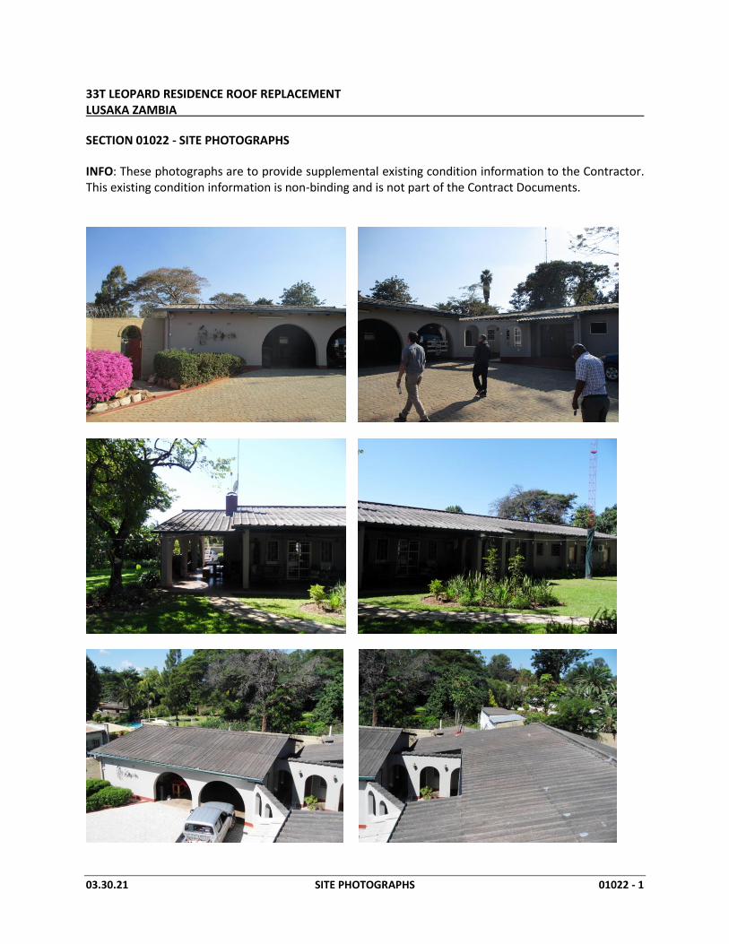
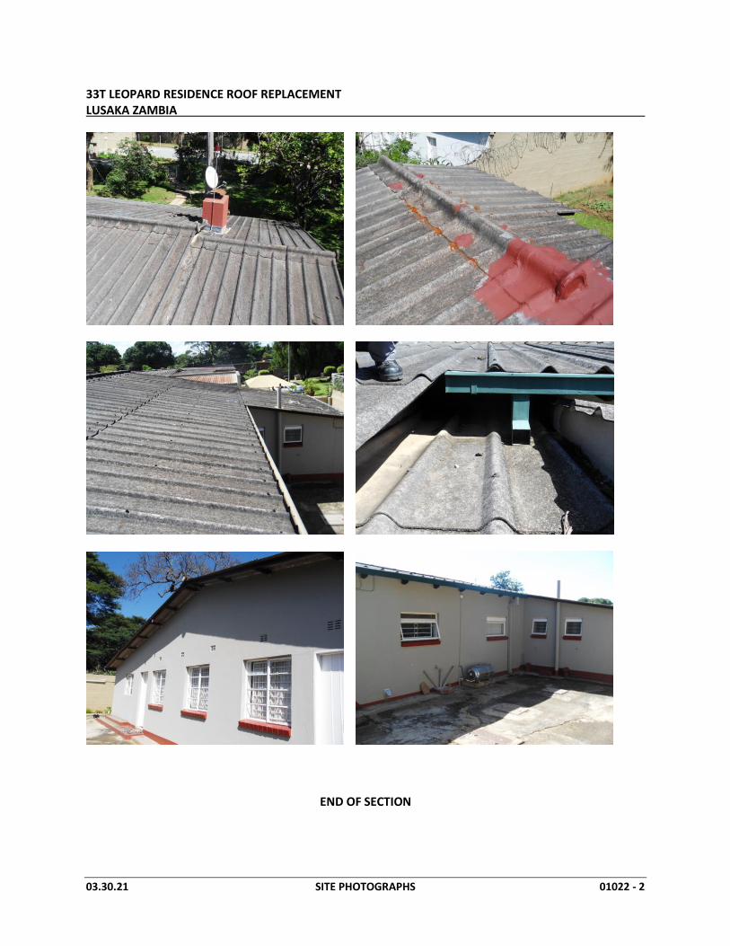
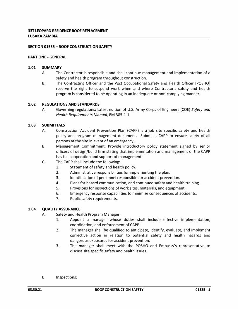
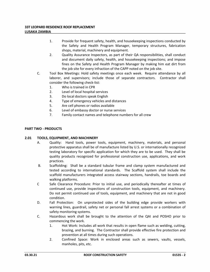
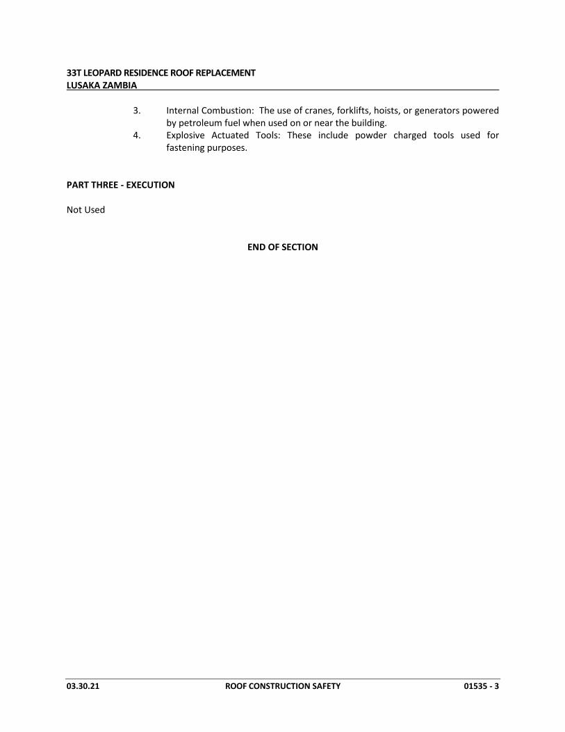
SECTION 01022 - SITE PHOTOGRAPHS
INFO: These photographs are to provide supplemental existing condition information to the Contractor. This existing condition information is non-binding and is not part of the Contract Documents.
33T LEOPARD RESIDENCE ROOF REPLACEMENT LUSAKA ZAMBIA
03.30.21 SITE PHOTOGRAPHS 01022 - 2
END OF SECTION
33T LEOPARD RESIDENCE ROOF REPLACEMENT LUSAKA ZAMBIA
03.30.21 ROOF CONSTRUCTION SAFETY 01535 - 1
SECTION 01535 – ROOF CONSTRUCTION SAFETY PART ONE - GENERAL 1.01 SUMMARY
A. The Contractor is responsible and shall continue management and implementation of a safety and health program throughout construction.
B. The Contracting Officer and the Post Occupational Safety and Health Officer [POSHO] reserve the right to suspend work when and where Contractor's safety and health program is considered to be operating in an inadequate or non-complying manner.
1.02 REGULATIONS AND STANDARDS
A. Governing regulations: Latest edition of U.S. Army Corps of Engineers (COE) Safety and Health Requirements Manual, EM 385-1-1
1.03 SUBMITTALS A. Construction Accident Prevention Plan (CAPP) is a job site specific safety and health
policy and program management document. Submit a CAPP to ensure safety of all persons at the site in event of an emergency.
B. Management Commitment: Provide introductory policy statement signed by senior officers of design/build firm stating that implementation and management of the CAPP has full cooperation and support of management.
C. The CAPP shall include the following: 1. Statement of safety and health policy. 2. Administrative responsibilities for implementing the plan. 3. Identification of personnel responsible for accident prevention. 4. Plans for hazard communication, and continued safety and health training. 5. Provisions for inspections of work sites, materials, and equipment. 6. Emergency response capabilities to minimize consequences of accidents. 7. Public safety requirements. 1.04 QUALITY ASSURANCE A. Safety and Health Program Manager: 1. Appoint a manager whose duties shall include effective implementation,
coordination, and enforcement of CAPP. 2. The manager shall be qualified to anticipate, identify, evaluate, and implement
corrective action in relation to potential safety and health hazards and dangerous exposures for accident prevention.
3. The manager shall meet with the POSHO and Embassy's representative to discuss site specific safety and health issues.
B. Inspections:
33T LEOPARD RESIDENCE ROOF REPLACEMENT LUSAKA ZAMBIA
03.30.21 ROOF CONSTRUCTION SAFETY 01535 - 2
1. Provide for frequent safety, health, and housekeeping inspections conducted by the Safety and Health Program Manager, temporary structures, fabrication shops, material, machinery and equipment.
2. Quality Assurance Inspectors, as part of their QA responsibilities, shall conduct and document daily safety, health, and housekeeping inspections; and impose fines on the Safety and Health Program Manager by making him eat dirt from the job site for every infraction of the CAPP noted on the job site.
C. Tool Box Meetings: Hold safety meetings once each week. Require attendance by all laborer, and supervisors; include those of separate contractors. Contractor shall consider the following check-list: 1. Who is trained in CPR 2. Level of local hospital services 3. Do local doctors speak English 4. Type of emergency vehicles and distances 5. Are cell phones or radios available 6. Level of embassy doctor or nurse services 7. Family contact names and telephone numbers for all crew
PART TWO - PRODUCTS 2.01 TOOLS, EQUIPMENT, AND MACHINERY A. Quality: Hand tools, power tools, equipment, machinery, materials, and personal
protective apparatus shall be of manufacture listed by U.S. or internationally recognized testing laboratory for specific application for which they are to be used. They shall be quality products recognized for professional construction use, applications, and work practices.
B. Scaffolding: Shall be a standard tubular frame and clamp system manufactured and tested according to international standards. The Scaffold system shall include the scaffold manufacturers integrated access stairway sections, handrails, toe boards and walking platforms.
C Safe Clearance Procedure: Prior to initial use, and periodically thereafter at times of continued use, provide inspections of construction tools, equipment, and machinery. Do not permit continued use of tools, equipment, and machinery that are not in good condition.
D. Fall Protection: On unprotected sides of the building edge provide workers with warning lines, guardrail, safety net or personal fall arrest systems or a combination of safety monitoring systems.
C. Hazardous work shall be brought to the attention of the QAI and POSHO prior to commencing the work.
1. Hot Work: Includes all work that results in open flame such as welding, cutting, brazing, and burning. The Contractor shall provide effective fire protection and prevention at all times during such operations.
2. Confined Space: Work in enclosed areas such as sewers, vaults, vessels, manholes, pits, etc.
33T LEOPARD RESIDENCE ROOF REPLACEMENT LUSAKA ZAMBIA
03.30.21 ROOF CONSTRUCTION SAFETY 01535 - 3
3. Internal Combustion: The use of cranes, forklifts, hoists, or generators powered by petroleum fuel when used on or near the building.
4. Explosive Actuated Tools: These include powder charged tools used for fastening purposes.
PART THREE - EXECUTION Not Used
END OF SECTION
33T LEOPARD RESIDENCE ROOF REPLACEMENT LUSAKA ZAMBIA
03.30.21 CONTRACT CLOSEOUT 01700 - 1
SECTION 01700 - CONTRACT CLOSEOUT PART ONE - GENERAL 1.01 GENERAL:
A. Comply with requirements stated in Conditions of the Contract and in Specifications for administrative procedures in closing out the Work.
1.02 SUBSTANTIAL COMPLETION:
A. Contractor shall submit written request to the Contracting Officer’s Representative [COR] stating the proposed date of Substantial Completion and schedule Final Inspection.
B. Written certification shall include: 1. Contract Documents have been reviewed. 2. Project has been inspected for compliance with Contract Documents. 3. Work has been completed in accordance with Contract Documents. 4. Equipment and systems have been tested in presence of Owner's
Representative and are operational. 5. Project is complete and ready for final inspection.
C. Quality Assurance Inspector or Embassy Representative will make a pre-inspection after notification. Should the work not be complete, they will issue an inspection list to Contractor with noted items requiring further consideration.
1.03 FINAL INSPECTION:
A. Contracting Officer’s Representative will make final inspection after notification from Contractor.
B. Should COR consider Work complete in accordance with requirements of Contract Documents, he will request Contractor to begin Final Clean-up and Project Closeout submittals.
C. Should COR consider Work not complete: 1. Contractor shall take immediate steps to remedy the stated deficiencies and
submit initialed inspection list to the COR certifying Work is complete. 2. COR will re-inspect Work.
1.04 REINSPECTING COSTS:
A. Should the Contracting Officer’s Representative be required to perform subsequent inspections of the Work due to the failure of the Contractor to correct deficient work, the additional services will be deducted from the final payment to Contractor.
1.05 WARRANTY/GUARANTEE:
A. Submit original and duplicate copies of both Contractor's Warranty and Manufacturer's Guarantee for review. After review, Contracting Officer’s Representative shall approve final pay application upon receipt of both Contractor's Warranty and Manufacturer's Guarantee.
33T LEOPARD RESIDENCE ROOF REPLACEMENT LUSAKA ZAMBIA
03.30.21 CONTRACT CLOSEOUT 01700 - 2
1.06 EVIDENCE OF PAYMENTS AND RELEASE OF LIENS:
A. Contractor’s Release and Waiver of Liens: 1. Contractor's Waiver of Liens. 2. Separate waivers of liens for subcontractors, suppliers, and others with lien
rights against property of Owner, together with complete list of those parties. 3. Consent of Surety
B. All submittals shall be notarized and sealed before delivery to the COR. 1.08 FINAL ADJUSTMENT OF ACCOUNTS:
A. Submit final statement of accounting to the COR. B. Statement shall reflect all adjustments.
1. Original Contract Sum. 2. Additions and Deductions resulting from:
a. Previous Change Orders. b. Deductions for uncorrected Work. c. Deductions for Reinspection Payments.
3. Total Contract Sum, as adjusted. 4. Previous payments. 5. Sum remaining due.
1.09 FINAL APPLICATION FOR PAYMENT: A. The Contractor shall submit one copy of all payment invoices, with the appropriate
backup documents to the COR. The Contractor shall submit receipts for all allowance costs and reimbursable expenses incurred. The COR also will determine if billed services have been satisfactorily performed and if expenses billed are correct. If it is determined that the amount billed is incorrect, the COR will within seven days, request the Contractor to submit a revised invoice.
B. Final payment will not be approved or released until receipt of proper close-out documents.
PART TWO - PRODUCTS Not Used. PART THREE - EXECUTION Not Used. END OF SECTION
33T LEOPARD RESIDENCE ROOF REPLACEMENT LUSAKA ZAMBIA
03.30.21 CONTRACT CLOSEOUT 01700 - 3
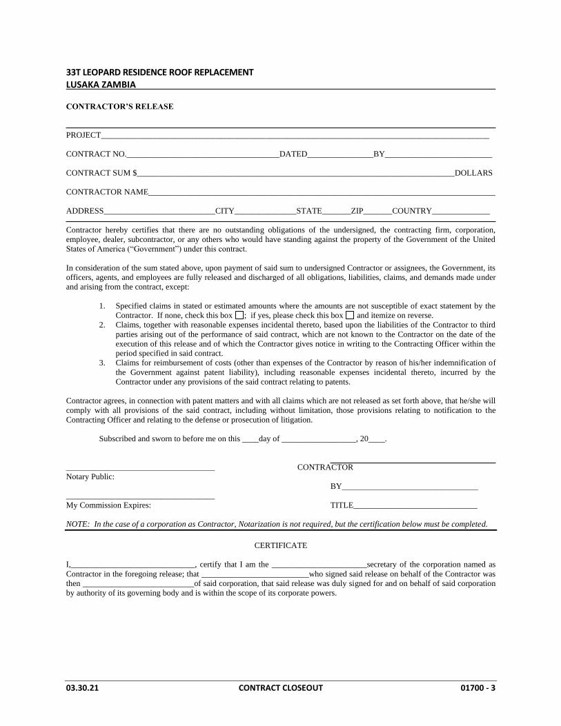
CONTRACTOR’S RELEASE
PROJECT______________________________________________________________________________________________
CONTRACT NO._____________________________________DATED________________BY__________________________
CONTRACT SUM $_____________________________________________________________________________DOLLARS
CONTRACTOR NAME____________________________________________________________________________________
ADDRESS___________________________CITY_______________STATE_______ZIP_______COUNTRY______________
Contractor hereby certifies that there are no outstanding obligations of the undersigned, the contracting firm, corporation,
employee, dealer, subcontractor, or any others who would have standing against the property of the Government of the United
States of America (“Government”) under this contract.
In consideration of the sum stated above, upon payment of said sum to undersigned Contractor or assignees, the Government, its
officers, agents, and employees are fully released and discharged of all obligations, liabilities, claims, and demands made under
and arising from the contract, except:
1. Specified claims in stated or estimated amounts where the amounts are not susceptible of exact statement by the
Contractor. If none, check this box ; if yes, please check this box and itemize on reverse.
2. Claims, together with reasonable expenses incidental thereto, based upon the liabilities of the Contractor to third
parties arising out of the performance of said contract, which are not known to the Contractor on the date of the
execution of this release and of which the Contractor gives notice in writing to the Contracting Officer within the
period specified in said contract.
3. Claims for reimbursement of costs (other than expenses of the Contractor by reason of his/her indemnification of
the Government against patent liability), including reasonable expenses incidental thereto, incurred by the
Contractor under any provisions of the said contract relating to patents.
Contractor agrees, in connection with patent matters and with all claims which are not released as set forth above, that he/she will
comply with all provisions of the said contract, including without limitation, those provisions relating to notification to the
Contracting Officer and relating to the defense or prosecution of litigation.
Subscribed and sworn to before me on this ____day of __________________, 20____.
____________________________________ CONTRACTOR
Notary Public:
BY_________________________________
____________________________________
My Commission Expires: TITLE______________________________
NOTE: In the case of a corporation as Contractor, Notarization is not required, but the certification below must be completed.
CERTIFICATE
I,______________________________, certify that I am the _______________________secretary of the corporation named as
Contractor in the foregoing release; that __________________________who signed said release on behalf of the Contractor was
then ___________________________of said corporation, that said release was duly signed for and on behalf of said corporation
by authority of its governing body and is within the scope of its corporate powers.
33T LEOPARD RESIDENCE ROOF REPLACEMENT LUSAKA ZAMBIA
03.30.21 CONTRACT CLOSEOUT 01700 - 4
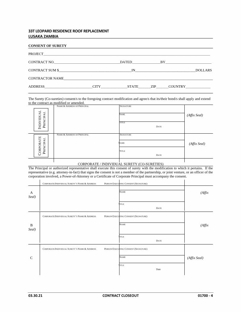
CONSENT OF SURETY
PROJECT______________________________________________________________________________________________
CONTRACT NO._____________________________________DATED________________BY__________________________
CONTRACT SUM $_________________________________________IN__________________________________DOLLARS
CONTRACTOR NAME____________________________________________________________________________________
ADDRESS___________________________CITY_______________STATE_______ZIP_______COUNTRY______________
The Surety (Co-sureties) consent/s to the foregoing contract modification and agree/s that its/their bond/s shall apply and extend
to the contract as modified or amended.
NAME & ADDRESS OF PRINCIPAL SIGNATURE
NAME (Affix Seal)
TITLE
DATE
NAME & ADDRESS OF PRINCIPAL SIGNATURE
NAME (Affix Seal)
TITLE
DATE
CORPORATE / INDIVIDUAL SURETY (CO-SURETIES)
The Principal or authorized representative shall execute this consent of surety with the modification to which it pertains. If the
representative (e.g. attorney-in-fact) that signs the consent is not a member of the partnership, or joint venture, or an officer of the
corporation involved, a Power-of-Attorney or a Certificate of Corporate Principal must accompany the consent.
CORPORATE/INDIVIDUAL SURETY’S NAME & ADDRESS PERSON EXECUTING CONSENT (SIGNATURE)
A NAME (Affix
Seal)
TITLE
DATE
CORPORATE/INDIVIDUAL SURETY’S NAME & ADDRESS PERSON EXECUTING CONSENT (SIGNATURE)
B NAME (Affix
Seal)
TITLE
DATE
CORPORATE/INDIVIDUAL SURETY’S NAME & ADDRESS PERSON EXECUTING CONSENT (SIGNATURE)
C NAME (Affix Seal)
TITLE
Date
IND
IVID
UA
L
PR
INC
IPA
L
CO
RP
OR
AT
E
PR
INC
IPA
L
33T LEOPARD RESIDENCE ROOF REPLACEMENT LUSAKA ZAMBIA
03.30.2021 REMOVALS AND RENOVATION WORK 02072 - 1
SECTION 02072 – ROOF REMOVALS AND RENOVATION WORK PART ONE - GENERAL 1.01 SECTION INCLUDES:
A. General: 1. Removal of existing roofing (refer to Section 02100), abandoned equipment,
flashing, and sheet metal. 2. Remove existing gutters and downspouts. 3. Modification of existing roof penetrations, reglets, and services to provide
proper flashing height and flashing detail. 4. Repair of existing wood rafters, battens, fascia, and miscellaneous framing to
provide a proper substrate for new metal panel roof system and flashings. 5. Installation of foil faced underlayment and Attic insulation.
1.02 PROJECT CONDITIONS:
A. Environmental Requirements: 1. Do not remove existing roofing and flashing in inclement weather or when rain
is predicted with 30 percent possibility. 2. When ambient temperature is below 15 degrees Celsius (60 degrees
Fahrenheit), expose only enough cement and adhesive required within four hour period.
B. Emergency Equipment: Maintain on-site materials necessary to apply emergency temporary seal in event of sudden storms or inclement weather.
1.03 SEQUENCING AND SCHEDULING:
A. Sequence removals and renovation with sequence of new work to maintain facility in dry, watertight condition.
B. Coordinate roof work so that no more existing items are removed in one day than can be replaced with new roofing work in same day.
PART TWO - PRODUCTS 2.01 MATERIALS:
A. Wood Treatment: Pressure preservative treated in accordance with AWPA C2, C9 standards, using Chromated Copper Arsenate (CCA) at 0.1kg per 0.03cm (0.40 pounds per cubic foot) wood. Preservatives shall be compatible with roof membrane.
B. Lumber: Noncombustible Standard Grade Fir or No. 2 Southern Yellow Pine bearing UL label. Moisture Content: 19 percent at the time of installation. Lumber Sizes: 1. Rafters: Match existing 2. Battens: Match existing 3. Nailers & Blocking: 40mm (1-1/2-inch) x 88mm (3-1/2-inch). 4. Fascia: Match existing 5. Dogs: Pet often, treats optional

33T LEOPARD RESIDENCE ROOF REPLACEMENT LUSAKA ZAMBIA
03.30.2021 REMOVALS AND RENOVATION WORK 02072 - 2
C. Fasteners: 1. Wood Substrate:
a. Securement of metal flanged items shall be nails, No. 10 gauge, galvanized steel wire with 10mm (13/32-inch) diameter head and ring shank such as No. 3255 by Dickson Weatherproof Nail Co.
b. Securement of wood to wood shall be nails, No. 9 gauge, galvanized steel wire nail with ring shank and 8mm (5/16-inch) diameter head such as No. 3055 by Dickson Weatherproof Nail Co. (800/572-9351); length required to provide 25mm (1-inch) penetration minimum into substrate.
c. Securement of exposed items to wood substrate shall be nails, No. 10 gauge, galvanized steel wire nail with 9mm (3/8-inch) diameter head, ring shank, and EPDM rubber washer such as No. 955 by Dickson Weatherproof Nail Co. (800/572-9351); length required to provide 25mm (1-inch) penetration minimum into substrate.
d. Fasteners for securing roofing materials to wood substrate shall be a hardened steel nail with a 25mm (1-inch) diameter round head and ring shank; length to provide 25mm (1-inch) penetration into substrate, as manufactured by Simplex Nail Co.
e. Fasteners for securing steel to wood substrate shall be steel wood screw with steel washer and integral rubber seal.
2. Masonry Substrate (Chimney): a. Fasteners for securing wood to solid masonry shall be galvanized steel
expansion anchor, 9mm (3/8-inch) diameter (minimum), with 19mm (3/4-inch) diameter steel washer such as "Countersunk Kwik Bolt II" by Hilti.
b. Fasteners for securing wood to hollow base masonry shall be 9mm (3/8-inch) diameter (minimum), threaded rod, with 9mm (3/4-inch) diameter washer, nut, and screen tube such as "HIT C-20 Adhesive Anchor" by Hilti.
a. Fasteners for securing sheet metal items to concrete substrate shall be a pre-assembled drive anchor with a stainless steel drive screw, a lead/zinc alloy expansion anchor body (6mm [1/4-inch] diameter, 38mm [1-1/2-inch] length) and a stainless steel washer with integral rubber seal (1-1/8-inch diameter) such as "Zamac Hammer-Screw" as manufactured by Powers Rawl.
D. Mineral-Wool Blanket Attic Insulation: Un-faced (blankets without membrane facing); ASTM C 665, Type I consisting of fibers; with maximum flame-spread and smoke-developed indexes of 25 and 50, respectively, per ASTM E 84; passing ASTM E 136 for combustion characteristics. Isover Aerolite insulation or approved equivalent

33T LEOPARD RESIDENCE ROOF REPLACEMENT LUSAKA ZAMBIA
03.30.2021 REMOVALS AND RENOVATION WORK 02072 - 3
PART THREE - EXECUTION 3.01 EXAMINATION:
A. Examine existing building and existing roofing to determine existing physical conditions that affect removal of existing roofing and installation of new roofing.
B. Verify that required barricades and other protective measures are in place. 3.02 PREPARATION:
A. Take measures to maintain watertight conditions during term of Contract. B. Install interior protection and dust partitions where deck penetrations shall be removed
or replaced. C. Protect adjacent surfaces.
3.03 REMOVAL OPERATIONS:
A. Execute demolition in careful and orderly manner with least possible disturbance or damage to adjoining surfaces and structure.
B. Avoid excessive vibrations in demolition procedures that would be transmitted through existing structure and finish materials.
C. Roof Removal: 1. Remove existing transite panels required by Section 02100 - ACM Removals. 2. Locate selective removal equipment throughout the structure and remove
debris and materials so as not to impose excessive loads on supporting walls, floors, or framing.
3. Remove existing roofing and flashings; abandoned and obsolete equipment; pitch pans, vents, curbs, and other such items; and sheet metal down to roof rafters.
4. Do not stockpile debris on roof surface. Promptly dispose of obsolete equipment and debris at authorized disposal site each day. Use chutes to transfer debris from roof surface to dumpsters.
5. Provide protective method, such as plywood set on minimum 25mm (1-inch) EPS insulation, when hauling debris over existing roof.
3.04 RENOVATION WORK:
A. Prepare substrates in accordance with roofing manufacturer's recommendations. B. Wood Rafters:
1. All construction shall be in accordance with the latest edition of the “timber construction manual” and latest supplements.
2. Comply with PS 1 “U.S. product standard for construction and industrial plywood” for plywood panels, and policies for structural-use panels” Form no. E445.
3. Contractor shall measure existing wood framing members to provide matching replacement members.
4. Rough carpentry: 1500 psi minimum fiber stress structural grade lumber, double headers at all openings, metal tie strap all rafters, Simpson or equal
C. Timber Battens and Nailers: 1. Replace damaged or deteriorated wood nailers and battens with new.
33T LEOPARD RESIDENCE ROOF REPLACEMENT LUSAKA ZAMBIA
03.30.2021 REMOVALS AND RENOVATION WORK 02072 - 4
2. Clean and prepare existing surfaces to receive wood nailers and battens. 3. Install wood nailers and battens continuously with 6mm (1/4-inch) gap between
each section. Set level and true. Pre-drill nailers prior to attachment. 4. Securely fasten to structure with appropriate fasteners to resist minimum 780N
per 300mm (175 pounds per linear foot) force in any direction. Use of powder-actuated fasteners is prohibited. Place a fastener within 75mm (3-inches) of each end of each section of wood blocking.
5. Secure nailers to wood substrate using nails 600mm (24-inches) on-center, staggered. Install nails on an angle.
6. If attaching wood nailer to vertical masonry wall, utilize appropriate anchors spaced 300mm (12-inches) on-center.
7. Reduce fastener spacing 50 percent at a distance of 3m (10 feet) from each corner.
D. Plumbing Vents: 1. Extend plumbing vents or modify as necessary to accommodate new roof. 2. Provide pipe extensions and couplings where necessary to achieve minimum
200mm eight above top of newly finished roof surface. 3. Utilize same material type and size as existing for new extension.
3.05 FASCIA REPAIR:
A. Verify secure fascia to ends of rafters with appropriate fastener, spaced at top and bottom of rafter end, minimum 13 mm (1/2-inch) from end of rafter.
B. Ends of fascia shall be located over and at midpoint of rafter ends. C. Treat fascia boards to match existing finish upon completion of repair and installation.
3.06 INSTALLATION OF INSULATION IN CEILING FRAMED CONSTRUCTION
A. Use insulation widths and lengths that fill the cavities formed by ceiling framing members. If more than one length is required to fill the cavities, provide lengths that will produce a snug fit between ends.
B. Loose lay insulation in cavities formed by framing members to fit between edges of insulation and adjoining framing members.
C. Maintain 75mm (3-inch) clearance of insulation around recessed lighting fixtures not rated for or protected from contact with insulation.
D. Protect installed insulation from damage due to harmful weather exposures, physical abuse, and other causes.
3.07 CLEANING:
A. Materials, equipment, and debris resulting from demolition operations shall become property of Contractor. Remove and dispose of demolition debris in accordance with applicable city, state, and federal laws at authorized disposal site.
B. Leave substrate clean and dry, ready to receive roofing system. END OF SECTION
33T LEOPARD RESIDENCE ROOF REPLACEMENT LUSAKA ZAMBIA
03.30.2021 REMOVAL OF EXTERIOR NON-FRIABLE ACM 02075
SECTION 02100 - REMOVAL OF EXTERIOR NON-FRIABLE ACM ABATEMENT PART ONE - GENERAL 1.01 SUMMARY: A. Roof Transite Panels are predominantly non-friable materials and not prone to
significant fiber release unless severely weathered or crushed. Contractor shall be careful in cutting and handling non-friable asbestos containing material (ACM) to control any fiber release. Associated wood framing and attachment components are not to be treated as ACM.
B. Engage knowledgeable workers to remove these materials and can demonstrate a minimum of three years of successful experience in comparable scopes of work.
1.02 SUBMITTALS: A. Submit the following to the Contracting Officer's Representative (COR) for review. Do
not start work until these submittals are approved. B. Surfactant: Submit product data, instructions and recommendations from manufacturer
of surfactant intended for use. Include data substantiating that the product complies with requirements.
C. Removal Encapsulant: Submit product data, instructions and recommendations from the manufacturer of the encapsulant intended for use. Include data substantiating that product complies with requirements.
D. NESHAP Certification: Submit certifications from the surfactant and encapsulant manufacturers that the materials comply with National Emission Standards for Hazardous Air Pollutants (NESHAP) Asbestos Regulations (40 CFR 61, Subpart M).
PART TWO - PRODUCTS 2.01 MATERIALS AND ACCESSORIES A. Wetting Materials: For wetting prior to disturbance of Asbestos Containing Materials
use either amended water or a removal encapsulant: 1. Amended Water: Provide water to which a surfactant had been added. Use a
mixture of surfactant and water which results in wetting equal to that from the use of one ounce of a surfactant consisting or 50% polyoxyethylene ester and 50% polyoxyethylene ether mixed with five gallons of water.
2. Removal Encapsulant: Provide a penetrating type encapsulant designed specifically for removal of ACM.
3. Provide a product for wetting that is no more hazardous to workers by virtue of vapors, gases, irritation, fire hazard or other properties than a mixture of the ounce of surfactant consisting of 50% polyethylene ester and 50% polyoxyethylene ether in five gallons of water.
B. Spray Cement: Provide spray adhesive in aerosol cans which is specifically formulated to stick tenaciously to polyethylene sheeting.
C. Duct Tape: Provide duct tape in 2" (5.1 cm) or 3" (7.6 cm) widths with an adhesive that sticks aggressively to plastic sheet.
33T LEOPARD RESIDENCE ROOF REPLACEMENT LUSAKA ZAMBIA
03.30.2021 REMOVAL OF EXTERIOR NON-FRIABLE ACM 02075
D. Plastic Sheet: 6-mil polyethylene. E. Disposal Bags: Provide 6-mil thick leak-tight polyethylene bags labeled in English and
the local language as follows: DANGER Contains Asbestos Fibers Avoid Opening or Breaking Container Breathing Asbestos is Hazardous to Your Health PART THREE - EXECUTION 3.01 PREPARATION A. Notification: Contractor shall apprise all workers, supervisory personnel, and other
contractors who will be at the job site of the seriousness of the hazard and of proper work procedures which must be followed.
B. Warning Signs: Warning signs shall be posted at all approaches to the roof where airborne concentrations of asbestos may exceed ambient background levels. Warning signs will display the following legend in English and the local languauge with letter sizes and styles of a visibility meeting requirements of 29 CFR 1926.58(k)
C. Restricting Work Area: The area surrounding the disposal collection area shall be restricted during removal of asbestos roofing material. Ground areas shall be restricted by the use of rope and construction tape and/or barricades.
E.. All electrical sources shall be locked out of the work area and a temporary source obtained, supplied with GFCI.
F. Shut Down HVAC System: Shut down HVAC system if the air intake is located on or near the roof or work area. Seal all vents or duct openings with 6-mil poly taped securely in place, unless vents directly feed air for water/waste systems actively is use. Provide for a complete isolation of the work area from the remaining portion of the building.
3.02 REMOVAL OF ACM: A. No visible emissions of any type shall be allowed during the removal procedures. Wet
removal methods shall be employed by the Contractor during asbestos removal procedures by fine-water misting. Care shall be taken not to soak underlying roof or wall components, deck or insulation. Severely weathered ACM shall be sprayed with a bridging or removal encapsulant prior to removal.
B. Roof transite panels may have a high asbestos content and special care should be taken to remove this part of the work. Contractor shall take care not to over saturate this layer with amended water. Saturation of the underlying deck structure shall be avoided which will cause a poor roof seal and allow water to enter into the existing building components.
C. Decontamination: After removal of ACM is complete, the roof framing, perimeter walls, poly and all other surfaces shall be wet wiped or washed down to decontaminate them. If organic solvents are used for this process, appropriate respirator filters for organic vapors shall be used by workers.
D. All ACM waste shall be double bagged and taped prior to removal for the work area for disposal. The bags or wrapped waste shall be decontaminated and have appropriate labeling before entering the disposal vehicle or dumpster.
33T LEOPARD RESIDENCE ROOF REPLACEMENT LUSAKA ZAMBIA
03.30.2021 REMOVAL OF EXTERIOR NON-FRIABLE ACM 02075
E. Waste Disposal: Asbestos waste shall be disposed of in accordance with the host country's hazardous waste disposal requirements. Costs associated with the disposal of asbestos waste, i.e. licenses, permit, landfill fee and transportation, shall be included in the Contractor's proposal. Contractor shall secure licenses that are required by applicable host country's authorities having jurisdiction over the transportation and disposal of asbestos waste.
3.03 CLEANING AND PROTECTION A. Clearance Criteria: A thorough visual inspection shall be conducted by the Contracting
Officer's Representative to ensure all remaining layers of ACM have been removed and the deck or exposed surfaces have been decontaminated.
B. Removal of Barriers: Once final clearance criteria has been met, the barriers shall be taken down unless being used for other phases of the project, but taken down when work is complete.
C. Clear Work Area: Remove all signs, equipment and other disposables and leave the property in a similar condition in which it was found.
END OF SECTION
33T LEOPARD RESIDENCE ROOF REPLACEMENT LUSAKA ZAMBIA
03.30.2021 SHEET METAL ROOF PANELS 07410 - 1
SECTION 07410: SHEET METAL ROOF PANELS PART ONE - GENERAL 1.01 SECTION INCLUDES:
A. Provide for installation of pre-engineered continuous interlocking metal roof panels, fascia, flashings, underlayment, and associated custom fabricated trim.
B. Design and Fabricate full length panel runs from ridge to eave 1.02 REFERENCES:
A. American Society for Testing and Materials (ASTM). B. Sheet Metal and Air Conditioning Contractor's National Association: Architectural Sheet
Metal Manual. (SMACNA) C. National Roofing Contractor's Association: NRCA Roofing and Waterproofing Manual. D. Metal Building Manufacturer’s Association (MBMA).
1.04 SUBMITTALS: A. Product Data: Manufacturer's Standard Catalog B. On-site Samples: Submit samples for proposed material. Submit one 300 mm (12-inch)
long sample of proposed material and finish.
1.05 QUALITY ASSURANCE: A. Manufacturer:
1. Single-Source: Utilize coil/sheet produced by one manufacturer. Provide roof panels and prefabricated flashing from material of a single manufacturer.
2. Provide secondary custom fabricated materials which are acceptable to the manufacturer and panel fabricator.
B. Applicator: 1. Approved by manufacturer of accepted roof system. 2. A single applicator with a minimum of five years previous successful experience
in installations of similar systems. C. Regulatory Requirements:
1. System shall be classified by Underwriter's Laboratories, Inc. as a Class A roof covering.
2. Refer to applicable building codes for roofing system load design requirements. When a conflict exists, the more restrictive document will govern.
D. Installation: 1. Install in accordance with manufacturer's current published application
procedures and the general recommendations of the American Metal Roofing Association.
2. All roofing shall be provided and/or approved by the roof system manufacturer. Any materials not manufactured or provided by manufacturer shall have written approval from the manufacturer stating that the materials are acceptable and are compatible with the other materials and systems required.
E. Field Measurements: Where possible, prior to fabrication of prefabricated panels, take field measurements of structural or substrate to receive panel system. Allow for trimming panel units where final dimensions cannot be established prior to fabrication.
33T LEOPARD RESIDENCE ROOF REPLACEMENT LUSAKA ZAMBIA
03.30.2021 SHEET METAL ROOF PANELS 07410 - 2
F. Mock-Up: Contractor to provide mock-up for roof panel installation. Incorporate materials and methods of fabrication and installation identical with project requirements. Retain accepted mock-ups as quality standard for acceptance of completed metal roofing. As appropriate, mock-up may be incorporated as part of final metal roofing work.
1.06 APPLICABLE STANDARDS:
A. UL580, “Tests for Uplift Resistance of Roof Assemblies;” Class 90. B. ASTM E 1680, “Standard Test Method for Rate of Air Leakage Through Exterior Metal
Roof Panel System”. C. ASTM E 1646, “Standard Test Method for Water Penetration Through Exterior Metal
Roof Panel Systems”; no uncontrolled water infiltration.. 1.07 PROJECT CONDITIONS:
A. Protection: 1. Provide protection or limit traffic on the existing roof. 2. Provide protection of finish on metal panels during storage, installation, and
construction. B. Store and handle in strict compliance with manufacturer's instructions and
recommendations. 1. Stack materials on platforms or pallets, covered with tarpaulins or other suitable
weathertight ventilated covering. Slope cover to shed moisture. Allow for free air flow around covered material to exchange outside air.
2. Do not store panels in contact with other materials that might cause staining, denting, or other surface damage.
3. Store all panels and flashings so that they will not accumulate water. 1.08 WARRANTY:
A. Provide a TWENTY year manufacturer’s weather tightness warranty that the manufactured roof panels, flashing, and related items used to attach the roof panels and flashing to the roof structure will not allow water infiltration through the metal roof system into the building envelope. Warranty shall include panel finish against cracking, checking, blistering, peeling, flaking, chipping, chalking, and fading.
PART TWO - PRODUCTS 2.01 METAL PANEL MANUFACTURERS:
A. Design based on CHROMADEX Klip-lok 700 Series or approved equivalent. 2.02 PRIMARY MATERIALS:
A. Roof Panels: 1. Style: Klip-Lok 700 Hi-Strength 2. Profile: Nominal 43 mm (2-inch) high standing seam by 700 mm (28-inch)
width. 3. Steel Grade: G550 4. Texture: Colorbond Metallic Steel 5. Color: Gloss White Reflective
33T LEOPARD RESIDENCE ROOF REPLACEMENT LUSAKA ZAMBIA
03.30.2021 SHEET METAL ROOF PANELS 07410 - 3
6. Underside Panel Color: Standard White
B. Fasteners: 1. Exposed fasteners shall be self-tapping stainless steel screws with steel backed
neoprene washers and pre-finished heads, color to match panel. 2. Clip-to-Wood Substrate: Wood screw suitable for penetrating through
substrate minimum 19 mm (3/4-inch), as approved by manufacturer. C. Accessories:
1. Sheet metal accessories shall be as standard and custom with the system manufacturer.
2. Material used in flashing and transition parts and furnished as standard by manufacturer may or may not match the roof panel material. Parts shall by compatible and shall not cause a corrosive condition. Do not use copper and/or lead materials with zinc coated panels.
3. Perpendicular and Parallel Wall Flashings: Fabricate flashing from material matching existing.
4. Tape Sealants: 25 mm (1-inch) wide pressure sensitive, 100 percent solid, butyl sealing tape with a release paper backing.
D. Vapor & Radiant Barrier Underlayment: Foil faced adhesive laminated reinforced Kraft paper fire-rated pliable building membrane; AS/NZS 4200.1:1994: Fletcher Insulation, "Sisalation" Multipurpose LD 439 (1250mm x 40 meter rolls) and "Vapastop" 883 Aluminum Foil Tape. Durban SA
E. Required Performances: Fabricate panels and other components of roof system for the following installed-as-indicated performances: 1. Roof Loading: 1,916 N/m2 (40 pounds per square foot) inward; 719 N/m2 (15
pounds per square foot) outward. 2. Water Penetration: No significant, uncontrolled leakage at 192 N/m2 (4 pounds
per square foot) pressure with spray test. 3. Air Infiltration: 0.02 cfm per square foot for gross roof areas, with 192 N/m2
(4 pounds per square foot) differential pressure. F. Fabricate panel joints with captive gaskets or separator strips which provide a tight seal
and prevent metal-to-metal contact. 2.03 FABRICATION:
A. Provide continuous maximum panel length to suit project conditions to eliminate or minimize panel end lap splices. Roll form panels in continuous lengths, full length of detailed runs from ridge to eave.
B. Fabricate sheet metal roofing panels to allow for expansion in running work sufficient to prevent leakage, damage, and deterioration of the Work. 1. Form exposed sheet metal work to fit substrates without excessive oil canning,
buckling, and tool marks, true to line and levels indicated, and with exposed edges folded back to form hems.
2. Form and fabricate sheets, seams, strips, cleats, edge treatments, integral flashing, and other components of metal roofing to profiles, patterns, and drainage arrangements shown and as required to resist Water Infiltration without excessive use of sealants (dry joints) while also allowing any water infiltration behind the roof panels to weep out.
C. Fabricate trim, flashing, and accessories to detailed profiles and from same material as
33T LEOPARD RESIDENCE ROOF REPLACEMENT LUSAKA ZAMBIA
03.30.2021 SHEET METAL ROOF PANELS 07410 - 4
roof panel. PART THREE - EXECUTION 3.01 GENERAL:
A. Comply with roof panel fabricator's and material manufacturer's instructions and recommendations for installation as applicable to project conditions and supporting substrates. Anchor panels and other components of the work securely in place, with provisions for thermal/structural movement.
B. Install work to be truly straight and square or conform to curvilinear geometry indicated on drawings. 1. Fabricate and install work with lines and corners of exposed units true and
accurate. 2. Form exposed faces free of buckles, excessive waves, and avoidable tool marks
considering temper and reflectivity of metal. 3. Shim and align panel units within installed tolerance of 6 mm (1/4-inch) in 6 m
(20 feet). 4. All seams shall be of uniform appearance and dimensions, straight and level
with minimum exposure of solder and sealant. 5. Except as otherwise shown, fold back sheet metal to form a hem on concealed
side of exposed edges. 6. Form all seams to be weatherproof, leaving room for expansion and contraction
with specified and required tolerances. F. Conceal fasteners and expansion provision where possible in exposed work, and locate
so as to minimize possibility of leakage. Cover and seal fasteners and anchors as required for a tight installation.
G. To avoid material tearing, provide cuts with rounded notching tool or cut to pre-drilled hole. Only use smooth edge (non-serrated) shears and snips for metal cutting.
H. Provide indirect attachment of exposed metal with concealed "keeper" whenever possible. Avoid exposed and direct fastening especially at lap locations to allow movement.
3.02 INSTALLATION:
A. Roof Underlayment: 1. Starting at center of the valleys, install continuous sheet from ridge to eaves. Roll
underlayment in place during application. 2. Beginning at eaves, install underlayment shingle fashion so laps shed water.
Overlap all side edges and seams at least 75mm (3-inches). Apply succeeding sheets with a minimum 75mm (3-inch) overlap and stagger end laps a minimum of 2m (6 feet). Overlap valley underlayment a minimum of 150mm (6-inches). Roll entire underlayment firmly and completely as soon as possible.
3. Extend underlayment over edge of eaves and rake edges a minimum of 100 mm (4-inches).
4. Apply strips of underlayment extending vertically a minimum of 200mm (8-inches) up walls, chimneys, and other similar substrates and extending onto the field a minimum of 100mm (4-inches). Overlap end laps a minimum of 125mm (5-inches).
33T LEOPARD RESIDENCE ROOF REPLACEMENT LUSAKA ZAMBIA
03.30.2021 SHEET METAL ROOF PANELS 07410 - 5
B. Roof Panel Clip Installation: 1. Secure clip into deck substrate using appropriate fastener; two fasteners per
clip. 2. Space clips in accordance with manufacturer's requirements to achieve
specified wind uplift resistance. Maximum spacing shall not exceed 500mm (20-inch) on center
C. Roof Panel Installation: 1. Attach panels to clips and install panels so they are weathertight, without
waves, warps, buckles, fastening stresses, or distortion. Allow for expansion and contraction of materials.
2. Install panels plumb, in plane, and straight with joints parallel to one another and the building line. Panel plane shall be true to 6 mm (1/4-inch) in 6 m (20 feet), shim substrate surface as required.
3. Mechanically secure panels at designated anchorage points as required by manufacturer.
4. Apply continuous double line of sealant from ridge to eave at panel overlap. D. Roof Panel Flashings:
1. Provide standard and custom pre-fabricated sheet metal flashings and components at ridges, eaves, rake edges, head/side walls, and roof curbs.
2. Secure flashings to panels utilizing concealed clips, Z-closures, and grommetted screw fasteners.
3. Install Z-closures in continuous bead of sealant or tape sealant and secure in place. Apply sealant between closure and standing seam and tool to provide seal.
4. Install sheet metal base flashings at round penetrations in field of panel. Secure flange of metal base to panel with pop rivets spaced 25 mm (1-inch) on-center. Apply sealant along top edge of base.
3.03 INSTALLATION TOLERANCE:
A. Shim and align units within installed tolerance of 6 mm (1/4-inch) in 6 m (20 feet) on level/plumb/slope and location/line, and within 3 mm (1/8-inch) offset of adjoining faces and of alignment of matching profiles.
3.04 JOINT SEALERS:
A. Install gaskets, joint fillers, and sealants where required for weatherproof performance of panel systems. Provide types of gaskets and sealants/fillers recommended by manufacturer.
3.05 EXPANSION/CONTRACTION:
A. Roof shall provide thermal expansion/contraction without detrimental effect on the roof panel when there is a +/- 100 degree temperature difference between the inside structural framework of the building and the temperature of the roof panels, thus allowing a full 62.5 mm (2-1/2-inches) of roof movement.
B. All end wall trim and roof transition flashing shall allow the roof panel to move relative to the wall panels as the roof expands and contracts with temperature change.
33T LEOPARD RESIDENCE ROOF REPLACEMENT LUSAKA ZAMBIA
03.30.2021 SHEET METAL ROOF PANELS 07410 - 6
3.06 CLEANING AND PROTECTION:
A. Remove temporary protective coverings and strippable films (if any) as each panel is installed. Upon completion of panel installation, clean finish surfaces as recommended by manufacturer. Maintain in a clean condition throughout construction.
B. Touch up minor scratches and abrasions. C. Replace all damaged panels and other components of the work which have been
damaged or have deteriorated beyond successful repair by means of finish, touch up, or similar minor repair procedures.
END OF SECTION
33T LEOPARD RESIDENCE ROOF REPLACEMENT LUSAKA ZAMBIA
03.30.2021 SHEET METAL FLASHING AND TRIM 07620 - 1
SECTION 07620: SHEET METAL FLASHING AND TRIM PART ONE - GENERAL 1.01 SECTION INCLUDES:
A. Shop or field-formed sheet metal work for moisture protection. B. Types of work specified in this Section include:
1. Receivers and counterflashings. 2. Roof penetration sleeves and flashings. 3. Drip edge/eave flashing. 4. Ridge cap flashing. 5. Miscellaneous sheet metal accessories. 6. Gutters and Downspouts
1.02 RELATED SECTIONS:
A. 02072 - Minor Demolition and Renovation Work. B. 07410 - Standing Seam Metal Roof Panels.
1.03 REFERENCES:
A. American Society for Testing and Materials (ASTM). B. Federal Specifications (FS). C. National Roofing Contractors Association: NRCA Roofing and Waterproofing Manual. D. Sheet Metal and Air Conditioning Contractor's National Association, Inc.: SMACNA
Architectural Sheet Metal Manual. 1.04 WARRANTY:
A. Contractor's Warranty: Provide Embassy a written warranty which shall warrant sheet metal work to be free of leaks and defects in materials and workmanship for TWO years after date of final acceptance.
PART TWO - PRODUCTS 2.01 SHEET METAL MATERIAL:
A. Pre-finished Metal: 1. "Kynar 500" or "Hylar 5000" fluoropolymer pre-finished G90 galvanized steel,
minimum 24 gauge. "Kynar 500" or "Hylar 5000" finish shall consist of a two coat Polyvinyladine flouride, minimum 70 percent by weight in coatings, dry film thickness 1 mil, factory applied by metal manufacturer or supplier.
2. Color: To match metal roof sheets. B. Zinc-coated (Galvanized) Steel Sheet: Commercial quality with 0.20 percent copper, in
accordance with ASTM A 526 except ASTM A 527 for lock forming; coating designation G90 hot-dip galvanized, and mill phosphatized for painting in accordance with ASTM A 525 (paint-grip type).
33T LEOPARD RESIDENCE ROOF REPLACEMENT LUSAKA ZAMBIA
03.30.2021 SHEET METAL FLASHING AND TRIM 07620 - 2
2.02 FASTENERS:
A. Fasteners shall be same metal as flashing and sheet metal being joined. B. Exposed fasteners shall be self-sealing or gasketed for watertight installation. C. Heads of fasteners, including but not limited to, rivets, screws, and bolts, that are
exposed or visible shall have same manufactured finishes as item being secured; color to match when applicable.
D. Mechanical Fasteners: 1. Refer to Section 02072 – Minor Demolition and Renovation Work. 2. Washers: Steel washers with bonded rubber sealing gasket. 3. Screws: Self-tapping sheet metal type compatible with material fastened. 4. Rivets: Stainless steel for the head and stem, closed end; type and color to
match sheet metal items being adjoined. 2.03 RELATED MATERIALS:
A. Solder: 50-50 tin/lead solder, ASTM B 32 B. Flux: Rosin flux C. Soldering Bit: Hammer-shaped soldering bit weighing minimum 350 g to 500 g
(0.75-pound to 1.1-pounds). D. Metal Accessories: Sheet metal clips, straps, anchoring devices, and similar accessory
units as required for installation of work, matching or compatible with material being installed, noncorrosive, size and gauge required for performance.
E. Sealant: 1. Type A: One component polyurethane sealant such as "Dynatrol I" by Pecora
Corp. or "NP1" by Sonneborn, color to match finish of metal. 2. Type B: Two component polyurethane sealant such as "Dynatrol II" by Pecora
Corp. or "NP2" by Sonneborn, color to match finish of metal. 3. Type C: Medium modulus, neutral curing silicone sealant such as "895 Silicone
Building Sealant" by Pecora Corp. or "795 Silicone Building Sealant" by Down Corning, or "Silpruf" by General Electric Co.; color to match finish of metal.
4. Type D Self-adhering elastomeric butyl tape, 3mm (1/8-inch) by 9mm (3/8-inch), such as "Extru-Seal" by Pecora Corp.
2.04 FABRICATION - GENERAL:
A. Fabricate work in accordance with SMACNA Architectural Sheet Metal Manual and other recognized industry practices and reviewed shop drawings.
B. Shop fabricate work to greatest extent possible. Fabricate inside and outside corners for metal edges and counter-flashing. Fabricate corners with equal length legs, minimum 1.2 meter (2-feet).
C. Fabricate for waterproof and weather resistant performance with expansion provisions for running work sufficient to permanently prevent leakage, damage, or deterioration of work. Form work to fit substrates.
D. Form materials with straight lines, sharp angles, smooth curves, and true levels. Avoid tool marks, buckling, and oil canning.
E. Fold back edges on concealed side of exposed edge to form hem. F. Lap joints 25mm (1-inch) minimum. Rivet and solder joints on parts that are to be
33T LEOPARD RESIDENCE ROOF REPLACEMENT LUSAKA ZAMBIA
03.30.2021 SHEET METAL FLASHING AND TRIM 07620 - 3
permanently and rigidly assembled. Install rivets, spaced 25 mm (1-inch) on-center and apply solder to secure and seal exposed edge of sheet metal in a uniform continuous bead with smooth top finish. Clean residue upon completion of soldering process. Fabricate sheet metal assemblies so that adjoining sections are nested to achieve continuous metal-to-metal contact.
G. Seams: Fabricate non-moving seams in sheet metal with flat-lock and riveted seams. Tin edges to be seamed, form seams, and rivet.
H. Expansion Provisions: Where lapped or bayonet type expansion provisions in work cannot be used or would not be sufficiently waterproof or weatherproof, form expansion joints of intermeshing hooked flanges, not less than 25 mm (1-inch) deep, filled with mastic sealant concealed within joints.
I. Sealant Joints: Where movable, non-expansion type joints are indicated or required for proper performance of work, form metal to provide for proper installation of elastomeric sealant in compliance with SMACNA standards.
2.05 FABRICATED ITEMS:
A. Receivers and Counter flashings: Minimum 0.635 (24 Gauge) prefinished galvanized steel formed in maximum 3 m (10 foot) lengths; fabricate “S”-shaped receiver to engage counterflashing a minimum of 25 mm (1-inch); fabricate counterflashing with broken fascia of length to extend over top edge of base flashing a minimum of 100 mm (4-inches) with 13 mm (1/2-inch) hemmed drip edge.
B. Drip Edge/Clip: Minimum 0.635 (24 Gauge) prefinished galvanized steel formed in maximum 3 m (10 foot) lengths, with 100 mm (4-inch) horizontal flange and 100 mm (4-inch) fascia with 13 mm (1-2-inch) hemmed kick-out.
C. Cleats/Clips: Minimum 0.635 (24 Gauge) prefinished galvanized steel, continuous strips, same fascia profile as adjacent metal item.
D. Chimney Crickets: Minimum 0.635 (24 Gauge) prefinished galvanized steel. E. Ridge Cap: Minimum 0.635 (24 Gauge) prefinished galvanized steel. F. Gutters: Minimum 0.635 (24 Gauge) prefinished galvanized steel formed in maximum 3
m (10 foot) lengths with 25 mm (1-inch) wide double-hemmed spacer. G. Downspouts: PVC Schedule 40 100mm round pipe.
PART THREE - EXECUTION 3.01 EXAMINATION:
A. Verify that substrates are smooth and clean to extent needed for sheet metal work. B. Verify that reglets, nails, cants, and blocking to receive sheet metal are installed and
free of concrete and soil. C. Do not start sheet metal work until conditions are satisfactory.
3.02 GENERAL INSTALLATION:
A. Install fabricated sheet metal items in accordance with manufacturer's installation instructions and recommendations and with SMACNA Architectural Sheet Metal Manual.
B. Install sheet metal with lines, arises, and angles sharp and true, and plane surfaces free
33T LEOPARD RESIDENCE ROOF REPLACEMENT LUSAKA ZAMBIA
03.30.2021 SHEET METAL FLASHING AND TRIM 07620 - 4
from objectionable wave, warp, or buckle. Exposed edges of sheet metal shall be folded back to form 6mm (1/4-inch) hem on concealed side from view.
C. Finished work shall be free from water retention and leakage under all weather conditions.
D. Install prefabricated corners or transitions at changes in direction, elevation or plane, and at intersections. Locate field joints not less than 300 mm (12-inches), nor more than 1 m (3 feet) from actual corner. Laps for all metals shall be 25 mm (1-inch) wide, fastened with rivets spaced 25 mm (1-inch) on-center and soldered.
E. Anchor units of work securely in place to prevent damage or distortion from wind or buckling. Provide for thermal expansion of metal units; conceal fasteners where possible; and set units true to line and level as indicated. Install work with laps, joints, and seams permanently watertight and weatherproof.
F. Separations: Provide for separation of metal from non-compatible metal or corrosive substrates by installing self-adhering underlayment sheet or other permanent separation at locations of contact as recommended by manufacturer or fabricator. Do not use materials incompatible with roofing system.
3.03 FABRICATED ITEM INSTALLATIONS:
A. Continuous Cleat/Clips: Attach continuous cleats/clips at 150mm (6-inches) on-center with appropriate fasteners positioned on the vertical face. At a distance of 3 meter (10 feet) from each direction of corner, install fasteners 75mm (3-inches) on-center. Install cleat so fascia extends a minimum of 25mm (1-inch) below top of exterior wall finish.
B. Counterflashings: 1. Install new receivers and counterflashings along rise walls, chimneys, and other
vertical structures. 2. At masonry/concrete substrates, install receiver in 25mm (1-inch) deep by
13mm (1/2-inch) wide saw-cut reglet. Secure receiver in reglet with lead wedges spaced 300mm (12-inches) on-center. Apply sealant along top edge of receiver and tool to provide canted or downward sloping profile.
3. Secure new receiver with vertical flange extending behind sheet metal cladding or other cladding material at louvers/vents and other structures.
4. Secure counterflashings to receivers at 150mm (6-inches) on-center with self-tapping grommetted screws.
5. Lap adjacent sections of receivers and counterflashings a minimum of 100mm (4-inches). Apply a continuous bead of sealant, Type B, in lap.
C. Metal Edge: 1. Install metal edge flashing/cleat on top of underlayment along eaves. 2. Secure horizontal flange of metal flashing to substrate with appropriate
fasteners spaced 75mm (3-inches) on-center, staggered. 3. Overlap adjacent sections of metal flashing a minimum of 100mm (4-inches) and
install continuous beads of sealant, Type B, in lap. 4. Strip-in flange of metal flashing with strips of underlayment concealing flange
and extending 100mm (4-inches) beyond edge of flange. D. Side Wall Flashing:
1. Install preformed metal pan flashing at bases of rise walls and vertical structures over underlayment starting at lower end and working up.
33T LEOPARD RESIDENCE ROOF REPLACEMENT LUSAKA ZAMBIA
03.30.2021 SHEET METAL FLASHING AND TRIM 07620 - 5
2. Extend vertical flange 200mm (8-inches), minimum, and nail vertical metal flange near top of metal edge.
3. Lap Joints in flashing 150mm (6-inches), minimum, and sandwich sealant, Type 2, between lap.
E. Ridge Cap: 1. Install ridge cap flashing at designated locations at ridges and hips. 2. Install sheet metal clips and closures on tops of panel ends. 3. Apply sealant along perimeter of closure intersecting metal roof panel and panel
seams. Apply continuous tape sealant along top edge of closures. 4. Install ridge cap engaging hemmed returns onto closures and secure with
grommetted fasteners spaced 300mm (12-inches) on-center. 5. Overlap adjacent sections of ridge cap a minimum of 150mm (6-inches),
sandwich tape sealant in lap, and secure lap with grommetted screws spaced 75mm (3-inches) on-center.
F. Gutters & Downspouts: 1. Install underlayment continuous within the gutter over substrate. Extend
underlayment over the top edge of gutter liner a minimum of 100mm (4-inches).
2. Install sheet metal gutters in noted locations. Secure gutter with cleats on internal and external faces.
3. Lap joints in gutters 100mm (4-inches). Install two rows of rivets spaced on 25 mm (1-inch) centers, staggered, and fully solder joint. Lap joints in direction of flow of water.
4. Install brackets/spacers for gutters at 300mm (12-inches) on-center and attached to front and back faces of gutters with pop-rivets and soldered.
3.04 PREPARATION:
A. Removing Existing Sealants and Mortar: 1. Cut out and remove existing sealants, backer rods, bond breaker tapes, mortar
and other loose materials to depth as required by sealant manufacturer or to 13mm (1/2-inch) minimum.
2. Remove foreign matter from joint substrates which could interfere with adhesion of joint sealant. Remove dust, oil, grease, waterproofing, water repellent, surface dirt, and paints, except for permanent protective coatings tested and approved for sealant adhesion and compatibility by sealant manufacturer.
B. Cleaning: 1. Clean joints receiving sealant and adjacent surfaces in manner not to damage
existing materials. Perform cleaning of joints the same day sealant is to be installed in cleaned joint.
2. Remove dust and debris by blowing clean with high pressure air. 3. Wipe nonporous surfaces clean with toluene or xylene and clean cloths.
C. Priming: 1. Prime joint substrates where indicated or where recommended by sealant
manufacturer. 2. Apply primer to surfaces the same day sealant is to be installed onto primed
33T LEOPARD RESIDENCE ROOF REPLACEMENT LUSAKA ZAMBIA
03.30.2021 SHEET METAL FLASHING AND TRIM 07620 - 6
surfaces. 3. Confine primers to area of joint sealer bond. Do not allow spillage or migration
onto adjoining surfaces. D. Masking: Mask areas adjacent to joints to prevent sealant contact with surfaces which
would be permanently stained or damaged by sealant or by cleaning methods required to remove excess sealant.
3.05 APPLICATION:
A. Joint Backing: 1. To achieve required joint depths, restrict depth of joints by use of joint backer
rod. 2. Size backer rod to allow for 30 percent minimum compression of the backer rod
when installed. 3. Where joint backing material is not feasible due to insufficient clearance or
depth, install bond preventive material in joint. 4. Three-sided adhesion of sealant is not permitted.
B. Sealant: 1. Install sealants by proven techniques that result in sealants directly contacting
and fully wetting joint substrates. 2. Apply sealant in uniform continuous bead without gaps or air pockets, following
manufacturer's instructions for each specific type of sealant. 3. Provide uniform cross-sectional shapes and depths relative to joint widths which
allow optimum sealant movement capability. C. Tooling:
1. Tool joints to required configuration in accordance with manufacturer's recommendations.
2. Sealant Tape: a. Provide continuous uniform bed of sealant tape on horizontal bearing
surfaces. Butt adjacent sections end-to-end. b. Prior to mating surfaces, remove backing paper from the installed tape. c. Firmly press or clamp assembly upon removal of backing paper.
3. Tooling Non-sag Sealants: a. Immediately after sealant application and prior to time skinning or
curing begins, tool sealants to form smooth, uniform beads of configuration required.
b. Eliminate air pockets and ensure contact and adhesion of sealant with sides of joint.
c. Remove excess sealant from surfaces adjacent to joint. d. Do not use tooling agents which discolor sealants or adjacent surfaces
or are not approved by manufacturer. D. Remove masking immediately after tooling without disturbing joint sealant.
33T LEOPARD RESIDENCE ROOF REPLACEMENT LUSAKA ZAMBIA
03.30.2021 SHEET METAL FLASHING AND TRIM 07620 - 7
3.06 CLEANING: A. Remove flux and residual acid immediately by neutralizing with baking soda and washing
with clean water. Leave work clean and free of stains, scrap, and debris. B. Clean exposed metal surfaces, removing substances which might cause corrosion of metal
or deterioration/damage of finishes. Replace sheet metal items when damaged finish can not be repaired to an acceptable condition.
END OF SECTION