Hybrid Electric Vehicle with Flywheel Energy Storage System
11
Hybrid Electric Vehicle with Flywheel Energy Storage System JIANHUI HE, GUOQIANG AO, JINSHENG GUO, ZIQIANG CHEN, LIN YANG School of Mechanical Engineering Shanghai Jiao Tong University Dong chuan Road No.800 Shanghai 200240, CHINA [email protected] Abstract: - A new hybrid-drive system taking flywheel energy storage system instead of chemical battery as assistant power source for hybrid electric vehicle is put forward. According to the particular energy characteristics of flywheel system, an energy management strategy based on fuzzy logic control is also developed with overall consideration on the optimization of both ICE (Internal Combustion Engine) and ISG (Integrated Started Generator). The strategy determines the optimal torque distribution between ICE and ISG through inputs of rotary speed of flywheel, rotary speed of ICE crankshaft and travel of accelerator pedal or brake pedal. Simulation results indicate that flywheel energy storage system is quite suitable for hybrid electric vehicle and with fuzzy logic control strategy both the performance of ICE and ISG are optimized that reduces fuel consumption of vehicle to greater extent. Key-Words: - Flywheel energy storage system, ISG, Hybrid electric vehicle, Energy management, Fuzzy logic control 1 Introduction Flywheel energy storage system (FESS) is different from chemical battery and fuel cell. It is a new type of energy storage system that stores energy by mechanical form and was first applied in the field of space industry. With the development of flywheel technology, it is current be widely used in various industry fields. The vehicle ‘AFS20’ which was produced by U.S. flywheel system Inc. with original shape of Daimler-Kreisler began the Popularization of FESS towards automobile industry. Pullen, K.R has developed a kinetic energy storage for vehicle using based on flywheel technology [3]. Gao Yimin has studied the characteristics of FESS and compared them to the vehicle requirements [4]. Kascak. P has applied FESS to Bus and developed relative control strategy for driving[5]. In this paper, parameter of energy storage state for FESS is introduced, which makes it more convenient for the control of vehicle and can also be contrasted easily with the SOC (State of charge) of chemical battery and the charge state of ultra-capacitor as well. The energy characteristics of FESS are restudied according to the newly introduced energy storage state of flywheel system. Besides its use-cost is considered additionally to the analysis and calculation of FESS for Hybrid electric vehicle (HEV). According to the special energy characteristics of FESS, a fuzzy logic control strategy is also developed. With purpose of reducing fuel consumption, the strategy synthesizes all the influencing factors to determine the energy management of vehicle and both the operating points of ICE and ISG are optimized to dig full potential of hybrid technology WSEAS TRANSACTIONS on SYSTEMS Jianhui He, Guoqiang Ao, Jinsheng Guo, Ziqiang Chen, Lin Yang ISSN: 1109-2777 638 Issue 5, Volume 8, May 2009
-
Upload
khangminh22 -
Category
Documents
-
view
0 -
download
0
Transcript of Hybrid Electric Vehicle with Flywheel Energy Storage System

Hybrid Electric Vehicle with Flywheel Energy Storage System
JIANHUI HE, GUOQIANG AO, JINSHENG GUO, ZIQIANG CHEN, LIN YANG School of Mechanical Engineering
Shanghai Jiao Tong University Dong chuan Road No.800 Shanghai 200240,
CHINA [email protected]
Abstract: - A new hybrid-drive system taking flywheel energy storage system instead of chemical battery as assistant power source for hybrid electric vehicle is put forward. According to the particular energy characteristics of flywheel system, an energy management strategy based on fuzzy logic control is also developed with overall consideration on the optimization of both ICE (Internal Combustion Engine) and ISG (Integrated Started Generator). The strategy determines the optimal torque distribution between ICE and ISG through inputs of rotary speed of flywheel, rotary speed of ICE crankshaft and travel of accelerator pedal or brake pedal. Simulation results indicate that flywheel energy storage system is quite suitable for hybrid electric vehicle and with fuzzy logic control strategy both the performance of ICE and ISG are optimized that reduces fuel consumption of vehicle to greater extent. Key-Words: - Flywheel energy storage system, ISG, Hybrid electric vehicle, Energy management, Fuzzy logic control
1 Introduction Flywheel energy storage system (FESS) is
different from chemical battery and fuel cell. It is a new type of energy storage system that stores energy by mechanical form and was first applied in the field of space industry. With the development of flywheel technology, it is current be widely used in various industry fields. The vehicle ‘AFS20’ which was produced by U.S. flywheel system Inc. with original shape of Daimler-Kreisler began the Popularization of FESS towards automobile industry. Pullen, K.R has developed a kinetic energy storage for vehicle using based on flywheel technology [3]. Gao Yimin has studied the characteristics of FESS and compared them to the vehicle requirements [4]. Kascak. P has applied FESS to Bus and developed relative control strategy for driving[5].
In this paper, parameter of energy storage state for FESS is introduced, which makes it more convenient for the control of vehicle and can also be contrasted easily with the SOC (State of charge) of chemical battery and the charge state of ultra-capacitor as well. The energy characteristics of FESS are restudied according to the newly introduced energy storage state of flywheel system. Besides its use-cost is considered additionally to the analysis and calculation of FESS for Hybrid electric vehicle (HEV). According to the special energy characteristics of FESS, a fuzzy logic control strategy is also developed. With purpose of reducing fuel consumption, the strategy synthesizes all the influencing factors to determine the energy management of vehicle and both the operating points of ICE and ISG are optimized to dig full potential of hybrid technology
WSEAS TRANSACTIONS on SYSTEMS Jianhui He, Guoqiang Ao, Jinsheng Guo, Ziqiang Chen, Lin Yang
ISSN: 1109-2777 638 Issue 5, Volume 8, May 2009

2 HEV with flywheel system 2.1 Comparison between energy storage systems
HEV taking ICE as the main power source usually adopts chemical battery as assistant power. Compared with ultra-capacitor and chemical batteries such as lead-acid battery or nickel metal hydride (NIMH) battery, FESS has advantages of the longest use-life, the highest energy storage density, the shortest charging time and also the easiest maintenance. Moreover it has the least demand for working environment and will cause no pollution. The Comparisons between them are shown in Table 1. Table 1 Comparison between chemical battery, Ultra-capacitors and FESS [1] Chemical
Battery
Ultra-
Capacitors
Flywheel
System
Storage
Mechanism
Chemical Electric Mechanical
Use-life 3~5
years
12~18years >20 years
Temperature
Range
Limited Limited Less
limited
Environmental
Concerns
Serious Less
serious
Slight
Relative mass
(Equivalent
energy)
Large Middle Small
Practical time
To hold a charge
months Days Hours
The key point of energy storage with flywheel is to reduce the loss of mechanical energy, namely the loss of kinetic energy that consists of air friction resistance and rotary resistance. According to different means for the reduction of energy loss, FESS can be divided into low-speed flywheel system and high-speed flywheel system. The first reduces air friction by increasing the mass of flywheel while the second is to reduce the air pressure of operating environment of flywheel. The high-speed
flywheel system benefits from the use of high strength compound material (carbonic fibre). It has characteristics of small mass, low volume and high speed. Thus it is fit for vehicle using.
The high-speed flywheel system consists mainly of a flywheel, a motor and a generator. It is connected with exterior electrical systems through input or output electronic equipments and the power transported from exterior systems is converted from electric energy into mechanical energy by raising rotary speed of flywheel. When it is needed to output power, mechanical energy is converted back into electric energy through generator and meantime the rotary speed of flywheel is reduced [2]. The motor and generator are usually integrated together and magnetic suspension bearings are adopted by flywheel system, through the support of which the flywheel is fixed in a vacuum container (Fig.2).
Excessive high cost is the main cause preventing FESS from popularizing. Its cost is about 1.5 times that of ultra-capacitor and is about 6 ~ 7 times that of chemical battery. But the use-life of flywheel system is 10 times or more than that of chemical battery and needs no recalling. Moreover the cost for installation and maintenance is also much lower than chemical battery and ultra-capacitor. So if the use-life of each vehicle were accounted for ten years, the annual expenditure consumed on FESS would be slightly higher than that consumed on chemical battery (Fig.1). Furthermore, the FESS will have greater potential of developing after industrialization. Fig.1 Cost comparison between chemical battery
and flywheel system
Cos
t
WSEAS TRANSACTIONS on SYSTEMS Jianhui He, Guoqiang Ao, Jinsheng Guo, Ziqiang Chen, Lin Yang
ISSN: 1109-2777 639 Issue 5, Volume 8, May 2009

2.2 Structure of hybrid system ISG (Integrated Started Generator) hybrid
electric vehicle belongs to parallel hybrid electric vehicle (PHEV). It is also one kind of light hybrid electric vehicle (LHEV) based on ISG technology. ISG system usually takes thin electric machinery with permanent magnetism.
Hybrid Control Unit (HCU) is the control center of vehicle, communicating with control module of flywheel system (FCM), ISG control module (ICM) and engine control module (ECM), harmonizing functions of all the units. In the driving process, the main task of HCU is to solve the problem of torque distribution between ISG and ICE (Internal Combustion Engine) [6-10].
The hybrid system takes four-cylinder ICE with maximal power of 45Kw and ISG with maximal power of 30Kw as its dynamic system.
A FESS with peak power of 35Kw and rotary inertia of 1.8Kg.m2 is chosen. The maximal rotary speed of flywheel is 18000r/min while the minimal rotary speed is 1350r/min. The Flywheel system is controlled by FCM, which receives commands of charging or discharging from HCU and then gives commands to the motor or generator of FESS. Except for harmonizing functions of all the controllers and determining energy management of vehicle, HCU also needs to deal with various fault signals. The structure of hybrid system is presented by Fig.2.
Fig.2 Structure of hybrid system with FESS
2.3 Energy characteristics of FESS FESS stores power by mechanical form and
the stored energy is the function of flywheel’s rotary speed (ω ).
( ) ( )( )42
1 4422 rRtltJE −== πρωω
(1)
Where ρ is the density of flywheel, R / r is
the outer/inner diameter of flywheel, l is the
length of flywheel and J is the rotary inertia
of flywheel. Chemical battery uses SOC ( State Of
Charge)as its energy storage state. In order to be convenient for control, a parameter is also needed to denote the energy storage state of FESS. As for FESS, the rotary speed ω varies
between its maximal value maxω and minimal
value minω . The current rotary speed can be
measured by sensor to confirm accurately the energy storage state of FESS.
Define ( ) ( )
2min
2max
2min
2
ωωωω
λ−−
=tt
(2)
If ( ) minωω =t , then 0=λ . If ( ) maxωω =t ,
then 1=λ . The value of λ varies linearly
with ( )t2ω in zone [0,1] and can be defined as
the parameter that confirms the energy storage state of FESS.
During the process of absorbing or releasing energy, power absorbed or released by FESS in
the period of tΔ can then be expressed by
energy storage state ( )tλ as follow:
( ) ( )J
EEttt 2
2min
2max
loss ⋅−−Δ
=−Δ+ωω
λλ (3)
As for the dynamic system of HEV, working
WSEAS TRANSACTIONS on SYSTEMS Jianhui He, Guoqiang Ao, Jinsheng Guo, Ziqiang Chen, Lin Yang
ISSN: 1109-2777 640 Issue 5, Volume 8, May 2009

voltage of FESS can be defined as a fix valueU ,
input or output current can be defined as ( )tI
and the efficiency of FESS is η . Then the ideal energy change of FESS is given as follow equation:
( )dttIUE ∫=Δ η (4)
Rotary speed of flywheel varies linearly with time, so the energy transmission between FESS and exterior system is a gradual process. Motor or generator absorbs or releases power through the accelerating or decelerating torque that is forced on flywheel. Under the effect of angular acceleration, the actual variety of energy will have phenomenon of delay at certain extent. Define the accelerating or decelerating torque at
time ( t ) as ( )tT , then
( ) ( )( ) ttJtUIt
JtT
Δ=Δ⋅=Δω
ηω (5)
The actual change of energy is inferred as follows:
( )( ) ( ) ( )( ) ttJdtttUIdttUIJtJE ⋅⎟⎟⎠
⎞⎜⎜⎝
⎛−=−Δ+=Δ ∫∫ 8
21
21
222
ωηηωωω
(6) The hybrid system uses high-speed flywheel
system with working speed rpm103>ω , so
the negative item of equation (6) is a high-order infinitely small item. Then the actual change of energy is expressed as follows:
( ) EdttUIE Δ≈≈Δ ∫η (7) Thus the actual energy characteristics of FESS are very close to its ideal value. High lose of energy is a factor that cannot be neglected. The energy loss of FESS is similar to the internal resistance of chemical battery. It is mainly caused by air friction and rotary friction and exists all the time during the running process of FESS. The energy loss is given as follows:
( )( ) ( )∫ ⋅+= dttktkE ωω 22
1loss (8)
Where 1k and 2k denote separately the
coefficient of air resistance and rotary resistance According to the equations (1), (2), (6), (7), (8), the energy characteristics of FESS can be expressed as:
( )( ) ( )( ) ( )[ ]( )( )
( )( ) ( )( ) ( )[ ]
( ) ( )⎪⎪
⎩
⎪⎪
⎨
⎧
−
+−=
−−
+−=
∫
∫
trRl
dttktktUItd
rRl
dttktktUItd
ωπρ
ωωηω
ωωπρ
ωωηλ
44
22
1
2min
2max
44
22
1
4
4
(9)
When there is no energy transmission, the rotary speed of flywheel will be reduced slowly to its minimal value under the effect of resistant power. At this moment, the friction resistance of flywheel approaches gradually to zero and then the rotary speed will be hardly reduced anymore. According to the equation (9), under situations of charging or discharging with maximal power, the change of energy storage state of FESS and the rotary speed of flywheel can be obtained
with initial conditions of rpm1350,0 == ωλ
and rpm18000,1 == ωλ . Fig.3 presents the
energy characteristics of FESS. Charging time of FESS is relative short.
With maximal charging power, it needs less than an hour to change the energy storage state from 0 to l. Discharging time is about half that of charging and the FESS can operate continuously for nearly half an hour with its maximal output power after full charging.
Fig.3 Energy characteristics of flywheel system
WSEAS TRANSACTIONS on SYSTEMS Jianhui He, Guoqiang Ao, Jinsheng Guo, Ziqiang Chen, Lin Yang
ISSN: 1109-2777 641 Issue 5, Volume 8, May 2009

If output or input power were zero, the rotary speed of flywheel would be reduced very slowly to its minimal value under the effect of friction
resistance. The energy storage state (λ ) would
also fall gradually to zero (Fig.4). The process of energy loss will last more than eight hours. Along with the falling of rotary speed, friction resistance falls as well. In the first hour, value of
λ drops quickly to 0.5 and then descends
slowly to zero. For the flywheel cannot hold a charge for long, it is suitable for exterior systems with demands of quick charging and discharging. HEV is just such a system.
Fig.4 Energy loss of FESS
3 Energy management 3.1 Characteristics of hybrid electric system
ISG is coupled coaxially with engine crankshaft and the rotary speed of ICE crankshaft is equal to that of ISG revolution axis. So the purpose of energy management is mainly to determine the torque distribution between ICE and ISG. At the beginning when HEV starts up, ISG offers positive torque and draws ICE to its minimal rotary speed for ignition. During the driving process, when greater torque for acceleration is needed, ISG offers positive torque and assist ICE to meet the demands of vehicle. Fig.5 presents the maximal driving torque curve of hybrid system.
Fig.5 External characteristic of hybrid system Efficiencies of ICE and ISG are the main factors that influence the performance of HEV. So the energy management strategy ought to improve both the efficiencies of ICE and ISG so that the full potential of hybrid technology could be exhumed. According to the data of experiments, the working torque areas of ICE and ISG with equivalent efficiency lines are presented in Fig.6.
(a) Working torque area of ICE and its efficiency map
(b) Working torque area of ISG and its efficiency map Fig.6 Working torque areas of ICE and ISG with equivalent efficiency lines
WSEAS TRANSACTIONS on SYSTEMS Jianhui He, Guoqiang Ao, Jinsheng Guo, Ziqiang Chen, Lin Yang
ISSN: 1109-2777 642 Issue 5, Volume 8, May 2009

The efficiency of ICE varies from 0.15 to 0.35 and the area circled by the equivalent efficiency line of 0.3 is the highest efficiency area of ICE. The efficiency of ISG varies from 0 .4 to 0.85 and is more related with its rotary speed. So in order to improve both the efficiencies of ICE and ISG, relationships among the rotary speed, the output torque of them as well as the energy
storage state (λ ) of FESS must be harmonized
to the greatest extent. For the complexity of energy flows, the relationships among the influencing factors forementioned are non-linear. Compared with conventional logic control, fuzzy logic control has better capability of solving complicated non-linear problems and is more suitable for the realization of torque distribution. 3.2 Fuzzy logic controller
Fuzzy logic controller uses fuzzy logic to imitate human thought and thus realizes control over non-linear and time-changing systems or systems where math models is difficult to be established [11-17].
The simulation model of hybrid system is established based on MATLAB/SIMULINK and the fuzzy logic controller has total three fuzzy inputs and two fuzzy outputs. First the working plane of hybrid system is divided into 9 zones according to its external characteristic (Fig.7). Driving torque required by HEV is calculated by vehicle model according to the travel of accelerator pedal or brake pedal. The rotary speed of ISG or ICE is also taken for calculation. Then the driving torque obtained by calculation is put into the working plane of hybrid system and the zone that it belongs to is thus determined as the first fuzzy input. The other two fuzzy inputs are the rotary speed of crankshaft of ICE and the energy storage state of FESS.
Fig.7 Area division of driving torque required by HEV
Likewise, the working areas of ICE and ISG are divided into 7 zones according to their equivalent efficiency lines (Fig.6). The fuzzy output of ICE (ISG) torque factor denotes which zone the output torque of ICE (ISG) belongs to. The actual output torques of ICE and ISG are obtained by the torque recondition model along with the calculated value of required driving torque. Fig.8 shows the block diagram of fuzzy logic controller.
Fig.8 Block diagram of fuzzy logic controller
According to the energy characteristics of
FESS, the energy storage state λ should be
confined in range of 0.1 to 0.4 so that the high energy-loss areas of FESS are avoided (Fig.4).Energy flows during the driving process of HEV are stated as follows: 1) Under situation when vehicle is parking or idle, ISG draws ICE to its minimal working rotary speed (about 900r/min) as soon as HCU receives signal of accelerator pedal; 2)Under situation when vehicle is accelerating, ISG assists ICE to offer positive torque if necessary; 3)Under situation when vehicle is braking, ISG offers about 0.4, torque of ICE should be
WSEAS TRANSACTIONS on SYSTEMS Jianhui He, Guoqiang Ao, Jinsheng Guo, Ziqiang Chen, Lin Yang
ISSN: 1109-2777 643 Issue 5, Volume 8, May 2009

reduced to zero and ISG offers total driving
torque. If λ were lower than about 0.2, torque
of ICE should be increased to its high efficiency
area and draws ISG to charge for FESS. If λ
were between 0.2 and 0.4, torque distribution depends on the actual drive cycle and both operating areas of ICE and ISG should be optimized to reduce fuel consumption to the greatest extent.
The variety of energy flows can be described by ‘IF-Then’ sentences in the fuzzy logic controller, which is also called the fuzzy rules. All the fuzzy membership functions and the control surfaces of fuzzy rules are presented by Fig.9. Define the total number of fuzzy rules as K. The three fuzzy inputs “Vehicle torque factor”, “rotary speed” and “energy storage state” for
each fuzzy rule are denoted as CBA ,, while
the two fuzzy outputs “ICE torque factor” and “ISG torque factor” for each fuzzy rule are
denoted as βα ~,~. Thus the process of fuzzy
calculation can be expressed as follows: 1) Fuzzification: The three fuzzy inputs are computed by the membership functions (Figs.9) and can also be expressed as:
( ) { }( ) { }( ) { }⎪
⎪⎩
⎪⎪⎨
⎧
∈
∈
−−∈
highVeryHighMiddleLowlowVeryC
HighMiddleLowlowVeryB
A
k
k
k
C
B
A
_,,,,_
,,,_
6,5,4,3,2,1,0,1,2
μ
μ
μ
(10)
2) Rules matching: Degree of fulfillment for the antecedent of each rule is computed by fuzzy logic operators that determines to which degree the rule is valid. The valid degree is given as follow: negative torque to regenerate barking energy; Under situation when vehicle runs at certain velocity, the energy flow depends mainly
on the energy storage state λ . If λ were
higher than
( ) ( ) ( )( )CBA
kkk CBAk μμμρ ,,min= (11)
3) Fuzzy Inference: The “If–then” sentences are represented and the step (2) is used to modify the consequent of rules accordingly. For each fuzzy output, results of the inference steps are combined into a single value by equations as follows:
( ) ( )
( ) ( )⎪⎪⎩
⎪⎪⎨
⎧
=
=
∑
∑
=
=K
kk
K
kk
k
k
1
~~
1~~
~~
~~
βμρβμ
αμραμ
ββ
αα
(12)
4) Defuzzification: The centroid method is chosen for defuzzification, through which the accurate fuzzy output values are got according to equations as follows:
( )( )
( ) ( )
( )( ) ( ) ( )
⎪⎪⎪
⎩
⎪⎪⎪
⎨
⎧
==
==
∑∫∑∫∫∫
∑∫∑∫∫∫
==
==
K
kk
K
kk
K
kk
K
kk
ddd
d
ddd
d
kk
kk
1
~
1
~~
~
1~
1~
~
~
~~~~~~~
~~~~
~~~~~~~
~~~~
ββμρββμρβββμ
ββμββ
ααμρααμραααμ
ααμαα
βββ
β
ααα
α
(13)
Fig.9 Structure of fuzzy logic controller with all fuzzy membership functions and control surfaces of fuzzy rules presented
WSEAS TRANSACTIONS on SYSTEMS Jianhui He, Guoqiang Ao, Jinsheng Guo, Ziqiang Chen, Lin Yang
ISSN: 1109-2777 644 Issue 5, Volume 8, May 2009

3.3 Simulation results China city drive cycle with maximal driving
velocity of 60Km/h and frequent braking situations are selected for simulation (Fig.10). The simulation step is set to one second to enhance the speed of calculation. The initial
energy storage state λ is set to 0.1 and 0.5
with the corresponding rotary speed of flywheel of 5834r/min and 12764r/min.
Some important simulation parameters are stated below: the mass of HEV is 1050Kg; rotary radius of wheel is 0.282m; the frontal area of vehicle is 2m2 and the coefficient of aerodynamic drag is 0.335.
Fig.10 China city drive cycle
Fig.11 presents the torque distribution between ICE and ISG as well as the change of
λ and the corresponding rotary speed of
flywheel. It is concluded from Fig.11 that the
variety of λ follows almost absolutely with the
speed of flywheel. So the value of λ is proper
to denote the energy storage state of FESS and
the introduction of λ to FESS also makes the
control strategy just similar to that of HEV with chemical battery. Furthermore, the SOC of chemical battery or the charge state of ultra-capacitor is much more difficult to be calculated accurately than the energy storage state of FESS. Thus HEV with FESS has its advantage of accurate control, which is
propitious to the practical application of hybrid technology. The total operating points of ICE and ISG are presented in Fig.12. The arrows in the figures point to the high efficiency areas. It can be seen from Fig.11~12 that most of the operating points are in the high efficiency areas and meanwhile the required driving torque is also achieved.
(a) The torque distribution between ICE and ISG as well as the change of energy storage state of FESS with initial value of 0.1 are presented in this figure, the rotary speed of flywheel is also shown corresponding to the energy storage state of FESS
WSEAS TRANSACTIONS on SYSTEMS Jianhui He, Guoqiang Ao, Jinsheng Guo, Ziqiang Chen, Lin Yang
ISSN: 1109-2777 645 Issue 5, Volume 8, May 2009

(b) The torque distribution between ICE and ISG as well as the change of energy storage state of FESS with initial value of 0.5 is presented in this figure, the rotary speed of flywheel is also shown corresponding to the energy storage state of FESS Fig.11 Simulation results with initial energy storage state of 0.1 and 0.5
(a) The operating points of ICE
(b) The operating points of ISG Fig.12 Operating points of ICE and ISG
Table 2 Comparison of fuel consumption between control strategies
Control Strategy Driving Cycle
Fuzzy logic Logic
Driving
Distance 5.8Km 5.8Km
ChinaCity Cycle
Fuel
Consumptio
n
7.82L/100K
m
8.15L/100K
m
Driving
Distance 4.2Km 4.2Km
1015 Cycle
Fuel
Consumptio
n
5.96L/100K
m 6.2 L/100Km
Driving
Distance 12Km 12Km UDD
S Cycle
Fuel
Consumptio
n
5.6 L/100Km 5.8 L/100Km
Driving
Distance 10.9Km 10.9Km
ECE Cycle
Fuel
Consumptio
n
5.67
L/100Km 5.9 L/100Km
The purpose of energy management is to reduce fuel consumption of vehicle. The improvements of operating efficiencies of ICE and ISG are reflected at last by the criterion of fuel consumption. It can be concluded from Table 2 that compared with logic control strategy, the fuzzy logic controller has reduced the fuel consumption of vehicle averagely by about 3.8 percent.
(a) Comparison under china city cycle with different initial energy storage state
WSEAS TRANSACTIONS on SYSTEMS Jianhui He, Guoqiang Ao, Jinsheng Guo, Ziqiang Chen, Lin Yang
ISSN: 1109-2777 646 Issue 5, Volume 8, May 2009
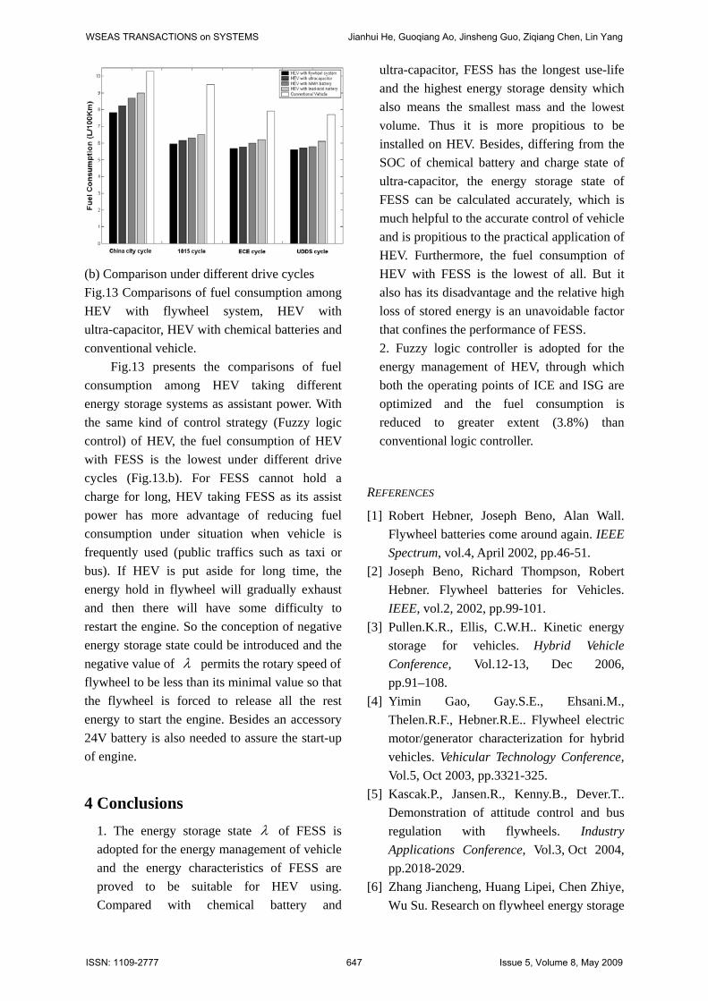
(b) Comparison under different drive cycles Fig.13 Comparisons of fuel consumption among HEV with flywheel system, HEV with ultra-capacitor, HEV with chemical batteries and conventional vehicle.
Fig.13 presents the comparisons of fuel consumption among HEV taking different energy storage systems as assistant power. With the same kind of control strategy (Fuzzy logic control) of HEV, the fuel consumption of HEV with FESS is the lowest under different drive cycles (Fig.13.b). For FESS cannot hold a charge for long, HEV taking FESS as its assist power has more advantage of reducing fuel consumption under situation when vehicle is frequently used (public traffics such as taxi or bus). If HEV is put aside for long time, the energy hold in flywheel will gradually exhaust and then there will have some difficulty to restart the engine. So the conception of negative energy storage state could be introduced and the negative value of λ permits the rotary speed of flywheel to be less than its minimal value so that the flywheel is forced to release all the rest energy to start the engine. Besides an accessory 24V battery is also needed to assure the start-up of engine.
4 Conclusions 1. The energy storage state λ of FESS is adopted for the energy management of vehicle and the energy characteristics of FESS are proved to be suitable for HEV using. Compared with chemical battery and
ultra-capacitor, FESS has the longest use-life and the highest energy storage density which also means the smallest mass and the lowest volume. Thus it is more propitious to be installed on HEV. Besides, differing from the SOC of chemical battery and charge state of ultra-capacitor, the energy storage state of FESS can be calculated accurately, which is much helpful to the accurate control of vehicle and is propitious to the practical application of HEV. Furthermore, the fuel consumption of HEV with FESS is the lowest of all. But it also has its disadvantage and the relative high loss of stored energy is an unavoidable factor that confines the performance of FESS. 2. Fuzzy logic controller is adopted for the energy management of HEV, through which both the operating points of ICE and ISG are optimized and the fuel consumption is reduced to greater extent (3.8%) than conventional logic controller.
REFERENCES
[1] Robert Hebner, Joseph Beno, Alan Wall. Flywheel batteries come around again. IEEE Spectrum, vol.4, April 2002, pp.46-51.
[2] Joseph Beno, Richard Thompson, Robert Hebner. Flywheel batteries for Vehicles. IEEE, vol.2, 2002, pp.99-101.
[3] Pullen.K.R., Ellis, C.W.H.. Kinetic energy storage for vehicles. Hybrid Vehicle Conference, Vol.12-13, Dec 2006, pp.91–108.
[4] Yimin Gao, Gay.S.E., Ehsani.M., Thelen.R.F., Hebner.R.E.. Flywheel electric motor/generator characterization for hybrid vehicles. Vehicular Technology Conference, Vol.5, Oct 2003, pp.3321-325.
[5] Kascak.P., Jansen.R., Kenny.B., Dever.T.. Demonstration of attitude control and bus regulation with flywheels. Industry Applications Conference, Vol.3, Oct 2004, pp.2018-2029.
[6] Zhang Jiancheng, Huang Lipei, Chen Zhiye, Wu Su. Research on flywheel energy storage
WSEAS TRANSACTIONS on SYSTEMS Jianhui He, Guoqiang Ao, Jinsheng Guo, Ziqiang Chen, Lin Yang
ISSN: 1109-2777 647 Issue 5, Volume 8, May 2009

system for power quality. Power System Technology, Vol.1, Oct. 2002,pp.496-499.
[7] Sivrioglu.S., Nonami.K. Active permanent magnet support for a superconducting magnetic-bearing flywheel rotor. IEEE Transactions on Applied Superconductivity, Vol.10, Dec 2000, pp.1673-1677.
[8] Yimin Gao, H.Moghbelli, and M.Ehsani. Investigation of High-Energy And High-Power Hybrid Energy Storage Systems for Military Vehicle Application. SAE Future Transportation Technology Conference, June 23-25, Costa Mesa, CA., Paper No.2003-01-2287
[9] Zierer, T.Stifflemire. Design and Performance Testing of an Advanced Integrated Power System with Flywheel Energy Storage. International Future Transportation Technology Conference, June 23-25, 2003 Costa Mesa, CA, SAE, Paper No.2003FTT-79
[10] Boyes.J.D, Clark.N.H.. Technologies for energy storage. Flywheels and super conducting magnetic energy storage. IEEE Power Engineering Society Summer Meeting, Vol.3, July 2000, pp.1548-1550.
[11] R.J.Hayes, J.P.Kajs, R.C.Thompson, and J.H.Beno. Design and Testing of a Flywheel Battery for a Transit Bus. Society of Automotive Engineers, February 1999, SAE publication No.1999-01-1159.
[12] Paul P. A., Barrie C. M., Lames S. B., Design Principles for A Flywheel Energy Store for Road Vehicles. IEEE Transactions on Industry Application, vol.32, no.6, 1996, pp.1402-1408.
[13] Schouten.N.J., Salman.M.A., Kheir.N.A. Fuzzy logic control for parallel hybrid vehicles. IEEE Transactions on Control Systems Technology, Vol.10, May 2002, pp.460-68.
[14] Kamiya.M. Ikeda.H. Shinohara.S., Yoshida.H.. Torque control strategy for a parallel-hybrid vehicle using fuzzy logic. Industry Applications Magazine. IEEE, Vol.6, Nov-Dec 2000, pp.33-38.
[15] K.Asai, M.Sugeno, T.Terano. Applied Fuzzy Systems. Academic Press, New York, 1994
[16] Szum anow skiA. Basis of hybrid electric vehicle. Beijing institute of technology press, 2001
[17] Zhang Wenxiu. Liang Guangxi. Fuzzy control system. Xi’an Jiao Tong university press,1998
WSEAS TRANSACTIONS on SYSTEMS Jianhui He, Guoqiang Ao, Jinsheng Guo, Ziqiang Chen, Lin Yang
ISSN: 1109-2777 648 Issue 5, Volume 8, May 2009