IBM System Storage DS4000 and Storage Manager V10.30
770
ibm.com/redbooks Front cover IBM System Storage DS4000 and Storage Manager V10.30 Sangam Racherla Corne Lottering Mahendran Ramasamy Vaclav Sindelar New Storage Manager 10.30 features and enhancements Enhanced drive migration support and RAID 6 support New and updated multipath drivers
-
Upload
khangminh22 -
Category
Documents
-
view
0 -
download
0
Transcript of IBM System Storage DS4000 and Storage Manager V10.30
ibm.com/redbooks
Front cover
IBM System Storage DS4000 and Storage Manager V10.30
Sangam RacherlaCorne Lottering
Mahendran RamasamyVaclav Sindelar
New Storage Manager 10.30 features and enhancements
Enhanced drive migration support and RAID 6 support
New and updated multipath drivers


International Technical Support Organization
IBM System Storage DS4000 and Storage Manager V10.30
March 2009
SG24-7010-06
© Copyright International Business Machines Corporation 2004, 2005, 2006, 2007, 2008, 2009. All rightsreserved.Note to U.S. Government Users Restricted Rights -- Use, duplication or disclosure restricted by GSA ADP ScheduleContract with IBM Corp.
Seventh Edition (March 2009)
This edition applies to Version 10, Release 30, of the DS4000 Storage Manager with Controller code v7.15.
Note: Before using this information and the product it supports, read the information in “Notices” on page xi.

Contents
Notices . . . . . . . . . . . . . . . . . . . . . . . . . . . . . . . . . . . . . . . . . . . . . . . . . . . . . . . . . . . . . . . . . xiTrademarks . . . . . . . . . . . . . . . . . . . . . . . . . . . . . . . . . . . . . . . . . . . . . . . . . . . . . . . . . . . . . . xii
Preface . . . . . . . . . . . . . . . . . . . . . . . . . . . . . . . . . . . . . . . . . . . . . . . . . . . . . . . . . . . . . . . . xiiiThe team that wrote this book . . . . . . . . . . . . . . . . . . . . . . . . . . . . . . . . . . . . . . . . . . . . . . . xiiiBecome a published author . . . . . . . . . . . . . . . . . . . . . . . . . . . . . . . . . . . . . . . . . . . . . . . . . .xvComments welcome. . . . . . . . . . . . . . . . . . . . . . . . . . . . . . . . . . . . . . . . . . . . . . . . . . . . . . . xvi
Summary of changes . . . . . . . . . . . . . . . . . . . . . . . . . . . . . . . . . . . . . . . . . . . . . . . . . . . . . xviiMarch 2009, Seventh Edition . . . . . . . . . . . . . . . . . . . . . . . . . . . . . . . . . . . . . . . . . . . . . . . . xvii
Chapter 1. Introducing the DS4000 series . . . . . . . . . . . . . . . . . . . . . . . . . . . . . . . . . . . . 11.1 Positioning the DS4000 series . . . . . . . . . . . . . . . . . . . . . . . . . . . . . . . . . . . . . . . . . . . . 21.2 DS4000 models. . . . . . . . . . . . . . . . . . . . . . . . . . . . . . . . . . . . . . . . . . . . . . . . . . . . . . . . 21.3 Storage Manager software . . . . . . . . . . . . . . . . . . . . . . . . . . . . . . . . . . . . . . . . . . . . . . . 6
Chapter 2. What is new . . . . . . . . . . . . . . . . . . . . . . . . . . . . . . . . . . . . . . . . . . . . . . . . . . . . 92.1 Storage Manager enhancements . . . . . . . . . . . . . . . . . . . . . . . . . . . . . . . . . . . . . . . . . 10
2.1.1 New features. . . . . . . . . . . . . . . . . . . . . . . . . . . . . . . . . . . . . . . . . . . . . . . . . . . . . 102.1.2 Enhancements in Version 10.30 . . . . . . . . . . . . . . . . . . . . . . . . . . . . . . . . . . . . . . 13
Chapter 3. DS4000 series hardware . . . . . . . . . . . . . . . . . . . . . . . . . . . . . . . . . . . . . . . . 153.1 IBM System Storage DS4200 Express . . . . . . . . . . . . . . . . . . . . . . . . . . . . . . . . . . . . . 16
3.1.1 DS4200 features . . . . . . . . . . . . . . . . . . . . . . . . . . . . . . . . . . . . . . . . . . . . . . . . . . 163.1.2 DS4200: Front view . . . . . . . . . . . . . . . . . . . . . . . . . . . . . . . . . . . . . . . . . . . . . . . 183.1.3 DS4200 rear view . . . . . . . . . . . . . . . . . . . . . . . . . . . . . . . . . . . . . . . . . . . . . . . . . 193.1.4 DS4200: Speed selector and LED indicator lights . . . . . . . . . . . . . . . . . . . . . . . . 213.1.5 DS4200: Host-side connections . . . . . . . . . . . . . . . . . . . . . . . . . . . . . . . . . . . . . . 253.1.6 DS4200: Drive-side connections. . . . . . . . . . . . . . . . . . . . . . . . . . . . . . . . . . . . . . 263.1.7 DS4200: Drive-side cabling. . . . . . . . . . . . . . . . . . . . . . . . . . . . . . . . . . . . . . . . . . 273.1.8 DS4200 controller enclosure IDs . . . . . . . . . . . . . . . . . . . . . . . . . . . . . . . . . . . . . 313.1.9 DS4200 physical/environmental specifications . . . . . . . . . . . . . . . . . . . . . . . . . . . 31
3.2 IBM System Storage DS4700 Express . . . . . . . . . . . . . . . . . . . . . . . . . . . . . . . . . . . . . 323.2.1 DS4700 features . . . . . . . . . . . . . . . . . . . . . . . . . . . . . . . . . . . . . . . . . . . . . . . . . . 323.2.2 DS4700 front view. . . . . . . . . . . . . . . . . . . . . . . . . . . . . . . . . . . . . . . . . . . . . . . . . 343.2.3 DS4700 rear view . . . . . . . . . . . . . . . . . . . . . . . . . . . . . . . . . . . . . . . . . . . . . . . . . 353.2.4 DS4700: Speed selector and LED indicator lights . . . . . . . . . . . . . . . . . . . . . . . . 383.2.5 DS4700: Host-side connections . . . . . . . . . . . . . . . . . . . . . . . . . . . . . . . . . . . . . . 423.2.6 DS4700: Drive-side connections. . . . . . . . . . . . . . . . . . . . . . . . . . . . . . . . . . . . . . 443.2.7 DS4700: Drive-side cabling. . . . . . . . . . . . . . . . . . . . . . . . . . . . . . . . . . . . . . . . . . 453.2.8 DS4700: Controller/enclosure IDs. . . . . . . . . . . . . . . . . . . . . . . . . . . . . . . . . . . . . 483.2.9 DS4700: Physical/environmental specifications . . . . . . . . . . . . . . . . . . . . . . . . . . 49
3.3 IBM System Storage DS4800 storage server . . . . . . . . . . . . . . . . . . . . . . . . . . . . . . . . 503.3.1 DS4800 features . . . . . . . . . . . . . . . . . . . . . . . . . . . . . . . . . . . . . . . . . . . . . . . . . . 503.3.2 DS4800 chassis design . . . . . . . . . . . . . . . . . . . . . . . . . . . . . . . . . . . . . . . . . . . . 523.3.3 DS4800 front view. . . . . . . . . . . . . . . . . . . . . . . . . . . . . . . . . . . . . . . . . . . . . . . . . 533.3.4 Interconnect module and battery packs . . . . . . . . . . . . . . . . . . . . . . . . . . . . . . . . 543.3.5 DS4800 rear view . . . . . . . . . . . . . . . . . . . . . . . . . . . . . . . . . . . . . . . . . . . . . . . . . 553.3.6 DS4800 LED indicator lights . . . . . . . . . . . . . . . . . . . . . . . . . . . . . . . . . . . . . . . . . 55
© Copyright IBM Corp. 2004, 2005, 2006, 2007, 2008, 2009. All rights reserved. iii
3.3.7 DS4800 host-side connections . . . . . . . . . . . . . . . . . . . . . . . . . . . . . . . . . . . . . . . 603.3.8 DS4800 drive-side connections . . . . . . . . . . . . . . . . . . . . . . . . . . . . . . . . . . . . . . 623.3.9 DS4800 drive-side cabling . . . . . . . . . . . . . . . . . . . . . . . . . . . . . . . . . . . . . . . . . . 653.3.10 DS4800: Expansion enclosure scaling considerations . . . . . . . . . . . . . . . . . . . . 683.3.11 DS4800: Additional connections . . . . . . . . . . . . . . . . . . . . . . . . . . . . . . . . . . . . . 733.3.12 DS4800: Controller/enclosure IDs. . . . . . . . . . . . . . . . . . . . . . . . . . . . . . . . . . . . 743.3.13 DS4800: Physical/environmental specifications . . . . . . . . . . . . . . . . . . . . . . . . . 763.3.14 DS4800: Upgrading previous DS4000 models . . . . . . . . . . . . . . . . . . . . . . . . . . 76
3.4 DS4000 family supported operating system and topologies . . . . . . . . . . . . . . . . . . . . . 773.4.1 Supported operating systems . . . . . . . . . . . . . . . . . . . . . . . . . . . . . . . . . . . . . . . . 773.4.2 Clustering support . . . . . . . . . . . . . . . . . . . . . . . . . . . . . . . . . . . . . . . . . . . . . . . . . 773.4.3 Supported server platforms. . . . . . . . . . . . . . . . . . . . . . . . . . . . . . . . . . . . . . . . . . 77
3.5 DS4000 series product comparison . . . . . . . . . . . . . . . . . . . . . . . . . . . . . . . . . . . . . . . 783.6 DS4000 series expansion enclosures. . . . . . . . . . . . . . . . . . . . . . . . . . . . . . . . . . . . . . 80
3.6.1 IBM TotalStorage DS4000 EXP100 Expansion Enclosure . . . . . . . . . . . . . . . . . . 813.6.2 IBM Total Storage DS4000 EXP710 expansion enclosure. . . . . . . . . . . . . . . . . . 823.6.3 EXP100 and EXP710 enclosure ID and link speed . . . . . . . . . . . . . . . . . . . . . . . 853.6.4 IBM System Storage EXP420 Expansion Enclosure . . . . . . . . . . . . . . . . . . . . . . 873.6.5 IBM System Storage EXP810 Expansion Enclosure . . . . . . . . . . . . . . . . . . . . . . 903.6.6 Intermixing EXP810 and EXP710 . . . . . . . . . . . . . . . . . . . . . . . . . . . . . . . . . . . . . 943.6.7 Intermixing EXP100, EXP710, and EXP810 enclosures. . . . . . . . . . . . . . . . . . . . 953.6.8 Drive intermixing within enclosures. . . . . . . . . . . . . . . . . . . . . . . . . . . . . . . . . . . 102
3.7 DS4000 physical installation and cabling considerations . . . . . . . . . . . . . . . . . . . . . . 1053.7.1 Rack considerations . . . . . . . . . . . . . . . . . . . . . . . . . . . . . . . . . . . . . . . . . . . . . . 1063.7.2 Cables and connectors . . . . . . . . . . . . . . . . . . . . . . . . . . . . . . . . . . . . . . . . . . . . 1073.7.3 Cable management and labeling . . . . . . . . . . . . . . . . . . . . . . . . . . . . . . . . . . . . 1103.7.4 Fibre Channel adapters . . . . . . . . . . . . . . . . . . . . . . . . . . . . . . . . . . . . . . . . . . . 1123.7.5 SAN switches . . . . . . . . . . . . . . . . . . . . . . . . . . . . . . . . . . . . . . . . . . . . . . . . . . . 113
Chapter 4. Managing the DS4000. . . . . . . . . . . . . . . . . . . . . . . . . . . . . . . . . . . . . . . . . . 1154.1 DS4000 Storage Manager Software . . . . . . . . . . . . . . . . . . . . . . . . . . . . . . . . . . . . . . 116
4.1.1 Storage subsystem management methods. . . . . . . . . . . . . . . . . . . . . . . . . . . . . 1204.1.2 The Storage Manager client . . . . . . . . . . . . . . . . . . . . . . . . . . . . . . . . . . . . . . . . 1234.1.3 Storage Manager utilities . . . . . . . . . . . . . . . . . . . . . . . . . . . . . . . . . . . . . . . . . . 1264.1.4 Host Bus Drivers for Windows . . . . . . . . . . . . . . . . . . . . . . . . . . . . . . . . . . . . . . 1274.1.5 Multipath driver support . . . . . . . . . . . . . . . . . . . . . . . . . . . . . . . . . . . . . . . . . . . 1294.1.6 AVT or non-AVT mode . . . . . . . . . . . . . . . . . . . . . . . . . . . . . . . . . . . . . . . . . . . . 134
4.2 DS4000 management concepts and basics . . . . . . . . . . . . . . . . . . . . . . . . . . . . . . . . 1364.2.1 Firmware design . . . . . . . . . . . . . . . . . . . . . . . . . . . . . . . . . . . . . . . . . . . . . . . . . 1364.2.2 DACstore . . . . . . . . . . . . . . . . . . . . . . . . . . . . . . . . . . . . . . . . . . . . . . . . . . . . . . 1374.2.3 Arrays and logical drives. . . . . . . . . . . . . . . . . . . . . . . . . . . . . . . . . . . . . . . . . . . 1394.2.4 Segment size . . . . . . . . . . . . . . . . . . . . . . . . . . . . . . . . . . . . . . . . . . . . . . . . . . . 1484.2.5 Hot spare drive . . . . . . . . . . . . . . . . . . . . . . . . . . . . . . . . . . . . . . . . . . . . . . . . . . 1494.2.6 Storage partitioning. . . . . . . . . . . . . . . . . . . . . . . . . . . . . . . . . . . . . . . . . . . . . . . 1514.2.7 Performance monitor data . . . . . . . . . . . . . . . . . . . . . . . . . . . . . . . . . . . . . . . . . 1554.2.8 Diagnostics . . . . . . . . . . . . . . . . . . . . . . . . . . . . . . . . . . . . . . . . . . . . . . . . . . . . . 1564.2.9 Password . . . . . . . . . . . . . . . . . . . . . . . . . . . . . . . . . . . . . . . . . . . . . . . . . . . . . . 1574.2.10 Script Editor and command-line interface . . . . . . . . . . . . . . . . . . . . . . . . . . . . . 158
4.3 Advanced functions. . . . . . . . . . . . . . . . . . . . . . . . . . . . . . . . . . . . . . . . . . . . . . . . . . . 1604.3.1 Expanding arrays and logical drives . . . . . . . . . . . . . . . . . . . . . . . . . . . . . . . . . . 1604.3.2 Unconfiguring storage subsystem and arrays. . . . . . . . . . . . . . . . . . . . . . . . . . . 1624.3.3 Pre-read redundancy check . . . . . . . . . . . . . . . . . . . . . . . . . . . . . . . . . . . . . . . . 1624.3.4 Defragmenting an array . . . . . . . . . . . . . . . . . . . . . . . . . . . . . . . . . . . . . . . . . . . 164
iv IBM System Storage DS4000 and Storage Manager V10.30
4.3.5 Controller ownership . . . . . . . . . . . . . . . . . . . . . . . . . . . . . . . . . . . . . . . . . . . . . . 1644.3.6 Cache parameters . . . . . . . . . . . . . . . . . . . . . . . . . . . . . . . . . . . . . . . . . . . . . . . 1654.3.7 Logical drive modification priority . . . . . . . . . . . . . . . . . . . . . . . . . . . . . . . . . . . . 1704.3.8 Media scan . . . . . . . . . . . . . . . . . . . . . . . . . . . . . . . . . . . . . . . . . . . . . . . . . . . . . 1714.3.9 Failover alert delay . . . . . . . . . . . . . . . . . . . . . . . . . . . . . . . . . . . . . . . . . . . . . . . 1724.3.10 Persistent reservations . . . . . . . . . . . . . . . . . . . . . . . . . . . . . . . . . . . . . . . . . . . 1734.3.11 Automatic firmware synchronization . . . . . . . . . . . . . . . . . . . . . . . . . . . . . . . . . 1734.3.12 Fibre Channel and SATA drive intermix . . . . . . . . . . . . . . . . . . . . . . . . . . . . . . 1744.3.13 Enhanced performance feature . . . . . . . . . . . . . . . . . . . . . . . . . . . . . . . . . . . . 175
4.4 Premium features . . . . . . . . . . . . . . . . . . . . . . . . . . . . . . . . . . . . . . . . . . . . . . . . . . . . 1764.5 Virtualization . . . . . . . . . . . . . . . . . . . . . . . . . . . . . . . . . . . . . . . . . . . . . . . . . . . . . . . . 178
Chapter 5. Step-by-step procedures using Storage Manager. . . . . . . . . . . . . . . . . . . 1795.1 Installing DS4000 Storage Manager software. . . . . . . . . . . . . . . . . . . . . . . . . . . . . . . 180
5.1.1 Installing Storage Manager in a Windows host . . . . . . . . . . . . . . . . . . . . . . . . . . 1805.1.2 Installing DS4000 Storage Manager software on an AIX host . . . . . . . . . . . . . . 1885.1.3 Installing DS4000 storage server software on a Linux System x host . . . . . . . . 2035.1.4 Installing DS/4000 Storage Manager software on a HP-UX host . . . . . . . . . . . . 217
5.2 Preparing the DS4000 storage server. . . . . . . . . . . . . . . . . . . . . . . . . . . . . . . . . . . . . 2255.2.1 Turning on the power . . . . . . . . . . . . . . . . . . . . . . . . . . . . . . . . . . . . . . . . . . . . . 2265.2.2 Network setup of the controllers . . . . . . . . . . . . . . . . . . . . . . . . . . . . . . . . . . . . . 2265.2.3 Using the DS4000 Storage Management client . . . . . . . . . . . . . . . . . . . . . . . . . 2335.2.4 Updating the controller microcode . . . . . . . . . . . . . . . . . . . . . . . . . . . . . . . . . . . 241
5.3 Configuring the DS4000 storage subsystem. . . . . . . . . . . . . . . . . . . . . . . . . . . . . . . . 2425.3.1 Planning your configuration . . . . . . . . . . . . . . . . . . . . . . . . . . . . . . . . . . . . . . . . 2425.3.2 Initial setup . . . . . . . . . . . . . . . . . . . . . . . . . . . . . . . . . . . . . . . . . . . . . . . . . . . . . 2435.3.3 Automatic configuration . . . . . . . . . . . . . . . . . . . . . . . . . . . . . . . . . . . . . . . . . . . 2455.3.4 Manual configuration. . . . . . . . . . . . . . . . . . . . . . . . . . . . . . . . . . . . . . . . . . . . . . 2505.3.5 Configuring storage partitioning . . . . . . . . . . . . . . . . . . . . . . . . . . . . . . . . . . . . . 2595.3.6 Monitoring and alerting . . . . . . . . . . . . . . . . . . . . . . . . . . . . . . . . . . . . . . . . . . . . 2715.3.7 Storage subsystem profile . . . . . . . . . . . . . . . . . . . . . . . . . . . . . . . . . . . . . . . . . 276
5.4 Advanced configuration. . . . . . . . . . . . . . . . . . . . . . . . . . . . . . . . . . . . . . . . . . . . . . . . 2785.4.1 Maintaining arrays. . . . . . . . . . . . . . . . . . . . . . . . . . . . . . . . . . . . . . . . . . . . . . . . 2785.4.2 Maintaining logical drives . . . . . . . . . . . . . . . . . . . . . . . . . . . . . . . . . . . . . . . . . . 2815.4.3 Cache settings . . . . . . . . . . . . . . . . . . . . . . . . . . . . . . . . . . . . . . . . . . . . . . . . . . 2855.4.4 Media scanning. . . . . . . . . . . . . . . . . . . . . . . . . . . . . . . . . . . . . . . . . . . . . . . . . . 2885.4.5 Failover alert delay . . . . . . . . . . . . . . . . . . . . . . . . . . . . . . . . . . . . . . . . . . . . . . . 2895.4.6 Persistent reservations . . . . . . . . . . . . . . . . . . . . . . . . . . . . . . . . . . . . . . . . . . . . 2905.4.7 Component properties . . . . . . . . . . . . . . . . . . . . . . . . . . . . . . . . . . . . . . . . . . . . 2925.4.8 Advanced recovery options. . . . . . . . . . . . . . . . . . . . . . . . . . . . . . . . . . . . . . . . . 295
Chapter 6. Troubleshooting and diagnostics . . . . . . . . . . . . . . . . . . . . . . . . . . . . . . . . 2976.1 Storage Manager error reporting and diagnostics. . . . . . . . . . . . . . . . . . . . . . . . . . . . 298
6.1.1 Preventive maintenance and support notifications . . . . . . . . . . . . . . . . . . . . . . . 2986.1.2 Recovery Guru . . . . . . . . . . . . . . . . . . . . . . . . . . . . . . . . . . . . . . . . . . . . . . . . . . 2986.1.3 Major Event Log . . . . . . . . . . . . . . . . . . . . . . . . . . . . . . . . . . . . . . . . . . . . . . . . . 3006.1.4 Support data: Collecting information . . . . . . . . . . . . . . . . . . . . . . . . . . . . . . . . . . 3026.1.5 Managing drive problems . . . . . . . . . . . . . . . . . . . . . . . . . . . . . . . . . . . . . . . . . . 3066.1.6 Diagnostics options. . . . . . . . . . . . . . . . . . . . . . . . . . . . . . . . . . . . . . . . . . . . . . . 3106.1.7 Degraded drive channels . . . . . . . . . . . . . . . . . . . . . . . . . . . . . . . . . . . . . . . . . . 3166.1.8 Managing ESMs . . . . . . . . . . . . . . . . . . . . . . . . . . . . . . . . . . . . . . . . . . . . . . . . . 3186.1.9 Locating and removing parts. . . . . . . . . . . . . . . . . . . . . . . . . . . . . . . . . . . . . . . . 3196.1.10 Performance monitoring and analysis. . . . . . . . . . . . . . . . . . . . . . . . . . . . . . . . 321
Contents v
6.2 Storage Manager Advanced Recovery options. . . . . . . . . . . . . . . . . . . . . . . . . . . . . . 3256.3 Replacing adapters (HBA) and DS4000 controllers . . . . . . . . . . . . . . . . . . . . . . . . . . 3316.4 Operating system specific tools . . . . . . . . . . . . . . . . . . . . . . . . . . . . . . . . . . . . . . . . . 331
6.4.1 Qlogic SANsurfer (Windows/Linux). . . . . . . . . . . . . . . . . . . . . . . . . . . . . . . . . . . 3316.4.2 Windows . . . . . . . . . . . . . . . . . . . . . . . . . . . . . . . . . . . . . . . . . . . . . . . . . . . . . . . 3406.4.3 Linux . . . . . . . . . . . . . . . . . . . . . . . . . . . . . . . . . . . . . . . . . . . . . . . . . . . . . . . . . . 3506.4.4 HP-UX. . . . . . . . . . . . . . . . . . . . . . . . . . . . . . . . . . . . . . . . . . . . . . . . . . . . . . . . . 3536.4.5 Solaris . . . . . . . . . . . . . . . . . . . . . . . . . . . . . . . . . . . . . . . . . . . . . . . . . . . . . . . . . 3546.4.6 AIX . . . . . . . . . . . . . . . . . . . . . . . . . . . . . . . . . . . . . . . . . . . . . . . . . . . . . . . . . . . 354
6.5 Using the controller shell . . . . . . . . . . . . . . . . . . . . . . . . . . . . . . . . . . . . . . . . . . . . . . . 3646.6 Remote Support Manager for Storage . . . . . . . . . . . . . . . . . . . . . . . . . . . . . . . . . . . . 368
6.6.1 Hardware and software requirements . . . . . . . . . . . . . . . . . . . . . . . . . . . . . . . . . 3696.6.2 How RSM for Storage works. . . . . . . . . . . . . . . . . . . . . . . . . . . . . . . . . . . . . . . . 3716.6.3 Notification e-mail and events filtering . . . . . . . . . . . . . . . . . . . . . . . . . . . . . . . . 3726.6.4 Remote access methods . . . . . . . . . . . . . . . . . . . . . . . . . . . . . . . . . . . . . . . . . . 3736.6.5 RSM management interface . . . . . . . . . . . . . . . . . . . . . . . . . . . . . . . . . . . . . . . . 3746.6.6 RSM security considerations. . . . . . . . . . . . . . . . . . . . . . . . . . . . . . . . . . . . . . . . 376
6.7 Installing and setting up RSM . . . . . . . . . . . . . . . . . . . . . . . . . . . . . . . . . . . . . . . . . . . 3776.7.1 Installing the host OS . . . . . . . . . . . . . . . . . . . . . . . . . . . . . . . . . . . . . . . . . . . . . 3776.7.2 Installing RSM. . . . . . . . . . . . . . . . . . . . . . . . . . . . . . . . . . . . . . . . . . . . . . . . . . . 3776.7.3 Setting up RSM. . . . . . . . . . . . . . . . . . . . . . . . . . . . . . . . . . . . . . . . . . . . . . . . . . 3776.7.4 Configuring SNMP traps in Storage Manager. . . . . . . . . . . . . . . . . . . . . . . . . . . 3896.7.5 Remote access connectivity . . . . . . . . . . . . . . . . . . . . . . . . . . . . . . . . . . . . . . . . 3906.7.6 Activating RSM . . . . . . . . . . . . . . . . . . . . . . . . . . . . . . . . . . . . . . . . . . . . . . . . . . 3956.7.7 Managing alerts . . . . . . . . . . . . . . . . . . . . . . . . . . . . . . . . . . . . . . . . . . . . . . . . . 397
Chapter 7. FlashCopy . . . . . . . . . . . . . . . . . . . . . . . . . . . . . . . . . . . . . . . . . . . . . . . . . . . 4017.1 FlashCopy: How it works. . . . . . . . . . . . . . . . . . . . . . . . . . . . . . . . . . . . . . . . . . . . . . . 402
7.1.1 Estimating FlashCopy repository logical drive capacity . . . . . . . . . . . . . . . . . . . 4047.1.2 FlashCopy failure policy . . . . . . . . . . . . . . . . . . . . . . . . . . . . . . . . . . . . . . . . . . . 4057.1.3 FlashCopy premium feature . . . . . . . . . . . . . . . . . . . . . . . . . . . . . . . . . . . . . . . . 406
7.2 FlashCopy using the wizard: Step-by-step . . . . . . . . . . . . . . . . . . . . . . . . . . . . . . . . . 4067.2.1 Checking the status of the FlashCopy premium feature . . . . . . . . . . . . . . . . . . . 4067.2.2 Creating a FlashCopy logical drive . . . . . . . . . . . . . . . . . . . . . . . . . . . . . . . . . . . 4077.2.3 Mapping a FlashCopy drive to a host . . . . . . . . . . . . . . . . . . . . . . . . . . . . . . . . . 4197.2.4 Viewing the FlashCopy drive status . . . . . . . . . . . . . . . . . . . . . . . . . . . . . . . . . . 4217.2.5 Disabling a FlashCopy logical drive . . . . . . . . . . . . . . . . . . . . . . . . . . . . . . . . . . 4247.2.6 Re-creating a FlashCopy logical drive . . . . . . . . . . . . . . . . . . . . . . . . . . . . . . . . 4257.2.7 Resizing a FlashCopy Repository logical drive . . . . . . . . . . . . . . . . . . . . . . . . . . 4277.2.8 Deleting a FlashCopy drive. . . . . . . . . . . . . . . . . . . . . . . . . . . . . . . . . . . . . . . . . 431
7.3 FlashCopy using command-line interface . . . . . . . . . . . . . . . . . . . . . . . . . . . . . . . . . . 4327.3.1 Create FlashCopyLogicalDrive using the CLI . . . . . . . . . . . . . . . . . . . . . . . . . . . 4327.3.2 The set logicalDrive command with the CLI. . . . . . . . . . . . . . . . . . . . . . . . . . . . 4357.3.3 The disableFlashCopy logicalDrive command (CLI) . . . . . . . . . . . . . . . . . . . . . . 4367.3.4 The recreateFlashCopy logicalDrive command (CLI) . . . . . . . . . . . . . . . . . . . . . 4377.3.5 The delete logicalDrive command (CLI) . . . . . . . . . . . . . . . . . . . . . . . . . . . . . . . 438
7.4 Practical scenarios . . . . . . . . . . . . . . . . . . . . . . . . . . . . . . . . . . . . . . . . . . . . . . . . . . . 4387.4.1 Backup of a Windows 2003 Server . . . . . . . . . . . . . . . . . . . . . . . . . . . . . . . . . . . 4387.4.2 DB2 backup using DS4000 FlashCopy in AIX . . . . . . . . . . . . . . . . . . . . . . . . . . 444
Chapter 8. Enhanced Remote Mirroring . . . . . . . . . . . . . . . . . . . . . . . . . . . . . . . . . . . . 4498.1 Overview of the Enhanced Remote Mirroring . . . . . . . . . . . . . . . . . . . . . . . . . . . . . . . 450
8.1.1 Requirements . . . . . . . . . . . . . . . . . . . . . . . . . . . . . . . . . . . . . . . . . . . . . . . . . . . 451
vi IBM System Storage DS4000 and Storage Manager V10.30
8.1.2 ERM terminology . . . . . . . . . . . . . . . . . . . . . . . . . . . . . . . . . . . . . . . . . . . . . . . . 4538.2 Mirror repository logical drives . . . . . . . . . . . . . . . . . . . . . . . . . . . . . . . . . . . . . . . . . . 4558.3 Primary and secondary logical drives . . . . . . . . . . . . . . . . . . . . . . . . . . . . . . . . . . . . . 455
8.3.1 Logical drive parameters, roles, and maximum number of mirrored pairs . . . . . 4568.3.2 Host accessibility of secondary logical drive . . . . . . . . . . . . . . . . . . . . . . . . . . . . 4568.3.3 Mirrored logical drive controller ownership . . . . . . . . . . . . . . . . . . . . . . . . . . . . . 4578.3.4 Deleting a mirrored logical drive . . . . . . . . . . . . . . . . . . . . . . . . . . . . . . . . . . . . . 4578.3.5 Enhanced Remote Mirroring and on demand functions . . . . . . . . . . . . . . . . . . . 4578.3.6 Enhanced Remote Mirroring and FlashCopy premium feature. . . . . . . . . . . . . . 4588.3.7 Enhanced Remote Mirroring and VolumeCopy premium feature . . . . . . . . . . . . 4588.3.8 Enhanced Remote Mirroring and storage partitioning premium feature . . . . . . . 4588.3.9 Volume role compatibility . . . . . . . . . . . . . . . . . . . . . . . . . . . . . . . . . . . . . . . . . . 459
8.4 Mirror relationship . . . . . . . . . . . . . . . . . . . . . . . . . . . . . . . . . . . . . . . . . . . . . . . . . . . . 4598.5 Data replication process . . . . . . . . . . . . . . . . . . . . . . . . . . . . . . . . . . . . . . . . . . . . . . . 462
8.5.1 Metro Mirroring (synchronous mirroring). . . . . . . . . . . . . . . . . . . . . . . . . . . . . . . 4628.5.2 Global Copy (asynchronous mirroring without write consistency group) . . . . . . 4638.5.3 Global Mirroring (asynchronous mirroring with write consistency group) . . . . . . 4648.5.4 Data resynchronization process . . . . . . . . . . . . . . . . . . . . . . . . . . . . . . . . . . . . . 4668.5.5 Data synchronization priority. . . . . . . . . . . . . . . . . . . . . . . . . . . . . . . . . . . . . . . . 467
8.6 SAN fabric and Ethernet connectivity . . . . . . . . . . . . . . . . . . . . . . . . . . . . . . . . . . . . . 4688.6.1 SAN fabric and SAN zoning configuration . . . . . . . . . . . . . . . . . . . . . . . . . . . . . 4688.6.2 Ethernet management network configuration for ERM . . . . . . . . . . . . . . . . . . . . 473
8.7 Enhanced Remote Mirroring: Step-by-step. . . . . . . . . . . . . . . . . . . . . . . . . . . . . . . . . 4758.7.1 Enabling and activating Enhanced Remote Mirroring . . . . . . . . . . . . . . . . . . . . . 4758.7.2 Creating Enhanced Remote Mirroring relationships . . . . . . . . . . . . . . . . . . . . . . 4818.7.3 Viewing Enhanced Remote Mirroring properties and status . . . . . . . . . . . . . . . . 4898.7.4 Changing mirror synchronization settings. . . . . . . . . . . . . . . . . . . . . . . . . . . . . . 4938.7.5 Changing mirror write mode . . . . . . . . . . . . . . . . . . . . . . . . . . . . . . . . . . . . . . . . 4958.7.6 Adding logical drives to the write consistency group. . . . . . . . . . . . . . . . . . . . . . 4978.7.7 Mapping a secondary drive. . . . . . . . . . . . . . . . . . . . . . . . . . . . . . . . . . . . . . . . . 4988.7.8 Suspending and resuming a mirror relationship . . . . . . . . . . . . . . . . . . . . . . . . . 4998.7.9 Removing mirror relationships . . . . . . . . . . . . . . . . . . . . . . . . . . . . . . . . . . . . . . 507
8.8 ERM and disaster recovery. . . . . . . . . . . . . . . . . . . . . . . . . . . . . . . . . . . . . . . . . . . . . 5088.8.1 Role reversal concept . . . . . . . . . . . . . . . . . . . . . . . . . . . . . . . . . . . . . . . . . . . . . 5098.8.2 Re-establishing Remote Mirroring after failure recovery. . . . . . . . . . . . . . . . . . . 517
8.9 Enhanced Remote Mirroring solution design . . . . . . . . . . . . . . . . . . . . . . . . . . . . . . . 5178.9.1 Intra-site configuration . . . . . . . . . . . . . . . . . . . . . . . . . . . . . . . . . . . . . . . . . . . . 5198.9.2 Intersite configuration with redundant fabric . . . . . . . . . . . . . . . . . . . . . . . . . . . . 5208.9.3 High-availability intersite configuration . . . . . . . . . . . . . . . . . . . . . . . . . . . . . . . . 521
8.10 ERM maintenance. . . . . . . . . . . . . . . . . . . . . . . . . . . . . . . . . . . . . . . . . . . . . . . . . . . 5228.10.1 Unsynchronized state indication . . . . . . . . . . . . . . . . . . . . . . . . . . . . . . . . . . . . 5228.10.2 Link interruptions. . . . . . . . . . . . . . . . . . . . . . . . . . . . . . . . . . . . . . . . . . . . . . . . 5238.10.3 Fibre Channel mirror link test function . . . . . . . . . . . . . . . . . . . . . . . . . . . . . . . 5248.10.4 Secondary logical drive error . . . . . . . . . . . . . . . . . . . . . . . . . . . . . . . . . . . . . . 5258.10.5 Primary controller failure . . . . . . . . . . . . . . . . . . . . . . . . . . . . . . . . . . . . . . . . . . 5268.10.6 Primary controller reset . . . . . . . . . . . . . . . . . . . . . . . . . . . . . . . . . . . . . . . . . . . 5268.10.7 Secondary controller failure . . . . . . . . . . . . . . . . . . . . . . . . . . . . . . . . . . . . . . . 5268.10.8 Write consistency group and unsynchronized state . . . . . . . . . . . . . . . . . . . . . 526
8.11 Performance considerations . . . . . . . . . . . . . . . . . . . . . . . . . . . . . . . . . . . . . . . . . . . 5268.11.1 Synchronization priority. . . . . . . . . . . . . . . . . . . . . . . . . . . . . . . . . . . . . . . . . . . 5278.11.2 Synchronization performance and logical drive settings. . . . . . . . . . . . . . . . . . 5278.11.3 Mirroring mode and performance . . . . . . . . . . . . . . . . . . . . . . . . . . . . . . . . . . . 5288.11.4 Mirroring connection distance and performance. . . . . . . . . . . . . . . . . . . . . . . . 528
Contents vii

8.12 Long-distance ERM. . . . . . . . . . . . . . . . . . . . . . . . . . . . . . . . . . . . . . . . . . . . . . . . . . 529
Chapter 9. VolumeCopy . . . . . . . . . . . . . . . . . . . . . . . . . . . . . . . . . . . . . . . . . . . . . . . . . 5319.1 Introduction to VolumeCopy . . . . . . . . . . . . . . . . . . . . . . . . . . . . . . . . . . . . . . . . . . . . 532
9.1.1 Copying data for greater access . . . . . . . . . . . . . . . . . . . . . . . . . . . . . . . . . . . . . 5339.1.2 Creating and managing VolumeCopy copies . . . . . . . . . . . . . . . . . . . . . . . . . . . 5349.1.3 Understanding VolumeCopy . . . . . . . . . . . . . . . . . . . . . . . . . . . . . . . . . . . . . . . . 5359.1.4 VolumeCopy and performance considerations . . . . . . . . . . . . . . . . . . . . . . . . . . 537
9.2 VolumeCopy: Step-by-step . . . . . . . . . . . . . . . . . . . . . . . . . . . . . . . . . . . . . . . . . . . . . 5389.2.1 Checking the status of the VolumeCopy premium feature . . . . . . . . . . . . . . . . . 5389.2.2 Creating a VolumeCopy pair . . . . . . . . . . . . . . . . . . . . . . . . . . . . . . . . . . . . . . . . 5399.2.3 Viewing VolumeCopy properties . . . . . . . . . . . . . . . . . . . . . . . . . . . . . . . . . . . . . 5439.2.4 Using the Copy Manager . . . . . . . . . . . . . . . . . . . . . . . . . . . . . . . . . . . . . . . . . . 5469.2.5 Re-copying a logical drive . . . . . . . . . . . . . . . . . . . . . . . . . . . . . . . . . . . . . . . . . . 5479.2.6 Changing VolumeCopy priority . . . . . . . . . . . . . . . . . . . . . . . . . . . . . . . . . . . . . . 5509.2.7 Setting the read-only attribute for a target logical drive. . . . . . . . . . . . . . . . . . . . 5519.2.8 Stopping VolumeCopy . . . . . . . . . . . . . . . . . . . . . . . . . . . . . . . . . . . . . . . . . . . . 5529.2.9 Removing copy pairs . . . . . . . . . . . . . . . . . . . . . . . . . . . . . . . . . . . . . . . . . . . . . 553
9.3 Command-line interface for VolumeCopy . . . . . . . . . . . . . . . . . . . . . . . . . . . . . . . . . . 5549.3.1 The create logicalDriveCopy command (CLI) . . . . . . . . . . . . . . . . . . . . . . . . . . . 5559.3.2 The show logicalDriveCopy command (CLI). . . . . . . . . . . . . . . . . . . . . . . . . . . . 5559.3.3 The stop logicalDriveCopy command (CLI) . . . . . . . . . . . . . . . . . . . . . . . . . . . . 5559.3.4 The set logicalDriveCopy command (CLI) . . . . . . . . . . . . . . . . . . . . . . . . . . . . . 5569.3.5 The recopy logicalDriveCopy command (CLI) . . . . . . . . . . . . . . . . . . . . . . . . . . 5569.3.6 The remove logicalDriveCopy command (CLI) . . . . . . . . . . . . . . . . . . . . . . . . . . 556
Chapter 10. SAN boot with the DS4000. . . . . . . . . . . . . . . . . . . . . . . . . . . . . . . . . . . . . 55710.1 Introduction to SAN boot . . . . . . . . . . . . . . . . . . . . . . . . . . . . . . . . . . . . . . . . . . . . . . 55810.2 AIX SAN boot for System p. . . . . . . . . . . . . . . . . . . . . . . . . . . . . . . . . . . . . . . . . . . . 560
10.2.1 Creating a boot disk with alt_disk_install . . . . . . . . . . . . . . . . . . . . . . . . . . . . . 56110.2.2 Creating a SAN boot disk by mirroring . . . . . . . . . . . . . . . . . . . . . . . . . . . . . . . 56310.2.3 Installation on external storage from bootable AIX CD-ROM . . . . . . . . . . . . . . 56510.2.4 AIX SAN installation with NIM. . . . . . . . . . . . . . . . . . . . . . . . . . . . . . . . . . . . . . 56710.2.5 Advanced configuration procedures . . . . . . . . . . . . . . . . . . . . . . . . . . . . . . . . . 568
10.3 Windows 2003/2008 SAN boot for BladeCenter HS20 . . . . . . . . . . . . . . . . . . . . . . . 57210.3.1 Configuration procedure overview . . . . . . . . . . . . . . . . . . . . . . . . . . . . . . . . . . 57410.3.2 SAN boot implementation steps for Windows 2003/2008 hosts . . . . . . . . . . . . 576
10.4 Linux SAN boot for IBM System x servers . . . . . . . . . . . . . . . . . . . . . . . . . . . . . . . . 59510.4.1 Linux boot process . . . . . . . . . . . . . . . . . . . . . . . . . . . . . . . . . . . . . . . . . . . . . . 59610.4.2 Installing Linux SAN boot with DS4700: Configuration procedure overview. . . 59710.4.3 Installing Linux SAN boot with DS4700: Step-by-step procedure . . . . . . . . . . . 59810.4.4 Controller failure simulation. . . . . . . . . . . . . . . . . . . . . . . . . . . . . . . . . . . . . . . . 620
10.5 Implementing MCSC SAN boot with blade servers. . . . . . . . . . . . . . . . . . . . . . . . . . 626
Chapter 11. Command-line interface and Script Editor. . . . . . . . . . . . . . . . . . . . . . . . 62911.1 Command-line interface . . . . . . . . . . . . . . . . . . . . . . . . . . . . . . . . . . . . . . . . . . . . . . 630
11.1.1 Using CLI commands . . . . . . . . . . . . . . . . . . . . . . . . . . . . . . . . . . . . . . . . . . . . 63011.1.2 CLI parameters . . . . . . . . . . . . . . . . . . . . . . . . . . . . . . . . . . . . . . . . . . . . . . . . . 63111.1.3 Syntax requirements . . . . . . . . . . . . . . . . . . . . . . . . . . . . . . . . . . . . . . . . . . . . . 63711.1.4 Error reporting. . . . . . . . . . . . . . . . . . . . . . . . . . . . . . . . . . . . . . . . . . . . . . . . . . 63811.1.5 Commands overview. . . . . . . . . . . . . . . . . . . . . . . . . . . . . . . . . . . . . . . . . . . . . 63811.1.6 CLI examples . . . . . . . . . . . . . . . . . . . . . . . . . . . . . . . . . . . . . . . . . . . . . . . . . . 649
11.2 Script editor . . . . . . . . . . . . . . . . . . . . . . . . . . . . . . . . . . . . . . . . . . . . . . . . . . . . . . . . 65611.2.1 Using the script editor . . . . . . . . . . . . . . . . . . . . . . . . . . . . . . . . . . . . . . . . . . . . 656
viii IBM System Storage DS4000 and Storage Manager V10.30
11.2.2 Embedding commands in batch files . . . . . . . . . . . . . . . . . . . . . . . . . . . . . . . . 659
Chapter 12. Advanced maintenance . . . . . . . . . . . . . . . . . . . . . . . . . . . . . . . . . . . . . . . 66112.1 Upgrades and maintenance . . . . . . . . . . . . . . . . . . . . . . . . . . . . . . . . . . . . . . . . . . . 662
12.1.1 Displaying installed firmware versions . . . . . . . . . . . . . . . . . . . . . . . . . . . . . . . 66212.1.2 Obtaining updates. . . . . . . . . . . . . . . . . . . . . . . . . . . . . . . . . . . . . . . . . . . . . . . 66312.1.3 Planning for upgrades. . . . . . . . . . . . . . . . . . . . . . . . . . . . . . . . . . . . . . . . . . . . 66412.1.4 Updating the DS4000 host software . . . . . . . . . . . . . . . . . . . . . . . . . . . . . . . . . 66512.1.5 Updating controller firmware . . . . . . . . . . . . . . . . . . . . . . . . . . . . . . . . . . . . . . . 66612.1.6 Updating the ESM board firmware . . . . . . . . . . . . . . . . . . . . . . . . . . . . . . . . . . 67912.1.7 Updating hard disk drives firmware. . . . . . . . . . . . . . . . . . . . . . . . . . . . . . . . . . 68212.1.8 Updating Host FC adapter firmware . . . . . . . . . . . . . . . . . . . . . . . . . . . . . . . . . 686
12.2 Handling premium features . . . . . . . . . . . . . . . . . . . . . . . . . . . . . . . . . . . . . . . . . . . . 68912.2.1 Listing premium features/feature enabler . . . . . . . . . . . . . . . . . . . . . . . . . . . . . 68912.2.2 Enabling a premium feature . . . . . . . . . . . . . . . . . . . . . . . . . . . . . . . . . . . . . . . 69212.2.3 Disabling a premium feature . . . . . . . . . . . . . . . . . . . . . . . . . . . . . . . . . . . . . . . 694
12.3 Saving and loading the configuration . . . . . . . . . . . . . . . . . . . . . . . . . . . . . . . . . . . . 69412.4 Migrating arrays between DS4000 subsystems . . . . . . . . . . . . . . . . . . . . . . . . . . . . 700
12.4.1 Migration prerequisites . . . . . . . . . . . . . . . . . . . . . . . . . . . . . . . . . . . . . . . . . . . 70012.4.2 Migrating an array . . . . . . . . . . . . . . . . . . . . . . . . . . . . . . . . . . . . . . . . . . . . . . . 70212.4.3 Importing an array . . . . . . . . . . . . . . . . . . . . . . . . . . . . . . . . . . . . . . . . . . . . . . . 707
12.5 Upgrading EXP700 to EXP710 . . . . . . . . . . . . . . . . . . . . . . . . . . . . . . . . . . . . . . . . . 71112.5.1 Switched-ESM option upgrade overview . . . . . . . . . . . . . . . . . . . . . . . . . . . . . 71112.5.2 Cold-case ESM upgrade procedure . . . . . . . . . . . . . . . . . . . . . . . . . . . . . . . . . 71212.5.3 Hot-case ESM upgrade procedure . . . . . . . . . . . . . . . . . . . . . . . . . . . . . . . . . . 713
12.6 Securing the DS4000 Client using remote management . . . . . . . . . . . . . . . . . . . . . 718
Appendix A. Additional instructions for FlashCopy logical drives . . . . . . . . . . . . . . 721Operating system resources for additional instructions . . . . . . . . . . . . . . . . . . . . . . . . . . . 722Windows 2003/2008: Basic/regular disks . . . . . . . . . . . . . . . . . . . . . . . . . . . . . . . . . . . . . 722
Process overview . . . . . . . . . . . . . . . . . . . . . . . . . . . . . . . . . . . . . . . . . . . . . . . . . . . . . 723Detailed instructions for Windows 2003/2008 basic disks . . . . . . . . . . . . . . . . . . . . . . 724
AIX: LogicalDrive Manager Logical Drives. . . . . . . . . . . . . . . . . . . . . . . . . . . . . . . . . . . . . 727Process overview . . . . . . . . . . . . . . . . . . . . . . . . . . . . . . . . . . . . . . . . . . . . . . . . . . . . . 728Detailed instructions for AIX: LVM Logical Drives. . . . . . . . . . . . . . . . . . . . . . . . . . . . . 729
Related publications . . . . . . . . . . . . . . . . . . . . . . . . . . . . . . . . . . . . . . . . . . . . . . . . . . . . 733IBM Redbooks publications . . . . . . . . . . . . . . . . . . . . . . . . . . . . . . . . . . . . . . . . . . . . . . . . 733Other publications . . . . . . . . . . . . . . . . . . . . . . . . . . . . . . . . . . . . . . . . . . . . . . . . . . . . . . . 733Online resources . . . . . . . . . . . . . . . . . . . . . . . . . . . . . . . . . . . . . . . . . . . . . . . . . . . . . . . . 734How to get Redbooks publications. . . . . . . . . . . . . . . . . . . . . . . . . . . . . . . . . . . . . . . . . . . 734Help from IBM . . . . . . . . . . . . . . . . . . . . . . . . . . . . . . . . . . . . . . . . . . . . . . . . . . . . . . . . . . 734
Index . . . . . . . . . . . . . . . . . . . . . . . . . . . . . . . . . . . . . . . . . . . . . . . . . . . . . . . . . . . . . . . . . 735
Contents ix

x IBM System Storage DS4000 and Storage Manager V10.30

Notices
This information was developed for products and services offered in the U.S.A.
IBM may not offer the products, services, or features discussed in this document in other countries. Consult your local IBM representative for information on the products and services currently available in your area. Any reference to an IBM product, program, or service is not intended to state or imply that only that IBM product, program, or service may be used. Any functionally equivalent product, program, or service that does not infringe any IBM intellectual property right may be used instead. However, it is the user's responsibility to evaluate and verify the operation of any non-IBM product, program, or service.
IBM may have patents or pending patent applications covering subject matter described in this document. The furnishing of this document does not give you any license to these patents. You can send license inquiries, in writing, to: IBM Director of Licensing, IBM Corporation, North Castle Drive, Armonk, NY 10504-1785 U.S.A.
The following paragraph does not apply to the United Kingdom or any other country where such provisions are inconsistent with local law: INTERNATIONAL BUSINESS MACHINES CORPORATION PROVIDES THIS PUBLICATION "AS IS" WITHOUT WARRANTY OF ANY KIND, EITHER EXPRESS OR IMPLIED, INCLUDING, BUT NOT LIMITED TO, THE IMPLIED WARRANTIES OF NON-INFRINGEMENT, MERCHANTABILITY OR FITNESS FOR A PARTICULAR PURPOSE. Some states do not allow disclaimer of express or implied warranties in certain transactions, therefore, this statement may not apply to you.
This information could include technical inaccuracies or typographical errors. Changes are periodically made to the information herein; these changes will be incorporated in new editions of the publication. IBM may make improvements and/or changes in the product(s) and/or the program(s) described in this publication at any time without notice.
Any references in this information to non-IBM Web sites are provided for convenience only and do not in any manner serve as an endorsement of those Web sites. The materials at those Web sites are not part of the materials for this IBM product and use of those Web sites is at your own risk.
IBM may use or distribute any of the information you supply in any way it believes appropriate without incurring any obligation to you.
Information concerning non-IBM products was obtained from the suppliers of those products, their published announcements or other publicly available sources. IBM has not tested those products and cannot confirm the accuracy of performance, compatibility or any other claims related to non-IBM products. Questions on the capabilities of non-IBM products should be addressed to the suppliers of those products.
This information contains examples of data and reports used in daily business operations. To illustrate them as completely as possible, the examples include the names of individuals, companies, brands, and products. All of these names are fictitious and any similarity to the names and addresses used by an actual business enterprise is entirely coincidental.
COPYRIGHT LICENSE:
This information contains sample application programs in source language, which illustrate programming techniques on various operating platforms. You may copy, modify, and distribute these sample programs in any form without payment to IBM, for the purposes of developing, using, marketing or distributing application programs conforming to the application programming interface for the operating platform for which the sample programs are written. These examples have not been thoroughly tested under all conditions. IBM, therefore, cannot guarantee or imply reliability, serviceability, or function of these programs.
© Copyright IBM Corp. 2004, 2005, 2006, 2007, 2008, 2009. All rights reserved. xi
Trademarks
IBM, the IBM logo, and ibm.com are trademarks or registered trademarks of International Business Machines Corporation in the United States, other countries, or both. These and other IBM trademarked terms are marked on their first occurrence in this information with the appropriate symbol (® or ™), indicating US registered or common law trademarks owned by IBM at the time this information was published. Such trademarks may also be registered or common law trademarks in other countries. A current list of IBM trademarks is available on the Web at http://www.ibm.com/legal/copytrade.shtml
The following terms are trademarks of the International Business Machines Corporation in the United States, other countries, or both:
AFS®AIX 5L™AIX®BladeCenter®DB2 Universal Database™DB2®DS4000®DS6000™DS8000®Enterprise Storage Server®
FlashCopy®GPFS™HACMP™IBM®Lotus®Netfinity®POWER®Redbooks®Redbooks (logo) ®RS/6000®
System p5®System p®System Storage™System Storage DS®System x®Tivoli®TotalStorage®xSeries®
The following terms are trademarks of other companies:
Disk Magic, IntelliMagic, and the IntelliMagic logo are trademarks of IntelliMagic BV in the United States, other countries, or both.
Novell, SUSE, the Novell logo, and the N logo are registered trademarks of Novell, Inc. in the United States and other countries.
QLogic, SANsurfer, and the QLogic logo are registered trademarks of QLogic Corporation. SANblade is a registered trademark in the United States.
VMware, the VMware "boxes" logo and design are registered trademarks or trademarks of VMware, Inc. in the United States and/or other jurisdictions.
Java, Java runtime environment, RSM, Solaris, Sun, and all Java-based trademarks are trademarks of Sun Microsystems, Inc. in the United States, other countries, or both.
Microsoft, MS, SQL Server, Windows Server, Windows, and the Windows logo are trademarks of Microsoft Corporation in the United States, other countries, or both.
Intel Xeon, Intel, Intel logo, Intel Inside logo, and Intel Centrino logo are trademarks or registered trademarks of Intel Corporation or its subsidiaries in the United States, other countries, or both.
UNIX is a registered trademark of The Open Group in the United States and other countries.
Linux is a trademark of Linus Torvalds in the United States, other countries, or both.
Other company, product, or service names may be trademarks or service marks of others.
xii IBM System Storage DS4000 and Storage Manager V10.30
Preface
This IBM® Redbooks® publication consolidates, in one document, detailed descriptions of the hardware configurations and options offered as part of the DS4000® series of storage servers. This edition covers updates and additional functions available with the DS4000 Storage Manager Version 10.30 (firmware level 7.15).
The book presents the concepts and functions used in planning and managing the DS4000 storage servers. Concepts such as multipathing and path failover are discussed. This book offers a step-by-step guide to using the Storage Manager to create arrays, logical drives, and other basic (as well as advanced) management tasks.
This publication also contains practical information about diagnostics and troubleshooting, and includes practical examples of how to use scripts and the command-line interface.
This book covers the Copy Services premium features and their implementation and usage. It also discusses how to boot servers from storage area network (SAN) attached DS4000 disks (SAN boot).
This publication is intended for customers, IBM Business Partners, and IBM technical professionals who want to learn more about the capabilities and advanced functions of the DS4000 series of storage servers with Storage Manager Software 10.30. It also targets those who have a DS4000 storage system and need detailed advice on how to configure it.
The team that wrote this book
This book was produced by a team of specialists from around the world working at the International Technical Support Organization, San Jose Center.
© Copyright IBM Corp. 2004, 2005, 2006, 2007, 2008, 2009. All rights reserved. xiii
Figure 1 The team: Corne, Mahendran, Sangam, and Vaclav
Sangam Racherla is an IT Specialist and Project Leader working at the International Technical Support Organization, San Jose Center. He holds a degree in electronics and communication engineering and has eight years of experience in the IT field. He has been with the International Technical Support Organization for the past five years and has extensive experience installing and supporting the ITSO lab equipment for various Redbooks publication projects. His areas of expertise include Microsoft® Windows®, Linux®, AIX®, System x®, and System p® servers and various SAN and storage products.
Corne Lottering is a Systems Storage Field Technical Sales Specialist (FTSS) supporting the System Storage™ sales team in IBM South Africa, Systems and Technology Group. He has been with IBM for eight years and has experience in a wide variety of storage technologies including the DS4000, DS8000®, IBM SAN switches, N-Series, tape, and storage software. His daily support activities include pre-sales and post-sales support, including developing and presenting technical solutions and proposals. Since joining the System Storage team, he has been responsible for various implementation and support projects for customers across Africa.
Mahendran Ramasamy is a Project Manager supporting SAN storage, data backup and recovery, and file system management for India Software Labs, SWG Group, IBM India. He is a Brocade Certified Engineer and he has been with IBM for four years. He has experience in a wide variety of storage technologies including the DS4000, DS6000™, DS8000, IBM SAN switches, ITSM, Tape Libraries, AFS®, GSA, storage management software and HP storage. His daily support activities include operations management and project management for India Software Lab’s new initiatives. Since joining the ISL IS/IT Operations Team, he has been responsible for various implementation and support projects for internal customers across India Software Lab locations.
xiv IBM System Storage DS4000 and Storage Manager V10.30

Vaclav Sindelar is a Field Technical Support Specialist (FTSS) for IBM System Storage at the IBM Czech Republic headquarter in Prague. His daily support activities include pre-sales support for IBM Storage products. He has five years of FTSS Storage experience with a focus to IBM disk arrays and SAN. He has been with IBM since 2001 and also has worked as a Storage Specialist coming to IBM. He holds a master’s degree in computer science from the Technical University of Brno in the Czech Republic.
Thanks to the following people for their contributions to this project:
Deanna Polm, Jon Tate, Alex Osuna, Bertrand Dufrasne, and Emma JacobsInternational Technical Support Organization, San Jose Center
The authors would like to express their thanks to the following people, whose expertise and support were integral to the writing of this book:
Doris Konieczny
Bruce Allworth
John Fasano
Gene Cullum
Danh T. Le
Eric W. Konieczny
Michael Quillen
Harold Pike
Shawn Andrews
Chuck Grimm
Bob D. Dalton
Paul Goetz
Dariusz Ferenc
John Sexton
Florian Graf
Nikolaj B. Kjeldsen
Bill Willson
David Watts
Richard Mancini
Margaret Ticknor
Don Brennan
Jon Etkins
Hernando Bedoya
Khalid M. Ansari
IBM
Become a published author
Join us for a two- to six-week residency program! Help write a book dealing with specific products or solutions, while getting hands-on experience with leading-edge technologies. You will have the opportunity to team with IBM technical professionals, Business Partners, and Clients.
Preface xv
Your efforts will help increase product acceptance and customer satisfaction. As a bonus, you will develop a network of contacts in IBM development labs, and increase your productivity and marketability.
Find out more about the residency program, browse the residency index, and apply online at:
ibm.com/redbooks/residencies.html
Comments welcome
Your comments are important to us!
We want our books to be as helpful as possible. Send us your comments about this book or other IBM Redbooks in one of the following ways:
� Use the online Contact us review Redbooks form found at:
ibm.com/redbooks
� Send your comments in an e-mail to:
� Mail your comments to:
IBM Corporation, International Technical Support OrganizationDept. HYTD Mail Station P0992455 South RoadPoughkeepsie, NY 12601-5400
xvi IBM System Storage DS4000 and Storage Manager V10.30

Summary of changes
This section describes the technical changes made in this edition of the book and in previous editions. This edition may also include minor corrections and editorial changes that are not identified.
Summary of Changesfor SG24-7010-06for IBM System Storage DS4000 and Storage Manager V10.30as created or updated on March 5, 2009.
March 2009, Seventh Edition
This revision reflects the addition, deletion, or modification of new and changed information described below:
� New information
New DS4000 Storage Manager V10.30 features (with firmware Version 7.15)
� Changed information
IPv6 support on the Ethernet management ports
© Copyright IBM Corp. 2004, 2005, 2006, 2007, 2008, 2009. All rights reserved. xvii

xviii IBM System Storage DS4000 and Storage Manager V10.30

Chapter 1. Introducing the DS4000 series
This chapter introduces the IBM System Storage DS4000 series of storage servers and positions it within the overall IBM System Storage Disk Systems family. The current hardware models are briefly described, as well as the Storage Manager software. Detailed information is given in subsequent chapters of this IBM Redbooks publication.
1
© Copyright IBM Corp. 2004, 2005, 2006, 2007, 2008, 2009. All rights reserved. 1

1.1 Positioning the DS4000 seriesIBM has brought together into one family, known as the DS family, a broad range of disk systems to help small to large size enterprises select the correct solutions for their needs. The DS family combines the high-performance IBM System Storage DS6000 and DS8000 series of enterprise servers that inherit from the Enterprise Storage Server® (ESS), with the DS4000 series of mid-range systems, and other line-of-entry systems (DS3000).
The IBM System Storage DS4000 series of disk storage systems that this book addresses are the IBM solution for mid-range/departmental storage requirements. The overall positioning of the DS4000 series within IBM System Storage DS® family is shown in Figure 1-1.
Within the DS family, the DS4000 series of servers supports both Fibre Channel (FC) and Serial ATA (SATA) disk drives. The maximum raw SATA storage capacity of this family is over 84 TB (using 750 GB SATA drives) and 224 TB (using 1 TB SATA drive). The maximum raw FC storage capacity is 98.4 TB.
Figure 1-1 IBM TotalStorage® DS family
1.2 DS4000 modelsThe DS4000 series of storage servers use Redundant Array of Independent Disks (RAID) technology. RAID technology is used to protect the user data from disk drive failures. DS4000 storage servers contain Fibre Channel interfaces to connect both the host systems and disk drive enclosures.
The storage servers in the DS4000 series provide high system availability through the use of hot-swappable and redundant components. This is crucial when the storage server is placed in high-end customer environments such as server consolidation on storage area networks (SANs).
Most models offer autonomic functions such as Dynamic Volume Expansion and Dynamic Capacity Addition, allowing unused storage to be brought online without stopping operations.
2 IBM System Storage DS4000 and Storage Manager V10.30
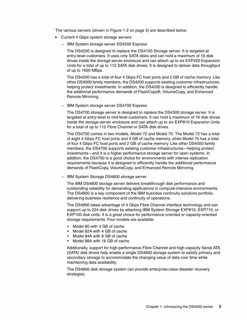
The various servers (shown in Figure 1-2 on page 5) are described below:
� Current 4 Gbps system storage servers
– IBM System storage server DS4200 Express
The DS4200 is designed to replace the DS4100 Storage server. It is targeted at entry-level customers. It uses only SATA disks and can hold a maximum of 16 disk drives inside the storage server enclosure and can attach up to six EXP420 Expansion Units for a total of up to 112 SATA disk drives. It is designed to deliver data throughput of up to 1600 MBps.
The DS4200 has a total of four 4 Gbps FC host ports and 2 GB of cache memory. Like other DS4000 family members, the DS4200 supports existing customer infrastructures, helping protect investments. In addition, the DS4200 is designed to efficiently handle the additional performance demands of FlashCopy®, VolumeCopy, and Enhanced Remote Mirroring.
– IBM System storage server DS4700 Express
The DS4700 storage server is designed to replace the DS4300 storage server. It is targeted at entry-level to mid-level customers. It can hold a maximum of 16 disk drives inside the storage server enclosure and can attach up to six EXP810 Expansion Units for a total of up to 112 Fibre Channel or SATA disk drives.
The DS4700 comes in two models, Model 72 and Model 70. The Model 72 has a total of eight 4 Gbps FC host ports and 4 GB of cache memory, while Model 70 has a total of four 4 Gbps FC host ports and 2 GB of cache memory. Like other DS4000 family members, the DS4700 supports existing customer infrastructures—helping protect investments—and it is a higher performance storage server for open systems. In addition, the DS4700 is a good choice for environments with intense replication requirements because it is designed to efficiently handle the additional performance demands of FlashCopy, VolumeCopy, and Enhanced Remote Mirroring.
– IBM System Storage DS4800 storage server
The IBM DS4800 storage server delivers breakthrough disk performance and outstanding reliability for demanding applications in compute-intensive environments. The DS4800 is a key component of the IBM business continuity solutions portfolio, delivering business resilience and continuity of operations.
The DS4800 takes advantage of 4 Gbps Fibre Channel interface technology and can support up to 224 disk drives by attaching IBM System Storage EXP810, EXP710, or EXP100 disk units. It is a great choice for performance-oriented or capacity-oriented storage requirements. Four models are available:
• Model 80 with 4 GB of cache• Model 82A with 4 GB of cache • Model 84A with 8 GB of cache • Model 88A with 16 GB of cache
Additionally, support for high-performance Fibre Channel and high-capacity Serial ATA (SATA) disk drives help enable a single DS4800 storage system to satisfy primary and secondary storage to accommodate the changing value of data over time while maintaining data availability.
The DS4800 disk storage system can provide enterprise-class disaster recovery strategies.
Chapter 1. Introducing the DS4000 series 3

Table 1-1 compares the above discussed models.
Table 1-1 Product Comparison DS4200, DS4700 and DS4800
� Former 2 Gbps TotalStorage Servers
– IBM TotalStorage DS4100 storage server
The DS4100 storage server (formerly known as the FAStT100) is an entry-level SATA storage system that is available in a single and dual controller configuration.
– IBM TotalStorage DS4300 storage server
The DS4300 storage server (formerly known as the FAStT600) is a mid-level, highly scalable 2 Gbps Fibre Channel storage server, which is available in a single and dual controller configuration. There is also a DS4300 with Turbo feature that offers up to 65% read performance improvement and has higher Fibre Channel drive scalability over the base DS4300.
– IBM TotalStorage DS4500 storage server
The IBM DS4500 storage server (formerly known as FAStT900) delivers high disk performance and outstanding reliability for demanding applications in compute-intensive environments. The DS4500 is designed to offer investment protection with advanced functions and flexible features.
Dual-controller system (unless noted)
DS4800 DS4700Model 72/70
DS4200
Host channels 8 8/4 4
Native host interface link speed
4 Gbps 4 Gbps 4 Gbps
Supported host interface link speeds
4, 2, 1 Gbps 4, 2, 1 Gbps 4, 2, 1 Gbps
Total host channel maximum bandwidth
3,200 MBps 3,200/1,600 MBps 1,600 MBps
Redundant drive channels
Eight 4 Gbps Four 4 Gbps Four 4 Gbps
Total drive channel maximum bandwidth
3,200 MBps 1,600 MBps 1,600 MBps
Max drives 224 112 112
Drives supported FC and SATA FC and SATA SATA
Processor Intel® Xeon 2.4 GHz Intel xScale 667 MHz Intel xScale 667 MHz
Processor memory (single controller)
512 MB/1 GB 128 MB 128 MB
XOR engine Dedicated Integrated Integrated
Dedicated data cache per dual-controller system
4, 8, or 16 GB 4 GB/2 GB(256 MB for memory)
2 GB (256 MB for memory
4 IBM System Storage DS4000 and Storage Manager V10.30
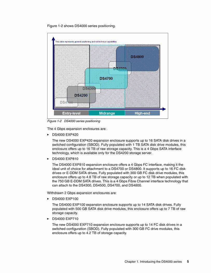
Figure 1-2 shows DS4000 series positioning.
Figure 1-2 DS4000 series positioning
The 4 Gbps expansion enclosures are:
� DS4000 EXP420
The new DS4000 EXP420 expansion enclosure supports up to 16 SATA disk drives in a switched configuration (SBOD). Fully populated with 1 TB SATA disk drive modules, this enclosure offers up to 16 TB of raw storage capacity. This is a 4 Gbps SATA interface technology, which is available only for the DS4200 storage server.
� DS4000 EXP810
The DS4000 EXP810 expansion enclosure offers a 4 Gbps FC interface, making it the ideal unit of choice for attachment to a DS4700 or DS4800. It supports up to 16 FC disk drives or E-DDM SATA drives. Fully populated with 300 GB FC disk drive modules, this enclosure offers up to 4.8 TB of raw storage capacity or up to 12 TB when populated with the 750 GB E-DDM SATA drives. This is a 4 Gbps Fibre Channel interface technology that can attach to the DS4300, DS4500, DS4700, and DS4800.
Withdrawn 2 Gbps expansion enclosures are:
� DS4000 EXP100
The DS4000 EXP100 expansion enclosure supports up to 14 SATA disk drives. Fully populated with 500 GB SATA disk drive modules, this enclosure offers up to 7 TB of raw storage capacity.
� DS4000 EXP710
The new DS4000 EXP710 expansion enclosure supports up to 14 FC disk drives in a switched configuration (SBOD). Fully populated with 300 GB FC drive modules, this enclosure offers up to 4.2 TB of storage capacity.
Chapter 1. Introducing the DS4000 series 5

Telco industry standard supportThe IBM System Storage DS4700 Express Models 70-DC and 72-DC and expansion units EXP810 model 81-DC are NEBS-3-compliant midrange disk systems designed to be powered from a -48 V dc Telco industry-standard power source.
1.3 Storage Manager softwareThe DS4000 Storage Manager software is used to configure, manage, and troubleshoot the DS4000 storage servers. It is used primarily to configure RAID arrays and logical drives, assign logical drives to hosts, replace and rebuild failed disk drives, expand the size of the arrays and logical drives, and convert from one RAID level to another. It allows troubleshooting and management tasks, such as checking the status of the storage server components, updating the firmware of the RAID controllers, and managing the storage server. Finally, it offers advanced functions such as FlashCopy, VolumeCopy, and Enhanced Remote Mirroring.
The Storage Manager software is now packaged into the following combinations:
� Host-based software
– Storage Manager Client (SMclient)
The SMclient component provides the graphical user interface (GUI) for managing storage systems through the Ethernet network or from the host computer.
– Storage Manager Runtime (SMruntime)
The SMruntime is a Java™ runtime environment that is required for the SMclient to function. SMruntime must be installed before SMclient is installed. It is not available on every platform as a separate package, but in those cases, it has been bundled into the SMclient package..
– Storage Manager Agent (SMagent)
The SMagent package is an optional component that allows in-band management of the DS4000 storage server.
– Storage Manager Utilities (SMutil)
The Storage Manager Utilities package contains command-line tools for making logical drives available to the operating system.
– Failover driver support
Storage Manager host-based software includes an optional failover driver. It is a multipath driver built on MPIO technology.
� Controller-based software
– DS4000 storage server Controller firmware and Non Volatile Static Random Access Memory (NVSRAM)
The controller firmware and NVSRAM are always installed as a pair and provide the brains of the DS4000 storage server.
– DS4000 storage server Environmental Service Modules (ESM) firmware
The ESM firmware controls the interface between the controller and the drives.
– DS4000 storage server Drive firmware
The drive firmware is the software that tells the Fibre Channel (FC) drives how to behave on the FC loop.
6 IBM System Storage DS4000 and Storage Manager V10.30

The Storage Manager functions are reviewed in detail in Chapter 4, “Managing the DS4000” on page 115.
Chapter 1. Introducing the DS4000 series 7

8 IBM System Storage DS4000 and Storage Manager V10.30
Chapter 2. What is new
This chapter is a brief overview of additions and enhancements available with Storage Manager V10.30 (firmware V7.15).
This chapter is intended for readers already familiar with most of the DS4000 concepts and features who just need a quick overview of the latest changes.
2
© Copyright IBM Corp. 2004, 2005, 2006, 2007, 2008, 2009. All rights reserved. 9

2.1 Storage Manager enhancements
Storage Manager Version 10.30 (controller code Version 7.15) includes all the functions already available in previous Storage Manager releases, and also offers several significant new features.
The controller code (firmware) Version 7.10 and later is based on a new layered code design that provides better scalability and flexibility for future code enhancements. As part of the new design, the configuration database (dacstor region) has also been restructured. This new structure provides the foundation for supporting some of the new features such as greater than 2 TB logical drives, RAID-6 (for DS4700and DS4200), and an increased number of logical partitions.
The new 7.15 firmware is only supported on the DS4200, DS4700, and DS4800. Former DS4000 models (such as the DS4500 or DS4300) must remain at the latest compatible 6.xx firmware. Those former models can, however, be managed from Storage Manager V10.30 client.
2.1.1 New features
The new features discussed in this section were first introduced with Storage Manager V10.10 (firmware V7.10) and are applicable to Storage Manager V10.30 (firmware V7.15) as well.
RAID-6 supportRAID-6 technology is designed to provide improved data protection against multiple disk drive failure. RAID-6 uses a double parity check implementation (designated as p+q). Dynamic RAID-level migration is supported but may require capacity expansion prior to RAID migration.
Support for more than 30 drives for RAID-0 and RAID-1A logical drive can be created using all the drives in the storage system. Although not a recommendation, you could now create a logical drive using a possible maximum of 224 drives for a DS4800 or 112 drives for a DS4200 and DS4700.
Support for greater than 2 TB logical drivesYou can now create greater than 2 TB (TeraBytes) logical drives. If you combine this feature with the possibility to also now support more than 30 physical drives (assuming RAID-0 or RAID-1), and if you use 500 GB drives in a DS4800 with its maximum of 224 disk drives, you can create a 112 TB logical drive. (Keep in mind, however, that the operating system (OS) making use of the logical drive can impose other limitations.)
Restriction: Because of the design changes, upgrading the firmware to Version 7.15 is a non-concurrent upgrade and it must be done offline. Refer to “Upgrading to firmware level 7.xx” on page 668 for details.
Note: RAID-6 is not supported on the DS4800. This feature is available only on DS4200 and DS4700. This is because some of the RAID-6 parity calculations rely on electronic components available only with the DS4700 and DS4200 systems. This hardware-based implementation offers better performance than the RAID-6 software-based implementation used by other storage vendors.
10 IBM System Storage DS4000 and Storage Manager V10.30
Increased maximum number of partitionsThe maximum number of supported partitions for DS4200, DS4700, and DS4800 with firmware versions older than 7.10 was 64. This number is increased to 128 for DS4200 and DS4700 and to 512 for DS4800.
Increased queue depthThe controller queue depth is increased to 4096 for DS4800 and to 2048 for DS4200 and DS4700.
Support bundle collected on critical eventsThe event monitor on the client system, upon occurrence of a critical event, saves diagnostic data (support bundle) to the local hard drive of the client system in the same area already used for other recovery information. This information is stored and is not overwritten for 72 hours. E-mail notification can be set up for all critical events.
Use diagnostic data capture for additional failure eventsThe goal of this feature is to capture enough information about the controller state at the time of an unusual event and stores that diagnostic data for later retrieval. For details refer to 6.1.4, “Support data: Collecting information” on page 302.
Increased number of GHS (Global Hot Spares)The new controller code allows the creation of unlimited Global Hot Spares. There are now three ways to create GHS drives:
� Automatically assigned hot spares� Automatic assignment by specification of number of drives � Explicit assignment by specification of a list of drives
Refer to 4.2.5, “Hot spare drive” on page 149, for details.
Unconfiguring Storage Subsystem and arraysStorage Manager 10.10 (controller code 7.10) allows you to clear the storage subsystem or previously created arrays if you must do so. Clearing the storage subsystem completely removes all configurations of the storage subsystem. Clearing the array configuration clears logical drives and group configuration in all arrays while leaving the remaining subsystem configuration intact. Refer to 4.3.2, “Unconfiguring storage subsystem and arrays” on page 162.
Drive migration warningThis feature allows the user to manually intervene and permits safer migration scenarios. (When migrating configured logical drives to an existing storage subsystem, there is a warning given if the number of the logical drives being added will overrun the maximum number of drives allowed on this particular subsystem.) This feature thus prevents users from being allowed to import more logical drives than a particular subsystem can support.
Configurable failed drive replacementYou can now designate a hot spare to be a permanent member of a logical drive, thus eliminating the copyback portion once the failed drive has been replaced. The replacement drive in that case is in an unassigned state.
Chapter 2. What is new 11
Enhanced performance featureThis is a premium feature and requires a premium key to enable higher-performance on a DS4800 Mod 80. Application of this key is an off-line operation (requiring a quiesce of the storage system and a subsequent reboot of the controllers). Refer to 4.3.13, “Enhanced performance feature” on page 175, for details.
RAID redundant data verification prior to readThis feature is supported on all RAID levels and enables verification of redundant RAID data consistency before returning the requested read data back to the host. This must be enabled on a logical drive basis. The function is automatically disabled when a logical drive becomes degraded. If a mismatch is detected, the system returns a media error (unrecoverable read error (03/11/00)). The system does not attempt to correct or recalculate parity automatically.
8 K cache block sizeCache block size dictates the size of individual data buffers within the cache. In addition to the previously possible 4 K and 16 K cache block sizes, the new firmware V7.10 and later also adds the choice for an 8 K block size.
Increased number of FlashCopies per logical driveThe maximum number of FlashCopies per logical drive that is supported on DS4800 is 16, instead of 4 with previous versions of the firmware. For DS4200 and DS4700 the maximum number of FlashCopies increases from 4 to 8 per logical drive.
Increased number of mirrors supported With firmware V7.10 and later, the number of mirrors supported on DS4800 increases from 64 to 128 and, on DS4200 and DS4700, from 32 to 64.
Unmanageable iconA new icon is available in the DS Storage Manager GUI to differentiate between unresponsive and unmanageable controllers. The unmanageable would be any storage subsystem that has no corresponding configuration file.
New multipath driver support: SDDDSMSDDDSM is a multipath I/O solution based on Microsoft MPIO technology. The SDDDSM driver also supports other storage solutions from IBM such as IBM System Storage DS8000 and IBM SAN Volume Controller (SVC). It is now also available for the DS4000 systems.
Windows RDAC no longer supportedRDAC for Windows is not supported with this new version of Storage Manager (V10.10 and later). For multipathing and failover support, you must install the SM failover driver (MPIO/DSM) or the new, separately provided, SDDDSM driver (RPQ). More details are available in “Multipathing in Windows” on page 129 and in 5.1.1, “Installing Storage Manager in a Windows host” on page 180.
Enhanced cache supportThe cache memory management has been improved. All cache is now read/write. Previously, only the first 1 GB was read/write all other was read only.
Additional statistic gathering via GUI and CLIController response and performance along with additional drive statistics via the GUI and CLI option is available now.
12 IBM System Storage DS4000 and Storage Manager V10.30

Additional operating system supportsThese are:
� MS® Vista client support� MicroSoft Windows Server® 2008� Support RedHat v5.2� HP-Ux v11.23 full solution� Solaris™ 10 x86 support� SLES 10 SP-2
2.1.2 Enhancements in Version 10.30
In summary, with the Storage Manager 10.30, IBM introduced the following major new features:
� 1,000 GB: 7.2K rpm, SATA (E-DDM) disk drive. Using 1,000 GB disk, the capacity can go up from 12 TB to 16 TB per enclosure.
� DS4000 SNMP MIB file change to support SNMPv2.
� IPv6 support on the Ethernet management ports for DS4800, DS4700, and DS4200.
� Increase the number of supported host logins on the DS4700 and DS4200 controller to 640 from 512.
� Windows Server 2008, RHEL 5.2, SLES 10 SP2, HP-UX 11.23, and Solaris 10 on x86 support.
� IBM SDD support on Windows and HP-UX.
Chapter 2. What is new 13

14 IBM System Storage DS4000 and Storage Manager V10.30

Chapter 3. DS4000 series hardware
This chapter describes the hardware and features of the DS4000 series of storage servers. The currently available models (IBM System Storage DS4200, DS4700, and DS4800) are successively reviewed along with some of the former models that they replace (the DS4100, DS4300, and DS4500, respectively).
This chapter also includes a description of additional hardware components that are essential for a complete storage solution. These include the current EXP420 and EXP810 expansion enclosures and older models such as the EXP710 and EXP100 with cabling considerations, host bus adapters (HBAs), and storage area network (SAN) switches.
3
© Copyright IBM Corp. 2004, 2005, 2006, 2007, 2008, 2009. All rights reserved. 15

3.1 IBM System Storage DS4200 Express
The DS4200 disk storage system is a Serial Advanced Technology Attachment (SATA)-only disk storage solution designed to be an economical alternative for data archiving, reference data, and near-line storage applications. The DS4200 includes 16 disks and offers a fully switched drive-side architecture, and it can have a maximum internal physical storage capacity of up to 8 TB using 500 GB Enhanced Value Disk Drive Modules, up to 12 TB using the 750 GB EV-DDM, and up to 16 TB using 1 TB: 7.2K rpm, SATA (E-DDM). The storage capacity can be increased up to 112 TB by attachment of up to six EXP420 Storage Expansion Units.
The DS4200 is designed as the replacement for the DS4100 storage server.
One of the key advantages of the DS4200 Express 4 Gbps technology is that it is backward compatible with 2 Gbps and even 1 Gbps technologies. This is true as well for the DS4700 and DS4800. This means that you can avoid replacing your entire SAN with 4 Gbps technology. You can add new technology incrementally. The 4 Gbps products will slow down to the 2 Gbps or 1 Gbps speed if they are connected. In addition, zoning allows you to implement a rolling upgrade strategy with minimal disruption.
3.1.1 DS4200 featuresThe System Storage DS4200 Express storage server model 7V (1814-7VA) offers the key features discussed below. See Figure 3-1.
Figure 3-1 DS4200 Express: Chassis design
The key features are:
� Compact, 3U rack-mountable enclosures containing dual high-performance intelligent RAID controller cards, accommodating sixteen 500, 750 GB SATA EV-DDMs for up to 12 TB or 1 TB 7.2K rpm SATA (E-DDM) for up to 16 TB internal physical storage capacity.
� DS4200 Express models provide end-to-end 4 Gbps support when used in conjunction with 4 Gbps switches and 4 Gbps host bus adapters.
� Dual, redundant 4 Gbps RAID controllers with up to 2 GB of cache memory (1 GB per RAID controller).
� New lithium-ion battery backup protects data cache in each controller for at least 72 hours.
Controllers
Power/Cooling
SATA Drives
or ESMs
16 IBM System Storage DS4000 and Storage Manager V10.30

� Hot-swappable cache backup battery.
� Redundant, hot-swappable power supplies and fans.
� Supports RAID-0, RAID-1, RAID-3, RAID-5, RAID-6, and RAID-10 (RAID-1+0).
� Switched loop architecture that supports two dual redundant FC disk loops.
� Auto negotiates 1, 2, or 4 Gbps host connection speeds.
� Supports Global Hot Spare.
� Host-side connections support Fibre Channel Switched, Loop, or Direct Connections.
� Redundant drive-side connections designed to avoid any single-point of failure and maintain high availability.
� Supports up to six EXP420 (each EXP420 has 16 disk bays) to attach up to 112 SATA disks (additional licenses required).
� High capacity disk drives, 4 Gbps 750 GB SATA 7200 rpm EV-DDM and 1 TB 7.2K rpm SATA (E-DDM).
� Supports shortwave Fibre Channel 4 Gbps host attachment.
� Multiple heterogeneous server and operating system support (host kits required).
� Storage partitions up to 128.
� Powerful On Demand functions: Dynamic volume expansion, dynamic capacity expansion, and dynamic RAID level migration, which allow users to modify storage configurations on-the-fly without incurring any downtime.
� DS4000 Remote Service Manager to notify IBM in case of problems or failures.
� Dual 10/100 Ethernet for out-of-band management to separate out-of-band management from service diagnostics for each controller.
� FlashCopy, VolumeCopy, and Enhanced Remote Mirroring (premium features).
� DS4000 Storage Manager Version 10.30 (Controller firmware Version 7.15).
Restriction: The EXP420 is the only expansion unit supported by the DS4200.
Note: The DS4200 Express requires Enhanced Value Disk Drive Modules (EV-DDMs) to be installed. The form factor (size) for the EV-DDMs is smaller than the previous DDMs. The DS4200 Express has a lower-profile EV-DDM in order to support 16 drives in its 19" 3U enclosure.
Chapter 3. DS4000 series hardware 17

3.1.2 DS4200: Front viewThe front section of the DS4200 shows the 16 pre-installed drive bays of hot swap disk drives (Figure 3-2).
Figure 3-2 The DS4200 front view
The hot-swap features of the DS4200 enable you to remove and replace the Fibre Channel hard disk drives without turning off the storage expansion enclosure. You can maintain the availability of your system while a hot-swap device is removed, installed, or replaced.
The DS4200 Express supports up to 16 SATA EV-DDMs, which come pre-installed in drive trays. Each drive, ATA translator card (also referred to as interposer card), and carrier assembly are called EV-DDM CRUs. The ATA translator card converts the Fibre Channel protocol interface of the DS4200 Express drive channel into the SATA protocol interface. It also provides dual paths to the SATA drive for drive customer replacement unit (CRU) path redundancy.
Install drive CRUs in the 16 drive bays on the front of the storage expansion enclosure from the rightmost slot (slot 16) to the leftmost slot (slot 1).
Several LED indicators and the FC Link speed selector are also visible from the front of the storage unit.
Attention: Never hot-swap an EV-DDM CRU when its associated green activity LED is flashing. Hot-swap a drive CRU only when its associated amber fault LED light is not flashing or when the drive is inactive and its associated green activity LED light is not flashing.
18 IBM System Storage DS4000 and Storage Manager V10.30
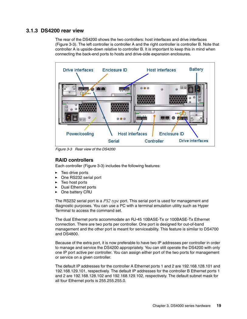
3.1.3 DS4200 rear view
The rear of the DS4200 shows the two controllers: host interfaces and drive interfaces (Figure 3-3). The left controller is controller A and the right controller is controller B. Note that controller A is upside-down relative to controller B. It is important to keep this in mind when connecting the back-end ports to hosts and drive-side expansion enclosures.
Figure 3-3 Rear view of the DS4200
RAID controllersEach controller (Figure 3-3) includes the following features:
� Two drive ports� One RS232 serial port� Two host ports� Dual Ethernet ports� One battery CRU
The RS232 serial port is a PS2 type port. This serial port is used for management and diagnostic purposes. You can use a PC with a terminal emulation utility such as Hyper Terminal to access the command set.
The dual Ethernet ports accommodate an RJ-45 10BASE-Tx or 100BASE-Tx Ethernet connection. There are two ports per controller. One port is designed for out-of-band management and the other port is meant for serviceability. This feature is similar to DS4700 and DS4800.
Because of the extra port, it is now preferable to have two IP addresses per controller in order to manage and service the DS4200 appropriately. You can still operate the DS4200 with only one IP port active per controller. You can assign either port of the two ports for management or service on a given controller.
The default IP addresses for the controller A Ethernet ports 1 and 2 are 192.168.128.101 and 192.168.129.101, respectively. The default IP addresses for the controller B Ethernet ports 1 and 2 are 192.168.128.102 and 192.168.129.102, respectively. The default subnet mask for all four Ethernet ports is 255.255.255.0.
Chapter 3. DS4000 series hardware 19

DS4200 has a redundant battery system. Each controller has one battery customer replacement unit, which is a new Lithium Ion battery system for cache. Its hold-up time is up to three days. The minimum life of the battery can be up to three years. The battery can be easily replaced on site. See Figure 3-4.
Figure 3-4 Replaceable Backup Battery Unit (BBU)
The components in Figure 3-4 are:
1. Controller A cache backup battery unit2. Controller B cache backup battery unit3. Latch4. Pull handle
Power supply fan unitsThe DS4200 controller enclosure has two removable power supply fans. Each power supply fan contains one power supply and two fans.
The four fans pull air through the drive from front to back across the drives. The fans provide redundant cooling, which means that if one of the fans in either fan housing fails, the remaining fans continue to provide sufficient cooling to operate the controller enclosure.
The power supplies provide power to the internal components by converting incoming AC voltage to DC voltage. If one power supply is turned off or malfunctions, the other power supply maintains electrical power to the controller enclosure.
To preserve the optimal airflow, do not remove a failed power supply fan CRU from the DS4200 controller enclosure chassis until you are ready to replace it with a new CRU.
Important: When changing the default IP addresses, remember that port 1 and 2 of each controller must be in separate subnets.
20 IBM System Storage DS4000 and Storage Manager V10.30
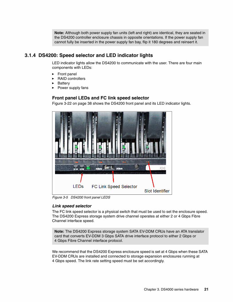
3.1.4 DS4200: Speed selector and LED indicator lightsLED indicator lights allow the DS4200 to communicate with the user. There are four main components with LEDs:
� Front panel� RAID controllers� Battery� Power supply fans
Front panel LEDs and FC link speed selectorFigure 3-22 on page 38 shows the DS4200 front panel and its LED indicator lights.
Figure 3-5 DS4200 front panel LEDS
Link speed selectorThe FC link speed selector is a physical switch that must be used to set the enclosure speed. The DS4200 Express storage system drive channel operates at either 2 or 4 Gbps Fibre Channel interface speed.
We recommend that the DS4200 Express enclosure speed is set at 4 Gbps when these SATA EV-DDM CRUs are installed and connected to storage expansion enclosures running at 4 Gbps speed. The link rate setting speed must be set accordingly.
Note: Although both power supply fan units (left and right) are identical, they are seated in the DS4200 controller enclosure chassis in opposite orientations. If the power supply fan cannot fully be inserted in the power supply fan bay, flip it 180 degrees and reinsert it.
Note: The DS4200 Express storage system SATA EV-DDM CRUs have an ATA translator card that converts EV-DDM 3 Gbps SATA drive interface protocol to either 2 Gbps or 4 Gbps Fibre Channel interface protocol.
Chapter 3. DS4000 series hardware 21

Front LEDsThese are:
� Locate LED (white or blue)
– On: This indicates storage subsystem locate.
– Off: This is the normal status.
� Service action allowed LED (blue)
– On: This service action can be performed on the component with no adverse consequences.
– Off: This is the normal status.
� Service action required LED (amber)
– On: There is a corresponding needs attention condition flagged by the controller firmware. Some of these conditions might not be hardware related.
– Off: This is the normal status.
� Power LED (green)
– On: The subsystem is powered on.
– Off: The subsystem is powered off.
RAID controller LEDsThere are LEDs on the RAID controllers that serve as indicators of key information (refer to Figure 3-23 on page 39, Table 3-3 on page 39, and Table 3-4 on page 40).
Figure 3-6 RAID controller LEDs
LEDs 1-2 (Host ports) 3
6-7 8-9 10-11
54
(12)
22 IBM System Storage DS4000 and Storage Manager V10.30

The LEDs are:
� LED #1 (green): Host channel speed L1
� LED #2 (green): Host channel speed L2
Table 3-1 FC host SFP status LED definitions
� LED #3 (blue): Serviced action allowed
– Off: Normal status– On: Safe to remove
� LED #4 (amber): Need attention
– Off: Normal status– On: Controller needs attention (controller fault or controller is offline)
� LED #5 (green): Caching active
– On: Data in cache– Off: No data in cache
� LED #6 (green): Ethernet link speed
– Off: 10BASE-T– On: 100BASE-T
� LED #7 (green): Ethernet link activity
– Off: No link established.– On: Link established.
� LED #8 (amber): Drive channel bypass
– Off: Normal status– On: Drive port bypass problem
� LED #9 (green): Drive channel speed L1
� LED #10 (green): Drive channel speed L2
Table 3-2 FC DISK expansion port SFP LED definitions
LED#1 LED#2 Port status
OFF OFF Link down
ON OFF Link rate 1 Gbps
OFF ON Link rate 2 Gbps
ON ON Link rate 4 Gbps
LED#9 LED#10 Port status
OFF OFF Link down
ON OFF Reserved
OFF ON Link rate 2 Gbps
ON ON Link rate 4 Gbps
Chapter 3. DS4000 series hardware 23
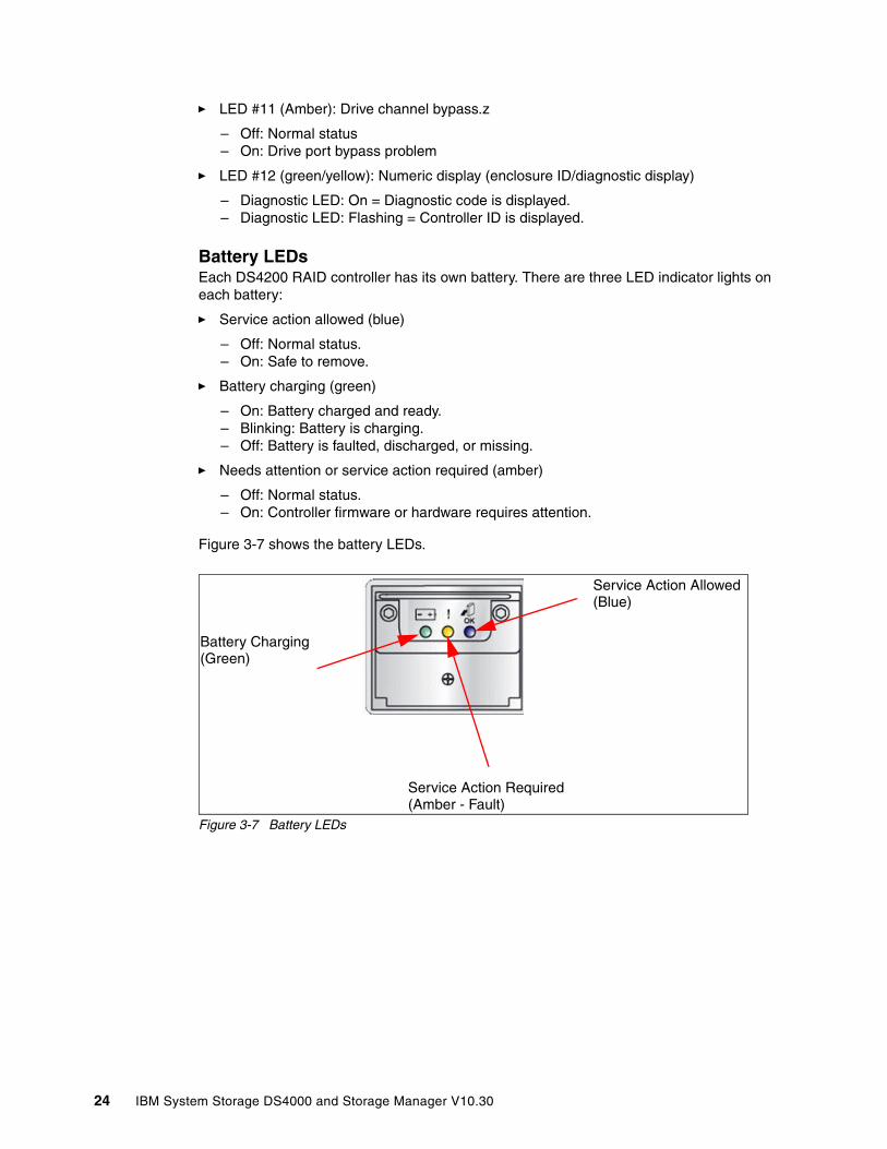
� LED #11 (Amber): Drive channel bypass.z
– Off: Normal status– On: Drive port bypass problem
� LED #12 (green/yellow): Numeric display (enclosure ID/diagnostic display)
– Diagnostic LED: On = Diagnostic code is displayed.– Diagnostic LED: Flashing = Controller ID is displayed.
Battery LEDsEach DS4200 RAID controller has its own battery. There are three LED indicator lights on each battery:
� Service action allowed (blue)
– Off: Normal status.– On: Safe to remove.
� Battery charging (green)
– On: Battery charged and ready.– Blinking: Battery is charging.– Off: Battery is faulted, discharged, or missing.
� Needs attention or service action required (amber)
– Off: Normal status.– On: Controller firmware or hardware requires attention.
Figure 3-7 shows the battery LEDs.
Figure 3-7 Battery LEDs
Battery Charging(Green)
Service Action Required(Amber - Fault)
Service Action Allowed(Blue)
24 IBM System Storage DS4000 and Storage Manager V10.30
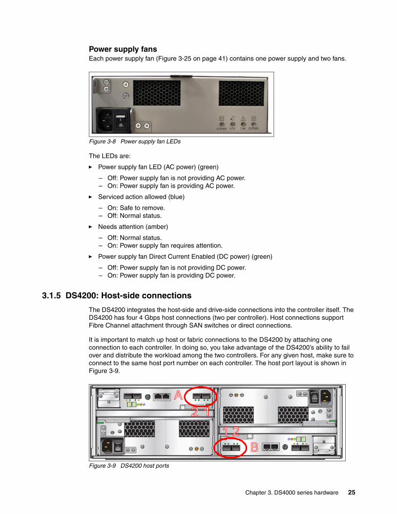
Power supply fansEach power supply fan (Figure 3-25 on page 41) contains one power supply and two fans.
Figure 3-8 Power supply fan LEDs
The LEDs are:
� Power supply fan LED (AC power) (green)
– Off: Power supply fan is not providing AC power.– On: Power supply fan is providing AC power.
� Serviced action allowed (blue)
– On: Safe to remove.– Off: Normal status.
� Needs attention (amber)
– Off: Normal status.– On: Power supply fan requires attention.
� Power supply fan Direct Current Enabled (DC power) (green)
– Off: Power supply fan is not providing DC power.– On: Power supply fan is providing DC power.
3.1.5 DS4200: Host-side connections
The DS4200 integrates the host-side and drive-side connections into the controller itself. The DS4200 has four 4 Gbps host connections (two per controller). Host connections support Fibre Channel attachment through SAN switches or direct connections.
It is important to match up host or fabric connections to the DS4200 by attaching one connection to each controller. In doing so, you take advantage of the DS4200’s ability to fail over and distribute the workload among the two controllers. For any given host, make sure to connect to the same host port number on each controller. The host port layout is shown in Figure 3-9.
Figure 3-9 DS4200 host ports
Chapter 3. DS4000 series hardware 25
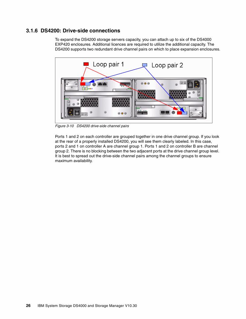
3.1.6 DS4200: Drive-side connections
To expand the DS4200 storage servers capacity, you can attach up to six of the DS4000 EXP420 enclosures. Additional licences are required to utilize the additional capacity. The DS4200 supports two redundant drive channel pairs on which to place expansion enclosures.
Figure 3-10 DS4200 drive-side channel pairs
Ports 1 and 2 on each controller are grouped together in one drive channel group. If you look at the rear of a properly installed DS4200, you will see them clearly labeled. In this case, ports 2 and 1 on controller A are channel group 1. Ports 1 and 2 on controller B are channel group 2. There is no blocking between the two adjacent ports at the drive channel group level. It is best to spread out the drive-side channel pairs among the channel groups to ensure maximum availability.
26 IBM System Storage DS4000 and Storage Manager V10.30
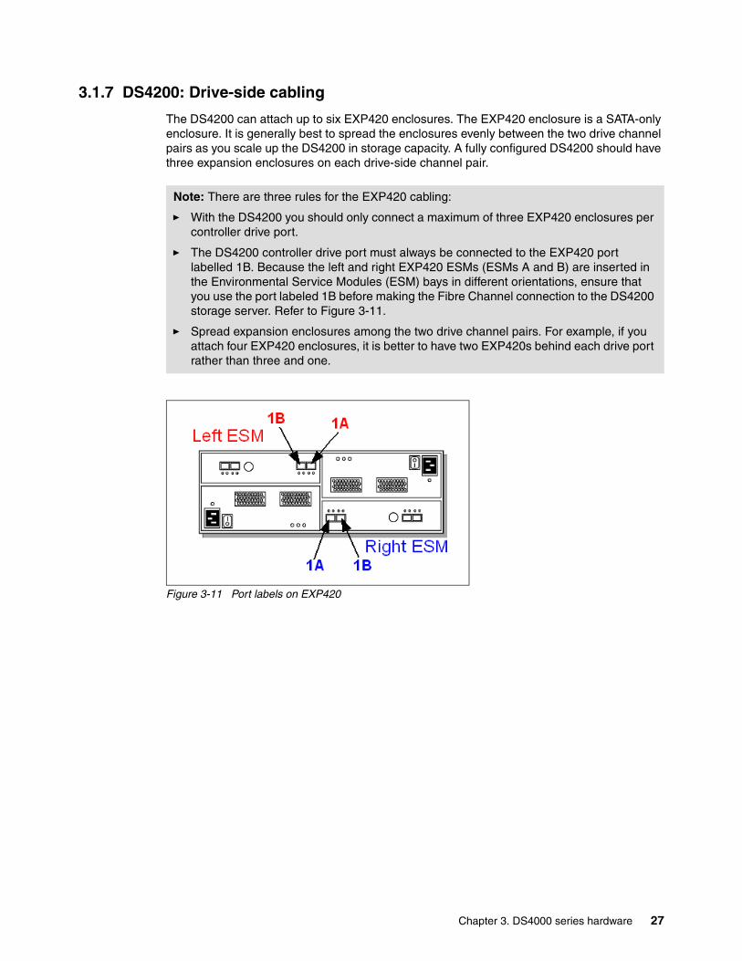
3.1.7 DS4200: Drive-side cabling
The DS4200 can attach up to six EXP420 enclosures. The EXP420 enclosure is a SATA-only enclosure. It is generally best to spread the enclosures evenly between the two drive channel pairs as you scale up the DS4200 in storage capacity. A fully configured DS4200 should have three expansion enclosures on each drive-side channel pair.
Figure 3-11 Port labels on EXP420
Note: There are three rules for the EXP420 cabling:
� With the DS4200 you should only connect a maximum of three EXP420 enclosures per controller drive port.
� The DS4200 controller drive port must always be connected to the EXP420 port labelled 1B. Because the left and right EXP420 ESMs (ESMs A and B) are inserted in the Environmental Service Modules (ESM) bays in different orientations, ensure that you use the port labeled 1B before making the Fibre Channel connection to the DS4200 storage server. Refer to Figure 3-11.
� Spread expansion enclosures among the two drive channel pairs. For example, if you attach four EXP420 enclosures, it is better to have two EXP420s behind each drive port rather than three and one.
Chapter 3. DS4000 series hardware 27
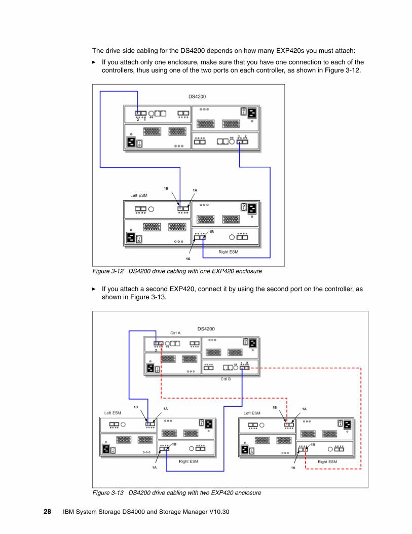
The drive-side cabling for the DS4200 depends on how many EXP420s you must attach:
� If you attach only one enclosure, make sure that you have one connection to each of the controllers, thus using one of the two ports on each controller, as shown in Figure 3-12.
Figure 3-12 DS4200 drive cabling with one EXP420 enclosure
� If you attach a second EXP420, connect it by using the second port on the controller, as shown in Figure 3-13.
Figure 3-13 DS4200 drive cabling with two EXP420 enclosure
28 IBM System Storage DS4000 and Storage Manager V10.30

� Beyond two enclosures (up to a maximum of six) make sure that you equally distribute the enclosures among the redundant drive channel pairs (Figure 3-14 and Figure 3-15 on page 30).
Figure 3-14 DS4200 drive cabling with three EXP420 enclosures
Chapter 3. DS4000 series hardware 29

When six enclosures are required, the same method is employed again, maintaining drive channel redundancy and using both controllers. See Figure 3-15.
Figure 3-15 DS4200 drive-side connections with two drive channel pairs and EXP420 enclosures
Drive-side cabling exampleRefer to Figure 3-15. In this example, the DS4200 is cabled using all two-drive channel pairs, assuming that there are six EXP420 expansion enclosures evenly spread out across the drive channel pairs (three enclosures each).
Each EXP420 ESM only has one pair of ports, labelled 1A and 1B, that can be used to connect FC cables. The other pair of ports is reserved for future use. Proceed as follows:
1. Start with the first expansion enclosure, which we attach to drive channel pair #1. Cable controller A, port 2 to the leftmost port (1B) of the first pair of ports of the left ESM of the first EXP420 unit.
2. Cable the rightmost port (1A) of the first pair of ports of the left ESM of the first EXP420 unit to the leftmost port (1B) of the first pair of ports on the left ESM of the second EXP420 unit.
3. Cable the rightmost port (1A) of the first pair of ports of the left ESM of the second EXP420 unit to the leftmost port (1B) of the first pair of ports on the left ESM of the third EXP420 unit.
4. Cable the rightmost port (1B) of the first pair of ports of the right ESM of the first EXP420 unit to the leftmost port (1A) of the first pair of ports of the right ESM of the second EXP420 unit.
30 IBM System Storage DS4000 and Storage Manager V10.30

5. Cable the rightmost port (1B) of the first pair of ports of the right ESM of the second EXP420 unit to the leftmost port (1A) of the first pair of ports of the right ESM of the third EXP420 unit.
6. Cable controller B, port 1 to the rightmost port (1B) of the first pair of ports of the right ESM of the third EXP420 unit located on the first drive channel pair. This is the last step of the first drive channel pair.
Repeat steps 1–6 (using the next drive-side channel pair ports) for the second drive channel pairs (three EXP420 units each).
3.1.8 DS4200 controller enclosure IDsThe base controller unit and each expansion enclosure has an ID number associated with it. The ID allows each expansion enclosure to be identified properly to the base controller unit. Since the base and all expansion enclosures are connected by Fibre Channel loop, it is necessary for each ID address to be distinct and unique for I/O to flow properly. The DS4000 controller firmware and the EXP420 ESMs automatically set the enclosure ID number. You can change the setting with the Storage Manager software. Both ESM enclosure ID numbers will be identical under normal operating conditions.
3.1.9 DS4200 physical/environmental specificationsThe following information describes the DS4200 storage server’s physical and environmental specifications.
Physical specificationsThe physical specifications are:
� Height: 12.95 cm (5.1 in.)� Width: 48.26 cm (19.00 in.)� Depth: 57.15 cm (22.5 in.)� Weight:
– Drive-ready (without drive modules installed): 29.03 kg (64 lb.) – Fully configured (with 16 drive modules): 39.92 kg (88 lb.)
Operating environmentThe operating environment is:
� Temperature
– 10° to 35°C (50° to 95°F) at 0 to 914 m (0 to 3,000 ft.)– 10° to 32°C (50° to 90°F) at 914 to 2,133 m (3,000 to 7,000 ft.)
� Relative humidity: 8–80%
� Electrical power (per power supply, system rating)
– Voltage range: nominal (100–240 V ac) – Operating current: (6.0–2.5 amperes) – Power: 600 watts – Power Consumption: 0.454 kVa – Frequency: 50/60 Hz
� Heat dissipation: 1516 BTU per hour
� Noise level (normal operation): 6.8 bels
Chapter 3. DS4000 series hardware 31
3.2 IBM System Storage DS4700 Express
The IBM System Storage DS4700 Express storage server uses 4 Gbps technology (4 Gbps capable drives and HBAs required to achieve 4 Gbps throughput speeds). It is designed to handle the most rigorous customer workloads and can expand from workgroup to enterprise-wide capability with the attachment of six DS4000 EXP810 disk enclosures. The DS4700 includes 16 disks and offers a fully switched drive-side architecture. Its RAID controllers use a 667 MHz xScale processor with an embedded high-speed XOR engine that generates RAID parity with no performance penalty.
Designed to excel at input/output operations per second (IOPS) and MBps, the DS4700 Express can work well for both transaction-oriented and bandwidth-intensive applications. Additionally, the DS4700 Express is a good choice for environments with replication requirements because it is designed to handle the performance demands of FlashCopy, VolumeCopy, and Enhanced Remote Mirroring.
One of the key advantages of the DS4700 Express 4 Gbps technology is that it is backward compatible with 2 Gbps and even 1 Gbps technologies. This means that you can avoid replacing your entire SAN with 4 Gbps technology. You can add new technology incrementally. The 4 Gbps products will slow down to the 2 Gbps or 1 Gbps speed if they are connected, but zoning allows you to implement a rolling upgrade strategy with minimal disruption.
The DS4700 Express Disk System and the EXP810 Storage Expansion Unit offer new models designed to be powered from a - 48 V dc Telco industry standard power source and are NEBS-3 compliant. They also include an air filter option with the optional front bezel.
3.2.1 DS4700 featuresTwo models are currently available:
� DS4700 Express Model 70 (1814-70A)� DS4700 Express Model 72 (1814-72A)
Attention: New enhancements for the DS4700 Express models are now available as Models 70-DC and 72-DC. These new models are designed to be powered from a - 48 V dc Telco industry standard power source and are NEBS-3 compliant. It also includes an air filter option with the optional front bezel.
32 IBM System Storage DS4000 and Storage Manager V10.30
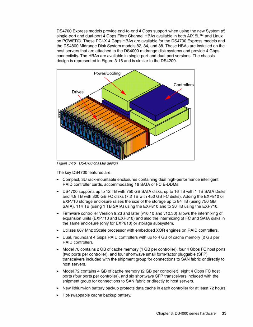
DS4700 Express models provide end-to-end 4 Gbps support when using the new System p5 single-port and dual-port 4 Gbps Fibre Channel HBAs available in both AIX 5L™ and Linux on POWER®. These PCI-X 4 Gbps HBAs are available for the DS4700 Express models and the DS4800 Midrange Disk System models 82, 84, and 88. These HBAs are installed on the host servers that are attached to the DS4000 midrange disk systems and provide 4 Gbps connectivity. The HBAs are available in single-port and dual-port versions. The chassis design is represented in Figure 3-16 and is similar to the DS4200.
Figure 3-16 DS4700 chassis design
The key DS4700 features are:
� Compact, 3U rack-mountable enclosures containing dual high-performance intelligent RAID controller cards, accommodating 16 SATA or FC E-DDMs.
� DS4700 supports up to 12 TB with 750 GB SATA disks, up to 16 TB with 1 TB SATA Disks and 4.8 TB with 300 GB FC disks (7.2 TB with 450 GB FC disks). Adding the EXP810 or EXP710 storage enclosure raises the size of the storage up to 84 TB (using 750 GB SATA), 114 TB (using 1 TB SATA) using the EXP810 and to 30 TB using the EXP710.
� Firmware controller Version 9.23 and later (v10.10 and v10.30) allows the intermixing of expansion units (EXP710 and EXP810) and also the intermixing of FC and SATA disks in the same enclosure (only for EXP810) or storage subsystem.
� Utilizes 667 Mhz xScale processor with embedded XOR engines on RAID controllers.
� Dual, redundant 4 Gbps RAID controllers with up to 4 GB of cache memory (2 GB per RAID controller).
� Model 70 contains 2 GB of cache memory (1 GB per controller), four 4 Gbps FC host ports (two ports per controller), and four shortwave small form-factor pluggable (SFP) transceivers included with the shipment group for connections to SAN fabric or directly to host servers.
� Model 72 contains 4 GB of cache memory (2 GB per controller), eight 4 Gbps FC host ports (four ports per controller), and six shortwave SFP transceivers included with the shipment group for connections to SAN fabric or directly to host servers.
� New lithium-ion battery backup protects data cache in each controller for at least 72 hours.
� Hot-swappable cache backup battery.
Drives
Power/Cooling
Controllers
Chapter 3. DS4000 series hardware 33

� Redundant, hot-swappable power supplies and fans.
� Supports RAID-0, RAID-1, RAID-3, RAID-5, RAID-6, and RAID-10 (RAID-1+0).
� Switched loop architecture that supports two dual redundant FC disk loops.
� Auto negotiates 1, 2, or 4 Gbps host connection speeds.
� Supports Global Hot Spare.
� Host-side connections support Fibre Channel switched, loop, or direct connections.
� Redundant drive-side connections designed to avoid any single point of failure and maintain high availability.
� Supports up to six EXP810 (each EXP810 has 16 disk bays) to attach up to 112 FC disks (additional licenses required).
� The following disks are supported:
– 2 Gbps FC: 15 Krpm, 146 GB/73 GB/36 GB
– 2 Gbps FC: 10 Krpm, 300 GB/146 GB/73 GB
– 4 Gbps FC: 15 Krpm, 146 GB/73 GB/36 GB
– 4 Gbps FC: 15 Krpm 450 GB
– 4 Gbps SATA: 7200 rpm, 500 GB E-DDM, 750 GB E-DDM, 1 TB E-DDM (SATA and FC cannot be intermixed in the same enclosure.)
� Supports shortwave Fibre Channel 4 Gbps host attachment (on initial release).
� Multiple heterogeneous server and operating system support (host kits required).
� Both models 70 and 72 have selectable storage partitions up to 128.
� Powerful on demand functions: Dynamic volume expansion, dynamic capacity expansion, and dynamic RAID level migration, which allow users to modify storage configurations on-the-fly without incurring any downtime.
� DS4000 Service Alert to notify IBM in case of problems or failures.
� New dual 10/100 Ethernet for out-of-band management to separate out-of-band management from service diagnostics for each controller.
� FlashCopy, VolumeCopy, and Enhanced Remote Mirroring (premium features).
� DS4000Storage Manger: SM Version 10.10 and 10.30
� Controller firmware: Version 7.15.
3.2.2 DS4700 front viewThe front section of the DS4700 shows the 16 pre-installed drive bays of hot-swap disk drives (Figure 3-17).
Figure 3-17 DS4700 front view
34 IBM System Storage DS4000 and Storage Manager V10.30

The hot-swap features of the DS4700 enable you to remove and replace the Fibre Channel or SATA hard disk drives without turning off the storage expansion enclosure. You can maintain the availability of your system while a hot-swap device is removed, installed, or replaced.
Each drive and carrier assembly is called a drive CRU. Install drive CRUs in the 16 drive bays on the front of the storage expansion enclosure from the rightmost slot (slot 16) to the leftmost slot (slot 1).
Several LED indicators and the FC Link speed selector are also visible from the front of the storage unit. They are described in 3.2.4, “DS4700: Speed selector and LED indicator lights” on page 38.
3.2.3 DS4700 rear viewThe rear of the DS4700 shows the two hot-swappable and redundant RAID controllers. The left controller is labeled controller A and the right controller is labeled controller B. Note that controller A is positioned upside-down relative to controller B. It is important to keep this in mind when connecting the back-end ports to hosts and drive-side expansion enclosures. The redundant power supply fan units are also visible from the back of the DS4700 (Figure 3-18).
Figure 3-18 DS4700 rear view (may look a little different on the GA product)
Chapter 3. DS4000 series hardware 35
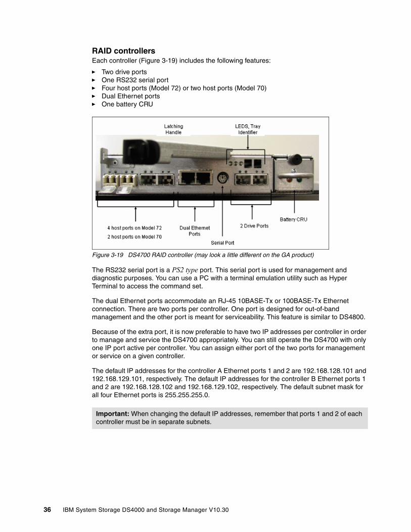
RAID controllersEach controller (Figure 3-19) includes the following features:
� Two drive ports� One RS232 serial port� Four host ports (Model 72) or two host ports (Model 70)� Dual Ethernet ports� One battery CRU
Figure 3-19 DS4700 RAID controller (may look a little different on the GA product)
The RS232 serial port is a PS2 type port. This serial port is used for management and diagnostic purposes. You can use a PC with a terminal emulation utility such as Hyper Terminal to access the command set.
The dual Ethernet ports accommodate an RJ-45 10BASE-Tx or 100BASE-Tx Ethernet connection. There are two ports per controller. One port is designed for out-of-band management and the other port is meant for serviceability. This feature is similar to DS4800.
Because of the extra port, it is now preferable to have two IP addresses per controller in order to manage and service the DS4700 appropriately. You can still operate the DS4700 with only one IP port active per controller. You can assign either port of the two ports for management or service on a given controller.
The default IP addresses for the controller A Ethernet ports 1 and 2 are 192.168.128.101 and 192.168.129.101, respectively. The default IP addresses for the controller B Ethernet ports 1 and 2 are 192.168.128.102 and 192.168.129.102, respectively. The default subnet mask for all four Ethernet ports is 255.255.255.0.
Important: When changing the default IP addresses, remember that ports 1 and 2 of each controller must be in separate subnets.
36 IBM System Storage DS4000 and Storage Manager V10.30
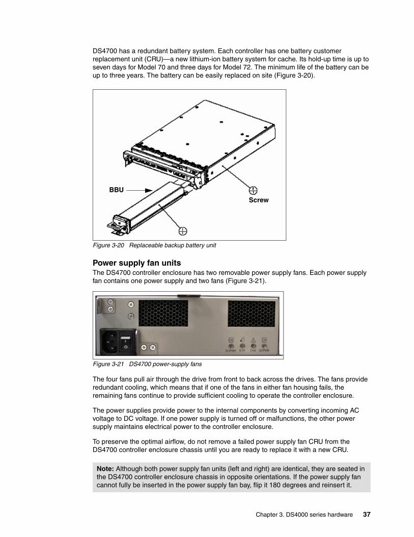
DS4700 has a redundant battery system. Each controller has one battery customer replacement unit (CRU)—a new lithium-ion battery system for cache. Its hold-up time is up to seven days for Model 70 and three days for Model 72. The minimum life of the battery can be up to three years. The battery can be easily replaced on site (Figure 3-20).
Figure 3-20 Replaceable backup battery unit
Power supply fan unitsThe DS4700 controller enclosure has two removable power supply fans. Each power supply fan contains one power supply and two fans (Figure 3-21).
Figure 3-21 DS4700 power-supply fans
The four fans pull air through the drive from front to back across the drives. The fans provide redundant cooling, which means that if one of the fans in either fan housing fails, the remaining fans continue to provide sufficient cooling to operate the controller enclosure.
The power supplies provide power to the internal components by converting incoming AC voltage to DC voltage. If one power supply is turned off or malfunctions, the other power supply maintains electrical power to the controller enclosure.
To preserve the optimal airflow, do not remove a failed power supply fan CRU from the DS4700 controller enclosure chassis until you are ready to replace it with a new CRU.
Note: Although both power supply fan units (left and right) are identical, they are seated in the DS4700 controller enclosure chassis in opposite orientations. If the power supply fan cannot fully be inserted in the power supply fan bay, flip it 180 degrees and reinsert it.
BBU
Screw
Chapter 3. DS4000 series hardware 37

3.2.4 DS4700: Speed selector and LED indicator lightsLED indicator lights allow the DS4700 to communicate with the user. There are four main components with LEDs:
� Front panel� RAID controllers� Battery� Power supply fans
Front panel LEDs and FC link speed selectorFigure 3-22 shows the DS4700 front panel and its LED indicator lights.
Figure 3-22 DS4700 front panel LEDS
Link speed selectorThe FC link speed selector is a physical switch that must be used to set the enclosure speed. It should be set to 2 Gbps if 2 Gbps drives are used. If it is set to 4 Gbps while 2 Gbps drives are used, the 2 Gbps drives will appear as bypassed drives in Storage Manager.
Because both drive channel pairs in the DS4700 connect to the same loop switch on each controller, it is not possible to support one drive channel pair at 4 Gbps and the other drive channel pair at 2 Gbps.
Front LEDsThey are:
� Locate LED (white or blue)
– On: Indicates storage subsystem locate.
– Off: This is the normal status.
� Service action allowed LED (blue)
– On: The service action can be performed on the component with no adverse consequences.
– Off: This is the normal status.
38 IBM System Storage DS4000 and Storage Manager V10.30
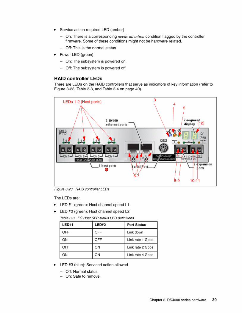
� Service action required LED (amber)
– On: There is a corresponding needs attention condition flagged by the controller firmware. Some of these conditions might not be hardware related.
– Off: This is the normal status.
� Power LED (green)
– On: The subsystem is powered on.
– Off: The subsystem is powered off.
RAID controller LEDsThere are LEDs on the RAID controllers that serve as indicators of key information (refer to Figure 3-23, Table 3-3, and Table 3-4 on page 40).
Figure 3-23 RAID controller LEDs
The LEDs are:
� LED #1 (green): Host channel speed L1
� LED #2 (green): Host channel speed L2
Table 3-3 FC Host SFP status LED definitions
� LED #3 (blue): Serviced action allowed
– Off: Normal status.– On: Safe to remove.
LED#1 LED#2 Port Status
OFF OFF Link down
ON OFF Link rate 1 Gbps
OFF ON Link rate 2 Gbps
ON ON Link rate 4 Gbps
LEDs 1-2 (Host ports) 3
8-9 10-11
54
(12)
6-7
Chapter 3. DS4000 series hardware 39

� LED #4 (amber): Need attention
– Off: Normal status.– On: Controller needs attention (controller fault or controller is offline).
� LED #5 (green): Caching active
– On: Data in cache.– Off: No data in cache.
� LED #6 (green): Ethernet link speed
– Off: 10BASE-T.– On: 100BASE-T.
� LED #7 (green): Ethernet link activity
– Off: No link established.– On: Link established.
� LED #8 (amber): Drive channel bypass
– Off: Normal status.– On: Drive port bypass problem.
� LED #9 (green): Drive channel speed L1
� LED #10 (green): Drive channel speed L2
Table 3-4 FC DISK expansion port SFP LED definitions
� LED #11 (Amber): Drive channel bypass
– Off: Normal status– On: Drive port bypass problem
� LED #12 (green/yellow): Numeric display (enclosure ID/diagnostic display)
– Diagnostic LED: On = Diagnostic code is displayed.– Diagnostic LED: Flashing = Controller ID is displayed.
LED#9 LED#10 Port status
OFF OFF Link down
ON OFF Reserved
OFF ON Link rate 2 Gbps
ON ON Link rate 4 Gbps
40 IBM System Storage DS4000 and Storage Manager V10.30

Battery LEDsEach DS4700 RAID controller has its own battery. There are three LED indicator lights on each battery:
� Service action allowed (blue)
– Off: Normal status.– On: Safe to remove.
� Battery charging (green)
– On: Battery charged and ready.– Blinking: Battery is charging.– Off: Battery is faulted, discharged, or missing.
� Needs attention or service action required (amber)
– Off: Normal status.– On: Controller firmware or hardware requires attention.
Figure 3-24 Battery LEDs
Power supply fansEach power supply fan (Figure 3-25) contains one power supply and two fans.
Figure 3-25 Power supply fan LEDs
Battery Charging(Green)
Service Action Required(Amber - Fault)
Service Action Allowed(Blue)
Chapter 3. DS4000 series hardware 41
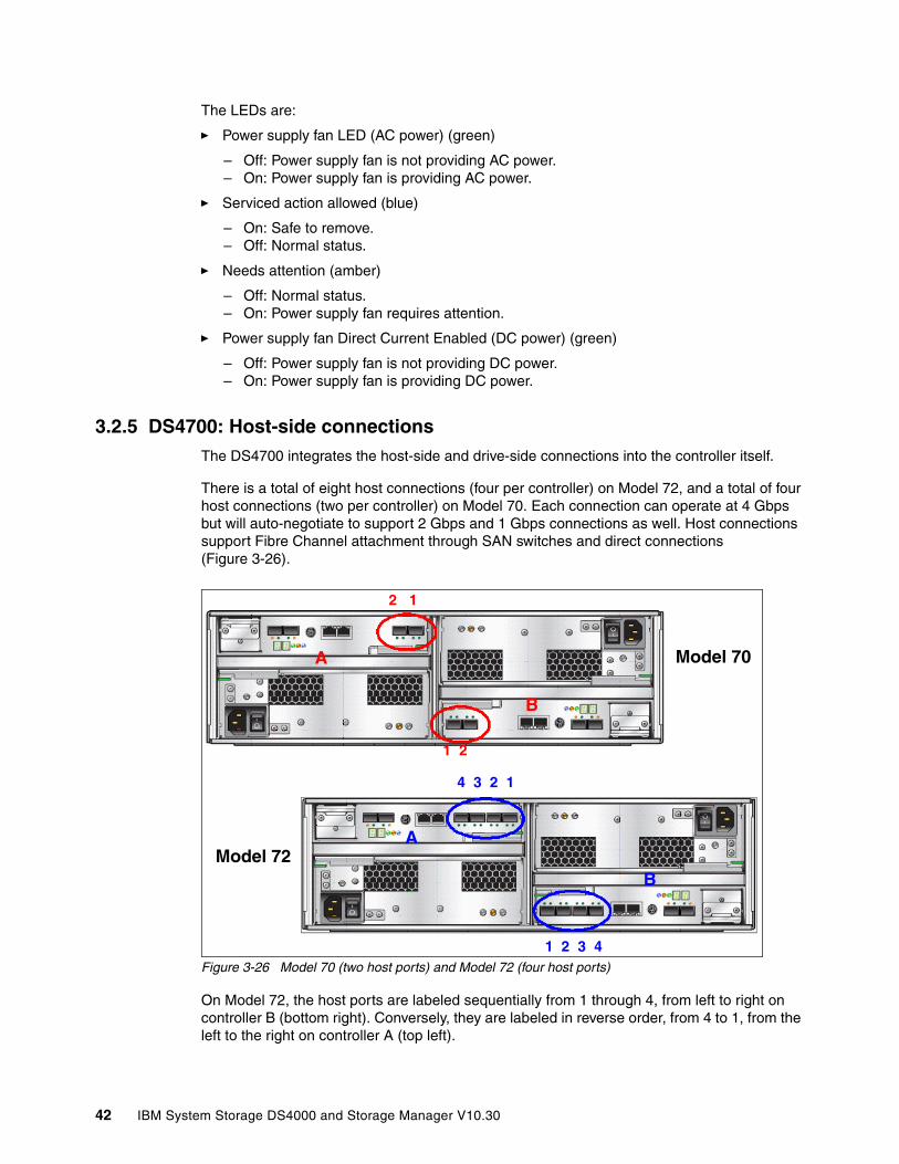
The LEDs are:
� Power supply fan LED (AC power) (green)
– Off: Power supply fan is not providing AC power.– On: Power supply fan is providing AC power.
� Serviced action allowed (blue)
– On: Safe to remove.– Off: Normal status.
� Needs attention (amber)
– Off: Normal status.– On: Power supply fan requires attention.
� Power supply fan Direct Current Enabled (DC power) (green)
– Off: Power supply fan is not providing DC power.– On: Power supply fan is providing DC power.
3.2.5 DS4700: Host-side connectionsThe DS4700 integrates the host-side and drive-side connections into the controller itself.
There is a total of eight host connections (four per controller) on Model 72, and a total of four host connections (two per controller) on Model 70. Each connection can operate at 4 Gbps but will auto-negotiate to support 2 Gbps and 1 Gbps connections as well. Host connections support Fibre Channel attachment through SAN switches and direct connections (Figure 3-26).
Figure 3-26 Model 70 (two host ports) and Model 72 (four host ports)
On Model 72, the host ports are labeled sequentially from 1 through 4, from left to right on controller B (bottom right). Conversely, they are labeled in reverse order, from 4 to 1, from the left to the right on controller A (top left).
2 1
4 3 2 1
1 2 3 4
1 2
B
A
A
B
Model 70
Model 72
42 IBM System Storage DS4000 and Storage Manager V10.30
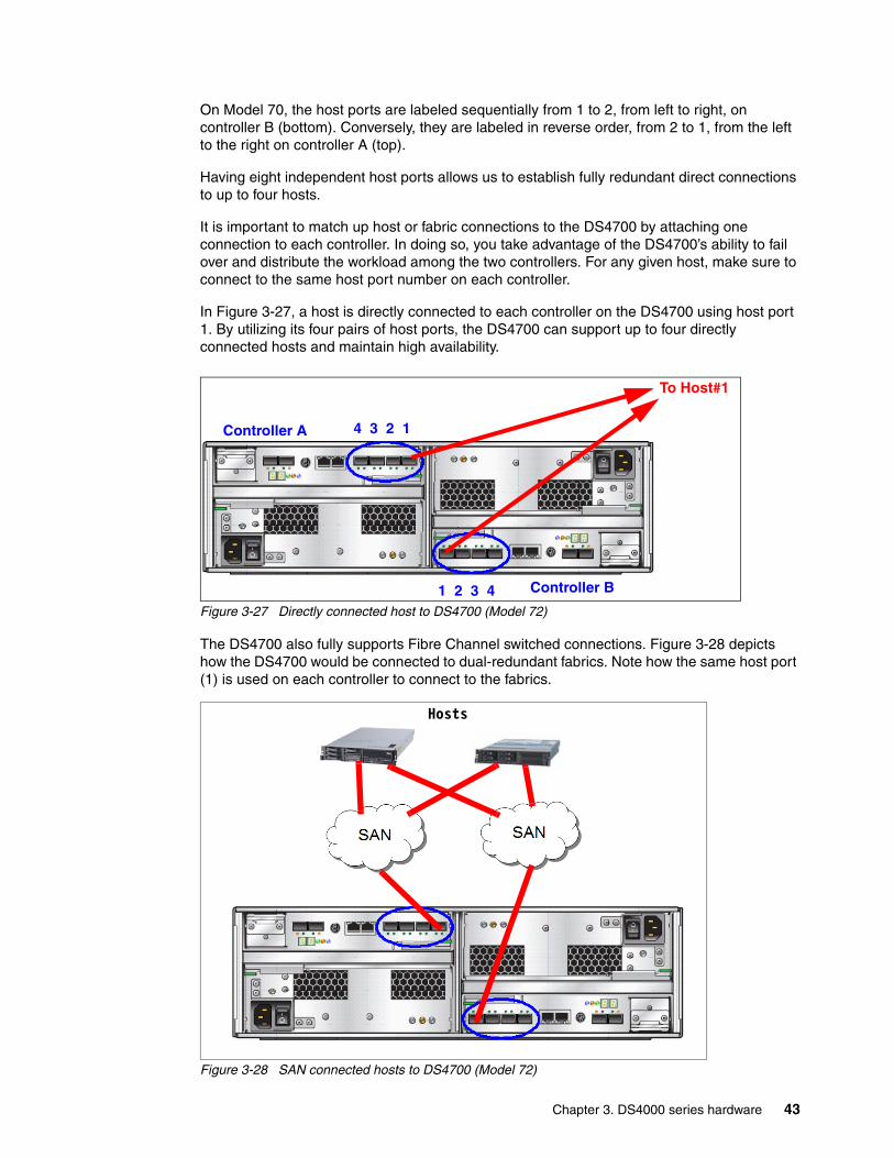
On Model 70, the host ports are labeled sequentially from 1 to 2, from left to right, on controller B (bottom). Conversely, they are labeled in reverse order, from 2 to 1, from the left to the right on controller A (top).
Having eight independent host ports allows us to establish fully redundant direct connections to up to four hosts.
It is important to match up host or fabric connections to the DS4700 by attaching one connection to each controller. In doing so, you take advantage of the DS4700’s ability to fail over and distribute the workload among the two controllers. For any given host, make sure to connect to the same host port number on each controller.
In Figure 3-27, a host is directly connected to each controller on the DS4700 using host port 1. By utilizing its four pairs of host ports, the DS4700 can support up to four directly connected hosts and maintain high availability.
Figure 3-27 Directly connected host to DS4700 (Model 72)
The DS4700 also fully supports Fibre Channel switched connections. Figure 3-28 depicts how the DS4700 would be connected to dual-redundant fabrics. Note how the same host port (1) is used on each controller to connect to the fabrics.
Figure 3-28 SAN connected hosts to DS4700 (Model 72)
4 3 2 1
1 2 3 4
Controller A
Controller B
To Host#1
Hosts
Chapter 3. DS4000 series hardware 43

3.2.6 DS4700: Drive-side connectionsThe drive-side connections operate at up to 4 Gbps (2 Gbps or 4 Gbps) and allow connection of disk expansion enclosures to the base controller unit.
There are four total drive-side connections (two on each controller). The numbering scheme for the drive connections is structured like the host connections. Since controller A is upside-down, the left-to-right numbering of the drive connection ports is reversed. This means that controller A is numbered left to right, 2 to 1, in reverse sequential order. Controller B is numbered left to right, 1 to 2, in forward sequential order, as shown on Figure 3-29.
Figure 3-29 Drive-side connection of DS4700
The DS4700 supports two dual-redundant drive channel pairs on which to place expansion enclosures. Ports 1 and 2 on each controller are grouped together in one drive channel group. If you look at the rear of a properly installed DS4700, you will see them clearly labeled. In this case, ports 2 and 1 on controller A are channel group 1. Ports 1 and 2 on controller B are channel group 2. The two ports on each drive channel group must run at the same speed. There is no blocking between the two adjacent ports at the drive channel group level. It is best to spread out the drive-side channel pairs among the channel groups to ensure maximum availability.
A drive-side channel pair is made up of one port from each controller, going left to right. For instance, drive channel pair 1 is composed of controller A, port 1, and controller B, port 2. Drive channel pair 2 is composed of controller A, port 2, and controller B, port 1.
Drive Connections A2 1
Drive Connections B
Channel Group 1
Channel Group 21 2
44 IBM System Storage DS4000 and Storage Manager V10.30
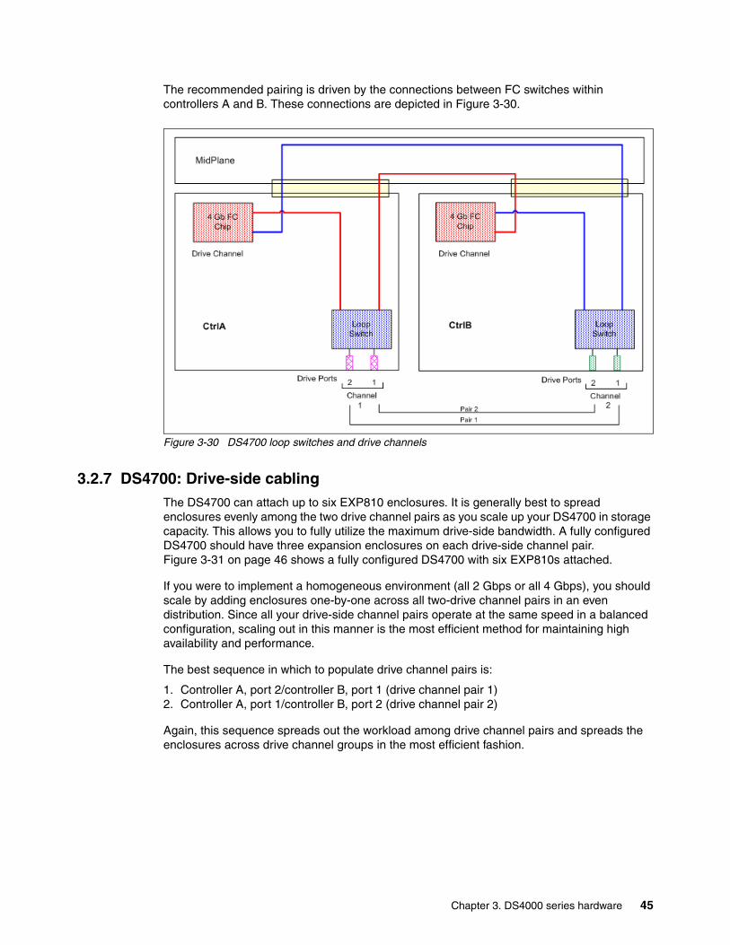
The recommended pairing is driven by the connections between FC switches within controllers A and B. These connections are depicted in Figure 3-30.
Figure 3-30 DS4700 loop switches and drive channels
3.2.7 DS4700: Drive-side cablingThe DS4700 can attach up to six EXP810 enclosures. It is generally best to spread enclosures evenly among the two drive channel pairs as you scale up your DS4700 in storage capacity. This allows you to fully utilize the maximum drive-side bandwidth. A fully configured DS4700 should have three expansion enclosures on each drive-side channel pair. Figure 3-31 on page 46 shows a fully configured DS4700 with six EXP810s attached.
If you were to implement a homogeneous environment (all 2 Gbps or all 4 Gbps), you should scale by adding enclosures one-by-one across all two-drive channel pairs in an even distribution. Since all your drive-side channel pairs operate at the same speed in a balanced configuration, scaling out in this manner is the most efficient method for maintaining high availability and performance.
The best sequence in which to populate drive channel pairs is:
1. Controller A, port 2/controller B, port 1 (drive channel pair 1)2. Controller A, port 1/controller B, port 2 (drive channel pair 2)
Again, this sequence spreads out the workload among drive channel pairs and spreads the enclosures across drive channel groups in the most efficient fashion.
Chapter 3. DS4000 series hardware 45
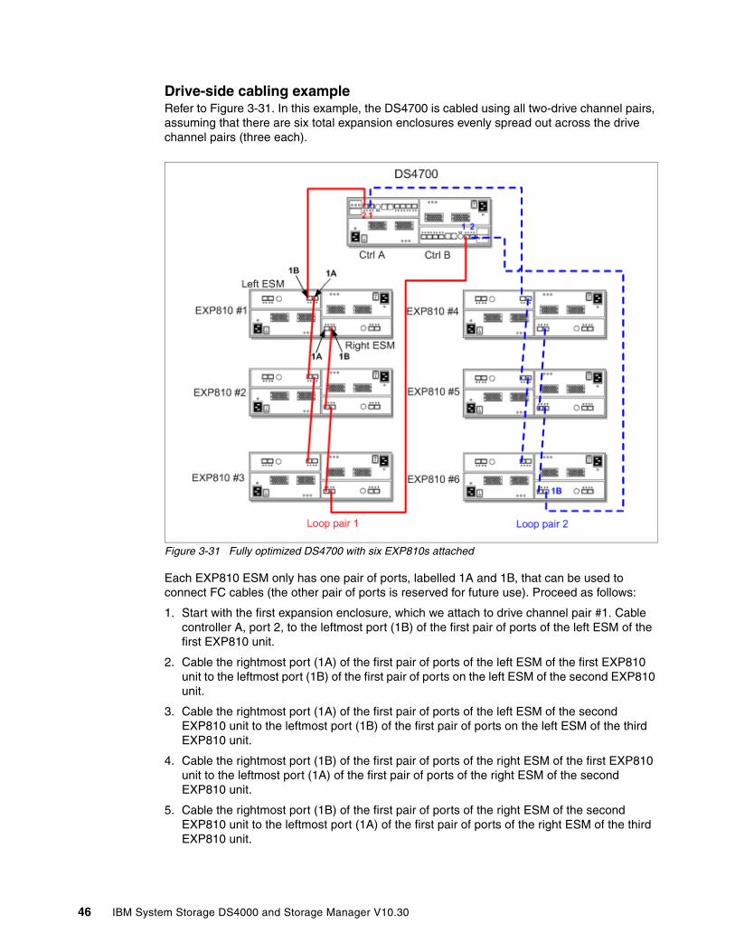
Drive-side cabling exampleRefer to Figure 3-31. In this example, the DS4700 is cabled using all two-drive channel pairs, assuming that there are six total expansion enclosures evenly spread out across the drive channel pairs (three each).
Figure 3-31 Fully optimized DS4700 with six EXP810s attached
Each EXP810 ESM only has one pair of ports, labelled 1A and 1B, that can be used to connect FC cables (the other pair of ports is reserved for future use). Proceed as follows:
1. Start with the first expansion enclosure, which we attach to drive channel pair #1. Cable controller A, port 2, to the leftmost port (1B) of the first pair of ports of the left ESM of the first EXP810 unit.
2. Cable the rightmost port (1A) of the first pair of ports of the left ESM of the first EXP810 unit to the leftmost port (1B) of the first pair of ports on the left ESM of the second EXP810 unit.
3. Cable the rightmost port (1A) of the first pair of ports of the left ESM of the second EXP810 unit to the leftmost port (1B) of the first pair of ports on the left ESM of the third EXP810 unit.
4. Cable the rightmost port (1B) of the first pair of ports of the right ESM of the first EXP810 unit to the leftmost port (1A) of the first pair of ports of the right ESM of the second EXP810 unit.
5. Cable the rightmost port (1B) of the first pair of ports of the right ESM of the second EXP810 unit to the leftmost port (1A) of the first pair of ports of the right ESM of the third EXP810 unit.
46 IBM System Storage DS4000 and Storage Manager V10.30
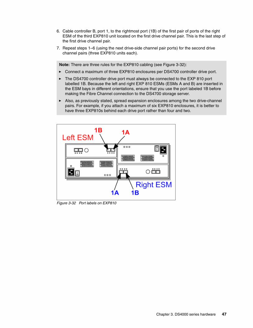
6. Cable controller B, port 1, to the rightmost port (1B) of the first pair of ports of the right ESM of the third EXP810 unit located on the first drive channel pair. This is the last step of the first drive channel pair.
7. Repeat steps 1–6 (using the next drive-side channel pair ports) for the second drive channel pairs (three EXP810 units each).
Figure 3-32 Port labels on EXP810
Note: There are three rules for the EXP810 cabling (see Figure 3-32):
� Connect a maximum of three EXP810 enclosures per DS4700 controller drive port.
� The DS4700 controller drive port must always be connected to the EXP 810 port labelled 1B. Because the left and right EXP 810 ESMs (ESMs A and B) are inserted in the ESM bays in different orientations, ensure that you use the port labeled 1B before making the Fibre Channel connection to the DS4700 storage server.
� Also, as previously stated, spread expansion enclosures among the two drive-channel pairs. For example, if you attach a maximum of six EXP810 enclosures, it is better to have three EXP810s behind each drive port rather than four and two.
Chapter 3. DS4000 series hardware 47
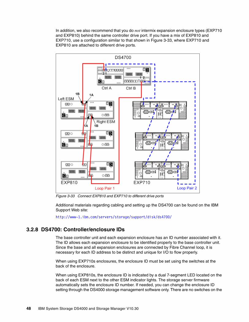
In addition, we also recommend that you do not intermix expansion enclosure types (EXP710 and EXP810) behind the same controller drive port. If you have a mix of EXP810 and EXP710, use a configuration similar to that shown in Figure 3-33, where EXP710 and EXP810 are attached to different drive ports.
Figure 3-33 Connect EXP810 and EXP710 to different drive ports
Additional materials regarding cabling and setting up the DS4700 can be found on the IBM Support Web site:
http://www-1.ibm.com/servers/storage/support/disk/ds4700/
3.2.8 DS4700: Controller/enclosure IDsThe base controller unit and each expansion enclosure has an ID number associated with it. The ID allows each expansion enclosure to be identified properly to the base controller unit. Since the base and all expansion enclosures are connected by Fibre Channel loop, it is necessary for each ID address to be distinct and unique for I/O to flow properly.
When using EXP710s enclosures, the enclosure ID must be set using the switches at the back of the enclosure.
When using EXP810s, the enclosure ID is indicated by a dual 7-segment LED located on the back of each ESM next to the other ESM indicator lights. The storage server firmware automatically sets the enclosure ID number. If needed, you can change the enclosure ID setting through the DS4000 storage management software only. There are no switches on the
48 IBM System Storage DS4000 and Storage Manager V10.30

EXP810 chassis to manually set the enclosure ID. Both ESM enclosure ID numbers will be identical under normal operating conditions.
With DS4000 Storage Manager 9.16 and later the DS4700 base controller ID can also be adjusted through the Storage Manager client software. The base controller ID is shown on the two digital displays at the rear of the controller units (Figure 3-34).
Figure 3-34 Base controller ID LEDs
On the DS4700, the dual 7-segment displays are used to display the enclosure ID, but also error codes. When the lower digit decimal point (DP) is on, it means that an error code is displayed instead of the enclosure ID. Note that although the controllers are upside down relative to each other, both controllers display the same orientation.
3.2.9 DS4700: Physical/environmental specificationsThis section information describes the DS4700 storage server’s physical and environmental specifications.
Physical specificationsThese are:
� Height: 12.95 cm (5.1 in.)� Width: 48.26 cm (19.00 in.)� Depth: 57.15 cm (22.5 in.)� Weight (max): 40 kg (88 lb.)
Operating environmentThis is:
� Temperature
– 10° to 35°C (50° to 95°F) at 0 to 914 m (0 to 3,000 ft.)– 10° to 32°C (50° to 90°F) at 914 to 2,133 m (3,000 to 7,000 ft.)
� Relative humidity: 8–80%
� Electrical power (per power supply, system rating):
– Voltage range: 100 to 240 V ac– Power: 600 watts– Frequency: 50/60 Hz
� Heat dissipation: 1300 BTU per hour
� Noise level (normal operation): 6.8 bels
Base Controller LEDs
Chapter 3. DS4000 series hardware 49

3.3 IBM System Storage DS4800 storage serverThe IBM System Storage DS4800 storage server truly represents a breakthrough disk storage solution and is designed to handle the most rigorous customer workloads in small and large enterprises alike. Offering performance up to 550,000+ cache-based IOPS and the first IBM 4 Gbps storage solution, the DS4800 offers enterprise-class performance and availability but still maintains the ease-of-use and functionality that users have come to expect with the DS4000 family. With the ability to hold up to 67.2 TB of FC disk physical capacity or 224 TB of SATA disk physical capacity, the DS4800 can be customized for both performance-oriented and capacity-oriented storage solutions (Figure 3-35).
Refer to the IBM Support Web site for specific model-related information:
http://www.ibm.com/servers/storage/support/disk/ds4800/index.html
Figure 3-35 DS4800 storage server
3.3.1 DS4800 featuresThe following four models are available:
� 1815-80A� 1815-82A� 1815-84A� 1815-88A
The 1825-80A and 1815-82A come with 4 GB of total cache (although Model 80A is lower in performance than Model 82A). The 1815-84A has 8 GB of total cache and 1815-88A has 16 GB of total cache.
Models 1815-80A, 1815-82A, 1815-84A, and 1815-88A have these features:
� Compact 4U rack-mountable enclosure.
� Features Intel Xeon® 2.4 GHz processor.
� Utilizes next-generation XOR engines on RAID controllers.
� Dual, redundant 4 Gbps RAID controllers with up to 8 GB of cache memory (4 GB per RAID controller).
� New lithium-ion battery backup protects data cache in each controller for at least 72 hours.
� Hot-swappable cache backup battery.
� Redundant, hot-swappable power supplies and fans.
� New hot-swappable midplane via an interconnect module.
� Supports RAID-0, RAID-1, RAID-3, RAID-5, and RAID-10 (RAID-1+0).
50 IBM System Storage DS4000 and Storage Manager V10.30

� Supports RAID-1 and 10 dedicated mirrored drive pairs configuration.
� Supports Global Hot Spare.
� Supports eight 4 Gbps host-side connections for two controllers. Each controller is assigned four connections. Four host-side connections total are standard, with the option of adding four more.
� Host-side connections support Fibre Channel Switched, Loop, or Direct Connections.
� Supports eight 4 Gbps drive-side connections for two controllers. This allows a total of eight drive channel pairs (four dual-redundant drive channel pairs) to be implemented to support expansion enclosure additions. (Note that ports are paired into channels for a total of four channels, and FC loop restrictions, as to number of devices, apply to an entire channel).
� Redundant drive-side connections designed to avoid any single-point of failure and maintain high availability.
� New utilization of four dual-redundant pairs (versus two in the previous DS4000s) allows the optimization of back-end bandwidth (four times more) and performance.
� Supports up to 16 EXP100 SATA-only enclosures for a total of 224 disks. This allows you to install up to 112 TB of raw capacity with 500 GB SATA disks or 224 TB of raw capacity if we use a 1 TB SATA drive.
� Supports up to 16 EXP710 FC-only enclosures for a total of 224 disks. This allows you to install up to 67.2 TB of raw capacity with 300 GB FC disks.
� Supports up to 14 EXP810 enclosures for a total of 224 disks. This allows you to install up to 67.2 TB of raw capacity with 300 GB FC disks, up to 168 TB using the 750 GB SATA E-DDM drives, or up to 224 TB using 1 TB SATA E-DDM drives.
� Fully supports Fibre Channel/SATA intermix (premium feature) by allowing the simultaneous usage of SATA and Fibre Channel behind one DS4800 controller, allowing user flexibility and increased storage capacity utilization.
� Supports up to 512 host storage partitions.
� Supports shortwave Fibre Channel 4 Gbps host attachment.
� Multiple heterogeneous server and operating system support (host kits required).
� Powerful on demand functions: Dynamic volume expansion, dynamic capacity expansion, and dynamic RAID level migration, which allow users to modify storage configurations on-the-fly without incurring any downtime.
� DS4000 Remote Service Manager to notify IBM in case of an issue.
� New dual 10/100 Ethernet for out-of-band management to separate out-of-band management from service diagnostics for each controller.
� FlashCopy (premium feature).
� VolumeCopy (premium feature).
� Remote Volume Mirroring: Metro Mirror, Global Mirror, Global Copy (premium features).
� Enhanced performance (premium feature with firmware starting with Version 7.10) lets you enable higher performance and a low-performance tier DS4800 Model 80 only. (The DS4800 Model 80 is configured to be either a high-performance tier or low-performance tier subsystem during manufacturing.) Refer to 4.3.13, “Enhanced performance feature” on page 175, for details.
Chapter 3. DS4000 series hardware 51
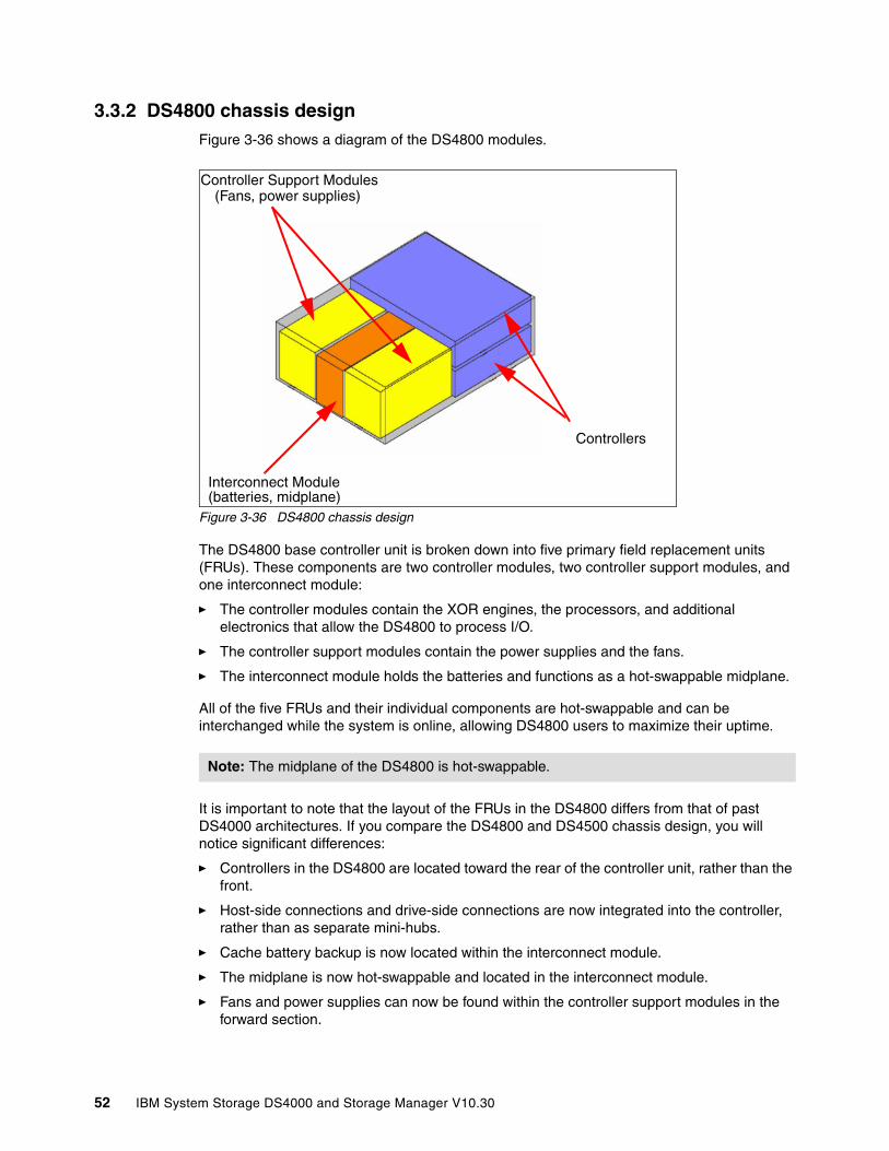
3.3.2 DS4800 chassis designFigure 3-36 shows a diagram of the DS4800 modules.
Figure 3-36 DS4800 chassis design
The DS4800 base controller unit is broken down into five primary field replacement units (FRUs). These components are two controller modules, two controller support modules, and one interconnect module:
� The controller modules contain the XOR engines, the processors, and additional electronics that allow the DS4800 to process I/O.
� The controller support modules contain the power supplies and the fans.
� The interconnect module holds the batteries and functions as a hot-swappable midplane.
All of the five FRUs and their individual components are hot-swappable and can be interchanged while the system is online, allowing DS4800 users to maximize their uptime.
It is important to note that the layout of the FRUs in the DS4800 differs from that of past DS4000 architectures. If you compare the DS4800 and DS4500 chassis design, you will notice significant differences:
� Controllers in the DS4800 are located toward the rear of the controller unit, rather than the front.
� Host-side connections and drive-side connections are now integrated into the controller, rather than as separate mini-hubs.
� Cache battery backup is now located within the interconnect module.
� The midplane is now hot-swappable and located in the interconnect module.
� Fans and power supplies can now be found within the controller support modules in the forward section.
Note: The midplane of the DS4800 is hot-swappable.
Interconnect Module
Controllers
Controller Support Modules(Fans, power supplies)
(batteries, midplane)
52 IBM System Storage DS4000 and Storage Manager V10.30
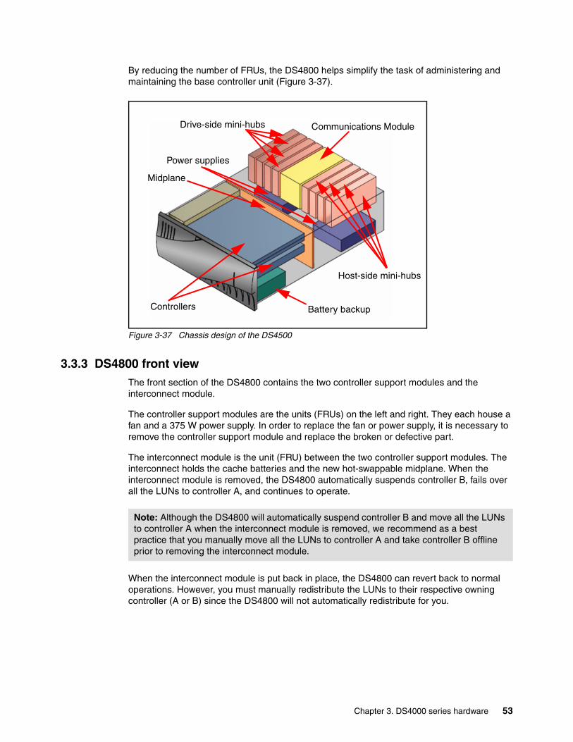
By reducing the number of FRUs, the DS4800 helps simplify the task of administering and maintaining the base controller unit (Figure 3-37).
Figure 3-37 Chassis design of the DS4500
3.3.3 DS4800 front viewThe front section of the DS4800 contains the two controller support modules and the interconnect module.
The controller support modules are the units (FRUs) on the left and right. They each house a fan and a 375 W power supply. In order to replace the fan or power supply, it is necessary to remove the controller support module and replace the broken or defective part.
The interconnect module is the unit (FRU) between the two controller support modules. The interconnect holds the cache batteries and the new hot-swappable midplane. When the interconnect module is removed, the DS4800 automatically suspends controller B, fails over all the LUNs to controller A, and continues to operate.
When the interconnect module is put back in place, the DS4800 can revert back to normal operations. However, you must manually redistribute the LUNs to their respective owning controller (A or B) since the DS4800 will not automatically redistribute for you.
Host-side mini-hubs
Controllers Battery backup
Communications Module
Midplane
Drive-side mini-hubs
Power supplies
Note: Although the DS4800 will automatically suspend controller B and move all the LUNs to controller A when the interconnect module is removed, we recommend as a best practice that you manually move all the LUNs to controller A and take controller B offline prior to removing the interconnect module.
Chapter 3. DS4000 series hardware 53
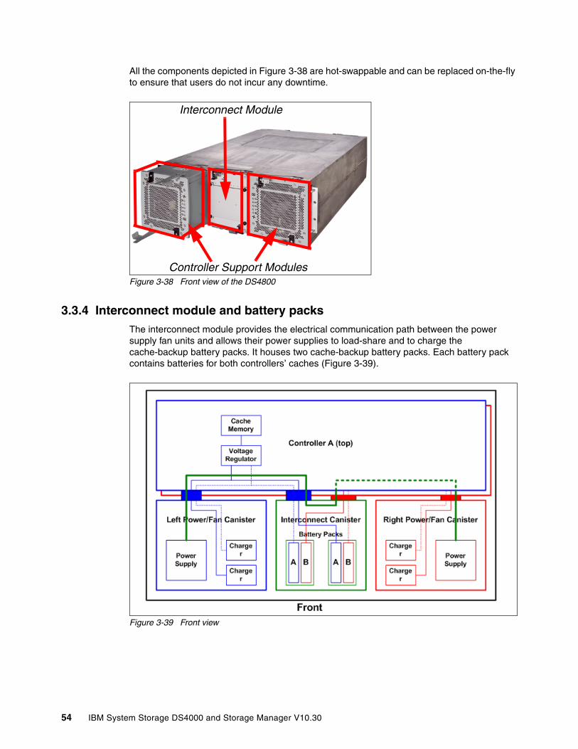
All the components depicted in Figure 3-38 are hot-swappable and can be replaced on-the-fly to ensure that users do not incur any downtime.
Figure 3-38 Front view of the DS4800
3.3.4 Interconnect module and battery packsThe interconnect module provides the electrical communication path between the power supply fan units and allows their power supplies to load-share and to charge the cache-backup battery packs. It houses two cache-backup battery packs. Each battery pack contains batteries for both controllers’ caches (Figure 3-39).
Figure 3-39 Front view
Controller Support Modules
Interconnect Module
54 IBM System Storage DS4000 and Storage Manager V10.30
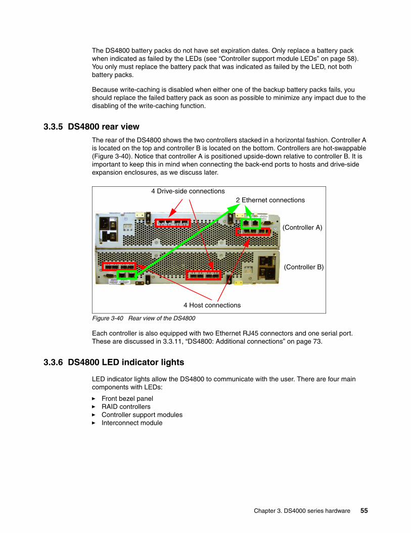
The DS4800 battery packs do not have set expiration dates. Only replace a battery pack when indicated as failed by the LEDs (see “Controller support module LEDs” on page 58). You only must replace the battery pack that was indicated as failed by the LED, not both battery packs.
Because write-caching is disabled when either one of the backup battery packs fails, you should replace the failed battery pack as soon as possible to minimize any impact due to the disabling of the write-caching function.
3.3.5 DS4800 rear viewThe rear of the DS4800 shows the two controllers stacked in a horizontal fashion. Controller A is located on the top and controller B is located on the bottom. Controllers are hot-swappable (Figure 3-40). Notice that controller A is positioned upside-down relative to controller B. It is important to keep this in mind when connecting the back-end ports to hosts and drive-side expansion enclosures, as we discuss later.
Figure 3-40 Rear view of the DS4800
Each controller is also equipped with two Ethernet RJ45 connectors and one serial port. These are discussed in 3.3.11, “DS4800: Additional connections” on page 73.
3.3.6 DS4800 LED indicator lights
LED indicator lights allow the DS4800 to communicate with the user. There are four main components with LEDs:
� Front bezel panel� RAID controllers� Controller support modules� Interconnect module
4 Drive-side connections
(Controller A)
4 Host connections
2 Ethernet connections
(Controller B)
Chapter 3. DS4000 series hardware 55
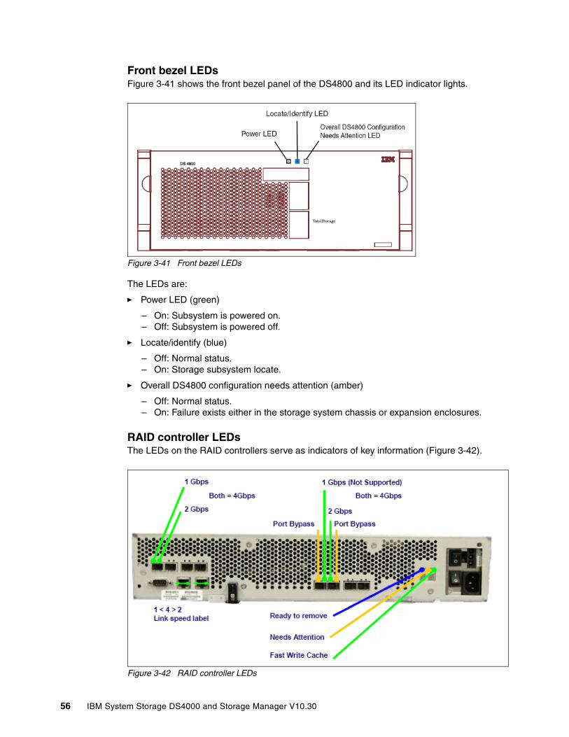
Front bezel LEDsFigure 3-41 shows the front bezel panel of the DS4800 and its LED indicator lights.
Figure 3-41 Front bezel LEDs
The LEDs are:
� Power LED (green)
– On: Subsystem is powered on.– Off: Subsystem is powered off.
� Locate/identify (blue)
– Off: Normal status.– On: Storage subsystem locate.
� Overall DS4800 configuration needs attention (amber)
– Off: Normal status.– On: Failure exists either in the storage system chassis or expansion enclosures.
RAID controller LEDsThe LEDs on the RAID controllers serve as indicators of key information (Figure 3-42).
Figure 3-42 RAID controller LEDs
56 IBM System Storage DS4000 and Storage Manager V10.30
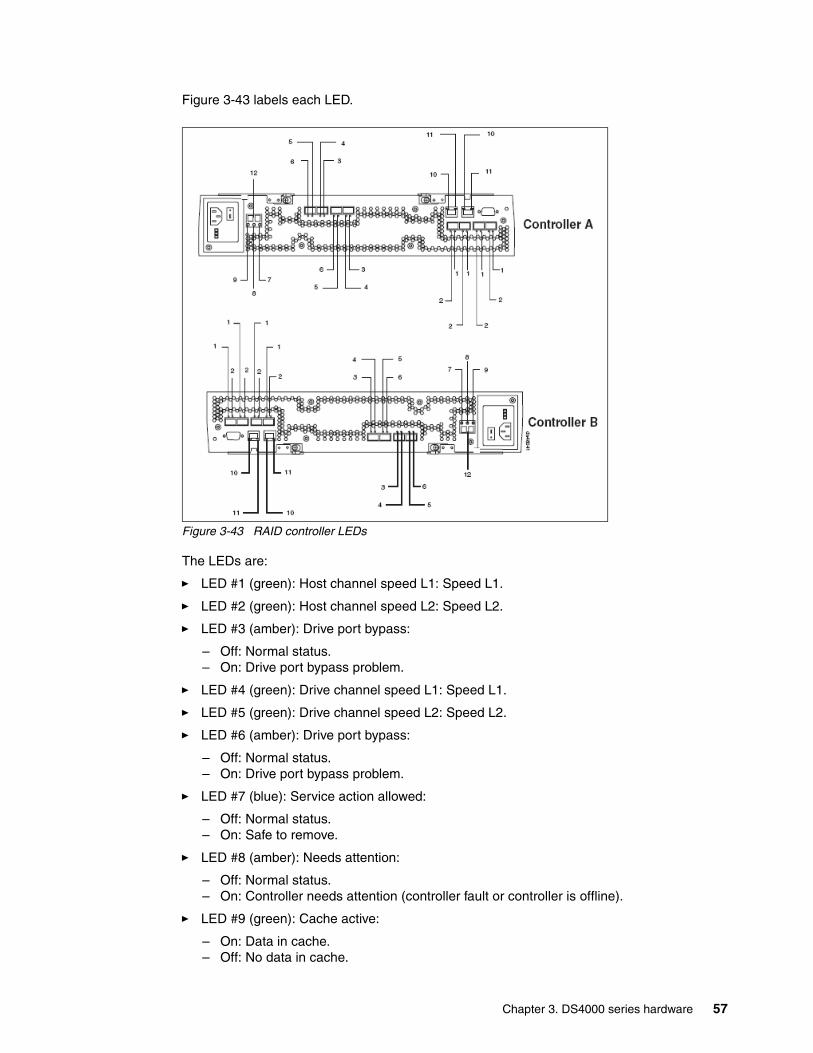
Figure 3-43 labels each LED.
Figure 3-43 RAID controller LEDs
The LEDs are:
� LED #1 (green): Host channel speed L1: Speed L1.
� LED #2 (green): Host channel speed L2: Speed L2.
� LED #3 (amber): Drive port bypass:
– Off: Normal status.– On: Drive port bypass problem.
� LED #4 (green): Drive channel speed L1: Speed L1.
� LED #5 (green): Drive channel speed L2: Speed L2.
� LED #6 (amber): Drive port bypass:
– Off: Normal status.– On: Drive port bypass problem.
� LED #7 (blue): Service action allowed:
– Off: Normal status.– On: Safe to remove.
� LED #8 (amber): Needs attention:
– Off: Normal status.– On: Controller needs attention (controller fault or controller is offline).
� LED #9 (green): Cache active:
– On: Data in cache.– Off: No data in cache.
Chapter 3. DS4000 series hardware 57
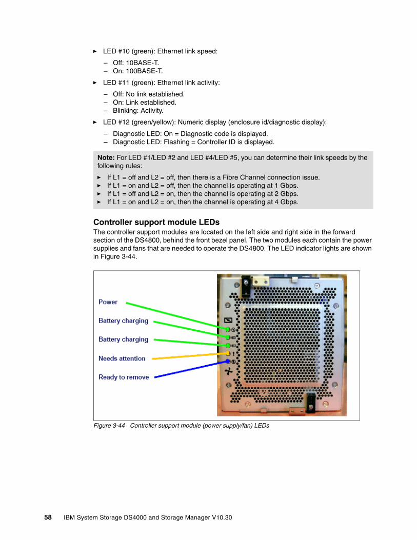
� LED #10 (green): Ethernet link speed:
– Off: 10BASE-T.– On: 100BASE-T.
� LED #11 (green): Ethernet link activity:
– Off: No link established.– On: Link established.– Blinking: Activity.
� LED #12 (green/yellow): Numeric display (enclosure id/diagnostic display):
– Diagnostic LED: On = Diagnostic code is displayed.– Diagnostic LED: Flashing = Controller ID is displayed.
Controller support module LEDsThe controller support modules are located on the left side and right side in the forward section of the DS4800, behind the front bezel panel. The two modules each contain the power supplies and fans that are needed to operate the DS4800. The LED indicator lights are shown in Figure 3-44.
Figure 3-44 Controller support module (power supply/fan) LEDs
Note: For LED #1/LED #2 and LED #4/LED #5, you can determine their link speeds by the following rules:
� If L1 = off and L2 = off, then there is a Fibre Channel connection issue.� If L1 = on and L2 = off, then the channel is operating at 1 Gbps.� If L1 = off and L2 = on, then the channel is operating at 2 Gbps.� If L1 = on and L2 = on, then the channel is operating at 4 Gbps.
58 IBM System Storage DS4000 and Storage Manager V10.30
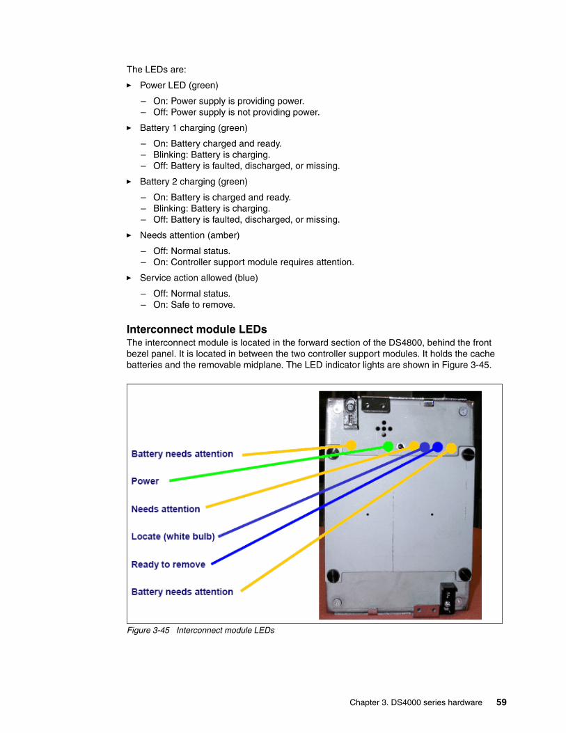
The LEDs are:
� Power LED (green)
– On: Power supply is providing power.– Off: Power supply is not providing power.
� Battery 1 charging (green)
– On: Battery charged and ready.– Blinking: Battery is charging.– Off: Battery is faulted, discharged, or missing.
� Battery 2 charging (green)
– On: Battery is charged and ready.– Blinking: Battery is charging.– Off: Battery is faulted, discharged, or missing.
� Needs attention (amber)
– Off: Normal status.– On: Controller support module requires attention.
� Service action allowed (blue)
– Off: Normal status.– On: Safe to remove.
Interconnect module LEDsThe interconnect module is located in the forward section of the DS4800, behind the front bezel panel. It is located in between the two controller support modules. It holds the cache batteries and the removable midplane. The LED indicator lights are shown in Figure 3-45.
Figure 3-45 Interconnect module LEDs
Chapter 3. DS4000 series hardware 59
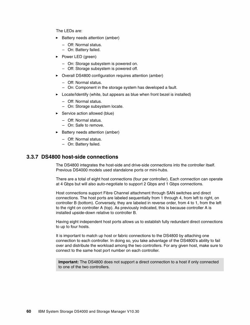
The LEDs are:
� Battery needs attention (amber)
– Off: Normal status.– On: Battery failed.
� Power LED (green)
– On: Storage subsystem is powered on.– Off: Storage subsystem is powered off.
� Overall DS4800 configuration requires attention (amber)
– Off: Normal status.– On: Component in the storage system has developed a fault.
� Locate/Identify (white, but appears as blue when front bezel is installed)
– Off: Normal status.– On: Storage subsystem locate.
� Service action allowed (blue)
– Off: Normal status.– On: Safe to remove.
� Battery needs attention (amber)
– Off: Normal status.– On: Battery failed.
3.3.7 DS4800 host-side connectionsThe DS4800 integrates the host-side and drive-side connections into the controller itself. Previous DS4000 models used standalone ports or mini-hubs.
There are a total of eight host connections (four per controller). Each connection can operate at 4 Gbps but will also auto-negotiate to support 2 Gbps and 1 Gbps connections.
Host connections support Fibre Channel attachment through SAN switches and direct connections. The host ports are labeled sequentially from 1 through 4, from left to right, on controller B (bottom). Conversely, they are labeled in reverse order, from 4 to 1, from the left to the right on controller A (top). As previously indicated, this is because controller A is installed upside-down relative to controller B.
Having eight independent host ports allows us to establish fully redundant direct connections to up to four hosts.
It is important to match up host or fabric connections to the DS4800 by attaching one connection to each controller. In doing so, you take advantage of the DS4800’s ability to fail over and distribute the workload among the two controllers. For any given host, make sure to connect to the same host port number on each controller.
Important: The DS4800 does not support a direct connection to a host if only connected to one of the two controllers.
60 IBM System Storage DS4000 and Storage Manager V10.30
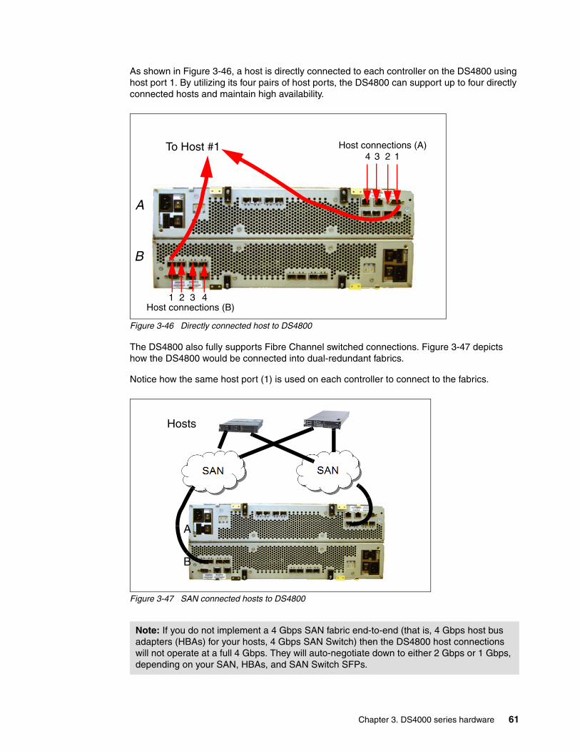
As shown in Figure 3-46, a host is directly connected to each controller on the DS4800 using host port 1. By utilizing its four pairs of host ports, the DS4800 can support up to four directly connected hosts and maintain high availability.
Figure 3-46 Directly connected host to DS4800
The DS4800 also fully supports Fibre Channel switched connections. Figure 3-47 depicts how the DS4800 would be connected into dual-redundant fabrics.
Notice how the same host port (1) is used on each controller to connect to the fabrics.
Figure 3-47 SAN connected hosts to DS4800
Note: If you do not implement a 4 Gbps SAN fabric end-to-end (that is, 4 Gbps host bus adapters (HBAs) for your hosts, 4 Gbps SAN Switch) then the DS4800 host connections will not operate at a full 4 Gbps. They will auto-negotiate down to either 2 Gbps or 1 Gbps, depending on your SAN, HBAs, and SAN Switch SFPs.
1 2 3 4
A
B
3 124Host connections (A)
Host connections (B)
To Host #1
Hosts
A
B
Chapter 3. DS4000 series hardware 61

3.3.8 DS4800 drive-side connectionsThe drive-side connections operate at up to 4 Gbps (2 Gbps or 4 Gbps) and allow connection of disk expansion enclosures to the base controller unit.
There are eight total drive-side connections (four on each controller). The numbering scheme for the drive connections is structured like the host connections. Since controller A is upside-down, the left-to-right numbering of the drive connection ports is reversed. This means that controller A is numbered left to right, 4 through 1, in reverse sequential order. Controller B is numbered left to right, 1 through 4, in forward sequential order (Figure 3-48).
Figure 3-48 Drive-side connections of DS4800
The DS4800 supports four redundant drive channel pairs on which to place expansion enclosures. This is different from past DS4000 versions that have only allowed a maximum of two drive channel pairs for expansion units. Adding two more drive channel pairs allows us to potentially quadruple the back-end data bandwidth from an aggregate of 800 MBps to 3,200 MBps. This increase is accounted for by doubling the number of drive-side channel pairs and by utilizing new 4 Gbps technology. It also brings the DS4800 to an unprecedented level of availability, with the ability to spread out disk enclosures over twice as many back-end drive channels.
Ports 1 and 2 on each controller are grouped together in one drive channel group. Similarly, ports 3 and 4 are grouped together in another drive channel group. If you look at the rear of a properly installed DS4800, you will see them clearly labeled. In this case:
� Ports 4 and 3 on controller A are channel group 1. � Ports 2 and 1 on controller A are channel group 2. � Ports 1 and 2 on controller B are channel group 3. � Ports 3 and 4 on controller B are channel group 4.
The two ports on each drive channel group must run at the same speed. There is no blocking between the two adjacent ports at the drive channel group level. It is best to spread out the drive-side channel pairs among the channel groups to ensure maximum availability. In the next section, we discuss how this might impact how you would scale.
Important: Note that ports are paired into channels (drive channels) for a total of four channels, and FC loop restrictions, as to number of devices, apply to an entire channel.
1 2 3 4
4 3 2 1Drive Connections (A)
Drive Connections (B)
A
B
62 IBM System Storage DS4000 and Storage Manager V10.30
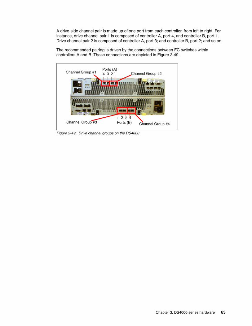
A drive-side channel pair is made up of one port from each controller, from left to right. For instance, drive channel pair 1 is composed of controller A, port 4, and controller B, port 1. Drive channel pair 2 is composed of controller A, port 3; and controller B, port 2; and so on.
The recommended pairing is driven by the connections between FC switches within controllers A and B. These connections are depicted in Figure 3-49.
Figure 3-49 Drive channel groups on the DS4800
Channel Group #4
Channel Group #2Channel Group #1
Channel Group #3
4 3 2 1
1 2 3 4
Ports (A)
Ports (B)
Chapter 3. DS4000 series hardware 63
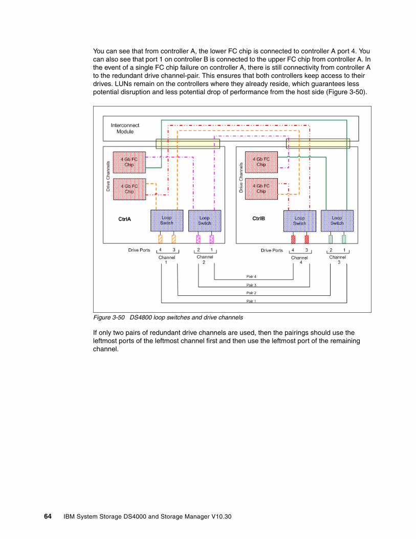
You can see that from controller A, the lower FC chip is connected to controller A port 4. You can also see that port 1 on controller B is connected to the upper FC chip from controller A. In the event of a single FC chip failure on controller A, there is still connectivity from controller A to the redundant drive channel-pair. This ensures that both controllers keep access to their drives. LUNs remain on the controllers where they already reside, which guarantees less potential disruption and less potential drop of performance from the host side (Figure 3-50).
Figure 3-50 DS4800 loop switches and drive channels
If only two pairs of redundant drive channels are used, then the pairings should use the leftmost ports of the leftmost channel first and then use the leftmost port of the remaining channel.
64 IBM System Storage DS4000 and Storage Manager V10.30

3.3.9 DS4800 drive-side cablingThe DS4800 can attach up to 16 EXP100 (SATA) or EXP710 (FC), or 14 EXP810(FC). It also fully supports an intermix of the FC and SATA enclosures to allow users maximum flexibility for customizing storage solutions. It is generally best to spread enclosures evenly among the four drive channel pairs as you scale up your DS4800 in storage capacity. This allows you to fully utilize the maximum drive-side bandwidth. A fully configured DS4800 should have four expansion enclosures on each drive-side channel pair. Figure 3-51 shows a fully configured DS4800 with 16 EXP710s attached.
Figure 3-51 Fully optimized DS4800 with 16 EXP710s attached
Although we recommend spreading expansion enclosures among the four drive channel pairs (with a maximum of four EXP710 per drive channel pair), we still support up to eight EXP710 in one drive channel pair on the DS4800. This is how the DS4500 is configured (it only supports a maximum of two drive channel pairs). Using this cabling method on the DS4800 would forgo many of the performance and availability benefits unique to the DS4800’s ability to use four drive channel pairs. However, there are situations in which using only two drive-side channel pairs can be an advantage, as we discuss in 3.3.10, “DS4800: Expansion enclosure scaling considerations” on page 68.
Note: In addition to the limitation of only eight EXP710 enclosures on one drive channel pair, we have an additional limitation of eight total EXP710 enclosures that can be attached to the two drive channel pairs that share a drive channel group. This means that drive channel pair #1 and drive channel pair #2 combined cannot have more than eight EXP710 units. So, if you were to place eight EXP710 units on drive channel pair #1, you could not place any unit on drive channel pair #2. The same guidelines apply to drive channel pair #3 and drive channel pair #4. As another example, if you were to place six EXP710 units on drive channel pair #3, you could not place more than two EXP710 units on drive channel pair #4.
Chapter 3. DS4000 series hardware 65
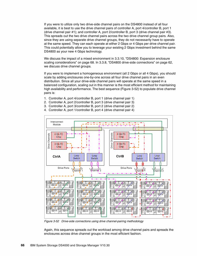
If you were to utilize only two drive-side channel pairs on the DS4800 instead of all four available, it is best to use the drive channel pairs of controller A, port 4/controller B, port 1 (drive channel pair #1); and controller A, port 2/controller B, port 3 (drive channel pair #3). This spreads out the two drive channel pairs across the two drive channel group pairs. Also, since they are using separate drive channel groups, they do not necessarily have to operate at the same speed. They can each operate at either 2 Gbps or 4 Gbps per drive channel pair. This could potentially allow you to leverage your existing 2 Gbps investment behind the same DS4800 as your new 4 Gbps technology.
We discuss the impact of a mixed environment in 3.3.10, “DS4800: Expansion enclosure scaling considerations” on page 68. In 3.3.8, “DS4800 drive-side connections” on page 62, we discuss drive channel groups.
If you were to implement a homogeneous environment (all 2 Gbps or all 4 Gbps), you should scale by adding enclosures one-by-one across all four drive channel pairs in an even distribution. Since all your drive-side channel pairs will operate at the same speed in a balanced configuration, scaling out in this manner is the most efficient method for maintaining high availability and performance. The best sequence (Figure 3-52) to populate drive channel pairs is:
1. Controller A, port 4/controller B, port 1 (drive channel pair 1)2. Controller A, port 2/controller B, port 3 (drive channel pair 3)3. Controller A, port 3/controller B, port 2 (drive channel pair 2)4. Controller A, port 1/controller B, port 4 (drive channel pair 4)
Figure 3-52 Drive-side connections using drive channel-pairing methodology
Again, this sequence spreads out the workload among drive channel pairs and spreads the enclosures across drive channel groups in the most efficient fashion.
66 IBM System Storage DS4000 and Storage Manager V10.30

DS4800 drive-side cabling example with EXP710In this example, the DS4800 is cabled using all four drive channel pairs, assuming that there are 16 total expansion enclosures evenly spread out across the drive channel pairs (four each). See Figure 3-51 on page 65 for the schematic.
1. Start with the first expansion enclosure, which we will attach to drive channel pair #1. Cable controller A, port 4, to the IN port on the left ESM board of the EXP unit.
2. Cable the OUT port of the left ESM of the first EXP unit to the IN port of the left ESM of the second EXP unit located on the first drive channel pair.
3. Repeat step 2 for the third and fourth EXP units on the first drive channel pair.
4. Cable the OUT port of the right ESM of the first EXP unit to the IN port of the right ESM of the second EXP unit.
5. Repeat step 4 for the third and fourth EXP units on the first drive channel pair.
6. Cable controller B, port 1, to the OUT port of the right ESM of the fourth EXP unit of the first drive channel pair. This will be the last step of the first drive channel pair.
7. Repeat steps 1–7 (using the next drive-side channel pair ports) for the second, third, and fourth drive channel pairs (four EXP units each).
This procedure illustrates the DS4800 cabling according to IBM best practices and should visually appear as in Figure 3-51 on page 65.
DS4800 drive-side cabling example with EXP810When using the EXP810 enclosures, the DS4800 can only attach 14 enclosures. Figure 3-53 shows a fully configured DS4800 with 14 EXP810s attached.
Figure 3-53 Fully optimized DS4800 with 14 EXP810s attached
Chapter 3. DS4000 series hardware 67
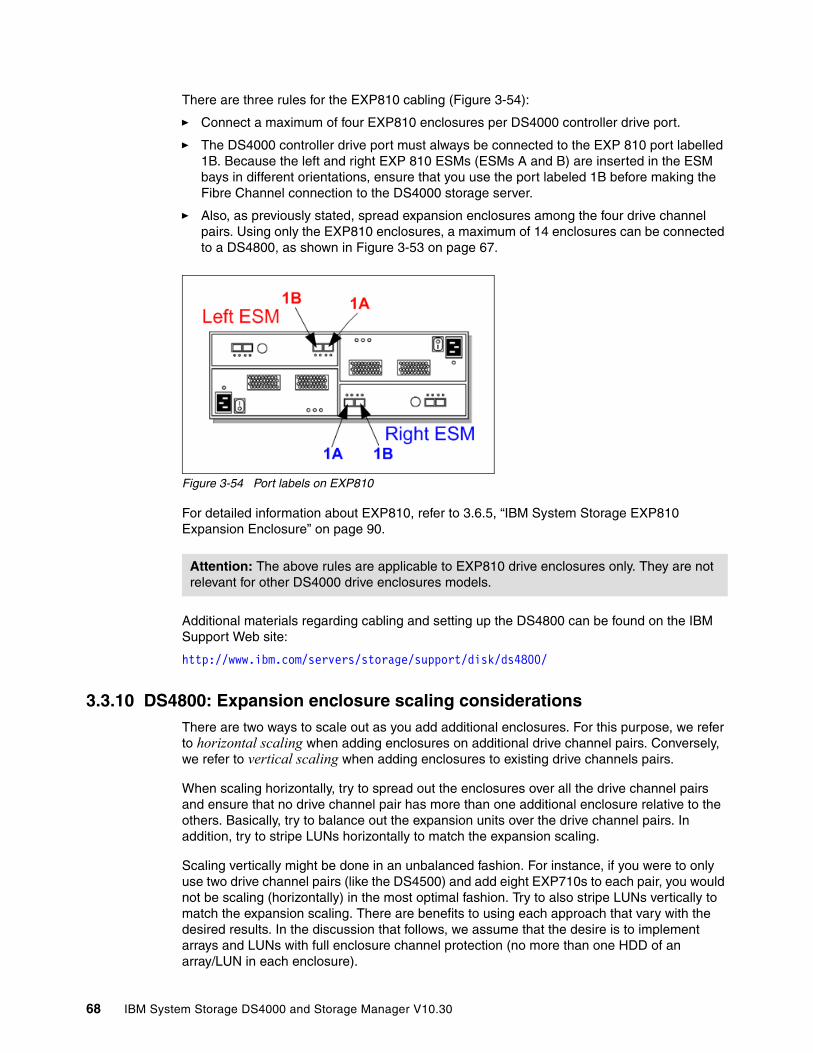
There are three rules for the EXP810 cabling (Figure 3-54):
� Connect a maximum of four EXP810 enclosures per DS4000 controller drive port.
� The DS4000 controller drive port must always be connected to the EXP 810 port labelled 1B. Because the left and right EXP 810 ESMs (ESMs A and B) are inserted in the ESM bays in different orientations, ensure that you use the port labeled 1B before making the Fibre Channel connection to the DS4000 storage server.
� Also, as previously stated, spread expansion enclosures among the four drive channel pairs. Using only the EXP810 enclosures, a maximum of 14 enclosures can be connected to a DS4800, as shown in Figure 3-53 on page 67.
Figure 3-54 Port labels on EXP810
For detailed information about EXP810, refer to 3.6.5, “IBM System Storage EXP810 Expansion Enclosure” on page 90.
Additional materials regarding cabling and setting up the DS4800 can be found on the IBM Support Web site:
http://www.ibm.com/servers/storage/support/disk/ds4800/
3.3.10 DS4800: Expansion enclosure scaling considerationsThere are two ways to scale out as you add additional enclosures. For this purpose, we refer to horizontal scaling when adding enclosures on additional drive channel pairs. Conversely, we refer to vertical scaling when adding enclosures to existing drive channels pairs.
When scaling horizontally, try to spread out the enclosures over all the drive channel pairs and ensure that no drive channel pair has more than one additional enclosure relative to the others. Basically, try to balance out the expansion units over the drive channel pairs. In addition, try to stripe LUNs horizontally to match the expansion scaling.
Scaling vertically might be done in an unbalanced fashion. For instance, if you were to only use two drive channel pairs (like the DS4500) and add eight EXP710s to each pair, you would not be scaling (horizontally) in the most optimal fashion. Try to also stripe LUNs vertically to match the expansion scaling. There are benefits to using each approach that vary with the desired results. In the discussion that follows, we assume that the desire is to implement arrays and LUNs with full enclosure channel protection (no more than one HDD of an array/LUN in each enclosure).
Attention: The above rules are applicable to EXP810 drive enclosures only. They are not relevant for other DS4000 drive enclosures models.
68 IBM System Storage DS4000 and Storage Manager V10.30
Benefits of scaling horizontallyThe benefits of scaling horizontally are:
� Maximum availability: There is the possibility of striping LUNs across four drive channel pairs, rather than two.
� Maximum bandwidth: This allows fully striped LUNs (LUNs using HDDs that exist in all four drive channel pairs) to utilize up to the full 3,200 MBps bandwidth (up to 800 MBps per drive channel pair).
Benefits of scaling verticallyThe benefits of scaling vertically are:
� Dedicated bandwidth: Placing LUNs on only one drive channel pair ensures that they will receive a total of up to 800 MBps in bandwidth. If you stripe a LUN among all the drive loops, that LUN must contend with all other LUNs on all other loops for bandwidth. It probably will not affect performance negatively. However, it will vary according to your workload and your environment.
� Optimized utilization of 2/4 Gbps mixed environment: The DS4800 can support separate drive-side channel pairs that run at 2 Gbps and 4 Gbps behind the same controller. This will allow you to reap the immediate benefits of new 4 Gbps technology, but still leverage your existing 2 Gbps investment. In such a circumstance, it is best to stripe your LUNs across enclosures in drive channel pairs that run at the same speed. Therefore, in this mixed 2 and 4 Gbps environment, scaling horizontally would not be a benefit.
Chapter 3. DS4000 series hardware 69
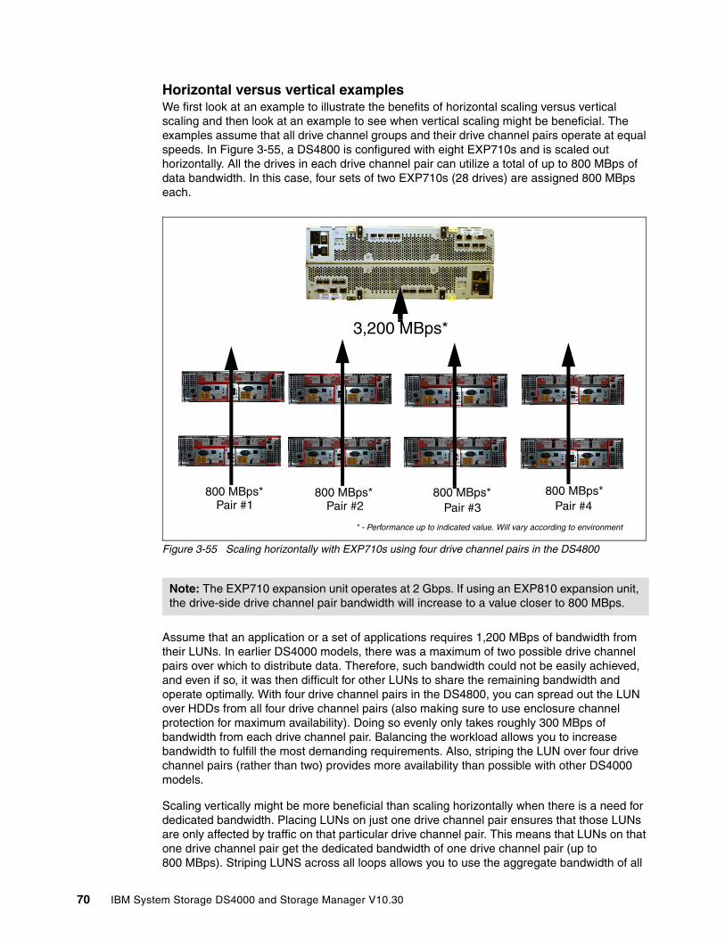
Horizontal versus vertical examplesWe first look at an example to illustrate the benefits of horizontal scaling versus vertical scaling and then look at an example to see when vertical scaling might be beneficial. The examples assume that all drive channel groups and their drive channel pairs operate at equal speeds. In Figure 3-55, a DS4800 is configured with eight EXP710s and is scaled out horizontally. All the drives in each drive channel pair can utilize a total of up to 800 MBps of data bandwidth. In this case, four sets of two EXP710s (28 drives) are assigned 800 MBps each.
Figure 3-55 Scaling horizontally with EXP710s using four drive channel pairs in the DS4800
Assume that an application or a set of applications requires 1,200 MBps of bandwidth from their LUNs. In earlier DS4000 models, there was a maximum of two possible drive channel pairs over which to distribute data. Therefore, such bandwidth could not be easily achieved, and even if so, it was then difficult for other LUNs to share the remaining bandwidth and operate optimally. With four drive channel pairs in the DS4800, you can spread out the LUN over HDDs from all four drive channel pairs (also making sure to use enclosure channel protection for maximum availability). Doing so evenly only takes roughly 300 MBps of bandwidth from each drive channel pair. Balancing the workload allows you to increase bandwidth to fulfill the most demanding requirements. Also, striping the LUN over four drive channel pairs (rather than two) provides more availability than possible with other DS4000 models.
Scaling vertically might be more beneficial than scaling horizontally when there is a need for dedicated bandwidth. Placing LUNs on just one drive channel pair ensures that those LUNs are only affected by traffic on that particular drive channel pair. This means that LUNs on that one drive channel pair get the dedicated bandwidth of one drive channel pair (up to 800 MBps). Striping LUNS across all loops allows you to use the aggregate bandwidth of all
Note: The EXP710 expansion unit operates at 2 Gbps. If using an EXP810 expansion unit, the drive-side drive channel pair bandwidth will increase to a value closer to 800 MBps.
800 MBps*800 MBps*800 MBps* 800 MBps*
3,200 MBps*
Pair #1 Pair #2 Pair #3 Pair #4
* - Performance up to indicated value. Will vary according to environment
70 IBM System Storage DS4000 and Storage Manager V10.30

four drive channel pairs (up to 3,200 MBps). However, the LUNs must share that aggregate bandwidth with all the other LUNs on the DS4800 and, in the process, be at the mercy of the overall traffic of the entire subsystem, not just one drive channel pair.
In Figure 3-56 you can see that there are only two drive channel pairs being utilized. The advantage of scaling vertically is that LUNs can be created on drive channel pair 1 only and can be dedicated to the 800 MBps bandwidth. You can still achieve full enclosure protection for larger LUNs. For instance, a 5+P RAID-5 array could still be placed on the six enclosures in drive channel pair #1. A drive channel pair can support up to eight total EXP710s, much like past versions of the DS4000 line.
Figure 3-56 Scaling vertically with EXP710s using two drive-side drive channel pairs on the DS4800
By putting a LUN on this dedicated bandwidth, you can control what other LUNs can be placed on the same drive channel pair. If you do not want others to take up most of this dedicated bandwidth, you can place them on another drive-side drive channel pair. In the horizontal scaling example, you stripe a given LUN across the four drive channel pairs. This means that you do have the benefit of having additional bandwidth to work with (3,200 MBps versus 800 MBps), but any other LUN that is provisioned on any of the four drive channel pairs will affect the original LUNs that you have created. Due to the incredible amount of overall bandwidth of the four drive channel pairs, you probably will not run into any issues. However, allowing you to scale vertically will give you more options to provision your storage in the manner that you desire.
Scaling vertically also allows you to utilize two different back-end bandwidth speeds on two different drive channel pairs. In the previous examples, we have assumed that all drive channel groups and their associated drive channel pairs operated at equal speeds. We now discuss how scaling vertically benefits you when using a mixed bandwidth environment. As mentioned earlier, drive channel pair #1/drive channel pair #2 must operate at the same speed. Drive channel pair #3/drive channel pair #4 must also operate at the same speed. This
800 MBps*Pair #2
DedicatedBandwidth
* - Performance up to indicated value. Will vary according to environment800 MBps*Pair #1
Chapter 3. DS4000 series hardware 71
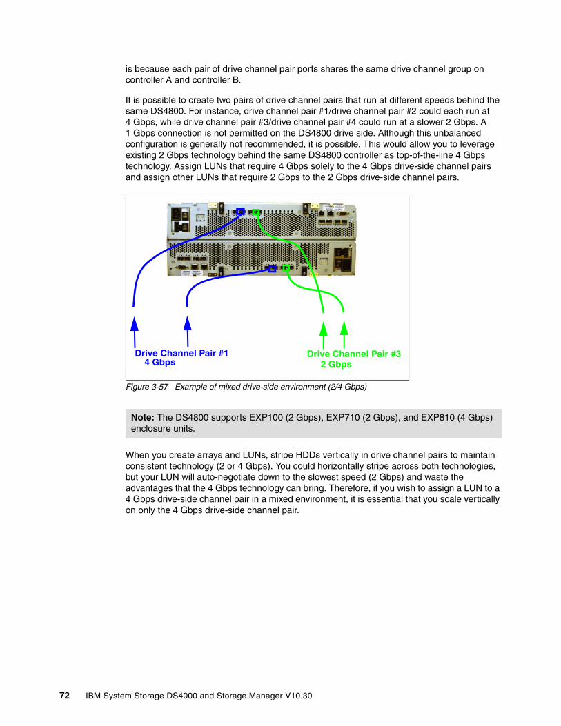
is because each pair of drive channel pair ports shares the same drive channel group on controller A and controller B.
It is possible to create two pairs of drive channel pairs that run at different speeds behind the same DS4800. For instance, drive channel pair #1/drive channel pair #2 could each run at 4 Gbps, while drive channel pair #3/drive channel pair #4 could run at a slower 2 Gbps. A 1 Gbps connection is not permitted on the DS4800 drive side. Although this unbalanced configuration is generally not recommended, it is possible. This would allow you to leverage existing 2 Gbps technology behind the same DS4800 controller as top-of-the-line 4 Gbps technology. Assign LUNs that require 4 Gbps solely to the 4 Gbps drive-side channel pairs and assign other LUNs that require 2 Gbps to the 2 Gbps drive-side channel pairs.
Figure 3-57 Example of mixed drive-side environment (2/4 Gbps)
When you create arrays and LUNs, stripe HDDs vertically in drive channel pairs to maintain consistent technology (2 or 4 Gbps). You could horizontally stripe across both technologies, but your LUN will auto-negotiate down to the slowest speed (2 Gbps) and waste the advantages that the 4 Gbps technology can bring. Therefore, if you wish to assign a LUN to a 4 Gbps drive-side channel pair in a mixed environment, it is essential that you scale vertically on only the 4 Gbps drive-side channel pair.
Note: The DS4800 supports EXP100 (2 Gbps), EXP710 (2 Gbps), and EXP810 (4 Gbps) enclosure units.
2 Gbps4 Gbps Drive Channel Pair #1 Drive Channel Pair #3
72 IBM System Storage DS4000 and Storage Manager V10.30
3.3.11 DS4800: Additional connectionsIn addition to host and drive connections, the DS4800 rear also has connections for Ethernet and serial ports. You can manage and service the DS4800 through these ports:
� RJ-45 Ethernet connector
This connector is for an RJ-45 10BASE-Tx or 100BASE-Tx Ethernet connection. There are two connections per controller. One port is designed for out-of-band management and the other port is meant for serviceability. This is a new feature and differs from previous models of the DS4000. Previous models had only one port that handled both management and service for each controller. The logic behind adding an extra port was to introduce additional isolation and to separate management and service traffic from one another. Because of the extra port, it is now preferable to have two IP addresses per controller in order to manage and service the DS4800 appropriately. You can still operate the DS4800 with only one IP port active per controller. You can assign either port of the two ports for management or service on a given controller.
The default IP addresses for the controller A Ethernet ports 1 and 2 are 192.168.128.101 and 192.168.129.101, respectively. The default IP addresses for the controller B Ethernet ports 1 and 2 are 192.168.128.102 and 192.168.129.102, respectively. The default subnet mask for all four Ethernet ports is 255.255.255.0.
Now DS4800 supports IPv4 and IPv6 Ethernet configuration.
Note: You can combine the horizontal and vertical scaling of expansion units into a customized solution. Keep in mind the following limitations:
� Four total drive-side channel pairs.
� No more than eight EXP710 or four EXP810 units in one drive-side channel pair.
� No more than 16 total EXP710 or 14 total EXP810 units connected to one DS4800.
� Drive channel pair #1 and drive channel pair #2 combined cannot have more than eight EXP710 or seven EXP810 units.
� Drive channel pair #3 and drive channel pair #4 combined cannot have more than eight EXP710 or seven EXP810 units.
� Drive channel pair #1 and drive channel pair #2 operate at the same speed (2 Gbps or 4 Gbps per drive channel pair).
� Drive channel pair #3 and drive channel pair #4 operate at the same speed (2 Gbps or 4 Gbps per drive channel pair).
Important: The numbers that we use for drive-side bandwidth (800 MBps per drive channel pair) are dependent on having a fully supported 4 Gbps storage system. This means that you must be using 4 Gbps HDDs, 4 Gbps EXP units, and 4 Gbps SFPs. If you do not use all 4 Gbps components, the DS4800 backside bandwidth will only operate at the maximum speed of the lowest performing component. Since drive-side connections on the DS4800 only support 2 and 4 Gbps connections (no 1 Gbps), this means that it will operate at 2 Gbps.
Attention: It is a best practice to use only 2 Gb HDDs or only 4 Gb HDDs in the same drive channel pair.
Chapter 3. DS4000 series hardware 73
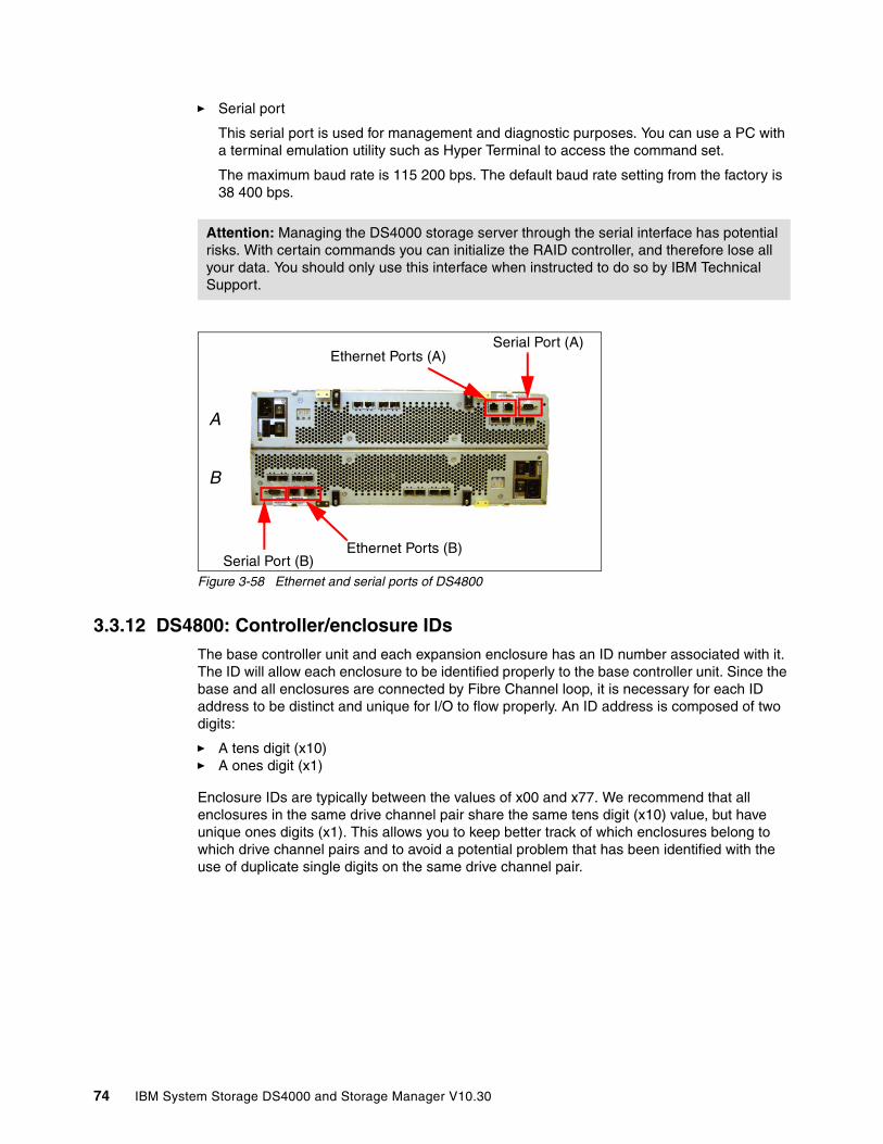
� Serial port
This serial port is used for management and diagnostic purposes. You can use a PC with a terminal emulation utility such as Hyper Terminal to access the command set.
The maximum baud rate is 115 200 bps. The default baud rate setting from the factory is 38 400 bps.
Figure 3-58 Ethernet and serial ports of DS4800
3.3.12 DS4800: Controller/enclosure IDsThe base controller unit and each expansion enclosure has an ID number associated with it. The ID will allow each enclosure to be identified properly to the base controller unit. Since the base and all enclosures are connected by Fibre Channel loop, it is necessary for each ID address to be distinct and unique for I/O to flow properly. An ID address is composed of two digits:
� A tens digit (x10) � A ones digit (x1)
Enclosure IDs are typically between the values of x00 and x77. We recommend that all enclosures in the same drive channel pair share the same tens digit (x10) value, but have unique ones digits (x1). This allows you to keep better track of which enclosures belong to which drive channel pairs and to avoid a potential problem that has been identified with the use of duplicate single digits on the same drive channel pair.
Attention: Managing the DS4000 storage server through the serial interface has potential risks. With certain commands you can initialize the RAID controller, and therefore lose all your data. You should only use this interface when instructed to do so by IBM Technical Support.
A
B
Ethernet Ports (B)Serial Port (B)
Ethernet Ports (A)Serial Port (A)
74 IBM System Storage DS4000 and Storage Manager V10.30
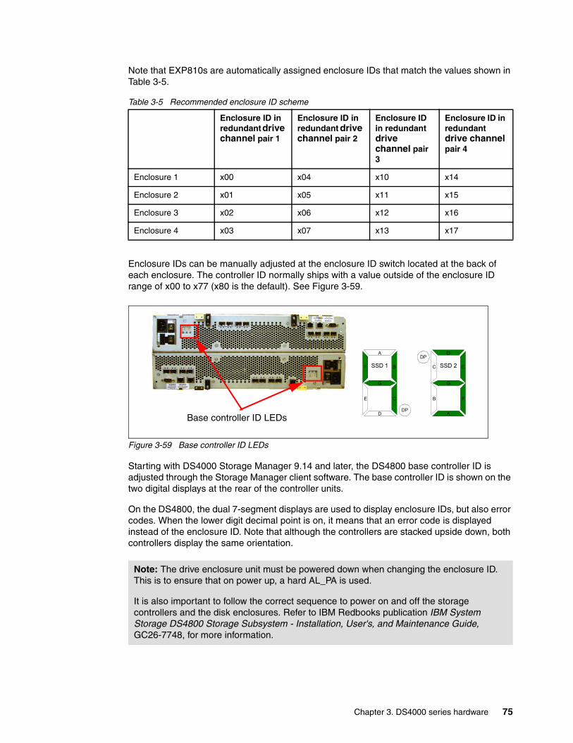
Note that EXP810s are automatically assigned enclosure IDs that match the values shown in Table 3-5.
Table 3-5 Recommended enclosure ID scheme
Enclosure IDs can be manually adjusted at the enclosure ID switch located at the back of each enclosure. The controller ID normally ships with a value outside of the enclosure ID range of x00 to x77 (x80 is the default). See Figure 3-59.
Figure 3-59 Base controller ID LEDs
Starting with DS4000 Storage Manager 9.14 and later, the DS4800 base controller ID is adjusted through the Storage Manager client software. The base controller ID is shown on the two digital displays at the rear of the controller units.
On the DS4800, the dual 7-segment displays are used to display enclosure IDs, but also error codes. When the lower digit decimal point is on, it means that an error code is displayed instead of the enclosure ID. Note that although the controllers are stacked upside down, both controllers display the same orientation.
Enclosure ID in redundant drive channel pair 1
Enclosure ID in redundant drive channel pair 2
Enclosure ID in redundant drive channel pair 3
Enclosure ID in redundant drive channel pair 4
Enclosure 1 x00 x04 x10 x14
Enclosure 2 x01 x05 x11 x15
Enclosure 3 x02 x06 x12 x16
Enclosure 4 x03 x07 x13 x17
Note: The drive enclosure unit must be powered down when changing the enclosure ID. This is to ensure that on power up, a hard AL_PA is used.
It is also important to follow the correct sequence to power on and off the storage controllers and the disk enclosures. Refer to IBM Redbooks publication IBM System Storage DS4800 Storage Subsystem - Installation, User's, and Maintenance Guide, GC26-7748, for more information.
Base controller ID LEDs
F
A
G
D
B
CE
DP
C
D
G
A
E
FB
DP
SSD 1 SSD 2
Chapter 3. DS4000 series hardware 75

3.3.13 DS4800: Physical/environmental specificationsThe information in this section describes the DS4800 storage server’s physical and environmental specifications.
Physical specificationsThese are:
� Height: 174.50 mm (6.87 in.)� Width: 481.75 mm (18.97 in.)� Depth: 634.92 mm (25.0 in.)� Weight: 36.38 kg (80.2 lb.)
Operating environmentThis is:
� Temperature
– 10° to 35°C (50° to 95°F) at 0 to 914 m (0 to 3,000 ft.)– 10° to 32°C (50° to 90°F) at 914 to 2,133 m (3,000 to 7,000 ft.)
� Relative humidity: 8–80%
� Electrical power (per power supply, system rating):
– Voltage range: 100 to 240 V ac– Operating current: 2.25 to 5.4 Amperes– Power: 540 watts– Frequency: 50/60 Hz
� Heat dissipation: 804 BTU per hour
� Noise level (normal operation): 6.75 bels
3.3.14 DS4800: Upgrading previous DS4000 modelsThe DS4000 family is designed around interchangeable, hot-swappable components with the intent to leverage existing customer storage hardware investments. The DS4800 can leverage existing DS4000 models by easily upgrading the base controller unit and reusing existing EXP710s that are already populated with disk and data. The DS4000 feature that enables this function is the DACstore. The DACstore region is a 512 MB reserved region on each physical disk. This region holds the configuration information of data and allows you to interchange disks seamlessly behind different DS4000 controller units.
In order to upgrade a DS4400/DS4500 to a DS4800, it is a prerequisite that you have all EXP710s. This means that if you have any EXP700s, it is necessary that you acquire the upgrade kit for each EXP700 and convert them to EXP710s prior to upgrading to the DS4800. This conversion not only allows you to upgrade to the DS4800, but it will also allow you to reap additional benefits of availability, performance, and enhanced diagnostic capabilities that come with a switched expansion enclosure (SBOD).
Once you have all EXP710s, all you must do is swap out the DS4400/DS4500 storage server for the DS4800 storage server and re-cable the disk-side back-end. This upgrade will require an outage in order to complete.
Note: It is also possible to upgrade the DS4100/DS4300/DS4300 Turbo models in this fashion as well. However, you must acquire an additional EXP100 (DS4100) or EXP710 (DS4300) because the DS4100/DS4300 houses 14 HDDs internally, while the DS4800 does not.
76 IBM System Storage DS4000 and Storage Manager V10.30

3.4 DS4000 family supported operating system and topologies
This section lists the most popular supported operating system platforms and topologies. For a complete and up-to-date list, refer to the DS4000 series interoperability matrix, available at:
http://www.ibm.com/servers/storage/disk/ds4000/interop-matrix.html
3.4.1 Supported operating systemsThe DS4800 and DS4700 support the following operating systems.
� Windows 2000 Advanced Server with SP4� Windows 2003 Server with SP2, R2, and x64� Windows 2008 Server� MS Vista Client (SM Manager client only)� Novell® NetWare 6.5 with SP6� Red Hat Enterprise Linux 4.x and 5.0� SuSE Linux Enterprise Server 9 SP3� SuSE Linux Enterprise Server 10 SP1� VMWare ESX 2.5.3 and 3.0.1� AIX 5.1, 5.2, 5.3 and 6.1� HP UX 11, 11i and 11.23 with PVLinks� Solaris 8, 9, 10 and 10 on x86
3.4.2 Clustering supportClustering support applies to DS4000 dual controller models only. Supported clustering services are:
� IBM SAN Volume Controller (SVC) 3.1.0, 4.1.x, 4.2.x, and 4.3.x� Microsoft Cluster Services� Novell Cluster Services� IBM HACMP™� PSS, GPFS/RVSD support� Steeleye - Lifekeeper 5.3 and 6.0� Veritas Cluster Server � HP MC/Service Guard� GPFS™ for Linux v 1 and 3
3.4.3 Supported server platformsThe supported server platforms are:
� IBM System x and System p � IBM BladeCenter®� HP (Intel) � Dell (selected models)� HP and Sun™ UNIX® based
Chapter 3. DS4000 series hardware 77
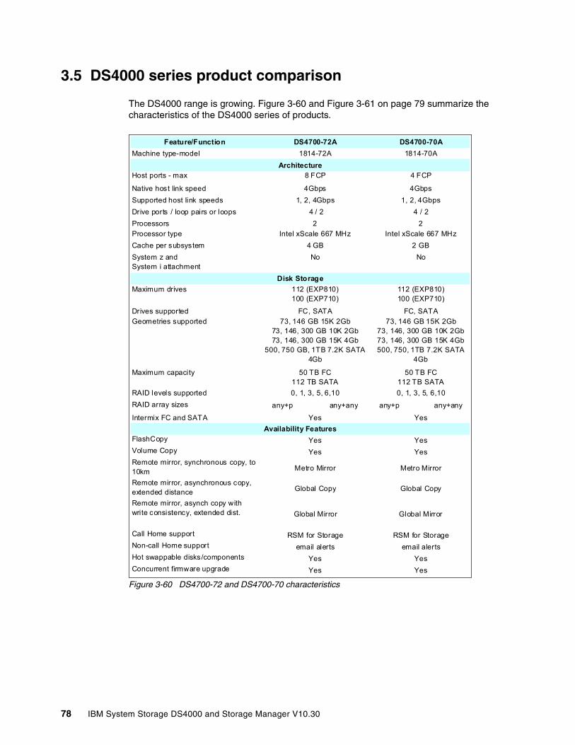
3.5 DS4000 series product comparison
The DS4000 range is growing. Figure 3-60 and Figure 3-61 on page 79 summarize the characteristics of the DS4000 series of products.
Figure 3-60 DS4700-72 and DS4700-70 characteristics
Feature/Function DS4700-72A DS4700-70AMachine type-model 1814-72A 1814-70A
Host ports - max 8 FCP 4 FCP
Native host link speed 4Gbps 4GbpsSupported host link speeds 1, 2, 4Gbps 1, 2, 4GbpsDrive ports / loop pairs or loops 4 / 2 4 / 2Processors 2 2Processor type Intel xScale 667 MHz Intel xScale 667 MHzCache per subsystem 4 GB 2 GBSystem z and System i attachment
No No
Maximum drives 112 (EXP810)100 (EXP710)
112 (EXP810)100 (EXP710)
Drives supported FC, SATA FC, SATAGeometries supported 73, 146 GB 15K 2Gb
73, 146, 300 GB 10K 2Gb 73, 146, 300 GB 15K 4Gb
500, 750 GB, 1TB 7.2K SATA 4Gb
73, 146 GB 15K 2Gb 73, 146, 300 GB 10K 2Gb 73, 146, 300 GB 15K 4Gb 500, 750, 1TB 7.2K SATA
4Gb
Maximum capacity 50 TB FC 112 TB SATA
50 TB FC112 TB SATA
RAID levels supported 0, 1, 3, 5, 6,10 0, 1, 3, 5, 6,10RAID array sizes any+p any+any any+p any+any
Intermix FC and SATA Yes Yes
FlashCopy Yes YesVolume Copy Yes YesRemote mirror, synchronous copy, to 10km Metro Mirror Metro Mirror
Remote mirror, asynchronous copy, extended distance Global Copy Global Copy
Remote mirror, asynch copy with write consistency, extended dist. Global Mirror Global Mirror
Call Home support RSM for Storage RSM for StorageNon-call Home support email alerts email alertsHot swappable disks/components Yes YesConcurrent firmware upgrade Yes Yes
Architecture
Disk Storage
Availability Features
78 IBM System Storage DS4000 and Storage Manager V10.30
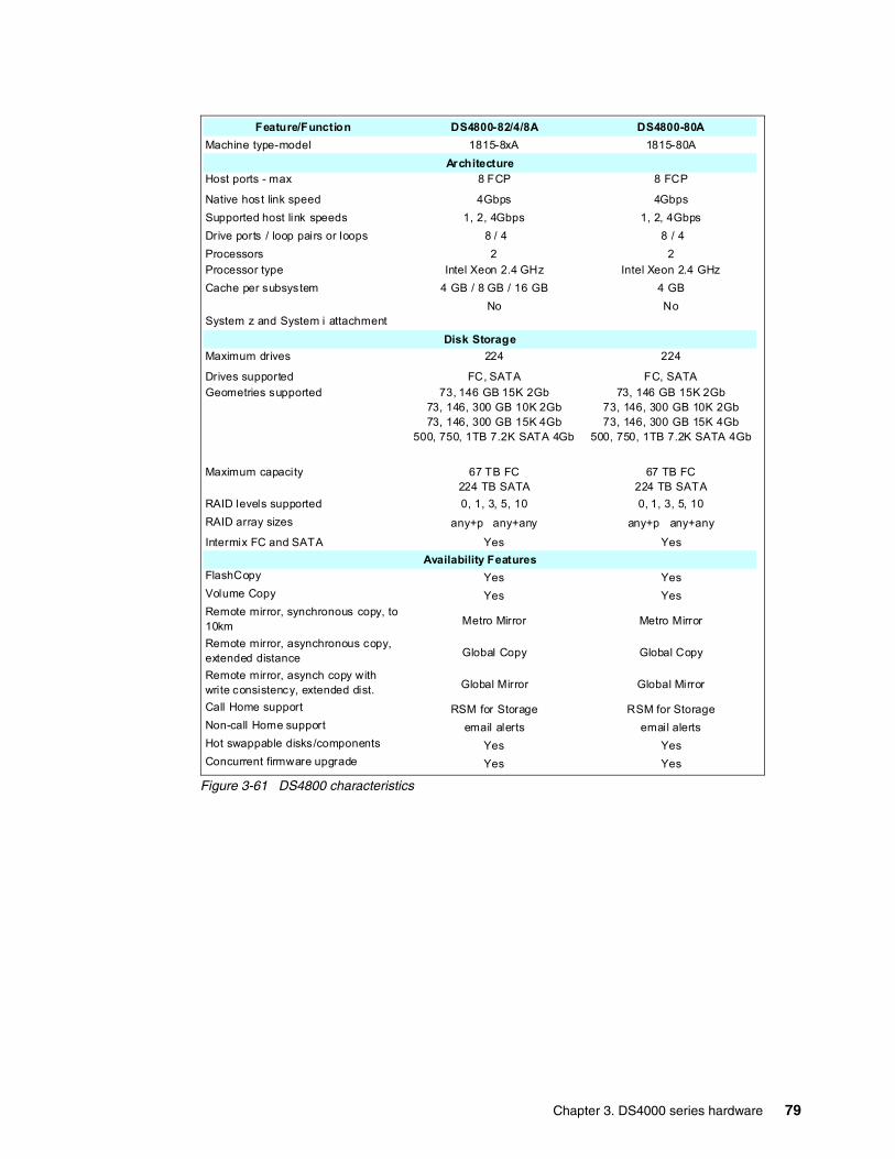
Figure 3-61 DS4800 characteristics
Feature/Function DS4800-82/4/8A DS4800-80AMachine type-model 1815-8xA 1815-80A
Host ports - max 8 FCP 8 FCP
Native host link speed 4Gbps 4GbpsSupported host link speeds 1, 2, 4Gbps 1, 2, 4GbpsDrive ports / loop pairs or loops 8 / 4 8 / 4Processors 2 2Processor type Intel Xeon 2.4 GHz Intel Xeon 2.4 GHzCache per subsystem 4 GB / 8 GB / 16 GB 4 GB
System z and System i attachmentNo No
Maximum drives 224 224
Drives supported FC, SATA FC, SATAGeometries supported 73, 146 GB 15K 2Gb
73, 146, 300 GB 10K 2Gb 73, 146, 300 GB 15K 4Gb
500, 750, 1TB 7.2K SATA 4Gb
73, 146 GB 15K 2Gb 73, 146, 300 GB 10K 2Gb 73, 146, 300 GB 15K 4Gb
500, 750, 1TB 7.2K SATA 4Gb
Maximum capacity 67 TB FC224 TB SATA
67 TB FC224 TB SATA
RAID levels supported 0, 1, 3, 5, 10 0, 1, 3, 5, 10RAID array sizes any+p any+any any+p any+any
Intermix FC and SATA Yes Yes
FlashCopy Yes YesVolume Copy Yes YesRemote mirror, synchronous copy, to 10km Metro Mirror Metro Mirror
Remote mirror, asynchronous copy, extended distance Global Copy Global Copy
Remote mirror, asynch copy with write consistency, extended dist. Global Mirror Global Mirror
Call Home support RSM for Storage RSM for StorageNon-call Home support email alerts email alertsHot swappable disks/components Yes YesConcurrent firmware upgrade Yes Yes
Architecture
Disk Storage
Availability Features
Chapter 3. DS4000 series hardware 79
3.6 DS4000 series expansion enclosuresThere are four models of expansion enclosures available for the DS4000 series of storage servers:
� DS4000 EXP100 SATA Expansion Enclosure with 2 Gbps capability
� DS4000 EXP710 FC Expansion Enclosure with 2 Gbps Switched Disk Technology (This technology is also referred to as a Switched Bunch Of Disks (SBOD).)
� DS4000 EXP420 SATA Expansion Enclosure with 4 Gbps capability (DS4200-only expansion enclosure)
� DS4000 EXP810 FC Expansion Enclosure with 4 Gbps capability
In this section we discuss the features of the DS4000 expansion units (EXP) and how they can be attached and combined to expand the storage capacity of the DS4000 storage servers. In particular, we look at the possibilities and limitations of intermixing FC and SATA enclosures, as that is now supported with Storage Manager 9.x and later.
Connectors, LED indicators, and switches located at the rear of the expansion units are similar on all models.
For additional information about drive migration and special handling procedures for expansion enclosures, refer to the IBM System Storage DS4000 Hard Drive and Storage Expansion Enclosure, GC53-1139-00, available at:
http://www-1.ibm.com/support/docview.wss?uid=psg1MIGR-57818
Note: The usable disk space is less than overall disk capacity. Consider these usable capacity amounts for storage capacity calculation issues:
� 73.4 GB formatted capacity is equal to 67.860 GB usable capacity.� 146.8 GB formatted capacity is equal to 136.219 GB usable capacity.� 300 GB formatted capacity is equal to 278.897 GB usable capacity.� 500 GB formatted capacity is equal to 465.161 GB usable capacity
The usable capacities are what the SMclient will report as storage that can be used by the hosts. We arrive at this number by the following steps:
1. Take the listed raw disk amount (listed in decimal, as the storage industry standard dictates) and divide by 1.073742 to get a raw binary capacity (1 decimal GB = 1,000,000,000 bytes. One binary GB = 1,073,741,824 bytes (2^30 bytes)).
2. Subtract out the 512 MB DACstore region (region that holds configuration information) after converting the DACstore to binary.
3. This gives you the usable binary capacity that can be utilized by hosts and is what the SMclient will report to you as usable capacity.
80 IBM System Storage DS4000 and Storage Manager V10.30

3.6.1 IBM TotalStorage DS4000 EXP100 Expansion EnclosureThe EXP100 (machine type 1710-10U), shown in Figure 3-62, is a rack-mountable storage expansion enclosure that contains 14 bays for slim-line hot-swappable Serial ATA (SATA) disk drives. It occupies 3U inside a rack and features hot-pluggable and redundant power supplies and fans. Additionally, it contains two Environmental Service Modules (ESM) boards that can connect to the FAStT storage server in a fully redundant Serial ATA point-to-point (switched) fabric. Fully populated with 400 GB SATA drives, it offers 5.6 TB of raw capacity. If we use 1 TB SATA, it offers 14 TB raw capacity.
Additional information can also be found at:
http://www.ibm.com/servers/storage/support/disk/exp100/
Figure 3-62 EXP100 front view
Front viewFrom the front panel (Figure 3-62) you can access up to 14 hot swappable SATA hard disk drives and view the status LEDs (28 on the top of the server and two at the bottom on the right side).
� Green activity LED
Each drive has an associated activity LED on the EXP100 chassis. A flashing green LED indicates drive activity. A solid green LED indicates that the drive is properly installed and powered on. If the LED is off, it means the EXP100 is not powered up or the drive has not spun up.
� Amber disk-drive-fault LED
Each drive has an associated fault LED on the DS4100 chassis. A solid amber LED indicates a drive failure. A flashing LED indicates that a drive identify process is in progress.
� Green power-on LED
This indicates a powered-on system.
� Amber general-system-fault LED
When a storage server component fails (such as a disk drive, fan, or power supply), this LED is on.
The number of HDDs in the enclosure can vary from 1–14. To ensure proper cooling and avoid Electro Magnetic Interference (EMI), all 14 bays should be occupied either by an HDD or by a filler module.
Chapter 3. DS4000 series hardware 81

EXP100 ESM boardThe ESM boards provide connectivity from the drives inside the EXP100 to the DS4000 storage server. As depicted in Figure 3-63, both ESM boards are connected to all 14 disk drive bays in the EXP100. This provides redundancy in the case of one ESM board failure or if one connection loop to the storage server is broken. In case of one ESM board failure, all disk drives remain connected through the other ESM board. Each ESM board has an incoming and outgoing SFP module port.
Figure 3-63 EXP100 ESM board diagram
One SFP module port is marked as IN, the other one OUT. A close look at Figure 3-63 reveals that both ports function identically. Thus, it is not mandatory to stick to their incoming or outgoing role. However, the best practice is to use them in accordance with their labeling. Always connect outgoing ports on the storage servers to incoming ports on the EXP Enclosures. This ensures clarity and consistency in cabling implementation, making troubleshooting easier, faster, and more efficient.
3.6.2 IBM Total Storage DS4000 EXP710 expansion enclosureThe EXP710 is a rack-mountable storage expansion enclosure that contains 14 bays for slim-line hot-swappable Fibre Channel disk drives. It occupies 3U inside a rack and features hot-pluggable and redundant power supplies and fans.
The redesigned Environmental Service Module board (two ESMs in an EXP710) provide a redundant switched fabric connection to each drive in EXP710, eliminating the arbitrated loop within the disk enclosure that existed in the previous EXP700 model.
Important: The correct power-on sequence is to switch on all expansion enclosures first, and when all disks in the enclosures are ready (steady green LED for each disk), switch on the storage server. The correct power-off sequence is just the opposite: First, switch off the storage server, then the expansion enclosures.
Applying the wrong sequence can cause a configuration loss, resulting in a loss of data. Refer to 5.2.1, “Turning on the power” on page 226, for more information.
82 IBM System Storage DS4000 and Storage Manager V10.30
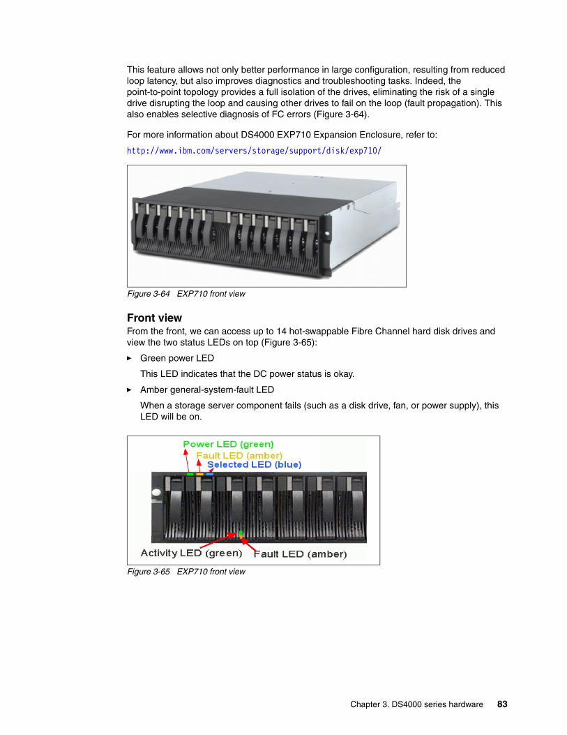
This feature allows not only better performance in large configuration, resulting from reduced loop latency, but also improves diagnostics and troubleshooting tasks. Indeed, the point-to-point topology provides a full isolation of the drives, eliminating the risk of a single drive disrupting the loop and causing other drives to fail on the loop (fault propagation). This also enables selective diagnosis of FC errors (Figure 3-64).
For more information about DS4000 EXP710 Expansion Enclosure, refer to:
http://www.ibm.com/servers/storage/support/disk/exp710/
Figure 3-64 EXP710 front view
Front viewFrom the front, we can access up to 14 hot-swappable Fibre Channel hard disk drives and view the two status LEDs on top (Figure 3-65):
� Green power LED
This LED indicates that the DC power status is okay.
� Amber general-system-fault LED
When a storage server component fails (such as a disk drive, fan, or power supply), this LED will be on.
Figure 3-65 EXP710 front view
Chapter 3. DS4000 series hardware 83

Each disk drive also has its own status LEDs:
� Green activity LED
When this LED is flashing as quickly as about three times per second, it indicates disk drive activity. When it is steadily on, it means that the disk drive is okay and properly installed. When it is flashing as slowly as once per second, it seems that the RAID controller does not recognize the HDD.
� Amber disk-drive-fault LED
If a disk drive fails, this LED will be steadily on. While the drive is being identified or rebuilt, it flashes.
� Blue LED
This is situated right of the general system error LED and is used as a locate option from Storage Manager to locate and identify a drive enclosure in the storage system.
The HDDs in the enclosure can vary from 2 to 14. To ensure proper cooling and avoid EMI, all 14 bays should be occupied either by a HDD or by a filler module.
EXP710 ESM boardThe ESM boards provide the connectivity of the drives inside the EXP710 to the DS4000 storage server. As you can see in Figure 3-63 on page 82, both ESM boards are connected to all 14 disk drive bays in the EXP710. This provides redundancy in the case of one ESM board or one loop connection failing. All disk drives remain connected through the other ESM board or FC loop. Each ESM board has an incoming and outgoing SFP module port (Figure 3-66).
Figure 3-66 EXP710 ESM board diagram
One SFP module port is marked as IN, the other one OUT. A close look at Figure 3-66 reveals that both ports function identically, so it is not mandatory to stick to their incoming or outgoing role. However, we recommend that you use them in the suggested manner. If you always connect outgoing ports on DS4500 to incoming ports on EXP710, you will introduce
84 IBM System Storage DS4000 and Storage Manager V10.30
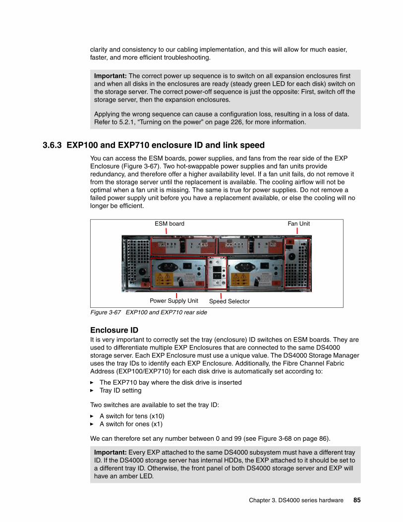
clarity and consistency to our cabling implementation, and this will allow for much easier, faster, and more efficient troubleshooting.
3.6.3 EXP100 and EXP710 enclosure ID and link speedYou can access the ESM boards, power supplies, and fans from the rear side of the EXP Enclosure (Figure 3-67). Two hot-swappable power supplies and fan units provide redundancy, and therefore offer a higher availability level. If a fan unit fails, do not remove it from the storage server until the replacement is available. The cooling airflow will not be optimal when a fan unit is missing. The same is true for power supplies. Do not remove a failed power supply unit before you have a replacement available, or else the cooling will no longer be efficient.
Figure 3-67 EXP100 and EXP710 rear side
Enclosure IDIt is very important to correctly set the tray (enclosure) ID switches on ESM boards. They are used to differentiate multiple EXP Enclosures that are connected to the same DS4000 storage server. Each EXP Enclosure must use a unique value. The DS4000 Storage Manager uses the tray IDs to identify each EXP Enclosure. Additionally, the Fibre Channel Fabric Address (EXP100/EXP710) for each disk drive is automatically set according to:
� The EXP710 bay where the disk drive is inserted� Tray ID setting
Two switches are available to set the tray ID:
� A switch for tens (x10)� A switch for ones (x1)
We can therefore set any number between 0 and 99 (see Figure 3-68 on page 86).
Important: The correct power up sequence is to switch on all expansion enclosures first and when all disks in the enclosures are ready (steady green LED for each disk) switch on the storage server. The correct power-off sequence is just the opposite: First, switch off the storage server, then the expansion enclosures.
Applying the wrong sequence can cause a configuration loss, resulting in a loss of data. Refer to 5.2.1, “Turning on the power” on page 226, for more information.
Important: Every EXP attached to the same DS4000 subsystem must have a different tray ID. If the DS4000 storage server has internal HDDs, the EXP attached to it should be set to a different tray ID. Otherwise, the front panel of both DS4000 storage server and EXP will have an amber LED.
ESM board Fan Unit
Power Supply Unit Speed Selector
Chapter 3. DS4000 series hardware 85
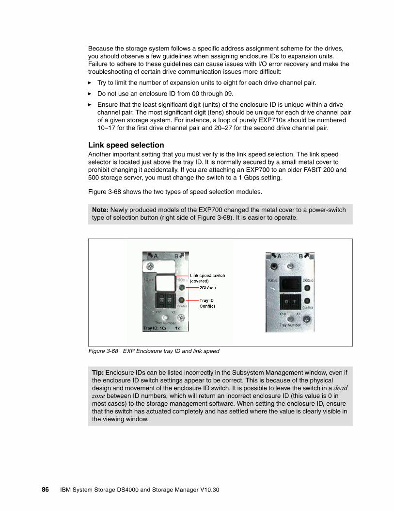
Because the storage system follows a specific address assignment scheme for the drives, you should observe a few guidelines when assigning enclosure IDs to expansion units. Failure to adhere to these guidelines can cause issues with I/O error recovery and make the troubleshooting of certain drive communication issues more difficult:
� Try to limit the number of expansion units to eight for each drive channel pair.
� Do not use an enclosure ID from 00 through 09.
� Ensure that the least significant digit (units) of the enclosure ID is unique within a drive channel pair. The most significant digit (tens) should be unique for each drive channel pair of a given storage system. For instance, a loop of purely EXP710s should be numbered 10–17 for the first drive channel pair and 20–27 for the second drive channel pair.
Link speed selectionAnother important setting that you must verify is the link speed selection. The link speed selector is located just above the tray ID. It is normally secured by a small metal cover to prohibit changing it accidentally. If you are attaching an EXP700 to an older FAStT 200 and 500 storage server, you must change the switch to a 1 Gbps setting.
Figure 3-68 shows the two types of speed selection modules.
Figure 3-68 EXP Enclosure tray ID and link speed
Note: Newly produced models of the EXP700 changed the metal cover to a power-switch type of selection button (right side of Figure 3-68). It is easier to operate.
Tip: Enclosure IDs can be listed incorrectly in the Subsystem Management window, even if the enclosure ID switch settings appear to be correct. This is because of the physical design and movement of the enclosure ID switch. It is possible to leave the switch in a dead zone between ID numbers, which will return an incorrect enclosure ID (this value is 0 in most cases) to the storage management software. When setting the enclosure ID, ensure that the switch has actuated completely and has settled where the value is clearly visible in the viewing window.
86 IBM System Storage DS4000 and Storage Manager V10.30
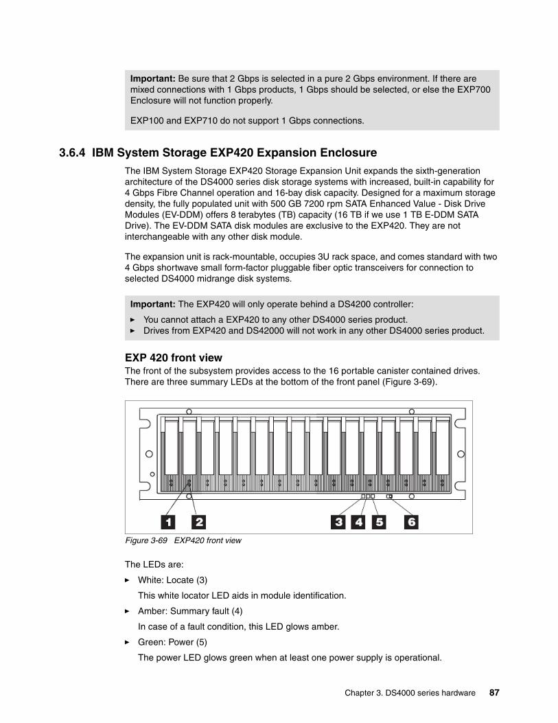
3.6.4 IBM System Storage EXP420 Expansion EnclosureThe IBM System Storage EXP420 Storage Expansion Unit expands the sixth-generation architecture of the DS4000 series disk storage systems with increased, built-in capability for 4 Gbps Fibre Channel operation and 16-bay disk capacity. Designed for a maximum storage density, the fully populated unit with 500 GB 7200 rpm SATA Enhanced Value - Disk Drive Modules (EV-DDM) offers 8 terabytes (TB) capacity (16 TB if we use 1 TB E-DDM SATA Drive). The EV-DDM SATA disk modules are exclusive to the EXP420. They are not interchangeable with any other disk module.
The expansion unit is rack-mountable, occupies 3U rack space, and comes standard with two 4 Gbps shortwave small form-factor pluggable fiber optic transceivers for connection to selected DS4000 midrange disk systems.
EXP 420 front viewThe front of the subsystem provides access to the 16 portable canister contained drives. There are three summary LEDs at the bottom of the front panel (Figure 3-69).
Figure 3-69 EXP420 front view
The LEDs are:
� White: Locate (3)
This white locator LED aids in module identification.
� Amber: Summary fault (4)
In case of a fault condition, this LED glows amber.
� Green: Power (5)
The power LED glows green when at least one power supply is operational.
Important: Be sure that 2 Gbps is selected in a pure 2 Gbps environment. If there are mixed connections with 1 Gbps products, 1 Gbps should be selected, or else the EXP700 Enclosure will not function properly.
EXP100 and EXP710 do not support 1 Gbps connections.
Important: The EXP420 will only operate behind a DS4200 controller:
� You cannot attach a EXP420 to any other DS4000 series product.� Drives from EXP420 and DS42000 will not work in any other DS4000 series product.
Chapter 3. DS4000 series hardware 87
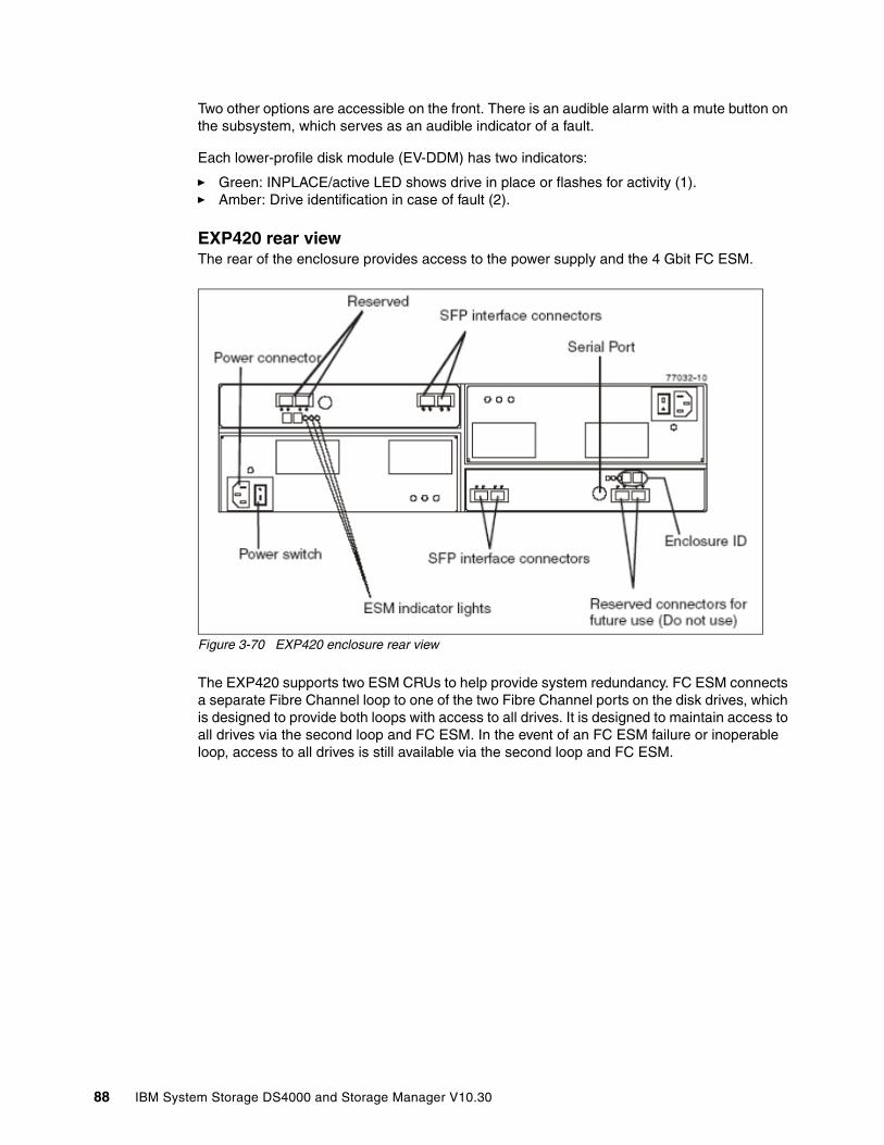
Two other options are accessible on the front. There is an audible alarm with a mute button on the subsystem, which serves as an audible indicator of a fault.
Each lower-profile disk module (EV-DDM) has two indicators:
� Green: INPLACE/active LED shows drive in place or flashes for activity (1).� Amber: Drive identification in case of fault (2).
EXP420 rear viewThe rear of the enclosure provides access to the power supply and the 4 Gbit FC ESM.
Figure 3-70 EXP420 enclosure rear view
The EXP420 supports two ESM CRUs to help provide system redundancy. FC ESM connects a separate Fibre Channel loop to one of the two Fibre Channel ports on the disk drives, which is designed to provide both loops with access to all drives. It is designed to maintain access to all drives via the second loop and FC ESM. In the event of an FC ESM failure or inoperable loop, access to all drives is still available via the second loop and FC ESM.
88 IBM System Storage DS4000 and Storage Manager V10.30

ESM indicatorsThe indicators on the ESM board, as shown in Figure 3-71, include:
� Power: Normally green and indicates that the enclosure is switched on.
� ESM fault: The amber color shows that the SCSI-3 Enclosure Services (SES) has detected a problem on the board. Normally it is off.
� Service action allowed: When blue, this indicates that it is safe to remove the ESM.
� Bypass LEDs: Amber if fiber connection is not detected. Blinking in case of fault.
� Port LEDs: Green to indicate the data rate according to the speed.
Figure 3-71 Seven-segment LEDs and diagnostic LED
In addition, each ESM CRU contains a dual 7-segment display that indicates a unique tray ID, which is determined by software/firmware. Both ESM displays within a drive enclosure displays the same tray ID.
If an error has occurred, the numeric display (7-segment display) shows diagnostic information. The numeric display indicates that the information is diagnostic by illuminating an LED that appears as a decimal point between the display numbers. The diagnostic LED turns off when the numeric display shows the storage subsystem enclosure ID under normal circumstances.
The numeric display shows various diagnostic codes as the enclosures perform the startup process after each power cycle or reset. After diagnostics are complete, the current storage subsystem enclosure ID is displayed. Diagnostic codes in the form of Lx or Hx, where x is a hexadecimal digit, indicate storage expansion enclosure state information. In general, these codes are displayed only when the storage expansion enclosure is in a non-operational state.
The storage expansion enclosure could be non-operational due to a configuration problem (such as mismatched types) or due to hardware faults. If the storage expansion enclosure is non-operational due to system configuration, the storage expansion enclosure ESM fault LED is off. If the storage expansion enclosure is non-operational due to a hardware fault, the storage expansion enclosure ESM fault LED is on.
Power supply and fansThe subsystem requires two power supplies to maintain system cooling. Each CRU consists of a portable, removable canister containing one 600-watt redundant switching power supply. The canister has four LEDs:
� Power LED: Glows green if the power supply is being applied and the power switch is on.
� Service action allowed: Glows blue to indicate that the power supply can safely be replaced.
F
A
G
D
B
CE
DP
C
D
G
A
E
FB
DP
SSD 1 SSD 2
Diagnostic indicatorLED
Chapter 3. DS4000 series hardware 89
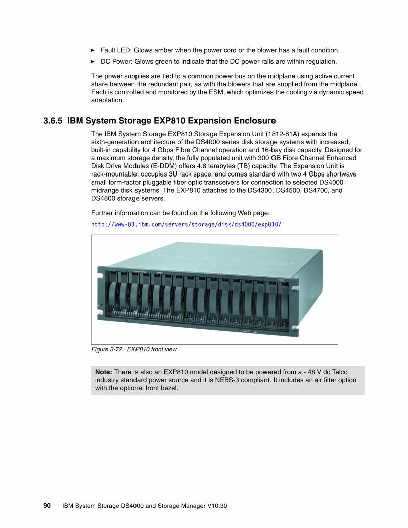
� Fault LED: Glows amber when the power cord or the blower has a fault condition.
� DC Power: Glows green to indicate that the DC power rails are within regulation.
The power supplies are tied to a common power bus on the midplane using active current share between the redundant pair, as with the blowers that are supplied from the midplane. Each is controlled and monitored by the ESM, which optimizes the cooling via dynamic speed adaptation.
3.6.5 IBM System Storage EXP810 Expansion EnclosureThe IBM System Storage EXP810 Storage Expansion Unit (1812-81A) expands the sixth-generation architecture of the DS4000 series disk storage systems with increased, built-in capability for 4 Gbps Fibre Channel operation and 16-bay disk capacity. Designed for a maximum storage density, the fully populated unit with 300 GB Fibre Channel Enhanced Disk Drive Modules (E-DDM) offers 4.8 terabytes (TB) capacity. The Expansion Unit is rack-mountable, occupies 3U rack space, and comes standard with two 4 Gbps shortwave small form-factor pluggable fiber optic transceivers for connection to selected DS4000 midrange disk systems. The EXP810 attaches to the DS4300, DS4500, DS4700, and DS4800 storage servers.
Further information can be found on the following Web page:
http://www-03.ibm.com/servers/storage/disk/ds4000/exp810/
Figure 3-72 EXP810 front view
Note: There is also an EXP810 model designed to be powered from a - 48 V dc Telco industry standard power source and it is NEBS-3 compliant. It includes an air filter option with the optional front bezel.
90 IBM System Storage DS4000 and Storage Manager V10.30
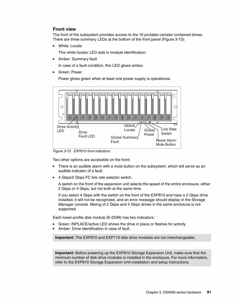
Front viewThe front of the subsystem provides access to the 16 portable canister contained drives. There are three summary LEDs at the bottom of the front panel (Figure 3-73):
� White: Locate
This white locator LED aids in module identification.
� Amber: Summary fault
In case of a fault condition, this LED glows amber.
� Green: Power
Power glows green when at least one power supply is operational.
Figure 3-73 EXP810 front indicators
Two other options are accessible on the front:
� There is an audible alarm with a mute button on the subsystem, which will serve as an audible indicator of a fault.
� 4 Gbps/2 Gbps FC link rate selector switch.
A switch on the front of the expansion unit selects the speed of the entire enclosure, either 2 Gbps or 4 Gbps, but not both at the same time.
If you select 4 Gbps with the switch on the front of the EXP810 and have a 2 Gbps drive installed, it will not be recognized, and an error message should display in the Storage Manager console. Mixing of 2 Gbps and 4 Gbps drives in the same enclosure is not supported.
Each lower-profile disk module (E-DDM) has two indicators:
� Green: INPLACE/active LED shows the drive in place or flashes for activity.� Amber: Drive identification in case of fault.
Important: The EXP810 and EXP710 disk drive modules are not interchangeable.
Important: Before powering up the EXP810 Storage Expansion Unit, make sure that the minimum number of disk drive modules is installed in the enclosure. For more information, refer to the EXP810 Storage Expansion Unit installation and setup instructions.
Chapter 3. DS4000 series hardware 91
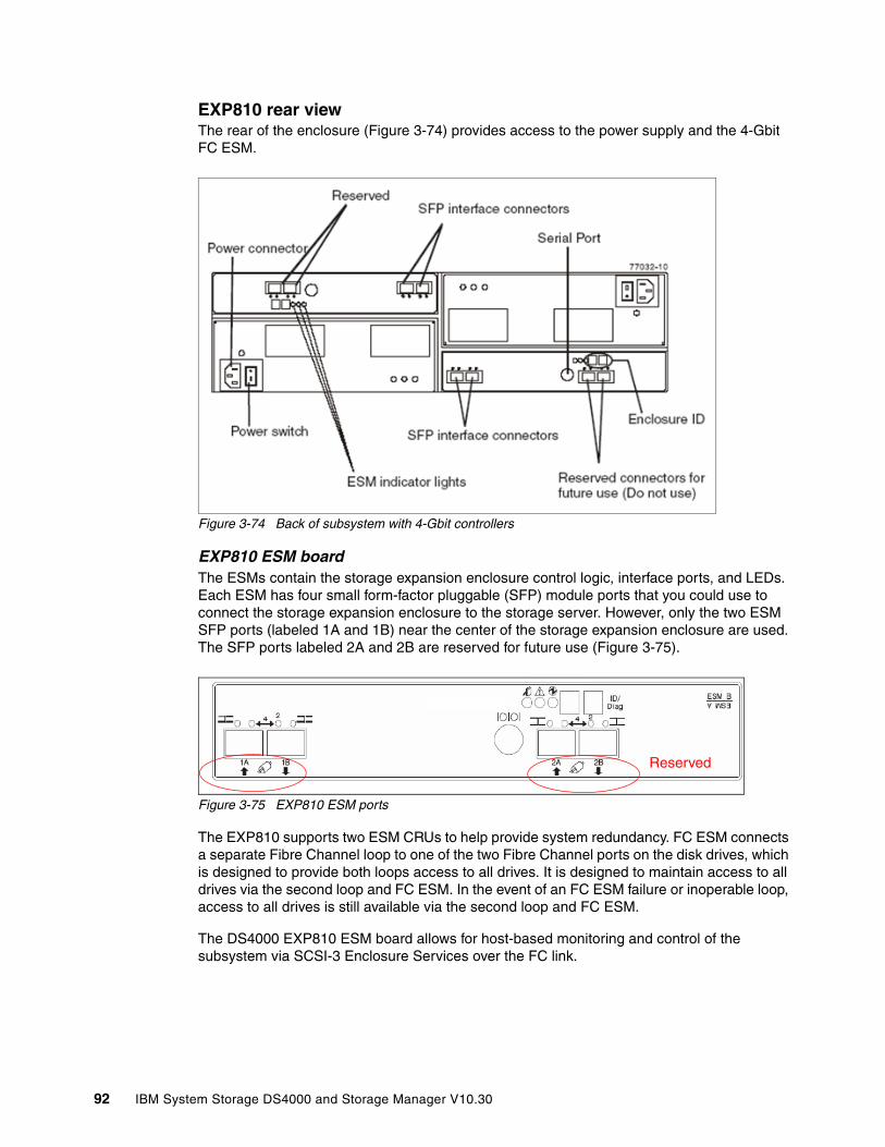
EXP810 rear viewThe rear of the enclosure (Figure 3-74) provides access to the power supply and the 4-Gbit FC ESM.
Figure 3-74 Back of subsystem with 4-Gbit controllers
EXP810 ESM boardThe ESMs contain the storage expansion enclosure control logic, interface ports, and LEDs. Each ESM has four small form-factor pluggable (SFP) module ports that you could use to connect the storage expansion enclosure to the storage server. However, only the two ESM SFP ports (labeled 1A and 1B) near the center of the storage expansion enclosure are used. The SFP ports labeled 2A and 2B are reserved for future use (Figure 3-75).
Figure 3-75 EXP810 ESM ports
The EXP810 supports two ESM CRUs to help provide system redundancy. FC ESM connects a separate Fibre Channel loop to one of the two Fibre Channel ports on the disk drives, which is designed to provide both loops access to all drives. It is designed to maintain access to all drives via the second loop and FC ESM. In the event of an FC ESM failure or inoperable loop, access to all drives is still available via the second loop and FC ESM.
The DS4000 EXP810 ESM board allows for host-based monitoring and control of the subsystem via SCSI-3 Enclosure Services over the FC link.
Reserved
92 IBM System Storage DS4000 and Storage Manager V10.30
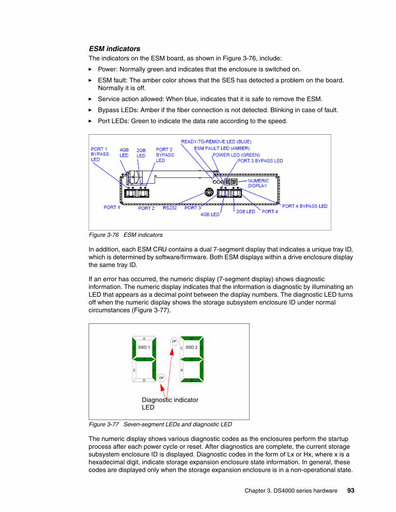
ESM indicatorsThe indicators on the ESM board, as shown in Figure 3-76, include:
� Power: Normally green and indicates that the enclosure is switched on.
� ESM fault: The amber color shows that the SES has detected a problem on the board. Normally it is off.
� Service action allowed: When blue, indicates that it is safe to remove the ESM.
� Bypass LEDs: Amber if the fiber connection is not detected. Blinking in case of fault.
� Port LEDs: Green to indicate the data rate according to the speed.
Figure 3-76 ESM indicators
In addition, each ESM CRU contains a dual 7-segment display that indicates a unique tray ID, which is determined by software/firmware. Both ESM displays within a drive enclosure display the same tray ID.
If an error has occurred, the numeric display (7-segment display) shows diagnostic information. The numeric display indicates that the information is diagnostic by illuminating an LED that appears as a decimal point between the display numbers. The diagnostic LED turns off when the numeric display shows the storage subsystem enclosure ID under normal circumstances (Figure 3-77).
Figure 3-77 Seven-segment LEDs and diagnostic LED
The numeric display shows various diagnostic codes as the enclosures perform the startup process after each power cycle or reset. After diagnostics are complete, the current storage subsystem enclosure ID is displayed. Diagnostic codes in the form of Lx or Hx, where x is a hexadecimal digit, indicate storage expansion enclosure state information. In general, these codes are displayed only when the storage expansion enclosure is in a non-operational state.
F
A
G
D
B
CE
DP
C
D
G
A
E
FB
DP
SSD 1 SSD 2
Diagnostic indicatorLED
Chapter 3. DS4000 series hardware 93
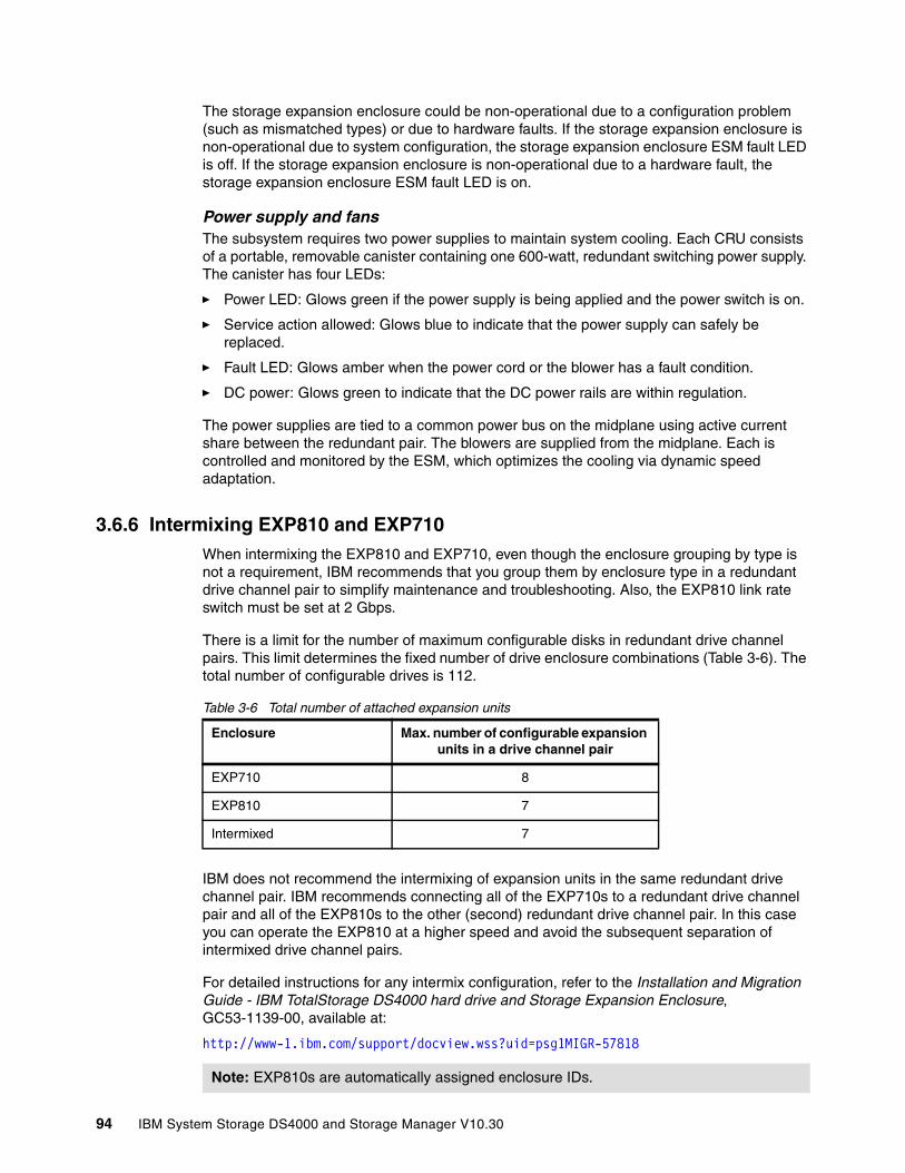
The storage expansion enclosure could be non-operational due to a configuration problem (such as mismatched types) or due to hardware faults. If the storage expansion enclosure is non-operational due to system configuration, the storage expansion enclosure ESM fault LED is off. If the storage expansion enclosure is non-operational due to a hardware fault, the storage expansion enclosure ESM fault LED is on.
Power supply and fansThe subsystem requires two power supplies to maintain system cooling. Each CRU consists of a portable, removable canister containing one 600-watt, redundant switching power supply. The canister has four LEDs:
� Power LED: Glows green if the power supply is being applied and the power switch is on.
� Service action allowed: Glows blue to indicate that the power supply can safely be replaced.
� Fault LED: Glows amber when the power cord or the blower has a fault condition.
� DC power: Glows green to indicate that the DC power rails are within regulation.
The power supplies are tied to a common power bus on the midplane using active current share between the redundant pair. The blowers are supplied from the midplane. Each is controlled and monitored by the ESM, which optimizes the cooling via dynamic speed adaptation.
3.6.6 Intermixing EXP810 and EXP710When intermixing the EXP810 and EXP710, even though the enclosure grouping by type is not a requirement, IBM recommends that you group them by enclosure type in a redundant drive channel pair to simplify maintenance and troubleshooting. Also, the EXP810 link rate switch must be set at 2 Gbps.
There is a limit for the number of maximum configurable disks in redundant drive channel pairs. This limit determines the fixed number of drive enclosure combinations (Table 3-6). The total number of configurable drives is 112.
Table 3-6 Total number of attached expansion units
IBM does not recommend the intermixing of expansion units in the same redundant drive channel pair. IBM recommends connecting all of the EXP710s to a redundant drive channel pair and all of the EXP810s to the other (second) redundant drive channel pair. In this case you can operate the EXP810 at a higher speed and avoid the subsequent separation of intermixed drive channel pairs.
For detailed instructions for any intermix configuration, refer to the Installation and Migration Guide - IBM TotalStorage DS4000 hard drive and Storage Expansion Enclosure, GC53-1139-00, available at:
http://www-1.ibm.com/support/docview.wss?uid=psg1MIGR-57818
Enclosure Max. number of configurable expansion units in a drive channel pair
EXP710 8
EXP810 7
Intermixed 7
Note: EXP810s are automatically assigned enclosure IDs.
94 IBM System Storage DS4000 and Storage Manager V10.30
3.6.7 Intermixing EXP100, EXP710, and EXP810 enclosures
Intermixing EXP100, EXP710, and EXP810 enclosures is supported with the DS4300, DS4500, DS4700, and DS4800.
The following requirements apply:
� The FC/SATA Intermix Feature must be ordered from IBM and enabled (licensed) on the storage server.
� Each array must be configured with the same type of drives, either all FC drives or all SATA drives. Intermixing FC and SATA in the same array is not supported.
� EXP100 expansion enclosures must be placed at the top or bottom of the intermixed stack.
Dependant upon the firmware version, EXP710, EXP100, and EXP810 enclosures can be intermixed. Below is a description of the intermixing details:
� With Version 6.15 firmware, the intermix of EXP710 and EXP100 was supported with the DS4800.
� With the Version 6.16 firmware, the intermix of EXP710 and EXP810 was supported on the DS4800, but the EXP100 was no longer supported with this firmware version.
� With the Version 6.16 firmware, the intermix of the EXP710 and EXP810 was supported on the DS4700.
� With Version 6.19 firmware, the intermix of EXP710, EXP100, and EXP810 is supported with the DS4300 and DS4500 only.
� With Version 6.23 or 6.60 firmware, the intermix of EXP710, EXP100, and EXP810 is supported with the DS4300, DS4500, DS4700, and DS4800.
� With Version 7.10 and 7.15 firmware, the intermix of EXP710, EXP100, and EXP810 is supported with the DS4700 and DS4800.
When intermixing these three types of enclosures, you group them by group of EXP100, followed or preceded by a group of EXP810 and EXP710 enclosures. Even though there is not a requirement to group EXP710 and EXP810 separately because the EXP810 and EXP710 enclosures are considered to be SBOD enclosures, IBM strongly recommends grouping EXP810 and EXP710 by enclosure type in the EP810/EXP710 enclosure group. The reason is to simplify maintenance and troubleshooting. Also, as the EXP710 and EXP100 only are 2 Gbps enclosures, when intermixing with the EXP810, its link rate switch must be set at 2 Gbps. Incorrect cabling of the EXP100 SATA enclosure could impact the performance of your DS4000 Storage Server.
Important: For detailed instructions on intermix configurations, refer to the IBM System Storage S4000/DS5000 Fibre Channel and Serial ATA Intermix Premium Feature Installation Overview:
http://www-947.ibm.com/systems/support/supportsite.wss/docdisplay?lndocid=MIGR-57823&brandind=5000028
Note: The link rate setting only becomes effective after the EXP810 is powered up. Do not change the setting while the EXP810 is operational. Schedule downtime to shut down the entire DS4000 configuration to change the link rate speed setting.
Chapter 3. DS4000 series hardware 95

There is a limit for the number of maximum configurable disks in redundant drive channel pairs. This limit determines the fixed number of drive enclosure combinations (Table 3-6 on page 94). The total number of configurable drives is 112.
Table 3-7 Total number of attached expansion units
Table 3-8 shows the DS4800 and the DS4500 for the intermix enclosure numbers.
Table 3-8 EXP810 and EXP710/EXP100 enclosures per drive channel pair for DS4500/DS4800
Table 3-9 Supported EXP810 and EXP710/EXP100 enclosures with the DS4700
Enclosure Max. number of configurable expansion units in a drive channel pair
EXP710 or EXP100 8
EXP810 7
Intermixed 7
Number of fully populated EXP810s
Total number of drives in EXP810
Number of fully populated EXP710s or EXP100s
Total number of drives in EXP710s and or EPXP100s
Total number of drives in a mixed EXP810 and EXP710 and or EXP100 drive channel pair
0 0 8 112 112
0 0 7 98 98
1 16 6 84 100
2 32 5 70 102
3 48 4 56 104
4 64 3 42 106
5 80 2 28 108
6 96 1 14 110
7 112 0 0 112
Number of fully populated EXP810s
Total number of drives in EXP810
Number of fully populated EXP710s or EXP100s
Total number of drives in EXP710s and or EX100s
Drives in DS4700
Total number of drives in mixed EXP810 and EXP710 and or EXP100s
0 0 6 84 16 100
1 16 5 70 16 102
2 32 4 56 16 104
3 48 3 42 16 106
4 64 2 28 16 108
5 80 1 14 16 110
96 IBM System Storage DS4000 and Storage Manager V10.30

With the DS4700 we recommend that the EXP710s or EXP100s are on their own drive channel pair.
Table 3-10 Supported EXP810 and EXP710/EXP100 enclosures with the DS4300 Turbo
6 96 0 0 16 112
Number of fully populated EXP810s
Total number of drives in EXP810
Number of fully populated EXP710s or EXP100
Total number of drives in EXP710s and or EXP100s
Drives in DS4300
Total number of drives in mixed EXP810 and EXP710 and or EXP100s
0 0 7 98 14 112
1 16 5 70 14 100
2 32 4 56 14 102
3 48 3 42 14 104
4 64 2 28 14 106
5 80 1 14 14 108
6 96 0 0 14 110
Number of fully populated EXP810s
Total number of drives in EXP810
Number of fully populated EXP710s or EXP100s
Total number of drives in EXP710s and or EX100s
Drives in DS4700
Total number of drives in mixed EXP810 and EXP710 and or EXP100s
Chapter 3. DS4000 series hardware 97

When intermixing EXP810 and EXP710, IBM recommends the cabling layout depicted in Figure 3-78 for the DS4800 and in Figure 3-79 on page 99 for the DS4700.
Figure 3-78 Preferred drive channel pair configuration for intermixed EXP810 and EXP710
98 IBM System Storage DS4000 and Storage Manager V10.30

Figure 3-79 Intermixing EXP710 and EXP810 enclosures with the DS4700
It is possible to create two drive channel pairs that run at different speeds behind the same DS4800, as shown in Figure 3-80. For instance, drive channel pair #1/drive channel pair #2 could each run at 4 Gbps, while drive channel pair #3/drive channel pair #4 could run at a slower 2 Gbps. See 3.3.10, “DS4800: Expansion enclosure scaling considerations” on page 68, for more information.
Figure 3-80 Example of mixed drive-side environment (2/4 Gbps)
2 Gbps4 Gbps Drive Channel Pair #1 Drive Channel Pair #3
Chapter 3. DS4000 series hardware 99
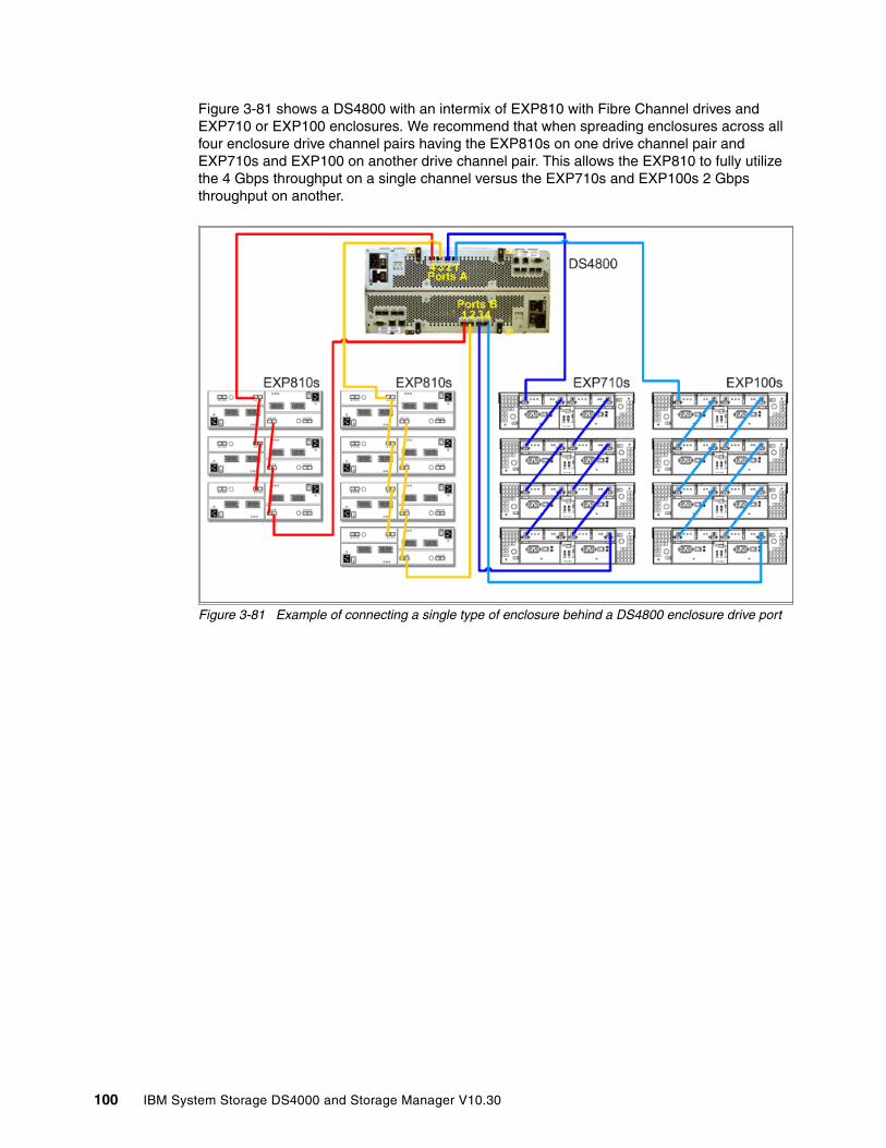
Figure 3-81 shows a DS4800 with an intermix of EXP810 with Fibre Channel drives and EXP710 or EXP100 enclosures. We recommend that when spreading enclosures across all four enclosure drive channel pairs having the EXP810s on one drive channel pair and EXP710s and EXP100 on another drive channel pair. This allows the EXP810 to fully utilize the 4 Gbps throughput on a single channel versus the EXP710s and EXP100s 2 Gbps throughput on another.
Figure 3-81 Example of connecting a single type of enclosure behind a DS4800 enclosure drive port
100 IBM System Storage DS4000 and Storage Manager V10.30
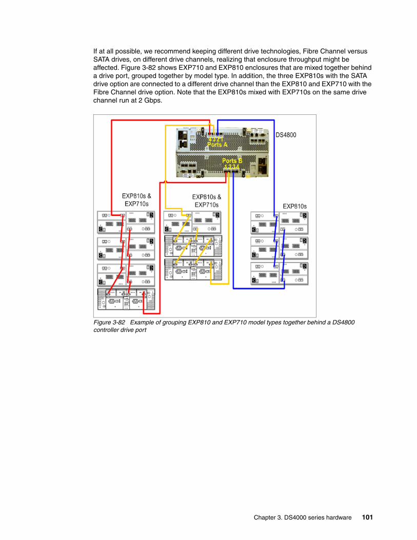
If at all possible, we recommend keeping different drive technologies, Fibre Channel versus SATA drives, on different drive channels, realizing that enclosure throughput might be affected. Figure 3-82 shows EXP710 and EXP810 enclosures that are mixed together behind a drive port, grouped together by model type. In addition, the three EXP810s with the SATA drive option are connected to a different drive channel than the EXP810 and EXP710 with the Fibre Channel drive option. Note that the EXP810s mixed with EXP710s on the same drive channel run at 2 Gbps.
Figure 3-82 Example of grouping EXP810 and EXP710 model types together behind a DS4800 controller drive port
Chapter 3. DS4000 series hardware 101
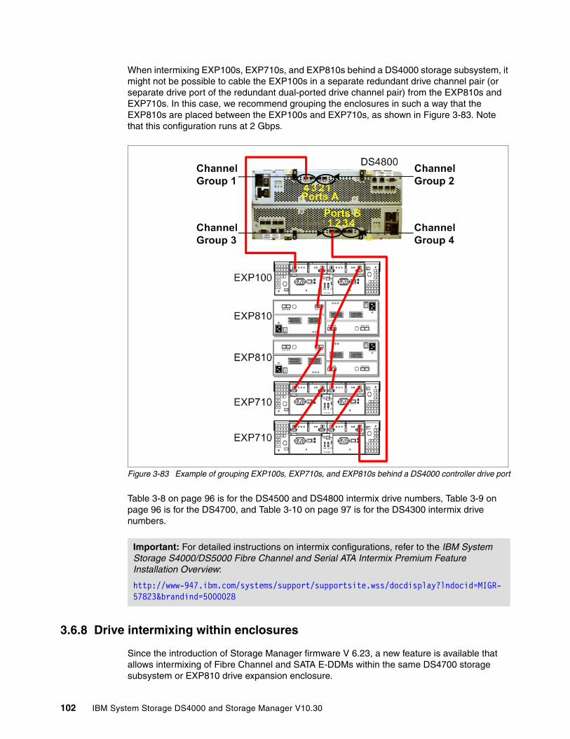
When intermixing EXP100s, EXP710s, and EXP810s behind a DS4000 storage subsystem, it might not be possible to cable the EXP100s in a separate redundant drive channel pair (or separate drive port of the redundant dual-ported drive channel pair) from the EXP810s and EXP710s. In this case, we recommend grouping the enclosures in such a way that the EXP810s are placed between the EXP100s and EXP710s, as shown in Figure 3-83. Note that this configuration runs at 2 Gbps.
Figure 3-83 Example of grouping EXP100s, EXP710s, and EXP810s behind a DS4000 controller drive port
Table 3-8 on page 96 is for the DS4500 and DS4800 intermix drive numbers, Table 3-9 on page 96 is for the DS4700, and Table 3-10 on page 97 is for the DS4300 intermix drive numbers.
3.6.8 Drive intermixing within enclosures
Since the introduction of Storage Manager firmware V 6.23, a new feature is available that allows intermixing of Fibre Channel and SATA E-DDMs within the same DS4700 storage subsystem or EXP810 drive expansion enclosure.
Important: For detailed instructions on intermix configurations, refer to the IBM System Storage S4000/DS5000 Fibre Channel and Serial ATA Intermix Premium Feature Installation Overview:
http://www-947.ibm.com/systems/support/supportsite.wss/docdisplay?lndocid=MIGR-57823&brandind=5000028
102 IBM System Storage DS4000 and Storage Manager V10.30
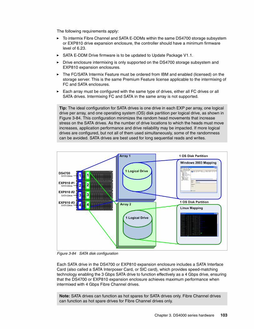
The following requirements apply:
� To intermix Fibre Channel and SATA E-DDMs within the same DS4700 storage subsystem or EXP810 drive expansion enclosure, the controller should have a minimum firmware level of 6.23.
� SATA E-DDM Drive firmware is to be updated to Update Package V1.1.
� Drive enclosure intermixing is only supported on the DS4700 storage subsystem and EXP810 expansion enclosures.
� The FC/SATA Intermix Feature must be ordered from IBM and enabled (licensed) on the storage server. This is the same Premium Feature license applicable to the intermixing of FC and SATA enclosures.
� Each array must be configured with the same type of drives, either all FC drives or all SATA drives. Intermixing FC and SATA in the same array is not supported.
Figure 3-84 SATA disk configuration
Each SATA drive in the DS4700 or EXP810 expansion enclosure includes a SATA Interface Card (also called a SATA Interposer Card, or SIC card), which provides speed-matching technology enabling the 3 Gbps SATA drive to function effectively as a 4 Gbps drive, ensuring that the DS4700 or EXP810 expansion enclosure achieves maximum performance when intermixed with 4 Gbps Fibre Channel drives.
Tip: The ideal configuration for SATA drives is one drive in each EXP per array, one logical drive per array, and one operating system (OS) disk partition per logical drive, as shown in Figure 3-84. This configuration minimizes the random head movements that increase stress on the SATA drives. As the number of drive locations to which the heads must move increases, application performance and drive reliability may be impacted. If more logical drives are configured, but not all of them used simultaneously, some of the randomness can be avoided. SATA drives are best used for long sequential reads and writes.
Note: SATA drives can function as hot spares for SATA drives only. Fibre Channel drives can function as hot spare drives for Fibre Channel drives only.
Chapter 3. DS4000 series hardware 103
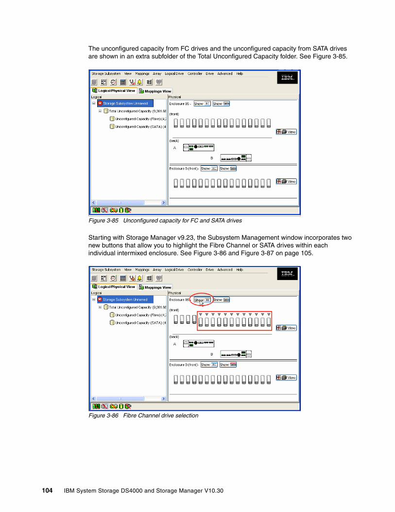
The unconfigured capacity from FC drives and the unconfigured capacity from SATA drives are shown in an extra subfolder of the Total Unconfigured Capacity folder. See Figure 3-85.
Figure 3-85 Unconfigured capacity for FC and SATA drives
Starting with Storage Manager v9.23, the Subsystem Management window incorporates two new buttons that allow you to highlight the Fibre Channel or SATA drives within each individual intermixed enclosure. See Figure 3-86 and Figure 3-87 on page 105.
Figure 3-86 Fibre Channel drive selection
104 IBM System Storage DS4000 and Storage Manager V10.30

Figure 3-87 SATA drive selection
However, when acceptable, intermixed configurations can be used as presented in the following examples:
� In a backup scenario where a FlashCopy and a VolumeCopy are made to a target logical drive residing on SATA disks technology. The backup can then be performed to tape, using less expensive storage for staging the data to be backed up and therefore reducing the total cost of the storage solution.
� If you can afford to do application testing utilizing SATA disk technology, a VolumeCopy of production data residing on Fibre Channel disks can be done to a logical volume on SATA disk technology, again using a less expensive disk for testing purposes.
3.7 DS4000 physical installation and cabling considerations In this section we review some topics of importance when planning for the physical installation of a DS4000 system. We review elements related to physical characteristics of an installation, such as fiber cables, Fibre Channel adapters, and other elements related to the structure of
Important: For detailed instructions on intermix configurations, refer to the IBM System Storage DS4000 Fibre Channel and Serial ATA Intermix Premium Feature Installation Overview.
Tip: The premium features FlashCopy, VolumeCopy, and Enhanced Remote Mirroring are supported in intermixed configurations. This means that you can configure copies and mirror relationships from FC drives to SATA drives and vice versa.
Best practice: We recommend that all copy services have the source and target logical drives of the same physical type, Fibre Channel versus SATA.
Chapter 3. DS4000 series hardware 105
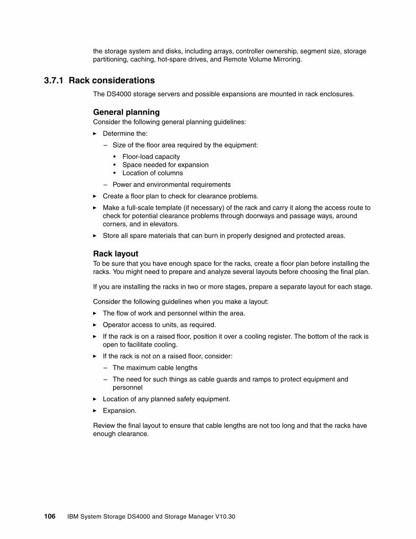
the storage system and disks, including arrays, controller ownership, segment size, storage partitioning, caching, hot-spare drives, and Remote Volume Mirroring.
3.7.1 Rack considerationsThe DS4000 storage servers and possible expansions are mounted in rack enclosures.
General planningConsider the following general planning guidelines:
� Determine the:
– Size of the floor area required by the equipment:
• Floor-load capacity• Space needed for expansion• Location of columns
– Power and environmental requirements
� Create a floor plan to check for clearance problems.
� Make a full-scale template (if necessary) of the rack and carry it along the access route to check for potential clearance problems through doorways and passage ways, around corners, and in elevators.
� Store all spare materials that can burn in properly designed and protected areas.
Rack layoutTo be sure that you have enough space for the racks, create a floor plan before installing the racks. You might need to prepare and analyze several layouts before choosing the final plan.
If you are installing the racks in two or more stages, prepare a separate layout for each stage.
Consider the following guidelines when you make a layout:
� The flow of work and personnel within the area.
� Operator access to units, as required.
� If the rack is on a raised floor, position it over a cooling register. The bottom of the rack is open to facilitate cooling.
� If the rack is not on a raised floor, consider:
– The maximum cable lengths
– The need for such things as cable guards and ramps to protect equipment and personnel
� Location of any planned safety equipment.
� Expansion.
Review the final layout to ensure that cable lengths are not too long and that the racks have enough clearance.
106 IBM System Storage DS4000 and Storage Manager V10.30
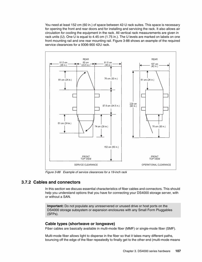
You need at least 152 cm (60 in.) of space between 42-U rack suites. This space is necessary for opening the front and rear doors and for installing and servicing the rack. It also allows air circulation for cooling the equipment in the rack. All vertical rack measurements are given in rack units (U). One U is equal to 4.45 cm (1.75 in.). The U levels are marked on labels on one front mounting rail and one rear mounting rail. Figure 3-88 shows an example of the required service clearances for a 9306-900 42U rack.
Figure 3-88 Example of service clearances for a 19-inch rack
3.7.2 Cables and connectorsIn this section we discuss essential characteristics of fiber cables and connectors. This should help you understand options that you have for connecting your DS4000 storage server, with or without a SAN.
Cable types (shortwave or longwave)Fiber cables are basically available in multi-mode fiber (MMF) or single-mode fiber (SMF).
Multi-mode fiber allows light to disperse in the fiber so that it takes many different paths, bouncing off the edge of the fiber repeatedly to finally get to the other end (multi-mode means
Important: Do not populate any unreservered or unused drive or host ports on the DS4000 storage subsystem or expansion enclosures with any Small Form Pluggables (SFPs).
Chapter 3. DS4000 series hardware 107
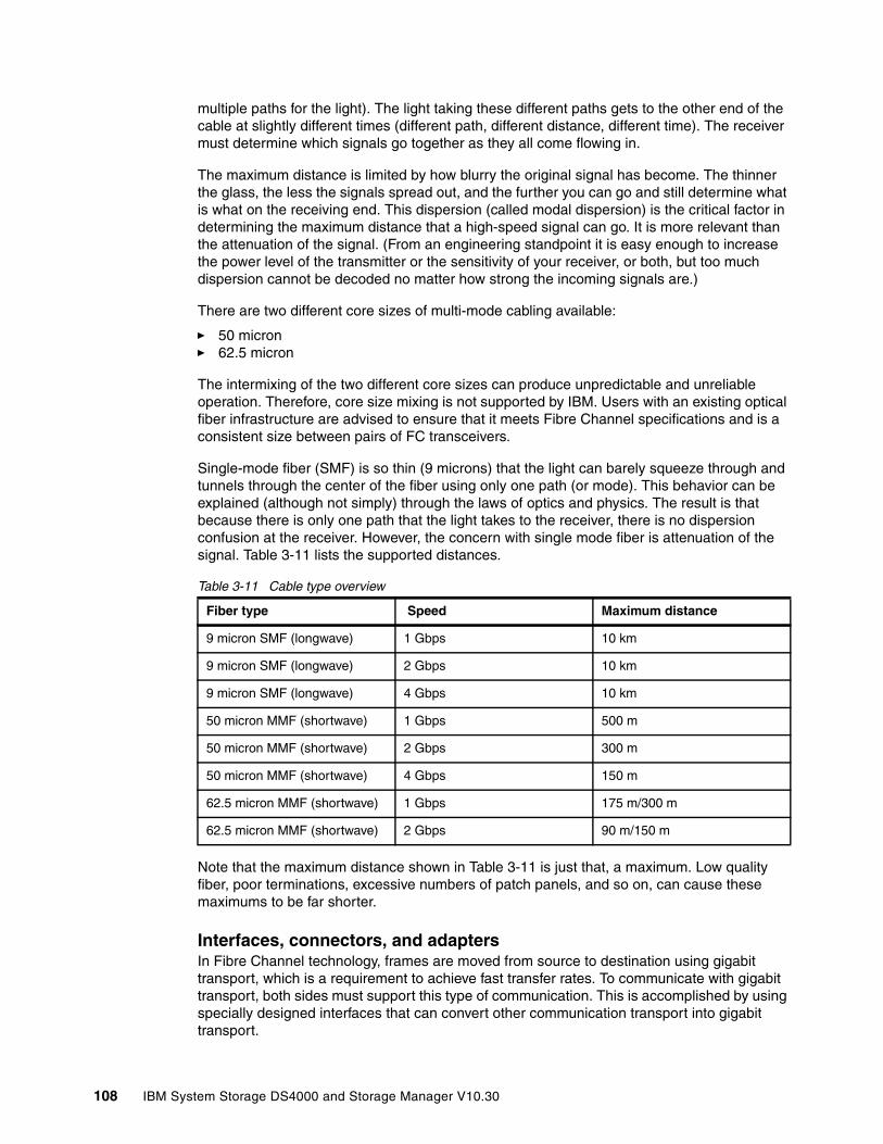
multiple paths for the light). The light taking these different paths gets to the other end of the cable at slightly different times (different path, different distance, different time). The receiver must determine which signals go together as they all come flowing in.
The maximum distance is limited by how blurry the original signal has become. The thinner the glass, the less the signals spread out, and the further you can go and still determine what is what on the receiving end. This dispersion (called modal dispersion) is the critical factor in determining the maximum distance that a high-speed signal can go. It is more relevant than the attenuation of the signal. (From an engineering standpoint it is easy enough to increase the power level of the transmitter or the sensitivity of your receiver, or both, but too much dispersion cannot be decoded no matter how strong the incoming signals are.)
There are two different core sizes of multi-mode cabling available:
� 50 micron � 62.5 micron
The intermixing of the two different core sizes can produce unpredictable and unreliable operation. Therefore, core size mixing is not supported by IBM. Users with an existing optical fiber infrastructure are advised to ensure that it meets Fibre Channel specifications and is a consistent size between pairs of FC transceivers.
Single-mode fiber (SMF) is so thin (9 microns) that the light can barely squeeze through and tunnels through the center of the fiber using only one path (or mode). This behavior can be explained (although not simply) through the laws of optics and physics. The result is that because there is only one path that the light takes to the receiver, there is no dispersion confusion at the receiver. However, the concern with single mode fiber is attenuation of the signal. Table 3-11 lists the supported distances.
Table 3-11 Cable type overview
Note that the maximum distance shown in Table 3-11 is just that, a maximum. Low quality fiber, poor terminations, excessive numbers of patch panels, and so on, can cause these maximums to be far shorter.
Interfaces, connectors, and adaptersIn Fibre Channel technology, frames are moved from source to destination using gigabit transport, which is a requirement to achieve fast transfer rates. To communicate with gigabit transport, both sides must support this type of communication. This is accomplished by using specially designed interfaces that can convert other communication transport into gigabit transport.
Fiber type Speed Maximum distance
9 micron SMF (longwave) 1 Gbps 10 km
9 micron SMF (longwave) 2 Gbps 10 km
9 micron SMF (longwave) 4 Gbps 10 km
50 micron MMF (shortwave) 1 Gbps 500 m
50 micron MMF (shortwave) 2 Gbps 300 m
50 micron MMF (shortwave) 4 Gbps 150 m
62.5 micron MMF (shortwave) 1 Gbps 175 m/300 m
62.5 micron MMF (shortwave) 2 Gbps 90 m/150 m
108 IBM System Storage DS4000 and Storage Manager V10.30
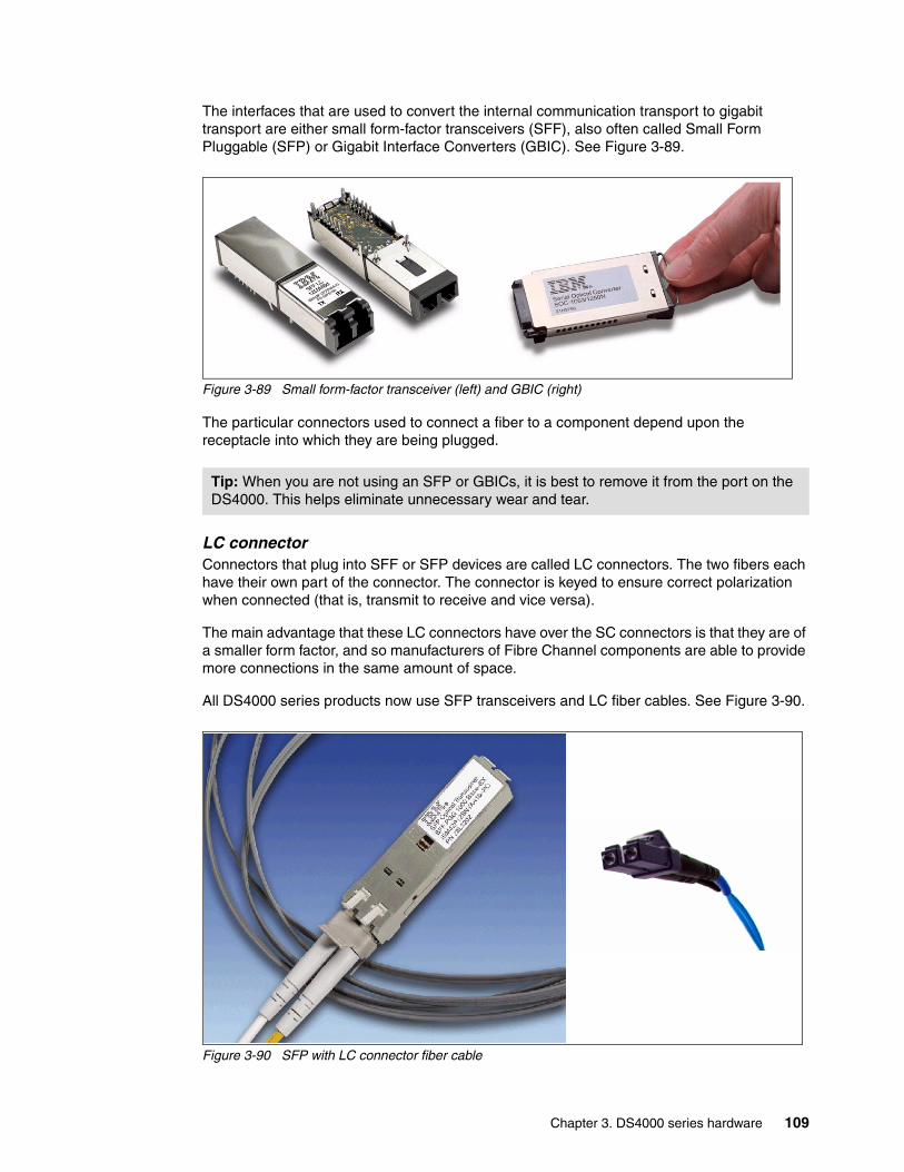
The interfaces that are used to convert the internal communication transport to gigabit transport are either small form-factor transceivers (SFF), also often called Small Form Pluggable (SFP) or Gigabit Interface Converters (GBIC). See Figure 3-89.
Figure 3-89 Small form-factor transceiver (left) and GBIC (right)
The particular connectors used to connect a fiber to a component depend upon the receptacle into which they are being plugged.
LC connectorConnectors that plug into SFF or SFP devices are called LC connectors. The two fibers each have their own part of the connector. The connector is keyed to ensure correct polarization when connected (that is, transmit to receive and vice versa).
The main advantage that these LC connectors have over the SC connectors is that they are of a smaller form factor, and so manufacturers of Fibre Channel components are able to provide more connections in the same amount of space.
All DS4000 series products now use SFP transceivers and LC fiber cables. See Figure 3-90.
Figure 3-90 SFP with LC connector fiber cable
Tip: When you are not using an SFP or GBICs, it is best to remove it from the port on the DS4000. This helps eliminate unnecessary wear and tear.
Chapter 3. DS4000 series hardware 109
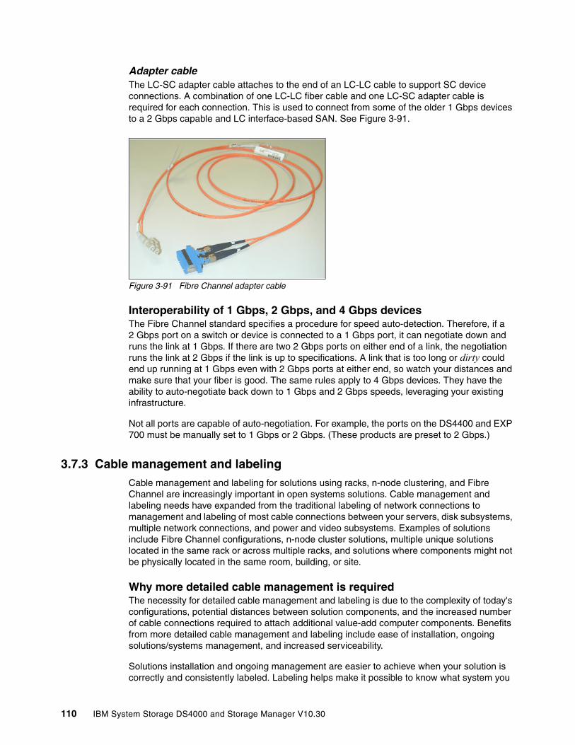
Adapter cableThe LC-SC adapter cable attaches to the end of an LC-LC cable to support SC device connections. A combination of one LC-LC fiber cable and one LC-SC adapter cable is required for each connection. This is used to connect from some of the older 1 Gbps devices to a 2 Gbps capable and LC interface-based SAN. See Figure 3-91.
Figure 3-91 Fibre Channel adapter cable
Interoperability of 1 Gbps, 2 Gbps, and 4 Gbps devicesThe Fibre Channel standard specifies a procedure for speed auto-detection. Therefore, if a 2 Gbps port on a switch or device is connected to a 1 Gbps port, it can negotiate down and runs the link at 1 Gbps. If there are two 2 Gbps ports on either end of a link, the negotiation runs the link at 2 Gbps if the link is up to specifications. A link that is too long or dirty could end up running at 1 Gbps even with 2 Gbps ports at either end, so watch your distances and make sure that your fiber is good. The same rules apply to 4 Gbps devices. They have the ability to auto-negotiate back down to 1 Gbps and 2 Gbps speeds, leveraging your existing infrastructure.
Not all ports are capable of auto-negotiation. For example, the ports on the DS4400 and EXP 700 must be manually set to 1 Gbps or 2 Gbps. (These products are preset to 2 Gbps.)
3.7.3 Cable management and labeling Cable management and labeling for solutions using racks, n-node clustering, and Fibre Channel are increasingly important in open systems solutions. Cable management and labeling needs have expanded from the traditional labeling of network connections to management and labeling of most cable connections between your servers, disk subsystems, multiple network connections, and power and video subsystems. Examples of solutions include Fibre Channel configurations, n-node cluster solutions, multiple unique solutions located in the same rack or across multiple racks, and solutions where components might not be physically located in the same room, building, or site.
Why more detailed cable management is requiredThe necessity for detailed cable management and labeling is due to the complexity of today's configurations, potential distances between solution components, and the increased number of cable connections required to attach additional value-add computer components. Benefits from more detailed cable management and labeling include ease of installation, ongoing solutions/systems management, and increased serviceability.
Solutions installation and ongoing management are easier to achieve when your solution is correctly and consistently labeled. Labeling helps make it possible to know what system you
110 IBM System Storage DS4000 and Storage Manager V10.30
are installing or managing, for example, when it is necessary to access the CD-ROM of a particular system and you are working from a centralized management console. It is also helpful to be able to visualize where each server is when completing custom configuration tasks such as node naming and assigning IP addresses.
Cable management and labeling improve service and support by reducing problem determination time, ensuring that the correct cable is disconnected when necessary. Labels assist in quickly identifying which cable must be removed when connected to a device such as a hub that might have multiple connections of the same cable type. Labels also help identify which cable to remove from a component. This is especially important when a cable connects two components that are not in the same rack, room, or even the same site.
Cable planningSuccessful cable management planning includes three basic activities:
� Site planning (before your solution is installed)� Cable routing� Cable labeling
Site planningAdequate site planning completed before your solution is installed results in a reduced chance of installation problems. Significant attributes covered by site planning are location specifications, electrical considerations, raised/non-raised floor determinations, and determination of cable lengths.
Cable routingWith effective cable routing, you can keep your solution's cables organized, reduce the risk of damaging cables, and allow for effective service and support. To assist with cable routing, IBM recommends the following guidelines:
� When installing cables to devices mounted on sliding rails:
– Run the cables neatly along equipment cable-management arms and tie the cables to the arms. (Obtain the cable ties locally.)
– Take particular care when attaching fiber optic cables to the rack. Refer to the instructions included with your fiber optic cables for guidance on minimum radius, handling, and care of fiber optic cables.
– Run the cables neatly along the rack rear corner posts.
– Use cable ties to secure the cables to the corner posts.
– Make sure that the cables cannot be pinched or cut by the rack rear door.
– Run internal cables that connect devices in adjoining racks through the open rack sides.
– Run external cables through the open rack bottom.
– Leave enough slack so that the device can be fully extended without putting a strain on the cables.
– Tie the cables so that the device can be retracted without pinching or cutting the cables.
Note: Do not use cable-management arms for fiber cables.
Chapter 3. DS4000 series hardware 111

� To avoid damage to your fiber optic cables, follow these guidelines:
– Use great care when utilizing cable management arms.
– When attaching to a device on slides, leave enough slack in the cable so that it does not bend to a radius smaller than 76 mm (3 in.) when extended or become pinched when retracted.
– Route the cable away from places where it can be snagged by other devices in the rack.
– Do not overtighten the cable straps or bend the cables to a radius smaller than 76 mm (3 in.).
– Do not put excess weight on the cable at the connection point and be sure that it is well supported. For instance, a cable that goes from the top of the rack to the bottom must have some method of support other than the strain relief boots built into the cable.
Additional information for routing cables with IBM Netfinity® Rack products can be found in the IBM Netfinity Rack Planning and Installation Guide, part number 24L8055. This publication includes pictures providing more details about the recommended cable routing.
Cable labelingWhen labeling your solution, follow these tips:
� As you install cables in the rack, label each cable with appropriate identification.
� Remember to attach labels to any cables that you replace.
� Document deviations from the label scheme that you use. Keep a copy with your Change Control Log book.
Whether using a simple or complex scheme, the label should always implement a format including these attributes:
� Function (optional).
� Location information should be broad to specific (for example, the site/building to a specific port on a server or hub).
� The optional Function row helps identify the purpose of the cable (that is, Ethernet versus token ring or between multiple networks).
Other cabling mistakesSome of the most common mistakes include:
� Leaving cables hanging from connections with no support.
� Not using dust caps.
� Not keeping connectors clean. (Some cable manufacturers require the use of lint-free alcohol wipes in order to maintain the cable warranty.)
� Leaving cables on the floor where people might kick or trip over them.
� Not removing old cables when they are no longer needed and are not planned for future use.
3.7.4 Fibre Channel adaptersWe now review hardware-related topics for Fibre Channel adapters:
� Placement on the host system bus� Distributing the load among several adapters
112 IBM System Storage DS4000 and Storage Manager V10.30

Host system busToday, there is a choice of high-speed adapters for connecting disk drives. Fast adapters can provide better performance.
Qlogic-based HBAs come in both 2 Gbps and 4 Gbps speeds. The FC4 is the new 4 Gbps PCI-X HBA. It comes in both dual port and single port. Care should be used with the 4 Gbps dual port, as it must be in a high performance slot. Otherwise, it could become the host performance bottleneck.
Emulex-based HBAs come in both 2 Gbps and 4 Gbps speeds. The new 4 Gbps HBAs come in PCI-X and PCI-E and single and dual port. Care should be used with the 4 Gbps dual port, as it must be in a high-performance slot. Otherwise, it could become the host performance bottleneck.
We recommend that you distribute high-speed adapters across several busses. When you use PCI adapters, make sure that you first review your system specifications. Some systems include a PCI adapter placement guide.
The number of adapters that you can install depends on the number of PCI slots available on your server, but also on what traffic volume you expect on your SAN. The rationale behind multiple adapters is either redundancy (failover) or load sharing.
Refer to the following Web site for a list of DS4000-supported HBAs in various platforms:
http://www-03.ibm.com/servers/storage/disk/ds4000/interop-matrix.html
3.7.5 SAN switchesIBM offers a wide variety of SAN switches that can be used when connecting DS4000 storage servers in a SAN infrastructure.
For a full list of products, consult the following Web site:
http://www.storage.ibm.com/ibmsan
For the latest firmware level and SAN support, see:
http://www.ibm.com/servers/storage/support/san/index.html
For a list of DS4000-supported SAN fabrics, routers, and gateways, see:
http://www-03.ibm.com/servers/storage/disk/ds4000/interop-matrix.html
Important: Do not place all the high-speed host bus adapters on a single system bus. If you do, the computer bus becomes the performance bottleneck.
Chapter 3. DS4000 series hardware 113

114 IBM System Storage DS4000 and Storage Manager V10.30
Chapter 4. Managing the DS4000
This chapter presents the main features and components of the DS4000 Storage Manager software that is used to configure, manage, and troubleshoot the DS4000 storage servers.
We start by introducing the components of the DS4000 Storage Manager and the management methods, and then continue with an overview of the concepts and tasks used for basic management of the storage server. Finally, we introduce the premium features, then discuss storage virtualization.
You can use the DS4000 Storage Manager software to:
� Create new arrays and logical drives.
� Expand existing arrays and logical drives.
� Migrate to a different RAID level.
� Configure storage partitioning.
� Tune the DS4000 storage server.
� Perform diagnostic and troubleshooting tasks.
� Use advanced functions such as FlashCopy, VolumeCopy, and Enhanced Remote Mirroring.
4
© Copyright IBM Corp. 2004, 2005, 2006, 2007, 2008, 2009. All rights reserved. 115
4.1 DS4000 Storage Manager Software
The DS4000 Storage Manager software is used to:
� Configure arrays and logical drives.� Assign logical drives into storage partitions.� Replace and rebuild failed disk drives.� Expand the size of arrays and logical drives.� Convert from one RAID level to another.
Storage Manager also allows you to perform troubleshooting and management tasks, like checking the status of the storage server components, updating the firmware of RAID controllers, and similar activities.
The IBM DS4000 Storage Manager software is packaged as two separate groups of software, as illustrated in Figure 4-1 on page 117. The host-based software consists of all the software components that must be installed on a host system using the storage server or a management station controlling the storage server. The controller-based software is all of the firmware that is required for the different components of the storage server.
Note: Not all software components are available for all platforms.
116 IBM System Storage DS4000 and Storage Manager V10.30
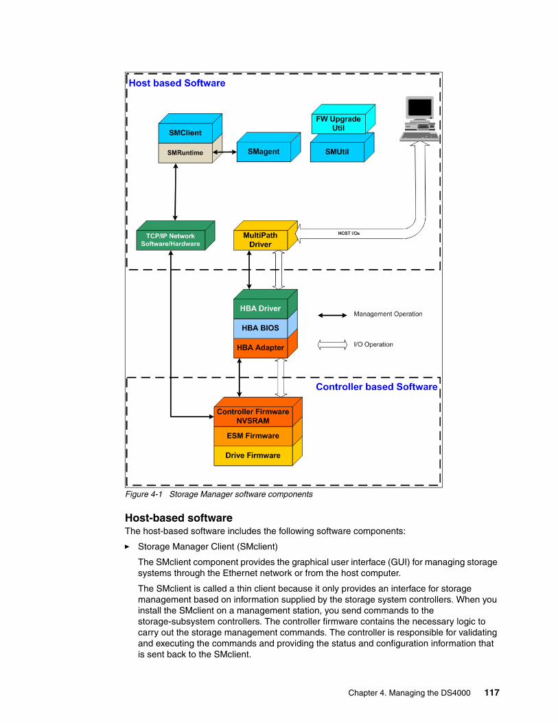
Figure 4-1 Storage Manager software components
Host-based softwareThe host-based software includes the following software components:
� Storage Manager Client (SMclient)
The SMclient component provides the graphical user interface (GUI) for managing storage systems through the Ethernet network or from the host computer.
The SMclient is called a thin client because it only provides an interface for storage management based on information supplied by the storage system controllers. When you install the SMclient on a management station, you send commands to the storage-subsystem controllers. The controller firmware contains the necessary logic to carry out the storage management commands. The controller is responsible for validating and executing the commands and providing the status and configuration information that is sent back to the SMclient.
Chapter 4. Managing the DS4000 117
The SMclient is bundled with an Event Monitor, which can run in the background and send alert notifications in the event of a critical problem. The Event Monitor service handles notification functions (e-mail and SNMP traps) and monitors storage systems whenever the Enterprise Management window is not open.
The command-line interface (SMcli) is also packaged with the SMclient and provides command-line access to perform all management functions.
Refer to 4.1.2, “The Storage Manager client” on page 123, for additional details. The functions of the SMclient are reviewed throughout this book.
� Storage Manager Runtime (SMruntime)
The SMruntime is a Java runtime environment™ that is required for the SMclient to function. It is not available on every platform as a separate package, but in those cases it has been bundled into the SMclient package.
� Storage Manager Agent (SMagent)
The SMagent package is an optional component that allows in-band management of the DS4000 storage server. This agent allows you to manage your storage server using the same path as the I/O requests coming from the system. The host agent software takes requests from a management station that is connected to the host computer through a network connection and passes the requests to the storage system controllers through the Fibre Channel I/O path.
The host agent, along with the network connection on the host computer, provides an in-band host agent type network management connection to the storage system instead of the out-of-band direct network management connection through the individual Ethernet connections on each controller. The management station can communicate with a storage system through the host computer that has host agent management software installed. The host agent receives requests from the management station through the network connection to the host computer and sends them to the controllers in the storage system through the Fibre Channel I/O path.
� Storage Manager Utilities (SMutil)
The Storage Manager Utilities package contains command-line tools such as:
– hot_add: Allows you to dynamically discover new logical drives for use by the host.
– SMdevices: Allows you to view logical drives for the host.
– SMrepassist: Allows you to flush buffers in anticipation of a FlashCopy operation.
– mppUtil: Allows you to configure and troubleshoot the RDAC driver for Linux RDAC. This utility can display information on the RDAC driver itself, assist in debugging errors, and can manually initiate one of the RDAC driver’s scan tasks. This utility is installed with the RDAC driver itself.
Refer to 4.1.3, “Storage Manager utilities” on page 126, for more details.
Note: This is a Windows-only utility. Unmount the file system when using other operating systems.
118 IBM System Storage DS4000 and Storage Manager V10.30
� Multipath Driver
Fibre Channel I/O path failover drivers or multipath drivers are installed on host computers, depending on the operating system of the host computer. Usually, a pair of active controllers is located in a storage system enclosure. Each logical drive in the storage system is assigned to one of the controllers, which controls the Fibre Channel I/O path between the logical drive and the host computer through the Fibre Channel network. When a component in the Fibre Channel I/O path fails, such as a cable or the controller itself, the multipath driver transfers ownership of the logical drives assigned to that controller to the other controller in the pair.
For more information about multipath drivers refer to 4.1.5, “Multipath driver support” on page 129.
� Controller firmware upgrade utility
With Storage Manager v10.10 a Controller firmware upgrade utility was introduced and included in the package. This utility can also be downloaded from the IBM support Web site as a separate package. The utility is required to upgrade controller firmware on storage subsystems between major firmware release levels only, for example, upgrading from firmware release v6.14 to V7.10 or later. This includes not only upgrading the controller firmware and Non Volatile Static Random Access Memory (NVSRAM), but also a migration of the drive configuration database (DACstore) to the new format. The upgrade utility helps to ensure that any storage subsystem selected meets the following conditions:
– It is at the supported levels of hardware and controller firmware.
– It has no existing conditions that may prevent the upgrade from completing successfully.
– It has its configuration and Major Event Log (MEL) saved prior to upgrade for later use if required.
– It is offline for the minimum amount of time possible.
This utility is a stand-alone application that runs independently of any storage management application. It is run from any workstation that has a management connection (either in-band or out-of-band) to the storage subsystem for communication and file-transfer purposes. A read-me file is provided within the installation directory structure that contains restrictions, limitations, recommendations, and instructions for using the utility.
The utility performs compatibility checking for files selected for download. Files must be compatible with the controller type of the selected storage subsystem to allow the upgrade to take place.
For information about how to use the controller firmware upgrade utility refer to Chapter 12, “Advanced maintenance” on page 661.
Controller-based softwareThe controller-based software consists of:
� DS4000 storage server controller firmware and NVSRAM
The controller firmware and NVSRAM are always installed as a pair and provide the brains of the DS4000 storage server. All commands from the SMclient and SMcli come through this code to cause actions to be performed on the storage devices. The controller
Note: Firmware release V7.10 and later are only supported on DS4200, DS4700, and DS4800 storage subsystems.
Chapter 4. Managing the DS4000 119

firmware can be thought of as the operating system and application code for the storage server, while the NVSRAM can be thought of as the configuration of the application.
� DS4000 storage server Environmental Service Modules (ESM) firmware
The ESM firmware controls the interface between the controller and the drives.
� DS4000 storage server drive firmware
The drive firmware is the software that tells the Fibre Channel (FC) drives how to behave on the FC loop.
4.1.1 Storage subsystem management methodsThe storage-management software provides two methods for managing storage systems:
� Host agent (in-band) management method � Direct (out-of-band) management method
Depending on your specific storage system configurations and host systems, you can use either or both methods. The management methods that you select determine where you must install the software components.
Host agent (in-band) management methodWhen you use the host agent (in-band) management method, you manage the storage systems through the Fibre Channel I/O path to the host. This requires installation of the Storage Manager agent (SMagent) package. The management information can either be processed on the host or passed to the management station through the network connection, as shown in Figure 4-2.
Figure 4-2 In-band management
120 IBM System Storage DS4000 and Storage Manager V10.30
Managing storage systems through the host agent has the following advantages:
� Ethernet cables do not need to be run to the controllers.
� A host name or IP address must only be specified for the host instead of for the individual controllers in a storage system. Storage systems that are attached to the host can be automatically discovered.
Managing storage systems through the host agent has the following disadvantages:
� The host agent requires a special logical drive, called the access logical drive, to communicate with the controllers in the storage system. Therefore, you are limited to configuring one less logical drive than the maximum number that is allowed by the operating system and the host adapter that you are using. Not all operating systems support the access logical drive. In-band management is not supported on these systems.
� If the connection through the Fibre Channel is lost between the host and the subsystem, the subsystem cannot be managed or monitored.
Notes: The access logical drive is also referred to as the Universal Transport Mechanism (UTM) device.
Linux does not support the access LUN. Thus, it cannot support in-band management.
Important: If your host already has the maximum number of logical drives configured, either use the direct management method or give up a logical drive for use as the access logical drive.
Chapter 4. Managing the DS4000 121
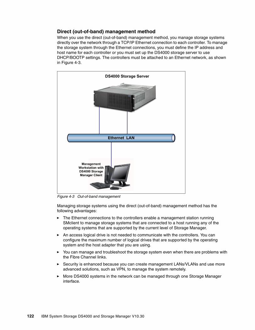
Direct (out-of-band) management methodWhen you use the direct (out-of-band) management method, you manage storage systems directly over the network through a TCP/IP Ethernet connection to each controller. To manage the storage system through the Ethernet connections, you must define the IP address and host name for each controller or you must set up the DS4000 storage server to use DHCP/BOOTP settings. The controllers must be attached to an Ethernet network, as shown in Figure 4-3.
Figure 4-3 Out-of-band management
Managing storage systems using the direct (out-of-band) management method has the following advantages:
� The Ethernet connections to the controllers enable a management station running SMclient to manage storage systems that are connected to a host running any of the operating systems that are supported by the current level of Storage Manager.
� An access logical drive is not needed to communicate with the controllers. You can configure the maximum number of logical drives that are supported by the operating system and the host adapter that you are using.
� You can manage and troubleshoot the storage system even when there are problems with the Fibre Channel links.
� Security is enhanced because you can create management LANs/VLANs and use more advanced solutions, such as VPN, to manage the system remotely.
� More DS4000 systems in the network can be managed through one Storage Manager interface.
122 IBM System Storage DS4000 and Storage Manager V10.30

Managing storage systems using the direct (out-of-band) management method has the following disadvantages:
� You need two Ethernet cables to connect the storage system controllers to a network.
� When adding devices, you must specify an IP address or host name for each controller.
� You might need a DHCP/BOOTP server, and network preparation tasks are required. You can avoid DHCP/BOOTP server and network tasks by assigning static IP addresses to the controller or by using the default IP address.
To assign static IP addresses refer to 5.2.2, “Network setup of the controllers” on page 226.
4.1.2 The Storage Manager clientIn this section we continue our overview of the Storage Manager client.
Supported host systemsThe DS4000/FastT Storage Manager client is a Java-based GUI utility that is available for various operating systems. For up-to-date information about support for specific DS4000 models and operating systems, check the DS4000 support Web site at:
http://www.ibm.com/servers/storage/support/disk
The DS4000 Storage Manager client uses two main window types to give you control over your storage servers:
� The Enterprise Management window� The Subsystem Management window
Tip: To manage storage subsystems through a firewall, configure the firewall to open port 2463 for TCP and UDP data.
Note: On the DS4200, DS4700, and DS4800, there are two Ethernet connections per controller. One port is designed for out-of-band management and the other port is meant for serviceability. Previous models had only one port that handled both management and service for each controller. The logic behind adding an extra port is to introduce additional isolation and to separate management and service traffic from one another. Because of the extra port, it is now desirable to have two IP addresses per controller in order to manage and service these DS4000s appropriately. You can still operate the DS4000 with only one IP port active per controller. You can assign either of the two ports for management or service on a given controller.
Chapter 4. Managing the DS4000 123
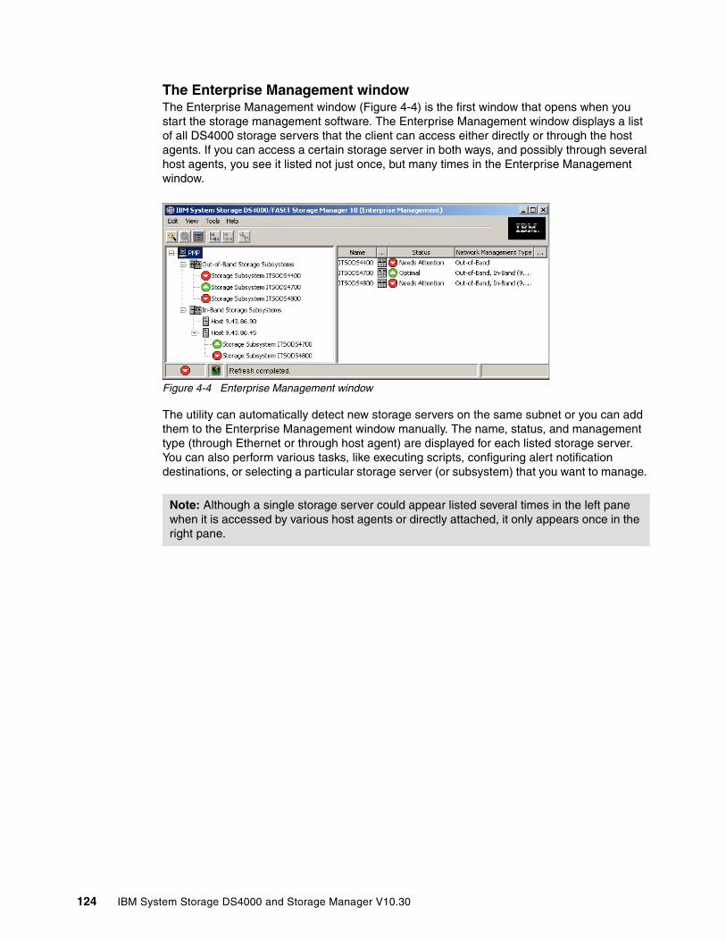
The Enterprise Management windowThe Enterprise Management window (Figure 4-4) is the first window that opens when you start the storage management software. The Enterprise Management window displays a list of all DS4000 storage servers that the client can access either directly or through the host agents. If you can access a certain storage server in both ways, and possibly through several host agents, you see it listed not just once, but many times in the Enterprise Management window.
Figure 4-4 Enterprise Management window
The utility can automatically detect new storage servers on the same subnet or you can add them to the Enterprise Management window manually. The name, status, and management type (through Ethernet or through host agent) are displayed for each listed storage server. You can also perform various tasks, like executing scripts, configuring alert notification destinations, or selecting a particular storage server (or subsystem) that you want to manage.
Note: Although a single storage server could appear listed several times in the left pane when it is accessed by various host agents or directly attached, it only appears once in the right pane.
124 IBM System Storage DS4000 and Storage Manager V10.30

The Subsystem Management windowOnce you select a system that you want to manage in the Enterprise Management window, the Subsystem Management window for that particular system opens. As you can see in Figure 4-5, this window has two tabs that can be alternated. A specific Subsystem Management window allows you to manage one particular storage server, but you can have multiple windows open at any one time.
Figure 4-5 The Logical/physical view
Logical/physical viewThe left pane shows the logical view. The storage-subsystem capacity is organized into a tree-like structure that shows all arrays and logical drives configured on the storage server. You can select any array or logical drive object in the tree and perform various tasks on it.
The right pane shows the physical view. The physical view displays the physical devices in the storage system, such as controllers and drives. When you click a logical drive or other item in the logical view, the associated physical components are displayed in the physical view. Selection of controllers or disk drives enables you to perform tasks on them.
Chapter 4. Managing the DS4000 125
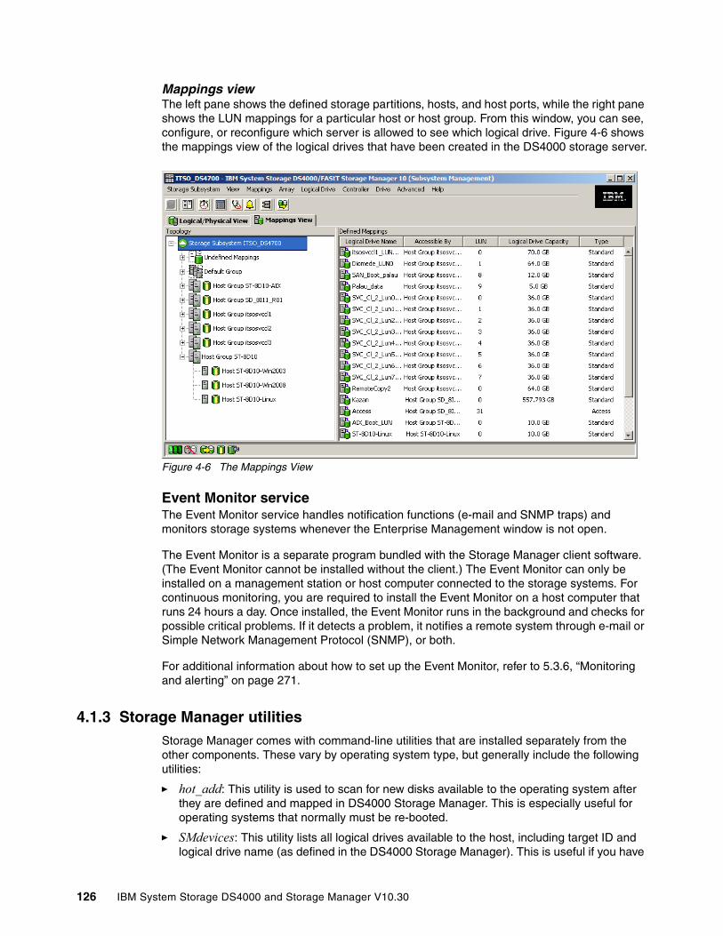
Mappings viewThe left pane shows the defined storage partitions, hosts, and host ports, while the right pane shows the LUN mappings for a particular host or host group. From this window, you can see, configure, or reconfigure which server is allowed to see which logical drive. Figure 4-6 shows the mappings view of the logical drives that have been created in the DS4000 storage server.
Figure 4-6 The Mappings View
Event Monitor serviceThe Event Monitor service handles notification functions (e-mail and SNMP traps) and monitors storage systems whenever the Enterprise Management window is not open.
The Event Monitor is a separate program bundled with the Storage Manager client software. (The Event Monitor cannot be installed without the client.) The Event Monitor can only be installed on a management station or host computer connected to the storage systems. For continuous monitoring, you are required to install the Event Monitor on a host computer that runs 24 hours a day. Once installed, the Event Monitor runs in the background and checks for possible critical problems. If it detects a problem, it notifies a remote system through e-mail or Simple Network Management Protocol (SNMP), or both.
For additional information about how to set up the Event Monitor, refer to 5.3.6, “Monitoring and alerting” on page 271.
4.1.3 Storage Manager utilitiesStorage Manager comes with command-line utilities that are installed separately from the other components. These vary by operating system type, but generally include the following utilities:
� hot_add: This utility is used to scan for new disks available to the operating system after they are defined and mapped in DS4000 Storage Manager. This is especially useful for operating systems that normally must be re-booted.
� SMdevices: This utility lists all logical drives available to the host, including target ID and logical drive name (as defined in the DS4000 Storage Manager). This is useful if you have
126 IBM System Storage DS4000 and Storage Manager V10.30
several logical drives of the same size defined for a given host because it allows you to identify which is which before mounting and formatting under the operating system.
� SMrepassist: This utility is a host-based utility for Windows platforms and performs certain functions needed to make the subsystem hardware FlashCopy work smoothly. It is run against a specific drive or mount point and causes the buffers to be flushed to disk.
� mppUtil: This utility is used in conjunction with the Linux RDAC driver to configure and troubleshoot the driver. This utility can display information on the RDAC driver itself, assist in debugging errors, and manually initiate one of the RDAC driver’s scan tasks. This utility is installed with the RDAC driver itself.
For information about how to install Storage Manager utilities refer to 5.1, “Installing DS4000 Storage Manager software” on page 180.
4.1.4 Host Bus Drivers for Windows
With the host bus adapter (HBA) for Windows there is a choice of two drivers, SCSIPort and StorPort. The proper driver selection could impact performance and reliability of the entire storage solution.
SCSIport and Storport device driversMicrosoft Windows operating systems use two types of storage interface drivers in conjunction with vendor-written, adapter-specific drivers (miniport drivers). These are the SCSIport driver and the Storport driver.
Until recently, the HBA drivers developed by the different vendors have relied on the Microsoft SCSIport driver. The SCSIport driver, however, was designed to work optimally with the parallel SCSI interconnects used with direct-attached storage and it cannot meet the high-performance standards of Fibre Channel SAN configurations and RAID storage systems, such as the DS4000.
Some of these limitations are:
� Adapter I/O limits
SCSIport can support a maximum of 254 outstanding I/O requests per adapter and thus for all of the devices attached to that adapter. This is acceptable in a SCSI environment knowing that the SCSI bus will only support a maximum of 15 attached devices. In a Fibre Channel environment, and using an FC-AL topology as we have for the DS4000, the adapter can potentially support up to 126 devices, and the SCSIport limitation of 254 I/O becomes a real constraint.
� Sequential I/O processing
SCSIport cannot send an I/O request to the HBA and handle an interrupt from the storage system at the same time. This inability to handle multiple I/O requests in parallel specifically inhibits the performance of multiprocessor systems. Although up to 64 processors may be available for I/O processing, SCSIport cannot exploit the parallel processing capabilities.
� Error handling and bus resets
If an I/O operation encounters a command time out, SCSIport instructs the miniport driver to perform a bus reset. This is highly disruptive in SAN environments, where many of the attached devices can be impacted. Tape backup operations can fail due to a bus reset being issued for an I/O time out on a disk device.
Chapter 4. Managing the DS4000 127
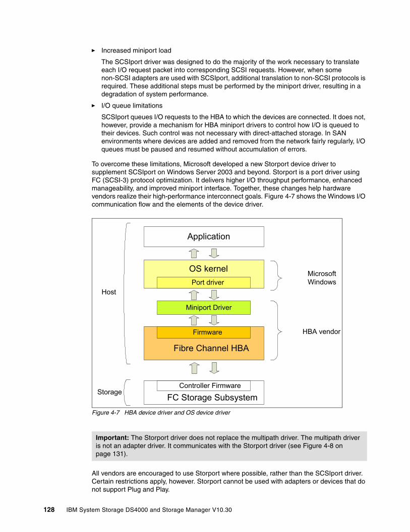
� Increased miniport load
The SCSIport driver was designed to do the majority of the work necessary to translate each I/O request packet into corresponding SCSI requests. However, when some non-SCSI adapters are used with SCSIport, additional translation to non-SCSI protocols is required. These additional steps must be performed by the miniport driver, resulting in a degradation of system performance.
� I/O queue limitations
SCSIport queues I/O requests to the HBA to which the devices are connected. It does not, however, provide a mechanism for HBA miniport drivers to control how I/O is queued to their devices. Such control was not necessary with direct-attached storage. In SAN environments where devices are added and removed from the network fairly regularly, I/O queues must be paused and resumed without accumulation of errors.
To overcome these limitations, Microsoft developed a new Storport device driver to supplement SCSIport on Windows Server 2003 and beyond. Storport is a port driver using FC (SCSI-3) protocol optimization. It delivers higher I/O throughput performance, enhanced manageability, and improved miniport interface. Together, these changes help hardware vendors realize their high-performance interconnect goals. Figure 4-7 shows the Windows I/O communication flow and the elements of the device driver.
Figure 4-7 HBA device driver and OS device driver
All vendors are encouraged to use Storport where possible, rather than the SCSIport driver. Certain restrictions apply, however. Storport cannot be used with adapters or devices that do not support Plug and Play.
Important: The Storport driver does not replace the multipath driver. The multipath driver is not an adapter driver. It communicates with the Storport driver (see Figure 4-8 on page 131).
Fibre Channel HBA
FC Storage Subsystem
OS kernel
Miniport Driver
Firmware
Port driver
Application
HBA vendor
Microsoft Windows
Host
StorageController Firmware
128 IBM System Storage DS4000 and Storage Manager V10.30

The Storport driver is recommended for use with hardware RAID storage arrays and high-performance Fibre Channel interconnects.
See the IBM support Web site for the latest Storport driver relevant to the HBA use. Refer to the readme file when installing the driver and ensure that you follow the Microsoft hotfix requirements for Windows Server 2003.
For the latest StorPort driver there are also minimum firmware levels on the DS4000 storage server. The Fibre Channel host bus adapter STOR miniport device driver is supported with controller firmware Versions 6.12.27.xx or later only.
For compatibility information, always refer to the current DS4000 interoperability matrix or the readme file for your HBA driver.
4.1.5 Multipath driver supportIBM offers different multipath drivers that you can use with your DS4000 storage server. Only one of those drivers is required. Table 4-1 lists the multipath driver supported by operating system. Different drivers for older levels of firmware are still available. Contact you local IBM support for more information.
Table 4-1 DS4000 multipath driver supportt
A multipath device driver is not required when the host operating system has its own mechanism to handle multiple I/O paths. Make sure in this case that you select the correct host type, which will set the appropriate AVT/ADT settings.
Multipathing in WindowsStorage Manager V10.10 (controller firmware V7.10) and later includes a MPIO/DSM failover driver built on the Microsoft MPIO architecture. Previous versions of Storage Manager also included a multipath driver known as RDAC (for Windows). The RDAC choice is no longer available.
IBM also offers a separate Subsystem Device Driver Device Specific Module (SDDDSM) to support the DS4000 when attached to Windows 2003 and Windows 2008 servers. SDDDSM also relies on the Microsoft MPIO architecture. The SDDDSM driver, however, is not
Operating system
MPIO/DSM IBM SDDDSM
AIX FCP device array (RDAC)
AIX MPIO Linux RDAC SDD HP PVLinks
Windows 2003 Ya
a. Driver installation is part of DS4000 Storage Manager.
Y
Windows 2008 Ya Y
AIX v5.3 Y Y
AIX v6.1 Y Yb
b. Default driver on AIX v6.1.
Linuxc
c. All supported Linux variants for firmware v7.10 and later.
Yd
d. RDAC level 9.03.0C05.0013 or later required for Linux RHEL v5.2 or SLES v10 SP2.
HP-UX 11i, 11iv2 and 11iv3
Ye
e. Support only for HP-UX 11i and 11iv2. This includes ServiceGuard cluster support.
Yf
f. Support for all three HP-UX levels. Service Guard cluster support only on 11i and 11i v2.
Chapter 4. Managing the DS4000 129

packaged with the Storage Manager host code and can be downloaded from the IBM support Web site.
In summary, for Windows 2003 and Windows 2008 hosts, there is currently a choice of two multipath drivers:
� SM MPIO/DSM failover driver (multipath driver built on the MPIO technology)
� Subsystem Device Driver Device Specific Module: IBM multipath driver also built on MPIO technology
SM MPIO/DSM failover driver The SM MPIO/DSM failover driver packaged with the DS4000 SM code is a Microsoft MPIO-based driver. The SM MPIO/DSM failover driver consists of a DS4000 Device Specific Module (DSM) and uses MPIO to provide LUN multipath functionality while maintaining compatibility with existing Microsoft Windows device driver stacks.
The SM MPIO/DSM failover driver performs the following tasks:
� Detects and claims the physical disk devices presented by the DS4000 storage subsystems based on vendor/product ID strings and manages the logical paths to the physical devices.
� Presents a single instance of each LUN to the rest of the Windows operating system.
� Provides an optional interface via WMI for use by user-mode applications.
� Relies on the Device Specific Module for the information about the behavior of storage subsystem devices on the following:
– I/O routing information
– Conditions requiring a request to be retried, failed, failed over, or failed back (for example, vendor-unique errors)
– Handles miscellaneous functions such as release/reservation commands
� Multiple Device Specific Modules for different disk storage subsystems can be installed on the same host server.
The SM MPIO/DSM failover driver is currently supported only with the following:
� Controller firmware Versions 6.12.xx.xx and later.
� Fibre Channel host bus adapter device drivers based on Microsoft Storport miniport device driver models. See the IBM support Web site for the latest Storport driver relevant to the HBA used.
Note: Since Storage Manager V10.10, RDAC is no longer available or supported for Windows. If you are upgrading your system from a previous version to firmware V7.10 and Storage Manager V10.10 or later, you must uninstall RDAC and use the SM MPIO/DSM failover driver or SDDDSM for Windows instead.
Note: Only the SM MPIO/DSM failover driver is included in DS Storage Manager host code. SDDDSM is available from the IBM support Web site.
Note: The SM MPIO/DSM failover driver is currently supported only with controller firmware Versions 6.12.xx.xx and later.
130 IBM System Storage DS4000 and Storage Manager V10.30

In Device Manager the SM MPIO/DSM failover driver is seen as the Multipath Disk Device (Figure 4-8).
Figure 4-8 Disk drives using MPIO multipath driver
Co-existence of RDAC and the SM MPIO/DSM failover driver in the same host is not supported. RDAC and SMMPIO/DSM failover drivers handle logical drives (LUNs) in fail conditions similarly because the DSM module that has code to handle these conditions is ported from RDAC. However, the SM MPIO/DSM failover driver will be the required Microsoft multipath driver for future Microsoft Windows operating systems. Furthermore, as specified before, RDAC for Windows is no longer supported starting with SM V10.10 (firmware V7.10).
IBM SDDDSMSubsystem Device Driver Device Specific Module is another IBM multipath I/O solution also based on Microsoft MPIO technology. It is a device-specific module specifically designed to support various IBM storage devices (not just the DS4000 family). SDDDSM is only compatible with Storage Manager V10.10 (and firmware V7.10) and later. It resides in a host system with the native disk device driver and provides the following functions:
� Enhanced data availability
The SDDDSM, residing on the host system, uses the multipath configuration to enhance data availability. That is, when there is a path failure, the SDDDSM reroutes I/O operations from the failing path to an alternate operational path. This capability prevents a single failing bus adapter on the host system, SCSI or Fibre Channel cable, or host-interface adapter on the disk storage system from disrupting data access.
� Dynamic I/O load-balancing across multiple paths
By distributing the I/O workload over multiple active paths, the SDDDSM can provide dynamic load balancing. In the event of failure in one data path, the SDDDSM automatically switches the affected I/O operations to another active data path, ensuring path-failover protection.
� Automatic path failover protection
The SDDDSM failover protection feature minimizes any disruptions in I/O operations and recovers I/O operations from a failing data path. The SDDDSM provides path-failover protection using the following process:
a. Detects a path failure. b. Notifies the host system of the path failure. c. Selects and uses an alternate data path.
Chapter 4. Managing the DS4000 131
� Concurrent download of licensed internal code
With the SDDDSM multipath mode (configured with at least two paths per SDDDSM vpath device), you can concurrently download and install new firmware while applications continue to run.
� Path-selection policies for the host system
The SDDDSM distinguishes the paths to a virtualization product LUN—paths on the preferred controller and paths on the alternate controller.
Other vendors multipath driversBesides the SM MPIO/DSM failover multipath driver provided as part of the DS4000 Storage Manager host software package or the other IBM-supplied SDDDSM, you can also use other host software package such as Symantec (Veritas) Dynamic Multipathing for Windows (DMP) with the DS4000. However, the installation and support of these multipath drivers will not come from the IBM DS4000 support team. You must contact the provider of these multipath drivers for installation and ongoing support.
Multipathing in AIXAt the time of writing, the only IBM-supported multipath driver for AIX when attached to a DS4000 storage subsystem is the AIX FCP disk array driver (RDAC).
AIX FCP disk array The AIX FCP disk array (also known as RDAC for AIX) package is an IBM multipath device driver that provides controller failover support when a failure occurs anywhere along the Fibre Channel I/O path. The AIX FCP disk array driver uses LUN-level failover and supports four paths to the storage.
The driver is contained in AIX file sets that are not included on the DS4000 Storage Manager installation CD. Refer to “Installing AIX FCP disk array (RDAC) driver” on page 196 for details.
AIX MPIOWith AIX Multiple Path I/O (MPIO) a device can be uniquely detected through one or more physical connections, or paths. A path-control module (PCM) provides the path management functions. An MPIO-capable device driver can control more than one type of target device. A PCM can support one or more specific devices. Therefore, one device driver can be interfaced to multiple PCMs that control the I/O across the paths to each of the target devices.
132 IBM System Storage DS4000 and Storage Manager V10.30

Multipathing in LinuxStorage Manager 9.10 introduced a new Linux Redundant Dual Active Controller (RDAC) driver that is recommended over the previous multipathing solution, which involved a failover version of the HBA driver. The two different multipathing solutions are illustrated in Figure 4-9.
Figure 4-9 Linux RDAC driver versus HBA failover driver
The Linux RDAC provides redundant failover/failback support for the logical drives in the DS4000 storage subsystem that are mapped to the Linux host server. The Linux host server must have Fibre Channel connections to the host ports of both controllers A and B of the DS4000 storage subsystem. It is provided as a redundant path failover/failback driver alternative to the Linux FC host bus adapter failover device driver.
Remember that the use of RDAC requires that you use the non-failover Linux HBA driver.
The RDAC multipath driver consists of two parts. One part (mppUpper) is loaded before any HBA is loaded and prevents the HBA from advertising the LUNs to the system, while the other part (mppVhba) is a virtual HBA on top of the real HBA, which is responsible for bundling the different paths to the same LUN to a single (multipath) device.
Note: You cannot use different HBA types as a failover pair. For example, you cannot fail over an IBM DS4000 FC2-133 HBA to an IBM DS4000 FC 4 Gbps HBA.
Note: In Linux, RDAC cannot be installed with the installation wizard. If you need RDAC, you must download and install it separately.
Application
FileSystem
DiskDriver
RDAC
HBA
Application
FileSystem
DiskDriver
HBA
Linux RDAC Driver
HBA FailoverDriver
Chapter 4. Managing the DS4000 133

4.1.6 AVT or non-AVT mode
AVT is a built-in feature of controller firmware that allows logical drive-level failover rather than controller-level failover (as is the case with RDAC).
The ADT feature is automatically disabled or enabled depending on the type of host ports on the host partition to which you mapped the logical drives. It is disabled by default for Microsoft Windows, IBM AIX, and Sun Solaris operating systems. It is enabled by default for Linux, Novell NetWare, and HP-UX operating systems.
� AVT-disabled failover
The multi-path software will send a SCSI Mode Select command to cause a change in volume ownership (see 4.3.5, “Controller ownership” on page 164) before using the alternate path. All logical drives on the preferred controller are transferred to the alternate controller. This is the configuration setting for Microsoft Windows, IBM AIX, Sun Solaris, and Linux (when using the RDAC driver and non-failover Fibre Channel HBA driver) systems. When AVT is disabled, the I/O data path is still protected as long as you use a multi-path driver. After the I/O data path problem is corrected, the preferred controller does not automatically reestablish ownership of the logical drive. You must open a storage management window, select Redistribute Logical Drives from the Advanced menu, and perform the redistribute logical drives task. Figure 4-10 on page 135 shows the AVT-disabled failover mode phases.
Important: Linux RDAC does not support auto-volume transfer/auto-disk transfer (AVT/ADT) mode. If you are using the RDAC driver, you must disable AVT/ADT. AVT/ADT is automatically enabled if the Linux storage partitioning host type is selected. Disable it by using the script that is bundled in the IBM Linux RDAC Web package or in the \Scripts directory of the DS4000 Storage Manager Version 9 or later Linux CD. The name of the script file is DisableAVT_Linux.scr.
Review your system requirements and additional support information in the latest Linux RDAC readme file for your specific DS4000 storage system and code level.
Note: AVT is not a failover driver. AVT provides storage systems with the flexibility to work with third-party failover software.
Note: In AVT-disabled mode, you are required to issue a redistribution command manually to balance the LUNs across the controllers.
134 IBM System Storage DS4000 and Storage Manager V10.30
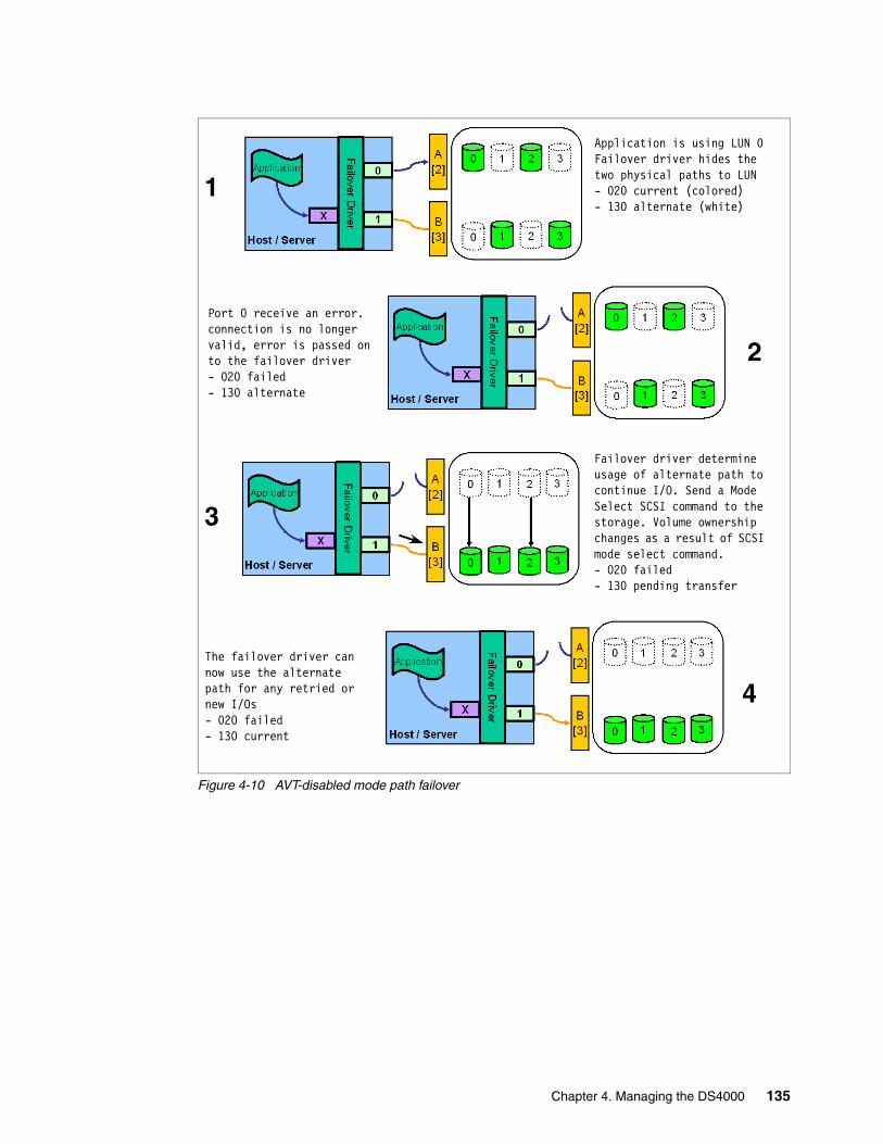
Figure 4-10 AVT-disabled mode path failover
Port 0 receive an error. connection is no longer valid, error is passed on to the failover driver- 020 failed- 130 alternate
The failover driver can now use the alternate path for any retried or new I/Os- 020 failed- 130 current
Application is using LUN 0Failover driver hides the two physical paths to LUN- 020 current (colored)- 130 alternate (white)
Failover driver determine usage of alternate path to continue I/O. Send a Mode Select SCSI command to the storage. Volume ownership changes as a result of SCSI mode select command.- 020 failed- 130 pending transfer
4
3
2
1
Chapter 4. Managing the DS4000 135
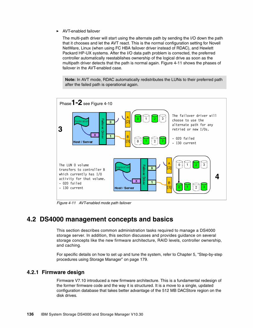
� AVT-enabled failover
The multi-path driver will start using the alternate path by sending the I/O down the path that it chooses and let the AVT react. This is the normal configuration setting for Novell NetWare, Linux (when using FC HBA failover driver instead of RDAC), and Hewlett Packard HP-UX systems. After the I/O data path problem is corrected, the preferred controller automatically reestablishes ownership of the logical drive as soon as the multipath driver detects that the path is normal again. Figure 4-11 shows the phases of failover in the AVT-enabled case.
Figure 4-11 AVT-enabled mode path failover
4.2 DS4000 management concepts and basics
This section describes common administration tasks required to manage a DS4000 storage server. In addition, this section discusses and provides guidance on several storage concepts like the new firmware architecture, RAID levels, controller ownership, and caching.
For specific details on how to set up and tune the system, refer to Chapter 5, “Step-by-step procedures using Storage Manager” on page 179.
4.2.1 Firmware designFirmware V7.10 introduced a new firmware architecture. This is a fundamental redesign of the former firmware code and the way it is structured. It is a move to a single, updated configuration database that takes better advantage of the 512 MB DACStore region on the disk drives.
Note: In AVT mode, RDAC automatically redistributes the LUNs to their preferred path after the failed path is operational again.
Phase1-2 see Figure 4-10
The LUN 0 volume transfers to controller B which currently has I/O activity for that volume.- 020 failed- 130 current
The failover driver will choose to use the alternate path for any retried or new I/Os.
- 020 failed- 130 current
4
3
136 IBM System Storage DS4000 and Storage Manager V10.30
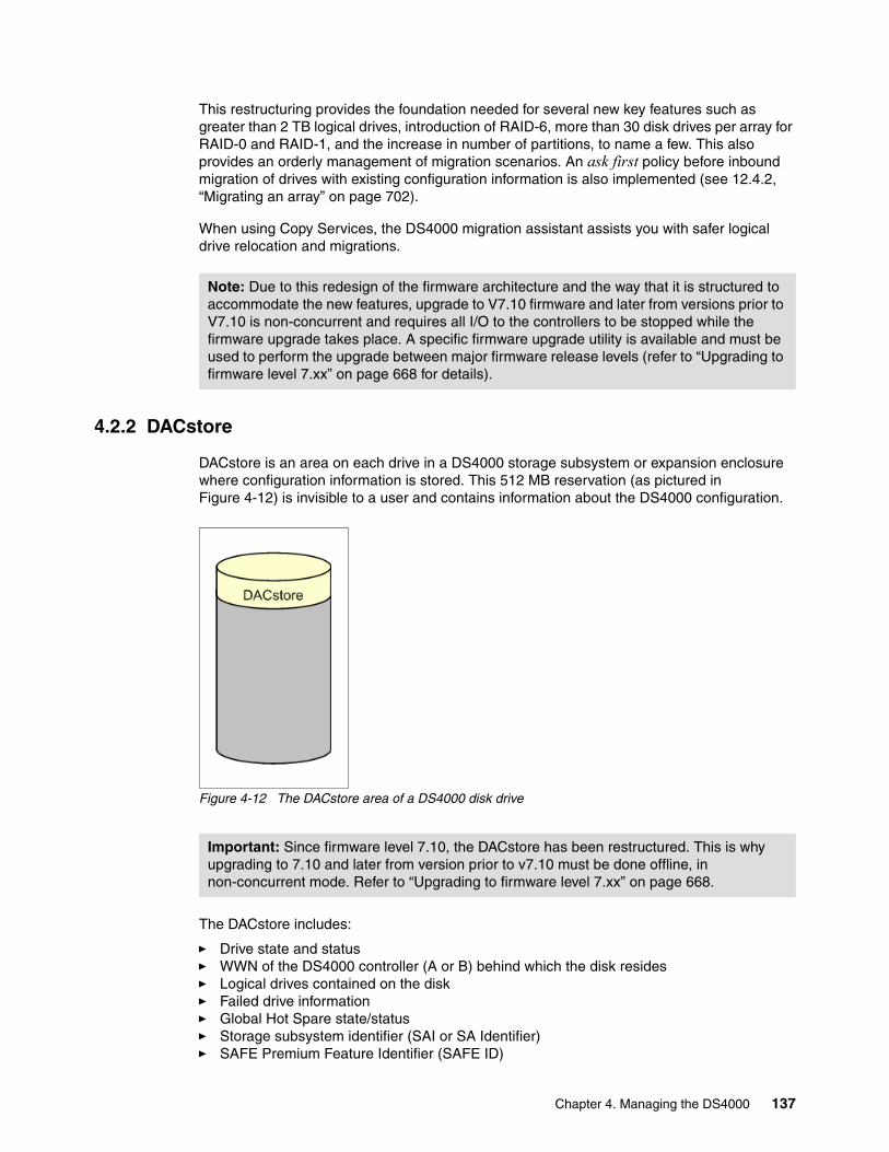
This restructuring provides the foundation needed for several new key features such as greater than 2 TB logical drives, introduction of RAID-6, more than 30 disk drives per array for RAID-0 and RAID-1, and the increase in number of partitions, to name a few. This also provides an orderly management of migration scenarios. An ask first policy before inbound migration of drives with existing configuration information is also implemented (see 12.4.2, “Migrating an array” on page 702).
When using Copy Services, the DS4000 migration assistant assists you with safer logical drive relocation and migrations.
4.2.2 DACstore
DACstore is an area on each drive in a DS4000 storage subsystem or expansion enclosure where configuration information is stored. This 512 MB reservation (as pictured in Figure 4-12) is invisible to a user and contains information about the DS4000 configuration.
Figure 4-12 The DACstore area of a DS4000 disk drive
The DACstore includes:
� Drive state and status� WWN of the DS4000 controller (A or B) behind which the disk resides� Logical drives contained on the disk� Failed drive information� Global Hot Spare state/status� Storage subsystem identifier (SAI or SA Identifier)� SAFE Premium Feature Identifier (SAFE ID)
Note: Due to this redesign of the firmware architecture and the way that it is structured to accommodate the new features, upgrade to V7.10 firmware and later from versions prior to V7.10 is non-concurrent and requires all I/O to the controllers to be stopped while the firmware upgrade takes place. A specific firmware upgrade utility is available and must be used to perform the upgrade between major firmware release levels (refer to “Upgrading to firmware level 7.xx” on page 668 for details).
Important: Since firmware level 7.10, the DACstore has been restructured. This is why upgrading to 7.10 and later from version prior to v7.10 must be done offline, in non-concurrent mode. Refer to “Upgrading to firmware level 7.xx” on page 668.
Chapter 4. Managing the DS4000 137
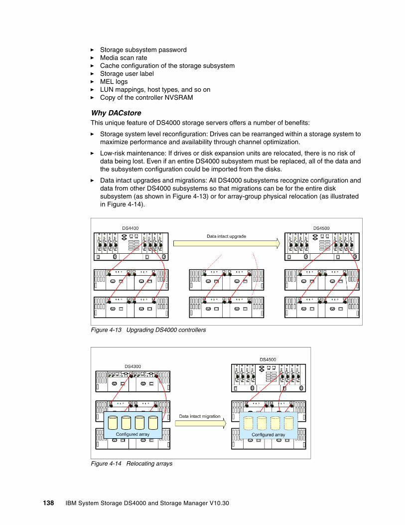
� Storage subsystem password� Media scan rate� Cache configuration of the storage subsystem� Storage user label� MEL logs� LUN mappings, host types, and so on� Copy of the controller NVSRAM
Why DACstoreThis unique feature of DS4000 storage servers offers a number of benefits:
� Storage system level reconfiguration: Drives can be rearranged within a storage system to maximize performance and availability through channel optimization.
� Low-risk maintenance: If drives or disk expansion units are relocated, there is no risk of data being lost. Even if an entire DS4000 subsystem must be replaced, all of the data and the subsystem configuration could be imported from the disks.
� Data intact upgrades and migrations: All DS4000 subsystems recognize configuration and data from other DS4000 subsystems so that migrations can be for the entire disk subsystem (as shown in Figure 4-13) or for array-group physical relocation (as illustrated in Figure 4-14).
Figure 4-13 Upgrading DS4000 controllers
Figure 4-14 Relocating arrays
138 IBM System Storage DS4000 and Storage Manager V10.30
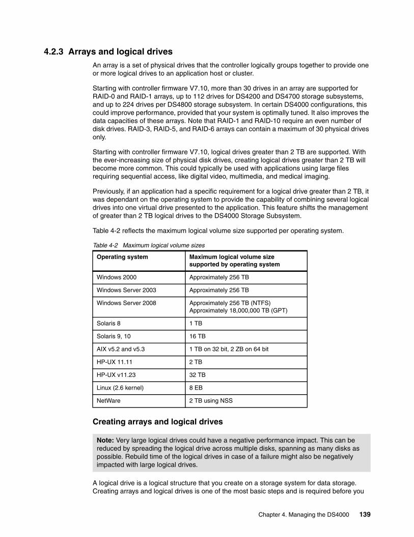
4.2.3 Arrays and logical drivesAn array is a set of physical drives that the controller logically groups together to provide one or more logical drives to an application host or cluster.
Starting with controller firmware V7.10, more than 30 drives in an array are supported for RAID-0 and RAID-1 arrays, up to 112 drives for DS4200 and DS4700 storage subsystems, and up to 224 drives per DS4800 storage subsystem. In certain DS4000 configurations, this could improve performance, provided that your system is optimally tuned. It also improves the data capacities of these arrays. Note that RAID-1 and RAID-10 require an even number of disk drives. RAID-3, RAID-5, and RAID-6 arrays can contain a maximum of 30 physical drives only.
Starting with controller firmware V7.10, logical drives greater than 2 TB are supported. With the ever-increasing size of physical disk drives, creating logical drives greater than 2 TB will become more common. This could typically be used with applications using large files requiring sequential access, like digital video, multimedia, and medical imaging.
Previously, if an application had a specific requirement for a logical drive greater than 2 TB, it was dependant on the operating system to provide the capability of combining several logical drives into one virtual drive presented to the application. This feature shifts the management of greater than 2 TB logical drives to the DS4000 Storage Subsystem.
Table 4-2 reflects the maximum logical volume size supported per operating system.
Table 4-2 Maximum logical volume sizes
Creating arrays and logical drives
A logical drive is a logical structure that you create on a storage system for data storage. Creating arrays and logical drives is one of the most basic steps and is required before you
Operating system Maximum logical volume size supported by operating system
Windows 2000 Approximately 256 TB
Windows Server 2003 Approximately 256 TB
Windows Server 2008 Approximately 256 TB (NTFS)Approximately 18,000,000 TB (GPT)
Solaris 8 1 TB
Solaris 9, 10 16 TB
AIX v5.2 and v5.3 1 TB on 32 bit, 2 ZB on 64 bit
HP-UX 11.11 2 TB
HP-UX v11.23 32 TB
Linux (2.6 kernel) 8 EB
NetWare 2 TB using NSS
Note: Very large logical drives could have a negative performance impact. This can be reduced by spreading the logical drive across multiple disks, spanning as many disks as possible. Rebuild time of the logical drives in case of a failure might also be negatively impacted with large logical drives.
Chapter 4. Managing the DS4000 139

can start using the physical disk space. That is, you divide your disk drives into arrays and create one or more logical drives inside each array.
Through Storage Manager you have the option of letting the system automatically create arrays for you. This usually ensures the most optimal balance between capacity, performance, and redundancy. The automatic configuration provides you with a suggested configuration per RAID level (provided that there are enough unassigned drives to satisfy the minimum requirement per RAID level). Each configuration provides volume groups, volumes, and hot spare drives.
You also have the option to select your own characteristics for the automatic configuration specifying the RAID level required, number of logical drive groups, number of disk drives per array, number of hot spare drives required, and I/O characteristics associated with the configuration.
On an already configured storage subsystem this feature lets you automatically configure the arrays using the remaining unconfigured storage capacity. Any free capacity on existing arrays within the storage subsystem will not be configured.
The Create Logical Drive wizard allows you to manually create one or more logical drives on the storage system. Using the wizard, select the capacity that you want to allocate for the logical drive (free capacity or unconfigured capacity) and then define basic and optional advanced logical drive parameters for the logical drive.
For more information refer to “Creating arrays and logical drives” on page 253.
In the simplest configuration, all of your drives would be assigned to one array, and multiple logical drives could be created within it. This configuration presents the following drawbacks:
� If you experience a drive failure, the rebuild process will affect all logical drives and the overall system performance will go down.
� There is no way to mitigate the impact of high read/write operations on particular logical drives. For example, if there is database application on one of the logical drives in the single array and another logical drive is being swamped with I/O requests, the database application is impacted. Separate arrays would isolate the database application from spurious read/write behavior to other logical drives in another array.
With the advent of larger capacity drives and the ability to distribute logical drives across controllers, creating more than one logical drive per array is a good way to use your storage capacity and protect your data.
Number of drivesThe more physical drives that you have per array, the shorter the access time for read and write I/O operations.
You can determine how many physical drives should be associated with a RAID controller by looking at disk transfer rates (rather than at the megabytes per second). For example, if a hard disk drive is capable of 75 nonsequential (random) I/Os per second, then about 26 hard
Tip: Storage Manager allows you to use the default setup through the automatic configuration, should you not have a specific setup requirement. This usually ensures the optimal balance between capacity, performance, and redundancy.
Note: Starting from firmware V7.10, it is now possible to create arrays without defining logical drives within them.
140 IBM System Storage DS4000 and Storage Manager V10.30
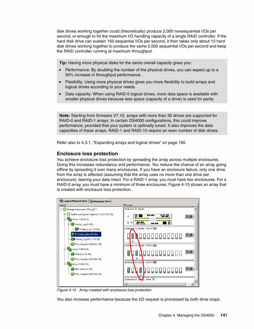
disk drives working together could (theoretically) produce 2,000 nonsequential I/Os per second, or enough to hit the maximum I/O handling capacity of a single RAID controller. If the hard disk drive can sustain 150 sequential I/Os per second, it then takes only about 13 hard disk drives working together to produce the same 2,000 sequential I/Os per second and keep the RAID controller running at maximum throughput.
Refer also to 4.3.1, “Expanding arrays and logical drives” on page 160.
Enclosure loss protectionYou achieve enclosure loss protection by spreading the array across multiple enclosures. Doing this increases redundancy and performance. You reduce the chance of an array going offline by spreading it over many enclosures. If you have an enclosure failure, only one drive from the array is affected (assuming that the array uses no more than one drive per enclosure), leaving your data intact. For a RAID-1 array, you must have two enclosures. For a RAID-5 array, you must have a minimum of three enclosures. Figure 4-15 shows an array that is created with enclosure loss protection.
Figure 4-15 Array created with enclosure loss protection
You also increase performance because the I/O request is processed by both drive loops.
Tip: Having more physical disks for the same overall capacity gives you:
� Performance: By doubling the number of the physical drives, you can expect up to a 50% increase in throughput performance.
� Flexibility: Using more physical drives gives you more flexibility to build arrays and logical drives according to your needs.
� Data capacity: When using RAID-5 logical drives, more data space is available with smaller physical drives because less space (capacity of a drive) is used for parity.
Note: Starting from firmware V7.10, arrays with more than 30 drives are supported for RAID-0 and RAID-1 arrays. In certain DS4000 configurations, this could improve performance, provided that your system is optimally tuned. It also improves the data capacities of these arrays. RAID-1 and RAID-10 require an even number of disk drives.
Chapter 4. Managing the DS4000 141

RAID levelsWhen creating an array, you must specify the RAID level. We review here the different RAID levels and explain which setting to choose, depending on the situation.
� RAID-0: For performance, but generally not recommended (Figure 4-16)
RAID-0 is also known as data striping. It is well suited for program libraries requiring rapid loading of large tables, or more generally, applications requiring fast access to read-only data or fast writing. RAID-0 is only designed to increase performance. There is no redundancy, so any disk failures require reloading from backups. Select RAID level 0 for applications that would benefit from the increased performance capabilities of this RAID level. Never use this level for critical applications that require high availability.
Figure 4-16 RAID-0
etc.Block 3Block 0Disk 1
etc.Block 4Block 1Disk 2
etc.Block 5Block 2Disk 3
etc.Block 5Block 4Block 3Block 2Block 1Block 0
Logical Drive
Actualdevice
mappings
Stripeset
Host view
142 IBM System Storage DS4000 and Storage Manager V10.30
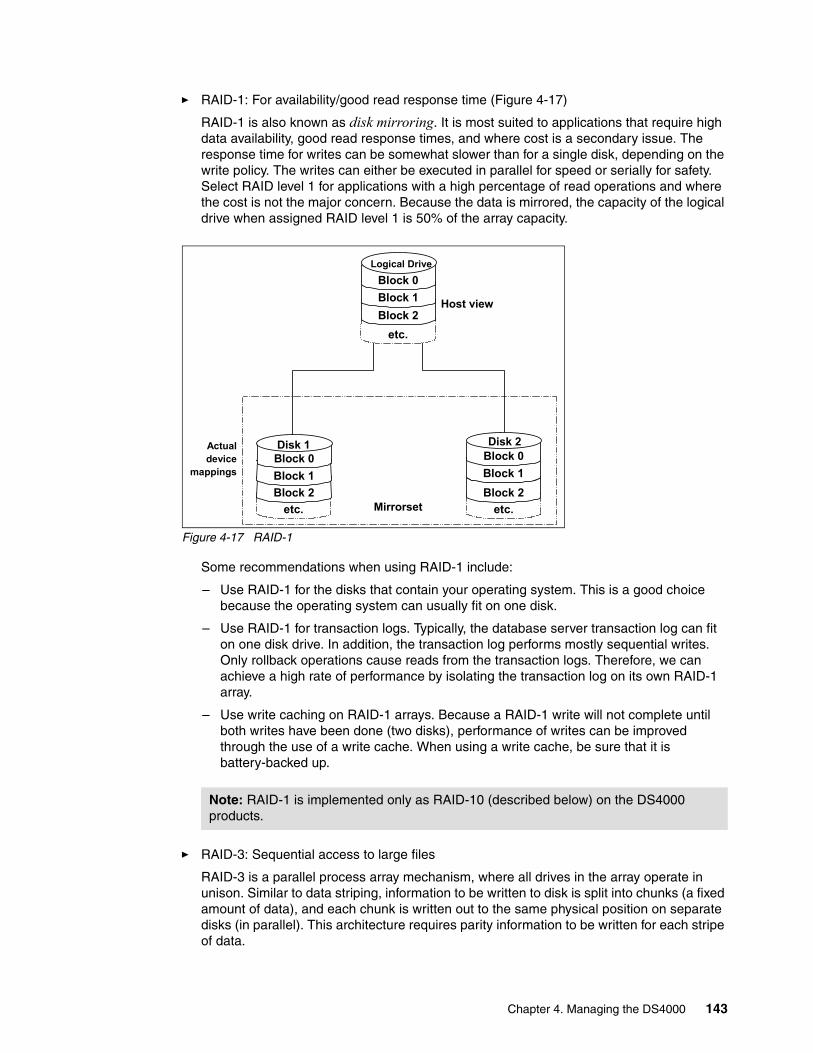
� RAID-1: For availability/good read response time (Figure 4-17)
RAID-1 is also known as disk mirroring. It is most suited to applications that require high data availability, good read response times, and where cost is a secondary issue. The response time for writes can be somewhat slower than for a single disk, depending on the write policy. The writes can either be executed in parallel for speed or serially for safety. Select RAID level 1 for applications with a high percentage of read operations and where the cost is not the major concern. Because the data is mirrored, the capacity of the logical drive when assigned RAID level 1 is 50% of the array capacity.
Figure 4-17 RAID-1
Some recommendations when using RAID-1 include:
– Use RAID-1 for the disks that contain your operating system. This is a good choice because the operating system can usually fit on one disk.
– Use RAID-1 for transaction logs. Typically, the database server transaction log can fit on one disk drive. In addition, the transaction log performs mostly sequential writes. Only rollback operations cause reads from the transaction logs. Therefore, we can achieve a high rate of performance by isolating the transaction log on its own RAID-1 array.
– Use write caching on RAID-1 arrays. Because a RAID-1 write will not complete until both writes have been done (two disks), performance of writes can be improved through the use of a write cache. When using a write cache, be sure that it is battery-backed up.
� RAID-3: Sequential access to large files
RAID-3 is a parallel process array mechanism, where all drives in the array operate in unison. Similar to data striping, information to be written to disk is split into chunks (a fixed amount of data), and each chunk is written out to the same physical position on separate disks (in parallel). This architecture requires parity information to be written for each stripe of data.
Note: RAID-1 is implemented only as RAID-10 (described below) on the DS4000 products.
etc.Block 2Block 1Block 0
Logical Drive
Actualdevice
mappings
etc.Block 2Block 1Block 0Disk 1
etc.Block 2Block 1Block 0Disk 2
Mirrorset
Host view
Chapter 4. Managing the DS4000 143
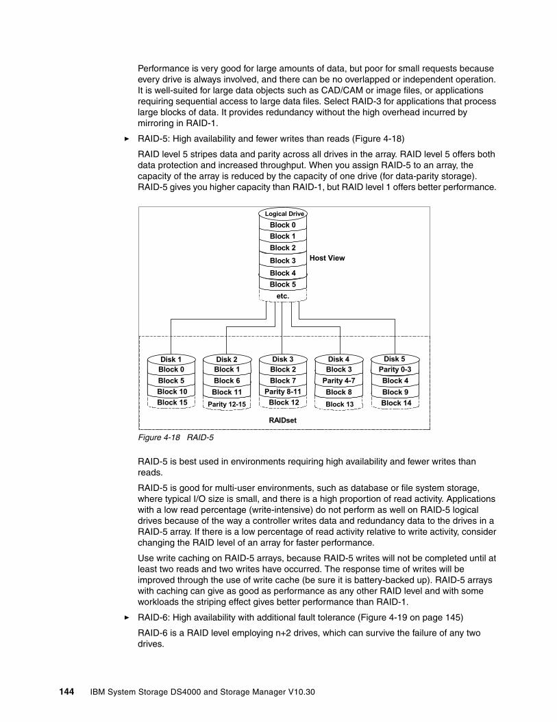
Performance is very good for large amounts of data, but poor for small requests because every drive is always involved, and there can be no overlapped or independent operation. It is well-suited for large data objects such as CAD/CAM or image files, or applications requiring sequential access to large data files. Select RAID-3 for applications that process large blocks of data. It provides redundancy without the high overhead incurred by mirroring in RAID-1.
� RAID-5: High availability and fewer writes than reads (Figure 4-18)
RAID level 5 stripes data and parity across all drives in the array. RAID level 5 offers both data protection and increased throughput. When you assign RAID-5 to an array, the capacity of the array is reduced by the capacity of one drive (for data-parity storage). RAID-5 gives you higher capacity than RAID-1, but RAID level 1 offers better performance.
Figure 4-18 RAID-5
RAID-5 is best used in environments requiring high availability and fewer writes than reads.
RAID-5 is good for multi-user environments, such as database or file system storage, where typical I/O size is small, and there is a high proportion of read activity. Applications with a low read percentage (write-intensive) do not perform as well on RAID-5 logical drives because of the way a controller writes data and redundancy data to the drives in a RAID-5 array. If there is a low percentage of read activity relative to write activity, consider changing the RAID level of an array for faster performance.
Use write caching on RAID-5 arrays, because RAID-5 writes will not be completed until at least two reads and two writes have occurred. The response time of writes will be improved through the use of write cache (be sure it is battery-backed up). RAID-5 arrays with caching can give as good as performance as any other RAID level and with some workloads the striping effect gives better performance than RAID-1.
� RAID-6: High availability with additional fault tolerance (Figure 4-19 on page 145)
RAID-6 is a RAID level employing n+2 drives, which can survive the failure of any two drives.
RAIDset
etc.Block 5Block 4Block 3Block 2Block 1Block 0
Logical Drive
Block 15 Block 10Block 5Block 0Disk 1
Parity 12-15
Block 11Block 6Block 1Disk 2
Block 12Parity 8-11
Block 7Block 2Disk 3
Block 13
Block 8Parity 4-7Block 3Disk 4
Block 14Block 9Block 4
Parity 0-3Disk 5
Host View
144 IBM System Storage DS4000 and Storage Manager V10.30
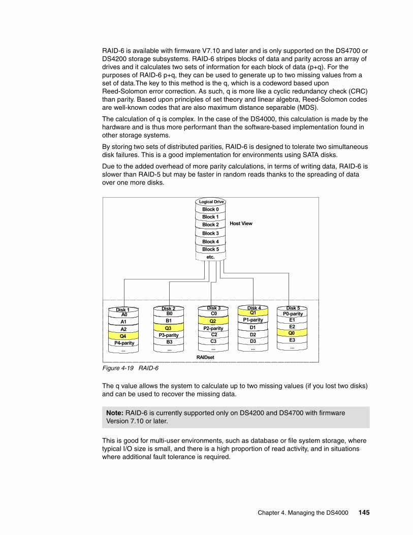
RAID-6 is available with firmware V7.10 and later and is only supported on the DS4700 or DS4200 storage subsystems. RAID-6 stripes blocks of data and parity across an array of drives and it calculates two sets of information for each block of data (p+q). For the purposes of RAID-6 p+q, they can be used to generate up to two missing values from a set of data.The key to this method is the q, which is a codeword based upon Reed-Solomon error correction. As such, q is more like a cyclic redundancy check (CRC) than parity. Based upon principles of set theory and linear algebra, Reed-Solomon codes are well-known codes that are also maximum distance separable (MDS).
The calculation of q is complex. In the case of the DS4000, this calculation is made by the hardware and is thus more performant than the software-based implementation found in other storage systems.
By storing two sets of distributed parities, RAID-6 is designed to tolerate two simultaneous disk failures. This is a good implementation for environments using SATA disks.
Due to the added overhead of more parity calculations, in terms of writing data, RAID-6 is slower than RAID-5 but may be faster in random reads thanks to the spreading of data over one more disks.
Figure 4-19 RAID-6
The q value allows the system to calculate up to two missing values (if you lost two disks) and can be used to recover the missing data.
This is good for multi-user environments, such as database or file system storage, where typical I/O size is small, and there is a high proportion of read activity, and in situations where additional fault tolerance is required.
Note: RAID-6 is currently supported only on DS4200 and DS4700 with firmware Version 7.10 or later.
...E3Q0 E2E1
...D3D2D1
...C3 C2
P2-parityQ2
... B3
P3-parityQ3 B1
... P4-parity
Q4 A2
RAIDset
etc.Block 5Block 4Block 3
Block 2Block 1Block 0
Logical Drive
A1 A0
Disk 1
Host View
B0Disk 2
C0Disk 3
P1-parity Q1 Disk 4
P0-parityDisk 5
Chapter 4. Managing the DS4000 145

� RAID-10: Higher performance than RAID-1 (Figure 4-20)
RAID-10, also known as RAID 1+0, implements block interleave data striping and mirroring. In RAID-10, data is striped across multiple disk drives, and then those drives are mirrored to another set of drives.
Figure 4-20 RAID-10
The performance of RAID-10 is approximately the same as RAID-0 for sequential I/Os. RAID-10 provides an enhanced feature for disk mirroring that stripes data and copies the data across all the drives of the array. The first stripe is the data stripe. The second stripe is the mirror (copy) of the first data stripe, but it is shifted over one drive. Because the data is mirrored, the capacity of the logical drive is 50% of the physical capacity of the hard disk drives in the array.
Our recommendations for using RAID-10 are:
� Use RAID-10 whenever the array experiences more than 10% writes. RAID-5 does not perform well as RAID-10 with a large number of writes.
� Use RAID-10 when performance is critical. Use write caching on RAID-10. Because RAID-10 write will not be completed until both writes have been done, the performance of the writes can be improved through the use of a write cache (be sure that it is battery-backed up).
When comparing RAID-10 to RAID-5:
� RAID-10 writes a single block through two writes. RAID-5 requires two reads (read original data and parity) and two writes. Random writes are significantly faster on RAID-10.
� RAID-10 rebuilds take less time than RAID-5 rebuilds. If a real disk fails, RAID-10 rebuilds it by copying all the data on the mirrored disk to a spare. RAID-5 rebuilds a failed disk by merging the contents of the surviving disks in an array and writing the result to a spare.
RAID-10 is the best fault-tolerant solution in terms of protection and performance, but it comes at a cost. You must purchase twice the number of disks that are necessary with RAID-0.
Stripeset
etc.Block 5Block 4Block 3Block 2Block 1Block 0
Logical Drive
Host View
Controllerinternal
mapping
Actualdevice
mappings
Block 6Block 3Block 0Disk 1
Block 6Block 3Block 0Disk 2
Block 7Block 4Block 1Disk 3
Block 7Block 4Block 1Disk 4
Block 8Block 5Block 2Disk 5
Block 8Block 5Block 2Disk 6
Disk Array #1 Mirrorset Disk Array #2 Mirrorset Disk Array #3 Mirrorset
146 IBM System Storage DS4000 and Storage Manager V10.30

The following note and Table 4-3 summarize this information.
Table 4-3 RAID levels comparison
See “Creating arrays and logical drives” on page 253 for additional information.
Summary: Based on the respective level, RAID offers the following performance results:
� RAID-0 offers high performance, but does not provide any data redundancy.
� RAID-1 offers high performance for write-intensive applications.
� RAID-3 is good for large data transfers in applications, such as multimedia or medical imaging, that write and read large sequential chunks of data.
� RAID-5 is good for multi-user environments, such as database or file system storage, where the typical I/O size is small, and there is a high proportion of read activity.
� RAID-6 is good for multi-user environments, such as database or file system storage, where the typical I/O size is small and there is a high proportion of read activity, and in situations where additional fault tolerance is required.
� RAID-10 offers higher performance than RAID-1 and more reliability than RAID-5.
RAID Description APP Advantage Disadvantage
0 Stripes data across multiple drives.
IOPS Mbps
Performance due to parallel operation of the access.
No redundancy. One drive fails, data is lost.
1 Disk's data is mirrored to another drive.
IOPS Performance as multiple requests can be fulfilled simultaneously.
Storage costs are doubled.
10 Data is striped across multiple drives and mirrored to same number of disks.
IOPS Performance as multiple requests can be fulfilled simultaneously. Most reliable RAID level on the DS4000.
Storage costs are doubled.
3 Drives operated independently with data blocks distributed among all drives. Parity is written to a dedicated drive.
Mbps High performance for large, sequentially accessed files (image, video, graphical).
Degraded performance with 8–9 I/O threads, random input/output operations per second (IOPS), smaller more numerous IOPS.
5 Drives operated independently with data and parity blocks distributed across all drives in the group.
IOPSMbps
Good for reads, small IOPS, many concurrent IOPS, and random I/Os.
Writes are particularly demanding.
6 Stripes blocks of data and parity across an array of drives and calculates two sets of parity information for each block of data.
IOPSMbps
Good for multi-user environments, such as database or file system storage, where typical I/O size is small, and in situations where additional fault tolerance is required.
Slower in writing data, complex raid controller architecture.
Chapter 4. Managing the DS4000 147

RAID reliability considerationsAt first glance both RAID-3 and RAID-5 appear to provide excellent protection against drive failure. With today’s high-reliability drives, it appears unlikely that a second drive in an array would fail (causing data loss) before an initial failed drive could be replaced. However, field experience has shown that when a RAID-3 or RAID-5 array fails, it is not usually due to two drives in the array experiencing complete failure. Instead, most failures are caused by one drive going bad, and a single block somewhere else in the array that cannot be read reliably. This problem is exacerbated by using large arrays with RAID-5. This stripe kill can lead to data loss when the information to re-build the stripe is not available. The end effect of this issue will of course depend on the type of data and how sensitive it is to corruption. While most storage systems (including the DS4000 series) have mechanisms in place to try to prevent this from happening, they cannot work 100% of the time.
Any selection of RAID type should take into account the cost of downtime. Simple math tells us that RAID-3 and RAID-5 are going to suffer from failures more often than RAID-10. (Exactly how often is subject to many variables and is beyond the scope of this book.) The money saved by economizing on drives can be easily overwhelmed by the business cost of a crucial application going down until it can be restored from backup.
Naturally, no data protection method is 100% reliable, and even if RAID were 100% solid, it would not protect your data from accidental corruption or deletion by program error or operator error. Therefore, all crucial data should be backed up by appropriate software, according to business needs.
4.2.4 Segment sizeThe segment size is the maximum amount of data that the controller can write at once on one physical disk in a logical drive before writing to the next physical disk.
The choice of a segment size can have a major influence on performance in both IOPS and throughput. Small segment sizes increase the request rate (IOPS) by allowing multiple disk drives to respond to multiple requests. Large segment sizes increase the data transfer rate (Mbps) by allowing multiple disk drives to participate in one I/O request. Use a small segment size relative to the I/O size to increase sequential performance.
Segment size = I/O requestSome typical results of this choice are:
� Fewer disks used per request� Higher IOPS� Ideal for random I/O requests such as database file system
Segment size < I/O requestSome typical results of this choice are:
� More disks used/requested� Higher throughput (Mbps)� Ideal for sequential writes such as large multimedia application
148 IBM System Storage DS4000 and Storage Manager V10.30
You can use the performance monitor (see 4.2.7, “Performance monitor data” on page 155) to evaluate how a given segment size affects the workload. Use the following guidelines:
� If the typical I/O size is larger than the segment size, increase the segment size in order to minimize the number of drives needed to satisfy an I/O request. This is especially true in a multi-user, database, or file system storage environment. Using a single drive for a single request leaves other drives available to simultaneously service other requests.
� If you are using the logical drive in a single-user, large I/O environment (such as for multimedia application storage), performance is optimized when a single I/O request can be serviced with a single data stripe (the segment size multiplied by the number of drives in the array that are used for I/O). In this case, multiple disks are used for the same request, but each disk is only accessed once.
4.2.5 Hot spare driveHot spare disk drives provide additional protection that can be essential in case of a disk drive failure in a fault tolerant array (RAID-1, RAID-3, RAID-5, or RAID-6). A hot-spare drive is like a replacement drive installed in advance.
A hot spare drive defined on the DS4000 storage server is always used as a so-called global hot spare. That is, a hot spare drive can always be used for a failed drive. It does not matter in which array or storage enclosure the hot spare is located. The spare and failed drives must, however, be of the same type (FC or SATA).
Previously, a maximum of up to 15 hot spare drives could be specified. With Storage Manager V10.10 (and firmware V7.10) and later an unlimited amount of hot spare drives is supported.
Tips: The possible segment sizes available are 8 KB, 16 KB, 32 KB, 64 KB, 128 KB,256 KB, and 512 KB.
� Storage Manager sets a default block size of 64 KB.
� For database applications, block sizes between 32–128 KB have shown to be more effective.
� In a large file environment, such as on media streaming or CAD, 128 KB and higher are recommended.
� For Web, file, and print servers, the range should be between 16–64 KB.
Note: You should do performance testing in your environment before you go into production with a given segment size. Segment size can be dynamically changed, but only by rewriting the data, which consumes bandwidth and impacts performance. Plan this carefully to avoid having to redo your choices.
Note: There is no definitive recommendation as to how many hot spares you should install, but it is common practice to use a ratio of one hot spare for two fully populated expansion enclosures.
Chapter 4. Managing the DS4000 149

Three methods exist to allocate hot spare drives in the storage subsystem:
� Automatic assignment: The storage subsystem automatically calculates the number of hot spare drives needed and allocates accordingly. This can be used on unconfigured storage subsystems.
� Automatic assignment by specification of the number of drives: The number of hot spare drives desired is specified and the storage subsystem automatically allocates them.
� Explicit assignment: The hot spare drives are manually selected and assigned.
With Storage Manager V10.10 (firmware V7.10) and later, you can select the preferred recovery option for data that has been written to the hot spare drive.
We present three scenarios:
� Once the failed drive is replaced with a new drive, the new replacement drive becomes an unassigned drive. This drive can then be selected as a replacement drive for the data stored on the hot spare drive, and data is copied back to the replaced drive. The original hot spare drive that is now in use becomes a free hot spare drive again. The location of a hot spare drive in this case is fixed and does not wander if it is used.
� Once the failed drive is replaced with a new drive, the new replacement drive becomes an unassigned drive. Any unassigned drive in the storage subsystem can now be selected as a replacement drive for the data stored on the hot spare drive, and data is copied back to this selected replacement drive. The original hot spare drive that is now in use becomes a free hot spare drive again. The location of a hot spare drive in this case is fixed and does not wonder if it is used.
� Once the failed drive is replaced with a new drive, the new replacement drive becomes an unassigned drive. The original hot spare drive can be selected as the replacement drive, and no data copy occurs. The original hot spare drive becomes a permanent member of the array. The location of the hot spare drive in this case is not fixed. A new hot spare drive can now be assigned from the unassigned disk drive pool.
A hot spare drive must be of the same type (FC or SATA) and at least of the capacity of the configured space on the failed drive (if the failed disk drive is larger than the hot spare, reconstruction is not possible). The DS4000 storage server can use a larger drive to recover a smaller failed drive to it. Then the remaining capacity is blocked.
The DS4000 attempts to find a hot spare drive in the enclosure with the failed drive first. It finds a drive that is at least the same size as the failed drive, but not necessarily giving preference to one the exact same size as the failed drive. If a match does not exist in the same enclosure, it looks for spares in the other enclosures that contain sufficient capacity to spare over.
The controller uses a free hot spare drive as soon as it finds one, even if there is another one that might be closer to the failed drive.
Important: Remember to allocate a new hot spare drive after a hot spare drive has been made a permanent member of an array.
Note: We recommend having your hot spare drives distributed across different disk drive channels to avoid the risk of a single disk drive channel failure causing loss of access to all hot spare drives in the storage subsystem.
150 IBM System Storage DS4000 and Storage Manager V10.30
4.2.6 Storage partitioningStorage partitioning adds a high level of flexibility to the DS4000 storage server. It enables you to connect to the same storage server multiple and heterogeneous host systems, either in stand-alone or clustered mode. The term storage partitioning is somewhat misleading, as it actually represents a host or a group of hosts and the logical disks that they access.
Without storage partitioning, the logical drives configured on a DS4000 storage server can only be accessed by a single host system or by a single cluster. This can lead to inefficient use of storage server hardware.
Storage partitioning, on the other hand, allows you to create sets containing the hosts with their host bus adapters and the logical drives. We call these sets storage partitions. Now the host systems can only access their assigned logical drives, just as though these logical drives were locally attached to them. Storage partitioning adapts the SAN idea of globally accessible storage to the local-storage-minded operating systems.
Storage partitioning lets you map and mask LUNs (that is why it is also referred to as LUN masking). This means that once you have assigned the LUN to a host it is hidden from all other hosts connected to the same storage server. Therefore, the access to that LUN is exclusively reserved for that host.
It is a good practice to do your storage partitioning prior to connecting multiple hosts. Operating systems such as AIX and Windows like to write their signatures to any device that they can access.
Heterogeneous host support means that the host systems can run different operating systems. But be aware that all the host systems within a particular storage partition must run the same operating system, as all host systems within a particular storage partition have unlimited access to all logical drives in this partition. Therefore, file systems on these logical drives must be compatible with host systems. To ensure this, the best way is running the same operating system on all hosts within the same partition. Some operating systems might be able to mount foreign file systems.
Storage partition topology is a collection of topological elements (default group, host groups, hosts, and host ports) shown as nodes in the topology view of the mappings view. You must define the various topological elements if you want to define specific logical drive-to-LUN mappings for host groups or hosts.
A storage partition contains several components:
� Hosts groups� Hosts� Host ports� Logical drive mappings
A host group is a collection of hosts that are allowed to access certain logical drives, for example, a cluster of two systems.
A host is a single system that can be mapped to a logical drive.
Note: The are limitations as to how many logical drives you can map per host. Most DS4000 series storage servers can support up to 256 LUNs (including the access LUN) per partition (although there are also restrictions depending on the host operating system) and a maximum of two partitions per host. Keep these limitations in mind when planning your installation.
Chapter 4. Managing the DS4000 151
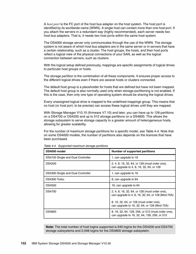
A host port is the FC port of the host bus adapter on the host system. The host port is identified by its worldwide name (WWN). A single host can contain more than one host port. If you attach the servers in a redundant way (highly recommended), each server needs two host bus adapters. That is, it needs two host ports within the same host system.
The DS4000 storage server only communicates through the use of the WWN. The storage system is not aware of which host bus adapters are in the same server or in servers that have a certain relationship, such as a cluster. The host groups, the hosts, and their host ports reflect a logical view of the physical connections of your SAN, as well as the logical connection between servers, such as clusters.
With the logical setup defined previously, mappings are specific assignments of logical drives to particular host groups or hosts.
The storage partition is the combination of all these components. It ensures proper access to the different logical drives even if there are several hosts or clusters connected.
The default host group is a placeholder for hosts that are defined but have not been mapped. The default host group is also normally used only when storage partitioning is not enabled. If this is the case, then only one type of operating system should be sharing the logical drives.
Every unassigned logical drive is mapped to the undefined mappings group. This means that no host (or host port, to be precise) can access these logical drives until they are mapped.
With Storage Manager V10.10 (firmware V7.10) and later, you can have up to 128 partitions on a DS4700 or DS4200 and up to 512 storage partitions on a DS4800. This allows the storage subsystem to serve storage capacity to a greater amount of heterogeneous hosts, allowing for greater scalability.
For the number of maximum storage partitions for a specific model, see Table 4-4. Note that on some DS4000 models, the number of partitions also depends on the licences that have been purchased.
Table 4-4 Supported maximum storage partitions
DS4000 model Number of supported partitions
DS4100 Single and Dual Controller 1, can upgrade to 16
DS4200 2, 4, 8, 16, 32, 64, or 128 (must order one),can upgrade to 4, 8, 16, 32, 64, or 128
DS4300 Single and Dual Controller 1, can upgrade to 16
DS4300 Turbo 8, can upgrade to 64
DS4500 16, can upgrade to 64
DS4700 2, 4, 8, 16, 32, 64, or 128 (must order one),can upgrade to 4, 8, 16, 32, 64, or 128 (Mod 70A)
8, 16, 32, 64, or 128 (must order one),can upgrade to 16, 32, 64, or 128 (Mod 72A)
DS4800 8, 16, 32, 64, 128, 256, or 512 (must order one),can upgrade to 16, 32, 64, 128, 256, or 512
Note: The total number of host logins supported is 640 logins for the DS4200 and DS4700 storage subsystems and 2,048 logins for the DS4800 storage subsystem.
152 IBM System Storage DS4000 and Storage Manager V10.30

Every mapping of a logical drive to a new host or host group creates a new storage partition. If you map additional logical drives to the same host or host group, this does not count as a new storage partition. For example, a cluster with two nodes with redundant I/O paths would be configured as one host group with two hosts. Each host would have two host ports for redundancy. Several logical drives would be mapped to this host group. All these components represent one storage partition. If you attach another single host system to the same storage system and map a logical drive to that host, you create another storage partition. If you then define a new logical drive and map it to either the cluster or the single host, you are still using two storage partitions.
For a step-by-step guide see 5.3.5, “Configuring storage partitioning” on page 259.
Mapping logical drives to the host systemsIf you do not intend to use storage partitioning (for example, you only intend to attach a single host or cluster), you still must define your hosts and host ports to the default host group. You also must define mappings for any logical drives created because Storage Manager does not put new logical drives in the default host group by default.
A valid reason for not using storage partitioning is if you want to use one of the storage virtualization packages that are now available.
If you defined multiple hosts to the default host group, each host system has equal access to all defined logical drives. Since operating systems do not usually allow multiple hosts to access the same logical drives, you must create storage partitions. You do this by mapping specific logical drives to the host ports of host systems. You must identify the host ports by the WWN of the host bus adapters.
You create a host group first, then define a new host and its host ports. This is where you must know the WWN of your host bus adapters. Then map one or more logical drives to this host group. You must also select a LUN for each logical drive.
Attention: Be careful when changing the mapping and LUN of the access logical drive. If you use host-attached management through the host agent component, you will immediately lose the management connection when altering the access logical drive setting.
Note: There are limitations as to how many logical drives you can map per host. DS4000 allows up to 256 LUNs per partition (including the access LUN) and a maximum of two partitions per host. Note that a particular OS platform (refer to the operating system documentation about restrictions) can also impose limitations to the number of LUNs they can support. Keep all these limitations in mind when planning your installation.
Chapter 4. Managing the DS4000 153
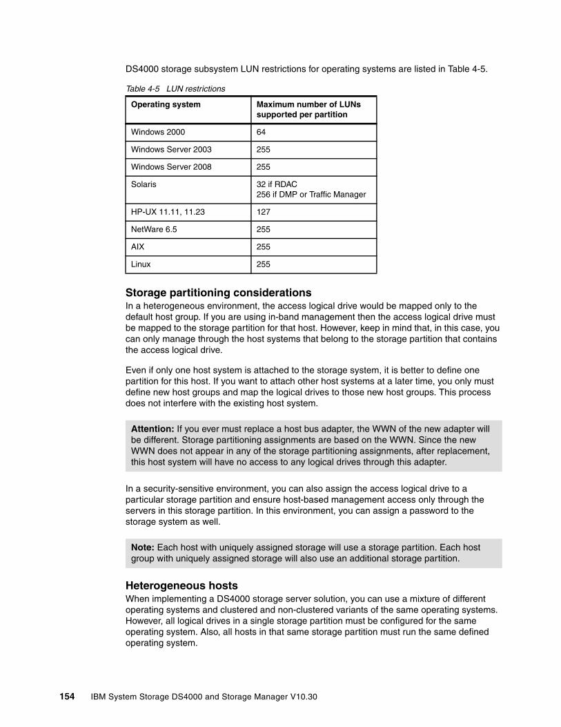
DS4000 storage subsystem LUN restrictions for operating systems are listed in Table 4-5.
Table 4-5 LUN restrictions
Storage partitioning considerationsIn a heterogeneous environment, the access logical drive would be mapped only to the default host group. If you are using in-band management then the access logical drive must be mapped to the storage partition for that host. However, keep in mind that, in this case, you can only manage through the host systems that belong to the storage partition that contains the access logical drive.
Even if only one host system is attached to the storage system, it is better to define one partition for this host. If you want to attach other host systems at a later time, you only must define new host groups and map the logical drives to those new host groups. This process does not interfere with the existing host system.
In a security-sensitive environment, you can also assign the access logical drive to a particular storage partition and ensure host-based management access only through the servers in this storage partition. In this environment, you can assign a password to the storage system as well.
Heterogeneous hosts When implementing a DS4000 storage server solution, you can use a mixture of different operating systems and clustered and non-clustered variants of the same operating systems. However, all logical drives in a single storage partition must be configured for the same operating system. Also, all hosts in that same storage partition must run the same defined operating system.
Operating system Maximum number of LUNs supported per partition
Windows 2000 64
Windows Server 2003 255
Windows Server 2008 255
Solaris 32 if RDAC256 if DMP or Traffic Manager
HP-UX 11.11, 11.23 127
NetWare 6.5 255
AIX 255
Linux 255
Attention: If you ever must replace a host bus adapter, the WWN of the new adapter will be different. Storage partitioning assignments are based on the WWN. Since the new WWN does not appear in any of the storage partitioning assignments, after replacement, this host system will have no access to any logical drives through this adapter.
Note: Each host with uniquely assigned storage will use a storage partition. Each host group with uniquely assigned storage will also use an additional storage partition.
154 IBM System Storage DS4000 and Storage Manager V10.30

Before connecting the systems, always check for the latest interoperability issues on the following site:
http://www.ibm.com/servers/storage/support/disk/
4.2.7 Performance monitor dataThe DS4000 Storage Manager has a built-in tool for monitoring and analyzing performance on each logical volume. The performance monitor data can be used to help tune the storage system. The data collected (see Figure 4-21) includes:
� Total I/Os� Read percentage� Cache hit percentage� Current KB/sec and maximum KBps� Current I/O per sec and maximum I/O per sec
With Storage Manager V10.10 (and firmware V7.10) and later, drive statistics are being collected to support SMI-S 1.1 specifications. Processor utilization statistics are also collected. These statistics, however, are not available through the Performance Monitor GUI.
Figure 4-21 Performance Monitor
Launch the Performance Monitor from the SMclient Subsystem Management window by taking one of the following steps:
� Selecting the Monitor Performance icon.
� Selecting the Storage Subsystem → Monitor Performance pull-down menu option.
� Selecting the storage system node in the logical view or mappings view, then Monitor Performance from the right-mouse pop-up menu.
Important: Heterogeneous hosts are only supported with storage partitioning enabled.
Note: Cache hit percentage is only for reads when read caching is enabled. (Writes are always cache hits if caching is enabled. Thus, they are not reported.)
Chapter 4. Managing the DS4000 155
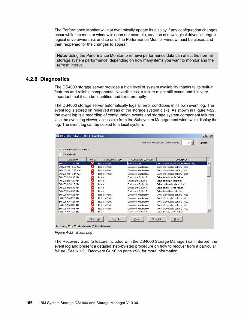
The Performance Monitor will not dynamically update its display if any configuration changes occur while the monitor window is open (for example, creation of new logical drives, change in logical drive ownership, and so on). The Performance Monitor window must be closed and then reopened for the changes to appear.
4.2.8 DiagnosticsThe DS4000 storage server provides a high level of system availability thanks to its built-in features and reliable components. Nevertheless, a failure might still occur, and it is very important that it can be identified and fixed promptly.
The DS4000 storage server automatically logs all error conditions in its own event log. The event log is stored on reserved areas of the storage system disks. As shown in Figure 4-22, the event log is a recording of configuration events and storage system component failures. Use the event log viewer, accessible from the Subsystem Management window, to display the log. The event log can be copied to a local system.
Figure 4-22 Event Log
The Recovery Guru (a feature included with the DS4000 Storage Manager) can interpret the event log and present a detailed step-by-step procedure on how to recover from a particular failure. See 6.1.2, “Recovery Guru” on page 298, for more information.
Note: Using the Performance Monitor to retrieve performance data can affect the normal storage system performance, depending on how many items you want to monitor and the refresh interval.
156 IBM System Storage DS4000 and Storage Manager V10.30

To start the Recovery Guru select the Storage Subsystem → Recovery Guru pull-down menu option in the Subsystem Management window.
Figure 4-23 Recovery Guru
4.2.9 PasswordExecuting destructive commands on a storage system can cause unwanted damage, including data loss. By specifying a password, you can protect against the execution of actions that the controller firmware deems destructive (including actions that change the state of the storage system, such as the creation of logical drives and modification of cache settings).
When using passwords, consider these points:
� If no password was set previously, no current password is required to establish a new password.
� The password is stored on the storage system. Each storage system that you want to be password protected requires a password.
� You cannot change a storage system password unless you have supplied the current password first. If you have forgotten the password, contact IBM Technical Support.
� The maximum password length is 30 characters.
� Passwords are case sensitive. Remember your use of uppercase and lowercase letters when you change a password.
� Trailing white spaces are not stripped from passwords. Be careful not to include trailing spaces in the new password, because they can be difficult to enter accurately in the future.
� Only asterisks are displayed when you type a password.
Setting a password is one way to protect your DS4000 from unauthorized remote access. We recommend setting a password on your DS4000 storage server.
Chapter 4. Managing the DS4000 157

For additional information about how to set up a password, refer to 5.3.2, “Initial setup” on page 243.
4.2.10 Script Editor and command-line interfaceAll of the storage management options available through the Subsystem Management window can be sent to the storage system using statements in scripts. You can use the Script Editor to create or edit a script file, save a script file to the Storage Management station’s local disk, or load a script file from disk. You can also use the command-line interface (CLI) to issue individual commands to the scripting engine from the host operating system command shell or to call pre-written scripts.
Script EditorTo open the Script Editor, follow these steps:
1. From the Enterprise Management window select a storage system in the Device Tree view or device table.
2. Click Tools → Execute Script, as shown in Figure 4-24, or right-click and select Execute Script.
Figure 4-24 Starting the Script Editor
Tip: For an additional method of how to protect your DS4000 from unauthorized remote access, refer to 12.6, “Securing the DS4000 Client using remote management” on page 718.
158 IBM System Storage DS4000 and Storage Manager V10.30

The Script Editor opens as shown in Figure 4-25. There are two views in the window:
� Script view: Provides an area for inputting/editing script commands� Output view: Displays verification or execution results
A splitter bar divides the window between the script view and the output view. You can use the splitter bar to resize the views.
Figure 4-25 The Script Editor
For more information regarding the Script Editor, refer to 11.2, “Script editor” on page 656.
Command-line interface The command-line interface gives you direct access to the script engine from the command-line shell of your operating system. The CLI provides an efficient way to edit, send, and execute Storage Management commands on multiple networked storage systems. You can also access the script engine using the Enterprise Management window. In doing so, you can only edit or execute script commands on the storage system that you selected in the Enterprise Management window instead of multiple storage systems.
The command-line interface can be used to:
� Access the script engine directly instead of through the Enterprise Management window.
� Select multiple storage systems on which to execute script commands.
� Supply script language commands either directly to the command-line interface window or to a script file.
� Create batch files of script commands for execution on multiple storage systems.
� Execute script commands on host-agent managed or directly managed storage systems, or a combination of both.
� Execute mass operations on multiple storage systems, such as firmware downloads and upgrades.
� Add storage systems to the management domain.
Note: Starting with DS4000 Storage Manager V9.12, the SM client script window looks for the files with the file type of .script as the possible script command files. In the previous versions of the DS4000 Storage Manager host software, the script window looks for the file type .scr instead.
Chapter 4. Managing the DS4000 159
� Perform an automatic discovery of all storage systems attached to the local subnet.
� Direct the output to a standard command-line display or to a named file.
Any function available through the SMclient GUI is also available through the command-line interface.
To use the CLI, go to the command-line shell of your operating system. At the command prompt, enter SMcli, followed by either the controller name, host-agent name, worldwide name (WWN), controller IP addresses, or user-supplied name of the specific storage systems depending on the storage system management method that you are using. For more information regarding the command-line interface, refer to Chapter 11, “Command-line interface and Script Editor” on page 629.
4.3 Advanced functionsThis section of introduces some of the advanced features of the DS4000 Storage Manager.
4.3.1 Expanding arrays and logical drivesThe ability to increase the available free capacity on an array (Dynamic Capacity Expansion, DCE) without needing to restart the host system is a very important feature. In today’s IT environment, the need for storage space grows constantly. Many customers exhaust their existing space sooner or later and must expand their storage capacity. It is essential that this process be nondisruptive and not cause any downtime.
With DS4000 Storage Manager, you can simply add new disk drives to the storage server and start the expansion procedure while the system remains fully operational. Once the procedure starts, you cannot stop it. Be aware that you might see some performance impact because the expansion process competes with normal disk access. We recommend that, where possible, you carry out this type of activity when I/O activity is at a minimum. You can use this free capacity to create additional logical drives. Existing logical drives in the array do not increase in size as a result of this operation.
It is also possible to increase the size of logical drives. This is called Dynamic Volume Expansion (DVE). The capacity of standard logical drives and FlashCopy repository logical drives might be increased using one or both of the following capacities:
� Free capacity available on the array of the standard or FlashCopy repository logical drive
� Unconfigured capacity (in the form of unused drives) on the array of the standard or FlashCopy repository logical drive
Note: Starting with Storage Manager V10.10 (with firmware V7.10), arrays with more than 30 drives are supported for RAID-0 and RAID-1 arrays. In certain DS4000 configurations, this could improve performance, provided that your system is optimally tuned. It also improves the data capacities of these arrays. RAID-1 and RAID-10 require an even number of disk drives.
Attention: It is still not possible to use more than 30 drives in RAID-3, RAID-5, and RAID-6 arrays. Once the maximum number of drives is reached, you can no longer add new drives.
160 IBM System Storage DS4000 and Storage Manager V10.30
Increasing the capacity of a FlashCopy repository logical drive does not increase the capacity of the associated FlashCopy logical drive. The FlashCopy logical drive's capacity is always based on the capacity of the base logical drive at the time that the FlashCopy is created.
The storage capacity of a standard logical drive cannot be increased if:
� One or more hot spare drives are in use on the logical drive.
� The logical drive has non-optimal status.
� Any logical drive in the array is in any state of modification.
� The controller that owns this logical drive is in the process of adding capacity to another logical drive (each controller can add capacity to only one logical drive at a time).
� No free capacity exists in the array and no unconfigured capacity (in the form of drives) is available to be added to the array.
You can find more information in 5.4, “Advanced configuration” on page 278.
Changing the RAID level of an array is performed in a nondisruptive manner. The system remains fully operational while the process takes place. A few possible reasons why customers might want to do this operation are:
� The storage requirements have changed over time and existing RAID levels are no longer optimal for a particular environment.
� The performance tuning process has indicated that a different RAID level would be more appropriate than the existing one.
You can change any RAID level to any other one. Be aware there are some restrictions that apply to the new arrays:
� RAID-1 and RAID-10 require even numbers of disk drives.� RAID-3 and RAID-5 require at least three drives.� RAID-6 requires at least five drives.� There is a limit of 30 drives per array for RAID-3, RAID-5, and RAID-6 arrays.
There are limitations if you do not have enough free space in the array. For example, a RAID-5 array of four disk drives with no free space cannot be migrated directly to RAID level
Note: Starting with Storage Manager V10.10 (with firmware V7.10), support is provided for logical drives greater than 2 TB. This improves the capacity requirement for applications that require large capacity logical drives.
Note: Increasing the capacity of a standard logical drive is only supported on certain operating systems. If you increase the logical drive capacity on a host operating system that is not supported, the expanded capacity will be unusable and you cannot restore the original logical drive capacity.
Tip: If a logical drive-to-LUN mapping has not yet been defined, you can increase the capacity for a standard logical drive on any host operating system.
Note: Storage Manager V10.10 (with firmware V7.10) and later provides RAID-6 protection for the DS4700 and DS4200. RAID-6 stripes blocks of data and parity across an array of drives and it uses two sets of parity information for each block of data.
Chapter 4. Managing the DS4000 161
1. If you start this migration, you will receive an error message stating that you do not have enough free space. You must add new drives to the array first to increase the free capacity and then you can change the RAID level. Also, if the array has an odd number of drives and you want to migrate to RAID-1, you must add a drive first to have an even number.
By doing the opposite, changing from RAID-1 to RAID-5, you gain free space in the array that can be used to define new logical drives or expand existing ones.
Starting this procedure is simple. Use DS4000 Storage Manager to select your array and perform the RAID level migration. When the procedure starts, it reorganizes the data segments in the array according to the new RAID level.
Because this requires a large amount of I/O to be performed, there is an impact on performance while the migration lasts. You can influence the performance impact by changing the value of the modification priority. This parameter is set on a logical drive basis and you should change it for all logical drives in the array. The higher modification priority means the shorter migration time, but the performance impact will be higher.
You might change the modification priority to a low value during the migration process to minimize performance degradation. When the migration finishes, change the value to a higher one again to reduce the time for a rebuild in the case of a drive failure. This minimizes the critical time of non-redundant operation caused by the disk drive fault. Once the migration starts, you cannot stop it.
4.3.2 Unconfiguring storage subsystem and arrays
Starting with Storage Manager 10.10, you can clear the storage subsystem or previously created arrays, if you must do so. Clearing the storage subsystem completely removes all configuration of the storage subsystem, essentially bringing it back to its state when it was initially installed. Information defining all arrays, logical drives, and hot spares is deleted. Use this feature when you must create a new configuration on a storage subsystem that already has a configuration defined.
Clearing the array configuration clears logical drives and group configuration in all arrays while leaving the remaining subsystem configuration intact.
4.3.3 Pre-read redundancy check
RAID arrays are created to provide tolerance against disk failure and errors. To allow it to recover from failures, the RAID array stores additional data called redundancy data. This redundancy data could potentially become inconsistent from time to time. Redundant data is said to be consistent if every portion of the redundancy group can be reliably and consistently reconstructed in the event of a failure to the array, and said to be inconsistent if it cannot be read or the consistency cannot be verified.
Note: Even though RAID migration is a nondisruptive process, we recommend carrying out this migration when I/O activity is at a minimum.
Warning: In both cases (clearing the storage subsystem and array configuration) data loss occurs. Ensure that a backup of the storage subsystem data as well as the storage subsystem configuration profile is made before attempting these operations.
162 IBM System Storage DS4000 and Storage Manager V10.30
Starting with Storage Manager V10.10 a pre-read redundancy check feature is available. The pre-read redundancy feature allows the consistency of redundancy data of a RAID array to be optionally checked prior to returning data for host read requests. The consistency check cannot determine whether the data itself is correct. It does, however, determine that a redundancy consistency error has occurred within the extent of the read command. Once an inconsistency is discovered, an error is reported in the storage subsystem and no read data is returned depending on the data inconsistency error.
This feature can be activated on a logical drive basis, which is created as a RAID array that supports redundancy information. The feature allows data verification in environments where data consistency is a key requirement. This feature cannot be enabled for logical drives that do not have any redundancy data.
When a read request is issued to the storage subsystem, the controller verifies that the redundancy group is consistent for the extent of the data specified in the read request. If the controller found that the redundancy group data is in a consistent state, the read request is returned to the host successfully. If the redundancy group data is found to be in an inconsistent state, the read request is returned to the host with a check condition status. The consistency check is only performed for data not already in cache.
In order to verify the consistency of the redundancy group, the entire redundancy group must be read from disk into cache. Should no inconsistency be found, all user data that comprises the redundancy group is left in cache in order to potentially satisfy subsequent cache hits. The data left in cache may include data that is outside the extent of the original read request. Such data does not require a consistency check since the data is already in cache.
During the process of verifying the consistency of the redundancy group, a media error or unreadable sector may be encountered within the extent of the redundancy group. When such an error occurs, the RAID controller attempts to perform a reconstruction of the data, using the redundancy information of the data. If this operation is successful, the consistency check indicates that the redundancy group is consistent and the read data is returned to the host.
During the process of verifying the consistency of the redundancy group, an unrecoverable read error may be encountered. When such an error occurs, the consistency check fails. However, the original read request continues to be processed. If the entire extent of the request is still readable, the read data is returned to the host. If some portion of the original read request is unavailable, the read command fails.
In most situations, recovery from an inconsistent redundancy group involves restoring the volume from a backup source.
When activating the pre-read redundancy check feature, the media scan feature no longer automatically corrects discovered redundancy group inconsistencies.
Note: The pre-read redundancy check feature only supports logical drives created as RAID-1, RAID-3, RAID-5, and RAID-6.
Note: Should a drive associated with an array become degraded, the pre-check feature is disabled.
Note: In a FlashCopy or Enhanced Remote Mirror copy pair relationship, the pre-read redundancy feature is only supported on the source logical drives.
Chapter 4. Managing the DS4000 163

You can find more information in “Pre-read redundancy check” on page 284.
4.3.4 Defragmenting an array
Defragmenting an array results in the consolidation of all free capacity on the selected array. Doing this lets you create additional logical drives from the maximum amount of free capacity. A fragmented array can result from logical drive deletion or from not using all available free capacity in a free capacity node during logical drive creation.
You cannot cancel the operation once it begins, but your data remains accessible during the defragmentation operation. To use this option, all logical drives in the array must be online and have optimal status. Also, there must not be any logical drive modification operations, such as changing the segment size of a logical drive, in progress. You can find more information in 5.4.1, “Maintaining arrays” on page 278.
4.3.5 Controller ownershipEach logical drive has a preferred controller of ownership. This controller normally handles all I/O requests for this particular logical drive. In other words, each logical drive is owned by one and only one controller. The alternate controller only takes over and handles the I/O requests in the case of a failure along the I/O path, for example, a defect host bus adapter or switch. When defining logical drives, the system normally alternates ownership between the two controllers.
All heavily stressed logical drives can reside on only one controller while the other one handles only a small amount of all I/O requests. To balance the workload between the controllers, you can change the preferred ownership of a logical drive to the other controller, and normally the storage system is balanced better regarding the workload. To change the preferred ownership of a logical drive, it must reside on this one. You cannot change the ownership if the logical drive is handled by its alternate controller.
Balancing traffic is unfortunately not always a trivial task. For example, if an application requires large disk space to be located and accessed in one chunk, it becomes harder to balance traffic by spreading the smaller volumes among controllers.
In addition, typically, the load across controllers and logical drives are constantly changing. The logical drives and data accessed at any given time depend on which applications and users are active during that time period, hence the importance of monitoring the system.
The Performance Monitor provides data useful for monitoring the I/O activity of a specific controller and a specific logical drive, which can help identify possible high-traffic I/O areas. Identify actual I/O patterns to the individual logical drives and compare those with the expectations based on the application. If a particular controller has considerably more I/O activity, consider moving logical drives to the other controller in the storage system.
You might notice a disparity in the total I/Os (workload) of controllers. For example, the workload of one controller is heavy or is increasing over time, while that of the other controller
Attention: Care should be taken when enabling this feature, as it could have an impact on I/O performance.
Important: Be sure that the operating system using the logical drive uses a multipath I/O driver. Otherwise, it loses access to the logical drive.
164 IBM System Storage DS4000 and Storage Manager V10.30
is lighter or more stable. In this case, consider changing the controller ownership of one or more logical drives to the controller with the lighter workload.
The preferred controller ownership of a logical drive or array is the controller of an active-active pair that is designated to own these logical drives. The preferred controller owner is the controller that currently owns the logical drive or array.
If the preferred controller is undergoing a firmware download, ownership of the logical drives is automatically shifted to the other controller, and that controller becomes the current owner of the logical drives. If the preferred controller must be replaced, disable the controller first. This intentionally causes a failover of LUNs to the other controller and allows the removal and replacement of the preferred controller. This is considered a routine ownership change and is reported with an informational entry in the event log.
There can also be a forced failover from the preferred controller to the other controller because of I/O path errors. This is reported with a critical entry in the event log, and will be reported by the Enterprise Management software to e-mail and SNMP alert destinations.
4.3.6 Cache parametersCache memory is an area of temporary volatile storage (RAM) on the controller that has a faster access time than the drive media. This cache memory is shared for read and write operations.
Efficient use of the RAID controller cache is essential for good performance of the DS4000 storage server.
Tip: Here are some guidelines for LUN assignment and storage partitioning:
� Assign LUNs across all controllers to balance controller utilization.
� Use the manual method of creating logical drives. This allows greater flexibility for configuration settings, such as enclosure loss protection and utilizing both drive loops.
� If you have highly used LUNs, where possible, move them away from other LUNs and put them on their own separate array. This reduces disk contention for that array.
� Always leave a small amount of free space in the array after the LUNs have been created.
Restriction: A secondary logical drive in a Remote Mirror does not have a preferred owner. Instead, the ownership of the secondary logical drive is determined by the controller owner of the associated primary logical drive. For example, if controller A owns the primary logical drive in the primary storage system, then controller A owns the associated secondary logical drive in the secondary storage system. Controller ownership changes of the primary logical drive cause a corresponding controller ownership change of the secondary logical drive.
Chapter 4. Managing the DS4000 165

Figure 4-26 shows a schematic model of the major elements of a disk storage system—elements through which data moves (as opposed to other elements such as power supplies). In the model, these elements are organized into eight vertical layers: Four layers of electronic components shown inside the dotted ovals and four layers of paths (that is, wires) connecting adjacent layers of components to each other. Starting at the top in this model, there are a number of host computers (not shown) that connect (over some number of paths) to host adapters. The host adapters connect to cache components. The cache components in turn connect to disk adapters that in turn connect to disk drives.
Figure 4-26 Conceptual model of disk caching
Now we explain how a read I/O request is handled in this model. A host issues a read I/O request that is sent over a path (such as a Fibre Channel) to the disk system. The request is received by a disk system host adapter. The host adapter checks whether the requested data is already in cache, in which case it is immediately sent back to the host. If the data is not in cache, the request is forwarded to a disk adapter that reads the data from the appropriate disk and copies the data into cache. The host adapter sends the data from cache to the requesting host.
Most (hardware) RAID controllers have some form of read or write caching. You should plan to take advantage of these caching capabilities, as they enhance the effective I/O capacity of the disk subsystem. The principle of these controller-based caching mechanisms is to gather smaller and potentially nonsequential I/O requests coming in from the host server (for example, SQL Server®) and try to batch them with other I/O requests. Consequently, the I/O requests are sent as larger (32 KB to 128 KB), and possibly sequential, requests to the hard disk drives. The RAID controller cache arranges incoming I/O requests by making the best use of the hard disk’s underlying I/O processing ability. This increases the disk I/O throughput.
There are many different settings (related to caching) that come into play. When implementing a DS4000 storage server as part of an entire solution, you should plan at least one week of performance testing and monitoring to adjust the settings.
. . .
. . .
. . .
. . .
. . .
. . .
. . .
. . .
paths to hosts 1...n
1...n
1...n
1...n
1...n
1...n
1...n
1...n
paths to cache
paths to adapters
paths to disks
host adapters
cache
disk adapters
disk drives
166 IBM System Storage DS4000 and Storage Manager V10.30
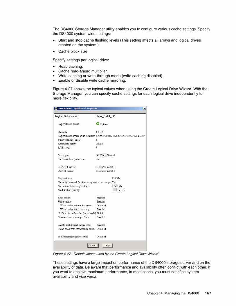
The DS4000 Storage Manager utility enables you to configure various cache settings. Specify the DS4000 system wide settings:
� Start and stop cache flushing levels (This setting affects all arrays and logical drives created on the system.)
� Cache block size
Specify settings per logical drive:
� Read caching.� Cache read-ahead multiplier.� Write caching or write-through mode (write caching disabled).� Enable or disable write cache mirroring.
Figure 4-27 shows the typical values when using the Create Logical Drive Wizard. With the Storage Manager, you can specify cache settings for each logical drive independently for more flexibility.
Figure 4-27 Default values used by the Create Logical Drive Wizard
These settings have a large impact on performance of the DS4000 storage server and on the availability of data. Be aware that performance and availability often conflict with each other. If you want to achieve maximum performance, in most cases, you must sacrifice system availability and vice versa.
Chapter 4. Managing the DS4000 167

The default settings are read and write cache for all logical drives, with cache mirroring to the alternate controller for all write data. The write cache is only used if the battery for the controller is fully charged. Read ahead is not normally used on the logical drives.
Read cachingRead caching allows read operations from the host to be stored in controller cache memory. If a host requests data that is not in the cache, the controller reads the needed data blocks from the disk and places them in the cache. Until he cache is flushed, any other requests for this data are fulfilled with the cache data instead of initiating another read operation to the disk.
Read-ahead multiplierCache read-ahead, or prefetch, allows the controller, while it is reading and copying host-requested data blocks from disk into the cache, to copy additional data blocks into the cache. This increases the chance that a future request for data will be fulfilled from the cache. Cache read-ahead is important for multimedia applications that use sequential I/O.
This feature uses an automatic pre-fetching multiplier to maximize its cache hit efficiency and system performance. This turns on monitoring of the I/O to the logical drive and enables the new algorithm to dynamically choose how much to read ahead. This simplifies the process for the administrator as there is no need to manually set a specific value for the read ahead multiplier. The system tunes itself depending on the I/O characteristics. When sequential access is detected the controller automatically starts using read ahead buffering. When random or non-sequential I/O is used then it stops using the read ahead buffer. To disable this feature, simply uncheck the Dynamic Cache Read Prefetch check box for the relevant logical drive.
Write cachingThe write caching parameter enables the storage subsystem to cache write data instead of writing it directly to the disks. This can improve performance significantly, especially for environments with random writes such as databases. For sequential writes, the performance gain varies with the size of the data written. If the logical drive is only used for read access, it might improve overall performance to disable the write cache for this logical drive. Then no cache memory is reserved for this logical drive.
Write cache mirroringDS4000 write cache mirroring provides the integrity of cached data if a RAID controller fails. This is excellent from a high-availability perspective, but it decreases performance. The data is mirrored between controllers across the drive-side FC loop. This competes with normal data transfers on the loop. We recommend that you keep the controller write cache mirroring enabled for data integrity reasons in case of a controller failure.
By default, a write cache is always mirrored to the other controller to ensure proper contents, even if the logical drive moves to the other controller. Otherwise, the data of the logical drive can be corrupted if the logical drive is shifted to the other controller and the cache still contains unwritten data. If you turn off this parameter, you risk data loss in the case of a controller failover, which might also be caused by a path failure in your fabric.
The cache of the DS4000 storage server is protected by a battery against power loss. If the batteries are not fully charged (for example, just after powering on) the controllers automatically disable the write cache. If you enable the parameter, the write cache is used, even if no battery backup is available, resulting in a higher risk of data loss.
168 IBM System Storage DS4000 and Storage Manager V10.30

Write caching or write-throughWrite-through means that writing operations do not use cache at all. The data is always going to be written directly to the disk drives. Disabling write caching frees up cache for reading (because the cache is shared for read and write operations).
Write caching can increase the performance of write operations. The data is not written straight to the disk drives. It is only written to the cache. From an application perspective, this is much faster than waiting for the disk write operation to complete. Therefore, you can expect a significant gain in application writing performance. It is the responsibility of the cache controller to eventually flush the unwritten cache entries to the disk drives.
Write cache mode appears to be faster than write-through mode, because it increases the performance of both reads and writes. But this is not always true, because it depends on the disk access pattern and workload.
A lightly loaded disk subsystem usually works faster in write-back mode, but when the workload is high, the write cache can become inefficient. As soon as the data is written to the cache, it must be flushed to the disks in order to make room for new data arriving into the cache. The controller would perform faster if the data went directly to the disks. In this case, writing the data to the cache is an unnecessary step that decreases throughput.
Starting and stopping cache flushing levelsThese two settings affect the way the cache controller handles unwritten cache entries. They are only effective when you configure the write-back cache policy. Writing the unwritten cache entries to the disk drives is called flushing. You can configure the start and stop flushing level values. They are expressed as percentages of the entire cache capacity. When the number of unwritten cache entries reaches the start flushing value, the controller begins to flush the cache (write the entries to the disk drives). The flushing stops when the number of unwritten entries drops below the stop flush value. The controller always flushes the oldest cache entries first. Unwritten cache entries older than 20 seconds are flushed automatically.
The default is the start flushing level, and the stop flushing level set to 80%. This means that the cache controller does not allow more than 80% of the entire cache size for write-back cache, but it also tries to keep as much of it as possible for this purpose. If you use such settings you can expect a high number of unwritten entries in the cache. This is good for writing performance, but be aware that it offers less data protection.
If the stop level value is significantly lower than the start value, this causes a high amount of disk traffic when flushing the cache. If the values are similar, the controller only flushes the amount needed to stay within limits.
Performance tests have shown that it is a good idea to use similar values for start and stop flushing levels. If the stop level value is significantly lower than the start value, this causes a high amount of disk traffic when flushing the cache. If the values are similar, then the controller only flushes the amount needed to stay within limits.
Note: Typically, we see that a start flushing level of 50% and a stop flushing level of 50% is best for customer environments.
Chapter 4. Managing the DS4000 169

Cache block sizeThis is the size of the cache memory allocation unit and can be either 4 K, 8 K, or 16 K for the DS4200, DS4700, and DS4800 storage subsystems. This provides flexibility in managing and customizing your cache setup of the DS4000 storage subsystem based on your specific requirements. By selecting the proper value for your particular situation, you can improve the caching efficiency and performance. For example, if applications mostly access the data in small blocks up to 8 K, but you use 16 K for cache block size, then each cache entry block is only partially populated. You will always occupy 16 K in cache to store 8 K (or less) of data. This means that only up to 50% of cache capacity is effectively used to store the data. You can expect lower performance. For random workloads and small data transfer sizes, 4 K is better.
On the other hand, if the workload is sequential and you use a large segment size, as is the case with multimedia applications, it is better to use the larger cache block sizes of 8 K or 16 K. A larger block size means a lower number of cache blocks and reduces cache overhead delays. In addition, a larger cache block size requires fewer cache data transfers to handle the same amount of data.
4.3.7 Logical drive modification priorityThe modification priority defines how much processing time is allocated for operations modifying the logical drive relative to the system performance. Operations that cause a logical drive modification are:
� Initializing a logical drive� Reconstructing after a disk failure� Copying back from a hot spare drive� Changing the segment size of a logical drive� Dynamic logical drive expansion� Adding free capacity to an array� Defragmenting an array� Changing the RAID level of an array
If the logical drive contains critical data, you might prefer a high modification priority to keep the time of a critical state (for example, after losing a disk) as short as possible, even if this affects the system performance during the modification process.
The following modification priority rates are available:
� Lowest� Low� Medium� High � Highest
When a storage system logical drive is a primary logical drive and a full synchronization is necessary, the controller owner performs the full synchronization in the background while processing local I/O writes to the primary logical drive and associated remote writes to the secondary logical drive. Because the full synchronization diverts controller processing
Note: The lowest priority rate favors system performance, but the modification operation takes longer. The highest priority rate favors the modification operation, but system performance might be compromised.
The progress bar at the bottom of the Logical Drive Properties dialog displays the progress of a modification operation.
170 IBM System Storage DS4000 and Storage Manager V10.30

resources from I/O activity, it can impact performance on the host application. The synchronization priority defines how much processing time is allocated for synchronization activities relative to system performance.
The guidelines in Table 4-6 can help you determine how long a synchronization can take and how much various synchronization priorities can affect system performance.
Table 4-6 Impact of modification priority on relative time for full synchronization
The synchronization progress bar at the bottom of the Mirroring tab of the Logical Drive Properties dialog displays the progress of a full synchronization.
4.3.8 Media scanMedia scan is a background process that checks the physical disks for defects by reading the raw data from the disk and writing it back. This detects possible problems caused by bad sectors of the physical disks before they disrupt normal data reads or writes. This process is sometimes known as data scrubbing.
The media scan continuously runs in the background, using spare cycles to complete its work. The default media scan is for a scan every 30 days, that is, the maximum time the media scan has to complete the task. During the scan process, the DS4000 calculates how much longer the scan process will take to complete and adjusts the priority of the scan to ensure that the scan completes within the time setting allocated. Once the media scan has completed, it starts over again and resets its time for completion to the current setting. This media scan setting can be reduced, however. If the setting is too low, priority is given to the media scan over host activity to ensure that the scan completes in the allocated time. This scan can impact performance, but improve data integrity.
The media scan should be enabled for the entire storage subsystem. The system-wide enabling specifies the duration over which the media scan runs. The logical drive enabling specifies whether to do a redundancy check as well as a media scan.
A media scan can be considered a surface scan of the hard drives, while a redundancy check scans the blocks of a RAID-3, RAID-5, or RAID-6 logical drive and compares it against the redundancy data. In the case of a RAID-1 logical drive, the redundancy scan compares blocks between copies on mirrored drives.
We have seen no effect on I/O in a 30-day setting unless the processor is utilized in excess of 95%. The length of time that it takes to scan the LUNs depends on the capacity of all the LUNs on the system and the utilization of the controller.
Modification priority Relative time
Highest Fastest possible time
High Two times longer than fastest possible time
Medium Three and a half times longer than fastest possible time
Low Six times longer than fastest possible time
Lowest Eight times longer than fastest possible time
Note: A media scan is only capable of resolving media errors and data or parity mismatches. A media scan does not attempt to resolve any other sort of error occurring during I/O operations.
Chapter 4. Managing the DS4000 171
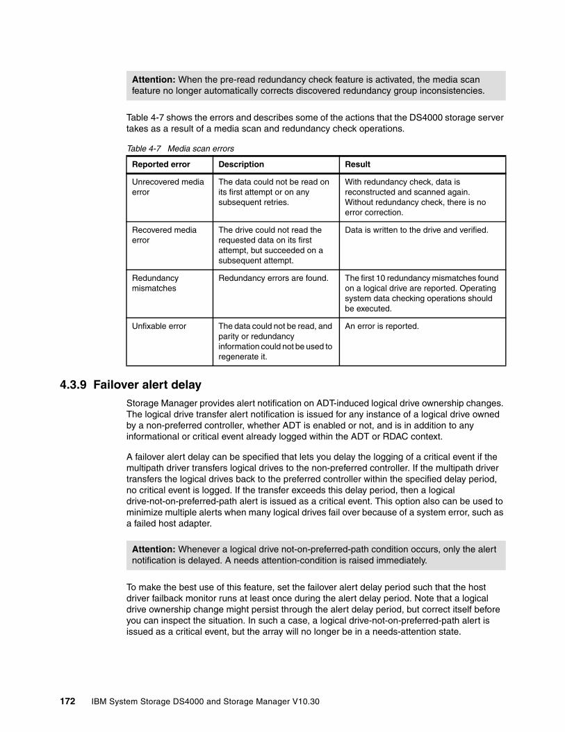
Table 4-7 shows the errors and describes some of the actions that the DS4000 storage server takes as a result of a media scan and redundancy check operations.
Table 4-7 Media scan errors
4.3.9 Failover alert delayStorage Manager provides alert notification on ADT-induced logical drive ownership changes. The logical drive transfer alert notification is issued for any instance of a logical drive owned by a non-preferred controller, whether ADT is enabled or not, and is in addition to any informational or critical event already logged within the ADT or RDAC context.
A failover alert delay can be specified that lets you delay the logging of a critical event if the multipath driver transfers logical drives to the non-preferred controller. If the multipath driver transfers the logical drives back to the preferred controller within the specified delay period, no critical event is logged. If the transfer exceeds this delay period, then a logical drive-not-on-preferred-path alert is issued as a critical event. This option also can be used to minimize multiple alerts when many logical drives fail over because of a system error, such as a failed host adapter.
To make the best use of this feature, set the failover alert delay period such that the host driver failback monitor runs at least once during the alert delay period. Note that a logical drive ownership change might persist through the alert delay period, but correct itself before you can inspect the situation. In such a case, a logical drive-not-on-preferred-path alert is issued as a critical event, but the array will no longer be in a needs-attention state.
Attention: When the pre-read redundancy check feature is activated, the media scan feature no longer automatically corrects discovered redundancy group inconsistencies.
Reported error Description Result
Unrecovered media error
The data could not be read on its first attempt or on any subsequent retries.
With redundancy check, data is reconstructed and scanned again.Without redundancy check, there is no error correction.
Recovered media error
The drive could not read the requested data on its first attempt, but succeeded on a subsequent attempt.
Data is written to the drive and verified.
Redundancy mismatches
Redundancy errors are found. The first 10 redundancy mismatches found on a logical drive are reported. Operating system data checking operations should be executed.
Unfixable error The data could not be read, and parity or redundancy information could not be used to regenerate it.
An error is reported.
Attention: Whenever a logical drive not-on-preferred-path condition occurs, only the alert notification is delayed. A needs attention-condition is raised immediately.
172 IBM System Storage DS4000 and Storage Manager V10.30

Important:
� The failover alert delay option operates at the storage system level, so one setting applies to all logical drives.
� The failover alert delay option is reported in minutes in the storage system profile as a storage system property.
� The default failover alert delay interval is five minutes. The delay period can be set within a range of 0 to 60 minutes. Setting the alert delay to a value of zero results in instant notification of a logical drive not on the preferred path. A value of zero does not mean that alert notification is disabled.
� The failover alert delay is activated after controller start-of-day completes to determine whether all logical drives were restored during the start-of-day operation. Thus, the earliest that the not-on-preferred path alert will be generated is after boot up and the configured failover alert delay.
4.3.10 Persistent reservations Persistent reservations is a SCSI-3 feature for restricting access to storage media, based on the concept of reservations that the host can establish and manipulate. Earlier versions of SCSI provide a simple reservation capability through the RESERVE and RELEASE commands. SCSI-3 persistent reservations provide a significant super-set of the earlier capability. Improvements that come with persistent reservations include:
� Well-defined model for reserving across multiple host and target ports
� Levels of access control, for example, shared reads, exclusive writes, exclusive reads, and writes
� Ability to query the storage system about registered ports and reservations
� Provisions for persistence of reservations through power loss at the storage system
A logical drive reservation is a feature of the cluster software (the actual reservation of the logical drive is handled by the host application) that allows one or more host ports to reserve a logical drive, thus preventing other host ports from accessing the same logical drive.
Unlike other types of reservations, a persistent reservation reserves across multiple host ports, provides various levels of access control, offers the ability to query the storage system about registered ports and reservations, and, optionally, provides for persistence of reservations in the event of a storage system power loss.
The benefits of the persistent reservations feature is that it allows the DS4000 storage server to integrate with cluster solutions that use shared logical drives for increased availability, scalability, and performance. For instance, this enables VERITAS Dynamic Multipathing (DMP) to manage the DS4000 storage server when the VERITAS Cluster Server is in use.
See 5.4.6, “Persistent reservations” on page 290, for more details.
4.3.11 Automatic firmware synchronizationThe automatic code synchronization (ACS) feature ensures that both controllers within a storage subsystem are executing the same version of the controller firmware. The primary purpose of this feature is to reconcile the possible difference in controller firmware version present on a replacement controller. ACS is also used to address inconsistent versions of firmware that can occur without controller replacement if a firmware upgrade is interrupted.
Chapter 4. Managing the DS4000 173
We do not recommend replacing both controllers, since ACS is intended to use the firmware image on the remaining native controller to resolve the inconsistency. ACS does address the replacement of both controllers. In this case, ACS synchronizes to the newer of the two firmware.
A failure to successfully transfer the incumbent image from the native to the foreign controller results in the native controller holding the alternate controller in reset.
The ACS feature behavior is based on three key persistent data representations:
� The serial number of each controller.
� The serial numbers of the last known native controllers. The identities of the last known controllers are contained within the metadata on the native drive set.
� The firmware version number of the incumbent firmware. This is the firmware associated with the metadata on the native drive set. The version of the incumbent firmware is stored within the drive metadata.
The controller firmware uses this information to determine what ACS action is required. If the serial number of a controller does not match the serial number for the slot in which it resides, this controller is considered to be foreign for the purposes of ACS, and a firmware synchronization occurs.
4.3.12 Fibre Channel and SATA drive intermixAs discussed previously, it is possible to attach a mix of Fibre Channel and SATA enclosures to the same storage system. It is now also possible to intermix Fibre Channel drives and SATA E-DDM drives within the same DS4700 and EXP810 expansion enclosures with v6.23 firmware and later. Intermixing Fibre Channel and SATA disk enclosures and the intermixing of Fibre Channel drives and SATA E-DDM drives within the same DS4700 and EXP810 expansion enclosures are premium features that must be licensed. At this point, we explore the benefits and considerations for configuring the storage this way. Consider these three classes of storage:
� Online (or primary) storage is the storage for applications that require immediate access to data, such as databases and frequently accessed user data. Primary storage holds business-critical information and data with the highest value and importance. This storage requires high performance and high-availability technologies like Fibre Channel technology.
� Near-line (or secondary) storage is used for applications that do not require immediate access but still require the performance, availability, and flexibility of disk storage. It can also be used to cache online storage to reduce the time required for data backups. Secondary storage represents a large percentage of a company’s data and is an ideal fit for Serial ATA technology.
� Offline (archival) storage is used for backup or long-term storage. For this type of storage, tape remains the most economical solution.
174 IBM System Storage DS4000 and Storage Manager V10.30
Now that we have identified that SATA technology is best suited to near-line storage usage, we have the following considerations regarding its use in the same storage server as online storage:
� Performance: Intermixing the Fibre Channel and SATA drives on a DS4300 and DS4500 gives superior performance when compared with the DS4100. Instead of having a storage server for online storage and another for near-line storage, you can combine both types of storage with one storage server, and leverage the higher performance controllers. The DS4700 and DS4800 can intermix Fibre Channel and SATA. The best performing intermix is the EXP810 enclosure using SATA E-DDM drives or FC drives. This allows the enclosure loops to run at the full 4 Gbps.
� Scalability: The total SATA disk capacity is far greater than the Fibre Channel offering. The new EV-DDM and E-DDM drives are 750 GB, as compared to the largest FC drive being 300 GB.
� Cost: Consider an existing Fibre Channel environment for which one wants to implement SATA technology. This consideration is further enhanced with Fibre Channel and SATA drive intermixing within the same DS4700 and EXP810 enclosures with v6.23 firmware and later. The cost considerations of intermixing versus implementing a separate SATA storage server are:
– Implementation costs of a new SATA storage server versus intermixing with the existing Fibre Channel enclosures.
– SAN infrastructure costs for more ports or hardware.
– Administration costs (effort) depend on the number of controllers managed. Intermixing eliminates controller pairs by leveraging existing controllers.
After you have considered these factors and identified the criteria for your environment, the choice to intermix or not can be determined.
4.3.13 Enhanced performance featureStarting from V7.10 firmware comes a DS4800 Model 80 enhanced performance feature. This feature is designed to provide enhanced storage server processing capability internally within the DS4800 Model 80 controller. With the enhanced performance activation feature, the DS4800 Model 80 is designed to provide the equivalent storage server processing capability as the DS4800 Model 82 controller.
This feature allows a DS4800 storage subsystem to be configured to operate at two different performance levels. A high-performance tier storage subsystem is configured to always operate at the best possible bandwidth and drive IOPS performance levels. A low performance tier storage subsystem is configured to operate at a lower bandwidth and drive IOPS performance level than a high-performance tier version of the same storage subsystem type.
A subsystem is configured to be either a high-performance tier or low-performance tier subsystem during manufacturing. Once set, the base performance tier of a given subsystem cannot be changed in the field. The base performance tier of a given subsystem is determined by the sub-model identifier. A high-performance tier subsystem never operates at lower performance levels. A low-performance tier subsystem can have its performance upgraded to high using a premium feature key, but it is still inherently a low performance tier subsystem.
Note: The enhanced performance feature is only applicable to the DS4800 Model 80 Storage Subsystem.
Chapter 4. Managing the DS4000 175

The enhanced performance feature key can be removed from a storage subsystem if required. Note that key removal requires a reboot of the storage array and must be done offline.
Due to the performance tier being linked to the storage subsystem sub-model identifier that is programmed into the NVSRAM during manufacturing, when a controller fails, it must be replaced with a controller with the same performance tier configuration.
Cache IOPS performance is not controlled or defined by this feature.
4.4 Premium featuresPremium features are storage system features that might not be available in the standard configuration of the storage management software. The set of available premium features depends on the model of DS4000 storage server. Possible premium features are FlashCopy, VolumeCopy, Enhanced Remote Mirroring, FC/SATA intermix, enhanced performance (DS4800 mod 80), and storage partitioning.
Refer to 12.2, “Handling premium features” on page 689, for details.
FlashCopyA FlashCopy logical drive is a point-in-time image of a logical drive. It is the logical equivalent of a complete physical copy, but you create it much more quickly than a physical copy. With SM 10.10 (firmware v7.10) and later it is possible to have up to 16 FlashCopies per logical drive, depending on the DS4000 storage subsystem, which allows you to keep more frequent point-in-time copies of your data.This firmware also introduces a new feature key scheme that dictates the quantity of mirror pairs based on the licences that have been purchased. For the number of maximum FlashCopies per logical drive for a specific model, see Table 4-8.
Table 4-8 Supported maximum FlashCopies with v7.10 and later firmware
Refer to Chapter 7, “FlashCopy” on page 401, for more information.
Warning: In order for the high-performance tier to take effect, both controllers that comprise the storage subsystem are rebooted following the application of this premium feature key. Because of this behavior, the Enhanced Performance Premium Feature key application process must be done offline.
Note: High-performance tier storage subsystems (DS4800 mod 82) reject attempts to apply an enhanced performance premium feature key as an unsupported operation.
DS4000 model Number of supported FlashCopies per logical drive
DS4200 4, can upgrade to 8
DS4700 4, can upgrade to 8
DS4800 4, can upgrade to 16
Note: The maximum number of FlashCopies supported per DS4000 storage subsystem is 512 for the DS4200 and DS4700, and 1024 for the DS4800.
176 IBM System Storage DS4000 and Storage Manager V10.30
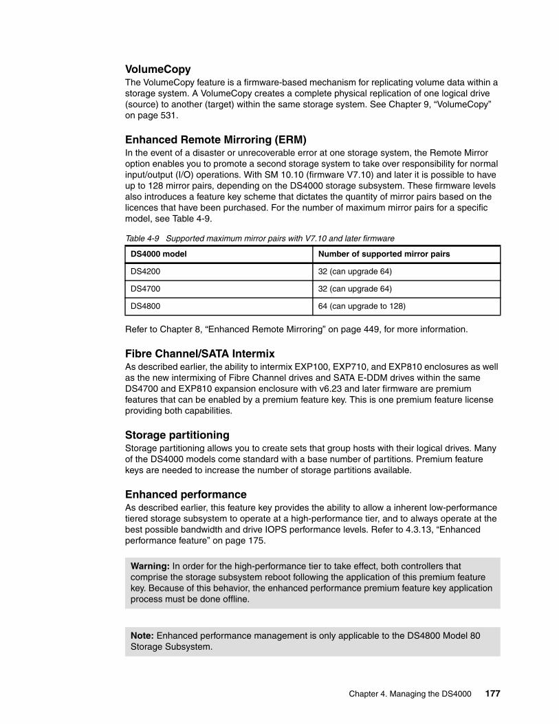
VolumeCopyThe VolumeCopy feature is a firmware-based mechanism for replicating volume data within a storage system. A VolumeCopy creates a complete physical replication of one logical drive (source) to another (target) within the same storage system. See Chapter 9, “VolumeCopy” on page 531.
Enhanced Remote Mirroring (ERM)In the event of a disaster or unrecoverable error at one storage system, the Remote Mirror option enables you to promote a second storage system to take over responsibility for normal input/output (I/O) operations. With SM 10.10 (firmware V7.10) and later it is possible to have up to 128 mirror pairs, depending on the DS4000 storage subsystem. These firmware levels also introduces a feature key scheme that dictates the quantity of mirror pairs based on the licences that have been purchased. For the number of maximum mirror pairs for a specific model, see Table 4-9.
Table 4-9 Supported maximum mirror pairs with V7.10 and later firmware
Refer to Chapter 8, “Enhanced Remote Mirroring” on page 449, for more information.
Fibre Channel/SATA IntermixAs described earlier, the ability to intermix EXP100, EXP710, and EXP810 enclosures as well as the new intermixing of Fibre Channel drives and SATA E-DDM drives within the same DS4700 and EXP810 expansion enclosure with v6.23 and later firmware are premium features that can be enabled by a premium feature key. This is one premium feature license providing both capabilities.
Storage partitioningStorage partitioning allows you to create sets that group hosts with their logical drives. Many of the DS4000 models come standard with a base number of partitions. Premium feature keys are needed to increase the number of storage partitions available.
Enhanced performanceAs described earlier, this feature key provides the ability to allow a inherent low-performance tiered storage subsystem to operate at a high-performance tier, and to always operate at the best possible bandwidth and drive IOPS performance levels. Refer to 4.3.13, “Enhanced performance feature” on page 175.
DS4000 model Number of supported mirror pairs
DS4200 32 (can upgrade 64)
DS4700 32 (can upgrade 64)
DS4800 64 (can upgrade to 128)
Warning: In order for the high-performance tier to take effect, both controllers that comprise the storage subsystem reboot following the application of this premium feature key. Because of this behavior, the enhanced performance premium feature key application process must be done offline.
Note: Enhanced performance management is only applicable to the DS4800 Model 80 Storage Subsystem.
Chapter 4. Managing the DS4000 177
4.5 Virtualization
With the growth and popularity of storage area networks, storage environments are getting more and more complex. Storage virtualization reduces the complexity and costs of managing your storage environment and optimizes your storage utilization in a heterogeneous environment.
The IBM Storage Area Network Volume Controller (SVC) and TotalStorage Productivity Center products addresses some of these needs.
IBM System Storage SAN Volume Controller overviewThe IBM System Storage SAN Volume Controller is a scalable hardware and software solution to allow aggregation of storage from different disk subsystems. It provides storage virtualization and a consistent view of storage across a storage area network (SAN).
The SAN Volume Controller provides in-band storage virtualization by creating a pool of managed disks from attached back-end disk storage systems. These managed disks are then mapped to a set of virtual disks for use by various host computer systems.
In conjunction with the DS4000 storage server family, the SAN Volume Controller can increase the storage copy services functionality and also the flexibility of SAN-based storage. The SVC is very flexible in its use. It can manage all of your host storage requirements or just part of them. You can still use your DS4000 storage server to allocate storage to hosts or use the SVC. This is dependant upon your needs and requirements.
The SVC also offers an alternative for the FlashCopy, VolumeCopy, and Enhanced Remote Mirroring for disaster recovery, high availability, and maintenance. If you are planning to use the SVC with your DS4000 storage server, then you may not need these premium features.
The SVC may also reduce the requirement for additional partitions. The SVC only consumes one storage partition. If you plan to use the SVC for all of your hosts then a storage partition upgrade may not be required.
SVC is licensed by capacity that is being managed. This capacity also includes the capacity used by the copy services.
For detailed information about SVC implementation, refer to IBM Redbooks publication Implementing the IBM System Storage SAN Volume Controller V4.3, SG24-6423.
For more information about storage virtualization, refer to the IBM System Storage Virtualization Web site:
http://www-03.ibm.com/systems/storage/software/virtualization/
For more information about the SAN Volume Controller, refer to its home page:
http://www-03.ibm.com/systems/storage/software/virtualization/svc/
178 IBM System Storage DS4000 and Storage Manager V10.30

Chapter 5. Step-by-step procedures using Storage Manager
This chapter explains the installation of the Storage Managment software, device drivers, and other required software for several host platforms and operating system environments. This is followed by a step-by-step procedure on how to use the DS4000 Storage Manager client to configure the storage server, define arrays and logical drives, and enable storage partitioning. We also discuss the various ways to monitor the DS4000.
5
© Copyright IBM Corp. 2004, 2005, 2006, 2007, 2008, 2009. All rights reserved. 179
5.1 Installing DS4000 Storage Manager software
IBM System Storage DS4000 Storage Manager (SM) consists of a set of client and host server software packages that enable you to manage and connect to the DS4000 storage subsystems. IBM DS4000 Storage Subsystem comes with a CD providing the following packages for the various supported operating systems:
� SMruntime software: Provides the Java runtime environment required to run the SMclient
� SMclient software: Java-based graphical user interface (GUI)
� SMagent software: Provides managment capabilities through the host I/O path
� SMutil software: Utility to register and map new logical drives to the operating system
� A new firmware upgrade utility (DS4000 FW Upgrade Tool) for a one-time upgrade to firmware 7.10 or later Version 7.xx
In this section we provide the procedure for the installation of the DS4000 Storage Manager software on the following platforms:
� Windows� AIX� Linux� HP-UX
Go to the IBM Storage Product Support Web page to get the latest DS4000 compatibility information. There you also can find important technical information, downloads, and product documentation:
http://www.ibm.com/systems/support/supportsite.wss/brandmain?brandind=5345868
5.1.1 Installing Storage Manager in a Windows host
This section covers the installation of the DS4000 Storage Manager 10 software in Windows 2000, Windows 2003, and Windows 2008 host environments.
Note that RDAC for Windows is no longer supported with SM V10.10 or later.
Note: Before installing your DS4000 hardware and software, be sure to meet all the requirements for your DS4000 model, HBAs, firmware version, SAN, and OS level as specified in the IBM Support Web site.
Note: IBM now offers two installation options for multipath drivers for Windows:
� The SM failover driver (MPIO/DSM) � Subsystem Device Driver Device Specific Module (SDDDSM)
The SM Failover (MPIO/DSM) driver is packaged with the Storage Manager 10. SDDDSM is a separate package available for download from the IBM SDD Support Web site. The drivers are mutually exclusive. You cannot install both on the same host.
Important: If a version of RDAC is already installed, it must be uninstalled and the server must be rebooted before the MPIO failover driver (or SDDDSM) driver can be installed.
180 IBM System Storage DS4000 and Storage Manager V10.30
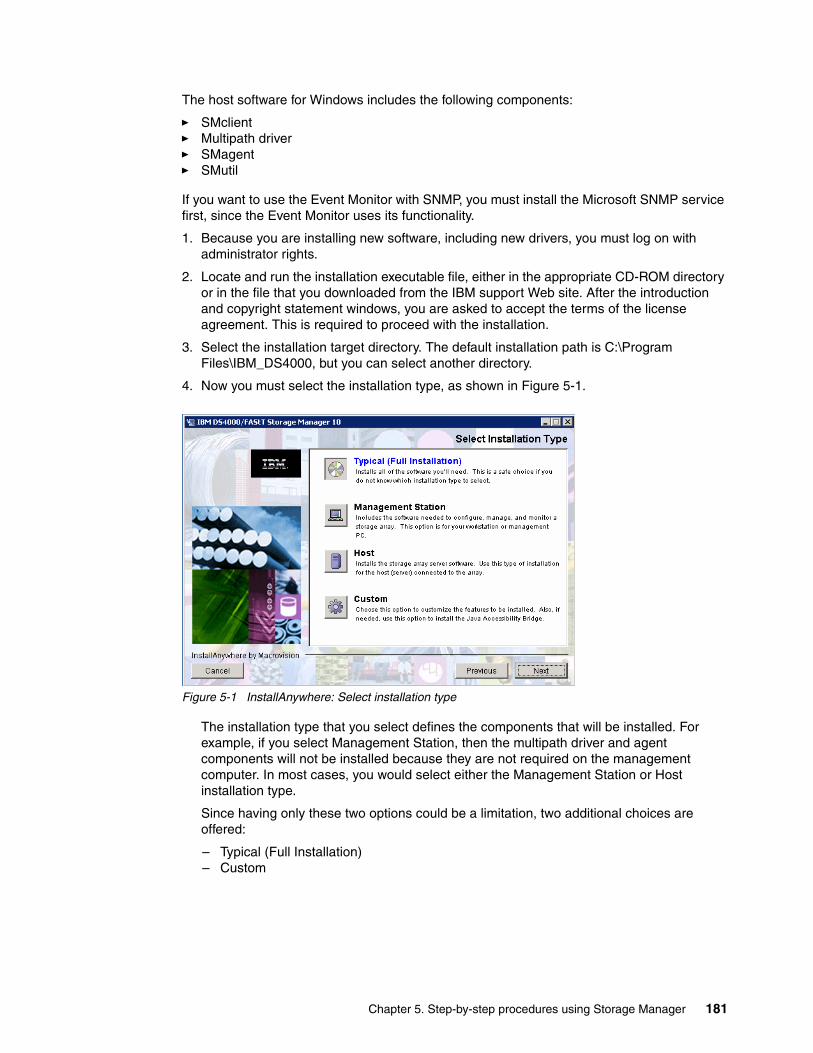
The host software for Windows includes the following components:
� SMclient � Multipath driver � SMagent � SMutil
If you want to use the Event Monitor with SNMP, you must install the Microsoft SNMP service first, since the Event Monitor uses its functionality.
1. Because you are installing new software, including new drivers, you must log on with administrator rights.
2. Locate and run the installation executable file, either in the appropriate CD-ROM directory or in the file that you downloaded from the IBM support Web site. After the introduction and copyright statement windows, you are asked to accept the terms of the license agreement. This is required to proceed with the installation.
3. Select the installation target directory. The default installation path is C:\Program Files\IBM_DS4000, but you can select another directory.
4. Now you must select the installation type, as shown in Figure 5-1.
Figure 5-1 InstallAnywhere: Select installation type
The installation type that you select defines the components that will be installed. For example, if you select Management Station, then the multipath driver and agent components will not be installed because they are not required on the management computer. In most cases, you would select either the Management Station or Host installation type.
Since having only these two options could be a limitation, two additional choices are offered:
– Typical (Full Installation) – Custom
Chapter 5. Step-by-step procedures using Storage Manager 181

As the name suggests, typical (full installation) installs all components and custom installation lets you choose the components, as shown in Figure 5-2. When installing Storage Manager on a desktop computer or mobile computer that does not have a Fibre Channel (FC) host bus adapter (HBA) Adapter, you will not be able to install any components other than the Storage Manager client.
Figure 5-2 InstallAnywhere: Select Storage Manager components
Besides the usual Storage Manager components, you can choose to install Java Access Bridge. This selection enables support for the window reader (like JAWS from Freedom Scientific, and so on) for blind or visually impaired users.
Note: If you already have SDDDSM installed and want to use it, you must choose not to install the failover driver.
Remember also that the SM Failover drivers (MPIO/DSM) are only supported for connection to DS4000 storage servers with controller firmware 6.19 and later.
182 IBM System Storage DS4000 and Storage Manager V10.30
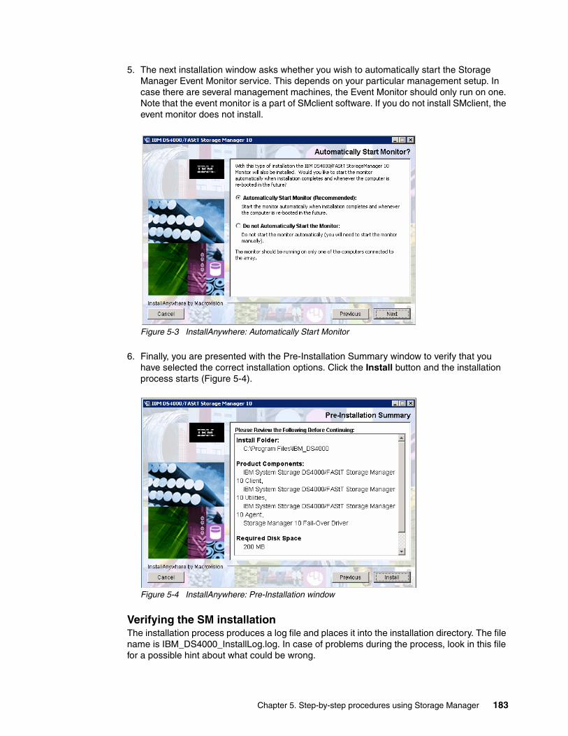
5. The next installation window asks whether you wish to automatically start the Storage Manager Event Monitor service. This depends on your particular management setup. In case there are several management machines, the Event Monitor should only run on one. Note that the event monitor is a part of SMclient software. If you do not install SMclient, the event monitor does not install.
Figure 5-3 InstallAnywhere: Automatically Start Monitor
6. Finally, you are presented with the Pre-Installation Summary window to verify that you have selected the correct installation options. Click the Install button and the installation process starts (Figure 5-4).
Figure 5-4 InstallAnywhere: Pre-Installation window
Verifying the SM installation The installation process produces a log file and places it into the installation directory. The file name is IBM_DS4000_InstallLog.log. In case of problems during the process, look in this file for a possible hint about what could be wrong.
Chapter 5. Step-by-step procedures using Storage Manager 183
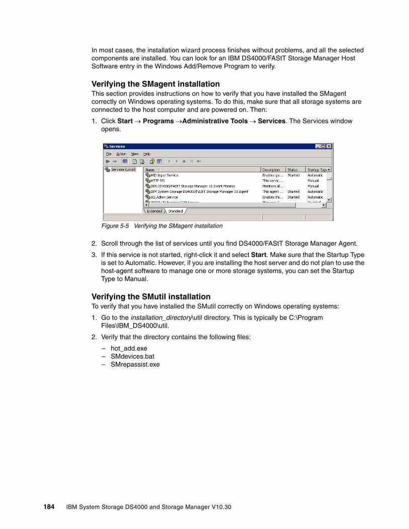
In most cases, the installation wizard process finishes without problems, and all the selected components are installed. You can look for an IBM DS4000/FAStT Storage Manager Host Software entry in the Windows Add/Remove Program to verify.
Verifying the SMagent installationThis section provides instructions on how to verify that you have installed the SMagent correctly on Windows operating systems. To do this, make sure that all storage systems are connected to the host computer and are powered on. Then:
1. Click Start → Programs →Administrative Tools → Services. The Services window opens.
Figure 5-5 Verifying the SMagent installation
2. Scroll through the list of services until you find DS4000/FAStT Storage Manager Agent.
3. If this service is not started, right-click it and select Start. Make sure that the Startup Type is set to Automatic. However, if you are installing the host server and do not plan to use the host-agent software to manage one or more storage systems, you can set the Startup Type to Manual.
Verifying the SMutil installationTo verify that you have installed the SMutil correctly on Windows operating systems:
1. Go to the installation_directory\util directory. This is typically be C:\Program Files\IBM_DS4000\util.
2. Verify that the directory contains the following files:
– hot_add.exe – SMdevices.bat – SMrepassist.exe
184 IBM System Storage DS4000 and Storage Manager V10.30

Verifying the SM Failover driver (MPIO/DSM) installationIf you chose the SM Failover (MPIO/DSM) as the multipathing driver, verify the installation:
1. Check the install directory for the SM Failover driver. The default install directory is C:\Program Files\DSMDrivers\ds4dsm.
2. Open the Device Manager in Computer Management. There should be a Multi-Path Support entry under the SCSI and RAID Controller folder, as shown in Figure 5-6.
Figure 5-6 SM Failover (MPIO/DSM) Multi-Path Support
3. If there are logical drives from the DS4000 already mapped to the server, you will see IBM xxx Multipath Disk Device under the Disk drives folder, where xxx is the product ID of the DS4000 storage subsystem, as shown in Figure 5-7. Note that xxx SCSI Disk Devices represent the physical devices reachable by different FC paths.
Figure 5-7 SM Failover (MPIO/DSM) Multi-Path Disk Device
Chapter 5. Step-by-step procedures using Storage Manager 185
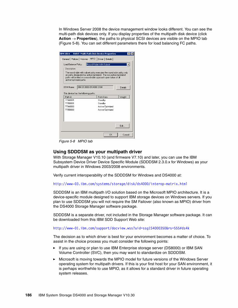
In Windows Server 2008 the device management window looks different. You can see the multi-path disk devices only. If you display properties of the multipath disk device (click Action → Properties), the paths to physical SCSI devices are visible on the MPIO tab (Figure 5-8). You can set different parameters there for load balancing FC paths.
Figure 5-8 MPIO tab
Using SDDDSM as your multipath driverWith Storage Manager V10.10 (and firmware V7.10) and later, you can use the IBM Subsystem Device Driver Device Specific Module (SDDDSM 2.3.0.x for Windows) as your multipath driver in Windows 2003/2008 environments.
Verify current interoperability of the SDDDSM for Windows and DS4000 at:
http://www-03.ibm.com/systems/storage/disk/ds4000/interop-matrix.html
SDDDSM is an IBM multipath I/O solution based on the Microsoft MPIO architecture. It is a device-specific module designed to support IBM storage devices on Windows servers. If you plan to use SDDDSM you will not require the SM Failover (also known as MPIO) driver from the DS4000 Storage Manager software package.
SDDDSM is a separate driver, not included in the Storage Manager software package. It can be downloaded from this IBM SDD Support Web site:
http://www-01.ibm.com/support/docview.wss?uid=ssg1S4000350&rs=555#ds4k
The decision as to which driver is best for your environment becomes a matter of choice. To assist in the choice process you must consider the following points:
� If you are using or plan to use IBM Enterprise storage server (DS8000) or IBM SAN Volume Controller (SVC), then you may want to standardize on SDDDSM.
� Microsoft is moving towards the MPIO model for future versions of the Windows Server operating system for multipath drivers. If this is your first host for your SAN environment, it is perhaps worthwhile to use MPIO, as it allows for a standard driver in future operating system releases.
186 IBM System Storage DS4000 and Storage Manager V10.30
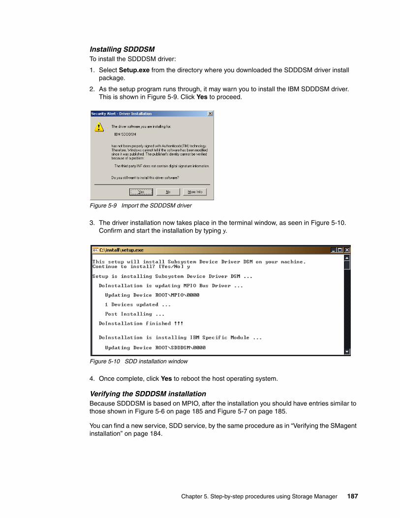
Installing SDDDSMTo install the SDDDSM driver:
1. Select Setup.exe from the directory where you downloaded the SDDDSM driver install package.
2. As the setup program runs through, it may warn you to install the IBM SDDDSM driver. This is shown in Figure 5-9. Click Yes to proceed.
Figure 5-9 Import the SDDDSM driver
3. The driver installation now takes place in the terminal window, as seen in Figure 5-10. Confirm and start the installation by typing y.
Figure 5-10 SDD installation window
4. Once complete, click Yes to reboot the host operating system.
Verifying the SDDDSM installationBecause SDDDSM is based on MPIO, after the installation you should have entries similar to those shown in Figure 5-6 on page 185 and Figure 5-7 on page 185.
You can find a new service, SDD service, by the same procedure as in “Verifying the SMagent installation” on page 184.
Chapter 5. Step-by-step procedures using Storage Manager 187
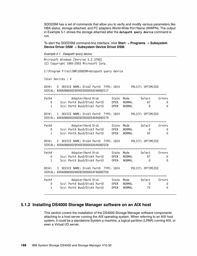
SDDDSM has a set of commands that allow you to verify and modify various parameters like HBA status, storage attached, and FC adapters World-Wide Port Name (WWPN). The output in Example 5-1 shows the storage attached after the datapath query device command is run.
To start the SDDDSM command-line interface, click Start → Programs → Subsystem Device Driver DSM → Subsystem Device Driver DSM.
Example 5-1 Datapath query device
Microsoft Windows [Version 5.2.3790](C) Copyright 1985-2003 Microsoft Corp.
C:\Program Files\IBM\SDDDSM>datapath query device
Total Devices : 4
DEV#: 0 DEVICE NAME: Disk2 Part0 TYPE: 1814 POLICY: OPTIMIZEDSERIAL: 600A0B80002904DE000005A246D82E17============================================================================Path# Adapter/Hard Disk State Mode Select Errors 0 Scsi Port4 Bus0/Disk2 Part0 OPEN NORMAL 67 0 1 Scsi Port5 Bus0/Disk2 Part0 OPEN NORMAL 0 0
DEV#: 1 DEVICE NAME: Disk3 Part0 TYPE: 1814 POLICY: OPTIMIZEDSERIAL: 600A0B800026B2820000054D46D82E79============================================================================Path# Adapter/Hard Disk State Mode Select Errors 0 Scsi Port4 Bus0/Disk3 Part0 OPEN NORMAL 0 0 1 Scsi Port5 Bus0/Disk3 Part0 OPEN NORMAL 67 0
DEV#: 2 DEVICE NAME: Disk4 Part0 TYPE: 1814 POLICY: OPTIMIZEDSERIAL: 600A0B80002904DE000005A546D82EE8============================================================================Path# Adapter/Hard Disk State Mode Select Errors 0 Scsi Port4 Bus0/Disk4 Part0 OPEN NORMAL 67 0 1 Scsi Port5 Bus0/Disk4 Part0 OPEN NORMAL 0 0
DEV#: 3 DEVICE NAME: Disk5 Part0 TYPE: 1814 POLICY: OPTIMIZEDSERIAL: 600A0B800026B2820000054F46D82F00============================================================================Path# Adapter/Hard Disk State Mode Select Errors 0 Scsi Port4 Bus0/Disk5 Part0 OPEN NORMAL 0 0 1 Scsi Port5 Bus0/Disk5 Part0 OPEN NORMAL 72 0
5.1.2 Installing DS4000 Storage Manager software on an AIX host
This section covers the installation of the DS4000 Storage Manager software components attaching to a host server running the AIX operating system. When referring to an AIX host system, it could be a standalone System p machine, a logical partition (LPAR) running AIX, or even a Virtual I/O server.
188 IBM System Storage DS4000 and Storage Manager V10.30

Before installing SMclient, make sure that the following conditions are met:
� The System p server hardware to which you connect the DS4000 meets the required specifications for your storage model.
� The AIX host on which you install SMruntime meets the minimum software requirements.
� You have prepared the correct file sets for the installation on an AIX system.
In addition, refer to the Installation and Support Guide for AIX, HP-UX, Solaris and Linux, GC26-7848, for your DS4000 storage version.
SMruntime provides the Java runtime environment required to run the SMclient. The AIX FCP disk array driver (also known as RDAC for AIX) provides redundancy in the I/O paths and is part of the AIX operating system, and therefore not included in the DS4000 Storage Manager software CD shipped with the storage server.
Depending on your configuration and environment, you have the option to install the software packages using two different methods:
� From a graphic workstation using the installation wizard� Using the standard command-line method.
We describe both installation methods in the following sections. You might need to adjust the following instructions for the specifics of your environment. No AIX reboot is required during the installation process.
Installing using a graphical desktop To install the DS4000 Storage Manager software using the installation wizard, use the following sequence:
1. Locate the installation code file, either in the appropriate CD-ROM directory or on the IBM support Web site, and transfer the code to a directory on your AIX system.
2. Make sure that the file has permissions to execute. If not, type the following command to allow its execution:
# ls -la SM*-rw-r----- 1 root system 262690421 Aug 23 08:49 SMIA-AIX-10.10.65.51.bin
# chmod +x SMIA-AIX-10.10.65.51.bin# ls -la SM*-rwxr-x--x 1 root system 262690421 Aug 23 08:49 SMIA-AIX-10.10.65.51.bin
Important: Review your system requirements and additional support information in the latest Storage Manager readme file for your specific DS4000 storage system and code level.
Note: The installation package requires sufficient free space in several file systems. It identifies and informs you of the space needed during the installation. You must allocate enough space to successfully install the software.
Chapter 5. Step-by-step procedures using Storage Manager 189
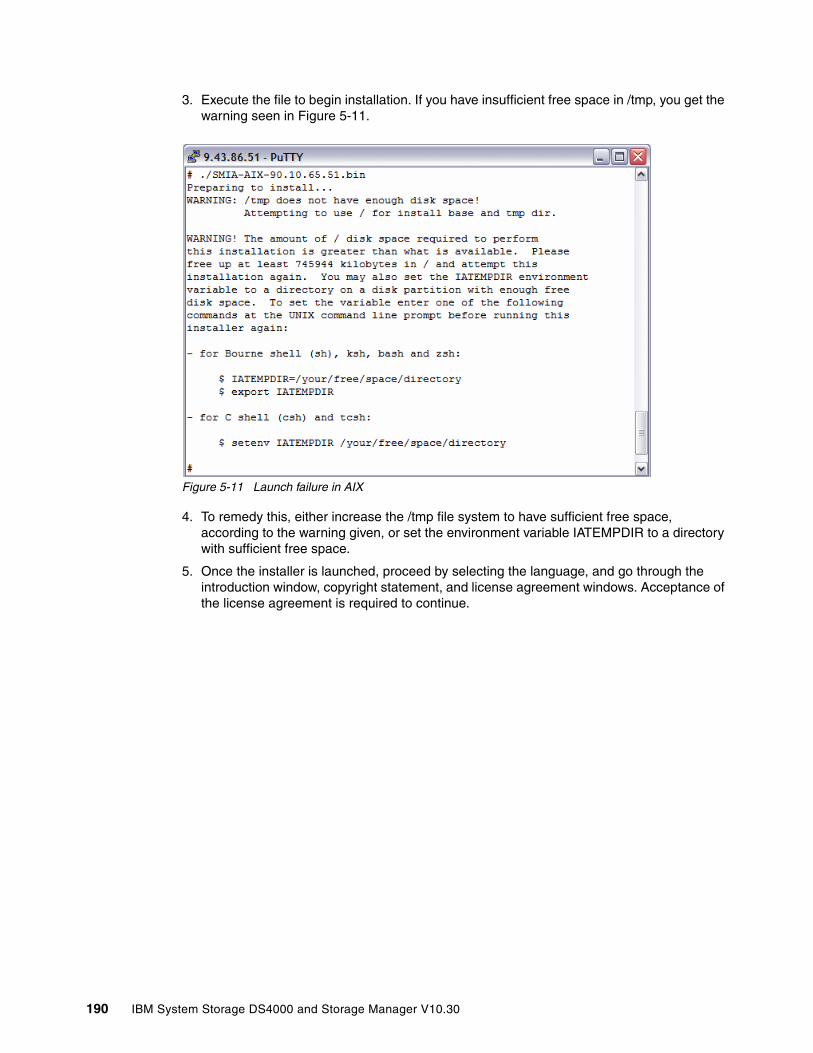
3. Execute the file to begin installation. If you have insufficient free space in /tmp, you get the warning seen in Figure 5-11.
Figure 5-11 Launch failure in AIX
4. To remedy this, either increase the /tmp file system to have sufficient free space, according to the warning given, or set the environment variable IATEMPDIR to a directory with sufficient free space.
5. Once the installer is launched, proceed by selecting the language, and go through the introduction window, copyright statement, and license agreement windows. Acceptance of the license agreement is required to continue.
190 IBM System Storage DS4000 and Storage Manager V10.30
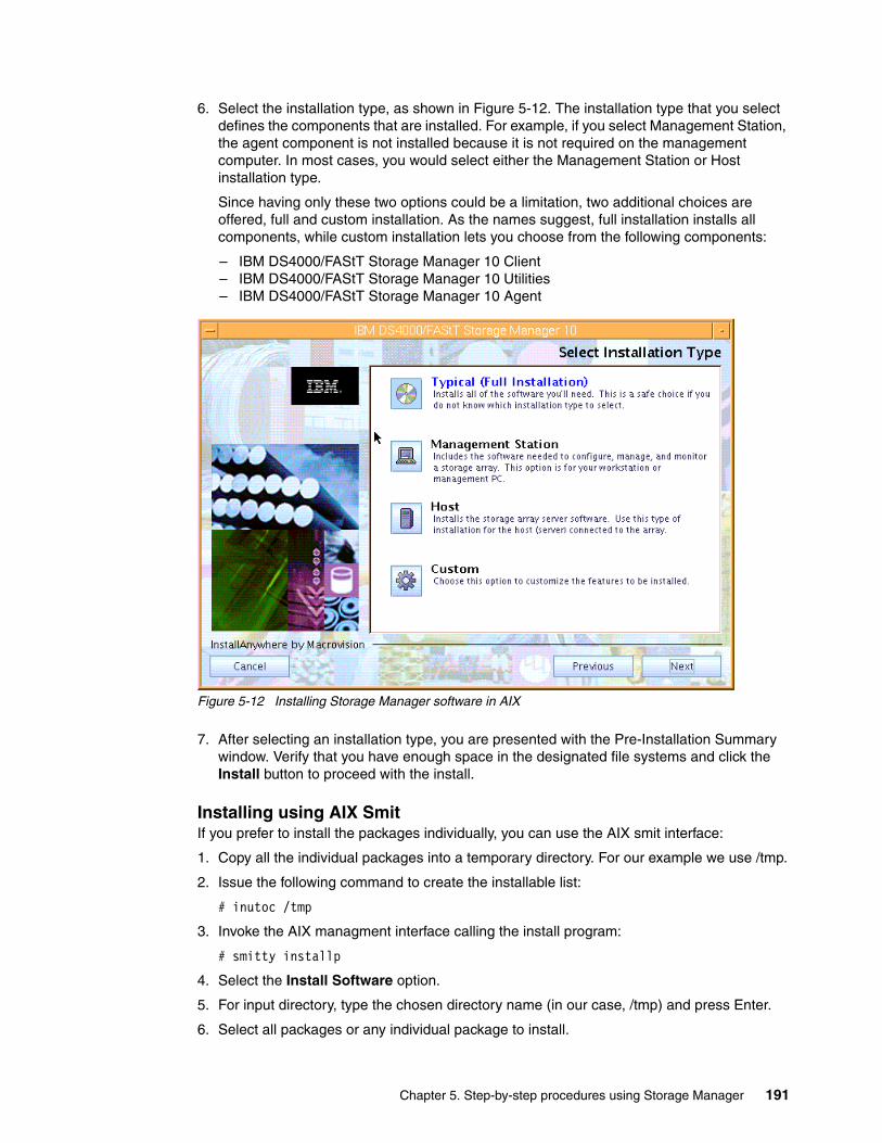
6. Select the installation type, as shown in Figure 5-12. The installation type that you select defines the components that are installed. For example, if you select Management Station, the agent component is not installed because it is not required on the management computer. In most cases, you would select either the Management Station or Host installation type.
Since having only these two options could be a limitation, two additional choices are offered, full and custom installation. As the names suggest, full installation installs all components, while custom installation lets you choose from the following components:
– IBM DS4000/FAStT Storage Manager 10 Client– IBM DS4000/FAStT Storage Manager 10 Utilities– IBM DS4000/FAStT Storage Manager 10 Agent
Figure 5-12 Installing Storage Manager software in AIX
7. After selecting an installation type, you are presented with the Pre-Installation Summary window. Verify that you have enough space in the designated file systems and click the Install button to proceed with the install.
Installing using AIX SmitIf you prefer to install the packages individually, you can use the AIX smit interface:
1. Copy all the individual packages into a temporary directory. For our example we use /tmp.
2. Issue the following command to create the installable list:
# inutoc /tmp
3. Invoke the AIX managment interface calling the install program:
# smitty installp
4. Select the Install Software option.
5. For input directory, type the chosen directory name (in our case, /tmp) and press Enter.
6. Select all packages or any individual package to install.
Chapter 5. Step-by-step procedures using Storage Manager 191

Installing through the command lineIn this section we discuss an alternative method for individual package installation done from the AIX command line. This method can be used when you only have access to a regular text terminal.
To successfully install the client software through the AIX command line, you must install the different packages in the following sequence:
1. SMruntime2. SMesm 3. SMclient (optional)4. SMagent (optional)5. SMutil (optional)
Installing SMruntimeTo install:
1. Install SMruntime by typing the following command:
# installp -a -d /complete path name/SMruntime-AIX-10.10.65.01.bff SMruntime.aix.rte
2. Verify that the installation was successful by typing the following command:
# lslpp -ah SMruntime.aix.rte
The verification process should return a table that describes the software installation, including the install package file name, version number, action, and action status:
Fileset Level Action Status Date Time ----------------------------------------------------------------------------Path: /usr/lib/objrepos SMruntime.aix.rte 10.10.6501.0 COMMIT COMPLETE 08/23/07 11:04:46 10.10.6501.0 APPLY COMPLETE 08/23/07 11:04:46
Installing SMesm This package provides firmware images for the disk expansion enclosures controllers cards and can be used in case of compatibility problems. SMesm is required if installing SMclient.
1. Install SMesm by typing the following command:
# installp -a -d /tmp/SM10/SMesm-AIX-10.10.G5.00.bff SMesm.aix.rte
2. Verify it by typing the following:
# lslpp -ah SMesm.aix.rte
This should generate output showing the status of the package installed as in the previous window.
Note: If you install the packages individually, be sure to install them in the sequence shown in “Installing through the command line” on page 192.
Note: The SMesm package is new with SM V10.10. It is a prerequisite for the SMclient installation and is used for the enclosure firmware management.
Note: Check the status column for complete installation. Levels should match your specific version.
192 IBM System Storage DS4000 and Storage Manager V10.30

Installing SMclientSMclient is required only if you plan to run the managment client from the AIX host:
1. Install SMclient by typing the following command:
# installp -a -d /complete path name/SMclient-AIX-10.10.G5.51.bff SMclient.aix.rte
2. Verify that the installation was successful by typing the following command:
# lslpp -ah SMclient.aix.rte
The verification process should return a table that describes the software installation, including the install package file name, version number, action, and action status:
Fileset Level Action Status Date Time ----------------------------------------------------------------------------Path: /usr/lib/objrepos SMclient.aix.rte 10.10.6551.0 COMMIT COMPLETE 08/23/07 11:33:23 10.10.6551.0 APPLY COMPLETE 08/23/07 11:33:23
3. To start the client, issue the following command:
# /usr/SMclient/SMclient
Installing SMagentSMagent is required only for in-band management (that is, through Fibre Channel). To install the SMagent:
1. Type the following command:
# installp -a -d /tmp/SM10/SMagent-AIX-10.10.65.04.bff SMagent.aix.rte
2. Verify the installation by typing the following command:
# lslpp -ah SMagent.aix.rte
The verification process should return a table that describes the software installation, including the install package file name, version number, action, and action status:
Fileset Level Action Status Date Time ----------------------------------------------------------------------------Path: /usr/lib/objrepos SMagent.aix.rte 10.0.6504.0 COMMIT COMPLETE 08/23/07 11:38:44 10.0.6504.0 APPLY COMPLETE 08/23/07 11:38:44
Installing SMutilThe SMutil package provides additional commands for listing and adding DS4000 devices. This utility is also available for other operating systems.
1. Install the SMutil by typing in the following command:
# installp -a -d /tmp/SM10/SMutil-AIX-10.00.65.02.bff SMutil.aix.rte
2. Verify the installation:
# lslpp -ah SMutil.aix.rte
Note: If the Fibre Channel connections to the controllers are lost, the SMclient software cannot be accessed for problem determination. We suggest having IP network connectivity as well to enable you to continue to manage and troubleshoot the storage subsystem when there are problems with the Fibre Channel links.
Chapter 5. Step-by-step procedures using Storage Manager 193
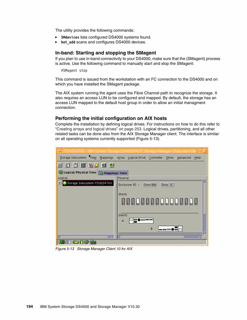
The utility provides the following commands:
� SMdevices lists configured DS4000 systems found. � hot_add scans and configures DS4000 devices.
In-band: Starting and stopping the SMagentIf you plan to use in-band connectivity to your DS4000, make sure that the (SMagent) process is active. Use the following command to manually start and stop the SMagent:
#SMagent stop
This command is issued from the workstation with an FC connection to the DS4000 and on which you have installed the SMagent package.
The AIX system running the agent uses the Fibre Channel path to recognize the storage. It also requires an access LUN to be configured and mapped. By default, the storage has an access LUN mapped to the default host group in order to allow an initial managment connection.
Performing the initial configuration on AIX hostsComplete the installation by defining logical drives. For instructions on how to do this refer to “Creating arrays and logical drives” on page 253. Logical drives, partitioning, and all other related tasks can be done also from the AIX Storage Manager client. The interface is similar on all operating systems currently supported (Figure 5-13).
Figure 5-13 Storage Manager Client 10 for AIX
194 IBM System Storage DS4000 and Storage Manager V10.30
Follow the instructions in 5.3.5, “Configuring storage partitioning” on page 259, to create a host group, host, and host ports for the AIX server. After you set up storage partitioning, perform the following steps to verify that the host ports match the AIX host:
1. Type the following command:
# lscfg -l fcs*
A list that contains all the HBAs that are in the system is displayed. Use the second column to determine the adapter slot location placement in your server when you must cable the fibers:
# lscfg -l fcs* fcs1 U0.1-P2-I5/Q1 FC Adapter fcs0 U0.1-P2-I4/Q1 FC Adapter
2. If you have multiple adapters, identify the fcs number of the HBAs to use with your DS4000 storage server.
3. Check adapter microcode by typing the following command for each of the HBAs used by the DS4000 storage server, as shown in Example 5-2.
Example 5-2 Check HBA microcode level
# lsmcode -d fcs0
DISPLAY MICROCODE LEVEL 802111fcs0 FC Adapter
The current microcode level for fcs0 is 391101.
Use Enter to continue.
Use the level seen in the output together with the type or feature code of your HBA to make sure that you have at least the minimum recommended level as listed in the IBM support Web site:
http://www-01.ibm.com/systems/support/storage/config/ssic/index.jsp
4. Type the following command to determine the adapter’s WWN:
# lscfg -vl fcs? |grep Network
Where fcs? is the fcs number of the HBA that is connected to the DS4000 storage server.
You will need this information later when mapping the logical drives or configuring zoning if your DS4000 is connected through a SAN. The network address number of the HBA is displayed, as in the following example:
# lscfg -vl fcs0 |grep Network Network Address.............10000000C932A75D
5. Verify that the network address number matches the host port number that displays in the host partition table of SMclient.
6. Repeat this procedure to verify the other host ports.
Note: Remember that we do not recommend sharing the same HBAs for tape and disk traffic.
Chapter 5. Step-by-step procedures using Storage Manager 195
7. Depending on the HBA, you need specific file sets, as shown in Table 5-1.
Table 5-1 FC HBA and AIX drivers
Always check for at least the minimum required levels for your adapter driver, as well as adapter microcode. You will find that information on the IBM support Web site.
Get your AIX installation CDs and install the above file sets from the media.
Installing AIX MPIOAs mentioned in 4.1.5, “Multipath driver support” on page 129, newer versions of AIX operating systems support MPIO for DS4000 attachment.
The detailed information for this method can be found on the IBM Support site:
http://www-03.ibm.com/systems/resources/systems_storage_disk_ds4000_pdf_aix.pdf
Other important information can be found in the readme files supplied with DS4000 Storage Manager software and DS4000 firmware upgrades.
Installing AIX FCP disk array (RDAC) driverThe AIX FCP disk array driver (also known as RDAC driver) is part of the AIX Operating System. In order to install on your host, you need the following file sets:
� devices.fcp.disk.array.rte: RDAC runtime software� devicess.fcp.disk.array.diag: RDAC diagnostic software� devices.common.IBM.fc.rte: Common FC software� devices.pci.df1000f7: Common FC driver
Use the lslpp command to verify that the correct driver versions are installed:
# lslpp -ah devices.fcp.disk.array.rte
Make sure that you have the latest RDAC driver available for your AIX level by checking on the AIX download Web site.
HBA feature code Description AIX driver
6227 1 Gb Fibre Channel Adapter PCI devices.pci.df1000f7
6228 2 Gb Fibre Channel Adapter PCI devices.pci.df1000f9
6239 2 Gb Fibre Channel PCI-X devices.pci.df1080f9
5716, 1977, 1957 2 Gb Fibre Channel PCI-X devices.pci.df1000fa
1905, 5758 4 Gb Single-Port Fibre Channel PCI-X devices.pci.df1000fd
1910, 5759 4 Gb Dual-Port Fibre Channel PCI-X devices.pci.df1000fd
5773, 5774 4 Gb PCI Express Single/Dual Port devices.pciex.df1000fe
Important: To avoid compatibility problems, always make sure to download and apply the latest FCP disk array (RDAC) and relevant HBA AIX file sets.
196 IBM System Storage DS4000 and Storage Manager V10.30

The FCP disk array (RDAC) driver must be installed on all AIX hosts that will be attached to a DS4000 storage system. The driver creates the following devices that represent the DS4000 storage system configuration:
� dar (disk array router): Represents the entire array, including the current and the deferred paths to all LUNs (hdisks on AIX). You will see a dar device per partition defined for your AIX system.
� dac (disk array controller devices): Represents a controller within the storage system. There are two dacs in the storage system.
� hdisk: These devices represent individual LUNs on the array.
� utm: The universal transport mechanism (utm) device is used only with in-band management configurations, as a communication channel between the SMagent and the DS4000 storage server.
After the DS4000 storage system has been set up, the logical drives assigned to the host, and the FCP disk array (RDAC) driver installed, you must verify that all of your DS4000 device names and paths are correct and that AIX recognizes your dars, dacs, and hdisks.
You must do this before you mount file systems and install applications. Type the following command to probe for the new devices:
# cfgmgr -v
Make sure that you have only one dar configured for each of your DS4000 Storage servers. If you have set partitions in the SM, you should see a dar device per partition created for your host system. You should see two active dacs depending on a dar device, and the logical disks below on each preferred path.
Use the lsdev -Cc disk command to see whether the FCP array disk (RDAC) software recognizes each DS4000 logical drive correctly:
� The DS4200 logical drive is recognized as an 1814 DS4200 disk array device.� The DS4300 logical drive is recognized as an 1722-600 (600) disk array device.� The DS4700 logical drive is recognized as an 1814 DS4700 disk array device.� The DS4800 logical drive is recognized as an 1815 DS4800 disk array device.
The following example illustrates the results of the command for a set of DS4700 LUNs:
# lsdev -Cc diskhdisk0 Available 1S-08-00-8,0 16 Bit LVD SCSI Disk Drivehdisk3 Available 1D-08-02 1814 DS4700 Disk Array Devicehdisk4 Available 1Z-08-02 1814 DS4700 Disk Array Device
After the operating system device names are found, those names must be correlated to the preferred and failover paths of the DS4000 device, and then from each path to its associated logical drive.
Note: You might see the utm device listed in command output, whether or not you have an in-band management configuration. For example, a utm might be listed when you run the lsattr command on a dac.
Note: You should run cfgmgr once the DS4000 is cabled to allow the Storage Manager client to discover the AIX HBA WWN. Otherwise, you are not able to define the host port under the partitioning section.
Chapter 5. Step-by-step procedures using Storage Manager 197
AIX provides the following commands to help you determine the DS4000 configuration and to get information about device names and bus numbers:
� lsdev
Displays devices and their characteristics. The lsdev command shows the state of the devices at startup time, or the last time that the cfgmgr -v command was run.
� lsattr
Displays device attributes and possible values. Attributes are only updated at startup time or the last time that the cfgmgr -v command was run.
� fget_config
Displays controllers and hdisks that are associated with a specified DS4000 (dar). The command shows the current state and volume (hdisk) ownership.
There are several ways to correlate a system’s configuration and monitor the state of DS4000 storage systems.
Example 5-3 shows dar as a machine type 1814, which is a DS4700. It is in the available state, which is the state at the time that the device was last configured by AIX.
Example 5-3 Status of dar
# lsdev -C |grep dardar0 Available 1814 DS4700 Disk Array Router# lsdev -C|grep dacdac0 Available 1Z-08-02 1814 DS4700 Disk Array Controllerdac1 Available 1D-08-02 1814 DS4700 Disk Array Controller
Example 5-3 also shows the status of two dacs, which represent the DS4000 storage system controllers. The third column shows the location code. In this example, each dac has its own location or path, which are represented by the values 1Z-08-02 and 1D-08-02. Each AIX system has its own set of location codes that describe the internal path of that device, including bus and host adapter locations. See the service manual for your system type to identify device locations.
Example 5-4 uses the lsdev command to show the status and location codes of two DS4700 hdisks mapped. Notice that the location codes of hdisk4 correspond to the same location code of dac0 in the previous example, and that hdisk3 corresponds to the same location code of dac1. This means that the preferred path for I/O for hdisk4 is through dac0. The failover path would be through dac1. Conversely, the preferred path for the hdisk3 would be through dac1, and the failover path through dac0.
Example 5-4 Disks status and location codes
# lsdev -Ccdiskhdisk0 Available 1S-08-00-8,0 16 Bit LVD SCSI Disk Drivehdisk3 Available 1D-08-02 1814 DS4700 Disk Array Devicehdisk4 Available 1Z-08-02 1814 DS4700 Disk Array Device
198 IBM System Storage DS4000 and Storage Manager V10.30
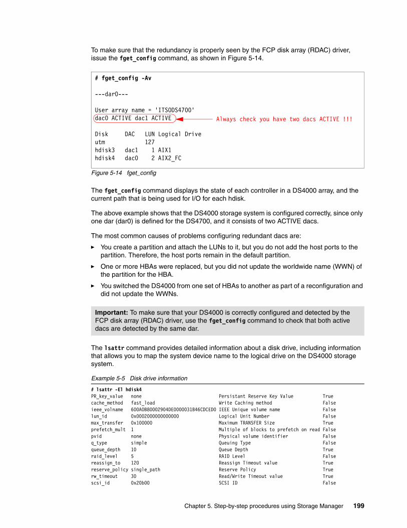
To make sure that the redundancy is properly seen by the FCP disk array (RDAC) driver, issue the fget_config command, as shown in Figure 5-14.
Figure 5-14 fget_config
The fget_config command displays the state of each controller in a DS4000 array, and the current path that is being used for I/O for each hdisk.
The above example shows that the DS4000 storage system is configured correctly, since only one dar (dar0) is defined for the DS4700, and it consists of two ACTIVE dacs.
The most common causes of problems configuring redundant dacs are:
� You create a partition and attach the LUNs to it, but you do not add the host ports to the partition. Therefore, the host ports remain in the default partition.
� One or more HBAs were replaced, but you did not update the worldwide name (WWN) of the partition for the HBA.
� You switched the DS4000 from one set of HBAs to another as part of a reconfiguration and did not update the WWNs.
The lsattr command provides detailed information about a disk drive, including information that allows you to map the system device name to the logical drive on the DS4000 storage system.
Example 5-5 Disk drive information
# lsattr -El hdisk4PR_key_value none Persistant Reserve Key Value Truecache_method fast_load Write Caching method Falseieee_volname 600A0B80002904DE0000031B46CDCED0 IEEE Unique volume name Falselun_id 0x0002000000000000 Logical Unit Number Falsemax_transfer 0x100000 Maximum TRANSFER Size Trueprefetch_mult 1 Multiple of blocks to prefetch on read Falsepvid none Physical volume identifier Falseq_type simple Queuing Type Falsequeue_depth 10 Queue Depth Trueraid_level 5 RAID Level Falsereassign_to 120 Reassign Timeout value Truereserve_policy single_path Reserve Policy Truerw_timeout 30 Read/Write Timeout value Truescsi_id 0x20b00 SCSI ID False
Important: To make sure that your DS4000 is correctly configured and detected by the FCP disk array (RDAC) driver, use the fget_config command to check that both active dacs are detected by the same dar.
# fget_config -Av
---dar0---
User array name = 'ITSODS4700'dac0 ACTIVE dac1 ACTIVE
Disk DAC LUN Logical Driveutm 127hdisk3 dac1 1 AIX1hdisk4 dac0 2 AIX2_FC
Always check you have two dacs ACTIVE !!!
Chapter 5. Step-by-step procedures using Storage Manager 199
size 7127959512 Size in Mbytes Falsewrite_cache yes Write Caching enabled False
In Example 5-5 on page 199 we run the lsattr command on the LUN named hdisk4. The command output provides the size information, RAID type (RAID-5), and LUN ID (2). Use this LUN number information to correlate to your Storage Manager client by locating the LUN ID on the right side of the Mappings View tab (see Figure 6-48 on page 357).
As you did for the disk drive, you can also match the controllers by their serial numbers. For that purpose, issue the AIX command:
# lsattr -El dac0
Now from the Storage Manager, right-click each of the DS4000 controllers and click Properties. Relate the serial number field from the SM output to the controller_SN obtained from the AIX “lsattr -El dac0” command, as shown in Figure 6-46 on page 356.
Changing ODM attribute settings in AIXAfter a logical drive has been created and mapped to the host, devices can be configured and the Object Data Manager (ODM) is updated with default parameters. In most cases and for most configurations, the default parameters are satisfactory. However, there are some parameters that can be modified for maximum performance and availability. See Installation and Support Guide for AIX, HP-UX, Solaris and Linux provided with the Storage Manager software.
You can actually change the ODM attributes for the FCP disk array (RDAC) driver and DS4000, and here we describe the settings that can be used for best performance and availability on hdisk devices.
This section lists the attribute settings that you should use for hdisk devices and shows how to set them using the chdev -l command. To make the attribute changes permanent in the customized devices object class, use the -P option. To make these changes permanent, the modifications must be made by changing the AIX ODM attribute.
The specific hdisk attributes affected (see also Example 5-5 on page 199) are:
� write_cache
This is an indicator that shows whether write-caching is enabled on this device (yes) or not (no). This value should be changed from the Storage Manager by right-clicking the logical drive to be changed, then selecting Change → Cache Settings.
� cache_method
If write_cache is enabled, the write-caching method of this array is set to one of these:
– default: Default mode. The word default is not seen if write_cache is set to yes.
– fast_write: Fast-write (battery-backed, mirrored write-cache) mode.
– fw_unavail: Fast-write mode was specified but could not be enabled. Write-caching is not in use.
– fast_load: Fast-load (non-battery backed, non-mirrored write-cache) mode.
– fl_unavail: Fast-load mode was specified but could not be enabled.
200 IBM System Storage DS4000 and Storage Manager V10.30
� prefetch_mult
Number of blocks to be prefetched into read cache for each block read (value 0–100).
� queue_depth
Number that specifies the depth of the queue based on system configuration. Reduce this number if the array is returning a BUSY status on a consistent basis (value 1–64).
Setting the queue depth for hdisk devicesSetting the queue_depth attribute to the appropriate value is important for system performance. For large DS4000 configurations with many logical drives and hosts attached, this is a critical setting for high availability.
Use the following formula to determine the maximum queue depth for your system:
Maximum queue depth = DS4000 queue depth / (number-of-hosts * LUNs-per-host)
Where DS4000 queue depth is 4096 for DS4800, and 2048 for DS4200 and DS4700.
Note that with firmware levels before 7.10, the queue depth was 2048 for DS4800, and 1024 for DS4200 and DS4700.
For example, a DS4700 system running firmware 7.10 or later, with four hosts, each with 32 LUNs, would have a maximum queue depth of 16:
Maximum queue depth = 2048 / ( 4 * 32 ) = 16
In this case, you would set the queue_depth attribute for hdiskX as follows:
#chdev -l hdiskX -a queue_depth=16 -P
AIX restrictionsWhen connecting the DS4000 to AIX systems, there are some restrictions/guidelines that you must take into account. This does not mean that other configurations will not work, but you might end up with unstable or unpredictable configurations that are hard to manage and troubleshoot. All the references to an AIX host could be used for an standalone system, an LPAR, or a VIOS.
Note: Controller cache mirroring should not be disabled while cache_write is enabled. If this condition exists, the RDAC software will automatically re-enable it the next time that the system is restarted or when cfgmgr is run.
Note: Use the maximum queue depth as a guideline, and adjust the setting as necessary for your specific configuration.
In systems with one or more SATA devices attached, you might need to set the queue depth attribute to a lower value than the maximum queue depth.
Chapter 5. Step-by-step procedures using Storage Manager 201
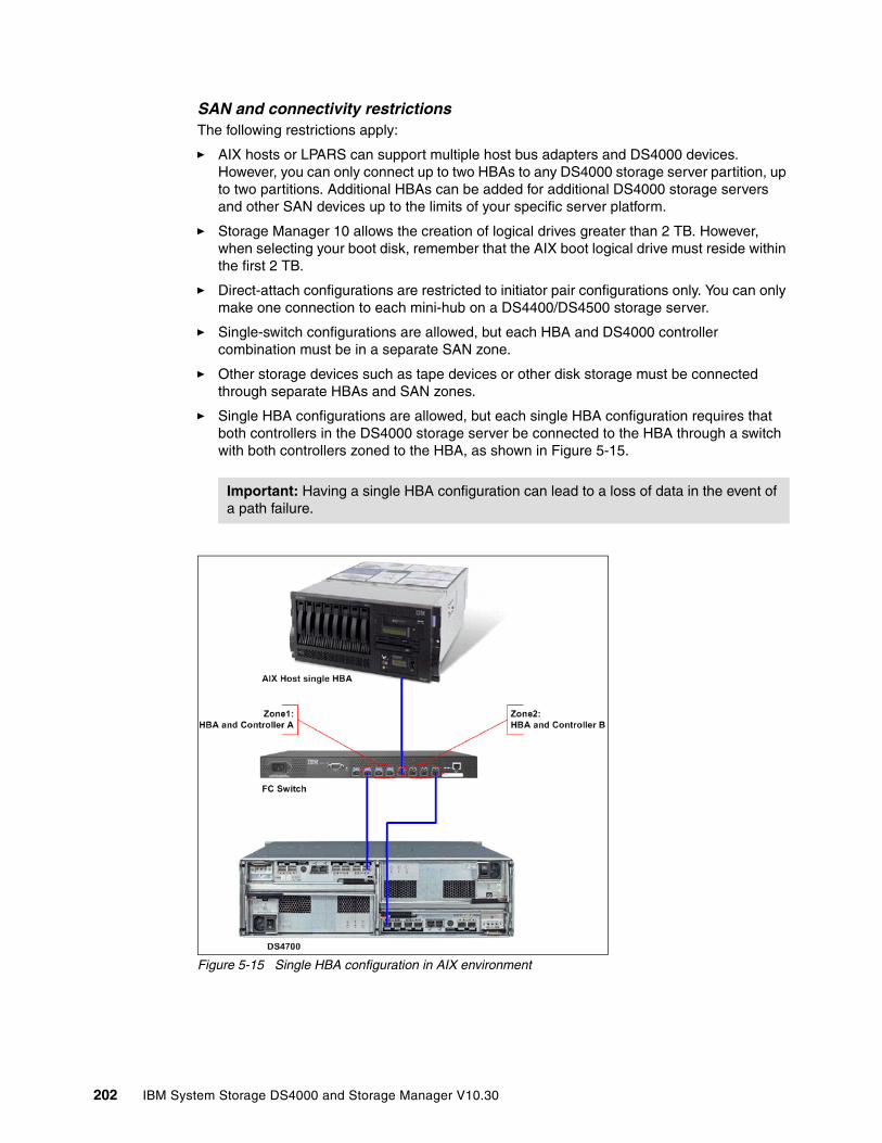
SAN and connectivity restrictionsThe following restrictions apply:
� AIX hosts or LPARS can support multiple host bus adapters and DS4000 devices. However, you can only connect up to two HBAs to any DS4000 storage server partition, up to two partitions. Additional HBAs can be added for additional DS4000 storage servers and other SAN devices up to the limits of your specific server platform.
� Storage Manager 10 allows the creation of logical drives greater than 2 TB. However, when selecting your boot disk, remember that the AIX boot logical drive must reside within the first 2 TB.
� Direct-attach configurations are restricted to initiator pair configurations only. You can only make one connection to each mini-hub on a DS4400/DS4500 storage server.
� Single-switch configurations are allowed, but each HBA and DS4000 controller combination must be in a separate SAN zone.
� Other storage devices such as tape devices or other disk storage must be connected through separate HBAs and SAN zones.
� Single HBA configurations are allowed, but each single HBA configuration requires that both controllers in the DS4000 storage server be connected to the HBA through a switch with both controllers zoned to the HBA, as shown in Figure 5-15.
Figure 5-15 Single HBA configuration in AIX environment
Important: Having a single HBA configuration can lead to a loss of data in the event of a path failure.
202 IBM System Storage DS4000 and Storage Manager V10.30
Restrictions when booting up your system from the SANThe following restrictions apply:
� If you create more than 32 LUNs on a partition, you must use the AIX 5.2 or later release to install AIX on a DS4000 device on that partition.
� When you boot your system from a DS4000 device (SAN boot), both paths to the controller must be up and running.
� The system cannot use path failover during the AIX boot process. Once the AIX host has started, failover operates normally.
� If you have FC and SATA drives in your DS4000 storage, we recommend not using SATA drives as boot devices.
Partitioning restrictionsThe following restrictions apply:
� The maximum number of partitions per AIX host, per DS4000 storage server is two.
� All logical drives that are configured for AIX must be mapped to an AIX host group. If using the default host group, change your default host type to AIX.
� On each controller you must configure at least one LUN with an ID between 0 and 31 that is not a utm or access logical drive.
Interoperability restrictionsThese are:
� Concurrent download is not supported with some controller firmware versions. See the latest Storage Manager readme file for AIX to learn which firmware versions support concurrent download.
� Dynamic volume expansion (DVE) is supported in AIX Versions 5.2 and later.
� DS4100 and DS4300 single-controller storage subsystems are not supported with AIX hosts.
5.1.3 Installing DS4000 storage server software on a Linux System x host
This section describes the installation of device drivers and host software on a System x server running a Linux distribution with kernel v2.6. There are versions of the components available for 32-bit and 64-bit architectures.
The Linux drivers for IBM DS4000 FC HBA are available for download at:
http://www-1.ibm.com/servers/storage/support/disk
The RDAC drivers are in the same section as DS4000 Storage Manager SW on the same Web site.
The drivers only work with certain combinations of distribution and kernel version. Therefore, it may be necessary to upgrade your system to a specific kernel version according to the readme file contained in the driver package. Updated kernel packages are available for download for the different distributions.
You can find the Linux Red Hat updates from the following URLs:
http://www.redhat.comhttp://updates.redhat.com
Chapter 5. Step-by-step procedures using Storage Manager 203
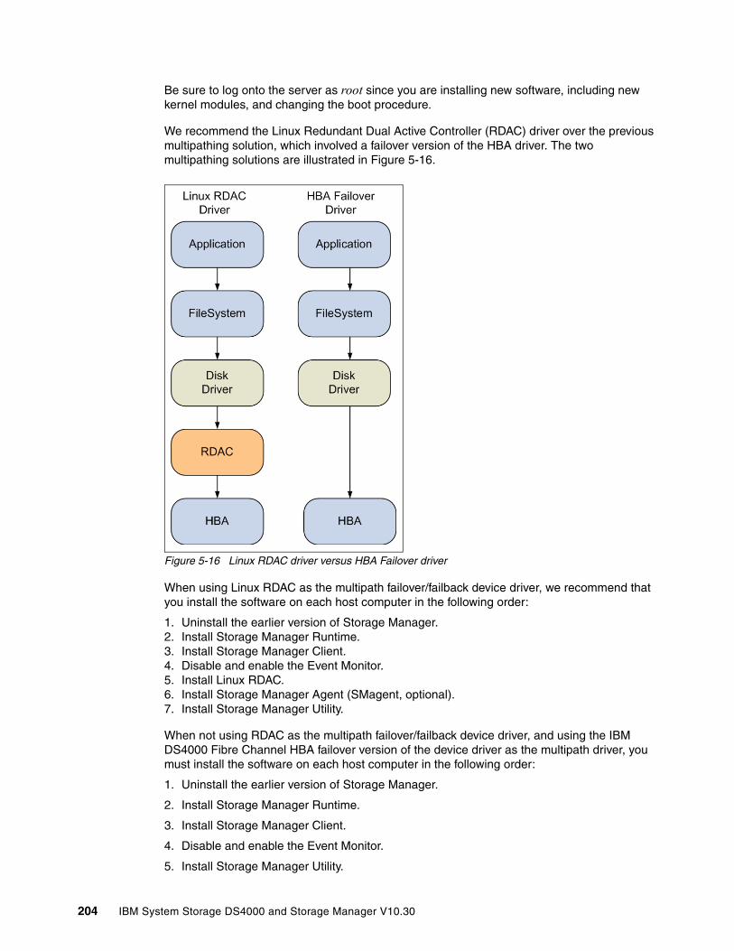
Be sure to log onto the server as root since you are installing new software, including new kernel modules, and changing the boot procedure.
We recommend the Linux Redundant Dual Active Controller (RDAC) driver over the previous multipathing solution, which involved a failover version of the HBA driver. The two multipathing solutions are illustrated in Figure 5-16.
Figure 5-16 Linux RDAC driver versus HBA Failover driver
When using Linux RDAC as the multipath failover/failback device driver, we recommend that you install the software on each host computer in the following order:
1. Uninstall the earlier version of Storage Manager.2. Install Storage Manager Runtime. 3. Install Storage Manager Client.4. Disable and enable the Event Monitor. 5. Install Linux RDAC.6. Install Storage Manager Agent (SMagent, optional).7. Install Storage Manager Utility.
When not using RDAC as the multipath failover/failback device driver, and using the IBM DS4000 Fibre Channel HBA failover version of the device driver as the multipath driver, you must install the software on each host computer in the following order:
1. Uninstall the earlier version of Storage Manager.
2. Install Storage Manager Runtime.
3. Install Storage Manager Client.
4. Disable and enable the Event Monitor.
5. Install Storage Manager Utility.
204 IBM System Storage DS4000 and Storage Manager V10.30
6. Uninstall the existing IBM DS4000 Management Suite Java. (Use this procedure when installing Storage Manager on an existing storage subsystem.)
7. Install the IBM Fibre Channel Host Adapter (HA) failover device driver for Linux operating systems.
8. Install IBM DS4000 Management Suite Java and QLRemote Agent.
9. Configure path failover/failback. See the device driver readme file for information.
In this section we focus on the installation steps for the Linux RDAC multipathing solution. Remember that the use of RDAC requires that you install the non-failover HBA driver.
The DS4000 Storage Manager software for Linux operating systems is available as a single package that you can install using the installation wizard, or as individual packages that you can install manually.
The DS4000 Storage Manager Installation Wizard is a Java-based interactive method of choosing which packages to automatically install on your host system. The installation wizard package can be used to install the following components on the Linux host:
� SMruntime � SMesm� SMclient � SMagent � SMutil
Because the installation wizard requires a GUI interface, and this might not be available on all Linux servers, you also have the possibility to install the Storage Manager components manually (without using the installation wizard).
The installation wizard package file names have the SMIA prefix. Each individual package file name has one of the following prefixes:
� SMruntime� SMclient� SMutil� SMagent
The RDAC multipath driver consists of two parts. One part (mppUpper) is loaded before any HBA is loaded and prevents the HBA from advertising the LUNs to the system, while the other part (mppVhba) is a virtual HBA on top of the real HBA, which is responsible for bundling the different paths to the same LUN to a single (multipath) device.
Important: For Linux distributions with kernel 2.6, a non-failover version of the HBA driver is compiled with the kernel. To obtain the driver with the failover function, an out-of-distribution version of the HBA driver must be installed. Note that there is only one type of external driver available for kernel v2.6 that supports both failover and non-failover. When you install RDAC, it forces you to load the non-failover method.
Note: You cannot use different type HBAs as a failover pair. For example, you cannot fail over an IBM DS4000 FC2-133 HBA to an IBM DS4000 FC 4 Gbps HBA.
Note: In Linux, RDAC cannot be installed with the installation wizard package. If you need RDAC, you must download and install it separately.
Chapter 5. Step-by-step procedures using Storage Manager 205

The RDAC driver can be downloaded from these URLs:
http://www.ibm.com/servers/storage/support/disk http://www.lsi.com/rdac
Installing with the installation wizard The installation wizard greatly simplifies the installation process of the Storage Manager. The basic installation steps are as follows:
1. If any earlier version of Storage Manager is installed, uninstall all its components. See “Uninstalling wizard-installed Storage Manager packages” on page 206.
2. Disable and enable the Event Monitor. See “Disabling and enabling the Event Monitor” on page 209.
3. Install the driver for the HBA. See “Installing host bus adapter driver for Linux aeparately” on page 211.
4. Install the Storage Manager components using the SMIA installation file. See “Installation steps using the installation wizard” on page 206. You can choose between the following installation types:
– Typical (Full) Installation: This option installs all Storage Manager components. – Management Station: Installs SMruntime and SMclient components. – Host: Installs SMruntime, SMagent, and SMutil. – Custom: You can select the components that you want.
5. Install Linux RDAC from a separate package. See “Installing the Linux RDAC driver” on page 212.
Uninstalling wizard-installed Storage Manager packages The DS4000 Storage Manager Installation Wizard creates an uninstall directory in the directory that you specified to install the Storage Manager host software. The default name for this directory is /opt/IBM_DS4000. Inside, there is a file named Uninstall_IBM_DS4000. To uninstall the host software, change to this directory and type the following command:
# sh ./Uninstall_IBM_DS4000
When the wizard opens, follow the instructions.
Installation steps using the installation wizardComplete the following steps to install the DS4000 Storage Manager software using the installation wizard. Adjust the steps as necessary for your specific installation.
1. Ensure that you have root privileges, which are required to install the software.
2. Get the Storage Manager SMIA host software installation package file from the DS4000 Storage Manager CD, or download it from the IBM Support Web site to a SM directory on your system.
3. Change into the SM directory and type the following command to start the Storage Manager installation wizard, replacing the SMIA-LINUXxxx-xx.xx.xx.xx.bin file name with the file name of the package file that you obtain from step 2:
./SMIA-LINUXxxx-xx.xx.xx.xx.bin
Note: Always verify the latest version of the DS4000 Storage Manager host software packages available for download on the IBM Support Web site.
206 IBM System Storage DS4000 and Storage Manager V10.30
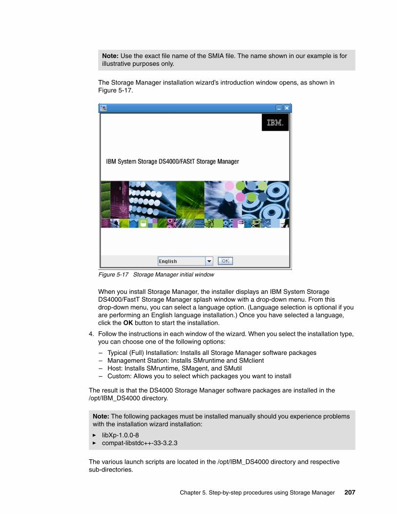
The Storage Manager installation wizard’s introduction window opens, as shown in Figure 5-17.
Figure 5-17 Storage Manager initial window
When you install Storage Manager, the installer displays an IBM System Storage DS4000/FastT Storage Manager splash window with a drop-down menu. From this drop-down menu, you can select a language option. (Language selection is optional if you are performing an English language installation.) Once you have selected a language, click the OK button to start the installation.
4. Follow the instructions in each window of the wizard. When you select the installation type, you can choose one of the following options:
– Typical (Full) Installation: Installs all Storage Manager software packages – Management Station: Installs SMruntime and SMclient– Host: Installs SMruntime, SMagent, and SMutil– Custom: Allows you to select which packages you want to install
The result is that the DS4000 Storage Manager software packages are installed in the /opt/IBM_DS4000 directory.
The various launch scripts are located in the /opt/IBM_DS4000 directory and respective sub-directories.
Note: Use the exact file name of the SMIA file. The name shown in our example is for illustrative purposes only.
Note: The following packages must be installed manually should you experience problems with the installation wizard installation:
� libXp-1.0.0-8� compat-libstdc++-33-3.2.3
Chapter 5. Step-by-step procedures using Storage Manager 207

Installing the components manually In case you cannot or do not want to use the InstallAnywhere wizard, you must install each component separately.To do so:
1. If an earlier version of Storage Manager is installed, remove it. See “Uninstalling Storage Manager components” on page 208.
2. Install SMruntime.
3. Install SMclient.
4. Disable and enable the Event Monitor. (You must make the decision at install time.)
5. Install the IBM Fibre Channel HBA non-failover version device driver for Linux (if the kernel is Version 2.4). See “Installing host bus adapter driver for Linux aeparately” on page 211.
6. Install the Linux RDAC driver. See “Installing the Linux RDAC driver” on page 212.
7. Install SMesm.
8. Install SMagent (if required for in-band management).
9. Install SMutil.
Uninstalling Storage Manager componentsBefore installing the new version of Storage Manager, you must remove and verify removal of any previous versions using the Linux rpm commands, as shown in Table 5-2.
Table 5-2 Software removal/verification commands
Steps for installing the Storage Manager components manually Use the procedures in this section to install the applicable Storage Manager software packages on a management station or host computer. These software installation procedures can also be performed using an rpm-compatible, GUI-based package manager.
Ensure that you have root privileges, which are required to install the software.
Installing Storage Manager Runtime (SMruntime)Installation of the SMruntime package is necessary for both hosts and storage management stations.
Package name Removal command Verification command
SMutil rpm -e SMutil rpm -qi SMutil
SMesm rmp -e SMesm rpm -qi SMesm
SMclient rpm -e SMclient rpm -qi SMclient
SMagent rpm -e SMagent rpm -qi SMagent
SMruntime rpm -e SMruntime rpm -qi SMruntime
Important: Before installing the client software, install the runtime software. A system reboot is only required when installing the RDAC driver package. The Event Monitor software is installed automatically during the client software installation.
208 IBM System Storage DS4000 and Storage Manager V10.30
To install SMruntime:
1. Type the following command at the command prompt and press Enter:
rpm -ivh SMruntime-LINUX<version number>.rpm
2. To verify the installation of the SMruntime package, type the following command at the command prompt and press Enter:
rpm -qa SMruntime
3. If the installation was successful, and no failure was reported, continue with the next section. If the installation was unsuccessful, repeat steps 1 and 2. If the failure persists, see the Storage Manager Release Notes or contact your IBM technical support representative.
Installing the Storage Manager Client (SMclient) Installation of the SMclient package is necessary only if the system is a storage management station or if the system is a host acting as a storage management station.
To install the SMclient:
1. Type the following command at the command prompt and press Enter:
rpm -ivh SMclient-LINUX<version number>.rpm
2. To verify the installation of the SMclient package, type the following command at the command prompt and press Enter:
rpm -qa SMclient
3. If the installation was unsuccessful, repeat steps 1 and 2. If the failure persists, see the Storage Manager Release Notes or contact your IBM technical support representative.
Disabling and enabling the Event Monitor The Event Monitor, which comes with the client software, installs automatically during the client software installation. The Event Monitor handles storage subsystem error notification through e-mail or SNMP traps when the storage management software is not actively running on the management station or host computer.
You can disable and enable the Event Monitor while the Event Monitor is running, or you can disable and enable the boot-time reloading of the Event Monitor. If you disable the Event Monitor while it is running, it starts automatically at the next reboot.
To disable the Event Monitor while the software is running, at the command prompt, type the following command and press Enter:
SMmonitor stop
When the program shutdown is complete, the system displays the following message:
Stopping SMmonitor process <xxxx>
Where xxxx represents the process ID number.
Important: The Event Monitor must remain enabled if you intend to use automatic Environmental Service Modules (ESM) firmware synchronization.
If you installed the client software and configured alert notifications on multiple hosts, you might receive duplicate error messages from the same storage subsystem. To avoid receiving duplicate error messages, disable the Event Monitor on all but one system. You must run the Event Monitor on one host (server) that will run continually.
Chapter 5. Step-by-step procedures using Storage Manager 209
To enable the Event Monitor while the software is running, at the command prompt, type the following command and press Enter:
SMmonitor start
When the program startup begins, the system displays the following message:
SMmonitor started.
To disable boot-time loading of the Event Monitor, at the command prompt, type the following command and press Enter:
mv /etc/rc2.d/S99SMmonitor /etc/rc2.d/disabledS99SMmonitor
You are returned to the command prompt.
To enable boot-time loading of the Event Monitor, at the command prompt, type the following command and press Enter:
mv /etc/rc2.d/S99SMmonitor /etc/rc2.d/S99SMmonitor
You are returned to the command prompt.
Installing the Storage Manager Utility (SMutil)Installing the SMutil package is necessary only if the system is a host. To install the SMutil:
1. Type the following command at the system prompt and press Enter:
rpm -ivh SMutil-LINUX<version number>.rpm
2. To verify installation of the SMutil package, type the following command at the system prompt and press Enter:
rpm -qa SMutil
If the installation was successful, and no failure was reported, continue with the following section. If the installation was unsuccessful, repeat steps 1 and 2. If the failure persists, see the Storage Manager Release Notes or contact your IBM technical support representative.
Installing Storage Manager Agent (SMagent) Installation of the Storage Manager Agent software is necessary only if the system is a host and the storage array is to be managed using the in-band storage array management method. In addition, RDAC must be installed.
To install the SMagent package:
1. Type the following command at the system prompt and press Enter:
rpm -ivh SMagent-LINUX<version number>.rpm
2. To verify installation of the SMagent package, type the following command at the system prompt and press Enter:
rpm -qa SMagent
If the installation was unsuccessful, repeat steps 1 and 2. If the failure persists, see the Storage Manager Release Notes or contact your IBM technical support representative.
210 IBM System Storage DS4000 and Storage Manager V10.30
Installing Storage Manager ESM (SMesm)Installation of the SMesm is required for the possibility of ESM firmware upgrades. To install the SMesm package:
1. Type the following command at the system prompt and press Enter.
rpm -ivh SMesm-LINUX<version number>.rpm
2. To verify installation of the SMagent package, type the following command at the system prompt and press Enter:
rpm -qa SMesm
3. If the installation was unsuccessful, repeat steps 1 and 2. If the failure persists, see the Storage Manager Release Notes or contact your IBM technical support representative.
The result is that the DS4000 Storage Manager software packages are installed in the /opt/IBM_DS4000 directory.
The various launch scripts are located in the /opt/IBM_DS4000 directory and respective sub-directories.
Installing host bus adapter driver for Linux aeparatelyThe device driver enables the operating system to communicate with the host bus adapter.
Before installing the driver, make sure that your system meets the requirements stated in the readme file of the driver package regarding kernel versions, host adapter settings, and so on. You might have to install the kernel headers and kernel source for the supported version of kernel before you install the drivers. These can be downloaded from:
http://updates.redhat.com
Now you can install the driver by following these steps:
1. Download and install the drivers as described in the readme that is contained with the driver package.
2. Configure the startup procedures of your system to load the module by default. Add lines similar to the following lines into the file /etc/modules.conf:
alias scsi_hostadapter2 qla2200alias scsi_hostadapter3 qla2300options scsi_mod max_luns=128
3. Invoke the following command to generate the new module dependencies:
depmod -a
Again, since these settings can change with a newer driver version, always check the readme file.
Important: For Linux distributions with kernel 2.6, a non-failover version of the HBA driver is compiled with the kernel. To obtain the driver with the failover function, an out-of-distribution version of the HBA driver must be installed. Note that there is only one type of external driver available for kernel v2.6 that supports both failover and non-failover. When you install RDAC, it forces you to load the non-failover method.
Important: For Linux kernel 2.4, there are two types of drivers available for download, failover and non-failover. For use with the RDAC, we must download and install the non-failover driver.
Chapter 5. Step-by-step procedures using Storage Manager 211

4. Rebuild the initial RAM disk to include the module at boot time:
# mkinitrd -f /boot/initrd-`uname -r`.img `uname -r`
The result of the command is a new initial RAM disk file located under the /boot directory. If the kernel version is 2.6.9-42.ELsmp, the file name will be initrd-2.6.9-42.ELsmp.img.
5. If GRUB is installed as the boot loader, check the /boot/grub/menu.lst file and make sure that it is pointing to the correct initial RAM disk:
# cat /boot/grub/menu.lst{truncated}...title Red Hat Enterprise Linux AS (2.6.9-42.ELsmp)root (hd0,0)kernel /vmlinuz-2.6.9-42.ELsmp ro root=LABEL=/ rhgb quietinitrd /initrd-2.6.9-42.ELsmp.img...{truncated}
6. Reboot the system and the new driver loads automatically with the new settings.
If you do not want to install RDAC but must load the non-failover driver, this can be done by loading the driver using the parameter shown below:
# insmod qla2xxx.ko ql2xfailover=0 ; insmod qla2400.ko
You can put that parameter into the /etc/modules.conf file so that it will be loaded every time that the operating system (OS) is restarted, as shown below:
"options qla2xxx ql2xfailover=0 ConfigRequired=1 ql2xretrycount=60 ql2xsuspendcount=70”
Installing the Linux RDAC driverSimilar to the HBA drivers, make sure that your system meets the requirements stated in the readme file of the driver package regarding kernel versions, HBA settings, and so on.
At the time of writing, the following Linux RDAC restrictions apply:
� The Linux RDAC driver cannot coexist with the failover HBA driver.
� Auto Logical Drive Transfer (ADT/AVT) mode is not supported.
� The Linux SCSI layer does not support sparse/skipped LUNs. This means that mapped LUNs must be sequentially numbered for the Linux host to see them.
� When using multiple HBAs on the host server, each HBA should only see one controller or the RDAC driver returns errors.
� The Linux RDAC reports I/O failures immediately if it detects failure of all paths to the storage server. This behavior is different from the HBA failover driver, which delayed for a certain period of time.
� The DS4000 storage server must be connected to the HBAs in order for the virtual HBA driver to be loaded.
Tip: We recommend that you save a copy of the existing initial ramdisk before installing the RDAC driver. This backup copy, together with a separate stanza in /etc/lilo.conf or /boot/grub/menu.lst, is needed in case the system does not boot after installing the RDAC device driver.
212 IBM System Storage DS4000 and Storage Manager V10.30
To install the Linux RDAC driver, proceed as follows. (For the latest details, always check the readme file that comes with the driver package.)
1. This Linux RDAC release does not support auto-volume transfer/auto-disk transfer (AVT/ADT) mode. AVT/ADT is automatically enabled in the Linux storage partitioning host type. Disable it by using the script that is bundled in the IBM Linux RDAC Web package or in the \Scripts directory of the DS4000 Storage Manager Version Linux CD. The name of the script file is DisableAVT_Linux.scr. Use the following steps to disable the AVT/ADT mode in your Linux host type partition. To change it:
a. Start the SMclient on your management station.
b. From the Enterprise Management window, highlight the storage system that is used with the Linux host. Select Tools → Execute Script.
c. In the script editing window, select File → Load Script. Select the full path name for the script (<CDROM>/scripts/DisableAVT_Linux.scr).
d. Select Tools → Verify and Execute.
This script resets the controllers individually.
We assume that the Linux host type is selected for the storage partition in which the Linux host server HBA port is defined. This Linux host type has AVT/ADT enabled as the default.
Be sure that all connected hosts have redundant FC paths to the DS4000 subsystem, as each controller is rebooted, one at a time, and the FC paths swap temporarily.
2. The host server must have the non-failover Fibre Channel HBA device driver properly built and installed before the Linux RDAC driver installation.
3. The kernel source tree for the Linux kernel version to be built against should already be installed before installing the RDAC driver package.
4. Unpack the source package. Type the following command (where xx. xx.xx.xx is the release version of the RDAC driver):
tar -zxvf rdac-LINUX-xx.xx.xx.xx-source.tar.gz
5. Change to the linuxrdac directory. To remove the old driver modules in that directory, type the following command and press Enter:
make clean
6. To compile all driver modules and utilities in a multiple-CPU server (SMP kernel), type the following command and press Enter:
make
7. To install the driver, type the following command:
make install
This command:
– Copies the driver modules to the kernel module tree
– Builds the new RAMdisk image (mpp-`uname -r`.img), which includes the RDAC driver modules and all driver modules that are needed at boot
8. Follow the instructions displayed at the end of the build process to add a new boot menu option that uses /boot/mpp-`uname -r`.img as the initial RAMdisk image.
9. Reboot the system.
Chapter 5. Step-by-step procedures using Storage Manager 213
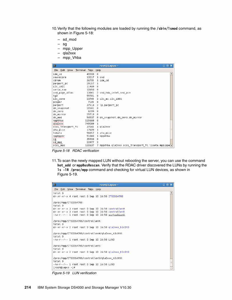
10.Verify that the following modules are loaded by running the /sbin/lsmod command, as shown in Figure 5-18:
– sd_mod– sg– mpp_Upper– qla2xxx– mpp_Vhba
Figure 5-18 RDAC verification
11.To scan the newly mapped LUN without rebooting the server, you can use the command hot_add or mppBusRescan. Verify that the RDAC driver discovered the LUNs by running the ls -lR /proc/mpp command and checking for virtual LUN devices, as shown in Figure 5-19.
Figure 5-19 LUN verification
214 IBM System Storage DS4000 and Storage Manager V10.30
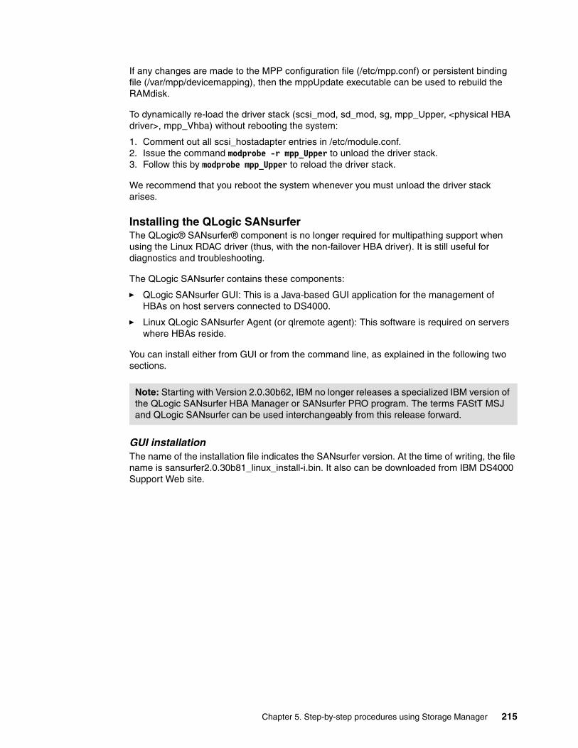
If any changes are made to the MPP configuration file (/etc/mpp.conf) or persistent binding file (/var/mpp/devicemapping), then the mppUpdate executable can be used to rebuild the RAMdisk.
To dynamically re-load the driver stack (scsi_mod, sd_mod, sg, mpp_Upper, <physical HBA driver>, mpp_Vhba) without rebooting the system:
1. Comment out all scsi_hostadapter entries in /etc/module.conf.2. Issue the command modprobe -r mpp_Upper to unload the driver stack.3. Follow this by modprobe mpp_Upper to reload the driver stack.
We recommend that you reboot the system whenever you must unload the driver stack arises.
Installing the QLogic SANsurferThe QLogic® SANsurfer® component is no longer required for multipathing support when using the Linux RDAC driver (thus, with the non-failover HBA driver). It is still useful for diagnostics and troubleshooting.
The QLogic SANsurfer contains these components:
� QLogic SANsurfer GUI: This is a Java-based GUI application for the management of HBAs on host servers connected to DS4000.
� Linux QLogic SANsurfer Agent (or qlremote agent): This software is required on servers where HBAs reside.
You can install either from GUI or from the command line, as explained in the following two sections.
GUI installation The name of the installation file indicates the SANsurfer version. At the time of writing, the file name is sansurfer2.0.30b81_linux_install-i.bin. It also can be downloaded from IBM DS4000 Support Web site.
Note: Starting with Version 2.0.30b62, IBM no longer releases a specialized IBM version of the QLogic SANsurfer HBA Manager or SANsurfer PRO program. The terms FAStT MSJ and QLogic SANsurfer can be used interchangeably from this release forward.
Chapter 5. Step-by-step procedures using Storage Manager 215
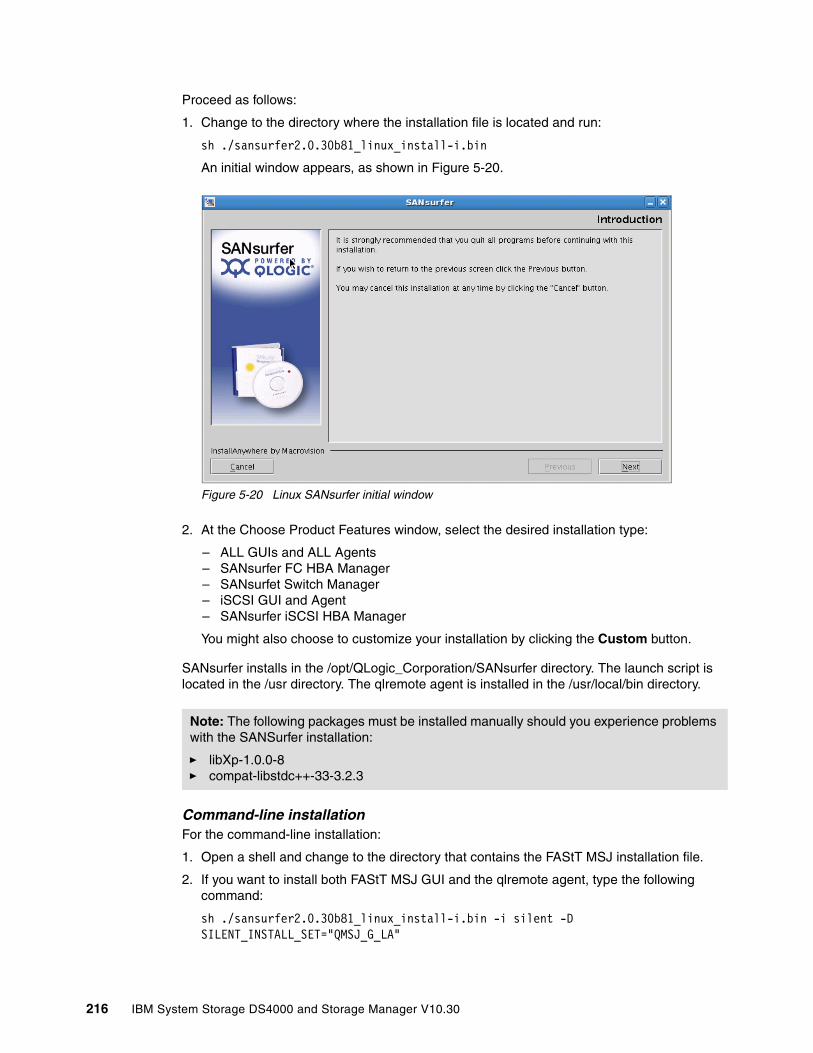
Proceed as follows:
1. Change to the directory where the installation file is located and run:
sh ./sansurfer2.0.30b81_linux_install-i.bin
An initial window appears, as shown in Figure 5-20.
Figure 5-20 Linux SANsurfer initial window
2. At the Choose Product Features window, select the desired installation type:
– ALL GUIs and ALL Agents– SANsurfer FC HBA Manager– SANsurfet Switch Manager– iSCSI GUI and Agent– SANsurfer iSCSI HBA Manager
You might also choose to customize your installation by clicking the Custom button.
SANsurfer installs in the /opt/QLogic_Corporation/SANsurfer directory. The launch script is located in the /usr directory. The qlremote agent is installed in the /usr/local/bin directory.
Command-line installation For the command-line installation:
1. Open a shell and change to the directory that contains the FAStT MSJ installation file.
2. If you want to install both FAStT MSJ GUI and the qlremote agent, type the following command:
sh ./sansurfer2.0.30b81_linux_install-i.bin -i silent -D SILENT_INSTALL_SET="QMSJ_G_LA"
Note: The following packages must be installed manually should you experience problems with the SANSurfer installation:
� libXp-1.0.0-8� compat-libstdc++-33-3.2.3
216 IBM System Storage DS4000 and Storage Manager V10.30

3. If you want to install the qlremote agent only, use the following command:
sh ./sansurfer2.0.30b81_linux_install-i.bin -i silent -D SILENT_INSTALL_SET="QMSJ_LA"
5.1.4 Installing DS/4000 Storage Manager software on a HP-UX host
This section contains procedures for installing components of the Storage Manager software in an HP-UX environment. In addition, we provide detailed system requirements and procedures for verifying the installation and starting the software.
Before installing Storage Manager, make sure that the HP-UX host on which you are installing SMruntime meets the minimum hardware and software requirements described in the Installation and Support Guide for AIX, HP-UX, Solaris, and Linux on POWER, GC26-7848, for the release of Storage Manager that you are installing.
You can Install Storage Manager software packages automatically by using the installation wizard, or you can install each package manually. The DS4000 Storage Manager CD for HP-UX can be downloaded from the IBM Support Web site or you can use the CD-ROM that is shipped with the product. The software includes the following packages:
� SMRuntime (required)� SMclient (optional)� SMagent (optional)� SMutil (required)
Installation wizardThe Storage Manager installation wizard makes sure that the proper selection of the above components is installed. To install:
1. Open the appropriate version of the install file on your system, such as:
sh SMIA-HPUX-10.1x.xx.xx.bin
2. Click Next and accept the license agreement.
3. Follow the instructions and select the installation type:
– Typical (full installation): This selection, which is the default, installs all of the packages on the system. This is a safe choice if you do not know which installation type to select.
– Management Station: This selection installs the software needed to configure, manage, and monitor a storage array. This option is for your management workstation.
– Host: This selection installs the storage server software. Use this type of installation for the host (server) connected to the storage subsystem.
– Custom: This selection enables you to customize the features to be installed.
The selected installation type is highlighted in blue.
4. Click Next. The Pre-Installation Summary window is displayed.
5. Click Install. The Installing window is displayed while the software is loading. When the software is loaded, the Install Complete window is displayed.
Important: Storage Manager V10.10 and controller firmware V7.10 initially incorporate support for HP-UX 11.23 in IA64 in addition to PA-RISC. Refer to your specific model and controller firmware readme file for compatibilities with your HP-UX version.
Chapter 5. Step-by-step procedures using Storage Manager 217
6. Click Done to exit the installation program. Several files and program packages are installed in the /opt/StorageManager and the /opt/SM9 directories.
Manual installationUse the sequence below to install specific components of the Storage Manager software.
SMruntime (required)Follow these steps:
1. Start the installation process by typing the following command:
swinstall -s /complete path_name/SMruntime_10xxxxx
Where path_name is the directory path to the SMruntime package. The Software Selection window opens and displays this message:
SMruntime
2. Select SMruntime.
3. Click Actions → Mark for installation.
4. Click Actions → Install (Analysis).
5. Click OK when the analysis is finished.
6. In the confirmation window, click Yes to start the installation.
7. When the installation is finished, click Done in the Installation window and close the application.
SMclient (optional)If you are using your HP-UX host as a storage management workstation, then you must install SMclient on the host. If you are using a different computer as your storage management station, install SMclient on that computer. Proceed as follows:
1. Start the installation process by typing the following command:
swinstall -s /complete path_name/SMclient_10xxxxx
Where path_name is the directory path to the SMruntime package. The Software Selection window opens and displays this message:
SMclient
2. Select SMclient.
3. Click Actions → Mark for installation.
4. Click Actions → Install (Analysis).
5. Click OK when the analysis is finished.
6. In the confirmation window, click Yes to start the installation.
7. When the installation is finished, click Done in the Installation window and close the application.
Important: If you cancel an installation before it completes its run (while the progress bar is still visible), the installation terminates prematurely and the software creates an install log. You must manually uninstall the software using the steps recorded in this install log.
If you cancel the installation before the progress bar is visible, you do not need to uninstall the software.
218 IBM System Storage DS4000 and Storage Manager V10.30
SMagent (optional)SMagent is required for in-band management only. It is not required for out-of-band management (by Ethernet connection to the RAID controllers). See “Host agent (in-band) management method” on page 120. Follow these steps:
1. Start the installation process by typing the following command:
swinstall -s /complete path_name/SMagent_10xxxxx
Where path_name is the directory path to the SMruntime package.The Software Selection window opens and displays this message:
SMagent
2. Select SMagent.
3. Click Actions → Mark for installation.
4. Click Actions → Install (Analysis).
5. Click OK when the analysis is finished.
6. In the confirmation window, click Yes to start the installation.
7. When the installation is finished, click Done in the Installation window and close the application.
SMutil (required)Follow these steps:
1. Start the installation process by typing the following command:
swinstall -s /complete path_name/SMutil_10xxxxx
Where path_name is the directory path to the SMruntime package.The Software Selection window opens and displays this message:
SMutil
2. Select SMutil.
3. Click Actions → Mark for installation.
4. Click Actions → Install (Analysis).
5. Click OK when the analysis is finished.
6. In the confirmation window, click Yes to start the installation.
7. When the installation is finished, click Done in the Installation window and close the application.
VerificationTo verify the installation, follow these steps:
1. At the prompt, type the following command and press Enter. In this command, <package name> is the name of a package that you installed.
swverify -v <package name>
For example:
swverify -v SMruntime
2. Note any failure reported.
3. For each package that you installed, repeat steps 1 and 2.
Chapter 5. Step-by-step procedures using Storage Manager 219

4. Was the installation successful (no failures reported)?
– If yes, go to step 5.
– If no, from the /opt/StorageManager directory, review any error messages from the error message log and correct the problems. If the failure persists, contact customer and technical support.
5. When the verification is finished successfully, continue with DS4000 logical drive installation.
Configuring DS4000 in the HP-UX environmentThe procedure explained in this section assumes that you already have a physical connection between the host and the storage subsystem controllers, and that you have also connected and zoned the SAN switch (if any). Without this preliminary setup, Storage Manager will not be able to list the WWPNs of the HBAs.
Defining host and mapping in the HP-UX environmentBefore you start the configuration, identify the worldwide port name for each of your HBAs. Use the following commands to find your HBAs listed in the dev directory as td0, td1, and so on, where x in the following example represents the td number:
#cd /dev/td#tdutil /dev/tdx
Refer to 5.3.5, “Configuring storage partitioning” on page 259, for a general procedure from the Storage Manager client.
� In the “Define Host wizard” on page 263, make sure to select the appropiated host type and HBA WWPNs.
� Storage Manager 10 allows up to 256 LUNs per partition. However, depending on your HP-UX version you will be limited in the quantity of LUNs supported:
– HP-UX 11.10 supports up to 32 LUNs per partition.– HP-UX 11.11 supports up to 128 LUNs per partition.– HP-UX 11.23 supports up to 128 LUNs per partition.
� Evaluate the maximum LUN size supported for your version. The Storage Manager 10 initially supports logical drives greater than 2 TB. However:
– HP-UX 11.11 supports up to 2 TB LUNs.– HP-UX 11.23 supports up to 32 TB LUNs.
Adding mapped logical drives to the HP-UX operating systemThe hot_add utility allows you to add new volumes (logical drives) dynamically without restarting the system. The utility registers the new logical drives with the HP-UX operating system so that you can perform functions, such as adding devices. The hot_add utility is installed as a part of the SMutil package.
To run the hot_add utility:
1. Ensure that you have root or root-equivalent privileges.
Note: Make sure to specify the host type when defining the partition or mapping the logical volumes. For host type HP-UX, AVT/ADT is enabled by default. Leave it in that state.
220 IBM System Storage DS4000 and Storage Manager V10.30
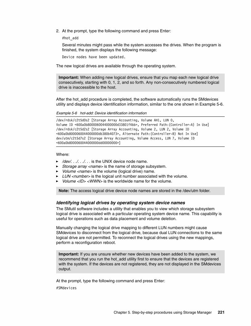
2. At the prompt, type the following command and press Enter:
#hot_add
Several minutes might pass while the system accesses the drives. When the program is finished, the system displays the following message:
Device nodes have been updated.
The new logical drives are available through the operating system.
After the hot_add procedure is completed, the software automatically runs the SMdevices utility and displays device identification information, similar to the one shown in Example 5-6.
Example 5-6 hot-add: Device identification information
/dev/rdsk/c2t5d0s2 [Storage Array Accounting, Volume AH1, LUN 0,Volume ID <600a0b8000060044000000d33801f4bb>, Preferred Path:(Controller-A) In Use]/dev/rdsk/c2t5d2s2 [Storage Array Accounting, Volume 2, LUN 2, Volume ID <600a0b8000060044000000db380b4073>, Alternate Path:(Controller-B) Not In Use]dev/utm/c2t5d7s2 [Storage Array Accounting, Volume Access, LUN 7, Volume ID <600a0b8000060044000000dd00000000>]
Where:
� /dev/. . ./. . ./. . . is the UNIX device node name.� Storage array <name> is the name of storage subsystem.� Volume <name> is the volume (logical drive) name.� LUN <number> is the logical unit number associated with the volume.� Volume <ID> <WWN> is the worldwide name for the volume.
Identifying logical drives by operating system device names The SMutil software includes a utility that enables you to view which storage subsystem logical drive is associated with a particular operating system device name. This capability is useful for operations such as data placement and volume deletion.
Manually changing the logical drive mapping to different LUN numbers might cause SMdevices to disconnect from the logical drive, because dual LUN connections to the same logical drive are not permitted. To reconnect the logical drives using the new mappings, perform a reconfiguration reboot.
At the prompt, type the following command and press Enter:
#SMdevices
Important: When adding new logical drives, ensure that you map each new logical drive consecutively, starting with 0, 1, 2, and so forth. Any non-consecutively numbered logical drive is inaccessible to the host.
Note: The access logical drive device node names are stored in the /dev/utm folder.
Important: If you are unsure whether new devices have been added to the system, we recommend that you run the hot_add utility first to ensure that the devices are registered with the system. If the devices are not registered, they are not displayed in the SMdevices output.
Chapter 5. Step-by-step procedures using Storage Manager 221
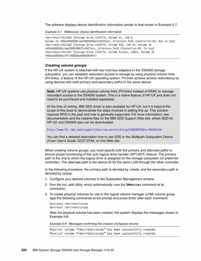
The software displays device identification information similar to that shown in Example 5-7.
Example 5-7 SMdevices: Device identification information
/dev/rdsk/c101t0d0 [Storage Array n124774, Volume V1, LUN 0,Volume ID <600a0b80000c3ee20000006e3c6925ba>, Alternate Path (Controller-B): Not In Use]/dev/rdsk/c101t3d0 [Storage Array n124774, Volume V25, LUN 24, Volume ID <600a0b80000c3ee20000008f3c6927ac>, Alternate Path (Controller-B): In Use]/dev/rdsk/c101t3d7 [Storage Array n124774, Volume Access, LUN31, Volume ID <600a0b80000c3ffc000000e000000000>]
Creating volume groups If the HP-UX system is attached with two host bus adapters to the DS4000 storage subsystem, you can establish redundant access to storage by using physical volume links (PV-links), a feature of the HP-UX operating system. PV-links achieve access redundancy by using devices with both primary and secondary paths to the same device.
When creating volume groups, you must specify both the primary and alternate paths to ensure proper functioning of the auto logical drive transfer (AVT/ADT) feature. The primary path is the one to which the logical drive is assigned on the storage subsystem (to preferred controller). The alternate path is the device ID for the same LUN through the other controller.
In the following procedure, the primary path is denoted by cxtxdx, and the secondary path is denoted by cytydy:
1. Configure your desired volumes in the Subsystem Management window.
2. Run the hot_add utility, which automatically runs the SMdevices command at its conclusion.
3. To create physical volumes for use in the logical volume manager (LVM) volume group, type the following commands at the prompt and press Enter after each command:
#pvcreate /dev/rdsk/cxtxdx#pvcreate /dev/rdsk/cytydy
After the physical volume has been created, the system displays the messages shown in Example 5-8.
Example 5-8 Messages confirming the creation of physical volume
Physical volume “/dev/rdsk/cxtxdx” has been successfully created.Physical volume “/dev/rdsk/cytydy” has been successfully created.
Note: HP-UX systems use physical volume links (PV-links) instead of RDAC to manage redundant access to the DS4000 system. This is a native feature of HP-UX and does not need to be purchased and installed separately.
At the time of writing, IBM SDD driver is also available for HP-UX, but it is beyond the scope of this book to demonstrate the steps involved in setting this up. This solution required RPQ in the past and now is generally supported. For more information, see documentation and the readme files on the IBM SDD Support Web site, where SDD for HP-UX and DS4000 also can be downloaded:
http://www-01.ibm.com/support/docview.wss?uid=ssg1S4000053&rs=555#ds4k
You can find a detailed description how to use SDD in the Multipath Subsystem Device Driver User's Guide, GC27-2164, on this Web site.
222 IBM System Storage DS4000 and Storage Manager V10.30

4. To make a directory in which to store HP Volume Group information, type the following command at the prompt and press Enter. In this command, vglabel is the label name of the HP Volume Group.
#mkdir /dev/vglabel
5. To change to the newly created directory, type the following command at the prompt and press Enter. In this command, vglabel is the label name of the HP Volume Group.
#cd /dev/vglabel
For example, for volume group 01, type the following command at the prompt and press Enter:
#cd /dev/vg01
6. To create the definition of the HP Volume Group, type the following command at the prompt and press Enter. In this command, vglabel is the label name of the HP Volume Group and ZZ is the unique identifier for the HP Volume Group.
mknod group /dev/vglabel/group c 64 0xZZ0000
For example, for volume group 01, type the following command at the prompt and press Enter.
mknod group /dev/vg01/group c 64 0x010000
7. To create the volume group containing the new physical volume, type the following command at the prompt and press Enter. In this command, vglabel is the label name of the HP Volume Group, cxtxdx is the primary path, and cytydy is the secondary path.
vgcreate /dev/vglabel /dev/dsk/cxtxdx /dev/dsk/cytydy
For example, for the volume group vg01, type the following command at the prompt and press Enter:
vgcreate /dev/vg01 /dev/dsk/c1t0d0 /dev/dsk/c2t0d0
After the volume group directory and group node have been created, the system displays the messages shown in Example 5-9.
Example 5-9 Messages confirming the creation of volume group directory and group node
“Increased the number of physical extents per physical volume to 17326Volume Group /dev/vg01 has been successfully createdVolume Group configuration for /dev/vg01 has been saved in /etc/lvmconf/vg01.conf
8. To create the HP-UX logical volume in the volume group, type the following command at the prompt and press Enter. In this command, size is the desired size of the logical volume and vglabel is the label name of the HP Volume Group.
lvcreate -L size /dev/vglabel
For example, for logical volume 01, with size 60 MB, type the following command at the prompt and press Enter:
lvcreate -L 60000 /dev/vg01
Important: Type the primary path first and specify an alternate path second. Otherwise, the DS4000 storage system goes into a continuous “Volume not on preferred path” error mode whenever any I/O activity is run to the volume.
Chapter 5. Step-by-step procedures using Storage Manager 223
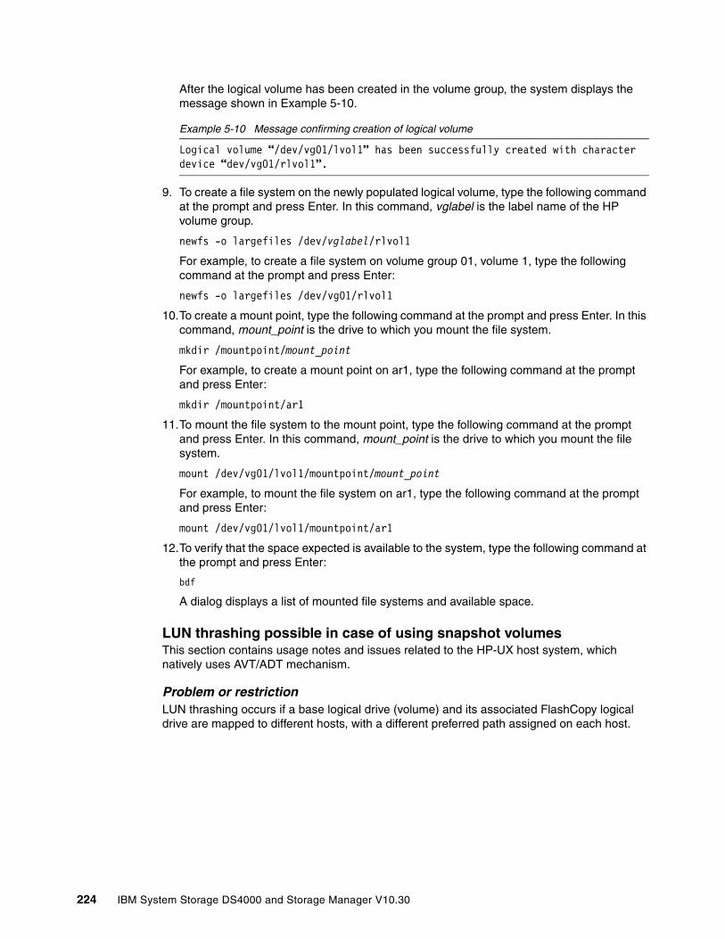
After the logical volume has been created in the volume group, the system displays the message shown in Example 5-10.
Example 5-10 Message confirming creation of logical volume
Logical volume “/dev/vg01/lvol1” has been successfully created with character device “dev/vg01/rlvol1”.
9. To create a file system on the newly populated logical volume, type the following command at the prompt and press Enter. In this command, vglabel is the label name of the HP volume group.
newfs -o largefiles /dev/vglabel/rlvol1
For example, to create a file system on volume group 01, volume 1, type the following command at the prompt and press Enter:
newfs -o largefiles /dev/vg01/rlvol1
10.To create a mount point, type the following command at the prompt and press Enter. In this command, mount_point is the drive to which you mount the file system.
mkdir /mountpoint/mount_point
For example, to create a mount point on ar1, type the following command at the prompt and press Enter:
mkdir /mountpoint/ar1
11.To mount the file system to the mount point, type the following command at the prompt and press Enter. In this command, mount_point is the drive to which you mount the file system.
mount /dev/vg01/lvol1/mountpoint/mount_point
For example, to mount the file system on ar1, type the following command at the prompt and press Enter:
mount /dev/vg01/lvol1/mountpoint/ar1
12.To verify that the space expected is available to the system, type the following command at the prompt and press Enter:
bdf
A dialog displays a list of mounted file systems and available space.
LUN thrashing possible in case of using snapshot volumesThis section contains usage notes and issues related to the HP-UX host system, which natively uses AVT/ADT mechanism.
Problem or restriction LUN thrashing occurs if a base logical drive (volume) and its associated FlashCopy logical drive are mapped to different hosts, with a different preferred path assigned on each host.
224 IBM System Storage DS4000 and Storage Manager V10.30

In Figure 5-21, the base logical drive is mapped to host 1, and the FlashCopy logical drive is mapped to host 2. (This is a typical setup when creating a point-in-time backup.) Host 1 is set up with controller A as the base logical drive preferred path. Host 2 is set up with controller B as the snapshot volume’s preferred path.
Figure 5-21 Invalid preferred path configuration
In this case, each time host 1 sends I/O to the base logical drive, the AVT/ADT mechanism on the controller moves both the base logical drive and the FlashCopy logical drive to controller A. Then, for each I/O to the FlashCopy logical drive from host 2, the controller moves both the base volume and the FlashCopy logical drive to controller B. So, for every I/O, both the base logical drive and the FlashCopy logical drive move. The result of this is thrashing that, depending on load, can lead to host hang, create stale data, and cause data corruption.
Workaround The base logical drive and FlashCopy logical drive must have the same preferred path when mapped to one or more hosts. The preferred path can be either controller A or controller B, as long as the base logical drive, FlashCopy logical drive, and FlashCopy repository logical drive are owned by the same controller, and the controller owner is configured as the preferred path from both hosts.
5.2 Preparing the DS4000 storage server
This section explains how to configure the DS4000 storage server. This includes:
� Powering on the storage system� Configuring TCP/IP addresses on the DS4000 storage server� Initializing the Storage Manager client� Updating the controller microcode� Updating the drive and ESM microcode
You should have already completed the physical installation of your DS4000 storage hardware. Refer to your specific DS4000 storage subsystem Installation, User’s and Maintenance Guide for specific instructions.
Base FlashCopy
Chapter 5. Step-by-step procedures using Storage Manager 225

5.2.1 Turning on the powerBefore powering your subsystem, make sure to have your hardware installed correctly. In particular, check whether your system has a FC speed switch located on the front of the system. This should be set to 2 Gbps or 4 Gbps FC interface speed, matching the speed of the drives installed in your DS4000 Storage Subsystem. If you have any mix of 2 Gbps and 4 Gbps disks in the entire backend FC loop, you must select 2 Gbps on all enclosures on this loop.
You must check, if you have multiple expansion units with mechanical ID-switch, that all of them have a different enclosure ID assigned. For specific details, see Chapter 3, “DS4000 series hardware” on page 15, in the section for your specific DS4000 model.
When turning power on or off, a certain order must be followed on the DS4000.
The drives attached to the storage server must be available when the storage server is powered up. In other words, when expansion enclosures are attached to a storage server, the expansions must be powered up first.
The Fibre Channel hubs and switches, if installed, must be powered on before the host to ensure proper loop initialization.
The power-up procedure includes the following steps:
1. Turn on the expansion enclosures. 2. After the last enclosure is powered on, wait for all the disks to be ready. 3. Turn on hubs/switches (if attached). 4. Turn on the DS4000 storage server. 5. Turn on the host application server.
The power-down procedure includes the following steps:
1. Turn off the host application server.2. Turn off the DS4000 storage server. 3. Turn off hubs/switches (if attached). 4. Turn off the expansion enclosures.
5.2.2 Network setup of the controllersBy default, the DS4000 storage server will try BOOTP/DHCP to request an IP address. If no BOOTP/DHCP service is found in the network, the controllers revert to fixed IP addresses. By default, the fixed addresses are:
� Controller A: 192.168.128.101� Controller B: 192.168.128.102
Warning: Never try to use the FC speed switches when DS4000 system is powered on, as it can lead to data corruption.
Important: Always power up the expansion enclosures first. The controllers in the storage server might not recognize the correct configuration if the drives are powered up after the storage server.
Important: Ensure that your system is in an optimal state before you shut it down. Never turn the power off if any fault light is lit. Be sure to resolve any error conditions before you shut down the system.
226 IBM System Storage DS4000 and Storage Manager V10.30
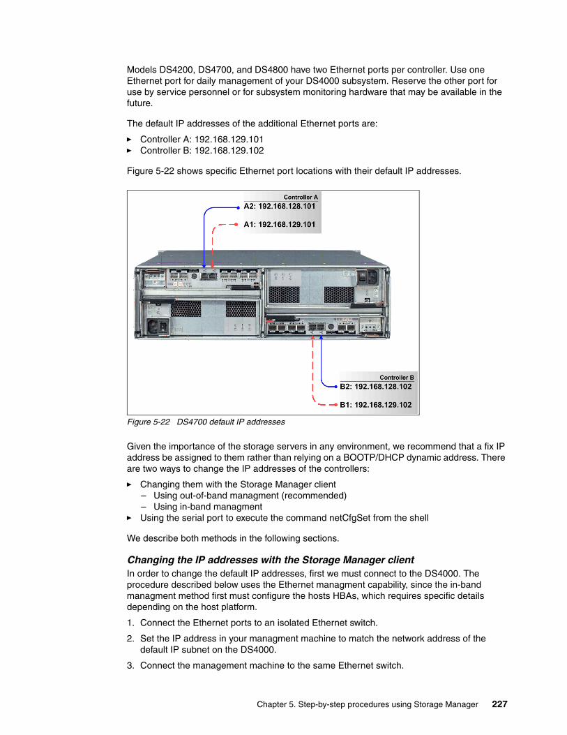
Models DS4200, DS4700, and DS4800 have two Ethernet ports per controller. Use one Ethernet port for daily management of your DS4000 subsystem. Reserve the other port for use by service personnel or for subsystem monitoring hardware that may be available in the future.
The default IP addresses of the additional Ethernet ports are:
� Controller A: 192.168.129.101� Controller B: 192.168.129.102
Figure 5-22 shows specific Ethernet port locations with their default IP addresses.
Figure 5-22 DS4700 default IP addresses
Given the importance of the storage servers in any environment, we recommend that a fix IP address be assigned to them rather than relying on a BOOTP/DHCP dynamic address. There are two ways to change the IP addresses of the controllers:
� Changing them with the Storage Manager client– Using out-of-band managment (recommended)– Using in-band managment
� Using the serial port to execute the command netCfgSet from the shell
We describe both methods in the following sections.
Changing the IP addresses with the Storage Manager clientIn order to change the default IP addresses, first we must connect to the DS4000. The procedure described below uses the Ethernet managment capability, since the in-band managment method first must configure the hosts HBAs, which requires specific details depending on the host platform.
1. Connect the Ethernet ports to an isolated Ethernet switch.
2. Set the IP address in your managment machine to match the network address of the default IP subnet on the DS4000.
3. Connect the management machine to the same Ethernet switch.
Chapter 5. Step-by-step procedures using Storage Manager 227
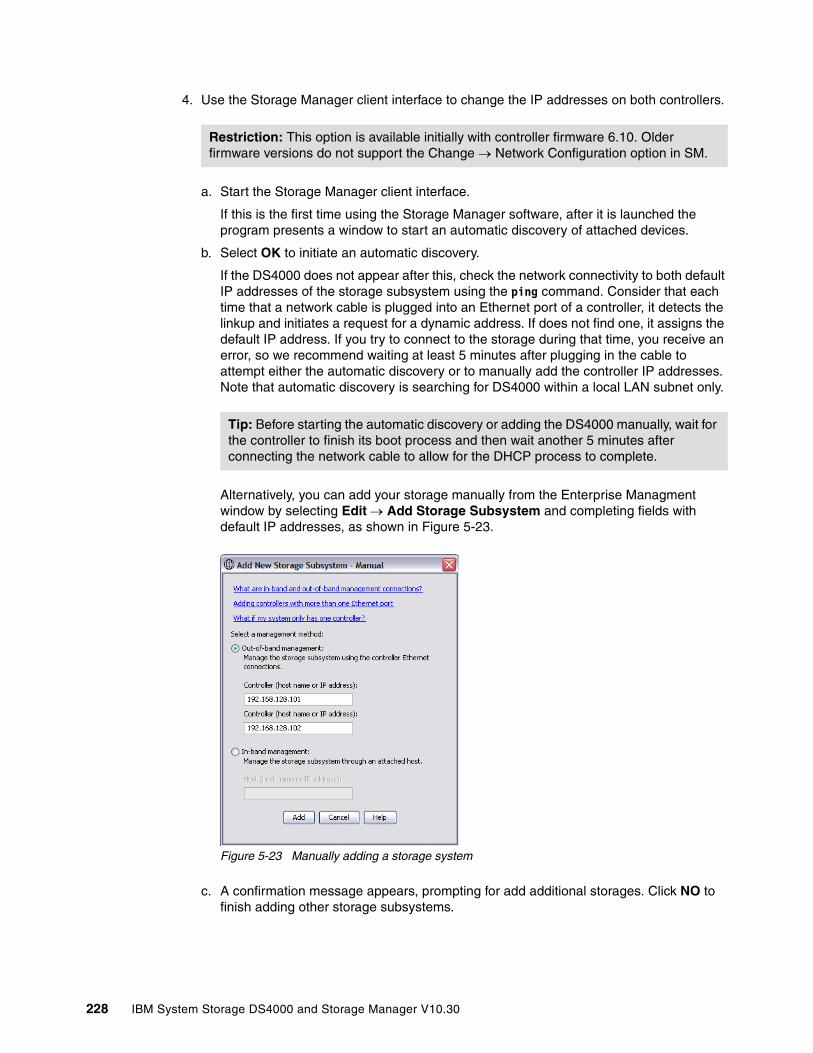
4. Use the Storage Manager client interface to change the IP addresses on both controllers.
a. Start the Storage Manager client interface.
If this is the first time using the Storage Manager software, after it is launched the program presents a window to start an automatic discovery of attached devices.
b. Select OK to initiate an automatic discovery.
If the DS4000 does not appear after this, check the network connectivity to both default IP addresses of the storage subsystem using the ping command. Consider that each time that a network cable is plugged into an Ethernet port of a controller, it detects the linkup and initiates a request for a dynamic address. If does not find one, it assigns the default IP address. If you try to connect to the storage during that time, you receive an error, so we recommend waiting at least 5 minutes after plugging in the cable to attempt either the automatic discovery or to manually add the controller IP addresses. Note that automatic discovery is searching for DS4000 within a local LAN subnet only.
Alternatively, you can add your storage manually from the Enterprise Managment window by selecting Edit → Add Storage Subsystem and completing fields with default IP addresses, as shown in Figure 5-23.
Figure 5-23 Manually adding a storage system
c. A confirmation message appears, prompting for add additional storages. Click NO to finish adding other storage subsystems.
Restriction: This option is available initially with controller firmware 6.10. Older firmware versions do not support the Change → Network Configuration option in SM.
Tip: Before starting the automatic discovery or adding the DS4000 manually, wait for the controller to finish its boot process and then wait another 5 minutes after connecting the network cable to allow for the DHCP process to complete.
228 IBM System Storage DS4000 and Storage Manager V10.30
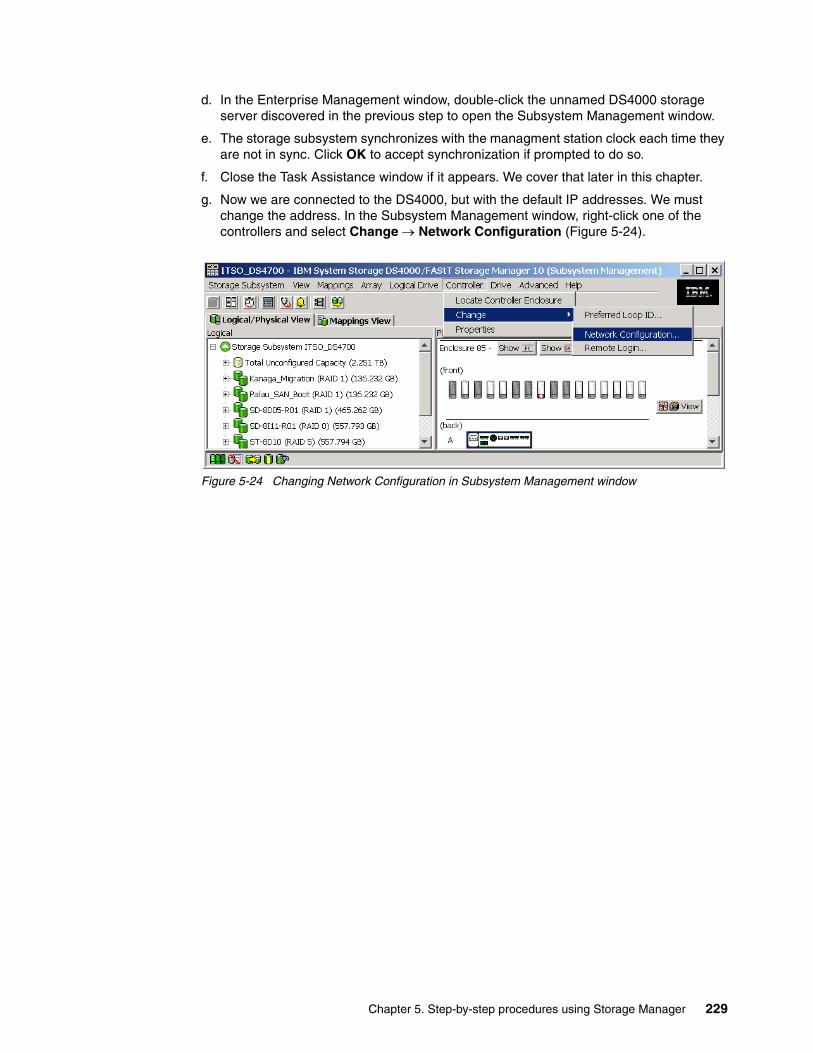
d. In the Enterprise Management window, double-click the unnamed DS4000 storage server discovered in the previous step to open the Subsystem Management window.
e. The storage subsystem synchronizes with the managment station clock each time they are not in sync. Click OK to accept synchronization if prompted to do so.
f. Close the Task Assistance window if it appears. We cover that later in this chapter.
g. Now we are connected to the DS4000, but with the default IP addresses. We must change the address. In the Subsystem Management window, right-click one of the controllers and select Change → Network Configuration (Figure 5-24).
Figure 5-24 Changing Network Configuration in Subsystem Management window
Chapter 5. Step-by-step procedures using Storage Manager 229

h. Fill in the network information and click OK, as shown in Figure 5-25. You can configure both controllers and all Ethernet ports from this panel by selecting them in the drop-down menu. You can also enable or disable IPv4 or IPv6. If your workstation will be in some other LAN subnet than the DS4000, do not forget to set the correct gateway IP address.
DS42000, DS4700, and DS4800 have two Ethernet ports per controller. Make sure to select the correct port and cable. If you are planning to have the system connected to only one network, select port 1, leaving port 2 for service. See Figure 5-22 on page 227 to be sure of where to connect the LAN cables.
Figure 5-25 DS4700 Controller Network Configuration change
After changing the IP addresses, close the Storage Subsystem window and remove the added device from the Enterprise Managment window. After you change your IP connection to the new LAN subnet, again add the DS4000 subsystem, repeating step 2 on page 184, step 3 on page 184, and step d on page 213, but this time, with your new assigned IP addresses.
Note: To manage storage subsystems through a firewall using out-of-band management, configure the firewall to open port 2463 to TCP data.
Remember that automatic discovery is trying to find DS4000 within the local LAN subnet only, so you must use manual adding and define the correct LAN gateway, if you can manage DS4000 from different subnets.
230 IBM System Storage DS4000 and Storage Manager V10.30

Using the serial port to change the IP addresses
In older versions of DS4000 firmware it was possible to change the IP addresses by the connection to the serial port of DS4000 controllers. Beginning with firmware 7.10, this can only be done by authorized IBM Support engineers. The new login name and password is not available for users.
Serial port usage is described below only for the subsystems that are running older firmware versions.
The steps are:
1. Connect to the serial port on a controller in the DS4000 storage server with a null modem cable. For the serial connection, choose the correct port and use the following settings in your emulator program:
– 57600 Baud – 8 Data Bits – 1 Stop Bit – No Parity – Xon/Xoff Flow Control
2. Send a break signal to the controller. The exact command varies with different terminal emulation software. For most terminal emulations, press Ctrl+Break.
3. If you only receive unreadable characters, send another break signal until the following message appears:
Set baud rate: press <space> within 5 seconds.
4. Press the space bar to ensure the correct baud rate setting. If the baud rate is set correctly, a confirmation message appears.
5. Send a break signal to log onto the controller. The following message appears:
Press within 5 seconds: <ESC> for SHELL, <BREAK> for baud rate.
6. Press the Esc key to access the controller Shell. The default password for the DS4000 storage server is infiniti.
7. Run the netCfgShow command to see the current network configuration. The controller outputs a list similar to Example 5-11. The example given here is for a DS4800, where each controller has two Ethernet interfaces (if0 and if1), and thus two IP addresses.
Example 5-11 Sample DS4000 network configuration
-> netCfgShow
==== CURRENT NETWORK CONFIGURATION ====My Host Name : targetInterface Name if0 : esmc0MAC Address if0 : 00:a0:b8:29:04:deIP Address if0 : 192.168.128.101Subnet Mask if0 : 255.255.255.0Interface Name if1 : esmc1MAC Address if1 : 00:a0:b8:29:04:dfIP Address if1 : 192.168.129.101Subnet Mask if1 : 255.255.255.0
Important: Follow the procedure outlined here carefully. Some commands available in the command shell can have destructive effects, causing loss of data or severely impacting the functionality of the DS4000.
Chapter 5. Step-by-step procedures using Storage Manager 231

Server Host Name : hostServer IP Address : 0.0.0.0Gateway IP Address : Network Init Flags : 0x80User Name : guestUser Password :value = 24 = 0x18->
8. To change any of the values, enter the netCfgSet command. This command prompts you for each line in the network configuration list. You can use the following options:
– Press Enter to skip the current entry. – Press the period key (.) to reset the current value to the factory default. – Enter a new value to change the current field.
See Example 5-12 for typical output. Basic configuration requires the changing of only three fields:
– IP address if0/if1 – Gateway IP address– Subnet mask if0/if1
Example 5-12 Changing the network settings
-> netCfgSet
'.' = clear field; '-' = to previous field; ^D = quit (keep changes)
==== CURRENT NETWORK CONFIGURATION ====My Host Name : targetIP Address if0 : 192.168.128.101 9.43.86.99Subnet Mask if0 : 255.255.255.0 255.255.252.0IP Address if1 : 192.168.129.102Subnet Mask if1 : 255.255.255.0Server Host Name : hostServer IP Address : Gateway IP Address : 192.168.128.1 9.43.85.1Network Init Flags : 0x81User Name : guestUser Password :
Network Configuration successfully written to NVSRAM.value = 0 = 0x0->
Optionally, the Network Init Flags can be set to redefine the network startup mode for the controllers. This is a one-byte field that you can use to set various parameters. The most common settings are:
– 0x00: BOOTP first and then revert to default IP address (DEFAULT).– 0x01: Disable BOOTP.– 0x02: Use BOOTP unconditionally.– 0x20: Disable remote login to the shell.
9. After you assign a fixed IP address to controller A, disconnect from controller A and repeat the procedure for controller B. Remember to assign a different IP address.
232 IBM System Storage DS4000 and Storage Manager V10.30

10.Because the configuration changed, the network driver is reset and uses the new network configuration. Wait a few minutes for the internal process to finish before attempting to add the DS4000 for managing.
If you want to use a BOOTP server to assign the controllers a specific IP address, define the MAC addresses of the controllers in your BOOTP server. The MAC addresses of the controllers are printed on the back of each controller.
5.2.3 Using the DS4000 Storage Management client
We know already that the DS4000 Storage Manager client can be used for either in-band or out-of-band management of theDS4000 storage subsystem. In-band management uses the Fibre Channel network to communicate with the IBM DS4000 storage server, while out-of-band management uses the TCP/IP network. On host platforms that support both methods, it is possible to use them both on the same machine if you have a TCP/IP connection and also a Fibre Channel connection to the DS4000 storage server.
When you install SMclient and SMagent on a stand-alone host and manage the storage server through the Fibre Channel I/O path only (Ethernet ports in DS4000 are not used), you can install the TCP/IP software on this host and assign an IP address to it. This way permits other workstations in the IP network with the SMclient installed to manage the DS4000 storage subsystem by connecting through the SMagent of the host with in-band management.
In our illustration we assume out-of-band management from a machine that only has a TCP/IP connection to the DS4000 storage server.
The DS4000 Storage Manager client GUI (SMclient) uses two main windows:
� Enterprise Management window � Subsystem Management window
The concepts of enterprise and subsystem management are explained in 4.1.2, “The Storage Manager client” on page 123. In this chapter we discuss the navigation steps in both the Enterprise and Subsystem Management windows.
Chapter 5. Step-by-step procedures using Storage Manager 233
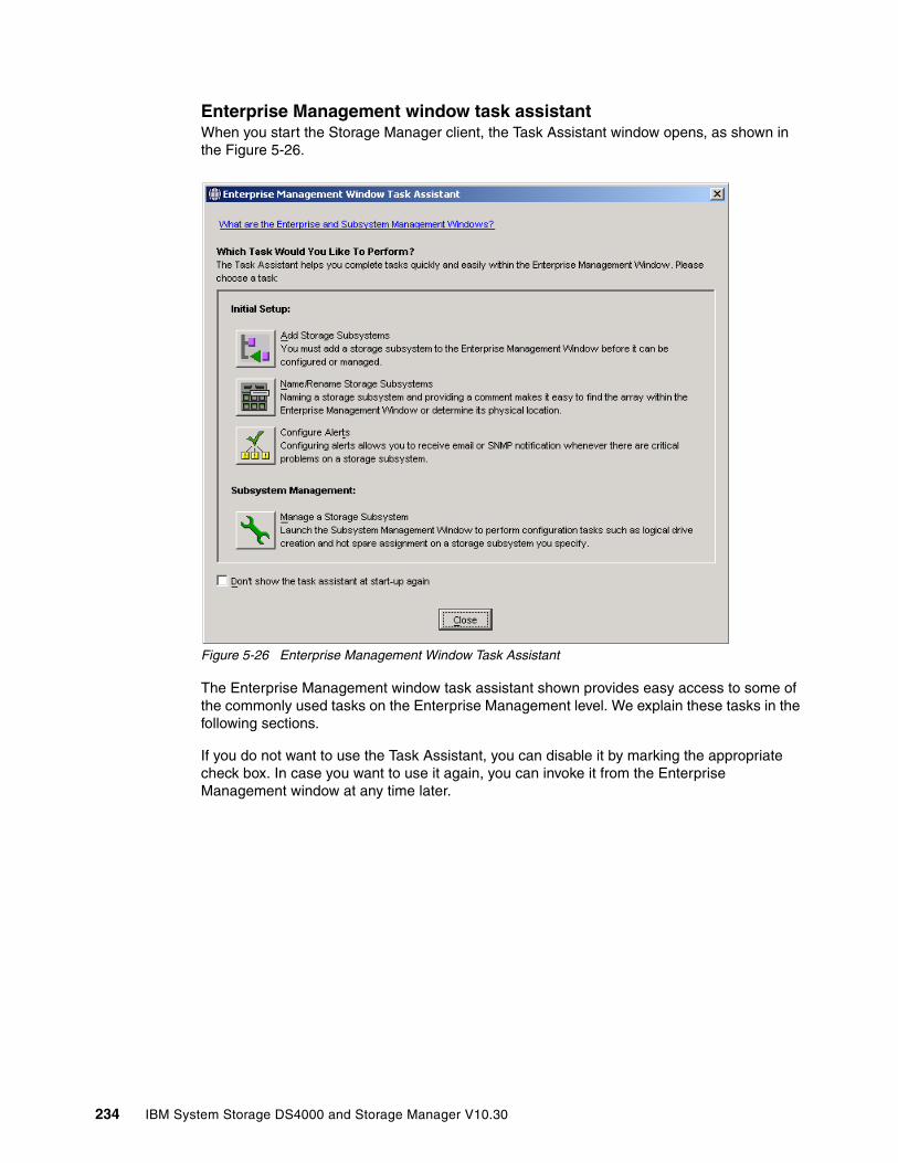
Enterprise Management window task assistantWhen you start the Storage Manager client, the Task Assistant window opens, as shown in the Figure 5-26.
Figure 5-26 Enterprise Management Window Task Assistant
The Enterprise Management window task assistant shown provides easy access to some of the commonly used tasks on the Enterprise Management level. We explain these tasks in the following sections.
If you do not want to use the Task Assistant, you can disable it by marking the appropriate check box. In case you want to use it again, you can invoke it from the Enterprise Management window at any time later.
234 IBM System Storage DS4000 and Storage Manager V10.30

Adding storage systems Before you can manage a DS4000 storage server, you must add it to the Enterprise Management window. You can select either the automatic or the manual addition method, as you can see in Figure 5-27.
Figure 5-27 Task Assistant: Add storage system
The automatic discovery process sends out broadcasts via Fibre Channel (if SMagent is installed and started) and the IP network. If it finds directly attached storage systems or hosts running the DS4000 Storage Manager agent (with an attached storage system), it adds these storage systems into the Enterprise Management window.
The manual addition method requires that you provide the IP addresses (or host names) of both controllers for out-of-band management. If one of the controllers is not connected or is not reachable, then some of the managment functions could not be performed (except in cases where you manage a single-controller storage server).
Chapter 5. Step-by-step procedures using Storage Manager 235
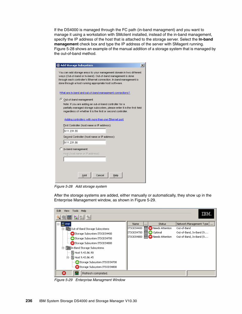
If the DS4000 is managed through the FC path (in-band managment) and you want to manage it using a workstation with SMclient installed, instead of the in-band management, specify the IP address of the host that is attached to the storage server. Select the In-band management check box and type the IP address of the server with SMagent running. Figure 5-28 shows an example of the manual addition of a storage system that is managed by the out-of-band method.
Figure 5-28 Add storage system
After the storage systems are added, either manually or automatically, they show up in the Enterprise Management window, as shown in Figure 5-29.
Figure 5-29 Enterprise Managment Window
236 IBM System Storage DS4000 and Storage Manager V10.30
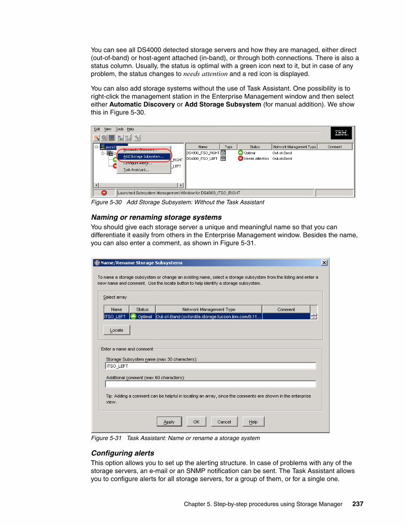
You can see all DS4000 detected storage servers and how they are managed, either direct (out-of-band) or host-agent attached (in-band), or through both connections. There is also a status column. Usually, the status is optimal with a green icon next to it, but in case of any problem, the status changes to needs attention and a red icon is displayed.
You can also add storage systems without the use of Task Assistant. One possibility is to right-click the management station in the Enterprise Management window and then select either Automatic Discovery or Add Storage Subsystem (for manual addition). We show this in Figure 5-30.
Figure 5-30 Add Storage Subsystem: Without the Task Assistant
Naming or renaming storage systems You should give each storage server a unique and meaningful name so that you can differentiate it easily from others in the Enterprise Management window. Besides the name, you can also enter a comment, as shown in Figure 5-31.
Figure 5-31 Task Assistant: Name or rename a storage system
Configuring alertsThis option allows you to set up the alerting structure. In case of problems with any of the storage servers, an e-mail or an SNMP notification can be sent. The Task Assistant allows you to configure alerts for all storage servers, for a group of them, or for a single one.
Chapter 5. Step-by-step procedures using Storage Manager 237
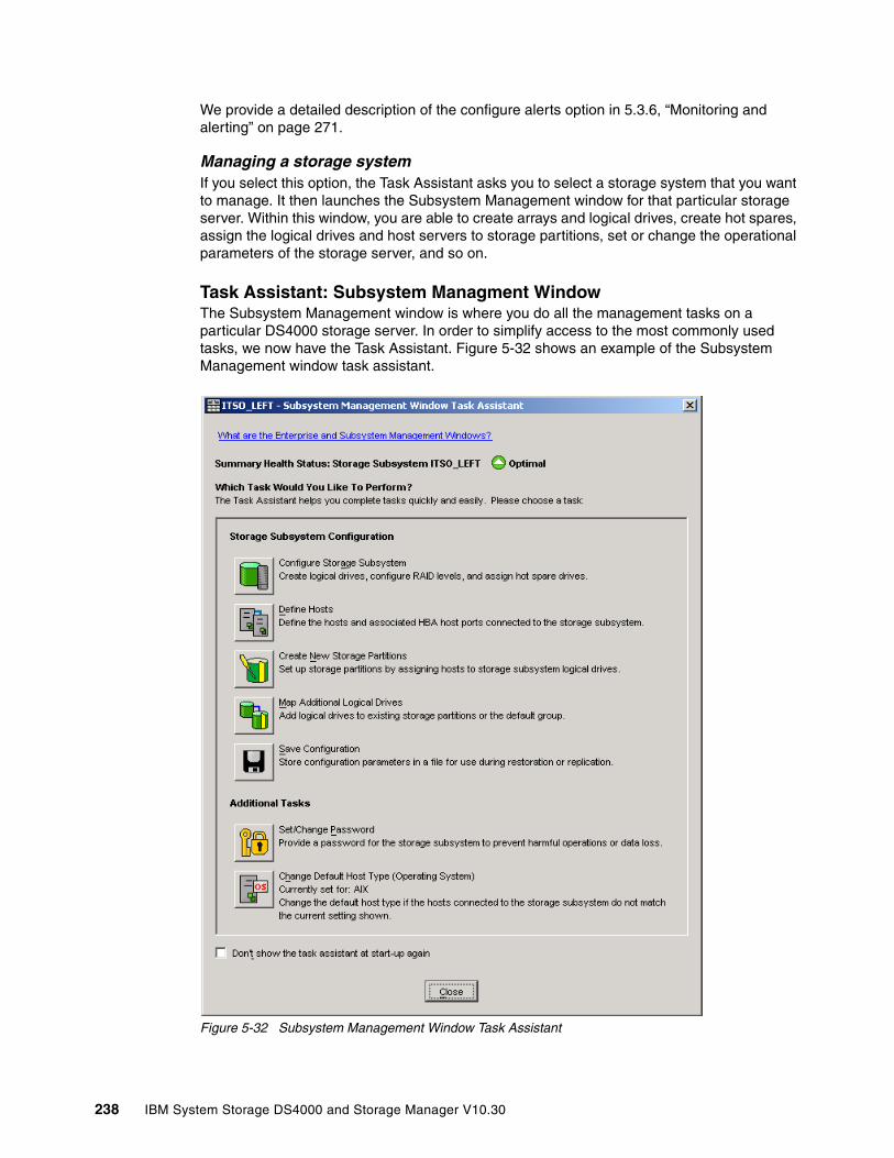
We provide a detailed description of the configure alerts option in 5.3.6, “Monitoring and alerting” on page 271.
Managing a storage system If you select this option, the Task Assistant asks you to select a storage system that you want to manage. It then launches the Subsystem Management window for that particular storage server. Within this window, you are able to create arrays and logical drives, create hot spares, assign the logical drives and host servers to storage partitions, set or change the operational parameters of the storage server, and so on.
Task Assistant: Subsystem Managment WindowThe Subsystem Management window is where you do all the management tasks on a particular DS4000 storage server. In order to simplify access to the most commonly used tasks, we now have the Task Assistant. Figure 5-32 shows an example of the Subsystem Management window task assistant.
Figure 5-32 Subsystem Management Window Task Assistant
238 IBM System Storage DS4000 and Storage Manager V10.30
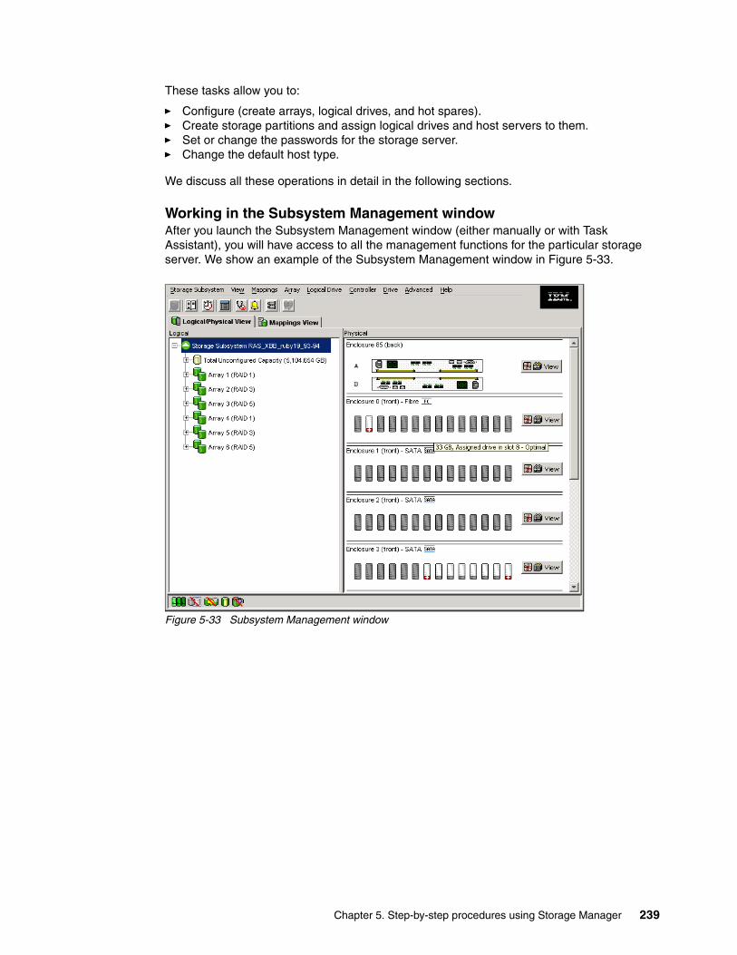
These tasks allow you to:
� Configure (create arrays, logical drives, and hot spares).� Create storage partitions and assign logical drives and host servers to them. � Set or change the passwords for the storage server. � Change the default host type.
We discuss all these operations in detail in the following sections.
Working in the Subsystem Management window After you launch the Subsystem Management window (either manually or with Task Assistant), you will have access to all the management functions for the particular storage server. We show an example of the Subsystem Management window in Figure 5-33.
Figure 5-33 Subsystem Management window
Chapter 5. Step-by-step procedures using Storage Manager 239
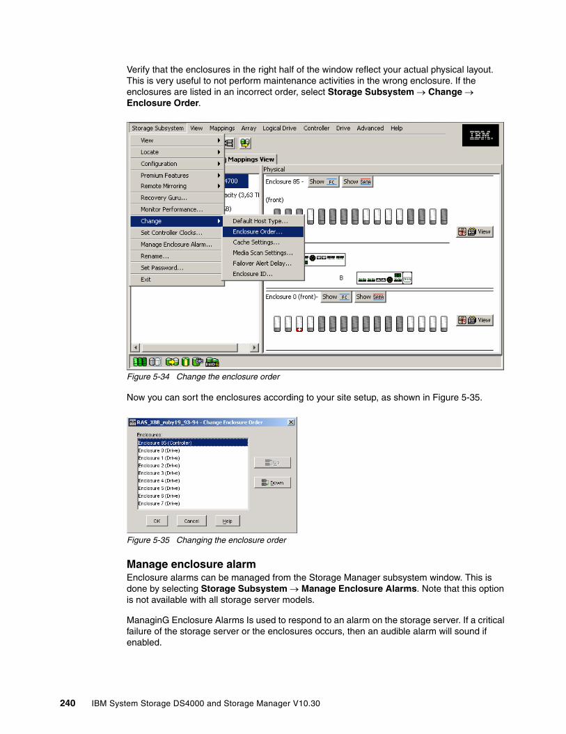
Verify that the enclosures in the right half of the window reflect your actual physical layout. This is very useful to not perform maintenance activities in the wrong enclosure. If the enclosures are listed in an incorrect order, select Storage Subsystem → Change → Enclosure Order.
Figure 5-34 Change the enclosure order
Now you can sort the enclosures according to your site setup, as shown in Figure 5-35.
Figure 5-35 Changing the enclosure order
Manage enclosure alarmEnclosure alarms can be managed from the Storage Manager subsystem window. This is done by selecting Storage Subsystem → Manage Enclosure Alarms. Note that this option is not available with all storage server models.
ManaginG Enclosure Alarms Is used to respond to an alarm on the storage server. If a critical failure of the storage server or the enclosures occurs, then an audible alarm will sound if enabled.
240 IBM System Storage DS4000 and Storage Manager V10.30

The audible alarm is just one of three ways in which Storage Manager will inform you of a fault. The other two are that the Alarm button becomes animated and the Recovery Guru button in the toolbar links.
By default, the alarm is enabled, but this can be changed by the Storage Manager client. This can be done on all enclosures or individual enclosures and controllers (Figure 5-36). The options are to sound an alarm always or to sound an alarm never.
Figure 5-36 Manage Enclosure Alarm
The managing enclosure alarms is also used to silence current alarms that are sounding.
5.2.4 Updating the controller microcodeUpdating the firmware (controller microcode) of your DS4000 Storage server may be required when installing a new version of the DS4000 Storage Manager software and to use all the latest DS4000 features. Check the IBM support Web site for newer versions to keep your DS4000 updated with the latest fixes and enhancements.
As described in Chapter 2, “What is new” on page 9, several enhancements are initially implemented in firmware 7.10. To accommodate those enhancements, the DACstore configuration region on the disk drives must be overwritten. Consequently, upgrading to firmware Version 7.10 or later changes the DACstore layout. To ensure an error-free upgrade process, there is a new firmware upgrade utility designed specifically to manage upgrades from Version 6.14 or later to firmware Version 7.xx. If your DS4000 uses an older version than 6.14, you must upgrade to 6.14 or later first. For more details see 12.1.5, “Updating controller firmware” on page 666.
The DS4000 components that can be updated are:
� Controller firmware� Non Volatile Static Random Access Memory (NVSRAM) in controller� Environmental Services Monitor (ESM) canister in expansion modules� Disk drives
Chapter 5. Step-by-step procedures using Storage Manager 241
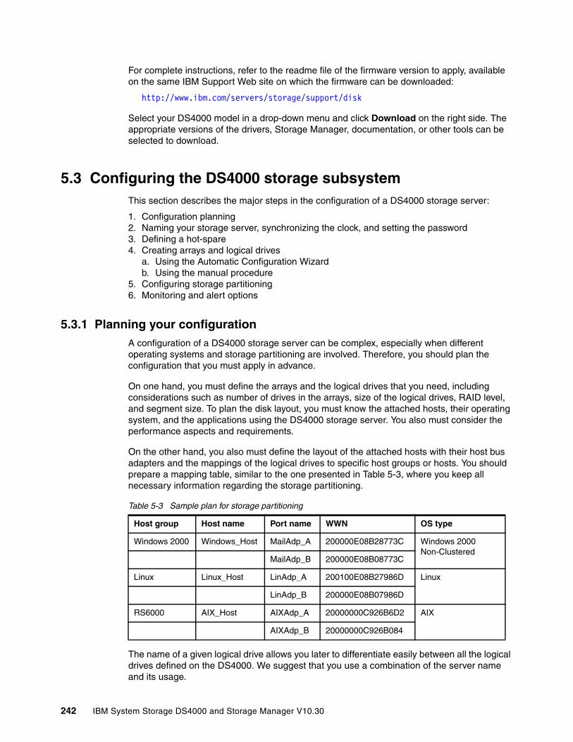
For complete instructions, refer to the readme file of the firmware version to apply, available on the same IBM Support Web site on which the firmware can be downloaded:
http://www.ibm.com/servers/storage/support/disk
Select your DS4000 model in a drop-down menu and click Download on the right side. The appropriate versions of the drivers, Storage Manager, documentation, or other tools can be selected to download.
5.3 Configuring the DS4000 storage subsystemThis section describes the major steps in the configuration of a DS4000 storage server:
1. Configuration planning2. Naming your storage server, synchronizing the clock, and setting the password3. Defining a hot-spare4. Creating arrays and logical drives
a. Using the Automatic Configuration Wizardb. Using the manual procedure
5. Configuring storage partitioning6. Monitoring and alert options
5.3.1 Planning your configurationA configuration of a DS4000 storage server can be complex, especially when different operating systems and storage partitioning are involved. Therefore, you should plan the configuration that you must apply in advance.
On one hand, you must define the arrays and the logical drives that you need, including considerations such as number of drives in the arrays, size of the logical drives, RAID level, and segment size. To plan the disk layout, you must know the attached hosts, their operating system, and the applications using the DS4000 storage server. You also must consider the performance aspects and requirements.
On the other hand, you also must define the layout of the attached hosts with their host bus adapters and the mappings of the logical drives to specific host groups or hosts. You should prepare a mapping table, similar to the one presented in Table 5-3, where you keep all necessary information regarding the storage partitioning.
Table 5-3 Sample plan for storage partitioning
The name of a given logical drive allows you later to differentiate easily between all the logical drives defined on the DS4000. We suggest that you use a combination of the server name and its usage.
Host group Host name Port name WWN OS type
Windows 2000 Windows_Host MailAdp_A 200000E08B28773C Windows 2000 Non-Clustered
MailAdp_B 200000E08B08773C
Linux Linux_Host LinAdp_A 200100E08B27986D Linux
LinAdp_B 200000E08B07986D
RS6000 AIX_Host AIXAdp_A 20000000C926B6D2 AIX
AIXAdp_B 20000000C926B084
242 IBM System Storage DS4000 and Storage Manager V10.30

5.3.2 Initial setupBefore defining any arrays or logical drives, you must perform some basic configuration steps. This also applies when you reset the configuration of your DS4000 storage server.
1. If you installed more than one DS4000 storage server, it is important to give it a literal name that let you precisely identify. To rename the DS4000 storage server, open the Subsystem Management window. Right-click the subsystem and click Storage Subsystem → Rename (Figure 5-37).
Figure 5-37 Renaming the DS4000 storage server
2. Enter a new name for the subsystem in the Rename Storage Subsystem dialog box (Figure 5-38).
Figure 5-38 Renaming the DS4000 storage server
Chapter 5. Step-by-step procedures using Storage Manager 243

3. Because the DS4000 storage server stores its own event log, synchronize the controller clocks with the time of all the host systems accessing it. This improves problem determination procedures. If you have not already set the clocks on the storage servers, set them now. Be sure that your local system is working using the correct time. Then click Storage Subsystem → Set Controller Clock (Figure 5-39).
Figure 5-39 Setting the controller clock
4. For security reasons, especially if the DS4000 storage server is directly attached to the network, you should set a password. This password is required for all actions on the DS4000 storage server that change or update the configuration in any way.
To set a password, highlight the storage system, right-click, and click Change → Password (Figure 5-40). This password is then stored on the DS4000 storage server. It is used if you connect through another SMclient, no matter whether you are using in-band or out-of-band management.
Figure 5-40 Setting password
Note: Setting an access password provides additional protection for DS4000 in a public LAN. However, you gain higher protection by connecting the DS4000 to a private network, reserved for administration.
244 IBM System Storage DS4000 and Storage Manager V10.30
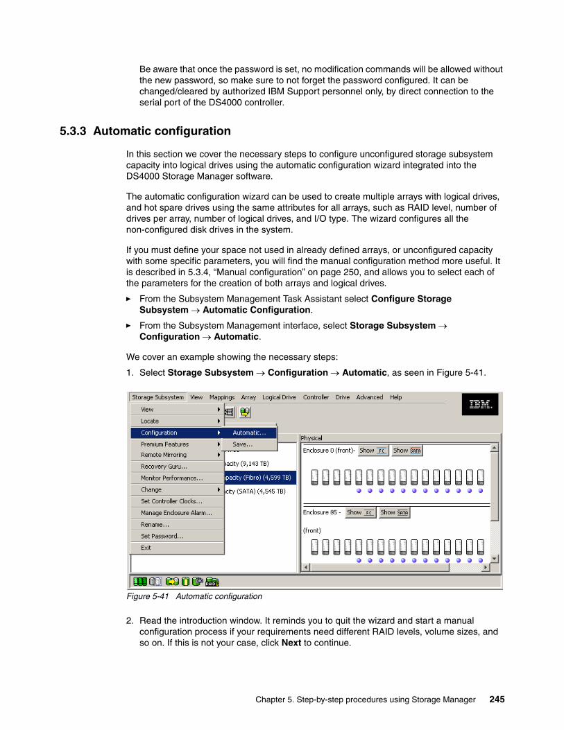
Be aware that once the password is set, no modification commands will be allowed without the new password, so make sure to not forget the password configured. It can be changed/cleared by authorized IBM Support personnel only, by direct connection to the serial port of the DS4000 controller.
5.3.3 Automatic configuration
In this section we cover the necessary steps to configure unconfigured storage subsystem capacity into logical drives using the automatic configuration wizard integrated into the DS4000 Storage Manager software.
The automatic configuration wizard can be used to create multiple arrays with logical drives, and hot spare drives using the same attributes for all arrays, such as RAID level, number of drives per array, number of logical drives, and I/O type. The wizard configures all the non-configured disk drives in the system.
If you must define your space not used in already defined arrays, or unconfigured capacity with some specific parameters, you will find the manual configuration method more useful. It is described in 5.3.4, “Manual configuration” on page 250, and allows you to select each of the parameters for the creation of both arrays and logical drives.
� From the Subsystem Management Task Assistant select Configure Storage Subsystem → Automatic Configuration.
� From the Subsystem Management interface, select Storage Subsystem → Configuration → Automatic.
We cover an example showing the necessary steps:
1. Select Storage Subsystem → Configuration → Automatic, as seen in Figure 5-41.
Figure 5-41 Automatic configuration
2. Read the introduction window. It reminds you to quit the wizard and start a manual configuration process if your requirements need different RAID levels, volume sizes, and so on. If this is not your case, click Next to continue.
Chapter 5. Step-by-step procedures using Storage Manager 245
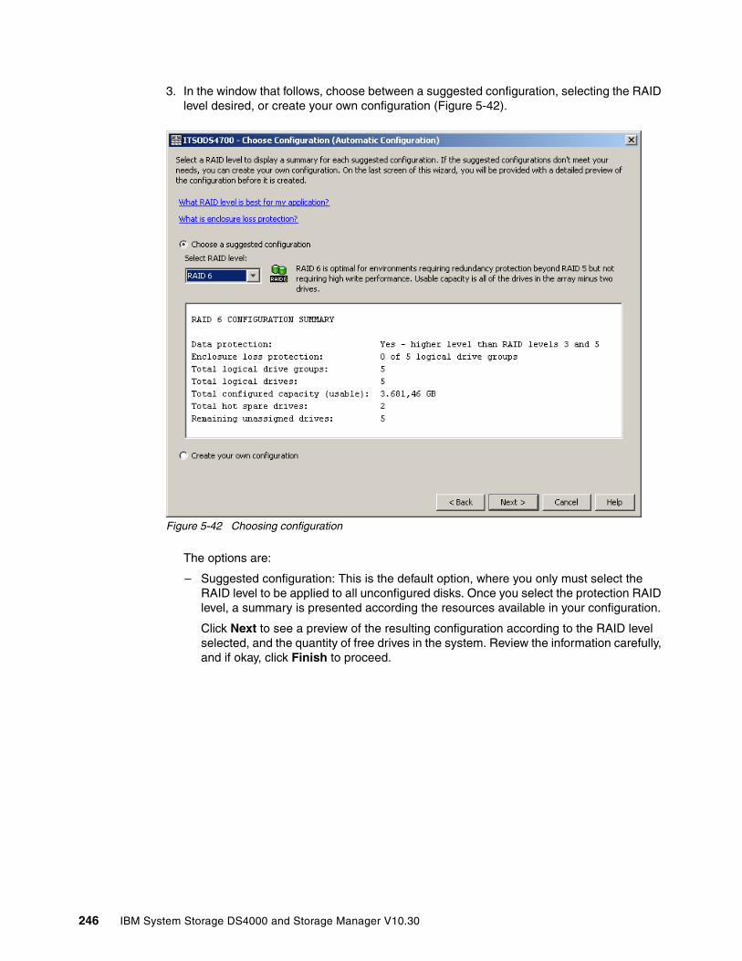
3. In the window that follows, choose between a suggested configuration, selecting the RAID level desired, or create your own configuration (Figure 5-42).
Figure 5-42 Choosing configuration
The options are:
– Suggested configuration: This is the default option, where you only must select the RAID level to be applied to all unconfigured disks. Once you select the protection RAID level, a summary is presented according the resources available in your configuration.
Click Next to see a preview of the resulting configuration according to the RAID level selected, and the quantity of free drives in the system. Review the information carefully, and if okay, click Finish to proceed.
246 IBM System Storage DS4000 and Storage Manager V10.30
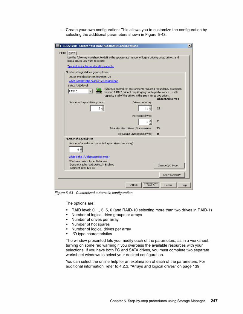
– Create your own configuration: This allows you to customize the configuration by selecting the additional parameters shown in Figure 5-43.
Figure 5-43 Customized automatic configuration
The options are:
• RAID level: 0, 1, 3, 5, 6 (and RAID-10 selecting more than two drives in RAID-1)• Number of logical drive groups or arrays• Number of drives per array• Number of hot spares• Number of logical drives per array• I/O type characteristics
The window presented lets you modify each of the parameters, as in a worksheet, turning on some red warning if you overpass the available resources with your selections. If you have both FC and SATA drives, you must complete two separate worksheet windows to select your desired configuration.
You can select the online help for an explanation of each of the parameters. For additional information, refer to 4.2.3, “Arrays and logical drives” on page 139.
Chapter 5. Step-by-step procedures using Storage Manager 247

Click Change I/O type if you want to set up your logical drives for other type of access (different from the defaults preset for regular file systems, as seen in Figure 5-44).
Figure 5-44 Changing I/O characteristics
For additional information about the above values, refer to 4.2.4, “Segment size” on page 148.
248 IBM System Storage DS4000 and Storage Manager V10.30

Once you have specified all of your desired values, click Next (Figure 5-43 on page 247) to bring up the window shown in Figure 5-45.
Figure 5-45 Preview automatic configuration
4. Review the configuration that will be created based on your input and click Finish to proceed. You see a confirmation message informing that, depending on the number of drives and volumes, it might take time for all the changes to appear in the Management window. Do not submit another request until this configuration is complete. You can check the event log to see whether the operation was successful.
Chapter 5. Step-by-step procedures using Storage Manager 249
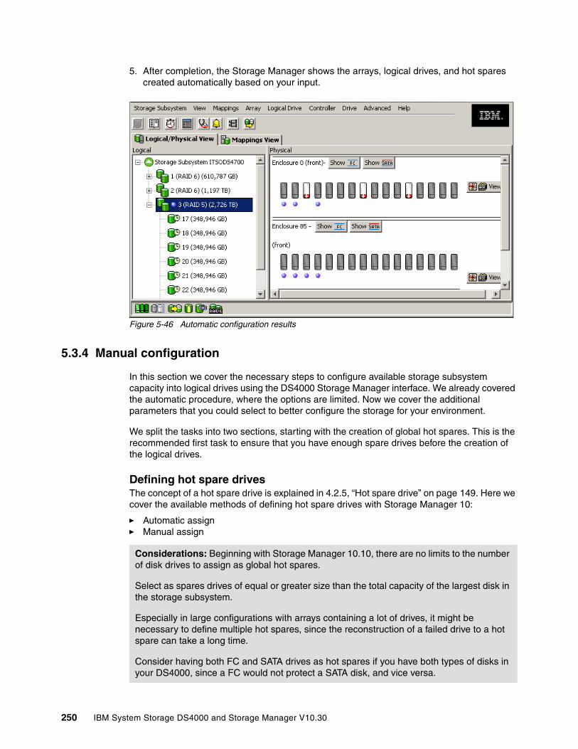
5. After completion, the Storage Manager shows the arrays, logical drives, and hot spares created automatically based on your input.
Figure 5-46 Automatic configuration results
5.3.4 Manual configuration
In this section we cover the necessary steps to configure available storage subsystem capacity into logical drives using the DS4000 Storage Manager interface. We already covered the automatic procedure, where the options are limited. Now we cover the additional parameters that you could select to better configure the storage for your environment.
We split the tasks into two sections, starting with the creation of global hot spares. This is the recommended first task to ensure that you have enough spare drives before the creation of the logical drives.
Defining hot spare drivesThe concept of a hot spare drive is explained in 4.2.5, “Hot spare drive” on page 149. Here we cover the available methods of defining hot spare drives with Storage Manager 10:
� Automatic assign� Manual assign
Considerations: Beginning with Storage Manager 10.10, there are no limits to the number of disk drives to assign as global hot spares.
Select as spares drives of equal or greater size than the total capacity of the largest disk in the storage subsystem.
Especially in large configurations with arrays containing a lot of drives, it might be necessary to define multiple hot spares, since the reconstruction of a failed drive to a hot spare can take a long time.
Consider having both FC and SATA drives as hot spares if you have both types of disks in your DS4000, since a FC would not protect a SATA disk, and vice versa.
250 IBM System Storage DS4000 and Storage Manager V10.30
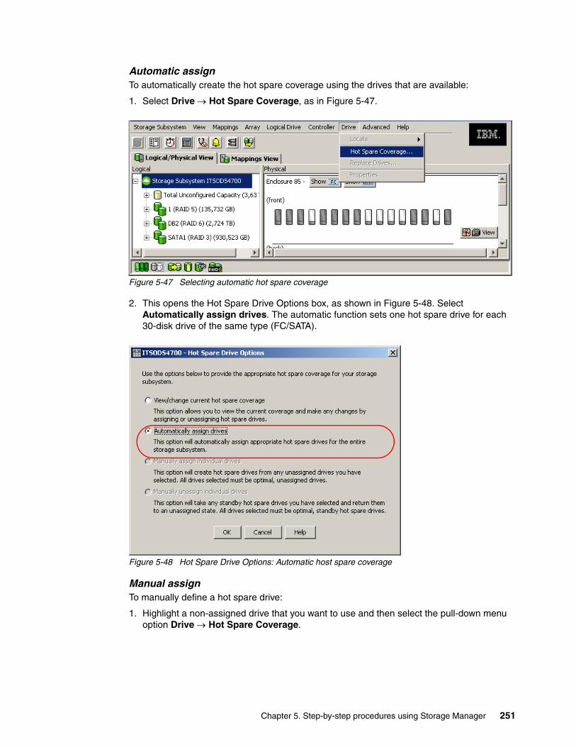
Automatic assignTo automatically create the hot spare coverage using the drives that are available:
1. Select Drive → Hot Spare Coverage, as in Figure 5-47.
Figure 5-47 Selecting automatic hot spare coverage
2. This opens the Hot Spare Drive Options box, as shown in Figure 5-48. Select Automatically assign drives. The automatic function sets one hot spare drive for each 30-disk drive of the same type (FC/SATA).
Figure 5-48 Hot Spare Drive Options: Automatic host spare coverage
Manual assignTo manually define a hot spare drive:
1. Highlight a non-assigned drive that you want to use and then select the pull-down menu option Drive → Hot Spare Coverage.
Chapter 5. Step-by-step procedures using Storage Manager 251
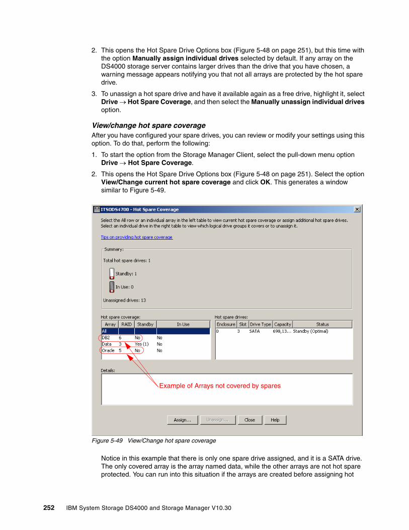
2. This opens the Hot Spare Drive Options box (Figure 5-48 on page 251), but this time with the option Manually assign individual drives selected by default. If any array on the DS4000 storage server contains larger drives than the drive that you have chosen, a warning message appears notifying you that not all arrays are protected by the hot spare drive.
3. To unassign a hot spare drive and have it available again as a free drive, highlight it, select Drive → Hot Spare Coverage, and then select the Manually unassign individual drives option.
View/change hot spare coverageAfter you have configured your spare drives, you can review or modify your settings using this option. To do that, perform the following:
1. To start the option from the Storage Manager Client, select the pull-down menu option Drive → Hot Spare Coverage.
2. This opens the Hot Spare Drive Options box (Figure 5-48 on page 251). Select the option View/Change current hot spare coverage and click OK. This generates a window similar to Figure 5-49.
Figure 5-49 View/Change hot spare coverage
Notice in this example that there is only one spare drive assigned, and it is a SATA drive. The only covered array is the array named data, while the other arrays are not hot spare protected. You can run into this situation if the arrays are created before assigning hot
Example of Arrays not covered by spares
252 IBM System Storage DS4000 and Storage Manager V10.30
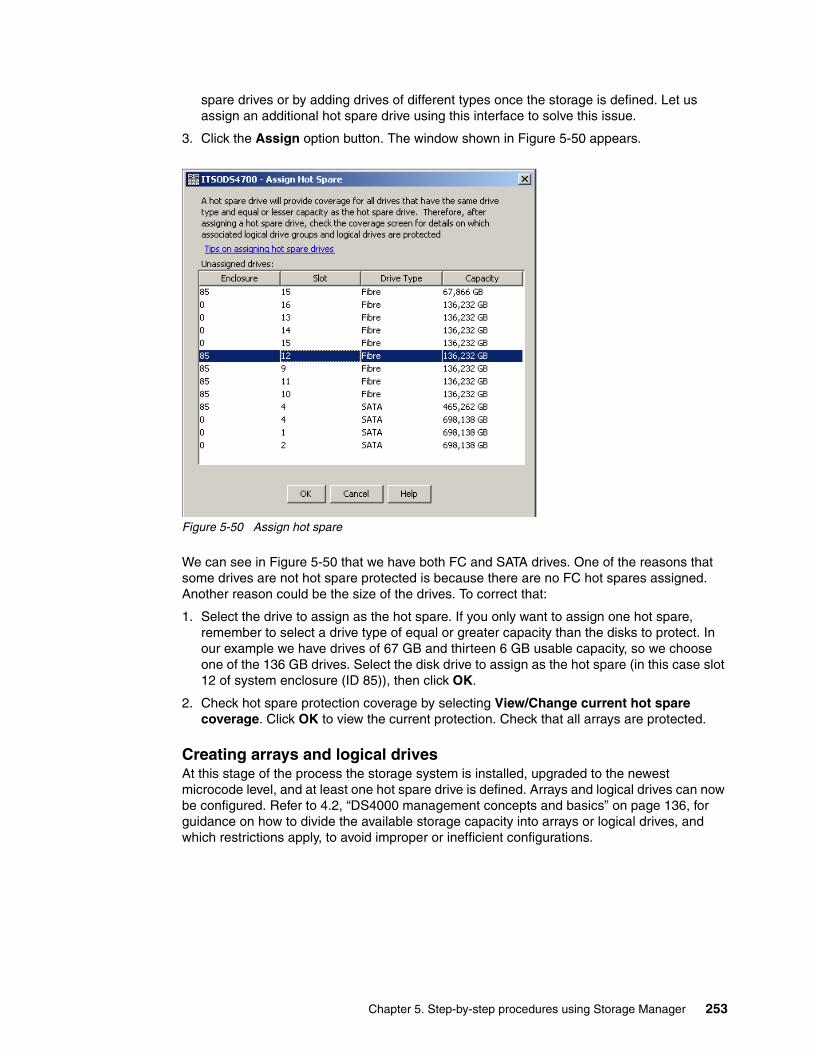
spare drives or by adding drives of different types once the storage is defined. Let us assign an additional hot spare drive using this interface to solve this issue.
3. Click the Assign option button. The window shown in Figure 5-50 appears.
Figure 5-50 Assign hot spare
We can see in Figure 5-50 that we have both FC and SATA drives. One of the reasons that some drives are not hot spare protected is because there are no FC hot spares assigned. Another reason could be the size of the drives. To correct that:
1. Select the drive to assign as the hot spare. If you only want to assign one hot spare, remember to select a drive type of equal or greater capacity than the disks to protect. In our example we have drives of 67 GB and thirteen 6 GB usable capacity, so we choose one of the 136 GB drives. Select the disk drive to assign as the hot spare (in this case slot 12 of system enclosure (ID 85)), then click OK.
2. Check hot spare protection coverage by selecting View/Change current hot spare coverage. Click OK to view the current protection. Check that all arrays are protected.
Creating arrays and logical drivesAt this stage of the process the storage system is installed, upgraded to the newest microcode level, and at least one hot spare drive is defined. Arrays and logical drives can now be configured. Refer to 4.2, “DS4000 management concepts and basics” on page 136, for guidance on how to divide the available storage capacity into arrays or logical drives, and which restrictions apply, to avoid improper or inefficient configurations.
Chapter 5. Step-by-step procedures using Storage Manager 253
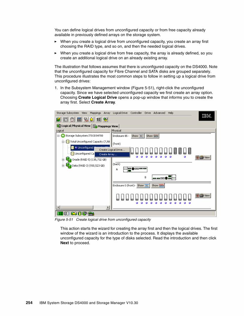
You can define logical drives from unconfigured capacity or from free capacity already available in previously defined arrays on the storage system.
� When you create a logical drive from unconfigured capacity, you create an array first choosing the RAID type, and so on, and then the needed logical drives.
� When you create a logical drive from free capacity, the array is already defined, so you create an additional logical drive on an already existing array.
The illustration that follows assumes that there is unconfigured capacity on the DS4000. Note that the unconfigured capacity for Fibre Channel and SATA disks are grouped separately. This procedure illustrates the most common steps to follow in setting up a logical drive from unconfigured drives:
1. In the Subsystem Management window (Figure 5-51), right-click the unconfigured capacity. Since we have selected unconfigured capacity we first create an array option. Choosing Create Logical Drive opens a pop-up window that informs you to create the array first. Select Create Array.
Figure 5-51 Create logical drive from unconfigured capacity
This action starts the wizard for creating the array first and then the logical drives. The first window of the wizard is an introduction to the process. It displays the available unconfigured capacity for the type of disks selected. Read the introduction and then click Next to proceed.
254 IBM System Storage DS4000 and Storage Manager V10.30

2. In the Create array window presented, type a meaningful array name that describes your set of disks, and then select either automatic mode or manual mode. Automatic mode is the default option. By selecting the automatic option, the Storage Manager software selects a combination of available drives to optimize performance and availability, attempting to select physical drives from different enclosures in order to provide enclosure protection whenever possible. Click Next.
Figure 5-52 Create array-assign name and mode
The automatic creation of the array selects the drives considering the following order:
– Same capacity-same speed-enclosure redundancy– Same capacity-mixed speed-enclosure redundancy– Same capacity-mixed speed-no enclosure redundancy– Mixed capacity-same or mixed speed-no enclosure redundancy
Creating the array using the manual option presents a window different from that shown in Figure 5-52. In manual mode, you must select all the drives individually. Make sure that you select them with consideration to maximize performance and availability.
3. Click Next to be presented with the option to select the RAID level.
a. Select the desired RAID level. The window now displays the different capacity options depending on the unconfigured drives available in your configuration. If you have different disk sizes, you have more than one option for the same number of disks. See the discussion in 4.2.3, “Arrays and logical drives” on page 139, to determine the best RAID level for your specific environment and application.
b. Select the total capacity required and click Finish.
Note: Starting with controller firmware 7.10 and Storage Manager 10.10, new possibilities are available for arrays:
� RAID level 6 is available for DS4200 and DS4700.
� More than 30 drives per array are now supported for RAID-0 and RAID-10. The maximum number of drives for DS4800 is 224, and 112 for DS4700 or DS4200.
� The possible RAID level options supported by the DS4000 are 0, 1, 3, 5, and 6 (and RAID-10 if selecting RAID-1 with more than two drives).
Chapter 5. Step-by-step procedures using Storage Manager 255

In our example (Figure 5-57 on page 261) we create a RAID-6 array with 12 drives.
Figure 5-53 RAID Level and Capacity
4. The Array Success dialog appears as a confirmation that the array is now created. Click YES to continue with the creation of a logical drive.
5. Right-click the selected free capacity icon and select Create Logical Drive. In a wizard window click Next to start configuring the logical drive.
6. In the Specify Capacity/Name dialog window:
a. If you want to define more than one logical drive in the array, enter the desired size capacity below the limit of the array capacity.
b. Assign a name to the logical drive.
Note: Beginning with controller firmware 7.10 and Storage Manager 10.10, logical drives larger than 2 TB are allowed.
256 IBM System Storage DS4000 and Storage Manager V10.30
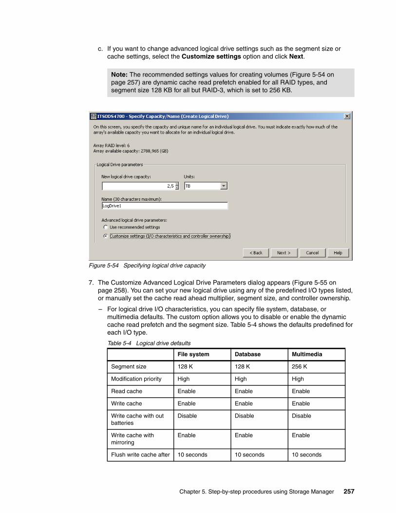
c. If you want to change advanced logical drive settings such as the segment size or cache settings, select the Customize settings option and click Next.
Figure 5-54 Specifying logical drive capacity
7. The Customize Advanced Logical Drive Parameters dialog appears (Figure 5-55 on page 258). You can set your new logical drive using any of the predefined I/O types listed, or manually set the cache read ahead multiplier, segment size, and controller ownership.
– For logical drive I/O characteristics, you can specify file system, database, or multimedia defaults. The custom option allows you to disable or enable the dynamic cache read prefetch and the segment size. Table 5-4 shows the defaults predefined for each I/O type.
Table 5-4 Logical drive defaults
Note: The recommended settings values for creating volumes (Figure 5-54 on page 257) are dynamic cache read prefetch enabled for all RAID types, and segment size 128 KB for all but RAID-3, which is set to 256 KB.
File system Database Multimedia
Segment size 128 K 128 K 256 K
Modification priority High High High
Read cache Enable Enable Enable
Write cache Enable Enable Enable
Write cache with out batteries
Disable Disable Disable
Write cache with mirroring
Enable Enable Enable
Flush write cache after 10 seconds 10 seconds 10 seconds
Chapter 5. Step-by-step procedures using Storage Manager 257
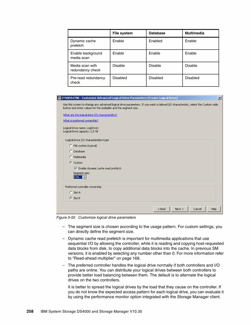
Figure 5-55 Customize logical drive parameters
– The segment size is chosen according to the usage pattern. For custom settings, you can directly define the segment size.
– Dynamic cache read prefetch is important for multimedia applications that use sequential I/O by allowing the controller, while it is reading and copying host-requested data blocks from disk, to copy additional data blocks into the cache. In previous SM versions, it is enabled by selecting any number other than 0. For more information refer to “Read-ahead multiplier” on page 168.
– The preferred controller handles the logical drive normally if both controllers and I/O paths are online. You can distribute your logical drives between both controllers to provide better load balancing between them. The default is to alternate the logical drives on the two controllers.
It is better to spread the logical drives by the load that they cause on the controller. If you do not know the expected access pattern for each logical drive, you can evaluate it by using the performance monitor option integrated with the Storage Manager client.
Dynamic cache prefetch
Enable Enabled Enable
Enable background media scan
Enable Enable Enable
Media scan with redundancy check
Disable Disable Disable
Pre-read redundancy check
Disabled Disabled Disabled
File system Database Multimedia
258 IBM System Storage DS4000 and Storage Manager V10.30
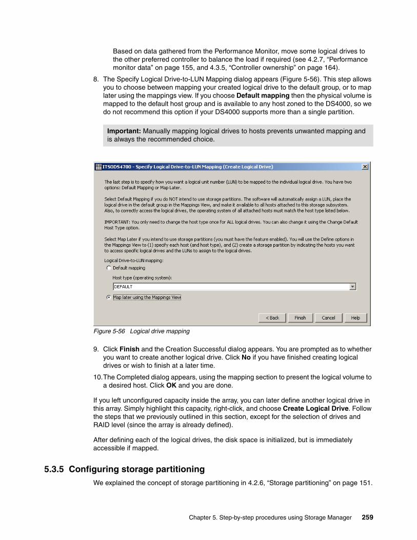
Based on data gathered from the Performance Monitor, move some logical drives to the other preferred controller to balance the load if required (see 4.2.7, “Performance monitor data” on page 155, and 4.3.5, “Controller ownership” on page 164).
8. The Specify Logical Drive-to-LUN Mapping dialog appears (Figure 5-56). This step allows you to choose between mapping your created logical drive to the default group, or to map later using the mappings view. If you choose Default mapping then the physical volume is mapped to the default host group and is available to any host zoned to the DS4000, so we do not recommend this option if your DS4000 supports more than a single partition.
Figure 5-56 Logical drive mapping
9. Click Finish and the Creation Successful dialog appears. You are prompted as to whether you want to create another logical drive. Click No if you have finished creating logical drives or wish to finish at a later time.
10.The Completed dialog appears, using the mapping section to present the logical volume to a desired host. Click OK and you are done.
If you left unconfigured capacity inside the array, you can later define another logical drive in this array. Simply highlight this capacity, right-click, and choose Create Logical Drive. Follow the steps that we previously outlined in this section, except for the selection of drives and RAID level (since the array is already defined).
After defining each of the logical drives, the disk space is initialized, but is immediately accessible if mapped.
5.3.5 Configuring storage partitioningWe explained the concept of storage partitioning in 4.2.6, “Storage partitioning” on page 151.
Important: Manually mapping logical drives to hosts prevents unwanted mapping and is always the recommended choice.
Chapter 5. Step-by-step procedures using Storage Manager 259

Since heterogeneous hosts can be attached to the DS4000 storage server, you must configure storage partitioning for two reasons:
� Each host operating system requires slightly different settings on the DS4000 storage server. You must tell the storage system the host type that it is attached to.
� There is interference between the hosts if every host has access to every logical drive. By using storage partitioning and LUN masking, you ensure that each host or host group only has access to its assigned logical drives. You can have up to 256 LUNs assigned to a single storage partition. You might have a maximum of 2048 LUNs configured per DS4000 depending on the model.
Depending on your DS4000 model and premium features enabled, you may have the option to configure partitions. If your DS4000 does not allow creating partitions, you should proceed by mapping all your logical drives to the default host group.
The overall process of defining the storage partitions is as follows:
1. Define host groups. 2. Define hosts. 3. Define host ports for each host. 4. Define storage partitions by assigning logical drives to the hosts or host groups.
The Subsystem Managment Task Assistant has wizards that can assist you with setting up the storage partitioning:
� Define the host wizard. � Create the new storage partitions wizard.
Note: Controller firmware 7.10 and later increases the maximum number of partitions allowed from 64 to 512 for the DS4800. See Chapter 4, “Managing the DS4000” on page 115, for additional information about the maximum supported for your specific DS4000 model and feature.
260 IBM System Storage DS4000 and Storage Manager V10.30
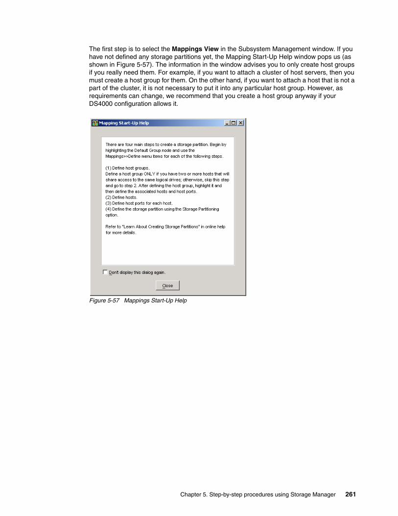
The first step is to select the Mappings View in the Subsystem Management window. If you have not defined any storage partitions yet, the Mapping Start-Up Help window pops us (as shown in Figure 5-57). The information in the window advises you to only create host groups if you really need them. For example, if you want to attach a cluster of host servers, then you must create a host group for them. On the other hand, if you want to attach a host that is not a part of the cluster, it is not necessary to put it into any particular host group. However, as requirements can change, we recommend that you create a host group anyway if your DS4000 configuration allows it.
Figure 5-57 Mappings Start-Up Help
Chapter 5. Step-by-step procedures using Storage Manager 261
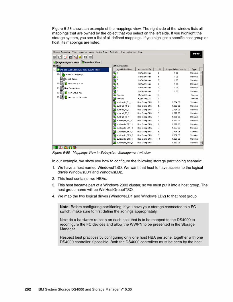
Figure 5-58 shows an example of the mappings view. The right side of the window lists all mappings that are owned by the object that you select on the left side. If you highlight the storage system, you see a list of all defined mappings. If you highlight a specific host group or host, its mappings are listed.
Figure 5-58 Mappings View in Subsystem Management window
In our example, we show you how to configure the following storage partitioning scenario:
1. We have a host named WindowsITSO. We want that host to have access to the logical drives WindowsLD1 and WindowsLD2.
2. This host contains two HBAs.
3. This host became part of a Windows 2003 cluster, so we must put it into a host group. The host group name will be WinHostGroupITSO.
4. We map the two logical drives (WindowsLD1 and Windows LD2) to that host group.
Note: Before configuring partitioning, if you have your storage connected to a FC switch, make sure to first define the zonings appropriately.
Next do a hardware re-scan on each host that is to be mapped to the DS4000 to reconfigure the FC devices and allow the WWPN to be presented in the Storage Manager.
Respect best practices by configuring only one host HBA per zone, together with one DS4000 controller if possible. Both the DS4000 controllers must be seen by the host.
262 IBM System Storage DS4000 and Storage Manager V10.30
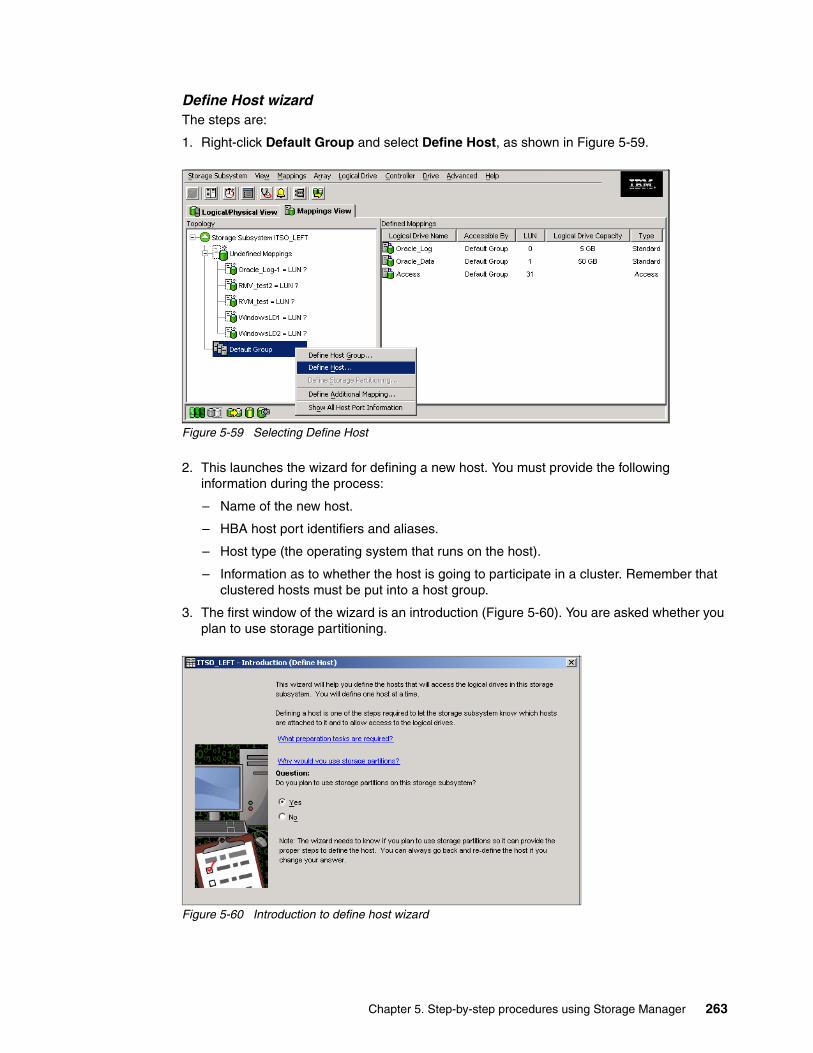
Define Host wizard The steps are:
1. Right-click Default Group and select Define Host, as shown in Figure 5-59.
Figure 5-59 Selecting Define Host
2. This launches the wizard for defining a new host. You must provide the following information during the process:
– Name of the new host.
– HBA host port identifiers and aliases.
– Host type (the operating system that runs on the host).
– Information as to whether the host is going to participate in a cluster. Remember that clustered hosts must be put into a host group.
3. The first window of the wizard is an introduction (Figure 5-60). You are asked whether you plan to use storage partitioning.
Figure 5-60 Introduction to define host wizard
Chapter 5. Step-by-step procedures using Storage Manager 263

4. If you only plan to attach a single host server, then you do not need storage partitioning. But the customers usually attach many hosts to their storage servers, so the usual reply is Yes.
5. The next window allows you to specify the host name and the HBA host port information (host port identifier and alias). Remember that the HBA host port identifier is the world-wide port name of the particular HBA. Figure 5-61 shows our example. Our host name is WindowsITSO and we have defined two HBA host ports. If you must enter a host port name that is not currently active, type the world-wide port name directly in the field.
Figure 5-61 Define host: Specifying the host name and HBA attributes
Click Edit to assign a name to each WWN address added and click Next.
6. The next window requires you to specify the host type. This is basically the operating system running on the host. It is vital that you select the appropriate host type because the RDAC and ADT settings rely on this. In addition, this is the part of the configuration where you configure the heterogeneous host support. Each operating system expects slightly different settings and handles SCSI commands differently. If you make a wrong choice, your operating system might not boot anymore or path failover cannot be used.
264 IBM System Storage DS4000 and Storage Manager V10.30
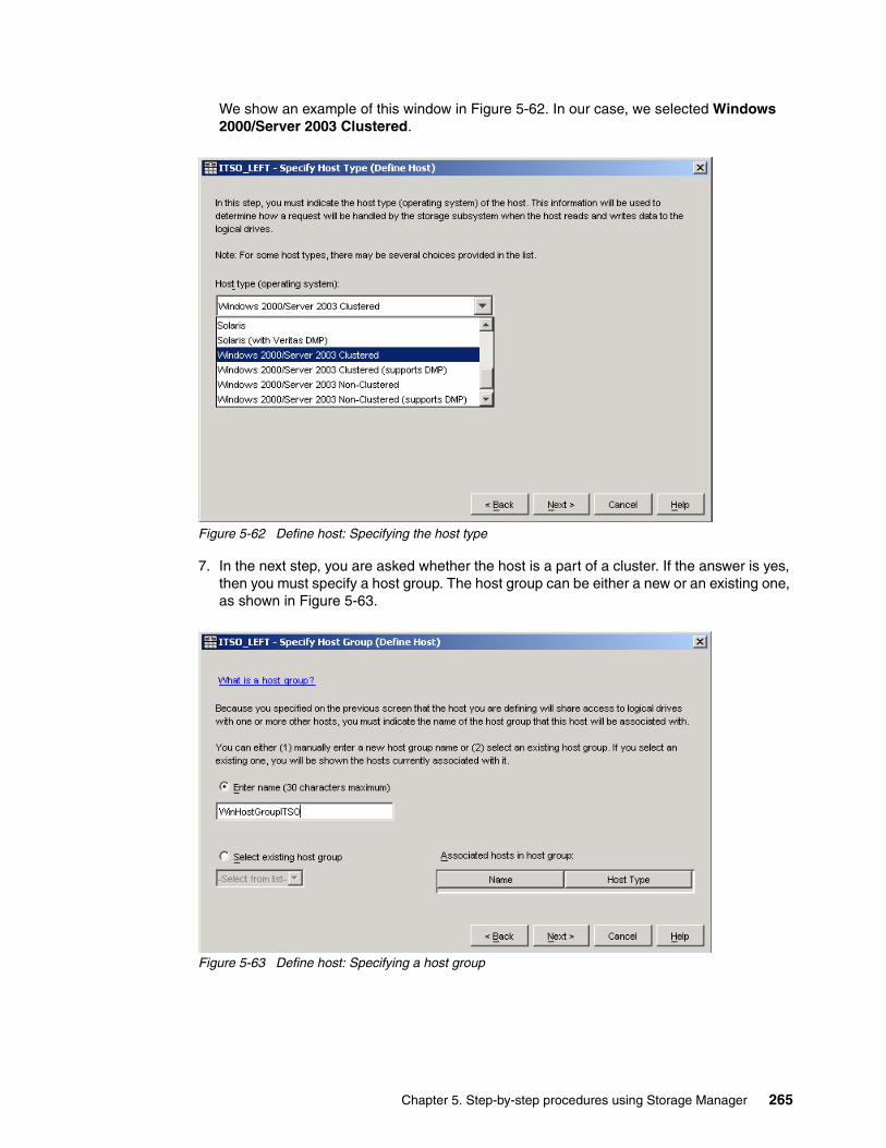
We show an example of this window in Figure 5-62. In our case, we selected Windows 2000/Server 2003 Clustered.
Figure 5-62 Define host: Specifying the host type
7. In the next step, you are asked whether the host is a part of a cluster. If the answer is yes, then you must specify a host group. The host group can be either a new or an existing one, as shown in Figure 5-63.
Figure 5-63 Define host: Specifying a host group
Chapter 5. Step-by-step procedures using Storage Manager 265

8. Finally, you have the chance to preview the new host definition (Figure 5-64). If all the selections are correct, click Finish to define the new host.
Figure 5-64 Define Host: Preview
9. The new host (and the host group, if it was also defined) is placed in the default group. It will stay there until you actually create a storage partition by assigning the logical drives to that host (or group). Figure 5-65 shows an example.
Figure 5-65 New host and host group, placed in the default group
266 IBM System Storage DS4000 and Storage Manager V10.30

Figure 5-66 Host properties in SMclient 10
Storage partitioning wizard Next we use the storage partitioning wizard:
1. We start by to creating a storage partition by assigning the logical drives to the hosts or host groups. The storage partitioning wizard leads you through the process, and you initiate it by right-clicking Default Group and selecting Define Storage Partitioning. We show an example in Figure 5-67.
Figure 5-67 Define storage partitioning
2. After the introduction, the wizard asks you to select either a host or a group of hosts. If you are creating a storage partition for clustered host servers, specify the appropriate group. Otherwise, you can select an individual host.
Note: The Storage Manager 10 does not show each host HBA port in the Mappings view. You can see HBAs in the Properties window of the selected host (Figure 5-66).
Chapter 5. Step-by-step procedures using Storage Manager 267

3. The next window allows you to select the logical drives that are going to be mapped to the host or the group. You also must specify a LUN for each logical drive. In our example, shown in Figure 5-68, we selected WindowsLD1 and WindowsLD2. We assigned the LUNs 0 and 1, respectively, to these two logical drives.
Figure 5-68 Storage Partitioning wizard: Selecting logical drives/LUNs
4. Click Finish when you are done with selecting the logical drives and assigning the LUNs. This completes the process. Figure 5-69 shows an example of our newly created storage partition in the mappings view.
Figure 5-69 A new storage partition in Mappings View
Now you can use the Windows Disk Administrator utility to scan for new storage, create and format partitions, and begin using the new disk space.
268 IBM System Storage DS4000 and Storage Manager V10.30

Define host group optionBecause the host groups can be created with the define host wizard, there is usually no need to define the groups from outside the wizard. But you still have the option to do so:
1. Right-click Default Group and select Define Host Group (as shown in Figure 5-70 on page 269).
Figure 5-70 Define Host Group
2. The Define Host Group window (Figure 5-71) opens. Enter the name of the host group that you wish to add. If you must define more host groups, click Add. When you are finished, click Close to exit the dialog.
Figure 5-71 Define Host Group name
3. If you accidentally assigned a host to the wrong host group, you can move the host to another group. Simply right-click the host and select Move. A pop-up window opens and asks you to specify the host group name.
4. Because the storage partitioning of the DS4000 storage server is based on the world-wide port names of the host ports, the definitions for the host groups and the hosts only represent a view of the physical and logical setup of your fabric. When this structure is available, it is much easier to identify which host ports are allowed to see the same logical drives and which are in different storage partitions.
Chapter 5. Step-by-step procedures using Storage Manager 269

Define additional mapping optionSuppose that a particular host (or a host group) is already a part of a certain storage partition. This means that the logical drives are already mapped to that host or group. If you must map additional logical drives to the same host or group, use the define additional mapping option:
1. Right-click the host or group to which you want to map a new logical drive. Select Define Additional Mapping, as you can see in Figure 5-72.
Figure 5-72 Define Additional Mapping
2. In the Define Additional Mapping window, select the logical drive that you want to map to this host group or host and assign the correct LUN number (Figure 5-73).
Figure 5-73 Define Additional Mapping
270 IBM System Storage DS4000 and Storage Manager V10.30

3. To make the logical drives available to the host systems without rebooting, the DS4000 Storage Manager Utilities package provides the hot_add command-line tool (for some operating systems). You simply run hot_add and all host bus adapters are re-scanned for new devices and the devices are assigned within the operating system.
– You might have to take appropriate steps to enable the use of the storage inside the operating system, such as formatting the disks with a file system and mounting them.
– If you attached a Linux system to the DS4000 storage server, you must remove the mapping of the access logical drive. Highlight the host or host group containing the Linux system in the Mappings View. In the right part of the window, you see the list of all logical drives mapped to this host or host group. To remove the mapping of the access logical drive, right-click it and choose Remove Mapping. The mapping of the access logical drive is removed immediately.
Note that so far we updated the storage system to the latest level, configured logical drives, and set up storage partitioning. The next step is to define the alerting methods in case of failure.
5.3.6 Monitoring and alerting
Included in the Storage Manager Client package is the Event Monitor program. It enables the host running this monitor to send out alerts via e-mail (SMTP) or traps (SNMP) of any of the DS4000 storage servers in your environment.
Earlier versions of Storage Manager including the Event Monitor and the Enterprise Management window had to remain open to monitor the storage subsystems and receive alerts. Now you will receive an alert either form the SMclient if it is opened or from the Event Monitor program.
For continuous monitoring, install the Event Monitor on a host computer that runs 24 hours a day. If you choose not to install the Event Monitor, you should still configure alerts on the host computer where the client software is installed, but will only work while the SMclient is opened. The server were installed should be capable of out-of-band and in-band management. This ensures proper alerting, even if one server is down or a connection type has failed.
The Enterprise Storage Managment Task Assitant will also let you configure alerts with the following options:
� All storage subsystems in the management domain� An individual storage subsystem� All storage subsystems managed through an specific host
Note: If you change an existing mapping of a logical drive, the change is effective immediately. Therefore, make sure that this logical drive is not in use or even assigned by any of the machines attached to the storage system.
Important: The DS4000 does not send the e-mail or SNMP trap itself. The management station running the event monitor service sends the e-mail or SNMP trap on behalf of the DS4000. If the managment station is down, or if the event monitor process is not running, no notifications will be sent.
Chapter 5. Step-by-step procedures using Storage Manager 271
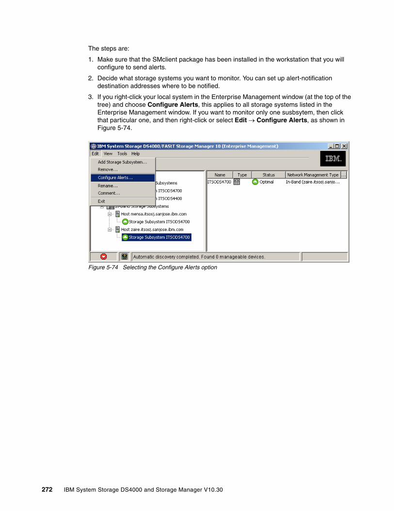
The steps are:
1. Make sure that the SMclient package has been installed in the workstation that you will configure to send alerts.
2. Decide what storage systems you want to monitor. You can set up alert-notification destination addresses where to be notified.
3. If you right-click your local system in the Enterprise Management window (at the top of the tree) and choose Configure Alerts, this applies to all storage systems listed in the Enterprise Management window. If you want to monitor only one susbsytem, then click that particular one, and then right-click or select Edit → Configure Alerts, as shown in Figure 5-74.
Figure 5-74 Selecting the Configure Alerts option
272 IBM System Storage DS4000 and Storage Manager V10.30

4. If you want to send e-mail alerts, you must define an SMTP server first. Enter the mail SMTP server name or IP address of your mail server and the sender e-mail address, usually the administrator address, which will show as originated of the message. We show this in Figure 5-75.
Figure 5-75 Configure Alerts: Defining the SMTP server
5. Select the Email tab. This window allows you to configure the e-mail addresses to which the alerts are sent. Type the e-mail address and press Add to append it to the list of notifications.
Chapter 5. Step-by-step procedures using Storage Manager 273

6. The default notification sends only the event when it occurs.
Note that you can also modify the Information to Send field to forward as well profile data, or support data, whenever an event occurs or at regular intervals. Make use of this new feature whenever possible, as illustrated in Figure 5-76.
Figure 5-76 E-mail notification setup
Be aware that sending the support data at regular frequencies might impact the destination e-mail address box mail.
7. When you have finished adding E-mail addresses to notify, test your SMTP and e-mail addresses specified by clicking the Test button.
8. If you have Network Managment Station (NMS) in your network collecting traps, select the SNMP tab to define the settings for SNMP alert. Type the IP address of your SNMP console and the community name. As with the e-mail addresses, you can define several trap destinations.
In order for NMS to decode the traps received, there is a MIB file included in the DS4000 Storage Manager software package, which should be compiled into the NMS console to allow proper display of the traps. See the Storage Manager installation guide for your operating system for details.
Note: Besides the e-mail notification with error capture attached, there is also another option to collect diagnostic data when an error is detected, by enabling automatic collect of support data. See 6.1.4, “Support data: Collecting information” on page 302.
274 IBM System Storage DS4000 and Storage Manager V10.30

After configuring the storage subsystem for alerts, check the results in the Enterprise Management window, as shown in Figure 5-77.
Figure 5-77 Alerts configured for one specific DS4000
Check for the mark beside each representation of the DS4700 configured for alerts.
– Since we configure only the DS4700, other managed storage subsystems will not be monitored by this service in our example.
– Event Monitor will send only one alert per event, even if monitored through different hosts or out-of-band. However, if you configure the Event Monitor in more than one management station, you will receive duplicate messages.
See also 6.6, “Remote Support Manager for Storage” on page 368, if you want IBM to receive these notifications.
Alerts Configured Mark
Chapter 5. Step-by-step procedures using Storage Manager 275
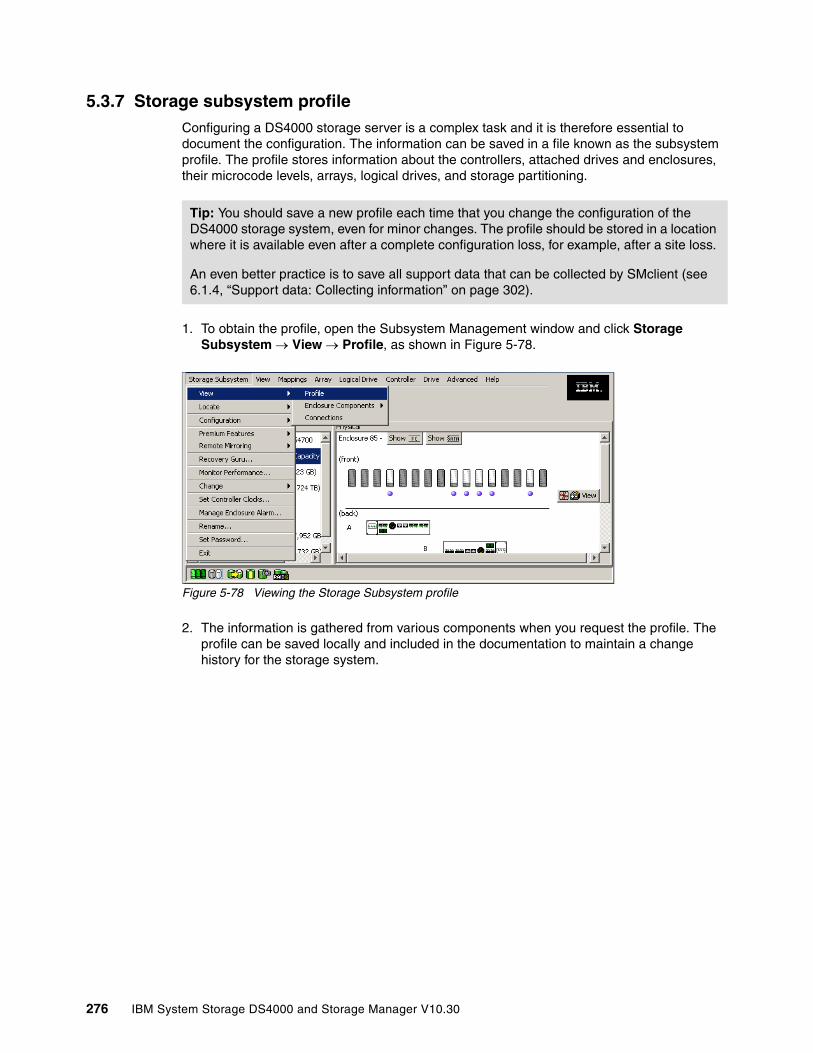
5.3.7 Storage subsystem profile Configuring a DS4000 storage server is a complex task and it is therefore essential to document the configuration. The information can be saved in a file known as the subsystem profile. The profile stores information about the controllers, attached drives and enclosures, their microcode levels, arrays, logical drives, and storage partitioning.
1. To obtain the profile, open the Subsystem Management window and click Storage Subsystem → View → Profile, as shown in Figure 5-78.
Figure 5-78 Viewing the Storage Subsystem profile
2. The information is gathered from various components when you request the profile. The profile can be saved locally and included in the documentation to maintain a change history for the storage system.
Tip: You should save a new profile each time that you change the configuration of the DS4000 storage system, even for minor changes. The profile should be stored in a location where it is available even after a complete configuration loss, for example, after a site loss.
An even better practice is to save all support data that can be collected by SMclient (see 6.1.4, “Support data: Collecting information” on page 302).
276 IBM System Storage DS4000 and Storage Manager V10.30
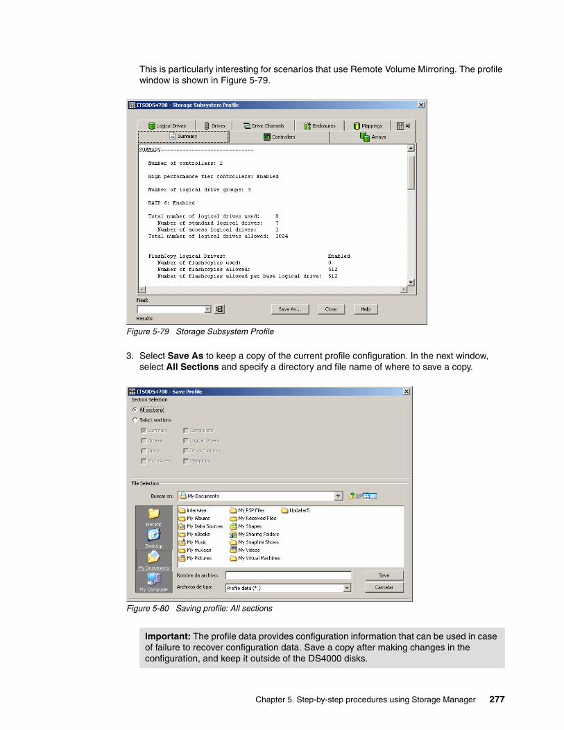
This is particularly interesting for scenarios that use Remote Volume Mirroring. The profile window is shown in Figure 5-79.
Figure 5-79 Storage Subsystem Profile
3. Select Save As to keep a copy of the current profile configuration. In the next window, select All Sections and specify a directory and file name of where to save a copy.
Figure 5-80 Saving profile: All sections
Important: The profile data provides configuration information that can be used in case of failure to recover configuration data. Save a copy after making changes in the configuration, and keep it outside of the DS4000 disks.
Chapter 5. Step-by-step procedures using Storage Manager 277
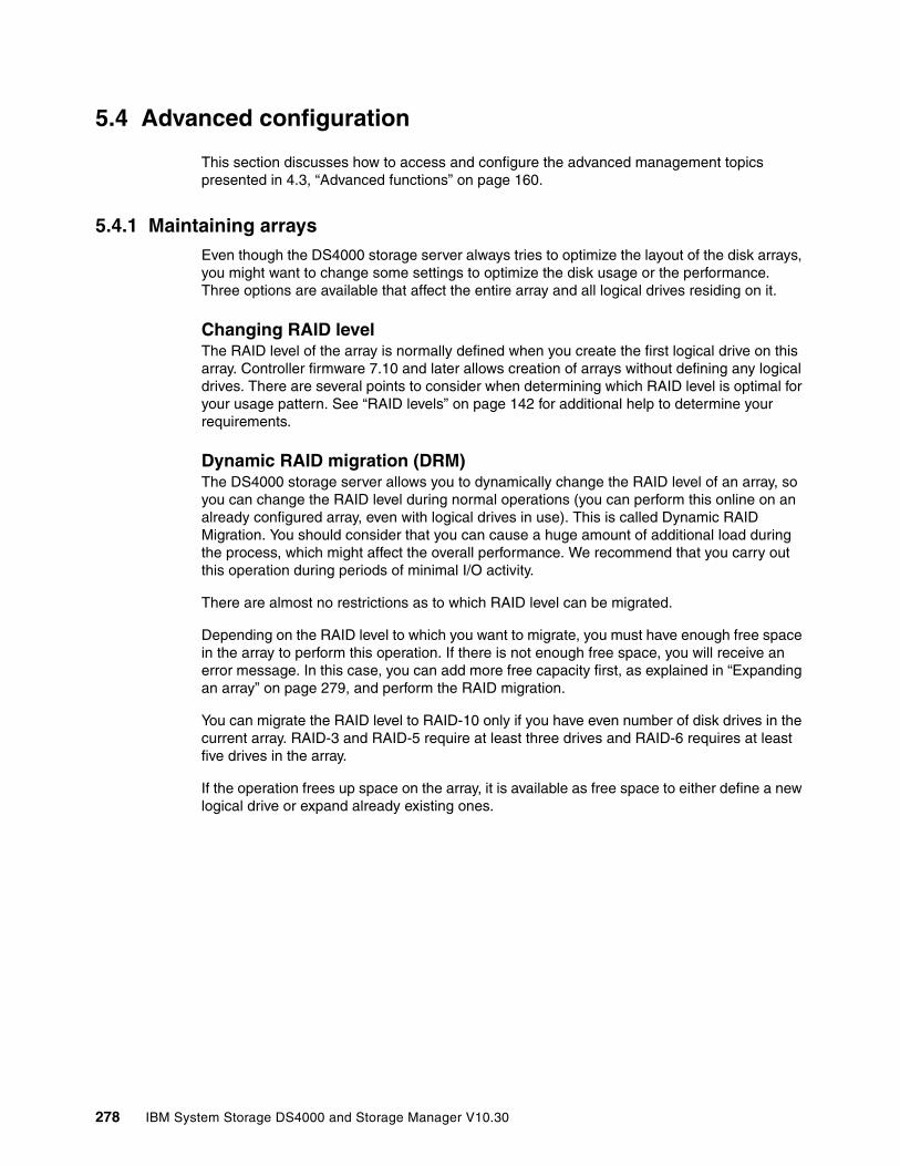
5.4 Advanced configuration
This section discusses how to access and configure the advanced management topics presented in 4.3, “Advanced functions” on page 160.
5.4.1 Maintaining arraysEven though the DS4000 storage server always tries to optimize the layout of the disk arrays, you might want to change some settings to optimize the disk usage or the performance. Three options are available that affect the entire array and all logical drives residing on it.
Changing RAID levelThe RAID level of the array is normally defined when you create the first logical drive on this array. Controller firmware 7.10 and later allows creation of arrays without defining any logical drives. There are several points to consider when determining which RAID level is optimal for your usage pattern. See “RAID levels” on page 142 for additional help to determine your requirements.
Dynamic RAID migration (DRM)The DS4000 storage server allows you to dynamically change the RAID level of an array, so you can change the RAID level during normal operations (you can perform this online on an already configured array, even with logical drives in use). This is called Dynamic RAID Migration. You should consider that you can cause a huge amount of additional load during the process, which might affect the overall performance. We recommend that you carry out this operation during periods of minimal I/O activity.
There are almost no restrictions as to which RAID level can be migrated.
Depending on the RAID level to which you want to migrate, you must have enough free space in the array to perform this operation. If there is not enough free space, you will receive an error message. In this case, you can add more free capacity first, as explained in “Expanding an array” on page 279, and perform the RAID migration.
You can migrate the RAID level to RAID-10 only if you have even number of disk drives in the current array. RAID-3 and RAID-5 require at least three drives and RAID-6 requires at least five drives in the array.
If the operation frees up space on the array, it is available as free space to either define a new logical drive or expand already existing ones.
278 IBM System Storage DS4000 and Storage Manager V10.30

To change an array RAID level, from the Storage Manager window select the array, right-click, select Change → RAID Level, and then select the desired RAID level, as shown in Example 5-81.
Figure 5-81 Changing RAID level
You receive a confirmation message informing you that the operation cannot be stopped until it is complete. The data remains accessible during this operation, which can take a long time. To check the progress status, select the logical drives in the array being modified, right-click, then select Properties to display a progress bar for the operation.
Expanding an arrayDynamic Capacity Expansion (DCE) allows you to increase the size of an array by adding new physical drives to it. This process can be done concurrently with access to the data on the logical drives. After the migration process, the new drives are included in the array and provide new free space within the array. This free space can then be used to define new logical drives or expand existing ones.
Chapter 5. Step-by-step procedures using Storage Manager 279
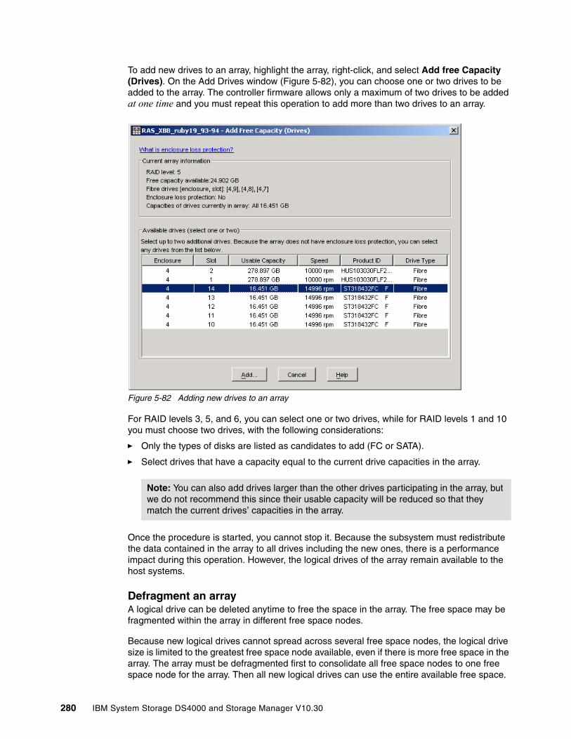
To add new drives to an array, highlight the array, right-click, and select Add free Capacity (Drives). On the Add Drives window (Figure 5-82), you can choose one or two drives to be added to the array. The controller firmware allows only a maximum of two drives to be added at one time and you must repeat this operation to add more than two drives to an array.
Figure 5-82 Adding new drives to an array
For RAID levels 3, 5, and 6, you can select one or two drives, while for RAID levels 1 and 10 you must choose two drives, with the following considerations:
� Only the types of disks are listed as candidates to add (FC or SATA).
� Select drives that have a capacity equal to the current drive capacities in the array.
Once the procedure is started, you cannot stop it. Because the subsystem must redistribute the data contained in the array to all drives including the new ones, there is a performance impact during this operation. However, the logical drives of the array remain available to the host systems.
Defragment an arrayA logical drive can be deleted anytime to free the space in the array. The free space may be fragmented within the array in different free space nodes.
Because new logical drives cannot spread across several free space nodes, the logical drive size is limited to the greatest free space node available, even if there is more free space in the array. The array must be defragmented first to consolidate all free space nodes to one free space node for the array. Then all new logical drives can use the entire available free space.
Note: You can also add drives larger than the other drives participating in the array, but we do not recommend this since their usable capacity will be reduced so that they match the current drives’ capacities in the array.
280 IBM System Storage DS4000 and Storage Manager V10.30
Open the Subsystem Management window. Highlight the array to defragment and click Advanced → Recovery → Defragment to start the procedure. The defragmentation can run concurrently with normal I/O, but it impacts performance because data of the logical drives must be moved within the array. Depending on the array configuration, this process continues to run for a long period of time. Once the procedure is started, it cannot be stopped again. During this time, no configuration changes can be performed on the array.
The defragmentation done on the DS4000 storage server only applies to the free space nodes on the array. It is not connected to a defragmentation of the file system used by the host operating systems in any way.
5.4.2 Maintaining logical drivesThere are several properties of the logical drive that you can change. This section explains the properties.
Changing ownership of a logical driveEach logical drive has a preferred controller of ownership. This controller normally handles all I/O requests for this particular logical drive. The alternate controller only takes over and handles the I/O requests in the case of a failure along the I/O path, for example, a defective host bus adapter or switch. Normally, the logical drive’s ownership is alternated between the two controllers when you define them.
Select this option to manually balance the load over each of the controllers. During initial setup, if the traffic to each of the logical drives is not known, make sure that at least half of the logical drives are assigned to each controller. Later, you can use the Performance Monitor tool integrated with the Storage Manager to analyze which controller and logical drives experience more traffic.
With that input, you might need to change some volumes to the other controller to balance the I/O traffic load.
Highlight the logical drive, right-click, and select Change → Ownership/Preferred Path. Then select the controller to which you want the logical drive to move. Depending on the current workload, the operation can take a while to finish.
Changing the segment sizeThe segment size of a logical drive can be changed to tune the drive for performance. This is called Dynamic Segment Sizing (DSS). You can find an explanation about segment size in 4.2.4, “Segment size” on page 148. Normally, a small segment size is used for databases, normal sizes for file servers, and large segment sizes for multimedia applications.
With the segment size, you can influence the throughput, because the throughput is the number of I/O operations per second multiplied by the segment size. If you increase the segment size, you gain more throughput.
Note: If the operating system on the host requires AVT/ADT enabled for the selected logical drive (HP-UX, OS with Veritas DMP, Linux, and so on), your manual change of the controller ownership for this logical drive is not accepted if the original path exists and is not broken. The ownership/preferred path is driven by the host in this case, and you must change ownership from the host.
Chapter 5. Step-by-step procedures using Storage Manager 281
To change the segment size of a logical drive, highlight the logical drive, right-click, and select Change → Segment Size. The available segment sizes are:
� 8 KB� 16 KB� 32 KB� 64 KB� 128 KB� 256 KB� 512 KB
You can only change the segment size one step at a time. For example, if you want to change the segment size from 16 KB to 128 KB, this requires three consecutive changes of the segment size.
Once this process starts, it cannot be stopped, but all data on the logical drive is available throughout the operation. As with all operations on logical drives or arrays, the overall performance might be affected.
Dynamic logical drive expansionYou can expand an array, define a new logical drive in this array, and enlarge a logical drive. This is called Dynamic Volume Expansion (DVE). You can run this process during normal operation since the logical drive remains accessible all the time.
Because the logical drive appears as a disk device on the host operating system and a file system is used on this disk, some restrictions apply depending on the type of operating system and file system you are using. See 4.2.3, “Arrays and logical drives” on page 139.
To enlarge a logical drive, free space must be available, either as free capacity in the array or as unconfigured capacity in the form of free disk drives. The disk does not need to be assigned to the array. The dynamic logical drive expansion invokes the array expansion if needed. If the array needs to be expanded, a maximum of two disk drives can be added to the array at any time, but the outlined procedure can be repeated.
Important: Initially, with controller firmware 7.10, logical drives greater than 2 TB are supported. Use the Dynamic Capacity Expansion capability to extend your array and then your logical volume size beyond 2 TB, if needed.
282 IBM System Storage DS4000 and Storage Manager V10.30

Highlight the logical drive to be expanded, right-click, and select Increase Capacity. In the Increase Logical Drive Capacity dialog (Figure 5-83), you can enter the amount of space by which the logical drive will be enlarged.
Figure 5-83 Dynamic logical drive expansion
In the top part of the panel shown in Figure 5-83 you see the current size of the logical drive and the available free capacity in the array. If no free configured space is available but you have unassigned drives, you have the option to add them from this same dialog window by clicking Add Drives before you continue to enlarge the logical drive. This takes you to the same dialog as described in “Expanding an array” on page 279.
Click OK after selecting the capacity to add. A warning message appears indicating that this operation cannot be stopped once it is started and that it might take a long time to finish. However, the data on the selected logical drive and all other logical drives on this array (if you added new drives) remains accessible during this time. As with all operations requiring a redistribution of the data on the physical disks, the procedure might affect the performance.
Modification priorityThe modification priority defines the relative amount of processing time of DS4000 controller used for operations modifying the selected logical drive.
Note: If the RAID level of the array is 3, 5, or 6 and the drive enclosure has enclosure loss protection, the Add Drives option should display only drives that ensure enclosure loss protection. If the RAID level is 1 or 10, a minimum of two drives must be added.
Chapter 5. Step-by-step procedures using Storage Manager 283

To change the modification priority, select a logical drive, then right-click and select Change → Modification Priority and enable the logical drives to be included in the media scan (Figure 5-84).
Figure 5-84 Modification priority for a logical drive
If a logical drive modification is in progress, a status bar appears at the bottom of the dialog.
Pre-read redundancy checkNew with firmware 7.10, this feature allows the system to check the consistency of RAID redundancy data prior to returning the data to the application for READ requests. It is available for additional security on RAID protected volumes (not available for RAID-0), where data integrity is a key exposure. Since this additional check impacts the I/O performance, it is disabled by default.
284 IBM System Storage DS4000 and Storage Manager V10.30

If you want to enable the feature:
1. Select the logical drive for which you want to enable a pre-read redundancy check.
2. Select Logical Drive → Change → Pre-Read redundancy check.
Figure 5-85 Pre-read redundancy check
3. Make sure that the correct logical volume is selected and click the check-box to enable the feature on the volume, as in Figure 5-86.
Figure 5-86 Enabling pre-read redundancy check
5.4.3 Cache settingsIf you want to tune performance, it might be necessary to change the settings for the use of the cache. There are two global settings that affect all logical drives on the DS4000 storage server. The other settings that are available affect only a single logical drive. This allows you a very granular optimization of the DS4000 storage server.
Whenever you change cache settings, you should monitor the DS4000 storage server with the built-in performance monitor for one to two weeks to see whether changes improve or degrade performance.
Chapter 5. Step-by-step procedures using Storage Manager 285
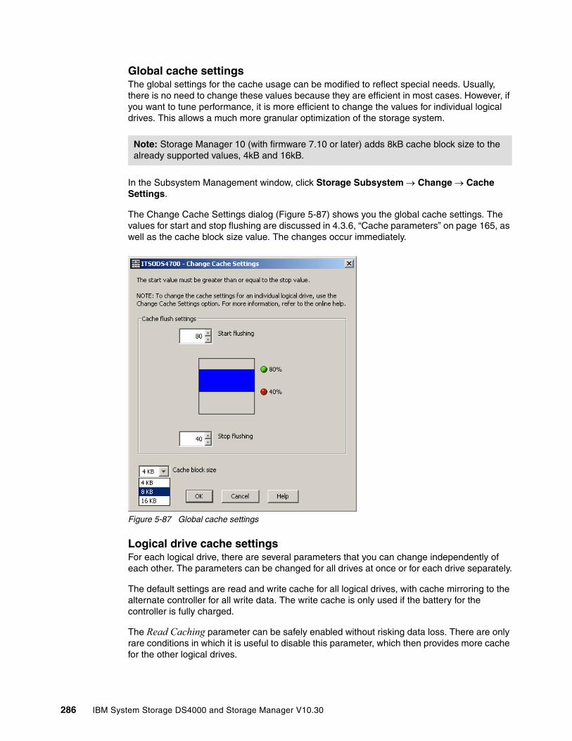
Global cache settingsThe global settings for the cache usage can be modified to reflect special needs. Usually, there is no need to change these values because they are efficient in most cases. However, if you want to tune performance, it is more efficient to change the values for individual logical drives. This allows a much more granular optimization of the storage system.
In the Subsystem Management window, click Storage Subsystem → Change → Cache Settings.
The Change Cache Settings dialog (Figure 5-87) shows you the global cache settings. The values for start and stop flushing are discussed in 4.3.6, “Cache parameters” on page 165, as well as the cache block size value. The changes occur immediately.
Figure 5-87 Global cache settings
Logical drive cache settingsFor each logical drive, there are several parameters that you can change independently of each other. The parameters can be changed for all drives at once or for each drive separately.
The default settings are read and write cache for all logical drives, with cache mirroring to the alternate controller for all write data. The write cache is only used if the battery for the controller is fully charged.
The Read Caching parameter can be safely enabled without risking data loss. There are only rare conditions in which it is useful to disable this parameter, which then provides more cache for the other logical drives.
Note: Storage Manager 10 (with firmware 7.10 or later) adds 8kB cache block size to the already supported values, 4kB and 16kB.
286 IBM System Storage DS4000 and Storage Manager V10.30

The write caching parameter allows the storage system to cache write data instead of writing it directly to the disks. This can improve performance significantly, especially for environments with random writes such as databases. For sequential writes, the performance gain varies with the size of the data written. If the logical drive is only used for read access, it might improve overall performance to disable the write cache for this logical drive. Then no cache memory is reserved for this logical drive.
The cache of the DS4000 storage server is battery protected against power loss. If the batteries are not fully charged (for example, just after powering on) the controllers automatically disable the write cache. If you enable the parameter, the write cache is used, even if no battery backup is available, resulting in a higher risk of data loss.
The cache read-ahead multiplier, or read prefetch, allows the controller, while it is reading and copying host-requested data blocks from disk into the cache, to copy additional data blocks into the cache. This increases the chance that a future request for data will be fulfilled from the cache. Cache read-ahead is important for multimedia applications and other applications that use preferably sequential read I/O.
There is a new automatic pre-fetching for the cache read ahead multiplier (introduced with Storage Manager 9.10). Now you only must enable or disable automatic cache, while in previous versions you must choose a value in a field named cache read ahead multiplier. In that case, read cache is enabled by specifying any non-zero value. Now only enabling prefetch will turn on monitoring of the I/O to the logical drive and enable the new algorithm to dynamically choose how much to read ahead. This simplifies the process for the administrator as there is no need to manually set a specific value for the read ahead multiplier.
The system will tune itself depending on the I/O characteristics. When sequential access is detected the controller will automatically start using read ahead buffering. When random or non-sequential I/O is used then it will stop using the read ahead buffer. To disable this feature, simply set the read-ahead multiplier to zero.
Note: By default, a write cache is always mirrored to the other controller to ensure that the data is consistent even if the logical drive ownership moves to the other controller. Otherwise, the data of the logical drive can be corrupted if the logical drive is shifted to the other controller and the cache still contains unwritten data. If you turn off this parameter, you risk data loss in the case of a controller failover, which might also be caused by a path failure in your fabric.
Chapter 5. Step-by-step procedures using Storage Manager 287
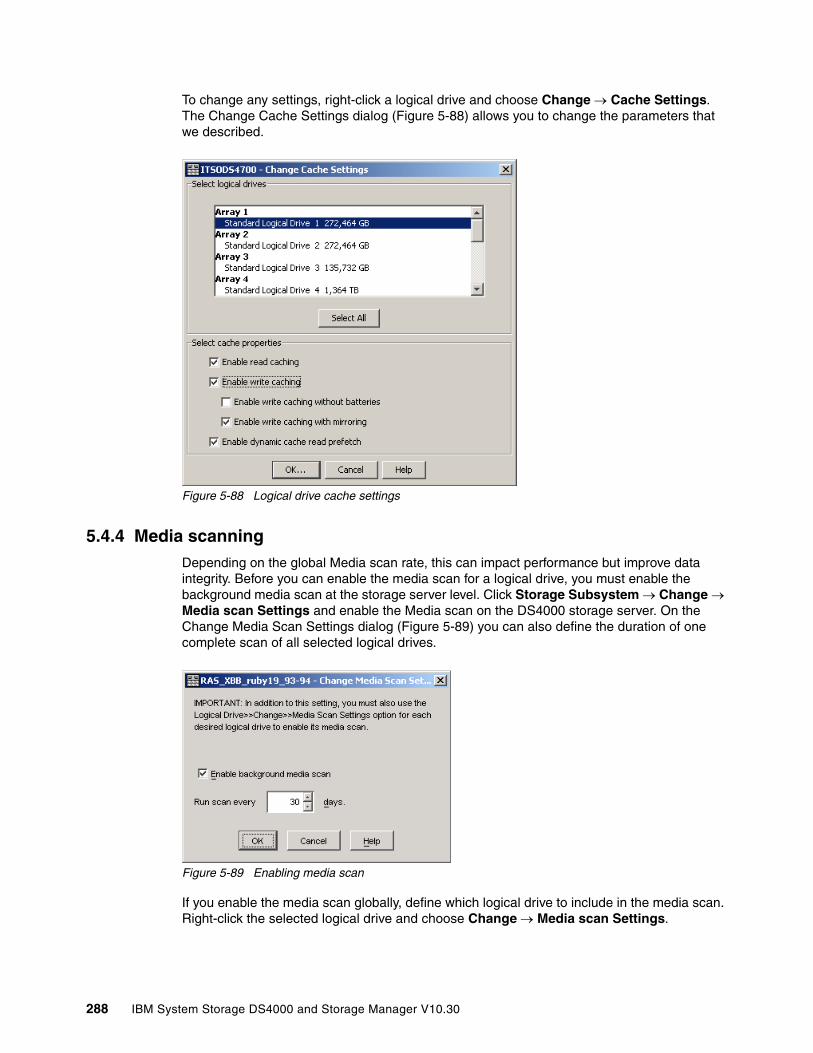
To change any settings, right-click a logical drive and choose Change → Cache Settings. The Change Cache Settings dialog (Figure 5-88) allows you to change the parameters that we described.
Figure 5-88 Logical drive cache settings
5.4.4 Media scanningDepending on the global Media scan rate, this can impact performance but improve data integrity. Before you can enable the media scan for a logical drive, you must enable the background media scan at the storage server level. Click Storage Subsystem → Change → Media scan Settings and enable the Media scan on the DS4000 storage server. On the Change Media Scan Settings dialog (Figure 5-89) you can also define the duration of one complete scan of all selected logical drives.
Figure 5-89 Enabling media scan
If you enable the media scan globally, define which logical drive to include in the media scan. Right-click the selected logical drive and choose Change → Media scan Settings.
288 IBM System Storage DS4000 and Storage Manager V10.30

You also have the choice for setting it in particular for each logical drive by selecting the volume Logical Drive → Change → Media scan setting (Figure 5-90) and then selecting the logical drives to include in the media scan.
Figure 5-90 Enabling a logical drive media scan
The redundancy check option checks redundancy information on a logical drive with RAID-3, RAID-5, or RAID-6 and compares the data blocks of RAID-1 mirrored devices. RAID-0 drives have no data redundancy.
5.4.5 Failover alert delayStorage Manager provides alert notification on the logical drive ownership changes. The logical drive transfer alert notification is issued for any instance of a logical drive owned by a non-preferred controller, whether AVT/ADT is enabled or not, and is in addition to any informational or critical event already logged within the AVT/ADT or RDAC context.
Tip: The default and recommended option to not impact performance is media scan enabled, without a redundancy check. Enable a redundancy check where data integrity is critical and performance is not an issue.
Chapter 5. Step-by-step procedures using Storage Manager 289
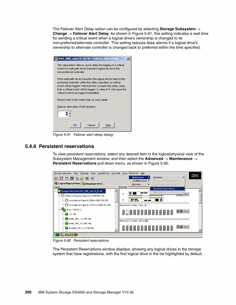
The Failover Alert Delay option can be configured by selecting Storage Subsystem → Change → Failover Alert Delay. As shown in Figure 5-91, this setting indicates a wait time for sending a critical event when a logical drive’s ownership is changed to its non-preferred/alternate controller. This setting reduces false alarms if a logical drive’s ownership to alternate controller is changed back to preferred within the time specified.
Figure 5-91 Failover alert delay dialog
5.4.6 Persistent reservationsTo view persistent reservations, select any desired item in the logical/physical view of the Subsystem Management window, and then select the Advanced → Maintenance → Persistent Reservations pull-down menu, as shown in Figure 5-92.
Figure 5-92 Persistent reservations
The Persistent Reservations window displays, showing any logical drives in the storage system that have registrations, with the first logical drive in the list highlighted by default.
290 IBM System Storage DS4000 and Storage Manager V10.30

As shown in Figure 5-93, the following information is displayed:
� Logical drive name: Displays the user label of the logical drive with persistent reservations. Logical drives are listed in alphabetical order. If a logical drive user label is not available, then its logical drive identifier (WWN) is shown.
� LUN: Displays the assigned LUN number for the particular logical drive.
� Accessible by: Displays the associated host group or host name that has access to the logical drive. If the topology has not been defined, then the term Default Group is displayed instead.
� Registrants: Displays the number of registrations for the particular logical drive.
� Reservation type: Each addressable logical drive can have one reservation, and each reservation can grant access rights to one or more registrants, depending on the reservation type. A logical drive can be reserved for a specific access level by a group of registrants. All registrants within a group are restricted to the access level defined by the reservation type. Reservation types are as follows:
– WE (write exclusive): Only the host port that reserved the logical drive can write to the logical drive. Any host port can read from the logical drive.
– EA (exclusive access): Only the host port that reserved the logical drive can read or write to the logical drive.
– WE-RO (write exclusive - registrants only): All registered host ports can write to the logical drive. Any host port can read from the logical drive.
– EA-RO (exclusive access - registrants only): Only registered host ports can read or write to the logical drive.
– WE-AR (write exclusive - all registrants): All registered host ports can write to the logical drive. Any host port can read from the logical drive.
– EA-AR (exclusive access - all registrants): Only a host port can read or write to the logical drive.
To view the associated registrations (that is, the associations between the initiator host port, the controller port logical drive, and the logical drive reservation) double-click the desired logical drive or highlight the logical drive and select the View Associated Registrations check box in the upper left of the dialog (Figure 5-93). Note that only one logical drive's registration can be viewed at a time.
Figure 5-93 Display persistent reservation and registrations
Chapter 5. Step-by-step procedures using Storage Manager 291
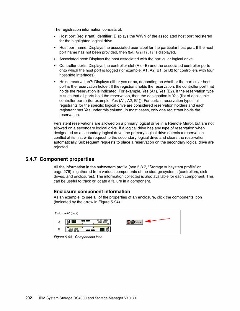
The registration information consists of:
� Host port (registrant) identifier: Displays the WWN of the associated host port registered for the highlighted logical drive.
� Host port name: Displays the associated user label for the particular host port. If the host port name has not been provided, then Not Available is displayed.
� Associated host: Displays the host associated with the particular logical drive.
� Controller ports: Displays the controller slot (A or B) and the associated controller ports onto which the host port is logged (for example, A1, A2, B1, or B2 for controllers with four host-side interfaces).
� Holds reservation?: Displays either yes or no, depending on whether the particular host port is the reservation holder. If the registrant holds the reservation, the controller port that holds the reservation is indicated. For example, Yes (A1), Yes (B2). If the reservation type is such that all ports hold the reservation, then the designation is Yes (list of applicable controller ports) (for example, Yes (A1, A2, B1)). For certain reservation types, all registrants for the specific logical drive are considered reservation holders and each registrant has Yes under this column. In most cases, only one registrant holds the reservation.
Persistent reservations are allowed on a primary logical drive in a Remote Mirror, but are not allowed on a secondary logical drive. If a logical drive has any type of reservation when designated as a secondary logical drive, the primary logical drive detects a reservation conflict at its first write request to the secondary logical drive and clears the reservation automatically. Subsequent requests to place a reservation on the secondary logical drive are rejected.
5.4.7 Component propertiesAll the information in the subsystem profile (see 5.3.7, “Storage subsystem profile” on page 276) is gathered from various components of the storage systems (controllers, disk drives, and enclosures). The information collected is also available for each component. This can be useful to track or locate a failure in a component.
Enclosure component information As an example, to see all of the properties of an enclosure, click the components icon (indicated by the arrow in Figure 5-94).
Figure 5-94 Components icon
292 IBM System Storage DS4000 and Storage Manager V10.30
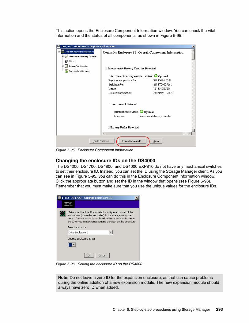
This action opens the Enclosure Component Information window. You can check the vital information and the status of all components, as shown in Figure 5-95.
Figure 5-95 Enclosure Component Information
Changing the enclosure IDs on the DS4000The DS4200, DS4700, DS4800, and DS4000 EXP810 do not have any mechanical switches to set their enclosure ID. Instead, you can set the ID using the Storage Manager client. As you can see in Figure 5-95, you can do this in the Enclosure Component Information window. Click the appropriate button and set the ID in the window that opens (see Figure 5-96). Remember that you must make sure that you use the unique values for the enclosure IDs.
Figure 5-96 Setting the enclosure ID on the DS4800
Note: Do not leave a zero ID for the expansion enclosure, as that can cause problems during the online addition of a new expansion module. The new expansion module should always have zero ID when added.
Chapter 5. Step-by-step procedures using Storage Manager 293
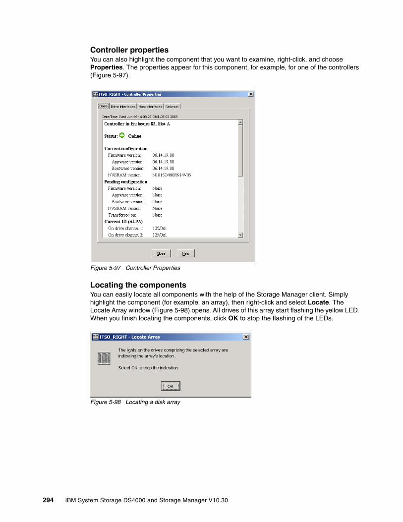
Controller properties You can also highlight the component that you want to examine, right-click, and choose Properties. The properties appear for this component, for example, for one of the controllers (Figure 5-97).
Figure 5-97 Controller Properties
Locating the components You can easily locate all components with the help of the Storage Manager client. Simply highlight the component (for example, an array), then right-click and select Locate. The Locate Array window (Figure 5-98) opens. All drives of this array start flashing the yellow LED. When you finish locating the components, click OK to stop the flashing of the LEDs.
Figure 5-98 Locating a disk array
294 IBM System Storage DS4000 and Storage Manager V10.30

Viewing associated elements Sometimes it is useful to see all components associated with one object. For example, you want to know which arrays and logical and physical drives are managed by controller A. Right-click Controller A and choose View Associated Elements. In the window, you see a list of all disk drives contained in arrays managed by this controller. You also see the logical drives and arrays, as shown in Figure 5-99.
Figure 5-99 Associated elements of controller A
5.4.8 Advanced recovery options
Advanced recovery options are accessible from the Advanced menu in the Storage Manager subsystem management window. These options include:
� Initializing a drive.� Initializing a Logical Drive.� Initializing an array.� Revive a drive.� Clear Storage Configuration.� Clear Array Configuration.� Place Controller Offline/Online/Service Mode.� Reset Controller.� Enable Controller Data Transfer.� Redistribute Logical Drives.� Fail Drive.� Reconstruct Drive.� Defragment Array.� Check Array Redundancy.� Unreadable Sectors.
All of these options are detailed in 6.2, “Storage Manager Advanced Recovery options” on page 325.
Chapter 5. Step-by-step procedures using Storage Manager 295

296 IBM System Storage DS4000 and Storage Manager V10.30
Chapter 6. Troubleshooting and diagnostics
In this chapter we discuss DS4000 Storage Manager integrated capabilities that can help in problem determination. We explain, based on examples, how to use the Recovery Guru, the Major Event Log (MEL), Read Link Status, and other diagnostic and recovery tools. In the performance monitoring section we show some tools and information about using the scripting capability for collecting performance data.
For some operating systems that can be used with the DS4000, we cover tools to manage your DS4000 logical disks, with commands usage and examples.
We also explain the DS4000 Remote Support Manager (RSM™) that facilitates automatic problem reporting to IBM for mission-critical environments.
For more information about some topics addressed in this chapter, refer to the Installation, Users and Maintenance Guide for your specific DS4000 model, and consult the IBM System Storage DS4000 - Problem Determination Guide, GC26-7703, available at:
http://www.ibm.com/support/docview.wss?rs=1157&context=HW27J&uid=psg1MIGR-57817
6
© Copyright IBM Corp. 2004, 2005, 2006, 2007, 2008, 2009. All rights reserved. 297
6.1 Storage Manager error reporting and diagnostics
The DS4000 Storage System and Storage Manager software offer several functions to detect failures and log them for further problem determination, notify users of faults, and guide them through the necessary recovery steps. We discuss Recovery Guru, Master Event Log, Performance Monitor and other tasks in the troubleshooting menu of DS4000 Storage Manager 10.
6.1.1 Preventive maintenance and support notifications
The DS4000 has integrated functions to collect diagnostic information as they arise and notify you about the problems so that you can take corrective actions without delays. Even if the product does not require specific maintenance, we recommend that the storage administrator consult the IBM Disk Support Web site on a regular basis and keep the product up to date with the latest firmware and notices published.
The IBM Disk Support Web site is:
http://www.ibm.com/servers/storage/support/disk
Better yet, a support notifications subscription service is available from the IBM System Storage Support Web site. This service is designed to keep you informed of new or updated system storage support site information, such as publications, hints and tips, technical notes, product flashes (alerts), downloads, and drivers.
The support notifications site is:
http://www.ibm.com/systems/support/storage/news/05072007SupportNotif.html
We recommend keeping your systems at the latest available (and compatible) firmware level. For instructions on how to update DS4000 Storage System to the latest firmware level, refer to Chapter 12, “Advanced maintenance” on page 661.
6.1.2 Recovery GuruIf there is an error condition on your DS4000, the Recovery Guru will explain the cause of the problem and will provide necessary actions to recover. It will guide you to perform specific actions, depending on the event, referring you also to the product documentation, or in particular situations will direct you to contact your IBM Service Representative.
Once the problem is solved, use the Recovery Guru to check that there is no longer a problem impacting the system. If this is the case, you should get the message No failures were detected on the storage subsystem. Note that a green icon displaying next to the Storage Subsystem in the SM GUI also indicates that the subsystem is clear of any error.
Important: We strongly recommend subscribing to the IBM System Storage product Web site to receive notifications directly into your e-mail.
298 IBM System Storage DS4000 and Storage Manager V10.30
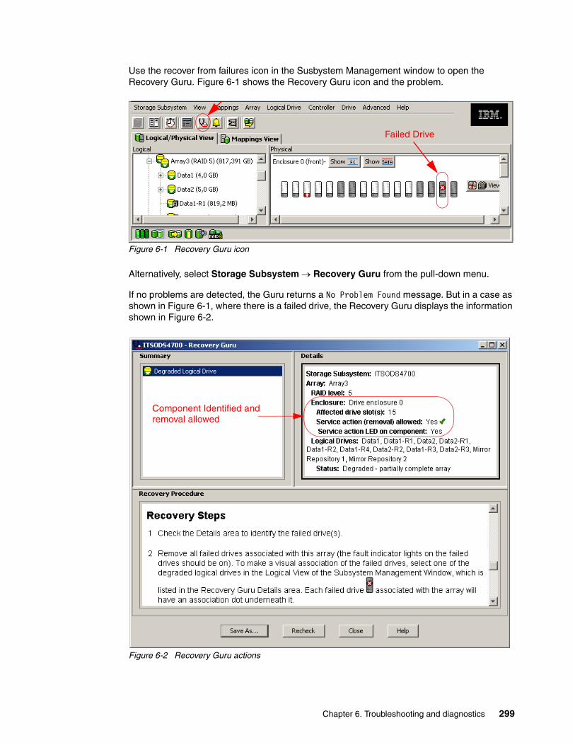
Use the recover from failures icon in the Susbystem Management window to open the Recovery Guru. Figure 6-1 shows the Recovery Guru icon and the problem.
Figure 6-1 Recovery Guru icon
Alternatively, select Storage Subsystem → Recovery Guru from the pull-down menu.
If no problems are detected, the Guru returns a No Problem Found message. But in a case as shown in Figure 6-1, where there is a failed drive, the Recovery Guru displays the information shown in Figure 6-2.
Figure 6-2 Recovery Guru actions
Failed Drive
Component Identified andremoval allowed
Chapter 6. Troubleshooting and diagnostics 299

The details area tells you in this case that a component was identified in enclosure0, slot 5, that it is safe to remove the component (service action allowed in green), and that you should also see a fault LED indication lit in the component to help you physically locate the part (unless you have multiple failures).
The recovery steps explain in details the actions to take for each problem.
For another problem case scenario, we cover a common drive failure in “Failed drive example” on page 306.
6.1.3 Major Event LogThe Major Event Log (MEL) is the primary source for troubleshooting a DS4000 storage server. To access the MEL select Advanced → Troubleshooting → View Event Log.
By default only the last 100 critical events are shown, but you can choose how many events you want to have listed. The maximum number you can set is 8191.
The MEL has two options:
� View only critical events (default option): For a quick overview of all events that might affect the operational status of your DS4000. This is an effective way of only viewing critical events rather than looking through the entire log file.
� View all events: Detailed information about all events logged by the controller. The number of events happening on the storage server may be quite large, with most of them as reference because they are informational messages only.
Figure 6-3 Major Event Log
If you want to troubleshoot your system, use the full event log, as it includes information about actions that took place before the actual critical event happened, thus giving you the complete history of the problem.
Important: Remember to configure the Event Monitor, and alerts will notify you in case of critical events as soon as they occur.
300 IBM System Storage DS4000 and Storage Manager V10.30
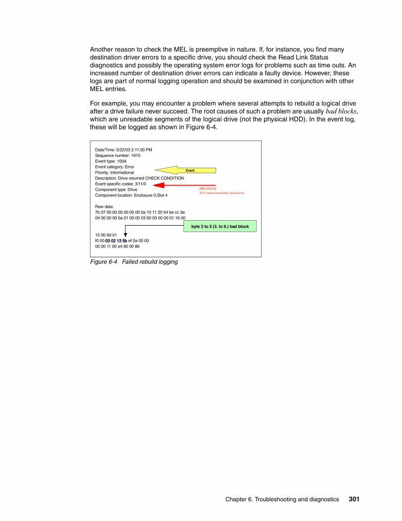
Another reason to check the MEL is preemptive in nature. If, for instance, you find many destination driver errors to a specific drive, you should check the Read Link Status diagnostics and possibly the operating system error logs for problems such as time outs. An increased number of destination driver errors can indicate a faulty device. However, these logs are part of normal logging operation and should be examined in conjunction with other MEL entries.
For example, you may encounter a problem where several attempts to rebuild a logical drive after a drive failure never succeed. The root causes of such a problem are usually bad blocks, which are unreadable segments of the logical drive (not the physical HDD). In the event log, these will be logged as shown in Figure 6-4.
Figure 6-4 Failed rebuild logging
Date/Time: 5/22/03 2:11:00 PMSequence number: 1915Event type: 100AEvent category: ErrorPriority: InformationalDescription: Drive returned CHECK CONDITIONEvent specific codes: 3/11/0Component type: DriveComponent location: Enclosure 0,Slot 4
Raw data:7b 07 00 00 00 00 00 00 0a 10 11 20 54 be cc 3e 04 00 00 00 0a 01 00 00 03 00 00 00 00 01 16 00
12 00 0d 01 f0 00 03 02 13 5b03 02 13 5b ef 0a 00 00 00 00 11 00 e4 80 00 86
Event
byte 2 to 5 (3. to 6.) bad block
ASC/ASCQ 3/11 unrecoverable read error
Chapter 6. Troubleshooting and diagnostics 301

The actual drive taken out of service will be the drive that is the target for reconstruction. You will find entries in the log similar to those in Figure 6-5. Even so, if the rebuild has failed, the MEL will state that the rebuild has finished and immediately after that you will see that the drive is taken offline (Figure 6-5).
Figure 6-5 Drive taken out of service
There is no point in replacing the drive, as the bad blocks reside on a different drive. You have two possibilities:
� Back up your data, delete and recreate the logical drive, and enable Media scan (preferred).
� Overwrite the bad block and start the rebuild again. However, the overwrite procedure has the drawback that the data in that block is lost and one cannot determine if there are more bad blocks on the logical drive. This procedure should only be done by IBM technical support personnel, who do it through the serial interface connection or using a login client.
6.1.4 Support data: Collecting informationWe describe in this section the options available to collect information normally required by your IBM Support Representative, for troubleshooting purposes.
Automatic support data collectionStorage Manager V10.10 and later newly incorporates the option to enable automatic support data collection. When enabled, a support data file is collected and transferred to the directory specified. Doing this, the information relevant for troubleshooting by your support representative is preserved in that directory, and even if a new event occurs, it does not overwrite the already collected file.
Date/Time: 5/22/03 2:11:20 PMSequence number: 1920Event type: 2216Event category: InternalPriority: InformationalDescription: Piece taken out of serviceEvent specific codes: 0/0/0Component type: DriveComponent location: Enclosure 1,Slot 10
Raw data:80 07 00 00 00 00 00 00 16 22 41 00 68 be cc 3e 04 00 10 00 00 00 00 00 01 00 00 00 00 00 00 00
Date/Time: 5/22/03 2:11:04 PMSequence number: 1919Event type: 2026Event category: InternalPriority: InformationalDescription: Reconstruction completedEvent specific codes: 0/0/0Component type: Logical DriveComponent location: 1
Raw data:7f 07 00 00 00 00 00 00 26 20 4d 00 58 be cc 3e 00 00 00 10 04 00 00 00 00 00 00 00 00 01 10 00 0c 00 13 06 04 00 00 00 0f 02 00 00 00 10 74 0c
Piece taken out of service
Reconstruction complete
302 IBM System Storage DS4000 and Storage Manager V10.30

To enable automatic captures:
1. Select Advanced → Troubleshooting → Support Data → Automatic Settings.
2. Click the check mark to enable the automatic data collection and specify the destination folder, as shown in Figure 6-6.
Figure 6-6 Enabling automatic data collection
Tip: We recommend that you enable the automatic support data collection option in order to have a support data file automatically generated and saved to the specified location after the occurrence of a critical event. Make sure that:
� You specify a directory outside your DS4000 system to collect the information.
� The Event Monitor process is running on the workstation or host where you indicate to collect the logs.
Chapter 6. Troubleshooting and diagnostics 303
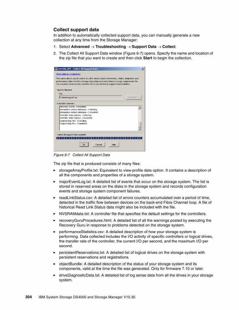
Collect support dataIn addition to automatically collected support data, you can manually generate a new collection at any time from the Storage Manager:
1. Select Advanced → Troubleshooting → Support Data → Collect.
2. The Collect All Support Data window (Figure 6-7) opens. Specify the name and location of the zip file that you want to create and then click Start to begin the collection.
Figure 6-7 Collect All Support Data
The zip file that is produced consists of many files:
� storageArrayProfile.txt: Equivalent to view-profile data option. It contains a description of all the components and properties of a storage system.
� majorEventLog.txt: A detailed list of events that occur on the storage system. The list is stored in reserved areas on the disks in the storage system and records configuration events and storage system component failures.
� readLinkStatus.csv: A detailed list of errors counters accumulated over a period of time, detected in the traffic flow between devices on the back-end Fibre Channel loop. A file of historical Read Link Status data might also be included with the file.
� NVSRAMdata.txt: A controller file that specifies the default settings for the controllers.
� recoveryGuruProcedures.html: A detailed list of all the warnings posted by executing the Recovery Guru in response to problems detected on the storage system.
� performanceStatistics.csv: A detailed description of how your storage system is performing. Data collected includes the I/O activity of specific controllers or logical drives, the transfer rate of the controller, the current I/O per second, and the maximum I/O per second.
� persistentReservations.txt: A detailed list of logical drives on the storage system withpersistent reservations and registrations.
� objectBundle: A detailed description of the status of your storage system and its components, valid at the time the file was generated. Only for firmware 7.10 or later.
� driveDiagnosticData.txt: A detailed list of log sense data from all the drives in your storage system.
304 IBM System Storage DS4000 and Storage Manager V10.30

� recoveryProfile.csv: A detailed description of the latest recovery profile record and historical data.
� unreadableSectors.txt: A detailed list of all the unreadable sectors that have been logged to the storage systems.
� stateCaptureData.dmp: A detailed description of the current state of your storage system.
� storageArrayConfiguration.cfg: A backup file of the current DS4000 configuration.
� socStatistics.csv: A detailed list of error counters found in the traffic between controllers and switched FC devices. This list, used together with the RLS diagnostics, helps to determine problems that may arise in the interconnection between the disks and controllers in your subsystem.
� featureBundle.txt: A detailed list of all the premium features with their installation statuses, current used capacities, and maximum supported.
� ExpansionTrayLog: Attached expansions event logs with details per Environmental Service Modules (ESM).
� Connections.txt: Detail of expansions connections.
Collect disk drive dataThis option collects log sense data from all the disk drives on your DS4000 subsystem. Log sense data consists of statistical information maintained by each of the disk drives in your storage subsystem. Your IBM Support Representative may request this information to analyze the performance of your disks and troubleshoot particular problems that might arise. Select Advanced → Troubleshooting → Collect Drive Data.
Capture state informationThe state capture option captures information about the current state of your DS4000 subsystem and saves the captured information to a file. The captured information can then be sent to your IBM Support Representative for analysis. Select Advanced → Troubleshooting → Capture State Information.
Diagnostic Data Capture (DDC)For certain unusual events in controller firmware, the Diagnostic Data Capture (DDC) should also be requested by your IBM Support Representative if event monitoring is enabled. See5.3.6, “Monitoring and alerting” on page 271. The DDC captured at the moment of the failure may be available at the management station. If not, Recovery Guru will guide you to execute the following command from the SMcli interface to collect the captured data:
save storageSubsystem diagnosticData file="filename.zip";
Where filename is the location and name of the file that will be saved. The file will beformatted as a .zip file.
Additional serial data collectionIn addition to the information collected by the automatic or manual data collect options, your IBM Support Representative may request, for certain unusual conditions, to log in via
Important: Use this option only under the guidance of an IBM Support Representative.
Important: The state capture option can cause a storage subsystem to become unresponsive. Use this option only under the guidance of your IBM Support Representative.
Chapter 6. Troubleshooting and diagnostics 305
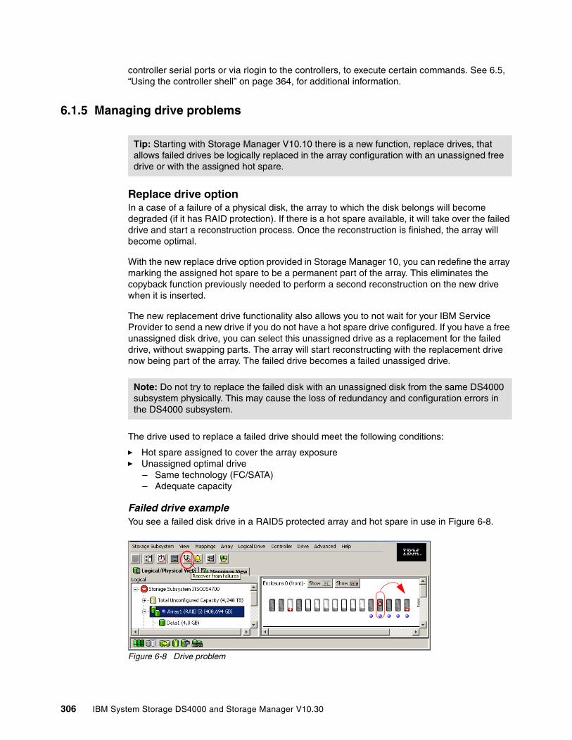
controller serial ports or via rlogin to the controllers, to execute certain commands. See 6.5, “Using the controller shell” on page 364, for additional information.
6.1.5 Managing drive problems
Replace drive optionIn a case of a failure of a physical disk, the array to which the disk belongs will become degraded (if it has RAID protection). If there is a hot spare available, it will take over the failed drive and start a reconstruction process. Once the reconstruction is finished, the array will become optimal.
With the new replace drive option provided in Storage Manager 10, you can redefine the array marking the assigned hot spare to be a permanent part of the array. This eliminates the copyback function previously needed to perform a second reconstruction on the new drive when it is inserted.
The new replacement drive functionality also allows you to not wait for your IBM Service Provider to send a new drive if you do not have a hot spare drive configured. If you have a free unassigned disk drive, you can select this unassigned drive as a replacement for the failed drive, without swapping parts. The array will start reconstructing with the replacement drive now being part of the array. The failed drive becomes a failed unassiged drive.
The drive used to replace a failed drive should meet the following conditions:
� Hot spare assigned to cover the array exposure� Unassigned optimal drive
– Same technology (FC/SATA)– Adequate capacity
Failed drive exampleYou see a failed disk drive in a RAID5 protected array and hot spare in use in Figure 6-8.
Figure 6-8 Drive problem
Tip: Starting with Storage Manager V10.10 there is a new function, replace drives, that allows failed drives be logically replaced in the array configuration with an unassigned free drive or with the assigned hot spare.
Note: Do not try to replace the failed disk with an unassigned disk from the same DS4000 subsystem physically. This may cause the loss of redundancy and configuration errors in the DS4000 subsystem.
306 IBM System Storage DS4000 and Storage Manager V10.30
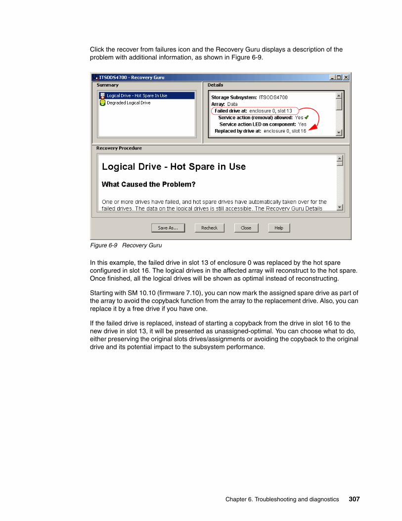
Click the recover from failures icon and the Recovery Guru displays a description of the problem with additional information, as shown in Figure 6-9.
Figure 6-9 Recovery Guru
In this example, the failed drive in slot 13 of enclosure 0 was replaced by the hot spare configured in slot 16. The logical drives in the affected array will reconstruct to the hot spare. Once finished, all the logical drives will be shown as optimal instead of reconstructing.
Starting with SM 10.10 (firmware 7.10), you can now mark the assigned spare drive as part of the array to avoid the copyback function from the array to the replacement drive. Also, you can replace it by a free drive if you have one.
If the failed drive is replaced, instead of starting a copyback from the drive in slot 16 to the new drive in slot 13, it will be presented as unassigned-optimal. You can choose what to do, either preserving the original slots drives/assignments or avoiding the copyback to the original drive and its potential impact to the subsystem performance.
Chapter 6. Troubleshooting and diagnostics 307
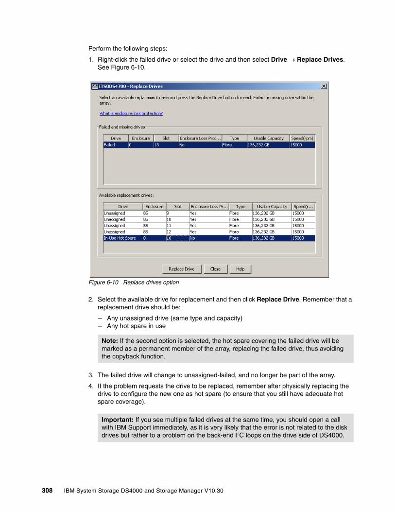
Perform the following steps:
1. Right-click the failed drive or select the drive and then select Drive → Replace Drives. See Figure 6-10.
Figure 6-10 Replace drives option
2. Select the available drive for replacement and then click Replace Drive. Remember that a replacement drive should be:
– Any unassigned drive (same type and capacity)– Any hot spare in use
3. The failed drive will change to unassigned-failed, and no longer be part of the array.
4. If the problem requests the drive to be replaced, remember after physically replacing the drive to configure the new one as hot spare (to ensure that you still have adequate hot spare coverage).
Note: If the second option is selected, the hot spare covering the failed drive will be marked as a permanent member of the array, replacing the failed drive, thus avoiding the copyback function.
Important: If you see multiple failed drives at the same time, you should open a call with IBM Support immediately, as it is very likely that the error is not related to the disk drives but rather to a problem on the back-end FC loops on the drive side of DS4000.
308 IBM System Storage DS4000 and Storage Manager V10.30
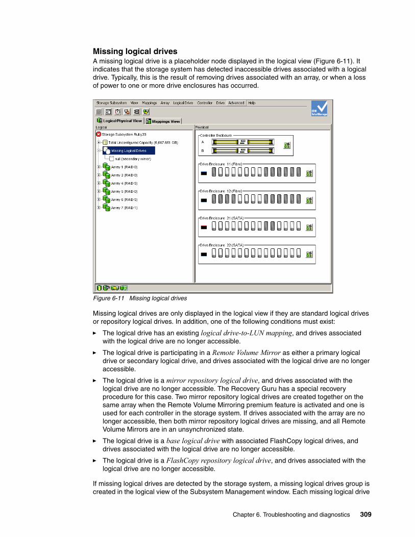
Missing logical drivesA missing logical drive is a placeholder node displayed in the logical view (Figure 6-11). It indicates that the storage system has detected inaccessible drives associated with a logical drive. Typically, this is the result of removing drives associated with an array, or when a loss of power to one or more drive enclosures has occurred.
Figure 6-11 Missing logical drives
Missing logical drives are only displayed in the logical view if they are standard logical drives or repository logical drives. In addition, one of the following conditions must exist:
� The logical drive has an existing logical drive-to-LUN mapping, and drives associated with the logical drive are no longer accessible.
� The logical drive is participating in a Remote Volume Mirror as either a primary logical drive or secondary logical drive, and drives associated with the logical drive are no longer accessible.
� The logical drive is a mirror repository logical drive, and drives associated with the logical drive are no longer accessible. The Recovery Guru has a special recoveryprocedure for this case. Two mirror repository logical drives are created together on the same array when the Remote Volume Mirroring premium feature is activated and one is used for each controller in the storage system. If drives associated with the array are no longer accessible, then both mirror repository logical drives are missing, and all Remote Volume Mirrors are in an unsynchronized state.
� The logical drive is a base logical drive with associated FlashCopy logical drives, and drives associated with the logical drive are no longer accessible.
� The logical drive is a FlashCopy repository logical drive, and drives associated with thelogical drive are no longer accessible.
If missing logical drives are detected by the storage system, a missing logical drives group is created in the logical view of the Subsystem Management window. Each missing logical drive
Chapter 6. Troubleshooting and diagnostics 309
is shown and identified by its worldwide name and logical drive type. Missing logical drives are identified as being either a standard logical drive, base logical drive, FlashCopy repository logical drive, primary logical drive, secondary logical drive, or mirror repository logical drive.
If missing logical drives are detected because drives are accidentally removed, or are detected as missing due to a loss of power to the drive enclosures, recovery of these logical drives is possible by:
� Re-inserting the drives back into the drive enclosure
� Ensuring that the drive enclosure's power supplies are properly connected to an operating power source and have an optimal status
6.1.6 Diagnostics options
We describe here the available diagnostic options integrated in the Storage Manager client interface, with particular emphasis in the Read Link Status diagnostics.
Controller diagnosticsThe controller diagnostics feature allows you to verify that a controller is functioning properly by performing various internal tests.
The diagnostics use a combination of three different tests:
� Read test� Write test� Data loopback test
You should run all three tests when suspecting a controller problem, or under guidance of your support representative.
Note: Missing logical drives, in most cases, are recoverable. Do not delete missing logical drives without confirming that the logical drives are no longer required, because they will be permanently removed from the configuration.
Important: During the diagnostics, the controller on which the tests are run will not be available for I/O. When diagnostics are completed, the controller should automatically allow data to be transferred to it. However, if there is a situation where data transfer is not re-enabled, select the controller and use the Advanced → Recovery → Enable Controller Data Transfer option.
310 IBM System Storage DS4000 and Storage Manager V10.30
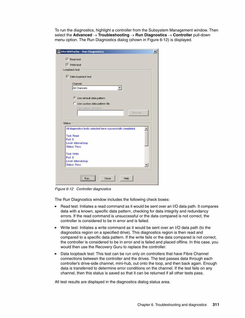
To run the diagnostics, highlight a controller from the Subsystem Management window. Then select the Advanced → Troubleshooting → Run Diagnostics → Controller pull-down menu option. The Run Diagnostics dialog (shown in Figure 6-12) is displayed.
Figure 6-12 Controller diagnostics
The Run Diagnostics window includes the following check boxes:
� Read test: Initiates a read command as it would be sent over an I/O data path. It compares data with a known, specific data pattern, checking for data integrity and redundancy errors. If the read command is unsuccessful or the data compared is not correct, the controller is considered to be in error and is failed.
� Write test: Initiates a write command as it would be sent over an I/O data path (to the diagnostics region on a specified drive). This diagnostics region is then read and compared to a specific data pattern. If the write fails or the data compared is not correct, the controller is considered to be in error and is failed and placed offline. In this case, you would then use the Recovery Guru to replace the controller.
� Data loopback test: This test can be run only on controllers that have Fibre Channel connections between the controller and the drives. The test passes data through each controller’s drive-side channel, mini-hub, out onto the loop, and then back again. Enough data is transferred to determine error conditions on the channel. If the test fails on any channel, then this status is saved so that it can be returned if all other tests pass.
All test results are displayed in the diagnostics dialog status area.
Chapter 6. Troubleshooting and diagnostics 311
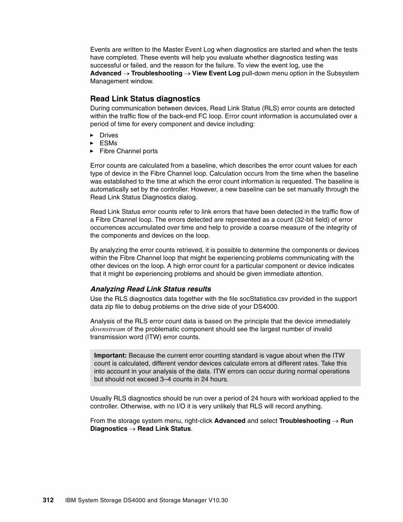
Events are written to the Master Event Log when diagnostics are started and when the tests have completed. These events will help you evaluate whether diagnostics testing was successful or failed, and the reason for the failure. To view the event log, use the Advanced → Troubleshooting → View Event Log pull-down menu option in the Subsystem Management window.
Read Link Status diagnosticsDuring communication between devices, Read Link Status (RLS) error counts are detected within the traffic flow of the back-end FC loop. Error count information is accumulated over a period of time for every component and device including:
� Drives � ESMs� Fibre Channel ports
Error counts are calculated from a baseline, which describes the error count values for each type of device in the Fibre Channel loop. Calculation occurs from the time when the baseline was established to the time at which the error count information is requested. The baseline is automatically set by the controller. However, a new baseline can be set manually through the Read Link Status Diagnostics dialog.
Read Link Status error counts refer to link errors that have been detected in the traffic flow of a Fibre Channel loop. The errors detected are represented as a count (32-bit field) of erroroccurrences accumulated over time and help to provide a coarse measure of the integrity of the components and devices on the loop.
By analyzing the error counts retrieved, it is possible to determine the components or devices within the Fibre Channel loop that might be experiencing problems communicating with the other devices on the loop. A high error count for a particular component or device indicates that it might be experiencing problems and should be given immediate attention.
Analyzing Read Link Status resultsUse the RLS diagnostics data together with the file socStatistics.csv provided in the support data zip file to debug problems on the drive side of your DS4000.
Analysis of the RLS error count data is based on the principle that the device immediately downstream of the problematic component should see the largest number of invalid transmission word (ITW) error counts.
Usually RLS diagnostics should be run over a period of 24 hours with workload applied to the controller. Otherwise, with no I/O it is very unlikely that RLS will record anything.
From the storage system menu, right-click Advanced and select Troubleshooting → Run Diagnostics → Read Link Status.
Important: Because the current error counting standard is vague about when the ITW count is calculated, different vendor devices calculate errors at different rates. Take this into account in your analysis of the data. ITW errors can occur during normal operations but should not exceed 3–4 counts in 24 hours.
312 IBM System Storage DS4000 and Storage Manager V10.30

Figure 6-13 shows the RLS diagnostics window. It lists all devices for each redundant loop. The channel numbers correspond with the drive-side mini-hubs.
Figure 6-13 Storage Manager 10: Read Link Status Diagnostics
Each of the columns in the window are explained in the following list:
� Devices: A list of all the devices on the Fibre Channel loop. The devices are displayed in channel order. Within each channel, they are sorted according to the device’s position within the loop.
� Baseline Time: The date and time when the baseline was last set.
� Elapsed Time: The elapsed time between when the baseline time was set and when the Read Link Status data was gathered.
� ITW: The total number of invalid transmission word errors detected on the Fibre Channel loop from the baseline time to the date and time. ITW can also be referred to as the received bad character count.
� Link Failure (LF): The total number of link failure errors detected on the Fibre Channelloop from the baseline time to the current date and time. When detected, link failures indicate that there has been a failure within the media module laser operation. Link failures might also be caused by a link fault signal, a loss of signal, or a loss of synchronization.
� Loss of Synchronization (LOS): The total number of loss of synchronization errors detected on the Fibre Channel loop from the baseline time to the current date and time. This indicates that the receiver cannot acquire symbol lock with the incoming data stream due to a degraded input signal. If this condition persists, the number of loss of signal errors increases.
� Loss of Signal (LOSG): The total number of loss-of-signal errors detected on the Fibre Channel loop from the baseline date to the current date and time. This indicates a loss of signal from the transmitting node or physical component within the Fibre Channel loop. Errors logged against a single drive usually point to a drive failure. If you see an increase in numbers against multiple drives across one channel the problem probably lays with cabling or connection (including mini-hubs or SFPs).
Errors logged against the ESM board can point to bad ESM boards or bad connectivity (cables, SFT, mini-hubs).
Chapter 6. Troubleshooting and diagnostics 313
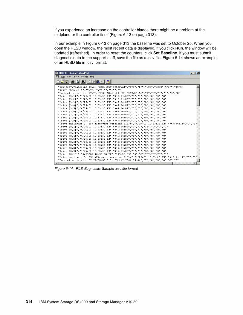
If you experience an increase on the controller blades there might be a problem at the midplane or the controller itself (Figure 6-13 on page 313).
In our example in Figure 6-13 on page 313 the baseline was set to October 25. When you open the RLSD window, the most recent data is displayed. If you click Run, the window will be updated (refreshed). In order to reset the counters, click Set Baseline. If you must submit diagnostic data to the support staff, save the file as a .csv file. Figure 6-14 shows an example of an RLSD file in .csv format.
Figure 6-14 RLS diagnostic: Sample .csv file format
314 IBM System Storage DS4000 and Storage Manager V10.30

You can use the .csv format to import the data in a database for better readability. As an example, Figure 6-15 shows the display, under Lotus® Approach, of error information collected for a bad drive that generated errors across the drive loop. The event log shows that many destination drive errors were logged. Not shown in Figure 6-15 is that drive channel 1 was virtually error free. Since the drives have two ports, we suspect that the port connected to drive channel 2 has a problem. In a fiber environment it is likely that the device that is downstream (AL-PA ID) from the error logging device is the faulty component. In this case, however, the MEL pointed to drive 3,1 (which was ultimately replaced).
Figure 6-15 RLSD approach database
As general guidance, you can use Table 6-1 to find the most likely defective part on the DS4000 drive loop.
Table 6-1 RLS diagnostics table
Location of device A(first device that detects a link error)
Location of device B(first device upstream of device A)
Possible candidates
Enclosure X Enclosure X Device B (drive), ESM of enclosure X, device A (drive)
Enclosure X Enclosure Y Cable or SFPs between enclosure X and Y, ESM of enclosure Y, Device B (drive), ESM of enclosure X, device A (drive)
Enclosure X Controller module Cable or SFPs between enclosure X and controller module, mini-hub, device B (controller), ESM of enclosure X, device A (drive), controller chassis
Controller module Enclosure Y Mini-hub, any cable or SFP in the channel, ESM of enclosure X, device B (drive), device A (controller), controller chassis
Controller module Controller module Mini-hub, device B (controller), device A (controller)
Chapter 6. Troubleshooting and diagnostics 315
In Example 6-1, you can see that device A (first device with error detected) corresponds to drive 5 in enclosure 1. The upstream device is drive 4 in enclosure 1, so this would be the enclosure X/enclosure X type of problem. Candidates for replacement would be drive 1,4 or the ESM in enclosure 1. It is also possible that drive 1,5 is the reason for the problem, but that is fairly unlikely.
Example 6-1 RLSD output usage example
Devices Baseline Time Sampling Interval ITW LF LOS LOSG PSP ICRCDrive Channel 3....Drive [1,2] 10/25/2004 16:51 0:16:02 0 0 0 0 0 0Drive [1,3] 10/25/2004 16:51 0:16:02 0 0 0 0 0 0Drive [1,4] 10/25/2004 16:51 0:16:02 0 0 0 0 0 0Drive [1,5] 10/25/2004 16:51 0:16:02 425 0 0 0 0 0Drive [1,6] 10/25/2004 16:51 0:16:02 425 0 0 0 0 0Drive [1,7] 10/25/2004 16:51 0:16:02 422 0 0 0 0 0Drive [1,8] 10/25/2004 16:51 0:16:02 418 0 0 0 0 0Drive [1,9] 10/25/2004 16:51 0:16:02 418 0 0 0 0 0Drive [1,10] 10/25/2004 16:51 0:16:02 418 0 0 0 0 0....
Discrete lines diagnosticsThe discrete lines are dedicated control and status lines between the controllers that reside in the interconnect-battery canister. The Recovery Guru will guide you when you must select this option as part of the recovery steps, although it is a tool mainly to be used by your IBM Support Representative.
This option is to execute diagnostics to the controllers to further identify a possible failure when there is not enough information from the error logged on which controller has failed, or if the problem was with the interconnect.
In the above case, the Recovery Guru guides you to place a specific controller offline, and then execute this diagnostics by selecting Advanced → Troubleshooting → Run Diagnostics → Discrete Lines.
6.1.7 Degraded drive channels
We see in“Read Link Status diagnostics” on page 312 that the RLS output is a good way to find problems on the FC loop of the DS4000.
If an error condition is detected by the controller in one of the drive channels, it will change its status from optimal to degraded, routing the traffic to the remaining optimal redundant disk channel path. If you are using the Storage Manager client with an older firmware, make sure to update your DS4000 to the latest supported level, since under some particular situation, older firmwares may keep retrying to recover the channel, creating an impact on the I/O traffic and a possible access problem. After firmware 6.10, a user intervention is required to set the channel drive back to optimal.
A drive channel is set to degraded when a certain threshold of errors in a certain period of time is exceeded. These errors include time-out errors, controller-detected errors, drive-detected errors, and link-down errors. The I/O is stopped on the degraded channel and only the optimal channel is used for I/O. A controller always selects an optimal channel over a degraded one. However, if both channels are degraded, the controller will arbitrarily choose one of the two.
316 IBM System Storage DS4000 and Storage Manager V10.30

To check the drive channels, select Advanced → Troubleshooting → Drive Channels, which displays the Drive Channels Summary window (Figure 6-16).
Figure 6-16 Drive Channel (Summary)
The link status is fully controlled by the controller. There are two states for the link status:
� Up: The link is currently able to handle I/Os.� Down: The link is currently not able to handle I/Os.
The link status cannot be manually changed. The controller will set the link status to down if the controller cannot do a loop initialization within a certain amount of time. When the link is down, the controller will continuously try to bring the link up.
Consequently, this means that even if a channel is degraded and the link is up, there is the possibility that I/O will occur on this link. However, the controller will first choose the channel that is not in a degraded state.
To get a more detailed view of the drive channel status, click Show Details. This will show the error counters on this specific channel during the sample period (Figure 6-17).
Figure 6-17 Drive Channel Status Details
See also “Expansion unit connections” on page 318 for an additional tools for problem determination on the drive channels side.
Chapter 6. Troubleshooting and diagnostics 317
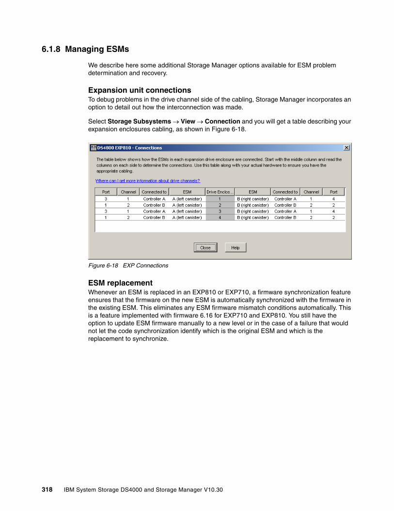
6.1.8 Managing ESMs
We describe here some additional Storage Manager options available for ESM problem determination and recovery.
Expansion unit connectionsTo debug problems in the drive channel side of the cabling, Storage Manager incorporates an option to detail out how the interconnection was made.
Select Storage Subsystems → View → Connection and you will get a table describing your expansion enclosures cabling, as shown in Figure 6-18.
Figure 6-18 EXP Connections
ESM replacementWhenever an ESM is replaced in an EXP810 or EXP710, a firmware synchronization feature ensures that the firmware on the new ESM is automatically synchronized with the firmware in the existing ESM. This eliminates any ESM firmware mismatch conditions automatically. This is a feature implemented with firmware 6.16 for EXP710 and EXP810. You still have the option to update ESM firmware manually to a new level or in the case of a failure that would not let the code synchronization identify which is the original ESM and which is the replacement to synchronize.
318 IBM System Storage DS4000 and Storage Manager V10.30

The ESMs also hold configuration settings as Non Volatile Static Random Access Memory (NVSRAM), which are automatically set. If, for a a particular problematic situation, one of the ESMs on an enclosure has a different configuration than the other and could not resolve the synchronization automatically, a needs attention condition would be displayed. For EXP420, EXP710, and EXP810, there is an option to set the enclosure settings by selecting Maintenance → Download → ESM Configuration Settings in the Storage Manager Subsystem Management window.
Figure 6-19 ESM configuration mismatch problem
This option should be used under supervision of your IBM Support Representative, when ESMs are reporting different versions of configuration settings. A configuration file is provided to reset the ESM NVSRAM settings.
6.1.9 Locating and removing parts
The DS4000 is a modular system containing customer replaceable part (CRU). Most of the parts contains LED indications that allow a clear indication of the affected part. The Recovery Guru option guides you in determining the problems, and, if necessary, replacing the affected part.
In 6.1.2, “Recovery Guru” on page 298, we discuss how to identify a part and know whether it is safe to proceed with the removal. We now discuss other options to identify a component in your DS4000 subsystem.
Chapter 6. Troubleshooting and diagnostics 319

Locate optionThis option allows you to physically identify a component by turning on a LED indication. Tolocate a drive right-click a drive, then select Locate → Drive, as in Figure 6-20.
Figure 6-20 Locating a drive
This action turns the on the LED indication on the component selected, so if you must perform any action you can physically identify it by the flashing LED.
The components that have identification LEDs to allow a physical identification are:
� Arrays: Will turn on all drives LEDs� Controller� Drives� Enclosures� Storage Subsystem
Use the locate option especially in highly populated racks with multiple subsystems and enclosures. Also make sure that your Storage Manager enclosures are shown in the graphical interface in the same physical order as installed in the racks. This eliminates anypossible confusion. See 5.2.3, “Using the DS4000 Storage Management client” on page 233, for a reference. See 5.4.7, “Component properties” on page 292, for additional information.
320 IBM System Storage DS4000 and Storage Manager V10.30

Prepare for removal optionUse this option (in Advanced → Troubleshooting) to locate a particular drive, ESM, or power/fan canister, and perform removal preparation. During this action, the identify LED turns on and will be checked for safe removal of the component. The tool will not let you select a drive in use, for example. Use this option only when guided by the Recovery Guru or as requested by your IBM Support Representative.
Figure 6-21 Prepare for Removal option
6.1.10 Performance monitoring and analysisThe Performance Monitor provided with Storage Manager client is described in 4.2.7, “Performance monitor data” on page 155.
IBM DS4000 Storage Manager allows performance monitoring by using:
� The integrated Monitor Performance utility� Scripts from the command-line interface
Note: Use the Monitor Performance tool output to improve performance by:
� Balancing logical drives across controllers to distribute the load evenly
� Identifying most used logical drives and types of traffic to balance the data across logical drives
� Adjusting cache settings and other parameters based on this output
Chapter 6. Troubleshooting and diagnostics 321
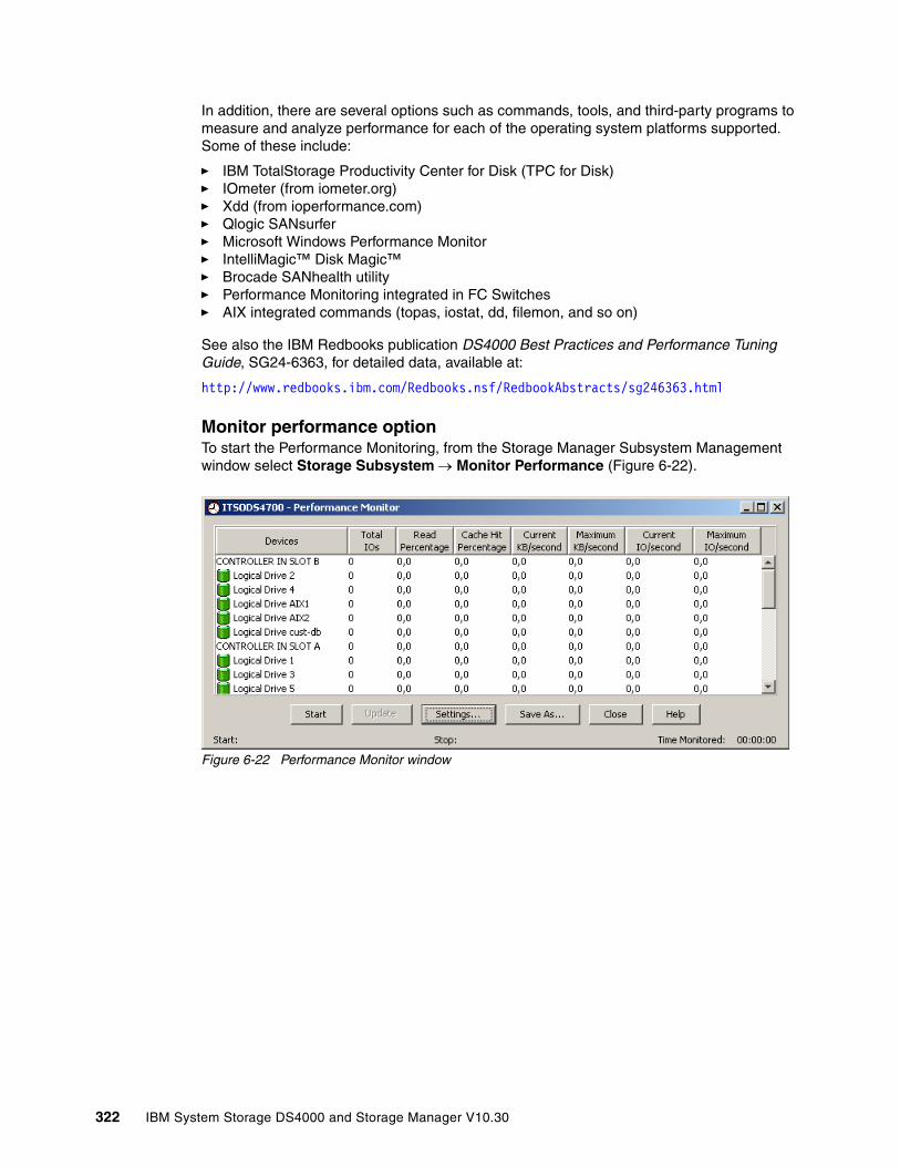
In addition, there are several options such as commands, tools, and third-party programs to measure and analyze performance for each of the operating system platforms supported. Some of these include:
� IBM TotalStorage Productivity Center for Disk (TPC for Disk)� IOmeter (from iometer.org)� Xdd (from ioperformance.com)� Qlogic SANsurfer� Microsoft Windows Performance Monitor� IntelliMagic™ Disk Magic™� Brocade SANhealth utility� Performance Monitoring integrated in FC Switches� AIX integrated commands (topas, iostat, dd, filemon, and so on)
See also the IBM Redbooks publication DS4000 Best Practices and Performance Tuning Guide, SG24-6363, for detailed data, available at:
http://www.redbooks.ibm.com/Redbooks.nsf/RedbookAbstracts/sg246363.html
Monitor performance optionTo start the Performance Monitoring, from the Storage Manager Subsystem Management window select Storage Subsystem → Monitor Performance (Figure 6-22).
Figure 6-22 Performance Monitor window
322 IBM System Storage DS4000 and Storage Manager V10.30
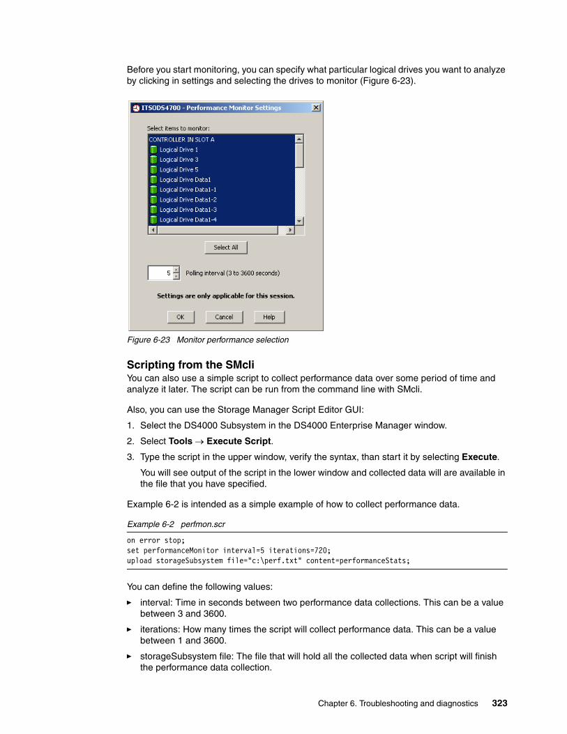
Before you start monitoring, you can specify what particular logical drives you want to analyze by clicking in settings and selecting the drives to monitor (Figure 6-23).
Figure 6-23 Monitor performance selection
Scripting from the SMcliYou can also use a simple script to collect performance data over some period of time and analyze it later. The script can be run from the command line with SMcli.
Also, you can use the Storage Manager Script Editor GUI:
1. Select the DS4000 Subsystem in the DS4000 Enterprise Manager window.
2. Select Tools → Execute Script.
3. Type the script in the upper window, verify the syntax, than start it by selecting Execute.
You will see output of the script in the lower window and collected data will are available in the file that you have specified.
Example 6-2 is intended as a simple example of how to collect performance data.
Example 6-2 perfmon.scr
on error stop;set performanceMonitor interval=5 iterations=720;upload storageSubsystem file="c:\perf.txt" content=performanceStats;
You can define the following values:
� interval: Time in seconds between two performance data collections. This can be a value between 3 and 3600.
� iterations: How many times the script will collect performance data. This can be a value between 1 and 3600.
� storageSubsystem file: The file that will hold all the collected data when script will finish the performance data collection.
Chapter 6. Troubleshooting and diagnostics 323

In our example, the script will run for 5 x 720 = 3600 seconds and collect new data every 5 seconds. The data will be written to the file c:\perf.txt as a list of comma-separated values.
Example 6-3 Performance Monitor statistics: Script output example
Performance Monitor Statistics for Storage Subsystem: DS4500Date/Time: 10/26/04 11:03:19 AMPolling interval in seconds: 5
Devices,Total,Read,Cache Hit,Current,Maximum,Current,Maximum,IOs,Percentage,Percentage,KB/second,KB/second,IO/second,IO/secondCapture Iteration: 1Date/Time: 10/26/04 11:03:23 AMCONTROLLER IN SLOT B,4034.0,100.0,97.1,32257.0,32257.0,504.2,504.2,Logical Drive x220_Volume1,2018.0,99.9,97.4,16129.0,16129.0,252.2,252.2,Logical Drive x220_volume4,2016.0,100.0,96.8,16128.0,16128.0,252.0,252.0,CONTROLLER IN SLOT A,3473.0,99.9,89.9,36443.7,36443.7,578.8,578.8,Logical Drive x220_Volume2,3406.0,100.0,91.6,36330.7,36330.7,567.7,567.7,Logical Drive x220_Volume3,47.0,91.5,0.0,85.7,85.7,7.8,7.8,Logical Drive x440_volume5,20.0,100.0,0.0,27.3,27.3,3.3,3.3,STORAGE SUBSYSTEM TOTALS,7507.0,99.9,93.8,68700.7,68700.7,1083.1,1083.1,
Capture Iteration: 2Date/Time: 10/26/04 11:03:29 AMCONTROLLER IN SLOT B,7374.0,100.0,97.0,30537.1,32257.0,477.1,504.2,
324 IBM System Storage DS4000 and Storage Manager V10.30

6.2 Storage Manager Advanced Recovery options
In this section we discuss options that are accessible from the Recovery menu of the Advanced menu in the Storage Manager Subsystem Management window. See Figure 6-24.
Figure 6-24 Advanced Menu options
Initializing a driveUse the initialize drive option only when you have moved a subset of drives that were previously part of an array from one storage system to another, to add space, not to migrate data. Because you did not move the entire set of drives, the array information on the drives is incomplete.
Therefore, to erase all logical drive/array information on these drives and make them available again for new logical drive creation, you must initialize these drives. This action erases the logical drive/array information and returns the selected drives to an unassigned state, adding new or additional unconfigured capacity to the storage subsystem. You can use this capacity to create additional logical drives. Perform the following steps. All data on the drives will be lost.
1. Select the drives to be initialized, then select Advanced → Recovery → Initialize → Drive.
2. Type yes, and click OK or press Enter.
Important: Most of these operations should not be attempted unless you have been instructed to by an IBM Technical Support Representative.
Chapter 6. Troubleshooting and diagnostics 325

Initializing a logical driveA logical drive is automatically initialized when it is first created. However, the Recovery Guru might advise the manual initialization of a logical drive to recover from certain failure conditions. Use the following procedure to initialize a logical drive:
1. Select the logical drive to be initialized in the logical view, and select Advanced → Recovery → Initialize → Logical Drive.
2. Type yes, and click OK or press Enter.
Important notes regarding this operation:
� You cannot cancel the operation after it begins.
� Do not use this option if any modification operations are in progress on the logical drive or the array.
� Do not change cache parameters of the logical drive while the initialize operation is in progress.
� All data on the logical drive is destroyed.
� Do not attempt this operation unless advised to do so by the Recovery Guru.
Initializing an array Use the initialization option when the Recovery Guru advises the manual to initialize all logical drives in an array. Perform the following steps:
1. Select the logical drive to be initialized in the logical view, and select Advanced → Recovery → Initialize → Array.
2. Type yes, and click OK or press Enter.
Important notes regarding this operation:
� You cannot cancel the operation after it begins.
� Do not use this option if any modification operations are in progress on the logical drive or the array.
� Do not change cache parameters of the logical drive while the initialize operation is in progress.
� All data on all logical drives on the array are destroyed.
� Do not attempt this operation unless advised to do so by the Recovery Guru.
Revive a driveThis option attempts to spin up a failed drive. However, the use of this may affect the data on all the physical disks participating in the array. Use this process only under direction of your support representative.
1. Select the drives to be initialized, and select Advanced → Recovery → Revive → Drive.2. Type yes, and click OK or press Enter.
This should not be used as a substitute for replacing a failed drive, unless multiple drives were marked as failed due to another problem.
Revive an arrayThis option is not available in Storage Manager 10. It was used in previous versions to revive (attempt to spin up) the drives in a selected array. The Recovery Guru advises using this option when a failed LUN or a failed canister causes a multi-drive failure. In either case, it is
326 IBM System Storage DS4000 and Storage Manager V10.30

possible that the data on the drives is not corrupt, and that the array can be successfully revived. Perform the following steps:
1. To revive a failed array select the array to be revived, and select Advanced → Recovery → Revive → Array.
2. Type yes, and click OK or press Enter.
Never attempt to revive an array unless supervised by an IBM Support Representative.
Clear configurationThis option lets you correct the configuration errors that cannot be corrected by using any other method. Use this option with caution.
You have the following options:
� Clear all DS4000 Storage Subsystem configuration:
a. Select Advanced → Recovery → Clear Configuration → Storage Subsystem.b. Type yes, and click OK or press Enter.
Important notes on resetting the configuration:
– The current configuration is deleted, destroying any existing data on the storage subsystem.
– Do not attempt this operation unless all data on the storage subsystem has been backed up to tape or to another storage subsystem.
– All logical drives and arrays are deleted.
– The user-supplied name is deleted.
– If you have password protected your storage subsystem to prevent destructive operations, that password protection is lost.
� Clear all array configuration.
This option is to clear all the arrays in your DS4000, destroying all existing data on the storage subsystem.
a. Select Advanced → Recovery → Clear Configuration → Array.
b. Type yes, and click OK or press Enter.
If you want to delete one specific array, select it from the Subsystem Management, right-click it, and select the Delete option.
In both cases, make sure that you have backed up your data or that it is no longer needed.
Note: Correct use of this option depends on the data configuration on all physical disks in the array. This operation fails if one or more of the drives is unusable and cannot be revived.
Chapter 6. Troubleshooting and diagnostics 327

Place controller online/offlineEach controller has three states:
� Online
When a controller is active it is called online. To place a controller online from either an offline or service mode, select the controller. Select Advanced → Recovery → Place Controller → Online. Select Yes to confirm that the controller is online. This removes the red cross through the controller if the controller was offline, or reinstates the look of the controller if it was in service mode.
Placing the controller online from being in service mode redistributes the logical drives back to their preferred controller.
Make sure that the problem that caused the controller to go offline was corrected before placing the controller online.
� Offline
To place a controller offline, select the controller and select Advanced → Recovery → Place Controller → Offline. Select Yes to confirm that the controller is offline. This places a red cross through the controller to signify that it is offline.
� In service mode
Placing a controller into service mode forces all logical drives to be serviced by the other active controller. This mode provides for continuous data access. The preferred logical drive owner does not change. When the controller is removed from service mode, the logical drives are redistributed back to their preferred owner.
A controller can only be put into service mode if the storage server has two controllers and they are both online or active. Placing a controller in service mode is a persistent setting. Even if the controller is reset it will return to the service mode state. A controller that is in service mode cannot be made the owner of any logical drive.
Reset controllerUse the reset option to reset a controller from within the storage management software. Resetting a controller makes the controller unavailable for I/O until the reset is complete. If a host is using logical drives owned by the controller being reset, the I/O directed to the controller is rejected, so before proceeding, either verify that the logical drives owned by the controller are not in use or ensure that there is a multipath driver properly installed on all hosts using these logical drives.
This is done by selecting the controller to be reset:
1. Select Advanced → Recovery → Reset → Controller.2. Click OK to reset the controller.
Controller data transferDisabling data transfer ensures that the controller is no longer available for I/O operations.
Select a controller in the physical view. Then select Advanced → Recovery → Disable Controller Data Transfer. The Confirm Data Transfer Disable dialog is displayed. Type Yes and select OK.
The controller no longer accepts I/O and is marked with a dashed red border in the physical view. If a multi-path driver is in use, I/O is sent to the other controller path, initiating a logical drive ownership transfer.
To enable data transfer and enable the controller for I/O operations, select a controller in the physical view. Then select Advanced → Recovery → Enable Controller Data Transfer.
328 IBM System Storage DS4000 and Storage Manager V10.30

Redistribute logical drivesThis happens when multipath drivers move logical drives from their preferred controller owner or when a problem occurs along the data path between the host and the storage server. When the problem is corrected, you should move all the logical drives back to their preferred controllers to maintain controller balance. Be aware that manually moving back to their preferred path without checking that the preferred path is working may generate an access problem.
Select a controller in the physical view. Then select Advanced → Recovery → Redistribute Logical Drives.
Fail driveUse this option to fail a selected drive. Select one or more drives in the physical view, then select Advanced → Recovery → Fail Drive.
In the confirm Fail Drive dialog type Yes and select OK.
Reconstruct driveUse this option to manually start reconstruction of a drive only if instructed to do so by the Recovery Guru. This option is available only when a drive is assigned to a RAID-1, RAID-3, RAID-5, RAID-6, or RAID-10 array, with either a failed status or a replaced status, and reconstruction did not automatically start. Normally, drive reconstruction should begin automatically after a drive replacement, so if it is not, make sure that there is not another problem by using MEL or RLS before continuing.
1. Select one drive in the physical view. Then select Advanced → Recovery → Reconstruct Drive.
2. In the confirm Reconstruct dialog select Yes.
3. The confirm Reconstruct dialog is closed and the drive reconstruction starts. To view the reconstruction progress, select a logical drive in the logical view that is associated with this drive, then select Logical Drive → Properties.
Defragment arrayA logical drive can be deleted anytime to free the space in the array. The free space may be fragmented within the array in different free space nodes.
Because new logical drives cannot spread across several free space nodes, the logical drive size is limited to the greatest free space node available, even if there is more free space in the logical drive. The array needs to be defragmented first to consolidate all free space nodes to one free space node for the array. Then all new logical drives can use the entire available free space.
Open the Subsystem Management window. Highlight the array to defragment and click Advanced → Recovery → Defragment to start the procedure. The defragmentation can run concurrently with normal I/O, but it impacts performance because data of the logical drives must be moved within the array. Depending on the array configuration, this process continues to run for a long period of time. Once the procedure is started, it cannot be stopped again. During this time, no configuration changes can be performed on the array.
The defragmentation done on the DS4000 storage server only applies to the free space nodes on the array. It is not connected to a defragmentation of the file system used by the host operating systems in any way.
Chapter 6. Troubleshooting and diagnostics 329
Check array redundancyUse this option to check the redundancy on a selected array only when instructed to do so by the Recovery Guru.
� This option cannot be used on RAID-0 arrays that have no redundancy.
� If you use this option on a RAID-1 and RAID-10 array, the redundancy check compares the data on the mirrored drives.
� If you perform this operation on a RAID-3, RAID-5, or RAID-6 array, the redundancy check inspects the parity information that is striped across the drives.
To successfully perform this operation:
� All the logical drives in the array in the array must be in optimal status.� The array must have no logical drive modification operations in progress.� This option can be performed only on one array at a time.
The steps are:
1. Select a single array in the logical view, then select Advanced → Recovery → Check Array Redundancy.
2. A confirmation dialog is displayed, warning that this option should only be used when instructed to do so by Recovery Guru. Select Yes to continue. Select Start.
3. The check redundancy operation begins. The logical drives in the array are sequentially scanned. Select Done after the last logical drive in the array has been checked.
Unreadable sectorsStarting with firmware 7.10, you now have the option from the Storage Manager client to display a detailed list of all known unreadable sectors detected on the storage subsystem.
Unreadable sectors are specified as a logical drive block address that is no longer readable due to a disk media-related error, double fault if under RAID protection different from RAID-0, or single fault error for non-redundant RAID-0 logical volumes. Since the small portion of data is no longer readable, it is important to indicate where the volume is being affected. This log is now available from the graphical interface.
To view the unreadable sectors log, select Advanced → Recovery → Unreadable Sectors.
Unreadable sectors are detected during normal I/O and during modification operations, such as reconstructions. When unreadable sectors are detected, a notification is posted to the event log and a storage subsystem attention indication icon is displayed for the storage subsystem.
Run the Recovery Guru to determine which unreadable sector condition needs attention. Furthermore, the Recovery Guru recommends the appropriate procedures for resolving the condition. The same list is also collected with the collect all support data option.
330 IBM System Storage DS4000 and Storage Manager V10.30
6.3 Replacing adapters (HBA) and DS4000 controllers
The logical volumes created in the DS4000 are mapped to the host’s Fibre Channel adapter’s worldwide name (WWN). Replacing an HBA affects the mappings in both the DS4000 and the SAN zoning configuration if not direct attached.
� Host adapter replacement
If for any reason an HBA is replaced and you are not using the default group to map your logical volumes in the DS4000, you will not see any disks through the new controller until the mappings are regenerated by replacing the old HBA WWPN with the new adapter WWPN.
Also, you should update your SAN zoning configuration after changing the HBA to allow the new WWPN to communicate with the target DS4000.
� DS4000 controller replacement
Under rare circumstances, it is possible that after replacement of a failed DS4000 controller, the World Wide Port Names could be changed on the resident as well as the replaced controller. If a user has his Fibre Channel switch zoned by WWPN, this will cause a loss of access. The zoning configuration on Fibre Channel switches must be adjusted. It is also possible to see this exceptional condition after performing a DS4000 controller firmware upgrade.
There is a feature for automatic code synchronization of the controllers in case one is replaced. This ensures that both controllers execute the same level of firmware (see also “ESM replacement” on page 318).
6.4 Operating system specific toolsThis section provides practical information for problem determination on specific OS platforms with the use of Storage Manager utilities like mppUtil and SMDevices, and other common operating system (OS) dependant commands used for reviewing disks status and data collection.
6.4.1 Qlogic SANsurfer (Windows/Linux)
The Qlogic SANsurfer is a graphical management interface program used to manage, configure, and diagnose host bus adapters in servers running the Qlogic SANsurfer agent, which is available for Windows or Linux hosts. It is especially useful if you have hosts that are directly connected to the DS4000, as you can check for errors on the FC link of the HBA as well and troubleshoot path problems. Some of the features include:
� Timely and accurate detection of I/O failures� Local and remote management of adapters� Performance statistics� Central control point in a network environment� Diagnostics and utilities
In this section we provide an overview of how to use the tool with the IBM DS4000 Storage Subsystem.
Setting the Qlogic SANsurfer clientYou can find the latest version of the Qlogic SANsurfer at the IBM Disk Support Web site:
http://www-1.ibm.com/servers/storage/support/disk
Chapter 6. Troubleshooting and diagnostics 331
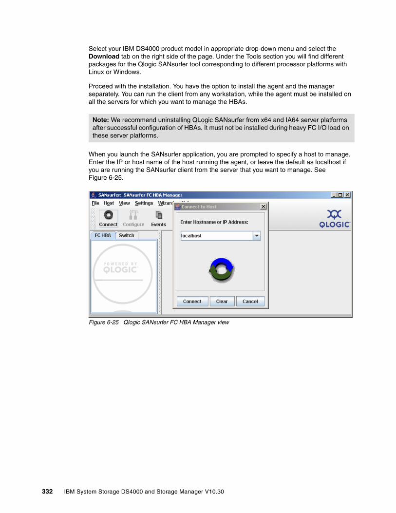
Select your IBM DS4000 product model in appropriate drop-down menu and select the Download tab on the right side of the page. Under the Tools section you will find different packages for the Qlogic SANsurfer tool corresponding to different processor platforms with Linux or Windows.
Proceed with the installation. You have the option to install the agent and the manager separately. You can run the client from any workstation, while the agent must be installed on all the servers for which you want to manage the HBAs.
When you launch the SANsurfer application, you are prompted to specify a host to manage. Enter the IP or host name of the host running the agent, or leave the default as localhost if you are running the SANsurfer client from the server that you want to manage. See Figure 6-25.
Figure 6-25 Qlogic SANsurfer FC HBA Manager view
Note: We recommend uninstalling QLogic SANsurfer from x64 and IA64 server platforms after successful configuration of HBAs. It must not be installed during heavy FC I/O load on these server platforms.
332 IBM System Storage DS4000 and Storage Manager V10.30
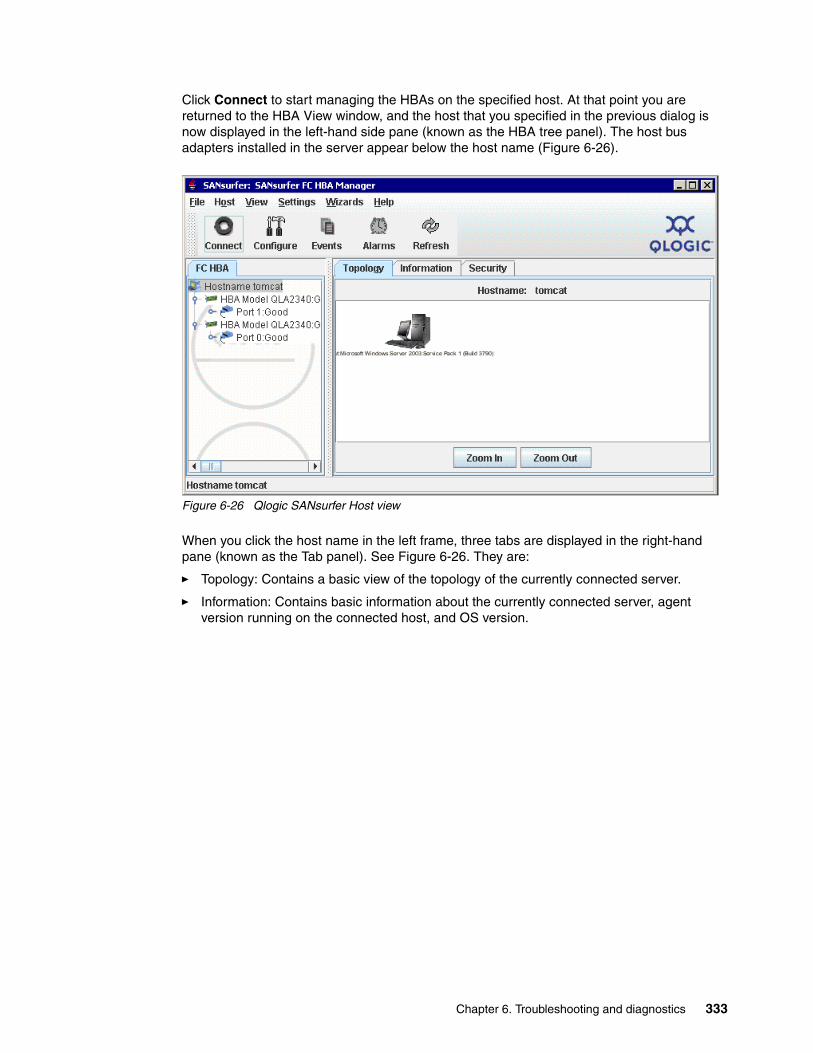
Click Connect to start managing the HBAs on the specified host. At that point you are returned to the HBA View window, and the host that you specified in the previous dialog is now displayed in the left-hand side pane (known as the HBA tree panel). The host bus adapters installed in the server appear below the host name (Figure 6-26).
Figure 6-26 Qlogic SANsurfer Host view
When you click the host name in the left frame, three tabs are displayed in the right-hand pane (known as the Tab panel). See Figure 6-26. They are:
� Topology: Contains a basic view of the topology of the currently connected server.
� Information: Contains basic information about the currently connected server, agent version running on the connected host, and OS version.
Chapter 6. Troubleshooting and diagnostics 333

� Security: Contains security settings for the connected agent. This lets you set host security and application security.
– Host access defines the authorized user with administrator or root privileges.
– Application access specifies the password for changing settings on the HBAs (for firmware or NVSRAM download or BIOS settings). See Figure 6-27.
Figure 6-27 Qlogic SANsurfer Security view
Viewing event and alarm logsThe Qlogic SANsurfer records an extensive set of information to the event and alarm logs. The logs are saved as text files (alarms.txt and events.txt) in the folder where Qlogic SANsurfer is installed. Qlogic SANsurfer can parse and view these logs in a window. To view these logs, click Event Log or Alarm Log from the view menu, or click the appropriate button on the button bar.
334 IBM System Storage DS4000 and Storage Manager V10.30

Using the Qlogic SANsurfer toolsWhen you click one of the host bus adapter ports in the HBA tree panel, the tab panel displays eight tabs, as shown in Figure 6-28.
Figure 6-28 Qlogic SANsurfer FC HBA Manager view
The Qlogic SANsurfer has several tabs for the HBAs:
� Information: Displays general information about the server and host bus adapters, such as worldwide name, BIOS, NVRAM, and driver version.
� Device List: Displays the devices currently available to the host bus adapter.
� Statistics: Displays a graph of the performance and errors on the host bus adapters over a period of time.
� Settings: Displays the current settings and allows you to make remote configuration changes to the NVSRAM of the adapters. All changes require a reboot of the server.
� Link Status: Displays link information for the devices attached to an adapter connected to a host.
� Target Persistent Binding: Allows you to bind a device to a specific LUN.
� Utilities: Allows you to update the flash and NVSRAM remotely.
� Diagnostics: Allows you to run diagnostic tests remotely.
Chapter 6. Troubleshooting and diagnostics 335

StatisticsThe Statistics panel (Figure 6-29) displays the following information:
� Adapter errors: The number of adapter errors reported by the adapter device driver (connection problem from or to switches or hubs).
� Device errors: The number of device errors reported by the adapter device driver (I/O problems to the storage server, and so on). This usually gives the first hint about what path to the storage server controller has a problem.
� Reset: The number of LIP resets reported by the adapter’s driver. If you get increasing numbers there might be a communication problem between HBAs and storage.
� I/O count: Total numbers of I/Os reported by the adapter’s driver.
� IOPS (I/O per second): The current number of I/Os processed by the adapter.
� BPS (bytes per second): The current numbers of bytes processed by the adapter.
Figure 6-29 Statistics window
336 IBM System Storage DS4000 and Storage Manager V10.30
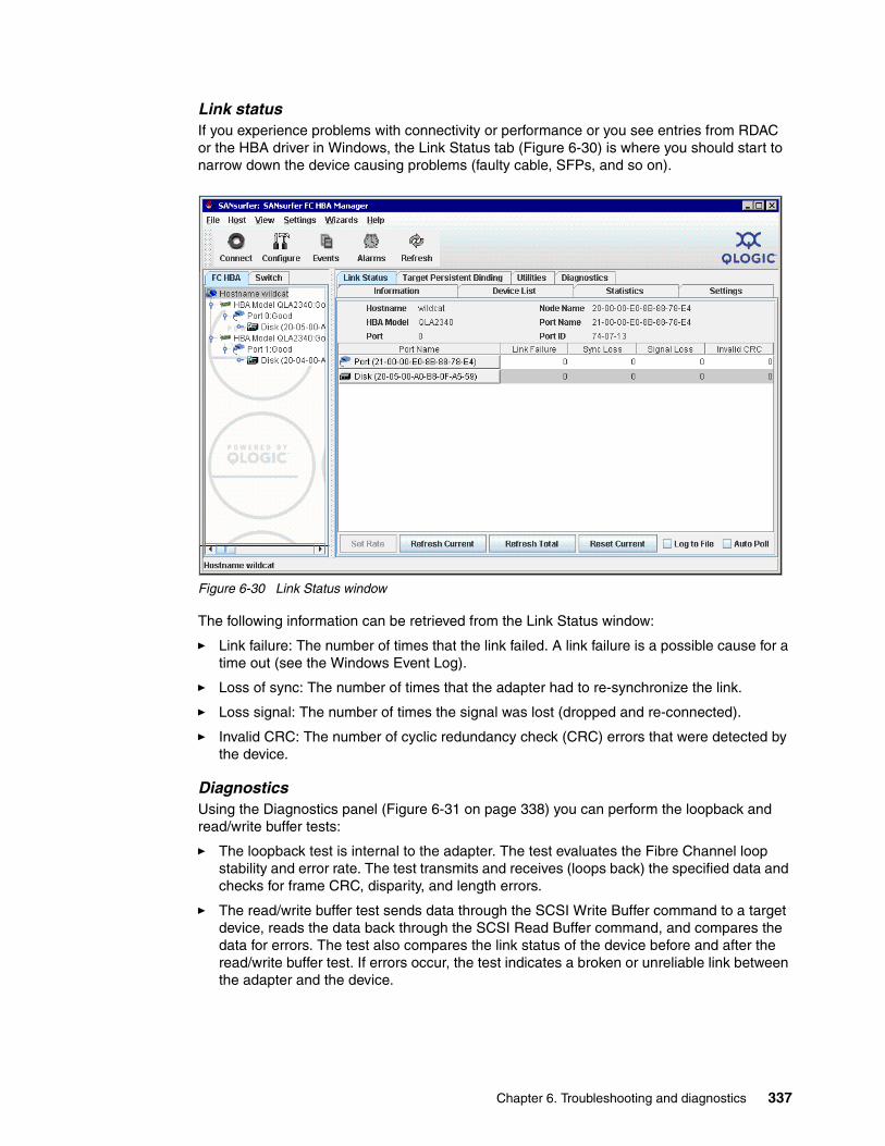
Link statusIf you experience problems with connectivity or performance or you see entries from RDAC or the HBA driver in Windows, the Link Status tab (Figure 6-30) is where you should start to narrow down the device causing problems (faulty cable, SFPs, and so on).
Figure 6-30 Link Status window
The following information can be retrieved from the Link Status window:
� Link failure: The number of times that the link failed. A link failure is a possible cause for a time out (see the Windows Event Log).
� Loss of sync: The number of times that the adapter had to re-synchronize the link.
� Loss signal: The number of times the signal was lost (dropped and re-connected).
� Invalid CRC: The number of cyclic redundancy check (CRC) errors that were detected by the device.
DiagnosticsUsing the Diagnostics panel (Figure 6-31 on page 338) you can perform the loopback and read/write buffer tests:
� The loopback test is internal to the adapter. The test evaluates the Fibre Channel loop stability and error rate. The test transmits and receives (loops back) the specified data and checks for frame CRC, disparity, and length errors.
� The read/write buffer test sends data through the SCSI Write Buffer command to a target device, reads the data back through the SCSI Read Buffer command, and compares the data for errors. The test also compares the link status of the device before and after the read/write buffer test. If errors occur, the test indicates a broken or unreliable link between the adapter and the device.
Chapter 6. Troubleshooting and diagnostics 337
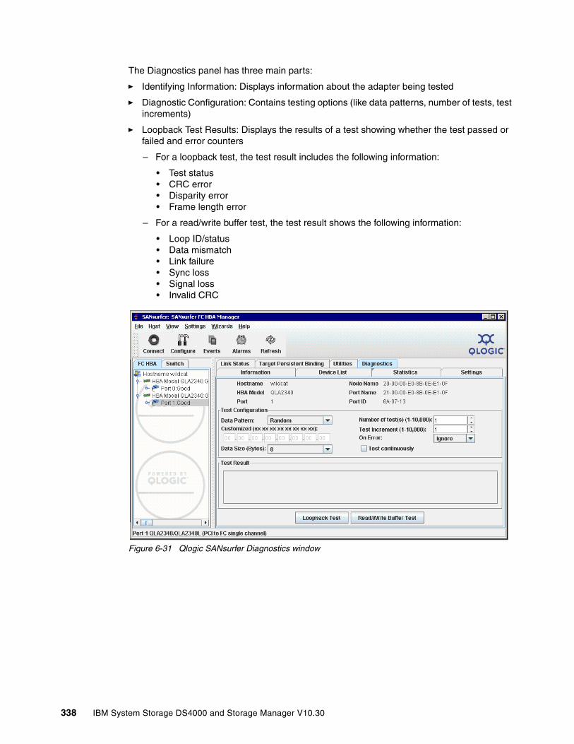
The Diagnostics panel has three main parts:
� Identifying Information: Displays information about the adapter being tested
� Diagnostic Configuration: Contains testing options (like data patterns, number of tests, test increments)
� Loopback Test Results: Displays the results of a test showing whether the test passed or failed and error counters
– For a loopback test, the test result includes the following information:
• Test status• CRC error• Disparity error• Frame length error
– For a read/write buffer test, the test result shows the following information:
• Loop ID/status• Data mismatch• Link failure• Sync loss• Signal loss• Invalid CRC
Figure 6-31 Qlogic SANsurfer Diagnostics window
338 IBM System Storage DS4000 and Storage Manager V10.30
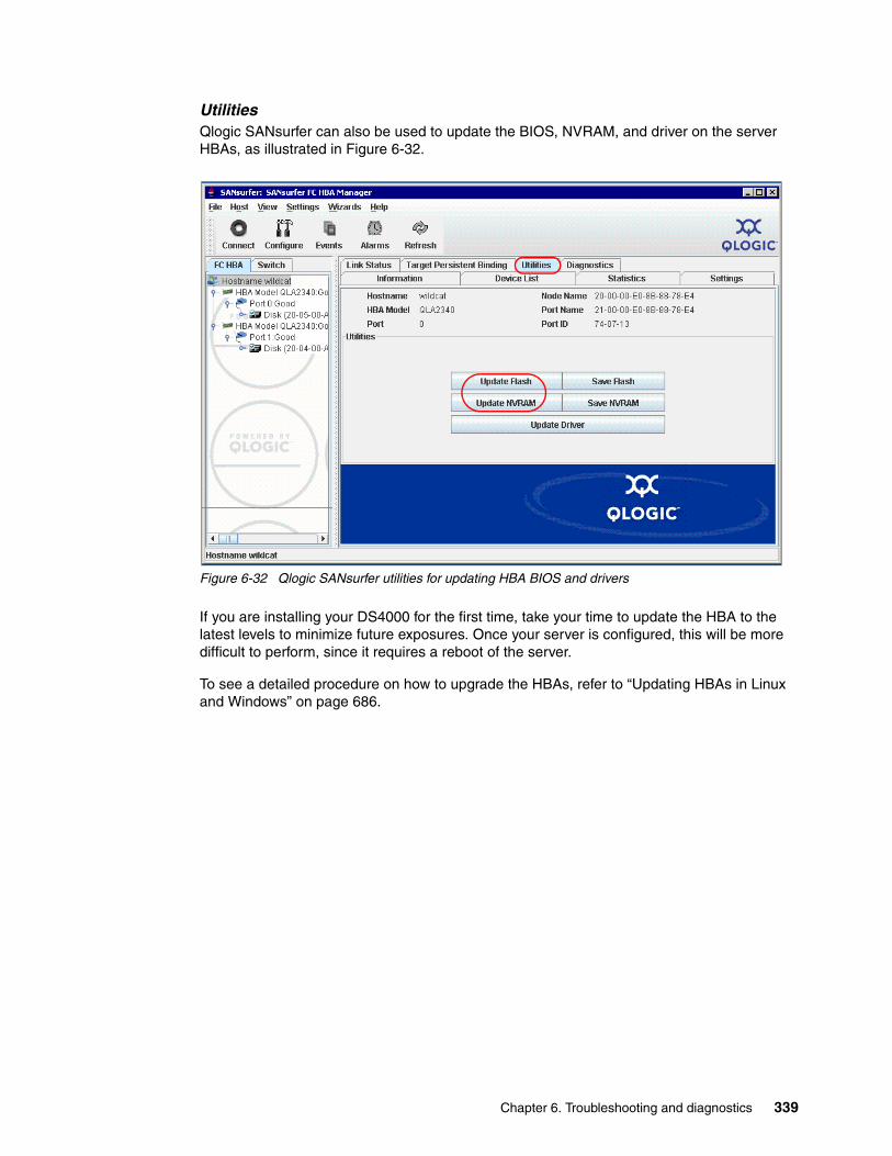
UtilitiesQlogic SANsurfer can also be used to update the BIOS, NVRAM, and driver on the server HBAs, as illustrated in Figure 6-32.
Figure 6-32 Qlogic SANsurfer utilities for updating HBA BIOS and drivers
If you are installing your DS4000 for the first time, take your time to update the HBA to the latest levels to minimize future exposures. Once your server is configured, this will be more difficult to perform, since it requires a reboot of the server.
To see a detailed procedure on how to upgrade the HBAs, refer to “Updating HBAs in Linux and Windows” on page 686.
Chapter 6. Troubleshooting and diagnostics 339

Displaying LUNs detectedTo display all the LUNs recognized by the HBAs, select the HBA tab in the left panel, then select the LUN list in the right panel, as shown in Figure 6-33.
Figure 6-33 Displaying LUNs with SANsurfer
6.4.2 Windows
The drivers supported for failover in Windows are:
� SM Failover driver (included with the Storage Manager 10 software package)� SDDDSM (available from the IBM SDD Support Web site)
The former RDAC drivers for Windows are no longer supported, starting with DS4000 Storage Manager 10.10 (firmware 7.10).
Important: SDDDSM is a driver first available with firmware 7.10. It can be used if there is a need to use the same HBA for access to different storage servers like DS6000, DS8000, or SVC that also support the SDDDSM driver. You need RPQ for this situation.
340 IBM System Storage DS4000 and Storage Manager V10.30

Determining driver and version in useYou can use the Windows Device Manager to check the driver and version being used:
� If you are running SDDDSM, as in the example shown in Figure 6-34, there is module under system devices identifying the driver. Select it and right-click to see the version of the driver installed.
Figure 6-34 Determining device driver in use
� If running the Storage Manager 10 Failover driver you will find under system devices an entry named IBM DS3000/DS4000 series Device Specific Module.
� If RDAC is installed, the devices are presented differently, and there is an RDAC Multipath Pseudo-Bus entry under the SCSI and RAID Controllers folder of the Device Manager.
Matching DS4000 logical drives with Windows disksThe DS4000 logical drives mapped to a Windows host are presented in the Windows Device Manager under the Disk drives section.
Chapter 6. Troubleshooting and diagnostics 341

Since both drivers supported (SM failover driver or SDDDSM) are based on the Microsoft MPIO architecture, but with different DCM modules, the device representation under the Device Manager is the same whether you have installed the MPIO driver or the SDDDSM driver. See Figure 6-35.
Figure 6-35 Device representation either using MPIO or SDDDSM
In the example presented in Figure 6-35, two DS4000 are configured:
� Machine type 1814 - DS4700 with three LUNs mapped and the access LUN� Machine type 1815 - DS4800 with only one logical drive mapped.
Therefore, we see in the Device Manager:
� IBM xxx Multipath Disk Device: Representation of each logical drive mapped. In the example in Figure 6-35, we have a total of 4.
� FAStT SCSI Disk Device: Representation of each logical volume as detected through each path. In the example we have two paths (two HBAs zoned), so we see twice the number of Multipath Disk Devices (that is, 8).
� IBM Universal Xport SCSI Disk Device: Representation of the DS4700 Access LUN as detected through each path. Since only one (DS4700) has the access LUN mapped in this example, and it is accesed through two different paths, two LUNs are detected. You should see in your system as many as the result of multiplying the number of HBAs connected per the number of access LUNs mapped to your host.
Use the QLogic SANsurfer utility to display more details for each LUN. If you have several DS4000s of the same model, it is easier to relate them using SANsurfer. See Figure 6-33 on page 340.
Access LUNrepresentation
Logical drivesas presented byeither MPIO orSDDDSM driver
342 IBM System Storage DS4000 and Storage Manager V10.30
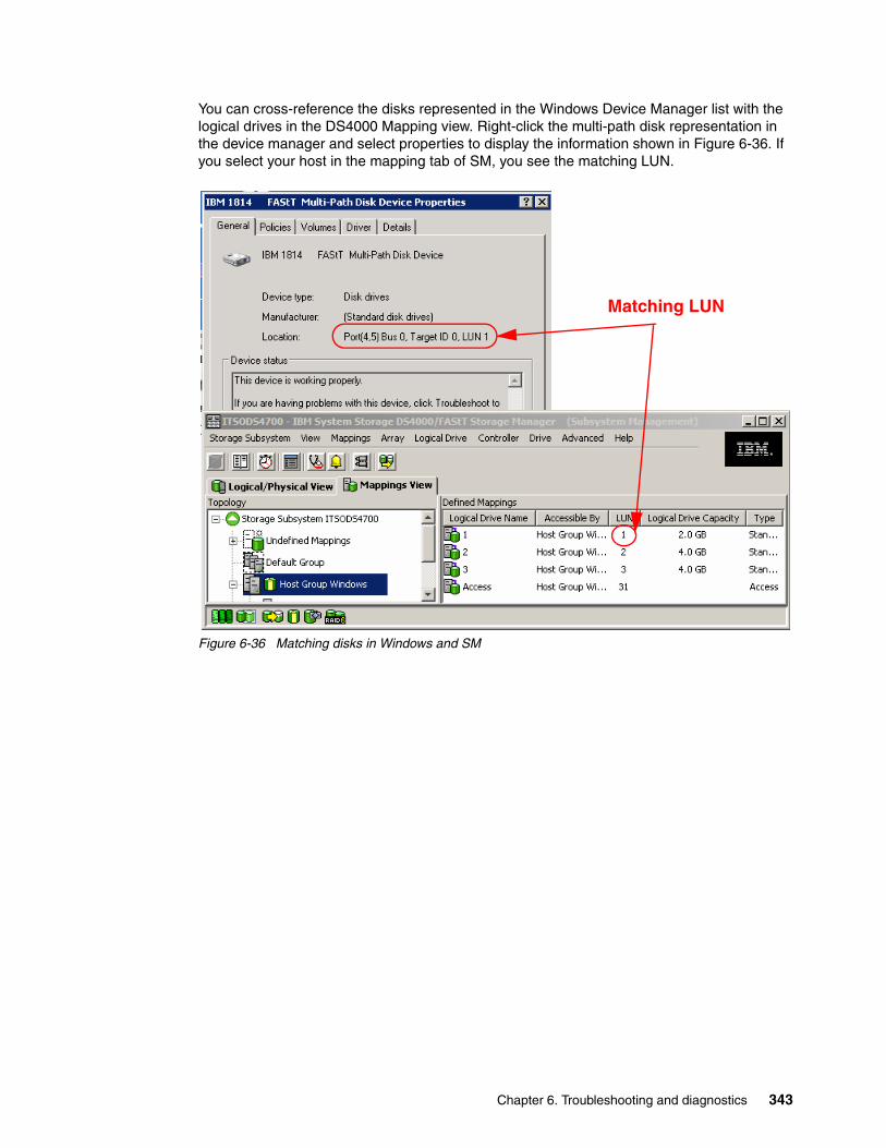
You can cross-reference the disks represented in the Windows Device Manager list with the logical drives in the DS4000 Mapping view. Right-click the multi-path disk representation in the device manager and select properties to display the information shown in Figure 6-36. If you select your host in the mapping tab of SM, you see the matching LUN.
Figure 6-36 Matching disks in Windows and SM
Matching LUN
Chapter 6. Troubleshooting and diagnostics 343

You can access the disk device properties in Windows from either the Device Manager or from the Disk Management window. In the Disk Management window, select the disk to match from the lower right panel, then right-click and select Properties. The same pop-up window as shown in Figure 6-36 on page 343 will be presented, but now with the added location indication that links the disk name to the physical location.
Figure 6-37 Disk Management
Right click and selectProperties to see LUN# and volumes
344 IBM System Storage DS4000 and Storage Manager V10.30
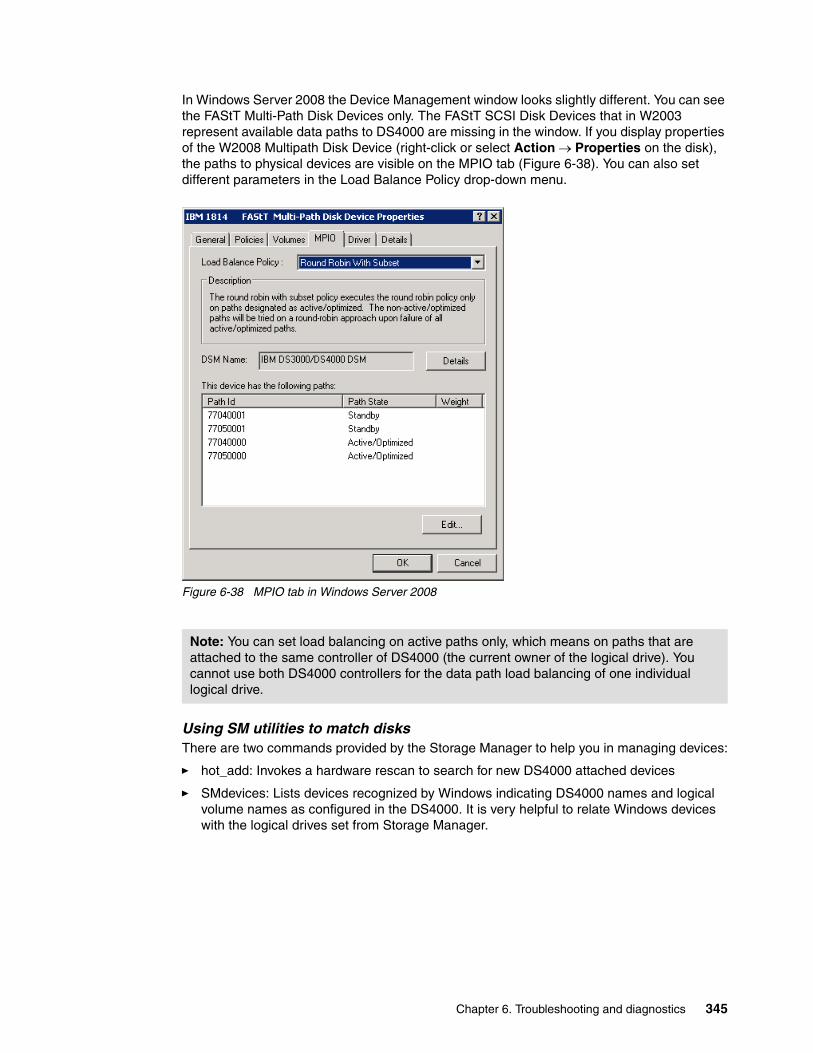
In Windows Server 2008 the Device Management window looks slightly different. You can see the FAStT Multi-Path Disk Devices only. The FAStT SCSI Disk Devices that in W2003 represent available data paths to DS4000 are missing in the window. If you display properties of the W2008 Multipath Disk Device (right-click or select Action → Properties on the disk), the paths to physical devices are visible on the MPIO tab (Figure 6-38). You can also set different parameters in the Load Balance Policy drop-down menu.
Figure 6-38 MPIO tab in Windows Server 2008
Using SM utilities to match disksThere are two commands provided by the Storage Manager to help you in managing devices:
� hot_add: Invokes a hardware rescan to search for new DS4000 attached devices
� SMdevices: Lists devices recognized by Windows indicating DS4000 names and logical volume names as configured in the DS4000. It is very helpful to relate Windows devices with the logical drives set from Storage Manager.
Note: You can set load balancing on active paths only, which means on paths that are attached to the same controller of DS4000 (the current owner of the logical drive). You cannot use both DS4000 controllers for the data path load balancing of one individual logical drive.
Chapter 6. Troubleshooting and diagnostics 345

SMdevices is installed under the util folder in the same directory where the SM Client is installed, and works with either MPIO or SDDDSM driver.
Figure 6-39 Using SMdevices utility
You can also use the drive ID string provided by the SMdevices output to identify your logical drive in the DS4000, as in Figure 6-40 on page 348.
SDDDSM driver utilitiesWe show below some commands available to manage devices through the SDDDSM driver.
The SDDDSM installation process generates a shortcut to the command starting at the directory where the utilities are installed. Select Start → Programs → Subsystem Device Driver DSM → Subsystem Device Driver DSM to go to the command line. Under the same folder are installed a readme file for the current version and a link to the IBM SDDDSM Web site.
Note: if you are using the SM Failover driver and you want to start using SDDDSM instead, you must uninstall the SM Failover driver by starting the uninstall process. From the control panel select Add Remove Programs → IBM DS4000 Storage Manager software. Then select only the SM Failover driver module to uninstall it.
C:\Program Files\IBM_DS4000\util>SMdevicesIBM System Storage DS4000/FAStT Storage Manager Devices, Version 90.00.35.06Built Wed Sep 05 17:11:53 CDT 2007(C) Copyright International Business Machines Corporation, 2003-2007 Licensed Material - Program Property of IBM. All rights reserved.
\\.\PHYSICALDRIVE2 [Storage Subsystem ITSODS4700, Logical Drive 1, LUN 1, Logical Drive ID <600a0b80002904de000005a246d82e17>, Preferred Path (Controller-A):In Use] \\.\PHYSICALDRIVE3 [Storage Subsystem ITSODS4700, Logical Drive 2, LUN 2, Logical Drive ID <600a0b800026b2820000054d46d82e79>, Preferred Path (Controller-B):In Use] \\.\PHYSICALDRIVE4 [Storage Subsystem ITSODS4700, Logical Drive 3, LUN 3, Logical Drive ID <600a0b80002904de000005a546d82ee8>, Preferred Path (Controller-A):In Use] \\.\PHYSICALDRIVE5 [Storage Subsystem ITSODS4800, Logical Drive Win1, LUN 1, Logical Drive ID <600a0b80001114be0000161646e97254>, Preferred Path (Controller-A): In Use] \\.\SYMsmUTMLun2 [Storage Subsystem ITSODS4700, Logical Drive Access, LUN 31,Logical Drive ID <600a0b800026b2820000022d46cc8bc4>] \\.\SYMsmUTMLun3 [Storage Subsystem ITSODS4700, Logical Drive Access, LUN 31,Logical Drive ID <600a0b800026b2820000022d46cc8bc4>]
346 IBM System Storage DS4000 and Storage Manager V10.30

Refer to the link provided for download, additional information, and updates for SDDDSM:
http://www.ibm.com/support/docview.wss?uid=ssg1S4000350&rs=555#ds4k
The commands provided to manage your SDDDSM devices are:
� datapath query version: Displays SDDDSM driver versions.
� datapath query adapter: Displays available paths to the devices from HBA.
� datapath query device: Shows all devices recognized by the SDDDSM driver.
� datapath set adapter online/offline: Sets all device paths that are attached to an adapter to online or offline.
� datapath set device path online/offline: Sets the path of an SDD path device to online or offline.
� datapath set device policy: Dynamically changes the path-selection policy of a single or multiple path devices. Specifies one of the following policies:
– rr, where rr indicates round robin– lb, where lb indicates load balancing (also known as optimized policy)– df, where df indicates the default policy, which is load balancing – fo, where fo indicates failover policy
For additional information about SDDDSM, refer to the latest Multipath Subsystem Device Driver User’s Guide, GC27-2164:
http://www.ibm.com/support/docview.wss?rs=540&context=ST52G7&uid=ssg1S7000303&loc=en_US&cs=utf-8&lang=en
Chapter 6. Troubleshooting and diagnostics 347

Matching DS4000 logical drives against SDDDSM devicesUse the command datapath query device to display all SDDDSM detected devices in your Windows host. To determine the relationship between your DS4000 logical drives, match the SERIAL field in the output of the command with the Logical drive world wide indentifier field in the Logical Drive Properties window, as shown in Figure 6-40.
Figure 6-40 Matching SDDDSM devices in Windows
The device name provided in this output is the name assigned by Windows as presented in the Disk Manager window, not the logical drive name that you assigned in the DS4000.
C:\Program Files\IBM\SDDDSM>datapath query device
Total Devices : 4
DEV#: 0 DEVICE NAME: Disk2 Part0 TYPE: 1814 POLICY: OPTIMIZEDSERIAL: 600A0B80002904DE0000293946F09D2F============================================================================Path# Adapter/Hard Disk State Mode Select Errors 0 Scsi Port4 Bus0/Disk2 Part0 OPEN NORMAL 41 0 1 Scsi Port5 Bus0/Disk2 Part0 OPEN NORMAL 0 0
DEV#: 1 DEVICE NAME: Disk3 Part0 TYPE: 1814 POLICY: OPTIMIZEDSERIAL: 600A0B80002904DE0000294546F10567============================================================================Path# Adapter/Hard Disk State Mode Select Errors 0 Scsi Port4 Bus0/Disk3 Part0 OPEN NORMAL 41 0 1 Scsi Port5 Bus0/Disk3 Part0 OPEN NORMAL 0 0
DEV#: 2 DEVICE NAME: Disk4 Part0 TYPE: 1814 POLICY: OPTIMIZEDSERIAL: 600A0B80002904DE0000294C46F1061D============================================================================Path# Adapter/Hard Disk State Mode Select Errors 0 Scsi Port4 Bus0/Disk4 Part0 OPEN NORMAL 41 0 1 Scsi Port5 Bus0/Disk4 Part0 OPEN NORMAL 0 0
348 IBM System Storage DS4000 and Storage Manager V10.30

Managing HBAsUse the datapath commands as illustrated in Figure 6-41 to query the adapter’s information when having a path problem. You might also find it useful when replacing HBAs to query the WWN and make necessary changes to the DS4000 mappings.
Figure 6-41 Managing HBAs with SDDDSM
Managing device pathsIf for any reason one device path is having problems, you can change its status back to online after solving the problem, using the sequence shown in Figure 6-42.
Figure 6-42 Managing SDDDSM device paths
C:\Program Files\IBM\SDDDSM>datapath query adapterActive Adapters :2Adpt# Name State Mode Select Errors Paths Active 0 Scsi Port4 Bus0 FAILED OFFLINE 123 0 4 0 1 Scsi Port5 Bus0 NORMAL ACTIVE 41 0 4 4
C:\Program Files\IBM\SDDDSM>datapath set adapter 0 onlineSuccess: set adapter 0 to onlineAdpt# Name State Mode Select Errors Paths Active 0 Scsi Port4 Bus0 NORMAL ACTIVE 123 0 4 4
C:\Program Files\IBM\SDDDSM>datapath query adapterActive Adapters :2Adpt# Name State Mode Select Errors Paths Active 0 Scsi Port4 Bus0 NORMAL ACTIVE 123 0 4 4 1 Scsi Port5 Bus0 NORMAL ACTIVE 41 0 4 4
C:\Program Files\IBM\SDDDSM>datapath query device 2
DEV#: 2 DEVICE NAME: Disk4 Part0 TYPE: 1814 POLICY: OPTIMIZEDSERIAL: 600A0B80002904DE0000294C46F1061D============================================================================Path# Adapter/Hard Disk State Mode Select Errors 0 Scsi Port4 Bus0/Disk4 Part0 DEAD OFFLINE 41 0 1 Scsi Port5 Bus0/Disk4 Part0 OPEN NORMAL 0 0
C:\Program Files\IBM\SDDDSM>datapath set device 2 path 0 online
Success: set device 2 path 0 to online
DEV#: 2 DEVICE NAME: Disk4 Part0 TYPE: 1814 POLICY: OPTIMIZEDSERIAL: 600A0B80002904DE0000294C46F1061D============================================================================Path# Adapter/Hard Disk State Mode Select Errors 0 Scsi Port4 Bus0/Disk4 Part0 OPEN NORMAL 41 0 1 Scsi Port5 Bus0/Disk4 Part0 OPEN NORMAL 0 0
Chapter 6. Troubleshooting and diagnostics 349

Collecting informationIn addition to the information mentioned in 6.1.4, “Support data: Collecting information” on page 302, you should also consider evaluating or sending your service provider the following information from your Windows host system to perform problem determination over certain failures:
� System event log: Right-click the my computer icon on your desktop and select Manage to open the System Management window. From the system tools option under Computer Management, select Event viewer → System. Now click Action from the pull-down menu, and select Save Log File as to save the event view log file.
� Application log: Proceed as for the system event log but this time selecting the application log.
� Dynamic system analysis, DSA log: IBM Dynamic System Analysis (DSA) collects and analyzes system information to aid in diagnosing system problems. This is a tool developed initially for System x servers that not only collects the system event and application logs, but also information from your adapters, drivers, and configuration. This allows you to easily provide all the information that your support representative needs in one package. This tool is available at:
http://www-03.ibm.com/systems/management/dsa.html
� sddgetdata: Use this script if SDDDSM is installed to collect support information. It creates a cab file in the directory where the driver was installed, with the current date and time as part of the file name.
6.4.3 Linux
There are two options of drivers available to manage DS4000 in Linux:
� The RDAC driver � The HBA failover driver
RDAC provides additional functions and utilities to get much better information out of the operating system about the DS4000. Once the RDAC driver is installed, you have access to several commands, useful for problem determination and fixing. The utilities are:
� mppUtil: This utility is used with the Linux RDAC driver to perform the various functions provided by the driver.
� hot_add: This command rescans your HBA to detect and configure new devices on SAN.
� mppBusRescan: This program is equivalent to hot_add and also probes the physical bus hardware to discover any newly attached DS4000 devices. These can either be new LUNs on an existing system or a new storage system. All the physical buses are scanned for new devices or LUNs. Any that are found are registered with the OS and attached to the RDAC driver. This script should be run any time that new storage server devices are connected or new LUNs are mapped to a system.
� mppUpdate: This script uses the mppUtil utility to discover the RDAC-assigned virtual target IDs of the attached subsystems. It then updates the RDAC driver configuration file (/var/mpp/devicemapping), so the entries will be persistent after a reboot. The first time that the RDAC driver sees a storage system, it will arbitrarily assign a target ID for the virtual target that represents the storage system. At this point the target ID assignment is not persistent. It could change on a reboot. The mppUpdate utility updates the RDAC driver configuration files so that these target ID assignments are persistent and do not change across reboots. Once made persistent, the user does not have to worry about the possibility of device names changing and invalidating mount points.
350 IBM System Storage DS4000 and Storage Manager V10.30

mppUpdate must be executed after a DS4000 is added to or removed from the system. If a storage system is added to the installation, mppBusRescan also must be run before mppUpdate is run. mppUpdate must also be executed whenever a user changes the RDAC configuration file /etc/mpp.conf to rebuild the new configuration file into the RAM Disk image that will be used for the next reboot.
Listing DS4000 subsystems in LinuxIf you want to scan for all the DS4000s that are attached to your Linux host, you must use the command mpputil -a, as shown in Example 6-4.
Example 6-4 mppUtil -a
[root@moleman root]# mppUtil -aHostname = moleman.tuscon.storage.ibm.comDomainname = (none)Time = GMT 09/13/2007 15:36:50
---------------------------------------------------------------Info of Array Module's seen by this Host. ---------------------------------------------------------------ID WWN Name ---------------------------------------------------------------0 600a0b80002904de0000000046cb276c ITSODS4700 1 600a0b80000c808a0000000041797a87 DS4400_PRIMARY ---------------------------------------------------------------
In Example 6-4 two DS4000s are presented to the Linux host. Each has an ID number assigned. You use that number to query for specific details of the subsystem.
Displaying DS4000 devices from LinuxUse the command mppUtil to list the DS4000 devices found together with their characteristics. Use the parameter -g to specify your specific DS4000 number previously obtained using the command mppUtil -a, as shown in Example 6-4.
Example 6-5 mppUtil -g
[root@moleman root]# mppUtil -g1Hostname = moleman.tuscon.storage.ibm.comDomainname = (none)Time = 09/13/2007 15:36:06
MPP Information:---------------- ModuleName: DS4400_PRIMARY SingleController: N VirtualTargetID: 0x001 ScanTriggered: N ObjectCount: 0x000 AVTEnabled: N WWN: 600a0b80000c808a0000000041797a87 RestoreCfg: N ModuleHandle: none Page2CSubPage: Y FirmwareVersion: 7.10.6.0 ScanTaskState: 0x00000000
Note: Linux RDAC supports re-scan of a newly mapped LUN without rebooting the server. The utility program is packaged with the Linux RDAC driver. Rescan can be invoked by either the hot_add or the mppBusRescan command. hot_add is a symbolic link to mppBusRescan. There are man pages for both commands. However, the Linux RDAC driver does not support LUN deletion. You must reboot the server after deleting the mapped logical drives.
Chapter 6. Troubleshooting and diagnostics 351
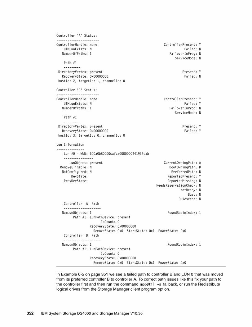
Controller 'A' Status:-----------------------ControllerHandle: none ControllerPresent: Y UTMLunExists: N Failed: N NumberOfPaths: 1 FailoverInProg: N ServiceMode: N Path #1 --------- DirectoryVertex: present Present: Y RecoveryState: 0x00000000 Failed: N hostId: 2, targetId: 1, channelId: 0
Controller 'B' Status:-----------------------ControllerHandle: none ControllerPresent: Y UTMLunExists: N Failed: Y NumberOfPaths: 1 FailoverInProg: N ServiceMode: N Path #1 --------- DirectoryVertex: present Present: Y RecoveryState: 0x00000000 Failed: Y hostId: 3, targetId: 0, channelId: 0
Lun Information--------------- Lun #0 - WWN: 600a0b80000cafca0000000441937cab ---------------- LunObject: present CurrentOwningPath: A RemoveEligible: N BootOwningPath: B NotConfigured: N PreferredPath: B DevState: ReportedPresent: Y PrevDevState: ReportedMissing: N NeedsReservationCheck: N NotReady: N Busy: N Quiescent: N Controller 'A' Path -------------------- NumLunObjects: 1 RoundRobinIndex: 1 Path #1: LunPathDevice: present IoCount: 0 RecoveryState: 0x00000000 RemoveState: 0x0 StartState: 0x1 PowerState: 0x0 Controller 'B' Path -------------------- NumLunObjects: 1 RoundRobinIndex: 1 Path #1: LunPathDevice: present IoCount: 0 RecoveryState: 0x00000000 RemoveState: 0x0 StartState: 0x1 PowerState: 0x0
In Example 6-5 on page 351 we see a failed path to controller B and LUN 0 that was moved from its preferred controller B to controller A. To correct path issues like this fix your path to the controller first and then run the command mppUtil -s failback, or run the Redistribute logical drives from the Storage Manager client program option.
352 IBM System Storage DS4000 and Storage Manager V10.30
To relate the devices detected by your Linux to the logical drives configured and mapped to your host in the DS4000, use the mppUtil utility. you can use the LUN number listed and the WWN string to determine the corresponding logical drive in your DS4000.
Collecting informationIn addition to the information mentioned in 6.1.4, “Support data: Collecting information” on page 302, you can also send to your service provider additional information about the Linux host server, collected through the following commands:
� SMdevices: Lists of DS4000s recognized by your server (if SMutil installed).
� rpm -qa: Lists installed software.
� mppUtil -V: Lists installed disk driver version.
� ls -lR /proc/mpp: Lists devices recognized by the RDAC driver.
� cat/proc/scsi/scsi: Lists the LUNs recognized by the HBAs.
� /opt/mpp/mppSupport: Script provided by RDAC to collect information. Generates a compressed file in the /tmp folder.
� Dynamic System Analysis, DSA log: IBM Dynamic System Analysis (DSA) collects and analyzes system information to aid in diagnosing system problems. This is a tool developed initially for System x servers, available for Linux and Windows, that executed in your server can provide all the information the your support representative will need in one package. You can find the DSA tools at:
http://www-03.ibm.com/systems/management/dsa.html
6.4.4 HP-UX
In this section we list commands available to help in problem determination under HP-UX.
Collecting informationIn addition to the information mentioned in 6.1.4, “Support data: Collecting information” on page 302, you can also send to your service provider additional information collected through the following commands:
� swlist: Shows current installed software packages.
� ioscan –f: Displays I/O configuration.
� /var/adm/syslog/syslog.log: System event log file.
� dmsg: Displays error messages.
� vgdisplay –v: Displays volume group information, including status of logical volumes and physical volumes (run for all volume groups).
� lvdisplay –v: Displays logical volume information, including mapping and status of logical extents (run for all volume groups).
� pvdisplay –v: Displays physical volume information, including status of physical extents (run for all volume groups).
� ll /dev/*dsk: Lists all disks recognized by the system.
� tdutil /dev/td*: Displays WWN of the installed HBAs. Do for all td* listed under /dev/td.
� SMdevices: Provides the DS4000 devices found in your system.
Chapter 6. Troubleshooting and diagnostics 353

6.4.5 Solaris
In this section we list commands available to help with problem determination under Solaris.
Collecting informationIn addition to the information mentioned in 6.1.4, “Support data: Collecting information” on page 302, you can also send to your service provider additional information collected through the following commands:
� /opt/SUNWexplo/bin/explorer –t /tmp: This collects a compresses file in the /tmp directory containing most of the information needed regarding the configuration on your Solaris system. This is provided by the explorer utility installed in your system. If it is not installed, you can find it in your Solaris distribution CDs, looking for package SUNWexplo.
� SMdevices: Lists all DS4000 devices recognized by the host.
Solaris commandsSome Solaris commands are:
� more /var/adm/messages: Displays the messages file to view events and errors
� luxadm probe: Displays Fibre Channel devices and manages hot swap operations
� pkginfo: Displays software package information
� showrev -p: Shows machine, software revision, and patch revision
� df -k: Displays used file systems and disk space
� devfsadm: Configures devices added after the last boot
� ls -la /dev/rdsk: Lists all disk devices recognized
� prtdiag -v: Displays system diagnostic information
SUN OBP commandsWhen installing new storage or an adapter in a SUN server, you must shut down Solaris. SUN machines have a prompt available before loading the kernel. Some the commands available in that environment that you may use for testing are:
� probe-scsi-all: Scans all SCSI adapters and displays devices found
� probe-fcal-all: Scans all FC adapters and displays devices found
� obdiag: Interactively runs tests and diagnostics on some SUN systems
6.4.6 AIX
In this section we discuss commands available to help in problem determination under AIX.
AIX host systems require the AIX FCP Disk Array Controller (RDAC for AIX) failover driver for Fibre Channel path redundancy. The failover driver monitors I/O paths. If a component failure occurs in one of the Fibre Channel paths, the failover driver reroutes all I/O to another path.
354 IBM System Storage DS4000 and Storage Manager V10.30
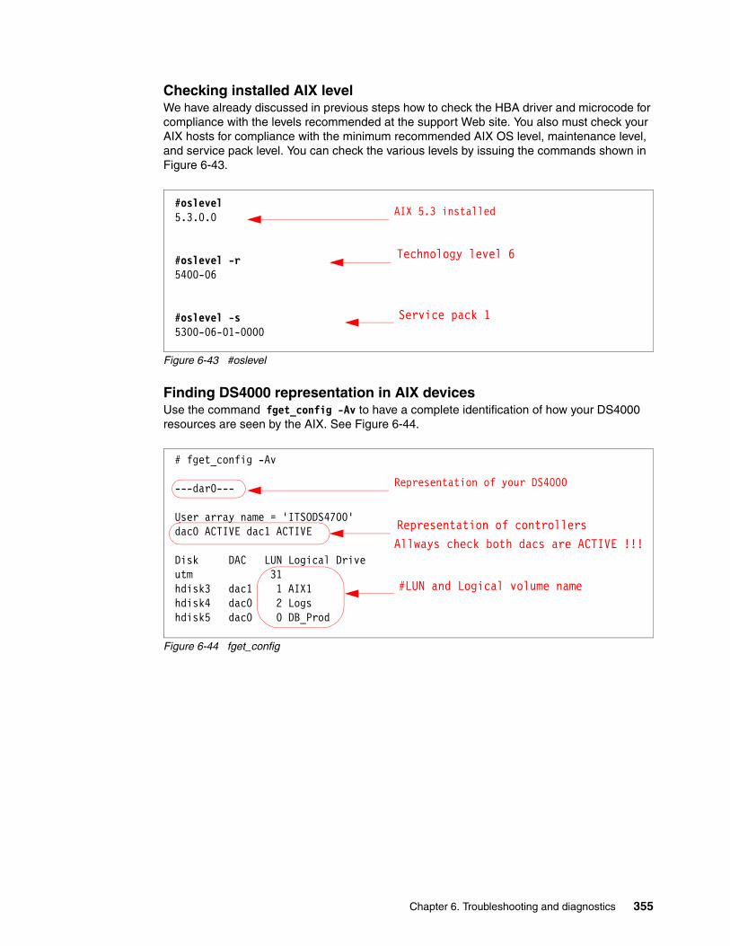
Checking installed AIX levelWe have already discussed in previous steps how to check the HBA driver and microcode for compliance with the levels recommended at the support Web site. You also must check your AIX hosts for compliance with the minimum recommended AIX OS level, maintenance level, and service pack level. You can check the various levels by issuing the commands shown in Figure 6-43.
Figure 6-43 #oslevel
Finding DS4000 representation in AIX devicesUse the command fget_config -Av to have a complete identification of how your DS4000 resources are seen by the AIX. See Figure 6-44.
Figure 6-44 fget_config
#oslevel5.3.0.0
#oslevel -r5400-06
#oslevel -s5300-06-01-0000
Service pack 1
AIX 5.3 installed
Technology level 6
# fget_config -Av
---dar0---
User array name = 'ITSODS4700'dac0 ACTIVE dac1 ACTIVE
Disk DAC LUN Logical Driveutm 31hdisk3 dac1 1 AIX1hdisk4 dac0 2 Logshdisk5 dac0 0 DB_Prod
#LUN and Logical volume name
Representation of your DS4000
Allways check both dacs are ACTIVE !!!Representation of controllers
Chapter 6. Troubleshooting and diagnostics 355
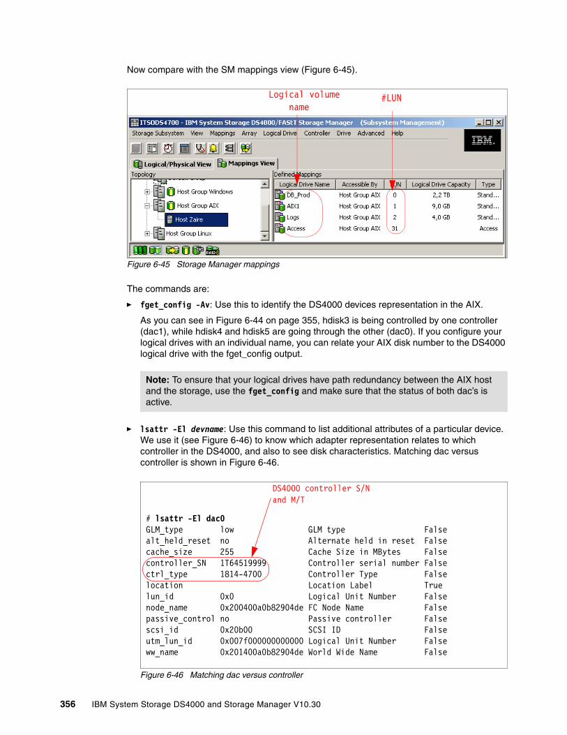
Now compare with the SM mappings view (Figure 6-45).
Figure 6-45 Storage Manager mappings
The commands are:
� fget_config -Av: Use this to identify the DS4000 devices representation in the AIX.
As you can see in Figure 6-44 on page 355, hdisk3 is being controlled by one controller (dac1), while hdisk4 and hdisk5 are going through the other (dac0). If you configure your logical drives with an individual name, you can relate your AIX disk number to the DS4000 logical drive with the fget_config output.
� lsattr -El devname: Use this command to list additional attributes of a particular device. We use it (see Figure 6-46) to know which adapter representation relates to which controller in the DS4000, and also to see disk characteristics. Matching dac versus controller is shown in Figure 6-46.
Figure 6-46 Matching dac versus controller
Note: To ensure that your logical drives have path redundancy between the AIX host and the storage, use the fget_config and make sure that the status of both dac’s is active.
#LUNLogical volumename
# lsattr -El dac0GLM_type low GLM type Falsealt_held_reset no Alternate held in reset Falsecache_size 255 Cache Size in MBytes Falsecontroller_SN 1T64519999 Controller serial number Falsectrl_type 1814-4700 Controller Type Falselocation Location Label Truelun_id 0x0 Logical Unit Number Falsenode_name 0x200400a0b82904de FC Node Name Falsepassive_control no Passive controller Falsescsi_id 0x20b00 SCSI ID Falseutm_lun_id 0x007f000000000000 Logical Unit Number Falseww_name 0x201400a0b82904de World Wide Name False
DS4000 controller S/Nand M/T
356 IBM System Storage DS4000 and Storage Manager V10.30
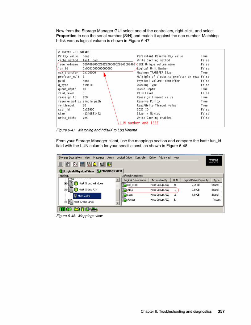
Now from the Storage Manager GUI select one of the controllers, right-click, and select Properties to see the serial number (S/N) and match it against the dac number. Matching hdisk versus logical volume is shown in Figure 6-47.
Figure 6-47 Matching and hdiskX to Log.Volume
From your Storage Manager client, use the mappings section and compare the lsattr lun_id field with the LUN column for your specific host, as shown in Figure 6-48.
Figure 6-48 Mappings view
# lsattr -El hdisk3PR_key_value none Persistant Reserve Key Value Truecache_method fast_load Write Caching method Falseieee_volname 600A0B800026B2820000029346CDB46B IEEE Unique volume name Falselun_id 0x0001000000000000 Logical Unit Number Falsemax_transfer 0x100000 Maximum TRANSFER Size Trueprefetch_mult 1 Multiple of blocks to prefetch on read Falsepvid none Physical volume identifier Falseq_type simple Queuing Type Falsequeue_depth 10 Queue Depth Trueraid_level 3 RAID Level Falsereassign_to 120 Reassign Timeout value Truereserve_policy single_path Reserve Policy Truerw_timeout 30 Read/Write Timeout value Truescsi_id 0x21900 SCSI ID Falsesize -1340551442 Size in Mbytes Falsewrite_cache yes Write Caching enabled False
LUN number and IEEE
Chapter 6. Troubleshooting and diagnostics 357
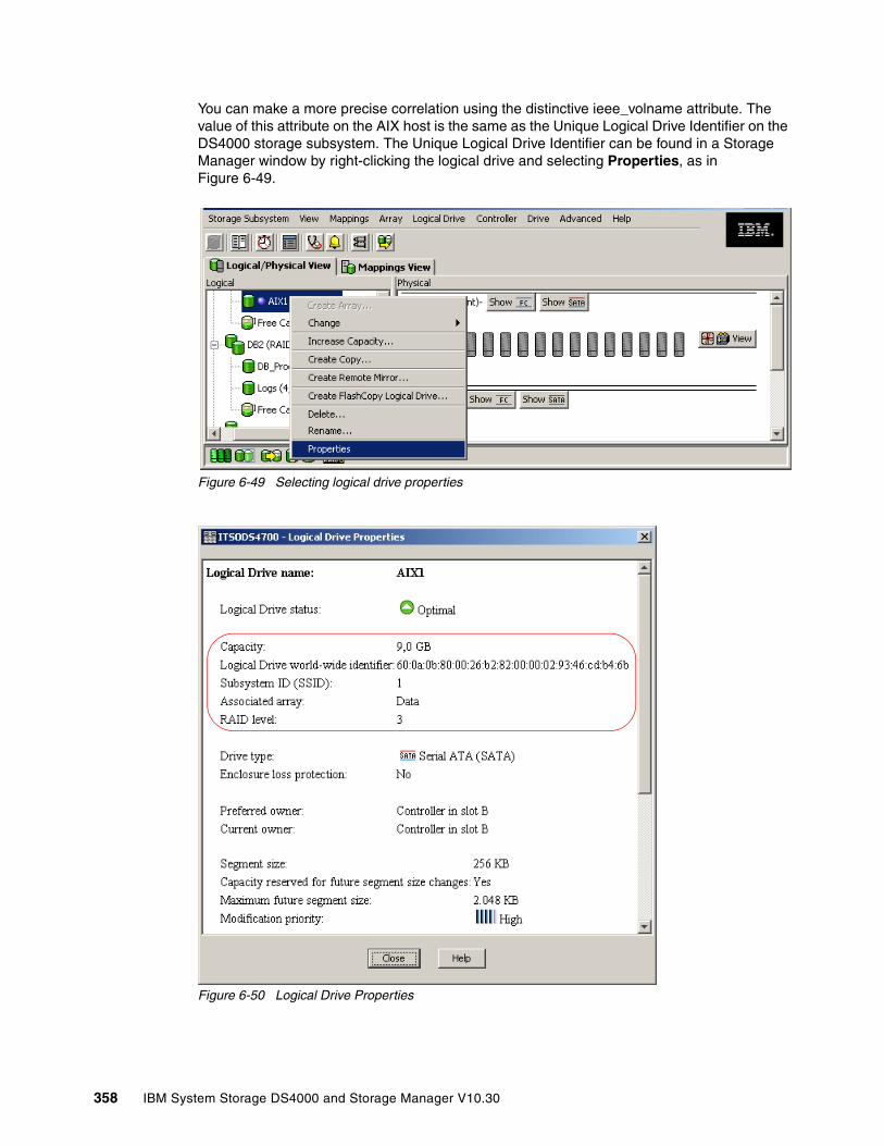
You can make a more precise correlation using the distinctive ieee_volname attribute. The value of this attribute on the AIX host is the same as the Unique Logical Drive Identifier on the DS4000 storage subsystem. The Unique Logical Drive Identifier can be found in a Storage Manager window by right-clicking the logical drive and selecting Properties, as in Figure 6-49.
Figure 6-49 Selecting logical drive properties
Figure 6-50 Logical Drive Properties
358 IBM System Storage DS4000 and Storage Manager V10.30

Displaying HBAsOften you must check your HBA WWPN or its firmware version. Use the command lscfg -vl fcs0 for an HBA with the name fcs0, as shown in Figure 6-51.
Figure 6-51 Diplaying HBA WWN and microcode
See 12.1.8, “Updating Host FC adapter firmware” on page 686, for examples of how to update an FC adapter microcode under AIX.
Collecting informationExecute the following sequence of commands to capture information to send for problem analysis:
1. snap -r: This removes previous data collections from /tmp/ibmsupt.
2. snap -gflHc: This collects information from your system and generates a compressed file in the /tmp/ibmsupt directory, named snap.pax.Z. Send the compressed file output to your IBM Support Representative for review.
3. fget_config -Av: This shows how your specific DS4000 is recognized by your RDAC AIX driver.
Commands to display disk usageThe commands are:
� lspv: Displays all disks and their usage per volume group (even vg not active)� lsvg -o: Displays only online volume groups.� mount: Displays file systems currently in use� lsvg -l vgname: Lists file systems for the vgname volume group (only if vg is active)� lspv -l hdisk*: Lists file systems in disk hdisk*
# lscfg -vl fcs0 fcs0 U0.1-P2-I4/Q1 FC Adapter
Part Number.................00P4494 EC Level....................A Serial Number...............1E3120A73F Manufacturer................001E Device Specific.(CC)........2765 FRU Number.................. 00P4495 Network Address.............10000000C932A8B3 ROS Level and ID............02C03891 Device Specific.(Z0)........2002606D Device Specific.(Z1)........00000000 Device Specific.(Z2)........00000000 Device Specific.(Z3)........02000909 Device Specific.(Z4)........FF401050 Device Specific.(Z5)........02C03891 Device Specific.(Z6)........06433891 Device Specific.(Z7)........07433891 Device Specific.(Z8)........20000000C932A8B3 Device Specific.(Z9)........CS3.82A1 Device Specific.(ZA)........C1D3.82A1 Device Specific.(ZB)........C2D3.82A1 Device Specific.(YL)........U0.1-P2-I4/Q1
Microcode Level
WWN
Chapter 6. Troubleshooting and diagnostics 359
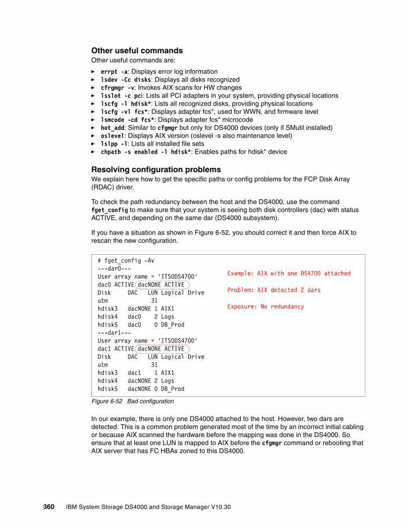
Other useful commandsOther useful commands are:
� errpt -a: Displays error log information� lsdev -Cc disks: Displays all disks recognized� cfrgmgr -v: Invokes AIX scans for HW changes� lsslot -c pci: Lists all PCI adapters in your system, providing physical locations� lscfg -l hdisk*: Lists all recognized disks, providing physical locations� lscfg -vl fcs*: Displays adapter fcs*, used for WWN, and firmware level� lsmcode -cd fcs*: Displays adapter fcs* microcode� hot_add: Similar to cfgmgr but only for DS4000 devices (only if SMutil installed)� oslevel: Displays AIX version (oslevel -s also maintenance level)� lslpp -l: Lists all installed file sets� chpath -s enabled -l hdisk*: Enables paths for hdisk* device
Resolving configuration problemsWe explain here how to get the specific paths or config problems for the FCP Disk Array (RDAC) driver.
To check the path redundancy between the host and the DS4000, use the command fget_config to make sure that your system is seeing both disk controllers (dac) with status ACTIVE, and depending on the same dar (DS4000 subsystem).
If you have a situation as shown in Figure 6-52, you should correct it and then force AIX to rescan the new configuration.
Figure 6-52 Bad configuration
In our example, there is only one DS4000 attached to the host. However, two dars are detected. This is a common problem generated most of the time by an incorrect initial cabling or because AIX scanned the hardware before the mapping was done in the DS4000. So ensure that at least one LUN is mapped to AIX before the cfgmgr command or rebooting that AIX server that has FC HBAs zoned to this DS4000.
# fget_config -Av---dar0---User array name = 'ITSODS4700'dac0 ACTIVE dacNONE ACTIVEDisk DAC LUN Logical Driveutm 31hdisk3 dacNONE 1 AIX1hdisk4 dac0 2 Logshdisk5 dac0 0 DB_Prod---dar1---User array name = 'ITSODS4700'dac1 ACTIVE dacNONE ACTIVEDisk DAC LUN Logical Driveutm 31hdisk3 dac1 1 AIX1hdisk4 dacNONE 2 Logshdisk5 dacNONE 0 DB_Prod
Example: AIX with one DS4700 attached
Problem: AIX detected 2 dars
Exposure: No redundancy
360 IBM System Storage DS4000 and Storage Manager V10.30
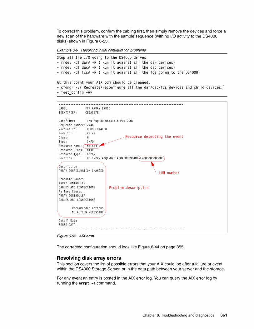
To correct this problem, confirm the cabling first, then simply remove the devices and force a new scan of the hardware with the sample sequence (with no I/O activity to the DS4000 disks) shown in Figure 6-53.
Example 6-6 Resolving initial configuration problems
Stop all the I/O going to the DS4000 drives- rmdev -dl dar# -R ( Run it against all the dar devices)- rmdev -dl dac# -R ( Run it against all the dac devices)- rmdev -dl fcs# -R ( Run it against all the fcs going to the DS4000)
At this point your AIX odm should be cleaned.- cfgmgr -v( Recreate/reconfigure all the dar/dac/fcs devices and child devices.)- fget_config -Av
Figure 6-53 AIX errpt
The corrected configuration should look like Figure 6-44 on page 355.
Resolving disk array errorsThis section covers the list of possible errors that your AIX could log after a failure or event within the DS4000 Storage Server, or in the data path between your server and the storage.
For any event an entry is posted in the AIX error log. You can query the AIX error log by running the errpt -a command.
---------------------------------------------------------------------------LABEL: FCP_ARRAY_ERR10IDENTIFIER: C86ACB7E
Date/Time: Thu Aug 30 06:33:16 PDT 2007Sequence Number: 7446Machine Id: 0009CF0A4C00Node Id: ZaireClass: HType: INFOResource Name: hdisk4Resource Class: diskResource Type: arrayLocation: U0.1-P2-I4/Q1-W201400A0B82904DE-L2000000000000
DescriptionARRAY CONFIGURATION CHANGED
Probable CausesARRAY CONTROLLERCABLES AND CONNECTIONSFailure CausesARRAY CONTROLLERCABLES AND CONNECTIONS
Recommended Actions NO ACTION NECESSARY
Detail DataSENSE DATA---------------------------------------------------------------------------
Resource detecting the event
LUN number
Problem description
Chapter 6. Troubleshooting and diagnostics 361
RDAC AIX disk array error labelsThe labels are:
� FCP_ARRAY_ERR1 ARRAY OPERATION ERROR
A permanent hardware error involving the disk array media.
� FCP_ARRAY_ERR2 ARRAY OPERATION ERROR
A permanent hardware error.
� FCP_ARRAY_ERR3 ARRAY OPERATION ERROR
A permanent error detected by the array adapter.
� FCP_ARRAY_ERR4 ARRAY OPERATION ERROR
A temporary error within the array, communications, adapter, and so on.
� FCP_ARRAY_ERR5 UNDETERMINED ERROR
An undetermined error has occurred.
� FCP_ARRAY_ERR6 SUBSYSTEM COMPONENT FAILURE
A degradation condition has occurred other than a disk drive.
� FCP_ARRAY_ERR7 CONTROLLER HEALTH CHECK FAILURE
A health check on the passive controller has failed.
� FCP_ARRAY_ERR8 ARRAY CONTROLLER SWITCH
One array controller has become unavailable, so I/O has moved to the other controller.
� FCP_ARRAY_ERR9 ARRAY CONTROLLER SWITCH FAILURE
An array controller switch has failed.
� FCP_ARRAY_ERR10 ARRAY CONFIGURATION CHANGED
A logical unit has been moved from one controller to the other (most likely by the action of an alternate host).
� FCP_ARRAY_ERR11 IMPROPER DRIVE TYPE FOR DUAL ACTIVE MODE
This error should not be possible on the 2102 array, and exists for history reasons only. FCP_ARRAY_ERR11 might be reused for a different error in the future.
� FCP_ARRAY_ERR12 POLLED AEN FAILURE
An automatic error notification has failed.
� FCP_ARRAY_ERR13 ARRAY INTER-CONTROLLER COMMUNICATION FAILURE
The controllers are unable to communicate with each other. This could result from one of the controllers being rebooted while the error log was being generated. However, it could be a much more serious error that indicates a problem with the Fibre Channel connections.
� FCP_ARRAY_ERR14 ARRAY DRIVE FAILURE
A serious or unrecoverable error has been detected on a physical disk within the DS4000 subsystem. A system engineer might be able to obtain the exact cause from an analysis of the sense data.
Important: Use the command errpt -a to query your AIX system for errors. In case of DS4000 disk subsystem errors, remember that this is the AIX representation of an external event, so you should check in your DS4000 Storage Manager interface for any attention indication or query the Major Event Log to find the root cause of the problem.
362 IBM System Storage DS4000 and Storage Manager V10.30
� FCP_ARRAY_ERR15 CACHE BATTERY LOW/DATA LOSS POSSIBLE
If a controller card is replaced, it is likely that the cache batteries will be flat. It can take two days for the cache batteries to be fully recharged. During this time errors are logged in the error log. Do not replace the controller.
� FCP_ARRAY_ERR16 CACHE BATTERY CHARGE BELOW 87.5%
If a controller card is replaced, it is likely that the cache batteries will be flat. It can take two days for the cache batteries to be fully recharged. During this time errors are logged in the error log. Do not replace the controller.
� FCP_ARRAY_ERR17 WORLDWIDE NAME CHANGED
A controller has changed worldwide names (most likely either it was replaced without placing it in the reset state first or the cabling was changed so that a different controller with the same SCSI ID is on the loop).
� FCP_ARRAY_ERR18 RESERVATION CONFLICT
An operation failed because the disk array logical drive (LUN) is reserved by another host.
� FCP_ARRAY_ERR19 SNAPSHOT VOLUME’S REPOSITORY FULL
The repository capacity limit has been reached. To resolve this error you can increase the repository capacity.
� FCP_ARRAY_ERR20 SNAPSHOT OPERATION STOPPED BY ADMIN
The FlashCopy (snapshot) operation has been disabled or stopped. To resolve this error you can recreate the FlashCopy.
� FCP_ARRAY_ERR21 SNAPSHOT REPOSITORY METADATA ERROR
There was a problem with the metadata of the FlashCopy (snapshot) repository during the FlashCopy operation. To resolve this error you can recreate the FlashCopy.
� FCP_ARRAY_ERR22 REMOTE VOL MIRRORING: ILLEGAL I/O ORIGIN
The primary logical drive received I/O from a remote array, or the secondary logical drive received I/O from other than the primary logical drive. To resolve this error you can try the operation again.
� FCP_ARRAY_ERR23 SNAPSHOT OPERATION NOT ALLOWED
The repository capacity limit has been reached, so the FlashCopy (snapshot) operation has failed. To resolve this error you can delete or recreate the FlashCopy.
� FCP_ARRAY_ERR24 SNAPSHOT VOLUME’S REPOSITORY FULL
The repository capacity limit has been reached. To resolve this error you can delete or recreate the FlashCopy (snapshot).
� FCP_ARRAY_ERR25 CACHED DATA WILL BE LOST IF CONTROLLER FAILS
This message is a warning that a disk array logical drive (LUN) is running with write cache enabled and cache mirroring disabled. The warning displays when the LUN is opened, and it displays again every 24 hours until cache mirroring is enabled again. If a controller failure or a power down occurs while the LUN is running in this mode, data that is in the write cache (but not written to the physical disk media) might be lost. This can result in corrupted files, file systems, or databases.
� FCP_ARRAY_ERR26 LOGICAL VOLUME IS WRITE PROTECTED
The status of the logical drive is read-only. The probable reason is that it is a secondarylogical drive of a FlashCopy, VolumeCopy, or Remote Mirror pair. Check which relationship applies to the logical drive. For FlashCopy, a status of read-only on the secondary logical drive usually indicates that the repository is full. For VolumeCopy, both the primary and secondary logical drives are read-only during the copy. The secondary logical drive is
Chapter 6. Troubleshooting and diagnostics 363
read-only when the copy is stopped but the copy pair had not been deleted. For Remote Mirroring, the secondary logical drive is always read-only, as long as the mirror is active.
� FCP_ARRAY_ERR27 SINGLE CONTROLLER RESTARTED
The subsystem is operating as a single controller, and an error has been repaired. The error might have been a communication or hardware problem, or it might have occurred because a LUN was moved to a controller that does not have a path to the current host. If this is a dual-controller subsystem, find the reason that the subsystem is operating in single-controller mode and resolve the problem. Possible reasons are that an HBA, switch port, switch, DS4000 port, or DS4000 controller was unavailable during the last system reboot or the last time the cfgmgr command was run. Another possible reason is that the user removed a path (dac) as part of a Fibre Channel adapter hot swap operation.
� FCP_ARRAY_ERR28 SINGLE CONTROLLER RESTART FAILURE
The subsystem is operating as a single controller, and the error has not been repaired. There is a problem with the path between this host and the subsystem or with the subsystem itself. The host has attempted to communicate with the subsystem and that communication has failed. If the number of retries that is specified in the ODM attribute switch_retries is reached, the I/O is failed back to the user. Repair the error. Then, if this is a dual-controller subsystem, find the reason that the subsystem is operating in single controller mode and resolve that problem. Possible reasons are that an HBA, switch port, switch, DS4000 port, or DS4000 controller was unavailable during the last system reboot or the last time the cfgmgr command was run, or a user removed a path (dac) as part of a Fibre Channel adapter hot swap operation.
For additional information regarding AIX error messages check in your AIX software documentation or consult the following Web site:
http://publib.boulder.ibm.com/infocenter/pseries/
6.5 Using the controller shell The shell commands are a powerful tool for troubleshooting the DS4000 storage servers. Keep in mind, however, that the primary purpose of the shell interface is for development, testing, and technical support. These commands are not meant for day-to-day use in normal production environments by the customers. In addition, the commands or their format can be changed at anytime.
In case of technical problems with their DS4000 storage servers, the customers may be instructed by the IBM Technical Support engineers to run a certain set of shell commands. For this reason, we provide a basic overview in this section.
You have two possibilities for entering the command shell:
� Through the serial interface � Through the Ethernet management port
We explain each of these options in the following two sections.
Using the serial interface You need the null modem cable to connect your management computer to the serial port on the DS4000 storage server controller. You can only be connected to one controller at a time,
Important: Some of the shell commands are potentially dangerous and should only be used by or as instructed by authorized IBM Support engineers.
364 IBM System Storage DS4000 and Storage Manager V10.30

so if you must perform a certain task on both controllers, you must do it first on one and then on the other.
You also need a terminal emulation utility (for example, HyperTerminal in Windows). We recommend the following configuration settings for the serial port:
� 38400 bps � 8 data bits � No parity � 1 stop bit � XON/XOFF
You could use any data rate up to 57,600 bps. The DS4000 RAID controller will try to communicate at different speeds until it finds the correct data rate.
Proceed as follows:
1. After you have connected the null modem cable, started HyperTerminal, and configured the serial port settings, then send a break signal by pressing Ctrl+Break.
2. You may need to wait for a short time or press Ctrl+Break more times until the controller’s data rate matches the one that you have selected in HyperTerminal. When this happens, you will see the message:
Set baud rate: press <space> within 5 seconds
3. Within 5 seconds press the space bar. You must send the break signal again. Another message appears:
Press within 5 seconds: <ESC> for SHELL, <BREAK> for baud rate
4. After pressing Esc, you are prompted for the password (the default password is infiniti).
5. Type in the password and the shell will be ready for your commands. As an example, we provide the output of the netCfgShow command in Example 6-7.
Example 6-7 Command shell: netCfgShow output
-> netCfgShow
==== CURRENT NETWORK CONFIGURATION ====My Host Name : ITSO_RIGHT_AInterface Name if0 : fei0MAC Address if0 : 00:a0:b8:11:15:4cIP Address if0 : 9.11.231.109Subnet Mask if0 : 255.255.254.0Connection Status if0 : Link UpInterface Name if1 : fei1MAC Address if1 : 00:a0:b8:11:15:4dIP Address if1 : 192.168.129.101Subnet Mask if1 : 255.255.255.0Connection Status if1 : Link DownServer Host Name : fast113Server IP Address : 9.11.231.53Gateway IP Address : 9.11.230.1Network Init Flags : 0x81User Name : rootUser Password : ************value = 38 = 0x26 = '&'->
Chapter 6. Troubleshooting and diagnostics 365
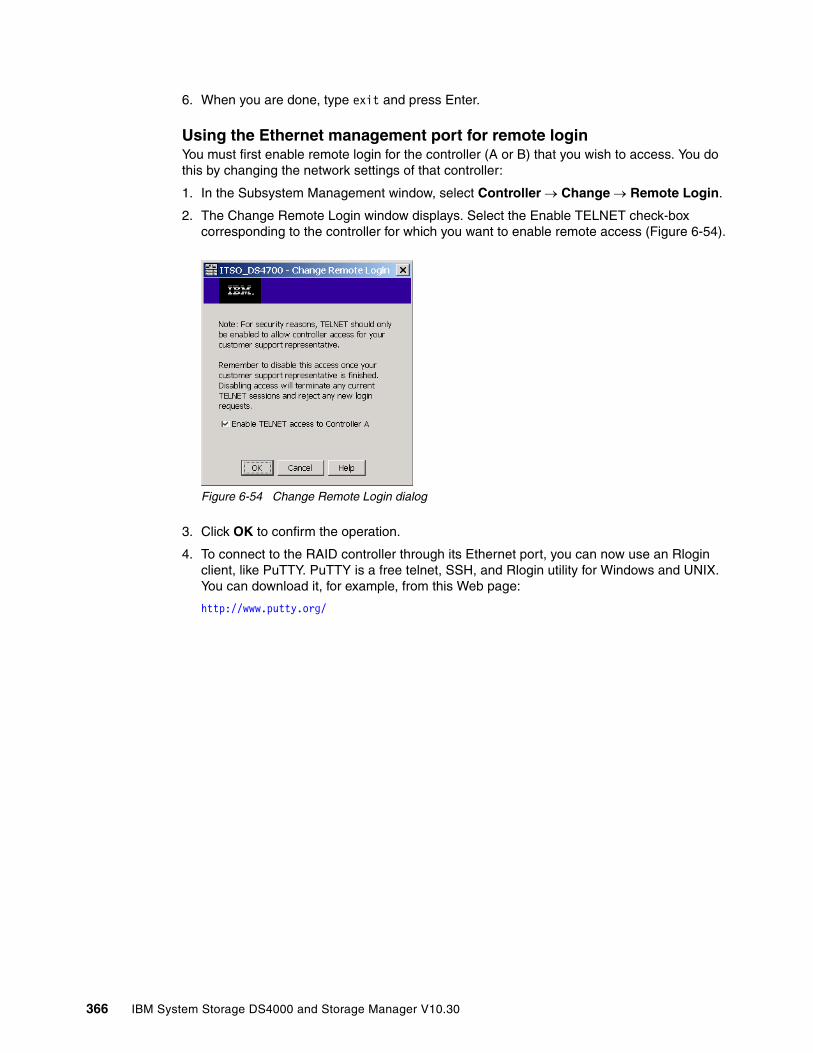
6. When you are done, type exit and press Enter.
Using the Ethernet management port for remote loginYou must first enable remote login for the controller (A or B) that you wish to access. You do this by changing the network settings of that controller:
1. In the Subsystem Management window, select Controller → Change → Remote Login.
2. The Change Remote Login window displays. Select the Enable TELNET check-box corresponding to the controller for which you want to enable remote access (Figure 6-54).
Figure 6-54 Change Remote Login dialog
3. Click OK to confirm the operation.
4. To connect to the RAID controller through its Ethernet port, you can now use an Rlogin client, like PuTTY. PuTTY is a free telnet, SSH, and Rlogin utility for Windows and UNIX. You can download it, for example, from this Web page:
http://www.putty.org/
366 IBM System Storage DS4000 and Storage Manager V10.30
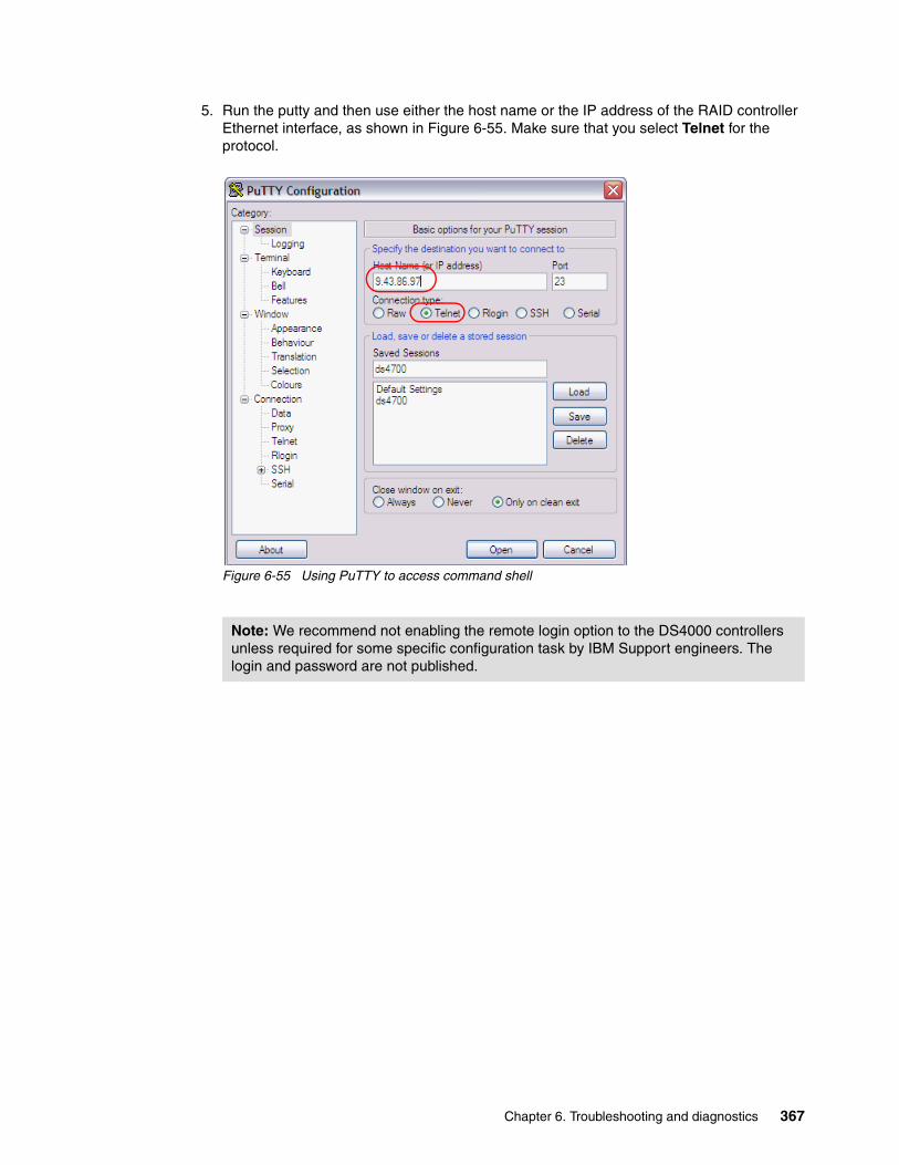
5. Run the putty and then use either the host name or the IP address of the RAID controller Ethernet interface, as shown in Figure 6-55. Make sure that you select Telnet for the protocol.
Figure 6-55 Using PuTTY to access command shell
Note: We recommend not enabling the remote login option to the DS4000 controllers unless required for some specific configuration task by IBM Support engineers. The login and password are not published.
Chapter 6. Troubleshooting and diagnostics 367

6. Type the login name and password when prompted and you will gain access to the shell. Now you can type the same commands as though you were connected to the serial port. As an example, Figure 6-56 shows the output of the moduleList command.
Figure 6-56 Command shell: moduleList output
7. When you are finished with the shell commands, type logout to exit the shell.
8. Do not forget to disable remote login on both controllers again.
6.6 Remote Support Manager for StorageIn this section we describe how to use Remote Support Manager (RSM) with the DS4000 Storage Subsystems.
IBM Remote Support Manager for Storage (RSM for Storage) software is a no-charge software package that installs on an IBM System x server running Novell SUSE® Linux Enterprise Server 9, SUSE Linux Enterprise Server 10, Red Hat Enterprise Linux 4 Advanced Server, or Red Hat Enterprise Linux 5 and provides problem reporting and remote access for IBM Service for the DS3000, DS4000, and DS5000 families of IBM storage subsystems.
The problem reporting provided by RSM for Storage automatically creates an entry in the IBM call management system for each subsystem that reports a problem. This is the equivalent of placing a phone call to IBM Service for a problem. Once in the system, problems are responded to with the same priority as specified by the maintenance agreement in place for the product.
RSM for Storage controls security for remote access by managing hardware and software components of the server that it is installed on. Once installed, the server should be considered a single purpose appliance for problem reporting and remote access support for your storage subsystems. Only applications approved by IBM and specified in this document
Note: Refer to the IBM Support Web site for the latest RSM and Storage Manager compatibility matrix:
http://www.ibm.com/support/docview.wss?uid=psg1MIGR-66062&rs=594
368 IBM System Storage DS4000 and Storage Manager V10.30
should be installed. (Management of the internal firewall and other configuration changes made by the software might prevent other applications from working.) There is no guarantee that applications that work with the current version of RSM for Storage will continue to work with future releases.
Remote access to the RSM for Storage system by IBM support is provided by either an external modem attached to the server or via an external SSH connection. This connection provides IBM Service with a command-line interface to the server. All bulk data transfers for logs and other problem determination files are sent to IBM via e-mail using the server’s Ethernet interface. Isolation of remote and local users of the system from other devices on your intranet is performed by an internal firewall that is managed by the RSM for Storage software. Local and remote IBM users of the system do not have the ability to change any security features of the software.
Monitoring of storage subsystems is performed by your existing IBM DS Storage Manager software, which is configured to send SNMP traps to the Remote Support Manager when critical events are detected. Configuration of the management application is addressed later in this document.
The RSM for Storage user interface allows you to control and view the status of four management areas:
� System configuration� Reporting� Remote access� Internal firewall
Your configured contact person for RSM for Storage will also receive e-mails of status changes in these areas.
One RSM for Storage server can support up to 50 DS5000, DS4000, DS3000, and FAStT 200, and 500 storage subsystems. Only IP connectivity to the Ethernet management ports of the subsystems is required. Serial cables are not needed for access to the disk subsystems. We recommend separating subsystems to be supported by an RSM for Storage system by country, and they must be covered under warranty or a current maintenance contract.
There are no annual fees for RSM.
6.6.1 Hardware and software requirements
RSM for Storage has the hardware and software requirements discussed in this section.
Hardware requirementsRSM for Storage can be run on a dedicated IBM System x server or in a VMware® client running on a System x server. Refer to the RSM for Storage Compatibility Guide for the minimum server requirements and a list of the specific servers that have been tested with the RSM software. The Compatibility Guide also contains the setup required for a VMware client that will host the Linux operating system running RSM for Storage. See the following URL for the RSM for Storage Compatibility Guide:
http://www.ibm.com/support/docview.wss?uid=psg1MIGR-66062&rs=594
RSM has been tested on the following System x servers:
� x3250 4364� x306m 8849
Chapter 6. Troubleshooting and diagnostics 369

With these options:
� 512 MB memory.
� 20 GB disk space.
� Serial port: This must be on the system board. The serial port on the Remote Supervisor Adapter (RSA) cannot be accessed by RSM.
� Ethernet port: Note that if your SAN devices are on a private management LAN, a second Ethernet port for accessing your company's SMTP server and the Internet will be required if your selected server has only a single Ethernet port.
Software requirementsThe RSM for Storage software requires the following prerequisite software:
� IBM DS4000 Storage Manager with Event Monitor installed in a management station in a different server.
� One of the following operating systems to install the RSM for Storage software:
– Novell SLES 9 (Service Pack 3) – Novell SUSE SLES 10 (Base or SP1)– Red Hat RHEL 4 AS (Update 4 or 5)– Red Hat RHEL 5 (Base or update 1)
RSM for Storage software receives SNMP traps from the Event Monitor included with IBM DS Storage Manager. RSM for Storage software cannot be installed on the same system used to manage your storage network.
Note: Refer to IBM RSM for Storage Compatibility Guide for the latest update of supported servers, modems, and operating systems. The document can be downloaded from the following Web page:
http://www.ibm.com/support/docview.wss?uid=psg1MIGR-66062&rs=594
370 IBM System Storage DS4000 and Storage Manager V10.30

6.6.2 How RSM for Storage works
RSM for Storage uses an Ethernet connection for problem reporting and a modem or SSH connection for remote access by IBM Service, as shown in Figure 6-57. The DS4000 disk subsystem can be any supported disk subsystem.
Figure 6-57 RSM for Storage connection diagram
The RSM for Storage server must have IP connectivity to the Ethernet management ports of the storage subsystems to be monitored and the management station running IBM Storage Manager’s Event Monitor. It is also required that all storage subsystems, the management station, the e-mail server, and the Internet gateway are accessible from the RSM server without requiring authorization through a firewall.
If your managed storage subsystems or other SAN devices are on a private management LAN, a second Ethernet port for accessing your company's SMTP server and the Internet will be required if your selected RSM server has only a single Ethernet port. Figure 6-57 shows that some storage subsystems and other SAN devices are managed through a private management LAN and that others are managed through the customer intranet. Therefore, the RSM server in this instance needs at least two network adapters.
Below are steps in a sample scenario for RSM after it is installed, configured, and activated. Refer to Figure 6-57 to understand the flow.
1. An error occurs in one of the storage subsystems and a critical event is logged in the management station (running Storage Manager).
2. The management station reports the critical event to the RSM server via an SNMP trap. The RSM system receives notification of the critical event and sends an alert to IBM Service.
Chapter 6. Troubleshooting and diagnostics 371
When an alert is received from the management station, RSM downloads logs and other problem determination data such as Major Event Log, Read Link Status, and storage system profile of the storage subsystem’s controllers that reports the problem using the out-of-band Ethernet interfaces, and sends them along with the alert to IBM Service via e-mail.
SNMP traps are sent by the IBM Storage Manager client or the IBM Storage Manager's Event Monitor service. As the Storage Manager Client may not always be running, we recommend that the Event Monitor be installed. Refer to Storage Manager documentation to check the installation of Event Monitor.
Refer also to 5.3.6, “Monitoring and alerting” on page 271, to configure the SNMP trap in Storage Manager.
3. IBM Support does problem determination based on information sent by the alert along with the problem determination data such as MEL, RLS, and subsystem profile. If the problem can be fixed with existing information, IBM Support contacts the customer either by phone or e-mail to resolve the problem. After the problem is solved, either IBM Support or the customer must indicate service complete for all alerts in the RSM. IBM Support can dial to the RSM modem or use the Secure Shell (SSH) connection to acknowledge and indicate service complete for all alerts for the subsystem.
4. If the problem cannot be fixed with existing information, IBM Support dials the RSM modem or uses an SSH connection, acknowledges the alert, and performs troubleshooting by connecting to the storage subsystem using the command-line interface (SMcli) or remote login. IBM Support may need to contact the customer to obtain the password for the storage subsystem to use SMcli. IBM may also have to contact the customer to enable remote login access (see “Using the Ethernet management port for remote login” on page 366). Indeed, we recommend normally disabling remote login.
If IBM Support needs to send or upload logs or other information from the RSM server to IBM, they can use FTP or e-mail commands from the Linux shell at the RSM server while connected through the modem line or SSH connection. Any data connected are sent to an IBM server through a customer network, not through the modem line or SSH connection.
5. After the problem is resolved, all alerts must be closed either by IBM Support or the customer before reporting will resume for that subsystem.
6.6.3 Notification e-mail and events filtering
The RSM for Storage software sends e-mails to notify of important changes in status. There are several types of notification sent by RSM to the primary contact or subsystem contact, as configured in the RSM:
� Remote access notifications, sent when:
– Remote access is enabled or disabled.
– A remote user connects to or disconnects from the system.
– The remote access automatic time out is about to expire and the system has one or more active alerts.
� Alerts status notifications, sent when an alert has been sent to IBM Service.
Note: Once the RSM for Storage reports a problem to IBM for a given subsystem, no additional problems will be reported to IBM for that particular subsystem until all existing alerts are closed.
372 IBM System Storage DS4000 and Storage Manager V10.30

� Daily status e-mails, serve as a heartbeat notification that the RSM for Storage system is operational. This includes the summary status for the system and status for alerts that may be active for storage subsystems.
� Firewall status notifications, sent when the internal firewall is enabled or disabled by a root or admin user.
� Ignored event notifications, sent when an event is received that is configured to be ignored by the RSM for Storage system, and therefore is not reported to IBM Service. These are events for which a response by IBM Service is not usually required, as listed in Table 6-2.
Table 6-2 Filtered events
RSM and Storage Manager e-mail alertsStorage Manager in the management station can be configured to send e-mail notifications when a problem is detected, as discussed in 5.3.6, “Monitoring and alerting” on page 271. However, this feature should be disabled when RSM for Storage is installed if the e-mail contact configured in the Storage Manager is the same as the e-mail contact configured in the RSM Contact List. Otherwise, you will receive multiple notification e-mails about the same problem: one notification from RSM and another one from Storage Manager.
To disable e-mail alerts in Storage Manager:
1. Right-click your management station in the Storage Manager Enterprise window and select Configure Alerts to select all storage subsystems.
2. On the Email tab, delete any configured e-mail destinations.
If there are e-mail addresses already configured to receive e-mails from Storage Manager but are not listed in the RSM Contact List (see Figure 6-63 on page 380 for the contact list), it is not necessary to delete them in Storage Manager.
6.6.4 Remote access methods
The required remote access for IBM Support can be provided by one or both of two methods. An external modem can be attached to the server’s serial port, or remote access via an SSH client can be enabled.
Remote access via modemThe functional requirements for the modem are minimal. The modem t is only used for remote access by IBM Support. Most Hayes-compatible external modems can be used. The modem should have a minimum speed of 56 KBps supporting either V.90 or V.92.
Event code Event text
6200 FlashCopy repository logical drive capacity - threshold.
6202 FlashCopy logical drive failed.
none The persistent monitor running on Host xxxxxxx cannot reach the indicated storage system.
none The persistent monitor running on Host xxxxxxx can now reach the indicated storage system.
4011 Logical drive not on preferred path due to ADT/RDAC.
Chapter 6. Troubleshooting and diagnostics 373
The RSM for Storage software has been tested with the following modems:
� Multitech Multimodem II MT5600BA� Multitech MultiModem ZBA MT5634ZBA
Refer to the RSM for Storage Compatibility Guide for updated information about which modems are supported. You must contact your IT support staff for installation and problem resolution related to the modem.
Remote access via SSHInstead of using a modem for external access to the RSM for Storage system, you can allow remote access by an external SSH connection. To do this you must map a port on your external firewall to the IP address and SSH port (22) on the RSM for Storage system. While the RSM for Storage system has several layers of login protection on the SSH port, you can also require authentication before the external firewall makes a connection to the RSM for Storage system.
You can also choose to allow remote access by both methods. More information about setting up and using an SSH connection is available in the IBM Remote Storage Manager for Storage Planing, Installation, and User’s Guide, GC26-7933, as well as the supplement “Installation Hints and Tips”:
http://www.ibm.com/support/docview.wss?uid=psg1MIGR-66062&rs=594
6.6.5 RSM management interface
The RSM management interface can be accessed through a Web browser pointing to the IP address or host name of the RSM server using HTTPS. You can use the Web interface to check the status and configure RSM settings. For IBM Support, the interface is a command-line interface when connected to the RSM server via a modem.
374 IBM System Storage DS4000 and Storage Manager V10.30
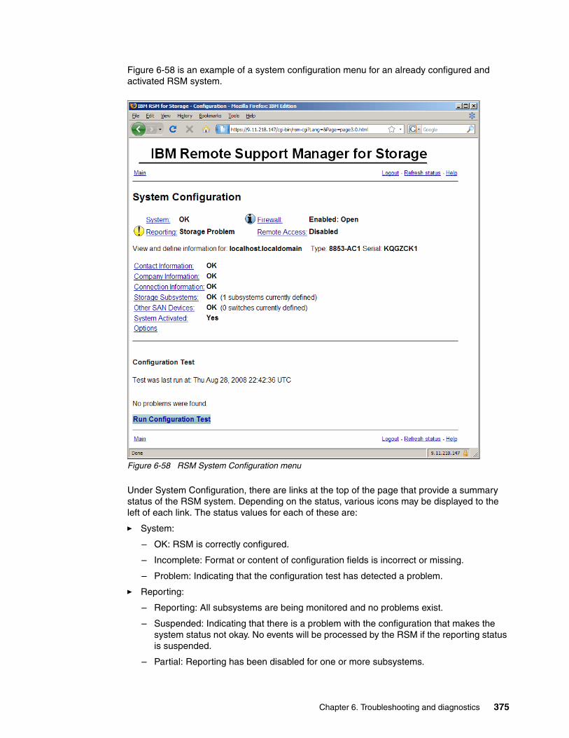
Figure 6-58 is an example of a system configuration menu for an already configured and activated RSM system.
Figure 6-58 RSM System Configuration menu
Under System Configuration, there are links at the top of the page that provide a summary status of the RSM system. Depending on the status, various icons may be displayed to the left of each link. The status values for each of these are:
� System:
– OK: RSM is correctly configured.
– Incomplete: Format or content of configuration fields is incorrect or missing.
– Problem: Indicating that the configuration test has detected a problem.
� Reporting:
– Reporting: All subsystems are being monitored and no problems exist.
– Suspended: Indicating that there is a problem with the configuration that makes the system status not okay. No events will be processed by the RSM if the reporting status is suspended.
– Partial: Reporting has been disabled for one or more subsystems.
Chapter 6. Troubleshooting and diagnostics 375

– Standby: Reporting has been disabled for all subsystems.
– Storage Problem: One or more subsystems has a problem.
� Firewall:
– Disabled: No restrictions on access to the networks connected to the RSM.
– Enabled:Closed: This is the normal state when there are no active alerts present and the system is waiting for notification of a problem from Storage Manager.
– Enabled:Open: The firewall allows access to one or more subsystems or other configured SAN devices.
� Remote access:
– Disabled: Remote access via the modem or SSH is not allowed.
– Enabled: The modem will answer and the remote service (rservice) user ID is valid for login via the remote connection or SSH.
– Active: The rservice remote user is logged into the RSM.
6.6.6 RSM security considerations
RSM for Storage controls security for remote access by managing the hardware and software components of the server on which it is installed. Once installed, the server should be considered as a single-purpose appliance for problem reporting and remote access support for your storage subsystems. It should not be used for other applications.
User IDDuring installation, the RSM software creates three user IDs:
� admin: This is the administrative user that can perform management and configuration tasks.
� lservice: This is the local service user intended for use by IBM Service when on site. This user ID has some restrictions on directories that it can access. This is to prevent any configuration change that might affect the security of the system.
� rservice: This is the remote service (IBM Service) user that is used exclusively for remote access to the system and only valid when remote access is enabled. This user ID also does not have the ability to change any of the RSM security features.
Passwords for user ID admin and lservice can be changed by the Linux root user using the command rsm-passwd admin or rsm-passwd lservice. We recommend setting a different password for each user ID.
For the remote user (rservice), the password is automatically generated by RSM and it is changed daily at midnight UTC. IBM Service has an internal tool that provides the current password. Therefore, you do not need to provide the current RSM password to IBM Service.
After validation of the initial login password, remote users are presented with a challenge string, which also requires access to an internal IBM tool in order to obtain the correct response. The response also includes an IBM employee user name that is recorded in the RSM for Storage security log.
376 IBM System Storage DS4000 and Storage Manager V10.30

6.7 Installing and setting up RSM
In this section we show how to install and configure RSM. Before beginning, go to the RSM support Web page and carefully review the IBM Remote Storage Manager for Storage Planing, Installation, and User’s Guide, as well as the supplement “Installation Hints and Tips,” available at:
http://www.ibm.com/support/docview.wss?uid=psg1MIGR-66062&rs=594
6.7.1 Installing the host OS
There are various operating systems supported for the RSM host, as shown in “Software requirements” on page 370. In our example, we used a Red Hat Linux Enterprise License 5 as the host operating system on the RSM server. When installing RHEL5, we selected the following additional packages:
� expect� mgetty� Simple Web server (apache2)� KDE desktop environment
See IBM Remote Storage Manager for Storage Planing, Installation, and User’s Guide, GC26-7933, for specific operating system installation instructions.
6.7.2 Installing RSM
The RSM software can be downloaded from
http://www.ibm.com/storage/disk/rsm
We installed RSM according to the instructions in IBM Remote Storage Manager for Storage Planing, Installation, and User’s Guide, GC26-7933. After the installation, you must define the admin and lservice user IDs.
6.7.3 Setting up RSM
After the installation is complete, we must set up RSM.
1. On the login window, do the following:
a. Click Session and select KDE.
b. Log in as the admin user.
Tip: Do not use a remote connection when installing the RSM for Storage on the workstation. We recommend being logged on locally to the graphical user interface of the workstation, as RSM resets the firewall settings, preventing remote access to the Linux workstation.
Chapter 6. Troubleshooting and diagnostics 377
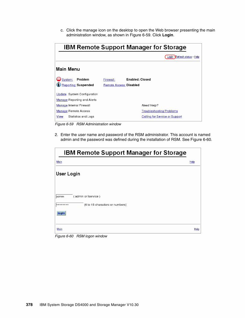
c. Click the manage icon on the desktop to open the Web browser presenting the main administration window, as shown in Figure 6-59. Click Login.
Figure 6-59 RSM Administration window
2. Enter the user name and password of the RSM administrator. This account is named admin and the password was defined during the installation of RSM. See Figure 6-60.
Figure 6-60 RSM logon window
378 IBM System Storage DS4000 and Storage Manager V10.30
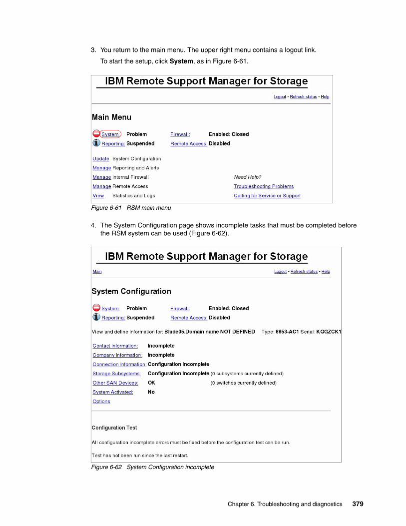
3. You return to the main menu. The upper right menu contains a logout link.
To start the setup, click System, as in Figure 6-61.
Figure 6-61 RSM main menu
4. The System Configuration page shows incomplete tasks that must be completed before the RSM system can be used (Figure 6-62).
Figure 6-62 System Configuration incomplete
Chapter 6. Troubleshooting and diagnostics 379

5. Click Contact Information to access the contact list to add a new contact (Figure 6-63 on page 380).
Figure 6-63 RSM contact list
380 IBM System Storage DS4000 and Storage Manager V10.30

6. Click Select to add, then fill out the form and click Update configuration. This information is very important. When the DS4000 storage subsystem reports a problem, IBM Support will contact the person specified here. See Figure 6-64.
Figure 6-64 RSM contact person information
Chapter 6. Troubleshooting and diagnostics 381
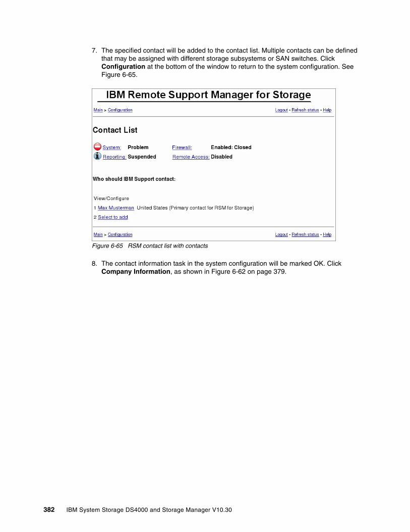
7. The specified contact will be added to the contact list. Multiple contacts can be defined that may be assigned with different storage subsystems or SAN switches. Click Configuration at the bottom of the window to return to the system configuration. See Figure 6-65.
Figure 6-65 RSM contact list with contacts
8. The contact information task in the system configuration will be marked OK. Click Company Information, as shown in Figure 6-62 on page 379.
382 IBM System Storage DS4000 and Storage Manager V10.30

9. Fill out the form with the appropriate information and click Update configuration (Figure 6-66).
Figure 6-66 RSM company information
10.The company information task in the system configuration is marked OK. Click Connection Information, as shown in Figure 6-62 on page 379.
Chapter 6. Troubleshooting and diagnostics 383
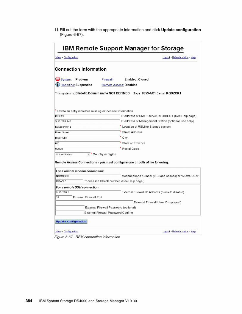
11.Fill out the form with the appropriate information and click Update configuration (Figure 6-67).
Figure 6-67 RSM connection information
384 IBM System Storage DS4000 and Storage Manager V10.30

12.The connection information task in the system configuration will be marked OK. Click Storage Subsystems, as shown in Figure 6-62 on page 379.
13.Click Select to add to define a storage subsystem in RSM (Figure 6-68).
Figure 6-68 RSM configure storage subsystem
RSM for Storage reports DS4000 Expansion Units as well and therefore the configuration of drive expansion units is also required. During the configuration test, done later on in the configuration steps, the profile for each subsystem will be downloaded. This will verify connectivity to the subsystem, verify that this version of RSM for Storage software is compatible with the firmware on the subsystem, and determine whether there are any drive expansion units attached to the controller. If any drive expansion units are detected, the configuration status for the subsystem will change to configuration incomplete and additional configuration fields will now be available for setting the IBM machine type and serial numbers of each detected drive expansion unit.
Fill out the form with the following fields:
1. The name of a storage subsystem as shown in the DS4000 Storage Manager.
2. The country where the storage subsystem is located.
3. A description of where to find the storage subsystem, for example, room number or rack number in the location field.
4. Management interface IP addresses of all controllers in the subsystem. If only one controller is installed, use only one IP address.
5. Type, model, and the serial number: This information can be found on the left front bezel or the rear side of the DS4000.
6. Select an entry from the contact list.
Chapter 6. Troubleshooting and diagnostics 385
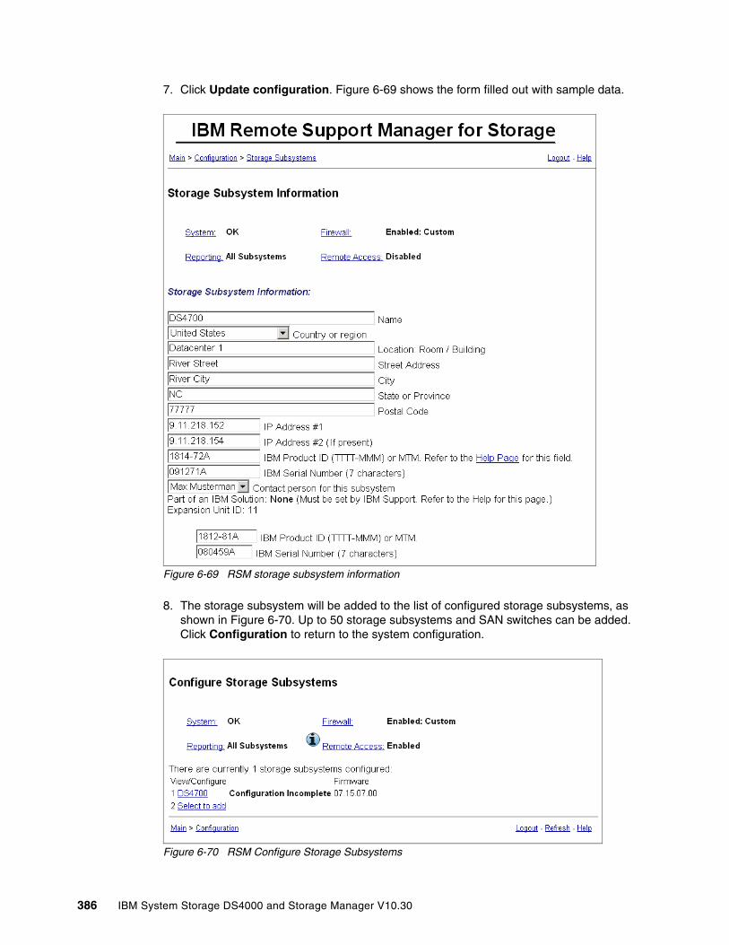
7. Click Update configuration. Figure 6-69 shows the form filled out with sample data.
Figure 6-69 RSM storage subsystem information
8. The storage subsystem will be added to the list of configured storage subsystems, as shown in Figure 6-70. Up to 50 storage subsystems and SAN switches can be added. Click Configuration to return to the system configuration.
Figure 6-70 RSM Configure Storage Subsystems
386 IBM System Storage DS4000 and Storage Manager V10.30
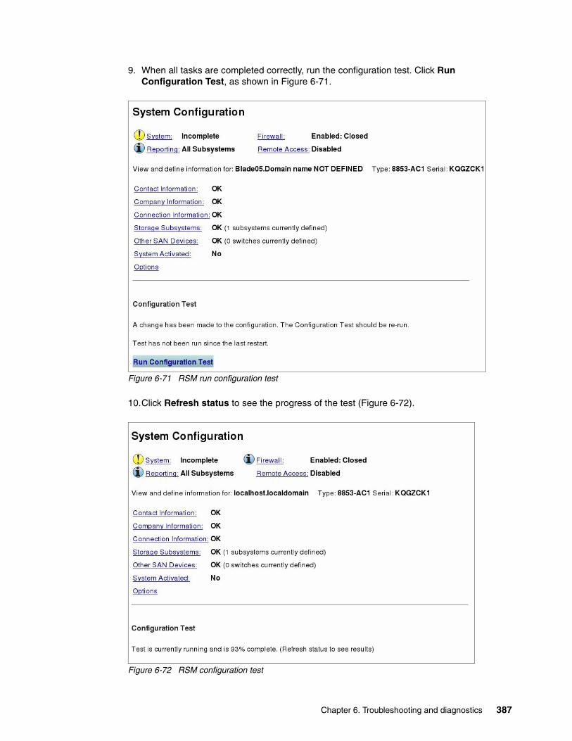
9. When all tasks are completed correctly, run the configuration test. Click Run Configuration Test, as shown in Figure 6-71.
Figure 6-71 RSM run configuration test
10.Click Refresh status to see the progress of the test (Figure 6-72).
Figure 6-72 RSM configuration test
Chapter 6. Troubleshooting and diagnostics 387

11.When the test is complete, the date and time of the last run is shown, as in Figure 6-73.
Figure 6-73 RSM Configuration test done
12.Results from this test are logged in the activity log. You can access the activity log by selecting View (Statistic and Logs) in the Main panel of RSM. Figure 6-74 shows an example of the log for the configuration test.
Figure 6-74 RSM Activity Log
388 IBM System Storage DS4000 and Storage Manager V10.30

6.7.4 Configuring SNMP traps in Storage Manager
To allow the DS4000 management workstation to send SNMP traps to the RSM server, set the RSM server as your SNMP traps destination in the Storage Manager client. We explained how to do this in 5.3.6, “Monitoring and alerting” on page 271.
Click the SNMP tab and type the IP address of the RSM server in the Trap Destination field. Keep the default community name public.
If you have an existing SNMP infrastructure and there is already an SNMP trap destination set, you can add the IP address of the RSM server as an additional SNMP trap destination without having to delete the existing SNMP trap destination setting.
Configure the DS4000 Storage Manager to send SNMP alerts for each defined storage subsystem in RSM to the RSM host. Open the Enterprise management window of the storage manager. Right-click a DS4000 storage subsystem. In the connect menu click Configure Alerts. In the Configure Alerts dialog click the SNMP tab. Enter the host name or the IP address of the RSM host in the trap destination field. Click Add (Figure 6-75). Do not change the SNMP community name (the default is public).
Figure 6-75 Add SNMP trap receiver
Chapter 6. Troubleshooting and diagnostics 389
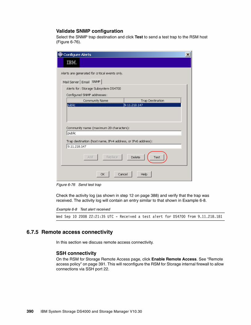
Validate SNMP configurationSelect the SNMP trap destination and click Test to send a test trap to the RSM host (Figure 6-76).
Figure 6-76 Send test trap
Check the activity log (as shown in step 12 on page 388) and verify that the trap was received. The activity log will contain an entry similar to that shown in Example 6-8.
Example 6-8 Test alert received
Wed Sep 10 2008 22:21:35 UTC - Received a test alert for DS4700 from 9.11.218.181
6.7.5 Remote access connectivity
In this section we discuss remote access connectivity.
SSH connectivityOn the RSM for Storage Remote Access page, click Enable Remote Access. See “Remote access policy” on page 391. This will reconfigure the RSM for Storage internal firewall to allow connections via SSH port 22.
390 IBM System Storage DS4000 and Storage Manager V10.30
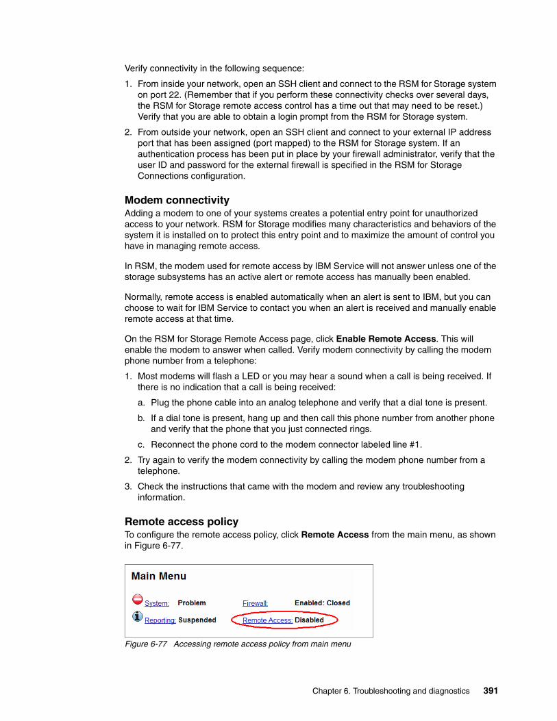
Verify connectivity in the following sequence:
1. From inside your network, open an SSH client and connect to the RSM for Storage system on port 22. (Remember that if you perform these connectivity checks over several days, the RSM for Storage remote access control has a time out that may need to be reset.) Verify that you are able to obtain a login prompt from the RSM for Storage system.
2. From outside your network, open an SSH client and connect to your external IP address port that has been assigned (port mapped) to the RSM for Storage system. If an authentication process has been put in place by your firewall administrator, verify that the user ID and password for the external firewall is specified in the RSM for Storage Connections configuration.
Modem connectivityAdding a modem to one of your systems creates a potential entry point for unauthorized access to your network. RSM for Storage modifies many characteristics and behaviors of the system it is installed on to protect this entry point and to maximize the amount of control you have in managing remote access.
In RSM, the modem used for remote access by IBM Service will not answer unless one of the storage subsystems has an active alert or remote access has manually been enabled.
Normally, remote access is enabled automatically when an alert is sent to IBM, but you can choose to wait for IBM Service to contact you when an alert is received and manually enable remote access at that time.
On the RSM for Storage Remote Access page, click Enable Remote Access. This will enable the modem to answer when called. Verify modem connectivity by calling the modem phone number from a telephone:
1. Most modems will flash a LED or you may hear a sound when a call is being received. If there is no indication that a call is being received:
a. Plug the phone cable into an analog telephone and verify that a dial tone is present.
b. If a dial tone is present, hang up and then call this phone number from another phone and verify that the phone that you just connected rings.
c. Reconnect the phone cord to the modem connector labeled line #1.
2. Try again to verify the modem connectivity by calling the modem phone number from a telephone.
3. Check the instructions that came with the modem and review any troubleshooting information.
Remote access policyTo configure the remote access policy, click Remote Access from the main menu, as shown in Figure 6-77.
Figure 6-77 Accessing remote access policy from main menu
Chapter 6. Troubleshooting and diagnostics 391

In the Remote Access settings page, you can enable or disable the remote access service and enable or disable the option to automatically enable the remote access when an alert is sent to IBM. This is shown in Figure 6-78.
Figure 6-78 Remote Access settings
392 IBM System Storage DS4000 and Storage Manager V10.30

Remote access also has a configurable time out between 12 and 96 hours. You can manually disable remote access when the service is complete or allow it to time out. After the timeout period has elapsed, the system is guaranteed to return to a secure state without intervention.
To configure the timeout value, select the desired time-out value and click Update Timeout Value, as shown in Figure 6-79.
Figure 6-79 Configure Remote Access Timeout
Internal firewallRSM for Storage includes an internal firewall to limit the scope of access that a remote user has to your network. It also limits the IP destinations that can be accessed by local and remote users of the system. The rules for inbound and outbound IP traffic that control the internal firewall are managed dynamically by the RSM for Storage software.
There are three possible states of the RSM firewall:
� Disabled
There are no restrictions on access to the networks connected to the RSM. Remote access is not permitted if the firewall is in this state.
� Enabled:Closed
This is the normal state when there are no active alerts present and the system is waiting for notification of a problem from Storage Manager.
The following rules are applied when RSM is in this state:
– Inbound SNMP traps, ping, traceroute, and HTTPS requests are accepted.
– Outbound traffic for DNS, ping, traceroute, IBM WWW and FTP sites, and port 25 of your SMTP server are accepted.
– Access to any of your other SAN devices is blocked.
– IP traffic forwarding is disabled.
– All other connections are blocked.
� Enabled:Open
The firewall allows access to one or more subsystems or other configured SAN devices. Access is allowed only to those devices that have active alerts or those that you have placed in service access mode.
Note: You do not need to provide the rservice user ID password to IBM Service because IBM Service has an internal tool that provides the current rservice password. You only must provide passwords of your storage subsystems or your other SAN devices if required.
Note: Subsystems with active alerts are automatically allowed access from the Remote Support Manager while the alert is active and do not need to be enabled for service access.
Chapter 6. Troubleshooting and diagnostics 393

To manage RSM internal firewall and service access of your managed storage subsystems (and other SAN devices) from the Web interface, click Firewall on the Main Menu, as shown in Figure 6-80.
Figure 6-80 Accessing firewall configuration from Main Menu
In the Internal Firewall and Service Access page, you can change the internal firewall status and service access mode of your managed storage subsystems, as shown in Figure 6-81.
Figure 6-81 Internal Firewall and Service Access page
Placing a device into service access mode creates a rule for the internal firewall that will allow connections to that device from the RSM server. For subsystems with active alerts, they are automatically allowed access from the Remote Support Manager while the alert is active and do not need to be enabled for service access.
394 IBM System Storage DS4000 and Storage Manager V10.30
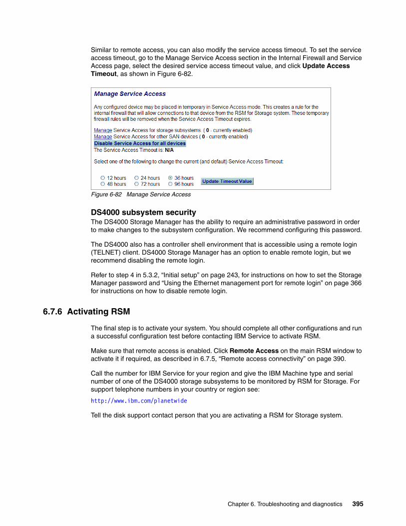
Similar to remote access, you can also modify the service access timeout. To set the service access timeout, go to the Manage Service Access section in the Internal Firewall and Service Access page, select the desired service access timeout value, and click Update Access Timeout, as shown in Figure 6-82.
Figure 6-82 Manage Service Access
DS4000 subsystem securityThe DS4000 Storage Manager has the ability to require an administrative password in order to make changes to the subsystem configuration. We recommend configuring this password.
The DS4000 also has a controller shell environment that is accessible using a remote login (TELNET) client. DS4000 Storage Manager has an option to enable remote login, but we recommend disabling the remote login.
Refer to step 4 in 5.3.2, “Initial setup” on page 243, for instructions on how to set the Storage Manager password and “Using the Ethernet management port for remote login” on page 366 for instructions on how to disable remote login.
6.7.6 Activating RSM
The final step is to activate your system. You should complete all other configurations and run a successful configuration test before contacting IBM Service to activate RSM.
Make sure that remote access is enabled. Click Remote Access on the main RSM window to activate it if required, as described in 6.7.5, “Remote access connectivity” on page 390.
Call the number for IBM Service for your region and give the IBM Machine type and serial number of one of the DS4000 storage subsystems to be monitored by RSM for Storage. For support telephone numbers in your country or region see:
http://www.ibm.com/planetwide
Tell the disk support contact person that you are activating a RSM for Storage system.
Chapter 6. Troubleshooting and diagnostics 395

Provide IBM Service with one or both of the following pieces of access information:
� The phone number of the modem attached to the RSM for Storage system
� The IP address/port number and any required authentication information to be used for SSH access
IBM Service will connect to the system, verify that the configuration is correct, send a test alert via e-mail, verify receipt of the alert and associated attachments, and then activate the system. See the main window, as in Figure 6-83.
Figure 6-83 RSM activated
Note: If you decide to install the RSM for Storage software on another server, you must contact IBM Service to obtain a new activation key for the new server.
396 IBM System Storage DS4000 and Storage Manager V10.30

6.7.7 Managing alerts
To manage alerts:
1. When RSM receives SNMP alerts from one of the defined storage subsystems, an attention mark (!) is shown next to the reporting link, as shown in Figure 6-84. Click Reporting to see the alerts.
Figure 6-84 Main menu with storage problems
2. The reporting and alert page shows all those subsystems that have sent alerts sent to RSM (Figure 6-85). Click View or Close Alerts.
Figure 6-85 RSM: Reporting and Alerts
Chapter 6. Troubleshooting and diagnostics 397
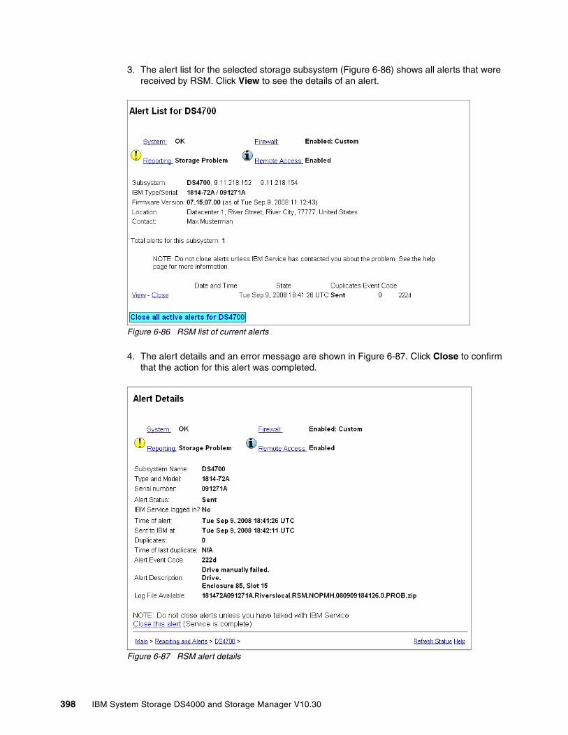
3. The alert list for the selected storage subsystem (Figure 6-86) shows all alerts that were received by RSM. Click View to see the details of an alert.
Figure 6-86 RSM list of current alerts
4. The alert details and an error message are shown in Figure 6-87. Click Close to confirm that the action for this alert was completed.
Figure 6-87 RSM alert details
398 IBM System Storage DS4000 and Storage Manager V10.30
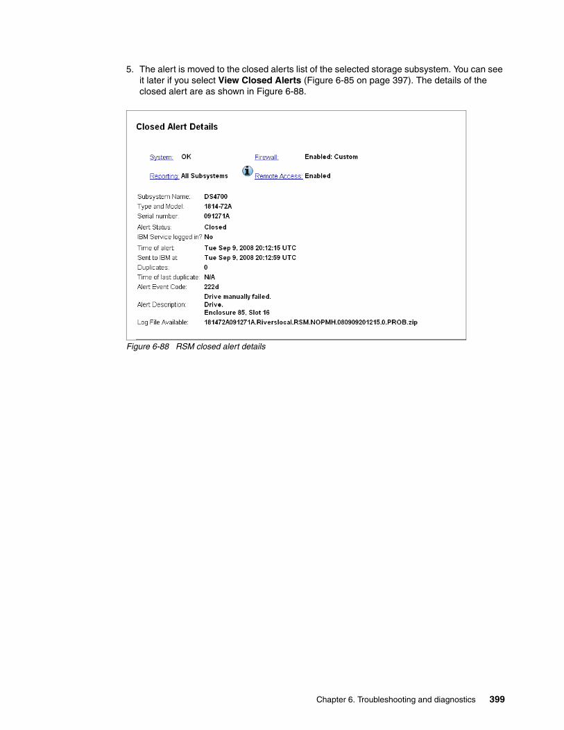
5. The alert is moved to the closed alerts list of the selected storage subsystem. You can see it later if you select View Closed Alerts (Figure 6-85 on page 397). The details of the closed alert are as shown in Figure 6-88.
Figure 6-88 RSM closed alert details
Chapter 6. Troubleshooting and diagnostics 399

400 IBM System Storage DS4000 and Storage Manager V10.30
Chapter 7. FlashCopy
This chapter covers the FlashCopy feature in detail and looks at the various components of FlashCopy, what they do, and how to set them up.
This is followed by a step-by-step guide to using the FlashCopy function either through the Storage Manager client graphical user interface (GUI) or by using the command-line interface (CLI) and scripts.
7
© Copyright IBM Corp. 2004, 2005, 2006, 2007, 2008, 2009. All rights reserved. 401
7.1 FlashCopy: How it worksA FlashCopy logical drive is a point-in-time image of a logical drive. It is the logical equivalent of a complete physical copy, but it is created much more quickly than a physical copy. It also requires less disk space. On the other hand, it is not a real physical copy, because it does not copy all the data. Consequently, if the source logical drive is damaged, the FlashCopy logical drive cannot be used for recovery.
In the DS4000 Storage Manager, the logical drive from which you are basing the FlashCopy, called the base logical drive, can be a standard logical drive or the secondary logical drive in a Remote Mirror relationship. Typically, you create a FlashCopy so that an application (for example, an application to take backups) can access the FlashCopy and read the data while the base logical drive remains online and user-accessible. The FlashCopy logical drive is no longer needed (it is usually disabled rather than deleted) when the backup completes.
You can also create multiple FlashCopies of a base logical drive and use the copies in write mode to perform testing and analysis. Before you upgrade your database management system, for example, you can use FlashCopy logical drives to test different configurations. Then you can use the performance data provided by the Storage Management software to help you decide how to configure your live database system.
Important: For analysis, data mining, and testing without any degradation of the production logical drive performance, you should use FlashCopy in conjunction with VolumeCopy, as explained in Chapter 9, “VolumeCopy” on page 531.
402 IBM System Storage DS4000 and Storage Manager V10.30
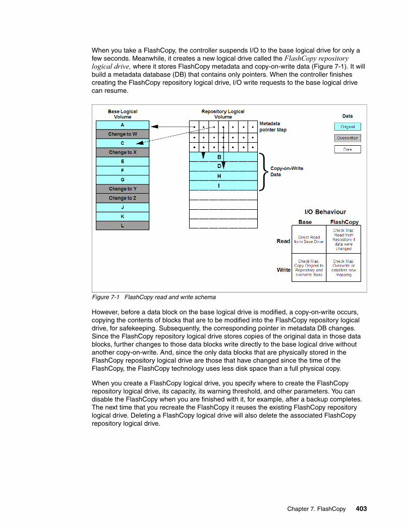
When you take a FlashCopy, the controller suspends I/O to the base logical drive for only a few seconds. Meanwhile, it creates a new logical drive called the FlashCopy repository logical drive, where it stores FlashCopy metadata and copy-on-write data (Figure 7-1). It will build a metadata database (DB) that contains only pointers. When the controller finishes creating the FlashCopy repository logical drive, I/O write requests to the base logical drive can resume.
Figure 7-1 FlashCopy read and write schema
However, before a data block on the base logical drive is modified, a copy-on-write occurs, copying the contents of blocks that are to be modified into the FlashCopy repository logical drive, for safekeeping. Subsequently, the corresponding pointer in metadata DB changes. Since the FlashCopy repository logical drive stores copies of the original data in those data blocks, further changes to those data blocks write directly to the base logical drive without another copy-on-write. And, since the only data blocks that are physically stored in the FlashCopy repository logical drive are those that have changed since the time of the FlashCopy, the FlashCopy technology uses less disk space than a full physical copy.
When you create a FlashCopy logical drive, you specify where to create the FlashCopy repository logical drive, its capacity, its warning threshold, and other parameters. You can disable the FlashCopy when you are finished with it, for example, after a backup completes. The next time that you recreate the FlashCopy it reuses the existing FlashCopy repository logical drive. Deleting a FlashCopy logical drive will also delete the associated FlashCopy repository logical drive.
Chapter 7. FlashCopy 403
7.1.1 Estimating FlashCopy repository logical drive capacityThe FlashCopy repository logical drive is created to store FlashCopy metadata (data about the FlashCopy) and any copy-on-write data needed during the life of the FlashCopy logical drive. By default the FlashCopy repository logical drive’s capacity is 20% of the base logical drive's capacity. In general, this capacity should be sufficient. However, you can use the following information to help determine the appropriate capacity of the FlashCopy repository logical drive:
� A FlashCopy repository logical drive can be no smaller than 8 MB.
� Set a larger percentage if a large percentage of data blocks will change on the base logical drive during the life of the FlashCopy logical drive due to heavy I/O activity. The Storage Manager’s Performance Monitor can help you determine typical I/O activity to the base logical drive.
� Set a larger percentage if you must keep the FlashCopy logical drive for a longer period.
Calculating expected overheadNormally, the default setting is okay. You will be given a warning when the FlashCopy repository logical drive reaches a certain percentage full. Then you can increase its capacity using the Logical Drive → Increase Capacity option in Storage Manager.
Use the following formula to calculate the amount of management overhead required to store FlashCopy data on the FlashCopy repository logical drive. This formula should be used merely as a guide, and FlashCopy repository logical drive capacity should be re-estimated periodically.
The formula to calculate the amount of management overhead required is:
192 KB + (X/2000)
Here, X is the capacity of the base logical drive in bytes.
ExampleFor a 5 GB base logical drive, where 30% of the data blocks are expected to change on the base logical drive, the estimated FlashCopy repository logical drive capacity can be calculated as follows:
1. Convert the base logical drive's capacity to bytes.
When converted, 5 GB equals 5,368,709,120 bytes.
[5 x 1024(K) x 1024(M) x 1024(G)]
2. Divide the base logical drive's capacity (in bytes) by 2,000.
When divided, the result is 2,684,354.56 bytes.
3. Convert the result from step 2 (in bytes) to kilobytes (KB).
When converted, the result is 2,621.44 KB.
[2,684,354.56 / 1024(K)]
4. Add 192 KB to the results from step 3.
192 KB + 2621.44 KB = 2813.44 KB
5. Convert the result from step 4 to megabytes (MB).
Note: Conversion from bytes to kilobytes, and then to megabytes, is required for this formula.
404 IBM System Storage DS4000 and Storage Manager V10.30

When converted, the amount of management overhead required is calculated to be 2.75 MB (or 0.002686 GB).
6. In this example, 30% of the data blocks on the base logical drive are expected to change. To accurately calculate the FlashCopy repository logical drive capacity, sufficient space must be allowed for the copy-on-write data as well as the management overhead (calculated in step 5).
To calculate the copy-on-write space required, calculate the percentage of the base logical drive expected change:
30 percent of 5 GB = 1.5 GB
The final estimated FlashCopy repository logical drive capacity for this example is:
1.5 GB + 0.002686 GB = 1.502686 GB
7. In the Create FlashCopy logical drive wizard, specify in the Repository Capacity window to use the percentage (%) full box of base logical drive to set the estimated FlashCopy repository logical drive capacity (Figure 7-8 on page 412).
7.1.2 FlashCopy failure policyThe FlashCopy repository logical drive's failure policy determines what happens when the FlashCopy repository logical drive becomes full (that is, all of its capacity has been used).
� Fail FlashCopy logical drive.
When the FlashCopy repository logical drive becomes full, the software fails the associated FlashCopy logical drive. This is the default policy. The base logical drive remains online and user accessible and writable. The FlashCopy logical drive is no longer valid.
� Fail writes to base logical drive.
When the FlashCopy repository logical drive becomes full, the software fails writes to the base logical drive. The FlashCopy logical drive is preserved and remains valid since no new copy-on-write data is generated for the FlashCopy repository logical drive.
If a FlashCopy logical drive or FlashCopy repository logical drive is displayed as a missing logical drive, it means that the storage system found the drives no longer accessible. Missing logical drives, in most cases, are recoverable. See “Missing logical drives” on page 309.
Note: The percentage (%) full box sets the FlashCopy repository logical drive capacity as a percentage of the base logical drive. Using the percentage (%) full box, increase or decrease the percentage until the FlashCopy Repository logical drive capacity value matches the estimated capacity calculated in step 6. (Some rounding up might be required.)
Attention: Do not ignore the FlashCopy repository logical drive threshold exceeded notification.
Chapter 7. FlashCopy 405
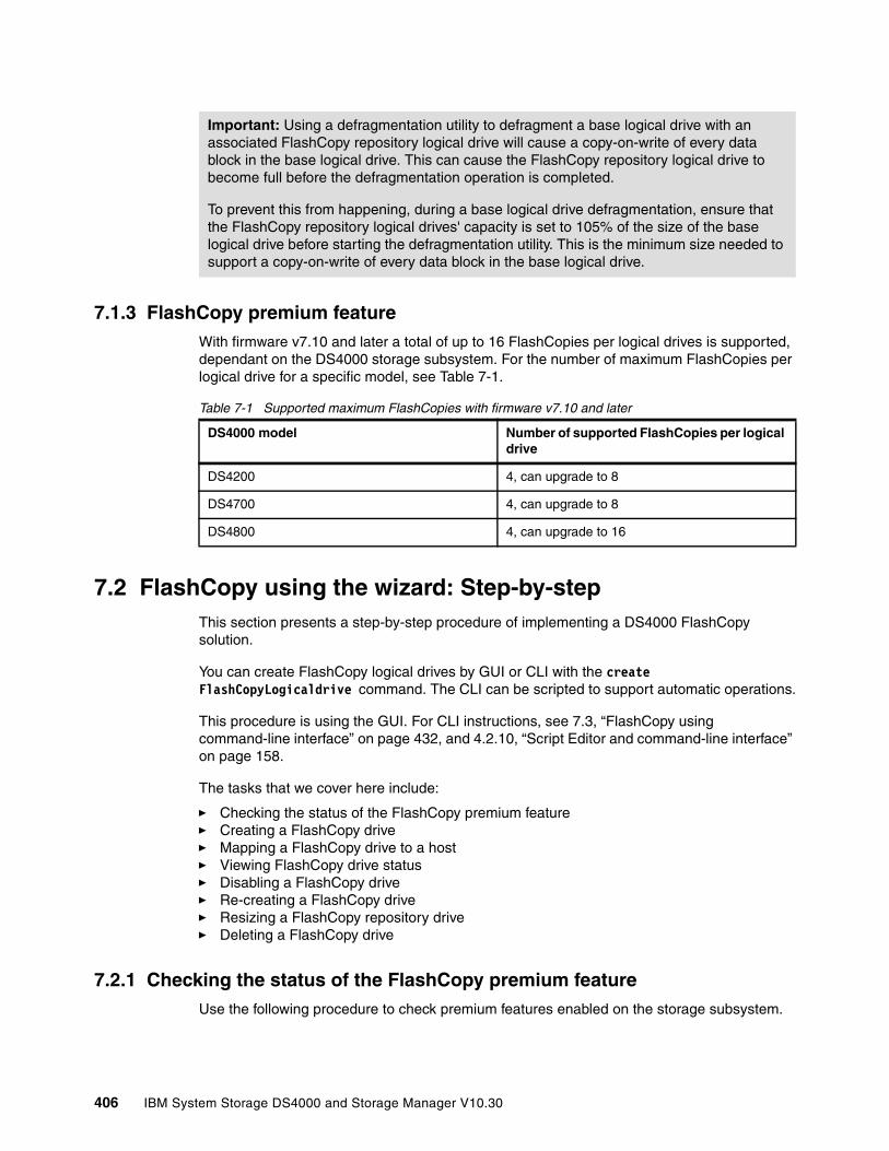
7.1.3 FlashCopy premium featureWith firmware v7.10 and later a total of up to 16 FlashCopies per logical drives is supported, dependant on the DS4000 storage subsystem. For the number of maximum FlashCopies per logical drive for a specific model, see Table 7-1.
Table 7-1 Supported maximum FlashCopies with firmware v7.10 and later
7.2 FlashCopy using the wizard: Step-by-stepThis section presents a step-by-step procedure of implementing a DS4000 FlashCopy solution.
You can create FlashCopy logical drives by GUI or CLI with the create FlashCopyLogicaldrive command. The CLI can be scripted to support automatic operations.
This procedure is using the GUI. For CLI instructions, see 7.3, “FlashCopy using command-line interface” on page 432, and 4.2.10, “Script Editor and command-line interface” on page 158.
The tasks that we cover here include:
� Checking the status of the FlashCopy premium feature� Creating a FlashCopy drive� Mapping a FlashCopy drive to a host� Viewing FlashCopy drive status� Disabling a FlashCopy drive� Re-creating a FlashCopy drive� Resizing a FlashCopy repository drive� Deleting a FlashCopy drive
7.2.1 Checking the status of the FlashCopy premium featureUse the following procedure to check premium features enabled on the storage subsystem.
Important: Using a defragmentation utility to defragment a base logical drive with an associated FlashCopy repository logical drive will cause a copy-on-write of every data block in the base logical drive. This can cause the FlashCopy repository logical drive to become full before the defragmentation operation is completed.
To prevent this from happening, during a base logical drive defragmentation, ensure that the FlashCopy repository logical drives' capacity is set to 105% of the size of the base logical drive before starting the defragmentation utility. This is the minimum size needed to support a copy-on-write of every data block in the base logical drive.
DS4000 model Number of supported FlashCopies per logical drive
DS4200 4, can upgrade to 8
DS4700 4, can upgrade to 8
DS4800 4, can upgrade to 16
406 IBM System Storage DS4000 and Storage Manager V10.30
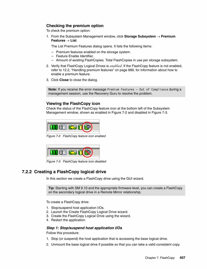
Checking the premium optionTo check the premium option:
1. From the Subsystem Management window, click Storage Subsystem → Premium Features → List.
The List Premium Features dialog opens. It lists the following items:
– Premium features enabled on the storage system.– Feature Enable Identifier.– Amount of existing FlashCopies. Total FlashCopies in use per storage subsystem.
2. Verify that FlashCopy Logical Drives is enabled. If the FlashCopy feature is not enabled, refer to 12.2, “Handling premium features” on page 689, for information about how to enable a premium feature.
3. Click Close to close the dialog.
Viewing the FlashCopy iconCheck the status of the FlashCopy feature icon at the bottom left of the Subsystem Management window, shown as enabled in Figure 7-2 and disabled in Figure 7-3.
Figure 7-2 FlashCopy feature icon enabled
Figure 7-3 FlashCopy feature icon disabled
7.2.2 Creating a FlashCopy logical driveIn this section we create a FlashCopy drive using the GUI wizard.
To create a FlashCopy drive:
1. Stop/suspend host application I/Os.2. Launch the Create FlashCopy Logical Drive wizard.3. Create the FlashCopy Logical Drive using the wizard.4. Restart the application.
Step 1: Stop/suspend host application I/OsFollow this procedure:
1. Stop (or suspend) the host application that is accessing the base logical drive.
2. Unmount the base logical drive if possible so that you can take a valid consistent copy.
Note: If you receive the error message Premium Features - Out of Compliance during a management session, use the Recovery Guru to resolve the problem.
Tip: Starting with SM 9.10 and the appropriate firmware level, you can create a FlashCopy on the secondary logical drive in a Remote Mirror relationship.
Chapter 7. FlashCopy 407
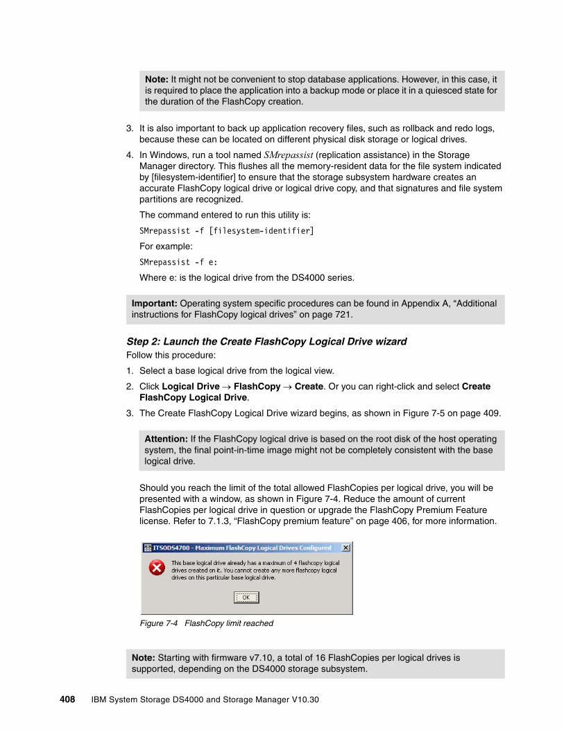
3. It is also important to back up application recovery files, such as rollback and redo logs, because these can be located on different physical disk storage or logical drives.
4. In Windows, run a tool named SMrepassist (replication assistance) in the Storage Manager directory. This flushes all the memory-resident data for the file system indicated by [filesystem-identifier] to ensure that the storage subsystem hardware creates an accurate FlashCopy logical drive or logical drive copy, and that signatures and file system partitions are recognized.
The command entered to run this utility is:
SMrepassist -f [filesystem-identifier]
For example:
SMrepassist -f e:
Where e: is the logical drive from the DS4000 series.
Step 2: Launch the Create FlashCopy Logical Drive wizardFollow this procedure:
1. Select a base logical drive from the logical view.
2. Click Logical Drive → FlashCopy → Create. Or you can right-click and select Create FlashCopy Logical Drive.
3. The Create FlashCopy Logical Drive wizard begins, as shown in Figure 7-5 on page 409.
Should you reach the limit of the total allowed FlashCopies per logical drive, you will be presented with a window, as shown in Figure 7-4. Reduce the amount of current FlashCopies per logical drive in question or upgrade the FlashCopy Premium Feature license. Refer to 7.1.3, “FlashCopy premium feature” on page 406, for more information.
Figure 7-4 FlashCopy limit reached
Note: It might not be convenient to stop database applications. However, in this case, it is required to place the application into a backup mode or place it in a quiesced state for the duration of the FlashCopy creation.
Important: Operating system specific procedures can be found in Appendix A, “Additional instructions for FlashCopy logical drives” on page 721.
Attention: If the FlashCopy logical drive is based on the root disk of the host operating system, the final point-in-time image might not be completely consistent with the base logical drive.
Note: Starting with firmware v7.10, a total of 16 FlashCopies per logical drives is supported, depending on the DS4000 storage subsystem.
408 IBM System Storage DS4000 and Storage Manager V10.30

Step 3: Create the FlashCopy logical drive using the wizardFollow this procedure:
1. Review the information about the initial window, as shown in Figure 7-5. Click OK to proceed to the wizard introduction window.
Figure 7-5 Create FlashCopy Logical Drive Wizard startup
Follow the instructions on each wizard panel, and click the Next button when ready to continue to the next panel.
Note: Each wizard panel has context-sensitive help. Click the Help button on a particular panel to receive help for that panel.
Chapter 7. FlashCopy 409
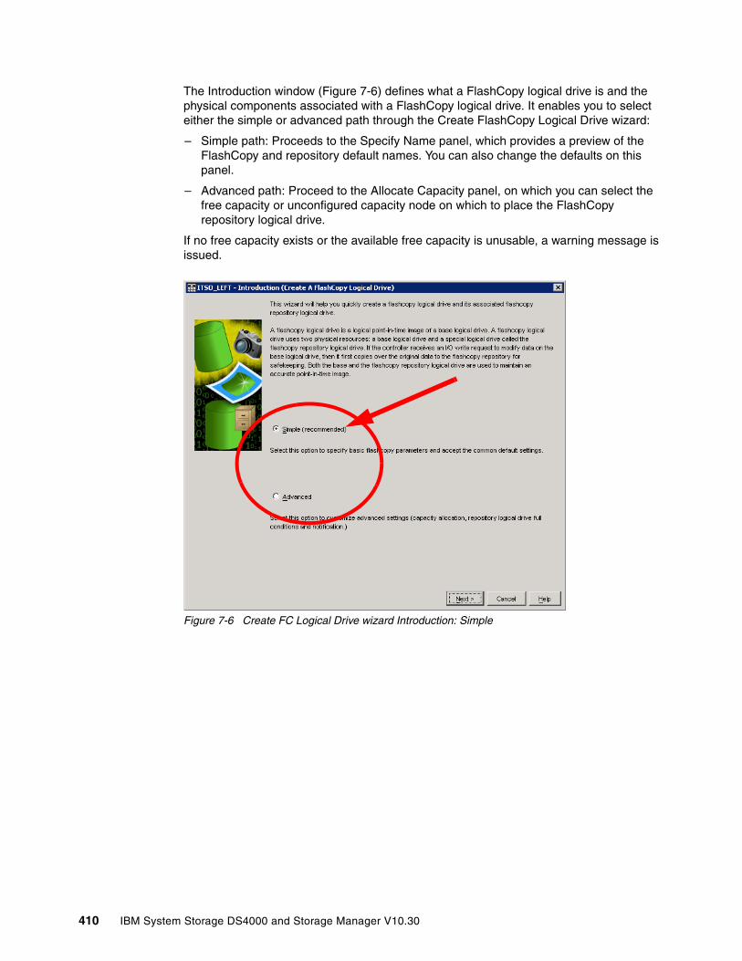
The Introduction window (Figure 7-6) defines what a FlashCopy logical drive is and the physical components associated with a FlashCopy logical drive. It enables you to select either the simple or advanced path through the Create FlashCopy Logical Drive wizard:
– Simple path: Proceeds to the Specify Name panel, which provides a preview of the FlashCopy and repository default names. You can also change the defaults on this panel.
– Advanced path: Proceed to the Allocate Capacity panel, on which you can select the free capacity or unconfigured capacity node on which to place the FlashCopy repository logical drive.
If no free capacity exists or the available free capacity is unusable, a warning message is issued.
Figure 7-6 Create FC Logical Drive wizard Introduction: Simple
410 IBM System Storage DS4000 and Storage Manager V10.30

2. If choosing the simple path, as shown in Figure 7-6 on page 410, click Next, then follow these steps:
a. The Specify Names panel is displayed (Figure 7-7) to define the name of the FlashCopy logical drive and its associated repository logical drive.
Figure 7-7 Create FC Logical Drive Wizard: Specify names
The default naming convention for the first FlashCopy is to use the base logical drive name and add a suffix of -1 for the logical drive and -R1 for the repository drive. The second FlashCopy uses 2 instead of 1. This is repeated up to the fourth logical drive.
For example, if you are creating the first FlashCopy logical drive for a base logical drive called data 1, then the default FlashCopy logical drive name is Data 1-1, and the associated FlashCopy repository logical drive default name is Data 1-R1. The default name of the next FlashCopy logical drive that you create based on Data 1 is Data 1-2, with the corresponding FlashCopy repository logical drive named Data 1-R2 by default.
Change the default names if required.
Click Next to continue.
Tips: Consider the following recommendations:
� Regardless of whether you use the software-supplied sequence number that (by default) populates the “FlashCopy logical drive name or FlashCopy repository logical drive name field, the next default name for a FlashCopy or FlashCopy repository logical drive still uses the sequence number determined by the software. For example, you might name the first FlashCopy of base logical drive Data 1 DataVolMay28, and not use the software-supplied sequence number of 1. The default name for the next FlashCopy of accounting is still Data 1-2.
� The next available sequence number is based on the number of existing FlashCopies of a base logical drive. If you delete a FlashCopy logical drive, its sequence number becomes available again.
� You must choose a unique name for the FlashCopy and FlashCopy repository logical drives. Otherwise, an error message is displayed.
Chapter 7. FlashCopy 411
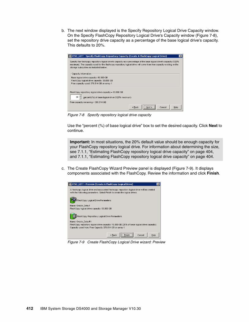
b. The next window displayed is the Specify Repository Logical Drive Capacity window. On the Specify FlashCopy Repository Logical Drive's Capacity window (Figure 7-8), set the repository drive capacity as a percentage of the base logical drive's capacity. This defaults to 20%.
Figure 7-8 Specify repository logical drive capacity
Use the “percent (%) of base logical drive” box to set the desired capacity. Click Next to continue.
c. The Create FlashCopy Wizard Preview panel is displayed (Figure 7-9). It displays components associated with the FlashCopy. Review the information and click Finish.
Figure 7-9 Create FlashCopy Logical Drive wizard: Preview
Important: In most situations, the 20% default value should be enough capacity for your FlashCopy repository logical drive. For information about determining the size, see 7.1.1, “Estimating FlashCopy repository logical drive capacity” on page 404, and 7.1.1, “Estimating FlashCopy repository logical drive capacity” on page 404.
412 IBM System Storage DS4000 and Storage Manager V10.30

d. The Wizard then displays a completion message (Figure 7-10). Click OK to continue.
Figure 7-10 Create a FlashCopy Logical Drive: Complete
e. Now you can see the newly created FlashCopy logical drive and its associated repository logical drive from the Subsystem Management window. See Figure 7-11.
Figure 7-11 New FlashCopy volume in subsystem management
New FlashCopyLogical andRepositoryLogical Volumes
Chapter 7. FlashCopy 413

3. If you chose the advanced path, select Advanced from the Create FC Logical Drive Wizard Introduction window (Figure 7-12) and click Next.
Figure 7-12 Create FlashCopy Logical Drive wizard: Advanced
a. The Specify Names panel is displayed. On the Specify Names panel (Figure 7-7 on page 411) define the FlashCopy logical drive name and the name of its associated FlashCopy repository logical drive. Click Next to continue.
b. The Allocate Capacity window (Figure 7-13) is presented, on which you can choose free capacity on the same array as the base, free capacity on a different array, or unconfigured capacity to create a new array.
Figure 7-13 Create FlashCopy Logical Drive wizard: Allocate capacity
414 IBM System Storage DS4000 and Storage Manager V10.30
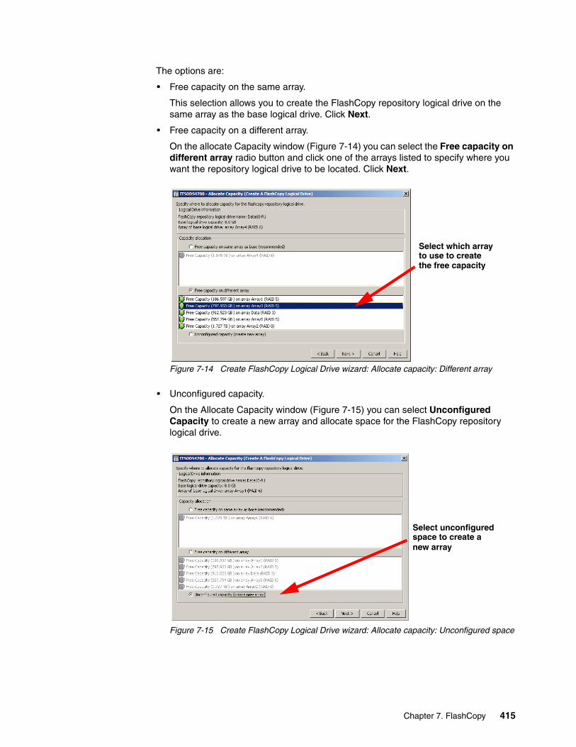
The options are:
• Free capacity on the same array.
This selection allows you to create the FlashCopy repository logical drive on the same array as the base logical drive. Click Next.
• Free capacity on a different array.
On the allocate Capacity window (Figure 7-14) you can select the Free capacity on different array radio button and click one of the arrays listed to specify where you want the repository logical drive to be located. Click Next.
Figure 7-14 Create FlashCopy Logical Drive wizard: Allocate capacity: Different array
• Unconfigured capacity.
On the Allocate Capacity window (Figure 7-15) you can select Unconfigured Capacity to create a new array and allocate space for the FlashCopy repository logical drive.
Figure 7-15 Create FlashCopy Logical Drive wizard: Allocate capacity: Unconfigured space
Select which arrayto use to createthe free capacity
Select unconfiguredspace to create anew array
Chapter 7. FlashCopy 415
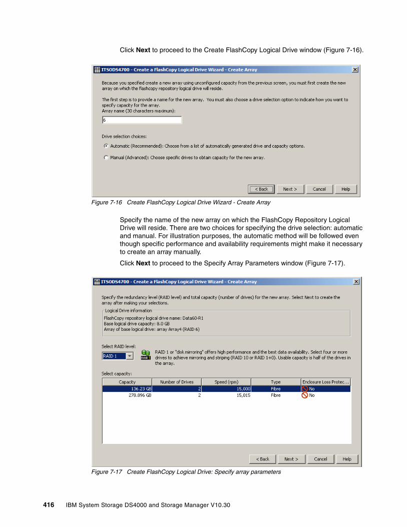
Click Next to proceed to the Create FlashCopy Logical Drive window (Figure 7-16).
Figure 7-16 Create FlashCopy Logical Drive Wizard - Create Array
Specify the name of the new array on which the FlashCopy Repository Logical Drive will reside. There are two choices for specifying the drive selection: automatic and manual. For illustration purposes, the automatic method will be followed even though specific performance and availability requirements might make it necessary to create an array manually.
Click Next to proceed to the Specify Array Parameters window (Figure 7-17).
Figure 7-17 Create FlashCopy Logical Drive: Specify array parameters
416 IBM System Storage DS4000 and Storage Manager V10.30
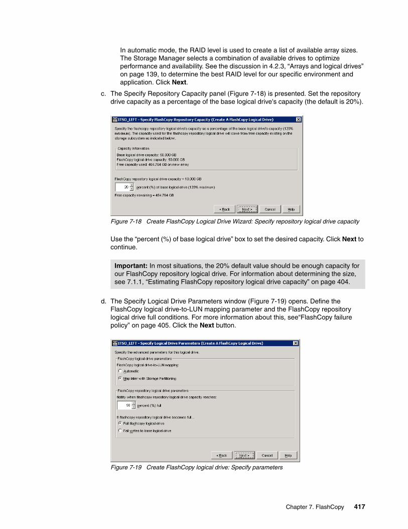
In automatic mode, the RAID level is used to create a list of available array sizes. The Storage Manager selects a combination of available drives to optimize performance and availability. See the discussion in 4.2.3, “Arrays and logical drives” on page 139, to determine the best RAID level for our specific environment and application. Click Next.
c. The Specify Repository Capacity panel (Figure 7-18) is presented. Set the repository drive capacity as a percentage of the base logical drive's capacity (the default is 20%).
Figure 7-18 Create FlashCopy Logical Drive Wizard: Specify repository logical drive capacity
Use the “percent (%) of base logical drive” box to set the desired capacity. Click Next to continue.
d. The Specify Logical Drive Parameters window (Figure 7-19) opens. Define the FlashCopy logical drive-to-LUN mapping parameter and the FlashCopy repository logical drive full conditions. For more information about this, see“FlashCopy failure policy” on page 405. Click the Next button.
Figure 7-19 Create FlashCopy logical drive: Specify parameters
Important: In most situations, the 20% default value should be enough capacity for our FlashCopy repository logical drive. For information about determining the size, see 7.1.1, “Estimating FlashCopy repository logical drive capacity” on page 404.
Chapter 7. FlashCopy 417
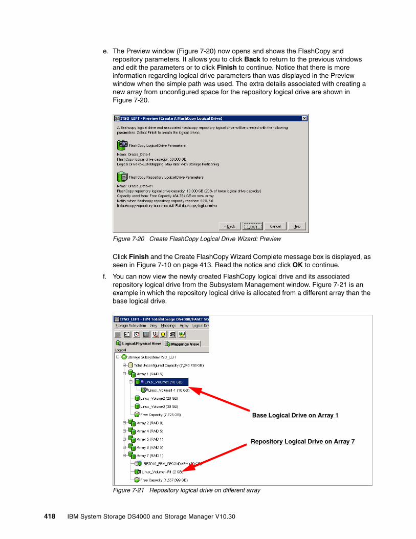
e. The Preview window (Figure 7-20) now opens and shows the FlashCopy and repository parameters. It allows you to click Back to return to the previous windows and edit the parameters or to click Finish to continue. Notice that there is more information regarding logical drive parameters than was displayed in the Preview window when the simple path was used. The extra details associated with creating a new array from unconfigured space for the repository logical drive are shown in Figure 7-20.
Figure 7-20 Create FlashCopy Logical Drive Wizard: Preview
Click Finish and the Create FlashCopy Wizard Complete message box is displayed, as seen in Figure 7-10 on page 413. Read the notice and click OK to continue.
f. You can now view the newly created FlashCopy logical drive and its associated repository logical drive from the Subsystem Management window. Figure 7-21 is an example in which the repository logical drive is allocated from a different array than the base logical drive.
Figure 7-21 Repository logical drive on different array
Repository Logical Drive on Array 7
Base Logical Drive on Array 1
418 IBM System Storage DS4000 and Storage Manager V10.30
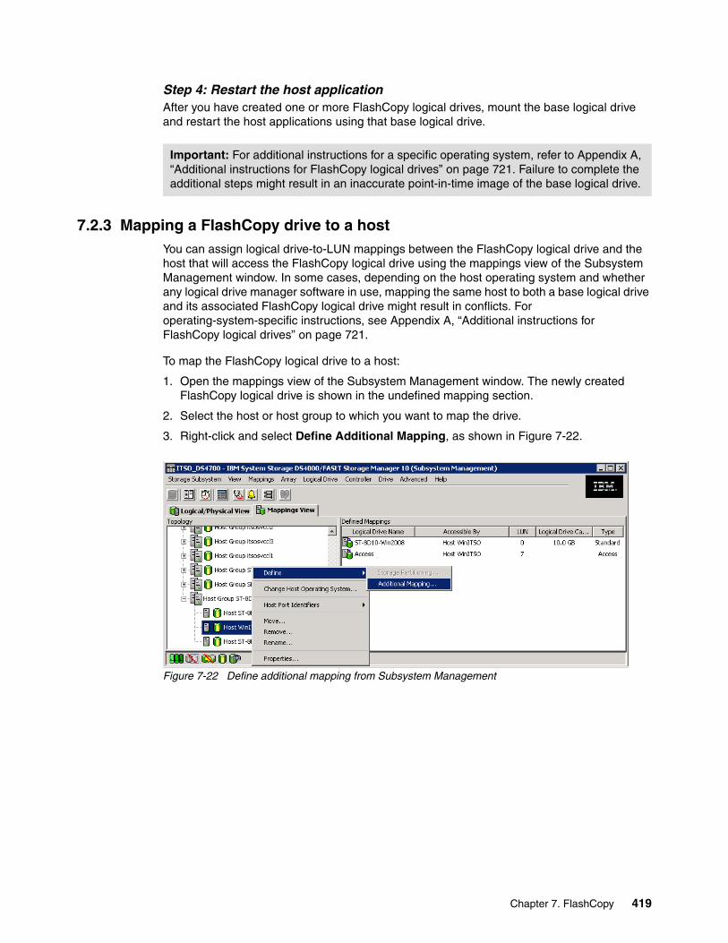
Step 4: Restart the host applicationAfter you have created one or more FlashCopy logical drives, mount the base logical drive and restart the host applications using that base logical drive.
7.2.3 Mapping a FlashCopy drive to a hostYou can assign logical drive-to-LUN mappings between the FlashCopy logical drive and the host that will access the FlashCopy logical drive using the mappings view of the Subsystem Management window. In some cases, depending on the host operating system and whether any logical drive manager software in use, mapping the same host to both a base logical drive and its associated FlashCopy logical drive might result in conflicts. For operating-system-specific instructions, see Appendix A, “Additional instructions for FlashCopy logical drives” on page 721.
To map the FlashCopy logical drive to a host:
1. Open the mappings view of the Subsystem Management window. The newly created FlashCopy logical drive is shown in the undefined mapping section.
2. Select the host or host group to which you want to map the drive.
3. Right-click and select Define Additional Mapping, as shown in Figure 7-22.
Figure 7-22 Define additional mapping from Subsystem Management
Important: For additional instructions for a specific operating system, refer to Appendix A, “Additional instructions for FlashCopy logical drives” on page 721. Failure to complete the additional steps might result in an inaccurate point-in-time image of the base logical drive.
Chapter 7. FlashCopy 419
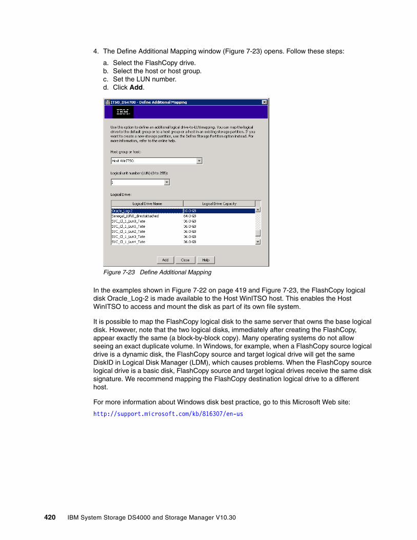
4. The Define Additional Mapping window (Figure 7-23) opens. Follow these steps:
a. Select the FlashCopy drive.b. Select the host or host group.c. Set the LUN number.d. Click Add.
Figure 7-23 Define Additional Mapping
In the examples shown in Figure 7-22 on page 419 and Figure 7-23, the FlashCopy logical disk Oracle_Log-2 is made available to the Host WinITSO host. This enables the Host WinITSO to access and mount the disk as part of its own file system.
It is possible to map the FlashCopy logical disk to the same server that owns the base logical disk. However, note that the two logical disks, immediately after creating the FlashCopy, appear exactly the same (a block-by-block copy). Many operating systems do not allow seeing an exact duplicate volume. In Windows, for example, when a FlashCopy source logical drive is a dynamic disk, the FlashCopy source and target logical drive will get the same DiskID in Logical Disk Manager (LDM), which causes problems. When the FlashCopy source logical drive is a basic disk, FlashCopy source and target logical drives receive the same disk signature. We recommend mapping the FlashCopy destination logical drive to a different host.
For more information about Windows disk best practice, go to this Microsoft Web site:
http://support.microsoft.com/kb/816307/en-us
420 IBM System Storage DS4000 and Storage Manager V10.30
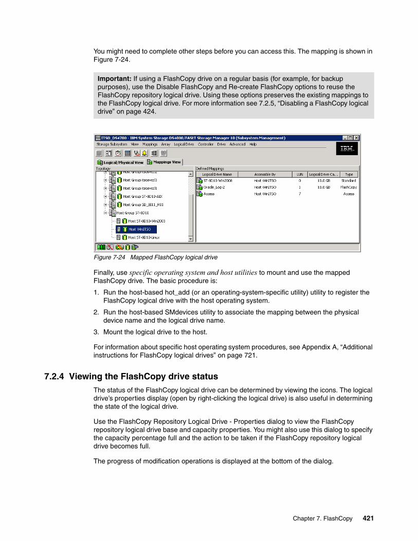
You might need to complete other steps before you can access this. The mapping is shown in Figure 7-24.
Figure 7-24 Mapped FlashCopy logical drive
Finally, use specific operating system and host utilities to mount and use the mapped FlashCopy drive. The basic procedure is:
1. Run the host-based hot_add (or an operating-system-specific utility) utility to register the FlashCopy logical drive with the host operating system.
2. Run the host-based SMdevices utility to associate the mapping between the physical device name and the logical drive name.
3. Mount the logical drive to the host.
For information about specific host operating system procedures, see Appendix A, “Additional instructions for FlashCopy logical drives” on page 721.
7.2.4 Viewing the FlashCopy drive statusThe status of the FlashCopy logical drive can be determined by viewing the icons. The logical drive’s properties display (open by right-clicking the logical drive) is also useful in determining the state of the logical drive.
Use the FlashCopy Repository Logical Drive - Properties dialog to view the FlashCopy repository logical drive base and capacity properties. You might also use this dialog to specify the capacity percentage full and the action to be taken if the FlashCopy repository logical drive becomes full.
The progress of modification operations is displayed at the bottom of the dialog.
Important: If using a FlashCopy drive on a regular basis (for example, for backup purposes), use the Disable FlashCopy and Re-create FlashCopy options to reuse the FlashCopy repository logical drive. Using these options preserves the existing mappings to the FlashCopy logical drive. For more information see 7.2.5, “Disabling a FlashCopy logical drive” on page 424.
Chapter 7. FlashCopy 421

FlashCopy icon statesTo view the FlashCopy icon, open the Storage Management Device Manager GUI physical/logical view. The icon states are described in Figure 7-25.
Figure 7-25 Status symbols
FlashCopy repository propertiesTo view the FlashCopy repository properties, complete the following procedure:
1. Select a FlashCopy repository logical drive in the logical view of the Subsystem Management window.
2. Click Logical Drive → Properties. Or you can right-click and select Properties.
Spare capacityFree capacity
Warning
Offline
Full
Failed
Degraded
OptimalRepository
Offline
Failed
Disabled
OptimalFlashCopyIconStatus
FlashCopy status representation
Spare capacityFree capacity
Warning
Offline
Full
Failed
Degraded
OptimalRepository
Offline
Failed
Disabled
OptimalFlashCopyIconStatus
FlashCopy status representation
422 IBM System Storage DS4000 and Storage Manager V10.30
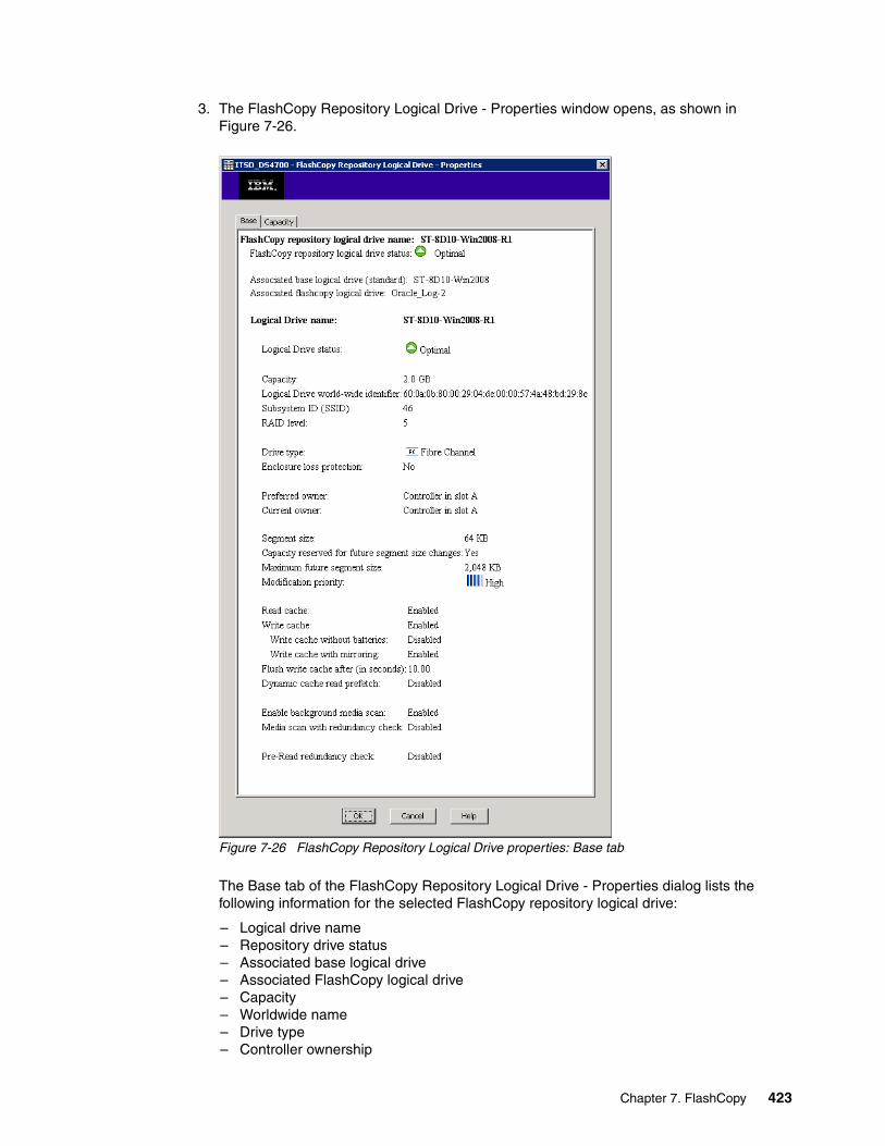
3. The FlashCopy Repository Logical Drive - Properties window opens, as shown in Figure 7-26.
Figure 7-26 FlashCopy Repository Logical Drive properties: Base tab
The Base tab of the FlashCopy Repository Logical Drive - Properties dialog lists the following information for the selected FlashCopy repository logical drive:
– Logical drive name– Repository drive status– Associated base logical drive – Associated FlashCopy logical drive – Capacity– Worldwide name – Drive type– Controller ownership
Chapter 7. FlashCopy 423
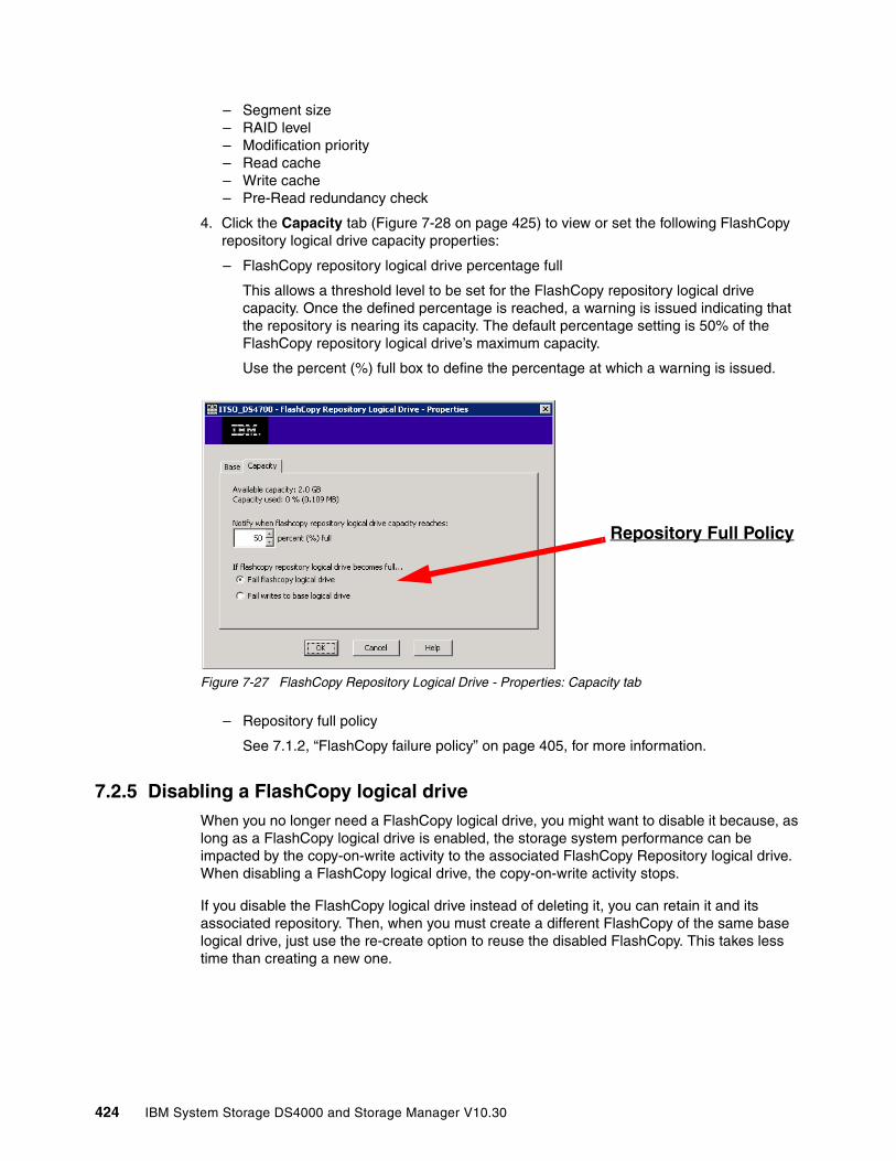
– Segment size– RAID level – Modification priority – Read cache– Write cache– Pre-Read redundancy check
4. Click the Capacity tab (Figure 7-28 on page 425) to view or set the following FlashCopy repository logical drive capacity properties:
– FlashCopy repository logical drive percentage full
This allows a threshold level to be set for the FlashCopy repository logical drive capacity. Once the defined percentage is reached, a warning is issued indicating that the repository is nearing its capacity. The default percentage setting is 50% of the FlashCopy repository logical drive’s maximum capacity.
Use the percent (%) full box to define the percentage at which a warning is issued.
Figure 7-27 FlashCopy Repository Logical Drive - Properties: Capacity tab
– Repository full policy
See 7.1.2, “FlashCopy failure policy” on page 405, for more information.
7.2.5 Disabling a FlashCopy logical driveWhen you no longer need a FlashCopy logical drive, you might want to disable it because, as long as a FlashCopy logical drive is enabled, the storage system performance can be impacted by the copy-on-write activity to the associated FlashCopy Repository logical drive. When disabling a FlashCopy logical drive, the copy-on-write activity stops.
If you disable the FlashCopy logical drive instead of deleting it, you can retain it and its associated repository. Then, when you must create a different FlashCopy of the same base logical drive, just use the re-create option to reuse the disabled FlashCopy. This takes less time than creating a new one.
Repository Full Policy
424 IBM System Storage DS4000 and Storage Manager V10.30
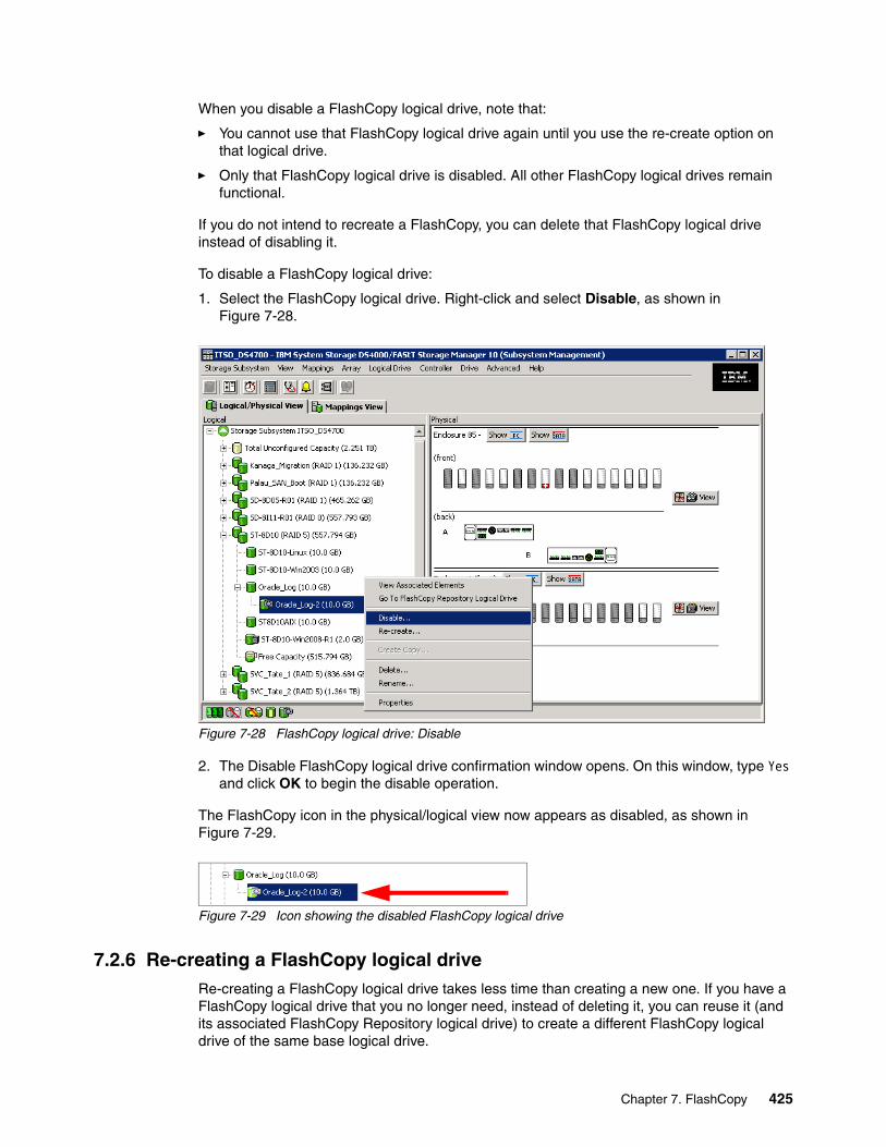
When you disable a FlashCopy logical drive, note that:
� You cannot use that FlashCopy logical drive again until you use the re-create option on that logical drive.
� Only that FlashCopy logical drive is disabled. All other FlashCopy logical drives remain functional.
If you do not intend to recreate a FlashCopy, you can delete that FlashCopy logical drive instead of disabling it.
To disable a FlashCopy logical drive:
1. Select the FlashCopy logical drive. Right-click and select Disable, as shown in Figure 7-28.
Figure 7-28 FlashCopy logical drive: Disable
2. The Disable FlashCopy logical drive confirmation window opens. On this window, type Yes and click OK to begin the disable operation.
The FlashCopy icon in the physical/logical view now appears as disabled, as shown in Figure 7-29.
Figure 7-29 Icon showing the disabled FlashCopy logical drive
7.2.6 Re-creating a FlashCopy logical driveRe-creating a FlashCopy logical drive takes less time than creating a new one. If you have a FlashCopy logical drive that you no longer need, instead of deleting it, you can reuse it (and its associated FlashCopy Repository logical drive) to create a different FlashCopy logical drive of the same base logical drive.
Chapter 7. FlashCopy 425
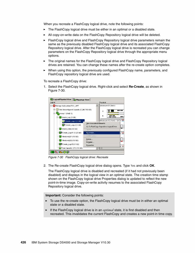
When you recreate a FlashCopy logical drive, note the following points:
� The FlashCopy logical drive must be either in an optimal or a disabled state.
� All copy-on-write data on the FlashCopy Repository logical drive will be deleted.
� FlashCopy logical drive and FlashCopy Repository logical drive parameters remain the same as the previously disabled FlashCopy logical drive and its associated FlashCopy Repository logical drive. After the FlashCopy logical drive is recreated you can change parameters on the FlashCopy Repository logical drive through the appropriate menu options.
� The original names for the FlashCopy logical drive and FlashCopy Repository logical drives are retained. You can change these names after the re-create option completes.
� When using this option, the previously configured FlashCopy name, parameters, and FlashCopy repository logical drive are used.
To recreate a FlashCopy drive:
1. Select the FlashCopy logical drive. Right-click and select Re-Create, as shown in Figure 7-30.
Figure 7-30 FlashCopy logical drive: Recreate
2. The Re-create FlashCopy logical drive dialog opens. Type Yes and click OK.
The FlashCopy logical drive is disabled and recreated (if it had not previously been disabled) and displays in the logical view in an optimal state. The creation time stamp shown on the FlashCopy logical drive Properties dialog is updated to reflect the new point-in-time image. Copy-on-write activity resumes to the associated FlashCopy Repository logical drive.
Important: Consider the following points:
� To use the re-create option, the FlashCopy logical drive must be in either an optimal state or a disabled state.
� If the FlashCopy logical drive is in an optimal state, it is first disabled and then recreated. This invalidates the current FlashCopy and creates a new point-in time copy.
426 IBM System Storage DS4000 and Storage Manager V10.30
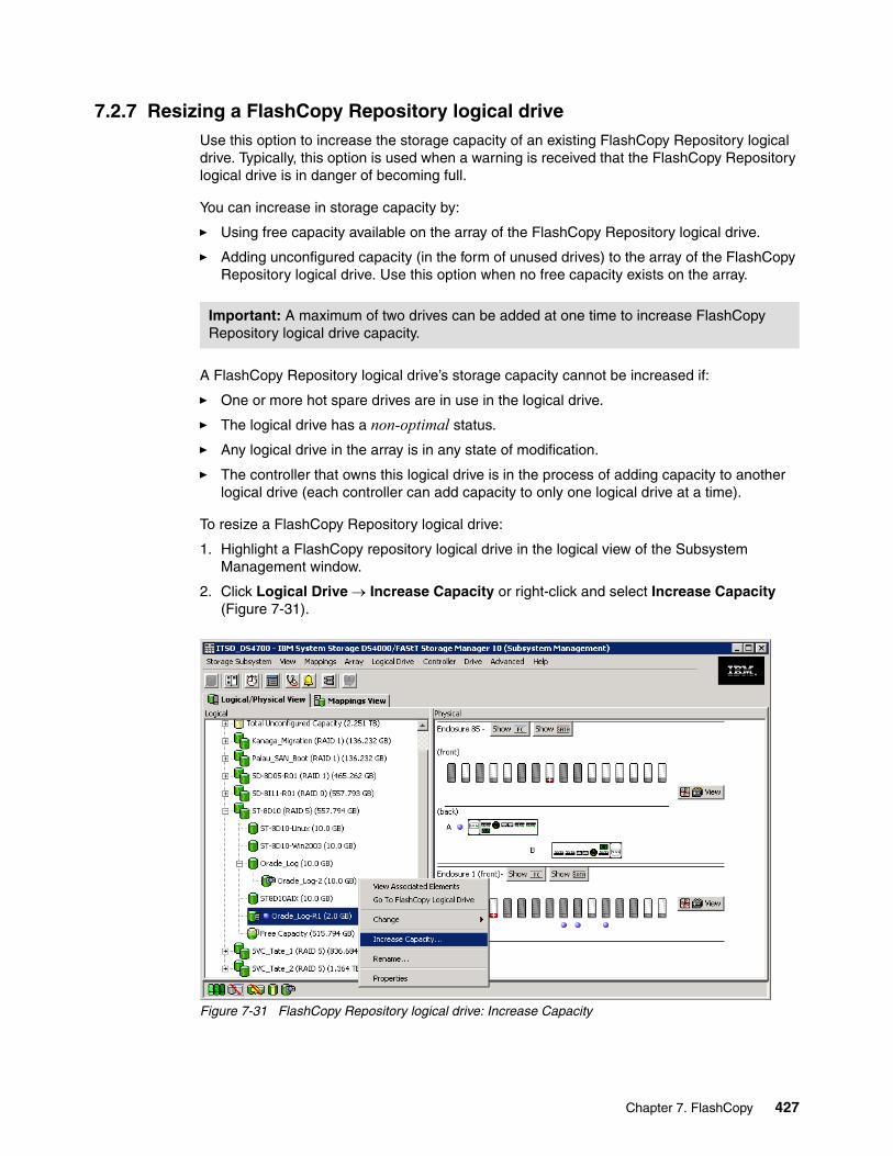
7.2.7 Resizing a FlashCopy Repository logical driveUse this option to increase the storage capacity of an existing FlashCopy Repository logical drive. Typically, this option is used when a warning is received that the FlashCopy Repository logical drive is in danger of becoming full.
You can increase in storage capacity by:
� Using free capacity available on the array of the FlashCopy Repository logical drive.
� Adding unconfigured capacity (in the form of unused drives) to the array of the FlashCopy Repository logical drive. Use this option when no free capacity exists on the array.
A FlashCopy Repository logical drive’s storage capacity cannot be increased if:
� One or more hot spare drives are in use in the logical drive.
� The logical drive has a non-optimal status.
� Any logical drive in the array is in any state of modification.
� The controller that owns this logical drive is in the process of adding capacity to another logical drive (each controller can add capacity to only one logical drive at a time).
To resize a FlashCopy Repository logical drive:
1. Highlight a FlashCopy repository logical drive in the logical view of the Subsystem Management window.
2. Click Logical Drive → Increase Capacity or right-click and select Increase Capacity (Figure 7-31).
Figure 7-31 FlashCopy Repository logical drive: Increase Capacity
Important: A maximum of two drives can be added at one time to increase FlashCopy Repository logical drive capacity.
Chapter 7. FlashCopy 427

The Increase Repository Capacity dialog opens. You can see the FlashCopy Repository logical drive name, the associated FlashCopy logical drive name, the associated base logical drive name, current capacity, and amount of free capacity available for the selected repository. If free capacity is available, the maximum free space is shown in the “Increase capacity by” box.
If there is no free capacity on the array, the free space that is shown in the “Increase capacity by” box is zero. Drives must be added to create free capacity on the array of the standard logical drive.
3. Use one of the following two methods to increase capacity:
– First method: Increase FlashCopy repository logical drive capacity using free capacity on the array of the FlashCopy repository logical drive (Figure 7-32).
Figure 7-32 Increase FlashCopy Repository Capacity
To do this:
i. Accept the final capacity increase or use the Increase capacity by box to adjust the capacity. Click OK.
ii. A confirmation dialog is displayed. Type Yes and click OK to continue.
The logical view is updated. The FlashCopy Repository logical drive with its capacity increased shows a status of operation in progress, together with its original capacity and the total capacity being added.
iii. In addition, the free capacity node involved shows a reduction in capacity. If all of the free capacity is used to increase the logical drive size, then the free capacity node involved is removed from the logical view.
Important: If no free capacity or unconfigured capacity is available, the increase capacity option is not available.
428 IBM System Storage DS4000 and Storage Manager V10.30
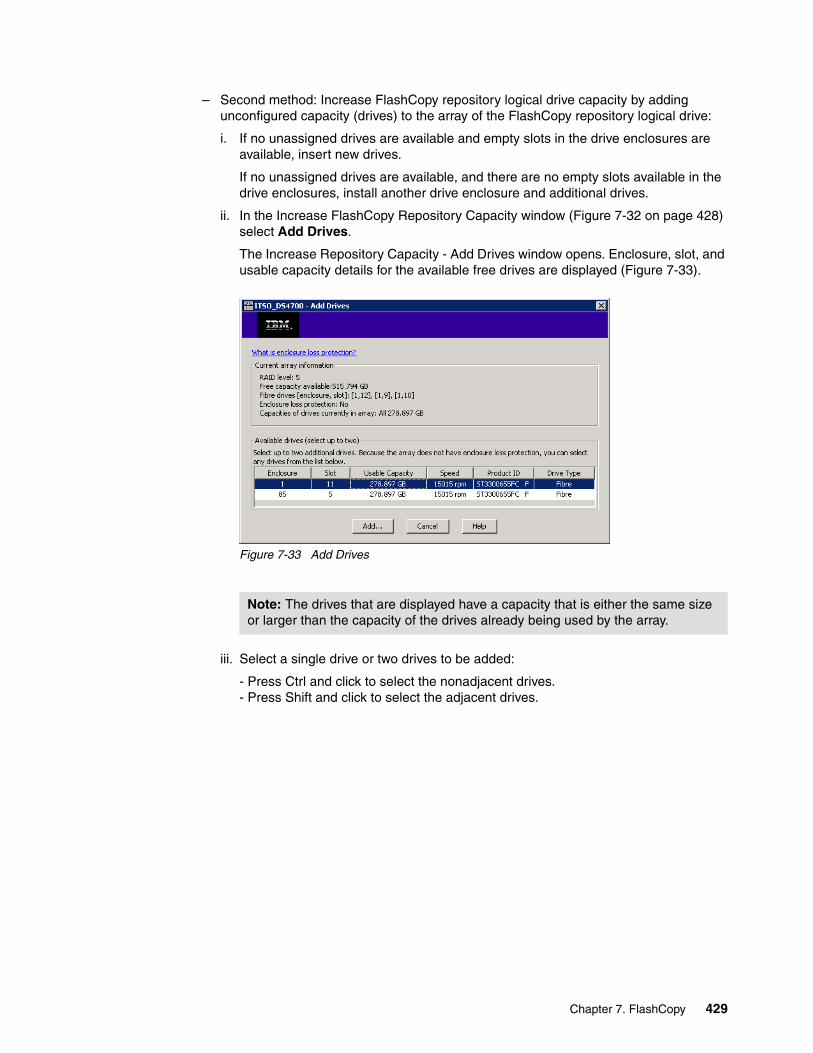
– Second method: Increase FlashCopy repository logical drive capacity by adding unconfigured capacity (drives) to the array of the FlashCopy repository logical drive:
i. If no unassigned drives are available and empty slots in the drive enclosures are available, insert new drives.
If no unassigned drives are available, and there are no empty slots available in the drive enclosures, install another drive enclosure and additional drives.
ii. In the Increase FlashCopy Repository Capacity window (Figure 7-32 on page 428) select Add Drives.
The Increase Repository Capacity - Add Drives window opens. Enclosure, slot, and usable capacity details for the available free drives are displayed (Figure 7-33).
Figure 7-33 Add Drives
iii. Select a single drive or two drives to be added:
- Press Ctrl and click to select the nonadjacent drives. - Press Shift and click to select the adjacent drives.
Note: The drives that are displayed have a capacity that is either the same size or larger than the capacity of the drives already being used by the array.
Chapter 7. FlashCopy 429
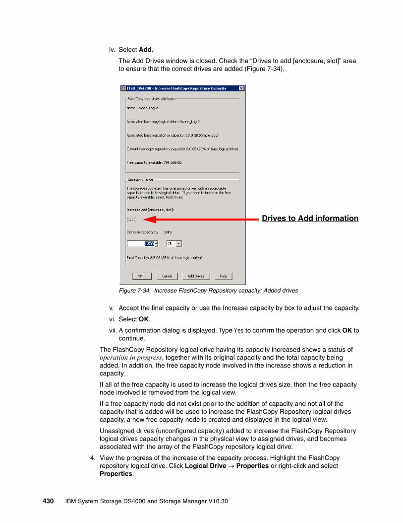
iv. Select Add.
The Add Drives window is closed. Check the “Drives to add [enclosure, slot]” area to ensure that the correct drives are added (Figure 7-34).
Figure 7-34 Increase FlashCopy Repository capacity: Added drives
v. Accept the final capacity or use the Increase capacity by box to adjust the capacity.
vi. Select OK.
vii. A confirmation dialog is displayed. Type Yes to confirm the operation and click OK to continue.
The FlashCopy Repository logical drive having its capacity increased shows a status of operation in progress, together with its original capacity and the total capacity being added. In addition, the free capacity node involved in the increase shows a reduction in capacity.
If all of the free capacity is used to increase the logical drives size, then the free capacity node involved is removed from the logical view.
If a free capacity node did not exist prior to the addition of capacity and not all of the capacity that is added will be used to increase the FlashCopy Repository logical drives capacity, a new free capacity node is created and displayed in the logical view.
Unassigned drives (unconfigured capacity) added to increase the FlashCopy Repository logical drives capacity changes in the physical view to assigned drives, and becomes associated with the array of the FlashCopy repository logical drive.
4. View the progress of the increase of the capacity process. Highlight the FlashCopy repository logical drive. Click Logical Drive → Properties or right-click and select Properties.
Drives to Add information
430 IBM System Storage DS4000 and Storage Manager V10.30
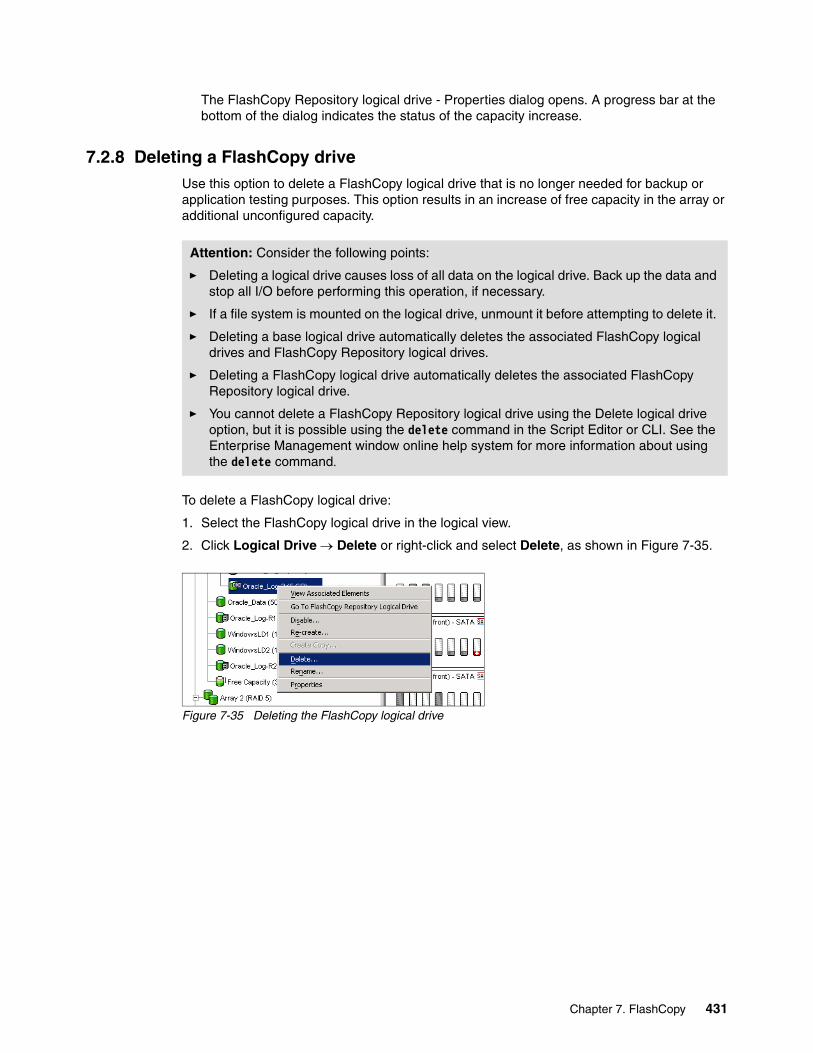
The FlashCopy Repository logical drive - Properties dialog opens. A progress bar at the bottom of the dialog indicates the status of the capacity increase.
7.2.8 Deleting a FlashCopy driveUse this option to delete a FlashCopy logical drive that is no longer needed for backup or application testing purposes. This option results in an increase of free capacity in the array or additional unconfigured capacity.
To delete a FlashCopy logical drive:
1. Select the FlashCopy logical drive in the logical view.
2. Click Logical Drive → Delete or right-click and select Delete, as shown in Figure 7-35.
Figure 7-35 Deleting the FlashCopy logical drive
Attention: Consider the following points:
� Deleting a logical drive causes loss of all data on the logical drive. Back up the data and stop all I/O before performing this operation, if necessary.
� If a file system is mounted on the logical drive, unmount it before attempting to delete it.
� Deleting a base logical drive automatically deletes the associated FlashCopy logical drives and FlashCopy Repository logical drives.
� Deleting a FlashCopy logical drive automatically deletes the associated FlashCopy Repository logical drive.
� You cannot delete a FlashCopy Repository logical drive using the Delete logical drive option, but it is possible using the delete command in the Script Editor or CLI. See the Enterprise Management window online help system for more information about using the delete command.
Chapter 7. FlashCopy 431
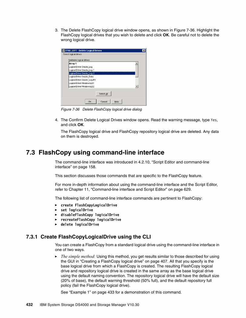
3. The Delete FlashCopy logical drive window opens, as shown in Figure 7-36. Highlight the FlashCopy logical drives that you wish to delete and click OK. Be careful not to delete the wrong logical drive.
Figure 7-36 Delete FlashCopy logical drive dialog
4. The Confirm Delete Logical Drives window opens. Read the warning message, type Yes, and click OK.
The FlashCopy logical drive and FlashCopy repository logical drive are deleted. Any data on them is destroyed.
7.3 FlashCopy using command-line interface The command-line interface was introduced in 4.2.10, “Script Editor and command-line interface” on page 158.
This section discusses those commands that are specific to the FlashCopy feature.
For more in-depth information about using the command-line interface and the Script Editor, refer to Chapter 11, “Command-line interface and Script Editor” on page 629.
The following list of command-line interface commands are pertinent to FlashCopy:
� create FlashCopyLogicalDrive � set logicalDrive � disableFlashCopy logicalDrive � recreateFlashCopy logicalDrive � delete logicalDrive
7.3.1 Create FlashCopyLogicalDrive using the CLIYou can create a FlashCopy from a standard logical drive using the command-line interface in one of two ways.
� The simple method: Using this method, you get results similar to those described for using the GUI in “Creating a FlashCopy logical drive” on page 407. All that you specify is the base logical drive from which a FlashCopy is created. The resulting FlashCopy logical drive and repository logical drive is created in the same array as the base logical drive using the default naming convention. The repository logical drive will have the default size (20% of base), the default warning threshold (50% full), and the default repository full policy (fail the FlashCopy logical drive).
See “Example 1” on page 433 for a demonstration of this command.
432 IBM System Storage DS4000 and Storage Manager V10.30
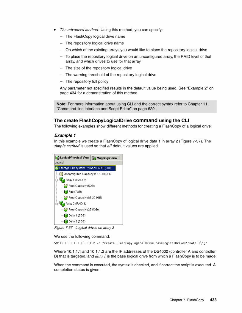
� The advanced method: Using this method, you can specify:
– The FlashCopy logical drive name
– The repository logical drive name
– On which of the existing arrays you would like to place the repository logical drive
– To place the repository logical drive on an unconfigured array, the RAID level of that array, and which drives to use for that array
– The size of the repository logical drive
– The warning threshold of the repository logical drive
– The repository full policy
Any parameter not specified results in the default value being used. See “Example 2” on page 434 for a demonstration of this method.
The create FlashCopyLogicalDrive command using the CLIThe following examples show different methods for creating a FlashCopy of a logical drive.
Example 1In this example we create a FlashCopy of logical drive data 1 in array 2 (Figure 7-37). The simple method is used so that all default values are applied.
Figure 7-37 Logical drives on array 2
We use the following command:
SMcli 10.1.1.1 10.1.1.2 -c "create FlashCopyLogicalDrive baseLogicalDrive=\"Data 1\";"
Where 10.1.1.1 and 10.1.1.2 are the IP addresses of the DS4000 (controller A and controller B) that is targeted, and data 1 is the base logical drive from which a FlashCopy is to be made.
When the command is executed, the syntax is checked, and if correct the script is executed. A completion status is given.
Note: For more information about using CLI and the correct syntax refer to Chapter 11, “Command-line interface and Script Editor” on page 629.
Chapter 7. FlashCopy 433
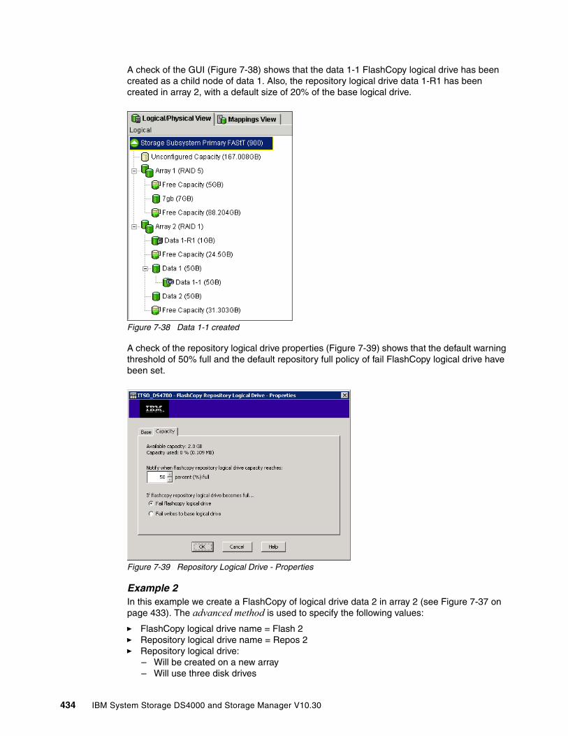
A check of the GUI (Figure 7-38) shows that the data 1-1 FlashCopy logical drive has been created as a child node of data 1. Also, the repository logical drive data 1-R1 has been created in array 2, with a default size of 20% of the base logical drive.
Figure 7-38 Data 1-1 created
A check of the repository logical drive properties (Figure 7-39) shows that the default warning threshold of 50% full and the default repository full policy of fail FlashCopy logical drive have been set.
Figure 7-39 Repository Logical Drive - Properties
Example 2In this example we create a FlashCopy of logical drive data 2 in array 2 (see Figure 7-37 on page 433). The advanced method is used to specify the following values:
� FlashCopy logical drive name = Flash 2� Repository logical drive name = Repos 2� Repository logical drive:
– Will be created on a new array– Will use three disk drives
434 IBM System Storage DS4000 and Storage Manager V10.30
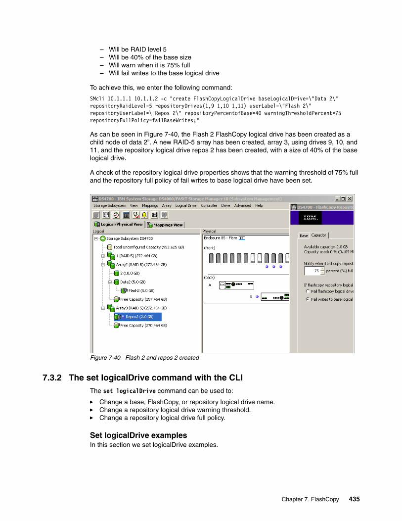
– Will be RAID level 5– Will be 40% of the base size– Will warn when it is 75% full– Will fail writes to the base logical drive
To achieve this, we enter the following command:
SMcli 10.1.1.1 10.1.1.2 -c "create FlashCopyLogicalDrive baseLogicalDrive=\"Data 2\" repositoryRaidLevel=5 repositoryDrives(1,9 1,10 1,11) userLabel=\"Flash 2\" repositoryUserLabel=\"Repos 2\" repositoryPercentofBase=40 warningThresholdPercent=75 repositoryFullPolicy=failBaseWrites;"
As can be seen in Figure 7-40, the Flash 2 FlashCopy logical drive has been created as a child node of data 2”. A new RAID-5 array has been created, array 3, using drives 9, 10, and 11, and the repository logical drive repos 2 has been created, with a size of 40% of the base logical drive.
A check of the repository logical drive properties shows that the warning threshold of 75% full and the repository full policy of fail writes to base logical drive have been set.
Figure 7-40 Flash 2 and repos 2 created
7.3.2 The set logicalDrive command with the CLIThe set logicalDrive command can be used to:
� Change a base, FlashCopy, or repository logical drive name.� Change a repository logical drive warning threshold.� Change a repository logical drive full policy.
Set logicalDrive examplesIn this section we set logicalDrive examples.
Chapter 7. FlashCopy 435
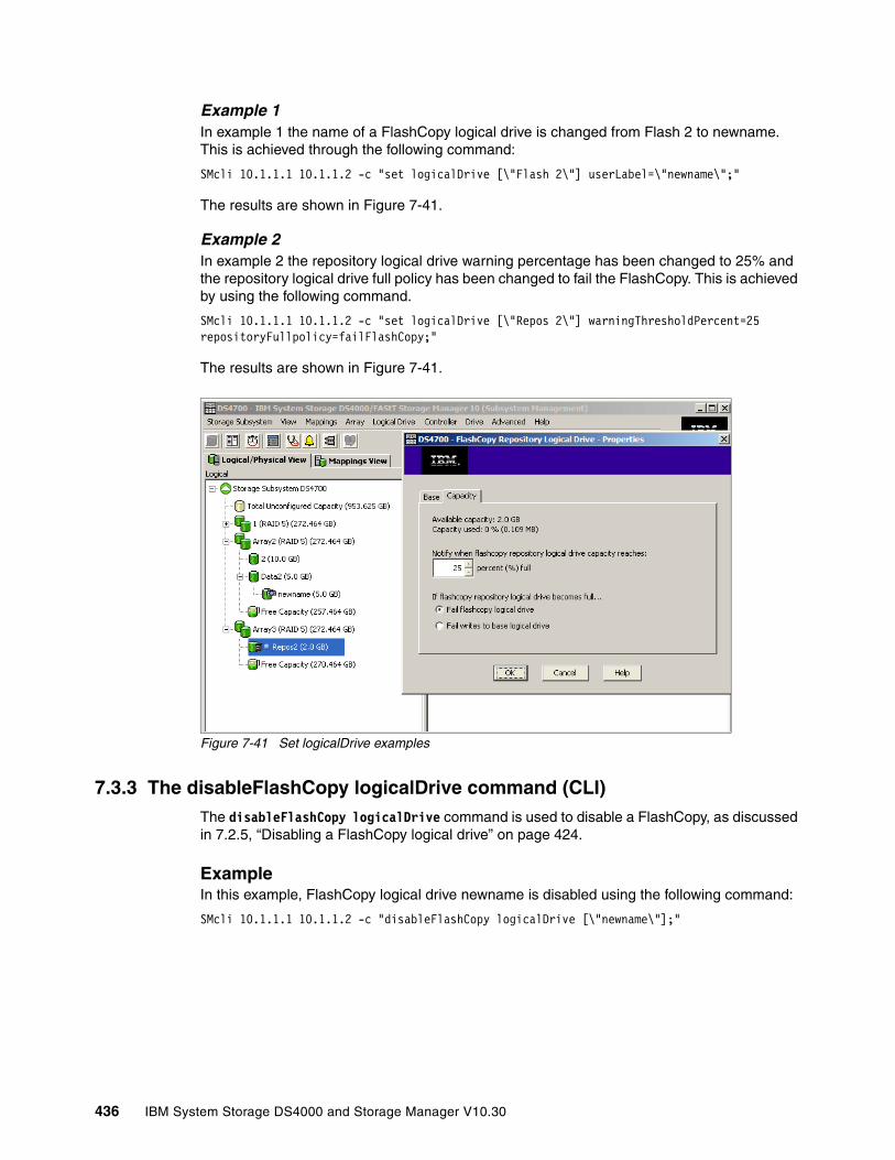
Example 1In example 1 the name of a FlashCopy logical drive is changed from Flash 2 to newname. This is achieved through the following command:
SMcli 10.1.1.1 10.1.1.2 -c "set logicalDrive [\"Flash 2\"] userLabel=\"newname\";"
The results are shown in Figure 7-41.
Example 2In example 2 the repository logical drive warning percentage has been changed to 25% and the repository logical drive full policy has been changed to fail the FlashCopy. This is achieved by using the following command.
SMcli 10.1.1.1 10.1.1.2 -c "set logicalDrive [\"Repos 2\"] warningThresholdPercent=25 repositoryFullpolicy=failFlashCopy;"
The results are shown in Figure 7-41.
Figure 7-41 Set logicalDrive examples
7.3.3 The disableFlashCopy logicalDrive command (CLI)The disableFlashCopy logicalDrive command is used to disable a FlashCopy, as discussed in 7.2.5, “Disabling a FlashCopy logical drive” on page 424.
ExampleIn this example, FlashCopy logical drive newname is disabled using the following command:
SMcli 10.1.1.1 10.1.1.2 -c "disableFlashCopy logicalDrive [\"newname\"];"
436 IBM System Storage DS4000 and Storage Manager V10.30
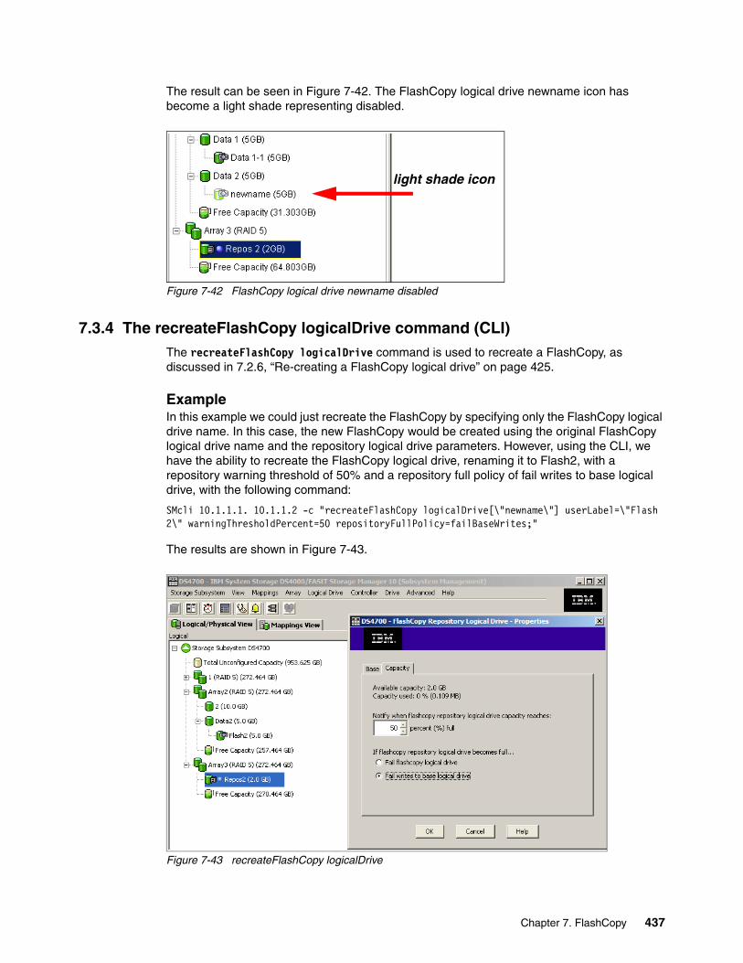
The result can be seen in Figure 7-42. The FlashCopy logical drive newname icon has become a light shade representing disabled.
Figure 7-42 FlashCopy logical drive newname disabled
7.3.4 The recreateFlashCopy logicalDrive command (CLI)The recreateFlashCopy logicalDrive command is used to recreate a FlashCopy, as discussed in 7.2.6, “Re-creating a FlashCopy logical drive” on page 425.
ExampleIn this example we could just recreate the FlashCopy by specifying only the FlashCopy logical drive name. In this case, the new FlashCopy would be created using the original FlashCopy logical drive name and the repository logical drive parameters. However, using the CLI, we have the ability to recreate the FlashCopy logical drive, renaming it to Flash2, with a repository warning threshold of 50% and a repository full policy of fail writes to base logical drive, with the following command:
SMcli 10.1.1.1. 10.1.1.2 -c "recreateFlashCopy logicalDrive[\"newname\"] userLabel=\"Flash 2\" warningThresholdPercent=50 repositoryFullPolicy=failBaseWrites;"
The results are shown in Figure 7-43.
Figure 7-43 recreateFlashCopy logicalDrive
light shade icon
Chapter 7. FlashCopy 437
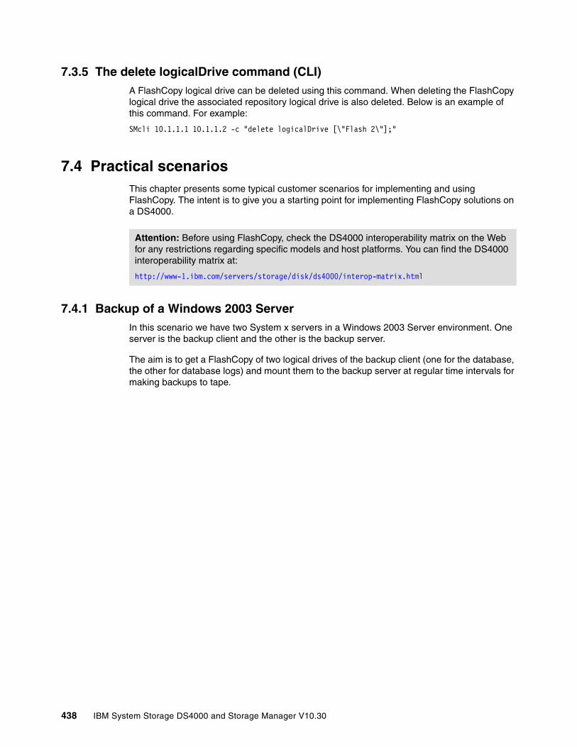
7.3.5 The delete logicalDrive command (CLI)A FlashCopy logical drive can be deleted using this command. When deleting the FlashCopy logical drive the associated repository logical drive is also deleted. Below is an example of this command. For example:
SMcli 10.1.1.1 10.1.1.2 -c "delete logicalDrive [\"Flash 2\"];"
7.4 Practical scenariosThis chapter presents some typical customer scenarios for implementing and using FlashCopy. The intent is to give you a starting point for implementing FlashCopy solutions on a DS4000.
7.4.1 Backup of a Windows 2003 ServerIn this scenario we have two System x servers in a Windows 2003 Server environment. One server is the backup client and the other is the backup server.
The aim is to get a FlashCopy of two logical drives of the backup client (one for the database, the other for database logs) and mount them to the backup server at regular time intervals for making backups to tape.
Attention: Before using FlashCopy, check the DS4000 interoperability matrix on the Web for any restrictions regarding specific models and host platforms. You can find the DS4000 interoperability matrix at:
http://www-1.ibm.com/servers/storage/disk/ds4000/interop-matrix.html
438 IBM System Storage DS4000 and Storage Manager V10.30
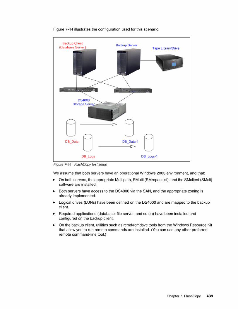
Figure 7-44 illustrates the configuration used for this scenario.
Figure 7-44 FlashCopy test setup
We assume that both servers have an operational Windows 2003 environment, and that:
� On both servers, the appropriate Multipath, SMutil (SMrepassist), and the SMclient (SMcli) software are installed.
� Both servers have access to the DS4000 via the SAN, and the appropriate zoning is already implemented.
� Logical drives (LUNs) have been defined on the DS4000 and are mapped to the backup client.
� Required applications (database, file server, and so on) have been installed and configured on the backup client.
� On the backup client, utilities such as rcmd/rcmdsvc tools from the Windows Resource Kit that allow you to run remote commands are installed. (You can use any other preferred remote command-line tool.)
Chapter 7. FlashCopy 439
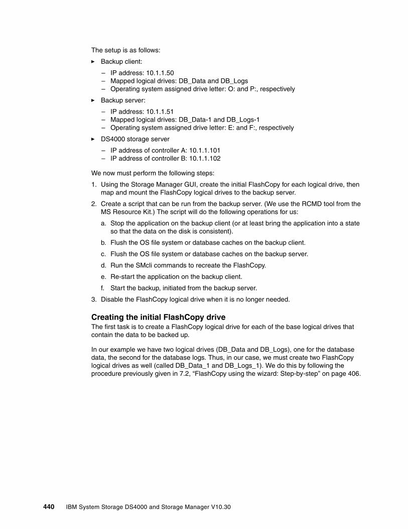
The setup is as follows:
� Backup client:
– IP address: 10.1.1.50– Mapped logical drives: DB_Data and DB_Logs– Operating system assigned drive letter: O: and P:, respectively
� Backup server:
– IP address: 10.1.1.51– Mapped logical drives: DB_Data-1 and DB_Logs-1– Operating system assigned drive letter: E: and F:, respectively
� DS4000 storage server
– IP address of controller A: 10.1.1.101– IP address of controller B: 10.1.1.102
We now must perform the following steps:
1. Using the Storage Manager GUI, create the initial FlashCopy for each logical drive, then map and mount the FlashCopy logical drives to the backup server.
2. Create a script that can be run from the backup server. (We use the RCMD tool from the MS Resource Kit.) The script will do the following operations for us:
a. Stop the application on the backup client (or at least bring the application into a state so that the data on the disk is consistent).
b. Flush the OS file system or database caches on the backup client.
c. Flush the OS file system or database caches on the backup server.
d. Run the SMcli commands to recreate the FlashCopy.
e. Re-start the application on the backup client.
f. Start the backup, initiated from the backup server.
3. Disable the FlashCopy logical drive when it is no longer needed.
Creating the initial FlashCopy driveThe first task is to create a FlashCopy logical drive for each of the base logical drives that contain the data to be backed up.
In our example we have two logical drives (DB_Data and DB_Logs), one for the database data, the second for the database logs. Thus, in our case, we must create two FlashCopy logical drives as well (called DB_Data_1 and DB_Logs_1). We do this by following the procedure previously given in 7.2, “FlashCopy using the wizard: Step-by-step” on page 406.
440 IBM System Storage DS4000 and Storage Manager V10.30
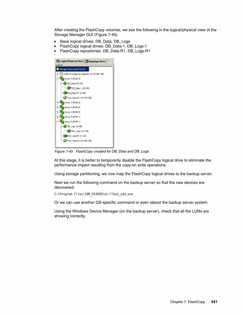
After creating the FlashCopy volumes, we see the following in the logical/physical view of the Storage Manager GUI (Figure 7-45).
� Base logical drives: DB_Data, DB_Logs� FlashCopy logical drives: DB_Data-1, DB_Logs-1� FlashCopy repositories: DB_Data-R1, DB_Logs-R1
Figure 7-45 FlashCopy created for DB_Data and DB_Logs
At this stage, it is better to temporarily disable the FlashCopy logical drive to eliminate the performance impact resulting from the copy-on write operations.
Using storage partitioning, we now map the FlashCopy logical drives to the backup server.
Next we run the following command on the backup server so that the new devices are discovered:
C:\Program Files\IBM_DS4000\util\hot_add.exe
Or we can use another OS-specific command or even reboot the backup server system.
Using the Windows Device Manager (on the backup server), check that all the LUNs are showing correctly.
Chapter 7. FlashCopy 441
In our case, we see two Multipath Disk Devices (DB_Data-1 and DB_Logs-1) and four IBM 1814 SCSI Disk Devices, which would be the paths to the disks (two paths to two disks = four IBM 1814 SCSI Disk Devices). This is illustrated in Figure 7-46.
Figure 7-46 Device Manager
Using the Disk Manager, we assign drive letters on the backup server for the newly recognized FlashCopy volumes (E and F).
We installed the rcmdsvc service (available from the Windows Resource Kit) on the backup client.
We used the script shown in Example 7-1 to perform a recreate of our FlashCopy logical drives, as would happen in a regular backup routine on the server.
Example 7-1 FlashCopy demo script
@ECHO OFFREM This is a basic script example intended for a scenario where we have one orREM more backup clients that will hold some sort of application. It shows theREM steps required to recreate a FlashCopy of the disks mapped to the backup clientsREM and how to make sure that the data is consistent before it is accessed by theREM backup server for backup.
REM -------------------------------------------------------------------------------REM 1. STOPPING THE IO FROM THE BACKUP CLIENT TO THE DS4000REMREM The first step is to make sure that the IO from the backup client to the DS4000
Tip: To install the rcmdsvc service, you must run the command rcmdsvc -install. To check that the service is installed correctly, go to the Services window, look for the remote command service, and check if it is started. The default it is set to manual. You should set it to automatic so it starts whenever the server is up and running.
442 IBM System Storage DS4000 and Storage Manager V10.30

REM Storage Server is stopped. If we cannot stop the application, place it in backup mode or use another method to bring the data into a consistent state before backup.REM If we want for example to stop a special service like an SQL Server we can doREM that using net stop mssqlserver
net stop mssqlserverREM -------------------------------------------------------------------------------REM 2. FLUSHING THE FILE SYSTEM CACHES ON THE BACKUP CLIENTREMREM After we have stopped the IO to the local disks of the backup client weREM have to flush the caches on the backup client. In this example the disksREM on the backup client are O: and P:ECHO Flushing caches on Backup Client
rcmd \\10.1.1.50 C:\Progra~1\IBM_DS4000\util\SMRepassist -f O:rcmd \\10.1.1.50 C:\Progra~1\IBM_DS4000\util\SMRepassist -f P:
REM -------------------------------------------------------------------------------REM 3. FLUSHING THE FILE SYSTEM CACHES ON THE BACKUP SERVERREMREM After that we also need to flush the caches on the disks that areREM mapped to the backup server. In our example that would be E: and F:ECHO Flushing caches on Backup Server
C:\Progra~1\IBM_DS4000\util\SMRepassist -f E:C:\Progra~1\IBM_DS4000\util\SMRepassist -f F:
REM -------------------------------------------------------------------------------REM 4. DOING THE FLASHCOPY ON THE DS4000REMREM Now we need to recreate the Flashcopy logical Drives on the DS4000.
ECHO Recreating the Flashcopy DrivesC:\Progra~1\IBM_DS4000\client\SMcli 10.1.1.101 10.1.1.102 -c "recreateFlashCopy logicalDrive[\"DB_Data-1\"];"C:\Progra~1\IBM_DS4000\client\SMcli 10.1.1.101 10.1.1.102 -c "recreateFlashCopy logicalDrive[\"DB_Logs-1\"];"
REM -------------------------------------------------------------------------------REM 5. REM Mount the disks representing the Flashcopy Logical DrivesREM (E: and F: in our example)
mountvol E: \\?\Volume\{2e4ca078d-5cbc-34d1-a8c5-29da06f30d0e}\mountvol F: \\?\Volume\{2e4ca078d-5cbc-34d1-a8c6-3937bc0d440e}\
REM -------------------------------------------------------------------------------REM 6. RESUMING IO ON THE BACKUP CLIENTREMREM After everything is finished we will start the services and applications onREM the backup client. With something likeREM net start mssqlserver
net start mssqlserver
REM -------------------------------------------------------------------------------REM 7. NOW YOU CAN USE THE FLASHCOPY DRIVES ON THE BACKUP SERVERREMREM Here we then can start to use our backup application for backing up the dataREM from the Flashcopy drivers (E: and F: in our example)
Chapter 7. FlashCopy 443
Run BakcupApplication
REM -------------------------------------------------------------------------------
REM 8. UNMOUNT THE VOLUMES ON THE BACKUP SERVERREM ECHO Dismounting volumes on Backup Server
mountvol E: /pmountvol F: /p
REM -------------------------------------------------------------------------------REM 9. DISABLE FLASHCOPY DRIVESREM When backup has completed , the FLashCopy logical drives can be disabled
C:\Progra~1\IBM_DS4000\client\SMcli 10.1.1.101 10.1.1.102 -c "disableFlashCopy logicalDrive[\"DB_Data-1\"];"C:\Progra~1\IBM_DS4000\client\SMcli 10.1.1.101 10.1.1.102 -c "disableFlashCopy logicalDrive[\"DB_Logs-1\"];"
7.4.2 DB2 backup using DS4000 FlashCopy in AIXIn this scenario we have two System p servers. One server is a backup server, with the IBM Tivoli® Storage Manager (TSM) installed. The other (our backup client) is the DB2® server.
444 IBM System Storage DS4000 and Storage Manager V10.30
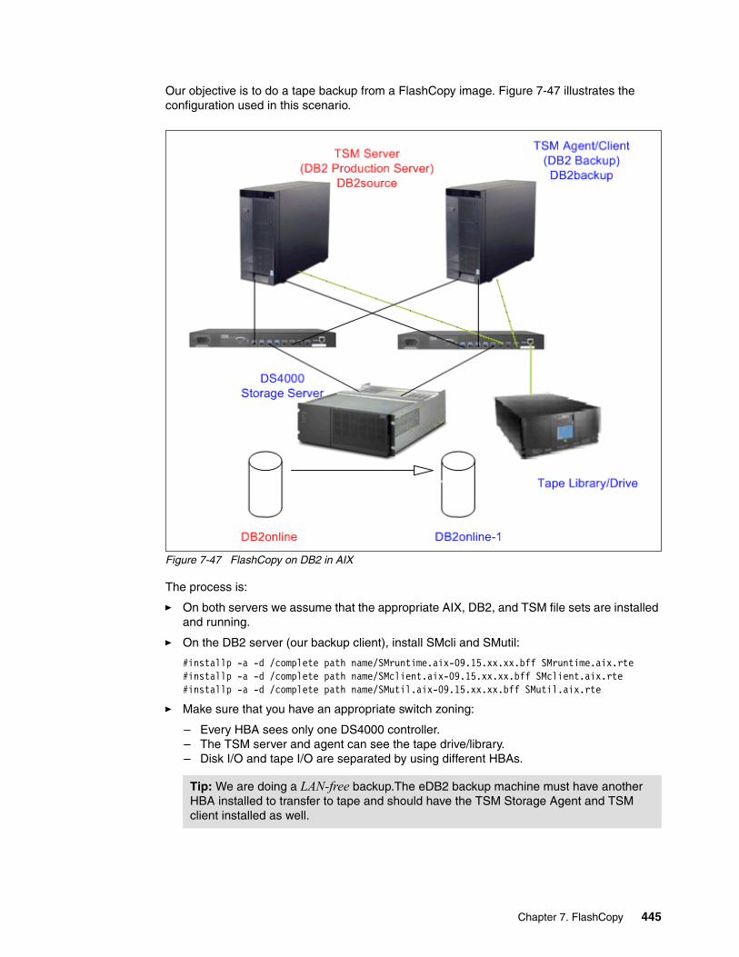
Our objective is to do a tape backup from a FlashCopy image. Figure 7-47 illustrates the configuration used in this scenario.
Figure 7-47 FlashCopy on DB2 in AIX
The process is:
� On both servers we assume that the appropriate AIX, DB2, and TSM file sets are installed and running.
� On the DB2 server (our backup client), install SMcli and SMutil:
#installp -a -d /complete path name/SMruntime.aix-09.15.xx.xx.bff SMruntime.aix.rte #installp -a -d /complete path name/SMclient.aix-09.15.xx.xx.bff SMclient.aix.rte #installp -a -d /complete path name/SMutil.aix-09.15.xx.xx.bff SMutil.aix.rte
� Make sure that you have an appropriate switch zoning:
– Every HBA sees only one DS4000 controller.– The TSM server and agent can see the tape drive/library.– Disk I/O and tape I/O are separated by using different HBAs.
Tip: We are doing a LAN-free backup.The eDB2 backup machine must have another HBA installed to transfer to tape and should have the TSM Storage Agent and TSM client installed as well.
Chapter 7. FlashCopy 445
� DS4000 with FlashCopy license
– IP address of controller A:172.16.3.106/255.255.255.0– IP address of controller B:172.16.3.107/255.255.255.0– DB2 production machine’s host name is DB2source– DB2 backup machine’s host name is DB2backup– DB2 production machine’s logical drive named DB2online– DB2 backup machine’s logical drive name will be DB2online-1
We perform the following steps:
1. Create a production database called flash on DB2online logical drive:
db2 "create db flash on /db2"db2 connect to flashdb2 "create tablespace data managed by database using (DEVICE 'dev/rdata' 200000)"db2 "create table test(age integer)"db2 connect reset
2. Create a script named CreateFC.scr in the /usr/SMclient directory to make FlashCopy and map to DB2backup:
create FlashCopyLogicalDrive baseLogicalDrive="DB2online";create mapping logicaldrive =’DB2online-1’ logicalUnitNumber=30 host=’DB2backup’;
3. Create a script named DisableFC.scr in the /usr/SMclient directory to disable FlashCopy DB2online-1:
disableFlashCopy logicaldrive ["DB2online-1"];
4. To experiment, write a DB2 script named batch in /db2 directory to generate I/O when doing FlashCopy.
a. Use the DB2 develop center to write a storage procedure:
public class Batch{ public static void batch ( ) throws SQLException, Exception { // connect to DB Connection con = DriverManager.getConnection("jdbc:default:connection"); PreparedStatement stmt = null; ResultSet rs1 = null; boolean bFlag; String sql; int i=1;
while (i < 200000) { sql = "insert into db2inst1.test values(" + i+")"; stmt = con.prepareStatement( sql ); bFlag = stmt.execute(); rs1 = stmt.getResultSet(); i++;
if (i == 20000)
Note: This script will insert 19,999 records in the database named flash, then commit. We will do a FlashCopy after the commit. As a result, on the FlashCopy target logical drive, the DB should have 19,999 records.
446 IBM System Storage DS4000 and Storage Manager V10.30

con.commit();
// check query result //while (rs1.next()) //{ // //}
// close all resthenources if (rs1 != null) rs1.close(); if (stmt != null) stmt.close(); } }}
b. Write script batch and place it in the /db2 directory:
#!/bin/kshdb2 connect to flash user db2inst1 using db2admindb2 "call db2inst1.batch2()"
5. After preparing the above script, execute the following commands:
a. Insert 19,999 records to flash DB and then suspend DB2 I/O:
#!bin/ksh /db2/batch &sleep 40db2 connect to flash user db2inst1 using db2admindb2 "set write suspend for database"
b. Make a FlashCopy of the DB2 online logical drive and map it to the DB2backup machine:
#!bin/kshsu - db2inst1 "-c /db2/sp1 -9 -u"/usr/SMclient/SMcli 172.16.3.107 -f /usr/SMclient/CreateFC.scr su - db2inst1 "-c /db2/resume -9 -u"
c. Resume DB2 I/O:
db2 connect to flash user db2inst1 using db2admindb2 "set write resume for database"
d. In DB2backup running DB2 with FlashCopied data, we should see 19,999 records:
db2startdb2inidb <target-database> as snapshothot_add importvg -y db2 hdisk10mount /db2chown -R db2inst1 /db2chmod -R 755 /db2cd /devchown db2inst1 rdatadb2 uncatalog db flashdb2 catalog db flash on /db2su - root. /home/db2inst1/sqllib/db2profiledb2inidb flash as snapshot
Note: The sleep for 40 seconds is to guarantee that 19,999 records have been successfully written to the flash DB.
Chapter 7. FlashCopy 447
su - db2inst1db2 connect to flashdb2 "select count(*) from test"
e. Back up FlashCopied data to tape:
db2 "backup db flash use tsm"
f. Stop the DB2backup db2 instance:
su - db2inst1db2stop forcefuser -ku /dev/lv02unmount /db2varyoffvg db2exportvg db2
g. Disable FlashCopied data:
/usr/SMclient/SMcli 172.16.3.107 -f /usr/SMclient/DisableFC.scrrmdev -l hdisk10 -d
For more information about how to use FlashCopy with DB2, refer to the document Split mirror using suspended I/O in DB2 Universal Database, available at:
http://www.ibm.com/developerworks/db2/library/techarticle/dm-0508quazi/index.html
448 IBM System Storage DS4000 and Storage Manager V10.30
Chapter 8. Enhanced Remote Mirroring
This chapter describes the concepts of Enhanced Remote Mirroring (ERM) and provides details on how information is mirrored between storage systems. It also explains the different mirroring methods with their terminology and what differentiates them.
The mirroring methods or modes are known as:
� Metro Mirroring� Global Copy� Global Mirroring
This chapter also includes step-by-step procedures for using, monitoring, and recovering an Enhanced Remote Mirroring installation.
ERM provides the technology that enables business continuity in the event of a disaster or unrecoverable error at one storage system. It achieves this by maintaining two copies of a data set in two different locations, on two or more different storage servers, and enabling a second storage system to take over responsibility.
Additional information about ERM planning and implementation best practices can be found in DS4000 Best Practices and Performance Tuning Guide, SG24-6363.
8
© Copyright IBM Corp. 2004, 2005, 2006, 2007, 2008, 2009. All rights reserved. 449
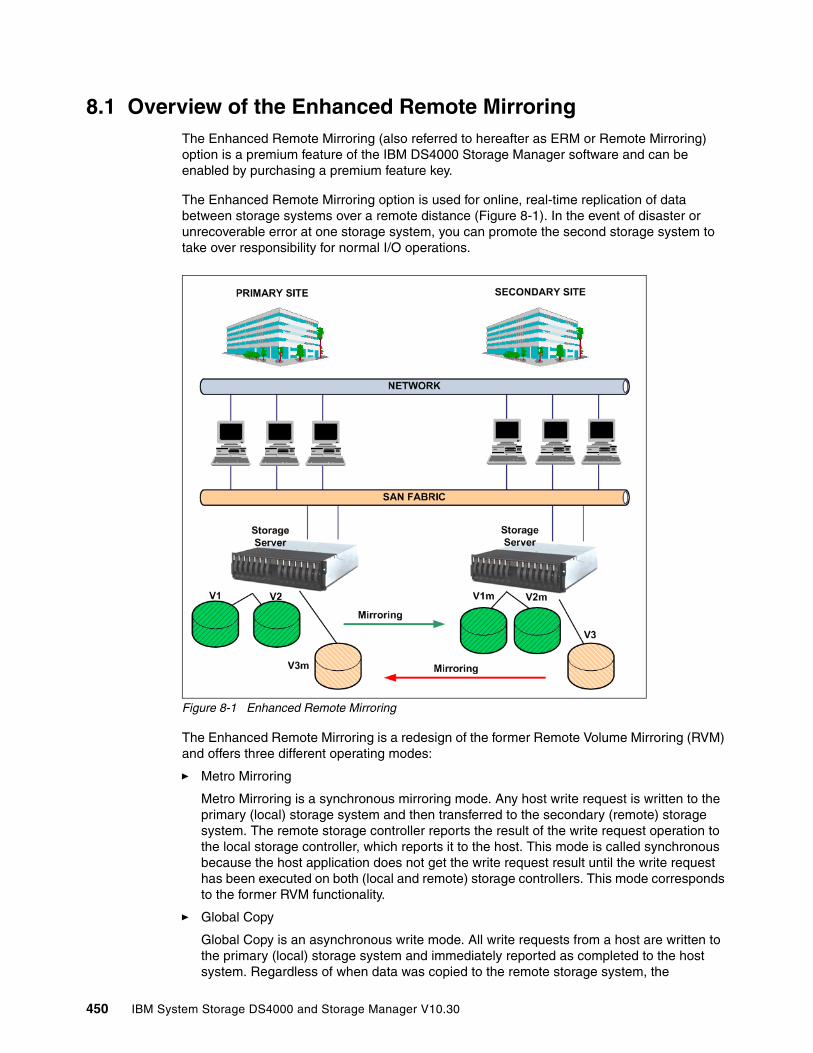
8.1 Overview of the Enhanced Remote MirroringThe Enhanced Remote Mirroring (also referred to hereafter as ERM or Remote Mirroring) option is a premium feature of the IBM DS4000 Storage Manager software and can be enabled by purchasing a premium feature key.
The Enhanced Remote Mirroring option is used for online, real-time replication of data between storage systems over a remote distance (Figure 8-1). In the event of disaster or unrecoverable error at one storage system, you can promote the second storage system to take over responsibility for normal I/O operations.
Figure 8-1 Enhanced Remote Mirroring
The Enhanced Remote Mirroring is a redesign of the former Remote Volume Mirroring (RVM) and offers three different operating modes:
� Metro Mirroring
Metro Mirroring is a synchronous mirroring mode. Any host write request is written to the primary (local) storage system and then transferred to the secondary (remote) storage system. The remote storage controller reports the result of the write request operation to the local storage controller, which reports it to the host. This mode is called synchronous because the host application does not get the write request result until the write request has been executed on both (local and remote) storage controllers. This mode corresponds to the former RVM functionality.
� Global Copy
Global Copy is an asynchronous write mode. All write requests from a host are written to the primary (local) storage system and immediately reported as completed to the host system. Regardless of when data was copied to the remote storage system, the
450 IBM System Storage DS4000 and Storage Manager V10.30
application does not wait for the I/O commit from the remote site. However, Global Copy does not ensure that write requests performed to multiple drives on the primary site are later processed in the same order on the remote site. As such, it is also referred to as Asynchronous Mirroring without Write Consistency Group.
� Global Mirroring
Global Mirroring is an asynchronous write mode. It ensures that the write requests are carried out in the same order at the remote site. This mode is also referred to as Asynchronous Mirroring with Write Consistency Group.
The new Enhanced Remote Mirroring has also been equipped with new functions for better business continuance solution design and maintenance tasks.
Secondary logical drive accessibilityWith the ERM, a secondary logical drive can be accessed in read-only mode.
Suspend mirror and resume mirror capabilitiesThis function allows you to suspend the mirroring process independently of the mirroring mode. While in suspended state, the secondary subsystem no longer receives any write I/Os from the primary subsystem, and all data blocks that change are logged in a special volume (logical drive) called the mirroring repository volume (see 8.2, “Mirror repository logical drives” on page 455).
Since the data on the secondary logical drive is not changing, you can access the frozen secondary logical volume and use it for test purposes or to back it up. You could even write to the disk, but changes would not be tracked.
To resume the mirroring, invoke the resume mirror function. It resynchronizes the changed data between the primary and the secondary logical drives. No full synchronization needs to take place.
Change write mode optionYou can switch among the different mirroring modes at any time for an established mirror relationship. This is called dynamic mode switching. You can switch between:
� Metro Mirroring (synchronous write mode)� Global Copy (asynchronous write mode without write consistency group)� Global Mirroring (asynchronous write mode with write consistency group)
Test Mirror communication functionAfter the mirroring relationship between the primary and the secondary logical drive is established, it is possible and easy to test the mirror communication status. Using the Storage Manager (SM) graphical user interface (GUI) client, you can perform the test with only one mouse click, and the result is graphically displayed (green or red traffic light picture).
8.1.1 Requirements
In this section we discuss the requirements to enable and use the Enhanced Remote Mirroring feature.
Enhanced Remote Mirroring premium featureYou must purchase an ERM Premium Feature License from IBM and enable the Premium Feature on each DS4000 storage server, which is supposed to hold primary or secondary mirrored logical drive.
Chapter 8. Enhanced Remote Mirroring 451
With V7.10 and later firmware it is now possible to have up to 128 mirror pairs, depending on the DS4000 storage subsystem. This firmware also introduces a new feature key scheme that dictates the quantity of mirror pairs based on the licence that has been purchased. For the number of maximum mirror pairs for a specific model, see Table 8-1.
Table 8-1 New supported maximum mirror pairs with V7.10 and later firmware
DS4000 model and host operating systemSince ERM is a storage system firmware driven function, most of the operating systems supported with the DS4000 storage servers also support ERM (note that not all DS4000 models support ERM). For an up-to-date list of compatible hosts for ERM, and which DS4000 models support ERM, refer to:
http://www.ibm.com/servers/storage/disk/ds4000/interop-matrix.html
HBAsRefer also to the interoperability matrix for a list of supported host bus adapters.
SAN environmentTo use ERM, it is mandatory to attach the storage servers to a SAN fabric using Fibre Channel switches or Fibre Channel-IP (FC-IP) routers. Refer to IBM System Storage/Brocade Multiprotocol Routing: An Introduction and Implementation, SG24-7544, for detailed implementations for FC-IP routing configuration examples. The ERM Fibre Channel connection must be a dedicated for data replication between the subsystems. The ports used for ERM cannot receive I/Os from any host.
These requirements are addressed by defining SAN zoning. The zones must separate the host ports from the storage system mirroring ports and also separate the mirroring ports between the redundant controllers. This means that the mirroring ports from pair A (primary and secondary controller A) must be in a separate zone from the mirroring ports from pair B (primary and secondary controller B). Zoning and site configuration examples are provided later in this chapter.
Refer to the interoperability matrix for choosing supported switch models.
Management network environmentIt is mandatory that the managing host (that is, the host or workstation used to manage the storage server using the DS4000 Storage Manager software) can simultaneously access the primary and secondary storage server through the Ethernet (IP) network. In other words, make sure that Ethernet ports on each storage server are on the same subnet or part of a Virtual Private Network (VPN) connection.
DS4000 model Number of supported mirror pairs
DS4200 32, can upgrade to 64
DS4700 32, can upgrade to 64
DS4800 64, can upgrade to128
Tip: The name server service of SAN switch is required for ERM communication (this means a switch with (soft) zoning capability). The SAN switch attachment is mandatory. You can have one switch to connect both DS4000s if the distance can be satisfied.
452 IBM System Storage DS4000 and Storage Manager V10.30
8.1.2 ERM terminologyBefore discussing in more detail the functionality and characteristics of ERM, we have included here, for reference, a definition of the terms used in the context of ERM.
The naming convention is generally based on the data flow direction in a mirror relationship.
Primary siteThe primary site is the location of the primary storage subsystem. This location with its systems provides the productive data to hosts and users. Data will be mirrored from here to the secondary site.
The primary site is also referred as the local site.
Secondary siteThe secondary site is the location of the secondary storage subsystem. This location with its systems holds the mirrored data. Data is mirrored from the primary site to here.
The secondary site is also referred as the remote site.
Primary storage systemThis is the storage system that provides the production data to hosts and users. Data is mirrored from here to the secondary storage subsystem.
The primary storage subsystem is also referred to as the local storage subsystem.
Secondary storage subsystemThis is the storage subsystem that holds the mirrored data. Data is mirrored from the primary storage subsystem to here.
The secondary storage subsystem is also referred as the remote storage subsystem.
Mirroring storage controller pairBecause in a mirror relationship of a logical volume there are exactly two controllers involved, they are called a mirroring storage controller pair. The mirror relationship is between the A to A controller and the B to B controller.
Mirror Fibre Channel connectionThere is a dedicated Fibre Channel connection for mirror I/Os from the primary controller to the secondary controller. The use of switches for the Mirror Fibre Channel connection is mandatory. Direct connections are not allowed. This connection must not be used for any other purposes. See also “SAN environment” on page 452.
Primary logical drive and secondary logical driveWhen you create an Enhanced Remote Mirroring relationship, a mirrored logical drive pair is defined and consists of a primary logical drive at the primary storage system and a secondary logical drive at a secondary storage system.
Note: It is not required for the primary and secondary storage systems to be of the same model. However, it can be useful to install the same hardware on both sites for optimal performance and reliability of the overall system. In the end you always must consider performance requirements of both of the sites.
Chapter 8. Enhanced Remote Mirroring 453

Mirror repository logical driveA mirror repository logical drive is a special logical drive in the storage system created as a resource for the controller owner of the primary logical drives in a mirror relationship.
Mirror relationshipA mirror relationship is an established mirroring connection between two logical drives, defined on two different storage systems. It is defined through the corresponding mirror repository drive, the mirrored logical drives pair, and controller ownership of the mirrored logical drives.
Mirror roleThere is always the primary role of a mirror relationship member, which grants the write access to the primary logical volume from the hosts system, and a secondary role of a mirror relationship member, which prohibits the write access to the secondary logical volume from the host systems.
Role reversalIn the event of a site failure or for maintenance tasks you can change the role of a logical drive in a given mirror relationship from primary to secondary and vice versa, and grant or deny (to the hosts) write access on these logical drives. This procedure is called role reversal.
Write consistency groupIn a configuration with multiple mirror relationships between logical drives, depending upon the application needs, it might be necessary to preserve the write order on some secondary logical drives. The write consistency group contains the logical drives for which the write order must be preserved. The write consistency group option is only available for Global Mirroring (asynchronous) operation mode.
Full synchronizationWhen you first create the mirror relationship, all data is initially copied from the primary logical drive to the remote logical drive. This procedure is called full synchronization. Under normal circumstances there is no need for full synchronization, since data changes can be logged on the mirror repository logical drive. If all segments for the given logical drive are changed before the synchronization can take place (due to link error conditions, for example), then the full synchronization is needed. Additionally, the full resynch is needed after a link failure with subsequent role reversal.
454 IBM System Storage DS4000 and Storage Manager V10.30
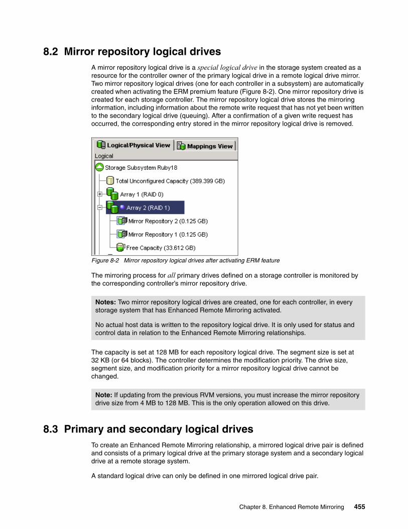
8.2 Mirror repository logical drivesA mirror repository logical drive is a special logical drive in the storage system created as a resource for the controller owner of the primary logical drive in a remote logical drive mirror. Two mirror repository logical drives (one for each controller in a subsystem) are automatically created when activating the ERM premium feature (Figure 8-2). One mirror repository drive is created for each storage controller. The mirror repository logical drive stores the mirroring information, including information about the remote write request that has not yet been written to the secondary logical drive (queuing). After a confirmation of a given write request has occurred, the corresponding entry stored in the mirror repository logical drive is removed.
Figure 8-2 Mirror repository logical drives after activating ERM feature
The mirroring process for all primary drives defined on a storage controller is monitored by the corresponding controller’s mirror repository drive.
The capacity is set at 128 MB for each repository logical drive. The segment size is set at 32 KB (or 64 blocks). The controller determines the modification priority. The drive size, segment size, and modification priority for a mirror repository logical drive cannot be changed.
8.3 Primary and secondary logical drivesTo create an Enhanced Remote Mirroring relationship, a mirrored logical drive pair is defined and consists of a primary logical drive at the primary storage system and a secondary logical drive at a remote storage system.
A standard logical drive can only be defined in one mirrored logical drive pair.
Notes: Two mirror repository logical drives are created, one for each controller, in every storage system that has Enhanced Remote Mirroring activated.
No actual host data is written to the repository logical drive. It is only used for status and control data in relation to the Enhanced Remote Mirroring relationships.
Note: If updating from the previous RVM versions, you must increase the mirror repository drive size from 4 MB to 128 MB. This is the only operation allowed on this drive.
Chapter 8. Enhanced Remote Mirroring 455
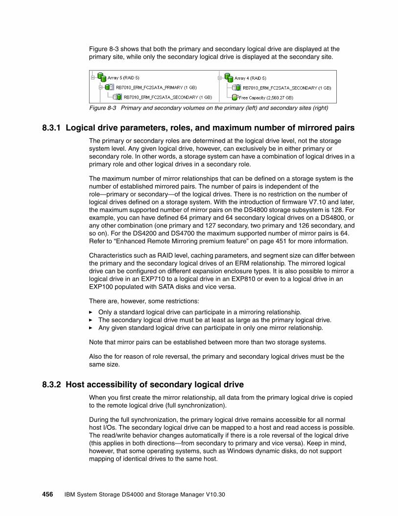
Figure 8-3 shows that both the primary and secondary logical drive are displayed at the primary site, while only the secondary logical drive is displayed at the secondary site.
Figure 8-3 Primary and secondary volumes on the primary (left) and secondary sites (right)
8.3.1 Logical drive parameters, roles, and maximum number of mirrored pairsThe primary or secondary roles are determined at the logical drive level, not the storage system level. Any given logical drive, however, can exclusively be in either primary or secondary role. In other words, a storage system can have a combination of logical drives in a primary role and other logical drives in a secondary role.
The maximum number of mirror relationships that can be defined on a storage system is the number of established mirrored pairs. The number of pairs is independent of the role—primary or secondary—of the logical drives. There is no restriction on the number of logical drives defined on a storage system. With the introduction of firmware V7.10 and later, the maximum supported number of mirror pairs on the DS4800 storage subsystem is 128. For example, you can have defined 64 primary and 64 secondary logical drives on a DS4800, or any other combination (one primary and 127 secondary, two primary and 126 secondary, and so on). For the DS4200 and DS4700 the maximum supported number of mirror pairs is 64. Refer to “Enhanced Remote Mirroring premium feature” on page 451 for more information.
Characteristics such as RAID level, caching parameters, and segment size can differ between the primary and the secondary logical drives of an ERM relationship. The mirrored logical drive can be configured on different expansion enclosure types. It is also possible to mirror a logical drive in an EXP710 to a logical drive in an EXP810 or even to a logical drive in an EXP100 populated with SATA disks and vice versa.
There are, however, some restrictions:
� Only a standard logical drive can participate in a mirroring relationship.� The secondary logical drive must be at least as large as the primary logical drive.� Any given standard logical drive can participate in only one mirror relationship.
Note that mirror pairs can be established between more than two storage systems.
Also the for reason of role reversal, the primary and secondary logical drives must be the same size.
8.3.2 Host accessibility of secondary logical driveWhen you first create the mirror relationship, all data from the primary logical drive is copied to the remote logical drive (full synchronization).
During the full synchronization, the primary logical drive remains accessible for all normal host I/Os. The secondary logical drive can be mapped to a host and read access is possible. The read/write behavior changes automatically if there is a role reversal of the logical drive (this applies in both directions—from secondary to primary and vice versa). Keep in mind, however, that some operating systems, such as Windows dynamic disks, do not support mapping of identical drives to the same host.
456 IBM System Storage DS4000 and Storage Manager V10.30
Also keep in mind that many operating systems (OSs) like Windows and AIX write a signature or a dirty bit when mounting a volume. In this case no direct read access is possible. The workaround for these OSs is to start a FlashCopy of the volume and take a VolumeCopy on top of it.
8.3.3 Mirrored logical drive controller ownershipThe logical drives belonging to controller A in the primary storage server must be mirrored to the logical drives owned by controller A in the secondary subsystem. The same rule applies for the logical drives owned by controller B.
A primary controller will only attempt to communicate with its matching controller in the secondary storage system. The controller (A or B) that owns the primary logical drive determines the controller owner of the secondary logical drive. If the primary logical drive is owned by controller A on the primary site, the secondary logical drive is therefore owned by controller A on the secondary side. If the primary controller A cannot communicate with the secondary controller A, no controller ownership changes take place, and the Remote Mirror link is broken for that logical drive pair.
If an ownership change of the logical drive on the primary site occurs (caused by an I/O path error or administrator interaction), an ownership change of the logical drive on the remote controller takes place with the first write request (from the primary controller to the secondary controller) issued through the mirror connection. A prerequisite is that the ownership transfer on the secondary side occurs and that there is no needs attention status displayed.
The logical drive ownership of the secondary controller cannot be changed by either the host or through the GUI. It is entirely controlled by the primary side.
8.3.4 Deleting a mirrored logical driveWhen deleting a primary logical drive, the ERM first deletes the corresponding mirror relationship, then the primary logical drive. If a secondary logical drive must be deleted, the corresponding mirror relationship must be deleted manually prior to the actual deletion of the secondary logical drive.
8.3.5 Enhanced Remote Mirroring and on demand functionsThis section describes how on demand functions are eventually affected by a Remote Mirroring relationship.
ERM and Dynamic Volume Expansion (DVE)The Enhanced Volume Mirroring feature does not restrict the DVE function. Either the capacity of the primary logical drive or the capacity of the secondary logical drive can be increased in the same way as increasing capacity on a standard logical volume. The logical drive capacity of the secondary logical drive must be at least the capacity of the primary logical drive. The operating system restrictions to increasing the capacity of a logical drive still remain. The capacity of the mirror repository drives cannot be increased by DVE.
Important: The CLI deletes the primary volume without deleting the mirror relationship. The mirror relationship can be removed on the secondary site, after deletion of the primary logical drive through CLI.
Chapter 8. Enhanced Remote Mirroring 457

ERM and dynamic capacity expansion (DCE)The amount of disk drives in an array that contain the primary or secondary logical drive can be increased by DCE in the same manner as on the other arrays. The array sizes of the primary and secondary logical drives are independent of each other. Keep in mind that there is a restriction of adding a maximum of two physical drives at the same time to an array.
ERM and the dynamic segment sizing (DSS)You can change the segment size of the primary or secondary logical drive dynamically, independently of each other.
ERM and the dynamic RAID level migration (DRM)The DRM function is not allowed on either the primary or the secondary logical drives. The RAID level of the arrays holding the mirrored drives can be different at the time of the creation the mirror relationship.
8.3.6 Enhanced Remote Mirroring and FlashCopy premium featureWith the ERM premium feature, you can take a FlashCopy of a primary and secondary logical drive (since read access to the secondary logical drive is now possible). Role reversals that cause a primary logical drive to reverse to a secondary logical drive will not fail any associated FlashCopy.
For data consistency, you should prevent the FlashCopy source from write I/Os. By flashing a logical volume you must stop the application and flush the write cache entries. By flashing the secondary logical volume first you must stop the application and flush the write cache entries and then suspend the mirror relationship (once the secondary is in sync). The application functionality can be restored and a FlashCopy of the secondary drive can be made, after which the mirror is resumed.
8.3.7 Enhanced Remote Mirroring and VolumeCopy premium featureA primary logical drive can be a source or target logical drive in a VolumeCopy. A secondary logical drive cannot be a source or target logical drive in a VolumeCopy unless a role reversal was initiated after the copy had completed. If a role reversal is initiated during a copy in progress, the copy will fail and cannot be restarted.
8.3.8 Enhanced Remote Mirroring and storage partitioning premium featureStorage partitioning is not affected by ERM. You must ensure that you to license enough storage partitions for all needed host attachments.
Attention: Starting a VolumeCopy for a given primary logical drive will set it to read-only access. The host application or host OS will not be able to issue write requests to this resource.
458 IBM System Storage DS4000 and Storage Manager V10.30

8.3.9 Volume role compatibilityTable 8-2 shows the dependencies of volume roles on Copy Services.
Table 8-2 Volume role compatibility
8.4 Mirror relationshipA mirror relationship is an established mirroring connection between two storage systems. It contains the definitions of mirror repository drives and mirroring pairs of the logical drives.
Before you can establish a mirror relationship between two storage systems, you must:
� Establish a proper Fibre Channel and Ethernet communication between the storage servers.
� Enable the Enhanced Remote Mirroring premium feature on both storage systems.
� Activate the ERM function on both storage systems. This step creates the mirror repository drives. These two repository drives on each storage system are used for all mirrored logical drives that will ever be created.
� Create a standard logical drive on the remote site with an equal to or greater than capacity of the primary logical drive.
See 8.6, “SAN fabric and Ethernet connectivity” on page 468, for information about ERM communication issues.
It can become a:
If volume is a:
FlashCopy volume
FlashCopy base volume
FlashCopy repository
Primary logical drive
Secondary logical drive
Mirror repository logical drive
VolumeCopy source
VolumeCopy target
FlashCopyvolume
NO NO NO NO NO NO YES NO
FlashCopybase volume
NO YES NO YES NO NO YES NO
FlashCopyrepository
NO NO NO NO NO NO NO NO
Primarylogical drive
NO YES NO NO NO NO YES NO
Secondarylogical drive
NO YES NO NO NO NO NO NO
Mirrorrepositorylogical drive
NO NO NO NO NO NO NO NO
VolumeCopysource
NO YES NO YES NO NO YES NO
VolumeCopytarget
NO YES NO YES NO NO YES NO
Chapter 8. Enhanced Remote Mirroring 459
Remote Mirror statusThe status of a Remote Mirror indicates whether the data on the primary logical drive is identical (fully synchronized) with data on the secondary logical drive. A mirror status is independent of the status of the actual logical drives in the mirrored pair. The primary and secondary logical drive icons in the logical view indicate both the state of the logical drive and the state of the Remote Mirror.
There are four statuses of a Remote Mirror:
� Synchronized� Synchronizing� Suspended� Unsynchronized
Attention: You cannot create a mirror relationship if the primary logical drive contains unreadable sectors. Furthermore, if an unreadable sector is discovered during a mirroring operation, the mirror relationship fails.
460 IBM System Storage DS4000 and Storage Manager V10.30
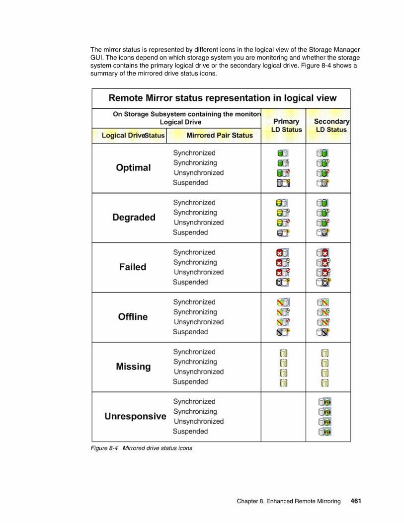
The mirror status is represented by different icons in the logical view of the Storage Manager GUI. The icons depend on which storage system you are monitoring and whether the storage system contains the primary logical drive or the secondary logical drive. Figure 8-4 shows a summary of the mirrored drive status icons.
Figure 8-4 Mirrored drive status icons
Chapter 8. Enhanced Remote Mirroring 461
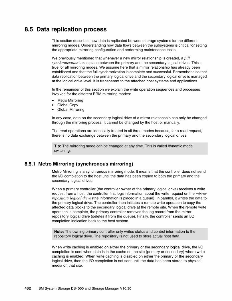
8.5 Data replication process
This section describes how data is replicated between storage systems for the different mirroring modes. Understanding how data flows between the subsystems is critical for setting the appropriate mirroring configuration and performing maintenance tasks.
We previously mentioned that whenever a new mirror relationship is created, a full synchronization takes place between the primary and the secondary logical drives. This is true for all mirroring modes. We assume here that a mirror relationship has already been established and that the full synchronization is complete and successful. Remember also that data replication between the primary logical drive and the secondary logical drive is managed at the logical drive level. It is transparent to the attached host systems and applications.
In the remainder of this section we explain the write operation sequences and processes involved for the different ERM mirroring modes:
� Metro Mirroring� Global Copy� Global Mirroring
In any case, data on the secondary logical drive of a mirror relationship can only be changed through the mirroring process. It cannot be changed by the host or manually.
The read operations are identically treated in all three modes because, for a read request, there is no data exchange between the primary and the secondary logical drives.
8.5.1 Metro Mirroring (synchronous mirroring)Metro Mirroring is a synchronous mirroring mode. It means that the controller does not send the I/O completion to the host until the data has been copied to both the primary and the secondary logical drives.
When a primary controller (the controller owner of the primary logical drive) receives a write request from a host, the controller first logs information about the write request on the mirror repository logical drive (the information is placed in a queue). In parallel, it writes the data to the primary logical drive. The controller then initiates a remote write operation to copy the affected data blocks to the secondary logical drive at the remote site. When the remote write operation is complete, the primary controller removes the log record from the mirror repository logical drive (deletes it from the queue). Finally, the controller sends an I/O completion indication back to the host system.
When write caching is enabled on either the primary or the secondary logical drive, the I/O completion is sent when data is in the cache on the site (primary or secondary) where write caching is enabled. When write caching is disabled on either the primary or the secondary logical drive, then the I/O completion is not sent until the data has been stored to physical media on that site.
Tip: The mirroring mode can be changed at any time. This is called dynamic mode switching.
Note: The owning primary controller only writes status and control information to the repository logical drive. The repository is not used to store actual host data.
462 IBM System Storage DS4000 and Storage Manager V10.30
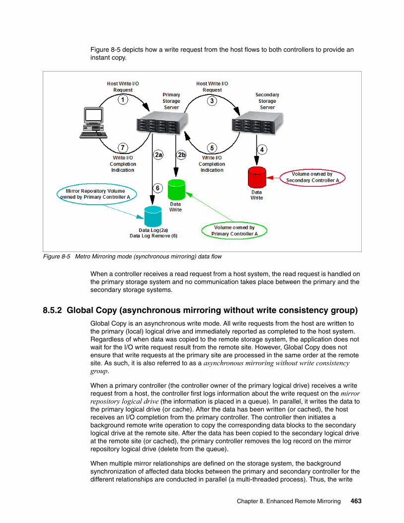
Figure 8-5 depicts how a write request from the host flows to both controllers to provide an instant copy.
Figure 8-5 Metro Mirroring mode (synchronous mirroring) data flow
When a controller receives a read request from a host system, the read request is handled on the primary storage system and no communication takes place between the primary and the secondary storage systems.
8.5.2 Global Copy (asynchronous mirroring without write consistency group)Global Copy is an asynchronous write mode. All write requests from the host are written to the primary (local) logical drive and immediately reported as completed to the host system. Regardless of when data was copied to the remote storage system, the application does not wait for the I/O write request result from the remote site. However, Global Copy does not ensure that write requests at the primary site are processed in the same order at the remote site. As such, it is also referred to as a asynchronous mirroring without write consistency group.
When a primary controller (the controller owner of the primary logical drive) receives a write request from a host, the controller first logs information about the write request on the mirror repository logical drive (the information is placed in a queue). In parallel, it writes the data to the primary logical drive (or cache). After the data has been written (or cached), the host receives an I/O completion from the primary controller. The controller then initiates a background remote write operation to copy the corresponding data blocks to the secondary logical drive at the remote site. After the data has been copied to the secondary logical drive at the remote site (or cached), the primary controller removes the log record on the mirror repository logical drive (delete from the queue).
When multiple mirror relationships are defined on the storage system, the background synchronization of affected data blocks between the primary and secondary controller for the different relationships are conducted in parallel (a multi-threaded process). Thus, the write
Chapter 8. Enhanced Remote Mirroring 463

order for multiple volumes (for example, write requests to a database data volume and a database log volume on a data base server) is not guaranteed with the Global Copy mode.
See Figure 8-6 for a logical view of the data flow.
Figure 8-6 Global Copy mode (asynchronous mirroring) data flow
When write caching is enabled on either the primary or the secondary logical drive, the I/O completion is sent when data is in the cache on the site (primary or secondary) where write caching is enabled. When write caching is disabled on either the primary or the secondary logical drive, then the I/O completion is not sent until the data has been stored to physical media on that site.
When a controller receives a read request from a host system, the read request is handled on the primary storage system and no communication takes place between the primary and the secondary storage systems.
8.5.3 Global Mirroring (asynchronous mirroring with write consistency group)Global Mirroring is an asynchronous write mode where the order of host write requests at the primary site is preserved at the secondary site. This mode is also referred as an asynchronous mirroring with write consistency group.
Note: The mirror repository logical drive can queue up to 128 I/O requests. Until the maximum number has been reached, the mirrored pair state is said to be in a synchronized state. If the maximum number of unsynchronized I/O requests is exceeded, the state of the mirrored pair changes to unsynchronized.
The host can continue to issue write requests to the primary logical drive, but remote writes to the secondary logical drive will not take place. The requests are stored in the Remote Mirror repository on the primary site (delta logging).
464 IBM System Storage DS4000 and Storage Manager V10.30
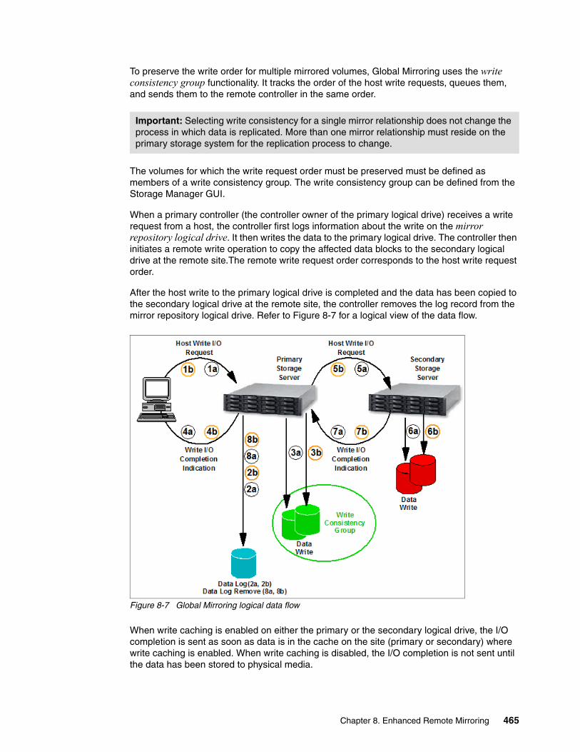
To preserve the write order for multiple mirrored volumes, Global Mirroring uses the write consistency group functionality. It tracks the order of the host write requests, queues them, and sends them to the remote controller in the same order.
The volumes for which the write request order must be preserved must be defined as members of a write consistency group. The write consistency group can be defined from the Storage Manager GUI.
When a primary controller (the controller owner of the primary logical drive) receives a write request from a host, the controller first logs information about the write on the mirror repository logical drive. It then writes the data to the primary logical drive. The controller then initiates a remote write operation to copy the affected data blocks to the secondary logical drive at the remote site.The remote write request order corresponds to the host write request order.
After the host write to the primary logical drive is completed and the data has been copied to the secondary logical drive at the remote site, the controller removes the log record from the mirror repository logical drive. Refer to Figure 8-7 for a logical view of the data flow.
Figure 8-7 Global Mirroring logical data flow
When write caching is enabled on either the primary or the secondary logical drive, the I/O completion is sent as soon as data is in the cache on the site (primary or secondary) where write caching is enabled. When write caching is disabled, the I/O completion is not sent until the data has been stored to physical media.
Important: Selecting write consistency for a single mirror relationship does not change the process in which data is replicated. More than one mirror relationship must reside on the primary storage system for the replication process to change.
Chapter 8. Enhanced Remote Mirroring 465
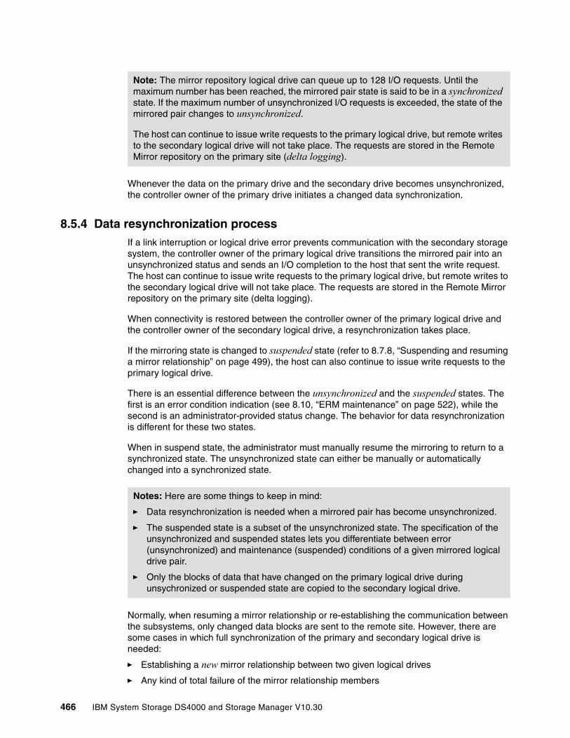
Whenever the data on the primary drive and the secondary drive becomes unsynchronized, the controller owner of the primary drive initiates a changed data synchronization.
8.5.4 Data resynchronization processIf a link interruption or logical drive error prevents communication with the secondary storage system, the controller owner of the primary logical drive transitions the mirrored pair into an unsynchronized status and sends an I/O completion to the host that sent the write request. The host can continue to issue write requests to the primary logical drive, but remote writes to the secondary logical drive will not take place. The requests are stored in the Remote Mirror repository on the primary site (delta logging).
When connectivity is restored between the controller owner of the primary logical drive and the controller owner of the secondary logical drive, a resynchronization takes place.
If the mirroring state is changed to suspended state (refer to 8.7.8, “Suspending and resuming a mirror relationship” on page 499), the host can also continue to issue write requests to the primary logical drive.
There is an essential difference between the unsynchronized and the suspended states. The first is an error condition indication (see 8.10, “ERM maintenance” on page 522), while the second is an administrator-provided status change. The behavior for data resynchronization is different for these two states.
When in suspend state, the administrator must manually resume the mirroring to return to a synchronized state. The unsynchronized state can either be manually or automatically changed into a synchronized state.
Normally, when resuming a mirror relationship or re-establishing the communication between the subsystems, only changed data blocks are sent to the remote site. However, there are some cases in which full synchronization of the primary and secondary logical drive is needed:
� Establishing a new mirror relationship between two given logical drives
� Any kind of total failure of the mirror relationship members
Note: The mirror repository logical drive can queue up to 128 I/O requests. Until the maximum number has been reached, the mirrored pair state is said to be in a synchronized state. If the maximum number of unsynchronized I/O requests is exceeded, the state of the mirrored pair changes to unsynchronized.
The host can continue to issue write requests to the primary logical drive, but remote writes to the secondary logical drive will not take place. The requests are stored in the Remote Mirror repository on the primary site (delta logging).
Notes: Here are some things to keep in mind:
� Data resynchronization is needed when a mirrored pair has become unsynchronized.
� The suspended state is a subset of the unsynchronized state. The specification of the unsynchronized and suspended states lets you differentiate between error (unsynchronized) and maintenance (suspended) conditions of a given mirrored logical drive pair.
� Only the blocks of data that have changed on the primary logical drive during unsychronized or suspended state are copied to the secondary logical drive.
466 IBM System Storage DS4000 and Storage Manager V10.30
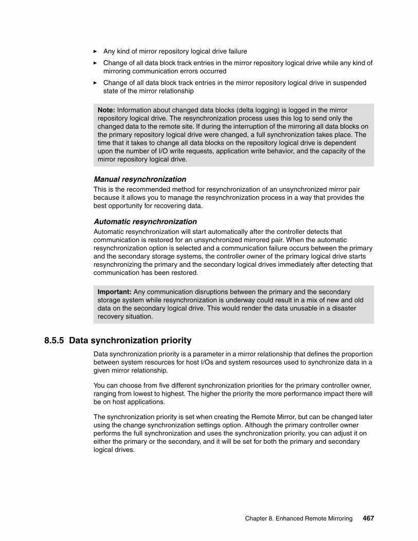
� Any kind of mirror repository logical drive failure
� Change of all data block track entries in the mirror repository logical drive while any kind of mirroring communication errors occurred
� Change of all data block track entries in the mirror repository logical drive in suspended state of the mirror relationship
Manual resynchronizationThis is the recommended method for resynchronization of an unsynchronized mirror pair because it allows you to manage the resynchronization process in a way that provides the best opportunity for recovering data.
Automatic resynchronizationAutomatic resynchronization will start automatically after the controller detects that communication is restored for an unsynchronized mirrored pair. When the automatic resynchronization option is selected and a communication failure occurs between the primary and the secondary storage systems, the controller owner of the primary logical drive starts resynchronizing the primary and the secondary logical drives immediately after detecting that communication has been restored.
8.5.5 Data synchronization priorityData synchronization priority is a parameter in a mirror relationship that defines the proportion between system resources for host I/Os and system resources used to synchronize data in a given mirror relationship.
You can choose from five different synchronization priorities for the primary controller owner, ranging from lowest to highest. The higher the priority the more performance impact there will be on host applications.
The synchronization priority is set when creating the Remote Mirror, but can be changed later using the change synchronization settings option. Although the primary controller owner performs the full synchronization and uses the synchronization priority, you can adjust it on either the primary or the secondary, and it will be set for both the primary and secondary logical drives.
Note: Information about changed data blocks (delta logging) is logged in the mirror repository logical drive. The resynchronization process uses this log to send only the changed data to the remote site. If during the interruption of the mirroring all data blocks on the primary repository logical drive were changed, a full synchronization takes place. The time that it takes to change all data blocks on the repository logical drive is dependent upon the number of I/O write requests, application write behavior, and the capacity of the mirror repository logical drive.
Important: Any communication disruptions between the primary and the secondary storage system while resynchronization is underway could result in a mix of new and old data on the secondary logical drive. This would render the data unusable in a disaster recovery situation.
Chapter 8. Enhanced Remote Mirroring 467

8.6 SAN fabric and Ethernet connectivity
There are some important requirements and rules to follow in regards to Fibre Channel connections and storage area network (SAN) fabric attachment for a correct implementation of ERM. SAN planning is a critical task and must include SAN ports, SAN zoning, and cabling considerations. This section reviews these SAN considerations and also addresses the Ethernet management network configuration.
8.6.1 SAN fabric and SAN zoning configurationHere we examine the SAN requirements from a general, conceptual standpoint. Detailed information and procedures for implementing the SAN fabric, configuring SAN switches, and SAN zones are beyond the scope of this book.
SAN fabric configurationDedicated Remote Mirroring ports (A2 and B2 host-side controller ports) must be attached to a SAN fabric with support for the directory service and name service interfaces. In other words, there must be at least one SAN switch with SAN zoning capability installed in the mirroring environment. Since ERM is typically for providing a high-availability solution, we strongly recommend that you use at least two switches in the SAN. See Figure 8-8 on page 469 and 8.7, “Enhanced Remote Mirroring: Step-by-step” on page 475, for SAN fabric configuration examples.
SAN fabric zoningIt is also mandatory to keep ERM links and the host links in separate SAN zones. We recommend that you create separate zones within the fabric (assuming that only two storage systems are involved):
� The first zone, for a host connection to controller A� The second zone, for a host connection to controller B� The third zone, for controller A Remote Mirroring links between storage systems� The fourth zone, for controller B Remote Mirroring links between storage systems
Important: The data synchronization priority parameter is only used during the data resynchronization process. Data resynchronization is needed every time that a mirrored pair becomes unsynchronized. The data resynchronization process can be started manually (resuming Remote Mirroring) or automatically depending on synchronization settings for a given mirrored pair.
Because the suspended state is a sub-state of the unsynchronized state, the synchronization priority is also used when resuming mirroring from suspended to synchronized state.
Tip: IBM and other SAN switch vendors recommend configuring two SAN fabrics with independent SAN zones for the highest level of redundancy when implementing ERM.
Note: You can have multiple zones for host connections on each controller, based upon the number of connections available. For example, the DS4800 permits up to three host connections per controller, reserving the fourth for the Remote Mirror link.
468 IBM System Storage DS4000 and Storage Manager V10.30
There is no special recommendation for defining the SAN zones. They can be based on either switch ports or WWPNs. However, for easier maintenance and troubleshooting, do not use mixed zoning definitions (ports and WWPN zones simultaneously), or at least differentiate these across the fabrics (one fabric with port zoning, one with WWPN zoning).
Figure 8-8 shows one example of zoning a fabric for DS4500 and Enhanced Remote Mirroring.
Figure 8-8 Enhanced Remote Mirroring zoning example
DS4000 storage server Fibre Channel configuration for ERMThe Enhanced Remote Mirroring option requires two dedicated controller host port connections for each storage system that will participate in Enhanced Remote Mirroring.
Chapter 8. Enhanced Remote Mirroring 469
When the Enhanced Remote Mirroring option is activated on a storage system, the last host-side controller ports become dedicated to Remote Mirror operations:
� On the DS4800 and DS4700 Model 72, you will use the fourth host port on controllers A and B for ERM (see Figure 8-9 and Figure 8-13 on page 472 for the host port locations).
Figure 8-9 Host-side ports for host and ERM connections on the DS4800
� On the DS4400 and DS 4500 storage servers, you will need four mini-hubs on the host side (two for the ERM, two for the hosts) to set up a connection for ERM on the third and fourth mini-hubs (see Figure 8-10 for the host-side port locations).
Figure 8-10 Host mini-hubs for host and ERM connections on DS4400/DS4500
Controller AController B1 2 2 1
Ports for HostConnections
Ports for ERMConnections4 4
3 3
470 IBM System Storage DS4000 and Storage Manager V10.30
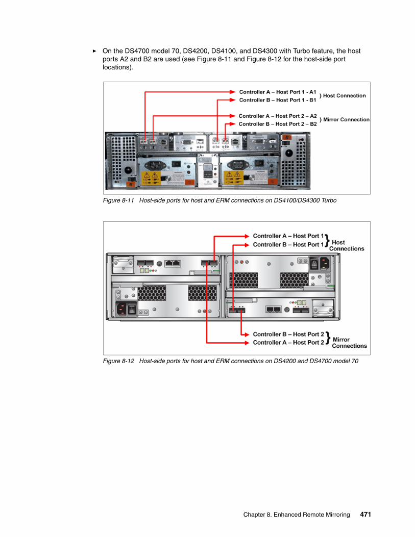
� On the DS4700 model 70, DS4200, DS4100, and DS4300 with Turbo feature, the host ports A2 and B2 are used (see Figure 8-11 and Figure 8-12 for the host-side port locations).
Figure 8-11 Host-side ports for host and ERM connections on DS4100/DS4300 Turbo
Figure 8-12 Host-side ports for host and ERM connections on DS4200 and DS4700 model 70
Chapter 8. Enhanced Remote Mirroring 471

Figure 8-13 Host-side ports for host and ERM connections on DS4700 model 72
After ERM activation, the last host-side controller ports no longer permit host system I/O requests. The persistent reservations will be also removed from these ports. The last host-side controller ports will only be able to communicate to other storage systems that have the Enhanced Remote Mirroring option activated and are connected by the same fabric with a proper SAN zoning configuration.
The level of redundancy within the fabric depends on the fabric design and Fibre Channel switch configuration. This publication does not specifically address SAN design issues. However, you can find three sample configurations in 8.9, “Enhanced Remote Mirroring solution design” on page 517.
472 IBM System Storage DS4000 and Storage Manager V10.30

Fibre Channel distance limitsThe distance between primary and remote storage systems is normally limited by the distance limitations of Fibre Channel inter-switch links (ISLs). See Table 8-3.
With the Global Copy and Global Mirror Remote Mirroring operating modes, it is now possible to establish mirroring for distances of more than 5000 km (3200 mi). For more information refer to 8.12, “Long-distance ERM” on page 529.
Table 8-3 Fibre Channel distance limits
Table 8-4 Multi-mode fibre types and connection bandwidth
Note that the maximum distances listed in Table 8-4 can be reduced due to low quality fiber, poor terminations, patch panels, and so on.
8.6.2 Ethernet management network configuration for ERMIt is mandatory that the managing workstation (with the DS4000 Storage Manager client software) can simultaneously access both sites (primary and secondary) through the Ethernet network. Ethernet ports from each storage server must be on the same subnet or part of a VPN connection.
Fiber cable type Laser type Distance limit in kilometers Distance limit in miles
Single mode 9 micron Long wave 10 km 6.25 miles
Multi mode 50 micron Short wave 0.5 km 0.32 mile
Important: The maximum distance for the shortwave SFPs has impact on the maximum connection bandwidth. The SFP automatically changes the connection speed to 1 Gbps if the maximum distance for a 2 Gbps connection is exceeded (and down to 2 Gbps if the maximum distance for a 4 Gbps connection is exceeded).
For the shortwave SFP, the maximum length for a 4 Gbps connection is 150 m. Refer to Table 8-4.
Fiber type Speed Maximum distance
50 micron MMF (shortwave) 1 Gbps 500 m
50 micron MMF (shortwave) 2 Gbps 300 m
50 micron MMF (shortwave) 4 Gbps 150 m
62.5 micron MMF (shortwave) 1 Gbps 175 m/300 m
62.5 micron MMF (shortwave) 2 Gbps 90 m/150 m
Chapter 8. Enhanced Remote Mirroring 473

As shown in Figure 8-14, the best practice is to set up a separate Ethernet management network, isolated from the user LAN. This configuration helps prevent LAN users from unauthorized access to the storage system management functions. It is also better for maintenance.
Figure 8-14 Ethernet network configuration for ERM
474 IBM System Storage DS4000 and Storage Manager V10.30

8.7 Enhanced Remote Mirroring: Step-by-stepThis section presents an easy-to-follow, step-by-step procedural guide to common administration tasks for a DS4000 Enhanced Remote Mirroring. The tasks that are covered include:
� Enabling and activating the Enhanced Remote Mirroring premium feature� Creating Enhanced Remote Mirroring relationships� Viewing Enhanced Remote Mirroring properties� Changing Enhanced Remote Mirroring synchronization settings� Changing Enhanced Remote Mirroring write mode� Removing Enhanced Remote Mirroring relationships
The configuration shown in Figure 8-15 was used while writing this section to demonstrate Enhanced Remote Mirroring.
Figure 8-15 Enhanced Remote Mirroring: Test environment
8.7.1 Enabling and activating Enhanced Remote MirroringBefore you can use Enhanced Remote Mirroring, you must first purchase the option (feature key) from IBM for all storage systems participating in Remote Mirroring. In this section we discuss the process for enabling, activating, and deactivating the Enhanced Remote Mirroring premium feature.
Chapter 8. Enhanced Remote Mirroring 475

There are four possible states for the Enhanced Remote Mirroring option:
� Disabled/deactivated
This is the default state if the feature key has not been installed.
� Enabled/deactivated
This is the state when the feature key has been enabled, but Enhanced Remote Mirroring has not been activated. There are no changes made to the storage system configuration and all host connectivity is normal.
� Enabled/activated
This state makes the following controller host ports available for mirroring only:
– A2 and B2 on a DS4100/DS4300 Turbo/DS4700– Mini-hubs 3 and 4 on the DS4400/DS4500– Host port 4 on both controllers for the DS4800
No host system I/Os are allowed. This is the normal state for Enhanced Remote Mirroring operations.
� Disabled/activated
This state is possible when the premium feature has been disabled before deactivation.
If mirrored pairs are present when this happens, an Out of Compliance error message occurs. Removing the mirrored pairs removes this error. However, if the feature is disabled/activated, controller ports A2 and B2 (or mini-hubs 3 and 4 or host port4 on both controllers) will still be unavailable for normal host I/O activity. This is an undesirable state. The status icon shown in Figure 8-16 illustrates this state.
Figure 8-16 Enhanced Remote Mirroring option disabled/activated
Enabling the Enhanced Remote Mirroring premium featureUse this section to:
� Check the premium features list.� Enable Enhanced Remote Mirroring.
Remember to enable the premium feature on all participating storage systems.
Note: With the introduction of firmware V7.10, the maximum supported number of mirror pairs on the DS4800 storage subsystem is 128. For example, you can have defined 64 primary and 64 secondary logical drives on a DS4800, or any other combination (one primary and 127 secondary, two primary and 126 secondary, and so on). For the DS4200 and DS4700 the maximum supported number of mirror pairs is 64.
Remote icon active (green)but disabled (red line)
476 IBM System Storage DS4000 and Storage Manager V10.30
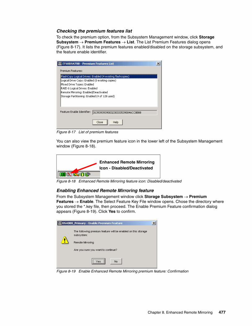
Checking the premium features listTo check the premium option, from the Subsystem Management window, click Storage Subsystem → Premium Features → List. The List Premium Features dialog opens (Figure 8-17). It lists the premium features enabled/disabled on the storage subsystem, and the feature enable identifier.
Figure 8-17 List of premium features
You can also view the premium feature icon in the lower left of the Subsystem Management window (Figure 8-18).
Figure 8-18 Enhanced Remote Mirroring feature icon: Disabled/deactivated
Enabling Enhanced Remote Mirroring featureFrom the Subsystem Management window click Storage Subsystem → Premium Features → Enable. The Select Feature Key File window opens. Chose the directory where you stored the *.key file, then proceed. The Enable Premium Feature confirmation dialog appears (Figure 8-19). Click Yes to confirm.
Figure 8-19 Enable Enhanced Remote Mirroring premium feature: Confirmation
Enhanced Remote MirroringIcon - Disabled/Deactivated
Chapter 8. Enhanced Remote Mirroring 477

To check that the Enhanced Remote Mirroring premium feature is enabled, you can view the icon in the lower left corner of the Subsystem Management window (Figure 8-20). The red slash is removed.
Figure 8-20 Enhanced Remote Mirroring icon: Enabled/deactivated
Activating the Enhanced Remote Mirroring option This is achieved by using the Activate Remote Mirroring wizard. Remember to activate the premium feature on all participating storage systems.
Activate the Enhanced Remote Mirroring feature as follows:
1. Select the Storage Subsystem → Remote Mirroring → Activate pull-down menu option, or select Remote Mirroring → Activate from the right-mouse pop-up menu (Figure 8-21).
Figure 8-21 Activating Remote Mirroring
Important: When the Remote Mirroring premium feature is activated, it creates two mirror repository logical drives per subsystem. The DS4500 and DS4800 storage systems support up to 2,048 logical drives. The DS4700, DS4200, and DS4300 Turbo support up to 1,024 logical drives. Before activating the ERM feature, verify that the number of configured logical drives on your storage system is under the supported limit.
Ensure that the switch fabric is appropriately configured before beginning this procedure. Refer to 8.6, “SAN fabric and Ethernet connectivity” on page 468.
Reservations on secondary logical drives are blocked. However, reservations on primary logical drives are allowed.
Enhanced Remote MirroringIcon - Enabled/Deactivated
478 IBM System Storage DS4000 and Storage Manager V10.30
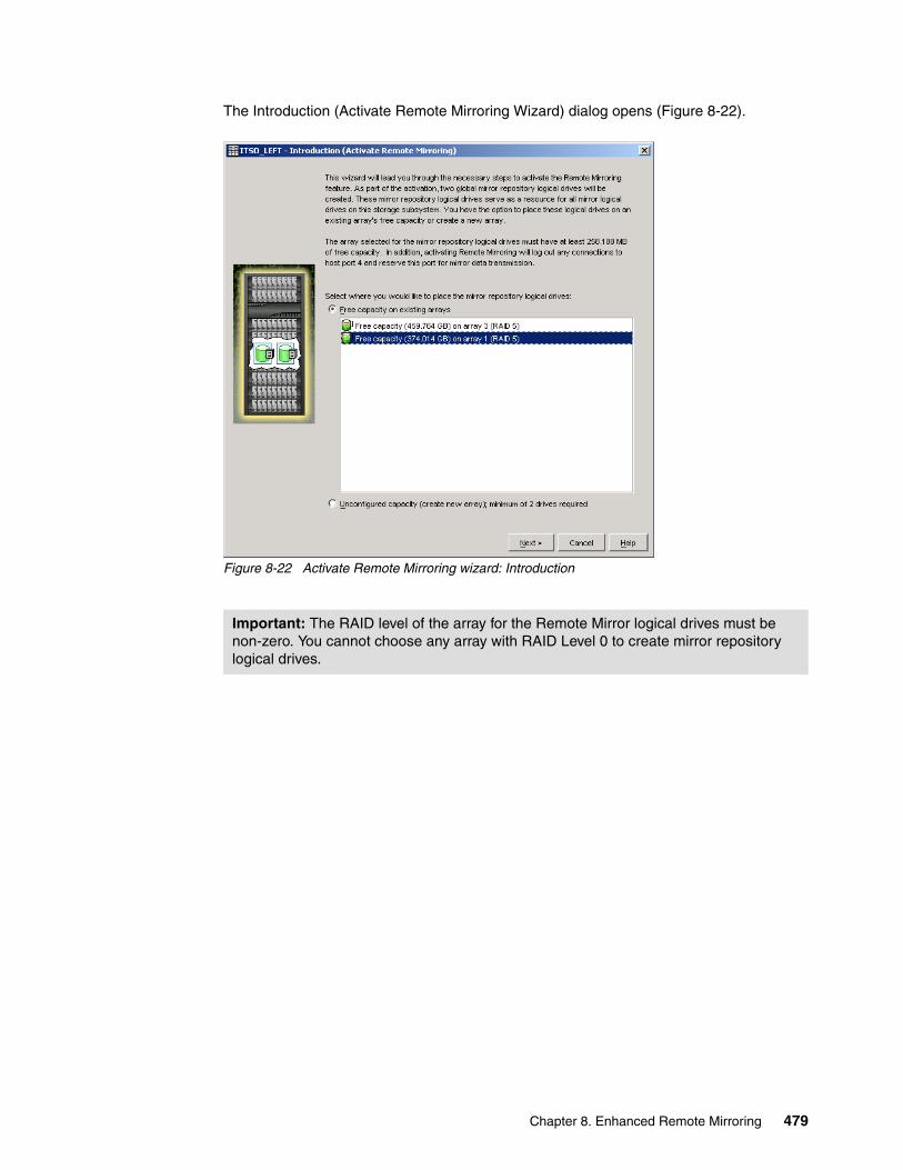
The Introduction (Activate Remote Mirroring Wizard) dialog opens (Figure 8-22).
Figure 8-22 Activate Remote Mirroring wizard: Introduction
Important: The RAID level of the array for the Remote Mirror logical drives must be non-zero. You cannot choose any array with RAID Level 0 to create mirror repository logical drives.
Chapter 8. Enhanced Remote Mirroring 479

2. In this dialog box choose where to allocate capacity for the mirror repository logical drives. Read the information in the window. You can choose to create these in either of the following arrays:
– An unconfigured array: Click Next to proceed to the create array window (Figure 8-23).
Figure 8-23 Activate Remote Mirroring wizard: Create new array
Create the array as desired and click Next to proceed to the preview window (Figure 8-24).
– An existing array with sufficient free space: If you choose this option, highlight the desired array and click Next to proceed to the preview window (Figure 8-24).
3. After choosing where to create the mirror repository logical drives, the Preview (Activate Remote Mirroring) wizard window is presented (Figure 8-24).
Figure 8-24 Activate Remote Mirroring wizard: Preview
480 IBM System Storage DS4000 and Storage Manager V10.30
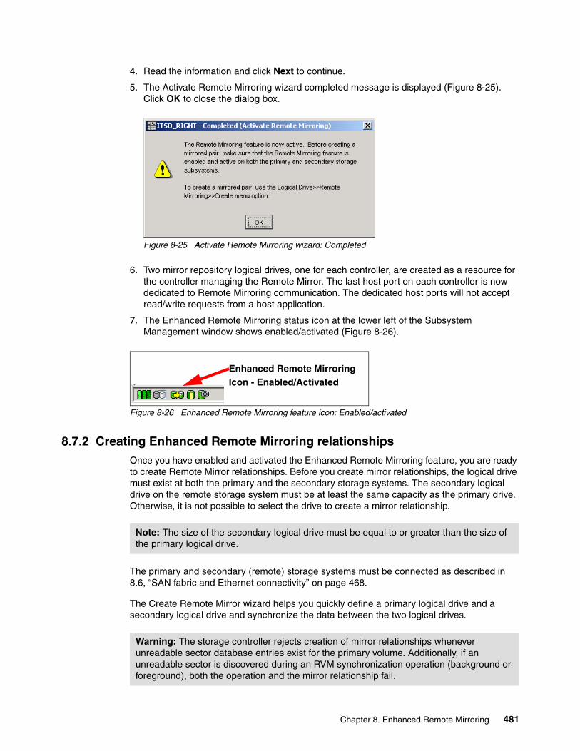
4. Read the information and click Next to continue.
5. The Activate Remote Mirroring wizard completed message is displayed (Figure 8-25). Click OK to close the dialog box.
Figure 8-25 Activate Remote Mirroring wizard: Completed
6. Two mirror repository logical drives, one for each controller, are created as a resource for the controller managing the Remote Mirror. The last host port on each controller is now dedicated to Remote Mirroring communication. The dedicated host ports will not accept read/write requests from a host application.
7. The Enhanced Remote Mirroring status icon at the lower left of the Subsystem Management window shows enabled/activated (Figure 8-26).
Figure 8-26 Enhanced Remote Mirroring feature icon: Enabled/activated
8.7.2 Creating Enhanced Remote Mirroring relationshipsOnce you have enabled and activated the Enhanced Remote Mirroring feature, you are ready to create Remote Mirror relationships. Before you create mirror relationships, the logical drive must exist at both the primary and the secondary storage systems. The secondary logical drive on the remote storage system must be at least the same capacity as the primary drive. Otherwise, it is not possible to select the drive to create a mirror relationship.
The primary and secondary (remote) storage systems must be connected as described in 8.6, “SAN fabric and Ethernet connectivity” on page 468.
The Create Remote Mirror wizard helps you quickly define a primary logical drive and a secondary logical drive and synchronize the data between the two logical drives.
Enhanced Remote MirroringIcon - Enabled/Activated
Note: The size of the secondary logical drive must be equal to or greater than the size of the primary logical drive.
Warning: The storage controller rejects creation of mirror relationships whenever unreadable sector database entries exist for the primary volume. Additionally, if an unreadable sector is discovered during an RVM synchronization operation (background or foreground), both the operation and the mirror relationship fail.
Chapter 8. Enhanced Remote Mirroring 481

To launch the Create Remote Mirror wizard:
1. Select a logical drive in the logical view of the designated primary storage system and then select the Logical Drive → Remote Mirroring → Create pull-down menu option or select Create Remote Mirror from the right-mouse pop-up menu (Figure 8-27).
Figure 8-27 Select primary logical drive from logical view
This launches the Introduction (Create Remote Mirror) window (Figure 8-28).
Figure 8-28 Introduction (Create Remote Mirror)
482 IBM System Storage DS4000 and Storage Manager V10.30
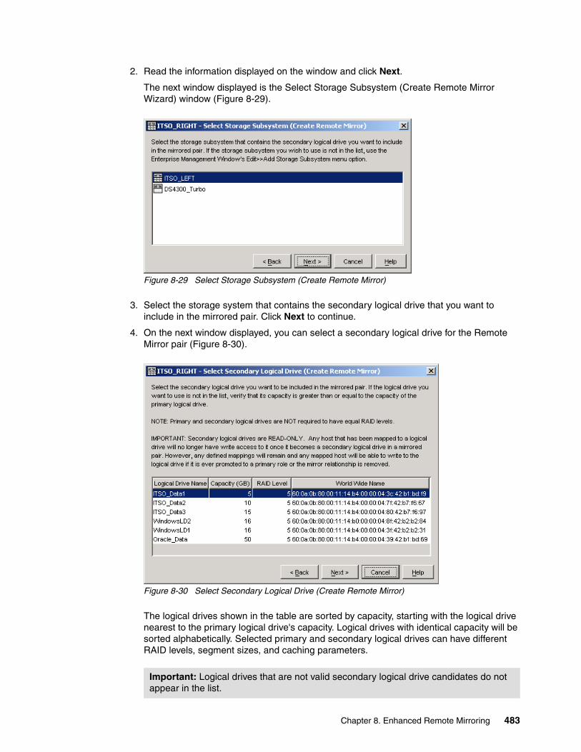
2. Read the information displayed on the window and click Next.
The next window displayed is the Select Storage Subsystem (Create Remote Mirror Wizard) window (Figure 8-29).
Figure 8-29 Select Storage Subsystem (Create Remote Mirror)
3. Select the storage system that contains the secondary logical drive that you want to include in the mirrored pair. Click Next to continue.
4. On the next window displayed, you can select a secondary logical drive for the Remote Mirror pair (Figure 8-30).
Figure 8-30 Select Secondary Logical Drive (Create Remote Mirror)
The logical drives shown in the table are sorted by capacity, starting with the logical drive nearest to the primary logical drive's capacity. Logical drives with identical capacity will be sorted alphabetically. Selected primary and secondary logical drives can have different RAID levels, segment sizes, and caching parameters.
Important: Logical drives that are not valid secondary logical drive candidates do not appear in the list.
Chapter 8. Enhanced Remote Mirroring 483
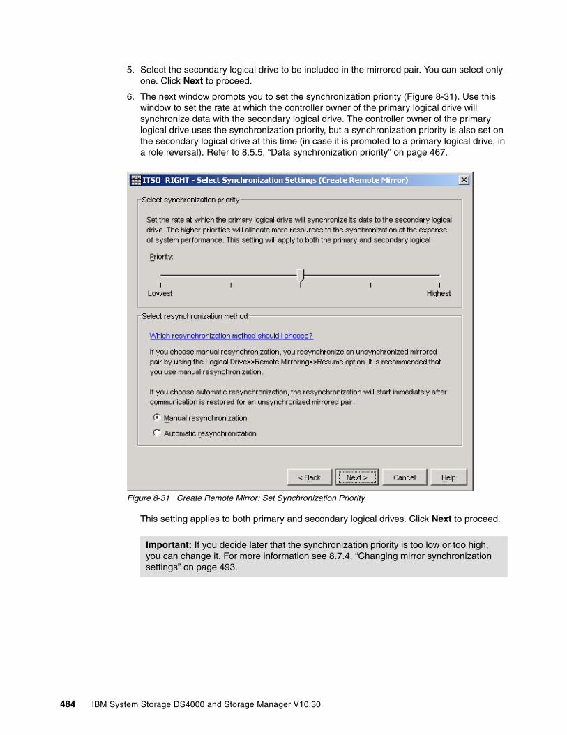
5. Select the secondary logical drive to be included in the mirrored pair. You can select only one. Click Next to proceed.
6. The next window prompts you to set the synchronization priority (Figure 8-31). Use this window to set the rate at which the controller owner of the primary logical drive will synchronize data with the secondary logical drive. The controller owner of the primary logical drive uses the synchronization priority, but a synchronization priority is also set on the secondary logical drive at this time (in case it is promoted to a primary logical drive, in a role reversal). Refer to 8.5.5, “Data synchronization priority” on page 467.
Figure 8-31 Create Remote Mirror: Set Synchronization Priority
This setting applies to both primary and secondary logical drives. Click Next to proceed.
Important: If you decide later that the synchronization priority is too low or too high, you can change it. For more information see 8.7.4, “Changing mirror synchronization settings” on page 493.
484 IBM System Storage DS4000 and Storage Manager V10.30
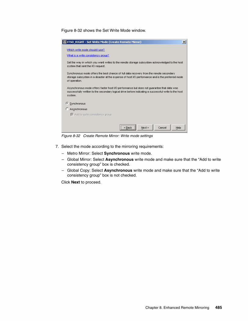
Figure 8-32 shows the Set Write Mode window.
Figure 8-32 Create Remote Mirror: Write mode settings
7. Select the mode according to the mirroring requirements:
– Metro Mirror: Select Synchronous write mode.
– Global Mirror: Select Asynchronous write mode and make sure that the “Add to write consistency group” box is checked.
– Global Copy: Select Asynchronous write mode and make sure that the “Add to write consistency group” box is not checked.
Click Next to proceed.
Chapter 8. Enhanced Remote Mirroring 485

8. The Preview window (Figure 8-33) is the last step before the Remote Mirror is created. Type Yes in the box and then click Finish to create the Remote Mirror.
Figure 8-33 Preview (Create Remote Mirror)
The Creation Successful message dialog is displayed (Figure 8-34).
Figure 8-34 Creation Successful (Create Remote Mirror)
486 IBM System Storage DS4000 and Storage Manager V10.30
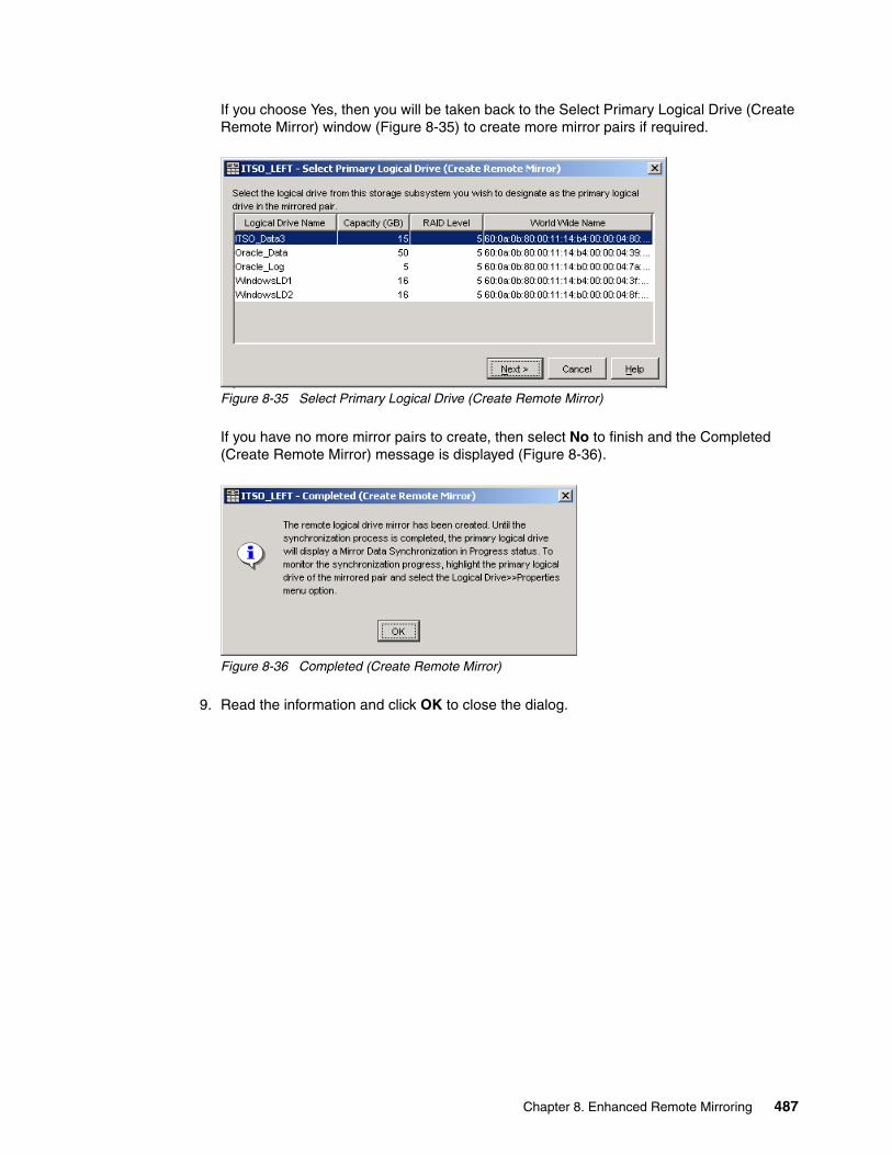
If you choose Yes, then you will be taken back to the Select Primary Logical Drive (Create Remote Mirror) window (Figure 8-35) to create more mirror pairs if required.
Figure 8-35 Select Primary Logical Drive (Create Remote Mirror)
If you have no more mirror pairs to create, then select No to finish and the Completed (Create Remote Mirror) message is displayed (Figure 8-36).
Figure 8-36 Completed (Create Remote Mirror)
9. Read the information and click OK to close the dialog.
Chapter 8. Enhanced Remote Mirroring 487

Looking at the logical view of the primary and secondary storage systems shows the (full) synchronization in progress. On the primary subsystem, the secondary logical drive appears as a child of the primary logical drive. See Figure 8-37.
Figure 8-37 Primary and secondary views on storage systems
488 IBM System Storage DS4000 and Storage Manager V10.30
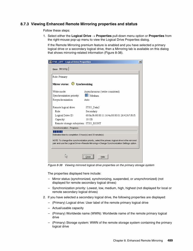
8.7.3 Viewing Enhanced Remote Mirroring properties and status
Follow these steps:
1. Select either the Logical Drive → Properties pull-down menu option or Properties from the right-mouse pop-up menu to view the Logical Drive Properties dialog.
If the Remote Mirroring premium feature is enabled and you have selected a primary logical drive or a secondary logical drive, then a Mirroring tab is available on this dialog that shows mirroring-related information (Figure 8-38).
Figure 8-38 Viewing mirrored logical drive properties on the primary storage system
The properties displayed here include:
– Mirror status (synchronized, synchronizing, suspended, or unsynchronized) (not displayed for remote secondary logical drives)
– Synchronization priority: Lowest, low, medium, high, highest (not displayed for local or remote secondary logical drives)
2. If you have selected a secondary logical drive, the following properties are displayed:
– (Primary) Logical drive: User label of the remote primary logical drive
– Actual/usable capacity
– (Primary) Worldwide name (WWN): Worldwide name of the remote primary logical drive
– (Primary) Storage system: WWN of the remote storage system containing the primary logical drive
Chapter 8. Enhanced Remote Mirroring 489

3. If you have selected a primary logical drive, the following properties are displayed:
– (Secondary) logical drive: User label of the remote secondary logical drive
– Actual/usable capacity
– (Secondary) worldwide name (WWN): WWN of the remote secondary logical drive
– (Secondary) storage system: WWN of the remote storage system containing the secondary logical drive
4. The progress bar at the bottom of the Mirroring tab of the Logical Drive Properties dialog displays the progress of a full synchronization.
5. Select Close to exit the dialog.
Enhanced Remote Mirroring can also be monitored by viewing the storage system profile. To view the storage subsystem profile:
1. Select either the Storage Subsystem → View → Profile pull-down menu option or View Profile from the right-mouse pop-up menu.
The Storage Subsystem Profile dialog is displayed (Figure 8-39).
Figure 8-39 Storage Subsystem Profile: All tab
Note: If the remote logical drive in the mirrored pair is in an Unresponsive state, the following fields will display in place of the fields shown above:
� Unresponsive remote logical drive: User label of the remote logical drive, from last known data in the cache
� Unresponsive remote logical drive worldwide name (WWN): WWN of the remote logical drive, from last known data in the cache
� Unresponsive remote storage system: WWN of the remote storage system, from last known data in the cache
490 IBM System Storage DS4000 and Storage Manager V10.30
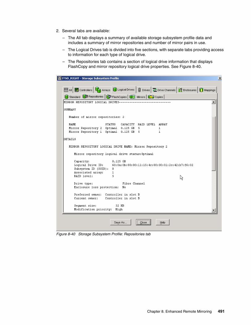
2. Several tabs are available:
– The All tab displays a summary of available storage subsystem profile data and includes a summary of mirror repositories and number of mirror pairs in use.
– The Logical Drives tab is divided into five sections, with separate tabs providing access to information for each type of logical drive.
– The Repositories tab contains a section of logical drive information that displays FlashCopy and mirror repository logical drive properties. See Figure 8-40.
Figure 8-40 Storage Subsystem Profile: Repositories tab
Chapter 8. Enhanced Remote Mirroring 491
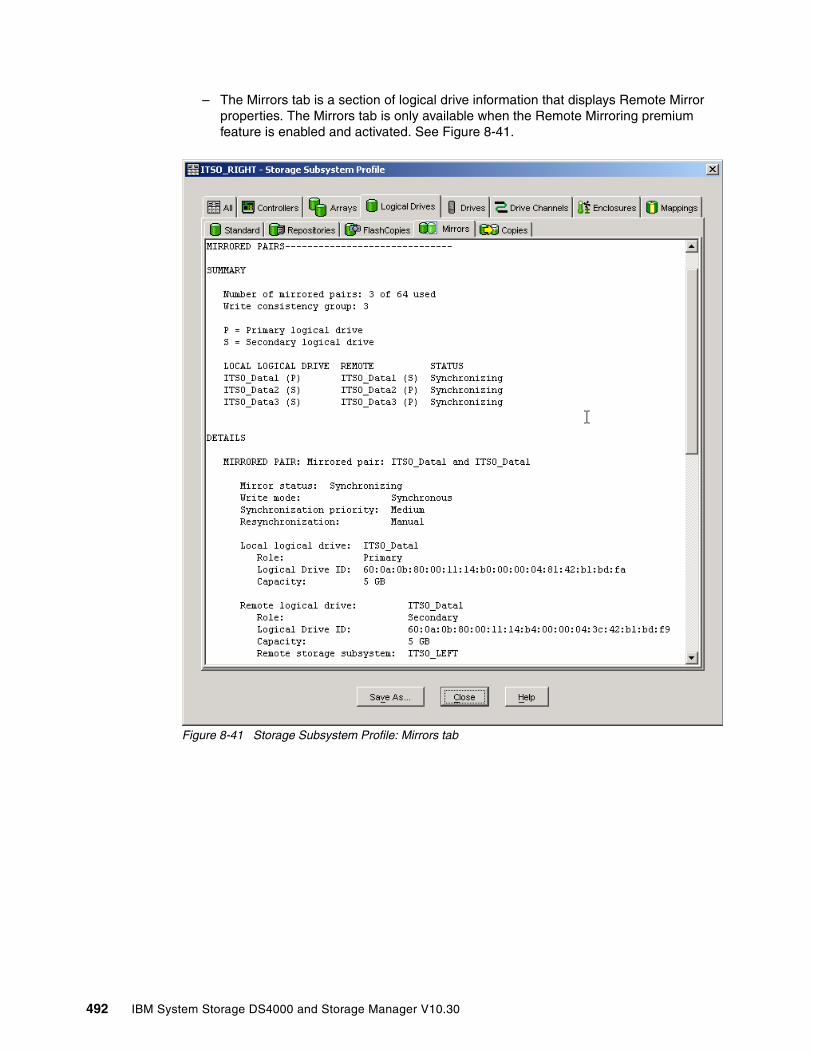
– The Mirrors tab is a section of logical drive information that displays Remote Mirror properties. The Mirrors tab is only available when the Remote Mirroring premium feature is enabled and activated. See Figure 8-41.
Figure 8-41 Storage Subsystem Profile: Mirrors tab
492 IBM System Storage DS4000 and Storage Manager V10.30

The View Associated Elements window (Figure 8-42) provides a graphical representation of the logical drives participating in the mirror relationship. In addition, details are provided for all components, rather than just for the logical drive initially selected. To view all associated components in a mirror relationship, including primary, secondary, and mirror repository logical drives:
1. Select the primary or secondary logical drive in a mirror relationship.
2. Right-click and select View Associated Components.
Figure 8-42 View Associated Elements
8.7.4 Changing mirror synchronization settingsUse this option to change the synchronization priority and the data resynchronization method that the controller owner of the primary logical drive uses when performing a full synchronization. The controller owner of the primary logical drive uses the synchronization priority, so this option is not available for secondary logical drives. To do this:
1. Select a primary logical drive in the Subsystem Management window logical view, then select either the Logical Drive → Remote Mirroring → Change → Synchronization Priority pull-down menu option or Change → Synchronization Settings from the right-mouse pop-up menu.
Chapter 8. Enhanced Remote Mirroring 493

The Change Synchronization Settings dialog is displayed. The Select logical drives list box lists all primary logical drives in the storage system. The primary logical drive that you selected to invoke the option is highlighted (Figure 8-43).
Figure 8-43 Change Synchronization Settings
2. Select the primary logical drives for which you want to change the synchronization priority in the Select logical drives list box. To select multiple logical drives, use the Ctrl+click or Shift+click keyboard options. To select all of the primary logical drives, select the Select All button.
3. In the Select synchronization priority area, use the slider bar to select the appropriate synchronization priority. There are five choices:
– Lowest– Low– Medium– High– Highest
These settings are shown with five check marks on the slider bar. The lowest and highest settings are labeled. The higher the setting, the more the primary controller will prioritize a full synchronization over host I/O, and the larger the impact to system performance.
494 IBM System Storage DS4000 and Storage Manager V10.30
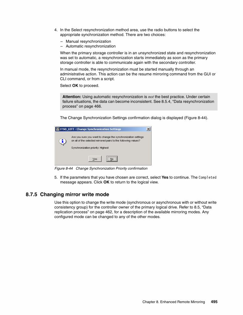
4. In the Select resynchronization method area, use the radio buttons to select the appropriate synchronization method. There are two choices:
– Manual resynchronization – Automatic resynchronization
When the primary storage controller is in an unsynchronized state and resynchronization was set to automatic, a resynchronization starts immediately as soon as the primary storage controller is able to communicate again with the secondary controller.
In manual mode, the resynchronization must be started manually through an administrative action. This action can be the resume mirroring command from the GUI or CLI command, or from a script.
Select OK to proceed.
The Change Synchronization Settings confirmation dialog is displayed (Figure 8-44).
Figure 8-44 Change Synchronization Priority confirmation
5. If the parameters that you have chosen are correct, select Yes to continue. The Completed message appears. Click OK to return to the logical view.
8.7.5 Changing mirror write modeUse this option to change the write mode (synchronous or asynchronous with or without write consistency group) for the controller owner of the primary logical drive. Refer to 8.5, “Data replication process” on page 462, for a description of the available mirroring modes. Any configured mode can be changed to any of the other modes.
Attention: Using automatic resynchronization is not the best practice. Under certain failure situations, the data can become inconsistent. See 8.5.4, “Data resynchronization process” on page 466.
Chapter 8. Enhanced Remote Mirroring 495

Proceed as follows:
1. Select a primary logical drive in the Subsystem Management window logical view, then select either the Logical Drive → Remote Mirroring → Change → Write Mode pull-down menu option or Change → Write Mode from the right-mouse pop-up menu (Figure 8-45).
Figure 8-45 Changing write mode
2. The Change Write Mode dialog is displayed. The Select logical drives list box lists all primary logical drives in the storage system. The primary logical drive that you selected to invoke the option is highlighted (Figure 8-46).
Figure 8-46 Change Write Mode dialog
3. Select the primary logical drives for which you want to change the write mode in the Select logical drives list box:
– To select multiple logical drives, press and hold the Ctrl or Shift key while selecting the drives with a mouse click.
– To select all of the primary logical drives, select the Select All button.
496 IBM System Storage DS4000 and Storage Manager V10.30
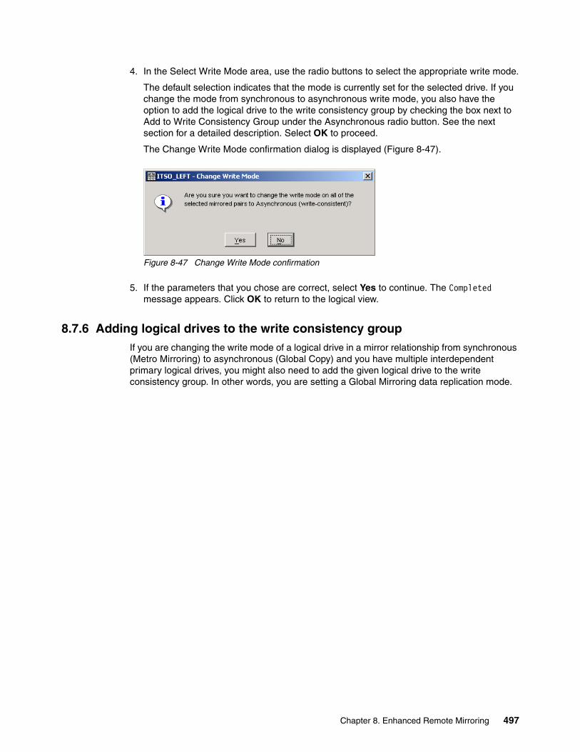
4. In the Select Write Mode area, use the radio buttons to select the appropriate write mode.
The default selection indicates that the mode is currently set for the selected drive. If you change the mode from synchronous to asynchronous write mode, you also have the option to add the logical drive to the write consistency group by checking the box next to Add to Write Consistency Group under the Asynchronous radio button. See the next section for a detailed description. Select OK to proceed.
The Change Write Mode confirmation dialog is displayed (Figure 8-47).
Figure 8-47 Change Write Mode confirmation
5. If the parameters that you chose are correct, select Yes to continue. The Completed message appears. Click OK to return to the logical view.
8.7.6 Adding logical drives to the write consistency groupIf you are changing the write mode of a logical drive in a mirror relationship from synchronous (Metro Mirroring) to asynchronous (Global Copy) and you have multiple interdependent primary logical drives, you might also need to add the given logical drive to the write consistency group. In other words, you are setting a Global Mirroring data replication mode.
Chapter 8. Enhanced Remote Mirroring 497
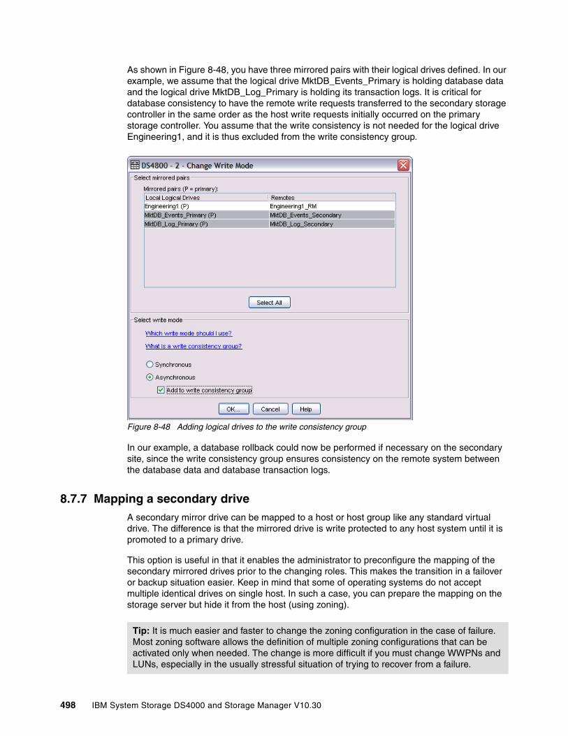
As shown in Figure 8-48, you have three mirrored pairs with their logical drives defined. In our example, we assume that the logical drive MktDB_Events_Primary is holding database data and the logical drive MktDB_Log_Primary is holding its transaction logs. It is critical for database consistency to have the remote write requests transferred to the secondary storage controller in the same order as the host write requests initially occurred on the primary storage controller. You assume that the write consistency is not needed for the logical drive Engineering1, and it is thus excluded from the write consistency group.
Figure 8-48 Adding logical drives to the write consistency group
In our example, a database rollback could now be performed if necessary on the secondary site, since the write consistency group ensures consistency on the remote system between the database data and database transaction logs.
8.7.7 Mapping a secondary driveA secondary mirror drive can be mapped to a host or host group like any standard virtual drive. The difference is that the mirrored drive is write protected to any host system until it is promoted to a primary drive.
This option is useful in that it enables the administrator to preconfigure the mapping of the secondary mirrored drives prior to the changing roles. This makes the transition in a failover or backup situation easier. Keep in mind that some of operating systems do not accept multiple identical drives on single host. In such a case, you can prepare the mapping on the storage server but hide it from the host (using zoning).
Tip: It is much easier and faster to change the zoning configuration in the case of failure. Most zoning software allows the definition of multiple zoning configurations that can be activated only when needed. The change is more difficult if you must change WWPNs and LUNs, especially in the usually stressful situation of trying to recover from a failure.
498 IBM System Storage DS4000 and Storage Manager V10.30
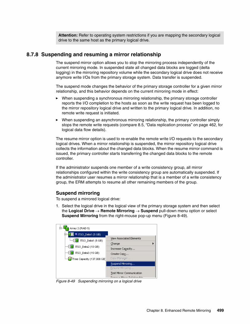
8.7.8 Suspending and resuming a mirror relationshipThe suspend mirror option allows you to stop the mirroring process independently of the current mirroring mode. In suspended state all changed data blocks are logged (delta logging) in the mirroring repository volume while the secondary logical drive does not receive anymore write I/Os from the primary storage system. Data transfer is suspended.
The suspend mode changes the behavior of the primary storage controller for a given mirror relationship, and this behavior depends on the current mirroring mode in effect:
� When suspending a synchronous mirroring relationship, the primary storage controller reports the I/O completion to the hosts as soon as the write request has been logged to the mirror repository logical drive and written to the primary logical drive. In addition, no remote write request is initiated.
� When suspending an asynchronous mirroring relationship, the primary controller simply stops the remote write requests (compare 8.5, “Data replication process” on page 462, for logical data flow details).
The resume mirror option is used to re-enable the remote write I/O requests to the secondary logical drives. When a mirror relationship is suspended, the mirror repository logical drive collects the information about the changed data blocks. When the resume mirror command is issued, the primary controller starts transferring the changed data blocks to the remote controller.
If the administrator suspends one member of a write consistency group, all mirror relationships configured within the write consistency group are automatically suspended. If the administrator user resumes a mirror relationship that is a member of a write consistency group, the ERM attempts to resume all other remaining members of the group.
Suspend mirroringTo suspend a mirrored logical drive:
1. Select the logical drive in the logical view of the primary storage system and then select the Logical Drive → Remote Mirroring → Suspend pull-down menu option or select Suspend Mirroring from the right-mouse pop-up menu (Figure 8-49).
Figure 8-49 Suspending mirroring on a logical drive
Attention: Refer to operating system restrictions if you are mapping the secondary logical drive to the same host as the primary logical drive.
Chapter 8. Enhanced Remote Mirroring 499
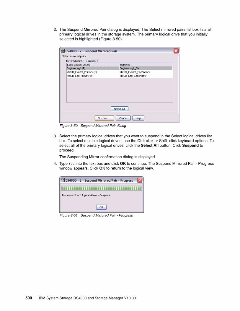
2. The Suspend Mirrored Pair dialog is displayed. The Select mirrored pairs list box lists all primary logical drives in the storage system. The primary logical drive that you initially selected is highlighted (Figure 8-50).
Figure 8-50 Suspend Mirrored Pair dialog
3. Select the primary logical drives that you want to suspend in the Select logical drives list box. To select multiple logical drives, use the Ctrl+click or Shift+click keyboard options. To select all of the primary logical drives, click the Select All button. Click Suspend to proceed.
The Suspending Mirror confirmation dialog is displayed.
4. Type Yes into the text box and click OK to continue. The Suspend Mirrored Pair - Progress window appears. Click OK to return to the logical view.
Figure 8-51 Suspend Mirrored Pair - Progress
500 IBM System Storage DS4000 and Storage Manager V10.30
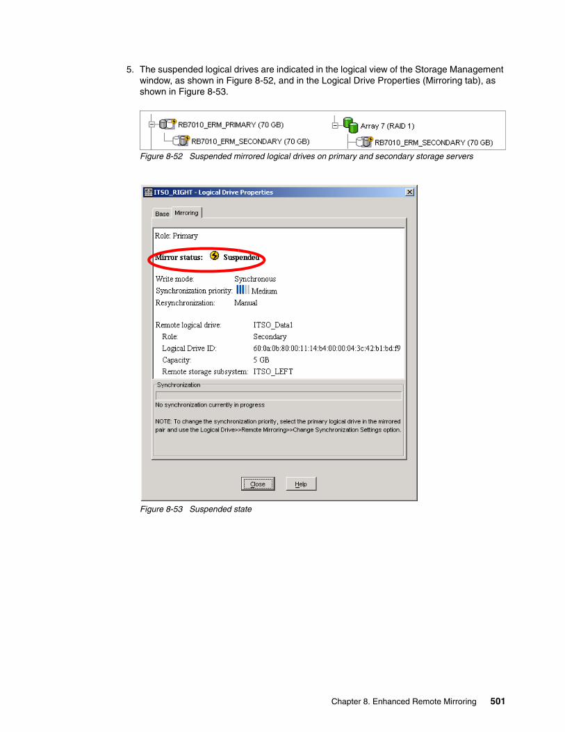
5. The suspended logical drives are indicated in the logical view of the Storage Management window, as shown in Figure 8-52, and in the Logical Drive Properties (Mirroring tab), as shown in Figure 8-53.
Figure 8-52 Suspended mirrored logical drives on primary and secondary storage servers
Figure 8-53 Suspended state
Chapter 8. Enhanced Remote Mirroring 501
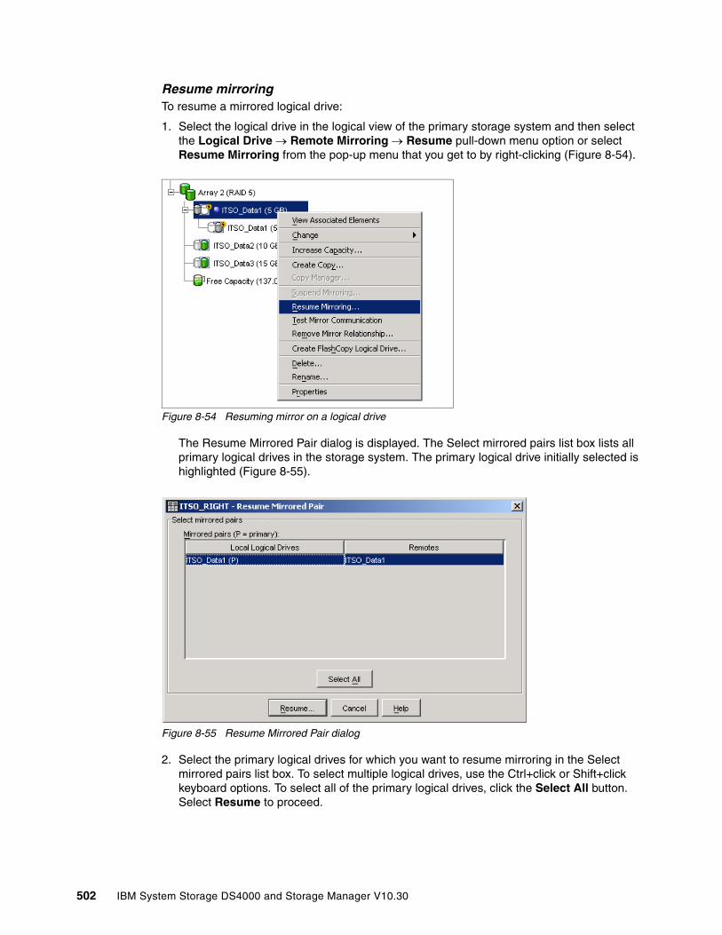
Resume mirroringTo resume a mirrored logical drive:
1. Select the logical drive in the logical view of the primary storage system and then select the Logical Drive → Remote Mirroring → Resume pull-down menu option or select Resume Mirroring from the pop-up menu that you get to by right-clicking (Figure 8-54).
Figure 8-54 Resuming mirror on a logical drive
The Resume Mirrored Pair dialog is displayed. The Select mirrored pairs list box lists all primary logical drives in the storage system. The primary logical drive initially selected is highlighted (Figure 8-55).
Figure 8-55 Resume Mirrored Pair dialog
2. Select the primary logical drives for which you want to resume mirroring in the Select mirrored pairs list box. To select multiple logical drives, use the Ctrl+click or Shift+click keyboard options. To select all of the primary logical drives, click the Select All button. Select Resume to proceed.
502 IBM System Storage DS4000 and Storage Manager V10.30
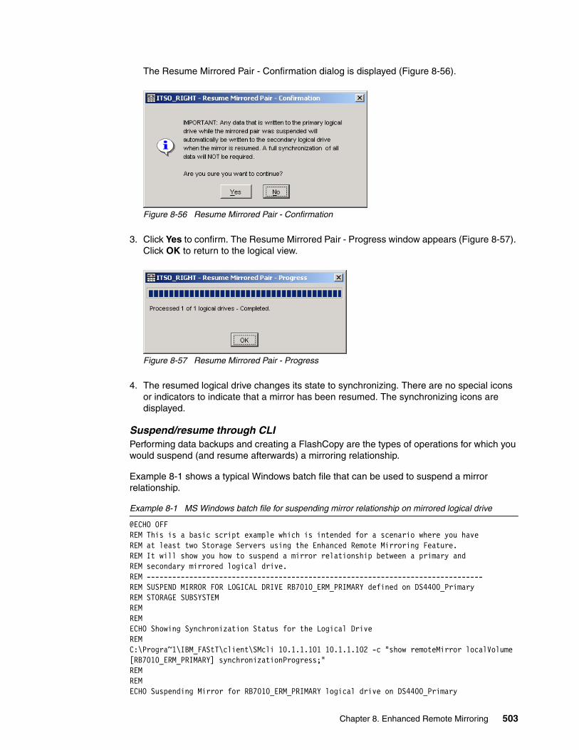
The Resume Mirrored Pair - Confirmation dialog is displayed (Figure 8-56).
Figure 8-56 Resume Mirrored Pair - Confirmation
3. Click Yes to confirm. The Resume Mirrored Pair - Progress window appears (Figure 8-57). Click OK to return to the logical view.
Figure 8-57 Resume Mirrored Pair - Progress
4. The resumed logical drive changes its state to synchronizing. There are no special icons or indicators to indicate that a mirror has been resumed. The synchronizing icons are displayed.
Suspend/resume through CLIPerforming data backups and creating a FlashCopy are the types of operations for which you would suspend (and resume afterwards) a mirroring relationship.
Example 8-1 shows a typical Windows batch file that can be used to suspend a mirror relationship.
Example 8-1 MS Windows batch file for suspending mirror relationship on mirrored logical drive
@ECHO OFFREM This is a basic script example which is intended for a scenario where you have REM at least two Storage Servers using the Enhanced Remote Mirroring Feature. REM It will show you how to suspend a mirror relationship between a primary and REM secondary mirrored logical drive.REM -------------------------------------------------------------------------------REM SUSPEND MIRROR FOR LOGICAL DRIVE RB7010_ERM_PRIMARY defined on DS4400_PrimaryREM STORAGE SUBSYSTEMREM REM ECHO Showing Synchronization Status for the Logical DriveREM C:\Progra~1\IBM_FAStT\client\SMcli 10.1.1.101 10.1.1.102 -c "show remoteMirror localVolume [RB7010_ERM_PRIMARY] synchronizationProgress;"REM REMECHO Suspending Mirror for RB7010_ERM_PRIMARY logical drive on DS4400_Primary
Chapter 8. Enhanced Remote Mirroring 503
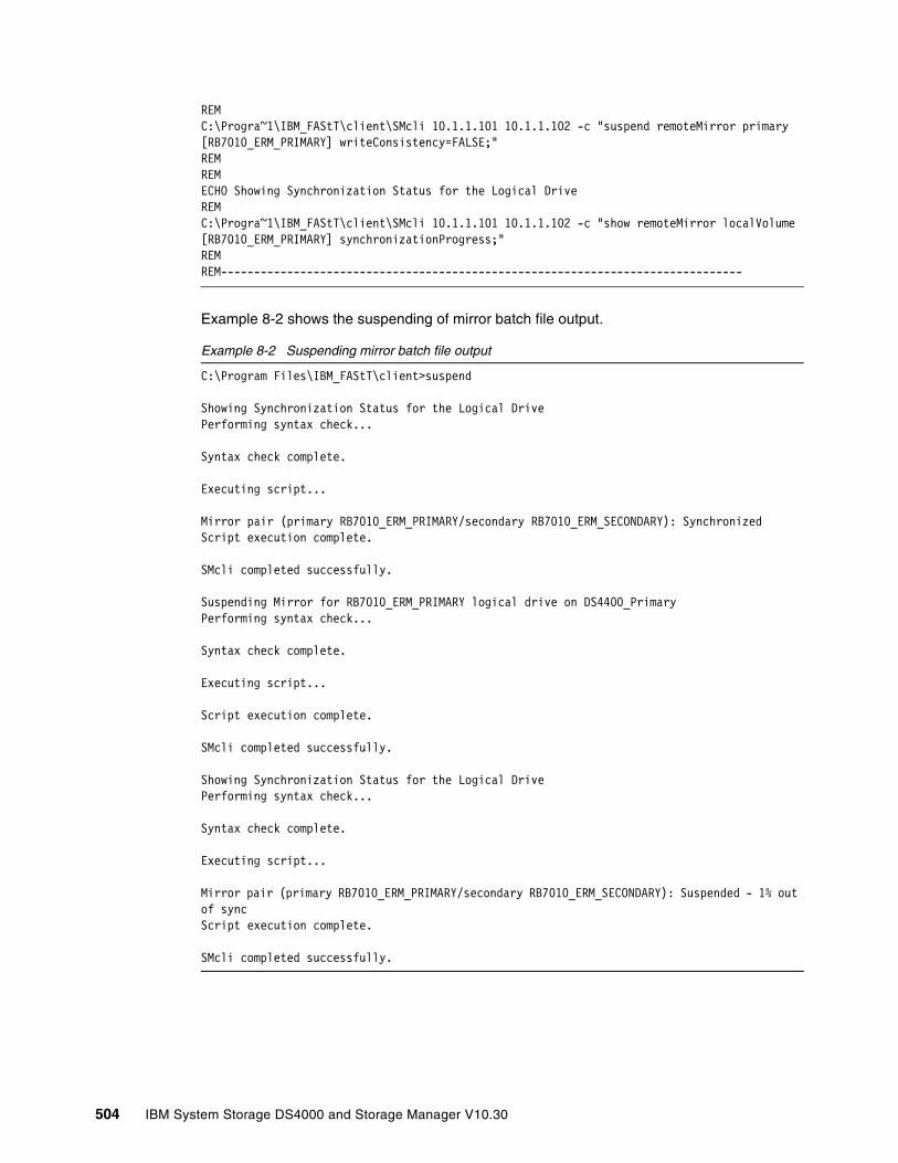
REMC:\Progra~1\IBM_FAStT\client\SMcli 10.1.1.101 10.1.1.102 -c "suspend remoteMirror primary [RB7010_ERM_PRIMARY] writeConsistency=FALSE;"REM REMECHO Showing Synchronization Status for the Logical DriveREM C:\Progra~1\IBM_FAStT\client\SMcli 10.1.1.101 10.1.1.102 -c "show remoteMirror localVolume [RB7010_ERM_PRIMARY] synchronizationProgress;"REMREM-------------------------------------------------------------------------------
Example 8-2 shows the suspending of mirror batch file output.
Example 8-2 Suspending mirror batch file output
C:\Program Files\IBM_FAStT\client>suspend
Showing Synchronization Status for the Logical DrivePerforming syntax check...
Syntax check complete.
Executing script...
Mirror pair (primary RB7010_ERM_PRIMARY/secondary RB7010_ERM_SECONDARY): SynchronizedScript execution complete.
SMcli completed successfully.
Suspending Mirror for RB7010_ERM_PRIMARY logical drive on DS4400_PrimaryPerforming syntax check...
Syntax check complete.
Executing script...
Script execution complete.
SMcli completed successfully.
Showing Synchronization Status for the Logical DrivePerforming syntax check...
Syntax check complete.
Executing script...
Mirror pair (primary RB7010_ERM_PRIMARY/secondary RB7010_ERM_SECONDARY): Suspended - 1% out of syncScript execution complete.
SMcli completed successfully.
504 IBM System Storage DS4000 and Storage Manager V10.30

You can also save the commands to a script file (*.scr) and load it into the DS4000 Storage Manager Script Editor tool. Figure 8-58 shows the suspend.scr file loaded in the Script Editor window (top pane) and the script execution output (bottom pane).
Figure 8-58 Script Editor windows with suspend.scr script file
To resume the mirroring relationship, use the batch file shown in Example 8-3.
Example 8-3 MS Windows 2003 batch file for resuming mirror relationship on mirrored logical drive
@ECHO OFFREM This is a basic script example which is intended for a scenario where you have REM at least two storage servers using the Enhanced Remote Mirroring Feature. REM It illustrates how to resume a mirroring relationship.REM -------------------------------------------------------------------------------REM RESUME MIRROR FOR LOGICAL DRIVE RB7010_ERM_PRIMARY defined on DS4400_PrimaryREM STORAGE SUBSYSTEMREM REM ECHO Showing Synchronization Status for the Logical DriveREM C:\Progra~1\IBM_FAStT\client\SMcli 10.1.1.101 10.1.1.102 -c "show remoteMirror localVolume [RB7010_ERM_PRIMARY] synchronizationProgress;"REM REMECHO Resuming Mirror for RB7010_ERM_PRIMARY logical drive on DS4400_PrimaryREMC:\Progra~1\IBM_FAStT\client\SMcli 10.1.1.101 10.1.1.102 -c "resume remoteMirror primary [RB7010_ERM_PRIMARY] writeConsistency=FALSE;"REM REMECHO Showing Synchronization Status for the Logical DriveREM C:\Progra~1\IBM_FAStT\client\SMcli 10.1.1.101 10.1.1.102 -c "show remoteMirror localVolume [RB7010_ERM_PRIMARY] synchronizationProgress;"REMREM -------------------------------------------------------------------------------
Chapter 8. Enhanced Remote Mirroring 505
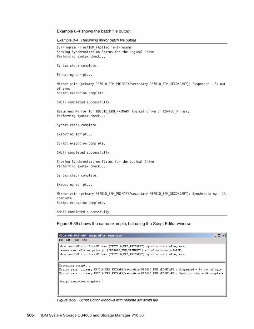
Example 8-4 shows the batch file output.
Example 8-4 Resuming mirror batch file output
C:\Program Files\IBM_FAStT\client>resumeShowing Synchronization Status for the Logical DrivePerforming syntax check...
Syntax check complete.
Executing script...
Mirror pair (primary RB7010_ERM_PRIMARY/secondary RB7010_ERM_SECONDARY): Suspended - 3% out of syncScript execution complete.
SMcli completed successfully.
Resuminng Mirror for RB7010_ERM_PRIMARY logical drive on DS4400_PrimaryPerforming syntax check...
Syntax check complete.
Executing script...
Script execution complete.
SMcli completed successfully.
Showing Synchronization Status for the Logical DrivePerforming syntax check...
Syntax check complete.
Executing script...
Mirror pair (primary RB7010_ERM_PRIMARY/secondary RB7010_ERM_SECONDARY): Synchronizing - 1% completeScript execution complete.
SMcli completed successfully.
Figure 8-59 shows the same example, but using the Script Editor window.
Figure 8-59 Script Editor windows with resume.scr script file
506 IBM System Storage DS4000 and Storage Manager V10.30

There are additional script examples in Chapter 11, “Command-line interface and Script Editor” on page 629.
8.7.9 Removing mirror relationshipsUse the remove mirror relationship option to remove the link between the primary and secondary logical drives in a mirrored relationship.
This action does not delete the primary logical drive, secondary logical drive, or mirror repository logical drives. Data on the logical drives is not affected and the primary logical drive still continues normal I/O operation. As a result of this operation the primary logical drive and secondary logical drive become standard, host-accessible, non-mirrored logical drives.
This option is only available for the local logical drive (primary or secondary) that is present in the storage system that you are currently managing. This option is not available if you select a remote secondary logical drive in the logical view.
The mirror relationship is first removed on the local storage system, then on the remote storage system. If the mirror relationship is successfully removed on the local storage system but cannot be removed on the remote storage system because of a communication problem, an error message is displayed. The error message shows the name of the remote storage system with the orphaned mirrored logical drive and the name of the logical drive. Open the Subsystem Management window for the remote storage system, select the specified logical drive, and remove the mirror relationship.
If the mirror relationship was successfully removed on the secondary side but not the primary side, then the first I/O write to the primary logical drive will cause the mirror state to go unsynchronized. The primary Subsystem Management window logical view also then shows an unresponsive remote secondary logical drive. Remove the mirror relationship on the primary storage system to correct the problem.
If the mirror relationship was successfully removed on the primary side, but not on the secondary side, then there will not typically be a change to the representation of the secondary logical drive in the secondary Subsystem Management window logical view. Remove the mirror relationship on the secondary storage system to correct the problem and make the logical drive accessible by hosts.
To remove a Remote Mirror relationship:
1. Select a primary or secondary logical drive in the logical view (whichever is local), then select either the Logical Drive → Remote Mirroring → Remove Mirror Relationship pull-down menu option or Remove Mirror Relationship from the right-mouse pop-up menu.
Chapter 8. Enhanced Remote Mirroring 507

The Remove Mirror Relationship dialog is displayed (Figure 8-60).
Figure 8-60 Remove Mirror Relationship
2. Select the mirrored logical drive pairs for which you wish to remove the mirror relationship. To select multiple mirrored pairs, use the Ctrl or Shift key in combination with the mouse click. To select all of the mirrored pairs, click the Select All button. Click Remove. The Remove Mirror Relationship - Confirmation dialog is displayed (Figure 8-61).
Figure 8-61 Remove Mirror Relationship - Confirmation
3. Click Yes. The Remove Mirror Relationship - Progress window is displayed. Click OK. All data on the logical drives remains intact and available. Logical drives that were the secondary logical drive in the mirrored pair are now accessible (read/write) by hosts that are mapped to them.
8.8 ERM and disaster recoveryAs modern business pressures increasingly require 24-hour data availability, system administrators are required to ensure that critical data is safeguarded against potential disasters. Additionally, storage administrators are searching for methods to migrate from one host to another or from one storage system to another, with as little disruption as possible.
508 IBM System Storage DS4000 and Storage Manager V10.30

Remote Mirroring is one method that can be implemented to assist in business continuity and disaster recovery. Once critical data has been mirrored from a primary storage system to a remote storage system, primary and secondary logical drives can have their roles reversed so that the copied data can be accessed from the remote storage system.
This section discusses how to reverse the roles of the primary and secondary logical drives. However, it does not cover building and implementing a complete disaster recovery plan.
8.8.1 Role reversal conceptA role reversal promotes a selected secondary logical drive to become the primary logical drive of the mirrored pair. As previously explained, the roles of primary and secondary logical drives are naming conventions based on the direction of data flow. They differentiate as follows:
� The relevant administrative commands for ERM must be provided on the primary site.� The mirror states are determined by the primary storage system.� The connection examination is provided by the primary storage system.� The secondary logical drive is only read-access enabled.
A role reversal is performed using one of the following methods.
Changing a secondary logical drive to a primary logical driveUse this option to perform a role reversal between the two paired logical drives in a mirror relationship. This option promotes a selected secondary logical drive to become the primary logical drive of the mirrored pair. If the associated primary logical drive can be contacted, the primary logical drive is automatically demoted to be the secondary logical drive. Use this option when a normally interruptible maintenance task on the primary site is needed or in a case of an unrecoverable failure to the storage system that contains the primary logical drive and you want to promote the secondary logical drive so that hosts can access data and business operations can continue.
Important: When the secondary logical drive becomes a primary logical drive, any hosts that are mapped to the logical drive through a logical drive-to-LUN mapping will now be able to write to the logical drive.
If a communication problem between the secondary and primary sites prevents the demotion of the primary logical drive, an error message is displayed. However, you are given the opportunity to proceed with the promotion of the secondary logical drive, even though this leads to a dual primary Remote Mirror status condition. For more information see “Forcing a secondary to change to a primary logical drive” on page 511.
Chapter 8. Enhanced Remote Mirroring 509
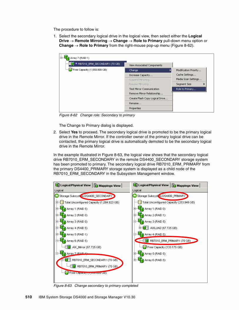
The procedure to follow is:
1. Select the secondary logical drive in the logical view, then select either the Logical Drive → Remote Mirroring → Change → Role to Primary pull-down menu option or Change → Role to Primary from the right-mouse pop-up menu (Figure 8-62).
Figure 8-62 Change role: Secondary to primary
The Change to Primary dialog is displayed.
2. Select Yes to proceed. The secondary logical drive is promoted to be the primary logical drive in the Remote Mirror. If the controller owner of the primary logical drive can be contacted, the primary logical drive is automatically demoted to be the secondary logical drive in the Remote Mirror.
In the example illustrated in Figure 8-63, the logical view shows that the secondary logical drive RB7010_ERM_SECONDARY in the remote DS4400_SECONDARY storage system has been promoted to primary. The secondary logical drive RB7010_ERM_PRIMARY from the primary DS4400_PRIMARY storage system is displayed as a child node of the RB7010_ERM_SECONDARY in the Subsystem Management window.
Figure 8-63 Change secondary to primary completed
510 IBM System Storage DS4000 and Storage Manager V10.30

Forcing a secondary to change to a primary logical driveIf, when attempting to promote a secondary logical drive to a primary logical drive, a communication failure between the primary and remote storage systems exists, then an error dialog appears (Figure 8-64).
Select Yes on the Change to Primary - Error dialog to force the software to promote the selected secondary logical drive to a primary role.
Figure 8-64 Force secondary to primary: Confirmation
You might want to do this under the following circumstances:
� Use this option when a catastrophic failure has occurred to the storage system that contains the primary logical drive, the primary storage system cannot be contacted, and you want to promote the secondary logical drive so that hosts can access data and business operations can continue.
� Or consider using this option when no catastrophic failure has occurred to the storage system that contains the primary logical drive, but you want to perform a role reversal for some other reason and a communication problem between the local and remote sites is preventing the demotion of the primary logical drive at the remote site.
Figure 8-65 shows a logical volume RB7010_RERM_SECONDARY on a remote subsystem that was forced to primary. Because the connection with the primary is lost, it is shown as unsynchronized.
Figure 8-65 Unsynchronized secondary
Unsynchronized
Chapter 8. Enhanced Remote Mirroring 511
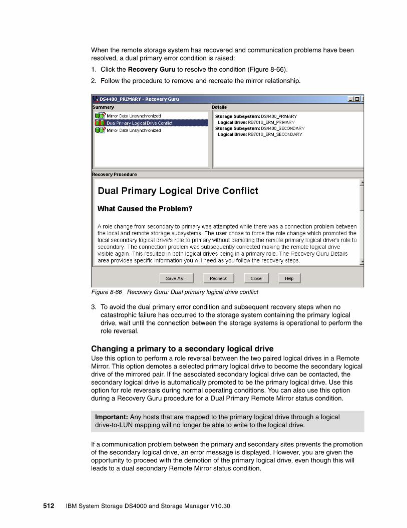
When the remote storage system has recovered and communication problems have been resolved, a dual primary error condition is raised:
1. Click the Recovery Guru to resolve the condition (Figure 8-66).
2. Follow the procedure to remove and recreate the mirror relationship.
Figure 8-66 Recovery Guru: Dual primary logical drive conflict
3. To avoid the dual primary error condition and subsequent recovery steps when no catastrophic failure has occurred to the storage system containing the primary logical drive, wait until the connection between the storage systems is operational to perform the role reversal.
Changing a primary to a secondary logical driveUse this option to perform a role reversal between the two paired logical drives in a Remote Mirror. This option demotes a selected primary logical drive to become the secondary logical drive of the mirrored pair. If the associated secondary logical drive can be contacted, the secondary logical drive is automatically promoted to be the primary logical drive. Use this option for role reversals during normal operating conditions. You can also use this option during a Recovery Guru procedure for a Dual Primary Remote Mirror status condition.
If a communication problem between the primary and secondary sites prevents the promotion of the secondary logical drive, an error message is displayed. However, you are given the opportunity to proceed with the demotion of the primary logical drive, even though this will leads to a dual secondary Remote Mirror status condition.
Important: Any hosts that are mapped to the primary logical drive through a logical drive-to-LUN mapping will no longer be able to write to the logical drive.
512 IBM System Storage DS4000 and Storage Manager V10.30
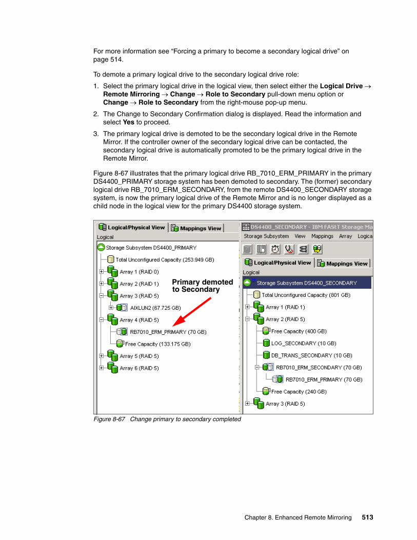
For more information see “Forcing a primary to become a secondary logical drive” on page 514.
To demote a primary logical drive to the secondary logical drive role:
1. Select the primary logical drive in the logical view, then select either the Logical Drive → Remote Mirroring → Change → Role to Secondary pull-down menu option or Change → Role to Secondary from the right-mouse pop-up menu.
2. The Change to Secondary Confirmation dialog is displayed. Read the information and select Yes to proceed.
3. The primary logical drive is demoted to be the secondary logical drive in the Remote Mirror. If the controller owner of the secondary logical drive can be contacted, the secondary logical drive is automatically promoted to be the primary logical drive in the Remote Mirror.
Figure 8-67 illustrates that the primary logical drive RB_7010_ERM_PRIMARY in the primary DS4400_PRIMARY storage system has been demoted to secondary. The (former) secondary logical drive RB_7010_ERM_SECONDARY, from the remote DS4400_SECONDARY storage system, is now the primary logical drive of the Remote Mirror and is no longer displayed as a child node in the logical view for the primary DS4400 storage system.
Figure 8-67 Change primary to secondary completed
Primary demotedto Secondary
Chapter 8. Enhanced Remote Mirroring 513

Forcing a primary to become a secondary logical driveIf, when attempting to demote a primary logical drive to a secondary logical drive, a communication failure between the primary and the remote storage systems exists, then an error dialog appears (Figure 8-68):
1. Select Yes on the Change to Secondary - Error dialog to force the software to demote the selected primary logical drive to a secondary role.
Figure 8-68 Force primary to secondary: Confirmation
Consider using this option when you want to perform a role reversal and a communication problem between the local and the remote sites is preventing the promotion of the secondary logical drive at the remote site.
514 IBM System Storage DS4000 and Storage Manager V10.30
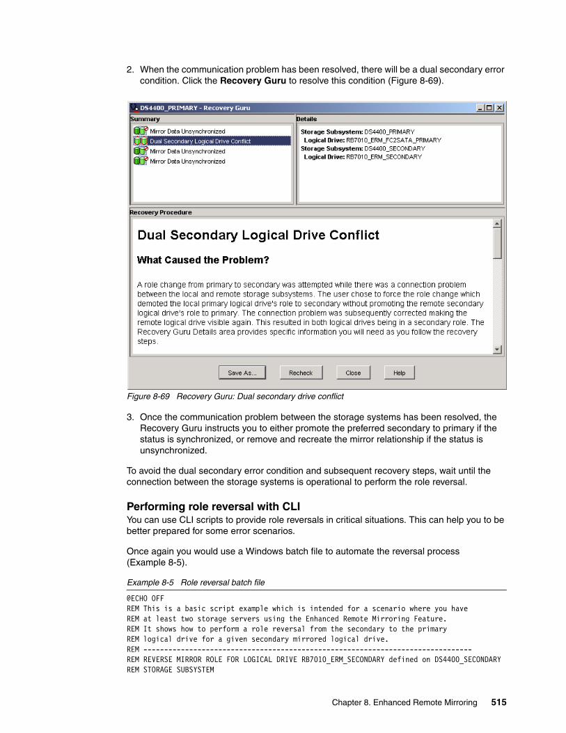
2. When the communication problem has been resolved, there will be a dual secondary error condition. Click the Recovery Guru to resolve this condition (Figure 8-69).
Figure 8-69 Recovery Guru: Dual secondary drive conflict
3. Once the communication problem between the storage systems has been resolved, the Recovery Guru instructs you to either promote the preferred secondary to primary if the status is synchronized, or remove and recreate the mirror relationship if the status is unsynchronized.
To avoid the dual secondary error condition and subsequent recovery steps, wait until the connection between the storage systems is operational to perform the role reversal.
Performing role reversal with CLIYou can use CLI scripts to provide role reversals in critical situations. This can help you to be better prepared for some error scenarios.
Once again you would use a Windows batch file to automate the reversal process (Example 8-5).
Example 8-5 Role reversal batch file
@ECHO OFFREM This is a basic script example which is intended for a scenario where you have REM at least two storage servers using the Enhanced Remote Mirroring Feature. REM It shows how to perform a role reversal from the secondary to the primaryREM logical drive for a given secondary mirrored logical drive.REM -------------------------------------------------------------------------------REM REVERSE MIRROR ROLE FOR LOGICAL DRIVE RB7010_ERM_SECONDARY defined on DS4400_SECONDARYREM STORAGE SUBSYSTEM
Chapter 8. Enhanced Remote Mirroring 515
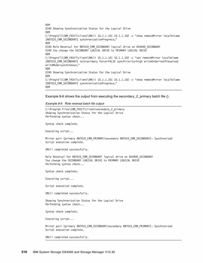
REM ECHO Showing Synchronization Status for the Logical DriveREM C:\Progra~1\IBM_FAStT\client\SMcli 10.1.1.101 10.1.1.102 -c "show remoteMirror localVolume [RB7010_ERM_SECONDARY] synchronizationProgress;"REMECHO Role Reversal for RB7010_ERM_SECONDARY logical drive on DS4400_SECONDARYECHO You change the SECONDARY LOGICAL DRIVE to PRIMARY LOGICAL DRIVE REMC:\Progra~1\IBM_FAStT\client\SMcli 10.1.1.101 10.1.1.102 -c "set remoteMirror localVolume [RB7010_ERM_SECONDARY] role=primary force=FALSE syncPriority=high writeOrder=notPreserved writeMode=synchronous;"REMECHO Showing Synchronization Status for the Logical DriveREM C:\Progra~1\IBM_FAStT\client\SMcli 10.1.1.101 10.1.1.102 -c "show remoteMirror localVolume [RB7010_ERM_SECONDARY] synchronizationProgress;"REM
Example 8-6 shows the output from executing the secondary_2_primary batch file ().
Example 8-6 Role reversal batch file output
C:\Program Files\IBM_FAStT\client>secondary_2_primaryShowing Synchronization Status for the Logical DrivePerforming syntax check...
Syntax check complete.
Executing script...
Mirror pair (primary RB7010_ERM_PRIMARY/secondary RB7010_ERM_SECONDARY): SynchronizedScript execution complete.
SMcli completed successfully.
Role Reversal for RB7010_ERM_SECONDARY logical drive on DS4400_SECONDARYYou change the SECONDARY LOGICAL DRIVE to PRIMARY LOGICAL DRIVEPerforming syntax check...
Syntax check complete.
Executing script...
Script execution complete.
SMcli completed successfully.
Showing Synchronization Status for the Logical DrivePerforming syntax check...
Syntax check complete.
Executing script...
Mirror pair (primary RB7010_ERM_SECONDARY/secondary RB7010_ERM_PRIMARY): SynchronizedScript execution complete.
SMcli completed successfully.
516 IBM System Storage DS4000 and Storage Manager V10.30
8.8.2 Re-establishing Remote Mirroring after failure recovery When the damaged site is back online and properly configured, mirror relationships can be resumed. Recreate a mirror relationship by completing the following steps:
1. Ensure that SAN connections and SAN zoning are properly configured.
2. From the active secondary site, define a mirror relationship using the logical drive on the recovered primary site as the secondary logical drive. For more information see “Enhanced Remote Mirroring: Step-by-step” on page 475.
3. Ensure that storage partitioning and host mapping are properly defined on the recovered primary site so that it can take over normal operation from the secondary site.
4. Ensure that the host software is properly configured so that the host systems at the recovered primary site can take over I/O from the secondary site host systems.
5. After the full synchronization has completed, perform a manual role reversal so that the recovered primary site now possesses the active primary logical drive, and the secondary logical drive now exists on the secondary site. For more information see “Changing a primary to a secondary logical drive” on page 512.
8.9 Enhanced Remote Mirroring solution designA SAN design is normally based on storage, flexibility, performance, and redundancy requirements. The Enhanced Remote Mirroring option is one piece of the solution.
This section presents three sample configurations showing how the Enhanced Remote Mirroring option can be implemented. The level of redundancy is determined by the type of configuration that you choose to use. However, they are only suggestions on how to build a reliable and highly available system environment based on IBM recommendations. The three sample solutions are:
� Intra-site configuration with minimum redundancy: This solution shows a simple departmental solution implemented using two Fibre Channel switches and two DS4000 storage systems.
� Intersite configuration with redundant fabric: Similar to the previous solution except for the storage systems being located in two physically separate sites.
� High-availability intersite configuration with redundant fabric. A solution that provides for the highest level of redundancy.
When designing a SAN storage solution, it is good practice to complete the following steps:
1. Produce a statement that outlines the solution requirements that can be used to determine the type of configuration that you need. It should also be used to cross-check that the solution design delivers the basic requirements. The statement should have easily defined bullet points covering the requirements, for example:
– Required capacity– Required redundancy levels– Backup and restore windows– Type of data protection needed– Network backups– LAN free backups– FlashCopy
Chapter 8. Enhanced Remote Mirroring 517
– Enhanced Remote Mirroring– Host and operating system types to be connected to SAN– Number of host connections required
2. Produce a hardware checklist. It should cover such items that you require you to:
– Ensure that the minimum hardware requirements are met.
– Make a complete list of the hardware requirements including the required premium options.
– Ensure that your primary and secondary storage systems are properly configured.
– Ensure that your Fibre Channel switches and cables are properly configured. The Remote Mirroring links must be in a separate zone.
3. Produce a software checklist to cover all the required items that must be certified and checked. It should include such items that require you to:
– Ensure that data on the primary and secondary storage systems participating in Enhanced Remote Mirroring is backed up.
– Ensure that the correct versions of firmware and storage-management software are installed.
– Ensure that the Enhanced Remote Mirroring option is enabled on both the primary and the secondary storage systems.
– Ensure that the Enhanced Remote Mirroring option is activated and that a mirror repository logical drive is created for each controller all participating storage system.
– Ensure that the required primary and secondary logical drives are created on the primary and remote storage systems.
Note: Additional information about ERM planning and implementation best practices can be found in DS4000 Best Practices and Performance Tuning Guide, SG24-6363.
518 IBM System Storage DS4000 and Storage Manager V10.30
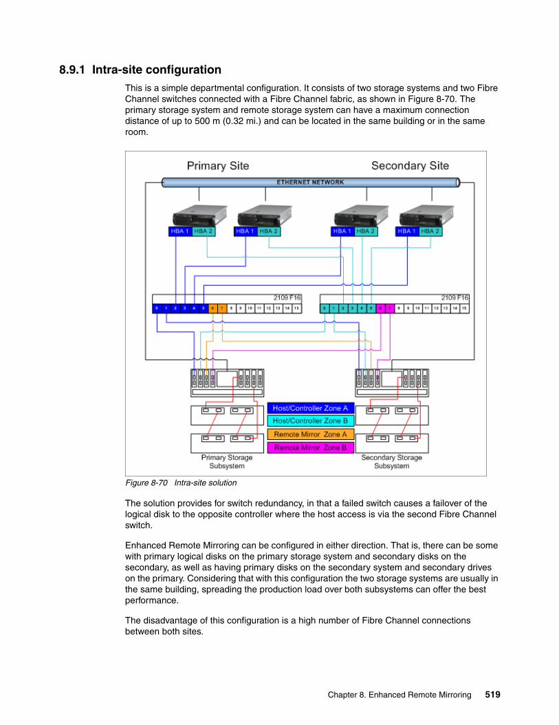
8.9.1 Intra-site configurationThis is a simple departmental configuration. It consists of two storage systems and two Fibre Channel switches connected with a Fibre Channel fabric, as shown in Figure 8-70. The primary storage system and remote storage system can have a maximum connection distance of up to 500 m (0.32 mi.) and can be located in the same building or in the same room.
Figure 8-70 Intra-site solution
The solution provides for switch redundancy, in that a failed switch causes a failover of the logical disk to the opposite controller where the host access is via the second Fibre Channel switch.
Enhanced Remote Mirroring can be configured in either direction. That is, there can be some with primary logical disks on the primary storage system and secondary disks on the secondary, as well as having primary disks on the secondary system and secondary drives on the primary. Considering that with this configuration the two storage systems are usually in the same building, spreading the production load over both subsystems can offer the best performance.
The disadvantage of this configuration is a high number of Fibre Channel connections between both sites.
Chapter 8. Enhanced Remote Mirroring 519

8.9.2 Intersite configuration with redundant fabricThis configuration is similar to the first solution, except for the storage systems being physically located in different sites. The configuration consists of two storage systems and two Fibre Channel switches connected with an inter-switch link (ISL) forming a Fibre Channel fabric, as shown in Figure 8-71. Using standard Fibre Channel longwave Gigabit Interface Converters (GBICs) and single mode cable, the primary storage system and remote storage system have a maximum connection distance of up to 10 km (6.25 mi.).
Figure 8-71 Campus solution
The configuration provides for redundancy based on a site failover. The fabric has been zoned into four separate zones and each switch shares in all four zones.
We recommend the zone in this solution as a best practice. The only mandatory zoning is for the Remote Mirroring links to be in a zone separate from the DS4xxx controller units and hosts. Unpredictable results can be obtained when the host scanned devices if the mirrors were in the same zone as the hosts and controllers.
The disadvantage of this configuration is the non-redundant SAN fabric. SAN switch vendors recommend using multiple fabrics for the highest availability.
520 IBM System Storage DS4000 and Storage Manager V10.30
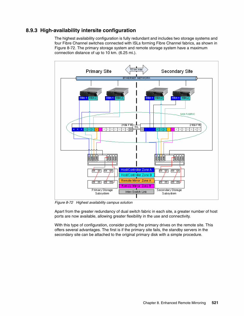
8.9.3 High-availability intersite configurationThe highest availability configuration is fully redundant and includes two storage systems and four Fibre Channel switches connected with ISLs forming Fibre Channel fabrics, as shown in Figure 8-72. The primary storage system and remote storage system have a maximum connection distance of up to 10 km. (6.25 mi.).
Figure 8-72 Highest availability campus solution
Apart from the greater redundancy of dual switch fabric in each site, a greater number of host ports are now available, allowing greater flexibility in the use and connectivity.
With this type of configuration, consider putting the primary drives on the remote site. This offers several advantages. The first is if the primary site fails, the standby servers in the secondary site can be attached to the original primary disk with a simple procedure.
Chapter 8. Enhanced Remote Mirroring 521
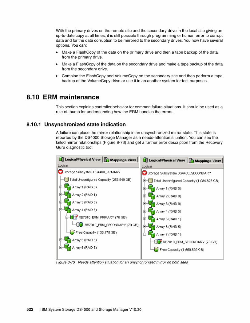
With the primary drives on the remote site and the secondary drive in the local site giving an up-to-date copy at all times, it is still possible through programming or human error to corrupt data and for the data corruption to be mirrored to the secondary drives. You now have several options. You can:
� Make a FlashCopy of the data on the primary drive and then a tape backup of the data from the primary drive.
� Make a FlashCopy of the data on the secondary drive and make a tape backup of the data from the secondary drive.
� Combine the FlashCopy and VolumeCopy on the secondary site and then perform a tape backup of the VolumeCopy drive or use it in an another system for test purposes.
8.10 ERM maintenanceThis section explains controller behavior for common failure situations. It should be used as a rule of thumb for understanding how the ERM handles the errors.
8.10.1 Unsynchronized state indicationA failure can place the mirror relationship in an unsynchronized mirror state. This state is reported by the DS4000 Storage Manager as a needs-attention situation. You can see the failed mirror relationships (Figure 8-73) and get a further error description from the Recovery Guru diagnostic tool.
Figure 8-73 Needs attention situation for an unsynchronized mirror on both sites
522 IBM System Storage DS4000 and Storage Manager V10.30
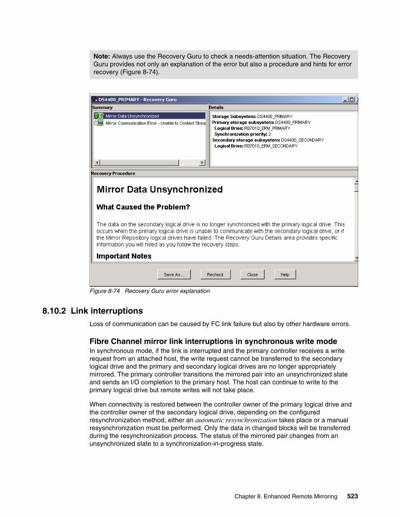
Figure 8-74 Recovery Guru error explanation
8.10.2 Link interruptions Loss of communication can be caused by FC link failure but also by other hardware errors.
Fibre Channel mirror link interruptions in synchronous write modeIn synchronous mode, if the link is interrupted and the primary controller receives a write request from an attached host, the write request cannot be transferred to the secondary logical drive and the primary and secondary logical drives are no longer appropriately mirrored. The primary controller transitions the mirrored pair into an unsynchronized state and sends an I/O completion to the primary host. The host can continue to write to the primary logical drive but remote writes will not take place.
When connectivity is restored between the controller owner of the primary logical drive and the controller owner of the secondary logical drive, depending on the configured resynchronization method, either an automatic resynchronization takes place or a manual resysnchronization must be performed. Only the data in changed blocks will be transferred during the resynchronization process. The status of the mirrored pair changes from an unsynchronized state to a synchronization-in-progress state.
Note: Always use the Recovery Guru to check a needs-attention situation. The Recovery Guru provides not only an explanation of the error but also a procedure and hints for error recovery (Figure 8-74).
Chapter 8. Enhanced Remote Mirroring 523
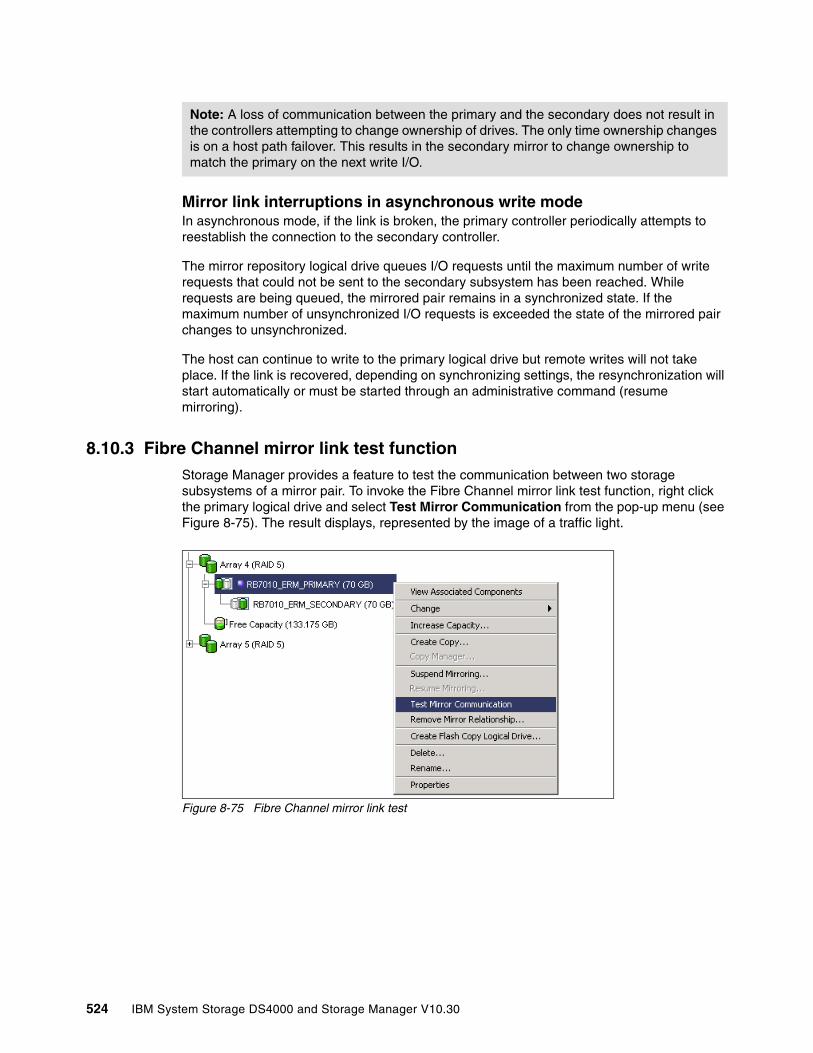
Mirror link interruptions in asynchronous write modeIn asynchronous mode, if the link is broken, the primary controller periodically attempts to reestablish the connection to the secondary controller.
The mirror repository logical drive queues I/O requests until the maximum number of write requests that could not be sent to the secondary subsystem has been reached. While requests are being queued, the mirrored pair remains in a synchronized state. If the maximum number of unsynchronized I/O requests is exceeded the state of the mirrored pair changes to unsynchronized.
The host can continue to write to the primary logical drive but remote writes will not take place. If the link is recovered, depending on synchronizing settings, the resynchronization will start automatically or must be started through an administrative command (resume mirroring).
8.10.3 Fibre Channel mirror link test functionStorage Manager provides a feature to test the communication between two storage subsystems of a mirror pair. To invoke the Fibre Channel mirror link test function, right click the primary logical drive and select Test Mirror Communication from the pop-up menu (see Figure 8-75). The result displays, represented by the image of a traffic light.
Figure 8-75 Fibre Channel mirror link test
Note: A loss of communication between the primary and the secondary does not result in the controllers attempting to change ownership of drives. The only time ownership changes is on a host path failover. This results in the secondary mirror to change ownership to match the primary on the next write I/O.
524 IBM System Storage DS4000 and Storage Manager V10.30
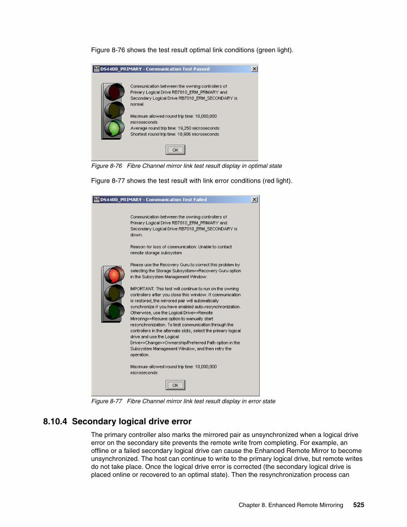
Figure 8-76 shows the test result optimal link conditions (green light).
Figure 8-76 Fibre Channel mirror link test result display in optimal state
Figure 8-77 shows the test result with link error conditions (red light).
Figure 8-77 Fibre Channel mirror link test result display in error state
8.10.4 Secondary logical drive errorThe primary controller also marks the mirrored pair as unsynchronized when a logical drive error on the secondary site prevents the remote write from completing. For example, an offline or a failed secondary logical drive can cause the Enhanced Remote Mirror to become unsynchronized. The host can continue to write to the primary logical drive, but remote writes do not take place. Once the logical drive error is corrected (the secondary logical drive is placed online or recovered to an optimal state). Then the resynchronization process can
Chapter 8. Enhanced Remote Mirroring 525

begin. Depending on synchronizing settings, the resynchronization will start automatically or must be started manually by issuing an administrative command (resume mirroring).
8.10.5 Primary controller failureIf a remote write is interrupted by a primary controller failure before it can be written to the secondary logical drive, the primary storage system provides controller ownership change from the preferred controller owner to the alternate controller in the storage system. The first write request to the remote site changes the ownership of the secondary logical drive. Once the transition of the ownership is completed the mirroring is proceeds as usual.
8.10.6 Primary controller resetIf a remote write is interrupted by a primary controller reset before it can be written to the secondary logical drive, there is normally no ownership change. After reboot the controller reads information stored in a log file in the mirror repository logical drive and uses the information to copy the affected data blocks from the primary logical drive to the secondary logical drive. We highly recommend suspending mirror relationships before resetting the controller.
8.10.7 Secondary controller failureIf the secondary controller fails, the primary site can no longer communicate with the secondary logical drive. The mirror state becomes unsynchronized. The host can continue to write to the primary logical drive, but remote writes will not take place. After the secondary controller failure has been recovered, depending on the synchronization settings, the primary controller changes the mirror state to synchronizing either automatically or through a resume command.
8.10.8 Write consistency group and unsynchronized stateMirror relationships configured within a write consistency group are considered an interdependent set with respect to the integrity of the data on the remote logical drives. A given secondary logical drive cannot be considered fully synchronized until all members of the write consistency group are synchronized. Similarly, when one mirrored logical drive pair of the write consistency group is in an unsynchronized state, all members of the group halt remote write activity to protect the consistency of the remote data.
The controller changes the state of all mirrored pairs within the group to unsynchronized when any mirror within the set becomes unsynchronized or failed. All pending write requests for the member of the write consistency croup are moved to the mirror repository logical drive. Mirror relationships configured with the manual resynchronization setting remain in the suspended state until a user intervenes by issuing a resume command. Mirror relationships configured to allow automatic resynchronization automatically resynchronize.
8.11 Performance considerationsThis section contains general performance considerations that apply only in the context of designing a Remote Mirror configuration. There are many factors that come into play, such as host operating system settings and different application requirements, and it usually takes some experimentation and observation over time to tune a configuration for better performance in a given environment.
526 IBM System Storage DS4000 and Storage Manager V10.30

8.11.1 Synchronization priorityThe controller owner of a primary logical drive performs a synchronization in the background while processing local I/O write operations to the primary logical drive and associated remote write operations to the secondary logical drive.
Because the synchronization diverts controller processing resources from I/O activity, it can have a performance impact to the host application. The synchronization priority defines how much processing time is allocated for synchronization activities relative to system performance. The following priority rates are available:
� Lowest� Low� Medium� High� Highest
You can use the synchronization priority to establish how the controller owner prioritizes the resources needed for the synchronization process relative to host I/O activity.
The following rules are a rough estimates for the relationships between the five synchronization priorities.
� A synchronization at the lowest synchronization priority rate will take approximately eight times as long as a synchronization at the highest synchronization priority rate.
� A synchronization at the low synchronization priority rate will take approximately six times as long as a synchronization at the highest synchronization priority rate.
� A synchronization at the medium synchronization priority rate will take approximately three and a half times as long as a synchronization at the highest synchronization priority rate.
� A synchronization at the high synchronization priority rate will take approximately twice as long as a synchronization at the highest synchronization priority rate.
8.11.2 Synchronization performance and logical drive settingsIn a configuration where both mirrored storage systems are holding primary and secondary logical drives (cross-mirroring) the count of host I/O requests to a local storage system and the synchronization I/O requests to the remote storage system are the two factors influencing the system’s overall performance.
The write performance of a given logical drive is estimated by four key factors
� Logical drive cache settings� Performance of a single physical drive in the array in which the logical drive is created� Number of physical drives in the array in which the logical drive is created� RAID level of the array in which the logical drive is created
Attention: Note that logical drive size can cause these estimates to vary widely.
Note: The lowest priority rate favors system performance, but the synchronization will take longer. The highest priority rate favors the synchronization, but system performance might be compromised. Logical drive size and host I/O rate loads affect the synchronization time comparisons. A synchronization at the lowest synchronization priority rate takes approximately eight times as long as a synchronization at the highest synchronization priority rate.
Chapter 8. Enhanced Remote Mirroring 527

A good practice is to balance resources among the mirrored logical drives. That means:
� Write cache settings should be the same on both storage servers.
� Do not use read cache for secondary logical drives.
� Use as many drives as you can get to create an array.
� If the write cache is disabled for the secondary logical drive use more disks (than on the primary site) to create the array for the secondary logical drive.
� Use RAID Level 1 for secondary logical drives receiving data from a RAID Level 3 or 5 primary logical drive to balance the performance.
With the possibility for FC/SATA Drive Intermixing, you might want to mirror data from FC drives to SATA drives (previous points still remaining).
8.11.3 Mirroring mode and performanceThe mirroring mode has an impact on the storage server performance. Remember if you have intensive host I/Os that:
� Metro Mirroring is a must synchronize mode.
� Global Copy and Global Mirror are can synchronize modes.
� Global Mirror needs more storage controller processing resources to enforce the host I/O write request order.
8.11.4 Mirroring connection distance and performanceFor distances longer than 10 km (6.25 mi), you assume that asynchronous mirroring only is used. Note that distances greater than 10 km (up to 150 km) can be supported in Metro Mirror mode, but support requires a request for price quotation (RPQ).
The maximum distance that can be supported whether using shortwave or longwave SFPs is greater in a 1 Gbps fabric than in 2 Gpbs (refer to Table 8-3 on page 473). However, using a 1 Gbps connection rather than 2 Gpbs negatively impacts the synchronization performance.
The major performance factor for long-distance solutions is the IP connection bandwidth between the Fibre Channel extenders. If you connect to a 100 Mbps IP network, you will able to transfer about 10 MB of data per second (assuming that the connection is stable).
� Estimate the time needed for the first full synchronization.
� Check the amount of data that is changing on average on the primary logical drives over a certain period of time and compare it to the available connection bandwidth.
� Always keep some reserve for unexpected transfer rate peaks.
Important: Even if the distances are in the range of shortwave fiber specification, it can be a good practice to use asynchronous mirroring mode if the storage system is heavily loaded with host I/O requests. The performance of the storage system does not improve by using asynchronous mode but the application performance will be almost unaffected while using Remote Mirroring.
528 IBM System Storage DS4000 and Storage Manager V10.30

8.12 Long-distance ERMWith Global Copy and Global Mirror operating modes the Enhanced Remote Mirroring provides the capability to mirror data over longer distances. Asynchronous mirroring, combined with the use of devices known as channel extenders, allows replication over distances of more than 5000 km (3200 mi.).
There are three main characteristics for a connection:
� Connection bandwidth: Defines how much information can be transferred over a connection in a given period of time. This is usually measured in bits per second (bps) or bytes per second (Bps). Fibre Channel bandwidth is 2 Gbps or 1 Gbps.
� Connection latency: Specifies how long it takes get a response in return for a request. Most applications expect values between 1 and 10 ms.
� Connection protocol: Is the set of the communication rules that both communication partners must use to understand each other.
For long distance, you could in theory use native Fibre Channel, low-latency, high-bandwidth connections such as Dense Wavelength Division Multiplexing (DWDM) or Coarse Wavelength Division Multiplexing (CWDM) technologies. But this is only a speculative possibility for most situations because of the connection and equipment costs.
It is also possible to build a long-distance connection based on Internet topology and TCP/IP protocols. TCP/IP implementations offer good bandwidth (10 Mbps to 1 Gbps) for storage mirroring purposes and can be secured by known and tested technologies like VPN.
The latency is the main issue using IP connections for storage mirroring. Due to the complexity of the Internet topology and many other various factors, the latency of an IP network does not have a constant value and can vary in a large range.
The second factor is the value itself. Latency values about 50–200 ms are common values for a Internet connection. Although the storage controller I/O completion acknowledgement time out could accommodate such latency, the host application probably would not. Also, keep in mind that you have not even considered the high I/O rates and possible connection breaks yet).
The solution to circumvent this problem is to use an asynchronous Mirroring Mode like Global Copy or Global Mirror for connection based on IP networks.
Remember that the mirror repository logical drive can queue a number of I/O requests until the maximum allowed difference of pending write requests between primary and secondary is attained (number of unsynchronized write requests). During this process the mirrored pair state remains synchronized. If the maximum number of unsynchronized I/O requests is exceeded the state of the mirrored pair changes to unsynchronized. The time that you have before the mirroring state changes from synchronized to unsynchronized mainly depends on two factors:
� Maximum number of unsynchronized write requests.� I/O write request per second to the primary storage system.
For example, if the queue is holding a maximum of 1,024 I/Os and you have an impact of 2,500 I/O write requests per second, the time difference between each I/O is 1s / 2500 IOPS = 0.4 ms.
The period of time that you can hold the synchronized state with your queue can be calculated as follows:
1024 writes * 0.4ms/write = 409.6ms
Chapter 8. Enhanced Remote Mirroring 529

You can assume that the connection can have a maximum latency of 200 ms (you must send the data and receive the confirmation). The theoretical value that can be assumed for an IP network is about 100 km/ms. In this case you could theoretically have a maximum connection length of 20,000 km. In reality the value is slightly less because of the unknown number of routing hops, alternate traffic volume, and other factors.
Now you must look at the communication protocol. Channel extenders must be used to route SAN data frames (based on FCP) over a TCP/IP Ethernet Network, and vice versa.
Using Global Copy or Global Mirror Enhanced Remote Mirroring mode, configurations with a distance of more than 5,150 km (3200 mi.) can be achieved. Lab tests with simulated IP networks have reached a distance of 10,000 km (6200 mi.) without synchronization problems.
Note: The queue size is 128 outstanding I/Os per logical drive. For a subsystem with 32 mirrored pairs, the queue length is 128x32=4096. For 64 pairs it is 8192, and for 128 pairs it is 16384. We recommend using as many logical drives as possible for ERM long distance to keep the I/Os on one particular logical drive in a smallest possible range.
530 IBM System Storage DS4000 and Storage Manager V10.30

Chapter 9. VolumeCopy
This chapter covers the usage of the VolumeCopy feature. The first part of this chapter presents the various components of VolumeCopy, describes what they do, and explains how to set them up. This is followed by a step-by-step guide on how to use VolumeCopy, first by using the IBM Storage Manager client graphical interface (GUI), then through the command-line interface (CLI).
9
© Copyright IBM Corp. 2004, 2005, 2006, 2007, 2008, 2009. All rights reserved. 531
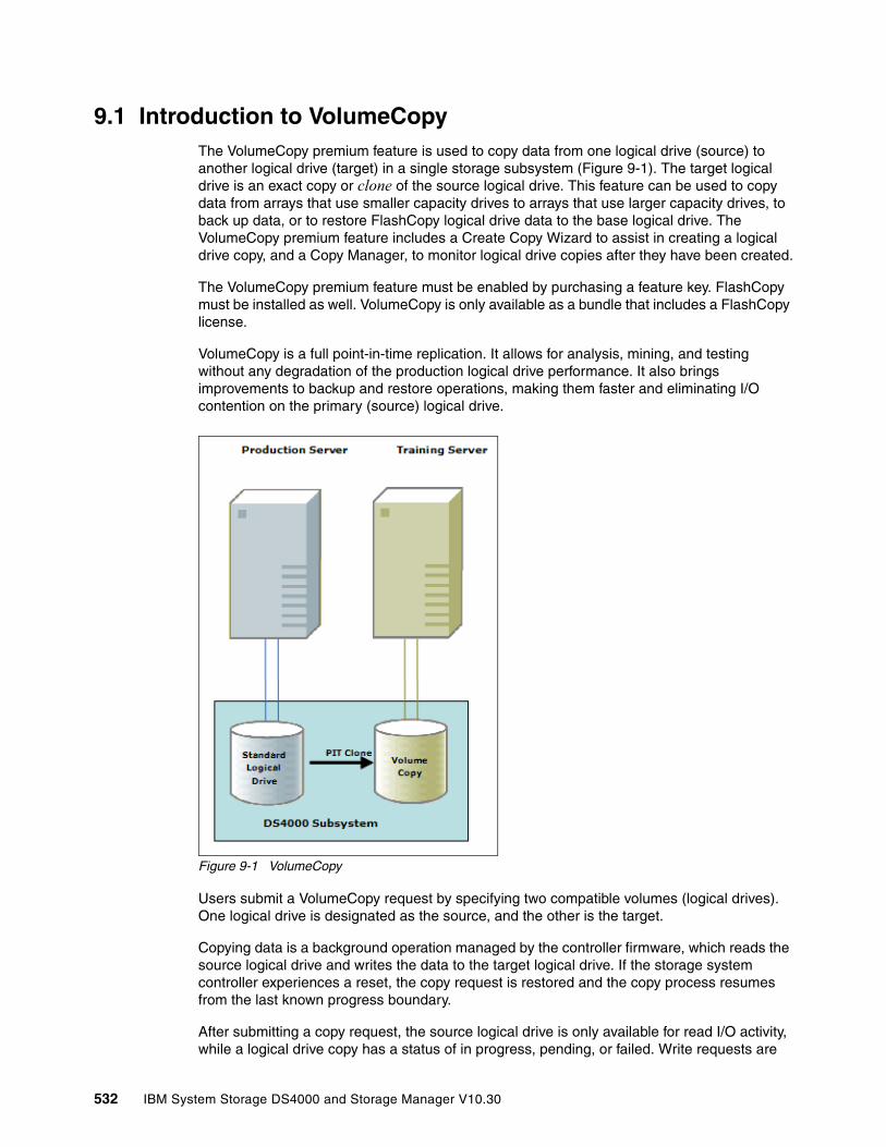
9.1 Introduction to VolumeCopyThe VolumeCopy premium feature is used to copy data from one logical drive (source) to another logical drive (target) in a single storage subsystem (Figure 9-1). The target logical drive is an exact copy or clone of the source logical drive. This feature can be used to copy data from arrays that use smaller capacity drives to arrays that use larger capacity drives, to back up data, or to restore FlashCopy logical drive data to the base logical drive. The VolumeCopy premium feature includes a Create Copy Wizard to assist in creating a logical drive copy, and a Copy Manager, to monitor logical drive copies after they have been created.
The VolumeCopy premium feature must be enabled by purchasing a feature key. FlashCopy must be installed as well. VolumeCopy is only available as a bundle that includes a FlashCopy license.
VolumeCopy is a full point-in-time replication. It allows for analysis, mining, and testing without any degradation of the production logical drive performance. It also brings improvements to backup and restore operations, making them faster and eliminating I/O contention on the primary (source) logical drive.
Figure 9-1 VolumeCopy
Users submit a VolumeCopy request by specifying two compatible volumes (logical drives). One logical drive is designated as the source, and the other is the target.
Copying data is a background operation managed by the controller firmware, which reads the source logical drive and writes the data to the target logical drive. If the storage system controller experiences a reset, the copy request is restored and the copy process resumes from the last known progress boundary.
After submitting a copy request, the source logical drive is only available for read I/O activity, while a logical drive copy has a status of in progress, pending, or failed. Write requests are
532 IBM System Storage DS4000 and Storage Manager V10.30
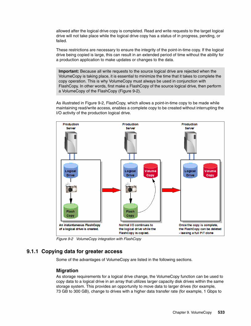
allowed after the logical drive copy is completed. Read and write requests to the target logical drive will not take place while the logical drive copy has a status of in progress, pending, or failed.
These restrictions are necessary to ensure the integrity of the point-in-time copy. If the logical drive being copied is large, this can result in an extended period of time without the ability for a production application to make updates or changes to the data.
As illustrated in Figure 9-2, FlashCopy, which allows a point-in-time copy to be made while maintaining read/write access, enables a complete copy to be created without interrupting the I/O activity of the production logical drive.
Figure 9-2 VolumeCopy integration with FlashCopy
9.1.1 Copying data for greater accessSome of the advantages of VolumeCopy are listed in the following sections.
MigrationAs storage requirements for a logical drive change, the VolumeCopy function can be used to copy data to a logical drive in an array that utilizes larger capacity disk drives within the same storage system. This provides an opportunity to move data to larger drives (for example, 73 GB to 300 GB), change to drives with a higher data transfer rate (for example, 1 Gbps to
Important: Because all write requests to the source logical drive are rejected when the VolumeCopy is taking place, it is essential to minimize the time that it takes to complete the copy operation. This is why VolumeCopy must always be used in conjunction with FlashCopy. In other words, first make a FlashCopy of the source logical drive, then perform a VolumeCopy of the FlashCopy (Figure 9-2).
Chapter 9. VolumeCopy 533
2 Gbps or to 4 Gbps), or to change to drives using different technologies (from SATA to FC) for higher performance and reliability.
Backing up dataThe VolumeCopy function allows you to create a backup of a logical drive by copying data from one logical drive to another logical drive in the same storage system. The target logical drive can be used as a backup of the source logical drive, for system testing, or to do a backup to another device, such as a tape drive.
Restoring FlashCopy logical drive data to the base logical driveIf you must restore data to the base logical drive from its associated FlashCopy logical drive, the VolumeCopy function can be used to copy the data from the FlashCopy logical drive to the base logical drive. You can create a VolumeCopy of the data on the FlashCopy logical drive, then copy the data to the base logical drive.
9.1.2 Creating and managing VolumeCopy copiesVolumeCopy can be managed using the IBM DS4000 Storage Manager graphical interface or using the relevant command-line interface commands and scripts.
Create copy wizardThe create copy wizard guides you through the process of selecting a source logical drive from a list of available logical drives, selecting a target logical drive from a list of available logical drives, and setting the copy priority for the VolumeCopy. When you have completed the wizard dialogs, the VolumeCopy starts and data is read from the source logical drive and written to the target logical drive.
Operation in progress icons are displayed on the source logical drive and target logical drive while the VolumeCopy has a status of in progress or pending. For a detailed description of how to use the create copy Wizard, refer to 9.2, “VolumeCopy: Step-by-step” on page 538.
Refer to “Restrictions” on page 536 for more information about source logical drives and target logical drives.
Copy ManagerAfter you create a VolumeCopy with the create copy wizard, the VolumeCopy can be monitored and managed through the Copy Manager. From the Copy Manager, a VolumeCopy can be recopied, stopped, or removed. Its attributes, including the copy priority and the target logical drive read-only attribute, can be modified. The status of a VolumeCopy can be viewed in the Copy Manager. Also, if you must determine what logical drives are involved in a VolumeCopy, use the Copy Manager or the storage system profile. Brief descriptions of the functions of the Copy Manager are as follows:
� Set the target logical drive read-only attribute.
This option determines how read and write requests to the target logical drive are handled after a VolumeCopy is complete or if the VolumeCopy fails prior to completing. After the VolumeCopy is complete, the target logical drive automatically becomes read-only to hosts, and write requests to the target logical drive will not take place. When the read-only attribute for a target logical drive is enabled, a lock icon is displayed in the target logical drive column of the Copy Manager. The read-only attribute can be changed in the Copy Manager only after the VolumeCopy is completed.
534 IBM System Storage DS4000 and Storage Manager V10.30
� Re-copy a logical drive.
This option allows you to create a new VolumeCopy of the data on a selected copy pair. Re-copy can be used to create a new VolumeCopy from the beginning if the original VolumeCopy failed or was stopped. You can also use this option for backup purposes. For instance, if the data on the source logical drive changes, you can use re-copy to duplicate any new data to the target logical drive.
� Stop a VolumeCopy.
This function can stop a VolumeCopy with a status of pending, in progress, or failed. If you decide not to use a particular logical drive as a source logical drive or target logical drive, you can use this option to stop the VolumeCopy before it completes. The logical drives can then be used in a new VolumeCopy. Using this function on a VolumeCopy with a status of failed clears the needs-attention condition on the storage system.
� Change copy priority.
This function is used to balance I/O activity with VolumeCopy activity on a storage system. You can set the copy priority to a rate that will have the least impact on I/O activity. There are five copy priority rates available:
– Lowest– Low– Medium– High– Highest
If the copy priority is set at the lowest rate, I/O activity is prioritized and the VolumeCopy takes longer. If the copy priority is set to the highest priority rate, the VolumeCopy is prioritized, but I/O activity for the storage system can be affected.
� Remove Copy Pairs.
This option allows you to remove a VolumeCopy from the Copy Manager. After the VolumeCopy is removed, the source logical drive and target logical drive can be used in a new VolumeCopy. When the VolumeCopy is removed, the read-only attribute for the target logical drive is also removed.
For a full description of using the Copy Manager refer to 9.2, “VolumeCopy: Step-by-step” on page 538.
9.1.3 Understanding VolumeCopyA VolumeCopy fails all FlashCopy logical drives associated with the target logical drive if any exist. If you select a base logical drive of a FlashCopy logical drive, you must disable all FlashCopy logical drives associated with the base logical drive before you can select it as a target logical drive. Otherwise, the base logical drive cannot be used as a target logical drive.
If there are eight logical drive copies with a status of in progress, any subsequent VolumeCopy will have a status of pending until one of the eight logical drive copies completes.
VolumeCopy and modification operationsIf a modification operation is running on a source logical drive or target logical drive, and the VolumeCopy has a status of in progress, pending, or failed, then the VolumeCopy will not take
Important: A VolumeCopy overwrites data on the target logical drive and automatically makes the target logical drive read only to hosts.
Chapter 9. VolumeCopy 535
place. If a modification operation is running on a source logical drive or target logical drive after a VolumeCopy has been created, then the modification operation must complete before the VolumeCopy can start. If a VolumeCopy has a status of in progress, then any modification operation will not take place.
Modification operations include:
� Defragmenting an array
� Copy back to a drive that is part of an array
� Initialization of a logical drive
� Dynamic segment sizing (DSS) change for a logical drive
� Dynamic reconstruction rate (DRR) of a drive that is part of an array
� Dynamic RAID level migration (DRM) change for an array
� Dynamic capacity expansion (DCE), to increase an array's capacity using unconfigured capacity (in the form of unused drives)
� Dynamic logical drive expansion (DVE), to increase a logical drive capacity using free capacity available on the array of the standard or FlashCopy repository logical drive
Failed VolumeCopyA VolumeCopy can fail because of a read error from the source logical drive, a write error to the target logical drive, or because of a failure on the storage system that affects the source logical drive or target logical drive (such as a Remote Mirror role reversal). A critical event is logged in the event log when the VolumeCopy fails, and a needs-attention icon is displayed in the Enterprise Management window. While a VolumeCopy has this status, the host has read-only access to the source logical drive, and read and write requests to the target logical drive do not take place until the failure is corrected by using the Recovery Guru.
Preferred controller ownershipDuring a VolumeCopy, the same controller must own both the source logical drive and the target logical drive. If both logical drives do not have the same preferred controller when the VolumeCopy starts, the ownership of the target logical drive is automatically transferred to the preferred controller of the source logical drive. When the VolumeCopy is completed or is stopped, ownership of the target logical drive is restored to its preferred controller. If ownership of the source logical drive is changed during the VolumeCopy, ownership of the target logical drive is also changed.
Failed controllerController ownership must be manually changed to the alternate controller to allow the VolumeCopy to complete under the following conditions: If a VolumeCopy has a status of in progress and its preferred controller fails, the ownership transfer does not occur automatically in the failover.
RestrictionsThe following restrictions apply to the source logical drive, target logical drive, and storage system:
� The source logical drive is available for read I/O activity only while a VolumeCopy has a status of in progress or pending. Write requests are allowed after the VolumeCopy is completed.
Tip: In practice, VolumeCopy must only be used with FlashCopy, in order to shorten the source logical driver read-only period of time.
536 IBM System Storage DS4000 and Storage Manager V10.30

� A logical drive can be used as a target logical drive in only one VolumeCopy at a time.
� The maximum allowable number of logical drive copies per storage system is dependent upon the number of target logical drives available on your storage system.
� A storage system can have up to eight VolumeCopies running at any given time.
� The target logical drive capacity must be equal to or greater than the source logical drive capacity.
� A source logical drive can be a standard logical drive, FlashCopy logical drive, FlashCopy base logical drive, or a Remote Mirror primary logical drive.
� A target logical drive can be a standard logical drive, a base logical drive of a disabled or failed FlashCopy logical drive, or a Remote Mirror primary logical drive.
Logical drives that have the following statuses cannot be used as a source logical drive or target logical drive:
� A logical drive that is reserved by the host cannot be selected as a source or target logical drive.
� A logical drive that is in a modification operation.
� A logical drive that is the source logical drive or target logical drive in another VolumeCopy with a status of failed, in progress, or pending.
� A logical drive with a status of failed.
� A logical drive with a status of degraded.
9.1.4 VolumeCopy and performance considerationsDuring a VolumeCopy, data is read from the source logical drive and written to the target logical drive in the same storage system. Because the VolumeCopy diverts controller process resources from I/O activity, it can affect I/O activity on the storage system. The copy priority defines how much processing time is allocated for a VolumeCopy versus I/O activity.
VolumeCopy priority ratesSeveral factors contribute to system performance, including I/O activity, logical drive RAID level, logical drive configuration (number of drives in the array or cache parameters), and logical drive type (FlashCopy logical drives can take more time to copy than standard logical drives).
You can select the copy priority while you are creating a new VolumeCopy, or you can change it later using the Copy Manager. The following copy priority rates are available:
� Lowest� Low� Medium� High� Highest
Important: If you choose a base logical drive of a FlashCopy logical drive as your target logical drive, you must disable all FlashCopy logical drives associated with the base logical drive before you can select it as a target logical drive. Otherwise, the base logical drive cannot be used as a target logical drive.
Chapter 9. VolumeCopy 537

Viewing the progress of a copy operationThe progress of the VolumeCopy is displayed in the status bar at the bottom-right of the Copy Manager. The status bar shows an estimate of the time remaining for the VolumeCopy to complete. You can view the progress of a VolumeCopy in the Copy Manager only when a VolumeCopy has a status of in progress.
9.2 VolumeCopy: Step-by-stepThis section presents an easy-to-follow, step-by-step procedural guide to common administration tasks for a VolumeCopy. The tasks that are covered include:
� Checking the status of the VolumeCopy premium feature� Creating a VolumeCopy pair� Viewing logical copy drive properties� Using the Copy Manager� Changing the copy priority� Stopping a logical copy� Re-copying a logical copy drive� Setting the target logical copy drive read-only attributes� Removing logical copy pairs� Viewing the storage subsystem profile
9.2.1 Checking the status of the VolumeCopy premium featureUse this procedure to view a list of premium features on the storage system and to verify that the VolumeCopy feature has been enabled. It requires you to:
1. Check the premium options list.2. View the VolumeCopy icon to verify that the feature has been enabled.
Checking the premium optionTo check the premium option:
1. From the Subsystem Management window, click Storage Subsystem → Premium Features → List. Or you can right-click and select Premium Features → List.
The List Premium Features dialog opens. It lists the following items:
– Premium features enabled on the storage system– Feature enable identifier
2. Verify that VolumeCopy Logical Drives indicates enabled. If you identify that the VolumeCopy feature is not enabled, refer to 12.2, “Handling premium features” on page 689, for information about how to enable a premium feature.
3. Click Close to close the dialog.
Note: The Lowest priority rate supports I/O activity, but the VolumeCopy takes longer. The highest priority rate supports the VolumeCopy, but I/O activity might be affected. Remember, however, that VolumeCopy should always be used in conjunction with FlashCopy.
Note: If you receive a Premium Features - Out of Compliance error message during a management session, use the Recovery Guru to resolve the problem.
538 IBM System Storage DS4000 and Storage Manager V10.30

Viewing the VolumeCopy iconCheck the status of the VolumeCopy feature icon at the bottom left of the Subsystem Management window, shown as disabled in Figure 9-3 and enabled in Figure 9-4.
Figure 9-3 Logical Copy Feature icon: Disabled
Figure 9-4 Logical Copy Feature icon: Enabled
9.2.2 Creating a VolumeCopy pairThis section describes in detail how to create VolumeCopies using the create copy wizard from the Subsystem Management console. The wizard guides you through the VolumeCopy creation process.
Important: Remember that we recommend first making a FlashCopy of the logical drive and then using the FlashCopy as the source of the VolumeCopy.
Chapter 9. VolumeCopy 539

To launch the create copy wizard:
1. Stop all I/O activity to the source logical drive and target logical drive.
2. Unmount any file systems on the source logical drive and target logical drive.
3. Select the source logical drive in the logical view of the Subsystem Management window.
4. Select either the Logical Drive → VolumeCopy → Create pull-down menu option or Create Copy from the right-mouse pop-up menu (Figure 9-5).
Figure 9-5 Launching create copy wizard from Subsystem Management window
The create copy wizard Introduction dialog is displayed. The logical drive that you selected to start the wizard is highlighted in the table if it is a valid source logical drive. Follow the directions on each wizard dialog and select Next when you are ready to move to the next wizard dialog.
Operation in progress icons are displayed on the source logical drive and target logical drive while the VolumeCopy has a status of in progress or pending.
Note: Each wizard dialog has context-sensitive help. Select Help to receive help applicable to that particular dialog.
Right Mouse clickPop-up
Pull Down Menu
540 IBM System Storage DS4000 and Storage Manager V10.30
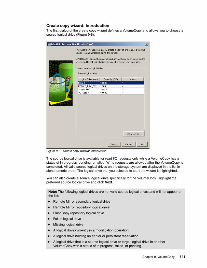
Create copy wizard: IntroductionThe first dialog of the create copy wizard defines a VolumeCopy and allows you to choose a source logical drive (Figure 9-6).
Figure 9-6 Create copy wizard: Introduction
The source logical drive is available for read I/O requests only while a VolumeCopy has a status of in progress, pending, or failed. Write requests are allowed after the VolumeCopy is completed. All valid source logical drives on the storage system are displayed in the list in alphanumeric order. The logical drive that you selected to start the wizard is highlighted.
You can also create a source logical drive specifically for the VolumeCopy. Highlight the preferred source logical drive and click Next.
Note: The following logical drives are not valid source logical drives and will not appear on the list:
� Remote Mirror secondary logical drive
� Remote Mirror repository logical drive
� FlashCopy repository logical drive
� Failed logical drive
� Missing logical drive
� A logical drive currently in a modification operation
� A logical drive holding an earlier or persistent reservation
� A logical drive that is a source logical drive or target logical drive in another VolumeCopy with a status of in progress, failed, or pending
Chapter 9. VolumeCopy 541
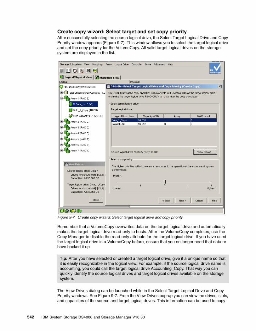
Create copy wizard: Select target and set copy priorityAfter successfully selecting the source logical drive, the Select Target Logical Drive and Copy Priority window appears (Figure 9-7). This window allows you to select the target logical drive and set the copy priority for the VolumeCopy. All valid target logical drives on the storage system are displayed in the list.
Figure 9-7 Create copy wizard: Select target logical drive and copy priority
Remember that a VolumeCopy overwrites data on the target logical drive and automatically makes the target logical drive read-only to hosts. After the VolumeCopy completes, use the Copy Manager to disable the read-only attribute for the target logical drive. If you have used the target logical drive in a VolumeCopy before, ensure that you no longer need that data or have backed it up.
The View Drives dialog can be launched while in the Select Target Logical Drive and Copy Priority windows. See Figure 9-7. From the View Drives pop-up you can view the drives, slots, and capacities of the source and target logical drives. This information can be used to copy
Tip: After you have selected or created a target logical drive, give it a unique name so that it is easily recognizable in the logical view. For example, if the source logical drive name is accounting, you could call the target logical drive Accounting_Copy. That way you can quickly identify the source logical drives and target logical drives available on the storage system.
542 IBM System Storage DS4000 and Storage Manager V10.30
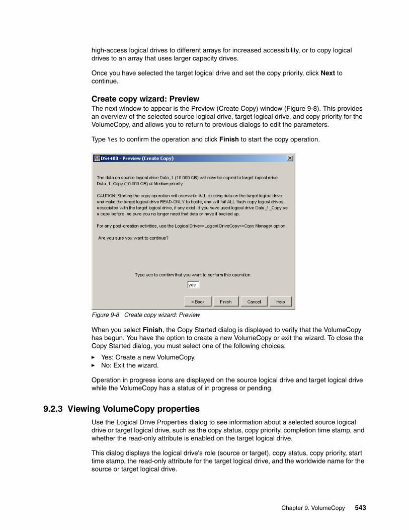
high-access logical drives to different arrays for increased accessibility, or to copy logical drives to an array that uses larger capacity drives.
Once you have selected the target logical drive and set the copy priority, click Next to continue.
Create copy wizard: PreviewThe next window to appear is the Preview (Create Copy) window (Figure 9-8). This provides an overview of the selected source logical drive, target logical drive, and copy priority for the VolumeCopy, and allows you to return to previous dialogs to edit the parameters.
Type Yes to confirm the operation and click Finish to start the copy operation.
Figure 9-8 Create copy wizard: Preview
When you select Finish, the Copy Started dialog is displayed to verify that the VolumeCopy has begun. You have the option to create a new VolumeCopy or exit the wizard. To close the Copy Started dialog, you must select one of the following choices:
� Yes: Create a new VolumeCopy.� No: Exit the wizard.
Operation in progress icons are displayed on the source logical drive and target logical drive while the VolumeCopy has a status of in progress or pending.
9.2.3 Viewing VolumeCopy propertiesUse the Logical Drive Properties dialog to see information about a selected source logical drive or target logical drive, such as the copy status, copy priority, completion time stamp, and whether the read-only attribute is enabled on the target logical drive.
This dialog displays the logical drive's role (source or target), copy status, copy priority, start time stamp, the read-only attribute for the target logical drive, and the worldwide name for the source or target logical drive.
Chapter 9. VolumeCopy 543

You can only view the progress of a VolumeCopy with a status of in progress. To view VolumeCopy properties:
1. Select the source logical drive or target logical drive in the logical view.
2. Select either the Logical Drive → Properties pull-down menu option or Properties from the right-mouse pop-up menu (Figure 9-9).
Figure 9-9 Logical Drive Properties: Base tab
544 IBM System Storage DS4000 and Storage Manager V10.30
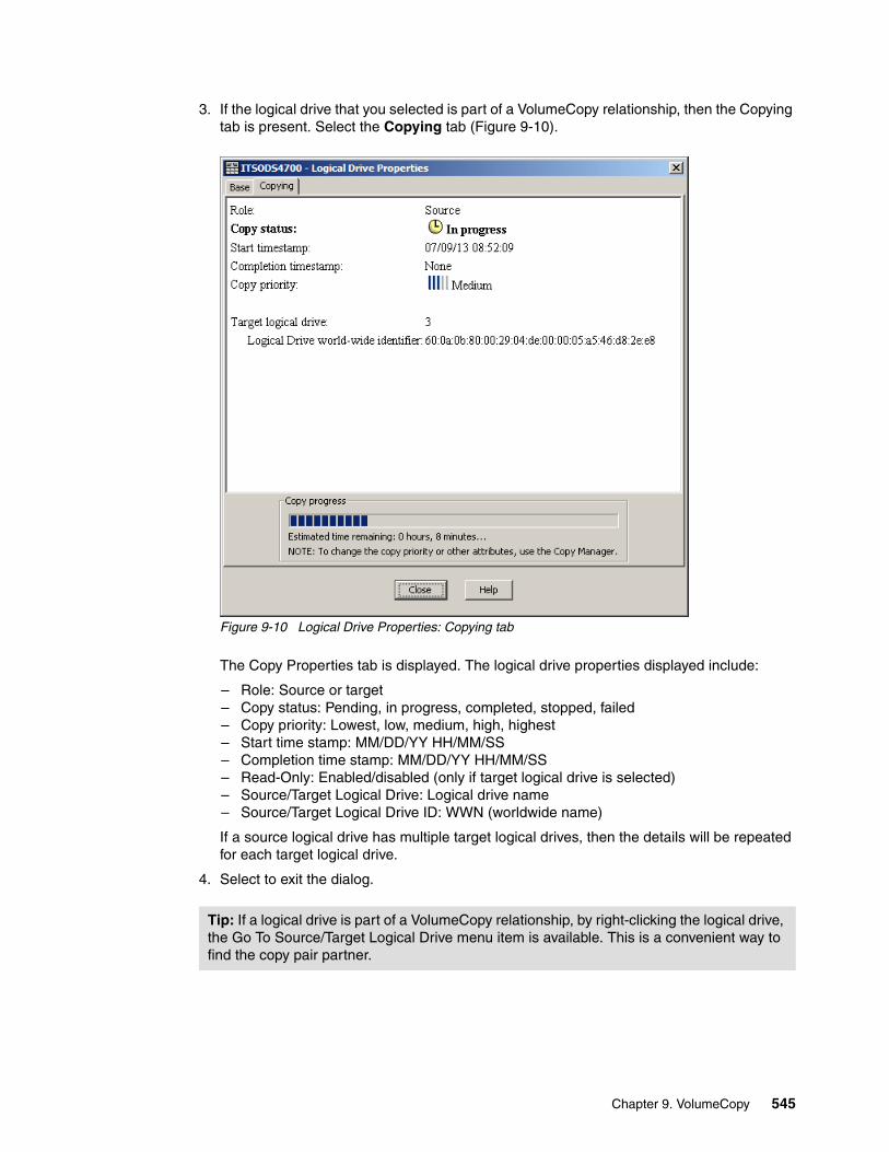
3. If the logical drive that you selected is part of a VolumeCopy relationship, then the Copying tab is present. Select the Copying tab (Figure 9-10).
Figure 9-10 Logical Drive Properties: Copying tab
The Copy Properties tab is displayed. The logical drive properties displayed include:
– Role: Source or target– Copy status: Pending, in progress, completed, stopped, failed– Copy priority: Lowest, low, medium, high, highest– Start time stamp: MM/DD/YY HH/MM/SS– Completion time stamp: MM/DD/YY HH/MM/SS– Read-Only: Enabled/disabled (only if target logical drive is selected)– Source/Target Logical Drive: Logical drive name– Source/Target Logical Drive ID: WWN (worldwide name)
If a source logical drive has multiple target logical drives, then the details will be repeated for each target logical drive.
4. Select to exit the dialog.
Tip: If a logical drive is part of a VolumeCopy relationship, by right-clicking the logical drive, the Go To Source/Target Logical Drive menu item is available. This is a convenient way to find the copy pair partner.
Chapter 9. VolumeCopy 545

9.2.4 Using the Copy ManagerThe Copy Manager dialog is used to monitor the progress of a VolumeCopy and perform the following tasks for all logical drive copies on the storage system:
� Recopy a logical drive.� Change VolumeCopy priority.� Set the read-only attribute for a target logical drive.� Stop VolumeCopy.� Remove copy pairs.
Information is displayed for all of the logical drive copies on the storage system, including the source logical drive, the target logical drive, the status of the VolumeCopy, a time stamp for any completed copies, and the VolumeCopy priority assigned to the VolumeCopy. If a target logical drive is read-only to hosts, a lock icon is displayed in the target logical drive column. You can view the progress of a VolumeCopy in the status column.
The progress of the VolumeCopy is displayed in the status bar at the bottom-right of the Copy Manager. The status bar shows an estimate of the time remaining for the VolumeCopy to complete. You can view the progress of a VolumeCopy in the Copy Manager only when a VolumeCopy has a status of in progress.
The procedure to launch the Copy Manager window is:
1. Select either the Logical Drive → VolumeCopy → Copy Manager pull-down menu option or Copy Manager from the right-mouse pop-up menu (Figure 9-11).
Figure 9-11 Launching the Copy Manager
546 IBM System Storage DS4000 and Storage Manager V10.30
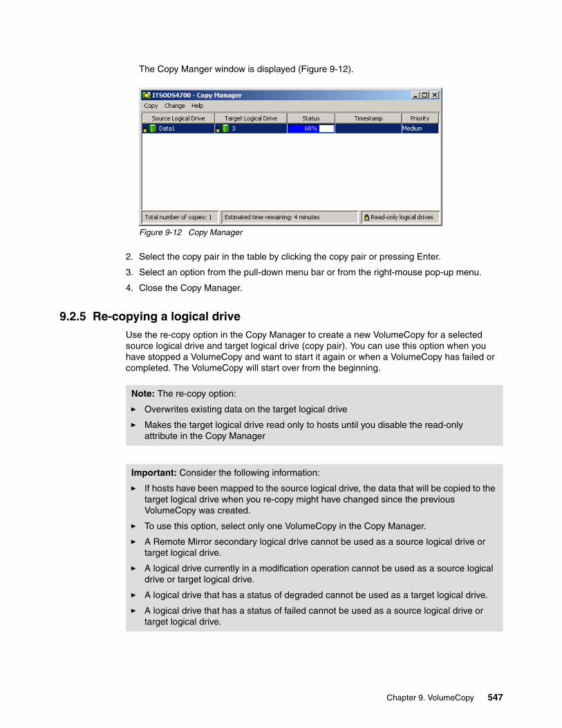
The Copy Manger window is displayed (Figure 9-12).
Figure 9-12 Copy Manager
2. Select the copy pair in the table by clicking the copy pair or pressing Enter.
3. Select an option from the pull-down menu bar or from the right-mouse pop-up menu.
4. Close the Copy Manager.
9.2.5 Re-copying a logical driveUse the re-copy option in the Copy Manager to create a new VolumeCopy for a selected source logical drive and target logical drive (copy pair). You can use this option when you have stopped a VolumeCopy and want to start it again or when a VolumeCopy has failed or completed. The VolumeCopy will start over from the beginning.
Note: The re-copy option:
� Overwrites existing data on the target logical drive
� Makes the target logical drive read only to hosts until you disable the read-only attribute in the Copy Manager
Important: Consider the following information:
� If hosts have been mapped to the source logical drive, the data that will be copied to the target logical drive when you re-copy might have changed since the previous VolumeCopy was created.
� To use this option, select only one VolumeCopy in the Copy Manager.
� A Remote Mirror secondary logical drive cannot be used as a source logical drive or target logical drive.
� A logical drive currently in a modification operation cannot be used as a source logical drive or target logical drive.
� A logical drive that has a status of degraded cannot be used as a target logical drive.
� A logical drive that has a status of failed cannot be used as a source logical drive or target logical drive.
Chapter 9. VolumeCopy 547
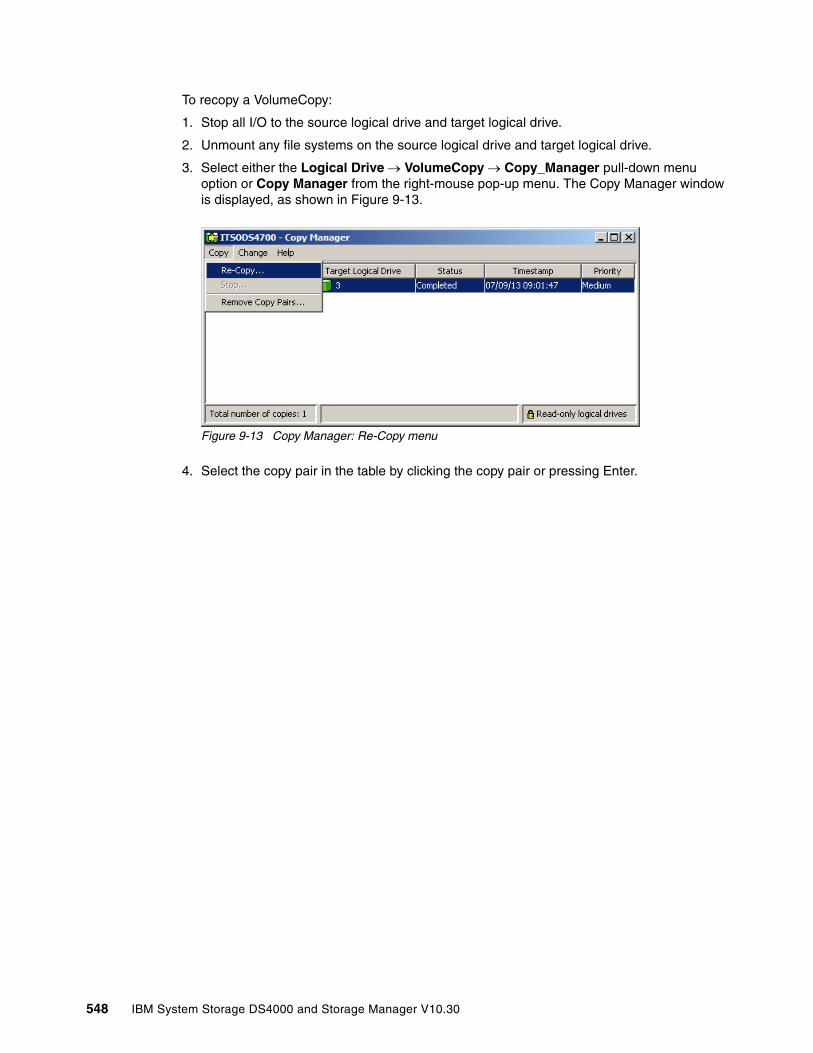
To recopy a VolumeCopy:
1. Stop all I/O to the source logical drive and target logical drive.
2. Unmount any file systems on the source logical drive and target logical drive.
3. Select either the Logical Drive → VolumeCopy → Copy_Manager pull-down menu option or Copy Manager from the right-mouse pop-up menu. The Copy Manager window is displayed, as shown in Figure 9-13.
Figure 9-13 Copy Manager: Re-Copy menu
4. Select the copy pair in the table by clicking the copy pair or pressing Enter.
548 IBM System Storage DS4000 and Storage Manager V10.30

5. Select either the Copy → Re-Copy pull-down menu option or Re-Copy from the right-mouse pop-up menu. The Re-Copy dialog is displayed (Figure 9-14).
Figure 9-14 Re-copy window
6. Set the copy priority.
7. Type Yes and select OK. The VolumeCopy begins.
8. Close the Copy Manager. Operation in progress icons are displayed on the source logical drive and target logical drive while the VolumeCopy has a status of in progress or pending.
Note: There are five copy priority rates available:
� Lowest � Low� Medium� High� Highest
If the copy priority is set at the lowest rate, I/O activity is prioritized and the VolumeCopy takes longer. If the copy priority is set to the highest priority rate, the VolumeCopy is prioritized, but I/O activity for the storage system might be affected.
Note: You can view the progress of a VolumeCopy in the Copy Manager only when a VolumeCopy has a status of in progress.
Chapter 9. VolumeCopy 549

9.2.6 Changing VolumeCopy priority
Use this option in the Copy Manager to select the rate at which a VolumeCopy completes for a selected copy pair. You can change the copy priority for a copy pair before the VolumeCopy begins, while the VolumeCopy has a status of in progress, or after the VolumeCopy has completed (for a recopy). Change to VolumeCopy priority as follows:
1. Select either the Logical Drive → VolumeCopy → Copy Manager pull-down menu option or Copy Manager from the right-mouse pop-up menu. The Copy Manager dialog is displayed.
2. Select one or more copy pairs in the table. You can select more than one copy pair by pressing Ctrl + the left mouse button.
3. Select Change → Copy Priority from the pull-down menu option or the right-mouse pop-up menu (Figure 9-15).
Figure 9-15 Select Copy Priority from Copy Manager
The Change Copy Priority window is displayed (Figure 9-16).
4. In the copy priority section, use the slider bar to select the appropriate copy priority, depending on your system performance needs.
5. Select OK. The copy priority for the selected copy pair is changed.
6. Close the Copy Manager.
Figure 9-16 Change Copy Priority
550 IBM System Storage DS4000 and Storage Manager V10.30

9.2.7 Setting the read-only attribute for a target logical driveRead and write requests to the target logical drive will not take place while the VolumeCopy has a status of pending or in progress, or if the VolumeCopy fails prior to completing.
After the VolumeCopy has completed, the target logical drive automatically becomes read-only to hosts. Figure 9-17 shows target logical drives with the read-only attribute set to enabled (small lock icon next to logical drive name).
Figure 9-17 Copy Manager showing read-only attribute icon enabled
You might want to keep this attribute enabled in order to preserve the data on the target logical drive, for example, if you are using the target logical drive for backup purposes, if you are copying data from one array to a larger array for greater accessibility, or if you are using the data on the target logical drive to copy back to the base logical drive of a disabled or failed FlashCopy logical drive.
If you decide not to preserve the data on the target logical drive after the VolumeCopy is completed, use the Copy Manager to disable the read-only attribute for the target logical drive.
How to disable the read-only attributeTo disable the read-only attribute:
1. Select either the Logical Drive → VolumeCopy → Copy_Manager pull-down menu option or Copy Manager from the right-mouse pop-up menu.
2. Select one or more copy pairs in the table. You can select more than one copy pair by pressing Ctrl + the left mouse button.
Note: There are five copy priority rates available (lowest, low, medium, high, and highest). If the copy priority is set at the lowest rate, I/O activity is prioritized and the VolumeCopy will take longer. If the copy priority is set to the highest priority rate, the VolumeCopy is prioritized, but I/O activity for the storage system might be affected.
Read-Only Attributeset to Enabled
Chapter 9. VolumeCopy 551

3. Select either the Change → Target Logical Drive Permissions → Disable Read-Only pull-down menu option or Disable Read-Only from the right-mouse pop-up menu (Figure 9-18).
Figure 9-18 Copy Manager: Disable Read-Only menu
The read-only attribute is disabled on the selected target logical drives. Write requests to the target logical drive are permitted. Figure 9-19 shows target logical drives with the read-only attribute set to enabled (small lock icon next to logical drive name has been removed).
Figure 9-19 Copy Manager showing read-only attribute icon disabled
4. Close the Copy Manager.
9.2.8 Stopping VolumeCopyThis option in the Copy Manager is used to stop a VolumeCopy with a status of in progress, pending, or failed.
Read-Only Attributeset to Disabled
Note: Using this option on a VolumeCopy with a status of failed clears the needs-attention condition on a storage system.
552 IBM System Storage DS4000 and Storage Manager V10.30

To stop a VolumeCopy:
1. Select either the Logical Drive → VolumeCopy → Copy Manager pull-down menu option or Copy Manager in the right-mouse pop-up menu to display the Copy Manager.
2. Highlight the copy pair in the table by clicking the copy pair.
3. Select either the Copy → Stop pull-down menu option or Stop Copy from the right-mouse pop-up menu (Figure 9-20).
Figure 9-20 Copy Manager: Stop copy menu
4. The Stop Copy dialog is displayed (Figure 9-21). Read the information. Click Yes to proceed. The VolumeCopy is stopped.
Figure 9-21 Stop Copy dialog
5. Close the Copy Manager.
9.2.9 Removing copy pairsUse this option to remove one or more logical drive copies from the Copy Manager. Any VolumeCopy-related information for the source and target logical drive is removed from the
Important: Consider the following information:
� To use this option, select only one copy pair in the Copy Manager.
� When the VolumeCopy is stopped, all mapped hosts will have write access to the source logical drive. If data is written to the source logical drive, the data on the target logical drive will no longer match the data on the source logical drive.
Chapter 9. VolumeCopy 553
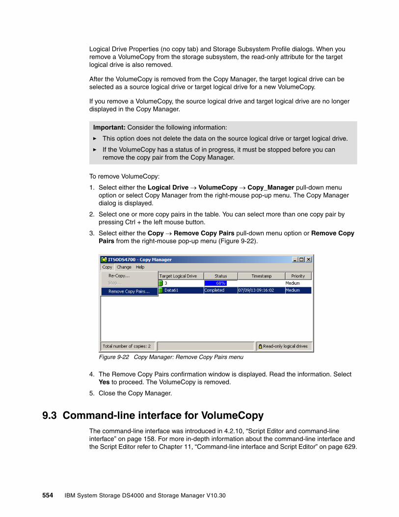
Logical Drive Properties (no copy tab) and Storage Subsystem Profile dialogs. When you remove a VolumeCopy from the storage subsystem, the read-only attribute for the target logical drive is also removed.
After the VolumeCopy is removed from the Copy Manager, the target logical drive can be selected as a source logical drive or target logical drive for a new VolumeCopy.
If you remove a VolumeCopy, the source logical drive and target logical drive are no longer displayed in the Copy Manager.
To remove VolumeCopy:
1. Select either the Logical Drive → VolumeCopy → Copy_Manager pull-down menu option or select Copy Manager from the right-mouse pop-up menu. The Copy Manager dialog is displayed.
2. Select one or more copy pairs in the table. You can select more than one copy pair by pressing Ctrl + the left mouse button.
3. Select either the Copy → Remove Copy Pairs pull-down menu option or Remove Copy Pairs from the right-mouse pop-up menu (Figure 9-22).
Figure 9-22 Copy Manager: Remove Copy Pairs menu
4. The Remove Copy Pairs confirmation window is displayed. Read the information. Select Yes to proceed. The VolumeCopy is removed.
5. Close the Copy Manager.
9.3 Command-line interface for VolumeCopyThe command-line interface was introduced in 4.2.10, “Script Editor and command-line interface” on page 158. For more in-depth information about the command-line interface and the Script Editor refer to Chapter 11, “Command-line interface and Script Editor” on page 629.
Important: Consider the following information:
� This option does not delete the data on the source logical drive or target logical drive.
� If the VolumeCopy has a status of in progress, it must be stopped before you can remove the copy pair from the Copy Manager.
554 IBM System Storage DS4000 and Storage Manager V10.30
This section discusses commands that are specific to the VolumeCopy function:
� create logicalDriveCopy� show logicalDriveCopy� stop logicalDriveCopy� set logicalDriveCopy� recopy logicalDriveCopy� remove logicalDriveCopy
9.3.1 The create logicalDriveCopy command (CLI)The create logicalDriveCopy command lets you create a VolumeCopy. Specify the source logical drive, the target logical drive, and the copy priority.
In Example 9-1 you create a VolumeCopy, specifying logical drive data 2 as the source logical drive and data 1 as the target logical drive, with a copy priority of low.
Example 9-1 create logicalDriveCopy
SMcli 10.1.1.1 10.1.1.2 -c "create logicalDriveCopy source=\"Data 2\" target=\"Data 1\" copyPriority=low;"
9.3.2 The show logicalDriveCopy command (CLI)The show logicalDriveCopy command shows data about all VolumeCopy pairs on the storage system or data about a specific VolumeCopy pair if the source logical drive is specified.
In Example 9-2 the allLogicalDrives parameter is specified and data is displayed about all VolumeCopy pairs on the subsystem.
Example 9-2 show logicalDriveCopy
SMcli 10.1.1.1 10.1.1.2 -c "show logicalDriveCopy allLogicalDrives;"Performing syntax check...Syntax check complete.Executing script...Copy pair: Data 2 and Data 1 Copy status: In progress Completion timestamp: None Copy priority: Low Source volume: Data 2 Target volume: Data 1Script execution complete.SMcli completed successfully.
9.3.3 The stop logicalDriveCopy command (CLI)You can stop a VolumeCopy that is in progress, pending, or failed. This was discussed in 9.2.8, “Stopping VolumeCopy” on page 552.
To stop a copy pair you must specify the target and source logical drives names. Example 9-3 shows how to stop the copy pair that has a source of data 2 and a target of data 1.
Example 9-3 stop logicalDriveCopy
SMcli 10.1.1.1 10.1.1.2 -c "stop logicalDriveCopy target[\"Data 1\"] source[\"Data 2\"];"
Chapter 9. VolumeCopy 555
9.3.4 The set logicalDriveCopy command (CLI)The set logicalDriveCopy command allows you to change the copy priority of a copy pair, as discussed in 9.2.6, “Changing VolumeCopy priority” on page 550, and to set the read-only attribute of a copy pair, as was discussed in 9.2.7, “Setting the read-only attribute for a target logical drive” on page 551.
The name of the target and source logical drives of the copy pair must be specified.
In Example 9-4, you choose the copy pair consisting of target data 1 and source data 2. You change the original copy priority from low to highest and set the target read-only attribute to disabled.
Example 9-4 set logicalDriveCopy
SMcli 10.1.1.1 10.1.1.2 -c "set logicalDriveCopy target[\"Data 1\"] source[\"Data 2\"] copyPriority=highest targetReadOnlyEnabled=FALSE;"
9.3.5 The recopy logicalDriveCopy command (CLI)As discussed in 9.2.5, “Re-copying a logical drive” on page 547, the recopy logicalDriveCopy command can be used to reinitiate a logical drive copy operation using an existing logical drive copy pair.
In Example 9-5 you choose to reinitiate the logical drive copy operation for a pair consisting of target data 1 and source data 2.
Example 9-5 recopy logicalDriveCopy
SMcli 10.1.1.1 10.1.1.2 -c "recopy logicalDriveCopy target[\"Data 1\"] source[\"Data 2\"] copyPriority=highest targetReadOnlyEnabled=FALSE;"
9.3.6 The remove logicalDriveCopy command (CLI)Removing a copy pair relationship was discussed in 9.2.9, “Removing copy pairs” on page 553.
In Example 9-6 you remove the copy pair with the target of data 1 and the source of data 2.
Example 9-6 remove logicalDriveCopy
SMcli 10.1.1.1 10.1.1.2 -c "remove logicalDriveCopy target[\"Data 1\"] source[\"Data 2\"];"
As a result, the copy pair consisting of data 1 and data 2 is removed and these logical drives no longer have any association with each other.
556 IBM System Storage DS4000 and Storage Manager V10.30
Chapter 10. SAN boot with the DS4000
SAN boot is a technique that allows servers to utilize an operating system (OS) image installed on external storage area network (SAN) based storage to boot, rather than booting off their own local disk or direct-attached storage.
This chapter explains the concept of SAN boot and general prerequisites for using this technique. We then look at three particular implementations:
� IBM System p servers and AIX� IBM HS20 BladeCenter with Windows Server 2003/2008 � IBM System x servers with Redhat Enterprise Linux v4 Update 4 and v5 Update 2
10
© Copyright IBM Corp. 2004, 2005, 2006, 2007, 2008, 2009. All rights reserved. 557
10.1 Introduction to SAN bootSAN boot is a technique that allows servers to utilize an OS image installed on external SAN-based storage to boot, rather than booting off their own local disk or direct attached storage. Using SAN boot has some distinct advantages. They include:
� Interchangeable servers
By allowing boot images to be stored on the SAN, servers are no longer physically bound to their startup configurations. Therefore, if a server were to fail, it would be very easy to replace it with another generic server and resume operations with the exact same boot image from the SAN (only minor reconfiguration is required on the storage server). This quick interchange helps reduce downtime and increase host application availability.
� Provisioning for peak usage
Since the boot image is available on the SAN, it becomes easy to deploy additional servers to temporarily cope with high workloads.
� Centralized administration
SAN boot enables simpler management of the startup configurations of servers. Rather than needing to manage boot images at the distributed level at each individual server, SAN boot empowers administrators to manage and maintain the images at a central location in the SAN. This feature enhances storage personnel productivity and helps to streamline administration.
� Utilizes high-availability features of SAN storage
SANs and SAN-based storage are typically designed with high-availability in mind. SANs can utilize redundant features in the storage network fabric and RAID controllers to ensure that users do not incur any downtime. Most boot images that are located on local disk or direct-attached storage do not share the same protection. Using SAN boot allows boot images to take advantage of the inherent availability built in to most SANs. This helps to increase availability and reliability of the boot image and reduce downtime.
� Efficient disaster recovery process
Assuming that data (boot image and application data) is mirrored over the SAN between a primary site and a recovery site, servers can take over at the secondary site in the case that a disaster destroys servers at the primary site.
� Reduce overall cost of servers
Locating server boot images on external SAN storage eliminates the need for local disk in the server. This helps lower costs and allows SAN boot users to purchase servers at a reduced cost but still maintain the same functionality. In addition, SAN boot minimizes the IT costs through consolidation, which is realized by electricity, floor space cost savings, and by the benefits of centralized management.
SAN boot implementationSetting up and executing SAN boot requires steps on both the server and the storage sides of the SAN. We briefly look at an overview of how a user would implement SAN boot and how SAN boot works.
SAN boot relies on configuring servers with a virtual boot device. The virtual boot device enables the server to access the actual boot information stored on a specific LUN in the storage server. The virtual boot device is configured on the HBA in the server and thus assumes that the HBA BIOS supports booting from SAN-attached storage.
Multiple logical unit numbers (LUNs) can be configured with different boot images if there is a need for different operating systems images. Each LUN that contains a boot image for a
558 IBM System Storage DS4000 and Storage Manager V10.30
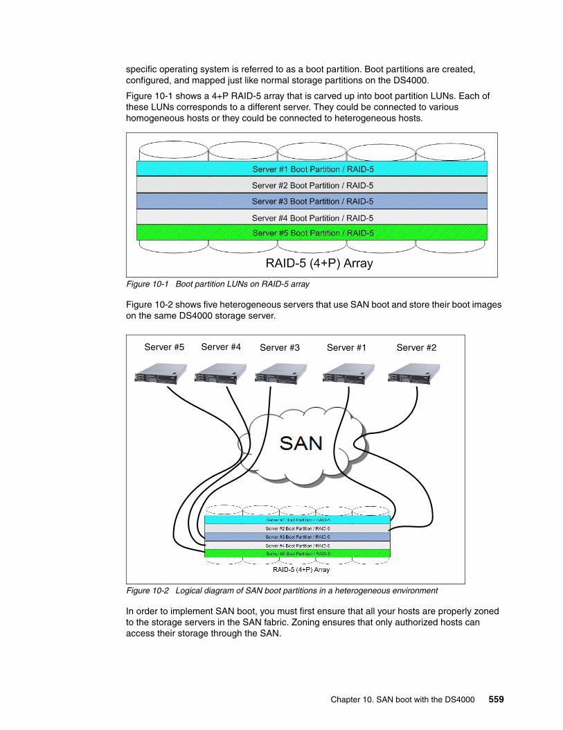
specific operating system is referred to as a boot partition. Boot partitions are created, configured, and mapped just like normal storage partitions on the DS4000.
Figure 10-1 shows a 4+P RAID-5 array that is carved up into boot partition LUNs. Each of these LUNs corresponds to a different server. They could be connected to various homogeneous hosts or they could be connected to heterogeneous hosts.
Figure 10-1 Boot partition LUNs on RAID-5 array
Figure 10-2 shows five heterogeneous servers that use SAN boot and store their boot images on the same DS4000 storage server.
Figure 10-2 Logical diagram of SAN boot partitions in a heterogeneous environment
In order to implement SAN boot, you must first ensure that all your hosts are properly zoned to the storage servers in the SAN fabric. Zoning ensures that only authorized hosts can access their storage through the SAN.
Server #5 Server #4 Server #3 Server #1 Server #2
Chapter 10. SAN boot with the DS4000 559

The host bus adapters (HBAs) and SAN-based storage server both require setup. The specific syntax and steps differ from vendor to vendor for HBAs, so we take more of a general approach when discussing setup with the DS4000. The general steps are as follows:
1. Establish the physical connectivity between the HBA, switch, and DS4000.
2. Provision LUNs on the DS4000 to handle host images. Create one LUN per boot image.
3. Select the proper port (HBA WWPN) and LUN from which the host should launch its boot.
4. Ensure that storage partitioning properly maps the appropriate LUN with the appropriate host server. It is also required that no other server can view that LUN.
5. Configure the HBAs of the hosts that are to utilize SAN boot to point toward the external storage unit. The HBA BIOS is what will tell the host that its boot image is now located on the SAN.
6. Install the boot image onto the appropriate LUN.
These general steps should serve as a guide to configuring SAN boot. It is important that you view more specific directions according to the particular host, HBA, fabric, and storage server that you might have.
10.2 AIX SAN boot for System p
This section contains a step-by-step illustration of SAN boot implementation for the IBM System p5® (formerly System p) in an AIX v5.3 environment. Similar steps can be followed for an AIX v6.1 environment. See Procedures for AIX 6.1 and DS4000 Interoperability for additional details:
http://www-03.ibm.com/systems/storage/disk/ds4000/interop-matrix.html
There are various possible implementations of SAN boot with AIX:
� To implement SAN boot on a system with an already installed AIX operating system, you can use the alt_disk_install system utility. Do this by mirroring of the rootvg volume to the SAN disk.
� To implement SAN boot for a new system, you can start the AIX installation from a bootable AIX CD install package or use the Network Installation Manager (NIM).
The methods known as Alt_disk_install and mirroring are simpler to implement than the more complete and more sophisticated method using the Network Installation Manager.
Important: When installing the operating system, you can only have one path to the storage device (LUN). Since servers are generally equipped with two HBAs, and because most DS4000 systems have two RAID controllers, you must isolate (disconnect) the second HBA and the second controller when installing the OS.
For Windows-based and Linux-based operating systems, the boot LUN must be assigned as LUN 0 when doing storage partitioning.
The boot LUN must be accessible only by the host that is utilizing it to boot. This can be achieved through the storage partitioning feature of the DS4000.
560 IBM System Storage DS4000 and Storage Manager V10.30
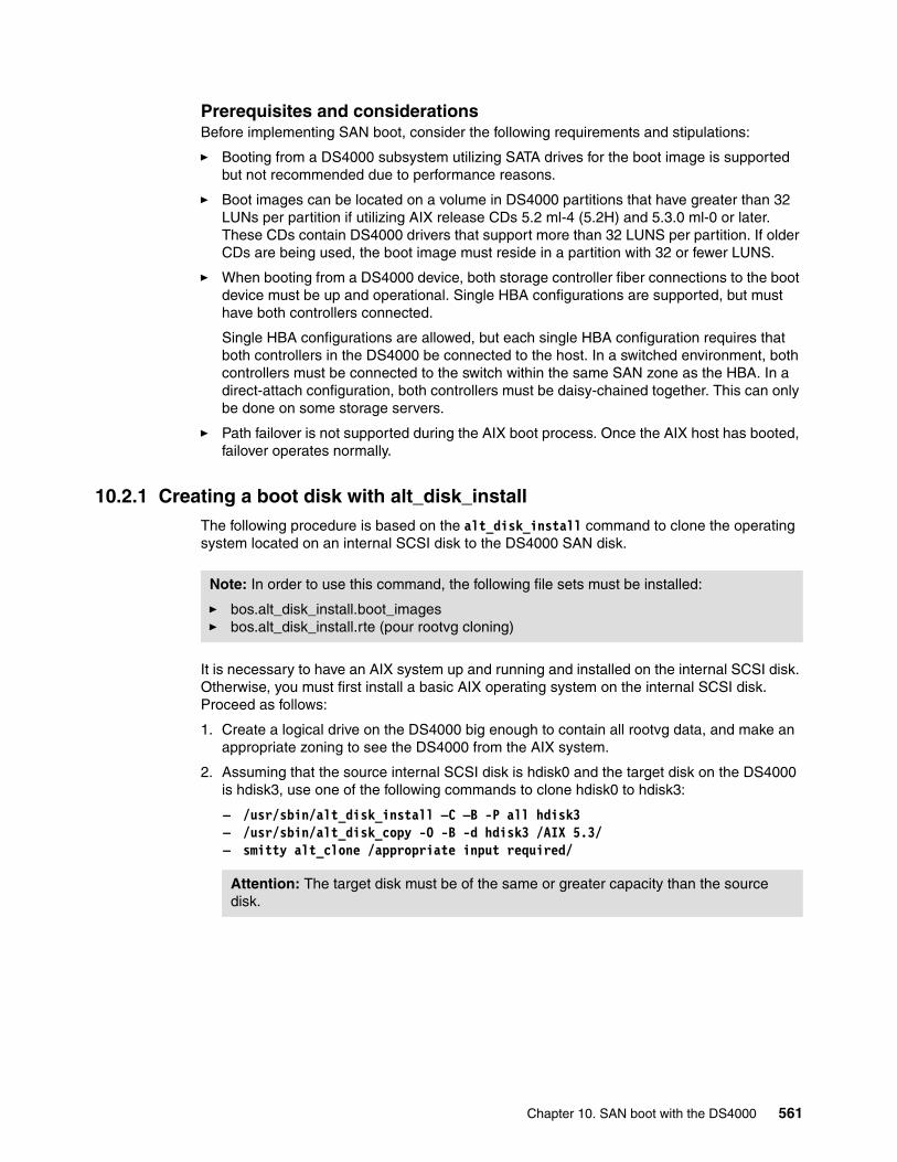
Prerequisites and considerationsBefore implementing SAN boot, consider the following requirements and stipulations:
� Booting from a DS4000 subsystem utilizing SATA drives for the boot image is supported but not recommended due to performance reasons.
� Boot images can be located on a volume in DS4000 partitions that have greater than 32 LUNs per partition if utilizing AIX release CDs 5.2 ml-4 (5.2H) and 5.3.0 ml-0 or later. These CDs contain DS4000 drivers that support more than 32 LUNS per partition. If older CDs are being used, the boot image must reside in a partition with 32 or fewer LUNS.
� When booting from a DS4000 device, both storage controller fiber connections to the boot device must be up and operational. Single HBA configurations are supported, but must have both controllers connected.
Single HBA configurations are allowed, but each single HBA configuration requires that both controllers in the DS4000 be connected to the host. In a switched environment, both controllers must be connected to the switch within the same SAN zone as the HBA. In a direct-attach configuration, both controllers must be daisy-chained together. This can only be done on some storage servers.
� Path failover is not supported during the AIX boot process. Once the AIX host has booted, failover operates normally.
10.2.1 Creating a boot disk with alt_disk_installThe following procedure is based on the alt_disk_install command to clone the operating system located on an internal SCSI disk to the DS4000 SAN disk.
It is necessary to have an AIX system up and running and installed on the internal SCSI disk. Otherwise, you must first install a basic AIX operating system on the internal SCSI disk. Proceed as follows:
1. Create a logical drive on the DS4000 big enough to contain all rootvg data, and make an appropriate zoning to see the DS4000 from the AIX system.
2. Assuming that the source internal SCSI disk is hdisk0 and the target disk on the DS4000 is hdisk3, use one of the following commands to clone hdisk0 to hdisk3:
– /usr/sbin/alt_disk_install –C –B -P all hdisk3– /usr/sbin/alt_disk_copy -O -B -d hdisk3 /AIX 5.3/– smitty alt_clone /appropriate input required/
Note: In order to use this command, the following file sets must be installed:
� bos.alt_disk_install.boot_images� bos.alt_disk_install.rte (pour rootvg cloning)
Attention: The target disk must be of the same or greater capacity than the source disk.
Chapter 10. SAN boot with the DS4000 561
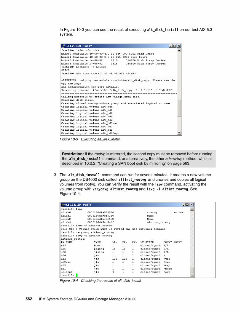
In Figure 10-3 you can see the result of executing alt_disk_install on our test AIX 5.3 system.
Figure 10-3 Executing alt_disk_install
3. The alt_disk_install command can run for several minutes. It creates a new volume group on the DS4000 disk called altinst_rootvg and creates and copies all logical volumes from rootvg. You can verify the result with the lspv command, activating the volume group with varyonvg altinst_rootvg and lsvg -l altint_rootvg. See Figure 10-4.
Figure 10-4 Checking the results of alt_disk_install
Restriction: If the rootvg is mirrored, the second copy must be removed before running the alt_disk_install command, or alternatively, the other mirroring method, which is described in 10.2.2, “Creating a SAN boot disk by mirroring” on page 563.
562 IBM System Storage DS4000 and Storage Manager V10.30
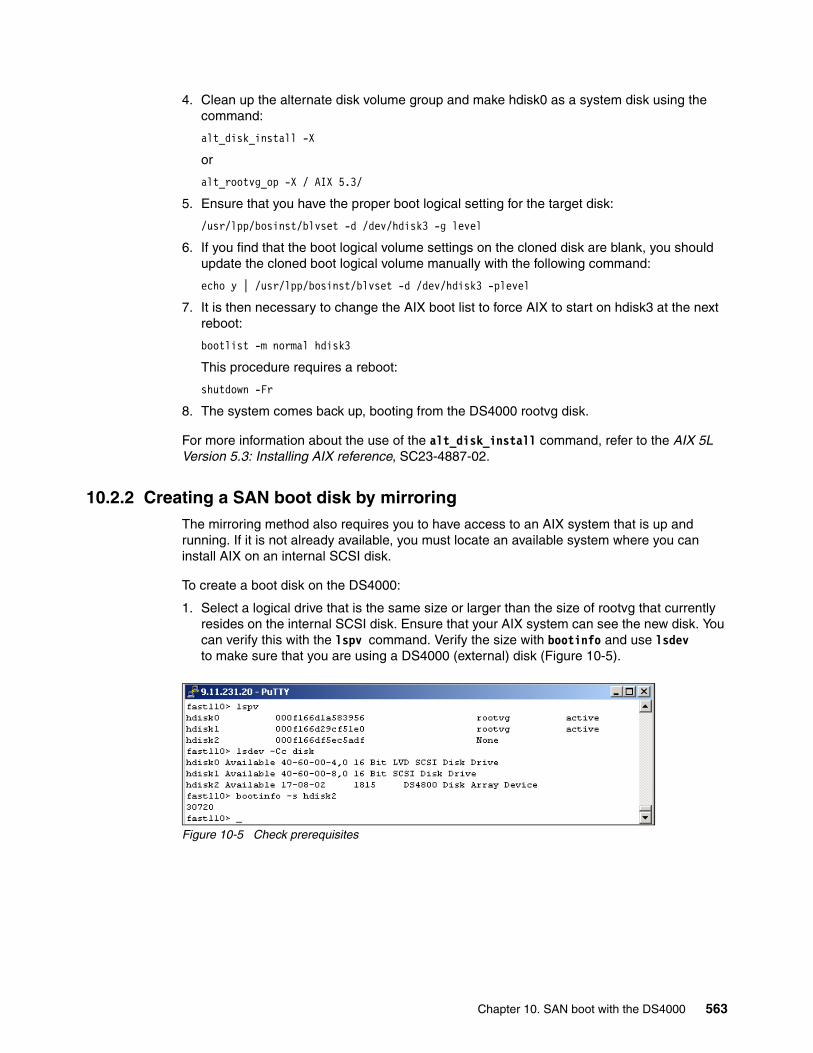
4. Clean up the alternate disk volume group and make hdisk0 as a system disk using the command:
alt_disk_install -X
or
alt_rootvg_op -X / AIX 5.3/
5. Ensure that you have the proper boot logical setting for the target disk:
/usr/lpp/bosinst/blvset -d /dev/hdisk3 -g level
6. If you find that the boot logical volume settings on the cloned disk are blank, you should update the cloned boot logical volume manually with the following command:
echo y | /usr/lpp/bosinst/blvset -d /dev/hdisk3 -plevel
7. It is then necessary to change the AIX boot list to force AIX to start on hdisk3 at the next reboot:
bootlist -m normal hdisk3
This procedure requires a reboot:
shutdown -Fr
8. The system comes back up, booting from the DS4000 rootvg disk.
For more information about the use of the alt_disk_install command, refer to the AIX 5L Version 5.3: Installing AIX reference, SC23-4887-02.
10.2.2 Creating a SAN boot disk by mirroringThe mirroring method also requires you to have access to an AIX system that is up and running. If it is not already available, you must locate an available system where you can install AIX on an internal SCSI disk.
To create a boot disk on the DS4000:
1. Select a logical drive that is the same size or larger than the size of rootvg that currently resides on the internal SCSI disk. Ensure that your AIX system can see the new disk. You can verify this with the lspv command. Verify the size with bootinfo and use lsdev to make sure that you are using a DS4000 (external) disk (Figure 10-5).
Figure 10-5 Check prerequisites
Chapter 10. SAN boot with the DS4000 563
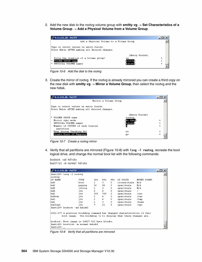
2. Add the new disk to the rootvg volume group with smitty vg → Set Characteristics of a Volume Group → Add a Physical Volume from a Volume Group.
Figure 10-6 Add the disk to the rootvg
3. Create the mirror of rootvg. If the rootvg is already mirrored you can create a third copy on the new disk with smitty vg → Mirror a Volume Group, then select the rootvg and the new hdisk.
Figure 10-7 Create a rootvg mirror
4. Verify that all partitions are mirrored (Figure 10-8) with lsvg -l rootvg, recreate the boot logical drive, and change the normal boot list with the following commands:
bosboot -ad hdiskxbootlist -m normal hdiskx
Figure 10-8 Verify that all partitions are mirrored
564 IBM System Storage DS4000 and Storage Manager V10.30

5. The next step is to remove the original mirror copy with smitty vg → Unmirror a Volume Group. Choose the rootvg volume group, then the disks that you want to remove from mirror and run the command.
6. Remove the disk from the volume group rootvg with smitty vg → Set Characteristics of a Volume Group → Remove a Physical Volume from a Volume Group, select rootvg for the volume group name ROOTVG and the internal SCSI disk you want to remove, and run the command.
7. We recommend that you execute the following commands again (see step 4):
bosboot -ad hdiskxbootlist -m normal hdiskx
At this stage, the creation of a bootable disk on the DS4000 is completed. Restarting the system makes it boot from the SAN (DS4000) disk.
10.2.3 Installation on external storage from bootable AIX CD-ROM To install AIX on DS40000 disks, make the following preparations:
1. Update the system/service processor microcode to the latest level. You can find the downloadable versions at:
http://www14.software.ibm.com/webapp/set2/firmware/gjsn
2. Update the Fibre Channel (FC) adapter (HBA) microcode to the latest supported level. For a detailed description on how to update the microcode, refer to “Downloading and installing microcode for Fibre Channel adapter” on page 568.
3. Make sure that you have an appropriate SAN configuration: The host is properly connected to the SAN, the zoning configuration is updated, and at least one LUN is mapped to the host.
The HBA has its own topology setting. This is in contrast to earlier versions of the firmware, and also to the device driver's auto detection of the topology. The default value for the topology is mostly auto topology (loop-1st PTP-2nd). But if you are attaching the adapter in a point-to-point (or switched) topology and are concerned that the adapter could cause a disruption when initially booted, follow the procedure to set the Fibre Channel adapter's topology. The same procedure can be used to display the current topology settings (see “Setting the Fibre Channel adapter's topology” on page 571).
Since by nature a SAN allows access to a large number of devices, identifying the hdisk to install to can be difficult. We recommend the following method to facilitate the discovery of the lun_id to hdisk correlation:
1. If possible, zone the switch or disk array such that the machine being installed can only discover the disks to be installed to. After the installation has completed, you can then reopen the zoning so the machine can discover all necessary devices.
2. If more than one disk is assigned to the host, make sure that you are using the correct one:
– If possible, assign Physical Volume Identifiers (PVIDs) to all disks from an already installed AIX system that can access the disks. This can be done using the command:
chdev-l hdiskX -apv=yes
Note: If the system cannot see the SAN fabric at login, you can configure the HBAs at the server open firmware prompt.
Chapter 10. SAN boot with the DS4000 565
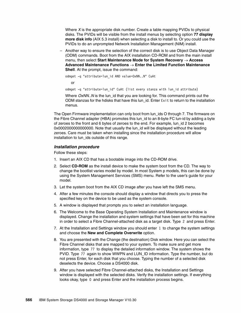
Where X is the appropriate disk number. Create a table mapping PVIDs to physical disks. The PVIDs will be visible from the install menus by selecting option 77 display more disk info (AIX 5.3 install) when selecting a disk to install to. Or you could use the PVIDs to do an unprompted Network Installation Management (NIM) install.
– Another way to ensure the selection of the correct disk is to use Object Data Manager (ODM) commands. Boot from the AIX installation CD-ROM and from the main install menu, then select Start Maintenance Mode for System Recovery → Access Advanced Maintenance Functions → Enter the Limited Function Maintenance Shell. At the prompt, issue the command:
odmget -q "attribute=lun_id AND value=OxNN..N" CuAt
or
odmget -q "attribute=lun_id" CuAt (list every stanza with lun_id attribute)
Where OxNN..N is the lun_id that you are looking for. This command prints out the ODM stanzas for the hdisks that have this lun_id. Enter Exit to return to the installation menus.
The Open Firmware implementation can only boot from lun_ids O through 7. The firmware on the Fibre Channel adapter (HBA) promotes this lun_id to an 8-byte FC lun-id by adding a byte of zeroes to the front and 6 bytes of zeroes to the end. For example, lun_id 2 becomes 0x0002000000000000. Note that usually the lun_id will be displayed without the leading zeroes. Care must be taken when installing since the installation procedure will allow installation to lun_ids outside of this range.
Installation procedureFollow these steps:
1. Insert an AIX CD that has a bootable image into the CD-ROM drive.
2. Select CD-ROM as the install device to make the system boot from the CD. The way to change the bootlist varies model by model. In most System p models, this can be done by using the System Management Services (SMS) menu. Refer to the user’s guide for your model.
3. Let the system boot from the AIX CD image after you have left the SMS menu.
4. After a few minutes the console should display a window that directs you to press the specified key on the device to be used as the system console.
5. A window is displayed that prompts you to select an installation language.
6. The Welcome to the Base Operating System Installation and Maintenance window is displayed. Change the installation and system settings that have been set for this machine in order to select a Fibre Channel-attached disk as a target disk. Type 2 and press Enter.
7. At the Installation and Settings window you should enter 1 to change the system settings and choose the New and Complete Overwrite option.
8. You are presented with the Change (the destination) Disk window. Here you can select the Fibre Channel disks that are mapped to your system. To make sure and get more information, type 77 to display the detailed information window. The system shows the PVID. Type 77 again to show WWPN and LUN_ID information. Type the number, but do not press Enter, for each disk that you choose. Typing the number of a selected disk deselects the device. Choose a DS4000 disk.
9. After you have selected Fibre Channel-attached disks, the Installation and Settings window is displayed with the selected disks. Verify the installation settings. If everything looks okay, type 0 and press Enter and the installation process begins.
566 IBM System Storage DS4000 and Storage Manager V10.30
10.When the system reboots, a window message displays the address of the device from which the system is reading the boot image. You can verify it via the SMS menu or with a command at the Open Firmware prompt (F8):
0 > printenv
This shows the current status of the boot-device.
Note that the AIX operating system installation of IBM BladeCenter JS20 and JS21 servers are slightly different. Refer to the following URL:
http://www.ibm.com/support/docview.wss?rs=113&uid=psg1MIGR-57235&loc=en_US
10.2.4 AIX SAN installation with NIMNetwork Installation Manager is a client server infrastructure and service that allows remote install of the operating system, manages software updates, and can be configured to install and update third-party applications. Although both the NIM server and client file sets are part of the operating system, a separate NIM server has to be configured, which keeps the configuration data and the installable product file sets.
We assume that the NIM environment is deployed and all of the necessary configurations on the NIM master are already done:
� The NIM server is properly configured as the NIM master and the basic NIM resources have been defined.
� The Fibre Channel Adapters are already installed on the machine onto which AIX is to be installed.
� The Fibre Channel Adapters are connected to a SAN and on the DS4000 system have at least one logical volume (LUN) mapped to the host.
� The target machine (NIM client) currently has no operating system installed and is configured to boot from the NIM server.
For more information about how to configure a NIM server, refer to the AIX 5L Version 5.3: Installing AIX reference, SC23-4887-02.
Installation procedurePrior the installation, you should modify the bosinst.data file, where the installation control is stored.
Insert your appropriate values at the following stanza:
SAN_DISKID
This specifies the worldwide port name and a logical unit ID for Fibre Channel-attached disks. The worldwide port name and logical unit ID are in the format returned by the lsattr command (that is, 0x followed by 1–16 hexadecimal digits). The ww_name and lun_id are separated by two slashes (//).
SAN_DISKID = <worldwide_portname//lun_id>
Important: Be sure that you have made the correct selection for root volume group because the existing data in the destination root volume group will be destroyed during BOS installation.
Chapter 10. SAN boot with the DS4000 567

For example:
SAN_DISKID = 0x0123456789FEDCBA//0x2000000000000
Or you can specify PVID (example with internal disk):
target_disk_data:PVID = 000c224a004a07faSAN_DISKID =CONNECTION = scsi0//10,0LOCATION = 10-60-00-10,0SIZE_MB = 34715HDISKNAME = hdisk0
To install:
1. Enter the command:
# smit nim_bosinst
2. Select the lpp_source resource for the BOS installation.
3. Select the SPOT resource for the BOS installation.
4. Select the BOSINST_DATA to use during installation option, and select a bosinst_data resource that is capable of performing a nonprompted BOS installation.
5. Select the RESOLV_CONF to use for network configuration option, and select a resolv_conf resource.
6. Select the Accept New License Agreements option, and select Yes. Accept the default values for the remaining menu options.
7. Press Enter to confirm and begin the NIM client installation.
8. To check the status of the NIM client installation, enter:
# lsnim -l va09
10.2.5 Advanced configuration procedures
This section covers advanced configuration procedures, which might be necessary to prepare or further customize the AIX SAN boot details.
Downloading and installing microcode for Fibre Channel adapterAppropriate adapter microcodes can be found at the following site:
http://www14.software.ibm.com/webapp/set2/firmware/gjsn
Always read the accompanying description for the specific adapter for up-to-date information.
To create the microcode diskette on an AIX system:
1. Save the microcode image as /etc/microcode/df1000f7.330.330.330.330.330.
2. Copy the file /etc/microcode/df1000f7.330.330.330.330.330 to /etc/microcode/df1000f7.330999 using the command:
cp/etc/microcode/df1000f7.330.330.330.330.330. /etc microcode/df1000f7.330999
3. Copy the file /rtc/microcode/df1000f7.330.330.330.330.330 to /etc/microcode/df1000f7.330 using the command:
cp/etc/microcode/df1000f7.330.330.330.330.330 /etc/microcode/df1000f7.330
568 IBM System Storage DS4000 and Storage Manager V10.30

4. Create a backup image on a floppy disk:
a. Insert a blank floppy disk.b. Enter the format /dev/rfd0 command.c. Enter the backup -iqvf/dev/rfd0 command.d. Enter the name of the file: /etc/microcode/df1000f7.330.330.330.330.330.e. Enter the name of the second file: /etc/microcode/df1000f7.330999.f. Enter the name of the third file: /etc/microcode/df1000f7.330.g. Press Ctrl+D.
Updating the microcode on the adapterThere are ways to update the microcode on the Fibre Channel adapter using an installed AIX operating system, but in the absence of an operating system, use the Standalone Diagnostic CD-ROM:
1. Boot the machine containing the Fibre Channel Adapter from a Standalone Diagnostics CD. You can find one of the appropriate versions of the Standalone Diagnostics CD at the following URL:
http://www14.software.ibm.com/webapp/set2/sas/f/diags/download/home.html
2. Press Enter when the first diagnostic window appears.
3. Select Task Selection (Diagnostics, Advanced Diagnostics, Service Aids)
4. Select Microcode Tasks.
5. Select Download Microcode.
6. Select the fcsX devices by highlighting and then pressing Enter.
7. Press F7 to commit the selections.
8. Press Enter at the warning window.
9. Select diskette as the input device for microcode.
10.Press F7 to commit.
11.Insert the microcode diskette into the diskette drive when prompted.
Using Open Firmware commands to locate the HBAsIf the target machine will be unattended during the reboot following the AIX installation, we highly recommend having multiboot startup enabled on that machine. In this case, the system will boot to the multiboot menu, allowing easy access to the Open Firmware (or OK) prompt without having an operator present during the reboot.
To enable multiboot startup, during the boot, after the banner appears, and after the word keyboard appears, press 1 (tty) or F1 (1ft) to enter the SMS menus. From there, select Multiboot and then enable Multiboot startup. The same procedure can be used to disable multiboot startup after executing this procedure, if so desired. In case of Hardware Management Console (HMC) managed machines, the boot procedure can be specified through the HMC.
1. Boot the system to an Open Firmware prompt.
2. Press 8 (tty to serial port) or F8 (1ft) after the RS/6000® or System p banner appears at the word keyboard, or select the OK prompt from the multiboot menu if multiboot startup is enabled. HMC-managed machine boots are configurable by right-clicking the profile and selecting properties.
Chapter 10. SAN boot with the DS4000 569
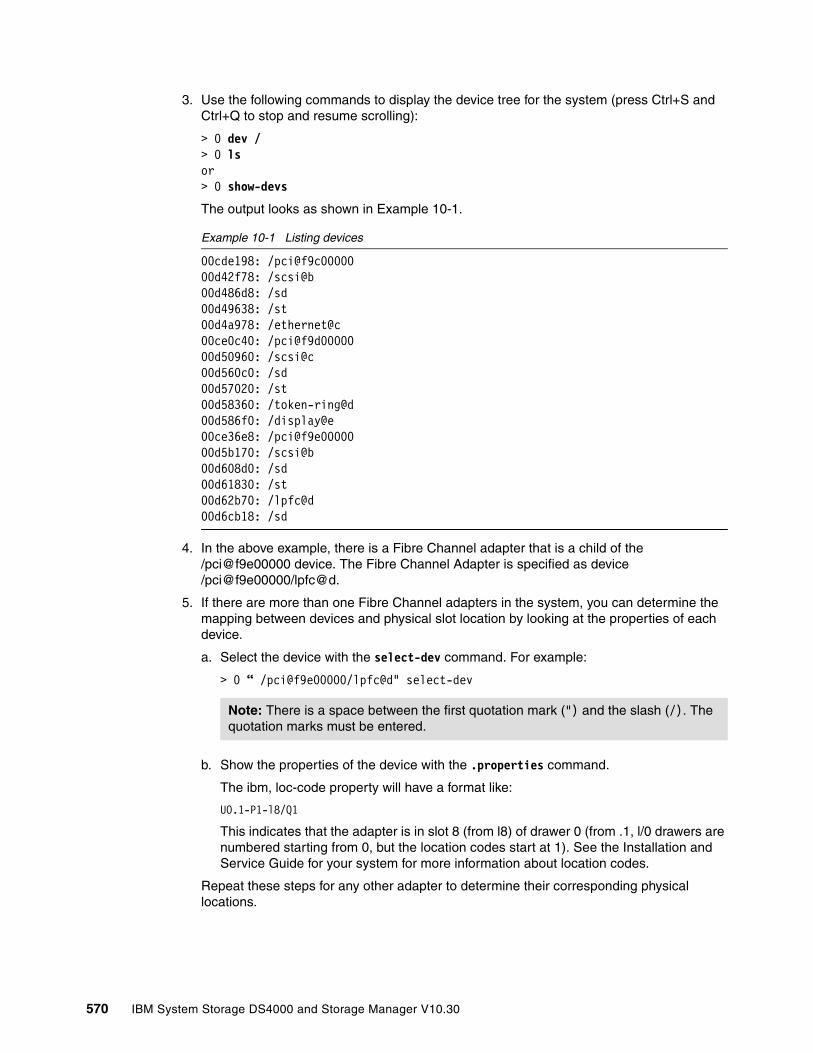
3. Use the following commands to display the device tree for the system (press Ctrl+S and Ctrl+Q to stop and resume scrolling):
> 0 dev /> 0 lsor> 0 show-devs
The output looks as shown in Example 10-1.
Example 10-1 Listing devices
00cde198: /pci@f9c0000000d42f78: /scsi@b00d486d8: /sd00d49638: /st00d4a978: /ethernet@c00ce0c40: /pci@f9d0000000d50960: /scsi@c00d560c0: /sd00d57020: /st00d58360: /token-ring@d00d586f0: /display@e00ce36e8: /pci@f9e0000000d5b170: /scsi@b00d608d0: /sd00d61830: /st00d62b70: /lpfc@d00d6cb18: /sd
4. In the above example, there is a Fibre Channel adapter that is a child of the /pci@f9e00000 device. The Fibre Channel Adapter is specified as device /pci@f9e00000/lpfc@d.
5. If there are more than one Fibre Channel adapters in the system, you can determine the mapping between devices and physical slot location by looking at the properties of each device.
a. Select the device with the select-dev command. For example:
> 0 “ /pci@f9e00000/lpfc@d" select-dev
b. Show the properties of the device with the .properties command.
The ibm, loc-code property will have a format like:
UO.1-P1-l8/Q1
This indicates that the adapter is in slot 8 (from l8) of drawer 0 (from .1, l/0 drawers are numbered starting from 0, but the location codes start at 1). See the Installation and Service Guide for your system for more information about location codes.
Repeat these steps for any other adapter to determine their corresponding physical locations.
Note: There is a space between the first quotation mark (") and the slash (/). The quotation marks must be entered.
570 IBM System Storage DS4000 and Storage Manager V10.30
To leave the Open Firmware prompt, choose one of the following possibilities:
� Boot the system:
> 0 boot
� Back to SMS menu:
> 0 dev /packages/gui> 0 obe
Setting the Fibre Channel adapter's topologyThe open boot portion of the adapter firmware has a setting for the topology to be used during the boot procedure. This topology setting does not affect the manner in which the device driver brings up the link once AIX is booted. This setting is only used during the boot process. Proceed as follows:
1. Find the Fibre Channel adapter's device information using the procedure in “Using Open Firmware commands to locate the HBAs” on page 569.
2. At the Open Firmware prompt, select the Fibre Channel Adapter with the select-dev command. For example:
> 0 “ /pci@f9e00000/lpfc@d" select-dev
3. Set the appropriate topology:
– For point-to-point (switch): set-ptp – For FC-AL: set-fc-al
Recovering from NVRAM corruption or SAN changesIf the NVRAM of the system becomes corrupted, or if changes are made to the SAN environment that cause the WWPN, SCSI ID (destination ID), or lun_id to change, you must redo some portions of this procedure to get the SAN boot working again. Here are the steps to follow:
1. Boot the system from an installation/maintenance image.
2. From the main install menu, select Start Maintenance Mode for System Recovery → Access Advanced Maintenance Functions → Enter the Limited Function Maintenance Shell.
3. From the shell prompt, locate the hdisk on which the AIX image you want to boot is installed.
You can use the command odmget q"attribute=lun_id AND value=OxNN..N" CuAt, where OxNN..N is the lun_id that you are looking for. This command prints out the ODM stanzas for the hdisks that have this lun_id. You can also use the command Isattr -ElhdiskN to see the WWPN associated with a particular hdisk.
4. Use the boot list command to update the boot list for the machine and to reset the necessary NVRAM variables.
To set the normal mode boot list to a particular hdisk (hdisk6 for this example) issue the following command:
bootlist -m normal hdisk6
Note: There is a space between the first quotation mark (") and the slash (/), and the quotation marks must be entered.
Note: The current topology can be checked by the .topology command.
Chapter 10. SAN boot with the DS4000 571

5. Reboot the system.
6. During the subsequent reboot, stop at an Open Firmware prompt. (Press 8 (tty) or F8 (1ft) after the RS/6000 banner appears and after the word keyboard appears, or select OK prompt from the multiboot menu if multiboot startup is enabled).
7. Issue the printenv command to find the values of two NVRAM variables, bootinfo-aix and ibm,aix-fc-bootinfo.
printenv bootinfo-aix
Bootinfo-aix will have a value like /pci@f8600000/lpfc@d/sd@0:3.
In this example, the Fibre Channel adapter that was used to reach the installation target disk is device pci@f8600000/lpfc@d;.
The command printenv ibm, aix-fc-bootinfo ibm,aix-fc-bootinfo returns values like Oxd4,Ox2000000000000,0x500604800000000b. The first value is the scsi_id (or destination ID) of the installation target disk. The second value is the lun_id of the installation target disk. The last value is the worldwide port name of the destination ID. Write down the scsi_id and the lun_id. They are needed for the next step.
8. Select the Fibre Channel adapter using the select-dev command and the device information obtained from the bootinfo-aix variable in the previous step. In our example:
> 0 “ /pci@f9e00000/lpfc@d" select-dev
9. Set the adapter to bind the boot device to target 0 using the did command and the information obtained from the ibm,aix-fc-bootinfo variable in step 7. In our example, did d4 2 0 set-boot-id is the scsi_id, 2 is byte 1 of the lun_id, and 0 is the target ID.
10.Unselect the device with the unselect-dev command.
11.Boot the machine with the boot command.
12.Once this procedure had been completed, subsequent reboots from the same disk require no intervention or Open Firmware commands.
10.3 Windows 2003/2008 SAN boot for BladeCenter HS20Next we describe an example configuration of a SAN boot with a DS4700 attached to the IBM BladeCenter HS20 under Windows 2003. This configuration example specifically addresses the installation of a Windows Server 2003 environment, but similar steps can be followed for a boot from SAN configuration for Windows Server 2008.
This is meant to act as a guide to help you gain a better understanding of SAN boot. Illustrations are based on Storage Manager Version 10.30. This is the latest version at the time of writing. You should check and, if applicable, use the latest version of the SM software and firmware.
Note: There is a space between the first quotation mark (") and the slash (/), and quotation marks must be entered.
Note: Currently, only 1-byte lun_ids are supported by the interface. Therefore, bytes 0, and 2 through 7 of the lun_id from step 6 must be zeroes or the machine will be unable to boot from the device.
572 IBM System Storage DS4000 and Storage Manager V10.30

The infrastructure and equipment used for our illustration consists of the following hardware and software:
� 2x HS20 BladeServers
� 2x Brocade SSM Enterprise switch modules
� 1x IBM DS4700 storage subsystem
� 1x 2109-F32 Fibre Channel switch
� DS4000 Storage Manager (At the time of writing the latest version available was DS4000 SM v10.30.)
HS20 Blades connect to the DS4700 via the two Brocade Enterprise FC switch modules with an inter-switch link (ISL) to the external 2109-F32. The DS4700 controllers connect to the 2109-F32 on ports 0 and 15. The two Brocade Enterprise FC switch modules provide switch redundancy to the blades, while the dual controllers on the DS4700 storage server provide redundant paths to the storage, as shown in Figure 10-9.
Figure 10-9 SAN Boot configuration
Chapter 10. SAN boot with the DS4000 573

10.3.1 Configuration procedure overviewThe boot from SAN configuration for the HS20 and HS40 Blades is very similar. The only difference for the HS40 Blade is that it requires the boot device to be configured from the startup sequence options in the blade setup menu (accessed by breaking the boot sequence using the F1 key). Otherwise, the procedure explained here for an HS20 Blade (located in slot 9) also applies to HS40 Blades.
1. HS20 Blade configuration:
a. Power on the HS20 Blade.
b. Disable the IDE devices in the HS20 Blade Server BIOS.
c. Configure the Fibre Channel BIOS parameters for the first HBA port from the FastT!Util menu.
2. FC switched fabric configuration.
Ensure that the Fibre Channel SAN fabric is correctly implemented according to the following steps:
a. Complete the necessary fiber cable connections with the DS4700 controllers, BladeCenter Brocade Module, and any external devices that will be connected to the SAN, and ensure that all the devices are properly connected.
b. Verify that all the switches in the fabric are configured with unique domain ID and IP addresses.
c. Verify and confirm that the two external ports on Brocade switch modules are enabled from the BladeCenter Management Module Advance Setup menu.
d. Verify and confirm that all the switches in the fabric are running the latest and compatible firmware version.
e. Verify that all the switches have merged into the fabric successfully.
f. Verify from the fabric NameServer database has all the hosts and storage ports are online as F ports.
g. Define and activate zoning.
3. DS4000 storage configuration for the primary path:
a. Load and execute the Auto Volume Transfer (AVT) script file.
b. Create a logical drive to be used as the operating system (C drive) disk for the HS20 Blade.
c. Complete the host group, host, and host port definitions.
d. Define the storage partition to map the logical drive with LUN ID 0 to the first host port in the host group.
e. Delete the Access LUN (ID =31) if it was automatically assigned to the host group while defining the storage partition for the logical drive.
4. Fibre Channel host configuration for primary path.
Configure boot device (FC BIOS parameter) for the primary path from the HS20 Blade to the DS4700 controller A.
a. Identify and select the boot device.
b. Configure the boot device for the HS20 Blade from the BIOS only.
Note: Verify that the displayed WWPN matches the WWPN of the DS4700 controller A zoned with the first port on the FC HBA and the LUN ID=0.
574 IBM System Storage DS4000 and Storage Manager V10.30

5. Operating system installation:
a. Install the Windows 2003/2008 operating system, relevant service packs, Multipath driver, and optional storage management software.
b. Verify that the HS20 Blade successfully boots from the logical drive on the primary path by a power off/on or by restarting the HS20 Blade.
6. Fibre Channel switched fabric configuration for the secondary path:
a. Add another zone to include the second port on the HS20 Blade FC HBA and the DS4700 controller B as members of that zone.
b. Modify the active zone config to add the new zone.
c. Enable the zone config.
d. Verify that the active zone config lists the correct configuration.
7. DS4700 storage configuration for the secondary path.
a. Define the host port for the second port on the HBA under the same host group used for the primary path configuration. The host type should be the same as for the first host port.
b. Add the access logical drive with LUN ID = 31 (optional).
8. FC host adapter BIOS configuration for the secondary path.
Configure the device BIOS parameters on the second port from the HS20 Blade:
a. Set Enable BIOS settings to enable.
b. Identify and select the boot device.
c. Configure the boot device for the HS20 Blade only from the BIOS.
Preconfiguration checklistBefore proceeding to implement the function, ensure that the following tasks are completed.
Fibre Channel switch fabricFor the Fibre Channel switch fabric:
� Ensure that the unique domain ID and IP address are configured on all the switches.
� Verify switch external port settings from the BladeCenter Management Module Advance Menu Setup.
� Back up the switch fabric configuration.
� Configure fabric zoning using the Brocade Fabric OS Procedures Guide.
DS4700 storage subsystemFor the DS4700 storage subsystem:
� Ensure that the DS4700 storage subsystem and drive expansions are properly cabled.
� Create a logical drive.
Note: For Windows 2003, press F6 at the start of the installation to specify and load the FC device driver for the HS20 Blade FC HBA.
Chapter 10. SAN boot with the DS4000 575
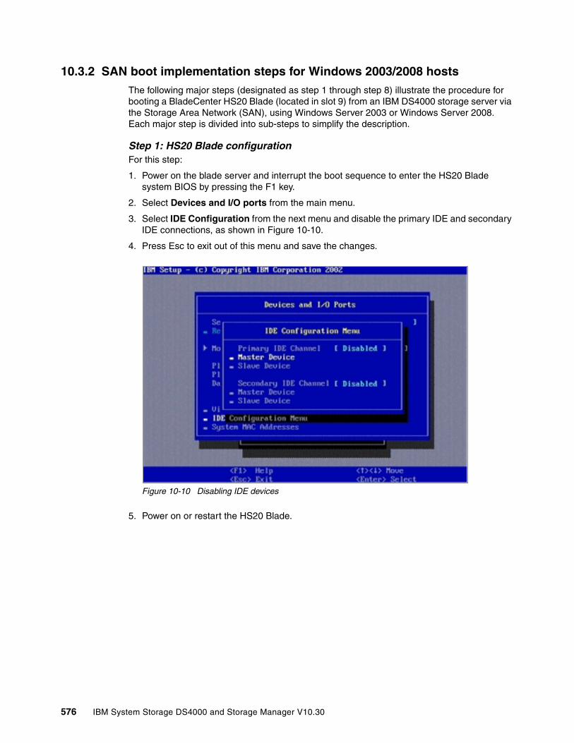
10.3.2 SAN boot implementation steps for Windows 2003/2008 hostsThe following major steps (designated as step 1 through step 8) illustrate the procedure for booting a BladeCenter HS20 Blade (located in slot 9) from an IBM DS4000 storage server via the Storage Area Network (SAN), using Windows Server 2003 or Windows Server 2008. Each major step is divided into sub-steps to simplify the description.
Step 1: HS20 Blade configurationFor this step:
1. Power on the blade server and interrupt the boot sequence to enter the HS20 Blade system BIOS by pressing the F1 key.
2. Select Devices and I/O ports from the main menu.
3. Select IDE Configuration from the next menu and disable the primary IDE and secondary IDE connections, as shown in Figure 10-10.
4. Press Esc to exit out of this menu and save the changes.
Figure 10-10 Disabling IDE devices
5. Power on or restart the HS20 Blade.
576 IBM System Storage DS4000 and Storage Manager V10.30
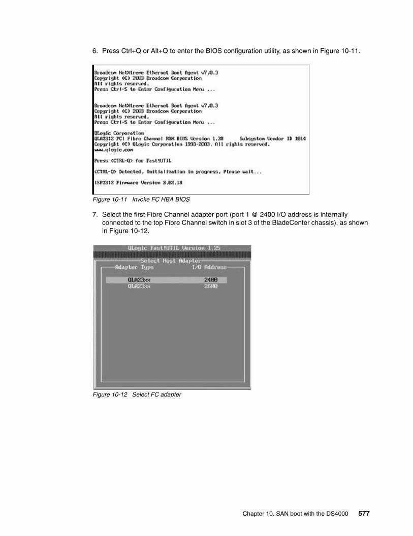
6. Press Ctrl+Q or Alt+Q to enter the BIOS configuration utility, as shown in Figure 10-11.
Figure 10-11 Invoke FC HBA BIOS
7. Select the first Fibre Channel adapter port (port 1 @ 2400 I/O address is internally connected to the top Fibre Channel switch in slot 3 of the BladeCenter chassis), as shown in Figure 10-12.
Figure 10-12 Select FC adapter
Chapter 10. SAN boot with the DS4000 577

8. Select Configuration Settings - Host Adapter Settings, as shown in Figure 10-13.
9. Change the Host Adapter BIOS to enabled (the default value is disabled).
Figure 10-13 Enable FC BIOS
10.Record the worldwide port name (WWPN) of this host bus adapter. It will be needed while configuring storage partitioning on the DS4700 storage subsystem and also for fabric zone configuration.
578 IBM System Storage DS4000 and Storage Manager V10.30
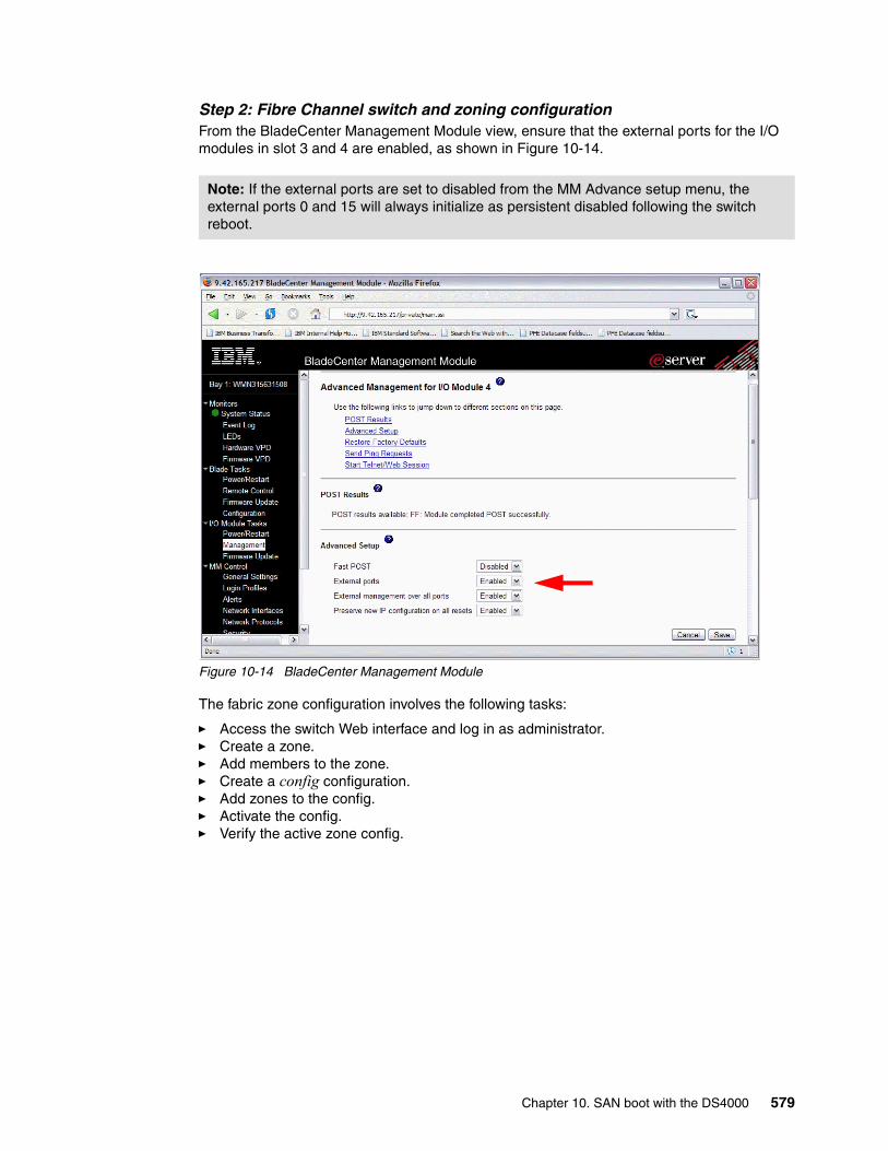
Step 2: Fibre Channel switch and zoning configurationFrom the BladeCenter Management Module view, ensure that the external ports for the I/O modules in slot 3 and 4 are enabled, as shown in Figure 10-14.
Figure 10-14 BladeCenter Management Module
The fabric zone configuration involves the following tasks:
� Access the switch Web interface and log in as administrator.� Create a zone.� Add members to the zone.� Create a config configuration.� Add zones to the config.� Activate the config.� Verify the active zone config.
Note: If the external ports are set to disabled from the MM Advance setup menu, the external ports 0 and 15 will always initialize as persistent disabled following the switch reboot.
Chapter 10. SAN boot with the DS4000 579
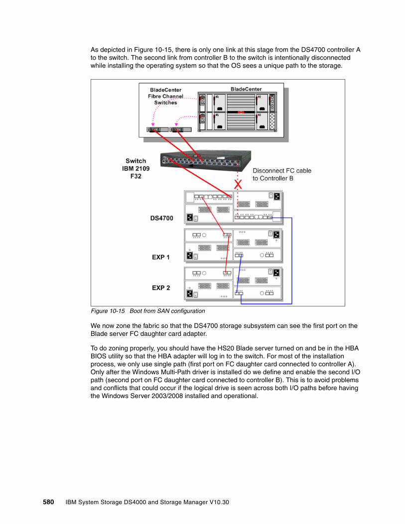
As depicted in Figure 10-15, there is only one link at this stage from the DS4700 controller A to the switch. The second link from controller B to the switch is intentionally disconnected while installing the operating system so that the OS sees a unique path to the storage.
Figure 10-15 Boot from SAN configuration
We now zone the fabric so that the DS4700 storage subsystem can see the first port on the Blade server FC daughter card adapter.
To do zoning properly, you should have the HS20 Blade server turned on and be in the HBA BIOS utility so that the HBA adapter will log in to the switch. For most of the installation process, we only use single path (first port on FC daughter card connected to controller A). Only after the Windows Multi-Path driver is installed do we define and enable the second I/O path (second port on FC daughter card connected to controller B). This is to avoid problems and conflicts that could occur if the logical drive is seen across both I/O paths before having the Windows Server 2003/2008 installed and operational.
580 IBM System Storage DS4000 and Storage Manager V10.30
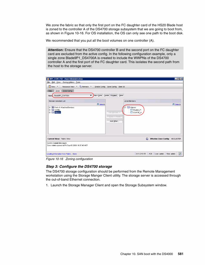
We zone the fabric so that only the first port on the FC daughter card of the HS20 Blade host is zoned to the controller A of the DS4700 storage subsystem that we are going to boot from, as shown in Figure 10-16. For OS installation, the OS can only see one path to the boot disk.
We recommended that you put all the boot volumes on one controller (A).
Figure 10-16 Zoning configuration
Step 3: Configure the DS4700 storageThe DS4700 storage configuration should be performed from the Remote Management workstation using the Storage Manger Client utility. The storage server is accessed through the out-of-band Ethernet connection.
1. Launch the Storage Manager Client and open the Storage Subsystem window.
Attention: Ensure that the DS4700 controller B and the second port on the FC daughter card are excluded from the active config. In the following configuration example, only a single zone Blade9P1_DS4700A is created to include the WWPNs of the DS4700 controller A and the first port of the FC daughter card. This isolates the second path from the host to the storage server.
Chapter 10. SAN boot with the DS4000 581

2. Create a logical drive to be used as the boot disk (C drive) using the create logical drive wizard (Figure 10-17).
Figure 10-17 Create logic drive
Configure the size and the name of the logical drive, as shown in Figure 10-18.
Figure 10-18 Specify logical drive parameters
582 IBM System Storage DS4000 and Storage Manager V10.30
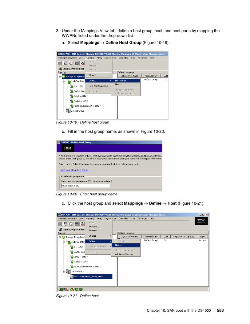
3. Under the Mappings View tab, define a host group, host, and host ports by mapping the WWPNs listed under the drop-down list.
a. Select Mappings → Define Host Group (Figure 10-19).
Figure 10-19 Define host group
b. Fill in the host group name, as shown in Figure 10-20.
Figure 10-20 Enter host group name
c. Click the host group and select Mappings → Define → Host (Figure 10-21).
Figure 10-21 Define host
Chapter 10. SAN boot with the DS4000 583

d. Fill in the host name, select the first host port on the HS20 BladeServer, and click Add, as shown in Figure 10-22.
Figure 10-22 Define name and host port
4. Identify and select the correct host type. The host type should be Windows 2000/Server 2003/Server 2008 non-clustered (supports DMP) because we want to have auto volume transfer (AVT) enabled for boot path protection, as shown in Figure 10-23.
Figure 10-23 Specify host type
Note: Only the first port on the HS20 Blade should be defined. In case the WWPN of the first host port does not appear in the selection box, manually fill in the WWPN by clicking New, assuming that the port has initialized correctly and is listed under the NameServer table and zoned with the DS4700 controller A.
584 IBM System Storage DS4000 and Storage Manager V10.30
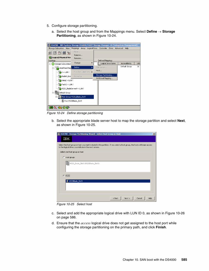
5. Configure storage partitioning.
a. Select the host group and from the Mappings menu. Select Define → Storage Partitioning, as shown in Figure 10-24.
Figure 10-24 Define storage partitioning
b. Select the appropriate blade server host to map the storage partition and select Next, as shown in Figure 10-25.
Figure 10-25 Select host
c. Select and add the appropriate logical drive with LUN ID 0, as shown in Figure 10-26 on page 586.
d. Ensure that the access logical drive does not get assigned to the host port while configuring the storage partitioning on the primary path, and click Finish.
Chapter 10. SAN boot with the DS4000 585

Figure 10-26 Select the access LUN
e. Click OK in the next window (Figure 10-27).
Figure 10-27 Storage partition defined
Figure 10-28 shows the logical drive nameHS20_BladeServer9 correctly mapped to the Host HS20Blade_Slot9.
Figure 10-28 Verify mapping
586 IBM System Storage DS4000 and Storage Manager V10.30

At this point the storage configuration process for the primary path is complete. Ensure that the secondary path from the HS20 Blade to the DS4700 controller B is disconnected and not included in the fabric zone configuration.
Step 4: Enable and map the boot deviceFor this step:
1. Configure the boot device for the HS20 Blade:
a. Boot the HS20 Blade server being configured for remote boot and enter the QLogic BIOS utility by pressing the Ctrl+Q function keys.
b. Ensure that the BIOS for the adapter is still set to enabled (Figure 10-29).
Figure 10-29 Enable boot device
c. Exit the menu by pressing the Esc key.
d. Select Selectable Boot Settings from the main menu.
e. Under the Selectable Boot Settings option, set the boot device to the controller's worldwide port name, as shown in Figure 10-30.
Figure 10-30 Map boot device
f. Set the boot LUN to reflect LUN 0.
Chapter 10. SAN boot with the DS4000 587
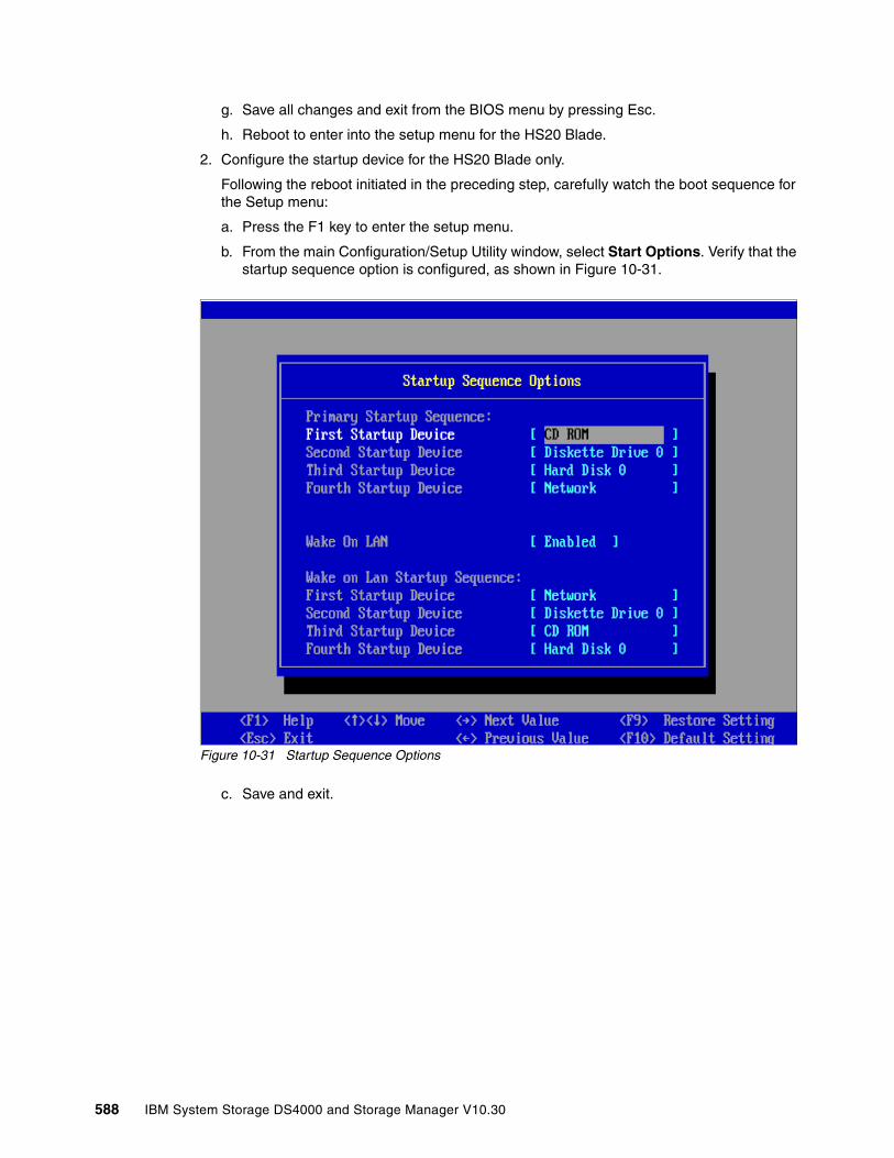
g. Save all changes and exit from the BIOS menu by pressing Esc.
h. Reboot to enter into the setup menu for the HS20 Blade.
2. Configure the startup device for the HS20 Blade only.
Following the reboot initiated in the preceding step, carefully watch the boot sequence for the Setup menu:
a. Press the F1 key to enter the setup menu.
b. From the main Configuration/Setup Utility window, select Start Options. Verify that the startup sequence option is configured, as shown in Figure 10-31.
Figure 10-31 Startup Sequence Options
c. Save and exit.
588 IBM System Storage DS4000 and Storage Manager V10.30

Step 5: OS installation (Windows Server 2003 and Server 2008)For this step:
1. Boot the blade server using the Windows Server 2003 or Windows Server 2008 installation CD.
For Windows 2003, get ready to press F6 as soon as the window shown in Figure 10-32 displays.
Figure 10-32 Windows Setup: Press F6
2. Install the FC device driver using a diskette. The FC device driver is available at the IBM BladeCenter support Web site for BladeCenter HS20:
http://www-304.ibm.com/systems/support/supportsite.wss/brandmain?brandind=5000020
Figure 10-33 shows that the FC device driver was correctly recognized for the HS20 FC.
Figure 10-33 Windows Setup: HS20 device driver
Once the FC device driver is installed and once the operating system installation process completes, perform the following tasks.
a. Install the recommended service packs and reboot.
Chapter 10. SAN boot with the DS4000 589
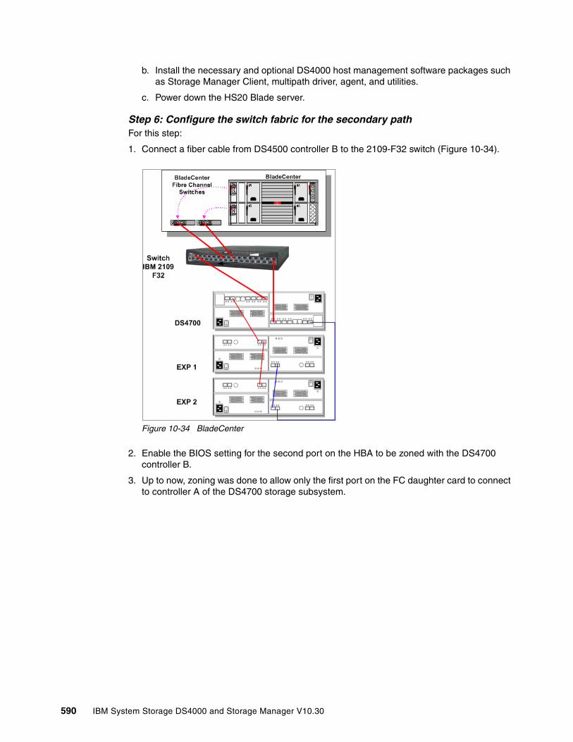
b. Install the necessary and optional DS4000 host management software packages such as Storage Manager Client, multipath driver, agent, and utilities.
c. Power down the HS20 Blade server.
Step 6: Configure the switch fabric for the secondary pathFor this step:
1. Connect a fiber cable from DS4500 controller B to the 2109-F32 switch (Figure 10-34).
Figure 10-34 BladeCenter
2. Enable the BIOS setting for the second port on the HBA to be zoned with the DS4700 controller B.
3. Up to now, zoning was done to allow only the first port on the FC daughter card to connect to controller A of the DS4700 storage subsystem.
590 IBM System Storage DS4000 and Storage Manager V10.30

We now zone the fabric to include a zone that allows the second port on the FC daughter card to connect to controller B of the DS4700 storage subsystem that we are going to boot from, as shown in Figure 10-35. This allows for redundant paths from the HS20 BladeServer to the DS4700 storage subsystem.
Figure 10-35 Zoning configuration for second path
Step 7: Configure secondary path to DS4700For this step:
1. Select the host and define the second host port of the HS20 Blade FC HBA.
2. Verify the storage partitioning and host group configuration such that the logical drives are mapped to the correct host and the two host ports on the HBA (Figure 10-36).
Figure 10-36 HBA port mappings
Chapter 10. SAN boot with the DS4000 591

Also ensure that the boot drive = 0, as shown in Figure 10-37.
Figure 10-37 Define additional mappings
Configure any additional host storage if needed.
Step 8: Configure the root device for the secondary pathFor this step:
1. Power on the HS20 Blade Server and enter into the QLogic BIOS using the Ctrl+Q keys.
2. Select port 2 of the FC HBA @2600 I/O address, as shown in Figure 10-38.
Figure 10-38 Configure boot device: Secondary path
592 IBM System Storage DS4000 and Storage Manager V10.30
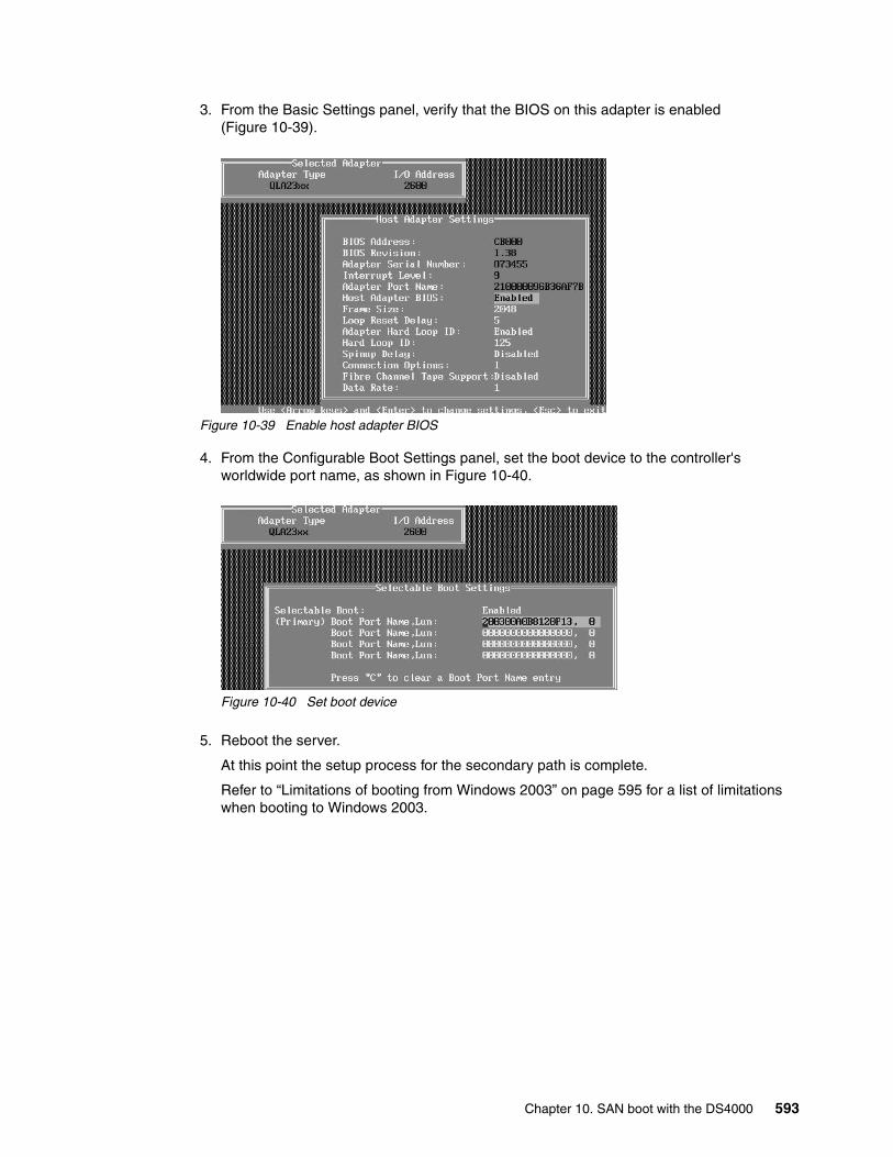
3. From the Basic Settings panel, verify that the BIOS on this adapter is enabled (Figure 10-39).
Figure 10-39 Enable host adapter BIOS
4. From the Configurable Boot Settings panel, set the boot device to the controller's worldwide port name, as shown in Figure 10-40.
Figure 10-40 Set boot device
5. Reboot the server.
At this point the setup process for the secondary path is complete.
Refer to “Limitations of booting from Windows 2003” on page 595 for a list of limitations when booting to Windows 2003.
Chapter 10. SAN boot with the DS4000 593
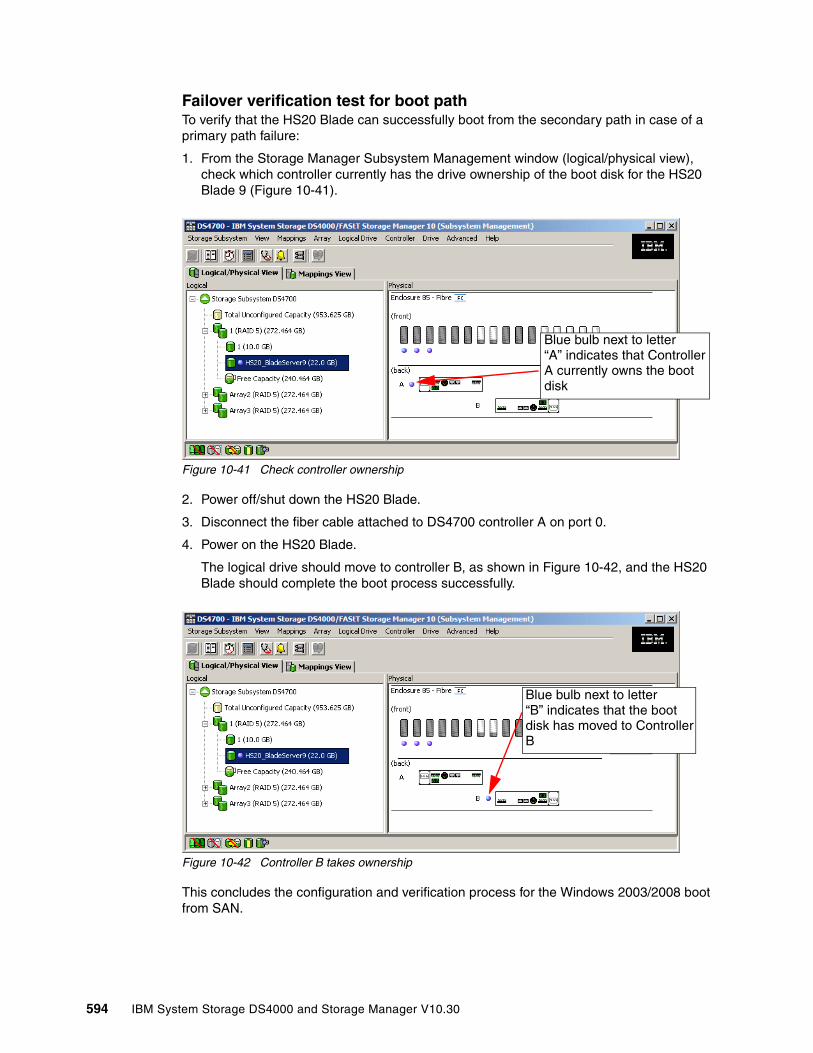
Failover verification test for boot pathTo verify that the HS20 Blade can successfully boot from the secondary path in case of a primary path failure:
1. From the Storage Manager Subsystem Management window (logical/physical view), check which controller currently has the drive ownership of the boot disk for the HS20 Blade 9 (Figure 10-41).
Figure 10-41 Check controller ownership
2. Power off/shut down the HS20 Blade.
3. Disconnect the fiber cable attached to DS4700 controller A on port 0.
4. Power on the HS20 Blade.
The logical drive should move to controller B, as shown in Figure 10-42, and the HS20 Blade should complete the boot process successfully.
Figure 10-42 Controller B takes ownership
This concludes the configuration and verification process for the Windows 2003/2008 boot from SAN.
Blue bulb next to letter “A” indicates that ControllerA currently owns the bootdisk
Blue bulb next to letter“B” indicates that the bootdisk has moved to ControllerB
594 IBM System Storage DS4000 and Storage Manager V10.30
Limitations of booting from Windows 2003When the server is configured with storage access and path redundancy, the limitations discussed in this section can be observed. The Microsoft Cluster Service uses bus-level resets in its operation. These resets must be isolated from the boot device. Therefore, configurations using the SCSIport driver with Microsoft Windows 2003 must utilize separate HBAs for the boot device and the shared cluster disks. In some cases where the fully redundant configuration is a requirement, a minimum of four HBAs is required.
In Fibre Channel implementations, by deploying Microsoft Cluster Services on a Windows Server 2003 platform using STORport drivers, both the boot disks and shared cluster disks can be accessed through the same HBA. A registry entry is required to enable a single HBA to connect to both shared and non-shared disks in an MSCS environment. Refer to the following URL:
http://technet.microsoft.com/en-us/library/cc759653.aspx
� If there is a path failure and the host is generating I/O, the boot drive moves to the other path. However, while this transition is occurring, the system will appear to halt for up to 30 seconds.
� If the boot device (LUN 0) is not on the same path as the bootable HBA port, you will receive an INACCESSIBLE_BOOT_DEVICE error message.
� If you suffer major path problems (LIPs) or path trashing, it can hang the server indefinitely as RDAC tries to find a stable path.
� By booting from the DS4000 storage device, most of the online diagnostic strategies are effectively canceled, and path problem determination must be done from the Ctrl+Q diagnostics panel instead of FAStT MSJ.
� The IDE disk devices should not be re-enabled.
10.4 Linux SAN boot for IBM System x servers
In this section we discuss how to implement Linux SAN boot with a System x (xSeries®) server connected to a DS4700 storage subsystem. Some steps are similar to those presented in 10.3, “Windows 2003/2008 SAN boot for BladeCenter HS20” on page 572, but there are several key differences.
For the lab experiment we used the hardware and software shown in Table 10-1.
Table 10-1 Hardware and software configuration
The following steps illustrate the procedure for booting a System x server from an IBM DS4700 storage server via the Storage Area Network (SAN), using Redhat Enterprise Linux AS 4 Update 4, but similar configuration steps for boot from SAN with RedHat Enterprise Linux v5 Update 2 can be followed.
Hardware configuration Software configuration
� IBM xSeries x342, 2x1.133 GHz Processor, 1 GB RAM, no internal disk
� 2 x QLogic QLA2340 HBAs� 2 x IBM 2109-F32 SAN switch� IBM DS4700 Dual-Controller, Controller
firmware Version 07.15.07.00
� Operating system: RedHat Enterprise Linux AS 4 Update 4, kernel Version 2.6.9-42.ELsmp
� Linux RDAC Version 09.02.B5.18� DS4000 Storage Manager Version 10.30
Chapter 10. SAN boot with the DS4000 595
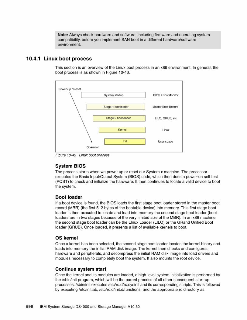
10.4.1 Linux boot process
This section is an overview of the Linux boot process in an x86 environment. In general, the boot process is as shown in Figure 10-43.
Figure 10-43 Linux boot process
System BIOSThe process starts when we power up or reset our System x machine. The processor executes the Basic Input/Output System (BIOS) code, which then does a power-on self test (POST) to check and initialize the hardware. It then continues to locate a valid device to boot the system.
Boot loaderIf a boot device is found, the BIOS loads the first stage boot loader stored in the master boot record (MBR) (the first 512 bytes of the bootable device) into memory. This first stage boot loader is then executed to locate and load into memory the second stage boot loader (boot loaders are in two stages because of the very limited size of the MBR). In an x86 machine, the second stage boot loader can be the LInux Loader (LILO) or the GRand Unified Boot loader (GRUB). Once loaded, it presents a list of available kernels to boot.
OS kernelOnce a kernel has been selected, the second stage boot loader locates the kernel binary and loads into memory the initial RAM disk image. The kernel then checks and configures hardware and peripherals, and decompress the initial RAM disk image into load drivers and modules necessary to completely boot the system. It also mounts the root device.
Continue system startOnce the kernel and its modules are loaded, a high-level system initialization is performed by the /sbin/init program, which will be the parent process of all other subsequent start-up processes. /sbin/init executes /etc/rc.d/rc.sysinit and its corresponding scripts. This is followed by executing /etc/inittab, /etc/rc.d/init.d/functions, and the appropriate rc directory as
Note: Always check hardware and software, including firmware and operating system compatibility, before you implement SAN boot in a different hardware/software environment.
596 IBM System Storage DS4000 and Storage Manager V10.30
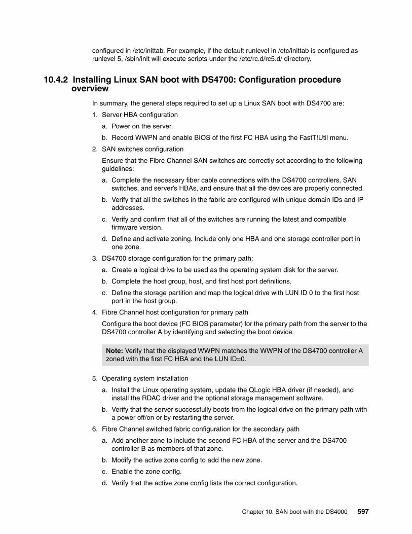
configured in /etc/inittab. For example, if the default runlevel in /etc/inittab is configured as runlevel 5, /sbin/init will execute scripts under the /etc/rc.d/rc5.d/ directory.
10.4.2 Installing Linux SAN boot with DS4700: Configuration procedure overview
In summary, the general steps required to set up a Linux SAN boot with DS4700 are:
1. Server HBA configuration
a. Power on the server.
b. Record WWPN and enable BIOS of the first FC HBA using the FastT!Util menu.
2. SAN switches configuration
Ensure that the Fibre Channel SAN switches are correctly set according to the following guidelines:
a. Complete the necessary fiber cable connections with the DS4700 controllers, SAN switches, and server’s HBAs, and ensure that all the devices are properly connected.
b. Verify that all the switches in the fabric are configured with unique domain IDs and IP addresses.
c. Verify and confirm that all of the switches are running the latest and compatible firmware version.
d. Define and activate zoning. Include only one HBA and one storage controller port in one zone.
3. DS4700 storage configuration for the primary path:
a. Create a logical drive to be used as the operating system disk for the server.
b. Complete the host group, host, and first host port definitions.
c. Define the storage partition and map the logical drive with LUN ID 0 to the first host port in the host group.
4. Fibre Channel host configuration for primary path
Configure the boot device (FC BIOS parameter) for the primary path from the server to the DS4700 controller A by identifying and selecting the boot device.
5. Operating system installation
a. Install the Linux operating system, update the QLogic HBA driver (if needed), and install the RDAC driver and the optional storage management software.
b. Verify that the server successfully boots from the logical drive on the primary path with a power off/on or by restarting the server.
6. Fibre Channel switched fabric configuration for the secondary path
a. Add another zone to include the second FC HBA of the server and the DS4700 controller B as members of that zone.
b. Modify the active zone config to add the new zone.
c. Enable the zone config.
d. Verify that the active zone config lists the correct configuration.
Note: Verify that the displayed WWPN matches the WWPN of the DS4700 controller A zoned with the first FC HBA and the LUN ID=0.
Chapter 10. SAN boot with the DS4000 597

7. DS4700 storage configuration for the secondary path
a. Define the host port for the second port of the HBA under the same host group used for the primary path configuration. The host type should be the same as for the first host port.
b. Add the access logical drive with LUN ID = 31 (optional).
8. Verify and test access to the secondary path from the host:
a. Check whether both controllers are visible from the host.
b. Test path redundancy.
10.4.3 Installing Linux SAN boot with DS4700: Step-by-step procedure
As a best practice, it is safer to have only one path from the server to the storage when doing the Linux OS installation. This ensures that the server only sees a unique path to the storage. You can disconnect the cable from the server’s second HBA for this purpose, as shown in Figure 10-44.
Figure 10-44 Installation diagram
Step 1: Record WWPN of HBAs and enable BIOS of first HBADo the following to record the WWPN and to enable the server’s first HBA BIOS. We do the same thing for the second HBA after the OS is installed.
1. Power on the server and press Ctrl+Q when prompted to enter the QLogic Fast!Util.
598 IBM System Storage DS4000 and Storage Manager V10.30
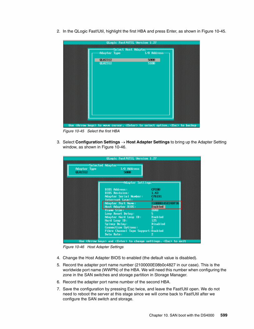
2. In the QLogic Fast!Util, highlight the first HBA and press Enter, as shown in Figure 10-45.
Figure 10-45 Select the first HBA
3. Select Configuration Settings → Host Adapter Settings to bring up the Adapter Setting window, as shown in Figure 10-46.
Figure 10-46 Host Adapter Settings
4. Change the Host Adapter BIOS to enabled (the default value is disabled).
5. Record the adapter port name number (2100000E08b0c4827 in our case). This is the worldwide port name (WWPN) of the HBA. We will need this number when configuring the zone in the SAN switches and storage partition in Storage Manager.
6. Record the adapter port name number of the second HBA.
7. Save the configuration by pressing Esc twice, and leave the Fast!Util open. We do not need to reboot the server at this stage since we will come back to Fast!Util after we configure the SAN switch and storage.
Chapter 10. SAN boot with the DS4000 599
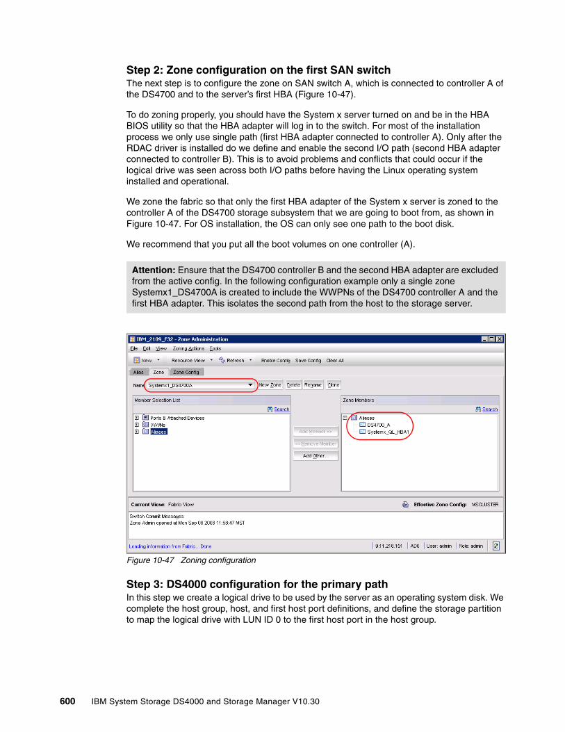
Step 2: Zone configuration on the first SAN switchThe next step is to configure the zone on SAN switch A, which is connected to controller A of the DS4700 and to the server’s first HBA (Figure 10-47).
To do zoning properly, you should have the System x server turned on and be in the HBA BIOS utility so that the HBA adapter will log in to the switch. For most of the installation process we only use single path (first HBA adapter connected to controller A). Only after the RDAC driver is installed do we define and enable the second I/O path (second HBA adapter connected to controller B). This is to avoid problems and conflicts that could occur if the logical drive was seen across both I/O paths before having the Linux operating system installed and operational.
We zone the fabric so that only the first HBA adapter of the System x server is zoned to the controller A of the DS4700 storage subsystem that we are going to boot from, as shown in Figure 10-47. For OS installation, the OS can only see one path to the boot disk.
We recommend that you put all the boot volumes on one controller (A).
Figure 10-47 Zoning configuration
Step 3: DS4000 configuration for the primary pathIn this step we create a logical drive to be used by the server as an operating system disk. We complete the host group, host, and first host port definitions, and define the storage partition to map the logical drive with LUN ID 0 to the first host port in the host group.
Attention: Ensure that the DS4700 controller B and the second HBA adapter are excluded from the active config. In the following configuration example only a single zone Systemx1_DS4700A is created to include the WWPNs of the DS4700 controller A and the first HBA adapter. This isolates the second path from the host to the storage server.
600 IBM System Storage DS4000 and Storage Manager V10.30
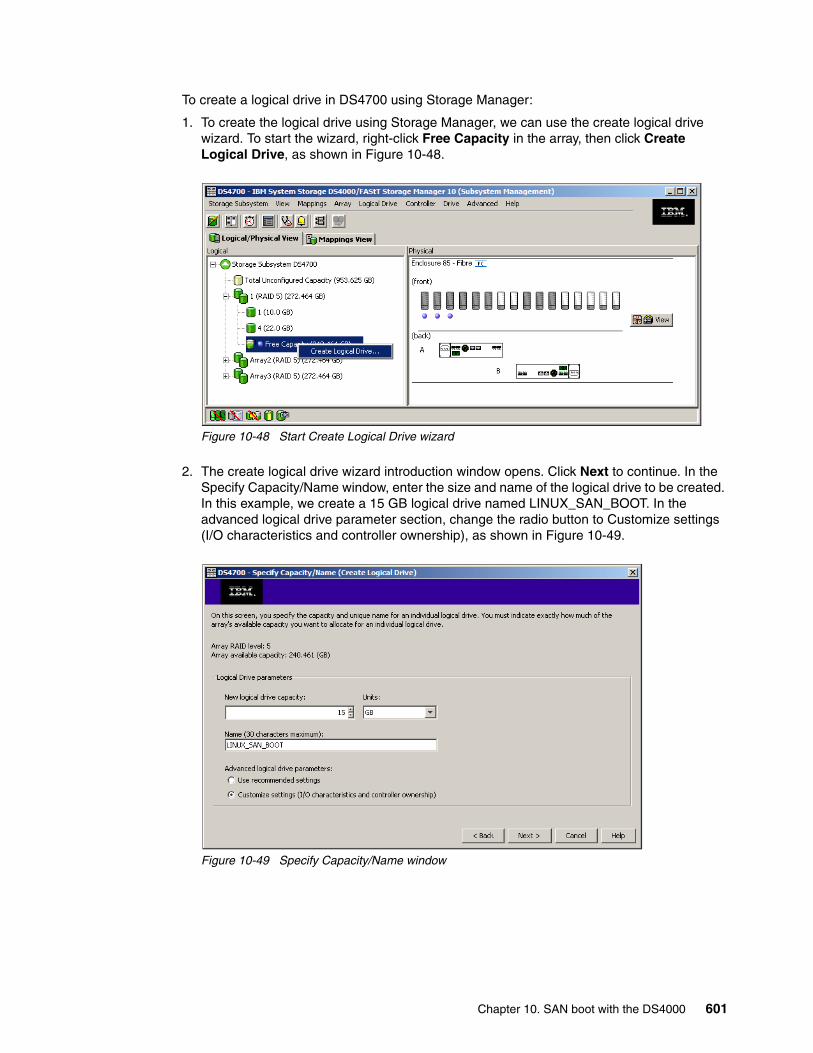
To create a logical drive in DS4700 using Storage Manager:
1. To create the logical drive using Storage Manager, we can use the create logical drive wizard. To start the wizard, right-click Free Capacity in the array, then click Create Logical Drive, as shown in Figure 10-48.
Figure 10-48 Start Create Logical Drive wizard
2. The create logical drive wizard introduction window opens. Click Next to continue. In the Specify Capacity/Name window, enter the size and name of the logical drive to be created. In this example, we create a 15 GB logical drive named LINUX_SAN_BOOT. In the advanced logical drive parameter section, change the radio button to Customize settings (I/O characteristics and controller ownership), as shown in Figure 10-49.
Figure 10-49 Specify Capacity/Name window
Chapter 10. SAN boot with the DS4000 601
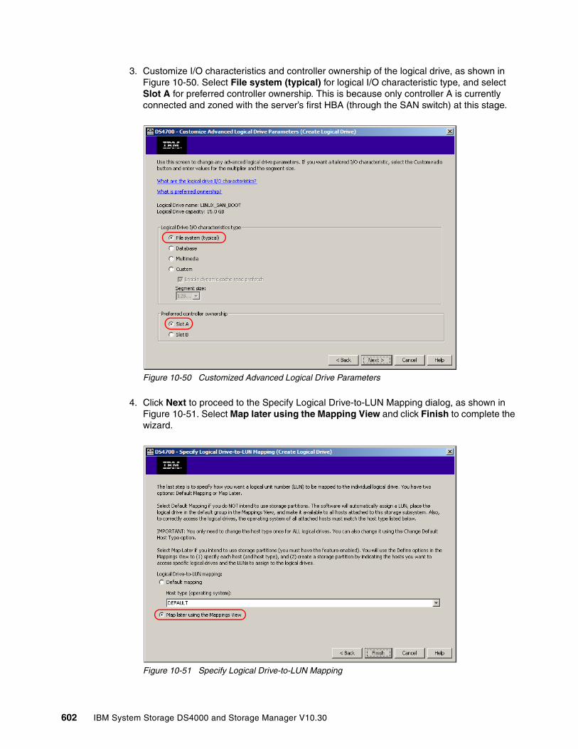
3. Customize I/O characteristics and controller ownership of the logical drive, as shown in Figure 10-50. Select File system (typical) for logical I/O characteristic type, and select Slot A for preferred controller ownership. This is because only controller A is currently connected and zoned with the server’s first HBA (through the SAN switch) at this stage.
Figure 10-50 Customized Advanced Logical Drive Parameters
4. Click Next to proceed to the Specify Logical Drive-to-LUN Mapping dialog, as shown in Figure 10-51. Select Map later using the Mapping View and click Finish to complete the wizard.
Figure 10-51 Specify Logical Drive-to-LUN Mapping
602 IBM System Storage DS4000 and Storage Manager V10.30

5. Create host group, host, and first host port definitions.
6. After creating the logical drive, we must define and create the host group, host, and host port definition for the server. In the Storage Manager Subsystem Management window, move to the Mapping View tab and click Mappings → Define → Host Group, as shown in Figure 10-52.
Figure 10-52 Define Host Group
7. Enter the group name and click OK, as shown in Figure 10-53.
Figure 10-53 Define Host Group Name
Chapter 10. SAN boot with the DS4000 603
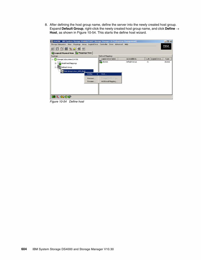
8. After defining the host group name, define the server into the newly created host group. Expand Default Group, right-click the newly created host group name, and click Define → Host, as shown in Figure 10-54. This starts the define host wizard.
Figure 10-54 Define host
604 IBM System Storage DS4000 and Storage Manager V10.30
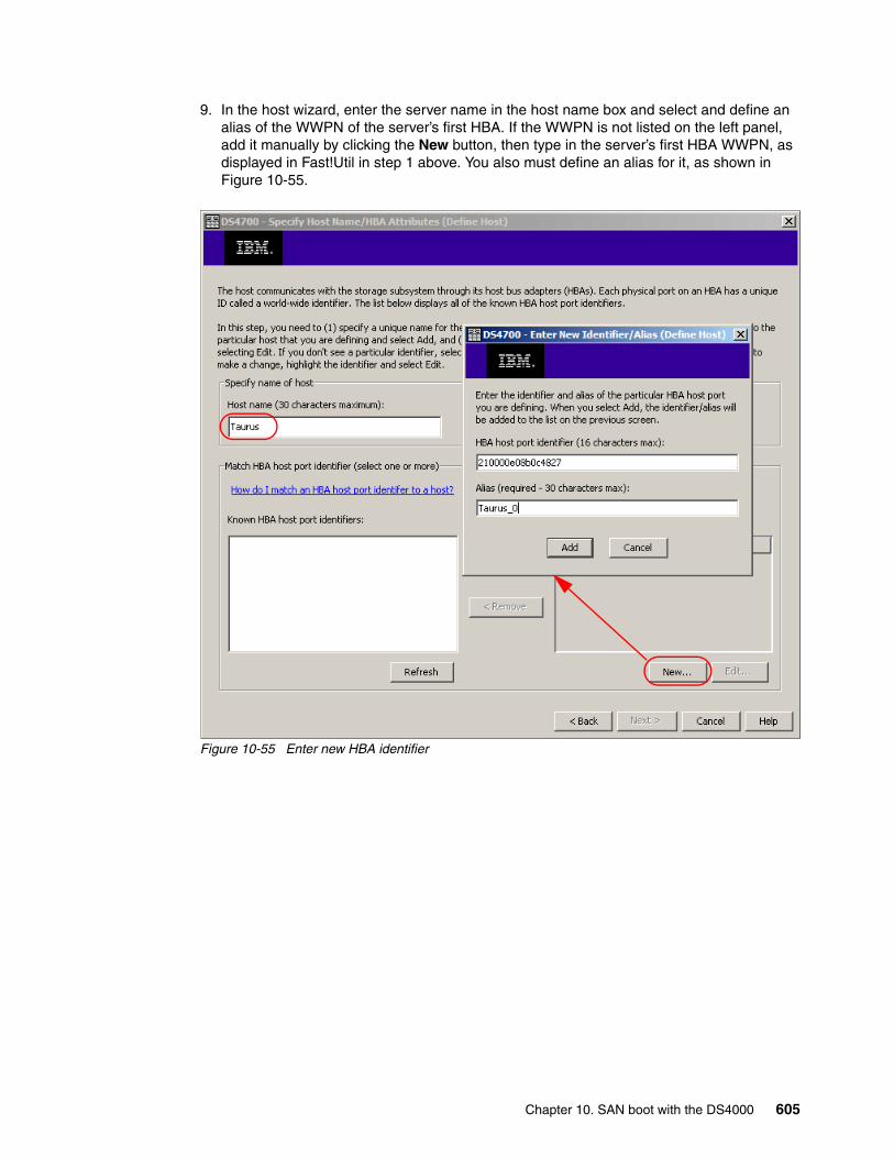
9. In the host wizard, enter the server name in the host name box and select and define an alias of the WWPN of the server’s first HBA. If the WWPN is not listed on the left panel, add it manually by clicking the New button, then type in the server’s first HBA WWPN, as displayed in Fast!Util in step 1 above. You also must define an alias for it, as shown in Figure 10-55.
Figure 10-55 Enter new HBA identifier
Chapter 10. SAN boot with the DS4000 605
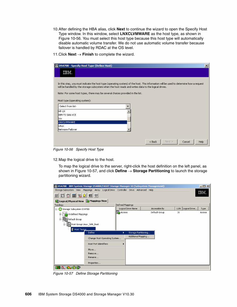
10.After defining the HBA alias, click Next to continue the wizard to open the Specify Host Type window. In this window, select LNXCLVMWARE as the host type, as shown in Figure 10-56. You must select this host type because this host type will automatically disable automatic volume transfer. We do not use automatic volume transfer because failover is handled by RDAC at the OS level.
11.Click Next → Finish to complete the wizard.
Figure 10-56 Specify Host Type
12.Map the logical drive to the host.
To map the logical drive to the server, right-click the host definition on the left panel, as shown in Figure 10-57, and click Define → Storage Partitioning to launch the storage partitioning wizard.
Figure 10-57 Define Storage Partitioning
606 IBM System Storage DS4000 and Storage Manager V10.30
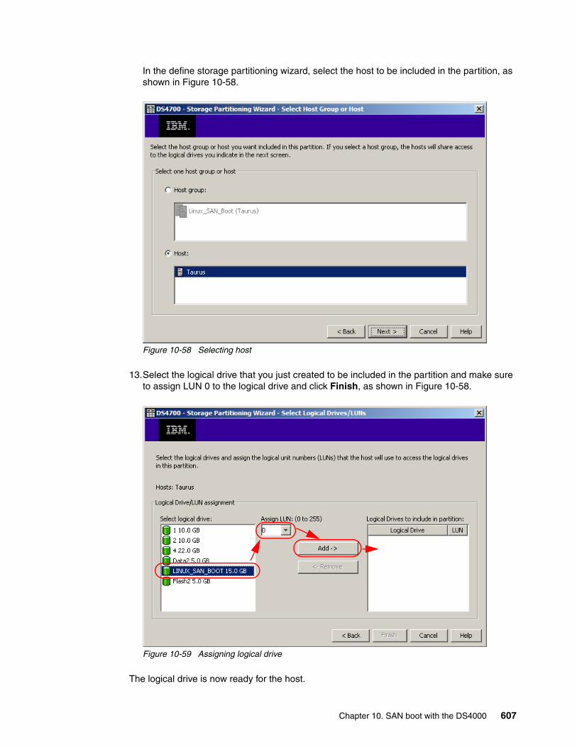
In the define storage partitioning wizard, select the host to be included in the partition, as shown in Figure 10-58.
Figure 10-58 Selecting host
13.Select the logical drive that you just created to be included in the partition and make sure to assign LUN 0 to the logical drive and click Finish, as shown in Figure 10-58.
Figure 10-59 Assigning logical drive
The logical drive is now ready for the host.
Chapter 10. SAN boot with the DS4000 607
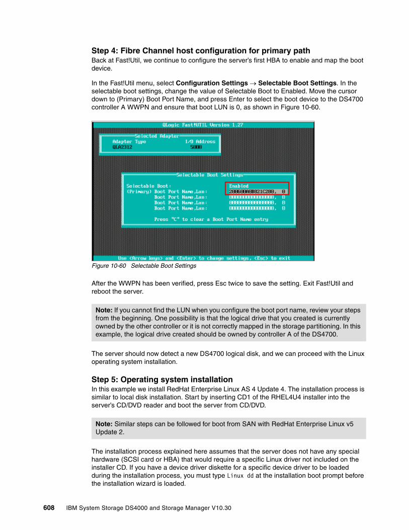
Step 4: Fibre Channel host configuration for primary pathBack at Fast!Util, we continue to configure the server’s first HBA to enable and map the boot device.
In the Fast!Util menu, select Configuration Settings → Selectable Boot Settings. In the selectable boot settings, change the value of Selectable Boot to Enabled. Move the cursor down to (Primary) Boot Port Name, and press Enter to select the boot device to the DS4700 controller A WWPN and ensure that boot LUN is 0, as shown in Figure 10-60.
Figure 10-60 Selectable Boot Settings
After the WWPN has been verified, press Esc twice to save the setting. Exit Fast!Util and reboot the server.
The server should now detect a new DS4700 logical disk, and we can proceed with the Linux operating system installation.
Step 5: Operating system installationIn this example we install RedHat Enterprise Linux AS 4 Update 4. The installation process is similar to local disk installation. Start by inserting CD1 of the RHEL4U4 installer into the server’s CD/DVD reader and boot the server from CD/DVD.
The installation process explained here assumes that the server does not have any special hardware (SCSI card or HBA) that would require a specific Linux driver not included on the installer CD. If you have a device driver diskette for a specific device driver to be loaded during the installation process, you must type Linux dd at the installation boot prompt before the installation wizard is loaded.
Note: If you cannot find the LUN when you configure the boot port name, review your steps from the beginning. One possibility is that the logical drive that you created is currently owned by the other controller or it is not correctly mapped in the storage partitioning. In this example, the logical drive created should be owned by controller A of the DS4700.
Note: Similar steps can be followed for boot from SAN with RedHat Enterprise Linux v5 Update 2.
608 IBM System Storage DS4000 and Storage Manager V10.30
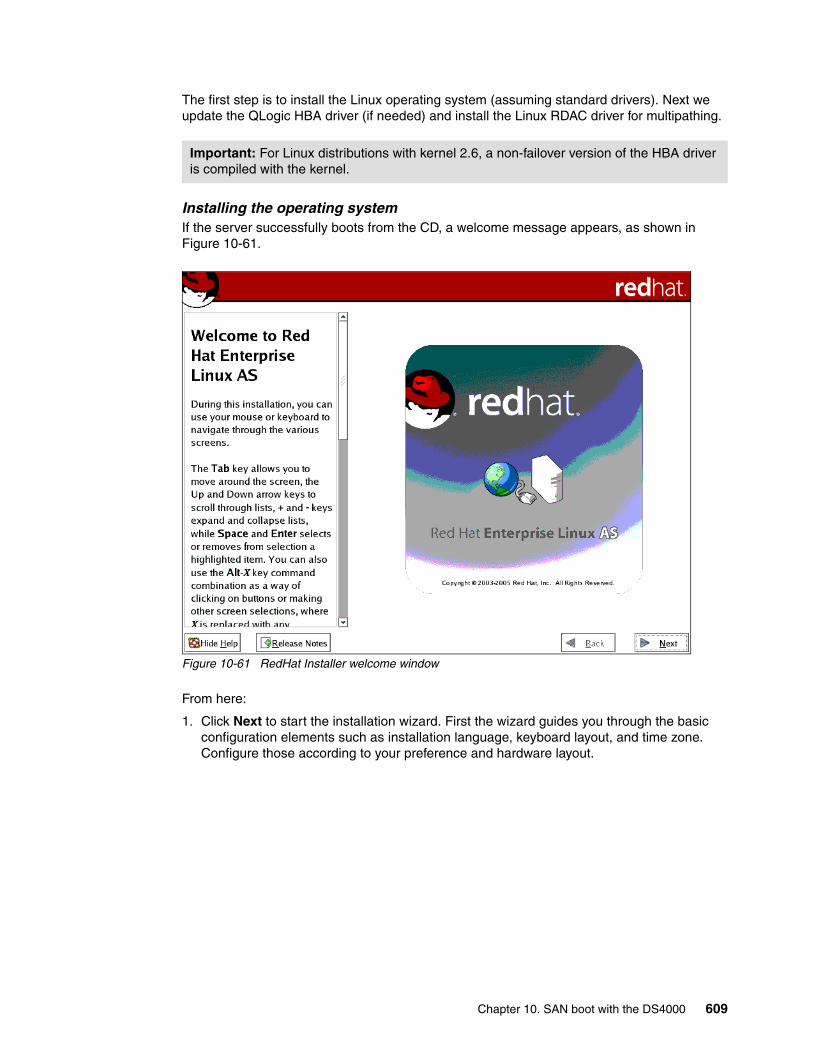
The first step is to install the Linux operating system (assuming standard drivers). Next we update the QLogic HBA driver (if needed) and install the Linux RDAC driver for multipathing.
Installing the operating systemIf the server successfully boots from the CD, a welcome message appears, as shown in Figure 10-61.
Figure 10-61 RedHat Installer welcome window
From here:
1. Click Next to start the installation wizard. First the wizard guides you through the basic configuration elements such as installation language, keyboard layout, and time zone. Configure those according to your preference and hardware layout.
Important: For Linux distributions with kernel 2.6, a non-failover version of the HBA driver is compiled with the kernel.
Chapter 10. SAN boot with the DS4000 609
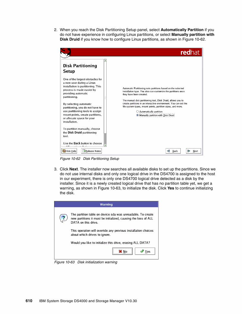
2. When you reach the Disk Partitioning Setup panel, select Automatically Partition if you do not have experience in configuring Linux partitions, or select Manually partition with Disk Druid if you know how to configure Linux partitions, as shown in Figure 10-62.
Figure 10-62 Disk Partitioning Setup
3. Click Next. The installer now searches all available disks to set up the partitions. Since we do not use internal disks and only one logical drive in the DS4700 is assigned to the host in our experiment, there is only one DS4700 logical drive detected as a disk by the installer. Since it is a newly created logical drive that has no partition table yet, we get a warning, as shown in Figure 10-63, to initialize the disk. Click Yes to continue initializing the disk.
Figure 10-63 Disk initialization warning
610 IBM System Storage DS4000 and Storage Manager V10.30
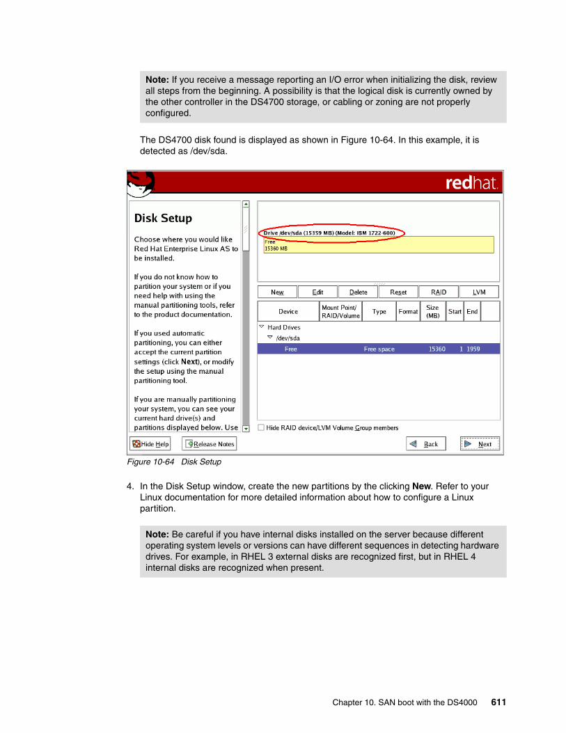
The DS4700 disk found is displayed as shown in Figure 10-64. In this example, it is detected as /dev/sda.
Figure 10-64 Disk Setup
4. In the Disk Setup window, create the new partitions by the clicking New. Refer to your Linux documentation for more detailed information about how to configure a Linux partition.
Note: If you receive a message reporting an I/O error when initializing the disk, review all steps from the beginning. A possibility is that the logical disk is currently owned by the other controller in the DS4700 storage, or cabling or zoning are not properly configured.
Note: Be careful if you have internal disks installed on the server because different operating system levels or versions can have different sequences in detecting hardware drives. For example, in RHEL 3 external disks are recognized first, but in RHEL 4 internal disks are recognized when present.
Chapter 10. SAN boot with the DS4000 611
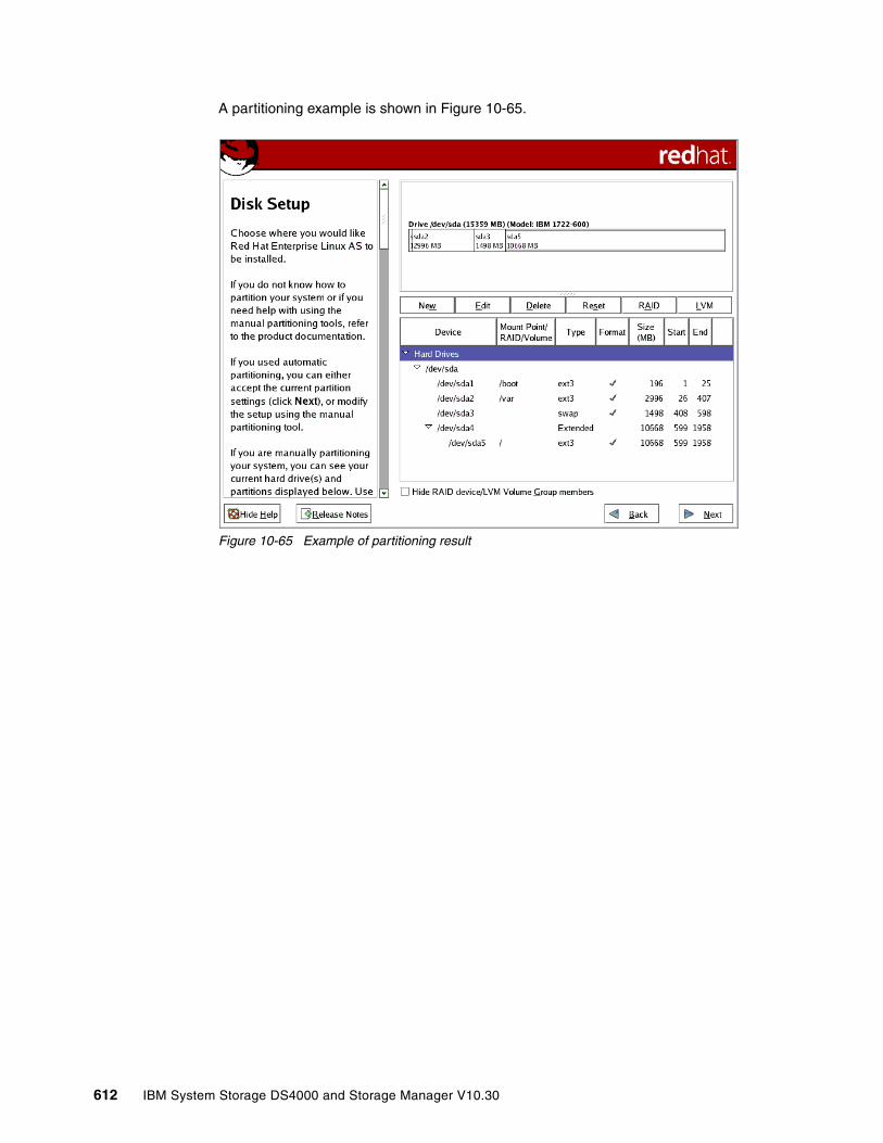
A partitioning example is shown in Figure 10-65.
Figure 10-65 Example of partitioning result
612 IBM System Storage DS4000 and Storage Manager V10.30

5. After disk partitioning is completed, continue the installation by following the instruction wizard. When you reach GRUB (boot loader) installation, ensure that GRUB is installed on the master boot record (MBR) of DS4700 LUN. In this example, GRUB will be installed on /dev/sda, as shown in Figure 10-66.
Figure 10-66 Boot Loader Configuration
Note: Depending on your version of RHEL, you might need to select Configure Advanced Boot Loader options in the Boot Loader Configuration, as shown in Figure 10-66, to modify the GRUB installation in the MBR of the DS4700 LUN, especially if you have internal disks installed.
Chapter 10. SAN boot with the DS4000 613
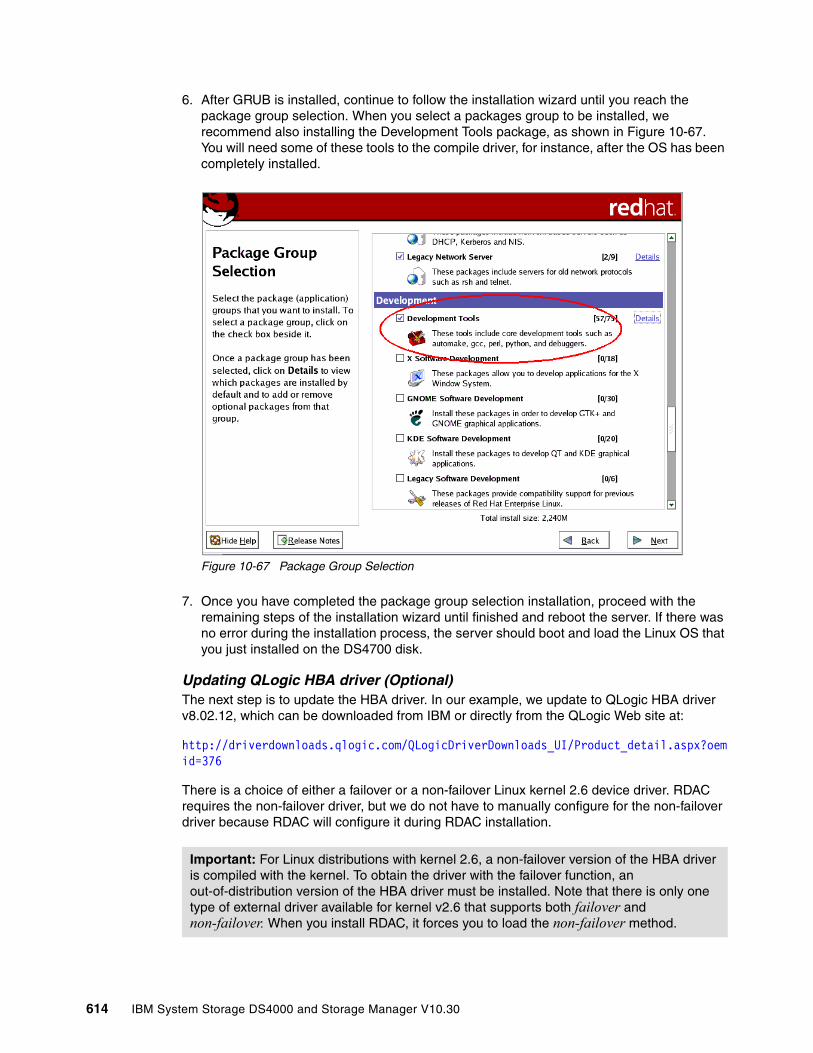
6. After GRUB is installed, continue to follow the installation wizard until you reach the package group selection. When you select a packages group to be installed, we recommend also installing the Development Tools package, as shown in Figure 10-67. You will need some of these tools to the compile driver, for instance, after the OS has been completely installed.
Figure 10-67 Package Group Selection
7. Once you have completed the package group selection installation, proceed with the remaining steps of the installation wizard until finished and reboot the server. If there was no error during the installation process, the server should boot and load the Linux OS that you just installed on the DS4700 disk.
Updating QLogic HBA driver (Optional)The next step is to update the HBA driver. In our example, we update to QLogic HBA driver v8.02.12, which can be downloaded from IBM or directly from the QLogic Web site at:
http://driverdownloads.qlogic.com/QLogicDriverDownloads_UI/Product_detail.aspx?oemid=376
There is a choice of either a failover or a non-failover Linux kernel 2.6 device driver. RDAC requires the non-failover driver, but we do not have to manually configure for the non-failover driver because RDAC will configure it during RDAC installation.
Important: For Linux distributions with kernel 2.6, a non-failover version of the HBA driver is compiled with the kernel. To obtain the driver with the failover function, an out-of-distribution version of the HBA driver must be installed. Note that there is only one type of external driver available for kernel v2.6 that supports both failover and non-failover. When you install RDAC, it forces you to load the non-failover method.
614 IBM System Storage DS4000 and Storage Manager V10.30

After downloading the driver, follow this procedure to update the driver:
1. Extract the file using the following command:
[root@taurus ~]# tar xfvz ibm_dd_ds4kfc_8.02.12_linux2.6_anycpu.tgz
2. Enter the following commands to extract the driver source:
[root@taurus ~]# cd qlogic/[root@taurus ~]# ./drvrsetupExtracting QLogic driver source...Done.
3. Enter the following command to install or set up the SNIA API library:
[root@taurus ~]# ./libinstall
4. Enter the following command to build and install the driver module files:
[root@taurus ~]# cd qla2xxx-8.02.12/[root@taurus ~]# ./extras/build.sh install
5. Add or edit the following lines into /etc/modules.conf:
alias scsi_hostadapter0 qla2xxx_confalias scsi_hostadapter1 qla2xxxalias scsi_hostadapter2 qla2300
Below is an example of file /etc/modules.conf after installing the driver and adding the lines mentioned above:
[root@taurus ~]# cat /etc/modules.confalias eth0 e100alias eth1 e100alias scsi_hostadapter aic7xxxalias usb-controller ohci-hcd
install qla2xxx /sbin/modprobe qla2xxx_conf; /sbin/modprobe --ignore-install qla2xxxremove qla2xxx /sbin/modprobe -r --first-time --ignore-remove qla2xxx && { /sbin/modprobe -r --ignore-remove qla2xxx_conf; }
alias scsi_hostadapter0 qla2xxx_confalias scsi_hostadapter1 qla2xxxalias scsi_hostadapter2 qla2300
6. Create a new RAM disk image:
[root@taurus ~]# depmod -a[root@taurus ~]# mkinitrd -f /boot/new-initrd-`uname -r`.img `uname -r`
The above command creates a new RAM disk image named /boot/new-initrd-2.6.9-42.ELsmp.img because we use Linux kernel 2.6.9-42.ELsmp.
7. Configure the boot loader with the new RAM disk image by modifying the file /boot/grub/menu.lst.
Note: You also must update the OS default HBA driver if you plan to install QLogic SANsurfer in Linux because SANsurfer will not recognize the HBA if the device driver is still the default driver supplied with the OS.
Note: Be careful when modifying file /boot/grub/menu.lst. A typo could make your Linux fail to boot.
Chapter 10. SAN boot with the DS4000 615
Below is sample content of the file /boot/grub/menu.lst after modification:
title Red Hat Enterprise Linux AS (2.6.9-42.ELsmp)root (hd0,0)kernel /vmlinuz-2.6.9-42.ELsmp ro root=LABEL=/ rhgb quietinitrd /new-initrd-2.6.9-42.ELsmp.img
8. Reboot the server.
9. Verify that the new driver is installed and loaded using the following commands:
[root@taurus ~]# ls -al /proc/scsi/qla2xxx/total 0dr-xr-xr-x 2 root root 0 Nov 22 23:21 .dr-xr-xr-x 5 root root 0 Nov 22 23:21 ..-rw-r--r-- 1 root root 0 Nov 22 23:21 2-rw-r--r-- 1 root root 0 Nov 22 23:21 3
[root@taurus ~]# cat /proc/scsi/qla2xxx/2QLogic PCI to Fibre Channel Host Adapter for QCP2340:Firmware version 3.03.19 IPX, Driver version 8.02.12-foISP: ISP2312, Serial# H96488...{truncated}
[root@taurus ~]# cat /proc/scsi/qla2xxx/3QLogic PCI to Fibre Channel Host Adapter for QCP2340:Firmware version 3.03.19 IPX, Driver version 8.02.12-foISP: ISP2312, Serial# H95592...{truncated}
From the above commands we can see that there are two HBAs installed (there are two folders under the /proc/scsi/qla2xxx/ folder) and both of them are loaded using driver Version 8.02.12-fo, which is the new driver that we just installed.
-fo after the driver version (in the above example, the driver version is 8.02.12-fo) means that the loaded driver is in failover mode, which is the default. To configure the new driver to be a non-failover driver, you can insert the line options qla2xxx ql2xfailover=0 into file /etc/modprobe.conf, rebuild the RAM disk image, modify the /boot/grub/menu.lst file, and reboot the server.
Installing RDACAfter updating the QLogic driver, we now install RDAC to handle the multipathing. The installer can be downloaded from the IBM Support Web site.
Note: Modifying file /etc/modprobe.conf to configure the HBA driver to be a non-failover driver as explained above is not necessary if you plan to use RDAC as the multipathing driver. This is because RDAC will put and activate the same parameter into the file /opt/mpp/modprobe.conf.mppappend during RDAC installation to force the QLogic driver to load the non-failover mode.
616 IBM System Storage DS4000 and Storage Manager V10.30

To install RDAC in Linux:
1. Extract the driver source:
[root@taurus ~]# tar xfvz rdac-LINUX-09.02.B5.18-source.tar.gz
2. Compile all driver modules and utilities:
[root@taurus ~]# cd linuxrdac-09.02.B5.18/[root@taurus ~]# make
3. Copy the driver modules to the kernel module tree and build the new RAMdisk image automatically:
[root@taurus ~]# make install
This command copies the driver modules to the kernel module tree and automatically builds the new RAMdisk image (mpp-`uname -r`.img). In our example, the new RAM disk image file is named /boot/mpp-2.6.9-34.ELsmp.img.
4. Configure the boot loader with the new RAM disk image by modifying the file /boot/grub/menu.lst. Replace the line pointing to the RAM disk image created after updating the QLogic driver in the previous section with the RAM disk image created by RDAC installation, including the RDAC driver modules.
Below is a partial example file /boot/grub/menu.lst after modification:
title Red Hat Enterprise Linux AS (2.6.9-42.ELsmp)root (hd0,0)kernel /vmlinuz-2.6.9-42.ELsmp ro root=LABEL=/ rhgb quietinitrd /mpp-2.6.9-42.ELsmp.img
5. Reboot the server.
6. Verify that the driver stack is properly loaded.
[root@taurus ~]# lsmod
The following modules should be loaded:
– scsi_mod– sd_mod– sg– mppUpper– mppVhba– Low-level HBA drivers (for example, qla2xxx, qla2300)
7. Verify that the RDAC driver discovered the available physical LUNs and created virtual LUNs for them:
[root@taurus ~]# ls -lR /proc/mpp
At this stage, RDAC only sees one physical LUN (DS4700) since the secondary path has not been configured yet, as shown in the following example:
[root@taurus ~]# ls -lR /proc/mpp//proc/mpp/:total 0dr-xr-xr-x 3 root root 0 Nov 23 01:39 nash1
/proc/mpp/nash1:total 0dr-xr-xr-x 3 root root 0 Nov 23 01:39 controllerA-rw-r--r-- 1 root root 0 Nov 23 01:39 virtualLun0
/proc/mpp/nash1/controllerA:
Chapter 10. SAN boot with the DS4000 617

total 0dr-xr-xr-x 2 root root 0 Nov 23 01:39 qla2xxx_h2c0t0
/proc/mpp/nash1/controllerA/qla2xxx_h2c0t0:total 0-rw-r--r-- 1 root root 0 Nov 23 01:39 LUN0
In this example, nash1 is the name of the storage subsystem. RDAC sees one physical LUN via controller A because only the primary path is currently configured, and created one virtual LUN. We run the same command and compare the result after configuring the secondary path later.
Step 6: Zone configuration on the second SAN switchNow that we have installed the operating system and tested the boot from SAN using one path, we start to configure the secondary path. The secondary path connects the DS4700 controller B with the server’s second HBA. Refer the to installation diagram in Figure 10-44 on page 598.
We now zone the fabric to include a zone that allows the second HBA adapter to connect to controller B of the DS4700 storage subsystem that we are going to boot from, as shown in Figure 10-68. This allows for redundant paths from the System x server to the DS4700 storage subsystem.
Figure 10-68 Zoning configuration for second path
Step 7: DS4000 configuration for the secondary pathAt this stage we only must define the server’s second HBA port in the Mapping View tab of the Storage Manager Subsystem Management window.
618 IBM System Storage DS4000 and Storage Manager V10.30
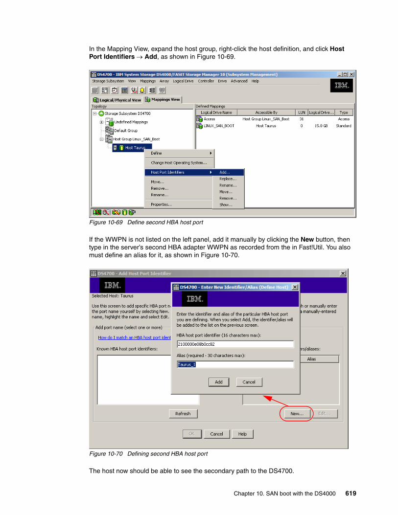
In the Mapping View, expand the host group, right-click the host definition, and click Host Port Identifiers → Add, as shown in Figure 10-69.
Figure 10-69 Define second HBA host port
If the WWPN is not listed on the left panel, add it manually by clicking the New button, then type in the server’s second HBA adapter WWPN as recorded from the in Fast!Util. You also must define an alias for it, as shown in Figure 10-70.
Figure 10-70 Defining second HBA host port
The host now should be able to see the secondary path to the DS4700.
Chapter 10. SAN boot with the DS4000 619
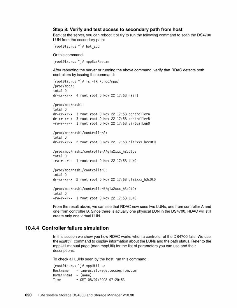
Step 8: Verify and test access to secondary path from hostBack at the server, you can reboot it or try to run the following command to scan the DS4700 LUN from the secondary path:
[root@taurus ~]# hot_add
Or this command:
[root@taurus ~]# mppBusRescan
After rebooting the server or running the above command, verify that RDAC detects both controllers by issuing the command:
[root@taurus ~]# ls -lR /proc/mpp//proc/mpp/:total 0dr-xr-xr-x 4 root root 0 Nov 22 17:58 nash1
/proc/mpp/nash1:total 0dr-xr-xr-x 3 root root 0 Nov 22 17:58 controllerAdr-xr-xr-x 3 root root 0 Nov 22 17:58 controllerB-rw-r--r-- 1 root root 0 Nov 22 17:58 virtualLun0
/proc/mpp/nash1/controllerA:total 0dr-xr-xr-x 2 root root 0 Nov 22 17:58 qla2xxx_h2c0t0
/proc/mpp/nash1/controllerA/qla2xxx_h2c0t0:total 0-rw-r--r-- 1 root root 0 Nov 22 17:58 LUN0
/proc/mpp/nash1/controllerB:total 0dr-xr-xr-x 2 root root 0 Nov 22 17:58 qla2xxx_h3c0t0
/proc/mpp/nash1/controllerB/qla2xxx_h3c0t0:total 0-rw-r--r-- 1 root root 0 Nov 22 17:58 LUN0
From the result above, we can see that RDAC now sees two LUNs, one from controller A and one from controller B. Since there is actually one physical LUN in the DS4700, RDAC will still create only one virtual LUN.
10.4.4 Controller failure simulation
In this section we show you how RDAC works when a controller of the DS4700 fails. We use the mppUtil command to display information about the LUNs and the path status. Refer to the mppUtil manual page (man mppUtil) for the list of parameters you can use and their descriptions.
To check all LUNs seen by the host, run this command:
[root@taurus ~]# mppUtil -aHostname = taurus.storage.tucson.ibm.comDomainname = (none)Time = GMT 08/07/2008 07:20:53
620 IBM System Storage DS4000 and Storage Manager V10.30

---------------------------------------------------------------Info of Array Module's seen by this Host.---------------------------------------------------------------ID WWN Name--------------------------------------------------------------- 0 600a0b8000220e9c0000000044d2f6dc nash1---------------------------------------------------------------
The result in this example shows one LUN with a virtual target ID 0 detected by RDAC. This is the LUN in the DS4700 where the operating system is installed.
To check the path status, run the following command:
[root@taurus ~]# mppUtil -g 0Hostname = taurus.storage.tucson.ibm.comDomainname = (none)Time = GMT 08/07/2008 07:05:12
MPP Information:---------------- ModuleName: nash1 SingleController: N VirtualTargetID: 0x000 ScanTriggered: N ObjectCount: 0x000 AVTEnabled: N WWN: 600a0b8000220e9c0000000044d2f6dc RestoreCfg: N ModuleHandle: none Page2CSubPage: Y FirmwareVersion: 7.15.07.0 ScanTaskState: 0x00000000
Controller 'A' Status:-----------------------ControllerHandle: none ControllerPresent: Y UTMLunExists: N Failed: N NumberOfPaths: 1 FailoverInProg: N ServiceMode: N
Path #1 --------- DirectoryVertex: present Present: Y PathState: OPTIMAL hostId: 2, targetId: 0, channelId: 0
Controller 'B' Status:-----------------------ControllerHandle: none ControllerPresent: Y UTMLunExists: N Failed: N NumberOfPaths: 1 FailoverInProg: N ServiceMode: N
Path #1 ---------DirectoryVertex: present Present: Y PathState: OPTIMAL hostId: 3, targetId: 0, channelId: 0
Chapter 10. SAN boot with the DS4000 621
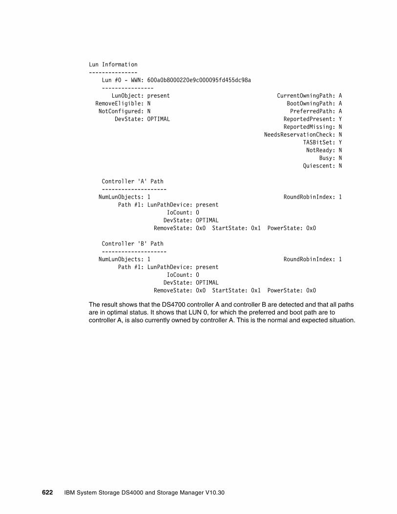
Lun Information--------------- Lun #0 - WWN: 600a0b8000220e9c000095fd455dc98a ---------------- LunObject: present CurrentOwningPath: A RemoveEligible: N BootOwningPath: A NotConfigured: N PreferredPath: A DevState: OPTIMAL ReportedPresent: Y ReportedMissing: N NeedsReservationCheck: N TASBitSet: Y NotReady: N Busy: N Quiescent: N
Controller 'A' Path -------------------- NumLunObjects: 1 RoundRobinIndex: 1 Path #1: LunPathDevice: present IoCount: 0 DevState: OPTIMAL RemoveState: 0x0 StartState: 0x1 PowerState: 0x0
Controller 'B' Path -------------------- NumLunObjects: 1 RoundRobinIndex: 1 Path #1: LunPathDevice: present IoCount: 0 DevState: OPTIMAL RemoveState: 0x0 StartState: 0x1 PowerState: 0x0
The result shows that the DS4700 controller A and controller B are detected and that all paths are in optimal status. It shows that LUN 0, for which the preferred and boot path are to controller A, is also currently owned by controller A. This is the normal and expected situation.
622 IBM System Storage DS4000 and Storage Manager V10.30
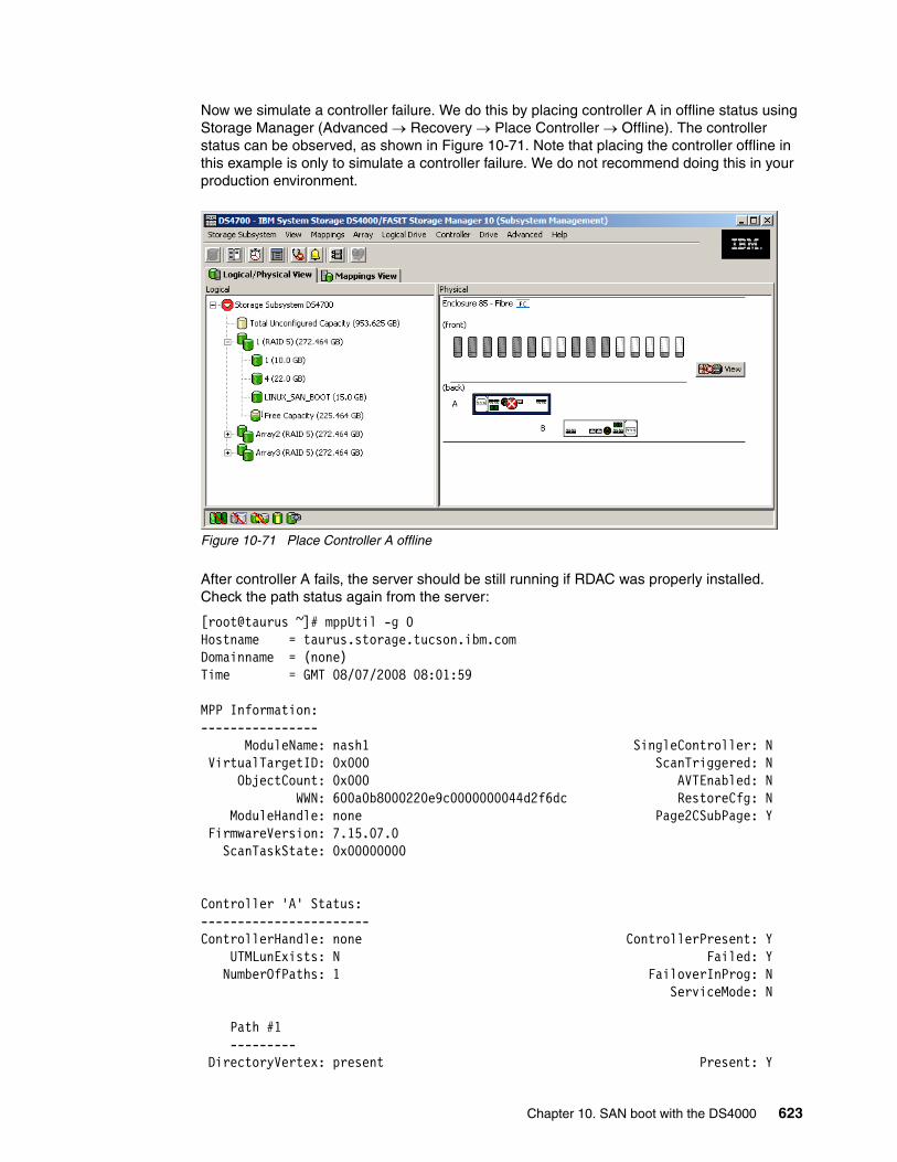
Now we simulate a controller failure. We do this by placing controller A in offline status using Storage Manager (Advanced → Recovery → Place Controller → Offline). The controller status can be observed, as shown in Figure 10-71. Note that placing the controller offline in this example is only to simulate a controller failure. We do not recommend doing this in your production environment.
Figure 10-71 Place Controller A offline
After controller A fails, the server should be still running if RDAC was properly installed. Check the path status again from the server:
[root@taurus ~]# mppUtil -g 0Hostname = taurus.storage.tucson.ibm.comDomainname = (none)Time = GMT 08/07/2008 08:01:59
MPP Information:---------------- ModuleName: nash1 SingleController: N VirtualTargetID: 0x000 ScanTriggered: N ObjectCount: 0x000 AVTEnabled: N WWN: 600a0b8000220e9c0000000044d2f6dc RestoreCfg: N ModuleHandle: none Page2CSubPage: Y FirmwareVersion: 7.15.07.0 ScanTaskState: 0x00000000
Controller 'A' Status:-----------------------ControllerHandle: none ControllerPresent: Y UTMLunExists: N Failed: Y NumberOfPaths: 1 FailoverInProg: N ServiceMode: N
Path #1 --------- DirectoryVertex: present Present: Y
Chapter 10. SAN boot with the DS4000 623
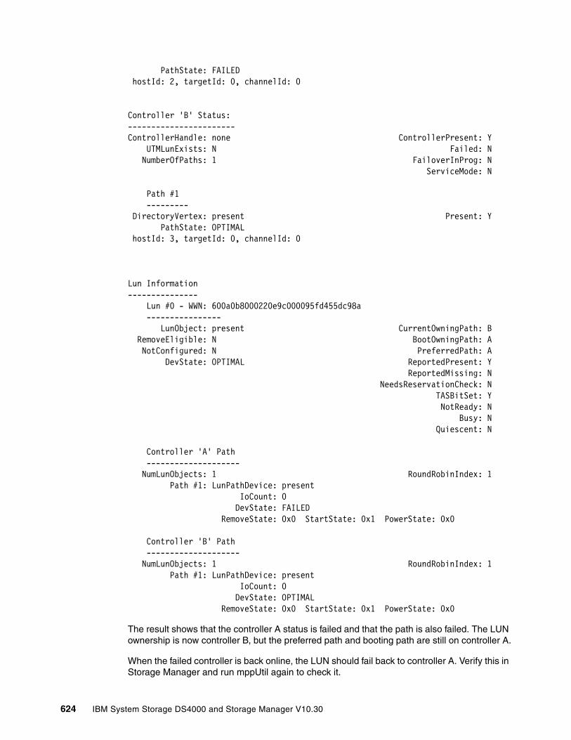
PathState: FAILED hostId: 2, targetId: 0, channelId: 0
Controller 'B' Status:-----------------------ControllerHandle: none ControllerPresent: Y UTMLunExists: N Failed: N NumberOfPaths: 1 FailoverInProg: N ServiceMode: N
Path #1 --------- DirectoryVertex: present Present: Y PathState: OPTIMAL hostId: 3, targetId: 0, channelId: 0
Lun Information--------------- Lun #0 - WWN: 600a0b8000220e9c000095fd455dc98a ---------------- LunObject: present CurrentOwningPath: B RemoveEligible: N BootOwningPath: A NotConfigured: N PreferredPath: A DevState: OPTIMAL ReportedPresent: Y ReportedMissing: N NeedsReservationCheck: N TASBitSet: Y NotReady: N Busy: N Quiescent: N
Controller 'A' Path -------------------- NumLunObjects: 1 RoundRobinIndex: 1 Path #1: LunPathDevice: present IoCount: 0 DevState: FAILED RemoveState: 0x0 StartState: 0x1 PowerState: 0x0
Controller 'B' Path -------------------- NumLunObjects: 1 RoundRobinIndex: 1 Path #1: LunPathDevice: present IoCount: 0 DevState: OPTIMAL RemoveState: 0x0 StartState: 0x1 PowerState: 0x0
The result shows that the controller A status is failed and that the path is also failed. The LUN ownership is now controller B, but the preferred path and booting path are still on controller A.
When the failed controller is back online, the LUN should fail back to controller A. Verify this in Storage Manager and run mppUtil again to check it.
624 IBM System Storage DS4000 and Storage Manager V10.30
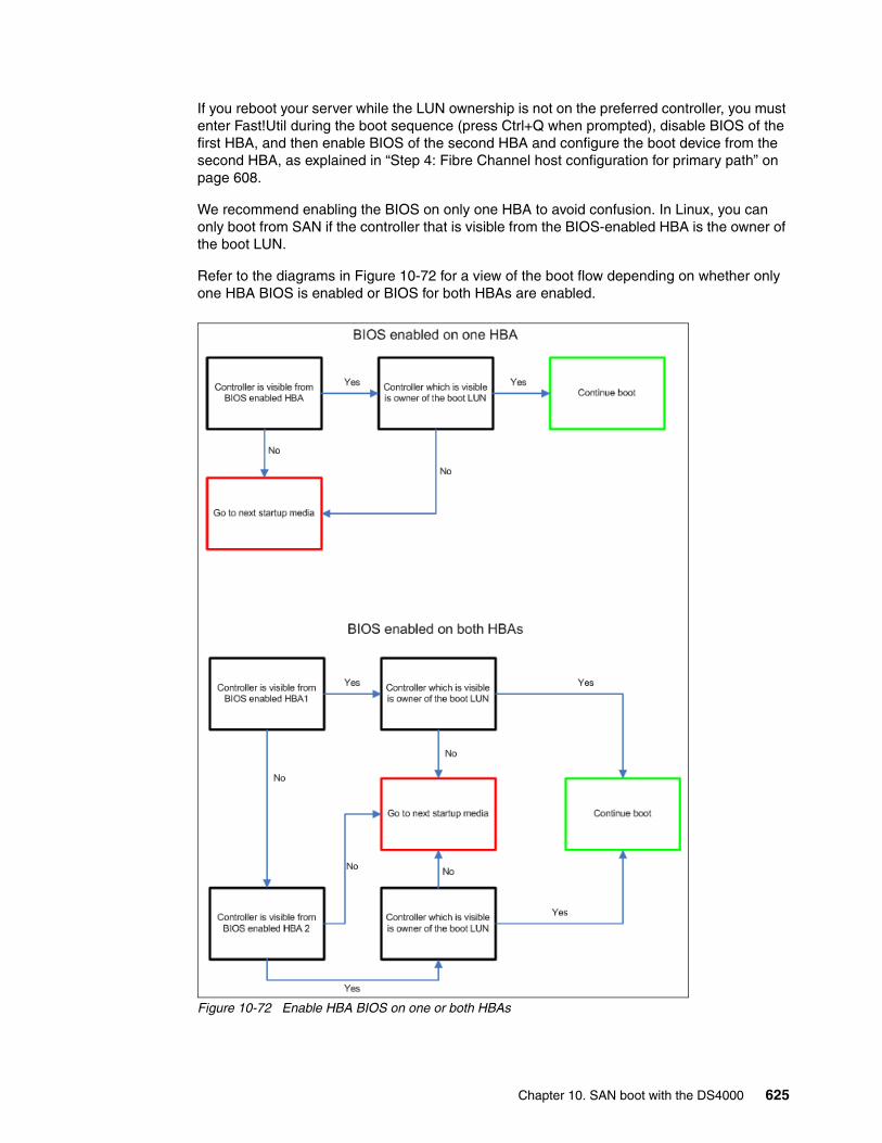
If you reboot your server while the LUN ownership is not on the preferred controller, you must enter Fast!Util during the boot sequence (press Ctrl+Q when prompted), disable BIOS of the first HBA, and then enable BIOS of the second HBA and configure the boot device from the second HBA, as explained in “Step 4: Fibre Channel host configuration for primary path” on page 608.
We recommend enabling the BIOS on only one HBA to avoid confusion. In Linux, you can only boot from SAN if the controller that is visible from the BIOS-enabled HBA is the owner of the boot LUN.
Refer to the diagrams in Figure 10-72 for a view of the boot flow depending on whether only one HBA BIOS is enabled or BIOS for both HBAs are enabled.
Figure 10-72 Enable HBA BIOS on one or both HBAs
Chapter 10. SAN boot with the DS4000 625

10.5 Implementing MCSC SAN boot with blade servers
This section briefly illustrates and explains limitations relevant to implementing Microsoft Cluster Server (MSCS) SAN boot with IBM Blade Servers.
When implementing an MSCS in a SAN boot environment, the MSCS servers must keep the boot LUNs separate from the shared cluster LUNs. The cluster setup fails if the boot LUN and the shared LUNs are discovered on the same bus.
Figure 10-73 on page 627 illustrates a scenario relevant to MSCS SAN boot limitations:
� With MSCS SAN boot, boot LUNs must be separated from data/shared cluster LUNs in the clustered environment.
� Boot LUNs must be owned by each individual host within the cluster and should be seen by the relevant hosts only (LUN X and LUN Y).
� Data/shared cluster LUNs should be shared across all hosts (LUN Z). This is achieved by creating a host group on the DS4000 storage subsystem for all hosts in the cluster with all data/shared cluster LUNs mapped to the host group (host group HG and LUN Z). All individual HBA host ports should be mapped to the host group.
� Individual cluster hosts should be created within a host group containing their private boot LUNs (hosts HA and HB with LUN X and LUN Y allocated, respectively, as LUN 0). Individual HBA host ports should be mapped to these hosts.
Note: This limitation is not applicable to Windows Server 2008.
626 IBM System Storage DS4000 and Storage Manager V10.30
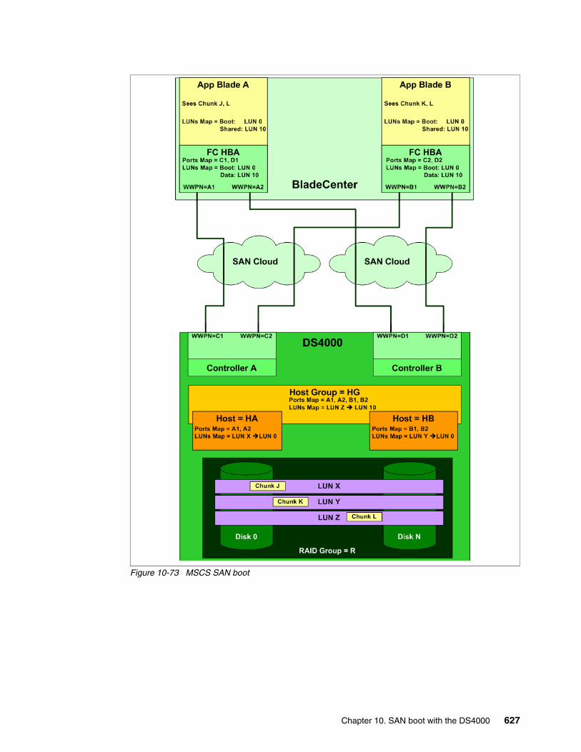
Figure 10-73 MSCS SAN boot
Chapter 10. SAN boot with the DS4000 627
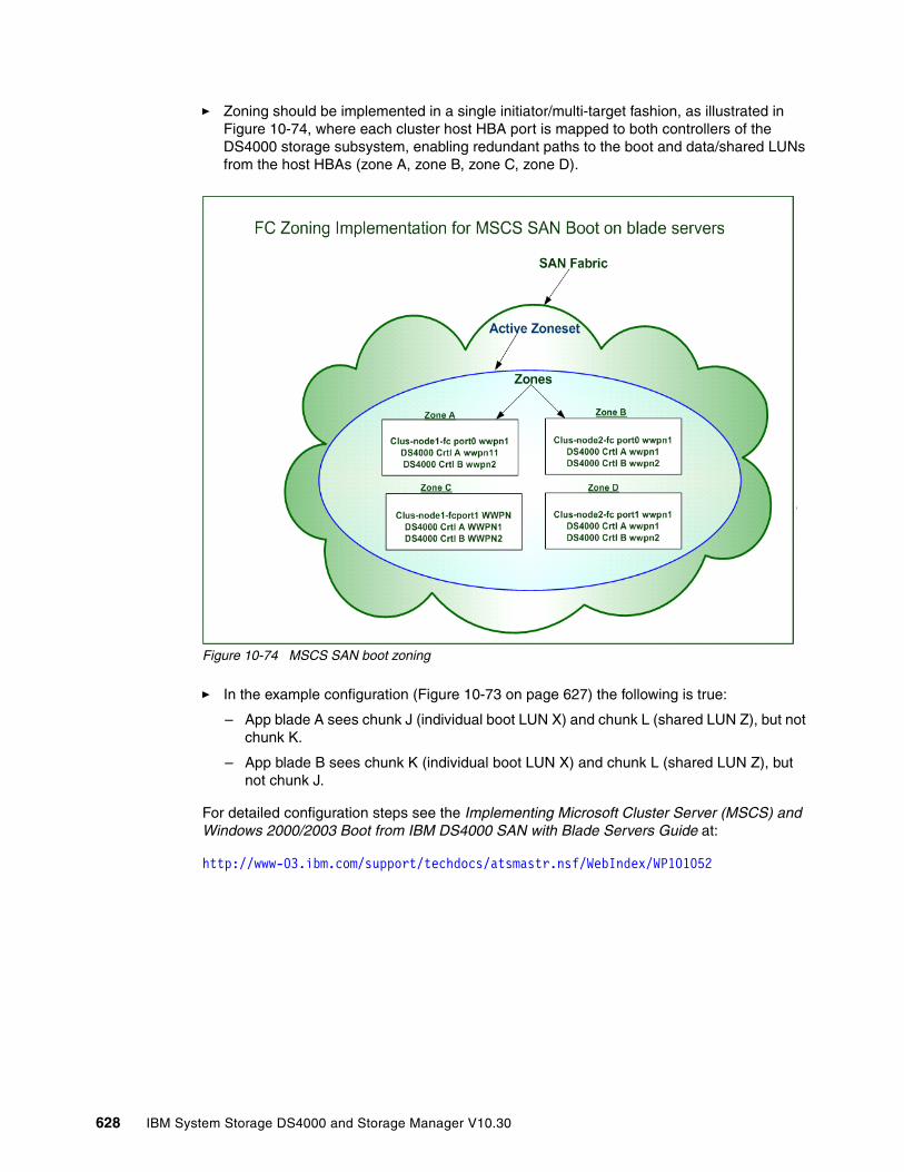
� Zoning should be implemented in a single initiator/multi-target fashion, as illustrated in Figure 10-74, where each cluster host HBA port is mapped to both controllers of the DS4000 storage subsystem, enabling redundant paths to the boot and data/shared LUNs from the host HBAs (zone A, zone B, zone C, zone D).
Figure 10-74 MSCS SAN boot zoning
� In the example configuration (Figure 10-73 on page 627) the following is true:
– App blade A sees chunk J (individual boot LUN X) and chunk L (shared LUN Z), but not chunk K.
– App blade B sees chunk K (individual boot LUN X) and chunk L (shared LUN Z), but not chunk J.
For detailed configuration steps see the Implementing Microsoft Cluster Server (MSCS) and Windows 2000/2003 Boot from IBM DS4000 SAN with Blade Servers Guide at:
http://www-03.ibm.com/support/techdocs/atsmastr.nsf/WebIndex/WP101052
628 IBM System Storage DS4000 and Storage Manager V10.30
Chapter 11. Command-line interface and Script Editor
All storage management functions available through the Subsystem Management window can also be performed and sent to the storage system using statements in scripts. You can use the Script Editor to create or edit a script file, save a script file to the Storage Management station’s local disk, or load a script file from disk. You can also use the command-line interface (CLI) to issue individual commands to the scripting engine from the host operating system command line or to invoke complete pre-written scripts.
This chapter explains how to work with the command-line interface and the Script Editor. Refer to the latest Command Line Interface and Script Commands Programming Guide on the IBM Support Web site for more information.
11
© Copyright IBM Corp. 2004, 2005, 2006, 2007, 2008, 2009. All rights reserved. 629
11.1 Command-line interfaceThe script engine is built into the storage management software and processes commands one at a time. It is invoked using three different methods:
� Interactive command-line interface� Batch command-line interface� Script editor
Both the interactive and the batch command-line interfaces use the SMcli command that is packaged with the SMclient GUI. The interactive command-line interface connects to a storage system and returns to a command prompt to await your instructions. This interface is useful for basic storage system configuration, command testing, and connectivity testing.
The batch command-line interface uses the SMcli -f <scriptfile> form of the command where scriptfile is simply a series of commands that you wish to execute. This simple feature gives you the ability to create platform-independent script files to execute against your storage systems. The format of the commands that you put in this file are exactly as you would enter them on the interactive command-line interface.
The script editor is accessed from the GUI and provides a simple way to manage a single storage system or test command syntax and execution. It is covered in more detail in 11.2, “Script editor” on page 656.
Any of these methods provides an efficient way to edit, send, and execute storage management commands on multiple network storage systems. The script engine makes it possible to automate many tasks, such as backup procedures or firmware upgrades on the storage system.
The SMclient software must be installed on the station that will be used for command-line instructions. Detailed instructions on the installation of the SMclient can be found in Chapter 5, “Step-by-step procedures using Storage Manager” on page 179.
11.1.1 Using CLI commandsThe basic syntax of a CLI command is:
command parameter;
The most important part of this syntax is the semicolon (;) at the end of the command. This terminates the command and causes the script engine to process it. A typical command looks like this:
show storagesubsystem;
Before you can execute a command, you must connect the SMcli to the storage system. Both the interactive and the batch command-line interfaces can address the target storage system using a number of different identifiers depending on the management method used:
� Directly managed (out-of-band): Use the host name or IP address of either or both controllers:
SMcli <IP address of one controller> <IP address of second controller>
If the storage system is configured in the Enterprise Management window, you can specify the storage system by its user-supplied name only using the -n option. The name must be unique to the Enterprise Management window, for example:
SMcli -n <name of the DS4000 Storage Server>
630 IBM System Storage DS4000 and Storage Manager V10.30

If the name of the DS4000 storage server consists of spaces and special characters you must put it into double quotation marks (“), for example:
SMcli -n “Remote DS4700"
� Host-agent managed (in-band): Use the host name or IP address of the managing host (the host that is running the SMagent):
SMcli <hostname of managing station>
You must use the -n option if more than one host-agent managed storage system is connected to the host, for example:
SMcli <hostname of managing station> -n <name of the DS4000 Storage Server>
If you specify the worldwide name of the storage system, use the -w option instead of the -n option, for example:
SMcli -w 600a0b800006602d000000003beb684b
After executing one of the above commands, you are in interactive command-line mode and can enter one or more commands. SMcli verifies the existence of the specified storage systems and returns to a command prompt to await your instructions. When you are finished entering commands, press Ctrl+C to return to the operating system command prompt.
11.1.2 CLI parametersExample 11-1 shows the help information displayed as a result of executing SMcli -? on a Windows platform.
Example 11-1 Help on SMcli
C:\Program Files\IBM_DS4000\client>SMcli -?SMcli <DNS-network-name-or-IP-address> [<DNS-network-name-or-IP-address>] [-c "<command>;[<command2>;...]"] [-n <storage-array-name> | -w <WWID>] [-o <outputfile>] [-p <password>] [-e] [-S] [-quick]SMcli <DNS-network-name-or-IP-address> [<DNS-network-name-or-IP-address>] [-f <scriptfile>] [-n <storage-array-name> | -w <WWID>] [-o <outputfile>] [-p <password>] [-e] [-S] [-quick]SMcli {-n <storage-array-name> | -w <WWID>} [-c "<command>;[<command2>;...]"] [-o <outputfile>] [-p <password>] [-e] [-S] [-quick]SMcli {-n <storage-array-name> | -w <WWID>} [-f <scriptfile>] [-o <outputfile>] [-p <password>] [-e] [-S] [-quick]SMcli -d [-i] [-s] [-w] [-v] [-S]SMcli -A [<DNS-network-name-or-IP-address1> [DNS-network-name-or-IP-address2]] [-S]SMcli -X (-n <storage-array-name> | -w <WWID> | -h <hostName>)SMcli -m <ip address> -F <email address> [-g <contactInfoFile>] [-S]SMcli -x email:<email address> [<hostname or IP address1> [<hostname or IP address2>]] [-n <storage-array-name> | -w WWID | -h <hostName> | -r (direct_sa | host_sa)]} [-S]SMcli -a email:<email address> [<hostname or IP address1> [<hostname or IP address2>]] [-n <storage-array-name> | -w <WWID> | -h <hostName> | -r (direct_sa | host_sa)]} [-I <informationToInclude>] [-q <frequency>] [-S]SMcli {-a | -x} trap:<community>,<hostname or IP address> [<hostname or IP address1> [<hostname or IP address2>]]
Chapter 11. Command-line interface and Script Editor 631
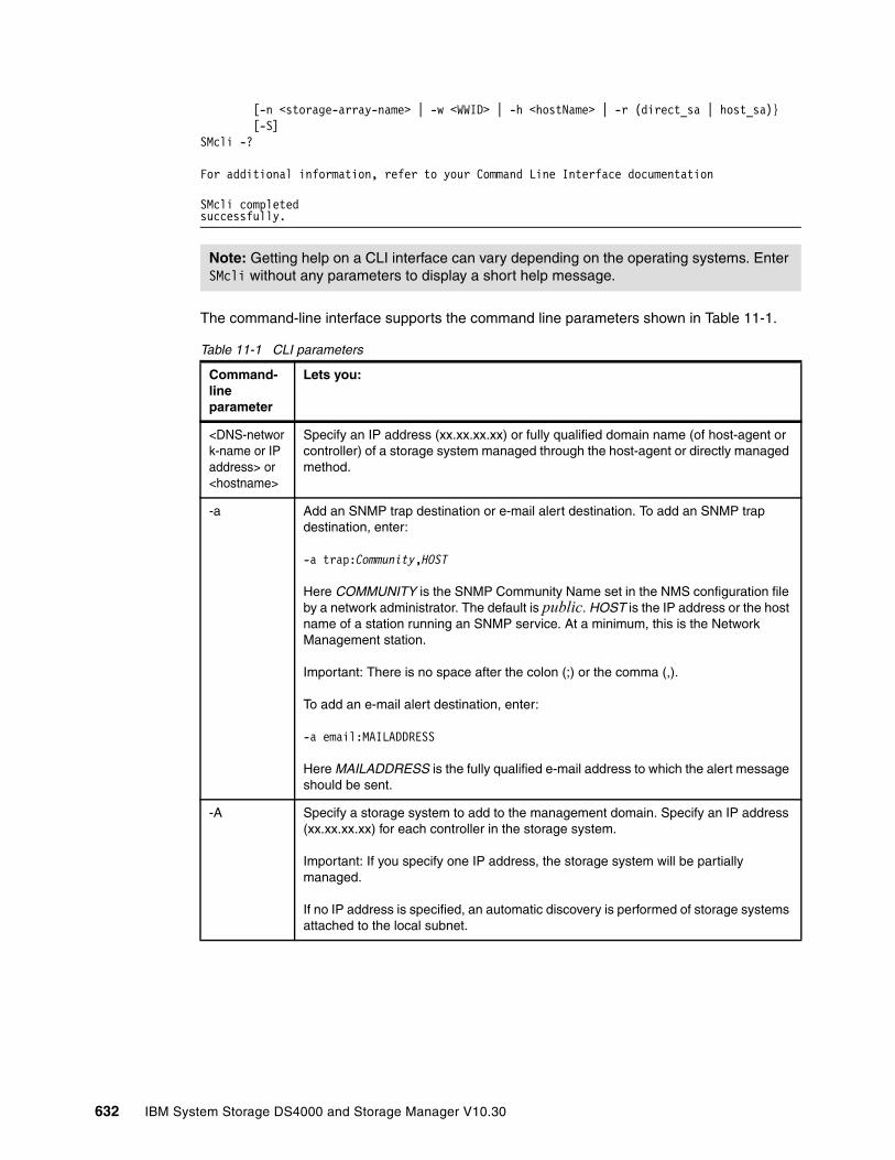
[-n <storage-array-name> | -w <WWID> | -h <hostName> | -r (direct_sa | host_sa)} [-S]SMcli -?
For additional information, refer to your Command Line Interface documentation
SMcli completed successfully.
The command-line interface supports the command line parameters shown in Table 11-1.
Table 11-1 CLI parameters
Note: Getting help on a CLI interface can vary depending on the operating systems. Enter SMcli without any parameters to display a short help message.
Command-line parameter
Lets you:
<DNS-network-name or IP address> or <hostname>
Specify an IP address (xx.xx.xx.xx) or fully qualified domain name (of host-agent or controller) of a storage system managed through the host-agent or directly managed method.
-a Add an SNMP trap destination or e-mail alert destination. To add an SNMP trap destination, enter:
-a trap:Community,HOST
Here COMMUNITY is the SNMP Community Name set in the NMS configuration file by a network administrator. The default is public. HOST is the IP address or the host name of a station running an SNMP service. At a minimum, this is the Network Management station.
Important: There is no space after the colon (;) or the comma (,).
To add an e-mail alert destination, enter:
-a email:MAILADDRESS
Here MAILADDRESS is the fully qualified e-mail address to which the alert message should be sent.
-A Specify a storage system to add to the management domain. Specify an IP address (xx.xx.xx.xx) for each controller in the storage system.
Important: If you specify one IP address, the storage system will be partially managed.
If no IP address is specified, an automatic discovery is performed of storage systems attached to the local subnet.
632 IBM System Storage DS4000 and Storage Manager V10.30
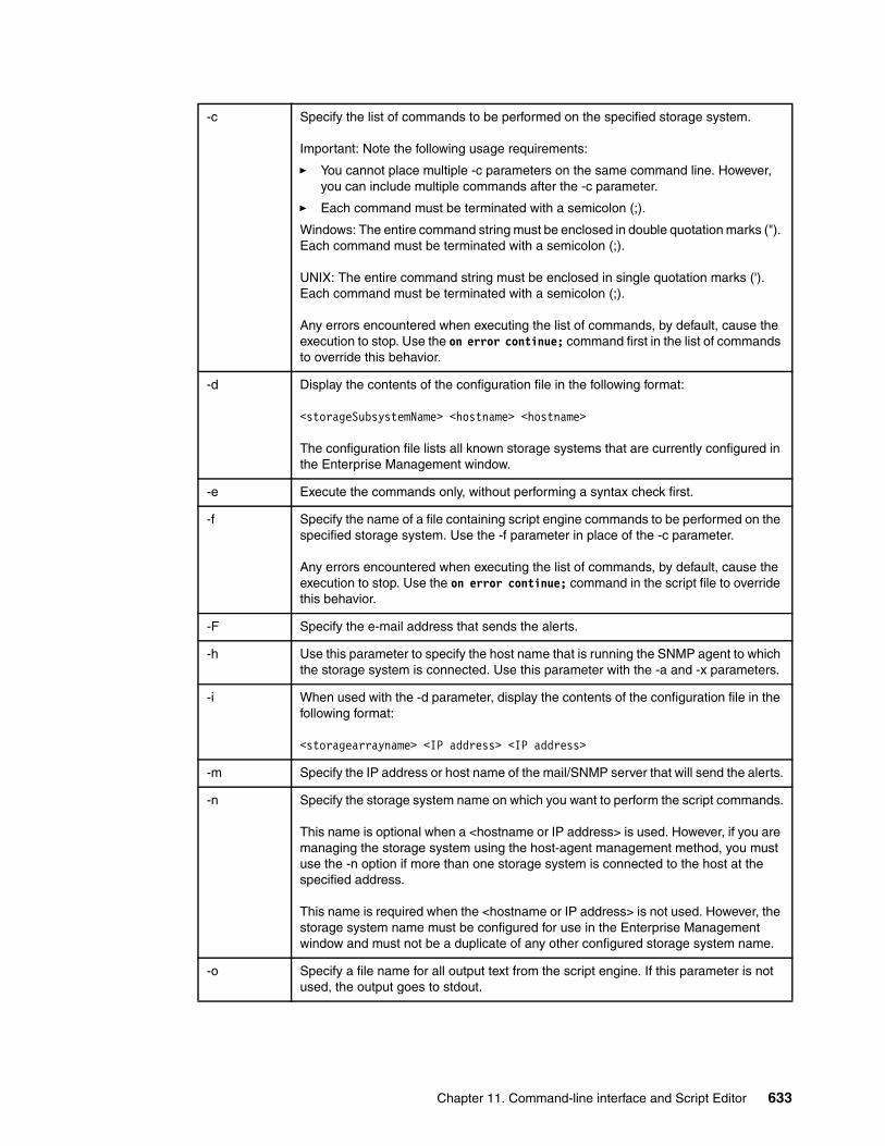
-c Specify the list of commands to be performed on the specified storage system.
Important: Note the following usage requirements:
� You cannot place multiple -c parameters on the same command line. However, you can include multiple commands after the -c parameter.
� Each command must be terminated with a semicolon (;).
Windows: The entire command string must be enclosed in double quotation marks ("). Each command must be terminated with a semicolon (;).
UNIX: The entire command string must be enclosed in single quotation marks ('). Each command must be terminated with a semicolon (;).
Any errors encountered when executing the list of commands, by default, cause the execution to stop. Use the on error continue; command first in the list of commands to override this behavior.
-d Display the contents of the configuration file in the following format:
<storageSubsystemName> <hostname> <hostname>
The configuration file lists all known storage systems that are currently configured in the Enterprise Management window.
-e Execute the commands only, without performing a syntax check first.
-f Specify the name of a file containing script engine commands to be performed on the specified storage system. Use the -f parameter in place of the -c parameter.
Any errors encountered when executing the list of commands, by default, cause the execution to stop. Use the on error continue; command in the script file to override this behavior.
-F Specify the e-mail address that sends the alerts.
-h Use this parameter to specify the host name that is running the SNMP agent to which the storage system is connected. Use this parameter with the -a and -x parameters.
-i When used with the -d parameter, display the contents of the configuration file in the following format:
<storagearrayname> <IP address> <IP address>
-m Specify the IP address or host name of the mail/SNMP server that will send the alerts.
-n Specify the storage system name on which you want to perform the script commands.
This name is optional when a <hostname or IP address> is used. However, if you are managing the storage system using the host-agent management method, you must use the -n option if more than one storage system is connected to the host at the specified address.
This name is required when the <hostname or IP address> is not used. However, the storage system name must be configured for use in the Enterprise Management window and must not be a duplicate of any other configured storage system name.
-o Specify a file name for all output text from the script engine. If this parameter is not used, the output goes to stdout.
Chapter 11. Command-line interface and Script Editor 633
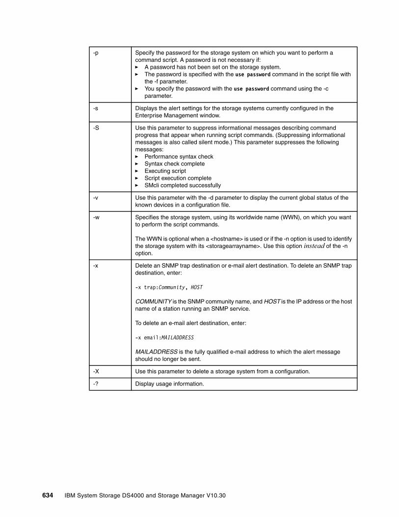
-p Specify the password for the storage system on which you want to perform a command script. A password is not necessary if:� A password has not been set on the storage system. � The password is specified with the use password command in the script file with
the -f parameter. � You specify the password with the use password command using the -c
parameter.
-s Displays the alert settings for the storage systems currently configured in the Enterprise Management window.
-S Use this parameter to suppress informational messages describing command progress that appear when running script commands. (Suppressing informational messages is also called silent mode.) This parameter suppresses the following messages:� Performance syntax check� Syntax check complete� Executing script� Script execution complete� SMcli completed successfully
-v Use this parameter with the -d parameter to display the current global status of the known devices in a configuration file.
-w Specifies the storage system, using its worldwide name (WWN), on which you want to perform the script commands.
The WWN is optional when a <hostname> is used or if the -n option is used to identify the storage system with its <storagearrayname>. Use this option instead of the -n option.
-x Delete an SNMP trap destination or e-mail alert destination. To delete an SNMP trap destination, enter:
-x trap:Community, HOST
COMMUNITY is the SNMP community name, and HOST is the IP address or the host name of a station running an SNMP service.
To delete an e-mail alert destination, enter:
-x email:MAILADDRESS
MAILADDRESS is the fully qualified e-mail address to which the alert message should no longer be sent.
-X Use this parameter to delete a storage system from a configuration.
-? Display usage information.
634 IBM System Storage DS4000 and Storage Manager V10.30
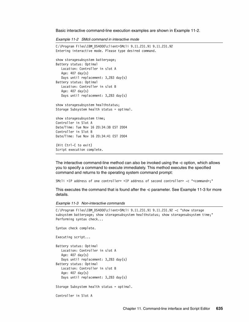
Basic interactive command-line execution examples are shown in Example 11-2.
Example 11-2 SMcli command in interactive mode
C:\Program Files\IBM_DS4000\client>SMcli 9.11.231.91 9.11.231.92Entering interactive mode. Please type desired command.
show storagesubsystem batteryage;Battery status: Optimal Location: Controller in slot A Age: 407 day(s) Days until replacement: 3,283 day(s)Battery status: Optimal Location: Controller in slot B Age: 407 day(s) Days until replacement: 3,283 day(s)
show storagesubsystem healthstatus;Storage Subsystem health status = optimal.
show storagesubsystem time;Controller in Slot ADate/Time: Tue Nov 16 20:34:38 EST 2004Controller in Slot BDate/Time: Tue Nov 16 20:34:41 EST 2004
(Hit Ctrl-C to exit)Script execution complete.
The interactive command-line method can also be invoked using the -c option, which allows you to specify a command to execute immediately. This method executes the specified command and returns to the operating system command prompt:
SMcli <IP address of one controller> <IP address of second controller> -c "<command>;"
This executes the command that is found after the -c parameter. See Example 11-3 for more details.
Example 11-3 Non-interactive commands
C:\Program Files\IBM_DS4000\client>SMcli 9.11.231.91 9.11.231.92 -c "show storagesubsystem batteryage; show storagesubsystem healthstatus; show storagesubsystem time;"Performing syntax check...
Syntax check complete.
Executing script...
Battery status: Optimal Location: Controller in slot A Age: 407 day(s) Days until replacement: 3,283 day(s)Battery status: Optimal Location: Controller in slot B Age: 407 day(s) Days until replacement: 3,283 day(s)
Storage Subsystem health status = optimal.
Controller in Slot A
Chapter 11. Command-line interface and Script Editor 635

Date/Time: Tue Nov 16 20:34:38 EST 2004Controller in Slot BDate/Time: Tue Nov 16 20:34:41 EST 2004
Script execution complete.
SMcli completed successfully.
C:\Program Files\IBM_FAStT\client>
If you use the batch command-line interface method then you would have specified a scriptfile as well. The SMcli verifies the file location and syntax of the commands. Each of the commands will be executed one at a time. When the commands are all executed, the SMcli returns to the operating system command prompt. The command looks like:
SMcli <IP address of one controller> <IP address of second controller> -f <script file name>
This executes the commands contained in the script file. If the script file is not in the SMclient directory or you do not have the path to the SMclient in your system environment settings, you must specify the full path to the script. See Example 11-4, where the command (show StorageSubsystem batteryage) is imbedded in the pre-written script (script.scr).
Example 11-4 Sending scripts to SMclient
C:\Program Files\IBM_DS4000\client>SMcli 9.11.231.91 9.11.231.92 -f script.scr
Performing syntax check...
Syntax check complete.
Executing script...
Battery status: Optimal Location: Controller in slot A Age: 407 day(s) Days until replacement: 3,283 day(s)Battery status: Optimal Location: Controller in slot B Age: 407 day(s) Days until replacement: 3,283 day(s)
Script execution complete.
SMcli completed successfully.
C:\Program Files\IBM_DS4000\client>
You can use this method to create, for example, scripts that automatically create (by combining native operating system commands with CLI commands) a FlashCopy logical drive, mount it under the operating system, and perform a backup on it.
For detailed information about the CLI parameters, consult the command-line reference included in the SMclient online help.
636 IBM System Storage DS4000 and Storage Manager V10.30
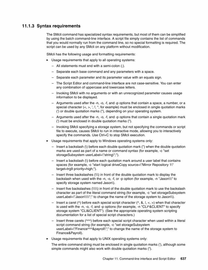
11.1.3 Syntax requirements
The SMcli command has specialized syntax requirements, but most of them can be simplified by using the batch command-line interface. A script file simply contains the list of commands that you would normally run from the command line, so no special formatting is required. The script can be used by any SMcli on any platform without modification.
SMcli has the following usage and formatting requirements:
� Usage requirements that apply to all operating systems:
– All statements must end with a semi-colon (;).
– Separate each base command and any parameters with a space.
– Separate each parameter and its parameter value with an equals sign.
– The Script Editor and command-line interface are not case-sensitive. You can enter any combination of uppercase and lowercase letters.
– Invoking SMcli with no arguments or with an unrecognized parameter causes usage information to be displayed.
– Arguments used after the -n, -o, -f, and -p options that contain a space, a number, or a special character (<, >, ', !, *, for example) must be enclosed in single quotation marks (') or double quotation marks ("), depending on your operating system.
– Arguments used after the -n, -o, -f, and -p options that contain a single quotation mark (') must be enclosed in double quotation marks (").
– Invoking SMcli specifying a storage system, but not specifying the commands or script file to execute, causes SMcli to run in interactive mode, allowing you to interactively specify the commands. Use Ctrl+C to stop SMcli execution.
� Usage requirements that apply to Windows operating systems only:
– Insert a backslash (\) before each double quotation mark (") when the double quotation marks are used as part of a name or command syntax (for example, -c "set storageSubsystem userLabel=\"string\";").
– Insert a backslash (\) before each quotation mark around a user label that contains spaces (for example, -c "start logical driveCopy source=\"Mirror Repository 1\" target=trg9 priority=high;").
– Insert three backslashes (\\\) in front of the double quotation mark to display the backslash when used with the -n, -o, -f, or -p option (for example, -n "Jason\\\" to specify storage system named Jason\).
– Insert five backslashes (\\\\\) in front of the double quotation mark to use the backslash character as part of the literal command string (for example, -c "set storageSubsystem userLabel=\"Jason\\\\\";" to change the name of the storage system to Jason\\).
– Insert a caret (^) before each special script character (^, &, |, <, >) when that character is used with the -n, -o, -f, and -p options (for example, -n "CLI^&CLIENT" to specify storage system "CLI&CLIENT"). (See the appropriate operating system scripting documentation for a list of special script characters.)
– Insert three carets (^^^) before each special script character when used within a literal script command string (for example, -c "set storageSubsystem userLabel=\"Finance^^^&payroll\";" to change the name of the storage system to Finance&Payroll).
� Usage requirements that apply to UNIX operating systems only:
The entire command string must be enclosed in single quotation marks ('), although some simple commands might also work with double quotation marks (“).
Chapter 11. Command-line interface and Script Editor 637
11.1.4 Error reportingWhen the CLI encounters an error, it writes information describing the error directly to the command line and sets a return code. Depending on the return code, the CLI might also write additional information about which parameter caused the error. The CLI also writes information about what it was expecting in the command syntax to help you identify any syntax errors that you might have entered.
When an exception occurs while a command is running, the CLI captures the error and, at the end of processing the command (after the command processing information has been written to the command line), the CLI automatically saves the error information to a file.
Special command-line options are not required to save the error data. Additionally, if the CLI must abnormally end running CLI and script commands, error data is collected and saved before the CLI finishes.
The name of the file to which error information is saved is excprpt.txt. It is located (in Windows) under the client\data directory. You cannot change the file name or location. The file is overwritten every time that an exception occurs. If you want to save the information in the file, you must copy the information to a new file or directory.
11.1.5 Commands overviewThis section shows all of the available commands broken down into the following areas:
� Storage subsystem� Controller� Physical disk drive� Enclosure� Array� Logical drive� Host topology� FlashCopy� Remote Mirror� VolumeCopy� Session� Other
Throughout the command listings, we have highlighted the most useful commands in bold.
If you are managing storage systems running firmware for previous releases, not all of these commands might be supported.
Important: As a general recommendation, it is better to avoid using special characters in order to stick to a simple command syntax.
Tip: While the Script Editor and command-line interface syntax have undergone some revisions, the former syntax is still supported. Any scripts that adhere to previous syntax rules will still pass the Script Editor syntax check and will execute.
638 IBM System Storage DS4000 and Storage Manager V10.30

Storage subsystem commandsTable 11-2 lists these commands.
Table 11-2 Storage subsystem commands
Command Description
Activate StorageSubsystem Firmware
This command activates firmware that you have previously downloaded to the pending configuration area on the controllers in the storage system.
Autoconfigure StorageSubsystem
This command automatically configures a storage system. Before entering the autoConfigure storageSubsystem command, enter the show storageSubsystem autoConfiguration command.
Autoconfigure Storage Subsystem HotSpares
This command automatically defines and configures the hot spares in a storage system.
Clear StorageSubsystem Configuration
Use this command to perform one of these operations:
� Clear the entire storage subsystem configuration and return it back to the initial installation state.
� Clear the configuration except for security information and identification information.
� Clear array configuration information and logical drive configuration information only.
Attention: Possible damage to the storage subsystem configuration: When you run this command, the existing storage subsystem configuration is deleted.
Clear StorageSubsystem EventLog
This command clears the storage system event log by deleting the data in the event log buffer.
Potential storage system configuration damage.
Clear StorageSubsystem FirmwarePendingArea
This command deletes from the pending area buffer a firmware image or Non Volatile Static Random Access Memory (NVSRAM) values that you have previously downloaded.
Potential storage system configuration damage.
Disable StorageSubsystem Feature
This command disables a storage system premium feature.
Download StorageSubsystem DriveFirmware
This command downloads firmware images to all physical disks in the storage system.
Download Storage Subsystem Firmware
This command downloads firmware and, optionally, NVSRAM values for the storage system controller.
Download Storage Subsystem NVSRAM
This command downloads NVSRAM values for the storage system controller.
Enable StorageSubsystem FeatureKey
This command enables a feature using a feature key file.
Reset StorageSubsystem BatteryInstallDate
This command resets the age of the batteries in a storage system to zero days.
Chapter 11. Command-line interface and Script Editor 639

Reset StorageSubsystem RLSBaseline
This command resets the Read Link Status (RLS) baseline for all devices.
Reset StorageSubsystem LogicalDriveDistribution
This command reassigns (moves) all logical drives to their preferred controller.
Save StorageSubsystem Configuration
This command creates a script file that you can use to create the current storage system logical drive configuration.
Save StorageSubsystem Events
This command saves events from the Major Event Log (MEL) to a file. You can save either all the events or only the critical events.
Save StorageSubsystem PerformanceStatistics
This command saves the performance statistics to a file. Before you use this command, issue the set session performanceMonitorInterval and set session performanceMonitorIterations commands to specify how often statistics are collected.
Save StorageSubsystem RLSCounts
This command saves the RLS counters to a file. Before using this command, issue the reset storageSubsystem RLSBaseline command to get current data.
Save StorageSubsystem StateCapture
This command saves the state capture to a file.
Save StorageSubsystem SupportData
This command saves the support-related information to a file. Support-related information includes:� Storage subsystem profile� Major Event Log information� Read Link Status data� NVSRAM data� Current problems and associated recovery information� Performance statistics for the entire storage system� Persistent registration and reservation information� Detailed information about the current status of the storage
system� Physical disk diagnostic data� A recovery profile for the storage system� Unreadable sectors detected on the storage system� State capture data
Set StorageSubsystem This command defines the properties of the storage system.
Set Storage Subsystem ICMP Response
This command returns the default values for negotiable settings for sessions and connections, which represent the starting point for the storage subsystem for negotiations.
Set Storage Subsystem iSNS Server IPv4 Address
This command sets the configuration method and address for an IPv4 Internet Storage Name Service (iSNS).
Set Storage Subsystem iSNS Server Listening Port
This command sets the iSNS server listening port.
Set Storage Subsystem iSNS Server Refresh
This command refreshes the network address information for the iSNS server. This command is valid for only IPv4.
Command Description
640 IBM System Storage DS4000 and Storage Manager V10.30
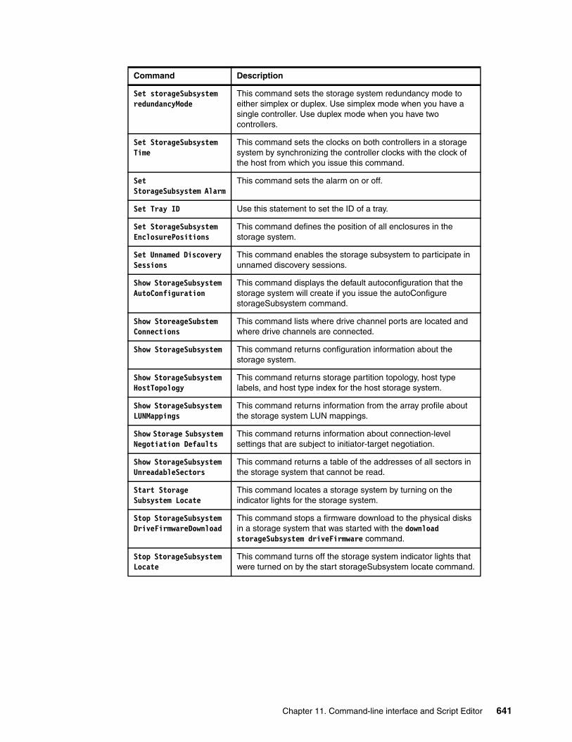
Set storageSubsystem redundancyMode
This command sets the storage system redundancy mode to either simplex or duplex. Use simplex mode when you have a single controller. Use duplex mode when you have two controllers.
Set StorageSubsystem Time
This command sets the clocks on both controllers in a storage system by synchronizing the controller clocks with the clock of the host from which you issue this command.
SetStorageSubsystem Alarm
This command sets the alarm on or off.
Set Tray ID Use this statement to set the ID of a tray.
Set StorageSubsystem EnclosurePositions
This command defines the position of all enclosures in the storage system.
Set Unnamed Discovery Sessions
This command enables the storage subsystem to participate in unnamed discovery sessions.
Show StorageSubsystem AutoConfiguration
This command displays the default autoconfiguration that the storage system will create if you issue the autoConfigure storageSubsystem command.
Show StoreageSubstem Connections
This command lists where drive channel ports are located and where drive channels are connected.
Show StorageSubsystem This command returns configuration information about the storage system.
Show StorageSubsystem HostTopology
This command returns storage partition topology, host type labels, and host type index for the host storage system.
Show StorageSubsystem LUNMappings
This command returns information from the array profile about the storage system LUN mappings.
Show Storage Subsystem Negotiation Defaults
This command returns information about connection-level settings that are subject to initiator-target negotiation.
Show StorageSubsystem UnreadableSectors
This command returns a table of the addresses of all sectors in the storage system that cannot be read.
Start Storage Subsystem Locate
This command locates a storage system by turning on the indicator lights for the storage system.
Stop StorageSubsystem DriveFirmwareDownload
This command stops a firmware download to the physical disks in a storage system that was started with the download storageSubsystem driveFirmware command.
Stop StorageSubsystem Locate
This command turns off the storage system indicator lights that were turned on by the start storageSubsystem locate command.
Command Description
Chapter 11. Command-line interface and Script Editor 641
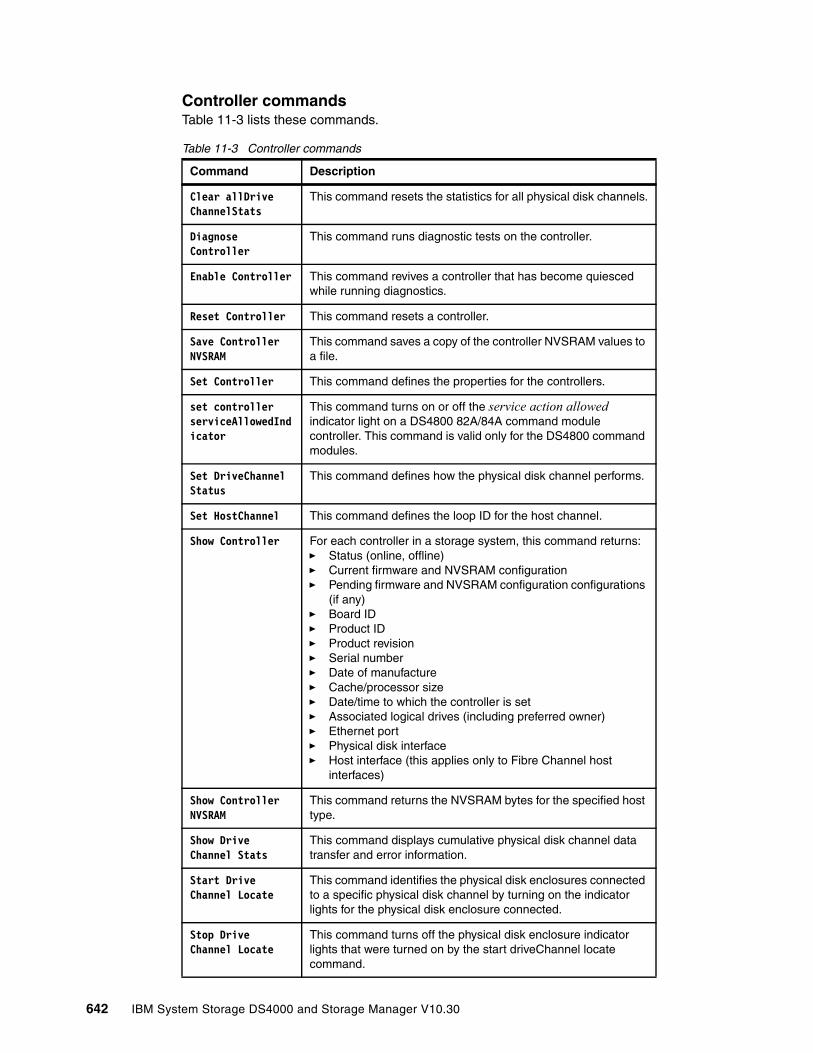
Controller commandsTable 11-3 lists these commands.
Table 11-3 Controller commands
Command Description
Clear allDrive ChannelStats
This command resets the statistics for all physical disk channels.
Diagnose Controller
This command runs diagnostic tests on the controller.
Enable Controller This command revives a controller that has become quiesced while running diagnostics.
Reset Controller This command resets a controller.
Save Controller NVSRAM
This command saves a copy of the controller NVSRAM values to a file.
Set Controller This command defines the properties for the controllers.
set controller serviceAllowedIndicator
This command turns on or off the service action allowed indicator light on a DS4800 82A/84A command module controller. This command is valid only for the DS4800 command modules.
Set DriveChannel Status
This command defines how the physical disk channel performs.
Set HostChannel This command defines the loop ID for the host channel.
Show Controller For each controller in a storage system, this command returns:� Status (online, offline)� Current firmware and NVSRAM configuration� Pending firmware and NVSRAM configuration configurations
(if any)� Board ID� Product ID� Product revision� Serial number� Date of manufacture� Cache/processor size� Date/time to which the controller is set� Associated logical drives (including preferred owner)� Ethernet port� Physical disk interface� Host interface (this applies only to Fibre Channel host
interfaces)
Show Controller NVSRAM
This command returns the NVSRAM bytes for the specified host type.
Show Drive Channel Stats
This command displays cumulative physical disk channel data transfer and error information.
Start Drive Channel Locate
This command identifies the physical disk enclosures connected to a specific physical disk channel by turning on the indicator lights for the physical disk enclosure connected.
Stop Drive Channel Locate
This command turns off the physical disk enclosure indicator lights that were turned on by the start driveChannel locate command.
642 IBM System Storage DS4000 and Storage Manager V10.30
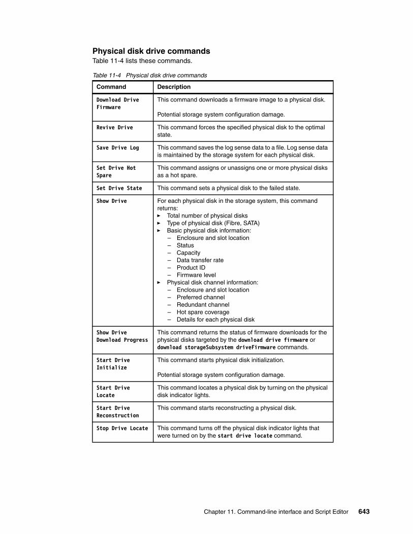
Physical disk drive commandsTable 11-4 lists these commands.
Table 11-4 Physical disk drive commands
Command Description
Download Drive Firmware
This command downloads a firmware image to a physical disk.
Potential storage system configuration damage.
Revive Drive This command forces the specified physical disk to the optimal state.
Save Drive Log This command saves the log sense data to a file. Log sense data is maintained by the storage system for each physical disk.
Set Drive Hot Spare
This command assigns or unassigns one or more physical disks as a hot spare.
Set Drive State This command sets a physical disk to the failed state.
Show Drive For each physical disk in the storage system, this command returns:� Total number of physical disks� Type of physical disk (Fibre, SATA)� Basic physical disk information:
– Enclosure and slot location– Status– Capacity– Data transfer rate– Product ID– Firmware level
� Physical disk channel information:– Enclosure and slot location– Preferred channel– Redundant channel– Hot spare coverage– Details for each physical disk
Show Drive Download Progress
This command returns the status of firmware downloads for the physical disks targeted by the download drive firmware or download storageSubsystem driveFirmware commands.
Start Drive Initialize
This command starts physical disk initialization.
Potential storage system configuration damage.
Start Drive Locate
This command locates a physical disk by turning on the physical disk indicator lights.
Start Drive Reconstruction
This command starts reconstructing a physical disk.
Stop Drive Locate This command turns off the physical disk indicator lights that were turned on by the start drive locate command.
Chapter 11. Command-line interface and Script Editor 643
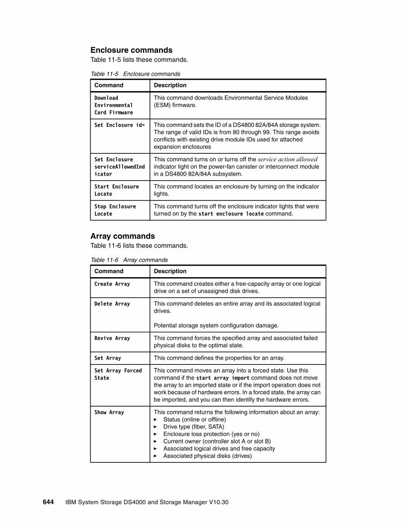
Enclosure commandsTable 11-5 lists these commands.
Table 11-5 Enclosure commands
Array commandsTable 11-6 lists these commands.
Table 11-6 Array commands
Command Description
Download Environmental Card Firmware
This command downloads Environmental Service Modules (ESM) firmware.
Set Enclosure id= This command sets the ID of a DS4800 82A/84A storage system. The range of valid IDs is from 80 through 99. This range avoids conflicts with existing drive module IDs used for attached expansion enclosures
Set Enclosure serviceAllowedIndicator
This command turns on or turns off the service action allowed indicator light on the power-fan canister or interconnect module in a DS4800 82A/84A subsystem.
Start Enclosure Locate
This command locates an enclosure by turning on the indicator lights.
Stop Enclosure Locate
This command turns off the enclosure indicator lights that were turned on by the start enclosure locate command.
Command Description
Create Array This command creates either a free-capacity array or one logical drive on a set of unassigned disk drives.
Delete Array This command deletes an entire array and its associated logical drives.
Potential storage system configuration damage.
Revive Array This command forces the specified array and associated failed physical disks to the optimal state.
Set Array This command defines the properties for an array.
Set Array Forced State
This command moves an array into a forced state. Use this command if the start array import command does not move the array to an imported state or if the import operation does not work because of hardware errors. In a forced state, the array can be imported, and you can then identify the hardware errors.
Show Array This command returns the following information about an array:� Status (online or offline)� Drive type (fiber, SATA)� Enclosure loss protection (yes or no)� Current owner (controller slot A or slot B)� Associated logical drives and free capacity� Associated physical disks (drives)
644 IBM System Storage DS4000 and Storage Manager V10.30

Logical drive commandsTable 11-7 lists these commands.
Table 11-7 Logical drive commands
Show Array Export Dependencies
This command shows a list of dependencies for the disk drives in a array that you want to move from one storage subsystem to a second storage subsystem.
Show Array Import Dependencies
This command shows a list of dependencies for the disk drives in an array that you want to move from one storage subsystem to a second storage subsystem.
Start Array Defragment
This command starts a defragment operation on the specified array.
Start Array Export
This command moves a array into an exported state. Then you can remove the disk drives that comprise the array and reinstall the disk drives in a different storage subsystem.
Note: Within the array, you cannot move logical drives that are associated with the premium features from one storage subsystem to another storage subsystem.
Start Array Import
This command moves an array into a complete state to make a newly introduced array available to its new storage subsystem. The array must be in an exported state or a forced state before you run this command. Upon successfully running the command, the array is operational.
Note: Within the array, you cannot move logical drives that are associated with the premium features from one storage subsystem to another storage subsystem.
Command Description
Check Logical Drive Parity
This command checks a logical drive for parity and media errors, and writes the results of the check to a file.
Clear Logical Drive Reservations
This command clears persistent logical drive reservations.
Clear Logical Drive Unreadable Sectors
This command clears unreadable sector information from one or more logical drives.
Create RAID Logical Drive (Automatic Drive Select)
This command creates an array across the storage system physical disks and a new logical drive in the array. The storage system controllers choose the physical disks to be included in the logical drive.
Create RAID Logical Drive (Manual Drive Select)
This command creates a new array and logical drive, and enables you to specify the physical disks for the logical drive.
Command Description
Chapter 11. Command-line interface and Script Editor 645
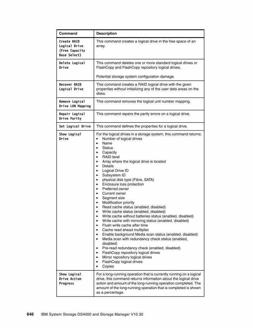
Create RAID Logical Drive (Free Capacity Base Select)
This command creates a logical drive in the free space of an array.
Delete Logical Drive
This command deletes one or more standard logical drives or FlashCopy and FlashCopy repository logical drives.
Potential storage system configuration damage.
Recover RAID Logical Drive
This command creates a RAID logical drive with the given properties without initializing any of the user data areas on the disks.
Remove Logical Drive LUN Mapping
This command removes the logical unit number mapping.
Repair Logical Drive Parity
This command repairs the parity errors on a logical drive.
Set Logical Drive This command defines the properties for a logical drive.
Show Logical Drive
For the logical drives in a storage system, this command returns:� Number of logical drives� Name� Status� Capacity� RAID level� Array where the logical drive is located� Details� Logical Drive ID� Subsystem ID� physical disk type (Fibre, SATA)� Enclosure loss protection� Preferred owner� Current owner� Segment size� Modification priority� Read cache status (enabled, disabled)� Write cache status (enabled, disabled)� Write cache without batteries status (enabled, disabled)� Write cache with mirroring status (enabled, disabled)� Flush write cache after time� Cache read ahead multiplier� Enable background Media scan status (enabled, disabled)� Media scan with redundancy check status (enabled,
disabled)� Pre-read redundancy check (enabled, disabled)� FlashCopy repository logical drives� Mirror repository logical drives� FlashCopy logical drives� Copies
Show Logical Drive Action Progress
For a long-running operation that is currently running on a logical drive, this command returns information about the logical drive action and amount of the long-running operation completed. The amount of the long-running operation that is completed is shown as a percentage.
Command Description
646 IBM System Storage DS4000 and Storage Manager V10.30
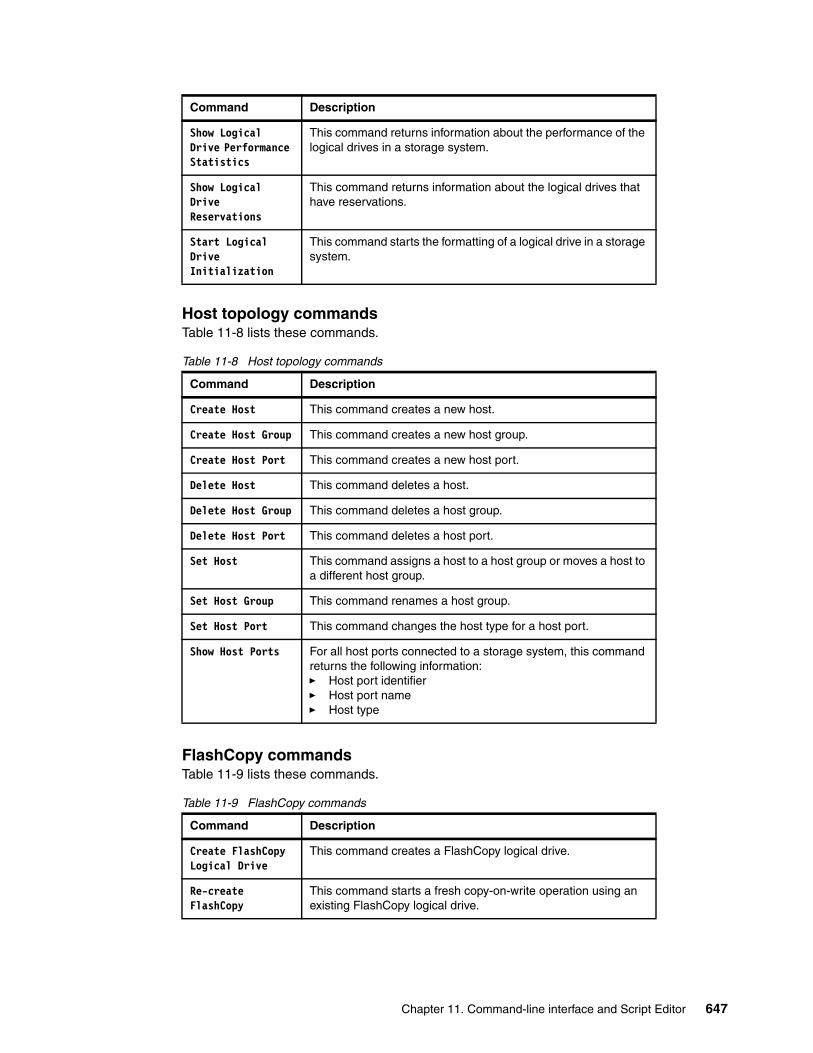
Host topology commandsTable 11-8 lists these commands.
Table 11-8 Host topology commands
FlashCopy commandsTable 11-9 lists these commands.
Table 11-9 FlashCopy commands
Show Logical Drive Performance Statistics
This command returns information about the performance of the logical drives in a storage system.
Show Logical Drive Reservations
This command returns information about the logical drives that have reservations.
Start Logical Drive Initialization
This command starts the formatting of a logical drive in a storage system.
Command Description
Create Host This command creates a new host.
Create Host Group This command creates a new host group.
Create Host Port This command creates a new host port.
Delete Host This command deletes a host.
Delete Host Group This command deletes a host group.
Delete Host Port This command deletes a host port.
Set Host This command assigns a host to a host group or moves a host to a different host group.
Set Host Group This command renames a host group.
Set Host Port This command changes the host type for a host port.
Show Host Ports For all host ports connected to a storage system, this command returns the following information:� Host port identifier� Host port name� Host type
Command Description
Create FlashCopy Logical Drive
This command creates a FlashCopy logical drive.
Re-create FlashCopy
This command starts a fresh copy-on-write operation using an existing FlashCopy logical drive.
Command Description
Chapter 11. Command-line interface and Script Editor 647
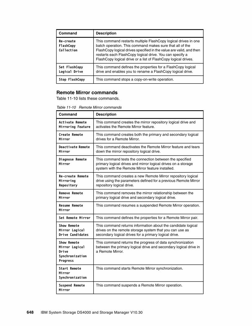
Remote Mirror commandsTable 11-10 lists these commands.
Table 11-10 Remote Mirror commands
Re-create FlashCopy Collection
This command restarts multiple FlashCopy logical drives in one batch operation. This command makes sure that all of the FlashCopy logical drives specified in the value are valid, and then restarts each FlashCopy logical drive. You can specify a FlashCopy logical drive or a list of FlashCopy logical drives.
Set FlashCopy Logical Drive
This command defines the properties for a FlashCopy logical drive and enables you to rename a FlashCopy logical drive.
Stop FlashCopy This command stops a copy-on-write operation.
Command Description
Activate Remote Mirroring Feature
This command creates the mirror repository logical drive and activates the Remote Mirror feature.
Create Remote Mirror
This command creates both the primary and secondary logical drives for a Remote Mirror.
Deactivate Remote Mirror
This command deactivates the Remote Mirror feature and tears down the mirror repository logical drive.
Diagnose Remote Mirror
This command tests the connection between the specified primary logical drives and mirror logical drives on a storage system with the Remote Mirror feature installed.
Re-create Remote Mirroring Repository
This command creates a new Remote Mirror repository logical drive using the parameters defined for a previous Remote Mirror repository logical drive.
Remove Remote Mirror
This command removes the mirror relationship between the primary logical drive and secondary logical drive.
Resume Remote Mirror
This command resumes a suspended Remote Mirror operation.
Set Remote Mirror This command defines the properties for a Remote Mirror pair.
Show Remote Mirror Logical Drive Candidates
This command returns information about the candidate logical drives on the remote storage system that you can use as secondary logical drives for a primary logical drive.
Show Remote Mirror Logical Drive Synchronization Progress
This command returns the progress of data synchronization between the primary logical drive and secondary logical drive in a Remote Mirror.
Start Remote Mirror Synchronization
This command starts Remote Mirror synchronization.
Suspend Remote Mirror
This command suspends a Remote Mirror operation.
Command Description
648 IBM System Storage DS4000 and Storage Manager V10.30

VolumeCopy (logical drive copy) commandsTable 11-11 lists these commands.
Table 11-11 Logical drive copy commands
Other commandsTable 11-12 lists other commands available.
Table 11-12 Other commands
11.1.6 CLI examplesThis section provides examples of how you can use the CLI to access and execute script engine commands. Note that the usage for the -c parameter varies depending on your operating system (enclosed in single quotation marks (') in UNIX or double quotation marks (") in Windows.
Command Description
Create logicalDriveCopy
This command creates a logical drive copy and starts the logical drive copy operation.
Recopy logicalDriveCopy
This command reinitiates a logical drive copy operation using an existing logical drive copy pair.
Remove logicalDriveCopy
This command removes a logical drive copy pair.
Set logicalDriveCopy
This command defines the properties for a logical drive copy pair.
Show logicalDriveCopy
This command returns information about logical drive copy operations. The information returned is:� Copy status� Start time stamp� Completion time stamp� Copy priority� Source or target logical drive WWN� Target logical drive read-only attribute setting� Percent completed, if a logical drive copy operation is in
progress
Show logicalDriveCopy Source Candidates
This command returns information about the candidate logical drives that you can use as the source for a logical drive copy operation.
Show logicalDriveCopy Target Candidates
This command returns information about the candidate logical drives that you can use as the target for a logical drive copy operation.
Stop logicalDriveCopy
This command stops a logical drive copy operation.
Command Description
Show String This command shows a string of text from a script file. This command is similar to the echo command in MS DOS and UNIX.
Set Session This command defines how you want the current script engine session to run.
Chapter 11. Command-line interface and Script Editor 649
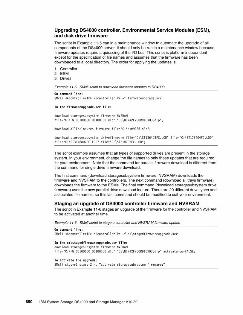
Upgrading DS4000 controller, Environmental Service Modules (ESM), and disk drive firmwareThe script in Example 11-5 can in a maintenance window to automate the upgrade of all components of the DS4000 server. It should only be run in a maintenance window because firmware updates require a quiescing of the I/O bus. This script is platform independent except for the specification of file names and assumes that the firmware has been downloaded to a local directory. The order for applying the updates is:
1. Controller2. ESM3. Drives
Example 11-5 SMcli script to download firmware updates to DS4000
On command line:SMcli <AcontrollerIP> <BcontrollerIP> -f firmwareupgrade.scr
In the firmwareupgrade.scr file:
download storagesubsystem firmware,NVSRAM file="C:\FW_06100600_06100100.dlp","C:\N1742F700R910V03.dlp";
download allEnclosures firmware file="C:\esm9326.s3r";
download storagesubsystem drivefirmware file="C:\ST136403FC.LOD" file="C:\ST173404FC.LOD" file="C:\ST3146807FC.LOD" file="C:\ST318203FC.LOD";
The script example assumes that all types of supported drives are present in the storage system. In your environment, change the file names to only those updates that are required for your environment. Note that the command for parallel firmware download is different from the command for single drive firmware download.
The first command (download storagesubsystem firmware, NVSRAM) downloads the firmware and NVSRAM to the controllers. The next command (download all trays firmware) downloads the firmware to the ESMs. The final command (download storagesubsystem drive firmware) uses the new parallel drive download feature. There are 20 different drive types and associated file names, so this last command should be modified to suit your environment.
Staging an upgrade of DS4000 controller firmware and NVSRAMThe script in Example 11-6 stages an upgrade of the firmware for the controller and NVSRAM to be activated at another time.
Example 11-6 SMcli script to stage a controller and NVSRAM firmware update
On command line:SMcli <AcontrollerIP> <BcontrollerIP> -f c:\stagedfirmwareupgrade.scr
In the c:\stagedfirmwareupgrade.scr file:download storagesubsystem firmware,NVSRAM file="C:\FW_06100600_06100100.dlp","C:\N1742F700R910V03.dlp" activatenow=FALSE;
To activate the upgrade:SMcli stgsvr1 stgsvr2 -c “activate storagesubsystem firmware;”
650 IBM System Storage DS4000 and Storage Manager V10.30

Upgrading individual components in the DS4000 storage controllerThe script in Example 11-7 can be useful for testing a new firmware level on a subset of your environment. It is included to show the slight differences in the commands that are required. In particular, the drive update command is different when you are not using the parallel upgrade functionality.
Example 11-7 SMcli script to update individual components in the DS4000
To update the controller only:SMcli stgsvr1 stgsvr2 -c “download storagesubsystem firmware file=\"C:\FW_06100600_06100100.dlp\";”
To update the NVSRAM only:SMcli stgsvr1 stgsvr2 -c “download storagesubsystem NVSRAM file=\"C:\N1742F700R910V03.dlp\";”
To update a particular ESM:SMcli stgsvr1 stgsvr2 -c “download enclosure[1] firmware file=\"C:\esm9326.s3r\";”
To update a single drive:SMcli stgsvr1 stgsvr2 -c “download drive [2,3] firmwarefile=\"C:\ST336732FC.LOD\";”
Creating and mapping a logical drive on SolarisThe script in Example 11-8 automates the creation of a logical drive and maps it to a storage partition for use by a specified host. The SMcli commands are platform independent but the script example is from a Solaris host and includes recommended steps to make the storage available to the operating system.
Example 11-8 Script to create and map a logical drive for Solaris
#!/bin/ksh########################################################## ## createDS4000disk script ## ########################################################### ## Purpose: To automate the creation of DS4000 Storage ## Server logical drives. ## ## Usage: ## createDS4000disk.sh <name> <lun> <size> ## ## where: ## name - logical drive name ## lun - lun number ## size - size in GB ## ############################################################ Command line variables#LOGICALDRIVENAME=$1LOGICALUNITNUMBER=$2LOGICALDRIVESIZE=$3## Fixed variables (configure per host)#
Chapter 11. Command-line interface and Script Editor 651
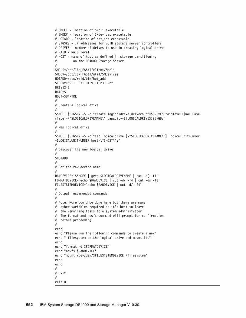
# SMCLI - location of SMcli executable# SMDEV - location of SMdevices executable# HOTADD - location of hot_add executable# STGSRV - IP addresses for BOTH storage server controllers# DRIVES - number of drives to use in creating logical drive# RAID - RAID level# HOST - name of host as defined in storage partitioning# on the DS4000 Storage Server#SMCLI=/opt/IBM_FAStT/client/SMcliSMDEV=/opt/IBM_FAStT/util/SMdevicesHOTADD=/etc/raid/bin/hot_addSTGSRV="9.11.231.91 9.11.231.92"DRIVES=5RAID=5HOST=SUNPYRE## Create a logical drive#$SMCLI $STGSRV -S -c "create logicaldrive drivecount=$DRIVES raidlevel=$RAID userlabel=\"$LOGICALDRIVENAME\" capacity=${LOGICALDRIVESIZE}GB;"## Map logical drive#$SMCLI $STGSRV -S -c "set logicaldrive [\"$LOGICALDRIVENAME\"] logicalunitnumber=$LOGICALUNITNUMBER host=\"$HOST\";"## Discover the new logical drive#$HOTADD## Get the raw device name#RAWDEVICE=`$SMDEV | grep $LOGICALDRIVENAME | cut -d[ -f1`FORMATDEVICE=`echo $RAWDEVICE | cut -d/ -f4 | cut -ds -f1`FILESYSTEMDEVICE=`echo $RAWDEVICE | cut -d/ -f4`## Output recommended commands## Note: More could be done here but there are many# other variables required so it’s best to leave# the remaining tasks to a system administrator# The format and newfs command will prompt for confirmation# before proceeding.#echoecho "Please run the following commands to create a new"echo " filesystem on the logical drive and mount it."echoecho “format -d $FORMATDEVICE”echo "newfs $RAWDEVICE"echo "mount /dev/dsk/$FILESYSTEMDEVICE /filesystem"echoecho## Exit#exit 0
652 IBM System Storage DS4000 and Storage Manager V10.30
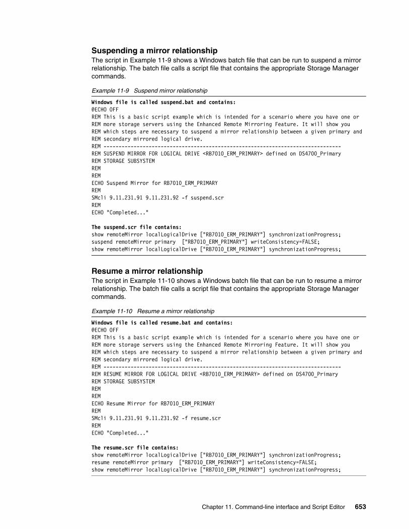
Suspending a mirror relationshipThe script in Example 11-9 shows a Windows batch file that can be run to suspend a mirror relationship. The batch file calls a script file that contains the appropriate Storage Manager commands.
Example 11-9 Suspend mirror relationship
Windows file is called suspend.bat and contains:@ECHO OFFREM This is a basic script example which is intended for a scenario where you have one or REM more storage servers using the Enhanced Remote Mirroring Feature. It will show youREM which steps are necessary to suspend a mirror relationship between a given primary and REM secondary mirrored logical drive.REM -------------------------------------------------------------------------------REM SUSPEND MIRROR FOR LOGICAL DRIVE <RB7010_ERM_PRIMARY> defined on DS4700_PrimaryREM STORAGE SUBSYSTEMREM REM ECHO Suspend Mirror for RB7010_ERM_PRIMARYREM SMcli 9.11.231.91 9.11.231.92 -f suspend.scrREMECHO "Completed..."
The suspend.scr file contains:show remoteMirror localLogicalDrive ["RB7010_ERM_PRIMARY"] synchronizationProgress;suspend remoteMirror primary ["RB7010_ERM_PRIMARY"] writeConsistency=FALSE;show remoteMirror localLogicalDrive ["RB7010_ERM_PRIMARY"] synchronizationProgress;
Resume a mirror relationshipThe script in Example 11-10 shows a Windows batch file that can be run to resume a mirror relationship. The batch file calls a script file that contains the appropriate Storage Manager commands.
Example 11-10 Resume a mirror relationship
Windows file is called resume.bat and contains:@ECHO OFFREM This is a basic script example which is intended for a scenario where you have one or REM more storage servers using the Enhanced Remote Mirroring Feature. It will show youREM which steps are necessary to suspend a mirror relationship between a given primary and REM secondary mirrored logical drive.REM -------------------------------------------------------------------------------REM RESUME MIRROR FOR LOGICAL DRIVE <RB7010_ERM_PRIMARY> defined on DS4700_PrimaryREM STORAGE SUBSYSTEMREM REM ECHO Resume Mirror for RB7010_ERM_PRIMARYREM SMcli 9.11.231.91 9.11.231.92 -f resume.scrREMECHO "Completed..."
The resume.scr file contains:show remoteMirror localLogicalDrive ["RB7010_ERM_PRIMARY"] synchronizationProgress;resume remoteMirror primary ["RB7010_ERM_PRIMARY"] writeConsistency=FALSE;show remoteMirror localLogicalDrive ["RB7010_ERM_PRIMARY"] synchronizationProgress;
Chapter 11. Command-line interface and Script Editor 653
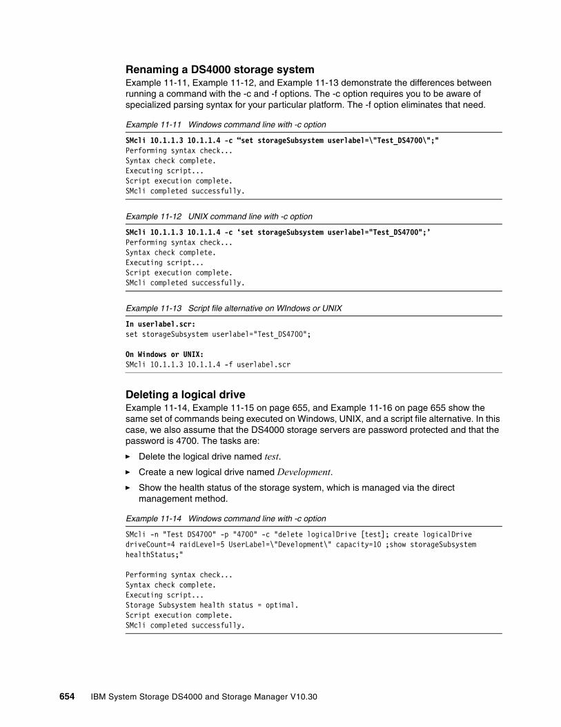
Renaming a DS4000 storage systemExample 11-11, Example 11-12, and Example 11-13 demonstrate the differences between running a command with the -c and -f options. The -c option requires you to be aware of specialized parsing syntax for your particular platform. The -f option eliminates that need.
Example 11-11 Windows command line with -c option
SMcli 10.1.1.3 10.1.1.4 -c “set storageSubsystem userlabel=\"Test_DS4700\";"Performing syntax check...Syntax check complete.Executing script...Script execution complete.SMcli completed successfully.
Example 11-12 UNIX command line with -c option
SMcli 10.1.1.3 10.1.1.4 -c ‘set storageSubsystem userlabel="Test_DS4700";’Performing syntax check...Syntax check complete.Executing script...Script execution complete.SMcli completed successfully.
Example 11-13 Script file alternative on WIndows or UNIX
In userlabel.scr:set storageSubsystem userlabel="Test_DS4700";
On Windows or UNIX:SMcli 10.1.1.3 10.1.1.4 -f userlabel.scr
Deleting a logical driveExample 11-14, Example 11-15 on page 655, and Example 11-16 on page 655 show the same set of commands being executed on Windows, UNIX, and a script file alternative. In this case, we also assume that the DS4000 storage servers are password protected and that the password is 4700. The tasks are:
� Delete the logical drive named test.� Create a new logical drive named Development.� Show the health status of the storage system, which is managed via the direct
management method.
Example 11-14 Windows command line with -c option
SMcli -n "Test DS4700" -p "4700" -c "delete logicalDrive [test]; create logicalDrive driveCount=4 raidLevel=5 UserLabel=\"Development\" capacity=10 ;show storageSubsystem healthStatus;"
Performing syntax check...Syntax check complete.Executing script...Storage Subsystem health status = optimal.Script execution complete.SMcli completed successfully.
654 IBM System Storage DS4000 and Storage Manager V10.30

Example 11-15 UNIX command line with -c option
SMcli -n "Test DS4700" -p "4700" -c 'delete logicalDrive [test]; create logicalDrive driveCount=4 raidLevel=5 UserLabel="Development" capacity=10;show storageSubsystem healthStatus;'
Performing syntax check...Syntax check complete.Executing script...Storage Subsystem health status = optimal.Script execution complete.SMcli completed successfully.
Example 11-16 Script file alternative on WIndows or UNIX
In deletelogicaldrive.scr:delete logicalDrive [test];create logicalDrive driveCount=4 raidLevel=5 UserLabel="Development" capacity=10;show storageSubsystem healthStatus;
On Windows or UNIX:SMcli -n "Test DS4700" -p "4700" -f deletelogicaldrive.scr
Configuration script example 1Example 11-17 creates a new logical drive using the create logicalDrive command in the free space of a array.
Example 11-17 Create logicalDrive
Show “Create RAID 5 LogicalDrive 7 on existing Array 1”;
//Create logicalDrive on array created by the create logicalDrive drives command
//Note: For arrays that use all available capacity, the last logicalDrive on the group is created using all remaining capacity by omitting the capacity=logicalDrive creation parameter
create logicalDrive array=1 RAIDLevel=5 userLabel="7" owner=A segmentSize=16 capacity=2;
show “Setting additional attributes for logicalDrive 7”; //Configuration settings that cannot be set during logicalDrive creationset logicalDrive[“7”] cacheFlushModifier=10;set logicalDrive[“7”] cacheWithoutBatteryEnabled=false;set logicalDrive[“7”] mirrorEnabled=true; set logicalDrive[“7”] readCacheEnabled=true; set logicalDrive[“7”] writeCacheEnabled=true; set logicalDrive[“7”] mediaScanEnabled=false;set logicalDrive[“7”] redundancyCheckEnabled=false; set logicalDrive[“7”] modificationPriority=high;
Each command is written on one line in the script file. However, the size of this page has caused the command text to wrap. In this example, the text Create RAID 5 LogicalDrive 7 on existing Array 1 serves as a title describing the expected results of running this script file.
The line beginning //Create is a comment explaining that the purpose of this script file is to create a new logical drive using the create logicalDrive command on an existing array.
Chapter 11. Command-line interface and Script Editor 655
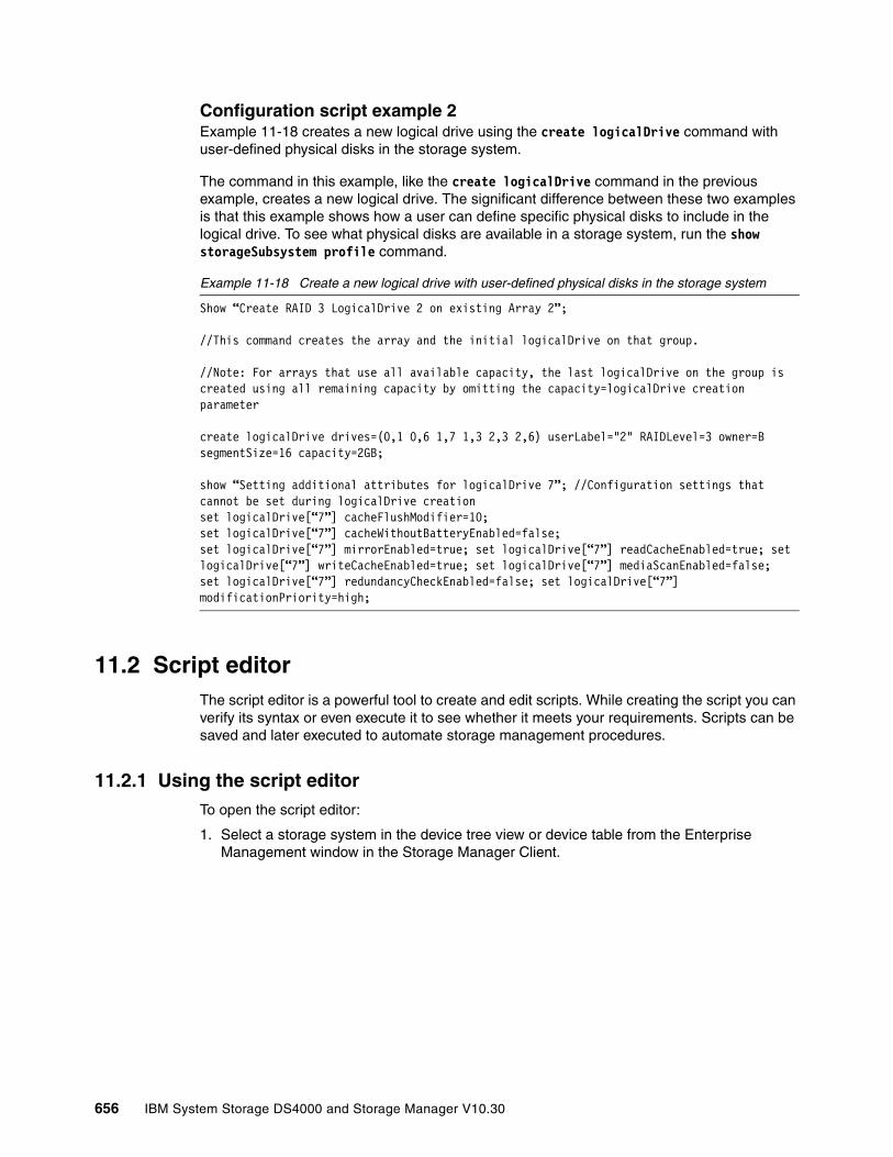
Configuration script example 2Example 11-18 creates a new logical drive using the create logicalDrive command with user-defined physical disks in the storage system.
The command in this example, like the create logicalDrive command in the previous example, creates a new logical drive. The significant difference between these two examples is that this example shows how a user can define specific physical disks to include in the logical drive. To see what physical disks are available in a storage system, run the show storageSubsystem profile command.
Example 11-18 Create a new logical drive with user-defined physical disks in the storage system
Show “Create RAID 3 LogicalDrive 2 on existing Array 2”;
//This command creates the array and the initial logicalDrive on that group.
//Note: For arrays that use all available capacity, the last logicalDrive on the group is created using all remaining capacity by omitting the capacity=logicalDrive creation parameter
create logicalDrive drives=(0,1 0,6 1,7 1,3 2,3 2,6) userLabel="2" RAIDLevel=3 owner=B segmentSize=16 capacity=2GB;
show “Setting additional attributes for logicalDrive 7”; //Configuration settings that cannot be set during logicalDrive creationset logicalDrive[“7”] cacheFlushModifier=10;set logicalDrive[“7”] cacheWithoutBatteryEnabled=false;set logicalDrive[“7”] mirrorEnabled=true; set logicalDrive[“7”] readCacheEnabled=true; set logicalDrive[“7”] writeCacheEnabled=true; set logicalDrive[“7”] mediaScanEnabled=false;set logicalDrive[“7”] redundancyCheckEnabled=false; set logicalDrive[“7”] modificationPriority=high;
11.2 Script editorThe script editor is a powerful tool to create and edit scripts. While creating the script you can verify its syntax or even execute it to see whether it meets your requirements. Scripts can be saved and later executed to automate storage management procedures.
11.2.1 Using the script editorTo open the script editor:
1. Select a storage system in the device tree view or device table from the Enterprise Management window in the Storage Manager Client.
656 IBM System Storage DS4000 and Storage Manager V10.30
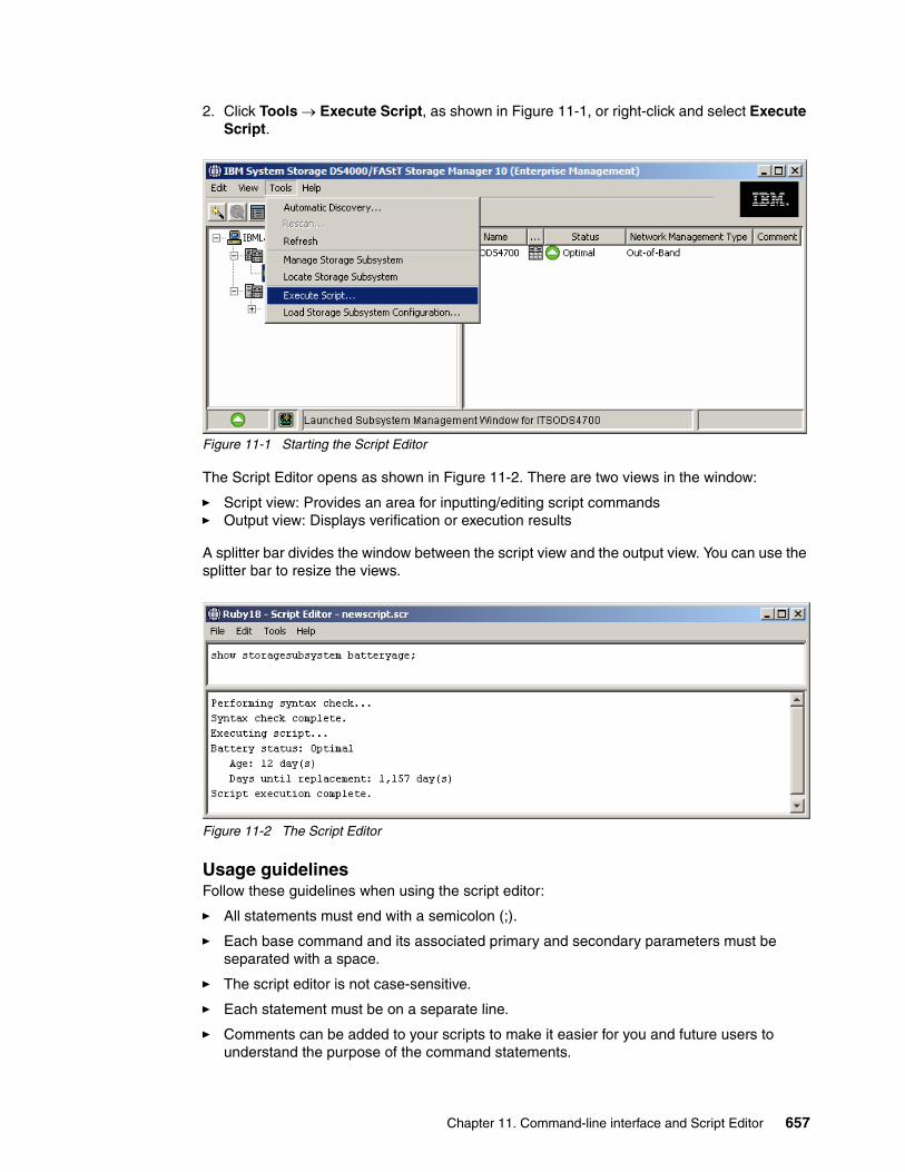
2. Click Tools → Execute Script, as shown in Figure 11-1, or right-click and select Execute Script.
Figure 11-1 Starting the Script Editor
The Script Editor opens as shown in Figure 11-2. There are two views in the window:
� Script view: Provides an area for inputting/editing script commands� Output view: Displays verification or execution results
A splitter bar divides the window between the script view and the output view. You can use the splitter bar to resize the views.
Figure 11-2 The Script Editor
Usage guidelinesFollow these guidelines when using the script editor:
� All statements must end with a semicolon (;).
� Each base command and its associated primary and secondary parameters must be separated with a space.
� The script editor is not case-sensitive.
� Each statement must be on a separate line.
� Comments can be added to your scripts to make it easier for you and future users to understand the purpose of the command statements.
Chapter 11. Command-line interface and Script Editor 657
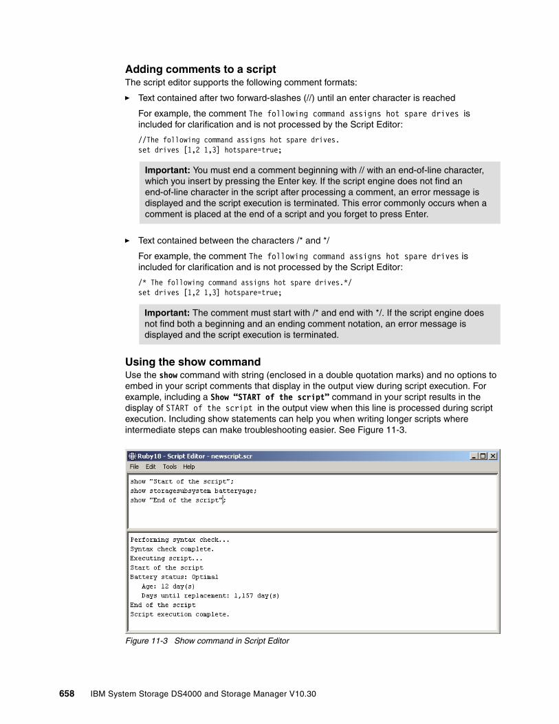
Adding comments to a scriptThe script editor supports the following comment formats:
� Text contained after two forward-slashes (//) until an enter character is reached
For example, the comment The following command assigns hot spare drives is included for clarification and is not processed by the Script Editor:
//The following command assigns hot spare drives.set drives [1,2 1,3] hotspare=true;
� Text contained between the characters /* and */
For example, the comment The following command assigns hot spare drives is included for clarification and is not processed by the Script Editor:
/* The following command assigns hot spare drives.*/set drives [1,2 1,3] hotspare=true;
Using the show commandUse the show command with string (enclosed in a double quotation marks) and no options to embed in your script comments that display in the output view during script execution. For example, including a Show “START of the script” command in your script results in the display of START of the script in the output view when this line is processed during script execution. Including show statements can help you when writing longer scripts where intermediate steps can make troubleshooting easier. See Figure 11-3.
Figure 11-3 Show command in Script Editor
Important: You must end a comment beginning with // with an end-of-line character, which you insert by pressing the Enter key. If the script engine does not find an end-of-line character in the script after processing a comment, an error message is displayed and the script execution is terminated. This error commonly occurs when a comment is placed at the end of a script and you forget to press Enter.
Important: The comment must start with /* and end with */. If the script engine does not find both a beginning and an ending comment notation, an error message is displayed and the script execution is terminated.
658 IBM System Storage DS4000 and Storage Manager V10.30

Script Editor toolsThe Script Editor offers the following tools to help you when writing scripts:
� Verify syntax.
To run this option select the Tools → Verify Syntax pull-down menu option. The script editor engine parses the statements in the script file one line at a time and verifies that they have the correct syntax. Any syntax errors are displayed in the output view, reporting the line number of the error and a description of the error. If the script editor encounters a syntax error, no further syntax verification is performed on the script. Fix the syntax error and rerun the Verify Syntax command to validate the error correction and check the remainder of the statements in the script.
� Verify and execute.
To run this option select the Tools → Verify and Execute option. The script editor engine parses the command statements in the script, interprets and converts the statements to the appropriate commands, and sends the commands to the storage system.
If a syntax error is encountered, the execution stops and an error message is displayed. Fix the error, then use the verify syntax or verify and execute options to validate the error correction.
If an execution error occurs, the script might or might not continue to execute depending on the included on error script statement. The on error stop statement stops the script if an execution error is encountered. The on error continue statement allows the script to continue even after an execution error is encountered. (This is the default.)
� Execute only.
To run this option select the Tools → Execute Only option. The Script Editor engine executes a script. It displays an error message if a syntax error is encountered.
If an execution error occurs, the script might or might not continue to execute depending on the included on error script statement. The on error stop statement stops the script if an execution error is encountered. The on error continue statement allows the script to continue even after an execution error is encountered. (This is the default.)
Interpreting the script execution resultsDuring script execution, messages are displayed in the output view beginning with:
Executing script...
After a successful script execution, you see the message:
Script execution complete.
If there is an error during the parse phase, an error indication is displayed in the output view, giving the line and column number and a description of the syntax error.
If there is an error during execution, a message is displayed in the output view stating that the command failed and reporting a description of the error.
11.2.2 Embedding commands in batch filesDue to the business demand for higher availability of data, the time window allocated to take backups is shrinking. Customers can no longer afford the daily downtime on their production
Note: Certain execution errors, including the inability to communicate with the storage system, always cause the script execution to halt. In these cases, execution stops even if you have used the on error continue statement.
Chapter 11. Command-line interface and Script Editor 659

server to perform backups. This becomes especially true as databases become larger and larger. Online backups improve the availability of the database, but cost CPU, disk, and network resources. Even with the use of incremental and differential backups, the time necessary to perform a backup can be significant. On the other hand, a feature like FlashCopy enables customers to perform offline backups.
660 IBM System Storage DS4000 and Storage Manager V10.30

Chapter 12. Advanced maintenance
This chapter addresses advanced maintenance topics for the DS4000. It explains how to check for and upgrade to the latest firmware level for the different DS4000 components. It also covers how to upgrade HBA firmware.
The chapter also includes information about other management and maintenance tasks such as handling the premium features, how to back up your configuration, and how to perform drives migration between different DS4000 subsystems using the new facilities for import-export volumes.
12
© Copyright IBM Corp. 2004, 2005, 2006, 2007, 2008, 2009. All rights reserved. 661
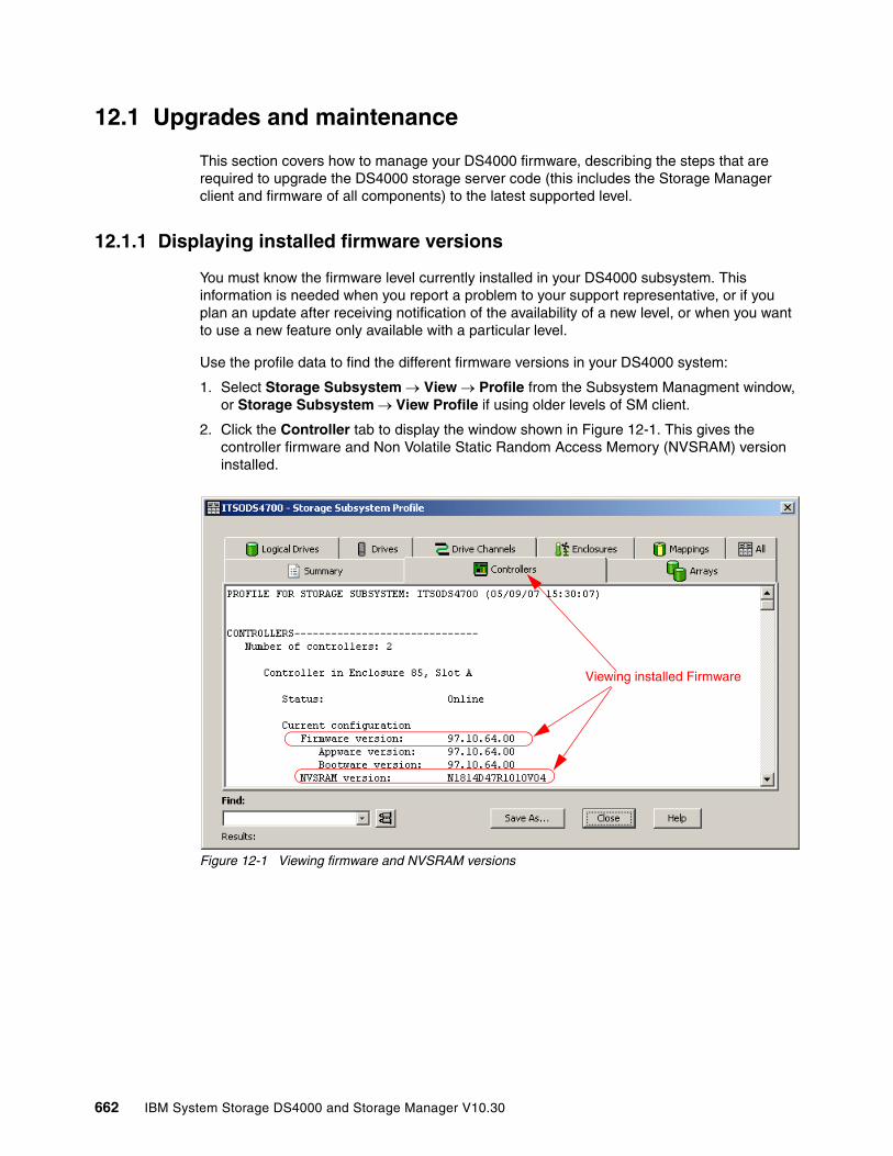
12.1 Upgrades and maintenance
This section covers how to manage your DS4000 firmware, describing the steps that are required to upgrade the DS4000 storage server code (this includes the Storage Manager client and firmware of all components) to the latest supported level.
12.1.1 Displaying installed firmware versions
You must know the firmware level currently installed in your DS4000 subsystem. This information is needed when you report a problem to your support representative, or if you plan an update after receiving notification of the availability of a new level, or when you want to use a new feature only available with a particular level.
Use the profile data to find the different firmware versions in your DS4000 system:
1. Select Storage Subsystem → View → Profile from the Subsystem Managment window, or Storage Subsystem → View Profile if using older levels of SM client.
2. Click the Controller tab to display the window shown in Figure 12-1. This gives the controller firmware and Non Volatile Static Random Access Memory (NVSRAM) version installed.
Figure 12-1 Viewing firmware and NVSRAM versions
Viewing installed Firmware
662 IBM System Storage DS4000 and Storage Manager V10.30

3. Click the Enclosures tab to see the Environmental Service Modules (ESM) current firmware level. As seen in Figure 12-2, you must use the scroll bar to show all of the ESM firmware (two per enclosure), as circled in red in Figure 12-2.
Figure 12-2 Viewing ESM firmware
4. Click the Drives tab to see the drives information. Scroll to the right side of the window until the firmware version column is visible. Be aware that you might have different drive types in your enclosures, so you can find multiple versions. See Figure 12-3.
Figure 12-3 Viewing disks firmware
12.1.2 Obtaining updates
To download the latest software, firmware, and drivers, and for updates, hints, and tips on known problems, fixes, technical notes, and product flashes (alerts), consult the IBM Support Web site at:
http://www.ibm.com/servers/storage/support/disk
Select your specific DS4000 model in the drop-down menu and click the Download tab on the right side to get to the latest versions of Storage Manager, firmware, HBA tools, tips, and publications available. There may be more than a single version of firmware available for download. Always review the readme file to make sure that it is the correct version for your
Chapter 12. Advanced maintenance 663
product and configuration. If the readme contains specific enhancements or fixes specifically for your system, then consider updating your DS4000.
Support Notifications subscription serviceThere is a Support Notifications subscription service launched on the IBM System Storage product support Web site. This service is designed to keep you informed of new or updated System Storage support site information, without the need to periodically check the IBM Support Web site for updates.
The Support Notifications site is:
http://www.ibm.com/systems/support/storage/news/05072007SupportNotif.html
System Storage Interoperation Center (SSIC)If you are planning to add a new host to your storage, add expansions, change HBAs in your hosts, or other hardware configuration changes, check also the latest supported combinations at the following Web site:
http://www.ibm.com/systems/support/storage/config/ssic/index.jsp
12.1.3 Planning for upgradesUpgrading the firmware and management software for the DS4000 storage server is a relatively simple procedure, but some preparation and caution are needed to ensure a smooth upgrade. Depending on your specific model and version to install, you should follow the specific instructions described in that version’s readme file.
The components that typically must be updated are:
� Storage Manager software� Controller firmware� NVSRAM firmware� ESM firmware� Disk drives firmware
Depending on the component to update, the current version, and the destination level, the procedure may allow a concurrent upgrade or be a disruptive update.
Important: We strongly recommend that you subscribe to the IBM System Storage product Web site to receive notifications directly via e-mail.
664 IBM System Storage DS4000 and Storage Manager V10.30

For a disruptive upgrade, before you start, make sure that you have an adequate maintenance window to do the procedure. Upgrading large storage configurations can be time consuming. Time estimates for upgrading all the associated firmware and software are listed in Table 12-1. (The new firmware upgrade utility required for upgrading from 6.xx to firmware 7.10 or later versions of 7.xx is covered separately in “Upgrading to firmware level 7.xx” on page 668.)
Table 12-1 Upgrade times
These times were observed in the lab. They are approximate and may vary from system to system. Activating controller firmware or NVSRAM maximum times are 15 minutes per controller.
It is critical that if you update one component, you also update other components to the matching levels (refer to the readme file for the release that you are upgrading to). You must not run a mismatched set.
12.1.4 Updating the DS4000 host softwareIn this section we discuss updating the DS4000 host software on a Windows and Linux host server.
For HP-UX and AIX, refer to 5.1, “Installing DS4000 Storage Manager software” on page 180.
Code update for the Windows environmentDS4000 Storage Manager (using the installation wizard InstallAnywhere) supports install upgrade. Launch the install program and it automatically upgrades all the components that you previously installed. For details on the installation procedures refer to 5.1.1, “Installing Storage Manager in a Windows host” on page 180. You can also find detailed information in Installation and Host Support Guide for Windows 2000/Server 2003, NetWare, VMware ESX Server, and Linux, GC27-2171. If your DS4000 Storage Manager is 9.12 or earlier, you may need to uninstall it manually before the new Storage Manager (SM) 10 installation.
Element being upgraded Approximate time of upgrade
Storage Manager and associated drivers and utilities
35 minutes
ESM firmware 5 minutes per ESM
DS4000 storage server firmware and NVSRAM 5 to 35 minutes
Hard drives 2 minutes per drive (but it is possible to do a parallel firmware upgrade)
Important: Storage Manager host software must be updated to SM 10.xx to manage DS4000 with firmware 7.xx. You must update the SM host software to the latest version available before performing the firmware upgrade.
Chapter 12. Advanced maintenance 665
Code update for the Linux environmentYou can update the host-based DS4000 software for Linux either with InstallAnywhere or manually.
The steps below explain the manual update procedure for all hosts running with RDAC:
1. Uninstall the earlier version of Storage Manager components. 2. Install SMruntime. 3. Install SMclient.4. Disable and enable the event monitor.5. Install IBM FC HBA non-failover version device driver for Linux.6. Install Linux RDAC.7. Install SMagent (optional).8. Install SMutil.9. Make sure that the correct host type is specified.
To update the Linux environment with IBM HBA failover driver as the multipath device driver:
1. Uninstall the earlier version of Storage Manager components. 2. Install SMruntime. 3. Install SMclient.4. Disable and enable the Event Monitor.5. Install SMutil.6. Uninstall existing IBM DS4000 Management Suite Java (QLogic SANSurfer). 7. Install the IBM FC HBA failover version device driver for Linux.8. Install IBM DS4000 Management Suite Java (QLogic SANSurfer) and QLRemote Agent. 9. Configure path failover/failback. See the device driver readme file for detailed information.
12.1.5 Updating controller firmware
Upgrading from firmware 6.xx to firmware level 7.x cannot be done from the Storage Manager client interface. You must use the provided firmware upgrade utility. Before using the upgrade utility, make sure that you meet all of the following conditions:
� The new firmware upgrade utility is used only when upgrading firmware for a DS4200, DS4700, or DS4800.
� This utility is used to upgrade from a minimum 6.14 release to 7.10 or later versions 7.xx firmware. If you were still using a version older than 6.14, you must first upgrade to the latest 6.xx code available from the support Web site.
� If you are already at release 7.xx, further firmware upgrades may be done from within Storage Manager, as usual.
666 IBM System Storage DS4000 and Storage Manager V10.30

Refer to Figure 12-4 to help you determine what upgrade path to follow.
Figure 12-4 Update decision tree
For both update methods, you can optionally transfer the controller firmware and NVSRAM to a designated flash area on the DS4000 controllers and activate it at a later time or transfer the files and apply them at the same moment.
The firmware is transferred to one of the controllers, which then copies the file to the other. The image is verified through a cyclic redundancy check (CRC) check on both controllers. If the checksum is okay, the uploaded firmware is marked as ready and available for activation. If one of the two controllers fails to validate the CRC, the image is marked as invalid on both controllers and is not available for activation. An error is returned to the management station as well.
In Storage Manager 10, if for any reason a firmware upgrade ends with different levels on each controller, the new automatic code synchronization feature addresses the inconsistent versions by transferring the later version to the alternate controller and rebooting it. The automatic code synchronization also works when a controller is replaced or if swapping controllers (which should normally not be done).
Note: New with Storage Manager 10.10, the automatic code synchronization feature ensures that both controllers are executing the same controller firmware version, preventing mismatched versions after controller replacement or if an upgrade process is interrupted.
Chapter 12. Advanced maintenance 667
Below we describe both the new procedure required to upgrade firmware from 6.xx to 7.xx, and the regular procedure for using the Storage Manager program to update to the latest 6.xx version, and also to update an existing storage with firmware 7.xx to a newer release 7.yy.
Upgrading to firmware level 7.xxThe storage models that support this new version are IBM DS4200, DS4700, and DS4800.
There were several important changes incorporated in controller firmware 7.10 that allow new functions and enhancements over previous versions. To accommodate those improvements, a rewrite of the DACstor region is necessary. This requires a non-concurrent update and the use of the special controller firmware upgrade utility.
Controller firmware upgrade utilityThis new utility was developed to upgrade DS4200, DS4700, and DS4800 running controller firmware 6.14 or later versions 6.xx to the new firmware version 7.10 or later versions 7.xx.
The utility makes sure that the storage to upgrade is in an optimal state and that other conditions are met prior to performing the upgrade. The utility checks the compatibility for all files selected for download and saves the recovery profile, the storage arrays configuration, the RLS diagnostics output, and the event log. This information is saved to the same directory where you chose to install the utility.
In addition to performing the upgrade of the controller firmware and NVSRAM, the utility also performs a migration of the drive configuration database region (DACstor) to a new format that can accommodate version 7.xx improvements.
The utility analyzes your configuration and, based on that information, provides an estimate of the time needed to perform the upgrade. This is important since the upgrade is a disruptive process.
Installing the upgrade utilityTo install:
1. Download the upgrade application from the IBM Support Web site. It is included in the DS4000 Storage Manager software package. Download the latest firmware versions 7.xx to update.
2. Read the readme provided to make sure that all restrictions, limitations, and recommendations for the utility are considered.
3. Start the installation of the utility by running the installation package that you just downloaded. A first dialog window is displayed where you can select the language of your choice.
4. Read the introduction and copyright information window, accept the license agreement, select the directory, and confirm that you want to install the stand-alone utility.
5. After a successful installation, a new program group Storage Manager 10 Firmware Upgrade is created in your programs menu.
Upgrading firmware and NVSRAM to Version 7.xxBefore you start, make sure that you have an adequate maintenance window to do the upgrade. The upgrade utility provides an estimate of the time required to upgrade your
Important: Upgrading to controller firmware 7.xx from 6.xx is a disruptive process (all I/Os to the drives must be stopped, which means application downtime).
668 IBM System Storage DS4000 and Storage Manager V10.30
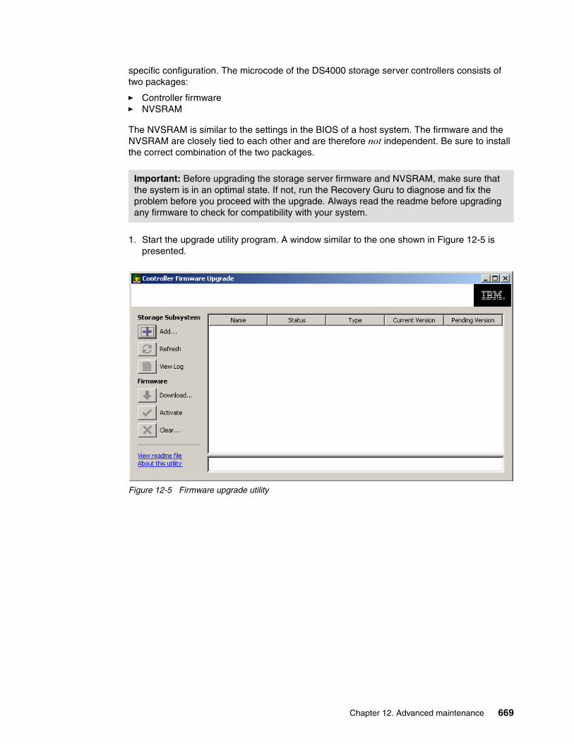
specific configuration. The microcode of the DS4000 storage server controllers consists of two packages:
� Controller firmware � NVSRAM
The NVSRAM is similar to the settings in the BIOS of a host system. The firmware and the NVSRAM are closely tied to each other and are therefore not independent. Be sure to install the correct combination of the two packages.
1. Start the upgrade utility program. A window similar to the one shown in Figure 12-5 is presented.
Figure 12-5 Firmware upgrade utility
Important: Before upgrading the storage server firmware and NVSRAM, make sure that the system is in an optimal state. If not, run the Recovery Guru to diagnose and fix the problem before you proceed with the upgrade. Always read the readme before upgrading any firmware to check for compatibility with your system.
Chapter 12. Advanced maintenance 669

2. Click Add to initiate either an automatic discovery or a manual addition of the DS4000 to upgrade. To add a subsystem manually, enter the DS4000 controller IP address or the IP of the host used for in-band management of the DS4000. See Figure 12-6.
Figure 12-6 Adding a DS4000 to the upgrade utility
The upgrade procedure needs two independent connections to the DS4000 storage server, one for each controller. It is not possible to perform a microcode update with only one controller connected. Therefore, both controllers must be accessible either via Fibre Channel or Ethernet. Both controllers must also be in optimal state.
You can add multiple DS4000 systems in the upgrade utility. However, we recommend installing one first, and then, if the operation was successful, continuing with others in a single pass. The utility program can download and activate firmware images to the same DS4000 model and controller type in a parallel fashion.
If multiple systems are added or automatically discovered, they are presented in the graphical interface and sorted by controller types and grouped as upgradeable or non-upgradeable, as shown in Figure 12-7 on page 671.
3. Once the DS4000 system was added successfully, the upgrade utility performs an automatic check for any non-optimal condition that would prevent the upgrade from succeeding. Check the status detected by the upgrade utility for your specific DS4000 to upgrade.
The status column shows different values depending on the version found in the storage system and the system itself, since not all the models are compatible with Version 7.xx and later. Models not supported by this firmware continue to use the Storage Manager to install upgrades up to the latest level available for the particular model.
670 IBM System Storage DS4000 and Storage Manager V10.30

The only status that allows you to proceed with the firmware upgrade is Upgradeable:Optimal, as shown in Figure 12-7.
Figure 12-7 Firmware upgrade utility: Status window
If the status is not optimal, you can use the view log option to find the reason detected by the utility. The conditions as checked by the utility for a system to be upgradeable and optimal are:
– Status upgradeable
• If the storage subsystem supports Version 7.10 or later and is a DS4200, DS4700, or DS4800
• If the current version is equal to or later than 6.14 (minimum) and earlier than 7.10 (already upgraded)
– Status optimal
• If no failed assigned drives are found
• If no hot spares replacing failed drives are found
• If there are no missing volumes
• If both controllers are in optimal status
• In there are no operations in progress
If there is a problem with any of the above conditions, the utility program does not allow the upgrade of the affected DS4000 subsystem. Other non-optimal conditions are indicated, and we recommend fixing them before proceeding with the upgrade (not fixing those, however, does not prevent the upgrade utility from performing the upgrade).
Status depending firmware level and healtcheck
Chapter 12. Advanced maintenance 671

4. Click the Download button in the left margin (Figure 12-5 on page 669) under firmware. This brings up a dialog window, as shown in Figure 12-8, where you can select the firmware source file previously downloaded.
Figure 12-8 Selecting downloads and source files
Note that the utility window is the same as the one obtained when updating through the Storage Manager, although the utility and background process are different.
5. Check Download NVSRAM file with firmware and select the NVSRAM file downloaded previously. Make sure that the NVSRAM selected is the one provided with the firmware file being downloaded, and for your specific DS4000 model.
Important: Make sure to install the firmware for each of the DS400 components (ESM, drives, controller, NVSRAM) in the sequence described in the readme file for that version.
Update the controller firmware and then the NVSRAM, or both at the same time.
Any power or network/SAN interruption during the update process might lead to configuration corruption or extended downtime. Therefore, do not power off the DS4000 storage server or the management station during the update. If you are using in-band management and have Fibre Channel hubs or managed hubs, then make sure that no SAN-connected devices are powered up during the update. Otherwise, this can cause a loop initialization process and interrupt the process.
672 IBM System Storage DS4000 and Storage Manager V10.30
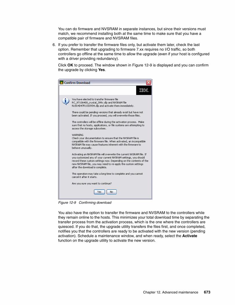
You can do firmware and NVSRAM in separate instances, but since their versions must match, we recommend installing both at the same time to make sure that you have a compatible pair of firmware and NVSRAM files.
6. If you prefer to transfer the firmware files only, but activate them later, check the last option. Remember that upgrading to firmware 7.xx requires no I/O traffic, so both controllers go offline at the same time to allow the upgrade (even if your host is configured with a driver providing redundancy).
Click OK to proceed. The window shown in Figure 12-9 is displayed and you can confirm the upgrade by clicking Yes.
Figure 12-9 Confirming download
You also have the option to transfer the firmware and NVSRAM to the controllers while they remain online to the hosts. This minimizes your total download time by separating the transfer process from the activation process, which is the one where the controllers are quiesced. If you do that, the upgrade utility transfers the files first, and once completed, notifies you that the controllers are ready to be activated with the new version (pending activation). Schedule a maintenance window, and when ready, select the Activate function on the upgrade utility to activate the new version.
Chapter 12. Advanced maintenance 673

7. Observe the progress indication during the file transfer and activation. Once finished, the utility indicates the result of the operation. If the transfer and activation were successful, the window shown in Figure 12-10 is displayed.
Figure 12-10 Firmware upgraded
– If you choose to transfer the files only and activate them later, the window in Figure 12-10 still shows the same current version as when the upgrade was started, while in the pending version column, the new level transferred is displayed. If so, the activate button in the left side is enabled. Schedule a maintenance window to activate it.
– If the operation finishes with an error, the utility displays failure details in the notification field. Check additional details for all the process using the view log option.
– If you choose a deferred install, but later decide not to activate that level, the already transferred image may be cleared from the staging area using the clear option.
Updating to 6.xx or between 7.xx versionsWe describe the regular procedure for upgrading the firmware using the Storage Manager client interface. This procedure is used for the following cases:
� Upgrading DS4200, DS4700, and DS4800 to the latest release of version 6.x� Upgrading DS4200, DS4700, and DS4800 from Version 7.xx to a later Version 7.yy� Upgrading other DS4000 models to the latest supported level of Version 6.xx
In general, the controller, NVSRAM, and ESM firmware upgrades can be done online during non-peak periods of traffic if your DS4000 model has redundant controllers, and if a redundant driver is installed in all the hosts being serviced by your DS4000.
In the above conditions, once the upgrade is initiated, the files are transferred to one controller, which then copies them to the other. A consistency check is done on both
Important: You cannot use the Storage Manager interface to upgrade from 6.xx to 7.xx firmware, but you should continue using Storage Manager to update up to the latest version 6.xx and to update from any 7.xx to any later level 7.yy.
674 IBM System Storage DS4000 and Storage Manager V10.30

controllers, and if the checksum is okay, the uploaded firmware is marked as ready and available for activation.
The activation procedure can be done immediately after the transfer or later during a period with less I/O access. During the activation, the first controller moves all logical drives to the second one. Then it reboots and activates new firmware. After that, it takes ownership of all logical drives, and the second controller is rebooted in order to have its new firmware activated. When both controllers are up again, the logical drives are redistributed to the preferred paths.
If you choose to not activate the transferred image at the same moment of the firmware transfer, remember that a normal reboot of a controller or a power cycle of the DS4000 does not activate the new firmware. It is only activated after the user specifically chooses to activate the firmware.
To perform the staged firmware and NVSRAM update:
1. Open the Subsystem Management window for the DS4000 storage server that you want to upgrade. To download the firmware select Advanced → Maintenance → Download → Controller Firmware, as shown in Figure 12-11.
Figure 12-11 Subsystem Management window: Controller firmware update
Chapter 12. Advanced maintenance 675
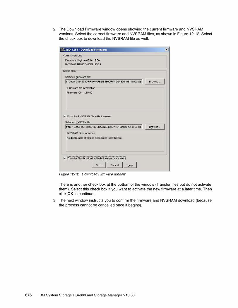
2. The Download Firmware window opens showing the current firmware and NVSRAM versions. Select the correct firmware and NVSRAM files, as shown in Figure 12-12. Select the check box to download the NVSRAM file as well.
Figure 12-12 Download Firmware window
There is another check box at the bottom of the window (Transfer files but do not activate them). Select this check box if you want to activate the new firmware at a later time. Then click OK to continue.
3. The next window instructs you to confirm the firmware and NVSRAM download (because the process cannot be cancelled once it begins).
676 IBM System Storage DS4000 and Storage Manager V10.30
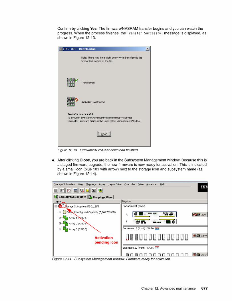
Confirm by clicking Yes. The firmware/NVSRAM transfer begins and you can watch the progress. When the process finishes, the Transfer Successful message is displayed, as shown in Figure 12-13.
Figure 12-13 Firmware/NVSRAM download finished
4. After clicking Close, you are back in the Subsystem Management window. Because this is a staged firmware upgrade, the new firmware is now ready for activation. This is indicated by a small icon (blue 101 with arrow) next to the storage icon and subsystem name (as shown in Figure 12-14).
Figure 12-14 Subsystem Management window: Firmware ready for activation
Activation pending icon
Chapter 12. Advanced maintenance 677

5. To activate the new firmware, select Advanced → Maintenance → Activate Controller Firmware, as shown in Figure 12-15.
Figure 12-15 Subsystem Management window: Firmware activation
The Activate Firmware window opens and asks you for confirmation to continue. After you click Yes, the activation process starts. The activation applies the transferred code to the controllers, rebooting first one, then the other. If you have all your hosts with path redundancy, you should not see any problem more than the disks going through one controller to the other while they are rebooted. We recommend scheduling this activation during a period of low I/O access.
You can monitor the progress in the Activation window, as shown in Figure 12-16.
Figure 12-16 Activating the firmware
When the new firmware is activated on both controllers, you will see the Activation successful message. Click Close to return to the Subsystem Management window.
678 IBM System Storage DS4000 and Storage Manager V10.30
12.1.6 Updating the ESM board firmwareAn Environmental Services Module (ESM) card monitors the environmental condition of the components in that enclosure. It also provides the interface between the Fibre Channel drives in a given storage expansion enclosure with other ESM cards and controller blades in a drive loop.
Before performing any upgrade, read the specific firmware version readme file for details of installation. Pay attention to any dependencies between controller and ESM, or drives, since there may be a specific sequence in which each of the components should be updated.
In case an ESM is replaced in an EXP810, there is a firmware synchronization feature that ensures that new ESM is automatically synchronized with the firmware in the existing ESM. This resolves any ESM firmware mismatch conditions automatically. You still have the option to update the ESM firmware manually, to a new level, or in the case of a failure that could not let the code synchronization identify which is the original ESM, which is the replacement ESM to synchronize.
The ESM upgrade can be done online in the case when you upgrade one expansion enclosure at a time only. The back-end FC loop is temporarily stopped and the second loop is used for access to the disk drives. When the first ESM is upgraded, the process automatically swaps all the communication and I/O back to the first loop and the second ESM is upgraded. We do not recommend selecting more than one expansion enclosure for ESM upgrade when there is heavy load on the DS4000.
For EXP420, EXP710, and EXP810, there is an option to set the enclosure settings using the Storage Manager by selecting Maintenance → Download → ESM Configuration Settings. This option should be used when ESM reports different versions of configuration settings and the software could not resolve the mismatch problem by automatically synchronizing the configuration settings between the two ESMs automatically.
Important: In many cases, the ESM firmware upgrade must be done before the controller upgrade. Some new versions of the controller firmware need a specific minimal level of ESM firmware. If ESM does not have the required firmware level, it can lose the connection to the controllers with newer firmware. It can lead to lose data or corruption.
Important: Before upgrading the ESM firmware, make sure that the system is in an optimal state. If not, run the Recovery Guru to diagnose and fix the problem before you proceed with the upgrade.
Chapter 12. Advanced maintenance 679
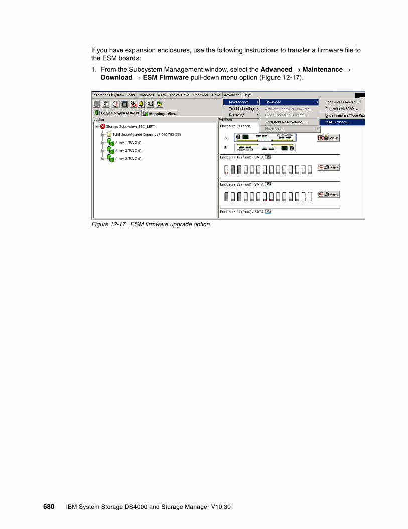
If you have expansion enclosures, use the following instructions to transfer a firmware file to the ESM boards:
1. From the Subsystem Management window, select the Advanced → Maintenance → Download → ESM Firmware pull-down menu option (Figure 12-17).
Figure 12-17 ESM firmware upgrade option
680 IBM System Storage DS4000 and Storage Manager V10.30

2. The Download Environmental (ESM) Card Firmware main window is displayed (see Figure 12-18).
– The select enclosures table lists all the enclosures found attached to the storage array that contain ESM cards.
– The select file allows you to specify the ESM firmware file to use as the source of the upgrade.
Figure 12-18 Download ESM firmware dialog
3. In the Select enclosures area, highlight each enclosure to which you wish to download firmware or select the Select All button to highlight all drive enclosures in the storage system (each drive enclosure selected should have the same product ID).
4. Enter the firmware file to download in the select file area by either entering the location and name of the file in the Select file text box, or selecting Browse and getting the firmware file from a local or network drive. (The Browse button is unavailable until an enclosure has been selected.)
5. Select Start. Confirm your selections and then select Yes to continue with the firmware download or No to quit.
6. The Status field in the Select enclosures table changes from pending to downloading for the ESM card firmware operation in progress.
Monitor the progress and completion status of the download to the enclosures. The progress and status of each drive enclosure participating in the download is displayed in the status field of the select enclosures table.
Note: If an ESM card does not show up in the list (because of a loss of redundancy or some other problem), run the Recovery Guru to diagnose and fix the problem before continuing with the download to avoid loosing both paths to the disks.
Chapter 12. Advanced maintenance 681

12.1.7 Updating hard disk drives firmware Updating the hard disk drives firmware is sometimes required after upgrading the ESM firmware or the controller firmware/NVSRAM. Always refer to the readme file associated with the hard drive and ESM firmware upgrade package for precise instructions.
Parallel drive firmware downloadStorage Manager allows you download hard disk drive firmware to several drives in parallel. This way, large configurations with multiple expansion enclosures are not affected by the download time that updating a large amount of drives might generate. However, make sure that you are not using an old version of Storage Manager, since versions prior to 9.10 manage the download to the drives in a serial way, thus impacting the total amount of time required.
You can update up to four different drive types (for example, ST373307FC, ST336732FC, ST336704FC, and ST318451FC) simultaneously. It does not matter whether there are different types or different firmware versions.
The ESM and disk drives firmware is usually downloadable as one package. You can find all the firmware files and full instructions at:
http://www.ibm.com/servers/storage/support/disk
Note: A disk drive firmware upgrade is always a disruptive procedure. No host I/O operations are provided during this upgrade.
Note: All I/O must be stopped while downloading the firmware to the drives.
In the DS4000 storage subsystems with the FC/SATA intermix premium feature enabled, do not download the drive firmware to both SATA-technology hard drives and Fibre Channel technology hard drives at the same time. Complete the drive firmware download to all of the drives of a drive technology (either SATA or FC) before downloading the drive firmware to the drives of the other drive technology (either FC or SATA).
682 IBM System Storage DS4000 and Storage Manager V10.30

To update the firmware of the disk drives:
1. Select Advanced → Maintenance → Download → Drive Firmware/Mode Pages, as shown in Figure 12-19.
Figure 12-19 Subsystem Management window: Drive firmware update
2. After taking the option from the Storage Manager, the window in Figure 12-20 appears. This window lists current drive firmware package information and allows you to specify up to four firmware update packages. Click the Add button to select these drive firmware packages.
Figure 12-20 Drive firmware: Adding packages
Notice that at the top, there is a section describing all the disk types detected in your system with their current firmware levels. This helps you choose which of the files to select, since you will have a large list of files downloaded with the hard drive microcode package.
Chapter 12. Advanced maintenance 683
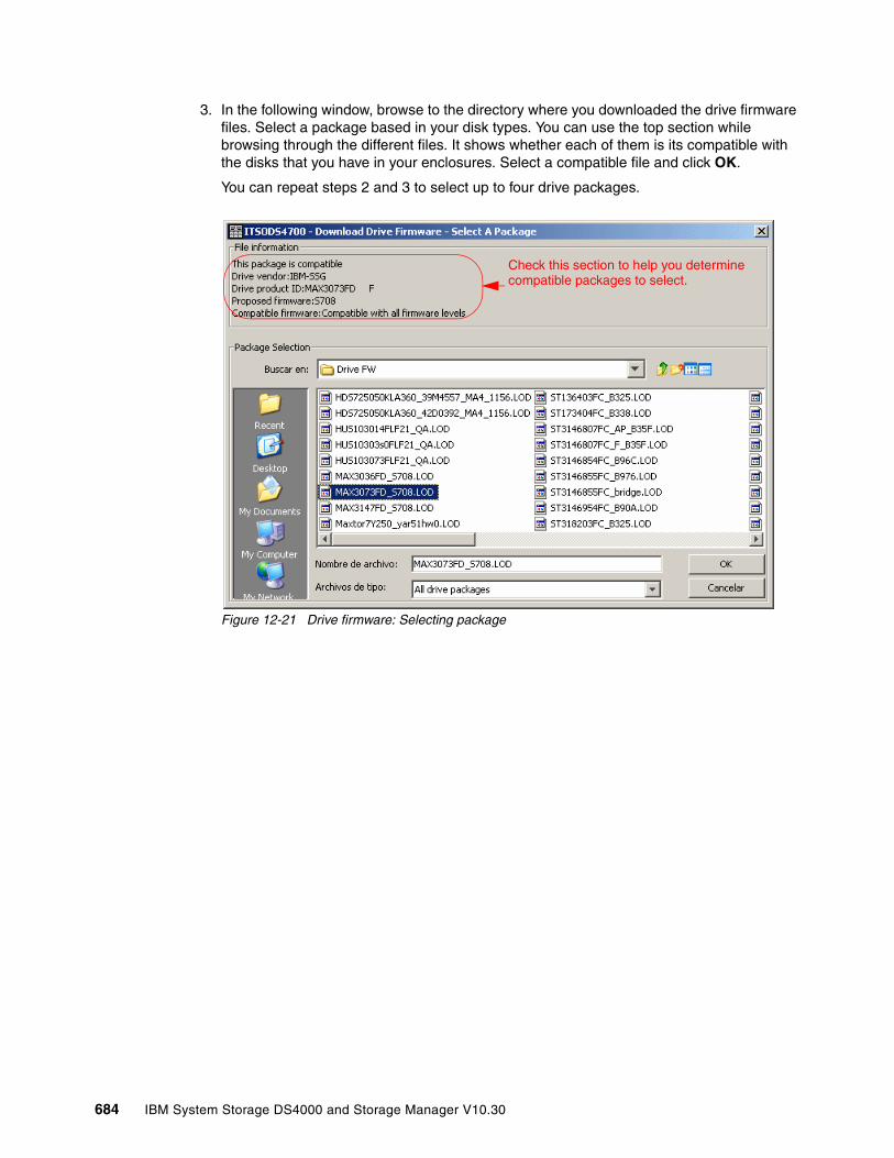
3. In the following window, browse to the directory where you downloaded the drive firmware files. Select a package based in your disk types. You can use the top section while browsing through the different files. It shows whether each of them is its compatible with the disks that you have in your enclosures. Select a compatible file and click OK.
You can repeat steps 2 and 3 to select up to four drive packages.
Figure 12-21 Drive firmware: Selecting package
Check this section to help you determinecompatible packages to select.
684 IBM System Storage DS4000 and Storage Manager V10.30
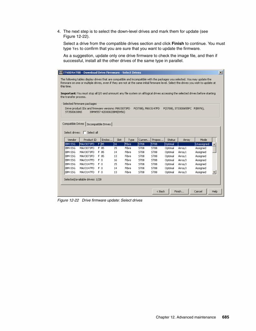
4. The next step is to select the down-level drives and mark them for update (see Figure 12-22).
Select a drive from the compatible drives section and click Finish to continue. You must type Yes to confirm that you are sure that you want to update the firmware.
As a suggestion, update only one drive firmware to check the image file, and then if successful, install all the other drives of the same type in parallel.
Figure 12-22 Drive firmware update: Select drives
Chapter 12. Advanced maintenance 685
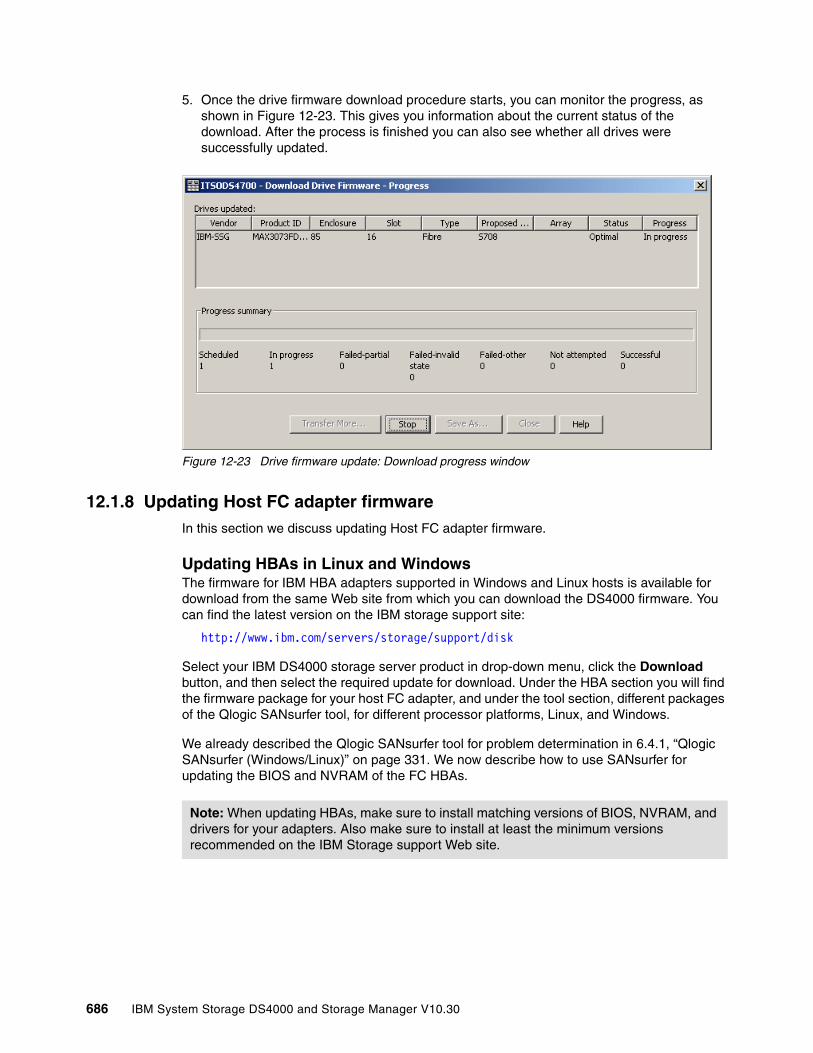
5. Once the drive firmware download procedure starts, you can monitor the progress, as shown in Figure 12-23. This gives you information about the current status of the download. After the process is finished you can also see whether all drives were successfully updated.
Figure 12-23 Drive firmware update: Download progress window
12.1.8 Updating Host FC adapter firmware In this section we discuss updating Host FC adapter firmware.
Updating HBAs in Linux and WindowsThe firmware for IBM HBA adapters supported in Windows and Linux hosts is available for download from the same Web site from which you can download the DS4000 firmware. You can find the latest version on the IBM storage support site:
http://www.ibm.com/servers/storage/support/disk
Select your IBM DS4000 storage server product in drop-down menu, click the Download button, and then select the required update for download. Under the HBA section you will find the firmware package for your host FC adapter, and under the tool section, different packages of the Qlogic SANsurfer tool, for different processor platforms, Linux, and Windows.
We already described the Qlogic SANsurfer tool for problem determination in 6.4.1, “Qlogic SANsurfer (Windows/Linux)” on page 331. We now describe how to use SANsurfer for updating the BIOS and NVRAM of the FC HBAs.
Note: When updating HBAs, make sure to install matching versions of BIOS, NVRAM, and drivers for your adapters. Also make sure to install at least the minimum versions recommended on the IBM Storage support Web site.
686 IBM System Storage DS4000 and Storage Manager V10.30

In order to update the BIOS version of the HBA, click the Utilities tab and you will be presented with a window, as shown in Figure 12-24.
Figure 12-24 Qlogic SANsurfer Utilities tab
Notice that there are two options to update: Flash Update and NVRAM. Click Update Flash, which corresponds to the BIOS version.
You are then presented with a warning, as shown in Figure 12-25. Make sure that you have suspended all I/O to the adapter before you proceed.
Figure 12-25 Qlogic SANsurfer BIOS update
Chapter 12. Advanced maintenance 687
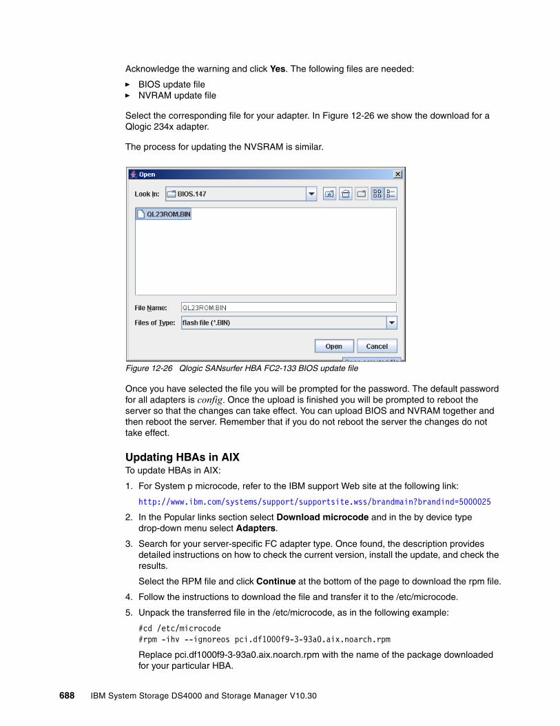
Acknowledge the warning and click Yes. The following files are needed:
� BIOS update file� NVRAM update file
Select the corresponding file for your adapter. In Figure 12-26 we show the download for a Qlogic 234x adapter.
The process for updating the NVSRAM is similar.
Figure 12-26 Qlogic SANsurfer HBA FC2-133 BIOS update file
Once you have selected the file you will be prompted for the password. The default password for all adapters is config. Once the upload is finished you will be prompted to reboot the server so that the changes can take effect. You can upload BIOS and NVRAM together and then reboot the server. Remember that if you do not reboot the server the changes do not take effect.
Updating HBAs in AIXTo update HBAs in AIX:
1. For System p microcode, refer to the IBM support Web site at the following link:
http://www.ibm.com/systems/support/supportsite.wss/brandmain?brandind=5000025
2. In the Popular links section select Download microcode and in the by device type drop-down menu select Adapters.
3. Search for your server-specific FC adapter type. Once found, the description provides detailed instructions on how to check the current version, install the update, and check the results.
Select the RPM file and click Continue at the bottom of the page to download the rpm file.
4. Follow the instructions to download the file and transfer it to the /etc/microcode.
5. Unpack the transferred file in the /etc/microcode, as in the following example:
#cd /etc/microcode#rpm -ihv --ignoreos pci.df1000f9-3-93a0.aix.noarch.rpm
Replace pci.df1000f9-3-93a0.aix.noarch.rpm with the name of the package downloaded for your particular HBA.
688 IBM System Storage DS4000 and Storage Manager V10.30
6. Flash the adapter microcode:
#diag -d fcsX -T download
Where X is the number returned by the "lsdev -C | grep fcs" command. Self-explanatory menus take you through the microcode installation. Repeat this for all the HBAs that must be updated.
7. Verify the adapter microcode level:
#lsmcode -d fcsX
Compare the obtained level with the readme file of the downloaded code.
12.2 Handling premium featuresDepending on your specific DS4000 model, you might want to use a specific function or capability of your subsystem. Some of these capabilities, although included in the firmware, are not enabled by default. These are called premium features, and you must activate them by entering an activation key. You must buy a license for the premium feature to get a key and instructions on how to activate it.
You can activate an individual premium feature providing its corresponding key, or activate a pack or bundle of multiple features.
Below we cover how to order, list, and install any of the premium features available for your DS4000.
The available premium features are:
� Storage partitioning� FlashCopy� Enhanced Remote Mirroring (ERM)� VolumeCopy� FC/SATA Intermix� Enhanced performance (DS4800 mod80 only)
Not all the premium features are available for all the models, and there are several new options starting with SM 10.10 (controller firmware 7.10). For example, the storage partitioning premium feature could be ordered to allow up to 32, 64, 96, 128, 256, or 512 partitions, depending on your DS4000 model and needs. See 4.4, “Premium features” on page 176, for additional reference.
12.2.1 Listing premium features/feature enablerFrom the Storage Manager client GUI, you can check what premium features are already activated in your DS4000 subsystem.
Chapter 12. Advanced maintenance 689

New with Storage Manager 10 and its related firmware, this information, with additional details, is generated as a text file. The file is available within the zip package generated by selecting the option Collect all Support Data from Storage Manager 10.10 and later.
1. Select Storage Subsystem → Premium Features → List from the Subsystem Managment window, or select Premium Features → List from the pop-up menu. As a result, the Premium Features dialog is displayed with a list of enabled premium features (Figure 12-27).
Figure 12-27 Listing premium features
If you receive a Premium Features - Out of Compliance error message during a management session, use the Recovery Guru to resolve the problem.
2. Collect all support data by selecting Advanced → Troubleshooting → Support Data → Collect. Provide a file name and directory where you want to store the zip file generated. See 6.1.4, “Support data: Collecting information” on page 302, for additional details for this option.
690 IBM System Storage DS4000 and Storage Manager V10.30

Once the file is generated, open the zip file and look at the file named featureBundle.txt to see the status, limits, and in-usage capacities for the premium features, as illustrated in Example 12-1.
Example 12-1 Collect support data featureBundle.txt file
FEATURE BUNDLE FOR STORAGE SUBSYSTEM: ITSODS4700 (28/08/07 20:34:11) Total logical drives allowed: 1024 Total logical drives allowed per partition: 256 Management application client: 1 Drives supported: B; J; S; BM Drive enclosures supported: IBM,EXP100,dSATA; IBM,EXP700,ESM_CARD; IBM,EXP710,SBOD_ESM; IBM,EXP810,HUSKER Drive enclosure expansion: 7 High Performance Tier: No data is available about supported values of this feature Storage Partitioning Enabled by default: Yes Default limit: 8 Enable/Upgrade via key: Yes Limit with feature key: 128 FlashCopy Logical Drives Enabled by default: No Enable/Upgrade via key: Yes Total flashcopies allowed: 512 Logical Drive Copy Enabled by default: No Enable/Upgrade via key: Yes Total copies allowed: 1024 Remote Mirroring Enabled by default: No Enable/Upgrade via key: Yes Total mirrors allowed: 32 Mixed Drive Types Enabled by default: No Enable/Upgrade via key: Yes
3. Gather the following data along with the feature enable identifier:
– Machine type
– Model
– Serial number of the DS4000 Storage Subsystem
– Controller firmware version (optional but recommended since some premium features are only available for specific versions)
Note: Machine type, model, and serial number information is printed on a label on the back of your DS4000 controller unit (with some models it is also on the plastic front cover). To view the installed level of firmware see 12.1.1, “Displaying installed firmware versions” on page 662.
The serial number of DS4000 is not a serial number of the DS4000 controller, as can be seen in the storage profile.
Chapter 12. Advanced maintenance 691
12.2.2 Enabling a premium featureObtaining a feature key varies depending upon DS4000 packaging procedures and time of order:
� If you bought any premium feature together with the DS4000, you receive the feature keys with the DS4000 hardware, but you still must activate them separately.
� If you are purchasing a new premium feature, you can get the key from your local storage support (IBM or Business Partner).
In any case, a premium feature is a chargeable optional feature for every DS4000, and you must request the feature from your sales contact person for a specific machine type, model, and serial number.
Once you have purchased a premium feature, you receive an envelope containing a license activation card for that particular feature with detailed instructions on how to proceed to activate it.
The procedure below will help you activate the new feature obtained or reactivate it if for any reason it is out of compliance:
1. On the card you received, locate the feature activation code and make sure that the instructions received are for your machine type and model. The feature activation code (XX-XXXX-XXXXX) is located at the top of the license activation card.
2. From the Subsystem Management window, select either the Storage Subsystem → Premium Features → List pull-down menu option or Premium Features → List from the right-click pop-up menu (Figure 12-27 on page 690).
3. Write down the 32-digit number (feature enable identifier), or preferably copy and paste the complete number to a text file to avoid typing errors.
You can also find the feature enable identifier in the profile data, either by selecting View-Profile or by opening the storageArrayProfile.txt file contained in the zip file generated when collecting all support data.
4. Go to the following Web site to personalize the key received to your specific system, and generate the activation key file:
http://www-912.ibm.com/PremiumFeatures/
Select the option to activate a premium feature.
5. Complete the form on the Web page with the following:
– Feature activation code– Feature enable identifier– Machine type – Model number– DS4000 serial number
The Web page generates an activation key file that you must download to your management station. It also sends the file to the specified e-mail address.
Important: All the premium features are activated immediately and do not require a reboot of the controllers. The exception to that is the new enhanced performance feature. Make sure to follow instructions provided and schedule the activation of the enhanced performance feature as a non-concurrent update.
692 IBM System Storage DS4000 and Storage Manager V10.30
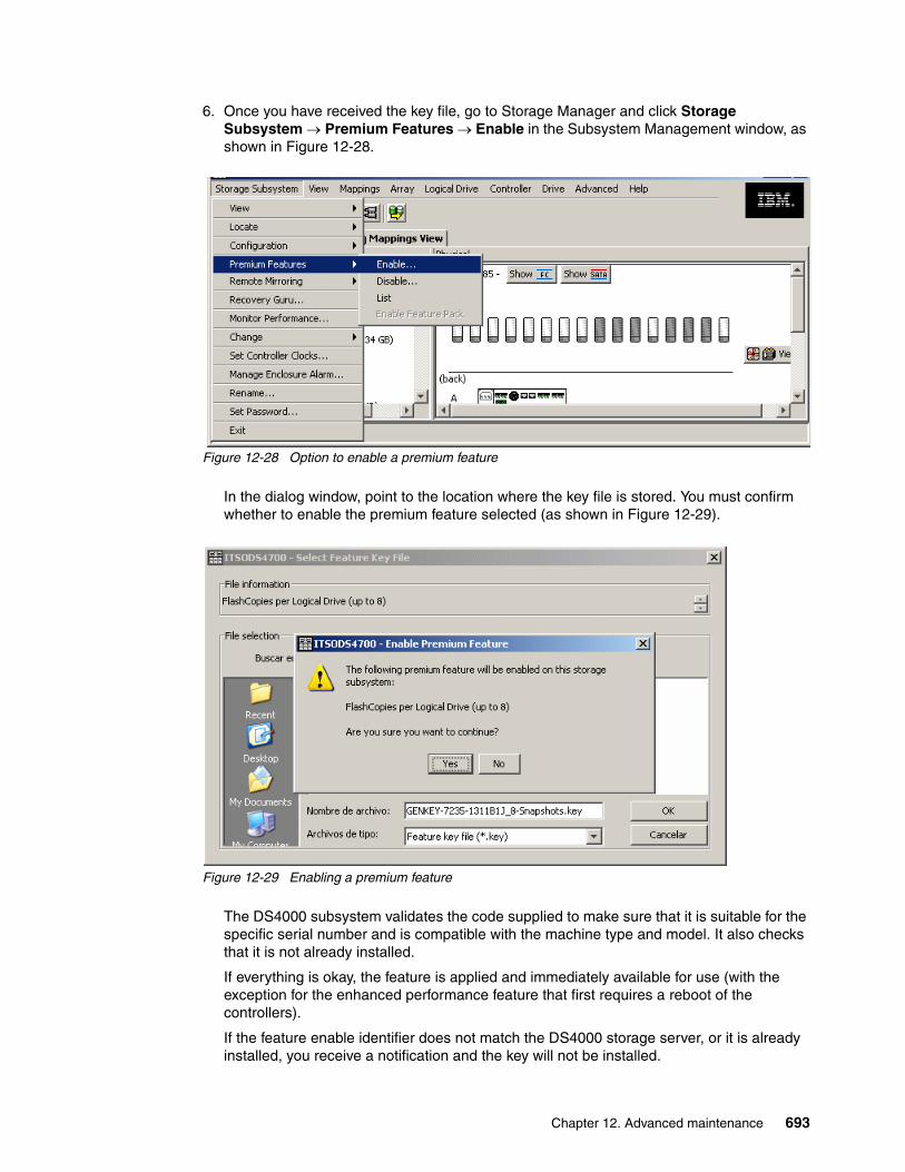
6. Once you have received the key file, go to Storage Manager and click Storage Subsystem → Premium Features → Enable in the Subsystem Management window, as shown in Figure 12-28.
Figure 12-28 Option to enable a premium feature
In the dialog window, point to the location where the key file is stored. You must confirm whether to enable the premium feature selected (as shown in Figure 12-29).
Figure 12-29 Enabling a premium feature
The DS4000 subsystem validates the code supplied to make sure that it is suitable for the specific serial number and is compatible with the machine type and model. It also checks that it is not already installed.
If everything is okay, the feature is applied and immediately available for use (with the exception for the enhanced performance feature that first requires a reboot of the controllers).
If the feature enable identifier does not match the DS4000 storage server, or it is already installed, you receive a notification and the key will not be installed.
Chapter 12. Advanced maintenance 693

12.2.3 Disabling a premium featureTo disable a premium feature, click Storage Subsystem → Premium Features → Disable in the Subsystem Management window. Choose the feature that you want to disable from the list, as shown in Figure 12-30, and confirm.
Figure 12-30 Disable Premium Feature
Keep in mind that the change happens immediately. If you use storage partitioning and disable the premium feature, then you cannot create new partitions. However, any existing partitions remain operational.
12.3 Saving and loading the configurationOnce your DS4000 storage subsystem is configured and running, save this configuration to be able to restore it in case of problems.
The saved configuration includes the array and logical drive configuration, the name of the subsystem, its cache settings, and other parametrization, including the storage partitioning configuration.
The saved file can be used to restore the configuration data to the same DS4000, or also to other DS4000 Storage subsystems in case you want to set up multiple storage systems with the same configuration. To allow that, the destination subsystem must have the same hardware layout, number of enclosures and drives, and drive capacities.
694 IBM System Storage DS4000 and Storage Manager V10.30
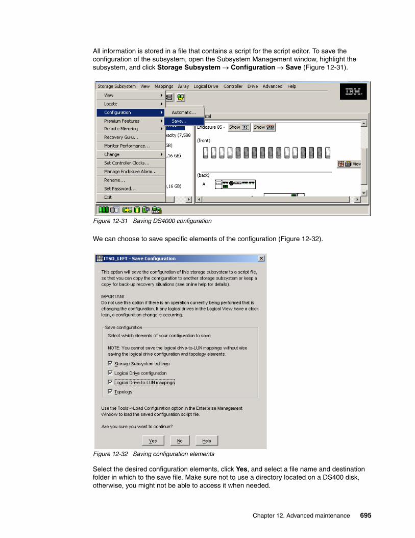
All information is stored in a file that contains a script for the script editor. To save the configuration of the subsystem, open the Subsystem Management window, highlight the subsystem, and click Storage Subsystem → Configuration → Save (Figure 12-31).
Figure 12-31 Saving DS4000 configuration
We can choose to save specific elements of the configuration (Figure 12-32).
Figure 12-32 Saving configuration elements
Select the desired configuration elements, click Yes, and select a file name and destination folder in which to the save file. Make sure not to use a directory located on a DS400 disk, otherwise, you might not be able to access it when needed.
Chapter 12. Advanced maintenance 695
The script created can be used to replicate the configuration of the DS4000. You can apply the configuration to the destination subsystem for all the saved elements, or any particular element. The script consists of the following information:
� Storage subsystem settings
– User label– Media scan rate– Cache block size– Cache flush start– Cache flush stop– Default host type – Failover alert delay
� Logical drive configuration
– RAID level– User label– Owning controller– Segment size– Capacity– Cache flush modifier– Read-ahead multiplier– Modification priority– Caching without batteries enabled/disabled– Cache mirroring enabled/disabled– Read caching enabled/disabled– Write caching enabled/disabled– Media scan enabled/disabled– Redundancy check enabled/disabled
� Logical drive-to-LUN mappings
� Topology
– Host groups– Hosts and parent host groups– Host ports, associated host type, and parent hosts
You have two possibilities to load the configuration to a DS4000 with the Storage Manager.
� Open the Enterprise Management window and select the subsystem. Click Tools → Load Storage Subsystem Configuration from the tool bar menu. Point to the file containing the configuration and load it. The script editor and a warning message appear. To load the configuration onto the DS4000 storage server, choose Execute. You can also edit the script before executing.
� Open the Enterprise Management window and select the subsystem. Click Tools → Load Configuration from the menu. Point to the file containing the configuration and load it. The script editor and a warning message appear. To load the configuration onto the DS4000 storage server, choose Execute. You can also edit the script before executing it.
Attention: This procedure replaces any configuration on the storage system. All data stored on the DS4000 storage server is lost because all logical drives are initialized. It is a good idea to save the configuration every time a change on the storage system is made.
Warning: Do not attempt to load a saved configuration on our DS4000 unless you fully understand all the consequences.
696 IBM System Storage DS4000 and Storage Manager V10.30
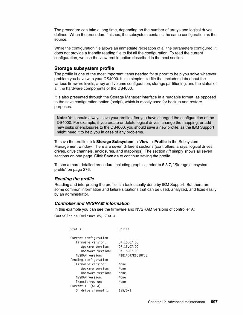
The procedure can take a long time, depending on the number of arrays and logical drives defined. When the procedure finishes, the subsystem contains the same configuration as the source.
While the configuration file allows an immediate recreation of all the parameters configured, it does not provide a friendly reading file to list all the configuration. To read the current configuration, we use the view profile option described in the next section.
Storage subsystem profileThe profile is one of the most important items needed for support to help you solve whatever problem you have with your DS4000. It is a simple text file that includes data about the various firmware levels, array and volume configuration, storage partitioning, and the status of all the hardware components of the DS4000.
It is also presented through the Storage Manager interface in a readable format, as opposed to the save configuration option (script), which is mostly used for backup and restore purposes.
To save the profile click Storage Subsystem → View → Profile in the Subsystem Management window. There are seven different sections (controllers, arrays, logical drives, drives, drive channels, enclosures, and mappings). The section all simply shows all seven sections on one page. Click Save as to continue saving the profile.
To see a more detailed procedure including graphics, refer to 5.3.7, “Storage subsystem profile” on page 276.
Reading the profileReading and interpreting the profile is a task usually done by IBM Support. But there are some common information and failure situations that can be used, analyzed, and fixed easily by an administrator.
Controller and NVSRAM informationIn this example you can see the firmware and NVSRAM versions of controller A:
Controller in Enclosure 85, Slot A Status: Online Current configuration Firmware version: 07.15.07.00 Appware version: 07.15.07.00 Bootware version: 07.15.07.00 NVSRAM version: N1814D47R1010V05 Pending configuration Firmware version: None Appware version: None Bootware version: None NVSRAM version: None Transferred on: None Current ID (ALPA) On drive channel 1: 125/0x1
Note: You should always save your profile after you have changed the configuration of the DS4000. For example, if you create or delete logical drives, change the mapping, or add new disks or enclosures to the DS4000, you should save a new profile, as the IBM Support might need it to help you in case of any problems.
Chapter 12. Advanced maintenance 697

Replacement part number: 41Y0676 Board ID: 3994 Submodel ID: 20 Product ID: 1814 FAStT Product revision: 0916 Serial number: 1T64519999 Date of manufacture: June 22, 2007 Cache Total data cache: 1709 MB Accessible data cache: 0 MB Processor cache: 339 MB Date/Time: Tue Sep 09 15:27:07 MST 2008
HDD informationthe Drives tab in the profile data provides the following information:
DRIVES------------------------------
SUMMARY Number of drives: 54 Supported drive types: Fibre (14), Serial ATA (SATA) (40)
BASIC: TRAY, SLOT STATUS CAPACITY CURRENT DATA RATE PRODUCT ID FIRMWARE VERSION 12, 1 Optimal 232.882 GB 2 Gbps Maxtor 7Y250M0 YAR51HW0 12, 2 Optimal 232.882 GB 2 Gbps Maxtor 7Y250M0 YAR51HW0 12, 3 Optimal 232.882 GB 2 Gbps Maxtor 7Y250M0 YAR51HW0 12, 4 Optimal 232.882 GB 2 Gbps Maxtor 7Y250M0 YAR51HW0 12, 5 Optimal 232.882 GB 2 Gbps Maxtor 7Y250M0 YAR51HW0.......
Mappings informationThe following is what you find in the profile mappings tab, similar to the mapping section of the Storage Manager client:
MAPPINGS (Storage Partitioning - Enabled (2 of 128 used))------------------- Logical Drive Name LUN Controller Accessible by Logical Drive status Access Logical Drive 31 A,B Host Group AIX Optimal Data1 0 A Host Group AIX Optimal Data2 1 A Host Group AIX Optimal Access Logical Drive 31 A,B Host Group Windows Optimal 1 1 A Host Group Windows Optimal 2 2 B Host Group Windows Optimal 3 3 A Host Group Windows Optimal 4 4 B Host Group Windows Optimal
Reading profile in a failed disk scenarioWe use this example to outline how to use the profile data to find a failed disk in the DS4000.
Open the profile data window, select the Arrays tab, and you will see the information shown in Example 12-2.
Example 12-2 Failed drive protected by hot spare
ARRAYS------------------------------
Name: Data Status: Degraded - partially complete array Capacity 930,523 GB
698 IBM System Storage DS4000 and Storage Manager V10.30
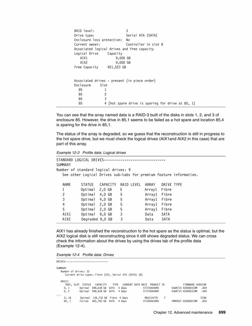
RAID level: 3 Drive type: Serial ATA (SATA) Enclosure loss protection: No Current owner: Controller in slot B Associated logical drives and free capacity Logical Drive Capacity
AIX1 9,000 GB AIX2 9,000 GB
Free Capacity 921,523 GB
Associated drives - present (in piece order) Enclosure Slot
85 1 85 2 85 3 85 4 [hot spare drive is sparing for drive at 85, 1]
You can see that the array named data is a RAID-3 built of the disks in slots 1, 2, and 3 of enclosure 85. However, the drive in 85,1 seems to be failed as a hot spare and location 85,4 is sparing for the drive in 85,1.
The status of the array is degraded, so we guess that the reconstruction is still in progress to the hot spare drive, but we must check the logical drives (AIX1and AIX2 in this case) that are part of this array.
Example 12-3 Profile data: Logical drives
STANDARD LOGICAL DRIVES------------------------------ SUMMARY Number of standard logical drives: 9
See other Logical Drives sub-tabs for premium feature information. NAME STATUS CAPACITY RAID LEVEL ARRAY DRIVE TYPE
1 Optimal 2,0 GB 5 Array1 Fibre 2 Optimal 4,0 GB 5 Array1 Fibre 3 Optimal 4,0 GB 5 Array1 Fibre 4 Optimal 2,0 GB 5 Array1 Fibre 5 Optimal 2,0 GB 5 Array1 Fibre AIX1 Optimal 9,0 GB 3 Data SATA
AIX2 Degraded 9,0 GB 3 Data SATA
AIX1 has already finished the reconstruction to the hot spare as the status is optimal, but the AIX2 logical disk is still reconstructing since it still shows degraded status. We can cross check the information about the drives by using the drives tab of the profile data (Example 12-4).
Example 12-4 Profile data: Drives
DRIVES------------------------------ SUMMARY Number of drives: 32 Current drive types: Fibre (24), Serial ATA (SATA) (8) BASIC: TRAY, SLOT STATUS CAPACITY TYPE CURRENT DATA RATE PRODUCT ID FIRMWARE VERSION 0, 1 Optimal 698,638 GB SATA 4 Gbps ST3750640NS 43W9715 42D0003IBM .AEH 0, 2 Optimal 698,638 GB SATA 4 Gbps ST3750640NS 43W9715 42D0003IBM .AEH ... 0, 16 Optimal 136,732 GB Fibre 4 Gbps MAX3147FD F S708 85, 1 Failed 465,762 GB SATA 4 Gbps ST3500630NS 39M4557 42D0002IBM .AEH
Chapter 12. Advanced maintenance 699
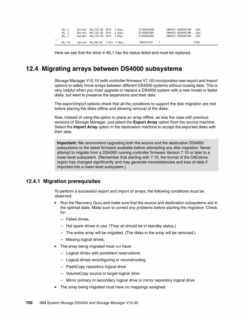
85, 2 Optimal 465,762 GB SATA 4 Gbps ST3500630NS 39M4557 42D0002IBM .AEH 85, 3 Optimal 465,762 GB SATA 4 Gbps ST3500630NS 39M4557 42D0002IBM .AEH 85, 4 Optimal 465,762 GB SATA 4 Gbps ST3500630NS 39M4557 42D0002IBM .AEH ...
85, 16 Optimal 68,366 GB Fibre 4 Gbps MAX3073FD F S708
Here we see that the drive in 85,1 has the status failed and must be replaced.
12.4 Migrating arrays between DS4000 subsystems
Storage Manager V10.10 (with controller firmware V7.10) incorporates new export and import options to safely move arrays between different DS4000 systems without loosing data. This is very helpful when you must upgrade or replace a DS4000 system with a new model or faster disks, but want to preserve the expansions and their data.
The export/import options check that all the conditions to support the disk migration are met before placing the disks offline and allowing removal of the disks.
Now, instead of using the option to place an array offline, as was the case with previous versions of Storage Manager, just select the Export Array option from the source machine. Select the Import Array option in the destination machine to accept the exported disks with their data.
12.4.1 Migration prerequisites
To perform a successful export and import of arrays, the following conditions must be observed:
� Run the Recovery Guru and make sure that the source and destination subsystems are in the optimal state. Make sure to correct any problems before starting the migration. Check for:
– Failed drives.
– Hot spare drives in use. (They all should be in standby status.)
– The entire array will be migrated. (The disks in the array will be removed.)
– Missing logical drives.
� The array being migrated must not have:
– Logical drives with persistent reservations
– Logical drives reconfiguring or reconstructing
– FlashCopy repository logical drive
– VolumeCopy source or target logical drive
– Mirror primary or secondary logical drive or mirror repository logical drive
� The array being migrated must have no mappings assigned.
Important: We recommend upgrading both the source and the destination DS4000 subsystems to the latest firmware available before attempting any disk migration. Never attempt to migrate from a DS4000 running controller firmware Version 7.10 or later to a lower-level subsystem. (Remember that starting with 7.10, the format of the DACstore region has changed significantly and may generate inconsistencies and loss of data if imported into a lower-level subsystem.)
700 IBM System Storage DS4000 and Storage Manager V10.30
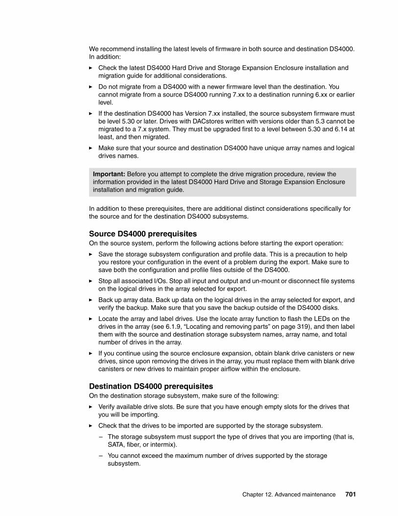
We recommend installing the latest levels of firmware in both source and destination DS4000. In addition:
� Check the latest DS4000 Hard Drive and Storage Expansion Enclosure installation and migration guide for additional considerations.
� Do not migrate from a DS4000 with a newer firmware level than the destination. You cannot migrate from a source DS4000 running 7.xx to a destination running 6.xx or earlier level.
� If the destination DS4000 has Version 7.xx installed, the source subsystem firmware must be level 5.30 or later. Drives with DACstores written with versions older than 5.3 cannot be migrated to a 7.x system. They must be upgraded first to a level between 5.30 and 6.14 at least, and then migrated.
� Make sure that your source and destination DS4000 have unique array names and logical drives names.
In addition to these prerequisites, there are additional distinct considerations specifically for the source and for the destination DS4000 subsystems.
Source DS4000 prerequisitesOn the source system, perform the following actions before starting the export operation:
� Save the storage subsystem configuration and profile data. This is a precaution to help you restore your configuration in the event of a problem during the export. Make sure to save both the configuration and profile files outside of the DS4000.
� Stop all associated I/Os. Stop all input and output and un-mount or disconnect file systems on the logical drives in the array selected for export.
� Back up array data. Back up data on the logical drives in the array selected for export, and verify the backup. Make sure that you save the backup outside of the DS4000 disks.
� Locate the array and label drives. Use the locate array function to flash the LEDs on the drives in the array (see 6.1.9, “Locating and removing parts” on page 319), and then label them with the source and destination storage subsystem names, array name, and total number of drives in the array.
� If you continue using the source enclosure expansion, obtain blank drive canisters or new drives, since upon removing the drives in the array, you must replace them with blank drive canisters or new drives to maintain proper airflow within the enclosure.
Destination DS4000 prerequisitesOn the destination storage subsystem, make sure of the following:
� Verify available drive slots. Be sure that you have enough empty slots for the drives that you will be importing.
� Check that the drives to be imported are supported by the storage subsystem.
– The storage subsystem must support the type of drives that you are importing (that is, SATA, fiber, or intermix).
– You cannot exceed the maximum number of drives supported by the storage subsystem.
Important: Before you attempt to complete the drive migration procedure, review the information provided in the latest DS4000 Hard Drive and Storage Expansion Enclosure installation and migration guide.
Chapter 12. Advanced maintenance 701

– Make sure that the drives are compatible with the storage expansion enclosure. For example, insert 2 Gbps FC drives into a storage expansion enclosure that runs with 2 Gbps FC speed. If the enclosure runs in 4 Gbps FC speed, new disks cannot be imported.
– Verify the physical size of disks in the expansion enclosures. Disks from older EXP710 or EXP100 (14 disks per enclosure) cannot be moved to EXP810 (16 disks per enclosure), even if the type and speed are equal.
� Check support for RAID-6. Make sure that the RAID-6 is supported on the destination storage subsystem if you are exporting a RAID level 6 array (only DS4200 and DS4700 support RAID-6 currently).
� You cannot exceed the maximum supported number of logical drives.
� When the destination DS4000 is not running firmware level 7.x, run the EnableDriveMigration script to ensure that the drive migration setting is set to enable before inserting any drives with configuration data.
12.4.2 Migrating an array
We cover separately the migration from a DS4000 running firmware Version 6.14 or later, and a migration or export/import between DS4000 with firmware with 7.10 or later.
Migrating arrays from firmware 5.30 or later to 7.xxA minimum firmware level of 5.30 is required on the source system if you want to migrate arrays to a destination DS4000 running firmware Version 7.xx.
Whenever possible, you should upgrade the firmware to Version 7.xx if supported on the DS4000 where you are planning to migrate the arrays. Not only will the DS4000 be more stable since all the known fixes will be applied, but you will also be able to use the export/import option available first with firmware level 7.10.
If you cannot upgrade to firmware 7.xx, follow these steps:
1. In the Subsystem Storage Manager 9 window, select the array to be migrated from the DS4000 subsystem.
2. Select Advanced → Maintenance → Place Array → Offline form the Subsystem Managment window, as shown in Figure 12-33.
Figure 12-33 Setting an array offline
702 IBM System Storage DS4000 and Storage Manager V10.30
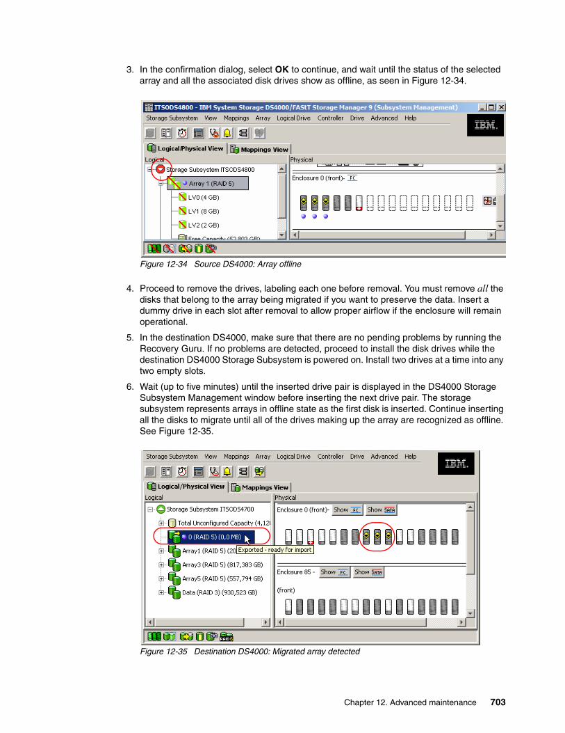
3. In the confirmation dialog, select OK to continue, and wait until the status of the selected array and all the associated disk drives show as offline, as seen in Figure 12-34.
Figure 12-34 Source DS4000: Array offline
4. Proceed to remove the drives, labeling each one before removal. You must remove all the disks that belong to the array being migrated if you want to preserve the data. Insert a dummy drive in each slot after removal to allow proper airflow if the enclosure will remain operational.
5. In the destination DS4000, make sure that there are no pending problems by running the Recovery Guru. If no problems are detected, proceed to install the disk drives while the destination DS4000 Storage Subsystem is powered on. Install two drives at a time into any two empty slots.
6. Wait (up to five minutes) until the inserted drive pair is displayed in the DS4000 Storage Subsystem Management window before inserting the next drive pair. The storage subsystem represents arrays in offline state as the first disk is inserted. Continue inserting all the disks to migrate until all of the drives making up the array are recognized as offline. See Figure 12-35.
Figure 12-35 Destination DS4000: Migrated array detected
Chapter 12. Advanced maintenance 703

Next proceed with the import operation in the destination DS4000. The procedure is covered in 12.4.3, “Importing an array” on page 707.
Migrating from firmware V7.10 or laterWith firmware V7.10 or later, the migration is started using the export option in the SM client, and with the advantage that the SM client will perform a preliminary check to validate the migration.
1. In the Subsystem Storage Manager window, select the array to be exported.
2. Select Advanced → Maintenance → Export array form the Subsystem management window, as in Figure 12-36.
Figure 12-36 Exporting an array
Note: In Figure 12-35 on page 703 pay attention to the array name. If the array name collides with an existing name, a different name is assigned to allow the migration, as in our example. You can change the label later once the import is complete.
704 IBM System Storage DS4000 and Storage Manager V10.30
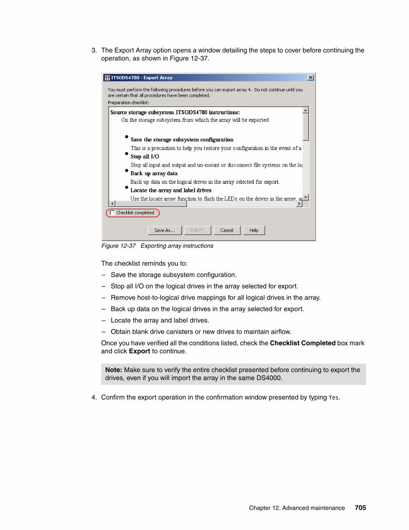
3. The Export Array option opens a window detailing the steps to cover before continuing the operation, as shown in Figure 12-37.
Figure 12-37 Exporting array instructions
The checklist reminds you to:
– Save the storage subsystem configuration.
– Stop all I/O on the logical drives in the array selected for export.
– Remove host-to-logical drive mappings for all logical drives in the array.
– Back up data on the logical drives in the array selected for export.
– Locate the array and label drives.
– Obtain blank drive canisters or new drives to maintain airflow.
Once you have verified all the conditions listed, check the Checklist Completed box mark and click Export to continue.
4. Confirm the export operation in the confirmation window presented by typing Yes.
Note: Make sure to verify the entire checklist presented before continuing to export the drives, even if you will import the array in the same DS4000.
Chapter 12. Advanced maintenance 705
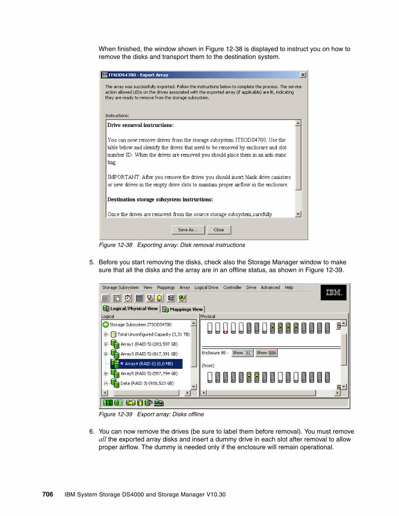
When finished, the window shown in Figure 12-38 is displayed to instruct you on how to remove the disks and transport them to the destination system.
Figure 12-38 Exporting array: Disk removal instructions
5. Before you start removing the disks, check also the Storage Manager window to make sure that all the disks and the array are in an offline status, as shown in Figure 12-39.
Figure 12-39 Export array: Disks offline
6. You can now remove the drives (be sure to label them before removal). You must remove all the exported array disks and insert a dummy drive in each slot after removal to allow proper airflow. The dummy is needed only if the enclosure will remain operational.
706 IBM System Storage DS4000 and Storage Manager V10.30
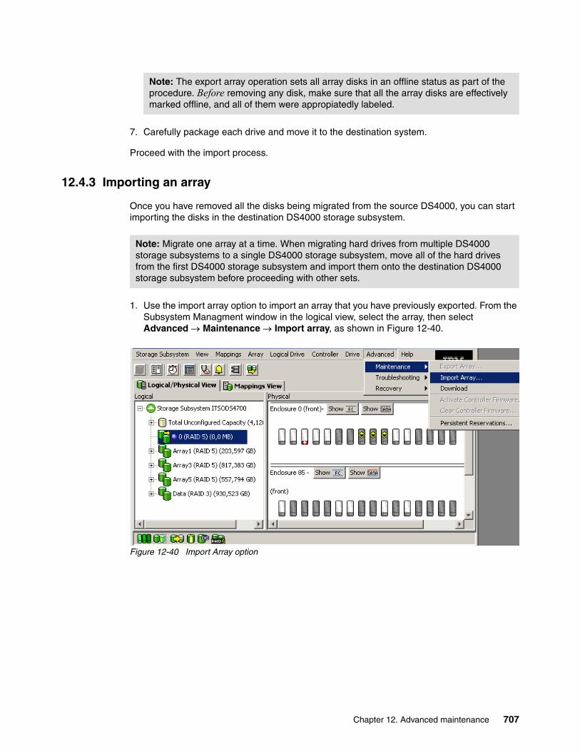
7. Carefully package each drive and move it to the destination system.
Proceed with the import process.
12.4.3 Importing an array
Once you have removed all the disks being migrated from the source DS4000, you can start importing the disks in the destination DS4000 storage subsystem.
1. Use the import array option to import an array that you have previously exported. From the Subsystem Managment window in the logical view, select the array, then select Advanced → Maintenance → Import array, as shown in Figure 12-40.
Figure 12-40 Import Array option
Note: The export array operation sets all array disks in an offline status as part of the procedure. Before removing any disk, make sure that all the array disks are effectively marked offline, and all of them were appropiatedly labeled.
Note: Migrate one array at a time. When migrating hard drives from multiple DS4000 storage subsystems to a single DS4000 storage subsystem, move all of the hard drives from the first DS4000 storage subsystem and import them onto the destination DS4000 storage subsystem before proceeding with other sets.
Chapter 12. Advanced maintenance 707
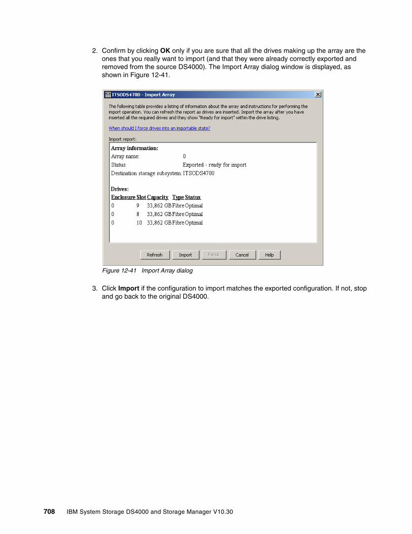
2. Confirm by clicking OK only if you are sure that all the drives making up the array are the ones that you really want to import (and that they were already correctly exported and removed from the source DS4000). The Import Array dialog window is displayed, as shown in Figure 12-41.
Figure 12-41 Import Array dialog
3. Click Import if the configuration to import matches the exported configuration. If not, stop and go back to the original DS4000.
708 IBM System Storage DS4000 and Storage Manager V10.30

4. If the controller detects any condition that will interfere with the current configuration, it lets you know. In Figure 12-42 the drives were exported without clearing the mapping information. If the condition detected is more critical, stop here. It is better to go back to the source DS4000 to solve the issue. When you are ready, check the Reviewed the non-portable components list check box and click Import to proceed.
Figure 12-42 Import Array warnings
5. A confirmation dialog window displays. Enter yes and click OK.
Chapter 12. Advanced maintenance 709
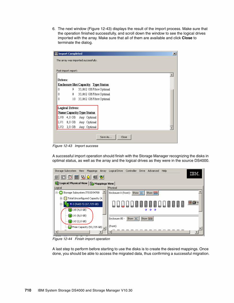
6. The next window (Figure 12-43) displays the result of the import process. Make sure that the operation finished successfully, and scroll down the window to see the logical drives imported with the array. Make sure that all of them are available and click Close to terminate the dialog.
Figure 12-43 Import success
A successful import operation should finish with the Storage Manager recognizing the disks in optimal status, as well as the array and the logical drives as they were in the source DS4000.
Figure 12-44 Finish import operation
A last step to perform before starting to use the disks is to create the desired mappings. Once done, you should be able to access the migrated data, thus confirming a successful migration.
710 IBM System Storage DS4000 and Storage Manager V10.30
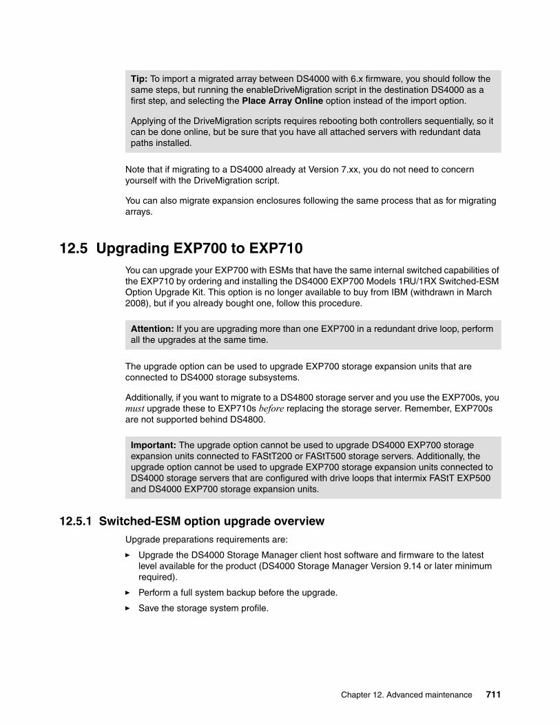
Note that if migrating to a DS4000 already at Version 7.xx, you do not need to concern yourself with the DriveMigration script.
You can also migrate expansion enclosures following the same process that as for migrating arrays.
12.5 Upgrading EXP700 to EXP710You can upgrade your EXP700 with ESMs that have the same internal switched capabilities of the EXP710 by ordering and installing the DS4000 EXP700 Models 1RU/1RX Switched-ESM Option Upgrade Kit. This option is no longer available to buy from IBM (withdrawn in March 2008), but if you already bought one, follow this procedure.
The upgrade option can be used to upgrade EXP700 storage expansion units that are connected to DS4000 storage subsystems.
Additionally, if you want to migrate to a DS4800 storage server and you use the EXP700s, you must upgrade these to EXP710s before replacing the storage server. Remember, EXP700s are not supported behind DS4800.
12.5.1 Switched-ESM option upgrade overviewUpgrade preparations requirements are:
� Upgrade the DS4000 Storage Manager client host software and firmware to the latest level available for the product (DS4000 Storage Manager Version 9.14 or later minimum required).
� Perform a full system backup before the upgrade.
� Save the storage system profile.
Tip: To import a migrated array between DS4000 with 6.x firmware, you should follow the same steps, but running the enableDriveMigration script in the destination DS4000 as a first step, and selecting the Place Array Online option instead of the import option.
Applying of the DriveMigration scripts requires rebooting both controllers sequentially, so it can be done online, but be sure that you have all attached servers with redundant data paths installed.
Attention: If you are upgrading more than one EXP700 in a redundant drive loop, perform all the upgrades at the same time.
Important: The upgrade option cannot be used to upgrade DS4000 EXP700 storage expansion units connected to FAStT200 or FAStT500 storage servers. Additionally, the upgrade option cannot be used to upgrade EXP700 storage expansion units connected to DS4000 storage servers that are configured with drive loops that intermix FAStT EXP500 and DS4000 EXP700 storage expansion units.
Chapter 12. Advanced maintenance 711

Two upgrade methods are available:
� Cold-case upgrade: The DS4000 EXP700s and connected storage server are powered down when ESMs are replaced.
� Hot-case upgrade: The DS4000 EXP700s and connected storage server remain powered on when ESMs are replaced. Because the DS4000 storage server drive loops/channels will be disturbed during the upgrade, you should schedule the upgrade during non-peak I/O period. Use the DS4000 Storage Manager performance monitor function to determine the non-peak I/O load time if required.
12.5.2 Cold-case ESM upgrade procedureIn the cold-case ESM upgrade procedure, you must power off the storage system before upgrading the EXP700 ESMs. If your environment does not allow you to power off the storage system in a non-emergency situation, use the hot-case ESM upgrade procedure described in 12.5.3, “Hot-case ESM upgrade procedure” on page 713.
If you are not upgrading all of the EXP700s in the redundant drive loop, or if you are upgrading additional EXP700s in the redundant drive loop that include both EXP700s and EXP710s, you must follow the intermixing requirements for drive loops that include bothEXP700s and EXP710s. Failure to do so can result in drive loop performance problems due to excessive time outs and LIPs.
1. Before you begin the upgrade procedure, perform a full system backup and save the storage system profile.
2. Upgrade the Storage Manager client to Version 9.14 or later.
3. Upgrade the controller firmware to the latest possible version.
4. After you have upgraded the Storage Manager client and controller firmware, verify that the storage server is in optimal condition. Use the Recovery Guru function in the Storage
Note: The cold-case ESM upgrade procedure is recommended if you are intermixing DS4000 EXP700s and DS4000 EXP710s in the same drive loop or if your production environment allows the scheduling of downtime for maintenance purposes.
Note: We recommend that you schedule the hot-case ESM upgrade during a non-peak (low-usage) I/O period for the following reasons:
� The DS4000 storage server drive loops/channels will be disturbed with FC Loop Initialization events every time that the ESM is replaced.
� One of the drive loops in the drive loop will be down during the upgrade, reducing the maximum data bandwidth to the drives by one-half.
Important: After an EXP700 is upgraded with the EXP700 Models 1RU/1RX Switched-ESM Option Upgrade Kit, it is considered an EXP710 for purposes of cabling a drive loop. Therefore, if you are not upgrading all the DS4000 EXP700 storage expansion units in a drive loop, you must follow the intermixing requirements for redundant drive loops that include both EXP700s and EXP710s. These requirements state that all EXP710s in a redundant drive loop must be grouped together.
Note: The cold-case ESM upgrade procedure is recommended if you are intermixing EXP700s and EXP710s in the same drive loop.
712 IBM System Storage DS4000 and Storage Manager V10.30

Manager client Subsystem Management window for information about how to fix any non-optimal conditions. Correct any faults before you turn off the power to the storage system using the proper troubleshooting or servicing procedures. This helps ensure that the storage expansion units will operate correctly after the upgrade.
5. Stop the applications in the server and then power down your storage system. Power down the DS4000 storage server first and then power down the drive expansion enclosures.
6. Whether you are upgrading one or multiple DS4000 EXP700s in a drive loop, complete the disconnection, upgrade, and reconnection process described in the following steps for each storage expansion unit before upgrading the next storage expansion unit. Disconnecting, upgrading, and reconnecting one EXP700 at time greatly reduces the possibility of making a Fibre Channel cabling error.
a. Disconnect all Fibre Channel cables from the left ESM in the first storage expansion unit that you will upgrade.
b. Replace the left ESM with the upgrade ESM CRU that you received in the EXP700 Models 1RU/1RX Switched-ESM Option Upgrade Kit.
c. Reconnect the Fibre Channel cables to the upgraded ESM in the first storage expansion unit.
d. Repeat steps a through c for the right ESM in the first storage expansion unit that you will upgrade.
e. Replace the EXP700 bezel with the new bezel that you received in the EXP700 Models 1RU/1RX Switched-ESM Option Upgrade Kit.
f. Repeat steps a through e for each EXP700 that you are upgrading. Complete the process for each EXP700 before you continue with the next storage expansion unit.
7. Power on your storage system. Power up the drive expansion enclosures first and then power up the DS4000 storage server. Use the LEDs to verify that the DS4000 configuration is operating normally. Correct any fault LED errors and verify that the ESM port bypass LEDs are not lit (if they are, remove the Fibre Channel cables and the SFPs and reinsert them).
8. Use the Storage Manager client Subsystem Management window to verify that the DS4000 storage server configuration is in an optimal state and that no ESM redundancy lost errors or drive errors are being reported. Use the Recovery Guru function in the Storage Manager client Subsystem Management window for information about how to fix any non-optimal conditions. If you experience any drive failure conditions, call IBM support for help.
9. Restore I/O activity to the DS4000 storage server.
12.5.3 Hot-case ESM upgrade procedureIn the hot-case ESM upgrade procedure, upgrade the DS4000 EXP700 ESMs while the storage system remains powered on.
Note: We recommend that you schedule the hot-case ESM upgrade during a non-peak (low-usage) I/O period for the following reasons:
� The DS4000 storage server drive loops/channels will be disturbed with FC loop initialization events every time that the ESM is replaced.
� One of the loops in the redundant drive loop will be down during the upgrade, reducing the maximum data bandwidth to the drives by a half.
Chapter 12. Advanced maintenance 713

The hot-case ESM upgrade procedure requires that both loops (drive channels) in the redundant drive loop that contains the EXP700s that you are upgrading be in an optimal state. If you perform the upgrade process with one drive loop (drive channel) in non-optimal state, your arrays might fail, causing loss of data access and possibly loss of data. If you are not sure that the drive loops are optimal, or if the environment allows you to power off the storage system in a non-emergency situation, we recommend that you use the cold-case ESM upgrade procedure as described in 12.5.2, “Cold-case ESM upgrade procedure” on page 712, instead of the hot-case ESM upgrade procedure. Contact IBM support for help if required.
You must perform the hot-case upgrade procedure one redundant drive loop at a time. If you are not upgrading all of the EXP700s in the redundant drive loop, or if you are upgrading additional EXP700s in a redundant drive loop that includes both EXP700s and EXP710s, you must follow the intermixing requirements for drive loops that include both EXP700s and EXP710s.
Failure to do so can result in drive loop performance problems due to excessive time outs and LIPs and possibly failed drives.
1. Before you begin the upgrade procedure, perform a full system backup and save the storage system profile.
2. Upgrade the DS4000 Storage Manager client to Version 9.14 or later.
3. Upgrade the controller firmware to the latest possible version.
4. Verify that the drive channels are in an optimal state. Monitor the status of the storage system for several days with the Storage Manager client and DS4000 storage server event logs. We recommend that you periodically monitor the read-link status and drive channels for two to three days, looking for any excessive increase in error counts. Use the Recovery Guru function in the Storage Manager client Subsystem Management window for information about how to fix any non-optimal conditions.
In addition, you can also manually force one drive loop/channel in the redundant drive loop to be upgraded into a degraded state in the Drive Channel (Summary) window. With one loop in a degraded state, monitor the error counts in the other (optimal) drive loop/channel in the redundant drive loop (for 20 minutes) with I/O activity present. Then set the degraded drive loop/channel back into optimal state. Wait at least 20 minutes and repeat the process for the other drive loop/channel in the redundant drive loop to be upgraded. If there are excessive errors counts (in the tens or hundreds), do not perform the ESM upgrade until you have first resolved the errors using the drive path diagnostics described in the IBM TotalStorage DS4000 Problem Determination Guide.
Attention: Resolve any non-optimal conditions before continuing with the next step.
714 IBM System Storage DS4000 and Storage Manager V10.30
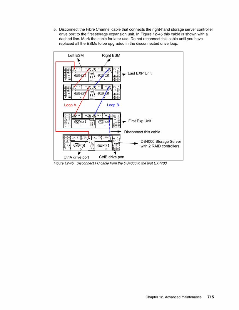
5. Disconnect the Fibre Channel cable that connects the right-hand storage server controller drive port to the first storage expansion unit. In Figure 12-45 this cable is shown with a dashed line. Mark the cable for later use. Do not reconnect this cable until you have replaced all the ESMs to be upgraded in the disconnected drive loop.
Figure 12-45 Disconnect FC cable from the DS4000 to the first EXP700
DS4000 Storage Serverwith 2 RAID controllers
CtrlB drive portCtrlA drive port
First Exp Unit
Loop B
Last EXP Unit
Disconnect this cable
Loop A
Left ESM Right ESM
Chapter 12. Advanced maintenance 715
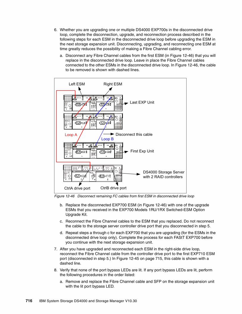
6. Whether you are upgrading one or multiple DS4000 EXP700s in the disconnected drive loop, complete the disconnection, upgrade, and reconnection process described in the following steps for each ESM in the disconnected drive loop before upgrading the ESM in the next storage expansion unit. Disconnecting, upgrading, and reconnecting one ESM at time greatly reduces the possibility of making a Fibre Channel cabling error.
a. Disconnect any Fibre Channel cables from the first ESM (in Figure 12-46) that you will replace in the disconnected drive loop. Leave in place the Fibre Channel cables connected to the other ESMs in the disconnected drive loop. In Figure 12-46, the cable to be removed is shown with dashed lines.
Figure 12-46 Disconnect remaining FC cables from first ESM in disconnected drive loop
b. Replace the disconnected EXP700 ESM (in Figure 12-46) with one of the upgrade ESMs that you received in the EXP700 Models 1RU/1RX Switched-ESM Option Upgrade Kit.
c. Reconnect the Fibre Channel cables to the ESM that you replaced. Do not reconnect the cable to the storage server controller drive port that you disconnected in step 5.
d. Repeat steps a through c for each EXP700 that you are upgrading (for the ESMs in the disconnected drive loop only). Complete the process for each FAStT EXP700 before you continue with the next storage expansion unit.
7. After you have upgraded and reconnected each ESM in the right-side drive loop, reconnect the Fibre Channel cable from the controller drive port to the first EXP710 ESM port (disconnected in step 5.) In Figure 12-45 on page 715, this cable is shown with a dashed line.
8. Verify that none of the port bypass LEDs are lit. If any port bypass LEDs are lit, perform the following procedures in the order listed:
a. Remove and replace the Fibre Channel cable and SFP on the storage expansion unit with the lit port bypass LED.
DS4000 Storage Serverwith 2 RAID controllers
CtrlB drive portCtrlA drive port
First Exp Unit
Loop B
Last EXP Unit
Disconnect this cableLoop A
Left ESM Right ESM
716 IBM System Storage DS4000 and Storage Manager V10.30

b. Perform the Fibre Channel connection path diagnostic tests detailed in the IBM TotalStorage DS4000 Problem Determination Guide.
If neither of the above procedures resolves the issue, contact IBM technical support.
9. Use Storage Manager to verify that no ESM redundancy lost errors are being reported. If ESM redundancy lost errors are being reported, perform the following tasks to resolve the errors:
– Verify that the correct firmware version is installed. – Follow the procedure suggested by the Recovery Guru.– Call IBM support for help.
Do not proceed with the upgrade until the ESM redundancy lost errors are corrected.
10.Open the Storage Manager Drive Channels (Summary) window (from the Subsystem Management window, click Advanced → Troubleshooting → Drive Channels). Clear the error counts. Then wait 15 minutes and view the error counts in the upgraded drive loop. If there are none or very few errors, proceed to the next step. Otherwise, wait another 15 minutes and then view the error counts again. If the errors continue to increase, call IBM support for help.
11.Repeat steps 5 through 9 to upgrade the ESMs in the second (left-side) drive loop. Begin by disconnecting the Fibre Channel cable that connects the left-hand storage server controller drive port to the last storage expansion unit on top in Figure 12-45 on page 715. You will reconnect this cable only after you have replaced all the ESMs to be upgraded in the second drive loop.
12.For every storage expansion unit that you have upgraded, replace the DS4000 EXP700 bezel with the new bezel received in the EXP700 Models 1RU/1RX Switched-ESM Option Upgrade Kit.
13.After you have upgraded and reconnected each ESM in the second drive loop, verify that the system has returned to the same state as before the ESM upgrade. No ESM redundancy lost errors or hardware/firmware mismatch errors should be reported as a result of the mismatch of ESM hardware (that is because both EXP700 and EXP710 ESM CRUs are inserted in the same drive expansion enclosure chassis).
You might receive ESM hardware/firmware mismatch errors due to mismatched ESM firmware versions. If this is the case, download the latest EXP710 ESM firmware version and upgrade the mismatched ESMs with this code, as described in the following step. If you experience any of the following drive failure conditions, call IBM support for help.
14.Check the ESM firmware and upgrade it to the latest level available on the IBM DS4000 support Web site:
http://www.ibm.com/servers/storage/support/disk
You can perform the ESM firmware upgrade with I/O activity present if you select to upgrade one storage expansion unit at a time in the ESM Firmware Download window. If you select all or multiple storage expansion units for upgrades, I/O activity must be stopped during the ESM upgrade.
Note: You might see errors reporting that ESM firmware or hardware is mismatched on every storage expansion unit in which you have upgraded the ESM. These errors are expected. They will stop being reported when you have replaced the other ESMs.
Chapter 12. Advanced maintenance 717

12.6 Securing the DS4000 Client using remote managementThe Remote Services feature of Microsoft Windows XP allows users of the DS4000 to remotely access the SM client, profile, information, and logs through a Virtual Private Network (VPN) connection and Microsoft’s Remote Desktop (RDP) function.
Remote access of the client workstation has some big advantages. It allows you to configure the DS4000 without having to be physically present at the client workstation. This allows you to be more responsive to your storage environment at any time and from any place. However, using a secure connection is very important. If unauthorized users are able to gain access to your internal client workstation, they can launch the Storage Manager client and gain access to any of the DS4000’s configuration information. Also, if you do not have a password set, they can even modify the configuration or potentially compromise data.
Securing your internal DS4000 Storage Manager Client workstation, while allowing authorized users remote access, can be best achieved by implementing the following:
� Virtual Private Network (VPN) connection: Permits only authorized users with access to your internal network
� Remote Desktop users/passwords: Permits only authorized users to access your Storage Manager Client workstation
� Dual-homed Storage Manager Client workstation:
– One network card to the DS4000 Management LAN
– One network card to the customer WAN
– Physically separates the DS4000 management network from the rest of the enterprise network
� DS4000 Storage Manager Client Password: Permits only authorized users to make configuration changes to the DS4000 through the Storage Manager Client
Note: The DS4000 Storage Manager client allows you to set a password to prevent unauthorized users from making configuration changes. However, the password does not prevent an unauthorized user from viewing the Storage Manager client, if he can gain access to your client workstation.
718 IBM System Storage DS4000 and Storage Manager V10.30

Figure 12-47 visually diagrams how to secure your environment for remote access. By introducing multiple layers of security, you will be best protected from unauthorized access to your DS4000.
Figure 12-47 Securing remote access to the DS4000 Storage Manager Client
In addition, Remote Desktop is a high-encryption client that can run on any Windows server. It uses RSA Security’s RC4 cipher and it has key strengths of 40, 56, or 128-bit.
Hardware requirementsIn order to use Remote Desktop for the secure remote management of the DS4000, you must have the following hardware/settings:
� Windows XP Professional on your client workstation
� Client workstation must be dual-homed
– One network card to the dedicated DS4000 Management LAN (can be VLAN)– One network card to the customer WAN
� Accounts that will allow authorized users to remote control desktop
� Client configured with Remote Desktop
� Client configured for Remote Assistance
� Client should have IBM DS4000 tools installed for management
– DS4000 Storage Manager Client (latest version)– DS4000 Storage Manager Utilities (latest version)– DS4000 Qlogic SANsurfer (latest version)– PuTTy Version 5.3 or earlier
� Dedicated DS4000 Management LAN (or VLAN)
� Customer firewall configuration
– Open firewall for well-known TCP port (3389) – Must be able to support dedicated VPN connection– Can be disabled (when not needed) for security precautions
Chapter 12. Advanced maintenance 719
The following Web sites offer more information about RDP and Remote Assistance:
� Microsoft information about RDP:
http://www.microsoft.com/windowsxp/using/mobility/default.mspx
� Microsoft RDP Frequently Asked Questions (FAQ):
http://www.microsoft.com/windowsxp/using/mobility/rdfaq.mspx
� Microsoft Remote Assistance:
http://www.microsoft.com/windowsxp/using/helpandsupport/learnmore/remoteassist/intro.mspx
720 IBM System Storage DS4000 and Storage Manager V10.30
Appendix A. Additional instructions for FlashCopy logical drives
This appendix provides an overview of and detailed information about using FlashCopy logical drives with specific operating systems and disk file systems.
A
Attention: You must check the DS4000 support Web site prior to connecting hosts to the DS4000 storage server or using the advanced functions. You can locate the DS4000 interoperability matrix at:
http://www-03.ibm.com/systems/storage/disk/ds4000/interop-matrix.html
© Copyright IBM Corp. 2004, 2005, 2006, 2007, 2008, 2009. All rights reserved. 721

Operating system resources for additional instructionsRefer to one of the following documents to view the additional instructions required for creating FlashCopy logical drives on your host operating system.
� Windows: Basic/Regular Disks:
– Process Overview
– Additional Instructions for Windows Server 2003 and Windows Server 2008 - Basic Disks
� AIX: Logical Drive Manager Logical Drives:
– Process Overview
– Additional Instructions for AIX - LVM Logical Drives
Windows 2003/2008: Basic/regular disksThis section discusses the procedures for Windows basic/regular disks.
Attention: Failure to complete the steps listed for your host operating system can result in a loss of FlashCopy data consistency.
722 IBM System Storage DS4000 and Storage Manager V10.30

Process overviewThe following process overviews outline the key steps required to:
� Create a FlashCopy logical drive on Windows Server 2003 or Windows Server 2008 (using basic or regular disks). See Figure A-1.
� Reuse a disabled FlashCopy logical drive on Windows Server 2003 or Windows Server 2008. See Figure A-2 on page 724.
Figure A-1 Creating a FlashCopy logical drive: Windows 2003/2008 basic/regular disks
Create the flashcopy logical drive(create FlashCopyLogicalDrive
or GUI equivalent)
Disable the flashcopy logical drive(disableFlashCopy logical
drive or GUI equivalent)
Define logical drive-to-LUN mappings for flashcopy
logical drive to host where it will be used
Register the flashcopy logical drive LUN(s)
(reboot or OS-specific method)
Stop the host application or suspend data transfer
Run SMrepassist -f
Re-create the flashcopy logical drive(recreateFlashCopy logical
drive or GUI equivalent)
Restart the host application or re-enable data transfer
End of Process
FlashCopy logical drive ready for use
(backup, speculative test, upgrades)
Disable flashcopy logical drive until required again (for backup or
testing)(disableFlashCopy logical
drive or GUI equivalent)
Appendix A. Additional instructions for FlashCopy logical drives 723

Figure A-2 Re-using disabled FlashCopy logical drives: Windows basic/regular disks
Detailed instructions for Windows 2003/2008 basic disksUse the following procedure when creating FlashCopy logical drives on a host running Windows Server 2003 or Windows Server 2008, using basic disks. Failure to complete the steps listed can result in an inaccurate point-in-time image of the base logical drive.
FlashCopy logical drives can be reused (for frequent or nightly backups) or created for one-time usage (speculative change or upgrade testing). For instructions on how to reuse a disabled FlashCopy logical drive, see “Reusing FlashCopy logical drives” on page 726.
Stop the host application or suspend data transfer
Run SMrepassist -f on host where flashcopy logical drive
resides
Disable the flashcopy logical drive(disableFlashCopy logical
drive or GUI equivalent)
Run SMrepassist -f on host where base logical drive resides
Re-create the flashcopy logical drive(recreateFlashCopy logical
drive or GUI equivalent)
Restart the host application or re-enable data transfer
End of Process
FlashCopy logical drive ready for use
(backup, speculative test, upgrades)
Disable flashcopy logical drive until required again (for backup or
testing)(disableFlashCopy logical
drive or GUI equivalent)
Tip: For command references and information about the use of the script editor and CLI, refer to Chapter 11, “Command-line interface and Script Editor” on page 629.
724 IBM System Storage DS4000 and Storage Manager V10.30

Creating a FlashCopy logical driveWe assume that you will use the command-line interface (CLI) to create the FlashCopy logical drive. In most cases, we just name the command to use. For examples of the precise syntax of the commands, refer to 7.3, “FlashCopy using command-line interface” on page 432”.
To create a FlashCopy logical drive:
1. Initialize the FlashCopy logical drive using the command:
create FlashcopyLogicalDrive
2. Disable the FlashCopy logical drive using the command:
disableFlashCopy LogicalDrive
3. Assign a logical drive-to-LUN mapping between the FlashCopy logical drive and the host that will access the FlashCopy logical drive using the command:
set LogicalDrive
4. Stop the host application that is accessing the base logical drive
5. Ensure that all data that is related to the base logical drive has been written to disk. In Windows environments, use the SMrepassist utility to flush all the write buffers from the base logical disk drive:
SMrepassist -f <filesystem-identifier>where <filesystem-identifier> is the drive letter assigned to the base logical drive.
6. Recreate the FlashCopy logical drive using:
recreateFlashCopy LogicalDrive
7. Run the hot_add utility or reboot the host where the FlashCopy will be used. This ensures that the host operating system recognizes the FlashCopy logical drive.
8. Run the SMdevices utility to associate the LUN with a host operating system storage system and to ensure that the FlashCopy logical drive is recognized by the host.
9. Open Disk Management. Select the Start → Settings → Control Panel pull-down menu option, double-click the administrative tools icon, and then double-click Computer Management. In the console tree under Storage, select Disk Management. The Disk Management is displayed with a graphical representation of all the physical disks connected to the host and their associated partitions.
Attention: There is a risk of application errors. Windows operating systems traditionally support a master boot record (MBR) disk partition format. 64-bit Windows Server 2003 and 32/64-bit Windows Server 2008 support the new GUID Partition Table (GPT) disk partition format. The 32-bit Windows Server 2003 operating system does not have support for this new partition format and does not know how to properly access a GPT disk.
When a base logical drive mapped to a 64 bit Windows Server 2003 or 32/64-bit Windows Server 2008 host is initialized with the GPT disk partition format, any FlashCopy logical drives created of this base logical drive must also be mapped to a 64-bit Windows Server 2003 or a 32/64-bit Windows Server 2008 host. If you map the FlashCopy logical drive to a 32-bit Windows Server 2003, the operating system will not recognize the partition format of the FlashCopy logical drive.
Alternatively, you can initialize the base logical drive on the 64-bit Windows Server 2003 and 32/64-bit Windows Server 2008 host with the older MBR disk partition format, and any FlashCopies of that base logical drive will be accessible by other 32-bit Windows hosts.
Appendix A. Additional instructions for FlashCopy logical drives 725

In the Disk Management dialog, locate the disk and logical drive definition that represents the FlashCopy logical drive that you recreated and ensure that a new drive letter has automatically been assigned.
10.Use the FlashCopy logical drive in conjunction with your backup application (reusing a FlashCopy logical drive), or for speculative change and upgrade testing (one-time usage).
Once the FlashCopy logical drive is no longer required, disable or delete the FlashCopy logical drive.
Reusing FlashCopy logical drives To create a new point-in-time image of the same base logical drive:
1. Stop the host application that is accessing the base logical drive
2. Ensure that all data that is related to the base logical drive has been written to disk. In Windows environments, use the SMrepassist utility to flush all the write buffers from the base logical disk drive:
SMrepassist -f <filesystem-identifier>where <filesystem-identifier> is the drive letter assigned to the base logical drive.
3. List all of the mounted logical drives and locate the disk representing the FlashCopy logical drive. At the command prompt, type the following command:
mountvol [drive:]path /lwhere [drive:]path is the NTFS folder where the mount point resides.
The result is that all of the mount logical drives are listed. For more information about using mountvol, refer to your operating system documentation.
4. Unmount the disk representing the FlashCopy logical drive. At the command prompt, type the following command and then press Enter:
mountvol [drive:]path /pwhere [drive:]path is the NTFS folder where the mount point resides.
Result: The disk is unmounted. For more information about using the mountvol utility, refer to your operating system documentation.
5. Remove any logical drive-to-LUN mappings for the FlashCopy logical drive. Use the command:
remove LogicaDrive ["logical drive name"]where ["logical drive name"] is the flashcopy logical drive name.
6. Disable the FlashCopy logical drive. Enter:
disableFlashCopy logical drive
7. Run the SMrepassist utility on the host where the base logical drive is mounted to flush all the write buffers from the new disk drive:
SMrepassist -f <filesystem-identifier>where <filesystem-identifier> is the drive letter assigned to the base logical drive.
8. Recreate the FlashCopy logical drive. Enter:
recreateFlashCopy LogicalDrive
9. Assign a logical drive-to-LUN mapping between the FlashCopy logical drive and the host that will access the FlashCopy logical drive.
create mapping LogicalDrive
10.Run the hot_add utility (or operating system-specific utility) or reboot the host where the FlashCopy will be used. This ensures that the host operating system recognizes the FlashCopy logical drive.
726 IBM System Storage DS4000 and Storage Manager V10.30

11.Mount the disk representing the FlashCopy logical drive. Enter:
mountvol [drive:]path Logical Drive{GUID}where [drive:]path is the NTFS folder where the mount point will reside, and Logical Drive{GUID} is the name of the logical drive that is the target of the mount point in Logical DriveGUID format.
The result is that the disk representing the FlashCopy logical drive is mounted. For more information about using mountvol, refer to your operating system documentation.
12.This step is optional. If you are configuring your storage system using auto scripting operations, we recommend that you complete this step.
Assign the original logical drive label to the disk representing the FlashCopy logical drive. At the command prompt, type the following command and press Enter:
label [drive:][label]where [drive:] is the location of the disk you want to name, and [label]is the new logical drive label.
The result is that the disk representing the FlashCopy logical drive is renamed. For more information about using the label command, refer to your operating system documentation.
13.This step is optional. If you are configuring your storage system using auto scripting operations, we recommend that you complete this step.
Run the chkdsk command on the FlashCopy logical drive to create and display a status report for the disk. Enter:
chkdsk [drive:]where [drive:] is the drive that contains the disk that you want to check.
The result is that a status report for the FlashCopy logical drive is displayed. For more information about using the chkdsk command, refer to your operating system documentation.
14.Use the FlashCopy logical drive in conjunction with your backup application (or with another application).
15.When the FlashCopy logical drive is no longer required, disable the FlashCopy logical drive.
AIX: LogicalDrive Manager Logical DrivesThe following process overview outlines the key steps required to create and reuse a FlashCopy logical drive on AIX with LogicalDrive Manager.
Appendix A. Additional instructions for FlashCopy logical drives 727
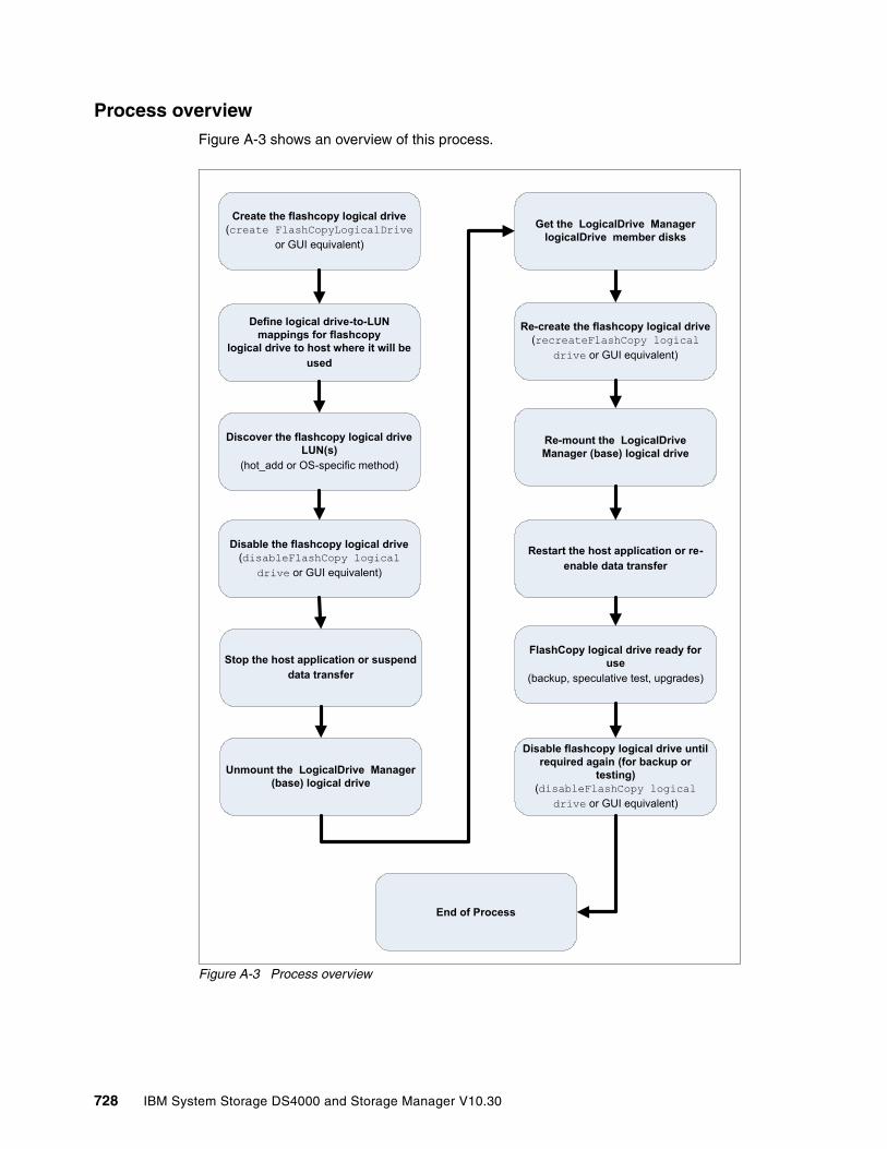
Process overviewFigure A-3 shows an overview of this process.
Figure A-3 Process overview
Create the flashcopy logical drive(create FlashCopyLogicalDrive
or GUI equivalent)
Disable the flashcopy logical drive(disableFlashCopy logical
drive or GUI equivalent)
Define logical drive-to-LUN mappings for flashcopy
logical drive to host where it will be used
Discover the flashcopy logical drive LUN(s)
(hot_add or OS-specific method)
Stop the host application or suspend data transfer
Re-create the flashcopy logical drive(recreateFlashCopy logical
drive or GUI equivalent)
Re-mount the LogicalDrive Manager (base) logical drive
Restart the host application or re-enable data transfer
End of Process
FlashCopy logical drive ready for use
(backup, speculative test, upgrades)
Disable flashcopy logical drive until required again (for backup or
testing)(disableFlashCopy logical
drive or GUI equivalent)
Unmount the LogicalDrive Manager (base) logical drive
Get the LogicalDrive Manager logicalDrive member disks
728 IBM System Storage DS4000 and Storage Manager V10.30
Detailed instructions for AIX: LVM Logical DrivesUse the following procedure when creating FlashCopy logical drives on a host running AIX, using LVM Logical Drives. Failure to complete the steps listed can result in an inaccurate point-in-time image of the base logical drive.
Creating a FlashCopy logical drive
1. Locate the array (on which the FlashCopy logical drive is to be based) and unmount its associated file systems.
At the host prompt, type the following command and press Enter:
umount mount-point
Here mount-point is the name of the file system being unmounted.
1. Initialize the FlashCopy logical drive using the command:
create FlashcopyLogicalDrive
2. Disable the FlashCopy logical drive using the command:
disableFlashCopy LogicalDrive
3. Assign a logical drive-to-LUN mapping between the FlashCopy logical drive and the host that will access the FlashCopy logical drive, using the command:
set LogicalDrive
4. Log into the host as root.
5. Run the hot_add utility to ensure that the host operating system recognizes the FlashCopy logical drives.
To use hot_add, at the host prompt, type the following command, and then press Enter:
hot_add
Several minutes can pass while the computer accesses the drives. When the program is finished, a window opens with the following message:
Device nodes have been updated
The new logical drives should now be available to you through the operating system.
Restriction: The following restrictions apply when attempting to create FlashCopy logical drives on AIX:
� To map FlashCopy logical drives to the same host as the base logical drive, you must use:
– AIX Version 4.3.3 with the AIX Version 4.3.3 Recommended Maintenance Level 06 (AIX 4330-06) maintenance package
– AIX Version 5.x
– AIX Version 6.1
� If a FlashCopy drive is created for a logical drive within an AIX LVM volume group, then FlashCopy drives must be created for all logical drives in the volume group. This is a requirement for the recreatevg command to work successfully.
Important: All I/O activity to the base logical drive should be stopped at this point (or data transfer suspended). This ensures that an accurate point-in-time image of the base logical drive is captured.
Appendix A. Additional instructions for FlashCopy logical drives 729

6. Run the SMdevices utility to associate the LUNs with a host operating system device and to ensure that the logical drive name and the operating system device name (assigned by the operating system) correlate.
Look for the newly created FlashCopy logical drive names and note the names of the associated operating system device name. For example, we created a FlashCopy logical drive named accountingMay14, and its associated operating system device name is hdisk4.
7. At the host prompt, type the following command and press Enter:
lspv
A list of all the physical logical drives recognized by the host operating system appears.
8. Look for the operating system device name of your FlashCopy logical drive or logical drives in the list. The listing shows a Physical Logical Drive ID (PVID) for this logical drive that will be the same as the PVID for the associated base logical drive. This is because the FlashCopy logical drive contains the same array data structures as the base logical drive.
9. Clear the PVID for the FlashCopy logical drives. At the host prompt, type the following command and press Enter:
chdev - l os_device_name -a pv=clear
Here os_device_name is the operating system device name of the FlashCopy logical drive. Repeat this step for each FlashCopy logical drive in the AIX array.
10.Recreate a new array. The recreatevg command, available in usr/sbin/, reads the array data structure inside a logical drive and reconstructs it. The command allocates new physical logical drive identifiers (PIDs) to the FlashCopy logical drives and enables access to the FlashCopy logical drive for the selected host.
At the host prompt, type the following command and press Enter:
recreatevg -y logical drivegroupname -L /directoryname os_device_name
Where:
– logical drivegroupname is the user-defined name to be assigned to the FlashCopy array.
– directoryname is the name of the directory where you want to mount the FlashCopy logical drive.
– os_device_name is the operating system device name of the FlashCopy logical drive. If your AIX array is made up of more than one FlashCopy logical drive, add an os_device_name for each logical drive.
The array is recreated and contains the FlashCopy logical drives.
11.Mount the file system to its intended host. At the host prompt, type the following command and then press Enter:
mount mount-point
mount-point is the name of the file system being mounted. Include the directory name used in step 12.
12.Ensure that the logical drives are back online. At the host prompt, type the following command and press Enter:
df -k
Important: If this command is not available in AIX 4.3.3, install the AIX Version 4.3.3 Recommended Maintenance Level 06 (AIX 4330-06) maintenance package.
730 IBM System Storage DS4000 and Storage Manager V10.30

A list of the mounted disks appears.
13.Use the FlashCopy logical drive in conjunction with your backup application for speculative testing, or with another application.
14.When the FlashCopy logical drive is no longer required, unmount the file system. At the host prompt, type the following command and press Enter:
umount mount-point
Here mount-point is the name of the file system being unmounted.
15.Delete the array created in step 12 that contains the FlashCopy logical drives. At the host prompt, type the following command and press Enter:
varyoffvg logical drivegroupnameexportvg logical drivegroupname
Here logical drivegroupname is the name of the FlashCopy array.
16.Disable or delete the FlashCopy logical drive or logical drives.
If you disable the FlashCopy logical drive instead of deleting it, you can retain the FlashCopy logical drive and its associated repository logical drive. Then, when you must create a different FlashCopy of the same base logical drive, you can recreate the disabled FlashCopy logical drive. This takes less time than creating a new FlashCopy logical drive and stops any reduction in performance that might occur if the FlashCopy logical drive remains available.
Reusing FlashCopy logical drivesTypically, once a FlashCopy logical drive is created, it is disabled until a new point-in-time image of the same base logical drive is required. To create a new point-in-time image of the same base logical drive, complete the following steps.
1. Unmount the file systems in the array on which the FlashCopy logical drive is to be based.
At the host prompt, type the following command and press Enter:
umount mount-point
mount-point is the name of the file system being unmounted.
2. Run the hot_add utility (or an operating-system specific utility) to ensure that the host operating system recognizes the FlashCopy logical drive. At the host prompt, type the following command and press Enter:
hot_add
Several minutes might pass while the computer accesses the drives. When the program is finished, a window displays the following message:
Device nodes have been updated
The new logical drives should now be available to you through the operating system.
3. Recreate the FlashCopy logical drives using the command:
recreateFlashCopy LogicalDrive
4. Clear the PVID for the FlashCopy logical drives. At the host prompt, type the following command and press Enter:
chdev - l os_device_name -a pv=clear
Important: All I/O activity to the base logical drive should be stopped at this point (or data transfer suspended). This ensures that an accurate point-in-time image of the base logical drive is captured.
Appendix A. Additional instructions for FlashCopy logical drives 731
os_device_name is the operating system device name of the FlashCopy logical drive. Repeat this step for each FlashCopy logical drive in the AIX array.
5. Recreate a new array. The recreatevg command, available in usr/sbin/, reads the array data structure inside a logical drive and reconstructs it. The command allocates new physical logical drive identifiers (PIDs) to the FlashCopy logical drives and enables access to the FlashCopy logical drive for the selected host.
At the host prompt, type the following command and press Enter:
recreatevg -y logical drivegroupname -L /directoryname os_device_name
Where:
– logical drivegroupname is the user-defined name to be assigned to the FlashCopy array.
– directoryname is the name of the directory where you want to mount the FlashCopy logical drive.
– os_device_name is the operating system device name of the FlashCopy logical drive. If your AIX array is made up of more than one FlashCopy logical drive, add an os_device_name for each logical drive.
The array is recreated and contains the FlashCopy logical drive or logical drives.
6. Mount the file system to its intended host. At the host prompt, type the following command and then press Enter:
mount mount-point
= mount-point is the name of the file system being mounted. Include the directoryname used in step 5.
7. Ensure that the logical drives are back online. At the host prompt, type the following command and press Enter:
df -k
A list of the mounted disks is displayed.
8. Use the FlashCopy logical drive in conjunction with your backup application (or another application).
9. Once the FlashCopy logical drive is no longer required, disable the FlashCopy logical drive.
If you disable the FlashCopy logical drive instead of deleting it, you can retain the FlashCopy logical drive and its associated repository logical drive. Then, when you must create a different FlashCopy of the same base logical drive, you can recreate the disabled FlashCopy logical drive. This takes less time than creating a new FlashCopy logical drive and stops any reduction in performance that might occur if the FlashCopy logical drive remains available.
Important: If this command is not available in AIX 4.3.3, install the AIX Version 4.3.3 Recommended Maintenance Level 06 (AIX 4330-06) maintenance package.
732 IBM System Storage DS4000 and Storage Manager V10.30

Related publications
The publications listed in this section are considered particularly suitable for a more detailed discussion of the topics covered in this book.
IBM Redbooks publications
For information about ordering these publications, see “How to get Redbooks publications” on page 734. Note that some of the documents referenced here may be available in softcopy only.
� IBM SAN Survival Guide, SG24-6143
� DS4000 Best Practices and Performance Tuning Guide, SG24-6363
� IBM TotalStorage Disk Solutions for xSeries, SG24-6874
� IBM i and Midrange External Storage, SG24-7668
Other publications
These publications are also relevant as further information sources:
� IBM System Storage DS4000 Storage Manager Concepts Guide, GC26-7734
� IBM System Storage DS4000 Storage Manager Version 10 Installation and Host Support Guide for Windows 2000/Server 2003/2008, NetWare, VMWare ESX Server and Linux, GC26-7847
� IBM System Storage DS4000 Storage Manager Version 10 Installation and Host Support Guide for AIX, HP-UX, Solaris, and Linux on POWER, GC26-7848
� DS4000 Hardware Maintenance Manual, GC26-7702
� IBM System Storage DS4000, Hard Drive and Storage Expansion Enclosure Installation and Migration Guide, GC26-7849
� IBM TotalStorage DS4000 Problem Determination Guide, GC26-7703-01
� IBM DS4000 Storage Server and Storage Expansion Enclosure Quick Start Guide, GC26-7738
� IBM System Storage DS4000 Fibre Channel and Serial ATA Intermix Premium Feature Installation Overview, GC26-7907
� IBM TotalStorage DS4500 Fibre Channel Storage Server Installation and Support Guide, GC26-7727
� IBM TotalStorage DS4500 Fibre Channel Storage Server User's Guide, GC26-7726
� IBM TotalStorage DS4300 Fibre Channel Storage Server Installation and User's Guide, GC26-77221
� IBM System Storage DS4700 Express Storage Subsystem Installation, User's and Maintenance Guide, GC26-7843
� IBM System Storage DS4800 Storage Subsystem Installation User's and Maintenance Guide, GC26-7845
© Copyright IBM Corp. 2004, 2005, 2006, 2007, 2008, 2009. All rights reserved. 733
� IBM System Storage DS4000 EXP810 Storage Expansion Enclosure Installation, User's and Maintenance Guide, GC26-7798
� IBM System Storage DS4000 EXP420 Installation, User's, and Maintenance Guide, GC27-2050
� IBM System Storage DS4200 Express Installation, User's and Maintenance Guide, GC27-2048
� IBM System Storage DS4200 Express Storage Subsystem Fibre Channel Cabling Guide, GC27-2049
� Remote Support Manager for Storage Planning, Installation, and User's Guide, GC26-7933
� IBM DS4000 FC2-133 Host Bus Adapter BIOS, GC26-7736
� Fibre Channel Installation and Cabling overview, GC26-7846
� Multipath Subsystem Device Driver User’s Guide, GC27-2122
Online resources
These Web sites are also relevant as further information sources:
� IBM System Storage
http://www.ibm.com/servers/storage/
� Support for IBM System Storage products
http://www.ibm.com/servers/storage/support/disk/
� IBM DS4000 disk systems family
http://www.ibm.com/servers/storage/disk/ds4000/index.html
� IBM DS4000 Storage interoperability matrix
http://www.ibm.com/servers/storage/disk/ds4000/interop-matrix.html
How to get Redbooks publications
You can search for, view, or download Redbooks publications, Redpapers publications, Technotes, draft publications and Additional materials, as well as order hardcopy Redbooks publications, at this Web site:
ibm.com/redbooks
Help from IBM
IBM Support and downloads
ibm.com/support
IBM Global Services
ibm.com/services
734 IBM System Storage DS4000 and Storage Manager V10.30

Index
Numerics4 Gbps FC technology 3
Aaccess logical drive 121, 153access LUN 153, 194access LUN. See access logical driveACS 173activating the Enhanced Remote Mirror option 475, 478activation 675activation key 692adapter cable 110ADT 172, 222, 264, 289Advanced recovery options 295Advanced Technology Attachment (ATA) 2airflow 701AIX
creating a FlashCopy logical drive 729LVM Logical Drives 729Multipathing 132reusing FlashCopy logical drives 731
AIX FCP disk array 132alarm 241alarm log 334alert 118, 237, 271
delay 172notification 172, 289
Amber Disk-Drive-Fault 81, 84Application Log 350archival 174array 139
defragmenting 280maintenance 278revive 295, 326
array initialize 295, 326Array Redundancy 330Asynchronous Mirroring 451ATA translator card 21attached storage subsystem
DS4000 Storage Manager agent 235attenuation 108Automatic Code Synchronization 667Automatic Code Synchronization (ACS) 173automatic discovery 160, 237, 632automatic resynchronization 467, 495, 523Automatic Support Data Collection 302autonomic 2AVT 136AVT/ADT 129, 134AVT-disabled failover 134AVT-enabled failover 136
© Copyright IBM Corp. 2004, 2005, 2006, 2007, 2008, 2009. A
Bbackup application 443, 731–732backup client 438–439, 442–443
data base caches 440ECHO Flushing caches 443Flushing file system caches 443local disks 443
bandwidth 529base logical drive 161, 309–310, 402, 404, 411–412, 415, 417, 419, 423, 428, 431–433, 435, 437, 534–535, 537, 551, 724, 729, 731
accurate point-in-time image 729, 731data blocks 405full box 405inaccurate point-in-time image 724, 729multiple FlashCopies 402
basic disk 724Basic/Regular Disc 722, 724batch 159battery 143, 146block size 149boot loader 596BOOTP 122, 226, 233BOOTP/DHCP 227bus reset 127
Ccable 119, 337, 518, 520
labeling 110, 112management 110–111null modem 231routing 111type 473types 107
cabling 107cache 143, 146, 166
block size 167, 170flushing 167, 169global settings 286logical drive settings 286memory 164mirroring 167–168read-ahead multiplier 167–168settings 285write-through 169
cache memory 165, 168, 170, 287cache read prefetch 257cache_method 200cfgmgr 197changing RAID level 278Channel Extenders 530channel protection 141Clear 674Clear Configuration 327
ll rights reserved. 735

CLI 158–159, 401, 406, 431–432, 435–437, 531, 534, 555–556, 629–632, 636–637, 724CLI (command line interface) 158–159, 630, 632
FlashCopy 433CLI example 649click Finish 412, 418, 543click Next 411–412, 414, 417, 541, 543Click Start 184, 304Click Tool 158, 657, 696clock 242, 244cluster 261Collect all Support Data 690command line
access 118instruction 630interface screen 159parameter 632shell 159tool 6, 118, 271utility 126
complete pathname/SMclient-AIX-09.10.G5.02.bff SMclient.aix.rte 193name/SMruntime-AIX-09.10.65.01.bff SMrunt-ime.aix.rte 192
configuration wizard 245connector 107Consistency Group 451, 497contention 165controller
ownership 164, 170, 454Controller Data Transfer 328controller diagnostis 310controller firmware 6, 117, 119, 157, 228, 280, 532, 667, 672, 675, 678, 682, 697, 712, 714Controller Firmware upgrade utility 119controller ID 75controller IP address 123controller support module 53Controller-based 6copy
Remote Volume Mirroring 106Copy Manager 534–535, 537–538, 542, 546–554
copy pair 553Target Logical Drive column 534
copy pair 535, 538, 546–548, 550–551, 553–554copy priority 550read-only attribute 556
Copy priority 534, 542, 649Copy wizard 534, 539–542copyback 306copy-on-write 403, 405–406, 424copy-on-write data 403, 405, 426Create Copy Wizard 543critical events 300CWDM 529Cyclic Redundancy Check (CRC) 337
Ddac 198–199
DACcstor 668DACStore 136DACstore 76, 80, 119, 137, 241dar 198–199Data 1 411, 420, 433, 555data block 147, 168, 287, 289, 403data scrubbing 171data striping 142–143data transfer 147, 310, 729, 731data verification 163datapath 349datapath query 347DCE 458DCM 342default group 151defragment 164, 406Defragment Array 329Defragmenting 536defragmenting an array 280degraded 163, 306delta logging 464, 466–467, 499detailed list 304devfsadm 354device driver 179, 203Device Specific Module 130Device Table 158Device Tree View 158, 656Diagnostic Data Capture 11Diagnostic Data Capture (DDC) 305diagnostics 215, 337
analyzing Read Link Status results 312Directory Service 468DisableAVT_Linux.scr 134disaster recovery 508–509Discrete Lines 316disk
mirroring 143, 146disk array
controller 197–198defragmentation 279driver 189expansion 279router 197–198
Disk drive 137disk drive 2, 5–6, 81–85, 116, 125, 139–141, 146, 148–149, 160–161, 166, 282, 292, 434
even number 139, 141, 160physical capacity 146
disk drive data 305Disk Manager 348disk system 2distance limitations of Fibre Channel inter-switch links 473distribute 258DMP 132, 173dmsg 353drive
revive 295, 326Drive Channel 315–317, 642, 697, 714
Degraded state 714
736 IBM System Storage DS4000 and Storage Manager V10.30

drive channel 62drive firmware
download 686Drive Intermix 528DRIVE Loop 165drive type 644, 650drive-side Mini-Hubs 313DRM 458DS family 2
positioning 2DS3000 2
enable second I/O path 590second I/O path 590
DS4000 2overall positioning 2
DS4000 EXP700 711bezel 717ESMs 713storage expansion unit 711–712
DS4000 Series 1–2, 15, 77–78, 80, 148, 151overall positioning 2
DS4100 4DS4200 3
Battery LED 24Battery System 20cabling 30controller enclosure ID 31LED 21power supply-fan 20RAID controller 19
DS4200 Express 3DS4300 Turbo 152
model 4DS4500 4DS4700 3
Battery LED 41cabling 45–46chassis 32controller enclosure ID 48LED 38power supply-fan 37RAID controller 36
DS4700 Express 3, 16, 32DS4800 3
battery pack 54chassis 54drive channel 62drive-side cabling 67drive-side connections 62enclosure ID 74front bezel LEDs 56interconnect module 54LED 58RAID controller LED 56
DS6000 2DS8000 2DSM 130DSS 458Dual Secondary error 515DVE 457
DWDM 529Dynamic Capacity Expansion 17Dynamic Capacity Expansion (DCE) 160, 279, 536Dynamic Capacity Expansion. See DCEdynamic disk 420Dynamic Mode Switching 451Dynamic Multipathing 132Dynamic RAID Level Migration 17Dynamic RAID Level Migration (DRM) 536Dynamic RAID Level Migration. See DRMDynamic RAID migration (DRM) 278Dynamic Reconstruction Rate (DRR) 536Dynamic Segment Sizing (DSS) 281, 536Dynamic Segment Sizing. See DSS.Dynamic System Analysis 350Dynamic Volume Expansion 17Dynamic Volume Expansion (DVE) 282Dynamic Volume Expansion. See DVE
EEhanced Performance 689Electro Magnetic Interference (EMI) 81E-mail 271, 273–274E-mail Address 632, 634enabling the Enhanced Remote Mirror option 475enclosure alarm 241Enclosure ID 85–86enclosure ID 74enclosure IDs 86enclosure loss 141Enhanced Performance 176Enhanced Remote Mirror
option 478Enhanced Remote Mirroring 3, 176Enhanced Remote Mirroring (ERM) 105, 115Enhanced Value Disk Drive Modules 16Enterprise Management 124Enterprise Management window 118, 123–124, 126, 158–159, 213, 272, 536, 630, 633, 656, 696
Device Table 656many times 124
entry levelSATA storage system 4
Environmental Service Module (ESM) 6, 81, 120, 315eplacement drive 150ERM
enabling and activating 475errpt 360ESM 6, 82, 225, 312–313, 318, 650, 663, 665, 679, 711, 715–716ESM board 81–82, 84–85, 141, 313
failure 82firmware 679tray ID switches 85
ESM replacement 318ESS 2Ethernet 118, 122, 124, 670
management port 366Ethernet network 6, 117, 122
storage subsystems 6
Index 737

Ethernet port 227EV-DDM 16Event Log 334event log 156, 165, 297, 300, 312, 315, 334, 337, 536
critical entry 165informational entry 165
Event Monitor 118, 126service 126, 271
event monitor 118, 181, 208, 666Event viewer 350existing FlashCopy repository logical drive
storage capacity 427EXP100 5, 81, 456EXP420 3EXP700 456, 712
ESM 712EXP710 5, 82, 456EXP810 5, 87, 90
LED 89, 93Expansion enclosure 94, 105, 138expansion enclosure 680, 713
special handling procedures 80Export/Import option 700
Ffabric configuration 468Fail Drive 329failed drive 137, 149–150, 250
configured space 150failover 165, 205, 614failover alert delay 172Failover Driver 130failover driver 341failure policy 405FAStT
utilities 6, 118FAStT configuration, saving 694FAStT MSJ 331, 334–335FAStT Storage Server 81, 332, 665, 672, 686FAStT600 4FAStT900 4FCP disk array 132, 197FCP disk array driver 196, 200fcs 195feature 691Feature Enable Identifier 691feature key 476, 532featureBundle.txt 691fget_config 199, 355, 359Fiber Channel (FC) 83–84, 95, 103, 108Fibre Channel 2
adapter 105, 112adapter cable 110configuration 110connection 233disk drive 82host interface 642hub 672I/O path 118, 120, 233I/O path failover driver 119
link 122loop 85, 304, 312–313, 337network 119, 233port 312standard 110technology 108, 174unconfigured capacity 254
Fibre Channel (FC) 4, 83, 94, 105, 109–110, 120–121, 166, 174, 208, 254Fibre Channel inter-switch link 473Field Replacement Units 52file system 197, 257, 271, 281–282, 329, 420, 431, 540, 548, 729–732firewall 230, 393firmware 120, 241Firmware File 650, 681firmware level 662firmware synchronization 319Firmware upgrade utility 665firmware upgrade utility 137flash copy 406, 433, 638, 646–647FlashCopy 3, 115, 161, 176, 458
disable 424recreate 425
FlashCopy logical drive 161, 176, 309, 402–405, 407–408, 410–411, 413–415, 418, 421, 423, 425–426, 428, 431–432, 434, 436–437, 440, 534–535, 537, 551, 636, 721–722, 724, 726, 729–732
creating 409creating on AIX 729creating on Windows 725deleting 431logical drive-to-LUN mappings 419mapping 419operating system device name 730, 732original names 426reusing in AIX 731
FlashCopy Logical Drive Wizard 408FlashCopy repository 403FlashCopy repository logical drive 309, 403–405, 410–412, 417, 421, 423–425, 427–428, 430, 432FlashCopy volume 441–442FlashCopy Wizard
Complete message box 418Preview screen 412
floor plan 106flushing level 167, 169Free Capacity
Base Select 646node 164, 428, 430
free capacity 160, 164, 278, 282, 410, 414–415, 427–428, 431, 536, 644
logical drive 254free space 161, 278–279, 428, 646
disk drives 161logical drive 646
FRU 52full synchronization 451, 456, 462, 517
738 IBM System Storage DS4000 and Storage Manager V10.30
GGBIC 109Gbps 110, 533Gigabit Interface Converters 109gigabit transport 108global cache settings 286Global Copy 450, 463global hot spare 149Global Mirroring 451, 464graphical user interface (GUI) 6, 117, 422, 432, 434GRUB 596
HHACMP 77hardware 15HBA setting 212HBAs 195, 202, 212, 334, 336HDD 81, 84hdisk 197, 201heterogeneous hosts 155horizontal scaling 68host agent 118
storage subsystems 121Host Bus Adapter 113host bus adapter
FC port 152Host Bus Adapter (HBA) 113host bus adapter (HBA) 15, 151–152, 154, 164, 202, 211, 242, 271, 281, 331, 335host computer 6, 117–118, 126, 178, 184
Event Monitor 126network connection 118storage subsystem 118
Host group 126, 151, 153, 195, 203, 242, 259–260, 269–270, 291, 419–420, 647, 696host group 151–152, 261, 269host name 121–123, 242, 269, 291, 333, 630, 632–634host operating system 151, 158, 161, 260, 282, 408, 419, 421, 722, 731
disk device 282FlashCopy logical drive 421logical drive capacity 161standard logical drive 161
Host Porthost type 647
Host port 126, 151, 153, 173, 195, 269, 291, 647, 696host port 152, 292, 481
associated user label 292world-wide names 269
host software 181, 203host system 116, 120, 123, 151–153, 160, 244, 271, 669
host ports 153Host-based 6hot spare 250hot spare coverage 252hot_add 118, 126, 221, 271HP Volume Group 223HP-UX 217, 222
II/O activity 160, 162, 164, 171, 304, 533, 535–537, 540, 549, 551, 713–714, 717, 729, 731
ESM firmware upgrade 717full synchronization diverts controller processing re-sources 170
I/O path 118, 120, 164–165, 189, 258I/O per second (I/OS) 336I/O request 118, 140, 148, 164, 166, 281, 541IATEMPDIR 190IBM DS4000 Storage Manager
graphical interface 534software 116
IBM System x 77ieee_volname 358Import Array 707in-band 118in-band management (IBM) 6, 118, 121, 154, 193, 197, 208, 233, 271, 672initialize
array 295, 326logical drive 326
InstallAnywhere 665Installation Wizard 205–206interconnect module 53intermix 95, 103, 174–175Intersite with FlashCopy drives and tape backup 521inter-switch link 473Invalid Transmission Word (ITW) 312–313IO 316, 324, 442–443IOPS 148ioscan 353IP address 111, 121–123, 225–226, 232–233, 273–274, 433, 440, 630, 632–636
controller 123ISL 473
KKB 149, 155, 166, 282, 404
Llabeling 110latency 529LC connector 109LC-SC 110LED 83LEDs 81, 83, 294, 713, 716left ESM
Fibre Channel cables 713LILO 596Link Failure 337link failure 523Link Failure (LF) 313, 316, 337–338link rate 94link rate selector 91link speed 86link speed selector 21Linux 121, 203, 242, 666
Multipathing 133
Index 739
Linux RDAC 134, 204LIP 712Local Site 453Locate component 294log sense data 305Logical Disk Manager (LDM) 420logical drive 6, 115–116, 118–119, 121, 125–126, 139–140, 143–144, 146, 148–149, 151, 153, 156–157, 160, 162, 164–165, 168, 170, 173, 177, 194, 197, 200, 203, 212, 242–243, 253, 258–260, 269–271, 276, 278, 280–292, 295, 301–302, 309, 324, 329, 352, 358, 404, 411–412, 417–418, 423, 427, 432–435, 532–533, 537, 539–540, 545, 547, 553–554, 638, 640, 642, 644–645, 647–649, 651–654, 697, 722, 724–725, 729–732
actual reservation 173array data structure 730, 732assigned LUN number 291bad blocks 302Changing ownership 281command returns information 647complete physical replication 177current owner 165current size 283existing mapping 271expansion 282Fibre Channel I/O path 119free space 280, 329high read/write operations 140I/O requests 164instant notification 173intialize 326Mappings view 126maximum number 121optional advanced logical drive parameters 140ownership 172, 289parity errors 646physical disk 148physical disks 645preferred controller ownership 165preferred ownership 164primary 165, 170, 292, 532RDAC multi-path driver transfers ownership 119re-create option 425redundancy information 289secondary 165, 170, 292Segment Size 164, 170segment size 281several properties 281specific assignments 152unreadable segments 301
Logical Drive Manager 722logical drive-to-LUN mapping 161, 309, 417Logical unit number (LUN) 121, 126, 151, 153, 200, 203, 214, 259–260, 291, 335, 641, 646, 651Logical View 125, 152, 155, 309, 408, 422, 425, 427–428, 430, 540, 542
base logical drive 408FlashCopy logical drive 431FlashCopy repository logical drive 422, 427logical drive 544
source logical drive 540logical view
other item 125storage subsystem node 155
Logical/Physical view 125, 441long distance 529loopback 337lsattr 197lservice 376lslpp 196lspv 359lsvg 359LUN 151LUN number 270, 420, 651LUNs 151, 197, 201, 203, 212, 214, 260, 439, 441LUNs by running (LR) 214luxadm 354lvdisplay 353LVM Logical Drives 729
MMajor Event Log (MEL) 119, 138, 297, 372major event log (MEL) 300, 640Manage Enclosure Alarms 241management interface 374management station 116–118, 120, 122, 126, 158, 213, 271, 672manual resynchronization 495manual resysnchronization 523mapping 153, 262, 349
logical drives to host systems 153Mappings View 126, 151, 155, 200, 259, 271, 419
Linux system 271Master Boot Record(MBR) 596MBR 725Media Error 163Media scan 171, 258, 288, 302, 646, 694, 696media scan 284, 288, 302MEL 300–301, 315Metro Mirroring 450, 462, 497MIB 274midplane 53midplane. 52Mini-Hub 202miniport 128Mirror Link Test 524mirror relationship 458–459, 489
recreating 517mirror repository 454–455, 459, 526mirror repository logical drive 309mirror status 460, 489mirroring 143, 146modal dispersion 108modification operation 170, 421, 535, 537, 541, 547Modification priority 162, 170, 257, 283, 424, 646, 696modification priority 170Monitor process 303monitoring 164mount point 224MPIO 130, 186
740 IBM System Storage DS4000 and Storage Manager V10.30

mppBusRescan 214, 351mppUpper 133, 205mppUtil 127, 331mppVhba 133, 205multi-mode fiber (MMF) 107
NName Service 468Near-line 174Needs Attention 522netCfgSet 227, 232Network Managment Station (NMS) 274non-failover 205, 614non-redundant operation 162
critical time 162NVSRAM 119, 176, 335, 669, 682NVSRAM file 650NVSRAM Informations 697NVSRAM version 676, 697
Oobdiag 354Object Data Manager (ODM) 200ODM 200on-demand 457one-time usage 724operating system 6, 77, 123, 179, 188, 197, 211, 242, 271, 301, 331, 350, 421, 632, 637, 721
FlashCopy logical drives 721Optimal state
Logical View 426optimal state 426, 643–644, 713–714OS platform 153OS version 333out-of-band 118, 122ownership 457
Pp+q 10partitions 11, 152password 157, 231, 242, 244, 334
considerations 157PCI slots 113performance 167–168performance impact 280Performance Monitor 281performance monitor 149, 155, 164Persistent reservation 173, 290–292, 304, 541Persistent Reservations 472persistent reservations 173physical component 313, 410physical disc 140–141, 148, 283, 638–646
firmware downloads 643storage subsystem 643
pkginfo 354Place Controller 328Point-in-Time 532–533point-in-time image 176, 402, 408, 419, 426, 729, 731
power on 226power supply 81–83, 85, 89, 94, 166, 310preferred controller 164Preferred owner 165, 646preferred path 173, 198, 225, 675pre-fetching 287Pre-Installation Summary 191premium feature 115, 176, 309, 407, 538, 661, 689, 694
enabling 692listing 689
Pre-Read redundancy check 163, 284previous version 208primary 165, 170, 292, 532Primary Contact 372primary logical drive 454–455primary path 600Primary Site 453priority rate 170probe-fcal-all 354probe-scsi-all 354Process Overview 722–723profile 173, 276, 490, 554, 662, 692Properties component 294prtdiag 354pull-down menu
bar 547option 311–312, 540, 544, 546, 548, 550–551, 553–554
PuTTY 366PuTTy 719pvcreate 222pvdisplay 353PV-links 222
QQLogic SANsurfer 215Qlogic SANsurfer 331qlremote 215queue depth 11, 201
RRAID
level 147, 161reliability 148
RAID 6 10, 137, 145RAID controller 6, 84, 116, 140, 165RAID Level 6, 115, 136, 142, 161, 242, 259, 417, 424, 433, 435, 646, 652, 696RAID level 278
increased performance capabilities 142RAMdisk 213RDAC 6, 12, 119, 130, 196, 212, 222, 264, 337RDAC driver 118, 127, 133, 181, 200, 204, 212, 214–215, 350RDP 718, 720read ahead multiplier 287Read Caching parameter 286Read Link Status (RLS) 312, 372Read Link Status error counts 312
Index 741
Read Link Status results 312read test 310read-ahead multiplier 167–168readme file 203, 211, 666read-only attribute 534, 542–543, 546, 551–552, 554, 556
logical drives 551–552rear side 85Reconstruct Drive 329reconstruction 330Re-copy 535Recovery Guru 156–157, 299, 304, 311, 407, 522, 536, 538, 669, 679, 681, 690, 712–714, 717recovery options 295Redbooks Web site 734
Contact us xviRedistribute Logical Drives 329Redundancy check 258, 289, 696redundancy check
Media scan 258redundancy data 284redundancy group 163redundant array
of independent disks 2, 6Redundant Dual Active Controller (RDAC) 118, 127, 133, 172, 201, 204, 289registrant 291Remote Assistance 720Remote Desktop 718–719Remote Mirror 165, 177, 292, 638, 648remote mirror
secondary logical drive 165Remote Mirror status 460Remote Service Manager 17Remote Support Manager (RSM) 297Remote Volume
Mirror 309Remote Volume Mirror 450
creating relationships 481status 489
Remote Volume Mirroring 106solution design 517
removal 321Remove Mirror Relationship 507repository logical drive 455, 463reservation 137, 478reservation types 291resume 466Resume Mirror 451resynchronization 467revive array 295, 326revive drive 295, 326right-mouse pop-up menu 155, 540, 544, 546, 548, 550–551, 553–554, 692
Copy Manager 546, 548, 550–551, 554Copy Pairs 554select Copy Manager 554Stop Copy 553
RLOGIN 372Rlogin 366
rlogin 302role reversal 509, 511, 515, 517, 536rservice 376RSM
change password 376firewall 393management interface 374remote access security 391security 376user ID 376
rsm-passwd 376RVM
activating 475creating Remote Volume Mirror relationships 481distance limitations 473enabling 475Intersite with FlashCopy drives and tape backup 521mirror relationships 489recreating a mirror relationship 517solution design 517status 489storage subsystem profile 490switch zoning 468using 475
Ssame base logical drive 424–425, 731–732
different FlashCopy 731–732different FlashCopy logical drive 425new point-in-time image 731
SAN Volume Controller (SVC) 178SAN zoning 468SATA 3SATA drive 2SATA Interface Card 103SATA Interposer Card 103SC connector 109scaling 68script 505, 696Script Editor 506script editor 158–159, 431–432, 554, 629–630, 637–638, 656–658, 695–696, 724
tools 659script engine 159, 658Script execution 555, 634–636, 654, 658–659
output view 658script file 158–159, 629, 633–634, 636–637, 640, 649, 653–654, 659
use password command 634SCSIport 127–128SDD 186SDDDSM 12, 129, 131, 180, 186sddgetdata 350second I/O path 590secondary 170, 174, 292secondary logical drive 292, 309–310, 407, 455, 648Secondary Site 453security 334Segment size 106, 148–149, 170, 242, 258, 281, 646, 696
742 IBM System Storage DS4000 and Storage Manager V10.30
segment size 148–149, 257, 281selected copy pair
copy priority 550selected FlashCopy repository logical drive
following information 423selected logical drive
complete scan 288selected source logical drive
new VolumeCopy 547serial data collection 305serial interface 302serial number (SN) 642serial port 231server platform 77, 202Service Access Timeout 395SFP 82, 84, 109, 473shell 231, 364, 368show storagesubsystem
batteryage 635–636healthstatus 635, 654time 635
showrev 354SIC card 103signature 420Simple Network Management Protocol (SNMP) 126, 181, 271, 274Single Controller (SC) 109–110single-mode fiber (SMF) 107–108SM 9.10 407SM Failover 130SM Failover Driver 130SMagent 6, 118, 181, 184, 193, 197, 631, 666Small Form Factor (SFF) 109small form factor plug (SFP) 109Small Form Factor Transceivers 109Small Form Pluggable (SFP) 109SMcli 630, 637SMcli 10.1.1.1 433, 435–437, 555SMclient 117, 119, 122, 155, 160, 181, 189, 192–193, 195, 208, 213, 233, 244, 439, 630, 636SMdevices 118, 126, 221, 331, 353SMdevices utility 730SMesm 192SMflashcopyassist 127smit 191SMrepassist 118, 127, 408SMruntime 118SMTP Server 273snap 359SNMP 271, 372SNMP trap 118, 126, 393source logical drive 532, 534–537, 540–543, 545–546, 549, 553–555
file systems 540, 548preferred controller 536
spare 146spare drive 149–150, 170, 250–252, 427, 658speculative change 724SSIC 664STANDARD LOGICAL Drive 160–161, 309, 402, 428,
537, 646standard logical drive
storage capacity 161State Capture 305states 460step-by-step guide 153, 401, 531storage area network (SAN) 178, 202storage capacity 2, 5, 80, 140, 160, 427storage expansion
unit 711–712, 717Storage Management
software 86, 124, 176, 402, 630station 158, 629
Storage Manager 6, 1169.1 Agent 6, 2089.10 client interface 228client graphical interface 531client GUI 401client Subsystem Management window 712–714controller based software 116current level 122GUI 441host based software 116new version 208Software 1, 6, 200, 665
Storage Manager (SM) 297–298, 300storage manager (SM) 80, 84–85, 115, 117, 120, 122, 126, 133, 149, 153, 155–156, 160, 162, 172, 179, 184, 188, 194, 225, 241–242, 250, 258, 271, 274, 287, 294, 321, 352, 358, 417, 653, 656, 666, 696, 711–712, 714, 717Storage Manager 9.1
Client 6, 208Runtime 6, 208, 666Utility 6, 208
storage partition 116, 153, 260, 641, 651host systems 151logical drives 116
Storage Partitioning 177, 267storage partitioning 165, 259Storage Server
IBM System Storage DS4000 Series 1in-band or out-of-band management 233
storage server 1, 80, 160, 233, 271, 298, 300, 350, 653, 662, 669, 675, 696, 712–715, 717
Always connecting outgoing ports 82application code 120basic management 115different components 116DS4000 Series 80
storage servers 2Storage Subsystem
drive enclosure 84storage subsystem 84, 117–118, 120–123, 125–126, 139, 148, 152, 154–159, 164–165, 170, 173–174, 176, 178, 184, 198, 292, 304, 309, 312, 324, 350, 405, 424, 532–534, 536–538, 541–542, 546, 549, 551–552, 554–555, 629–630, 632–635, 637–638, 642–648, 653–654, 656, 659, 681, 690, 692, 694–696, 711–714
automatic discovery 160
Index 743
change history 276command returns configuration information 641destructive commands 157drive enclosures 681firmware upgrades 630granular optimization 286health status 654I/O activity 535, 549, 551indicator lights 641individual controllers 121logical drive copies 546logical drives 646Needs-Attention condition 535other controller 164physical devices 125physical disk 643physical disks 639recovery profile 640standard logical drive 402unrecoverable error 177user-supplied name 160valid source logical drives 541valid target logical drives 542various components 292VolumeCopy pairs 555world-wide name 631
storage subsystem profile 490storageSubsystem userLabel 637, 654Storport 127–128, 130stripe kill 148Subsystem Contact 372Subsystem Device Driver Device Specific Module 129, 131Subsystem Management 125Subsystem Management Window 123support bundle 11support data 304Support Notifications 298Support Notifications subscription service 664surface scan 171suspend 466Suspend Mirror 451, 499switch 164, 336, 472, 517, 519–521
ID 85switch zoning 468switched bunch of disks (SBOD) 5, 80swlist 353synchronization 490, 526
priority 484, 494–495synchronization priority 467, 484, 489, 493–494, 527synchronization settings 493synchronous mirroring 450, 462syntax check 555, 633–636, 638, 654System Event Log 350System Storage Interoperation Center (SSIC) 664
TTarget Logical Drive
column 534, 546target logical drive 532, 534–537, 540–543, 545–547,
549, 551–553, 555read-only attribute 535, 542–543, 551, 554
Task Assistant 238telnet 366Test DS4400 654thrashing 224threshold exceeded 405throughput 148, 166, 169timestamp 426Tips
Read over the following tips 411
Total number 313, 336, 643transceivers 108transfer rate 140tray ID 85tray Id 85troubleshooting 215
Uunassigned drive 150unconfigured capacity 104, 140, 160–161, 245, 254, 259, 282, 410, 414, 427–430, 536
logical drive 254Unique Logical Drive Identifier 358Universal Transport Mechanism (UTM) 121, 197UNIX
Logical Drive Manager Logical 722Unmanageable Icon 12Unreadable Sector 163Unreadable sector 305, 640, 645Unreadable Sectors 330unreadable sectors log 330unrecoverable read error 163upgrade utility 119Upgrading EXP700 711usable capacity 489utilities 6, 118UTM 121utm 197
VVeritas DMP 173vertical scaling 68vgdisplay 353Virtual Private Network 718virtualization 178Volume Copy 3volume group 222VolumeCopy 105, 115, 176–177, 458, 531–538, 540–543, 545–546, 549, 551–555
Command Line Interface 554controller ownership 536Copy Manager 546failed 536logical drive 554modification operations 535pair 554progress 538
744 IBM System Storage DS4000 and Storage Manager V10.30
properties 543VolumeCopy function 555VPN 718
WWindows
basic/regular disks 722creating a FlashCopy logical drive 725
Windows 2000 180, 242, 340Additional Instructions 722, 724disabled FlashCopy logical drive 723DS4000 Storage Server management software com-ponents 180FlashCopy logical drive 723
Windows 2000/2003basic disc 724
WMI 130World Wide Name (WWN) 137World-wide Name (WWN) 489world-wide name (WWN) 152, 160, 242, 291–292, 351–352, 423, 543, 634write caching 168, 462, 464–465Write Caching parameter 287Write Consistency Group 526write mode 495write_cache 200write-back 169write-through 169WWN 152, 349WWPN 469
Zzone 468zoning 452
Index 745

746 IBM System Storage DS4000 and Storage Manager V10.30
IBM System
Storage DS4000 and Storage Manager V10.30
IBM System
Storage DS4000 and Storage M
anager V10.30
IBM System
Storage DS4000 and Storage M
anager V10.30
IBM System
Storage DS4000 and Storage Manager V10.30

IBM System
Storage DS4000 and Storage M
anager V10.30
IBM System
Storage DS4000 and Storage M
anager V10.30

®
SG24-7010-06 ISBN 0738432393
INTERNATIONAL TECHNICALSUPPORTORGANIZATION
BUILDING TECHNICAL INFORMATION BASED ON PRACTICAL EXPERIENCE
IBM Redbooks are developed by the IBM International Technical Support Organization. Experts from IBM, Customers and Partners from around the world create timely technical information based on realistic scenarios. Specific recommendations are provided to help you implement IT solutions more effectively in your environment.
For more information:ibm.com/redbooks
®
IBM System Storage DS4000 and Storage Manager V10.30
New Storage Manager 10.30 features and enhancements
Enhanced drive migration support and RAID 6 support
New and updated multipath drivers
This IBM Redbooks publication consolidates, in one document, detailed descriptions of the hardware configurations and options offered as part of the DS4000 series of storage servers. This edition covers updates and additional functions available with the DS4000 Storage Manager Version 10.30 (firmware level 7.15).
This book presents the concepts and functions used in planning and managing the DS4000 storage servers. Concepts such as multipathing and path failover are discussed. The book offers a step-by-step guide to using the Storage Manager to create arrays, logical drives, and other basic (as well as advanced) management tasks.
This publication also contains practical information about diagnostics and troubleshooting, and includes practical examples of how to use scripts and the command-line interface.
This book covers the Copy Services premium features and their implementation and usage. Another section discusses how to boot servers from SAN-attached DS4000 disks (SAN boot).
This publication is intended for customers, IBM Business Partners, and IBM technical professionals who want to learn more about the capabilities and advanced functions of the DS4000 series of storage servers with Storage Manager Software 10.30. It also targets those who have a DS4000 storage system and need detailed advice about how to configure it.
Back cover