SANtricity® Storage Manager 11.20 System Upgrade Guide
67
SANtricity ® Storage Manager 11.20 System Upgrade Guide NetApp, Inc. 495 East Java Drive Sunnyvale, CA 94089 U.S. Telephone: +1 (408) 822-6000 Fax: +1 (408) 822-4501 Support telephone: +1 (888) 463-8277 Web: www.netapp.com Feedback: [email protected] Part number: 215-09013_E0 November 2015
-
Upload
khangminh22 -
Category
Documents
-
view
4 -
download
0
Transcript of SANtricity® Storage Manager 11.20 System Upgrade Guide

SANtricity® Storage Manager 11.20
System Upgrade Guide
NetApp, Inc.495 East Java DriveSunnyvale, CA 94089U.S.
Telephone: +1 (408) 822-6000Fax: +1 (408) 822-4501Support telephone: +1 (888) 463-8277Web: www.netapp.comFeedback: [email protected]
Part number: 215-09013_E0November 2015


Contents
Deciding whether to use this guide ............................................................. 5How to send your comments ........................................................................ 6Preparing to upgrade your software or firmware ..................................... 7Upgrading controller firmware and NVSRAM ......................................... 8Upgrading the ESM firmware ................................................................... 10Upgrading drive firmware ......................................................................... 11
Steps to upgrade the drive firmware .......................................................................... 12
Viewing the progress of the drive firmware download ............................................. 13
Upgrading storage management software ............................................... 15Checking the current version of the storage management software .......................... 16
Steps to upgrade storage management software ....................................................... 17
Upgrade instructions for the Solaris OS .................................................................... 18
System requirements for Solaris ................................................................... 18
Additional information for SANtricity Storage Manager on Solaris ............ 19
Checking the installation on the Solaris OS .................................................. 21
Uninstalling the storage management software on the Solaris OS ............... 21
Upgrade instructions for the Linux OS ..................................................................... 22
System requirements for Linux ..................................................................... 22
System requirements for additional Linux distributions ............................... 25
System requirements for Linux with PowerPC processors ........................... 27
Installing the storage management software on the Linux OS ...................... 28
Checking the installation on the Linux OS ................................................... 30
Uninstalling storage management software on the Linux OS ....................... 31
Upgrade instructions for the Windows OS ................................................................ 32
System requirements for Windows OS ......................................................... 33
Installing the storage management software on the Windows OS ................ 35
Checking the installation on the Windows OS .............................................. 37
Uninstalling storage management software on the Windows OS ................. 38
Upgrade instructions for the AIX OS ........................................................................ 39
System requirements for AIX and VIOS ...................................................... 39
Installing the storage management software on the AIX OS ........................ 41
Checking the installation on the AIX OS ...................................................... 42
Uninstalling storage management software on the AIX OS ......................... 43
Upgrade instructions for asymmetric logical unit access (ALUA) with the
VMware OS ......................................................................................................... 43
System requirements for VMware ................................................................ 44
Installing ALUA support for VMware versions eSXi5.0 u3, eSXi5.1 u2,
eSXi5.5 u1, and subsequent versions ...................................................... 45
Upgrading or replacing all controller canisters in a controller-drivetray .......................................................................................................... 47
Cabling considerations for controller-drive tray hardware upgrades ........................ 50
Table of Contents | 3

Preparing to replace the controllers ........................................................................... 51
Removing controller canisters from a controller-drive tray ...................................... 53
Installing new controller canisters in the controller-drive tray .................................. 58
Powering on the storage array ................................................................................... 59
Remounting volumes after changing the vendor from lSI to NETAPP .................... 63
Remounting volumes on a Windows host ..................................................... 63
Steps for AIX hosts ....................................................................................... 64
Remounting volumes on a VMware host ...................................................... 64
Copyright information ............................................................................... 65Trademark information ............................................................................. 66How to send comments about documentation and receive update
notifications ............................................................................................ 67
4 | System Upgrade Guide

Deciding whether to use this guide
This guide describes how to upgrade storage management software, controller firmware andNVSRAM, and ESM firmware in your storage array. It has information about preparing to upgradeand about compatibility and system requirements for various upgrade options. For each supportedoperating system, this guide has procedures for installing or uninstalling SANtricity StorageManager. It also includes procedures for upgrading hardware by replacing controllers in controller-drive trays.
This guide assumes that you are upgrading an existing storage array that has previously beeninstalled and is functioning normally.
Where to Find the Latest Information About the Product
This guide references the Multipath Drivers Guide for SANtricity Storage Manager 11.20. To accessthe latest information about this product and other documentation for E-series and EF-series storagearrays, go to the NetApp® support site at mysupport.netapp.com/eseries.
5

How to send your comments
You can help us to improve the quality of our documentation by sending us your feedback.
Your feedback is important in helping us to provide the most accurate and high-quality information.If you have suggestions for improving this document, send us your comments by email to [email protected]. To help us direct your comments to the correct division, include in thesubject line the product name, version, and operating system.
You can also contact us in the following ways:
• NetApp, Inc., 495 East Java Drive, Sunnyvale, CA 94089 U.S.
• Telephone: +1 (408) 822-6000
• Fax: +1 (408) 822-4501
• Support telephone: +1 (888) 463-8277
6

Preparing to upgrade your software or firmware
The following table shows the supported upgrade paths for controller-drive trays for storagemanagement software version 11.20 and controller firmware (CFW) version 8.20.
Controller-Drive Tray Installed StorageManagement SoftwareVersion
Supported Upgrades CFW
E2612 E2624 E2660 10.70 or later to 11.20 7.70 to 8.20
7.75.27.xx or lower to7.75.28.xx
7.75.28.xx or higher to8.20.xx.xx
7.77.21.xx or lower to7.77.22.xx
7.77.22.xx or higher to8.20.xx.xx
7.80.xx.xx to 8.20.xx.xx
7.83.xx.xx to 8.20.xx.xx
7.84.xx.xx to 8.20.xx.xx
7.86.xx.xx to 8.20.xx.xx
E2712 E2724 E2760 11.10 to 11.20 8.10 to 8.20.xx.xx
E5412 E5424 E5460 10.80 or later to 11.20 7.70.xx.xx to 8.20.xx.xx
7.83.xx.xx to 8.20.xx.xx
7.84.xx.xx to 8.20.xx.xx
7.86.xx.xx to 8.20.xx.xx
E5512 E5524 E5560 10.86 or later to 11.20 7.86.xx.xx to 8.20.xx.xx
Note: On an E2600 controller-drive tray, if you are upgrading from controller firmware version7.75.xx where xx is less than 28, you must first upgrade to 7.75.28, and then upgrade to 8.20. Ifyou are upgrading from controller firmware version 7.77.xx where xx is less than 22, you mustfirst upgrade to 7.77.22, and then upgrade to 8.20. All other supported upgrades are performeddirectly without an intermediate step.
Note: To make sure that your failover driver is compatible with the new hardware, firmware, andsoftware, refer to the Multipath Drivers Guide. For the RHEL and SLES operating systems usingthe DM-MP multipath driver, if you are upgrading the storage array controller firmware fromversion 7.8 (or an earlier version), you might need to change the host type in the storage partitionmapping. Refer to the Failover Drivers Guide for information about which host type to select.
7

Upgrading controller firmware and NVSRAM
About this task
Obtain a copy of the installation files to upgrade controller firmware and NVSRAM from the NetAppsupport site at mysupport.netapp.com. Save the files on the management station where you willperform the upgrade. Check the information in the "readme" file that is included in the .zip archivewith the controller firmware and NVSRAM to make sure whether you need to upgrade.
Steps
1. In the SANtricity Enterprise Management window, double-click the icon for the storage array toupgrade.
The Array Management window for the storage array appears.
2. Check that the storage array has Optimal status.
3. Save a support bundle for the storage array.
a. In the Array Management window, select Monitor > Health > Collect Support DataManually.
b. Enter a file path for the archive file in the Specify filename text box.
c. Click Start.
There might be some delay while the data is saved and storage array performance might beslowed during that interval.
d. Click OK.
4. Select Upgrade > Controller Firmware > Upgrade.
5. In the Pre-Upgrade Check dialog, click OK.
6. Does an Event Log Error Verification dialog appear?
• If yes, select Monitor > Reports > Log, resolve any listed events, clear the log, and then goto step 7 on page 8.
• If no, continue with step 7 on page 8.
7. In the Download Controller Firmware dialog, click Select File for the controller firmware,locate and select the controller firmware upgrade file that you want to download, and then clickOK in the Select File dialog.
8. Do you choose to upgrade the NVSRAM while you upgrade the controller firmware?
The recommend option is to upgrade NVSRAM while you upgrade controller firmware.
• If yes, select the check box labeled Transfer NVSRAM file with controller firmware andthen go to step 9 on page 8.
• If no, continue with step 10 on page 8.
9. Click Select File for the NVSRAM, locate and select the NVSRAM upgrade file that want todownload, and then click OK in the Select File dialog.
10. Click Transfer.
The Confirm Download dialog appears.
8

11. In the Confirm Download dialog, click Yes.
The Downloading dialog appears. This dialog tracks progress while the installation proceeds.
12. In the Downloading dialog, when check marks appear beside each step of the update process,click Close.
Upgrading controller firmware and NVSRAM | 9

Upgrading the ESM firmware
About this task
Obtain a copy of the installation files to upgrade ESM firmware from the NetApp support site at mysupport.netapp.com. Save the files on the management station where you will perform theupgrade. Check the information in the "readme" file that is included in the .zip archive with the ESMfirmware to make sure whether you need to upgrade. The following steps describe how to upgradethe firmware one drive tray at a time. At step 3, you might, as an alternative, choose to upgrade all orsome subset of the drive trays at once.
Steps
1. In the SANtricity Enterprise Management window, double-click the icon for the storage array toupgrade.
The Array Management window for the storage array appears.
2. Select Upgrade Firmware > ESM Firmware.
The Download Environmental (ESM) Card Firmware dialog appears.
3. In the Download Environmental (ESM) Card Firmware dialog, select the first drive tray on thelist that you have not yet upgraded.
4. In the Download Environmental (ESM) Card Firmware dialog, click Select File, locate andselect the file that you want to download, and then click OK.
If you change the default selection for File of type to All Files or All Firmware Files, the ESMFirmware Compatibility Warning dialog might appears. If this occurs, review any warningmessages before you proceed.
5. In the Download Environmental (ESM) Card Firmware dialog, click Start.
The Confirm Download dialog appears.
6. In the Confirm Download dialog, type "yes" in the text box and then click OK.
7. When the Transfer complete message appears, click Close in the Download Environmental(ESM) Card Firmware dialog.
8. Do one of the following:
• If there are additional drive trays in the storage array that require an ESM firmware upgrade,go to step 2 on page 10.
• If you have upgraded the ESM firmware for all of the drive trays in the storage array, you havecompleted this task.
10

Upgrading drive firmware
Drive firmware controls the low-level operating characteristics of a disk drive. Periodically, the drivemanufacturers release updates to drive firmware to add new features, improve performance, and fixdefects.
Types of Drive Firmware Downloads
Each firmware image file contains information about the drive type on which the firmware imageruns. The specified firmware image can be downloaded only to a compatible drive. Differentfirmware download methods are available depending on the type and state of the volume group ordisk pool to which that drive belongs as described in the following list.
• Online: If the volume group or disk pool supports redundancy and is Optimal, you can use theOnline method to download the drive firmware. The Online method downloads firmware whilethe storage array is processing I/O. You do not have to stop I/O to the associated volumes usingthese drives. These drives are upgraded one at a time. If the drive is not assigned to a volumegroup or disk pool (or is a standby Hot Spared), then its firmware may be updated by the Onlineor the Parallel method.
Note: During an online drive firmware download, if a volume transfer takes place during therapid reconstruction process, the system initiates a full reconstruction on the volume that wastransferred. This operation might take a considerable amount of time. Generally, a fullreconstruction operation requires approximately 15 to 20 seconds per gigabyte for RAID 5 orRAID 6. Actual full reconstruction time depends on several factors, including the amount ofI/O activity occurring during the reconstruction operation, the number of drives in the volumegroup, the rebuild priority setting, and the drive performance.
• Parallel: If the volume group or disk pool does not support redundancy (RAID 0), or is degraded,you must use the Parallel method to download the drive firmware. The Parallel method downloadsfirmware only while all I/O activity is stopped. You must stop all I/O to any associated volumesusing these drives. If the drive is not assigned to a volume group or disk pool (or is a standby HotSpared), then its firmware may be updated by the Online method or the Parallel method.
• All: You can choose All to download firmware to all the drives included in the selection list,regardless of the state of the volume group or disk pool. The selection list can contain a mixtureof redundant and non-redundant volume group or disk pool drives or SSD cache drives, thereforethe system downloads firmware to all these drives using the Parallel method. All I/O to thevolumes using these drives must be stopped before the firmware download begins.
Guidelines
Keep these important guidelines in mind when you update the drive firmware to avoid the risk ofapplication errors:
• Downloading firmware incorrectly could result in damage to the drives or loss of data. Performdownloads only under the guidance of technical support.
• If using the Parallel download method, stop all I/O to the volume group containing the drivesbefore starting the download.
• Make sure that the firmware that you download to the drives is compatible with the drives thatyou select.
• Do not make any configuration changes to the storage array while downloading the firmware.
• Firmware on RAID 0 volume group drives can only be updated using the Parallel method.
11

Steps to upgrade the drive firmware
About this task
Use the Upgrade Drive Firmware option to upgrade compatible drives in the storage array with thelatest firmware version.
Steps
1. From the Array Management window, select Upgrade > Drive Firmware.
The Download Drive Firmware - Add Packages dialog appears. This dialog shows a list offirmware files that are currently in use by the drives on the storage array.
2. Select View Associated Drives to view the drives that are currently using the firmware fileslisted.
3. To select the latest firmware, click Add, and do the following:
a. Navigate to the directory that contains the firmware files that you want to download and selectup to four firmware files.
b. Click OK. The system updates the Packages to Be Transferred information area with thefirmware files you selected.
Note: Selecting more than one firmware file to update the firmware of the same drive mightresult in a file conflict error. If a file conflict error occurs, an error dialog appears. To resolvethis error, click OK and remove all other firmware files except the one that you want to use forupdating the firmware of the drive. To remove a firmware file, select the firmware file in thePackages to Be Transferred information area, and click Remove. In addition, you can onlyselect up to four (4) drive firmware packages at one time.
4. Click Next to view the Download Drive Firmware - Select Drives dialog. The following actionsoccur:
• All drives are scanned for configuration information and upgrade eligibility.
• You are presented with a selection (depending on what variety of drives you have in thestorage array) of compatible drives that can be upgraded with the firmware you selected. Thedrives capable of being updated as an online operation are displayed by default.
• The selected firmware for the drive appears in the Proposed Firmware information area. Ifyou must change the firmware, click Back to return to the previous dialog.
5. From the Drive upgrade capability drop-down, filter the drives based on whether they can supportan online or parallel download operation or both (all):
• Online (default) - Shows the drives that can support a firmware download while the storagearray is processing I/O. You do not have to stop I/O to the associated volumes using thesedrives when you select this download method. These drives are upgraded one at a time whilethe storage array is processing I/O to those drives.
• Parallel - Shows the drives that can support a firmware download only while all I/O activity isstopped. You must stop all I/O to any associated volumes using these drives when you selectthis download method. Drives that do not have redundancy must be processed as a paralleloperation. This requirement includes any drive associated with SSD cache, a RAID 0 volumegroup, or any disk pool or volume group that is degraded.
12 | System Upgrade Guide

• All - Shows a combination of drives that can support both an online firmware downloadoperation and a parallel firmware download operation. This option includes any driveassociated with SSD cache, a RAID 0 volume group, or any disk pool or volume group that isdegraded. If you select “All” as the download type, the firmware files are downloaded as aparallel operation. All I/O to the volumes using these drives must be stopped before thefirmware download begins.
6. In the Compatible Drives table, select the drives for which you want to download the selectedfirmware files. Choose one of the following actions:
• For one or more drives – In the Compatible Drives table, select each drive you want to update.
• For all compatible drives listed in the table – Click Select all.
7. Click Finish.
The Confirm Download dialog appears.
8. To start the firmware download, type yes in the text box.
9. Click OK.
The drive firmware download begins, and the following actions occur:
• Download Drive Firmware - Progress dialog opens, indicating the status of the firmwaretransfer for all drives.
• The status of each drive participating in the download appears in the Transfer Progress columnof the Devices updated area.
10. During the firmware download process, you can do the following:
• Click Stop to stop the firmware download in progress. Any firmware downloads currently inprogress are completed. Any drives that have attempted firmware downloads show theirindividual status. Any remaining drives are listed with a status of Not attempted.
• Click Save As to save a text report of the progress summary. The report saves with adefault .log file extension. If you want to change the file extension or directory, change theparameters in the Save Drive Download Log dialog.
11. After the drive firmware download operation completes, perform one of these actions:
• To close the Drive Firmware Download Wizard – Click Close.
• To start the wizard again – Click Transfer More.
Viewing the progress of the drive firmware download
About this task
Use the Download Drive Firmware - Progress dialog to monitor the progress of the drive firmwaredownload. The Drives Updated area contains a list of drives that are scheduled for firmwaredownloads and the transfer status of each drive’s download.
Timing of the drive firmware download operation
• The Parallel drive firmware download operation can take as much as 90 seconds to complete ifall drives are updated on a 24-drive system. On a larger system, the execution time is slightlylonger.
Upgrading drive firmware | 13

• The Online drive firmware download operation can range between two minutes per drive tocomplete to over an hour per drive to complete. Actual time depends on several factors, includingthe following:
◦ I/O load on the storage array and the amount of I/O activity occurring during an onlinefirmware download operation (write-heavy workloads will cause the online firmwaredownload time to increase)
◦ Number of drives that are participating in the download
◦ Drive performance
◦ Number of volumes and size of volumes that reside on the drives that are participating in thedownload
◦ RAID level of the associated disk pool or volume group
Status of the drive firmware download
The progress and status of each drive that is participating in the download appears in the TransferProgress column of the Drives Updated area. When monitoring the progress of the firmwaredownload, keep in mind the following:
• When an online drive firmware download operation is in-progress, a progress bar appearsindicating both the status of the firmware file transfer and the rapid reconstruction process.
• During an online drive firmware download, if a volume transfer takes place during the rapidreconstruction process, the system initiates a full reconstruction. The progress bar shows“Reconstruction in progress” as the download status. This operation might take a considerableamount of time.
Transfer ProgressStatus
Definition
Pending This status is shown for an online firmware download operation thathas been scheduled but has not yet started.
In progress The firmware is being transferred to the drive.
Reconstruction inprogress
This status is shown if a volume transfer takes place during the rapidreconstruction of a drive. This is typically due to a controller reset orfailure and the controller owner transfers the volume.
The system will initiate a full reconstruction of the drive.
Failed - partial The firmware was only partially transferred to the drive before aproblem prevented the rest of the file from being transferred.
Failed - invalid state The firmware is not valid.
Failed - other The firmware could not be downloaded, possibly because of a physicalproblem with the drive.
Not attempted The firmware was not downloaded, which may be due to a number ofdifferent reasons such as the download was stopped before it couldoccur, or the drive did not qualify for the update, or the download couldnot occur due to an error.
Successful The firmware was downloaded successfully.
14 | System Upgrade Guide

Upgrading storage management software
Before you upgrade SANtricity Storage Manager, check which version of SANtricity StorageManager is currently installed on your storage array, and understand the upgrade path from thatversion to version 11.20. Decide which SANtricity Storage Manager options you need to install.
Installation options
Install only the packages that are required for the type of installation you are performing. The JavaAccess Bridge is installed automatically with all options.
Software Package Description and Usage
SMclient This package contains the graphical user interface for managing thestorage array. This package also contains an optional monitorservice that sends alerts when a critical problem exists with thestorage array.
SMagent The storage management software that is installed only on a hostmachine to enable in-band management.1
SMruntime The operating system (OS)-specific storage management softwarethat installs the appropriate Java runtime environment (JRE), whichallows Java files to be displayed.
Redundant Dual ActiveController (RDAC)/Multi-Path Proxy (MPP)
A multi-path failover driver, proprietary to NetApp, that is installedon Linux hosts. This software package manages the I/O paths intothe controllers in the storage array. If a problem exists on the path ora failure occurs on one of the controllers, the driver automaticallyreroutes the request from the hosts to the other controller in thestorage array. For information about other supported failover driversfor your operating system, refer to the Multipath Drivers Guide.
Note: RDAC is not supported for Red Hat Enterprise Linuxversions 7.x or Suse Linux Enterprise Server versions 12.x.
MPIO DSM The device specific module (DSM) for Microsoft MPIO.
SMutil This package contains utilities that let the operating systemrecognize the volumes that you create in the storage array and toview the OS-specific device names for each volume.
SMprovider The storage management software interface to the Volume ShadowCopy Service (VSS) and Virtual Disk Service (VDS) technologies(these technologies are included with Microsoft’s .NET framework).
SMinstaller A package that manages the installation of SANtricity StorageManager.
1 In-band management is a method for managing a storage array in which the controllers aremanaged from a storage management station attached to a host that is running host-agent software.The host-agent software receives communication from the storage management client software andpasses it to the storage array controllers along the input/output (I/O) path. The controllers also usethe I/O connections to send event information back to the storage management station through thehost.
15
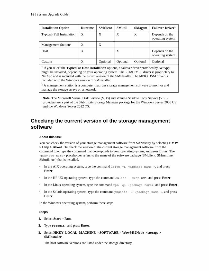
Installation Option Runtime SMclient SMutil SMagent Failover Driver1
Typical (Full Installation) X X X X Depends on theoperating system
Management Station2 X X
Host X X Depends on theoperating system
Custom X Optional Optional Optional Optional
1 If you select the Typical or Host Installation options, a failover driver provided by NetAppmight be installed, depending on your operating system. The RDAC/MPP driver is proprietary toNetApp and is included with the Linux version of the SMInstaller. The MPIO DSM driver isincluded with the Windows version of SMInstaller.2 A management station is a computer that runs storage management software to monitor andmanage the storage arrays on a network.
Note: The Microsoft Virtual Disk Service (VDS) and Volume Shadow Copy Service (VSS)providers are a part of the SANtricity Storage Manager package for the Windows Server 2008 OSand the Windows Server 2012 OS.
Checking the current version of the storage managementsoftware
About this task
You can check the version of your storage management software from SANtricity by selecting EMW> Help > About . To check the version of the current storage management software from thecommand line, type the command that corresponds to your operating system, and press Enter. The<package name> placeholder refers to the name of the software package (SMclient, SMruntime,SMutil, etc.) that is installed.
• In the AIX operating system, type the command lslpp -L <package name >, and pressEnter.
• In the HP-UX operating system, type the command swlist | grep SM*, and press Enter.
• In the Linux operating system, type the command rpm -qi <package name>, and press Enter.
• In the Solaris operating system, type the command pkginfo -l <package name >, and pressEnter.
In the Windows operating system, perform these steps.
Steps
1. Select Start > Run.
2. Type regedit , and press Enter.
3. Select HKEY_LOCAL_MACHINE > SOFTWARE > Wow6432Node > storage >SMInstaller.
The host software versions are listed under the storage directory.
16 | System Upgrade Guide

Steps to upgrade storage management software
About this task
Important: If you are upgrading the storage management software on an I/O-attached Windowshost for a storage array that has controller firmware version 7.80 (or a release prior to version7.80), change the order of the following steps. Before you perform step 6 on page 17 to installthe storage management software, perform step 8 on page 17 to upgrade the controller firmwareand NVSRAM on the storage array to version 8.20.
These steps are required for a successful upgrade to storage management software version 11.20 andcontroller firmware version 8.20. Perform the steps in order.
Steps
1. Make sure that the controller-drive trays in your storage array are compatible with the softwarelevel and the firmware level to which you are upgrading and that the current version of the storagemanagement software can be upgraded directly to SANtricity Storage Manager Version 11.20.
See the NetApp® support site at mysupport.netapp.com/matrix for the supported controller-drivetrays and upgrade paths.
2. Check that the host bus adapters (HBAs), switches, driver versions, and firmware levels aresupported.
Refer to your storage vendor for compatibility information and for specific hardware restrictions.
3. Start the existing storage management software with the procedure for your operating system.
4. Make sure that the hardware and operating systems on all attached hosts and managementsstations meet the minimum system requirements to work with your upgraded storage array.
Refer to the System Requirements topics for each operating system in this document.
5. Make sure that your failover driver is compatible with the new hardware, firmware, and software.Refer to the topics in Multipath Drivers Guide.
If you select the Host option when you run the SANtricity installer, the Windows DSM isinstalled.
6. Install storage management software version 11.20 using the instructions for your operatingsystem (OS). OS-specific instructions are given in subsequent chapters of this document.
7. Make sure that the installation was successful. Use the procedure in this document for youroperating system to start the storage management software.
8. Update the controller firmware and NVSRAM.
See the steps in Upgrading controller firmware and NVSRAM on page 8.
9. Update the ESM firmware.
See the steps in Upgrading the ESM Firmware on page 10.
Note: Starting with SANtricity Storage Manager Version 10.83, a storage array can useasymmetric logical unit access (ALUA). ALUA enables a controller-drive tray to service I/Orequests through either controller in a duplex configuration. Additional steps are required forVMware configurations. See Upgrade instructions for asymmetric logical unit access (ALUA)with the VMware OS on page 43 for instructions.
10. Confirm that the Default Operating System or Defined Host Operating Systems are set correctlyin Storage Partition Mapping.
Upgrading storage management software | 17

11. To verify that the storage array has an Optimal status, select Monitor > Health > View Health(Recovery Guru). If one or more managed devices has a Needs Attention status, follow theinstruction in the Recovery Guru. If Optimal status is not restored, contact technical support.
Upgrade instructions for the Solaris OSUse the procedures in this chapter to upgrade the storage management software on the Solarisoperating system.
System requirements for Solaris
Review these specifications to make sure that your system meets the minimum general requirements.
Note: Solaris supports only Fibre Channel host connections.
Operating system version for I/Oattached hosts
• Solaris 10 u11
• Solaris 11.1
• Solaris 11.2
Processor support Oracle Sparc, Intel Xeon 32 bit, Intel Xeon 64 bit, AMDOpteron 32 bit, AMD Opteron 64 bit
Controller-drive trays • E2600
• E2700
• E5400
• EF540
• E5500
• EF550
• E5600
• EF560
iSCSI Host Adapters NICs, CNAs, LoM (only with Solaris 11.x)
Fibre Channel Host adapters Emulex
• 8 Gb/s: LPE12000, LPE12002, LPE12004
Qlogic
• 8 Gb/s: QLE2560, QLE2562, QLE2564
Oracle
• 8 Gb/s: SG-XPCIE1FC-EM8-Z, SG-XPCIE2FC-EM8-Z,SG-XPCIE1FC-QF8-N, SG-XPCIE2FC-QF8-N
Host Connection Configurations • Direct connect
• Fabric
Rootboot supported? Yes, where supported by the HBA
18 | System Upgrade Guide
Local File systems supported Oracle provides the list of supported file systems. NetApp willtest a sampling of the supported file systems but will not limitsupport to those file systems only. Refer to Oracle's list of filesystems for official support.
SCSI driver sd/ssd/Leadville
I/O path failover and mode • Solaris 10 u11MPxIO (TPGS/ALUA or non-TPGS)
• Solaris 11.1 MPxIO (TPGS/ALUA)
• Solaris 11.2 MPxIO (TPGS/ALUA)
Node failover • Oracle Solaris Cluster 4.2 (Sol 11.2)
• Oracle Solaris Cluster 4.1 (Sol 11.1)
• Oracle Solaris Cluster 3.3 U2 (Sol 10 u11)
Providers SMI-S
Additional information for SANtricity Storage Manager on Solaris
About this task
Use this procedure to install the storage management software packages on the Solaris OS. Whenyou install the new software, earlier versions of the software are automatically removed as part ofthat process.
For this procedure, you must first obtain an installation file that is specific to your operating systemand to the release level of the storage management software from NetApp Support. In the followingsteps, the installation file is identified as SMIA-SOLX86-11.20.00nn.nnnn.bin (for the Intel x86platform) or SMIA-SOL-11.20.06nn.nnnn.bin (for the SPARC platform). The characters nn.nnnnare, in practice, alpha-numeric characters: for example, SMIA-SOLX86-11.20.0000.0178.bin.
Steps
1. Make sure that you have root privileges, which are required to install the software.
2. Download or copy the installation file, SMIA-SOLX86-11.20.nnnn.nnnn.bin or SMIA-SOL-11.20.nnnn.nnnn.bin, to a directory on your host. To download the installation file,navigate to NetApp Support and download the E-Series/EF-Series SANtricity Storage Manager11.20.06.nnnn.nnnn and related software package for your Solaris platform.
3. Change your current directory to the installation directory by typing cd <install> on thecommand line and then pressing Enter.
<install> is the name of the directory on your server to which you downloaded the installationfile.
4. Change the file permissions for the installer using the chmod 777 SMIA-SOL*.bin command.
This action allows you to run the installer.
5. Execute the installer using the ./SMIA-SOL*.bin command.
The following messages appear in the console window:
Preparing to install...Extracting the JRE from the installer archive...Unpacking the JRE...Extracting the installation resources from the installer archive...
Upgrading storage management software | 19

Configuring the installer for this system's environment...Launching installer...
After the software is loaded, the Introduction window appears.
6. Click Next.
The License Agreement window appears.
7. Select the option that accepts the terms of the License Agreement.
8. Click Next.
The Select Installation Type window appears.
9. Based on the type of installation you are performing, select one of these options.
The steps in this procedure describe a typical (full) installation.
• Typical (Full Installation) – This selection, which is the default, installs all of the packageson the system. Choose this option if you do not know which installation type to select.
• Management Station – This selection installs the software that is needed to configure,manage, and monitor a storage array. This option is for your workstation or managementcomputer.
• Host – This selection installs the storage array server software. Use this type of installation forthe host (server) that is connected to the storage array.
• Custom – This selection lets you customize the features to be installed.
The installation type that you select is highlighted in blue text.
10. Click Next.
A Software Incompatibility Detected screen may appear if there is a previous version of theSANtricity software installed on your system. If this is the case, click OK to override the pre-existing version.
The Pre-Installation Summary window appears.
11. Click Install.
The Installing window appears while the software is loading. When the software is loaded, theInstall Complete window appears.
Important:
If you cancel an installation before the installation completes or while the progress bar is stillvisible, the installation stops prematurely. The software creates an installation log. You mustmanually uninstall the software. If you cancel the installation before the progress bar is visible,you do not need to uninstall the software.
12. To exit the installation program, click Done.
Several files and program packages are installed to the /opt/SMgr directory and the /opt/StorageManager directory.
13. If you have volumes mapped to the server from a previous installation of the SANtricity software,run devfsadm -C, devfsadm, and cfgadm -al.
These commands ensure that the server continues to have access to the mapped volumes.
20 | System Upgrade Guide

After you finish
Solaris uses the native MPx10 for failover. After installing the host package, see the SANtricityStorage Manager Multipath Drivers Guide to enable MPx10 on the host.
Checking the installation on the Solaris OS
About this task
After you have completed installing the software packages, check that they installed successfully.
Steps
1. At the prompt, type this command and press Enter:
pkginfo -l <package name>
In this command, <package name> is the name of a package that you installed.
2. To determine which software packages reside on your system, type this command at the prompt.
pkginfo | grep SM
Look for the storage management software packages, such as SMagent, SMclient, SMutil, andSMruntime.
3. From the /opt/StorageManager directory, review any error messages from the error messagelog, and correct the problem. If the problem persists, contact technical support.
4. For each package you installed, repeat step 1 on page 21 through step 2 on page 21.
5. Start the storage management software. At the prompt, type this command, and press Enter:
SMclient
After the client software starts, the Enterprise Management Window and these dialogs appear:
• Select Addition Method
• Enterprise Management Window Task Assistant
Refer to the online help topics in storage management software for more information about howto manage your storage array.
Uninstalling the storage management software on the Solaris OS
About this task
If you have installed the storage management software, but you determine that you must uninstall it,perform this procedure.
Note: Uninstalling the software is not the same as removing previous versions of the software.
Steps
1. To change to the Uninstall directory, from the /opt/StorageManager directory, type thiscommand, and press Enter:
cd “Uninstall SANtricity”
Upgrading storage management software | 21

2. From the Uninstall SANtricity directory, type this command, and press Enter:
./Uninstall_SANtricity
The Uninstall window appears.
3. Click Next.
The Uninstall Options window appears. You can choose either to perform a completeuninstallation or to select specific packages to uninstall individually.
4. Either select the packages that you want to uninstall, or select a complete uninstallation.
5. Click Next.
While the software is uninstalling, the Uninstall window appears. When the procedure hascompleted, the Uninstall Complete window appears.
6. Click Done.
The uninstallation process is complete.
Upgrade instructions for the Linux OSUse the procedures in this chapter to upgrade the storage management software on the Linuxoperating system.
System requirements for Linux
Review these specifications to make sure that your system meets the minimum general requirements.
Component With Non-InfiniBand HostConnections
With InfiniBand HostConnections
Operating system version forI/O attached hosts
• RHEL 7.1 (IOP)
• RHEL 7.0
• RHEL 6.5
• RHEL 6.4
• RHEL 7.0
• RHEL 6.5
• RHEL 6.4
• SLES 12 (IOP)
• SLES 11 SP4 (IOP)
• SLES 11 SP3
• RHEL 7.0
• RHEL 6.5
• RHEL 6.4
Hypervisor OS for I/O attachhosts
• RedHat EnterpriseVirtualization (RHEV)
• Kernel-based VirtualMachine (KVM)
(RHEV and KVM are onlysupported on RHEL 7.0, 6.5and 6.4)
22 | System Upgrade Guide
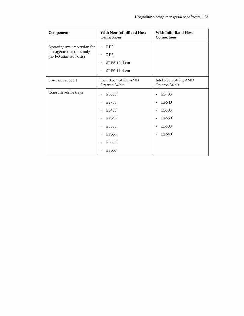
Component With Non-InfiniBand HostConnections
With InfiniBand HostConnections
Operating system version formanagement stations only(no I/O attached hosts)
• RH5
• RH6
• SLES 10 client
• SLES 11 client
Processor support Intel Xeon 64 bit, AMDOpteron 64 bit
Intel Xeon 64 bit, AMDOpteron 64 bit
Controller-drive trays • E2600
• E2700
• E5400
• EF540
• E5500
• EF550
• E5600
• EF560
• E5400
• EF540
• E5500
• EF550
• E5600
• EF560
Upgrading storage management software | 23

Component With Non-InfiniBand HostConnections
With InfiniBand HostConnections
Host Adapters Emulex (Fibre Channel)
• 8 Gb/s: LPE12000,LPE12002, LPE12004
• 16 Gb/s: LPE16000,LPE16000B, LPE16002
Qlogic (Fibre Channel)
• 8 Gb/s: QLE2560,QLE2562, QLE2564
• 16 Gb/s: QLE2670,QLE2672
Brocade (Fibre Channel)
• 8 Gb/s: 815, 825
• 16 Gb/s: 1860-1, 1860-2
HP BladeCenter (FibreChannel)
• Qlogic 8Gb: QMH2572,QMH2562
• Emulex 8Gb: LPE1205,LPE1205A
LSI (SAS)
• 6Gb: 9207-8e
• 12Gb: 9300-8e
Dell
• 6Gb: 7e
HP
• 6Gb: h222, h221
NICs, CNAs, LoM (iSCSI)
Mellanox (IB)
40Gb:
• MHQH19B-XSR,MHQH19B-XTR
• MHQH29B-XSR,MHQH29B-XTR
• MHQH19C-XSR,MHQH19C-XTR
• MHQH29C-XSR,MHQH29C-XTR
• MCX353A-QCAT,MCX353A-QCAT
• MCX353A-QCBT,MCX353A-QCBT
56 Gb:
• MCX353A-FCAT,MCX354A-FCAT
• MCX353A-FCBT,MCX354A-FCBT
• MCX353A-FCCT,MCX354A-FCCT
• MCB191A-FCAT,MCB192A-FCAT
• MCB193A-FBAT,MCB193A-FCAT
• MCB194A-FCAT
Fibre Channel configurations Direct Connect and Fabric
Local file systems supported RedHat and Novell providespecific file systems with theirindividual Linux distributions.NetApp will test a sampling ofthe inbox file systems but willnot limit support to those filesystems only. Refer to RedHat'sand Novell's list of file systemsfor official support
24 | System Upgrade Guide

Component With Non-InfiniBand HostConnections
With InfiniBand HostConnections
Rootboot supported? Yes, where supported by theHBA (not with iSCSI hostconnections)
No
I/O path failover DMMP (RDAC Handler withALUA support)
• SLES 12, SLES 11 SP4,SLES11 SP3
• RHEL 7.1, RHEL 7.0,RHEL 6.5, RHEL 6.4
DMMP: (DMMP-ALUAhandler)
• RHEL 7.1, RHEL 7.0,RHEL 6.5, RHEL 6.4
• SLES 12, SLES 11SP4,SLES 11SP3
MPP: (MPP-RDAC driver)
• RHEL 6.5, RHEL 6.4
• SLES 11 SP3
DMMP (RDAC Handler)
• SLES11 SP3
• RHEL 7.0, RHEL 6.5,RHEL 6.4
MPP: (MPP-RDAC driver)
• RHEL 6.5, RHEL 6.4
• SLES 11 SP3
Node failover • SIOS (SteelEye) LifeKeeperwith SLES
• Red Hat Cluster Server onRHEL
Providers SMI-S
System requirements for additional Linux distributions
Review these specifications to make sure that your system meets the minimum general requirements.
Component With Non-InfiniBand Host Connections
Operating system version for I/O attachedhosts
• CentOS 7.0
• CentOS 6.5
• CentOS 6.4
• Oracle Linux (OEL)7.0
• OEL6.5
• OES 6.4
Processor support Intel Xeon 64 bit, AMD Opteron 64 bit
Upgrading storage management software | 25

Component With Non-InfiniBand Host Connections
Controller-drive trays • E2600
• E2700
• E5400
• EF540
• E5500
• EF550
• E5600
• EF560
Host Adapters Emulex (Fibre Channel)
• 8 Gb/s: LPE12000, LPE12002, LPE12004
• 16 Gb/s: LPE16000, LPE16000B,LPE16002, LPE16002B
Qlogic (Fibre Channel)
• 8 Gb/s: QLE2560, QLE2562, QLE2564
• 16 Gb/s: QLE2670, QLE2672
Brocade (Fibre Channel)
• 8 Gb/s: 815, 825
• 16 Gb/s: 1860-1, 1860-2
HP BladeCenter (Fibre Channel)
• Qlogic 8Gb: QMH2572, QMH2562
• Emulex 8Gb: LPE1205, LPE1205A
LSI (SAS)
• 6Gb: 9207-8e
• 12Gb: 9300-8e
Dell
• 6Gb: 7e
HP
• 6Gb: h222, h221
NICs, CNAs, LoM (iSCSI)
Fibre Channel configurations Direct Connect and Fabric
Rootboot supported? Yes, where supported by the HBA (not withiSCSI host connections)
26 | System Upgrade Guide

Component With Non-InfiniBand Host Connections
Local file systems supported CentOS and Oracle provide specific filesy stemswith their Linux distribution. Since CentOS is acommunity-supported Linux distribution,NetApp will test and verify a sampling of theinbox file systems but makes no official supportclaims. For Oracle Enterprise Linux, refer toOracle's list of file systems for official support.
I/O path failover DMMP (DMMP-ALUA handler)
• CentOS7.0, CentOS 6.5, CentOS 6.4
• OEL7.0, OEL 6.5, OEL 6.4
DMMP: (DMMP-RDAC handler)
• CentOS7.0, CentOS 6.5, CentOS 6.4
• OEL7.0, OEL 6.5, OEL 6.4
Node failover None.
Providers SMI-S
System requirements for Linux with PowerPC processors
Review these specifications to make sure that your system meets the minimum general requirements.
Operating system version for I/Oattached hosts
• RHEL 7.1 (IOP)
• RHEL 7.0
• RHEL 6.5
• RHEL 6.4
• SLES 12 (IOP)
• SLES 11 SP4 (IOP)
• SLES 11 SP3
Processor support IBM Power 5 and newer
Controller-drive trays • E2600
• E2700
• E5400
• EF540
• E5500
• EF550
• E5600
• EF560
Upgrading storage management software | 27

Fibre Channel host adapters IBM
• 8 Gb/s: 5273-P, 5735-P, 5729-P
• 16 Gb/s: EN0A / EN0B
iSCSI host connections NICs, CNAs, LoM
Host channel configurations Direct Connect and Fabric
Rootboot supported? Yes, where supported by the HBA (not with iSCSI hostconnections)
I/O path failover DMMP (DMMP-ALUA handler)
• SLES 12, SLES11 SP3
• RHEL 7.0, RHEL 6.5, RHEL 6.4
DMMP: (DMMP-RDAC handler)
• SLES 12, SLES11 SP3
• RHEL 7.0, RHEL 6.5, RHEL 6.4
MPP: (MPP-RDAC handler)
• RHEL 7.0, RHEL 6.5, RHEL 6.4
• SLES 12, SLES 11 SP3
Node failover None
Providers None
Installing the storage management software on the Linux OS
About this task
Use this procedure to install the storage management software packages for the Linux OS. You alsocan perform the software installation procedure by using a package manager that is compatible withRed Hat Package Manager (RPM) and has a graphical user interface (GUI). When you install the newsoftware, earlier versions of the software are automatically removed as part of that process.
For this procedure, you must first obtain an installation file that is specific to your operating systemand to the release level of the storage management software from th NetApp support site at mysupport.netapp.com. In the following steps, the installation file is identified as SMIA-LINUXX64-11.20.0Bnn.nnnn.bin (for Linux on Intel x64 processors) or SMIA-LINUX-11.20.0Ann.nnnn.bin (for all other supported processors). The characters nn.nnnn are,in practice, alpha-numeric characters: for example, SMIA-LINUX-11.20.0400.0178.bin.
Steps
1. Make sure that you have root privileges, which are required to install the software.
2. Download or copy the installation file, SMIA-LINUXX64-11.20.04nn.nnnn.bin or SMIA-LINUX-11.20.04nn.nnnn.bin , to a directory on your host.
3. Change your current directory to the installation directory by typing cd <install> on thecommand line and then pressing Enter.
<install> is the name of the directory on your server to which you downloaded the installationfile.
28 | System Upgrade Guide

4. At the command prompt, type SMIA-LINUXX64-11.20.04nn.nnnn.bin or SMIA-LINUX-11.20.04nn.nnnn.bin , and then press Enter.
After the software is loaded, the Introduction window appears.
5. Click Next.
The License Agreement window appears.
6. Select the option that accepts the terms of the License Agreement.
7. Click Next.
The Select Installation Type window appears.
8. Based on the type of installation you are performing, select one of these options.
The steps in this procedure describe a typical (full) installation.
• Typical (Full Installation) – This option, which is the default, installs all of the packages onthe system. Choose this option if you do not know which installation type to select.
• Management Station – This option installs the software that is needed to configure, manage,and monitor a storage array. This option is for your workstation or management computer.
• Host – This selection installs the storage array server software. Use this type of installation forthe host (server) that is connected to the storage array.
• Custom – This option lets you customize the features to be installed.
The installation type that you select is highlighted in blue text.
9. Click Next.
The Multi-Path Driver Warning dialog appears.
10. Click Next.
The Pre-Installation Summary window appears.
11. Click Install.
The Installing window appears while the software is loading. When the software is loaded, theInstall Complete window appears.
Important:
If you cancel an installation before the installation completes or while the progress bar is stillvisible, the installation stops prematurely. The software creates an installation log. You mustmanually uninstall the software. If you cancel the installation before the progress bar is visible,you do not need to uninstall the software.
12. To exit the installation program, click Done.
Several files and program packages are installed to the /opt/SM9 directory and the/opt/StorageManager directory.
13. Do you want to manually install the RDAC package?
• Yes – Go to step 14 on page 29.
• No – Go to Checking the installation on the Linux OS on page 30.
14. Install the RDAC package.
Upgrading storage management software | 29

a. While in the /opt/StorageManager directory, type this command at the prompt, and pressEnter. In this command, <rdac-Package-name> is the name of the RDAC package.
tar -xvf <rdac-Package-name>.tar.gz
The source files uncompress into the linuxrdac-09.01.Bx.xx directory.
b. To change to the directory where the RDAC source is located, type the command for yourversion of the kernel, and press Enter.
2.4 kernel:
cd linuxrdac
2.6 kernel:
cd linuxrdac-09.01.Bx.xx
c. To remove the previously installed version of RDAC, type this command, and press Enter:
make uninstall
d. To clean the directory, type this command, and press Enter:
make clean
e. To compile the modules, type this command, and press Enter:
make
f. To install RDAC, type this command, and press Enter:
make install
g. After the make install process has completed, modify your bootloader configuration file. Formore information about how to modify the bootloader configuration file, refer to the outputfrom the make install command for Linux RDAC.
h. Read the readme.txt file in the linuxrdac directory to complete the RDAC installationprocess.
Note: After you update the boot loader, you must reboot the host to apply the new MPPinitrd image.
Note: For further details about installing RDAC, refer to the Multipath Drivers Guide.
Checking the installation on the Linux OS
About this task
After you have completed installing the software packages, make sure that they installed successfully.
30 | System Upgrade Guide

Steps
1. At the prompt, type this command and press Enter:
rpm -qa | grep SM*
2. At the prompt, type this command and press Enter. In this command, <package name> is thename of a package that you installed.
rqm -qi <package name>
3. Note any problem that is reported.
4. For each package you installed, repeat step 2 on page 31 through step 3 on page 31.
5. Was the installation successful (no problems were reported)?
• Yes – Go to step 3 on page 31.
• No – From the /opt/StorageManager directory, review any error messages from the errormessage logs, SANtricity_ES_InstallErrorLog.log andSANtricity_ES_InstallLog.log , and correct the problem. If the problem persists,contact technical support.
6. Start the storage management software. At the prompt, type this command, and press Enter:
SMclient
After the client software starts, the Enterprise Management Window and these dialogs appear:
• Select Addition Method
• Enterprise Management Window Task Assistant
Refer to the online help topics in storage management software for more information about howto manage your storage array.
Uninstalling storage management software on the Linux OS
About this task
If you have installed the storage management software but you have determined that you need touninstall it, perform this procedure.
Note: Uninstalling the software is not the same as removing previous versions of the software.
Steps
1. To change to the Uninstall directory, from the /opt/StorageManager directory, type thiscommand, and press Enter:
cd “Uninstall SANtricity”
2. From the Uninstall SANtricity directory, type this command and press Enter:
./Uninstall_SANtricity_ES
The Uninstall window appears.
Upgrading storage management software | 31

3. Click Next.
The Uninstall Options window appears. You can choose either to perform a completeuninstallation or to select specific packages to uninstall individually.
4. Either select the packages that you want to uninstall, or select a complete uninstallation.
5. Click Next.
The Multi-Path Driver Warning dialog appears.
6. Click Next.
While the software is uninstalling, the Uninstall window appears. When the procedure hascompleted, the Uninstall Complete window appears.
7. Manually uninstall the RDAC package.
a. Navigate to the /opt/StorageManager/linuxrdac directory.
Note: In this command, /opt/StorageManager/linuxrdac is the directory in whichthe RDAC files are stored.
b. To uninstall RDAC, type this command and press Enter:
make uninstall
c. To clean the directory, type this command and press Enter:
make clean
8. Revert the changes you made in the boot-loader configuration file.
9. Click Done.
The uninstallation process is complete.
10. Reboot the host.
Upgrade instructions for the Windows OSUse the procedures in this section to upgrade the storage management software on the Windowsoperating system.
32 | System Upgrade Guide

System requirements for Windows OS
Operating system version forI/O attached hosts
With Server Core, storage management is available only throughthe command line interface, SMcli
Supported editions (Windows 2012, Windows 2012 R2 andWindows 2008 R2)
• Standard server and core
• Foundation server and core
• Datacenter server and core
Supported editions (Windows 2012, Windows 2012 R2)
• Essentials Server and Core
Supported editions (Windows 2008 R2)
• Enterprise Server and Core
• Windows Storage Server
• Web Server (Client only, no Failover)
Unsupported editions (Windows 2008 R2)
• HPC Server
• Small or Essentials Business Server
• Unified Data Storage Server
OS versions for GUI clientonly
• Windows 7, 8 & 8.1
• Windows 7, 8 & 8.1 Pro
• Windows 7, 8 & 8.1 Enterprise
Hypervisor OS for I/O attach • Windows Server 2012 R2 Hyper-V
• Windows Server 2012 Hyper-V
• Hyper-V Server 2008 R2 SP1 (standalone)
• Windows Server 2008 R2 SP1 Hyper-V (add on to 2008)
Guest OSs for hypervisor Microsoft provides the list of supported Guest OSs for thishypervisor. NetApp will test a sampling of the supported OSs butwill not limit support to those OSs only. Please refer to Microsoft'slist of guest OSs for official support.
Processor support Intel Xeon 64 bit, AMD Opteron 64 bit
Upgrading storage management software | 33

Controller-drive trays • E2600
• E2700
• E5400
• EF540
• E5500
• EF550
• E5600
• EF560
Fibre Channel host adapters Emulex
• 8 Gb/s: LPE12000, LPE12002, LPE12004
• 16 Gb/s: LPE16000, LPE16000B, LPE16002, LPE16002B
Qlogic
• 8 Gb/s: QLE2560, QLE2562, QLE2564
• 16 Gb/s: QLE2670, QLE2672
Brocade
• 8 Gb/s: 815, 825
• 16 Gb/s: 1860-1, 1860-2
HP Blade Center
• 8 Gb/s: QMH2572, QMH2562
• 16 Gb/s: LPE1205,LPE1205A
SAS host adapters LSI
• 6 Gb/s: 9207-8e
• 12 Gb/s: 9300-8e
Dell
• 6 Gb/s: 7e
HP
• 6 Gb/s: h221, h222
iSCSI host connections NIC's and CNA's from multiple vendors will be tested. Support isnot limited to the tested NIC's or CNA's as long as the customeruses the supported Software Initiator (SWI). Hardware Initiator(HWI) is not supported.
Configurations Direct connect or Fabric
Rootboot supported? Yes, where supported by the HBA (not with iSCSI hostconnections)
34 | System Upgrade Guide

I/O path failover and mode Microsoft Cluster Server
• Windows 2012 R2 supports 64 nodes
• Windows 2012 supports 64 nodes
• Windows 2008 R2 supports 16 nodes
Local filesystems supported Microsoft provides the list of supported file systems. NetApp willtest a sampling of the supported file systems but will not limitsupport to those file systems only. Refer to Microsoft's list of filesystems for official support
Node failover Microsoft Cluster Server Windows 2012 supports 64 nodesWindows 2008 supports 16 nodes
Providers • SMIS
• VDS/VSS
• SMAPI
Installing the storage management software on the Windows OS
About this task
Use this procedure to install the storage management software packages on the Windows OS.
Attention:
Possible data corruption – If a host is allowed to access data on the storage array without RDACor a valid installation of a path failover product, and has dual paths to the storage array, the datamight become unusable.
Review the following important points before you begin to install the software:
• If you are upgrading the storage management software on an I/O-attached host for a storage arraythat has controller firmware version 7.80 (or a release prior to version 7.80), upgrade thecontroller firmware and NVSRAM on the storage array to the version 8.20 before you upgradethe storage management software.
• If you are installing the Windows boot device on a storage array, refer to the boot deviceinstallation procedures in Appendix A of SANtricity Storage Manager 11.20 Software InstallationReference. Determine where to install the software before you begin this procedure. You shouldnot install your monitoring stations on a root boot device, since doing so can result in the loss ofimportant debug information when the entire system is down.
• Do not restart the system during the installation process. You will restart the system after youinstall all of the storage management software components.
• Configure the Event Monitor on only one storage management station to prevent receivingduplicate event messages. Duplicate alerts are also sent if the Enterprise Management windowand the SMmonitor utility are running simultaneously.
• Before you start the primary server of a server cluster, complete all applicable configurationprocedures for each system.
Steps
1. Before you install this software, close all other programs.
Upgrading storage management software | 35

2. Download or copy the installation file, SMIA-WinX64-11.20.03nn.nnnn.exe (for Intel x64processors) or SMIA-WS32-11.20.03nn.nnnn.exe (for Intel x32 processors), to a directory onyour host.
3. To launch the installer, double-click the applicable.exe file.
The InstallAnywhere dialog appears while the software installs. When the software is installed,the Introduction window appears.
4. Click Next.
The License Agreement window appears.
5. Select the option that accepts the terms of the License Agreement.
6. Click Next.
The Choose Install Folder window appears, which identifies the default installation location.
7. Click Next.
The Select Installation Type window appears.
8. Based on the type of installation you are performing, select one of these options.
The steps in this procedure describe a typical (full) installation.
• Typical (Full Installation) – This selection, which is the default, installs all of the packageson the system. Choose this option if you do not know which installation type to select.
• Management Station – This selection installs the software that is needed to configure,manage, and monitor a storage array. This option is for your workstation or managementcomputer.
• Custom – This selection lets you customize the features to be installed.
The installation type that you select is highlighted in blue text.
9. Click Next.
If the software already exists, the Overwrite Warning dialog appears.
10. If the Overwrite Warning dialog appears, click OK.
The Automatically Start Monitor? window appears.
11. Select the appropriate option for your system.
If you start the Event Monitor on multiple machines, you might receive duplicate error messagesfrom the same storage array. If you do not want to receive duplicate error messages, start theEvent Monitor on only one machine. Make sure to run the Event Monitor on a machine that willrun continuously.
12. Click Next.
The Pre-Installation Summary window appears.
13. Click Install.
The Installing window appears while the software is loading. The Installation/Remove statuswindow also appears throughout the installation process.
The Security Alert dialog might appear multiple times.
14. Did the Security Alert dialog appear?
• Yes – Click Yes, and go to step 15 on page 37.
36 | System Upgrade Guide
• No – Go to step 15 on page 37.
Important: When RDAC is not installed, the Install Complete window shows an error messagethat states that the installation has completed and that there are some warnings. The messagesuggests that you look at the installation log for details. The installation log contains a warningthat a Win32 exception can be found. This is normal and expected behavior. The installationwas successful.
Note: If you cancel an installation before the installation completes or while the progress bar isstill visible, the installation stops prematurely. The software creates an installation log. Youmust manually uninstall the software by using the steps in “Uninstalling Storage ManagementSoftware on the Windows OS on page 38”. If you cancel the installation before the progressbar is visible, you do not need to uninstall the software.
When the software is loaded, the Install Complete window appears.
15. Make sure that the Yes, restart my system option is selected.
16. Click Done.
Several files and program packages are stored in the <LOCAL DRIVE>:\Program Files\StorageManager directory.
Important: If you repeatedly cancel an installation or uninstallation before the processcompletes fully and try to install the software again, the installation process might not work. Inaddition, the software might not be installed after the installation process has completed. Theinstallation complete panel tells you where the software is installed, but it is not there. If thisproblem occurs, delete the .xml file from the Program Files\Zero G directory.
The installation is completed, and Windows is restarted.
Checking the installation on the Windows OS
About this task
After you have completed installing the software packages, make sure that they installed successfully.
Note: To make sure that all of the packages installed successfully on the Windows OS, go to theregistry settings in theHKEY_LOCAL_MACHINE>Software>Wow6432NodeStorage>Storage>SMInstaller directory.
Steps
1. Select Start > Programs.
The list of installed programs appears.
2. Make sure that storage management software appears in the program list.
If the storage management software does not appear in the list, refer to the Product Release Notesfor the current release, or contact technical support.
3. To start the storage management software, select Start > All Programs > SANtricity StorageManager Client.
Refer to the online help topics in the storage management software for more information abouthow to manage your storage array.
After the client software starts, the Enterprise Management window and these dialogs appear:
• Select Addition Method
• Enterprise Management Window Task Assistant
Upgrading storage management software | 37

Uninstalling storage management software on the Windows OS
About this task
If you have installed storage management software, but you have determined that you need touninstall it, perform this procedure.
Note: Uninstalling the software is not the same as removing previous versions of the software.
Note: The procedure in step 1 on page 38 is required only if you are using the storage array as aboot device.
Steps
1. Make sure that a single path exists to the storage array. Choose one of two methods to make surethat the alternate path to the storage array has been removed:
• Method 1 – Remove the host interface cable to the alternate path. When you are finished, goto step 5 on page 39.
• Method 2 – Modify NVSRAM to temporarily disable RDAC multi-path functionality at thestorage array by performing these substeps:
Attention: Possible data corruption – If no multi-path driver exists in the host and you sendI/O to the storage array, data corruption could occur. Do not uninstall the multi-path driver,even if you are not using the storage array as a boot device.
a. Select the storage array in the Enterprise Management Window.
b. Select Tools > Execute Script.
The Script Editor dialog appears.
c. In the upper half of the Script Editor dialog, type these commands at the prompt, and pressEnter.
set controller[a] HostNVSRAMByte[1,0x16]=0xFF,0x20;
set controller[b] HostNVSRAMByte[1,0x16]=0xFF,0x20;
d. Select Tools > Execute Only.
e. For the NVSRAM modifications to take effect, turn off the power to the controller-drive tray,wait 30 seconds for the controller-drive tray to turn off the power, and turn on the poweragain.
2. Remove the software packages.
a. Select Start > Settings > Control Panel > Add or Remove Programs.
The Add or Remove Programs dialog appears.
b. Select storage management software from the list of programs.
c. Click Change/Remove.
The Uninstall window appears.
d. Click Next.
e. Make sure that the Complete Uninstall option is selected.
38 | System Upgrade Guide

f. Click Next.
The software uninstallation process begins. The status dialog appears during the uninstallationprocess. When the procedure has completed, the Uninstall Complete window appears.
g. Make sure that Yes is selected so that your computer will restart.
h. Click Done.
3. Is the Windows boot device on a storage array?
Attention: Possible data corruption – If the Windows host uses any volumes on the storagearray (boot device or otherwise), there is a risk of data corruption if RDAC is removed andthere are multiple paths to the storage array.
• Yes – Go to step 4 on page 39.
• No – You have completed the procedure.
4. Shut down the host system.
Attention: Possible data corruption – Because RDAC is removed, only a single path to thestorage array is expected. The path goes to the controller that owns the boot volume. If the hostis permitted to start without RDAC and still has dual paths to the storage array, the data mightbecome unusable.
5. Start the host system.
Upgrade instructions for the AIX OSUse the procedures in this chapter to upgrade the storage management software on the AIX operatingsystem.
System requirements for AIX and VIOS
Review these specifications to make sure that your system meets the minimum installationrequirements.
Operating system version for I/Oattached hosts
• AIX 7.1 TL3
• AIX 6.1 TL9
• VIOS 2.2.3.x
• VIOS 2.2.2.x
Processor support IBM POWER™ 5 and newer
Upgrading storage management software | 39

Controller-drive trays • E2600
• E2700
• E5400
• EF540
• E5500
• EF550
• E5600
• EF560
Host adapters 8 Gb/s
• 5273-P
• 5735-P
• EN0Y
• 5729-P
16 Gb/s
• EN0A
• EN0B
Configurations • Direct connect
• Fabric
Rootboot supported? Yes
I/O path failover and mode Native: (MPIO/non-ALUA)
• AIX 7.1 TL3
• AIX 6.1 TL9
• VIOS 2.2.3.x
• VIOS 2.2.2.x
Node failover Power HA (HACMP)
Providers None
Make sure that the maximum kernel parameters are configured depending on the requirements asshown in the following table.
Parameter Description Configuration
max_thread_proc 64 Maximum threads per process 1024
maxfiles Soft file limit per process 2048
maxuser Influences other parameters 256 or greater
ncallout Number of pending timeouts 4144
40 | System Upgrade Guide

Installing the storage management software on the AIX OS
About this task
Use this procedure to install the storage management software packages on the AIX OS. When youinstall the new software, earlier versions of the software are automatically removed as part of thatprocess.
For this procedure, you must first obtain an installation file that is specific to your operating systemand to the release level of the storage management software from the NetApp® support site at mysupport.netapp.com. In the following steps, the installation file is identified as SMIA-AIX-11.10.04nn.nnnn.bin . The characters nn.nnnn are, in practice, alpha-numeric characters:for example, SMIA-AIX-11.10.0400.0178.bin.
Steps
1. Make sure that you have root privileges, which are required to install the software.
2. Download or copy the installation file, SMIA-AIX-11.10.04nn.nnnn.bin to a directory onyour host.
3. Change your current directory to the installation directory by typing cd <install> on thecommand line and then pressing Enter.
<install> is the name of the directory on your server to which you downloaded the installationfile.
4. At the command prompt, type sh SMIA-AIX-11.10.04nn.nnnn.bin, and then press Enter.
After the software is loaded, the Introduction window appears.
5. Click Next.
The License Agreement window appears.
6. Select the option that accepts the terms of the License Agreement.
7. Click Next.
The Select Installation Type window appears.
8. Based on the type of installation that you are performing, select one of these options.
The steps in this procedure describe a typical (full) installation.
• Typical (Full Installation) – This selection, which is the default, installs all of the packageson the system. Choose this option if you do not know which installation type to select.
• Management Station – This selection installs the software that is needed to configure,manage, and monitor a storage array. This option is for your workstation or managementcomputer.
• Host – This selection installs the storage array server software. Use this type of installation forthe host (server) that is connected to the storage array.
• Custom – This selection lets you customize the features to be installed.
Note: The target directory for installing the SMclient utility must be the root directory of thehost system. Do not try to force the installation program to install the SMclient utility in adifferent location.
The installation type that you select is highlighted in blue text.
Upgrading storage management software | 41

9. Click Next.
The Pre-Installation Summary window appears.
10. Click Install.
The Installing window appears while the software is loading. When the software is loaded, theInstall Complete window appears.
Note: If you cancel an installation before the installation completes or while the progress bar isstill visible, the installation stops prematurely. The software creates an installation log. Youmust manually uninstall the software. If you cancel the installation before the progress bar isvisible, you do not need to uninstall the software.
11. To exit the installation program, click Done.
Several files and program packages are installed to the /opt/SM9 directory and the /opt/StorageManager directory.
Checking the installation on the AIX OS
About this task
After you have completed installing the software packages, check to make sure that the packagesinstalled successfully.
Steps
1. At the prompt, type this command, and press Enter:
swlist | grep SM*
This command lists the storage management software packages that you installed.
2. At the prompt, type this command, and press Enter:
swverify -v <package name>
In this command, <package name> is the name of a package that you installed.
3. Note any failure reported.
4. For each package you installed, repeat step 2 on page 42 through step 3 on page 42.
5. Was the installation successful (no problems were reported)?
• Yes – Go to step 6 on page 42.
• No – From the /opt/StorageManager directory, review any error messages from the errormessage log, and correct the problem. If the problem persists, contact your technical supportRepresentative.
6. For each system that is used as a storage management station or host, perform the softwareinstallation and removal procedures that are described in this chapter.
7. Start the storage management software. At the prompt, type this command, and press Enter:
SMclient
After the client software starts, the Enterprise Management Window and these dialogs appear:
42 | System Upgrade Guide

• Select Addition Method
• Enterprise Management Window Task Assistant
Refer to the online help topics in the storage management software for more information abouthow to manage your storage array.
Uninstalling storage management software on the AIX OS
About this task
If you have installed the storage management software, but you have determined that you need touninstall it, perform this procedure.
Note: Uninstalling the software is not the same as removing previous versions of the software.
Steps
1. To change to the Uninstall directory, from the /opt/StorageManager directory, type thiscommand, and press Enter:
cd “Uninstall SANtricity”
2. From the Uninstall SANtricity directory, type this command, and press Enter:
cd ./Uninstall_SANtricity
The Uninstall window appears.
3. Click Next.
The Uninstall Options window appears. You can choose either to perform a completeuninstallation or to select specific packages to uninstall individually.
4. Either select the packages that you want to uninstall, or select a complete uninstallation.
5. Click Next.
While the software is uninstalling, the Uninstall window appears. When the procedure hascompleted, the Uninstall Complete window appears.
6. Click Done.
The uninstallation process is complete.
Upgrade instructions for asymmetric logical unit access(ALUA) with the VMware OS
Use the procedures in this chapter to configure VMware to support ALUA/TPGS. Starting withstorage management software version 10.83 and controller firmware version 7.83, any storage arraywith the ALUA/TPGS feature enabled is managed by the VMW_SATP_ALUA plug-in on VMware.
To use a host running VMware as a management station, you must install SANtricity on one of theguest OSs running over VMware. Use the procedures in the guide for the supported guest OS toupgrade SANtricity on such a management station.
Upgrading storage management software | 43
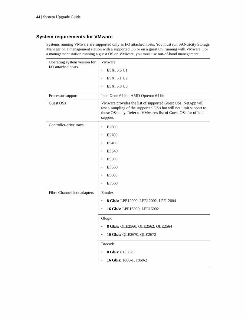
System requirements for VMware
Systems running VMware are supported only as I/O attached hosts. You must run SANtricity StorageManager on a management station with a supported OS or on a guest OS running with VMware. Fora management station running a guest OS on VMware, you must use out-of-band management.
Operating system version forI/O attached hosts
VMware
• ESXi 5.5 U1
• ESXi 5.1 U2
• ESXi 5.0 U3
Processor support Intel Xeon 64 bit, AMD Opteron 64 bit
Guest OSs VMware provides the list of supported Guest OSs. NetApp willtest a sampling of the supported OS's but will not limit support tothose OSs only. Refer to VMware's list of Guest OSs for officialsupport.
Controller-drive trays • E2600
• E2700
• E5400
• EF540
• E5500
• EF550
• E5600
• EF560
Fibre Channel host adapters Emulex
• 8 Gb/s: LPE12000, LPE12002, LPE12004
• 16 Gb/s: LPE16000, LPE16002
Qlogic
• 8 Gb/s: QLE2560, QLE2562, QLE2564
• 16 Gb/s: QLE2670, QLE2672
Brocade
• 8 Gb/s: 815, 825
• 16 Gb/s: 1860-1, 1860-2
44 | System Upgrade Guide

SAS host adapters LSI
• 6 Gb/s: 9207-8e
• 12 Gb/s: 9300-8e
Dell
• 6 Gb/s: 7e
HP
• 6 Gb/s: H221, H222
iSCSI host connections You may use any NIC or CNA provided that you use a supportedsoftware initiator (SWI). Use of a hardware initiator (HWI) is notsupported.
Rootboot supported? Yes, where supported by the HBA (not with iSCSI hostconnections)
Local filesystems Supported VMware provides the list of supported filesystems. NetApp willtest a sampling of the supported filesystems but will not limitsupport to those filesystems only. Please refer to VMware's list offilesystems for official support.
I/O path failover mode VMware Native failover (VMW SATP ALUA)
• ESXi 5.5
• ESXi 5.1
• ESXi 5.0
Node failover VMware HA
Providers None
Installing ALUA support for VMware versions eSXi5.0 u3, eSXi5.1 u2,eSXi5.5 u1, and subsequent versions
About this task
Starting with ESXi5.0 U1 and ESX4.1U3, VMware will automatically have the claim rules to selectthe VMW_SATP_ALUA plug-in to manage storage arrays that have the target port group support(TPGS) bit enabled. All arrays with TPGS bit disabled are still managed by the VMW_SATP_LSIplug-in.
Steps
1. Make sure that the host software on the management station is upgraded to version 11.20.
2. Upgrade the controllers in the storage array to controller firmware version 8.20 and thecorresponding NVSRAM version.
3. From host management client, verify that the host OS type is set to VMWARE. Starting with storagemanagement software version 10.84, the VMWARE host type will have the ALUA and TPGS bitsenabled by default.
4. Use one of the following command sequences to verify that the TPGS/ALUA enabled devices areclaimed by the VMW_SATP_ALUA plug-in.
Upgrading storage management software | 45

• For ESX4.1, enter the #esxcli nmp device list command on the command line of thehost. Check that the output shows VMW_SATP_ALUA as the value of Storage Array Typefor every storage array whose host software level is 10.83 or higher. Storage arrays with lowerlevel host software show VMW_SATP_LSI as the value of Storage Array Type.
• For ESXi5.0, enter the #esxcli storage nmp device list command on the commandline of the host. Check that the output shows VMW_SATP_ALUA as the value of StorageArray Type for every storage array whose host software level is 10.83 or later. Storagearrays with lower level host software show VMW_SATP_LSI as the value of Storage ArrayType.
46 | System Upgrade Guide

Upgrading or replacing all controller canisters in acontroller-drive tray
About this task
Use these procedures to replace all of the controllers in a controller-drive tray. You typically use theseprocedures when you choose to upgrade all of the controllers to a different model or platform. Youmight also use these procedures in the following situations:
• When all controllers in a controller-drive tray encounter hardware failures and are no longerfunctional.
• To upgrade the dual inline memory modules (DIMMs) in your controller-drive tray by replacingboth controllers with the same model of controllers, but with different DIMMs.
If you are upgrading the host interface cards (HICs) in your controller-drive tray by replacing bothcontrollers with the same model of controllers, but with different HICs, refer to the applicable flyerfor upgrade instructions:
• Replacing controller Canisters in the E5512 or the E5524 Controller-Drive tray to Upgrade HostInterface Cards
• Replacing controller Canisters in the E5560 Controller-Drive tray to Upgrade Host InterfaceCards
• Replacing controller Canisters in the E5612 or the E5624 Controller-Drive tray to Upgrade HostInterface Cards
• Replacing controller Canisters in the E5660 Controller-Drive tray to Upgrade Host InterfaceCards
If you are upgrading the HICs in your controller-drive tray to 56-Gb/sec InfiniBand (IB) HICs, youcan use the following document to convert the protocol of the new HIC from iSCSI Extensions forRemote Direct Memory Access (iSER) to Secure Remote Password (SRP).
• Converting an InfiniBand HIC from iSER to SRP
These documents are available at: NetApp E-Series and EF-Series Systems Documentation Center
For duplex controller-drive trays, you replace both controllers. For simplex controller-drive trays, youreplace the one controller. In both cases, you must power off the controller-drive tray. As a result, youcannot access data on the storage array until you successfully complete the replacement.
If your storage array participates in remote volume mirroring, only iSCSI or Fibre Channelconnections are supported between the primary site and the remote site. If the HIC configuration inyour new controllers does not include iSCSI or Fibre Channel connections, remote volume mirroringwill not be supported.
If you order a new controller, it will normally be shipped without a battery installed. When possible,you should remove the battery from your old controller and then install that battery in the newcontroller. However, for some controller upgrades, the battery from the old controller is notcompatible with the new controller. In those cases, you must order a battery along with your newcontroller, and have that battery available before you begin these tasks.
Some controller upgrades result in the Vendor ID in SCSI Inquiry Data changing from LSI toNETAPP. When the Vendor ID changes from LSI to NETAPP, additional steps are required on theWindows, VMware, and AIX operating systems to reclaim devices. Steps for these operating systemsare included in this document.
47

If you are replacing the controllers to upgrade to a new model, keep in mind that your current storagearray might have premium features installed that the new model cannot support. For example, E2700controllers do not support the legacy Snapshot premium feature. If you replace E2600 controllerswith E2700 controllers, and your storage array was using the legacy Snapshots feature, you mustdisable that feature and delete or convert all volumes (that is, snapshots, repositories) associated withthat feature before you replace the controllers. You can convert legacy Snapshots to Snapshots.Before you upgrade a controller-drive tray, you should disable any premium features used on yourstorage array that are not supported on the new controllers.
If you change your controllers from 5x00 models to 2x00 models, your new storage arrayconfiguration will support lower numbers of some objects (for example, volumes) in the storagemanagement software than your old configuration. You must make sure that your old configurationdoes not exceed the object limits listed below before you replace the controller(s).
• Maximum number of volumes - 512
• Maximum number of partitions - 128
• Maximum number of snapshot volumes - 512
• Maximum number of member volumes per consistency group - 32
• Maximum number of consistency groups - 16
• Maximum number of views - 256
• Maximum number of legacy RVM mirrors - 16
• Maximum number of ARVM mirrors - 32
• Maximum number of ARVM mirrors per mirror group - 32
• Maximum total number or mirrors (Legacy RVM + ARVM) - 32
• Maximum number of volume copies - 511
• Maximum number of thin provisioned volumes - 512
• Maximum number of drive slots in the storage array (controller-drive tray + all attached drivetrays) - 192
To E2x00 To E5x00 To EF5x0
From
E2x00
Battery - Reuse the oldbattery
Vendor ID - Additionalsteps required
Feature Support - Legacysnapshots are not supportedon the E2700
Battery - Order a newbattery
Vendor ID - Additionalsteps are required whenupgrading from E2600 toE5500 or E5600, or whenupgrading from E2700 toE5400
Feature Support - Legacysnapshots are not supportedon the E5500 or E5600
Legacy RVM is notsupported on the E5500 orE5600 with iSCSI HICs
Data Assurance is notsupported on the E5500 orE5600 with iSCSI HICs
Upgrades are not supported
48 | System Upgrade Guide

To E2x00 To E5x00 To EF5x0
From
E5x00
Battery - Order a newbattery
Vendor ID - Additionalsteps are required whenupgrading from E5500 orE5600 to E2600, or whenupgrading from E5400 toE2700
Feature Support - Legacysnapshots are not supportedon the E2700
Battery - Reuse the oldbattery
Vendor ID - Additionalsteps required whenupgrading from E5400 toE5500 or E5600
Feature Support - Nolegacy snapshots for E5500or E5600
No legacy RVM or DataAssurance for E5400/E5500 with iSCSI HICs
Upgrades are not supported
From
EF5x0
Upgrades are not supported Upgrades are not supported Battery - Reuse the oldbattery
Vendor ID - Additionalsteps required whenupgrading from EF540 toEF550 or EF560
Feature Support - NoLegacy Snapshots forEF550/EF560
No Data Assurance forEF550/EF560 with iSCSI
Attention: Possible loss of data access – Before you replace the controllers, make sure that anypremium features that are installed and any configuration of objects in the storage managementsoftware can be supported with your new controllers. Failure to do this will result in an out-of-compliance condition or configuration errors. Contact technical support if you encounterconfiguration errors.
Attention: Possible loss of data access – Before you replace the controllers, upgrade your storagearray to the latest version of the operating system (controller firmware), if possible. Normally, youwill upgrade the new controllers to the latest version of the operating system after you install them.If you are not able to upgrade the existing controllers to version 8.10.05 or later, then, after youinstall the replacement controllers, you must install an operating system version on them to match(same major version) what was installed on the old controllers. Contact technical support forassistance in making this determination.
Attention: Possible loss of data access – If any controller that you are replacing manages anysecure volumes, the new controller needs the correct security key to manage those volumes. Afteryou replace the controller and restore power to the controller-drive tray, you can use SANtricityStorage Manager to load the key from the file in which it was saved. Be sure that such a file existsand that you know the pass phrase required to install the security key before you replace thecontroller.
To complete this procedure, you will need antistatic protection and one or two new controllercanisters. You might also need new controller batteries. If your new controller canisters do not havethe same host interface cards as the controller canisters you are replacing, you might need new hostbus adapters, cables and Small Form-factor Pluggable (SFP) transceivers to re-cable your hostconnections. If the new controller canisters support different drive cabling from the old controllercanisters, you might also need different drive cables.
Upgrading or replacing all controller canisters in a controller-drive tray | 49

Cabling considerations for controller-drive tray hardwareupgrades
Compare your current host cabling to the supported cabling for your new controllers to determinewhether you can reuse SFPs, QSFPs or cables from your old cabling configuration. The HBAs,HCAs, or Ethernet adapters, as well as switches in the network fabric used to connect your hosts toyour storage array must match the HICs in your controller canisters.
Supported cables for E5500, EF550, E5600, and EF560 controller-drive trays
HIC Cable
Data Rate andProtocol
Number ofConnectors
Connector Type Length
12 Gb/s SAS 4 MiniSAS-HD passive copper 1-5m
MiniSAS-HD active copper 8-15m
MiniSAS-HD optical 5-100m
Fan-out cable type#2
passive copper 2m
Fan-out cable type#3
passive copper 2m
6 Gb/s SAS 4 MiniSAS-HD passive copper 1-10m
MiniSAS-HD active copper 5-20m
Fan-out cable type#1
passive copper 2m
56 Gb/s InfiniBand 2 QSFP+ passive copper 1-3m
QSFP+ optical 5-100m
40 Gb/s InfiniBand 2 QSFP+ passive copper 1-5m
QSFP+ optical 10-300m
16 Gb/s FibreChannel
4 SFP+ OM2 SW optical 2, 3, 5, 10,25m
SFP+ OM3 SW optical 50-150m
SFP+ OS2 LW optical 50-300m
10 Gb/s iSCSI 4 SFP+ OM2 optical 2, 3, 5, 10,25m
SFP+ OM3 optical 50-150m
Twin-Ax passive copper 2-7m
1 Gb/s iSCSI 4 RJ-45 passive copper 2-70m
50 | System Upgrade Guide

Supported cables for E2700 controller-drive trays
HIC Cable
Data Rate andProtocol
Number ofConnectors
Connector Type Length
12 Gb/s SAS 4 MiniSAS-HD passive copper 1-5m
MiniSAS-HD active copper 8-15m
MiniSAS-HD optical 5-100m
2 MiniSAS-HD passive copper 1-5m
MiniSAS-HD active copper 8-15m
MiniSAS-HD optical 5-100m
4 Fan-out cable type#2
passive copper 2m
Fan-out cable type#3
passive copper 2m
16 Gb/s FibreChannel
4 SFP+ OM2 SW optical 2,3,5,10,25m
SFP+ OM3 SW optical 50-150m
SFP+ OS2 LW optical 50-300m
2 SFP+ OM2 SW optical 2,3,5,10,25m
SFP+ OM3 SW optical 50-150m
SFP+ OS2 LW optical 50-300m
10 Gb/s iSCSI 4 SFP+ OM2 optical 2,3,5,10,25m
SFP+ OM3 optical 50-150m
Twin-Ax passive copper 2-7m
2 SFP+ OM2 optical 2,3,5,10,25m
SFP+ OM3 optical 50-150m
Twin-Ax passive copper 2-7m
RJ-45 Cat6a passive copper 2-100m
1 Gb/s iSCSI 4 RJ-45 passive copper 2-70m
2 RJ-45 Cat5 passive copper 2-70m
RJ-45 Cat6a passive copper 2-100m
Preparing to replace the controllers
Steps
1. Make sure that the existing storage array is updated to the latest released operating system(controller firmware) version.
Upgrading or replacing all controller canisters in a controller-drive tray | 51

Note: If you are not able to upgrade the existing storage array to the latest version, keep arecord of the current version. You will need to make sure that the operating system version onthe new controllers you install matches the version that you are replacing.
2. If an FDE security key exists on the storage array, save the FDE security key to a location not onthe storage array.
3. Perform the following steps to record the serial number for your storage array:
a. In the EMW tree view, double-click your storage array.
The AMW opens.
b. In the Summary tab of the AMW, click the View Storage Array Profile link.
c. Make a record of the value for Chassis Serial Number .
You need this serial number to perform the steps in "Powering on the storage array."
4. Gather support data about your storage array by using one of these methods:
• Use the storage management software to collect and save a support bundle of your storagearray. From the Array Management Window toolbar, select Monitor > Health > CollectSupport Data Manually. Then name and specify a location on your system where you wantto store the support bundle.
• Use the command line interface (CLI) to run the save storageArray supportDatacommand to gather comprehensive support data about the storage array. For more informationabout this command, refer to the current version of the Command Line Interface and ScriptCommands Programming Guide.
Note: Gathering support data can temporarily impact performance on your storage array.
5. Stop all I/O operations between the storage array and all connected hosts.
Attention: Possible data loss – If you continue with the steps to replace a controller while I/Ooperations are occurring between the storage array and attached hosts, you might lose data.
6. If the storage array participates in remote volume mirroring, stop all I/O operations on thesecondary storage array.
7. On each host that is connected to the storage array, unmount all file systems associated withvolumes on the storage array.
8. Wait for five minutes.
9. In the Hardware tab of the AMW, select the graphic representation of the storage array, and thenselect Monitor > Reports > Operations in Progress to make sure that there are no backgroundoperations in progress.
The Operations in Progress window shows the time remaining for any operations. Wait for thoseoperations to complete before you continue with the next step.
10. Turn off power to the controller-drive tray.
11. Wait for all of the LEDs on the controller-drive tray to go dark.
12. Turn off power to each drive tray that is connected to the controller-drive tray.
13. Wait for two minutes for all of the drives to spin down.
Related tasks
Powering on the storage array on page 59
52 | System Upgrade Guide

Removing controller canisters from a controller-drive tray
About this task
Attention: Possible hardware damage – To prevent electrostatic discharge damage to the tray,use proper antistatic protection when handling tray components.
Steps
1. Put on antistatic protection.
Attention: Potential degraded performance – To prevent degraded performance, do not twist,fold, pinch, or step on the cables. Many cables have a minimum bending radius. Check thespecifications for your cables, and do not bend any cable tighter than the minimum specifiedradius.
2. Label each cable that is attached to the old controller canister. Depending on the HICconfiguration, you might be able to reconnect some cables after you replace the controllercanister.
3. Disconnect all of the interface and Ethernet cables from the old controller canister.
If fiber-optic cables are present, you can use the two release levers to partially remove thecontroller canister. Opening these release levers makes it easier to press down the fiber-opticcable release tab.
4. If the old controller canister contains a Fibre Channel HIC or an InfiniBand HIC, remove thesmall form-factor pluggable (SFP+) transceivers (for Fibre Channel) or quad SFP (QSFP+)transceivers (for InfiniBand) from the HIC, and save them for possible reuse.
5. Remove controller A.
a. Unlock and rotate the release handles out to release the controller canister.
b. Using the release handles and your hands, pull the controller canister out of the controller-drive tray.
The following figures show the release handles for the E2612 and E2624 controller-drive traysand the E2660 controller-drive tray. The other controller-drive trays have a similar configurationfor the release handles.
Removing a controller canister from the E2612 or the E2624 controller-drive tray
Upgrading or replacing all controller canisters in a controller-drive tray | 53

1. Release Handles
2. Controller Canisters
Removing a controller canister from the E2712 or the E2724 controller-drive tray
1. Release Handles
2. Controller Canisters
54 | System Upgrade Guide

Removing a controller canister from the E2660 controller-drive tray
1. Release Handles
2. Controller Canisters
Removing a controller canister from the E2760 controller-drive tray
Upgrading or replacing all controller canisters in a controller-drive tray | 55

1. Release Handles
2. Controller Canisters
Removing a controller canister from the E5400, EF540, E5500, or EF550 controller-drive tray
51011-02
56 | System Upgrade Guide

1. Release Handles
2. Controller Canisters
Removing a controller canister from the E5460 or E5560 controller-drive tray
1. Release Handles
2. Controller Canisters
6. Set the old controller canister on a flat, static-free surface near the controller-drive tray with therelease levers up. Position the controller canister so that you can access the top cover.
7. Choose one of the following options:
• If you will reuse the battery from the old controller in the new controller, continue with step 8on page 57.
• If you will install a new battery in the new controller, go to step 11 on page 58.
8. Press down on both of the top cover latch buttons on the old controller canister, and slide the topcover to the rear of the canister.
9. Perform one of the following options, depending on your model of controller-drive tray, to releasethe old battery:
• For the E2600 controller-drive tray or the E2700 controller-drive tray, unscrew the thumbscrew that secures the battery to the controller canister.
• For the E5400 controller-drive tray, the EF540 controller-drive tray, the E5500 controller-drivetray, the EF550 controller-drive tray, the E5600 controller-drive tray, or the EF560 controller-drive tray, release the tab that secures the battery to the controller canister.
Upgrading or replacing all controller canisters in a controller-drive tray | 57

10. Remove the battery by sliding it towards the rear of the old controller canister.
11. For a duplex controller-drive tray, repeat step 2 on page 53 through step 10 on page 58 for thesecond controller canister.
Installing new controller canisters in the controller-drive tray
About this task
Perform the following steps for each controller in the controller-drive tray.
Steps
1. Unpack a new controller canister.
a. Set the new controller canister on a flat, static-free surface near the controller-drive tray withthe top cover up.
b. Save all of the packing materials so that you can, if necessary, ship the old controller canister.
2. Push down the two top cover latch buttons that secure the top cover to the new controller canister.
3. Remove the top cover by sliding it to the rear of the new controller canister.
4. Are you installing the battery in an E2600 controller-drive tray or an E2700 controller-drive tray?
• Yes – For an E2600 controller-drive tray or an E2700 controller-drive tray, go to step 9 onpage 58.
• No – Continue with the next step.
5. Insert the battery (either the new battery that you ordered or the battery that you removed fromthe old controller canister) into the new controller canister. Slide the battery into the canister,making sure it stays below the rivets on the wall of the new canister.
6. Keeping the locking handle at a 45 degree angle, align the connectors at the bottom of the batterywith the connectors on the canister.
7. Push the battery down until you hear it click, and move the locking handle up to secure thecontroller battery to the controller canister.
Attention: To make sure that the controller battery is seated correctly in an E5400 controller-drive tray, an E5500 controller-drive tray, an E5600 controller-drive tray, an EF540 controller-drive tray, an EF550 controller-drive tray, or an EF560 controller-drive tray, you might need toslide it out and insert it again. You will know it is secure when you hear it click into place, andwhen the locking handle does not move out of its upright position when you wiggle it.
8. Go to step 11 on page 58.
9. Insert the battery circuit board (either the new battery circuit board that you ordered or the batterycircuit board that you removed from the old controller canister) by sliding it towards the front ofthe new controller canister.
Note: To ensure that the battery is seated correctly in an E2600 controller-drive tray or anE2700 controller-drive tray, you might need to back it out of the connector to make sure that itis correctly aligned with the thumbscrew.
10. Tighten the thumbscrew to secure the battery circuit board in the new controller canister card.
11. Reinstall the top cover on the new controller canister by sliding it forward until the top latchcovers click.
58 | System Upgrade Guide

12. Slide the new controller canister all the way into the controller-drive tray. Rotate the release leverstowards the center of the controller canister to lock it into place.
13. If your new controller canister has a Fibre Channel HIC or an InfiniBand HIC, install the SFP+transceivers (Fibre Channel) or QSFP+ transceiver (InfiniBand) into the controller canister.
Depending on the HICs involved in your upgrade, you might be able to reuse SFP+ transceiver orQSFP+ transceivers that you removed from your old controller canister. See Cablingconsiderations for controller-drive tray hardware upgrades on page 50 for details about cablingrequirements.
14. Reconnect all of the cables between the controller-drive tray and the drive trays.
Note: If you are upgrading to E2700 controllers from an earlier model, the drive cablingconfiguration might be different from the configuration used for the old controllers.
If the drive cabling configuration is the same as it was with your old controllers, use the labelsthat you attached to the cables to reconnect the cables correctly.
Powering on the storage array
About this task
Note: If the controller upgrade involves a protocol change (for example, Fibre Channel to iSCSI),any hosts groups, hosts, and volume-to-LUN mappings defined in the host mappings tab remainintact. However, you must take steps to associate the new host ports with the hosts. If the controllerupgrade does not involve a protocol change, all host port mappings will remain intact and noadditional steps are required.
Steps
1. Turn on the Power switch on the rear of each drive tray that is connected to the controller-drivetray.
2. Wait two minutes for the drives to spin up.
3. Turn on the Power switch on the rear of the controller-drive tray.
4. Wait three minutes for the power-up process to complete.
5. If you saved a security key in Preparing to Replace the Controllers on page 51, perform thefollowing steps on each controller to import that security key.
a. If there is a mix of secured and unsecured drives in the storage array, create a new FDEsecurity key.
Unsecured drives are unassigned drives, GHS drives, or drives which are part of a volumegroup or a disk pool that is not secured by FDE. Secured drives are assigned drives which area part of an FDE secured volume group or Disk Pool.
b. Import the FDE security key that you saved in Preparing to Replace the Controllers on page51.
c. If there were only secured drives (no unsecured drives) in the storage array, the controller(s)will automatically reboot to complete the import operation. Wait for all controllers to boot up.When a controller finishes booting, its icon will appear in the Enterprise ManagementWindow (EMW).
6. Execute this step if there is a mix of secured and unsecured drives in the storage array:
a. Run the set allDrives nativeState SMcli command.
Upgrading or replacing all controller canisters in a controller-drive tray | 59

b. Reset all controllers using SANtricity Storage Manager.
c. Wait for all controllers to boot up. When a controllers has finished booting, it appeaars in theEMW.
7. Look at the LEDs on controller A to make sure that it is booting correctly.
The Host Link Service Action Required LEDs turns green during the reboot. The seven-segmentdisplay shows the sequence OS+ Sd+ blank- to indicate that the controller is performing Start-of-day (SOD) processing. After the controller successfully completes rebooting, the seven-segmentdisplay shows the tray ID matching the seven-segment display on the second controller. You canthen discover the new controller canister by using the storage management software.
Controller LEDs and seven segment display on the E5500, EF550, E5600 and EF560controller-drive trays
1. Controller Service Action Allowed LED (Blue)
2. Controller Service Action Required LED (Amber)
3. Seven-Segment Display
4. Host Link 1 Service Action Required LED (Amber
5. Host Link 2 Service Action Required LED (Amber)
6. Host Link 3 Service Action Required LED (Amber)
7. Host Link 4 Service Action Required LED (Amber)
Controller LEDs and seven segment display on the E5400 controller-drive tray
1. Controller Service Action Allowed LED (Blue)
60 | System Upgrade Guide

2. Controller Service Action Required LED (Amber)
3. Seven-Segment Display
4. Host Link 1 Service Action Required LED (Amber
5. Host Link 2 Service Action Required LED (Amber)
6. Host Link 3 Service Action Required LED (Amber)
7. Host Link 4 Service Action Required LED (Amber)
Controller LEDs on the E2600 controller-drive tray
98016-05
1 2
3 4 5
1. Host Link 1 Service Action Required LED (Amber)
2. Host Link 2 Service Action Required LED (Amber)
3. Battery Service Action Required LED
4. Controller Service Action Allowed LED (Amber)
5. Controller Service Action Required LED (Amber)
Controller LEDs and seven segment display on the E2700 controller-drive trays
1. Controller Service Action Allowed LED (Blue)
2. Controller Service Action Required LED (Amber)
3. Seven-Segment Display
8. Perform these steps if any of the controller-drive tray’s Service Action Required LEDs are on, orif the Controller Service Action Required LED is on:
Upgrading or replacing all controller canisters in a controller-drive tray | 61

a. Check that the controller canister has been installed correctly and that all of the cables arecorrectly seated. Reinstall the controller canister, if necessary.
b. Check the controller-drive tray’s Service Action Required LEDs and the Controller ServiceAction Required LED again. If the problem is not corrected, contact technical support.
9. For a duplex configuration, repeat step 7 on page 60 through step 8 on page 61 for controller B.
10. Using the LEDs and the storage management software, check the status of all of the trays in thestorage array.
11. Does any component have a Needs Attention status?
• Yes – Click the Recovery Guru toolbar button in the Array Management Window , andcomplete the recovery procedure. If the problem is not resolved, contact technical support.
• No – Go to step 12 on page 62.
12. Remove the antistatic protection.
13. Perform the appropriate action from the following choices to make sure that your new controllersare running with the correct operating system (controller firmware) level.
• If you were not able to upgrade the original controllers to the most recent operating systemversion, make sure that the version running on the new controllers matches the version that ranon the original controllers. If necessary, install the appropriate version on the new controllers.
• If you were able to upgrade the original controllers to the most recent operating systemversion, make sure that the latest version is also running on the new controllers. If necessary,install the latest version on the new controllers.
14. If your controller upgrade involves a protocol change (for example, Fibre Channel to iSCSI), andyou already have hosts defined for your storage array, perform the following steps to associate thenew host ports with your hosts:
a. In the Array Management Window, select the Host Mappings tab.
b. From the Storage Array tree on the left of the window, select the host to associate with aport.
c. From the Array Management Window toolbar, select Host Mappings > Manage Host PortIdentifiers.
d. To update the host port identifier information associated with each host, replace the host portIDs from the old host adapters with the new host port IDs for the new host adapter.
e. Repeat step d for each host.
15. Gather support data about your updated storage array by using one of these methods:
• Use the storage management software to collect and save a support bundle of your storagearray. From the Array Management Window toolbar, select Monitor > Health > CollectSupport Data Manually. Then name and specify a location on your system where you wantto store the support bundle.
• Use the CLI to run the save storageArray supportData command to gathercomprehensive support data about the storage array.
For more information about the CLI command, refer to the current version of the Command LineInterface and Script Commands Programming Guide.
Note: Gathering support data can temporarily impact performance on your storage array.
62 | System Upgrade Guide

16. Perform the following steps to open a non-technical case with NetApp Technical Support. Thisaction alerts NetApp Technical Support to the changes that you made to the configuration of yourstorage array.
a. Get the serial number of the controller-drive tray that you recorded in Preparing to replace thecontrollers on page 51.
b. Go to the NetApp support site at mysupport.netapp.com/eservice/assistant.
c. If the Login page appears, enter your username and password, and select Login.
The Give Us Feedback page opens.
d. Select Product Registration from the drop-down list under Category 1.
e. Enter the following text in the Comments text box, substituting the serial number of yourcontroller-drive tray for serial number:
Please create alert against Serial Number: serial number. The alert
name should be “E-Series Upgrade”. The alert text should read as
follows:
“Attention: The controllers in this system have been upgraded from the
original configuration. Verify the controller configuration before
ordering replacement controllers and notify dispatch that the system
has been upgraded.”
f. Click the Submit button at the bottom of the form.
Remounting volumes after changing the vendor from lSI toNETAPP
About this task
If your controller upgrade results in changing the vendor ID from LSI to NETAPP, you must takesteps on each Windows, VMware or AIX host that uses volumes from the updated storage array.Refer to the task for the corresponding operating system on each host.
Remounting volumes on a Windows host
Steps
1. In the Device Manager, select Show Hidden Devices.
2. For each NETAPP SCSI Disk Device listed in the Device Manager, right-click on the entry andselect Uninstall.
If Windows displays a dialog with a message indicating that you should reboot the host, finishuninstalling all of the volumes before you scan for hardware and reboot.
3. Right-click in the Device Manager and select Scan for Hardware Changes.
4. Reboot the host.
Upgrading or replacing all controller canisters in a controller-drive tray | 63

Steps for AIX hosts
About this task
After you replace the controllers, you might observer that host shows the new volumes on the storagearray, but also shows the original volumes as failed.If failed volumes appear, perform the followingsteps.
Step
1. From the command line, run the cfgmgr command.
Remounting volumes on a VMware host
About this task
After you replace the controllers, you might observe the following conditions:
• VMware shows new paths for the volumes on the storage array, but also shows the original pathsas dead paths.
• The hosts still list the volumes on the storage array as having LSI vendor IDs. This might occurwhen the volumes were claimed by the LSI rule at the start and so continue to use the same LSIrule when the volumes come back on line.
• The Display Name does not reflect the change from LSI to NetApp. This might occur because thedisplay name became free test after initial discovery. In this case, you can change the DisplayName manually.
If dead paths appear, perform the following steps.
Steps
1. Perform a rescan on the each host.
2. Halt all host I/O operations to this subsystem.
3. To reclaim the volumes under NetApp rule, perform the following steps.
a. From the command line, run the esxcli storage core device list command. Checkthe output from the command to identify volumes whose names have the form aa.xxxx.
b. From the command line, run the command do esxcli storage core claimingreclaim -d naa.xxxxx to change the LSI vendor ID to NetApp.
64 | System Upgrade Guide

Copyright information
Copyright © 1994–2015 NetApp, Inc. All rights reserved. Printed in the U.S.
No part of this document covered by copyright may be reproduced in any form or by any means—graphic, electronic, or mechanical, including photocopying, recording, taping, or storage in anelectronic retrieval system—without prior written permission of the copyright owner.
Software derived from copyrighted NetApp material is subject to the following license anddisclaimer:
THIS SOFTWARE IS PROVIDED BY NETAPP "AS IS" AND WITHOUT ANY EXPRESS ORIMPLIED WARRANTIES, INCLUDING, BUT NOT LIMITED TO, THE IMPLIEDWARRANTIES OF MERCHANTABILITY AND FITNESS FOR A PARTICULAR PURPOSE,WHICH ARE HEREBY DISCLAIMED. IN NO EVENT SHALL NETAPP BE LIABLE FOR ANYDIRECT, INDIRECT, INCIDENTAL, SPECIAL, EXEMPLARY, OR CONSEQUENTIALDAMAGES (INCLUDING, BUT NOT LIMITED TO, PROCUREMENT OF SUBSTITUTEGOODS OR SERVICES; LOSS OF USE, DATA, OR PROFITS; OR BUSINESS INTERRUPTION)HOWEVER CAUSED AND ON ANY THEORY OF LIABILITY, WHETHER IN CONTRACT,STRICT LIABILITY, OR TORT (INCLUDING NEGLIGENCE OR OTHERWISE) ARISING INANY WAY OUT OF THE USE OF THIS SOFTWARE, EVEN IF ADVISED OF THEPOSSIBILITY OF SUCH DAMAGE.
NetApp reserves the right to change any products described herein at any time, and without notice.NetApp assumes no responsibility or liability arising from the use of products described herein,except as expressly agreed to in writing by NetApp. The use or purchase of this product does notconvey a license under any patent rights, trademark rights, or any other intellectual property rights ofNetApp.
The product described in this manual may be protected by one or more U.S. patents, foreign patents,or pending applications.
RESTRICTED RIGHTS LEGEND: Use, duplication, or disclosure by the government is subject torestrictions as set forth in subparagraph (c)(1)(ii) of the Rights in Technical Data and ComputerSoftware clause at DFARS 252.277-7103 (October 1988) and FAR 52-227-19 (June 1987).
65

Trademark information
NetApp, the NetApp logo, Go Further, Faster, AltaVault, ASUP, AutoSupport, Campaign Express,Cloud ONTAP, Clustered Data ONTAP, Customer Fitness, Data ONTAP, DataMotion, Fitness, FlashAccel, Flash Cache, Flash Pool, FlashRay, FlexArray, FlexCache, FlexClone, FlexPod, FlexScale,FlexShare, FlexVol, FPolicy, GetSuccessful, LockVault, Manage ONTAP, Mars, MetroCluster,MultiStore, NetApp Insight, OnCommand, ONTAP, ONTAPI, RAID DP, RAID-TEC, SANtricity,SecureShare, Simplicity, Simulate ONTAP, Snap Creator, SnapCenter, SnapCopy, SnapDrive,SnapIntegrator, SnapLock, SnapManager, SnapMirror, SnapMover, SnapProtect, SnapRestore,Snapshot, SnapValidator, SnapVault, StorageGRID, Tech OnTap, Unbound Cloud, and WAFL andother names are trademarks or registered trademarks of NetApp, Inc., in the United States, and/orother countries. All other brands or products are trademarks or registered trademarks of theirrespective holders and should be treated as such. A current list of NetApp trademarks is available onthe web at http://www.netapp.com/us/legal/netapptmlist.aspx.
66

How to send comments about documentation andreceive update notifications
You can help us to improve the quality of our documentation by sending us your feedback. You canreceive automatic notification when production-level (GA/FCS) documentation is initially released orimportant changes are made to existing production-level documents.
If you have suggestions for improving this document, send us your comments by email to [email protected]. To help us direct your comments to the correct division, include in thesubject line the product name, version, and operating system.
If you want to be notified automatically when production-level documentation is released orimportant changes are made to existing production-level documents, follow Twitter account@NetAppDoc.
You can also contact us in the following ways:
• NetApp, Inc., 495 East Java Drive, Sunnyvale, CA 94089 U.S.
• Telephone: +1 (408) 822-6000
• Fax: +1 (408) 822-4501
• Support telephone: +1 (888) 463-8277
67
![Mission Manager[1]](https://static.fdokumen.com/doc/165x107/6313fe215cba183dbf075a68/mission-manager1.jpg)