low cost energy storage, flywheel systems, developed for ...
18
U.P.B. Sci. Bull., Series C, Vol. 82, Iss. 2, 2020 ISSN 2286-3540 LOW COST ENERGY STORAGE, FLYWHEEL SYSTEMS, DEVELOPED FOR INTELLIGENT BUILDING APPLICATIONS AND SENSOR FEEDING IN ISOLATED AREAS Valentin DACHE 1 , Valentin SGÂRCIU 2 The article presents a system of energy storage in the flywheel, as an study for alternative batteries, destined to power the underwater sensors or, generally, for isolated and inaccessible areas, as well as to conventional UPS (Uninterruptible Power Supply) systems with Pb-acid batteries, for the storage of energy from renewable sources. The purpose is to evaluate/measure how such a system is suitable for energy storage over a period of hours / tens of hours and its use in tandem with different energy sources (mainly renewable) on a small scale. It is demonstrated the operation of two alternator-flyer systems, at low costs and made with accessible components that exist on the market, being determined the main characteristics and performances. Keywords: flywheel, energy storage, renewable energy 1. Introduction Energy storage systems (SSE) are used to facilitate a balance between energy sources and consumers. Although they are not in themselves energy sources, they can substantially improve the stability, quality of energy and reliability of an energy system. In this process, the energy from the source is usually converted to another form of energy and stored, with the possibility of being converted back to the original or another form needed by final consumers [1]. The main forms in which energy can be stored are chemical, mechanical, thermal and magnetic energy [1] [2] [3]. To ensure the performance of today's electricity grids, there is a high demand for reliable, cost-effective, long-term service and environmentally friendly energy storage systems. Flywheels provide a solution for storing energy in mechanical form, and their use dates since pottery time. Over time the flywheels have found their main application in steam engines and later in internal combustion engines, to smooth the output power during combustion cycles. Over time, the clear advantages of incorporating the flyers into the electricity production and distribution grids, such as lowering energy cost, ensuring the need for energy in emergency situations, improving the quality of electricity by 1 Eng., University POLITEHNICA of Bucharest, Romania, e-mail: [email protected] 2 Prof., University POLITEHNICA of Bucharest, Romania, e-mail: [email protected]
-
Upload
khangminh22 -
Category
Documents
-
view
3 -
download
0
Transcript of low cost energy storage, flywheel systems, developed for ...
U.P.B. Sci. Bull., Series C, Vol. 82, Iss. 2, 2020 ISSN 2286-3540
LOW COST ENERGY STORAGE, FLYWHEEL SYSTEMS,
DEVELOPED FOR INTELLIGENT BUILDING
APPLICATIONS AND SENSOR FEEDING IN ISOLATED
AREAS
Valentin DACHE1, Valentin SGÂRCIU
2
The article presents a system of energy storage in the flywheel, as an study
for alternative batteries, destined to power the underwater sensors or, generally, for
isolated and inaccessible areas, as well as to conventional UPS (Uninterruptible
Power Supply) systems with Pb-acid batteries, for the storage of energy from
renewable sources. The purpose is to evaluate/measure how such a system is
suitable for energy storage over a period of hours / tens of hours and its use in tandem with different energy sources (mainly renewable) on a small scale. It is
demonstrated the operation of two alternator-flyer systems, at low costs and made
with accessible components that exist on the market, being determined the main
characteristics and performances.
Keywords: flywheel, energy storage, renewable energy
1. Introduction
Energy storage systems (SSE) are used to facilitate a balance between
energy sources and consumers. Although they are not in themselves energy
sources, they can substantially improve the stability, quality of energy and
reliability of an energy system. In this process, the energy from the source is
usually converted to another form of energy and stored, with the possibility of
being converted back to the original or another form needed by final consumers
[1]. The main forms in which energy can be stored are chemical, mechanical,
thermal and magnetic energy [1] [2] [3].
To ensure the performance of today's electricity grids, there is a high
demand for reliable, cost-effective, long-term service and environmentally
friendly energy storage systems. Flywheels provide a solution for storing energy
in mechanical form, and their use dates since pottery time. Over time the
flywheels have found their main application in steam engines and later in internal
combustion engines, to smooth the output power during combustion cycles. Over
time, the clear advantages of incorporating the flyers into the electricity
production and distribution grids, such as lowering energy cost, ensuring the need
for energy in emergency situations, improving the quality of electricity by
1 Eng., University POLITEHNICA of Bucharest, Romania, e-mail: [email protected] 2 Prof., University POLITEHNICA of Bucharest, Romania, e-mail: [email protected]
16 Valentin Dache, Valentin Sgârciu
reducing fluctuations and facilitating the implementation and exploitation of
renewable energy sources have been observed. Once with technological
advancement and development of more durable and cheaper materials, more
efficient bearings, more efficient and reliable electronic power components, the
technology of flywheel energy storage systems has advanced considerably [4] [5],
as well as the new spectrum of their applications, such as in the transport industry,
military applications or space satellites [6].
With storage capacities up to 500 MJ and power from kW to GW, these
systems can be used in important applications of energy storage in an electrical
system [6,8]. The most common application of the flywheels in electricity storage
is the construction of uninterruptible power supply (UPS) and the improvement of
power quality [9,10,11]. For this type of applications, the electrochemical battery
is very inadequate, because daily high number of charging/discharging cycles are
shortening battery life [12]. Network disruptions are efficiently managed by the
flywheel, which offers an improvement over batteries given the instant response
time and longer life cycle. Even with a single cycle per day, the electrochemical
battery is unlikely to last even 10 years under these conditions (3650 cycles). This
can only be achieved if the discharge level is low and the battery is carefully
managed, both electrically and thermally. It is also necessary to specify an energy
storage capacity of two to five times the capacity required to reduce the discharge
level, which leads to a higher cost.
Supercapacitors have been tested for these types of applications, but with
the same initial cost [3], their lifespan is relatively low (up to 12 years). For a
longer use of such a system and to reduce the capacity to minimize costs, it is
useful to use the system several times a day to offset daily consumption and to
introduce energy surplus into the grid during rush hours.
Several flywheel storage systems reviews have been presented by several
papers in the literature. A comparison of storage energy technologies is made in
[13], where the improvements and problems associated with Flywheel Energy
Storage Systems (FESS) are numerically and analytically demonstrated. A
comparison of energy storage technologies for high power applications is
performed in [14] and a FESS study for power system applications is provided in
[15]. The control of high-speed FESS systems for space applications is discussed
in [16]. Different FESS are briefly reviewed in [17] and an overview of previous
projects is presented in [8]. In [18], the authors focus on the engine-generator
(MG) evolutions for FESS, where common electric systems, used with flywheels
together with their control, are reported in [19]. An examination and simulation of
the FESS for an isolated wind system is presented in [9]. This analysis has a
different approach from the previous one, it is functional, and, above all, it takes a
very recent literature on what is a topic that is developing very quickly.
Low cost energy storage, flywheel systems, developed for intelligent building applications (...) 17
Mainly, the flywheel itself is a disc made of either steel or composite
materials (carbon fiber or glass, along with different types of resins), which
accumulates energy as its speed of rotation increases. The energy stored at a
certain speed of rotation depends on the flywheel geometry, the density of the
material used and the angular velocity:
(1)
(2)
, where I is inertial moment (kgm2), and ω is angular velocity (rad/s).
In operation, the flywheel suffers energy losses through various
mechanisms [7], in particular by air friction and bearing friction. The rate at which
energy (power) is lost due to air friction depends on the air density ρ_a, the
dynamic viscosity β_a, the angular velocity ω, and the height and radius of the
flywheel, h and r:
(3)
The power lost from bearings friction depends on their friction coefficient,
µ, mass m, radius r and angular velocity ω:
(4)
The total energy after a time interval t of the flywheel which initially
rotated with ω speed is:
(5)
The maximum radius of the flywheel and the speed of rotation are limited
by the resistance to breaking (and stretching) of the material used. Therefore,
when designing a flywheel it must be taken into consideration that breaking
resistance σ_t is higher than the radial loadσrad :
(6)
2. Building and testing proposed system
The functional diagram of chosen electro-mechanical assembly is
presented in Fig. 1. The diagram was realized in two variants, one for domestic
consumption study (using alternator 1), and the second one for small systems
study, that is most suitable for depth sensors power supply and beyond.
The system can be mainly operated with any power source as long as it
can provide a voltage of approximately 12Vdc (mini-turbines for deep ocean
currents, photovoltaic panels, small wind turbines, mini-hydro power plants
directly from the course river, etc.). Although it is suitable for domestic use, for
simplicity and given the purpose of the project, the possibility of pushing
electricity into the distribution grid was not implemented, and the energy source
used is a source of laboratory voltage, detailed below.
18 Valentin Dache, Valentin Sgârciu
The operating design principle is the following: while there is a surplus of
energy, a part of this is temporarily stored in a small battery (from which the rotor
of a synchronous machine is fed with constant current for a short time). ), and the
rest feeds a three-phase converter, which in turn supplies the three phases of the
synchronous machine, starting the flywheel. When the power is not available, the
three-phase converter is disconnected from the three phases of the machine stator
with the help of three relays, and this supplies the necessary consumers through
the three-phase rectifier, using the energy stored in the flywheel.
In a practical application, in the case that we are using alternator 1, the
output voltage will be controlled automatically during flywheel slowing, varying
the excitation current of the rotor. For the second alternator/motor, a DC-DC
converter can be used to maintain the output voltage to the desired value,
depending on the load consumption.
The Pb-acid battery is only required for startup system as long as the only
available power source is the flywheel. This can be avoided if the remaining
magnetization of the synchronous generator rotor is enough to provide an output
voltage, greater than the opening voltage of the rectifier diodes; After starting the
system, a small part of the generator's output power can be used to ensure the
excitation of the rotor. Decoupling the relays can also be avoided if a three-phase
converter is used which has no automatic braking option.
One of the advantages by using this type of system is that the maximum
energy stored depends mainly on the flywheel mechanical limits and the
synchronous machine, by being able to reach very high energy densities compared
to other conventional systems.
2.1. System components
Most of the components and subassemblies used for measurements were
specially designed and made for the purpose of the present work. For
measurements the following instruments have been used: twomultimeters Mastech
MS8218, digital oscilloscope Siglent SDS 1104X-E digital oscilloscope, Micsig
TO1074, acquisition board Omega DAQ 2416 and non-contact speedometer
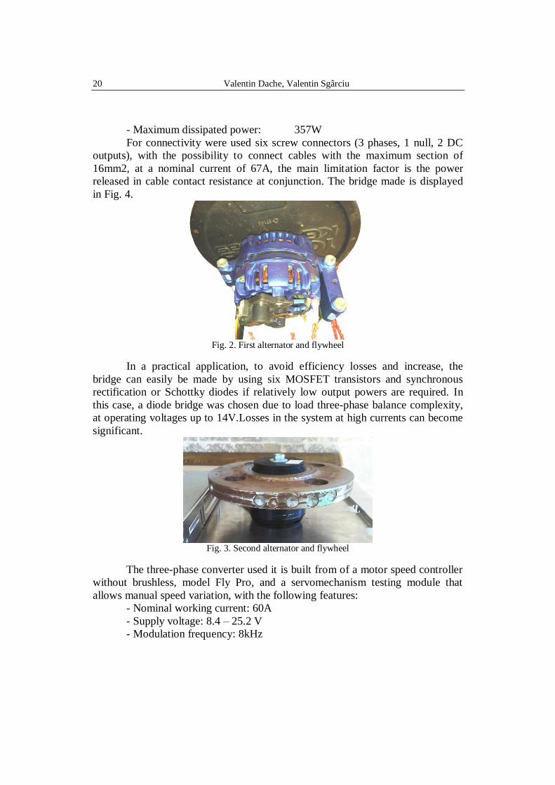
Peaktech 2790. For both studied cases, AC machines were studied because of the
contact wearing that would become a problem in long-term use with DC
machines. For motor / generator purpose, an car alternator was used for the first
case (Fig. 2). This is a three-phase synchronous machine with a maximum input /
output current of 100A, a 3Ω excitation winding resistance, a stator winding of
0.0195Ω (the windings are connected to the star) and a nominal working voltage
of 12V. In order to be able to control the excitation currentindependently and
separately, the rotary contacts of the rotor were directly connected, without using
the built-in voltage regulator. Also, the built-in rectifier diodes were disconnected

Low cost energy storage, flywheel systems, developed for intelligent building applications (...) 19
to allow access to the three-phase windings of the stator, and for the rectification
an external diode bridge was used.
Fig. 1. Functional diagram of the flywheel energy storage system
As a flywheel, a 10 kg training weight and 30cm diameter was used.
Given been intricate geometry, the steering wheel balance adjustment was
performed manually, and total inertial moment was determined experimentally.
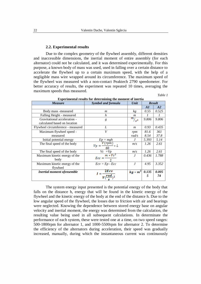
The second synchronous machine used is a brushless motor type U7-V2.0
KV420 (manufactured by T-Motor, Germany), with permanent magnets, with a
maximum current of 40A, a stator winding resistance of 0.0165Ω (the windings
are connected in a wye configuration), a maximum working voltage of 25V, a
maximum power of 1180W and a speed ratio of 420 rpm/volt (Fig. 3)
The flywheel, with a mass of approximately 1kg, was adapted to the
purpose of a steel flange. The balancing was done manually, and the adjustment
with the alternator shaft was made using an ABS adapter.
The rectifier bridge was built using six high-power IXYS DSEI120-06A
with the following characteristics:
- Maximum reverse voltage: 600V
- Nominal current: 126A
- Maximum current (pulse): 540A
- Recovery time: 35ns
- Direct polarization voltage drop: 1.12V
20 Valentin Dache, Valentin Sgârciu
- Maximum dissipated power: 357W
For connectivity were used six screw connectors (3 phases, 1 null, 2 DC
outputs), with the possibility to connect cables with the maximum section of
16mm2, at a nominal current of 67A, the main limitation factor is the power
released in cable contact resistance at conjunction. The bridge made is displayed
in Fig. 4.
Fig. 2. First alternator and flywheel
In a practical application, to avoid efficiency losses and increase, the
bridge can easily be made by using six MOSFET transistors and synchronous
rectification or Schottky diodes if relatively low output powers are required. In
this case, a diode bridge was chosen due to load three-phase balance complexity,
at operating voltages up to 14V.Losses in the system at high currents can become
significant.
Fig. 3. Second alternator and flywheel
The three-phase converter used it is built from of a motor speed controller
without brushless, model Fly Pro, and a servomechanism testing module that
allows manual speed variation, with the following features:
- Nominal working current: 60A
- Supply voltage: 8.4 – 25.2 V
- Modulation frequency: 8kHz

Low cost energy storage, flywheel systems, developed for intelligent building applications (...) 21
The manual rotation speed variation was used for all experimental
determinations. To determinate flywheel acceleration, it was tried to maintain a
constant acceleration. In order to disconnect the generator windings from the
three-phase converter during measurement, it have used three relays, supplied
separately, (common used use in cars), type HFV7 / 012-HT, with the following
specification:
- Control voltage: 12V (7.2V – 18V)
- Coil resistance: 90Ω
- Contact configuration: SPST-NO
- Maximum contact current: 70A
- Contact material: AgSnO2
- Maximum contact voltage: 50V
Fig. 4. The rectifier bridge
Fig. 5. The 3-phase converter
The power supply used for both alternators is a MeanWell RSP-320
switching voltage source that supplies 13.6V (adjustable) voltage at 24A
maximum current. To provide the excitation current of alternator 1, a separate
current source was used, and the required power was not included in the
efficiency calculations.
22 Valentin Dache, Valentin Sgârciu
2.2. Experimental results
Due to the complex geometry of the flywheel assembly, different densities
and inaccessible dimensions, the inertial moment of entire assembly (for each
alternator) could not be calculated, and it was determined experimentally. For this
purpose, a known body of mass was used, used in falling over a certain distance to
accelerate the flywheel up to a certain maximum speed, with the help of a
negligible mass wire wrapped around its circumference. The maximum speed of
the flywheel was measured with a non-contact Peaktech 2790 speedometer. For
better accuracy of results, the experiment was repeated 10 times, averaging the
maximum speeds thus measured. Table 1
Experimental results for determining the moment of inertia
Measure Symbol and formula Unit Result
A1 A2
Body mass -measured m kg 0.55 0.525
Falling Height - measured h m 1 1
Gravitational acceleration -
calculated based on location
g
9.806 9.806
Flywheel circumference - measured L m 0.93 0.435
Maximum flywheel speed -
measured
V rpm
rad/s
81.6
8.54
361
37.8
Initial potential energy Ep = mgh J 5.393 5.14
The final speed of the body
m/s 1.26 2.61
The final speed of the body Vc =Vp m/s 1.26 2.61
Maximum kinetic energy of the
body
J 0.436 1.788
Maximum kinetic energy of the
flywheel
Ecv = Ep - Ecc J 4.95 3.352
Inertial moment ofensemble
0.135
5
0.005
74
The system energy input presented is the potential energy of the body that
falls on the distance h, energy that will be found in the kinetic energy of the
flywheel and the kinetic energy of the body at the end of the distance h. Due to the
low angular speed of the flywheel, the losses due to friction with air and bearings
were neglected. Knowing the dependence between stored energy base on angular
velocity and inertial moment, the energy was determined from the calculation, the
resulting value being used in all subsequent calculations. In determinate the
performance of each system, these were tested one at a time, on two speed ranges:
500-1800rpm for alternator 1, and 1000-5500rpm for alternator 2. To determine
the efficiency of the alternators during acceleration, their speed was gradually
increased, manually, during which the instantaneous current was continuously

Low cost energy storage, flywheel systems, developed for intelligent building applications (...) 23
measured and recorded using Siglent SDS 1104X-E oscilloscope, at 50µs
intervals. The data obtained were processed to obtain the average current and the
RMS current. Due to the rapid acceleration, the mechanical losses were
substantially lower than in the case of generator operation. The results for both
alternators are summarized in Table 2. Table 2
Experimental results for determining the drive efficiency for the two alternators
Alternator 1 Alternator 2 Unit
Power supply voltage 13.62 13.62 V
Acceleration time 19.07 18.35 s
Measured current (medium) 10.24 3.98 A
Measured current (RMS) 10.90 4.16 A
Winding resistance 0.041 0.071 Ω, L-L
Today drive energy 2660.67 993.94 J
Copper losses 4.82 1.23 J
Winding losses, air, bearings, driver,
recovery circuit
434.40 72.45 J
Calculated mechanical energy 500-1800 rpm 1000-5500 rpm
2221.45 920.26 J
Drive efficiency 83.49 92.59 %
It can be observed that alternator 2 have an higher efficiency, mainly due
to lower copper losses, more efficient bearings and optimized geometry, although
the final speed was substantially higher.
a) Experimental results for Alternator 1
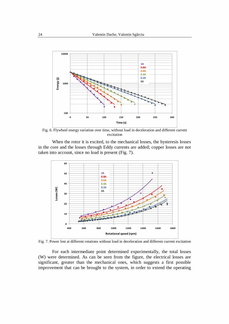
In order to determine the energy losses of the system in the absence of the
load current, a series of experimental determinations were carried out, in which
the flywheel was brought at a speed of 1800 rpm, after which it was left free up to
500 rpm without any consumer logged in. During the flywheel slowdown, its
speed was measured every 10 seconds.
The determinations were made first without any excitation current, and
then with excitation currents up to 1A, from 0.2 to 0.2A, according to Fig. 6. In
the absence of the excitation current and neglecting the remaining rotor
magnetization rotor, the only losses are the mechanical ones: friction of the
flywheel with the air, mechanical work of the internal fan incorporated in the
generator, friction in the bearings and friction of the brushes on the rotor.
24 Valentin Dache, Valentin Sgârciu
100
1000
10000
0 50 100 150 200 250 300
Ene
rgy
(j)
Time (s)
1A0.8A0.6A0.4A0.2A0A
Fig. 6. Flywheel energy variation over time, without load in deceleration and different current
excitation
When the rotor it is excited, to the mechanical losses, the hysteresis losses
in the core and the losses through Eddy currents are added; copper losses are not
taken into account, since no load is present (Fig. 7).
0
10
20
30
40
50
60
400 600 800 1000 1200 1400 1600 1800
Loss
es
(W)
Rotational speed (rpm)
1A0.8A0.6A0.4A0.2A0A
Fig. 7. Power lost at different rotations without load in deceleration and different current excitation
For each intermediate point determined experimentally, the total losses
(W) were determined. As can be seen from the figure, the electrical losses are
significant, greater than the mechanical ones, which suggests a first possible
improvement that can be brought to the system, in order to extend the operating
Low cost energy storage, flywheel systems, developed for intelligent building applications (...) 25
time to several hours. This would consist of the use of a generator with a high
performancetole pack, to avoid Eddy currents as much as possible. A second
improvement would be either placing the assembly in a vacuum chamber or
optimizing the flywheel surface in such a way as to minimize friction with the air.
A final improvement is the elimination of fan built into the generator.
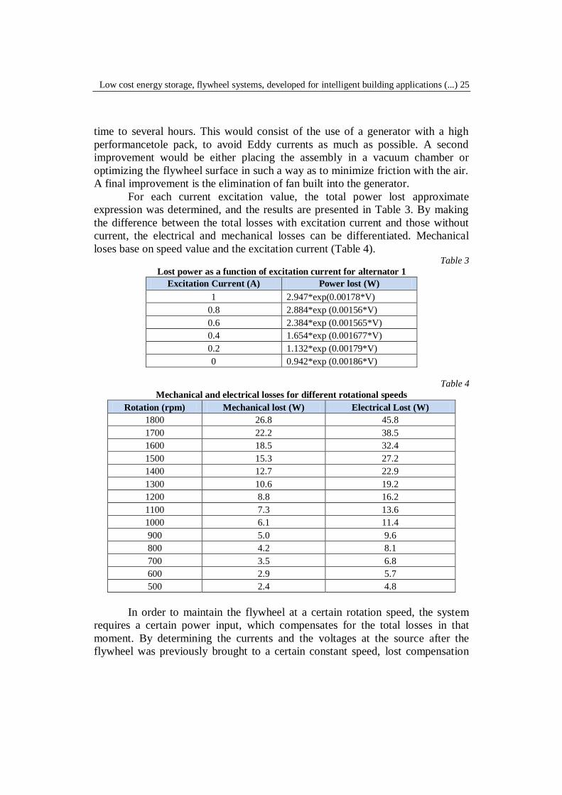
For each current excitation value, the total power lost approximate
expression was determined, and the results are presented in Table 3. By making
the difference between the total losses with excitation current and those without
current, the electrical and mechanical losses can be differentiated. Mechanical
loses base on speed value and the excitation current (Table 4). Table 3
Lost power as a function of excitation current for alternator 1
Excitation Current (A) Power lost (W)
1 2.947*exp(0.00178*V)
0.8 2.884*exp (0.00156*V)
0.6 2.384*exp (0.001565*V)
0.4 1.654*exp (0.001677*V)
0.2 1.132*exp (0.00179*V)
0 0.942*exp (0.00186*V)
Table 4
Mechanical and electrical losses for different rotational speeds
Rotation (rpm) Mechanical lost (W) Electrical Lost (W)
1800 26.8 45.8
1700 22.2 38.5
1600 18.5 32.4
1500 15.3 27.2
1400 12.7 22.9
1300 10.6 19.2
1200 8.8 16.2
1100 7.3 13.6
1000 6.1 11.4
900 5.0 9.6
800 4.2 8.1
700 3.5 6.8
600 2.9 5.7
500 2.4 4.8
In order to maintain the flywheel at a certain rotation speed, the system
requires a certain power input, which compensates for the total losses in that
moment. By determining the currents and the voltages at the source after the
flywheel was previously brought to a certain constant speed, lost compensation
26 Valentin Dache, Valentin Sgârciu
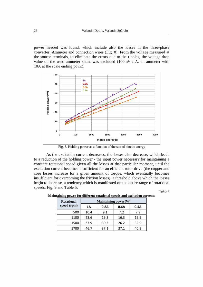
power needed was found, which include also the losses in the three-phase
converter, Ammeter and connection wires (Fig. 8). From the voltage measured at
the source terminals, to eliminate the errors due to the ripples, the voltage drop
value on the used ammeter shunt was excluded (100mV / A, an ammeter with
10A at the scale ending point).
0
10
20
30
40
50
60
0 500 1000 1500 2000 2500 3000
Ho
ldin
g p
ow
er (W
)
Stored energy (j)
1A0.8A0.6A0.4A
1A0.8A0.6A0.4A
Fig. 8. Holding power as a function of the stored kinetic energy
As the excitation current decreases, the losses also decrease, which leads
to a reduction of the holding power - the input power necessary for maintaining a
constant rotational speed given all the losses at that particular moment, until the
excitation current becomes insufficient for an efficient rotor drive (the copper and
core losses increase for a given amount of torque, which eventually becomes
insufficient for overcoming the friction losses), a threshold above which the losses
begin to increase, a tendency which is manifested on the entire range of rotational
speeds. Fig. 9 and Table 5: Table 5
Maintaining power for different rotational speeds and excitation currents
Rotational
speed (rpm) Maintaining power(W)
1A 0.8A 0.6A 0.4A
500 10.4 9.1 7.2 7.9
1100 23.6 19.3 16.3 19.9
1500 37.9 30.3 26.2 32.9
1700 46.7 37.1 37.1 40.9
Low cost energy storage, flywheel systems, developed for intelligent building applications (...) 27
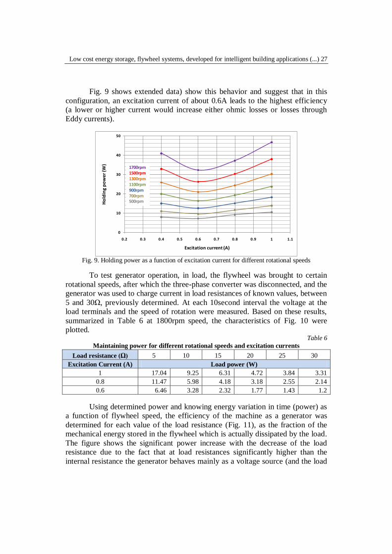
Fig. 9 shows extended data) show this behavior and suggest that in this
configuration, an excitation current of about 0.6A leads to the highest efficiency
(a lower or higher current would increase either ohmic losses or losses through
Eddy currents).
0
10
20
30
40
50
0.2 0.3 0.4 0.5 0.6 0.7 0.8 0.9 1 1.1
Ho
ldin
g p
ow
er
(W)
Excitation current (A)
1700rpm1500rpm1300rpm1100rpm900rpm700rpm500rpm
Fig. 9. Holding power as a function of excitation current for different rotational speeds
To test generator operation, in load, the flywheel was brought to certain
rotational speeds, after which the three-phase converter was disconnected, and the
generator was used to charge current in load resistances of known values, between
5 and 30Ω, previously determined. At each 10second interval the voltage at the
load terminals and the speed of rotation were measured. Based on these results,
summarized in Table 6 at 1800rpm speed, the characteristics of Fig. 10 were
plotted. Table 6
Maintaining power for different rotational speeds and excitation currents
Load resistance (Ω) 5 10 15 20 25 30
Excitation Current (A) Load power (W)
1 17.04 9.25 6.31 4.72 3.84 3.31
0.8 11.47 5.98 4.18 3.18 2.55 2.14
0.6 6.46 3.28 2.32 1.77 1.43 1.2
Using determined power and knowing energy variation in time (power) as
a function of flywheel speed, the efficiency of the machine as a generator was
determined for each value of the load resistance (Fig. 11), as the fraction of the
mechanical energy stored in the flywheel which is actually dissipated by the load.
The figure shows the significant power increase with the decrease of the load
resistance due to the fact that at load resistances significantly higher than the
internal resistance the generator behaves mainly as a voltage source (and the load
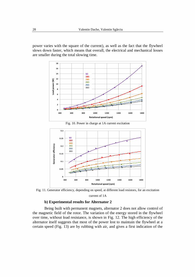
28 Valentin Dache, Valentin Sgârciu
power varies with the square of the current), as well as the fact that the flywheel
slows down faster, which means that overall, the electrical and mechanical losses
are smaller during the total slowing time.
0
2
4
6
8
10
12
14
16
18
400 600 800 1000 1200 1400 1600 1800
Loa
d p
ow
er
(W)
Rotational speed (rpm)
5Ω10Ω15Ω20Ω25Ω30Ω
Fig. 10. Power in charge at 1A current excitation
0
0.05
0.1
0.15
0.2
0.25
0.3
400 600 800 1000 1200 1400 1600 1800
Ge
ne
rato
r e
ffic
ien
cy
Rotational speed (rpm)
5Ω10Ω15Ω20Ω25Ω30Ω
Fig. 11. Generator efficiency, depending on speed, at different load resistors, for an excitation
current of 1A
b) Experimental results for Alternator 2
Being built with permanent magnets, alternator 2 does not allow control of
the magnetic field of the rotor. The variation of the energy stored in the flywheel
over time, without load resistance, is shown in Fig. 12. The high efficiency of the
alternator itself suggests that most of the power lost to maintain the flywheel at a
certain speed (Fig. 13) are by rubbing with air, and gives a first indication of the
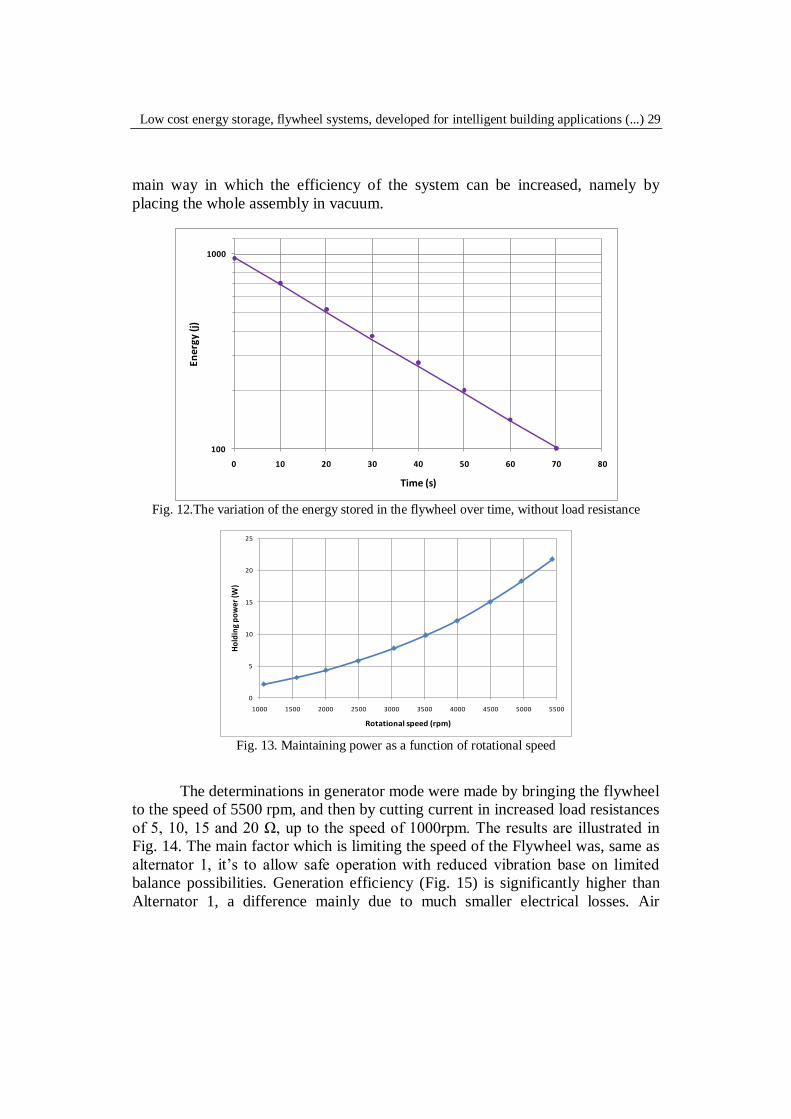
Low cost energy storage, flywheel systems, developed for intelligent building applications (...) 29
main way in which the efficiency of the system can be increased, namely by
placing the whole assembly in vacuum.
100
1000
0 10 20 30 40 50 60 70 80
En
erg
y (j
)
Time (s)
Fig. 12.The variation of the energy stored in the flywheel over time, without load resistance
0
5
10
15
20
25
1000 1500 2000 2500 3000 3500 4000 4500 5000 5500
Ho
ldin
g p
ow
er (W
)
Rotational speed (rpm)
Fig. 13. Maintaining power as a function of rotational speed
The determinations in generator mode were made by bringing the flywheel
to the speed of 5500 rpm, and then by cutting current in increased load resistances
of 5, 10, 15 and 20 Ω, up to the speed of 1000rpm. The results are illustrated in
Fig. 14. The main factor which is limiting the speed of the Flywheel was, same as
alternator 1, it’s to allow safe operation with reduced vibration base on limited
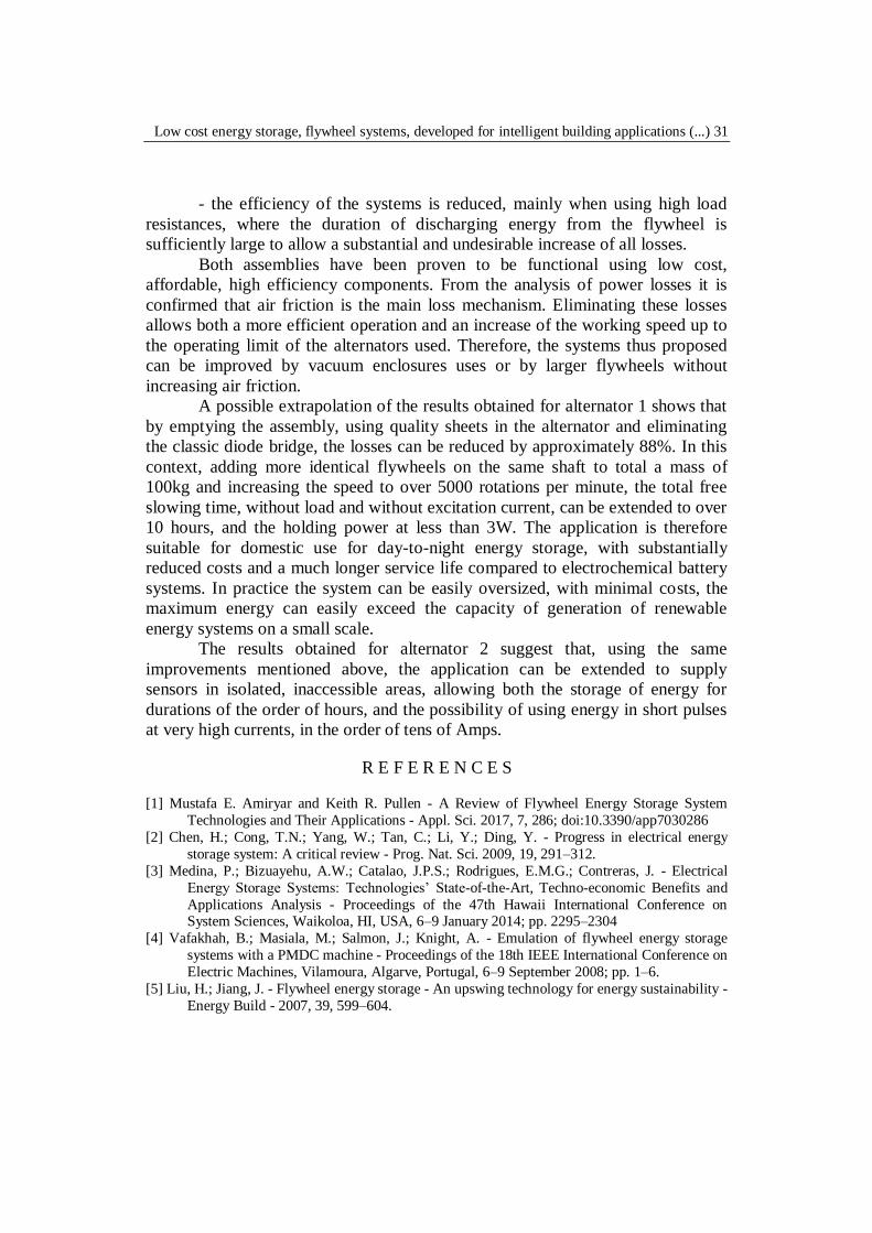
balance possibilities. Generation efficiency (Fig. 15) is significantly higher than
Alternator 1, a difference mainly due to much smaller electrical losses. Air
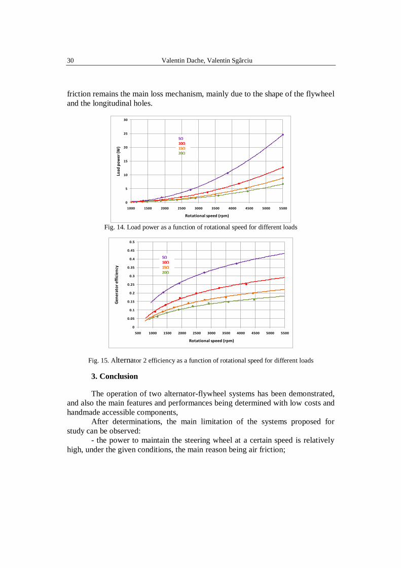
30 Valentin Dache, Valentin Sgârciu
friction remains the main loss mechanism, mainly due to the shape of the flywheel
and the longitudinal holes.
0
5
10
15
20
25
30
1000 1500 2000 2500 3000 3500 4000 4500 5000 5500
Load
po
wer
(W)
Rotational speed (rpm)
5Ω10Ω15Ω20Ω
Fig. 14. Load power as a function of rotational speed for different loads
0
0.05
0.1
0.15
0.2
0.25
0.3
0.35
0.4
0.45
0.5
500 1000 1500 2000 2500 3000 3500 4000 4500 5000 5500
Gen
erat
or
effi
cien
cy
Rotational speed (rpm)
5Ω10Ω15Ω20Ω
Fig. 15. Alternator 2 efficiency as a function of rotational speed for different loads
3. Conclusion
The operation of two alternator-flywheel systems has been demonstrated,
and also the main features and performances being determined with low costs and
handmade accessible components,
After determinations, the main limitation of the systems proposed for
study can be observed:
- the power to maintain the steering wheel at a certain speed is relatively
high, under the given conditions, the main reason being air friction;
Low cost energy storage, flywheel systems, developed for intelligent building applications (...) 31
- the efficiency of the systems is reduced, mainly when using high load
resistances, where the duration of discharging energy from the flywheel is
sufficiently large to allow a substantial and undesirable increase of all losses.
Both assemblies have been proven to be functional using low cost,
affordable, high efficiency components. From the analysis of power losses it is
confirmed that air friction is the main loss mechanism. Eliminating these losses
allows both a more efficient operation and an increase of the working speed up to
the operating limit of the alternators used. Therefore, the systems thus proposed
can be improved by vacuum enclosures uses or by larger flywheels without
increasing air friction.
A possible extrapolation of the results obtained for alternator 1 shows that
by emptying the assembly, using quality sheets in the alternator and eliminating
the classic diode bridge, the losses can be reduced by approximately 88%. In this
context, adding more identical flywheels on the same shaft to total a mass of
100kg and increasing the speed to over 5000 rotations per minute, the total free
slowing time, without load and without excitation current, can be extended to over
10 hours, and the holding power at less than 3W. The application is therefore
suitable for domestic use for day-to-night energy storage, with substantially
reduced costs and a much longer service life compared to electrochemical battery
systems. In practice the system can be easily oversized, with minimal costs, the
maximum energy can easily exceed the capacity of generation of renewable
energy systems on a small scale.
The results obtained for alternator 2 suggest that, using the same
improvements mentioned above, the application can be extended to supply
sensors in isolated, inaccessible areas, allowing both the storage of energy for
durations of the order of hours, and the possibility of using energy in short pulses
at very high currents, in the order of tens of Amps.
R E F E R E N C E S
[1] Mustafa E. Amiryar and Keith R. Pullen - A Review of Flywheel Energy Storage System
Technologies and Their Applications - Appl. Sci. 2017, 7, 286; doi:10.3390/app7030286
[2] Chen, H.; Cong, T.N.; Yang, W.; Tan, C.; Li, Y.; Ding, Y. - Progress in electrical energy
storage system: A critical review - Prog. Nat. Sci. 2009, 19, 291–312.
[3] Medina, P.; Bizuayehu, A.W.; Catalao, J.P.S.; Rodrigues, E.M.G.; Contreras, J. - Electrical
Energy Storage Systems: Technologies’ State-of-the-Art, Techno-economic Benefits and
Applications Analysis - Proceedings of the 47th Hawaii International Conference on System Sciences, Waikoloa, HI, USA, 6–9 January 2014; pp. 2295–2304
[4] Vafakhah, B.; Masiala, M.; Salmon, J.; Knight, A. - Emulation of flywheel energy storage
systems with a PMDC machine - Proceedings of the 18th IEEE International Conference on
Electric Machines, Vilamoura, Algarve, Portugal, 6–9 September 2008; pp. 1–6.
[5] Liu, H.; Jiang, J. - Flywheel energy storage - An upswing technology for energy sustainability -
Energy Build - 2007, 39, 599–604.
32 Valentin Dache, Valentin Sgârciu
[6] Hebner, R.; Beno, J.; Walls, A. - Flywheel batteries come around again - IEEE Spectr. 2002,
39, 46–51
[7] Prodromidis, G., and Coutelieris, F. - Experimental and Theoretical Investigation of Flywheel -
Based Energy Storage in Off-Grid Power Plants Using Renewables - Journal of Energy
Engineering, 142(1)
[8] Bolund, B.; Bernhoff, H.; Leijon, M. - Flywheel energy and power storage systems - Renew.
Sustain. Energy Rev. 2007, 11, 235–258
[9] Sebastián, R.; Alzola, R.P. - Flywheel energy storage systems: Review and simulation for an
isolated wind power system. - Renew. Sustain. Energy Rev. 2012, 16, 6803–6813. [10] Emadi, A.; Nasiri, A.; Bekiarov, S.B. - Uninterruptable Power Supplies and Active Filters -
Illinois Institute of Technology: Chicago, IL, USA; CRC Press: Washington, DC, USA,
2005
[11] DOE/EE. Flywheel Energy Storage. - An Alternative to Batteries for Uninterruptible Power
Sypply Systems - U.S Department of Energy (DOE), Energy Efficiency and Renewable
Energy: Washington, DC, USA, 2003.
[12] Bender, D. - Flywheels - Sandia Report; Sandia National Laboratories: Albuquerque, ME,
USA, 2015
[13] Sabihuddin, S.; Kiprakis, A.; Mueller, M. - A Numerical and Graphical Review of Energy
Storage Technologies. - Energies 2014, 8, 172–216
[14] Farhadi, M.; Member, S.; Mohammed, O. - Energy Storage Technologies for High-Power Applications. - IEEE Trans. Ind. Appl. 2016, 52, 1953–1961
[15] Daoud, M.I.; Abdel-Khalik, A.S.; Massoud, A.; Ahmed, S.; Abbasy, N.H. - On The
Development of Flywheel Storage Systems for Power System Applications: A Survey. -
Proceedings of the 20th International Conference on Electrical Machines ( ICEM),
Marseille, France, 2–5 September 2012; pp. 2119–2125
[16] Kenny, B.H.; Kascak, P.E.; Jansen, R.; Dever, T. - Control of a High Speed Flywheel System
for Energy Storage in Space Applications. - IEEE Trans. Ind. Appl. 2005, 41, 1029–1038
[17] Pena-Alzola, R.; Sebastián, R.; Quesada, J.; Colmenar, - A. Review of Flywheel based
Energy Storage Systems. - Proceedings of the 2011 International Conference on Power
Engineering, Energy and Electrical Drives, Malaga, Spain, 11–13 May 2011.
[18] Yu, Y.; Wang, Y.; Sun, F. - The Latest Development of the Motor/Generator for the Flywheel Energy Storage System. - Proceedings of the 2011 International Conference on
Mechatronic Science, Electric Engineering and Computer (MEC), Jilin, China, 19–22
August 2011; pp. 1228–1232.
[19] Awadallah, M.A.; Venkatesh, B. - Energy Storage in Flywheels: An Overview - Le stockage
dénergie dans les volants: Apercu. Can. J. Electr. Comput. Eng. 2015, 38, 183–193