Fixed Access Network Sharing (FANS) - Broadband Forum
18
Fixed Access Network Sharing (FANS) MARKETING REPORT MR-453
-
Upload
khangminh22 -
Category
Documents
-
view
4 -
download
0
Transcript of Fixed Access Network Sharing (FANS) - Broadband Forum
Fixed Access Network Sharing (FANS)
MARKETING REPORT
MR-453
Fixed Access Network Sharing (FANS)Technical Overview
©Broadband Forum. All rights reserved.
Abstract - Deep fiber deployments for ultra-fast
broadband are technically challenging. Broadband
Forum is defining Fixed Access Network Sharing
(FANS), to offer a highly enhanced form of virtual
unbundling of broadband access networks,
enabling cost sharing and enhancing the dynamics
of a competitive landscape. FANS automates and
harmonizes data, control, and management interfaces
among wholesale Infrastructure Providers (InPs) and
retail Virtual Network Operators (VNOs). Standardized
FANS interfaces can decrease operational expense
(OpEx) while increasing customer satisfaction. FANS
logically partitions and isolates network resources
shared among the VNOs, and such sharing can split
the cost of network upgrades among several entities.
FANS works with virtualization, where control-plane
functions are migrated from dedicated network
equipment into software running on commodity
hardware, with FANS providing Network as a Service
(NaaS). This paper describes emerging Broadband
Forum standards supporting FANS, use cases,
FANS components, and details of the architectures
supporting FANS.
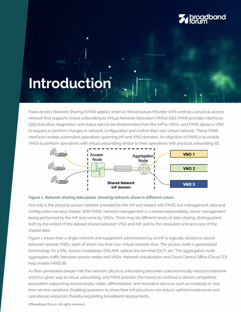
Fixed Access Network Sharing (FANS) applies when an Infrastructure Provider (InP) controls a physical access
network that supports virtual unbundling to Virtual Network Operators (VNOs) [1][2]. FANS provides interfaces
[3][5] that allow diagnostics and status data to be disseminated from the InP to VNOs, and FANS allows a VNO
to request or perform changes in network configuration and control their own virtual network. These FANS
interfaces enable automated operations spanning InP and VNO domains. An objective of FANS is to enable
VNOs to perform operations with virtual unbundling similar to their operations with physical unbundling [6].
Figure 1. Network sharing data plane, showing network slices in different colors.
Not only is the physical access network provided by the InP and shared with FANS, but management data and
configuration are also shared. With FANS, network management is a shared responsibility; some management
being performed by the InP and some by VNOs. There may be different levels of data sharing, distinguished
both by the extent of the dataset shared between VNO and InP, and by the resolution and accuracy of the
shared data.
Figure 1 shows how a single network and equipment administered by an InP is logically divided or sliced
between several VNOs, each of which has their own virtual network slice. The access node is generalized
terminology for a DSL access multiplexer (DSLAM), optical line terminal (OLT), etc. The aggregation node
aggregates traffic between access nodes and VNOs. Network virtualization and Cloud Central Office (Cloud CO)
help enable FANS [8].
As fiber penetrates deeper into the network, physical unbundling becomes uneconomically resource intensive
and thus gives way to virtual unbundling; and FANS provides the means to continue a vibrant competitive
ecosystem supporting economically viable, differentiated, and innovative services such as multicast or real-
time service variations. Enabling operators to share their infrastructure can reduce upfront investments and
operational resources; thereby expanding broadband deployments.
Introduction
©Broadband Forum. All rights reserved.
FANS in Broadband ForumThe Broadband Forum FANS [1][3] project is investigating the technical aspects associated with FANS that
involve the access network functionality, including access nodes and aggregation nodes.
BBF MR-229 [4] presents relevant Broadband Forum and Metro Ethernet Forum (MEF) specifications for next
generation broadband access networks operating in an open access environment, including architectures,
service definitions, interconnections, Quality of Service (QoS), multicast, and Ethernet Operations,
Administration, and Maintenance (OAM).
Broadband Forum DSL Data Sharing Broadband Forum TR-349 is somewhat of a precursor to FANS, with a limited scope. TR-349 [5] defines data
sharing for managing DSL. TR-349 was initiated after liaisons from the UK Network Interoperability Consultative
Committee (NICC), whose ND1518 specification [6] describes the use of data sharing between operators for
the purpose of Dynamic Spectrum Management (DSM) in DSL environments. In TR-349, DSL data sharing
architectures are described, with centralized and distributed architectures presented. High-level use cases are
defined and requirements presented for these use cases. The data and control parameters applicable to each
use case are identified, and most parameters are common to all use cases. Two types of DSL data sharing
interfaces are defined in detail: profile-level (general) and parameter level (specific). The parameter syntax is
defined in YANG data models for Gfast and for VDSL in Broadband Forum TR-355.
Broadband Forum Fixed Access Network Sharing (FANS)Architecture The Broadband Forum FANS project plans to generate several specifications, the first of which is TR-370,
FANS - Architecture and Nodal Requirements [1]. This document identifies architectures and interface points
for FANS. Both management system-based sharing (described in Section 5.1 below), and virtual access node-
based sharing (described in Section 5.2 below) are included in TR-370. The relationship of FANS and ETSI NFV,
requirements, and OAM aspects are also in TR-370.
Broadband Forum FANS Interfaces TR-386 specifies Fixed Access Network Sharing Interfaces in the Broadband Forum. TR-386 includes a system
overview describing the centralized management System, VNO management system, virtual access node,
InP port mapper, virtual switch, physical access node, and server; and defines the interfaces between these.
Specific YANG modules are referenced for the interfaces of FANS.
Further FANS specifications being considered by Broadband Forum include SDN-enabled FANS and access
network virtualization.
©Broadband Forum. All rights reserved.

Use Cases Currently bitstream or VULA, operations “interfaces” between InP and VNO are often manual. In conjunction
with appropriate business arrangements, FANS can assist in automating operations interactions between InPs
and VNOs; including fault, configuration, performance monitoring, and optimization. In particular, standardized
FANS interfaces allow efficient data exchange between all parties. This can lower OpEx costs, improve
customer satisfaction by enabling rapid response times, and increase the number of customers.
FANS can enhance competitiveness with competing broadband media. Multiple companies can share the
costs of infrastructure and its upgrades. The InP can offer enhanced product offerings to the VNOs, with
enhanced value for providing access to automated data and control interfaces. FANS use cases include:
Performance monitoring and optimization allows each VNO to have automated real-time access to
performance monitoring and fault data. This is useful for VNO network monitoring as well as repair
and troubleshooting operations. VNOs can optimize the configurations of their lines. Further, multi-line
optimizations can be performed across multiple operators’ lines by a Centralized Management system, which
can increase performance of all lines [6].
Fault correlation can be performed using shared data to correlate multiple faults across multiple lines and
multiple service providers; and this can further be used to help coordinate dispatches. For example, pooled
data across multiple VNOs and/or InP can be used to identify a fault that occurs in a single shared cable
section. A single dispatch to fix that cable section is much better than dispatching to each troubled line
separately.
Configuration can be automated, so that a VNO can rapidly turn-up service. VNOs can offer services with
different Quality of Service (QoS) levels, for example to maximize speed or stability, or to minimize delay or
power usage. Data sharing can help ensure that the lines can support the necessary QoS attributes.
Services innovation can flourish, for example VNOs can provide different types of assured services, business
class services, sponsored services, etc.
Network planning can be enhanced with network topology and capacity data. Lines in a small geographic
area should all have about the same performance, this performance data can be anonymized by a sharing
system to provide line performance projections to VNOs.
A single operator can exploit FANS within their company, segmenting the network among different operation
teams serving business customers, consumer broadband and/or mobile backhaul connectivity; thus providing
each internal business area with its own customized services, management criteria, and customer interfaces.
©Broadband Forum. All rights reserved.

FANS Components
ActorsFANS defines interfaces between an Infrastructure Provider (InP, aka wholesaler) and multiple Virtual Network
Operators (VNOs, aka retailers). The InP operates the physical network, while the VNOs interface to broadband
consumers.
The InP is responsible for deploying and managing the physical network, the InP:
• Enables physical resource slicing and carries out the slicing
• Provides an interface to the VNO for data and control
• Gets revenue from resource leasing
The VNO leases resources from the InP, and the main VNO functions are:
• Operate, control, and manage its own virtual area networks
• Run and redesign customized systems in its own virtual network, such as diagnostics and optimization
and DSM/DLM systems [10]
• Provide specific and customized service through its own area network
• Utilizes the network resources provided by the InP to provide its services
• Obtains revenue by selling services to end-users.
Centralized Management SystemFANS is generally instantiated around a Centralized Management system, as shown in Figure 2. The
Centralized Management system has Southbound interfaces to equipment, and Northbound interfaces to
VNO systems. The Centralized Management system performs certain functions, such as Authentication,
Authorization, and Accounting (AAA), and arbitration of requests for resources, data, and control. The
Centralized Management system can perform operations such as diagnostics, configuration, and optimization
for the VNO, as shown in Figure 2 for VNO A; or the external interface to the Centralized Management system
can enable these functions to be performed by a VNO itself, which is the case for VNO B in Figure 2. The
Centralized Management system may be administered by the InP, a VNO, or a third party. The Centralized
Management system itself could be provided by multiple parties either via shared or open source software, or
via APIs between proprietary systems. With shared or open source software, the cost of the software is split
across multiple parties.
The Centralized Management system implements multi-tenancy, although the functionality may be distributed
among multiple systems or locations. The Centralized Management system conceptually glues FANS together.
©Broadband Forum. All rights reserved.

Figure 2. Centralized Management System.
The components in Figure 2 are part of the infrastructure that supports FANS:
• The “hypervisor” manages authentication and authorization to use the Centralized Management
system, and manages resources. In this case, the hypervisor oversees the virtualization or slicing of the
network, rather than the compute infrastructure.
• AAA: Authentication, Authorization and Accounting. Verifies user credentials, admits requests and
limits access, maintains transactional records for billing and other purposes.
• Resources management includes assignment of network bandwidth, equipment interfaces, equipmen
computational resources, and management interface bandwidth/frequency of admissible requests.
• Southbound equipment management interfaces, which typically utilize the existing management
capabilities of network elements or their management systems.
• The Northbound sharing interface, which provides monitoring, performance, diagnostics, status, and
other state information from the network to the VNOs, and also relays or interprets control and
configuration requests from VNOs to the network. This interface should be standardized [3].
©Broadband Forum. All rights reserved.

Resources Management and SecurityResources must be assigned carefully, to control access permissions, arbitrate conflicts, ensure correct or fair
resource utilization, and guarantee reliability for the underlying physical infrastructure. Resources need to be
assigned, with data access and control separated between VNOs for the access network, equipment, and
computing infrastructure. A VNO cannot be allowed to access private data about another VNO’s customers.
Sharing of resources must be managed to ensure that resources are properly allocated among the competing
VNOs, and that any particular VNO cannot impair another VNO’s service.
Computing resources, including CPU, memory, and virtual network; can be shared between any or all of the
actors. Managing computing infrastructure resources is particularly important for virtual functions.
BackhaulThe backhaul network extends from the access node to whatever point the traffic is handed off to a VNO or
service. A VNO may wish to use its own backhaul network. In this case, data traffic may be handed-off from InP
to VNO at various reference points as shown in Figure 3, including at a Broadband Network Gateway (BNG), at
a point in the backhaul provider network, in the outside plant at a cabinet location, or at the V-interface to the
regional broadband network, or the A10 interface to service provider network(s) as defined in TR-178 [9].
Figure 3. Wholesale interface points [9]
Traffic on the backhaul broadband network needs to be segregated between different operators and services.
Backhaul segregation can use VLANs, MPLS tunnels, or VXLAN Tunnels. An interesting VLAN approach for
FANS, shown in Figure 4, is to use a new “Operator VLAN” (O-VLAN, or Q-in-Q-in-Q) tag, which is a third VLAN
tag in addition to C-VLAN and S-VLAN tags of IEEE 802.1ad Q-in-Q. This allows the VNO to manage two levels
of VLANS (S+C VLAN) for its service configurations while the InP only assigns the O-Tag for each VNO.
©Broadband Forum. All rights reserved.

Figure 4. Q-in-Q-in-Q VLAN frame detail
Another possible technique that could be used in the FANS scenario to manage the operators’ data flows is a
label-based switching technique, such as Multi-Protocol Label Switching (MPLS). VLAN tags remain but MPLS
tunnels segregate VNOs. In the downstream direction, the MPLS LSP tags are added to the Ethernet frame at
the switch at the A10 reference point, and these tags remain up to the physical access node. In the upstream
direction, the MPLS LSP tags are added to the Ethernet frame at the physical access node, and MPLS tag
information is discarded at the switch at the A10 reference point, while the S-VLAN information continues to be
forwarded in the VNO’s network.
Virtual eXtensible Local Area Network (VXLAN) can also be deployed in the FANS scenario to separate the
operator’s traffic. VXLAN is a tunneling scheme to overlay Layer 2 networks on top of Layer 3 networks. Each
VXLAN overlay network is identified through a 24-bit segment ID, which is the VXLAN Network Identifier (VNI).
This allows up to 16 million VXLAN overlay networks to coexist within the same administrative domain. In the
downstream direction, the VXLAN tag information is added to the Ethernet frame at the switch adjacent to the
A10 reference point. These information tags remain up to the physical access node. In the upstream direction,
the S-VLAN and O-VLAN tag information is added to the C-VLAN tag within the Ethernet frame at the physical
access node, and VXLAN information is discarded at the switch adjacent to the A10 reference while the
S-VLAN information continues to be forwarded in the VNO’s network. VXLAN is suited to the evolution towards
SDN and NFV technologies.
CPEThe Customer Premises Equipment (CPE), in particular the broadband termination at the customer, can be
provided by, or administered by, either the InP or the VNO. These CPE may be managed by the VNO using
Broadband Forum TR-069 (CWMP) or Broadband Forum TR-369 (USP).
FANS Architectures
Management System-Based SharingThe Centralized Management system in Figure 2 is the core of management system-based sharing. With this
sharing technique, a management system performs the network slicing at the management system level and
©Broadband Forum. All rights reserved.
not directly in the equipment itself. The management could be virtualized and hosted in the cloud or in other
operator locations. The management system supports multi-tenancy, where each VNO is a separate tenant.
Management system sharing separates the management plane from the data plane, with sharing and network
slicing between VNOs performed by the management systems. The data plane can remain unchanged, and
data-plane functions such as packet forwarding continue to be performed in the network elements. Aspects of
the control plane may also support sharing and network slicing functions to separate some control functions
between VNOs.
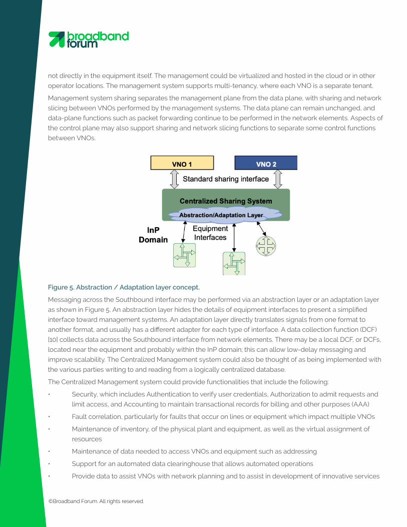
Figure 5. Abstraction / Adaptation layer concept.
Messaging across the Southbound interface may be performed via an abstraction layer or an adaptation layer
as shown in Figure 5. An abstraction layer hides the details of equipment interfaces to present a simplified
interface toward management systems. An adaptation layer directly translates signals from one format to
another format, and usually has a different adapter for each type of interface. A data collection function (DCF)
[10] collects data across the Southbound interface from network elements. There may be a local DCF, or DCFs,
located near the equipment and probably within the InP domain; this can allow low-delay messaging and
improve scalability. The Centralized Management system could also be thought of as being implemented with
the various parties writing to and reading from a logically centralized database.
The Centralized Management system could provide functionalities that include the following:
• Security, which includes Authentication to verify user credentials, Authorization to admit requests and
limit access, and Accounting to maintain transactional records for billing and other purposes (AAA)
• Fault correlation, particularly for faults that occur on lines or equipment which impact multiple VNOs
• Maintenance of inventory, of the physical plant and equipment, as well as the virtual assignment of
resources
• Maintenance of data needed to access VNOs and equipment such as addressing
• Support for an automated data clearinghouse that allows automated operations
• Provide data to assist VNOs with network planning and to assist in development of innovative services
©Broadband Forum. All rights reserved.

and differentiated services
• Multi-line optimization across multiple VNOs
Management system sharing allows a VNO to choose to perform operations such as:
• Services provisioning
• Fault and performance management
• Configuration of the network elements
• Testing and gathering of diagnostic data
• Line optimization
• Call center operations to answer trouble calls
Unlike virtual node sharing, management system-based sharing can be implemented with currently deployed
equipment.
Virtual Node SharingVirtual node sharing is based on equipment slicing. Virtual node sharing is performed within equipment,
including access nodes, aggregation nodes, and virtual port mappers. This may require the equipment
to host a common execution environment for sharing, such as a segmented space running a version of
Linux. A hypervisor controls lifecycle and resources of virtual machines (VMs). Equipment slicing is a sort of
virtualization that allows interchangeable functions to be hosted in equipment similar to the way a data center
can host Virtual Network Functions (VNF).
Figure 6. Deployment scenarios for Virtual Access Node Functions
The virtual access node model performs equipment slicing on physical access nodes to abstract them into
multiple virtual access nodes, where each VNO accesses a logically separate virtual access node. Separate
access node functions can be sliced independently. As shown in the bottom half of Figure 6, some functions
may also be fully virtualized and hosted on cloud virtualization infrastructure, where Virtual Network Functions
(VNFs) implement some of the functions that traditionally reside in the access node or the BNG. A virtual
access node element represents the whole set of characteristics of a physical access node.
©Broadband Forum. All rights reserved.

A Centralized Management system is still present and is involved as part of virtual node sharing. The
Centralized Management system as described in Section 4.2 performs orchestration, and monitors and scales
virtualized and physical network resources.
Other network nodes can similarly use virtual node sharing, including virtual aggregation nodes (e.g., Ethernet
Aggregation Switch, MPLS router, SDN switch) [1].
The port mapper concept is part of virtual node sharing. A port mapper maps a disparate set of physical
ports into a logical set of ports assigned to each VNO. The port mapper is a virtual entity used to map logical
ports over the host physical ports. The virtual ports are identified through virtual port IDs. For example, as
shown in Figure 7, an access node may assign each user-facing port to a separate VNO, and then the VNO
references the port through its virtual port ID. The port mapper may be combined with a virtual switch, which
can intelligently forward data by inspecting packets before passing them on, assuring traffic isolation. The port
mapper moreover facilitates the customer migration as the end customer maintains the same physical ID and
only changes the virtual port ID when moving from one operator to another.
Figure 7. Port mapper [1].
FANS and VirtualizationVirtualization disaggregates network equipment functions, so some functions can move to being hosted
on cloud platforms/data centers, as described in the Broadband Forum Cloud CO project [8]. FANS can
be considered a use case of Cloud CO. Virtualization generally follows the architecture of the European
©Broadband Forum. All rights reserved.
Telecommunications Standards Institute (ETSI) Industry Specification Group (ISG) for Network Functions
Virtualization (NFV). Here, the NFV Infrastructure (NFVI) runs a system such as OpenStack, CloudStack,
Containers, etc., and the VNFs run on this infrastructure. Management and Orchestration (MANO) are
controlled by a system such as Open Platform NFV (OPNFV), Open Source MANO (OSM), Open Orchestrator
(Open-O), Open Network Automation Platform (ONAP), Central Office Re-architected as a Datacenter (CORD), a
proprietary system, etc.
FANS with full virtualization can extend management system-based sharing to include control functions and
other VNFs and Network Services (NS); this can be thought of as fixed access Network as a Service (NaaS).
Here, the NFVI and MANO are to support multi-tenancy, where each VNO is a tenant, and they are logically
separated. For a given function, each VNO would have separate VNFs, NSs, or Virtual Machines (VMs), thereby
using the underlying NFV components to allocate resources, ensure privacy, perform lifecycle management,
etc.
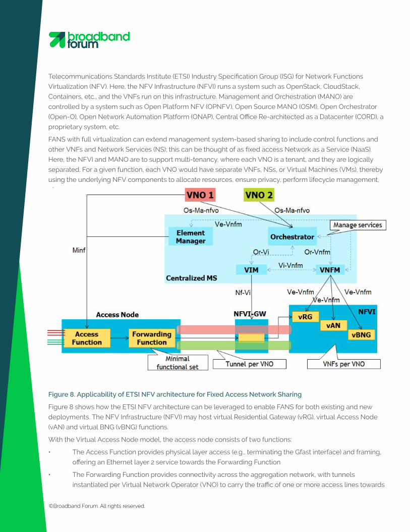
Figure 8. Applicability of ETSI NFV architecture for Fixed Access Network Sharing
Figure 8 shows how the ETSI NFV architecture can be leveraged to enable FANS for both existing and new
deployments. The NFV Infrastructure (NFVI) may host virtual Residential Gateway (vRG), virtual Access Node
(vAN) and virtual BNG (vBNG) functions.
With the Virtual Access Node model, the access node consists of two functions:
• The Access Function provides physical layer access (e.g., terminating the Gfast interface) and framing,
offering an Ethernet layer 2 service towards the Forwarding Function
• The Forwarding Function provides connectivity across the aggregation network, with tunnels
instantiated per Virtual Network Operator (VNO) to carry the traffic of one or more access lines towards
©Broadband Forum. All rights reserved.
the vAN in the NFVI.
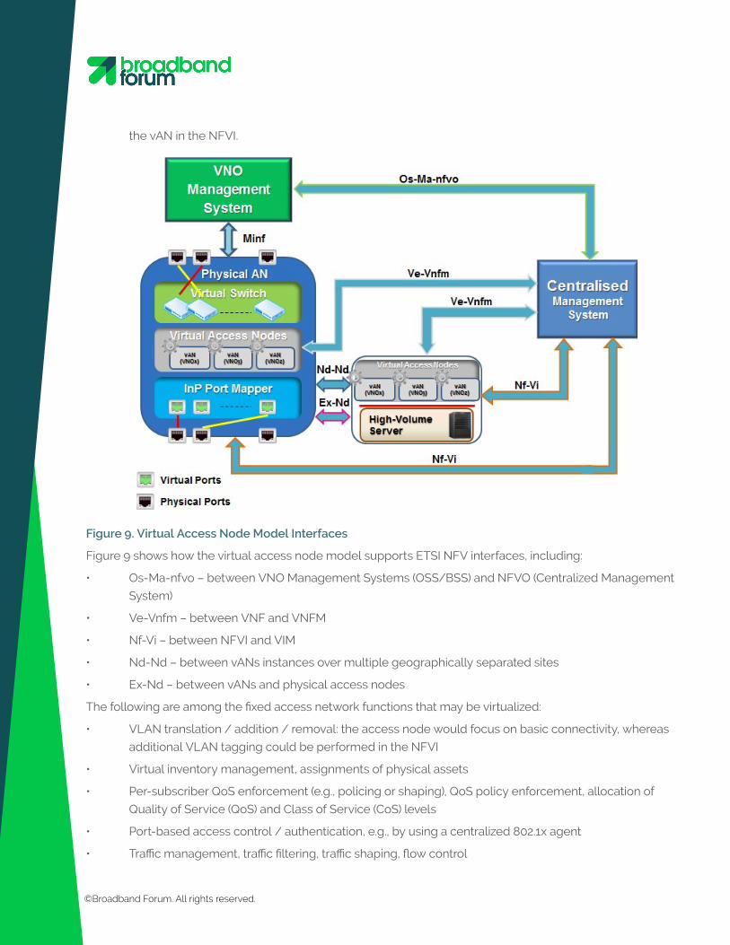
Figure 9. Virtual Access Node Model Interfaces
Figure 9 shows how the virtual access node model supports ETSI NFV interfaces, including:
• Os-Ma-nfvo – between VNO Management Systems (OSS/BSS) and NFVO (Centralized Management
System)
• Ve-Vnfm – between VNF and VNFM
• Nf-Vi – between NFVI and VIM
• Nd-Nd – between vANs instances over multiple geographically separated sites
• Ex-Nd – between vANs and physical access nodes
The following are among the fixed access network functions that may be virtualized:
• VLAN translation / addition / removal: the access node would focus on basic connectivity, whereas
additional VLAN tagging could be performed in the NFVI
• Virtual inventory management, assignments of physical assets
• Per-subscriber QoS enforcement (e.g., policing or shaping), QoS policy enforcement, allocation of
Quality of Service (QoS) and Class of Service (CoS) levels
• Port-based access control / authentication, e.g., by using a centralized 802.1x agent
• Traffic management, traffic filtering, traffic shaping, flow control
©Broadband Forum. All rights reserved.
©The Broadband Forum. All rights reserved.
• Forwarding, traffic steering, load balancing, SDN control
• Application awareness, deep packet inspection (DPI), services-aware networking
• Virtual gateway functions, residential and business
• Control and configuration. Each VNO controls and configures their own virtual access node dataset of
configuration objects
• Diagnostics and state information. Each VNO accesses virtual functions providing test, diagnostic,
performance, and status information
• Dynamic Rate Allocation (DRA): this function controls traffic scheduling, such as dynamically varying
the Gfast asymmetry ratio, or configuring PON Dynamic Bandwidth Allocation (DBA)
• Dynamic resource assignment; e.g., access and backhaul bandwidth assignment
• Dynamic Spectrum Management (DSM) and Dynamic Line Management (DLM) [10]
• Power Control Entity (PCE), cross-layer low-power mode control, for Gfast: there are a number of
thresholds and other settings that can be varied to configure low-power mode on individual
transceivers and these settings and primitives can be determined in a virtualized power control entity
and communicated to the transceivers
• VDSL/Gfast vectoring control and management [7]: virtualized functions can control part of the
vectoring configuration, and could even calculate vectoring coefficients
Ultra-fast fiber-deep broadband deployments are changing the competitive landscape. Sharing network
resources and management interfaces will allow virtual unbundling to be economically and operationally
efficient, and enable vibrant competition based upon differentiation of offered services between providers.
FANS extends virtual unbundling to unbundled management and control functions, enabling network
sharing and data sharing. FANS opens up management and control interfaces such that VNOs can perform
the same operations as they would with physical unbundling where they own and operate their own
network elements.
Standardized interfaces and a central management system are keys to enabling FANS in the near-term.
Longer-term, virtual nodes, and full virtualization will all feed into enabling FANS. Resource control, AAA,
security and configuration control must be carefully administered with FANS to ensure privacy and avoid
harm to the network.
FANS offers many benefits, both to InPs and VNOs:
• Automated interfaces lower operational costs relative to manual interfaces, both for the InP and the
VNOs.
• Fault correlation across multiple operators’ lines is enabled, again lowering operations costs.
• Multi-line, multi-operator, optimizations are enabled, which increases performance of all lines.
• Multiple companies can share the costs of network upgrades to ultra-fast broadband.
• Enables enhanced service levels, services differentiation, and innovation.
• The InP can offer FANS as an enhanced service to the VNOs.
• The VNOs can offer enhanced services to the broadband customers, e.g., enterprise.
Summary
©Broadband Forum. All rights reserved.

References and AbbreviationsThe following is a limited list of references and abbreviations. Please download TR-370 for a complete list.
References[1] Broadband Forum TR-370, Fixed Access Network Sharing - Architecture and Nodal Requirements,
2017.
[2] Broadband Forum MR-432, Fixed Access Network Sharing – Business Overview, 2018.
[3] Broadband Forum TR-386, FANS Access Network Sharing Interfaces.
[4] Broadband Forum MR-229, Leveraging Standards for Next Generation Wholesale Access, 2010.
[5] Broadband Forum TR-349, DSL Data Sharing, 2016.
[6] NICC ND1518, Data Sharing for DSM, 2015.
[7] Broadband Forum TR-320, Techniques to Mitigate Uncancelled Crosstalk on Vectored VDSL2 Lines,
2014.
[8] Broadband Forum TR-384, Cloud Central Office Reference Architectural Framework, 2017.
[9] Broadband Forum TR-178i1, Multi-service Broadband Network Architecture and Nodal Requirements,
2014.
[10] Broadband Forum TR-197i2, DQS: DSL Quality Management Techniques and Nomenclature, 2014.
For more on becoming a participant in the project please email [email protected]
AbbreviationsInP Infrastructure Provider: the organization responsible for maintaining the physical resources of the net
work and making them available to VNOs
VNO Virtual Network Operator
VULA Virtual Unbundled Local Access
AcknowledgementsEditors Ken Kerpez, ASSIA
Geoff Burke, Broadband Forum
FANS Project Stream Lead Bruno Cornaglia, Vodafone
SDN/NFV Work Area Directors Christopher Croot, BT
George Dobrowski, Huawei Technologies
©Broadband Forum. All rights reserved.
About Broadband ForumBroadband Forum is the communications industry’s leading organization focused on accelerating broadband
innovation, standards, and ecosystem development. Our members’ passion – delivering on the promise of
broadband by enabling smarter and faster broadband networks and a thriving broadband ecosystem.
A non-profit industry organization composed of the industry’s leading broadband operators, vendors, and
thought leaders, our work to date has been the foundation for broadband’s global proliferation and innovation.
For example, the Forum’s flagship TR-069 CPE WAN Management Protocol has nearly 1 billion installations
worldwide.
Broadband Forum working groups collaborate to define best practices for global networks, enable new
revenue-generating service and content delivery, establish technology migration strategies, and engineer
critical device, service & development management tools in the home and business IP networking
infrastructure. We develop multi-service broadband packet networking specifications addressing architecture,
device and service management, software data models, interoperability and certification in the broadband
market.
The Forum’s Open Broadband strategy brings together open source agility and standards-based architecture
to enable large-scale markets. We develop test interoperability and certification specifications and programs
to accelerate deployment. Visit www.broadband-forum.org. Twitter @Broadband_Forum.
NoticeThis Marketing Report is produced for informational purposes only. It has been approved by members of the
Forum and is subject to change. It is copyrighted by Broadband Forum, and all rights are reserved. Portions
of this Marketing Report may be copyrighted by Broadband Forum members. No user of this document is
authorized to modify any of the information contained herein. The text of this notice must be included in all
copies of this Marketing Report. This marketing report is being offered without any warranty of
non-infringement.
©Broadband Forum. All rights reserved.