Installation Guide (Six Fans) - Huawei Technical Support
311
FusionModule800 Smart Small Data Center V100R001 Installation Guide (Six Fans) Issue 11 Date 2020-03-20 HUAWEI TECHNOLOGIES CO., LTD.
-
Upload
khangminh22 -
Category
Documents
-
view
0 -
download
0
Transcript of Installation Guide (Six Fans) - Huawei Technical Support

FusionModule800 Smart Small Data Center V100R001
Installation Guide (Six Fans)
Issue 11
Date 2020-03-20
HUAWEI TECHNOLOGIES CO., LTD.

Issue 11 (2020-03-20) Copyright © Huawei Technologies Co., Ltd. i
Copyright © Huawei Technologies Co., Ltd. 2020. All rights reserved.
No part of this document may be reproduced or transmitted in any form or by any means without prior
written consent of Huawei Technologies Co., Ltd.
Trademarks and Permissions
and other Huawei trademarks are trademarks of Huawei Technologies Co., Ltd.
All other trademarks and trade names mentioned in this document are the property of their respective
holders.
Notice
The purchased products, services and features are stipulated by the contract made between Huawei and
the customer. All or part of the products, services and features described in this document may not be
within the purchase scope or the usage scope. Unless otherwise specified in the contract, all statements,
information, and recommendations in this document are provided "AS IS" without warranties, guarantees or
representations of any kind, either express or implied.
The information in this document is subject to change without notice. Every effort has been made in the
preparation of this document to ensure accuracy of the contents, but all statements, information, and
recommendations in this document do not constitute a warranty of any kind, express or implied.
Huawei Technologies Co., Ltd.
Address: Huawei Industrial Base
Bantian, Longgang
Shenzhen 518129
People's Republic of China
Website: https://e.huawei.com

FusionModule800 Smart Small Data Center
Installation Guide (Six Fans) About This Document
Issue 11 (2020-03-20) Copyright © Huawei Technologies Co., Ltd. ii
About This Document
Purpose
This document describes the FusionModule800 Smart Small Data Center (smart module for
short) in terms of the hardware installation, cable routes, installation inspection, and power-on
commissioning, which helps you understand the installation and commissioning for the smart
module in a systematic way.
The matching ECC800 version is ECC800 V100R002C00.
Intended Audience
This document is intended for:
Hardware installation engineers
Commissioning engineers
Maintenance engineers
Technical support engineers
Symbol Conventions
The symbols that may be found in this document are defined as follows.
Symbol Description
Indicates a hazard with a high level of risk which, if not
avoided, will result in death or serious injury.
Indicates a hazard with a medium level of risk which, if not
avoided, could result in death or serious injury.
Indicates a hazard with a low level of risk which, if not
avoided, could result in minor or moderate injury.
Indicates a potentially hazardous situation which, if not
avoided, could result in equipment damage, data loss,
performance deterioration, or unanticipated results.
NOTICE is used to address practices not related to personal
injury.

FusionModule800 Smart Small Data Center
Installation Guide (Six Fans) About This Document
Issue 11 (2020-03-20) Copyright © Huawei Technologies Co., Ltd. iii
Symbol Description
Supplements the important information in the main text.
NOTE is used to address information not related to personal
injury, equipment damage, and environment deterioration.
Change History
Changes between document issues are cumulative. The latest document issue contains all
updates made in previous issues.
Issue 11 (2020-03-20)
Optimized the Preparations and WebUI Login section.
Issue 10 (2019-12-20)
Updated the safety information.
Issue 09 (2019-11-26)
Updated the password change description.
Issue 08 (2019-02-20)
Updated the manual name and so on.
Issue 07 (2018-09-26)
Replaced the PDU2000 02120837 with 02120837-009.
Deleted the description related to the BOM number of the 04151747 cable.
Issue 06 (2018-08-05)
Added VCN540 and changed VCN500 to VCN.
Connect the VCN cable to the PoE_1 port on the smart ETH gateway.
Modified the section "Commission the CIM and Battery Interface Module (BIM)."
Issue 05 (2017-12-15)
This issue is the fifth official release.
Modified the smart cooling product refrigerant to be charged.
Issue 04 (2017-09-15)
This issue is the fourth official release.
Added the description about power cable specifications.
Optimized the figures of smart cooling product indoor units.
FusionModule800 Smart Small Data Center
Installation Guide (Six Fans) About This Document
Issue 11 (2020-03-20) Copyright © Huawei Technologies Co., Ltd. iv
Added email alarm settings.
Optimized the description about access actuator cabling requirements.
Added the emergency fan wiring port and cabling route.
Issue 03 (2017-04-25)
This issue is the third official release.
Optimized indoor units and added the NetCol500-A020 outdoor unit.
Optimized the method for installing T/H sensors (in hot aisle containments).
Added methods for installing and commissioning the in-room access control system.
Added the VCN500 commissioning guide.
Added the LAN switch installation method.
Optimized the monitoring cable wiring diagram.
Optimized the cable list.
Issue 02 (2016-11-15)
This is the second official release.
Optimized safety precautions.
Optimized the description about the camera support, water sensor mechanical part, and
PAD cable route.
Added the requirements for the upstream switch of the smart module.
Issue 01 (2016-08-30)
This issue is the first official release.
FusionModule800 Smart Small Data Center
Installation Guide (Six Fans) Contents
Issue 11 (2020-03-20) Copyright © Huawei Technologies Co., Ltd. v
Contents
About This Document .................................................................................................................... ii
1 Safety Information ........................................................................................................................ 1
1.1 General Safety .............................................................................................................................................................. 1
1.2 Personnel Requirements ............................................................................................................................................... 4
1.3 Electrical Safety ............................................................................................................................................................ 4
1.4 Installation Environment Requirements ....................................................................................................................... 6
1.5 Mechanical Safety ........................................................................................................................................................ 7
1.6 Cooling System Safety ............................................................................................................................................... 10
1.7 Battery Safety ............................................................................................................................................................. 11
1.8 Others.......................................................................................................................................................................... 13
2 Installation Preparations ........................................................................................................... 14
2.1 Tools and Instruments ................................................................................................................................................. 14
2.2 Checking the Installation Environment ...................................................................................................................... 17
2.3 Site Requirements ....................................................................................................................................................... 20
2.4 Installation Scenarios .................................................................................................................................................. 22
2.5 Smart Cooling Product Installation ............................................................................................................................. 24
2.6 Personnel Requirements ............................................................................................................................................. 25
3 Hardware Installation ................................................................................................................ 26
3.1 Transportation and Unpacking .................................................................................................................................... 26
3.1.1 Cabinet Transportation and Unpacking ................................................................................................................... 26
3.1.2 Smart Cooling Product Transportation and Unpacking ........................................................................................... 30
3.2 (Optional) Removing Aisle Containments .................................................................................................................. 34
3.3 Adjusting the Positions of Aisle Side Sealing Plates .................................................................................................. 42
3.4 Adjusting the Positions of Cabinet Side Panels .......................................................................................................... 45
3.4.1 Adjusting the Positions of IT Cabinet Side Panels ................................................................................................... 45
3.4.2 Adjusting the Positions of Battery Cabinet Side Panels ........................................................................................... 47
3.5 Installing a Cabinet ..................................................................................................................................................... 47
3.6 Installing a Fan Assembly ........................................................................................................................................... 50
3.7 Installing a Smart Cooling Product ............................................................................................................................. 52
3.7.1 Materials .................................................................................................................................................................. 52
3.7.2 Installation Layout ................................................................................................................................................... 57
3.7.3 (Optional) Installing an Indoor Unit ........................................................................................................................ 59

FusionModule800 Smart Small Data Center
Installation Guide (Six Fans) Contents
Issue 11 (2020-03-20) Copyright © Huawei Technologies Co., Ltd. vi
3.7.4 Installing an Outdoor Unit ....................................................................................................................................... 66
3.7.4.1 Installation Requirements ..................................................................................................................................... 66
3.7.4.2 Space Requirements .............................................................................................................................................. 67
3.7.4.3 Securing an Outdoor Unit ..................................................................................................................................... 69
3.7.5 Exhausting Nitrogen from the Indoor Unit .............................................................................................................. 71
3.7.6 Connecting Refrigerant Pipes .................................................................................................................................. 73
3.7.6.1 Laying Out Pipes Inside a Cabinet ........................................................................................................................ 73
3.7.6.2 Laying Out Pipes Outside a Cabinet ..................................................................................................................... 79
3.7.7 Connecting Water Pipes ........................................................................................................................................... 83
3.7.7.1 (Optional) Connecting the Humidifier Water Inlet Pipe ....................................................................................... 84
3.7.7.2 Connecting the Condensate Drainpipe .................................................................................................................. 88
3.7.8 Leakage Test with Nitrogen ..................................................................................................................................... 94
3.7.9 Connecting Cables ................................................................................................................................................... 95
3.7.10 Vacuumization ..................................................................................................................................................... 100
3.8 Installing Batteries .................................................................................................................................................... 102
3.9 Installing a Battery Pack ........................................................................................................................................... 114
3.10 (Optional) Installing Cable Troughs ....................................................................................................................... 117
3.10.1 Removing a Binding Plate ................................................................................................................................... 117
3.10.2 Installing a 600 mm Wide Cable Trough ............................................................................................................. 118
3.10.3 Installing an 800 mm Wide Cable Trough ........................................................................................................... 123
3.11 Installing Monitoring Devices ................................................................................................................................ 123
3.11.1 Installing the SIM Card and Antenna ................................................................................................................... 123
3.11.2 Installing a PAD ................................................................................................................................................... 124
3.11.3 (Optional) Installing a VCN500 ........................................................................................................................... 129
3.11.4 Installing the VCN540 ......................................................................................................................................... 131
3.11.5 (Optional) Installing a LAN Switch ..................................................................................................................... 134
3.11.6 Installing T/H Sensors (in Cold Aisle Containments) .......................................................................................... 137
3.11.7 Installing T/H Sensors (in Hot Aisle Containments) ............................................................................................ 151
3.11.8 Installing a Camera .............................................................................................................................................. 161
3.11.9 Installing a Smart ETH Gateway ......................................................................................................................... 166
3.11.10 Installing an AI/DI Module ................................................................................................................................ 169
3.11.11 Connecting a Cable to the WLDS900 Water Sensor .......................................................................................... 171
3.11.12 Installing a Smoke Detector ............................................................................................................................... 178
3.11.13 (Optional) Installing an In-Room Access Actuator ............................................................................................ 180
3.11.14 (Optional) Installing an In-Room Double Door Magnetic Lock ........................................................................ 185
3.11.15 (Optional) Installing an In-Room Single Door Magnetic Lock ......................................................................... 189
3.11.16 (Optional) Installing an In-Room Fingerprint and Card Reader with a Keypad ................................................ 193
3.11.17 (Optional) Installing an In-Room Fingerprint and Card Reader ........................................................................ 195
3.11.18 (Optional) Installing an In-Room Card Reader with a Keypad .......................................................................... 196
3.11.19 (Optional) Installing an In-Room Exit Button ................................................................................................... 198
3.11.20 (Optional) Installing an In-Room Emergency Door Release Button ................................................................. 199
3.11.21 (Optional) Installing an In-Room Camera ......................................................................................................... 201

FusionModule800 Smart Small Data Center
Installation Guide (Six Fans) Contents
Issue 11 (2020-03-20) Copyright © Huawei Technologies Co., Ltd. vii
4 Cable Routing ............................................................................................................................ 202
4.1 System Cabling Rules ............................................................................................................................................... 202
4.2 Cable Routes ............................................................................................................................................................. 207
4.3 Power Cable Routing ................................................................................................................................................ 214
4.4 Smart Module Grounding ......................................................................................................................................... 214
4.5 Cable Connections to the Power Supply and Distribution System ........................................................................... 217
4.5.1 Top Cable Routing ................................................................................................................................................. 217
4.5.1.1 Cable Routing Description .................................................................................................................................. 217
4.5.1.2 (Optional) Connecting Signal Cables to the Converged Cabinet ........................................................................ 220
4.5.1.3 Connecting Output Power Cables to the Converged Cabinet ............................................................................. 222
4.5.1.4 Connecting Input Power Cables to the Converged Cabinet ................................................................................ 225
4.5.2 Bottom Cable Routing ........................................................................................................................................... 228
4.5.3 Connecting a PDU2000 Power Cable .................................................................................................................... 230
4.5.4 Connecting Cables Between the Battery and the UPS ........................................................................................... 231
4.6 Management System Cable Connection ................................................................................................................... 231
4.6.1 ECC800 Ports ........................................................................................................................................................ 231
4.6.2 Connecting a Monitoring Cable to the Door Status Sensor ................................................................................... 232
4.6.3 Connecting VCN Cables ........................................................................................................................................ 233
4.6.4 Connecting a Monitoring Cable to the Smart ETH Gateway ................................................................................. 234
4.6.5 Connecting a Monitoring Cable to the AI/DI Module ........................................................................................... 235
4.6.6 Connecting the Smoke Detector Monitoring Cable ............................................................................................... 237
4.6.7 Connecting Cables to Water Sensors ..................................................................................................................... 237
4.6.8 (Optional) Connecting Cables for the In-Room Access Control System ............................................................... 238
5 Checking After Installation .................................................................................................... 241
6 Power-On Commissioning ...................................................................................................... 245
6.1 Power-On Commissioning for the ATS .................................................................................................................... 245
6.2 Power-On Commissioning for the Power Supply and Distribution System ............................................................. 246
6.3 Management System Power-On Commissioning ..................................................................................................... 249
6.3.1 Preparations and WebUI Login .............................................................................................................................. 249
6.3.2 Preparations and APP Login .................................................................................................................................. 251
6.3.3 Setting the Date and Time ...................................................................................................................................... 253
6.3.4 Creating a Micro-Module Plan View ..................................................................................................................... 253
6.3.5 Adding an Independent Deployment AI_DI Unit .................................................................................................. 253
6.3.6 Commissioning the Sensor .................................................................................................................................... 254
6.3.6.1 Commissioning the Smoke Detector .................................................................................................................. 254
6.3.6.2 Commissioning the Water Sensor ....................................................................................................................... 255
6.3.6.3 Commissioning the Temperature Sensor ............................................................................................................ 256
6.3.6.4 Commissioning the Door Status Sensor .............................................................................................................. 256
6.3.6.5 (Optional) Commissioning the In-Room Access Control System ...................................................................... 257
6.3.6.6 (Optional) Commissioning an In-Room Exit Button .......................................................................................... 260
6.3.6.7 (Optional) Commissioning an In-Room Emergency Door Release Button ........................................................ 260

FusionModule800 Smart Small Data Center
Installation Guide (Six Fans) Contents
Issue 11 (2020-03-20) Copyright © Huawei Technologies Co., Ltd. viii
6.3.7 Setting iBOX and iBAT Parameters....................................................................................................................... 261
6.3.8 Networking iBOXs and iBATs in Wireless Mode .................................................................................................. 261
6.3.9 Setting Alarm Notification by Email and SMS ...................................................................................................... 263
6.3.10 Commissioning Cameras and a VCN (Smart ETH Gateway Networking Scenario) ........................................... 266
6.3.10.1 Commissioning IPC6325 Cameras ................................................................................................................... 266
6.3.10.2 Commissioning IPC6325 Camera (SD Card Configured) ................................................................................ 270
6.3.10.3 Setting Parameters on the VCN WebUI ............................................................................................................ 272
6.3.10.4 Setting Parameters on the VCN IVS Client ...................................................................................................... 274
6.4 Power-On Commissioning for the Cooling System .................................................................................................. 277
6.4.1 Equipment Power-On ............................................................................................................................................ 277
6.4.2 Initial Configuration .............................................................................................................................................. 278
6.4.2.1 Setting Temperature and Humidity ..................................................................................................................... 278
6.4.2.2 Setting Teamwork Control Parameters ............................................................................................................... 279
6.4.2.3 Setting Max Speed of Indoor Fan ....................................................................................................................... 281
6.4.3 Commissioning ...................................................................................................................................................... 281
A Appendix ................................................................................................................................... 286
A.1 Installing Expansion Sleeves ................................................................................................................................... 286
A.2 Routing Monitoring Cables ...................................................................................................................................... 288
A.3 Cable list .................................................................................................................................................................. 292
A.4 Cooling System Layout............................................................................................................................................ 293
A.5 Installing a Dehumidifier ......................................................................................................................................... 294
A.6 Checking the Monitoring Parameters for the Factory-Installed Devices ................................................................. 299
B Acronyms and Abbreviations ................................................................................................ 301

FusionModule800 Smart Small Data Center
Installation Guide (Six Fans) 1 Safety Information
Issue 11 (2020-03-20) Copyright © Huawei Technologies Co., Ltd. 1
1 Safety Information
1.1 General Safety
Statement
Before installing, operating, and maintaining the equipment, read this document and observe
all the safety instructions on the equipment and in this document.
The "NOTICE", "CAUTION", "WARNING", and "DANGER" statements in this document
do not cover all the safety instructions. They are only supplements to the safety instructions.
Huawei will not be liable for any consequence caused by the violation of general safety
requirements or design, production, and usage safety standards.
Ensure that the equipment is used in environments that meet its design specifications.
Otherwise, the equipment may become faulty, and the resulting equipment malfunction,
component damage, personal injuries, or property damage are not covered under the warranty.
Follow local laws and regulations when installing, operating, or maintaining the equipment.
The safety instructions in this document are only supplements to local laws and regulations.
Huawei will not be liable for any consequences of the following circumstances:
Operation beyond the conditions specified in this document
Installation or use in environments which are not specified in relevant international or
national standards
Unauthorized modifications to the product or software code or removal of the product
Failure to follow the operation instructions and safety precautions on the product and in
this document
Equipment damage due to force majeure, such as earthquakes, fire, and storms
Damage caused during transportation by the customer
Storage conditions that do not meet the requirements specified in this document
General Requirements Do not install, use, or operate outdoor equipment and cables (including but not limited to
moving equipment, operating equipment and cables, inserting connectors to or removing
connectors from signal ports connected to outdoor facilities, working at heights, and
performing outdoor installation) in harsh weather conditions such as lightning, rain,
snow, and level 6 or stronger wind.

FusionModule800 Smart Small Data Center
Installation Guide (Six Fans) 1 Safety Information
Issue 11 (2020-03-20) Copyright © Huawei Technologies Co., Ltd. 2
Before installing, operating, or maintaining the equipment, remove any conductive
objects such as watches or metal jewelry like bracelets, bangles, and rings to avoid
electric shock.
When installing, operating, or maintaining the equipment, wear dedicated protective
gears such as insulation gloves, goggles, and safety clothing, helmet, and shoes, as
shown in the following figure.
Follow the specified procedures for installation, operation, and maintenance.
Before handling a conductor surface or terminal, measure the contact point voltage and
ensure that there is no risk of electric shock.
After installing the equipment, remove idle packing materials such as cartons, foam,
plastics, and cable ties from the equipment area.
In the case of a fire, immediately leave the building or the equipment area, and turn on
the fire alarm bell or make an emergency call. Do not enter the building on fire in any
case.
Do not stop using protective devices. Pay attention to the warnings, cautions, and related
precautionary measures in this document and on the equipment. Promptly replace
warning labels that have worn out.
Keep irrelevant people away from the equipment. Only operators are allowed to access
the equipment.
Use insulated tools or tools with insulated handles, as shown in the following figure.

FusionModule800 Smart Small Data Center
Installation Guide (Six Fans) 1 Safety Information
Issue 11 (2020-03-20) Copyright © Huawei Technologies Co., Ltd. 3
All cable holes should be sealed. Seal the used cable holes with firestop putty. Seal the
unused cable holes with the caps delivered with the cabinet. The following figure shows
the criteria for correct sealing with firestop putty.
Do not scrawl, damage, or block any warning label on the equipment.
Tighten the screws using tools when installing the equipment.
Do not work with power on during installation.
Repaint any paint scratches caused during equipment transportation or installation in a
timely manner. Equipment with scratches cannot be exposed to an outdoor environment
for a long period of time.
Before operations, ensure that the equipment is firmly secured to the floor or other solid
objects, such as a wall or an installation rack.
Do not use water to clean electrical components inside or outside of a cabinet.
Do not change the structure or installation sequence of equipment without permission.
Do not touch a running fan with your fingers, components, screws, tools, or boards
before the fan is powered off or stops running.
Personal Safety If there is a probability of personal injury or equipment damage during operations on the
equipment, immediately stop the operations, report the case to the supervisor, and take
feasible protective measures.
To avoid electric shock, do not connect safety extra-low voltage (SELV) circuits to
telecommunication network voltage (TNV) circuits.

FusionModule800 Smart Small Data Center
Installation Guide (Six Fans) 1 Safety Information
Issue 11 (2020-03-20) Copyright © Huawei Technologies Co., Ltd. 4
Do not power on the equipment before it is installed or confirmed by professionals.
1.2 Personnel Requirements Personnel who plan to install or maintain Huawei equipment must receive thorough
training, understand all necessary safety precautions, and be able to correctly perform all
operations.
Only qualified professionals or trained personnel are allowed to install, operate, and
maintain the equipment.
Only qualified professionals are allowed to remove safety facilities and inspect the
equipment.
Personnel who will operate the equipment, including operators, trained personnel, and
professionals, should possess the local national required qualifications in special
operations such as high-voltage operations, working at heights, and operations of special
equipment.
Professionals: personnel who are trained or experienced in equipment operations and are
clear of the sources and degree of various potential hazards in equipment installation,
operation, maintenance
Trained personnel: personnel who are technically trained, have required experience, are
aware of possible hazards on themselves in certain operations, and are able to take
protective measures to minimize the hazards on themselves and other people
Operators: operation personnel who may come in contact with the equipment, except
trained personnel and professionals
Only professionals or authorized personnel are allowed to replace the equipment or
components (including software).
1.3 Electrical Safety
Grounding For the equipment that needs to be grounded, install the ground cable first when
installing the equipment and remove the ground cable last when removing the
equipment.
Do not damage the ground conductor.
Do not operate the equipment in the absence of a properly installed ground conductor.
Ensure that the equipment is connected permanently to the protective ground. Before
operating the equipment, check its electrical connection to ensure that it is securely
grounded.
General Requirements
Use dedicated insulated tools when performing high-voltage operations.
AC and DC Power

FusionModule800 Smart Small Data Center
Installation Guide (Six Fans) 1 Safety Information
Issue 11 (2020-03-20) Copyright © Huawei Technologies Co., Ltd. 5
Do not connect or disconnect power cables with power on. Transient contact between the core
of the power cable and the conductor will generate electric arcs or sparks, which may cause
fire or personal injury.
If a "high electricity leakage" tag is attached on the equipment, ground the protective
ground terminal on the equipment enclosure before connecting the AC power supply;
otherwise, electric shock as a result of electricity leakage may occur.
Before installing or removing a power cable, turn off the power switch.
Before connecting a power cable, check that the label on the power cable is correct.
If the equipment has multiple inputs, disconnect all the inputs before operating the
equipment.
A circuit breaker equipped with a residual current device (RCD) is not recommended.
A damaged power cable must be replaced by the manufacturer, service agent, or
professionals to avoid risks.
High voltage operations and installation of AC-powered facilities must be performed by
qualified personnel.
Cabling When routing cables, ensure that a distance of at least 30 mm exists between the cables
and heat-generating components or areas. This prevents damage to the insulation layer of
the cables.
Do not route cables behind the air intake and exhaust vents of the equipment.
Ensure that cables meet the VW-1 flame spread rating requirements.
Bind cables of the same type together. When routing cables of different types, ensure that
they are at least 30 mm away from each other.
If an AC input power cable is connected to the cabinet from the top, bend the cable in a
U shape outside the cabinet and then route it into the cabinet.
When the temperature is low, violent impact or vibration may damage the plastic cable
sheathing. To ensure safety, comply with the following requirements:
Cables can be laid or installed only when the temperature is higher than 0°C. Handle
cables with caution, especially at a low temperature.
Cables stored at subzero temperatures must be stored at room temperature for at least 24
hours before they are laid out.
Do not perform any improper operations, for example, dropping cables directly from a
vehicle.
When selecting, connecting, and routing cables, follow local safety regulations and rules.
ESD
The static electricity generated by human bodies may damage the electrostatic-sensitive
components on boards, for example, the large-scale integrated (LSI) circuits.
FusionModule800 Smart Small Data Center
Installation Guide (Six Fans) 1 Safety Information
Issue 11 (2020-03-20) Copyright © Huawei Technologies Co., Ltd. 6
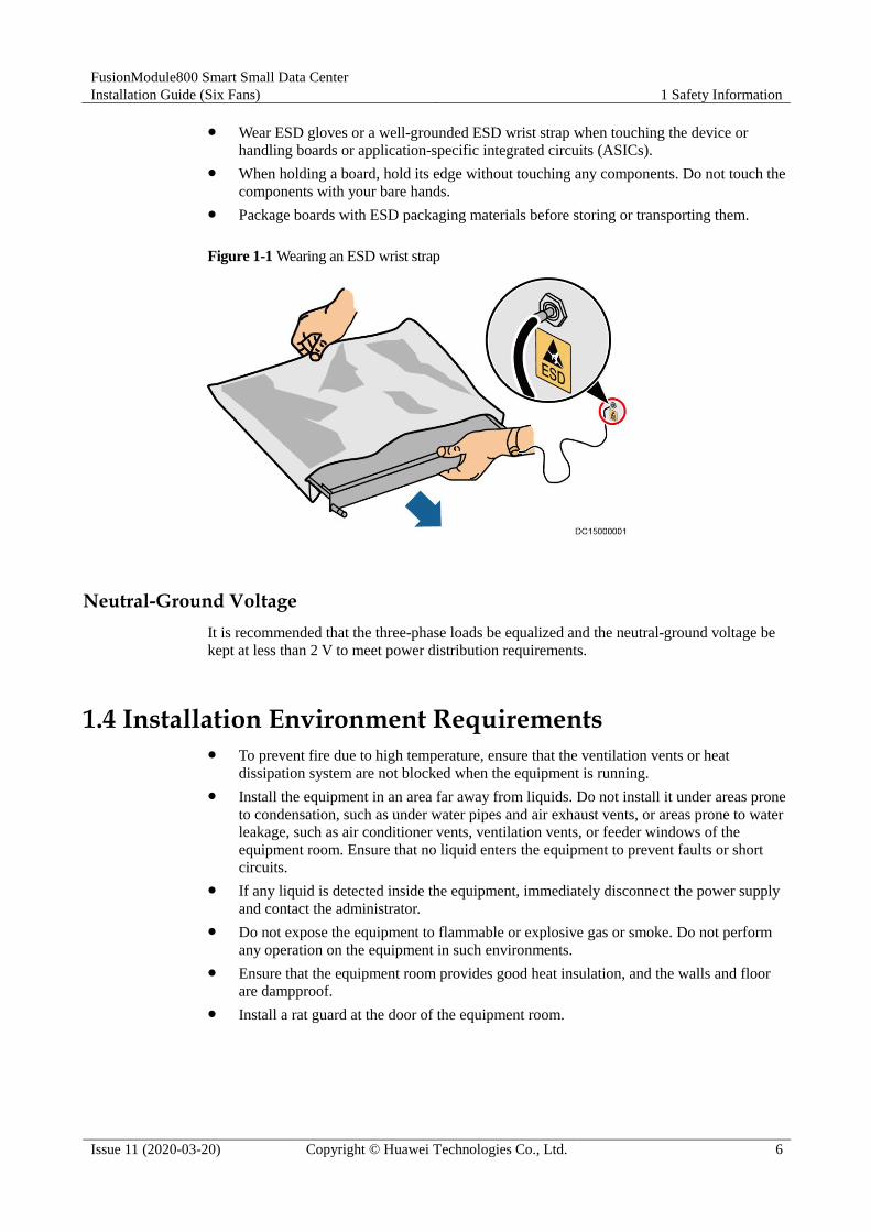
Wear ESD gloves or a well-grounded ESD wrist strap when touching the device or
handling boards or application-specific integrated circuits (ASICs).
When holding a board, hold its edge without touching any components. Do not touch the
components with your bare hands.
Package boards with ESD packaging materials before storing or transporting them.
Figure 1-1 Wearing an ESD wrist strap
Neutral-Ground Voltage
It is recommended that the three-phase loads be equalized and the neutral-ground voltage be
kept at less than 2 V to meet power distribution requirements.
1.4 Installation Environment Requirements To prevent fire due to high temperature, ensure that the ventilation vents or heat
dissipation system are not blocked when the equipment is running.
Install the equipment in an area far away from liquids. Do not install it under areas prone
to condensation, such as under water pipes and air exhaust vents, or areas prone to water
leakage, such as air conditioner vents, ventilation vents, or feeder windows of the
equipment room. Ensure that no liquid enters the equipment to prevent faults or short
circuits.
If any liquid is detected inside the equipment, immediately disconnect the power supply
and contact the administrator.
Do not expose the equipment to flammable or explosive gas or smoke. Do not perform
any operation on the equipment in such environments.
Ensure that the equipment room provides good heat insulation, and the walls and floor
are dampproof.
Install a rat guard at the door of the equipment room.

FusionModule800 Smart Small Data Center
Installation Guide (Six Fans) 1 Safety Information
Issue 11 (2020-03-20) Copyright © Huawei Technologies Co., Ltd. 7
Installation at Heights Working at heights refers to operations that are performed at least 2 meters above the
ground.
Do not work at heights if the steel pipes are wet or other potential danger exists. After the
preceding conditions no longer exist, the safety director and relevant technical personnel
need to check the involved equipment. Operators can begin working only after obtaining
consent.
When working at heights, comply with local relevant laws and regulations.
Only trained and qualified personnel are allowed to work at heights.
Before working at heights, check the climbing tools and safety gears such as safety
helmets, safety belts, ladders, springboards, scaffolding, and lifting equipment. If they do
not meet the requirements, take corrective measures or disallow working at heights.
Wear personal protective equipment such as the safety helmet and safety belt or waist
rope and fasten it to a solid structure. Do not mount it on an insecure moveable object or
metal object with sharp edges. Make sure that the hooks will not slide off.
Set a restricted area and eye-catching signs for working at heights to warn away
irrelevant personnel.
Carry the operation machinery and tools properly to prevent them from falling off and
causing injuries.
Personnel involving working at heights are not allowed to throw objects from the height
to the ground, or vice versa. Objects should be transported by tough slings, hanging
baskets, highline trolleys, or cranes.
Ensure that guard rails and warning signs are set at the edges and openings of the area
involving working at heights to prevent falls.
Do not pile up scaffolding, springboards, or other sundries on the ground under the area
involving working at heights. Do not allow people to stay or pass under the area
involving working at heights.
Inspect the scaffolding, springboards, and workbenches used for working at heights in
advance to ensure that their structures are solid and not overloaded.
Any violations must be promptly pointed out by the site manager or safety supervisor
and the involved personnel should be prompted for correction. Personnel who fail to stop
violations will be forbidden from working.
1.5 Mechanical Safety
Hoisting Devices Do not walk under hoisted objects.
Only trained and qualified personnel should perform hoisting operations.
Check that hoisting tools are available and in good condition.
Before hoisting objects, ensure that hoisting tools are firmly secured onto a load-bearing
object or wall.
Ensure that the angle formed by two hoisting cables is no more than 90 degrees, as
shown in the following figure.

FusionModule800 Smart Small Data Center
Installation Guide (Six Fans) 1 Safety Information
Issue 11 (2020-03-20) Copyright © Huawei Technologies Co., Ltd. 8
Do not drag steel ropes and hoisting tools or bump hoisted objects against hard objects
during hoisting.
Using Ladders Use wooden or fiberglass ladders when you need to perform live working at heights.
When a step ladder is used, ensure that the pull ropes are secured and the ladder is held
firm.
Before using a ladder, check that it is intact and confirm its load bearing capacity. Do not
overload it.
Ensure that the ladder is securely positioned. The recommended angle for a ladder
against the floor is 75 degrees, as shown in the following figure. An angle rule can be
used to measure the angle. Ensure that the wider end of the ladder is at the bottom, or
protective measures have been taken at the bottom to prevent the ladder from sliding.
When climbing a ladder, take the following precautions to reduce risks and ensure
safety:
Keep your body steady.
Do not climb higher than the fourth rung of the ladder from the top.
Ensure that your body's center of gravity does not shift outside the legs of the ladder.

FusionModule800 Smart Small Data Center
Installation Guide (Six Fans) 1 Safety Information
Issue 11 (2020-03-20) Copyright © Huawei Technologies Co., Ltd. 9
Drilling Holes
When drilling holes into a wall or floor, observe the following safety precautions:
Do not drill holes into the equipment. Doing so may affect the electromagnetic shielding of
the equipment and damage components or cables inside. Metal shavings from drilling may
short-circuit boards inside the equipment.
Obtain the consent from the customer, subcontractor, and Huawei before drilling.
Wear goggles and protective gloves when drilling holes.
When drilling holes, protect the equipment from shavings. After drilling, clean up any
shavings that have accumulated inside or outside the equipment.
Moving Heavy Objects
When removing a heavy or unstable component from a cabinet, be aware of unstable or heavy
objects on the cabinet.
Be cautious to avoid injury when moving heavy objects.
When moving the equipment by hand, wear protective gloves to prevent injuries.
Move or lift the equipment by holding its handles or lower edges. Do not hold the
handles of modules (such as power supply units, fans, and boards) that are installed in
the equipment because they cannot support the weight of the equipment.
Avoid scratching the cabinet surface or damaging cabinet components and cables during
equipment transportation.
When transporting the equipment using a forklift truck, ensure that the forks are properly
positioned to ensure that the equipment does not topple. Before moving the equipment,
secure it to the forklift truck using ropes. When moving the equipment, assign dedicated
personnel to take care of it.
Choose railways, sea, or a road with good condition for transportation to ensure
equipment safety. Avoid tilt or jolt during transportation.
Move a cabinet with caution. Any bumping or falling may damage the equipment.

FusionModule800 Smart Small Data Center
Installation Guide (Six Fans) 1 Safety Information
Issue 11 (2020-03-20) Copyright © Huawei Technologies Co., Ltd. 10
1.6 Cooling System Safety
Welding At least two persons are required on a welding site.
A welder must have a work permit.
A welding site must be free from inflammables.
Ensure that a fire extinguisher, wet wiper, and water container are available.
A burning welding torch must not be placed on a component or on the floor, and must
not be placed in a metal container with acetylene and oxygen. Otherwise, the gas may
leak and cause a fire.
High-temperature pipes after welding must be promptly cooled.
Do not weld or cut on pressurized containers or pipes. Electric devices must be powered
off before welding.
High Temperature and Pressure When maintaining or replacing components, pay attention to high-temperature
components (such as the compressor, refrigerant pipe, and electric heater) to prevent
scalds.
When maintaining or replacing components, pay attention to high-pressure components
(such as the compressor and refrigerant pipe) to prevent the refrigerant system from
being cracked or exploded due to misoperations.
Refrigerant Frostbite
Refrigerant leakage may cause frostbite. Take protective measures (for example, wear
antifreeze gloves) when handling refrigerant.
Storage and Recycling Do not store devices near a heat source or under direct sunshine.
Keep devices away from fire or high-temperature objects, especially devices injected
with pressurized nitrogen or refrigerant; otherwise, explosion or refrigerant leakage may
occur, causing personal injury.
The sign indicates that the product cannot be disposed of with other wastes that
have a shell in European Union (EU) areas. To avoid environment pollution and harm to
human health, wastes must be classified and recycled. This also promotes resource reuse.
When recycling a device, fill in the device information in the recycling collection system
or contact your dealer for help. The dealer can help you recycle devices in a safe and
environment-friendly way.

FusionModule800 Smart Small Data Center
Installation Guide (Six Fans) 1 Safety Information
Issue 11 (2020-03-20) Copyright © Huawei Technologies Co., Ltd. 11
1.7 Battery Safety
Basic Requirements
Before operating batteries, carefully read the safety precautions for battery handling and
master the correct battery connection methods.
Do not expose batteries at high temperatures or around heat-generating devices, such as
sunlight, fire sources, transformers, and heaters. Excessive heat exposure may cause the
batteries to explode.
Do not burn batteries. Otherwise, the batteries may explode.
To avoid leakage, overheating, fire, or explosions, do not disassemble, alter, or damage
batteries, for example, insert sundries into batteries or immerse batteries in water or other
liquids.
Wear goggles, rubber gloves, and protective clothing to prevent skin contact with
electrolyte in the case of electrolyte overflow. If a battery leaks, protect the skin or eyes
from the leaking liquid. If the skin or eyes come in contact with the leaking liquid, wash
it immediately with clean water and go to the hospital for medical treatment.
Use dedicated insulated tools.
Move batteries in the required direction. Do not place a battery upside down or tilt it.
Keep the battery loop disconnected during installation and maintenance.
Use batteries of specified models. Using batteries of other models may damage the
batteries.
Dispose of waste batteries in accordance with local laws and regulations. Do not dispose
of batteries as household waste. If a battery is disposed of improperly, it may explode.
The site must be equipped with qualified fire extinguishing facilities, such as firefighting
sands and powder fire extinguishers.
To ensure battery safety and battery management accuracy, use batteries provided with the
UPS by Huawei. Huawei is not responsible for any battery faults caused by batteries not
provided by Huawei.
Battery Installation
Before installing batteries, observe the following safety precautions:
Install batteries in a well-ventilated, dry, and cool environment that is far away from heat
sources, flammable materials, moistures, extensive infrared radiation, organic solvents,
and corrosive gases. Take fire prevention measures.
Place and secure batteries horizontally.
FusionModule800 Smart Small Data Center
Installation Guide (Six Fans) 1 Safety Information
Issue 11 (2020-03-20) Copyright © Huawei Technologies Co., Ltd. 12
Note the polarities when installing batteries. Do not short-circuit the positive and
negative poles of the same battery or battery string. Otherwise, the battery may be
short-circuited.
Check battery connections periodically, ensuring that all bolts are securely tightened.
When installing batteries, do not place installation tools on the batteries.
Battery Short Circuit
Battery short circuits can generate high instantaneous current and release a great amount of
energy, which may cause equipment damage or personal injury.
To avoid battery short-circuit, do not maintain batteries with power on.
Flammable Gas
Do not use unsealed lead-acid batteries.
To prevent fire or corrosion, ensure that flammable gas (such as hydrogen) is properly
exhausted for lead-acid batteries.
Lead-acid batteries emit flammable gas when used. Ensure that batteries are kept in a
well-ventilated area and take preventive measures against fire.
Battery Leakage
Battery overheating causes deformation, damage, and electrolyte spillage.
When the electrolyte overflows, absorb and neutralize the electrolyte immediately. When
moving or handling a battery whose electrolyte leaks, note that the leaking electrolyte may
hurt human bodies.
If the battery temperature exceeds 60°C, check for and promptly handle any leakage.
Electrolyte overflow may damage the equipment. It will corrode metal parts and boards,
and ultimately damage the boards.
If the electrolyte overflows, follow the instructions of the battery manufacturer or
neutralize the electrolyte by using sodium bicarbonate (NaHCO3) or sodium carbonate
(Na2CO3).

FusionModule800 Smart Small Data Center
Installation Guide (Six Fans) 1 Safety Information
Issue 11 (2020-03-20) Copyright © Huawei Technologies Co., Ltd. 13
Lithium Battery
The safety precautions for lithium batteries are similar to those for lead-acid batteries except
that you also need to note the precautions described in this section.
There is a risk of explosion if a battery is replaced with an incorrect model.
A battery can be replaced only with a battery of the same or similar model recommended
by the manufacturer.
When handling a lithium battery, do not place it upside down, tilt it, or bump it with
other objects.
Keep the lithium battery loop disconnected during installation and maintenance.
Do not charge a battery when the ambient temperature is below the lower limit of the
operating temperature (charging is forbidden at 0°C). Low-temperature charging may
cause crystallization, which will result in a short circuit inside the battery.
Use batteries within the allowed temperature range; otherwise, the battery performance
and safety will be compromised.
Do not throw a lithium battery in fire.
When maintenance is complete, return the waste lithium battery to the maintenance
office.
1.8 Others Exercise caution when shutting down the smart cooling product. Doing so may cause
equipment and room overheating, which will damage the equipment.
Exercise caution when powering off the rPDU or PDU2000. Doing so may affect the
power supply to equipment, which will interrupt services.
Exercise caution when manually shutting down the UPS inverter for transferring to
bypass mode, or when adjusting the UPS output voltage level or frequency. Doing so
may affect the power supply to equipment.
Exercise caution when setting battery parameters. Incorrect settings will affect the power
supply and battery lifespan.

FusionModule800 Smart Small Data Center
Installation Guide (Six Fans) 2 Installation Preparations
Issue 11 (2020-03-20) Copyright © Huawei Technologies Co., Ltd. 14
2 Installation Preparations
2.1 Tools and Instruments
Prepare the tools and meters required for installation.
Table 2-1 General tools and instruments
Name, Specifications, and Appearance
Protective gloves Marker Measuring tape (5 m) Level
Step ladder (2 m) Phillips screwdriver
(M4, M6, and M8)
Flat-head screwdriver
(2-5 mm)
Torque wrench
Adjustable wrench
(6")
Socket wrench (M6,
M8, and M12)
Hex key (5 mm) Laser locator
Right angle Electrician's knife Impact tool Heat gun

FusionModule800 Smart Small Data Center
Installation Guide (Six Fans) 2 Installation Preparations
Issue 11 (2020-03-20) Copyright © Huawei Technologies Co., Ltd. 15
Name, Specifications, and Appearance
Needle-nose pliers Diagonal pliers RJ11 crimping tool Polyvinyl chloride
(PVC) insulation
tape
Wire stripper Hydraulic pliers Wire clippers Crimping tool
Multimeter Electroprobe Heat shrink tubing Cable ties
Hammer drill Electric screwdriver Rubber mallet N/A
N/A
Table 2-2 Tools and instruments for installing smart cooling products
Name, Specifications, and Appearance
Flashlight Hacksaw Pallet truck Electric balance

FusionModule800 Smart Small Data Center
Installation Guide (Six Fans) 2 Installation Preparations
Issue 11 (2020-03-20) Copyright © Huawei Technologies Co., Ltd. 16
Name, Specifications, and Appearance
Antifreeze gloves Cutter Welding torch 5% silver solder
Oxygen Acetylene Hot melt device Clamp meter
Pipe bender Insulation gloves Pressure gauge (1
PCS)a
Leather hose (3
PCS)a
Nitrogenb Reducing valvec Vacuum pumpd Water pipe thread
sealante
a: Pressure gauge and leather hose: dedicated to R410A, pressure gauge measurement
range ≥ 4.0 MPa, and the leather hose tolerance range ≥ 4.5 MPa. The size of needle valve
in the unit is 1/4 inch. Purchase a conversion adapter if you have a different size of valve
on leather hoses.
b: Dry nitrogen.
c: Nitrogen reducing valve: A reducing valve must be installed on the head of the nitrogen
cylinder, and the reducing valve range ≥ 4.0 MPa.
d: Vacuum pump airflow: 2-4 L/s, absolute vacuum: ≤ 60 Pa.
e: For equipment with humidifiers, ensure that the water pipe thread sealant can resist

FusionModule800 Smart Small Data Center
Installation Guide (Six Fans) 2 Installation Preparations
Issue 11 (2020-03-20) Copyright © Huawei Technologies Co., Ltd. 17
Name, Specifications, and Appearance
temperatures higher than 85°C and the following requirements are met:
Applicable to all pipe materials
Anaerobic metal pipe thread sealant with PTEF as the padding
Maximum gap: 0.5 mm
Pressure resistance: above 1.6 MPa
Compliant with the industry standard JB∕T7311-2008 Technical Specification for the
Application of Anaerobic Glue in Engineering Machinery
2.2 Checking the Installation Environment
Ensure that the installation environment meets the requirements before installation.
Table 2-3 Installation environment checklist
Check Item Specifications Check Result
Bearing capacity Standard live load of the main
equipment room: 8-12 kN/m2 (If the
battery cabinet is placed inside the
module, use the standard live load of the
main equipment room as a reference.)
Suspended load of the main equipment
room: 1.2 kN/m2
Standard live load of the battery room:
16 kN/m2
□ Passed □ Failed
Levelness Allowed deviation: 3/2000 mm □ Passed □ Failed
Equipment room
height
≥ 2.6 m □ Passed □ Failed
Equipment room
area
8-30 m2 □ Passed □ Failed
Door size Height > 2.2 m; width > 0.9 m □ Passed □ Failed
Elevator Elevator bearing capacity > 1.5 t
Elevator internal size: height > 2.4 m,
depth > 1.4 m
Elevator door size: height > 2.2 m; width >
0.9 m
□ Passed □ Failed
Power supply 380 V AC/400 V AC/415 V AC, 3 Ph, 50
Hz/60 Hz
□ Passed □ Failed
Lighting Equipment room: 500 lx
Monitoring center: 500 lx
□ Passed □ Failed
FusionModule800 Smart Small Data Center
Installation Guide (Six Fans) 2 Installation Preparations
Issue 11 (2020-03-20) Copyright © Huawei Technologies Co., Ltd. 18
Check Item Specifications Check Result
Test area: 500 lx
Floor drain DN50 or larger, made of cast iron or
stainless steel
□ Passed □ Failed
Grounding A general ground bar is configured in the
Converged Cabinet. The general ground
point in each cabinet connects to the general
ground bar in the Converged Cabinet. The
general ground bar in the Converged
Cabinet connects to the floor ground bar or
collective ground bar.
□ Passed □ Failed
Water port Condensate drain outlet: for draining
condensate from the smart cooling product.
□ Passed □ Failed
Humidifier water pipe port: Connects to
external water pipes to supply water to the
humidifier.
□ Passed □ Failed
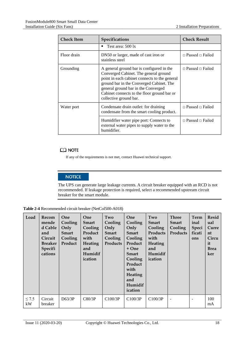
If any of the requirements is not met, contact Huawei technical support.
The UPS can generate large leakage currents. A circuit breaker equipped with an RCD is not
recommended. If leakage protection is required, select a recommended upstream circuit
breaker for the smart module.
Table 2-4 Recommended circuit breaker (NetCol500-A018)
Load Recommended Cable and Circuit Breaker Specifications
One Cooling Only Smart Cooling Product
One Smart Cooling Product with Heating and Humidification
Two Cooling Only Smart Cooling Products
One Cooling Only Smart Cooling Product + One Smart Cooling Product with Heating and Humidification
Two Smart Cooling Products with Heating and Humidification
Three Smart Cooling Products
Terminal Specifications
Residual Current Circuit Breaker
≤ 7.5
kW
Circuit
breaker D63/3P C80/3P C100/3P C100/3P C100/3P - - 100
mA

FusionModule800 Smart Small Data Center
Installation Guide (Six Fans) 2 Installation Preparations
Issue 11 (2020-03-20) Copyright © Huawei Technologies Co., Ltd. 19
Load Recommended Cable and Circuit Breaker Specifications
One Cooling Only Smart Cooling Product
One Smart Cooling Product with Heating and Humidification
Two Cooling Only Smart Cooling Products
One Cooling Only Smart Cooling Product + One Smart Cooling Product with Heating and Humidification
Two Smart Cooling Products with Heating and Humidification
Three Smart Cooling Products
Terminal Specifications
Residual Current Circuit Breaker
specifica
tions
Input
power
cable
specifica
tions
5 x 16
mm2
5 x 16
mm2
5 x 16
mm2
5 x 16
mm2
5 x 16
mm2
- M6
OT
termin
al
-
15
kW
Circuit
breaker
specifica
tions
- - C80/3P C100/3P C100/3P C100/3P - 300
mA
Input
power
cable
specifica
tions
- - 5 x 25
mm2
5 x 25
mm2
5 x 25
mm2
5 x 25
mm2
M6
OT
termin
al
-

FusionModule800 Smart Small Data Center
Installation Guide (Six Fans) 2 Installation Preparations
Issue 11 (2020-03-20) Copyright © Huawei Technologies Co., Ltd. 20
Table 2-5 Recommended circuit breaker (NetCol500-A020)
Load Recommended Cable and Circuit Breaker Specifications
One Cooling Only Smart Cooling Product
One Smart Cooling Product with Heating and Humidification
Two Cooling Only Smart Cooling Products
One Cooling Only Smart Cooling Product + One Smart Cooling Product with Heating and Humidification
Two Smart Cooling Products with Heating and Humidification
Three Smart Cooling Products
Terminal Specifications
Residual Current Circuit Breaker
≤ 6
kW
Circuit
breaker
specifica
tions
C80/3P C80/3P C100/3P C100/3P C125/3P - - 100
mA
Input
power
cable
specifica
tions
5 x 16
mm2
5 x 16
mm2
5 x 16
mm2
5 x 16
mm2
5 x 16
mm2
- M6
OT
termin
al
-
12
kW
Circuit
breaker
specifica
tions
- - C80/3P C100/3P C100/3P C100/3P - 300
mA
Input
power
cable
specifica
tions
- - 5 x 25
mm2
5 x 25
mm2
5 x 25
mm2
5 x 25
mm2
M6
OT
termin
al
-
The customer needs to purchase power cables based on site requirements.
2.3 Site Requirements
Figure 2-1 shows the space requirements for the equipment room.
The cabinet layouts shown in the figures are for ease of description and do not provide reference for
engineering layout.
If the site conditions do not meet the space requirements, contact Huawei technical support.

FusionModule800 Smart Small Data Center
Installation Guide (Six Fans) 2 Installation Preparations
Issue 11 (2020-03-20) Copyright © Huawei Technologies Co., Ltd. 21
The Smart Module can be installed with one side against a wall.
Figure 2-1 Space requirements for a cold-aisle containment
Table 2-6 Cabinet information
Cabinet Type Dimensions (H x W x D) Reference Net Weight
IT cabinet 2000 mm x 600 mm x 1350 mm 160 kg
Converged Cabinet 2000 mm x 600 mm x 1350 mm 410 kg
Battery cabinet (deployed
inside the aisle
containment)
2000 mm x 600 mm x 1350 mm 160 kg
Battery cabinet (deployed
outside the aisle
containment)
2000 mm x 600 mm x 1100 mm (or
1200 mm)
140 kg
Network cabinet 2000 mm x 600 mm x 1350 mm 160 kg
Cabinets and aisle containments are assembled for delivery. The cabinet depth is 1350 mm.
FusionModule800 Smart Small Data Center
Installation Guide (Six Fans) 2 Installation Preparations
Issue 11 (2020-03-20) Copyright © Huawei Technologies Co., Ltd. 22
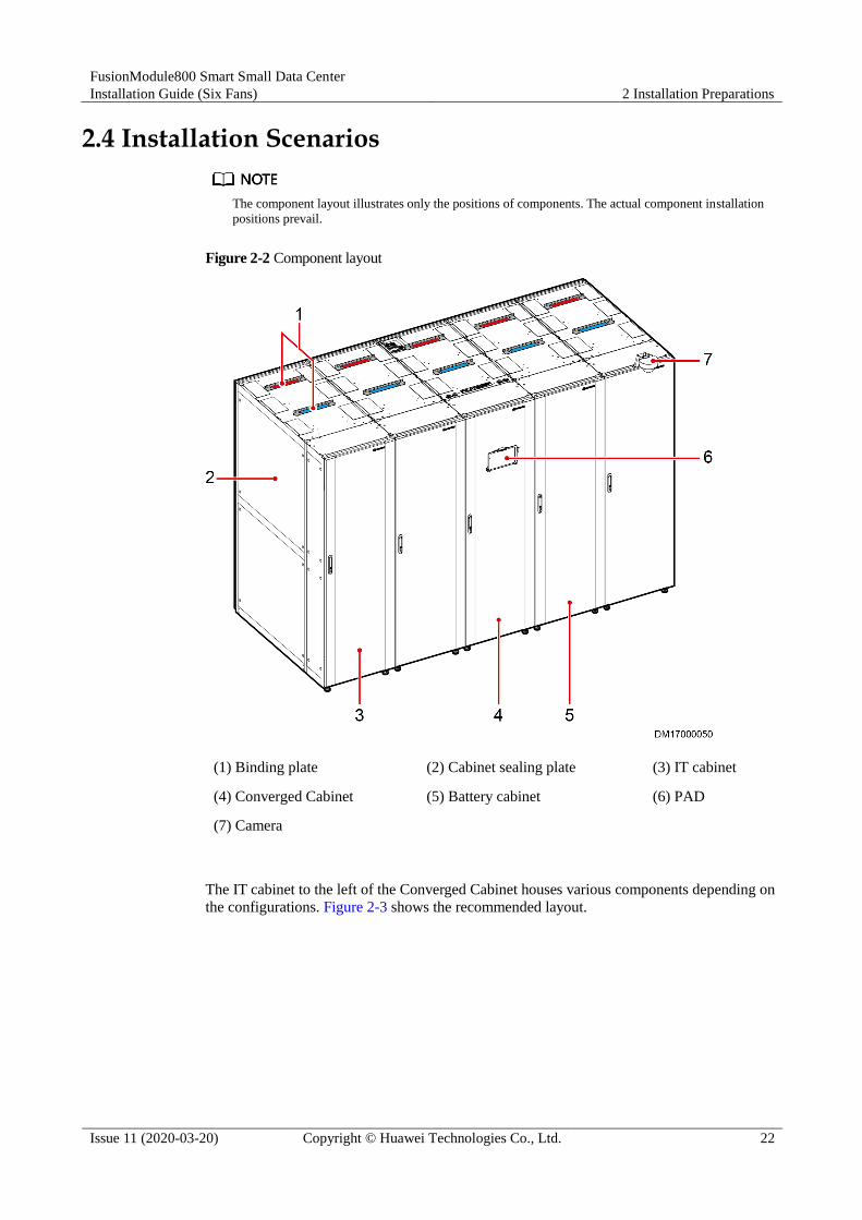
2.4 Installation Scenarios
The component layout illustrates only the positions of components. The actual component installation
positions prevail.
Figure 2-2 Component layout
(1) Binding plate (2) Cabinet sealing plate (3) IT cabinet
(4) Converged Cabinet (5) Battery cabinet (6) PAD
(7) Camera
The IT cabinet to the left of the Converged Cabinet houses various components depending on
the configurations. Figure 2-3 shows the recommended layout.

FusionModule800 Smart Small Data Center
Installation Guide (Six Fans) 2 Installation Preparations
Issue 11 (2020-03-20) Copyright © Huawei Technologies Co., Ltd. 23
Figure 2-3 Component layout in the IT cabinet to the left of the Converged Cabinet
You are advised to number cabinets and PDU2000s based on Figure 2-4.
The following describes how to number cabinets and PDU2000s in a scenario with five cabinets.
(1), (2), and (3) refer to the cabinet number, and A and B refer to the PDU2000 number.
You are advised to number cabinets from left to right.
The battery cabinet and Converged Cabinet do not have to be numbered.
PDU2000s are deployed at the cabinet rear door and are recommended to be numbered from exterior
to interior.

FusionModule800 Smart Small Data Center
Installation Guide (Six Fans) 2 Installation Preparations
Issue 11 (2020-03-20) Copyright © Huawei Technologies Co., Ltd. 24
Figure 2-4 Number example
2.5 Smart Cooling Product Installation
Installation Dimensions
Smart cooling product outdoor units are available in two models, NetCol500-A018 and
NetCol500-A020. Figure 2-5 and Figure 2-6 show the dimensions of NetCol500-A018 and
NetCol500-A020.
NetCol500-A018 and NetCol500-A020 are installed in the same way. This manual uses figures of
NetCol500-A018 as examples.
Figure 2-5 Installation dimensions of NetCol500-A018

FusionModule800 Smart Small Data Center
Installation Guide (Six Fans) 2 Installation Preparations
Issue 11 (2020-03-20) Copyright © Huawei Technologies Co., Ltd. 25
Figure 2-6 Installation dimensions of NetCol500-A020
Units
1 MPa ≈ 10 bar
1 MPa ≈ 145 psi
1 MPa ≈ 10.2 kgf/cm2
2.6 Personnel Requirements
Only trained and qualified personnel who fully understand basic safety precautions are
allowed to install and operate a modular data center.
Huawei will not be liable for any consequence caused by the violation of this document.
The requirements are as follows:
Customers' installation personnel must be trained by Huawei and understand how to
install and operate a modular data center.
The number of installation personnel varies based on the project progress and installation
environment. Typically, two to three persons are required.

FusionModule800 Smart Small Data Center
Installation Guide (Six Fans) 3 Hardware Installation
Issue 11 (2020-03-20) Copyright © Huawei Technologies Co., Ltd. 26
3 Hardware Installation
3.1 Transportation and Unpacking
3.1.1 Cabinet Transportation and Unpacking
Context Only trained personnel are allowed to move the cabinet. Remove the packed cabinet
from the pallet using a pallet truck and move the cabinet to the installation position.
To prevent the cabinet from falling over, secure it to the pallet truck using ropes before
moving it.
To prevent shocks or falls, move the cabinet gently. After placing the cabinet in the
installation position, unpack it and take care to prevent scratches. Keep the cabinet
steady during unpacking.
If the cabinet installation environment is in poor condition, to well store the cabinet after
it is unpacked, take measures to prevent dust. You can wrap the cabinet with the original
plastic coat.
Do not tear down the transparent film from the glass door during the installation. The film
will be removed after the entire module is installed.
Procedure
Step 1 Use a pallet truck to transport the cabinet to the installation position.
Step 2 Check that the cabinet package is intact.
Step 3 Cut off and remove the binding straps, and remove the packing.
Step 4 Remove pallets from ordinary cabinets.
Ordinary cabinets include IT cabinets, battery cabinets, and network cabinets.
1. Remove the plastic bag and take out the fitting box.

FusionModule800 Smart Small Data Center
Installation Guide (Six Fans) 3 Hardware Installation
Issue 11 (2020-03-20) Copyright © Huawei Technologies Co., Ltd. 27
2. Check the cabinet exterior for damage. If any damage is found, notify the carrier
immediately.
3. Check against the packing list that the equipment and fittings are correct and complete. If
some fittings are missing or do not comply with the packing list, record the information
and contact your local Huawei office immediately.
4. After checking that the cabinet is intact, remove the screw assemblies that secure the
cabinet to the pallet, as shown in Figure 3-1.
Set the screw assemblies aside for they will be used in installation steps.
Figure 3-1 Removing an ordinary cabinet
5. Remove the cabinet from the pallet and move the cabinet to the installation position.
To avoid personal injury, prevent the cabinet from falling over during transportation.

FusionModule800 Smart Small Data Center
Installation Guide (Six Fans) 3 Hardware Installation
Issue 11 (2020-03-20) Copyright © Huawei Technologies Co., Ltd. 28
Step 5 Remove the pallet from the Converged Cabinet.
1. Remove the plastic bag and take out the fitting box, ramps, and sliders.
Obtain the paper documents about the smart cooling product and UPS from the fitting box.
2. Check the cabinet exterior for damage. If any damage is found, notify the carrier
immediately.
3. Check against the packing list that the equipment and fittings are correct and complete. If
some fittings are missing or do not comply with the packing list, record the information
and contact your local Huawei office immediately.
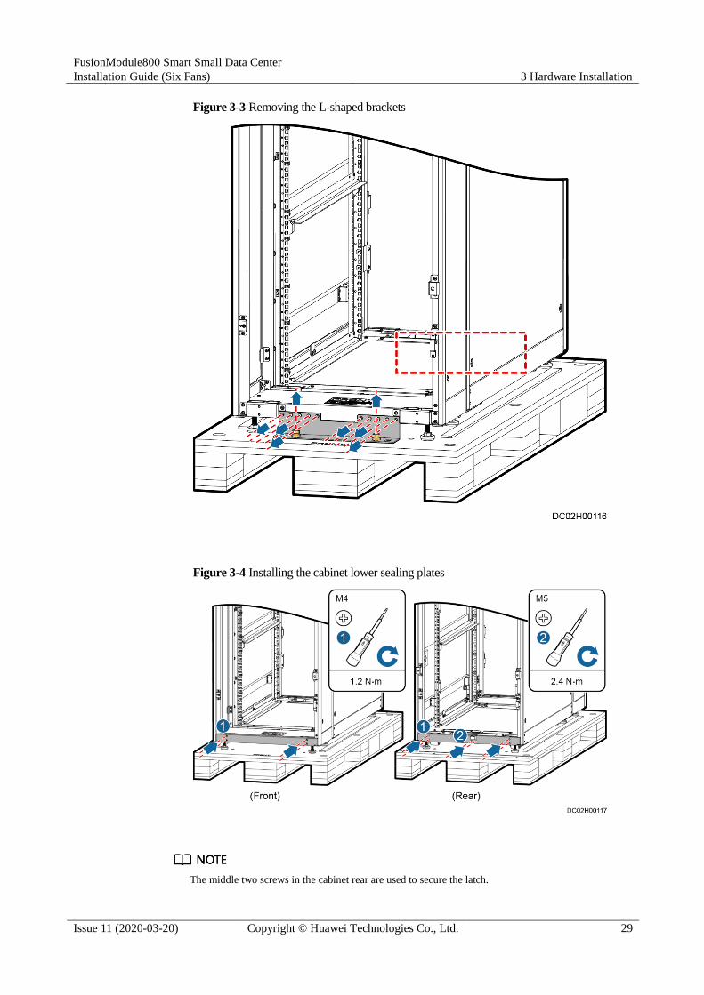
4. After checking that the Converged Cabinet is intact, remove the L-shaped brackets that
secure the cabinet to the pallet.
a. Open the front and rear doors of the cabinet, and remove the cabinet lower sealing
plates.
b. Remove the L-shaped brackets.
c. Reinstall the cabinet lower sealing plates, and close the front and rear doors of the
cabinet.
Figure 3-2 Removing the cabinet lower sealing plates
FusionModule800 Smart Small Data Center
Installation Guide (Six Fans) 3 Hardware Installation
Issue 11 (2020-03-20) Copyright © Huawei Technologies Co., Ltd. 29
Figure 3-3 Removing the L-shaped brackets
Figure 3-4 Installing the cabinet lower sealing plates
The middle two screws in the cabinet rear are used to secure the latch.

FusionModule800 Smart Small Data Center
Installation Guide (Six Fans) 3 Hardware Installation
Issue 11 (2020-03-20) Copyright © Huawei Technologies Co., Ltd. 30
5. Connect the ramps to the rear door side of the pallet and extend the ramps, and then
clamp the sliders at the bottom of the ramps, as shown in Figure 3-5.
Figure 3-5 Installing ramps
6. Raise the six leveling feet to the highest point using an adjustable wrench, and push the
cabinet to the installation position over castors.
----End
3.1.2 Smart Cooling Product Transportation and Unpacking

FusionModule800 Smart Small Data Center
Installation Guide (Six Fans) 3 Hardware Installation
Issue 11 (2020-03-20) Copyright © Huawei Technologies Co., Ltd. 31
Only trained personnel are allowed to move the equipment. Use a pallet truck to move the
equipment with its case down from the transportation truck. The forks must be properly
positioned to ensure that the equipment does not topple.
To avoid toppling, secure the equipment to the pallet truck before moving it, and assign
persons to watch out the equipment during movement.
Move the cabinet with caution. Any bumping or falling may damage the equipment.
Move the equipment close to the installation position before unpacking. Unpack the
equipment with caution to avoid scratching or bumping. Take down the equipment from
the pallet only immediately before installation.
Unpacking the Indoor Unit
Step 1 Verify that the indoor unit package is intact. If any damage is found, notify the carrier
immediately.
Step 2 Remove the package.
1. Remove the straps, outer packing materials, cushioning materials, and then plastic film.
2. Check that the indoor unit exterior is intact and free of collision and scratches. If any
damage is found, notify the carrier immediately.
Step 3 Check the type and quantity of fittings against the packing list. If some fittings are missing or
do not comply with the packing list, record the information and contact your local Huawei
office immediately.
----End
Checking the Outdoor Unit Upon Arrival
Step 1 After the outdoor unit is delivered onsite, check the overtemperature marks.
Overtemperature marks are attached to the outer package and indicate whether the ambient
temperature during transportation exceeds the threshold. If yes, the corresponding temperature
mark background turns black, as shown in Figure 3-6.
Figure 3-6 Overtemperature mark
If none of the three marks turn black, the transportation meets requirements and the
outdoor unit can be installed after its package is removed as instructed in Unpacking the
Outdoor Unit.
If the mark with 60 turns black, unpack the outdoor unit and open its top cover, front
panel, and left front panel. Then check whether there is trace of liquid around the safety

FusionModule800 Smart Small Data Center
Installation Guide (Six Fans) 3 Hardware Installation
Issue 11 (2020-03-20) Copyright © Huawei Technologies Co., Ltd. 32
valve connector. If yes, replace the safety valve. If no, install the outdoor unit. For
position of safety valve, see the overtemperature mark.
If the marks with 60 and 65 turn black or all the marks turn black, ask Huawei to confirm
whether the unit can be used.
----End
Unpacking the Outdoor Unit
Step 1 Verify that the outdoor unit package is intact. If any damage is found, notify the carrier
immediately.
Step 2 Remove the package.
1. Remove the straps, outer packing materials, cushioning materials, and then plastic film.
2. Check that the outdoor unit exterior is intact and free of collision and scratches. If any
damage is found, notify the carrier immediately.
Step 3 Check the type and quantity of fittings against the packing list. If some fittings are missing or
do not comply with the packing list, record the information and contact your local Huawei
office immediately.
Step 4 After checking that the outdoor unit is intact, remove the four bolts that secure the outdoor
unit to the pallet, as shown in Figure 3-7.

FusionModule800 Smart Small Data Center
Installation Guide (Six Fans) 3 Hardware Installation
Issue 11 (2020-03-20) Copyright © Huawei Technologies Co., Ltd. 33
Figure 3-7 Removing an outdoor unit
Step 5 If necessary, hoist the outdoor unit according to Figure 3-8 and Figure 3-9 onsite.

FusionModule800 Smart Small Data Center
Installation Guide (Six Fans) 3 Hardware Installation
Issue 11 (2020-03-20) Copyright © Huawei Technologies Co., Ltd. 34
Figure 3-8 Hoisting a NetCol500-A018 outdoor unit
Figure 3-9 Hoisting a NetCol500-A020 outdoor unit
----End
3.2 (Optional) Removing Aisle Containments
Prerequisites
The cabinets have been transported to the destination and unpacked.

FusionModule800 Smart Small Data Center
Installation Guide (Six Fans) 3 Hardware Installation
Issue 11 (2020-03-20) Copyright © Huawei Technologies Co., Ltd. 35
Context
If the site elevator is too small to transport a cabinet, remove the aisle containment from the
cabinet. Reassemble them after transporting them to the installation position. Then perform
subsequent operations.
The cabinet front door is made of glass. Pay attention to the following during transportation:
Move the cabinet gently.
Ensure that the glass door does not collide with sharp objects.
Place the glass door stably and reliably.
Procedure
Step 1 Open the cabinet front door 120°.
Step 2 (Optional) Cut off the cable tie on the PAD cable in the Converged Cabinet, and pull the cable
into the cabinet through the front door, as shown in Figure 3-10.
Record the PAD cable route because you need to bind the PAD cable along the original route
in subsequent installation.

FusionModule800 Smart Small Data Center
Installation Guide (Six Fans) 3 Hardware Installation
Issue 11 (2020-03-20) Copyright © Huawei Technologies Co., Ltd. 36
Figure 3-10 Removing the PAD cable
Step 3 Lift the cabinet door until it is separate from the hinge, and remove the front door, as shown
in Figure 3-11.

FusionModule800 Smart Small Data Center
Installation Guide (Six Fans) 3 Hardware Installation
Issue 11 (2020-03-20) Copyright © Huawei Technologies Co., Ltd. 37
The cabinet front door is heavy. Arrange at least two persons to carry the door.
Before removing the cabinet door, disconnect the ground cable between the cabinet door
and the cabinet.
Figure 3-11 Removing a cabinet door
Step 4 (Optional) Unscrew the air director from the Converged Cabinet and pull out the air director,
as shown in Figure 3-12.

FusionModule800 Smart Small Data Center
Installation Guide (Six Fans) 3 Hardware Installation
Issue 11 (2020-03-20) Copyright © Huawei Technologies Co., Ltd. 38
Figure 3-12 Removing an air director
Step 5 Remove the fan assembly from the top of the aisle containment, as shown in Figure 3-13.

FusionModule800 Smart Small Data Center
Installation Guide (Six Fans) 3 Hardware Installation
Issue 11 (2020-03-20) Copyright © Huawei Technologies Co., Ltd. 39
A step ladder is required in this step.
If no fan assembly is configured, remove the upper sealing plate from the aisle
containment in the same manner.
Figure 3-13 Removing a fan
Step 6 Remove the sealing plate from the bottom of the aisle containment using a Phillips
screwdriver, as shown in Figure 3-14.
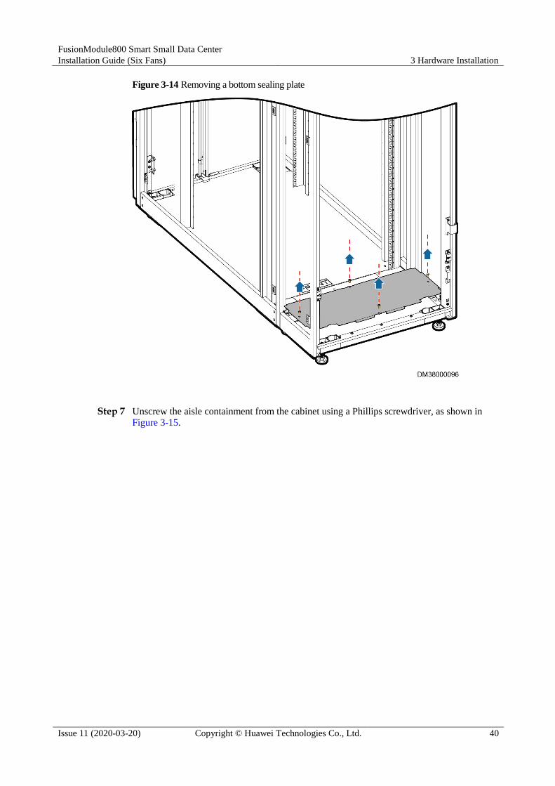
FusionModule800 Smart Small Data Center
Installation Guide (Six Fans) 3 Hardware Installation
Issue 11 (2020-03-20) Copyright © Huawei Technologies Co., Ltd. 40
Figure 3-14 Removing a bottom sealing plate
Step 7 Unscrew the aisle containment from the cabinet using a Phillips screwdriver, as shown in
Figure 3-15.
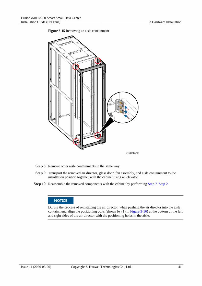
FusionModule800 Smart Small Data Center
Installation Guide (Six Fans) 3 Hardware Installation
Issue 11 (2020-03-20) Copyright © Huawei Technologies Co., Ltd. 41
Figure 3-15 Removing an aisle containment
Step 8 Remove other aisle containments in the same way.
Step 9 Transport the removed air director, glass door, fan assembly, and aisle containment to the
installation position together with the cabinet using an elevator.
Step 10 Reassemble the removed components with the cabinet by performing Step 7–Step 2.
During the process of reinstalling the air director, when pushing the air director into the aisle
containment, align the positioning bolts (shown by (1) in Figure 3-16) at the bottom of the left
and right sides of the air director with the positioning holes in the aisle.

FusionModule800 Smart Small Data Center
Installation Guide (Six Fans) 3 Hardware Installation
Issue 11 (2020-03-20) Copyright © Huawei Technologies Co., Ltd. 42
Figure 3-16 Positioning bolt on an air director
(1) Positioning bolt
----End
3.3 Adjusting the Positions of Aisle Side Sealing Plates
Context The Converged Cabinet has been configured with aisle side sealing plates on both sides
before delivery. The Converged Cabinet is often placed in the middle of the Smart
Module. Therefore, to ensure smooth airflow in the Smart Module, remove the aisle side
sealing plates from the Converged Cabinet before installing the cabinet.
The IT cabinet is not configured with aisle side sealing plates before delivery. If you
need to place the IT cabinet at the end of a row, install an aisle side sealing plate on the
cabinet side towards the aisle exterior.
Totally there are two aisle side sealing plates to be removed from the Converged Cabinet.
Each end cabinet needs to be installed with one aisle side sealing plate.

FusionModule800 Smart Small Data Center
Installation Guide (Six Fans) 3 Hardware Installation
Issue 11 (2020-03-20) Copyright © Huawei Technologies Co., Ltd. 43
Procedure
Step 1 Remove the sealing plate at the aisle side from the Converged Cabinet, as shown in Figure
3-17.
Set the removed materials aside for they will be used in subsequent installation steps.
Figure 3-17 Removing an aisle side sealing plate from the Converged Cabinet
Step 2 Remove the other aisle side sealing plate in the same way.
Step 3 Secure the sealing plate fasteners to the aisle frame on the end cabinet using M5 tapping
screws, as shown in Figure 3-18.

FusionModule800 Smart Small Data Center
Installation Guide (Six Fans) 3 Hardware Installation
Issue 11 (2020-03-20) Copyright © Huawei Technologies Co., Ltd. 44
Align the sealing plate fasteners with those in front of the appropriate sealing frame.
Obtain the sealing plate fasteners from the Converged Cabinet fitting bag.
Figure 3-18 Installing sealing plate fasteners on an end cabinet
Step 4 Install an aisle side sealing plate on the end cabinet side towards the aisle exterior using the
screws removed in Step 1.

FusionModule800 Smart Small Data Center
Installation Guide (Six Fans) 3 Hardware Installation
Issue 11 (2020-03-20) Copyright © Huawei Technologies Co., Ltd. 45
Figure 3-19 Installing an aisle side sealing plate on an end cabinet
Step 5 Install an aisle side sealing plate on the other end cabinet in the same manner.
----End
3.4 Adjusting the Positions of Cabinet Side Panels
3.4.1 Adjusting the Positions of IT Cabinet Side Panels
Prerequisites
An IT cabinet is configured.
Context Before installing an IT cabinet, adjust the side panel position and ensure that side panel
is installed on the cabinet side towards the aisle exterior.
Install two side panels for each end cabinet, one in the upper part and the other in the
lower part.

FusionModule800 Smart Small Data Center
Installation Guide (Six Fans) 3 Hardware Installation
Issue 11 (2020-03-20) Copyright © Huawei Technologies Co., Ltd. 46
Procedure
Step 1 Remove the side panel from the IT cabinet, as shown in Figure 3-20.
Set the removed materials aside for they will be used in subsequent installation steps.
Figure 3-20 Removing side panels from an IT cabinet
Step 2 Install the removed side panels on the side of end IT cabinets facing the aisle exterior by
referring to Step 1.
After adjusting the positions of IT cabinet side panels, ensure that side panels are installed on
the side of end IT cabinets facing the aisle exterior.
----End

FusionModule800 Smart Small Data Center
Installation Guide (Six Fans) 3 Hardware Installation
Issue 11 (2020-03-20) Copyright © Huawei Technologies Co., Ltd. 47
3.4.2 Adjusting the Positions of Battery Cabinet Side Panels
If an auxiliary battery cabinet (without circuit breakers) is deployed in the Smart Module,
remove the panel on one side of the main battery cabinet and install the side panel on the
outer side of the auxiliary cabinet. Ensure that there are side panels on the outer sides of the
main and auxiliary battery cabinets and there is no side panel between the battery cabinets.
For details, see 3.4.1 Adjusting the Positions of IT Cabinet Side Panels.
3.5 Installing a Cabinet
Prerequisites
The floor levelness meets engineering requirements.
Context
To position cabinets, perform the following steps:
1. Obtain a marking-off template for 600 mm wide cabinets from the Converged Cabinet
fitting bag.
2. Obtain a marking-off template for 800 mm wide cabinets from the 800 mm wide IT
cabinet fitting bag.
3. Mark the positions for end cabinets using the marking-off templates according to the
engineering layout diagram.
4. Place the end cabinets at the installation positions accurately.
5. Use the end cabinet as a basis and place other cabinets at their installation positions.
Procedure
Step 1 Place the end cabinets at the installation positions accurately.
Step 2 Level the cabinets using a wrench, as shown in Figure 3-21.

FusionModule800 Smart Small Data Center
Installation Guide (Six Fans) 3 Hardware Installation
Issue 11 (2020-03-20) Copyright © Huawei Technologies Co., Ltd. 48
Use a measuring tape to check that the vertical distance between the top of the 2000 mm
high cabinet and the floor is 2000 mm (+3 mm). Then use a level to check that the cabinet
is level.
To ensure the cabinet steadiness, adjust all the six anchor bolts at the bottom of the cabinet
in place.
Do not remove the anchor bolts. Otherwise, rework is required if the cabinet height does
not meet requirements.
Anchor bolt adjustment method: Wrench an anchor bolt clockwise to elevate a cabinet leg,
or wrench an anchor bolt anticlockwise to lower it. The anchor bolts can be adjusted
within a range of 0-8 mm.
Levelness check standard: Ensure that the cabinet is level in width and depth directions
when leveling the cabinet. Put a level at the bottom of the cabinet in width and depth
directions and check that the air bubble is in the middle between the two lines marked on
the glass tube.
Figure 3-21 Leveling a cabinet
Step 3 Combine cabinets.
1. Level the cabinet adjacent to the end cabinet using the method in Step 2.

FusionModule800 Smart Small Data Center
Installation Guide (Six Fans) 3 Hardware Installation
Issue 11 (2020-03-20) Copyright © Huawei Technologies Co., Ltd. 49
2. Remove the screws securing connecting kits from the cabinet, take off the connecting
kits, and properly store the removed screws, as shown by (1) in Figure 3-22.
The four connecting kits for the Converged Cabinet are bound at the upper left position of the
front door frame.
Figure 3-22 Combining cabinets
3. Combine adjacent cabinets by installing the connecting kits at the combination positions
on the front and rear doors of the cabinets with screws, as shown by (2) in Figure 3-22.
Step 4 Install other cabinets in the same way.
----End

FusionModule800 Smart Small Data Center
Installation Guide (Six Fans) 3 Hardware Installation
Issue 11 (2020-03-20) Copyright © Huawei Technologies Co., Ltd. 50
3.6 Installing a Fan Assembly
Context
If an emergency fan is configured, perform the following steps to install it.
Procedure
Step 1 Remove the baffle plate from the top of the aisle containment.
Step 2 Install the fan assembly.
Figure 3-23 Installing a fan assembly
Step 3 Remove the cover from the XT7 terminal block at the rear door of the Converged Cabinet.

FusionModule800 Smart Small Data Center
Installation Guide (Six Fans) 3 Hardware Installation
Issue 11 (2020-03-20) Copyright © Huawei Technologies Co., Ltd. 51
Figure 3-24 Removing the cover from the XT7 terminal block
Step 4 Connect the fan assemblies in series using the delivered cables.
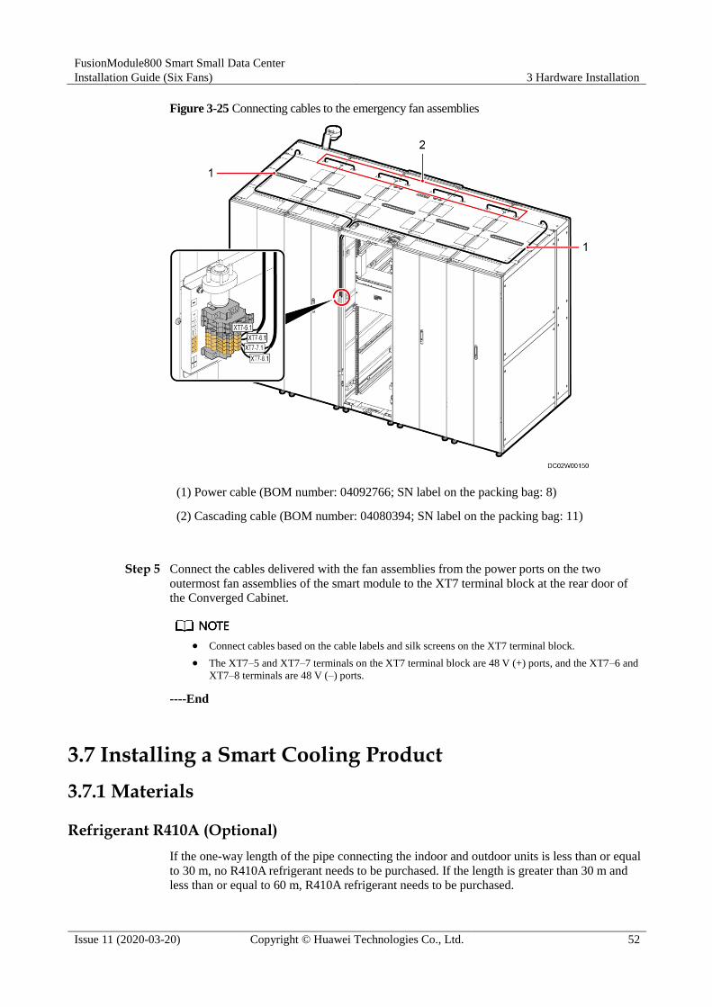
FusionModule800 Smart Small Data Center
Installation Guide (Six Fans) 3 Hardware Installation
Issue 11 (2020-03-20) Copyright © Huawei Technologies Co., Ltd. 52
Figure 3-25 Connecting cables to the emergency fan assemblies
(1) Power cable (BOM number: 04092766; SN label on the packing bag: 8)
(2) Cascading cable (BOM number: 04080394; SN label on the packing bag: 11)
Step 5 Connect the cables delivered with the fan assemblies from the power ports on the two
outermost fan assemblies of the smart module to the XT7 terminal block at the rear door of
the Converged Cabinet.
Connect cables based on the cable labels and silk screens on the XT7 terminal block.
The XT7–5 and XT7–7 terminals on the XT7 terminal block are 48 V (+) ports, and the XT7–6 and
XT7–8 terminals are 48 V (–) ports.
----End
3.7 Installing a Smart Cooling Product
3.7.1 Materials
Refrigerant R410A (Optional)
If the one-way length of the pipe connecting the indoor and outdoor units is less than or equal
to 30 m, no R410A refrigerant needs to be purchased. If the length is greater than 30 m and less than or equal to 60 m, R410A refrigerant needs to be purchased.

FusionModule800 Smart Small Data Center
Installation Guide (Six Fans) 3 Hardware Installation
Issue 11 (2020-03-20) Copyright © Huawei Technologies Co., Ltd. 53
Do not use unqualified refrigerant. Huawei will not be liable for any equipment damage
caused by unqualified refrigerant.
Customers can purchase this material from Huawei or other vendors. Verify that the
refrigerant is authentic in the following ways:
1. Dial the refrigerant manufacturer's hotline to confirm the refrigerant authenticity.
2. Place the refrigerant tank indoors for 24 hours. Use a point thermometer to measure the
outer surface temperature of the refrigerant tank, and connect a pressure gauge to the
tank to measure the internal pressure, as shown in Figure 3-26. Find the saturation
pressure corresponding to the measured outer surface temperature from Table 3-1. If the
deviation between the saturation pressure and the measured internal pressures is greater
than 0.2 MPa, the refrigerant does not meet the requirements and needs to be replaced.
Figure 3-26 Checking the refrigerant
Table 3-1 Mapping between the saturation pressure and the saturation temperature for R410A
Saturation Temperature (°C)
Gauge Pressure (MPa)
Saturation Temperature (°C)
Gauge Pressure (MPa)
Saturation Temperature (°C)
Gauge Pressure (MPa)
0 0.7 19 1.31 38 2.21
1 0.73 20 1.35 39 2.27
2 0.75 21 1.39 40 2.33
3 0.78 22 1.43 41 2.39
4 0.81 23 1.47 42 2.45
5 0.84 24 1.51 43 2.51
6 0.87 25 1.56 44 2.57
7 0.9 26 1.60 45 2.63
8 0.93 27 1.65 46 2.7
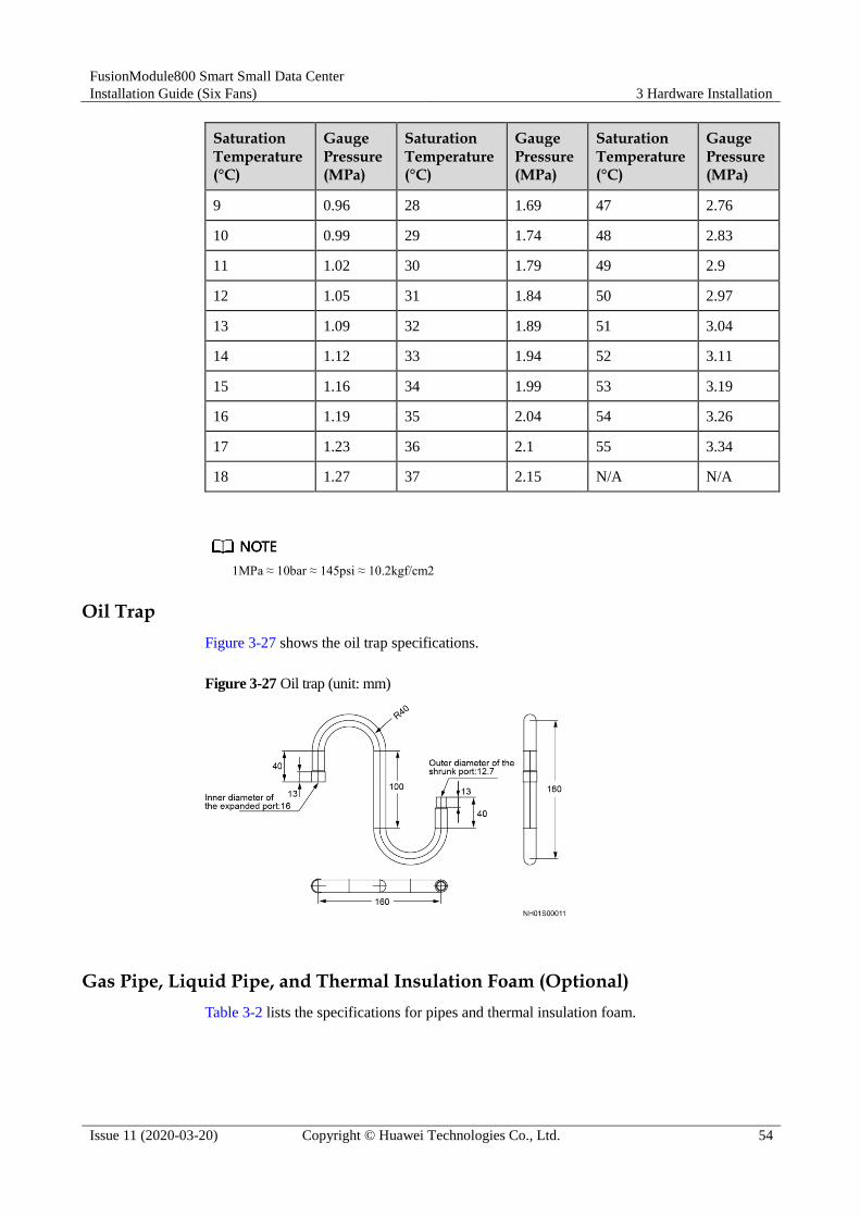
FusionModule800 Smart Small Data Center
Installation Guide (Six Fans) 3 Hardware Installation
Issue 11 (2020-03-20) Copyright © Huawei Technologies Co., Ltd. 54
Saturation Temperature (°C)
Gauge Pressure (MPa)
Saturation Temperature (°C)
Gauge Pressure (MPa)
Saturation Temperature (°C)
Gauge Pressure (MPa)
9 0.96 28 1.69 47 2.76
10 0.99 29 1.74 48 2.83
11 1.02 30 1.79 49 2.9
12 1.05 31 1.84 50 2.97
13 1.09 32 1.89 51 3.04
14 1.12 33 1.94 52 3.11
15 1.16 34 1.99 53 3.19
16 1.19 35 2.04 54 3.26
17 1.23 36 2.1 55 3.34
18 1.27 37 2.15 N/A N/A
1MPa ≈ 10bar ≈ 145psi ≈ 10.2kgf/cm2
Oil Trap
Figure 3-27 shows the oil trap specifications.
Figure 3-27 Oil trap (unit: mm)
Gas Pipe, Liquid Pipe, and Thermal Insulation Foam (Optional)
Table 3-2 lists the specifications for pipes and thermal insulation foam.

FusionModule800 Smart Small Data Center
Installation Guide (Six Fans) 3 Hardware Installation
Issue 11 (2020-03-20) Copyright © Huawei Technologies Co., Ltd. 55
Table 3-2 Specifications
Item Specifications
Gas pipe 5/8 inch (15.88 mm), wall thickness: 1.0 mm;
pressure withstanding capacity ≥ 4.5 MPa
Liquid pipe 3/8 inch (9.52 mm), wall thickness: 0.75 mm;
pressure withstanding capacity ≥ 4.5 MPa
Thermal insulation foam ≥ 13 mm
Water pipe
Figure 3-28 shows how to connect a drainpipe.
Figure 3-28 Connecting a drainpipe
(1) Drainpipe connector: BSPT
1/2-inch, delivered with the
smart cooling product
(2) Rigid pipe conversion adapter:
BSPP 1/2 inch, connected to a
rigid pipe with inner screw threads
(3) Rigid pipe:
made of PP-R or
other material
(4) Pagoda conversion adapter:
BSPP 1/2 inch, connected to a
pipe with inner screw threads
(5) Hose clamp (6) Hose: made of
EPDM or other
material
The object shown in the broken line box is the drainpipe connector with outer screw threads delivered
with smart cooling products. The hose clamp (part 5) is configured in standard configuration. Other parts
are not configured and need to be purchased onsite.
Figure 3-29 shows how to connect a water inlet pipe.

FusionModule800 Smart Small Data Center
Installation Guide (Six Fans) 3 Hardware Installation
Issue 11 (2020-03-20) Copyright © Huawei Technologies Co., Ltd. 56
Figure 3-29 Connecting a water inlet pipe
(1) Connector with inner screw
thread: G 1/2 inch, delivered
with the water inlet pipe
(2) Rigid pipe conversion adapter:
G 1/2 inch, connected to a rigid
pipe with outer screw threads
(3) Rigid pipe:
made of PP-R or
other material
(4) Pagoda conversion adapter:
G 1/2 inch, connected to a pipe
with outer screw threads
(5) Hose clamp (6) Hose: made of
EPDM or other
material
The object shown in the broken line box is the water inlet pipe connector with inner screw threads
delivered with smart cooling products. The hose clamp (part 5) is configured in standard configuration.
Other parts are not configured and need to be purchased onsite.
Pipe Support
Figure 3-30 shows a support for a refrigerant or water pipe. Select supports based on site
conditions.
Figure 3-30 Pipe support (unit: mm)
The height of a U-shaped pipe clamp equals the pipe diameter with thermal insulation foam minus 5
mm. The pipe supports are to be purchased by the customer.

FusionModule800 Smart Small Data Center
Installation Guide (Six Fans) 3 Hardware Installation
Issue 11 (2020-03-20) Copyright © Huawei Technologies Co., Ltd. 57
The recommended material for pipe supports and clamps is 304 stainless steel.
Install a support every 1500 mm in the straight sections of pipes, and 500 mm away from each
bending point in the turning section.
Cable
The site ground resistance must be less than 0.1 ohm.
The fireproof level of the cables must be at least VB.
Table 3-3 lists the cables to be connected onsite. When connecting cables, fit them with
protective hoses.
Table 3-3 Cable specifications
Application Scenario
Specifications Remarks
Outdoor unit
power cable
(optional)
Electrical power cable, 600 V, ZA-RVV, 3 x
6 mm2, black (three core wires: brown, blue,
green-and-yellow), 46 A, outdoor cable, CE
The length is
determined by site
survey.
Common terminal, single-wire cord end
terminal, 6 mm2, 0.02 m, 30 A, insertion
depth 12 mm, black
Delivered with the
fittings
Naked crimping terminal: OT, 6 mm2, M6,
50 A, tin plating, 12-10 AWG, yellow
Delivered with the
fittings
Signal cable to
the indoor and
outdoor units
(optional)
Electrical power cable, 300 V, SJTW, 16-22
AWG, black (three core wires: black, white,
green), 10 A, shielded outdoor cable, UL
The length is
determined by site
survey.
Naked crimping terminal, single-wire cord
end terminal, 1.5 mm2, 7.5 A, tin plating,
insertion depth 12 mm, black
Delivered with the
fittings
Naked crimping terminal: OT, 1.5 mm2, M4,
18 A, tin plating, 22-16 AWG, red
Delivered with the
fittings
3.7.2 Installation Layout
The layout principles are as follows:
If the outdoor unit is placed higher than the indoor unit, the maximum height deviation
between them should be less than or equal to 20 meters. Install an oil trap every 5–6
meters in the vertical direction along the gas pipe.
If the indoor unit is placed higher than the outdoor unit, the maximum height deviation
between them should be less than or equal to 5 meters.

FusionModule800 Smart Small Data Center
Installation Guide (Six Fans) 3 Hardware Installation
Issue 11 (2020-03-20) Copyright © Huawei Technologies Co., Ltd. 58
The height deviation refers to the distance from the stop valves of the indoor unit to the
stop valves of the outdoor unit.
is a sign of a tilt, and it indicates that the scale of the pipe tilting is 1:200. The pipe
tilting direction should be consistent with the hypotenuse of the right triangle.
Figure 3-31 Layout of upward piping
(1) Oil trap (2) Tilted gas pipe (3) Indoor unit (4) Tilted liquid pipe

FusionModule800 Smart Small Data Center
Installation Guide (Six Fans) 3 Hardware Installation
Issue 11 (2020-03-20) Copyright © Huawei Technologies Co., Ltd. 59
Figure 3-32 Layout of downward piping
(1) Oil trap (2) Tilted gas pipe (3) Indoor unit (4) Tilted liquid pipe
3.7.3 (Optional) Installing an Indoor Unit
Context
This section describes how to install the third smart cooling product in the IT cabinet (to the
left of the Converged Cabinet). Skip this section for the scenario with single smart cooling
product or double smart cooling products, because the indoor unit has been installed in the
Converged Cabinet before delivery.
Procedure
Step 1 Move the two mounting bars on the front door side 50 mm towards the cabinet exterior.
Arrange at least two persons to move the mounting bars.
Exercise caution when moving mounting bars to avoid deforming the cabinet bottom
panel.
1. Remove the baffle plate secured to the top of the mounting bars on the front door side, as
shown in Figure 3-33.

FusionModule800 Smart Small Data Center
Installation Guide (Six Fans) 3 Hardware Installation
Issue 11 (2020-03-20) Copyright © Huawei Technologies Co., Ltd. 60
Figure 3-33 Removing the baffle plate
2. Remove the guide rails.
Figure 3-34 Removing guide rails

FusionModule800 Smart Small Data Center
Installation Guide (Six Fans) 3 Hardware Installation
Issue 11 (2020-03-20) Copyright © Huawei Technologies Co., Ltd. 61
3. Remove screws from the mounting bar and move the entire mounting bar 50 mm
towards the cabinet exterior, as shown in Figure 3-35.
To remove one mounting bar, remove the four screws from the upper and lower and the four screws
in the middle that secure the mounting bar to the cabinet.
If there are guide rails fixed on mounting bars, remove the guide rails before moving the mounting
bars.
Figure 3-35 Removing screws from a mounting bar (unit: mm)
Step 2 Install two smart cooling product guide rails respectively at the bottom of both sides of the
cabinet, and secure the front and rear ends of the guide rails using eight M5x10 screws, as
shown in Figure 3-36.
Smart cooling product guide rails are delivered separately. The BOM number is 21241175.
Use the tapping screws packed with the cabinet.

FusionModule800 Smart Small Data Center
Installation Guide (Six Fans) 3 Hardware Installation
Issue 11 (2020-03-20) Copyright © Huawei Technologies Co., Ltd. 62
Figure 3-36 Installing guide rails
Step 3 Engage floating nuts into appropriate positions on the cabinet column using a floating nut
mounting bar or a flat-head screwdriver, as shown in Figure 3-37. Install two floating nuts on
each side, as shown in Figure 3-38.
Figure 3-37 Floating nut installation positions

FusionModule800 Smart Small Data Center
Installation Guide (Six Fans) 3 Hardware Installation
Issue 11 (2020-03-20) Copyright © Huawei Technologies Co., Ltd. 63
Figure 3-38 Installing floating nuts
Step 4 Take air director guide rails from the smart cooling product fitting bag and secure the guide
rails using five M5x10 screws, as shown in Figure 3-39.
Figure 3-39 Installing air director guide rails
Step 5 Push the indoor unit into the cabinet bottom along the guide rails, and secure the indoor unit
using eight M6x12 screws, as shown in Figure 3-40.
When pushing the indoor unit, ensure that the cables reserved at the weak-current power cable
hole in the rear of the cabinet are not affected.

FusionModule800 Smart Small Data Center
Installation Guide (Six Fans) 3 Hardware Installation
Issue 11 (2020-03-20) Copyright © Huawei Technologies Co., Ltd. 64
Figure 3-40 Installing an indoor unit
Step 6 Push the smart cooling product control unit to the 11 U position in the cabinet and secure the
cabinet using four M6x12 screws, as shown in Figure 3-41.
Figure 3-41 Installing a smart cooling product control unit
Step 7 (Optional) Install an air director.

FusionModule800 Smart Small Data Center
Installation Guide (Six Fans) 3 Hardware Installation
Issue 11 (2020-03-20) Copyright © Huawei Technologies Co., Ltd. 65
When there are more than six cabinets in the cold aisle and the indoor unit is installed
inside the cabinet, install an air director in front of the indoor unit.
When pushing an air director into the aisle containment, align the positioning poles at the
bottom of the left and right sides of the air director with the positioning holes in the aisle.
1. Install and secure the air director fasteners on the side columns.
Figure 3-42 Installing air director fasteners
2. Install an air director in front of the indoor unit in the cabinet and secure the control unit
using four M5 tapping screws, as shown in Figure 3-43.

FusionModule800 Smart Small Data Center
Installation Guide (Six Fans) 3 Hardware Installation
Issue 11 (2020-03-20) Copyright © Huawei Technologies Co., Ltd. 66
Figure 3-43 Installing an air director
----End
3.7.4 Installing an Outdoor Unit
3.7.4.1 Installation Requirements
Precautions An outdoor unit must be installed by professionals. Incorrect installation will cause fire,
electric shocks, damage, and water leaks.
When a smart cooling product requires to be moved or reinstalled, ask for professionals.
Do not perform operations by yourself.
Do not store an outdoor unit in a damp basement or expose it in rain, because the
humidity will cause short circuits.
Environmental Requirements To avoid fire disaster, install an outdoor unit in a dry and well-ventilated place without
flammable gas leakage.
Select a place away from direct sunshine and radiation from other heat sources. If the
sunshine or heat radiation cannot be avoided, cover the outdoor unit.
Do not install an outdoor unit in a place with much salt or corrosive gas.
When installing the outdoor unit, ensure that the air intake vent and air exhaust vent of
the condenser are not dirty or blocked. Install an outdoor unit in clean areas that are
away from residential areas.
At a high place with strong winds, install the outdoor unit against a wall to ensure the
normal operating of fans. Install baffle plates when necessary, take this measure to
prevent wind from blowing down the outdoor unit.

FusionModule800 Smart Small Data Center
Installation Guide (Six Fans) 3 Hardware Installation
Issue 11 (2020-03-20) Copyright © Huawei Technologies Co., Ltd. 67
Try to install an outdoor unit against a wall. If the site conditions cannot meet the
requirements and the local outdoor temperature may be below –10°C (NetCol500-A018)
or 0°C (NetCol500-A020), prepare and install an air baffle by referring to Figure 3-46 on
the following slide. The air baffle height and width should be greater than or equal to the
outdoor unit height and width, respectively.
If the site installation environment is complicated and the preceding conditions are not
met, contact Huawei technical support.
Concrete Base Requirements
Install an outdoor unit on the base to prevent it from falling down in an earthquake or a strong
wind. You can prepare a concrete base onsite by referring to Figure 3-44.
Figure 3-44 Concrete base requirements
3.7.4.2 Space Requirements
Single Outdoor Unit A single outdoor is recommended to be installed against a wall, as shown in Figure 3-45.

FusionModule800 Smart Small Data Center
Installation Guide (Six Fans) 3 Hardware Installation
Issue 11 (2020-03-20) Copyright © Huawei Technologies Co., Ltd. 68
Figure 3-45 Space requirements for installing single outdoor unit
If the outdoor unit cannot be installed against a wall or the local outdoor temperature
may be below –10°C (NetCol500-A018) or 0°C (NetCol500-A020), place an air baffle at
the air intake side of the outdoor unit based on the Figure 3-46.
Figure 3-46 Space requirements for installing an air baffle
Installing an outdoor unit on a wall, as shown in Figure 3-47.

FusionModule800 Smart Small Data Center
Installation Guide (Six Fans) 3 Hardware Installation
Issue 11 (2020-03-20) Copyright © Huawei Technologies Co., Ltd. 69
Figure 3-47 Requirements for installing an outdoor unit on a wall
The bearing capacity of the support platform is more than 230 kg.
Reserve no less than 300 mm from the left or right side of the outdoor unit for maintenance
personnel to walk.
Grid structure is recommended to avoid the air exhaust and intake of the smart cooling product being
affected by the guardrail structure.
The picture is only for reference, adjust based on the on-site situation if necessary.
Multiple Outdoor Units
When multiple outdoor units are to be installed, if they cannot be installed against a wall or
the local outdoor temperature may be below –10°C (NetCol500-A018) or 0°C
(NetCol500-A020), place an air baffle at the air intake side of each outdoor unit.
Figure 3-48 Space requirements for installing multiple outdoor unit
3.7.4.3 Securing an Outdoor Unit
Prerequisites The M10 expansion bolts used for securing an outdoor unit have been prepared.
The concrete groundwork is prepared.
Context

FusionModule800 Smart Small Data Center
Installation Guide (Six Fans) 3 Hardware Installation
Issue 11 (2020-03-20) Copyright © Huawei Technologies Co., Ltd. 70
Move the outdoor unit close to the installation position before unpacking. You are
recommended to stand the outdoor unit during transportation. If tilt is not avoidable, the
tilt degree cannot exceed 15°.
Do not hold the fan guard on the shell. Otherwise, it will be deformed.
Do not touch the blades using hand or any other object.
Procedure
Step 1 Determine the four mounting holes of the outdoor unit based on the installation dimensions
and drill holes in the concrete base.
Step 2 Align the outdoor unit mounting holes with the holes in the concrete base, and secure the
outdoor unit to the concrete base using four M10 expansion bolts, as shown in Figure 3-49.
Figure 3-49 Installing an outdoor unit
----End

FusionModule800 Smart Small Data Center
Installation Guide (Six Fans) 3 Hardware Installation
Issue 11 (2020-03-20) Copyright © Huawei Technologies Co., Ltd. 71
3.7.5 Exhausting Nitrogen from the Indoor Unit
Context
Nitrogen is exhausted from the indoor unit through both the gas pipe needle valve and liquid
pipe needle valve of the indoor unit stop valve. Figure 3-50 shows a smart cooling product
stop valve.
Figure 3-50 Stop valve
(1) Needle valve nut (2) Rear cover nut (3) Black plastic nut
Procedure
Step 1 Open the stop valves on the gas pipe and liquid pipe of the indoor unit in turn using a 5 mm
hex key.
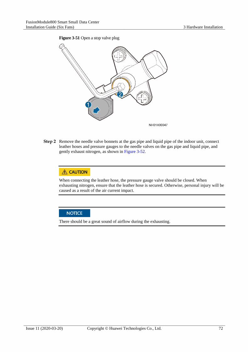
FusionModule800 Smart Small Data Center
Installation Guide (Six Fans) 3 Hardware Installation
Issue 11 (2020-03-20) Copyright © Huawei Technologies Co., Ltd. 72
Figure 3-51 Open a stop valve plug
Step 2 Remove the needle valve bonnets at the gas pipe and liquid pipe of the indoor unit, connect
leather hoses and pressure gauges to the needle valves on the gas pipe and liquid pipe, and
gently exhaust nitrogen, as shown in Figure 3-52.
When connecting the leather hose, the pressure gauge valve should be closed. When
exhausting nitrogen, ensure that the leather hose is secured. Otherwise, personal injury will be
caused as a result of the air current impact.
There should be a great sound of airflow during the exhausting.

FusionModule800 Smart Small Data Center
Installation Guide (Six Fans) 3 Hardware Installation
Issue 11 (2020-03-20) Copyright © Huawei Technologies Co., Ltd. 73
Figure 3-52 Exhausting nitrogen from an indoor unit
(1) Pressure gauge (2) Gas pipe needle valve (3) Liquid pipe needle valve
When exhausting nitrogen, do not remove the valve plug in case of losing it.
Step 3 After the airflow sound disappears, reinstall the needle valve bonnet.
----End
3.7.6 Connecting Refrigerant Pipes
3.7.6.1 Laying Out Pipes Inside a Cabinet
The gas pipe and liquid pipe used inside cabinets have been delivered to the site as a pipe
assembly, as shown in Figure 3-53. Secure the entire pipe assembly to the cabinet interior
onsite. Route pipes from the top or bottom based on site requirements.

FusionModule800 Smart Small Data Center
Installation Guide (Six Fans) 3 Hardware Installation
Issue 11 (2020-03-20) Copyright © Huawei Technologies Co., Ltd. 74
Figure 3-53 Pipe assembly
(1) Liquid pipe (2) Gas pipe (3) Sheet metal
Figure 3-53 describes how to route pipes inside a cabinet for the scenario with double smart cooling
products with top pipe routing. If there is only one smart cooling product, only one assembly of gas
pipe and liquid pipe is included.
The sheet metal shown in Figure 3-53 needs to be secured to the cabinet onsite.
Top Pipe Routing
When routing pipes from the top, do not route the pipes over servers or other devices to
protect the servers or other devices from being affected by pipe leaks.
Secure pipe fasteners to the cabinet.
Laying out pipes inside the Converged Cabinet
Figure 3-54 shows the pipe layout.

FusionModule800 Smart Small Data Center
Installation Guide (Six Fans) 3 Hardware Installation
Issue 11 (2020-03-20) Copyright © Huawei Technologies Co., Ltd. 75
Figure 3-54 Top pipe routing inside the Converged Cabinet
(Optional for installing a third smart cooling product) Laying out pipes inside the IT
cabinet
a. Remove the six cable rings from the side-routed pipe in the rear of the IT cabinet, as
shown in Figure 3-55.

FusionModule800 Smart Small Data Center
Installation Guide (Six Fans) 3 Hardware Installation
Issue 11 (2020-03-20) Copyright © Huawei Technologies Co., Ltd. 76
Figure 3-55 Removing cable rings
b. Take the binding plate from the pipe fitting bag, and secure it to the rear of the IT
cabinet using the screws removed in the previous step, as shown in Figure 3-56.
Figure 3-56 Installing a binding plate
c. Lay out pipes inside the IT cabinet, as shown in Figure 3-57.

FusionModule800 Smart Small Data Center
Installation Guide (Six Fans) 3 Hardware Installation
Issue 11 (2020-03-20) Copyright © Huawei Technologies Co., Ltd. 77
Figure 3-57 Top pipe routing inside the IT cabinet
Bottom Pipe Routing Laying out pipes inside the Converged Cabinet
Figure 3-58 shows the pipe layout.

FusionModule800 Smart Small Data Center
Installation Guide (Six Fans) 3 Hardware Installation
Issue 11 (2020-03-20) Copyright © Huawei Technologies Co., Ltd. 78
Figure 3-58 Bottom pipe routing inside the Converged Cabinet
(Optional for installing a third smart cooling product) Laying out pipes inside the IT
cabinet
Figure 3-59 shows the pipe layout.

FusionModule800 Smart Small Data Center
Installation Guide (Six Fans) 3 Hardware Installation
Issue 11 (2020-03-20) Copyright © Huawei Technologies Co., Ltd. 79
Figure 3-59 Bottom pipe routing inside the IT cabinet
3.7.6.2 Laying Out Pipes Outside a Cabinet
Prerequisites
Check that the nuts on the needle valve and rear cover of the smart cooling product are
tightened.
Context
Tools: adjustable wrench (250 mm x 30 mm), hex key (5 mm), torque wrench
(17#/19#/27#/30#/36#)
Before welding, exhaust all nitrogen from the refrigerant pipe to avoid explosion and personal
injury.

FusionModule800 Smart Small Data Center
Installation Guide (Six Fans) 3 Hardware Installation
Issue 11 (2020-03-20) Copyright © Huawei Technologies Co., Ltd. 80
When connecting the indoor and outdoor units, seal the pipe after the welding break
exceeds 15 minutes to prevent dust and water from entering the pipe.
To avoid burning the bottom panel, top panel, side panel, internal components, other pipes,
thermal insulation foam, power cables, and labels, take protective measures, such as
spreading a piece of wet cloth, around the welding position.
During and after the welding, avoid exposing the refrigerant pipe for over 15 minutes
because this may influence the system reliability.
Take appropriate sealing and protective measures when routing welded pipes through
holes to prevent air channel leaks and copper pipe damage. Otherwise, other components
may be damaged by impurities.
Avoid elbows and ensure that the connection between the indoor and outdoor units is the
shortest.
The refrigerant pipe should be wrapped with thermal insulation foam.
Procedure
Step 1 Route pipes based on the engineering requirements and weld pipes in the medium segment by
referring to Figure 3-61.
Exercise caution during welding to avoid burning components, such as rubber rings, inside the
cabinet.
During the welding, charge a little nitrogen into the pipes to avoid internal oxidation, as
shown in Figure 3-60.
When welding a gas pipe, gently inject nitrogen into the pipe at the gas pipe needle valve.
When welding a liquid pipe, gently inject nitrogen into the pipe at the liquid pipe needle
valve.
Figure 3-60 Welding pipes
When the direction of the refrigerant pipe is changed, add a support at the position that is
500 mm away from the changing point.
If the refrigerant pipe is straight, add a support every 1500 mm.

FusionModule800 Smart Small Data Center
Installation Guide (Six Fans) 3 Hardware Installation
Issue 11 (2020-03-20) Copyright © Huawei Technologies Co., Ltd. 81
Figure 3-61 Support positions for refrigerant pipes
Ask the site engineering personnel to prepare and install pipe supports. For details about the pipe support
requirements, see Pipe Support in 3.7.1 Materials.
Step 2 Route pipes inside the cabinet. For details, see 3.7.6.1 Laying Out Pipes Inside a Cabinet.
Step 3 Connect the indoor unit stop valve.
Connect the liquid pipe stop valve first, and then the gas pipe stop valve.
1. Remove the black plastic nut from the liquid pipe stop valve using an adjustable wrench.
Check that the PTFE washer on the stop valve and the inner protruding surface of the
active connector nut are free of impurities and scratches.
Clean up impurities using alcohol or a wet cloth. For any scratch, contact Huawei
technical support for replacement.
2. Hold the copper pipe after the pipe nut with one hand and keep the pipe nut and the stop
valve screw thread on the same center line. Secure the pipe nut to the stop valve with the
other hand and tighten the nut using a torque wrench, as shown in Figure 3-62.

FusionModule800 Smart Small Data Center
Installation Guide (Six Fans) 3 Hardware Installation
Issue 11 (2020-03-20) Copyright © Huawei Technologies Co., Ltd. 82
Tighten the liquid pipe stop valve using a 27# torque wrench to a torque of 35-37 N m.
Tighten the gas pipe stop valve using a 36# torque wrench to a torque of 50-52 N m.
When tightening a stop valve using a torque wrench, secure the hex nut of the active
connector at the welded copper pipe to prevent the copper pipe from turning and further
deforming as the stop valve is being tightened.
Figure 3-62 Connecting indoor unit stop valves
3. Tighten the pipe nut, needle valve nut, and rear cover nut based on the torque listed in
Table 3-4.
Ensure that you tighten the nut to the specified torque. The failure torque for the nut of the
liquid pipe stop valve is 70 N m and that for the nut of the gas pipe stop valve is 100 N m.
The torque greater than the failure torque will damage the screw thread.
Table 3-4 Torque requirements
Item Pipe Nut Needle Valve Nut Rear Cover Nut
Nut Size Tightening Torque (N m)
Nut Size Tightening Torque (N m)
Nut Size Tightening Torque (N m)
Liquid pipe
stop valve
27# 35-37 17# 10 19# 15-17
Gas pipe stop
valve 36# 50-52 17# 10 30# 20-22

FusionModule800 Smart Small Data Center
Installation Guide (Six Fans) 3 Hardware Installation
Issue 11 (2020-03-20) Copyright © Huawei Technologies Co., Ltd. 83
Step 4 Take out the outdoor unit stop valve pipe from the outdoor unit fitting bag and connect the
pipe by referring to Step 3.1, Step 3.2, and Step 3.3. Figure 3-63 shows the valve installation.
Connect the liquid pipe stop valve first, and then the gas pipe stop valve.
The outdoor unit has been charged 6 kg of R410A refrigerant before delivery, after the
outdoor unit stop valve pipe is installed, the stop valve plug should be closed. Open the
stop valve plugs of the outdoor unit gas pipe and liquid pipe after vacuumization is
complete to avoid refrigerant leaks.
Figure 3-63 Pipe ports on the outdoor unit
Step 5 Weld the routed pipe and the pipe port reserved outside the cabinet.
----End
3.7.7 Connecting Water Pipes
The water pipes to be connected onsite include humidifier water inlet pipes and condensate
drainpipes. Route pipes from the top or bottom based on site requirements.
Figure 3-64 shows the holes in the bottom of the smart cooling product.

FusionModule800 Smart Small Data Center
Installation Guide (Six Fans) 3 Hardware Installation
Issue 11 (2020-03-20) Copyright © Huawei Technologies Co., Ltd. 84
Figure 3-64 Holes in the smart cooling product
(1) Water inlet hole (2) Strong-current cable hole (3) Water outlet hole
(4) Signal cable hole (5) Gas pipe stop valve (6) Liquid pipe stop valve
3.7.7.1 (Optional) Connecting the Humidifier Water Inlet Pipe
Context
This section applies only to models with humidifiers.
The smart cooling product water inlet pipe inside the cabinet can be routed from the bottom or
top. Determine the pipe routing mode based on site conditions.
Figure 3-65 shows how to connect a water inlet pipe.
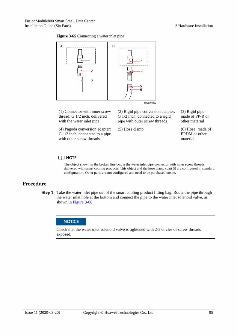
FusionModule800 Smart Small Data Center
Installation Guide (Six Fans) 3 Hardware Installation
Issue 11 (2020-03-20) Copyright © Huawei Technologies Co., Ltd. 85
Figure 3-65 Connecting a water inlet pipe
(1) Connector with inner screw
thread: G 1/2 inch, delivered
with the water inlet pipe
(2) Rigid pipe conversion adapter:
G 1/2 inch, connected to a rigid
pipe with outer screw threads
(3) Rigid pipe:
made of PP-R or
other material
(4) Pagoda conversion adapter:
G 1/2 inch, connected to a pipe
with outer screw threads
(5) Hose clamp (6) Hose: made of
EPDM or other
material
The object shown in the broken line box is the water inlet pipe connector with inner screw threads
delivered with smart cooling products. This object and the hose clamp (part 5) are configured in standard
configuration. Other parts are not configured and need to be purchased onsite.
Procedure
Step 1 Take the water inlet pipe out of the smart cooling product fitting bag. Route the pipe through
the water inlet hole at the bottom and connect the pipe to the water inlet solenoid valve, as
shown in Figure 3-66.
Check that the water inlet solenoid valve is tightened with 2-3 circles of screw threads
exposed.

FusionModule800 Smart Small Data Center
Installation Guide (Six Fans) 3 Hardware Installation
Issue 11 (2020-03-20) Copyright © Huawei Technologies Co., Ltd. 86
Figure 3-66 Installing the humidifier water inlet pipe
The other end is a reserved G 1/2 inch connector with inner screw threads. Connect the other
end to a hose or rigid pipe based on site requirements.
Step 2 Connect the external water inlet pipe and route pipes inside the cabinet according to the actual
conditions.
Figure 3-67 shows the top routing of the water inlet pipe.

FusionModule800 Smart Small Data Center
Installation Guide (Six Fans) 3 Hardware Installation
Issue 11 (2020-03-20) Copyright © Huawei Technologies Co., Ltd. 87
Figure 3-67 Top routing of the water inlet pipe
Route the bottom water inlet pipe.
a. Remove the baffle plate for the water pipe hole from the bottom of the cabinet, as
shown in Figure 3-68.
b. Figure 3-69 shows the bottom routing of the water inlet pipe.
Figure 3-68 Removing the baffle plate from the bottom of the cabinet

FusionModule800 Smart Small Data Center
Installation Guide (Six Fans) 3 Hardware Installation
Issue 11 (2020-03-20) Copyright © Huawei Technologies Co., Ltd. 88
Figure 3-69 Bottom routing of the water inlet pipe
After routing water pipes, secure them to the pipe assembly using cable ties, and seal the
cable hole using firestop putty.
----End
3.7.7.2 Connecting the Condensate Drainpipe
Context
The smart cooling product condensate drainpipe inside the cabinet can be routed from top or
bottom. Determine the pipe routing mode based on site conditions.
In top pipe routing, connect the drainpipe to the check valve and then to the cabinet top. The
drain outlet reserved on the top of the cabinet connects to an external pipe over the drainpipe
connector in the fitting bag.
In bottom pipe routing, the drainpipe connects to an external pipe over the drainpipe
connector in the fitting bag.
Figure 3-70 shows how to connect a drainpipe.

FusionModule800 Smart Small Data Center
Installation Guide (Six Fans) 3 Hardware Installation
Issue 11 (2020-03-20) Copyright © Huawei Technologies Co., Ltd. 89
Figure 3-70 Connecting a drainpipe
(1) Drainpipe connector: BSPT
1/2-inch, delivered with the
smart cooling product
(2) Rigid pipe conversion adapter:
BSPP 1/2 inch; connected to a
rigid pipe with inner screw threads
(3) Rigid pipe:
made of PP-R or
other material
(4) Pagoda conversion adapter:
BSPP 1/2 inch; connected to a
pipe with inner screw threads
(5) Hose clamp (6) Hose: made of
EPDM or other
material
The object shown in the broken line box is the drainpipe connector with outer screw threads delivered
with smart cooling products. The hose clamp (part 5) is used in standard configuration. Other parts are
not configured and need to be purchased onsite.
Top Pipe Routing
Step 1 Connect the check valve to the other end of the drainpipe, as shown in Figure 3-71.

FusionModule800 Smart Small Data Center
Installation Guide (Six Fans) 3 Hardware Installation
Issue 11 (2020-03-20) Copyright © Huawei Technologies Co., Ltd. 90
Figure 3-71 Connecting a drainpipe
Step 2 Secure the check valve and sheet metal to the right rack rail of the cabinet, as shown in Figure
3-72.
Step 3 Connect the top drainpipe, as shown in Figure 3-72.

FusionModule800 Smart Small Data Center
Installation Guide (Six Fans) 3 Hardware Installation
Issue 11 (2020-03-20) Copyright © Huawei Technologies Co., Ltd. 91
An arrow on the check valve body indicates the flow direction. Ensure that the water flow
direction is consistent with the direction of the arrow when the drainpipe connects to the
check valve.
It is recommended that the check valve be installed in a position lower than the smart
cooling product; otherwise, water leaked from the check valve may affect the running of
the smart cooling product.
After routing pipes, secure them to the pipe component using cable ties.
The drainpipe inside the indoor unit should be wrapped with the thermal insulation pipe in
accessories.
Figure 3-72 Top routing of the drainpipe
----End
Bottom Pipe Routing
Step 1 Take out a drainpipe connector from the fitting bag and put the connector on the other end of
the drainpipe, as shown in Figure 3-73.

FusionModule800 Smart Small Data Center
Installation Guide (Six Fans) 3 Hardware Installation
Issue 11 (2020-03-20) Copyright © Huawei Technologies Co., Ltd. 92
Figure 3-73 Connecting a drainpipe
Step 2 Route the bottom drainpipe.
The smart cooling product fitting bag contains drainpipe connectors. Choose hoses or rigid
pipes based on site requirements.
The drainpipe inside the indoor unit should be wrapped with the thermal insulation pipe in
accessories.
1. Remove the baffle plate for the water pipe hole from the bottom of the cabinet, as shown
in Figure 3-74.
2. Figure 3-75 shows the bottom drainpipe routing.

FusionModule800 Smart Small Data Center
Installation Guide (Six Fans) 3 Hardware Installation
Issue 11 (2020-03-20) Copyright © Huawei Technologies Co., Ltd. 93
Figure 3-74 Removing the baffle plate from the bottom of the cabinet
Figure 3-75 Bottom drainpipe routing
After routing water pipes, secure them to the pipe assembly using cable ties, and seal the
cable hole using firestop putty.
----End

FusionModule800 Smart Small Data Center
Installation Guide (Six Fans) 3 Hardware Installation
Issue 11 (2020-03-20) Copyright © Huawei Technologies Co., Ltd. 94
3.7.8 Leakage Test with Nitrogen
Context
The leakage test with nitrogen described in this section is dedicated for testing the leaks of
the indoor unit and the pipes connected to it.
The measuring range of the pressure gauge must be greater than or equal to 4.0 MPa, and
the tolerance range of the leather hose must be greater than or equal to 4.5 MPa.
During the pressure preservation process, do not remove the leather hose and pressure
gauge; otherwise, nitrogen may leak.
Procedure
Step 1 Open the stop valves for the gas pipe and liquid pipe of the indoor unit.
Before opening the indoor unit stop valves, ensure that the stop valves for the gas pipe and
liquid pipe of the outdoor unit are closed.
Step 2 Connect the pressure gauge, leather hose, and nitrogen cylinder. A reducing valve must be
installed on the head of the nitrogen cylinder, as shown in Figure 3-76. The outlet pressure of
the reducing valve must not exceed 3.0 MPa.
If the outlet pressure of the reducing valve is greater than 3.0 MPa, components may be
damaged.

FusionModule800 Smart Small Data Center
Installation Guide (Six Fans) 3 Hardware Installation
Issue 11 (2020-03-20) Copyright © Huawei Technologies Co., Ltd. 95
Figure 3-76 Leakage test with nitrogen
(1) Reducing valve (2) Nitrogen cylinder (3) Low pressure gauge
(4) High pressure gauge (5) Gas pipe needle valve (6) Liquid pipe needle valve
Step 3 Inject 3.0 MPa nitrogen and preserve the pressure for 24 hours. The system pressure should
stay constant under unchanging ambient temperature conditions. If there is considerable
temperature change and the pressure changes, perform the test again.
Step 4 If welding defects exist, locate and repair the leak point. If the pressure does not change,
exhaust the nitrogen through the injection needle valves.
----End
3.7.9 Connecting Cables
The indoor unit uses the single-phase power supply from the smart cooling product control
unit. The outdoor unit is energized by the power distribution box (PDB) in the Converged
Cabinet.
Figure 3-77 shows the front panel of the smart cooling product control unit, Figure 3-78
shows the rear panel, and Figure 3-79 shows the electrical ports on the indoor unit.
Figure 3-77 Front panel of the smart cooling product control unit
(1) Ground point (2) Rectifier (3) PSU

FusionModule800 Smart Small Data Center
Installation Guide (Six Fans) 3 Hardware Installation
Issue 11 (2020-03-20) Copyright © Huawei Technologies Co., Ltd. 96
(4) FE_2 port for connecting
a smart ETH gateway PoE or
LAN ports on the ECC
(5) FE_1 port for connecting
a smart ETH gateway PoE
or LAN ports on the ECC
(6) CAN_IN (input port of
the teamwork CAN and
northbound RS485 port)
(7) RS485/12 V port for
connecting the T/H sensor
(8) Dual in-line package
(DIP) switch
(9) COM
(10) CAN_OUT (output port
of the teamwork CAN and
northbound RS485 port)
(11) Main control module
Figure 3-78 Rear panel of the smart cooling product control unit
(1) J5 port (reserved) (2) J1 port (3) J2 port
(4) OUT1 port (5) J3 port (6) OUT2 port (reserved)
(7) INPUT1 port (8) J4 port (9) INPUT2 port (reserved)
(10) J6 port (reserved)
Figure 3-79 Electrical ports on the indoor unit
(1) Electric heater
contactor (required if an
electric heater is
(2) Wiring terminals for customer (X2.1, X2.2, and X2.3
connect to P, Q, and E on the outdoor unit. X2.4 and X2.5 are
reserved to connect to the port for reporting common alarms.

FusionModule800 Smart Small Data Center
Installation Guide (Six Fans) 3 Hardware Installation
Issue 11 (2020-03-20) Copyright © Huawei Technologies Co., Ltd. 97
configured) X2.6 and X2.7 are reserved to connect to water sensors.)
(3) Fan fuse base (4) Power transfer terminal for fan
(5) Signal cable wiring
terminal
Figure 3-80 shows the cable connections to the smart cooling product.
For the third smart cooling product, connect all the cables shown in Figure 3-80 except
cable 1 onsite. For the scenario with single smart cooling product or double smart cooling
products, connect cables 3, 4, and 10 only.
After connecting the T/H sensors in the aisle in series, connect them to the RS485 port on
the front panel of the smart cooling product control unit.
Do not pull cables J1, J2, J3, and J4 and their terminals casually. Ensure that the cables are
connected securely.
Figure 3-80 Cable connections to the smart cooling product
Table 3-5 Cable connection description
Applicable Scenario
No. Cable Name
From To Cable Specifications
Remarks
Third smart
cooling
1 Electric
heater contactor
N/A N/A N/A There is no need
to connect this cable because the
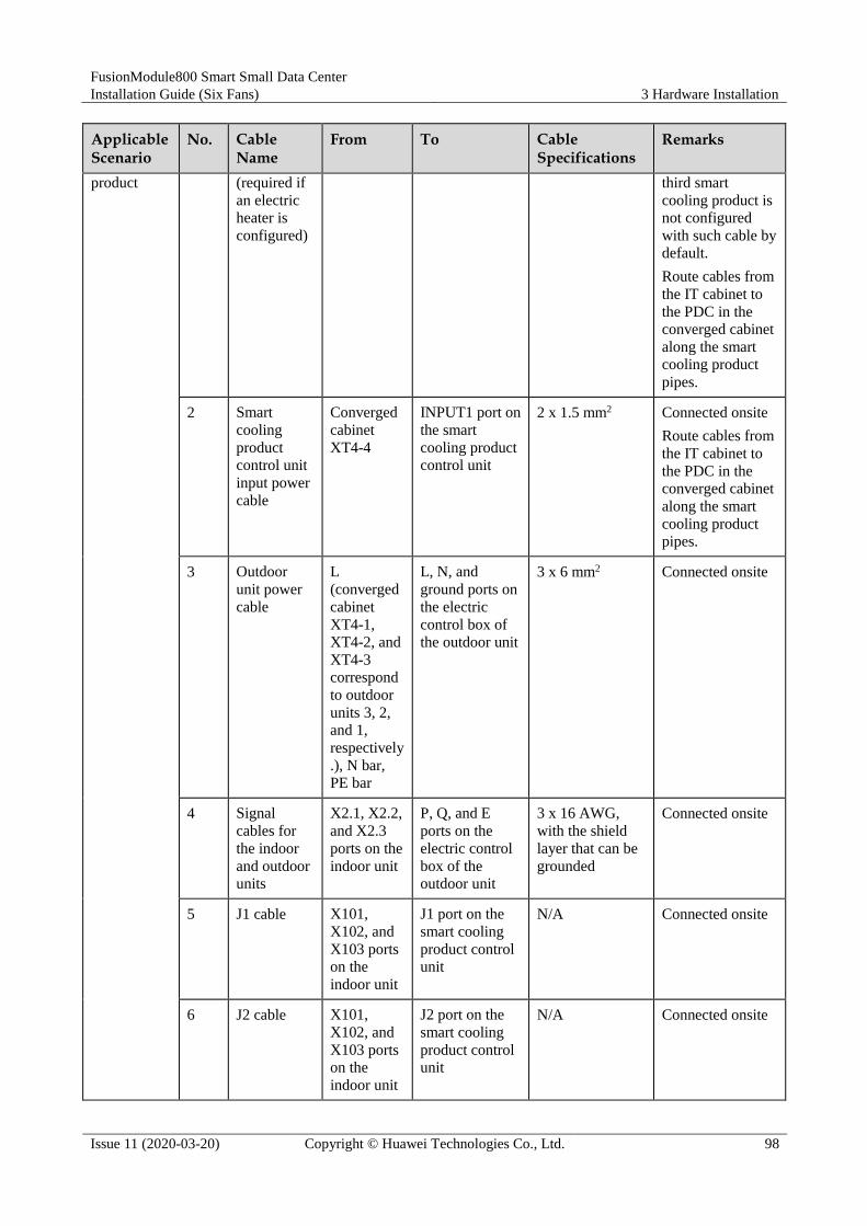
FusionModule800 Smart Small Data Center
Installation Guide (Six Fans) 3 Hardware Installation
Issue 11 (2020-03-20) Copyright © Huawei Technologies Co., Ltd. 98
Applicable Scenario
No. Cable Name
From To Cable Specifications
Remarks
product (required if
an electric
heater is
configured)
third smart
cooling product is
not configured
with such cable by
default.
Route cables from
the IT cabinet to
the PDC in the
converged cabinet
along the smart
cooling product
pipes.
2 Smart
cooling
product
control unit
input power
cable
Converged
cabinet
XT4-4
INPUT1 port on
the smart
cooling product
control unit
2 x 1.5 mm2 Connected onsite
Route cables from
the IT cabinet to
the PDC in the
converged cabinet
along the smart
cooling product
pipes.
3 Outdoor
unit power
cable
L
(converged
cabinet
XT4-1,
XT4-2, and
XT4-3
correspond
to outdoor
units 3, 2,
and 1,
respectively
.), N bar,
PE bar
L, N, and
ground ports on
the electric
control box of
the outdoor unit
3 x 6 mm2 Connected onsite
4 Signal
cables for
the indoor
and outdoor
units
X2.1, X2.2,
and X2.3
ports on the
indoor unit
P, Q, and E
ports on the
electric control
box of the
outdoor unit
3 x 16 AWG,
with the shield
layer that can be
grounded
Connected onsite
5 J1 cable X101,
X102, and
X103 ports
on the
indoor unit
J1 port on the
smart cooling
product control
unit
N/A Connected onsite
6 J2 cable X101,
X102, and
X103 ports
on the
indoor unit
J2 port on the
smart cooling
product control
unit
N/A Connected onsite

FusionModule800 Smart Small Data Center
Installation Guide (Six Fans) 3 Hardware Installation
Issue 11 (2020-03-20) Copyright © Huawei Technologies Co., Ltd. 99
Applicable Scenario
No. Cable Name
From To Cable Specifications
Remarks
7 Smart
cooling
product
control unit
output
power cable
X1.1, X1.2,
X1.3, and
FU1-FU3
ports on the
indoor unit
OUT1 port on
the smart
cooling product
control unit
N/A Connected onsite
8 J3 cable X101,
X102, and
X103 ports
on the
indoor unit
J3 port on the
smart cooling
product control
unit
N/A Connected onsite
9 J4 cable X101,
X102, and
X103 ports
on the
indoor unit
J4 port on the
smart cooling
product control
unit
N/A Connected onsite
10 T/H sensor
cable T/H sensor RS485/12 V
port on the
smart cooling
product control
unit
Two shielded
twisted pairs, 26
AWG
Connected onsite
11 Energy
control
center 800
(ECC800)
cable
FE-2 port
on the
control unit
PoE port on the
smart ETH
gateway
Four shielded
twisted pairs, 24
AWG
If the smart
ETH gateway
is configured,
connect the
cable to the
PoE port on
the smart ETH
gateway.
If no smart
ETH gateway
is configured,
connect the
cable to the
WAN_2 port
on the
ECC800.
12 Ground
cable
Ground
point on the
smart
cooling
product
control unit
IT cabinet
ground cable
4 mm2 Connected onsite
Single smart
cooling
product or double smart
1 Electric
heater
contactor (required if
Converged
cabinet
XT4-6 and XT4-5
Contactor KM1
of the
corresponding smart cooling
N/A Factory-installed

FusionModule800 Smart Small Data Center
Installation Guide (Six Fans) 3 Hardware Installation
Issue 11 (2020-03-20) Copyright © Huawei Technologies Co., Ltd. 100
Applicable Scenario
No. Cable Name
From To Cable Specifications
Remarks
cooling
products
an electric
heater is
configured)
correspond
to smart
cooling
products 1
and 2,
respectively
.
product
3 Outdoor
unit power
cable
L
(converged
cabinet
XT4-1,
XT4-2, and
XT4-3
correspond
to outdoor
units 3, 2,
and 1,
respectively
.), N bar,
PE bar
L, N, and
ground ports on
the electric
control box of
the outdoor unit
3 x 6 mm2 Connected onsite
4 Signal
cables for
the indoor
and outdoor
units
X2.1, X2.2,
and X2.3
ports on the
indoor unit
P, Q, and E
ports on the
electric control
box of the
outdoor unit
3 x 16 AWG,
with the shield
layer that can be
grounded
Connected onsite
10 T/H sensor
cable
T/H sensor RS485/12 V
port on the
smart cooling
product control
unit
Two shielded
twisted pairs, 26
AWG
Connected onsite
3.7.10 Vacuumization
Prerequisites Check that all pipe connectors are correct, and the refrigerant pipe tilts and has supports.
All pipes have been checked for leaks, and all pipes are not bent by a large angle.
Check that the hose clamps and cable ties of the drainpipe are secured. Water pipe joints
have been sealed by sealant.
The refrigerant pipe and water pipe are wrapped with thermal insulation foam.
Check that all nitrogen has been exhausted from the indoor unit.
Ensure that stop valves for the gas pipe and liquid pipe of the indoor unit are open.
Verify that stop valves for the gas pipe and liquid pipe of the outdoor unit are closed.

FusionModule800 Smart Small Data Center
Installation Guide (Six Fans) 3 Hardware Installation
Issue 11 (2020-03-20) Copyright © Huawei Technologies Co., Ltd. 101
Context
Tools: pressure gauge (measuring range ≥ 4.0 MPa), leather hose (withstanding a pressure of
at least 4.5 MPa), vacuum pump.
Procedure
Step 1 Connect the pressure gauge and vacuum pump and check that the pressure gauge valves are
all open.
Figure 3-81 Vacuumization
(1) Vacuum
pump
(2) Pressure
gauge
(3) Gas pipe needle
valve
(4) Liquid pipe needle
valve
Step 2 In the beginning, the vacuum pump makes loud noises and exhausts white smoke from the
exhaust vent. After 10 minutes, if it still exhausts white smoke, observe it for another 10
minutes because the cooling system may not be sealed properly or there may be too much
water in the cooling system.
Step 3 After 20 minutes, the pressure gauge pointer should be in the negative area and the vacuum
pump makes small noises. Close and open the pressure gauge alternatively for several times.
The position of the pressure gauge pointer and the noises made by the vacuum pump do not
change. Otherwise, the cooling system may not be sealed properly.
Step 4 Check that the time for pumping out the air is 80 minutes or longer after making sure that the
cooling system does not leak, and that the pressure displayed on the vacuum pump is less than
or equal to 60 Pa (absolute pressure). When the pressure stops dropping, pump for another 10
minutes.

FusionModule800 Smart Small Data Center
Installation Guide (Six Fans) 3 Hardware Installation
Issue 11 (2020-03-20) Copyright © Huawei Technologies Co., Ltd. 102
Step 5 After vacuumization, close all valves of the pressure gauge and the vacuum pump without
disconnecting it. Preserve the pressure for 10 minutes, and verify that the absolute pressure of
the cooling system is not greater than 90 Pa.
If the pressure gauge cannot display 60 Pa (absolute pressure), perform vacuum pumping so that the
pressure gauge stays at the smallest scale and preserve the pressure for 1 hour. Then, check whether the
pressure displayed on the gauge has an obvious increase.
Step 6 After making sure that the pressure gauge has no obvious increase, open the stop valves for
the gas pipe and liquid pipe of the outdoor unit.
After the outdoor unit stop valve is opened, the refrigerant in the outdoor unit flows to the
engineering pipe and indoor unit pipe. When performing other operations, be careful to
prevent refrigerant from spraying out.
After the vacuumization and before removing the rubber hose, ensure that there is positive
pressure inside the refrigerant pipe of the indoor unit.
Step 7 Remove the hose, pressure gauge, and vacuum pump.
Step 8 Install needle valve nut and rear cover nut of indoor unit and outdoor unit.
Step 9 Wrap the gas pipe stop valve with stop valve sponge.
Figure 3-82 Wrapping the gas pipe stop valve
(1) Stop valve
sponge
(2) Gas pipe stop
valve
(3) Liquid pipe stop
valve
(4) Cable
ties
Step 10 Wrap the gas liquid stop valve with stop valve sponge by referring to Step 9.
----End
3.8 Installing Batteries
If batteries are configured, perform the following steps to install them.

FusionModule800 Smart Small Data Center
Installation Guide (Six Fans) 3 Hardware Installation
Issue 11 (2020-03-20) Copyright © Huawei Technologies Co., Ltd. 103
Battery Cabinet Overview
The battery appearance and layout shown in the figure are for reference only. The actual
battery appearance and battery wiring diagram prevail.
Figure 3-83 Battery cabinet
(1) Circuit breaker (2) Battery (3) Tray
Correct Method for Connecting Battery Cables When the length of a battery cable equals the distance between two battery terminals,
connect the cable straight through, as shown in Figure 3-84.

FusionModule800 Smart Small Data Center
Installation Guide (Six Fans) 3 Hardware Installation
Issue 11 (2020-03-20) Copyright © Huawei Technologies Co., Ltd. 104
Figure 3-84 Directly connecting two batteries
When the length of a battery cable is longer than the distance between two battery
terminals, connect the cable in the way shown in Figure 3-85. To prevent misshaping
battery terminals, do not connect the cable in the way shown in Figure 3-86.

FusionModule800 Smart Small Data Center
Installation Guide (Six Fans) 3 Hardware Installation
Issue 11 (2020-03-20) Copyright © Huawei Technologies Co., Ltd. 105
Figure 3-85 Correct battery cable connection method

FusionModule800 Smart Small Data Center
Installation Guide (Six Fans) 3 Hardware Installation
Issue 11 (2020-03-20) Copyright © Huawei Technologies Co., Ltd. 106
Figure 3-86 Incorrect battery cable connection method
Precautions for Connecting Battery Cables For details about how to connect battery cables, see the battery cable connection diagram
delivered with the cables.
Battery trays consist of supports and trays, with space reserved between supports and
trays on adjacent layers for operation. If the battery trays need to be removed, perform
the following operations:
a. Remove the battery trays from top to bottom.
b. Install batteries and connect cables from bottom to top.
When installing batteries, install battery trays at first, then place batteries onto the trays, and
connect cables. Do not move all the batteries into the cabinet after placing the batteries on the
trays and connecting cables.
When placing batteries, install separators between adjacent batteries, as shown in Figure
3-87. If the battery capacity is 65 Ah or more, there is no need to install a separator in the
depth direction of the battery cabinet.

FusionModule800 Smart Small Data Center
Installation Guide (Six Fans) 3 Hardware Installation
Issue 11 (2020-03-20) Copyright © Huawei Technologies Co., Ltd. 107
Figure 3-87 Installing a separator
Route and secure cables between layers along the rack rail in the vertical direction, as
shown by (1) in Figure 3-88.
Route and secure cables between layers along the tray supporting beam in the horizontal
direction, as shown by (2) in Figure 3-88.
Figure 3-88 Cable routes
(Optional) When battery cabinets are installed adjacent to each other, remove the upper
side panels from the battery cabinets for routing cables to the corresponding ports.
Connecting Cables to the Circuit Breaker in a Battery Cabinet
Before connecting cables, ensure that the circuit breaker is OFF.
Connect cables to the circuit breaker as follows:
1. Remove the circuit breaker panel, as shown in Figure 3-89.
2. Connect cables to the +, N, and – ports on the UPS, as shown by (1) in Figure 3-90.
3. Connect cables to the +, N, and – terminals on the battery, as shown by (2) in Figure
3-90.

FusionModule800 Smart Small Data Center
Installation Guide (Six Fans) 3 Hardware Installation
Issue 11 (2020-03-20) Copyright © Huawei Technologies Co., Ltd. 108
4. (Optional) If two battery strings are configured, connect the cables from the +, N, and –
ports on the UPS of one battery string to the corresponding +, N, and – ports on the UPS
of the other battery string, as shown by (1) in Figure 3-91. Connect cables to the UPS, as
shown by (2) in Figure 3-91. Connect cables to the battery, as shown by (3) in Figure
3-91.
Figure 3-89 Removing the circuit breaker panel
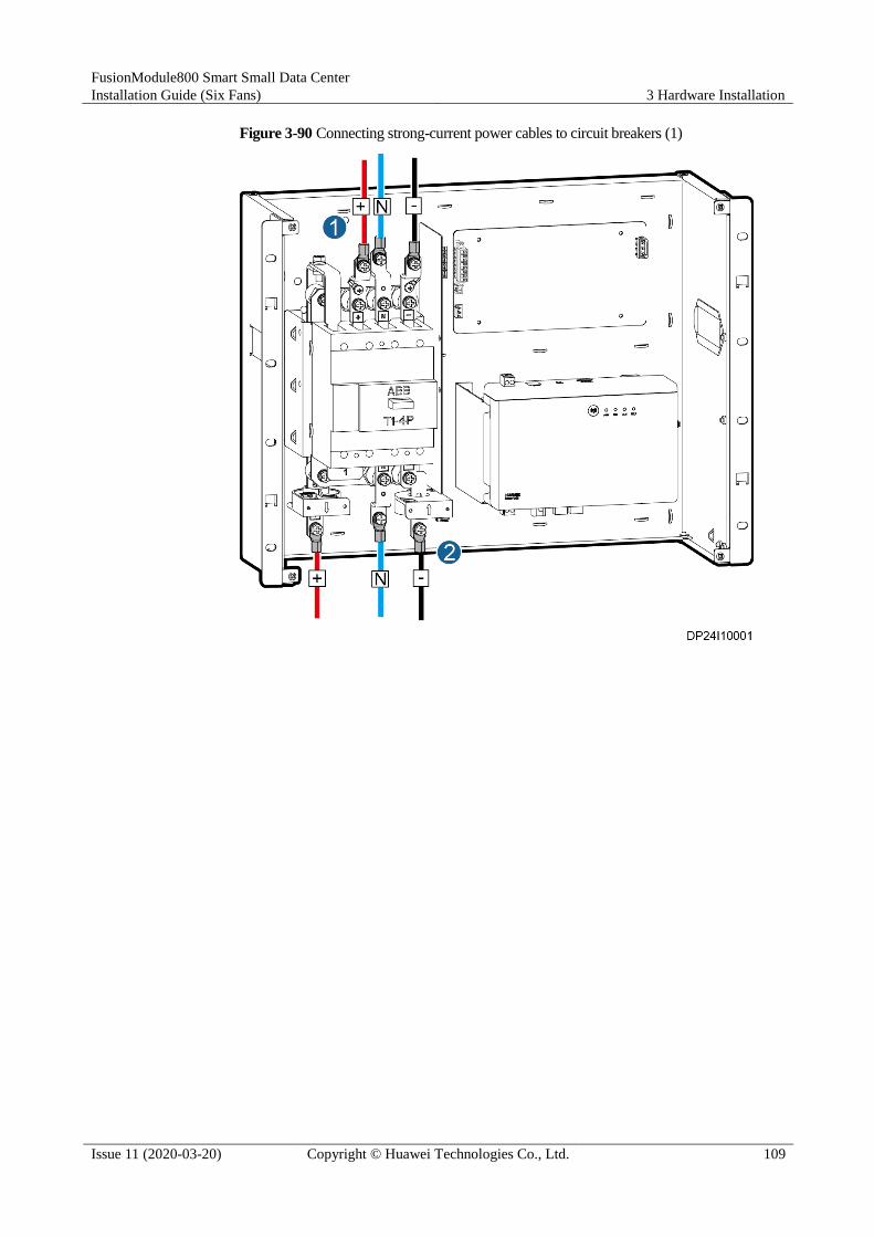
FusionModule800 Smart Small Data Center
Installation Guide (Six Fans) 3 Hardware Installation
Issue 11 (2020-03-20) Copyright © Huawei Technologies Co., Ltd. 109
Figure 3-90 Connecting strong-current power cables to circuit breakers (1)

FusionModule800 Smart Small Data Center
Installation Guide (Six Fans) 3 Hardware Installation
Issue 11 (2020-03-20) Copyright © Huawei Technologies Co., Ltd. 110
Figure 3-91 Connecting strong-current power cables to circuit breakers (2)
Connecting Cables to the MCBs in a Battery Cabinet
Before connecting cables, ensure that the miniature circuit breakers (MCBs) are OFF.
Connect cables to the MCBs as follows:
1. Remove the MCB panel, as shown in Figure 3-92.
2. Connect cables to the +, N, and – ports on the UPS, as shown by (1) in Figure 3-93.
3. Connect cables to the +, N, and – terminals on the battery, as shown by (2) in Figure
3-93.
4. (Optional) If two battery strings are configured, connect the cables from the +, N, and –
ports on the UPS of one battery string to the corresponding +, N, and – ports on the UPS
of the other battery string, as shown by (1) in Figure 3-94. Connect cables to the UPS, as
shown by (2) in Figure 3-94. Connect cables to the battery, as shown by (3) in Figure
3-94.

FusionModule800 Smart Small Data Center
Installation Guide (Six Fans) 3 Hardware Installation
Issue 11 (2020-03-20) Copyright © Huawei Technologies Co., Ltd. 111
Figure 3-92 Removing the MCB panel

FusionModule800 Smart Small Data Center
Installation Guide (Six Fans) 3 Hardware Installation
Issue 11 (2020-03-20) Copyright © Huawei Technologies Co., Ltd. 112
Figure 3-93 Connecting strong-current power cables to MCBs (1)

FusionModule800 Smart Small Data Center
Installation Guide (Six Fans) 3 Hardware Installation
Issue 11 (2020-03-20) Copyright © Huawei Technologies Co., Ltd. 113
Figure 3-94 Connecting strong-current power cables to MCBs (2)
Installing Panels
1. Reinstall the circuit breaker panel.
2. Secure filler panels to the rack rails on the rear door, as shown in Figure 3-95.
Install filler panels according to the U position markings on the cabinet. Ensure that filler panels fully
cover the rack rails.

FusionModule800 Smart Small Data Center
Installation Guide (Six Fans) 3 Hardware Installation
Issue 11 (2020-03-20) Copyright © Huawei Technologies Co., Ltd. 114
Figure 3-95 Installing filler panels
3.9 Installing a Battery Pack
Context
The battery pack is installed at the bottom of the IT cabinet adjacent to the Converged
Cabinet.

FusionModule800 Smart Small Data Center
Installation Guide (Six Fans) 3 Hardware Installation
Issue 11 (2020-03-20) Copyright © Huawei Technologies Co., Ltd. 115
If no smart cooling product is installed in the IT cabinet, install battery packs from bottom
to top starting from the 1 U position above the cabinet bottom.
If a smart cooling product is installed in the IT cabinet, install battery packs from bottom
to top starting from the 12 U position above the cabinet bottom.
Procedure
Step 1 Take out mounting ears from the battery pack fitting bag, and install the mounting ears on the
battery pack using eight M4 screws, as shown in Figure 3-96.
Figure 3-96 Installing mounting ears
Step 2 Install floating nuts at the battery pack installation position.
Step 3 Install heavy guide rails at the battery pack installation position, as shown in Figure 3-97.

FusionModule800 Smart Small Data Center
Installation Guide (Six Fans) 3 Hardware Installation
Issue 11 (2020-03-20) Copyright © Huawei Technologies Co., Ltd. 116
Figure 3-97 Installing heavy guide rails
Step 4 Push the battery back onto the guide rails, and secure the battery pack to the cabinet rack rails
using mounting ears and screws, as shown in Figure 3-98.
Figure 3-98 Installing a battery pack
Step 5 Install the protective cover for the battery pack.
Step 6 Install other battery packs in the same way.
----End

FusionModule800 Smart Small Data Center
Installation Guide (Six Fans) 3 Hardware Installation
Issue 11 (2020-03-20) Copyright © Huawei Technologies Co., Ltd. 117
3.10 (Optional) Installing Cable Troughs
If cable troughs are configured, perform the following steps to install them.
3.10.1 Removing a Binding Plate
Prerequisites
A cable trough is determined to be installed.
Context
Install a binding plate at the top of the cabinet, as shown in Figure 3-99.
Figure 3-99 Binding plate installation position
Procedure
Step 1 Remove the two M5 tapping screws from the binding plate and then remove the binding plate
from the cabinet top, as shown in Figure 3-100.

FusionModule800 Smart Small Data Center
Installation Guide (Six Fans) 3 Hardware Installation
Issue 11 (2020-03-20) Copyright © Huawei Technologies Co., Ltd. 118
Figure 3-100 Removing a binding plate
Step 2 Remove other binding plates in the same way.
----End
3.10.2 Installing a 600 mm Wide Cable Trough
Context
Install two 600 mm wide cable troughs on the top of every 600 mm wide cabinet. When
installing cable troughs, first install two cable troughs at the top of the end cabinet, and then
install the other cable troughs at the top of other cabinets along the aisle in sequence.
Figure 3-101 shows a 600 mm wide cable trough. Its BOM number is 21501142.

FusionModule800 Smart Small Data Center
Installation Guide (Six Fans) 3 Hardware Installation
Issue 11 (2020-03-20) Copyright © Huawei Technologies Co., Ltd. 119
Figure 3-101 600 mm wide cable trough
(1) Partition plate (2) Side panel (3) Supporting
plate
When installing cable troughs, be aware of PDU2000 cables at the top of the cabinet:
After cable troughs above the front and rear doors are installed, place the PDU2000
cables in the cable trough above the rear door.
After PDU2000 cables are placed, bind the cables to the cable trough using cable ties.
Install cable troughs based on the colors of binding plates at the cabinet top. Install
strong-current power cable troughs at red binding plates and weak-current power cable
troughs at blue binding plates.
Procedure
Step 1 Keep a vertical plate of the cable trough flush with the top surface of the cabinet and clamp
the clasps into the square holes in the first row counting from the front door to the rear door,
as shown in Figure 3-102.
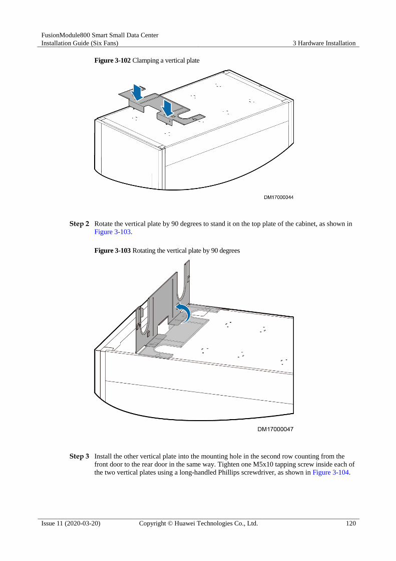
FusionModule800 Smart Small Data Center
Installation Guide (Six Fans) 3 Hardware Installation
Issue 11 (2020-03-20) Copyright © Huawei Technologies Co., Ltd. 120
Figure 3-102 Clamping a vertical plate
Step 2 Rotate the vertical plate by 90 degrees to stand it on the top plate of the cabinet, as shown in
Figure 3-103.
Figure 3-103 Rotating the vertical plate by 90 degrees
Step 3 Install the other vertical plate into the mounting hole in the second row counting from the
front door to the rear door in the same way. Tighten one M5x10 tapping screw inside each of
the two vertical plates using a long-handled Phillips screwdriver, as shown in Figure 3-104.

FusionModule800 Smart Small Data Center
Installation Guide (Six Fans) 3 Hardware Installation
Issue 11 (2020-03-20) Copyright © Huawei Technologies Co., Ltd. 121
Figure 3-104 Installing the other vertical plate
Step 4 Press a supporting plate along the two vertical plates down to the place between the four
clasps and the cable bridge, as shown in Figure 3-105. Ensure that the supporting plate is fully
into the clasps.
When installing the supporting plate, do not remove the grommet strip on the U-shaped trough.
Figure 3-105 Installing a supporting plate
Step 5 Install a partition plate. Press both sides of the V-shaped partition plate with hands to decrease
the angle to a proper degree, and clamp the clasps at the bottom into the square holes nearly,

FusionModule800 Smart Small Data Center
Installation Guide (Six Fans) 3 Hardware Installation
Issue 11 (2020-03-20) Copyright © Huawei Technologies Co., Ltd. 122
as shown in Figure 3-106. (By default, insert the clasps into the two adjacent square holes in
the middle. In actual conditions, determine the square holes as required.)
Figure 3-106 Installing a partition plate
Step 6 Install adjacent cable troughs in the same way.
Step 7 Rotate the interconnecting wrench and clamp it into the clasps until the wrench is horizontal,
as shown in Figure 3-107. This operation interconnects the cable troughs.
Figure 3-107 Installing an interconnecting wrench
(1) Interconnecting wrench

FusionModule800 Smart Small Data Center
Installation Guide (Six Fans) 3 Hardware Installation
Issue 11 (2020-03-20) Copyright © Huawei Technologies Co., Ltd. 123
Step 8 Install the cable trough above the rear door in a similar way.
----End
3.10.3 Installing an 800 mm Wide Cable Trough
An 800 mm wide cable trough (BOM number: 21501140) is installed on the top of an 800
mm wide cabinet. The installation method is similar to the method for installing a 600 mm
wide cable trough. For details, see 3.10.2 Installing a 600 mm Wide Cable Trough.
3.11 Installing Monitoring Devices
3.11.1 Installing the SIM Card and Antenna
If a subscriber identity module (SIM) card and an antenna are configured, perform the
following steps to install them.
Procedure
Step 1 Record the position of the signal cable connected to the panel of the ECC800 main control
module, and then disconnect the signal cable.
Step 2 Remove the ECC800 main control module, and then insert the SIM card into the left slot of
the ECC800 main control module.
The SIM card needs to support global system for mobile communications (GSM) or wideband code
division multiple access (WCDMA).
Figure 3-108 Removing the ECC800 main control module

FusionModule800 Smart Small Data Center
Installation Guide (Six Fans) 3 Hardware Installation
Issue 11 (2020-03-20) Copyright © Huawei Technologies Co., Ltd. 124
Figure 3-109 Installing a SIM card
Step 3 Reconnect the signal cable to the panel of the ECC800 main control module based on the
recorded position.
Step 4 Install the antenna.
1. Attach the antenna to the middle of the cabinet top.
2. Route the antenna cable into the cabinet through the signal cable hole at the top of the
cabinet and then to the appropriate port on the ECC800.
3. Connect the 2.4G antenna cable to the RF_Z port on the ECC800.
4. Connect the 3G antenna cable to the 3G/4G port on the ECC800.
Figure 3-110 Installing an antenna cable
----End
3.11.2 Installing a PAD
Prerequisites
Cabinets have been combined.

FusionModule800 Smart Small Data Center
Installation Guide (Six Fans) 3 Hardware Installation
Issue 11 (2020-03-20) Copyright © Huawei Technologies Co., Ltd. 125
Context
The PAD is installed on the door of the Converged Cabinet, as shown in Figure 3-111.
Figure 3-111 PAD installation position
(1) PAD installation position
Procedure
Step 1 Adjust the width and height of the PAD support to match the dimensions of the PAD to be
installed.

FusionModule800 Smart Small Data Center
Installation Guide (Six Fans) 3 Hardware Installation
Issue 11 (2020-03-20) Copyright © Huawei Technologies Co., Ltd. 126
Figure 3-112 Adjustment screws
(1) Adjustment screws
Step 2 Remove nuts from the PAD support, insert the support into the mounting holes on the cabinet
front door, and reinstall the nuts to secure the support to the front door.

FusionModule800 Smart Small Data Center
Installation Guide (Six Fans) 3 Hardware Installation
Issue 11 (2020-03-20) Copyright © Huawei Technologies Co., Ltd. 127
Figure 3-113 Removing the nut
Step 3 Route the PAD power cable to the cable hole in the PAD support and connect the cable to the
PAD.
Step 4 Adjust the feet above the PAD support and clamp the PAD to the PAD support.
Ensure that the PAD is installed securely and reliably.

FusionModule800 Smart Small Data Center
Installation Guide (Six Fans) 3 Hardware Installation
Issue 11 (2020-03-20) Copyright © Huawei Technologies Co., Ltd. 128
Figure 3-114 Installing a PAD
Step 5 Connect the PAD charge cable.

FusionModule800 Smart Small Data Center
Installation Guide (Six Fans) 3 Hardware Installation
Issue 11 (2020-03-20) Copyright © Huawei Technologies Co., Ltd. 129
The PAD charge cable has been routed near the charge port on the rear door of the
Converged Cabinet.
To connect the PAD charge cable, connect the charge conversion adapter obtained from
the PAD package to the charge port, and then connect the PAD charge cable to the charge
conversion adapter.
Figure 3-115 PAD charge port position (using a 3 U PDU as an example)
(1) PAD charge port
----End
3.11.3 (Optional) Installing a VCN500
Context
You are advised to deploy a VCN500 at the 40-41 U position on the front top of the IT cabinet
adjacent to the Converged Cabinet. For details, see Figure 3-116.

FusionModule800 Smart Small Data Center
Installation Guide (Six Fans) 3 Hardware Installation
Issue 11 (2020-03-20) Copyright © Huawei Technologies Co., Ltd. 130
Figure 3-116 VCN500 installation position
Procedure
Step 1 Select VCN500 mounting holes on the IT cabinet, adjust the guide rails or trays, and install
floating nuts.
Step 2 Place the VCN500 with caution into the IT cabinet, and gently press down buttons on the left
and right mounting ears, as shown in Figure 3-117.
Figure 3-117 Placing a VCN500
Step 3 Tighten the captive screws in the ears using a Phillips screwdriver to close the mounting ear
buttons, as shown in Figure 3-118.

FusionModule800 Smart Small Data Center
Installation Guide (Six Fans) 3 Hardware Installation
Issue 11 (2020-03-20) Copyright © Huawei Technologies Co., Ltd. 131
Figure 3-118 Installing a VCN500
Step 4 Connect the VCN500 power cable to the appropriate PDU2000.
----End
3.11.4 Installing the VCN540
Context The VCN540 does not carry disks when being delivered. First install disks and then
install the device in a network cabinet.
After the VCN540 is delivered to the site, disk filler panels are installed in slots where
disks are not installed, by default. You are not advised to remove the filler panels from
the slots where disks are not installed, because removing the filler panels will affect the
heat dissipation of fans and generate some noises.
Procedure
Step 1 Install a hard drive.
1. Install a hard drive.
2. Secure the hard drive to the front panel using a screwdriver.
3. Push the hard drive into the subrack along the guide rails until it cannot move forwards.
4. Close the ejector lever and push the hard drive in position.

FusionModule800 Smart Small Data Center
Installation Guide (Six Fans) 3 Hardware Installation
Issue 11 (2020-03-20) Copyright © Huawei Technologies Co., Ltd. 132
Figure 3-119 Installing a hard drive
Step 2 Determine the mounting holes for the VCN540 in the network cabinet based on the
engineering layout diagram, adjust the guide rails and install floating nuts.
Figure 3-120 Installing the floating nuts
(1) Guide rail (2) Floating nut installation position
Step 3 Use four screws to configure one mounting ear on the left of the front panel and the same way
to configure the other ones on the right side. Then use a Phillips screwdriver to fasten the
screws to fix the mounting ears.

FusionModule800 Smart Small Data Center
Installation Guide (Six Fans) 3 Hardware Installation
Issue 11 (2020-03-20) Copyright © Huawei Technologies Co., Ltd. 133
Figure 3-121 Installing mounting ears
Step 4 Place the VCN540 on the guide rails. Keep pushing the subrack until the mounting ears of the
subrack are close to the mounting bar at the front of the network cabinet.
Figure 3-122 Placing a VCN540
Step 5 Put two M6 screws through the slotted holes of one mounting ear and use a Phillips
screwdriver to fasten the screws to secure the device to the rack rail at front of the network
cabinet.

FusionModule800 Smart Small Data Center
Installation Guide (Six Fans) 3 Hardware Installation
Issue 11 (2020-03-20) Copyright © Huawei Technologies Co., Ltd. 134
Figure 3-123 Securing a VCN540
----End
3.11.5 (Optional) Installing a LAN Switch
Context
The LAN switch needs to be installed in the 38 U position on the top of the IT cabinet front
side to the left of the Converged Cabinet, as shown in Figure 3-124.

FusionModule800 Smart Small Data Center
Installation Guide (Six Fans) 3 Hardware Installation
Issue 11 (2020-03-20) Copyright © Huawei Technologies Co., Ltd. 135
Figure 3-124 Position for the LAN switch
Procedure
Step 1 Locate the LAN switch installation position in the IT cabinet, and install guide rails and
floating nuts.
Step 2 Install the mounting ears delivered with the LAN switch, and secure the LAN switch to the
rack rails in the front of the cabinet.
This section describes only the installation method. The actual product appearance prevails.

FusionModule800 Smart Small Data Center
Installation Guide (Six Fans) 3 Hardware Installation
Issue 11 (2020-03-20) Copyright © Huawei Technologies Co., Ltd. 136
Figure 3-125 Installing a LAN switch
Step 3 Connect the LAN switch power cable to the PDU2000.
Step 4 Connect any port among the 1-24 ports of the LAN switch to the WAN_1 port on the ECC800
using a network cable.
Step 5 Insert the power modules into the power slots of the 24-port LAN switch, and tighten the
captive screws on the power module panel.
Figure 3-126 Installing the power modules for a 24-port LAN switch

FusionModule800 Smart Small Data Center
Installation Guide (Six Fans) 3 Hardware Installation
Issue 11 (2020-03-20) Copyright © Huawei Technologies Co., Ltd. 137
Two power modules need to be installed for a 24-port LAN switch onsite.
----End
3.11.6 Installing T/H Sensors (in Cold Aisle Containments)
This section describes how to install T/H sensors in cold aisle containments.
Context The T/H sensor BOM number is 02310NBS.
The number of T/H sensors depends on the number of smart cooling products and
cabinets. Each smart cooling product should be configured with at least one T/H sensor.
For detailed configuration, see the T/H sensor layout.
Procedure
Step 1 Install T/H sensors.
1. Open the cabinet front door.
2. Install the T/H sensor bases at the 27 U to 28 U positions on the posts of the IT cabinet,
battery cabinet, and network cabinet in the cold aisle, and then clamp the T/H sensors
onto the bases. Install one or two T/H sensors on the top of the Converged Cabinet
outside the aisle.
If battery packs are configured, the installation positions of all T/H sensors can be moved upwards along
the rack rail to avoid interference with battery packs.
Figure 3-127 Installing a T/H sensor inside an aisle (on a left post)

FusionModule800 Smart Small Data Center
Installation Guide (Six Fans) 3 Hardware Installation
Issue 11 (2020-03-20) Copyright © Huawei Technologies Co., Ltd. 138
Figure 3-128 Installing a T/H sensor outside an aisle
Step 2 Set DIP switches for the T/H sensors and connect communications cables to them.
Figure 3-129 DIP switch on a T/H sensor

FusionModule800 Smart Small Data Center
Installation Guide (Six Fans) 3 Hardware Installation
Issue 11 (2020-03-20) Copyright © Huawei Technologies Co., Ltd. 139
Figure 3-130 Address and DIP switch setting on a T/H sensor
Description about the cable connection to and DIP switch setting on a T/H sensor:
Connect the T/H sensors in the shape of to smart cooling product control unit 1
in series.
Connect the T/H sensors in the shape of to smart cooling product control unit 2
in series.
Connect the T/H sensors in the shape of to smart cooling product control unit 3
in series.
Each of the T/H sensors connected in series has a unique address.
The DIP switch address for T/H A is always 21. T/H A connects to smart cooling product
control units 1 as the last T/H sensor connected in series.
The DIP switch address for T/H B is always 21. T/H B connects to smart cooling product
control units 2 as the last T/H sensor connected in series.

FusionModule800 Smart Small Data Center
Installation Guide (Six Fans) 3 Hardware Installation
Issue 11 (2020-03-20) Copyright © Huawei Technologies Co., Ltd. 140
Figure 3-131 Connecting T/H Sensors in Series and Then to the Control Unit
T/H is short for temperature and humidity sensor. A/C is short for smart cooling product. Addr is
short for DIP switch address.
T/H sensors are numbered T/H1–T/Hn from left to right based on their positions in the cabinet aisle.
T/H sensors at the top of the Converged Cabinet are numbered T/H A and T/H B from left to right.
The smart cooling products in the Converged Cabinet are numbered from bottom to top. The smart
cooling product in the IT cabinet is numbered 3.
The T/H sensors inside the aisle are installed on the left and right rack rails at the front door of the IT
cabinet, battery cabinet, and network cabinet. Outside the aisle, one to two T/H sensors are deployed
at the top of the Converged Cabinet.
The last cable from the T/H sensor to the smart cooling product controller is obtained from the cable
bag numbered 04092766.

FusionModule800 Smart Small Data Center
Installation Guide (Six Fans) 3 Hardware Installation
Issue 11 (2020-03-20) Copyright © Huawei Technologies Co., Ltd. 141
Figure 3-132 T/H sensor layout and DIP switch address (1 cabinet and 1 smart cooling product)
Figure 3-133 T/H sensor layout and DIP switch address (2 cabinets and 1 smart cooling product)

FusionModule800 Smart Small Data Center
Installation Guide (Six Fans) 3 Hardware Installation
Issue 11 (2020-03-20) Copyright © Huawei Technologies Co., Ltd. 142
Figure 3-134 T/H sensor layout and DIP switch address (3 cabinets and 1 smart cooling product)
Figure 3-135 T/H sensor layout and DIP switch address (4 cabinets and 1 smart cooling product)
Figure 3-136 T/H sensor layout and DIP switch address (5 cabinets and 1 smart cooling product)

FusionModule800 Smart Small Data Center
Installation Guide (Six Fans) 3 Hardware Installation
Issue 11 (2020-03-20) Copyright © Huawei Technologies Co., Ltd. 143
Figure 3-137 T/H sensor layout and DIP switch address (6 cabinets and 1 smart cooling product)
Figure 3-138 T/H sensor layout and DIP switch address (7 cabinets and 1 smart cooling product)

FusionModule800 Smart Small Data Center
Installation Guide (Six Fans) 3 Hardware Installation
Issue 11 (2020-03-20) Copyright © Huawei Technologies Co., Ltd. 144
Figure 3-139 T/H sensor layout and DIP switch address (8 cabinets and 1 smart cooling product)
Figure 3-140 T/H sensor layout and DIP switch address (2 cabinets and 2 smart cooling products)

FusionModule800 Smart Small Data Center
Installation Guide (Six Fans) 3 Hardware Installation
Issue 11 (2020-03-20) Copyright © Huawei Technologies Co., Ltd. 145
Figure 3-141 T/H sensor layout and DIP switch address (3 cabinets and 2 smart cooling products)
Figure 3-142 T/H sensor layout and DIP switch address (4 cabinets and 2 smart cooling products)
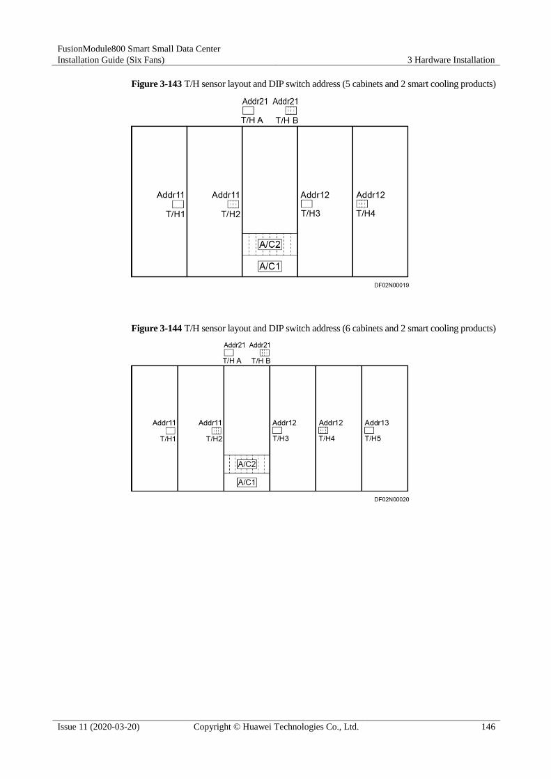
FusionModule800 Smart Small Data Center
Installation Guide (Six Fans) 3 Hardware Installation
Issue 11 (2020-03-20) Copyright © Huawei Technologies Co., Ltd. 146
Figure 3-143 T/H sensor layout and DIP switch address (5 cabinets and 2 smart cooling products)
Figure 3-144 T/H sensor layout and DIP switch address (6 cabinets and 2 smart cooling products)

FusionModule800 Smart Small Data Center
Installation Guide (Six Fans) 3 Hardware Installation
Issue 11 (2020-03-20) Copyright © Huawei Technologies Co., Ltd. 147
Figure 3-145 T/H sensor layout and DIP switch address (7 cabinets and 2 smart cooling products)
Figure 3-146 T/H sensor layout and DIP switch address (8 cabinets and 2 smart cooling products)
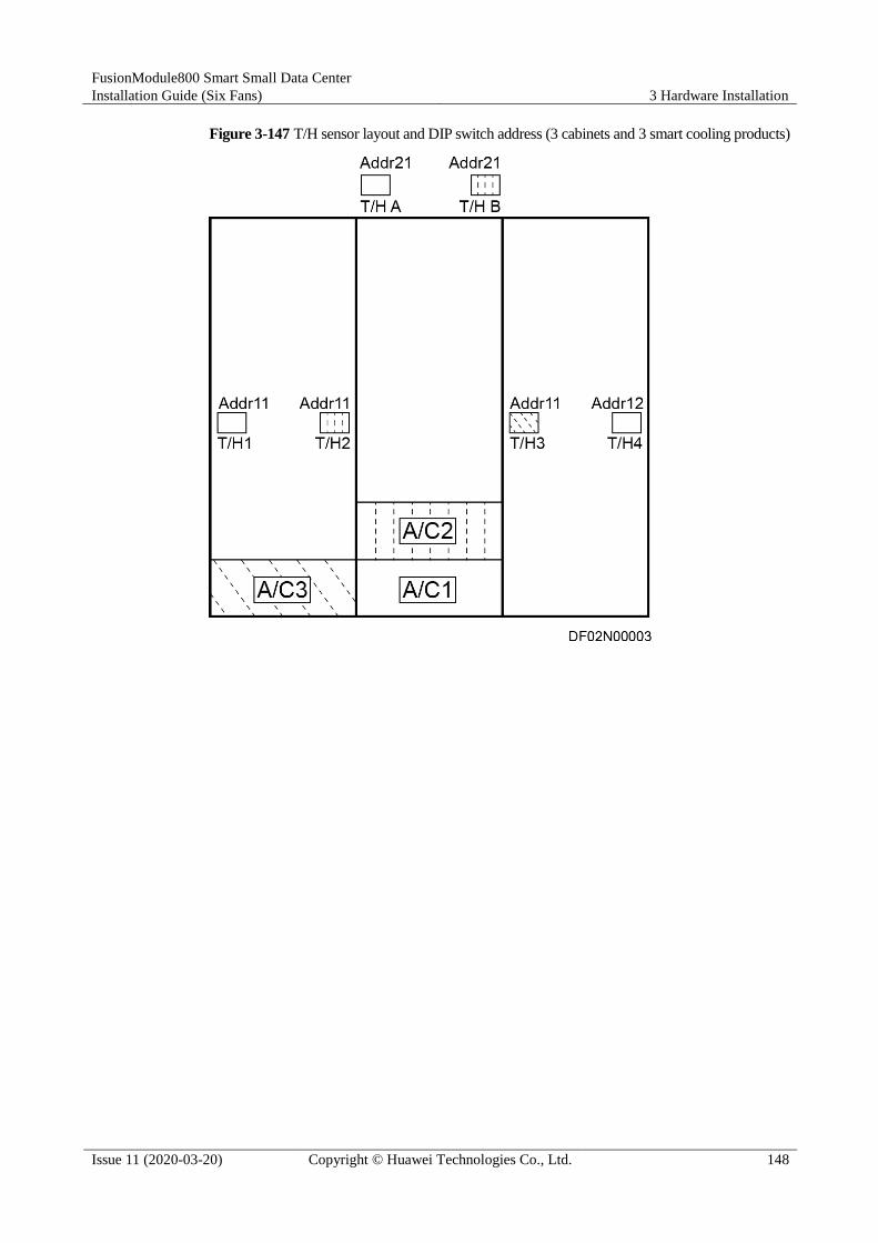
FusionModule800 Smart Small Data Center
Installation Guide (Six Fans) 3 Hardware Installation
Issue 11 (2020-03-20) Copyright © Huawei Technologies Co., Ltd. 148
Figure 3-147 T/H sensor layout and DIP switch address (3 cabinets and 3 smart cooling products)

FusionModule800 Smart Small Data Center
Installation Guide (Six Fans) 3 Hardware Installation
Issue 11 (2020-03-20) Copyright © Huawei Technologies Co., Ltd. 149
Figure 3-148 T/H sensor layout and DIP switch address (4 cabinets and 3 smart cooling products)
Figure 3-149 T/H sensor layout and DIP switch address (5 cabinets and 3 smart cooling products)

FusionModule800 Smart Small Data Center
Installation Guide (Six Fans) 3 Hardware Installation
Issue 11 (2020-03-20) Copyright © Huawei Technologies Co., Ltd. 150
Figure 3-150 T/H sensor layout and DIP switch address (6 cabinets and 3 smart cooling products)
Figure 3-151 T/H sensor layout and DIP switch address (7 cabinets and 3 smart cooling products)
Figure 3-152 T/H sensor layout and DIP switch address (8 cabinets and 3 smart cooling products)

FusionModule800 Smart Small Data Center
Installation Guide (Six Fans) 3 Hardware Installation
Issue 11 (2020-03-20) Copyright © Huawei Technologies Co., Ltd. 151
----End
3.11.7 Installing T/H Sensors (in Hot Aisle Containments)
This section describes how to install T/H sensors in hot aisle containments.
Context The T/H sensor BOM number is 02310NBS.
The number of T/H sensors depends on the number of smart cooling products and
cabinets. Each smart cooling product should be configured with at least one T/H sensor.
For detailed configuration, see the T/H sensor layout.
Procedure
Step 1 Install T/H sensors.
1. Open the cabinet front door.
2. Install the T/H sensor base at the 27 U to 28 U position of the post at the cabinet front
door, and then clamp the T/H sensor onto the base.
If battery packs are configured, the installation positions of all T/H sensors can be moved upwards along
the rack rail to avoid interference with battery packs.
Figure 3-153 Installing a T/H sensor (on a left post)
Step 2 Set DIP switches for the T/H sensors and connect communications cables to them.

FusionModule800 Smart Small Data Center
Installation Guide (Six Fans) 3 Hardware Installation
Issue 11 (2020-03-20) Copyright © Huawei Technologies Co., Ltd. 152
Figure 3-154 DIP switch on a T/H sensor
Figure 3-155 Address and DIP switch setting on a T/H sensor
Description about the cable connection to and DIP switch setting on a T/H sensor:
Connect the T/H sensors in the shape of to smart cooling product control unit 1 in
series.
Connect the T/H sensors in the shape of to smart cooling product control unit 2 in
series.
Connect the T/H sensors in the shape of to smart cooling product control unit 3 in
series.
Each of the T/H sensors connected in series has a unique address.

FusionModule800 Smart Small Data Center
Installation Guide (Six Fans) 3 Hardware Installation
Issue 11 (2020-03-20) Copyright © Huawei Technologies Co., Ltd. 153
Figure 3-156 Connecting T/H Sensors in Series and Then to the Control Unit
T/H is short for temperature and humidity sensor. A/C is short for smart cooling product. Addr is
short for DIP switch address.
T/H sensors are numbered T/H1-T/Hn from left to right based on their positions in the cabinet aisle.
The smart cooling products in the Converged Cabinet are numbered from bottom to top. The smart
cooling product in the IT cabinet is numbered 3.
The T/H sensors are installed on the left and right rack rails at the front door of the IT cabinet,
battery cabinet, and network cabinet.
The last cable from the T/H sensor to the smart cooling product controller is obtained from the cable
bag numbered 04092766.
Figure 3-157 T/H sensor layout and DIP switch address (1 smart cooling product for 1 cabinet)
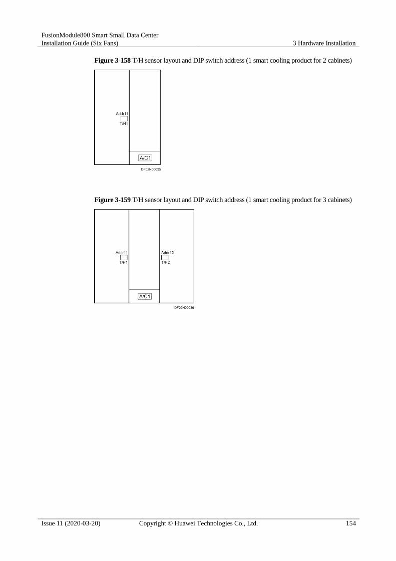
FusionModule800 Smart Small Data Center
Installation Guide (Six Fans) 3 Hardware Installation
Issue 11 (2020-03-20) Copyright © Huawei Technologies Co., Ltd. 154
Figure 3-158 T/H sensor layout and DIP switch address (1 smart cooling product for 2 cabinets)
Figure 3-159 T/H sensor layout and DIP switch address (1 smart cooling product for 3 cabinets)

FusionModule800 Smart Small Data Center
Installation Guide (Six Fans) 3 Hardware Installation
Issue 11 (2020-03-20) Copyright © Huawei Technologies Co., Ltd. 155
Figure 3-160 T/H sensor layout and DIP switch address (1 smart cooling product for 4 cabinets)
Figure 3-161 T/H sensor layout and DIP switch address (1 smart cooling product for 5 cabinets)

FusionModule800 Smart Small Data Center
Installation Guide (Six Fans) 3 Hardware Installation
Issue 11 (2020-03-20) Copyright © Huawei Technologies Co., Ltd. 156
Figure 3-162 T/H sensor layout and DIP switch address (1 smart cooling product for 6 cabinets)
Figure 3-163 T/H sensor layout and DIP switch address (1 smart cooling product for 7 cabinets)
Figure 3-164 T/H sensor layout and DIP switch address (1 smart cooling product for 8 cabinets)

FusionModule800 Smart Small Data Center
Installation Guide (Six Fans) 3 Hardware Installation
Issue 11 (2020-03-20) Copyright © Huawei Technologies Co., Ltd. 157
Figure 3-165 T/H sensor layout and DIP switch address (2 smart cooling products for 2 cabinets)
Figure 3-166 T/H sensor layout and DIP switch address (2 smart cooling products for 3 cabinets)

FusionModule800 Smart Small Data Center
Installation Guide (Six Fans) 3 Hardware Installation
Issue 11 (2020-03-20) Copyright © Huawei Technologies Co., Ltd. 158
Figure 3-167 T/H sensor layout and DIP switch address (2 smart cooling products for 4 cabinets)
Figure 3-168 T/H sensor layout and DIP switch address (2 smart cooling products for 5 cabinets)
Figure 3-169 T/H sensor layout and DIP switch address (2 smart cooling products for 6 cabinets)

FusionModule800 Smart Small Data Center
Installation Guide (Six Fans) 3 Hardware Installation
Issue 11 (2020-03-20) Copyright © Huawei Technologies Co., Ltd. 159
Figure 3-170 T/H sensor layout and DIP switch address (2 smart cooling products for 7 cabinets)
Figure 3-171 T/H sensor layout and DIP switch address (2 smart cooling products for 8 cabinets)
Figure 3-172 T/H sensor layout and DIP switch address (3 smart cooling products for 3 cabinets)

FusionModule800 Smart Small Data Center
Installation Guide (Six Fans) 3 Hardware Installation
Issue 11 (2020-03-20) Copyright © Huawei Technologies Co., Ltd. 160
Figure 3-173 T/H sensor layout and DIP switch address (3 smart cooling products for 4 cabinets)
Figure 3-174 T/H sensor layout and DIP switch address (3 smart cooling products for 5 cabinets)
Figure 3-175 T/H sensor layout and DIP switch address (3 smart cooling products for 6 cabinets)

FusionModule800 Smart Small Data Center
Installation Guide (Six Fans) 3 Hardware Installation
Issue 11 (2020-03-20) Copyright © Huawei Technologies Co., Ltd. 161
Figure 3-176 T/H sensor layout and DIP switch address (3 smart cooling products for 7 cabinets)
Figure 3-177 T/H sensor layout and DIP switch address (3 smart cooling products for 8 cabinets)
----End
3.11.8 Installing a Camera
Prerequisites A camera and tools for installing it have been prepared.
The network cable used for camera communication has been prepared.
Context
This section describes how to install and commission a camera. Two persons are required for
the commissioning.
This series of cameras support only microSD cards (SD cards for short).
For the camera installation method, see the documents delivered with the camera.
Install the camera at the front left position in the aisle and ensure that the camera can monitor
the entire front area of the smart module, especially PAD operations.

FusionModule800 Smart Small Data Center
Installation Guide (Six Fans) 3 Hardware Installation
Issue 11 (2020-03-20) Copyright © Huawei Technologies Co., Ltd. 162
In the hot aisle containment, install the camera at the front right position in the aisle.
Procedure
Step 1 (Optional) Install an SD card.
1. Loosen the screws on the front cover of the camera using a wrench, remove the front
cover, and take out the inner cover over the lens, as shown in Figure 3-178.
Figure 3-178 Removing front and inner covers
2. Gently insert the SD card into the SD card slot, as shown in Figure 3-179.
Figure 3-179 Installing an SD card
Step 2 Align the mounting holes in the dome camera base with those in the mounting plate, and
screw the camera to the mounting plate, as shown in Figure 3-180.

FusionModule800 Smart Small Data Center
Installation Guide (Six Fans) 3 Hardware Installation
Issue 11 (2020-03-20) Copyright © Huawei Technologies Co., Ltd. 163
Figure 3-180 Installing a Camera
This camera model provides triple-axis adjustment design. Connect the auxiliary video cable delivered
with the camera to a display device such as the monitor. Rotate the camera 0-355 degrees horizontally,
0-75 degrees vertically, or 0-355 degrees in the revolving direction to achieve an appropriate angle.
Figure 3-181 shows the adjustment methods.
Figure 3-181 Triple-axis adjustment
Step 3 Install the mounting plate with the camera at the top of the front door of the end cabinet, as shown in Figure 3-182.

FusionModule800 Smart Small Data Center
Installation Guide (Six Fans) 3 Hardware Installation
Issue 11 (2020-03-20) Copyright © Huawei Technologies Co., Ltd. 164
Figure 3-182 Installing a camera mounting plate
Step 4 Connect the camera monitoring cable. Connect one end of a network cable to the Ethernet
port on the camera and the other end to any network port on the smart ETH gateway (with
PoE power supply).
Device cables not mentioned in the document do not need to be connected onsite and should
be insulated only.
Step 5 Adjust monitoring images, as shown in Figure 3-183.
1. Determine an appropriate installation angle and enable manual iris control.
2. Power on the ECC800 to energize the camera.

FusionModule800 Smart Small Data Center
Installation Guide (Six Fans) 3 Hardware Installation
Issue 11 (2020-03-20) Copyright © Huawei Technologies Co., Ltd. 165
3. Appoint one person to log in to the camera control software and observe the image on
the monitor, and another person to rotate the lens to cover the target area.
4. Appoint one person to observe the image displayed on the monitor and another person to
adjust the Zoom screw (T to W) to achieve an appropriate angle of coverage.
5. Assign one person to observe the image on the monitor, and another person to adjust the
focus bolt (∞-N) for a clear picture.
6. After the adjustment, enable automatic iris control and tighten the lens adjustment pole.
Figure 3-183 Adjusting focal length
(1) Lens adjustment pole
Use a flat-head screwdriver to loosen the screw during first adjustment of focal length.
Step 6 Before installing the inner cover, adjust the infrared light panel of the camera to keep the
photoresistor vertical with the camera base, as shown in Figure 3-184. This prevents the
blockage of the infrared light and photoresistor.
Figure 3-184 Installing an inner cover
Step 7 Install the front cover of the camera in the direction shown in Figure 3-185, and tighten the
screws on the front cover.

FusionModule800 Smart Small Data Center
Installation Guide (Six Fans) 3 Hardware Installation
Issue 11 (2020-03-20) Copyright © Huawei Technologies Co., Ltd. 166
Before installing the camera front cover, remove the protective film from it.
Figure 3-185 Installing a front cover
----End
3.11.9 Installing a Smart ETH Gateway
If a smart ETH gateway is configured, perform the following steps to install it.
Prerequisites Smart ETH gateways, guide rails (delivered with smart ETH gateways), screws, and
other installation accessories are available.
The number and installation positions of smart ETH gateways have been determined.
Context
A smart ETH gateway can be installed in the following two positions based on the project
conditions:
If the M-shaped cable troughs are deployed for the smart module, install the smart ETH
gateway on the M-shaped cable trough on the top of the Converged Cabinet.

FusionModule800 Smart Small Data Center
Installation Guide (Six Fans) 3 Hardware Installation
Issue 11 (2020-03-20) Copyright © Huawei Technologies Co., Ltd. 167
If two smart ETH gateways are configured, install them in positions shown in Figure
3-186.
If three smart ETH gateways are configured, install two of them in positions shown in
Figure 3-186, and install the remaining one on the M-shaped cable trough of an adjacent
cabinet.
Figure 3-186 Position 1 for installing a smart ETH gateway
(1) Smart ETH gateway
If M-shaped cable troughs are not deployed for the Smart Module, install the smart ETH
gateway on the top of the Converged Cabinet, as shown in Figure 3-187.

FusionModule800 Smart Small Data Center
Installation Guide (Six Fans) 3 Hardware Installation
Issue 11 (2020-03-20) Copyright © Huawei Technologies Co., Ltd. 168
Figure 3-187 Position 2 for installing a smart ETH gateway
(1) Smart ETH gateway
The methods for installing a smart ETH gateway on the two positions are similar. This section
describes how to install a smart ETH gateway on the M-shaped cable trough.
Procedure
Step 1 Secure the guide rails for a smart ETH gateway to the M-shaped cable trough on the top of the
Converged Cabinet using two M4 screw assemblies, as shown in Figure 3-188.
Step 2 Install the smart ETH gateway to the guide rail, as shown in Figure 3-188.

FusionModule800 Smart Small Data Center
Installation Guide (Six Fans) 3 Hardware Installation
Issue 11 (2020-03-20) Copyright © Huawei Technologies Co., Ltd. 169
Figure 3-188 Installing a smart ETH gateway
1. Align the upper slot of the guide rail for the smart ETH gateway with the upper part of
the guide rail, and pre-mount it onto the guide rail.
2. Press the lower part of the smart ETH gateway to clamp the smart ETH gateway onto the
guide rail.
3. Shake the smart ETH gateway in different directions to ensure that it is reliably installed.
Step 3 Connect the smart ETH gateway ground cable to the ground point on the M-shaped cable
trough, as shown in Figure 3-188.
----End
3.11.10 Installing an AI/DI Module
If an AI/DI module is required, perform the following steps to install it.
Context
You are advised to deploy an AI/DI module at the 42 U position on the rear top of the IT
cabinet adjacent to the Converged Cabinet.
Figure 3-189 Installation position of an AI/DI module

FusionModule800 Smart Small Data Center
Installation Guide (Six Fans) 3 Hardware Installation
Issue 11 (2020-03-20) Copyright © Huawei Technologies Co., Ltd. 170
Procedure
Step 1 Determine the mounting holes for the AI/DI module based on the IT cabinet layout. Engage
floating nuts into appropriate mounting holes in the rack rail of the cabinet using a floating
nut mounting bar. Install two floating nuts on each side.
If no floating nut mounting bar is available, using a flat-head screwdriver instead.
Ensure that the floating nuts on both sides are on the same horizontal line.
Figure 3-190 Installing a floating nut
Step 2 Install the AI/DI module at the appropriate position in the IT cabinet.
Figure 3-191 Installing an AI/DI module
Step 3 Set the address for the AI/DI module to 1.

FusionModule800 Smart Small Data Center
Installation Guide (Six Fans) 3 Hardware Installation
Issue 11 (2020-03-20) Copyright © Huawei Technologies Co., Ltd. 171
Figure 3-192 Setting an address
----End
3.11.11 Connecting a Cable to the WLDS900 Water Sensor
Context The water sensor is composed of the water detection cable (BOM number: 33010445),
water detector (BOM number: 33010352), and conversion cable (packed with the water
detector).
The water detector is installed in the Converged Cabinet, as shown by (2) in Figure
3-193.
The water detection cable and water detector are interconnected using the conversion
cable. Figure 3-194 shows the connections of the components and cables.
A single water detection cable is 5 meters long. If a longer cable is required, connect the
male connector of a water detection cable to the female connector of another. One water
detector can be connected to a maximum of nine water detection cables.

FusionModule800 Smart Small Data Center
Installation Guide (Six Fans) 3 Hardware Installation
Issue 11 (2020-03-20) Copyright © Huawei Technologies Co., Ltd. 172
Figure 3-193 Detector positions
(1) Water detector

FusionModule800 Smart Small Data Center
Installation Guide (Six Fans) 3 Hardware Installation
Issue 11 (2020-03-20) Copyright © Huawei Technologies Co., Ltd. 173
Figure 3-194 Water sensor
(1) Water detector (2) Conversion cable end A,
connected to the water detector
(3) Conversion
cable
(4) Conversion cable end B,
connected to the water detection
cable
(5) Water detection cable end A,
connected to the conversion cable
(6) Water
detection cable

FusionModule800 Smart Small Data Center
Installation Guide (Six Fans) 3 Hardware Installation
Issue 11 (2020-03-20) Copyright © Huawei Technologies Co., Ltd. 174
Figure 3-195 Laying out the water detection cable
(1) Factory-installed water detector cable (2) Water detector
Procedure
Step 1 Install the water detector.
1. Remove the cover from the water detector, as shown in Figure 3-196.

FusionModule800 Smart Small Data Center
Installation Guide (Six Fans) 3 Hardware Installation
Issue 11 (2020-03-20) Copyright © Huawei Technologies Co., Ltd. 175
Figure 3-196 Removing the cover from the water detector
2. Install the water detector bottom plate in the Converged Cabinet using two M3 screws,
as shown in Figure 3-197.
The screws for installing a water detector bottom plate are in the Converged Cabinet fitting bag.

FusionModule800 Smart Small Data Center
Installation Guide (Six Fans) 3 Hardware Installation
Issue 11 (2020-03-20) Copyright © Huawei Technologies Co., Ltd. 176
Figure 3-197 Installing a water detector bottom plate
3. Reinstall the water detector cover by referring to Step 1.
Step 2 Figure 3-198 shows how to connect the water detection cable to the conversion cable.
Figure 3-198 Connecting cables
(1) Conversion cable end B, connected to
the water detection cable
(2) Water detection cable end A, connected
to the conversion cable
The water detection cable and conversion cable are interconnected through the male and female
connectors.
Step 3 Connect the other end of the conversion cable to the water detector, as shown in Figure 3-199.

FusionModule800 Smart Small Data Center
Installation Guide (Six Fans) 3 Hardware Installation
Issue 11 (2020-03-20) Copyright © Huawei Technologies Co., Ltd. 177
Figure 3-199 Connecting the water detector
Step 4 Plan the installation position for the fastener of the water detection cable. Ensure that the
water detection cable placed on the fastener is in good contact with the floor.
Step 5 Tear off the protection paper from the rear of the fastener, and then securely attach the
fastener to the floor.
If the fastener cannot be securely attached to the floor, perform Step 6.
If the fastener can be securely attached to the floor, perform Step 7.
Step 6 Drill holes in the floor with the same dimensions as the expansion bolts for the fastener. Use
the expansion bolts to secure the fastener to the floor, as shown in Figure 3-200.

FusionModule800 Smart Small Data Center
Installation Guide (Six Fans) 3 Hardware Installation
Issue 11 (2020-03-20) Copyright © Huawei Technologies Co., Ltd. 178
Figure 3-200 Installing fasteners
When laying out the water detection cable, ensure that the water detector is close to the
Converged Cabinet to facilitate further cable connections.
Step 7 Place the water detection cable onto the fastener, secure the fastener, and keep the water
detection cable in close contact with the floor, as shown in Figure 3-201.
Figure 3-201 Securing a water detection cable
If multiple water detection cables are connected in series, connect the male connector of one cable to the
female connector of another.
----End
3.11.12 Installing a Smoke Detector
If a smoke detector is required, perform the following steps to install it.
Context
Install the smoke detector at the top of the rear door of the Converged Cabinet.

FusionModule800 Smart Small Data Center
Installation Guide (Six Fans) 3 Hardware Installation
Issue 11 (2020-03-20) Copyright © Huawei Technologies Co., Ltd. 179
Figure 3-202 Detector positions
(1) Smoke detector
The screws for installing the smoke detector are in the Converged Cabinet fitting bag.
Procedure
Step 1 Secure the smoke detector base to the mounting bracket at the top of the cabinet.
Step 2 Route the smoke detector cable through the cable hole in the base.
Step 3 Align the mounting holes in the smoke detector with those in its base, and then rotate the
smoke detector until it is secured.

FusionModule800 Smart Small Data Center
Installation Guide (Six Fans) 3 Hardware Installation
Issue 11 (2020-03-20) Copyright © Huawei Technologies Co., Ltd. 180
Figure 3-203 Installing a smoke detector
----End
3.11.13 (Optional) Installing an In-Room Access Actuator
Context The BOM number of an access actuator is 52271874.
It is recommended that the access actuator be installed 0.5 m away from the door edge
and 2.2 m above the floor at the inner side of a door.
The communication distance (network cable length) between the access actuator and the
access control device should not exceed 5 m. If the distance exceeds 5 m, prepare the cable
onsite.
Before installing the access actuator, install a cable trough or drill a cable hole in the wall,
and route the lead into the trough or hole.
Procedure
Step 1 Take out the waterproof box and remove its cover.
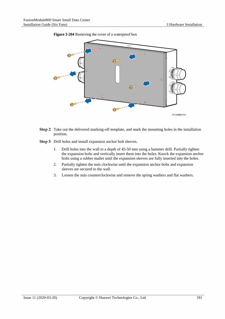
FusionModule800 Smart Small Data Center
Installation Guide (Six Fans) 3 Hardware Installation
Issue 11 (2020-03-20) Copyright © Huawei Technologies Co., Ltd. 181
Figure 3-204 Removing the cover of a waterproof box
Step 2 Take out the delivered marking-off template, and mark the mounting holes in the installation
position.
Step 3 Drill holes and install expansion anchor bolt sleeves.
1. Drill holes into the wall to a depth of 45-50 mm using a hammer drill. Partially tighten
the expansion bolts and vertically insert them into the holes. Knock the expansion anchor
bolts using a rubber mallet until the expansion sleeves are fully inserted into the holes.
2. Partially tighten the nuts clockwise until the expansion anchor bolts and expansion
sleeves are secured to the wall.
3. Loosen the nuts counterclockwise and remove the spring washers and flat washers.

FusionModule800 Smart Small Data Center
Installation Guide (Six Fans) 3 Hardware Installation
Issue 11 (2020-03-20) Copyright © Huawei Technologies Co., Ltd. 182
Figure 3-205 Drilling holes and installing expansion anchor bolt sleeves
(1) Expansion anchor bolt (2) M6 nut (3) Spring washer
(4) Flat washer (5) Expansion sleeve (6) Wall
(7) Rubber mallet (8) Socket wrench
Step 4 Secure the waterproof box to the wall.

FusionModule800 Smart Small Data Center
Installation Guide (Six Fans) 3 Hardware Installation
Issue 11 (2020-03-20) Copyright © Huawei Technologies Co., Ltd. 183
Figure 3-206 Securing a waterproof box
Step 5 Take out the access actuator and clamp it along the guide rails.

FusionModule800 Smart Small Data Center
Installation Guide (Six Fans) 3 Hardware Installation
Issue 11 (2020-03-20) Copyright © Huawei Technologies Co., Ltd. 184
Before installing the access actuator, ensure that the clip spring on the back of the actuator
is loose.
Verify that the access actuator indicator faces leftwards so that the indicator status can be
observed through the window in the waterproof box cover after the waterproof box cover
is reinstalled.
Figure 3-207 Installing an access actuator
Step 6 Reinstall the waterproof box cover.

FusionModule800 Smart Small Data Center
Installation Guide (Six Fans) 3 Hardware Installation
Issue 11 (2020-03-20) Copyright © Huawei Technologies Co., Ltd. 185
Figure 3-208 Reinstalling the waterproof box cover
----End
3.11.14 (Optional) Installing an In-Room Double Door Magnetic Lock
Prerequisites Verify that the room door is a revolving double-swing wooden door, and that the door
frame is wider than 42 mm.
The cable routes are planned.
Context The BOM number of a double door magnetic lock is 02070261.
A double door magnetic lock is installed on a room door.
Procedure
Step 1 Fold the delivered cutout template along the dotted line by 90°, as shown by (2) in Figure
3-209.
Step 2 Close the door, place the cutout template near the door top at the far end of the door axis,
mark the mounting holes, and drill holes, as shown in Figure 3-209.

FusionModule800 Smart Small Data Center
Installation Guide (Six Fans) 3 Hardware Installation
Issue 11 (2020-03-20) Copyright © Huawei Technologies Co., Ltd. 186
Figure 3-209 Marking mounting holes
(1) Door frame (2) Cutout template (3) Door panel
Step 3 Remove the hoisting strip using the delivered hex key.
Four hex socket screws need to be removed in this step.
Figure 3-210 Removing the hoisting strip
Step 4 Secure the hosting strip using the delivered screws, as shown by (1) in Figure 3-211.

FusionModule800 Smart Small Data Center
Installation Guide (Six Fans) 3 Hardware Installation
Issue 11 (2020-03-20) Copyright © Huawei Technologies Co., Ltd. 187
Pay attention to the direction of the hoisting strip, and ensure that the bulging surface of the
magnetic lock faces the magnet.
Figure 3-211 Installing a magnetic lock
Step 5 Route the magnetic lock cable through the cable hole, and secure the magnetic lock using a
hex key, as shown by (2) in Figure 3-211.
Step 6 Install the magnet.
1. Take out the magnet, and knock the positing pins of the magnet into the magnet using a
rubber mallet.

FusionModule800 Smart Small Data Center
Installation Guide (Six Fans) 3 Hardware Installation
Issue 11 (2020-03-20) Copyright © Huawei Technologies Co., Ltd. 188
Figure 3-212 Installing positioning pins of a magnet
2. Insert the assembled magnet into the positioning holes in the door, and secure the magnet
to the door using the screws and rubber pad delivered with the magnetic lock, as shown
in Figure 3-213.
When securing the magnet to the door panel, do not over-tighten the screws so that the rubber pad is
elastic. The rubber pad will adjust the magnet to a correct position because of its elasticity.
Figure 3-213 Installing the magnet
(1) Rubber pad
Step 7 (Optional) Adjust the magnet.
1. If the magnet cannot attract the door properly after power-on, place a magnetized metal
part near the magnet to check whether the magnet provides a proper magnetic force.
2. If the magnetic lock and the magnet do not work properly, check and troubleshoot the
circuit.

FusionModule800 Smart Small Data Center
Installation Guide (Six Fans) 3 Hardware Installation
Issue 11 (2020-03-20) Copyright © Huawei Technologies Co., Ltd. 189
----End
3.11.15 (Optional) Installing an In-Room Single Door Magnetic Lock
Prerequisites Verify that the room door is a revolving single-swing wooden door, and that the door
frame is wider than 42 mm.
The cable routes are planned.
Context The BOM number of a single door magnetic lock is 02070081.
A single door magnetic lock is installed on a room door.
Procedure
Step 1 Fold the delivered cutout template along the dotted line by 90°, as shown by (2) in Figure
3-214.
Step 2 Close the door, place the cutout template near the door top at the far end of the door axis,
mark the mounting holes, and drill holes, as shown in Figure 3-214.
Figure 3-214 Marking mounting holes

FusionModule800 Smart Small Data Center
Installation Guide (Six Fans) 3 Hardware Installation
Issue 11 (2020-03-20) Copyright © Huawei Technologies Co., Ltd. 190
(1) Door frame (2) Cutout template (3) Door panel
Step 3 Remove the hoisting strip using the delivered hex key.
Two hex socket screws need to be removed in this step.
Figure 3-215 Removing the hoisting strip
Step 4 Secure the hosting strip using the delivered screws, as shown by (1) in Figure 3-216.
Pay attention to the direction of the hoisting strip, and ensure that the bulging surface of the
magnetic lock faces the magnet.

FusionModule800 Smart Small Data Center
Installation Guide (Six Fans) 3 Hardware Installation
Issue 11 (2020-03-20) Copyright © Huawei Technologies Co., Ltd. 191
Figure 3-216 Installing a magnetic lock
Step 5 Remove the small cover from the magnetic lock, and route the cable out of the cable hole, as
shown in Figure 3-217.

FusionModule800 Smart Small Data Center
Installation Guide (Six Fans) 3 Hardware Installation
Issue 11 (2020-03-20) Copyright © Huawei Technologies Co., Ltd. 192
Figure 3-217 Connecting cables
(1) Cable outlet
Step 6 Secure the magnetic lock, as shown by (2) in Figure 3-216.
Step 7 Install the magnet.
1. Take out the magnet, and knock the positing pins of the magnet into the magnet using a
rubber mallet.
Figure 3-218 Installing positioning pins of a magnet
2. Insert the assembled magnet into the positioning holes in the door, and secure the magnet
to the door using the screws and rubber pad delivered with the magnetic lock, as shown in Figure 3-219.

FusionModule800 Smart Small Data Center
Installation Guide (Six Fans) 3 Hardware Installation
Issue 11 (2020-03-20) Copyright © Huawei Technologies Co., Ltd. 193
When securing the magnet to the door panel, do not over-tighten the screws so that the rubber pad is
elastic. The rubber pad will adjust the magnet to a correct position because of its elasticity.
Figure 3-219 Installing a magnet
(1) Rubber pad
Step 8 (Optional) Adjust the magnet.
1. If the magnet cannot attract the door properly after power-on, place a magnetized metal
part near the magnet to check whether the magnet provides a proper magnetic force.
2. If the magnetic lock and the magnet do not work properly, check and troubleshoot the
circuit.
----End
3.11.16 (Optional) Installing an In-Room Fingerprint and Card Reader with a Keypad
Context The BOM number of a fingerprint and card reader with a keypad is 02070174.
It is recommended that the device be installed outside a room 1.4-1.6 m above the floor.
Do not install the product in a place with heavy dust or exposed to sunlight.
Procedure
Step 1 Remove the screws (set aside) from the fingerprint and card reader with a keypad and take off
the baseplate, as shown by (1) in Figure 3-220.

FusionModule800 Smart Small Data Center
Installation Guide (Six Fans) 3 Hardware Installation
Issue 11 (2020-03-20) Copyright © Huawei Technologies Co., Ltd. 194
Figure 3-220 Installing a fingerprint and card reader with a keypad
Step 2 Mark the mounting holes using a marker, and drill holes using a hammer drill.
Figure 3-221 Marking mounting holes (unit: mm)
Step 3 Install the baseplate, as shown by (3) in Figure 3-220.
Step 4 Route the cable of the fingerprint and card reader with a keypad through the cable hole in the
baseplate, as shown by (4) in Figure 3-220.

FusionModule800 Smart Small Data Center
Installation Guide (Six Fans) 3 Hardware Installation
Issue 11 (2020-03-20) Copyright © Huawei Technologies Co., Ltd. 195
The fingerprint and card reader with a key pad is connected to the access actuator by a network cable.
Step 5 Check that cables are correctly connected.
Step 6 Secure the fingerprint and card reader with a keypad to the baseplate, as shown by (5) and (6)
in Figure 3-220.
----End
3.11.17 (Optional) Installing an In-Room Fingerprint and Card Reader
Context The BOM number of a finger and card reader is 02070173.
It is recommended that the device be installed outside a room 1.4-1.6 m above the floor.
Do not install the product in a place with heavy dust or exposed to sunlight.
Procedure
Step 1 Remove the screws (set aside) from the fingerprint and card reader and take off the baseplate,
as shown by (1) in Figure 3-222.
Figure 3-222 Installing a fingerprint and card reader
Step 2 Mark the mounting holes using a marker, and drill holes using a hammer drill.

FusionModule800 Smart Small Data Center
Installation Guide (Six Fans) 3 Hardware Installation
Issue 11 (2020-03-20) Copyright © Huawei Technologies Co., Ltd. 196
Figure 3-223 Marking mounting holes (unit: mm)
Step 3 Install the baseplate, as shown by (3) in Figure 3-222.
Step 4 Route the fingerprint and card reader cable through the cable hole in the baseplate, as shown
by (4) in Figure 3-222.
The fingerprint and card reader is connected to the access actuator by a network cable.
Step 5 Check that cables are correctly connected.
Step 6 Secure the fingerprint and card reader to the baseplate, as shown by (5) and (6) in Figure
3-222.
----End
3.11.18 (Optional) Installing an In-Room Card Reader with a Keypad
Context The BOM number of a card reader with a keypad is 02070172.

FusionModule800 Smart Small Data Center
Installation Guide (Six Fans) 3 Hardware Installation
Issue 11 (2020-03-20) Copyright © Huawei Technologies Co., Ltd. 197
It is recommended that the device be installed outside a room 1.4-1.6 m above the floor.
Do not install the product in a place with heavy dust or exposed to sunlight.
Procedure
Step 1 Remove the screws (set aside) from the card reader with a keypad and take off the baseplate,
as shown by (1) in Figure 3-224.
Figure 3-224 Installing a card reader with a keypad
Step 2 Mark the mounting holes using a marker, and drill holes using a hammer drill.

FusionModule800 Smart Small Data Center
Installation Guide (Six Fans) 3 Hardware Installation
Issue 11 (2020-03-20) Copyright © Huawei Technologies Co., Ltd. 198
Figure 3-225 Marking mounting holes (unit: mm)
Step 3 Install the baseplate, as shown by (3) in Figure 3-224.
Step 4 Route the cable of the card reader with a keypad through the cable hole in the baseplate, as
shown by (4) in Figure 3-224.
The card reader with a keypad is connected to the access actuator by a network cable.
Step 5 Check that cables are correctly connected.
Step 6 Secure the card reader with a keypad to the baseplate, as shown by (5) and (6) in Figure
3-224.
----End
3.11.19 (Optional) Installing an In-Room Exit Button
Context
The BOM number of an exit button is 52220135.

FusionModule800 Smart Small Data Center
Installation Guide (Six Fans) 3 Hardware Installation
Issue 11 (2020-03-20) Copyright © Huawei Technologies Co., Ltd. 199
Procedure
Step 1 Remove the exit button cover using a flat-head screwdriver.
Step 2 Remove screws from the exit button, remove the base, and mark mounting holes using the
base and a marker.
Step 3 Drill holes and install the exit button base.
Step 4 Take out the network cable, cut off one end of the cable, and connect pins 6 and 7 to the NO
and COM ports on the exit button.
The exit button is connected to the access actuator by a network cable.
Step 5 Route the cable through the cable hole.
Step 6 Reinstall the exit button and the cover.
----End
3.11.20 (Optional) Installing an In-Room Emergency Door Release Button
Context The BOM number of an emergency door release button is 02070053.
It is recommended that the device be installed outside a room 1.6 m above the floor.
Procedure
Step 1 Remove the emergency door release button.
Figure 3-226 Removing an emergency door release button
1. Remove screws from the emergency door release button using a Phillips screwdriver, as
shown by (1) in Figure 3-226.

FusionModule800 Smart Small Data Center
Installation Guide (Six Fans) 3 Hardware Installation
Issue 11 (2020-03-20) Copyright © Huawei Technologies Co., Ltd. 200
2. Remove the glass panel of the emergency door release button, as shown by (2) and (3) in
Figure 3-226.
3. Remove screws from the base, and remove the base, as shown by (4) in Figure 3-226.
Step 2 Mark the mounting holes using a marker and the base.
Figure 3-227 Marking mounting holes (unit: mm)
Step 3 Drill holes using a hammer drill, and route cables out of the cable hole.
Step 4 Install the emergency door release button.

FusionModule800 Smart Small Data Center
Installation Guide (Six Fans) 3 Hardware Installation
Issue 11 (2020-03-20) Copyright © Huawei Technologies Co., Ltd. 201
Figure 3-228 Installing an emergency door release button
1. Install the base of the emergency door release button, as shown by (1) in Figure 3-228.
2. Install the glass panel of the emergency door release button, as shown by (2) and (3) in
Figure 3-228.
3. Tighten screws of the emergency door release button using a Phillips screwdriver, as
shown by (4) in Figure 3-228.
----End
3.11.21 (Optional) Installing an In-Room Camera
For the detailed installation method, see documents delivered with the camera.

FusionModule800 Smart Small Data Center
Installation Guide (Six Fans) 4 Cable Routing
Issue 11 (2020-03-20) Copyright © Huawei Technologies Co., Ltd. 202
4 Cable Routing
4.1 System Cabling Rules
Attaching Cable Labels
A cable label must be consistent with the corresponding IT cabinet number.
Find the corresponding cable based on the wiring diagram in the cable fitting bag, and attach
the corresponding cable label taken out from the cable fitting bag to both ends of the cable by
wrapping the ends.
The cable labels must completely wrap the cable without wrinkles.
Attach the cable labels 20 mm away from the plug except for special circumstances. For
example, a label shall not be attached to the bending part of a cable or attached in some
positions that may affect cable installation. If a label conflicts with a cable tie, attach the label
to the outer side of the cable tie.
Attach labels to both ends of a cable.
Requirements for Neatly Routing and Binding Cables
To route and bind cables in an appealing way, follow these rules:
1. Neatly organize exterior cables in a large bundle of cables and prevent cable tangles that
are avoidable, as shown in Figure 4-1.

FusionModule800 Smart Small Data Center
Installation Guide (Six Fans) 4 Cable Routing
Issue 11 (2020-03-20) Copyright © Huawei Technologies Co., Ltd. 203
Figure 4-1 Neatly organizing cables
2. Keep a large number of cables neat and appealing in a network cabling cabinet by using
cable organizers. Move the excess parts of cables in unnoticeable positions, as shown in
Figure 4-2.
Figure 4-2 Cable organizer
3. Route and lay out a large number of cables in different areas to ensure neat cabling and
facilitate cable search and maintenance.
4. Route several flat cables along the same path and then overlap them as one.
5. Arrange cables on distinct layers and prevent cable tangles that are avoidable when
cables in different colors are bound together, as shown in Figure 4-3. Also comply with
these rules when cables of different thickness are bound together. Arrange cables by
thickness when arrangement by thickness conflicts with arrangement by color.

FusionModule800 Smart Small Data Center
Installation Guide (Six Fans) 4 Cable Routing
Issue 11 (2020-03-20) Copyright © Huawei Technologies Co., Ltd. 204
Figure 4-3 Binding cables in different colors
Cable Spacing Requirements
Comply with the following requirements if possible to lay out different types of cables:
1. Separate AC and DC power cables from diverse non-shielded signal cables. Keep the
cable spacing greater than 100 mm or use grounded metal for isolation purposes. Do not
bind the cables together. Preferentially route the cables along different sides of cabinets.
2. Network cables and optical cables are recommended to be routed separately.
Safety and Reliability Requirements for Routing and Binding Cables
1. Unless otherwise specified in a design file, ensure that the bend radius (R) of a cable
meets the following requirements:
− Common cable: R ≥ 3d
− Optical cable: R ≥ 40 mm
R indicates the bend radius, and d indicates the cable diameter.
2. Reserve slack at cable connection positions to facilitate connection and disconnection
and to prevent stress. Do not leave the cables tight and prevent connector misalignment,
as shown in Figure 4-4.
Figure 4-4 Cable connection positions
3. Before installing a semi-flexible cable, use a dedicated tool to curve the cable. Do not
curve the cable while holding the cable connector by hand.

FusionModule800 Smart Small Data Center
Installation Guide (Six Fans) 4 Cable Routing
Issue 11 (2020-03-20) Copyright © Huawei Technologies Co., Ltd. 205
4. If a number of wire terminals are connected to a multi-point connector, provide slack and
arrange them neatly to prevent stress on certain wires, as shown in Figure 4-5.
Figure 4-5 Cable connections
5. Protect cable holes in a metal kit with grommet strips. Alternatively, ensure that the
holes are rounded, free from burrs or sharp edges.
6. Keep cables far away from heat sources such as radiators and heat vents. If unavoidable,
take heat resistant measures.
7. Keep cables far away from operating components such as fan blades and do not bind
cables to an airflow path of fans.
8. Prevent rotating components such as doors from squeezing or pulling cables.
Cable Binding Requirements
Bind cables reliably along the route and ensure that the binding interval meets the
requirements in Table 4-1.
Table 4-1 Cable binding interval
Cable Diameter (mm) Binding Interval (mm)
< 10 150
10–30 200
> 30 300
1. Bind cables with a moderate force and ensure that cables are not misshapen to prevent
compromising the signal quality.
2. After binding cables, cut off the excess parts of cable ties and trim away any burrs, as
shown in Figure 4-6.

FusionModule800 Smart Small Data Center
Installation Guide (Six Fans) 4 Cable Routing
Issue 11 (2020-03-20) Copyright © Huawei Technologies Co., Ltd. 206
Figure 4-6 Cutting off the excess part of a cable tie
3. Do not use cable ties at a place where the cables are bent. Otherwise, the cable cores may
break due to strong stress, as shown in Figure 4-7.
Figure 4-7 Binding cables in a bending area
4. Ensure that the cable ties are wrapped and secured in the same direction and do not
generate interference with subsequent operations, as shown in Figure 4-8.

FusionModule800 Smart Small Data Center
Installation Guide (Six Fans) 4 Cable Routing
Issue 11 (2020-03-20) Copyright © Huawei Technologies Co., Ltd. 207
Figure 4-8 Direction for securing cable ties
4.2 Cable Routes
General Cable Route
Figure 4-9 shows the routes of power cables and signal cables.
When routing cables, leave a distance of at least 100 mm between power cables and signal cables.

FusionModule800 Smart Small Data Center
Installation Guide (Six Fans) 4 Cable Routing
Issue 11 (2020-03-20) Copyright © Huawei Technologies Co., Ltd. 208
Figure 4-9 Cable routes
(1) Power cable (2) Signal cable
The Converged Cabinet fitting bag contains 70 plastic cable ties that can be installed on holes
at the top of the cabinet for binding cables, as shown in Figure 4-10.
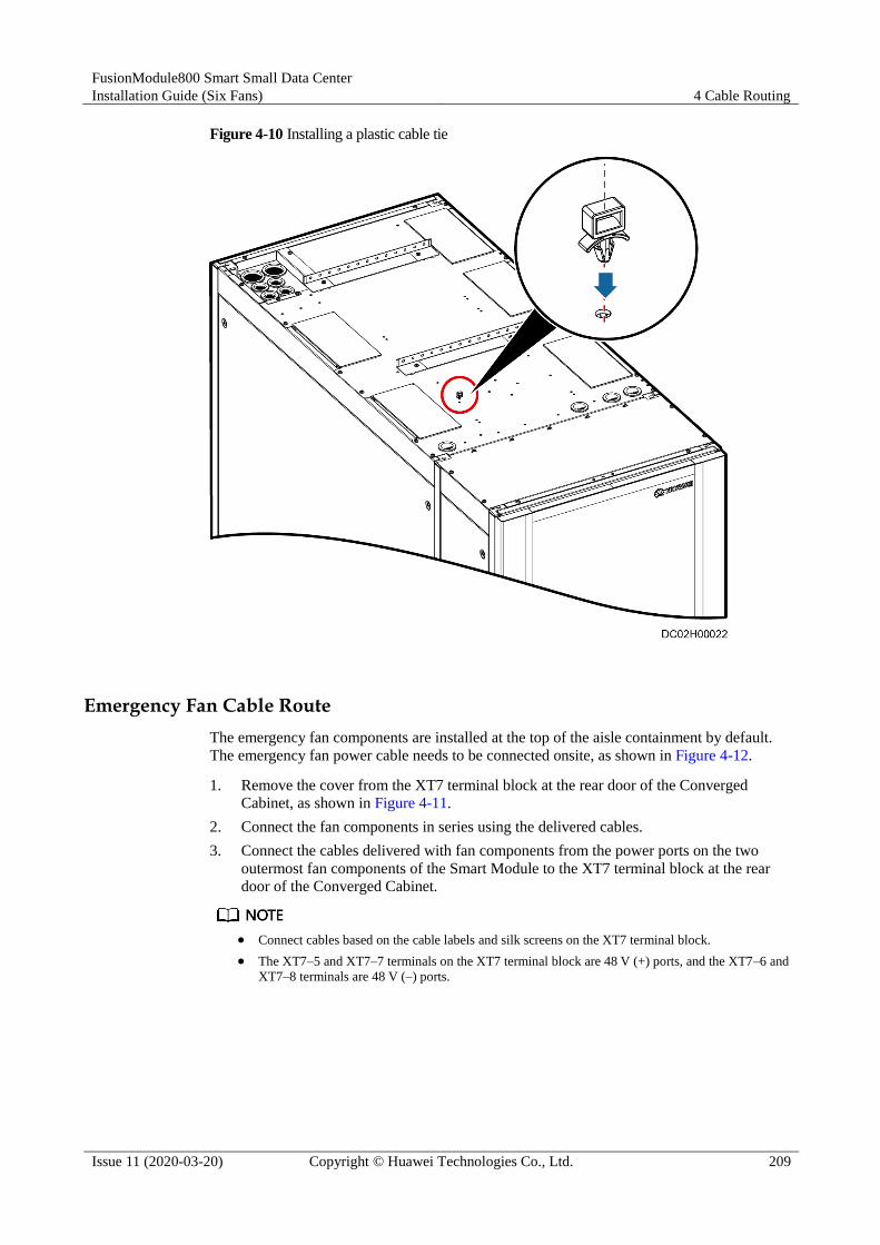
FusionModule800 Smart Small Data Center
Installation Guide (Six Fans) 4 Cable Routing
Issue 11 (2020-03-20) Copyright © Huawei Technologies Co., Ltd. 209
Figure 4-10 Installing a plastic cable tie
Emergency Fan Cable Route
The emergency fan components are installed at the top of the aisle containment by default.
The emergency fan power cable needs to be connected onsite, as shown in Figure 4-12.
1. Remove the cover from the XT7 terminal block at the rear door of the Converged
Cabinet, as shown in Figure 4-11.
2. Connect the fan components in series using the delivered cables.
3. Connect the cables delivered with fan components from the power ports on the two
outermost fan components of the Smart Module to the XT7 terminal block at the rear
door of the Converged Cabinet.
Connect cables based on the cable labels and silk screens on the XT7 terminal block.
The XT7–5 and XT7–7 terminals on the XT7 terminal block are 48 V (+) ports, and the XT7–6 and
XT7–8 terminals are 48 V (–) ports.
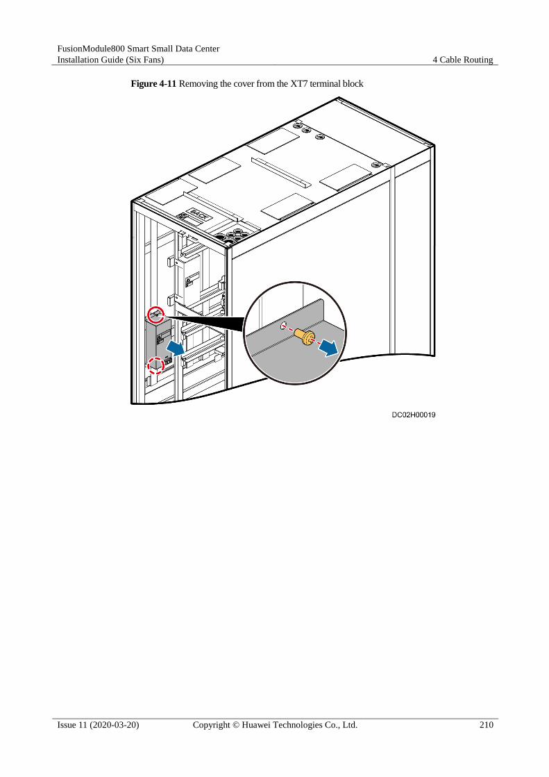
FusionModule800 Smart Small Data Center
Installation Guide (Six Fans) 4 Cable Routing
Issue 11 (2020-03-20) Copyright © Huawei Technologies Co., Ltd. 210
Figure 4-11 Removing the cover from the XT7 terminal block

FusionModule800 Smart Small Data Center
Installation Guide (Six Fans) 4 Cable Routing
Issue 11 (2020-03-20) Copyright © Huawei Technologies Co., Ltd. 211
Figure 4-12 Connecting cables to the emergency fan component
Door Status Sensor Cable Route
The door status sensor in each cabinet connects to the AI/DI module at the rear door of the IT
cabinet over the delivered cable. Then the standalone AI/DI module connects to the COM3/12
V port on the ECC800 over a network cable.

FusionModule800 Smart Small Data Center
Installation Guide (Six Fans) 4 Cable Routing
Issue 11 (2020-03-20) Copyright © Huawei Technologies Co., Ltd. 212
Figure 4-13 Door status sensor cable routes

FusionModule800 Smart Small Data Center
Installation Guide (Six Fans) 4 Cable Routing
Issue 11 (2020-03-20) Copyright © Huawei Technologies Co., Ltd. 213
Smart ETH Gateway Cable Route
Figure 4-14 Smart ETH gateway cable routes
(1) Power cable (2) Signal cable

FusionModule800 Smart Small Data Center
Installation Guide (Six Fans) 4 Cable Routing
Issue 11 (2020-03-20) Copyright © Huawei Technologies Co., Ltd. 214
4.3 Power Cable Routing
Figure 4-15 Power cable routing
(1) Power cable from the battery to
the UPS
(2) Mains input power
cable
(3) PDU2000 power
cable
The customer can purchase power cables as required. The recommended specifications of mains input
power cables are as follows:
6 kW and 7.5 kW loads (BOM number: 25030857): 600 V/1000 V-ZA-YJV-5 x 16 mm2-Black (5
cores: yellow, green, red, blue, black)-107 A-CE
12 kW and 15 kW loads (BOM number: 25030858): 600 V/1000 V-ZA-YJV-5 x 25 mm2-Black (5
cores: yellow, green, red, blue, black)-138 A-CE
4.4 Smart Module Grounding
1. Deploy a general ground bar (shown by (1) in Figure 4-16) in the Converged Cabinet.
2. Connect the general ground point (shown by (1) in Figure 4-17) in each cabinet to the
general ground bar in the Converged Cabinet.

FusionModule800 Smart Small Data Center
Installation Guide (Six Fans) 4 Cable Routing
Issue 11 (2020-03-20) Copyright © Huawei Technologies Co., Ltd. 215
3. Connect the general ground bar in the Converged Cabinet to the floor ground bar or
collective ground bar.
Figure 4-16 Converged Cabinet ground bar
(1) General ground bar

FusionModule800 Smart Small Data Center
Installation Guide (Six Fans) 4 Cable Routing
Issue 11 (2020-03-20) Copyright © Huawei Technologies Co., Ltd. 216
Figure 4-17 Cabinet ground point
(1) General ground point
Figure 4-18 Grounding the Smart Module
(1) General ground bar

FusionModule800 Smart Small Data Center
Installation Guide (Six Fans) 4 Cable Routing
Issue 11 (2020-03-20) Copyright © Huawei Technologies Co., Ltd. 217
4.5 Cable Connections to the Power Supply and Distribution System
4.5.1 Top Cable Routing
4.5.1.1 Cable Routing Description
Figure 4-19 shows the cable holes for routing cables over the top of the Converged Cabinet.
Figure 4-19 Cable holes for routing cables over the top of the Converged Cabinet
(1) Cable holes for smart
cooling product pipes
(2) Signal cable hole
(3) Door status sensor cable
hole
(4) Signal cable holes
(5) Input power cable hole (6) Cable hole for the emergency fan power cable, battery
power cable, and output power cable
Rodent-proof meshes or cable protecting rings are installed at the cable outlets of cabinets for
ease of cable routing.
Rodent-proof mesh: Use diagonal pliers to cut cable inlet and outlet holes on
rodent-proof meshes based on the number and specifications of cables, as shown in
Figure 4-20.

FusionModule800 Smart Small Data Center
Installation Guide (Six Fans) 4 Cable Routing
Issue 11 (2020-03-20) Copyright © Huawei Technologies Co., Ltd. 218
Wire bushing: Cut a cross in the middle of a wire bushing using an electrician's knife, as
shown in Figure 4-21.
Figure 4-20 Cutting a hole in a rodent-proof mesh
Figure 4-21 Cutting a notch in a wire bushing
Before connecting the input and output power cables to the Converged Cabinet, remove the
cover from the N busbar at the rear door of the Converged Cabinet. Then reinstall the cover
after connecting all neutral wires.

FusionModule800 Smart Small Data Center
Installation Guide (Six Fans) 4 Cable Routing
Issue 11 (2020-03-20) Copyright © Huawei Technologies Co., Ltd. 219
Figure 4-22 Removing the cover from the N busbar
Cables can be bound to the side panel or mounting bar of the Converged Cabinet. Figure 4-23
shows the place for binding cables routed across the cabinet interior.

FusionModule800 Smart Small Data Center
Installation Guide (Six Fans) 4 Cable Routing
Issue 11 (2020-03-20) Copyright © Huawei Technologies Co., Ltd. 220
Figure 4-23 Place for binding cables routed across the cabinet interior
(1) Place binding cables routed across the cabinet interior
4.5.1.2 (Optional) Connecting Signal Cables to the Converged Cabinet
Prerequisites
The ATS PDU has been configured.
Context
If the Converged Cabinet is configured with an ATS PDU, connect the diesel generator (DG)
and fire extinguishing signal cables to the XT6 terminal block. Table 4-2 describes the cable
connections.
Table 4-2 Cable connection description
Cable Connecting Position on the ATS PDU
Cable Connecting Position on the Device
XT6-1 Fire Protection-Fire

FusionModule800 Smart Small Data Center
Installation Guide (Six Fans) 4 Cable Routing
Issue 11 (2020-03-20) Copyright © Huawei Technologies Co., Ltd. 221
Cable Connecting Position on the ATS PDU
Cable Connecting Position on the Device
XT6-2 Fire Protection-COM
XT6-3 Generator-START
XT6-4 Generator-COM
XT6-5 Generator-STOP
Procedure
Step 1 Connect the DG and fire extinguishing signal cables to the XT6 terminal block, as shown in
Figure 4-24. Table 4-2 describes the cable connections.
Figure 4-24 Connecting signal cables
----End

FusionModule800 Smart Small Data Center
Installation Guide (Six Fans) 4 Cable Routing
Issue 11 (2020-03-20) Copyright © Huawei Technologies Co., Ltd. 222
4.5.1.3 Connecting Output Power Cables to the Converged Cabinet
Context
The Converged Cabinet has multiple configurations. This section describes how to connect
output power cables to different types of power distribution subracks in the Converged
Cabinet.
For detailed cable connection positions in the Converged Cabinet, see the Cable Connection
Diagram.
The power distribution subrack position in the cable connection description is for reference only.
The actual position prevails.
Before connecting the IT output power cable in the BC1 scenario, select an appropriate length
of cable and crimp the terminal based on the actual position of the power distribution subrack.
Crimp a cord end terminal on the live wire, as shown in Figure 4-25.
Crimp an OT terminal on the PE wire and neutral wire, as shown in Figure 4-26.
Figure 4-25 Preparing a cord end terminal
(1) Cable (2) Cord end terminal (3) Crimping tool

FusionModule800 Smart Small Data Center
Installation Guide (Six Fans) 4 Cable Routing
Issue 11 (2020-03-20) Copyright © Huawei Technologies Co., Ltd. 223
Figure 4-26 Preparing an OT terminal
(1) Cable (2) Heat shrink tubing (3) OT terminal
(4) Hydraulic pliers (5) Heat gun
Procedure
Step 1 (Optional) Connect output power cables to the 6 U PDU.

FusionModule800 Smart Small Data Center
Installation Guide (Six Fans) 4 Cable Routing
Issue 11 (2020-03-20) Copyright © Huawei Technologies Co., Ltd. 224
Figure 4-27 Connecting output power cables to the 6 U PDU
(1) IT cabinet output power cable (2) Smart Cooling Product output power cable
Step 2 (Optional) Connect output power cables to the 3 U PDU.

FusionModule800 Smart Small Data Center
Installation Guide (Six Fans) 4 Cable Routing
Issue 11 (2020-03-20) Copyright © Huawei Technologies Co., Ltd. 225
Figure 4-28 Connecting output power cables to the 3 U PDU
(1) Smart Cooling Product output power cable (2) IT cabinet output power cable
----End
4.5.1.4 Connecting Input Power Cables to the Converged Cabinet
Context
The Converged Cabinet has multiple configurations. This section describes how to connect
input power cables to different types of power distribution subracks in the Converged Cabinet.
For detailed cable connection positions in the Converged Cabinet, see the Cable Connection
Diagram.
The power distribution subrack position in the cable connection description is for reference only.
The actual position prevails.
Procedure
Step 1 (Optional) Connect input power cables to the ATS PDU, as shown in Figure 4-29.

FusionModule800 Smart Small Data Center
Installation Guide (Six Fans) 4 Cable Routing
Issue 11 (2020-03-20) Copyright © Huawei Technologies Co., Ltd. 226
Perform this step only when the system has double power inputs.
Ensure that cables to the power distribution box on the customer side are connected in
correct phase sequence.
Figure 4-29 Connecting input power cables to the ATS PDU
(1) Second power input cable (2) First power input cable
Step 2 (Optional) Connect input power cables to the 6 U PDU.

FusionModule800 Smart Small Data Center
Installation Guide (Six Fans) 4 Cable Routing
Issue 11 (2020-03-20) Copyright © Huawei Technologies Co., Ltd. 227
Figure 4-30 Connecting input power cables to the 6 U PDU
(1) Input power cable
Step 3 (Optional) Connect input power cables to the 3 U PDU.

FusionModule800 Smart Small Data Center
Installation Guide (Six Fans) 4 Cable Routing
Issue 11 (2020-03-20) Copyright © Huawei Technologies Co., Ltd. 228
Figure 4-31 Connecting input power cables to the 3 U PDU
(1) Input power cable
----End
4.5.2 Bottom Cable Routing
Cables connect to the same positions on the power distribution subrack irrespective of
whether cables are routed through the top or bottom of the Converged Cabinet, but the cable
routes inside the cabinet are different. This section describes how to connect the input power
cable to the 7.5 kW 3 U PDU in the bottom cable routing scenario for the Converged Cabinet.
Figure 4-32 shows the cable holes for routing cables through the bottom of the Converged
Cabinet.
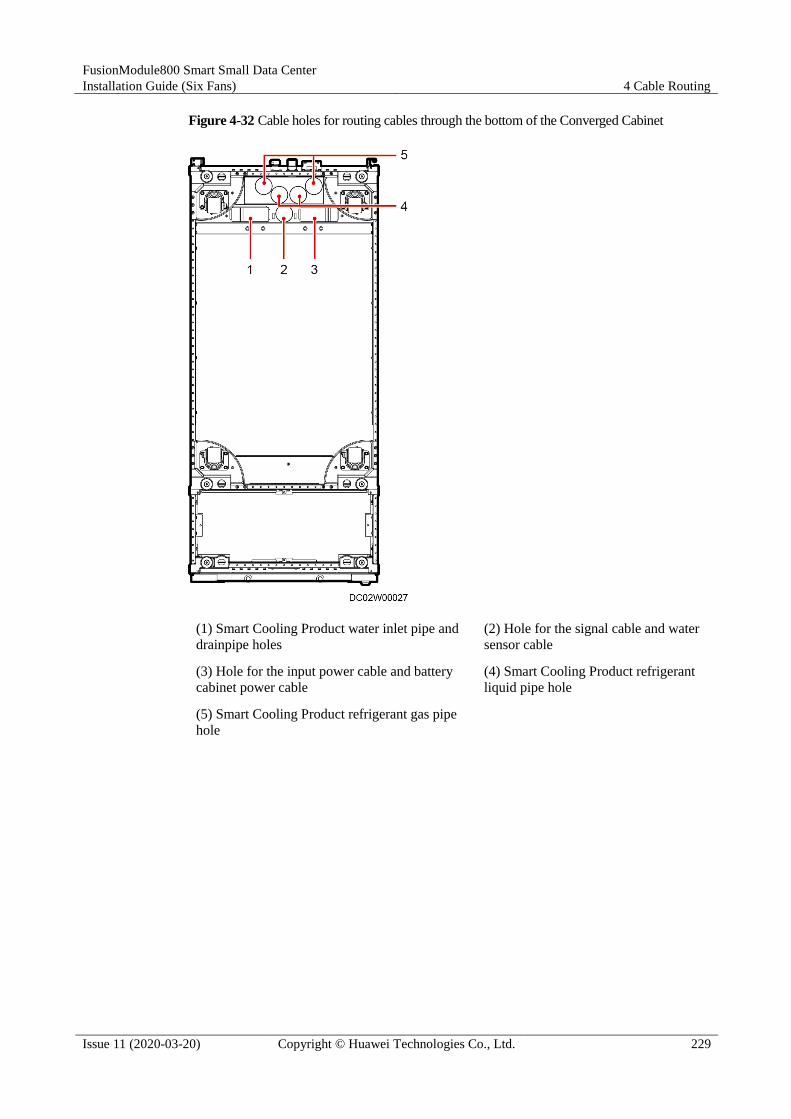
FusionModule800 Smart Small Data Center
Installation Guide (Six Fans) 4 Cable Routing
Issue 11 (2020-03-20) Copyright © Huawei Technologies Co., Ltd. 229
Figure 4-32 Cable holes for routing cables through the bottom of the Converged Cabinet
(1) Smart Cooling Product water inlet pipe and
drainpipe holes
(2) Hole for the signal cable and water
sensor cable
(3) Hole for the input power cable and battery
cabinet power cable
(4) Smart Cooling Product refrigerant
liquid pipe hole
(5) Smart Cooling Product refrigerant gas pipe
hole

FusionModule800 Smart Small Data Center
Installation Guide (Six Fans) 4 Cable Routing
Issue 11 (2020-03-20) Copyright © Huawei Technologies Co., Ltd. 230
Figure 4-33 Cable route example in the bottom cable routing scenario (3 U PDU for example)
4.5.3 Connecting a PDU2000 Power Cable
Procedure
Step 1 Connect the cord end terminal on the IT cabinet output power cable routed out of the
Converged Cabinet to the PDU2000 cable port in the IT cabinet, as shown in Figure 4-34.

FusionModule800 Smart Small Data Center
Installation Guide (Six Fans) 4 Cable Routing
Issue 11 (2020-03-20) Copyright © Huawei Technologies Co., Ltd. 231
Figure 4-34 Connecting a PDU2000 power cable
Step 2 Connect other PDU2000 power cables in the same way.
----End
4.5.4 Connecting Cables Between the Battery and the UPS
For details, see the manual delivered with the UPS.
4.6 Management System Cable Connection
4.6.1 ECC800 Ports
Figure 4-35 ECC800 external ports
(1) PSU (2) Filler panel (3) Status indicator

FusionModule800 Smart Small Data Center
Installation Guide (Six Fans) 4 Cable Routing
Issue 11 (2020-03-20) Copyright © Huawei Technologies Co., Ltd. 232
(4) 3G/4G antenna port (5) FE port (WAN_1–2 and
LAN_1–2)
(6) AI/DI_1–6 sensor
input port
(7) RF_Z antenna port (8) SW button (9) DO_1–2 dry contact
output
(10) RS485 port
(COM1–4/12 V) (11) Default button (12) USB port
(13) ECC800 main control
module
4.6.2 Connecting a Monitoring Cable to the Door Status Sensor
Prerequisites
The door status sensor has been installed.
Context
Figure 4-36 shows a door status sensor monitoring cable.
Figure 4-36 Door status sensor monitoring cable
(1) RJ45 terminal (2) Cord end terminal
Procedure
Step 1 Remove the cover from the door status sensor.
Step 2 Remove the cable cover from the middle of the door status sensor cover.
Step 3 Route the cord end terminal on the delivered cable through the cable hole in the door status
sensor base.
Step 4 Crimp the cord end terminals (as shown by (2) in Figure 4-36) under the washers of the door
status sensor cables, as shown in Figure 4-37.

FusionModule800 Smart Small Data Center
Installation Guide (Six Fans) 4 Cable Routing
Issue 11 (2020-03-20) Copyright © Huawei Technologies Co., Ltd. 233
Figure 4-37 Installing door status sensor cables
Step 5 Reinstall the cover on the door status sensor.
The cable holes in the door status sensor cover should match the positions of the door status
sensor cables.
Step 6 Connect the RJ45 terminal of the door status sensor monitoring cable to any AI/DI port on the
standalone AI/DI module.
----End
4.6.3 Connecting VCN Cables
Prerequisites
Cables have been prepared.
Procedure
Step 1 Secure one end of the ground cable to the ground terminal on the VCN and the other end to
the ground point on the cabinet using a Phillips screwdriver.
Step 2 Connect one end of the network cable to the GE1 port on the VCN and the other end to the
PoE_1 port on the smart ETH gateway. Figure 4-38 shows the ports on the VCN.

FusionModule800 Smart Small Data Center
Installation Guide (Six Fans) 4 Cable Routing
Issue 11 (2020-03-20) Copyright © Huawei Technologies Co., Ltd. 234
Figure 4-38 Ports on the VCN
(1) Ground point (2) GE2 port (3) Power switch
(4) Power input port (5) GE1 port
The figure uses the VCN500 as an example.
Step 3 Connect one end of the power cable to the power input port (as shown by (4) in Figure 4-38)
on the power module and the other end to the PDU2000 in the cabinet.
After connecting the power cable, turn on the power switch on the panel to start the device.
----End
4.6.4 Connecting a Monitoring Cable to the Smart ETH Gateway
Prerequisites
The smart ETH gateway has been installed.
Context
Figure 4-39 shows the external ports on a smart ETH gateway.

FusionModule800 Smart Small Data Center
Installation Guide (Six Fans) 4 Cable Routing
Issue 11 (2020-03-20) Copyright © Huawei Technologies Co., Ltd. 235
Figure 4-39 Ports on a smart ETH gateway
(1) PWR_IN cascading
power port
(2) FE_1 cascading signal
port
(3) PoE_1–2 ports
(4) PoE_3–4 ports (5) 48V_OUT1 power output
port
(6) 48V_OUT2 power
output port
(7) FE_2 cascading signal
port
(8) PWR_OUT cascading
power port
(9) BLINK button
(10) Status indicator
Procedure
Step 1 Take out the ground cable from the smart ETH gateway fitting bag and connect the cable to
the ground screw on the smart ETH gateway.
Step 2 Connect the PWR_IN port on the smart ETH gateway to the 53.5VDC_OUT1 or
53.5VDC_OUT2 port on the ECC800 using a power cable.
Step 3 Connect the FE_2 port on the smart ETH gateway to the WAN_2 port on the ECC800 using a
network cable.
----End
4.6.5 Connecting a Monitoring Cable to the AI/DI Module
Prerequisites
The standalone AI/DI module has been installed.
Context
If the AI/DI expansion card inserted into the ECC800 cannot meet the AI/DI collection
quantity requirements, connect an independent deployment AI/DI module to the
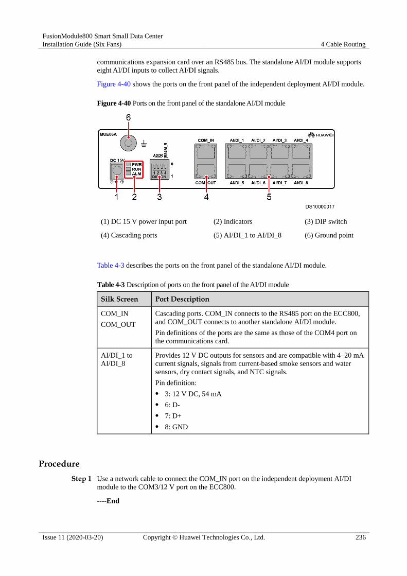
FusionModule800 Smart Small Data Center
Installation Guide (Six Fans) 4 Cable Routing
Issue 11 (2020-03-20) Copyright © Huawei Technologies Co., Ltd. 236
communications expansion card over an RS485 bus. The standalone AI/DI module supports
eight AI/DI inputs to collect AI/DI signals.
Figure 4-40 shows the ports on the front panel of the independent deployment AI/DI module.
Figure 4-40 Ports on the front panel of the standalone AI/DI module
(1) DC 15 V power input port (2) Indicators (3) DIP switch
(4) Cascading ports (5) AI/DI_1 to AI/DI_8 (6) Ground point
Table 4-3 describes the ports on the front panel of the standalone AI/DI module.
Table 4-3 Description of ports on the front panel of the AI/DI module
Silk Screen Port Description
COM_IN
COM_OUT
Cascading ports. COM_IN connects to the RS485 port on the ECC800,
and COM_OUT connects to another standalone AI/DI module.
Pin definitions of the ports are the same as those of the COM4 port on
the communications card.
AI/DI_1 to
AI/DI_8
Provides 12 V DC outputs for sensors and are compatible with 4–20 mA
current signals, signals from current-based smoke sensors and water
sensors, dry contact signals, and NTC signals.
Pin definition:
3: 12 V DC, 54 mA
6: D-
7: D+
8: GND
Procedure
Step 1 Use a network cable to connect the COM_IN port on the independent deployment AI/DI
module to the COM3/12 V port on the ECC800.
----End

FusionModule800 Smart Small Data Center
Installation Guide (Six Fans) 4 Cable Routing
Issue 11 (2020-03-20) Copyright © Huawei Technologies Co., Ltd. 237
4.6.6 Connecting the Smoke Detector Monitoring Cable
Prerequisites
The smoke detector has been installed.
Procedure
Step 1 Disconnect the male and female connectors on the cable delivered with the smoke detector, as
shown in Figure 4-41.
Figure 4-41 Disconnect the connectors on the cable delivered with the smoke detector
Step 2 Connect the non-RJ45 end (shown by (2) in Figure 4-42) of the delivered cable to the male
connector of the smoke detector.
Figure 4-42 Smoke detector cable connection
(1) RJ45 connector (2) Conversion terminal
----End
4.6.7 Connecting Cables to Water Sensors
Prerequisites Water sensor cables have been routed.
A monitoring cable required has been prepared.
FusionModule800 Smart Small Data Center
Installation Guide (Six Fans) 4 Cable Routing
Issue 11 (2020-03-20) Copyright © Huawei Technologies Co., Ltd. 238
Procedure
Step 1 Connect one end of the network cable that has been laid near the water detector to the
Ethernet port on the water detector.
----End
4.6.8 (Optional) Connecting Cables for the In-Room Access Control System
Prerequisites The required cables have been prepared.
It is recommended that cables of the in-room access control system be routed through a
trough in a wall.
Cables installed on the surface of a wall need to be routed through a pipe for protection.

FusionModule800 Smart Small Data Center
Installation Guide (Six Fans) 4 Cable Routing
Issue 11 (2020-03-20) Copyright © Huawei Technologies Co., Ltd. 239
Context
Figure 4-43 Description of ports on the access actuator
(1) 48 V power
port
(2) PoE port (3) RS485 port (COM2)
(4) RS485 port
(COM1)
(5) Address DIP
switch (6) Status indicator
(7) BLINK
button
(8) WG_2
Wiegand interface
(9) WG_1 Wiegand interface
(10) AI/DI_2
dry contact
(11) AI/DI_1 dry
contact
(12) LOCK/GND/GATE/COM/door status sensor
and magnetic lock port
Procedure
Step 1 Remove the covers from the waterproof box and cable holes of the access actuator.
Step 2 Connect cables by referring to Figure 4-44.
1. Connect the smart ETH gateway to the access actuator using a cable.
2. Connect the single/double door magnetic lock to the access actuator using a cable.

FusionModule800 Smart Small Data Center
Installation Guide (Six Fans) 4 Cable Routing
Issue 11 (2020-03-20) Copyright © Huawei Technologies Co., Ltd. 240
3. Connect the access controller to the access actuator using a cable.
4. Connect the exit button to the access actuator using a cable.
5. Connect the emergency door release button to the access actuator using a cable.
6. Connect the emergency door release button to the single/double door magnetic lock
using a cable.
Figure 4-44 Connecting cables for the in-room access control system
(1) Cable BOM number: 04093981-01 (2) Cable BOM number:
04093981-02
(3) Cable BOM number for a fingerprint and card reader:
04093981-03; cable BOM number for a fingerprint and
card reader with a keypad: 04093981-04
(4) Cable BOM number:
04093981-05
(5) Cable BOM number: 04093981-06
Step 3 Reinstall the covers of the waterproof box and cable holes.
----End

FusionModule800 Smart Small Data Center
Installation Guide (Six Fans) 5 Checking After Installation
Issue 11 (2020-03-20) Copyright © Huawei Technologies Co., Ltd. 241
5 Checking After Installation
Smart Cooling Product Installation Check
Table 5-1 Indoor unit installation checklist
Item Check That Check Result
Fan The fan is secured. □ Passed □ Failed
The fan has no foreign matter
inside.
□ Passed □ Failed
Humidifier float The humidifier float is secured. □ Passed □ Failed
The fasteners for the humidifier
float are secured. □ Passed □ Failed
Liquid level
detector
The liquid level detector is
secured.
□ Passed □ Failed
The fasteners for the liquid level
detector are secured.
□ Passed □ Failed
The low liquid level detector
functions flexibly.
□ Passed □ Failed
Return air filter The return air filter is installed in
the correct direction.
□ Passed □ Failed
Table 5-2 Outdoor unit installation checklist
Check That Check Result
The outdoor unit is secured. □ Passed □ Failed
The outdoor unit air intake and exhaust
vents are not blocked.
□ Passed □ Failed
The outdoor unit installation meets
requirements in 3.7.4.2 Space
Requirements.
□ Passed □ Failed

FusionModule800 Smart Small Data Center
Installation Guide (Six Fans) 5 Checking After Installation
Issue 11 (2020-03-20) Copyright © Huawei Technologies Co., Ltd. 242
Table 5-3 Pipe connection checklist
Check That Check Result
Pipe connectors are correct. The refrigerant
pipe tilts and has supports.
□ Passed □ Failed
The hose clamps and cable ties of the
drainpipe are secured.
□ Passed □ Failed
The refrigerant pipe and water pipe are
wrapped with thermal insulation foam.
□ Passed □ Failed
All pipes have been checked for leaks. □ Passed □ Failed
Water pipe joints have been sealed by
sealant.
□ Passed □ Failed
The pipes are not bent by a large angle. □ Passed □ Failed
Stop valves for the gas pipe and liquid pipe
of the outdoor unit are open.
□ Passed □ Failed
Cable holes in walls are sealed. □ Passed □ Failed
Cabinet Installation Check
Table 5-4 Cabinet installation check items
No. Check That Check Result
1 The cabinet layout position is consistent with the
equipment room layout diagram.
□ Passed □ Failed
2 All bolts are tightened, especially the bolts used for
electric connection. Flat washers and spring washers are
installed properly.
□ Passed □ Failed
3 The cabinet is clean and free of dust and other materials. □ Passed □ Failed
4 The cabinet is clear and complies with dustproof
requirements.
□ Passed □ Failed
5 The paint on the cabinet exterior is intact. Promptly
repaint the cabinet exterior if necessary to prevent
corrosion.
□ Passed □ Failed
6 The cabinet door and lock work properly. □ Passed □ Failed
7 All labels are correct, clear, and complete. □ Passed □ Failed
8 The cabinet has no waste tape, cable ties, paper, or
packing materials around it.
□ Passed □ Failed
9 All components are properly installed and no component □ Passed □ Failed

FusionModule800 Smart Small Data Center
Installation Guide (Six Fans) 5 Checking After Installation
Issue 11 (2020-03-20) Copyright © Huawei Technologies Co., Ltd. 243
No. Check That Check Result
is left onsite.
10 Block empty cable holes using plugs or lids. □ Passed □ Failed
Cable Installation Check
Table 5-5 Cable installation check items
No. Check That Check Result
1 All cable joints are secured properly, especially the cable
joints between network cables.
□ Passed □ Failed
2 Exposed parts near the wiring terminals and lugs are
wrapped in PVC insulation tape or heat shrinking tubing.
□ Passed □ Failed
3 The flat washers and spring washers of all wiring
terminals are securely installed.
□ Passed □ Failed
4 Cables are bound neatly and cable ties are secured evenly
and properly.
□ Passed □ Failed
5 Routed cables should be convenient for future
maintenance and expansion.
□ Passed □ Failed
6 All labels at the cable ends are clear. □ Passed □ Failed
7 The excess section of a cable strip is cut evenly. □ Passed □ Failed
8 There are no unnecessary adhesive tape or cable ties on
cables.
□ Passed □ Failed
Electrical Installation Check
Table 5-6 Electric installation check items
No. Check That Check Result
1 All ground cables are copper cables. Cable diameters are
correct. No switches or fuses are installed on the cables
and no short circuit occurs.
□ Passed □ Failed
2 The ground cable, AC power cables, and internal cables
are correctly connected and screws are secured. No short
circuit occurs during power input or output.
□ Passed □ Failed
3 The smart cooling product input voltage is within the
range of rated voltage ±10%, and the input frequency is
within the range of rated frequency ±3 Hz.
□ Passed □ Failed
4 The length of ground cables and power cables is correct. □ Passed □ Failed

FusionModule800 Smart Small Data Center
Installation Guide (Six Fans) 5 Checking After Installation
Issue 11 (2020-03-20) Copyright © Huawei Technologies Co., Ltd. 244
No. Check That Check Result
5 Lugs for power cables and PGND cables are soldered or
crimped securely.
□ Passed □ Failed
6 Power cables and PGND cables are routed and bundled
separately from other cables.
□ Passed □ Failed
7 Storage batteries are free of damage, cracks, and bulge. □ Passed □ Failed
8 Storage batteries are clear and experience no leakage. □ Passed □ Failed
9 Wiring terminals of storage batteries are free of damage,
break, and acid leakage.
□ Passed □ Failed
10 Battery safety valves remain intact and experience no
acid leakage.
□ Passed □ Failed
11 Storage batteries are connected correctly. □ Passed □ Failed
12 DIP switches on devices are correctly set. □ Passed □ Failed
Customer Sign:
Check Data:

FusionModule800 Smart Small Data Center
Installation Guide (Six Fans) 6 Power-On Commissioning
Issue 11 (2020-03-20) Copyright © Huawei Technologies Co., Ltd. 245
6 Power-On Commissioning
6.1 Power-On Commissioning for the ATS
Procedure
Step 1 Operate the handle to switch on and off the ATS for one to three times to ensure that the
primary and secondary contacts of the ATS can be switched smoothly.
Step 2 Flip the upstream AC input circuit breaker for the ATS to ON to light up the ATS controller.
Step 3 Check the Motor/Manual selection lever of the ATS, and flip it downwards to the Man
manual mode.
Step 4 Check whether the ATS controller has alarms. If an alarm exists, rectify the fault first.
Step 5 Press the locking latch on the ATS panel, pull out the handle, and insert it into the ATS
handle installation slot.
Step 6 Flip the Motor/Manual selection lever upwards to the M motor mode.
Step 7 Press the AUTO button on the ATS controller.
Step 8 (Optional) Select a display language.
The initial password is 0001.
On the default screen, hold down . The main menu screen is displayed.
Table 6-1 Setting a display language
Main Menu Second-Level Menu
Default Value Setting
Device
Configuration
Language English Set the parameter
based on site
requirements.
Step 9 (Optional) Set Generator Usage.

FusionModule800 Smart Small Data Center
Installation Guide (Six Fans) 6 Power-On Commissioning
Issue 11 (2020-03-20) Copyright © Huawei Technologies Co., Ltd. 246
Table 6-2 Setting generator parameters
Main Menu Second-Level Menu
Default Value Setting
System
Configuration
Generator Usage No Generator No Generator or
Generator In Use
----End
6.2 Power-On Commissioning for the Power Supply and Distribution System
Prerequisites
The installation has been checked.
Configure an upstream protective device that meets the overload and short-circuit protection
requirements for the Converged Cabinet. If one power input is overloaded or short-circuited,
the system can switch to the other power input automatically.
Context
Figure 6-1 shows the circuit breakers on the front panel of the Converged Cabinet.
The power distribution subrack of the Converged Cabinet can be the ATS PDU, 6 U PDU, or 3 U PDU.
This section describes the positions of circuit breakers in the Converged Cabinet when the Converged
Cabinet is configured with both the ATS PDU and 6 U PDU.
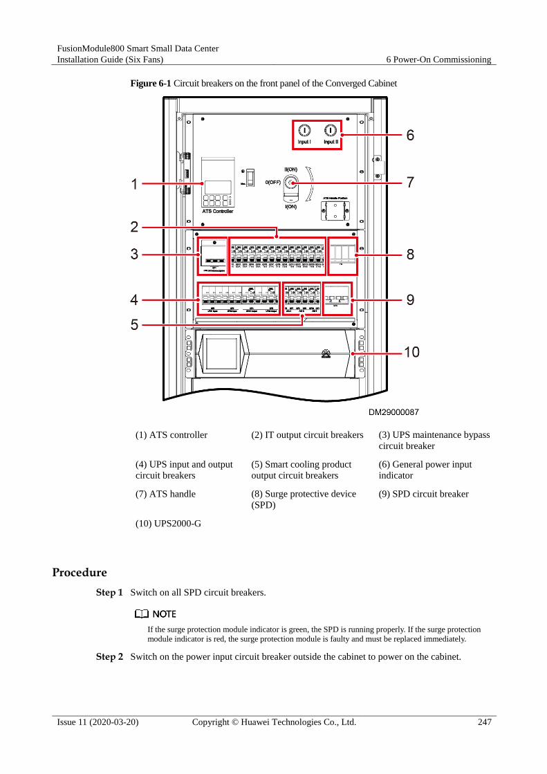
FusionModule800 Smart Small Data Center
Installation Guide (Six Fans) 6 Power-On Commissioning
Issue 11 (2020-03-20) Copyright © Huawei Technologies Co., Ltd. 247
Figure 6-1 Circuit breakers on the front panel of the Converged Cabinet
(1) ATS controller (2) IT output circuit breakers (3) UPS maintenance bypass
circuit breaker
(4) UPS input and output
circuit breakers
(5) Smart cooling product
output circuit breakers
(6) General power input
indicator
(7) ATS handle (8) Surge protective device
(SPD)
(9) SPD circuit breaker
(10) UPS2000-G
Procedure
Step 1 Switch on all SPD circuit breakers.
If the surge protection module indicator is green, the SPD is running properly. If the surge protection
module indicator is red, the surge protection module is faulty and must be replaced immediately.
Step 2 Switch on the power input circuit breaker outside the cabinet to power on the cabinet.

FusionModule800 Smart Small Data Center
Installation Guide (Six Fans) 6 Power-On Commissioning
Issue 11 (2020-03-20) Copyright © Huawei Technologies Co., Ltd. 248
If the green power indicator on the cabinet front panel lights up, the cabinet is powered on properly.
Step 3 (Optional) Press the Auto button on the ATS controller.
Step 4 Close the UPS input switch.
If the 10 kVA UPS is configured, turn on the UPS input switch on the UPS rear panel.
Step 5 Set UPS parameters.
Table 6-3 Set UPS parameters
Parameter Default Value Setting Value
Batteries (10 kVA
UPS)
Positive
batteries/Negative
batteries (20 kVA
UPS)
20 Set as required.
Battery capacity 65 Ah Battery capacity = Capacity of a single battery
string x Number of parallel battery
strings/Number of parallel UPSs sharing a battery
string.
Note: use two UPSs sharing a 65 Ah battery string as an example: if the calculated battery
capacity is (65 x 1)/2 = 32.5, set it to 32 Ah.
For details about how to operate the UPS, see the manual delivered with the UPS.
Step 6 Turn on the UPS output switch after the UPS starts.
Step 7 Switch on the PDU2000 circuit breakers one by one on the PDU and switch on the PDU2000
circuit breaker in the rear of the cabinet to power on corresponding devices.
When switching on the circuit breakers, observe whether there is any abnormal phenomenon,
such as sparks.
Step 8 Switch on the ECC circuit breaker on the PDU to power on the ECC.
Step 9 Switch on the smart cooling product circuit breaker on the PDU to power on the smart cooling
product.
----End

FusionModule800 Smart Small Data Center
Installation Guide (Six Fans) 6 Power-On Commissioning
Issue 11 (2020-03-20) Copyright © Huawei Technologies Co., Ltd. 249
6.3 Management System Power-On Commissioning
6.3.1 Preparations and WebUI Login
Prerequisites
User rights:
The default user with administrator rights is admin. The preset password is Changeme.
The admin user has all WebUI operation rights.
The default user with operation rights is operator. The preset password is Changeme. The
operator user has no rights for parameter setting, control, and maintenance that may
affect system running.
WebUI operating environment requirements:
The operating system of Windows 7 or later is supported.
Browser: Internet Explorer 8.0 and later versions; Firefox 38.0.5 and later versions;
Chrome 46.0.2490.80 and later versions
Procedure
Step 1 Connect a network cable between the PC network port and the WAN_1 port (protected by a
security mechanism) on the ECC800.
Table 6-4 lists the default IP addresses for the WAN and LAN ports on the ECC800.
Table 6-4 Default IP addresses for the WAN and LAN ports on the ECC800
Port Default IP Address
WAN_1 192.168.1.10
WAN_2 192.168.248.10
LAN_1 and LAN_2 192.168.248.10 or 192.168.245.10 (with
Vlan tag 15)
The WAN_1 port IP address cannot be set to an IP address in any of the following network
segments: 192.168.0.x, 192.168.8.x, 192.168.248.x, and 192.168.245.x.
IP addresses for the WAN_1 and WAN_2 ports should not be set in the same network
segment.
Step 2 Configure the PC IP address and the WAN_1 IP address in the same network segment.
If the port IP address is 192.168.1.10, subnet mask is 255.255.255.0, and default gateway is
192.168.1.1, set the PC IP address to 192.168.1.11, subnet mask to 255.255.255.0, and default
gateway to 192.168.1.1.
Step 3 Set LAN parameters.
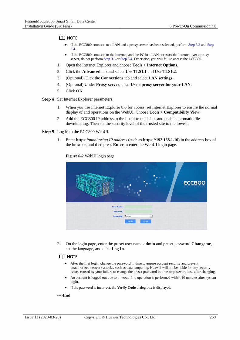
FusionModule800 Smart Small Data Center
Installation Guide (Six Fans) 6 Power-On Commissioning
Issue 11 (2020-03-20) Copyright © Huawei Technologies Co., Ltd. 250
If the ECC800 connects to a LAN and a proxy server has been selected, perform Step 3.3 and Step
3.4.
If the ECC800 connects to the Internet, and the PC in a LAN accesses the Internet over a proxy
server, do not perform Step 3.3 or Step 3.4. Otherwise, you will fail to access the ECC800.
1. Open the Internet Explorer and choose Tools > Internet Options.
2. Click the Advanced tab and select Use TLS1.1 and Use TLS1.2.
3. (Optional) Click the Connections tab and select LAN settings.
4. (Optional) Under Proxy server, clear Use a proxy server for your LAN.
5. Click OK.
Step 4 Set Internet Explorer parameters.
1. When you use Internet Explorer 8.0 for access, set Internet Explorer to ensure the normal
display of and operations on the WebUI. Choose Tools > Compatibility View.
2. Add the ECC800 IP address to the list of trusted sites and enable automatic file
downloading. Then set the security level of the trusted site to the lowest.
Step 5 Log in to the ECC800 WebUI.
1. Enter https://monitoring IP address (such as https://192.168.1.10) in the address box of
the browser, and then press Enter to enter the WebUI login page.
Figure 6-2 WebUI login page
2. On the login page, enter the preset user name admin and preset password Changeme,
set the language, and click Log In.
After the first login, change the password in time to ensure account security and prevent
unauthorized network attacks, such as data tampering. Huawei will not be liable for any security
issues caused by your failure to change the preset password in time or password loss after changing.
An account is logged out due to timeout if no operation is performed within 10 minutes after system
login.
If the password is incorrect, the Verify Code dialog box is displayed.
----End

FusionModule800 Smart Small Data Center
Installation Guide (Six Fans) 6 Power-On Commissioning
Issue 11 (2020-03-20) Copyright © Huawei Technologies Co., Ltd. 251
6.3.2 Preparations and APP Login
Prerequisites
FusionModule running environment requirements:
The mobile device must run Android 4.0 or later and no root operation is performed (the
operating system is not flashed).
The mobile device must have sufficient space for installing the new APP. The size of the
APP installation package is 7.9 MB, and the size of files after APP installation is about
9.28 MB.
The mobile device has sufficient battery reserve.
You have obtained the IP address of the ECC800 as well as the user name and password
used for WebUI login.
A PC with an IP address in the same network segment as that of the ECC800 is prepared,
and the PC has connected to port WAN_1 on the ECC800.
Procedure
Step 1 Download the FusionModule installation package in any of the following three ways:
Log in to HUAWEI App Store (https://appstore.huawei.com/) or Google Play, search for
FusionModule, and tap Download.
− Outside China: Tap the Google play app and search for FusionModule.
− In China:
i. Set the pad language to Chinese.
ii. Open the browser on the pad, enter www.baidu.com in the address box, search
for HUAWEI App Store, select Ordinary Download, and tap Save.
Do not use the Google Play to download the HUAWEI App Store.
iii. Install the HUAWEI App Store. If the downloaded file exists in the drop-down
list box, tap the file to install the HUAWEI App Store. If the downloaded file
does not exist in the drop-down list box, choose File > Local on the desktop,
find the Download folder, and click the HUAWEI App Store installation
package.
After you open the HUAWEI App Store, select NOT NOW if "New Version" is displayed.
Log in to the ECC800 WebUI using a PC. Choose Maintenance > APP Download,
click Download APP, and save the FusionModule installation package to the PC or a
path on a mobile storage device. Then, copy the FusionModule installation package to a
mobile phone or PAD.

FusionModule800 Smart Small Data Center
Installation Guide (Six Fans) 6 Power-On Commissioning
Issue 11 (2020-03-20) Copyright © Huawei Technologies Co., Ltd. 252
Log in to the ECC800 WebUI using the Firefox browser (version 41.0 or later) on a
mobile phone or PAD. Choose Maintenance > APP Download, tap Download APP,
and save the FusionModule installation package to the mobile phone or PAD.
Step 2 Installing the FusionModule.
By default, the Android operating system forbids the installation of applications not obtained
from the Android market. Therefore, before installing the FusionModule, set the mobile phone
so that it allows the installation of applications from unknown sources.
1. Tap the FusionModule installation file to start installation. After the installation is
complete, check that the FusionModule icon is displayed on the home
screen of the mobile phone or PAD.
Step 3 Enable the WiFi function on the ECC800 WebUI.
1. Log in to the ECC800 WebUI as an administrator.
2. Choose Monitoring > System > WiFi Converter and click WiFi Management.
3. Set Enable WiFi to Enable and click Submit.
4. If this is the first time you enable the WiFi function, set WiFi Password and click OK.
5. Enter the password currently used for logging in to the WebUI and click Submit.
6. Specify WiFi SSID and WiFi Password and click Submit to change the SSID and
password.
7. Enter the password currently used for logging in to the WebUI and click Submit.
Step 4 Log in to the FusionModule.
1. Start the mobile phone or pad APP, choose Settings > Network Connection on the
login screen, enter the values of WiFi SSID and WiFi Password specified on the
ECC800 WebUI, and select a corresponding WiFi for login.
2. On the login screen, choose Settings > Server IP Settings, and ensure that the IP
address is 192.168.245.10.
3. The user name and login password for the app are the same as those for the ECC800
WebUI. Enter the user name and password, and tap Login.
----End
Exception Handling
If the verification code is not displayed on the login screen, perform the following steps:
Step 1 Check whether the WiFi network that connects the pad or mobile phone and the ECC800 is
normal.
Yes: Go to Step 2.
No: Reconnect the pad or mobile phone and the ECC800 and check whether the
verification code can be displayed. If the verification code still fails to be displayed, go
to Step 2.
Step 2 On the login screen, choose Settings > Server IP Settings and check whether the ECC800 IP
address is set correctly.

FusionModule800 Smart Small Data Center
Installation Guide (Six Fans) 6 Power-On Commissioning
Issue 11 (2020-03-20) Copyright © Huawei Technologies Co., Ltd. 253
Yes: Contact Huawei technical support.
No: Correct the setting and check whether the verification code can be displayed. If the
verification code still fails to be displayed, contact Huawei technical support.
----End
6.3.3 Setting the Date and Time
Procedure
Step 1 Set the system date to the actual date upon the first login of the ECC800 WebUI. Path:
System Settings > Time Settings.
Step 2 Install the MDC_APP on a mobile phone or pad, log in, and set the system date to the actual
date.
----End
6.3.4 Creating a Micro-Module Plan View
Procedure
Step 1 Choose Home > Plan View, click Create Micro-Module in Micro-Module View and set the
layout and device quantity based on the actual micro-module scenario.
Step 2 Drag the icons of registered devices (such as WiFi converter and smart ETH gateway) and
devices on the cabinet list to appropriate positions in the layout to create a micro-module plan
view.
----End
6.3.5 Adding an Independent Deployment AI_DI Unit
If an Independent Deployment AI_DI Unit is configured, perform the following settings.
Procedure
Step 1 Log in to the ECC800 WebUI as an administrator.
Step 2 Add an independent deployment AI_DI unit.
Table 6-5 Adding an independent deployment AI_DI unit
Path Parameter Name
Setting
Choose System
Settings >
Device
Management and click Add
Device. The
Device
attribute
Select Independent Deployment AI_DI Unit from
the drop-down list box.
Device type Select Independent Deployment AI_DI Unit from
the drop-down list box.
Connect to Select ECC800 from the drop-down list box.

FusionModule800 Smart Small Data Center
Installation Guide (Six Fans) 6 Power-On Commissioning
Issue 11 (2020-03-20) Copyright © Huawei Technologies Co., Ltd. 254
Path Parameter Name
Setting
parameters for
adding devices
are displayed.
Communicatio
ns port
Select COM3 from the drop-down list box.
NOTE
The setting example indicates that the independent
deployment AI_DI unit is connected to the COM3 port on
the ECC800. If the independent deployment AI_DI unit is
connected to another port, set the COM port to the ECC800
port connected to the independent deployment AI_DI unit.
Device
address
In this example, Device address is set to 1. During
actual configuration, set the device address for the
independent deployment AI_DI unit based on the
actual situation.
Step 3 Click Test Connect to check whether the standalone AI/DI module connects to the ECC800
properly.
If the independent deployment AI_DI unit connects to the ECC800 properly, click
Confirm.
If the independent deployment AI_DI unit is not properly connected to the ECC800,
check whether the cable between the standalone AI/DI module and the ECC800 is
connected properly, whether the standalone AI/DI module and ECC800 are running
properly, and whether the input parameters are the consistent with the external AI/DI
module parameters.
----End
6.3.6 Commissioning the Sensor
6.3.6.1 Commissioning the Smoke Detector
Procedure
Step 1 Set smoke sensor parameters.
The parameter has been preset before delivery.
In this example, the smoke detector is connected to the AI/DI_1 port on the skylight actuator.
1. Log in to the ECC800 WebUI as an administrator.
2. Choose System Settings > Signal Name Modify. The Batch Signal Configuration
page is displayed.
3. Set Device type to ECC800, set Device name to ECC800, and click OK.
4. On the query result tab page, set the new signal name of AI/DI_3 to Smoke and click
Submit.
5. Choose Monitoring > System > ECC800 > Running Parameters > AI/DI_3 Port
Settings.
6. Set Smoke sensor to Enable and click Submit.

FusionModule800 Smart Small Data Center
Installation Guide (Six Fans) 6 Power-On Commissioning
Issue 11 (2020-03-20) Copyright © Huawei Technologies Co., Ltd. 255
7. Confirm that Smoke sensor type is automatically identified as Smoke Sensor or Smoke
sensor(NC). Ensure that Smoke power supply is Yes.
Step 2 Check the monitoring functions of smoke sensor.
Table 6-6 Commissioning the sensor
Check Method Normal Connection Status Alarm Clearance Method
Simulate a smoky
environment under
the smoke detector.
Smoke DI alarm is displayed on
the active alarm page of the app
or WebUI.
Press the reset button of the
smoke sensor to clear the alarm.
----End
6.3.6.2 Commissioning the Water Sensor
Procedure
Step 1 Set water sensor parameters.
The parameter has been preset before delivery.
In this example, the water sensor is connected to the AI/DI_1 port on the ECC800.
1. Log in to the ECC800 WebUI as an administrator.
2. Choose System Settings > Signal Name Modify. The Batch Signal Configuration
page is displayed.
3. Set Device type to ECC800, set Device name to ECC800, and click OK.
4. On the query result tab page, set the new signal name of AI/DI_1 to Leak and click
Submit.
5. Choose Monitoring > System > ECC800 > Running Parameters > AI/DI_1 Port
Settings.
6. Set Leak sensor to Enable and click Submit.
7. Confirm that Leak sensor type is automatically identified as Leak sensor(Rope).
Ensure that Leak power supply is Yes.
Step 2 Check the monitoring functions of water sensor.
Table 6-7 Commissioning the sensor
Check Method Normal Connection Status
Place the water detection cable
into water.
Leak DI alarm is displayed on the active alarm page
of the app or WebUI.
----End
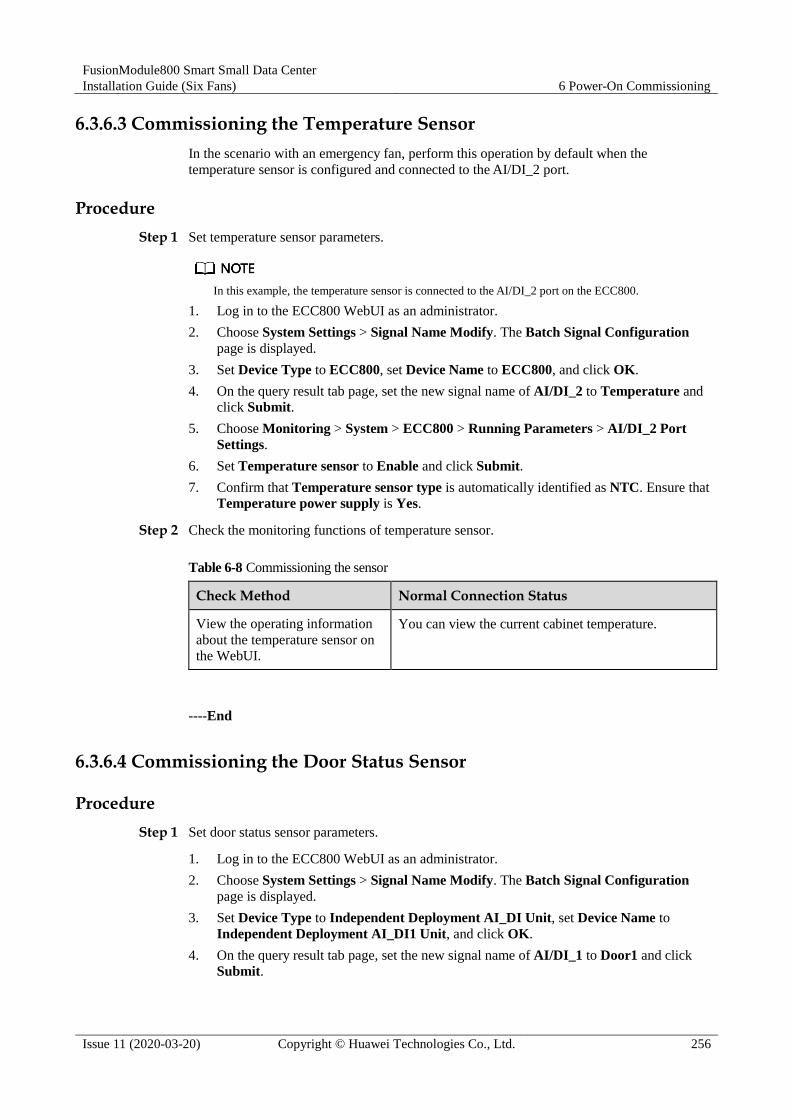
FusionModule800 Smart Small Data Center
Installation Guide (Six Fans) 6 Power-On Commissioning
Issue 11 (2020-03-20) Copyright © Huawei Technologies Co., Ltd. 256
6.3.6.3 Commissioning the Temperature Sensor
In the scenario with an emergency fan, perform this operation by default when the
temperature sensor is configured and connected to the AI/DI_2 port.
Procedure
Step 1 Set temperature sensor parameters.
In this example, the temperature sensor is connected to the AI/DI_2 port on the ECC800.
1. Log in to the ECC800 WebUI as an administrator.
2. Choose System Settings > Signal Name Modify. The Batch Signal Configuration
page is displayed.
3. Set Device Type to ECC800, set Device Name to ECC800, and click OK.
4. On the query result tab page, set the new signal name of AI/DI_2 to Temperature and
click Submit.
5. Choose Monitoring > System > ECC800 > Running Parameters > AI/DI_2 Port
Settings.
6. Set Temperature sensor to Enable and click Submit.
7. Confirm that Temperature sensor type is automatically identified as NTC. Ensure that
Temperature power supply is Yes.
Step 2 Check the monitoring functions of temperature sensor.
Table 6-8 Commissioning the sensor
Check Method Normal Connection Status
View the operating information
about the temperature sensor on
the WebUI.
You can view the current cabinet temperature.
----End
6.3.6.4 Commissioning the Door Status Sensor
Procedure
Step 1 Set door status sensor parameters.
1. Log in to the ECC800 WebUI as an administrator.
2. Choose System Settings > Signal Name Modify. The Batch Signal Configuration
page is displayed.
3. Set Device Type to Independent Deployment AI_DI Unit, set Device Name to
Independent Deployment AI_DI1 Unit, and click OK.
4. On the query result tab page, set the new signal name of AI/DI_1 to Door1 and click
Submit.

FusionModule800 Smart Small Data Center
Installation Guide (Six Fans) 6 Power-On Commissioning
Issue 11 (2020-03-20) Copyright © Huawei Technologies Co., Ltd. 257
Order number of door sensor name is same as cabinet.
5. Choose Monitoring > System > Independent Deployment AI_DI Unit Group >
Independent Deployment AI_DI1 Unit > Running Parameters > AI/DI_1 Port
Settings.
6. Set Door1 sensor to Enable and click Submit.
7. Set Door1 sensor type to Door sensor, ensure that Door1 power supply is Yes, and
click Submit.
8. Perform the preceding operations to set parameters for ports AI/DI_2 to AI/DI_8.
Step 2 Check the monitoring functions of door status sensor.
Table 6-9 Commissioning the sensor
Check Method Normal Connection Status
Open the cabinet door. Door_Sensor 1 AI/DI_1 DI Alarm is displayed on the
active alarm page of the APP or WebUI.
----End
6.3.6.5 (Optional) Commissioning the In-Room Access Control System
Prerequisites
A maximum of two access actuators are supported.
Procedure
Step 1 Set the access user management and access permission management.
1. Choose System Settings > Access Management to access the access management page.
The system supports the management of various access permissions through the access
card, password, and fingerprint.
2. On the Authorization Operations tab page, click Add to access the new user page. On
the Basic Info tab page, enter User name and Employee ID.
Specify the following information on the Password tab.
− Password: Enter and confirm the password.
− Card number: The card number can be recorded directly or by swiping the card.
Record directly: Type the access card number in the text box.
Record by swiping the card: Click Swipe Card and place the card on the
access control device. The card number is automatically recorded.
− Fingerprint: On the Fingerprint tab page, select Fingerprint for Select fingerprint
reader and click Collect. On the Please collect fingerprint page, click OK. Then
put your finger on the fingerprint reader to collect the fingerprint after hearing the
voice prompt. After you hear a beep sound, move your finger away and collect the
fingerprint again.
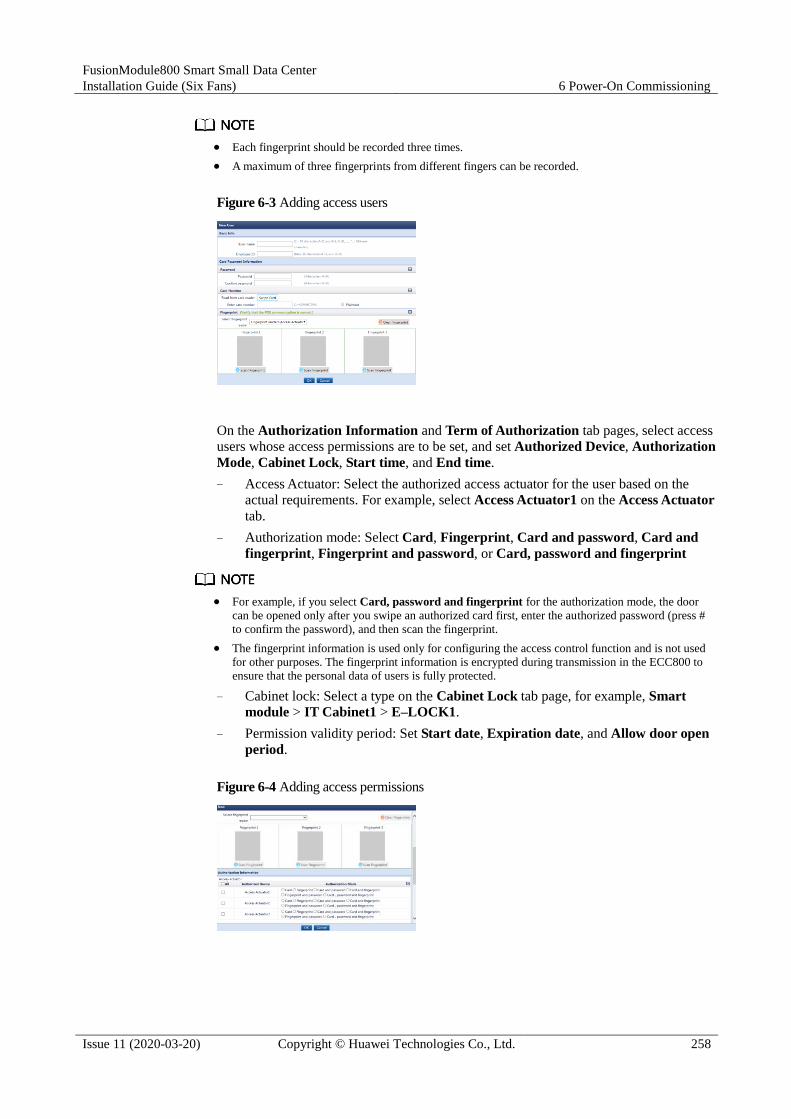
FusionModule800 Smart Small Data Center
Installation Guide (Six Fans) 6 Power-On Commissioning
Issue 11 (2020-03-20) Copyright © Huawei Technologies Co., Ltd. 258
Each fingerprint should be recorded three times.
A maximum of three fingerprints from different fingers can be recorded.
Figure 6-3 Adding access users
On the Authorization Information and Term of Authorization tab pages, select access
users whose access permissions are to be set, and set Authorized Device, Authorization
Mode, Cabinet Lock, Start time, and End time.
− Access Actuator: Select the authorized access actuator for the user based on the
actual requirements. For example, select Access Actuator1 on the Access Actuator
tab.
− Authorization mode: Select Card, Fingerprint, Card and password, Card and
fingerprint, Fingerprint and password, or Card, password and fingerprint
For example, if you select Card, password and fingerprint for the authorization mode, the door
can be opened only after you swipe an authorized card first, enter the authorized password (press #
to confirm the password), and then scan the fingerprint.
The fingerprint information is used only for configuring the access control function and is not used
for other purposes. The fingerprint information is encrypted during transmission in the ECC800 to
ensure that the personal data of users is fully protected.
− Cabinet lock: Select a type on the Cabinet Lock tab page, for example, Smart
module > IT Cabinet1 > E–LOCK1.
− Permission validity period: Set Start date, Expiration date, and Allow door open
period.
Figure 6-4 Adding access permissions

FusionModule800 Smart Small Data Center
Installation Guide (Six Fans) 6 Power-On Commissioning
Issue 11 (2020-03-20) Copyright © Huawei Technologies Co., Ltd. 259
You can authorize and delete access users in batches.
3. Click OK to complete the task of adding access management settings.
4. On the Authorization Operations tab page, click Synchronize to Device, select the
modified access control devices, and click Start Synchronization.
Figure 6-5 Synchronizing access permissions
5. When Synchronization Status is Synchronized for the related devices, close the
Synchronize Access Permission page.
Step 2 Set an alarm for card readers.
Set Logical level configuration for reader removed based on the fingerprint reader
configured for the access control system.
If the access control system uses a Card and password reader, choose Monitoring >
Aisle > Access Actuator Group > Access Actuator n on the ECC800 WebUI, click
Running Parameters, and set Logical level configuration for reader removed of the
corresponding card reader to High level alarm.
Table 6-10 Setting method
Cable Connection Scenario Setting Method
The card reader with a keypad is
connected to WG_1 port on the access
actuator.
Set Logical level configuration for reader 1
removed to High level alarm. Logical level
configuration for reader 2 removed remains as
Low level alarm.
The card reader with a keypad is
connected to WG_2 port on the access
actuator.
Set Logical level configuration for reader 2
removed to High level alarm. Logical level
configuration for reader 1 removed remains as
Low level alarm.
If the access control system uses a Card, Card and fingerprint, or Card, password
and fingerprint reader, retain the default value Low level alarm for Logical level
configuration for reader removed.
Step 3 Check the functions of the access control device and access actuator.
FusionModule800 Smart Small Data Center
Installation Guide (Six Fans) 6 Power-On Commissioning
Issue 11 (2020-03-20) Copyright © Huawei Technologies Co., Ltd. 260
Table 6-11 Function check
Check Method Normal Connection Status
Method 1: Attempt to open the door using
the configured authentication mode.
NOTE
For example, if you select Card, password and
fingerprint for the authorization mode, the door
can be opened only after you swipe an authorized
card first, enter the authorized password (press #
to confirm the password), and then scan the
fingerprint.
Method 2: On the WebUI, choose
Monitoring > Aisle > Access Actuator
Group > Access Actuator n, and click
Controls to open the door remotely.
For method 1: The aisle door is opened
successfully.
For method 2: After you choose Query >
Access Event on the WebUI, you can view
the type of this access control event.
----End
6.3.6.6 (Optional) Commissioning an In-Room Exit Button
Procedure
Step 1 Check functions of the exit button.
Table 6-12 Function check
Check That Normal Connection Status
Open the door by pressing the exit button
when the aisle door is properly closed.
The room door is opened properly.
----End
6.3.6.7 (Optional) Commissioning an In-Room Emergency Door Release Button
Procedure
Step 1 Check the function of an emergency door release button.
Table 6-13 Function check
Check That Normal Connection Status
Follow-up Procedure
When the room door is
properly closed, short circuit the wiring terminals NO and
The room door is opened
properly.
Remove the short-circuit
cable on the emergency door

FusionModule800 Smart Small Data Center
Installation Guide (Six Fans) 6 Power-On Commissioning
Issue 11 (2020-03-20) Copyright © Huawei Technologies Co., Ltd. 261
Check That Normal Connection Status
Follow-up Procedure
COM on the emergency
door release button.
release button.
----End
6.3.7 Setting iBOX and iBAT Parameters
Procedure
Step 1 Log in to the ECC800 WebUI as an administrator.
Step 2 Choose Monitoring > Power Distribution > iBOX/CIM > Running Parameters.
Step 3 Click Unhide All Advanced Signals, set iBOX single battery qty., Batt. installation time,
Single battery capacity, Current source, and Battery string No.. Retain default values for
other parameters.
Table 6-14 Setting iBOX parameters
Parameter Description Remarks
iBOX/CIM single
battery qty.
Total number of batteries monitored by
the iBOX/CIM
Set this parameter based
on the battery parameter
planned by the customer.
Batt installation
time
Actual time at which batteries are
installed
N/A
Single battery
capacity
Single battery capacity refers to the
capacity of a single battery in a battery
string managed by the iBOX.
Obtain the battery capacity
from the battery label or
document.
Current source 0–xxxA Hall
The actual specifications of the Hall
effect sensor prevail.
N/A
Battery string No. Set this parameter based on the planned
codes for iBOXs and battery strings.
Set this parameter based
on the customer's plan.
----End
6.3.8 Networking iBOXs and iBATs in Wireless Mode
Prerequisites
Before networking, ensure that all the iBOXs and iBATs have no network parameters, that is,
the RF_Z indicator on the iBOX is steady green and the RUN/ALM indicator on the iBAT is
steady red.

FusionModule800 Smart Small Data Center
Installation Guide (Six Fans) 6 Power-On Commissioning
Issue 11 (2020-03-20) Copyright © Huawei Technologies Co., Ltd. 262
The iBAT is connected to the iBOX in RF_Z networking mode.
If the RF_Z indicator on the iBOX is not steady on (green), press and hold down the networking
switch on the iBOX for 10–20 seconds to clear the original network.
If the RUN/ALM indicator on the iBAT is not steady red, hold down the iBAT networking switch for
at least 5 seconds to clear the original network.
Context If multiple iBOXs are connected, commission the iBOX one by one in the same way.
Otherwise, networking may be in disorder.
Indicator status:
− Blinking at long intervals: The indicator is on for 1 second and then off for 1 second
alternately.
− Blinking at super short intervals: The indicator is on for 0.05 seconds and then off
for 0.05 seconds alternately.
− Blinking at short intervals: The indicator is on for 0.125 seconds and then off for
0.125 seconds alternately.
Procedure
Step 1 Press the networking switch on the iBOX for 2 seconds. The ALM indicator blinks red once,
and the RF_Z indicator turns from steady green to blinking green at super short intervals,
which indicates that the iBOX is being networked.
Step 2 Press the iBAT networking switch for 2 seconds. When the RUN/ALM indicator turns from
steady red to blinking green at super short intervals (iBattery 2.0) or short intervals (iBattery
3.0), and finally to blinking green at long intervals, the iBAT connects to the iBOX network.
It is recommended that iBATs be networked from the positive battery string terminal according to
the battery cable connection sequence.
Batteries are numbered depending on the sequence of connecting iBATs to the iBOXs.
Step 3 Perform networking operations on the next iBAT only after networking for the previous iBAT
is successful. Repeat Step 2 to add other iBATs to the iBOX network.
Step 4 Press the iBOX networking switch for 2 seconds. When the RF_Z indicator on the iBOX
turns from blinking green at super short intervals to blinking green at long intervals, the
networking is complete.
After the networking is complete, if the ALM indicator on the iBOX is steady on, the number of devices
online is smaller than the value of iBAT Number. Check that iBAT Number is set to a correct value
and that the iBAT is successfully networked.
Step 5 (Optional) If multiple iBOXs are cascaded, repeat Step 1 to Step 4 to perform networking for
remaining iBOXs and iBATs.
----End

FusionModule800 Smart Small Data Center
Installation Guide (Six Fans) 6 Power-On Commissioning
Issue 11 (2020-03-20) Copyright © Huawei Technologies Co., Ltd. 263
6.3.9 Setting Alarm Notification by Email and SMS
The alarm notification by email and SMS is set as required. A maximum of 20 alarm
notification user information can be displayed.
Prerequisites
To implement alarm notification by SMS, the following conditions must be met:
The ECC800 is configured with a 3G module into which a GSM or WCDMA SIM card is
inserted.
To implement alarm notification by email, the following conditions must be met:
The ECC800 is connected to a network with mail servers through a WAN port. Both Internet
and local area network (LAN) can be used.
The ECC800 supports only SMS but not data services by using the 3G module.
Procedure
Step 1 Choose System Settings > Event Notification.
Step 2 Set the Outbox Setting parameter.
Figure 6-6 Setting the Outbox Setting parameter
Click Test to test whether the email is sent successfully. If the email fails to be sent, check the
sender's email parameter settings; if the email is sent successfully, click Submit.
If Test email sending failed is displayed, check whether the receiver's email server requires CA
certificate verification. If it is required, download the CA certificate from the receiver's email
website and upload it in the Mailbox Certificate area.
The following email addresses are for reference only (the actual parameters apply) and are used only
for configuring the email function.
Table 6-15 Main parameters on the sender's email configuration page
Email Type
Email Server Domain Name
Mailbox Server IP Address
Encryption Mode and SMTP port
Remarks
Sina Mail smtp.sina.co How to obtain: Non-encryption: The email

FusionModule800 Smart Small Data Center
Installation Guide (Six Fans) 6 Power-On Commissioning
Issue 11 (2020-03-20) Copyright © Huawei Technologies Co., Ltd. 264
Email Type
Email Server Domain Name
Mailbox Server IP Address
Encryption Mode and SMTP port
Remarks
m 1. Click Start on
the PC, enter
cmd in
Running area,
and click
Search to
access the
administrator
page.
2. Enter ping
email server
domain name at the position
of the blinking
cursor and
press Enter to
obtain email
server IP
addresses.
25 server must
comply with
the standard
SMTP
protocol to
ensure that the
email sending
and receiving
functions are
normal.
Enter the
email client
authorization
password at
Password for
163 Mail, 126
Mail, and QQ
Mail.
163 Mail smtp.163.com Non-encryption:
25; SSL
encryption: 465
126 Mail smtp.126.com Non-encryption:
25; SSL
encryption: 465
QQ Mail smtp.QQ.com SSL encryption:
465
Sohu Mail smtp.sohu.co
m
Non-encryption:
25
139 Mail smtp.139.com Non-encryption:
25
Hotmail smtp-mail.out
look.com
TLS encryption:
587
189 Mail smtp.189.com Non-encryption:
25
Step 3 Click Add in the Email Receiving Settings area and enter the receiver's email address.
Step 4 Click Confirm to access the re-authentication page. Enter Login password and click Submit.
Step 5 Click Test to check whether the added email address is available. If it is available,
Successfully to send the test email. is displayed. If it is unavailable, Failed to send the test
email. is displayed. Check whether the receiver's email parameters are correctly set.
Step 6 Select Add on the SMS Settings page and enter the receiver's mobile phone number.
Step 7 Click Confirm to access the re-authentication page. Enter Login password and click Submit.
Step 8 Click Test to check whether the added mobile phone number is available. If it is available,
Successfully to send the test short message. is displayed. If it is unavailable, Failed to send
the test short message. is displayed. Check whether the receiver's mobile phone parameters
for receiving short messages are correctly set.
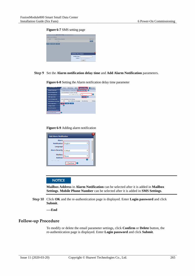
FusionModule800 Smart Small Data Center
Installation Guide (Six Fans) 6 Power-On Commissioning
Issue 11 (2020-03-20) Copyright © Huawei Technologies Co., Ltd. 265
Figure 6-7 SMS setting page
Step 9 Set the Alarm notification delay time and Add Alarm Notification parameters.
Figure 6-8 Setting the Alarm notification delay time parameter
Figure 6-9 Adding alarm notification
Mailbox Address in Alarm Notification can be selected after it is added in Mailbox
Settings. Mobile Phone Number can be selected after it is added in SMS Settings.
Step 10 Click OK and the re-authentication page is displayed. Enter Login password and click
Submit.
----End
Follow-up Procedure
To modify or delete the email parameter settings, click Confirm or Delete button, the
re-authentication page is displayed. Enter Login password and click Submit.

FusionModule800 Smart Small Data Center
Installation Guide (Six Fans) 6 Power-On Commissioning
Issue 11 (2020-03-20) Copyright © Huawei Technologies Co., Ltd. 266
6.3.10 Commissioning Cameras and a VCN (Smart ETH Gateway Networking Scenario)
Figure 6-10 Video system networked over a smart ETH gateway
To ensure the normal operating of the ECC800, avoid high data traffic, such as the
concurrent display of dynamic monitoring of cameras and VCN video playback.
To ensure the normal operating of the ECC800, you can view the videos from a maximum
of two IPC6325-WD-VR cameras concurrently.
6.3.10.1 Commissioning IPC6325 Cameras
Prerequisites
If multiple cameras are accessed, retain the connection of one camera and disconnect
connections from other cameras. After commissioning the connected camera, commission
other cameras in the same way.
Context The existing network is equipped with the ECC800 that supports the Dynamic Host
Configuration Protocol (DHCP). After the ECC800 and IPC6325 camera are powered on,
the IPC6325 camera automatically obtains an IP address that is in the same network
segment as the ECC800 IP address.
Before commissioning the IPC6325 camera, set the IP address for the IPC6325 camera
based on customer requirements.

FusionModule800 Smart Small Data Center
Installation Guide (Six Fans) 6 Power-On Commissioning
Issue 11 (2020-03-20) Copyright © Huawei Technologies Co., Ltd. 267
Set the internal and external IP addresses as planned by the customer. The following IP
addresses are just examples.
Table 6-16 IP address plan
Device Internal IP Address External IP Address
Camera Example: 192.168.248.50; range:
192.168.248.50–192.168.248.199
Camera external IP
address
VCN Example: 192.168.248.55; range:
192.168.248.50–192.168.248.199
VCN external IP address
Procedure
Step 1 Set the IP address for the IPC6325 camera.
1. Enter https://192.168.248.10 in the address box of the browser and press Enter to access
the WebUI login page. After login, choose System Settings > Video Management.
2. Under the Search for Video Device IP Address list, click Search.
Configure the camera IP address and the IP address of the LAN port on the ECC800 in the same
network segment.
The search timeout interval is 10s. If the search fails, a search failure message is displayed.
To avoid missing cameras, perform Search for multiple times.
Figure 6-11 Searching for the camera IP address
3. Add the camera that has been found to Video Information. Click Add under the Video
Information list, and enter the camera information in the displayed New Video
Information window.
− Name: Enter the camera name (for example, Camera1).
− External IP: Enter the external IP address of the camera (The IP address assigned
by the network administrator prevails).

FusionModule800 Smart Small Data Center
Installation Guide (Six Fans) 6 Power-On Commissioning
Issue 11 (2020-03-20) Copyright © Huawei Technologies Co., Ltd. 268
− Internal IP: Enter the internal IP address, that is, the found camera IP address:
192.168.248.50.
− Video Type: Select the video type based on the customer's device.
− Link: Enter the external IP address of the camera (for example, https://external IP
address of the camera).
Figure 6-12 Adding video information
4. Select the required camera, and click the link under Link (PC IP address and camera
external IP address should be in the same network segment) to access and log in to the
camera WebUI. Enter the preset user name admin and preset password HuaWei123, and
click Login.
5. (Optional) Choose Settings > Basic Configuration > Network Parameters, set Way to
obtain IP to Use the following IP address and set an IP address to the planned IP
address for the camera. The IP address should be in the range of 192.168.248.50 to
192.168.248.199.
Step 2 Click Confirm after video information is entered.
To perform Step 1.5, return to the ECC800 Video Management page. In the Video Information area,
select the camera added in Step 1.3 and click Modify. In the displayed New Video Information dialog
box, set Internal IP to the IP address planned in Step 1.5, and click Confirm.
Step 3 In the Video information list, click a link address under Link to go to the camera WebUI as
instructed.
Step 4 For details about how to commission IP cameras and set parameters for them, see the
documentation delivered with the equipment or obtain the documentation by referring to the
"Preparing Documentation" section.
1. Preview the site situation in real time and check the camera coverage through videos.
Adjust the lens if necessary.
2. (Optional) If you use the SD card when no VCN is configured, perform commissioning
by following the instructions in Commissioning IPC6325 Camera (SD Card Configured).
3. Set camera stream type, primary stream, and secondary stream 1 parameters.

FusionModule800 Smart Small Data Center
Installation Guide (Six Fans) 6 Power-On Commissioning
Issue 11 (2020-03-20) Copyright © Huawei Technologies Co., Ltd. 269
Set coding protocol to H.264.
Figure 6-13 Setting primary stream parameters
Figure 6-14 Setting secondary stream 1 parameters
----End
Follow-up Procedure
Commission the other cameras by referring to this section.

FusionModule800 Smart Small Data Center
Installation Guide (Six Fans) 6 Power-On Commissioning
Issue 11 (2020-03-20) Copyright © Huawei Technologies Co., Ltd. 270
6.3.10.2 Commissioning IPC6325 Camera (SD Card Configured)
Context
If the VCN is not configured and an SD card is chosen, perform the following procedure.
Procedure
Step 1 Format the SD card.
1. Choose Settings > System Configuration > Storage Management.
2. The Storage Management page is displayed. Format the SD card.
Step 2 Set the camera stream type and primary stream parameters.
Figure 6-15 Setting audio and video parameters
If longer-time video storage is required, set camera parameters according to the following table.
Table 6-17 Camera configuration parameters
Condition Result
Coding Protocol
Resolution Frame Rate I-frame Interval
Minimum Required Bit Rate
Supported Video Storage Duration (h)
H.265 1080P 25 50 1M 66
H.264 1080P 25 50 1M 66
H.265 720P 25 50 0.8M 75
H.264 720P 25 50 1M 66

FusionModule800 Smart Small Data Center
Installation Guide (Six Fans) 6 Power-On Commissioning
Issue 11 (2020-03-20) Copyright © Huawei Technologies Co., Ltd. 271
Condition Result
Coding Protocol
Resolution Frame Rate I-frame Interval
Minimum Required Bit Rate
Supported Video Storage Duration (h)
H.265 720P 25 50 0.6M 105
H.264 720P 25 50 0.8M 75
Step 3 Select Enable, click Add, add motion detection areas, set motion detection parameters, and
click Save.
Figure 6-16 Setting motion detection parameters
Step 4 Set the deployment policy.
Figure 6-17 Setting the deployment policy
Step 5 Set the alarm linkage policy.

FusionModule800 Smart Small Data Center
Installation Guide (Six Fans) 6 Power-On Commissioning
Issue 11 (2020-03-20) Copyright © Huawei Technologies Co., Ltd. 272
Figure 6-18 Setting the alarm linkage policy
----End
6.3.10.3 Setting Parameters on the VCN WebUI
Prerequisites
For details about the VCN hardware description and installation, see the "Hardware Guide" in
the corresponding VCN product documentation. For details about the VCN configuration, see
Configuration Guide.
The version number is subject to the Quick Start delivered with the VCN. The description and link in
this document are for reference only.
Context
A default IP address has been configured for the VCN before delivery. Modify the IP address
based on the actual network plan.
Procedure
Step 1 Modify the IP address for the VCN.
1. Configure the PC IP address and the VCN IP address in the same network segment.
Enter the OMU Portal address (the default address for VCN is
https://192.168.1.100:8443; the default address for VCN540 is
https://192.168.2.101:8443) in the address bar of the Internet Explorer and press the
Enter button.
The OMU Portal supports Internet Explorer 8.0 and later versions.
2. On the login page, enter the user name Admin and preset password Change_Me, and
click Log In to enter the OMU Portal page.

FusionModule800 Smart Small Data Center
Installation Guide (Six Fans) 6 Power-On Commissioning
Issue 11 (2020-03-20) Copyright © Huawei Technologies Co., Ltd. 273
After the first login, change the password in time to ensure account security and prevent unauthorized
network attacks, such as data tampering. Huawei will not be liable for any security issues caused by your
failure to change the preset password in time or password loss after changing.
3. Choose Local Configuration > Server configuration. Set the service IP address
(internal IP address of the VCN), NAT IP address (external IP address of the VCN), time
zone, and time according to the site requirements.
Figure 6-19 Configuring the server
Set Business IP to XXX.XXX.XXX.XXX, Subnet mask to 255.255.254.0, Gateway IP to
XXX.XXX.XXX.XXX. The values here are examples. The actual values prevail.
Set NAT IP to VCN external IP address, which is the same as the external IP address mapped from
the VCN internal IP address displayed on the ECC800.
4. Configure the NTP synchronization. After setting The NTP clock source server to Yes,
set the IP address of the NTP server.
The server that connects to cameras needs to enable the camera NTP synchronization function. For the
detailed operations, see Step 2.
Step 2 Enabling camera NTP synchronization.
The camera NTP synchronization function for the server is disabled by default. The camera
NTP synchronization function needs to be enabled for the server that connects to cameras.
After the camera NTP synchronization function is enabled, cameras will automatically
time-synchronize from their access servers.
1. Log in to the OMU portal of the VCN as the Admin user.
2. Choose Maintenance > Unified Configuration.
3. Select the server that the camera needs to access, set Module name to SCU and
Parameter type to System property, and click Search.

FusionModule800 Smart Small Data Center
Installation Guide (Six Fans) 6 Power-On Commissioning
Issue 11 (2020-03-20) Copyright © Huawei Technologies Co., Ltd. 274
Figure 6-20 Configuring Camera NTP Synchronization
4. In the search results, click Edit in the row where Parameter Name is NTPIPC and set
Value to 1.
5. Click Save. After the camera NTP synchronization function is enabled, the camera, after
being connected to the server, will automatically time-synchronize with the server.
----End
Follow-up Procedure The VCN automatically restarts after the IP address is modified. The restart takes about 5
minutes. After the restart, use the new IP address to access the VCN.
Change the PC IP address to an address in the network segment of the new VCN IP
address, enter the VCN IP address in the address box of the Internet browser, and log in
to the OMU Portal system.
(Optional) Deploying IVS in Stack Mode. For details, log in to the
https://e.huawei.com/, search for the VCN product documentation, open the
documentation, and see the section (Optional) Deploying IVS in Stack Mode.
(Optional) Deploying MPUs in Cluster Mode. For details, log in to the
https://e.huawei.com/, search for the VCN product documentation, open the
documentation, and see the section (Optional) Deploying MPUs in Cluster Mode.
For the VCN500, search for VCN500 Product Documentation. For the VCN540, search for
VCN510&VCN520&VCN540 Product Documentation.
6.3.10.4 Setting Parameters on the VCN IVS Client
Prerequisites
The network communication between the VCN and the camera is normal.
Procedure
Step 1 Install the VCN IVS client.
1. Download the VCN IVS client.
You can obtain the VCN IVS in either of the following ways:
Method 1 Obtain the HW_IVS_Client.exe file from the software CD-ROM delivered
with the VCN.
Method 2 1. Log in to the VCN OMU Portal, choose Local Configuration > Basic
Configuration, and view Current version.

FusionModule800 Smart Small Data Center
Installation Guide (Six Fans) 6 Power-On Commissioning
Issue 11 (2020-03-20) Copyright © Huawei Technologies Co., Ltd. 275
2. Log in to https://support.huawei.com/enterprise/, and search for Client
Package.zip followed by the VCN model (Client Package.zip VCN540
for example). In the search result, click the Software Download tab, click
the version and patch number corresponding to the current version, and
download the Client Package.zip software package.
Figure 6-21 Client Package search result
2. Double-click HW_IVS_Client.exe, adopt the default installation mode, and wait until
the installation is complete.
3. Double-click the client program and on the login page, enter the user name Admin and
preset password Change_Me, and set Server address to the actual service IP address
(VCN IP address) and Port to 9900.
If the VCN IVS and VCN are deployed in the same LAN, set Server IP address to the VCN internal IP
address (192.168.248.55, for example). If the VCN IVS is on an extranet and the VCN is on a LAN, set
Server IP address to the VCN external IP address.
If the VCN software version is V100R003 or later, the default user name is admin.
If the VCN software version is V100R002 or earlier, the default user name is Admin.
4. Click Log In to access the client home page.
After the first login, change the password in time to ensure account security and prevent unauthorized
network attacks, such as data tampering. Huawei will not be liable for any security issues caused by your
failure to change the preset password in time or password loss after changing.
Step 2 Add a camera. For details, see the documentation delivered with the equipment or obtain the
documentation by referring to the "Preparing Documentation" section. View the
corresponding section.
The IPC6325 camera is driven by the HWSDK protocol.
1. In the Quick Setup area on the VCN IVS home page, double-click Add Camera.
2. Click + in the lower left corner on the Search criteria page, setting the parameters
according to the following table, and click Next.
Table 6-18 Setting search criteria
Item Value
Start IP Address and End IP Address IP address range
Drive HWSDK
Access domain Select the domain that cameras need to

FusionModule800 Smart Small Data Center
Installation Guide (Six Fans) 6 Power-On Commissioning
Issue 11 (2020-03-20) Copyright © Huawei Technologies Co., Ltd. 276
Item Value
access
Mount Server Select the server that cameras need to access
There are multiple VCNs for multiple smart modules, you are advised to evenly distribute the cameras to
each VCN.
3. Click Search, in each camera record, enter the user name and password in the text boxes
and click Verify. If the camera is verified successfully, select cameras to add and click
Next.
4. Preview live video images, click the camera in the camera list on the left, and adjust
camera parameters to optimize the image effect. Then click Next.
5. (Optional) Group the cameras and click Next after grouping.
6. Click Finish to finish adding a camera.
Step 3 Configuring a Video Recording Plan.
1. In the Quick Setup area on the VCN IVS home page, double-click Server Recording
Plan.
2. Select the camera on the Cameras list and click Next.
3. (Optional) Set recording parameters, and click Next.
4. Set recording plan parameters in the Time settings. Drag the timeline to select the time
segment for implementing video recording.
If you set the recording plan policy is to All, you do not need to set the recording plan time.
5. Click Next to complete the recording plan setting. When is displayed in the status bar,
the recording plan has been set successfully.
6. Click Finish.
Step 4 Create a user.
When connecting to the VCN on the NetEco, you need to log in to the VCN as a non-admin
user.
1. Log in to the VCN IVS as user Admin.
If the VCN software version is V100R003 or later, the default user name is admin.
If the VCN software version is V100R002 or earlier, the default user name is Admin.
2. On the VCN IVS home page, double-click Add User, create a user, and click Next. The
Assign Rights page is displayed.
When creating a user, you can select Enable account validity period and set Valid from and Valid to
to set the account validity period for the created user.

FusionModule800 Smart Small Data Center
Installation Guide (Six Fans) 6 Power-On Commissioning
Issue 11 (2020-03-20) Copyright © Huawei Technologies Co., Ltd. 277
Figure 6-22 Creating a user
3. Set Multi-point logins to a value greater than 2.
4. In the Assign Device View Rights area, select the cameras to be browsed and queried by
the user. Set other parameters based on the documentation delivered with the equipment
or the documentation obtained by referring to the Preparing Documentation section,
and click Finish.
----End
6.4 Power-On Commissioning for the Cooling System
6.4.1 Equipment Power-On
Prerequisites Verify that the humidifier water inlet pipe and drainpipe are correctly connected, that the
thermal insulation foam is intact, and that refrigerant has been charged.
Check that the cables to the indoor and outdoor units are correctly connected and that the
live wire, neutral wire, and ground cable are correctly connected.
Ensure that the smart cooling product circuit breaker in the upstream PDB is OFF.
Verify that the indoor unit power cable is correctly connected and that the input voltage
meets requirements.
Check that the smart cooling product control unit and the ECC800 or smart ETH
gateway are correctly connected.
Context
The outdoor unit circuit breaker is ON by default. The stop valves on the gas pipe and liquid
pipe for the outdoor unit are open.
Procedure
Step 1 Switch on the circuit breakers for the indoor and outdoor units on the upstream PDB.

FusionModule800 Smart Small Data Center
Installation Guide (Six Fans) 6 Power-On Commissioning
Issue 11 (2020-03-20) Copyright © Huawei Technologies Co., Ltd. 278
The electric heating belt of the crankcase starts working. Before starting the compressor,
ensure that the electric heating belt of the crankcase has been preheated for more than 12
hours. Otherwise, Huawei will not repair the compressor.
Step 2 Commission the system after the electric heating belt of the crankcase has been preheated for
12 hours.
----End
6.4.2 Initial Configuration
6.4.2.1 Setting Temperature and Humidity
Procedure
Step 1 Log in to the ECC800 WebUI as user admin.
Step 2 Choose Monitoring > Air Conditioner > NetCol5000-A0101 > Running Parameters >
Temp/Hum Sensor Para to view temperature and humidity parameters.
0101 in NetCol5000-A0101 is variable and subject to changes with the smart cooling product
connection sequence. The displayed value prevails.
Step 3 Enable the T/H sensor connected to the smart cooling product.
Assume that one smart cooling product is configured for three cabinets. Three T/H sensors whose
addresses are 11, 12, and 21 connect to smart cooling product 1. Set cold-aisle sensor 1, cold-aisle
sensor 2, and hot-aisle sensor 1 to Enable. For settings in more configuration scenarios, see Figure
3-130.

FusionModule800 Smart Small Data Center
Installation Guide (Six Fans) 6 Power-On Commissioning
Issue 11 (2020-03-20) Copyright © Huawei Technologies Co., Ltd. 279
Figure 6-23 T/H sensor layout and DIP switch address (3 cabinets and 1 smart cooling product)
----End
6.4.2.2 Setting Teamwork Control Parameters
Context
Teamwork control parameters have the following bidirectional coupling relationships:
Number of running units ≤ Total number of units
Teamwork group no.: Group the smart cooling products in adjacent areas as one, that is,
assign one teamwork control number for them. At most four teamwork control groups
can be assigned (1–4).
Teamwork unit address: The addresses for the smart cooling products in the same group
cannot be the same (address range 1–32). The smart cooling product addressed 1 is the
master one that collects, processes, and delivers data. You are advised to set the value to
an integer in the range of 1 to the number of smart cooling products in the current group.
Procedure
Step 1 Log in to the ECC800 WebUI as admin.
Step 2 Choose Monitoring > Air Conditioner > NetCol5000-A0101 > Running Parameters >
Teamwork Settings to display the page for teamwork setting.
0101 in NetCol5000-A0101 is variable and subject to change with the smart cooling product connection
sequence. The displayed value prevails.
Step 3 Set teamwork control parameters.

FusionModule800 Smart Small Data Center
Installation Guide (Six Fans) 6 Power-On Commissioning
Issue 11 (2020-03-20) Copyright © Huawei Technologies Co., Ltd. 280
Table 6-19 Setting teamwork control parameters for two smart cooling products
Parameter Smart Cooling Product No.
1 2
Teamwork function Enable Enable
Teamwork group no. 1 1
Teamwork unit address 1 2
Total number of units 2 N/A
Number of running units 1 (1 standby smart cooling product) N/A
Rotation Enable N/A
Rotation period The parameter can be set by the day ranging
from one day to 30 days as required.
N/A
Rotation time The parameter can be set by the hour
ranging from midnight to 23:00 as required.
N/A
Requirement control Competitive running avoidance N/A
Table 6-20 Setting teamwork control parameters for three smart cooling products
Parameter Smart Cooling Product No.
1 2 3
Teamwork function Enable Enable Enable
Teamwork group no. 1 1 1
Teamwork unit
address
1 2 3
Total number of units 3 N/A N/A
Number of running
units
2 (1 standby smart cooling product) N/A N/A
Rotation Enable N/A N/A
Rotation period The parameter can be set by the day
ranging from one day to 30 days as
required.
N/A N/A
Rotation time The parameter can be set by the
hour ranging from midnight to
23:00 as required.
N/A N/A
Requirement control Competitive running avoidance N/A N/A

FusionModule800 Smart Small Data Center
Installation Guide (Six Fans) 6 Power-On Commissioning
Issue 11 (2020-03-20) Copyright © Huawei Technologies Co., Ltd. 281
Step 4 After setting teamwork control parameters, choose Monitoring > Air Conditioner >
NetCol5000-A0101 > Running Info > Teamwork Information and check that the displayed
teamwork control information is consistent with the parameter settings.
If the information displayed under Teamwork Information is inconsistent with the parameter
settings, check the teamwork control cable connection and teamwork control parameter
settings.
----End
6.4.2.3 Setting Max Speed of Indoor Fan
If the equipment room is near a noise-sensitive place, such as an office or a meeting room,
limit the rotational speed of the indoor fan within 80% to lower the noise.
Procedure
Step 1 Choose Monitoring > Air Conditioner > NetCol5000-A0101 > Running Parameters >
Indoor Fan Parameters, set Max speed of indoor fan to 80%.
Step 2 Set Max speed of indoor fan to 80% of other smart cooling products in turn.
----End
6.4.3 Commissioning
Prerequisites
Check that the indoor and outdoor units have been powered on.
Before starting the compressor, ensure that the electric heating belt of the crankcase has been
preheated for more than 12 hours.
The one-way indoor unit pipe is longer than 30 meters but not greater than 60 meters.
Therefore you need to add refrigerant during commissioning.
Before charging refrigerant, ensure that air is exhausted from the gas pipe connecting to
the refrigerant cylinder.

FusionModule800 Smart Small Data Center
Installation Guide (Six Fans) 6 Power-On Commissioning
Issue 11 (2020-03-20) Copyright © Huawei Technologies Co., Ltd. 282
Context
Convert the components that cause partial resistance loss such as elbows into the length
equivalent to that of straight pipes, and add the equivalent length to the length of the straight
pipe between the indoor and outdoor units to obtain the total one-way pipe length (L). L
should be less than or equal to 60 meters. If L exceeds 60 meters, contact Huawei technical
support.
Table 6-21 Equivalent length of pipe assemblies
Pipe Outer Diameter 90° Bend 180° Bend
5/8 inch (15.88 mm) 0.3 meter 0.6 meter
3/8 inch (9.52 mm) 0.2 meter 0.4 meter
Table 6-22 lists how to calculate the amount of refrigerant to be charged onsite.
Table 6-22 Calculating the amount of refrigerant to be charged onsite
Type NetCol5000-A011
One-way pipe length (m) 0 < L ≤ 30 30 < L ≤ 60
Amount of added
refrigerant (kg)
NetCol500-A018 0 (L – 30) x 0.05
NetCol500-A020 0 (L – 30) x 0.1
Refrigerant R410A from name brands such as Daikin are recommended.
Wear antifreeze gloves when performing refrigerant related operations.
Following are the tools used for commissioning and refrigerant charging:
Charging tools: pressure gauge (measuring range ≥ 4.0 MPa), leather hose (withstanding
a pressure of at least 4.5 MPa), vacuum pump
Measurement tools: electric balance
Protective tools: insulation gloves, antifreeze gloves, and insulation shoes
Other tools: flashlight
Table 3-3 lists the mapping between the saturation pressure and the temperature.

FusionModule800 Smart Small Data Center
Installation Guide (Six Fans) 6 Power-On Commissioning
Issue 11 (2020-03-20) Copyright © Huawei Technologies Co., Ltd. 283
Remove the refrigerant cylinder after ensuring that no refrigerant is required.
Users are categorized as admin (preset password: Changeme) and operator (preset
password: Changeme). To enter the diagnostic mode, log in as admin.
If the smart cooling product is not configured with a heater or humidifier, skip the
commissioning steps related to the electric heater and wet film humidifier.
The electric heater and humidifier can not work at the same time.
Procedure
Step 1 Log in to the ECC800 WebUI as admin. Choose Monitoring > Air Conditioner >
NetCol5000-A0101 to display the smart cooling product commissioning page.
0101 in NetCol5000-A0101 is variable and subject to change with the smart cooling product
connection sequence. The displayed value prevails.
If no manual operation is performed within 25 seconds after you click On, the device will
automatically run following the preset logic, and the compressor and indoor and outdoor fans will
also run according to the environment.
Step 2 Choose Controls > Control Information, set On/off status on EMS to On, and then click
Submit.
Step 3 Choose Controls > Control Information, set Diagnostic mode to Enable, and then click
Submit.
Step 4 (Optional) Choose Running Parameters > Diagnostic Mode Parameters, set Elec heater
manual control to Open, and then click Submit.
1. Check that the indoor fan operates properly, without alarms.
2. If hot air blows out from the air exhaust vent of the fan after a period of time, the electric
heater runs properly. Set Elec heater manual control to Off and click Submit.
Step 5 (Optional) Commission the wet film humidifier.
1. On the Diagnostic Mode Parameters page, set Inlet solenoid man ctrl to Open and
click Submit. Check that the water inlet pipe does not leak and the humidifier float
works properly. Set Inlet solenoid man ctrl to Closed and click Submit.
2. On the Diagnostic Mode Parameters page, set Humidifier film man ctrl to Open and
click Submit. Choose Running Info > Humidifier Information > Humidifier pump
ctrl to check that the humidifier water pump is Open in normal status and water flows
down along the wet film. Set Humidifier film man ctrl to Closed and click Submit.
Step 6 Commission the condensate pump.
1. Lift the low liquid level detector. After 5 seconds, you will hear the water pump
operating sound.
2. Lay down the low liquid level detector.
It is normal if a condensate pump faulty alarm is generated during the pump operation when there is no
water in the pan. The condensate pump generates this alarm for self-protection. The alarm needs to be
cleared manually.
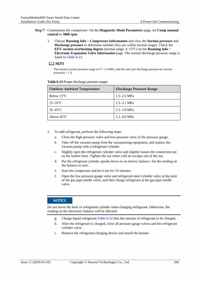
FusionModule800 Smart Small Data Center
Installation Guide (Six Fans) 6 Power-On Commissioning
Issue 11 (2020-03-20) Copyright © Huawei Technologies Co., Ltd. 284
Step 7 Commission the compressor. On the Diagnostic Mode Parameters page, set Comp manual
control to 3000 rpm.
1. Choose Running Info > Compressor Information and view the Suction pressure and
Discharge pressure to determine whether they are within normal ranges. Check the
EEV suction overheating degree (normal range: 4–15°C) on the Running Info >
Electronic Expansion Valve Information page. The normal discharge pressure range is
listed in Table 6-23.
The normal suction pressure range is 0.7–1.6 MPa, and the ratio (air discharge pressure/air suction
pressure) > 1.4.
Table 6-23 Proper discharge pressure ranges
Outdoor Ambient Temperature Discharge Pressure Range
Below 15°C 1.5–2.5 MPa
15–35°C 1.5–3.1 MPa
35–45°C 2.5–3.8 MPa
Above 45°C 3.1–4.0 MPa
2. To add refrigerant, perform the following steps:
a. Close the high-pressure valve and low-pressure valve of the pressure gauge.
b. Take off the vacuum pump from the vacuumizing equipment, and replace the
vacuum pump with a refrigerant cylinder.
c. Slightly open the refrigerant cylinder valve and slightly loosen the connection nut
on the leather hose. Tighten the nut when cold air escapes out of the nut.
d. Put the refrigerant cylinder upside down on an electric balance. Set the reading on
the balance to zero.
e. Start the compressor and let it run for 10 minutes.
f. Open the low-pressure gauge valve and refrigerant steel cylinder valve at the joint
of the gas pipe needle valve, and then charge refrigerant at the gas pipe needle
valve.
Do not move the hose or refrigerant cylinder when charging refrigerant. Otherwise, the
reading on the electronic balance will be affected.
g. Charge liquid refrigerant.Table 6-22 lists the amount of refrigerant to be charged.
h. After the refrigerant is charged, close all pressure gauge valves and the refrigerant
cylinder valve.
i. Remove the refrigerant charging device and install the bonnet.

FusionModule800 Smart Small Data Center
Installation Guide (Six Fans) 6 Power-On Commissioning
Issue 11 (2020-03-20) Copyright © Huawei Technologies Co., Ltd. 285
Tighten the needle valve bonnets after the charge is complete. Check whether a needle valve leaks by
applying soapy water to the valve vent or using a halogen leak detector. If it leaks, contact Huawei
technical support.
Figure 6-24 Charging refrigerant
(1) Refrigerant cylinder (2) Electric balance (3) Pressure gauge
(4) Connection nut (5) Gas pipe needle valve (6) Liquid pipe needle valve
3. On the Diagnostic Mode Parameters page, set Comp manual control to 0 rpm.
Step 8 On the Diagnostic Mode Parameters page, set Outdoor fan output man ctrl to 50% and
then click Submit.
1. Check that the outdoor fan operates properly, without alarms.
2. On the Diagnostic Mode Parameters page, set Outdoor fan output man ctrl to 0%
and then click Submit.
Step 9 Choose Controls > Control Information, set Diagnostic mode to Disable, and then click
Submit.
----End
Exception Handling
Step 1 Check that you have exited the diagnostic mode on the ECC800 WebUI.
Step 2 Check that the T/H control mode and T/H setpoint are properly set.
Step 3 Check that the current time is correctly set.
Step 4 Check that the air filter is installed in the correct direction.
----End

FusionModule800 Smart Small Data Center
Installation Guide (Six Fans) A Appendix
Issue 11 (2020-03-20) Copyright © Huawei Technologies Co., Ltd. 286
A Appendix
A.1 Installing Expansion Sleeves
Procedure
Step 1 Drill a hole at the position for installing the expansion bolt using a hammer drill with the hole
depth of 52 mm to 60 mm.
Step 2 Partially tighten the expansion bolts and vertically insert them into the holes. Knock the
expansion bolt using a rubber mallet until the expansion sleeve is fully inserted into the hole.
Step 3 Rotate the expansion bolt clockwise using a wrench until the expansion sleeve fully expands.
Step 4 Rotate the expansion bolt counterclockwise to remove it together with the spring washer and
flat washer.
Put aside the removed expansion bolt for securing the PDC.

FusionModule800 Smart Small Data Center
Installation Guide (Six Fans) A Appendix
Issue 11 (2020-03-20) Copyright © Huawei Technologies Co., Ltd. 287
Figure A-1 Expansion bolt
(1) M10 bolt (2) Spring washer
(3) Flat washer (4) Expansion sleeve

FusionModule800 Smart Small Data Center
Installation Guide (Six Fans) A Appendix
Issue 11 (2020-03-20) Copyright © Huawei Technologies Co., Ltd. 288
Figure A-2 Drilling a hole and installing an expansion sleeve (unit: mm)
----End
A.2 Routing Monitoring Cables
If no smart ETH gateway is configured onsite, connect the third smart cooling product to the
WAN_2 port on the ECC800.

FusionModule800 Smart Small Data Center
Installation Guide (Six Fans) A Appendix
Issue 11 (2020-03-20) Copyright © Huawei Technologies Co., Ltd. 289
Figure A-3 Cable connections to the management system
Table A-1 Description about the management system cable connections
No. From To Remarks
1 GE1 port on the VCN PoE_1 port on the smart
ETH gateway
Connected onsite
2 Port on the door status
sensor
Any AI/DI port on the
standalone AI/DI module
Connected onsite
3 ATS COM1/12 V port on the
ECC800
Factory-installed
4 FE_1 port on the first
smart cooling product
LAN_1 port on the
ECC800
Factory-installed
5 WiFi module USB port on the ECC800 Factory-installed
6 FE_1 port on the
second smart cooling
product
LAN_2 port on the
ECC800
Factory-installed
7 WAN_2 port on the FE_2 port on the smart Connected onsite

FusionModule800 Smart Small Data Center
Installation Guide (Six Fans) A Appendix
Issue 11 (2020-03-20) Copyright © Huawei Technologies Co., Ltd. 290
No. From To Remarks
ECC800 ETH gateway
8 53.5VDC_OUT2 port
in the rear of the
ECC800
PWR_OUT port on the
smart ETH gateway
Connected onsite
9 FE_2 port on the third
smart cooling product
Any PoE port on the smart
ETH gateway
Connected onsite
10 PoE port on the first
iBOX
Any PoE port on the smart
ETH gateway Connected onsite
11 PoE port on the
second iBOX
Any PoE port on the smart
ETH gateway
Connected onsite
12 FE port on the camera Any PoE port on the smart
ETH gateway
Connected onsite
13 UPS COM2/12 V port on the
ECC800
Factory-installed
14 Temperature sensor AI/DI_2 port on the
ECC800
Factory-installed
15 Water sensor AI/DI_4 port on the
ECC800
The cable has been
connected to the AI/DI_4
port on the ECC800
before delivery.
16 Smoke detector AI/DI_1 port on the
ECC800
The cable has been
connected to the AI/DI_1
port on the ECC800
before delivery.
17 Fan power contactor DO_1 port on the ECC800 Factory-installed
18 SPD AI/DI_3 port on the
ECC800
Factory-installed
19 COM_IN port on the
standalone AI/DI
module
COM3/12 V port on the
ECC800
Connected onsite
20 Smart ETH gateway Access actuator Connected onsite
21 Access actuator Card reader with a keypad Connected onsite
22 Access actuator Fingerprint and card
reader
Fingerprint and card
reader with a keypad
Connected onsite
23 Access actuator Exit button Connected onsite
24 Access actuator Emergency door release
button
Single/double door
Connected onsite

FusionModule800 Smart Small Data Center
Installation Guide (Six Fans) A Appendix
Issue 11 (2020-03-20) Copyright © Huawei Technologies Co., Ltd. 291
No. From To Remarks
magnetic lock
Emergency door
release button
Single/double door
magnetic lock
Connected onsite
25 No. 24 port on the
LAN switch
WAN_1 port on the
ECC800
Connected onsite
Preparing Monitoring Cables
Figure A-4 Preparing monitoring cables

FusionModule800 Smart Small Data Center
Installation Guide (Six Fans) A Appendix
Issue 11 (2020-03-20) Copyright © Huawei Technologies Co., Ltd. 292
Figure A-5 Preparing monitoring cables (RJ12)
A.3 Cable list
Table A-2 Cable list
BOM Number Cable Position
04092766 Emergency fan power cable
Cable from the smart cooling product to the T/H sensor
04092767 Power cable from the ECC800 to the smart ETH gateway
Signal cable from the ECC800 to the smart ETH gateway
Cable from the smart ETH gateway to the iBOX
04092768 Cable from the door status sensor to the AI/DI module
Cable from the AI/DI module to the ECC800
04070794 T/H sensor cascading cable
04070008 Cable from the camera to the smart ETH gateway
04150547 Cable between battery packs
04150671 Cable from the battery pack to the 10 kVA UPS
04151746 Cable from the battery pack to the 20 kVA UPS (required for N or
2N configuration)
04151745 Cable from the battery cabinet to the 10 kVA UPS

FusionModule800 Smart Small Data Center
Installation Guide (Six Fans) A Appendix
Issue 11 (2020-03-20) Copyright © Huawei Technologies Co., Ltd. 293
BOM Number Cable Position
04151745-001 Cable from the battery cabinet to the 10 kVA UPS deployed outside
the aisle containment
04151748 Cable from the battery cabinet to the 20 kVA UPS
04151748-001 Cable from the battery cabinet to the 20 kVA UPS deployed outside
the aisle containment
04093057 Cable from the battery cabinet to the 20 kVA UPS (required for N+1
configuration and battery string sharing)
04151722/0415172
3/04151724
PDU2000 power cable
04080394 Emergency fan cascading cable
04070009 Cable from the VCN to the smart ETH gateway
Cables from the LAN switch to the ECC800
0415G005 VCN power cable
04151689 Ground cable
04071171 Cable from the smoke detector to the ECC800
04151783 Cable for the third smart cooling product
04093981-01 Cable from the smart ETH gateway to the access actuator
04093981-02 Cable from the access actuator to the card reader with a keypad
04093981-03 Cable from the access actuator to the fingerprint and card reader
04093981-04 Cable from the access actuator to the fingerprint and card reader with
a keypad
04093981-05 Cable from the access actuator to the exit button
04093981-06 Cable from the access actuator to the single/double door magnetic
lock and emergency door release button
Cable from the emergency door release button to the single/double
door magnetic lock
A.4 Cooling System Layout
The indoor and outdoor units compose a complete cooling system. Figure A-6 shows the
overall layout of cooling devices.

FusionModule800 Smart Small Data Center
Installation Guide (Six Fans) A Appendix
Issue 11 (2020-03-20) Copyright © Huawei Technologies Co., Ltd. 294
Figure A-6 Cooling system layout
(1) Compressor (2) Oil separator (3) Check valve (4) High
pressure switch
(5) Condenser (6) Liquid storage
tank
(7) High pressure
sensor
(8) Filter dryer
(9) Outdoor unit liquid
pipe stop valve
(10) Indoor unit
liquid pipe stop valve
(11) Electronic
expansion valve
(12) Evaporator
(13) Low pressure
sensor
(14) Indoor unit gas
pipe stop valve
(15) Outdoor unit gas
pipe stop valve
(16) Gas-liquid
separator
(17) Low pressure
switch
A.5 Installing a Dehumidifier
Prerequisites The aisle containment structure and smart cooling products have been installed.
The dehumidifier, tray, floating nuts, and screws are ready.
Cable 25030384 and cord end terminal 14170096 are ready.
A three-way valve, PVC pipe (at least 200 mm long), female adapter, and male plug are
ready. The specifications meet the requirements of the drainage pipe of the smart cooling
product.
AB glue, PVC glue, and sealing tape are ready.
Context
It is recommended that you install the dehumidifiers at the bottom of IT cabinets near smart
cooling products in the aisle containment. One dehumidifier is required for each module when
the load is light but humidity is high.
Figure A-7 shows the external structure of a dehumidifier.

FusionModule800 Smart Small Data Center
Installation Guide (Six Fans) A Appendix
Issue 11 (2020-03-20) Copyright © Huawei Technologies Co., Ltd. 295
The dehumidifier structure diagram is for reference only. The actual product prevails.
Figure A-7 External structure of a dehumidifier
(1) Mounting ears (2) Air filter (3) Control panel
(4) Castor (5) Water outlet (6) Handle
(A) Air intake vent (B) Air exhaust vent
For details about how to install a dehumidifier, see the documents delivered with the product.
Procedure
Step 1 Move the dehumidifier to its installation position inside the aisle containment.
Step 2 Secure the tray to the rack rail at 1 U height at the bottom of the cabinet using four M6 screws,
as shown in Figure A-8.

FusionModule800 Smart Small Data Center
Installation Guide (Six Fans) A Appendix
Issue 11 (2020-03-20) Copyright © Huawei Technologies Co., Ltd. 296
Figure A-8 Installing the tray
Step 3 Place the dehumidifier on the tray and move it to its installation place, and secure the
dehumidifier mounting ears to the rack rail using a floating nut mounting bar and three
floating nuts for each mounting ear, as shown in Figure A-9.
If no floating nut mounting bar is available, using a flat-head screwdriver instead.
Ensure that the floating nuts on both sides are on the same horizontal line.
Floating nuts must be installed in mounting holes alternatively on the dehumidifier.
Figure A-9 Installing floating nuts
Step 4 Secure the dehumidifier to the dehumidifier mounting ears on the rack rail using six M6
screws, as shown in Figure A-10.

FusionModule800 Smart Small Data Center
Installation Guide (Six Fans) A Appendix
Issue 11 (2020-03-20) Copyright © Huawei Technologies Co., Ltd. 297
When installing the dehumidifier, verify that the air intake vent faces the cold aisle (as shown
by A in Figure A-7), and the air exhaust vent faces the hot aisle (as shown by B in Figure
A-7).
Figure A-10 Installing a Dehumidifier
Step 5 Connect the dehumidifier drainpipe.
The dehumidifier drainpipe is a hose. The bending diameter of the drainpipe must be
greater than or equal to 60 mm; otherwise, water may fail to be drained.
The specifications of the three-way valve, PVC pipe, female adapter, and male plug must
meet the requirements of the drainage pipe of the smart cooling product.
1. Route the dehumidifier drain pipe delivered with the dehumidifier out of the cabinet
through the dehumidifier water outlet, as shown by (5) in Figure A-7.
2. Cut through the main drainpipe of the equipment room smart cooling product using a
handsaw.
3. Route the dehumidifier drainpipe out of the other end of the cabinet, and connect it to the
smart cooling product drainpipe in the equipment room, as shown in Figure A-11.
Ensure that the angle between the drainpipe and the ground is greater than 30 degrees, and verify that the
pipe length is appropriate to avoid pressure from the floor.

FusionModule800 Smart Small Data Center
Installation Guide (Six Fans) A Appendix
Issue 11 (2020-03-20) Copyright © Huawei Technologies Co., Ltd. 298
Figure A-11 Connecting the dehumidifier drainpipe
(1) Smart cooling product drainpipe in the
equipment room
(2) Three-way
valve
(3) PVC pipe
(4) Female adapter (5) Male plug (6) Dehumidifier
drainpipe
4. Apply PVC glue where the three-way valve, PVC pipe, female adapter, and the cut smart
cooling product drainpipe are connected.
Precautions for PVC pipe connection:

FusionModule800 Smart Small Data Center
Installation Guide (Six Fans) A Appendix
Issue 11 (2020-03-20) Copyright © Huawei Technologies Co., Ltd. 299
Clear burs from the PVC pipe port chamfer the pipe port, and clean dust, water, or oil from
the pipe port using a piece of dry cloth.
Apply PVC glue evenly on the surface of the socket using a brush.
Align the two pipes to be interconnected, quickly insert the plug port into the socket port,
turn the plug port by one fourth circle, and keep the pipes stable for 10 minutes to enable
the PVC glue to consolidate and get evenly distributed.
Wipe off redundant PVC glue on the pipe surface using a piece of cloth, and switch on the
water supply 2 hours later.
5. Wrap thermal insulation foam around the pipe.
6. Apply sealing tape to the threads where the female adapter and male plug are connected
to seal them up.
7. Cut through the male plug using a handsaw, and insert the dehumidifier drainpipe into
the plug by at least 50 mm.
8. Apply AB glue evenly where the dehumidifier drainpipe and the male plug are
connected, and keep the glued parts steady for 30 minutes to solidify the glue.
Step 6 Connect the dehumidifier power cable.
1. Cut off the national standard three-pin plug of the power cable delivered with the
dehumidifier, and strip the power cable insulation layer for a proper length.
2. Strip the insulation layers of the brown and blue wires of cable 25030384 at both ends,
and wrap the yellow and green wires with insulation tape.
3. Crimp and connect the L and N wires of the dehumidifier power cable to the brown and
blue wires of cable 25030384 respectively using the cord end terminals delivered with
the dehumidifier.
4. Crimp the other end of the cable using cord end terminal 14170096 (brown wire) and OT
terminal 14170014 (blue wire), route the cable out of the cabinet top to the PDC through
the strong-current cable trough. Connect the brown wire to the 10 A circuit breaker or
lighting circuit breaker reserved in the PDC, and connect the blue wire to the N busbar in
the PDC.
5. Crimp the PE cable of the dehumidifier power cable using the OT terminal (M6)
delivered with the dehumidifier, and connect the crimped terminal to a nearby ground
point in the IT cabinet.
Step 7 Open the dehumidifier panel and start the dehumidifier, slowly pour water into the water
channel connected to the dehumidifier, and check that the water pump can drain water
smoothly.
Step 8 Reinstall the dehumidifier panel and, start the dehumidifier, and set the humidity for the
dehumidifier.
----End
A.6 Checking the Monitoring Parameters for the Factory-Installed Devices
Table A-3 Parameter settings for factory-installed devices
Device Access Port Parameter Setting

FusionModule800 Smart Small Data Center
Installation Guide (Six Fans) A Appendix
Issue 11 (2020-03-20) Copyright © Huawei Technologies Co., Ltd. 300
Device Access Port Parameter Setting
ATS COM1/12V port on
the ECC800
1. Set Equip Type_Enum to ATS.
2. Set COM to 1.
3. Set Device Address to 1.
The first smart
cooling product
LAN_1 port on the
ECC800
The device is identified automatically and
no parameter setting is required.
The second smart
cooling product
LAN_2 port on the
ECC800
The device is identified automatically and
no parameter setting is required.
UPS COM2/12V port on
the ECC800
1. Set Equip Type_Enum to UPS.
2. Set COM to 2.
3. Set Device Address to 2. The actual
UPS address can be obtained from the
UPS liquid crystal display (LCD).
SPD AI/DI_3 port on the
ECC800
1. Set AI/DI_3 Sensor to Enable.
2. Set AI/DI_3 Sensor Name to SPD.
3. AI/DI_3 Sensor Type is identified as
NC automatically.

FusionModule800 Smart Small Data Center
Installation Guide (Six Fans) B Acronyms and Abbreviations
Issue 11 (2020-03-20) Copyright © Huawei Technologies Co., Ltd. 301
B Acronyms and Abbreviations
A
AC alternating current
ATS automatic transfer switch
B
BIM battery interface module
C
CIM communication interface module
D
DC direct current
E
ECC energy control center
ETH Ethernet
F
FE fast Ethernet
I
iBAT ibattery
IT Internet Technology

FusionModule800 Smart Small Data Center
Installation Guide (Six Fans) B Acronyms and Abbreviations
Issue 11 (2020-03-20) Copyright © Huawei Technologies Co., Ltd. 302
L
LED light emitting diode
N
NTC negative temperature coefficient
P
PDU power distribution unit
PE protective earthing
PoE power over Ethernet
S
SD secure digital memory
U
UPS uninterruptible power system
V
VCN video cloud node
W
WiFi Wireless Fidelity