
Maintenance Guide - Huawei Technical Support
153
FusionModule1000A40 Prefabricated All-in-One Data Center V200R003C10 Maintenance Guide Issue 04 Date 2021-02-10 HUAWEI TECHNOLOGIES CO., LTD.
-
Upload
khangminh22 -
Category
Documents
-
view
0 -
download
0
Transcript of Maintenance Guide - Huawei Technical Support
FusionModule1000A40 Prefabricated All-in-OneData Center
V200R003C10
Maintenance Guide
Issue 04
Date 2021-02-10
HUAWEI TECHNOLOGIES CO., LTD.
Copyright © Huawei Technologies Co., Ltd. 2021. All rights reserved.
No part of this document may be reproduced or transmitted in any form or by any means without priorwritten consent of Huawei Technologies Co., Ltd. Trademarks and Permissions
and other Huawei trademarks are trademarks of Huawei Technologies Co., Ltd.All other trademarks and trade names mentioned in this document are the property of their respectiveholders. NoticeThe purchased products, services and features are stipulated by the contract made between Huawei andthe customer. All or part of the products, services and features described in this document may not bewithin the purchase scope or the usage scope. Unless otherwise specified in the contract, all statements,information, and recommendations in this document are provided "AS IS" without warranties, guaranteesor representations of any kind, either express or implied.
The information in this document is subject to change without notice. Every effort has been made in thepreparation of this document to ensure accuracy of the contents, but all statements, information, andrecommendations in this document do not constitute a warranty of any kind, express or implied.
Huawei Technologies Co., Ltd.Address: Huawei Industrial Base
Bantian, LonggangShenzhen 518129People's Republic of China
Website: https://e.huawei.com
Issue 04 (2021-02-10) Copyright © Huawei Technologies Co., Ltd. i

About This Document
PurposeThis document describes the operation methods and precautions for theFusionModule1000A prefabricated all-in-one data center (FusionModule1000 forshort) in terms of the routine maintenance and parts replacement. It provides youa quick grasp of the operation and maintenance (O&M) methods of theFusionModule1000.
Intended AudienceThis document is intended for:
● Maintenance engineers● Technical support engineers● System engineers● Hardware installation engineers● Commissioning engineers● Data configuration engineers
Symbol ConventionsThe symbols that may be found in this document are defined as follows.
Symbol Description
Indicates a hazard with a high level of risk which, if notavoided, will result in death or serious injury.
Indicates a hazard with a medium level of risk which, ifnot avoided, could result in death or serious injury.
Indicates a hazard with a low level of risk which, if notavoided, could result in minor or moderate injury.
FusionModule1000A40 Prefabricated All-in-OneData CenterMaintenance Guide About This Document
Issue 04 (2021-02-10) Copyright © Huawei Technologies Co., Ltd. ii
Symbol Description
Indicates a potentially hazardous situation which, if notavoided, could result in equipment damage, data loss,performance deterioration, or unanticipated results.NOTICE is used to address practices not related topersonal injury.
Supplements the important information in the maintext.NOTE is used to address information not related topersonal injury, equipment damage, and environmentdeterioration.
Change HistoryChanges between document issues are cumulative. The latest document issuecontains all the changes made in earlier issues.
Issue 04 (2021-02-10)This issue is the fourth official release.
● Optimized the content description.● Optimized the figure display.
Issue 03 (2020-10-30)This issue is the third official release.
● Optimized the content description.● Optimized the figure display.
Issue 02 (2020-06-09)This issue is the second official release.
● Updated the fire extinguishing devices.
Issue 01 (2019-07-15)This issue is the first official release.
FusionModule1000A40 Prefabricated All-in-OneData CenterMaintenance Guide About This Document
Issue 04 (2021-02-10) Copyright © Huawei Technologies Co., Ltd. iii

Contents
About This Document................................................................................................................ ii
1 Operation and Maintenance Precautions..........................................................................1
2 Operation and Maintenance Preparations........................................................................ 42.1 Tools............................................................................................................................................................................................. 42.2 Reference Documentation....................................................................................................................................................62.3 Pre-fab. Module Entry Requirements............................................................................................................................... 72.4 O&M Personnel Skill Requirements.................................................................................................................................. 8
3 Routine Maintenance............................................................................................................. 93.1 Pre-fab. Module Repainting................................................................................................................................................. 93.2 Sliding Cabinets..................................................................................................................................................................... 133.3 Daily Maintenance................................................................................................................................................................153.4 Monthly Maintenance......................................................................................................................................................... 153.4.1 Power Supply and Distribution System......................................................................................................................163.4.2 Cooling System................................................................................................................................................................... 163.4.3 Monitoring System............................................................................................................................................................173.4.4 Fire Extinguishing System (Standard)........................................................................................................................ 213.4.5 Fire Extinguishing System (CE)..................................................................................................................................... 223.4.6 Other Systems.................................................................................................................................................................... 243.5 Quarterly Maintenance....................................................................................................................................................... 243.5.1 Monitoring System............................................................................................................................................................253.5.2 Fire Extinguishing System (Standard)........................................................................................................................ 293.5.3 Fire Extinguishing System (CE)..................................................................................................................................... 303.5.4 Other Systems.................................................................................................................................................................... 303.6 Semi-annual Maintenance.................................................................................................................................................313.6.1 Power Supply and Distribution System......................................................................................................................313.6.2 Cooling System................................................................................................................................................................... 323.6.3 Monitoring System............................................................................................................................................................333.6.4 Fire Extinguishing System (Standard)........................................................................................................................ 343.6.5 Fire Extinguishing System (CE)..................................................................................................................................... 373.6.6 Other Systems.................................................................................................................................................................... 39
4 Common Faults and Troubleshooting Measures........................................................... 414.1 Troubleshooting the Extinguishant Control Panel..................................................................................................... 42
FusionModule1000A40 Prefabricated All-in-OneData CenterMaintenance Guide Contents
Issue 04 (2021-02-10) Copyright © Huawei Technologies Co., Ltd. iv
4.2 Troubleshooting the ASD................................................................................................................................................... 504.3 Troubleshooting Power Distribution Devices.............................................................................................................. 52
5 Parts Replacement................................................................................................................ 535.1 Replacing Components for the Power Supply and Distribution System............................................................535.1.1 Replacing Components for the Power Supply And Distribution System........................................................535.1.2 Replacing a Cabinet rPDU.............................................................................................................................................. 545.1.3 Replacing a Battery for the Integrated UPS............................................................................................................. 555.1.4 Replacing a Battery Pack................................................................................................................................................ 555.1.5 Replacing a Light............................................................................................................................................................... 575.1.6 Replacing the Power PDB............................................................................................................................................... 585.1.7 Replacing a Battery Bus Box.......................................................................................................................................... 585.2 Replacing Cooling System Components....................................................................................................................... 595.2.1 Replacing Components for the Cooling System..................................................................................................... 595.2.2 Replacing an In-row Air Cooled Smart Cooling Product......................................................................................605.2.3 Replacing a T/H Sensor................................................................................................................................................... 755.2.4 (Optional) Replacing the Electric heating belt....................................................................................................... 775.3 Replacing Monitoring System Components................................................................................................................ 775.3.1 Replacing an ECC800-Pro Main Control Module....................................................................................................785.3.2 Replacing an ECC800-Pro PSU...................................................................................................................................... 795.3.3 Replacing ECC800-Pro Antennas..................................................................................................................................805.3.4 Replacing a Smart ETH Gateway................................................................................................................................. 815.3.5 Replacing a Camera..........................................................................................................................................................815.3.6 Replacing a Water Sensor (Point Type)..................................................................................................................... 835.3.7 Replacing Access Control Components...................................................................................................................... 845.3.7.1 Replacing an IC Card Reader..................................................................................................................................... 845.3.7.2 Replacing an Exit Button............................................................................................................................................. 865.3.7.3 Replacing an Emergency Door Release Button................................................................................................... 875.3.7.4 Replacing an Access Actuator.................................................................................................................................... 895.3.7.5 Replacing a Door Status Sensor................................................................................................................................895.3.8 Replacing an AC Actuator.............................................................................................................................................. 905.3.9 Replacing a T/H Sensor................................................................................................................................................... 915.3.10 Replacing the WiFi Module......................................................................................................................................... 925.3.11 (Optional) Replacing a PAD........................................................................................................................................ 925.4 Replacing Fire Extinguishing System Components................................................................................................... 935.4.1 Replacing Fire Extinguishing System Components (Standard)......................................................................... 935.4.1.1 Changing an Address Code.........................................................................................................................................935.4.1.2 Replacing a Smoke Detector...................................................................................................................................... 945.4.1.3 Replacing a Heat Detector..........................................................................................................................................965.4.1.4 Replacing an Input/Output Module........................................................................................................................ 985.4.1.5 Replacing a Gas Release Indicator........................................................................................................................... 995.4.1.6 Replacing a Fire Alarm Horn/Strobe..................................................................................................................... 1015.4.1.7 Replacing an Internal Fire Alarm Horn/Strobe..................................................................................................102
FusionModule1000A40 Prefabricated All-in-OneData CenterMaintenance Guide Contents
Issue 04 (2021-02-10) Copyright © Huawei Technologies Co., Ltd. v
5.4.1.8 Replacing a Fire Alarm Sounder............................................................................................................................. 1035.4.1.9 Replacing the Emergency Start/Abort Switch....................................................................................................1055.4.1.10 Replacing Batteries for the Fire Alarm Control Panel.................................................................................. 1075.4.1.11 Replacing a Fire Cylinder........................................................................................................................................ 1095.4.1.12 Replacing a Fire Alarm Control Panel................................................................................................................ 1145.4.1.13 Replacing an Emergency Light............................................................................................................................. 1175.4.1.14 Replacing Batteries for the ASD Power Box.....................................................................................................1185.4.2 Replacing Fire Extinguishing System Components (CE)....................................................................................1205.4.2.1 Replacing a Smoke Detector (CE) ........................................................................................................................ 1205.4.2.2 Replacing a Heat Detector (CE)............................................................................................................................. 1215.4.2.3 Replacing Warning Signs (CE)................................................................................................................................ 1225.4.2.4 Replacing an Internal Horn Strobe (CE)..............................................................................................................1245.4.2.5 Replacing an External Horn Strobe (CE)............................................................................................................. 1255.4.2.6 Replacing a Fire Alarm Bell (CE)............................................................................................................................ 1275.4.2.7 Replacing an Extinguishant Abort Button (CE).................................................................................................1295.4.2.8 Replacing Batteries for the Extinguishant Control Panel (CE).....................................................................1325.4.2.9 Replacing a Fire Cylinder (CE)................................................................................................................................ 1335.4.2.10 Replacing an Extinguishant Control Panel (CE)............................................................................................. 1355.4.2.11 Replacing an Emergency Light (CE)................................................................................................................... 1375.4.2.12 Replacing Batteries for the ASD Power Box.....................................................................................................139
6 Emergency Operations.......................................................................................................1416.1 Emergency Operations When Pre-fab. Module Door Cannot Open.................................................................141
7 Appendixes............................................................................................................................1437.1 Repairing the Pre-fab. Module.......................................................................................................................................143
8 Acronyms and Abbreviations............................................................................................145
FusionModule1000A40 Prefabricated All-in-OneData CenterMaintenance Guide Contents
Issue 04 (2021-02-10) Copyright © Huawei Technologies Co., Ltd. vi

1 Operation and Maintenance Precautions
Power Supply and Distribution System● When operating power distribution equipment, follow the local regulations
and rules.● When performing high-voltage and AC operations, use dedicated tools and
wear protection equipment.● Before entering the power supply zone, verify that no hydrogen alarm is
displayed on the ECC800 or NetEco LCD.● Before replacing a component which is not hot swappable, you must switch
off the upstream circuit breaker, and verify that the component to be replacedis power off.
● Assess impact on the system before switching off the general circuit breakeror cutting off the cooling system during parts replacement.
● Do not install or remove power cables for a device which is powered on.Transient contact between the core of the power cable and the conductormay generate electric arcs or sparks, which may cause fire or hurt humaneyes.
● Before removing component cables, mark the cables with their correspondingport numbers for later connection.
● Before connecting a power cable, check that the label on the power cable iscorrect.
● For the detailed power control relationships between devices, see the powerdistribution system diagram for the solution in use.
During battery O&M, observe the following:● Insulate tools before battery O&M.● Assign only professional engineers to perform the O&M.● Do not use any organic solvent to clean batteries.● Do not remove the safety valve or fill anything into batteries.● Never smoke or use fire around batteries.● Do not place tools on bare batteries terminals.● Do not short-circuit the terminals of batteries; otherwise, a fire may occur.● Do not maintain batteries online. Replace a battery if it is faulty.
FusionModule1000A40 Prefabricated All-in-OneData CenterMaintenance Guide 1 Operation and Maintenance Precautions
Issue 04 (2021-02-10) Copyright © Huawei Technologies Co., Ltd. 1
● Charge the battery within 24 hours after battery discharge; otherwise, thebattery capacity will be affected.
● Do not open batteries as electrolyte leakage may cause personal injuries. Ifyou contact the electrolyte accidentally, immediately clean your skin withwater and seek medical advice from a doctor.
● Replace batteries only with the ones of the same or equivalent type. Improperbattery replacement may cause an explosion.
Cooling System● Assign only professional engineers to perform O&M for the cooling system.
● Do not operate valves of the cooling system arbitrarily.
● Do not block the air exhaust and return vents of smart cooling products.
● Promptly put serviced units into use after the cooling system is maintained;otherwise, equipment cannot work at optimal status.
● If the number of running smart cooling products in an area is less than therated minimum number, some loads must be powered off; otherwise,temperature inside the pre-fab. module may go out of control.
● For detailed configurations of the cooling system, see the initial configurationparameter manual for the solution in use.
Management System (Monitoring System)● Do not smoke or use open flame inside the pre-fab. module.
● Assign only professional engineers to perform O&M for the managementsystem.
● Routine maintenance for the management system is critical for long-termstable and efficient operation of the FusionModule1000 because most alarmsare reported over the management system.
● Promptly handle reported alarms to prevent equipment damage or serviceinterruption.
● Check and calibrate the hydrogen detection equipment sensors half a yearwithin the sensor service life (less than 5 years).
● For detailed initial configurations for the management system, see the initialconfiguration parameter manual for the solution in use.
Fire Extinguishing System● Assign only qualified engineers to perform O&M for the fire extinguishing
system.
● Before performing routine maintenance for the fire extinguishing system,inform the related departments of the temporary downtime due tomaintenance. In addition, disable the logical control function of the area orsystem to prevent false alarms. Inform the related departments of the systemrecovery after the maintenance is complete.
● Take antistatic measures before removing the front panel from a ASD;otherwise, the ASD may be damaged.
FusionModule1000A40 Prefabricated All-in-OneData CenterMaintenance Guide 1 Operation and Maintenance Precautions
Issue 04 (2021-02-10) Copyright © Huawei Technologies Co., Ltd. 2
● During fire extinguishing system commissioning, disconnect the solenoidvalve, and insert the fire cylinder safety pin to prevent agent release bymistake.
FusionModule1000A40 Prefabricated All-in-OneData CenterMaintenance Guide 1 Operation and Maintenance Precautions
Issue 04 (2021-02-10) Copyright © Huawei Technologies Co., Ltd. 3
2 Operation and MaintenancePreparations
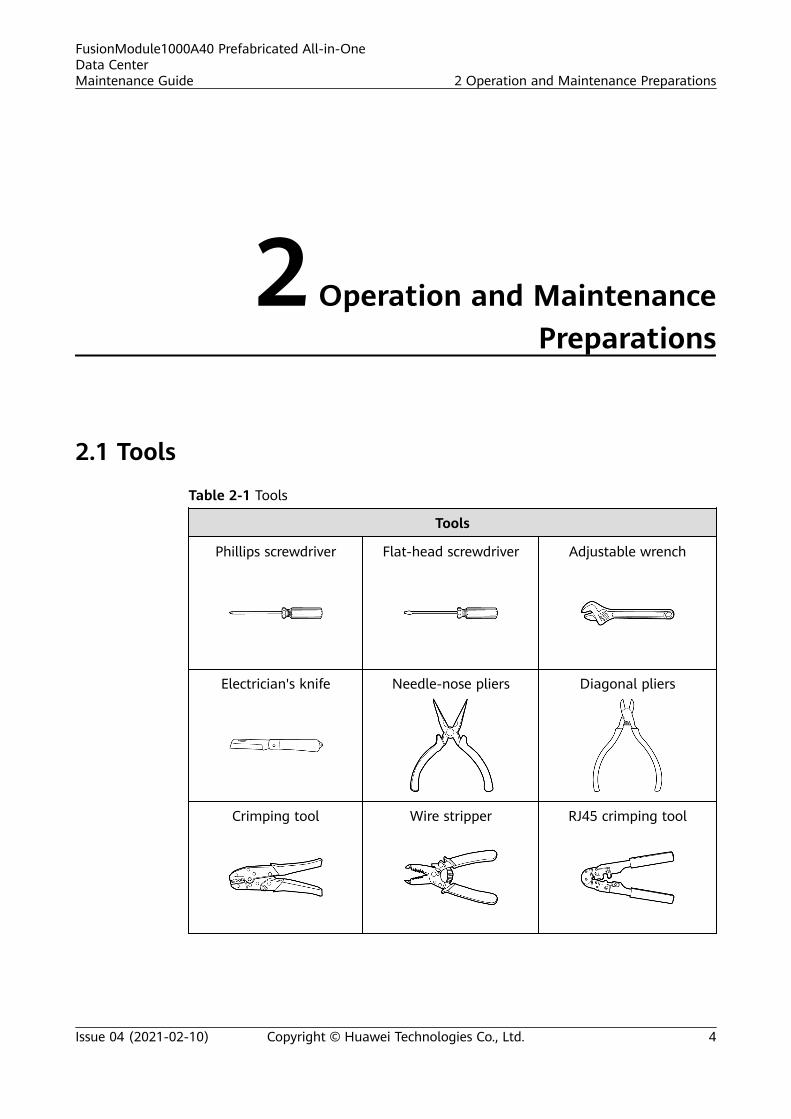
2.1 Tools
Table 2-1 Tools
Tools
Phillips screwdriver Flat-head screwdriver Adjustable wrench
Electrician's knife Needle-nose pliers Diagonal pliers
Crimping tool Wire stripper RJ45 crimping tool
FusionModule1000A40 Prefabricated All-in-OneData CenterMaintenance Guide 2 Operation and Maintenance Preparations
Issue 04 (2021-02-10) Copyright © Huawei Technologies Co., Ltd. 4

Tools
Cable cutter Hex key Socket wrench
Hand-heldthermohygrograph
Multimeter Electroprobe
Network cable tester Heat gun Utility knife
Step ladder (2 m) Cable tie Insulation tape
ESD wrist strap ESD gloves Protective gloves
Clamp meter Vacuum cleaner -
FusionModule1000A40 Prefabricated All-in-OneData CenterMaintenance Guide 2 Operation and Maintenance Preparations
Issue 04 (2021-02-10) Copyright © Huawei Technologies Co., Ltd. 5
NO TE
The listed tools are for routine maintenance only. Prepare other tools as required.
2.2 Reference Documentation
NO TICE
The documents provided in the solution only include the special maintenanceitems, maintenance methods, and precautions of the components. For othermaintenance items of the components, see the documents delivered with thecomponents.
Table 2-2 Maintenance documents to be prepared
Component Document
FusionModule1000A FusionModule1000A Prefabricated All-in-OneData Center V200R003C10 Initial ConfigurationParameter Manual)
Integrated UPS UPS5000-E-(50 kVA–125 kVA) User Manual(Integrated UPS 3.0)
UPS5000-E-(20 kVA–80 kVA) User Manual(Integrated UPS, 208 V)
NetCol5000-A025 In-row Air Cooled SmartCooling Product
NetCol5000-A025 In-row Air Cooled SmartCooling Product User Manual (300 mm Width)
NetCol5000-A021 In-row Air Cooled SmartCooling Product
NetCol5000-A021 In-row Air Cooled SmartCooling Product User Manual (208 V)
Outdoor unit NetCol500 Variable Speed Outdoor Unit UserManual
ECC800 ECC800 Data Center Controller V100R021C00User Manual
NetEco iManager NetEco Product Documentation-(V600R021C00)
NO TE
● The ECC800/NetEco version depends on the version in use. Click on the ECC800/NetEco WebUI to obtain the current version.
● For NetEco maintenance, see the NetEco documents.
FusionModule1000A40 Prefabricated All-in-OneData CenterMaintenance Guide 2 Operation and Maintenance Preparations
Issue 04 (2021-02-10) Copyright © Huawei Technologies Co., Ltd. 6
2.3 Pre-fab. Module Entry RequirementsThe following describes the requirements for working in the FusionModule1000.
Item Requirement
Before entry ● Obtain the entry permit.● The detailed operations are performed based on the requirements
specified by the manager of the FusionModule1000.
Entrypreparations
● Obtain ESD clothes and shoes.● Remove dust from tools and materials that need to be taken into the data
center, and make a record.● Do not bring in forbidden items, such as storage devices, cameras, or
portable hard disks into the FusionModule1000.
Working in thedata center
● Only professional personnel are allowed to work in the data center andonly in the presence of designated personnel.
● Obtain permission from designated personnel and take necessaryprecautions and preventive measures before entering theFusionModule1000 and performing any operation which may affect thenormal running of the FusionModule1000.
● Do not perform any unauthorized operations.
After all work isfinished
● Pack up the tools and surplus materials.● Clean up and organize the equipment room environment according to
environment requirements.● Accept the operations and make records about any operations performed.
Check beforeleaving
● Check the items to be taken out.● Sign out.
Follow-upProcedure
● Return the ESD clothes and shoes.● If any faulty component is replaced, dispose of the removed faulty
component.
NO TICE
Replace, maintain, and troubleshoot components of the FusionModule1000 only inthe presence of qualified engineers.
FusionModule1000A40 Prefabricated All-in-OneData CenterMaintenance Guide 2 Operation and Maintenance Preparations
Issue 04 (2021-02-10) Copyright © Huawei Technologies Co., Ltd. 7
2.4 O&M Personnel Skill RequirementsField Personnel Skill Requirement
Power supplyanddistributionsystem
Familiar with the power supply and distribution system configurations and theoperations for each core component in the FusionModule1000With power distribution system engineer qualifications
Coolingsystem
Familiar with the cooling system configurations and the operations for each corecomponent in the FusionModule1000With cooling engineer qualifications
Managementsystem
With knowledge in the hardware and software of the prefabricated data center,familiar with basic communications protocols, familiar with equipment interfacesin extra low voltage (ELV) systems, and proficient in operating the NetEcomanagement systemWith ELV engineer qualifications
Fireextinguishingsystem
Familiar with the fire extinguishing system configurations and the operations foreach core component in the FusionModule1000With fire engineer qualifications
Lighting andstructuralsystem
Familiar with the overall configurations and layout of the FusionModule1000Experienced in maintaining the FusionModule1000
FusionModule1000A40 Prefabricated All-in-OneData CenterMaintenance Guide 2 Operation and Maintenance Preparations
Issue 04 (2021-02-10) Copyright © Huawei Technologies Co., Ltd. 8
3 Routine Maintenance
3.1 Pre-fab. Module Repainting
Prerequisites● Before repainting, communicate with the customer and inform the customer
that the front, left, and right surfaces of the data center exterior are level Asurfaces, and rear, bottom, and top surfaces are level B surfaces.– The color may be slightly different when level A surfaces are repainted.
Reach an agreement with the customer before repainting.– Acceptance criteria for repainting of level B surfaces: The repainted area
should have the same color as surrounding areas. The color difference ΔEis not greater than 3. (Use a colorimeter to measure the color difference.If a colorimeter is not available, check that no obvious edge existsbetween the repainted area and its surrounding.) The paint should alsobe free from bulges, scratches, flake-off, or cracks.
● The outdoor area without shelters is not subject to bad weather conditionssuch as raining, sandstorm, strong wind, or snowing during paint repair.
● You have prepared the required paint that matches the color palette deliveredwith equipment.
ContextThe FusionModule1000 pre-fab. module exterior should be intact. If the pre-fab.module surface is bumped, scratched, or rusted, the paint should be repaired.
NO TE
Check the damage to the pre-fab. module paint and prepare appropriate tools and materials.The number of materials depends on site requirements.
FusionModule1000A40 Prefabricated All-in-OneData CenterMaintenance Guide 3 Routine Maintenance
Issue 04 (2021-02-10) Copyright © Huawei Technologies Co., Ltd. 9
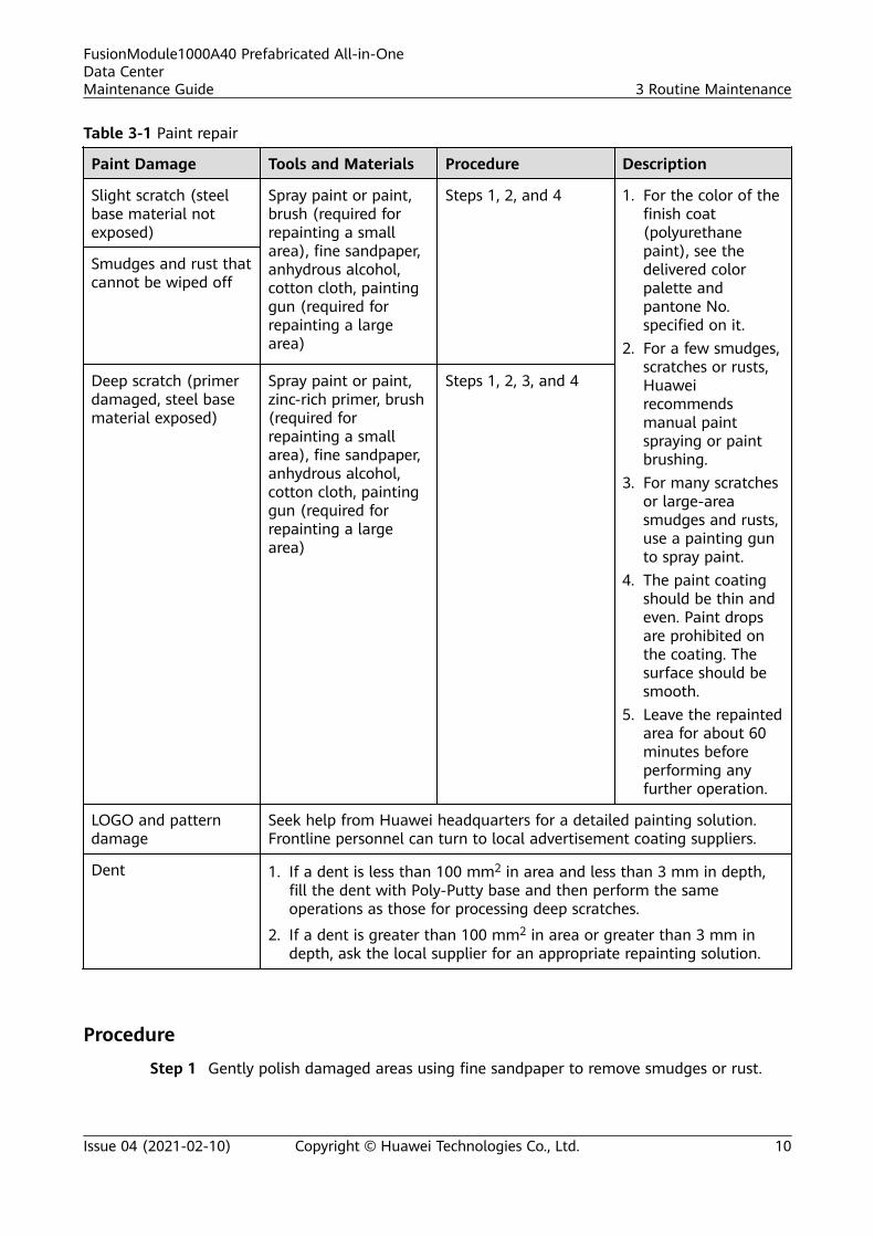
Table 3-1 Paint repair
Paint Damage Tools and Materials Procedure Description
Slight scratch (steelbase material notexposed)
Spray paint or paint,brush (required forrepainting a smallarea), fine sandpaper,anhydrous alcohol,cotton cloth, paintinggun (required forrepainting a largearea)
Steps 1, 2, and 4 1. For the color of thefinish coat(polyurethanepaint), see thedelivered colorpalette andpantone No.specified on it.
2. For a few smudges,scratches or rusts,Huaweirecommendsmanual paintspraying or paintbrushing.
3. For many scratchesor large-areasmudges and rusts,use a painting gunto spray paint.
4. The paint coatingshould be thin andeven. Paint dropsare prohibited onthe coating. Thesurface should besmooth.
5. Leave the repaintedarea for about 60minutes beforeperforming anyfurther operation.
Smudges and rust thatcannot be wiped off
Deep scratch (primerdamaged, steel basematerial exposed)
Spray paint or paint,zinc-rich primer, brush(required forrepainting a smallarea), fine sandpaper,anhydrous alcohol,cotton cloth, paintinggun (required forrepainting a largearea)
Steps 1, 2, 3, and 4
LOGO and patterndamage
Seek help from Huawei headquarters for a detailed painting solution.Frontline personnel can turn to local advertisement coating suppliers.
Dent 1. If a dent is less than 100 mm2 in area and less than 3 mm in depth,fill the dent with Poly-Putty base and then perform the sameoperations as those for processing deep scratches.
2. If a dent is greater than 100 mm2 in area or greater than 3 mm indepth, ask the local supplier for an appropriate repainting solution.
Procedure
Step 1 Gently polish damaged areas using fine sandpaper to remove smudges or rust.
FusionModule1000A40 Prefabricated All-in-OneData CenterMaintenance Guide 3 Routine Maintenance
Issue 04 (2021-02-10) Copyright © Huawei Technologies Co., Ltd. 10
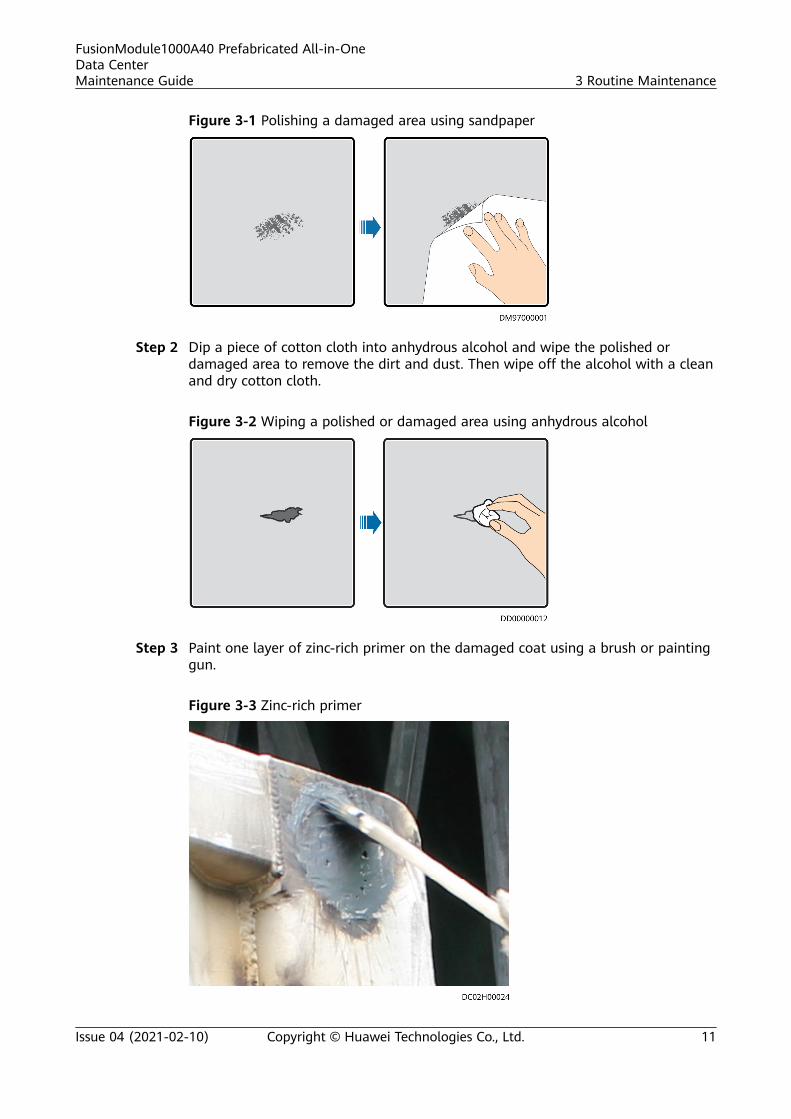
Figure 3-1 Polishing a damaged area using sandpaper
Step 2 Dip a piece of cotton cloth into anhydrous alcohol and wipe the polished ordamaged area to remove the dirt and dust. Then wipe off the alcohol with a cleanand dry cotton cloth.
Figure 3-2 Wiping a polished or damaged area using anhydrous alcohol
Step 3 Paint one layer of zinc-rich primer on the damaged coat using a brush or paintinggun.
Figure 3-3 Zinc-rich primer
FusionModule1000A40 Prefabricated All-in-OneData CenterMaintenance Guide 3 Routine Maintenance
Issue 04 (2021-02-10) Copyright © Huawei Technologies Co., Ltd. 11
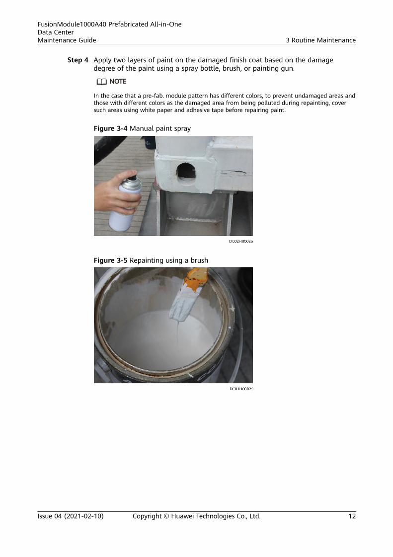
Step 4 Apply two layers of paint on the damaged finish coat based on the damagedegree of the paint using a spray bottle, brush, or painting gun.
NO TE
In the case that a pre-fab. module pattern has different colors, to prevent undamaged areas andthose with different colors as the damaged area from being polluted during repainting, coversuch areas using white paper and adhesive tape before repairing paint.
Figure 3-4 Manual paint spray
Figure 3-5 Repainting using a brush
FusionModule1000A40 Prefabricated All-in-OneData CenterMaintenance Guide 3 Routine Maintenance
Issue 04 (2021-02-10) Copyright © Huawei Technologies Co., Ltd. 12
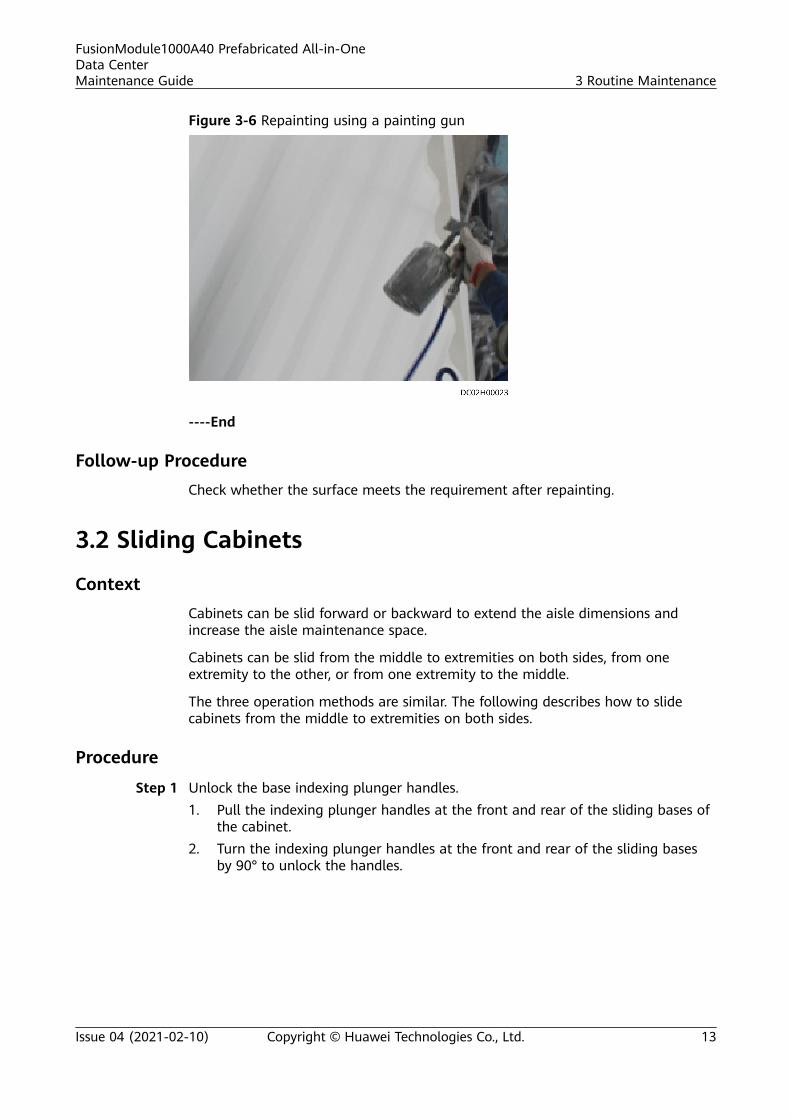
Figure 3-6 Repainting using a painting gun
----End
Follow-up ProcedureCheck whether the surface meets the requirement after repainting.
3.2 Sliding Cabinets
ContextCabinets can be slid forward or backward to extend the aisle dimensions andincrease the aisle maintenance space.
Cabinets can be slid from the middle to extremities on both sides, from oneextremity to the other, or from one extremity to the middle.
The three operation methods are similar. The following describes how to slidecabinets from the middle to extremities on both sides.
Procedure
Step 1 Unlock the base indexing plunger handles.1. Pull the indexing plunger handles at the front and rear of the sliding bases of
the cabinet.2. Turn the indexing plunger handles at the front and rear of the sliding bases
by 90° to unlock the handles.
FusionModule1000A40 Prefabricated All-in-OneData CenterMaintenance Guide 3 Routine Maintenance
Issue 04 (2021-02-10) Copyright © Huawei Technologies Co., Ltd. 13
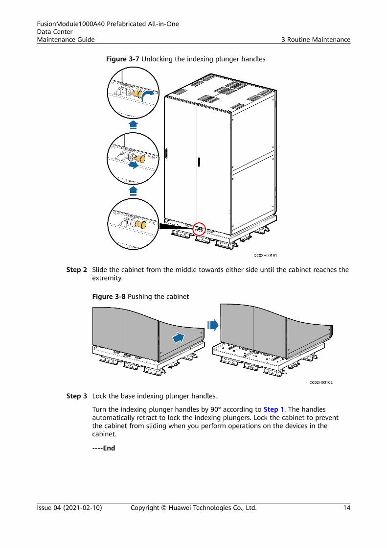
Figure 3-7 Unlocking the indexing plunger handles
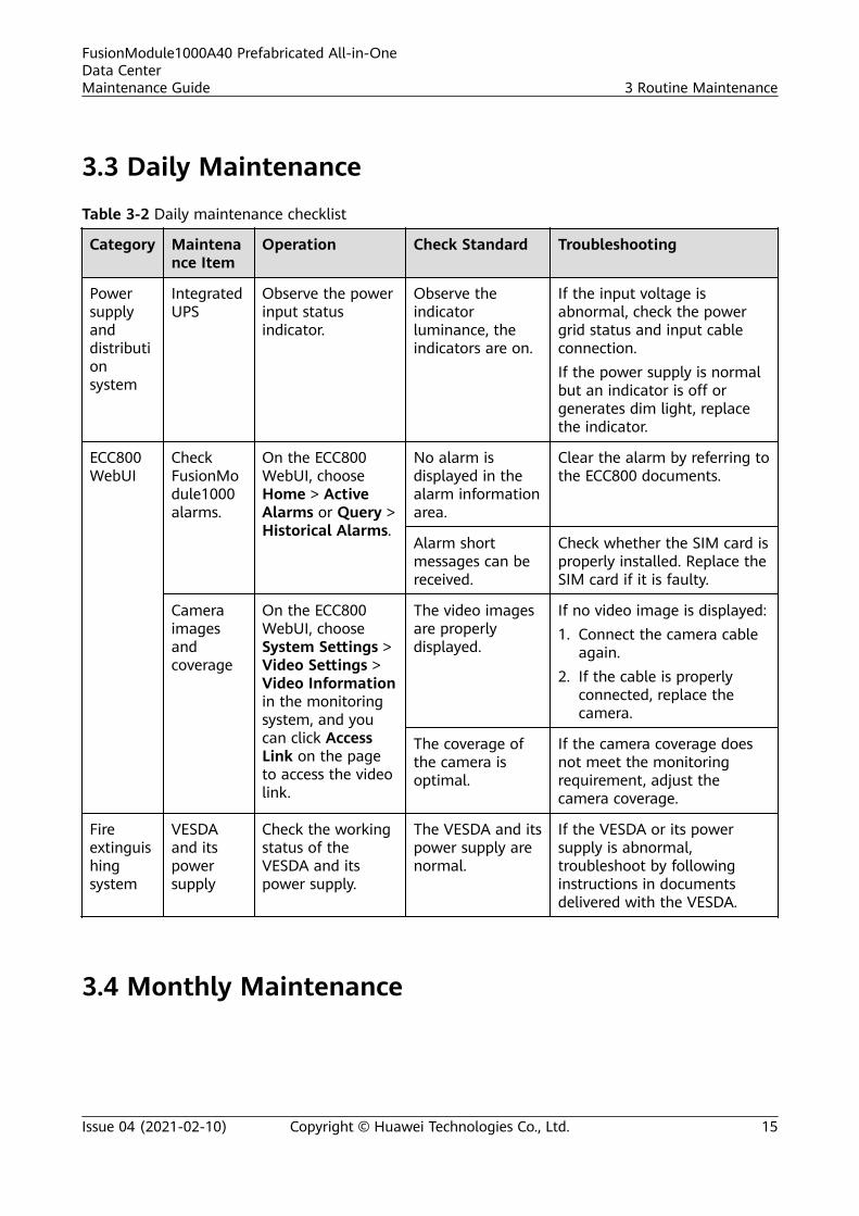
Step 2 Slide the cabinet from the middle towards either side until the cabinet reaches theextremity.
Figure 3-8 Pushing the cabinet
Step 3 Lock the base indexing plunger handles.
Turn the indexing plunger handles by 90° according to Step 1. The handlesautomatically retract to lock the indexing plungers. Lock the cabinet to preventthe cabinet from sliding when you perform operations on the devices in thecabinet.
----End
FusionModule1000A40 Prefabricated All-in-OneData CenterMaintenance Guide 3 Routine Maintenance
Issue 04 (2021-02-10) Copyright © Huawei Technologies Co., Ltd. 14
3.3 Daily Maintenance
Table 3-2 Daily maintenance checklist
Category Maintenance Item
Operation Check Standard Troubleshooting
Powersupplyanddistributionsystem
IntegratedUPS
Observe the powerinput statusindicator.
Observe theindicatorluminance, theindicators are on.
If the input voltage isabnormal, check the powergrid status and input cableconnection.If the power supply is normalbut an indicator is off orgenerates dim light, replacethe indicator.
ECC800WebUI
CheckFusionModule1000alarms.
On the ECC800WebUI, chooseHome > ActiveAlarms or Query >Historical Alarms.
No alarm isdisplayed in thealarm informationarea.
Clear the alarm by referring tothe ECC800 documents.
Alarm shortmessages can bereceived.
Check whether the SIM card isproperly installed. Replace theSIM card if it is faulty.
Cameraimagesandcoverage
On the ECC800WebUI, chooseSystem Settings >Video Settings >Video Informationin the monitoringsystem, and youcan click AccessLink on the pageto access the videolink.
The video imagesare properlydisplayed.
If no video image is displayed:1. Connect the camera cable
again.2. If the cable is properly
connected, replace thecamera.
The coverage ofthe camera isoptimal.
If the camera coverage doesnot meet the monitoringrequirement, adjust thecamera coverage.
Fireextinguishingsystem
VESDAand itspowersupply
Check the workingstatus of theVESDA and itspower supply.
The VESDA and itspower supply arenormal.
If the VESDA or its powersupply is abnormal,troubleshoot by followinginstructions in documentsdelivered with the VESDA.
3.4 Monthly Maintenance
FusionModule1000A40 Prefabricated All-in-OneData CenterMaintenance Guide 3 Routine Maintenance
Issue 04 (2021-02-10) Copyright © Huawei Technologies Co., Ltd. 15
3.4.1 Power Supply and Distribution System
Table 3-3 Monthly maintenance checklist for the power supply and distribution system
Item Method Check Standard Troubleshooting
Integrated UPS
Operatingenvironment
● Ambienttemperature: 0–40°C
● Humidity: 5%–95%RH (non-condensing)
● Rodent-proofmeasures have beentaken for theequipment room.
● The equipment roomis airtight.
● If the humidity or temperature isabnormal, check the smart coolingproduct status.
● Put rodent-proof baffle plates at thedoor of the UPS equipment room.
● Check that the equipment room isairtight and not in a directventilation environment.
Power gridenvironment
● Input voltage: 380 VAC, 400 V AC, or 415V AC (line voltage)
● Output voltage: 380V AC, 400 V AC, or415 V AC (tolerance± 1%, line voltage)
● Frequency: 40–70 Hz
● If the input voltage is abnormal,check the power grid status andinput cable connection.
● If the output voltage is abnormal,check the UPS running status andcheck whether an alarm isgenerated.
Information onthe LCD
The status icons on theLCD indicate that allunits are operatingproperly, all operatingparameters are withintheir normal ranges,and no fault or alarminformation isdisplayed.
If an alarm is generated, rectify thefault by checking the device status andparameters.
3.4.2 Cooling System
Table 3-4 Monthly maintenance checklist for the cooling system
Item Method Check Standard Troubleshooting
Thermalinsulation foamfor thehumidifier/condensatedrainpipe
Check whetherthe thermalinsulation layersare in goodcondition withoutcondensation.
The thermalinsulation layersare in goodcondition andfree fromcondensation.
If there is condensation under a pipe,replace the thermal insulation foam byfollowing instructions in theNetCol5000-A025 In-row Air CooledSmart Cooling Product User Manual(300 mm Width).
FusionModule1000A40 Prefabricated All-in-OneData CenterMaintenance Guide 3 Routine Maintenance
Issue 04 (2021-02-10) Copyright © Huawei Technologies Co., Ltd. 16
NO TICE
If a cooling component needs to be powered off for maintenance, take measuresto prevent device overheating before powering off the component.
3.4.3 Monitoring System
Table 3-5 Monthly maintenance checklist for the monitoring system
Check Item Operation Check Standard Troubleshooting
Combinedmodule
INPUT1indicator
The green indicator issteady on.
Check the mains and the input powercables.NOTICE
Before replacing the combined module,verify that it is powered off and all threeindicators are off.
INPUT2indicator
The green indicator issteady on.
OUTPUTindicator
The green indicator issteady on.
Power input Dual-input voltagerange: 43–58 V DC;rated voltage: 53.5 V DC
If the input voltage is abnormal, checkthe power grid and input cableconnection.
Power output Voltage range: 43–58 VDC; rated voltage: 53.5 VDC
For details, contact Huawei technicalsupport.
Operatingenvironment
Temperature: –20°C to+65°CHumidity: 5–95% RH(non-condensing)
Check that the ambient temperatureand humidity for the combined moduleare normal.
Accessactuator
Power input Input voltage: 36–60 VDC
Check the input power cables if theinput voltage is abnormal.
PWRindicator
Steady on: The powersupply is normal.Off: No power supply isavailable.
Check the input power cables.
ALMindicator
Steady on: A fault alarmis generated.Off: No fault alarm isgenerated.
Clear the alarm by referring to theECC800 documents.
FusionModule1000A40 Prefabricated All-in-OneData CenterMaintenance Guide 3 Routine Maintenance
Issue 04 (2021-02-10) Copyright © Huawei Technologies Co., Ltd. 17
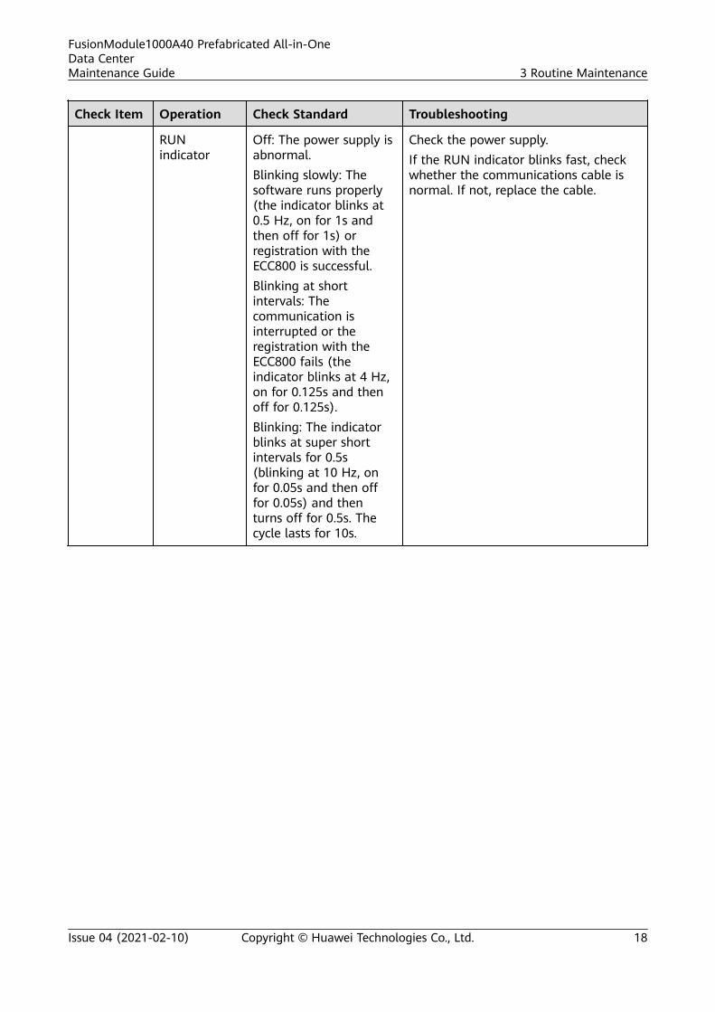
Check Item Operation Check Standard Troubleshooting
RUNindicator
Off: The power supply isabnormal.Blinking slowly: Thesoftware runs properly(the indicator blinks at0.5 Hz, on for 1s andthen off for 1s) orregistration with theECC800 is successful.Blinking at shortintervals: Thecommunication isinterrupted or theregistration with theECC800 fails (theindicator blinks at 4 Hz,on for 0.125s and thenoff for 0.125s).Blinking: The indicatorblinks at super shortintervals for 0.5s(blinking at 10 Hz, onfor 0.05s and then offfor 0.05s) and thenturns off for 0.5s. Thecycle lasts for 10s.
Check the power supply.If the RUN indicator blinks fast, checkwhether the communications cable isnormal. If not, replace the cable.
FusionModule1000A40 Prefabricated All-in-OneData CenterMaintenance Guide 3 Routine Maintenance
Issue 04 (2021-02-10) Copyright © Huawei Technologies Co., Ltd. 18

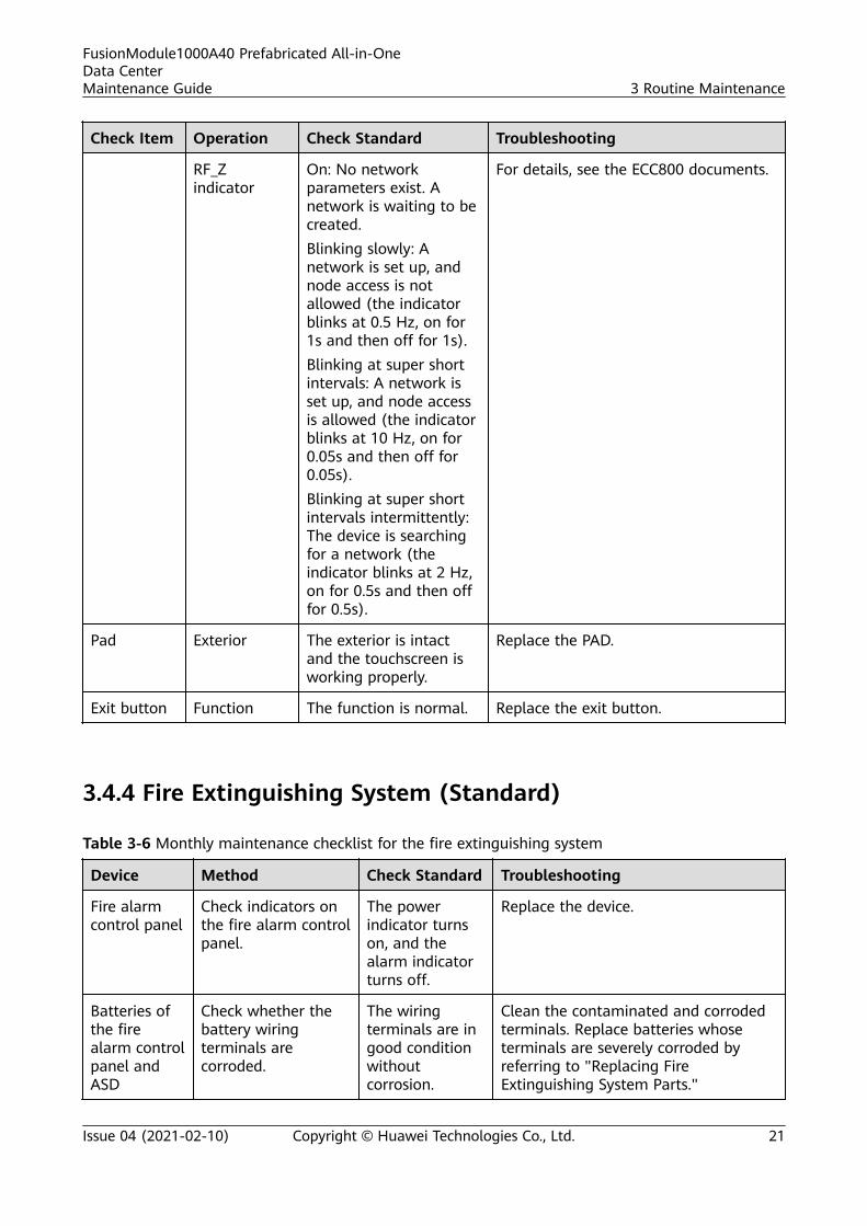
Check Item Operation Check Standard Troubleshooting
RF_Zindicator
On: No networkparameters exist. Anetwork is waiting to becreated.Blinking slowly: Anetwork is set up, andnode access is notallowed (the indicatorblinks at 0.5 Hz, on for1s and then off for 1s).Blinking at super shortintervals: A network isset up, and node accessis allowed (the indicatorblinks at 10 Hz, on for0.05s and then off for0.05s).Blinking at super shortintervals intermittently:The device is searchingfor a network (theindicator blinks at 2 Hz,on for 0.5s and then offfor 0.5s).
For details, see the ECC800 documents.
AC actuator Power input Input voltage: 90–240 VAC
Check the input power cables if theinput voltage is abnormal.
Power output Output voltage: 90–240V AC
For details, contact Huawei technicalsupport.
PWRindicator
Steady on: The powersupply is normal.Off: No power supply isavailable.
Check the input power cables.
ALMindicator
Steady on: A fault alarmis generated.Off: No fault alarm isgenerated.
Clear the alarm by referring to theECC800 documents.
FusionModule1000A40 Prefabricated All-in-OneData CenterMaintenance Guide 3 Routine Maintenance
Issue 04 (2021-02-10) Copyright © Huawei Technologies Co., Ltd. 19
Check Item Operation Check Standard Troubleshooting
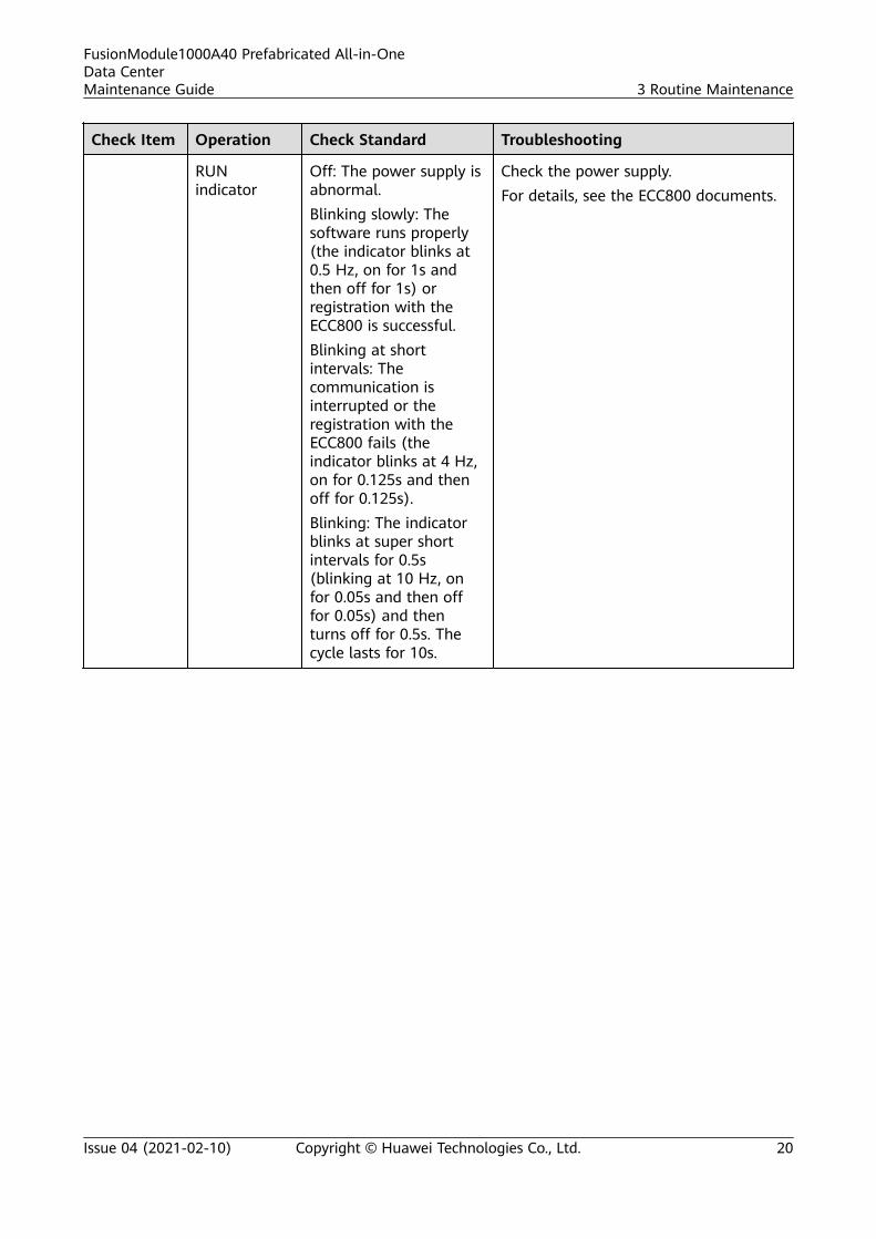
RUNindicator
Off: The power supply isabnormal.Blinking slowly: Thesoftware runs properly(the indicator blinks at0.5 Hz, on for 1s andthen off for 1s) orregistration with theECC800 is successful.Blinking at shortintervals: Thecommunication isinterrupted or theregistration with theECC800 fails (theindicator blinks at 4 Hz,on for 0.125s and thenoff for 0.125s).Blinking: The indicatorblinks at super shortintervals for 0.5s(blinking at 10 Hz, onfor 0.05s and then offfor 0.05s) and thenturns off for 0.5s. Thecycle lasts for 10s.
Check the power supply.For details, see the ECC800 documents.
FusionModule1000A40 Prefabricated All-in-OneData CenterMaintenance Guide 3 Routine Maintenance
Issue 04 (2021-02-10) Copyright © Huawei Technologies Co., Ltd. 20
Check Item Operation Check Standard Troubleshooting
RF_Zindicator
On: No networkparameters exist. Anetwork is waiting to becreated.Blinking slowly: Anetwork is set up, andnode access is notallowed (the indicatorblinks at 0.5 Hz, on for1s and then off for 1s).Blinking at super shortintervals: A network isset up, and node accessis allowed (the indicatorblinks at 10 Hz, on for0.05s and then off for0.05s).Blinking at super shortintervals intermittently:The device is searchingfor a network (theindicator blinks at 2 Hz,on for 0.5s and then offfor 0.5s).
For details, see the ECC800 documents.
Pad Exterior The exterior is intactand the touchscreen isworking properly.
Replace the PAD.
Exit button Function The function is normal. Replace the exit button.
3.4.4 Fire Extinguishing System (Standard)
Table 3-6 Monthly maintenance checklist for the fire extinguishing system
Device Method Check Standard Troubleshooting
Fire alarmcontrol panel
Check indicators onthe fire alarm controlpanel.
The powerindicator turnson, and thealarm indicatorturns off.
Replace the device.
Batteries ofthe firealarm controlpanel andASD
Check whether thebattery wiringterminals arecorroded.
The wiringterminals are ingood conditionwithoutcorrosion.
Clean the contaminated and corrodedterminals. Replace batteries whoseterminals are severely corroded byreferring to "Replacing FireExtinguishing System Parts."
FusionModule1000A40 Prefabricated All-in-OneData CenterMaintenance Guide 3 Routine Maintenance
Issue 04 (2021-02-10) Copyright © Huawei Technologies Co., Ltd. 21

Device Method Check Standard Troubleshooting
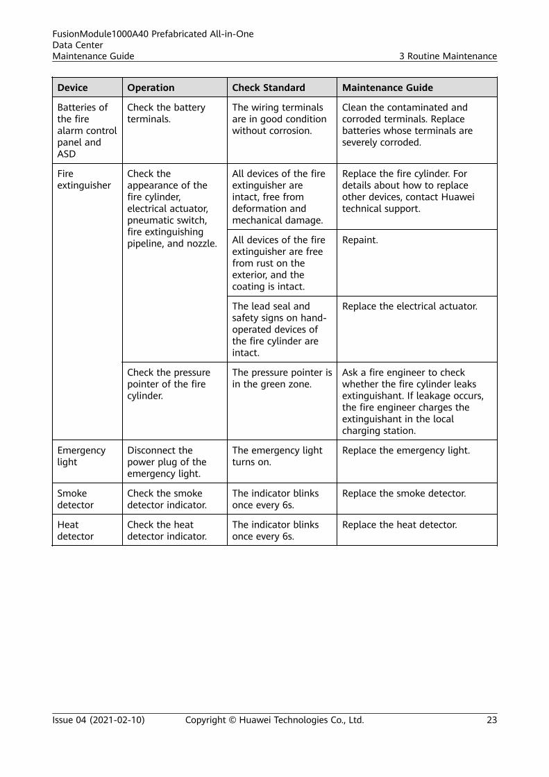
Fireextinguisher
Check theappearance of thefire cylinder,electromagneticvalve, pipeline, andnozzle.
All devices ofthe fireextinguisher areintact, free fromdeformation andmechanicaldamage.
Replace the fire cylinder by followinginstructions in "Replacing a FireCylinder." For details about how toreplace other devices, contact Huaweitechnical support.
All devices ofthe fireextinguisher arefree from ruston the exterior,and the coatingis intact.
Repaint the device.
The lead sealand safety signson hand-operated devicesare intact.
Replace the electromagnetic valve.
Read the pressureshown on thepressure gauge.
The pressurepointer is in thegreen zone.
Ask a local maintenance engineer tocheck whether the fire cylinder leaksextinguishant. If leakage occurs, themaintenance engineer asks the fireextinguisher manufacturer to rechargethe extinguishant.
Emergencylight
Switch off the powercircuit breaker.
The emergencylight turns on.
Replace the device.
Smokedetector
Check the smokedetector indicator.
The indicatorblinks onceevery 6s.
Replace the smoke detector.
Heatdetector
Check the heatdetector indicator.
The indicatorblinks onceevery 6s.
Replace the heat detector.
3.4.5 Fire Extinguishing System (CE)
Table 3-7 Monthly maintenance checklist for the fire extinguishing system
Device Operation Check Standard Maintenance Guide
Extinguishantcontrol panel
Check indicators onthe extinguishantcontrol panel.
The power indicatorturns on, and thealarm indicator turnsoff.
Replace the extinguishant controlpanel.
FusionModule1000A40 Prefabricated All-in-OneData CenterMaintenance Guide 3 Routine Maintenance
Issue 04 (2021-02-10) Copyright © Huawei Technologies Co., Ltd. 22
Device Operation Check Standard Maintenance Guide
Batteries ofthe firealarm controlpanel andASD
Check the batteryterminals.
The wiring terminalsare in good conditionwithout corrosion.
Clean the contaminated andcorroded terminals. Replacebatteries whose terminals areseverely corroded.
Fireextinguisher
Check theappearance of thefire cylinder,electrical actuator,pneumatic switch,fire extinguishingpipeline, and nozzle.
All devices of the fireextinguisher areintact, free fromdeformation andmechanical damage.
Replace the fire cylinder. Fordetails about how to replaceother devices, contact Huaweitechnical support.
All devices of the fireextinguisher are freefrom rust on theexterior, and thecoating is intact.
Repaint.
The lead seal andsafety signs on hand-operated devices ofthe fire cylinder areintact.
Replace the electrical actuator.
Check the pressurepointer of the firecylinder.
The pressure pointer isin the green zone.
Ask a fire engineer to checkwhether the fire cylinder leaksextinguishant. If leakage occurs,the fire engineer charges theextinguishant in the localcharging station.
Emergencylight
Disconnect thepower plug of theemergency light.
The emergency lightturns on.
Replace the emergency light.
Smokedetector
Check the smokedetector indicator.
The indicator blinksonce every 6s.
Replace the smoke detector.
Heatdetector
Check the heatdetector indicator.
The indicator blinksonce every 6s.
Replace the heat detector.
FusionModule1000A40 Prefabricated All-in-OneData CenterMaintenance Guide 3 Routine Maintenance
Issue 04 (2021-02-10) Copyright © Huawei Technologies Co., Ltd. 23
3.4.6 Other Systems
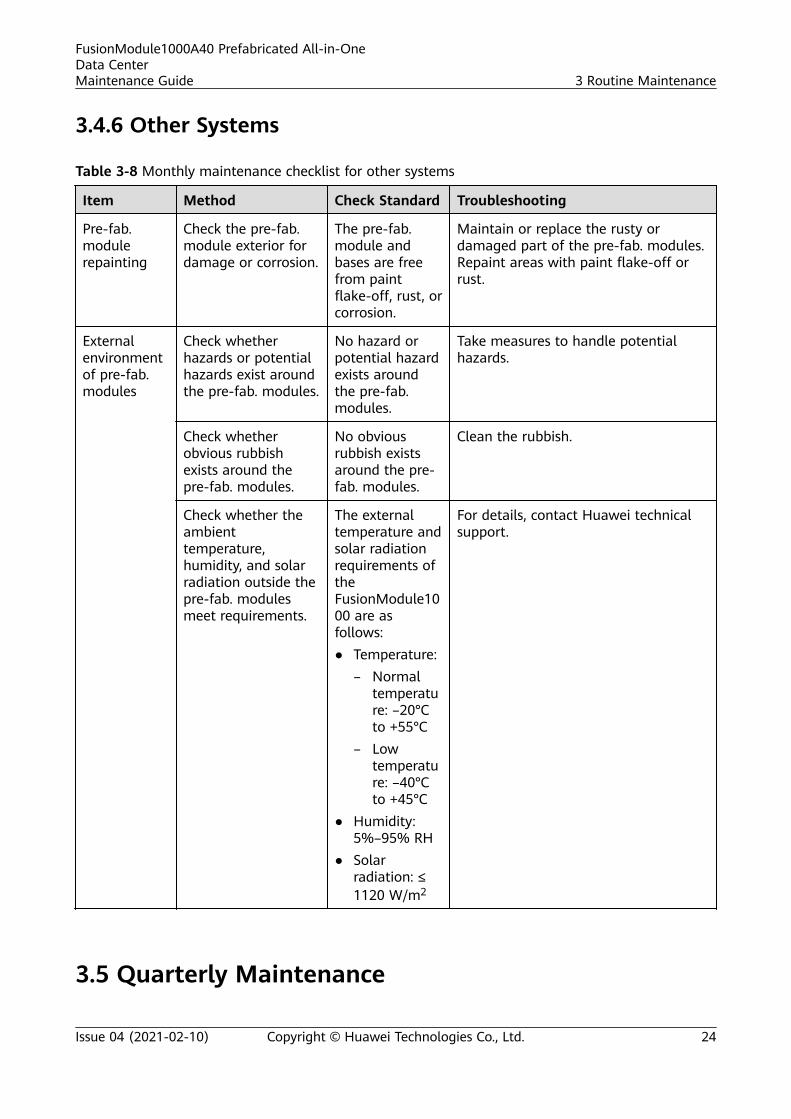
Table 3-8 Monthly maintenance checklist for other systems
Item Method Check Standard Troubleshooting
Pre-fab.modulerepainting
Check the pre-fab.module exterior fordamage or corrosion.
The pre-fab.module andbases are freefrom paintflake-off, rust, orcorrosion.
Maintain or replace the rusty ordamaged part of the pre-fab. modules.Repaint areas with paint flake-off orrust.
Externalenvironmentof pre-fab.modules
Check whetherhazards or potentialhazards exist aroundthe pre-fab. modules.
No hazard orpotential hazardexists aroundthe pre-fab.modules.
Take measures to handle potentialhazards.
Check whetherobvious rubbishexists around thepre-fab. modules.
No obviousrubbish existsaround the pre-fab. modules.
Clean the rubbish.
Check whether theambienttemperature,humidity, and solarradiation outside thepre-fab. modulesmeet requirements.
The externaltemperature andsolar radiationrequirements oftheFusionModule1000 are asfollows:● Temperature:
– Normaltemperature: –20°Cto +55°C
– Lowtemperature: –40°Cto +45°C
● Humidity:5%–95% RH
● Solarradiation: ≤1120 W/m2
For details, contact Huawei technicalsupport.
3.5 Quarterly Maintenance
FusionModule1000A40 Prefabricated All-in-OneData CenterMaintenance Guide 3 Routine Maintenance
Issue 04 (2021-02-10) Copyright © Huawei Technologies Co., Ltd. 24
3.5.1 Monitoring System
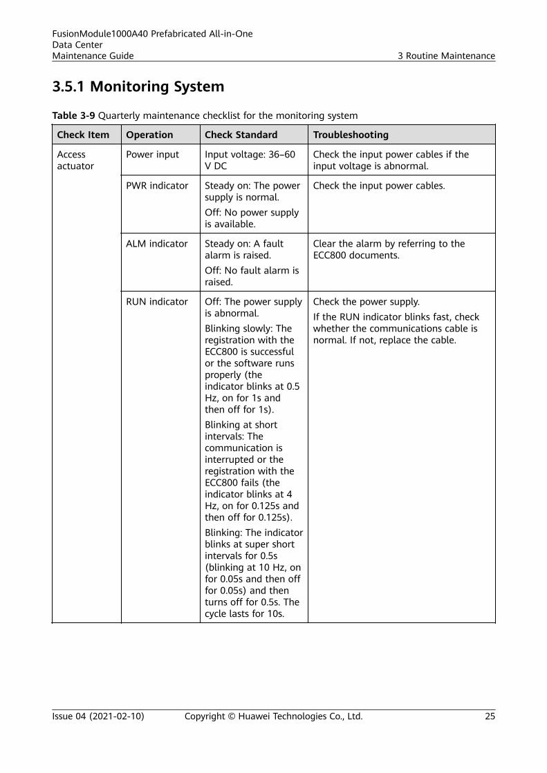
Table 3-9 Quarterly maintenance checklist for the monitoring system
Check Item Operation Check Standard Troubleshooting
Accessactuator
Power input Input voltage: 36–60V DC
Check the input power cables if theinput voltage is abnormal.
PWR indicator Steady on: The powersupply is normal.Off: No power supplyis available.
Check the input power cables.
ALM indicator Steady on: A faultalarm is raised.Off: No fault alarm israised.
Clear the alarm by referring to theECC800 documents.
RUN indicator Off: The power supplyis abnormal.Blinking slowly: Theregistration with theECC800 is successfulor the software runsproperly (theindicator blinks at 0.5Hz, on for 1s andthen off for 1s).Blinking at shortintervals: Thecommunication isinterrupted or theregistration with theECC800 fails (theindicator blinks at 4Hz, on for 0.125s andthen off for 0.125s).Blinking: The indicatorblinks at super shortintervals for 0.5s(blinking at 10 Hz, onfor 0.05s and then offfor 0.05s) and thenturns off for 0.5s. Thecycle lasts for 10s.
Check the power supply.If the RUN indicator blinks fast, checkwhether the communications cable isnormal. If not, replace the cable.
FusionModule1000A40 Prefabricated All-in-OneData CenterMaintenance Guide 3 Routine Maintenance
Issue 04 (2021-02-10) Copyright © Huawei Technologies Co., Ltd. 25
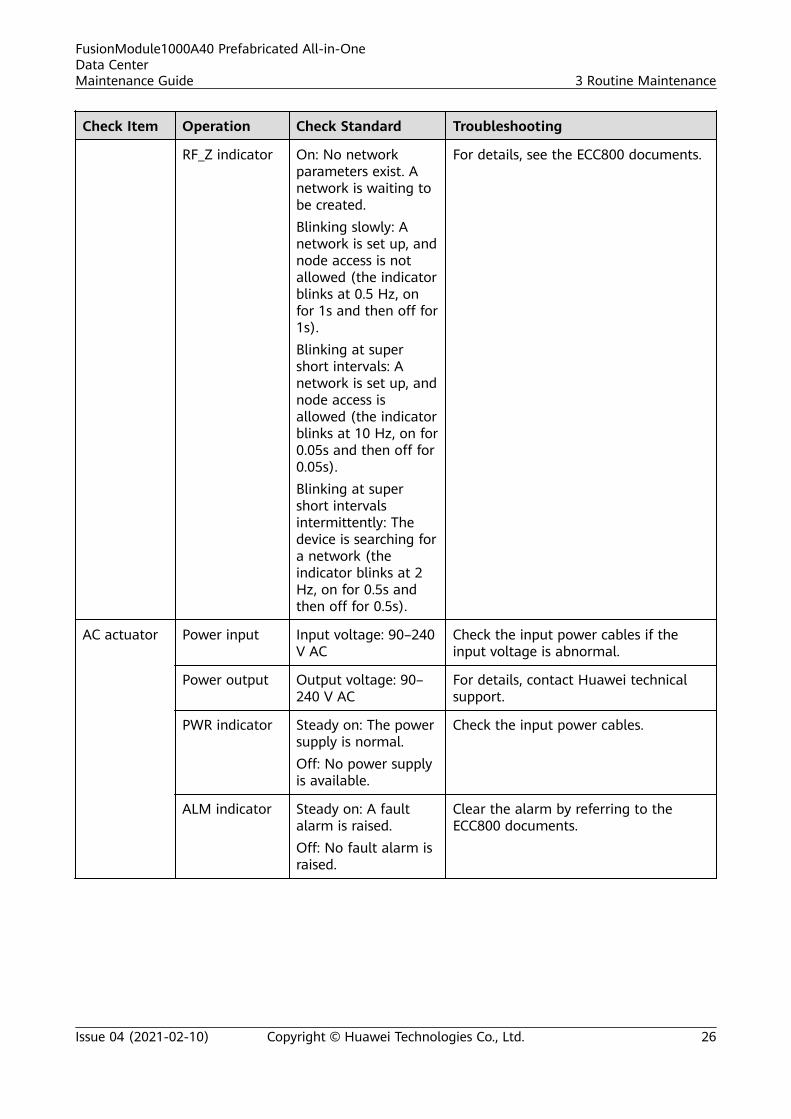
Check Item Operation Check Standard Troubleshooting
RF_Z indicator On: No networkparameters exist. Anetwork is waiting tobe created.Blinking slowly: Anetwork is set up, andnode access is notallowed (the indicatorblinks at 0.5 Hz, onfor 1s and then off for1s).Blinking at supershort intervals: Anetwork is set up, andnode access isallowed (the indicatorblinks at 10 Hz, on for0.05s and then off for0.05s).Blinking at supershort intervalsintermittently: Thedevice is searching fora network (theindicator blinks at 2Hz, on for 0.5s andthen off for 0.5s).
For details, see the ECC800 documents.
AC actuator Power input Input voltage: 90–240V AC
Check the input power cables if theinput voltage is abnormal.
Power output Output voltage: 90–240 V AC
For details, contact Huawei technicalsupport.
PWR indicator Steady on: The powersupply is normal.Off: No power supplyis available.
Check the input power cables.
ALM indicator Steady on: A faultalarm is raised.Off: No fault alarm israised.
Clear the alarm by referring to theECC800 documents.
FusionModule1000A40 Prefabricated All-in-OneData CenterMaintenance Guide 3 Routine Maintenance
Issue 04 (2021-02-10) Copyright © Huawei Technologies Co., Ltd. 26
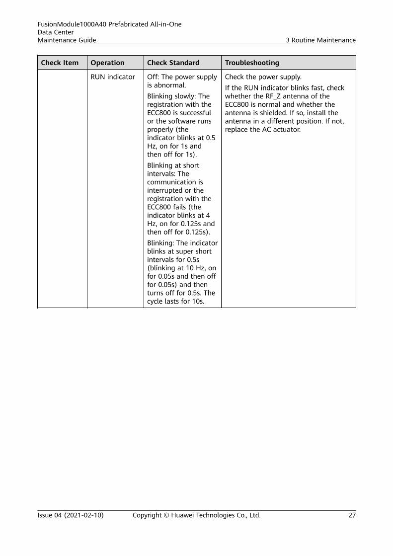
Check Item Operation Check Standard Troubleshooting
RUN indicator Off: The power supplyis abnormal.Blinking slowly: Theregistration with theECC800 is successfulor the software runsproperly (theindicator blinks at 0.5Hz, on for 1s andthen off for 1s).Blinking at shortintervals: Thecommunication isinterrupted or theregistration with theECC800 fails (theindicator blinks at 4Hz, on for 0.125s andthen off for 0.125s).Blinking: The indicatorblinks at super shortintervals for 0.5s(blinking at 10 Hz, onfor 0.05s and then offfor 0.05s) and thenturns off for 0.5s. Thecycle lasts for 10s.
Check the power supply.If the RUN indicator blinks fast, checkwhether the RF_Z antenna of theECC800 is normal and whether theantenna is shielded. If so, install theantenna in a different position. If not,replace the AC actuator.
FusionModule1000A40 Prefabricated All-in-OneData CenterMaintenance Guide 3 Routine Maintenance
Issue 04 (2021-02-10) Copyright © Huawei Technologies Co., Ltd. 27

Check Item Operation Check Standard Troubleshooting
RF_Z indicator On: No networkparameters exist. Anetwork is waiting tobe created.Blinking slowly: Anetwork is set up, andnode access is notallowed (the indicatorblinks at 0.5 Hz, onfor 1s and then off for1s).Blinking at supershort intervals: Anetwork is set up, andnode access isallowed (the indicatorblinks at 10 Hz, on for0.05s and then off for0.05s).Blinking at supershort intervalsintermittently: Thedevice is searching fora network (theindicator blinks at 2Hz, on for 0.5s andthen off for 0.5s).
For details, see the ECC800 documents.
Door statussensor
Open a doorwith a statussensor, andcheck thealarminformationdisplayed onthe monitoringsoftwareterminal.
An access alarm isgenerated on theECC800 WebUI.
If no alarm is raised when a door with astatus sensor is opened, replace thedoor status sensor.
FusionModule1000A40 Prefabricated All-in-OneData CenterMaintenance Guide 3 Routine Maintenance
Issue 04 (2021-02-10) Copyright © Huawei Technologies Co., Ltd. 28

3.5.2 Fire Extinguishing System (Standard)
Table 3-10 Quarterly maintenance checklist for the fire extinguishing system
Device Method Check Standard Troubleshooting
Fire alarmcontrol panelbatteries
1. Switch off thepower inputcircuit breaker ofthe fire alarmcontrol panel sothat the batteriespower the panel.
2. Measure thebattery voltageusing amultimeter.
1. The firealarm controlpanel reportsa mainspower supplyfault.
2. The batteryvoltage is24±1 V DC.
1. Check whether the mains inputpower and the voltage are normal.If the mains input power is normal,check whether the fuse is intact. Ifthe fuse is blown, replace the fuse.
2. Replace the fire alarm control panel.
Hand-heldfireextinguisher
Check the fireextinguisher.
The fireextinguisher isintact.
Replace the fire extinguisher.
The pressurepointer of thefire extinguisheris in the greenzone.
Replace the fire extinguisher.
The fireextinguisher iswithin thevalidity period.
Replace the fire extinguisher.
Fire controlcable
Check cablesconnected to theelectromagneticvalve and pressureannounciator.
Cables aresecurelyconnected to theelectromagneticvalve andpressureannounciator.
Connect the cable properly.
Emergencystart/abortswitch
Check the emergencystart/abort switch.
The exterior andkey panel areintact. The runindicator issteady green.
If the exterior is damaged, replace theemergency start/abort switch.
FusionModule1000A40 Prefabricated All-in-OneData CenterMaintenance Guide 3 Routine Maintenance
Issue 04 (2021-02-10) Copyright © Huawei Technologies Co., Ltd. 29
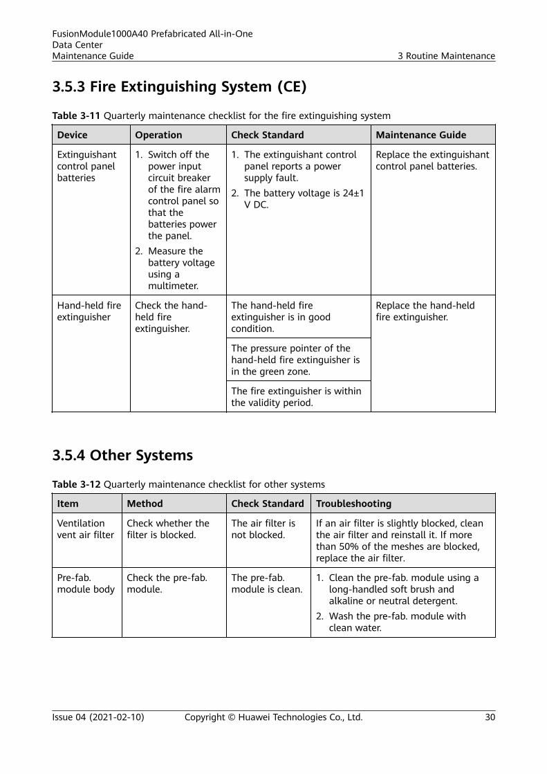
3.5.3 Fire Extinguishing System (CE)
Table 3-11 Quarterly maintenance checklist for the fire extinguishing system
Device Operation Check Standard Maintenance Guide
Extinguishantcontrol panelbatteries
1. Switch off thepower inputcircuit breakerof the fire alarmcontrol panel sothat thebatteries powerthe panel.
2. Measure thebattery voltageusing amultimeter.
1. The extinguishant controlpanel reports a powersupply fault.
2. The battery voltage is 24±1V DC.
Replace the extinguishantcontrol panel batteries.
Hand-held fireextinguisher
Check the hand-held fireextinguisher.
The hand-held fireextinguisher is in goodcondition.
Replace the hand-heldfire extinguisher.
The pressure pointer of thehand-held fire extinguisher isin the green zone.
The fire extinguisher is withinthe validity period.
3.5.4 Other Systems
Table 3-12 Quarterly maintenance checklist for other systems
Item Method Check Standard Troubleshooting
Ventilationvent air filter
Check whether thefilter is blocked.
The air filter isnot blocked.
If an air filter is slightly blocked, cleanthe air filter and reinstall it. If morethan 50% of the meshes are blocked,replace the air filter.
Pre-fab.module body
Check the pre-fab.module.
The pre-fab.module is clean.
1. Clean the pre-fab. module using along-handled soft brush andalkaline or neutral detergent.
2. Wash the pre-fab. module withclean water.
FusionModule1000A40 Prefabricated All-in-OneData CenterMaintenance Guide 3 Routine Maintenance
Issue 04 (2021-02-10) Copyright © Huawei Technologies Co., Ltd. 30

Item Method Check Standard Troubleshooting
Pre-fab.modulerepainting
Check the pre-fab.module exterior fordamage or corrosion.
The pre-fab.module andbases are freefrom paintflake-off, rust, orcorrosion.
Maintain or replace the rusty ordamaged part of the pre-fab. modules.Repaint areas with paint flake-off orrust.
3.6 Semi-annual Maintenance
3.6.1 Power Supply and Distribution System
Table 3-13 Semi-annual maintenance checklist for the power supply and distribution system
Item Method Check Standard Troubleshooting
ATS Check the ATScontroller displaypanel.
The panelindicator is on.
1. If the panel indicator is off, verify that thepower cable is properly connected, andreconnect the cable if it is not properlyconnected.
2. Replace the ATS by following instructionsin documents delivered with the ATS.
The display panelof the controllerdisplaysinformationproperly.
1. If the information is not properlydisplayed (fuzzy or blank), verify that thepower cable is properly connected.
2. Replace the ATS by following instructionsin documents delivered with the ATS.
FusionModule1000A40 Prefabricated All-in-OneData CenterMaintenance Guide 3 Routine Maintenance
Issue 04 (2021-02-10) Copyright © Huawei Technologies Co., Ltd. 31

3.6.2 Cooling System
Table 3-14 Semi-annual maintenance checklist for the cooling system
Item Method Check Standard Troubleshooting
Monitoring Export smart coolingproduct logs, alarms,temperature, humidity, theoperating status of thecompressor, fan, electricheater, electric humidifier,and water pump, and timefrom the monitoringsystem. View the historicalalarms generated in thisquarter and select themost common five ones(skip this step if nomonitoring system isconfigured).
- Rectify the fault or contactHuawei technical support.
Electricheater
The electric heater issecure.
The electric heater issecurely installed.
Secure the electric heaterand switch.
Check that the electricheater surfaces are noteroded.
The electric heatersurface is not corroded.
Replace the electric heaterif its surface is eroded.
Componentsinside theelectriccontrol box(Remove theelectriccontrol boxbeforemaintainingthe internalcomponents.)
Check that all circuitbreakers and fuses workproperly.
Switches and fuses areworking properly.
Replace faulty circuitbreakers and fuses.
Check that the cableconnection is secure andcorrect.
Cables are securelyconnected.
Secure loose cables.
Check that the electricalcomponents, controlcomponents, SPDs, andvoltage detection boardsare not dusty.
The components areclean and free fromdust.
(Perform the operationwith the power off.) Use abrush or compressed dry airto remove dust fromelectrical components,control components, andvoltage detection boards.
Check that the controlboard, display panel, T/Hsensor, and surgeprotection and voltagedetection board are notaging on the surface.
All components arenormal and free fromsigns of aging.
Replace the abnormalboard.
Check that all contactorswork properly.
Contactors workproperly and smoothly.
Replace abnormalcomponents.
FusionModule1000A40 Prefabricated All-in-OneData CenterMaintenance Guide 3 Routine Maintenance
Issue 04 (2021-02-10) Copyright © Huawei Technologies Co., Ltd. 32
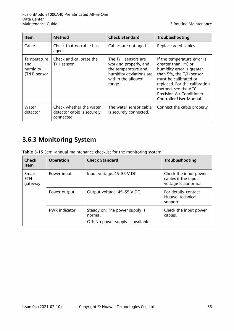
Item Method Check Standard Troubleshooting
Cable Check that no cable hasaged.
Cables are not aged. Replace aged cables.
Temperatureandhumidity(T/H) sensor
Check and calibrate theT/H sensor.
The T/H sensors areworking properly, andthe temperature andhumidity deviations arewithin the allowedrange.
If the temperature error isgreater than 1°C orhumidity error is greaterthan 5%, the T/H sensormust be calibrated orreplaced. For the calibrationmethod, see the ACCPrecision Air ConditionerController User Manual.
Waterdetector
Check whether the waterdetector cable is securelyconnected.
The water sensor cableis securely connected.
Connect the cable properly.
3.6.3 Monitoring System
Table 3-15 Semi-annual maintenance checklist for the monitoring system
CheckItem
Operation Check Standard Troubleshooting
SmartETHgateway
Power input Input voltage: 45–55 V DC Check the input powercables if the inputvoltage is abnormal.
Power output Output voltage: 45–55 V DC For details, contactHuawei technicalsupport.
PWR indicator Steady on: The power supply isnormal.Off: No power supply is available.
Check the input powercables.
FusionModule1000A40 Prefabricated All-in-OneData CenterMaintenance Guide 3 Routine Maintenance
Issue 04 (2021-02-10) Copyright © Huawei Technologies Co., Ltd. 33

CheckItem
Operation Check Standard Troubleshooting
RUN indicator Off: The power supply is abnormal.Blinking slowly: The software runsproperly (the indicator blinks at 0.5Hz, on for 1s and then off for 1s) orregistration with the ECC800 issuccessful.Blinking at short intervals: Thecommunication is interrupted or theregistration with the ECC800 fails (theindicator blinks at 4 Hz, on for 0.125sand then off for 0.125s).Blinking: The indicator blinks at supershort intervals for 0.5s (blinking at 10Hz, on for 0.05s and then off for0.05s) and then turns off for 0.5s. Thecycle lasts for 10s.
If the RUN indicator isoff, check the powersupply.If the RUN indicatorblinks at short intervals,check whether thecommunications cableis loose ordisconnected. If so,reconnect the cable.
ALM indicator Steady on: A fault alarm is raised.Off: No fault alarm is raised.
Clear the alarm byreferring to the ECC800documents.
Watersensor(pointtype)
Dip the watersensor into water,and view alarmsin themanagementsystem.
An alarm is raised on the ECC800WebUI.
If no alarm is raised,replace the watersensor.
3.6.4 Fire Extinguishing System (Standard)
NO TICE
● Semi-annual maintenance of the fire extinguishing system involves systemcommissioning. Before the maintenance, inform the related administrativedepartments that the fire extinguishing system will be maintained and stopworking.
● Before the maintenance, disconnect all cables to fire cylinder electromagneticvalves to avoid extinguishant release and damage to equipment due tomisoperations.
● After the maintenance, reconnect the cables to fire cylinder electromagneticvalves and inform the administrative departments that the fire extinguishingsystem has resumed.
FusionModule1000A40 Prefabricated All-in-OneData CenterMaintenance Guide 3 Routine Maintenance
Issue 04 (2021-02-10) Copyright © Huawei Technologies Co., Ltd. 34

Table 3-16 Semi-annual maintenance checklist for the fire extinguishing system
Device Method Check Standard Troubleshooting
Fireextinguishingsystemcommissioning
Commission the fireextinguishing system byfollowing theinstructions in the FireExtinguishing SystemCommissioning(Standard) section inthe commissioning guidefor the solution in use.
Devices work properly, and themanagement system displaysrelated alarms.
If a fireextinguishingsystem componentis abnormal, replaceit by referring to"Replacing FireExtinguishingSystem Parts."
Gas releaseindicator
Disconnect the red andblack cables from thepressure announciator,and short-circuit thecables from the firealarm control panel tothe pressureannounciator.
The gas release indicator issteady on.
Replace the gasrelease indicator.
Heat detector Heat the heat detectorusing a heating device.
If the temperature is below thealarm threshold (54–70°C), thegas release indicator blinksonce every 6s.
If the fault persists,replace the heatdetector.
If the temperature exceeds thealarm threshold, the gasrelease indicator is steady on.The fire alarm control panelgenerates an alarm andtriggers the fire alarm sounder.
If the fault persists,replace the heatdetector.
Smokedetector
Release smoke onto thesmoke detector using asmoke pistol.
If the smoke density is belowthe alarm threshold, the alarmindicator blinks once every 6s.
Replace the smokedetector.
If the smoke density exceedsthe alarm threshold, theindicator turns on. The firealarm control panel generatesan alarm and triggers the firealarm sounder.
If the fault persists,replace the smokedetector.
Fire alarmsounder
When the heat detectoror smoke detectorgenerates an alarm, thefire alarm bell generatesa harsh sound.
The alarm is loud and clear. 1. Check andreconnect cablesto the fire alarmsounder.
2. If the faultpersists, replacethe fire alarmsounder.
FusionModule1000A40 Prefabricated All-in-OneData CenterMaintenance Guide 3 Routine Maintenance
Issue 04 (2021-02-10) Copyright © Huawei Technologies Co., Ltd. 35
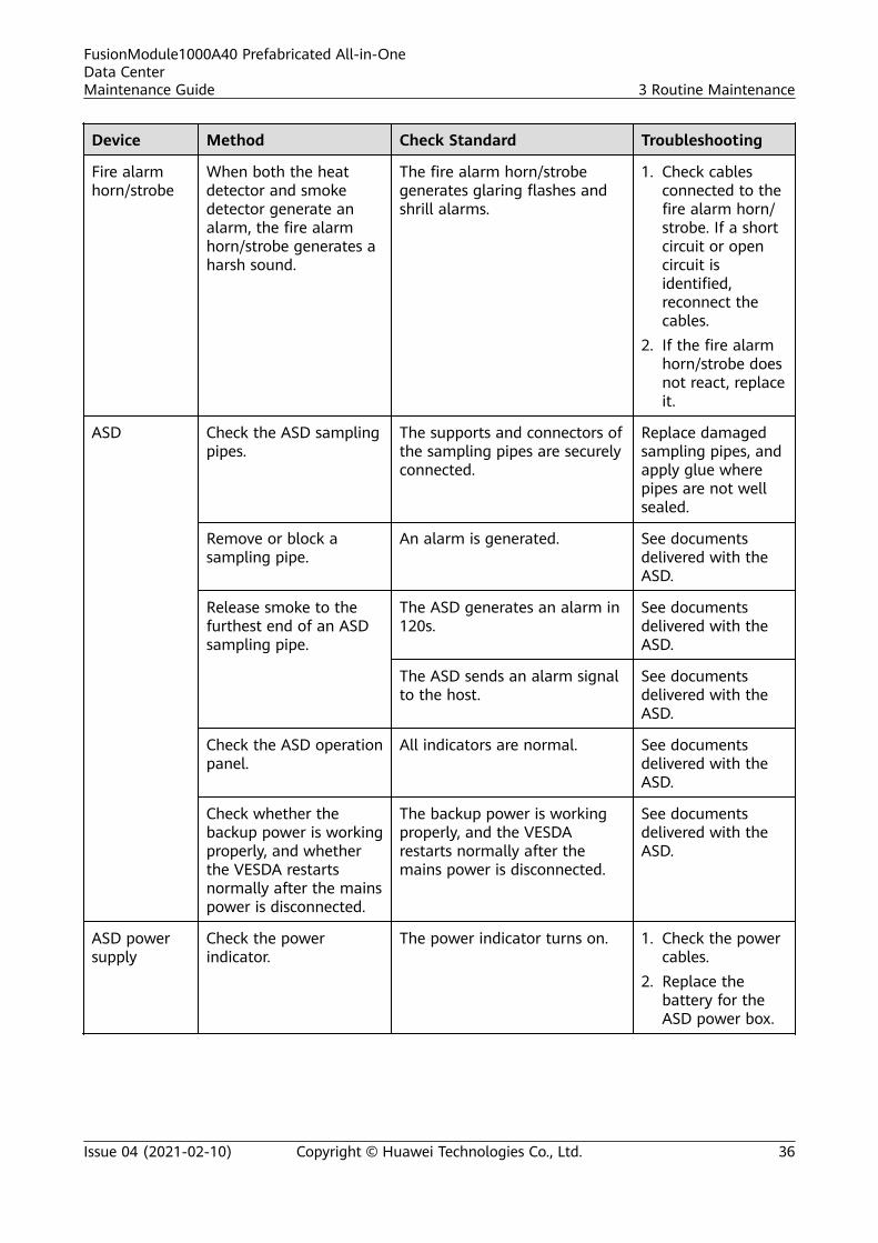
Device Method Check Standard Troubleshooting
Fire alarmhorn/strobe
When both the heatdetector and smokedetector generate analarm, the fire alarmhorn/strobe generates aharsh sound.
The fire alarm horn/strobegenerates glaring flashes andshrill alarms.
1. Check cablesconnected to thefire alarm horn/strobe. If a shortcircuit or opencircuit isidentified,reconnect thecables.
2. If the fire alarmhorn/strobe doesnot react, replaceit.
ASD Check the ASD samplingpipes.
The supports and connectors ofthe sampling pipes are securelyconnected.
Replace damagedsampling pipes, andapply glue wherepipes are not wellsealed.
Remove or block asampling pipe.
An alarm is generated. See documentsdelivered with theASD.
Release smoke to thefurthest end of an ASDsampling pipe.
The ASD generates an alarm in120s.
See documentsdelivered with theASD.
The ASD sends an alarm signalto the host.
See documentsdelivered with theASD.
Check the ASD operationpanel.
All indicators are normal. See documentsdelivered with theASD.
Check whether thebackup power is workingproperly, and whetherthe VESDA restartsnormally after the mainspower is disconnected.
The backup power is workingproperly, and the VESDArestarts normally after themains power is disconnected.
See documentsdelivered with theASD.
ASD powersupply
Check the powerindicator.
The power indicator turns on. 1. Check the powercables.
2. Replace thebattery for theASD power box.
FusionModule1000A40 Prefabricated All-in-OneData CenterMaintenance Guide 3 Routine Maintenance
Issue 04 (2021-02-10) Copyright © Huawei Technologies Co., Ltd. 36
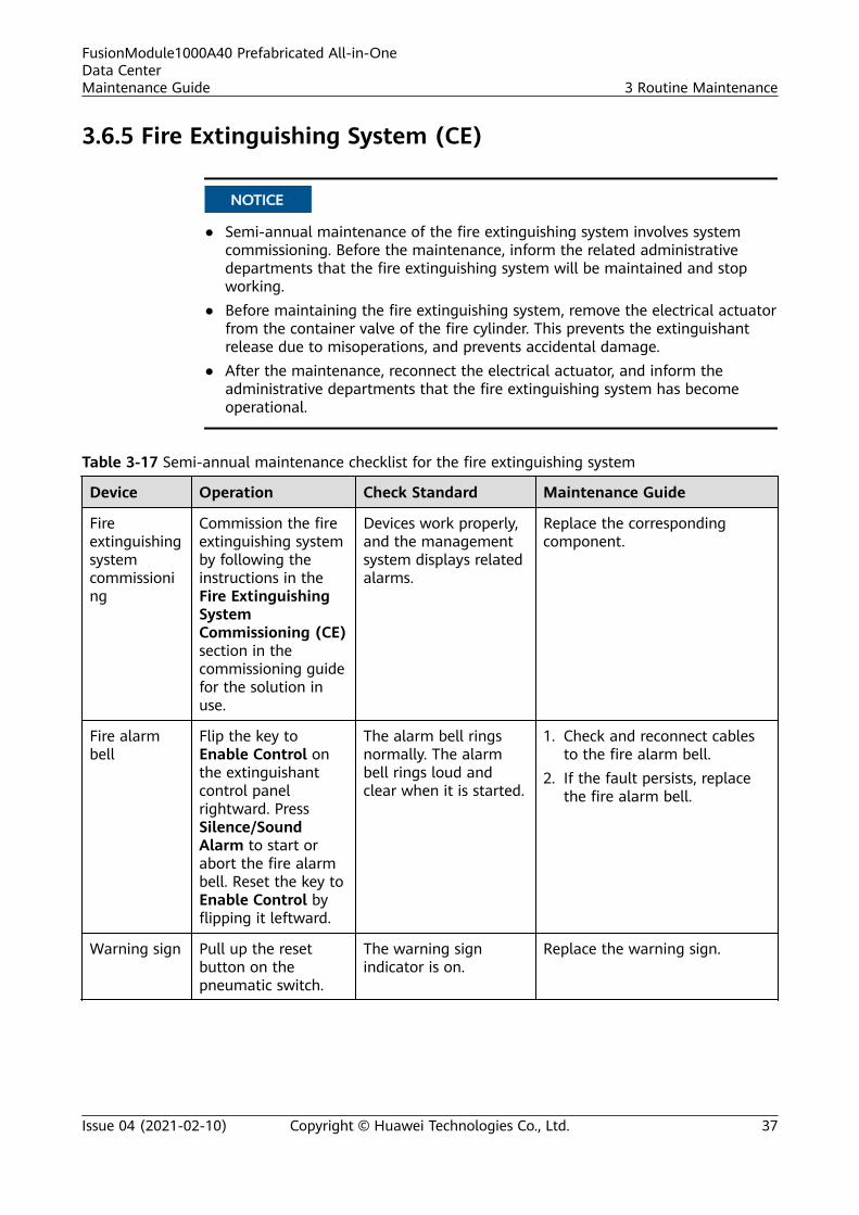
3.6.5 Fire Extinguishing System (CE)
NO TICE
● Semi-annual maintenance of the fire extinguishing system involves systemcommissioning. Before the maintenance, inform the related administrativedepartments that the fire extinguishing system will be maintained and stopworking.
● Before maintaining the fire extinguishing system, remove the electrical actuatorfrom the container valve of the fire cylinder. This prevents the extinguishantrelease due to misoperations, and prevents accidental damage.
● After the maintenance, reconnect the electrical actuator, and inform theadministrative departments that the fire extinguishing system has becomeoperational.
Table 3-17 Semi-annual maintenance checklist for the fire extinguishing system
Device Operation Check Standard Maintenance Guide
Fireextinguishingsystemcommissioning
Commission the fireextinguishing systemby following theinstructions in theFire ExtinguishingSystemCommissioning (CE)section in thecommissioning guidefor the solution inuse.
Devices work properly,and the managementsystem displays relatedalarms.
Replace the correspondingcomponent.
Fire alarmbell
Flip the key toEnable Control onthe extinguishantcontrol panelrightward. PressSilence/SoundAlarm to start orabort the fire alarmbell. Reset the key toEnable Control byflipping it leftward.
The alarm bell ringsnormally. The alarmbell rings loud andclear when it is started.
1. Check and reconnect cablesto the fire alarm bell.
2. If the fault persists, replacethe fire alarm bell.
Warning sign Pull up the resetbutton on thepneumatic switch.
The warning signindicator is on.
Replace the warning sign.
FusionModule1000A40 Prefabricated All-in-OneData CenterMaintenance Guide 3 Routine Maintenance
Issue 04 (2021-02-10) Copyright © Huawei Technologies Co., Ltd. 37
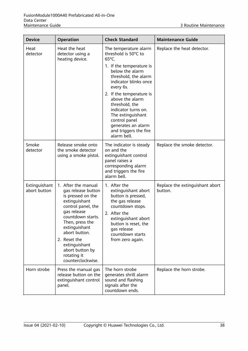
Device Operation Check Standard Maintenance Guide
Heatdetector
Heat the heatdetector using aheating device.
The temperature alarmthreshold is 50°C to65°C.1. If the temperature is
below the alarmthreshold, the alarmindicator blinks onceevery 6s.
2. If the temperature isabove the alarmthreshold, theindicator turns on.The extinguishantcontrol panelgenerates an alarmand triggers the firealarm bell.
Replace the heat detector.
Smokedetector
Release smoke ontothe smoke detectorusing a smoke pistol.
The indicator is steadyon and theextinguishant controlpanel raises acorresponding alarmand triggers the firealarm bell.
Replace the smoke detector.
Extinguishantabort button
1. After the manualgas release buttonis pressed on theextinguishantcontrol panel, thegas releasecountdown starts.Then, press theextinguishantabort button.
2. Reset theextinguishantabort button byrotating itcounterclockwise.
1. After theextinguishant abortbutton is pressed,the gas releasecountdown stops.
2. After theextinguishant abortbutton is reset, thegas releasecountdown startsfrom zero again.
Replace the extinguishant abortbutton.
Horn strobe Press the manual gasrelease button on theextinguishant controlpanel.
The horn strobegenerates shrill alarmsound and flashingsignals after thecountdown ends.
Replace the horn strobe.
FusionModule1000A40 Prefabricated All-in-OneData CenterMaintenance Guide 3 Routine Maintenance
Issue 04 (2021-02-10) Copyright © Huawei Technologies Co., Ltd. 38

Device Operation Check Standard Maintenance Guide
ASD Check the ASDsampling pipes.
The supports andconnectors of thesampling pipes aresecurely connected.
Replace damaged samplingpipes, and apply glue wherepipes are not well sealed.
Remove or block asampling pipe.
An alarm is generated. See documents delivered withthe ASD.
Release smoke to thefurthest end of aASD sampling pipe.
The ASD generates analarm in 120s.
See documents delivered withthe ASD.
The ASD panel displaysan alarm.
See documents delivered withthe ASD.
Check the ASDoperation panel.
All indicators arenormal.
See documents delivered withthe ASD.
Check whether thebackup power isworking properly,and whether the ASDrestarts normallyafter the mainspowered isdisconnected.
The backup power isworking properly, andthe ASD restartsnormally after themains power isdisconnected.
See documents delivered withthe ASD.
ASD powersupply
Check the powerindicator.
The power indicatorturns on.
1. Check the power cables.2. Replace the ASD power
supply.
3.6.6 Other Systems
Table 3-18 Semi-annual maintenance checklist for other systems
Item Method Check Standard Troubleshooting
Lights Check whether thelights can beswitched onnormally.
The lights turn onnormally.
1. If a light cannot be switched on,check whether the light is securelyinstalled and in good contact withthe light base.
2. If a light is securely installed and ingood contact with the light base butfails to turn on, replace the light.
Ventilation vent airfilter
Check whether thefilter is blocked.
The air filter is notblocked.
If an air filter is slightly blocked, cleanthe air filter and reinstall it. If morethan 50% of the meshes are blocked,replace the air filter.
FusionModule1000A40 Prefabricated All-in-OneData CenterMaintenance Guide 3 Routine Maintenance
Issue 04 (2021-02-10) Copyright © Huawei Technologies Co., Ltd. 39
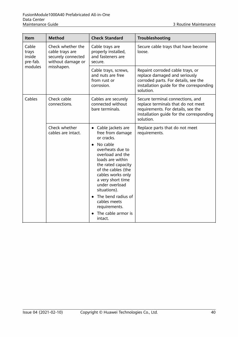
Item Method Check Standard Troubleshooting
Cabletraysinsidepre-fab.modules
Check whether thecable trays aresecurely connectedwithout damage ormisshapen.
Cable trays areproperly installed,and fasteners aresecure.
Secure cable trays that have becomeloose.
Cable trays, screws,and nuts are freefrom rust orcorrosion.
Repaint corroded cable trays, orreplace damaged and seriouslycorroded parts. For details, see theinstallation guide for the correspondingsolution.
Cables Check cableconnections.
Cables are securelyconnected withoutbare terminals.
Secure terminal connections, andreplace terminals that do not meetrequirements. For details, see theinstallation guide for the correspondingsolution.
Check whethercables are intact.
● Cable jackets arefree from damageor cracks.
● No cableoverheats due tooverload and theloads are withinthe rated capacityof the cables (thecables works onlya very short timeunder overloadsituations).
● The bend radius ofcables meetsrequirements.
● The cable armor isintact.
Replace parts that do not meetrequirements.
FusionModule1000A40 Prefabricated All-in-OneData CenterMaintenance Guide 3 Routine Maintenance
Issue 04 (2021-02-10) Copyright © Huawei Technologies Co., Ltd. 40

4 Common Faults and TroubleshootingMeasures
FusionModule1000A40 Prefabricated All-in-OneData CenterMaintenance Guide 4 Common Faults and Troubleshooting Measures
Issue 04 (2021-02-10) Copyright © Huawei Technologies Co., Ltd. 41

4.1 Troubleshooting the Extinguishant Control Panel
Table 4-1 Troubleshooting the extinguishant control panel
AlarmIndicatorName
AlarmType
AlarmSeverity
System Action PossibleCauses
Solution
Fire FIRERELAY
Major 1. S1 is triggeredto output 24 VDC voltagewhen only thesmoke detectoror heat detectorraises an alarm.NO and C onthe 1st portbecome closed,while NC and Cbecome open.NO and C onthe FIRE RELAYport becomeclosed, while NCand C becomeopen.
2. S3 is triggeredto output 24 VDC voltagewhen bothsmoke and heatdetectors raisealarms.Meanwhile, NOand C on the2nd Stage portbecome closed,while NC and Cbecome open.
The smoke orheat detectorraises analarm.
Locate and clear thealarm raised by thesmoke or heatdetector. Theindicator is steady onwhen there is analarm, and startsblinking (once every6 seconds) after thealarm is cleared.
Power On Warning
Minor N/A The powersupply isnormal.
N/A
Delay On Warning
Minor N/A Theextinguishantcontrol panel isin delay mode.
Handle relevantdevices to restore thepanel to normal.
FusionModule1000A40 Prefabricated All-in-OneData CenterMaintenance Guide 4 Common Faults and Troubleshooting Measures
Issue 04 (2021-02-10) Copyright © Huawei Technologies Co., Ltd. 42
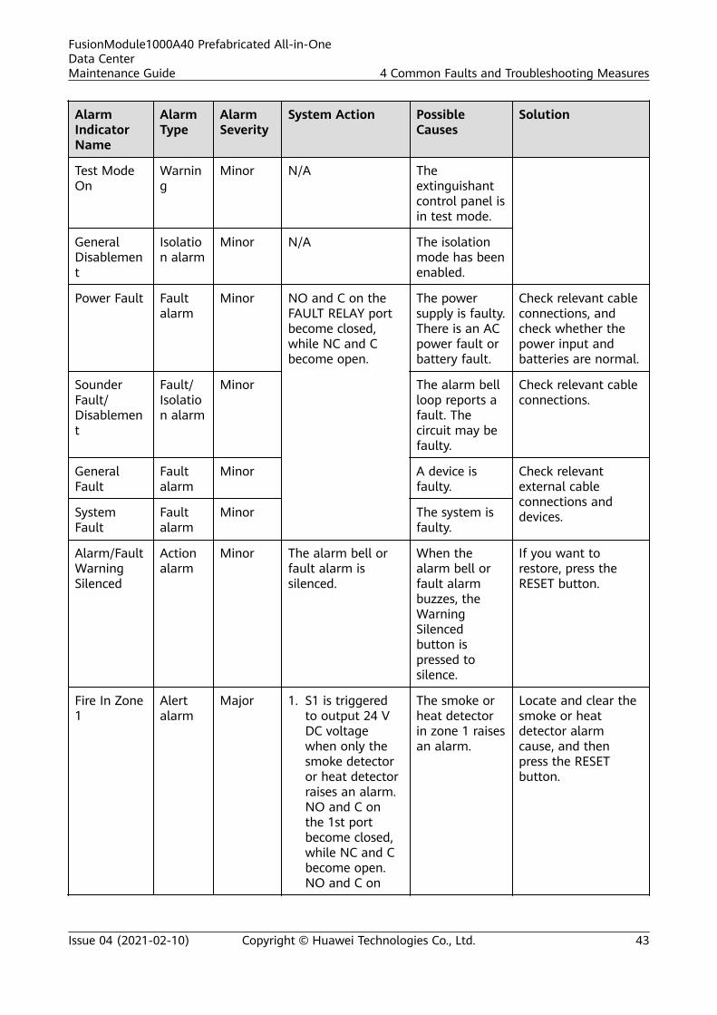
AlarmIndicatorName
AlarmType
AlarmSeverity
System Action PossibleCauses
Solution
Test ModeOn
Warning
Minor N/A Theextinguishantcontrol panel isin test mode.
GeneralDisablement
Isolation alarm
Minor N/A The isolationmode has beenenabled.
Power Fault Faultalarm
Minor NO and C on theFAULT RELAY portbecome closed,while NC and Cbecome open.
The powersupply is faulty.There is an ACpower fault orbattery fault.
Check relevant cableconnections, andcheck whether thepower input andbatteries are normal.
SounderFault/Disablement
Fault/Isolation alarm
Minor The alarm bellloop reports afault. Thecircuit may befaulty.
Check relevant cableconnections.
GeneralFault
Faultalarm
Minor A device isfaulty.
Check relevantexternal cableconnections anddevices.System
FaultFaultalarm
Minor The system isfaulty.
Alarm/FaultWarningSilenced
Actionalarm
Minor The alarm bell orfault alarm issilenced.
When thealarm bell orfault alarmbuzzes, theWarningSilencedbutton ispressed tosilence.
If you want torestore, press theRESET button.
Fire In Zone1
Alertalarm
Major 1. S1 is triggeredto output 24 VDC voltagewhen only thesmoke detectoror heat detectorraises an alarm.NO and C onthe 1st portbecome closed,while NC and Cbecome open.NO and C on
The smoke orheat detectorin zone 1 raisesan alarm.
Locate and clear thesmoke or heatdetector alarmcause, and thenpress the RESETbutton.
FusionModule1000A40 Prefabricated All-in-OneData CenterMaintenance Guide 4 Common Faults and Troubleshooting Measures
Issue 04 (2021-02-10) Copyright © Huawei Technologies Co., Ltd. 43
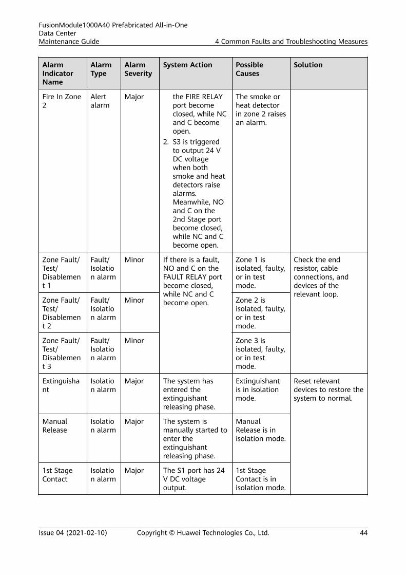
AlarmIndicatorName
AlarmType
AlarmSeverity
System Action PossibleCauses
Solution
Fire In Zone2
Alertalarm
Major the FIRE RELAYport becomeclosed, while NCand C becomeopen.
2. S3 is triggeredto output 24 VDC voltagewhen bothsmoke and heatdetectors raisealarms.Meanwhile, NOand C on the2nd Stage portbecome closed,while NC and Cbecome open.
The smoke orheat detectorin zone 2 raisesan alarm.
Zone Fault/Test/Disablement 1
Fault/Isolation alarm
Minor If there is a fault,NO and C on theFAULT RELAY portbecome closed,while NC and Cbecome open.
Zone 1 isisolated, faulty,or in testmode.
Check the endresistor, cableconnections, anddevices of therelevant loop.
Zone Fault/Test/Disablement 2
Fault/Isolation alarm
Minor Zone 2 isisolated, faulty,or in testmode.
Zone Fault/Test/Disablement 3
Fault/Isolation alarm
Minor Zone 3 isisolated, faulty,or in testmode.
Extinguishant
Isolation alarm
Major The system hasentered theextinguishantreleasing phase.
Extinguishantis in isolationmode.
Reset relevantdevices to restore thesystem to normal.
ManualRelease
Isolation alarm
Major The system ismanually started toenter theextinguishantreleasing phase.
ManualRelease is inisolation mode.
1st StageContact
Isolation alarm
Major The S1 port has 24V DC voltageoutput.
1st StageContact is inisolation mode.
FusionModule1000A40 Prefabricated All-in-OneData CenterMaintenance Guide 4 Common Faults and Troubleshooting Measures
Issue 04 (2021-02-10) Copyright © Huawei Technologies Co., Ltd. 44
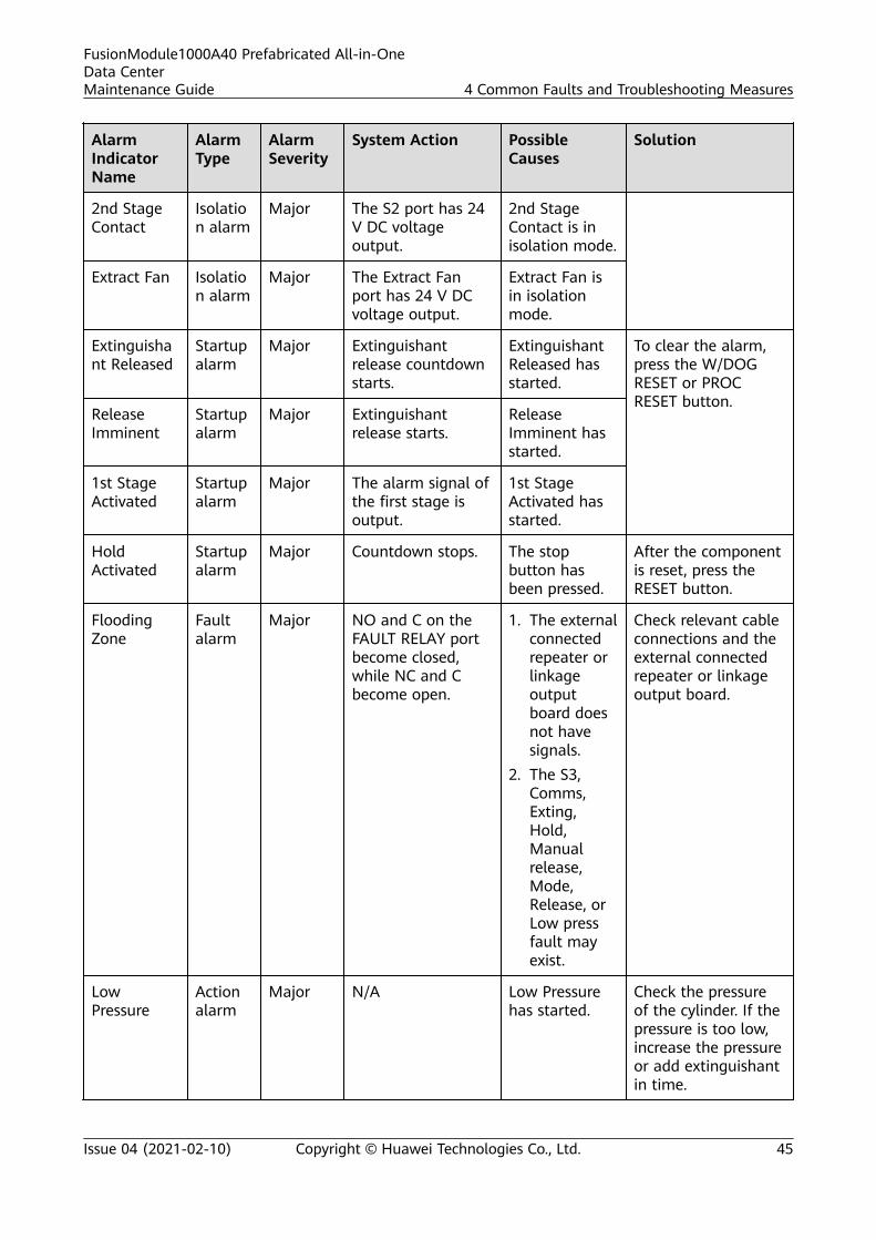
AlarmIndicatorName
AlarmType
AlarmSeverity
System Action PossibleCauses
Solution
2nd StageContact
Isolation alarm
Major The S2 port has 24V DC voltageoutput.
2nd StageContact is inisolation mode.
Extract Fan Isolation alarm
Major The Extract Fanport has 24 V DCvoltage output.
Extract Fan isin isolationmode.
Extinguishant Released
Startupalarm
Major Extinguishantrelease countdownstarts.
ExtinguishantReleased hasstarted.
To clear the alarm,press the W/DOGRESET or PROCRESET button.
ReleaseImminent
Startupalarm
Major Extinguishantrelease starts.
ReleaseImminent hasstarted.
1st StageActivated
Startupalarm
Major The alarm signal ofthe first stage isoutput.
1st StageActivated hasstarted.
HoldActivated
Startupalarm
Major Countdown stops. The stopbutton hasbeen pressed.
After the componentis reset, press theRESET button.
FloodingZone
Faultalarm
Major NO and C on theFAULT RELAY portbecome closed,while NC and Cbecome open.
1. The externalconnectedrepeater orlinkageoutputboard doesnot havesignals.
2. The S3,Comms,Exting,Hold,Manualrelease,Mode,Release, orLow pressfault mayexist.
Check relevant cableconnections and theexternal connectedrepeater or linkageoutput board.
LowPressure
Actionalarm
Major N/A Low Pressurehas started.
Check the pressureof the cylinder. If thepressure is too low,increase the pressureor add extinguishantin time.
FusionModule1000A40 Prefabricated All-in-OneData CenterMaintenance Guide 4 Common Faults and Troubleshooting Measures
Issue 04 (2021-02-10) Copyright © Huawei Technologies Co., Ltd. 45

AlarmIndicatorName
AlarmType
AlarmSeverity
System Action PossibleCauses
Solution
Auto&Manual
Actionalarm
Major The system is inautomatic state,and will releaseextinguishantautomatically whenthe second stagealarm conditionsare met.
Auto & Manualhas started.
N/A
ManualOnly
Actionalarm
Major The system is inmanual state andwill notautomaticallyreleaseextinguishant.
Manual Onlyhas started.
N/A
Mains fail Faultalarm
Major NO and C on theFAULT RELAY portbecome closed,while NC and Cbecome open.
The 220 V ACmains is faulty.
Check relevant cableconnections, andcheck whether themains is normal.
Batt fail Faultalarm
Major The backupbatteries arefaulty.
Check relevant cableconnections andbatteries.
CPU fault Faultalarm
Major The CPU isfaulty.
Replace themainboard.
Aux 24Vfault
Faultalarm
Major Aux 24V isfaulty.
Check relevant cableconnections anddevices.
Batt low Faultalarm
Major The batteryvoltage may belower than20.5 V.
Connect theextinguishant controlpanel to the mainsto charge thebatteries. If thebatteries cannotrecover, replacethem.
FusionModule1000A40 Prefabricated All-in-OneData CenterMaintenance Guide 4 Common Faults and Troubleshooting Measures
Issue 04 (2021-02-10) Copyright © Huawei Technologies Co., Ltd. 46
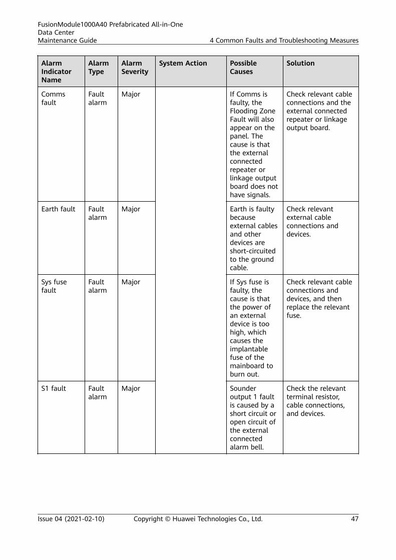
AlarmIndicatorName
AlarmType
AlarmSeverity
System Action PossibleCauses
Solution
Commsfault
Faultalarm
Major If Comms isfaulty, theFlooding ZoneFault will alsoappear on thepanel. Thecause is thatthe externalconnectedrepeater orlinkage outputboard does nothave signals.
Check relevant cableconnections and theexternal connectedrepeater or linkageoutput board.
Earth fault Faultalarm
Major Earth is faultybecauseexternal cablesand otherdevices areshort-circuitedto the groundcable.
Check relevantexternal cableconnections anddevices.
Sys fusefault
Faultalarm
Major If Sys fuse isfaulty, thecause is thatthe power ofan externaldevice is toohigh, whichcauses theimplantablefuse of themainboard toburn out.
Check relevant cableconnections anddevices, and thenreplace the relevantfuse.
S1 fault Faultalarm
Major Sounderoutput 1 faultis caused by ashort circuit oropen circuit ofthe externalconnectedalarm bell.
Check the relevantterminal resistor,cable connections,and devices.
FusionModule1000A40 Prefabricated All-in-OneData CenterMaintenance Guide 4 Common Faults and Troubleshooting Measures
Issue 04 (2021-02-10) Copyright © Huawei Technologies Co., Ltd. 47
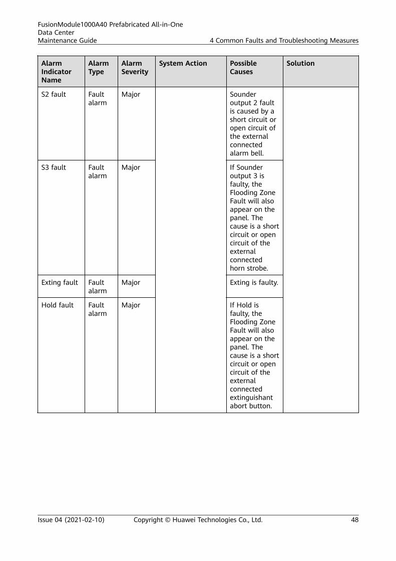
AlarmIndicatorName
AlarmType
AlarmSeverity
System Action PossibleCauses
Solution
S2 fault Faultalarm
Major Sounderoutput 2 faultis caused by ashort circuit oropen circuit ofthe externalconnectedalarm bell.
S3 fault Faultalarm
Major If Sounderoutput 3 isfaulty, theFlooding ZoneFault will alsoappear on thepanel. Thecause is a shortcircuit or opencircuit of theexternalconnectedhorn strobe.
Exting fault Faultalarm
Major Exting is faulty.
Hold fault Faultalarm
Major If Hold isfaulty, theFlooding ZoneFault will alsoappear on thepanel. Thecause is a shortcircuit or opencircuit of theexternalconnectedextinguishantabort button.
FusionModule1000A40 Prefabricated All-in-OneData CenterMaintenance Guide 4 Common Faults and Troubleshooting Measures
Issue 04 (2021-02-10) Copyright © Huawei Technologies Co., Ltd. 48
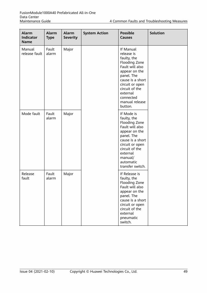
AlarmIndicatorName
AlarmType
AlarmSeverity
System Action PossibleCauses
Solution
Manualrelease fault
Faultalarm
Major If Manualrelease isfaulty, theFlooding ZoneFault will alsoappear on thepanel. Thecause is a shortcircuit or opencircuit of theexternalconnectedmanual releasebutton.
Mode fault Faultalarm
Major If Mode isfaulty, theFlooding ZoneFault will alsoappear on thepanel. Thecause is a shortcircuit or opencircuit of theexternalmanual/automatictransfer switch.
Releasefault
Faultalarm
Major If Release isfaulty, theFlooding ZoneFault will alsoappear on thepanel. Thecause is a shortcircuit or opencircuit of theexternalpneumaticswitch.
FusionModule1000A40 Prefabricated All-in-OneData CenterMaintenance Guide 4 Common Faults and Troubleshooting Measures
Issue 04 (2021-02-10) Copyright © Huawei Technologies Co., Ltd. 49

AlarmIndicatorName
AlarmType
AlarmSeverity
System Action PossibleCauses
Solution
Low presfault
Faultalarm
Major If Low pres isfaulty, theFlooding ZoneFault will alsoappear on thepanel. Thecause is a shortcircuit or opencircuit of theexternalpneumaticswitch.
Tell tale Actionalarm
Major Extinguishantrelease countdownstarts.
The Tell talemode has beenenabledbecause themanual releasebutton on thecontrol panelhas beenpressed.
To clear the alarm,press the W/DOGRESET or PROCRESET button.
4.2 Troubleshooting the ASD
Table 4-2 Troubleshooting the ASD power supply
Check Item Check Content ExpectedResult
Troubleshooting
Check whether thesampling pipe is cracked.
Sampling pipe The pipe is notcracked.
Replace the pipe.
Check whether thesampling pipe is blocked.
Sampling holes in themiddle and at theend of the pipe
The pipe is notblocked.
Clean the sampling pipe.
Check whether dustaccumulates in the filterbox.
Filter box There is no dustaccumulation.
Clean or replace the filter.
FusionModule1000A40 Prefabricated All-in-OneData CenterMaintenance Guide 4 Common Faults and Troubleshooting Measures
Issue 04 (2021-02-10) Copyright © Huawei Technologies Co., Ltd. 50

Check Item Check Content ExpectedResult
Troubleshooting
Check whether the HolesDIP switch setting iscorrect.
Figure 4-1 Holes DIPswitch setting
Holes DIP switchsetting and the actualnumber of samplingholes
The DIP switchsetting is thesame as theactual numberof samplingholes.
Set the DIP switch on thecontrol board to a correctvalue and reset the board.
Check whether the ClassDIP switch setting iscorrect.
Figure 4-2 Class DIPswitch setting
Class DIP switchsetting
The DIP switchsetting is 2, thatis, the sensitivityclass is 2.
Set the DIP switch on thecontrol board to a correctvalue and reset the board.
Check whether the ModeDIP switch setting iscorrect.
Figure 4-3 Mode DIPswitch setting
Mode DIP switchsetting
The DIP switchsetting is 1,indicating thatthe device isrunningproperly.
Set the DIP switch on thecontrol board to a correctvalue and reset the board.
FusionModule1000A40 Prefabricated All-in-OneData CenterMaintenance Guide 4 Common Faults and Troubleshooting Measures
Issue 04 (2021-02-10) Copyright © Huawei Technologies Co., Ltd. 51
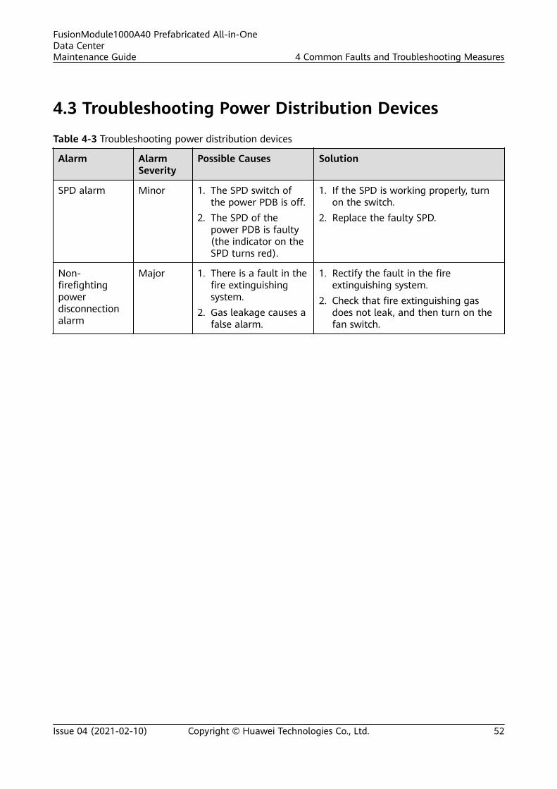
4.3 Troubleshooting Power Distribution Devices
Table 4-3 Troubleshooting power distribution devices
Alarm AlarmSeverity
Possible Causes Solution
SPD alarm Minor 1. The SPD switch ofthe power PDB is off.
2. The SPD of thepower PDB is faulty(the indicator on theSPD turns red).
1. If the SPD is working properly, turnon the switch.
2. Replace the faulty SPD.
Non-firefightingpowerdisconnectionalarm
Major 1. There is a fault in thefire extinguishingsystem.
2. Gas leakage causes afalse alarm.
1. Rectify the fault in the fireextinguishing system.
2. Check that fire extinguishing gasdoes not leak, and then turn on thefan switch.
FusionModule1000A40 Prefabricated All-in-OneData CenterMaintenance Guide 4 Common Faults and Troubleshooting Measures
Issue 04 (2021-02-10) Copyright © Huawei Technologies Co., Ltd. 52
5 Parts Replacement
5.1 Replacing Components for the Power Supply andDistribution System
5.1.1 Replacing Components for the Power Supply AndDistribution System
NO TICE
● For details about how to replace components for the power supply anddistribution system, see the user manuals for the components.
● During smart cooling product parts replacement, the system may need to bepowered off. Take measures to prevent device overheating.
For details about replacing parts for the integrated UPS, see the section "PartsReplacement" in the UPS user manual.
Table 5-1 Components that can be replaced for the power supply and distribution system
Device Component Name
Integrated UPS 3.0 Fuse
Indicator
Integrated UPS 208 V Fuse
Indicator
FusionModule1000A40 Prefabricated All-in-OneData CenterMaintenance Guide 5 Parts Replacement
Issue 04 (2021-02-10) Copyright © Huawei Technologies Co., Ltd. 53
5.1.2 Replacing a Cabinet rPDU
Prerequisites
A spare rPDU of the same model is available and functional.
NO TE
● Locate the faulty rPDU based on the alarm information on the monitoring softwareterminal.
● Check that the standby power supply to the rPDU is available.
Impact on the System
None
Preparations
Tools: Phillips screwdriver, protective gloves, step ladder
Material: spare rPDU
Skill requirement: electrician's work permit
Procedure
Step 1 Switch off the circuit breaker of the faulty rPDU in the integrated UPS.
Step 2 Remove all power connectors from the rPDU.
Step 3 Remove the baffle plate from the top of the cabinet using a Phillips screwdriver.
Step 4 Remove the rPDU power cable on the top of the cabinet.
Step 5 Loosen the screws securing the rPDU support at the top and bottom of the rPDUusing a Phillips screwdriver until the rPDU can be removed.
Step 6 Lift the faulty rPDU and take it out.
Step 7 Remove the support and screws from the faulty rPDU and install them on a newrPDU.
Step 8 Mount the new rPDU with a support into the cabinet, and tighten the fasteningscrews of the rPDU using a Phillips screwdriver.
Step 9 Connect the rPDU power cable on the top of the cabinet.
Step 10 Switch on the circuit breaker for the rPDU in the integrated UPS and check thatthe new rPDU is working properly.
Step 11 Insert device power plugs in the rPDU.
Step 12 Reinstall the cabinet top baffle plate.
----End
FusionModule1000A40 Prefabricated All-in-OneData CenterMaintenance Guide 5 Parts Replacement
Issue 04 (2021-02-10) Copyright © Huawei Technologies Co., Ltd. 54
5.1.3 Replacing a Battery for the Integrated UPS
Prerequisites
A spare integrated UPS battery of the same model is available and functional.
Impact on the System
None
Preparations
Tools: pallet truck, wrench, protective gloves
Materials: insulation tape, integrated UPS battery, copper bar or cable
Documents: documents delivered with integrated UPS battery, power supply anddistribution system diagram, power supply and distribution device layout diagram,
Skill requirement: electrician's work permit
Procedure
Step 1 Move the new battery to the place where a faulty battery needs to be replaced.
Step 2 Switch off the circuit breaker of the battery in the switch box based on the powersupply and distribution system diagram.
Step 3 Remove cables from the faulty battery using a wrench, and insulate the cables.
Step 4 Move the faulty battery out of the battery rack.
NO TICE
Ensure human safety during the movement.
Step 5 Install the new battery and connect cables correctly based on battery wiringdiagram.
Step 6 Verify the battery connections. Ensure that the battery quantity and cableconnections comply with the design and the cables or copper bars are reliablyinstalled.
Step 7 Switch on the circuit breaker of the battery in the switch box based on the powersupply and distribution system diagram.
----End
5.1.4 Replacing a Battery Pack
Prerequisites● The AC input power supply is normal.
FusionModule1000A40 Prefabricated All-in-OneData CenterMaintenance Guide 5 Parts Replacement
Issue 04 (2021-02-10) Copyright © Huawei Technologies Co., Ltd. 55
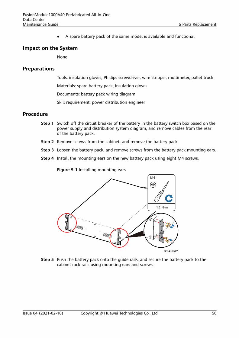
● A spare battery pack of the same model is available and functional.
Impact on the SystemNone
PreparationsTools: insulation gloves, Phillips screwdriver, wire stripper, multimeter, pallet truck
Materials: spare battery pack, insulation gloves
Documents: battery pack wiring diagram
Skill requirement: power distribution engineer
Procedure
Step 1 Switch off the circuit breaker of the battery in the battery switch box based on thepower supply and distribution system diagram, and remove cables from the rearof the battery pack.
Step 2 Remove screws from the cabinet, and remove the battery pack.
Step 3 Loosen the battery pack, and remove screws from the battery pack mounting ears.
Step 4 Install the mounting ears on the new battery pack using eight M4 screws.
Figure 5-1 Installing mounting ears
Step 5 Push the battery pack onto the guide rails, and secure the battery pack to thecabinet rack rails using mounting ears and screws.
FusionModule1000A40 Prefabricated All-in-OneData CenterMaintenance Guide 5 Parts Replacement
Issue 04 (2021-02-10) Copyright © Huawei Technologies Co., Ltd. 56
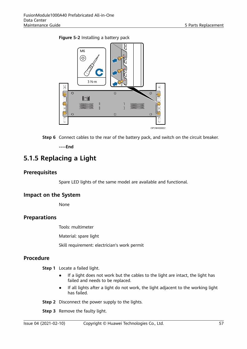
Figure 5-2 Installing a battery pack
Step 6 Connect cables to the rear of the battery pack, and switch on the circuit breaker.
----End
5.1.5 Replacing a Light
Prerequisites
Spare LED lights of the same model are available and functional.
Impact on the System
None
Preparations
Tools: multimeter
Material: spare light
Skill requirement: electrician's work permit
Procedure
Step 1 Locate a failed light.● If a light does not work but the cables to the light are intact, the light has
failed and needs to be replaced.● If all lights after a light do not work, the light adjacent to the working light
has failed.
Step 2 Disconnect the power supply to the lights.
Step 3 Remove the faulty light.
FusionModule1000A40 Prefabricated All-in-OneData CenterMaintenance Guide 5 Parts Replacement
Issue 04 (2021-02-10) Copyright © Huawei Technologies Co., Ltd. 57
D ANGER
During replacement, do not touch any end of the light with bare hands. You willget an electric shock if you touch bare electrodes.
Step 4 Install the new light in the original position.
----End
5.1.6 Replacing the Power PDB
PrerequisitesA spare power PDB of the same model is available and functional.
Impact on the SystemNone
PreparationsTools: Phillips screwdriver, socket wrench
Material: spare power PDB
Document: power supply and distribution system diagram
Skill requirement: electrician's work permit
Procedure
Step 1 Power off the power PDB based on the power supply and distribution systemdiagram.
Step 2 Remove cables using a socket wrench and Phillips screwdriver.
Step 3 Remove screws securing the power PDB and remove the power PDB.
Step 4 Secure the new power PDB and connect cables correctly.
----End
5.1.7 Replacing a Battery Bus Box
PrerequisitesA spare BBB of the same model is available and functional.
Impact on the SystemNone
PreparationsTools: Phillips screwdriver, socket wrench
FusionModule1000A40 Prefabricated All-in-OneData CenterMaintenance Guide 5 Parts Replacement
Issue 04 (2021-02-10) Copyright © Huawei Technologies Co., Ltd. 58
Materials: spare BBB
Document: power supply and distribution system diagram
Skill requirement: electrician's work permit
Procedure
Step 1 Power off the BBB based on the power supply and distribution system diagram.
Step 2 Remove cables using a socket wrench and Phillips screwdriver.
Step 3 Remove screws securing the BBB, and remove the BBB.
Step 4 Secure the new BBB and connect cables correctly.
----End
5.2 Replacing Cooling System Components
5.2.1 Replacing Components for the Cooling System
NO TICE
● For details about how to replace components for the cooling system, see theuser manuals for the components.
● During smart cooling product parts replacement, the system may need to bepowered off. Take measures to prevent device overheating.
For details about parts replacement for smart cooling products, see the section"Parts Replacement" in the smart cooling product user manual.
Table 5-2 Replacing cooling system components
Device Component Name
NetCol5000-A025 In-row Air Cooled SmartCooling Product
Air filter
Indoor fan
Differential pressure switch
Compressor
Dryer filter
(Optional) Wet film humidifier
(Optional) Humidifier cylinder
Electric control box
Temperature and humidity (T/H) sensor
FusionModule1000A40 Prefabricated All-in-OneData CenterMaintenance Guide 5 Parts Replacement
Issue 04 (2021-02-10) Copyright © Huawei Technologies Co., Ltd. 59
Device Component Name
Module
(Optional) Liquid level detector
(Optional) Water pump
Display screen
5.2.2 Replacing an In-row Air Cooled Smart Cooling Product
PrerequisitesA spare in-row air cooled smart cooling product of the same model is availableand functional.
NO TICE
Before replacing the smart cooling product, take measures to protect the floors inthe cold aisle and long aisle in the pre-fab. module.
Context
NO TICE
Do not replace a smart cooling product on damp or rainy days. Keep the indoorenvironment clean during the replacement.
The indoor unit of the in-row air cooled smart cooling product can be replacedonly in the cold aisle of the pre-fab. module.
● To replace smart cooling product A1 or B1, you need to push cabinets A1, A2,B1, and B2 on both sides of cold aisle A to the extremities towards the hotaisle, and replace the smart cooling product in cold aisle A.
● Smart cooling product C1 or D1 can be replaced in cold aisle B.
FusionModule1000A40 Prefabricated All-in-OneData CenterMaintenance Guide 5 Parts Replacement
Issue 04 (2021-02-10) Copyright © Huawei Technologies Co., Ltd. 60
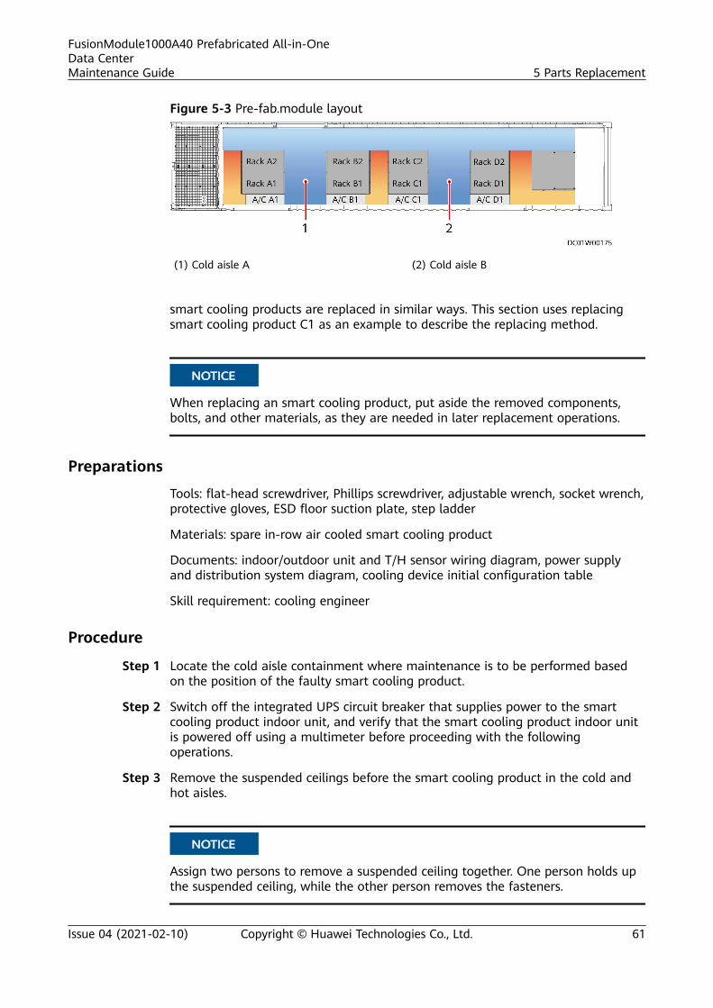
Figure 5-3 Pre-fab.module layout
(1) Cold aisle A (2) Cold aisle B
smart cooling products are replaced in similar ways. This section uses replacingsmart cooling product C1 as an example to describe the replacing method.
NO TICE
When replacing an smart cooling product, put aside the removed components,bolts, and other materials, as they are needed in later replacement operations.
Preparations
Tools: flat-head screwdriver, Phillips screwdriver, adjustable wrench, socket wrench,protective gloves, ESD floor suction plate, step ladder
Materials: spare in-row air cooled smart cooling product
Documents: indoor/outdoor unit and T/H sensor wiring diagram, power supplyand distribution system diagram, cooling device initial configuration table
Skill requirement: cooling engineer
Procedure
Step 1 Locate the cold aisle containment where maintenance is to be performed basedon the position of the faulty smart cooling product.
Step 2 Switch off the integrated UPS circuit breaker that supplies power to the smartcooling product indoor unit, and verify that the smart cooling product indoor unitis powered off using a multimeter before proceeding with the followingoperations.
Step 3 Remove the suspended ceilings before the smart cooling product in the cold andhot aisles.
NO TICE
Assign two persons to remove a suspended ceiling together. One person holds upthe suspended ceiling, while the other person removes the fasteners.
FusionModule1000A40 Prefabricated All-in-OneData CenterMaintenance Guide 5 Parts Replacement
Issue 04 (2021-02-10) Copyright © Huawei Technologies Co., Ltd. 61
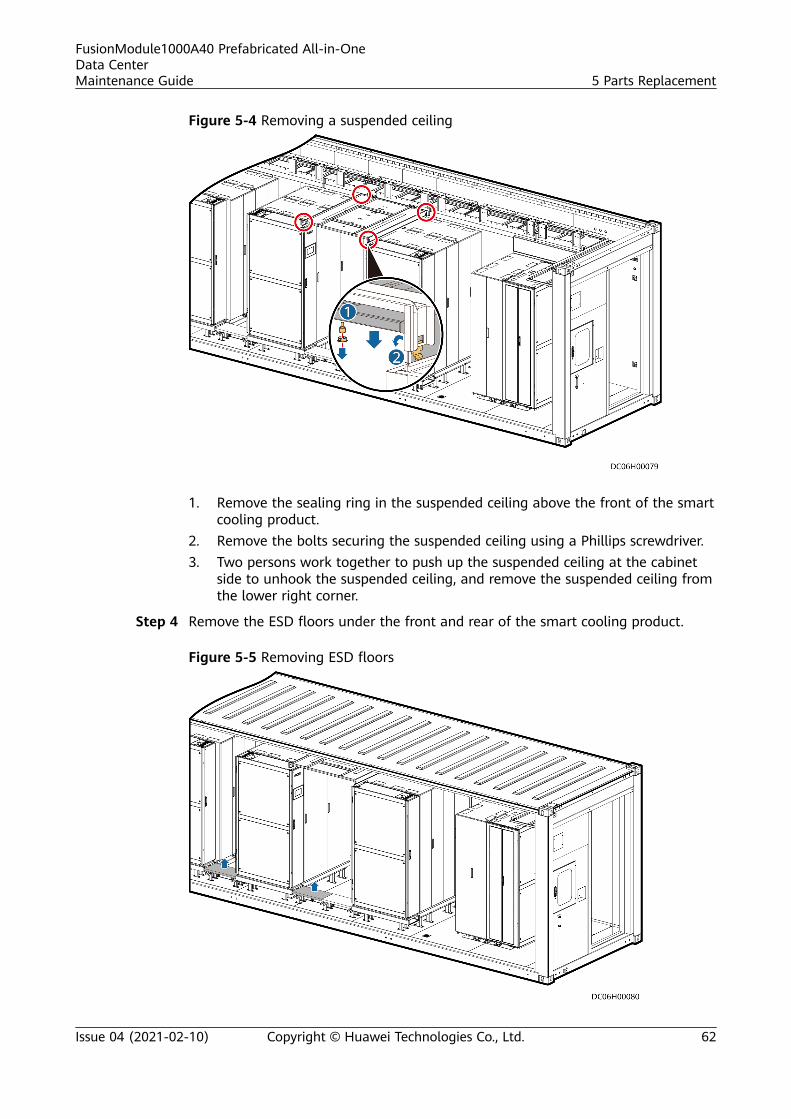
Figure 5-4 Removing a suspended ceiling
1. Remove the sealing ring in the suspended ceiling above the front of the smartcooling product.
2. Remove the bolts securing the suspended ceiling using a Phillips screwdriver.3. Two persons work together to push up the suspended ceiling at the cabinet
side to unhook the suspended ceiling, and remove the suspended ceiling fromthe lower right corner.
Step 4 Remove the ESD floors under the front and rear of the smart cooling product.
Figure 5-5 Removing ESD floors
FusionModule1000A40 Prefabricated All-in-OneData CenterMaintenance Guide 5 Parts Replacement
Issue 04 (2021-02-10) Copyright © Huawei Technologies Co., Ltd. 62
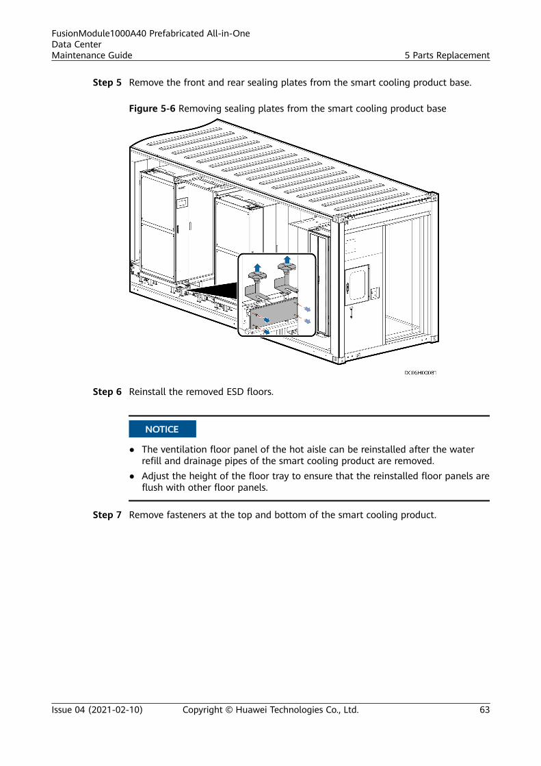
Step 5 Remove the front and rear sealing plates from the smart cooling product base.
Figure 5-6 Removing sealing plates from the smart cooling product base
Step 6 Reinstall the removed ESD floors.
NO TICE
● The ventilation floor panel of the hot aisle can be reinstalled after the waterrefill and drainage pipes of the smart cooling product are removed.
● Adjust the height of the floor tray to ensure that the reinstalled floor panels areflush with other floor panels.
Step 7 Remove fasteners at the top and bottom of the smart cooling product.
FusionModule1000A40 Prefabricated All-in-OneData CenterMaintenance Guide 5 Parts Replacement
Issue 04 (2021-02-10) Copyright © Huawei Technologies Co., Ltd. 63
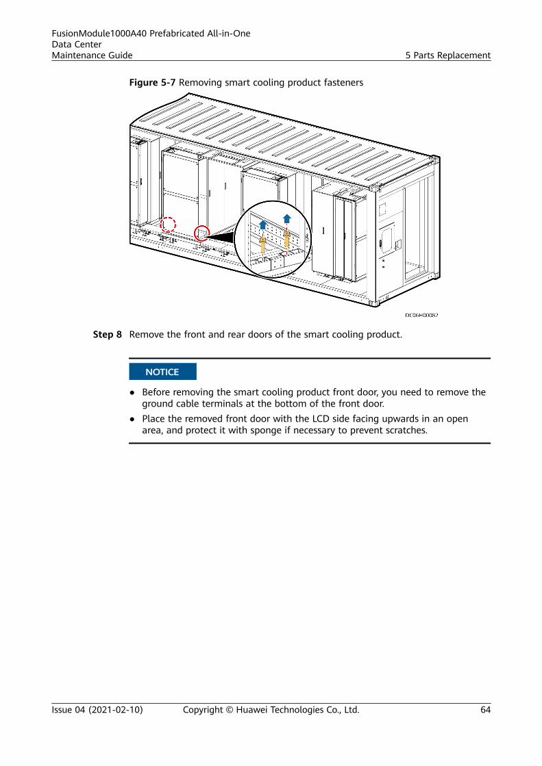
Figure 5-7 Removing smart cooling product fasteners
Step 8 Remove the front and rear doors of the smart cooling product.
NO TICE
● Before removing the smart cooling product front door, you need to remove theground cable terminals at the bottom of the front door.
● Place the removed front door with the LCD side facing upwards in an openarea, and protect it with sponge if necessary to prevent scratches.
FusionModule1000A40 Prefabricated All-in-OneData CenterMaintenance Guide 5 Parts Replacement
Issue 04 (2021-02-10) Copyright © Huawei Technologies Co., Ltd. 64

Figure 5-8 Removing the front and rear doors of the smart cooling product
1. Open the locks on the front and rear doors of the smart cooling product usingkeys, and open the smart cooling product rear door.
2. Remove cables from the LCD on the front door, and cut off cable ties usingdiagonal pliers.
NO TICE
Verify that the thermal insulation foam is not damaged during the operation.
3. Remove the front door, rear door, and hinge bases from smart cooling productC1.
4. Unfasten the eight rotating baffle plates in the upper, middle, and lowerpositions of the air filters, and remove the upper and lower air filters.
FusionModule1000A40 Prefabricated All-in-OneData CenterMaintenance Guide 5 Parts Replacement
Issue 04 (2021-02-10) Copyright © Huawei Technologies Co., Ltd. 65

Figure 5-9 Removing air filters
5. Remove the front door and hinge bases from smart cooling product C1.
Step 9 Remove the smart cooling product cables.
NO TICE
1. Before replacing cables, record the cable routes to ensure that the cable routesare the same before and after the replacement.
2. Pull removed cables completely out of the smart cooling product indoor unit tofacilitate smart cooling product replacement.
1. Use a Phillips screwdriver to remove the active and standby input powercables for the smart cooling product indoor unit from ports AC1 and AC2 onthe smart cooling product PDB, and remove the corresponding cables fromthe integrated UPS circuit breaker.
FusionModule1000A40 Prefabricated All-in-OneData CenterMaintenance Guide 5 Parts Replacement
Issue 04 (2021-02-10) Copyright © Huawei Technologies Co., Ltd. 66
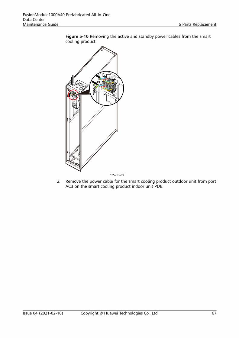
Figure 5-10 Removing the active and standby power cables from the smartcooling product
2. Remove the power cable for the smart cooling product outdoor unit from portAC3 on the smart cooling product indoor unit PDB.
FusionModule1000A40 Prefabricated All-in-OneData CenterMaintenance Guide 5 Parts Replacement
Issue 04 (2021-02-10) Copyright © Huawei Technologies Co., Ltd. 67
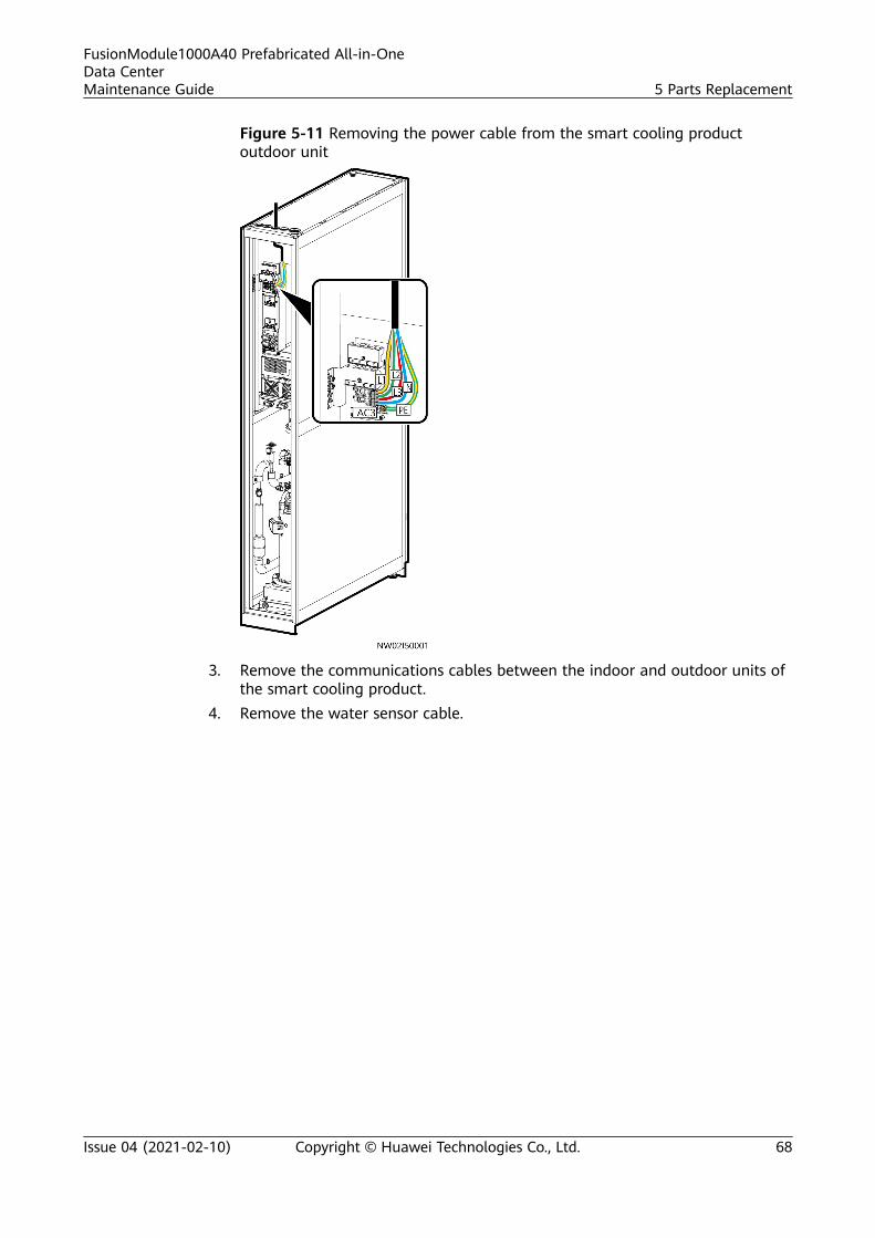
Figure 5-11 Removing the power cable from the smart cooling productoutdoor unit
3. Remove the communications cables between the indoor and outdoor units ofthe smart cooling product.
4. Remove the water sensor cable.
FusionModule1000A40 Prefabricated All-in-OneData CenterMaintenance Guide 5 Parts Replacement
Issue 04 (2021-02-10) Copyright © Huawei Technologies Co., Ltd. 68
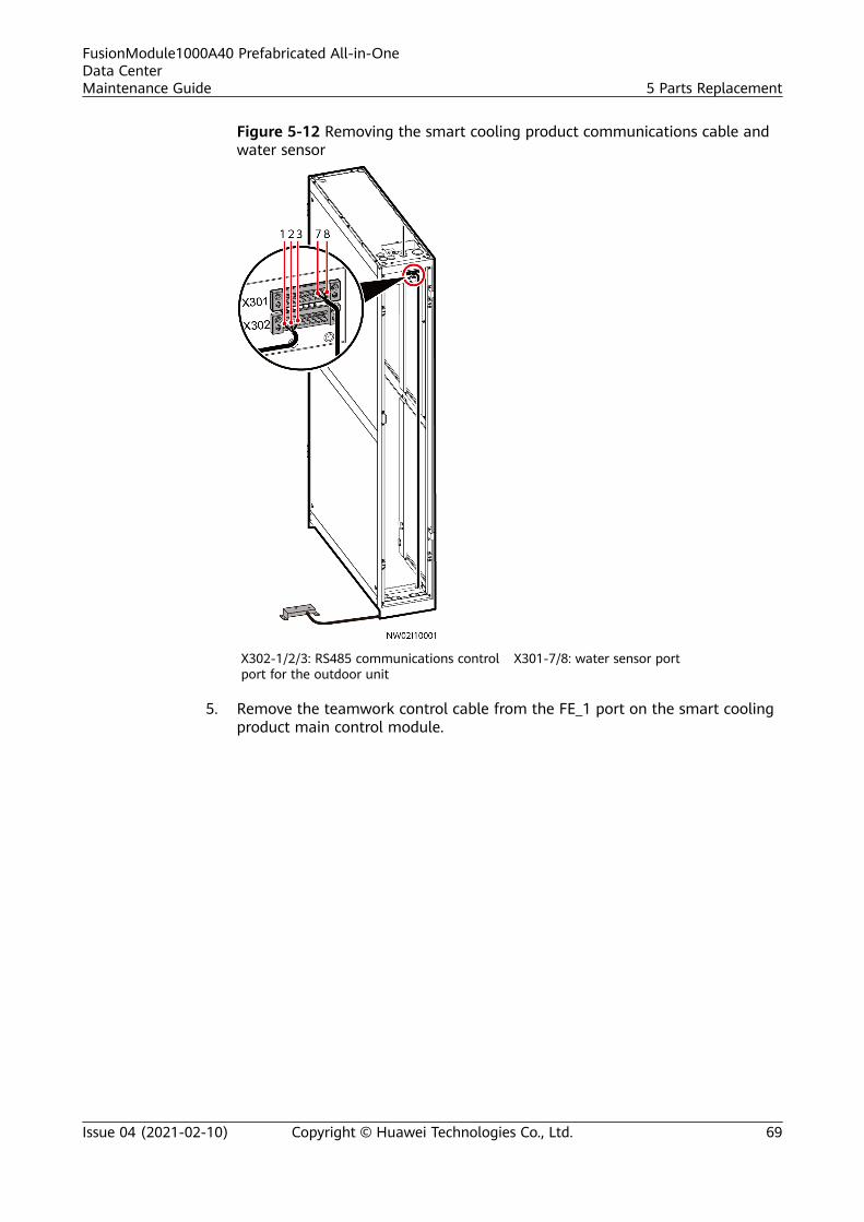
Figure 5-12 Removing the smart cooling product communications cable andwater sensor
X302-1/2/3: RS485 communications controlport for the outdoor unit
X301-7/8: water sensor port
5. Remove the teamwork control cable from the FE_1 port on the smart coolingproduct main control module.
FusionModule1000A40 Prefabricated All-in-OneData CenterMaintenance Guide 5 Parts Replacement
Issue 04 (2021-02-10) Copyright © Huawei Technologies Co., Ltd. 69
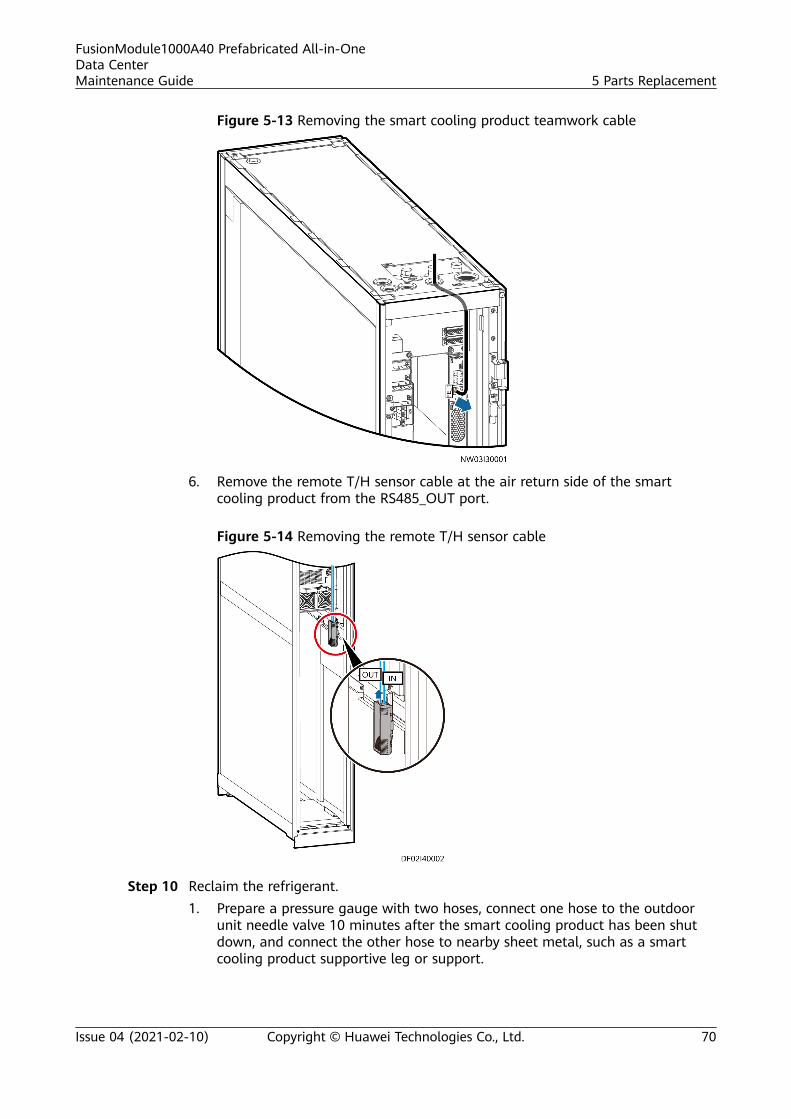
Figure 5-13 Removing the smart cooling product teamwork cable
6. Remove the remote T/H sensor cable at the air return side of the smartcooling product from the RS485_OUT port.
Figure 5-14 Removing the remote T/H sensor cable
Step 10 Reclaim the refrigerant.1. Prepare a pressure gauge with two hoses, connect one hose to the outdoor
unit needle valve 10 minutes after the smart cooling product has been shutdown, and connect the other hose to nearby sheet metal, such as a smartcooling product supportive leg or support.
FusionModule1000A40 Prefabricated All-in-OneData CenterMaintenance Guide 5 Parts Replacement
Issue 04 (2021-02-10) Copyright © Huawei Technologies Co., Ltd. 70
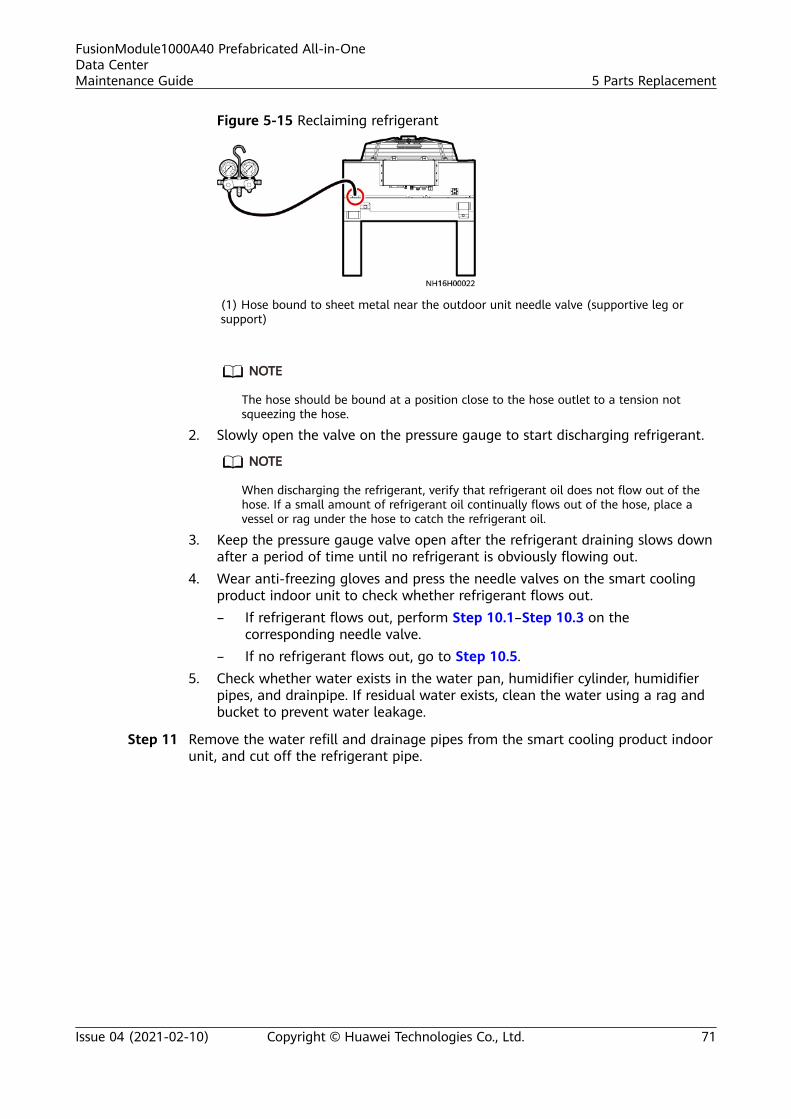
Figure 5-15 Reclaiming refrigerant
(1) Hose bound to sheet metal near the outdoor unit needle valve (supportive leg orsupport)
NO TE
The hose should be bound at a position close to the hose outlet to a tension notsqueezing the hose.
2. Slowly open the valve on the pressure gauge to start discharging refrigerant.
NO TE
When discharging the refrigerant, verify that refrigerant oil does not flow out of thehose. If a small amount of refrigerant oil continually flows out of the hose, place avessel or rag under the hose to catch the refrigerant oil.
3. Keep the pressure gauge valve open after the refrigerant draining slows downafter a period of time until no refrigerant is obviously flowing out.
4. Wear anti-freezing gloves and press the needle valves on the smart coolingproduct indoor unit to check whether refrigerant flows out.– If refrigerant flows out, perform Step 10.1–Step 10.3 on the
corresponding needle valve.– If no refrigerant flows out, go to Step 10.5.
5. Check whether water exists in the water pan, humidifier cylinder, humidifierpipes, and drainpipe. If residual water exists, clean the water using a rag andbucket to prevent water leakage.
Step 11 Remove the water refill and drainage pipes from the smart cooling product indoorunit, and cut off the refrigerant pipe.
FusionModule1000A40 Prefabricated All-in-OneData CenterMaintenance Guide 5 Parts Replacement
Issue 04 (2021-02-10) Copyright © Huawei Technologies Co., Ltd. 71
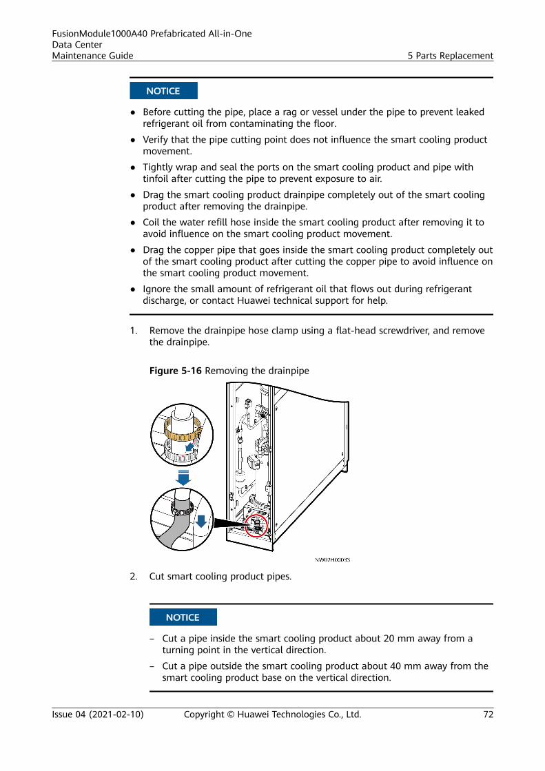
NO TICE
● Before cutting the pipe, place a rag or vessel under the pipe to prevent leakedrefrigerant oil from contaminating the floor.
● Verify that the pipe cutting point does not influence the smart cooling productmovement.
● Tightly wrap and seal the ports on the smart cooling product and pipe withtinfoil after cutting the pipe to prevent exposure to air.
● Drag the smart cooling product drainpipe completely out of the smart coolingproduct after removing the drainpipe.
● Coil the water refill hose inside the smart cooling product after removing it toavoid influence on the smart cooling product movement.
● Drag the copper pipe that goes inside the smart cooling product completely outof the smart cooling product after cutting the copper pipe to avoid influence onthe smart cooling product movement.
● Ignore the small amount of refrigerant oil that flows out during refrigerantdischarge, or contact Huawei technical support for help.
1. Remove the drainpipe hose clamp using a flat-head screwdriver, and removethe drainpipe.
Figure 5-16 Removing the drainpipe
2. Cut smart cooling product pipes.
NO TICE
– Cut a pipe inside the smart cooling product about 20 mm away from aturning point in the vertical direction.
– Cut a pipe outside the smart cooling product about 40 mm away from thesmart cooling product base on the vertical direction.
FusionModule1000A40 Prefabricated All-in-OneData CenterMaintenance Guide 5 Parts Replacement
Issue 04 (2021-02-10) Copyright © Huawei Technologies Co., Ltd. 72
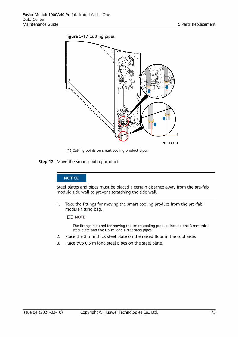
Figure 5-17 Cutting pipes
(1) Cutting points on smart cooling product pipes
Step 12 Move the smart cooling product.
NO TICE
Steel plates and pipes must be placed a certain distance away from the pre-fab.module side wall to prevent scratching the side wall.
1. Take the fittings for moving the smart cooling product from the pre-fab.module fitting bag.
NO TE
The fittings required for moving the smart cooling product include one 3 mm thicksteel plate and five 0.5 m long DN32 steel pipes.
2. Place the 3 mm thick steel plate on the raised floor in the cold aisle.3. Place two 0.5 m long steel pipes on the steel plate.
FusionModule1000A40 Prefabricated All-in-OneData CenterMaintenance Guide 5 Parts Replacement
Issue 04 (2021-02-10) Copyright © Huawei Technologies Co., Ltd. 73

Figure 5-18 Placing the steel plate and pipes
(1) 0.5 m long steel pipe (2) 3 mm thick steel plate
4. Push the smart cooling product until it is separated from the base and placedonto the two steel pipes.
NO TICE
Adjust the positions of the two steel pipes and the distance in between toensure that the smart cooling product is evenly carried on the two steel pipes.
Step 13 Pull the smart cooling product.1. Slide the smart cooling product to the cold aisle.2. Place the three 0.5 m long steel pipes evenly in the long aisle near the
entrance of cold aisle B.3. Push the smart cooling product completely onto the three 0.5 m long steel
pipes, and move the smart cooling product along the long aisle to the pre-fab.module side door.
FusionModule1000A40 Prefabricated All-in-OneData CenterMaintenance Guide 5 Parts Replacement
Issue 04 (2021-02-10) Copyright © Huawei Technologies Co., Ltd. 74
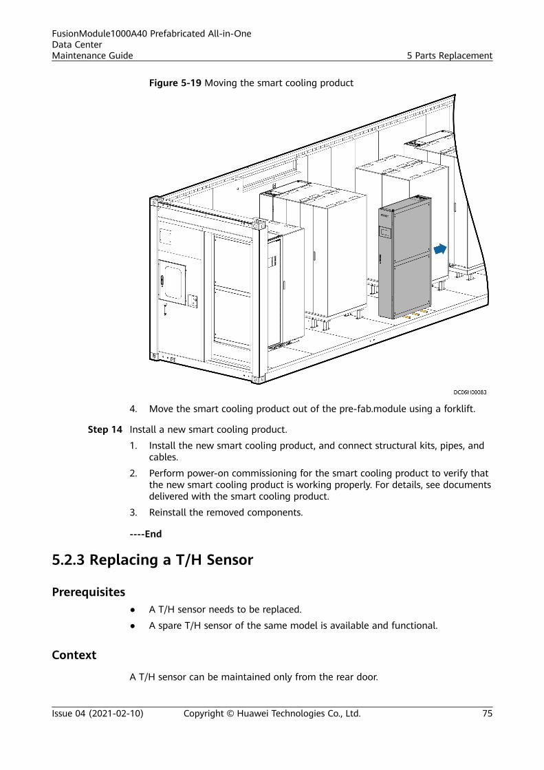
Figure 5-19 Moving the smart cooling product
4. Move the smart cooling product out of the pre-fab.module using a forklift.
Step 14 Install a new smart cooling product.
1. Install the new smart cooling product, and connect structural kits, pipes, andcables.
2. Perform power-on commissioning for the smart cooling product to verify thatthe new smart cooling product is working properly. For details, see documentsdelivered with the smart cooling product.
3. Reinstall the removed components.
----End
5.2.3 Replacing a T/H Sensor
Prerequisites● A T/H sensor needs to be replaced.
● A spare T/H sensor of the same model is available and functional.
Context
A T/H sensor can be maintained only from the rear door.
FusionModule1000A40 Prefabricated All-in-OneData CenterMaintenance Guide 5 Parts Replacement
Issue 04 (2021-02-10) Copyright © Huawei Technologies Co., Ltd. 75
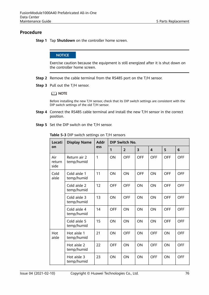
Procedure
Step 1 Tap Shutdown on the controller home screen.
NO TICE
Exercise caution because the equipment is still energized after it is shut down onthe controller home screen.
Step 2 Remove the cable terminal from the RS485 port on the T/H sensor.
Step 3 Pull out the T/H sensor.
NO TE
Before installing the new T/H sensor, check that its DIP switch settings are consistent with theDIP switch settings of the old T/H sensor.
Step 4 Connect the RS485 cable terminal and install the new T/H sensor in the correctposition.
Step 5 Set the DIP switch on the T/H sensor.
Table 5-3 DIP switch settings on T/H sensors
Location
Display Name Address
DIP Switch No.
1 2 3 4 5 6
Airreturnside
Return air 2temp/humid
1 ON OFF OFF OFF OFF OFF
Coldaisle
Cold aisle 1temp/humid
11 ON ON OFF ON OFF OFF
Cold aisle 2temp/humid
12 OFF OFF ON ON OFF OFF
Cold aisle 3temp/humid
13 ON OFF ON ON OFF OFF
Cold aisle 4temp/humid
14 OFF ON ON ON OFF OFF
Cold aisle 5temp/humid
15 ON ON ON ON OFF OFF
Hotaisle
Hot aisle 1temp/humid
21 ON OFF ON OFF ON OFF
Hot aisle 2temp/humid
22 OFF ON ON OFF ON OFF
Hot aisle 3temp/humid
23 ON ON ON OFF ON OFF
FusionModule1000A40 Prefabricated All-in-OneData CenterMaintenance Guide 5 Parts Replacement
Issue 04 (2021-02-10) Copyright © Huawei Technologies Co., Ltd. 76
Location
Display Name Address
DIP Switch No.
1 2 3 4 5 6
Hot aisle 4temp/humid
24 OFF OFF OFF ON ON OFF
Hot aisle 5temp/humid
25 ON OFF OFF ON ON OFF
----End
5.2.4 (Optional) Replacing the Electric heating belt
Prerequisites
A spare low-temperature component of the same model is available andfunctional.
Impact on the System
None
Preparations
Tool: flat-head screwdriver
Materials: spare low-temperature component
Skill requirement: cooling engineer, common technician
Procedure
Step 1 Disconnect the power cable from the faulty electric heating belt.
Step 2 Remove the electric heating belt.
Step 3 Install the new electric heating belt in the original position.
Step 4 Connect the power cable of the electric heating belt to the reservedinterconnection terminal.
----End
Follow-up Procedure
Dispose of the removed low-temperature component that is confirmed faulty.
5.3 Replacing Monitoring System Components
FusionModule1000A40 Prefabricated All-in-OneData CenterMaintenance Guide 5 Parts Replacement
Issue 04 (2021-02-10) Copyright © Huawei Technologies Co., Ltd. 77
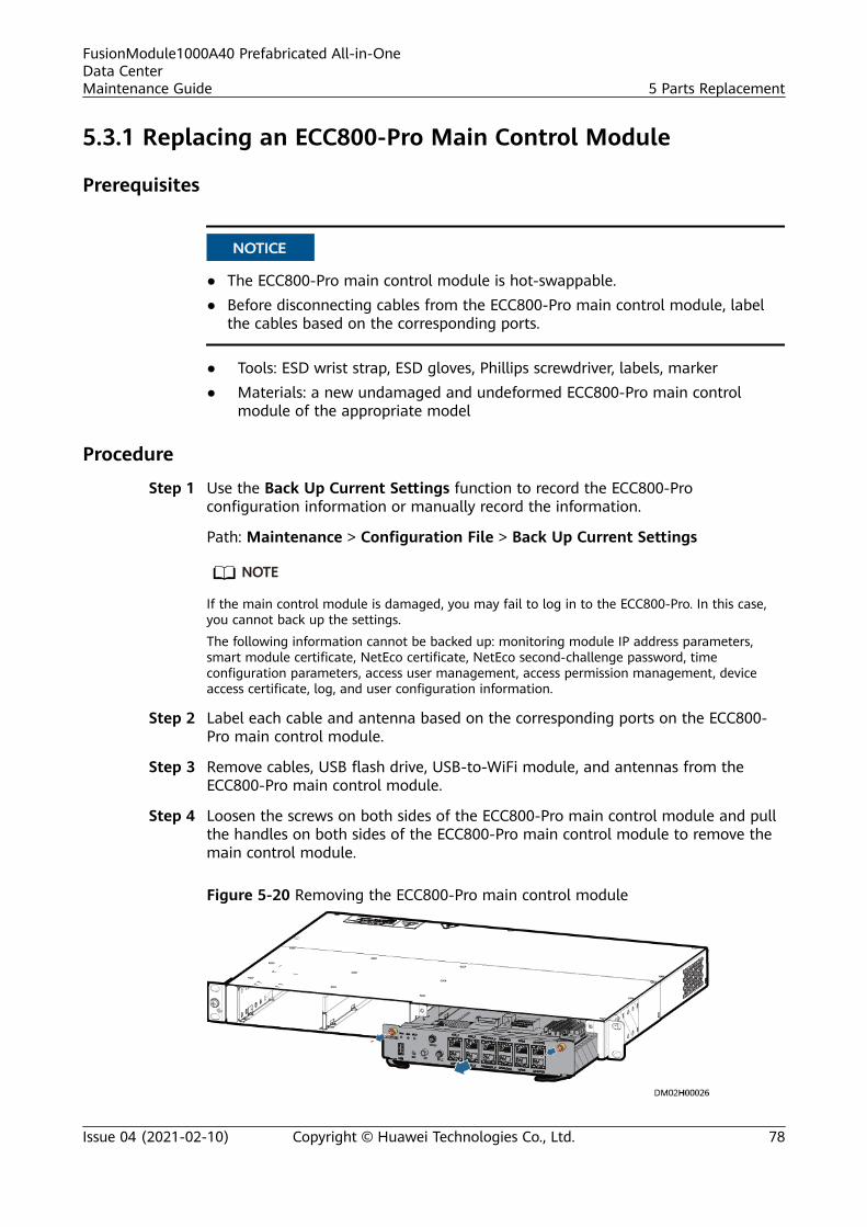
5.3.1 Replacing an ECC800-Pro Main Control Module
Prerequisites
NO TICE
● The ECC800-Pro main control module is hot-swappable.● Before disconnecting cables from the ECC800-Pro main control module, label
the cables based on the corresponding ports.
● Tools: ESD wrist strap, ESD gloves, Phillips screwdriver, labels, marker● Materials: a new undamaged and undeformed ECC800-Pro main control
module of the appropriate model
Procedure
Step 1 Use the Back Up Current Settings function to record the ECC800-Proconfiguration information or manually record the information.
Path: Maintenance > Configuration File > Back Up Current Settings
NO TE
If the main control module is damaged, you may fail to log in to the ECC800-Pro. In this case,you cannot back up the settings.
The following information cannot be backed up: monitoring module IP address parameters,smart module certificate, NetEco certificate, NetEco second-challenge password, timeconfiguration parameters, access user management, access permission management, deviceaccess certificate, log, and user configuration information.
Step 2 Label each cable and antenna based on the corresponding ports on the ECC800-Pro main control module.
Step 3 Remove cables, USB flash drive, USB-to-WiFi module, and antennas from theECC800-Pro main control module.
Step 4 Loosen the screws on both sides of the ECC800-Pro main control module and pullthe handles on both sides of the ECC800-Pro main control module to remove themain control module.
Figure 5-20 Removing the ECC800-Pro main control module
FusionModule1000A40 Prefabricated All-in-OneData CenterMaintenance Guide 5 Parts Replacement
Issue 04 (2021-02-10) Copyright © Huawei Technologies Co., Ltd. 78
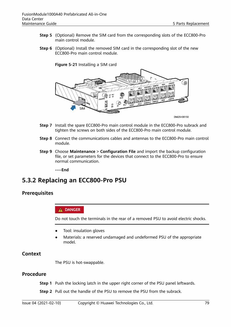
Step 5 (Optional) Remove the SIM card from the corresponding slots of the ECC800-Promain control module.
Step 6 (Optional) Install the removed SIM card in the corresponding slot of the newECC800-Pro main control module.
Figure 5-21 Installing a SIM card
Step 7 Install the spare ECC800-Pro main control module in the ECC800-Pro subrack andtighten the screws on both sides of the ECC800-Pro main control module.
Step 8 Connect the communications cables and antennas to the ECC800-Pro main controlmodule.
Step 9 Choose Maintenance > Configuration File and import the backup configurationfile, or set parameters for the devices that connect to the ECC800-Pro to ensurenormal communication.
----End
5.3.2 Replacing an ECC800-Pro PSU
Prerequisites
D ANGER
Do not touch the terminals in the rear of a removed PSU to avoid electric shocks.
● Tool: insulation gloves● Materials: a reserved undamaged and undeformed PSU of the appropriate
model.
Context
The PSU is hot-swappable.
Procedure
Step 1 Push the locking latch in the upper right corner of the PSU panel leftwards.
Step 2 Pull out the handle of the PSU to remove the PSU from the subrack.
FusionModule1000A40 Prefabricated All-in-OneData CenterMaintenance Guide 5 Parts Replacement
Issue 04 (2021-02-10) Copyright © Huawei Technologies Co., Ltd. 79

Step 3 Gently push the reserved PSU into the subrack along guide rails, and push thelocking latch rightwards to secure the handle.
Figure 5-22 Replacing a PSU
----End
5.3.3 Replacing ECC800-Pro Antennas
Prerequisites● Tools: ESD wrist strap, ESD gloves
● Materials: Spare ECC800-Pro antennas of the same model are available andfunctional.
Procedure
Step 1 Remove the 4G antenna cables and RF_Z antenna cables connected to the portson the ECC800-Pro, as shown in Figure 5-23.
Figure 5-23 Removing antennas
Step 2 Install the spare 4G antenna cables and RF_Z antenna cables in the originalpositions and connect them to the ECC800-Pro.
----End
FusionModule1000A40 Prefabricated All-in-OneData CenterMaintenance Guide 5 Parts Replacement
Issue 04 (2021-02-10) Copyright © Huawei Technologies Co., Ltd. 80
5.3.4 Replacing a Smart ETH Gateway
PrerequisitesA spare ETH gateway of the same model is available and functional.
Impact on the SystemDevices connected to the ETH gateway will be disconnected.
PreparationsTools: ESD wrist strap, ESD gloves, Phillips screwdriver, step ladder, label, marker
Materials: spare ETH gateway
Skill requirement: extra low voltage (ELV) engineer
Procedure
Step 1 Label each cable based on the corresponding ports on the smart ETH gateway.
Step 2 Disconnect cables from the smart ETH gateway.
Step 3 Remove the faulty smart ETH gateway from the guide rails of the cable trough.
Step 4 Install the spare smart ETH gateway in the original position and connect thecables.
----End
5.3.5 Replacing a Camera
PrerequisitesA spare camera of the same model is available and functional.
Impact on the SystemVideo surveillance stops.
PreparationsTools: Phillips screwdriver, step ladder, protective gloves
Material: spare camera
Documents: documents delivered with the camera, monitoring drawings andparameters
Skill requirement: ELV engineer
Procedure
Step 1 Remove the front cover of the camera and remove the screws from the frontcover.
FusionModule1000A40 Prefabricated All-in-OneData CenterMaintenance Guide 5 Parts Replacement
Issue 04 (2021-02-10) Copyright © Huawei Technologies Co., Ltd. 81
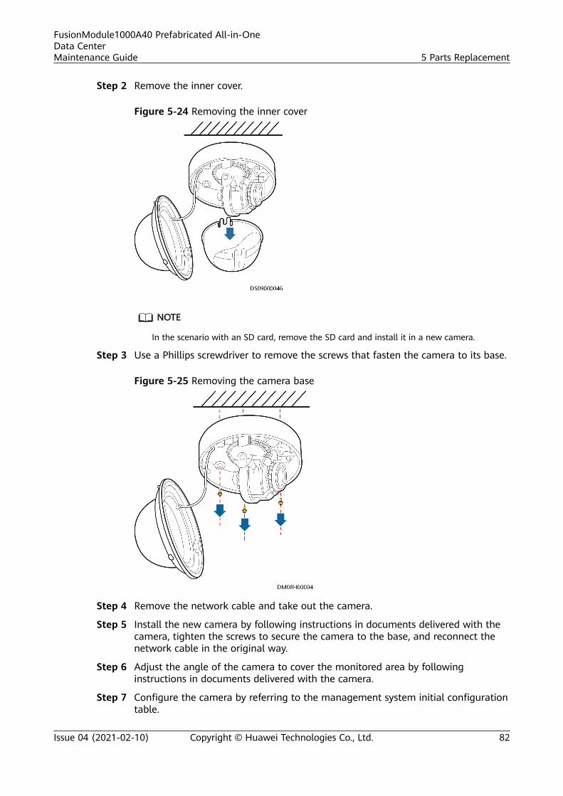
Step 2 Remove the inner cover.
Figure 5-24 Removing the inner cover
NO TE
In the scenario with an SD card, remove the SD card and install it in a new camera.
Step 3 Use a Phillips screwdriver to remove the screws that fasten the camera to its base.
Figure 5-25 Removing the camera base
Step 4 Remove the network cable and take out the camera.
Step 5 Install the new camera by following instructions in documents delivered with thecamera, tighten the screws to secure the camera to the base, and reconnect thenetwork cable in the original way.
Step 6 Adjust the angle of the camera to cover the monitored area by followinginstructions in documents delivered with the camera.
Step 7 Configure the camera by referring to the management system initial configurationtable.
FusionModule1000A40 Prefabricated All-in-OneData CenterMaintenance Guide 5 Parts Replacement
Issue 04 (2021-02-10) Copyright © Huawei Technologies Co., Ltd. 82
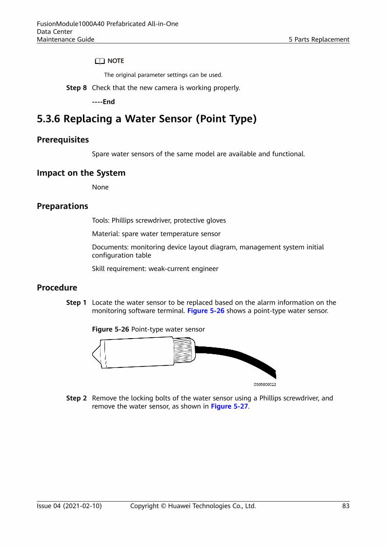
NO TE
The original parameter settings can be used.
Step 8 Check that the new camera is working properly.
----End
5.3.6 Replacing a Water Sensor (Point Type)
PrerequisitesSpare water sensors of the same model are available and functional.
Impact on the SystemNone
PreparationsTools: Phillips screwdriver, protective gloves
Material: spare water temperature sensor
Documents: monitoring device layout diagram, management system initialconfiguration table
Skill requirement: weak-current engineer
Procedure
Step 1 Locate the water sensor to be replaced based on the alarm information on themonitoring software terminal. Figure 5-26 shows a point-type water sensor.
Figure 5-26 Point-type water sensor
Step 2 Remove the locking bolts of the water sensor using a Phillips screwdriver, andremove the water sensor, as shown in Figure 5-27.
FusionModule1000A40 Prefabricated All-in-OneData CenterMaintenance Guide 5 Parts Replacement
Issue 04 (2021-02-10) Copyright © Huawei Technologies Co., Ltd. 83
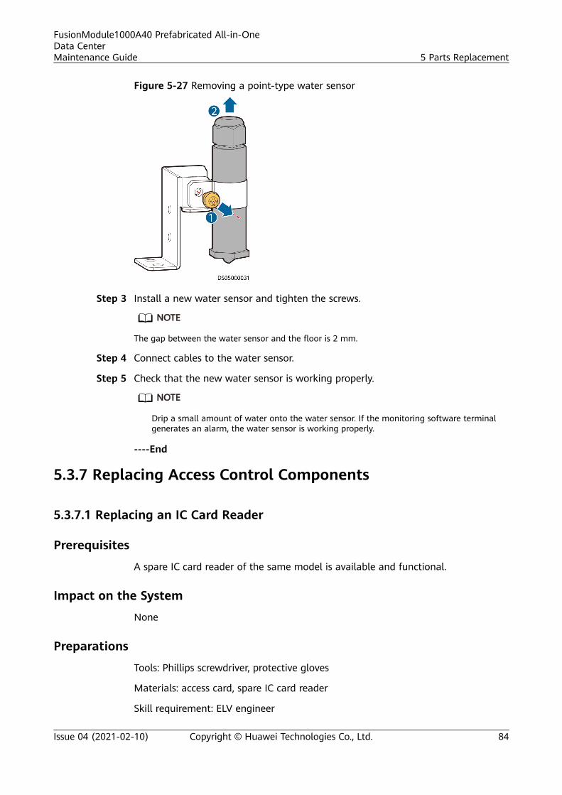
Figure 5-27 Removing a point-type water sensor
Step 3 Install a new water sensor and tighten the screws.
NO TE
The gap between the water sensor and the floor is 2 mm.
Step 4 Connect cables to the water sensor.
Step 5 Check that the new water sensor is working properly.
NO TE
Drip a small amount of water onto the water sensor. If the monitoring software terminalgenerates an alarm, the water sensor is working properly.
----End
5.3.7 Replacing Access Control Components
5.3.7.1 Replacing an IC Card Reader
Prerequisites
A spare IC card reader of the same model is available and functional.
Impact on the System
None
Preparations
Tools: Phillips screwdriver, protective gloves
Materials: access card, spare IC card reader
Skill requirement: ELV engineer
FusionModule1000A40 Prefabricated All-in-OneData CenterMaintenance Guide 5 Parts Replacement
Issue 04 (2021-02-10) Copyright © Huawei Technologies Co., Ltd. 84
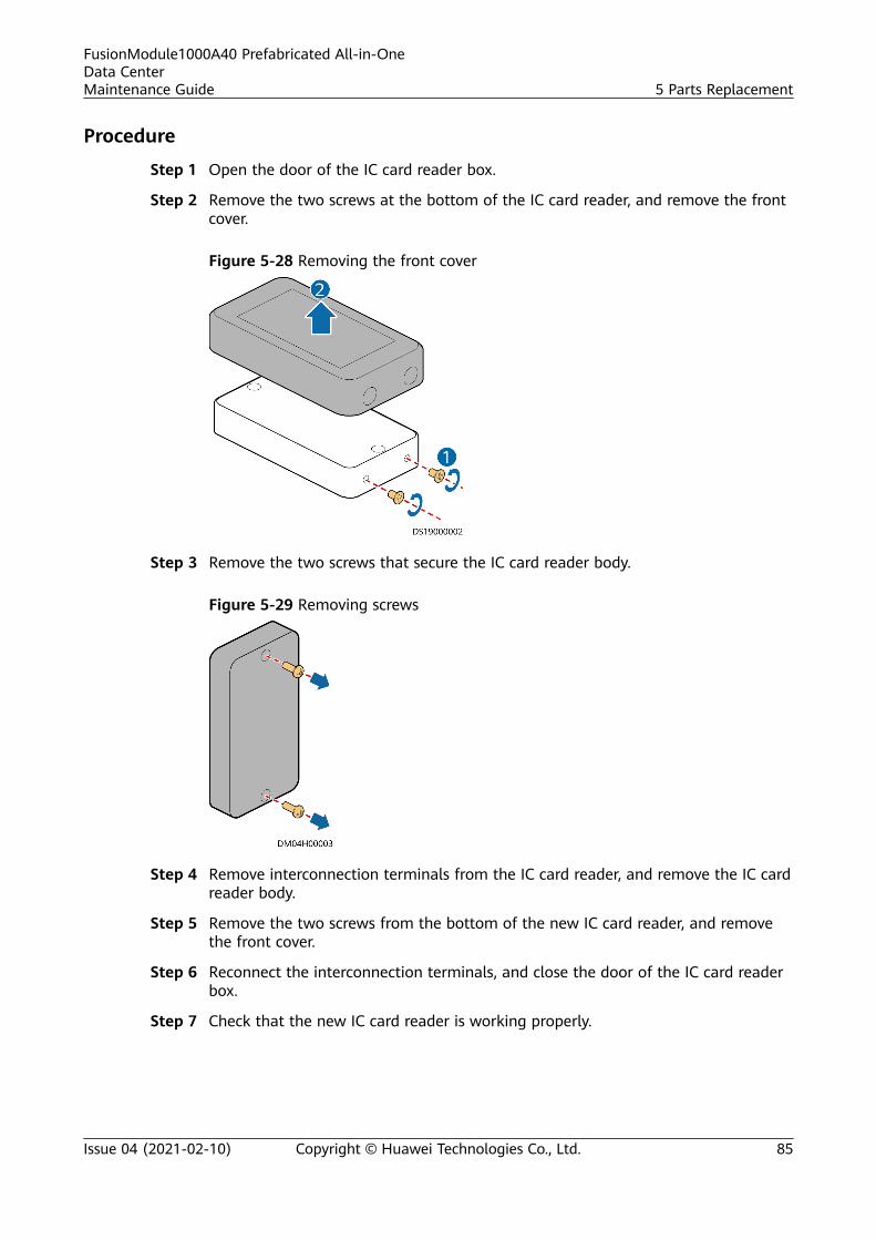
Procedure
Step 1 Open the door of the IC card reader box.
Step 2 Remove the two screws at the bottom of the IC card reader, and remove the frontcover.
Figure 5-28 Removing the front cover
Step 3 Remove the two screws that secure the IC card reader body.
Figure 5-29 Removing screws
Step 4 Remove interconnection terminals from the IC card reader, and remove the IC cardreader body.
Step 5 Remove the two screws from the bottom of the new IC card reader, and removethe front cover.
Step 6 Reconnect the interconnection terminals, and close the door of the IC card readerbox.
Step 7 Check that the new IC card reader is working properly.
FusionModule1000A40 Prefabricated All-in-OneData CenterMaintenance Guide 5 Parts Replacement
Issue 04 (2021-02-10) Copyright © Huawei Technologies Co., Ltd. 85

NO TE
The IC card reader is working properly if the pre-fab. module door can be opened fromoutside the pre-fab. module using an access card and door opening operations are loggedin the monitoring system.
----End
5.3.7.2 Replacing an Exit Button
PrerequisitesA spare exit button of the same model is available and functional.
Impact on the SystemNone
PreparationsTools: insulation tape, Phillips screwdriver, small flat-head screwdriver, protectivegloves
Material: spare exit button
Skill requirement: ELV engineer
Procedure
Step 1 Disassemble the faulty exit button, remove cables, and remove the faulty exitbutton, as shown in Figure 5-30.
FusionModule1000A40 Prefabricated All-in-OneData CenterMaintenance Guide 5 Parts Replacement
Issue 04 (2021-02-10) Copyright © Huawei Technologies Co., Ltd. 86
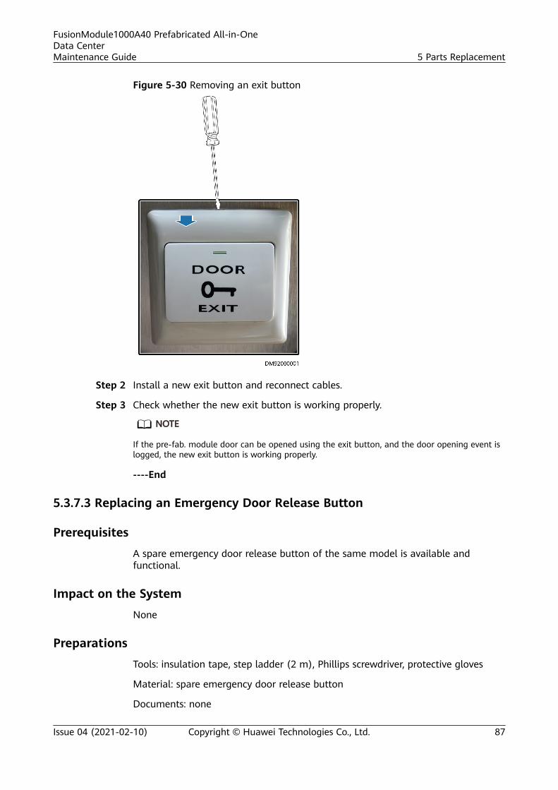
Figure 5-30 Removing an exit button
Step 2 Install a new exit button and reconnect cables.
Step 3 Check whether the new exit button is working properly.
NO TE
If the pre-fab. module door can be opened using the exit button, and the door opening event islogged, the new exit button is working properly.
----End
5.3.7.3 Replacing an Emergency Door Release Button
Prerequisites
A spare emergency door release button of the same model is available andfunctional.
Impact on the System
None
Preparations
Tools: insulation tape, step ladder (2 m), Phillips screwdriver, protective gloves
Material: spare emergency door release button
Documents: none
FusionModule1000A40 Prefabricated All-in-OneData CenterMaintenance Guide 5 Parts Replacement
Issue 04 (2021-02-10) Copyright © Huawei Technologies Co., Ltd. 87
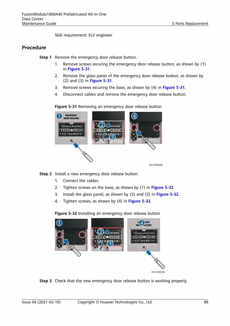
Skill requirement: ELV engineer
Procedure
Step 1 Remove the emergency door release button.
1. Remove screws securing the emergency door release button, as shown by (1)in Figure 5-31.
2. Remove the glass panel of the emergency door release button, as shown by(2) and (3) in Figure 5-31.
3. Remove screws securing the base, as shown by (4) in Figure 5-31.
4. Disconnect cables and remove the emergency door release button.
Figure 5-31 Removing an emergency door release button
Step 2 Install a new emergency door release button.
1. Connect the cables.
2. Tighten screws on the base, as shown by (1) in Figure 5-32.
3. Install the glass panel, as shown by (2) and (3) in Figure 5-32.
4. Tighten screws, as shown by (4) in Figure 5-32.
Figure 5-32 Installing an emergency door release button
Step 3 Check that the new emergency door release button is working properly.
FusionModule1000A40 Prefabricated All-in-OneData CenterMaintenance Guide 5 Parts Replacement
Issue 04 (2021-02-10) Copyright © Huawei Technologies Co., Ltd. 88
NO TE
Remove the cover of the emergency door release button using a screwdriver, press the button,and rotate the door handle clockwise to open the pre-fab. module door. If the door can beopened, the emergency door release button is working properly.
----End
5.3.7.4 Replacing an Access Actuator
PrerequisitesA spare access actuator of the same model is available and functional.
Impact on the SystemNone
PreparationsTools: ESD wrist strap, ESD gloves, step ladder, label, marker
Material: spare access actuator
Documents: none
Skill requirement: ELV engineer
Procedure
Step 1 Label each cable based on the corresponding ports on the access actuator.
Step 2 Disconnect cables from the access actuator.
Step 3 Remove the faulty access actuator from guide rails.
Step 4 Install the spare access actuator in the original position and connect the cables.
----End
5.3.7.5 Replacing a Door Status Sensor
PrerequisitesA spare door status sensor of the same model is available and functional.
Impact on the SystemNone
PreparationsTools: insulation tape, step ladder (2 m), Phillips screwdriver, flat-head screwdriver,protective gloves
Material: spare door status sensor
FusionModule1000A40 Prefabricated All-in-OneData CenterMaintenance Guide 5 Parts Replacement
Issue 04 (2021-02-10) Copyright © Huawei Technologies Co., Ltd. 89
Documents: monitoring device layout diagram, management system initialconfiguration table
Skill requirement: ELV engineer
NO TE
For the diagram and table, see the initial configuration parameter manual for the solution inuse.
Procedure
Step 1 Open the pre-fab. module door where the door status sensor to be replaced isinstalled.
NO TE
Obtain permission from the relevant administration department before opening a pre-fab.module door.
Step 2 Open the door status sensor box and disconnect the cable to remove the doorstatus sensor to be replaced.
Figure 5-33 Replacing a door status sensor
Step 3 Install a new door status sensor, and reconnect the cables.
Step 4 Check that the new door status sensor is working properly.
NO TE
Open the pre-fab. module door and check whether the management system reports an alarmindicating that the door was opened. If yes, the door status sensor is working properly.
----End
5.3.8 Replacing an AC Actuator
Prerequisites● A spare AC actuator of the same model is available and functional.● Before replacing the AC actuator, ensure that the upstream AC input power is
off.
FusionModule1000A40 Prefabricated All-in-OneData CenterMaintenance Guide 5 Parts Replacement
Issue 04 (2021-02-10) Copyright © Huawei Technologies Co., Ltd. 90
Impact on the System
Lights in the data center will turn off.
Preparations
Tools: insulation gloves, Phillips screwdriver, step ladder, label, marker
Materials: spare AC actuator
Documents: none
Skill requirement: extra low voltage (ELV) engineer
Procedure
Step 1 Switch off the upstream AC input circuit breaker for the AC actuator.
Step 2 Label each cable based on the corresponding ports on the AC actuator.
Step 3 Open the cover on the front panel of the AC actuator, and disconnect the cables.
Step 4 Remove the faulty AC actuator.
Step 5 Install the spare AC actuator in the original position and connect the cables.
Step 6 Switch on the upstream AC input circuit breaker for the AC actuator and press thewireless communications button on the AC actuator to network the AC actuatorwith the ECC800.
----End
5.3.9 Replacing a T/H Sensor
Prerequisites● Recommended tools: Phillips screwdriver, flat-head screwdriver● A T/H sensor needs to be replaced.● A spare T/H sensor of the same model is available and functional.
Procedure
Step 1 Remove cables from the T/H sensor.
Step 2 Remove the T/H sensor from its base.
NO TICE
After removing cables, wrap exposed terminals with insulation tape and do notblock cable labels. If cable labels are blocked, cables may be connected incorrectly.
Step 3 Install a new T/H sensor onto the base.
FusionModule1000A40 Prefabricated All-in-OneData CenterMaintenance Guide 5 Parts Replacement
Issue 04 (2021-02-10) Copyright © Huawei Technologies Co., Ltd. 91

NO TICE
Before removing a T/H sensor, remember the DIP switch setting on it. When youinstall a new T/H sensor, you need to set the same DIP switch setting for the newone.
Step 4 Reconnect cables to the new T/H sensor.
----End
5.3.10 Replacing the WiFi Module
Impact on the System
The app cannot be connected to the ECC800-Pro, and the smart moduleinformation cannot be properly displayed.
Preparations
Material: WiFi module
Procedure
Step 1 Remove the old WiFi module from the USB port on the ECC800-Pro.
Step 2 Install the spare WiFi module in the original position.
Step 3 Log in to the ECC800-Pro WebUI.
Figure 5-34 Position of the WiFi module
----End
5.3.11 (Optional) Replacing a PAD
Prerequisites
A spare PAD of the same model is available and functional.
FusionModule1000A40 Prefabricated All-in-OneData CenterMaintenance Guide 5 Parts Replacement
Issue 04 (2021-02-10) Copyright © Huawei Technologies Co., Ltd. 92
Impact on the System
None
Preparations
Tools: ESD wrist strap, ESD gloves, label, marker
Materials: new PAD of the same model
Documents: none
Skill requirement: extra low voltage (ELV) engineer
Procedure
Step 1 Install the app on the spare PAD and connect the PAD to the network over theWiFi hotspot of the data center.
Step 2 Specify the user name and password for the app on the spare PAD and log in tocheck that the app works properly.
Step 3 Remove the old PAD from the support and install the spare PAD on the support.
----End
5.4 Replacing Fire Extinguishing System Components
5.4.1 Replacing Fire Extinguishing System Components(Standard)
5.4.1.1 Changing an Address Code
Prerequisites
Before replacing a fire extinguishing device, reset the address code for the device.
Procedure1. Press and hold the ON/OFF key on the encoder for 1 second to start the
encoder.
2. Press # to switch the mode. When 324 is displayed on the screen, use adedicated external connection cable to connect the terminal device and setthe address code for the device on the bus.
FusionModule1000A40 Prefabricated All-in-OneData CenterMaintenance Guide 5 Parts Replacement
Issue 04 (2021-02-10) Copyright © Huawei Technologies Co., Ltd. 93
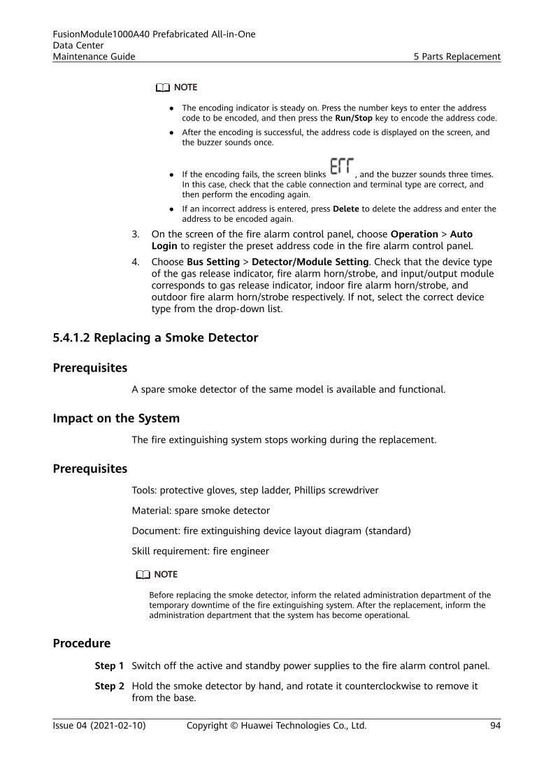
NO TE
● The encoding indicator is steady on. Press the number keys to enter the addresscode to be encoded, and then press the Run/Stop key to encode the address code.
● After the encoding is successful, the address code is displayed on the screen, andthe buzzer sounds once.
● If the encoding fails, the screen blinks , and the buzzer sounds three times.In this case, check that the cable connection and terminal type are correct, andthen perform the encoding again.
● If an incorrect address is entered, press Delete to delete the address and enter theaddress to be encoded again.
3. On the screen of the fire alarm control panel, choose Operation > AutoLogin to register the preset address code in the fire alarm control panel.
4. Choose Bus Setting > Detector/Module Setting. Check that the device typeof the gas release indicator, fire alarm horn/strobe, and input/output modulecorresponds to gas release indicator, indoor fire alarm horn/strobe, andoutdoor fire alarm horn/strobe respectively. If not, select the correct devicetype from the drop-down list.
5.4.1.2 Replacing a Smoke Detector
Prerequisites
A spare smoke detector of the same model is available and functional.
Impact on the System
The fire extinguishing system stops working during the replacement.
Prerequisites
Tools: protective gloves, step ladder, Phillips screwdriver
Material: spare smoke detector
Document: fire extinguishing device layout diagram (standard)
Skill requirement: fire engineer
NO TE
Before replacing the smoke detector, inform the related administration department of thetemporary downtime of the fire extinguishing system. After the replacement, inform theadministration department that the system has become operational.
Procedure
Step 1 Switch off the active and standby power supplies to the fire alarm control panel.
Step 2 Hold the smoke detector by hand, and rotate it counterclockwise to remove itfrom the base.
FusionModule1000A40 Prefabricated All-in-OneData CenterMaintenance Guide 5 Parts Replacement
Issue 04 (2021-02-10) Copyright © Huawei Technologies Co., Ltd. 94
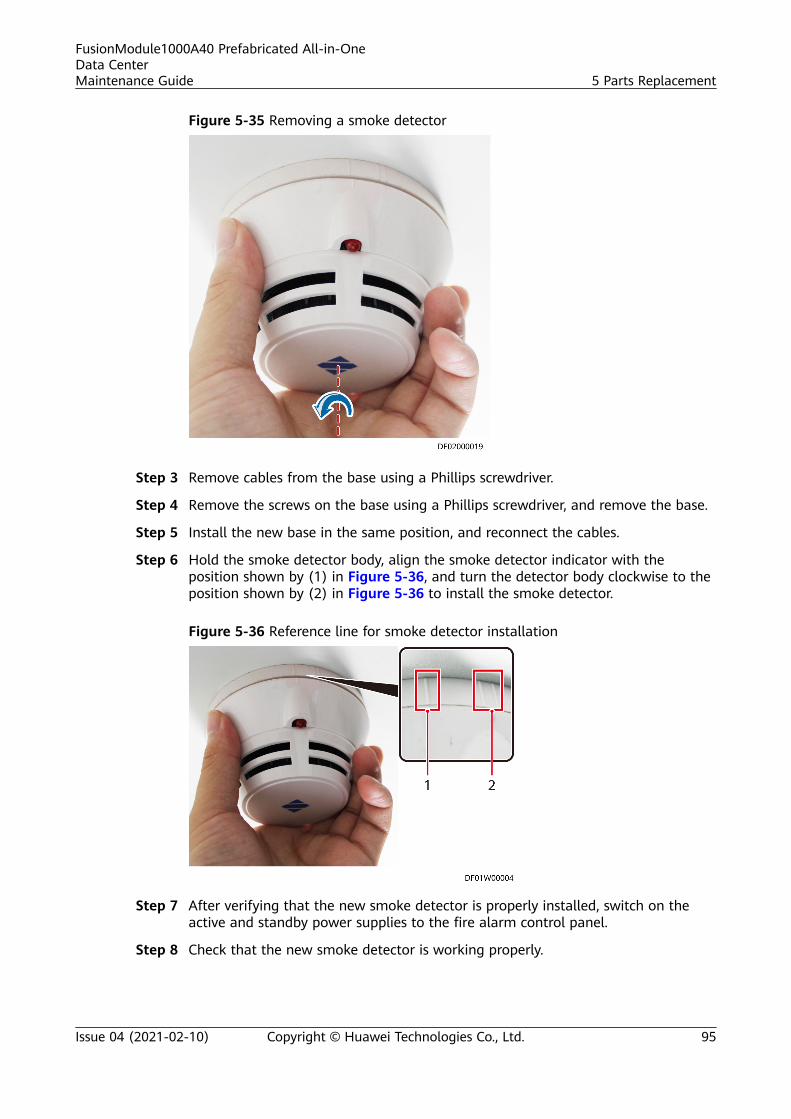
Figure 5-35 Removing a smoke detector
Step 3 Remove cables from the base using a Phillips screwdriver.
Step 4 Remove the screws on the base using a Phillips screwdriver, and remove the base.
Step 5 Install the new base in the same position, and reconnect the cables.
Step 6 Hold the smoke detector body, align the smoke detector indicator with theposition shown by (1) in Figure 5-36, and turn the detector body clockwise to theposition shown by (2) in Figure 5-36 to install the smoke detector.
Figure 5-36 Reference line for smoke detector installation
Step 7 After verifying that the new smoke detector is properly installed, switch on theactive and standby power supplies to the fire alarm control panel.
Step 8 Check that the new smoke detector is working properly.
FusionModule1000A40 Prefabricated All-in-OneData CenterMaintenance Guide 5 Parts Replacement
Issue 04 (2021-02-10) Copyright © Huawei Technologies Co., Ltd. 95
NO TE
If the red indicator blinks once every 6s, the smoke detector is working properly.
----End
Follow-up ProcedureDispose of the removed smoke detector that is confirmed faulty.
5.4.1.3 Replacing a Heat Detector
PrerequisitesA spare heat detector of the same model is available and functional.
Impact on the SystemThe fire extinguishing system stops working during the replacement.
PrerequisitesTools: protective gloves, step ladder, Phillips screwdriver
Material: spare heat detector
Document: fire extinguishing device layout diagram (standard)
Skill requirement: fire engineer
NO TE
Before replacing the heat detector, inform the related administration department of thetemporary downtime of the fire extinguishing system. After the replacement, inform theadministration department that the system has become operational.
Procedure
Step 1 Switch off the active and standby power supplies to the fire alarm control panel.
Step 2 Hold the heat detector by hand, and rotate it counterclockwise to remove it fromthe base.
FusionModule1000A40 Prefabricated All-in-OneData CenterMaintenance Guide 5 Parts Replacement
Issue 04 (2021-02-10) Copyright © Huawei Technologies Co., Ltd. 96
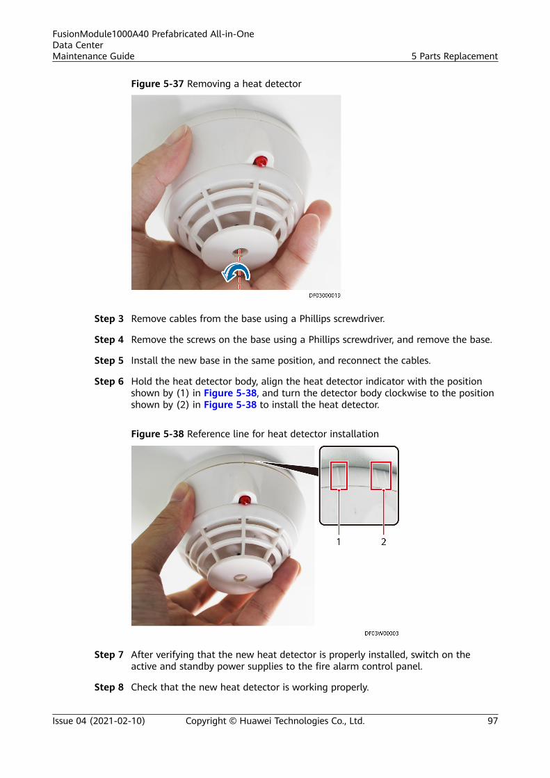
Figure 5-37 Removing a heat detector
Step 3 Remove cables from the base using a Phillips screwdriver.
Step 4 Remove the screws on the base using a Phillips screwdriver, and remove the base.
Step 5 Install the new base in the same position, and reconnect the cables.
Step 6 Hold the heat detector body, align the heat detector indicator with the positionshown by (1) in Figure 5-38, and turn the detector body clockwise to the positionshown by (2) in Figure 5-38 to install the heat detector.
Figure 5-38 Reference line for heat detector installation
Step 7 After verifying that the new heat detector is properly installed, switch on theactive and standby power supplies to the fire alarm control panel.
Step 8 Check that the new heat detector is working properly.
FusionModule1000A40 Prefabricated All-in-OneData CenterMaintenance Guide 5 Parts Replacement
Issue 04 (2021-02-10) Copyright © Huawei Technologies Co., Ltd. 97
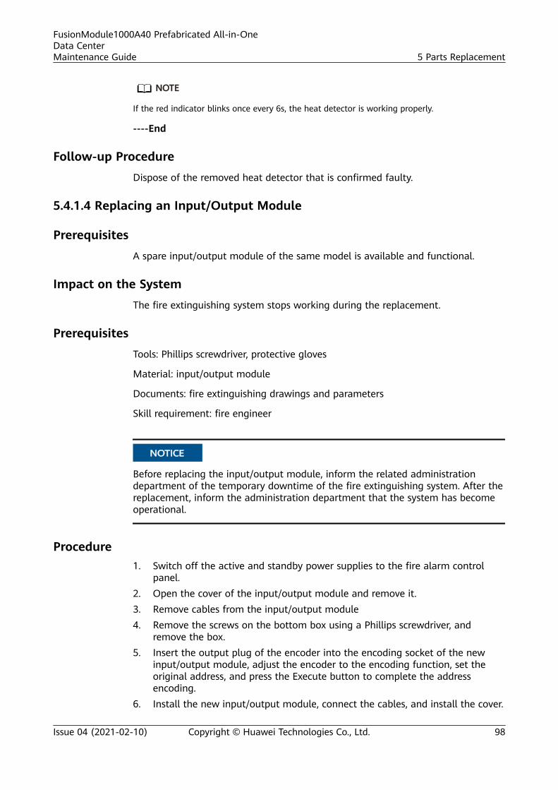
NO TE
If the red indicator blinks once every 6s, the heat detector is working properly.
----End
Follow-up Procedure
Dispose of the removed heat detector that is confirmed faulty.
5.4.1.4 Replacing an Input/Output Module
Prerequisites
A spare input/output module of the same model is available and functional.
Impact on the System
The fire extinguishing system stops working during the replacement.
Prerequisites
Tools: Phillips screwdriver, protective gloves
Material: input/output module
Documents: fire extinguishing drawings and parameters
Skill requirement: fire engineer
NO TICE
Before replacing the input/output module, inform the related administrationdepartment of the temporary downtime of the fire extinguishing system. After thereplacement, inform the administration department that the system has becomeoperational.
Procedure1. Switch off the active and standby power supplies to the fire alarm control
panel.2. Open the cover of the input/output module and remove it.3. Remove cables from the input/output module4. Remove the screws on the bottom box using a Phillips screwdriver, and
remove the box.5. Insert the output plug of the encoder into the encoding socket of the new
input/output module, adjust the encoder to the encoding function, set theoriginal address, and press the Execute button to complete the addressencoding.
6. Install the new input/output module, connect the cables, and install the cover.
FusionModule1000A40 Prefabricated All-in-OneData CenterMaintenance Guide 5 Parts Replacement
Issue 04 (2021-02-10) Copyright © Huawei Technologies Co., Ltd. 98
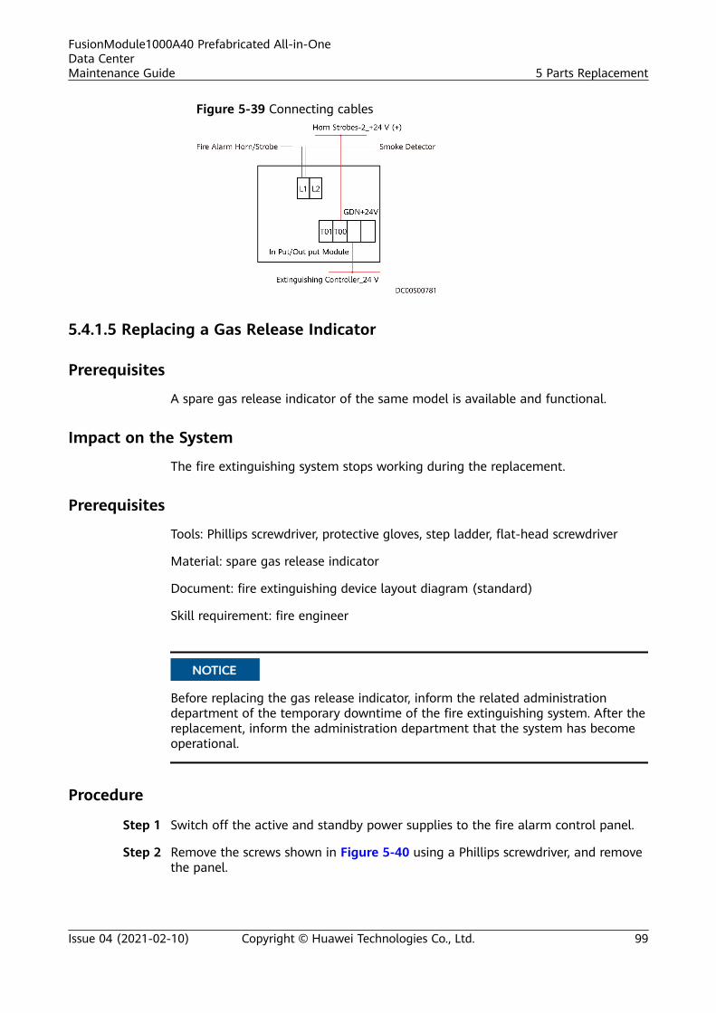
Figure 5-39 Connecting cables
5.4.1.5 Replacing a Gas Release Indicator
Prerequisites
A spare gas release indicator of the same model is available and functional.
Impact on the System
The fire extinguishing system stops working during the replacement.
Prerequisites
Tools: Phillips screwdriver, protective gloves, step ladder, flat-head screwdriver
Material: spare gas release indicator
Document: fire extinguishing device layout diagram (standard)
Skill requirement: fire engineer
NO TICE
Before replacing the gas release indicator, inform the related administrationdepartment of the temporary downtime of the fire extinguishing system. After thereplacement, inform the administration department that the system has becomeoperational.
Procedure
Step 1 Switch off the active and standby power supplies to the fire alarm control panel.
Step 2 Remove the screws shown in Figure 5-40 using a Phillips screwdriver, and removethe panel.
FusionModule1000A40 Prefabricated All-in-OneData CenterMaintenance Guide 5 Parts Replacement
Issue 04 (2021-02-10) Copyright © Huawei Technologies Co., Ltd. 99
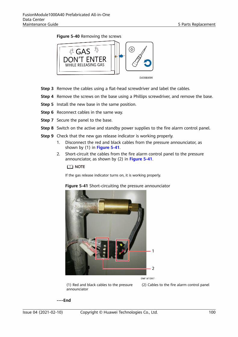
Figure 5-40 Removing the screws
Step 3 Remove the cables using a flat-head screwdriver and label the cables.
Step 4 Remove the screws on the base using a Phillips screwdriver, and remove the base.
Step 5 Install the new base in the same position.
Step 6 Reconnect cables in the same way.
Step 7 Secure the panel to the base.
Step 8 Switch on the active and standby power supplies to the fire alarm control panel.
Step 9 Check that the new gas release indicator is working properly.1. Disconnect the red and black cables from the pressure announciator, as
shown by (1) in Figure 5-41.2. Short-circuit the cables from the fire alarm control panel to the pressure
announciator, as shown by (2) in Figure 5-41.
NO TE
If the gas release indicator turns on, it is working properly.
Figure 5-41 Short-circuiting the pressure announciator
(1) Red and black cables to the pressureannounciator
(2) Cables to the fire alarm control panel
----End
FusionModule1000A40 Prefabricated All-in-OneData CenterMaintenance Guide 5 Parts Replacement
Issue 04 (2021-02-10) Copyright © Huawei Technologies Co., Ltd. 100
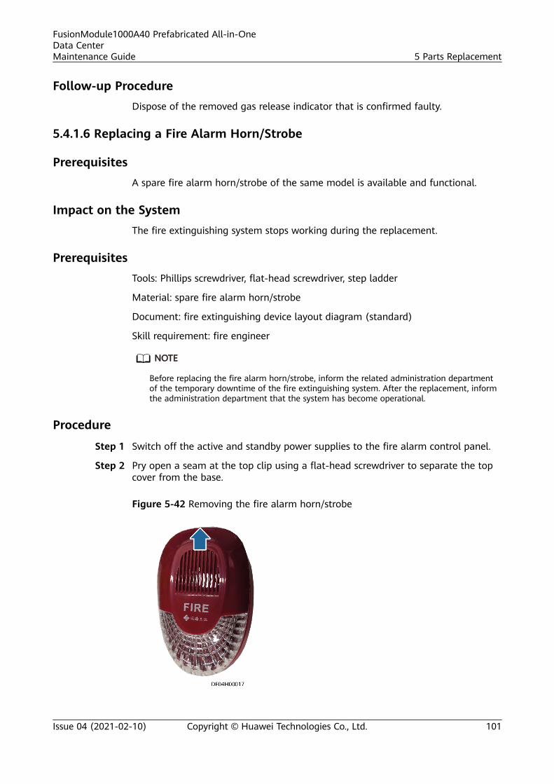
Follow-up ProcedureDispose of the removed gas release indicator that is confirmed faulty.
5.4.1.6 Replacing a Fire Alarm Horn/Strobe
PrerequisitesA spare fire alarm horn/strobe of the same model is available and functional.
Impact on the SystemThe fire extinguishing system stops working during the replacement.
PrerequisitesTools: Phillips screwdriver, flat-head screwdriver, step ladder
Material: spare fire alarm horn/strobe
Document: fire extinguishing device layout diagram (standard)
Skill requirement: fire engineer
NO TE
Before replacing the fire alarm horn/strobe, inform the related administration departmentof the temporary downtime of the fire extinguishing system. After the replacement, informthe administration department that the system has become operational.
Procedure
Step 1 Switch off the active and standby power supplies to the fire alarm control panel.
Step 2 Pry open a seam at the top clip using a flat-head screwdriver to separate the topcover from the base.
Figure 5-42 Removing the fire alarm horn/strobe
FusionModule1000A40 Prefabricated All-in-OneData CenterMaintenance Guide 5 Parts Replacement
Issue 04 (2021-02-10) Copyright © Huawei Technologies Co., Ltd. 101
Step 3 Remove the two cables using a Phillips screwdriver.
NO TE
When removing cables, clearly label the cables with its corresponding terminal ports.
Step 4 Install the base of the new fire alarm horn/strobe in the same position.
Step 5 Connect cables in the same way to the correct poles.
NO TE
Connect the red cable to the 24V+ terminal, and connect the black cable to the GND terminal.
Step 6 Install the top cover of the fire alarm horn/strobe.
Step 7 Switch on the active and standby power supplies to the fire alarm control panel,and check that the new fire alarm horn/strobe is working properly.
NO TE
Unlock the keyboard of the fire alarm control panel, and press the HORN/STROBE key totrigger the fire alarm horn/strobe.
----End
Follow-up ProcedureDispose of the removed fire alarm horn/strobe that is confirmed faulty.
5.4.1.7 Replacing an Internal Fire Alarm Horn/Strobe
PrerequisitesA spare fire alarm horn/strobe of the same model is available and functional.
Impact on the SystemThe fire extinguishing system stops working during the replacement.
PrerequisitesTools: Phillips screwdriver, step ladder
Material: spare fire alarm horn/strobe
Documents: fire extinguishing drawings and parameters
Skill requirement: fire engineer
NO TICE
Before replacing the fire alarm horn/strobe, inform the related administrationdepartment of the temporary downtime of the fire extinguishing system. After thereplacement, inform the administration department that the system has becomeoperational.
FusionModule1000A40 Prefabricated All-in-OneData CenterMaintenance Guide 5 Parts Replacement
Issue 04 (2021-02-10) Copyright © Huawei Technologies Co., Ltd. 102
Procedure
Step 1 Disconnect the battery cables, and switch off the input circuit breaker of the firealarm control panel.
Step 2 Open the cover of the fire alarm horn/strobe and remove it.
Step 3 Remove cables from the fire alarm horn/strobe.
Step 4 Remove screws from the fire alarm horn/strobe base using a Phillips screwdriver,and remove the base.
Step 5 Insert the output plug of the encoder into the encoding socket of the new firealarm horn/strobe, adjust the encoder to the encoding function, set the originaladdress, and press the Execute button to complete the address encoding.
Step 6 Install the new fire alarm horn/strobe, connect the cables, and install the cover.
Figure 5-43 Connecting cables
----End
5.4.1.8 Replacing a Fire Alarm Sounder
Prerequisites
A spare fire alarm sounder of the same model is available and functional.
Impact on the System
The fire extinguishing system stops working during the replacement.
Prerequisites
Tools: needle-nose pliers, insulation tape, protective gloves, step ladder
Materials: spare fire alarm sounder, cord end terminals
Document: fire extinguishing device layout diagram (standard)
Skill requirement: fire engineer
FusionModule1000A40 Prefabricated All-in-OneData CenterMaintenance Guide 5 Parts Replacement
Issue 04 (2021-02-10) Copyright © Huawei Technologies Co., Ltd. 103

NO TICE
Before replacing the fire alarm sounder, inform the related administrationdepartment of the temporary downtime of the fire extinguishing system. After thereplacement, inform the administration department that the system has becomeoperational.
ProcedureStep 1 Switch off the active and standby power supplies to the fire alarm control panel.
Step 2 Push the fire alarm sounder out of the base.
Figure 5-44 Removing the fire alarm sounder
Step 3 Cut off the power cable of the fire alarm sounder, as shown in Figure 5-45.
Figure 5-45 Cutting off the power cable
Step 4 Connect the input wires with the two wires (polarity insensitive) of the spare firealarm sounder and wrap the connection points using insulation tape.
NO TE
Cord end terminals are recommended if applicable.
FusionModule1000A40 Prefabricated All-in-OneData CenterMaintenance Guide 5 Parts Replacement
Issue 04 (2021-02-10) Copyright © Huawei Technologies Co., Ltd. 104
Step 5 Install the new fire alarm sounder.
Step 6 Switch on the active and standby power supplies to the fire alarm control panel.
Step 7 Check that the new fire alarm sounder is working properly.
NO TE
Unlock the fire alarm control panel, and press the ALARM BELL key to trigger the fire alarmsounder.
----End
Follow-up Procedure
Dispose of the removed fire alarm sounder that is confirmed faulty.
5.4.1.9 Replacing the Emergency Start/Abort Switch
Prerequisites
A spare emergency start/abort switch of the same model is available andfunctional.
Impact on the System
The fire extinguishing system stops working during the replacement.
Prerequisites
Tools: Phillips screwdriver, flat-head screwdriver, protective gloves
Material: spare emergency start/abort switch
Document: fire extinguishing device layout diagram (standard)
Skill requirement: fire engineer
NO TE
Before replacing the emergency start/abort switch, inform the related administrationdepartment of the temporary downtime of the fire extinguishing system. After thereplacement, inform the administration department that the system has becomeoperational.
Procedure
Step 1 Switch off the active and standby power supplies to the fire alarm control panel.
Step 2 Use a Phillips screwdriver to remove the screws from the emergency start/abortswitch, as shown in Figure 5-46.
FusionModule1000A40 Prefabricated All-in-OneData CenterMaintenance Guide 5 Parts Replacement
Issue 04 (2021-02-10) Copyright © Huawei Technologies Co., Ltd. 105
Figure 5-46 Removing the emergency start/abort switch
Step 3 Pry the cover of the emergency start/abort switch from the base using a flat-headscrewdriver to separate them.
Step 4 Remove the cables using a flat-head screwdriver and label the cables.
Step 5 Remove the two screws on the base using a Phillips screwdriver, and remove thebase.
Step 6 Install the base of the new emergency start/abort switch in the same position.
Step 7 Connect the cables to the new emergency start/abort switch using a flat-headscrewdriver. Ensure that the polarities of the cables are correct.
NO TE
Switch on the power supply only after verifying that the cables are correctly connected.
Step 8 Use a Phillips screwdriver to tighten the screws at the upper and lower parts ofthe new emergency start/abort switch.
Step 9 Switch on the active and standby power supplies to the fire alarm control panel.
Step 10 Check that the new emergency start/abort switch is working properly.
NO TE
If the run indicator of the new emergency start/abort switch is on after power-on, theemergency start/abort switch is working properly.
----End
Follow-up Procedure
Dispose of the removed emergency start/abort switch that is confirmed faulty.
FusionModule1000A40 Prefabricated All-in-OneData CenterMaintenance Guide 5 Parts Replacement
Issue 04 (2021-02-10) Copyright © Huawei Technologies Co., Ltd. 106
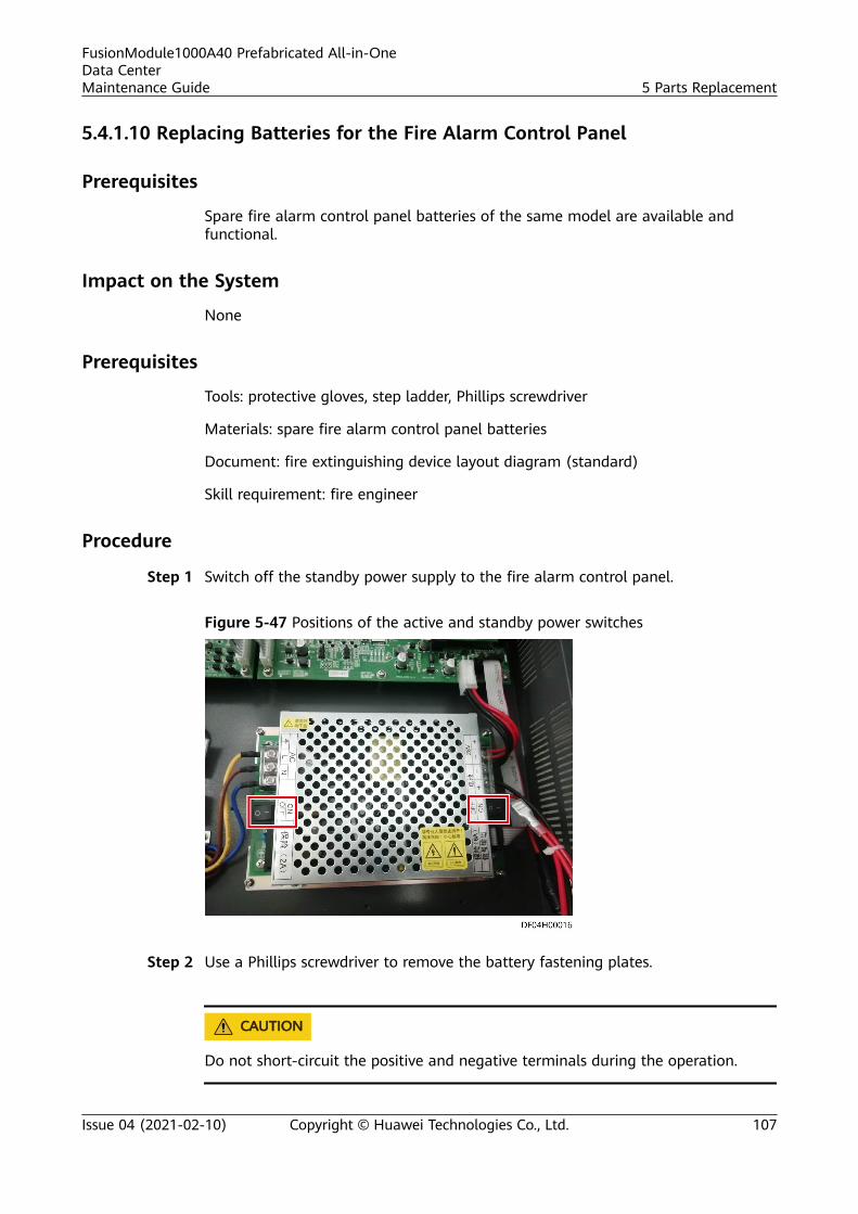
5.4.1.10 Replacing Batteries for the Fire Alarm Control Panel
Prerequisites
Spare fire alarm control panel batteries of the same model are available andfunctional.
Impact on the System
None
Prerequisites
Tools: protective gloves, step ladder, Phillips screwdriver
Materials: spare fire alarm control panel batteries
Document: fire extinguishing device layout diagram (standard)
Skill requirement: fire engineer
Procedure
Step 1 Switch off the standby power supply to the fire alarm control panel.
Figure 5-47 Positions of the active and standby power switches
Step 2 Use a Phillips screwdriver to remove the battery fastening plates.
CA UTION
Do not short-circuit the positive and negative terminals during the operation.
FusionModule1000A40 Prefabricated All-in-OneData CenterMaintenance Guide 5 Parts Replacement
Issue 04 (2021-02-10) Copyright © Huawei Technologies Co., Ltd. 107
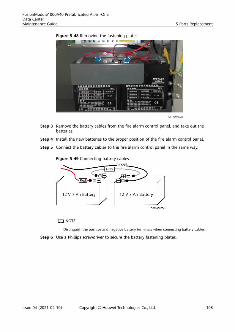
Figure 5-48 Removing the fastening plates
Step 3 Remove the battery cables from the fire alarm control panel, and take out thebatteries.
Step 4 Install the new batteries to the proper position of the fire alarm control panel.
Step 5 Connect the battery cables to the fire alarm control panel in the same way.
Figure 5-49 Connecting battery cables
NO TE
Distinguish the positive and negative battery terminals when connecting battery cables.
Step 6 Use a Phillips screwdriver to secure the battery fastening plates.
FusionModule1000A40 Prefabricated All-in-OneData CenterMaintenance Guide 5 Parts Replacement
Issue 04 (2021-02-10) Copyright © Huawei Technologies Co., Ltd. 108
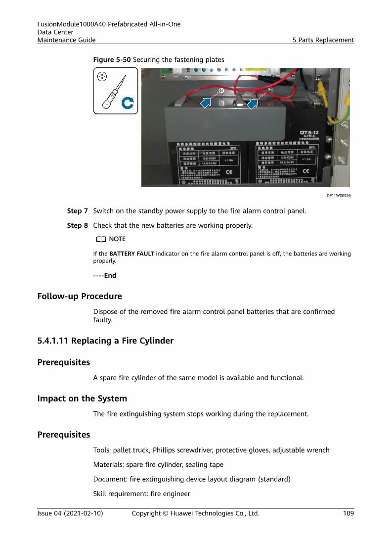
Figure 5-50 Securing the fastening plates
Step 7 Switch on the standby power supply to the fire alarm control panel.
Step 8 Check that the new batteries are working properly.
NO TE
If the BATTERY FAULT indicator on the fire alarm control panel is off, the batteries are workingproperly.
----End
Follow-up Procedure
Dispose of the removed fire alarm control panel batteries that are confirmedfaulty.
5.4.1.11 Replacing a Fire Cylinder
Prerequisites
A spare fire cylinder of the same model is available and functional.
Impact on the System
The fire extinguishing system stops working during the replacement.
Prerequisites
Tools: pallet truck, Phillips screwdriver, protective gloves, adjustable wrench
Materials: spare fire cylinder, sealing tape
Document: fire extinguishing device layout diagram (standard)
Skill requirement: fire engineer
FusionModule1000A40 Prefabricated All-in-OneData CenterMaintenance Guide 5 Parts Replacement
Issue 04 (2021-02-10) Copyright © Huawei Technologies Co., Ltd. 109
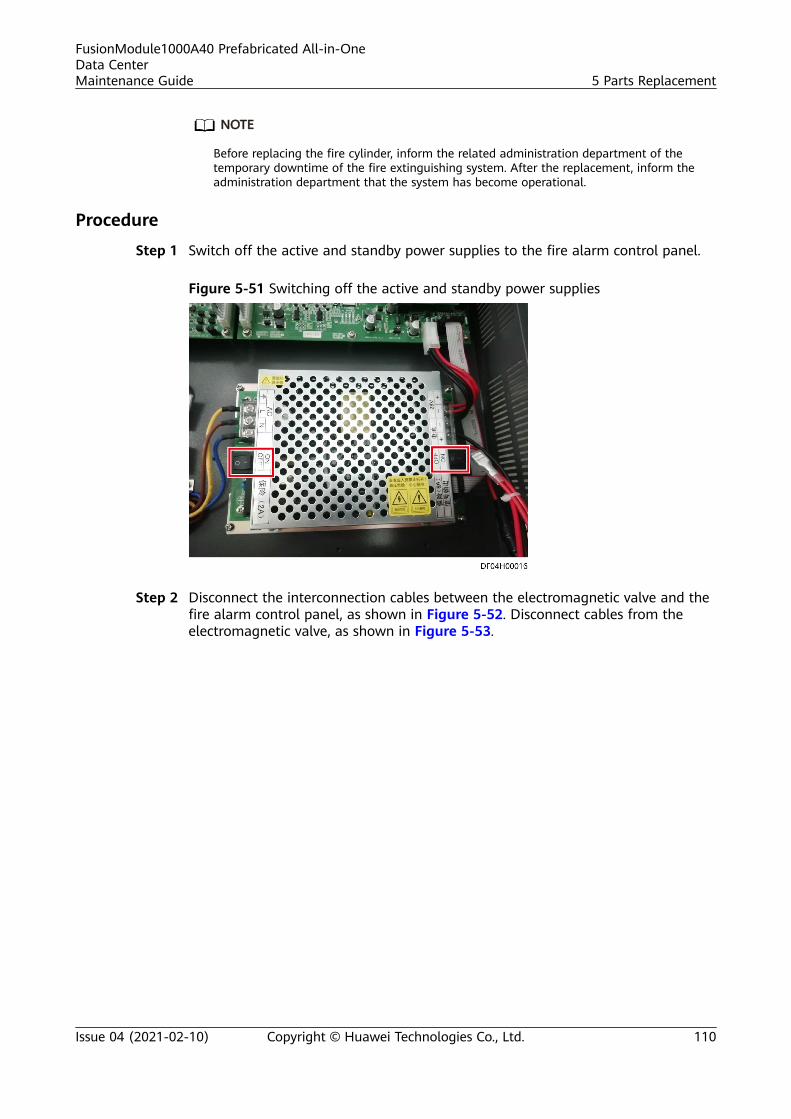
NO TE
Before replacing the fire cylinder, inform the related administration department of thetemporary downtime of the fire extinguishing system. After the replacement, inform theadministration department that the system has become operational.
Procedure
Step 1 Switch off the active and standby power supplies to the fire alarm control panel.
Figure 5-51 Switching off the active and standby power supplies
Step 2 Disconnect the interconnection cables between the electromagnetic valve and thefire alarm control panel, as shown in Figure 5-52. Disconnect cables from theelectromagnetic valve, as shown in Figure 5-53.
FusionModule1000A40 Prefabricated All-in-OneData CenterMaintenance Guide 5 Parts Replacement
Issue 04 (2021-02-10) Copyright © Huawei Technologies Co., Ltd. 110
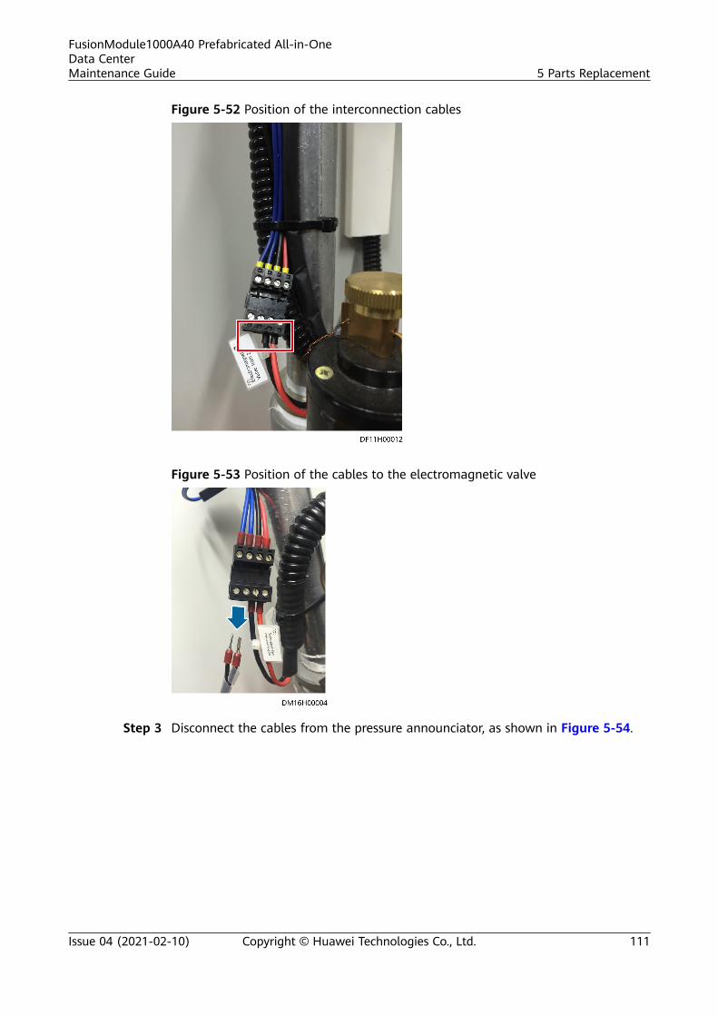
Figure 5-52 Position of the interconnection cables
Figure 5-53 Position of the cables to the electromagnetic valve
Step 3 Disconnect the cables from the pressure announciator, as shown in Figure 5-54.
FusionModule1000A40 Prefabricated All-in-OneData CenterMaintenance Guide 5 Parts Replacement
Issue 04 (2021-02-10) Copyright © Huawei Technologies Co., Ltd. 111
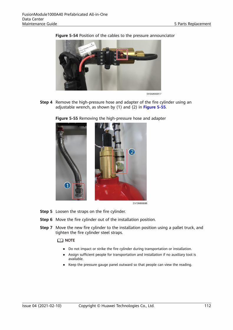
Figure 5-54 Position of the cables to the pressure announciator
Step 4 Remove the high-pressure hose and adapter of the fire cylinder using anadjustable wrench, as shown by (1) and (2) in Figure 5-55.
Figure 5-55 Removing the high-pressure hose and adapter
Step 5 Loosen the straps on the fire cylinder.
Step 6 Move the fire cylinder out of the installation position.
Step 7 Move the new fire cylinder to the installation position using a pallet truck, andtighten the fire cylinder steel straps.
NO TE
● Do not impact or strike the fire cylinder during transportation or installation.● Assign sufficient people for transportation and installation if no auxiliary tool is
available.● Keep the pressure gauge panel outward so that people can view the reading.
FusionModule1000A40 Prefabricated All-in-OneData CenterMaintenance Guide 5 Parts Replacement
Issue 04 (2021-02-10) Copyright © Huawei Technologies Co., Ltd. 112
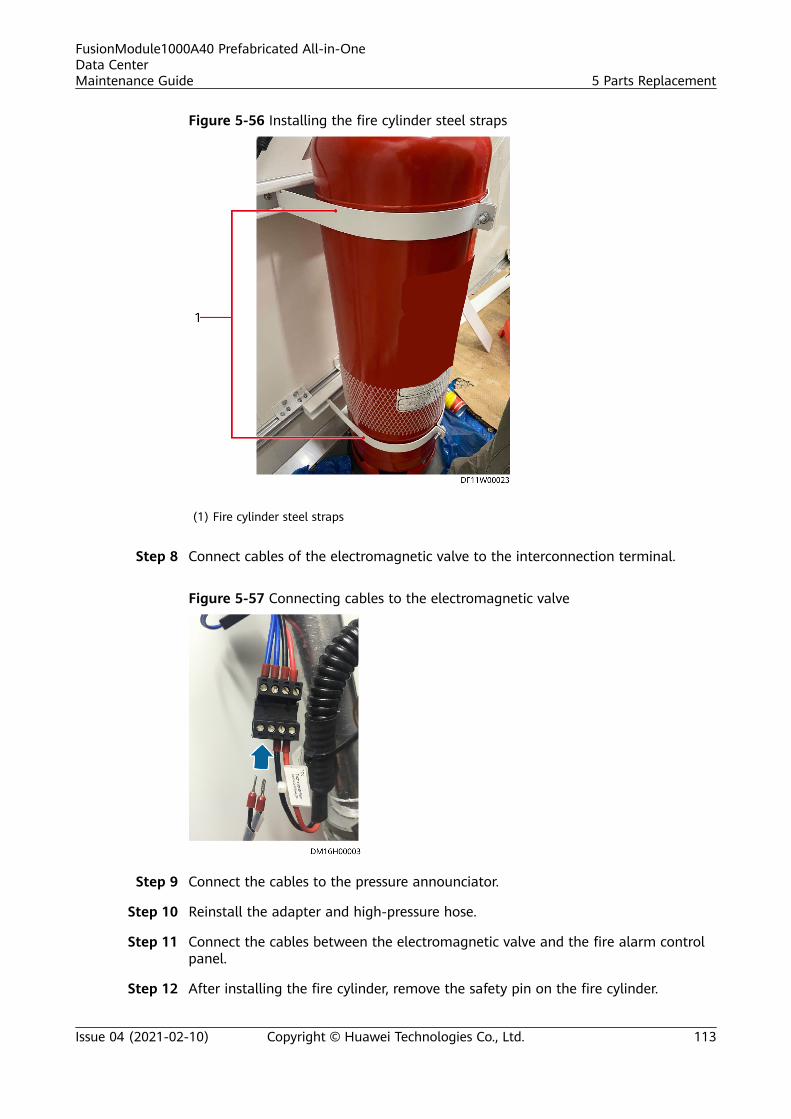
Figure 5-56 Installing the fire cylinder steel straps
(1) Fire cylinder steel straps
Step 8 Connect cables of the electromagnetic valve to the interconnection terminal.
Figure 5-57 Connecting cables to the electromagnetic valve
Step 9 Connect the cables to the pressure announciator.
Step 10 Reinstall the adapter and high-pressure hose.
Step 11 Connect the cables between the electromagnetic valve and the fire alarm controlpanel.
Step 12 After installing the fire cylinder, remove the safety pin on the fire cylinder.
FusionModule1000A40 Prefabricated All-in-OneData CenterMaintenance Guide 5 Parts Replacement
Issue 04 (2021-02-10) Copyright © Huawei Technologies Co., Ltd. 113
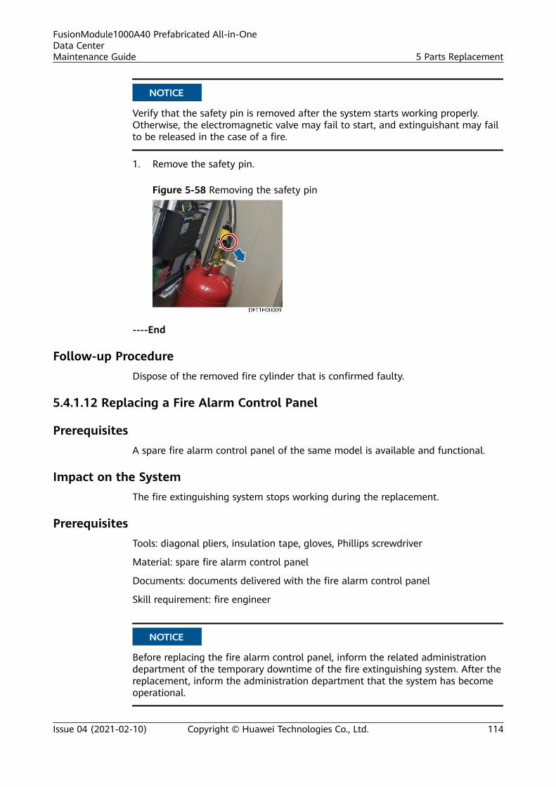
NO TICE
Verify that the safety pin is removed after the system starts working properly.Otherwise, the electromagnetic valve may fail to start, and extinguishant may failto be released in the case of a fire.
1. Remove the safety pin.
Figure 5-58 Removing the safety pin
----End
Follow-up ProcedureDispose of the removed fire cylinder that is confirmed faulty.
5.4.1.12 Replacing a Fire Alarm Control Panel
PrerequisitesA spare fire alarm control panel of the same model is available and functional.
Impact on the SystemThe fire extinguishing system stops working during the replacement.
PrerequisitesTools: diagonal pliers, insulation tape, gloves, Phillips screwdriver
Material: spare fire alarm control panel
Documents: documents delivered with the fire alarm control panel
Skill requirement: fire engineer
NO TICE
Before replacing the fire alarm control panel, inform the related administrationdepartment of the temporary downtime of the fire extinguishing system. After thereplacement, inform the administration department that the system has becomeoperational.
FusionModule1000A40 Prefabricated All-in-OneData CenterMaintenance Guide 5 Parts Replacement
Issue 04 (2021-02-10) Copyright © Huawei Technologies Co., Ltd. 114
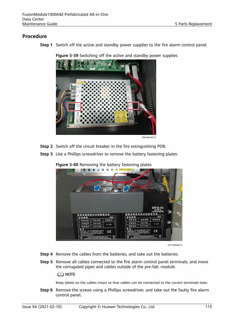
ProcedureStep 1 Switch off the active and standby power supplies to the fire alarm control panel.
Figure 5-59 Switching off the active and standby power supplies
Step 2 Switch off the circuit breaker in the fire extinguishing PDB.
Step 3 Use a Phillips screwdriver to remove the battery fastening plates.
Figure 5-60 Removing the battery fastening plates
Step 4 Remove the cables from the batteries, and take out the batteries.
Step 5 Remove all cables connected to the fire alarm control panel terminals, and movethe corrugated pipes and cables outside of the pre-fab. module.
NO TE
Keep labels on the cables intact so that cables can be connected to the correct terminals later.
Step 6 Remove the screws using a Phillips screwdriver, and take out the faulty fire alarmcontrol panel.
FusionModule1000A40 Prefabricated All-in-OneData CenterMaintenance Guide 5 Parts Replacement
Issue 04 (2021-02-10) Copyright © Huawei Technologies Co., Ltd. 115
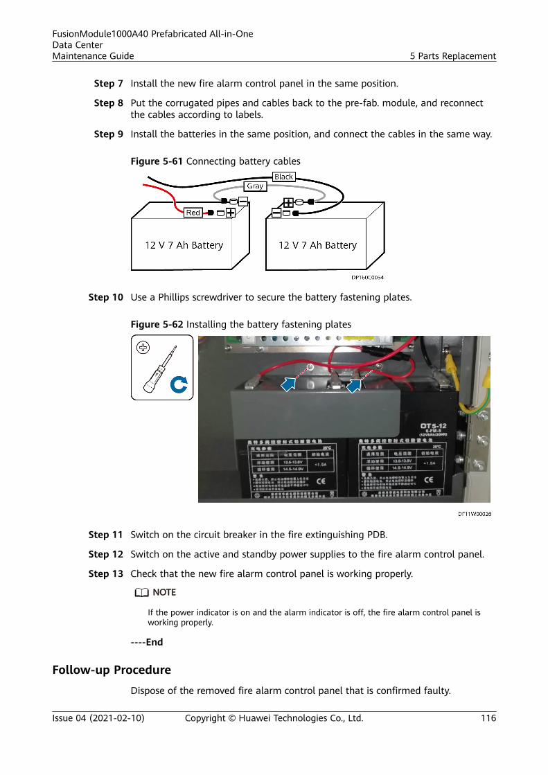
Step 7 Install the new fire alarm control panel in the same position.
Step 8 Put the corrugated pipes and cables back to the pre-fab. module, and reconnectthe cables according to labels.
Step 9 Install the batteries in the same position, and connect the cables in the same way.
Figure 5-61 Connecting battery cables
Step 10 Use a Phillips screwdriver to secure the battery fastening plates.
Figure 5-62 Installing the battery fastening plates
Step 11 Switch on the circuit breaker in the fire extinguishing PDB.
Step 12 Switch on the active and standby power supplies to the fire alarm control panel.
Step 13 Check that the new fire alarm control panel is working properly.
NO TE
If the power indicator is on and the alarm indicator is off, the fire alarm control panel isworking properly.
----End
Follow-up Procedure
Dispose of the removed fire alarm control panel that is confirmed faulty.
FusionModule1000A40 Prefabricated All-in-OneData CenterMaintenance Guide 5 Parts Replacement
Issue 04 (2021-02-10) Copyright © Huawei Technologies Co., Ltd. 116

5.4.1.13 Replacing an Emergency Light
Prerequisites
A spare emergency light of the same model is available and functional.
Impact on the System
None
Prerequisites
Tools: Phillips screwdriver, flat-head screwdriver, step ladder, protective gloves
Material: spare emergency light
Documents: none
Skill requirement: fire engineer
Procedure
Step 1 Turn off the upstream switch of the emergency light power cable.
Figure 5-63 Emergency light
Step 2 Remove the protective cover of the emergency light.
Step 3 Loosen the emergency panel using a flat-head screwdriver, and remove the panel.
Step 4 Remove screws from the emergency light base using a Phillips screwdriver, andremove the base.
Step 5 Install the new emergency light base and the panel in the same way.
Step 6 Remove the red pin, and reinstall the protective cover.
FusionModule1000A40 Prefabricated All-in-OneData CenterMaintenance Guide 5 Parts Replacement
Issue 04 (2021-02-10) Copyright © Huawei Technologies Co., Ltd. 117
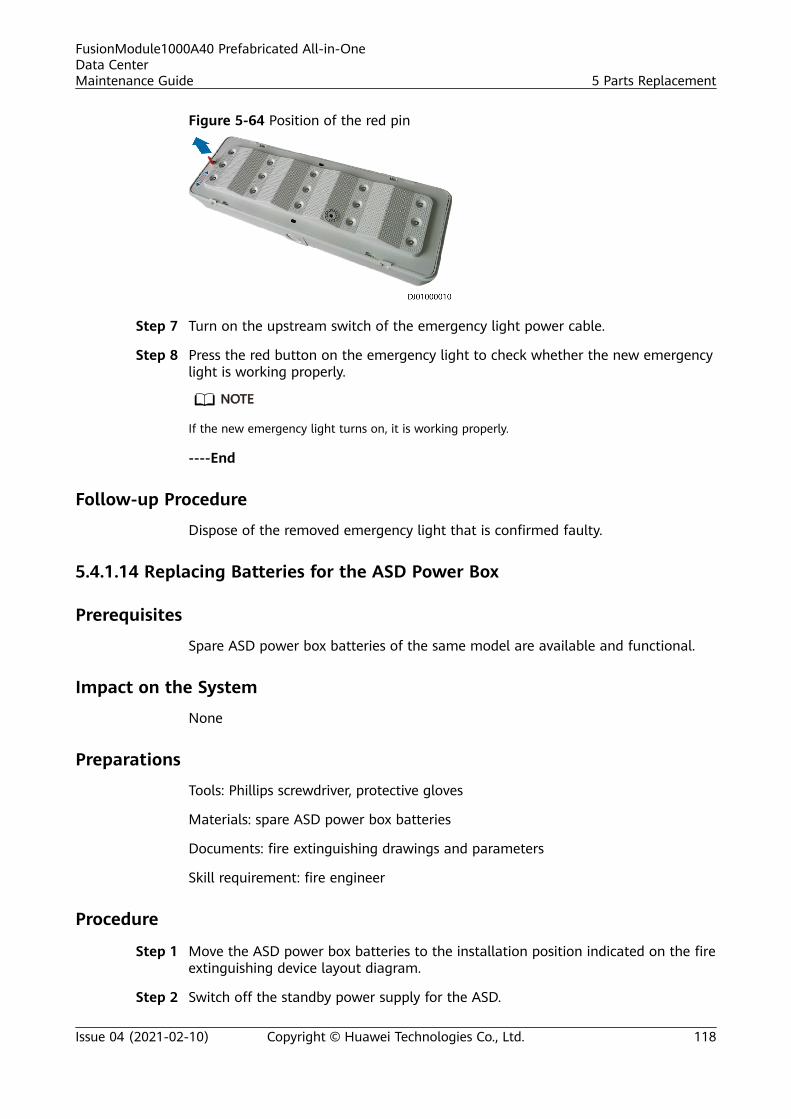
Figure 5-64 Position of the red pin
Step 7 Turn on the upstream switch of the emergency light power cable.
Step 8 Press the red button on the emergency light to check whether the new emergencylight is working properly.
NO TE
If the new emergency light turns on, it is working properly.
----End
Follow-up Procedure
Dispose of the removed emergency light that is confirmed faulty.
5.4.1.14 Replacing Batteries for the ASD Power Box
Prerequisites
Spare ASD power box batteries of the same model are available and functional.
Impact on the System
None
Preparations
Tools: Phillips screwdriver, protective gloves
Materials: spare ASD power box batteries
Documents: fire extinguishing drawings and parameters
Skill requirement: fire engineer
Procedure
Step 1 Move the ASD power box batteries to the installation position indicated on the fireextinguishing device layout diagram.
Step 2 Switch off the standby power supply for the ASD.
FusionModule1000A40 Prefabricated All-in-OneData CenterMaintenance Guide 5 Parts Replacement
Issue 04 (2021-02-10) Copyright © Huawei Technologies Co., Ltd. 118
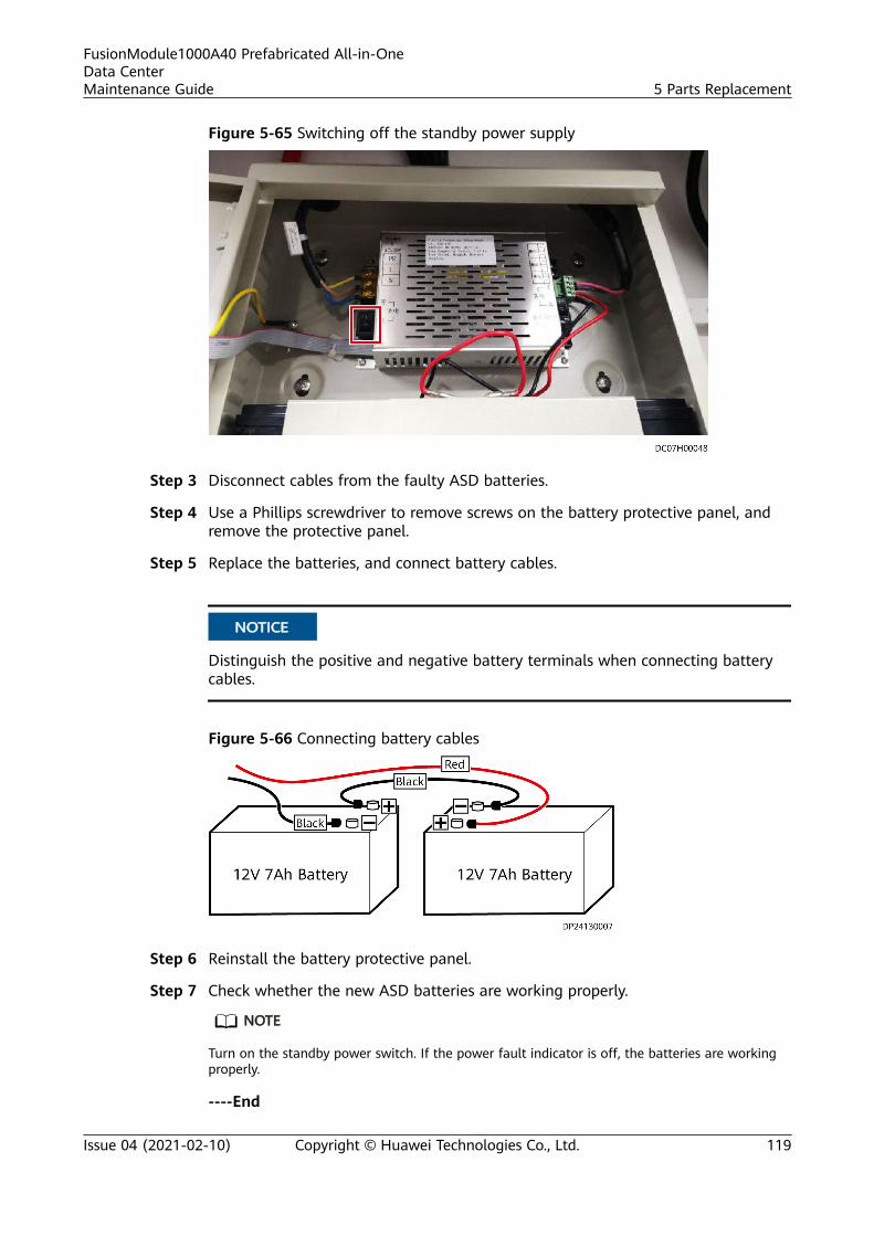
Figure 5-65 Switching off the standby power supply
Step 3 Disconnect cables from the faulty ASD batteries.
Step 4 Use a Phillips screwdriver to remove screws on the battery protective panel, andremove the protective panel.
Step 5 Replace the batteries, and connect battery cables.
NO TICE
Distinguish the positive and negative battery terminals when connecting batterycables.
Figure 5-66 Connecting battery cables
Step 6 Reinstall the battery protective panel.
Step 7 Check whether the new ASD batteries are working properly.
NO TE
Turn on the standby power switch. If the power fault indicator is off, the batteries are workingproperly.
----End
FusionModule1000A40 Prefabricated All-in-OneData CenterMaintenance Guide 5 Parts Replacement
Issue 04 (2021-02-10) Copyright © Huawei Technologies Co., Ltd. 119
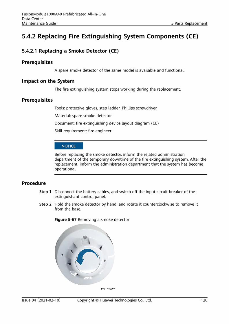
5.4.2 Replacing Fire Extinguishing System Components (CE)
5.4.2.1 Replacing a Smoke Detector (CE)
PrerequisitesA spare smoke detector of the same model is available and functional.
Impact on the SystemThe fire extinguishing system stops working during the replacement.
PrerequisitesTools: protective gloves, step ladder, Phillips screwdriver
Material: spare smoke detector
Document: fire extinguishing device layout diagram (CE)
Skill requirement: fire engineer
NO TICE
Before replacing the smoke detector, inform the related administrationdepartment of the temporary downtime of the fire extinguishing system. After thereplacement, inform the administration department that the system has becomeoperational.
ProcedureStep 1 Disconnect the battery cables, and switch off the input circuit breaker of the
extinguishant control panel.
Step 2 Hold the smoke detector by hand, and rotate it counterclockwise to remove itfrom the base.
Figure 5-67 Removing a smoke detector
FusionModule1000A40 Prefabricated All-in-OneData CenterMaintenance Guide 5 Parts Replacement
Issue 04 (2021-02-10) Copyright © Huawei Technologies Co., Ltd. 120

Step 3 Remove cables from the base.
NO TE
As a terminal resistor is connected to the last smoke detector in the loop in parallel, removethe terminal resistor from the faulty smoke detector, and connect the resistor to the newsmoke detector when you replace the smoke detector.
Step 4 Remove the screws on the base using a Phillips screwdriver, and remove the base.
Step 5 Install the new base in the same position, and reconnect the cables.
Step 6 Insert the new smoke detector into the base, and rotate it clockwise until it locksin position.
Step 7 Switch on the input circuit breaker of the extinguishant control panel, and connectthe battery cables.
Step 8 Check that the new smoke detector is working properly.
NO TE
If the red indicator blinks once every 6s, the smoke detector is working properly.
----End
5.4.2.2 Replacing a Heat Detector (CE)
Prerequisites
A spare heat detector of the same model is available and functional.
Impact on the System
The fire extinguishing system stops working during the replacement.
Prerequisites
Tools: protective gloves, step ladder, Phillips screwdriver
Material: spare heat detector
Document: fire extinguishing device layout diagram (CE)
Skill requirement: fire engineer
NO TICE
● Before replacing the heat detector, inform the related administrationdepartment of the temporary downtime of the fire extinguishing system. Afterthe replacement, inform the administration department that the system hasbecome operational.
FusionModule1000A40 Prefabricated All-in-OneData CenterMaintenance Guide 5 Parts Replacement
Issue 04 (2021-02-10) Copyright © Huawei Technologies Co., Ltd. 121
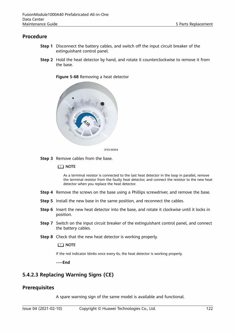
Procedure
Step 1 Disconnect the battery cables, and switch off the input circuit breaker of theextinguishant control panel.
Step 2 Hold the heat detector by hand, and rotate it counterclockwise to remove it fromthe base.
Figure 5-68 Removing a heat detector
Step 3 Remove cables from the base.
NO TE
As a terminal resistor is connected to the last heat detector in the loop in parallel, removethe terminal resistor from the faulty heat detector, and connect the resistor to the new heatdetector when you replace the heat detector.
Step 4 Remove the screws on the base using a Phillips screwdriver, and remove the base.
Step 5 Install the new base in the same position, and reconnect the cables.
Step 6 Insert the new heat detector into the base, and rotate it clockwise until it locks inposition.
Step 7 Switch on the input circuit breaker of the extinguishant control panel, and connectthe battery cables.
Step 8 Check that the new heat detector is working properly.
NO TE
If the red indicator blinks once every 6s, the heat detector is working properly.
----End
5.4.2.3 Replacing Warning Signs (CE)
Prerequisites
A spare warning sign of the same model is available and functional.
FusionModule1000A40 Prefabricated All-in-OneData CenterMaintenance Guide 5 Parts Replacement
Issue 04 (2021-02-10) Copyright © Huawei Technologies Co., Ltd. 122
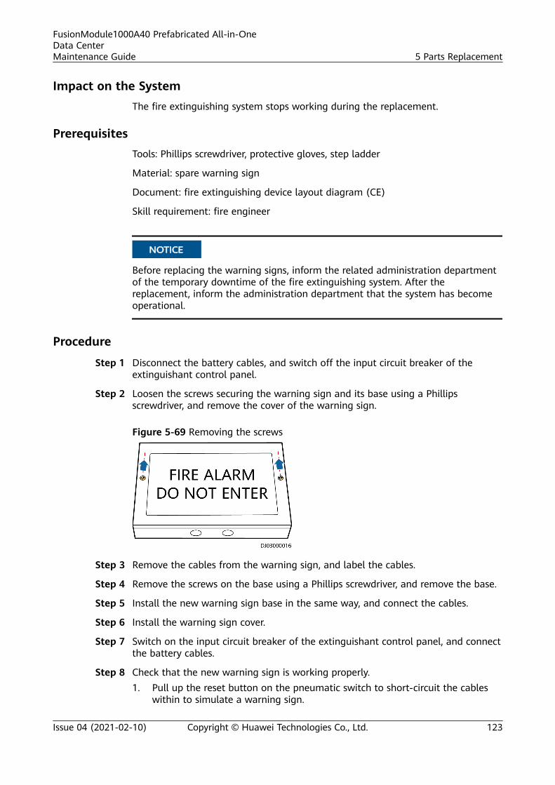
Impact on the SystemThe fire extinguishing system stops working during the replacement.
PrerequisitesTools: Phillips screwdriver, protective gloves, step ladder
Material: spare warning sign
Document: fire extinguishing device layout diagram (CE)
Skill requirement: fire engineer
NO TICE
Before replacing the warning signs, inform the related administration departmentof the temporary downtime of the fire extinguishing system. After thereplacement, inform the administration department that the system has becomeoperational.
Procedure
Step 1 Disconnect the battery cables, and switch off the input circuit breaker of theextinguishant control panel.
Step 2 Loosen the screws securing the warning sign and its base using a Phillipsscrewdriver, and remove the cover of the warning sign.
Figure 5-69 Removing the screws
Step 3 Remove the cables from the warning sign, and label the cables.
Step 4 Remove the screws on the base using a Phillips screwdriver, and remove the base.
Step 5 Install the new warning sign base in the same way, and connect the cables.
Step 6 Install the warning sign cover.
Step 7 Switch on the input circuit breaker of the extinguishant control panel, and connectthe battery cables.
Step 8 Check that the new warning sign is working properly.1. Pull up the reset button on the pneumatic switch to short-circuit the cables
within to simulate a warning sign.
FusionModule1000A40 Prefabricated All-in-OneData CenterMaintenance Guide 5 Parts Replacement
Issue 04 (2021-02-10) Copyright © Huawei Technologies Co., Ltd. 123
NO TE
If the warning sign turns on, the warning sign is working properly.
2. Press the reset button on the pneumatic switch.3. Flip the key Enable Control rightward. Reset the extinguishant control panel
by pressing Reset on it. Then, reset the key Enable Control leftward.
----End
5.4.2.4 Replacing an Internal Horn Strobe (CE)
PrerequisitesA spare horn strobe of the same model is available and functional.
Impact on the SystemThe fire extinguishing system stops working during the replacement.
PreparationsTools: Phillips screwdriver, step ladder
Materials: spare horn strobe
Documents: fire extinguishing drawings and parameters
Skill requirement: fire engineer
NO TICE
Before replacing the horn strobe, inform the related administrative department ofthe temporary downtime of the fire control system. After the replacement, informthe administration department that the system has become operational.
Procedure
Step 1 Disconnect the battery cables, and switch off the input circuit breaker of theextinguishant control panel.
Step 2 Rotate the horn strobe cover counterclockwise and remove it.
Step 3 Remove cables from the horn strobe.
NO TICE
● While removing cables, label the cables with the corresponding terminal portsfor later connection.
● As a terminal resistor is connected to the last internal horn strobe in parallel,remove the terminal resistor from the faulty horn strobe, and connect theresistor to the new horn strobe when you replace the horn strobe.
FusionModule1000A40 Prefabricated All-in-OneData CenterMaintenance Guide 5 Parts Replacement
Issue 04 (2021-02-10) Copyright © Huawei Technologies Co., Ltd. 124
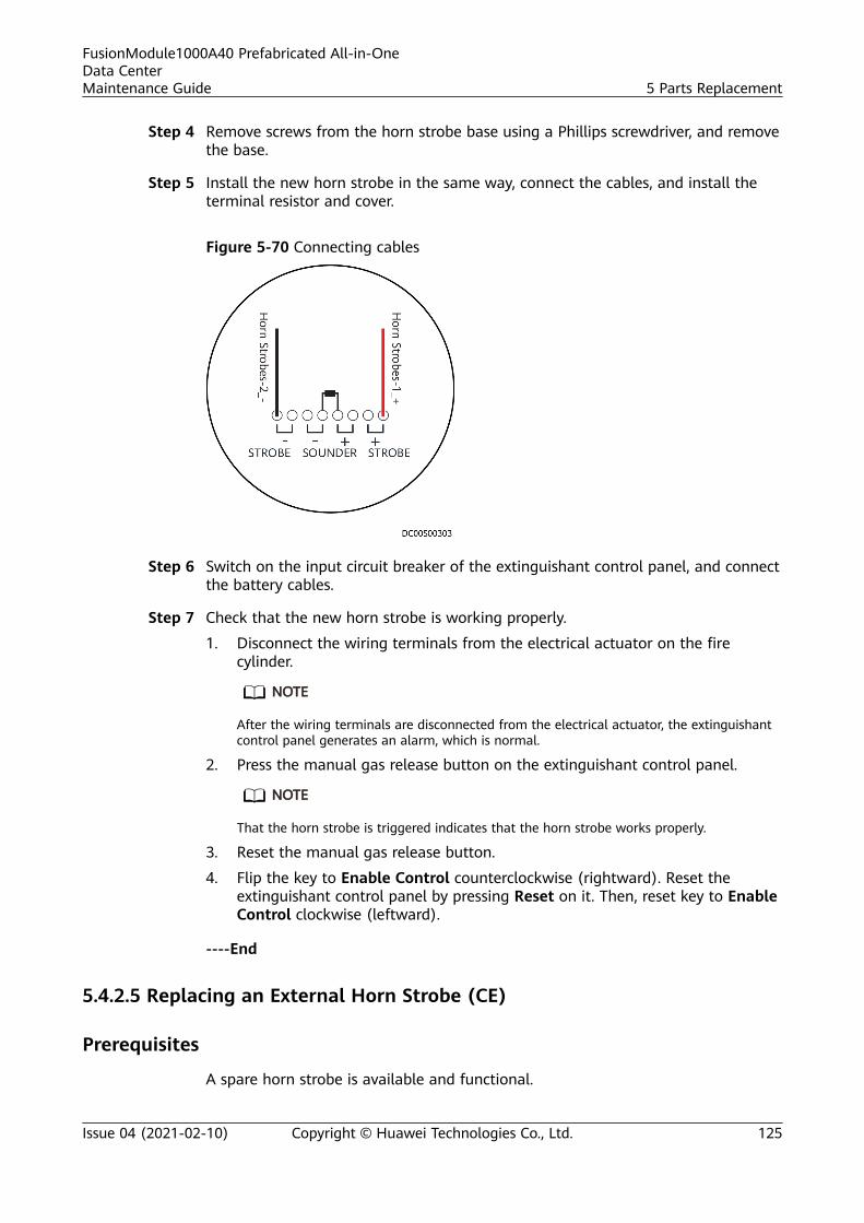
Step 4 Remove screws from the horn strobe base using a Phillips screwdriver, and removethe base.
Step 5 Install the new horn strobe in the same way, connect the cables, and install theterminal resistor and cover.
Figure 5-70 Connecting cables
Step 6 Switch on the input circuit breaker of the extinguishant control panel, and connectthe battery cables.
Step 7 Check that the new horn strobe is working properly.
1. Disconnect the wiring terminals from the electrical actuator on the firecylinder.
NO TE
After the wiring terminals are disconnected from the electrical actuator, the extinguishantcontrol panel generates an alarm, which is normal.
2. Press the manual gas release button on the extinguishant control panel.
NO TE
That the horn strobe is triggered indicates that the horn strobe works properly.
3. Reset the manual gas release button.
4. Flip the key to Enable Control counterclockwise (rightward). Reset theextinguishant control panel by pressing Reset on it. Then, reset key to EnableControl clockwise (leftward).
----End
5.4.2.5 Replacing an External Horn Strobe (CE)
Prerequisites
A spare horn strobe is available and functional.
FusionModule1000A40 Prefabricated All-in-OneData CenterMaintenance Guide 5 Parts Replacement
Issue 04 (2021-02-10) Copyright © Huawei Technologies Co., Ltd. 125
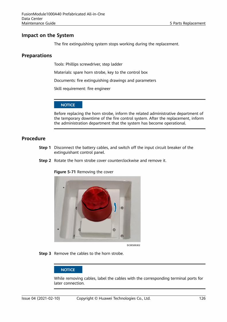
Impact on the System
The fire extinguishing system stops working during the replacement.
Preparations
Tools: Phillips screwdriver, step ladder
Materials: spare horn strobe, key to the control box
Documents: fire extinguishing drawings and parameters
Skill requirement: fire engineer
NO TICE
Before replacing the horn strobe, inform the related administrative department ofthe temporary downtime of the fire control system. After the replacement, informthe administration department that the system has become operational.
Procedure
Step 1 Disconnect the battery cables, and switch off the input circuit breaker of theextinguishant control panel.
Step 2 Rotate the horn strobe cover counterclockwise and remove it.
Figure 5-71 Removing the cover
Step 3 Remove the cables to the horn strobe.
NO TICE
While removing cables, label the cables with the corresponding terminal ports forlater connection.
FusionModule1000A40 Prefabricated All-in-OneData CenterMaintenance Guide 5 Parts Replacement
Issue 04 (2021-02-10) Copyright © Huawei Technologies Co., Ltd. 126
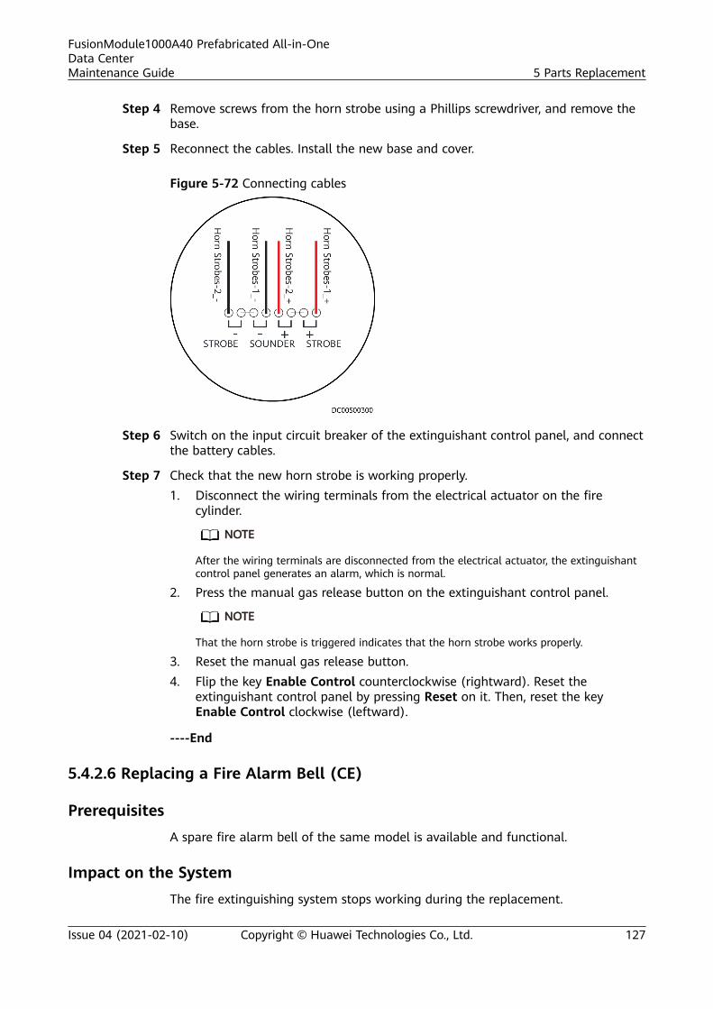
Step 4 Remove screws from the horn strobe using a Phillips screwdriver, and remove thebase.
Step 5 Reconnect the cables. Install the new base and cover.
Figure 5-72 Connecting cables
Step 6 Switch on the input circuit breaker of the extinguishant control panel, and connectthe battery cables.
Step 7 Check that the new horn strobe is working properly.1. Disconnect the wiring terminals from the electrical actuator on the fire
cylinder.
NO TE
After the wiring terminals are disconnected from the electrical actuator, the extinguishantcontrol panel generates an alarm, which is normal.
2. Press the manual gas release button on the extinguishant control panel.
NO TE
That the horn strobe is triggered indicates that the horn strobe works properly.
3. Reset the manual gas release button.4. Flip the key Enable Control counterclockwise (rightward). Reset the
extinguishant control panel by pressing Reset on it. Then, reset the keyEnable Control clockwise (leftward).
----End
5.4.2.6 Replacing a Fire Alarm Bell (CE)
PrerequisitesA spare fire alarm bell of the same model is available and functional.
Impact on the SystemThe fire extinguishing system stops working during the replacement.
FusionModule1000A40 Prefabricated All-in-OneData CenterMaintenance Guide 5 Parts Replacement
Issue 04 (2021-02-10) Copyright © Huawei Technologies Co., Ltd. 127
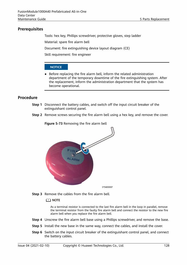
PrerequisitesTools: hex key, Phillips screwdriver, protective gloves, step ladder
Material: spare fire alarm bell
Document: fire extinguishing device layout diagram (CE)
Skill requirement: fire engineer
NO TICE
● Before replacing the fire alarm bell, inform the related administrationdepartment of the temporary downtime of the fire extinguishing system. Afterthe replacement, inform the administration department that the system hasbecome operational.
ProcedureStep 1 Disconnect the battery cables, and switch off the input circuit breaker of the
extinguishant control panel.
Step 2 Remove screws securing the fire alarm bell using a hex key, and remove the cover.
Figure 5-73 Removing the fire alarm bell
Step 3 Remove the cables from the fire alarm bell.
NO TE
As a terminal resistor is connected to the last fire alarm bell in the loop in parallel, removethe terminal resistor from the faulty fire alarm bell and connect the resistor to the new firealarm bell when you replace the fire alarm bell.
Step 4 Unscrew the fire alarm bell base using a Phillips screwdriver, and remove the base.
Step 5 Install the new base in the same way, connect the cables, and install the cover.
Step 6 Switch on the input circuit breaker of the extinguishant control panel, and connectthe battery cables.
FusionModule1000A40 Prefabricated All-in-OneData CenterMaintenance Guide 5 Parts Replacement
Issue 04 (2021-02-10) Copyright © Huawei Technologies Co., Ltd. 128
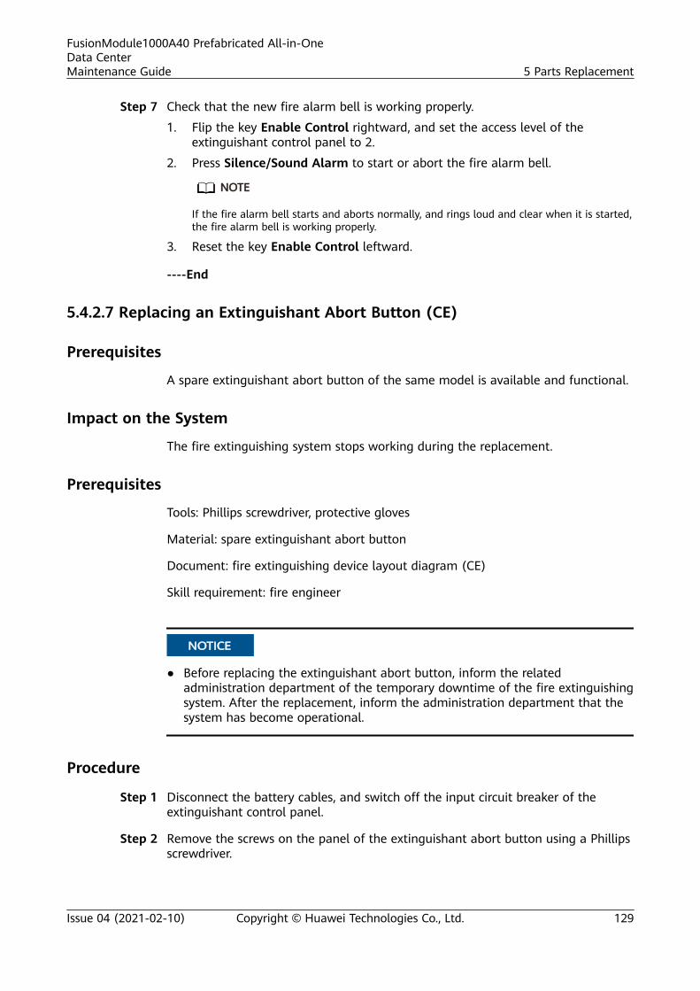
Step 7 Check that the new fire alarm bell is working properly.
1. Flip the key Enable Control rightward, and set the access level of theextinguishant control panel to 2.
2. Press Silence/Sound Alarm to start or abort the fire alarm bell.
NO TE
If the fire alarm bell starts and aborts normally, and rings loud and clear when it is started,the fire alarm bell is working properly.
3. Reset the key Enable Control leftward.
----End
5.4.2.7 Replacing an Extinguishant Abort Button (CE)
Prerequisites
A spare extinguishant abort button of the same model is available and functional.
Impact on the System
The fire extinguishing system stops working during the replacement.
Prerequisites
Tools: Phillips screwdriver, protective gloves
Material: spare extinguishant abort button
Document: fire extinguishing device layout diagram (CE)
Skill requirement: fire engineer
NO TICE
● Before replacing the extinguishant abort button, inform the relatedadministration department of the temporary downtime of the fire extinguishingsystem. After the replacement, inform the administration department that thesystem has become operational.
Procedure
Step 1 Disconnect the battery cables, and switch off the input circuit breaker of theextinguishant control panel.
Step 2 Remove the screws on the panel of the extinguishant abort button using a Phillipsscrewdriver.
FusionModule1000A40 Prefabricated All-in-OneData CenterMaintenance Guide 5 Parts Replacement
Issue 04 (2021-02-10) Copyright © Huawei Technologies Co., Ltd. 129
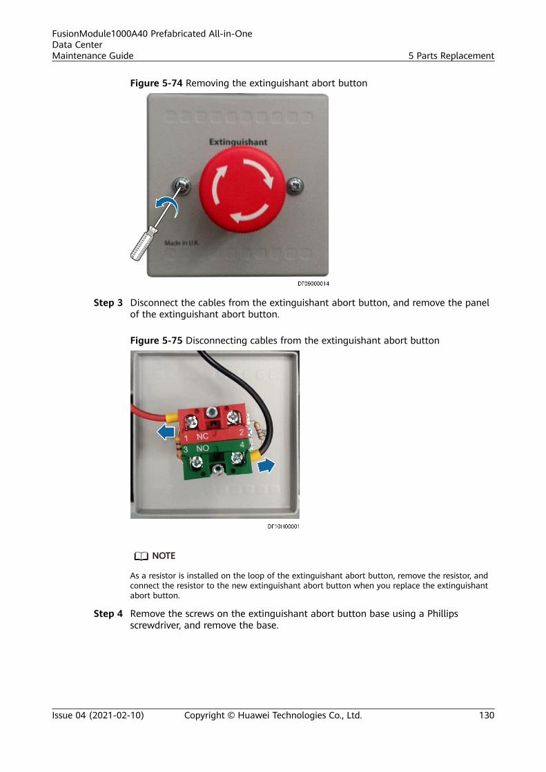
Figure 5-74 Removing the extinguishant abort button
Step 3 Disconnect the cables from the extinguishant abort button, and remove the panelof the extinguishant abort button.
Figure 5-75 Disconnecting cables from the extinguishant abort button
NO TE
As a resistor is installed on the loop of the extinguishant abort button, remove the resistor, andconnect the resistor to the new extinguishant abort button when you replace the extinguishantabort button.
Step 4 Remove the screws on the extinguishant abort button base using a Phillipsscrewdriver, and remove the base.
FusionModule1000A40 Prefabricated All-in-OneData CenterMaintenance Guide 5 Parts Replacement
Issue 04 (2021-02-10) Copyright © Huawei Technologies Co., Ltd. 130
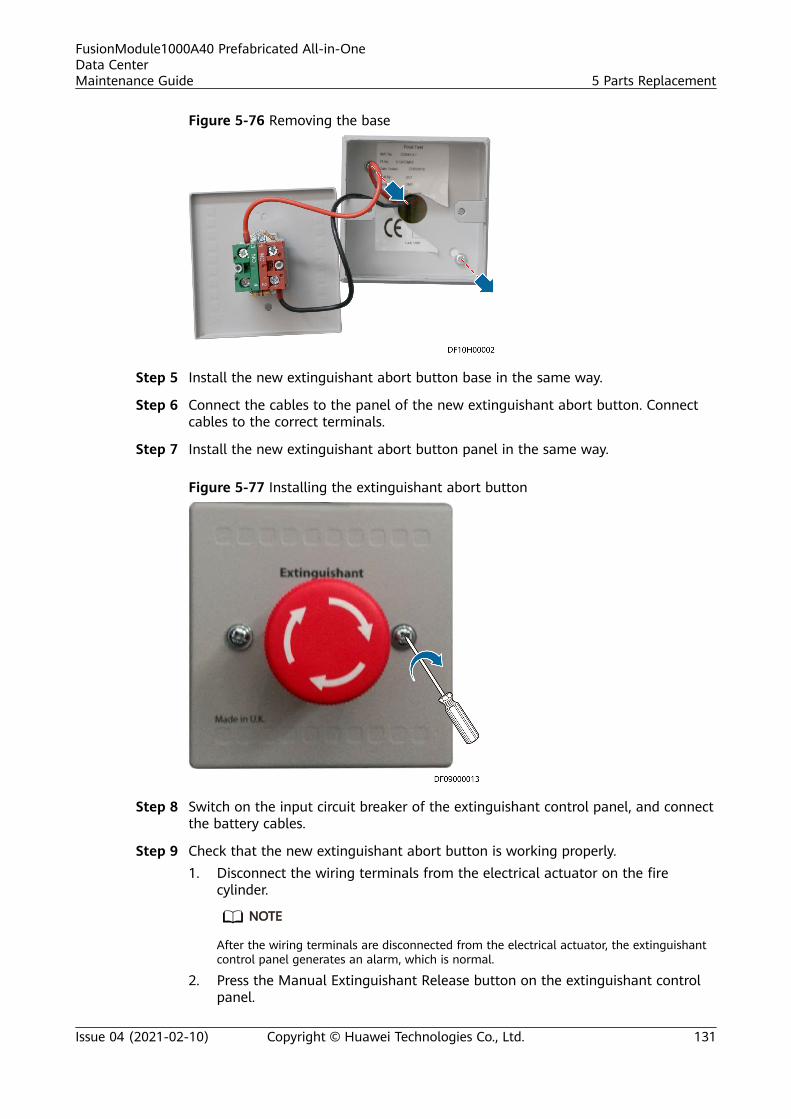
Figure 5-76 Removing the base
Step 5 Install the new extinguishant abort button base in the same way.
Step 6 Connect the cables to the panel of the new extinguishant abort button. Connectcables to the correct terminals.
Step 7 Install the new extinguishant abort button panel in the same way.
Figure 5-77 Installing the extinguishant abort button
Step 8 Switch on the input circuit breaker of the extinguishant control panel, and connectthe battery cables.
Step 9 Check that the new extinguishant abort button is working properly.1. Disconnect the wiring terminals from the electrical actuator on the fire
cylinder.
NO TE
After the wiring terminals are disconnected from the electrical actuator, the extinguishantcontrol panel generates an alarm, which is normal.
2. Press the Manual Extinguishant Release button on the extinguishant controlpanel.
FusionModule1000A40 Prefabricated All-in-OneData CenterMaintenance Guide 5 Parts Replacement
Issue 04 (2021-02-10) Copyright © Huawei Technologies Co., Ltd. 131
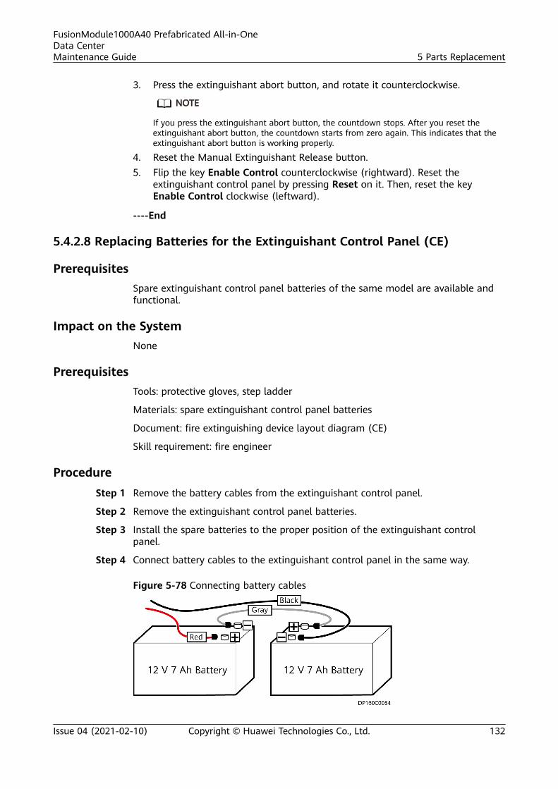
3. Press the extinguishant abort button, and rotate it counterclockwise.
NO TE
If you press the extinguishant abort button, the countdown stops. After you reset theextinguishant abort button, the countdown starts from zero again. This indicates that theextinguishant abort button is working properly.
4. Reset the Manual Extinguishant Release button.5. Flip the key Enable Control counterclockwise (rightward). Reset the
extinguishant control panel by pressing Reset on it. Then, reset the keyEnable Control clockwise (leftward).
----End
5.4.2.8 Replacing Batteries for the Extinguishant Control Panel (CE)
PrerequisitesSpare extinguishant control panel batteries of the same model are available andfunctional.
Impact on the SystemNone
PrerequisitesTools: protective gloves, step ladder
Materials: spare extinguishant control panel batteries
Document: fire extinguishing device layout diagram (CE)
Skill requirement: fire engineer
ProcedureStep 1 Remove the battery cables from the extinguishant control panel.
Step 2 Remove the extinguishant control panel batteries.
Step 3 Install the spare batteries to the proper position of the extinguishant controlpanel.
Step 4 Connect battery cables to the extinguishant control panel in the same way.
Figure 5-78 Connecting battery cables
FusionModule1000A40 Prefabricated All-in-OneData CenterMaintenance Guide 5 Parts Replacement
Issue 04 (2021-02-10) Copyright © Huawei Technologies Co., Ltd. 132
NO TICE
Distinguish the positive and negative battery terminals when connecting batterycables.
----End
5.4.2.9 Replacing a Fire Cylinder (CE)
Prerequisites
A spare fire cylinder of the same model is available and functional.
Impact on the System
The fire extinguishing system stops working during the replacement.
Prerequisites
Tools: pipe wrench, pallet truck, Phillips screwdriver, adjustable wrench, protectivegloves
Materials: spare fire cylinder, sealing tape
Document: fire extinguishing device layout diagram (CE)
Skill requirement: fire engineer
NO TICE
● Before replacing the fire cylinder, inform the related administration departmentof the temporary downtime of the fire extinguishing system. After thereplacement, inform the administration department that the system hasbecome operational.
Procedure
Step 1 Disconnect the battery cables, and switch off the input circuit breaker of theextinguishant control panel.
Step 2 Move the new fire cylinder using a pallet truck to a position near the pre-fab.module door.
NO TICE
● Do not impact or strike the fire cylinder during transportation or installation.● Assign sufficient people for transportation and installation if no auxiliary tool is
available.
FusionModule1000A40 Prefabricated All-in-OneData CenterMaintenance Guide 5 Parts Replacement
Issue 04 (2021-02-10) Copyright © Huawei Technologies Co., Ltd. 133
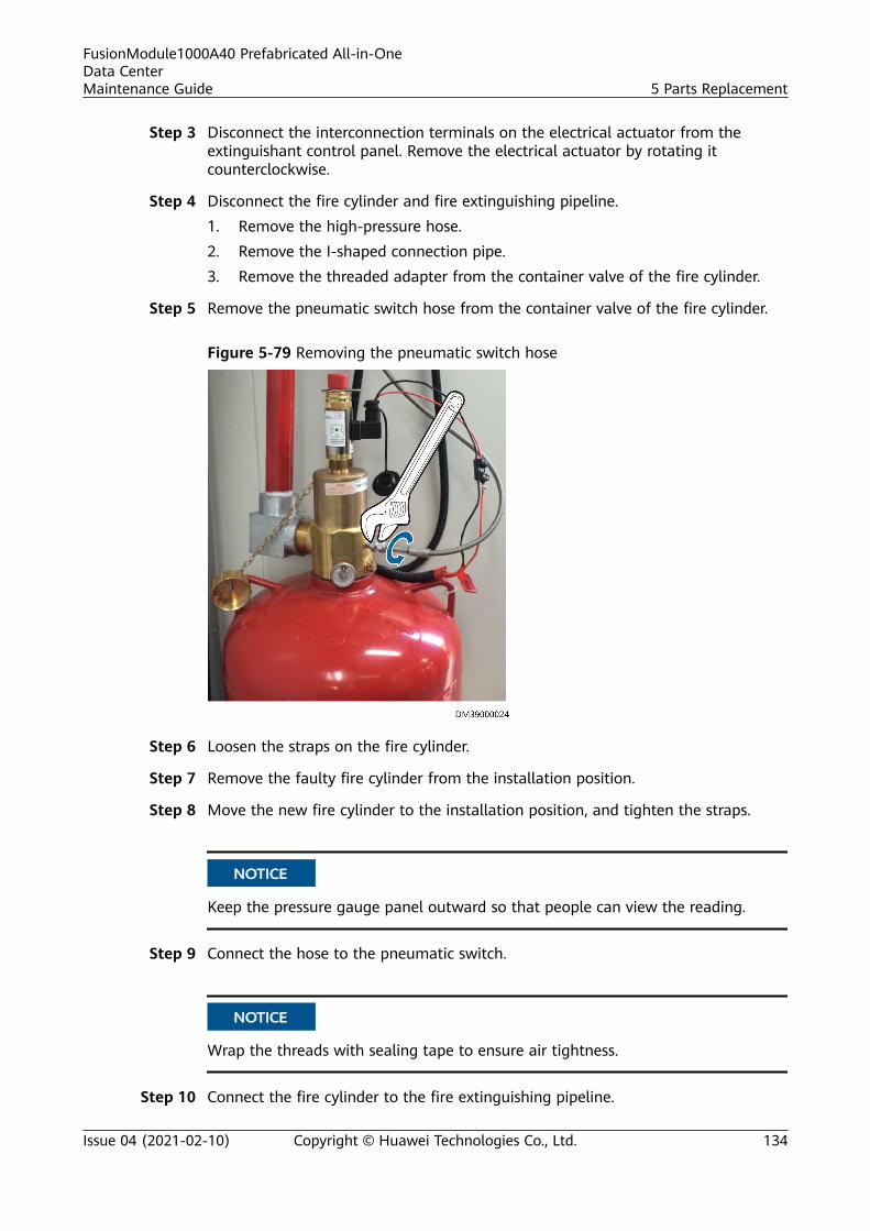
Step 3 Disconnect the interconnection terminals on the electrical actuator from theextinguishant control panel. Remove the electrical actuator by rotating itcounterclockwise.
Step 4 Disconnect the fire cylinder and fire extinguishing pipeline.1. Remove the high-pressure hose.2. Remove the I-shaped connection pipe.3. Remove the threaded adapter from the container valve of the fire cylinder.
Step 5 Remove the pneumatic switch hose from the container valve of the fire cylinder.
Figure 5-79 Removing the pneumatic switch hose
Step 6 Loosen the straps on the fire cylinder.
Step 7 Remove the faulty fire cylinder from the installation position.
Step 8 Move the new fire cylinder to the installation position, and tighten the straps.
NO TICE
Keep the pressure gauge panel outward so that people can view the reading.
Step 9 Connect the hose to the pneumatic switch.
NO TICE
Wrap the threads with sealing tape to ensure air tightness.
Step 10 Connect the fire cylinder to the fire extinguishing pipeline.
FusionModule1000A40 Prefabricated All-in-OneData CenterMaintenance Guide 5 Parts Replacement
Issue 04 (2021-02-10) Copyright © Huawei Technologies Co., Ltd. 134
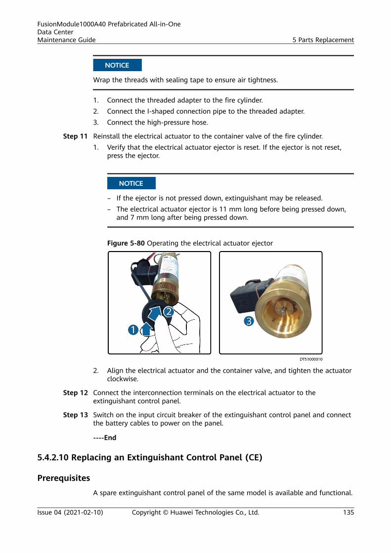
NO TICE
Wrap the threads with sealing tape to ensure air tightness.
1. Connect the threaded adapter to the fire cylinder.2. Connect the I-shaped connection pipe to the threaded adapter.3. Connect the high-pressure hose.
Step 11 Reinstall the electrical actuator to the container valve of the fire cylinder.1. Verify that the electrical actuator ejector is reset. If the ejector is not reset,
press the ejector.
NO TICE
– If the ejector is not pressed down, extinguishant may be released.– The electrical actuator ejector is 11 mm long before being pressed down,
and 7 mm long after being pressed down.
Figure 5-80 Operating the electrical actuator ejector
2. Align the electrical actuator and the container valve, and tighten the actuatorclockwise.
Step 12 Connect the interconnection terminals on the electrical actuator to theextinguishant control panel.
Step 13 Switch on the input circuit breaker of the extinguishant control panel and connectthe battery cables to power on the panel.
----End
5.4.2.10 Replacing an Extinguishant Control Panel (CE)
Prerequisites
A spare extinguishant control panel of the same model is available and functional.
FusionModule1000A40 Prefabricated All-in-OneData CenterMaintenance Guide 5 Parts Replacement
Issue 04 (2021-02-10) Copyright © Huawei Technologies Co., Ltd. 135
Impact on the SystemThe fire extinguishing system stops working during the replacement.
PrerequisitesTools: Phillips screwdriver, protective gloves
Material: spare extinguishant control panel
Documents: documents delivered with the extinguishant control panel
Skill requirement: fire engineer
NO TICE
Before replacing the extinguishant control panel, inform the related administrationdepartment of the temporary downtime of the fire extinguishing system. After thereplacement, inform the administration department that the system has becomeoperational.
Procedure
Step 1 Switch off the input circuit breaker of the extinguishant control panel.
Step 2 Remove the cables from the batteries, and take out the batteries.
Step 3 Remove all cables connected to the terminals on the extinguishant control panel.
NO TE
While removing the cables, label the cables with their corresponding port numbers for laterconnection.
Step 4 Remove the corrugated pipes and cables from the pre-fab. module.
Step 5 Remove the screws using a Phillips screwdriver, and take out the faultyextinguishant control panel.
FusionModule1000A40 Prefabricated All-in-OneData CenterMaintenance Guide 5 Parts Replacement
Issue 04 (2021-02-10) Copyright © Huawei Technologies Co., Ltd. 136
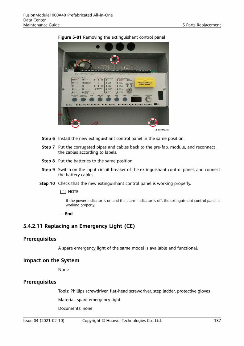
Figure 5-81 Removing the extinguishant control panel
Step 6 Install the new extinguishant control panel in the same position.
Step 7 Put the corrugated pipes and cables back to the pre-fab. module, and reconnectthe cables according to labels.
Step 8 Put the batteries to the same position.
Step 9 Switch on the input circuit breaker of the extinguishant control panel, and connectthe battery cables.
Step 10 Check that the new extinguishant control panel is working properly.
NO TE
If the power indicator is on and the alarm indicator is off, the extinguishant control panel isworking properly.
----End
5.4.2.11 Replacing an Emergency Light (CE)
PrerequisitesA spare emergency light of the same model is available and functional.
Impact on the SystemNone
PrerequisitesTools: Phillips screwdriver, flat-head screwdriver, step ladder, protective gloves
Material: spare emergency light
Documents: none
FusionModule1000A40 Prefabricated All-in-OneData CenterMaintenance Guide 5 Parts Replacement
Issue 04 (2021-02-10) Copyright © Huawei Technologies Co., Ltd. 137
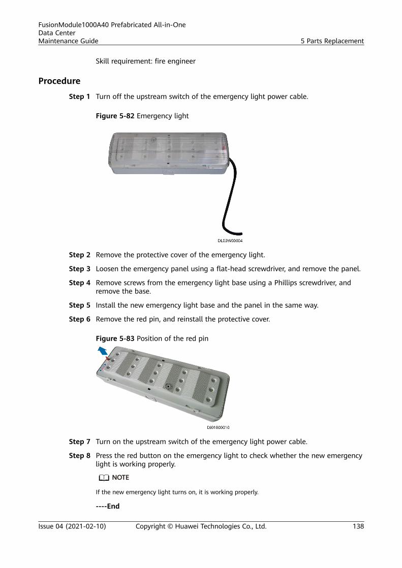
Skill requirement: fire engineer
Procedure
Step 1 Turn off the upstream switch of the emergency light power cable.
Figure 5-82 Emergency light
Step 2 Remove the protective cover of the emergency light.
Step 3 Loosen the emergency panel using a flat-head screwdriver, and remove the panel.
Step 4 Remove screws from the emergency light base using a Phillips screwdriver, andremove the base.
Step 5 Install the new emergency light base and the panel in the same way.
Step 6 Remove the red pin, and reinstall the protective cover.
Figure 5-83 Position of the red pin
Step 7 Turn on the upstream switch of the emergency light power cable.
Step 8 Press the red button on the emergency light to check whether the new emergencylight is working properly.
NO TE
If the new emergency light turns on, it is working properly.
----End
FusionModule1000A40 Prefabricated All-in-OneData CenterMaintenance Guide 5 Parts Replacement
Issue 04 (2021-02-10) Copyright © Huawei Technologies Co., Ltd. 138
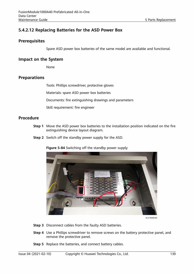
5.4.2.12 Replacing Batteries for the ASD Power Box
Prerequisites
Spare ASD power box batteries of the same model are available and functional.
Impact on the System
None
Preparations
Tools: Phillips screwdriver, protective gloves
Materials: spare ASD power box batteries
Documents: fire extinguishing drawings and parameters
Skill requirement: fire engineer
Procedure
Step 1 Move the ASD power box batteries to the installation position indicated on the fireextinguishing device layout diagram.
Step 2 Switch off the standby power supply for the ASD.
Figure 5-84 Switching off the standby power supply
Step 3 Disconnect cables from the faulty ASD batteries.
Step 4 Use a Phillips screwdriver to remove screws on the battery protective panel, andremove the protective panel.
Step 5 Replace the batteries, and connect battery cables.
FusionModule1000A40 Prefabricated All-in-OneData CenterMaintenance Guide 5 Parts Replacement
Issue 04 (2021-02-10) Copyright © Huawei Technologies Co., Ltd. 139
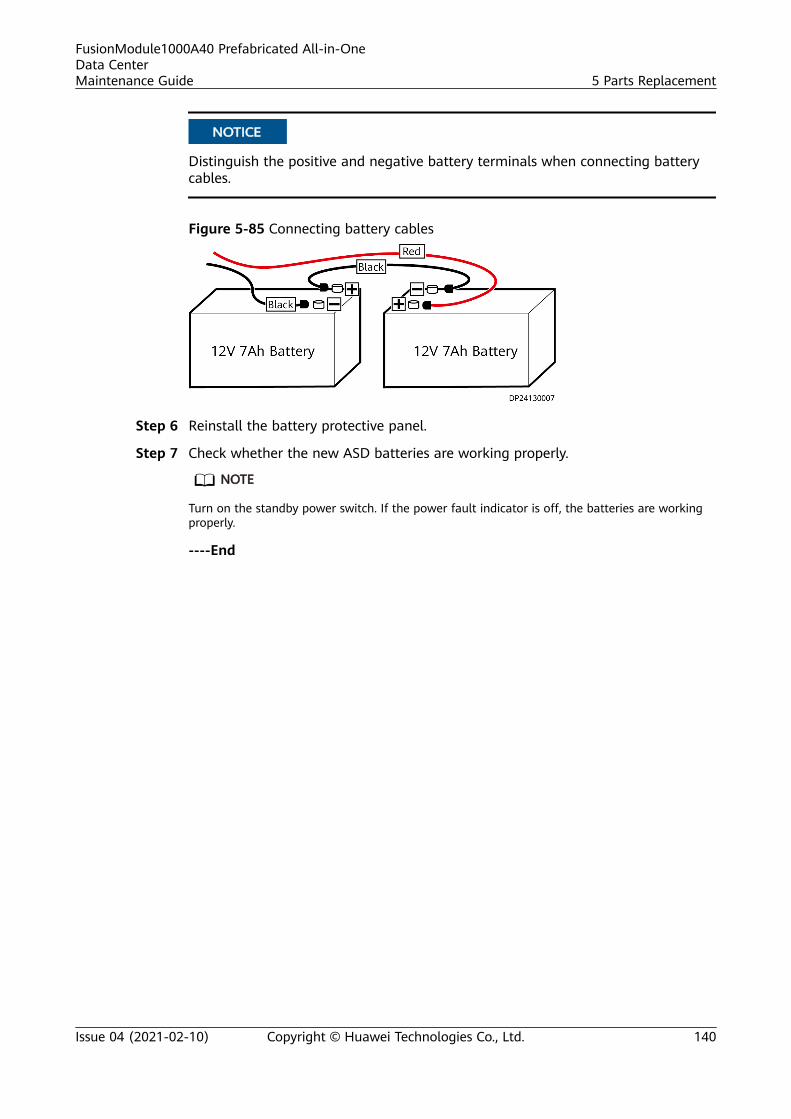
NO TICE
Distinguish the positive and negative battery terminals when connecting batterycables.
Figure 5-85 Connecting battery cables
Step 6 Reinstall the battery protective panel.
Step 7 Check whether the new ASD batteries are working properly.
NO TE
Turn on the standby power switch. If the power fault indicator is off, the batteries are workingproperly.
----End
FusionModule1000A40 Prefabricated All-in-OneData CenterMaintenance Guide 5 Parts Replacement
Issue 04 (2021-02-10) Copyright © Huawei Technologies Co., Ltd. 140
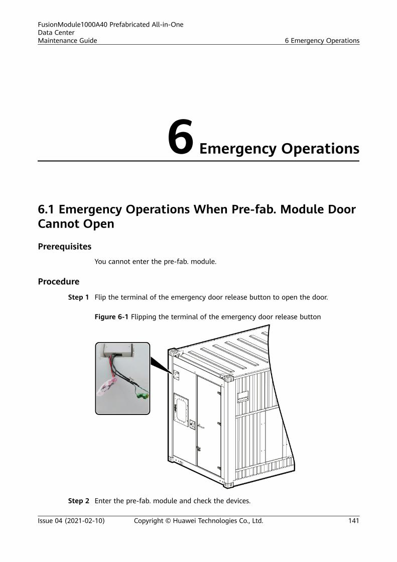
6 Emergency Operations
6.1 Emergency Operations When Pre-fab. Module DoorCannot Open
Prerequisites
You cannot enter the pre-fab. module.
Procedure
Step 1 Flip the terminal of the emergency door release button to open the door.
Figure 6-1 Flipping the terminal of the emergency door release button
Step 2 Enter the pre-fab. module and check the devices.
FusionModule1000A40 Prefabricated All-in-OneData CenterMaintenance Guide 6 Emergency Operations
Issue 04 (2021-02-10) Copyright © Huawei Technologies Co., Ltd. 141
Step 3 Locate the cause why the pre-fab. module door cannot be opened after verifyingthat the devices are running properly.
NO TE
Possible causes why a pre-fab. module door cannot be opened are as follows:● Replace the access card and assign the access permission if the access card is faulty.● Replace the end door card reader if it is faulty.● Replace the exit button if it is faulty.● Replace the magnetic lock if it is faulty.● Replace the access controller if it is faulty.
Step 4 (Optional) Reinstall the terminal of the emergency door release button after thefault is rectified.
----End
Follow-up ProcedureAnalyze the cause of the fault, and work out and record the preventive measures.
FusionModule1000A40 Prefabricated All-in-OneData CenterMaintenance Guide 6 Emergency Operations
Issue 04 (2021-02-10) Copyright © Huawei Technologies Co., Ltd. 142

7 Appendixes
7.1 Repairing the Pre-fab. Module
Preparations
Tools: cutting machine, polishing machine, fine sandpaper, anhydrous alcohol,cotton cloth, spray gun (for large area repainting), paint (epoxy zinc rich primer+epoxy intermediate paint+polyurethane topcoat)
Materials: The attachment contains the repair steel plate.
Procedure
Step 1 Cut the damaged part into a regular rectangle.
Figure 7-1 Cut the damaged part into a regular rectangle.
Step 2 Use a polishing machine to polish the paint on the cut surface and the polishingwidth is 10–20 mm.
Step 3 Cut the prepared materials into the same size as the holes to be welded.
Step 4 Fully weld along the joints.
FusionModule1000A40 Prefabricated All-in-OneData CenterMaintenance Guide 7 Appendixes
Issue 04 (2021-02-10) Copyright © Huawei Technologies Co., Ltd. 143

Figure 7-2 Fully weld along the joints.
Step 5 After the welding is complete, polish the welding joints. Use water to check forleakage.
Figure 7-3 polish the welding joints
Step 6 Clean the welding joints with alcohol, and add the paint (epoxy zinc rich primer+epoxy intermediate paint+polyurethane topcoat) according to the procedure:After the primer is dry, apply the epoxy intermediate paint. After the intermediatepaint is dry, apply the polyurethane topcoat.
----End
FusionModule1000A40 Prefabricated All-in-OneData CenterMaintenance Guide 7 Appendixes
Issue 04 (2021-02-10) Copyright © Huawei Technologies Co., Ltd. 144
8 Acronyms and Abbreviations
A
AC alternating current
ATS automatic transfer switch
C
CAN control area network
CE Conformite Europende
D
DDF digital distribution frame
E
ECC energy control center
L
LCD liquid crystal display
M
FusionModule1000A40 Prefabricated All-in-OneData CenterMaintenance Guide 8 Acronyms and Abbreviations
Issue 04 (2021-02-10) Copyright © Huawei Technologies Co., Ltd. 145

MDU monitor display module
P
POE power over Ethernet
PDF power distribution frame
PDU power distribution unit
R
rPDU rack power distribution unit
S
SIM subscriber identity module
U
UPS uninterruptible power system
V
VCN video cloud node
ASD aspirating smoke detector
FusionModule1000A40 Prefabricated All-in-OneData CenterMaintenance Guide 8 Acronyms and Abbreviations
Issue 04 (2021-02-10) Copyright © Huawei Technologies Co., Ltd. 146