Quick Installation Guide Wireless Access Point Supporting Router Mode
Upload
khangminh22Category
view
2download
0
(IEC 19-inch & ETSI 21-inch Cabinet)
1 U Quick Installation Guide This document applies to the installation of the ATN 910C-K/M/G, ATN 910D-A, NetEngine 8000 M1A/M1C, and OptiX PTN 916-F.
Issue:01

Device Overview1
DC chassis
AC chassis
DC and AC Chassis are installed in the same way. For installation details, see the corresponding installation guide.Figures in the document are for reference only and may be different from actual devices.The type and quantity of items in an installation accessory package vary according to the device model. Check the delivered items against the actual packing list.
NOTE
DC and AC power modules can be installed in any of the power module slots on the ATN 910C-K/M and ATN 910D-A.
NOTE
Packing list
Insulation tape Serial cableLabel cable tie
Fiber binding tapePanel screw (M6x12)Floating nut (M6)
Signal cable labelCable tie (300 x 3.6 mm)
Power cable label
Cable management frameCorrugated pipe ESD wrist strap

Device Overview1Technical Specifications
Item
Chassis height[U]
Maximum inputcurrent [A]
Input voltage range [V]
Maximum input current [A]
DC Chassis
1 U
44.45 mm x 442 mm x 220 mm(1.75 in. x 17.4 in. x 8.66 in.)
OptiX PTN 916-F: 4.0 kgNetEngine 8000 M1A: 3.9 kgNetEngine 8000 M1C:3.8 kgATN 910C-K: 4.0 kgATN 910C-M: 3.8 kgATN 910C-G: 3.9 kgATN 910D-A: 4.2 kg
OptiX PTN 916-F: 2.5 ANetEngine 8000 M1A: 4 ANetEngine 8000 M1C: 10 AATN 910C-K/M: 10 AATN 910C-G: 4 AATN 910D-A: 10 A
-48 V/-60 V
-40 V to -72 V 100 V to 240 V
OptiX PTN 916-F/NetEngine 8000 M1A/ATN 910C-G: 110 V/220 VNetEngine 8000 M1C/ATN910C-K/M/ATN 910D-A: 200 V to 240 V/100 V to 127 V dual live wires, support 240V HVDC
AC Chassis
1 U
44.45 mm x 442 mm x 220 mm(1.75 in. x 17.4 in. x 8.66 in.)
OptiX PTN 916-F: 3.6 kgNetEngine 8000 M1A: 4.5 kgNetEngine 8000 M1C:3.9 kgATN 910C-K: 4.1 kgATN 910C-M: 3.9 kgATN 910C-G: 4.5 kgATN 910D-A: 4.3 kg
OptiX PTN 916-F: 1.5 ANetEngine 8000 M1A: 1.5 ANetEngine 8000 M1C: 4 AATN 910C-K/M: 4 AATN 910C-G: 1.5 AATN 910D-A: 4 A
Dimensions without packaging (H x W x D) [mm(in.)]
Weight without packaging (base configuration)[kg(lb)]

Safety Guidelines2Observe all safety regulations and precautions
Only trained and qualified personnel are allowed to install, operate or maintain the equipment. Familiarize yourself with all safety pre-cautions before performing any operation on the equipment.
Operator qualifications
To ensure personal and equipment safety, observe all the safety precautions on the equipmentand in this document. and and items do not cover all the safety precautions and are only supplementary to the safety precautions.Follow all the safety precautions and instructions provided by Huawei. The safety precautions outlined in this document are only requirements of Huawei and do not cover general safety regulations. Huawei is not liable for any consequence that results from violation of regulation spertaining to safe operations or safety codes pertaining to design, production, and equipment use.
DANGER WARNING
CAUTION NOTICE
Do not install or remove the equipment or power cables while power is on.To ensure equipment and personal safety, ground the equipment before powering it on.
DANGER
Use multiple persons to move or lift a chassis and take measures toprotect personal safety.Laser beams will cause eye damage. Do not look into bores of optical modules or opticalfibers without eye protection.
WARNING
During equipment transport and installation, prevent the equipment from colliding with objects like doors, walls, or shelves.Move an unpacked chassis upright. Do not drag it with it lying down.Do not touch unpainted surfaces of the equipment with wet or contaminated gloves.Do not open the ESD bags of cards and modules until they are delivered to the equipmentroom. When taking a card out of the ESD bag, do not use the connector to support the card's weight because this operation will distort the connector and make the pins on the backplane connector bend.
NOTICE
Before installing, operating, or maintaining the equipment, wear an ESD wrist strap and insert the other end into the ESD jack on the chassis or cabinet. Remove conductive objects like jewelry and watches to prevent damages to the equipment and cards caused by electrostatic discharge.
ESD Protection
Site Requirements3To ensure personal and equipment safety, observe all the safety precautions on the equipmentand in this document. and and items do not cover all the safety precautions and are only supplementary to the safety precautions.
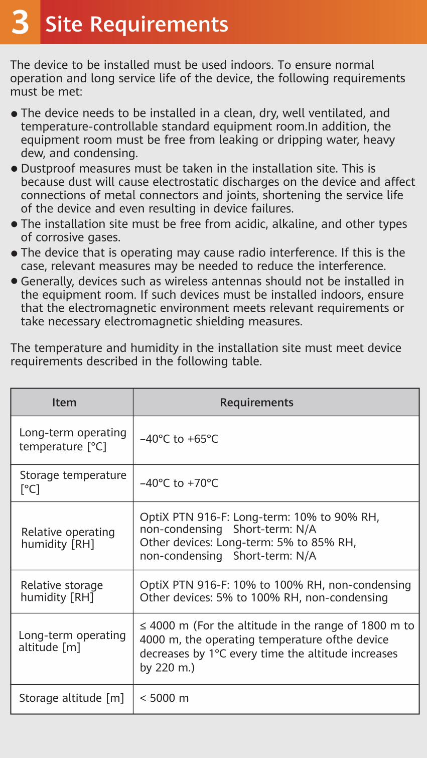
The device needs to be installed in a clean, dry, well ventilated, and temperature-controllable standard equipment room.In addition, the equipment room must be free from leaking or dripping water, heavy dew, and condensing.Dustproof measures must be taken in the installation site. This is because dust will cause electrostatic discharges on the device and affect connections of metal connectors and joints, shortening the service life of the device and even resulting in device failures.The installation site must be free from acidic, alkaline, and other types of corrosive gases.The device that is operating may cause radio interference. If this is the case, relevant measures may be needed to reduce the interference.Generally, devices such as wireless antennas should not be installed in the equipment room. If such devices must be installed indoors, ensure that the electromagnetic environment meets relevant requirements or take necessary electromagnetic shielding measures.
The device to be installed must be used indoors. To ensure normal operation and long service life of the device, the following requirements must be met:
The temperature and humidity in the installation site must meet device requirements described in the following table.
Long-term operating temperature [°C]
Relative operating humidity [RH]
–40°C to +65°C
≤ 4000 m (For the altitude in the range of 1800 m to 4000 m, the operating temperature ofthe device decreases by 1°C every time the altitude increases by 220 m.)
Item Requirements
Storage temperature[°C] –40°C to +70°C
Relative storage humidity [RH]
Long-term operating altitude [m]
Storage altitude [m] < 5000 m
OptiX PTN 916-F: Long-term: 10% to 90% RH, non-condensing Short-term: N/AOther devices: Long-term: 5% to 85% RH, non-condensing Short-term: N/A
OptiX PTN 916-F: 10% to 100% RH, non-condensingOther devices: 5% to 100% RH, non-condensing

Cabinet Requirements4NOTE
The device must be installed in an IEC 19-inch cabinet or an ETSI 21-inch cabinet.Huawei A63E cabinet is recommended. If customers choose to purchase cabinets by themselves, the cabinets must meet the following requirements:1. 19-inch or 21-inch cabinet with a depth of greater than or equal to 300 mm.2. The cabling space in front of the cabinet complies with the cabling space requirements of boards. It is recommended that the distance between the cabinet door and any device board be greater than or equal to 120 mm. If the cabling space is insufficient, cables will block the cabinet door from closing. Therefore, a cabinet with broader cabling space is recommended, such as a cabinet with a convex door.3. The device draws air from the left side and exhausts from the right side. Therefore, if the device is installed in a 19-inch cabinet, there must be a clearance of at least 75 mm at the left and right sides of the cabinet to ensure good ventilation.4. The porosity of each cabinet door must be greater than 50%, meeting heat dissipation requirements of devices.5. The cabinet has installation accessories, such as guide rails, floating nuts, and screws.6. The cabinet has a ground terminal to connect to the device.7. The cabinet has a cable outlet on the top or at the bottom for overhead or underfloor cabling.
The cabinet may be installed on an ESD floor or a concrete floor. For details about how to install a cabinet, see the Cabinet Installation Guide delivered with a cabinet.For cabinets with left-to-right air channels, such as open racks, installing cabinets side by side may cause cascaded heating. Therefore, you are advised to install cabinets with left-to-right air channels verti-cally at different levels rather than side by side. If side-by-side installa-tion cannot be avoided, it is recommended that the distance between cabinets be at least 500 mm (19.67 in.).If the device requires optical modules or attenuators with a puller, ensure that sufficient space is available for routing optical fibers. For a convex door or open rack, it is recommended that the distance between the cabinet door and the front panel of the board be greater than or equal to 120 mm (4.72 in.).

Installing a Device5
5.1 Installing a Device in an IEC 19-Inch Cabinet
1 Install floating nuts onto the cabinet.
When installing a device in a cabinet, ensure that the total heat consumption of all devices in the cabinet does not exceed the heat dissipation capability of the cabinet.To prevent air return from affecting heat dissipation, leave at least 2 U space between devices in the cabinet.Do not block the heat dissipation holes on panels.A device that needs to share the same cabinet with other devices cannot be installed near the air exhaust vents of those devices.Consider the impact of a device's air exhaust vent on adjacent devices to prevent high temperature.When fastening floating nuts, ensure that there is at least 75 mm space on the left and right sides of the device for ventilation after device installation.
CAUTION
Installation hole
Floating nut
NOTE
Certain steps support two installation modes. Select a proper PGND cable installation mode according to cabling requirements. The PGND cable can be connected to either the front or side face of the device. Connecting the cable to the side face is preferred.Figures in the document are for reference only, and the actual device appearance may vary depending on the exact device model.

Installing a Device5
M4
PWR2
PWR1
2 Connect the PGND cable to the front or side face of the device. Connecting the cable to the side face is preferred.

Installing a Device5
M6
3 Install the device into the cabinet.
ATN 910D-ACLK/TOD
ETH/OAMALM/ALMO
RST
STAT
CLK/TEST
ALM
0 1 2 3 4 5 6 7 8 9 10 11 12 13 14 15 16 17 18 19 20 21 22 23
10GE/FE/(0~7) 25GE/10GE/GE(8~23)BREAKOUT 0
12
324
25
100GE/50GE
2627
PWR2
PWR1

Installing a Device55.2 Installing a Device in an ETSI 21-Inch Cabinet with Front Columns1 Install floating nuts onto the cabinet.
2 Install the conversion mounting ears on both sides of the chassis.
Installation hole
Floating nut
M6

Installing a Device53 Connect the PGND cable to the front or side face of the device.
Connecting the cable to the side face is preferred.
M4
ATN 910D-ACLK/TOD
ETH/OAMALM/ALMO
RST
STAT
CLK/TEST
ALM
PWR2
PWR1
0 1 2 3 4 5 6 7 8 9 10 11 12 13 14 15 16 17 18 19 20 21 22 23
10GE/FE/(0~7) 25GE/10GE/GE(8~23)BREAKOUT 0
12
324
25
100GE/50GE
2627
PWR2
PWR1

Installing a Device5
Connecting Cables6Common Cables
4 Install the device into the cabinet.
PGND cable Optical fiberDC power cable AC power cable
Shielded Ethernetcable
120-ohm 16 x E1 cable
75-ohm 16 x E1 cable
M6
ATN 910D-ACLK/TOD
ETH/OAMALM/ALMO
RST
STAT
CLK/TEST
ALM
0 1 2 3 4 5 6 7 8 9 10 11 12 13 14 15 16 17 18 19 20 21 22 23
10GE/FE/(0~7) 25GE/10GE/GE(8~23)BREAKOUT 0
12
324
25
100GE/50GE
2627
PWR2
PWR1

Connecting Cables6
Cable layout for a DC device
Cable layout for an AC device
Routing Planning
To ensure that power cables are connected in order, you are advised to plan power cable routing.It is recommended that power cables and ground cables be routed on the left side of thecabinet.It is recommended that cables, such as optical fibers and Ethernet cables, be on the right side of the cabinet.If cables are routed on the rear of a device, ensure that the cables do not block the air vents of the device to achieve proper heat dissipation.Before routing cables, make temporary labels and attach them to the cables. After the cables are routed, make formal labels and attach them to the cables as required.Do not bundle or route outdoor cables (such as outdoor antenna feeders and outdoor power cables) and indoor cables together in thecabinet or cable tray.
NOTE

Connecting Cables6Installing DC Power CablesCheck the fuse capacity of the external power supply.
Select a cabling mode according to the actual DC power supply port type of the device.
NEG1 RTN1 NEG2 RTN2
(-) (+) (-) (+)
Device Model Maximum Cable SizeRecommended Fuse CapacityNetEngine 8000 M1A/M1C
OptiX PTN 916-F
4 mm²ATN 910C-G/K/M
ATN 910D-A
≥4 AFor hierarchical power supplying protection, the current of the circuit breaker at the user side should be no less than 4 A.
≥6 AFor hierarchical power supplying protection, the current of the circuitbreaker at the user side should be no less than 6 A.

Connecting Cables6Installing AC Power CablesCheck the fuse capacity of the external power supply.
Select a cabling mode according to the actual AC power supply port type of the device.
Device Model Recommended Fuse Capacity
NetEngine 8000 M1A
ATN 910C-G
NetEngine 8000 M1C
OptiX PTN 916-F
ATN 910C-K/M
ATN 910D-A
≥1.5 AFor hierarchical power supplying protection, the current of the circuit breaker at the user side should be no less than 1.5 A.
≥2 AFor hierarchical power supplying protection, the current of the circuit breaker at the user side should be no less than 2 A.
≥4 AFor hierarchical power supplying protection, the current of the circuit breaker at the user side should be no less than 4 A.
211

Connecting Cables6
The bending radius of a single-mode G.657A2 optical fiber is no less than 10 mm, and that of a multi-mode A1b optical fiber is no less than 30 mm.After laying out optical fibers, use binding straps to bind the fibers neatly without squeezing them.After the optical fibers are connected, the optical ports and optical connectors that are not used must be covered by dustproof plugs and dustproof caps, respectively.Do not use an open-end corrugated pipe to hold excessive optical fibers. It is recommended that an open-end corrugated pipe with a diameter of 32 mm accommodate a maximum of 60 fibers with a diameter of 2 mm.It is recommended that the length of a corrugated pipe inside a cabi-net be about 100 mm.
NOTE
Installing Optical Fibers
When performing operations such as installing or maintaining optical fibers, do not move your eyes close to or look into the optical fiber outlet without eye protection.
WARNING
CAUTION
Before routing internal optical fibers, install fixed optical attenuators at the corresponding optical ports on devices according to the fixed optical attenuator installation table.
Handling Corrugated Pipes
1
2

Connecting Cables6
Installing an E1 Cable
This step is required only for the ATN 910C-K chassis. It is recommended that E1 cables and Ethernet cables be routed in interleaving mode.
NOTE
Installing Optical Fibers
1 2
Connecting Cables6
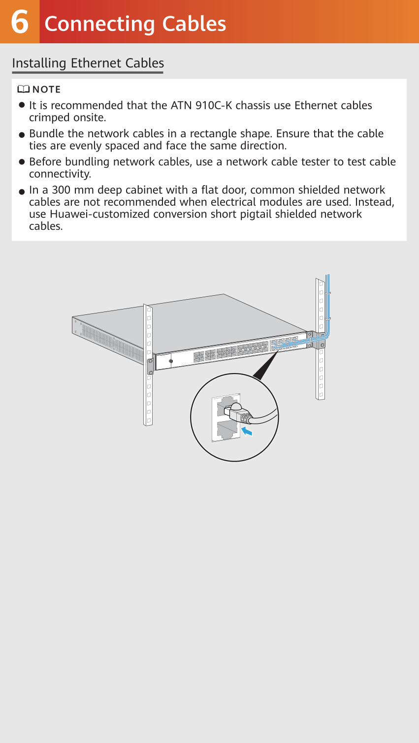
It is recommended that the ATN 910C-K chassis use Ethernet cables crimped onsite.Bundle the network cables in a rectangle shape. Ensure that the cable ties are evenly spaced and face the same direction.Before bundling network cables, use a network cable tester to test cable connectivity.In a 300 mm deep cabinet with a flat door, common shielded network cables are not recommended when electrical modules are used. Instead, use Huawei-customized conversion short pigtail shielded network cables.
NOTE
Installing Ethernet Cables

Checking the Installation7Check Before Power-on
If the power supply voltage does not meet requirements, do not poweron the device.
Check whether fixed optical attenuators have been added in accor-dance with corresponding configuration rules.Check whether the fuse capacity of the external power supply meetsrequirements.Check whether the external power supply voltage is normal.
CAUTION
Before performing a power-on check, turn off all the switches on the device and external power supply system.If indicators are in specified abnormal states after you power on the device, handle the abnormalities onsite.
WARNING
Hardware Module
Steady greenChassis off
Steady green
STATALM
PWR/STAT
Indicator
Working status indicatorAlarm indicator
Power supply status indicator
Name State
Power-on Check
For more information about device indicators, see in the corresponding product documentation.
The following table describes the states of indicators when the device is operating properly.
NOTE
Hardware Description

Obtaining Product Documentation and Technical Support8
Log in to Huawei enterprise technical support website (https://support.huawei.com/enterprise) and select a specific product model and version to find its documentation.Log in to Huawei enterprise support community (https://forum.huawei.com/enterprise), and post your questions in the community.
Log in to Huawei carrier technical support website (https://support.huawei.com/carrier), and select a specific product model and version to find its documentation.Log in to carrier enterprise support community (https://forum.huawei.com/carrier) and post your questions in the community.
For enterprise users:
For carrier usesrs:
Huawei Carrier Technical Support Huawei Enterprise Technical Support
Trademarks and Permissions
All other trademarks and trade names mentioned in this document are the property of their respective holders.Copyright © Huawei Technologies Co., Ltd. 2021. All rights reserved.No part of this document may be reproduced or transmitted in any form or by any means without prior written consent of Huawei Technologies Co., Ltd.
and other Huawei trademarks are trademarks of Huawei Technologies Co., Ltd.

Appendix Inspecting and Cleaning Optical Fiber Connectors and AdaptersSince the 50G optical module link uses the PAM4 encoding technology, there are higher requirements on the optical fiber and cable quality and the link is more sensitive to multipath reflection interference of signals. If the fiber link connector, fiber section, or fiber splicing surface is dirty, optical signals are reflected back and forth on the fiber link, causing interference due to co-channel noise on the receive side. As a result, the optical link is unstable or intermittently disconnected.To prevent this issue, you need to check and clean the optical fiber connectors before installation. For details, see Installation and maintenance > Preparing for the installation> Inspecting and Cleaning Optical Fiber Connec-tors and Adapters in the product documentation.
Copyright © 2022 FDOKUMEN