MUL / ACQ580-01 quick installation and start-up guide for ...
60
— DRIVES FOR WATER ACQ580-01 drives, frames R1 to R5 Quick installation and start-up guide 3AXD50000044864 Rev B MUL EFFECTIVE: 2019-06-30 R1- R4 R5 EN DE ES FI FR RU SV
-
Upload
khangminh22 -
Category
Documents
-
view
1 -
download
0
Transcript of MUL / ACQ580-01 quick installation and start-up guide for ...

—DRIVES FOR WATER
ACQ580-01 drives, frames R1 to R5Quick installation and start-up guide
3AXD50000044864 Rev B MULEFFECTIVE: 2019-06-30
R1-R4
R5
EN
DE
ES
FI
FR
RU
SV

List of related manuals in English
You can find manuals and other product documents in PDF format on the Internet.
See section Document library on the Internet on the inside of the back cover. For manuals not available in the Document library, contact your local ABB representative.
The QR code below opens an online listing of the manuals applicable to this product.
Drive manuals and guides Code (English)ACQ580 pump control program firmware manual 3AXD50000035867ACQ580-01 (0.75 to 250 kW, 1.0 to 350 hp) hardware manual
3AXD50000044862
ACQ580-01 frames R1 to R5 quick installation and start-up guide
3AXD50000044864
ACQ580-01 frames R6 to R9 quick installation and start-up guide
3AXD50000037301
ACx-AP-x assistant control panels user’s manual 3AUA0000085685
Option manuals and guidesACS580-01, ACH580-01 and ACQ580-01 installation guide for UK gland plate (option +H358)
3AXD50000034735
CPTC-02 ATEX-certified thermistor protection module, Ex II (2) GD (+L537+Q971) user's manual
3AXD50000030058
CDPI-01 communication adapter module user's manual 3AXD50000009929DPMP-01 mounting platform for control panels 3AUA0000100140DPMP-02/03 mounting platform for control panels 3AUA0000136205FDNA-01 DeviceNet™ adapter module user's manual 3AFE68573360FEIP-21 Ethernet/IP adapter module user’s manual 3AXD50000158621FENA-01/-11/-21 Ethernet adapter module user's manual 3AUA0000093568FMBA-01 Modbus adapter module user’s manual 3AFE68586704FMBT-21 Modbus/TCP adapter module user’s manual 3AXD50000158607FPBA-01 PROFIBUS DP adapter module user's manual 3AFE68573271FPNO-21 PROFINET adapter module user’s manual 3AXD50000158614FSCA-01 RS-485 adapter module user's manual 3AUA0000109533ACS580-01…, ACH580-01… and ACQ580-01…+C135 drives with flange mounting kit supplement
3AXD50000019100
ACS580-01…, ACH580-01… and ACQ580-01…+C135 frames R1 to R3 flange mounting kit quick installation guide
3AXD50000119172
ACS580-01…, ACH580-01… and ACQ580-01…+C135 frames R4 to R5 flange mounting kit quick installation guide
3AXD50000287093
Main switch and EMC C1 filter options (+F278, +F316, +E223) installation supplement for ACS580-01, ACH580-01 and ACH580-01 frames R1 to R5
3AXD50000155132
UL Type 12 hood quick installation guide for ACS580-01, ACH580-01 and ACQ580-01 frames R1 to R9
3AXD50000196067
ACQ580-01 manuals

Table of contents 3
Table of contents
List of related manuals in English
Frames R1 to R4
Ratings and fusesIEC ratings at UN = 230 V, 400 V and 480 V . . . . . . . . . . . . . . . . . . . . . . . . . . . . . . . . . . . . . . 9
UN = 230 V . . . . . . . . . . . . . . . . . . . . . . . . . . . . . . . . . . . . . . . . . . . . . . . . . . . . . . . . . . . . . 9UN = 400 V . . . . . . . . . . . . . . . . . . . . . . . . . . . . . . . . . . . . . . . . . . . . . . . . . . . . . . . . . . . . 10UN = 480 V . . . . . . . . . . . . . . . . . . . . . . . . . . . . . . . . . . . . . . . . . . . . . . . . . . . . . . . . . . . . 10
gG fuses . . . . . . . . . . . . . . . . . . . . . . . . . . . . . . . . . . . . . . . . . . . . . . . . . . . . . . . . . . . . . . . . . 11uR or aR fuses . . . . . . . . . . . . . . . . . . . . . . . . . . . . . . . . . . . . . . . . . . . . . . . . . . . . . . . . . . . . . 12
EN – R1…R4 Quick installation guideObey the safety instructions . . . . . . . . . . . . . . . . . . . . . . . . . . . . . . . . . . . . . . . . . . . . . . . . . . 15Check if capacitors need to be reformed . . . . . . . . . . . . . . . . . . . . . . . . . . . . . . . . . . . . . . . . . 15Select the power cables . . . . . . . . . . . . . . . . . . . . . . . . . . . . . . . . . . . . . . . . . . . . . . . . . . . . . 16Ensure the cooling . . . . . . . . . . . . . . . . . . . . . . . . . . . . . . . . . . . . . . . . . . . . . . . . . . . . . . . . . . 16Protect the drive and input power cable . . . . . . . . . . . . . . . . . . . . . . . . . . . . . . . . . . . . . . . . . 16Install the drive on the wall . . . . . . . . . . . . . . . . . . . . . . . . . . . . . . . . . . . . . . . . . . . . . . . . . . . 16Check the insulation of the power cables and the motor . . . . . . . . . . . . . . . . . . . . . . . . . . . . . 16Switch off the power and open the cover . . . . . . . . . . . . . . . . . . . . . . . . . . . . . . . . . . . . . . . . 17Install the cable box . . . . . . . . . . . . . . . . . . . . . . . . . . . . . . . . . . . . . . . . . . . . . . . . . . . . . . . . . 17Attach the warning sticker . . . . . . . . . . . . . . . . . . . . . . . . . . . . . . . . . . . . . . . . . . . . . . . . . . . . 17Check the compatibility with IT (ungrounded), corner-grounded delta, midpoint-grounded delta, and TT systems . . . . . . . . . . . . . . . . . . . . . . . . . . . . . . . . . . . . . . . . . . . . . . . . . . . . . . . 17
EMC filter . . . . . . . . . . . . . . . . . . . . . . . . . . . . . . . . . . . . . . . . . . . . . . . . . . . . . . . . . . . . . 17Ground-to-phase varistor . . . . . . . . . . . . . . . . . . . . . . . . . . . . . . . . . . . . . . . . . . . . . . . . . 18
Connect the power cables . . . . . . . . . . . . . . . . . . . . . . . . . . . . . . . . . . . . . . . . . . . . . . . . . . . . 19Connect the control cables . . . . . . . . . . . . . . . . . . . . . . . . . . . . . . . . . . . . . . . . . . . . . . . . . . . 20Default I/O connections . . . . . . . . . . . . . . . . . . . . . . . . . . . . . . . . . . . . . . . . . . . . . . . . . . . . . . 21Install optional modules, if any . . . . . . . . . . . . . . . . . . . . . . . . . . . . . . . . . . . . . . . . . . . . . . . . 22Reinstall cover . . . . . . . . . . . . . . . . . . . . . . . . . . . . . . . . . . . . . . . . . . . . . . . . . . . . . . . . . . . . . 22
Compliance with the European Machinery Directive 2006/42/ECDeclaration of conformity . . . . . . . . . . . . . . . . . . . . . . . . . . . . . . . . . . . . . . . . . . . . . . . . . . . . . 23
Frames R5
Ratings and fusesIEC ratings at UN = 230 V, 400 V and 480 V . . . . . . . . . . . . . . . . . . . . . . . . . . . . . . . . . . . . . 27
UN = 230 V . . . . . . . . . . . . . . . . . . . . . . . . . . . . . . . . . . . . . . . . . . . . . . . . . . . . . . . . . . . . 27UN = 400 V . . . . . . . . . . . . . . . . . . . . . . . . . . . . . . . . . . . . . . . . . . . . . . . . . . . . . . . . . . . . 27
Safety

4 Table of contents
UN = 480 V . . . . . . . . . . . . . . . . . . . . . . . . . . . . . . . . . . . . . . . . . . . . . . . . . . . . . . . . . . . 28gG fuses . . . . . . . . . . . . . . . . . . . . . . . . . . . . . . . . . . . . . . . . . . . . . . . . . . . . . . . . . . . . . . . . . 29uR or aR fuses . . . . . . . . . . . . . . . . . . . . . . . . . . . . . . . . . . . . . . . . . . . . . . . . . . . . . . . . . . . . 29
EN – R5 Quick installation guideObey the safety instructions . . . . . . . . . . . . . . . . . . . . . . . . . . . . . . . . . . . . . . . . . . . . . . . . . . 31Check if capacitors need to be reformed . . . . . . . . . . . . . . . . . . . . . . . . . . . . . . . . . . . . . . . . 31Select the power cables . . . . . . . . . . . . . . . . . . . . . . . . . . . . . . . . . . . . . . . . . . . . . . . . . . . . . 32Ensure the cooling . . . . . . . . . . . . . . . . . . . . . . . . . . . . . . . . . . . . . . . . . . . . . . . . . . . . . . . . . 32Protect the drive and input power cable . . . . . . . . . . . . . . . . . . . . . . . . . . . . . . . . . . . . . . . . . 32Install the drive on the wall . . . . . . . . . . . . . . . . . . . . . . . . . . . . . . . . . . . . . . . . . . . . . . . . . . . 32Check the insulation of the power cables and the motor . . . . . . . . . . . . . . . . . . . . . . . . . . . . 32Switch off the power and open the cover . . . . . . . . . . . . . . . . . . . . . . . . . . . . . . . . . . . . . . . . 33Check the compatibility with IT (ungrounded), corner-grounded delta, midpoint-grounded delta, and TT systems . . . . . . . . . . . . . . . . . . . . . . . . . . . . . . . . . . . . . . . . . . . . . . . . . . . . . . 33
EMC filter . . . . . . . . . . . . . . . . . . . . . . . . . . . . . . . . . . . . . . . . . . . . . . . . . . . . . . . . . . . . . 33Ground-to-phase varistor . . . . . . . . . . . . . . . . . . . . . . . . . . . . . . . . . . . . . . . . . . . . . . . . . 33
Connect the power cables . . . . . . . . . . . . . . . . . . . . . . . . . . . . . . . . . . . . . . . . . . . . . . . . . . . 35Connect the control cables . . . . . . . . . . . . . . . . . . . . . . . . . . . . . . . . . . . . . . . . . . . . . . . . . . . 36Default I/O connections . . . . . . . . . . . . . . . . . . . . . . . . . . . . . . . . . . . . . . . . . . . . . . . . . . . . . 37Install optional modules, if any . . . . . . . . . . . . . . . . . . . . . . . . . . . . . . . . . . . . . . . . . . . . . . . . 38Reinstall cover . . . . . . . . . . . . . . . . . . . . . . . . . . . . . . . . . . . . . . . . . . . . . . . . . . . . . . . . . . . . 38
Compliance with the European Machinery Directive 2006/42/ECDeclaration of conformity . . . . . . . . . . . . . . . . . . . . . . . . . . . . . . . . . . . . . . . . . . . . . . . . . . . . 40
Quick start-up guide
EN – Quick start-up guideBefore you start . . . . . . . . . . . . . . . . . . . . . . . . . . . . . . . . . . . . . . . . . . . . . . . . . . . . . . . . . . . 43Start-up with the Set-up assistant on an HVAC control panel . . . . . . . . . . . . . . . . . . . . . . . . 43
Frames R1 to R4 and R5 installation figures
R1…R4 Figures AB1 . . . . . . . . . . . . . . . . . . . . . . . . . . . . . . . . . . . . . . . . . . . . . . . . . . . . . . . . . . . . . . . . . . . . . . 51B2 . . . . . . . . . . . . . . . . . . . . . . . . . . . . . . . . . . . . . . . . . . . . . . . . . . . . . . . . . . . . . . . . . . . . . . 51B3 . . . . . . . . . . . . . . . . . . . . . . . . . . . . . . . . . . . . . . . . . . . . . . . . . . . . . . . . . . . . . . . . . . . . . . 51C1 . . . . . . . . . . . . . . . . . . . . . . . . . . . . . . . . . . . . . . . . . . . . . . . . . . . . . . . . . . . . . . . . . . . . . . 51C2 . . . . . . . . . . . . . . . . . . . . . . . . . . . . . . . . . . . . . . . . . . . . . . . . . . . . . . . . . . . . . . . . . . . . . . 51D . . . . . . . . . . . . . . . . . . . . . . . . . . . . . . . . . . . . . . . . . . . . . . . . . . . . . . . . . . . . . . . . . . . . . . . 52E1 . . . . . . . . . . . . . . . . . . . . . . . . . . . . . . . . . . . . . . . . . . . . . . . . . . . . . . . . . . . . . . . . . . . . . . 52E2 . . . . . . . . . . . . . . . . . . . . . . . . . . . . . . . . . . . . . . . . . . . . . . . . . . . . . . . . . . . . . . . . . . . . . . 52F . . . . . . . . . . . . . . . . . . . . . . . . . . . . . . . . . . . . . . . . . . . . . . . . . . . . . . . . . . . . . . . . . . . . . . . 52G1 . . . . . . . . . . . . . . . . . . . . . . . . . . . . . . . . . . . . . . . . . . . . . . . . . . . . . . . . . . . . . . . . . . . . . . 52G2 . . . . . . . . . . . . . . . . . . . . . . . . . . . . . . . . . . . . . . . . . . . . . . . . . . . . . . . . . . . . . . . . . . . . . . 52

Table of contents 5
R1…R4 Figures HI . . . . . . . . . . . . . . . . . . . . . . . . . . . . . . . . . . . . . . . . . . . . . . . . . . . . . . . . . . . . . . . . . . . . . . . . 53I2 . . . . . . . . . . . . . . . . . . . . . . . . . . . . . . . . . . . . . . . . . . . . . . . . . . . . . . . . . . . . . . . . . . . . . . . 53J . . . . . . . . . . . . . . . . . . . . . . . . . . . . . . . . . . . . . . . . . . . . . . . . . . . . . . . . . . . . . . . . . . . . . . . . 54
R5 Figures AB . . . . . . . . . . . . . . . . . . . . . . . . . . . . . . . . . . . . . . . . . . . . . . . . . . . . . . . . . . . . . . . . . . . . . . . 55C . . . . . . . . . . . . . . . . . . . . . . . . . . . . . . . . . . . . . . . . . . . . . . . . . . . . . . . . . . . . . . . . . . . . . . . 56D . . . . . . . . . . . . . . . . . . . . . . . . . . . . . . . . . . . . . . . . . . . . . . . . . . . . . . . . . . . . . . . . . . . . . . . 56E . . . . . . . . . . . . . . . . . . . . . . . . . . . . . . . . . . . . . . . . . . . . . . . . . . . . . . . . . . . . . . . . . . . . . . . 56
R5 Figures FG . . . . . . . . . . . . . . . . . . . . . . . . . . . . . . . . . . . . . . . . . . . . . . . . . . . . . . . . . . . . . . . . . . . . . . . 57H . . . . . . . . . . . . . . . . . . . . . . . . . . . . . . . . . . . . . . . . . . . . . . . . . . . . . . . . . . . . . . . . . . . . . . . 57I . . . . . . . . . . . . . . . . . . . . . . . . . . . . . . . . . . . . . . . . . . . . . . . . . . . . . . . . . . . . . . . . . . . . . . . . 58
Further informationProduct and service inquiries . . . . . . . . . . . . . . . . . . . . . . . . . . . . . . . . . . . . . . . . . . . . . . . . . 59Product training . . . . . . . . . . . . . . . . . . . . . . . . . . . . . . . . . . . . . . . . . . . . . . . . . . . . . . . . . . . . 59Providing feedback on ABB Drives manuals . . . . . . . . . . . . . . . . . . . . . . . . . . . . . . . . . . . . . . 59Document library on the Internet . . . . . . . . . . . . . . . . . . . . . . . . . . . . . . . . . . . . . . . . . . . . . . . 59

6 Table of contents

English . . . . . . 15
R1-R4
R5
EN
DE
ES
FI
FR
RU
SV
ACQ580-01 drivesQuick installation guideFrames R1 to R4
3AXD50000044864 Rev B MULEFFECTIVE: 2019-06-30
—DRIVES FOR WATER

2019 ABB Oy. All Rights Reserved.

9
1-4
5
6-9
N
A
E
S
I
R
T
L
L
T
U
V
R
H
RR
R
RR
E
D
D
E
F
F
I
N
P
P
R
S
T
Z
Ratings and fuses
IEC ratings at UN = 230 V, 400 V and 480 V
UN = 230 V
TypeACQ580
-01-
Input rating
Output ratings Heatdissipation
Air flow FramesizeMax.
currentNominal use
I1 Imax IN PN
A A A kW W m3/h
3-phase UN = 230 V 04A7-2 4.7 6.3 4.7 0.75 45 43 R106A7-2 6.7 8.9 6.7 1.1 55 43 R107A6-2 7.6 11.9 7.6 1.5 66 43 R1012A-2 12.0 19.1 12.0 3.0 106 43 R1018A-2 16.9 22.0 16.9 4.0 133 43 R1025A-2 24.5 32.7 24.5 5.5 174 101 R2032A-2 31.2 43.6 31.2 7.5 228 101 R2047A-2 46.7 62.4 46.7 11 322 179 R3060A-2 60 83.2 60.0 15 430 179 R3
3AXD00000586715.xls L
TypeACQ580-01-
Input ratings Output ratings Frame size
I1 IN PN
A A1) kW
1-phase UN = 230 V04A7-2 3.3 2.2 0.37 R106A7-2 4.6 3.2 0.5 R107A6-2 6.3 4.2 0.75 R112A0-2 8.9 6.0 1.1 R1018A-2 11.8 6.8 1.5 R1025A-2 17.3 9.6 2.2 R2032A-2 30.4 15.2 4.0 R2047A-2 42 22 5.5 R3060A-2 55 28 7.5 R3
3AXD00000586715.xls L1) Continuous current, no overloadability

10
R1-R4
R5
R6-R9
EN
DA
DE
ES
FI
FR
IT
NL
PL
PT
RU
SV
TR
ZH
UN = 400 V
UN = 480 V
TypeACQ580
-01-
Input rating
Output ratings Heatdissipation
Air flow FramesizeMax.
currentNominal use
I1 Imax IN PN
A A A kW W m3/h
3-phase UN = 400 V02A7-4 2.6 3.2 2.6 0.75 69 43 R103A4-4 3.3 4.7 3.3 1.1 78 43 R104A1-4 4.0 5.9 4.0 1.5 87 43 R105A7-4 5.6 7.2 5.6 2.2 113 43 R107A3-4 7.2 10.1 7.2 3.0 127 43 R109A5-4 9.4 13.0 9.4 4.0 165 43 R112A7-4 12.6 15.3 12.6 5.5 237 43 R1018A-4 17.0 22.7 17.0 7.5 265 101 R2026A-4 25.0 30.6 25.0 11.0 416 101 R2033A-4 32.0 44.3 32.0 15.0 514 179 R3039A-4 38.0 56.9 38.0 18.5 570 179 R3046A-4 45.0 67.9 45.0 22.0 709 179 R3062A-4 62 76 62 30 957 134 R4073A-4 73 104 73 37 1230 134 R4
3AXD00000586715.xls L
TypeACQ580
-01-
Input rating
Output ratings Heatdissipation
Air flow FramesizeMax.
currentNominal use
I1 Imax ILd PLd
A A A hp W m3/h
3-phase UN = 480 V02A7-4 2.1 2.9 2.1 1.0 45 43 R103A4-4 3.0 3.8 3.0 1.5 55 43 R104A1-4 3.4 5.4 3.5 2.0 66 43 R105A7-4 4.8 6.1 4.8 3.0 84 43 R107A3-4 6.0 7.2 6.0 3.0 106 43 R109A5-4 7.6 8.6 7.6 5.0 133 43 R112A7-4 11.0 13.7 12.0 7.5 174 43 R1018A-4 14.0 19.8 14.0 10.0 228 101 R2026A-4 21.0 25.2 23.0 15.0 322 101 R2033A-4 27.0 37.8 27.0 20.0 430 179 R3039A-4 34.0 48.6 34.0 25.0 525 179 R3046A-4 40.0 61.2 44.0 30.0 619 179 R3062A-4 52 76 52 40 835 134 R4073A-4 65 104 65 50 1024 134 R4
3AXD00000586715.xls L

11
1-4
5
6-9
N
A
E
S
I
R
T
L
L
T
U
V
R
H
RR
R
RR
E
D
D
E
F
F
I
N
P
P
R
S
T
Z
gG fusesType
ACQ580-01-Min. short-
circuit current1)
Input current
gG (IEC 60269)
Nominal current
I2t Voltage rating
ABB type IEC60269 sizeA A A A2s V
3-phase UN = 230 V04A7-2 200 4.7 25.0 2500.0 500 OFAF000H25 00006A7-2 200 6.7 25.0 2500.0 500 OFAF000H25 00007A6-2 200 7.6 25.0 2500.0 500 OFAF000H25 000012A-2 200 12.0 25.0 2500.0 500 OFAF000H25 000018A-2 200 16.9 25.0 2500.0 500 OFAF000H25 000025A-2 320 24.5 40.0 7700.0 500 OFAF000H40 000032A-2 320 31.2 40.0 7700.0 500 OFAF000H40 000047A-2 500 46.7 63.0 20100.0 500 OFAF000H63 000060A-2 500 60.0 63.0 20100.0 500 OFAF000H63 000
3-phase UN = 400 or 480 V02A7-4 32 2.6 4 55 500 OFAF000H4 00003A4-4 48 3.3 6 110 500 OFAF000H6 00004A1-4 48 4.0 6 110 500 OFAF000H6 00005A7-4 80 5.6 10 360 500 OFAF000H10 00007A3-4 80 7.2 10 360 500 OFAF000H10 00009A5-4 128 9.4 16 740 500 OFAF000H16 00012A7-4 128 12.6 16 740 500 OFAF000H16 000018A-4 200 17.0 25 2500 500 OFAF000H25 000026A-4 256 25.0 32 4000 500 OFAF000H32 000033A-4 320 32.0 40 7700 500 OFAF000H40 000039A-4 400 38.0 50 16000 500 OFAF000H50 000046A-4 500 45.0 63 20100 500 OFAF000H63 000062A-4 800 62 80 37500 500 OFAF000H80 000073A-4 1000 73 100 65000 500 OFAF000H100 000
3AXD00000586715.xls L1) Minimum short-circuit current of the installation

12
R1-R4
R5
R6-R9
EN
DA
DE
ES
FI
FR
IT
NL
PL
PT
RU
SV
TR
ZH
uR or aR fusesType
ACQ580-01-
Min. short-circuit
current1)
Input current
uR or aR (DIN 43620 blade style)
Nominal current
I2t Voltage rating
Bussmann type
IEC 60269 size
A A A A2s V3-phase UN = 230 V
04A7-2 120.0 4.7 40.0 460.0 690 170M1563 00006A7-2 120.0 6.7 40.0 460.0 690 170M1563 00007A6-2 120.0 7.6 40.0 460.0 690 170M1563 000012A-2 120.0 12.0 40.0 460.0 690 170M1563 000018A-2 120.0 16.9 40.0 460.0 690 170M1563 000025A-2 170.0 24.5 63.0 1450.0 690 170M1565 000032A-2 170.0 31.2 63.0 1450.0 690 170M1565 000047A-2 280.0 46.7 80.0 2550.0 690 170M1566 000060A-2 280.0 60.0 80.0 2550.0 690 170M1566 000089A-2 700.0 89.0 200.0 15000.0 690 170M3815 1115A-2 700.0 115.0 200.0 15000.0 690 170M3815 1144A-2 1000 144.0 315 46500 690 170M3817 1171A-2 1280 171.0 450 105000 690 170M5809 2213A-2 1450 213.0 500 155000 690 170M5810 2276A-2 2050 276.0 630 220000 690 170M6810 3
3-phase UN = 400 or 480 V02A7-4 65 2.6 25 130 690 170M1561 00003A4-4 65 3.3 25 130 690 170M1561 00004A1-4 65 4.0 25 130 690 170M1561 00005A7-4 65 5.6 25 130 690 170M1561 00007A3-4 65 7.2 25 130 690 170M1561 00009A5-4 65 9.4 25 130 690 170M1561 00012A7-4 65 12.6 25 130 690 170M1561 000018A-4 120 17.0 40 460 690 170M1563 000026A-4 120 25.0 40 460 690 170M1563 000033A-4 170 32.0 63 1450 690 170M1565 000039A-4 170 38.0 63 1450 690 170M1565 000046A-4 280 45.0 80 2550 690 170M1566 000062A-4 380 62 100 4650 690 170M1567 000073A-4 480 73 125 8500 690 170M1568 000088A-4 700 88 160 16000 690 170M1569 000106A-4 1280 106 315 46500 690 170M3817 1145A-4 1280 145 315 46500 690 170M3817 1169A-4 1800 169 450 105000 690 170M5809 1206A-4 2210 206 500 145000 690 170M5810 1246A-4 3010 246 630 275000 690 170M5812 2293A-4 4000 293 800 490000 690 170M6812D 2363A-4 5550 363 1000 985000 690 170M6814D 2430A-4 7800 430 1250 2150000 690 170M8554D 2
3AXD00000586715.xls L1) Minimum short-circuit current of the installation

13
1-4
5
6-9
N
A
E
S
I
R
T
L
L
T
U
V
R
H
RR
R
RR
E
D
D
E
F
F
I
N
P
P
R
S
T
Z
TypeACQ580
-01-
Min. short-circuit
current1)
Input current
uR or aR (DIN 43653 bolted tags)
Nominal current
I2t Voltage rating
Bussmann type
IEC 60269 size
A A A A2s V3-phase UN = 400 or 480 V
02A7-4 65 2.6 25 130 690 170M1311 00003A4-4 65 3.3 25 130 690 170M1311 00004A1-4 65 4.0 25 130 690 170M1311 00005A7-4 65 5.6 25 130 690 170M1311 00007A3-4 65 7.2 25 130 690 170M1311 00009A5-4 65 9.4 25 130 690 170M1311 00012A7-4 65 12.6 25 130 690 170M1311 000018A-4 120 17.0 40 460 690 170M1313 000026A-4 120 25.0 40 460 690 170M1313 000033A-4 170 32.0 63 1450 690 170M1315 000039A-4 170 38.0 63 1450 690 170M1315 000046A-4 280 45.0 80 2550 690 170M1316 000062A-4 380 62 100 4650 690 170M1417 000073A-4 480 73 125 8500 690 170M1318 000088A-4 700 88 160 16000 690 170M1319 000106A-4 700 106 200 15000 690 170M3015 1145A-4 1000 145 250 28500 690 170M3016 1169A-4 1280 169 315 46500 690 170M3017 1206A-4 1520 206 350 68500 690 170M3018 1246A-4 2050 246 450 105000 690 170M5009 2293A-4 2200 293 500 145000 690 170M5010 2363A-4 3100 363 630 275000 690 170M5012 2430A-4 3600 430 700 405000 690 170M5013 2
3AXD00000586715.xls L1) Minimum short-circuit current of the installation

14
R1-R4
R5
R6-R9
EN
DA
DE
ES
FI
FR
IT
NL
PL
PT
RU
SV
TR
ZH

EN – R1…R4 Quick installation guide 15
1-4
5
6-9
N
E
S
I
R
U
V
H
RR
R
RR
E
D
E
F
F
R
S
Z
EN – R1…R4 Quick installation guide
This guide briefly describes how to install the drive for IEC use. For complete information on installation, see ACQ580-01 (0.75 to 250 kW, 1.0 to 350 hp) hardware manual (3AXD50000044862 [English]). For start-up instructions, see chapter EN – Quick start-up guide on page 43.
To read a manual, go to www.abb.com/drives/documents and search for the document number.
Obey the safety instructions
Check if capacitors need to be reformed
The capacitors must be reformed if the drive has not been powered (either in storage or unused) for a year or more.
You can determine the manufacturing time from the serial number, which you find on the type designation label attached to the drive. The serial number is of format MYYWWRXXXX. YY and WW tell the manufacturing year and week as follows:
YY: 17, 18, 19, … for 2017, 2018, 2019, … WW: 01, 02, 03, … for week 1, week 2, week 3, …
For information on reforming the capacitors, see Converter module capacitor reforming instructions (3BFE64059629 [English]), available on the Internet at www.abb.com/drives/documents.
WARNING! Obey these instructions. If you ignore them, injury or death, or damage to the equipment can occur:
• If you are not a qualified electrical professional, do not do electrical installation work.
• Do not work on the drive, motor cable or motor when main power is applied. If the drive is already connected to the input power, wait for 5 minutes after disconnecting the input power.
• Do not work on the control cables when power is applied to the drive or to the external control circuits.
• Make sure that debris from drilling, cutting and grinding does not enter the drive when installing.
• Make sure that the floor below the drive and the wall where the drive is installed are non-flammable.

16 EN – R1…R4 Quick installation guide
R1-R4
R5
R6-R9
EN
DE
ES
FI
FR
RU
SV
Select the power cables
Size the power cables according to local regulations to carry the nominal current given on the type designation label of your drive.
Ensure the cooling
See table IEC ratings at UN = 230 V, 400 V and 480 V on page 9 for the heat dissipation. The allowed operating temperature range of the drive is -15 to +50 °C (+5 to +122 °F). No condensation or frost is allowed. For more information on the ambient temperature and derating, see chapter Technical data in ACQ580-01 (0.75 to 250 kW) hardware manual (3AXD50000044862 [English]).
Protect the drive and input power cable
See tables gG fuses (on page 11) and uR or aR fuses (on page 12).
If you use gG fuses, make sure that the operating time of the fuse is below 0.5 seconds. Follow the local regulations.
Install the drive on the wall
See figure R1…R4 Figures A on page 51.
Check the insulation of the power cables and the motor
Check the insulation of the input cable according to local regulations before connecting it to the drive.
See figure B1 on page 51.
1. Check the insulation of the motor cable and motor when the cable is disconnected from the drive. Measure the insulation resistance between each phase conductor and then between each phase conductor and the Protective Earth conductor using a measuring voltage of 1000 V DC. The insulation resistance of a typical motor must exceed 100 Mohm (reference value at 25 °C or 77 °F). For the insulation resistance of motors, see the manufacturer’s instructions.
Note: Moisture inside the motor casing will reduce the insulation resistance. If moisture is suspected, dry the motor and repeat the measurement.

EN – R1…R4 Quick installation guide 17
1-4
5
6-9
N
E
S
I
R
U
V
H
RR
R
RR
E
D
E
F
F
R
S
Z
Switch off the power and open the cover
See figure B1 on page 51.
2. Switch off the power from the drive.
3. Remove the front cover: Loosen the retaining screw, if any, with a screwdriver (3a) and lift the cover from the bottom outwards (3b) and then up (3c).
Install the cable box
Only for frames IP21, R1….R2.
See figures B1 on page 51.
4. IP21, R1….R2: Remove the screw (4a) and lift the cover off (4b) from the separate cable box.
5. IP21, R1….R2: Attach the cable box cover to the front cover.
6. IP21, R1….R2: Install the cable box to the frame. Position the cable box (6a) and tighten the screws (6b).
Attach the warning sticker
See figure B2 on page 51.
7. Attach the residual voltage warning sticker in the local language.
Check the compatibility with IT (ungrounded), corner-grounded delta, midpoint-grounded delta, and TT systems
See figure B3 on page 51.
EMC filter
A drive with the internal EMC filter connected can be installed to a symmetrically grounded TN-S system. If you install the drive to another system, you may need to disconnect the EMC filter. See section Checking the compatibility with IT (ungrounded), corner-grounded delta, midpoint-grounded delta, and TT systems (for IEC) in ACQ580-01 (0.75 to 250 kW, 1.0 to 350 hp) hardware manual (3AXD50000044862 [English]).
WARNING! Do not install a drive with the EMC filter connected to a system that the filter is not suitable for. This can cause danger, or damage the drive.
Note: When the internal EMC filter is disconnected, the EMC compatibility of the drive is considerably reduced. See section EMC compatibility and motor cable length

18 EN – R1…R4 Quick installation guide
R1-R4
R5
R6-R9
EN
DE
ES
FI
FR
RU
SV
in chapter Technical data in ACQ580-01 (0.75 to 250 kW, 1.0 to 350 hp) hardware manual (3AXD50000044862 [English]).
Ground-to-phase varistor
A drive with the ground-to-phase varistor connected can be installed to a symmetrically grounded TN-S system. If you install the drive to another system, you may need to disconnect the varistor. See section See section Checking the compatibility with IT (ungrounded), corner-grounded delta, midpoint-grounded delta, and TT systems (for IEC) in ACQ580-01 (0.75 to 250 kW, 1.0 to 350 hp) hardware manual (3AXD50000044862 [English]).
WARNING! Do not install a drive with the ground-to-phase varistor connected to a system that the varistor is not suitable for. If you do, the varistor circuit can
be damaged.

EN – R1…R4 Quick installation guide 19
1-4
5
6-9
N
E
S
I
R
U
V
H
RR
R
RR
E
D
E
F
F
R
S
Z
Connect the power cables
See figures C1 (page 51), C2, D, E1, E2, F, G1, G2 and R1…R4 Figures H (page 53).
1. Remove the rubber grommets from the cable entry.
Use symmetrical shielded cable for motor cabling. If the cable shield is the sole PE conductor for drive or motor, make sure that is has sufficient conductivity for the PE.
2. Cut an adequate hole into the rubber grommet. Slide the grommet onto the cable.
3. Prepare the ends of the motor cable as illustrated in figures 3a and 3b (two different motor cable types are shown). In frames R1 and R2 there are markings on the drive frame near the power cable terminals helping you to strip the wires to the correct length of 8 mm. Note: The bare shield will be grounded 360 degrees. Mark the pigtail made from the shield as a PE conductor with yellow-and-green color.
4. Slide the cable through the hole in the cable entry. and attach the grommet to the hole.
5. Connect the motor cable:
• Ground the shield 360 degrees by tightening the clamp of the power cable grounding shelf onto the stripped part of the cable (5a).
• Connect the twisted shield of the cable to the grounding terminal (5b).
• Connect the phase conductors of the cable to the T1/U, T2/V and T3/W terminals (5c). Tighten the screws to the torque given in the figure.
6. Repeat steps 2…4 for the input power cable.
7. Connect the input power cable. Connect the additional PE conductor of the cable (7c). Tighten the screws to the torque given in the figure.
8. R1…R2, R4: Install the grounding shelf.
9. Repeat steps 2…4 for the brake resistor cable (if used). Cut off extra phase conductors (if any).
10. Connect the resistor cable (if used). Tighten the screws to the torque given in the figure.
11. Put the unused rubber grommets to the holes in the cable entry.
12. Secure the cables outside the unit mechanically.
13. Ground the motor cable shield at the motor end. For minimum radio frequency interference, ground the motor cable shield 360 degrees at the cable entry of the motor terminal box.

20 EN – R1…R4 Quick installation guide
R1-R4
R5
R6-R9
EN
DE
ES
FI
FR
RU
SV
Connect the control cables
See figures I and I2 on page 53. It shows an example with one analog signal cable and one digital signal cable. Make the connections according to the default configuration in use. The default connections of the Water default configuration are shown in section Default I/O connections on page 21.
1. Remove the front cover, if not already removed. See section Switch off the power and open the cover on page 17.
Example of connecting an analog signal cable:
2. Cut an adequate hole into the rubber grommet and slide the grommet onto the cable. Slide the cable through a hole in the cable entry and attach the grommet to the hole.
3. Ground the outer shield of the cable 360 degrees under the grounding clamp. Keep the cable unstripped as close to the terminals of the control board as possible. Ground also the pair-cable shields and grounding wire at the SCR1 terminal.
4. Route the cable as shown in the figure.
5. Connect the conductors to the appropriate terminals of the control board and tighten to 0.5…0.6 N·m (0.4 lbf·ft).
6. Tie all control cables to the provided cable tie mounts.

EN – R1…R4 Quick installation guide 21
1-4
5
6-9
N
E
S
I
R
U
V
H
RR
R
RR
E
D
E
F
F
R
S
Z
Default I/O connections
Default I/O connections of the Water default configuration are shown below.
max.500 ohm
1…10 kohm
X1 Reference voltage and analog inputs and outputs1 SCR Signal cable shield (screen)2 AI1 Output frequency/speed reference: 0…10 V3 AGND Analog input circuit common4 +10V Reference voltage 10 V DC5 AI2 Actual feedback: 0…10 V6 AGND Analog input circuit common7 AO1 Output frequency: 0…10 V8 AO2 Output current: 0…20 mA9 AGND Analog output circuit common
X2 & X3 Aux. voltage output and programmable digital inputs10 +24V Aux. voltage output +24 V DC, max. 250 mA11 DGND Aux. voltage output common12 DCOM Digital input common for all13 DI1 Stop (0) / Start (1) 14 DI2 Not configured15 DI3 Constant frequency/speed selection16 DI4 Not configured17 DI5 Not configured18 DI6 Not configured
X6, X7, X8 Relay outputs19 RO1C Ready run
250 V AC / 30 V DC2 A
20 RO1A21 RO1B22 RO2C Running
250 V AC / 30 V DC 2 A
23 RO2A24 RO2B25 RO3C Fault (-1)
250 V AC / 30 V DC2 A
26 RO3A27 RO3BX5 Embedded fieldbus29 B+
Embedded fieldbus, EFB (EIA-485)30 A-31 DGNDS4 TERM Termination switchS5 BIAS Bias resistors switchX4 Safe torque off34 OUT1 Safe torque off. Factory connection. Both circuits
must be closed for the drive to start. See chapter The Safe torque off function in ACQ580-01 (0.75 to 250 kW, 1.0 to 350 hp) hardware manual (3AXD50000044862 [English]).
35 OUT236 SGND37 IN138 IN2
Total load capacity of the Auxiliary voltage output +24V (X2:10) is 6.0 W (250 mA / 24 V DC).
Wire sizes: 0.2…2.5 mm2 (24…14 AWG): Terminals +24V, DGND, DCOM, B+, A-, DGND, Ext. 24V0.14…1.5 mm2 (26…16 AWG): Terminals DI, AI, AO, AGND, RO, STO
Tightening torques: 0.5…0.6 N·m (0.4 lbf·ft)

22 EN – R1…R4 Quick installation guide
R1-R4
R5
R6-R9
EN
DE
ES
FI
FR
RU
SV
Install optional modules, if any
See chapter Electrical installation in ACQ580-01 (0.75 to 250 kW, 1.0 to 350 hp) hardware manual (3AXD50000044862 [English]).
Reinstall cover
See figure J on page 54.
1. Put the tabs on the inside of the cover top in their counterparts on the housing (1a) and then press the cover at the bottom (1b).
2. Tighten the retaining screw with a screwdriver.
For start-up instructions, see chapter EN – Quick start-up guide on page 43.

23
1-4
5
6-9
N
A
E
S
I
R
T
L
L
T
U
V
R
H
RR
R
RR
E
D
D
E
F
F
I
N
P
P
R
S
T
Z
Compliance with the European Machinery Directive 2006/42/EC
Declaration of conformity
EU Declaration of ConformityMachinery Directive 2006/42/ECWe
Manufacturer: ABB OyAddress: Hiomotie 13, 00380 Helsinki, Finland.Phone: +358 10 22 11
declare under our sole responsibility that the following product:
Frequency converter(s)
with regard to the safety function(s)
The following harmonized standards have been applied:
EN 61800-5-2:2007
EN 62061:2005 + AC:2010 + A1:2013 + A2:2015
EN ISO 13849-1:2015
EN ISO 13849-2:2012
EN 60204-1: 2006 + A1:2009 + AC:2010
The following other standards have been applied:
IEC 61508:2010, parts 1-2
IEC 61800-5-2:2016
Person authorized to compile the technical fileName and address: Risto Mynttinen, Hiomotie 13, 00380 Helsinki, Finland.
Helsinki 07.06.2019
Manufacturer representative: Tuomo TarulaVice President, ABB Oy
Document number 3AXD10000486283
The product(s) referred in this Declaration of conformity fulfil(s) the relevant provisions of other European Union Directiveswhich are notified in Single EU Declaration of conformity 3AXD10000497692.
ACQ580-01/-31
Safety of machinery – Safety-related parts of the control systems.Part 2: Validation
Safety of machinery – Electrical equipment of machines – Part 1:General requirements
Functional safety of electrical / electronic / programmableelectronic safety-related systems
Adjustable speed electrical power drive systems – Part 5-2: Safetyrequirements - Functional
Safety of machinery – Safety-related parts of control systems. Part1: General requirements
Safety of machinery – Functional safety of safety-related electrical,electronic and programmable electronic control systems
Adjustable speed electrical power drive systems – Part 5-2: Safetyrequirements - Functional
is/are in conformity with all the relevant safety component requirements of EU Machinery Directive 2006/42/EC, when thelisted safety function is used for safety component functionality.
Safe Torque Off
Page 1 of 1

24
R1-R4
R5
R6-R9

English . . . . . . .31
R0-R3
R5
EN
DE
ES
FI
FR
RU
SV
—DRIVES FOR WATER
ACQ580-01 drivesQuick installation guideFrames R5
3AXD50000044864 Rev B MULEFFECTIVE: 2019-06-30

2019 ABB Oy. All Rights Reserved.

27
0-4
5
6-9
N
A
E
S
I
R
T
L
L
T
U
V
R
H
RR
R
RR
E
D
D
E
F
F
I
N
P
P
R
S
T
Z
Ratings and fuses
IEC ratings at UN = 230 V, 400 V and 480 V
UN = 230 V
UN = 400 V
TypeACQ580
-01-
Input rating
Output ratings Heatdissipation
Air flow FramesizeMax.
currentNominal use
I1 Imax IN PN
A A A kW W m3/h
3-phase UN = 230 V 089A-2 89 135 89 22 619 139 R5115A-2 115 158 115 30 835 139 R5
3AXD00000586715.xls L
TypeACQ580-01-
Input ratings Output ratings Frame size
I1 IN PN
A A1) kW
1-phase UN = 230 V089A-2 81 42 11 R5115A-2 111 54 15 R5
3AXD00000586715.xls L1) Continuous current, no overloadability
TypeACQ580
-01-
Input rating
Output ratings Heatdissipation
Air flow FramesizeMax.
currentNominal use
I1 Imax IN PN
A A A kW W m3/h
3-phase UN = 400 V088A-4 88 122 88 45 1316 139 R5106A-4 106 148 106 55 1589 139 R5
3AXD00000586715.xls L
28
R0-R4
R5
R6-R9
EN
DA
DE
ES
FI
FR
IT
NL
PL
PT
RU
SV
TR
ZH
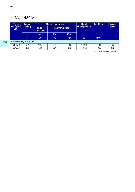
UN = 480 V
TypeACQ580
-01-
Input rating
Output ratings Heatdissipation
Air flow FramesizeMax.
currentNominal use
I1 Imax ILd PLd
A A A hp W m3/h
3-phase UN = 480 V088A-4 77 122 77 60 1240 139 R5106A-4 96 148 96 75 1510 139 R5
3AXD00000586715.xls L

29
0-4
5
6-9
N
A
E
S
I
R
T
L
L
T
U
V
R
H
RR
R
RR
E
D
D
E
F
F
I
N
P
P
R
S
T
Z
gG fuses
uR or aR fuses
TypeACQ580-01-
Min. short-circuit
current1)
Input current
gG (IEC 60269)
Nominal current
I2t Voltage rating
ABB type IEC60269 sizeA A A A2s V
3-phase UN = 230 V089A-2 1300 89.0 125.0 103000 500 OFAF00H125 00115A-2 1300 115.0 125.0 103000 500 OFAF00H125 00
3-phase UN = 400 or 480 V088A-4 1000 88 100 65000 500 OFAF000H100 000106A-4 1300 106 125 103000 500 OFAF00H125 00
3AXD00000586715.xls L1) Minimum short-circuit current of the installation
TypeACQ580
-01-
Min. short-circuit
current1)
Input current
uR or aR (DIN 43620 blade style)
Nominal current
I2t Voltage rating
Bussmann type
IEC 60269 size
A A A A2s V3-phase UN = 230 V
089A-2 700.0 89.0 200.0 15000.0 690 170M3815 1115A-2 700.0 115.0 200.0 15000.0 690 170M3815 1
3-phase UN = 400 or 480 V088A-4 700 88 160 16000 690 170M1569 000106A-4 1280 106 315 46500 690 170M3817 1
3AXD00000586715.xls L1) Minimum short-circuit current of the installation
TypeACQ580
-01-
Min. short-circuit
current1)
Input current
uR or aR (DIN 43653 bolted tags)
Nominal current
I2t Voltage rating
Bussmann type
IEC 60269 size
A A A A2s V3-phase UN = 400 or 480 V
088A-4 700 88 160 16000 690 170M1319 000106A-4 700 106 200 15000 690 170M3015 1
3AXD00000586715.xls L1) Minimum short-circuit current of the installation

30
R0-R4
R5
R6-R9
EN
DA
DE
ES
FI
FR
IT
NL
PL
PT
RU
SV
TR
ZH

EN – R5 Quick installation guide 31
0-4
5
6-9
N
E
S
I
R
U
V
H
RR
R
RR
E
D
E
F
F
R
S
Z
EN – R5 Quick installation guide
This guide briefly describes how to install the drive for IEC use. For complete information on installation, see ACQ580-01 (0.75 to 250 kW, 1.0 to 350 hp) hardware manual (3AXD50000044862 [English]). For start-up instructions, see chapter EN – Quick start-up guide on page 43.
To read a manual, go to www.abb.com/drives/documents and search for the document number.
Obey the safety instructions
Check if capacitors need to be reformed
The capacitors must be reformed if the drive has not been powered (either in storage or unused) for a year or more.
You can determine the manufacturing time from the serial number, which you find on the type designation label attached to the drive. The serial number is of format MYYWWRXXXX. YY and WW tell the manufacturing year and week as follows:
YY: 16, 17, 18, … for 2016, 2017, 2018, … WW: 01, 02, 03, … for week 1, week 2, week 3, …
For information on reforming the capacitors, see Converter module capacitor reforming instructions (3BFE64059629 [English]), available on the Internet at www.abb.com/drives/documents.
WARNING! Obey these instructions. If you ignore them, injury or death, or damage to the equipment can occur:
• If you are not a qualified electrical professional, do not do electrical installation work.
• Do not work on the drive, motor cable or motor when main power is applied. If the drive is already connected to the input power, wait for 5 minutes after disconnecting the input power.
• Do not work on the control cables when power is applied to the drive or to the external control circuits.
• Make sure that debris from drilling, cutting and grinding does not enter the drive when installing.
• Make sure that the floor below the drive and the wall where the drive is installed are non-flammable.

32 EN – R5 Quick installation guide
R0-R4
R5
R6-R9
EN
DE
ES
FI
FR
RU
SV
Select the power cables
Size the power cables according to local regulations to carry the nominal current given on the type designation label of your drive.
Ensure the cooling
See table IEC ratings at UN = 230 V, 400 V and 480 V on page 27 for the heat dissipation. The allowed operating temperature range of the drive is -15 to +50 °C (+5 to +122 °F). No condensation or frost is allowed. For more information on the ambient temperature and derating, see chapter Technical data in ACQ580-01 (0.75 to 250 kW) hardware manual (3AXD50000044862 [English]).
Protect the drive and input power cable
See tables gG fuses (on page 29) and uR or aR fuses (on page 29).
If you use gG fuses, make sure that the operating time of the fuse is below 0.5 seconds. Follow the local regulations.
Install the drive on the wall
See figure R5 Figures A on page 55.
Check the insulation of the power cables and the motor
Check the insulation of the input cable according to local regulations before connecting it to the drive.
See figure B on page 55.
1. Check the insulation of the motor cable and motor when the cable is disconnected from the drive. Measure the insulation resistance between each phase conductor and then between each phase conductor and the Protective Earth conductor using a measuring voltage of 1000 V DC. The insulation resistance of a typical motor must exceed 100 Mohm (reference value at 25 °C or 77 °F). For the insulation resistance of motors, see the manufacturer’s instructions.
Note: Moisture inside the motor casing will reduce the insulation resistance. If moisture is suspected, dry the motor and repeat the measurement.

EN – R5 Quick installation guide 33
0-4
5
6-9
N
E
S
I
R
U
V
H
RR
R
RR
E
D
E
F
F
R
S
Z
Switch off the power and open the cover
See figure B on page 55.
2. Switch off the power from the drive.
3. IP21, Remove the module cover: Loosen the retaining screws with a screwdriver (3a) and lift the cover from the bottom outwards (3b) and then up (3c).
4. IP21, Remove the box cover: Loosen the retaining screws with a screwdriver (4a) and slide the cover downwards (4b).
5. IP55, Remove the front cover: Loosen the retaining screws with a screwdriver (4a) and lift the cover from the bottom outwards (4b) and then up (4c).
Check the compatibility with IT (ungrounded), corner-grounded delta, midpoint-grounded delta, and TT systems
See figure C on page 56.
EMC filter
A drive with the internal EMC filter connected can be installed to a symmetrically grounded TN-S system. If you install the drive to another system, you may need to disconnect the EMC filter. See section Checking the compatibility with IT (ungrounded), corner-grounded delta, midpoint-grounded delta, and TT systems (for IEC) in ACQ580-01 (0.75 to 250 kW, 1.0 to 350 hp) hardware manual (3AXD50000044862 [English]).
WARNING! Do not install a drive with the EMC filter connected to a system that the filter is not suitable for. This can cause danger, or damage the drive.
Note: When the internal EMC filter is disconnected, the EMC compatibility of the drive is considerably reduced. See section EMC compatibility and motor cable length in chapter Technical data in ACQ580-01 (0.75 to 250 kW, 1.0 to 350 hp) hardware manual (3AXD50000044862 [English]).
Ground-to-phase varistor
A drive with the ground-to-phase varistor connected can be installed to a symmetrically grounded TN-S system. If you install the drive to another system, you may need to disconnect the varistor. See section See section Checking the compatibility with IT (ungrounded), corner-grounded delta, midpoint-grounded delta, and TT systems (for IEC) in ACQ580-01 (0.75 to 250 kW, 1.0 to 350 hp) hardware manual (3AXD50000044862 [English]).

34 EN – R5 Quick installation guide
R0-R4
R5
R6-R9
EN
DE
ES
FI
FR
RU
SV
WARNING! Do not install a drive with the ground-to-phase varistor connected to a system that the varistor is not suitable for. If you do, the varistor circuit can
be damaged.

EN – R5 Quick installation guide 35
0-4
5
6-9
N
E
S
I
R
U
V
H
RR
R
RR
E
D
E
F
F
R
S
Z
Connect the power cables
See figures D (page 56), E and R5 Figures F (page 57).
1. Attach the residual voltage warning sticker in the local language next to the control board.
2. Remove the shroud on the power cable terminals by releasing the clips with a screwdriver and pulling the shroud out.
Use symmetrical shielded cable for motor cabling. If the cable shield is the sole PE conductor for drive or motor, make sure that is has sufficient conductivity for the PE.
3. Cut an adequate hole into the rubber grommet. Slide the grommet onto the cable.
4. Prepare the ends of the motor cable as illustrated in figures 4a and 4b (two different motor cable types are shown). Note: The bare shield will be grounded 360 degrees. Mark the pigtail made from the shield as a PE conductor with yellow-and-green color.
5. Slide the cable through the hole in the cable entry and attach the grommet to the hole.
6. Connect the motor cable:
• Ground the shield 360 degrees by tightening the clamp of the power cable grounding shelf onto the stripped part of the cable (6a).
• Connect the twisted shield of the cable to the grounding terminal (6b).
• Connect the phase conductors of the cable to the T1/U, T2/V and T3/W terminals (6c). Tighten the screws to the torque given in the figure.
7. Repeat steps 3…5 for the input power cable.
8. Connect the input power cable. Tighten the screws to the torque given in the figure.
9. Install the cable box plate. Position the plate and tighten the screw.
10. Reinstall the shroud on the power terminals by putting the tabs at the top of the shroud in their counterparts on the drive frame and then pressing the shroud in place.
11. Secure the cables outside the unit mechanically.
12. See figure G (page 57). Ground the motor cable shield at the motor end. For minimum radio frequency interference, ground the motor cable shield 360 degrees at the cable entry of the motor terminal box.

36 EN – R5 Quick installation guide
R0-R4
R5
R6-R9
EN
DE
ES
FI
FR
RU
SV
Connect the control cables
See figure H on page 57. It shows an example with one analog signal cable and one digital signal cable. Make the connections according to the default configuration in use. The default connections of the Water default configuration are shown in section Default I/O connections on page 37.
1. Remove the front cover, if not already removed. See section Switch off the power and open the cover on page 33.
Example of connecting an analog signal cable:
2. Cut an adequate hole into the rubber grommet and slide the grommet onto the cable. Slide the cable through a hole in the cable entry and attach the grommet to the hole.
3. Ground the outer shield of the cable 360 degrees under the grounding clamp. Keep the cable unstripped as close to the terminals of the control board as possible. Ground also the pair-cable shields and grounding wire at the SCR1 terminal.
4. Route the cable as shown in the figure.
5. Connect the conductors to the appropriate terminals of the control board and tighten to 0.5…0.6 N·m (0.4 lbf·ft).
6. Tie all control cables to the provided cable tie mounts.

EN – R5 Quick installation guide 37
0-4
5
6-9
N
E
S
I
R
U
V
H
RR
R
RR
E
D
E
F
F
R
S
Z
Default I/O connections
Default I/O connections of the Water default configuration are shown below.
max.500 ohm
1…10 kohm
X1 Reference voltage and analog inputs and outputs1 SCR Signal cable shield (screen)2 AI1 Output frequency/speed reference: 0…10 V3 AGND Analog input circuit common4 +10V Reference voltage 10 V DC5 AI2 Actual feedback: 0…10 V6 AGND Analog input circuit common7 AO1 Output frequency: 0…10 V8 AO2 Output current: 0…20 mA9 AGND Analog output circuit common
X2 & X3 Aux. voltage output and programmable digital inputs10 +24V Aux. voltage output +24 V DC, max. 250 mA11 DGND Aux. voltage output common12 DCOM Digital input common for all13 DI1 Stop (0) / Start (1) 14 DI2 Not configured15 DI3 Constant frequency/speed selection16 DI4 Not configured17 DI5 Not configured18 DI6 Not configured
X6, X7, X8 Relay outputs19 RO1C Ready run
250 V AC / 30 V DC2 A
20 RO1A21 RO1B22 RO2C Running
250 V AC / 30 V DC 2 A
23 RO2A24 RO2B25 RO3C Fault (-1)
250 V AC / 30 V DC2 A
26 RO3A27 RO3BX5 Embedded fieldbus29 B+
Embedded fieldbus, EFB (EIA-485)30 A-31 DGNDS4 TERM Termination switchS5 BIAS Bias resistors switchX4 Safe torque off34 OUT1 Safe torque off. Factory connection. Both circuits
must be closed for the drive to start. See chapter The Safe torque off function in ACQ580-01 (0.75 to 250 kW, 1.0 to 350 hp) hardware manual (3AXD50000044862 [English]).
35 OUT236 SGND37 IN138 IN2
Total load capacity of the Auxiliary voltage output +24V (X2:10) is 6.0 W (250 mA / 24 V DC).
Wire sizes: 0.2…2.5 mm2 (24…14 AWG): Terminals +24V, DGND, DCOM, B+, A-, DGND, Ext. 24V0.14…1.5 mm2 (26…16 AWG): Terminals DI, AI, AO, AGND, RO, STO
Tightening torques: 0.5…0.6 N·m (0.4 lbf·ft)

38 EN – R5 Quick installation guide
R0-R4
R5
R6-R9
EN
DE
ES
FI
FR
RU
SV
Install optional modules, if any
See chapter Electrical installation in ACQ580-01 (0.75 to 250 kW, 1.0 to 350 hp) hardware manual (3AXD50000044862 [English]).
Reinstall cover
See figure I on page 58.
1. IP21, Reinstall the box cover: Slide the cover upwards (1a) and tighten the retaining screws (1b).
2. IP21, Reinstall the module cover: Put the tabs on the inside of the cover top in their counterparts on the housing (2a), press the cover at the bottom (2b) and tighten the retaining screws (2c).
3. IP55, Reinstall the front cover: Put the tabs on the inside of the cover top in their counterparts on the housing (3a), press the cover at the bottom (3a) and tighten the retaining screws (3b).
For start-up instructions, see chapter EN – Quick start-up guide on page 43.

39
0-4
5
6-9
N
A
E
S
I
R
T
L
L
T
U
V
R
H
RR
R
RR
E
D
D
E
F
F
I
N
P
P
R
S
T
Z
Compliance with the European Machinery Directive 2006/42/EC


ACQ580-01 drivesQuick start-up guideFrames R1 to R9
English. . . . . . . 43
R0-R4
R1-R9
EN
DE
ES
FI
FR
RU
SV
—DRIVES FOR WATER
3AXD50000044864 Rev B MULEFFECTIVE: 2019-06-30

2019 ABB Oy. All Rights Reserved.

EN – Quick start-up guide 43
0-4
1-9
N
E
S
I
R
U
V
RR
RR
E
D
E
F
F
R
S
EN – Quick start-up guide
This guide describes how to start-up the drive using the Set-up assistant on the HVAC control panel. For complete information on start-up, see ACQ580 pump control program firmware manual (3AXD50000035867 [English]).
Before you start
Ensure that the drive has been installed as described in chapter EN – R1…R4 Quick installation guide on page 15 (frames R1…R4) or in chapter EN – R5 Quick installation guide page 31 (frame R5).
Start-up with the Set-up assistant on an HVAC control panel
Safety
Make sure that the installation work is complete. Make sure that cover of the drive and the cable box, if included, are on place.
Check that the starting of the motor does not cause any danger. De-couple the driven machine if there is a risk of damage in case of an incorrect direction of
rotation.
Hints on using the assistant control panel
The two commands at the bottom of the display (Options and Menu in the figure on the right), show the functions of the two softkeys and
located below the display. The commands assigned to the softkeys vary depending on the context.
Use keys , , and to move the cursor and/or change values depending on the active view.
Key shows a context-sensitive help page.
1 – First start assistant guided settings:Language, date and time, and motor nominal values
Have the motor name plate data at hand.
Power up the drive.
?

44 EN – Quick start-up guide
R0-R4
R1-R9
EN
DE
ES
FI
FR
RU
SV
The First start assistant guides you through the first start-up.
The assistant begins automatically. Wait until the control panel enters the view shown on the right.
Select the language you want to use by highlighting it (if not already highlighted) and pressing (OK).
Note: After you have selected the language, it takes a few minutes for the control panel to wake up.
Select Start set-up and press (Next).
Set the date and time as well as date and time display formats.
• Go to the edit view of a selected row by pressing .
• Scroll the view with and .
Go to the next view by pressing (Next).
To change a value in an edit view:
• Use and to move the cursor left and right.
• Use and to change the value.
• Press (Save) to accept the new setting, or press (Cancel) to go back to the previous view without making changes.
Change the units shown on the control panel if needed.
• Go to the edit view of a selected row by pressing .
• Scroll the view with and .
Go to the next view by pressing (Next).

EN – Quick start-up guide 45
0-4
1-9
N
E
S
I
R
U
V
RR
RR
E
D
E
F
F
R
S
To give the drive a name that will be shown at the top, press . If you do not want to change the default name (ACQ580), continue by pressing (Next).
For information on editing text, see ACQ580 pump control program firmware manual (3AXD50000035867 [English]).
Hint: Name the drive, for example, Pump 1.
Refer to the motor or pump nameplate for the following nominal value settings of the motor. Enter the values exactly as shown on the motor or pump nameplate.
Example of a nameplate of an induction (asynchronous) motor:
Check that the motor data is correct. Values are predefined on the basis of the drive size but you should verify that they correspond to the motor.
Start with the motor type.Go to the edit view of a selected row by pressing .
• Scroll the view with and .
Motor nominal cosΦ and nominal torque are optional.
Press (Next) to continue.
Adjust the limits according to your needs.
• Go to the edit view of a selected row by pressing .
• Scroll the view with and .
Go to the next view by pressing (Next).
M2AA 200 MLA 4
14751475
1470147014751770
32.556
34595459
0.830.83
0.830.830.830.83
3GAA 202 001 - ADA
180
IEC 34-1
6210/C36312/C3
Cat. no 35 30 30 30
30 3050
5050
505060
690 Y400 D660 Y
380 D415 D440 D
V Hz kW r/min A cos IA/IN tE/s
Ins.cl. F IP 55No
IEC 200 M/L 55
3 motor
ABB Motors

46 EN – Quick start-up guide
R0-R4
R1-R9
EN
DE
ES
FI
FR
RU
SV
If you want to make a backup of the settings made so far, select Backup and press (Next).
If you do not want to make a backup, select Not now and press (Next).
The set-up is now complete and the drive is ready for use.
Press (Done) to enter the Home view.
The Home view 1 monitoring the values of the selected signals is shown on the panel.
There are four preconfigured Home view displays. Home view 1 is the default Home view. You can browse them with keys and .
For changing the signals and their display style shown in the Home view, see ACx -AP-x assistant control panels user’s manual (3AUA0000085685 [English]).
2 – Additional settings in the Primary settings menu
Make any additional adjustments, for example, pump protections, starting from the Main menu – press (Menu) to enter the Main menu.
Select Primary settings and press (Select) (or ).
In the Primary settings menu, select Pump features and press (Select) (or ).
To get more information on the Primary settings menu items, press to open the help page.?
EN – Quick start-up guide 47
0-4
1-9
N
E
S
I
R
U
V
RR
RR
E
D
E
F
F
R
S
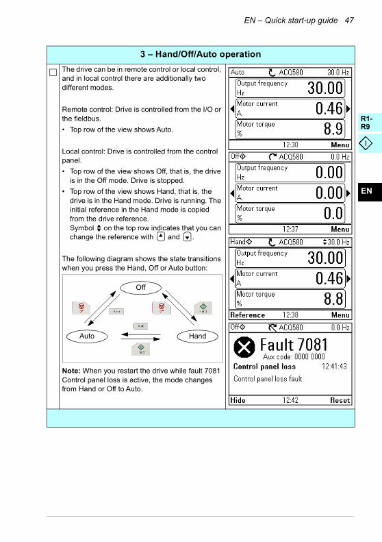
3 – Hand/Off/Auto operation
The drive can be in remote control or local control, and in local control there are additionally two different modes.
Remote control: Drive is controlled from the I/O or the fieldbus.
• Top row of the view shows Auto.
Local control: Drive is controlled from the control panel.
• Top row of the view shows Off, that is, the drive is in the Off mode. Drive is stopped.
• Top row of the view shows Hand, that is, the drive is in the Hand mode. Drive is running. The initial reference in the Hand mode is copied from the drive reference.Symbol on the top row indicates that you can change the reference with and .
The following diagram shows the state transitions when you press the Hand, Off or Auto button:
Note: When you restart the drive while fault 7081 Control panel loss is active, the mode changes from Hand or Off to Auto.
Auto
Off
Hand

48 EN – Quick start-up guide
R0-R4
R1-R9
EN
DE
ES
FI
FR
RU
SV

ACQ580-01 drivesQuick installation guideFrames R1 to R4 and R5 installation figures
R1-R4
R5
EN
DE
ES
FI
FR
RU
SV
—DRIVES FOR WATER
3AXD50000044864 Rev B MULEFFECTIVE: 2019-06-30

2019 ABB Oy. All Rights Reserved.

51R1…R4 Figures A
B1
B2
B3
C1
C2
a
b × 4
× 4
× 4
× 4
R1…R2: M5R3…R4: M6
321
4a 4b 5
IP21 R1…R2
1
ohm
M3~
U1
V1
W1 PE
1000V DC, > 100Mohm
U1-V1, U1-W1, V1-W1U1-PE, V1-PE, W1-PE
IP21 R3…R4
3b3a
3c
3a
3b
3c
x6
IP55 R4IP55 R1…R3
3a3b
3c3c
3b
IP21 R1…R2 IP21 R1…R2 IP21 R1…R2
4a4b
6b6b
x2
3 3 3 3
4 5 6
6a
3a
R1 R2 R3…R4
7 7 7
EN: See page 17. DE: Siehe Seite 29. ES: Véase la página 41. FI: Katso sivu 51. FR: Cf. page 61. RU: См. стр. 71. SV: Se sidan 83.
ACQ580
PE
N
L3
L2
L1
IT (UNGROUNDED), CORNER-GROUNDED DELTA, MIDPOINT-ROUNDED DELTA AND TT SYSTEMS
SYMMETRICALLY GROUNDED TN SYSTEMS (TN-S) = CENTER-GROUNDED WYE
ACQ580
PE
L2
L3
L1
N
= OK
ACQ580
PEL3L2
L1
ACQ580
L3
L2
L1
ACQ580
N
L3
L2
L1
ACQ580
PEL3L2
L1
!
13a 3b
2C2:
L1 L2 L3 T1/U T2/V T3/WUDC+
R+R-
L1 L2 L3(PE) (PE)PE
PE
U1V1
W1
3 ~ M
ACQ580-01
PE
3b
3a
PE
4

52 D
E1
E2
F
G1
G2
MOTOR
T1U
T2V
T3W
INPUT
L1 L2 L3
BRAKE RES
R-R+UDC+
PE
BRAKE RESINPUTPE
MOTORR-R+
UDC+L1 L2 L3 T1/U T2/V T3/W
R3
5b
5b5c
R1…R2
5a5a
5c
5b
R4
5a
5c5
5 5
Frame size
R1 R2
N·m lbf·ft N·m lbf·ft
T1/U, T2/V, T3/W
1.0 0.7 1.5 1.1
PE, 1.5 1.1 1.5 1.1
1.2 0.9 1.2 0.9
Frame size
R3 R4
N·m lbf·ft N·m lbf·ft
T1/U, T2/V, T3/W
3.5 2.6 4.0 3.0
PE, 1.5 1.1 2.9 2.1
1.2 0.9 1.2 0.9
PE
6a 6b
PE
6c
MOTOR
T1U
T2V
T3W
INPUT
L1 L2 L3
BRAKE RES
R-R+UDC+
PE
BRAKE RESINPUTPE
MOTORR-R+
UDC+L1 L2 L3 T1/U T2/V T3/W
R3
7b 7c
7a
7d
R1…R2
7d7b 7c
7a
7b
7a
7d
R47
77
Frame size
R1 R2
N·m lbf·ft N·m lbf·ft
L1, L2, L3 1.0 0.7 1.5 1.1PE, 1.5 1.1 1.5 1.1
1.2 0.9 1.2 0.9
Frame size
R3 R4
N·m lbf·ft N·m lbf·ft
L1, L2, L3 3.5 2.6 4.0 3.0PE, 1.5 1.1 2.9 2.1
1.2 0.9 1.2 0.9
R4R1…R28 8
PE
9
MOTOR
T1U
T2V
T3W
INPUT
L1 L2 L3
BRAKE RES
R-R+UDC+
PE
BRAKE RESINPUTPE
MOTORR-R+
UDC+L1 L2 L3 T1/U T2/V T3/W
R3R1…R2
10a
10b
10c
10a
10c
10b10 10
Frame size
R1 R2 R3
N·m lbf·ft N·m lbf·ft N·m lbf·ft
R-, R+ 1.0 0.7 1.5 1.1 3.5 2.6PE, 1.5 1.1 1.5 1.1 1.5 1.1
1.2 0.9 1.2 0.9 1.2 0.9
3A
XD
500
0004
4864
Re
v B

53R1…R4 Figures H I I2
BREAKERSINPUTPE
MOTORR-R+
UDC+L1 L2 L3 T1/U T2/V T3/W
MOTORT1/U T2/V T3/W
INPUTL1 L2 L3
BREAKERSR-R+
UDC+
PE
R3R1…R2
11 11
13
R4
11
MOTOR
T1U
T2V
T3W
INPUT
L1 L2 L3
BRAKE RES
R-R+UDC+
PE
BRAKE RESINPUTPE
MOTORR-R+
UDC+L1 L2 L3 T1/U T2/V T3/W
R1…R2
2
3
6
6
4
5
0.5…0.6 N·m
0.5…0.6 N·m
R3
2
3
6
6
4
5
0.5…0.6 N·m
0.5…0.6 N·m
R4
2
3
6
6
4
5
0.5…0.6 N·m
0.5…0.6 N·m
5

54 J
1b
2
× 2
IP21 R3…R4
1a
2
IP21 R1…R2
1b
2
IP55 R1…R3 IP55 R4
× 2
1b 1b
1a
2
3A
XD
500
0004
4864
Re
v B

55B
× 2
× 2
9
7
7a
7b
9a
9b
9b
IP21
7b
1
3a
1000V DC,
> 100Mohm
U1-V1, U1-W1, V1-W1U1-PE, V1-PE, W1-PE
4 5
3b
3c
4a
4b
× 85a
5b
5c
IP21 IP55
3 IP21
ohm
M3~
U1
V1
W1 PE
R5 Figures A
ca
d
e
b
5
2
R5 IP21 R5 IP55
mm in mm in
a 612 24.09 612 24.09
b 581 22.87 581 22.87
c 160 6.30 160 6.30
d > 200 7.87 200 7.87
e > 100 3.94 100 3.94
R5 IP21 R5 IP55
kg lb kg lb
28.3 62.4 29.0 64.0
1
4
× 2× 2
× 6
4a
4b
4c
IP21 IP21
3R5: M6
6
8
10
3xM5
8a
8bIP21
IP21
× 2
× 2
× 2

56 C D E
2a
2b
2a
T1/U T2/V T3/W
U1V1
W1
3 ~ M
PE
PE
4b
4a
PE
Frame size T1/U, T2/V, T3/W PE,
N·m lbf·ft M N·m lbf·ft N·m lbf·ft
R5 5.6 4.1 M5 2.2 1,6 1.2 0.9
3
5 6
4a 4b
6c
6a
6b
3A
XD
500
0004
4864
Re
v B
PE
EN: See page 33. DE: Siehe Seite 109. ES: Véase la página 119. FI: Katso sivu 129. FR: Cf. page 139. RU: См. стр. 149. SV: Se sidan 159.
1 2
L1 L2 L3
L1 L2 L3
ACQ580-01 R5
PE
PE
ACQ580
PE
N
L3
L2
L1
IT (UNGROUNDED), CORNER-GROUNDED DELTA, MIDPOINT-ROUNDED DELTA AND TT SYSTEMS
SYMMETRICALLY GROUNDED TN SYSTEMS (TN-S) = CENTER-GROUNDED WYE
ACQ580
PE
L2
L3
L1
N
= OK
ACQ580
PEL3L2
L1
ACQ580
L3
L2
L1
ACQ580
N
L3
L2
L1
ACQ580
PEL3L2
L1
!

57H
2
3
6
6
4
5
0.5…0.6 N·m
0.5…0.6 N·m
5
3
R5 Figures F G
PE
8
Frame size L1, L2, L3, PE,
N·m lbf·ft M N·m lbf·ft N·m lbf·ft
R5 5.6 4.1 M5 2.2 1,6 1.2 0.9
7b7a
PE
PE
8c
8b
8a
9
10
9a
9b
10a
10b
12

58 I
3A
XD
50
0000
4486
4 R
ev B
1b
1a
IP21 IP21
IP55
1b
1 2
2b2c
3
3b
× 83c
2a
3a

Further information
Product and service inquiries
Address any inquiries about the product to your local ABB representative, quoting the type designation and serial number of the unit in question. A listing of ABB sales, support and service contacts can be found by navigating to www.abb.com/searchchannels.
Product training
For information on ABB product training, navigate to new.abb.com/service/training.
Providing feedback on ABB Drives manuals
Your comments on our manuals are welcome. Navigate to new.abb.com/drives/manuals-feedback-form.
Document library on the Internet
You can find manuals and other product documents in PDF format on the Internet at www.abb.com/drives/documents.

© Copyright 2019 ABB. All rights reserved.Specifications subject to change without notice. 3A
XD
500
00
04
486
4 R
ev B
(M
UL)
20
10-0
6-3
0
abb.com/drives