QUICK START GUIDE - Hyperaktive Performance Solutions
24
QUICK START GUIDE
-
Upload
khangminh22 -
Category
Documents
-
view
5 -
download
0
Transcript of QUICK START GUIDE - Hyperaktive Performance Solutions

1
QUICK START GUIDE
NEXUS R5 OVERVIEW
2
What is NEXUS R5?
• A new generation engine management system
• A power distribution module
• A data logger
• A dual channel universal wideband controller
• A high speed Wi-Fi communications module
• All natively interconnected with each other
• All programmable with one single piece of software
The NEXUS R5 is Haltech’s new flagship product. Boasting new, innovative yet user-friendly technology, it sets a new market standard for engine management and power distribution systems.
An ECU, PDM, Wi-Fi module, wideband controller and a data logger all in one.
NEX-US [noun]– a connection or series of connections linking two or more things.
– a connected group or series
– the central or most important point or place
3
NEXUS R5 OVERVIEW
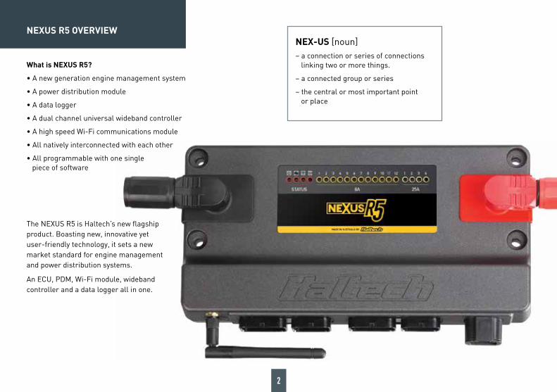
Optional accessories (sold separately)
• Plug and Pins Set. AMP 26 pin key 1 & 3 and 34 pin key 1 & 2, DTP-4. HT-030015
• Plug and Pins Set. Male DTP06-4S, Black connector 25A (inc male plug, female pins, wedgelock seal). HT-031201
• Plug Set. SurLok connectors red/black 200A. HT-030030
• 1AWG Battery Cable red/black pair. Pre terminated with SurLok connectors. 2m: HT-039212, 4m: HT-039214, 6m: HT-039216
• Manual cable lug crimping tool. HT-070305
• Hydraulic cable lug crimping tool. HT-070306
• Glass mount Wi-Fi antenna with 1.5m terminated lead. HT-011401
• Wideband Flying Lead Adaptor Harness 400mm. HT-010723
• LSU4.9 Wideband Adaptor Harness 1200mm. HT-010726
• LSU4.9 Wideband Hardware Pack. Inc sensor, adaptor harness and weld-in bung. HT-010746
• NTK Wideband Adaptor Harness 1200mm. HT-010727
• NTK Wideband Hardware Pack. Inc sensor, adaptor harness and weld in bung. HT-010747
What’s in the box?
• NEXUS R5• SurLok Connectors (Red & Black)• Wi-Fi Antenna RP-SMA 108mm• Mounting Bolts• USB-C Cable• USB-C Dust Cap• USB drive with NSP Software• Haltech Product Catalogue
4
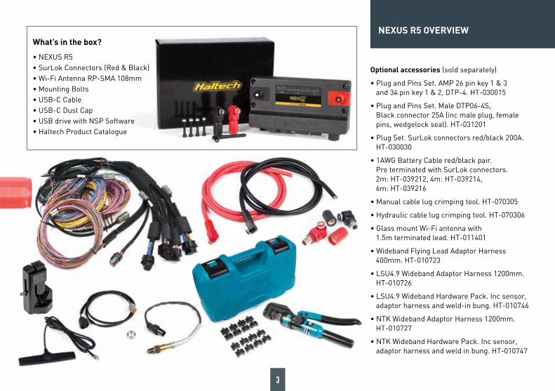
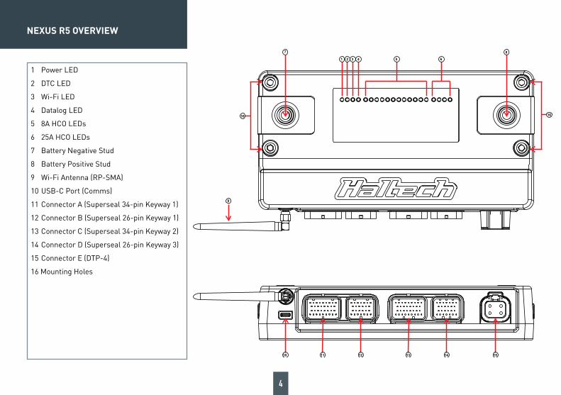
1 Power LED
2 DTC LED
3 Wi-Fi LED
4 Datalog LED
5 8A HCO LEDs
6 25A HCO LEDs
7 Battery Negative Stud
8 Battery Positive Stud
9 Wi-Fi Antenna (RP-SMA)
10 USB-C Port (Comms)
11 Connector A (Superseal 34-pin Keyway 1)
12 Connector B (Superseal 26-pin Keyway 1)
13 Connector C (Superseal 34-pin Keyway 2)
14 Connector D (Superseal 26-pin Keyway 3)
15 Connector E (DTP-4)
16 Mounting Holes
10 11 12 13 14 15
1 2 3 4 5 6
7 8
9
1616
NEXUS R5 OVERVIEW

5
NEXUS R5 LED BEHAVIOUR
LED COLOUR CONDITION
Power Green Normal operation (on main power or low power mode)
Blue Connecttounitandinstallfirmware
Red Hardware fault
DTC None DTCs not present
Yellow A DTC is present (of any kind, past/present/not severe/severe)
Blue PDMinbootmode-connecttounitandinstallfirmware
WiFi None Wi-Fi is disabled
Green solid Wi-Fi is enabled
Green flashing Wi-Fi is enabled and connected to NSP
Datalog None Unit is not logging
Yellow flashing Unit is logging, unit is not looping or not full
Yellow Logging, unit is looping or full
HCO (all) None Channel is off
Green Channel is on - duty cycle is >0% and operating correctly
Red Channel is not allowed to be driven. Usually caused by (but not limited to) an overcurrent this drive cycle
6
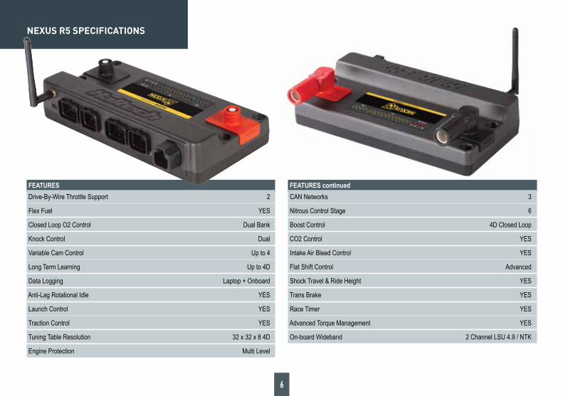
NEXUS R5 SPECIFICATIONS
FEATURES Drive-By-Wire Throttle Support 2
Flex Fuel YES
Closed Loop O2 Control Dual Bank
Knock Control Dual
Variable Cam Control Up to 4
Long Term Learning Up to 4D
Data Logging Laptop + Onboard
Anti-Lag Rotational Idle YES
Launch Control YES
Traction Control YES
Tuning Table Resolution 32 x 32 x 8 4D
Engine Protection Multi Level
FEATURES continued CAN Networks 3
Nitrous Control Stage 6
Boost Control 4D Closed Loop
CO2 Control YES
Intake Air Bleed Control YES
Flat Shift Control Advanced
Shock Travel & Ride Height YES
Trans Brake YES
Race Timer YES
Advanced Torque Management YES
On-board Wideband 2 Channel LSU 4.9 / NTK
7
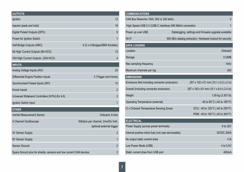
OUTPUTS Ignition 12
Injector (peak and hold) 18
Digital Pulsed Outputs (DPO) 8
Power for Ignition Switch 1
Half Bridge Outputs (HBO) 4 (2 x H-Bridges/DBW throttles)
8A High Current Outputs (8A HCO) 12
25A High Current Outputs (25A HCO) 4
INPUTS Analog Voltage Inputs (AVI) 23
Differential Engine Position Inputs 2 (Trigger and Home)
Synchronised Pulsed Inputs (SPI) 10
Knock Inputs 2
Universal Wideband Controllers (NTK/LSU 4.9) 2
Ignition Switch Input 1
OTHER Inertial Measurement Sensor Onboard, 6 Axis
4 Channel Oscilloscope 50kSa/s per channel, 2ms/Div limit, optional external trigger
5V Sensor Supply 2
8V Sensor Supply 1
Sensor Ground 2
Spare Ground pins for shields, sensors and low current CAN devices 2
COMMUNICATIONS CAN Bus Networks 1000, 500 or 250 kbit/s 3
High Speed USB 2.0 (USB-C interface) 480 Mbit/s connection 1
PowerupoverUSB Datalogging,settingsandfirmwareupgradeavailable
Wi-Fi 900 kB/s datalog extraction. Hardware lockout for security
DATA LOGGING Location Onboard
Storage 512MB
Max sampling frequency 1kHz
Maximum channels per log 300
DIMENSIONS Enclosure (Not including connector protrusion) 257 x 132 x 51 mm (10.1 x 5.2 x 2 in)
Overall (Including connector protrusion) 257 x 163 x 61 mm (10.1 x 6.4 x 2.4 in)
Weight 1.50 kg (3.307 lb)
Operating Temperature (external) -40 to 85°C (-40 to 185°F)
12 x Onboard Temperature Sensing Zones ECU: -40 to 125°C (-40 to 255°F)
PDM: -40 to 150°C (-40 to 300°F)
ELECTRICAL Power Supply (across power terminals) 8 to 22V
Internal positive inline fuse (not user-serviceable) 32VDC 200A
No output static current draw <1A
Low Power Mode (USB) 4 to 5.5V
Static current draw from USB port 400mA
8
NEXUS SOFTWARE - NSP
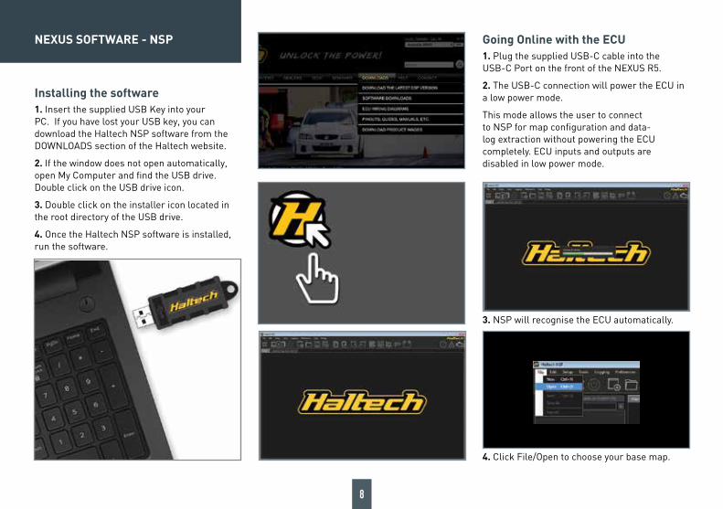
Installing the software1. Insert the supplied USB Key into your PC. If you have lost your USB key, you can download the Haltech NSP software from the DOWNLOADS section of the Haltech website.
2. If the window does not open automatically, open My Computer and find the USB drive. Double click on the USB drive icon.
3. Double click on the installer icon located in the root directory of the USB drive.
4. Once the Haltech NSP software is installed, run the software.
Going Online with the ECU1. Plug the supplied USB-C cable into the USB-C Port on the front of the NEXUS R5.
2. The USB-C connection will power the ECU in a low power mode.
This mode allows the user to connect to NSP for map configuration and data-log extraction without powering the ECU completely. ECU inputs and outputs are disabled in low power mode.
3. NSP will recognise the ECU automatically.
4. Click File/Open to choose your base map.
9
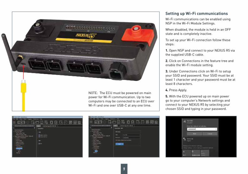
Setting up Wi-Fi communicationsWi-Fi communications can be enabled using NSP in the Wi-Fi Module Settings.
When disabled, the module is held in an OFF state and is completely inactive.
To set up your Wi-Fi connection follow these steps:
1. Open NSP and connect to your NEXUS R5 via the supplied USB-C cable.
2. Click on Connections in the feature tree and enable the Wi-Fi module setting.
3. Under Connections click on Wi-Fi to setup your SSID and password. Your SSID must be at least 1 character and your password must be at least 8 characters.
4. Press Apply.
5. With the ECU powered up on main power go to your computer’s Network settings and connect to your NEXUS R5 by selecting your chosen SSID and typing in your password.
NOTE: The ECU must be powered on main power for Wi-Fi communication. Up to two computers may be connected to an ECU over Wi-Fi and one over USB-C at any one time.
10
NEXUS R5 WIRING
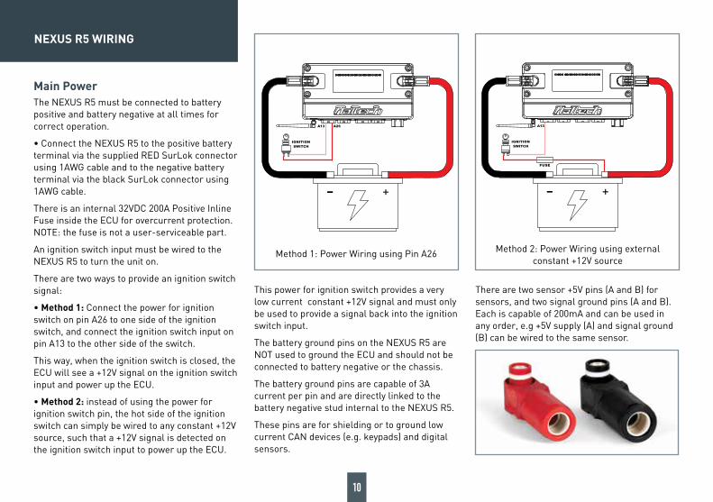
Main PowerThe NEXUS R5 must be connected to battery positive and battery negative at all times for correct operation.
• Connect the NEXUS R5 to the positive battery terminal via the supplied RED SurLok connector using 1AWG cable and to the negative battery terminal via the black SurLok connector using 1AWG cable.
There is an internal 32VDC 200A Positive Inline Fuse inside the ECU for overcurrent protection. NOTE: the fuse is not a user-serviceable part.
An ignition switch input must be wired to the NEXUS R5 to turn the unit on.
There are two ways to provide an ignition switch signal:
• Method 1: Connect the power for ignition switch on pin A26 to one side of the ignition switch, and connect the ignition switch input on pin A13 to the other side of the switch.
This way, when the ignition switch is closed, the ECU will see a +12V signal on the ignition switch input and power up the ECU.
• Method 2: instead of using the power for ignition switch pin, the hot side of the ignition switch can simply be wired to any constant +12V source, such that a +12V signal is detected on the ignition switch input to power up the ECU.
This power for ignition switch provides a very low current constant +12V signal and must only be used to provide a signal back into the ignition switch input.
The battery ground pins on the NEXUS R5 are NOT used to ground the ECU and should not be connected to battery negative or the chassis.
The battery ground pins are capable of 3A current per pin and are directly linked to the battery negative stud internal to the NEXUS R5.
These pins are for shielding or to ground low current CAN devices (e.g. keypads) and digital sensors.
There are two sensor +5V pins (A and B) for sensors, and two signal ground pins (A and B). Each is capable of 200mA and can be used in any order, e.g +5V supply (A) and signal ground (B) can be wired to the same sensor.
+-
IGNITION
SWITCH
A13 A26
+-
IGNITION
SWITCH
A13
Method 1: Power Wiring using Pin A26 Method 2: Power Wiring using external constant +12V source

11
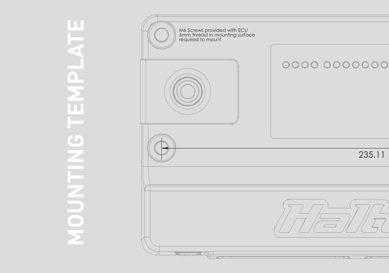
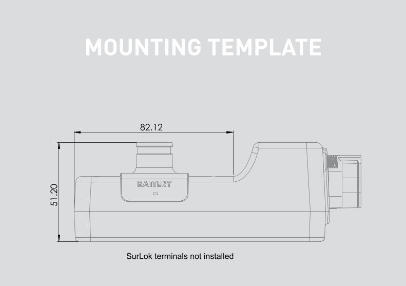
SurLok terminals not installed
SurLok terminals installed
MOUNTING TEMPLATE
MO
UN
TIN
G T
EMP
LATE

MO
UN
TIN
G T
EMP
LATE
14
MOUNTING TEMPLATE
SurLok terminals not installed
SurLok terminals installed
15
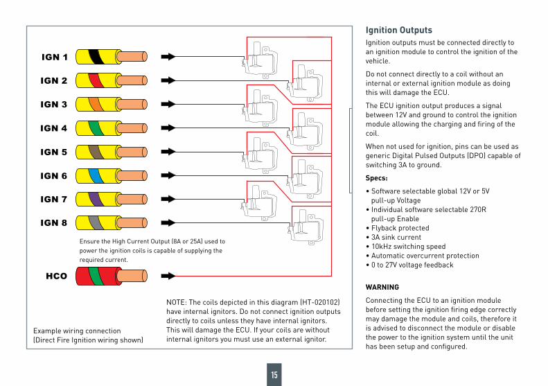
Ignition OutputsIgnition outputs must be connected directly to an ignition module to control the ignition of the vehicle.
Do not connect directly to a coil without an internal or external ignition module as doing this will damage the ECU.
The ECU ignition output produces a signal between 12V and ground to control the ignition module allowing the charging and firing of the coil.
When not used for ignition, pins can be used as generic Digital Pulsed Outputs (DPO) capable of switching 3A to ground.
Specs:
• Software selectable global 12V or 5V pull-up Voltage • Individual software selectable 270R pull-up Enable • Flyback protected • 3A sink current • 10kHz switching speed • Automatic overcurrent protection • 0 to 27V voltage feedback
WARNING
Connecting the ECU to an ignition module before setting the ignition firing edge correctly may damage the module and coils, therefore it is advised to disconnect the module or disable the power to the ignition system until the unit has been setup and configured.
IGN 1
IGN 4
IGN 2
IGN 3
IGN 5
IGN 8
IGN 6
IGN 7
HCO
WIRING SHOWN
DIRECT FIRE IGNITION
WARNING
THE COILS DEPICTED IN THIS DIAGRAM
(HT-020102) .HAVE INTERNAL IGNITORS
DO NOT CONNECT IGNITION OUTPUTS
DIRECTLY TO COILS UNLESS THEY
HAVE INTERNAL IGNITORS
T ECU.HIS WILL DAMAGE THE
PLEASE USE AN EXTERNAL IGNITOR FOR
.COILS WITHOUT INTERNAL IGNITORS
Example wiring connection (Direct Fire Ignition wiring shown)
NOTE: The coils depicted in this diagram (HT-020102) have internal ignitors. Do not connect ignition outputs directly to coils unless they have internal ignitors. This will damage the ECU. If your coils are without internal ignitors you must use an external ignitor.
Ensure the High Current Output (8A or 25A) used to power the ignition coils is capable of supplying the required current.
NEXUS R5 WIRING
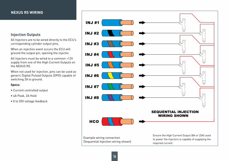
Injection OutputsAll Injectors are to be wired directly to the ECU’s corresponding cylinder output pins.
When an injection event occurs the ECU will ground the output pin, opening the injector.
All injectors must be wired to a common +12V supply from one of the High Current Outputs on the NEXUS R5.
When not used for injection, pins can be used as generic Digital Pulsed Outputs (DPO) capable of switching 2A to ground.
Specs:
• Current controlled output
• 4A Peak, 2A Hold
• 0 to 55V voltage feedback
INJ #1
INJ #4
INJ #2
INJ #3
INJ #5
INJ #8
INJ #6
INJ #7
HCO
WIRING SHOWN
SEQUENTIAL INJECTION
Example wiring connection (Sequential Injection wiring shown)
Ensure the High Current Output (8A or 25A) used to power the injectors is capable of supplying the required current.
16
17
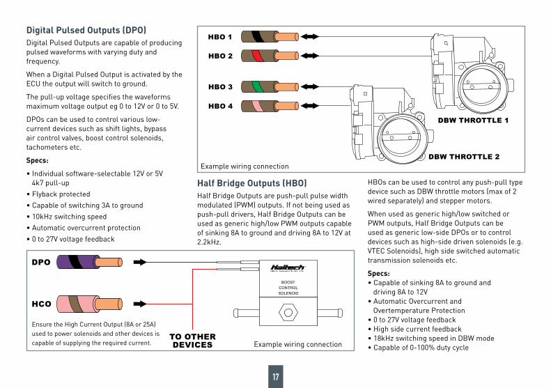
Digital Pulsed Outputs (DPO)Digital Pulsed Outputs are capable of producing pulsed waveforms with varying duty and frequency.
When a Digital Pulsed Output is activated by the ECU the output will switch to ground.
The pull-up voltage specifies the waveforms maximum voltage output eg 0 to 12V or 0 to 5V.
DPOs can be used to control various low-current devices such as shift lights, bypass air control valves, boost control solenoids, tachometers etc.
Specs:
• Individual software-selectable 12V or 5V 4k7 pull-up
• Flyback protected
• Capable of switching 3A to ground
• 10kHz switching speed
• Automatic overcurrent protection
• 0 to 27V voltage feedback
Half Bridge Outputs (HBO)Half Bridge Outputs are push-pull pulse width modulated (PWM) outputs. If not being used as push-pull drivers, Half Bridge Outputs can be used as generic high/low PWM outputs capable of sinking 8A to ground and driving 8A to 12V at 2.2kHz.
HBOs can be used to control any push-pull type device such as DBW throttle motors (max of 2 wired separately) and stepper motors.
When used as generic high/low switched or PWM outputs, Half Bridge Outputs can be used as generic low-side DPOs or to control devices such as high-side driven solenoids (e.g. VTEC Solenoids), high side switched automatic transmission solenoids etc.
Specs: • Capable of sinking 8A to ground and driving 8A to 12V • Automatic Overcurrent and Overtemperature Protection • 0 to 27V voltage feedback • High side current feedback • 18kHz switching speed in DBW mode • Capable of 0-100% duty cycle
DPO
HCO
BOOST
CONTROL
SOLENOID
TO OTHER
DEVICES
HBO 1
HBO 4
HBO 2
HBO 3
DBW THROTTLE 2
DBW THROTTLE 1
Example wiring connection
Example wiring connection
Ensure the High Current Output (8A or 25A) used to power solenoids and other devices is capable of supplying the required current.
18
NEXUS R5 WIRING
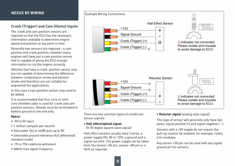
Crank (Trigger) and Cam (Home) InputsThe crank and cam position sensors are required so that the ECU has the necessary information available to determine engine speed and position at any point in time.
Generally two sensors are required - a cam position and crank position, however many engines will have just a cam position sensor that is capable of giving the ECU enough information to run the engine correctly.
Vehicles that have a crank position sensor only are not capable of determining the difference between compression stroke and exhaust stroke and therefore are not suitable for sequential fire applications.
In this case a cam position sensor may need to be added.
It is recommended that four-core or twin-core shielded cable is used for crank and cam position sensors. Shields must be terminated to battery ground at one end only.
Specs:• -5V to 5V input • 1 million samples per second• Selectable 1k2 or 440R pull-up to 5V• Selectable ground reference (full differential standard mode)• -75 to 75V indefinite withstand• 48kHz max signal frequency
There are two common types of crank/cam sensor signals:
• Hall effect/optical signal (0-5V digital square wave signal)
Hall effect sensors usually have 3 wires; a power supply (5V, 8V or 12V), a ground and a signal out wire. The power supply can be taken from the Sensor +5V pin, sensor +8V pin or a HCO as required.
• Reluctor signal (analog style signal)
This type of sensor will generally only have two wires, signal positive (+) and signal negative ( - )
Sensors with a +5V supply do not require the pull-up resistor be enabled, for example, rotary trim modules.
Any sensor +5V pin can be used with any signal ground pin for sensors.
X indicates not connectedPlease isolate and insulateto avoid damage to ECU
X indicates not connectedPlease isolate and insulateto avoid damage to ECU
Hall E�ect Sensor
X
o-+
+12V
Signal Ground
Crank (Trigger) (+)
Crank (Trigger) (-)
Reluctor Sensor
X
-+
X
+12V
Signal Ground
Crank (Trigger) (+)
Crank (Trigger) (-)
Example Wiring Connections
19
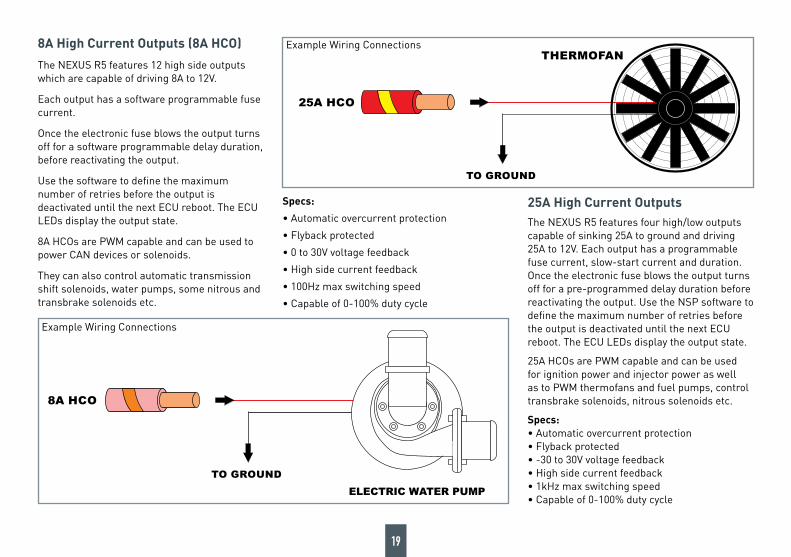
8A High Current Outputs (8A HCO)
The NEXUS R5 features 12 high side outputs which are capable of driving 8A to 12V.
Each output has a software programmable fuse current.
Once the electronic fuse blows the output turns off for a software programmable delay duration, before reactivating the output.
Use the software to define the maximum number of retries before the output is deactivated until the next ECU reboot. The ECU LEDs display the output state.
8A HCOs are PWM capable and can be used to power CAN devices or solenoids.
They can also control automatic transmission shift solenoids, water pumps, some nitrous and transbrake solenoids etc.
Specs:
• Automatic overcurrent protection
• Flyback protected
• 0 to 30V voltage feedback
• High side current feedback
• 100Hz max switching speed
• Capable of 0-100% duty cycle
25A High Current OutputsThe NEXUS R5 features four high/low outputs capable of sinking 25A to ground and driving 25A to 12V. Each output has a programmable fuse current, slow-start current and duration. Once the electronic fuse blows the output turns off for a pre-programmed delay duration before reactivating the output. Use the NSP software to define the maximum number of retries before the output is deactivated until the next ECU reboot. The ECU LEDs display the output state.
25A HCOs are PWM capable and can be used for ignition power and injector power as well as to PWM thermofans and fuel pumps, control transbrake solenoids, nitrous solenoids etc.
Specs: • Automatic overcurrent protection • Flyback protected • -30 to 30V voltage feedback • High side current feedback • 1kHz max switching speed • Capable of 0-100% duty cycle
8A HCO
TO GROUND
25A HCO
TO GROUND
THERMOFANExample Wiring Connections
Example Wiring Connections
20
NEXUS R5 WIRING
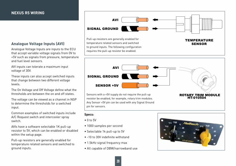
Analogue Voltage Inputs (AVI)Analogue Voltage Inputs are inputs to the ECU that accept variable voltage signals from 0V to +5V such as signals from pressure, temperature and fuel level sensors.
AVI inputs can tolerate a maximum input voltage of 30V.
These inputs can also accept switched inputs that change between two different voltage levels.
The On Voltage and Off Voltage define what the thresholds are between the on and off states.
The voltage can be viewed as a channel in NSP to determine the thresholds for a switched input.
Common examples of switched inputs include A/C Request switch and intercooler spray switch.
AVIs have a software selectable 1K pull-up resistor to 5V, which can be enabled or disabled within the setup page.
Pull-up resistors are generally enabled for temperature related sensors and switched to ground inputs.
Specs:
• 0 to 5V
• 1000 samples per second
• Selectable 1k pull-up to 5V
• -10 to 30V indefinite withstand
• 1.5kHz signal frequency max
• All capable of DBW/narrowband use
TEMPERATURE
AVI
SIGNAL GROUND
SENSOR
AVI
SIGNAL GROUND
SENSOR +5V
ROTARY TRIM MODULEHT-010504
TEMPERATURE
AVI
SIGNAL GROUND
SENSOR
AVI
SIGNAL GROUND
SENSOR +5V
ROTARY TRIM MODULEHT-010504
Pull-up resistors are generally enabled for temperature related sensors and switched to ground inputs. The following configuration requires the pull-up resistor be enabled.
Sensors with a +5V supply do not require the pull-up resistor be enabled, for example, rotary trim modules. Any Sensor +5V pin can be used with any Signal Ground pin for sensors.
21
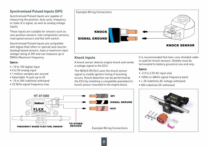
Synchronised Pulsed Inputs (SPI)Synchronised Pulsed Inputs are capable of measuring the position, duty cycle, frequency or state of a signal, as well as analog voltage inputs.
These inputs are suitable for sensors such as cam position sensors, fuel composition sensors, road speed sensors and flat shift switch.
Synchronised Pulsed Inputs are compatible with digital (hall effect or optical) and reluctor (analog) based sensors, have a maximum input voltage rating of 25V and can measure up to 50KHz Maximum frequency.
Specs:
• -10 to 10V digital input• 0 to 5V analog input• 1 million samples per second• Selectable 1k pull-up to 5V• -15 to 30V indefinite withstand • 22.5kHz signal frequency max
SPI
SIGNAL GROUND
HCO
FREQUENCY BASED FLEX FUEL SENSOR
FLEXFUEL SENSORFUEL SENSOR
TO OTHER
DEVICES
KNOCK
SIGNAL GROUND
KNOCK SENSOR
Knock InputsA knock sensor detects engine knock and sends a voltage signal to the ECU.
The NEXUS R5 ECU uses the knock sensor signal to modify ignition timing if knocking occurs. Knock detection can be performed by the ECU by installing a compatible piezoelectric knock sensor mounted to the engine block.
It is recommended that twin-core shielded cable is used for knock sensors. Shields must be terminated to battery ground at one end only.
Specs:• -2.5 to 2.5V AC input only• 160Hz to 48kHz signal frequency band• +-3V indefinite AC voltage withstand• 50V indefinite DC withstand
Example Wiring Connections
Example Wiring Connections
HT-011000
22
NEXUS R5 WIRING
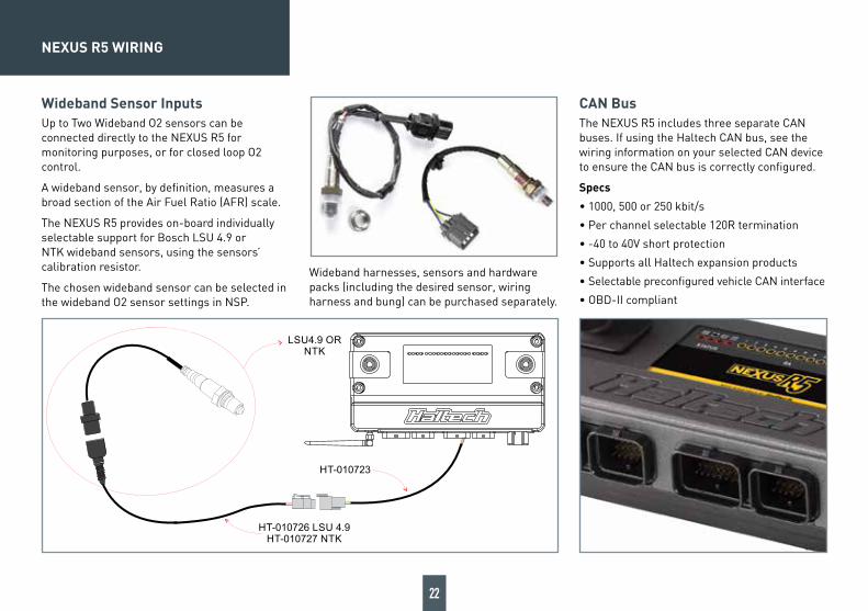
Wideband Sensor InputsUp to Two Wideband O2 sensors can be connected directly to the NEXUS R5 for monitoring purposes, or for closed loop O2 control.
A wideband sensor, by definition, measures a broad section of the Air Fuel Ratio (AFR) scale.
The NEXUS R5 provides on-board individually selectable support for Bosch LSU 4.9 or NTK wideband sensors, using the sensors’ calibration resistor.
The chosen wideband sensor can be selected in the wideband O2 sensor settings in NSP.
Wideband harnesses, sensors and hardware packs (including the desired sensor, wiring harness and bung) can be purchased separately.
CAN BusThe NEXUS R5 includes three separate CAN buses. If using the Haltech CAN bus, see the wiring information on your selected CAN device to ensure the CAN bus is correctly configured.
Specs
• 1000, 500 or 250 kbit/s
• Per channel selectable 120R termination
• -40 to 40V short protection
• Supports all Haltech expansion products
• Selectable preconfigured vehicle CAN interface
• OBD-II compliant
LSU4.9 ORNTK
HT-010723
HT-010726 LSU 4.9HT-010727 NTK

23
At Haltech we make every effort to design and manufacture fault-free products that perform up to or above the market expectations. All our products are covered by a Limited 12 Month Warranty.
Haltech Limited WarrantyUnless specified otherwise, Haltech warrants its products to be free from defects in material or workmanship for a period of 12 months from the date of purchase.
If the Haltech product is found to be defective as mentioned above, it will be replaced or repaired if returned prepaid along with proof of purchase. Proof of purchase in the form of a copy of the original purchase invoice, receipt or bill of sale which indicates that the product is within the warranty period, must be presented to obtain warranty service.
Replacement or repair of a defective product shall constitute the sole liability of Haltech. To the extent permitted by law, the foregoing is exclusive and in lieu of all other warranties or representations, either expressed or implied, including any implied warranty of merchantability or fitness. In no event shall Haltech, be liable for special or consequential damages.
Product ReturnsPlease include a copy of the original purchase invoice, receipt or bill of sale along with the unused, undamaged product and its original packaging. Any product returned with missing ac-cessory items or packaging will incur extra charges to return the item to a re-saleable condition.
All product returns must be sent via a freight method with adequate tracking, insurance and proof of delivery services. Haltech will not be held responsible for product returns lost during transit.
Returns of Products Supplied in Sealed Packaging The sale of any sensor or accessory supplied in sealed packaging is strictly non-refundable if the sealed packaging has been opened or tampered with. This will be clearly noted on the product packaging. If you do not accept these terms please return the sensor in its original un-opened packaging within 30 days for a full refund.
A sensor or accessory product may be returned after 30 days of purchase (with its sealed pack-aging in tact) for credit only (no refunds given) and will be subject to a 10% restocking fee.
Installation of Haltech ProductsNo responsibility whatsoever is accepted by Haltech for the fitment of Haltech Products. The onus is clearly on the installer to ensure that both their knowledge and the parts selected are cor-rect for that particular application. Any damage to parts or consequential damage or costs result-ing from the incorrect installation of Haltech products are totally the responsibility of the installer.
Always disconnect the battery when doing electrical work on your vehicle. Avoid sparks, open flames or use of electrical devices near flammable substances. Do not run the engine with a battery charger connected as this could damage the ECU and other electrical equipment.
Do not overcharge the battery or reverse the polarity of the battery or any charging unit. Discon-nect the Haltech ECU from the electrical system whenever doing any welding on the vehicle by unplugging the wiring harness connector from the ECU.
After completing the ECU installation, make sure there is no wiring left un-insulated. Uninsulated wiring can cause sparks, short circuits and in some cases fire. Before attempting to run the en-gine ensure there are no leaks in the fuel system.
All fuel system components and wiring should be mounted away from heat sources, shielded if necessary and well ventilated. Always ensure that you follow workshop safety procedures. If you’re working underneath a jacked-up car, always use safety stands!
____________________________________________________________________________
Haltech Off-Road Usage PolicyIn many states it is unlawful to tamper with your vehicle’s emissions equipment. Haltech products are designed and sold for sanctioned off-road/competition non-emissions controlled vehicles only and may never be used on a public road or highway.
Using Haltech products for street/road use on public roads or highways is prohibited by law un-less a specific regulatory exemption exists (more information can be found on the SEMA Action Network website www.semasan.com/emissions for state by state details in the USA).
It is the responsibility of the installer and/or user of this product to ensure compliance with all applicable local and federal laws and regulations. Please check with your local vehicle authority before purchasing, using or installing any Haltech product.
WARRANTY CERTIFICATE

Haltech Australia17 Durian Place, Wetherill Park NSW 2164 Australia Phone: +61 2 9729 0999 Email: [email protected]
Haltech New ZealandGrey Lynn Auckland, NZ 1021 Phone: 09 887 0616 Email: [email protected]
Haltech USA East750 Miles Point Way, Lexington, KY 40510 USA Phone: +1 888 298 8116 Email: [email protected]
Haltech USA West26429 Rancho Parkway S, Unit 125 Lake Forest, CA 92630 USA Phone: +1 949 490 5660 Email: [email protected]
Haltech UK4 Wharton Street Industrial Estate, Wharton Street, Birmingham B7 5TR Phone: +44 121 285 6650 Email: [email protected]
Haltech EuropeOttogasse 2A, 2333 Leopoldsdorf, Austria Phone: +43 720 883968 Email: [email protected] facebook.com/HaltechEngineManagement youtube.com/haltechecu instagram.com/haltechecu
06/2020