C-Nav7000 Quick Start Guide - Oceaneering
13
Quick Start Guide Revision 2 Revision Date: March 29, 2018 C-Nav Positioning Solutions 730 E. Kaliste Saloom Road Lafayette, LA 70508 U.S.A. www.oceaneering.com/cnav
-
Upload
khangminh22 -
Category
Documents
-
view
0 -
download
0
Transcript of C-Nav7000 Quick Start Guide - Oceaneering

Quick Start Guide
Revision 2
Revision Date: March 29, 2018
C-Nav Positioning Solutions
730 E. Kaliste Saloom Road
Lafayette, LA 70508 U.S.A.
www.oceaneering.com/cnav

C-Nav7000 Quick Start Guide
Revision 2 Page 2 of 13 3/29/2018
Release Notice
This is the March 2018 release of the C-Nav7000 Quick Start Guide.
Revision History
2 3/29/2018 Changed logos to OI standards L.C
1 1/31/2014 Initial Review J. Hauschildt
Revision Date Description Author

C-Nav7000 Quick Start Guide
Revision 2 Page 3 of 13 3/29/2018
Trademarks
The C-Nav, C-Nav3050, and C-Nav7000 logo are trademarks of Oceaneering International, Inc. Microsoft, MS-DOS, Windows, Windows NT, Windows XP, Windows Vista, and Windows 7 are trademarks of Microsoft Corporation. All other brand names are trademarks of their respective holders.
FCC Notice
This device complies with Part 15 Subpart B Class B of the FCC Rules. Operation is subject to the following two conditions:
1. This device may not cause harmful interference, and
2. This device must accept any interference received, including interference that may cause undesired operation.
The GNSS sensor has been tested in accordance with FCC regulations for electromagnetic interference. This does not guarantee non-interference with other equipment. Additionally, the GNSS sensor may be adversely affected by nearby sources of electromagnetic radiation.
Disclaimer of Warranty
EXCEPT AS INDICATED IN “LIMITED WARRANTY” HEREIN, OCEANEERING INTERNATIONAL, INC. SOFTWARE, FIRMWARE AND DOCUMENTATION ARE PROVIDED “AS IS” AND WITHOUT EXPRESSED OR LIMITED WARRANTY OF ANY KIND BY EITHER OCEANEERING INTERNATIONAL, INC., OR ANYONE WHO HAS BEEN INVOLVED IN ITS CREATION, PRODUCTION, OR DISTRIBUTION INCLUDING BUT NOT LIMITED TO THE IMPLIED WARRANTIES OF MERCHANTABILITY AND FITNESS FOR A PARTICULAR PURPOSE. THE ENTIRE RISK, AS TO THE QUALITY AND PERFORMANCE OF THE OCEANEERING INTERNATIONAL, INC. HARDWARE, SOFTWARE, FIRMWARE AND DOCUMENTATION, IS WITH YOU. SOME STATES DO NOT ALLOW THE EXCLUSION OF IMPLIED WARRANTIES, SO THE ABOVE EXCLUSION MAY NOT APPLY TO YOU.
Limitation of Liability
IN NO EVENT WILL OCEANEERING INTERNATIONAL, INC., OR ANY PERSON INVOLVED IN THE CREATION, PRODUCTION, OR DISTRIBUTION OF THE OCEANEERING INTERNATIONAL, INC. SOFTWARE, HARDWARE, FIRMWARE AND DOCUMENTATION BE LIABLE TO YOU ON ACCOUNT OF ANY CLAIM FOR ANY DAMAGES, INCLUDING ANY LOST PROFITS, LOST SAVINGS, OR OTHER SPECIAL, INCIDENTAL, CONSEQUENTIAL, OR EXEMPLARY DAMAGES, INCLUDING BUT NOT LIMITED TO ANY DAMAGES ASSESSED AGAINST OR PAID BY YOU TO ANY THIRD PARTY, RISING OUT

C-Nav7000 Quick Start Guide
Revision 2 Page 4 of 13 3/29/2018
OF THE USE, LIABILITY TO USE, QUALITY OR PERFORMANCE OF SUCH OCEANEERING INTERNATIONAL, INC. SOFTWARE, HARDWARE, AND DOCUMENTATION, EVEN IF OCEANEERING INTERNATIONAL, INC., OR ANY SUCH PERSON OR ENTITY HAS BEEN ADVISED OF THE POSSIBILITY OF DAMAGES, OR FOR ANY CLAIM BY ANY OTHER PARTY. SOME STATES DO NOT ALLOW THE LIMITATION OR EXCLUSION OF LIABILITY FOR INCIDENTAL OR CONSEQUENTIAL DAMAGES SO, THE ABOVE LIMITATIONS MAY NOT APPLY TO YOU
Use of this Document
This Quick Start Guide is intended to be used by someone familiar with the concepts of GNSS Sensor hardware installation and rack mounted equipment in a marine environment. Revisions to this Quick Start Guide can be obtained on our website www.oceaneering.com/cnav or by contacting C-Nav Support: [email protected]

C-Nav7000 Quick Start Guide
Revision 2 Page 5 of 13 3/29/2018
Table of Contents Table of Contents .................................................................................................. 5
List of Figures ....................................................................................................... 5
List of Tables ........................................................................................................ 5
Manual Organization ......................................................................................... 6
Conventions ...................................................................................................... 6
Section 1 - Overview ............................................................................................. 7
Introduction ....................................................................................................... 7
Supplied Equipment .......................................................................................... 7
Optional Equipment ........................................................................................... 8
Section 2 – Installation ........................................................................................ 10
Section 3 - Operation .......................................................................................... 11
List of Figures Figure 1: C-Nav7000 Interconnection Diagram ................................................... 10
Figure 2: C-Nav7000 Front Panel ....................................................................... 11
Figure 3: Receiving Data .................................................................................... 12
Figure 4: Not Receiving Data .............................................................................. 12
List of Tables Table 1: The C-Nav7000 (P/N BUNDLE_C-NAV7000) Supplied Equipment ........ 8
Table 2: IALA OPTION (CNV7000-IALA-MOD-K) ................................................. 8
Table 3: UHF OPTION #1 (CNV7000-UHF-OMOD1-K) ........................................ 8
Table 4: UHF OPTION #2 (CNV7000-UHF-OMOD2-K) ........................................ 9
Table 5: The Nav7000 Power Supply Option Kit (CNV7000-PSU-12V-K) ............ 9

C-Nav7000 Quick Start Guide
Revision 2 Page 6 of 13 3/29/2018
Manual Organization
This section describes how the manual is laid out. It gives one or two sentence descriptions about each major section.
Section 1 - Overview (Page 7) gives a brief overview of the purpose of this document.
Section 2 – Installation (Page 10) provides guidance on how the
C-Nav7000 works.
Section 3 - Operation (Page 11) provides guidance on operating the C-Nav7000.
Conventions
Arial font is used for plain text in this document.
Arial italic font is used for settings names.
“Arial quoted” font is used for settings values.
Arial Bold font is used for button names.
Arial Bold Italic font is used for menu items.
Arial Blue font is used for cross-references.
Arial Blue Underline font is used for hyperlinks.
Arial red italic is used for typed commands.
This symbol is used for warnings in which failure to take heed may cause severe injury or death.
This symbol is used to caution the user that the improper installation and use of this product may damage this product and/or other devices connected to it.
Important notes are displayed in shaded text boxes
Please note:
Such note boxes display important information that should not be ignored.

C-Nav7000 Quick Start Guide
Revision 2 Page 7 of 13 3/29/2018
Section 1 - Overview
Introduction
This Quick Start Guide is intended to familiarize the user with the basic setup of the C-Nav7000 only. The supplied C-Nav7000 USB Thumb Drive (P/N 7CNG002-0) includes the C-Nav7000 User Guide (P/N CNV7000CMANUAL). This C-Nav7000 consists of supplied equipment (Table 1) and optional equipment (Tables 2 - 4), depending on the customer’s preferences.
Supplied Equipment
1 C-Nav3050 GNSS Sensor
(P/N CNV92_310413_3002)
2 C-Nav3050 Y-cable, 9-Pin to RJ45 & DB9
(P/N CNV94-310272-3006)
3 C-Nav3050 Y-Cable, 9-Pin to USB & DB9S
(P/N CNV94-310273-3006)
4 C-Nav3050 Power & 1PPS Cable w/filter
(P/N CNV94-310274-3010)
5 USB Thumb Drive
(P/N 7CNG002-0)
6 C-Nav GNSS Antenna
(P/N CNV82-001020-3001)
7 12" Antenna Pole
(P/N CNVWES534610)
8 Antenna Mounting Adaptor
(P/N CNV3250005-0)
9 C-Nav3050 Quick Start Guide
(P/N CNV96-310033-3001)
10 C-Nav7000 Base Unit
(P/N CNV7000-Enclosure)
11 C-Nav7000 Quick Start Guide
(P/N CNV7000-QS)
12 C-Nav7000 User Guide

C-Nav7000 Quick Start Guide
Revision 2 Page 8 of 13 3/29/2018
(P/N CNV7000MANUAL)
13 DC Power Supply Cable
(P/N CNVPSC001-1)
14 6' Standard Serial Cable
(P/N QVSCC317-06) (3ea.)
Table 1: The C-Nav7000 (P/N BUNDLE_C-NAV7000) Supplied Equipment
Optional Equipment
1 SBX-4 Beacon Module
(P/N CNVHEM940-4013-000)
2 12" Antenna Pole
(P/N CNVWES534610)
3 Internal RF Cable for IALA Mod
(P/N CNVFCI-INT-RF-IALA)
4 A31 Antenna, GPS L1 & Beacon
(P/N CNVHEM940-2088-000)
Table 2: IALA OPTION (CNV7000-IALA-MOD-K)
1 ADL RXO UHF Module 430-470MHZ
(P/N CNVPACK01147)
2 Base Antenna, 440-470Mhz, 7dBi
(P/N CNVKAT721388 TNC)
3 Internal RF Cable for UHF OPT #1
(P/N CNVFCI-INT-RF-UHF1)
Table 3: UHF OPTION #1 (CNV7000-UHF-OMOD1-K)
1 ADL RXO UHF Module 430-470MHZ
(P/N CNVPACK01147)
2 Base Antenna, 440-470Mhz, 7dBi
(P/N CNVKAT721388 TNC)
3 Internal RF Cable for UHF OPT #2
(P/N CNVFCI-INT-RF-UHF2)

C-Nav7000 Quick Start Guide
Revision 2 Page 9 of 13 3/29/2018
Table 4: UHF OPTION #2 (CNV7000-UHF-OMOD2-K)
1 12V DC Desktop Power Supply (P/N CNVGS90A12-PIM)
2 Neutrik XLR Connector- Plug (P/N CNVNEUNC3MXX-B)
3 Cord, Power, IEC320-C13 (US) (P/N CNV4000001-110)
Table 5: The Nav7000 Power Supply Option Kit (CNV7000-PSU-12V-K)

C-Nav7000 Quick Start Guide
Revision 2 Page 10 of 13 3/29/2018
Section 2 – Installation
This section provides guidance on hardware installation. Figure 1 (Page 10) shows the rear panel of the C-Nav7000 and its connections.
UHF UHFIALA
DP ADP B
SECOND OUTPUT
(IF REQUIRED)
POWER
SUPPLYDUAL DATA ADAPTER
FROM C-Nav3050
TO DP SYSTEM
PC for UHF
and/or IALA
Configuration
Figure 1: C-Nav7000 Interconnection Diagram

C-Nav7000 Quick Start Guide
Revision 2 Page 11 of 13 3/29/2018
Section 3 - Operation
This section provides guidance on operating the C-Nav7000. Figure 2 (Page 11) shows the front panel of the C-Nav7000 with its buttons, switches and indicators.
Figure 2: C-Nav7000 Front Panel
Refer to Figure 2 (Page 11) for the following from left to right:
1) ON/OFF Pushing this button turns the UHF and IALA receiver modules on; this button will illuminate green. Pushing this button again turns the UHF and IALA receiver modules off; the lamp is extinguished.
Please Note:
The ON/OFF function on the C-Nav3050 will already be powered up upon
connecting to the 12V DC receptacle from a 12V DC source.
2) Select UHF Receiver #1 and #2: This switch selects which UHF Receiver
the user wants to receive the corrections data from. In order to receive data on the selected receiver, the appropriate channel must be selected on the Screen Key that the UHF Receiver is selected to. The Screen Key must be illuminated green in order to receive any data.
3) Channel Select Screen Keys: These allow the user to select the appropriate channel for each of the two UHF receivers. When the proper UHF Receiver is selected, the user can either advance to a known channel or scan to a receiving channel. Channel selection is performed by: a. Press the Screen Key in ½ second intervals to advance the channel
manually (channel numbers only increase). An amber background on the Screen Key denotes that the channel is in a manual change state.
b. To scan a channel, press and hold the Screen Key for 5 seconds and release. The receiver will search for the channel that is receiving data by
C-Nav7000 Quick Start Guide
Revision 2 Page 12 of 13 3/29/2018
staying at that channel for 5 seconds before moving up to next channel if no data has been received.
c. If a channel is receiving data, the background of the Screen Key will illuminate green as seen in Figure 3 (Page 12).
Figure 3: Receiving Data
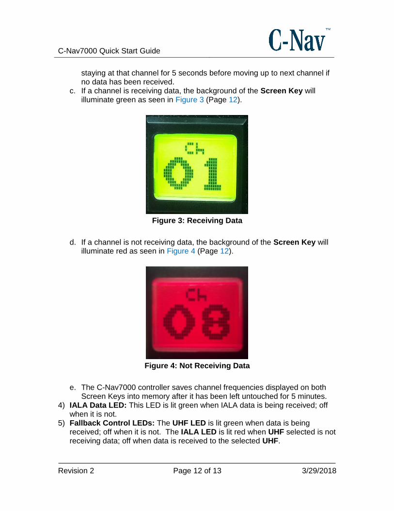
d. If a channel is not receiving data, the background of the Screen Key will illuminate red as seen in Figure 4 (Page 12).
Figure 4: Not Receiving Data
e. The C-Nav7000 controller saves channel frequencies displayed on both Screen Keys into memory after it has been left untouched for 5 minutes.
4) IALA Data LED: This LED is lit green when IALA data is being received; off when it is not.
5) Fallback Control LEDs: The UHF LED is lit green when data is being received; off when it is not. The IALA LED is lit red when UHF selected is not receiving data; off when data is received to the selected UHF.

C-Nav7000 Quick Start Guide
Revision 2 Page 13 of 13 3/29/2018
6) C-Nav3050: The LEDs on the C-Nav3050 show GNSS, satellite corrections, data, and Bluetooth status. For further information, please refer to C-Nav3050 User Guide.