TWR-K80F150M Quick Start Guide - Octopart
12
TWR-K80F150M Quick Start Guide Power-Efficient, 150 MHz ARM ® Cortex ® -M4-based MCUs with FPU, up to 256 KB Flash and 256 KB SRAM Tower System Development Platform
-
Upload
khangminh22 -
Category
Documents
-
view
1 -
download
0
Transcript of TWR-K80F150M Quick Start Guide - Octopart

TWR-K80F150M Quick Start GuidePower-Efficient, 150 MHz ARM®
Cortex®-M4-based MCUs with FPU,
up to 256 KB Flash and 256 KB SRAM
Tower System Development Platform

2
Quick Start Guide
Get to Know the TWR-K80F150M
SDRAM
Reset
K80 JTAG
K80 USB
OpenSDA USB
MK80FN256VDC15
SW3
Potentiometer
SW2
FXAS21002C 3-Axis Gyroscope
LEDs
MPL3115A2 Digital Pressure Sensor
SD Card Slot
Touch Pads
Figure 1: Front side of TWR-K80F150M

3
freescale.com
TWR-K80F150M Freescale Tower System Development PlatformThe TWR-K80F150M board is designed to work either in standalone mode or as part of the Freescale Tower System, a modular development board platform that enables rapid prototyping and tool re-use through reconfigurable hardware. Begin constructing your Tower System evaluation board platform today by visiting freescale.com/Tower for additional Tower System boards and compatible peripherals.
Figure 2: Back side of TWR-K80F150M
Battery Receptacle for VBAT
2x 32Mbit Serial Flash QuadSPI
EVM SIM Card Socket
FXOS8700CQ 3D Accelerometer +
3D Magnetometer

4
Quick Start Guide
TWR-K80F150M Features• MK80FN256VDC15 MCU
150 MHz Cortex-M4 core, 256KB Flash, 256 KB SRAM, 121 XFBGA, with SDRAM controller and USB
• Tower compatible processor board
• Onboard debug circuit: K20DX128VFM5 OpenSDA with virtual serial port
• 2 x 32 Mbit (4MB) Dual On-board QuadSPI memory @ 1.8V
• 64 Mbit (8MB) SDRAM Memory
• Five (5) user-controlled status LEDs
• Two (2) capacitive touch pads
• Two (2) mechanical push buttons
• Standalone full-speed USB host and device function
• Potentiometer
• MicroSD Card Slot
• EMVSIM Card Interface
• Ten (10) axis sensor system
FXOS8700CQ 3D Accelerometer + 3D Magnetometer
MPL3115A2 Digital Pressure Sensor
FXAS21002C 3-axis gyroscope• Socket for Touch Keypad plug-in (TWRPI-TOUCH-STR)
• Board power select with 3.3V or 1.8V MCU operation
• Independent, battery-operated power supply for real-time clock (RTC) module
• Battery holder for 20mm lithium battery (e.g. 2032, 2025)
5
freescale.com
Step-by-Step Installation InstructionsIn this Quick Start Guide, you will learn how to set up the TWR-K80F150M board and run the included demonstrated software. For more detailed information, review the user manual at freescale.com/TWR-K80F150M.
1 Configure the Hardware
Connect one end of the USB cable to the PC and the other end to the Power/OpenSDA micro-AB connector on the TWR-K80F150M module. Allow the PC to automatically configure the USB drivers if needed.
Download Software and Tools
Download installation software and documentation under “Jump Start Your Design” at freescale.com/TWR-K80F150M.
2 Run the Quick Start Demo
The LEDs on the board, D2 and D3, will gradually illuminate as the board is tilted. When rotated around the accelerometer’s x-axis the Blue LED (D3) will illuminate. Similarly, the green LED (D2) will gradually illuminate as rotated around the y-axis.
3

6
Quick Start Guide
Expanded Software and Tools Now Available for Kinetis MCUsAdditional details regarding the Quick Start Demo are included as part of the Kinetis software development kit (SDK).
To take your design to the next level, leverage the Kinetis SDK and other online enablement software and tools for Kinetis MCUs, available for download at the relevant links listed here.
• Kinetis software development kit at freescale.com/ksdk
• Kinetis Design Studio IDE at freescale.com/kds
• Bootloader for Kinetis MCUs at freescale.com/kboot

7
freescale.com
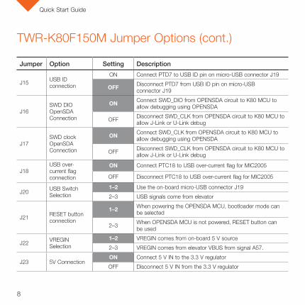
Jumper Option Setting Description
J2MCU reset connection on JTAG connector
ON Connect MCU reset on pin10 of JTAG connector J11
OFF Disconnect MCU reset on pin10 of JTAG connector J11
J3 VBAT Power Selection
1–2 Connect VBAT to on board MCU supply from MCU_PWR
2–3 Connect VBAT to the higher voltage between on board MCU_PWR supply or coin cell supply
J4 JTAG Power Connection
ON Connect on-board 5 V supply to JTAG port (supports powering board from external JTAG probe)
OFF Disconnect on-board 5V supply from JTAG port
J5 QuadSPI Power Enable
ON Connect VDDIO_E domain to power QuadSPI flash. Should only be connected when VDDIO_E is at 1.8 V
OFF Disconnect VDDIO_E domain from QuadSPI flash.
J6 UART RX Connection
1–2 Connect UART1_RX to elevator
2–3 Connect UART1_RX to OpenSDA UART RX
J8 UART TX Connection
1–2 Connect UART1_TX to elevator
2–3 Connect UART1_TX to OpenSDA UART TX
J9 MCU power connection
ON Connect V_BRD and MCU_PWR to MCU_VDD
OFF Disconnect V_BRD and MCU_PWR from MCU_VDD
J10 VDD and VDDA connection
ON Connect VDD and VDDA
OFF Disconnect VDD and VDDA
TWR-K80F150M Jumper OptionsThe following is a list of all the jumper options. The default installed jumper settings are indicated in the shaded boxes.
8
Quick Start Guide
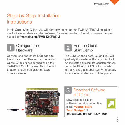
TWR-K80F150M Jumper Options (cont.)
J15 USB ID connection
ON Connect PTD7 to USB ID pin on micro-USB connector J19
OFF Disconnect PTD7 from USB ID pin on micro-USB connector J19
J16SWD DIO OpenSDA Connection
ON Connect SWD_DIO from OPENSDA circuit to K80 MCU to allow debugging using OPENSDA
OFF Disconnect SWD_CLK from OPENSDA circuit to K80 MCU to allow J-Link or U-Link debug
J17SWD clock OpenSDA Connection
ON Connect SWD_CLK from OPENSDA circuit to K80 MCU to allow debugging using OPENSDA
OFF Disconnect SWD_CLK from OPENSDA circuit to K80 MCU to allow J-Link or U-Link debug
J18USB over-current flag connection
ON Connect PTC18 to USB over-current flag for MIC2005
OFF Disconnect PTC18 to USB over-current flag for MIC2005
J20 USB Switch Selection
1–2 Use the on-board micro-USB connector J19
2–3 USB signals come from elevator
J21 RESET button connection
1–2 When powering the OPENSDA MCU, bootloader mode can be selected
2–3 When OPENSDA MCU is not powered, RESET button can be used
J22 VREGIN Selection
1–2 VREGIN comes from on-board 5 V source
2–3 VREGIN comes from elevator VBUS from signal A57.
J23 5V ConnectionON Connect 5 V IN to the 3.3 V regulator
OFF Disconnect 5 V IN from the 3.3 V regulator
Jumper Option Setting Description

9
freescale.com
TWR-K80F150M Jumper Options (cont.)
J25Board Power and Regulator Selection
1–3 3V3_BRD connected to output of 3.3 V regualtor
2–4 Invalid configuration. Do not use.
3–4 Invalid configuration. Do not use.
4–6 1.8 V regulator uses output of Li-Ion Battery Domain
5–6 1.8 V regulator uses output of 3.3 V regulator
6–8 1.8 V regulator uses 5 V IN directory.
J26 5V Input Power Selection
1–3 VREGIN uses USB 5 V
3–4 Raw 5 V input from K80 USB
5–6 Regulated 5 V output from OpenSDA 5 V input
7–8 Power from P5V_ELEV input
9–10 Raw 5 V input from OpenSDA USB port J24
J27 OpenSDA Reset
ONConnect OpenSDA reset signal to board reset. There is a board trace that makes this connection even if jumper is not populated.
OFF*Disconnect OpenSDA reset signal to board reset. *By default there is a board trace connecting this signal even though jumper is off.
J28USB power enable connection
ON Connect PTC19 to USB power enable for MIC2005
OFF Disconnect PTC19 to USB power enable for MIC2005
Jumper Option Setting Description
10
Quick Start Guide
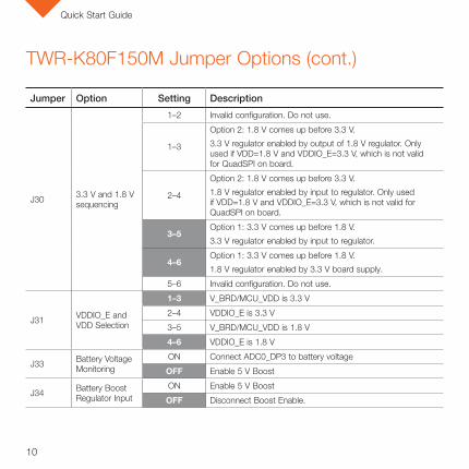
TWR-K80F150M Jumper Options (cont.)
Jumper Option Setting Description
J30 3.3 V and 1.8 V sequencing
1–2 Invalid configuration. Do not use.
1–3
Option 2: 1.8 V comes up before 3.3 V.
3.3 V regulator enabled by output of 1.8 V regulator. Only used if VDD=1.8 V and VDDIO_E=3.3 V, which is not valid for QuadSPI on board.
2–4
Option 2: 1.8 V comes up before 3.3 V.
1.8 V regulator enabled by input to regulator. Only used if VDD=1.8 V and VDDIO_E=3.3 V, which is not valid for QuadSPI on board.
3–5Option 1: 3.3 V comes up before 1.8 V.
3.3 V regulator enabled by input to regulator.
4–6Option 1: 3.3 V comes up before 1.8 V.
1.8 V regulator enabled by 3.3 V board supply.
5–6 Invalid configuration. Do not use.
J31 VDDIO_E and VDD Selection
1–3 V_BRD/MCU_VDD is 3.3 V
2–4 VDDIO_E is 3.3 V
3–5 V_BRD/MCU_VDD is 1.8 V
4–6 VDDIO_E is 1.8 V
J33 Battery Voltage Monitoring
ON Connect ADC0_DP3 to battery voltage
OFF Enable 5 V Boost
J34 Battery Boost Regulator Input
ON Enable 5 V Boost
OFF Disconnect Boost Enable.

11
freescale.com

Visit freescale.com/TWR-K80F150M or freescale.com/Kinetis for more information on the TWR-K80F150M board.
SupportVisit freescale.com/support for a list of phone numbers within your region.
WarrantyVisit freescale.com/warranty for complete warranty information.
Get StartedDownload installation software and documentation under “Jump Start Your Design” at freescale.com/TWR-K80F150M.
For more information, visit freescale.com/TWR-K80F150M, freescale.com/Kinetis or freescale.com/Tower
Freescale, the Freescale logo and Kinetis are trademarks of Freescale Semiconductor, Inc., Reg. U.S. Pat. & Tm. Off. All other product or service names are the property of their respective owners. ARM and Cortex are registered trademarks of ARM Limited (or its subsidiaries) in the EU and/or elsewhere. All rights reserved. © 2015 Freescale Semiconductor, Inc.
Doc Number: TWRKK80F150MQSG REV 0 Agile Number: 926-28608 REV A