Installation Guide - Huawei Technical Support
102
FusionModule1000A20 Prefabricated All-in-One Data Center V200R003C10 Installation Guide Issue 03 Date 2020-10-30 HUAWEI TECHNOLOGIES CO., LTD.
-
Upload
khangminh22 -
Category
Documents
-
view
2 -
download
0
Transcript of Installation Guide - Huawei Technical Support
FusionModule1000A20 Prefabricated All-in-OneData Center
V200R003C10
Installation Guide
Issue 03
Date 2020-10-30
HUAWEI TECHNOLOGIES CO., LTD.

Copyright © Huawei Technologies Co., Ltd. 2020. All rights reserved.No part of this document may be reproduced or transmitted in any form or by any means without prior written consent of Huawei Technologies Co., Ltd.
Trademarks and Permissions
and other Huawei trademarks are trademarks of Huawei Technologies Co., Ltd.All other trademarks and trade names mentioned in this document are the property of their respective holders.
NoticeThe purchased products, services and features are stipulated by the contract made between Huawei and the customer. All or part of the products, services and features described in this document may not be within the purchase scope or the usage scope. Unless otherwise specified in the contract, all statements, information, and recommendations in this document are provided "AS IS" without warranties, guarantees or representations of any kind, either express or implied.
The information in this document is subject to change without notice. Every effort has been made in the preparation of this document to ensure accuracy of the contents, but all statements, information, and recommendations in this document do not constitute a warranty of any kind, express or implied.
Huawei Technologies Co., Ltd.Address: Huawei Industrial Base
Bantian, LonggangShenzhen 518129People's Republic of China
Website: https://e.huawei.com
Issue 03 (2020-10-30) Copyright © Huawei Technologies Co., Ltd. i

About This Document
PurposeThis document describes the site requirements for installing theFusionModule1000A prefabricated all-in-one data center (FusionModule1000A forshort) as well as the methods and skills required for installing pre-fab. modules,pipes, and cables, providing installation guidance and technical support for onsiteinstallation personnel and technical support engineers.
Intended AudienceThis document is intended for:
● Hardware installation engineers● Technical support engineers● Commissioning engineers● Maintenance engineers
Symbol ConventionsThe symbols that may be found in this document are defined as follows.
Symbol Description
Indicates a hazard with a high level of risk which,if not avoided, will result in death or seriousinjury.
Indicates a hazard with a medium level of riskwhich, if not avoided, could result in death orserious injury.
Indicates a hazard with a low level of risk which,if not avoided, could result in minor or moderateinjury.
FusionModule1000A20 Prefabricated All-in-OneData CenterInstallation Guide About This Document
Issue 03 (2020-10-30) Copyright © Huawei Technologies Co., Ltd. ii

Symbol Description
Indicates a potentially hazardous situation which,if not avoided, could result in equipment damage,data loss, performance deterioration, orunanticipated results.NOTICE is used to address practices not related topersonal injury.
Supplements the important information in themain text.NOTE is used to address information not relatedto personal injury, equipment damage, andenvironment deterioration.
Change HistoryChanges between document issues are cumulative. The latest document issuecontains all the changes made in earlier issues.
Issue 03 (2020-10-30)This issue is the third official release.
● Updated the battery wiring diagram.
Issue 02 (2020-01-15)This issue is the second release.
● Updated the layout diagrams of the concrete platform scenario and baseinstallation scenario.
● Added a U-shaped drip loop for mains input.
Issue 01 (2019-07-15)This issue is the first official release.
FusionModule1000A20 Prefabricated All-in-OneData CenterInstallation Guide About This Document
Issue 03 (2020-10-30) Copyright © Huawei Technologies Co., Ltd. iii

Contents
About This Document................................................................................................................ ii
1 Installation Guide Usage....................................................................................................... 1
2 Site Requirements................................................................................................................... 22.1 Site Selection Requirements................................................................................................................................................ 22.2 Field Requirements................................................................................................................................................................. 22.2.1 (Optional) Concrete Platform Scenario....................................................................................................................... 22.2.2 (Optional) Base Installation Scenario...........................................................................................................................32.3 Power Supply and Distribution Requirements.............................................................................................................. 42.4 Grounding Requirements......................................................................................................................................................52.5 External Environment Requirements................................................................................................................................ 6
3 Installation Preparations....................................................................................................... 73.1 Obtaining Tools and Materials........................................................................................................................................... 73.2 Installation Personnel Requirements............................................................................................................................. 113.3 Checking the Installation Environment......................................................................................................................... 11
4 Installing Pre-fab. Modules.................................................................................................124.1 (Optional) Concrete Platform Scenario........................................................................................................................ 124.1.1 Determining the Pre-fab. Module Installation Position....................................................................................... 124.1.2 Removing the Pre-fab. Module Protective Cover................................................................................................... 134.1.3 Hoisting and Securing Pre-fab. Modules...................................................................................................................144.2 (Optional) Base Installation Scenario............................................................................................................................194.2.1 Installing Pre-fab. Module Bases..................................................................................................................................194.2.2 Removing the Pre-fab. Module Protective Cover................................................................................................... 234.2.3 Hoisting and Securing Pre-fab. Modules...................................................................................................................244.3 Grounding Pre-fab. Modules............................................................................................................................................. 27
5 Installing External Accessories for Pre-fab. Modules....................................................295.1 (Optional) Installing External Cable Trays................................................................................................................... 295.2 (Optional) Installing Awnings.......................................................................................................................................... 315.3 (Optional) Installing Step Ladders..................................................................................................................................34
6 Installing Devices Inside the Pre-fab. Module................................................................376.1 Installing Cooling Devices.................................................................................................................................................. 376.1.1 (Optional) Installing the Fresh Air Integrated Unit...............................................................................................37
FusionModule1000A20 Prefabricated All-in-OneData CenterInstallation Guide Contents
Issue 03 (2020-10-30) Copyright © Huawei Technologies Co., Ltd. iv

6.1.2 (Optional) Connecting Cables of the Fresh Air Integrated Unit....................................................................... 416.2 Installing Power Supply and Distribution Devices..................................................................................................... 436.2.1 Installing the Rectifier (TP48400B)............................................................................................................................. 436.2.2 Installing the Rectifier (TP48600B, TP481200B).....................................................................................................446.2.3 Installing a Battery (TP48400B or TP48600B).........................................................................................................456.2.4 Installing a Battery (TP481200B).................................................................................................................................486.3 (Optional) Installing the Electric Heating Belt........................................................................................................... 516.4 Installing Monitoring Devices........................................................................................................................................... 546.4.1 (Optional) Installing ECC800 Accessories................................................................................................................. 546.4.2 (Optional) Installing the WiFi Antenna..................................................................................................................... 566.4.3 (Optional) Installing a Pad............................................................................................................................................ 576.5 (Optional) Installing CE-Certified Fire Extinguishing Devices............................................................................... 586.5.1 (Optional) Installing the Fire Cylinder (CE)............................................................................................................. 586.5.2 Installing Extinguishant Control Panel Batteries.................................................................................................... 616.5.3 (Optional) Connecting a Cable to the ASD Power Box Battery........................................................................ 626.5.4 Installing an External Horn Strobe.............................................................................................................................. 64
7 Installing a Cable Outside a Pre-fab. Module................................................................ 667.1 Installing External Input Power Cables......................................................................................................................... 667.2 (Optional) Connecting DG Start/Stop Cables (ATS Input).....................................................................................70
8 Removing Transport Protection Materials...................................................................... 738.1 Removing Transport Protection Materials for Fire Extinguishing Devices........................................................ 738.2 Removing Transport Protection Materials for Intelligent Heat Exchangers..................................................... 74
9 Installation Verification.......................................................................................................76
A A Basic Installation Operations......................................................................................... 78A.1 Cable Installation Techniques...........................................................................................................................................78A.1.1 Cabling Rules...................................................................................................................................................................... 78A.1.2 Measuring Cables..............................................................................................................................................................79A.1.3 Laying Out Cables............................................................................................................................................................. 80A.1.4 Routing Cables Through a Plastic-coated Metal Hose.........................................................................................81A.1.5 Mounting Cables on the Cable Tray........................................................................................................................... 82A.1.6 Routing Cables into Feeder Windows........................................................................................................................ 84A.1.6.1 Installing DPJ End Connectors...................................................................................................................................84A.1.6.2 Installing Waterproof Metal Connectors............................................................................................................... 87A.1.7 Attaching Cable Labels....................................................................................................................................................89A.2 Preparing Cable Terminals................................................................................................................................................ 90
B Cleaning Pre-fab. Modules..................................................................................................92
C Dimensions of External Cable Trays and Step Ladders................................................93
D Acronyms and Abbreviations............................................................................................. 95
FusionModule1000A20 Prefabricated All-in-OneData CenterInstallation Guide Contents
Issue 03 (2020-10-30) Copyright © Huawei Technologies Co., Ltd. v

1 Installation Guide Usage
This section describes how to use the FusionModule1000 Installation Guide.
● This document focuses on the installation methods and precautions for theFusionModule1000.
● Some parameters of the FusionModule1000 should be provided andconfigured by onsite technical support engineers based on the actualapplication scenario.
● Before using this document, understand the actual configurations of theFusionModule1000 to enable quick installation.
● Operations marked as "optional" in the chapters, sections, or procedures canbe performed depending on the actual configurations and requirements.
● Before performing an operation, ensure that the prerequisites are met.Otherwise, the expected result may not be achieved, and equipment damageand personal injury may occur.
● Before installing the FusionModule1000, read through and keep in mind thenotes and precautions in this document.
● Precautions provided in this document are only supplementary to the locallaws and regulations governing the FusionModule1000.
● The figures provided in this document illustrate only installation andconnection methods. The actual product appearance prevails.
● Put on protective equipment such as the safety helmet and gloves beforeentering the site.
● Before using this document, make available the documents delivered witheach component.
● Unless otherwise specified, dimensions of devices in this document are bydefault height x width x depth, and the default measurement is mm.
FusionModule1000A20 Prefabricated All-in-OneData CenterInstallation Guide 1 Installation Guide Usage
Issue 03 (2020-10-30) Copyright © Huawei Technologies Co., Ltd. 1

2 Site Requirements
2.1 Site Selection Requirements● The power supply is stable and reliable.● The communication and traffic or convenient.● The site is far away from dust, smoke, harmful gas, and corrosive, flammable,
or explosive objects.● The site is not on a low-lying land, and above the highest water level of that
area.● The site is far away from sources of strong variation, loud noises, and strong
electromagnetic interference.● The ground is solid without spongy or soft soil, and is not prone to water
aggregation or subsidence.● The site is in an open area, meets the pre-fab. module installation and
maintenance requirements.● The site is far away from a class D environment or at least 500 m away from
the seashore.
2.2 Field RequirementsThe FusionModule1000 can be installed on bases or concrete platforms dependingon the actual scenario. The site requirements vary with the selected installationmode.
2.2.1 (Optional) Concrete Platform Scenario● Build concrete platforms on the selected installation site.
FusionModule1000A20 Prefabricated All-in-OneData CenterInstallation Guide 2 Site Requirements
Issue 03 (2020-10-30) Copyright © Huawei Technologies Co., Ltd. 2

Figure 2-1 Concrete platform (unit: mm)
(1) Concrete platform (2) Ground (3) Angle steel
NO TICE
● The cross-sectional area of a concrete platform must be 700 mm x 700mm. The horizontal error between concrete platforms must be less than 5mm.A concrete platform must be at least 500 mm higher than the ground.
NO TE
Determine the actual height of the concrete platforms based on the local drainage andweather conditions.
● The concrete platform should have a maximum load bearing capacity of15,000 kg and the recommended seismic acceleration is 3 g. The specificstrength is calculated based on the contact area (a single supporting pointinstalled on the ground is 400 cm2).
● Concrete pads or passages with the load-bearing capacity meeting local civilwork standards can be built on the site outside the concrete platforms foraccess and servicing.
2.2.2 (Optional) Base Installation Scenario● Build concrete platforms on the selected installation site.
FusionModule1000A20 Prefabricated All-in-OneData CenterInstallation Guide 2 Site Requirements
Issue 03 (2020-10-30) Copyright © Huawei Technologies Co., Ltd. 3

Figure 2-2 Base installation scenario diagram (unit: mm)
(1) Pre-fab. module base (2) Concrete platform (3) Ground
NO TICE
● The minimum cross-sectional area of a concrete platform must be 2900mm x 1000 mm. The error of the upper surface of a concrete platformmust be less than 10 mm. A concrete platform must be at least 200 mmhigher than the ground.
NO TE
Determine the actual height of the concrete platforms based on the local drainage andweather conditions.
● The concrete platform should have a maximum load bearing capacity of15,000 kg and the recommended seismic acceleration is 3 g. The specificstrength is calculated based on the contact area (a single base installed onthe ground is 1720 cm2).
● Concrete pads or passages with the load-bearing capacity meeting local civilwork standards can be built on the site outside the concrete platforms foraccess and servicing.
2.3 Power Supply and Distribution Requirements● The power supply for the FusionModule1000 can be the mains or a diesel
generator (DG). For the detailed input routes and capacity, see the powersupply and distribution system diagram for the solution in use.
FusionModule1000A20 Prefabricated All-in-OneData CenterInstallation Guide 2 Site Requirements
Issue 03 (2020-10-30) Copyright © Huawei Technologies Co., Ltd. 4

● Supported power systems: 380/400/415 V, 50 Hz/60 Hz, three-phase, four-wire, and PE; 208 V, 60 Hz, three-phase, four-wire, and PE
● A Class I surge protective device (SPD) with a maximum discharge current(Imax) of 100 kA (8/20 µs) is required for the upstream input powerdistribution frame (PDF) for the FusionModule1000.
● External cables of the FusionModule1000 are routed into the pre-fab. modulethrough the feeder window or the bottom cable hole. It is recommended thatexternal cables be buried underground.
Figure 2-3 Pre-fab. module exterior ports
(1) Feeder window (2) Bottom cable hole
2.4 Grounding Requirements● The external ground resistance of the pre-fab. module must not exceed 10
ohms, or the equivalent radius of the ground grid is no less than 5 m.● The pre-buried ground grid must be at least 0.7 m underground. In cold areas,
the ground electrodes must be buried under the frozen layer.● A pre-fab. module can be grounded using ground lugs or ground cables.
– Ground lug method: Use a ground lug made of hot-dip zinc-coated flatsteel sheet with a cross-sectional area of 40 mm x 4 mm (1.57 in. x 0.16in.), connect one end of the ground lug to the pre-buried ground grid,and connect the other end to the pre-fab. module ground point. When aground grid is pre-buried, the ground lug must be long enough toconnect to a ground point on the pre-fab. module.
FusionModule1000A20 Prefabricated All-in-OneData CenterInstallation Guide 2 Site Requirements
Issue 03 (2020-10-30) Copyright © Huawei Technologies Co., Ltd. 5

– Ground cable method: Use a 95 mm2 cable as the ground cable, connectone end of the cable to the pre-buried ground grid, and connect theother end to the pre-fab. module ground point. When a ground cable isused, the ground cable must be routed through a plastic-coated metalhose.
NO TE
● The screw reserved at a ground point is an M12 screw.● A pre-fab. module can be grounded in the TN-S or TN-C-S mode.
2.5 External Environment Requirements● Temperature: –20°C to +55°C● Relative humidity: 5%–95% RH
● Solar radiation: ≤ 1120 W/m2
FusionModule1000A20 Prefabricated All-in-OneData CenterInstallation Guide 2 Site Requirements
Issue 03 (2020-10-30) Copyright © Huawei Technologies Co., Ltd. 6

3 Installation Preparations
Before the installation, unpack and check the products, make available all requiredtechnical documents, tools, and materials, check the installation environment, drillholes based on the installation positions, fix the pre-fab. module bases, and trainonsite installation personnel.
3.1 Obtaining Tools and Materials
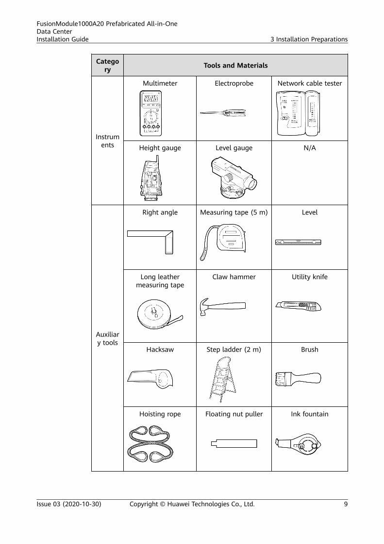
Table 3-1 Tools and materials
Category Tools and Materials
Tightening tools
Phillips screwdriver(M5, M6, and M8)
Flat-head screwdriver(2–5 mm)
Phillips screwdriverM4 (length < 100
mm)
Phillips screwdriverM8 (length = 200
mm)
Solid wrench Adjustable wrench
FusionModule1000A20 Prefabricated All-in-OneData CenterInstallation Guide 3 Installation Preparations
Issue 03 (2020-10-30) Copyright © Huawei Technologies Co., Ltd. 7

Category Tools and Materials
Torque wrench Socket wrench N/A
Pliers
Pliers Diagonal pliers Wire clippers
Crimping tool Wire stripper Hydraulic pliers
Pipe wrench N/A N/A
Powertools
Hammer drill anddrill bit (Φ22 mm,
7/8 inch)
Heat gun Vacuum cleaner
Hot melt device Crane Small cutter
FusionModule1000A20 Prefabricated All-in-OneData CenterInstallation Guide 3 Installation Preparations
Issue 03 (2020-10-30) Copyright © Huawei Technologies Co., Ltd. 8
Category Tools and Materials
Instruments
Multimeter Electroprobe Network cable tester
Height gauge Level gauge N/A
Auxiliary tools
Right angle Measuring tape (5 m) Level
Long leathermeasuring tape
Claw hammer Utility knife
Hacksaw Step ladder (2 m) Brush
Hoisting rope Floating nut puller Ink fountain
FusionModule1000A20 Prefabricated All-in-OneData CenterInstallation Guide 3 Installation Preparations
Issue 03 (2020-10-30) Copyright © Huawei Technologies Co., Ltd. 9

Category Tools and Materials
Cable reel Paint brush Jack
Consumables
Cable tie Insulation tape Marker
ESD gloves Protective gloves Safety helmet
Safety belt Safety goggles Anti-skid shoes
ESD wrist strap Rubber gloves Heat shrink tubing(diameter 20 mm-
radial shrinkage rate50%- operating
temperature range55 °C-105 °C-length
10 mm)
FusionModule1000A20 Prefabricated All-in-OneData CenterInstallation Guide 3 Installation Preparations
Issue 03 (2020-10-30) Copyright © Huawei Technologies Co., Ltd. 10

Category Tools and Materials
Scissors N/A N/A
NO TE
● This table may not list some tools required at specific sites. Onsite installation personneland technical support personnel should prepare tools based on site requirements.
● Some dedicated tools and installation materials provided with the equipment may notbe listed in this table.
● Preventive measures should be applied before installation to avoid water seepage intopre-fab. modules and equipment in the case of a sudden change in the weather.
3.2 Installation Personnel Requirements● Installation personnel must be trained and qualified by Huawei to master
methods for system installation, and must obtain work permits before theybegin to install the equipment.
● Technical personnel from the customer must be trained by Huawei andmaster the installation method.
● The number of construction personnel depends on the project progress andinstallation environment.
● Construction personnel have read through the safety precautions and relatedproduct documents before they begin working.
NO TE
● Common technician: familiar with the equipment installation process.
● Skilled technician: familiar with the equipment installation process and having an electriciancertificate.
3.3 Checking the Installation EnvironmentCheck the site requirements one by one, and start installation only after allrequirements are met. Huawei will not be liable for any consequences caused ifthe installation environment does not meet the requirements.
NO TE
Mark the security zone: Use red caution belts to delimit a security zone, clean up obstaclesin that zone, and place construction signs and warning signs in eye-catching positions.
FusionModule1000A20 Prefabricated All-in-OneData CenterInstallation Guide 3 Installation Preparations
Issue 03 (2020-10-30) Copyright © Huawei Technologies Co., Ltd. 11

4 Installing Pre-fab. Modules
4.1 (Optional) Concrete Platform Scenario
4.1.1 Determining the Pre-fab. Module Installation Position
Prerequisites● The field meets site requirements.● Before installing pre-fab. modules, check the height of concrete platforms and
ensure that the height (altitude) error between the upper surfaces of allplatforms does not exceed 5 mm.
NO TICE
Concrete platform levelness is critical to pre-fab. module installation. Ensure thatthe concrete platform meet requirements before installing pre-fab. modules.
ContextBefore installing pre-fab. modules, determine their installation positions anddirections based on site space.
PreparationsTools: marker, ink foundation, long leather measuring tape
Materials: none
Skill requirement: skilled technician
FusionModule1000A20 Prefabricated All-in-OneData CenterInstallation Guide 4 Installing Pre-fab. Modules
Issue 03 (2020-10-30) Copyright © Huawei Technologies Co., Ltd. 12

Procedure
Step 1 Determine the reference points for installing pre-fab. modules on the concreteplatforms and the onsite installation space. Mark the reference points using amarker.
Step 2 On the basis of the reference points, mark the mounting positions for the fourcorner fittings of a pre-fab. module using an ink fountain and long leathermeasuring tape.
NO TICE
When marking the mounting positions for corner fittings, ensure that the fourlines form a rectangle.
Figure 4-1 Concrete platform (unit: mm)
(1) Concrete platform (2) Ground (3) Angle steel
----End
4.1.2 Removing the Pre-fab. Module Protective Cover
Prerequisites
The weather condition is good without rain or snow.
FusionModule1000A20 Prefabricated All-in-OneData CenterInstallation Guide 4 Installing Pre-fab. Modules
Issue 03 (2020-10-30) Copyright © Huawei Technologies Co., Ltd. 13

ContextA protective cover is installed to protect the pre-fab. module during transportation.
PreparationsTools: safety helmet, safety belt, step ladder, protective gloves, utility knife
Materials: none
Skill requirement: common technician
Procedure
Step 1 Cut open the protective cover using a utility knife and remove the protective cover.
NO TE
When removing the protective cover, take protective measures for working at heights.
----End
4.1.3 Hoisting and Securing Pre-fab. Modules
Prerequisites
NO TICE
To facilitate subsequent installation, ensure that pre-fab. modules are level afterhoisting.
● Select an appropriate crane based on standards of the crane company, andask a professional to assess the crane onsite.
● The hoisting ropes are available.● The positions of pre-fab. module corner fittings are correctly marked.● The doors of pre-fab. modules to be hoisted are closed.● Ensure that the weather condition is good without wind when pre-fab.
modules need to be hoisted outdoors.
ContextThe crane and steel ropes must meet the pre-fab. module hoisting requirements.
Table 4-1 Parameters for hoisting pre-fab. modules
Weight Steel RopeLength
Steel RopeQuantity
Dimensions (H x W x D)
Net weight: <6000 kg
> 6.5 m 4 PCS 2896 mm x 2438 mm x 6058mm
FusionModule1000A20 Prefabricated All-in-OneData CenterInstallation Guide 4 Installing Pre-fab. Modules
Issue 03 (2020-10-30) Copyright © Huawei Technologies Co., Ltd. 14

Hoisting PrecautionsStage Precautions
Before hoisting Ensure that the crane and steel ropes provide the requiredbearing capacity.
Ensure that the steel ropes are securely connected.
During hoisting Do not allow any unauthorized people to enter thehazardous areas and never stand under the crane armduring hoisting.
Ensure that the crane is properly located and avoid long-distance hoisting.
Keep the pre-fab. module stable and horizontal duringhoisting, and ensure that the diagonal gradient of the pre-fab. module is within 5 degrees.
Lift and land a pre-fab. module slowly to prevent shock toequipment inside it.
Remove the steel ropes after ensuring that the pre-fab.module is placed evenly on the concrete platforms.
PreparationsTools: crane, socket wrench, torque wrench, Phillips screwdriver, jack, steel hoistingrope, level, level gauge, hammer drill, angle rule, marker, ink fountain, longleather measuring tape, claw hammer, vacuum cleaner
Materials: pre-fab. module to be hoisted, expansion bolt, angle steel bracket
Skill requirement: skilled technician, common technician, crane driver
Procedure
Step 1 Adjust the pre-fab. module in the required direction, connect the steel hoistingropes, and hoist the pre-fab. module onto the concrete platforms.
NO TICE
When hoisting a pre-fab. module, ensure that the four corner fittings of the pre-fab. module are aligned with the marked mounting positions for corner fittings onthe concrete platforms.
FusionModule1000A20 Prefabricated All-in-OneData CenterInstallation Guide 4 Installing Pre-fab. Modules
Issue 03 (2020-10-30) Copyright © Huawei Technologies Co., Ltd. 15

Figure 4-2 Hoisting a pre-fab. module
Step 2 Use four angle steel brackets to secure the pre-fab. module.1. Align the two mounting holes in an angle steel bracket with the two holes on
the pre-fab. module, and mark the hole positions for mounting the anglesteel bracket on the concrete platforms using a marker.
NO TICE
– Mark all four mounting holes where each angle steel bracket contacts theconcrete platform.
– Place a wooden block on the top of an expansion bolt, and then knock atthe wooden block using a claw hammer to avoid damaging the expansionbolt.
– When you drill a hole using a hammer drill, keep the drill bit perpendicularto the ground and hold the drill stock firmly with both hands to preventirregular drilling and damage to the ground.
– If the ground is too hard and smooth for the drill bit to secure its position,use a chisel to punch a pit before drilling.
– Before you hammer an expansion bolt vertically into a mounting hole,clean up dust from the inside and surrounding of the hole.
– Each angle steel bracket must be secured by two mounting holes.Preferentially drill the outer two mounting holes. If steel bars in a concreteplatform block the drill bit, drill the inner mounting holes.
FusionModule1000A20 Prefabricated All-in-OneData CenterInstallation Guide 4 Installing Pre-fab. Modules
Issue 03 (2020-10-30) Copyright © Huawei Technologies Co., Ltd. 16

Figure 4-3 Determining mounting holes for an angle steel bracket
2. Drill a hole in each mounting hole position using a hammer drill.3. Rotate the nut onto the expansion tube to prevent the expansion tube from
fluttering.4. Hammer the expansion bolt into the hole vertically until the flat washer is
flush with the ground.5. Remove the nut, spring washer, and flat washer.
Figure 4-4 Installing an expansion bolt (unit: mm)
(A) Nut (B) Spring washer
(C) Flat washer (D) Wooden block
6. Reinstall the angle steel brackets to the concrete platforms with theexpansion bolts securing the angle steel brackets. Remount the flat washers,spring washers, and nuts on the expansion bolts and tighten the expansionbolts in sequence using a torque wrench.
FusionModule1000A20 Prefabricated All-in-OneData CenterInstallation Guide 4 Installing Pre-fab. Modules
Issue 03 (2020-10-30) Copyright © Huawei Technologies Co., Ltd. 17

Figure 4-5 Securing an angle steel bracket
7. Remove the rubber plugs from the pre-fab. module fixing holes using aPhillips screwdriver.
8. Secure the angle steel brackets to the pre-fab. module using bolt assemblies.
----End
Follow-up ProcedureAfter pre-fab. modules are hoisted and installed, verify the installation to ensurenormal use of products and smooth subsequent installation.
Table 4-2 Installation checklist
No. Check Item Check Method Criteria
1 Contact between pre-fab. modules andconcrete platforms
Observe. A pre-fab. module isin close contact withand evenly supportedby the concreteplatforms.
2 Bolts and nuts Partially tighten themusing a wrench.
Bolts and nuts aretightened.
3 Pre-fab. module doors Open and close eachpre-fab. module dooronce.
All pre-fab. moduledoors can besmoothly opened andclosed.
FusionModule1000A20 Prefabricated All-in-OneData CenterInstallation Guide 4 Installing Pre-fab. Modules
Issue 03 (2020-10-30) Copyright © Huawei Technologies Co., Ltd. 18

4.2 (Optional) Base Installation Scenario
4.2.1 Installing Pre-fab. Module Bases
Prerequisites● The field meets site requirements.● Before installing pre-fab. modules, check the height of concrete platforms and
ensure that the height (altitude) error between the upper surfaces of allplatforms does not exceed 10 mm.
CA UTION
Concrete platform levelness is critical to pre-fab. module installation. Ensure thatthe concrete platform meet requirements before installing pre-fab. module bases.
Context
Before installing pre-fab. modules, determine their installation positions anddirections based on site space.
Figure 4-6 Single-capacity base (unit: mm)
Preparations
Tools: torque wrench, adjustable wrench, level, level gauge, hammer drill, rightangle, marker, ink fountain, long leather measuring tape, claw hammer, vacuumcleaner
Materials: single-capacity base, twistlock, expansion bolt, spacer
Skill requirement: skilled technician
Procedure
Step 1 Determine the installation areas on the concrete platforms and the actual sitespace. Mark the installation areas on the concrete platforms using an ink fountain.
FusionModule1000A20 Prefabricated All-in-OneData CenterInstallation Guide 4 Installing Pre-fab. Modules
Issue 03 (2020-10-30) Copyright © Huawei Technologies Co., Ltd. 19
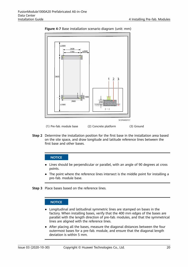
Figure 4-7 Base installation scenario diagram (unit: mm)
(1) Pre-fab. module base (2) Concrete platform (3) Ground
Step 2 Determine the installation position for the first base in the installation area basedon the site space, and draw longitude and latitude reference lines between thefirst base and other bases.
NO TICE
● Lines should be perpendicular or parallel, with an angle of 90 degrees at crosspoints.
● The point where the reference lines intersect is the middle point for installing apre-fab. module base.
Step 3 Place bases based on the reference lines.
NO TICE
● Longitudinal and latitudinal symmetric lines are stamped on bases in thefactory. When installing bases, verify that the 400 mm edges of the bases areparallel with the length direction of pre-fab. modules, and that the symmetricallines are aligned with the reference lines.
● After placing all the bases, measure the diagonal distances between the fouroutermost bases for a pre-fab. module, and ensure that the diagonal lengthdeviation is within 5 mm.
FusionModule1000A20 Prefabricated All-in-OneData CenterInstallation Guide 4 Installing Pre-fab. Modules
Issue 03 (2020-10-30) Copyright © Huawei Technologies Co., Ltd. 20
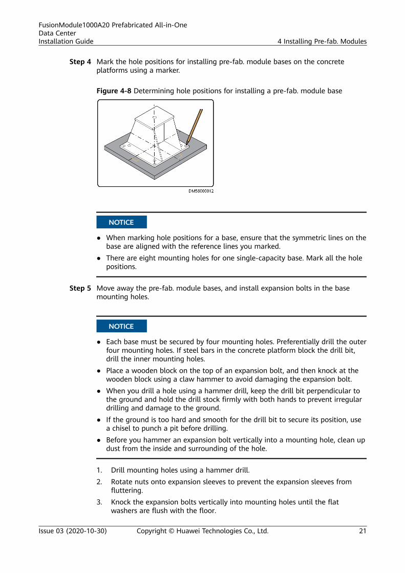
Step 4 Mark the hole positions for installing pre-fab. module bases on the concreteplatforms using a marker.
Figure 4-8 Determining hole positions for installing a pre-fab. module base
NO TICE
● When marking hole positions for a base, ensure that the symmetric lines on thebase are aligned with the reference lines you marked.
● There are eight mounting holes for one single-capacity base. Mark all the holepositions.
Step 5 Move away the pre-fab. module bases, and install expansion bolts in the basemounting holes.
NO TICE
● Each base must be secured by four mounting holes. Preferentially drill the outerfour mounting holes. If steel bars in the concrete platform block the drill bit,drill the inner mounting holes.
● Place a wooden block on the top of an expansion bolt, and then knock at thewooden block using a claw hammer to avoid damaging the expansion bolt.
● When you drill a hole using a hammer drill, keep the drill bit perpendicular tothe ground and hold the drill stock firmly with both hands to prevent irregulardrilling and damage to the ground.
● If the ground is too hard and smooth for the drill bit to secure its position, usea chisel to punch a pit before drilling.
● Before you hammer an expansion bolt vertically into a mounting hole, clean updust from the inside and surrounding of the hole.
1. Drill mounting holes using a hammer drill.2. Rotate nuts onto expansion sleeves to prevent the expansion sleeves from
fluttering.3. Knock the expansion bolts vertically into mounting holes until the flat
washers are flush with the floor.
FusionModule1000A20 Prefabricated All-in-OneData CenterInstallation Guide 4 Installing Pre-fab. Modules
Issue 03 (2020-10-30) Copyright © Huawei Technologies Co., Ltd. 21

4. Remove the nuts, spring washers, and flat washers.
Figure 4-9 Installing an expansion bolt (unit: mm)
(A) Nut (B) Spring washer
(C) Flat washer (D) Wooden block
Step 6 Reinstall the pre-fab. module bases to the concrete platforms with the expansionbolts securing the bases. Remount the flat washers, spring washers, and nuts onthe expansion bolts and tighten the expansion bolts in sequence using a torquewrench.
Figure 4-10 Securing pre-fab. module bases
Step 7 Level all bases.
1. Measure the height of each base using the level gauge, and record the heighton its upper surface using the marker.
2. Identify the base with the highest upper surface, and use it as the adjustmentreference.
3. Select spacers based on the height difference between a base and thereference base, and add spacers to adjust the height. Ensure that the heightdifference is within 5 mm after adjustment.
FusionModule1000A20 Prefabricated All-in-OneData CenterInstallation Guide 4 Installing Pre-fab. Modules
Issue 03 (2020-10-30) Copyright © Huawei Technologies Co., Ltd. 22

Figure 4-11 Installing the washer
(1) Spacer (2) Base
NO TE
Spacers delivered with the bases have two specifications: 2 mm and 5 mm thick.
Step 8 Insert a twistlock into the mounting hole in a single-capacity base and keep thelock head in the pre-fab. module length direction.
Step 9 Pre-mount the nuts onto the twistlocks using an adjustable wrench.
Figure 4-12 Installing a twistlock for a single-capacity base
NO TE
It is recommended that you tighten the base twistlocks after pre-fab. modules are hoisted inplace.
----End
4.2.2 Removing the Pre-fab. Module Protective Cover
PrerequisitesThe weather condition is good without rain or snow.
ContextA protective cover is installed to protect the pre-fab. module during transportation.
FusionModule1000A20 Prefabricated All-in-OneData CenterInstallation Guide 4 Installing Pre-fab. Modules
Issue 03 (2020-10-30) Copyright © Huawei Technologies Co., Ltd. 23

Preparations
Tools: safety helmet, safety belt, step ladder, protective gloves, utility knife
Materials: none
Skill requirement: common technician
Procedure
Step 1 Cut open the protective cover using a utility knife and remove the protective cover.
NO TE
When removing the protective cover, take protective measures for working at heights.
----End
4.2.3 Hoisting and Securing Pre-fab. Modules
Prerequisites
NO TICE
To facilitate subsequent installation, ensure that pre-fab. modules are level afterhoisting.
● Select an appropriate crane based on standards of the crane company, andask a professional to assess the crane onsite.
● Twistlocks in pre-fab. module bases are in correct positions.
● The hoisting ropes are available.
● The doors of pre-fab. modules to be hoisted are closed.
● Ensure that the weather condition is good without wind when pre-fab.modules need to be hoisted outdoors.
Context
Ensure that the crane and steel ropes can bear the load weight.
Table 4-3 Hoisting specifications
Weight SteelRopeLength
Steel RopeQuantity
Dimensions (H x W x D)
Net weight: <6000 kg
> 6.5 m 4 PCS 2896 mm x 2438 mm x 6058 mm
FusionModule1000A20 Prefabricated All-in-OneData CenterInstallation Guide 4 Installing Pre-fab. Modules
Issue 03 (2020-10-30) Copyright © Huawei Technologies Co., Ltd. 24

Hoisting PrecautionsStage Precautions
Before hoisting Ensure that the crane and steel ropes provide the requiredbearing capacity.
Ensure that the twistlocks in container bases are in correctpositions.
Ensure that the steel ropes are securely connected.
During hoisting Do not allow any unauthorized people to enter thehazardous areas and never stand under the crane armduring hoisting.
Ensure that the crane is properly located and avoid long-distance hoisting.
Keep the pre-fab. module stable and horizontal duringhoisting, and ensure that the diagonal gradient of the pre-fab. module is within 5 degrees.
Lift and land a pre-fab. module slowly to prevent shock toequipment inside it.
Remove the ropes after ensuring that the pre-fab. module isplaced evenly on the four bases.
PreparationsTools: crane, torque wrench, steel hoisting rope, level
Materials: pre-fab. module to be hoisted, spacer
Documents: none
Skill requirement: skilled technician, common technician, crane driver
Procedure
Step 1 Adjust the pre-fab. module in the installation direction, connect the steel hoistingropes, and hoist the pre-fab. module onto the bases.
FusionModule1000A20 Prefabricated All-in-OneData CenterInstallation Guide 4 Installing Pre-fab. Modules
Issue 03 (2020-10-30) Copyright © Huawei Technologies Co., Ltd. 25

Figure 4-13 Hoisting a pre-fab. module
Step 2 Turn the twistlocks in the bases by 90 degrees to lock the pre-fab. module, andtighten the twistlocks using a torque wrench.
NO TICE
Before you tighten twistlocks, ensure that the twistlocks lock the pre-fab. module.
Figure 4-14 Tightening a twistlock in a single-capacity base
----End
Follow-up ProcedureAfter pre-fab. modules are hoisted and installed, verify the installation to ensurenormal use of products and smooth subsequent installation.
FusionModule1000A20 Prefabricated All-in-OneData CenterInstallation Guide 4 Installing Pre-fab. Modules
Issue 03 (2020-10-30) Copyright © Huawei Technologies Co., Ltd. 26

Table 4-4 Installation checklist
No. Check Item Check Method Criteria
1 Bolts and nuts oftwistlocks
Partially tighten themusing a wrench.
Bolts and nuts aretightened.
2 Contact betweenpre-fab. modulesand bases
Observe. A pre-fab. module is inclose contact with andevenly supported by thebases underneath.
3 Pre-fab. moduledoors
Open and close eachpre-fab. module dooronce.
All pre-fab. module doorscan be smoothly openedand closed.
4.3 Grounding Pre-fab. Modules
Prerequisites● The pre-fab. modules have been installed.● The grounding positions have been specified.● The grounding requirements have been specified.
Context
Ground lugs or ground cables can be used to ground the pre-fab. modules. Therequirements are as follows:
● Ground lug: use ground lugs made of hot-dip zinc-coated flat steel with across-sectional area of 40 mm x 4 mm, and leave 500 mm of each ground lugout of the concrete platform.
● Ground cable: Use 95 mm2 ground cables and route them through a plastic-coated metal hose.
Preparations
Tool: torque wrench
Materials: none
Skill requirement: common technician
Procedure
Step 1 Secure the ground lugs to the pre-fab. module ground points by tighteningM12x30 stainless steel bolt assemblies.
NO TE
Before the installation, remove the tinfoil from the ground lugs.
FusionModule1000A20 Prefabricated All-in-OneData CenterInstallation Guide 4 Installing Pre-fab. Modules
Issue 03 (2020-10-30) Copyright © Huawei Technologies Co., Ltd. 27

Figure 4-15 Installing a ground lug
NO TE
In addition to using ground lugs, you can also connect ground cables to pre-fab. module groundpoints using M12x30 stainless steel bolt assemblies, as shown in the following figure. Groundcables can be routed through plastic-coated metal hoses for protection based on siterequirements.
Figure 4-16 Installing a ground cable
----End
FusionModule1000A20 Prefabricated All-in-OneData CenterInstallation Guide 4 Installing Pre-fab. Modules
Issue 03 (2020-10-30) Copyright © Huawei Technologies Co., Ltd. 28

5 Installing External Accessories for Pre-fab. Modules
5.1 (Optional) Installing External Cable Trays
PrerequisitesThe external cable trays to be installed have been obtained.
ContextThe external cable tray fittings consist of long cable trays, short cable trays,fasteners, M8 bolt assemblies, and M10 bolt assemblies.
FusionModule1000A20 Prefabricated All-in-OneData CenterInstallation Guide 5 Installing External Accessories for Pre-fab. Modules
Issue 03 (2020-10-30) Copyright © Huawei Technologies Co., Ltd. 29

Figure 5-1 Composition of the external cable tray
(1) Long cable tray (2) Short cable tray (3) Fastener
(4) M10 bolt assemblies (5) M8 bolt assemblies
PreparationsTools: adjustable wrench, Phillips screwdriver
Materials: external cable tray, external Cable Tray screws
Skill requirement: common technician
Procedure
Step 1 Locate the external cable tray installation position, and remove the rubber plugsfrom the corresponding mounting holes in the pre-fab. module using a Phillipsscrewdriver.
Step 2 Align the ends of long and short cable trays, and secure the long and short cabletrays using fasteners.
FusionModule1000A20 Prefabricated All-in-OneData CenterInstallation Guide 5 Installing External Accessories for Pre-fab. Modules
Issue 03 (2020-10-30) Copyright © Huawei Technologies Co., Ltd. 30

Figure 5-2 Assembling the cable tray
Step 3 Secure the cable tray to the ports reserved on the pre-fab. module.
Figure 5-3 Securing the cable tray
----End
5.2 (Optional) Installing Awnings
Prerequisites● The pre-fab. modules have been installed.● The position for installing the awning has been specified.
FusionModule1000A20 Prefabricated All-in-OneData CenterInstallation Guide 5 Installing External Accessories for Pre-fab. Modules
Issue 03 (2020-10-30) Copyright © Huawei Technologies Co., Ltd. 31

ContextAn awning must be installed on the top of the main entrance door to preventrainwater from entering the pre-fab. module when the door is open.
PreparationsTools: socket wrench, Phillips screwdriver, glue gun, step ladder
Materials: awning, awning mounting plate, rubber pad, white sealant, awning bolt
Skill requirement: common technician
Procedure
Step 1 Remove the eave.
NO TE
Store the removed screws for securing the awning mounting plate.
Figure 5-4 Removing an eave
Step 2 Secure the awning mounting plate at the top of the pre-fab. module door.
FusionModule1000A20 Prefabricated All-in-OneData CenterInstallation Guide 5 Installing External Accessories for Pre-fab. Modules
Issue 03 (2020-10-30) Copyright © Huawei Technologies Co., Ltd. 32

Figure 5-5 Installing an awning mounting plate
Step 3 Lift the awning and insert it into the U-shaped slot in the awning mounting platefrom above the mounting plate.
Step 4 Insert a rubber pad between the awning and the mounting plate, and use twoM10x40 bolts delivered with the awning to secure the installation.
FusionModule1000A20 Prefabricated All-in-OneData CenterInstallation Guide 5 Installing External Accessories for Pre-fab. Modules
Issue 03 (2020-10-30) Copyright © Huawei Technologies Co., Ltd. 33
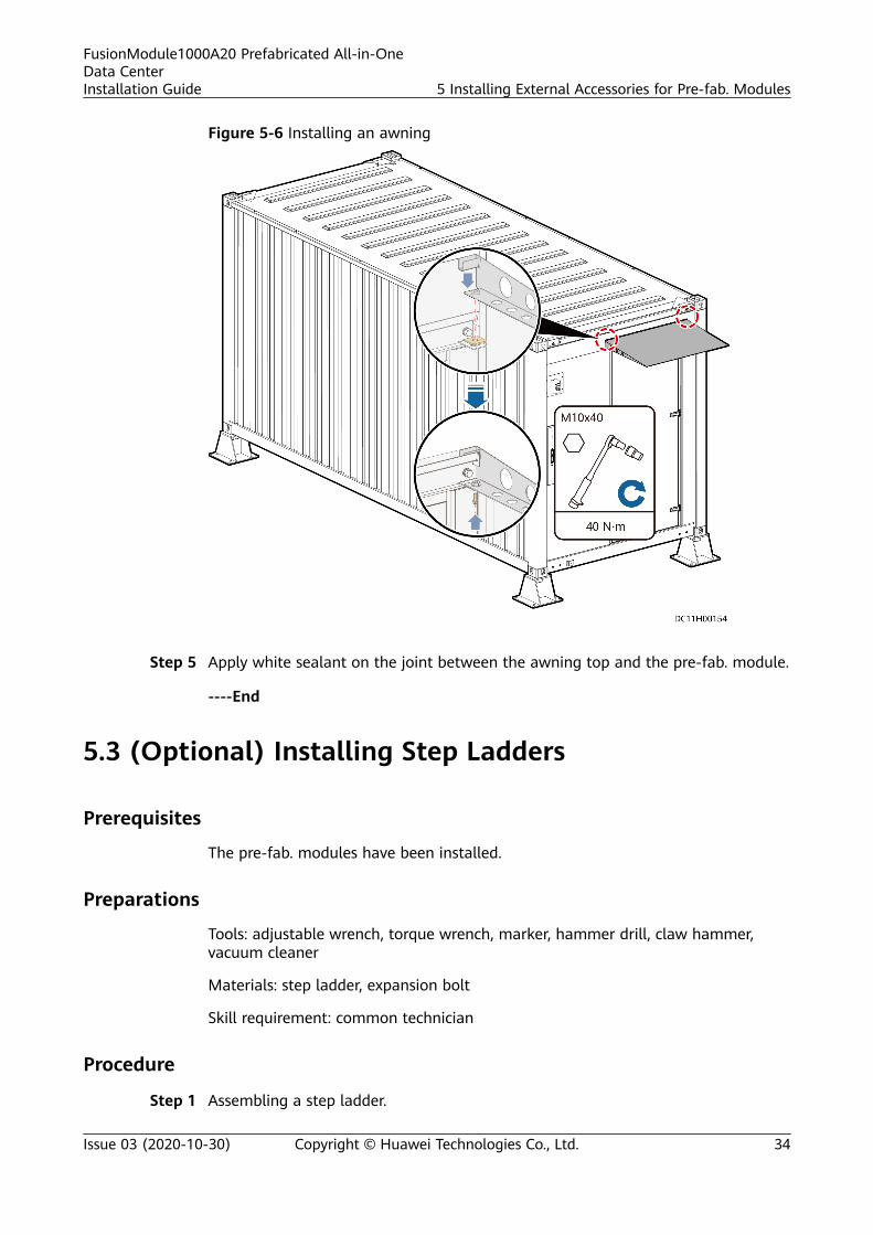
Figure 5-6 Installing an awning
Step 5 Apply white sealant on the joint between the awning top and the pre-fab. module.
----End
5.3 (Optional) Installing Step Ladders
Prerequisites
The pre-fab. modules have been installed.
Preparations
Tools: adjustable wrench, torque wrench, marker, hammer drill, claw hammer,vacuum cleaner
Materials: step ladder, expansion bolt
Skill requirement: common technician
Procedure
Step 1 Assembling a step ladder.
FusionModule1000A20 Prefabricated All-in-OneData CenterInstallation Guide 5 Installing External Accessories for Pre-fab. Modules
Issue 03 (2020-10-30) Copyright © Huawei Technologies Co., Ltd. 34

Figure 5-7 Assembling a step ladder
Step 2 Place the step ladder in the middle outside the outward opening door of the pre-fab. module, and mark mounting holes on the concrete pad for the step ladder.
Step 3 Drill mounting holes using a hammer drill.
NO TE
● When you drill a hole using a hammer drill, keep the drill bit perpendicular to the groundand hold the drill stock firmly with both hands to prevent irregular drilling and damage tothe ground.
● If the ground is too hard and smooth for the drill bit to secure its position, use a chisel topunch a pit before drilling.
Step 4 Rotate nuts onto expansion sleeves to prevent the expansion sleeves fromfluttering.
Step 5 Knock the expansion bolts vertically into mounting holes until the flat washers areflush with the floor.
Step 6 Remove the nuts, spring washers, and flat washers.
Figure 5-8 Installing an expansion bolt (unit: mm)
(A) Nut (B) Spring washer (C) Flat washer
Step 7 Install the step ladder on the concrete pad with the expansion bolts securingthem. Remount the flat washers, spring washers, and nuts on the expansion boltsand tighten the expansion bolts.
FusionModule1000A20 Prefabricated All-in-OneData CenterInstallation Guide 5 Installing External Accessories for Pre-fab. Modules
Issue 03 (2020-10-30) Copyright © Huawei Technologies Co., Ltd. 35

Figure 5-9 Installing Step Ladders
----End
FusionModule1000A20 Prefabricated All-in-OneData CenterInstallation Guide 5 Installing External Accessories for Pre-fab. Modules
Issue 03 (2020-10-30) Copyright © Huawei Technologies Co., Ltd. 36

6 Installing Devices Inside the Pre-fab.Module
6.1 Installing Cooling Devices
6.1.1 (Optional) Installing the Fresh Air Integrated Unit
PrerequisitesFour installation positions are reserved of the pre-fab. Module. You need to installthree of them in sequence based on the site requirements.
Procedure
Step 1 Open the front panel of the smart cooling product, remove the two M8 nuts fromthe compressor base, remove the two compressor fasteners, and tighten the twoM8 bolts again, as shown in the following figure.
Figure 6-1 Removing the compressor fixing plates
Step 2 Take off the cable connection box cover, supply air vent cover, and return air ventcover from the pre-fab. module.
FusionModule1000A20 Prefabricated All-in-OneData CenterInstallation Guide 6 Installing Devices Inside the Pre-fab. Module
Issue 03 (2020-10-30) Copyright © Huawei Technologies Co., Ltd. 37

Figure 6-2 Covers position
(1) Supply air vent cover (2) Cable connection box cover (3) Return air vent cover
1. Use a Phillips screwdriver to remove the screws reserved on the cover of theconnection box from outside of the pre-fab. module.
Figure 6-3 Removing the screws on the cover of the connection box
2. Cut the glue between the cover and the pre-fab. module using a utility knife.
Figure 6-4 Cuting the glue
FusionModule1000A20 Prefabricated All-in-OneData CenterInstallation Guide 6 Installing Devices Inside the Pre-fab. Module
Issue 03 (2020-10-30) Copyright © Huawei Technologies Co., Ltd. 38
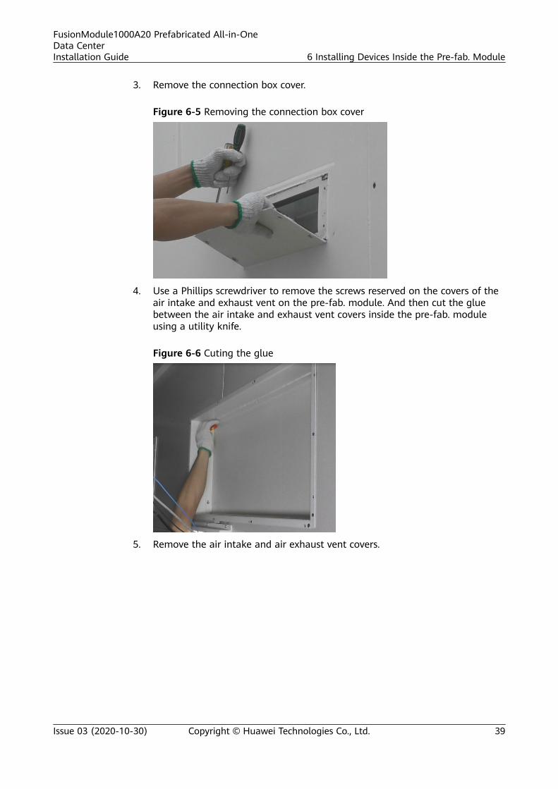
3. Remove the connection box cover.
Figure 6-5 Removing the connection box cover
4. Use a Phillips screwdriver to remove the screws reserved on the covers of theair intake and exhaust vent on the pre-fab. module. And then cut the gluebetween the air intake and exhaust vent covers inside the pre-fab. moduleusing a utility knife.
Figure 6-6 Cuting the glue
5. Remove the air intake and air exhaust vent covers.
FusionModule1000A20 Prefabricated All-in-OneData CenterInstallation Guide 6 Installing Devices Inside the Pre-fab. Module
Issue 03 (2020-10-30) Copyright © Huawei Technologies Co., Ltd. 39

Figure 6-7 Removing the connection box cover
Step 3 Install two bolts on the outdoor side wall to hang the device.
Figure 6-8 Installing two bolts
Step 4 Hoist the pre-fab. module to the installation position using a crane and place it onthe two bolts that have been installed.
FusionModule1000A20 Prefabricated All-in-OneData CenterInstallation Guide 6 Installing Devices Inside the Pre-fab. Module
Issue 03 (2020-10-30) Copyright © Huawei Technologies Co., Ltd. 40

Figure 6-9 Hanging
Step 5 Align the air intake and exhaust vents on the indoor side of the smart coolingproduct with the air intake and exhaust vent holes on the pre-fab. module, andinstall all bolts.
----End
6.1.2 (Optional) Connecting Cables of the Fresh Air IntegratedUnit
Context
Figure 6-10 Signal terminals
Table 6-1 Symbol list
Symbol Name
L1 Live line
L2 Live line
L3 Live line
N Neutral wire
FusionModule1000A20 Prefabricated All-in-OneData CenterInstallation Guide 6 Installing Devices Inside the Pre-fab. Module
Issue 03 (2020-10-30) Copyright © Huawei Technologies Co., Ltd. 41

Symbol Name
PE (left) Cable grounding
PE (right) Shell grounding
0V Positive pole
-48VDC Negative pole
RS485 EMS communication port
Display Display port
CAN1 Port of the teamwork (+)
CAN2 Port of the teamwork (-)
1 Port for remote startup and shutdown
2
3 N/A
4 N/A
5 Normally close alarm dry contact
6 Common port for alarm dry contact
7 Normally open alarm dry contact
CA UTION
Port 1 and 2 only receive passive (non-live) switching signals. If the active (live)signals are connected, the internal components of the unit will be burned down.For signal cables such as remote startup and shutdown, shielded cables arerecommended to ensure reliable grounding.
Procedure
Step 1 Connect equipotential grounding wire to PE (right) terminal.
Step 2 Connect the reserved AC power cables on the pre-fab. module to the L1, L2, L3, N,and PE (left) terminals of the cooling product.
NO TICE
1. Electrical connections must be trained professionals.2. Do not connect the power cables when the device is on.3. The supply voltage must be the same as the rated voltage on the nameplate of
the cooling product.
FusionModule1000A20 Prefabricated All-in-OneData CenterInstallation Guide 6 Installing Devices Inside the Pre-fab. Module
Issue 03 (2020-10-30) Copyright © Huawei Technologies Co., Ltd. 42

Step 3 Connect the reserved DC power cables on the pre-fab. module to the 0 and -48Vterminals of the cooling product.
Step 4 Connect the unit communication cable to RS485 port.
Step 5 Teamwork cables need to be connected hand in hand to CAN1 and CAN2 ports.
Figure 6-11 Teamwork networking
----End
6.2 Installing Power Supply and Distribution Devices
6.2.1 Installing the Rectifier (TP48400B)
Prerequisites● The pre-fab. modules have been installed.● The rectifier delivered onsite is complete and intact after unpacking and
acceptance. If any problem is found, contact your local Huawei office.
Preparations
Tool: none
Material: rectifier
Skill requirement: skilled technician
D ANGER
● To avoid electric shock, do not put your hands into a rectifier slot.● When a rectifier is running, a high temperature is generated around the air
exhaust vent at the rear. Do not touch the vent or cover the vent with cables orother objects.
Procedure
Step 1 Determining the position of the rectifier
Step 2 (Optional) Remove filler panels from the rectifier installation position based onthe installation requirements.
Step 3 Push the locking latch leftwards and pull out the handle.
FusionModule1000A20 Prefabricated All-in-OneData CenterInstallation Guide 6 Installing Devices Inside the Pre-fab. Module
Issue 03 (2020-10-30) Copyright © Huawei Technologies Co., Ltd. 43

Step 4 Gently push the rectifier into its slot along the guide rails.
Step 5 Push the handle upwards.
Step 6 Push the locking latch rightward to lock the handle.
Figure 6-12 Installing a rectifier
----End
6.2.2 Installing the Rectifier (TP48600B, TP481200B)
Prerequisites● The pre-fab. modules have been installed.● The rectifier delivered onsite is complete and intact after unpacking and
acceptance. If any problem is found, contact your local Huawei office.
PreparationsTool: none
Material: rectifier
Skill requirement: skilled technician
D ANGER
● To avoid electric shock, do not put your hands into a rectifier slot.● When a rectifier is running, a high temperature is generated around the air
exhaust vent at the rear. Do not touch the vent or cover the vent with cables orother objects.
Procedure
Step 1 Determining the position of the rectifier
Step 2 (Optional) Remove filler panels from the rectifier installation position based onthe installation requirements.
Step 3 Push the locking latch leftward and pull out the handle.
FusionModule1000A20 Prefabricated All-in-OneData CenterInstallation Guide 6 Installing Devices Inside the Pre-fab. Module
Issue 03 (2020-10-30) Copyright © Huawei Technologies Co., Ltd. 44

Step 4 Gently push the rectifier into its slot along the guide rails.
Step 5 Push the handle in place.
Step 6 Push the locking latch downward.
Figure 6-13 Installing the TP48600B rectifier
----End
6.2.3 Installing a Battery (TP48400B or TP48600B)
PrerequisitesThe pre-fab. modules have been installed.
Precautions● Before installing batteries, ensure that battery circuit breakers are OFF or
battery fuses are in the open position.● To ensure personal safety, unpack, move, and install batteries by following the
instructions in the manuals delivered with the batteries.● Except for necessary functional parts, wrap the exposed metal parts of tools
such as screwdrivers and wrenches with at least two layers of insulation tape.● Wrap the OT terminal of a cable with insulation tape, and remove the tape
when the cable is placed in position and the terminal to be connected isconfirmed.
● Leave one break point disconnected when connecting batteries at each layer,and connect the break point on each layer after other cables are connected.
● Tighten screws to prevent sparks generated upon power-on.● Only qualified technicians can connect battery cables.● Ensure that all the safety measures have been taken before installation.● Before connecting battery cables, remove the battery fuses from the DC
power system using a fuse extracting unit.● Never short-circuit the two poles of a battery when handling or installing
batteries.
PreparationsTools: Phillips screwdriver, pallet truck, adjustable wrench, protective gloves
Materials: insulation tape, battery, copper bar or cable
FusionModule1000A20 Prefabricated All-in-OneData CenterInstallation Guide 6 Installing Devices Inside the Pre-fab. Module
Issue 03 (2020-10-30) Copyright © Huawei Technologies Co., Ltd. 45

Documents: documents delivered with the batteries
Skill requirement: personnel qualified for installing batteries
Procedure
Step 1 Use a pallet truck to move batteries to a position near the pre-fab. module door.
Step 2 Unpack the batteries.
Step 3 Install the battery into a large power supply and complete the connection of thebattery power cable.1. Install the batteries in the battery compartment from right to left, and from
the bottom to the top.
NO TE
Install the TP48400B battery in the central office (CO) power cabinet, and theTP48600B battery in the battery cabinet.
NO TICE
Due to space limitation, connect power cables after you place batteries onone layer. Place batteries in the battery cabinet from bottom to top and fromright to left.
Figure 6-14 Installing the battery
2. Install a battery copper bar.
FusionModule1000A20 Prefabricated All-in-OneData CenterInstallation Guide 6 Installing Devices Inside the Pre-fab. Module
Issue 03 (2020-10-30) Copyright © Huawei Technologies Co., Ltd. 46

Figure 6-15 Installing the battery copper bar
3. Install copper bars between other batteries in the same way.4. Install the negative battery cable.
Figure 6-16 Installing the negative battery cable
5. If there are multiple battery strings, install negative battery cables for theremaining battery strings in the same way.
FusionModule1000A20 Prefabricated All-in-OneData CenterInstallation Guide 6 Installing Devices Inside the Pre-fab. Module
Issue 03 (2020-10-30) Copyright © Huawei Technologies Co., Ltd. 47

6. Install the positive battery cable.
Figure 6-17 Installing the positive battery cable
7. If there are multiple battery strings, install positive battery cables for theremaining battery strings in the same way.
----End
Follow-up Procedure
Verify the battery cable connections. Ensure that the battery quantity and cableconnections comply with the design and the cables or copper bars are reliablyinstalled.
6.2.4 Installing a Battery (TP481200B)
Prerequisites
The pre-fab. modules have been installed.
Precautions● Before installing batteries, ensure that batteries are OFF or battery fuses are
in the open position.● To ensure personal safety, unpack, move, and install batteries by following the
instructions in the manuals delivered with the batteries.● Except for necessary functional parts, wrap the exposed metal parts of tools
such as screwdrivers and wrenches with at least two layers of insulation tape.
FusionModule1000A20 Prefabricated All-in-OneData CenterInstallation Guide 6 Installing Devices Inside the Pre-fab. Module
Issue 03 (2020-10-30) Copyright © Huawei Technologies Co., Ltd. 48

● Wrap the OT terminal of a cable with insulation tape, and remove the tapewhen the cable is placed in position and the terminal to be connected isconfirmed.
● Leave one break point disconnected when connecting batteries at each layer,and connect the break point on each layer after other cables are connected.
● Tighten screws to prevent sparks generated upon power-on.● Only qualified technicians can connect battery cables.● Ensure that all the safety measures have been taken before installation.● Before connecting battery cables, remove the battery fuses from the DC
power system using a fuse extracting unit.● Never short-circuit the two poles of a battery when handling or installing
batteries.
PreparationsTools: Phillips screwdriver, pallet truck, adjustable wrench, protective gloves
Materials: insulation tape, battery, copper bar or cable
Documents: documents delivered with the batteries
Skill requirement: personnel qualified for installing batteries
ProcedureStep 1 Remove five battery baffle plate at the front of the battery rack.
NO TE
Install the TP481200B battery on the battery rack.
Figure 6-18 Removing the battery baffle plate
FusionModule1000A20 Prefabricated All-in-OneData CenterInstallation Guide 6 Installing Devices Inside the Pre-fab. Module
Issue 03 (2020-10-30) Copyright © Huawei Technologies Co., Ltd. 49

Step 2 Lay out batteries from the bottom layer up.
Figure 6-19 Laying out the batteries
Step 3 Connect the battery short-circuit copper bar and reinstall the insulation cover.
Figure 6-20 Connect the battery short-circuit copper bar 1
----End
FusionModule1000A20 Prefabricated All-in-OneData CenterInstallation Guide 6 Installing Devices Inside the Pre-fab. Module
Issue 03 (2020-10-30) Copyright © Huawei Technologies Co., Ltd. 50

Follow-up ProcedureVerify the battery cable connections. Ensure that the battery quantity and cableconnections comply with the design and the cables or copper bars are reliablyinstalled. Connect the battery short-circuit copper bar and reinstall the insulationcover.
6.3 (Optional) Installing the Electric Heating Belt
PrerequisitesThe pre-fab. modules have been installed.
PreparationsTools: None
Materials: low-temperature component suite
Skill requirements: cooling engineer, common technician
Procedure
Step 1 Wrap the electric heating belt around the drainpipe and water refill pipe outsidethe pre-fab. module.
Figure 6-21 Wrap the electric heating belt around the drainpipe and water refillpipe
Step 2 Secure the temperature probe to the pipe using a cable tie.
NO TE
Secure the temperature probe to the position on the water refill and drainage pipe. Theposition is the point where the electric heating belt is wrapped 50 cm long around thewater refill and drainage pipe from the water refill and drainage pipe port.
FusionModule1000A20 Prefabricated All-in-OneData CenterInstallation Guide 6 Installing Devices Inside the Pre-fab. Module
Issue 03 (2020-10-30) Copyright © Huawei Technologies Co., Ltd. 51

Figure 6-22 Secure the temperature probe
Step 3 Connect the electric heating belt and temperature probe to the controller.
FusionModule1000A20 Prefabricated All-in-OneData CenterInstallation Guide 6 Installing Devices Inside the Pre-fab. Module
Issue 03 (2020-10-30) Copyright © Huawei Technologies Co., Ltd. 52

Figure 6-23 Wiring diagram
Step 4 Install thermal insulation foam on pipes.
NO TE
Wrap the electric heating belt before wrapping the thermal insulation foam, and thethermal insulation foam covers the electric heating belt. Verify that the thermal insulationfoam can withstand a temperature greater than or equal to 200°C.
----End
FusionModule1000A20 Prefabricated All-in-OneData CenterInstallation Guide 6 Installing Devices Inside the Pre-fab. Module
Issue 03 (2020-10-30) Copyright © Huawei Technologies Co., Ltd. 53

6.4 Installing Monitoring DevicesThis manual does not cover the installation of upstream monitoring devices. Forthe detailed installation methods, see iManager NetEco Product Document -(NetEco Version).
6.4.1 (Optional) Installing ECC800 Accessories
Prerequisites
Required ECC800 accessories have been obtained.
Preparations
Tools: Phillips screwdriver
Materials: Micro SD card, SIM card, 4G antenna, RF_Z antenna
NO TICE
The SIM card needs to support Global System for Mobile Communications (GSM)and Wideband Code Division Multiple Access (WCDMA).
Skill requirement: common technician
Procedure
Step 1 (Optional) Remove the ECC800 main control module and install the SIM card andSD card inin the corresponding slot side if SIM card and SD card are required.1. Loosen the screws on both sides of the ECC800 main control module.2. Pull the handles on both sides of the ECC800 main control module, and
remove the main control module.
Figure 6-24 Removing the ECC800 main control module
3. Install the Micro SD and SIM card in the corresponding slot of the ECC800main control module.
FusionModule1000A20 Prefabricated All-in-OneData CenterInstallation Guide 6 Installing Devices Inside the Pre-fab. Module
Issue 03 (2020-10-30) Copyright © Huawei Technologies Co., Ltd. 54

Figure 6-25 Installing the Micro SD and SIM card
4. Reinstall the ECC800 main control module in the ECC800 subrack.
Step 2 Attach the 4G antenna to the top of the cable feeder window on the pre-fab.module.
NO TICE
● After routing the 4G antenna cable into the pre-fab. module through its ELVfeeder window (No. 8), seal the port in the feeder window using sealing putty.
● The cable outside the pre-fab. module needs to be fit with a corrugated metalhose. For details, see A.1 Cable Installation Techniques.
● The cable outside the pre-fab. module can be bent only in the U-shape.
Figure 6-26 Installing the 4G antenna
Step 3 Attach the RF_Z antenna on the top of the monitoring box.
FusionModule1000A20 Prefabricated All-in-OneData CenterInstallation Guide 6 Installing Devices Inside the Pre-fab. Module
Issue 03 (2020-10-30) Copyright © Huawei Technologies Co., Ltd. 55

Figure 6-27 Installing the RF_Z antenna
Step 4 Connect the 4G antenna cable and RF_Z antenna cable to the ECC800.
Figure 6-28 Installing the antenna
----End
6.4.2 (Optional) Installing the WiFi Antenna
Prerequisites
The required WiFi antenna has been obtained.
Preparations
Tool: none
Materials: WiFi antenna
Skill requirement: common technician
FusionModule1000A20 Prefabricated All-in-OneData CenterInstallation Guide 6 Installing Devices Inside the Pre-fab. Module
Issue 03 (2020-10-30) Copyright © Huawei Technologies Co., Ltd. 56

Procedure
Step 1 Attach the WiFi antenna on the ceiling.
Step 2 Connect WiFi antenna cable to the RF_1 and RF_2 ports of the WiFi converter.
Figure 6-29 Installing a WiFi antenna
----End
6.4.3 (Optional) Installing a Pad
Prerequisites
The pad to be installed has been obtained.
Context
Tool: Phillips screwdriver
Materials: pad and pad charging cable
Skill requirement: common technician
Procedure
Step 1 Adjust the feet at the bottom of the pad mounting support until they are in thesame width as the pad. Route the pad power cable through the cable hole in thepad mounting support and then connect the cable to the pad.
Step 2 Adjust the feet in the upper part of the pad mounting support and clip the padinto the mounting support.
FusionModule1000A20 Prefabricated All-in-OneData CenterInstallation Guide 6 Installing Devices Inside the Pre-fab. Module
Issue 03 (2020-10-30) Copyright © Huawei Technologies Co., Ltd. 57

Figure 6-30 Installing a pad
----End
6.5 (Optional) Installing CE-Certified Fire ExtinguishingDevices
6.5.1 (Optional) Installing the Fire Cylinder (CE)
Prerequisites● The pre-fab. modules have been installed.● The extinguishant in the fire cylinder meets the requirement.
FusionModule1000A20 Prefabricated All-in-OneData CenterInstallation Guide 6 Installing Devices Inside the Pre-fab. Module
Issue 03 (2020-10-30) Copyright © Huawei Technologies Co., Ltd. 58

CA UTION
● As the fire cylinder is heavy, determine the installation position, port, andfastening mode in advance to avoid long-distance movement.
● Do not impact or strike the fire cylinder during transportation or installation.Do not remove or flip the dowel on the fire cylinder.
● Assign at least four persons for transportation and installation if no auxiliarytool is available.
● Do not touch any button in the fire extinguishing system without permissionduring installation.
● Do not power on the fire extinguishing system during installation.
PreparationsTools: protective gloves, pallet truck, pipe wrench, adjustable wrench, step ladder
Materials: fire cylinder, high-pressure hose, sealing tape, threaded adapter, I-shaped connector
Skill requirement: common technician
Procedure
Step 1 Move the fire cylinder using a pallet truck to a position near the container doorclosest to the installation position.
NO TICE
Do not move the fire cylinder over a long distance by hands.
Step 2 Move the fire cylinder to the installation position and secure it using steel straps.
NO TICE
Keep the pressure gauge panel outwards so that people can view the reading,which also facilitates later maintenance.
Step 3 Connect the fire cylinder to the fire extinguishing pipeline.
NO TICE
Wrap the threads with sealing tape to ensure air tightness.
1. Remove the protective cover at the threaded adapter position of the containervalve, and connect the threaded adapter to the fire cylinder, as shown by (1)in Figure 6-31.
FusionModule1000A20 Prefabricated All-in-OneData CenterInstallation Guide 6 Installing Devices Inside the Pre-fab. Module
Issue 03 (2020-10-30) Copyright © Huawei Technologies Co., Ltd. 59

2. Connect the I-shaped connection pipe to the threaded adapter.
3. Connect one end of the high-pressure hose to the fire cylinder and the otherend to the fire extinguishing pipeline, as shown by (2) in Figure 6-31.
Figure 6-31 Positions of the threaded adapter and high-pressure hose
(1) Threaded adapter (2) High-pressure hose
Step 4 (Optional) Install the electrical actuator.
NO TE
Do not install the electrical actuator when installing the fire cylinder for the first time. Installthe electrical actuator when commissioning the fire extinguishing system.
1. Verify that the electrical actuator ejector is reset. If the ejector is not reset,press down the ejector, as shown by (1) in Figure 6-32. (2) in Figure 6-32shows the effect after the ejector is pressed down.
NO TICE
If the ejector is not pressed down, extinguishant may be released.
Figure 6-32 Operating the electrical actuator ejector
FusionModule1000A20 Prefabricated All-in-OneData CenterInstallation Guide 6 Installing Devices Inside the Pre-fab. Module
Issue 03 (2020-10-30) Copyright © Huawei Technologies Co., Ltd. 60

2. Remove the protective cover at the electrical actuator installation position onthe container valve. Align the electrical actuator and the container valve, andtighten the electrical actuator clockwise.
3. Connect the cables between the electrical actuator and the extinguishantcontrol panel.
NO TICE
Connect the red wire to the red wire, and connect the black wire to the blackwire.
----End
6.5.2 Installing Extinguishant Control Panel Batteries
PrerequisitesThe pre-fab. modules have been installed.
ContextThe fire control panel battery has been installed before delivery. You only need toconnect the reserved cable to the battery onsite.
PreparationsTools: protective gloves
Materials: extinguishant control panel batteries
Skill requirement: common technician
Procedure
Step 1 Open the door of the extinguishant control panel, and install batteries in thereserved position.
FusionModule1000A20 Prefabricated All-in-OneData CenterInstallation Guide 6 Installing Devices Inside the Pre-fab. Module
Issue 03 (2020-10-30) Copyright © Huawei Technologies Co., Ltd. 61

Figure 6-33 Battery installation position
Step 2 Connect the battery cables to the reserved power cable terminals.
Figure 6-34 Connecting battery cables
NO TICE
● Do not connect the red positive cable until power-on commissioning.
● Ensure that battery cables for the extinguishant control panel are connected tocorrect polarities.
----End
6.5.3 (Optional) Connecting a Cable to the ASD Power BoxBattery
Prerequisites● The position of the ASD power box has been specified.
● Documents delivered with the ASD power box have been obtained.
FusionModule1000A20 Prefabricated All-in-OneData CenterInstallation Guide 6 Installing Devices Inside the Pre-fab. Module
Issue 03 (2020-10-30) Copyright © Huawei Technologies Co., Ltd. 62

ContextThe ASD power box and batteries inside the pre-fab. module have been installedbefore delivery. You only need to connect the reserved cables to the batteriesonsite.
PreparationsTools: Phillips screwdriver
Materials: none
Skill requirement: common technician
Procedure
Step 1 Open the power box using a key.
Step 2 Remove the protective foam from the battery and check whether the battery isintact or leaks.
NO TICE
If the battery is damaged or leaks, contact Huawei technical support to replacethe battery.
Step 3 Connect the reserved battery cable.
NO TICE
Distinguish the positive and negative battery terminals when connecting a batterycable.
Figure 6-35 ASD battery wiring diagram
FusionModule1000A20 Prefabricated All-in-OneData CenterInstallation Guide 6 Installing Devices Inside the Pre-fab. Module
Issue 03 (2020-10-30) Copyright © Huawei Technologies Co., Ltd. 63

Figure 6-36 Connecting the reserved battery cable
----End
6.5.4 Installing an External Horn Strobe
Prerequisites● The pre-fab. modules have been installed.● The position for installing the horn strobe has been specified.
preparing for the InstallationTools: Phillips screwdriver, step ladder
Materials: external horn strobe and its screws
Skill requirement: common technician
Procedure
Step 1 Remove the sealing plate from the installationposition of the horn strobe.
NO TE
Use sealant to seal the screw holes left after the sealing plate is removed.
Step 2 Install the horn strobe cover.
FusionModule1000A20 Prefabricated All-in-OneData CenterInstallation Guide 6 Installing Devices Inside the Pre-fab. Module
Issue 03 (2020-10-30) Copyright © Huawei Technologies Co., Ltd. 64

Figure 6-37 Installing the horn strobe cover
----End
FusionModule1000A20 Prefabricated All-in-OneData CenterInstallation Guide 6 Installing Devices Inside the Pre-fab. Module
Issue 03 (2020-10-30) Copyright © Huawei Technologies Co., Ltd. 65

7 Installing a Cable Outside a Pre-fab.Module
7.1 Installing External Input Power Cables
PrerequisitesPre-fab. modules and external cable trays have been installed.
PreparationsTools: crimping tool, Phillips screwdriver, adjustable wrench, cable cutter, heat gun
Materials: cable tie, cable, terminal, heat shrink tube
Skill requirement: skilled technician
Procedure
Step 1 Open the door of the main input PDB.
Step 2 Route the external input power cables into the pre-fab. module through the feederwindow, as shown in A.1 Cable Installation Techniques.
FusionModule1000A20 Prefabricated All-in-OneData CenterInstallation Guide 7 Installing a Cable Outside a Pre-fab. Module
Issue 03 (2020-10-30) Copyright © Huawei Technologies Co., Ltd. 66

Figure 7-1 Wall cabling
NO TE
Add a drip loop for external cables routed into the feeder window to prevent water fromflowing along the cables into the PDF.
FusionModule1000A20 Prefabricated All-in-OneData CenterInstallation Guide 7 Installing a Cable Outside a Pre-fab. Module
Issue 03 (2020-10-30) Copyright © Huawei Technologies Co., Ltd. 67

Figure 7-2 Bottom cabling
NO TE
After bottom cabling is completed, use sealing putty to seal the cable holes.
Step 3 Connect the PDB input power cables.
FusionModule1000A20 Prefabricated All-in-OneData CenterInstallation Guide 7 Installing a Cable Outside a Pre-fab. Module
Issue 03 (2020-10-30) Copyright © Huawei Technologies Co., Ltd. 68

Figure 7-3 Connecting the input cable of PDB (02404913)
Figure 7-4 Connecting the input cable of PDB (02402732-009)
FusionModule1000A20 Prefabricated All-in-OneData CenterInstallation Guide 7 Installing a Cable Outside a Pre-fab. Module
Issue 03 (2020-10-30) Copyright © Huawei Technologies Co., Ltd. 69

Figure 7-5 Connecting the input cable of PDB (02404923)
Step 4 Close the door of the main input PDB.
----End
7.2 (Optional) Connecting DG Start/Stop Cables (ATSInput)
PrerequisitesPre-fab. modules and external cable trays have been installed.
Procedure
Step 1 Connect the DG start/stop cable to the XT2 terminal block.
FusionModule1000A20 Prefabricated All-in-OneData CenterInstallation Guide 7 Installing a Cable Outside a Pre-fab. Module
Issue 03 (2020-10-30) Copyright © Huawei Technologies Co., Ltd. 70

Figure 7-6 Connecting the DG start/stop cable (02404913)
NO TE
XT3-17 stands for Start, XT3-18 stands for Com, and XT3-19 stands for Stop.
FusionModule1000A20 Prefabricated All-in-OneData CenterInstallation Guide 7 Installing a Cable Outside a Pre-fab. Module
Issue 03 (2020-10-30) Copyright © Huawei Technologies Co., Ltd. 71
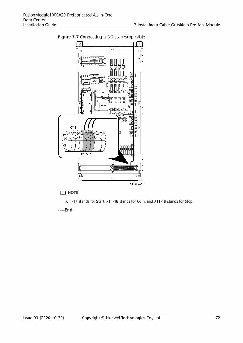
Figure 7-7 Connecting a DG start/stop cable
NO TE
XT1-17 stands for Start, XT1-18 stands for Com, and XT1-19 stands for Stop.
----End
FusionModule1000A20 Prefabricated All-in-OneData CenterInstallation Guide 7 Installing a Cable Outside a Pre-fab. Module
Issue 03 (2020-10-30) Copyright © Huawei Technologies Co., Ltd. 72

8 Removing Transport ProtectionMaterials
8.1 Removing Transport Protection Materials for FireExtinguishing Devices
PrerequisitesThe pre-fab. modules have been installed.
ContextProtection materials are installed for fire extinguishing devices to prevent themfrom falling off or being damaged due to strong vibration duringFusionModule1000 transportation.
NO TE
To prevent damage to aisle floors in the FusionModule1000, you are advised to remove theprotective films after the FusionModule1000 is installed.
PreparationsTools: step ladder
Materials: none
Documents: fire extinguishing device layout diagram
Skill requirement: common technician
ProcedureStep 1 Understand the internal layout of the FusionModule1000 by referring to the fire
extinguishing device layout diagram.
Step 2 Remove the transport protection materials from the top of the aisles inside theFusionModule1000.
FusionModule1000A20 Prefabricated All-in-OneData CenterInstallation Guide 8 Removing Transport Protection Materials
Issue 03 (2020-10-30) Copyright © Huawei Technologies Co., Ltd. 73

Table 8-1 Transport protection materials to be removed
No. Device Protection Materials
1 Photoelectric smokedetector
Red cover, securing tape
2 Heat detector (optional) Red cover, securing tape
3 Horn strobe (optional) Securing tape
4 Fire alarm bell (optional) Securing tape
5 Emergency light Securing tape
6 Temperature andhumidity (T/H) sensor
Securing tape
7 Camera Securing tape
----End
8.2 Removing Transport Protection Materials forIntelligent Heat Exchangers
PrerequisitesThe pre-fab. modules have been installed.
Preparations
Transportation protection materials are installed for intelligent heat exchangers inthe FusionModule1000.
Tools: step ladder, Phillips screwdriver
Materials: none
Skill requirement: common technician
Procedure
Step 1 Remove the protective cover from the intelligent heat exchanger.
FusionModule1000A20 Prefabricated All-in-OneData CenterInstallation Guide 8 Removing Transport Protection Materials
Issue 03 (2020-10-30) Copyright © Huawei Technologies Co., Ltd. 74

Figure 8-1 Removing the cover
Step 2 Install the drainage support.
Figure 8-2 Installing the drainage support
----End
FusionModule1000A20 Prefabricated All-in-OneData CenterInstallation Guide 8 Removing Transport Protection Materials
Issue 03 (2020-10-30) Copyright © Huawei Technologies Co., Ltd. 75
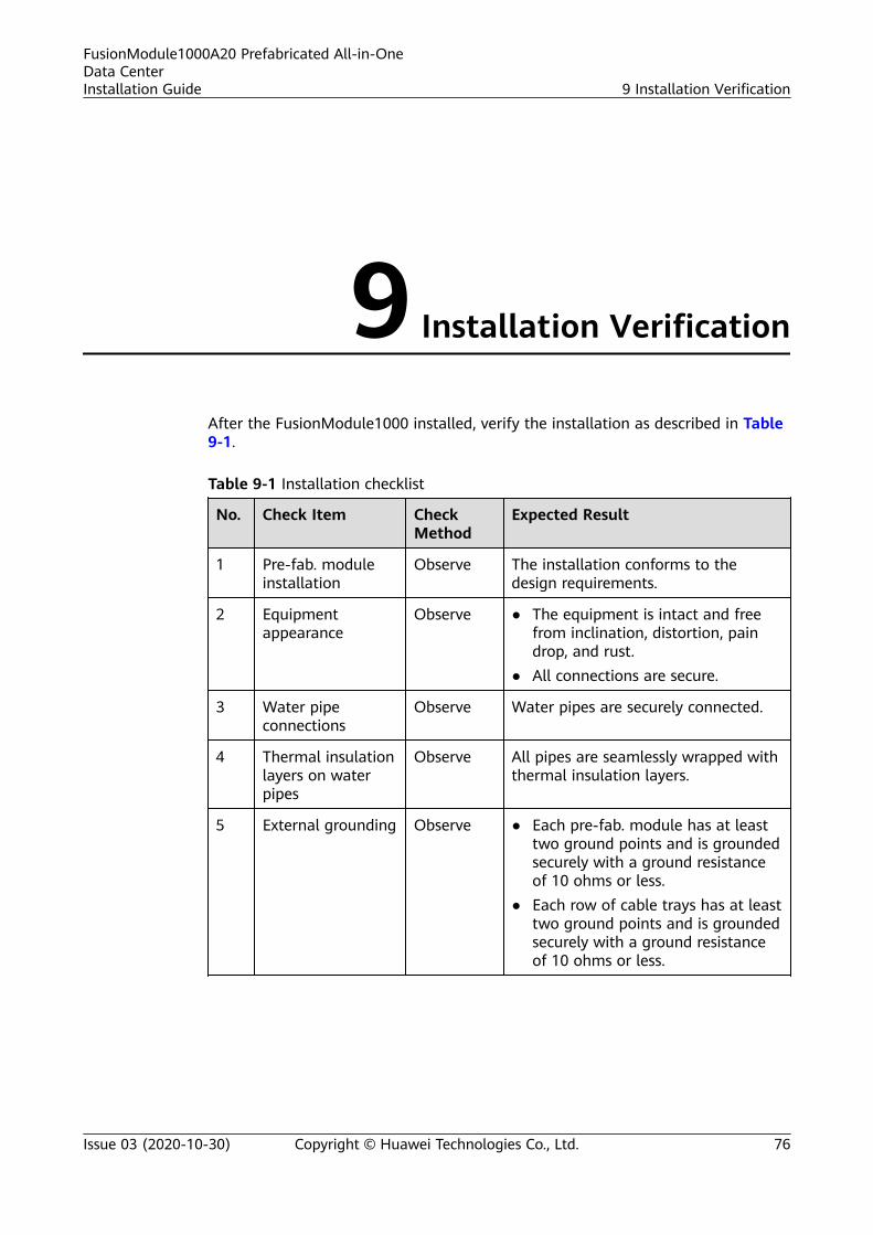
9 Installation Verification
After the FusionModule1000 installed, verify the installation as described in Table9-1.
Table 9-1 Installation checklist
No. Check Item CheckMethod
Expected Result
1 Pre-fab. moduleinstallation
Observe The installation conforms to thedesign requirements.
2 Equipmentappearance
Observe ● The equipment is intact and freefrom inclination, distortion, paindrop, and rust.
● All connections are secure.
3 Water pipeconnections
Observe Water pipes are securely connected.
4 Thermal insulationlayers on waterpipes
Observe All pipes are seamlessly wrapped withthermal insulation layers.
5 External grounding Observe ● Each pre-fab. module has at leasttwo ground points and is groundedsecurely with a ground resistanceof 10 ohms or less.
● Each row of cable trays has at leasttwo ground points and is groundedsecurely with a ground resistanceof 10 ohms or less.
FusionModule1000A20 Prefabricated All-in-OneData CenterInstallation Guide 9 Installation Verification
Issue 03 (2020-10-30) Copyright © Huawei Technologies Co., Ltd. 76

No. Check Item CheckMethod
Expected Result
6 Cable connections Observe ● All cable connections are secure,especially network cableconnections.
● Bear cables and terminal barrelsnear wearing terminals arewrapped in insulation tape or heatshrink tubing.
● Flat washers and spring washers ofall wiring terminals are securelyinstalled.
● Cables are routed in the wayconvenient for future maintenanceand expansion.
● Cabinets are clean and have nodust, excessive cable ties, cablecuts, or other foreign matter inside.
7 Cable binding Observe ● Cables are neat and not coiled, andexcessive parts are cut.
● Cable ties do not overlap, and thejoints are evenly cut without burrs.
● Cables are placed properly and nottense at turning points.
● Cable routes are straight andsmooth, and do not intersect insidea cabinet.
8 Installation ofexternalaccessories
Observe The number and positions of externalaccessories installed conform todesign requirements.
9 Labels Observe All labels are correct, clear, andcomplete.
FusionModule1000A20 Prefabricated All-in-OneData CenterInstallation Guide 9 Installation Verification
Issue 03 (2020-10-30) Copyright © Huawei Technologies Co., Ltd. 77

A A Basic Installation Operations
A.1 Cable Installation Techniques
A.1.1 Cabling Rules
Cable Layout
When laying out cables, observe the following rules:● Determine the cable specifications, route, cross-sectional area, and location
according to the construction drawings.● Cables must be neatly arranged and cable insulation layers must be intact.● Different types of cables must be routed separately.● Connection ports and cabling methods must facilitate maintenance, cable
routing, and capacity expansion.● Cable connectors prepared onsite must be secure, reliable, and neat, and
conform to specifications.● Power cables, ground cables, and signal cables must be securely connected.
Adapters must be securely plugged or screwed.
Binding Cables
When binding cables, observe the following rules:● Power cables and signal cables must be bound separately.● Bind cables with a proper strength and do not pull the cables during binding.● The labels on both sides of a cable must be concise, easy to understand, and
face outwards.● Cable ties must be neatly cut without sharp burs, evenly distributed, bound to
a proper strength, and fastened towards the same direction, as shown inFigure A-1 and Figure A-2.
● Cables must be bound closely and neatly. Each bundle must not exceed 15cables.
FusionModule1000A20 Prefabricated All-in-OneData CenterInstallation Guide A A Basic Installation Operations
Issue 03 (2020-10-30) Copyright © Huawei Technologies Co., Ltd. 78

● Extra cables must be coiled neatly and easy to find.
Figure A-1 Cable ties without sharp burs
Figure A-2 Cable ties in the same direction
Bending CablesWhen bending cables, observe the following rules:● Cables must not be overly bent because over bending may damage the cable
cores.● The bending radius of a cable must be more than twice the cable diameter.
The bending radius near a connector outlet must be more than four to sixtimes the cable diameter.
● Cables must not be tied where they bend.
Figure A-3 Binding cables at a turning point
A.1.2 Measuring Cables
Prerequisites● Pre-fab. modules have been installed.● External cable trays have been installed.
PreparationsTools: thin rope, protective gloves, and measuring tape
Material: cable
FusionModule1000A20 Prefabricated All-in-OneData CenterInstallation Guide A A Basic Installation Operations
Issue 03 (2020-10-30) Copyright © Huawei Technologies Co., Ltd. 79

Documents: none
Skill requirement: common technician
Procedure
Step 1 Select a cable to be connected between two devices. Measure the cable routelength between the two devices using a thin rope or small cable (such as a signalcable or fire control cable) available on-site.
Step 2 Add the length reserved for installing terminals and a tolerance to the cablelength measured in Step 1 to determine the required cable run length.
NO TE
● To improve installation efficiency, complete all cable measurements before you performsubsequent operations.
● Determine the length of the other cables between the devices based on the length ofthe cable measured.
● To facilitate installation, it is recommended that you lay out cables to the measuredcable route length plus about 2 m.
----End
A.1.3 Laying Out Cables
Prerequisites● Do not lay out cables outdoors under bad weather conditions if no shelter is
available.● Cables have been measured.
NO TICE
Some external cables for the FusionModule1000 are long and thick. Assign at leasttwo persons to lay out cables especially armored cables if no assistant tool isavailable onsite.
Preparations
Tools: protective gloves and marker
Material: cable
Document: none
Skill requirement: common technician
Procedure
Step 1 Select the designed cables.
Step 2 Lay out cables to the required run length.
FusionModule1000A20 Prefabricated All-in-OneData CenterInstallation Guide A A Basic Installation Operations
Issue 03 (2020-10-30) Copyright © Huawei Technologies Co., Ltd. 80

NO TICE
To protect cable sheathings, do not press or stab cables with a hard object and donot drag cables on the ground at will during cable layout.
Step 3 Attach labels to both ends of cables that you have laid out.
NO TICE
Ensure that the labels are clear, endurable, and consistent between both ends.
----End
A.1.4 Routing Cables Through a Plastic-coated Metal Hose
Prerequisites● Do not route cables through a plastic-coated metal hose under bad weather
conditions if no shelter is available.● Cables have been labeled.
NO TICE
● In the FusionModule1000, external cables except armored cables must berouted through a plastic-coated metal hose.
● To prevent burrs on cable ends from hurting people and scraping thecorrugated hose, wrap the cable ends properly before routing cables through aplastic-coated metal hose.
● To protect cable sheathings, do not drag the cables at will when routing cablesthrough a plastic-coated metal hose.
● Wear a pair of protective gloves when pulling the thin copper cable. Ensurethat protective treatment has been applied on the contact with the coppercable.
● Some external cables for the FusionModule1000 are long and thick. Assignsufficient people (at least three persons) to route cables especially armoredcables through a plastic-coated metal hose if no assistant tool is availableonsite.
Preparations
Tools: protective gloves
Material: plastic-coated metal hose
Documents: none
Skill requirement: skilled technician
FusionModule1000A20 Prefabricated All-in-OneData CenterInstallation Guide A A Basic Installation Operations
Issue 03 (2020-10-30) Copyright © Huawei Technologies Co., Ltd. 81
Procedure
Step 1 Select an appropriate plastic-coated metal hose.
NO TE
Deduct the cable length of both ends in pre-fab. modules from the actual cable run length todetermine the required length of the plastic-coated metal hose.
Step 2 Cut the plastic-coated metal hose to the required length calculated in Step 1.
NO TE
● To facilitate installation, it is recommended that you lay out cables to the measuredcable route length plus about 1 m.
● Do not tread on the plastic-coated metal hose during cable layout and routing.
Step 3 Route cables through the plastic-coated metal hose.
NO TICE
All monitoring cables must be routed at the same time through the same plastic-coated metal hose.
1. Put a thin copper cable through a plastic-coated metal hose, with sufficientlength reserved at both ends to facilitate subsequent operations.
2. Lay out the plastic-coated metal hose with the thin copper cable in a straightline.
3. When installing cables, bind all cables of the same category between twodevices.
4. Tie a cable or a bundle of cables with the thin copper cable at one end of theplastic-coated metal hose. Pull the thin copper cable at the other end whenanother person is holding the plastic-coated metal hose to pull the cablesthrough the hose.
----End
A.1.5 Mounting Cables on the Cable Tray
Prerequisites● Do not mount cables on a cable tray outdoors under bad weather conditions
if no shelter is available.● The selected cables have been routed through a plastic-coated metal hose.
NO TE
Some external cables for the FusionModule1000 are long and have a large diameter. Assignsufficient people to mount cables especially armored cables on cable trays if no assistant tool isavailable onsite.
PreparationsTools: step ladder, protective gloves, and safety helmet
FusionModule1000A20 Prefabricated All-in-OneData CenterInstallation Guide A A Basic Installation Operations
Issue 03 (2020-10-30) Copyright © Huawei Technologies Co., Ltd. 82

Materials: cable tie and rubber washer
Documents: none
Skill requirement: skilled technician
Procedure
Step 1 (Optional) Install a rubber pad in the position where external mains or dieselgenerator power cables will be mounted on a cable tray.
NO TE
A rubber pad is installed in the mounting position to prevent cable tray burrs from scrapingcable sheathings.
Step 2 Carry the cables routed into a plastic coated metal hose onto the cable tray, andbind them with cable ties.
NO TICE
● The cables are long. Assign sufficient people and ladders to carry the cablesonto the cable tray.
● Before mounting cables on the cable tray, understand the installationprecautions and the regulations for working at heights, and put on necessaryprotective equipment such as safety helmets and gloves.
● After mounting cables on the cable tray, lay out the cables horizontally withouttwists and bind the cables in proper positions with cable ties.
● Reserve sufficient cable length and bending space when turning an armoredpower cable.
● If possible, place armored cables and thick cables on the outside and lowerlayer of the cable tray.
Step 3 Cut the cable ties and adjust the cables.
NO TICE
The cable adjustment requirements are as follows:
● The cable bend radius must meet requirements.
● Fire control cables and monitoring cables must be placed in the inside on theupper layer of cable trays.
● Armored cables and power cables must be placed in the outside and bottomlayer of cable trays.
● Cables must be level, without unevenness and deflection.
Step 4 After adjusting cables as required, bind them with cable ties.
FusionModule1000A20 Prefabricated All-in-OneData CenterInstallation Guide A A Basic Installation Operations
Issue 03 (2020-10-30) Copyright © Huawei Technologies Co., Ltd. 83

NO TICE
Cables must be bound neatly, and cable ties must be secured evenly and properlyin the same direction.
----End
A.1.6 Routing Cables into Feeder WindowsDPJ end connectors and waterproof metal connectors are available on pre-fab.module feeder windows. When routing cables through a feeder window, follow theappropriate installation procedure.
NO TICE
● After cables are routed into feeder windows on the ends of pre-fab. modules,use Styrofoam to seal the hole inside the pre-fab. modules.
● The armored cables must be grounded.
External cables must be routed from bottom to top and have backwater bend.
Figure A-4 Backwater bend
A.1.6.1 Installing DPJ End Connectors
Prerequisites● Do not operate a feeder window outdoors under bad weather conditions if no
shelter is available.● Cables have been mounted on cable trays.● Cables need to be routed into a feeder window using DPJ end connectors.
NO TE
Except armored power cables, other external cables of the FusionModule1000 must be routedthrough a feeder window using DPJ end connectors.
Context
A DPJ end connector consists of a body, ferrule, guarding, and cover lock nut, asshown in Figure A-5.
FusionModule1000A20 Prefabricated All-in-OneData CenterInstallation Guide A A Basic Installation Operations
Issue 03 (2020-10-30) Copyright © Huawei Technologies Co., Ltd. 84

Figure A-5 DPJ end connector
(1) Body (2) Ferrule
(3) Guarding (4) Cover lock nut
(5) Plastic-coated metal hose
PreparationsTools: small cutter, scissors, wrench dedicated for feeder windows, glue gun
Material: sealant
Documents: none
Skill requirement: skilled technician
ProcedureStep 1 Cut the plastic-coated metal hose to facilitate connection between the metal hose
and the ferrule.1. Use a small cutter or a pair of scissors to cut the hose at the joint between
the plastic-coated metal hose and the end connector at an angle of 30 to 45degrees, as shown in Figure A-6.
Figure A-6 Cutting a hose
2. Trim any burrs on the cut.
Step 2 Remove the sealant from the DPJ end connector.
Step 3 Remove the cover lock nut, guarding, and ferrule from the DPJ end connectorusing the feeder window wrench shipped with pre-fab. modules.
Step 4 Place the cover lock nut and guarding along a cable into the plastic-coated metalhose, as shown in Figure A-7.
FusionModule1000A20 Prefabricated All-in-OneData CenterInstallation Guide A A Basic Installation Operations
Issue 03 (2020-10-30) Copyright © Huawei Technologies Co., Ltd. 85

Figure A-7 Connecting the hose to the DPJ end connector
Step 5 Screw the ferrule into the plastic-coated metal hose, as shown in Figure A-8.
Figure A-8 Installing a DPJ end connector
Step 6 Route the cable into the pre-fab. module through the body of the DPJ endconnector.
NO TICE
● People inside and outside the pre-fab. module should work together to routethe cable to the specified connection position inside the pre-fab. module.
● To facilitate operation during internal routing, you can remove some top platein the pre-fab. module aisle.
Step 7 Connect the ferrule to the body and tighten the cover lock nut using the dedicatedfeeder window wrench.
Step 8 Apply sealant on the joint between the DPJ end connector and the sheet metal onthe pre-fab. module, as shown in Figure A-9.
Figure A-9 Applying sealant
Step 9 Spray water to test the waterproof performance of the DPJ end connector.
----End
FusionModule1000A20 Prefabricated All-in-OneData CenterInstallation Guide A A Basic Installation Operations
Issue 03 (2020-10-30) Copyright © Huawei Technologies Co., Ltd. 86

A.1.6.2 Installing Waterproof Metal Connectors
Prerequisites● Do not operate a feeder window outdoors under bad weather conditions if no
shelter is available.
● Cables have been mounted on cable trays.
● Cables need to be routed into a feeder window using waterproof metalconnectors.
Preparations
Tool: wrench dedicated for the feeder window
Materials: transparent sealant, sealing rubber strip
Documents: none
Skill requirement: skilled technician
Procedure
Step 1 Disassemble a waterproof metal connector using the dedicated feeder windowwrench shipped with the pre-fab. module, and take the plug out of the connector,as shown in Figure A-10.
Figure A-10 Disassembling a waterproof metal connector
Step 2 Route a cable into the pre-fab. module through the waterproof metal connector,as shown in Figure A-11.
NO TICE
● People inside and outside the pre-fab. module should work together to routethe armored power cable to the specified connection position inside the pre-fab. module.
● To facilitate operation during internal routing, you can remove some top platein the pre-fab. module aisle.
FusionModule1000A20 Prefabricated All-in-OneData CenterInstallation Guide A A Basic Installation Operations
Issue 03 (2020-10-30) Copyright © Huawei Technologies Co., Ltd. 87

Figure A-11 Routing cables
Step 3 Wrap four circles of waterproof sealing tape around the joint between the cableand the waterproof metal connector, as shown in Figure A-12.
Figure A-12 Wrapping sealing tape
NO TE
If the cable is not regular or the size does not meet the requirements, wrap waterproof sealingtape.
Step 4 Secure the waterproof metal connector using the dedicated feeder window wrenchby tightening the nut to a torque of 100 N·m, as shown in Figure A-13.
Figure A-13 Securing the waterproof metal connector
Step 5 Apply transparent sealant onto the joint between the waterproof metal connectorand the sheet metal on the pre-fab. module, as shown in Figure A-14.
FusionModule1000A20 Prefabricated All-in-OneData CenterInstallation Guide A A Basic Installation Operations
Issue 03 (2020-10-30) Copyright © Huawei Technologies Co., Ltd. 88

Figure A-14 Applying sealant
Step 6 Spray water to test the waterproof performance of the waterproof metalconnector.
----End
A.1.7 Attaching Cable Labels
Prerequisites● Cables have been connected.● You are clear about the connections of cables to be labeled.
NO TE
Clear and specific label information facilitates future pre-fab. module maintenance work.
Preparations
Tool: pen
Material: label
Documents: none
Skill requirement: common technician
Procedure
Step 1 (Optional) Prepare labels based on site requirements.
NO TICE
● Label information must be clear and specific.● Labels must be easy to attach and can be securely attached.● Labels must be resistant to corrosion and deterioration.
Step 2 Select correct cable labels.
Step 3 Remove the simple labels attached to a cable during layout and attach theselected labels to both ends of the cable.
FusionModule1000A20 Prefabricated All-in-OneData CenterInstallation Guide A A Basic Installation Operations
Issue 03 (2020-10-30) Copyright © Huawei Technologies Co., Ltd. 89

NO TICE
● Labels must be securely attached.● Labels must be attached in eye-catching positions on cables for ease of
maintenance.● The labels on both ends of a cable must be the same.
----End
A.2 Preparing Cable Terminals
Preparations
Tools: hydraulic pliers, heat gun, and crimping tool
Materials: heat shrink tubing, DT terminal, OT terminal, and cord end terminal
Documents: none
Skill requirement: common technician
Procedure
Step 1 Figure A-15 shows how to prepare a DT terminal.
Figure A-15 Preparing a DT terminal
(1) Cable (2) Heat shrink tubing (3) DT terminal
(4) Hydraulic pliers (5) Heat gun
Step 2 Figure A-16 shows how to prepare an OT terminal.
FusionModule1000A20 Prefabricated All-in-OneData CenterInstallation Guide A A Basic Installation Operations
Issue 03 (2020-10-30) Copyright © Huawei Technologies Co., Ltd. 90

Figure A-16 Preparing an OT terminal
(1) Cable (2) Heat shrink tubing (3) OT terminal
(4) Hydraulic pliers (5) Heat gun
Step 3 Figure A-17 shows how to prepare a cord end terminal.
Figure A-17 Preparing a cord end terminal
(1) Cable (2) Cord end terminal (3) Crimping tool
----End
FusionModule1000A20 Prefabricated All-in-OneData CenterInstallation Guide A A Basic Installation Operations
Issue 03 (2020-10-30) Copyright © Huawei Technologies Co., Ltd. 91

B Cleaning Pre-fab. Modules
PrerequisitesThe pre-fab. modules have been installed.
PreparationsTools: long-handled soft brush, barrel, vacuum cleaner, cotton cloth
Materials: detergent and clean water
Documents: none
Skill requirement: common technician
Procedure
Step 1 Clean the interior of a pre-fab. module.1. Clean metal scraps in all holes drilled inside the pre-fab. module.2. Clear all smudges inside the pre-fab. module.3. Clean visible rubbish and dust inside the pre-fab. module.
Step 2 Clean the exterior of a pre-fab. module.1. Clear dust, rain marks, or stains on the outer panels of pre-fab. modules using
a long-handled soft brush dipped with alkaline or neutral detergent.2. Wash the pre-fab. module with clean water.
NO TE
It is recommended that you clean the pre-fab. modules once every quarter.
----End
FusionModule1000A20 Prefabricated All-in-OneData CenterInstallation Guide B Cleaning Pre-fab. Modules
Issue 03 (2020-10-30) Copyright © Huawei Technologies Co., Ltd. 92

C Dimensions of External Cable Trays andStep Ladders
NO TE
The external cable trays and step ladders are optional.The unit of the dimensions in the figure is mm.
Figure C-1 Installation dimensions of external cable trays
(1) Power PDB (2) External cable tray
FusionModule1000A20 Prefabricated All-in-OneData CenterInstallation Guide
C Dimensions of External Cable Trays and StepLadders
Issue 03 (2020-10-30) Copyright © Huawei Technologies Co., Ltd. 93

Figure C-2 Installation dimensions of step ladders (concrete platform scenario)
Figure C-3 Step ladder port dimensions (base scenario)
FusionModule1000A20 Prefabricated All-in-OneData CenterInstallation Guide
C Dimensions of External Cable Trays and StepLadders
Issue 03 (2020-10-30) Copyright © Huawei Technologies Co., Ltd. 94

D Acronyms and Abbreviations
A
ATS automatic transfer switch
C
CE Conformite Europende
P
PVC polyvinyl chloride
R
rPDU rack power distribution unit
S
SPD surge protective device
T
TCP/IP Transmission Control Protocol/InternetProtocol
U
UPS uninterruptible power system
FusionModule1000A20 Prefabricated All-in-OneData CenterInstallation Guide D Acronyms and Abbreviations
Issue 03 (2020-10-30) Copyright © Huawei Technologies Co., Ltd. 95

V
VCN video cloud node
FusionModule1000A20 Prefabricated All-in-OneData CenterInstallation Guide D Acronyms and Abbreviations
Issue 03 (2020-10-30) Copyright © Huawei Technologies Co., Ltd. 96