Commissioning Guide (IT Scenario) - Huawei Technical Support
Upload
khangminh22Category
view
1download
0
SmartLi 2.0
User Manual
Issue 09
Date 2022-01-30
HUAWEI TECHNOLOGIES CO., LTD.
Copyright © Huawei Technologies Co., Ltd. 2022. All rights reserved.
No part of this document may be reproduced or transmitted in any form or by any means without priorwritten consent of Huawei Technologies Co., Ltd.
Trademarks and Permissions
and other Huawei trademarks are trademarks of Huawei Technologies Co., Ltd.All other trademarks and trade names mentioned in this document are the property of their respectiveholders.
NoticeThe purchased products, services and features are stipulated by the contract made between Huawei andthe customer. All or part of the products, services and features described in this document may not bewithin the purchase scope or the usage scope. Unless otherwise specified in the contract, all statements,information, and recommendations in this document are provided "AS IS" without warranties, guaranteesor representations of any kind, either express or implied.
The information in this document is subject to change without notice. Every effort has been made in thepreparation of this document to ensure accuracy of the contents, but all statements, information, andrecommendations in this document do not constitute a warranty of any kind, express or implied.
Huawei Technologies Co., Ltd.Address:
Website:
Huawei Industrial Base Bantian, Longgang Shenzhen 518129 People's Republic of China
https://e.huawei.com
Issue 09 (2022-01-30) Copyright © Huawei Technologies Co., Ltd. i
About This Document
PurposeThis document describes the SmartLi in terms of its features, performancespecifications, working principles, appearance, structure, installation, andoperation and maintenance (O&M).
Intended AudienceThis document is intended for:
● Sales engineers● Technical support engineers● System engineers● Hardware installation engineers● Commissioning engineers● Data configuration engineers● Maintenance engineers
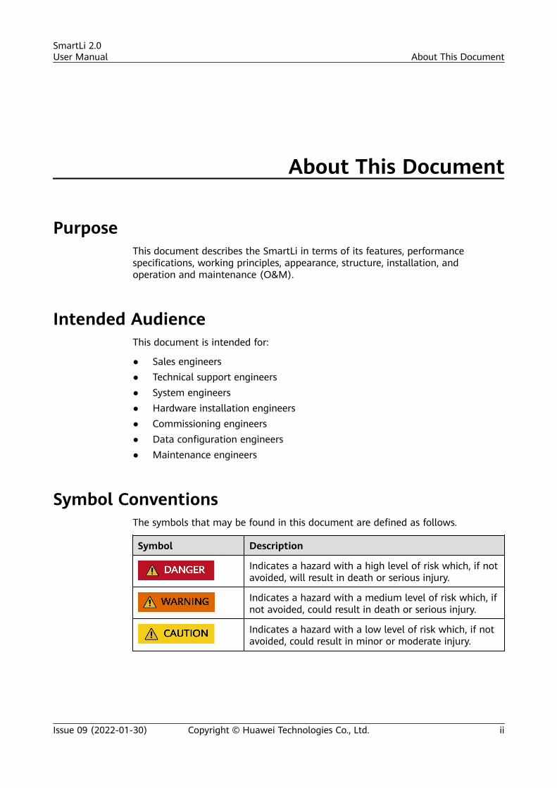
Symbol ConventionsThe symbols that may be found in this document are defined as follows.
Symbol Description
Indicates a hazard with a high level of risk which, if notavoided, will result in death or serious injury.
Indicates a hazard with a medium level of risk which, ifnot avoided, could result in death or serious injury.
Indicates a hazard with a low level of risk which, if notavoided, could result in minor or moderate injury.
SmartLi 2.0User Manual About This Document
Issue 09 (2022-01-30) Copyright © Huawei Technologies Co., Ltd. ii
Symbol Description
Indicates a potentially hazardous situation which, if notavoided, could result in equipment damage, data loss,performance deterioration, or unanticipated results.NOTICE is used to address practices not related topersonal injury.
Supplements the important information in the maintext.NOTE is used to address information not related topersonal injury, equipment damage, and environmentdeterioration.
Change HistoryChanges between document issues are cumulative. The latest document issuecontains all the changes made in earlier issues.
Issue 09 (2022-01-30)1. Updated the description about the fire extinguisher cylinder.2. Updated the safety information.3. Updated the maximum recharge interval corresponding to the SOC upon
power-off.
Issue 08 (2021-08-20)1. Updated the description that the SmartLi supports a maximum of 15 cabinets
connected in parallel.2. Deleted the description about battery pooling.3. Added module quantity mismatch and alarm parameter settings.4. Added the description about fire extinguisher cylinder installation.5. Updated the description about routine maintenance.
Issue 07 (2021-03-22)● Updated the requirements on the extinguishant charging pressure of the fire
extinguisher cylinder.● Added the description about communications port mapping.● Added the appearance and technical specifications in the 7+7 and 7+0
scenarios.
Issue 06 (2021-01-10)● Added the transportation requirements and the descriptions about storage
and recharge.
SmartLi 2.0User Manual About This Document
Issue 09 (2022-01-30) Copyright © Huawei Technologies Co., Ltd. iii
● Updated the fuse specifications.
Issue 05 (2020-11-20)Deleted the description about the combiner cabinet.
Issue 04 (2020-09-28)Updated the safety information.
Issue 03 (2020-08-07)Added the description about the combiner cabinet.
Issue 02 (2020-05-17)Updated related descriptions.
Issue 01 (2019-11-29)This issue is the first official release.
SmartLi 2.0User Manual About This Document
Issue 09 (2022-01-30) Copyright © Huawei Technologies Co., Ltd. iv
Important Safety Instructions
D ANGER
The site must be equipped with qualified fire extinguishing facilities, such asfirefighting sands and liquid carbon dioxide fire extinguishers. An independentbattery room with firefighting capabilities is recommended.
D ANGER
Install the equipment in an area far away from liquids. Do not install it underareas prone to condensation, such as water pipes and air exhaust vents, or areasprone to water leakage, such as air conditioner vents, ventilation vents, or feederwindows of the equipment room. Ensure that no liquid enters the equipment toprevent faults or short circuits.
D ANGER
When installing, operating, or maintaining the equipment, wear dedicatedprotective gears and use insulated tools to prevent electric shocks and shortcircuits.
WARNING
● Before unpacking battery modules, ensure that the packing cases are intact andcorrectly placed according to the labels on the packing cases during theirstorage and transportation. Do not place a battery module upside down, lay iton one side, or tilt it. Stack the battery modules according to the stackingrequirements on the packing cases. Any bumping or falling may damage thebattery modules.
● After unpacking battery modules, place them in the required direction. Do notplace a battery module upside down or vertically, lay it on one side, tilt it, orstack it with other modules. Any bumping or falling may damage the batterymodules.
SmartLi 2.0User Manual Important Safety Instructions
Issue 09 (2022-01-30) Copyright © Huawei Technologies Co., Ltd. v
WARNING
Do not transport a cabinet with battery modules installed. If the cabinet needs tobe transported or moved, remove the battery modules first.
CA UTION
Strictly follow the instructions in this document during storage, transportation,installation, and maintenance to prevent risks caused by system exceptions.
CA UTION
If the battery cabinet is installed but not powered on, manually powered off, ordischarged, avoid keeping it at low SOC for an extended period. Recharge thebattery cabinet in a timely manner according to the instructions in Transportationand Storage > Battery Cabinet Storage with Low SOC in the user manual.Otherwise, batteries may be damaged due to overdischarge.
CA UTION
After the lithium battery system is installed, fully charge the system before puttingit into use. When the system is in operation, do not replace battery moduleswithout permission.
CA UTION
Battery modules should not be stored for an extended period. They should be usedsoon after being deployed onsite. For battery modules that have been stored foran extended period, recharge them periodically according to the instructions inTransportation and Storage > Battery Module Storage and Recharge in theuser manual. Otherwise, the battery modules may be damaged.
SmartLi 2.0User Manual Important Safety Instructions
Issue 09 (2022-01-30) Copyright © Huawei Technologies Co., Ltd. vi
Contents
About This Document................................................................................................................ ii
Important Safety Instructions.................................................................................................. v
1 Safety Information.................................................................................................................. 11.1 General Safety.......................................................................................................................................................................... 11.2 Personnel Requirements....................................................................................................................................................... 41.3 Electrical Safety........................................................................................................................................................................41.4 Installation Environment Requirements.......................................................................................................................... 61.5 Mechanical Safety................................................................................................................................................................... 71.6 Battery Safety......................................................................................................................................................................... 101.7 Others....................................................................................................................................................................................... 12
2 Overview................................................................................................................................. 132.1 Positioning and Features.................................................................................................................................................... 132.1.1 Positioning........................................................................................................................................................................... 132.1.2 Features................................................................................................................................................................................ 132.2 Application Scenarios.......................................................................................................................................................... 142.3 Model Number Description............................................................................................................................................... 152.4 Overview.................................................................................................................................................................................. 162.4.1 Appearance.......................................................................................................................................................................... 162.4.2 Structure............................................................................................................................................................................... 172.4.3 Battery Module...................................................................................................................................................................182.4.4 BCU......................................................................................................................................................................................... 202.4.5 Monitoring Interface Unit...............................................................................................................................................212.4.6 MDU....................................................................................................................................................................................... 232.4.7 Fire Detection and Extinguishing Equipment.......................................................................................................... 252.5 Optional Components......................................................................................................................................................... 262.5.1 Lithium Battery Side Cabinet.........................................................................................................................................26
3 Transportation and Storage................................................................................................303.1 Transportation Requirements........................................................................................................................................... 303.2 Battery Module Storage and Recharge......................................................................................................................... 313.2.1 Storage Requirements......................................................................................................................................................313.2.2 Conditions for Judging Overdue Storage.................................................................................................................. 313.2.3 Check Before Recharge.................................................................................................................................................... 32
SmartLi 2.0User Manual Contents
Issue 09 (2022-01-30) Copyright © Huawei Technologies Co., Ltd. vii
3.2.4 Battery Recharge Methods............................................................................................................................................. 323.3 Battery Cabinet Storage with Low SOC........................................................................................................................ 36
4 Installation..............................................................................................................................384.1 Installation Preparations.................................................................................................................................................... 384.1.1 Site.......................................................................................................................................................................................... 384.1.1.1 Installation Environment............................................................................................................................................. 384.1.1.2 Installation Clearances................................................................................................................................................. 384.1.2 Tools and Instruments..................................................................................................................................................... 394.1.3 Preparing Power Cables.................................................................................................................................................. 414.1.4 Unpacking and Checking................................................................................................................................................ 424.2 Installing a Fire Extinguisher Cylinder and Cabinets (Without a Lithium Battery Side Cabinet)..............424.2.1 Installing a Fire Extinguisher Cylinder........................................................................................................................ 434.2.2 Installing Cabinets............................................................................................................................................................. 474.3 Installing a Fire Extinguisher Cylinder and Cabinets (With a Lithium Battery Side Cabinet).................... 514.3.1 Installing a Fire Extinguisher Cylinder........................................................................................................................ 514.3.2 Installing Cabinets............................................................................................................................................................. 564.4 Installing Battery Modules and Cables..........................................................................................................................644.4.1 Cable Connection Reference.......................................................................................................................................... 644.4.2 Installing a PE Cable.........................................................................................................................................................654.4.3 Installing Battery Modules and Cables...................................................................................................................... 674.4.4 Remote EPO........................................................................................................................................................................ 754.4.5 Installing Output Cables................................................................................................................................................. 754.5 Verifying the Installation and Filling the Sealing Putty...........................................................................................80
5 User Interface......................................................................................................................... 835.1 Login.......................................................................................................................................................................................... 835.2 LCD Interface.......................................................................................................................................................................... 855.2.1 Main Menu Screen............................................................................................................................................................ 855.2.2 System Status..................................................................................................................................................................... 865.2.2.1 Battery Cabinet............................................................................................................................................................... 865.2.2.2 Runn Info.......................................................................................................................................................................... 875.2.2.3 Alarms................................................................................................................................................................................ 905.2.2.4 Settings.............................................................................................................................................................................. 905.2.2.5 Maintenance.................................................................................................................................................................... 975.2.2.6 About.................................................................................................................................................................................. 985.2.3 Common Functions........................................................................................................................................................... 985.3 WebUI....................................................................................................................................................................................... 995.3.1 Home..................................................................................................................................................................................... 995.3.2 Monitoring......................................................................................................................................................................... 1005.3.3 Query...................................................................................................................................................................................1005.3.4 System Settings................................................................................................................................................................1005.3.5 Maintenance..................................................................................................................................................................... 101
SmartLi 2.0User Manual Contents
Issue 09 (2022-01-30) Copyright © Huawei Technologies Co., Ltd. viii
6 Operations............................................................................................................................ 1026.1 Connecting the Battery Supply...................................................................................................................................... 1026.2 Powering Off Batteries..................................................................................................................................................... 1066.3 Performing EPO...................................................................................................................................................................1076.4 Clearing the EPO State..................................................................................................................................................... 1076.5 Adding a SmartLi................................................................................................................................................................ 1086.6 Removing a SmartLi.......................................................................................................................................................... 1106.7 Removing a Battery Module........................................................................................................................................... 1126.8 Testing Batteries..................................................................................................................................................................1156.8.1 Shallow Discharge Test................................................................................................................................................. 1156.8.2 Capacity Test..................................................................................................................................................................... 1176.8.3 Performing a Group Capacity Test............................................................................................................................ 1186.8.4 Downloading Test Data................................................................................................................................................ 1196.9 Exporting Data.................................................................................................................................................................... 119
7 Routine Maintenance.........................................................................................................122
8 Troubleshooting...................................................................................................................126
9 Parts Replacement.............................................................................................................. 1279.1 Replacing an MDU............................................................................................................................................................. 1279.2 Replacing a BCU................................................................................................................................................................. 1289.3 Replacing a Battery Module........................................................................................................................................... 1299.4 Replacing a SmartLi Fuse................................................................................................................................................ 1309.5 Upgrading Software...........................................................................................................................................................1319.6 Replacing a Fire Extinguisher Cylinder (Without a Lithium Battery Side Cabinet)..................................... 1359.7 Replacing a Fire Extinguisher Cylinder (With a Lithium Battery Side Cabinet)............................................142
10 Technical Specifications...................................................................................................148
A Alarm List............................................................................................................................. 152
B Supplementary Warranty Rules...................................................................................... 153
C Acronyms and Abbreviations........................................................................................... 155
SmartLi 2.0User Manual Contents
Issue 09 (2022-01-30) Copyright © Huawei Technologies Co., Ltd. ix
1 Safety Information
1.1 General Safety
Statement
Before installing, operating, and maintaining the equipment, carefully read thisdocument and observe all safety instructions provided herein and written on theequipment itself.
The "NOTICE", "CAUTION", "WARNING", and "DANGER" statements in thisdocument do not cover all the safety instructions. They are only supplements tothe safety instructions. The Company will not be liable for any consequencecaused by the violation of general safety requirements or design, production, andusage safety standards.
Ensure that the equipment is used in environments that meet its designspecifications. Otherwise, the equipment may become faulty, and the resultingequipment malfunction, component damage, personal injuries, or propertydamage will not be covered under the warranty.
Follow local laws and regulations when installing, operating, or maintaining theequipment. The safety instructions in this document are only supplements to locallaws and regulations.
The Company will not be liable for any consequences of the followingcircumstances:
● Operation beyond the conditions specified in this document● Installation or use in environments which are not specified in relevant
international or national standards● Unauthorized modifications to the product or software code or removal of the
product● Failure to follow the operation instructions and safety precautions on the
product and in this document● Equipment damage due to force majeure, such as earthquakes, fire, and
storms
SmartLi 2.0User Manual 1 Safety Information
Issue 09 (2022-01-30) Copyright © Huawei Technologies Co., Ltd. 1
● Damage caused during transportation by the customer
● Storage conditions that do not meet the requirements specified in thisdocument
General Requirements● Do not install, use, or operate outdoor equipment and cables (including but
not limited to moving equipment, operating equipment and cables, insertingconnectors to or removing connectors from signal ports connected to outdoorfacilities, working at heights, and performing outdoor installation) in harshweather conditions such as lightning, rain, snow, and level 6 or stronger wind.
● Before installing, operating, or maintaining the equipment, remove anyconductive objects such as watches or metal jewelry like bracelets, bangles,and rings to avoid electric shock.
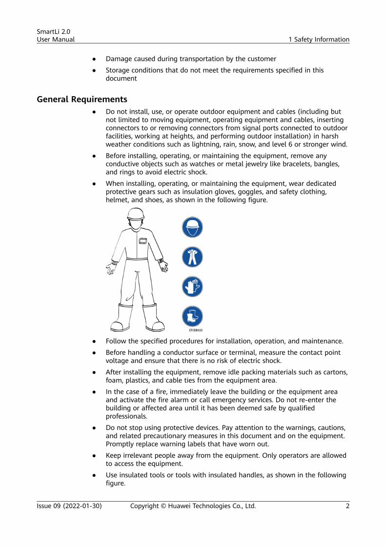
● When installing, operating, or maintaining the equipment, wear dedicatedprotective gears such as insulation gloves, goggles, and safety clothing,helmet, and shoes, as shown in the following figure.
● Follow the specified procedures for installation, operation, and maintenance.
● Before handling a conductor surface or terminal, measure the contact pointvoltage and ensure that there is no risk of electric shock.
● After installing the equipment, remove idle packing materials such as cartons,foam, plastics, and cable ties from the equipment area.
● In the case of a fire, immediately leave the building or the equipment areaand activate the fire alarm or call emergency services. Do not re-enter thebuilding or affected area until it has been deemed safe by qualifiedprofessionals.
● Do not stop using protective devices. Pay attention to the warnings, cautions,and related precautionary measures in this document and on the equipment.Promptly replace warning labels that have worn out.
● Keep irrelevant people away from the equipment. Only operators are allowedto access the equipment.
● Use insulated tools or tools with insulated handles, as shown in the followingfigure.
SmartLi 2.0User Manual 1 Safety Information
Issue 09 (2022-01-30) Copyright © Huawei Technologies Co., Ltd. 2
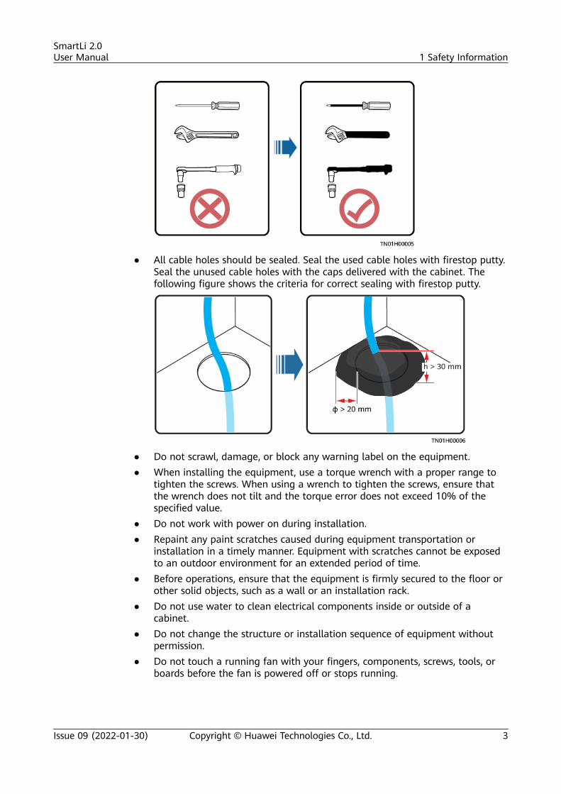
● All cable holes should be sealed. Seal the used cable holes with firestop putty.Seal the unused cable holes with the caps delivered with the cabinet. Thefollowing figure shows the criteria for correct sealing with firestop putty.
● Do not scrawl, damage, or block any warning label on the equipment.● When installing the equipment, use a torque wrench with a proper range to
tighten the screws. When using a wrench to tighten the screws, ensure thatthe wrench does not tilt and the torque error does not exceed 10% of thespecified value.
● Do not work with power on during installation.● Repaint any paint scratches caused during equipment transportation or
installation in a timely manner. Equipment with scratches cannot be exposedto an outdoor environment for an extended period of time.
● Before operations, ensure that the equipment is firmly secured to the floor orother solid objects, such as a wall or an installation rack.
● Do not use water to clean electrical components inside or outside of acabinet.
● Do not change the structure or installation sequence of equipment withoutpermission.
● Do not touch a running fan with your fingers, components, screws, tools, orboards before the fan is powered off or stops running.
SmartLi 2.0User Manual 1 Safety Information
Issue 09 (2022-01-30) Copyright © Huawei Technologies Co., Ltd. 3
Personal Safety● If there is a likelihood of personal injury or equipment damage during
operations, immediately stop, report the case to the supervisor, and takefeasible protective measures.
● To avoid electric shock, do not connect safety extra-low voltage (SELV) circuitsto telecommunication network voltage (TNV) circuits.
● Do not power on the equipment before it is installed or confirmed byprofessionals.
1.2 Personnel Requirements● Personnel who plan to install or maintain the equipment must receive
thorough training, understand all necessary safety precautions, and be able tocorrectly perform all operations.
● Only qualified professionals or trained personnel are allowed to install,operate, and maintain the equipment.
● Only qualified professionals are allowed to remove safety facilities and inspectthe equipment.
● Personnel who will operate the equipment, including operators, trainedpersonnel, and professionals, should possess the local national requiredqualifications in special operations such as high-voltage operations, workingat heights, and operations of special equipment.
● Professionals: personnel who are trained or experienced in equipmentoperations and are clear of the sources and degree of various potentialhazards in equipment installation, operation, maintenance
● Trained personnel: personnel who are technically trained, have requiredexperience, are aware of possible hazards on themselves in certain operations,and are able to take protective measures to minimize the hazards onthemselves and other people
● Operators: operation personnel who may come in contact with theequipment, except trained personnel and professionals
● Only professionals or authorized personnel are allowed to replace theequipment or components (including software).
1.3 Electrical Safety
Grounding● For the equipment that needs to be grounded, install the ground cable first
when installing the equipment and remove the ground cable last whenremoving the equipment.
● Do not damage the ground conductor.● Do not operate the equipment in the absence of a properly installed ground
conductor.● Ensure that the equipment is connected permanently to the protective
ground. Before operating the equipment, check its electrical connection toensure that it is reliably grounded.
SmartLi 2.0User Manual 1 Safety Information
Issue 09 (2022-01-30) Copyright © Huawei Technologies Co., Ltd. 4
General Requirements
Use dedicated insulated tools when performing high-voltage operations.
DC Operation Requirements
D ANGER
Do not install or remove power cables with power on. Transient contact betweenthe core of the power cable and the conductor will generate electric arcs orsparks, which may cause fire or personal injury.
● Before installing or removing power cables, ensure that the switch is turnedoff.
● Before connecting a power cable, check that the label on the power cable iscorrect.
● A damaged cable must be replaced by the manufacturer, service agent, orprofessionals to avoid risks.
● Only qualified personnel are allowed to perform high-voltage operations onthe equipment.
Cabling● When routing cables, ensure that a distance of at least 30 mm exists between
the cables and heat-generating components or areas. This prevents damageto the insulation layer of the cables.
● Do not route cables behind the air intake and exhaust vents of theequipment.
● Ensure that cables meet the VW-1 or ZB and higher flame spread ratingrequirements.
● Bind cables of the same type together. When routing cables of different types,ensure that they are at least 30 mm away from each other.
● If a cable is connected to the cabinet from the top, bend the cable in a Ushape outside the cabinet and then route it into the cabinet.
● When the temperature is low, violent impact or vibration may damage theplastic cable sheathing. To ensure safety, comply with the followingrequirements:
– Cables can be laid or installed only when the temperature is higher than0°C. Handle cables with caution, especially at a low temperature.
– Cables stored at subzero temperatures must be stored at roomtemperature for at least 24 hours before they are laid out.
● Do not perform any improper operations, for example, dropping cablesdirectly from a vehicle.
● When selecting, connecting, and routing cables, follow local safety regulationsand rules.
SmartLi 2.0User Manual 1 Safety Information
Issue 09 (2022-01-30) Copyright © Huawei Technologies Co., Ltd. 5
ESD
NO TICE
The static electricity generated by human bodies may damage the electrostatic-sensitive components on boards, for example, the large-scale integrated (LSI)circuits.
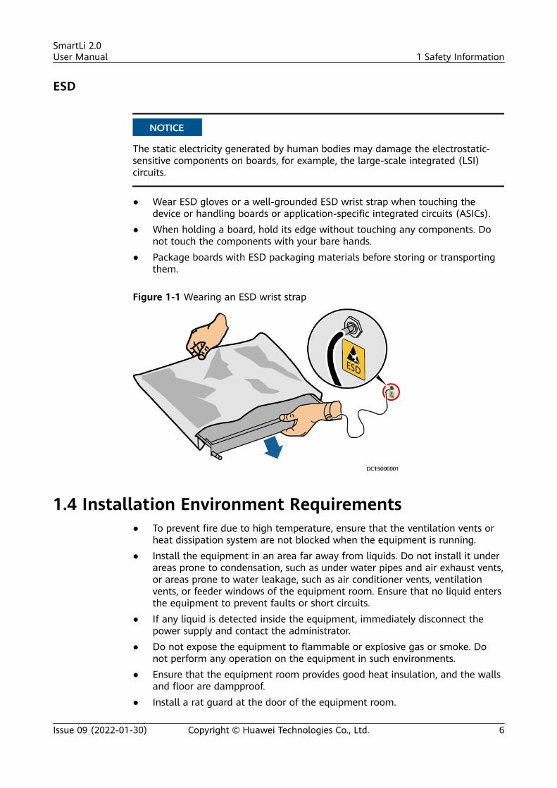
● Wear ESD gloves or a well-grounded ESD wrist strap when touching thedevice or handling boards or application-specific integrated circuits (ASICs).
● When holding a board, hold its edge without touching any components. Donot touch the components with your bare hands.
● Package boards with ESD packaging materials before storing or transportingthem.
Figure 1-1 Wearing an ESD wrist strap
1.4 Installation Environment Requirements● To prevent fire due to high temperature, ensure that the ventilation vents or
heat dissipation system are not blocked when the equipment is running.● Install the equipment in an area far away from liquids. Do not install it under
areas prone to condensation, such as under water pipes and air exhaust vents,or areas prone to water leakage, such as air conditioner vents, ventilationvents, or feeder windows of the equipment room. Ensure that no liquid entersthe equipment to prevent faults or short circuits.
● If any liquid is detected inside the equipment, immediately disconnect thepower supply and contact the administrator.
● Do not expose the equipment to flammable or explosive gas or smoke. Donot perform any operation on the equipment in such environments.
● Ensure that the equipment room provides good heat insulation, and the wallsand floor are dampproof.
● Install a rat guard at the door of the equipment room.
SmartLi 2.0User Manual 1 Safety Information
Issue 09 (2022-01-30) Copyright © Huawei Technologies Co., Ltd. 6
Installation at Heights● Working at heights refers to operations that are performed at least 2 meters
above the ground.● Do not work at heights if the steel pipes are wet or other potential danger
exists. After the preceding conditions no longer exist, the safety director andrelevant technical personnel need to check the involved equipment. Operatorscan begin working only after obtaining consent.
● When working at heights, comply with local relevant laws and regulations.● Only trained and qualified personnel are allowed to work at heights.● Before working at heights, check the climbing tools and safety gears such as
safety helmets, safety belts, ladders, springboards, scaffolding, and liftingequipment. If they do not meet the requirements, take corrective measures ordisallow working at heights.
● Wear personal protective equipment such as the safety helmet and safety beltor waist rope and fasten it to a solid structure. Do not mount it on aninsecure moveable object or metal object with sharp edges. Make sure thatthe hooks will not slide off.
● Set a restricted area and eye-catching signs for working at heights to warnaway irrelevant personnel.
● Carry the operation machinery and tools properly to prevent them fromfalling off and causing injuries.
● Personnel involving working at heights are not allowed to throw objects fromthe height to the ground, or vice versa. Objects should be transported bytough slings, hanging baskets, highline trolleys, or cranes.
● Ensure that guard rails and warning signs are set at the edges and openingsof the area involving working at heights to prevent falls.
● Do not pile up scaffolding, springboards, or other sundries on the groundunder the area involving working at heights. Do not allow people to stay orpass under the area involving working at heights.
● Inspect the scaffolding, springboards, and workbenches used for working atheights in advance to ensure that their structures are solid and notoverloaded.
● Any violations must be promptly pointed out by the site manager or safetysupervisor and the involved personnel should be prompted for correction.Personnel who fail to stop violations will be forbidden from working.
1.5 Mechanical Safety
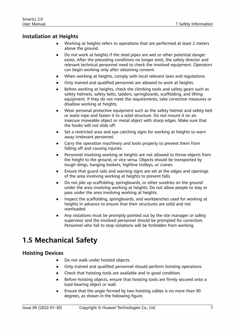
Hoisting Devices● Do not walk under hoisted objects.● Only trained and qualified personnel should perform hoisting operations.● Check that hoisting tools are available and in good condition.● Before hoisting objects, ensure that hoisting tools are firmly secured onto a
load-bearing object or wall.● Ensure that the angle formed by two hoisting cables is no more than 90
degrees, as shown in the following figure.
SmartLi 2.0User Manual 1 Safety Information
Issue 09 (2022-01-30) Copyright © Huawei Technologies Co., Ltd. 7
● Do not drag steel ropes and hoisting tools or bump hoisted objects againsthard objects during hoisting.
Using Ladders● Use wooden or fiberglass ladders when you need to perform live working at
heights.● When a step ladder is used, ensure that the pull ropes are secured and the
ladder is held firm.● Before using a ladder, check that it is intact and confirm its load bearing
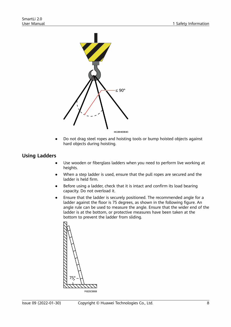
capacity. Do not overload it.● Ensure that the ladder is securely positioned. The recommended angle for a
ladder against the floor is 75 degrees, as shown in the following figure. Anangle rule can be used to measure the angle. Ensure that the wider end of theladder is at the bottom, or protective measures have been taken at thebottom to prevent the ladder from sliding.
SmartLi 2.0User Manual 1 Safety Information
Issue 09 (2022-01-30) Copyright © Huawei Technologies Co., Ltd. 8
● When climbing a ladder, take the following precautions to reduce risks andensure safety:– Keep your body steady.– Do not climb higher than the fourth rung of the ladder from the top.– Ensure that your body's center of gravity does not shift outside the legs
of the ladder.
Drilling HolesWhen drilling holes into a wall or floor, observe the following safety precautions:
NO TICE
Do not drill holes into the equipment. Doing so may affect the electromagneticshielding of the equipment and damage components or cables inside. Metalshavings from drilling may short-circuit boards inside the equipment.
● Obtain consent from the customer and contractor before drilling holes.● Wear goggles and protective gloves when drilling holes.● When drilling holes, protect the equipment from shavings. After drilling, clean
up any shavings that have accumulated inside or outside the equipment.
Moving Heavy Objects
D ANGER
When removing a heavy or unstable component from a cabinet, be aware ofunstable or heavy objects on the cabinet.
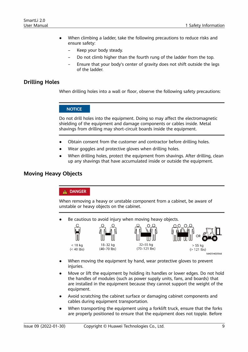
● Be cautious to avoid injury when moving heavy objects.
● When moving the equipment by hand, wear protective gloves to preventinjuries.
● Move or lift the equipment by holding its handles or lower edges. Do not holdthe handles of modules (such as power supply units, fans, and boards) thatare installed in the equipment because they cannot support the weight of theequipment.
● Avoid scratching the cabinet surface or damaging cabinet components andcables during equipment transportation.
● When transporting the equipment using a forklift truck, ensure that the forksare properly positioned to ensure that the equipment does not topple. Before
SmartLi 2.0User Manual 1 Safety Information
Issue 09 (2022-01-30) Copyright © Huawei Technologies Co., Ltd. 9
moving the equipment, secure it to the forklift truck using ropes. Whenmoving the equipment, assign dedicated personnel to take care of it.
● Choose sea or a road with good conditions for transportation to ensureequipment safety. Avoid tilt or jolt during transportation.
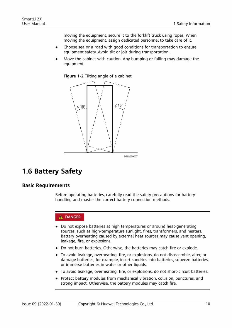
● Move the cabinet with caution. Any bumping or falling may damage theequipment.
Figure 1-2 Tilting angle of a cabinet
1.6 Battery Safety
Basic Requirements
Before operating batteries, carefully read the safety precautions for batteryhandling and master the correct battery connection methods.
D ANGER
● Do not expose batteries at high temperatures or around heat-generatingsources, such as high-temperature sunlight, fires, transformers, and heaters.Battery overheating caused by external heat sources may cause vent opening,leakage, fire, or explosions.
● Do not burn batteries. Otherwise, the batteries may catch fire or explode.
● To avoid leakage, overheating, fire, or explosions, do not disassemble, alter, ordamage batteries, for example, insert sundries into batteries, squeeze batteries,or immerse batteries in water or other liquids.
● To avoid leakage, overheating, fire, or explosions, do not short-circuit batteries.
● Protect battery modules from mechanical vibration, collision, punctures, andstrong impact. Otherwise, the battery modules may catch fire.
SmartLi 2.0User Manual 1 Safety Information
Issue 09 (2022-01-30) Copyright © Huawei Technologies Co., Ltd. 10
WARNING
There is a risk of explosion if a battery is replaced with an incorrect model.
● Wear goggles, rubber gloves, and protective clothing to avoid damage causedby electrolyte in the case of electrolyte overflow. If a battery overflows,protect the skin or eyes from the leaking liquid. If the skin or eyes come incontact with the leaking liquid, wash it immediately with clean water and goto the hospital for medical treatment.
● Use dedicated insulated tools.● Move batteries in the required direction. Do not place a battery upside down,
tilt it, or bump it with other objects.● Use batteries of specified models. Using batteries of other models may
damage the batteries.● A battery can be replaced only with a battery of the same or similar model
recommended by the manufacturer.● Dispose of waste batteries in accordance with local laws and regulations. Do
not dispose of batteries as household waste. If a battery is disposed ofimproperly, it may explode.
● The site must be equipped with qualified fire extinguishing facilities, such asfirefighting sands and liquid carbon dioxide fire extinguishers.
Battery InstallationBefore installing batteries, observe the following safety precautions:
● Install batteries in a well-ventilated, dry, and cool environment that is faraway from heat sources, flammable materials, moisture, extensive infraredradiation, organic solvents, and corrosive gases. Take fire preventionmeasures.
● Place and secure batteries horizontally.● Keep the lithium battery loop disconnected during installation and
maintenance.● Note the polarities when installing batteries. Do not short-circuit the positive
and negative poles of the same battery or battery string. Otherwise, thebattery may be short-circuited.
● Check battery connections periodically, ensuring that all screws are securelytightened.
● When installing batteries, do not place installation tools on the batteries.
Battery Short Circuit
D ANGER
Battery short circuits can generate high instantaneous current and release a greatamount of energy, which may cause equipment damage or personal injury.
To avoid battery short circuit, do not maintain batteries with power on.
SmartLi 2.0User Manual 1 Safety Information
Issue 09 (2022-01-30) Copyright © Huawei Technologies Co., Ltd. 11
Battery Leakage
WARNING
● If the electrolyte overflows, power off the device, remove the battery modulefrom the cabinet, and contact technical support.
● When moving or handling a battery whose electrolyte leaks, note that theleaking electrolyte may cause damage.
Flammable Gas● A battery module is an enclosed battery system and will not release any gases
under normal operations.● If a battery module is improperly treated, for example, burnt, needle-pricked,
squeezed, overcharged, or subject to other adverse conditions that may causebattery thermal runaway, the battery may be damaged or an abnormalchemical reaction may occur inside the battery, resulting in electrolyteleakage or production of gases such as CO2, CO, N2, and H2. To prevent fire orcorrosion, ensure that flammable gas (such as hydrogen) is properlyexhausted.
1.7 Others● This is a category C3 product for commercial and industrial application in the
second environment – installation restrictions or additional measures may beneeded to prevent disturbances.
● Exercise caution when setting battery parameters. Incorrect settings will affectthe power supply and battery lifespan.
SmartLi 2.0User Manual 1 Safety Information
Issue 09 (2022-01-30) Copyright © Huawei Technologies Co., Ltd. 12
2 Overview
The SmartLi provides lithium battery backup power for medium- and high-powerUPSs. It is compatible with UPSs with or without a battery neutral wire. Thelithium battery cabinet supports power backup, battery management, andintelligent current management. When multiple battery strings are connected inparallel, the output of each battery string is balanced and reliable protection isachieved.
2.1 Positioning and Features
2.1.1 PositioningThe SmartLi is a battery energy storage system solution developed for HuaweiUPS. The product provides cabinet-level battery management, and up to 15cabinets can be connected in parallel to meet the requirements for MW-level UPSbackup power. The product uses lithium cells with superior charge and dischargecharacteristics and high cycle performance. The modular design of keycomponents facilitates replacement and greatly reduces O&M costs.
The lithium battery system applies to the following scenarios:● Large-sized data centers● Small- and medium-sized data centers● Rail transits● State grids
2.1.2 Features● Easy capacity expansion: Batteries can be added along with load increase by
stages. New and old battery cabinets can be connected in parallel.● Easy maintenance: Batteries can be swapped for maintenance due to the
modular design.● High cycle performance of cells: 25°C, 0.5C charging/1C discharging, 50%
depth of discharge (DOD), 5000 cycles at 70% end of life (EOL).● High reliability: Current equalization control technology is used for cabinets
connected in parallel to keep current imbalance within 2%.
SmartLi 2.0User Manual 2 Overview
Issue 09 (2022-01-30) Copyright © Huawei Technologies Co., Ltd. 13
2.2 Application Scenarios
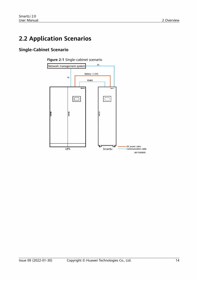
Single-Cabinet Scenario
Figure 2-1 Single-cabinet scenario
SmartLi 2.0User Manual 2 Overview
Issue 09 (2022-01-30) Copyright © Huawei Technologies Co., Ltd. 14

Multi-Cabinet Scenario
Figure 2-2 Multi-cabinet scenario
NO TE
● The SmartLi supports a maximum of 15 cabinets connected in parallel.
● When multiple cabinets are connected in parallel, only the master cabinet has an LCD.
2.3 Model Number Description
Figure 2-3 Model number
Table 2-1 Model number description
No. Item Description
1 Productcategory
SmartLi
2 Productsubcategory
512 V
3 Capacity 80AH: battery capacity being 80 Ah
SmartLi 2.0User Manual 2 Overview
Issue 09 (2022-01-30) Copyright © Huawei Technologies Co., Ltd. 15
No. Item Description
4 Configurationtype
● F: with an LCD (master cabinet)● S: without an LCD (slave cabinet)
5 Version 01
2.4 OverviewThe SmartLi system consists of the battery modules, battery control unit (BCU),monitoring interface unit, power distribution unit (PDU), and monitoring displayunit (MDU), which are integrated into a standard cabinet.
Battery modules are connected in series to provide energy. The BCU providescentralized battery management. The PDU connects power cables and disconnectsthe power circuit in case of exceptions. The MDU allows you to set parametersand query status.
When multiple battery cabinets are connected in parallel, the BCU balances theloads between cabinets to improve system reliability. The master battery cabinetprovides an LCD that displays battery running information in real time and allowsusers to set battery parameters. Battery cabinets can connect to the UPS andnetwork management system (NMS) for intelligent management.
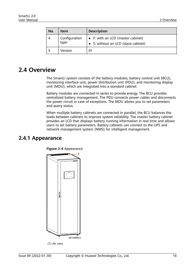
2.4.1 Appearance
Figure 2-4 Appearance
(1) Air vent
SmartLi 2.0User Manual 2 Overview
Issue 09 (2022-01-30) Copyright © Huawei Technologies Co., Ltd. 16
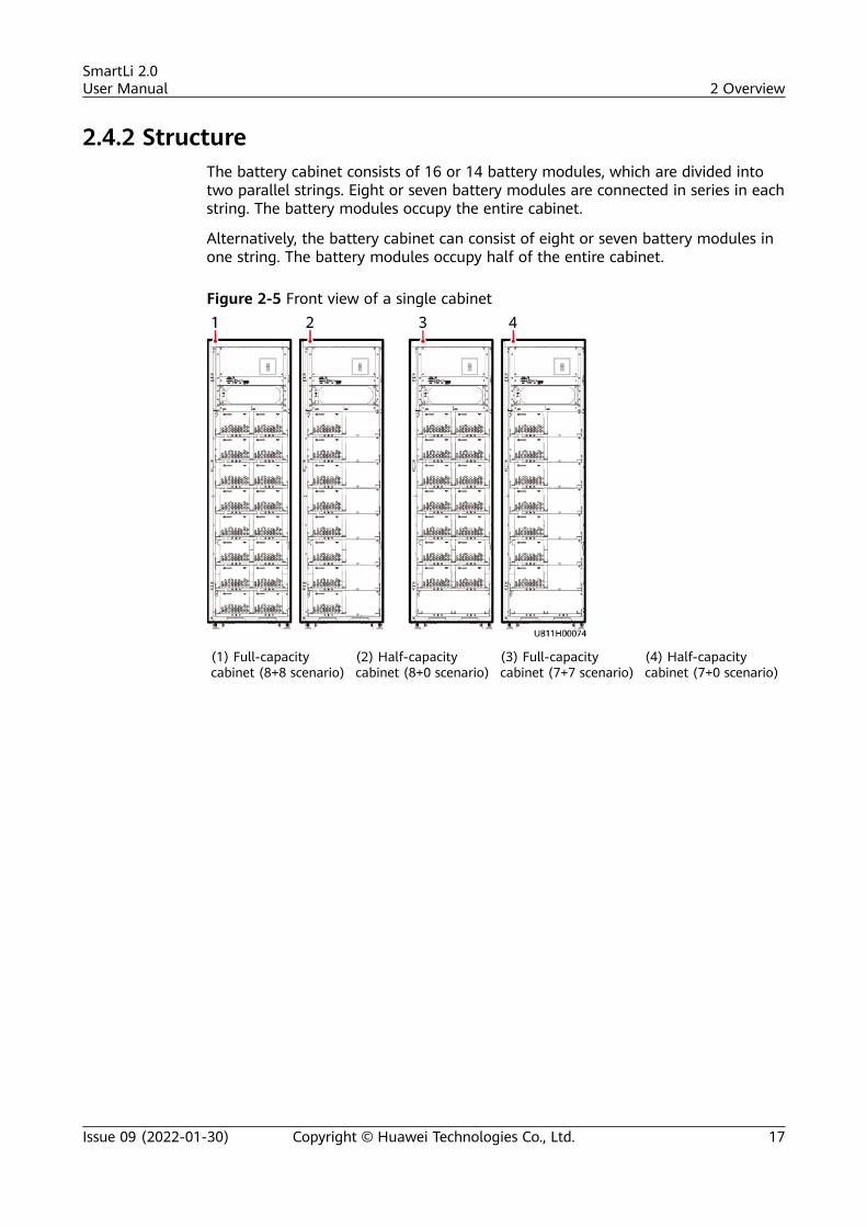
2.4.2 StructureThe battery cabinet consists of 16 or 14 battery modules, which are divided intotwo parallel strings. Eight or seven battery modules are connected in series in eachstring. The battery modules occupy the entire cabinet.
Alternatively, the battery cabinet can consist of eight or seven battery modules inone string. The battery modules occupy half of the entire cabinet.
Figure 2-5 Front view of a single cabinet
(1) Full-capacitycabinet (8+8 scenario)
(2) Half-capacitycabinet (8+0 scenario)
(3) Full-capacitycabinet (7+7 scenario)
(4) Half-capacitycabinet (7+0 scenario)
SmartLi 2.0User Manual 2 Overview
Issue 09 (2022-01-30) Copyright © Huawei Technologies Co., Ltd. 17
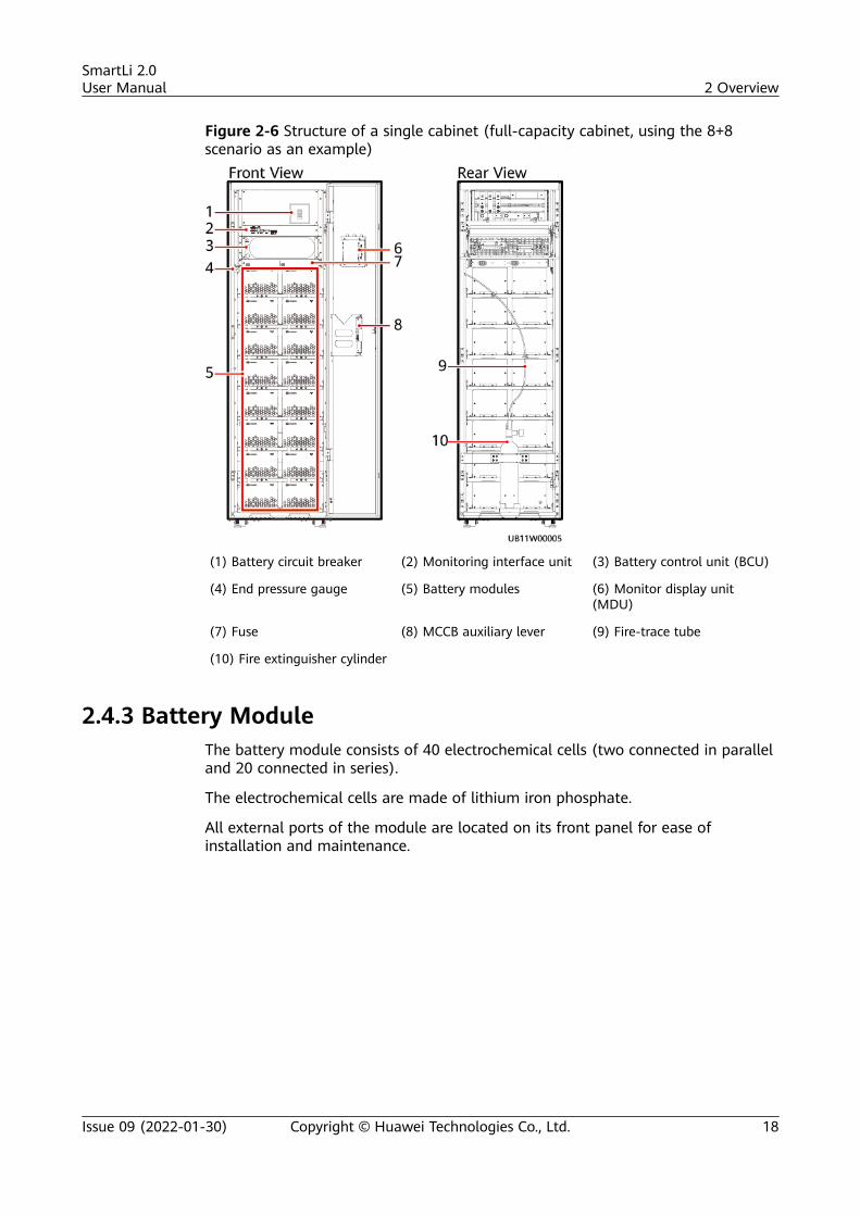
Figure 2-6 Structure of a single cabinet (full-capacity cabinet, using the 8+8scenario as an example)
(1) Battery circuit breaker (2) Monitoring interface unit (3) Battery control unit (BCU)
(4) End pressure gauge (5) Battery modules (6) Monitor display unit(MDU)
(7) Fuse (8) MCCB auxiliary lever (9) Fire-trace tube
(10) Fire extinguisher cylinder
2.4.3 Battery ModuleThe battery module consists of 40 electrochemical cells (two connected in paralleland 20 connected in series).
The electrochemical cells are made of lithium iron phosphate.
All external ports of the module are located on its front panel for ease ofinstallation and maintenance.
SmartLi 2.0User Manual 2 Overview
Issue 09 (2022-01-30) Copyright © Huawei Technologies Co., Ltd. 18
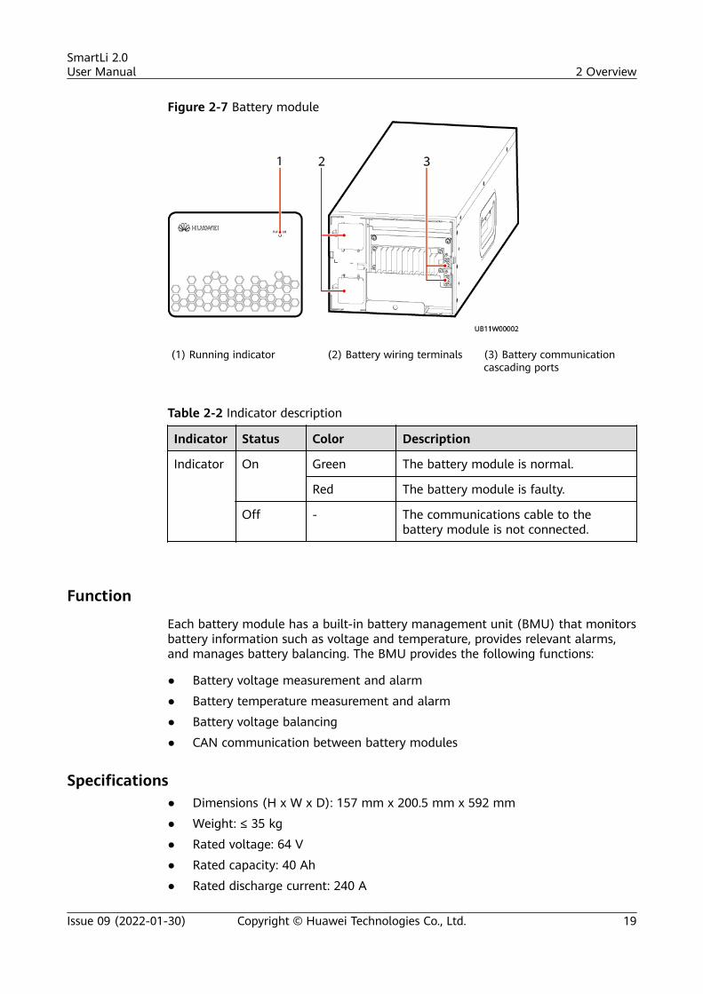
Figure 2-7 Battery module
(1) Running indicator (2) Battery wiring terminals (3) Battery communicationcascading ports
Table 2-2 Indicator description
Indicator Status Color Description
Indicator On Green The battery module is normal.
Red The battery module is faulty.
Off - The communications cable to thebattery module is not connected.
Function
Each battery module has a built-in battery management unit (BMU) that monitorsbattery information such as voltage and temperature, provides relevant alarms,and manages battery balancing. The BMU provides the following functions:
● Battery voltage measurement and alarm
● Battery temperature measurement and alarm
● Battery voltage balancing
● CAN communication between battery modules
Specifications● Dimensions (H x W x D): 157 mm x 200.5 mm x 592 mm
● Weight: ≤ 35 kg
● Rated voltage: 64 V
● Rated capacity: 40 Ah
● Rated discharge current: 240 A
SmartLi 2.0User Manual 2 Overview
Issue 09 (2022-01-30) Copyright © Huawei Technologies Co., Ltd. 19
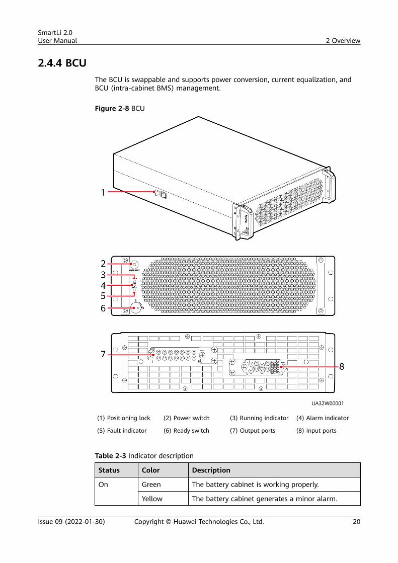
2.4.4 BCUThe BCU is swappable and supports power conversion, current equalization, andBCU (intra-cabinet BMS) management.
Figure 2-8 BCU
(1) Positioning lock (2) Power switch (3) Running indicator (4) Alarm indicator
(5) Fault indicator (6) Ready switch (7) Output ports (8) Input ports
Table 2-3 Indicator description
Status Color Description
On Green The battery cabinet is working properly.
Yellow The battery cabinet generates a minor alarm.
SmartLi 2.0User Manual 2 Overview
Issue 09 (2022-01-30) Copyright © Huawei Technologies Co., Ltd. 20
Status Color Description
Red The battery cabinet generates a critical alarm.
Off - The battery cabinet is shut down.
Functions● The BCU converts the battery string power. When the consistency between
battery strings is poor, the BCU controls the current balance between batterystrings through voltage boosting and balance adjustment to ensure reliablesystem operation.
● The BCU implements communication inside a battery cabinet, betweencabinets, and between the UPS and NMS, and provides battery managementand protection against exceptions.
Specifications● Dimensions (H x W x D): 130 mm x 442 mm x 550 mm
● Weight: ≤ 35 kg
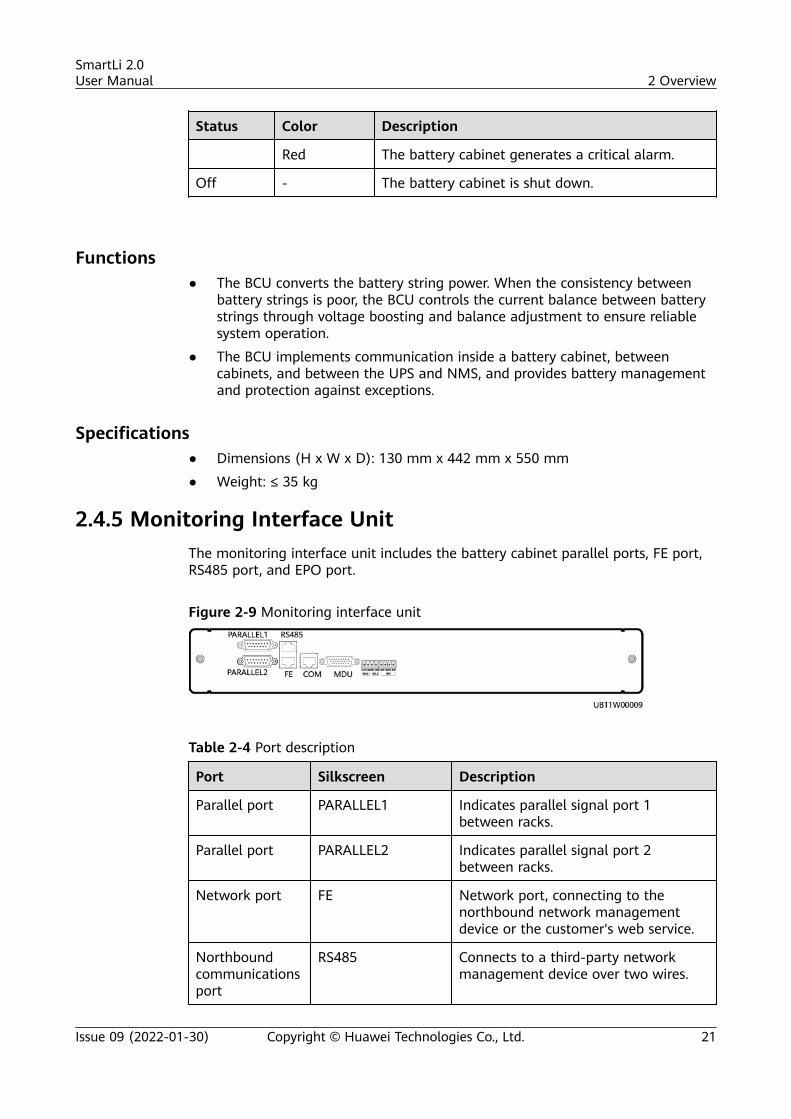
2.4.5 Monitoring Interface UnitThe monitoring interface unit includes the battery cabinet parallel ports, FE port,RS485 port, and EPO port.
Figure 2-9 Monitoring interface unit
Table 2-4 Port description
Port Silkscreen Description
Parallel port PARALLEL1 Indicates parallel signal port 1between racks.
Parallel port PARALLEL2 Indicates parallel signal port 2between racks.
Network port FE Network port, connecting to thenorthbound network managementdevice or the customer's web service.
Northboundcommunicationsport
RS485 Connects to a third-party networkmanagement device over two wires.
SmartLi 2.0User Manual 2 Overview
Issue 09 (2022-01-30) Copyright © Huawei Technologies Co., Ltd. 21
Port Silkscreen Description
Northboundcommunicationsport
COM Connects to an UPS.
DB26 MDU Supports FE, RS485, I2C, CAN, andother signals.
DO_1 DO_1 Output dry contact 1 function settingfor the lithium battery cabinet
DO_2 DO_2 Output dry contact 2 function settingfor the lithium battery cabinet
EPO NO If the normally open (NO) port isconnected to the EPO_12V port,emergency power-off (EPO) istriggered.
12V
NC If the normally closed (NC) port isdisconnected from the EPO_12V port,EPO is triggered.12V
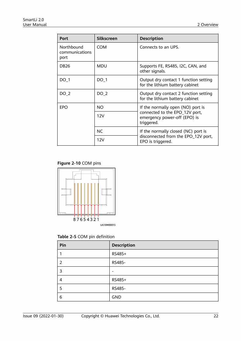
Figure 2-10 COM pins
Table 2-5 COM pin definition
Pin Description
1 RS485+
2 RS485-
3 -
4 RS485+
5 RS485-
6 GND
SmartLi 2.0User Manual 2 Overview
Issue 09 (2022-01-30) Copyright © Huawei Technologies Co., Ltd. 22
Pin Description
7 CANH0
8 CANL0
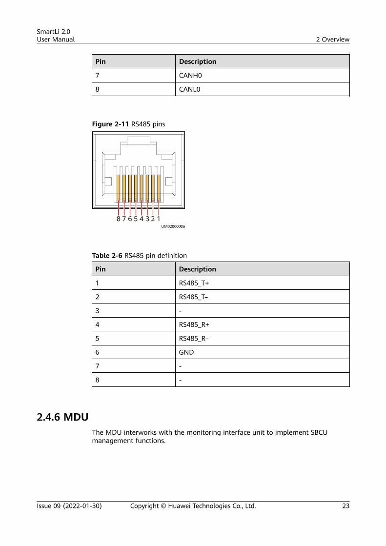
Figure 2-11 RS485 pins
Table 2-6 RS485 pin definition
Pin Description
1 RS485_T+
2 RS485_T–
3 -
4 RS485_R+
5 RS485_R–
6 GND
7 -
8 -
2.4.6 MDUThe MDU interworks with the monitoring interface unit to implement SBCUmanagement functions.
SmartLi 2.0User Manual 2 Overview
Issue 09 (2022-01-30) Copyright © Huawei Technologies Co., Ltd. 23
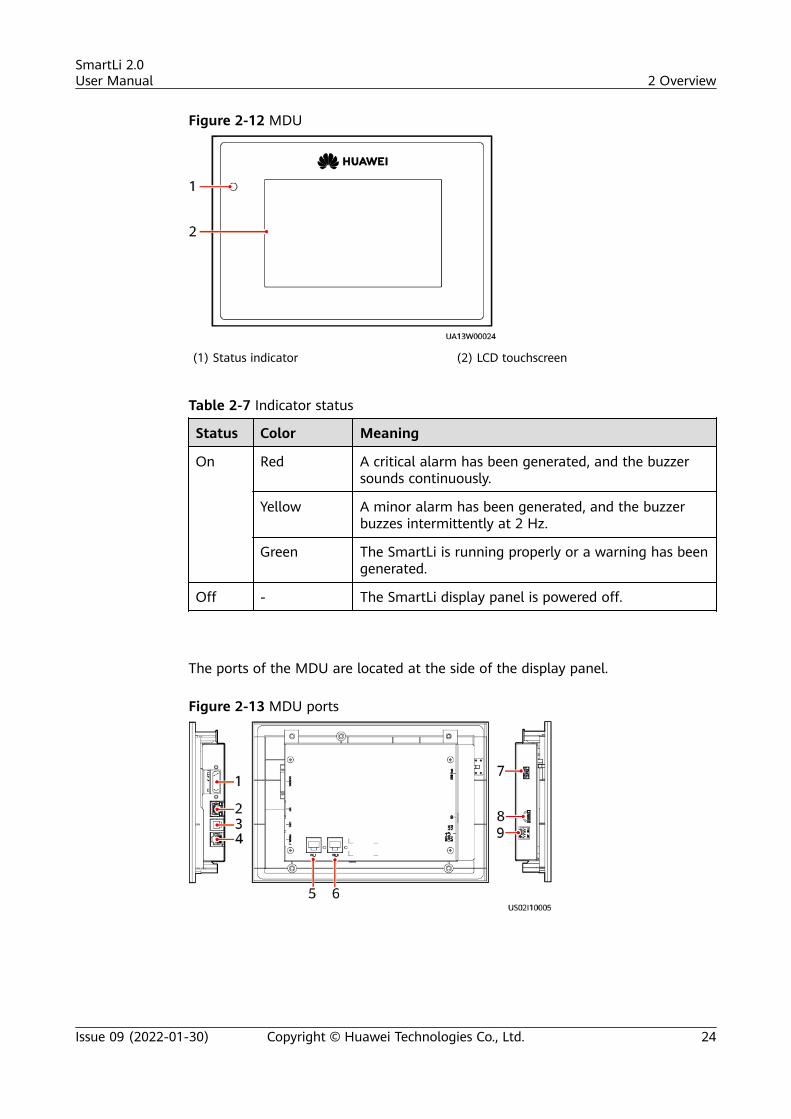
Figure 2-12 MDU
(1) Status indicator (2) LCD touchscreen
Table 2-7 Indicator status
Status Color Meaning
On Red A critical alarm has been generated, and the buzzersounds continuously.
Yellow A minor alarm has been generated, and the buzzerbuzzes intermittently at 2 Hz.
Green The SmartLi is running properly or a warning has beengenerated.
Off - The SmartLi display panel is powered off.
The ports of the MDU are located at the side of the display panel.
Figure 2-13 MDU ports
SmartLi 2.0User Manual 2 Overview
Issue 09 (2022-01-30) Copyright © Huawei Technologies Co., Ltd. 24
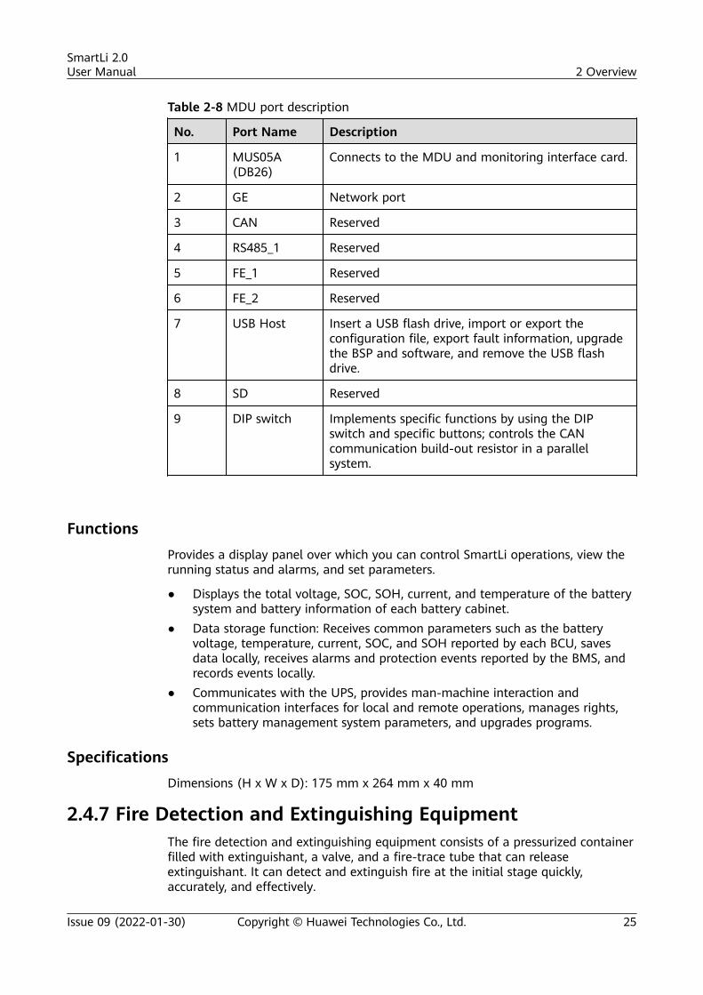
Table 2-8 MDU port description
No. Port Name Description
1 MUS05A(DB26)
Connects to the MDU and monitoring interface card.
2 GE Network port
3 CAN Reserved
4 RS485_1 Reserved
5 FE_1 Reserved
6 FE_2 Reserved
7 USB Host Insert a USB flash drive, import or export theconfiguration file, export fault information, upgradethe BSP and software, and remove the USB flashdrive.
8 SD Reserved
9 DIP switch Implements specific functions by using the DIPswitch and specific buttons; controls the CANcommunication build-out resistor in a parallelsystem.
FunctionsProvides a display panel over which you can control SmartLi operations, view therunning status and alarms, and set parameters.
● Displays the total voltage, SOC, SOH, current, and temperature of the batterysystem and battery information of each battery cabinet.
● Data storage function: Receives common parameters such as the batteryvoltage, temperature, current, SOC, and SOH reported by each BCU, savesdata locally, receives alarms and protection events reported by the BMS, andrecords events locally.
● Communicates with the UPS, provides man-machine interaction andcommunication interfaces for local and remote operations, manages rights,sets battery management system parameters, and upgrades programs.
SpecificationsDimensions (H x W x D): 175 mm x 264 mm x 40 mm
2.4.7 Fire Detection and Extinguishing EquipmentThe fire detection and extinguishing equipment consists of a pressurized containerfilled with extinguishant, a valve, and a fire-trace tube that can releaseextinguishant. It can detect and extinguish fire at the initial stage quickly,accurately, and effectively.
SmartLi 2.0User Manual 2 Overview
Issue 09 (2022-01-30) Copyright © Huawei Technologies Co., Ltd. 25
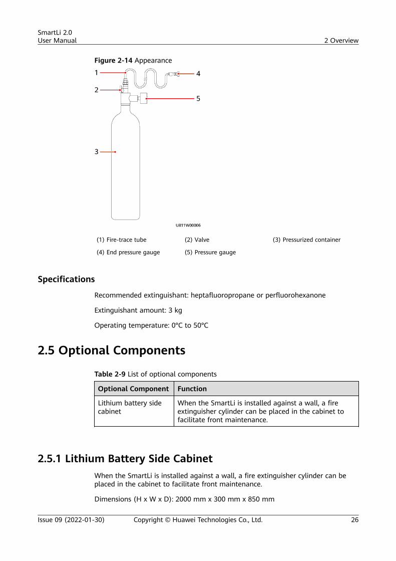
Figure 2-14 Appearance
(1) Fire-trace tube (2) Valve (3) Pressurized container
(4) End pressure gauge (5) Pressure gauge
Specifications
Recommended extinguishant: heptafluoropropane or perfluorohexanone
Extinguishant amount: 3 kg
Operating temperature: 0°C to 50°C
2.5 Optional Components
Table 2-9 List of optional components
Optional Component Function
Lithium battery sidecabinet
When the SmartLi is installed against a wall, a fireextinguisher cylinder can be placed in the cabinet tofacilitate front maintenance.
2.5.1 Lithium Battery Side CabinetWhen the SmartLi is installed against a wall, a fire extinguisher cylinder can beplaced in the cabinet to facilitate front maintenance.
Dimensions (H x W x D): 2000 mm x 300 mm x 850 mm
SmartLi 2.0User Manual 2 Overview
Issue 09 (2022-01-30) Copyright © Huawei Technologies Co., Ltd. 26
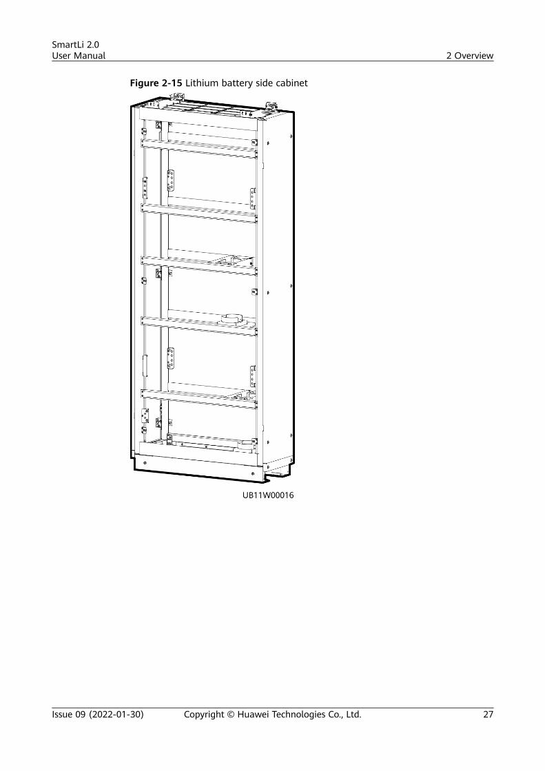
Figure 2-15 Lithium battery side cabinet
SmartLi 2.0User Manual 2 Overview
Issue 09 (2022-01-30) Copyright © Huawei Technologies Co., Ltd. 27
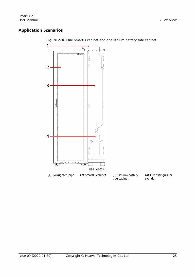
Application Scenarios
Figure 2-16 One SmartLi cabinet and one lithium battery side cabinet
(1) Corrugated pipe (2) SmartLi cabinet (3) Lithium batteryside cabinet
(4) Fire extinguishercylinder
SmartLi 2.0User Manual 2 Overview
Issue 09 (2022-01-30) Copyright © Huawei Technologies Co., Ltd. 28
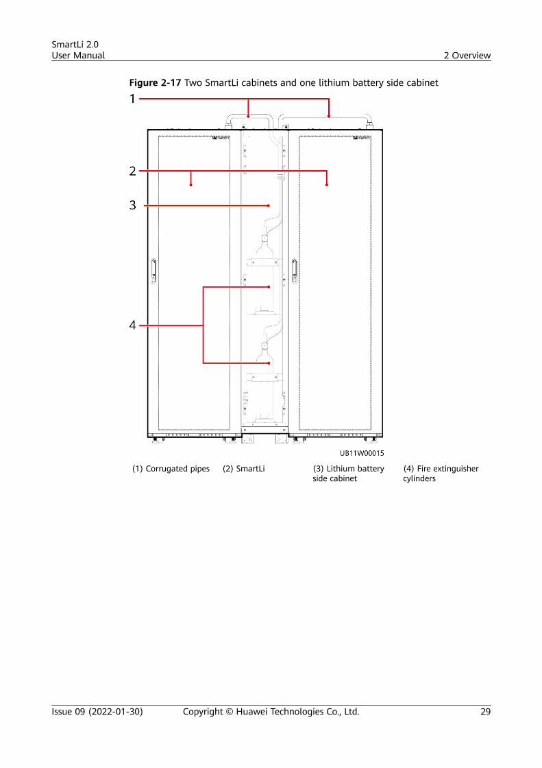
Figure 2-17 Two SmartLi cabinets and one lithium battery side cabinet
(1) Corrugated pipes (2) SmartLi (3) Lithium batteryside cabinet
(4) Fire extinguishercylinders
SmartLi 2.0User Manual 2 Overview
Issue 09 (2022-01-30) Copyright © Huawei Technologies Co., Ltd. 29
3 Transportation and Storage
3.1 Transportation RequirementsThe product passes the certifications of the UN38.3 (UN38.3: Section 38.3 of thesixth Revised Edition of the Recommendations on the Transport of DangerousGoods, Manual of Tests and Criteria) and SN/T 0370.2-2009 (Part 2: PerformanceTest of the Rules for the Inspection of Packaging for Exporting Dangerous Goods).This product belongs to class 9 dangerous goods.
The product can be delivered to the site directly and transported by land andwater. The packing case must be secured for transportation, compliant withrelated national standards, and printed with marks such as anti-collision andmoisture prevention. Affected by external environment factors, such astemperature, transportation, and storage, the product specifications at the deliverydate prevail.
Loading requirements for packages and common goods:
● Unless otherwise specified, dangerous goods cannot be mixed with goodscontaining food, medicine, animal feed, and their additives in the samevehicle or container.
● Unless otherwise specified, when dangerous goods packages are loaded in thesame vehicle or container as ordinary goods, they should be separated ineither of the following ways:
1. Use a spacer that is as high as the packages.2. Keep a distance of at least 0.8 m around.
NO TICE
Protect the packing case with the product from the following situations:● Being dampened by rains, snows, or falling into water● Falling or mechanical impact● Being upside-down or tilted
SmartLi 2.0User Manual 3 Transportation and Storage
Issue 09 (2022-01-30) Copyright © Huawei Technologies Co., Ltd. 30
3.2 Battery Module Storage and Recharge
3.2.1 Storage Requirements1. When storing battery modules, ensure that the packing cases are intact and
correctly placed according to the label on the packing cases. Do not put themupside down or sidelong.
2. Stack battery module packing cases by complying with the stackingrequirements on the external package.
3. The storage environment requirements are as follows:
– Ambient temperature: 0–40°C (constant damp heat is recommended toavoid condensation); recommended storage temperature: 20–30°C
– Relative humidity: ≤ 95%
– Dry and clean environment with proper ventilation
– Away from corrosive and organic substances (including gas)
– Away from direct sunlight
– At least 2 meters away from heat sources (such as a heater)
4. The warehouse keeper should collect battery module storage informationevery month and periodically report the battery module inventory informationto the planning department. The battery modules that have been storedoverdue should be recharged in a timely manner.
5. Regional offices or organizations should not store battery modules orcommunication equipment configured with battery modules. Prior approvalshould be obtained for any requirements on battery module storage.
6. Battery modules should be delivered based on the "first in, first out" rule.
7. Install battery modules in a dry, clean, and ventilated environment that is freefrom sources of strong infrared radiation, organic solvents, and corrosivegases. Do not expose the battery modules to sunlight or water and keep themfar away from sources of ignition.
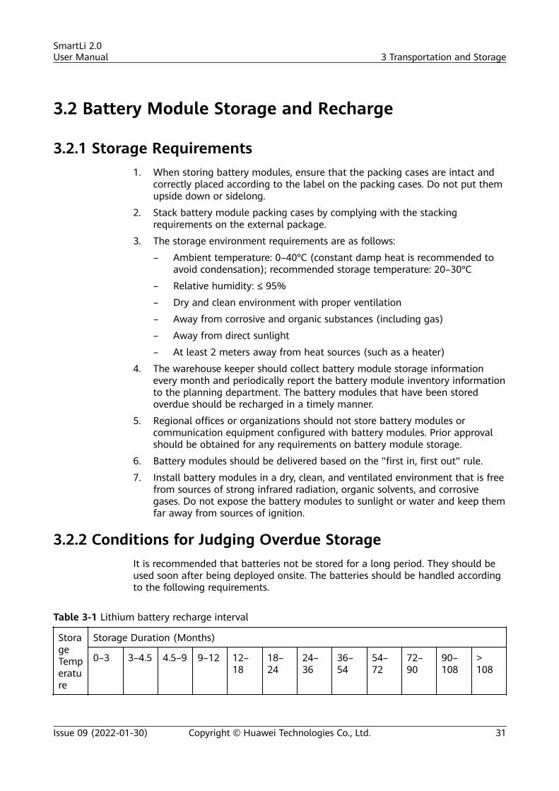
3.2.2 Conditions for Judging Overdue StorageIt is recommended that batteries not be stored for a long period. They should beused soon after being deployed onsite. The batteries should be handled accordingto the following requirements.
Table 3-1 Lithium battery recharge interval
StorageTemperature
Storage Duration (Months)
0–3 3–4.5 4.5–9 9–12 12–18
18–24
24–36
36–54
54–72
72–90
90–108
>108
SmartLi 2.0User Manual 3 Transportation and Storage
Issue 09 (2022-01-30) Copyright © Huawei Technologies Co., Ltd. 31
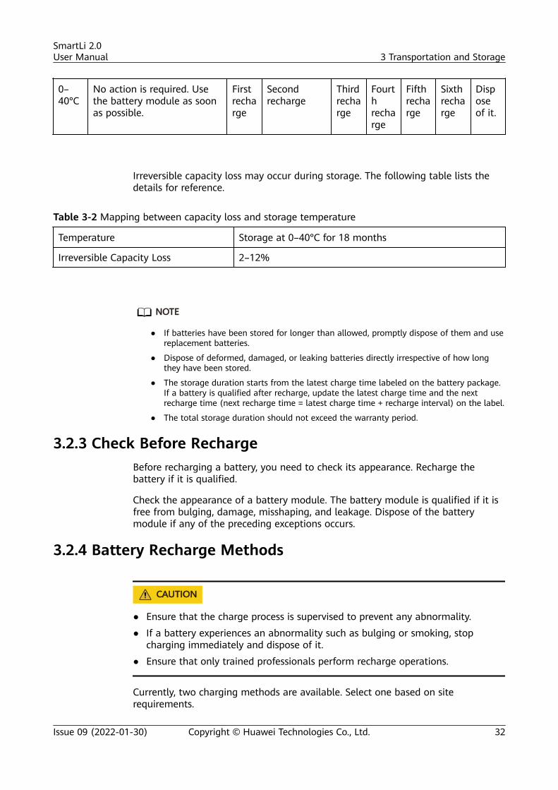
0–40°C
No action is required. Usethe battery module as soonas possible.
Firstrecharge
Secondrecharge
Thirdrecharge
Fourthrecharge
Fifthrecharge
Sixthrecharge
Disposeof it.
Irreversible capacity loss may occur during storage. The following table lists thedetails for reference.
Table 3-2 Mapping between capacity loss and storage temperature
Temperature Storage at 0–40°C for 18 months
Irreversible Capacity Loss 2–12%
NO TE
● If batteries have been stored for longer than allowed, promptly dispose of them and usereplacement batteries.
● Dispose of deformed, damaged, or leaking batteries directly irrespective of how longthey have been stored.
● The storage duration starts from the latest charge time labeled on the battery package.If a battery is qualified after recharge, update the latest charge time and the nextrecharge time (next recharge time = latest charge time + recharge interval) on the label.
● The total storage duration should not exceed the warranty period.
3.2.3 Check Before RechargeBefore recharging a battery, you need to check its appearance. Recharge thebattery if it is qualified.
Check the appearance of a battery module. The battery module is qualified if it isfree from bulging, damage, misshaping, and leakage. Dispose of the batterymodule if any of the preceding exceptions occurs.
3.2.4 Battery Recharge Methods
CA UTION
● Ensure that the charge process is supervised to prevent any abnormality.
● If a battery experiences an abnormality such as bulging or smoking, stopcharging immediately and dispose of it.
● Ensure that only trained professionals perform recharge operations.
Currently, two charging methods are available. Select one based on siterequirements.
SmartLi 2.0User Manual 3 Transportation and Storage
Issue 09 (2022-01-30) Copyright © Huawei Technologies Co., Ltd. 32
SmartLi Recharge Method
NO TICE
● Before removing the BCU, confirm with the customer that services will not beaffected.
● Before removing the BCU, ensure that the lithium battery cabinet is poweredoff.
Step 1 Identify the battery module qualified for recharge.
Step 2 Pull out the BCU and install the battery module and cables.
Step 3 Reinstall the battery management module. Turn the ready switch on the batterymanagement module to the ready state. Press and hold the POWER ON/OFFbutton on the battery management module for more than 2s. The green indicatorof the battery management module blinks at 4 Hz.
Step 4 Set the language, time, date, network parameters, and system parameters on thetouchscreen Settings Wizard.
Step 5 After the green indicator of the BCU blinks at 10 Hz and the red indicator is steadyon, switch on the battery circuit breaker.
Step 6 Ensure that the lithium battery charging status is monitored in real time until thecharging ends.
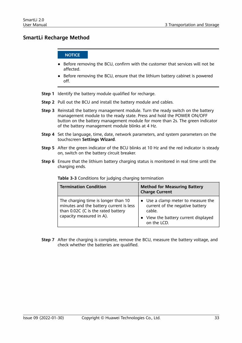
Table 3-3 Conditions for judging charging termination
Termination Condition Method for Measuring BatteryCharge Current
The charging time is longer than 10minutes and the battery current is lessthan 0.02C (C is the rated batterycapacity measured in A).
● Use a clamp meter to measure thecurrent of the negative batterycable.
● View the battery current displayedon the LCD.
Step 7 After the charging is complete, remove the BCU, measure the battery voltage, andcheck whether the batteries are qualified.
SmartLi 2.0User Manual 3 Transportation and Storage
Issue 09 (2022-01-30) Copyright © Huawei Technologies Co., Ltd. 33
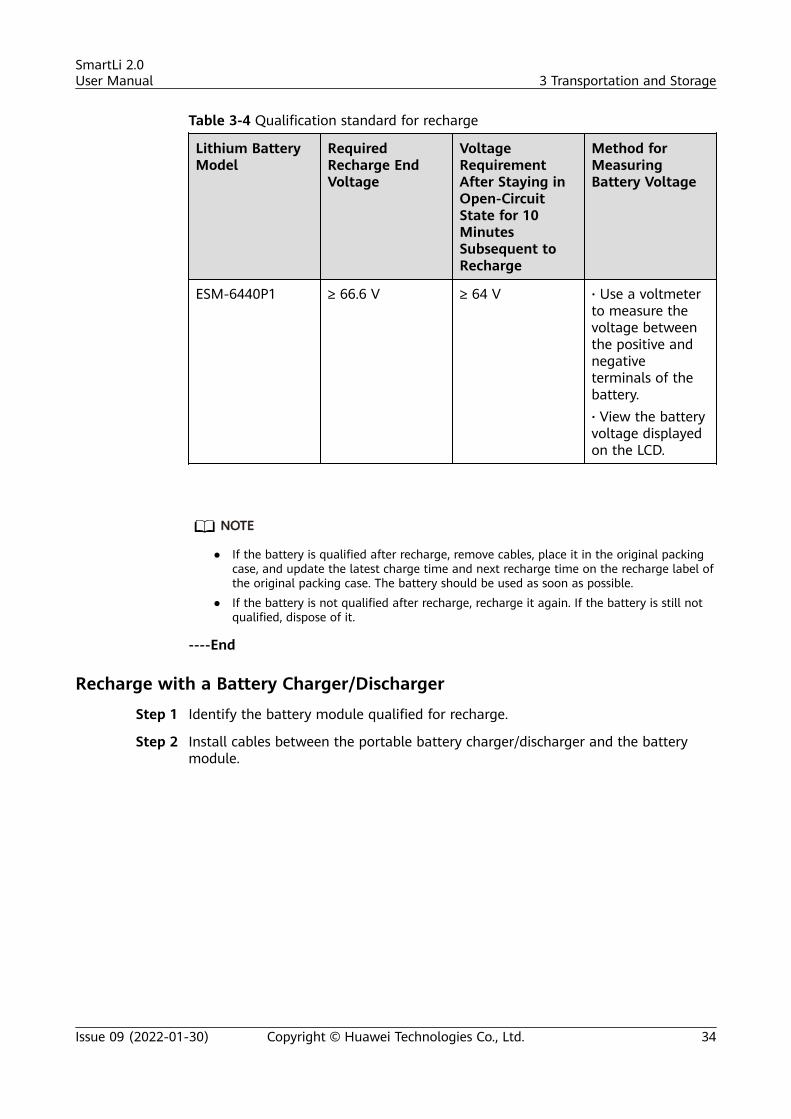
Table 3-4 Qualification standard for recharge
Lithium BatteryModel
RequiredRecharge EndVoltage
VoltageRequirementAfter Staying inOpen-CircuitState for 10MinutesSubsequent toRecharge
Method forMeasuringBattery Voltage
ESM-6440P1 ≥ 66.6 V ≥ 64 V · Use a voltmeterto measure thevoltage betweenthe positive andnegativeterminals of thebattery.· View the batteryvoltage displayedon the LCD.
NO TE
● If the battery is qualified after recharge, remove cables, place it in the original packingcase, and update the latest charge time and next recharge time on the recharge label ofthe original packing case. The battery should be used as soon as possible.
● If the battery is not qualified after recharge, recharge it again. If the battery is still notqualified, dispose of it.
----End
Recharge with a Battery Charger/Discharger
Step 1 Identify the battery module qualified for recharge.
Step 2 Install cables between the portable battery charger/discharger and the batterymodule.
SmartLi 2.0User Manual 3 Transportation and Storage
Issue 09 (2022-01-30) Copyright © Huawei Technologies Co., Ltd. 34
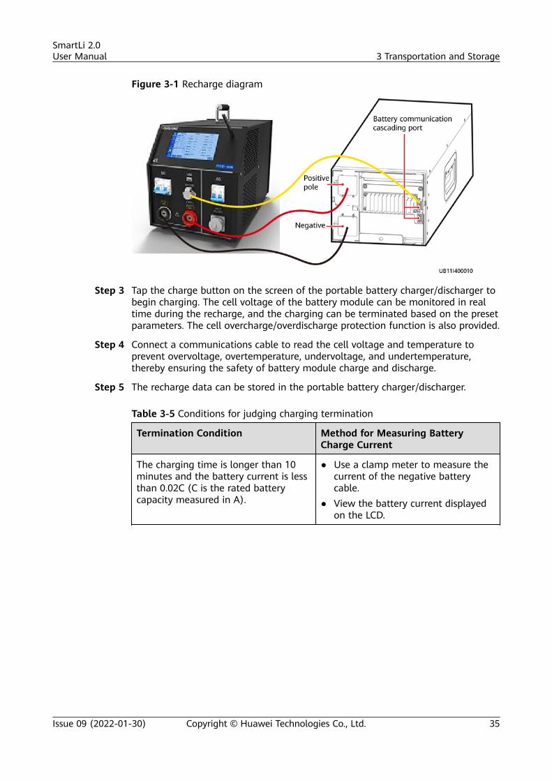
Figure 3-1 Recharge diagram
Step 3 Tap the charge button on the screen of the portable battery charger/discharger tobegin charging. The cell voltage of the battery module can be monitored in realtime during the recharge, and the charging can be terminated based on the presetparameters. The cell overcharge/overdischarge protection function is also provided.
Step 4 Connect a communications cable to read the cell voltage and temperature toprevent overvoltage, overtemperature, undervoltage, and undertemperature,thereby ensuring the safety of battery module charge and discharge.
Step 5 The recharge data can be stored in the portable battery charger/discharger.
Table 3-5 Conditions for judging charging termination
Termination Condition Method for Measuring BatteryCharge Current
The charging time is longer than 10minutes and the battery current is lessthan 0.02C (C is the rated batterycapacity measured in A).
● Use a clamp meter to measure thecurrent of the negative batterycable.
● View the battery current displayedon the LCD.
SmartLi 2.0User Manual 3 Transportation and Storage
Issue 09 (2022-01-30) Copyright © Huawei Technologies Co., Ltd. 35
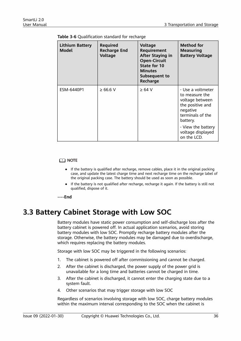
Table 3-6 Qualification standard for recharge
Lithium BatteryModel
RequiredRecharge EndVoltage
VoltageRequirementAfter Staying inOpen-CircuitState for 10MinutesSubsequent toRecharge
Method forMeasuringBattery Voltage
ESM-6440P1 ≥ 66.6 V ≥ 64 V · Use a voltmeterto measure thevoltage betweenthe positive andnegativeterminals of thebattery.· View the batteryvoltage displayedon the LCD.
NO TE
● If the battery is qualified after recharge, remove cables, place it in the original packingcase, and update the latest charge time and next recharge time on the recharge label ofthe original packing case. The battery should be used as soon as possible.
● If the battery is not qualified after recharge, recharge it again. If the battery is still notqualified, dispose of it.
----End
3.3 Battery Cabinet Storage with Low SOCBattery modules have static power consumption and self-discharge loss after thebattery cabinet is powered off. In actual application scenarios, avoid storingbattery modules with low SOC. Promptly recharge battery modules after thestorage. Otherwise, the battery modules may be damaged due to overdischarge,which requires replacing the battery modules.
Storage with low SOC may be triggered in the following scenarios:
1. The cabinet is powered off after commissioning and cannot be charged.2. After the cabinet is discharged, the power supply of the power grid is
unavailable for a long time and batteries cannot be charged in time.3. After the cabinet is discharged, it cannot enter the charging state due to a
system fault.4. Other scenarios that may trigger storage with low SOC
Regardless of scenarios involving storage with low SOC, charge battery moduleswithin the maximum interval corresponding to the SOC when the cabinet is
SmartLi 2.0User Manual 3 Transportation and Storage
Issue 09 (2022-01-30) Copyright © Huawei Technologies Co., Ltd. 36
completely powered off. If the maximum interval is exceeded, the battery modulesmay be damaged due to overdischarge.
Maximum recharge interval corresponding to the SOC upon power-off:
● SOC ≥ 20%: 30 days● 15% ≤ SOC < 20%: 25 days● 12% ≤ SOC < 15%: 20 days● 9% ≤ SOC < 12%: 15 days● 6% ≤ SOC < 9%: 10 days● 4% ≤ SOC < 6%: 5 days● SOC < 4%: charging within 2 hours
If power supply is not available to recharge battery modules in the cabinet for along time, power off the cabinet completely and recharge the battery moduleswithin the maximum interval corresponding to the SOC. Otherwise, the cells ofthe lithium battery system may be overdischarged and the battery modules maybe damaged.
SmartLi 2.0User Manual 3 Transportation and Storage
Issue 09 (2022-01-30) Copyright © Huawei Technologies Co., Ltd. 37
4 Installation
4.1 Installation Preparations
4.1.1 Site
4.1.1.1 Installation Environment
● Do not install the SmartLi in high temperature, low temperature, or dampenvironments.
● Install the SmartLi away from water sources, heat sources, and flammable orexplosive materials.
● Keep the SmartLi away from direct sunlight, dust, volatile gases, corrosivematerials, and air dense with salt particles.
● Do not install the SmartLi in environments with conductive metal scraps inthe air.
4.1.1.2 Installation Clearances
Reserve the following clearances around the cabinet to facilitate operations andventilation:
● Reserve at least 800 mm from the front of the cabinet.● Reserve at least 500 mm from the top of the cabinet.● The SmartLi can be installed against a wall and no space needs to be reserved
at the rear.
SmartLi 2.0User Manual 4 Installation
Issue 09 (2022-01-30) Copyright © Huawei Technologies Co., Ltd. 38
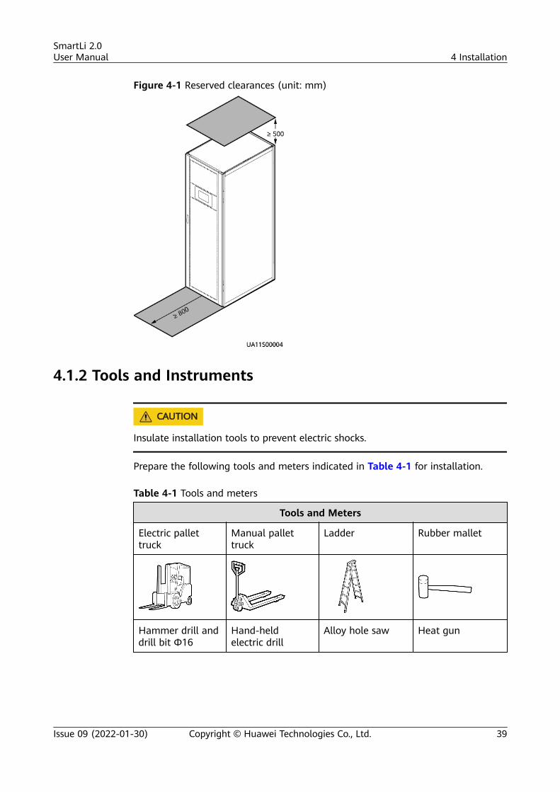
Figure 4-1 Reserved clearances (unit: mm)
4.1.2 Tools and Instruments
CA UTION
Insulate installation tools to prevent electric shocks.
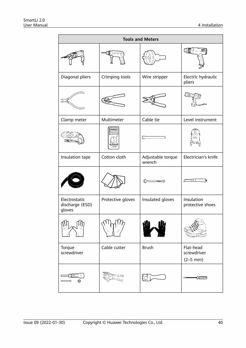
Prepare the following tools and meters indicated in Table 4-1 for installation.
Table 4-1 Tools and meters
Tools and Meters
Electric pallettruck
Manual pallettruck
Ladder Rubber mallet
Hammer drill anddrill bit Φ16
Hand-heldelectric drill
Alloy hole saw Heat gun
SmartLi 2.0User Manual 4 Installation
Issue 09 (2022-01-30) Copyright © Huawei Technologies Co., Ltd. 39
Tools and Meters
Diagonal pliers Crimping tools Wire stripper Electric hydraulicpliers
Clamp meter Multimeter Cable tie Level instrument
Insulation tape Cotton cloth Adjustable torquewrench
Electrician's knife
Electrostaticdischarge (ESD)gloves
Protective gloves Insulated gloves Insulationprotective shoes
Torquescrewdriver
Cable cutter Brush Flat-headscrewdriver(2–5 mm)
SmartLi 2.0User Manual 4 Installation
Issue 09 (2022-01-30) Copyright © Huawei Technologies Co., Ltd. 40
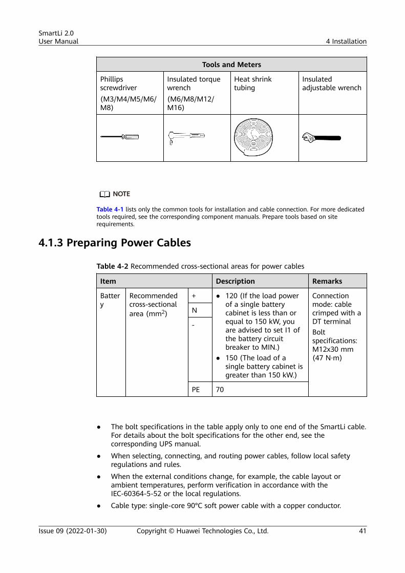
Tools and Meters
Phillipsscrewdriver(M3/M4/M5/M6/M8)
Insulated torquewrench(M6/M8/M12/M16)
Heat shrinktubing
Insulatedadjustable wrench
NO TE
Table 4-1 lists only the common tools for installation and cable connection. For more dedicatedtools required, see the corresponding component manuals. Prepare tools based on siterequirements.
4.1.3 Preparing Power Cables
Table 4-2 Recommended cross-sectional areas for power cables
Item Description Remarks
Battery
Recommendedcross-sectionalarea (mm2)
+ ● 120 (If the load powerof a single batterycabinet is less than orequal to 150 kW, youare advised to set I1 ofthe battery circuitbreaker to MIN.)
● 150 (The load of asingle battery cabinet isgreater than 150 kW.)
Connectionmode: cablecrimped with aDT terminalBoltspecifications:M12x30 mm(47 N·m)
N
-
PE 70
● The bolt specifications in the table apply only to one end of the SmartLi cable.For details about the bolt specifications for the other end, see thecorresponding UPS manual.
● When selecting, connecting, and routing power cables, follow local safetyregulations and rules.
● When the external conditions change, for example, the cable layout orambient temperatures, perform verification in accordance with theIEC-60364-5-52 or the local regulations.
● Cable type: single-core 90°C soft power cable with a copper conductor.
SmartLi 2.0User Manual 4 Installation
Issue 09 (2022-01-30) Copyright © Huawei Technologies Co., Ltd. 41

● It is recommended that the cables between the SmartLi and the UPS be 50 mor shorter. In a parallel SmartLi system, the power cables for each cabinetshould have the same length and specifications.
● If more than eight SmartLi cabinets are connected in parallel, a maximum offour 15 m parallel communications cables are supported.
4.1.4 Unpacking and Checking
Context
NO TICE
● To prevent the SmartLi from falling over, secure it to a pallet truck using ropesbefore moving it.
● To prevent shocks or falls, move the SmartLi gently. After placing the SmartLi inthe installation position, unpack it and take care to prevent scratches. Keep theSmartLi steady during unpacking.
● To prevent dust from settling on the SmartLi, leave the original plastic coat onuntil installation is required.
● Battery modules are transported separately.
Procedure
Step 1 Use a pallet truck to transport the SmartLi to the installation position.
Step 2 Remove the SmartLi outer packing and take out the fittings box.
Step 3 Check that the SmartLi is intact.
1. Visually inspect the SmartLi appearance for shipping damage. If it isdamaged, notify the carrier immediately.
2. Check that all fittings comply with the packing list. If there is any discrepancy,keep a record and contact the supplier immediately.
Step 4 After confirming that the cabinet is intact, remove the L-shaped bracket thatsecures the cabinet and the pallet, and secure the sliding plate to the pallet usingthe two M12 bolts that you have removed.
Step 5 Raise the four anchor bolts to the highest position using an adjustable wrench.
Step 6 Push the cabinet along the sliding plate to the floor.
----End
4.2 Installing a Fire Extinguisher Cylinder and Cabinets(Without a Lithium Battery Side Cabinet)
SmartLi 2.0User Manual 4 Installation
Issue 09 (2022-01-30) Copyright © Huawei Technologies Co., Ltd. 42
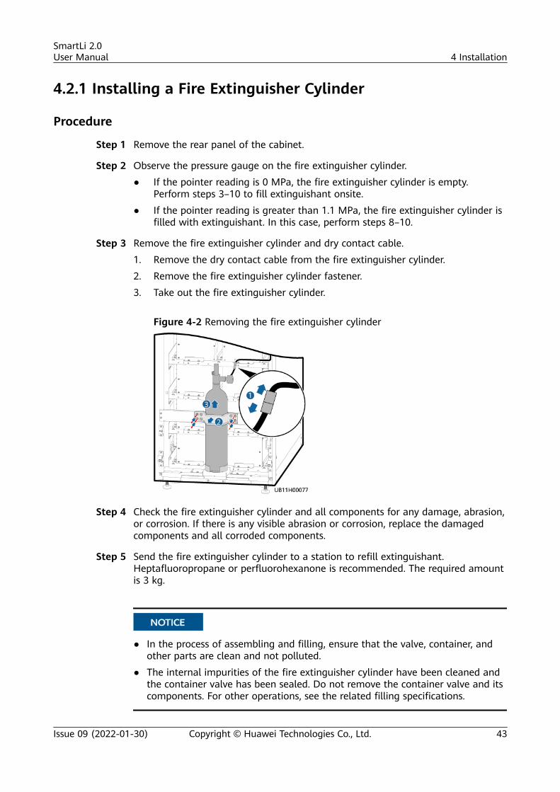
4.2.1 Installing a Fire Extinguisher Cylinder
Procedure
Step 1 Remove the rear panel of the cabinet.
Step 2 Observe the pressure gauge on the fire extinguisher cylinder.
● If the pointer reading is 0 MPa, the fire extinguisher cylinder is empty.Perform steps 3–10 to fill extinguishant onsite.
● If the pointer reading is greater than 1.1 MPa, the fire extinguisher cylinder isfilled with extinguishant. In this case, perform steps 8–10.
Step 3 Remove the fire extinguisher cylinder and dry contact cable.
1. Remove the dry contact cable from the fire extinguisher cylinder.
2. Remove the fire extinguisher cylinder fastener.
3. Take out the fire extinguisher cylinder.
Figure 4-2 Removing the fire extinguisher cylinder
Step 4 Check the fire extinguisher cylinder and all components for any damage, abrasion,or corrosion. If there is any visible abrasion or corrosion, replace the damagedcomponents and all corroded components.
Step 5 Send the fire extinguisher cylinder to a station to refill extinguishant.Heptafluoropropane or perfluorohexanone is recommended. The required amountis 3 kg.
NO TICE
● In the process of assembling and filling, ensure that the valve, container, andother parts are clean and not polluted.
● The internal impurities of the fire extinguisher cylinder have been cleaned andthe container valve has been sealed. Do not remove the container valve and itscomponents. For other operations, see the related filling specifications.
SmartLi 2.0User Manual 4 Installation
Issue 09 (2022-01-30) Copyright © Huawei Technologies Co., Ltd. 43
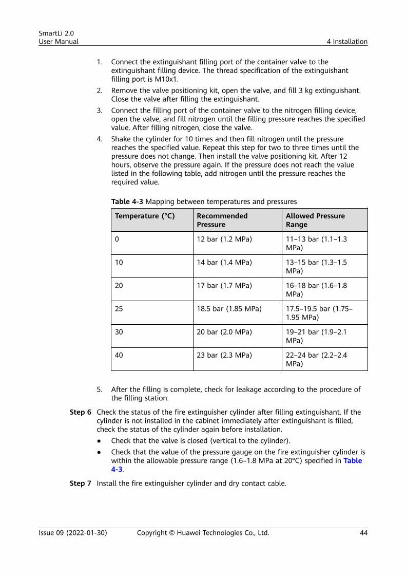
1. Connect the extinguishant filling port of the container valve to theextinguishant filling device. The thread specification of the extinguishantfilling port is M10x1.
2. Remove the valve positioning kit, open the valve, and fill 3 kg extinguishant.Close the valve after filling the extinguishant.
3. Connect the filling port of the container valve to the nitrogen filling device,open the valve, and fill nitrogen until the filling pressure reaches the specifiedvalue. After filling nitrogen, close the valve.
4. Shake the cylinder for 10 times and then fill nitrogen until the pressurereaches the specified value. Repeat this step for two to three times until thepressure does not change. Then install the valve positioning kit. After 12hours, observe the pressure again. If the pressure does not reach the valuelisted in the following table, add nitrogen until the pressure reaches therequired value.
Table 4-3 Mapping between temperatures and pressures
Temperature (°C) RecommendedPressure
Allowed PressureRange
0 12 bar (1.2 MPa) 11–13 bar (1.1–1.3MPa)
10 14 bar (1.4 MPa) 13–15 bar (1.3–1.5MPa)
20 17 bar (1.7 MPa) 16–18 bar (1.6–1.8MPa)
25 18.5 bar (1.85 MPa) 17.5–19.5 bar (1.75–1.95 MPa)
30 20 bar (2.0 MPa) 19–21 bar (1.9–2.1MPa)
40 23 bar (2.3 MPa) 22–24 bar (2.2–2.4MPa)
5. After the filling is complete, check for leakage according to the procedure of
the filling station.
Step 6 Check the status of the fire extinguisher cylinder after filling extinguishant. If thecylinder is not installed in the cabinet immediately after extinguishant is filled,check the status of the cylinder again before installation.● Check that the valve is closed (vertical to the cylinder).● Check that the value of the pressure gauge on the fire extinguisher cylinder is
within the allowable pressure range (1.6–1.8 MPa at 20°C) specified in Table4-3.
Step 7 Install the fire extinguisher cylinder and dry contact cable.
SmartLi 2.0User Manual 4 Installation
Issue 09 (2022-01-30) Copyright © Huawei Technologies Co., Ltd. 44
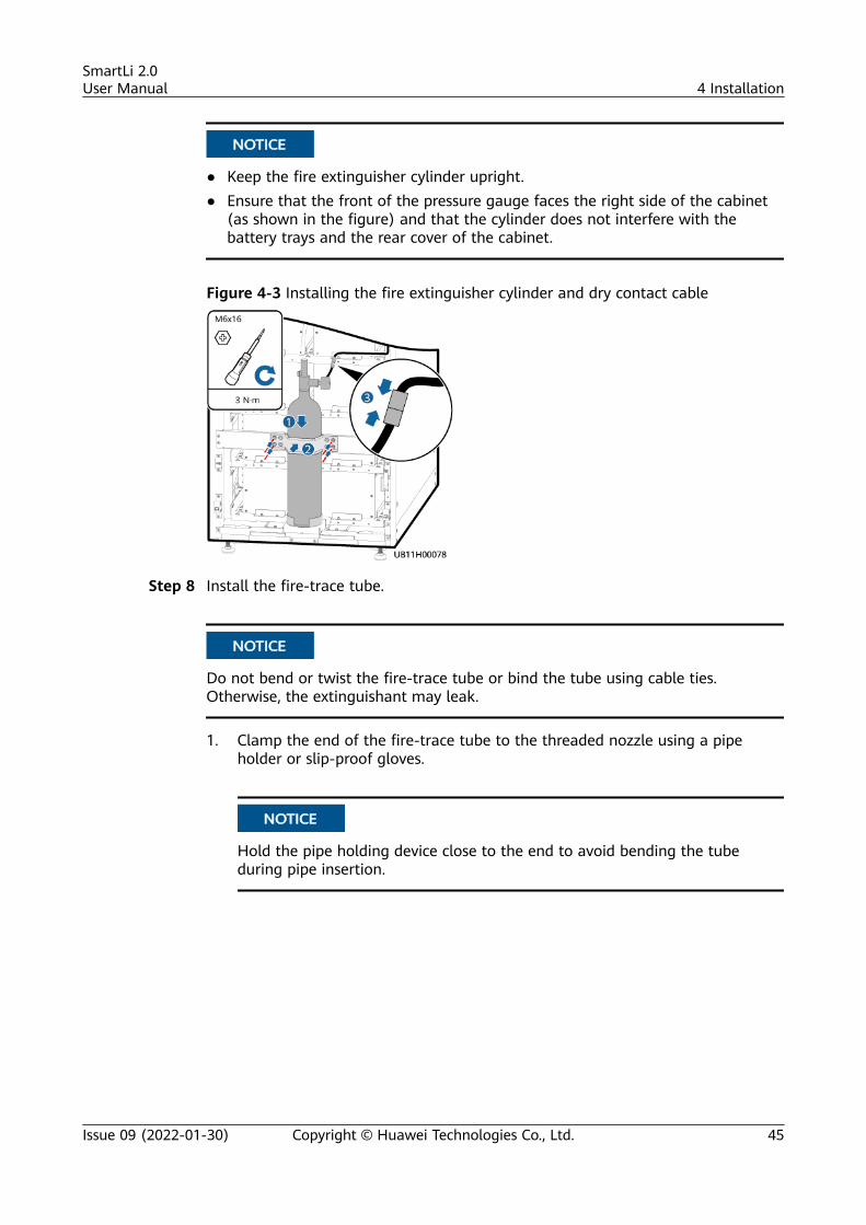
NO TICE
● Keep the fire extinguisher cylinder upright.● Ensure that the front of the pressure gauge faces the right side of the cabinet
(as shown in the figure) and that the cylinder does not interfere with thebattery trays and the rear cover of the cabinet.
Figure 4-3 Installing the fire extinguisher cylinder and dry contact cable
Step 8 Install the fire-trace tube.
NO TICE
Do not bend or twist the fire-trace tube or bind the tube using cable ties.Otherwise, the extinguishant may leak.
1. Clamp the end of the fire-trace tube to the threaded nozzle using a pipeholder or slip-proof gloves.
NO TICE
Hold the pipe holding device close to the end to avoid bending the tubeduring pipe insertion.
SmartLi 2.0User Manual 4 Installation
Issue 09 (2022-01-30) Copyright © Huawei Technologies Co., Ltd. 45
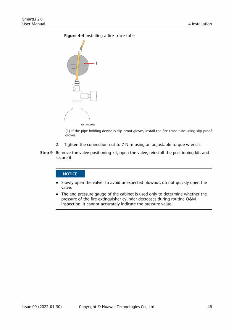
Figure 4-4 Installing a fire-trace tube
(1) If the pipe holding device is slip-proof gloves, install the fire-trace tube using slip-proofgloves.
2. Tighten the connection nut to 7 N·m using an adjustable torque wrench.
Step 9 Remove the valve positioning kit, open the valve, reinstall the positioning kit, andsecure it.
NO TICE
● Slowly open the valve. To avoid unexpected blowout, do not quickly open thevalve.
● The end pressure gauge of the cabinet is used only to determine whether thepressure of the fire extinguisher cylinder decreases during routine O&Minspection. It cannot accurately indicate the pressure value.
SmartLi 2.0User Manual 4 Installation
Issue 09 (2022-01-30) Copyright © Huawei Technologies Co., Ltd. 46
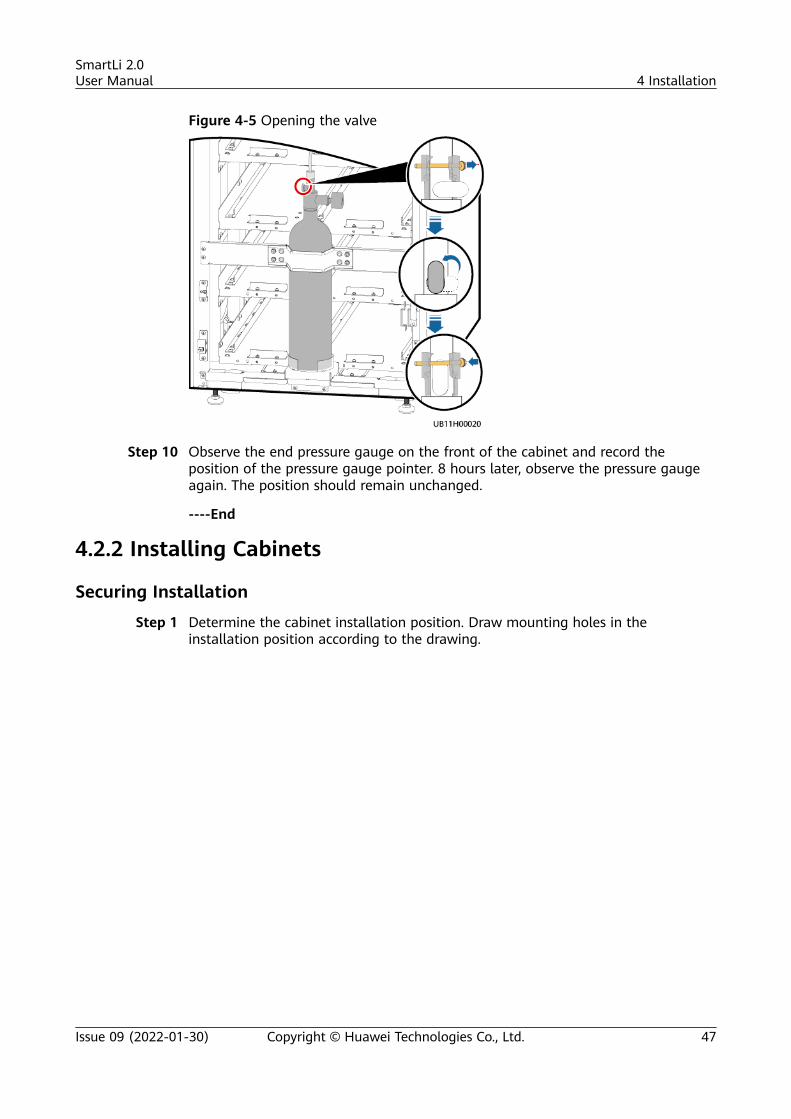
Figure 4-5 Opening the valve
Step 10 Observe the end pressure gauge on the front of the cabinet and record theposition of the pressure gauge pointer. 8 hours later, observe the pressure gaugeagain. The position should remain unchanged.
----End
4.2.2 Installing Cabinets
Securing Installation
Step 1 Determine the cabinet installation position. Draw mounting holes in theinstallation position according to the drawing.
SmartLi 2.0User Manual 4 Installation
Issue 09 (2022-01-30) Copyright © Huawei Technologies Co., Ltd. 47
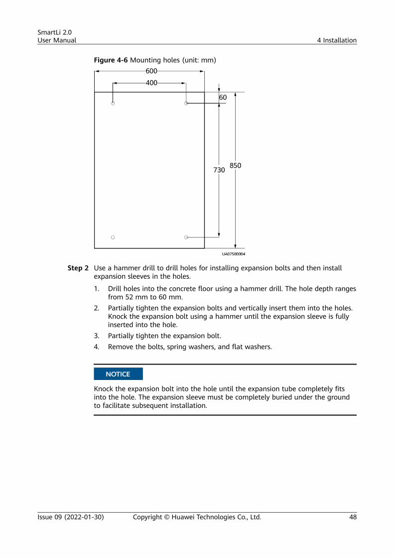
Figure 4-6 Mounting holes (unit: mm)
Step 2 Use a hammer drill to drill holes for installing expansion bolts and then installexpansion sleeves in the holes.
1. Drill holes into the concrete floor using a hammer drill. The hole depth rangesfrom 52 mm to 60 mm.
2. Partially tighten the expansion bolts and vertically insert them into the holes.Knock the expansion bolt using a hammer until the expansion sleeve is fullyinserted into the hole.
3. Partially tighten the expansion bolt.4. Remove the bolts, spring washers, and flat washers.
NO TICE
Knock the expansion bolt into the hole until the expansion tube completely fitsinto the hole. The expansion sleeve must be completely buried under the groundto facilitate subsequent installation.
SmartLi 2.0User Manual 4 Installation
Issue 09 (2022-01-30) Copyright © Huawei Technologies Co., Ltd. 48
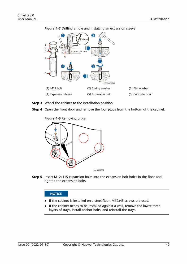
Figure 4-7 Drilling a hole and installing an expansion sleeve
(1) M12 bolt (2) Spring washer (3) Flat washer
(4) Expansion sleeve (5) Expansion nut (6) Concrete floor
Step 3 Wheel the cabinet to the installation position.
Step 4 Open the front door and remove the four plugs from the bottom of the cabinet.
Figure 4-8 Removing plugs
Step 5 Insert M12x115 expansion bolts into the expansion bolt holes in the floor andtighten the expansion bolts.
NO TICE
● If the cabinet is installed on a steel floor, M12x45 screws are used.● If the cabinet needs to be installed against a wall, remove the lower three
layers of trays, install anchor bolts, and reinstall the trays.
SmartLi 2.0User Manual 4 Installation
Issue 09 (2022-01-30) Copyright © Huawei Technologies Co., Ltd. 49
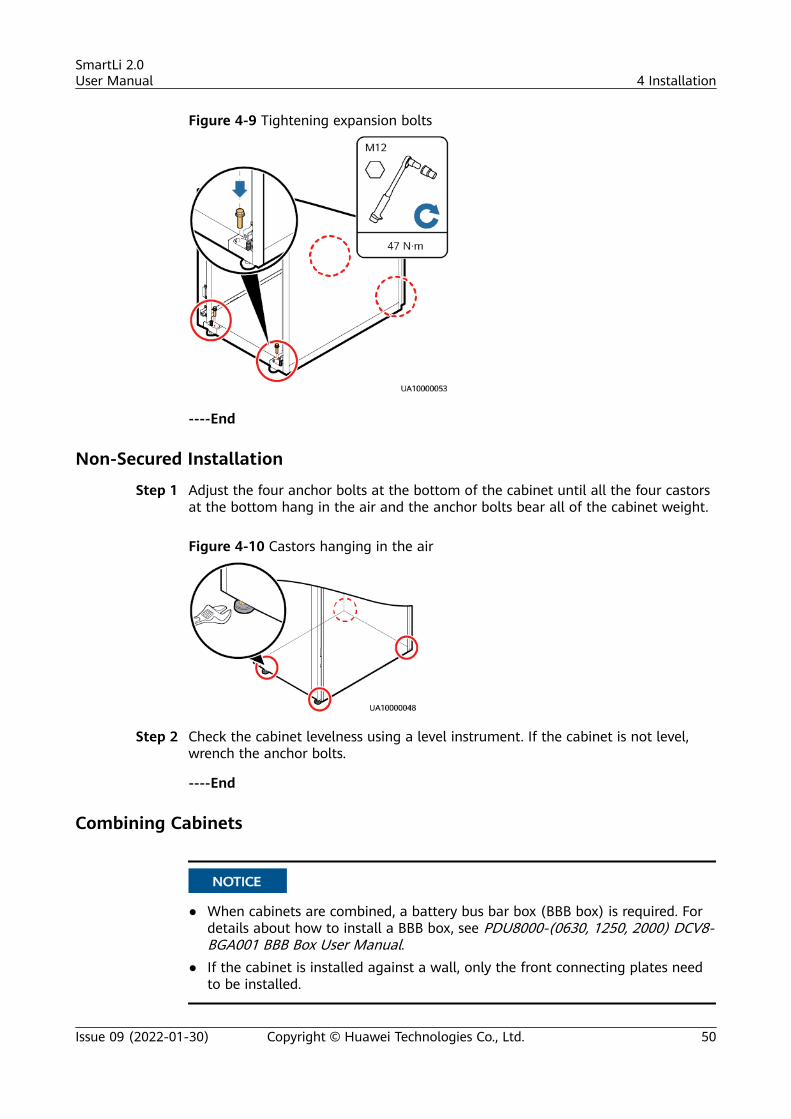
Figure 4-9 Tightening expansion bolts
----End
Non-Secured Installation
Step 1 Adjust the four anchor bolts at the bottom of the cabinet until all the four castorsat the bottom hang in the air and the anchor bolts bear all of the cabinet weight.
Figure 4-10 Castors hanging in the air
Step 2 Check the cabinet levelness using a level instrument. If the cabinet is not level,wrench the anchor bolts.
----End
Combining Cabinets
NO TICE
● When cabinets are combined, a battery bus bar box (BBB box) is required. Fordetails about how to install a BBB box, see PDU8000-(0630, 1250, 2000) DCV8-BGA001 BBB Box User Manual.
● If the cabinet is installed against a wall, only the front connecting plates needto be installed.
SmartLi 2.0User Manual 4 Installation
Issue 09 (2022-01-30) Copyright © Huawei Technologies Co., Ltd. 50
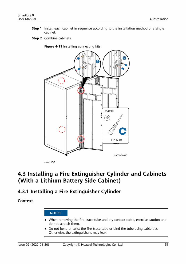
Step 1 Install each cabinet in sequence according to the installation method of a singlecabinet.
Step 2 Combine cabinets.
Figure 4-11 Installing connecting kits
----End
4.3 Installing a Fire Extinguisher Cylinder and Cabinets(With a Lithium Battery Side Cabinet)
4.3.1 Installing a Fire Extinguisher Cylinder
Context
NO TICE
● When removing the fire-trace tube and dry contact cable, exercise caution anddo not scratch them.
● Do not bend or twist the fire-trace tube or bind the tube using cable ties.Otherwise, the extinguishant may leak.
SmartLi 2.0User Manual 4 Installation
Issue 09 (2022-01-30) Copyright © Huawei Technologies Co., Ltd. 51
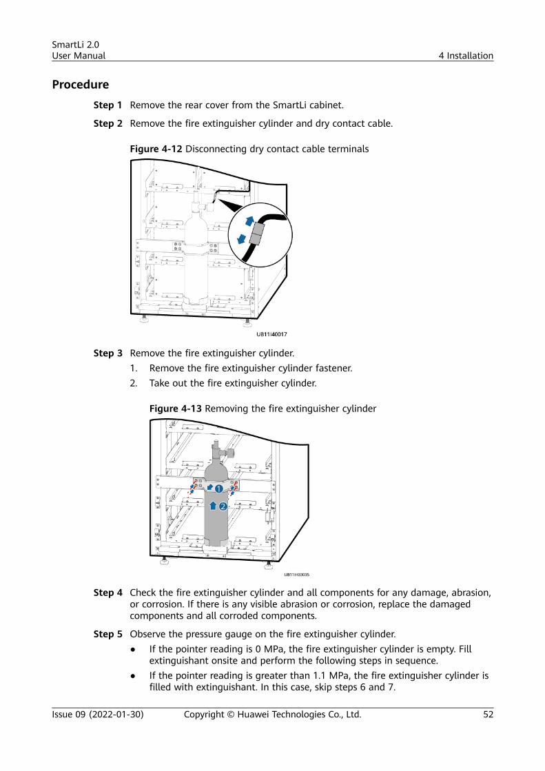
Procedure
Step 1 Remove the rear cover from the SmartLi cabinet.
Step 2 Remove the fire extinguisher cylinder and dry contact cable.
Figure 4-12 Disconnecting dry contact cable terminals
Step 3 Remove the fire extinguisher cylinder.1. Remove the fire extinguisher cylinder fastener.2. Take out the fire extinguisher cylinder.
Figure 4-13 Removing the fire extinguisher cylinder
Step 4 Check the fire extinguisher cylinder and all components for any damage, abrasion,or corrosion. If there is any visible abrasion or corrosion, replace the damagedcomponents and all corroded components.
Step 5 Observe the pressure gauge on the fire extinguisher cylinder.● If the pointer reading is 0 MPa, the fire extinguisher cylinder is empty. Fill
extinguishant onsite and perform the following steps in sequence.● If the pointer reading is greater than 1.1 MPa, the fire extinguisher cylinder is
filled with extinguishant. In this case, skip steps 6 and 7.
SmartLi 2.0User Manual 4 Installation
Issue 09 (2022-01-30) Copyright © Huawei Technologies Co., Ltd. 52
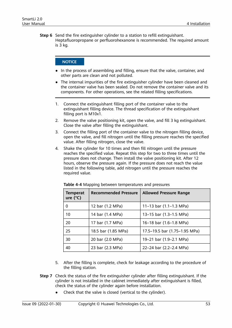
Step 6 Send the fire extinguisher cylinder to a station to refill extinguishant.Heptafluoropropane or perfluorohexanone is recommended. The required amountis 3 kg.
NO TICE
● In the process of assembling and filling, ensure that the valve, container, andother parts are clean and not polluted.
● The internal impurities of the fire extinguisher cylinder have been cleaned andthe container valve has been sealed. Do not remove the container valve and itscomponents. For other operations, see the related filling specifications.
1. Connect the extinguishant filling port of the container valve to theextinguishant filling device. The thread specification of the extinguishantfilling port is M10x1.
2. Remove the valve positioning kit, open the valve, and fill 3 kg extinguishant.Close the valve after filling the extinguishant.
3. Connect the filling port of the container valve to the nitrogen filling device,open the valve, and fill nitrogen until the filling pressure reaches the specifiedvalue. After filling nitrogen, close the valve.
4. Shake the cylinder for 10 times and then fill nitrogen until the pressurereaches the specified value. Repeat this step for two to three times until thepressure does not change. Then install the valve positioning kit. After 12hours, observe the pressure again. If the pressure does not reach the valuelisted in the following table, add nitrogen until the pressure reaches therequired value.
Table 4-4 Mapping between temperatures and pressures
Temperature (°C)
Recommended Pressure Allowed Pressure Range
0 12 bar (1.2 MPa) 11–13 bar (1.1–1.3 MPa)
10 14 bar (1.4 MPa) 13–15 bar (1.3–1.5 MPa)
20 17 bar (1.7 MPa) 16–18 bar (1.6–1.8 MPa)
25 18.5 bar (1.85 MPa) 17.5–19.5 bar (1.75–1.95 MPa)
30 20 bar (2.0 MPa) 19–21 bar (1.9–2.1 MPa)
40 23 bar (2.3 MPa) 22–24 bar (2.2–2.4 MPa)
5. After the filling is complete, check for leakage according to the procedure of
the filling station.
Step 7 Check the status of the fire extinguisher cylinder after filling extinguishant. If thecylinder is not installed in the cabinet immediately after extinguishant is filled,check the status of the cylinder again before installation.● Check that the valve is closed (vertical to the cylinder).
SmartLi 2.0User Manual 4 Installation
Issue 09 (2022-01-30) Copyright © Huawei Technologies Co., Ltd. 53
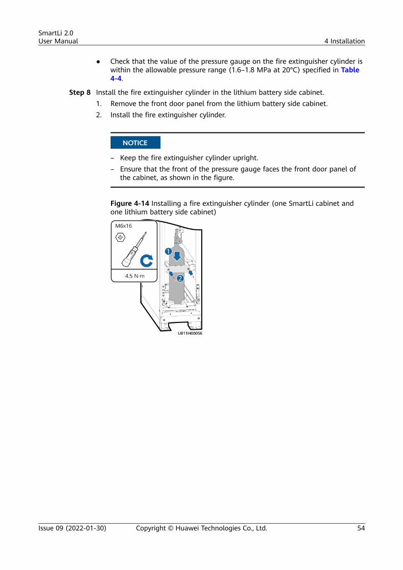
● Check that the value of the pressure gauge on the fire extinguisher cylinder iswithin the allowable pressure range (1.6–1.8 MPa at 20°C) specified in Table4-4.
Step 8 Install the fire extinguisher cylinder in the lithium battery side cabinet.1. Remove the front door panel from the lithium battery side cabinet.2. Install the fire extinguisher cylinder.
NO TICE
– Keep the fire extinguisher cylinder upright.– Ensure that the front of the pressure gauge faces the front door panel of
the cabinet, as shown in the figure.
Figure 4-14 Installing a fire extinguisher cylinder (one SmartLi cabinet andone lithium battery side cabinet)
SmartLi 2.0User Manual 4 Installation
Issue 09 (2022-01-30) Copyright © Huawei Technologies Co., Ltd. 54
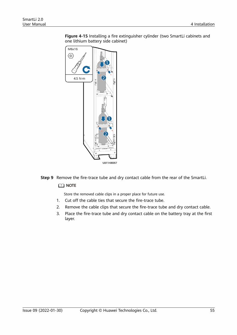
Figure 4-15 Installing a fire extinguisher cylinder (two SmartLi cabinets andone lithium battery side cabinet)
Step 9 Remove the fire-trace tube and dry contact cable from the rear of the SmartLi.
NO TE
Store the removed cable clips in a proper place for future use.
1. Cut off the cable ties that secure the fire-trace tube.2. Remove the cable clips that secure the fire-trace tube and dry contact cable.3. Place the fire-trace tube and dry contact cable on the battery tray at the first
layer.
SmartLi 2.0User Manual 4 Installation
Issue 09 (2022-01-30) Copyright © Huawei Technologies Co., Ltd. 55
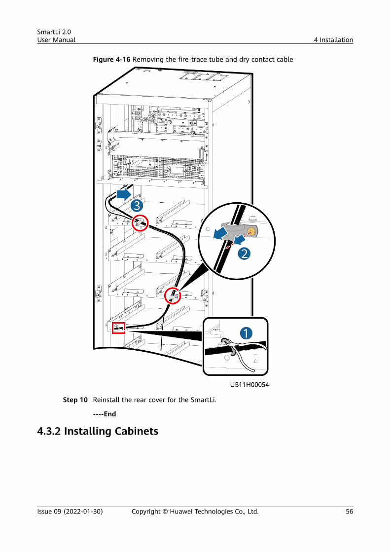
Figure 4-16 Removing the fire-trace tube and dry contact cable
Step 10 Reinstall the rear cover for the SmartLi.
----End
4.3.2 Installing Cabinets
SmartLi 2.0User Manual 4 Installation
Issue 09 (2022-01-30) Copyright © Huawei Technologies Co., Ltd. 56
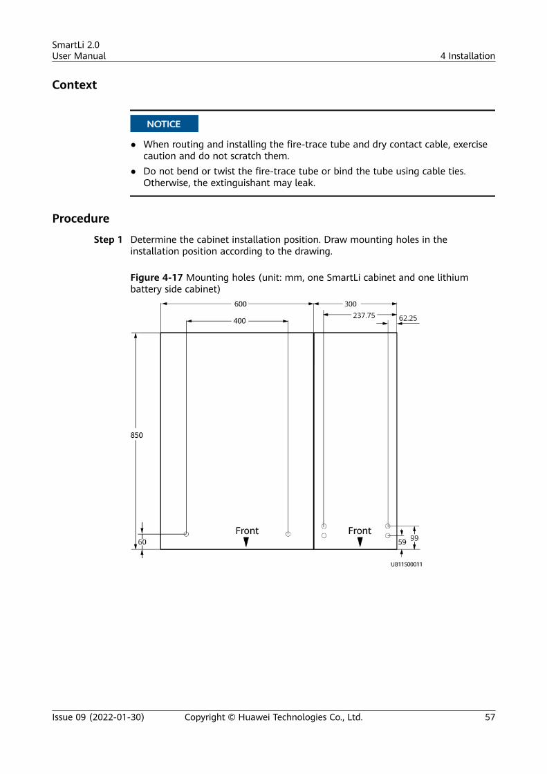
Context
NO TICE
● When routing and installing the fire-trace tube and dry contact cable, exercisecaution and do not scratch them.
● Do not bend or twist the fire-trace tube or bind the tube using cable ties.Otherwise, the extinguishant may leak.
Procedure
Step 1 Determine the cabinet installation position. Draw mounting holes in theinstallation position according to the drawing.
Figure 4-17 Mounting holes (unit: mm, one SmartLi cabinet and one lithiumbattery side cabinet)
SmartLi 2.0User Manual 4 Installation
Issue 09 (2022-01-30) Copyright © Huawei Technologies Co., Ltd. 57
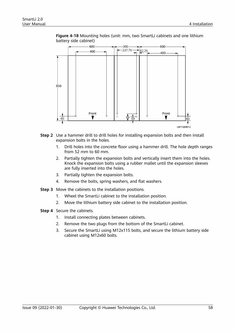
Figure 4-18 Mounting holes (unit: mm, two SmartLi cabinets and one lithiumbattery side cabinet)
Step 2 Use a hammer drill to drill holes for installing expansion bolts and then installexpansion bolts in the holes.1. Drill holes into the concrete floor using a hammer drill. The hole depth ranges
from 52 mm to 60 mm.2. Partially tighten the expansion bolts and vertically insert them into the holes.
Knock the expansion bolts using a rubber mallet until the expansion sleevesare fully inserted into the holes.
3. Partially tighten the expansion bolts.4. Remove the bolts, spring washers, and flat washers.
Step 3 Move the cabinets to the installation positions.1. Wheel the SmartLi cabinet to the installation position.2. Move the lithium battery side cabinet to the installation position.
Step 4 Secure the cabinets.1. Install connecting plates between cabinets.2. Remove the two plugs from the bottom of the SmartLi cabinet.3. Secure the SmartLi using M12x115 bolts, and secure the lithium battery side
cabinet using M12x60 bolts.
SmartLi 2.0User Manual 4 Installation
Issue 09 (2022-01-30) Copyright © Huawei Technologies Co., Ltd. 58
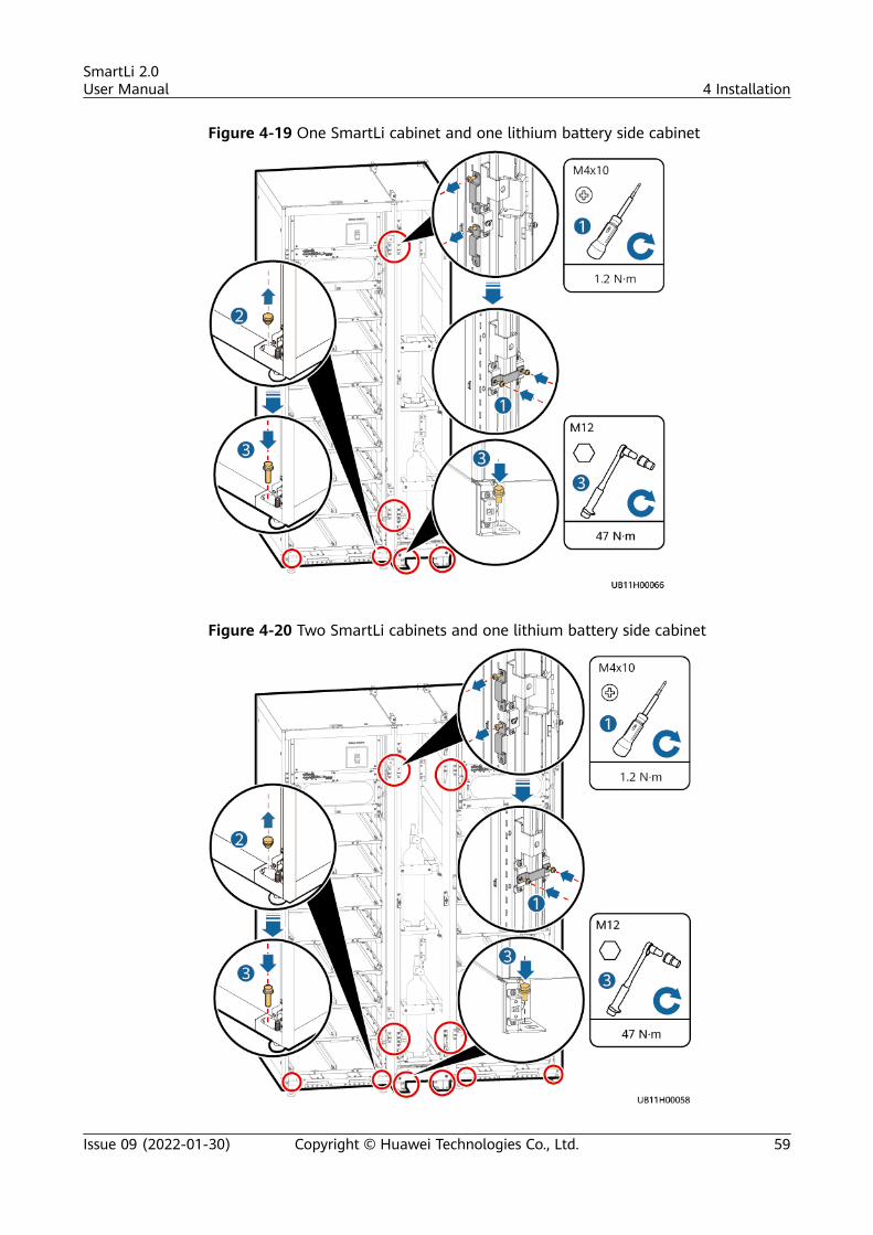
Figure 4-19 One SmartLi cabinet and one lithium battery side cabinet
Figure 4-20 Two SmartLi cabinets and one lithium battery side cabinet
SmartLi 2.0User Manual 4 Installation
Issue 09 (2022-01-30) Copyright © Huawei Technologies Co., Ltd. 59
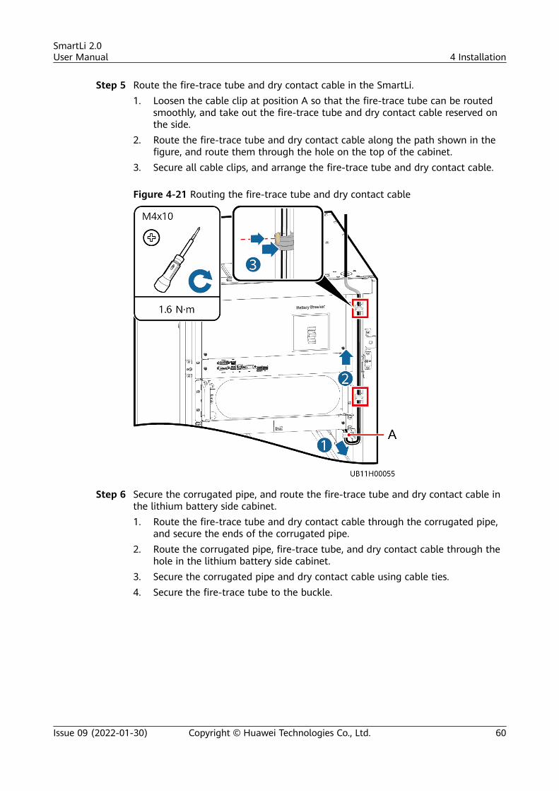
Step 5 Route the fire-trace tube and dry contact cable in the SmartLi.1. Loosen the cable clip at position A so that the fire-trace tube can be routed
smoothly, and take out the fire-trace tube and dry contact cable reserved onthe side.
2. Route the fire-trace tube and dry contact cable along the path shown in thefigure, and route them through the hole on the top of the cabinet.
3. Secure all cable clips, and arrange the fire-trace tube and dry contact cable.
Figure 4-21 Routing the fire-trace tube and dry contact cable
Step 6 Secure the corrugated pipe, and route the fire-trace tube and dry contact cable inthe lithium battery side cabinet.1. Route the fire-trace tube and dry contact cable through the corrugated pipe,
and secure the ends of the corrugated pipe.2. Route the corrugated pipe, fire-trace tube, and dry contact cable through the
hole in the lithium battery side cabinet.3. Secure the corrugated pipe and dry contact cable using cable ties.4. Secure the fire-trace tube to the buckle.
SmartLi 2.0User Manual 4 Installation
Issue 09 (2022-01-30) Copyright © Huawei Technologies Co., Ltd. 60

Figure 4-22 Securing the corrugated pipe and routing the fire-trace tube and drycontact cable (one SmartLi cabinet and one lithium battery side cabinet)
Figure 4-23 Securing the corrugated pipes and routing the fire-trace tubes anddry contact cables (two SmartLi cabinets and one lithium battery side cabinet)
Step 7 Install the fire-trace tube.
SmartLi 2.0User Manual 4 Installation
Issue 09 (2022-01-30) Copyright © Huawei Technologies Co., Ltd. 61
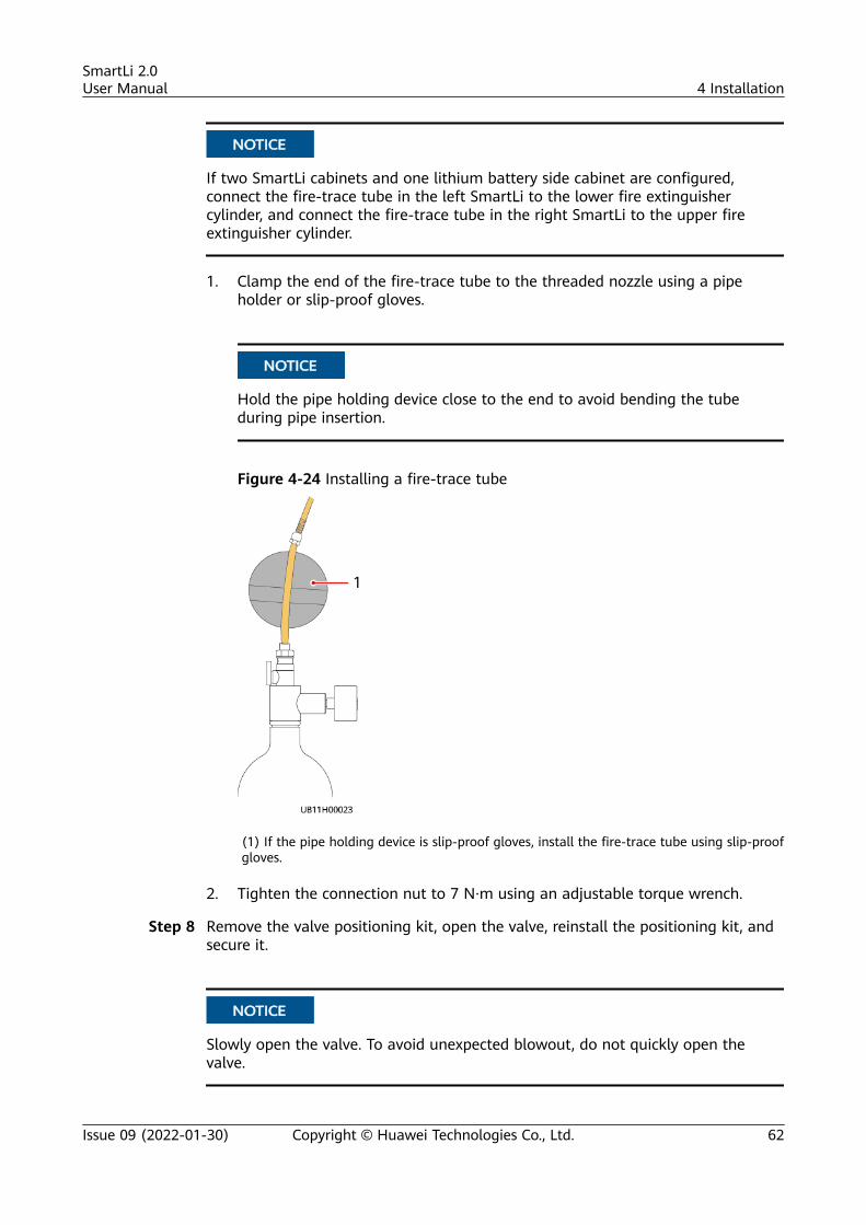
NO TICE
If two SmartLi cabinets and one lithium battery side cabinet are configured,connect the fire-trace tube in the left SmartLi to the lower fire extinguishercylinder, and connect the fire-trace tube in the right SmartLi to the upper fireextinguisher cylinder.
1. Clamp the end of the fire-trace tube to the threaded nozzle using a pipeholder or slip-proof gloves.
NO TICE
Hold the pipe holding device close to the end to avoid bending the tubeduring pipe insertion.
Figure 4-24 Installing a fire-trace tube
(1) If the pipe holding device is slip-proof gloves, install the fire-trace tube using slip-proofgloves.
2. Tighten the connection nut to 7 N·m using an adjustable torque wrench.
Step 8 Remove the valve positioning kit, open the valve, reinstall the positioning kit, andsecure it.
NO TICE
Slowly open the valve. To avoid unexpected blowout, do not quickly open thevalve.
SmartLi 2.0User Manual 4 Installation
Issue 09 (2022-01-30) Copyright © Huawei Technologies Co., Ltd. 62
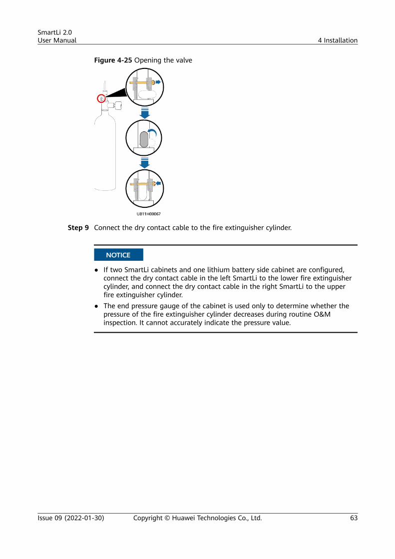
Figure 4-25 Opening the valve
Step 9 Connect the dry contact cable to the fire extinguisher cylinder.
NO TICE
● If two SmartLi cabinets and one lithium battery side cabinet are configured,connect the dry contact cable in the left SmartLi to the lower fire extinguishercylinder, and connect the dry contact cable in the right SmartLi to the upperfire extinguisher cylinder.
● The end pressure gauge of the cabinet is used only to determine whether thepressure of the fire extinguisher cylinder decreases during routine O&Minspection. It cannot accurately indicate the pressure value.
SmartLi 2.0User Manual 4 Installation
Issue 09 (2022-01-30) Copyright © Huawei Technologies Co., Ltd. 63
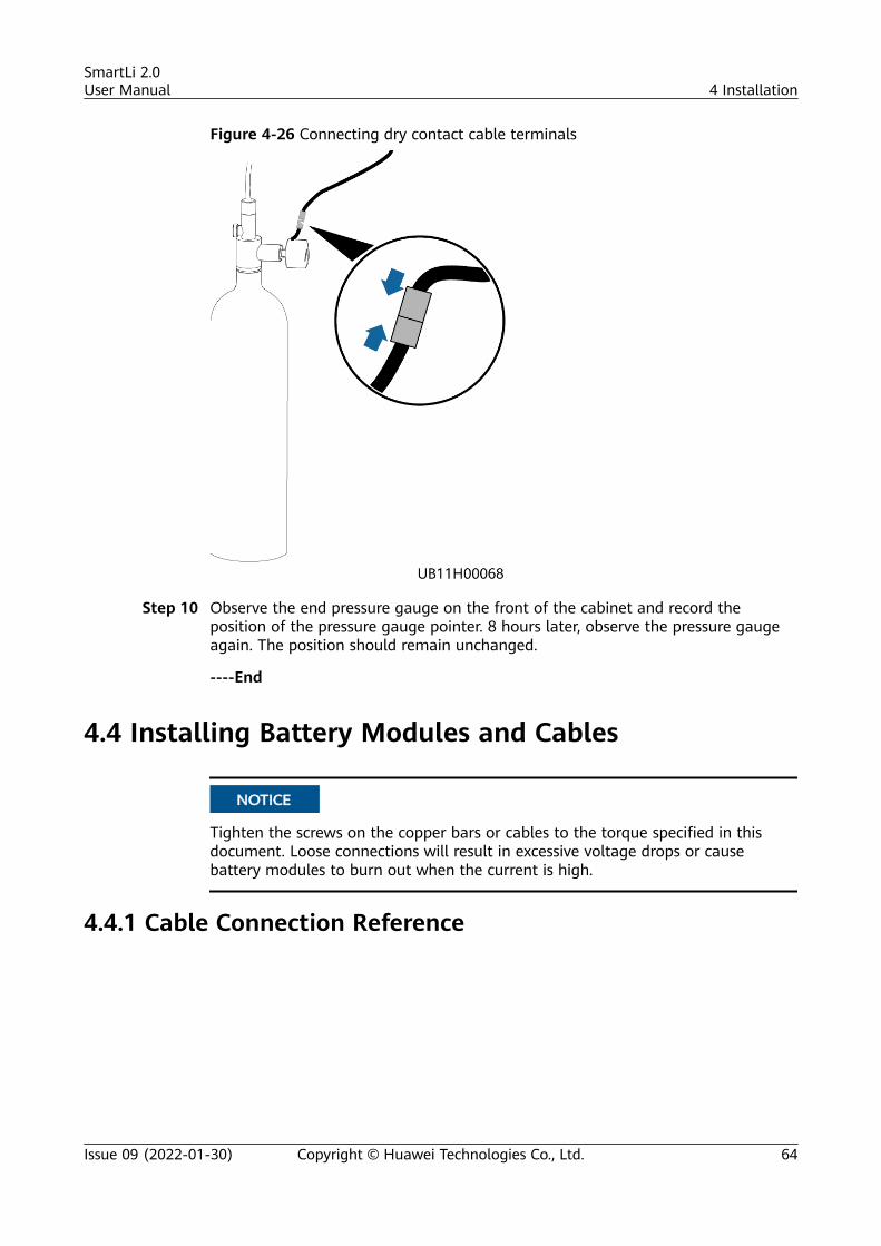
Figure 4-26 Connecting dry contact cable terminals
Step 10 Observe the end pressure gauge on the front of the cabinet and record theposition of the pressure gauge pointer. 8 hours later, observe the pressure gaugeagain. The position should remain unchanged.
----End
4.4 Installing Battery Modules and Cables
NO TICE
Tighten the screws on the copper bars or cables to the torque specified in thisdocument. Loose connections will result in excessive voltage drops or causebattery modules to burn out when the current is high.
4.4.1 Cable Connection Reference
SmartLi 2.0User Manual 4 Installation
Issue 09 (2022-01-30) Copyright © Huawei Technologies Co., Ltd. 64
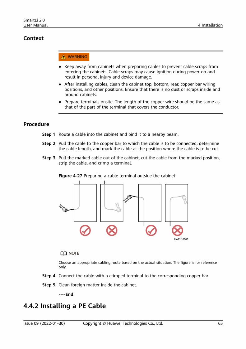
Context
WARNING
● Keep away from cabinets when preparing cables to prevent cable scraps fromentering the cabinets. Cable scraps may cause ignition during power-on andresult in personal injury and device damage.
● After installing cables, clean the cabinet top, bottom, rear, copper bar wiringpositions, and other positions. Ensure that there is no dust or scraps inside andaround cabinets.
● Prepare terminals onsite. The length of the copper wire should be the same asthat of the part of the terminal that covers the conductor.
Procedure
Step 1 Route a cable into the cabinet and bind it to a nearby beam.
Step 2 Pull the cable to the copper bar to which the cable is to be connected, determinethe cable length, and mark the cable at the position where the cable is to be cut.
Step 3 Pull the marked cable out of the cabinet, cut the cable from the marked position,strip the cable, and crimp a terminal.
Figure 4-27 Preparing a cable terminal outside the cabinet
NO TE
Choose an appropriate cabling route based on the actual situation. The figure is for referenceonly.
Step 4 Connect the cable with a crimped terminal to the corresponding copper bar.
Step 5 Clean foreign matter inside the cabinet.
----End
4.4.2 Installing a PE Cable
SmartLi 2.0User Manual 4 Installation
Issue 09 (2022-01-30) Copyright © Huawei Technologies Co., Ltd. 65
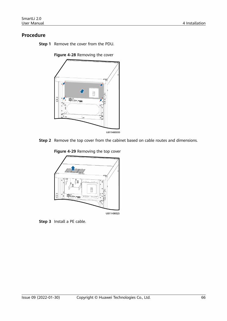
Procedure
Step 1 Remove the cover from the PDU.
Figure 4-28 Removing the cover
Step 2 Remove the top cover from the cabinet based on cable routes and dimensions.
Figure 4-29 Removing the top cover
Step 3 Install a PE cable.
SmartLi 2.0User Manual 4 Installation
Issue 09 (2022-01-30) Copyright © Huawei Technologies Co., Ltd. 66
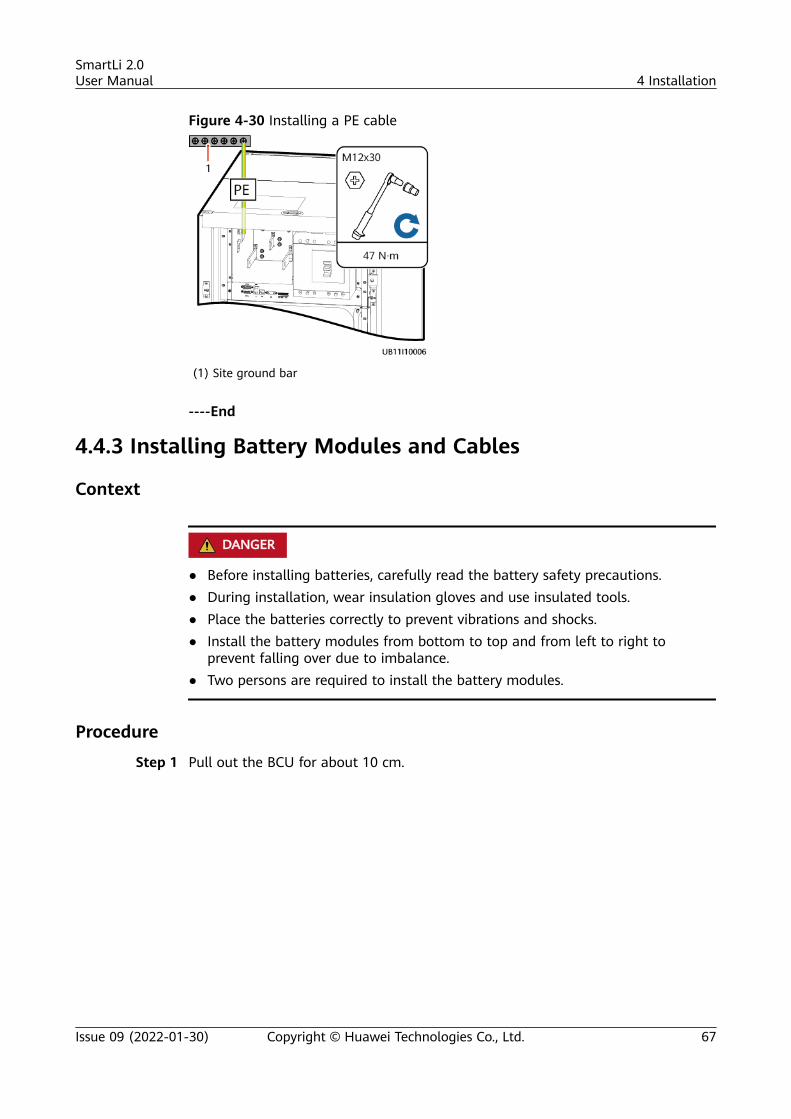
Figure 4-30 Installing a PE cable
(1) Site ground bar
----End
4.4.3 Installing Battery Modules and Cables
Context
D ANGER
● Before installing batteries, carefully read the battery safety precautions.● During installation, wear insulation gloves and use insulated tools.● Place the batteries correctly to prevent vibrations and shocks.● Install the battery modules from bottom to top and from left to right to
prevent falling over due to imbalance.● Two persons are required to install the battery modules.
Procedure
Step 1 Pull out the BCU for about 10 cm.
SmartLi 2.0User Manual 4 Installation
Issue 09 (2022-01-30) Copyright © Huawei Technologies Co., Ltd. 67
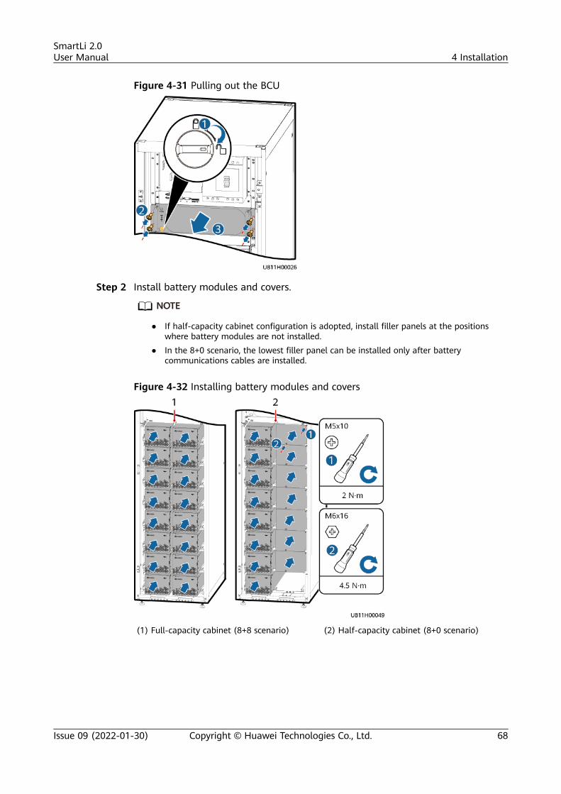
Figure 4-31 Pulling out the BCU
Step 2 Install battery modules and covers.
NO TE
● If half-capacity cabinet configuration is adopted, install filler panels at the positionswhere battery modules are not installed.
● In the 8+0 scenario, the lowest filler panel can be installed only after batterycommunications cables are installed.
Figure 4-32 Installing battery modules and covers
(1) Full-capacity cabinet (8+8 scenario) (2) Half-capacity cabinet (8+0 scenario)
SmartLi 2.0User Manual 4 Installation
Issue 09 (2022-01-30) Copyright © Huawei Technologies Co., Ltd. 68
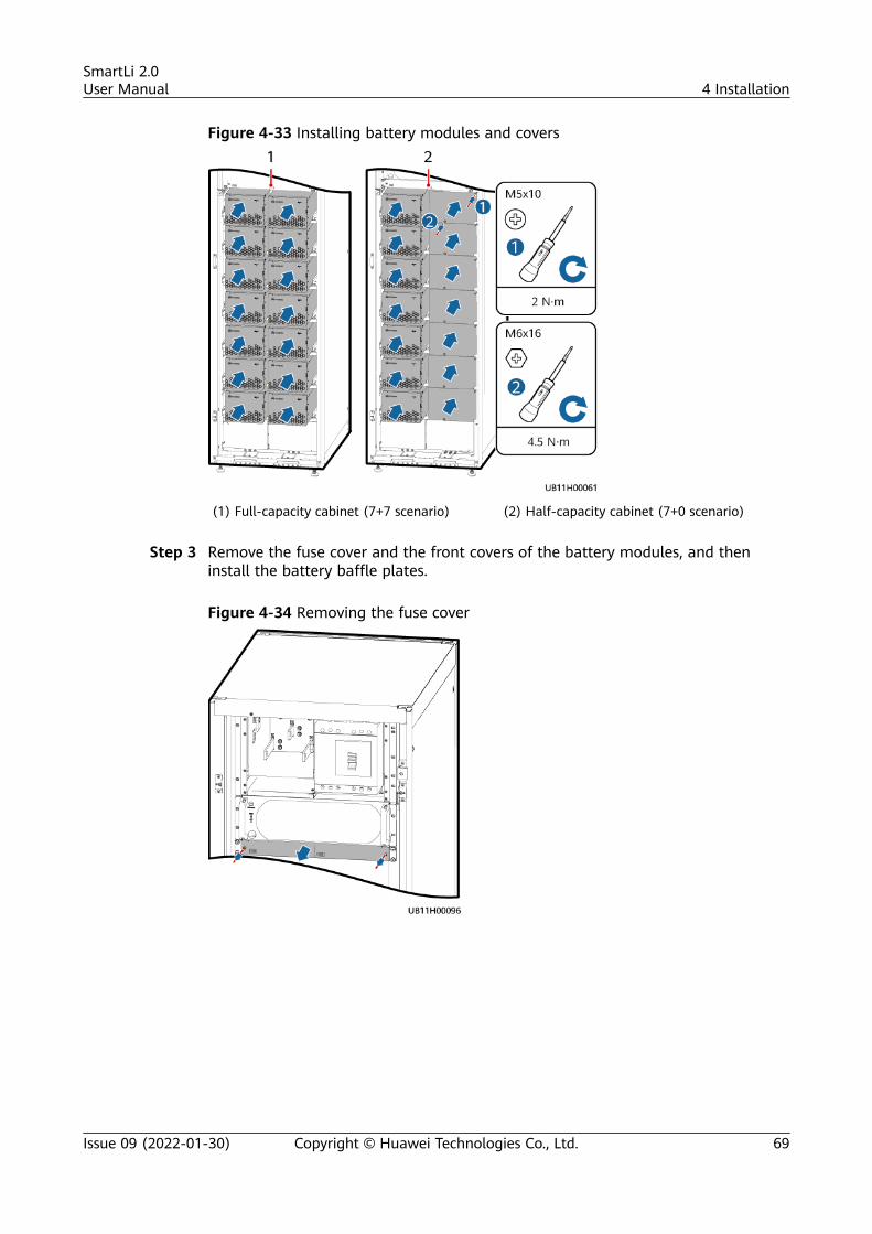
Figure 4-33 Installing battery modules and covers
(1) Full-capacity cabinet (7+7 scenario) (2) Half-capacity cabinet (7+0 scenario)
Step 3 Remove the fuse cover and the front covers of the battery modules, and theninstall the battery baffle plates.
Figure 4-34 Removing the fuse cover
SmartLi 2.0User Manual 4 Installation
Issue 09 (2022-01-30) Copyright © Huawei Technologies Co., Ltd. 69
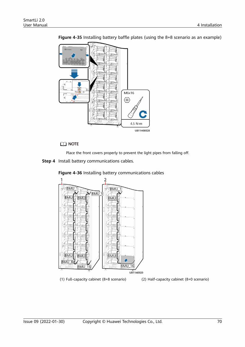
Figure 4-35 Installing battery baffle plates (using the 8+8 scenario as an example)
NO TE
Place the front covers properly to prevent the light pipes from falling off.
Step 4 Install battery communications cables.
Figure 4-36 Installing battery communications cables
(1) Full-capacity cabinet (8+8 scenario) (2) Half-capacity cabinet (8+0 scenario)
SmartLi 2.0User Manual 4 Installation
Issue 09 (2022-01-30) Copyright © Huawei Technologies Co., Ltd. 70
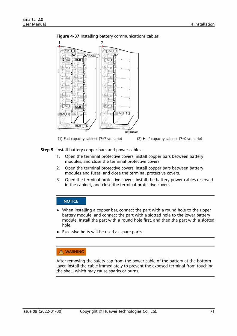
Figure 4-37 Installing battery communications cables
(1) Full-capacity cabinet (7+7 scenario) (2) Half-capacity cabinet (7+0 scenario)
Step 5 Install battery copper bars and power cables.1. Open the terminal protective covers, install copper bars between battery
modules, and close the terminal protective covers.2. Open the terminal protective covers, install copper bars between battery
modules and fuses, and close the terminal protective covers.3. Open the terminal protective covers, install the battery power cables reserved
in the cabinet, and close the terminal protective covers.
NO TICE
● When installing a copper bar, connect the part with a round hole to the upperbattery module, and connect the part with a slotted hole to the lower batterymodule. Install the part with a round hole first, and then the part with a slottedhole.
● Excessive bolts will be used as spare parts.
WARNING
After removing the safety cap from the power cable of the battery at the bottomlayer, install the cable immediately to prevent the exposed terminal from touchingthe shell, which may cause sparks or burns.
SmartLi 2.0User Manual 4 Installation
Issue 09 (2022-01-30) Copyright © Huawei Technologies Co., Ltd. 71
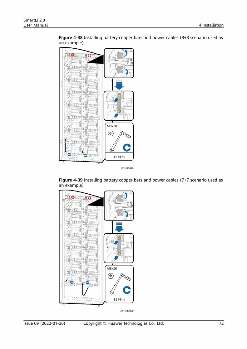
Figure 4-38 Installing battery copper bars and power cables (8+8 scenario used asan example)
Figure 4-39 Installing battery copper bars and power cables (7+7 scenario used asan example)
SmartLi 2.0User Manual 4 Installation
Issue 09 (2022-01-30) Copyright © Huawei Technologies Co., Ltd. 72
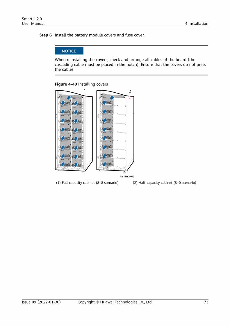
Step 6 Install the battery module covers and fuse cover.
NO TICE
When reinstalling the covers, check and arrange all cables of the board (thecascading cable must be placed in the notch). Ensure that the covers do not pressthe cables.
Figure 4-40 Installing covers
(1) Full-capacity cabinet (8+8 scenario) (2) Half-capacity cabinet (8+0 scenario)
SmartLi 2.0User Manual 4 Installation
Issue 09 (2022-01-30) Copyright © Huawei Technologies Co., Ltd. 73
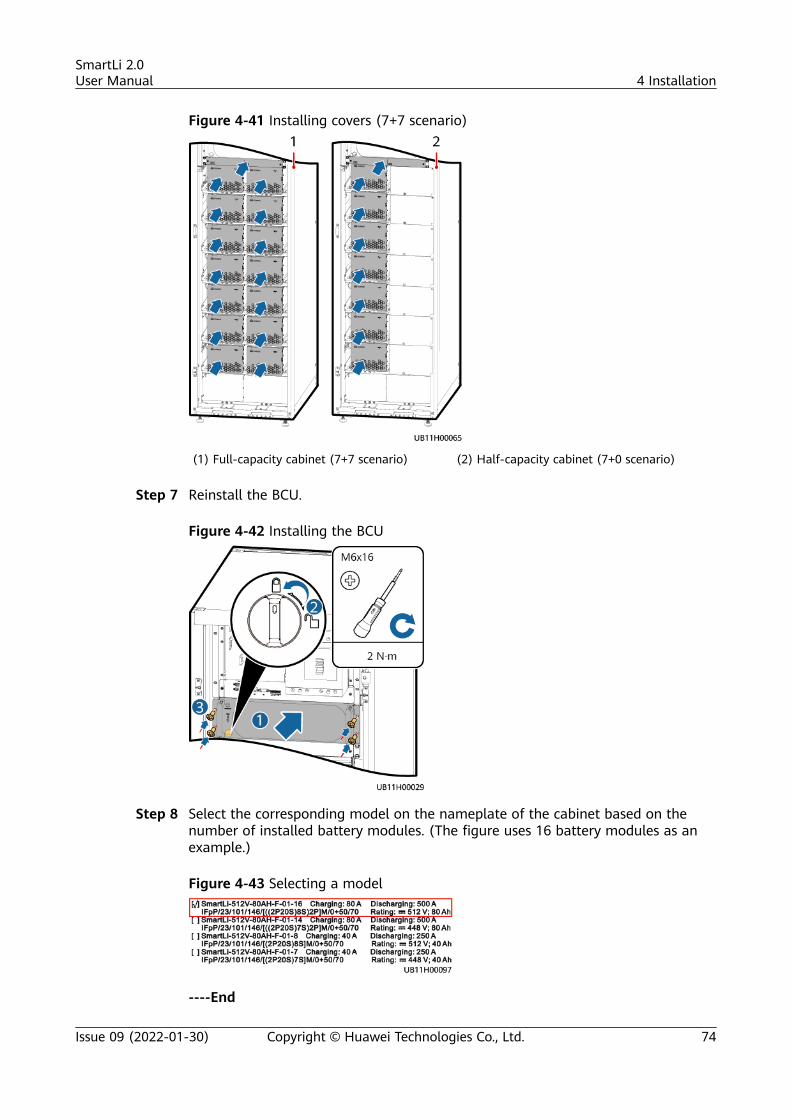
Figure 4-41 Installing covers (7+7 scenario)
(1) Full-capacity cabinet (7+7 scenario) (2) Half-capacity cabinet (7+0 scenario)
Step 7 Reinstall the BCU.
Figure 4-42 Installing the BCU
Step 8 Select the corresponding model on the nameplate of the cabinet based on thenumber of installed battery modules. (The figure uses 16 battery modules as anexample.)
Figure 4-43 Selecting a model
----End
SmartLi 2.0User Manual 4 Installation
Issue 09 (2022-01-30) Copyright © Huawei Technologies Co., Ltd. 74
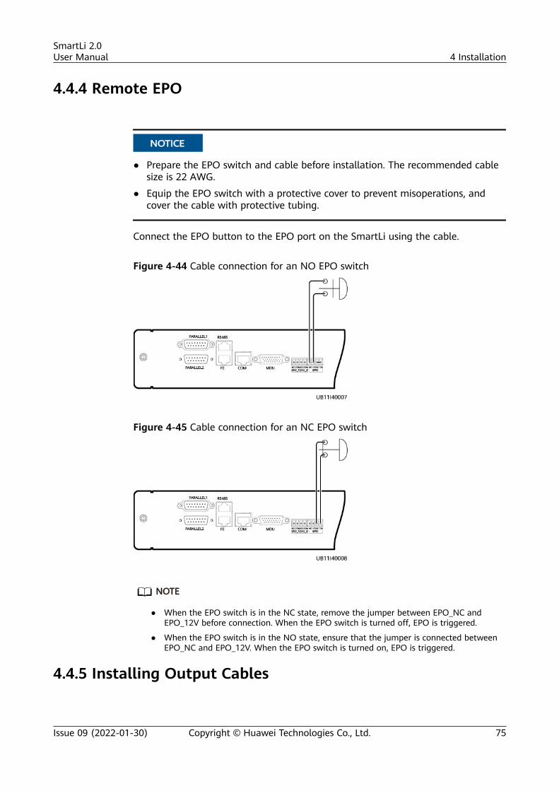
4.4.4 Remote EPO
NO TICE
● Prepare the EPO switch and cable before installation. The recommended cablesize is 22 AWG.
● Equip the EPO switch with a protective cover to prevent misoperations, andcover the cable with protective tubing.
Connect the EPO button to the EPO port on the SmartLi using the cable.
Figure 4-44 Cable connection for an NO EPO switch
Figure 4-45 Cable connection for an NC EPO switch
NO TE
● When the EPO switch is in the NC state, remove the jumper between EPO_NC andEPO_12V before connection. When the EPO switch is turned off, EPO is triggered.
● When the EPO switch is in the NO state, ensure that the jumper is connected betweenEPO_NC and EPO_12V. When the EPO switch is turned on, EPO is triggered.
4.4.5 Installing Output Cables
SmartLi 2.0User Manual 4 Installation
Issue 09 (2022-01-30) Copyright © Huawei Technologies Co., Ltd. 75
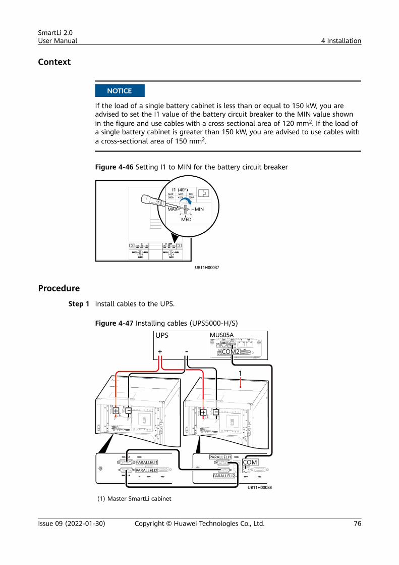
Context
NO TICE
If the load of a single battery cabinet is less than or equal to 150 kW, you areadvised to set the I1 value of the battery circuit breaker to the MIN value shownin the figure and use cables with a cross-sectional area of 120 mm2. If the load ofa single battery cabinet is greater than 150 kW, you are advised to use cables witha cross-sectional area of 150 mm2.
Figure 4-46 Setting I1 to MIN for the battery circuit breaker
Procedure
Step 1 Install cables to the UPS.
Figure 4-47 Installing cables (UPS5000-H/S)
(1) Master SmartLi cabinet
SmartLi 2.0User Manual 4 Installation
Issue 09 (2022-01-30) Copyright © Huawei Technologies Co., Ltd. 76
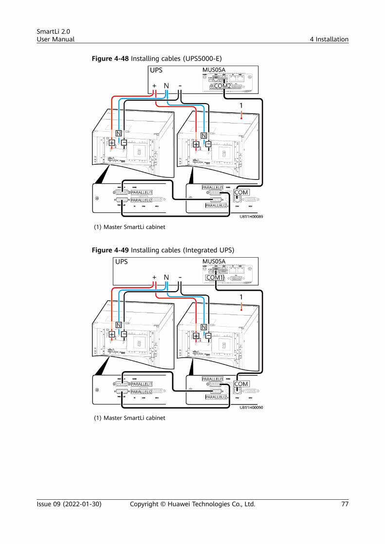
Figure 4-48 Installing cables (UPS5000-E)
(1) Master SmartLi cabinet
Figure 4-49 Installing cables (Integrated UPS)
(1) Master SmartLi cabinet
SmartLi 2.0User Manual 4 Installation
Issue 09 (2022-01-30) Copyright © Huawei Technologies Co., Ltd. 77
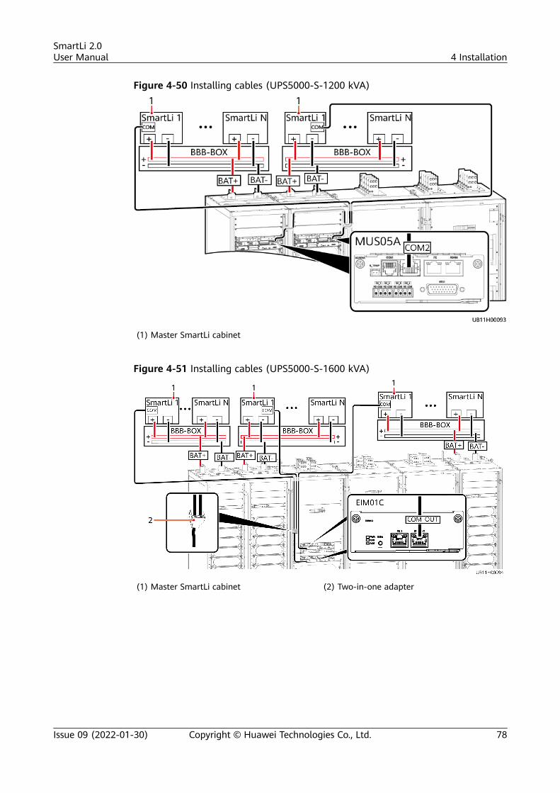
Figure 4-50 Installing cables (UPS5000-S-1200 kVA)
(1) Master SmartLi cabinet
Figure 4-51 Installing cables (UPS5000-S-1600 kVA)
(1) Master SmartLi cabinet (2) Two-in-one adapter
SmartLi 2.0User Manual 4 Installation
Issue 09 (2022-01-30) Copyright © Huawei Technologies Co., Ltd. 78
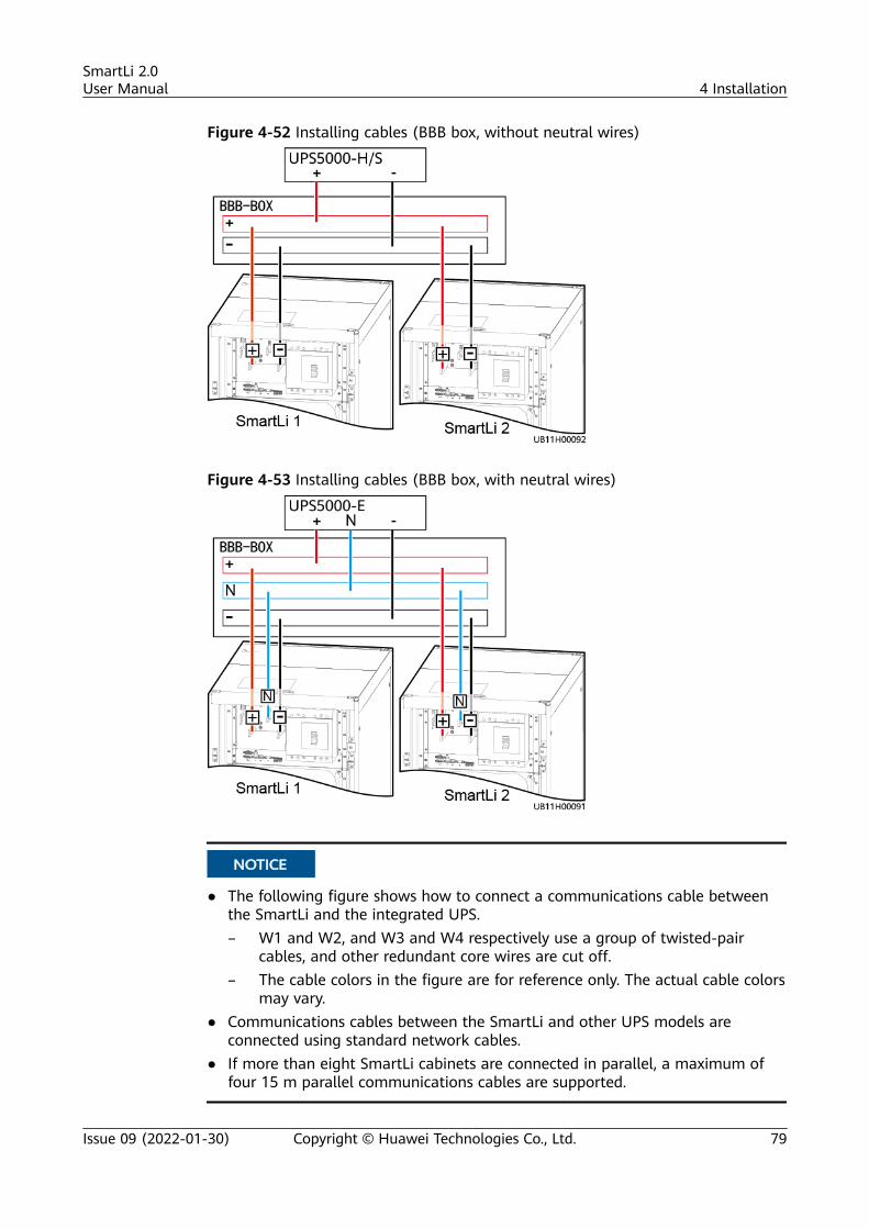
Figure 4-52 Installing cables (BBB box, without neutral wires)
Figure 4-53 Installing cables (BBB box, with neutral wires)
NO TICE
● The following figure shows how to connect a communications cable betweenthe SmartLi and the integrated UPS.– W1 and W2, and W3 and W4 respectively use a group of twisted-pair
cables, and other redundant core wires are cut off.– The cable colors in the figure are for reference only. The actual cable colors
may vary.● Communications cables between the SmartLi and other UPS models are
connected using standard network cables.● If more than eight SmartLi cabinets are connected in parallel, a maximum of
four 15 m parallel communications cables are supported.
SmartLi 2.0User Manual 4 Installation
Issue 09 (2022-01-30) Copyright © Huawei Technologies Co., Ltd. 79
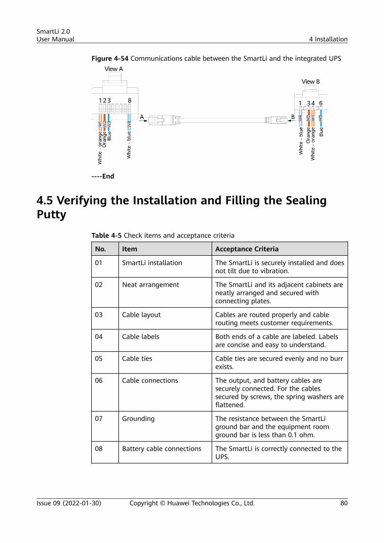
Figure 4-54 Communications cable between the SmartLi and the integrated UPS
----End
4.5 Verifying the Installation and Filling the SealingPutty
Table 4-5 Check items and acceptance criteria
No. Item Acceptance Criteria
01 SmartLi installation The SmartLi is securely installed and doesnot tilt due to vibration.
02 Neat arrangement The SmartLi and its adjacent cabinets areneatly arranged and secured withconnecting plates.
03 Cable layout Cables are routed properly and cablerouting meets customer requirements.
04 Cable labels Both ends of a cable are labeled. Labelsare concise and easy to understand.
05 Cable ties Cable ties are secured evenly and no burrexists.
06 Cable connections The output, and battery cables aresecurely connected. For the cablessecured by screws, the spring washers areflattened.
07 Grounding The resistance between the SmartLiground bar and the equipment roomground bar is less than 0.1 ohm.
08 Battery cable connections The SmartLi is correctly connected to theUPS.
SmartLi 2.0User Manual 4 Installation
Issue 09 (2022-01-30) Copyright © Huawei Technologies Co., Ltd. 80
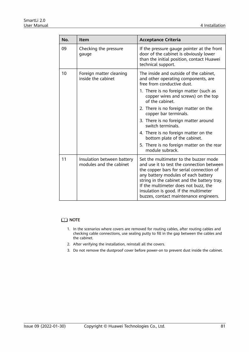
No. Item Acceptance Criteria
09 Checking the pressuregauge
If the pressure gauge pointer at the frontdoor of the cabinet is obviously lowerthan the initial position, contact Huaweitechnical support.
10 Foreign matter cleaninginside the cabinet
The inside and outside of the cabinet,and other operating components, arefree from conductive dust.1. There is no foreign matter (such as
copper wires and screws) on the topof the cabinet.
2. There is no foreign matter on thecopper bar terminals.
3. There is no foreign matter aroundswitch terminals.
4. There is no foreign matter on thebottom plate of the cabinet.
5. There is no foreign matter on the rearmodule subrack.
11 Insulation between batterymodules and the cabinet
Set the multimeter to the buzzer modeand use it to test the connection betweenthe copper bars for serial connection ofany battery modules of each batterystring in the cabinet and the battery tray.If the multimeter does not buzz, theinsulation is good. If the multimeterbuzzes, contact maintenance engineers.
NO TE
1. In the scenarios where covers are removed for routing cables, after routing cables andchecking cable connections, use sealing putty to fill in the gap between the cables andthe cabinet.
2. After verifying the installation, reinstall all the covers.3. Do not remove the dustproof cover before power-on to prevent dust inside the cabinet.
SmartLi 2.0User Manual 4 Installation
Issue 09 (2022-01-30) Copyright © Huawei Technologies Co., Ltd. 81
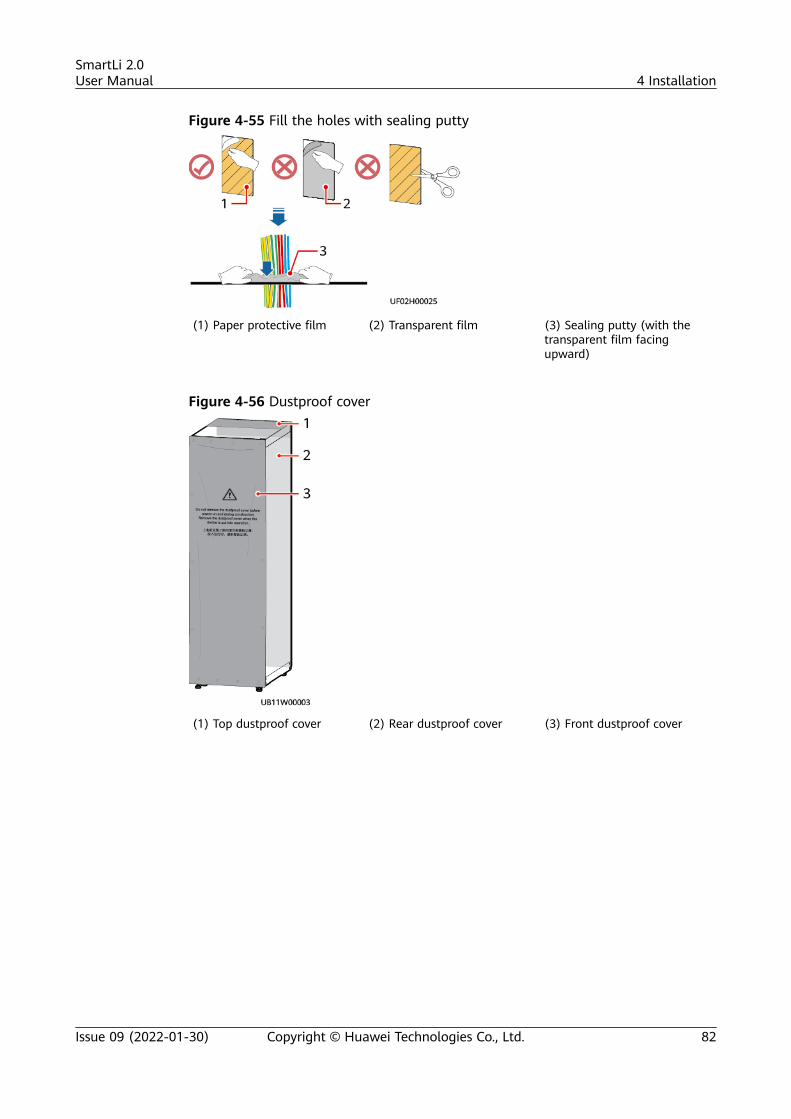
Figure 4-55 Fill the holes with sealing putty
(1) Paper protective film (2) Transparent film (3) Sealing putty (with thetransparent film facingupward)
Figure 4-56 Dustproof cover
(1) Top dustproof cover (2) Rear dustproof cover (3) Front dustproof cover
SmartLi 2.0User Manual 4 Installation
Issue 09 (2022-01-30) Copyright © Huawei Technologies Co., Ltd. 82
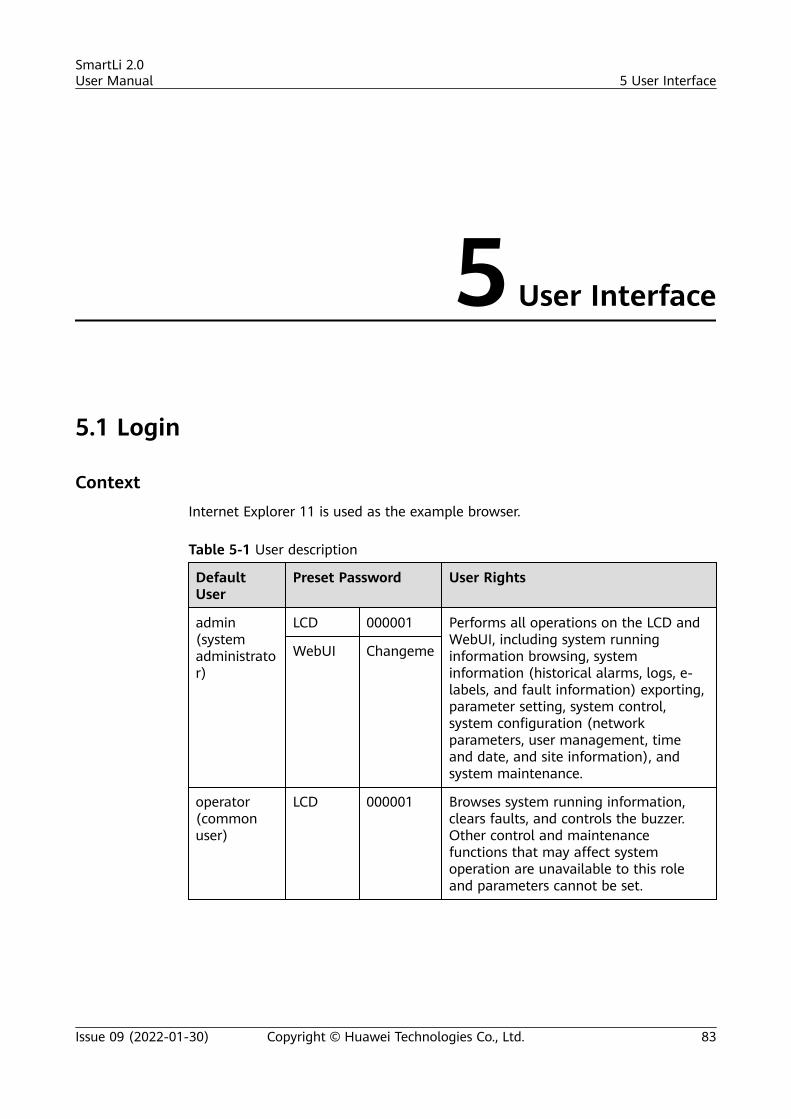
5 User Interface
5.1 Login
ContextInternet Explorer 11 is used as the example browser.
Table 5-1 User description
DefaultUser
Preset Password User Rights
admin(systemadministrator)
LCD 000001 Performs all operations on the LCD andWebUI, including system runninginformation browsing, systeminformation (historical alarms, logs, e-labels, and fault information) exporting,parameter setting, system control,system configuration (networkparameters, user management, timeand date, and site information), andsystem maintenance.
WebUI Changeme
operator(commonuser)
LCD 000001 Browses system running information,clears faults, and controls the buzzer.Other control and maintenancefunctions that may affect systemoperation are unavailable to this roleand parameters cannot be set.
SmartLi 2.0User Manual 5 User Interface
Issue 09 (2022-01-30) Copyright © Huawei Technologies Co., Ltd. 83
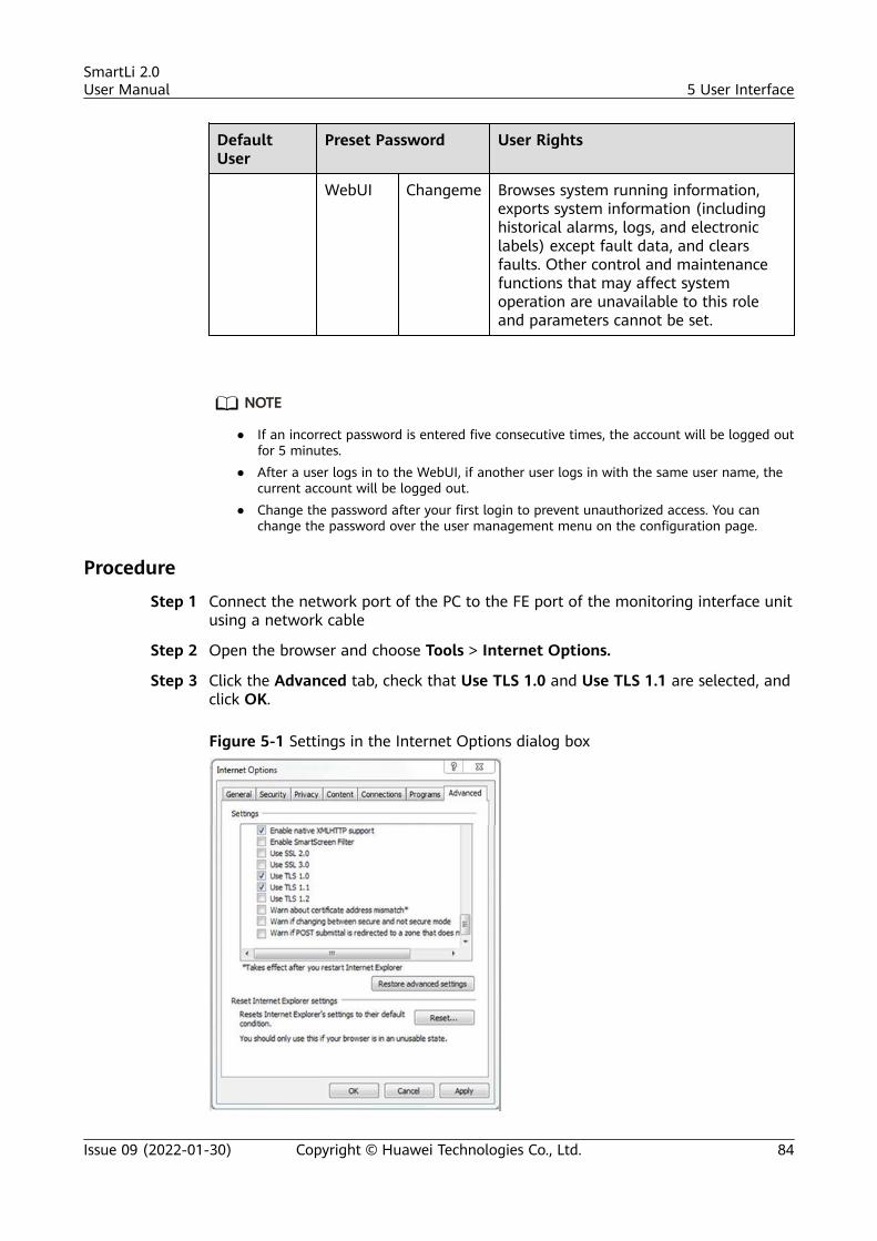
DefaultUser
Preset Password User Rights
WebUI Changeme Browses system running information,exports system information (includinghistorical alarms, logs, and electroniclabels) except fault data, and clearsfaults. Other control and maintenancefunctions that may affect systemoperation are unavailable to this roleand parameters cannot be set.
NO TE
● If an incorrect password is entered five consecutive times, the account will be logged outfor 5 minutes.
● After a user logs in to the WebUI, if another user logs in with the same user name, thecurrent account will be logged out.
● Change the password after your first login to prevent unauthorized access. You canchange the password over the user management menu on the configuration page.
Procedure
Step 1 Connect the network port of the PC to the FE port of the monitoring interface unitusing a network cable
Step 2 Open the browser and choose Tools > Internet Options.
Step 3 Click the Advanced tab, check that Use TLS 1.0 and Use TLS 1.1 are selected, andclick OK.
Figure 5-1 Settings in the Internet Options dialog box
SmartLi 2.0User Manual 5 User Interface
Issue 09 (2022-01-30) Copyright © Huawei Technologies Co., Ltd. 84
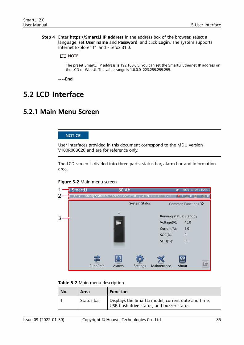
Step 4 Enter https://SmartLi IP address in the address box of the browser, select alanguage, set User name and Password, and click Login. The system supportsInternet Explorer 11 and Firefox 31.0.
NO TE
The preset SmartLi IP address is 192.168.0.5. You can set the SmartLi Ethernet IP address onthe LCD or WebUI. The value range is 1.0.0.0–223.255.255.255.
----End
5.2 LCD Interface
5.2.1 Main Menu Screen
NO TICE
User interfaces provided in this document correspond to the MDU versionV100R003C20 and are for reference only.
The LCD screen is divided into three parts: status bar, alarm bar and informationarea.
Figure 5-2 Main menu screen
Table 5-2 Main menu description
No. Area Function
1 Status bar Displays the SmartLi model, current date and time,USB flash drive status, and buzzer status.
SmartLi 2.0User Manual 5 User Interface
Issue 09 (2022-01-30) Copyright © Huawei Technologies Co., Ltd. 85
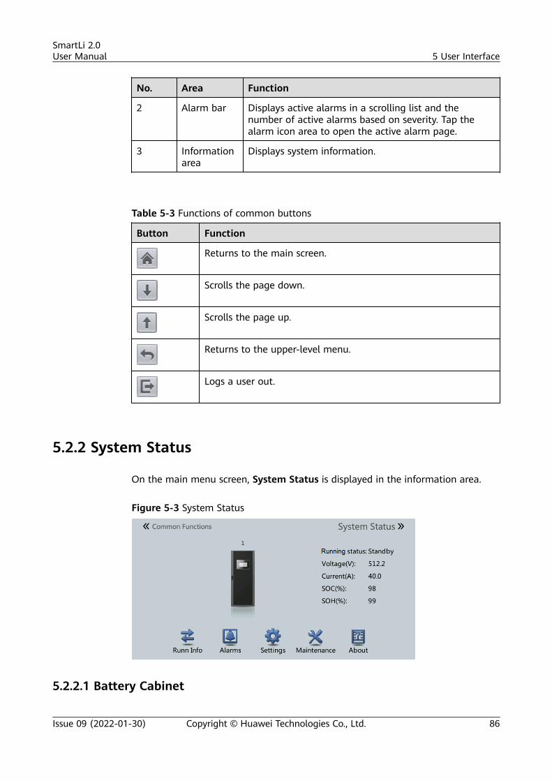
No. Area Function
2 Alarm bar Displays active alarms in a scrolling list and thenumber of active alarms based on severity. Tap thealarm icon area to open the active alarm page.
3 Informationarea
Displays system information.
Table 5-3 Functions of common buttons
Button Function
Returns to the main screen.
Scrolls the page down.
Scrolls the page up.
Returns to the upper-level menu.
Logs a user out.
5.2.2 System Status
On the main menu screen, System Status is displayed in the information area.
Figure 5-3 System Status
5.2.2.1 Battery Cabinet
SmartLi 2.0User Manual 5 User Interface
Issue 09 (2022-01-30) Copyright © Huawei Technologies Co., Ltd. 86
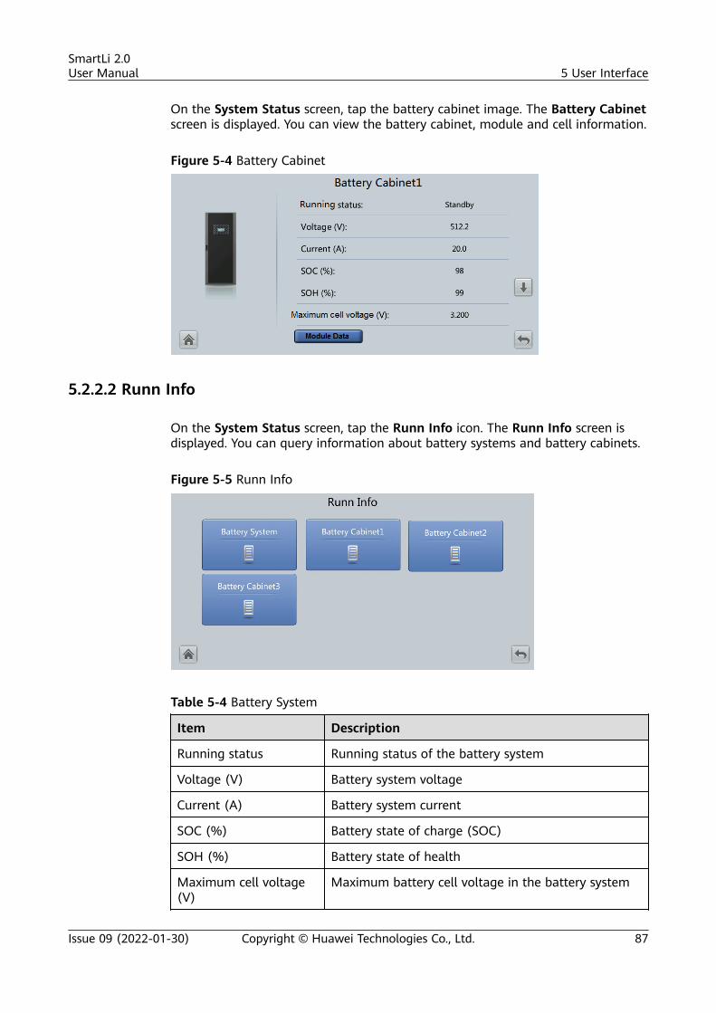
On the System Status screen, tap the battery cabinet image. The Battery Cabinetscreen is displayed. You can view the battery cabinet, module and cell information.
Figure 5-4 Battery Cabinet
5.2.2.2 Runn Info
On the System Status screen, tap the Runn Info icon. The Runn Info screen isdisplayed. You can query information about battery systems and battery cabinets.
Figure 5-5 Runn Info
Table 5-4 Battery System
Item Description
Running status Running status of the battery system
Voltage (V) Battery system voltage
Current (A) Battery system current
SOC (%) Battery state of charge (SOC)
SOH (%) Battery state of health
Maximum cell voltage(V)
Maximum battery cell voltage in the battery system
SmartLi 2.0User Manual 5 User Interface
Issue 09 (2022-01-30) Copyright © Huawei Technologies Co., Ltd. 87
Item Description
Minimum cell voltage(V)
Minimum battery cell voltage in the battery system
Maximum celltemperature (°C)
Maximum battery cell temperature in the batterysystem
Minimum celltemperature (°C)
Minimum battery cell temperature in the batterysystem
Total discharge times Total discharge times of the battery system
Total discharge capacity(Ah)
Total discharge capacity of the battery system
Table 5-5 Battery Cabinet
Item Description
Running status Battery cabinet running status
Voltage (V) Battery cabinet voltage
Current (A) Battery cabinet current
SOC (%) State of charge (SOC)
SOH (%) State of health
Maximum cell voltage(V)
Maximum battery cell voltage in the battery cabinet
Minimum cell voltage(V)
Minimum battery cell voltage in the battery cabinet
Maximum celltemperature (°C)
Maximum battery cell temperature in the batterycabinet
Minimum celltemperature (°C)
Minimum battery cell temperature in the batterycabinet
Total discharge times Total discharge times of the battery cabinet
Total discharge capacity(Ah)
Total discharge capacity of the battery cabinet
Online status -
Table 5-6 Battery Module
Item Description
Voltage (V) Battery module voltage
SmartLi 2.0User Manual 5 User Interface
Issue 09 (2022-01-30) Copyright © Huawei Technologies Co., Ltd. 88
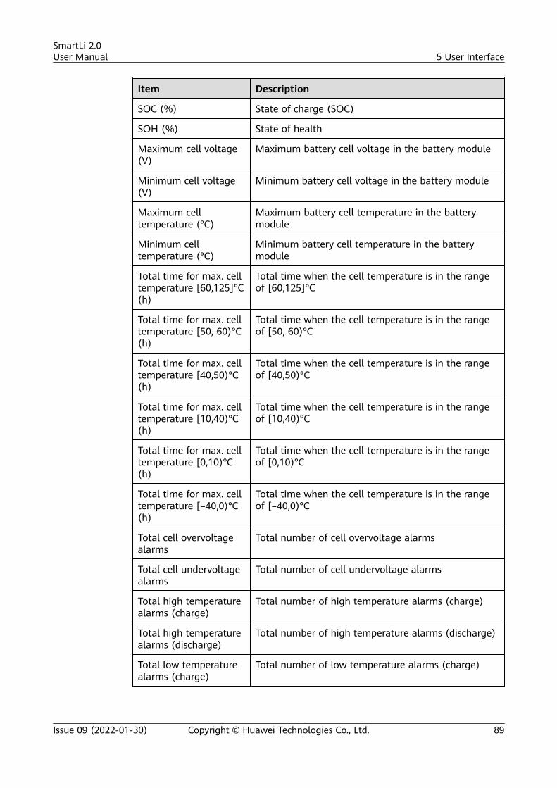
Item Description
SOC (%) State of charge (SOC)
SOH (%) State of health
Maximum cell voltage(V)
Maximum battery cell voltage in the battery module
Minimum cell voltage(V)
Minimum battery cell voltage in the battery module
Maximum celltemperature (°C)
Maximum battery cell temperature in the batterymodule
Minimum celltemperature (°C)
Minimum battery cell temperature in the batterymodule
Total time for max. celltemperature [60,125]°C(h)
Total time when the cell temperature is in the rangeof [60,125]°C
Total time for max. celltemperature [50, 60)°C(h)
Total time when the cell temperature is in the rangeof [50, 60)°C
Total time for max. celltemperature [40,50)°C(h)
Total time when the cell temperature is in the rangeof [40,50)°C
Total time for max. celltemperature [10,40)°C(h)
Total time when the cell temperature is in the rangeof [10,40)°C
Total time for max. celltemperature [0,10)°C(h)
Total time when the cell temperature is in the rangeof [0,10)°C
Total time for max. celltemperature [–40,0)°C(h)
Total time when the cell temperature is in the rangeof [–40,0)°C
Total cell overvoltagealarms
Total number of cell overvoltage alarms
Total cell undervoltagealarms
Total number of cell undervoltage alarms
Total high temperaturealarms (charge)
Total number of high temperature alarms (charge)
Total high temperaturealarms (discharge)
Total number of high temperature alarms (discharge)
Total low temperaturealarms (charge)
Total number of low temperature alarms (charge)
SmartLi 2.0User Manual 5 User Interface
Issue 09 (2022-01-30) Copyright © Huawei Technologies Co., Ltd. 89
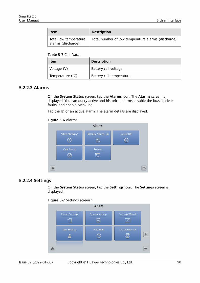
Item Description
Total low temperaturealarms (discharge)
Total number of low temperature alarms (discharge)
Table 5-7 Cell Data
Item Description
Voltage (V) Battery cell voltage
Temperature (°C) Battery cell temperature
5.2.2.3 Alarms
On the System Status screen, tap the Alarms icon. The Alarms screen isdisplayed. You can query active and historical alarms, disable the buzzer, clearfaults, and enable twinkling.
Tap the ID of an active alarm. The alarm details are displayed.
Figure 5-6 Alarms
5.2.2.4 SettingsOn the System Status screen, tap the Settings icon. The Settings screen isdisplayed.
Figure 5-7 Settings screen 1
SmartLi 2.0User Manual 5 User Interface
Issue 09 (2022-01-30) Copyright © Huawei Technologies Co., Ltd. 90
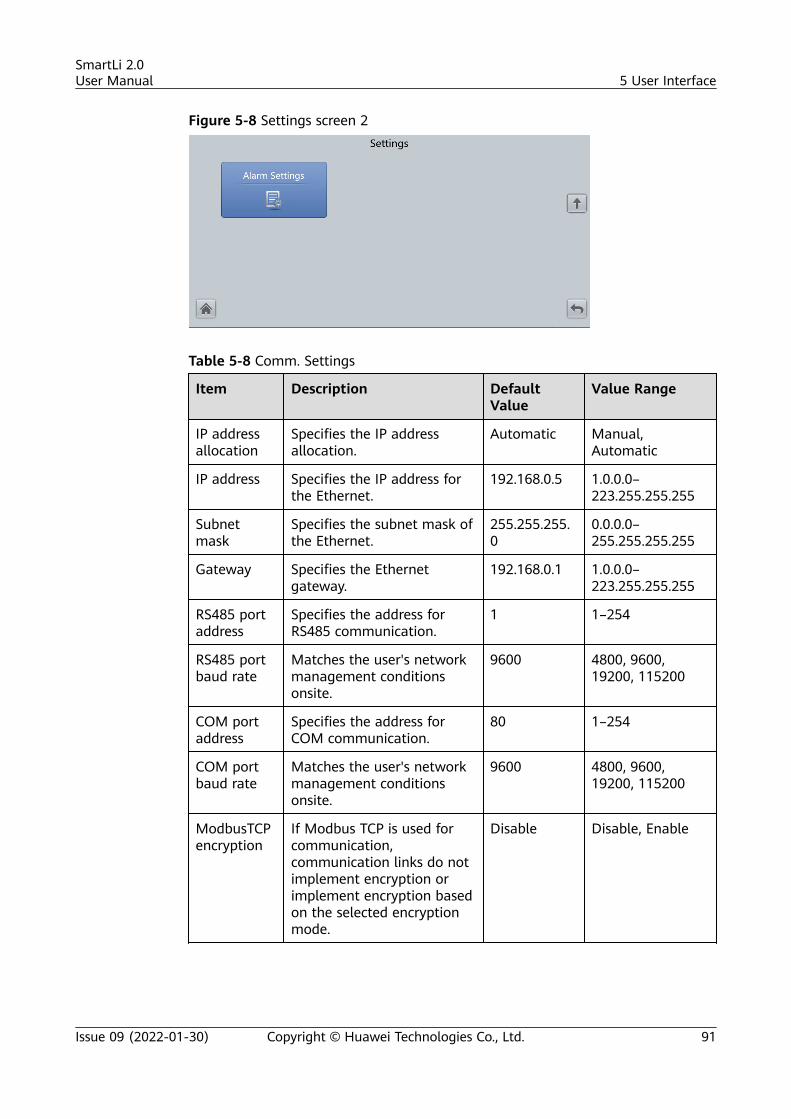
Figure 5-8 Settings screen 2
Table 5-8 Comm. Settings
Item Description DefaultValue
Value Range
IP addressallocation
Specifies the IP addressallocation.
Automatic Manual,Automatic
IP address Specifies the IP address forthe Ethernet.
192.168.0.5 1.0.0.0–223.255.255.255
Subnetmask
Specifies the subnet mask ofthe Ethernet.
255.255.255.0
0.0.0.0–255.255.255.255
Gateway Specifies the Ethernetgateway.
192.168.0.1 1.0.0.0–223.255.255.255
RS485 portaddress
Specifies the address forRS485 communication.
1 1–254
RS485 portbaud rate
Matches the user's networkmanagement conditionsonsite.
9600 4800, 9600,19200, 115200
COM portaddress
Specifies the address forCOM communication.
80 1–254
COM portbaud rate
Matches the user's networkmanagement conditionsonsite.
9600 4800, 9600,19200, 115200
ModbusTCPencryption
If Modbus TCP is used forcommunication,communication links do notimplement encryption orimplement encryption basedon the selected encryptionmode.
Disable Disable, Enable
SmartLi 2.0User Manual 5 User Interface
Issue 09 (2022-01-30) Copyright © Huawei Technologies Co., Ltd. 91
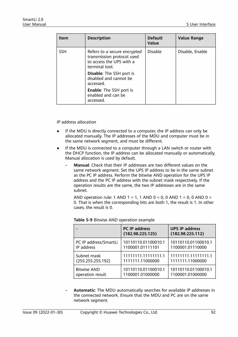
Item Description DefaultValue
Value Range
SSH Refers to a secure encryptedtransmission protocol usedto access the UPS with aterminal tool.Disable: The SSH port isdisabled and cannot beaccessed.Enable: The SSH port isenabled and can beaccessed.
Disable Disable, Enable
IP address allocation
● If the MDU is directly connected to a computer, the IP address can only beallocated manually. The IP addresses of the MDU and computer must be inthe same network segment, and must be different.
● If the MDU is connected to a computer through a LAN switch or router withthe DHCP function, the IP address can be allocated manually or automatically.Manual allocation is used by default.
– Manual: Check that their IP addresses are two different values on thesame network segment. Set the UPS IP address to be in the same subnetas the PC IP address. Perform the bitwise AND operation for the UPS IPaddress and the PC IP address with the subnet mask respectively. If theoperation results are the same, the two IP addresses are in the samesubnet.
AND operation rule: 1 AND 1 = 1, 1 AND 0 = 0, 0 AND 1 = 0, 0 AND 0 =0. That is when the corresponding bits are both 1, the result is 1. In othercases, the result is 0.
Table 5-9 Bitwise AND operation example
- PC IP address(182.98.225.125)
UPS IP address(182.98.225.112)
PC IP address/SmartLiIP address
10110110.01100010.11100001.01111101
10110110.01100010.11100001.01110000
Subnet mask(255.255.255.192)
11111111.11111111.11111111.11000000
11111111.11111111.11111111.11000000
Bitwise ANDoperation result
10110110.01100010.11100001.01000000
10110110.01100010.11100001.01000000
– Automatic: The MDU automatically searches for available IP addresses inthe connected network. Ensure that the MDU and PC are on the samenetwork segment.
SmartLi 2.0User Manual 5 User Interface
Issue 09 (2022-01-30) Copyright © Huawei Technologies Co., Ltd. 92
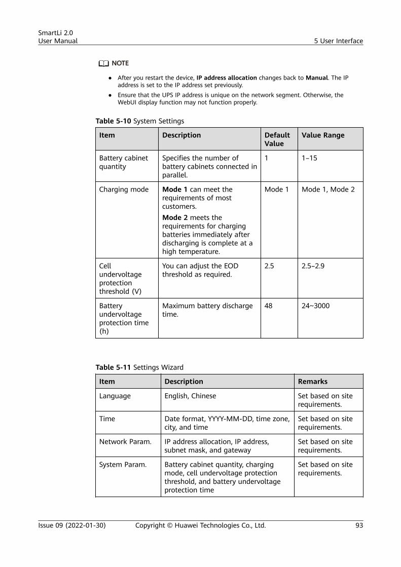
NO TE
● After you restart the device, IP address allocation changes back to Manual. The IPaddress is set to the IP address set previously.
● Ensure that the UPS IP address is unique on the network segment. Otherwise, theWebUI display function may not function properly.
Table 5-10 System Settings
Item Description DefaultValue
Value Range
Battery cabinetquantity
Specifies the number ofbattery cabinets connected inparallel.
1 1–15
Charging mode Mode 1 can meet therequirements of mostcustomers.Mode 2 meets therequirements for chargingbatteries immediately afterdischarging is complete at ahigh temperature.
Mode 1 Mode 1, Mode 2
Cellundervoltageprotectionthreshold (V)
You can adjust the EODthreshold as required.
2.5 2.5–2.9
Batteryundervoltageprotection time(h)
Maximum battery dischargetime.
48 24~3000
Table 5-11 Settings Wizard
Item Description Remarks
Language English, Chinese Set based on siterequirements.
Time Date format, YYYY-MM-DD, time zone,city, and time
Set based on siterequirements.
Network Param. IP address allocation, IP address,subnet mask, and gateway
Set based on siterequirements.
System Param. Battery cabinet quantity, chargingmode, cell undervoltage protectionthreshold, and battery undervoltageprotection time
Set based on siterequirements.
SmartLi 2.0User Manual 5 User Interface
Issue 09 (2022-01-30) Copyright © Huawei Technologies Co., Ltd. 93
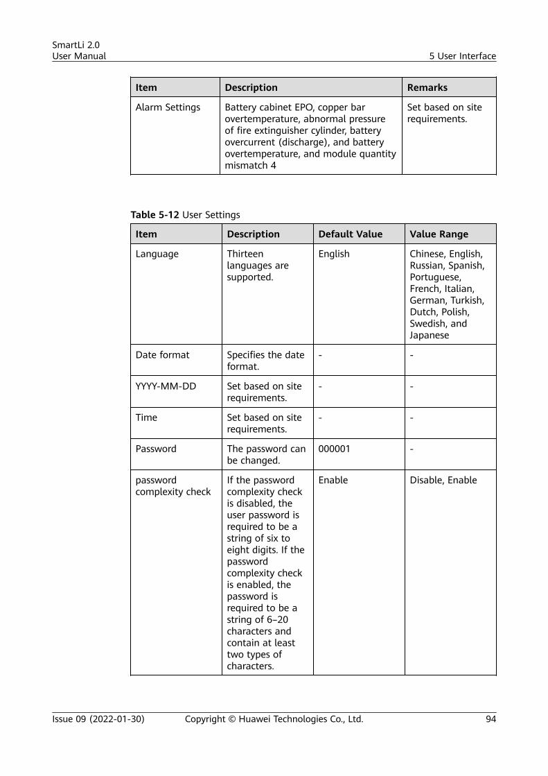
Item Description Remarks
Alarm Settings Battery cabinet EPO, copper barovertemperature, abnormal pressureof fire extinguisher cylinder, batteryovercurrent (discharge), and batteryovertemperature, and module quantitymismatch 4
Set based on siterequirements.
Table 5-12 User Settings
Item Description Default Value Value Range
Language Thirteenlanguages aresupported.
English Chinese, English,Russian, Spanish,Portuguese,French, Italian,German, Turkish,Dutch, Polish,Swedish, andJapanese
Date format Specifies the dateformat.
- -
YYYY-MM-DD Set based on siterequirements.
- -
Time Set based on siterequirements.
- -
Password The password canbe changed.
000001 -
passwordcomplexity check
If the passwordcomplexity checkis disabled, theuser password isrequired to be astring of six toeight digits. If thepasswordcomplexity checkis enabled, thepassword isrequired to be astring of 6–20characters andcontain at leasttwo types ofcharacters.
Enable Disable, Enable
SmartLi 2.0User Manual 5 User Interface
Issue 09 (2022-01-30) Copyright © Huawei Technologies Co., Ltd. 94
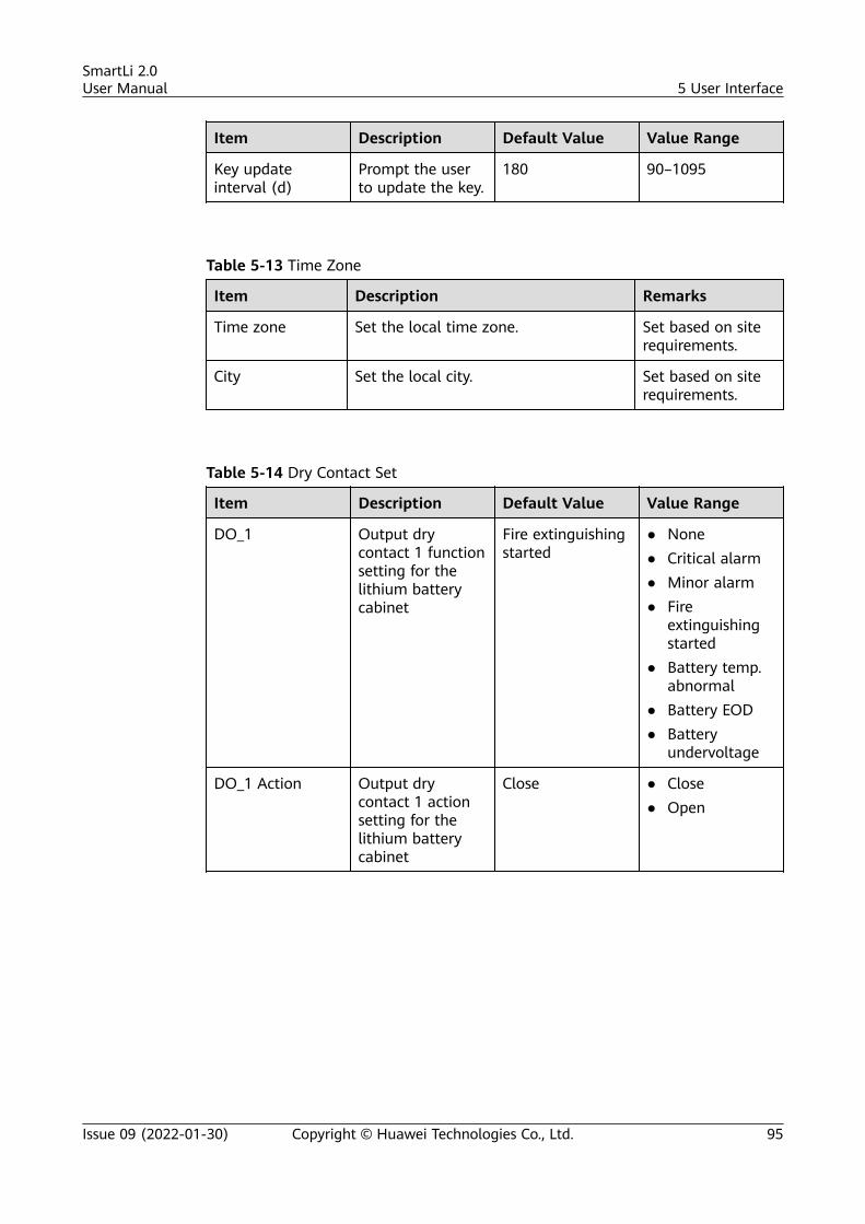
Item Description Default Value Value Range
Key updateinterval (d)
Prompt the userto update the key.
180 90–1095
Table 5-13 Time Zone
Item Description Remarks
Time zone Set the local time zone. Set based on siterequirements.
City Set the local city. Set based on siterequirements.
Table 5-14 Dry Contact Set
Item Description Default Value Value Range
DO_1 Output drycontact 1 functionsetting for thelithium batterycabinet
Fire extinguishingstarted
● None● Critical alarm● Minor alarm● Fire
extinguishingstarted
● Battery temp.abnormal
● Battery EOD● Battery
undervoltage
DO_1 Action Output drycontact 1 actionsetting for thelithium batterycabinet
Close ● Close● Open
SmartLi 2.0User Manual 5 User Interface
Issue 09 (2022-01-30) Copyright © Huawei Technologies Co., Ltd. 95
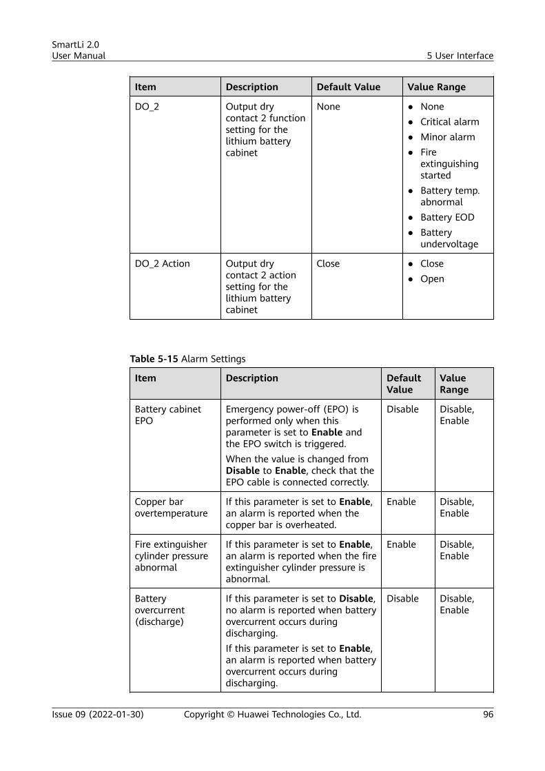
Item Description Default Value Value Range
DO_2 Output drycontact 2 functionsetting for thelithium batterycabinet
None ● None● Critical alarm● Minor alarm● Fire
extinguishingstarted
● Battery temp.abnormal
● Battery EOD● Battery
undervoltage
DO_2 Action Output drycontact 2 actionsetting for thelithium batterycabinet
Close ● Close● Open
Table 5-15 Alarm Settings
Item Description DefaultValue
ValueRange
Battery cabinetEPO
Emergency power-off (EPO) isperformed only when thisparameter is set to Enable andthe EPO switch is triggered.When the value is changed fromDisable to Enable, check that theEPO cable is connected correctly.
Disable Disable,Enable
Copper barovertemperature
If this parameter is set to Enable,an alarm is reported when thecopper bar is overheated.
Enable Disable,Enable
Fire extinguishercylinder pressureabnormal
If this parameter is set to Enable,an alarm is reported when the fireextinguisher cylinder pressure isabnormal.
Enable Disable,Enable
Batteryovercurrent(discharge)
If this parameter is set to Disable,no alarm is reported when batteryovercurrent occurs duringdischarging.If this parameter is set to Enable,an alarm is reported when batteryovercurrent occurs duringdischarging.
Disable Disable,Enable
SmartLi 2.0User Manual 5 User Interface
Issue 09 (2022-01-30) Copyright © Huawei Technologies Co., Ltd. 96
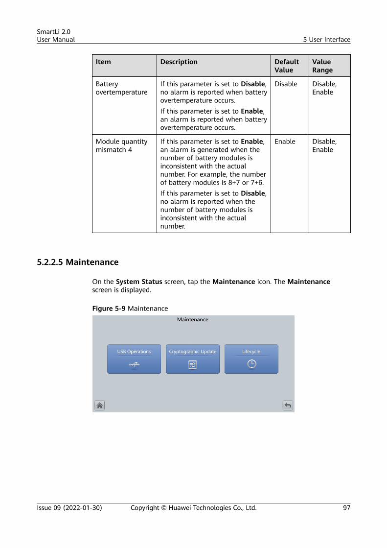
Item Description DefaultValue
ValueRange
Batteryovertemperature
If this parameter is set to Disable,no alarm is reported when batteryovertemperature occurs.If this parameter is set to Enable,an alarm is reported when batteryovertemperature occurs.
Disable Disable,Enable
Module quantitymismatch 4
If this parameter is set to Enable,an alarm is generated when thenumber of battery modules isinconsistent with the actualnumber. For example, the numberof battery modules is 8+7 or 7+6.If this parameter is set to Disable,no alarm is reported when thenumber of battery modules isinconsistent with the actualnumber.
Enable Disable,Enable
5.2.2.5 Maintenance
On the System Status screen, tap the Maintenance icon. The Maintenancescreen is displayed.
Figure 5-9 Maintenance
SmartLi 2.0User Manual 5 User Interface
Issue 09 (2022-01-30) Copyright © Huawei Technologies Co., Ltd. 97
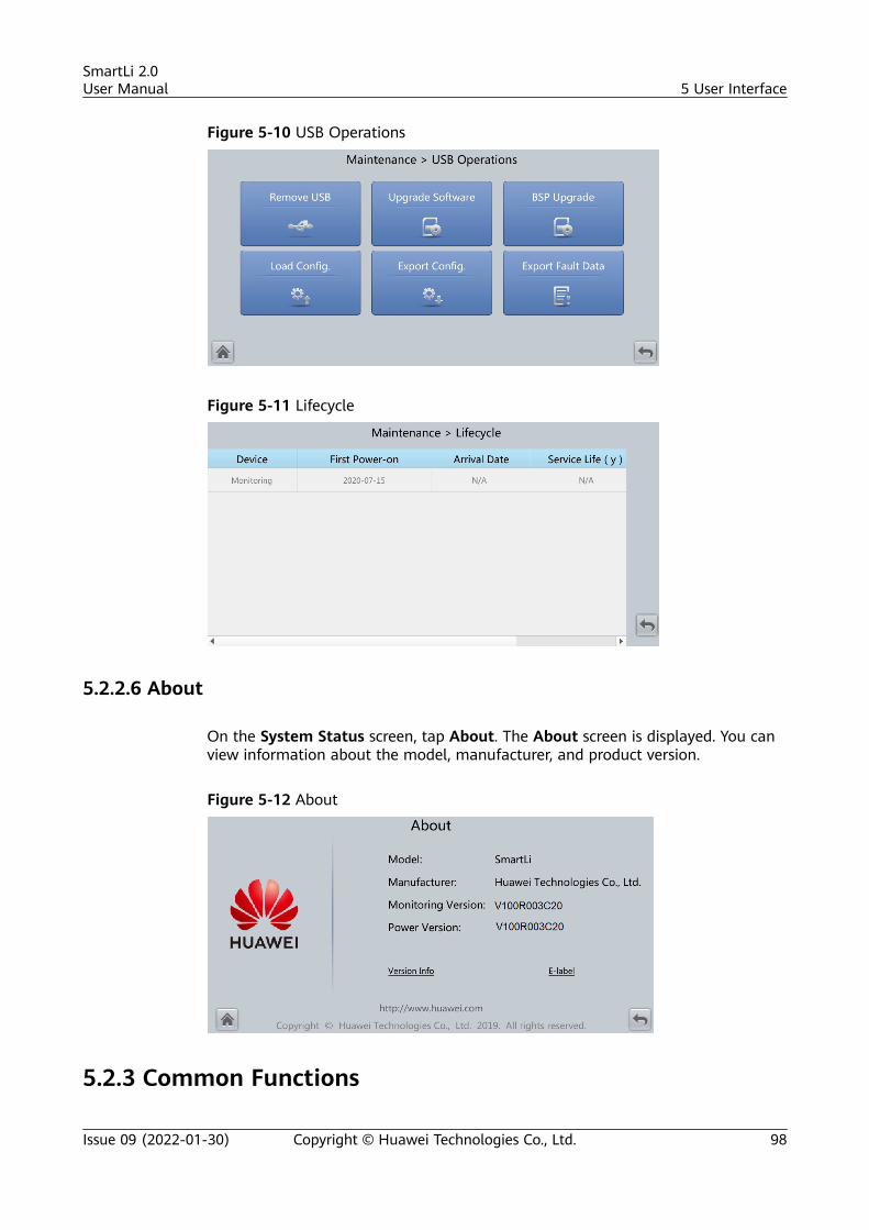
Figure 5-10 USB Operations
Figure 5-11 Lifecycle
5.2.2.6 About
On the System Status screen, tap About. The About screen is displayed. You canview information about the model, manufacturer, and product version.
Figure 5-12 About
5.2.3 Common Functions
SmartLi 2.0User Manual 5 User Interface
Issue 09 (2022-01-30) Copyright © Huawei Technologies Co., Ltd. 98
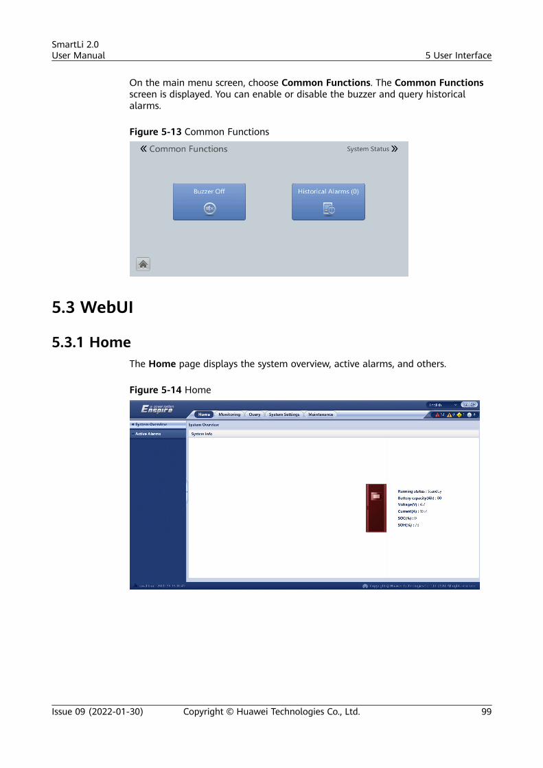
On the main menu screen, choose Common Functions. The Common Functionsscreen is displayed. You can enable or disable the buzzer and query historicalalarms.
Figure 5-13 Common Functions
5.3 WebUI
5.3.1 HomeThe Home page displays the system overview, active alarms, and others.
Figure 5-14 Home
SmartLi 2.0User Manual 5 User Interface
Issue 09 (2022-01-30) Copyright © Huawei Technologies Co., Ltd. 99
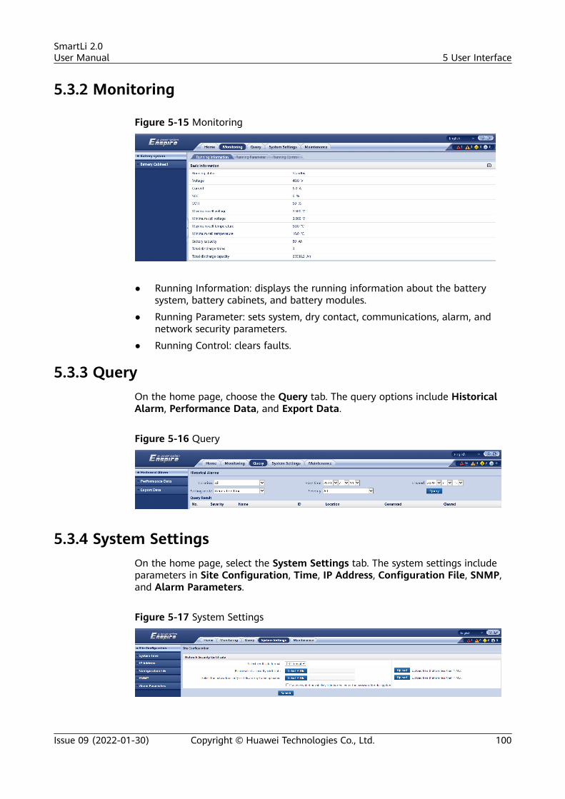
5.3.2 Monitoring
Figure 5-15 Monitoring
● Running Information: displays the running information about the batterysystem, battery cabinets, and battery modules.
● Running Parameter: sets system, dry contact, communications, alarm, andnetwork security parameters.
● Running Control: clears faults.
5.3.3 QueryOn the home page, choose the Query tab. The query options include HistoricalAlarm, Performance Data, and Export Data.
Figure 5-16 Query
5.3.4 System SettingsOn the home page, select the System Settings tab. The system settings includeparameters in Site Configuration, Time, IP Address, Configuration File, SNMP,and Alarm Parameters.
Figure 5-17 System Settings
SmartLi 2.0User Manual 5 User Interface
Issue 09 (2022-01-30) Copyright © Huawei Technologies Co., Ltd. 100
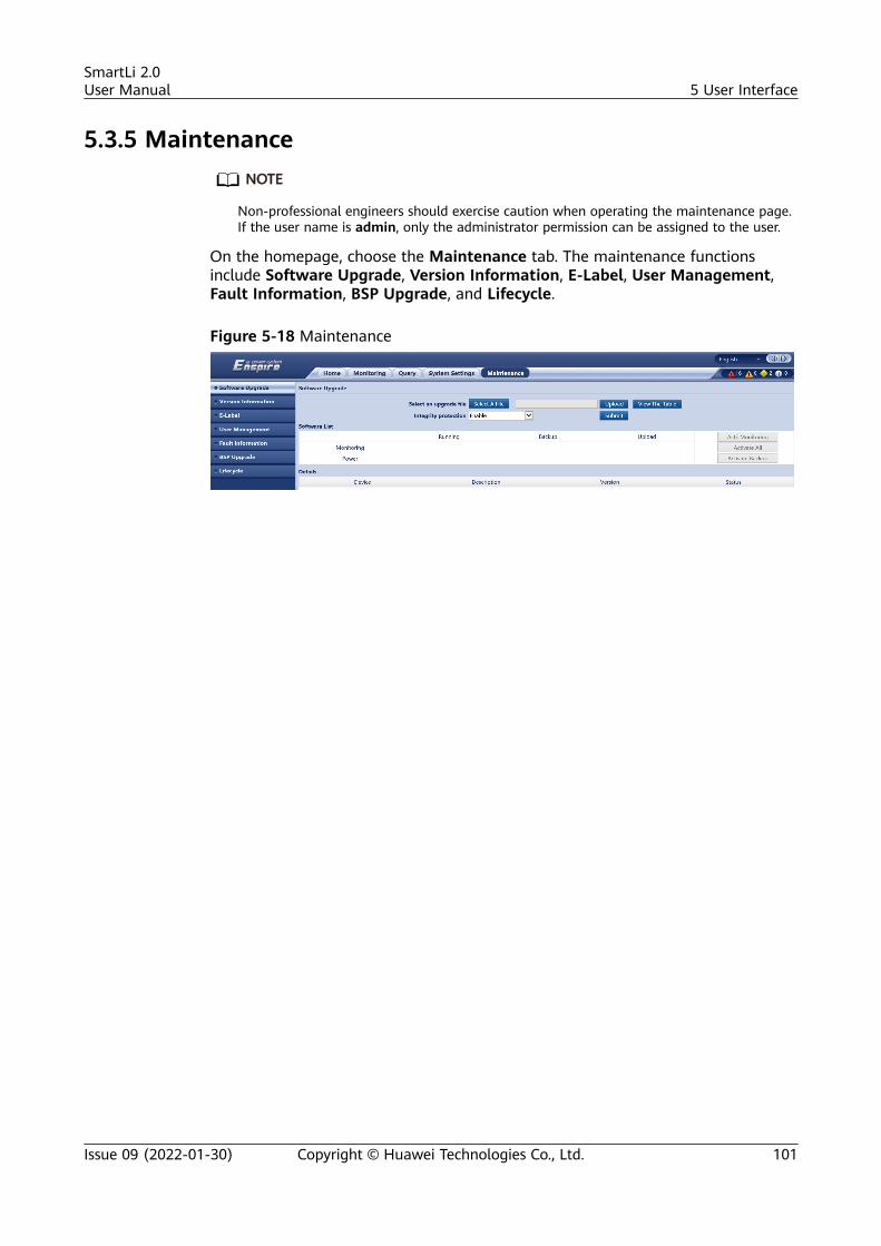
5.3.5 MaintenanceNO TE
Non-professional engineers should exercise caution when operating the maintenance page.If the user name is admin, only the administrator permission can be assigned to the user.
On the homepage, choose the Maintenance tab. The maintenance functionsinclude Software Upgrade, Version Information, E-Label, User Management,Fault Information, BSP Upgrade, and Lifecycle.
Figure 5-18 Maintenance
SmartLi 2.0User Manual 5 User Interface
Issue 09 (2022-01-30) Copyright © Huawei Technologies Co., Ltd. 101
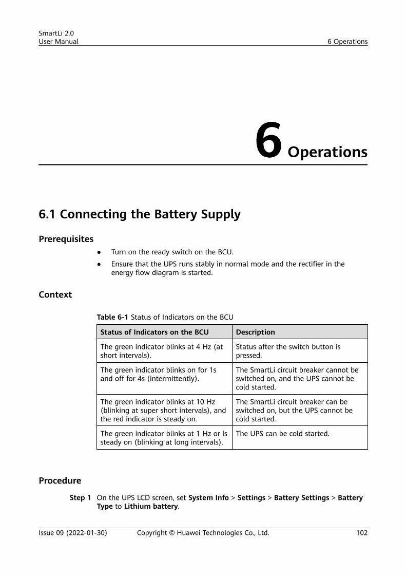
6 Operations
6.1 Connecting the Battery Supply
Prerequisites● Turn on the ready switch on the BCU.
● Ensure that the UPS runs stably in normal mode and the rectifier in theenergy flow diagram is started.
Context
Table 6-1 Status of Indicators on the BCU
Status of Indicators on the BCU Description
The green indicator blinks at 4 Hz (atshort intervals).
Status after the switch button ispressed.
The green indicator blinks on for 1sand off for 4s (intermittently).
The SmartLi circuit breaker cannot beswitched on, and the UPS cannot becold started.
The green indicator blinks at 10 Hz(blinking at super short intervals), andthe red indicator is steady on.
The SmartLi circuit breaker can beswitched on, but the UPS cannot becold started.
The green indicator blinks at 1 Hz or issteady on (blinking at long intervals).
The UPS can be cold started.
Procedure
Step 1 On the UPS LCD screen, set System Info > Settings > Battery Settings > BatteryType to Lithium battery.
SmartLi 2.0User Manual 6 Operations
Issue 09 (2022-01-30) Copyright © Huawei Technologies Co., Ltd. 102
NO TICE
The UPS software needs to be upgraded to the version that supports lithiumbattery connection. See UPS5000 The Relationship of Software Version to checkthe version number.
Step 2 Press and hold the POWER ON/OFF button on the BCU for more than 2s. Thegreen indicator of the BCU blinks at short intervals.
NO TICE
● The BCB off alarm (the red indicator is steady on) is displayed on the SmartLiLCD. No action is required. After the battery circuit breaker is switched on, thealarm is automatically cleared.
● The green indicator blinks intermittently. After 1 minute, the BCU starts. Thegreen indicator blinks at super short intervals and the red indicator is steadyon.
● If multiple SmartLi cabinets are combined, press and hold the POWER ON/OFFbutton on the BCU of the master cabinet for more than 2s to power on themaster cabinet. Then, power on slave cabinets one by one in the same way.
Step 3 Set the language, time, date, network parameters, and system parameters on theSettings Wizard screen of the SmartLi.
SmartLi 2.0User Manual 6 Operations
Issue 09 (2022-01-30) Copyright © Huawei Technologies Co., Ltd. 103
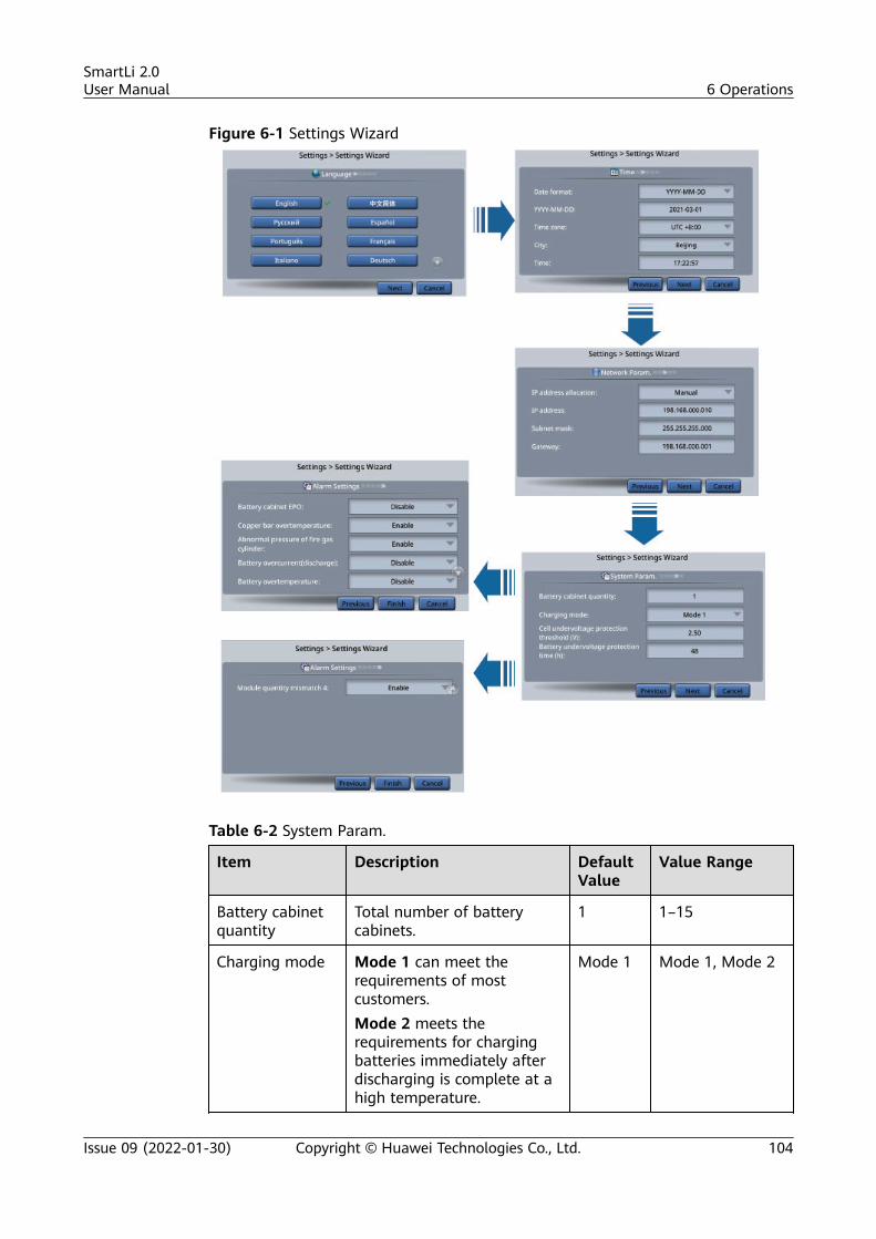
Figure 6-1 Settings Wizard
Table 6-2 System Param.
Item Description DefaultValue
Value Range
Battery cabinetquantity
Total number of batterycabinets.
1 1–15
Charging mode Mode 1 can meet therequirements of mostcustomers.Mode 2 meets therequirements for chargingbatteries immediately afterdischarging is complete at ahigh temperature.
Mode 1 Mode 1, Mode 2
SmartLi 2.0User Manual 6 Operations
Issue 09 (2022-01-30) Copyright © Huawei Technologies Co., Ltd. 104
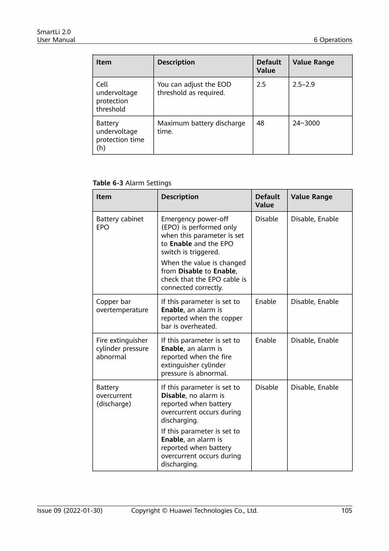
Item Description DefaultValue
Value Range
Cellundervoltageprotectionthreshold
You can adjust the EODthreshold as required.
2.5 2.5–2.9
Batteryundervoltageprotection time(h)
Maximum battery dischargetime.
48 24~3000
Table 6-3 Alarm Settings
Item Description DefaultValue
Value Range
Battery cabinetEPO
Emergency power-off(EPO) is performed onlywhen this parameter is setto Enable and the EPOswitch is triggered.When the value is changedfrom Disable to Enable,check that the EPO cable isconnected correctly.
Disable Disable, Enable
Copper barovertemperature
If this parameter is set toEnable, an alarm isreported when the copperbar is overheated.
Enable Disable, Enable
Fire extinguishercylinder pressureabnormal
If this parameter is set toEnable, an alarm isreported when the fireextinguisher cylinderpressure is abnormal.
Enable Disable, Enable
Batteryovercurrent(discharge)
If this parameter is set toDisable, no alarm isreported when batteryovercurrent occurs duringdischarging.If this parameter is set toEnable, an alarm isreported when batteryovercurrent occurs duringdischarging.
Disable Disable, Enable
SmartLi 2.0User Manual 6 Operations
Issue 09 (2022-01-30) Copyright © Huawei Technologies Co., Ltd. 105
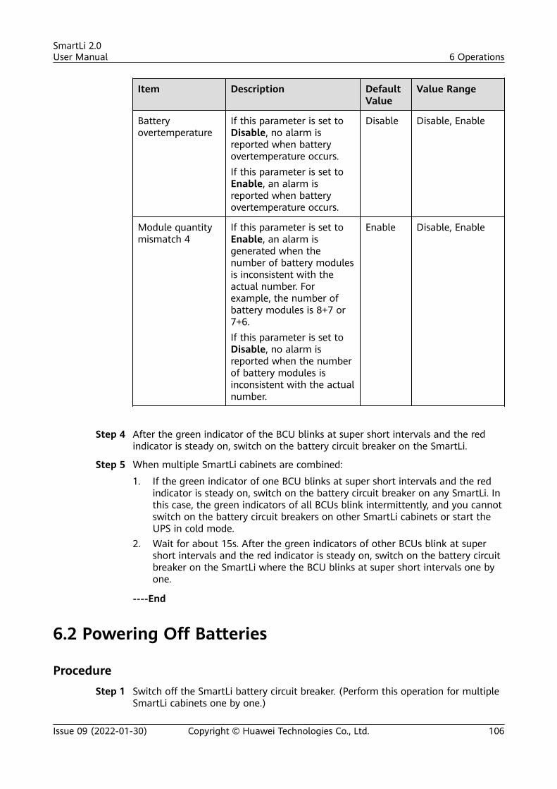
Item Description DefaultValue
Value Range
Batteryovertemperature
If this parameter is set toDisable, no alarm isreported when batteryovertemperature occurs.If this parameter is set toEnable, an alarm isreported when batteryovertemperature occurs.
Disable Disable, Enable
Module quantitymismatch 4
If this parameter is set toEnable, an alarm isgenerated when thenumber of battery modulesis inconsistent with theactual number. Forexample, the number ofbattery modules is 8+7 or7+6.If this parameter is set toDisable, no alarm isreported when the numberof battery modules isinconsistent with the actualnumber.
Enable Disable, Enable
Step 4 After the green indicator of the BCU blinks at super short intervals and the redindicator is steady on, switch on the battery circuit breaker on the SmartLi.
Step 5 When multiple SmartLi cabinets are combined:
1. If the green indicator of one BCU blinks at super short intervals and the redindicator is steady on, switch on the battery circuit breaker on any SmartLi. Inthis case, the green indicators of all BCUs blink intermittently, and you cannotswitch on the battery circuit breakers on other SmartLi cabinets or start theUPS in cold mode.
2. Wait for about 15s. After the green indicators of other BCUs blink at supershort intervals and the red indicator is steady on, switch on the battery circuitbreaker on the SmartLi where the BCU blinks at super short intervals one byone.
----End
6.2 Powering Off Batteries
ProcedureStep 1 Switch off the SmartLi battery circuit breaker. (Perform this operation for multiple
SmartLi cabinets one by one.)
SmartLi 2.0User Manual 6 Operations
Issue 09 (2022-01-30) Copyright © Huawei Technologies Co., Ltd. 106
Step 2 Press and hold the POWER ON/OFF button on the BCU for more than 5s. (Performthis operation for multiple SmartLi cabinets one by one.)
NO TICE
● If batteries will not be charged for more than one month after they are fullycharged and powered off, remove the BCU to prevent battery module damagedue to overdischarge.
● If battery modules are stored without being fully charged, charge themaccording to the requirements in Transportation and Storage > BatteryCabinet Storage with Low SOC to prevent battery module damage due tooverdischarge.
----End
6.3 Performing EPO
NO TICE
● After EPO is triggered, there is no SmartLi output.● After EPO is triggered, the system reports a Battery cabinet shutdown alarm.
Press the external EPO switch that connects to the dry contact card or remove the4-pin terminal on the EPO port of the dry contact card of the bypass unit.
6.4 Clearing the EPO State
Procedure
Step 1 Clear the EPO state. Ensure that the EPO button connected to the external EPO isnot in the EPO state.
Step 2 On the LCD screen, choose System Status > Alarms > Clear Faults. In thedisplayed dialog box, tap Yes. The Battery cabinet shutdown alarm is clearedsuccessfully.
SmartLi 2.0User Manual 6 Operations
Issue 09 (2022-01-30) Copyright © Huawei Technologies Co., Ltd. 107
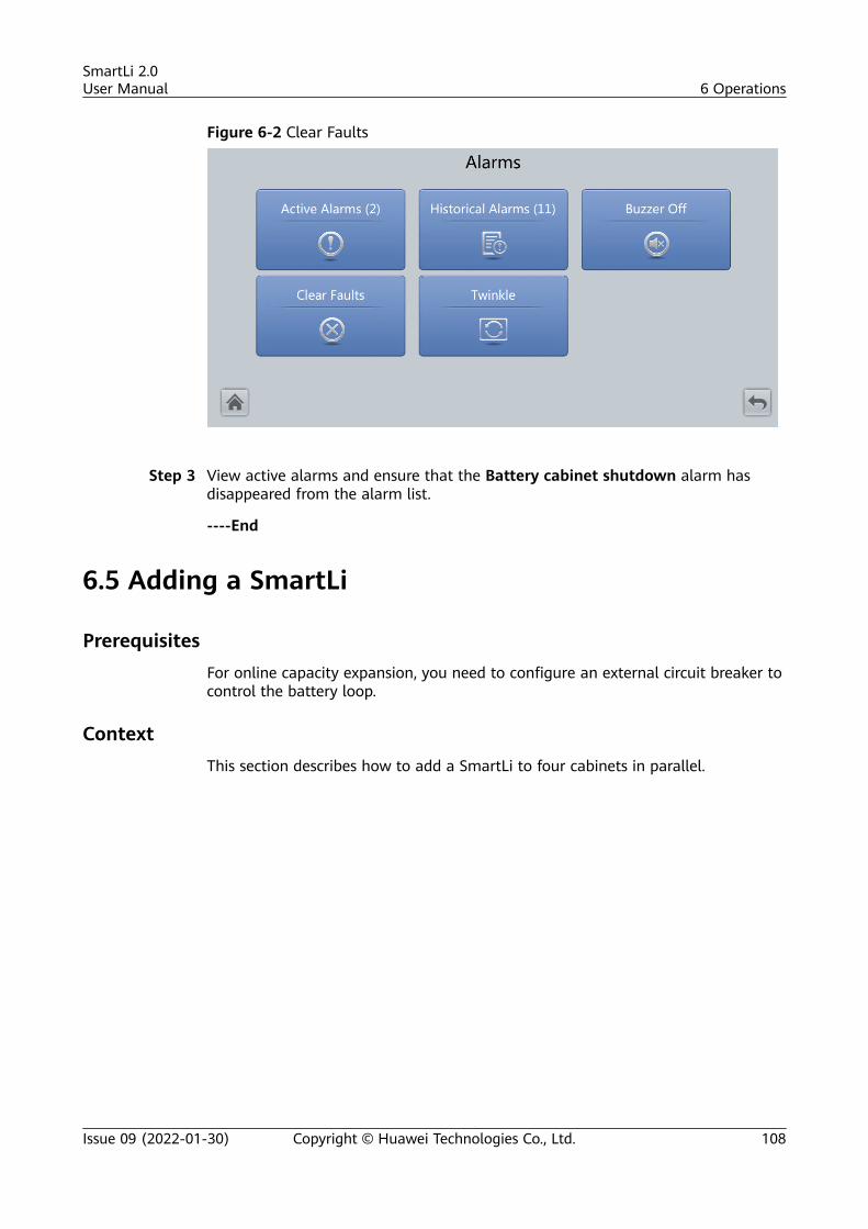
Figure 6-2 Clear Faults
Step 3 View active alarms and ensure that the Battery cabinet shutdown alarm hasdisappeared from the alarm list.
----End
6.5 Adding a SmartLi
PrerequisitesFor online capacity expansion, you need to configure an external circuit breaker tocontrol the battery loop.
ContextThis section describes how to add a SmartLi to four cabinets in parallel.
SmartLi 2.0User Manual 6 Operations
Issue 09 (2022-01-30) Copyright © Huawei Technologies Co., Ltd. 108
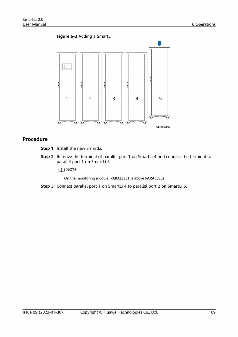
Figure 6-3 Adding a SmartLi
Procedure
Step 1 Install the new SmartLi.
Step 2 Remove the terminal of parallel port 1 on SmartLi 4 and connect the terminal toparallel port 1 on SmartLi 5.
NO TE
On the monitoring module, PARALLEL1 is above PARALLEL2.
Step 3 Connect parallel port 1 on SmartLi 4 to parallel port 2 on SmartLi 5.
SmartLi 2.0User Manual 6 Operations
Issue 09 (2022-01-30) Copyright © Huawei Technologies Co., Ltd. 109
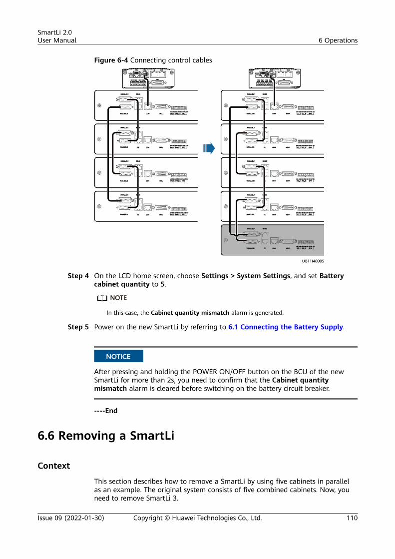
Figure 6-4 Connecting control cables
Step 4 On the LCD home screen, choose Settings > System Settings, and set Batterycabinet quantity to 5.
NO TE
In this case, the Cabinet quantity mismatch alarm is generated.
Step 5 Power on the new SmartLi by referring to 6.1 Connecting the Battery Supply.
NO TICE
After pressing and holding the POWER ON/OFF button on the BCU of the newSmartLi for more than 2s, you need to confirm that the Cabinet quantitymismatch alarm is cleared before switching on the battery circuit breaker.
----End
6.6 Removing a SmartLi
Context
This section describes how to remove a SmartLi by using five cabinets in parallelas an example. The original system consists of five combined cabinets. Now, youneed to remove SmartLi 3.
SmartLi 2.0User Manual 6 Operations
Issue 09 (2022-01-30) Copyright © Huawei Technologies Co., Ltd. 110
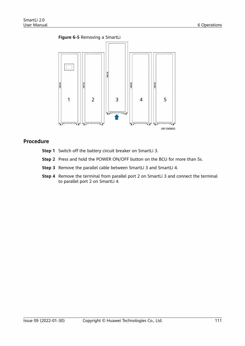
Figure 6-5 Removing a SmartLi
Procedure
Step 1 Switch off the battery circuit breaker on SmartLi 3.
Step 2 Press and hold the POWER ON/OFF button on the BCU for more than 5s.
Step 3 Remove the parallel cable between SmartLi 3 and SmartLi 4.
Step 4 Remove the terminal from parallel port 2 on SmartLi 3 and connect the terminalto parallel port 2 on SmartLi 4.
SmartLi 2.0User Manual 6 Operations
Issue 09 (2022-01-30) Copyright © Huawei Technologies Co., Ltd. 111
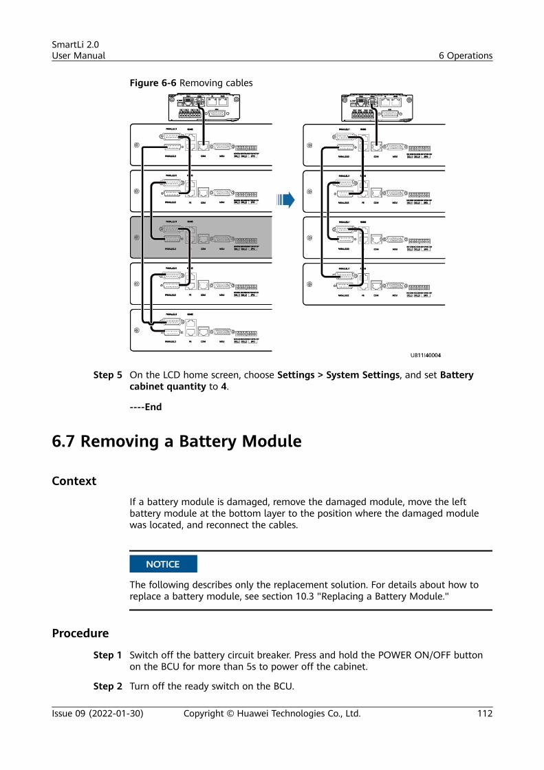
Figure 6-6 Removing cables
Step 5 On the LCD home screen, choose Settings > System Settings, and set Batterycabinet quantity to 4.
----End
6.7 Removing a Battery Module
Context
If a battery module is damaged, remove the damaged module, move the leftbattery module at the bottom layer to the position where the damaged modulewas located, and reconnect the cables.
NO TICE
The following describes only the replacement solution. For details about how toreplace a battery module, see section 10.3 "Replacing a Battery Module."
Procedure
Step 1 Switch off the battery circuit breaker. Press and hold the POWER ON/OFF buttonon the BCU for more than 5s to power off the cabinet.
Step 2 Turn off the ready switch on the BCU.
SmartLi 2.0User Manual 6 Operations
Issue 09 (2022-01-30) Copyright © Huawei Technologies Co., Ltd. 112
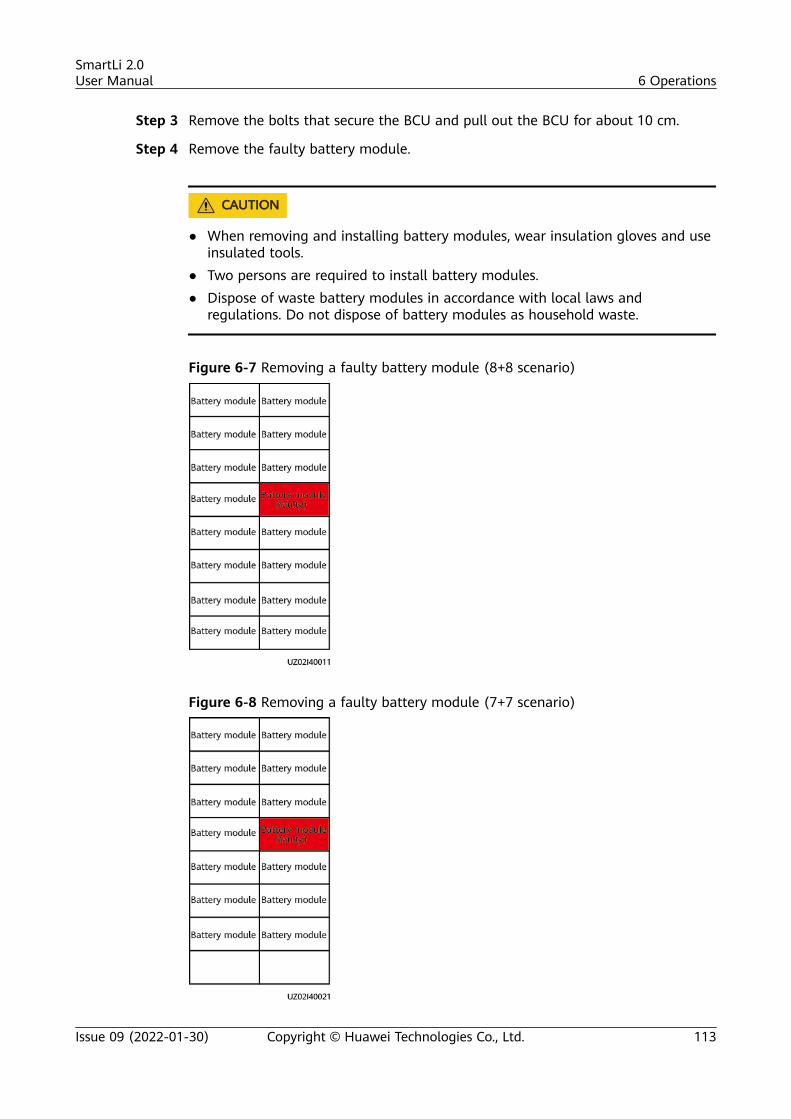
Step 3 Remove the bolts that secure the BCU and pull out the BCU for about 10 cm.
Step 4 Remove the faulty battery module.
CA UTION
● When removing and installing battery modules, wear insulation gloves and useinsulated tools.
● Two persons are required to install battery modules.● Dispose of waste battery modules in accordance with local laws and
regulations. Do not dispose of battery modules as household waste.
Figure 6-7 Removing a faulty battery module (8+8 scenario)
Figure 6-8 Removing a faulty battery module (7+7 scenario)
SmartLi 2.0User Manual 6 Operations
Issue 09 (2022-01-30) Copyright © Huawei Technologies Co., Ltd. 113
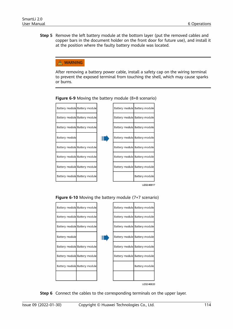
Step 5 Remove the left battery module at the bottom layer (put the removed cables andcopper bars in the document holder on the front door for future use), and install itat the position where the faulty battery module was located.
WARNING
After removing a battery power cable, install a safety cap on the wiring terminalto prevent the exposed terminal from touching the shell, which may cause sparksor burns.
Figure 6-9 Moving the battery module (8+8 scenario)
Figure 6-10 Moving the battery module (7+7 scenario)
Step 6 Connect the cables to the corresponding terminals on the upper layer.
SmartLi 2.0User Manual 6 Operations
Issue 09 (2022-01-30) Copyright © Huawei Technologies Co., Ltd. 114
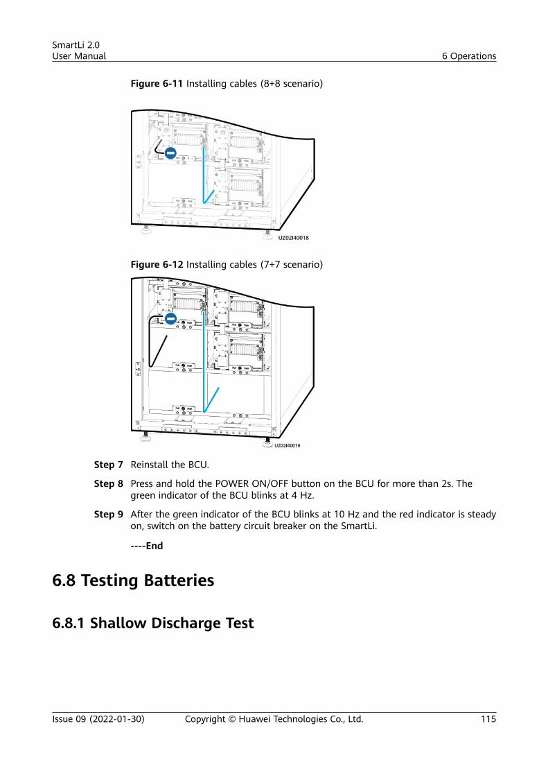
Figure 6-11 Installing cables (8+8 scenario)
Figure 6-12 Installing cables (7+7 scenario)
Step 7 Reinstall the BCU.
Step 8 Press and hold the POWER ON/OFF button on the BCU for more than 2s. Thegreen indicator of the BCU blinks at 4 Hz.
Step 9 After the green indicator of the BCU blinks at 10 Hz and the red indicator is steadyon, switch on the battery circuit breaker on the SmartLi.
----End
6.8 Testing Batteries
6.8.1 Shallow Discharge Test
SmartLi 2.0User Manual 6 Operations
Issue 09 (2022-01-30) Copyright © Huawei Technologies Co., Ltd. 115
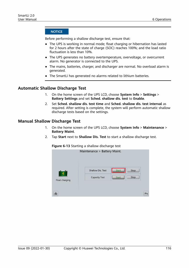
NO TICE
Before performing a shallow discharge test, ensure that:● The UPS is working in normal mode; float charging or hibernation has lasted
for 2 hours after the state of charge (SOC) reaches 100%; and the load ratiofluctuation is less than 10%.
● The UPS generates no battery overtemperature, overvoltage, or overcurrentalarm. No generator is connected to the UPS.
● The mains, batteries, charger, and discharger are normal. No overload alarm isgenerated.
● The SmartLi has generated no alarms related to lithium batteries.
Automatic Shallow Discharge Test1. On the home screen of the UPS LCD, choose System Info > Settings >
Battery Settings and set Sched. shallow dis. test to Enable.2. Set Sched. shallow dis. test time and Sched. shallow dis. test interval as
required. After setting is complete, the system will perform automatic shallowdischarge tests based on the settings.
Manual Shallow Discharge Test1. On the home screen of the UPS LCD, choose System Info > Maintenance >
Battery Maint.2. Tap Start next to Shallow Dis. Test to start a shallow discharge test.
Figure 6-13 Starting a shallow discharge test
SmartLi 2.0User Manual 6 Operations
Issue 09 (2022-01-30) Copyright © Huawei Technologies Co., Ltd. 116
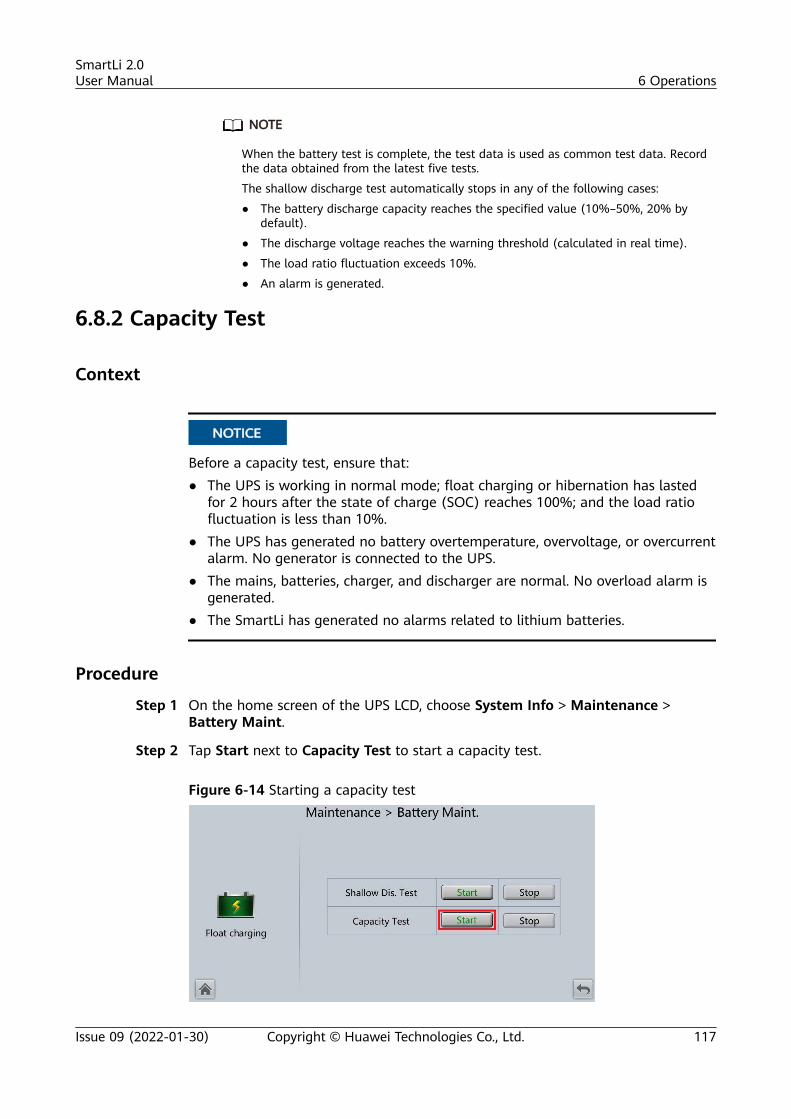
NO TE
When the battery test is complete, the test data is used as common test data. Recordthe data obtained from the latest five tests.
The shallow discharge test automatically stops in any of the following cases:
● The battery discharge capacity reaches the specified value (10%–50%, 20% bydefault).
● The discharge voltage reaches the warning threshold (calculated in real time).
● The load ratio fluctuation exceeds 10%.
● An alarm is generated.
6.8.2 Capacity Test
Context
NO TICE
Before a capacity test, ensure that:● The UPS is working in normal mode; float charging or hibernation has lasted
for 2 hours after the state of charge (SOC) reaches 100%; and the load ratiofluctuation is less than 10%.
● The UPS has generated no battery overtemperature, overvoltage, or overcurrentalarm. No generator is connected to the UPS.
● The mains, batteries, charger, and discharger are normal. No overload alarm isgenerated.
● The SmartLi has generated no alarms related to lithium batteries.
Procedure
Step 1 On the home screen of the UPS LCD, choose System Info > Maintenance >Battery Maint.
Step 2 Tap Start next to Capacity Test to start a capacity test.
Figure 6-14 Starting a capacity test
SmartLi 2.0User Manual 6 Operations
Issue 09 (2022-01-30) Copyright © Huawei Technologies Co., Ltd. 117
NO TE
The capacity test automatically stops in any of the following cases:● The minimum cell voltage reaches 2.65 V.● The load fluctuation exceeds 10%.● An alarm is generated.The test is complete when the minimum cell voltage reaches 2.65 V. A maximum of recent36 capacity test records can be saved.
----End
6.8.3 Performing a Group Capacity Test
ContextIf multiple SmartLi cabinets are connected in parallel, discharge each SmartLi oneby one. (When a SmartLi is fully discharged, charge the SmartLi until its SOCreaches 100%, and then discharge the next SmartLi until all SmartLi cabinets arefully discharged.) A deep discharge test is conducted to obtain the batterydischarge performance data.
NO TICE
Before performing a capacity test, ensure that:● The active power of the UPS is greater than 20 kW.● (Total power of SmartLi cabinets in the system – Power of a single SmartLi) >
UPS active power x 110%.● The UPS is working in normal mode; float charging has lasted for 5 minutes
after the SOC of batteries reaches 100%; the load fluctuation of the system isless than 20%.
● The UPS generates no battery overtemperature, overvoltage, or overcurrentalarm. No generator is connected to the UPS.
● The mains, batteries, charger, and discharger are normal. No overload alarm isgenerated.
● The SmartLi generates no alarms related to lithium batteries.
Procedure
Step 1 On the home screen of the LCD, choose System Info > Maintenance > BatteryMaint.
Step 2 Tap Start on the right of Group Capacity Test to start a group capacity test.
SmartLi 2.0User Manual 6 Operations
Issue 09 (2022-01-30) Copyright © Huawei Technologies Co., Ltd. 118
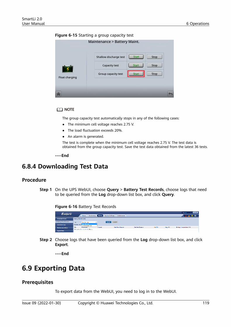
Figure 6-15 Starting a group capacity test
NO TE
The group capacity test automatically stops in any of the following cases:
● The minimum cell voltage reaches 2.75 V.
● The load fluctuation exceeds 20%.
● An alarm is generated.
The test is complete when the minimum cell voltage reaches 2.75 V. The test data isobtained from the group capacity test. Save the test data obtained from the latest 36 tests.
----End
6.8.4 Downloading Test Data
Procedure
Step 1 On the UPS WebUI, choose Query > Battery Test Records, choose logs that needto be queried from the Log drop-down list box, and click Query.
Figure 6-16 Battery Test Records
Step 2 Choose logs that have been queried from the Log drop-down list box, and clickExport.
----End
6.9 Exporting Data
Prerequisites
To export data from the WebUI, you need to log in to the WebUI.
SmartLi 2.0User Manual 6 Operations
Issue 09 (2022-01-30) Copyright © Huawei Technologies Co., Ltd. 119
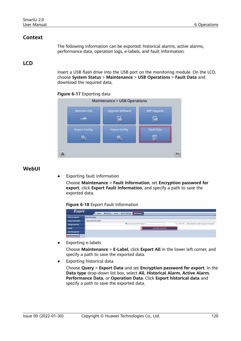
ContextThe following information can be exported: historical alarms, active alarms,performance data, operation logs, e-labels, and fault information.
LCDInsert a USB flash drive into the USB port on the monitoring module. On the LCD,choose System Status > Maintenance > USB Operations > Fault Data anddownload the required data.
Figure 6-17 Exporting data
WebUI● Exporting fault information
Choose Maintenance > Fault Information, set Encryption password forexport, click Export Fault Information, and specify a path to save theexported data.
Figure 6-18 Export Fault Information
● Exporting e-labelsChoose Maintenance > E-Label, click Export All in the lower left corner, andspecify a path to save the exported data.
● Exporting historical dataChoose Query > Export Data and set Encryption password for export. In theData type drop-down list box, select All, Historical Alarm, Active Alarm,Performance Data, or Operation Data. Click Export historical data andspecify a path to save the exported data.
SmartLi 2.0User Manual 6 Operations
Issue 09 (2022-01-30) Copyright © Huawei Technologies Co., Ltd. 120
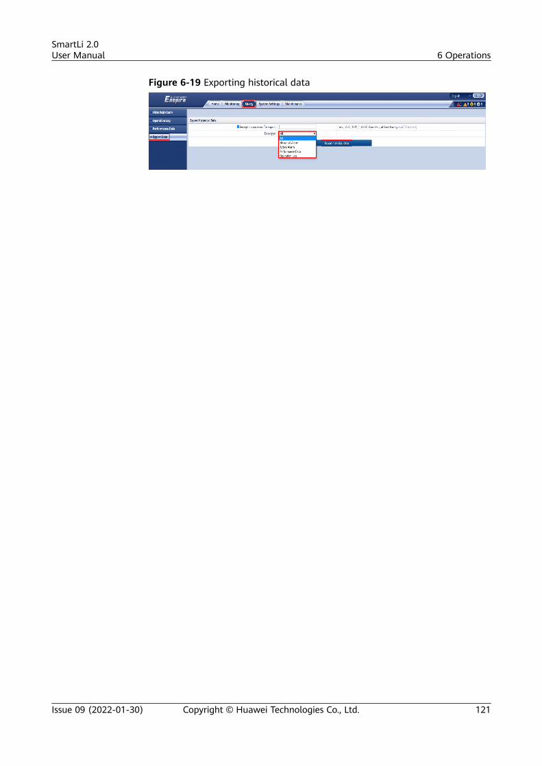
Figure 6-19 Exporting historical data
SmartLi 2.0User Manual 6 Operations
Issue 09 (2022-01-30) Copyright © Huawei Technologies Co., Ltd. 121
7 Routine Maintenance
● Before performing operations, read through the user manual and payattention to safety precautions and battery connection methods.
● Before maintenance, get the tools insulated.● Keep the battery switch off during installation and maintenance.● Before installing and maintaining the battery modules, remove the BCU, and
reinstall the BCU after the installation or maintenance is complete.● When moving batteries, handle batteries gently, and pay attention to personal
safety.● Never use any organic solvent to clean batteries.● Do not use wet cloth to clean exposed copper bars or other conductive parts.● Never smoke or have an open flame around batteries.● After battery discharge, charge the battery in time to maintain a good service
life.● Only professionals are allowed to perform the maintenance tasks.
SmartLi 2.0User Manual 7 Routine Maintenance
Issue 09 (2022-01-30) Copyright © Huawei Technologies Co., Ltd. 122
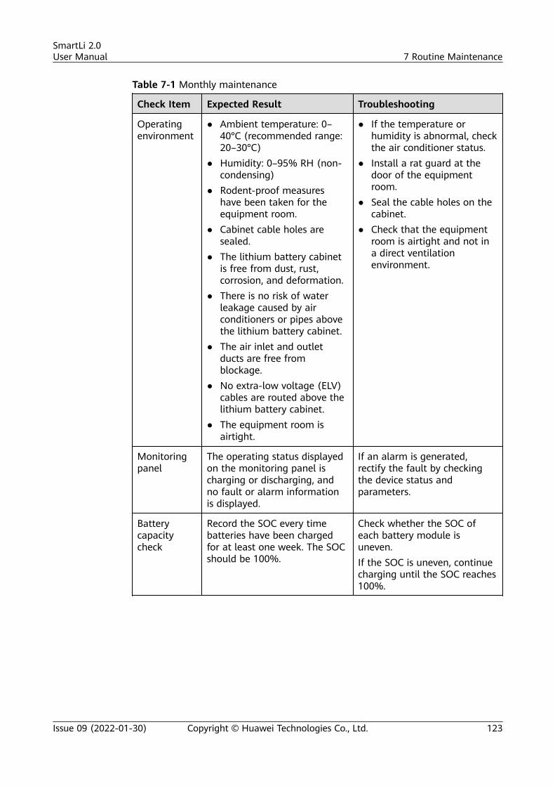
Table 7-1 Monthly maintenance
Check Item Expected Result Troubleshooting
Operatingenvironment
● Ambient temperature: 0–40°C (recommended range:20–30°C)
● Humidity: 0–95% RH (non-condensing)
● Rodent-proof measureshave been taken for theequipment room.
● Cabinet cable holes aresealed.
● The lithium battery cabinetis free from dust, rust,corrosion, and deformation.
● There is no risk of waterleakage caused by airconditioners or pipes abovethe lithium battery cabinet.
● The air inlet and outletducts are free fromblockage.
● No extra-low voltage (ELV)cables are routed above thelithium battery cabinet.
● The equipment room isairtight.
● If the temperature orhumidity is abnormal, checkthe air conditioner status.
● Install a rat guard at thedoor of the equipmentroom.
● Seal the cable holes on thecabinet.
● Check that the equipmentroom is airtight and not ina direct ventilationenvironment.
Monitoringpanel
The operating status displayedon the monitoring panel ischarging or discharging, andno fault or alarm informationis displayed.
If an alarm is generated,rectify the fault by checkingthe device status andparameters.
Batterycapacitycheck
Record the SOC every timebatteries have been chargedfor at least one week. The SOCshould be 100%.
Check whether the SOC ofeach battery module isuneven.If the SOC is uneven, continuecharging until the SOC reaches100%.
SmartLi 2.0User Manual 7 Routine Maintenance
Issue 09 (2022-01-30) Copyright © Huawei Technologies Co., Ltd. 123
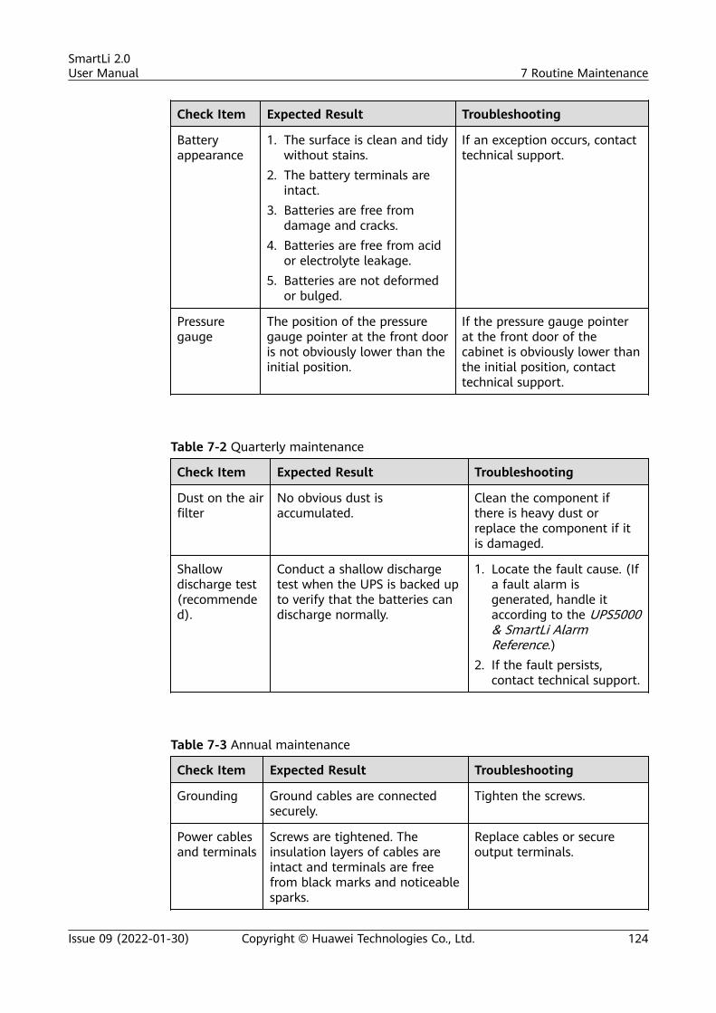
Check Item Expected Result Troubleshooting
Batteryappearance
1. The surface is clean and tidywithout stains.
2. The battery terminals areintact.
3. Batteries are free fromdamage and cracks.
4. Batteries are free from acidor electrolyte leakage.
5. Batteries are not deformedor bulged.
If an exception occurs, contacttechnical support.
Pressuregauge
The position of the pressuregauge pointer at the front dooris not obviously lower than theinitial position.
If the pressure gauge pointerat the front door of thecabinet is obviously lower thanthe initial position, contacttechnical support.
Table 7-2 Quarterly maintenance
Check Item Expected Result Troubleshooting
Dust on the airfilter
No obvious dust isaccumulated.
Clean the component ifthere is heavy dust orreplace the component if itis damaged.
Shallowdischarge test(recommended).
Conduct a shallow dischargetest when the UPS is backed upto verify that the batteries candischarge normally.
1. Locate the fault cause. (Ifa fault alarm isgenerated, handle itaccording to the UPS5000& SmartLi AlarmReference.)
2. If the fault persists,contact technical support.
Table 7-3 Annual maintenance
Check Item Expected Result Troubleshooting
Grounding Ground cables are connectedsecurely.
Tighten the screws.
Power cablesand terminals
Screws are tightened. Theinsulation layers of cables areintact and terminals are freefrom black marks and noticeablesparks.
Replace cables or secureoutput terminals.
SmartLi 2.0User Manual 7 Routine Maintenance
Issue 09 (2022-01-30) Copyright © Huawei Technologies Co., Ltd. 124
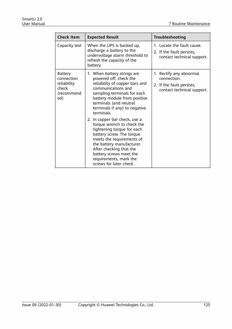
Check Item Expected Result Troubleshooting
Capacity test When the UPS is backed up,discharge a battery to theundervoltage alarm threshold torefresh the capacity of thebattery.
1. Locate the fault cause.2. If the fault persists,
contact technical support.
Batteryconnectionreliabilitycheck(recommended)
1. When battery strings arepowered off, check thereliability of copper bars andcommunications andsampling terminals for eachbattery module from positiveterminals (and neutralterminals if any) to negativeterminals.
2. In copper bar check, use atorque wrench to check thetightening torque for eachbattery screw. The torquemeets the requirements ofthe battery manufacturer.After checking that thebattery screws meet therequirements, mark thescrews for later check.
1. Rectify any abnormalconnection.
2. If the fault persists,contact technical support.
SmartLi 2.0User Manual 7 Routine Maintenance
Issue 09 (2022-01-30) Copyright © Huawei Technologies Co., Ltd. 125
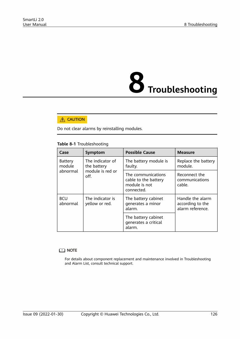
8 Troubleshooting
CA UTION
Do not clear alarms by reinstalling modules.
Table 8-1 Troubleshooting
Case Symptom Possible Cause Measure
Batterymoduleabnormal
The indicator ofthe batterymodule is red oroff.
The battery module isfaulty.
Replace the batterymodule.
The communicationscable to the batterymodule is notconnected.
Reconnect thecommunicationscable.
BCUabnormal
The indicator isyellow or red.
The battery cabinetgenerates a minoralarm.
Handle the alarmaccording to thealarm reference.
The battery cabinetgenerates a criticalalarm.
NO TE
For details about component replacement and maintenance involved in Troubleshootingand Alarm List, consult technical support.
SmartLi 2.0User Manual 8 Troubleshooting
Issue 09 (2022-01-30) Copyright © Huawei Technologies Co., Ltd. 126
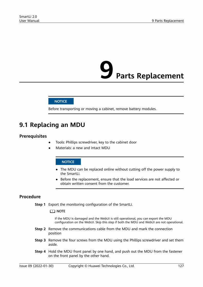
9 Parts Replacement
NO TICE
Before transporting or moving a cabinet, remove battery modules.
9.1 Replacing an MDU
Prerequisites● Tools: Phillips screwdriver, key to the cabinet door● Materials: a new and intact MDU
NO TICE
● The MDU can be replaced online without cutting off the power supply tothe SmartLi.
● Before the replacement, ensure that the load services are not affected orobtain written consent from the customer.
Procedure
Step 1 Export the monitoring configuration of the SmartLi.
NO TE
If the MDU is damaged and the WebUI is still operational, you can export the MDUconfiguration on the WebUI. Skip this step if both the MDU and WebUI are not operational.
Step 2 Remove the communications cable from the MDU and mark the connectionposition
Step 3 Remove the four screws from the MDU using the Phillips screwdriver and set themaside.
Step 4 Hold the MDU front panel by one hand, and push out the MDU from the fasteneron the front panel by the other hand.
SmartLi 2.0User Manual 9 Parts Replacement
Issue 09 (2022-01-30) Copyright © Huawei Technologies Co., Ltd. 127
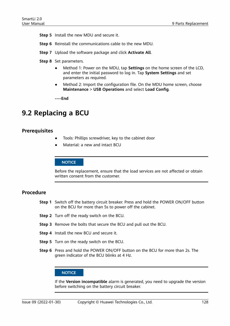
Step 5 Install the new MDU and secure it.
Step 6 Reinstall the communications cable to the new MDU.
Step 7 Upload the software package and click Activate All.
Step 8 Set parameters.
● Method 1: Power on the MDU, tap Settings on the home screen of the LCD,and enter the initial password to log in. Tap System Settings and setparameters as required.
● Method 2: Import the configuration file. On the MDU home screen, chooseMaintenance > USB Operations and select Load Config.
----End
9.2 Replacing a BCU
Prerequisites● Tools: Phillips screwdriver, key to the cabinet door
● Material: a new and intact BCU
NO TICE
Before the replacement, ensure that the load services are not affected or obtainwritten consent from the customer.
Procedure
Step 1 Switch off the battery circuit breaker. Press and hold the POWER ON/OFF buttonon the BCU for more than 5s to power off the cabinet.
Step 2 Turn off the ready switch on the BCU.
Step 3 Remove the bolts that secure the BCU and pull out the BCU.
Step 4 Install the new BCU and secure it.
Step 5 Turn on the ready switch on the BCU.
Step 6 Press and hold the POWER ON/OFF button on the BCU for more than 2s. Thegreen indicator of the BCU blinks at 4 Hz.
NO TICE
If the Version incompatible alarm is generated, you need to upgrade the versionbefore switching on the battery circuit breaker.
SmartLi 2.0User Manual 9 Parts Replacement
Issue 09 (2022-01-30) Copyright © Huawei Technologies Co., Ltd. 128
Step 7 After the green indicator of the BCU blinks at 10 Hz and the red indicator is steadyon, switch on the battery circuit breaker on the SmartLi.
----End
9.3 Replacing a Battery Module
Prerequisites● Tools: insulated socket wrench, insulation gloves, Phillips screwdriver, key to
the cabinet door● Materials: a new and intact battery module
NO TICE
Before the replacement, ensure that the load services are not affected or obtainwritten consent from the customer.
WARNING
After removing a battery power cable, install a safety cap on the wiring terminalto prevent the exposed terminal from touching the shell, which may cause sparksor burns.
Procedure
Step 1 Switch off the battery circuit breaker. Press and hold the POWER ON/OFF buttonon the BCU for more than 5s to power off the cabinet.
Step 2 Turn off the ready switch on the BCU.
Step 3 Remove the bolts that secure the BCU and pull out the BCU for about 10 cm.
Step 4 Remove the front covers from the faulty battery module and the battery modulesbelow and above the faulty one.
NO TE
● If the faulty module is at the top layer, remove the front cover from the faulty moduleand the battery module below, and the fuse cover plate above.
● If the faulty module is located at the bottom layer, remove the covers from the faultymodule and the battery module above.
Step 5 Remove the cables and copper bars that are connected to the faulty batterymodule.
Step 6 Remove the battery baffle plate and pull out the faulty battery module.
Step 7 Install the new battery module and secure the baffle plate.
Step 8 Reinstall the cables, copper bars, and front covers to the battery modules.
SmartLi 2.0User Manual 9 Parts Replacement
Issue 09 (2022-01-30) Copyright © Huawei Technologies Co., Ltd. 129
Step 9 Reinstall the BCU and turn on the ready switch.
Step 10 Press and hold the POWER ON/OFF button on the BCU for more than 2s. Thegreen indicator of the BCU blinks at 4 Hz.
NO TICE
If the Version incompatible alarm is generated, you need to upgrade the versionbefore switching on the battery circuit breaker.
Step 11 After the green indicator of the BCU blinks at 10 Hz and the red indicator is steadyon, switch on the battery circuit breaker on the SmartLi.
----End
9.4 Replacing a SmartLi Fuse
Prerequisites● Tools: insulated socket wrench, insulation gloves, Phillips screwdriver, key to
the cabinet door● Material: a new fuse
Procedure
Step 1 Open the front door of the cabinet and switch off the battery circuit breaker. Pressand hold the POWER ON/OFF button on the BCU for more than 5s to power offthe cabinet.
Step 2 Turn off the ready switch on the BCU, remove the bolts that secure the BCU, andpull it out for about 10 cm.
Step 3 Remove the fuse cover.
Step 4 Remove the screws that secure the fuse and replace the faulty fuse with a newone.
SmartLi 2.0User Manual 9 Parts Replacement
Issue 09 (2022-01-30) Copyright © Huawei Technologies Co., Ltd. 130
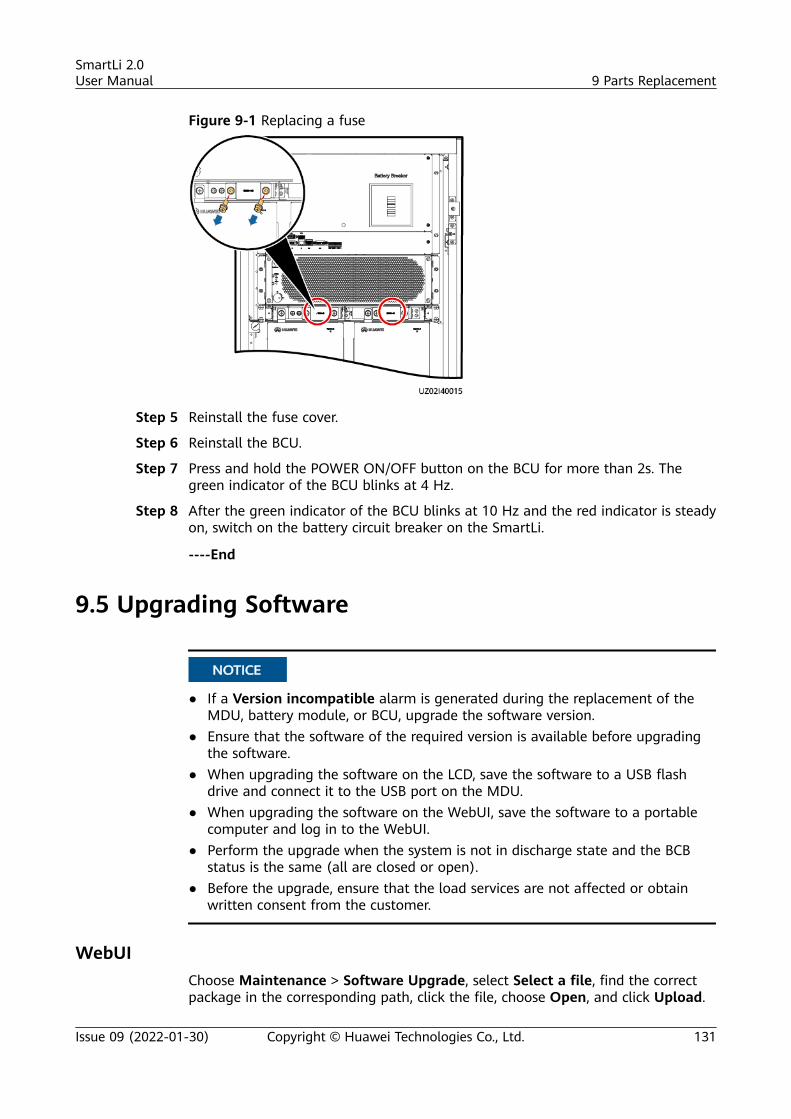
Figure 9-1 Replacing a fuse
Step 5 Reinstall the fuse cover.
Step 6 Reinstall the BCU.
Step 7 Press and hold the POWER ON/OFF button on the BCU for more than 2s. Thegreen indicator of the BCU blinks at 4 Hz.
Step 8 After the green indicator of the BCU blinks at 10 Hz and the red indicator is steadyon, switch on the battery circuit breaker on the SmartLi.
----End
9.5 Upgrading Software
NO TICE
● If a Version incompatible alarm is generated during the replacement of theMDU, battery module, or BCU, upgrade the software version.
● Ensure that the software of the required version is available before upgradingthe software.
● When upgrading the software on the LCD, save the software to a USB flashdrive and connect it to the USB port on the MDU.
● When upgrading the software on the WebUI, save the software to a portablecomputer and log in to the WebUI.
● Perform the upgrade when the system is not in discharge state and the BCBstatus is the same (all are closed or open).
● Before the upgrade, ensure that the load services are not affected or obtainwritten consent from the customer.
WebUIChoose Maintenance > Software Upgrade, select Select a file, find the correctpackage in the corresponding path, click the file, choose Open, and click Upload.
SmartLi 2.0User Manual 9 Parts Replacement
Issue 09 (2022-01-30) Copyright © Huawei Technologies Co., Ltd. 131
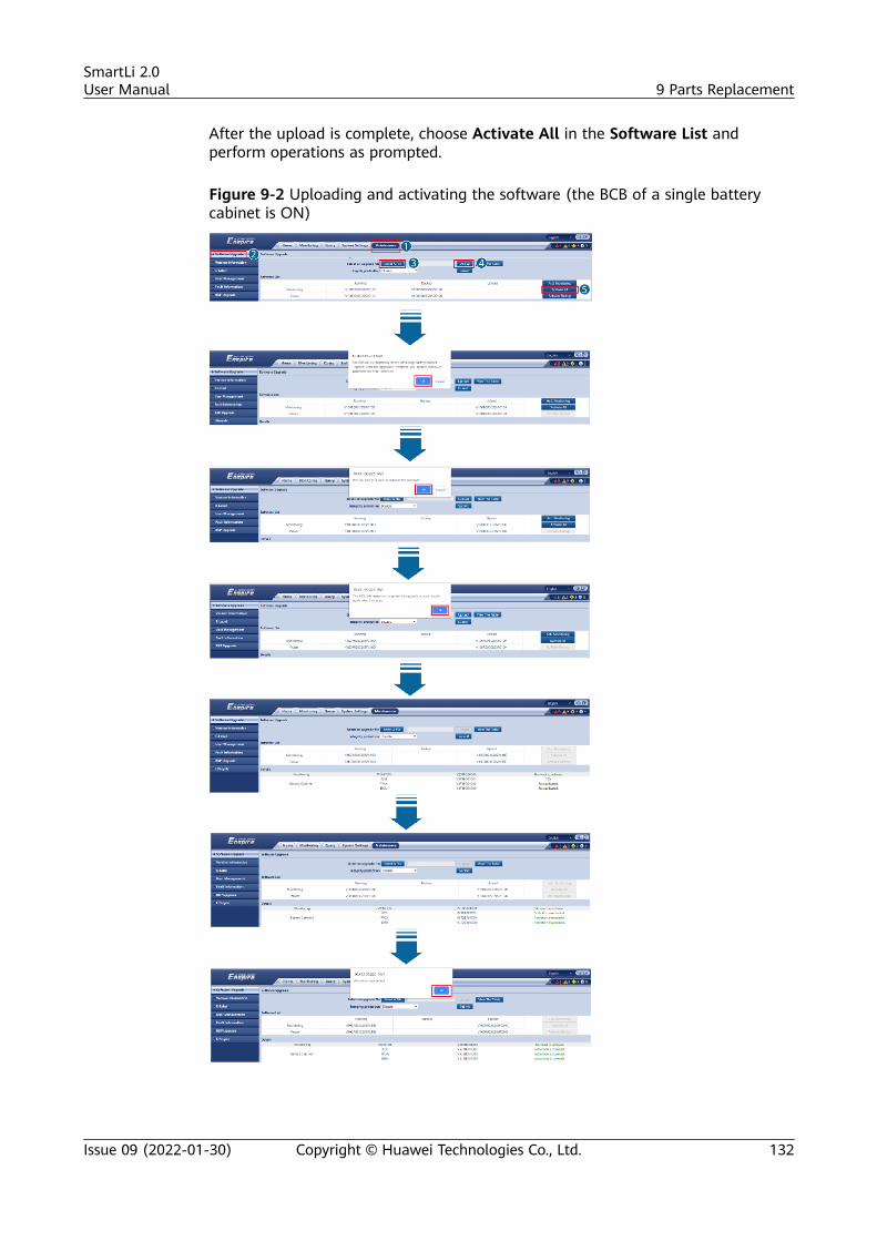
After the upload is complete, choose Activate All in the Software List andperform operations as prompted.
Figure 9-2 Uploading and activating the software (the BCB of a single batterycabinet is ON)
SmartLi 2.0User Manual 9 Parts Replacement
Issue 09 (2022-01-30) Copyright © Huawei Technologies Co., Ltd. 132
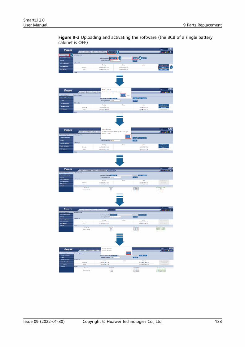
Figure 9-3 Uploading and activating the software (the BCB of a single batterycabinet is OFF)
SmartLi 2.0User Manual 9 Parts Replacement
Issue 09 (2022-01-30) Copyright © Huawei Technologies Co., Ltd. 133
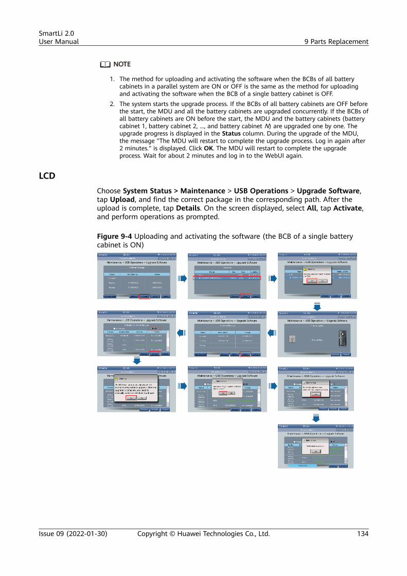
NO TE
1. The method for uploading and activating the software when the BCBs of all batterycabinets in a parallel system are ON or OFF is the same as the method for uploadingand activating the software when the BCB of a single battery cabinet is OFF.
2. The system starts the upgrade process. If the BCBs of all battery cabinets are OFF beforethe start, the MDU and all the battery cabinets are upgraded concurrently. If the BCBs ofall battery cabinets are ON before the start, the MDU and the battery cabinets (batterycabinet 1, battery cabinet 2, ..., and battery cabinet N) are upgraded one by one. Theupgrade progress is displayed in the Status column. During the upgrade of the MDU,the message "The MDU will restart to complete the upgrade process. Log in again after2 minutes." is displayed. Click OK. The MDU will restart to complete the upgradeprocess. Wait for about 2 minutes and log in to the WebUI again.
LCDChoose System Status > Maintenance > USB Operations > Upgrade Software,tap Upload, and find the correct package in the corresponding path. After theupload is complete, tap Details. On the screen displayed, select All, tap Activate,and perform operations as prompted.
Figure 9-4 Uploading and activating the software (the BCB of a single batterycabinet is ON)
SmartLi 2.0User Manual 9 Parts Replacement
Issue 09 (2022-01-30) Copyright © Huawei Technologies Co., Ltd. 134
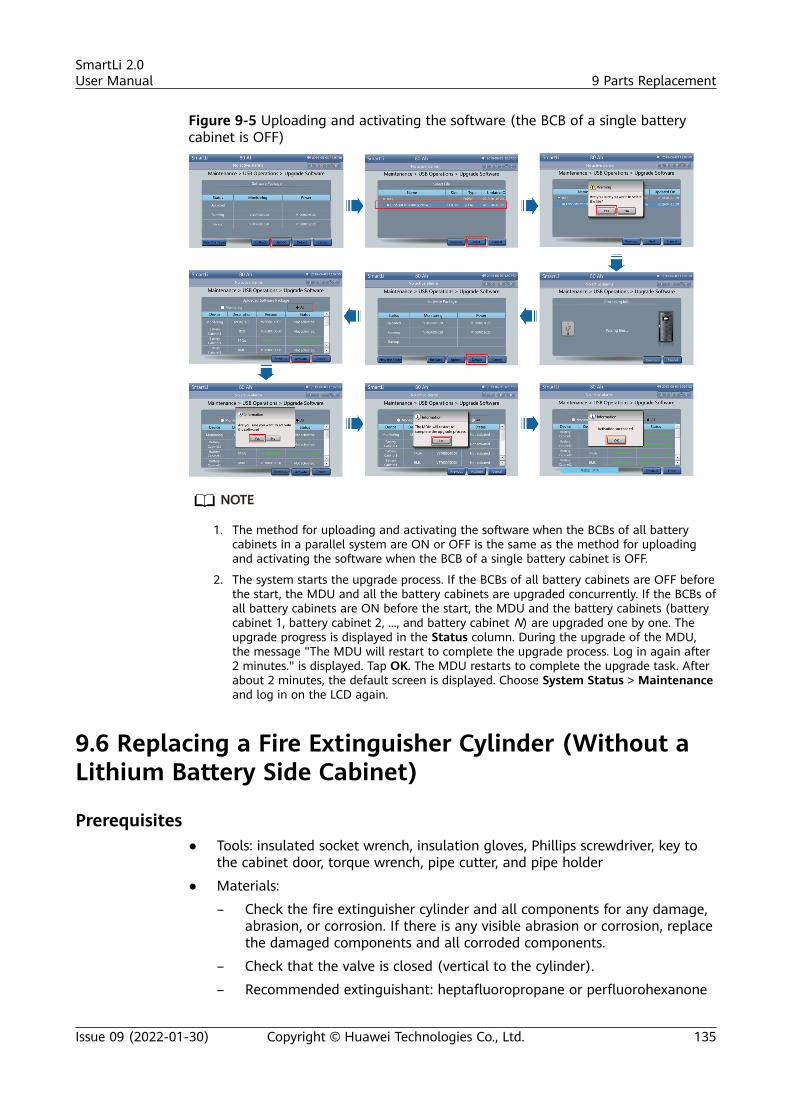
Figure 9-5 Uploading and activating the software (the BCB of a single batterycabinet is OFF)
NO TE
1. The method for uploading and activating the software when the BCBs of all batterycabinets in a parallel system are ON or OFF is the same as the method for uploadingand activating the software when the BCB of a single battery cabinet is OFF.
2. The system starts the upgrade process. If the BCBs of all battery cabinets are OFF beforethe start, the MDU and all the battery cabinets are upgraded concurrently. If the BCBs ofall battery cabinets are ON before the start, the MDU and the battery cabinets (batterycabinet 1, battery cabinet 2, ..., and battery cabinet N) are upgraded one by one. Theupgrade progress is displayed in the Status column. During the upgrade of the MDU,the message "The MDU will restart to complete the upgrade process. Log in again after2 minutes." is displayed. Tap OK. The MDU restarts to complete the upgrade task. Afterabout 2 minutes, the default screen is displayed. Choose System Status > Maintenanceand log in on the LCD again.
9.6 Replacing a Fire Extinguisher Cylinder (Without aLithium Battery Side Cabinet)
Prerequisites● Tools: insulated socket wrench, insulation gloves, Phillips screwdriver, key to
the cabinet door, torque wrench, pipe cutter, and pipe holder
● Materials:
– Check the fire extinguisher cylinder and all components for any damage,abrasion, or corrosion. If there is any visible abrasion or corrosion, replacethe damaged components and all corroded components.
– Check that the valve is closed (vertical to the cylinder).
– Recommended extinguishant: heptafluoropropane or perfluorohexanone
SmartLi 2.0User Manual 9 Parts Replacement
Issue 09 (2022-01-30) Copyright © Huawei Technologies Co., Ltd. 135
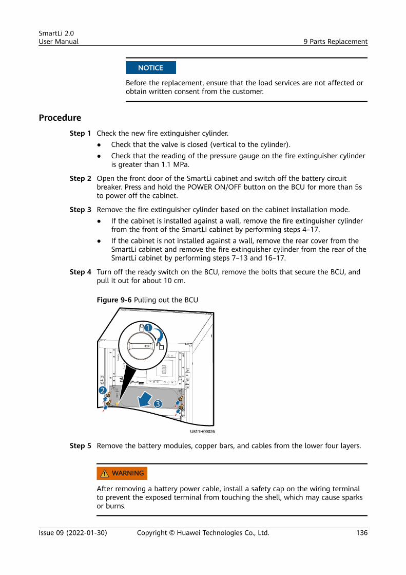
NO TICE
Before the replacement, ensure that the load services are not affected orobtain written consent from the customer.
Procedure
Step 1 Check the new fire extinguisher cylinder.● Check that the valve is closed (vertical to the cylinder).● Check that the reading of the pressure gauge on the fire extinguisher cylinder
is greater than 1.1 MPa.
Step 2 Open the front door of the SmartLi cabinet and switch off the battery circuitbreaker. Press and hold the POWER ON/OFF button on the BCU for more than 5sto power off the cabinet.
Step 3 Remove the fire extinguisher cylinder based on the cabinet installation mode.● If the cabinet is installed against a wall, remove the fire extinguisher cylinder
from the front of the SmartLi cabinet by performing steps 4–17.● If the cabinet is not installed against a wall, remove the rear cover from the
SmartLi cabinet and remove the fire extinguisher cylinder from the rear of theSmartLi cabinet by performing steps 7–13 and 16–17.
Step 4 Turn off the ready switch on the BCU, remove the bolts that secure the BCU, andpull it out for about 10 cm.
Figure 9-6 Pulling out the BCU
Step 5 Remove the battery modules, copper bars, and cables from the lower four layers.
WARNING
After removing a battery power cable, install a safety cap on the wiring terminalto prevent the exposed terminal from touching the shell, which may cause sparksor burns.
SmartLi 2.0User Manual 9 Parts Replacement
Issue 09 (2022-01-30) Copyright © Huawei Technologies Co., Ltd. 136
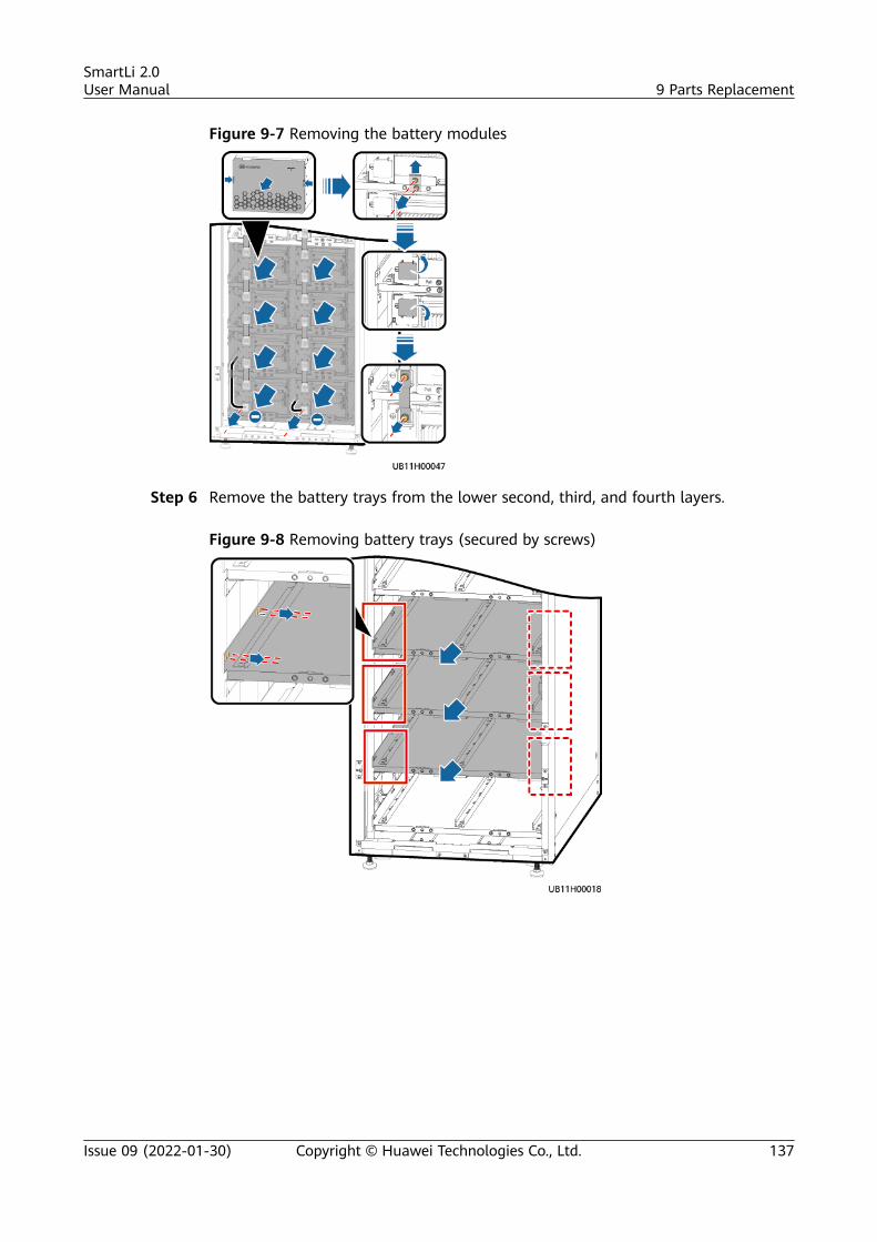
Figure 9-7 Removing the battery modules
Step 6 Remove the battery trays from the lower second, third, and fourth layers.
Figure 9-8 Removing battery trays (secured by screws)
SmartLi 2.0User Manual 9 Parts Replacement
Issue 09 (2022-01-30) Copyright © Huawei Technologies Co., Ltd. 137
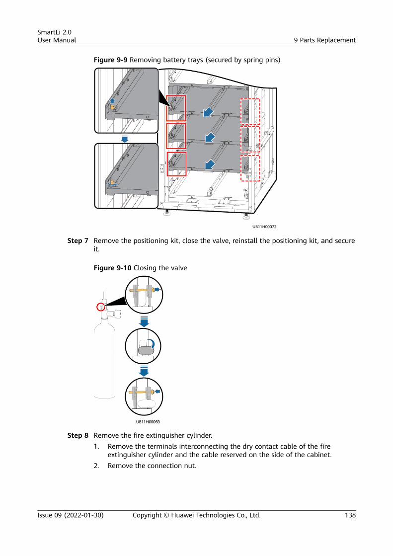
Figure 9-9 Removing battery trays (secured by spring pins)
Step 7 Remove the positioning kit, close the valve, reinstall the positioning kit, and secureit.
Figure 9-10 Closing the valve
Step 8 Remove the fire extinguisher cylinder.1. Remove the terminals interconnecting the dry contact cable of the fire
extinguisher cylinder and the cable reserved on the side of the cabinet.2. Remove the connection nut.
SmartLi 2.0User Manual 9 Parts Replacement
Issue 09 (2022-01-30) Copyright © Huawei Technologies Co., Ltd. 138
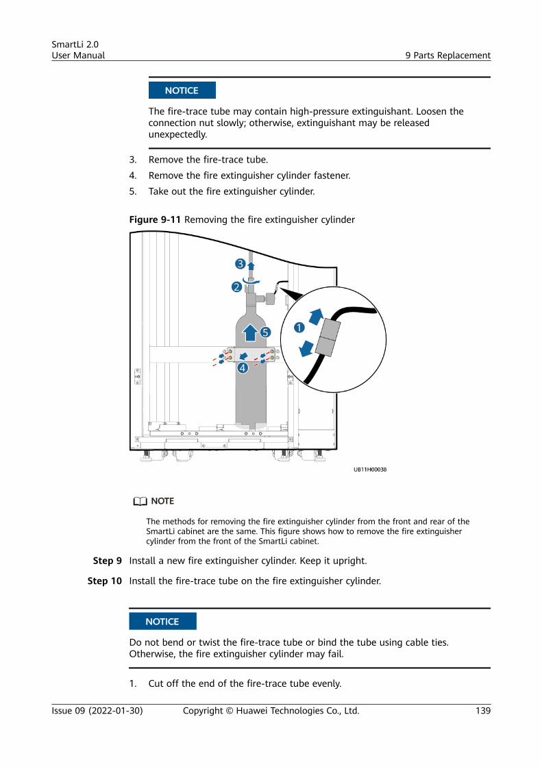
NO TICE
The fire-trace tube may contain high-pressure extinguishant. Loosen theconnection nut slowly; otherwise, extinguishant may be releasedunexpectedly.
3. Remove the fire-trace tube.4. Remove the fire extinguisher cylinder fastener.5. Take out the fire extinguisher cylinder.
Figure 9-11 Removing the fire extinguisher cylinder
NO TE
The methods for removing the fire extinguisher cylinder from the front and rear of theSmartLi cabinet are the same. This figure shows how to remove the fire extinguishercylinder from the front of the SmartLi cabinet.
Step 9 Install a new fire extinguisher cylinder. Keep it upright.
Step 10 Install the fire-trace tube on the fire extinguisher cylinder.
NO TICE
Do not bend or twist the fire-trace tube or bind the tube using cable ties.Otherwise, the fire extinguisher cylinder may fail.
1. Cut off the end of the fire-trace tube evenly.
SmartLi 2.0User Manual 9 Parts Replacement
Issue 09 (2022-01-30) Copyright © Huawei Technologies Co., Ltd. 139
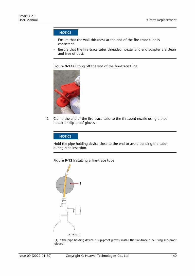
NO TICE
– Ensure that the wall thickness at the end of the fire-trace tube isconsistent.
– Ensure that the fire-trace tube, threaded nozzle, and end adapter are cleanand free of dust.
Figure 9-12 Cutting off the end of the fire-trace tube
2. Clamp the end of the fire-trace tube to the threaded nozzle using a pipeholder or slip-proof gloves.
NO TICE
Hold the pipe holding device close to the end to avoid bending the tubeduring pipe insertion.
Figure 9-13 Installing a fire-trace tube
(1) If the pipe holding device is slip-proof gloves, install the fire-trace tube using slip-proofgloves.
SmartLi 2.0User Manual 9 Parts Replacement
Issue 09 (2022-01-30) Copyright © Huawei Technologies Co., Ltd. 140
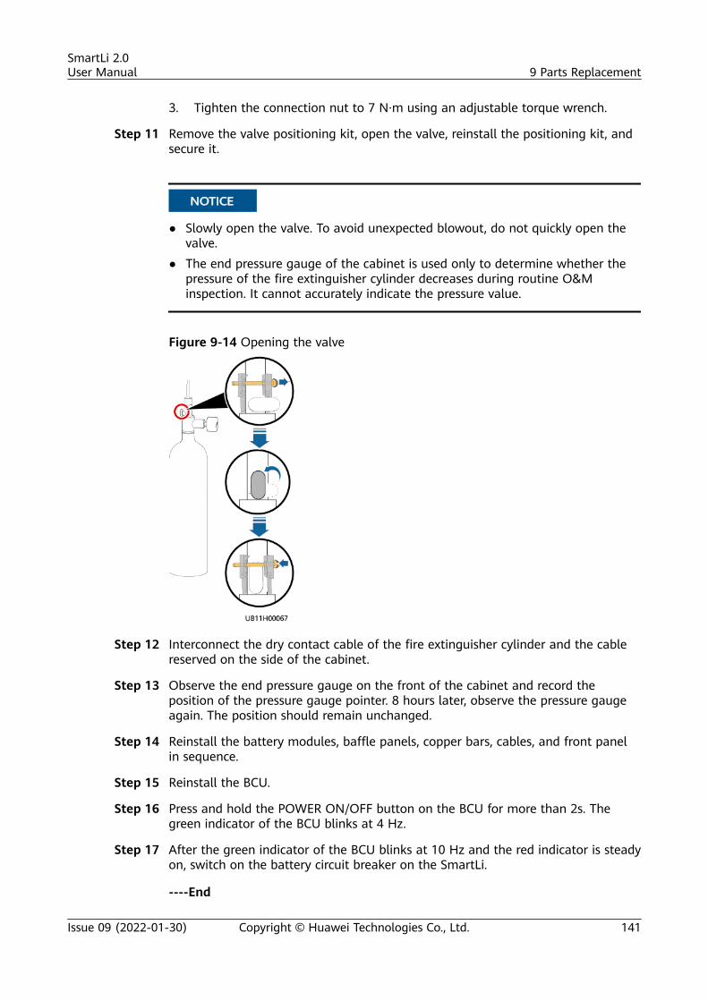
3. Tighten the connection nut to 7 N·m using an adjustable torque wrench.
Step 11 Remove the valve positioning kit, open the valve, reinstall the positioning kit, andsecure it.
NO TICE
● Slowly open the valve. To avoid unexpected blowout, do not quickly open thevalve.
● The end pressure gauge of the cabinet is used only to determine whether thepressure of the fire extinguisher cylinder decreases during routine O&Minspection. It cannot accurately indicate the pressure value.
Figure 9-14 Opening the valve
Step 12 Interconnect the dry contact cable of the fire extinguisher cylinder and the cablereserved on the side of the cabinet.
Step 13 Observe the end pressure gauge on the front of the cabinet and record theposition of the pressure gauge pointer. 8 hours later, observe the pressure gaugeagain. The position should remain unchanged.
Step 14 Reinstall the battery modules, baffle panels, copper bars, cables, and front panelin sequence.
Step 15 Reinstall the BCU.
Step 16 Press and hold the POWER ON/OFF button on the BCU for more than 2s. Thegreen indicator of the BCU blinks at 4 Hz.
Step 17 After the green indicator of the BCU blinks at 10 Hz and the red indicator is steadyon, switch on the battery circuit breaker on the SmartLi.
----End
SmartLi 2.0User Manual 9 Parts Replacement
Issue 09 (2022-01-30) Copyright © Huawei Technologies Co., Ltd. 141
9.7 Replacing a Fire Extinguisher Cylinder (With aLithium Battery Side Cabinet)
Prerequisites● Tools: insulated socket wrench, insulation gloves, Phillips screwdriver, key to
the cabinet door, torque wrench, pipe cutter, and pipe holder● Materials:
– Check the fire extinguisher cylinder and all components for any damage,abrasion, or corrosion. If there is any visible abrasion or corrosion, replacethe damaged components and all corroded components.
– Check that the valve is closed (vertical to the cylinder).– Recommended extinguishant: heptafluoropropane or perfluorohexanone
NO TICE
Before the replacement, ensure that the load services are not affected orobtain written consent from the customer.
Procedure
Step 1 Check the new fire extinguisher cylinder.● Check that the valve is closed (vertical to the cylinder).● Check that the reading of the pressure gauge on the fire extinguisher cylinder
is greater than 1.1 MPa.
Step 2 Open the front door of the SmartLi cabinet and switch off the battery circuitbreaker. Press and hold the POWER ON/OFF button on the BCU for more than 5sto power off the cabinet.
Step 3 Remove the front door panel of the lithium battery side cabinet and thepositioning kit, close the valve, reinstall the positioning kit, and secure it.
SmartLi 2.0User Manual 9 Parts Replacement
Issue 09 (2022-01-30) Copyright © Huawei Technologies Co., Ltd. 142
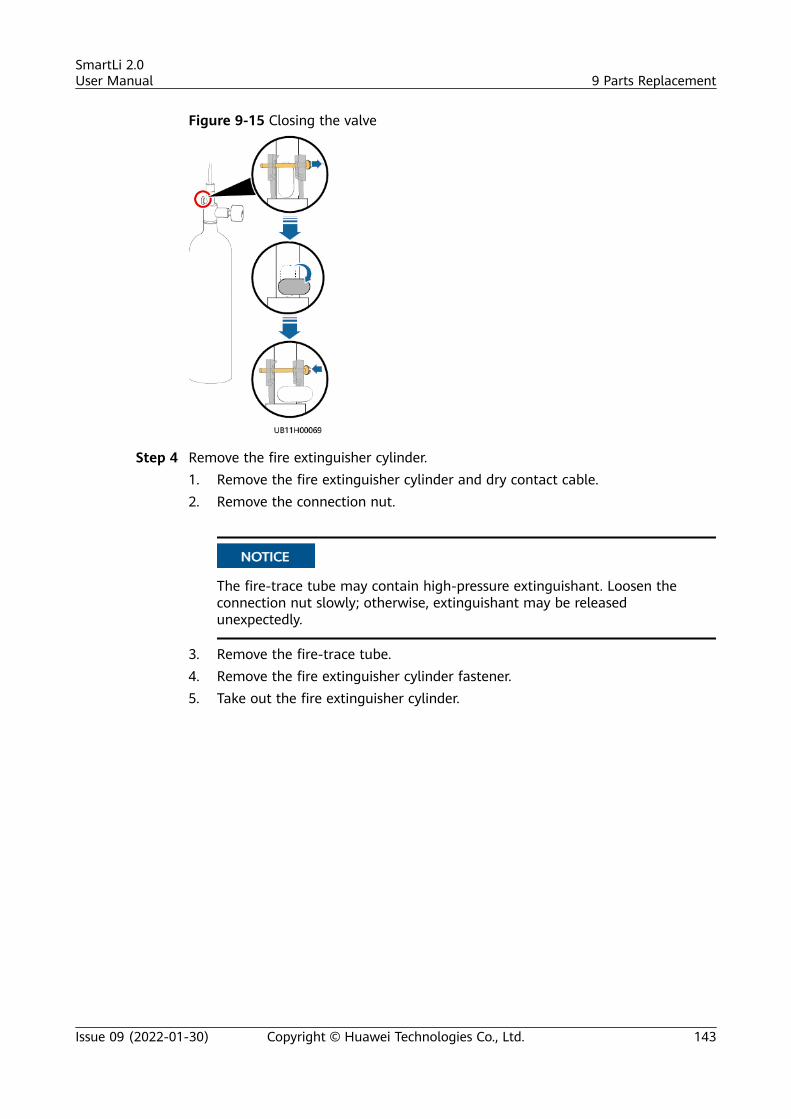
Figure 9-15 Closing the valve
Step 4 Remove the fire extinguisher cylinder.1. Remove the fire extinguisher cylinder and dry contact cable.2. Remove the connection nut.
NO TICE
The fire-trace tube may contain high-pressure extinguishant. Loosen theconnection nut slowly; otherwise, extinguishant may be releasedunexpectedly.
3. Remove the fire-trace tube.4. Remove the fire extinguisher cylinder fastener.5. Take out the fire extinguisher cylinder.
SmartLi 2.0User Manual 9 Parts Replacement
Issue 09 (2022-01-30) Copyright © Huawei Technologies Co., Ltd. 143
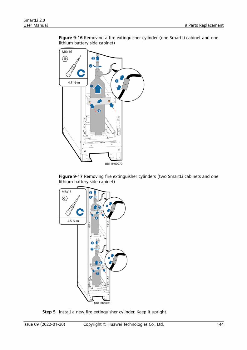
Figure 9-16 Removing a fire extinguisher cylinder (one SmartLi cabinet and onelithium battery side cabinet)
Figure 9-17 Removing fire extinguisher cylinders (two SmartLi cabinets and onelithium battery side cabinet)
Step 5 Install a new fire extinguisher cylinder. Keep it upright.
SmartLi 2.0User Manual 9 Parts Replacement
Issue 09 (2022-01-30) Copyright © Huawei Technologies Co., Ltd. 144
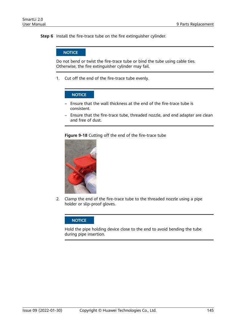
Step 6 Install the fire-trace tube on the fire extinguisher cylinder.
NO TICE
Do not bend or twist the fire-trace tube or bind the tube using cable ties.Otherwise, the fire extinguisher cylinder may fail.
1. Cut off the end of the fire-trace tube evenly.
NO TICE
– Ensure that the wall thickness at the end of the fire-trace tube isconsistent.
– Ensure that the fire-trace tube, threaded nozzle, and end adapter are cleanand free of dust.
Figure 9-18 Cutting off the end of the fire-trace tube
2. Clamp the end of the fire-trace tube to the threaded nozzle using a pipeholder or slip-proof gloves.
NO TICE
Hold the pipe holding device close to the end to avoid bending the tubeduring pipe insertion.
SmartLi 2.0User Manual 9 Parts Replacement
Issue 09 (2022-01-30) Copyright © Huawei Technologies Co., Ltd. 145
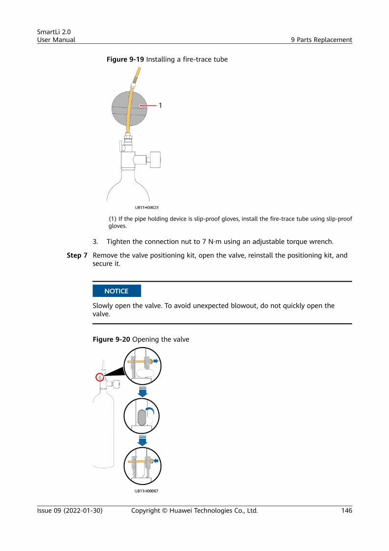
Figure 9-19 Installing a fire-trace tube
(1) If the pipe holding device is slip-proof gloves, install the fire-trace tube using slip-proofgloves.
3. Tighten the connection nut to 7 N·m using an adjustable torque wrench.
Step 7 Remove the valve positioning kit, open the valve, reinstall the positioning kit, andsecure it.
NO TICE
Slowly open the valve. To avoid unexpected blowout, do not quickly open thevalve.
Figure 9-20 Opening the valve
SmartLi 2.0User Manual 9 Parts Replacement
Issue 09 (2022-01-30) Copyright © Huawei Technologies Co., Ltd. 146
Step 8 Connect the dry contact cable to the fire extinguisher cylinder.
Step 9 Observe the pressure gauge on the front of the cabinet. The value of the pressuregauge should be within the allowable pressure range (1.6–1.8 MPa at 20°C)specified in Table 4-3, and record the position of the pressure gauge pointer. After8 hours, observe the pressure gauge again. The position should remainunchanged.
Step 10 Press and hold the POWER ON/OFF button on the BCU for more than 2s. Thegreen indicator of the BCU blinks at 4 Hz.
Step 11 After the green indicator of the BCU blinks at 10 Hz and the red indicator is steadyon, switch on the battery circuit breaker on the SmartLi.
----End
SmartLi 2.0User Manual 9 Parts Replacement
Issue 09 (2022-01-30) Copyright © Huawei Technologies Co., Ltd. 147
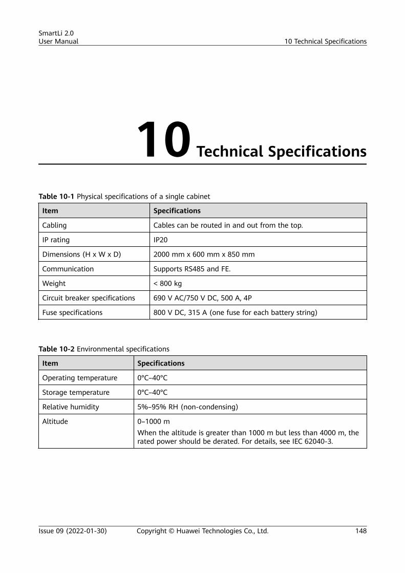
10 Technical Specifications
Table 10-1 Physical specifications of a single cabinet
Item Specifications
Cabling Cables can be routed in and out from the top.
IP rating IP20
Dimensions (H x W x D) 2000 mm x 600 mm x 850 mm
Communication Supports RS485 and FE.
Weight < 800 kg
Circuit breaker specifications 690 V AC/750 V DC, 500 A, 4P
Fuse specifications 800 V DC, 315 A (one fuse for each battery string)
Table 10-2 Environmental specifications
Item Specifications
Operating temperature 0°C–40°C
Storage temperature 0°C–40°C
Relative humidity 5%–95% RH (non-condensing)
Altitude 0–1000 mWhen the altitude is greater than 1000 m but less than 4000 m, therated power should be derated. For details, see IEC 62040-3.
SmartLi 2.0User Manual 10 Technical Specifications
Issue 09 (2022-01-30) Copyright © Huawei Technologies Co., Ltd. 148
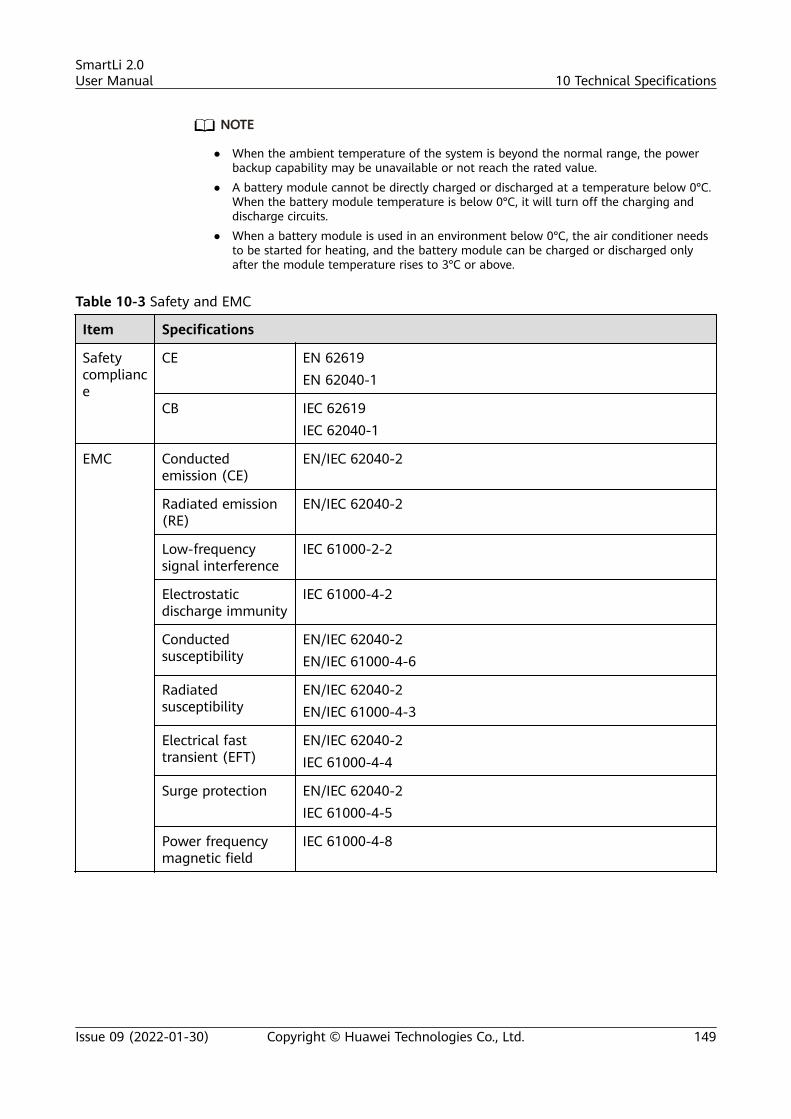
NO TE
● When the ambient temperature of the system is beyond the normal range, the powerbackup capability may be unavailable or not reach the rated value.
● A battery module cannot be directly charged or discharged at a temperature below 0°C.When the battery module temperature is below 0°C, it will turn off the charging anddischarge circuits.
● When a battery module is used in an environment below 0°C, the air conditioner needsto be started for heating, and the battery module can be charged or discharged onlyafter the module temperature rises to 3°C or above.
Table 10-3 Safety and EMC
Item Specifications
Safetycompliance
CE EN 62619EN 62040-1
CB IEC 62619IEC 62040-1
EMC Conductedemission (CE)
EN/IEC 62040-2
Radiated emission(RE)
EN/IEC 62040-2
Low-frequencysignal interference
IEC 61000-2-2
Electrostaticdischarge immunity
IEC 61000-4-2
Conductedsusceptibility
EN/IEC 62040-2EN/IEC 61000-4-6
Radiatedsusceptibility
EN/IEC 62040-2EN/IEC 61000-4-3
Electrical fasttransient (EFT)
EN/IEC 62040-2IEC 61000-4-4
Surge protection EN/IEC 62040-2IEC 61000-4-5
Power frequencymagnetic field
IEC 61000-4-8
SmartLi 2.0User Manual 10 Technical Specifications
Issue 09 (2022-01-30) Copyright © Huawei Technologies Co., Ltd. 149
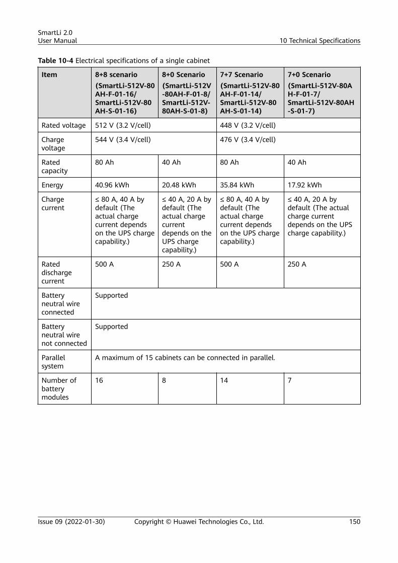
Table 10-4 Electrical specifications of a single cabinet
Item 8+8 scenario(SmartLi-512V-80AH-F-01-16/SmartLi-512V-80AH-S-01-16)
8+0 Scenario(SmartLi-512V-80AH-F-01-8/SmartLi-512V-80AH-S-01-8)
7+7 Scenario(SmartLi-512V-80AH-F-01-14/SmartLi-512V-80AH-S-01-14)
7+0 Scenario(SmartLi-512V-80AH-F-01-7/SmartLi-512V-80AH-S-01-7)
Rated voltage 512 V (3.2 V/cell) 448 V (3.2 V/cell)
Chargevoltage
544 V (3.4 V/cell) 476 V (3.4 V/cell)
Ratedcapacity
80 Ah 40 Ah 80 Ah 40 Ah
Energy 40.96 kWh 20.48 kWh 35.84 kWh 17.92 kWh
Chargecurrent
≤ 80 A, 40 A bydefault (Theactual chargecurrent dependson the UPS chargecapability.)
≤ 40 A, 20 A bydefault (Theactual chargecurrentdepends on theUPS chargecapability.)
≤ 80 A, 40 A bydefault (Theactual chargecurrent dependson the UPS chargecapability.)
≤ 40 A, 20 A bydefault (The actualcharge currentdepends on the UPScharge capability.)
Rateddischargecurrent
500 A 250 A 500 A 250 A
Batteryneutral wireconnected
Supported
Batteryneutral wirenot connected
Supported
Parallelsystem
A maximum of 15 cabinets can be connected in parallel.
Number ofbatterymodules
16 8 14 7
SmartLi 2.0User Manual 10 Technical Specifications
Issue 09 (2022-01-30) Copyright © Huawei Technologies Co., Ltd. 150

Table 10-5 Protection function
Item Specifications
Battery overvoltageprotection
Cell:● Level-1 protection: > 3.65 V● Level-2 protection warning: > 3.8 V● Level-2 protection: > 3.9 VBattery string:● Level-1 protection: > 564 V● Level-2 protection warning: > 568 V● Level-2 protection: > 580 V
Battery undervoltageprotection
Cell:● Undervoltage warning: < 2.6 V● Level-1 protection: < 2.5 V● Level-2 protection: < 2.3 VBattery string:● Undervoltage warning: < 448 V● Protection: < 408 V
Overtemperatureprotection
> 67°C
Undertemperatureprotection
< –5°C
Overcurrent protection Charge:● Level-1 protection: > 96 A● Level-2 protection: > 200 ADischarge:● Level-1 protection: > 500 A● Level-2 protection: > 520 A
EPO protection You can trigger the SmartLi EPO protection by performing EPO on theUPS or over the specified dry contact of the SmartLi.
NO TE
When the UPS5000-E is used with the SmartLi, the maximum half-wave load capacity is 5%of the rated load.
SmartLi 2.0User Manual 10 Technical Specifications
Issue 09 (2022-01-30) Copyright © Huawei Technologies Co., Ltd. 151
A Alarm List
NO TE
For details about alarms, see the UPS5000 & SmartLi Alarm Reference.
SmartLi 2.0User Manual A Alarm List
Issue 09 (2022-01-30) Copyright © Huawei Technologies Co., Ltd. 152
B Supplementary Warranty Rules
● Huawei will not be liable for any damage to Huawei battery modulescaused by force majeure:
– Natural disasters such as earthquakes, volcanic eruptions, and landslides
– Fires
– Wars
– Lightning strikes
● Huawei will not be liable for any damage to Huawei battery modulescaused by the following events:
– Damage such as breakage and leakage is caused to battery modules due tomisoperations or incorrect connections during battery module transportation andinstallation performed by the customer.
– Capacity loss or irreversible damage is caused to battery modules because theyare not charged in a timely manner and stored over due to customer reasons.
– After battery modules are installed at a site and connected to the system, theyare damaged due to overdischarge because they are not powered on in a timelymanner due to customer reasons.
– Battery modules are damaged because they are not accepted in a timely mannerdue to customer reasons.
– Battery modules are damaged because the operating environment or externalpower specifications do not meet environmental requirements. For example, theoperating temperature is poor, power outages occur frequently, battery modulesare frequently overdischarged due to improper maintenance, the capacity of acustomer site is expanded, or battery modules are not fully charged for a longperiod.
– No air conditioner is available onsite, or the ambient humidity is too high. As aresult, the PCB and components are corroded, affecting the product reliability andquality. The product cannot be used properly or is even damaged.
– The customer changes the application scenarios of battery modules withoutnotifying Huawei.
SmartLi 2.0User Manual B Supplementary Warranty Rules
Issue 09 (2022-01-30) Copyright © Huawei Technologies Co., Ltd. 153
– Battery modules are damaged due to the reasons of the customer or a thirdparty, such as reallocating or reinstalling battery modules without followingHuawei's requirements.
– The customer incorrectly sets operating management parameters for batterymodules. The parameters include but are not limited to battery module capacity,quantity, equalized charging voltage, float charging voltage, charge current limit,and disconnection voltage.
– The customer fails to follow the Quick Guide or User Manual in battery modulemaintenance. For example, the customer does not periodically check whether theterminal screws of battery modules are tightened.
– The customer connects extra loads to battery modules.
– The customer uses the battery modules provided by Huawei together with otherbattery modules, which causes the acceleration of capacity decrease. For example,the customer uses Huawei's battery modules together with battery modules ofother brands, with battery modules of different rated capacity, or with old batterymodules.
– The warranty period of battery modules has expired.
SmartLi 2.0User Manual B Supplementary Warranty Rules
Issue 09 (2022-01-30) Copyright © Huawei Technologies Co., Ltd. 154
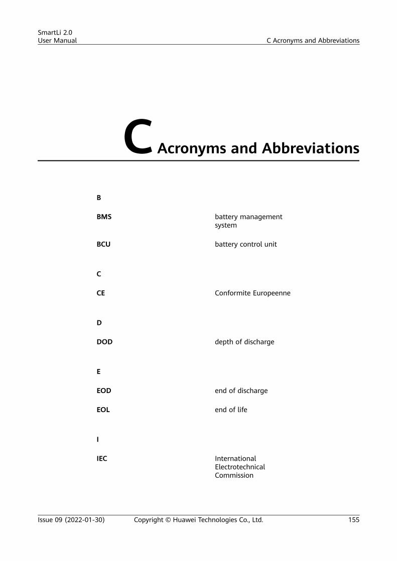
C Acronyms and Abbreviations
B
BMS battery managementsystem
BCU battery control unit
C
CE Conformite Europeenne
D
DOD depth of discharge
E
EOD end of discharge
EOL end of life
I
IEC InternationalElectrotechnicalCommission
SmartLi 2.0User Manual C Acronyms and Abbreviations
Issue 09 (2022-01-30) Copyright © Huawei Technologies Co., Ltd. 155
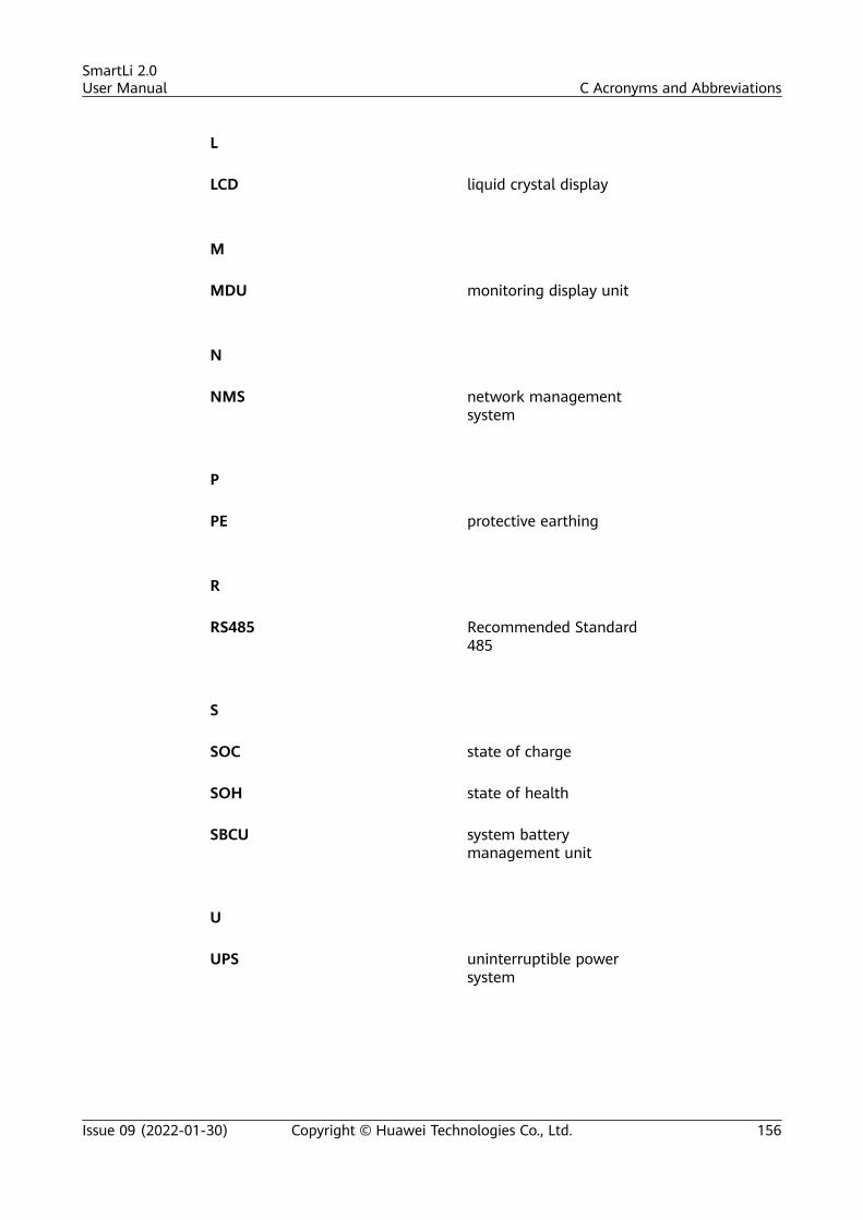
L
LCD liquid crystal display
M
MDU monitoring display unit
N
NMS network managementsystem
P
PE protective earthing
R
RS485 Recommended Standard485
S
SOC state of charge
SOH state of health
SBCU system batterymanagement unit
U
UPS uninterruptible powersystem
SmartLi 2.0User Manual C Acronyms and Abbreviations
Issue 09 (2022-01-30) Copyright © Huawei Technologies Co., Ltd. 156
Copyright © 2022 FDOKUMEN