Ball Screw - THK Technical Support
474
Ball Screw General Catalog A15-1 511E
-
Upload
khangminh22 -
Category
Documents
-
view
1 -
download
0
Transcript of Ball Screw - THK Technical Support

Ball ScrewGeneral Catalog
A15-1
511E

A15-2
Ball ScrewGeneral Catalog
A Product DescriptionsTypes of Ball Screws ............................. A15-6
Point of Selection ................................ A15-8Flowchart for Selecting a Ball Screw ..... A15-8Accuracy of the Ball Screw .................... A15-11
• Lead Angle Accuracy ............................ A15-11• Accuracy of the Mounting Surface .......... A15-14• Axial Clearance ................................... A15-19• Preload .............................................. A15-20
Selecting a Screw Shaft ........................ A15-24• Maximum Length of the Screw Shaft ...... A15-24• Standard Combinations of Shaft Diameter and Lead for the Precision Ball Screw . A15-26• Standard Combinations of Shaft Diameter and Lead for the Rolled Ball Screw .. A15-27
Method for Mounting the Ball Screw Shaft .. A15-28Permissible Axial Load .......................... A15-30Permissible Rotational Speed ............... A15-32Selecting a Nut ...................................... A15-35
• Types of Nuts ...................................... A15-35Selecting a Model Number .................... A15-40
• Calculating the Axial Load ..................... A15-40• Static Safety Factor .............................. A15-41• Studying the Service Life ...................... A15-42
Studying the Rigidity .............................. A15-45• Axial Rigidity of the Feed Screw System .. A15-45
Studying the Positioning Accuracy ........ A15-49• Causes of Error in the Positioning Accuracy .. A15-49• Studying the Lead Angle Accuracy ......... A15-49• Studying the Axial Clearance ................. A15-49• Studying the Axial Clearance of the Feed Screw System .. A15-51• Studying the Thermal Displacement through Heat Generation ... A15-53• Studying the Orientation Change during Traveling .. A15-54
Studying the Rotational Torque ............. A15-55• Frictional Torque Due to an External Load .. A15-55• Torque Due to a Preload on the Ball Screw .. A15-56• Torque Required for Acceleration ........... A15-57• Investigating the Terminal Strength of Ball Screw Shafts .. A15-58
Studying the Driving Motor .................... A15-60• When Using a Servomotor .................... A15-60• When Using a Stepping Motor (Pulse Motor) .. A15-62
Features of Each Model ...................... A15-63Precision, Caged Ball ScrewModels SBN-V, SBK, SDA-V, HBN and SBKH .. A15-64
• Structure and Features ......................... A15-65• Ball Cage Effect ................................... A15-65• Types and Features ............................. A15-68• Examples of Assembling Models HBN and SBKH .. A15-70
Dimensional Drawing, Dimensional TableModel SBN-V ......................................... A15-72Model SBK............................................. A15-76Model SDA-V ......................................... A15-80Model HBN ............................................ A15-86Model SBKH .......................................... A15-88
Models EBA, EBB, EBC, EPA, EPB and EPC .. A15-90• Structure and Features ......................... A15-91• Types and Features ............................. A15-92• Accuracy Standards ............................. A15-93
Dimensional Drawing, Dimensional TableModel EBA (Oversized-ball preload type or non-preloaded type) .. A15-94Model EBB (Oversized-ball preload type or non-preloaded type) .. A15-96Model EBC (Oversized-ball preload type or non-preloaded type) .. A15-98Model EPA (Offset Preload Type) .......... A15-100Model EPB (Offset Preload Type) ......... A15-102Model EPC (Offset Preload Type) ......... A15-104
Unfi nished Shaft Ends Precision Ball Screw Models BIF, MDK, MBF and BNF .................. A15-106
• Structure and Features ......................... A15-107• Types and Features ............................. A15-108• Nut Types and Axial Clearance .............. A15-109
Dimensional Drawing, Dimensional TableUnfi nished Shaft Ends ........................... A15-110
Finished Shaft Ends Precision Ball ScrewModel BNK ............................................. A15-132
• Features ............................................. A15-133• Types and Features ............................. A15-133• Table of Ball Screw Types with Finished Shaft Ends
and the CorrespondingSupport Units and Nut Brackets .. A15-134
Dimensional Drawing, Dimensional TableBNK0401-3 Shaft diameter: 4; lead: 1 ... A15-136BNK0501-3 Shaft diameter: 5; lead: 1 ... A15-138BNK0601-3 Shaft diameter: 6; lead: 1 ... A15-140BNK0801-3 Shaft diameter: 8; lead: 1 ... A15-142BNK0802-3 Shaft diameter: 8; lead: 2 ... A15-144BNK0810-3 Shaft diameter: 8; lead: 10 .. A15-146BNK1002-3 Shaft diameter: 10; lead: 2 .. A15-148BNK1004-2.5 Shaft diameter: 10; lead: 4 .. A15-150BNK1010-1.5 Shaft diameter: 10; lead: 10 .. A15-152BNK1202-3 Shaft diameter: 12; lead: 2 .. A15-154BNK1205-2.5 Shaft diameter: 12; lead: 5 .. A15-156BNK1208-2.6 Shaft diameter: 12; lead: 8 .. A15-158
511E

A15-3
BNK1402-3 Shaft diameter: 14; lead: 2 .. A15-160BNK1404-3 Shaft diameter: 14; lead: 4 .. A15-162BNK1408-2.5 Shaft diameter: 14; lead: 8 .. A15-164BNK1510-5.6 Shaft diameter: 15; lead: 10 .. A15-166BNK1520-3 Shaft diameter: 15; lead: 20 .. A15-168BNK1616-3.6 Shaft diameter: 16; lead: 16 .. A15-170BNK2010-2.5 Shaft diameter: 20; lead: 10 .. A15-172BNK2020-3.6 Shaft diameter: 20; lead: 20 .. A15-174BNK2520-3.6 Shaft diameter: 25; lead: 20 .. A15-176
Precision Ball ScrewModels BIF-V, DIK, BNFN-V/BNFN, DKN, BLW, BNF-V/BNF, DK, MDK, WHF, BLK/WGF and BNT .. A15-178
• Structure and Features ......................... A15-179• Types and Features ............................. A15-180
Dimensional Drawing, Dimensional TablePreload Type of Precision Ball Screw .... A15-184No Preload Type of Precision Ball Screw .. A15-204No Preload Type of Precision Ball Screw (Square Nut) .. A15-228
• Model Number Coding .......................... A15-230
Precision Rotary Ball ScrewModels DIR and BLR ........................... A15-232
• Structure and Features ......................... A15-233• Type .................................................. A15-235• Accuracy Standards ............................. A15-236• Example of Assembly ........................... A15-238
Dimensional Drawing, Dimensional TableModel DIR Standard Lead Rotary-Nut Ball Screw .. A15-240Model BLR Large Lead Rotary-Nut Ball Screw .. A15-242
• Permissible Rotational Speeds for Rotary Ball Screws .. A15-244
Precision Ball Screw/SplineModels BNS-A, BNS, NS-A and NS .... A15-246
• Structure and Features ......................... A15-247• Type .................................................. A15-248• Accuracy Standards ............................. A15-249• Action Patterns .................................... A15-250• Example of Assembly ........................... A15-253• Example of Use ................................... A15-254• Precautions on Use .............................. A15-255
Dimensional Drawing, Dimensional TableModel BNS-A Compact Type: Linear-Rotary Motion .... A15-256Model BNS Heavy Load Type: Linear-Rotary Motion ... A15-258Model NS-A Compact Type: Linear Motion .... A15-260Model NS Heavy Load Type: Linear Motion .. A15-262
Rolled Ball ScrewModels JPF, BTK-V, MTF, WHF, BLK/WTF, CNF and BNT .. A15-264
• Structure and Features ......................... A15-265• Types and Features ............................. A15-266
Dimensional Drawing, Dimensional TablePreload Type of Rolled Ball Screw ........ A15-270No Preload Type of Rolled Ball Screw ... A15-272No Preload Type of Rolled Ball Screw (Square Nut) .. A15-280
• Model Number Coding .......................... A15-283
Standard Unfi nished Shaft Ends Rolled Ball ScrewModel MTF ................................................. A15-284
• Structure and Features ......................... A15-285• Types and Features ............................. A15-285
Dimensional Drawing, Dimensional TableUnfi nished Shaft Ends Rolled Ball Screw Model MTF .. A15-286
Rolled Rotary Ball ScrewModel BLR ............................................ A15-288
• Structure and Features ......................... A15-289• Type .................................................. A15-289• Accuracy Standards ............................. A15-290• Example of Assembly ........................... A15-291
Dimensional Drawing, Dimensional TableModel BLR Large Lead Rotary Nut Rolled Ball Screw .. A15-294
• Maximum Length of the Ball Screw Shaft .. A15-296
Ball Screw Peripherals ........................ A15-299Support UnitModels EK, BK, FK, EF, BF and FF .... A15-300
• Structure and Features ......................... A15-300• Type .................................................. A15-302• Types of Support Units and Applicable Screw Shaft Outer Diameters .. A15-303• Model Numbers of Bearings and Characteristic Values .. A15-304• Example of Installation .......................... A15-305• Mounting Procedure ............................. A15-306• Types of Recommended Shapes of the Shaft Ends .. A15-308
Dimensional Drawing, Dimensional TableModel EK Square Type Support Unit on the Fixed Side .. A15-310Model BK Square Type Support Unit on the Fixed Side .. A15-312Model FK Round Type Support Unit on the Fixed Side .. A15-314Model EF Square Type Support Unit on the Supported Side .. A15-318Model BF Square Type Support Unit on the Supported Side .. A15-320Model FF Round Type Support Unit on the Supported Side .. A15-322
511E

A15-4
Recommended Shapes of Shaft Ends - Shape H (H1, H2 and H3) (For Support Unit Models FK and EK) .. A15-324Recommended Shapes of Shaft Ends - Shape J (J1, J2 and J3) (For Support Unit Model BK) .. A15-326Recommended Shapes of Shaft Ends - Shape K (For Support Unit Models FF, EF and BF) .... A15-328
Nut Bracket (Model MC) ...................... A15-330• Structure and Features ......................... A15-330• Type .................................................. A15-330
Dimensional Drawing, Dimensional TableNut Bracket ............................................ A15-331
Lock Nut (Model RN) ........................... A15-332• Structure and Features ......................... A15-332• Type .................................................. A15-332
Dimensional Drawing, Dimensional TableLock Nut ................................................ A15-333
Options ................................................. A15-335Contaminaton Protection ....................... A15-336Lubrication ............................................. A15-337Corrosion Resistance (Surface Treatment, etc.) .. A15-337Contamination Protection Seal for Ball Screws .. A15-338Wiper Ring W ........................................ A15-339Dust Cover for Ball Screws.................... A15-341QZ Lubricator......................................... A15-342Dimensions of Each Model with an Option Attached .. A15-344
• Dimensions of the Ball Screw Nut Attached with Wiper Ring W and QZ Lubricator . A15-344• Specifi cations of the Bellows ................. A15-352
Model No. ............................................. A15-353• Model Number Coding .......................... A15-353• Notes on Ordering................................ A15-357
Precautions on Use ............................. A15-358Precautions on Using Options for the Ball Screw . A15-360
• QZ Lubricator for the Ball Screw ............ A15-360
511E

A15-5
Examples of Selecting a Ball Screw ...... B15-69• High-speed Transfer Equipment (Horizontal Use) .. B15-69• Vertical Conveyance System ................. B15-83
Options ................................................. B15-95Contaminaton Protection ....................... B15-96Lubrication ............................................. B15-97Corrosion Resistance (Surface Treatment, etc.) .. B15-97Contamination Protection Seal for Ball Screws .. B15-98Wiper Ring W ........................................ B15-99Dust Cover for Ball Screws.................... B15-101QZ Lubricator......................................... B15-102
Mounting Procedure and Maintenance .. B15-104Mounting Procedure .............................. B15-104
• Installing the Support Unit ..................... B15-104• Installation onto the Table and the Base .. B15-104• Checking the Accuracy and Fully Fastening the Support Unit ... B15-105• Connection with the Motor ..................... B15-105
Maintenance Method ............................. B15-106• Amount of Lubricant ............................. B15-106
Model No. ............................................. B15-107• Model Number Coding .......................... B15-107• Notes on Ordering................................ B15-111
Precautions on Use ............................. B15-112Precautions on Using Options for the Ball Screw . B15-114
• QZ Lubricator for the Ball Screw ............ B15-114
Features and Types ............................. B15-6Features of the Ball Screw .................... B15-6
• Driving Torque One Third of the Sliding Screw .. B15-6• Examples of Calculating Driving Torque ........ B15-8• Ensuring High Accuracy ........................ B15-9• Capable of Micro Feeding ..................... B15-10• High Rigidity without Backlash ............... B15-11• Capable of Fast Feed ........................... B15-12
Types of Ball Screws ............................. B15-14
Point of Selection ................................ B15-16Flowchart for Selecting a Ball Screw ..... B15-16Accuracy of the Ball Screw .................... B15-19
• Lead Angle Accuracy ............................ B15-19• Accuracy of the Mounting Surface .......... B15-22• Axial Clearance ................................... B15-27• Preload .............................................. B15-28• Example of calculating the preload torque ........ B15-31
Selecting a Screw Shaft ........................ B15-32• Maximum Length of the Screw Shaft ...... B15-32• Standard Combinations of Shaft Diameter and Lead for the Precision Ball Screw . B15-34• Standard Combinations of Shaft Diameter and Lead for the Rolled Ball Screw .. B15-35
Method for Mounting the Ball Screw Shaft .. B15-36Permissible Axial Load .......................... B15-38Permissible Rotational Speed ............... B15-40Selecting a Nut ...................................... B15-43
• Types of Nuts ...................................... B15-43Selecting a Model Number .................... B15-46
• Calculating the Axial Load ..................... B15-46• Static Safety Factor .............................. B15-47• Studying the Service Life ...................... B15-48
Studying the Rigidity .............................. B15-51• Axial Rigidity of the Feed Screw System .. B15-51
Studying the Positioning Accuracy ........ B15-55• Causes of Error in the Positioning Accuracy .. B15-55• Studying the Lead Angle Accuracy ......... B15-55• Studying the Axial Clearance ................. B15-55• Studying the Axial Clearance of the Feed Screw System .. B15-57• Example of considering the rigidity of a feed screw system .. B15-57• Studying the Thermal Displacement through Heat Generation ... B15-59• Studying the Orientation Change during Traveling .. B15-60
Studying the Rotational Torque ............. B15-61• Frictional Torque Due to an External Load .. B15-61• Torque Due to a Preload on the Ball Screw .. B15-62• Torque Required for Acceleration ........... B15-63• Investigating the Terminal Strength of Ball Screw Shafts .. B15-64
Studying the Driving Motor .................... B15-66• When Using a Servomotor .................... B15-66• When Using a Stepping Motor (Pulse Motor) .. B15-68
B Support Book (Separate)
511E

A15-6
Types of Ball Screws
Model SBN-VHigh Speed
Model SBK
PreloadModel HBN
High Load
No Preload
Ball Screw
Precision (for positioning)
Caged Ball Full-Ball
Square NutModel BNT
Slim NutModel DK
MiniatureModel MDK
Large LeadModel BLK
Super LeadModel WHF
Super LeadModel WGF
No PreloadModels BNF-V/BNF
Standard Nut
Model BIF-V
Model DIKSlim Nut
Model DKNSlim Nut
Model BLW
Large Lead
Preload
Models BNFN-V/BNFN
Model SBKH
Double-Nut
Standard Nut
Model DIRRotary Nut
PreloadModel BLR
Large LeadRotary Nut
No Preload
Model BIFStandard Nut
PreloadModel MDK
Miniature
Model MBFMiniature
Model BNFStandard Nut
No Preload
Model BNKStandard to Super Lead
Preload,No Preload
No PreloadModel NSModel BNS
Standard Nut
Precision Rotary
High LoadHigh Speed
Precision Ball Screw/Spline
Double-Nut
Double-Nut
High SpeedLarge Lead
Unfinished Shaft Ends
Finished Shaft Ends
Model SDA-V
CompactHigh Speed
Standard to Super Lead
Preload,No Preload
Standard Nut
Round-flange type
Type with one cut face
Type with two cut faces
Compact
Compact
Preload,No Preload
Model EB□
Model EBA
Model EBC
Model EBB
Model EPA
Model EPB
Model EPC
Model EP□
Type with one cut face
Type with two cut faces
Round-flange type
DIN69051
DIN69051
511E

A15-7
Ball Screw
MiniatureModel MTF
Square NutModel BNT
Large LeadModel BLK
Super LeadModel WHF
Super LeadModel WTF
Super LeadModel CNF
No PreloadModel BTK-V
Standard Nut
PreloadModel JPFConstant Pressure Preload
Slim Nut
Model BLRLarge LeadRotary Nut
No Preload
Rolled (Transport)
Full-Ball
Rolled Rotary
Model MTF
No Preload
Unfinished Shaft Ends
Ball Screw Peripherals
Nut BracketSupport Unit
Model EF
Model BF
Model MCLock NutModel RN
Model EK
Model BK
Model FK Model FF
Supported SideFixed Side
Miniature
Features and TypesTypes of Ball Screws
511E

A15-8
Selection StartsSelecting conditions
Estimating the shaft length
Studying the permissible axial load
Selecting the permissible rotational speed
Selecting lead
Selecting a shaft diameter
Selecting a method for mounting the screw shaft
Calculating the permissible axial load
Selecting a model number (type of nut)
Lead angle accuracy
Selecting Ball Screw accuracy
Selecting axial clearance
Axial clearance of Rolled Ball Screw
Axial clearance of Precision Ball Screw
Ball Screw Point of Selection
Flowchart for Selecting a Ball Screw [Ball Screw Selection Procedure] When selecting a Ball Screw, it is necessary to make a selection while considering various param-eters. The following is a fl owchart for selecting a Ball Screw.
A15-10
A15-19 A15-19
A15-11~
A15-24~
A15-26~
A15-26~
A15-28~
A15-35~
A15-30~
A15-32~
A15-40~
511E

A15-9
Ball Screw
Studying the rotational torque
Calculating the torque from the preload on the Ball Screw
Calculating the friction torque from an external load
Calculating the torque required for acceleration
Selection Completed
Studying the service life
Studying the rigidity
Studying the positioning accuracy
Studying the rotational torque
Studying the driving motor
Studying the rigidity
Calculating the rigidity of the nut
Calculating the axial rigidity of the screw shaft
Calculating the rigidity of the support bearing
Studying the lubrication and contamination protection
Safety design
Point of SelectionFlowchart for Selecting a Ball Screw
A15-42~
A15-49~
A15-45~A15-47~A15-48~
A15-55~A15-56~A15-57~
A15-60~
A15-336~
511E

A15-10
[Conditions of the Ball Screw] The following conditions are required when selecting a Ball Screw.
Transfer orientation (horizontal, vertical, etc.) Transferred mass m (kg) Table guide method (sliding, rolling) Frictional coeffi cient of the guide surface (—) Guide surface resistance f (N) External load in the axial direction F (N) Desired service life time L h (h) Stroke length ℓ S (mm) Operating speed V max (m/s) Acceleration time t 1 (s) Even speed time t 2 (s) Deceleration time t 3 (s)
Acceleration ) 2 (m/s α = Vmax
t1
Acceleration distance ℓ 1 =V max ×t 1 ×1000/2 (mm) Even speed distance ℓ 2 =V max ×t 2 ×1000 (mm) Deceleration distance ℓ 3 =V max ×t 3 ×1000/2 (mm) Number of reciprocations per minute n (min ‒1 ) Positioning accuracy (mm) Positioning accuracy repeatability (mm) Backlash (mm) Minimum feed amount s (mm/pulse)
Velocity diagram
(mm)
(m/s)
(mm)(s)
ℓ1 ℓ2 ℓ3
t1
Vmax
Vmax
t2 t3
ℓ1 ℓ2 ℓ3
t1 t2ℓS ℓS
t3
Driving motor (AC servomotor, stepping motor, etc.) The rated rotation speed of the motor N MO (min -1 ) Inertial moment of the motor J M (kg•m 2 ) Motor resolution (pulse/rev) Reduction ratio A (—)
511E

A15-11
Ball Screw
Accuracy of the Ball Screw Lead Angle Accuracy
The accuracy of the Ball Screw in the lead angle is controlled in accordance with the JIS standards (JIS B 1192 - 1997). Accuracy grades C0 to C5 are defi ned in the linearity and the directional property, and C7 to C10 in the travel distance error in relation to 300 mm.
Effective thread length
Nominal travel distance
Reference travel distance
Actual travel distance
Representative travel distance Repre
senta
tive t
ravel
distan
ce er
ror
Trav
el d
ista
nce
erro
r Target value for reference travel distance
Fluctuation/2π
Fluctuation
Fig.1 Terms on Lead Angle Accuracy
[Actual Travel Distance] An error in the travel distance measured with an actual Ball Screw.
[Reference Travel Distance] Generally, it is the same as nominal travel distance, but can be an intentionally corrected value of the nominal travel distance according to the intended use.
[Target Value for Reference Travel Distance] You may provide some tension in order to pre-vent the screw shaft from runout, or set the ref-erence travel distance in “negative” or “positive” value in advance given the possible expansion/contraction from external load or temperature. In such cases, indicate a target value for the reference travel distance.
[Representative Travel Distance] It is a straight line representing the tendency in the actual travel distance, and obtained with the least squares method from the curve that indi-cates the actual travel distance.
[Representative Travel Distance Error (in )] Difference between the representative travel distance and the reference travel distance.
[Fluctuation] The maximum width of the actual travel distance between two straight lines drawn in parallel with the representative travel distance.
[Fluctuation/300] Indicates a fluctuation against a given thread length of 300 mm.
[Fluctuation/2] A fl uctuation in one revolution of the screw shaft.
Point of SelectionAccuracy of the Ball Screw
511E

A15-12
Table1 Lead Angle Accuracy (Permissible Value) Unit: m
Precision Ball Screw
Rolled Ball Screw Accuracygrades C0 C1 C2 C3 C5 C7 C8 C10
Effective threadlength Representative
travel distance error
Fluc
tuat
ion
Representative travel distance
error
Fluc
tuat
ion
Representative travel distance
error
Fluc
tuat
ion
Representative travel distance
error
Fluc
tuat
ion
Representative travel distance
error
Fluc
tuat
ion
Traveldistance
error
Traveldistance
error
Traveldistance
error Above Or less
— 100 3 3 3.5 5 5 7 8 8 18 18
±50/ 300mm
±100/ 300mm
±210/ 300mm
100 200 3.5 3 4.5 5 7 7 10 8 20 18
200 315 4 3.5 6 5 8 7 12 8 23 18
315 400 5 3.5 7 5 9 7 13 10 25 20
400 500 6 4 8 5 10 7 15 10 27 20
500 630 6 4 9 6 11 8 16 12 30 23
630 800 7 5 10 7 13 9 18 13 35 25
800 1000 8 6 11 8 15 10 21 15 40 27
1000 1250 9 6 13 9 18 11 24 16 46 30
1250 1600 11 7 15 10 21 13 29 18 54 35
1600 2000 — — 18 11 25 15 35 21 65 40
2000 2500 — — 22 13 30 18 41 24 77 46
2500 3150 — — 26 15 36 21 50 29 93 54
3150 4000 — — 30 18 44 25 60 35 115 65
4000 5000 — — — — 52 30 72 41 140 77
5000 6300 — — — — 65 36 90 50 170 93
6300 8000 — — — — — — 110 60 210 115
8000 10000 — — — — — — — — 260 140
Note) Unit of effective thread length: mm
Table2 Fluctuation in Thread Length of 300 mm and in One Revolution (permissible value) Unit: m
Accuracy grades C0 C1 C2 C3 C5 C7 C8 C10
Fluctuation/300 3.5 5 7 8 18 — — —
Fluctuation/2 3 4 5 6 8 — — —
Table3 Types and Grades
Type Series symbol Grade Remarks
For positioning Cp 1, 3, 5 ISO compliant
For transport Ct 1, 3, 5, 7, 10
Note) Accuracy grades apply also to the Cp series and Ct series. Contact THK for details.
511E

A15-13
Ball Screw
Example: When the lead of a Ball Screw manufactured is measured with a target value for the refer-ence travel distance of ‒9 m/500 mm, the following data are obtained.
Table4 Measurement Data on Travel Distance Error Unit: mm
Command position (A) 0 50 100 150
Travel distance (B) 0 49.998 100.001 149.996
Travel distance error (A–B) 0 –0.002 +0.001 –0.004
Command position (A) 200 250 300 350
Travel distance (B) 199.995 249.993 299.989 349.985
Travel distance error (A–B) –0.005 –0.007 –0.011 –0.015
Command position (A) 400 450 500
Travel distance (B) 399.983 449.981 499.984
Travel distance error (A–B) –0.017 –0.019 –0.016
The measurement data are expressed in a graph as shown in Fig.2 . The positioning error (A-B) is indicated as the actual travel distance while the straight line represent-ing the tendency of the (A-B) graph refers to the representative travel distance. The difference between the reference travel distance and the representative travel distance appears as the representative travel distance error.
Fluctuation
Actual travel distance
Representative travel distance
Target value forreference travel distance
Representative travel distance error
Measurement point on the thread (mm)
Trav
el d
ista
nce
erro
r (μ
m) +10
0100 200 300 400 500
8.8μm
(A–B)
–7μm
–9μm/500mm
–10
–20
–30
Fig.2 Measurement Data on Travel Distance Error
[Measurements] Representative travel distance error: -7m Fluctuation: 8.8m
Point of SelectionAccuracy of the Ball Screw
511E

A15-14
Accuracy of the Mounting Surface
The accuracy of the Ball Screw mounting surface complies with the JIS standard (JIS B 1192-1997).
Table 9
Table 8
Table 7Table 6
Table 6Table 5 Note
Table 5
Square nut
C
C
CE
C
G
GF
EF
EFEF EF
EF
Note) For the overall radial runout of the screw shaft axis, refer to JIS B 1192-1997.
Fig.3 Accuracy of the Mounting Surface of the Ball Screw
511E

A15-15
Ball Screw
[Accuracy Standards for the Mounting Surface] Table5 to Table9 show accuracy standards for the mounting surfaces of the precision Ball Screw.
Table5 Radial Runout of the Circumference of the Thread Root in Relation to the Supporting Portion Axis of the Screw Shaft
Unit: m
Screw shaft outerdiameter (mm) Runout (maximum)
Above Or less C0 C1 C2 C3 C5 C7
— 8 3 5 7 8 10 14
8 12 4 5 7 8 11 14
12 20 4 6 8 9 12 14
20 32 5 7 9 10 13 20
32 50 6 8 10 12 15 20
50 80 7 9 11 13 17 20
80 100 — 10 12 15 20 30
Note) The measurements on these items include the effect of the runout of the screw shaft diameter. Therefore, it is neces-sary to obtain the correction value from the overall runout of the screw shaft axis, using the ratio of the distance be-tween the fulcrum and measurement point to the overall screw shaft length, and add the obtained value to the table above.
Example: model No. DIK2005-6RRGO+500LC5
V block Surface table Measurement point
L=500
L1=80
E1 E-F E2 E-F
E1 = e + ΔΔe e : Standard value in Table5 (0.012) e : Correction value
Δe = E2L1
L
L : Overall screw shaft length L 1 : Distance between the fulcrum and the measurement point E 2 : Overall radial runout of the screw shaft axis (0.06)
Note) For the overall radial runout of the screw shaft axis, refer to JIS B 1192-1997.
= × 0.06
= 0.01
= 0.022 E1 = 0.012 + 0.01
80 500
Point of SelectionAccuracy of the Ball Screw
511E

A15-16
Table6 Perpendicularity of the Supporting Portion End of the Screw Shaft to the Supporting Portion Axis
Unit: m
Screw shaft outerdiameter (mm) Perpendicularity (maximum)
Above Or less C0 C1 C2 C3 C5 C7
— 8 2 3 3 4 5 7
8 12 2 3 3 4 5 7
12 20 2 3 3 4 5 7
20 32 2 3 3 4 5 7
32 50 2 3 3 4 5 8
50 80 3 4 4 5 7 10
80 100 — 4 5 6 8 11
Table7 Perpendicularity of the Flange Mounting Surface of the Screw Shaft to the Screw Shaft Axis
Unit: m
Nut diameter (mm) Perpendicularity (maximum)
Above Or less C0 C1 C2 C3 C5 C7
— 20 5 6 7 8 10 14
20 32 5 6 7 8 10 14
32 50 6 7 8 8 11 18
50 80 7 8 9 10 13 18
80 125 7 9 10 12 15 20
125 160 8 10 11 13 17 20
160 200 — 11 12 14 18 25
Table8 Radial Runout of the Nut Circumference in Relation to the Screw Shaft Axis
Unit: m
Nut diameter (mm) Runout (maximum)
Above Or less C0 C1 C2 C3 C5 C7
— 20 5 6 7 9 12 20
20 32 6 7 8 10 12 20
32 50 7 8 10 12 15 30
50 80 8 10 12 15 19 30
80 125 9 12 16 20 27 40
125 160 10 13 17 22 30 40
160 200 — 16 20 25 34 50
Table9 Parallelism of the Nut Circumference (Flat Mounting Surface) to the Screw Shaft Axis
Unit: m
Mounting referencelength (mm) Parallelism (maximum)
Above Or less C0 C1 C2 C3 C5 C7
— 50 5 6 7 8 10 17
50 100 7 8 9 10 13 17
100 200 — 10 11 13 17 30
[Method for Measuring Accuracy of the Mounting Surface] Radial Runout of the Circumference of the Motor-mounting Shaft-end in Relation to the Bearing Journals of the Screw Shaft (see Table5 on A15-15 )
Support the end journal of the screw shaft on V blocks. Place a probe on the circumference of the motor-mounting shaft-end, and record the largest difference on the dial gauge as a measurement while rotating the screw shaft through one revolution.
Dial gauge
V block V block
Surface table
511E

A15-17
Ball Screw
Radial Runout of the Circumference of the Raceway Threads in Relation to the Bear-ing Journals of the Screw Shaft (see Table5 on A15-15 )
Support the end journal of the screw shaft on V blocks. Place a probe on the circumference of the nut, and record the largest difference on the dial gauge as a measurement while rotating the screw shaft by one revolution without rotating the nut.
Dial gauge
V block V block
Surface table
Perpendicularity of the End Journal of the Screw Shaft to the Bearing Journals (see Table6 on A15-16 )
Support the bearing journal portions of the screw shaft on V blocks. Place a probe on the screw shaft’s supporting portion end, and record the largest difference on the dial gauge as a measure-ment while rotating the screw shaft through one revolution.
Dial gauge
V block V block
Surface table
Perpendicularity of the Flange Mounting Surface of the Screw Shaft to the Bearing Journals (see Table7 on A15-16 )
Support the thread of the screw shaft on V blocks near the nut. Place a probe on the fl ange end, and record the largest difference on the dial gauge as a measurement while simultaneously rotating the screw shaft and the nut through one revolution.
Dial gauge
V block V block
Surface table
Point of SelectionAccuracy of the Ball Screw
511E

A15-18
Radial Runout of the Nut Circumference in Relation to the Screw Shaft Axis (see Table8 on A15-16 )
Support the thread of the screw shaft on V blocks near the nut. Place a probe on the circumference of the nut, and record the largest difference on the dial gauge as a measurement while rotating the nut through one revolution without rotating the screw shaft.
Dial gauge
V block V block
Surface table
Parallelism of the Nut Circumference (Flat Mounting Surface) to the Screw Shaft Axis (see Table9 on A15-16 )
Support the thread of the screw shaft on V blocks near the nut. Place a probe on the circumference of the nut (fl at mounting surface), and record the largest difference on the dial gauge as a measure-ment while moving the dial gauge in parallel with the screw shaft.
Dial gauge
V block V block
Surface table
Overall Radial Runout of the Screw Shaft Axis Support the supporting portion of the screw shaft on V blocks. Place a probe on the circumference of the screw shaft, and record the largest difference on the dial gauge at several points in the axial directions as a measurement while rotating the screw shaft through one revolution.
Dial gauge
V block V block
Surface table Note) For the overall radial runout of the screw shaft axis, refer to JIS B 1192-1997.
511E

A15-19
Ball Screw
Axial Clearance
[Axial Clearance of the Precision Ball Screw] Table10 shows the axial clearance of the precision Screw Ball. If the manufacturing length exceeds the value in Table11 , the resultant clearance may partially be negative (preload applied). The manufacturing limit lengths of the Ball Screws compliant with the DIN standard are provided in Table12 . For the axial clearance of the Precision Caged Ball Screw, see A15-72 to A15-89 .
Table10 Axial Clearance of the Precision Ball Screw Unit: mm
Clearance symbol G0 GT G1 G2 G3 Axial Clearance 0 or less 0 to 0.005 0 to 0.01 0 to 0.02 0 to 0.05
Table11 Maximum Length of the Precision Ball Screw in Axial Clearance Unit: mm
Screw shaftouter diameter
Clearance GT Clearance G1 Clearance G2 C0 C1 C2•C3 C5 C0 C1 C2•C3 C5 C0 C1 C2 C3 C5 C7
4•6 80 80 80 100 80 80 80 100 80 80 80 80 100 120 8 230 250 250 200 230 250 250 250 230 250 250 250 300 300
10 250 250 250 200 250 250 250 250 250 250 250 250 300 300 12•13 440 500 500 400 440 500 500 500 440 500 630 680 600 500
14 500 500 500 400 500 500 500 500 530 620 700 700 600 500 15 500 500 500 400 500 500 500 500 570 670 700 700 600 500 16 500 500 500 400 500 500 500 500 620 700 700 700 600 500 18 720 800 800 700 720 800 800 700 720 840 1000 1000 1000 1000 20 800 800 800 700 800 800 800 700 820 950 1000 1000 1000 1000 25 800 800 800 700 800 800 800 700 1000 1000 1000 1000 1000 1000 28 900 900 900 800 1100 1100 1100 900 1300 1400 1400 1400 1200 1200
30•32 900 900 900 800 1100 1100 1100 900 1400 1400 1400 1400 1200 1200 36•40•45 1000 1000 1000 800 1300 1300 1300 1000 2000 2000 2000 2000 1500 1500
50•55•63•70 1200 1200 1200 1000 1600 1600 1600 1300 2000 2500 2500 2500 2000 2000 80•100 — — — — 1800 1800 1800 1500 2000 4000 4000 4000 3000 3000
*When manufacturing the Ball Screw of precision-grade accuracy C7 with clearance GT or G1, the resultant clearance is partially negative.
Table12 Manufacturing limit lengths of precision Ball Screws with axial clearances (DIN standard compliant Ball Screws) Unit: mm
Shaft diameter
Clearance GT Clearance G1 Clearance G2 C3, Cp3 C5, Cp5, Ct5 C3, Cp3 C5, Cp5, Ct5 C3, Cp3 C5, Cp5, Ct5 C7, Cp7
16 500 400 500 500 700 600 500 20, 25 800 700 800 700 1000 1000 1000
32 900 800 1100 900 1400 1200 1200 40 1000 800 1300 1000 2000 1500 1500
50, 63 1200 1000 1600 1300 2500 2000 2000 *When manufacturing the Ball Screw of precision-grade accuracy C7 (Ct7) with clearance GT or G1, the resultant clearance
is partially negative. [Axial Clearance of the Rolled Ball Screw] Table13 shows axial clearance of the rolled Ball Screw.
Table13 Axial Clearance of the Rolled Ball Screw Unit: mm
Screw shaft outer diameter Axial clearance (maximum) 6 to 12 0.05 14 to 28 0.1 30 to 32 0.14 36 to 45 0.17
50 0.2
Point of SelectionAccuracy of the Ball Screw
511E

A15-20
Preload
A preload is provided in order to eliminate the axial clearance and minimize the displacement under an axial load. When performing a highly accurate positioning, a preload is generally provided.
[Rigidity of the Ball Screw under a Preload] When a preload is provided to the Ball Screw, the rigidity of the nut is increased. Fig.4 shows elastic displacement curves of the Ball Screw under a preload and without a preload.
Without a preload
With a preload
Parallel
Axial load
Axi
al d
ispl
acem
ent 2δao
0
δao
Ft=3Fao
Fig.4 Elastic Displacement Curve of the Ball Screw
511E

A15-21
Ball Screw
Fig.5 shows a single-nut type of the Ball Screw.
Phase
External load: 0
B side A side
B side A side
Phase
External load: Fa
Fa0Fa0
Fa
FAFB
Fig.5
B sideA side
Axial displacement
Displacement of B side Displacement of A side
Axial load
δAδa0
δBδa0
δa
Fa0
Fa
Ft
FB
FA Fa'
Fa•Fa'
Fig.6
The A and B sides are provided with preload Fa 0 by changing the groove pitch in the center of the nut to create a phase. Because of the preload, the A and B sides are elastically displaced by a 0 each. If an axial load (Fa) is applied from outside in this state, the displacement of the A and B sides is calculated as follows.
δδB = δa0 -- δaδA = δa0 + δa
In other words, the loads on the A and B sides are expressed as follows:
FB = Fa0 -- Fa' FA = Fa0 + (Fa -- Fa')
Therefore, under a preload, the load that the A side receives equals to Fa‒Fa'. This means that since load Fa', which is applied when the A side receives no preload, is deducted from Fa, the dis-placement of the A side is smaller. This effect extends to the point where the displacement (a 0 ) caused by the preload applied on the B side reaches zero. To what extent is the elastic displacement reduced? The relationship between the axial load on the Ball Screw under no preload and the elastic displacement can be expressed by aFa 2/3 . From Fig.6 , the following equations are established.
constant 2δa0 = KFt
2/3
= 2 Ft = 23/2 Fa0 = 2.8Fa0 3Fa0 ( ) Ft
Fa0
2 3
δa0 = KFa02/3 (K: )
Thus, the Ball Screw under a preload is displaced by a 0 when an axial load (F t ) approximately three times greater than the preload is provided from outside. As a result, the displacement of the Ball Screw under a preload is half the displacement (2a 0 ) of the Ball Screw without a preload. As stated above, since the preloading is effective up to approximately three times the applied pre-load, the optimum preload is one third of the maximum axial load. Note that an excessive preload adversely affects the service life and heat generation. The maximum pre-load should be set at 10% of the basic dynamic load rating (Ca) in the axial direction.
Point of SelectionAccuracy of the Ball Screw
511E

A15-22
[Preload Torque] The preload torque of the Ball Screw in lead is controlled in accordance with the JIS standard (JIS B 1192-1997).
Actual starting torque
Actual starting torque
Negative actual-torque fluctuation
Positive actual torque fluctuation
Actual torque
Actual torque (minimum)
Actual torque
Actual torque
(maximum)
Effective running distance of the nut
Effective running distance of the nut
(Forward)
(Backward)
Mean actual torque
Mean actual torque
Reference torque
Reference torque
Torque fluctuation
Torque fluctuation
Fric
tion
torq
ue
0
(—)
(+)
(—)
(+)
Fig.7 Terms on Preload Torque
Dynamic Preload Torque A torque required to continuously rotate the screw shaft of a Ball Screw under a given pre-load without an external load applied.
Actual Torque A dynamic preload torque measured with an ac-tual Ball Screw.
Torque Fluctuation Variation in a dynamic preload torque set at a target value. It can be positive or negative in relation to the reference torque.
Coeffi cient of Torque Fluctuation Ratio of torque fluctuation to the reference torque.
Reference Torque A dynamic preload torque set as a target.
Calculating the Reference Torque The reference torque of a Ball Screw provided with a preload is obtained in the following equa-tion (4).
………(4)Tp = 0.05 (tanβ)–0.5 Fa0•Ph
2π T p : Reference torque (N-mm) : Lead angle Fa 0 : Applied preload (N) Rh : Lead (mm)
511E

A15-23
Ball Screw
Example: When a preload of 3,000 N is provided to the Ball Screw model BIF4010-10G0 + 1500LC3 with a thread length of 1,300 mm (shaft diameter: 40 mm; ball center-to-center diameter: 41.75 mm; lead: 10 mm), the preload torque of the Ball Screw is calculated in the steps below.
Calculating the Reference Torque : Lead angle
leadπ×ball center-to-center diameter
tanβ = = = 0.076210π×41.75
Fa 0 : Applied preload=3000N Ph : Lead = 10mm
3000 × 102π
Fa0•Ph2π
Tp = 0.05 (tanβ)–0.5 = 0.05 (0.0762)–0.5 = 865N • mm
Calculating the Torque Fluctuation
thread length screw shaft outer diameter
= = 32.5 ≦ 40 1300 40
Thus, with the reference torque in Table14 being between 600 and 1,000 N-mm, effective thread length 4,000 mm or less and accuracy grade C3, the coeffi cient of torque fl uctuation is obtained as 30%. As a result, the torque fl uctuation is calculated as follows. 865×(10.3) = 606 N•mm to 1125 N•mm
Result Reference torque : 865 N-mn Torque fl uctuation : 606 N-mm to 1125 N-mm
Table14 Tolerance Range in Torque Fluctuation
Reference torque N•mm
Effective thread length
4000mm or less Above 4,000 mm and 10,000 mm or less
thread length screw shaft outer diameter
≦40
thread length screw shaft outer diameter 40< <60
—
Accuracy grades Accuracy grades Accuracy grades
Above Or less C0 C1 C3 C5 C7 C0 C1 C3 C5 C7 C3 C5 C7
200 400 30% 35% 40% 50% — 40% 40% 50% 60% — — — —
400 600 25% 30% 35% 40% — 35% 35% 40% 45% — — — —
600 1000 20% 25% 30% 35% 40% 30% 30% 35% 40% 45% 40% 45% 50%
1000 2500 15% 20% 25% 30% 35% 25% 25% 30% 35% 40% 35% 40% 45%
2500 6300 10% 15% 20% 25% 30% 20% 20% 25% 30% 35% 30% 35% 40%
6300 10000 — 15% 15% 20% 30% — — 20% 25% 35% 25% 30% 35%
Point of SelectionAccuracy of the Ball Screw
511E

A15-24
Selecting a Screw Shaft Maximum Length of the Screw Shaft
Table15 shows the manufacturing limit lengths of precision Ball Screws by accuracy grades, Table16 shows the manufacturing limit lengths of precision Ball Screws compliant with DIN standard by ac-curacy grades, and Table17 shows the manufacturing limit lengths of rolled Ball Screws by accuracy grades. If the shaft dimensions exceed the manufacturing limit in Table15 , Table16 or Table17 , contact THK.
Table15 Maximum Length of the Precision Ball Screw by Accuracy Grade Unit: mm
Screw shaftouter diameter
Overall screw shaft length
C0 C1 C2 C3 C5 C7
4 90 110 120 120 120 120
6 150 170 210 210 210 210
8 230 270 340 340 340 340
10 350 400 500 500 500 500
12 440 500 630 680 680 680
13 440 500 630 680 680 680
14 530 620 770 870 890 890
15 570 670 830 950 980 1100
16 620 730 900 1050 1100 1400
18 720 840 1050 1220 1350 1600
20 820 950 1200 1400 1600 1800
25 1100 1400 1600 1800 2000 2400
28 1300 1600 1900 2100 2350 2700
30 1450 1700 2050 2300 2570 2950
32 1600 1800 2200 2500 2800 3200
36
2000
2100 2550 2950 3250 3650
40 2400 2900 3400 3700 4300
45 2750 3350 3950 4350 5050
50 3100 3800 4500 5000 5800
55 3450 4150 5300 6050 6500
63
4000
5200 5800 6700 7700
70
6300
6450 7650 9000
80 7900 9000 10000
100 10000 10000
511E

A15-25
Ball Screw
Table16 Manufacturing limit lengths of precision Ball Screws (DIN standard compliant Ball Screws) Unit: mm
Shaft diameter Ground shaft CES shaft
C3 C5 C7 Cp3 Cp5 Ct5 Ct7
16 1050 1100 1400 1050 1100 1100 1400
20 1400 1600 1800 1400 1600 1600 1800
25 1800 2000 2400 1800 2000 2000 2400
32 2500 2800 3200 2500 2800 2800 3200
40 3400 3700 4300 3400 3700 3700 4300
50 4500 5000 5800 — — — —
63 5800 6700 7700 — — — —
Table17 Maximum Length of the Rolled Ball Screw by Accuracy Grade Unit: mm
Screw shaftouter diameter
Overall screw shaft length
C7 C8 C10
6 to 8 320 320 —
10 to 12 500 1000 —
14 to 15 1500 1500 1500
16 to 18 1500 1800 1800
20 2000 2200 2200
25 2000 3000 3000
28 3000 3000 3000
30 3000 3000 4000
32 to 36 3000 4000 4000
40 3000 5000 5000
45 3000 5500 5500
50 3000 6000 6000
Point of SelectionSelecting a Screw Shaft
511E

A15-26
Standard Combinations of Shaft Diameter and Lead for the Precision Ball Screw
Table18 shows standard combinations of shaft diameters and leads of precision Ball Screws, and Table19 shows standard combinations of shaft diameters and leads of precision Ball Screws compli-ant with DIN standard. For standard combinations of shaft diameter and lead of the Precision Caged Ball Screw, see A15-72 to A15-89 . If a Ball Screw not covered by the table is required,contact THK.
Table18 Standard Combinations of Screw Shaft and Lead (Precision Ball Screw) Unit: mm
Screw shaft outer diameter
Lead
1 2 4 5 6 8 10 12 15 16 20 24 25 30 32 36 40 50 60 80 90 100 4 ● 5 ● 6 ● 8 ● ● ● ○ 10 ● ● ● ○ 12 ● ● ● 13 ○ 14 ● ● ● ● 15 ● ● ○ ○ 16 ○ ● ○ ○ ● 18 ● 20 ○ ● ○ ○ ● ○ ● ○ ○ 25 ○ ● ○ ○ ● ○ ○ ● ○ ○ 28 ○ ● ○ ○ 30 ○ ○ 32 ○ ● ● ○ ● ○ ○ ○ 36 ○ ○ ● ○ ○ ○ ○ ○ 40 ○ ○ ○ ● ● ○ ○ ○ ○ ○ 45 ○ ○ ○ ○ ○ ○ 50 ○ ○ ● ○ ○ ○ ○ ○ ○ ○ 55 ○ ○ ○ ○ ○ ○ 63 ○ ○ ○ ○ 70 ○ ○ ○ 80 ○ ○ ○ 100 ○ 120
●: Standardized Screw Shafts (Unfi nished Shaft Ends/Finished Shaft Ends) ○: Semi-standard stock
Table19 Standard combinations of outer diameters and leads of the screw shafts (DIN standard compliant Ball Screws) Unit: mm
Shaft diameter Lead
5 10 20 16 ● — — 20 ● — — 25 ● ● — 32 ● ● — 40 ○ ● ○ * 50 — ○ ○ * 63 — ○ ○ *
●: Ground shaft, CES shaft ○: Ground shaft only *: Model EB (no preload) only
511E

A15-27
Ball Screw
Standard Combinations of Shaft Diameter and Lead for the Rolled Ball Screw
Table20 shows the standard combinations of shaft diameter and lead for the rolled Ball Screw.
Table20 Standard Combinations of Screw Shaft and Lead (Rolled Ball Screw) Unit: mm
Screw shaftouter diameter
Lead
1 2 4 5 6 8 10 12 16 20 24 25 30 32 36 40 50 60 80 100
6 ●
8 ●
10 ● ○
12 ● ○
14 ● ●
15 ● ● ●
16 ● ●
18 ●
20 ● ● ● ●
25 ● ● ● ●
28 ●
30 ●
32 ● ●
36 ● ● ● ●
40 ● ● ●
45 ●
50 ● ● ●
●: Standard stock ○: Semi-standard stock
Point of SelectionSelecting a Screw Shaft
511E

A15-28
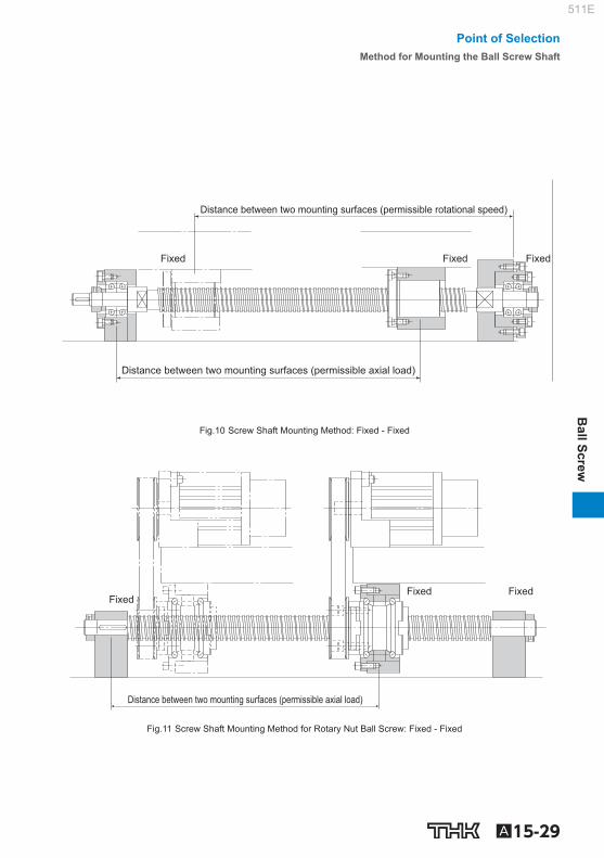
Method for Mounting the Ball Screw Shaft Fig.8 to Fig.11 show the representative mounting methods for the screw shaft. The permissible axial load and the permissible rotational speed vary with mounting methods for the screw shaft. Therefore, it is necessary to select an appropriate mounting method according to the conditions.
Distance between two mounting surfaces (permissible rotational speed)
Distance between two mounting surfaces (permissible axial load)
Fixed Fixed Free
Fig.8 Screw Shaft Mounting Method: Fixed - Free
Distance between two mounting surfaces (permissible axial load)
Distance between two mounting surfaces (permissible rotational speed)
Fixed Supported Fixed
Fig.9 Screw Shaft Mounting Method: Fixed - Supported
511E
A15-29
Ball Screw
Distance between two mounting surfaces (permissible axial load)
Distance between two mounting surfaces (permissible rotational speed)
Fixed Fixed Fixed
Fig.10 Screw Shaft Mounting Method: Fixed - Fixed
Distance between two mounting surfaces (permissible axial load)
Fixed Fixed
Fixed
Fig.11 Screw Shaft Mounting Method for Rotary Nut Ball Screw: Fixed - Fixed
Point of SelectionMethod for Mounting the Ball Screw Shaft
511E

A15-30
Permissible Axial Load [Buckling Load on the Screw Shaft] With the Ball Screw, it is necessary to select a screw shaft so that it will not buckle when the maxi-mum compressive load is applied in the axial direction. Fig.12 on A15-31 shows the relationship between the screw shaft diameter and a buckling load. If determining a buckling load by calculation, it can be obtained from the equation (5) below. Note that in this equation, a safety factor of 0.5 is multiplied to the result.
………(5)P1 = 0.5 = η 2 104η1• π2• E • I
ℓa2
d14
ℓa2
P 1 : Buckling load (N) ℓ a : Distance between two mounting surfaces (mm) E : Young’s modulus (2.06×10 5 N/mm 2 ) I : Minimum geometrical moment of inertia of the shaft (mm 4 )
d1: screw-shaft thread minor diameter (mm) I = d14 π
64 1 , 2 =Factor according to the mounting method Fixed - free 1 =0.25 2 =1.3 Fixed - supported 1 =2 2 =10 Fixed - fi xed 1 =4 2 =20
[Permissible Tensile Compressive Load on the Screw Shaft] If an axial load is applied to the Ball Screw, it is necessary to take into account not only the buckling load but also the permissible tensile compressive load in relation to the yielding stress on the screw shaft. The permissible tensile compressive load is obtained from the equation (6).
………(6)P2 = σ d1
2 = 116d12π
4 P 2 : Permissible tensile compressive load (N) : Permissible tensile compressive stress (147 MPa) d 1 : Screw-shaft thread minor diameter (mm)
511E

A15-31
Ball Screw
Fixed - free
Fixed - supported
Fixed - fixed
Mounting method Axial load (kN)
Dis
tanc
e be
twee
n tw
o m
ount
ing
surfa
ces
(mm
)
2 2 2 1 0.8 0.6 0.4 10 8 6 4 8 6 4 102
2 2 2 10 8 6 4 2 8 6 4 8 6 4 102
4 2 2 4 2 10 8 6 4 8 6 4 8 6 102
103
103
200
400
600
800
1000
2000
4000
6000
8000
10000
φ 45
φ 80
φ 70
φ 63
φ 55
φ 50
φ 100
φ 40
φ 36
φ 32φ 30
φ 28φ 25
φ 20
φ 18φ 16
φ 15φ 14
φ 12
φ 10
φ 8
φ 6
Fig.12 Permissible Tensile Compressive Load Diagram
Point of SelectionPermissible Axial Load
511E

A15-32
Permissible Rotational Speed [Dangerous Speed of the Screw Shaft] When the rotational speed reaches a high magnitude, the Ball Screw may resonate and eventually become unable to operate due to the screw shaft’s natural frequency. Therefore, it is necessary to select a model so that it is used below the resonance point (dangerous speed). Fig.13 on A15-34 shows the relationship between the screw shaft diameter and a dangerous speed. If determining a dangerous speed by calculation, it can be obtained from the equation (7) below. Note that in this equation, a safety factor of 0.8 is multiplied to the result.
………(7)N1 = 0.8 = λ2• • 107d1
ℓb2
E 103• Iγ • A
60 • λ12
2π •ℓb2
N 1 : Permissible rotational speed determined by dangerous speed (min -1 ) ℓ b : Distance between two mounting surfaces (mm) E : Young’s modulus (2.06×10 5 N/mm 2 ) I : Minimum geometrical moment of inertia of the shaft (mm 4 )
d1: screw-shaft thread minor diameter (mm) I = d14
π
64 : Density (specifi c gravity) (7.85×10 -6 kg/mm 3 ) A : Screw shaft cross-sectional area (mm 2 )
A = d12
π
4 1 , 2 : Factor according to the mounting method Fixed - free 1 =1.875 2 =3.4 Supported - supported 1 =3.142 2 =9.7 Fixed - supported 1 =3.927 2 =15.1 Fixed - fi xed 1 =4.73 2 =21.9
511E

A15-33
Ball Screw
[DN Value] The permissible rotational speed of the Ball Screw must be obtained from the dangerous speed of the screw shaft and the DN value. The permissible rotational speed determined by the DN value is obtained using the equations (8) to (16) below.
Pre
cisi
on
Caged Ball
Large Lead
Model SBK (SBK3636, SBK4040 and SBK5050)
………(8-1)N2 = 210000D
Model SBK (Other than the above model numbers and the small size model SBK * )
………(8-2)N2 = 160000D
Standard lead Model SBN-V (Medium)
………(9-1)N2 = 160000
D
Models SBN-V (Small), HBN, and SBKH
………(9-2)N2 = 130000D
Full- Complement Ball
Super Lead Model WHF
………(10-1)N2 = 120000
D
Model WGF
………(10-2)N2 = 70000D
Large Lead Models BLW, BLK, BLR, BNS and NS
………(11)N2 = 70000D
Standard lead
Models BIF-V (Medium), BNFN-V (Medium), and BNF (Medium)
………(12-1)N2 = 130000D
Models BIF-V (Small), BNFN-V (Small), and BNF (Small)
………(12-2)N2 = 100000D
Models BIF, DIK, BNFN, DKN, BNF, BNT, DK, MDK, MBF, BNK and DIR ………(12-3)N2 = 70000
D
Full-Complement Ball(DIN Standard Compliant) Standard lead Models EBA, EBB, EBC, EPA, EPB
and EPC ………(13)N2 = 100000
D
Rol
led Full-
Complement Ball
Super Lead Model WHF
………(14-1)N2 = 100000D
Models WTF and CNF ………(14-2)N2 = 70000
D
Large Lead Models BLK and BLR ………(15)N2 = 70000
D
Standard lead Model BTK-V
………(16-1)N2 = 100000D
Models JPF, BNT and MTF
………(16-2)N2 = 50000D
N 2 : Permissible rotational speed determined by the DN value (min -1 (rpm)) D : Ball center-to-center diameter (indicated in the specifi cation tables of the respective model number) Of the permissible rotational speed determined by dangerous speed (N 1 ) and the permissible rotational speed determined by DN value (N 2 ), the lower rotational speed is regarded as the permissible rotational speed. For small size SBK (SBK1520 to 3232) and SDA, the permissible rotational speed (N 2 ) is the maxi-mum permissible rotational speed shown in the dimensional tables.(See dimensional tables on pages A15-76 to A15-77 , and A15-80 to A15-85 ) If the service rotational speed exceeds N 2 , contact THK.
Point of SelectionPermissible Rotational Speed
511E

A15-34
Fixed - free
Fixed - supported
Fixed - fixed
Mounting method
Rotational speed (min-1)
Dis
tanc
e be
twee
n tw
o m
ount
ing
surfa
ces
(mm
)
4 4 6 8 2 2 102 6 8 103
2 4 6 8 2 103 4 6 8 104
4 2 2 6 8 104 4 6 8 103
200
400
600
800
1000
2000
4000
6000
8000
10000
φ 100φ 80φ 70φ 63φ 55φ 50φ 45φ 40φ 32φ 30φ 28φ 25
φ 18φ 16φ 15φ 14φ 12
φ 36
φ 20
φ 10φ 8φ 6
Fig.13 Permissible Rotational Speed Diagram
511E

A15-35
Ball Screw
Selecting a Nut Types of Nuts
The nuts of the Ball Screws are categorized by the ball circulation method into the return-pipe type, the defl ector type and end the cap type. These three nut types are described as follows. In addition to the circulation methods, the Ball Screws are categorized also by the preloading method.
[Types by Ball Circulation Method] Return-Pipe Type (Models SBN-V (Medium), BIF-V (Medium), BIF, BNF-V (Medium), BNF, BNFN-V (Medium), BNFN, BNT, BTK-V), Return-Piece Type (Models SBN-V (Small), HBN, BIF-V (Small), BNF-V (Small), BNFN-V (Small))
These are most common types of nuts that use a return pipe for ball circulation. The return pipe allows balls to be picked up, pass through the pipe, and return to their original positions to complete infi nite motion.
Pipe presser
Return pipe
Screw shaft
Ball
Labyrinth seal
Ball screw nut
Ball screw nut
Example of Structure of Return-Pipe Nut
Defl ector Type (Models EB, EP, DK, DKN, DIK, JPF, DIR and MDK)
These are the most compact type of nut. The balls change their traveling direction with a deflector, pass over the circumference of the screw shaft, and return to their original positions to complete an infi nite motion.
Deflector Screw shaft
Ball
Greasing hole
Labyrinth seal
Ball screw nut
Example of Structure of Simple Nut
End-cap Type: Large lead Nut (Models SBK, SBKH, WHF, BLK, WGF, BLW, WTF, CNF and BLR)
These nuts are most suitable for the fast feed. The balls are picked up with an end cap, pass through the through hole of the nut, and return to their original positions to complete an infi nite motion.
End cap
Screw shaft
Ball
Greasing hole
End cap Ball screw nut
Example of Structure of Large lead Nut
Point of SelectionSelecting a Nut
511E

A15-36
[Types by Preloading Method] Fixed-point Preloading Double-nut Preload (Models BNFN-V, BNFN, DKN and BLW) A spacer is inserted between two nuts to provide a preload.
Model BLWModel DKNModels BNFN-V and BNFN
Applied preload Applied preload
(3.5 to 4.5) pitches + preloadSpacer
Offset Preload (Models SBN-V, EP, BIF-V, BIF, DIK, DIR and SBK) More compact than the double-nut method, the offset preloading provides a preload by changing the groove pitch of the nut without using a spacer.
Model SBKModel DIR
Models BIF-V and BIF Model DIKModel SBN-V
0.5 pitch + preload
Applied preload Applied preload
Model EPB
511E

A15-37
Ball Screw
Constant Pressure Preloading (Model JPF) With this method, a spring structure is installed almost in the middle of the nut, and it provides a pre-load by changing the groove pitch in the middle of the nut.
4 pitches - preload
Applied preloadApplied preload
Spring sectionModel JPF
[Structure and Features of Offset Preload Type Simple-Nut Ball Screw] The Simple-Nut Ball Screw is an offset preload type in which a phase is provided in the middle of a single ball screw nut, and an axial clearance is set at a below-zero value (under a preload). The Simple-Nut Ball Screw has a more compact structure and allows smoother motion than the con-ventional double-nut type (spacer inserted between two nuts).
[Comparison between the Simple Nut and the Double-Nuts]
Simple-Nut Ball Screw Conventional Double-Nut Type Ball Screw
Ball screw nut
Ball screw nut Ball screw nutSpacer
Preloading Structure
Screw shaft
Pitch Pitch
Pitch Pitch Pitch
(Pitch + preload)
Applied preload Applied preload
Ball screw nut
Screw shaft
Pitch Pitch Pitch Pitch Pitch
Pitch Pitch (4 to 5 pitches + preload)
Applied preload Applied preload
Spacer Ball screw nut Ball screw nut
Point of SelectionSelecting a Nut
511E

A15-38
Simple-Nut Ball Screw Conventional Double-Nut Type Ball Screw
Rotational Performance The preload adjustment with Simple Nut Bal l Screw is performed according to the ball diameter. This eliminates the inconsistency in the contact angle, which is the most important factor of the Ball Screw performance. It also ensures the high rigidity, the smooth motion and the high wobbling accuracy.
The use of a spacer in the double-nuts tends to cause inconsistency in the contact angle due to inaccurate fl atness of the spacer surface and an inaccurate per-pendicularity of the nut. This results in a non-uniform ball contact, an inferior rotational performance and a low wobbling accuracy.
Dimensions Since Simple-Nut Ball Screw is based on apreloading mechanism that does not require a spacer, the overall nut length can be kept short. As a result, the whole nut can be lightly and compactly designed.
Simple-Nut
φ 63 φ 20
53
φ 63 φ 20
69
Double-Nut
511E

A15-39
Ball Screw
[Comparison between the Offset Preload Type of Simple-Nut Ball Screw and the Oversized-ball Preload Nut Ball Screw]
Simple-Nut Ball Screw Model DIK Conventional Oversized-ball Preload Nut Ball Screw Model BNF
Ball screw nut
Ball screw nut
Preloading Structure
Screw shaft
Pitch Pitch
Pitch Pitch Pitch
Pitch + preload
Preload Preload
Ball screw nut
Screw shaft
Pitch
Pitch Pitch Pitch
Pitch Pitch Ball screw nut
Accuracy Life
Simple-Nut Ball Screw model DIK has a similar preloading structure to that of the double-nut type although the former only has one ball screw nut. As a result, no differential slip or spin occurs, thus minimizing the increase in the rotational torque and the generation of heat. Accordingly, a high level of accuracy can be maintained over a long period.
Ball rotational axis
Contact width
Differential slip
2 point contact structure
d2
d1
A
B
d2
d1 B A
π×d1
π×d2
B’ A’
With the oversized-ball preload nut ball Screw, a pre-load is provided through each of the balls in contact with the raceway at four points. This causes differ-ential slip and spin increasing the rotational torque, resulting in accelerated wear and heat generation. Therefore, the accuracy deteriorates in a short period.
Ball rotational axis
Contact width
Differential slip
4 point contact structure
A
B
d2
d1 d2
B A π×d1
π×d2
B’ A’
Point of SelectionSelecting a Nut
511E

A15-40
Selecting a Model Number Calculating the Axial Load [In Horizontal Mount] With ordinary conveyance systems, the axial load (Fa n ) applied when horizontally reciprocating the work is obtained in the equation below.
(22) …………………
(21)
(20)
(19)
…………………
…………………
(18)
…………………………
…………………………
(17) …………………
Fa2= μμ • mg + f
Fa5= −μ • mg − fFa6= −μ • mg − f + mα
Fa4= −μ • mg − f − mαFa3= μ • mg + f − mα
Fa1= μ • mg + f + mα
V max : Maximum speed (m/s) t 1 : Acceleration time (m/s)
: Acceleration ) 2 (m/s α =
Vmax
t1
Fa 1 : Axial load during forward acceleration (N) Fa 2 : Axial load during forward uniform motion (N) Fa 3 : Axial load during forward deceleration (N) Fa 4 : Axial load during backward acceleration (N) Fa 5 : Axial load during uniform backward motion (N)
Axial load: Fan Mass: m
Guide surfaceFriction coefficient : μResistance without load : fGravitational acceleration: g
Fa 6 : Axial load during backward deceleration (N) m : Transferred mass (kg) : Frictional coeffi cient of the guide surface (–) f : Guide surface resistance (without load) (N)
[In Vertical Mount] With ordinary conveyance systems, the axial load (Fa n ) applied when vertically reciprocating the work is obtained in the equation below.
(28) …………………………
(27)
(26)
(25)
…………………………
…………………………
(24)
…………………………………
…………………………………
(23) …………………………
Fa5= mg − f Fa6= mg − f + mαα
Fa4= mg − f − mαFa3= mg + f − mα
Fa1= mg + f + mαFa2= mg + f
V max : Maximum speed (m/s) t 1 : Acceleration time (m/s)
: Acceleration ) 2 (m/s α =
Vmax
t1
Fa 1 : Axial load during upward acceleration (N) Fa 2 : Axial load during uniform upward motion (N) Fa 3 : Axial load during upward deceleration (N) Fa 4 : Axial load during downward acceleration (N) Fa 5 : Axial load during uniform downward motion (N)
Axial load: Fan
Mass: m
Guide surfaceFriction coefficient : μResistance without load: f
Des
cent
A
scen
t
Fa 6 : Axial load during downward deceleration (N) m : Transferred mass (kg) f : Guide surface resistance (without load) (N)
511E

A15-41
Ball Screw
Static Safety Factor
The basic static load rating (C 0 a) generally equals to the permissible axial load of a Ball Screw. Depending on the conditions, it is necessary to take into account the following static safety factor against the calculated load. When the Ball Screw is stationary or in motion, unexpected external force may be applied through an inertia caused by the impact or the start and stop.
………(29)Famax = C0a
fS Fa max : Allowable Axial Load (kN) C 0 a : Basic static load rating * (kN) f S : Static safety factor (see Table21 )
Table21 Static Safety Factor (f S )
Machine usingthe LM system Load conditions Lower
limit of f S
General industrial machinery
Without vibration or impact 1.0 to 3.5
With vibration or impact 2.0 to 5.0
Machine tool Without vibration or impact 1.0 to 4.0
With vibration or impact 2.5 to 7.0
*The basic static load rating (C 0 a) is a static load with a constant direction and magnitude whereby the sum of the permanent deformation of the rolling element and that of the raceway on the contact area under the maximum stress is 0.0001 times the rolling element diameter. With the Ball Screw, it is defi ned as the axial load. (Specifi c values of each Ball Screw model are indicated in the specifi cation tables for the corresponding model number.)
[Permissible Load Safety Margin (Models HBN and SBKH)] High load Ball Screw model HBN and high-load high-speed Ball Screw model SBKH, in comparison to previous Ball Screws, are designed to achieve longer service lives under high load conditions, and for axial load it is necessary to consider the permissible load Fp. Permissible load Fp indicates the maxim axial load that the high load Ball Screw can receive, and this range should not be exceeded.
………(30)> 1 Fp
Fa Fp : Permissible Axial Load (kN) Fa : Applied Axial Load (kN)
Point of SelectionSelecting a Model Number
511E

A15-42
Studying the Service Life
[Service Life of the Ball Screw] The Ball Screw in motion under an external load receives repeated stress on its raceways and balls. When the stress reaches the limit, the raceways break from fatigue and their surfaces fl akes like scales. This phenomenon is called fl aking. The service life of the Ball Screw is the total number of revolutions until the fi rst fl aking occurs on any of the raceways or the balls as a result of rolling fa-tigue of the material. The service life of the Ball Screw varies from unit to unit even if they are manufactured in the same process and used in the same operating conditions. For this reason, when determining the service life of a Ball Screw unit, the nominal life as defi ned below is used as a guideline. The nominal life is the total number of revolutions that 90% of identical Ball Screw units in a group achieve without developing fl aking (scale-like pieces of a metal surface) after they independently operate in the same conditions.
[Calculating the Rated Life] The service life of the Ball Screw is calculated from the equation (31) below using the basic dynamic load rating (Ca) and the applied axial load.
Nominal Life (Total Number of Revolutions)
………(31)L =
3
106 Ca
fW•Fa ( )
L : Nominal life (total number of revolutions) (rev) Ca : Basic dynamic load rating * (N) Fa : Applied axial load (N) f w : Load factor (see Table22 )
Table22 Load Factor (f W )
Vibrations/impact Speed(V) f W
Faint Very low V≦0.25m/s 1 to 1.2
Weak Slow 0.25<V≦1m/s 1.2 to 1.5
Medium Medium 1<V≦2m/s 1.5 to 2
Strong High V>2m/s 2 to 3.5
*The basic dynamic load rating (Ca) is used in calculations of service life when the ball screw is under an axial load. The basic dynamic load rating is defi ned as a load rating based on the movement of a set of identical ball screws with a rated life (L) of 10 6 revolutions, using a load applied in the axial direction that does not vary in either mass or direction. (The basic dynamic load ratings (Ca) for each model number are indicated in the specifi cation tables.)
*The rated service life is estimated by calculating the load on the premise that the product is set up in ideal mounting condi-tions with the assurance of good lubrication. The service life can be affected by the precision of the mounting materials used and any distortion.
511E

A15-43
Ball Screw
Service Life Time If the revolutions per minute is determined, the service life time can be calculated from the equation (32) below using the nominal life (L).
………(32)Lh = = L
60 N L Ph
2 60 n ℓS L h : Service life time (h) N : Revolutions per minute (min ‒1 ) n : Number of reciprocations per minute (min ‒1 ) Ph : Ball Screw lead (mm) ℓ S : Stroke length (mm)
Service Life in Travel Distance The service life in travel distance can be calculated from the equation (33) below using the nominal life (L) and the Ball Screw lead.
………(33)LS = L Ph
106 L S : Service Life in Travel Distance (km) Ph : Ball Screw lead (mm)
Applied Load and Service Life with a Preload Taken into Account If the Ball Screw is used under a preload (medium preload), it is necessary to consider the applied preload in calculating the service life since the ball screw nut already receives an internal load. For details on applied preload for a specifi c model number, contact THK.
Average Axial Load If an axial load acting on the Ball Screw is present, it is necessary to calculate the service life by de-termining the average axial load. The average axial load (F m ) is a constant load that equals to the service life in fl uctuating the load conditions. If the load changes in steps, the average axial load can be obtained from the equation below.
………(34)
3
Fm = (Fa13ℓ1 + Fa2
3ℓ2 + •••• + Fan3ℓn)1
ℓ F m : Average Axial Load (N) Fa n : Varying load (N) ℓ n : Distance traveled under load (F n ) ℓ : Total travel distance
Point of SelectionSelecting a Model Number
511E

A15-44
To determine the average axial load using a rotational speed and time, instead of a distance, calcu-late the average axial load by determining the distance in the equation below. ℓ = ℓ 1 + ℓ 2 + • • •ℓ n ℓ 1 = N 1 • t 1 ℓ 2 = N 2 • t 2 ℓ n = N n • t n N: Rotational speed t: Time
When the Applied Load Sign Changes If the sign (positive or negative) used for vari-able load is always the same, there are no problems with formula (34). However, if the vari-able load sign changes depending on the type of operation, calculate the average axial load for either positive or negative load, allowing for the load direction. (If the average axial load for positive load is calculated, the negative load is taken to be zero.) The larger of the two aver-age axial loads is taken as the average axial load when the service life is calculated. Example: Calculate the average axial load
with the following load conditions.
Operation No. Varying loadFa n (N)
Travel distanceℓ n (mm)
No.1 10 10
No.2 50 50
No.3 –40 10
No.4 –10 70
Positive-sign load
Negative-sign load
*The subscripts of the fl uctuating load symbol and the travel distance symbol indicate operation numbers. ● Average axial load of positive-sign load *To calculate the average axial load of the positive-sign load, assume Fa 3 and Fa 4 to be zero.
3
Fa13 × ℓ1 + Fa2
3 × ℓ2
ℓ1 + ℓ2 + ℓ3 + ℓ4Fm1 = = 35.5N
● Average axial load of negative-sign load *To calculate the average axial load of the negative-sign load, assume Fa 1 and Fa 2 to be zero.
Fa3 3 × ℓ3 + Fa4
3 × ℓ4
ℓ1 + ℓ2 + ℓ3 + ℓ4
Fm2 = = 17.2N3
Accordingly, the average axial load of the positive-sign load (F m1 ) is adopted as the average axial load (F m ) for calculating the service life.
511E

A15-45
Ball Screw
Studying the Rigidity To increase the positioning accuracy of feed screws in NC machine tools or the precision machines, or to reduce the displacement caused by the cutting force, it is necessary to design the rigidity of the components in a well-balanced manner.
Axial Rigidity of the Feed Screw System
When the axial rigidity of a feed screw system is K, the elastic displacement in the axial direction can be obtained using the equation (35) below.
………(35)δ = Fa
K : Elastic displacement of a feed screw system in the axial direction (m) Fa : Applied axial load (N) The axial rigidity (K) of the feed screw system is obtained using the equation (36) below.
………(36) = + + + 1
K 1 KS
1 KN
1 KB
1 KH
K : Axial Rigidity of the Feed Screw System (N/m) K S : Axial rigidity of the screw shaft (N/m) K N : Axial rigidity of the nut (N/m) K B : Axial rigidity of the support bearing (N/m) K H : Rigidity of the nut bracket and the support bearing bracket (N/m)
[Axial rigidity of the screw shaft] The axial rigidity of a screw shaft varies depending on the method for mounting the shaft.
For Fixed-Supported (or -Free) Confi guration
………(37)KS = A•E
1000•L A : Screw shaft cross-sectional area (mm 2 )
π4
A = d12
d 1 : Screw-shaft thread minor diameter (mm) E : Young’s modulus (2.06×10 5 N/mm 2 ) L : Distance between two mounting surfaces (mm) Fig.14 on A15-46 shows an axial rigidity diagram for the screw shaft.
Fixed Supported (Free)
L
Point of SelectionStudying the Rigidity
511E

A15-46
For Fixed-Fixed Confi guration
………(38)
A•E•L 1000•a•b KS =
KS becomes the lowest and the elastic displace-ment in the axial direction is the greatest at the
position of .
KS = 4A•E1000L
a = b = L2
Fig.15 on A15-47 shows an axial rigidity diagram of the screw shaft in this confi guration.
Fixed Fixed
L a b
Distance between two mounting surfaces (mm)
Rig
idity
of t
he s
crew
sha
ft (k
N/μ
m)
φ 100
φ 80φ 70φ 63φ 55φ 50φ 45φ 40φ 36φ 32φ 30φ 28φ 25
φ 20φ 18
φ 16φ 15
φ 14φ 12
φ 10φ 8
φ 6φ 4
10 8 6
4
2
1 8 6
4
8
8
6
6
4
4
2
2 102 8 6 103 4 2 8 6 104
10‐1
Fig.14 Axial Rigidity of the Screw Shaft (Fixed-Free, Fixed-Supported)
511E

A15-47
Ball Screw
Distance between two mounting surfaces (mm)
Rig
idity
of t
he s
crew
sha
ft (k
N/μ
m)
φ 55φ 63
φ 70
φ 80φ 100
φ 50φ 45φ 40φ 36φ 32φ 30φ 28φ 25
φ 20φ 18φ 16φ 15φ 14φ 12
φ 10φ 8
φ 6
φ 4
10 8 6 4
2
1 8 6
4
8 6
4
2
8 6 4 2 102 8 6 103 4 2 8 6 104
10‐1
Fig.15 Axial Rigidity of the Screw Shaft (Fixed-Fixed)
[Axial rigidity of the nut] The axial rigidity of the nut varies widely with preloads.
No Preload Type The logical rigidity in the axial direction when an axial load accounting for 30% of the basic dynamic load rating (Ca) is applied is indicated in the specifi cation tables of the corresponding model num-ber. This value does not include the rigidity of the components related to the nut-mounting bracket. In general, set the rigidity at roughly 80% of the value in the table. The rigidity when the applied axial load is not 30% of the basic dynamic load rating (Ca) is calculated using the equation (39) below.
………(39)KN = K 0.8 ( ) Fa
0.3Ca
1 3
K N : Axial rigidity of the nut (N/m) K : Rigidity value in the specifi cation tables (N/m) Fa : Applied axial load (N) Ca : Basic dynamic load rating (N)
Point of SelectionStudying the Rigidity
511E

A15-48
Preload Type The logical rigidity in the axial direction when an axial load accounting for 10% of the basic dynamic load rating (Ca) is applied is indicated in the dimensional table of the corresponding model number. This value does not include the rigidity of the components related to the nut-mounting bracket. In general, generally set the rigidity at roughly 80% of the value in the table. The rigidity when the applied preload is not 10% of the basic dynamic load rating (Ca) is calculated using the equation (40) below.
………(40)KN = K 0.8 ( ) Fa0
0.1Ca
1 3
K N : Axial rigidity of the nut (N/m) K : Rigidity value in the specifi cation tables (N/m) Fa 0 : Applied preload (N) Ca : Basic dynamic load rating (N)
[Axial rigidity of the support bearing] The rigidity of the Ball Screw support bearing varies depending on the support bearing used. The calculation of the rigidity with a representative angular contact ball bearing is shown in the equation (41) below.
………(41)
3Fa0
δa0KB
K B : Axial rigidity of the support bearing (N/m) Fa 0 : Applied preload of the support bearing (N) a 0 : Axial displacements (m)
Q =
( ) δa0 =
Fa0
Zsinα
1 3 Q2
Da 0.45sinα
Q : Axial load (N) Da : Ball diameter of the support bearing (mm) : Initial contact angle of the support bearing () Z : Number of balls For details of a specifi c support bearing, contact its manufacturer.
[Axial Rigidity of the Nut Bracket and the Support Bearing Bracket] Take this factor into consideration when designing your machine. Set the rigidity as high as possible.
511E

A15-49
Ball Screw
Studying the Positioning Accuracy Causes of Error in the Positioning Accuracy
The causes of error in the positioning accuracy include the lead angle accuracy, the axial clearance and the axial rigidity of the feed screw system. Other important factors include the thermal displace-ment from heat and the orientation change of the guide system during traveling.
Studying the Lead Angle Accuracy
It is necessary to select the correct accuracy grade of the Ball Screw that satisfi es the required po-sitioning accuracy from the Ball Screw accuracies ( Table1 on A15-12 ). Table23 on A15-50 shows examples of selecting the accuracy grades by the application.
Studying the Axial Clearance
The axial clearance is not a factor of positioning accuracy in single-directional feed. However, it will cause a backlash when the feed direction is inversed or the axial load is inversed. Select an axial clearance that meets the required backlash from Table10 and Table13 on A15-19 .
Point of SelectionStudying the Positioning Accuracy
511E

A15-50
Table23 Examples of Selecting Accuracy Grades by Application
Applications Shaft Accuracy grades
C0 C1 C2 C3 C5 C7 C8 C10
NC
mac
hine
tool
s
Lathe X ● ● ● ● Z ● ●
Machining center XY ● ● ● Z ● ● ●
Drilling machine XY ● ● Z ● ●
Jig borer XY ● ● Z ● ●
Surface grinder X ● ● Y ● ● ● ● Z ● ● ● ●
Cylindrical grinder X ● ● ● Z ● ● ●
Electric dischargemachine
XY ● ● ● Z ● ● ● ●
Electric dischargemachine
Wire cutting machine
XY ● ● ● Z ● ● ● ●
UV ● ● ● Punching press XY ● ● ●
Laser beam machine X ● ● ● Z ● ● ●
Woodworking machine ● ● ● ● General-purpose machine; dedicated machine ● ● ● ● ●
Indu
stria
l rob
ot
Cartesian coordinate Assembly ● ● ● ●
Other ● ● ● ●
Vertical articulated type Assembly ● ● ●
Other ● ● Cylindrical coordinate ● ● ●
Sem
icond
ucto
r m
anuf
actu
ring
mac
hine
Photolithography machine ● ● Chemical treatment machine ● ● ● ● ● ●
Wire bonding machine ● ● Prober ● ● ● ●
Printed circuit board drilling machine ● ● ● ● ● Electronic component inserter ● ● ● ●
3D measuring instrument ● ● ● Image processing machine ● ● ● Injection molding machine ● ● ●
Offi ce equipment ● ● ● ●
511E

A15-51
Ball Screw
Studying the Axial Clearance of the Feed Screw System
Of the axial rigidities of the feed screw system, the axial rigidity of the screw shaft fl uctuates ac-cording to the stroke position. When the axial rigidity is large, such change in the axial rigidity of the screw shaft will affect the positioning accuracy. Therefore, it is necessary to take into account the rigidity of the feed screw system ( A15-45 to A15-48 ). Example: Positioning error due to the axial rigidity of the feed screw system during a vertical transfer
L
1000N
500N
[Conditions] Transferred weight: 1,000 N; table weight: 500 N Ball Screw used: model BNF2512–2.5 (screw-shaft thread minor diameter d 1 = 21.9 mm) Stroke length: 600 mm (L=100 mm to 700 mm) Screw shaft mounting type: fi xed-supported
[Consideration] The difference in axial rigidity between L = 100 mm and L = 700 mm applied only to the axial rigidity of the screw shaft. Therefore, positioning error due to the axial rigidity of the feed screw system equals to the difference in the axial displacement of the screw shaft between L = 100 mm and L = 700 mm.
Point of SelectionStudying the Positioning Accuracy
511E

A15-52
[Axial Rigidity of the Screw Shaft (see A15-45 and A15-46 )]
Ks = = =
4 π
4 πA = d1
2 = ×21.92 = 376.5mm2
E = 2.06×10⁵ N/mm2
77.6×10³
L 376.5×2.06×105
1000×L 1000L A•E
(1) When L = 100 mm
KS1 = = 776 N/μm100
77.6×10³
(2) When L = 700mm
KS2 = = 111 N/μm
700 77.6×10³
[Axial Displacement due to Axial Rigidity of the Screw Shaft] (1) When L = 100 mm
δ1 = = = 1.9μmKS1
Fa 776
1000+500
(2) When L = 700mm
δ2 = = = 13.5μm
KS2
Fa 111
1000+500
[Positioning Error due to Axial Rigidity of the Feed Screw System] Positioning accuracy= 1 – 2 =1.9–13.5 =–11.6m Therefore, the positioning error due to the axial rigidity of the feed screw system is 11.6 m.
511E

A15-53
Ball Screw
Studying the Thermal Displacement through Heat Generation
If the temperature of the screw shaft increases during operation, the screw shaft is elongated due to heat thereby to lower the positioning accuracy. The expansion and contraction of the screw shaft is calculated using the equation (42) below.
………(42)ΔΔ ℓ = ρ Δt ℓ
ℓ : Axial expansion/contraction of the screw shaft (mm) : Thermal expansion coeffi cient (12×10 -6 /℃) t : Temperature change in the screw shaft (℃) ℓ : Effective thread length (mm) Thus, if the temperature of the screw shaft increases by 1℃, the screw shaft is elongated by 12 m per meter. Therefore, as the Ball Screw travels faster, the more heat is generated. So, as the tem-perature increases, the positioning accuracy lowers. Accordingly, if high accuracy is required, it is necessary to take measures to cope with the temperature increase.
[Measures to Cope with the Temperature Rise] Minimize the Heat Generation
● Minimize the preloads on the Ball Screw and the support bearing. ● Increase the Ball Screw lead and reduce the rotational speed. ● Select a correct lubricant. (See Accessories for Lubrication on A24-2 .) ● Cool the circumference of the screw shaft with a lubricant or air.
Avoid Effect of Temperature Rise through Heat Generation ● Set a negative target value for the reference travel distance of the Ball Screw.
Generally, set a negative target value for the reference travel distance assuming a temperature increase of 2℃ to 5℃ by heat. (–0.02mm to –0.06 mm/m)
● Preload the shaft screw with tension. (See Fig.10 of the structure on A15-29 .)
Point of SelectionStudying the Positioning Accuracy
511E

A15-54
Studying the Orientation Change during Traveling
The lead angle accuracy of the Ball Screw equals the positioning accuracy of the shaft center of the Ball Screw. Normally, the point where the highest positioning accuracy is required changes accord-ing to the ball screw center and the vertical or horizontal direction. Therefore, the orientation change during traveling affects the positioning accuracy. The largest factor of orientation change affecting the positioning accuracy is pitching if the change occurs in the ball screw center and the vertical direction, and yawing if the change occurs in the horizontal direction. Accordingly, it is necessary to study the orientation change (accuracy in pitching, yawing, etc.) dur-ing the traveling on the basis of the distance from the ball screw center to the location where posi-tioning accuracy is required. Positioning error due to pitching and yawing is obtained using the equation (43) below.
………(43)A = ℓℓ sinθ A : Positioning accuracy due to pitching (or yawing) (mm) ℓ : Vertical (or horizontal) distance from the ball screw center (mm) (see Fig.16 ) : Pitching (or yawing) ()
θ
θ
ℓ
A
A
ℓ
Fig.16
511E

A15-55
Ball Screw
Studying the Rotational Torque The rotational torque required to convert rotational motion of the Ball Screw into straight motion is obtained using the equation (44) below.
[During Uniform Motion]
………(44)( T1 + T2 + T4)• A T t : Rotation torque required during uniform motion (N-mm) T 1 : Friction torque due to an external load (N-mm) T 2 : Preload torque of the Ball Screw (N-mm) T 4 : Other torque (N-mm) (frictional torque of the support bearing and oil seal) A : Reduction ratio
[During Acceleration]
………(45)TK = Tt + T3 T K : Rotation torque required during acceleration (N-mm) T 3 : Torque required for acceleration (N-mm)
[During Deceleration]
………(46)Tg = Tt - T3 T g : Rotational torque required for deceleration (N-mm)
Frictional Torque Due to an External Load
Of the turning forces required for the Ball Screw, the rotational torque needed for an external load (guide surface resistance or external force) is obtained using the equation (47) below.
………(47)2π • η
Fa •Ph T1 =
T 1 : Friction torque due to an external load (N-mm) Fa : Applied load (N) Ph : Ball Screw lead (mm) : Ball Screw effi ciency (0.9 to 0.95)
Point of SelectionStudying the Rotational Torque
511E

A15-56
Torque Due to a Preload on the Ball Screw
For a preload on the Ball Screw, see “Preload Torque” on A15-22 .
511E

A15-57
Ball Screw
Torque Required for Acceleration
………(48)T3 = J ωω′ 103
T 3 : Torque required for acceleration (N-mm) J : Inertial moment (kg•m 2 ) ´ : Angular acceleration (rad/s 2 )
2πPh ( )
2
J = m • A2• 10-6 + JS• A2 + JA• A2 + JB
m : Transferred mass (kg) Ph : Ball Screw lead (mm) J S : Inertial moment of the screw shaft (kg•m 2 ) (indicated in the specifi cation tables of the respective model number) A : Reduction ratio J A : Inertial moment of gears, etc. attached to the screw shaft side (kg•m 2 ) J B : Inertial moment of gears, etc. attached to the motor side (kg•m 2 )
60t ω ′ = 2π•Nm
Nm : Motor revolutions per minute (min -1 ) t : Acceleration time (s) [Ref.] Inertial moment of a round object
J =
8•106 m•D2
J : Inertial moment (kg•m 2 ) m : Mass of a round object (kg) D : Screw shaft outer diameter (mm)
Point of SelectionStudying the Rotational Torque
511E

A15-58
Investigating the Terminal Strength of Ball Screw Shafts
When torque is conveyed through the screw shaft in a ball screw, the strength of the screw shaft must be taken into consideration since it experiences both torsion load and bending load.
[Screw shaft under torsion] When torsion load is applied to the end of a ball screw shaft, use equation (49) to obtain the end diameter of the screw shaft.
and T = τa•ZP ZP = T
τa………(49)
T : Maximum torsion moment (N-mm) τ a : Permissible torsion stress of the screw Shaft (49 N/mm 2 ) Z P : Section modulus (mm 3 )
16 ZP = π•d3
T: Torsion moment
T
φd
[Screw shaft under bending] When bending load is applied to the end of a ball screw shaft, use equation (50) to obtain the end diameter of the screw shaft.
and M = σσ•Z Z = M
………(50)σ
M : Maximum bending moment (N-mm) : Permissible bending stress of the screw shaft (98 N/mm 2 ) Z : Section Modulus (mm 3 )
32 Z = π•d3
M: Bending moment
M
φd
511E

A15-59
Ball Screw
[If the shaft experiences both torsion and bending] When torsion load and bending load are both applied simultaneously to the end of a ball screw shaft, calculate the diameter of the screw shaft separately for each, taking into consideration the corresponding bending moment (M e ) and the corresponding torsion moment (T e ). Then calculate the thickness of the screw shaft and use the largest of the values.
Equivalent torsion moment
Equivalent bending moment
Me = = 1 + 1 + 2
M + M2+ T2
2
Te = M2+ T2 = M • 1 + 2
T M
T M
M 2
Te = τa • ZP
Me = σ • Z
Point of SelectionStudying the Rotational Torque
511E

A15-60
Studying the Driving Motor When selecting a driving motor required to rotate the Ball Screw, normally take into account the ro-tational speed, rotational torque and minimum feed amount.
When Using a Servomotor
[Rotational Speed] The rotation speed required for the motor is obtained using the equation (51) based on the feed speed, Ball Screw lead and reduction ratio.
………(51)NM = Ph
V 1000 60 A 1
N M : Required rotation speed of the motor (min ‒1 ) V : Feeding speed (m/s) Ph : Ball Screw lead (mm) A : Reduction ratio The rated rotational speed of the motor must be equal to or above the calculated value (N M ) above. N M ≦N R N R : The rated rotation speed of the motor (min ‒1 )
[Required Resolution] Resolutions required for the encoder and the driver are obtained using the equation (52) based on the minimum feed amount, Ball Screw lead and reduction ratio.
………(52)B = S
Ph•A
B : Resolution required for the encoder and the driver (p/rev) Ph : Ball Screw lead (mm) A : Reduction ratio S : Minimum feed amount (mm)
511E

A15-61
Ball Screw
[Motor Torque] The torque required for the motor differs between uniform motion, acceleration and deceleration. To calculate the rotational torque, see “Studying the Rotational Torque” on A15-55 . a. Maximum torque
The maximum torque required for the motor must be equal to or below the maximum peak torque of the motor. T max ≦Tp max T max : Maximum torque acting on the motor Tp max : Maximum peak torque of the motor
b. Effective torque value The effective value of the torque required for the motor must be calculated. The effective value of the torque is obtained using the equation (53).
………(53)Trms =
T12 t1 + T2
2 t2 + T32 t3
t T rms : Effective torque value (N-mm) T n : Fluctuating torque (N-mm) t n : Time during which the torque T n is applied (s) t : Cycle time (s) (t=t 1 +t 2 +t 3 )
The calculated effective value of the torque must be equal to or below the rated torque of the motor. T rms ≦T R T R : Rated torque of the motor (N-mm)
[Inertial Moment] The inertial moment required for the motor is obtained using the equation (54).
………(54)JM = C
J
J M : Inertial moment required for the motor (kg•m 2 ) C : Factor determined by the motor and the driver (It is normally between 3 to 10. However, it varies depending on the motor and the driver. Check the specifi c value in the catalog by the motor manufacturer.) The inertial moment of the motor must be equal to or above the calculated J M value.
Point of SelectionStudying the Driving Motor
511E

A15-62
When Using a Stepping Motor (Pulse Motor)
[Minimal Feed Amount(per Step)] The step angle required for the motor and the driver is obtained using the equation (55) based on the minimum feed amount, Ball Screw lead and reduction ratio.
………(55)E = 360S
Ph•A E : Step angle required for the motor and the driver () S : Minimum feed amount (mm) (per step) Ph : Ball Screw lead (mm) A : Reduction ratio
[Pulse Speed and Motor Torque] a. Pulse speed
The pulse speed is obtained using the equation (56) based on the feed speed and the minimum feed amount.
………(56)f =
S V 1000
f : Pulse speed (Hz) V : Feeding speed (m/s) S : Minimum feed amount (mm)
b. Torque required for the motor
The torque required for the motor differs between the uniform motion, the acceleration and the deceleration. To calculate the rotational torque, see “Studying the Rotational Torque” on A15-55 .
Thus, the pulse speed required for the motor and the required torque can be calculated in the man-ner described above. Although the torque varies depending on the motors, normally the calculated torque should be dou-bled to ensure safety. Check if the torque can be used in the motor’s speed-torque curve.
511E

A15-63
Ball Screw
Features of Each Model
511E

A15-64
Precision, Caged Ball Screw Models SBN-V, SBK, SDA-V, HBN and SBKH
Screw shaftPipe presser
Return pipe
Ball screw nut
Fig.1 Structure of High-Speed Ball Screw with Ball Cage Model SBN-V
Point of Selection A15-8 Options A15-336 Model No. A15-353 Precautions on Use A15-358 Accessories for Lubrication A24-1 Mounting Procedure and Maintenance B15-104
Lead Angle Accuracy A15-11
Accuracy of the Mounting Surface A15-14
Axial Clearance A15-19
Maximum Length of the Screw Shaft A15-24
DN Value A15-33
Support Unit A15-300
Recommended Shapes of Shaft Ends A15-308
Dimensions of Each Model with an Option Attached A15-344
511E

A15-65
Ball Screw
Precision, Caged Ball Screw
Structure and Features
The use of a ball cage in the Ball Screw with the Ball Cage eliminates collision and friction between balls and increases the grease retention. This makes it possible to achieve a low noise, a low torque fl uctuation and a long-term maintenance-free operation. In addition, this Ball Screw is superbly capable of responding to the high speed because of an ideal ball recirculation structure, a strengthened circulation path and an adoption of the ball cage.
Ball Cage Effect
[Low Noise, Acceptable Running Sound] The use of the ball cage eliminates the collision noise between the balls. Additionally, as balls are picked up in the tangential direction, the collision noise from the ball circulation has also been eliminated.
[Long-term Maintenance-free Operation] The friction between the balls has been elimi-nated, and the grease retention has been im-proved through the provision of grease pockets. As a result, the long-term maintenance-free operation (i.e., lubrication is unnecessary over a long period) is achieved.
[Smooth Motion] The use of a ball cage eliminates the friction between the balls and minimizes the torque fl uctuation, thus allowing the smooth motion to be achieved.
Structure of the Ball Screw with Ball Cage
Oil film contact Grease pocket
Point (metal) contact
Conventional Structure
511E

A15-66
[Low Noise] Noise Level Data
Since the balls in the Ball Screw with the Ball Cage do not collide with each other, they do not pro-duce a metallic sound and a low noise level is achieved.
Noise Measurement [Conditions]
Item Description
Sample High load ball screw with ball cage
HBN3210-5 Conventional type: model
BNF3210-5
Stroke 600mm
Lubrication Grease lubrication
(lithium-based grease containing extreme pressure agent)
Noise meter
Soundproof material
FFT analyzer
1000mm
M
Noise measurement instrument
Ball diameter × ball center diameter × rotational speed
Noi
se le
vel [
dB(A
)]
Conventional type (BNF3210-5) Model HBN (HBN3210-5)
90
85
80
75
70
65
60
55
50
45
40 10000 100000 1000000 10000000
Fig.2 Ball Screw Noise Level
511E

A15-67
Ball Screw
Precision, Caged Ball Screw
[Long-term Maintenance-free Operation] High speed, Load-bearing Capacity
Thanks to the ball circulating method supporting high speed and the caged ball technology, the Ball Screw with Ball Cage excels in high speed and load-bearing capacity.
High Speed Durability Test [Test conditions]
Item Description
Sample High Speed Ball Screw with Ball Cage SDA3110V-5
Speed 5000(min ‒1 )(DN value * : 160,000)
Stroke 500mm
Lubricant THK AFJ Grease
Quantity 4cm 3 (lubricated every 500km)
Applied load 1.27kN
Acceleration 0.5G
* DN value: Ball center-to-center diameter x revolutions per minute
Load Bearing Test [Test conditions]
Item Description
Sample High Speed Ball Screw with Ball Cage SBN5016V-5
Speed 1500(min ‒1 )(DN value * : 79,000)
Stroke 400mm
Lubricant THK AFG Grease
Quantity 57.7 cm 3 (Lubricated every 100 km)
Applied load 36.1kN(0.38Ca)
Acceleration 0.5G
[Test result] Shows no deviation after running 6,000 km.
[Test result] Shows no deviation after running for the calcu-lated service life
[Smooth Motion] Low Torque Fluctuation
The caged ball technology allows smoother motion than the conventional type to be achieved, thus to reduce torque fl uctuation. [Conditions]
Item Description
Shaft diameter/lead 25/25mm
Shaft rotational speed 100min ‒1
Torq
ue T
q(N
-m)
Measurement Time T (s)
Model SDA-V
–0.5
–0.3
–0.1
0.1
0.3
0.5
0 20 40 60 80 100 120 140 160
Fig.3 Torque Fluctuation Data
511E

A15-68
Types and Features
[Preload Type]
Model SBN-V Specifi cation Table⇒A15-72 The circulation structure feature allows the balls to be picked up tangential to the direction of movement. The circulation components have been strengthened, increasing the DN value to 160,000 (small type: 130,000).
Model SBK Specifi cation Table⇒A15-76 As a result of adopting the offset preloading method, which shifts two rows of grooves of the ball screw nut, a compact structure is achieved.
[Preload/No Preload Type]
Model SDA-V Specifi cation Table⇒A15-80 A ball screw with newly developed circulation components that give it an ideal ball circulation structure. (Maximum DN value: 160,000) The nut dimensions conform to DIN standards (DIN69051). Furthermore, the use of the newly developed thin film seal reduces the length of the nut, achieving a more compact design for the device.
511E

A15-69
Ball Screw
Precision, Caged Ball Screw
[No Preload Type]
Model HBN Specifi cation Table⇒A15-86 With the optimal design for high loads, this Ball Screw model achieves a rated load more than twice the conventional type.
Model SBKH Specifi cation Table⇒A15-88 Model SBKH is a ball screw that achieves a high load carrying capacity and is capable of high-speed operation (92 m/min at a maximum).
511E

A15-70
Examples of Assembling Models HBN and SBKH
If using model HBN or SBKH under a large load, arrange the nut fl ange and the fi xed-side support unit in relation to the loading direction as indicated in the fi gure below while taking into account the load balance of the balls. In addition, while HBN or SBKH is operating, be sure not to apply a tensile load to the bolts. If you intend to use HBN or SBKH in confi gurations other than below, contact THK.
[Examples of Recommended Assembly of Models HBN and SBKH]
Good example (with the nut moving)
Axial loadTravel directionof the nut
Axial load
Good example (with the shaft moving)
Travel directionof the shaft
[Examples of Un-recommended Assembly of Models HBN and SBKH]
Axial loadAxial load
Bad example (with the nut moving) Bad example (with the shaft moving)
Travel direction of the nut
Travel direction of the shaft
511E

A15-71
Ball Screw
Precision, Caged Ball Screw511E

Model number coding
A15-72 Download data by searching for the corresponding model number on the Technical Support site. https://tech.thk.com
(Greasing hole)
PCD
A
60°
Model No.
Screw shaft outer diameter
Lead Ball center-to-center diameter
Thread minor
diameter
No. of loaded circuits
Basic load rating Rigidity
Ca C 0 a K
d Ph dp dc Rows × turns kN kN N/m
SBN 1604V-5 16 4 16.5 13.8 1×2.5 5.3 8 281 SBN 1605V-5 16 5 16.75 13.2 1×2.5 9.2 12.9 309 SBN 2004V-5 20 4 20.5 17.8 1×2.5 5.9 10.1 335 SBN 2005V-5 20 5 20.75 17.2 1×2.5 10.3 16.2 370 SBN 2010V-5 20 10 20.75 17.2 1×2.5 10.2 16.4 362 SBN 2504V-5 25 4 25.5 22.8 1×2.5 6.4 12.7 400 SBN 2505V-5 25 5 25.75 22.2 1×2.5 11.3 20.3 442 SBN 2506V-5 25 6 26 21.4 1×2.5 15.4 25.4 457 SBN 2805V-5 28 5 28.75 25.2 1×2.5 11.8 22.8 483 SBN 3205V-5 32 5 32.75 29.2 1×2.5 12.6 26.1 536 SBN 3206V-5 32 6 33 28.4 1×2.5 17.2 32.7 555
SBN-V Small With Preload
DN value 130000
Contamination protection accessory symbol (*1)
With QZ lubricator(No code without QZ lubricator)
Model No.
Overall screw shaft length (in mm)
Accuracy symbol (*2)
Symbol for Clearance in the axial direction (G0 for all SBN-V variations)
SBN1604V-5 QZ RR G0 +1200L C5
(*1) See A15-336 . (*2) See A15-12 .
511E

A15-73
Ball Screw
Precision, Caged Ball Screw
Options⇒A15-335
LH B1
h
φ d1φ d2
φ d φ Dg6φ dcφ D1 φ dp
Unit: mm
Nut dimensions Screw shaft inertial
moment/mm
Nut mass
Shaft mass
Outer diameter
Flange diameter
Overall length Greasing
hole
Dg6 D 1 L 1 H B 1 PCD d 1 ×d 2 ×h A kg-cm 2 /mm kg kg/m
36 59 53 11 42 47 5.5×9.5×5.5
M6
5.05×10 -4 0.42 1.42 40 60 56 10 46 50 4.5×8×4.5 5.05×10 -4 0.5 1.37 40 63 49 11 38 51 5.5×9.5×5.5 1.23×10 -3 0.43 2.22 44 67 56 11 45 55 5.5×9.5×5.5 1.23×10 -3 0.61 2.6 46 74 90 15 75 59 5.5×9.5×5.5 1.23×10 -3 1.06 2.33 46 69 48 11 37 57 5.5×9.5×5.5 3.01×10 -3 0.55 3.6 50 73 55 11 44 61 5.5×9.5×5.5 3.01×10 -3 0.72 3.52 53 76 62 11 51 64 5.5×9.5×5.5 3.01×10 -3 0.9 3.43 55 85 59 12 47 69 6.6×11×6.5 4.74×10 -3 0.98 4.45 58 85 56 12 44 71 6.6×11×6.5 8.08×10 -3 0.96 5.88 62 89 63 12 51 75 6.6×11×6.5 8.08×10 -3 1.22 5.89
Axial Clearance Unit: mm
Clearance symbol G0 Axial Clearance 0 or less
Note) The overall length of the nut will increase when equipping the QZ lubricating device. See A15-344 for further details. It is not possible to chamfer both ends of the screw shaft. When designing your system this way, contact THK.
The rigidity values in the table represent spring constants, each obtained from the load and the elastic deformation when providing a preload equal to 10% of the basic axial dy-namic load rating (Ca) and applying an axial load three times greater than the pre-load. These values do not include the rigidity of the components related to mounting the ball screw nut. Therefore, it is normally appropriate to regard roughly 80% of the value in the table as the actual value. If the applied preload (Fa 0 ) is not 0.1 Ca, the rigidity value (K N ) is obtained from the fol-lowing equation.
K: Rigidity value in the dimensional table.
1 3 Fa0
0.1Ca KN=K ( )
511E

Model number coding
A15-74 Download data by searching for the corresponding model number on the Technical Support site. https://tech.thk.com
(Greasing hole)
PCD
A
60°
Model No.
Screw shaft outer diameter
Lead Ball center-to-center diameter
Thread minor
diameter
No. of loaded circuits
Basic load rating Rigidity
Ca C 0 a K
d Ph dp dc Rows × turns kN kN N/m SBN 2508V-7 25 8 26.25 20.5 1×3.5 26.2 43 650 SBN 2510V-5 25 10 26.25 21.5 1×2.5 19.6 30.9 474 SBN 2810V-3 28 10 29.75 22.4 1×1.5 19.5 27.8 332 SBN 3210V-7 32 10 33.75 26.4 1×3.5 43 73.1 836.7 SBN 3212V-5 32 12 34 26.1 1×2.5 37.4 58.7 612.2 SBN 3216V-5 32 16 33.75 26.4 1×2.5 31.9 52.2 592 SBN 3610V-7 36 10 37.75 30.4 1×3.5 45.6 82.3 900 SBN 3612V-7 36 12 38 30.1 1×3.5 53.2 92.6 920 SBN 3616V-5 36 16 38 30.1 1×2.5 39.7 66.4 662 SBN 3620V-3 36 20 37.75 30.5 1×1.5 21.6 32.9 398 SBN 4010V-5 40 10 41.75 34.4 1×2.5 35.8 65.2 708 SBN 4012V-5 40 12 42 34.1 1×2.5 42 73.6 735.4 SBN 4016V-5 40 16 42 34.1 1×2.5 41.9 73.8 736.6 SBN 4020V-5 40 20 41.75 34.4 1×2.5 35.4 65.2 706 SBN 4510V-5 45 10 46.75 39.5 1×2.5 37.9 73.8 780 SBN 4512V-5 45 12 47 39.2 1×2.5 44.4 82.9 809.1 SBN 4516V-5 45 16 47 39.2 1×2.5 44.3 83.1 810.1 SBN 4520V-5 45 20 47 39.2 1×2.5 43.9 82.5 788 SBN 5010V-5 50 10 51.75 44.4 1×2.5 39.4 81 838 SBN 5012V-5 50 12 52.25 43.3 1×2.5 53.6 101.9 936 SBN 5016V-5 50 16 52.7 42.9 1×2.5 89 167.7 1228 SBN 5020V-5 50 20 52.7 42.9 1×2.5 88.7 167.7 1228
SBN-V Medium With Preload
DN value 160000
Accuracy symbol (*2)
Symbol for Clearance in the axial direction(G0 for all SBN-V variations)
Model No.
Overall screw shaft length (in mm)
Contamination protection accessory symbol (*1)
With QZ lubricator(No code without QZ lubricator)
SBN4012V-5 QZ RR G0 +1200L C5
(*1) See A15-336 . (*2) See A15-12 .
511E

A15-75
Ball Screw
Precision, Caged Ball Screw
Options⇒A15-335
φ D1
LH B1
h
φ d1φ d2
φ d φ Dg6φ dcφ dp
Unit: mm
Nut dimensions Screw shaft inertial
moment/mm
Nut mass
Shaft mass Outer
diameter Flange
diameter Overall length Greasing
hole Dg6 D 1 L 1 H B 1 PCD d 1 ×d 2 ×h A kg-cm 2 /mm kg kg/m 58 85 98 15 83 71 6.6×11×6.5
M6
3.01×10 -3 1.5 3.51 58 85 100 18 82 71 6.6×11×6.5 3.01×10 -3 1.31 3.5 65 106 88 18 70 85 11×17.5×11 4.74×10 -3 2.41 4.15 74 108 120 15 105 90 9×14×8.5 8.08×10 -3 3.1 5.53 76 121 117 18 99 98 11×17.5×11 8.08×10 -3 3.7 5.7 74 108 139 18 121 90 9×14×8.5 8.08×10 -3 3.81 5.82 75 120 123 18 105 98 11×17.5×11 1.29×10 -2 3.82 7.1 78 123 140 18 122 100 11×17.5×11 1.29×10 -2 4.34 7.99 78 123 140 18 122 100 11×17.5×11 1.29×10 -2 4.31 7.99 75 114 122 18 104 93 11×17.5×11 1.29×10 -2 3.4 7.54 82 124 103 18 85 102 11×17.5×11 1.97×10 -2 3.61 8.87 84 126 119 18 101 104 11×17.5×11 1.97×10 -2 4.2 8.83 84 126 144 18 126 104 11×17.5×11 1.97×10 -2 4.9 9.09 82 126 162 18 144 104 11×17.5×11 1.97×10 -2 5.17 9.37 88 132 111 18 93 110 11×17.5×11
R1/8 (PT1/8)
3.16×10 -2 4.29 11.36 90 130 119 18 101 110 11×17.5×11 3.16×10 -2 4.6 11.32 90 130 140 18 122 110 11×17.5×11 3.16×10 -2 5.3 11.61 90 130 162 18 144 110 11×17.5×11 3.16×10 -2 5.96 11.1 93 135 103 18 85 113 11×17.5×11 4.82×10 -2 4.28 14.16
100 146 123 22 101 122 14×20×13 4.82×10 -2 6.12 13.82 105 152 164 25 139 128 14×20×13 4.82×10 -2 8.82 13.71 105 152 201 28 173 128 14×20×13 4.82×10 -2 10.63 14.05
Axial Clearance Unit: mm
Clearance symbol G0 Axial Clearance 0 or less
Note) The overall length of the nut will increase when equipping the QZ lubricating device. See A15-344 for further details. It is not possible to chamfer both ends of the screw shaft. When designing your system this way, contact THK.
The rigidity values in the table represent spring constants, each obtained from the load and the elastic deformation when providing a preload equal to 10% of the basic axial dynamic load rating (Ca) and applying an axial load three times greater than the pre-load. These values do not include the rigidity of the components related to mounting the ball screw nut. Therefore, it is normally appropriate to regard roughly 80% of the value in the table as the actual value. If the applied preload (Fa 0 ) is not 0.1 Ca, the rigidity value (K N ) is obtained from the following equation.
K: Rigidity value in the dimensional table.
1 3 Fa0
0.1Ca KN=K ( )
511E

Model number coding
A15-76 Download data by searching for the corresponding model number on the Technical Support site. https://tech.thk.com
(Greasing hole)
TW
30° 30°
PCD
A 4-φ d1
Model No.
Screw shaft outerdiameter
Lead Ball center-to-centerdiameter
Threadminor
diameter
No. ofloadedcircuits
Basic load rating Rigidity
Ca C 0 a K
d Ph dp dc Rows × turns kN kN N/m
SBK 1520-3.6 15 20 15.75 12.2 1×1.8 5.8 7.8 178 SBK 1616-3.6 16 16 16.65 13.5 1×1.8 4.6 6.4 182 SBK 2010-5.6 20 10 20.75 17.2 1×2.8 10.7 17.3 353 SBK 2020-3.6 20 20 20.75 17.2 1×1.8 7 10.5 229 SBK 2030-3.6 20 30 20.75 17.2 1×1.8 6.9 11.2 236 SBK 2520-3.6 25 20 26 21.5 1×1.8 11 16.9 292 SBK 2525-3.6 25 25 26 21.5 1×1.8 10.8 16.9 290 SBK 3220-5.6 32 20 33.25 27.9 1×2.8 23.6 41.1 565 SBK 3232-5.6 32 32 33.25 27.9 1×2.8 23.1 41.8 567
Axial Clearance Unit: mm
Clearance symbol G0 Axial Clearance 0 or less
With QZ Lubricator(no symbol if the model is without a QZ Lubricator)
Accuracy symbol (*1)
Overall screw shaftlength (in mm)
Symbol for clearance in the axial direction(G0 for all SBK variations)
Model Number
SBK2525-3.6 QZ G0 +1200L C5
(*1) See A15-12 .
SBKWith Preload
DN value SBK3636,4040,5050 160000
All other Model SBK units 210000
511E

A15-77
Ball Screw
Precision, Caged Ball Screw
Options⇒A15-335
φ Dg6φ dc φ dφ D1 φ D
HL1
B1
Unit: mm
Nut dimensions Screw shaft inertial
moment/mm Nut
mass Shaft mass
Maximum permissible
rotation speed Outerdiameter
Flangediameter
Overall length Greasing
hole D D 1 L 1 H B 1 PCD d 1 T W A kg-cm 2 /mm kg kg/m min -1
38 62 54 10 38.5 49 5.5 39 M6 3.9×10 -4 0.41 1.27
5000
33 54 45 10 29.5 43 4.5 38 M6 5.05×10 -4 0.25 1.46 40 65 45 10 29.5 53 5.5 49 M6 1.23×10 -3 0.37 2.18 40 65 54 10 38.5 53 5.5 49 M6 1.23×10 -3 0.43 2.32 40 65 71 10 55.5 53 5.5 49 M6 1.23×10 -3 0.55 2.36 47 74 57 12 38 60 6.6 56 M6 3.01×10 -3 0.59 3.58 47 74 68 12 49 60 6.6 56 M6 3.01×10 -3 0.69 3.63 58 92 82 15 58 74 9 68 M6 8.08×10 -3 1.23 5.82
3900 58 92 118 15 94 74 9 68 M6 8.08×10 -3 1.70 5.99
Note) The rigidity values in the table represent spring constants, each obtained from the load and the elastic deformation when providing a preload equal to 10% of the ba-sic axial dynamic load rating (Ca) and applying an axial load three times greater than the pre-load. These values do not include the rigidity of the components related to mounting the ball screw nut. Therefore, it is normally appropriate to regard roughly 80% of the value in the table as the actual value. If the applied preload (Fa 0 ) is not 0.1 Ca, the rigidity value (K N ) is obtained from the following equation.
K: Rigidity value in the dimensional table.
1 3 Fa0
0.1Ca KN=K ( )
511E

Model number coding
A15-78 Download data by searching for the corresponding model number on the Technical Support site. https://tech.thk.com
(Greasing hole)
6-φ d1
A
PCD
TW
45°45°
22°
Model No.
Screw shaft outerdiameter
Lead Ball center-to-centerdiameter
Threadminor
diameter
No. ofloadedcircuits
Basic load rating Rigidity
Ca C 0 a K
d Ph dp dc Rows × turns kN kN N/m SBK 3620-7.6 36 20 37.75 30.4 1×3.8 48.5 85 870 SBK 3636-5.6 36 36 37.75 31.4 1×2.8 36.6 64.7 460 SBK 4020-7.6 40 20 42 34.1 1×3.8 59.7 112.7 970 SBK 4030-7.6 40 30 42 34.1 1×3.8 59.2 107.5 970 SBK 4040-5.6 40 40 42 34.9 1×2.8 44.8 80.3 520 SBK 5020-7.6 50 20 52 44.1 1×3.8 66.8 141.9 1170 SBK 5030-7.6 50 30 52 44.1 1×3.8 66.5 135 1170 SBK 5036-7.6 50 36 52 44.1 1×3.8 65.9 135 1170 SBK 5050-5.6 50 50 52 44.9 1×2.8 50.3 102.4 630 SBK 5520-7.6 55 20 57 49.1 1×3.8 69.8 156.4 1250 SBK 5530-7.6 55 30 57 49.1 1×3.8 69.2 147 1250 SBK 5536-7.6 55 36 57 49.1 1×3.8 69.1 148.7 1260 Note) With model SBK, the raising of both ends of the thread groove is not available. When designing your system this way,
contact THK.
Axial Clearance Unit: mm
Clearance symbol G0 Axial Clearance 0 or less
Seal symbol (*1)
Accuracy symbol (*2)
Overall screw shaft length (in mm)
Model number
Symbol for clearancein the axial direction (G0 for all SBK variations)
SBK3620-7.6 RR G0 +1500L C5
(*1) See A15-336 . (*2) See A15-12 .
SBKWith Preload
DN value SBK3636,4040,5050 160000
All other Model SBK units 210000
511E

A15-79
Ball Screw
Precision, Caged Ball Screw
Options⇒A15-335
B1
L1
H
φ D1 φ D φ Dg6φ dc φ d
Unit: mm
Nut dimensions Screw shaftinertial
moment/mm
Nutmass
Shaftmass Outer
diameter Flange
diameter Overall length Greasing
hole D D 1 L 1 H B 1 PCD d 1 T W A kg-cm 2 /mm kg kg/m 73 114 110 18 81 93 11 86 PT 1/8 1.29×10 -2 3.4 5.0 73 114 134 18 105 93 11 86 PT 1/8 1.29×10 -2 3.37 7.43 80 136 110 20 79 112 14 103 PT 1/8 1.97×10 -2 4.5 5.7 80 136 148 20 117 112 14 103 PT 1/8 1.97×10 -2 5.6 7.0 80 136 146 20 115 112 14 103 PT 1/8 1.97×10 -2 4.74 9.16 90 146 110 22 77 122 14 110 PT 1/8 4.82×10 -2 5.3 10.2 90 146 149 22 116 122 14 110 PT 1/8 4.82×10 -2 6.6 11.9 90 146 172 22 139 122 14 110 PT 1/8 4.82×10 -2 7.4 12.5 90 146 175 22 142 122 14 110 PT 1/8 4.82×10 -2 6.46 14.72 96 152 110 22 77 128 14 114 PT 1/8 7.05×10 -2 5.7 13.0 96 152 149 22 116 128 14 114 PT 1/8 7.05×10 -2 7.2 14.8 96 152 172 22 139 128 14 114 PT 1/8 7.05×10 -2 8.1 15.5
Note) The rigidity values in the table represent spring constants, each obtained from the load and the elastic deformation when providing a preload equal to 10% of the ba-sic axial dynamic load rating (Ca) and applying an axial load three times greater than the pre-load. These values do not include the rigidity of the components related to mounting the ball screw nut. Therefore, it is normally appropriate to regard roughly 80% of the value in the table as the actual value. If the applied preload (Fa 0 ) is not 0.1 Ca, the rigidity value (K N ) is obtained from the following equation.
K: Rigidity value in the dimensional table.
1 3 Fa0
0.1Ca KN=K ( )
511E

Model number coding
A15-80 Download data by searching for the corresponding model number on the Technical Support site. https://tech.thk.com
A(Greasing hole)
6-φ d1
22.5°
45°
Tw
PCD
45°
Model No.
Screw shaft outer diameter
Lead Ball center-to-center diameter
Screw shaft Thread minor
diameter
No. of loaded circuits
Basic load rating Rigidity
SDA-V (With Retainer)
SDA-VZ (Full-Complement
Bearings)
SDA-V (With Re-
tainer)
SDA-VZ (Full-Comple-
ment Bearings) Ca C 0 a Ca C 0 a K K
d Ph dp dc Rows × turns kN kN kN kN N/m N/m SDA 1505V-3 15 5 15.5 13.1 1×3 5.9 7.9 5.6 8.8 140 153 SDA 1510V-3 15 10 15.5 13.1 1×3 5.8 7.6 5.5 8.4 141 154 SDA 1520V-4 15 20 15.5 13.1 2×2 6.8 10.1 6.5 11.2 181 198 SDA 1530V-4 15 30 15.5 13.1 2×2 6.5 8.8 6.2 9.7 188 205 SDA 1605V-3 16 5 16.5 14.1 1×3 6 8.4 5.8 9.4 147 162 SDA 1610V-3 16 10 16.5 14.1 1×3 6 8.1 5.7 9 148 163 SDA 1616V-3 16 16 16.5 14.1 1×3 5.9 8.4 5.6 9.2 151 165 SDA 2005V-3 20 5 20.75 17.1 1×3 11.7 17.7 11.1 18.9 200 213 SDA 2010V-3 20 10 20.75 17.1 1×3 11.6 17.7 11 19 200 213 SDA 2020V-3 20 20 20.75 17.1 1×3 11.4 17.2 10.8 18.5 203 217 SDA 2030V-2 20 30 20.75 17.1 1×2 7.4 11.5 7 12.3 135 143 SDA 2040V-2 20 40 20.75 17.1 1×2 7.1 9.7 6.8 10.4 137 147 SDA 2505V-3 25 5 25.75 22.1 1×3 12.9 22 12.3 23.7 237 254 SDA 2510V-3 25 10 25.75 22.1 1×3 12.8 22 12.2 23.8 237 254 SDA 2520V-3 25 20 25.75 22.1 1×3 12.7 21.3 12.1 22.9 241 257 SDA 2525V-3 25 25 25.75 22.1 1×3 12.5 21.6 11.9 23.3 243 259 SDA 2530V-2 25 30 25.75 22.1 1×2 8.3 13.9 7.9 14.9 158 168 SDA 2550V-2 25 50 25.75 22.1 1×2 7.8 12.1 7.5 13.1 163 176
SDA-V With Preload/No Preload
DN value 160000
Model No. Number of turnsFull-complement bearings type code(No code for retainer type)
Overall screw shaft length (in mm)
Axial direction clearance code (*2)
(Preloaded products: GO Clearance, Non-preloaded products: GT Clearance)
Accuracy symbol (*3)
Contamination protection accessory symbol (*1)
SDA2005V Z -3 TT G0 +830L C5
(*1) See A15-336 . (*2) See A15-19 . (*3) See A15-12 .
511E

A15-81
Ball Screw
Precision, Caged Ball Screw
Options⇒A15-335
dc d
L1
B1HB2
D1
D g6 D-0.2
-0.3
Unit: mm
Nut dimensions Screw shaft inertial
moment/mm
Nut mass
Shaft mass
Permissible Rotational Speed
Outer diameter
Flange diameter
Overall length Greasing
hole SDA-V
(With Retainer) SDA-VZ
(Full-Comple-ment Bearings)
D D 1 L 1 H B 1 B 2 PCD d 1 T W A kg-cm 2 /mm kg kg/m min -1 min -1 28 48 25 10 15 12.5 38 5.5 40 M6 3.9×10 -4 0.13 1.27 5000 5000 28 48 38 10 28 10 38 5.5 40 M6 3.9×10 -4 0.17 1.33 5000 5000 28 48 46 10 36 10 38 5.5 40 M6 3.9×10 -4 0.19 1.33 5000 5000 28 48 65 10 55 10 38 5.5 40 M6 3.9×10 -4 0.25 1.34 5000 5000 28 48 25 10 15 12.5 38 5.5 40 M6 5.05×10 -4 0.13 1.46 5000 5000 28 48 39 10 29 10 38 5.5 40 M6 5.05×10 -4 0.16 1.52 5000 5000 28 48 56 10 46 10 38 5.5 40 M6 5.05×10 -4 0.21 1.54 5000 5000 36 58 27 10 17 13.5 47 6.6 44 M6 1.23×10 -3 0.18 2.21 5000 4819 36 58 40 10 30 10 47 6.6 44 M6 1.23×10 -3 0.25 2.34 5000 4819 36 58 67 10 57 12 47 6.6 44 M6 1.23×10 -3 0.39 2.4 5000 4819 36 58 66 10 56 12 47 6.6 44 M6 1.23×10 -3 0.38 2.42 5000 4819 36 58 84 10 74 12 47 6.6 44 M6 1.23×10 -3 0.47 2.43 5000 4819 40 62 27 10 17 13.5 51 6.6 48 M6 3.01×10 -3 0.2 3.53 5000 3883 40 62 40 10 30 10 51 6.6 48 M6 3.01×10 -3 0.28 3.7 5000 3883 40 62 67 10 57 16 51 6.6 48 M6 3.01×10 -3 0.42 3.78 5000 3883 40 62 82 10 72 16 51 6.6 48 M6 3.01×10 -3 0.5 3.79 5000 3883 40 62 66 10 56 16 51 6.6 48 M6 3.01×10 -3 0.41 3.8 5000 3883 40 62 102 10 92 16 51 6.6 48 M6 3.01×10 -3 0.61 3.83 5000 3883
Axial Clearance Unit: mm
Clearance symbol G0 GT Axial Clearance 0 or less 0 to 0.005
Note) The overall length of the nut will increase when equipping the QZ lubricating device. See A15-344 for further details. It is not possible to chamfer both ends of the screw shaft. When designing your system this way, contact THK.
The rigidity values (K) in the table represent spring constants, each obtained from the load and the elastic de-formation under an axial load equal to 30% of the basic axial dynamic load rating (Ca). These values do not include the rigidity of the components related to mounting the ball screw nut. Therefore, it is normally appropriate to regard roughly 80% of the rigidity value (K) in the table as the actual value. If the axial load (Fa) is not 0.3 Ca, the rigidity value (K N ) is obtained from the following equation.
K: Rigidity value in the dimensional table.
13Fa
0.3CaKN=K( )
511E

Model number coding
A15-82 Download data by searching for the corresponding model number on the Technical Support site. https://tech.thk.com
SDA3110V/3112V/3116V/3120V/3132V
A(Greasing hole)
L1
H
B2
B1
φ D g6
φ dcφ dφ D1 φ D-0.2-0.3
6-φ d1
45°
PCD
45°
Tw22.5°
Model No.
Screw shaft outer diameter
Lead Ball center-to-center diameter
Screw shaft Thread minor
diameter
No. of loaded circuits
Basic load rating Rigidity
SDA-V (With Retainer)
SDA-VZ (Full-Complement
Bearings) SDA-V
(With Retainer) SDA-VZ
(Full-Comple-ment Bearings)
Ca C 0 a Ca C 0 a K K d Ph dp dc Rows × turns kN kN kN kN N/m N/m
SDA 3110V-5 31 10 32 25.4 1×5 57.1 94.7 54.4 99.7 529 554 SDA 3112V-5 31 12 32 25.4 1×5 57 94.7 54.3 99.9 529 555 SDA 3116V-5 31 16 32 25.4 1×5 56.8 96 54.1 100.5 534 556 SDA 3120V-5 31 20 32 25.4 1×5 56.6 90.3 53.9 95.1 533 558 SDA 3132V-2 31 32 32 25.4 1×2 23.2 33.8 22.1 35.4 206 214 SDA 3610V-5 36 10 37 30.4 1×5 61.7 110.6 58.8 116.4 598 626 SDA 3612V-5 36 12 37 30.4 1×5 61.7 110.6 58.7 116.6 598 627 SDA 3616V-5 36 16 37 30.4 1×5 61.5 111.9 58.6 117.1 603 628 SDA 3620V-5 36 20 37 30.4 1×5 61.3 105.2 58.4 110.6 602 629 SDA 3636V-2 36 36 37 30.4 1×2 25.1 39.3 23.9 41.3 232 242 SDA 3810V-5 38 10 39 32.4 1×5 63.4 117.7 60.4 123.1 629 654 SDA 3812V-5 38 12 39 32.4 1×5 63.4 117.7 60.3 123.3 628 655 SDA 3816V-5 38 16 39 32.4 1×5 63.2 117.7 60.2 123.7 627 656 SDA 3820V-5 38 20 39 32.4 1×5 63 111.9 60 116.9 632 657 SDA 3825V-4 38 25 39 32.4 1×4 51.1 87.8 48.6 92.7 500 525 SDA 3830V-3 38 30 39 32.4 1×3 38.7 64.9 36.9 68.2 373 390 SDA 3840V-2 38 40 39 32.4 1×2 25.7 42 24.4 43.9 244 253
SDA-V With Preload/No Preload
DN value 160000
Overall screw shaft length (in mm)
Model No. Accuracy symbol (*3)Number of turns
Contamination protection accessory symbol (*1)
Axial direction clearance code (*2)
(Preloaded products: GO Clearance, Non-preloaded products: GT Clearance)
Full-complement bearings type code(No code for retainer type)
SDA3810V Z -5 TT G0 +830L C5
(*1) See A15-336 . (*2) See A15-19 . (*3) See A15-12 .
511E

A15-83
Ball Screw
Precision, Caged Ball Screw
30°15° 15°
8 ー φ d1
PCD
30°
φ D1
HL1
B1
B2
φ D g6
φ dc φ d φ D-0.2-0.3
30°Tw
SDA3610V/3612V/3616V/3620V/3636V/3810V/3812V/3816V/3820V/3825V/3830V/3840V
A(Greasing hole)
Unit: mm
Nut dimensions Screw shaft inertial
moment/mm
Nut mass
Shaft mass
Permissible Rotational Speed
Outer diameter
Flange diameter
Overall length Greasing
hole SDA-V
(With Retainer) SDA-VZ
(Full-Comple-ment Bearings)
D D 1 L 1 H B 1 B 2 PCD d 1 T W A kg-cm 2 /mm kg kg/m min -1 min -1 56 86 65 14 50 20 71 9 65 M6 7.07×10 -3 0.96 5.02 5000 4063 56 86 74 14 59 20 71 9 65 M6 7.07×10 -3 1.08 5.17 5000 4063 56 86 93 14 78 20 71 9 65 M6 7.07×10 -3 1.31 5.36 5000 4063 56 86 112 14 97 20 71 9 65 M6 7.07×10 -3 1.54 5.47 5000 4063 56 86 73 14 58 20 71 9 65 M6 7.07×10 -3 1.04 5.63 5000 4063 61 91 65 14 50 20 76 9 68 M8×1 1.29×10 -2 1.06 6.93 4324 3514 61 91 74 14 59 20 76 9 68 M8×1 1.29×10 -2 1.19 7.11 4324 3514 61 91 93 14 78 20 76 9 68 M8×1 1.29×10 -2 1.45 7.34 4324 3514 61 91 112 14 97 20 76 9 68 M8×1 1.29×10 -2 1.7 7.47 4324 3514 61 91 81 14 66 20 76 9 68 M8×1 1.29×10 -2 1.24 7.69 4324 3514 63 93 65 14 50 20 78 9 70 M8×1 1.6×10 -2 1.1 7.79 4103 3333 63 93 74 14 59 20 78 9 70 M8×1 1.6×10 -2 1.23 7.97 4103 3333 63 93 93 14 78 20 78 9 70 M8×1 1.6×10 -2 1.5 8.21 4103 3333 63 93 112 14 97 20 78 9 70 M8×1 1.6×10 -2 1.77 8.35 4103 3333 63 93 111 14 96 20 78 9 70 M8×1 1.6×10 -2 1.73 8.45 4103 3333 63 93 100 14 85 20 78 9 70 M8×1 1.6×10 -2 1.56 8.53 4103 3333 63 93 87 14 72 20 78 9 70 M8×1 1.6×10 -2 1.38 8.62 4103 3333
Axial Clearance Unit: mm
Clearance symbol G0 GT Axial Clearance 0 or less 0 to 0.005
Note) The overall length of the nut will increase when equipping the QZ lubricating device. See A15-344 for further details. It is not possible to chamfer both ends of the screw shaft. When designing your system this way, contact THK.
The rigidity values (K) in the table represent spring constants, each obtained from the load and the elastic de-formation under an axial load equal to 30% of the basic axial dynamic load rating (Ca). These values do not include the rigidity of the components related to mounting the ball screw nut. Therefore, it is normally appropriate to regard roughly 80% of the rigidity value (K) in the table as the actual value. If the axial load (Fa) is not 0.3 Ca, the rigidity value (K N ) is obtained from the following equation.
K: Rigidity value in the dimensional table.
13Fa
0.3CaKN=K( )
Options⇒A15-335
511E

Model number coding
A15-84 Download data by searching for the corresponding model number on the Technical Support site. https://tech.thk.com
A(Greasing hole)
30°
30°
30°15°15°
8-φ d1
Tw
PCD
Model No.
Screw shaft outer diameter
Lead Ball center-to-center diameter
Screw shaft Thread minor
diameter
No. of loaded circuits
Basic load rating Rigidity
SDA-V (With Retainer)
SDA-VZ (Full-Comple-
ment Bearings) SDA-V
(With Retainer) SDA-VZ
(Full-Comple-ment Bearings)
Ca C 0 a Ca C 0 a K K d Ph dp dc Rows × turns kN kN kN kN N/m N/m
SDA 4510V-5 45 10 46 39.4 1×5 68.7 139.4 65.4 146.5 717 749 SDA 4512V-5 45 12 46 39.4 1×5 68.6 139.4 65.4 146.7 717 750 SDA 4516V-5 45 16 46 39.4 1×5 68.5 140.7 65.3 147 722 751 SDA 4520V-5 45 20 46 39.4 1×5 68.4 140.7 65.1 147.5 721 752 SDA 4525V-4 45 25 46 39.4 1×4 55.5 104 52.8 109.8 572 600 SDA 4530V-4 45 30 46 39.4 1×4 55.3 105.3 52.6 110.5 577 602 SDA 4540V-3 45 40 46 39.4 1×3 41.7 78.3 39.7 81.9 431 449 SDA 5010V-5 50 10 51 44.4 1×5 72 155.2 68.6 163.2 780 815 SDA 5012V-5 50 12 51 44.4 1×5 72 155.2 68.5 163.3 779 816 SDA 5016V-5 50 16 51 44.4 1×5 71.9 156.6 68.4 163.7 785 816 SDA 5020V-5 50 20 51 44.4 1×5 71.7 156.6 68.3 164.2 784 817 SDA 5025V-4 50 25 51 44.4 1×4 58.2 123.6 55.5 129.8 624 652 SDA 5030V-4 50 30 51 44.4 1×4 58 117.5 55.3 122.6 629 654 SDA 5040V-3 50 40 51 44.4 1×3 43.9 86.5 41.8 90.7 467 487 SDA 5050V-2 50 50 51 44.4 1×2 29.2 55.5 27.8 58 303 316
SDA-V With Preload/No Preload
DN value 160000
Full-complement bearings type code(No code for retainer type)
Overall screw shaft length (in mm)
Accuracy symbol (*3)Number of turns
Contamination protection accessory symbol (*1)
Axial direction clearance code (*2)
(Preloaded products: GO Clearance, Non-preloaded products: GT Clearance)
Model No.
SDA4510V Z -5 TT G0 +830L C5
(*1) See A15-336 . (*2) See A15-19 . (*3) See A15-12 .
511E

A15-85
Ball Screw
Precision, Caged Ball Screw
φ D1
HL1
B1
B2
φ Dg6
φ dc φ d φ D-0.2-0.3
Unit: mm
Nut dimensions Screw shaft inertial
moment/mm
Nut mass
Shaft mass
Permissible Rotational Speed
Outer diameter
Flange diameter
Overall length Greasing
hole SDA-V
(With Retainer) SDA-VZ
(Full-Comple-ment Bearings)
D D 1 L 1 H B 1 B 2 PCD d 1 T W A kg-cm 2 /mm kg kg/m min -1 min -1 70 105 65 16 48 20 88 11 80 M8×1 3.16×10 -2 1.35 11.16 3478 2826 70 105 74 16 57 20 88 11 80 M8×1 3.16×10 -2 1.5 11.38 3478 2826 70 105 93 16 76 20 88 11 80 M8×1 3.16×10 -2 1.81 11.67 3478 2826 70 105 112 16 95 20 88 11 80 M8×1 3.16×10 -2 2.11 11.84 3478 2826 70 105 110 16 93 20 88 11 80 M8×1 3.16×10 -2 2.04 11.95 3478 2826 70 105 130 16 113 20 88 11 80 M8×1 3.16×10 -2 2.36 12.04 3478 2826 70 105 129 16 112 20 88 11 80 M8×1 3.16×10 -2 2.33 12.16 3478 2826 75 110 65 16 48 20 93 11 85 M8×1 4.82×10 -2 1.46 13.93 3137 2549 75 110 74 16 57 20 93 11 85 M8×1 4.82×10 -2 1.63 14.19 3137 2549 75 110 93 16 76 20 93 11 85 M8×1 4.82×10 -2 1.96 14.5 3137 2549 75 110 112 16 95 20 93 11 85 M8×1 4.82×10 -2 2.29 14.69 3137 2549 75 110 110 16 93 20 93 11 85 M8×1 4.82×10 -2 2.22 14.82 3137 2549 75 110 130 16 113 20 93 11 85 M8×1 4.82×10 -2 2.57 14.92 3137 2549 75 110 128 16 111 20 93 11 85 M8×1 4.82×10 -2 2.52 15.06 3137 2549 75 110 107 16 90 20 93 11 85 M8×1 4.82×10 -2 2.13 15.13 3137 2549
Axial Clearance Unit: mm
Clearance symbol G0 GT Axial Clearance 0 or less 0 to 0.005
Note) The overall length of the nut will increase when equipping the QZ lubricating device. See A15-344 for further details. It is not possible to chamfer both ends of the screw shaft. When designing your system this way, contact THK.
The rigidity values (K) in the table represent spring constants, each obtained from the load and the elastic de-formation under an axial load equal to 30% of the basic axial dynamic load rating (Ca). These values do not include the rigidity of the components related to mounting the ball screw nut. Therefore, it is normally appropriate to regard roughly 80% of the rigidity value (K) in the table as the actual value. If the axial load (Fa) is not 0.3 Ca, the rigidity value (K N ) is obtained from the following equation.
K: Rigidity value in the dimensional table.
13Fa
0.3CaKN=K( )
Options⇒A15-335
511E
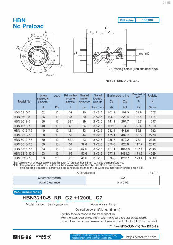
Model number coding
A15-86 Download data by searching for the corresponding model number on the Technical Support site. https://tech.thk.com
Greasing hole A (from the backside)
Models HBN3210 to 3612
30° 30°
R
PCD
U
V
5–φ d1
φ D1
H T1 T2
φ d φ D
L1
Model No.
Screw shaft outerdiameter
Lead Ball center-to-centerdiameter
Threadminor
diameter
No. ofloadedcircuits
Basic load rating Permissibleload* Rigidity
Ca C 0 a F P K
d Ph dp dc Rows × turns kN kN kN N/m
HBN 3210-5 32 10 34 26 2×2.5 102.9 191.3 31.9 1077 HBN 3610-5 36 10 38 30 2×2.5 108.2 220.4 33.5 1176 HBN 3612-5 36 12 38.4 29 2×2.5 141.1 267.7 43.7 1207 HBN 4010-7.5 40 10 42 34 3×2.5 162.6 336 50.4 1910 HBN 4012-7.5 40 12 42.4 33 3×2.5 212.4 441.6 65.8 1922 HBN 5010-7.5 50 10 52 44 3×2.5 179.1 462.7 55.5 2279 HBN 5012-7.5 50 12 52.4 43 3×2.5 235.7 572.2 73.1 2345 HBN 5016-7.5 50 16 53 39.6 3×2.5 379.6 820.9 117.7 2392 HBN 6316-7.5 63 16 66 52.6 3×2.5 427.1 1043.8 132.4 2898 HBN 6316-10.5 63 16 66 52.6 3×3.5 577.1 1461.3 178.9 4029 HBN 6320-7.5 63 20 66.5 49.6 3×2.5 578.8 1283.1 179.4 3030
*Ball screws with an outer screw shaft diameter (d) greater than 63 mm can also be manufactured. Note) The permissible load F P * indicates the maxim axial load that the Ball Screw can receive.
This model is capable of achieving a longer service life than the conventional Ball Screw under a high load.
Axial Clearance Unit: mm
Clearance symbol G2 Axial Clearance 0 to 0.02
Model number
Symbol for clearance in the axial direction(For the axial clearance, this model has clearance G2 as standard. Other clearance is also available at your request. Contact THK for details.)
Overall screw shaft length (in mm)
Accuracy symbol (*2)Seal symbol (*1)
HBN3210-5 RR G2 +1200L C7
(*1) See A15-336 . (*2) See A15-12 .
HBNNo Preload
DN value 130000
511E

A15-87
Ball Screw
Precision, Caged Ball Screw
Options⇒A15-335
Greasing hole A (from the backside)
Models HBN4010 to 6320
L1H T1 T2 T2
φ D1 φ d φ D
Unit: mm
Nut dimensions Screw shaftinertial
moment/mm
Nutmass
Shaftmass Outer
diameter Flange
diameter Overalllength
Greasinghole
D D 1 L 1 H PCD d 1 T1 T2 U MAX V MAX R MAX A kg-cm 2 /mm kg kg/m
58 85 98 15 71 6.6 22 30 43 46 43.5 M6 8.08×10 -3 1.8 5.26 62 89 98 15 75 6.6 22 30 45 50 46 M6 1.29×10 -2 1.9 6.79 66 100 116 18 82 9 26 36 49 52.5 50 M6 1.29×10 -2 2.8 6.55 66 100 135 18 82 9 23.5 30 46.5 54 48 M6 1.97×10 -2 2.9 8.52 70 104 152 18 86 9 26 36 51 56 52 M6 1.97×10 -2 3.7 5.24 78 112 135 18 94 9 23.5 30 52 63.5 54.5 M6 4.82×10 -2 3.7 13.7 80 114 152 18 96 9 26 36 56 66 58.5 M6 4.82×10 -2 4.4 13.34 95 135 211 28 113 9 37.5 48 64.5 69.6 65.2 PT 1/8 4.82×10 -2 10.0 12.1 105 139 211 28 122 9 37.5 48 70.5 82 72.5 PT 1/8 1.21×10 -1 10.6 20.2 105 139 259 28 122 9 53.5 64 70.5 82 73 PT 1/8 1.21×10 -1 17.4 20.2 117 157 252 32 137 11 44 60 79 86.5 80 PT 1/8 1.21×10 -1 17.2 19.13
Note) The rigidity values in the table represent spring constants, each obtained from the load and the elastic deformation under an axial load equal to 30% of the basic axial dynamic load rating (Ca). These values do not include the rigidity of the components related to mounting the ball screw nut. Therefore, it is normally appropriate to regard roughly 80% of the value in the table as the actual value. If the axial load (Fa) is not 0.3 Ca, the rigidity value (K N ) is obtained from the fol-lowing equation.
K: Rigidity value in the dimensional table.
1 3 Fa
0.3Ca KN=K ( )
511E

Model number coding
A15-88 Download data by searching for the corresponding model number on the Technical Support site. https://tech.thk.com
(Greasing hole)
60°60°
PCD
6-φ d1
2-A
Model No.
Screw shaft outerdiameter
Lead Ball center-to-center diameter
Screw shaft Thread minor
diameter
No. ofloaded circuits
Basic load rating Permissibleload * Rigidity
Ca C 0 a Fp K
d Ph dp dc Rows × turns kN kN kN N/m
SBKH 6332-3.8 63 32 66.5 49.8 1×3.8 304 631 88 1435
SBKH 6340-7.6 63 40 66.0 52.6 2×3.8 413 967 135 2723
SBKH 8050-7.6 80 50 84.0 63.6 2×3.8 777 1788 250 3402
SBKH 8060-7.6 80 60 84.0 63.6 2×3.8 780 1824 255 3452
SBKH 10050-7.6 100 50 104.0 83.6 2×3.8 876 2401 336 4098
SBKH 10060-7.6 100 60 104.0 83.6 2×3.8 880 2294 321 4149
SBKH 12060-7.6 120 60 124.0 103.6 2×3.8 962 2941 411 4809 Note) The permissible load Fp * indicates the maximum axial load that the Ball Screw can receive.
If desiring both ends of the screw shaft to be larger than the screw shaft diameter, contact THK.
Axial Clearance Unit: mm
Clearance symbol G1 G2 G3 Axial Clearance 0 to 0.01 0 to 0.02 0 to 0.05
Model Number
Seal symbol(*1) (RR: labyrinth seal on both sides)
Overall screw shaft length (in mm)
Accuracy symbol (*2)
Axial clearance symbol(clearance in the axial direction must be: G1, G2 or G3.Clearance G0 and GT are not supported.)
SBKH8050-7.6 RR G2 +1200L C7
(*1) See A15-336 . (*2) See A15-12 .
SBKH No Preload
DN value 130000
511E
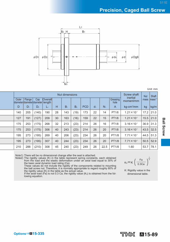
A15-89
Ball Screw
Precision, Caged Ball Screw
Options⇒A15-335
H B1
L1
φ D1 φ dc φ d φ Dg6
B2
φ D2
N1
Unit: mm
Nut dimensions Screw shaftinertial
moment/mm Nut
mass Shaft
mass *1 Outerdiameter
Flange diameter
Capdiameter
Overall length Greasing
hole D D 1 D 2 L 1 H B 1 B 2 PCD d 1 N 1 A kg-cm 2 /mm kg kg/m
140 205 (140) 190 28 143 (19) 173 22 14 PT1/8 1.21×10 -1 17.2 21.0
127 191 (127) 209 30 163 (16) 159 22 15 PT1/8 1.21×10 -1 15.5 21.0
175 253 (175) 268 32 213 (23) 214 26 16 PT1/8 3.16×10 -1 36.9 31.3
175 253 (175) 306 40 243 (23) 214 26 20 PT1/8 3.16×10 -1 43.5 32.5
195 273 (195) 269 40 206 (23) 234 26 20 PT1/8 7.71×10 -1 44.5 51.3
195 273 (195) 307 40 244 (23) 234 26 20 PT1/8 7.71×10 -1 50.5 52.9
210 288 (210) 308 45 240 (23) 249 26 22.5 PT1/8 1.60 53.7 78.1
Note1) There will be no dimensional change after the seal is attached. Note2) The rigidity values (K) in the table represent spring constants, each obtained
from the load and the elastic deformation under an axial load equal to 30% of the basic axial dynamic load rating (Ca). These values do not include the rigidity of the components related to mounting the ball screw nut. Therefore, it is normally appropriate to regard roughly 80% of the rigidity value (K) in the table as the actual value. If the axial load (Fa) is not 0.3 Ca, the rigidity value (K N ) is obtained from the fol-lowing equation.
K: Rigidity value in the dimensional table.
13Fa
0.3CaKN=K( )
511E

A15-90
DIN Standard compliant Ball Screw (DIN69051) Models EBA, EBB, EBC, EPA, EPB and EPC
Nut
Screw shaft
Deflector
Fig.1 DIN Standard (DIN69051) Compliant Precision Ball Screw
Point of Selection A15-8 Options A15-336 Model No. A15-353 Precautions on Use A15-358 Accessories for Lubrication A24-1 Mounting Procedure and Maintenance B15-104
Lead Angle Accuracy A15-11
Accuracy of the Mounting Surface A15-14
Axial Clearance A15-19
Maximum Length of the Screw Shaft A15-24
DN Value A15-33
Support Unit A15-300
Recommended Shapes of Shaft Ends A15-308
Dimensions of Each Model with an Option Attached A15-344
511E

A15-91
Ball Screw
DIN Standard compliant Ball Screw (DIN69051)
Structure and Features
In the DIN standard compliant Ball Screw, balls under a load roll in the raceway cut between the screw shaft and the nut while receiving the axial load, travel along the groove of a defl ector embed-ded inside the nut to the adjacent raceway, and then circulate back to the loaded area. Thus, the balls perform infi nite rolling motion. Two types of nuts are available: model EB of oversized-ball preload type or non-preloaded type, and model EP of offset preloaded type.
[Compact] This Ball Screw is compactly built. Because of an internal circulation system using defl ectors, the outer diameter of the nut is 70 to 80% of the conventional double nut and the overall nut length is only 60 to 80% of the return pipe nut.
[Compliant with a DIN standard] The nut fl ange shape, mounting holes and rated load are compliant with DIN69051.
511E

A15-92
Types and Features
Models EPA/EBA Specifi cation Table⇒A15-100/ A15-94 [Flange shape: round-fl ange type]
Models EPB/EBB Specifi cation Table⇒A15-102/ A15-96 [Flange shape: type with two cut faces]
Models EPC/EBC Specifi cation Table⇒A15-104/ A15-98 [Flange shape: type with one cut face]
511E

A15-93
Ball Screw
DIN Standard compliant Ball Screw (DIN69051)
Accuracy Standards
The accuracy of DIN standard compliant Ball Screw is controlled in accordance with ISO standard (ISO3408-3) and JIS standard (JIS B1192-1997). C, Cp and Ct grades are defined for this Ball Screw series. Grade C (see page A15-11 ) Grade Cp, Ct (see ISO 3408-3)
Grade 0 1 2 3 5 7
C ○ ○ ○ ○ ○ ○
Cp — — — ○ ○ —
Ct — — — ○ ○ ○
511E

Model number coding
A15-94 Download data by searching for the corresponding model number on the Technical Support site. https://tech.thk.com
Hole type 1(Model EBA1605 to 3210)
Hole type 2(Model EBA4005 to 6320)
A (Greasing hole)
A (Greasing hole)
PCD
30°90°
30°
PCD
22.5°
45° 45°
8-φ d16-φ d1
Model No.
Screw shaft outer diameter
Lead Ball center-to-center diameter
Thread minor
diameter
No. of loaded circuits
Basic load rating Rigidity
Ca ★ C 0 a K
d ℓ dp d C Rows x turns kN kN N/m EBA 1605-4 16 5 16.75 13.1 4×1 11.9 17.4 210 EBA 2005-3 20 5 20.75 17.1 3×1 10.6 17.3 200 EBA 2505-3 25 5 25.75 22.1 3×1 12.1 22.6 250 EBA 2510-3 25 10 26 21.6 3×1 15.9 27 250 EBA 2510-4 25 10 26 21.6 4×1 20.9 37.6 330 EBA 3205-3 32 5 32.75 29.2 3×1 13.9 30.2 300 EBA 3205-4 32 5 32.75 29.2 4×1 17.8 40.3 400 EBA 3205-6 32 5 32.75 29.2 6×1 25.1 60.4 600 EBA 3210-3 32 10 33.75 26.4 3×1 32.1 52.2 300 EBA 3210-4 32 10 33.75 26.4 4×1 41.3 69.7 390 EBA 4005-6 40 5 40.75 37.1 6×1 26.6 77.5 716 EBA 4010-3 40 10 41.75 34.4 3×1 37.3 69.3 380 EBA 4010-4 40 10 41.75 34.4 4×1 47.6 92.4 500 EBA 4020-3 40 20 41.75 34.7 3×1 36.8 69.3 750 EBA 5010-4 50 10 51.75 44.4 4×1 54.3 120.5 610 EBA 5020-3 50 20 52.25 43.6 3×1 55.3 108.8 470 EBA 6310-6 63 10 64.75 57.7 6×1 87.9 242.1 1140 EBA 6320-3 63 20 65.7 56.0 3×1 104.4 229.3 1470 Note) ★ Basic Dynamic Load Rating(Ca) of the accuracy C7 and Ct7 is 0.9Ca.
Shaft diameter Number of turns
Lead
Clearance symbol Accuracy symbol
Nut type: oversized-ball preload type or non-preloaded type
With QZ Lubricator (no symbol without QZ Lubricator) Seal symbol (RR : Labyrinth seal, WW : Wiper ring.)
Ball screw shaft length (mm)
Flange shape: A: round; B: double chamfered; C: single chamfered
EB A 20 05 -6 QZ RR G0 +650L C3
EBA Oversized-ball Preload / No Preload
DN value 100000
511E
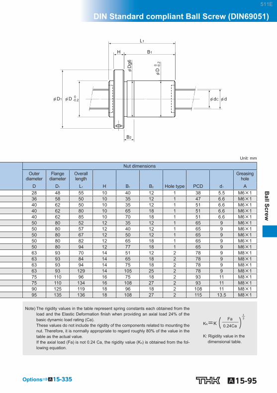
A15-95
Ball Screw
DIN Standard compliant Ball Screw (DIN69051)
Options⇒A15-335
L1
B1H
φD
g6
φ dC φ d
B2
φ D1
φD
0
-0.2
φ D 0 -0.2
Unit: mm
Nut dimensions Outer
diameter Flange
diameter Overall length Greasing
hole D D 1 L 1 H B 1 B 2 Hole type PCD d 1 A 28 48 55 10 40 12 1 38 5.5 M6×1 36 58 50 10 35 12 1 47 6.6 M6×1 40 62 50 10 35 12 1 51 6.6 M6×1 40 62 80 10 65 18 1 51 6.6 M6×1 40 62 85 10 70 18 1 51 6.6 M6×1 50 80 52 12 35 12 1 65 9 M6×1 50 80 57 12 40 12 1 65 9 M6×1 50 80 67 12 50 12 1 65 9 M6×1 50 80 82 12 65 18 1 65 9 M6×1 50 80 94 12 77 18 1 65 9 M6×1 63 93 70 14 51 12 2 78 9 M8×1 63 93 84 14 65 18 2 78 9 M8×1 63 93 94 14 75 18 2 78 9 M8×1 63 93 129 14 105 25 2 78 9 M8×1 75 110 96 16 75 18 2 93 11 M8×1 75 110 134 16 108 27 2 93 11 M8×1 90 125 119 18 96 18 2 108 11 M8×1 95 135 136 18 108 27 2 115 13.5 M8×1
Note) The rigidity values in the table represent spring constants each obtained from the load and the Elastic Deformation fi nish when providing an axial load 24% of the basic dynamic load rating (Ca). These values do not include the rigidity of the components related to mounting the nut. Therefore, it is normally appropriate to regard roughly 80% of the value in the table as the actual value. If the axial load (Fa) is not 0.24 Ca, the rigidity value (K N ) is obtained from the fol-lowing equation.
K: Rigidity value in the dimensional table.
( )13Fa
0.24CaKN=K
511E

Model number coding
A15-96 Download data by searching for the corresponding model number on the Technical Support site. https://tech.thk.com
Hole type 1(Model EBB1605 to 3210)
Hole type 2(Model EBB4005 to 6320)
A (Greasing hole)
A (Greasing hole)
PCD
Tm Tm
30°90°
30°22.5°
45° 45°
PCD
6-φ d1 8-φ d1
Model No.
Screw shaft outer diameter
Lead Ball center-to-center diameter
Thread minor
diameter
No. of loaded circuits
Basic load rating Rigidity Ca ★ C 0 a K
d ℓ dp d C Rows x turns kN kN N/m EBB 1605-4 16 5 16.75 13.1 4×1 11.9 17.4 210 EBB 2005-3 20 5 20.75 17.1 3×1 10.6 17.3 200 EBB 2505-3 25 5 25.75 22.1 3×1 12.1 22.6 250 EBB 2510-3 25 10 26 21.6 3×1 15.9 27 250 EBB 2510-4 25 10 26 21.6 4×1 20.9 37.6 330 EBB 3205-3 32 5 32.75 29.2 3×1 13.9 30.2 300 EBB 3205-4 32 5 32.75 29.2 4×1 17.8 40.3 400 EBB 3205-6 32 5 32.75 29.2 6×1 25.1 60.4 600 EBB 3210-3 32 10 33.75 26.4 3×1 32.1 52.2 300 EBB 3210-4 32 10 33.75 26.4 4×1 41.3 69.7 390 EBB 4005-6 40 5 40.75 37.1 6×1 26.6 77.5 716 EBB 4010-3 40 10 41.75 34.4 3×1 37.3 69.3 380 EBB 4010-4 40 10 41.75 34.4 4×1 47.6 92.4 500 EBB 4020-3 40 20 41.75 34.7 3×1 36.8 69.3 750 EBB 5010-4 50 10 51.75 44.4 4×1 54.3 120.5 610 EBB 5020-3 50 20 52.25 43.6 3×1 55.3 108.8 470 EBB 6310-6 63 10 64.75 57.7 6×1 87.9 242.1 1140 EBB 6320-3 63 20 65.7 56.0 3×1 104.4 229.3 1470 Note) ★ Basic Dynamic Load Rating(Ca) of the accuracy C7 and Ct7 is 0.9Ca.
Shaft diameter Number of turns
Lead
Clearance symbol Accuracy symbol
Nut type: oversized-ball preload type or non-preloaded type
With QZ Lubricator (no symbol without QZ Lubricator) Seal symbol (RR : Labyrinth seal, WW : Wiper ring.)
Ball screw shaft length (mm)
Flange shape: A: round; B: double chamfered; C: single chamfered
EB B 20 05 -6 QZ RR G0 +650L C3
EBB Oversized-ball Preload / No Preload
DN value 100000
511E

A15-97
Ball Screw
DIN Standard compliant Ball Screw (DIN69051)
Options⇒A15-335
φ D1
B2
φ D 0 -0.2
L1
B1H
0
-0
.2φ
D
φ dC φ d
φD
g6
Unit: mm
Nut dimensions Outer
diameter Flange
diameter Overall length
Greasing hole
D D 1 L 1 H B 1 B 2 Hole type PCD d 1 Tm A 28 48 55 10 40 12 1 38 5.5 20 M6×1 36 58 50 10 35 12 1 47 6.6 22 M6×1 40 62 50 10 35 12 1 51 6.6 24 M6×1 40 62 80 10 65 18 1 51 6.6 24 M6×1 40 62 85 10 70 18 1 51 6.6 24 M6×1 50 80 52 12 35 12 1 65 9 31 M6×1 50 80 57 12 40 12 1 65 9 31 M6×1 50 80 67 12 50 12 1 65 9 31 M6×1 50 80 82 12 65 18 1 65 9 31 M6×1 50 80 94 12 77 18 1 65 9 31 M6×1 63 93 70 14 51 12 2 78 9 35 M8×1 63 93 84 14 65 18 2 78 9 35 M8×1 63 93 94 14 75 18 2 78 9 35 M8×1 63 93 129 14 105 25 2 78 9 35 M8×1 75 110 96 16 75 18 2 93 11 42.5 M8×1 75 110 134 16 108 27 2 93 11 42.5 M8×1 90 125 119 18 96 18 2 108 11 47.5 M8×1 95 135 136 18 108 27 2 115 13.5 50 M8×1
Note) The rigidity values in the table represent spring constants each obtained from the load and the Elastic Deformation fi nish when providing an axial load 24% of the basic dynamic load rating (Ca). These values do not include the rigidity of the components related to mounting the nut. Therefore, it is normally appropriate to regard roughly 80% of the value in the table as the actual value. If the axial load (Fa) is not 0.24 Ca, the rigidity value (K N ) is obtained from the fol-lowing equation.
K: Rigidity value in the dimensional table.
( )13Fa
0.24CaKN=K
511E

Model number coding
A15-98 Download data by searching for the corresponding model number on the Technical Support site. https://tech.thk.com
Hole type 1(Model EBC1605 to 3210)
Hole type 2(Model EBC4005 to 6320)
A (Greasing hole)
A (Greasing hole)
PCD
22.5°
45° 45°
Tm Tm
PCD
30°90°
30°
6-φ d18-φ d1
Model No.
Screw shaft outer diameter
Lead Ball center-to-center diameter
Thread minor
diameter
No. of loaded circuits
Basic load rating Rigidity
Ca ★ C 0 a K
d ℓ dp d C Rows x turns kN kN N/m EBC 1605-4 16 5 16.75 13.1 4×1 11.9 17.4 210 EBC 2005-3 20 5 20.75 17.1 3×1 10.6 17.3 200 EBC 2505-3 25 5 25.75 22.1 3×1 12.1 22.6 250 EBC 2510-3 25 10 26 21.6 3×1 15.9 27 250 EBC 2510-4 25 10 26 21.6 4×1 20.9 37.6 330 EBC 3205-3 32 5 32.75 29.2 3×1 13.9 30.2 300 EBC 3205-4 32 5 32.75 29.2 4×1 17.8 40.3 400 EBC 3205-6 32 5 32.75 29.2 6×1 25.1 60.4 600 EBC 3210-3 32 10 33.75 26.4 3×1 32.1 52.2 300 EBC 3210-4 32 10 33.75 26.4 4×1 41.3 69.7 390 EBC 4005-6 40 5 40.75 37.1 6×1 26.6 77.5 716 EBC 4010-3 40 10 41.75 34.4 3×1 37.3 69.3 380 EBC 4010-4 40 10 41.75 34.4 4×1 47.6 92.4 500 EBC 4020-3 40 20 41.75 34.7 3×1 36.8 69.3 750 EBC 5010-4 50 10 51.75 44.4 4×1 54.3 120.5 610 EBC 5020-3 50 20 52.25 43.6 3×1 55.3 108.8 470 EBC 6310-6 63 10 64.75 57.7 6×1 87.9 242.1 1140 EBC 6320-3 63 20 65.7 56.0 3×1 104.4 229.3 1470 Note) ★ Basic Dynamic Load Rating(Ca) of the accuracy C7 and Ct7 is 0.9Ca.
Shaft diameter Number of turns
Lead
Clearance symbol Accuracy symbol
Nut type: oversized-ball preload type or non-preloaded type
With QZ Lubricator (no symbol without QZ Lubricator) Seal symbol (RR : Labyrinth seal, WW : Wiper ring.)
Ball screw shaft length (mm)
Flange shape: A: round; B: double chamfered; C: single chamfered
EB C 20 05 -6 QZ RR G0 +650L C3
EBC Oversized-ball Preload / No Preload
DN value 100000
511E

A15-99
Ball Screw
DIN Standard compliant Ball Screw (DIN69051)
Options⇒A15-335
φ dC φ d
L1
B1H
φD
g6
B2
φ D1 φ D 0 -0.2
φD
0
-0.2
Unit: mm
Nut dimensions Outer
diameter Flange
diameter Overall length Greasing
hole D D 1 L 1 H B 1 B 2 Hole type PCD d 1 Tm A 28 48 55 10 40 12 1 38 5.5 20 M6×1 36 58 50 10 35 12 1 47 6.6 22 M6×1 40 62 50 10 35 12 1 51 6.6 24 M6×1 40 62 80 10 65 18 1 51 6.6 24 M6×1 40 62 85 10 70 18 1 51 6.6 24 M6×1 50 80 52 12 35 12 1 65 9 31 M6×1 50 80 57 12 40 12 1 65 9 31 M6×1 50 80 67 12 50 12 1 65 9 31 M6×1 50 80 82 12 65 18 1 65 9 31 M6×1 50 80 94 12 77 18 1 65 9 31 M6×1 63 93 70 14 51 12 2 78 9 35 M8×1 63 93 84 14 65 18 2 78 9 35 M8×1 63 93 94 14 75 18 2 78 9 35 M8×1 63 93 129 14 105 25 2 78 9 35 M8×1 75 110 96 16 75 18 2 93 11 42.5 M8×1 75 110 134 16 108 27 2 93 11 42.5 M8×1 90 125 119 18 96 18 2 108 11 47.5 M8×1 95 135 136 18 108 27 2 115 13.5 50 M8×1
Note) The rigidity values in the table represent spring constants each obtained from the load and the Elastic Deformation fi nish when providing an axial load 24% of the basic dynamic load rating (Ca). These values do not include the rigidity of the components related to mounting the nut. Therefore, it is normally appropriate to regard roughly 80% of the value in the table as the actual value. If the axial load (Fa) is not 0.24 Ca, the rigidity value (K N ) is obtained from the fol-lowing equation.
K: Rigidity value in the dimensional table.
( )13Fa
0.24CaKN=K
511E

Model number coding
A15-100 Download data by searching for the corresponding model number on the Technical Support site. https://tech.thk.com
Hole type 1(Model EPA1605 to 3210)
Hole type 2(Model EPA4005 to 6310)
A (Greasing hole)
A (Greasing hole)
PCD
30°90°
30°
PCD
22.5°
45° 45°
8-φ d16-φ d1
Model No.
Screw shaft outer diameter
Lead Ball center-to-center diameter
Thread minor
diameter
No. of loaded circuits
Basic load rating Rigidity
Ca ★ C 0 a K
d ℓ dp d C Rows x turns kN kN N/m EPA 1605-6 16 5 16.75 13.1 3×1 9.3 13.1 317 EPA 2005-6 20 5 20.75 17.1 3×1 10.6 17.3 310 EPA 2505-6 25 5 25.75 22.1 3×1 12.1 22.6 490 EPA 2510-4 25 10 26 21.6 2×1 11.3 18 330 EPA 3205-6 32 5 32.75 29.2 3×1 13.9 30.2 620 EPA 3205-8 32 5 32.75 29.2 4×1 17.8 40.3 810 EPA 3210-6 32 10 33.75 26.4 3×1 32.1 52.2 600 EPA 4005-6 40 5 40.75 37.1 3×1 15.4 38.8 298 EPA 4010-6 40 10 41.75 34.7 3×1 37.3 69.3 750 EPA 4010-8 40 10 41.75 34.7 4×1 47.6 92.4 1000 EPA 5010-8 50 10 51.75 44.4 4×1 54.3 120.5 1230 EPA 6310-8 63 10 64.75 57.7 4×1 61.9 160.7 1550 Note) ★ Basic Dynamic Load Rating(Ca) of the accuracy C7 and Ct7 is 0.9Ca.
Shaft diameter Number of turns
Lead
Clearance symbol Accuracy symbol
Nut type: offset preloaded type
With QZ Lubricator (no symbol without QZ Lubricator)Seal symbol (RR : Labyrinth seal, WW : Wiper ring.)
Ball screw shaft length (mm)
Flange shape: A: round; B: double chamfered; C: single chamfered
EP A 20 05 -6 QZ RR G0 +650L C3
EPA With Preload
511E
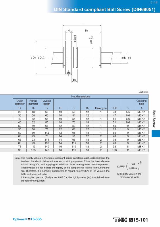
A15-101
Ball Screw
DIN Standard compliant Ball Screw (DIN69051)
Options⇒A15-335
L1
B1H
φD
g6
φ dC φ d
B2
φ D1
φD
0
-0.2
φ D 0 -0.2
Unit: mm
Nut dimensions Outer
diameter Flange
diameter Overall length Greasing
hole D D 1 L 1 H B 1 B 2 Hole type PCD d 1 A 28 48 65 10 50 12 1 38 5.5 M6×1 36 58 66 10 51 12 1 47 6.6 M6×1 40 62 66 10 51 12 1 51 6.6 M6×1 40 62 85 10 70 18 1 51 6.6 M6×1 50 80 67 12 50 12 1 65 9 M6×1 50 80 78 12 61 12 1 65 9 M6×1 50 80 112 12 95 18 1 65 9 M6×1 63 93 70 14 51 12 2 78 9 M8×1 63 93 114 14 95 18 2 78 9 M8×1 63 93 138 14 119 18 2 78 9 M8×1 75 110 140 16 119 18 2 93 11 M8×1 90 125 142 18 119 18 2 108 11 M8×1
Note) The rigidity values in the table represent spring constants each obtained from the load and the elastic deformation when providing a preload 8% of the basic dynam-ic load rating (Ca) and applying an axial load three times greater than the preload. These values do not include the rigidity of the components related to mounting the nut. Therefore, it is normally appropriate to regard roughly 80% of the value in the table as the actual value. If the applied preload (Fa0) is not 0.08 Ca, the rigidity value (K N ) is obtained from the following equation.
K: Rigidity value in the dimensional table.
( )13Fa0
0.08CaKN=K
511E

Model number coding
A15-102 Download data by searching for the corresponding model number on the Technical Support site. https://tech.thk.com
Hole type 1(Model EPB1605 to 3210)
Hole type 2(Model EPB4005 to 6310)
A (Greasing hole)
A (Greasing hole)
PCD
Tm Tm
30°90°
30°22.5°
45° 45°
PCD
6-φ d1 8-φ d1
Model No.
Screw shaft outer diameter
Lead Ball center-to-center diameter
Thread minor
diameter
No. of loaded circuits
Basic load rating Rigidity
Ca ★ C 0 a K
d ℓ dp d C Rows x turns kN kN N/m EPB 1605-6 16 5 16.75 13.1 3×1 9.3 13.1 317 EPB 2005-6 20 5 20.75 17.1 3×1 10.6 17.3 310 EPB 2505-6 25 5 25.75 22.1 3×1 12.1 22.6 490 EPB 2510-4 25 10 26 21.6 2×1 11.3 18 330 EPB 3205-6 32 5 32.75 29.2 3×1 13.9 30.2 620 EPB 3205-8 32 5 32.75 29.2 4×1 17.8 40.3 810 EPB 3210-6 32 10 33.75 26.4 3×1 32.1 52.2 600 EPB 4005-6 40 5 40.75 37.1 3×1 15.4 38.8 298 EPB 4010-6 40 10 41.75 34.7 3×1 37.3 69.3 750 EPB 4010-8 40 10 41.75 34.7 4×1 47.6 92.4 1000 EPB 5010-8 50 10 51.75 44.4 4×1 54.3 120.5 1230 EPB 6310-8 63 10 64.75 57.7 4×1 61.9 160.7 1550 Note) ★ Basic Dynamic Load Rating(Ca) of the accuracy C7 and Ct7 is 0.9Ca.
Shaft diameter Number of turns
Lead
Clearance symbol Accuracy symbol
Nut type: offset preloaded type
With QZ Lubricator (no symbol without QZ Lubricator)Seal symbol (RR : Labyrinth seal, WW : Wiper ring.)
Ball screw shaft length (mm)
Flange shape: A: round; B: double chamfered; C: single chamfered
EP B 20 05 -6 QZ RR G0 +650L C3
EPB With Preload
511E

A15-103
Ball Screw
DIN Standard compliant Ball Screw (DIN69051)
Options⇒A15-335
φ D1
B2
φ D 0 -0.2
L1
B1H
0
-0
.2φ
D
φ dC φ d
φD
g6
Unit: mm
Nut dimensions Outer
diameter Flange
diameter Overall length Greasing
hole D D 1 L 1 H B 1 B 2 Hole type PCD d 1 Tm A 28 48 65 10 50 12 1 38 5.5 20 M6×1 36 58 66 10 51 12 1 47 6.6 22 M6×1 40 62 66 10 51 12 1 51 6.6 24 M6×1 40 62 85 10 70 18 1 51 6.6 24 M6×1 50 80 67 12 50 12 1 65 9 31 M6×1 50 80 78 12 61 12 1 65 9 31 M6×1 50 80 112 12 95 18 1 65 9 31 M6×1 63 93 70 14 51 12 2 78 9 35 M8×1 63 93 114 14 95 18 2 78 9 35 M8×1 63 93 138 14 119 18 2 78 9 35 M8×1 75 110 140 16 119 18 2 93 11 42.5 M8×1 90 125 142 18 119 18 2 108 11 47.5 M8×1
Note) The rigidity values in the table represent spring constants each obtained from the load and the elastic deformation when providing a preload 8% of the basic dynam-ic load rating (Ca) and applying an axial load three times greater than the preload. These values do not include the rigidity of the components related to mounting the nut. Therefore, it is normally appropriate to regard roughly 80% of the value in the table as the actual value. If the applied preload (Fa0) is not 0.08 Ca, the rigidity value (K N ) is obtained from the following equation.
K: Rigidity value in the dimensional table.
( )13Fa0
0.08CaKN=K
511E

Model number coding
A15-104 Download data by searching for the corresponding model number on the Technical Support site. https://tech.thk.com
Hole type 1(Model EPC1605 to 3210)
Hole type 2(Model EPC4005 to 6310)
A (Greasing hole)
A (Greasing hole)
PCD
22.5°
45° 45°
Tm Tm
PCD
30°90°
30°
6-φ d18-φ d1
Model No.
Screw shaft outer diameter
Lead Ball center-to-center diameter
Thread minor
diameter
No. of loaded circuits
Basic load rating Rigidity
Ca ★ C 0 a K
d ℓ dp d C Rows x turns kN kN N/m EPC 1605-6 16 5 16.75 13.1 3×1 9.3 13.1 317 EPC 2005-6 20 5 20.75 17.1 3×1 10.6 17.3 310 EPC 2505-6 25 5 25.75 22.1 3×1 12.1 22.6 490 EPC 2510-4 25 10 26 21.6 2×1 11.3 18 330 EPC 3205-6 32 5 32.75 29.2 3×1 13.9 30.2 620 EPC 3205-8 32 5 32.75 29.2 4×1 17.8 40.3 810 EPC 3210-6 32 10 33.75 26.4 3×1 32.1 52.2 600 EPC 4005-6 40 5 40.75 37.1 3×1 15.4 38.8 298 EPC 4010-6 40 10 41.75 34.7 3×1 37.3 69.3 750 EPC 4010-8 40 10 41.75 34.7 4×1 47.6 92.4 1000 EPC 5010-8 50 10 51.75 44.4 4×1 54.3 120.5 1230 EPC 6310-8 63 10 64.75 57.7 4×1 61.9 160.7 1550 Note) ★ Basic Dynamic Load Rating(Ca) of the accuracy C7 and Ct7 is 0.9Ca.
Shaft diameter Number of turns
Lead
Clearance symbol Accuracy symbol
Nut type: offset preloaded type
With QZ Lubricator (no symbol without QZ Lubricator)Seal symbol (RR : Labyrinth seal, WW : Wiper ring.)
Ball screw shaft length (mm)
Flange shape: A: round; B: double chamfered; C: single chamfered
EP C 20 05 -6 QZ RR G0 +650L C3
EPC With Preload
511E

A15-105
Ball Screw
DIN Standard compliant Ball Screw (DIN69051)
Options⇒A15-335
φ dC φ d
L1
B1H
φD
g6
B2
φ D1 φ D 0 -0.2
φD
0
-0.2
Unit: mm
Nut dimensions Outer
diameter Flange
diameter Overall length Greasing
hole D D 1 L 1 H B 1 B 2 Hole type PCD d 1 Tm A 28 48 65 10 50 12 1 38 5.5 20 M6×1 36 58 66 10 51 12 1 47 6.6 22 M6×1 40 62 66 10 51 12 1 51 6.6 24 M6×1 40 62 85 10 70 18 1 51 6.6 24 M6×1 50 80 67 12 50 12 1 65 9 31 M6×1 50 80 78 12 61 12 1 65 9 31 M6×1 50 80 112 12 95 18 1 65 9 31 M6×1 63 93 70 14 51 12 2 78 9 35 M8×1 63 93 114 14 95 18 2 78 9 35 M8×1 63 93 138 14 119 18 2 78 9 35 M8×1 75 110 140 16 119 18 2 93 11 42.5 M8×1 90 125 142 18 119 18 2 108 11 47.5 M8×1
Note) The rigidity values in the table represent spring constants each obtained from the load and the elastic deformation when providing a preload 8% of the basic dynam-ic load rating (Ca) and applying an axial load three times greater than the preload. These values do not include the rigidity of the components related to mounting the nut. Therefore, it is normally appropriate to regard roughly 80% of the value in the table as the actual value. If the applied preload (Fa0) is not 0.08 Ca, the rigidity value (K N ) is obtained from the following equation.
K: Rigidity value in the dimensional table.
( )13Fa0
0.08CaKN=K
511E

A15-106
Unfi nished Shaft Ends Precision Ball Screw Models BIF, MDK, MBF and BNF
Point of Selection A15-8 Options A15-336 Model No. A15-353 Precautions on Use A15-358 Accessories for Lubrication A24-1 Mounting Procedure and Maintenance B15-104
Lead Angle Accuracy A15-11
Accuracy of the Mounting Surface A15-14
Axial clearance A15-109
DN Value A15-33
Support Unit A15-300
Recommended Shapes of Shaft Ends A15-308
511E

A15-107
Ball Screw
Unfi nished Shaft Ends Precision Ball Screw
Structure and Features
This type of ball screw is mass produced by cutting the standard screw shafts of precision ball screws to regular lengths. Additional machining of the shaft ends can be performed easily. To meet various intended purposes, THK offers several Ball Screw models with different types of nuts: the single-nut type (model BNF), the offset preload-nut type (model BIF) and the miniature Ball Screw (models MDK and MBF).
[Contamination Protection] Nuts of the following model numbers are attached with a labyrinth seal. ● All variations of models BNF and BIF ● Model MDK0802/1002/1202/1402/1404/1405 When dust or other foreign material may enter the Ball Screw, it is necessary to use a contamination protection device (e.g., bellows) to completely protect the screw shaft.
[Lubrication] The ball screw nuts are supplied with lithium soap-group grease with shipments. (Models MDK and MBF are applied only with an anti-rust oil.)
[Additional Machining of the Shaft End] Since only the effective thread of the screw shaft is surface treated with induction-hardening (all variations of models BNF and BIF; model MDK 1405) or carburizing (all variations of model MBF; model MDK0401 to 1404), the shaft ends can additionally be machined easily either by grinding or milling. In addition, since both ends of the screw shaft have a center hole, they can be cylindrically ground. Surface hardness of the effective thread : 58 to 64 HRC Hardness of the screw shaft ends All variations of models BNF and BIF; model MDK 1405 : 22 to 27 HRC All variations of model MBF; model MDK0401 to 1404 : 35 HRC or below THK has standardized the shapes of the screw shaft ends in order to allow speedy estimation and manufacturing of the Ball Screws. The shapes of shaft ends are divided into those allowing the standard support units to be used (symbols H, K and J) and those compliant with JIS B 1192-1997 (symbols A, B and C). See A15-308 for details.
511E
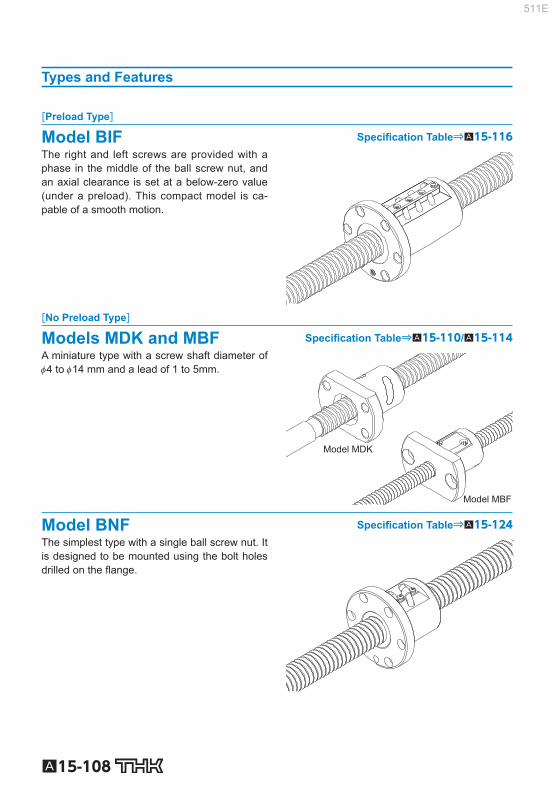
A15-108
Types and Features
[Preload Type]
Model BIF Specifi cation Table⇒A15-116 The right and left screws are provided with a phase in the middle of the ball screw nut, and an axial clearance is set at a below-zero value (under a preload). This compact model is ca-pable of a smooth motion.
[No Preload Type]
Models MDK and MBF Specifi cation Table⇒A15-110/ A15-114 A miniature type with a screw shaft diameter of 4 to 14 mm and a lead of 1 to 5mm.
Model MDK
Model MBF
Model BNF Specifi cation Table⇒A15-124 The simplest type with a single ball screw nut. It is designed to be mounted using the bolt holes drilled on the fl ange.
511E

A15-109
Ball Screw
Unfi nished Shaft Ends Precision Ball Screw
Nut Types and Axial Clearance Screw shaft outer
diameter (mm) 4 to 14
Nut type
Model MDK Model MBF
No preload type No preload type
Accuracy grades C3, C5 C7 C3, C5 C7
Axial clearance (mm) 0.005 or less (GT) 0.02 or less (G2) 0.005 or less (GT) 0.02 or less (G2)
Note) The symbols in the parentheses indicate axial clearance symbols.
Screw shaft outdiameter (mm) 16 to 50
Nut type
Model BIF Model BNF
Preload Type No preload type
Accuracy grades C5 C7 C5 C7
Axial clearance (mm) 0 or less (G0) 0 or less (G0) 0.01 or less (G1) 0.02 or less (G2)
Note1) The symbols in the parentheses indicate axial clearance symbols.
511E

Model number coding
A15-110 Download data by searching for the corresponding model number on the Technical Support site. https://tech.thk.com
4-φ d1 through hole
Tw
30° 30°
PCD
Model No.
Ball screw specifi cations Nut
Screw shaft outer diameter
Lead Ball center-to-center diameter
Thread minor
diameter
No. of loaded circuits
Basic load rating Outer diameter
Flange diameter
Overall length
Ca C 0 a
d Ph dp dc Rows × turns kN kN D D 1 L 1 H
MDK 0401-3 4 1 4.15 3.4 3×1 0.29 0.42 9 19 13 3
MDK 0601-3 6 1 6.2 5.3 3×1 0.54 0.94 11 23 14.5 3.5
MDK 0801-3 8 1 8.2 7.3 3×1 0.64 1.4 13 26 15 4
MDK 0802-3 8 2 8.3 7 3×1 1.4 2.3 15 28 22 5
MDK 1002-3 10 2 10.3 9 3×1 1.5 2.9 17 34 22 5
Model No. Overall screw shaft length (in mm)
Symbol for clearancein the axial direction (*1)
Accuracy symbol (*2)
Unfinished shaft ends code
MDK0401-3 GT +95L C5 A
(*1) See A15-19 . (*2) See A15-12 .
MDK (Unfi nished Shaft Ends) No Preload
DN value 70000
511E

A15-111
Ball Screw
Unfi nished Shaft Ends Precision Ball Screw
Options⇒A15-335
φ d3
B1
L1
L
φ d4φ dφ Dg6φD1
H
K (ℓ0)ℓ3ℓ2 ℓ1
Unit: mm
Dimensions Screw shaft dimensions Nut
mass Shaft mass
Unfi nished Shaft End
Code
Overall length
B 1 PCD d 1 Tw L ℓ 0 ℓ 1 ℓ 2 ℓ 3 d 3 d 4 K kg kg/m
10 14 2.9 13 A 95 47
10 35 50
6.2 3.2 3 0.01 0.07 115 67 70 145 97 100
11 17 3.4 15 A 120 67
10 40 70
8.2 5.3 3 0.02 0.14 150 97 100 180 127 130
11 20 3.4 17 A
130 67
15 45
70
10.2 7.3 3 0.02 0.29 160 97 100 190 127 130 240 177 180
17 22 3.4 19 A
140 76
15 45
80
10.2 7 4 0.04 0.27 170 106 110 200 136 140 250 186 190
17 26 4.5 21 A
160 86
15 55
90
12.2 9 4 0.05 0.47 210 136 140 260 186 190 310 236 240
Note) Models MDK 0401, 0601, and 0801 are not provided with a labyrinth seal.
511E

Model number coding
A15-112 Download data by searching for the corresponding model number on the Technical Support site. https://tech.thk.com
4-φ d1 through hole
Tw
30° 30°
PCD
φ d3
B1
L1
L
φ d4φ dφ Dg6φD1
H
K (ℓ0)ℓ3ℓ2 ℓ1
Model No.
Ball screw specifi cations Nut Screw
shaft outer diameter
Lead Ball center-to-center diameter
Thread minor
diameter
No. of loaded circuits
Basic load rating Outer diameter
Flange diameter
Overall length
Ca C 0 a
d Ph dp dc Rows × turns kN kN D D 1 L 1 H
MDK 1202-3 12 2 12.3 11 3×1 1.7 3.6 19 36 22 5
MDK 1402-3 14 2 14.3 13 3×1 1.8 4.3 21 40 23 6
MDK 1404-3 14 4 14.65 12.2 3×1 4.2 7.6 26 45 33 6
MDK 1405-3 14 5 14.75 11.2 3×1 7 11.6 26 45 42 10
Seal symbol (*1) Unfinished shaft ends code
Accuracy symbol (*3)
Overall screw shaftlength (in mm)
Symbol for clearancein the axial direction (*2)
Model No.
MDK1202-3 RR GT +165L C5 A
(*1) See A15-336 . (*2) See A15-19 . (*3) See A15-12 .
MDK (Unfi nished Shaft Ends) No Preload
DN value 70000
511E

A15-113
Ball Screw
Unfi nished Shaft Ends Precision Ball Screw
Options⇒A15-335
4-φ d1 through hole(Greasing hole)
Tw
30° 30°
PCD
B1
L1
φ D1
HM6
5
φ Dg6
Unit: mm
Dimensions Screw shaft dimensions Nut
mass Shaft mass
Unfi nished Shaft End
Code
Overall length
B 1 PCD d 1 Tw L ℓ 0 ℓ 1 ℓ 2 ℓ 3 d 3 d 4 K kg kg/m
17 28 4.5 23 A
165 86
15 60
90
14.2 11 4 0.05 0.71 215 136 140 265 186 190 315 236 240 365 286 290
17 31 5.5 26 A
175 86
25 60
90
15.2 13 4 0.07 1 225 136 140 275 186 190 325 236 240 425 336 340
27 36 5.5 28 A
240 150
25 60
155
15.2 11.9 5 0.14 0.8 290 200 205 340 250 255 440 350 355 540 450 455
32 36 5.5 28 A
250 160
25 60
165
14 11.2 5 0.19 1.2 300 210 215 350 260 265 450 360 365 550 460 465
511E

Model number coding
A15-114 Download data by searching for the corresponding model number on the Technical Support site. https://tech.thk.com
2-φ d1 through hole, φ d2 counter bore depth h
TwPCD
Model No.
Ball screw specifi cations Nut Screw
shaft outer diameter
Lead Ball center-to-center diameter
Thread minor
diameter
No. of loaded circuits
Basic load rating Outer diameter
Flange diameter
Overall length
Ca C 0 a
d Ph dp dc Rows × turns kN kN D D 1 L 1 H
MBF 0401-3.7 4 1 4.15 3.3 1×3.7 0.59 0.93 11 24 18 4
MBF 0601-3.7 6 1 6.15 5.3 1×3.7 0.74 1.5 13 30 21 5
MBF 0802-3.7 8 2 8.3 6.6 1×3.7 2.5 4.2 20 40 28 6
MBF 1002-3.7 10 2 10.3 8.6 1×3.7 2.8 5.3 23 43 28 6
MBF 1202-3.7 12 2 12.3 10.6 1×3.7 3 6.5 25 47 30 8
MBF 1402-3.7 14 2 14.3 12.6 1×3.7 3.3 7.5 26 48 30 8
MBF 1404-3.7 14 4 14.3 11.8 1×3.7 5.7 11.1 30 54 38 8
Accuracy symbol (*3)
Model No.
Symbol for clearancein the axial direction (*2)
Overall screw shaftlength (in mm)
Unfinished shaft ends code
Seal symbol (*1)
MBF0802-3.7 RR GT +218L C5 A
(*1) See A15-336 . (*2) See A15-19 . (*3) See A15-12 .
MBF (Unfi nished Shaft Ends) No Preload
DN value 70000
511E

A15-115
Ball Screw
Unfi nished Shaft Ends Precision Ball Screw
Options⇒A15-335
φ d3
B1
L1
L
φ d4φ dφ Dg6φ D1
H
K (ℓ0)ℓ3ℓ2 ℓ1
Unit: mm
Dimensions Screw shaft dimensions Nut
mass Shaft mass
Unfi nished Shaft End
Code
Overall length
B 1 PCD d 1 d 2 h Tw L ℓ 0 ℓ 1 ℓ 2 ℓ 3 d 3 d 4 K kg kg/m
14 17 3.4 6.5 2.5 13 A 90 48
10 30 50
4.3 3.2 2 0.02 0.07 110 68 70 130 88 90
16 21.5 3.4 6.5 3 17 A 131 58
20 50 61
6.3 5.2 3 0.04 0.14 161 88 91 201 128 131
22 30 4.5 8 4 24 A 168 85
25 55 88
8.3 6.2 3 0.1 0.19 193 110 113 218 135 138
22 33 4.5 8 4 27 A 183 95
25 60 98
10.3 8.2 3 0.11 0.36 223 135 138 273 185 188
22 36 5.5 9.5 5.5 29 A 210 117
30 60 120
12.3 10.2 3 0.15 0.58 235 142 145 285 192 195
22 37 5.5 9.5 5.5 32 A
205 102
40 60
105
14.3 12.2 3 0.16 0.85 245 142 145 295 192 195 345 242 245
30 42 5.5 9.5 5.5 34 A
233 129
40 60
133
14.3 11.2 4 0.25 1.2 293 189 193 353 249 253 413 309 313
Note) Models MBF 0401 and 0601 are not provided with a labyrinth seal.
511E

Model number coding
A15-116 Download data by searching for the corresponding model number on the Technical Support site. https://tech.thk.com
(Greasing hole)
PCD
A
60°
Model No.
Ball screw specifi cations Nut Screw
shaft outer diameter
Lead Ball center-to-center diameter
Thread minor
diameter
No. of loaded circuits
Basic load rating Outer diameter
Flange diameter
Overall length
Ca C 0 a
d Ph dp dc Rows × turns kN kN D D 1 L 1 H
BIF 1605-5 16 5 16.75 13.2 1×2.5 7.4 13.9 40 60 56 10
BIF 1810-3 18 10 18.8 15.5 1×1.5 5.1 9.6 42 65 75 12
BIF 2005-5 20 5 20.75 17.2 1×2.5 8.3 17.4 44 67 56 11
BIF 2505-5 25 5 25.75 22.2 1×2.5 9.2 22 50 73 55 11
Seal symbol (*1)
Unfinished shaft ends code (A or B)Accuracy symbol (*3)
Overall screw shaft length (in mm)
Symbol for clearancein the axial direction (*2)
Model No.
BIF2005-5 RR G0 +610L C5 A
(*1) See A15-336 . (*2) See A15-19 . (*3) See A15-12 .
BIF (Unfi nished Shaft Ends) With Preload
DN value 70000
511E

A15-117
Ball Screw
Unfi nished Shaft Ends Precision Ball Screw
Options⇒A15-335
φ D1
C0.5 C1C0.5
(ℓ0)ℓ2 ℓ1
φ d3 φ d4
φ dp
φ d
φ Dg6
B1
L1
Hh
φ d1φ d2
L Unit: mm
Dimensions Screw shaft dimensions Nut
mass Shaft mass
Greasing hole Stan-
dardstock symbol
Overall length
B 1 PCD d 1 d 2 h A L ℓ 0 ℓ 1 ℓ 2 d 3 d 4 kg kg/m
46 50 4.5 8 4.5 M6 A
410 200
50 160 16 12.8 0.56 0.92 510 300
610 400 710 500 1.25
63 53 5.5 9.5 5.5 M6 A
410 200
50 160 18 15.3 0.75 1.62 510 300 610 400 710 500 810 600
45 55 5.5 9.5 5.5 M6 A
410 200
50 160 20 15.3
0.57 1.65
510 300 610 400 710 500 810 600
16.8 1010 800
B 610 300
50 260 20 16.8 710 400
44 61 5.5 9.5 5.5 M6 A
520 300
60 160 25
20.3
0.75 2.84
620 400 720 500 820 600
1020 800 21.8 1220 1000
1420 1200
B 720 400
60 260 25 21.8 820 500
511E
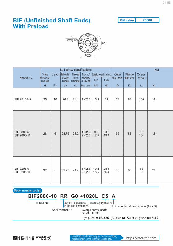
Model number coding
A15-118 Download data by searching for the corresponding model number on the Technical Support site. https://tech.thk.com
(Greasing hole)
PCD
A
60°
Model No.
Ball screw specifi cations Nut Screw
shaft outer diameter
Lead Ball center-to-center diameter
Thread minor
diameter
No. of loaded circuits
Basic load rating Outer diameter
Flange diameter
Overall length
Ca C 0 a
d Ph dp dc Rows × turns kN kN D D 1 L 1 H
BIF 2510A-5 25 10 26.3 21.4 1×2.5 15.8 33 58 85 100 18
BIF 2806-5 BIF 2806-10 28 6 28.75 25.2 1×2.5
2×2.5 9.6
17.5 24.6 49.4 55 85 68
104 12
BIF 3205-5 BIF 3205-10 32 5 32.75 29.2 1×2.5
2×2.5 10.2 18.5
28.1 56.4 58 85 56
86 12
Model No.
Seal symbol (*1) Overall screw shaftlength (in mm)
Unfinished shaft ends code (A or B)Accuracy symbol (*3)Symbol for clearance
in the axial direction (*2)
BIF2806-10 RR G0 +1020L C5 A
(*1) See A15-336 . (*2) See A15-19 . (*3) See A15-12 .
BIF (Unfi nished Shaft Ends) With Preload
DN value 70000
511E

A15-119
Ball Screw
Unfi nished Shaft Ends Precision Ball Screw
Options⇒A15-335
φ D1
C0.5 C1C0.5
(ℓ0)ℓ2 ℓ1
φ d3 φ d4
φ dp
φ d
φ Dg6
B1
L1
Hh
φ d1φ d2
L Unit: mm
Dimensions Screw shaft dimensions Nut
mass Shaft mass
Greasing hole Stan-
dardstock symbol
Overall length
B 1 PCD d 1 d 2 h A L ℓ 0 ℓ 1 ℓ 2 d 3 d 4 kg kg/m
82 71 6.6 11 6.5 M6 A
620 400
60 160 25 20.3 1.87 2.68 820 600
1020 800 1220 1000 1420 1200
56 92 69 6.6 11 6.5 M6
A
520 300
60 160 28
20.3
1 1.57 3.89
620 400 720 500 920 700
1020 800 24.8 1220 1000
1420 1200
B 720 400
70 250
28 24.8 920 500 350 1100 700 330
44 74 71 6.6 11 6.5 M6 A
730 500
70 160 32 25.3
0.87 1.32 5.03
930 700 1230 1000 1430 1200 1630 1400
27.8 1830 1600
511E

Model number coding
A15-120 Download data by searching for the corresponding model number on the Technical Support site. https://tech.thk.com
(Greasing hole)
PCD
A
60°
Model No.
Ball screw specifi cations Nut Screw
shaft outer diameter
Lead Ball center-to-center diameter
Thread minor
diameter
No. of loaded circuits
Basic load rating Outer diameter
Flange diameter
Overall length
Ca C 0 a
d Ph dp dc Rows × turns kN kN D D 1 L 1 H
BIF 3206-5 BIF 3206-10 32 6 33 28.4 1×2.5
2×2.5 13.9 25.2
35.2 70.4 62 89 63
99 12
BIF 3210A-5 32 10 33.75 26.4 1×2.5 26.1 56.2 74 108 100 15
BIF 3610-5 BIF 3610-10 36 10 37.75 30.5 1×2.5
2×2.5 27.6 50.1
63.3 126.4 75 120 111
171 18
Unfinished shaft ends code (A or B)Overall screw shaftlength (in mm)
Accuracy symbol (*3)Symbol for clearancein the axial direction (*2)
Seal symbol (*1)
Model No.
BIF3206-10 RR G0 +1100L C5 B
(*1) See A15-336 . (*2) See A15-19 . (*3) See A15-12 .
BIF (Unfi nished Shaft Ends) With Preload
DN value 70000
511E

A15-121
Ball Screw
Unfi nished Shaft Ends Precision Ball Screw
Options⇒A15-335
φ D1
C0.5 C1C0.5
(ℓ0)ℓ2 ℓ1
φ d3 φ d4
φ dp
φ d
φ Dg6
B1
L1
Hh
φ d1φ d2
L Unit: mm
Dimensions Screw shaft dimensions Nut
mass Shaft mass
Greasing hole Stan-
dardstock symbol
Overall length
B 1 PCD d 1 d 2 h A L ℓ 0 ℓ 1 ℓ 2 d 3 d 4 kg kg/m
51 87 75 6.6 11 6.5 M6
A
730 500
70 160 32 25.3
1.2 1.76 4.63
930 700 1230 1000 1430 1200 1630 1400
27.8 1830 1600
B 930 500
70 360
32 27.8 1100 700 330 1430 1000 360
85 90 9 14 8.5 M6 A
730 500
70 160 32 25.3 2.8 3.66 930 700
1430 1200 1830 1600
93 153 98 11 17.5 11 M6
A
730 500
70 160
36 30.3 3.4 4.8 5.03
930 700 1430 1200 1830 1600
B 930 500
100 330
1100 700 300 1830 1200 530
511E

Model number coding
A15-122 Download data by searching for the corresponding model number on the Technical Support site. https://tech.thk.com
(Greasing hole)
PCD
A
60°
Model No.
Ball screw specifi cations Nut Screw
shaft outer diameter
Lead Ball center-to-center diameter
Thread minor
diameter
No. of loaded circuits
Basic load rating Outer diameter
Flange diameter
Overall length
Ca C 0 a
d Ph dp dc Rows × turns kN kN D D 1 L 1 H
BIF 4010-5 BIF 4010-10 40 10 41.75 34.4 1×2.5
2×2.5 29
52.7 70.4
141.1 82 124 103 163 18
BIF 4012-5 BIF 4012-10 40 12 42 34.1 1×2.5
2×2.5 33.9 61.6
79.2 158.8 84 126 119
191 18
BIF 5010-5 BIF 5010-10 50 10 51.75 44.4 1×2.5
2×2.5 32
58.2 88.2
176.4 93 135 103 163 18
Unfinished shaft ends code (A or B)Overall screw shaft length (in mm)
Accuracy symbol (*3)Symbol for clearancein the axial direction (*2)
Seal symbol (*1)
Model No.
BIF4012-10 RR G0 +1230L C5 A
(*1) See A15-336 . (*2) See A15-19 . (*3) See A15-12 .
BIF (Unfi nished Shaft Ends) With Preload
DN value 70000
511E

A15-123
Ball Screw
Unfi nished Shaft Ends Precision Ball Screw
Options⇒A15-335
φ D1
C0.5 C1C0.5
(ℓ0)ℓ2 ℓ1
φ d3 φ d4
φ dp
φ d
φ Dg6
B1
L1
Hh
φ d1φ d2
L Unit: mm
Dimensions Screw shaft dimensions Nut
mass Shaft mass
Greasing hole Stan-
dardstock symbol
Overall length
B 1 PCD d 1 d 2 h A L ℓ 0 ℓ 1 ℓ 2 d 3 d 4 kg kg/m
85 145 102 11 17.5 11 M6 A
1230 1000
70 160 40 30.3 3.58 5.18 6.59
1730 1500 2030 1800 2230 2000
101 173 104 11 17.5 11 M6
A
1230 1000
70 160 40 30.3 4.2 6.24 6.39
1730 1500 2030 1800 2230 2000
B 1730 1200
100 430
40 33.8 2030 1200 730
85 145 113 11 17.5 11 R1/8
(PT1/8) A
1300 1000
100 200 50 40.3 4.4 6.35 11.36
1800 1500 2300 2000 2800 2500
511E

Model number coding
A15-124 Download data by searching for the corresponding model number on the Technical Support site. https://tech.thk.com
(Greasing hole)
PCD
A
60°
Model No.
Ball screw specifi cations Nut Screw
shaft outer diameter
Lead Ball center-to-center diameter
Thread minor
diameter
No. of loaded circuits
Basic load rating Outer diameter
Flange diameter
Overall length
Ca C 0 a
d Ph dp dc Rows × turns kN kN D D 1 L 1 H
BNF 1605-2.5 16 5 16.75 13.2 1×2.5 7.4 13.9 40 60 41 10
BNF 1810-2.5 18 10 18.8 15.5 1×2.5 7.8 15.9 42 65 69 12
BNF 2005-5 20 5 20.75 17.2 2×2.5 15.1 35 44 67 56 11
BNF 2505-5 25 5 25.75 22.2 2×2.5 16.7 44 50 73 55 11
Unfinished shaft ends code (A or B)Overall screw shaft length (in mm)
Accuracy symbol (*3)Symbol for clearancein the axial direction (*2)
Seal symbol (*1)
Model No.
BNF2005-5 RR G0 +610L C5 A
(*1) See A15-336 . (*2) See A15-19 . (*3) See A15-12 .
BNF (Unfi nished Shaft Ends) No Preload
DN value 70000
511E

A15-125
Ball Screw
Unfi nished Shaft Ends Precision Ball Screw
Options⇒A15-335
φ D1
C0.5 C1C0.5
(ℓ0)ℓ2 ℓ1
φ d3 φ d4
φ dp
φ d
φ Dg6
B1
L1
Hh
φ d1φ d2
L Unit: mm
Dimensions Screw shaft dimensions Nut
mass Shaft mass
Greasing hole Stan-
dardstock symbol
Overall length
B 1 PCD d 1 d 2 h A L ℓ 0 ℓ 1 ℓ 2 d 3 d 4 kg kg/m
31 50 4.5 8 4.5 M6 A
410 200
50 160 16 12.8 0.37 0.92 510 300
610 400 710 500 1.25
57 53 5.5 9.5 5.5 M6 A
410 200
50 160 18 15.3 0.67 1.62 510 300 610 400 710 500 810 600
45 55 5.5 9.5 5.5 M6 A
410 200
50 160 20 15.3
0.57 1.65
510 300 610 400 710 500 810 600
16.8 1010 800
B 610 300
50 260 20 16.8 710 400
44 61 5.5 9.5 5.5 M6 A
520 300
60 160 25
20.3
0.75 2.84
620 400 720 500 820 600
1020 800 21.8 1220 1000
1420 1200
B 720 400
60 260 25 21.8 820 500
511E

Model number coding
A15-126 Download data by searching for the corresponding model number on the Technical Support site. https://tech.thk.com
(Greasing hole)
PCD
A
60°
Model No.
Ball screw specifi cations Nut Screw
shaft outer diameter
Lead Ball center-to-center diameter
Thread minor
diameter
No. of loaded circuits
Basic load rating Outer diameter
Flange diameter
Overall length Ca C 0 a
d Ph dp dc Rows × turns kN kN D D 1 L 1 H
BNF 2510A-2.5 25 10 26.3 21.4 1×2.5 15.8 33 58 85 70 18
BNF 2806-5 28 6 28.75 25.2 2×2.5 17.5 49.4 55 85 68 12
BNF 3205-5 32 5 32.75 29.2 2×2.5 18.5 56.4 58 85 56 12
Unfinished shaft ends code (A or B)Overall screw shaft length (in mm)
Accuracy symbol (*3)Symbol for clearancein the axial direction (*2)
Seal symbol (*1)
Model No.
BNF2806-10 RR G0 +1020L C5 A
(*1) See A15-336 . (*2) See A15-19 . (*3) See A15-12 .
BNF (Unfi nished Shaft Ends) No Preload
DN value 70000
511E

A15-127
Ball Screw
Unfi nished Shaft Ends Precision Ball Screw
Options⇒A15-335
φ D1
C0.5 C1C0.5
(ℓ0)ℓ2 ℓ1
φ d3 φ d4
φ dp
φ d
φ Dg6
B1
L1
Hh
φ d1φ d2
L Unit: mm
Dimensions Screw shaft dimensions Nut
mass Shaft mass
Greasing hole Stan-
dardstock symbol
Overall length
B 1 PCD d 1 d 2 h A L ℓ 0 ℓ 1 ℓ 2 d 3 d 4 kg kg/m
52 71 6.6 11 6.5 M6 A
620 400
60 160 25 20.3 1.43 2.68 820 600
1020 800 1220 1000 1420 1200
56 69 6.6 11 6.5 M6
A
520 300
60 160 28
20.3
1.13 3.89
620 400 720 500 920 700
1020 800 24.8 1220 1000
1420 1200
B 720 400
70 250
28 24.8 920 500 350 1100 700 330
44 71 6.6 11 6.5 M6 A
730 500
70 160 32 25.3
0.93 5.03
930 700 1230 1000 1430 1200 1630 1400
27.8 1830 1600
511E

Model number coding
A15-128 Download data by searching for the corresponding model number on the Technical Support site. https://tech.thk.com
(Greasing hole)
PCD
A
60°
Model No.
Ball screw specifi cations Nut Screw
shaft outer diameter
Lead Ball center-to-center diameter
Thread minor
diameter
No. of loaded circuits
Basic load rating Outer diameter
Flange diameter
Overall length
Ca C 0 a
d Ph dp dc Rows × turns kN kN D D 1 L 1 H
BNF 3206-5 32 6 33 28.4 2×2.5 25.2 70.4 62 89 63 12
BNF 3210A-5 32 10 33.75 26.4 2×2.5 47.2 112.7 74 108 100 15
BNF 3610-5 36 10 37.75 30.5 2×2.5 50.1 126.4 75 120 111 18
Unfinished shaft ends code (A or B)Overall screw shaft length (in mm)
Accuracy symbol (*3)Symbol for clearancein the axial direction (*2)
Seal symbol (*1)
Model No.
BNF3206-10 RR G0 +1100L C5 B
(*1) See A15-336 . (*2) See A15-19 . (*3) See A15-12 .
BNF (Unfi nished Shaft Ends) No Preload
DN value 70000
511E

A15-129
Ball Screw
Unfi nished Shaft Ends Precision Ball Screw
Options⇒A15-335
φ D1
C0.5 C1C0.5
(ℓ0)ℓ2 ℓ1
φ d3 φ d4
φ dp
φ d
φ Dg6
B1
L1
Hh
φ d1φ d2
L Unit: mm
Dimensions Screw shaft dimensions Nut
mass Shaft mass
Greasing hole Stan-
dardstock symbol
Overall length
B 1 PCD d 1 d 2 h A L ℓ 0 ℓ 1 ℓ 2 d 3 d 4 kg kg/m
51 75 6.6 11 6.5 M6
A
730 500
70 160 32 25.3
1.2 4.63
930 700 1230 1000 1430 1200 1630 1400
27.8 1830 1600
B 930 500
70 360
32 27.8 1100 700 330 1430 1000 360
85 90 9 14 8.5 M6 A
730 500
70 160 32 25.3 2.8 3.66 930 700
1430 1200 1830 1600
93 98 11 17.5 11 M6
A
730 500
70 160 36 30.3
3.4 5.03
930 700 1430 1200 1830 1600
B 930 500
100 330
36 30.3 1100 700 300 1830 1200 530
511E

Model number coding
A15-130 Download data by searching for the corresponding model number on the Technical Support site. https://tech.thk.com
(Greasing hole)
PCD
A
60°
Model No.
Ball screw specifi cations Nut Screw
shaft outer diameter
Lead Ball center-to-center diameter
Thread minor
diameter
No. of loaded circuits
Basic load rating Outer diameter
Flange diameter
Overall length
Ca C 0 a
d Ph dp dc Rows × turns kN kN D D 1 L 1 H
BNF 4010-5 40 10 41.75 34.4 2×2.5 52.7 141.1 82 124 103 18
BNF 4012-5 40 12 42 34.1 2×2.5 61.6 158.8 84 126 119 18
BNF 5010-5 50 10 51.75 44.4 2×2.5 58.2 176.4 93 135 103 18
Unfinished shaft ends code (A or B)Overall screw shaft length (in mm)
Accuracy symbol (*3)Symbol for clearancein the axial direction (*2)
Seal symbol (*1)
Model No.
BNF4012-10 RR G0 +1230L C5 A
(*1) See A15-336 . (*2) See A15-19 . (*3) See A15-12 .
BNF (Unfi nished Shaft Ends) No Preload
DN value 70000
511E

A15-131
Ball Screw
Unfi nished Shaft Ends Precision Ball Screw
Options⇒A15-335
φ D1
C0.5 C1C0.5
(ℓ0)ℓ2 ℓ1
φ d3 φ d4
φ dp
φ d
φ Dg6
B1
L1
Hh
φ d1φ d2
L Unit: mm
Dimensions Screw shaft dimensions Nut
mass Shaft mass
Greasing hole Stan-
dardstock symbol
Overall length
B 1 PCD d 1 d 2 h A L ℓ 0 ℓ 1 ℓ 2 d 3 d 4 kg kg/m
85 102 11 17.5 11 M6 A
1230 1000
70 160 40 30.3 3.58 6.59 1730 1500 2030 1800 2230 2000
101 104 11 17.5 11 M6 A
1230 1000
70 160 40 30.3 4.2 6.39
1730 1500 2030 1800 2230 2000
B 1730 1200
100 430
40 33.8 2030 1200 730
85 113 11 17.5 11 R1/8(PT1/8) A
1300 1000
100 200 50 40.3 4.4 11.36 1800 1500 2300 2000 2800 2500
511E

A15-132
Finished Shaft Ends Precision Ball Screw Model BNK
Point of Selection A15-8 Options A15-336 Model No. A15-353 Precautions on Use A15-358 Accessories for Lubrication A24-1 Mounting Procedure and Maintenance B15-104
Lead Angle Accuracy A15-11
Accuracy of the Mounting Surface A15-14
DN Value A15-33
Support Unit A15-300
Nut Bracket A15-330
Dimensions of Each Model with an Option Attached A15-344
511E

A15-133
Ball Screw
Finished Shaft Ends Precision Ball Screw
Features
To meet the space-saving requirement, this type of Ball Screw has a standardized screw shaft and a ball screw nut. The ends of the screw shaft are standardized to fi t the corresponding support unit. The shaft sup-port method with models BNK0401, 0501 and 0601 is “fi xed-free,” while other models use the “fi xed-supported” method with the shaft directly coupled with the motor. Screw shafts and nuts are compactly designed. When a support unit and a nut bracket are com-bined with a Ball Screw, the assembly can be mounted on your machine as it is. Thus, a high-accu-racy feed mechanism can easily be achieved.
[Contamination Protection and Lubrication] Each ball screw nut contains a right amount of grease. In addition, the ball nuts of model BNK0802 or higher contain a labyrinth seal (with models BNK1510, BNK1520, BNK1616, BNK2020 and BNK2520, the end cap also serves as a labyrinth seal). When foreign material may enter the screw nut, it is necessary to use a dust-prevention device (e.g., bellows) to completely protect the screw shaft.
Types and Features
Model BNK Specifi cation Table⇒A15-136 For this model, screw shafts with a diameter 4 to 25 mm and a lead 1 to 20 mm are available as the standard.
511E

A15-134
Table of Ball Screw Types with Finished Shaft Ends and the CorrespondingSupport Units and Nut Brackets
Model No. BNK
0401 0501 0601 0801 0802 0810 1002 1004 1010 Accuracy grades C3, C5, C7 C3, C5, C7 C3, C5, C7 C3, C5, C7 C3, C5, C7 C5, C7 C3, C5, C7 C3, C5, C7 C5, C7 Axial clearance Note G0 GT G2 G0 GT G2 G0 GT G2 G0 GT G2 G0 GT G2 — GT G2 G0 GT G2 G0 GT G2 G0 GT G2
Stro
ke (m
m)
20 ● ● 30 40 ● ● ● ● ● 50 ● ● 60 70 ● ● ● ● ● 100 ● ● ● ● ● ● ● 120 150 ● ● ● ● ● ● 170 200 ● ● ● ● 250 ● ● ● 300 ● ● 350 400 450 500 550 600 700 800 900
1000 1100 1200 1400 1600
Support unit: square on fi xed side EK4 EK4 EK5 EK6 EK6 EK6 EK8 EK10 EK10 — — — — — — — BK10 BK10
Support unit: round on fi xed side FK4 FK4 FK5 FK6 FK6 FK6 FK8 FK10 FK10 Support unit: square on supported side — — — EF6 EF6 EF6 EF8 EF10 EF10 Support unit: round on supported side — — — FF6 FF6 FF6 FF6 FF10 FF10
Nut bracket — — — — — — — MC1004 MC1004 Note) Axial clearance: G0: 0 or less
GT: 0.005 mm or less G2: 0.02 mm or less For details of the support unit and the nut bracket, see A15-300 onward and A15-330 onward, respectively.
511E

A15-135
Ball Screw
Finished Shaft Ends Precision Ball Screw
BNK 1202 1205 1208 1402 1404 1408 1510 1520 1616 2010 2020 2520
C3,C5,C7 C3,C5,C7 C7 C3,C5,C7 C3,C5,C7 C5,C7 C5,C7 C5,C7 C5,C7 C5,C7 C5,C7 C5,C7 G0 GT G2 G0 GT G2 — — G2 G0 GT G2 G0 GT G2 G0 GT G2 G0 GT G2 G0 GT G2 G0 GT G2 G0 GT G2 G0 GT G2 G0 GT G2
● ● ● ●
● ● ● ● ●
● ● ● ● ● ● ● ● ●
● ● ● ● ● ● ● ● ● ● ● ● ● ● ● ● ● ● ● ● ● ● ● ● ● ● ● ● ● ● ● ● ● ● ● ● ● ● ● ● ● ● ● ● ● ● ● ● ● ● ● ● ● ● ● ● ● ● ● ● ● ● ● ● ● ● ● ● ● ● ● ● ● ● ● ● ● ● ●
EK10 EK10 EK10 EK12 EK12 EK12 EK12 EK12 EK12 EK15 EK15 EK20 BK10 BK10 BK10 BK12 BK12 BK12 BK12 BK12 BK12 — — — FK10 FK10 FK10 FK12 FK12 FK12 FK12 FK12 FK12 FK15 FK15 FK20 EF10 EF10 EF10 EF12 EF12 EF12 EF12 EF12 EF12 EF15 EF15 EF20 FF10 FF10 FF10 FF12 FF12 FF12 FF12 FF12 FF12 FF15 FF15 FF20
— MC1205 MC1205 — — MC1408 MC1408 MC1408 MC1408 MC2010 MC2020 —
511E

A15-136 Download data by searching for the corresponding model number on the Technical Support site. https://tech.thk.com
BNK0401-3 Shaft diameter: 4; lead: 1
R: 0.2 or less
φ3h
6
23
5 18
3 10
13
X
X
C0.3
C0.3
5
φ19
φ9g
6
-0.0
01
-0.0
06
φ4
30°
φ4
φ6
M4×0.5
0.3
2.5 6.5
J E
H A
L3
L2
L1 6
D G
0.005 E
I G 0.0025
G A E
E
0 -0.2
-0.0
05
-0.0
14
0
-0.0
06
(3)
Model No. Stroke
Screw shaft length
L 1 L 2 L 3
BNK 0401-3G0+77LC3Y
20 45 54 77
BNK 0401-3G0+77LC5Y
BNK 0401-3G2+77LC7Y
BNK 0401-3G0+97LC3Y
40 65 74 97
BNK 0401-3G0+97LC5Y
BNK 0401-3G2+97LC7Y
BNK 0401-3G0+127LC3Y
70 95 104 127
BNK 0401-3G0+127LC5Y
BNK 0401-3G2+127LC7Y
Note) A stainless steel type is also available for model BNK0401. When placing an order, add symbol “M” to the end of the model number.
Symbol for stainless steel type (Example) BNK0401-3G0+77LC3Y M
For accuracy grades C3 and C5, clearance GT is also available as standard.
511E

A15-137
Ball Screw
Finished Shaft Ends Precision Ball Screw
X-X arrow view
4-φ 2.9 through hole
13
30°
PCD14
30°
Ball Screw Specifi cations
Lead (mm) 1 BCD (mm) 4.15 Thread minor diameter (mm) 3.4
Threading direction,No. of threaded grooves Rightward, 1
No. of circuits 1 turn × 3 rows Clearance symbol G0 GT G2
Axial clearance (mm) 0 0.005 or less
0.02 or less
Basic dynamic load rating Ca (kN) 0.29 0.29 0.29
Basic static load rating C 0 a (kN) 0.42 0.42 0.42
Preload torque (N-m) to 9.8×10 -3 — — Spacer ball None None None Rigidity value (N/m) 35 Circulation method Defl ector
Unit: mm
Runout of thescrew shaft axis
Runout of thenut circumference
Flangeperpendicularity
Runout of thethread groove
surface
Lead angle accuracy Nutmass
Shaftmass Representative
travel distanceerror
Fluctuation D H I J kg kg/m
0.015 0.009 0.008 0.008 0.008 0.008 0.01 0.07
0.025 0.012 0.01 0.01 0.018 0.018 0.01 0.07
0.035 0.02 0.014 0.014 Travel distance: 0.05/300 0.01 0.07
0.02 0.009 0.008 0.008 0.008 0.008 0.01 0.07
0.025 0.012 0.01 0.01 0.018 0.018 0.01 0.07
0.035 0.02 0.014 0.014 Travel distance: 0.05/300 0.01 0.07
0.025 0.009 0.008 0.008 0.008 0.008 0.01 0.07
0.035 0.012 0.01 0.01 0.018 0.018 0.01 0.07
0.05 0.02 0.014 0.014 Travel distance: 0.05/300 0.01 0.07
Options⇒A15-335
511E

A15-138 Download data by searching for the corresponding model number on the Technical Support site. https://tech.thk.com
BNK0501-3 Shaft diameter: 5; lead: 1
R: 0.2 or less
L3 L2
L1
3
3 23
13
X
X 10
18 5
30°6.5 0.3
2.5
6
J E 0.005 E
φ H A D G
G
φ10
g6
5
φ3h
6
-0.0
01-0
.006
φ4
C0.3 C0.3 C0.5
φ6
φ20φ5
A
E
I
M4×0.5
0.0025 E G
-0.0
05-0
.014
0 -0.2
0
-0
.006
Model No. Stroke
Screw shaft length
L 1 L 2 L 3
BNK 0501-3G0+77LC3Y
20 45 54 77
BNK 0501-3G0+77LC5Y
BNK 0501-3G2+77LC7Y
BNK 0501-3G0+97LC3Y
40 65 74 97
BNK 0501-3G0+97LC5Y
BNK 0501-3G2+97LC7Y
BNK 0501-3G0+127LC3Y
70 95 104 127
BNK 0501-3G0+127LC5Y
BNK 0501-3G2+127LC7Y
Note) A stainless steel type is also available for model BNK0501. When placing an order, add symbol “M” to the end of the model number.
Symbol for stainless steel type (Example) BNK0501-3G0+77LC3Y M
For accuracy grades C3 and C5, clearance GT is also available as standard.
511E

A15-139
Ball Screw
Finished Shaft Ends Precision Ball Screw
Options⇒A15-335
X-X arrow view
4-φ 2.9 through hole 30°30°
14
PCD15
Ball Screw Specifi cations
Lead (mm) 1 BCD (mm) 5.15 Thread minor diameter (mm) 4.4
Threading direction,No. of threaded grooves Rightward, 1
No. of circuits 1 turn × 3 rows Clearance symbol G0 GT G2
Axial clearance (mm) 0 0.005 or less
0.02 or less
Basic dynamic load rating Ca (kN) 0.32 0.32 0.32
Basic static load rating C 0 a (kN) 0.55 0.55 0.55
Preload torque (N-m) to 9.8×10 -3 — — Spacer ball None None None Rigidity value (N/m) 47 Circulation method Defl ector
Unit: mm
Runout of thescrew shaft axis
Runout of thenut circumference
Flangeperpendicularity
Runout of thethread groove
surface
Lead angle accuracy Nutmass
Shaftmass Representative
travel distanceerror
Fluctuation D H I J kg kg/m
0.015 0.009 0.008 0.008 0.008 0.008 0.012 0.11
0.025 0.012 0.01 0.01 0.018 0.018 0.012 0.11
0.035 0.02 0.014 0.014 Travel distance: 0.05/300 0.012 0.11
0.02 0.009 0.008 0.008 0.008 0.008 0.012 0.11
0.025 0.012 0.01 0.01 0.018 0.018 0.012 0.11
0.035 0.02 0.014 0.014 Travel distance: 0.05/300 0.012 0.11
0.025 0.009 0.008 0.008 0.008 0.008 0.012 0.11
0.035 0.012 0.01 0.01 0.018 0.018 0.012 0.11
0.05 0.02 0.014 0.014 Travel distance: 0.05/300 0.012 0.11
511E

A15-140 Download data by searching for the corresponding model number on the Technical Support site. https://tech.thk.com
BNK0601-3 Shaft diameter: 6; lead: 1
R: 0.2 or less
φ4h
6
25 6 19
3.5 11 14.5
X
X
C0.3
C0.3
7
φ23
φ11
g6
-0.0
01
-0.0
06
φ530
°
φ6
φ8
M5×0.5
0.5
3 6.5
J E
H A
L3
L2
L1 7 3
D G
0.005 E
I G 0.0025
G A E
E
0
-0
.008
0 -0.2
-0.0
06-0
.017
Model No. Stroke
Screw shaft length
L 1 L 2 L 3
BNK 0601-3G0+100LC3Y
40 65 75 100
BNK 0601-3G0+100LC5Y
BNK 0601-3G2+100LC7Y
BNK 0601-3G0+130LC3Y
70 95 105 130
BNK 0601-3G0+130LC5Y
BNK 0601-3G2+130LC7Y
BNK 0601-3G0+160LC3Y
100 125 135 160
BNK 0601-3G0+160LC5Y
BNK 0601-3G2+160LC7Y
Note) A stainless steel type is also available for model BNK0601. When placing an order, add symbol “M” to the end of the model number.
Symbol for stainless steel type (Example) BNK0601-3G0+100LC3Y M
For accuracy grades C3 and C5, clearance GT is also available as standard.
511E

A15-141
Ball Screw
Finished Shaft Ends Precision Ball Screw
Options⇒A15-335
X-X arrow view
4-φ 3.4 through hole
15
30°
PCD17
30°
Ball Screw Specifi cations
Lead (mm) 1 BCD (mm) 6.2 Thread minor diameter (mm) 5.3
Threading direction,No. of threaded grooves Rightward, 1
No. of circuits 1 turn × 3 rows Clearance symbol G0 GT G2
Axial clearance (mm) 0 0.005 or less
0.02 or less
Basic dynamic load rating Ca (kN) 0.54 0.54 0.54
Basic static load rating C 0 a (kN) 0.94 0.94 0.94
Preload torque (N-m) to 1.3×10 -2 — — Spacer ball None None None Rigidity value (N/m) 60 Circulation method Defl ector
Unit: mm
Runout of thescrew shaft axis
Runout of thenut circumference
Flangeperpendicularity
Runout of thethread groove
surface
Lead angle accuracy Nutmass
Shaftmass Representative
travel distance error
Fluctuation D H I J kg kg/m
0.015 0.009 0.008 0.008 0.008 0.008 0.017 0.14
0.025 0.012 0.01 0.01 0.018 0.018 0.017 0.14
0.035 0.02 0.014 0.014 Travel distance: 0.05/300 0.017 0.14
0.02 0.009 0.008 0.008 0.008 0.008 0.017 0.14
0.035 0.012 0.01 0.01 0.018 0.018 0.017 0.14
0.05 0.02 0.014 0.014 Travel distance: 0.05/300 0.017 0.14
0.025 0.009 0.008 0.008 0.01 0.008 0.017 0.14
0.035 0.012 0.01 0.01 0.02 0.018 0.017 0.14
0.05 0.02 0.014 0.014 Travel distance: 0.05/300 0.017 0.14
511E

A15-142 Download data by searching for the corresponding model number on the Technical Support site. https://tech.thk.com
BNK0801-3 Shaft diameter: 8; lead: 1
R: 0.2 or less R: 0.2 or less
φ6
-0.0
6
C0.2
C0.5
+0.1 0 6.8
φ5.
7
+0.1 0 0.8
30 7.5 22.5
4 11 15
X
X
C0.3
C0.3
8
φ26
φ13
g6
-0.0
01
-0.0
06
φ6 φ4.
5h6
30°
φ8
φ9.
5
M6×0.75
0.5
3 7
J E-F
H A
L3
L2
L1 7 3
D G J E-F
I G
0.0025 E-F 0.0025
9
F G A E
E-F
0
-0.0
02-0
.010
0 -0.2
-0.0
06-0
.017
0
-0
.008
Model No. Stroke
Screw shaft length
L 1 L 2 L 3
BNK 0801-3G0+115LC3Y
40 66 76 115
BNK 0801-3G0+115LC5Y
BNK 0801-3G2+115LC7Y
BNK 0801-3G0+145LC3Y
70 96 106 145
BNK 0801-3G0+145LC5Y
BNK 0801-3G2+145LC7Y
BNK 0801-3G0+175LC3Y
100 126 136 175
BNK 0801-3G0+175LC5Y
BNK 0801-3G2+175LC7Y
BNK 0801-3G0+225LC3Y
150 176 186 225
BNK 0801-3G0+225LC5Y
BNK 0801-3G2+225LC7Y
Note) A stainless steel type is also available for model BNK0801. When placing an order, add symbol “M” to the end of the model number.
Symbol for stainless steel type (Example) BNK0801-3G0+115LC3Y M
For accuracy grades C3 and C5, clearance GT is also available as standard.
511E

A15-143
Ball Screw
Finished Shaft Ends Precision Ball Screw
Options⇒A15-335
X-X arrow view
4-φ 3.4 through hole
17
30°
PCD20
30°
Ball Screw Specifi cations
Lead (mm) 1 BCD (mm) 8.2 Thread minor diameter (mm) 7.3
Threading direction,No. of threaded grooves Rightward, 1
No. of circuits 1 turn × 3 rows Clearance symbol G0 GT G2
Axial clearance (mm) 0 0.005 or less
0.02 or less
Basic dynamic load rating Ca (kN) 0.64 0.64 0.64
Basic static load rating C 0 a (kN) 1.4 1.4 1.4
Preload torque (N-m) to 1.8×10 -2 — — Spacer ball None None None Rigidity value (N/m) 80 Circulation method Defl ector
Unit: mm
Runout of thescrew shaft axis
Runout of thenut circumference
Flangeperpendicularity
Runout of the thread groove
surface
Lead angle accuracy Nutmass
Shaftmass Representative
travel distance error
Fluctuation D H I J kg kg/m
0.025 0.009 0.008 0.008 0.008 0.008 0.024 0.29
0.025 0.012 0.01 0.01 0.018 0.018 0.024 0.29
0.035 0.02 0.014 0.014 Travel distance: 0.05/300 0.024 0.29
0.03 0.009 0.008 0.008 0.008 0.008 0.024 0.29
0.035 0.012 0.01 0.01 0.018 0.018 0.024 0.29
0.05 0.02 0.014 0.014 Travel distance: 0.05/300 0.024 0.29
0.03 0.009 0.008 0.008 0.01 0.008 0.024 0.29
0.035 0.012 0.01 0.01 0.02 0.018 0.024 0.29
0.05 0.02 0.014 0.014 Travel distance: 0.05/300 0.024 0.29
0.035 0.009 0.008 0.008 0.01 0.008 0.024 0.29
0.05 0.012 0.01 0.01 0.02 0.018 0.024 0.29
0.065 0.02 0.014 0.014 Travel distance: 0.05/300 0.024 0.29
511E

A15-144 Download data by searching for the corresponding model number on the Technical Support site. https://tech.thk.com
BNK0802-3 Shaft diameter: 8; lead: 2
R: 0.2 or less R: 0.2 or less
φ4.
5h6
φ5.
7
φ6
C0.2
C0.5
+0.1 0 6.8
+0.1 0 0.8
30 7.5 22.5
5 17 22
X
X
C0.3
C0.3
8
φ28
φ15
g6
-0.0
01-0
.006
φ630°
φ8
φ9.
5
M6×0.75
0.5
3 7
J E-F
H A
L3
L2
L1 7 4
D G
J E-F
I G
0.0025 E-F 0.0025
9
F G A E
E-F
-0.0
02-0
.010
0
-0.0
6
0
-0
.008
0 -0.2
-0.0
06-0
.017
Model No. Stroke
Screw shaft length
L 1 L 2 L 3
BNK 0802-3RRG0+125LC3Y
40 75 86 125
BNK 0802-3RRG0+125LC5Y
BNK 0802-3RRG2+125LC7Y
BNK 0802-3RRG0+155LC3Y
70 105 116 155
BNK 0802-3RRG0+155LC5Y
BNK 0802-3RRG2+155LC7Y
BNK 0802-3RRG0+185LC3Y
100 135 146 185
BNK 0802-3RRG0+185LC5Y
BNK 0802-3RRG2+185LC7Y
BNK 0802-3RRG0+235LC3Y
150 185 196 235
BNK 0802-3RRG0+235LC5Y
BNK 0802-3RRG2+235LC7Y
Note) A stainless steel type is also available for model BNK0802. When placing an order, add symbol “M” to the end of the model number.
Symbol for stainless steel type (Example) BNK0802-3RRG0+125LC3Y M
For accuracy grades C3 and C5, clearance GT is also available as standard.
511E

A15-145
Ball Screw
Finished Shaft Ends Precision Ball Screw
Options⇒A15-335
X-X arrow view
4-φ 3.4 through hole
19
30°
PCD22
30°
Ball Screw Specifi cations Lead (mm) 2 BCD (mm) 8.3 Thread minor diameter (mm) 7
Threading direction,No. of threaded grooves Rightward, 1
No. of circuits 1 turn × 3 rows Clearance symbol G0 GT G2
Axial clearance (mm) 0 0.005 or less
0.02 or less
Basic dynamic load rating Ca (kN) 1.4 1.4 1.4
Basic static load rating C 0 a (kN) 2.3 2.3 2.3
Preload torque (N-m) to 2×10 -2 — — Spacer ball None None None Rigidity value (N/m) 100 Circulation method Defl ector
Unit: mm
Runout of thescrew shaft axis
Runout of thenut circumference
Flangeperpendicularity
Runout of the thread groove
surface
Lead angle accuracy Nutmass
Shaftmass Representative
travel distance error
Fluctuation D H I J kg kg/m
0.025 0.009 0.008 0.008 0.008 0.008 0.034 0.27
0.025 0.012 0.01 0.01 0.018 0.018 0.034 0.27
0.035 0.02 0.014 0.014 Travel distance: 0.05/300 0.034 0.27
0.03 0.009 0.008 0.008 0.01 0.008 0.034 0.27
0.035 0.012 0.01 0.01 0.02 0.018 0.034 0.27
0.05 0.02 0.014 0.014 Travel distance: 0.05/300 0.034 0.27
0.03 0.009 0.008 0.008 0.01 0.008 0.034 0.27
0.035 0.012 0.01 0.01 0.02 0.018 0.034 0.27
0.05 0.02 0.014 0.014 Travel distance: 0.05/300 0.034 0.27
0.035 0.009 0.008 0.008 0.01 0.008 0.034 0.27
0.05 0.012 0.01 0.01 0.02 0.018 0.034 0.27
0.065 0.02 0.014 0.014 Travel distance: 0.05/300 0.034 0.27
511E

A15-146 Download data by searching for the corresponding model number on the Technical Support site. https://tech.thk.com
BNK0810-3 Shaft diameter: 8; lead: 10
R: 0.2 or less
R: 0.2 or less
G
M6×0.75
I
φ9.
5
φ8
φ31
C0.5 C0.3
C0.5
φ6
-0.0
01
-0.0
06
φ6
-0.0
02-0
.010
φ4.
5h6
φ5.
7 0 -0
.06
8
6.8 0.8
φ18
g6G
F
A
E
G D A H E-F J
E-F 0.0025 E-F 0.0025
E-F J
7
3 0.5
30°
X
X 5
9
13 24
4 7
7 7.5 22.5 30
L1 L2
L3
0
-0
.008
0 -0.2
+0.1 0
+0.1 0
-0.0
06-0
.017
Model No. Stroke
Screw shaft length
L 1 L 2 L 3
BNK 0810-3GT+205LC5Y 100 154 166 205
BNK 0810-3G2+205LC7Y
BNK 0810-3GT+255LC5Y 150 204 216 255
BNK 0810-3G2+255LC7Y
BNK 0810-3GT+305LC5Y 200 254 266 305
BNK 0810-3G2+305LC7Y
BNK 0810-3GT+355LC5Y 250 304 316 355
BNK 0810-3G2+355LC7Y
BNK 0810-3GT+405LC5Y 300 354 366 405
BNK 0810-3G2+405LC7Y
511E

A15-147
Ball Screw
Finished Shaft Ends Precision Ball Screw
Options⇒A15-335
4-φ 3.4 through hole
X-X arrow view
30°30°
PCD25
20
Ball Screw Specifi cations
Lead (mm) 10 BCD (mm) 8.4 Thread minor diameter (mm) 6.7
Threading direction,No. of threaded grooves Rightward, 2
No. of circuits 1.5 turns × 2 rows Clearance symbol GT G2 Axial clearance (mm) 0.005 or less 0.02 or less Basic dynamic load rating Ca (kN) 2.16 2.16
Basic static load rating C 0 a (kN) 3.82 3.82
Preload torque (N-m) — — Spacer ball None None Rigidity value (N/m) 100 Circulation method End cap
Unit: mm
Runout of thescrew shaft axis
Runout of thenut circumference
Flangeperpendicularity
Runout of the thread groove
surface
Lead angle accuracy Nutmass
Shaftmass Representative
travel distance error
Fluctuation D H I J kg kg/m
0.05 0.012 0.01 0.01 0.02 0.018 0.049 0.30
0.065 0.02 0.014 0.014 Travel distance: 0.05/300 0.049 0.30
0.05 0.012 0.01 0.01 0.023 0.018 0.049 0.30
0.065 0.02 0.014 0.014 Travel distance: 0.05/300 0.049 0.30
0.05 0.012 0.01 0.01 0.023 0.018 0.049 0.30
0.065 0.02 0.014 0.014 Travel distance: 0.05/300 0.049 0.30
0.06 0.012 0.01 0.01 0.023 0.018 0.049 0.30
0.075 0.02 0.014 0.014 Travel distance: 0.05/300 0.049 0.30
0.07 0.012 0.01 0.01 0.025 0.018 0.049 0.30
0.09 0.02 0.014 0.014 Travel distance: 0.05/300 0.049 0.30
511E

A15-148 Download data by searching for the corresponding model number on the Technical Support site. https://tech.thk.com
BNK1002-3 Shaft diameter: 10; lead: 2
R: 0.2 or less R: 0.2 or less
φ6h
6
φ5.
7
φ6
C0.2
C0.5
+0.1 0 6.8
+0.1 0 0.8
37 10 27
5 17
22
X
X
C0.5
C0.5
10
φ34
φ17
g6
-0.0
02
-0.0
08
φ830
°
φ10
φ11
.5
M8×1
0.5
4 9
J E-F
H A
L3
L2
L1 8 4
D G
J E-F
I G
0.0025 E-F
0.0025
9
F G A E
E-F
0
-0
.008
0
-0
.06
-0.0
02-0
.010
0 -0.2
-0.0
06-0
.017
Model No. Stroke
Screw shaft length
L 1 L 2 L 3
BNK 1002-3RRG0+143LC3Y
50 85 97 143
BNK 1002-3RRG0+143LC5Y
BNK 1002-3RRG2+143LC7Y
BNK 1002-3RRG0+193LC3Y
100 135 147 193
BNK 1002-3RRG0+193LC5Y
BNK 1002-3RRG2+193LC7Y
BNK 1002-3RRG0+243LC3Y
150 185 197 243
BNK 1002-3RRG0+243LC5Y
BNK 1002-3RRG2+243LC7Y
BNK 1002-3RRG0+293LC3Y
200 235 247 293
BNK 1002-3RRG0+293LC5Y
BNK 1002-3RRG2+293LC7Y
Note) A stainless steel type is also available for model BNK1002. When placing an order, add symbol “M” to the end of the model number.
Symbol for stainless steel type (Example) BNK1002-3RRG0+143LC3Y M
For accuracy grades C3 and C5, clearance GT is also available as standard.
511E

A15-149
Ball Screw
Finished Shaft Ends Precision Ball Screw
Options⇒A15-335
X-X arrow view
4-φ 4.5 through hole
21
30°
PCD26
30°
Ball Screw Specifi cations
Lead (mm) 2 BCD (mm) 10.3 Thread minor diameter (mm) 9
Threading direction,No. of threaded grooves Rightward, 1
No. of circuits 1 turn × 3 rows Clearance symbol G0 GT G2
Axial clearance (mm) 0 0.005 or less
0.02 or less
Basic dynamic load rating Ca (kN) 1.5 1.5 1.5
Basic static load rating C 0 a (kN) 2.9 2.9 2.9
Preload torque (N-m) to 2.5×10 -2 — — Spacer ball None None None Rigidity value (N/m) 100 Circulation method Defl ector
Unit: mm
Runout of thescrew shaft axis
Runout of thenut circumference
Flangeperpendicularity
Runout of the thread groove
surface
Lead angle accuracy Nutmass
Shaftmass Representative
travel distance error
Fluctuation D H I J kg kg/m
0.02 0.009 0.008 0.007 0.008 0.008 0.045 0.47
0.035 0.012 0.01 0.011 0.018 0.018 0.045 0.47
0.04 0.02 0.014 0.014 Travel distance: 0.05/300 0.045 0.47
0.03 0.009 0.008 0.007 0.01 0.008 0.045 0.47
0.035 0.012 0.01 0.011 0.02 0.018 0.045 0.47
0.04 0.02 0.014 0.014 Travel distance: 0.05/300 0.045 0.47
0.03 0.009 0.008 0.007 0.01 0.008 0.045 0.47
0.04 0.012 0.01 0.011 0.02 0.018 0.045 0.47
0.055 0.02 0.014 0.014 Travel distance: 0.05/300 0.045 0.47
0.03 0.009 0.008 0.007 0.012 0.008 0.045 0.47
0.04 0.012 0.01 0.011 0.023 0.018 0.045 0.47
0.055 0.02 0.014 0.014 Travel distance: 0.05/300 0.045 0.47
511E

A15-150 Download data by searching for the corresponding model number on the Technical Support site. https://tech.thk.com
BNK1004-2.5 Shaft diameter: 10; lead: 4
R: 0.2 or less R: 0.2 or less
φ8h
6φ26
g6
φ7.
6
φ8
45
5
5 30 15 10 10
M10×1
10 24
34
10
C0.2
C0.5
+0.1 0 7.9
+0.1 0 0.9
X
X
C0.5
C0.2
C0.5
12
φ10
φ46
-0.0
02-0
.008
φ10
φ14
J E-F
H A
L3
L2
L1
D E-F
J E-F
I G 0.003 E-F 0.003
F G
E A
E-F
0
-0.0
09 -0
.007
0.
020
0
-0
.08
-0.0
04-0
.012
0 -0.25
Model No. Stroke
Screw shaft length
L 1 L 2 L 3
BNK 1004-2.5RRG0+180LC3Y
50 110 125 180
BNK 1004-2.5RRG0+180LC5Y
BNK 1004-2.5RRG2+180LC7Y
BNK 1004-2.5RRG0+230LC3Y
100 160 175 230
BNK 1004-2.5RRG0+230LC5Y
BNK 1004-2.5RRG2+230LC7Y
BNK 1004-2.5RRG0+280LC3Y
150 210 225 280
BNK 1004-2.5RRG0+280LC5Y
BNK 1004-2.5RRG2+280LC7Y
BNK 1004-2.5RRG0+330LC3Y
200 260 275 330
BNK 1004-2.5RRG0+330LC5Y
BNK 1004-2.5RRG2+330LC7Y
BNK 1004-2.5RRG0+380LC3Y
250 310 325 380
BNK 1004-2.5RRG0+380LC5Y
BNK 1004-2.5RRG2+380LC7Y
Note) For accuracy grades C3 and C5, clearance GT is also available as standard.
511E

A15-151
Ball Screw
Finished Shaft Ends Precision Ball Screw
Options⇒A15-335
4-φ 4.5 through hole, φ 8 counter bore depth 4
(Greasing hole)
X-X arrow view
M6
PCD36
42
28
14
30° 30°
Ball Screw Specifi cations
Lead (mm) 4 BCD (mm) 10.5 Thread minor diameter (mm) 7.8
Threading direction,No. of threaded grooves Rightward, 1
No. of circuits 2.5 turns × 1 row Clearance symbol G0 GT G2
Axial clearance (mm) 0 0.005 or less
0.02 or less
Basic dynamic load rating Ca (kN) 2.1 3.4 3.4
Basic static load rating C 0 a (kN) 2.7 5.4 5.4
Preload torque (N-m) 9.8×10 -3
to 4.9×10 -2 — —
Spacer ball 1 : 1 None None Rigidity value (N/m) 50 100 Circulation method Return pipe
Unit: mm
Runout of thescrew shaft axis
Runout of thenut circumference
Flangeperpendicularity
Runout of the thread groove
surface
Lead angle accuracy Nutmass
Shaftmass Representative
travel distance error
Fluctuation D H I J kg kg/m
0.02 0.009 0.008 0.008 0.01 0.008 0.15 0.32
0.035 0.012 0.01 0.011 0.02 0.018 0.15 0.32
0.04 0.02 0.014 0.014 Travel distance: 0.05/300 0.15 0.32
0.03 0.009 0.008 0.008 0.01 0.008 0.15 0.32
0.04 0.012 0.01 0.011 0.02 0.018 0.15 0.32
0.055 0.02 0.014 0.014 Travel distance: 0.05/300 0.15 0.32
0.03 0.009 0.008 0.008 0.012 0.008 0.15 0.32
0.04 0.012 0.01 0.011 0.023 0.018 0.15 0.32
0.055 0.02 0.014 0.014 Travel distance: 0.05/300 0.15 0.32
0.04 0.009 0.008 0.008 0.012 0.008 0.15 0.32
0.05 0.012 0.01 0.011 0.023 0.018 0.15 0.32
0.065 0.02 0.014 0.014 Travel distance: 0.05/300 0.15 0.32
0.04 0.009 0.008 0.008 0.012 0.008 0.15 0.32
0.05 0.012 0.01 0.011 0.023 0.018 0.15 0.32
0.065 0.02 0.014 0.014 Travel distance: 0.05/300 0.15 0.32
511E
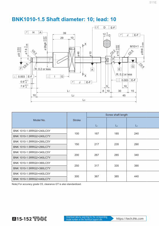
A15-152 Download data by searching for the corresponding model number on the Technical Support site. https://tech.thk.com
BNK1010-1.5 Shaft diameter: 10; lead: 10
R: 0.2 or less
R: 0.2 or less
φ8h
6
φ7.
6
φ8
45
5
8 30 15 10
10
M10×1
10 29
39
10
C0.2
C0.5
+0.1 0 7.9
+0.1 0 0.9
X
X
C0.5
C0.2
C0.5
12
φ10
φ46
φ26
g6
-0.0
02-0
.008
φ10
φ14
J E-F
H A
L3
L2
L1
D E-F
J E-F
I G 0.003 E-F 0.003
F G
E A
E-F
0
-0
.009
0
-0
.08
-0.0
04-0
.012
0 -0.25
-0.0
07-0
.020
Model No. Stroke
Screw shaft length
L 1 L 2 L 3
BNK 1010-1.5RRG0+240LC5Y 100 167 185 240
BNK 1010-1.5RRG2+240LC7Y
BNK 1010-1.5RRG0+290LC5Y 150 217 235 290
BNK 1010-1.5RRG2+290LC7Y
BNK 1010-1.5RRG0+340LC5Y 200 267 285 340
BNK 1010-1.5RRG2+340LC7Y
BNK 1010-1.5RRG0+390LC5Y 250 317 335 390
BNK 1010-1.5RRG2+390LC7Y
BNK 1010-1.5RRG0+440LC5Y 300 367 385 440
BNK 1010-1.5RRG2+440LC7Y
Note) For accuracy grade C5, clearance GT is also standardized.
511E
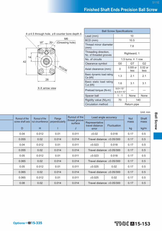
A15-153
Ball Screw
Finished Shaft Ends Precision Ball Screw
Options⇒A15-335
4-φ 4.5 through hole, φ 8 counter bore depth 4
(Greasing hole)
X-X arrow view
M6
PCD36
28
42 14
30° 30°
Ball Screw Specifi cations
Lead (mm) 10 BCD (mm) 10.5 Thread minor diameter (mm) 7.8
Threading direction,No. of threaded grooves Rightward, 1
No. of circuits 1.5 turns × 1 row Clearance symbol G0 GT G2
Axial clearance (mm) 0 0.005 or less
0.02 or less
Basic dynamic load rating Ca (kN) 1.3 2.1 2.1
Basic static load rating C 0 a (kN) 1.6 3.1 3.1
Preload torque (N-m) 9.8×10 -3
to 4.9×10 -2 — —
Spacer ball 1 : 1 None None Rigidity value (N/m) 70 140 Circulation method Return pipe
Unit: mm
Runout of thescrew shaft axis
Runout of thenut circumference
Flangeperpendicularity
Runout of the thread groove
surface
Lead angle accuracy Nutmass
Shaftmass Representative
travel distance error
Fluctuation D H I J kg kg/m
0.04 0.012 0.01 0.011 0.02 0.018 0.17 0.5
0.055 0.02 0.014 0.014 Travel distance: 0.05/300 0.17 0.5
0.04 0.012 0.01 0.011 0.023 0.018 0.17 0.5
0.055 0.02 0.014 0.014 Travel distance: 0.05/300 0.17 0.5
0.05 0.012 0.01 0.011 0.023 0.018 0.17 0.5
0.065 0.02 0.014 0.014 Travel distance: 0.05/300 0.17 0.5
0.05 0.012 0.01 0.011 0.025 0.02 0.17 0.5
0.065 0.02 0.014 0.014 Travel distance: 0.05/300 0.17 0.5
0.065 0.012 0.01 0.011 0.025 0.02 0.17 0.5
0.08 0.02 0.014 0.014 Travel distance: 0.05/300 0.17 0.5
511E

A15-154 Download data by searching for the corresponding model number on the Technical Support site. https://tech.thk.com
BNK1202-3 Shaft diameter: 12; lead: 2
R: 0.2 or less R: 0.2 or less
φ8h
6
φ7.
6
φ8
C0.2
C0.5
+0.1 0 7.9
+0.1 0 0.9
45
15 30
5 17
22
X
X
C0.5
C0.5
12
φ36
φ19
g6
-0.0
02-0
.008
φ1030
°
φ14
φ12
M10×1
0.5
5 10
J E-F
H A
L3
L2
L1 10 4
D G
J E-F
I G
0.003 E-F 0.003
10
F A G
E
E-F
0
-0
.009
0
-0
.08
-0.0
04-0
.012
0 -0.25
-0.0
07-0
.020
Model No. Stroke
Screw shaft length
L 1 L 2 L 3
BNK 1202-3RRG0+154LC3Y 50 85 99 154
BNK 1202-3RRG0+154LC5Y BNK 1202-3RRG2+154LC7Y BNK 1202-3RRG0+204LC3Y
100 135 149 204
BNK 1202-3RRG0+204LC5Y BNK 1202-3RRG2+204LC7Y BNK 1202-3RRG0+254LC3Y
150 185 199 254
BNK 1202-3RRG0+254LC5Y BNK 1202-3RRG2+254LC7Y BNK 1202-3RRG0+304LC3Y
200 235 249 304
BNK 1202-3RRG0+304LC5Y BNK 1202-3RRG2+304LC7Y BNK 1202-3RRG0+354LC3Y
250 285 299 354
BNK 1202-3RRG0+354LC5Y BNK 1202-3RRG2+354LC7Y
Note) A stainless steel type is also available for model BNK1202. When placing an order, add symbol “M” to the end of the model number.
Symbol for stainless steel type (Example) BNK1202-3RRG0+154LC3Y M
For accuracy grades C3 and C5, clearance GT is also available as standard.
511E

A15-155
Ball Screw
Finished Shaft Ends Precision Ball Screw
Options⇒A15-335
X-X arrow view
4-φ 4.5 through hole
23
30°
PCD28
30°
Ball Screw Specifi cations
Lead (mm) 2 BCD (mm) 12.3 Thread minor diameter (mm) 11
Threading direction,No. of threaded grooves Rightward, 1
No. of circuits 1 turn × 3 rows Clearance symbol G0 GT G2
Axial clearance (mm) 0 0.005 or less
0.02 or less
Basic dynamic load rating Ca (kN) 1.7 1.7 1.7
Basic static load rating C 0 a (kN) 3.6 3.6 3.6
Preload torque (N-m) 4.0×10 -3
to 3.4×10 -2 — —
Spacer ball None None None Rigidity value (N/m) 120 Circulation method Defl ector
Unit: mm
Runout of thescrew shaft axis
Runout of thenut circumference
Flangeperpendicularity
Runout of the thread groove
surface
Lead angle accuracy Nutmass
Shaft mass Representative
travel distance error
Fluctuation D H I J kg kg/m
0.02 0.01 0.008 0.007 0.008 0.008 0.05 0.71 0.035 0.012 0.01 0.011 0.018 0.018 0.05 0.71 0.04 0.02 0.014 0.014 Travel distance: 0.05/300 0.05 0.71 0.03 0.01 0.008 0.007 0.01 0.008 0.05 0.71 0.04 0.012 0.01 0.011 0.02 0.018 0.05 0.71
0.055 0.02 0.014 0.014 Travel distance: 0.05/300 0.05 0.71 0.03 0.01 0.008 0.007 0.01 0.008 0.05 0.71 0.04 0.012 0.01 0.011 0.02 0.018 0.05 0.71
0.055 0.02 0.014 0.014 Travel distance: 0.05/300 0.05 0.71 0.04 0.01 0.008 0.007 0.012 0.008 0.05 0.71 0.05 0.012 0.01 0.011 0.023 0.018 0.05 0.71 0.055 0.02 0.014 0.014 Travel distance: 0.05/300 0.05 0.71 0.04 0.01 0.008 0.007 0.012 0.008 0.05 0.71 0.05 0.012 0.01 0.011 0.023 0.018 0.05 0.71
0.065 0.02 0.014 0.014 Travel distance: 0.05/300 0.05 0.71
511E

A15-156 Download data by searching for the corresponding model number on the Technical Support site. https://tech.thk.com
BNK1205-2.5 Shaft diameter: 12; lead: 5
R: 0.2 or less R: 0.2 or less
φ8h
6
φ7.
6
φ8
45
5
5 30 15 10
10
M10×1
10 30
40
10
C0.2
C0.5
+0.1 0 7.9
+0.1 0 0.9
X
X
C0.5
C0.2
C0.5
12
φ12
φ50
φ30
g6
-0.0
02-0
.008
φ10
φ14
J E-F
H A
L3
L2
L1
D E-F
J E-F
I G 0.003 E-F 0.003
F G
E A
E-F
0
-0
.009
0
-0
.08
-0.0
04-0
.012
0 -0.25
-0.0
07-0
.020
Model No. Stroke
Screw shaft length
L 1 L 2 L 3
BNK 1205-2.5RRG0+180LC3Y
50 110 125 180
BNK 1205-2.5RRG0+180LC5Y
BNK 1205-2.5RRG2+180LC7Y
BNK 1205-2.5RRG0+230LC3Y
100 160 175 230
BNK 1205-2.5RRG0+230LC5Y
BNK 1205-2.5RRG2+230LC7Y
BNK 1205-2.5RRG0+280LC3Y
150 210 225 280
BNK 1205-2.5RRG0+280LC5Y
BNK 1205-2.5RRG2+280LC7Y
BNK 1205-2.5RRG0+330LC3Y
200 260 275 330
BNK 1205-2.5RRG0+330LC5Y
BNK 1205-2.5RRG2+330LC7Y
BNK 1205-2.5RRG0+380LC3Y
250 310 325 380
BNK 1205-2.5RRG0+380LC5Y
BNK 1205-2.5RRG2+380LC7Y
Note) For accuracy grades C3 and C5, clearance GT is also available as standard.
511E

A15-157
Ball Screw
Finished Shaft Ends Precision Ball Screw
Options⇒A15-335
4-φ 4.5 through hole, φ 8 counter bore depth 4
(Greasing hole)
X-X arrow view
M6
PCD40
32
45
15
30° 30°
Ball Screw Specifi cations
Lead (mm) 5 BCD (mm) 12.3 Thread minor diameter (mm) 9.6
Threading direction,No. of threaded grooves Rightward, 1
No. of circuits 2.5 turns × 1 row Clearance symbol G0 GT G2
Axial clearance (mm) 0 0.005 or less
0.02 or less
Basic dynamic load rating Ca (kN) 2.3 3.7 3.7
Basic static load rating C 0 a (kN) 3.2 6.4 6.4
Preload torque (N-m) 9.8×10 -3
to 4.9×10 -2 — —
Spacer ball 1 : 1 None None Rigidity value (N/m) 60 120 Circulation method Return pipe
Unit: mm
Runout of thescrew shaft axis
Runout of thenut circumference
Flangeperpendicularity
Runout of the thread groove
surface
Lead angle accuracy Nutmass
Shaftmass Representative
travel distance error
Fluctuation D H I J kg kg/m
0.02 0.009 0.008 0.008 0.01 0.008 0.22 0.61
0.035 0.012 0.01 0.011 0.02 0.018 0.22 0.61
0.04 0.02 0.014 0.014 Travel distance: 0.05/300 0.22 0.61
0.03 0.009 0.008 0.008 0.01 0.008 0.22 0.61
0.04 0.012 0.01 0.011 0.02 0.018 0.22 0.61
0.055 0.02 0.014 0.014 Travel distance: 0.05/300 0.22 0.61
0.03 0.009 0.008 0.008 0.012 0.008 0.22 0.61
0.04 0.012 0.01 0.011 0.023 0.018 0.22 0.61
0.055 0.02 0.014 0.014 Travel distance: 0.05/300 0.22 0.61
0.04 0.009 0.008 0.008 0.012 0.008 0.22 0.61
0.05 0.012 0.01 0.011 0.023 0.018 0.22 0.61
0.065 0.02 0.014 0.014 Travel distance: 0.05/300 0.22 0.61
0.04 0.009 0.008 0.008 0.012 0.008 0.22 0.61
0.05 0.012 0.01 0.011 0.023 0.018 0.22 0.61
0.065 0.02 0.014 0.014 Travel distance: 0.05/300 0.22 0.61
511E

A15-158 Download data by searching for the corresponding model number on the Technical Support site. https://tech.thk.com
BNK1208-2.6 Shaft diameter: 12; lead: 8
R: 0.2 or less
R: 0.2 or less
φ7.
6
φ8 φ
8h6
X
X
45 L3
L2 L1 5 30 15 10
10
J E-F
M10×1
5
0.003 E-F
10
R0.5
I G +0.1 0 7.9
+0.1 0 0.9
J E-F
0.003 E-F
H A D G
φ29
g6
10 36 46
F
G
E
A
C0.2
C0.5 C0.5 C0.5
12
-0.0
02-0
.008
φ10
φ14
φ12
φ50
0
-0
.08
-0.0
04-0
.012
0
-0
.009
-0.0
07-0
.020
0 -0.25
C0.2
Model No. Stroke
Screw shaft length
L 1 L 2 L 3
BNK 1208-2.6RRG2+180LC7Y 50 110 125 180
BNK 1208-2.6RRG2+230LC7Y 100 160 175 230
BNK 1208-2.6RRG2+280LC7Y 150 210 225 280
BNK 1208-2.6RRG2+330LC7Y 200 260 275 330
BNK 1208-2.6RRG2+380LC7Y 250 310 325 380
511E

A15-159
Ball Screw
Finished Shaft Ends Precision Ball Screw
Options⇒A15-335
4-φ 4.5 through hole, φ 8 counter bore depth 4.5
(Greasing hole)
X-X arrow view
M6
PCD40
32
45 15
30° 30°
Ball Screw Specifi cations
Lead (mm) 8 BCD (mm) 12.65 Thread minor diameter (mm) 9.7
Threading direction,No. of threaded grooves Rightward, 1
No. of circuits 2.6 turns × 1 row Clearance symbol G2 Axial clearance (mm) 0.02 or less Basic dynamic load rating Ca (kN) 4.7
Basic static load rating C 0 a (kN) 7.5
Preload torque (N-m) — Spacer ball None Rigidity value (N/m) 127 Circulation method Return pipe
Unit: mm
Runout of thescrew shaft axis
Runout of thenut circumference
Flangeperpendicularity
Runout of the thread groove
surface Lead angle accuracy Nut
mass Shaftmass
D H I J kg kg/m
0.04 0.02 0.014 0.014 Travel distance: 0.05/300 0.269 0.64
0.055 0.02 0.014 0.014 Travel distance: 0.05/300 0.269 0.64
0.055 0.02 0.014 0.014 Travel distance: 0.05/300 0.269 0.64
0.065 0.02 0.014 0.014 Travel distance: 0.05/300 0.269 0.64
0.065 0.02 0.014 0.014 Travel distance: 0.05/300 0.269 0.64
511E

A15-160 Download data by searching for the corresponding model number on the Technical Support site. https://tech.thk.com
BNK1402-3 Shaft diameter: 14; lead: 2
R: 0.2 or less R: 0.2 or less
φ10
h6 0
-0
.009
φ9.
6
φ10
45
0.5
5
4 30 15 10
10
M12×1
6 17 23
22
C0.2
C0.5
+0.14 0 1.15 +0.1 0 9.15
X
X
C0.5
C0.5
12
φ14
φ40
φ21
g6
φ12
φ15
J E-F
H A
L3
L2
L1
D G
J E-F
I
30°
G
0.004 E-F 0.004
F G
E A
E-F
0
-0
.09
-0.0
04-0
.012
0 -0.25
-0.0
07-0
.020
-0.0
03-0
.011
Model No. Stroke
Screw shaft length
L 1 L 2 L 3
BNK 1402-3RRG0+166LC3Y 50 85 99 166
BNK 1402-3RRG0+166LC5Y BNK 1402-3RRG2+166LC7Y BNK 1402-3RRG0+216LC3Y
100 135 149 216
BNK 1402-3RRG0+216LC5Y BNK 1402-3RRG2+216LC7Y BNK 1402-3RRG0+266LC3Y
150 185 199 266
BNK 1402-3RRG0+266LC5Y BNK 1402-3RRG2+266LC7Y BNK 1402-3RRG0+316LC3Y
200 235 249 316
BNK 1402-3RRG0+316LC5Y BNK 1402-3RRG2+316LC7Y BNK 1402-3RRG0+416LC3Y
300 335 349 416
BNK 1402-3RRG0+416LC5Y BNK 1402-3RRG2+416LC7Y
Note) A stainless steel type is also available for model BNK1402. When placing an order, add symbol “M” to the end of the model number.
Symbol for stainless steel type (Example) BNK1402-3RRG0+166LC3Y M
For accuracy grades C3 and C5, clearance GT is also available as standard.
511E

A15-161
Ball Screw
Finished Shaft Ends Precision Ball Screw
Options⇒A15-335
X-X arrow view
4-φ 5.5 through hole
26
30°
PCD31
30°
Ball Screw Specifi cations
Lead (mm) 2 BCD (mm) 14.3 Thread minor diameter (mm) 13
Threading direction,No. of threaded grooves Rightward, 1
No. of circuits 1 turn × 3 rows Clearance symbol G0 GT G2
Axial clearance (mm) 0 0.005 or less
0.02 or less
Basic dynamic load rating Ca (kN) 1.8 1.8 1.8
Basic static load rating C 0 a (kN) 4.3 4.3 4.3
Preload torque (N-m) 4.9×10 -3
to 4.9×10 -2 — —
Spacer ball None None None Rigidity value (N/m) 140 Circulation method Defl ector
Unit: mm
Runout of thescrew shaft axis
Runout of thenut circumference
Flangeperpendicularity
Runout of the thread groove
surface
Lead angle accuracy Nutmass
Shaftmass Representative
travel distance error
Fluctuation D H I J kg kg/m
0.02 0.01 0.008 0.009 0.008 0.008 0.15 1.0 0.025 0.012 0.01 0.012 0.018 0.018 0.15 1.0 0.04 0.02 0.014 0.014 Travel distance: 0.05/300 0.15 1.0
0.025 0.01 0.008 0.009 0.01 0.008 0.15 1.0 0.03 0.012 0.01 0.012 0.02 0.018 0.15 1.0
0.045 0.02 0.014 0.014 Travel distance: 0.05/300 0.15 1.0 0.025 0.01 0.008 0.009 0.01 0.008 0.15 1.0 0.03 0.012 0.01 0.012 0.02 0.018 0.15 1.0
0.045 0.02 0.014 0.014 Travel distance: 0.05/300 0.15 1.0 0.03 0.01 0.008 0.009 0.012 0.008 0.15 1.0 0.04 0.012 0.01 0.012 0.023 0.018 0.15 1.0
0.055 0.02 0.014 0.014 Travel distance: 0.05/300 0.15 1.0 0.04 0.01 0.008 0.009 0.013 0.01 0.15 1.0 0.05 0.012 0.01 0.012 0.025 0.02 0.15 1.0 0.06 0.02 0.014 0.014 Travel distance: 0.05/300 0.15 1.0
511E

A15-162 Download data by searching for the corresponding model number on the Technical Support site. https://tech.thk.com
BNK1404-3 Shaft diameter: 14; lead: 4
R: 0.2 or less R: 0.2 or less
φ10
h6 0
-0
.009
φ9.
6
φ10
45
0.5
5
5 30 15 10
10
M12×1
6 27 33
22
C0.2
C0.5
+0.14 01.15 +0.1 09.15
X
X
C0.5
C0.5
12
φ14
φ45
φ26
g6
φ12
φ15
J E-F
H A
L3
L2
L1
D G
J E-F
I
30°
G
0.004 E-F 0.004
F G
E A
E-F
0 -0.0
9
-0.0
04-0
.012
0 -0.25
-0.0
07-0
.020
-0.0
03-0
.011
Model No. Stroke
Screw shaft length
L 1 L 2 L 3
BNK 1404-3RRG0+230LC3Y 100 148 163 230
BNK 1404-3RRG0+230LC5Y BNK 1404-3RRG2+230LC7Y BNK 1404-3RRG0+280LC3Y
150 198 213 280
BNK 1404-3RRG0+280LC5Y BNK 1404-3RRG2+280LC7Y BNK 1404-3RRG0+330LC3Y
200 248 263 330
BNK 1404-3RRG0+330LC5Y BNK 1404-3RRG2+330LC7Y BNK 1404-3RRG0+430LC3Y
300 348 363 430
BNK 1404-3RRG0+430LC5Y BNK 1404-3RRG2+430LC7Y BNK 1404-3RRG0+530LC3Y
400 448 463 530
BNK 1404-3RRG0+530LC5Y BNK 1404-3RRG2+530LC7Y
Note) A stainless steel type is also available for model BNK1404. When placing an order, add symbol “M” to the end of the model number.
Symbol for stainless steel type (Example) BNK1404-3RRG0+230LC3Y M
For accuracy grades C3 and C5, clearance GT is also available as standard.
511E

A15-163
Ball Screw
Finished Shaft Ends Precision Ball Screw
Options⇒A15-335
X-X arrow view
4-φ 5.5 through hole
28
30°
PCD36
30°
Ball Screw Specifi cations
Lead (mm) 4 BCD (mm) 14.65 Thread minor diameter (mm) 12.2
Threading direction,No. of threaded grooves Rightward, 1
No. of circuits 1 turn × 3 rows Clearance symbol G0 GT G2
Axial clearance (mm) 0 0.005 or less
0.02 or less
Basic dynamic load rating Ca (kN) 4.2 4.2 4.2
Basic static load rating C 0 a (kN) 7.6 7.6 7.6
Preload torque (N-m) 9.8×10 -3
to 6.9×10 -2 — —
Spacer ball None None None Rigidity value (N/m) 190 Circulation method Defl ector
Unit: mm
Runout of thescrew shaft axis
Runout of thenut circumference
Flangeperpendicularity
Runout of the thread groove
surface
Lead angle accuracy Nutmass
Shaftmass Representative
travel distance error
Fluctuation D H I J kg kg/m
0.025 0.01 0.008 0.009 0.01 0.008 0.13 0.8 0.03 0.012 0.01 0.012 0.02 0.018 0.13 0.8
0.045 0.02 0.014 0.014 Travel distance: 0.05/300 0.13 0.8 0.025 0.01 0.008 0.009 0.01 0.008 0.13 0.8 0.03 0.012 0.01 0.012 0.02 0.018 0.13 0.8
0.045 0.02 0.014 0.014 Travel distance: 0.05/300 0.13 0.8 0.03 0.01 0.008 0.009 0.012 0.008 0.13 0.8 0.04 0.012 0.01 0.012 0.023 0.018 0.13 0.8
0.055 0.02 0.014 0.014 Travel distance: 0.05/300 0.13 0.8 0.04 0.01 0.008 0.009 0.013 0.01 0.13 0.8 0.05 0.012 0.01 0.012 0.025 0.02 0.13 0.8 0.06 0.02 0.014 0.014 Travel distance: 0.05/300 0.13 0.8 0.045 0.01 0.008 0.009 0.015 0.01 0.13 0.8 0.055 0.012 0.01 0.012 0.027 0.02 0.13 0.8 0.075 0.02 0.014 0.014 Travel distance: 0.05/300 0.13 0.8
511E

A15-164 Download data by searching for the corresponding model number on the Technical Support site. https://tech.thk.com
BNK1408-2.5 Shaft diameter: 14; lead: 8
R: 0.2 or less R: 0.2 or less
φ10
h6 0
-0
.009
φ9.
6
φ10
D E-F
45
5 5 30 15 10
10
M12×1
5 11 35
46
22
C0.5
C0.5
+0.14 01.15 +0.1 0 9.15
X
X
C0.5
C0.2
C0.5
12
φ14
φ57
φ34
g6
φ12
φ15
J E-F
H A
L3
L2
L1
J E-F
I G 0.004 E-F 0.004
F G
E A
E-F
0 -0.0
9
-0.0
04-0
.012
0 -0.25
-0.0
09-0
.025
-0.0
03-0
.011
Model No. Stroke
Screw shaft length
L 1 L 2 L 3 BNK 1408-2.5RRG0+321LC5Y 150 239 254 321 BNK 1408-2.5RRG2+321LC7Y BNK 1408-2.5RRG0+371LC5Y 200 289 304 371 BNK 1408-2.5RRG2+371LC7Y BNK 1408-2.5RRG0+421LC5Y 250 339 354 421 BNK 1408-2.5RRG2+421LC7Y BNK 1408-2.5RRG0+471LC5Y 300 389 404 471 BNK 1408-2.5RRG2+471LC7Y BNK 1408-2.5RRG0+521LC5Y 350 439 454 521 BNK 1408-2.5RRG2+521LC7Y BNK 1408-2.5RRG0+571LC5Y 400 489 504 571 BNK 1408-2.5RRG2+571LC7Y BNK 1408-2.5RRG0+621LC5Y 450 539 554 621 BNK 1408-2.5RRG2+621LC7Y BNK 1408-2.5RRG0+671LC5Y 500 589 604 671 BNK 1408-2.5RRG2+671LC7Y BNK 1408-2.5RRG0+721LC5Y 550 639 654 721 BNK 1408-2.5RRG2+721LC7Y BNK 1408-2.5RRG0+771LC5Y 600 689 704 771 BNK 1408-2.5RRG2+771LC7Y BNK 1408-2.5RRG0+871LC5Y 700 789 804 871 BNK 1408-2.5RRG2+871LC7Y Note) For accuracy grade C5, clearance GT is also standardized.
Plug the unused oil hole before using the product.
511E

A15-165
Ball Screw
Finished Shaft Ends Precision Ball Screw
Options⇒A15-335
4-φ 5.5 through hole, φ 9.5 counter bore depth 5.5
(Greasing hole)
X-X arrow view
M6
PCD45
34
50 17
30° 30°
Ball Screw Specifi cations
Lead (mm) 8 BCD (mm) 14.75 Thread minor diameter (mm) 11.2
Threading direction,No. of threaded grooves Rightward, 1
No. of circuits 2.5 turns × 1 row Clearance symbol G0 GT G2
Axial clearance (mm) 0 0.005 or less
0.02 or less
Basic dynamic load rating Ca (kN) 4.3 6.9 6.9
Basic static load rating C 0 a (kN) 5.8 11.5 11.5
Preload torque (N-m) 2×10 -2
to 7.8×10 -2 — —
Spacer ball 1 : 1 None None Rigidity value (N/m) 80 150 Circulation method Return pipe
Unit: mm
Runout of thescrew shaft axis
Runout of thenut circumference
Flangeperpendicularity
Runout of the thread groove
surface
Lead angle accuracy Nutmass
Shaftmass Representative
travel distance error
Fluctuation D H I J kg kg/m
0.035 0.015 0.011 0.012 0.023 0.018 0.29 0.84 0.055 0.03 0.018 0.014 Travel distance: 0.05/300 0.29 0.84 0.035 0.015 0.011 0.012 0.023 0.018 0.29 0.84 0.055 0.03 0.018 0.014 Travel distance: 0.05/300 0.29 0.84 0.04 0.015 0.011 0.012 0.025 0.02 0.29 0.84 0.06 0.03 0.018 0.014 Travel distance: 0.05/300 0.29 0.84 0.04 0.015 0.011 0.012 0.025 0.02 0.29 0.84 0.06 0.03 0.018 0.014 Travel distance: 0.05/300 0.29 0.84 0.05 0.015 0.011 0.012 0.027 0.02 0.29 0.84 0.075 0.03 0.018 0.014 Travel distance: 0.05/300 0.29 0.84 0.05 0.015 0.011 0.012 0.027 0.02 0.29 0.84 0.075 0.03 0.018 0.014 Travel distance: 0.05/300 0.29 0.84 0.05 0.015 0.011 0.012 0.03 0.023 0.29 0.84
0.075 0.03 0.018 0.014 Travel distance: 0.05/300 0.29 0.84 0.065 0.015 0.011 0.012 0.03 0.023 0.29 0.84 0.09 0.03 0.018 0.014 Travel distance: 0.05/300 0.29 0.84
0.065 0.015 0.011 0.012 0.035 0.025 0.29 0.84 0.09 0.03 0.018 0.014 Travel distance: 0.05/300 0.29 0.84
0.065 0.015 0.011 0.012 0.035 0.025 0.29 0.84 0.09 0.03 0.018 0.014 Travel distance: 0.05/300 0.29 0.84 0.085 0.015 0.011 0.012 0.035 0.025 0.29 0.84 0.12 0.03 0.018 0.014 Travel distance: 0.05/300 0.29 0.84
511E

A15-166 Download data by searching for the corresponding model number on the Technical Support site. https://tech.thk.com
BNK1510-5.6 Shaft diameter: 15; lead: 10
R: 0.2 or lessR: 0.2 or less
φ10
h6 0
-0
.009
φ9.
6
φ10
45
55 30 1510
10
M12×1
10102444
22
C0.5
+0.14 01.15+0.1 09.15
X
X
C0.5
C0.2 C0.5
12
φ15
φ34
φ57
φ34
g6
φ12
φ15
J E-F
H A
L3
L2
L1
D
J
E-F
E-F
I G0.004 E-F0.004
GEF A
E-F
0 -0.0
9
-0.0
04-0
.012
0-0.25
-0.0
09-0
.025
-0.0
03-0
.011
Model No. Stroke
Screw shaft length
L 1 L 2 L 3 BNK 1510-5.6G0+321LC5Y 150 239 254 321 BNK 1510-5.6G2+321LC7Y BNK 1510-5.6G0+371LC5Y 200 289 304 371 BNK 1510-5.6G2+371LC7Y BNK 1510-5.6G0+421LC5Y 250 339 354 421 BNK 1510-5.6G2+421LC7Y BNK 1510-5.6G0+471LC5Y 300 389 404 471 BNK 1510-5.6G2+471LC7Y BNK 1510-5.6G0+521LC5Y 350 439 454 521 BNK 1510-5.6G2+521LC7Y BNK 1510-5.6G0+571LC5Y 400 489 504 571 BNK 1510-5.6G2+571LC7Y BNK 1510-5.6G0+621LC5Y 450 539 554 621 BNK 1510-5.6G2+621LC7Y BNK 1510-5.6G0+671LC5Y 500 589 604 671 BNK 1510-5.6G2+671LC7Y BNK 1510-5.6G0+721LC5Y 550 639 654 721 BNK 1510-5.6G2+721LC7Y BNK 1510-5.6G0+771LC5Y 600 689 704 771 BNK 1510-5.6G2+771LC7Y BNK 1510-5.6G0+871LC5Y 700 789 804 871 BNK 1510-5.6G2+871LC7Y BNK 1510-5.6G0+971LC5Y 800 889 904 971 BNK 1510-5.6G2+971LC7Y Note) For accuracy grade C5, clearance GT is also standardized.
511E

A15-167
Ball Screw
Finished Shaft Ends Precision Ball Screw
Options⇒A15-335
4-φ 5.5 through hole, φ 9.5 counter bore depth 5.5
(Greasing hole)
X-X arrow view
M6×0.75
PCD45
34
50 12.5
30° 30°
Ball Screw Specifi cations
Lead (mm) 10 BCD (mm) 15.75 Thread minor diameter (mm) 12.5
Threading direction,No. of threaded grooves Rightward, 2
No. of circuits 2.8 turns × 2 rows Clearance symbol G0 GT G2
Axial clearance (mm) 0 0.005 or less
0.02 or less
Basic dynamic load rating Ca (kN) 9 14.3 14.3
Basic static load rating C 0 a (kN) 13.9 27.9 27.9
Preload torque (N-m) 2×10 -2
to 9.8×10 -2 — —
Spacer ball 1 : 1 None None Rigidity value (N/m) 190 350 Circulation method End cap
Unit: mm
Runout of thescrew shaft axis
Runout of thenut circumference
Flangeperpendicularity
Runout of the thread groove
surface
Lead angle accuracy Nutmass
Shaftmass Representative
travel distance error
Fluctuation D H I J kg kg/m
0.035 0.015 0.011 0.012 0.023 0.018 0.22 0.76 0.055 0.03 0.018 0.014 Travel distance: 0.05/300 0.22 0.76 0.035 0.015 0.011 0.012 0.023 0.018 0.22 0.76 0.055 0.03 0.018 0.014 Travel distance: 0.05/300 0.22 0.76 0.04 0.015 0.011 0.012 0.025 0.02 0.22 0.76 0.06 0.03 0.018 0.014 Travel distance: 0.05/300 0.22 0.76 0.04 0.015 0.011 0.012 0.025 0.02 0.22 0.76 0.06 0.03 0.018 0.014 Travel distance: 0.05/300 0.22 0.76 0.05 0.015 0.011 0.012 0.027 0.02 0.22 0.76 0.075 0.03 0.018 0.014 Travel distance: 0.05/300 0.22 0.76 0.05 0.015 0.011 0.012 0.027 0.02 0.22 0.76 0.075 0.03 0.018 0.014 Travel distance: 0.05/300 0.22 0.76 0.05 0.015 0.011 0.012 0.03 0.023 0.22 0.76
0.075 0.03 0.018 0.014 Travel distance: 0.05/300 0.22 0.76 0.065 0.015 0.011 0.012 0.03 0.023 0.22 0.76 0.09 0.03 0.018 0.014 Travel distance: 0.05/300 0.22 0.76
0.065 0.015 0.011 0.012 0.035 0.025 0.22 0.76 0.09 0.03 0.018 0.014 Travel distance: 0.05/300 0.22 0.76
0.065 0.015 0.011 0.012 0.035 0.025 0.22 0.76 0.09 0.03 0.018 0.014 Travel distance: 0.05/300 0.22 0.76 0.085 0.015 0.011 0.012 0.035 0.025 0.22 0.76 0.12 0.03 0.018 0.014 Travel distance: 0.05/300 0.22 0.76
0.085 0.015 0.011 0.012 0.04 0.027 0.22 0.76 0.12 0.03 0.018 0.014 Travel distance: 0.05/300 0.22 0.76
511E

A15-168 Download data by searching for the corresponding model number on the Technical Support site. https://tech.thk.com
BNK1520-3 Shaft diameter: 15; lead: 20
R: 0.2 or less R: 0.2 or less
E-F
A F E G
0.004 E-F 0.004 G I
E-F
E-F
J
D
L1
L2
L3
A H
E-F J
φ15
φ12φ
32g6
φ57
φ32
φ15
12
C0.5
C0.2
C0.5
X
X
9.15 +0.1 0
1.15 +0.14 0
C0.5
C0.5
22
45 28 10 7
5
M12×1
10 10 15 30 8 5
45
φ10 φ
9.6
0
-0.0
09φ
10h6-0
.003
-0.0
11
0 -0.25
-0.0
04-0
.012 0 -0.0
9 -0.0
09-0
.025
Model No. Stroke
Screw shaft length
L 1 L 2 L 3 BNK 1520-3G0+321LC5Y 150 236 254 321 BNK 1520-3G2+321LC7Y BNK 1520-3G0+371LC5Y 200 286 304 371 BNK 1520-3G2+371LC7Y BNK 1520-3G0+421LC5Y 250 336 354 421 BNK 1520-3G2+421LC7Y BNK 1520-3G0+471LC5Y 300 386 404 471 BNK 1520-3G2+471LC7Y BNK 1520-3G0+521LC5Y 350 436 454 521 BNK 1520-3G2+521LC7Y BNK 1520-3G0+571LC5Y 400 486 504 571 BNK 1520-3G2+571LC7Y BNK 1520-3G0+621LC5Y 450 536 554 621 BNK 1520-3G2+621LC7Y BNK 1520-3G0+671LC5Y 500 586 604 671 BNK 1520-3G2+671LC7Y BNK 1520-3G0+721LC5Y 550 636 654 721 BNK 1520-3G2+721LC7Y BNK 1520-3G0+771LC5Y 600 686 704 771 BNK 1520-3G2+771LC7Y BNK 1520-3G0+871LC5Y 700 786 804 871 BNK 1520-3G2+871LC7Y BNK 1520-3G0+971LC5Y 800 886 904 971 BNK 1520-3G2+971LC7Y Note) For accuracy grade C5, clearance GT is also standardized.
511E

A15-169
Ball Screw
Finished Shaft Ends Precision Ball Screw
Options⇒A15-335
4-φ 5.5 through hole, φ 9.5 counter bore depth 5.5
(Greasing hole)
X-X arrow view
M6
PCD45
34
50
30° 30°
Ball Screw Specifi cations
Lead (mm) 20 BCD (mm) 15.75 Thread minor diameter (mm) 12.5
Threading direction,No. of threaded grooves Rightward, 2
No. of circuits 1.5 turns × 2 rows Clearance symbol G0 GT G2
Axial clearance (mm) 0 0.005 or less
0.02 or less
Basic dynamic load rating Ca (kN) 5.1 8 8
Basic static load rating C 0 a (kN) 7.9 15.8 15.8
Preload torque (N-m) 2×10 -2
to 8.8×10 -2 — —
Spacer ball 1 : 1 None None Rigidity value (N/m) 110 200 Circulation method End cap
Unit: mm
Runout of thescrew shaft axis
Runout of thenut circumference
Flangeperpendicularity
Runout of the thread groove
surface
Lead angle accuracy Nutmass
Shaftmass Representative
travel distance error
Fluctuation D H I J kg kg/m
0.035 0.015 0.011 0.012 0.023 0.018 0.32 1.05 0.055 0.03 0.018 0.014 Travel distance: 0.05/300 0.32 1.05 0.035 0.015 0.011 0.012 0.023 0.018 0.32 1.05 0.055 0.03 0.018 0.014 Travel distance: 0.05/300 0.32 1.05 0.04 0.015 0.011 0.012 0.025 0.02 0.32 1.05 0.06 0.03 0.018 0.014 Travel distance: 0.05/300 0.32 1.05 0.04 0.015 0.011 0.012 0.025 0.02 0.32 1.05 0.06 0.03 0.018 0.014 Travel distance: 0.05/300 0.32 1.05 0.05 0.015 0.011 0.012 0.027 0.02 0.32 1.05 0.075 0.03 0.018 0.014 Travel distance: 0.05/300 0.32 1.05 0.05 0.015 0.011 0.012 0.027 0.02 0.32 1.05 0.075 0.03 0.018 0.014 Travel distance: 0.05/300 0.32 1.05 0.05 0.015 0.011 0.012 0.03 0.023 0.32 1.05
0.075 0.03 0.018 0.014 Travel distance: 0.05/300 0.32 1.05 0.065 0.015 0.011 0.012 0.03 0.023 0.32 1.05 0.09 0.03 0.018 0.014 Travel distance: 0.05/300 0.32 1.05
0.065 0.015 0.011 0.012 0.035 0.025 0.32 1.05 0.09 0.03 0.018 0.014 Travel distance: 0.05/300 0.32 1.05
0.065 0.015 0.011 0.012 0.035 0.025 0.32 1.05 0.09 0.03 0.018 0.014 Travel distance: 0.05/300 0.32 1.05 0.085 0.015 0.011 0.012 0.035 0.025 0.32 1.05 0.12 0.03 0.018 0.014 Travel distance: 0.05/300 0.32 1.05
0.085 0.015 0.011 0.012 0.04 0.027 0.32 1.05 0.12 0.03 0.018 0.014 Travel distance: 0.05/300 0.32 1.05
511E

A15-170 Download data by searching for the corresponding model number on the Technical Support site. https://tech.thk.com
BNK1616-3.6 Shaft diameter: 16; lead: 16
R: 0.2 or less R: 0.2 or less
E-F
A F E G
0.004 E-F 0.004 G I
E-F
E-F
J
D
L1
L2
L3
A H
E-F J
φ15
φ12φ
32g6
φ57
φ32
φ16
12
C0.5
C0.2
C0.5
X
X
9.15 +0.1 0
1.15 +0.14 0
C0.5
C0.5
22
42 23 10 9
M12×1
10 10 15 30 10 5
45
φ10 φ
9.6
0
-0.0
09φ
10h6-0
.003
-0.0
11
-0.0
09-0
.025
0 -0.25
-0.0
04-0
.012 0 -0.0
9
Model No. Stroke
Screw shaft length
L 1 L 2 L 3 BNK 1616-3.6G0+321LC5Y 150 234 254 321 BNK 1616-3.6G2+321LC7Y BNK 1616-3.6G0+371LC5Y 200 284 304 371 BNK 1616-3.6G2+371LC7Y BNK 1616-3.6G0+421LC5Y 250 334 354 421 BNK 1616-3.6G2+421LC7Y BNK 1616-3.6G0+471LC5Y 300 384 404 471 BNK 1616-3.6G2+471LC7Y BNK 1616-3.6G0+521LC5Y 350 434 454 521 BNK 1616-3.6G2+521LC7Y BNK 1616-3.6G0+571LC5Y 400 484 504 571 BNK 1616-3.6G2+571LC7Y BNK 1616-3.6G0+621LC5Y 450 534 554 621 BNK 1616-3.6G2+621LC7Y BNK 1616-3.6G0+671LC5Y 500 584 604 671 BNK 1616-3.6G2+671LC7Y BNK 1616-3.6G0+721LC5Y 550 634 654 721 BNK 1616-3.6G2+721LC7Y BNK 1616-3.6G0+771LC5Y 600 684 704 771 BNK 1616-3.6G2+771LC7Y BNK 1616-3.6G0+871LC5Y 700 784 804 871 BNK 1616-3.6G2+871LC7Y BNK 1616-3.6G0+971LC5Y 800 884 904 971 BNK 1616-3.6G2+971LC7Y Note) For accuracy grade C5, clearance GT is also standardized.
511E

A15-171
Ball Screw
Finished Shaft Ends Precision Ball Screw
Options⇒A15-335
4-φ 5.5 through hole, φ 9.5 counter bore depth 5.5
(Greasing hole)
X-X arrow view
M6×0.75
PCD45
34
50 12.5
30° 30°
Ball Screw Specifi cations
Lead (mm) 16 BCD (mm) 16.65 Thread minor diameter (mm) 13.7
Threading direction,No. of threaded grooves Rightward, 2
No. of circuits 1.8 turns × 2 rows Clearance symbol G0 GT G2
Axial clearance (mm) 0 0.005 or less
0.02 or less
Basic dynamic load rating Ca (kN) 4.4 7.1 7.1
Basic static load rating C 0 a (kN) 7.2 14.3 14.3
Preload torque (N-m) 2×10 -2
to 9.8×10 -2 — —
Spacer ball 1 : 1 None None Rigidity value (N/m) 120 230 Circulation method End cap
Unit: mm
Runout of thescrew shaft axis
Runout of thenut circumference
Flangeperpendicularity
Runout of the thread groove
surface
Lead angle accuracy Nutmass
Shaftmass Representative
travel distance error
Fluctuation D H I J kg kg/m
0.035 0.015 0.011 0.012 0.023 0.018 0.2 1.25 0.055 0.03 0.018 0.014 Travel distance: 0.05/300 0.2 1.25 0.035 0.015 0.011 0.012 0.023 0.018 0.2 1.25 0.055 0.03 0.018 0.014 Travel distance: 0.05/300 0.2 1.25 0.04 0.015 0.011 0.012 0.025 0.02 0.2 1.25 0.06 0.03 0.018 0.014 Travel distance: 0.05/300 0.2 1.25 0.04 0.015 0.011 0.012 0.025 0.02 0.2 1.25 0.06 0.03 0.018 0.014 Travel distance: 0.05/300 0.2 1.25 0.05 0.015 0.011 0.012 0.027 0.02 0.2 1.25 0.075 0.03 0.018 0.014 Travel distance: 0.05/300 0.2 1.25 0.05 0.015 0.011 0.012 0.027 0.02 0.2 1.25 0.075 0.03 0.018 0.014 Travel distance: 0.05/300 0.2 1.25 0.05 0.015 0.011 0.012 0.03 0.023 0.2 1.25
0.075 0.03 0.018 0.014 Travel distance: 0.05/300 0.2 1.25 0.065 0.015 0.011 0.012 0.03 0.023 0.2 1.25 0.09 0.03 0.018 0.014 Travel distance: 0.05/300 0.2 1.25
0.065 0.015 0.011 0.012 0.035 0.025 0.2 1.25 0.09 0.03 0.018 0.014 Travel distance: 0.05/300 0.2 1.25
0.065 0.015 0.011 0.012 0.035 0.025 0.2 1.25 0.09 0.03 0.018 0.014 Travel distance: 0.05/300 0.2 1.25 0.085 0.015 0.011 0.012 0.035 0.025 0.2 1.25 0.12 0.03 0.018 0.014 Travel distance: 0.05/300 0.2 1.25
0.085 0.015 0.011 0.012 0.04 0.027 0.2 1.25 0.12 0.03 0.018 0.014 Travel distance: 0.05/300 0.2 1.25
511E

A15-172 Download data by searching for the corresponding model number on the Technical Support site. https://tech.thk.com
BNK2010-2.5 Shaft diameter: 20; lead: 10
R: 0.2 or less R: 0.2 or less
φ12
h6 0
-0
.011
φ14
.3
φ15
φ19
.5
φ20
φ74
D E-F
60
5 15 40 20 10
15
M15×1
6 13 41
54
25
C0.3
C0.5
+0.14 0 1.15 +0.1 0 10.15
X
X
C0.5
C0.3
C0.5
17
φ46
g6
φ15
J E-F
H A
L3
L2
L1
J E-F
I G 0.004 E-F 0.004
F G
E A
E-F
0
-0.1
1
-0.0
04
-0.0
12
-0.0
09
-0.0
25
0 -0.25
-0.0
04
-0.0
12
Model No. Stroke
Screw shaft length
L 1 L 2 L 3
BNK 2010-2.5RRG0+499LC5Y 300 389 414 499
BNK 2010-2.5RRG2+499LC7Y BNK 2010-2.5RRG0+599LC5Y
400 489 514 599
BNK 2010-2.5RRG2+599LC7Y BNK 2010-2.5RRG0+699LC5Y
500 589 614 699
BNK 2010-2.5RRG2+699LC7Y BNK 2010-2.5RRG0+799LC5Y
600 689 714 799
BNK 2010-2.5RRG2+799LC7Y BNK 2010-2.5RRG0+899LC5Y
700 789 814 899
BNK 2010-2.5RRG2+899LC7Y BNK 2010-2.5RRG0+999LC5Y
800 889 914 999
BNK 2010-2.5RRG2+999LC7Y BNK 2010-2.5RRG0+1099LC5Y
900 989 1014 1099
BNK 2010-2.5RRG2+1099LC7Y BNK 2010-2.5RRG0+1199LC5Y
1000 1089 1114 1199
BNK 2010-2.5RRG2+1199LC7Y BNK 2010-2.5RRG0+1299LC5Y
1100 1189 1214 1299
BNK 2010-2.5RRG2+1299LC7Y Note) For accuracy grade C5, clearance GT is also standardized.
Plug the unused oil hole before using the product.
511E

A15-173
Ball Screw
Finished Shaft Ends Precision Ball Screw
4-φ 6.6 through hole, φ 11 counter bore depth 6.5
(Greasing hole)
X-X arrow view
M6
PCD59
66
46
24
30° 30°
Ball Screw Specifi cations
Lead (mm) 10 BCD (mm) 21 Thread minor diameter (mm) 16.4
Threading direction,No. of threaded grooves Rightward, 1
No. of circuits 2.5 turns × 1 row Clearance symbol G0 GT G2
Axial clearance (mm) 0 0.005 or less
0.02 or less
Basic dynamic load rating Ca (kN) 7 11.1 11.1
Basic static load rating C 0 a (kN) 11 22 22
Preload torque (N-m) 2×10 -2
to 9.8×10 -2 — —
Spacer ball 1 : 1 None None Rigidity value (N/m) 110 210 Circulation method Return pipe
Unit: mm
Runout of thescrew shaft axis
Runout of thenut circumference
Flangeperpendicularity
Runout of the thread groove
surface
Lead angle accuracy Nutmass
Shaftmass Representative
travel distance error
Fluctuation D H I J kg kg/m
0.04 0.015 0.011 0.012 0.025 0.02 0.58 1.81 0.06 0.03 0.018 0.014 Travel distance: 0.05/300 0.58 1.81 0.05 0.015 0.011 0.012 0.027 0.02 0.58 1.81 0.075 0.03 0.018 0.014 Travel distance: 0.05/300 0.58 1.81 0.065 0.015 0.011 0.012 0.03 0.023 0.58 1.81 0.09 0.03 0.018 0.014 Travel distance: 0.05/300 0.58 1.81
0.065 0.015 0.011 0.012 0.035 0.025 0.58 1.81 0.09 0.03 0.018 0.014 Travel distance: 0.05/300 0.58 1.81
0.085 0.015 0.011 0.012 0.035 0.025 0.58 1.81 0.12 0.03 0.018 0.014 Travel distance: 0.05/300 0.58 1.81 0.085 0.015 0.011 0.012 0.04 0.027 0.58 1.81 0.12 0.03 0.018 0.014 Travel distance: 0.05/300 0.58 1.81 0.11 0.015 0.011 0.012 0.04 0.027 0.58 1.81 0.15 0.03 0.018 0.014 Travel distance: 0.05/300 0.58 1.81 0.11 0.015 0.011 0.012 0.046 0.03 0.58 1.81 0.15 0.03 0.018 0.014 Travel distance: 0.05/300 0.58 1.81 0.15 0.015 0.011 0.012 0.046 0.03 0.58 1.81 0.19 0.03 0.018 0.014 Travel distance: 0.05/300 0.58 1.81
Options⇒A15-335
511E

A15-174 Download data by searching for the corresponding model number on the Technical Support site. https://tech.thk.com
BNK2020-3.6 Shaft diameter: 20; lead: 20
R: 0.2 or less R: 0.2 or less
φ12
h6 0
-0
.011
φ14
.3
φ15
φ19
.5
φ20
φ74
φ39
D E-F
60
5 15 40 20 10
15
M15×1
11 10 31 52
25
C0.3
C0.5
+0.14 0 1.15 +0.1 010.15
X
X
C0.5
C0.3
C0.5
17
φ39
g6
φ15
J E-F
H A
L3
L2
L1
J E-F
I G 0.004 E-F
0.004
F G
E A
E-F
0 -0.1
1
-0.0
04-0
.012
0 -0.25
-0.0
09-0
.025
-0.0
04-0
.012
Model No. Stroke
Screw shaft length
L 1 L 2 L 3
BNK 2020-3.6G0+520LC5Y 300 410 435 520
BNK 2020-3.6G2+520LC7Y BNK 2020-3.6G0+620LC5Y
400 510 535 620
BNK 2020-3.6G2+620LC7Y BNK 2020-3.6G0+720LC5Y
500 610 635 720
BNK 2020-3.6G2+720LC7Y BNK 2020-3.6G0+820LC5Y
600 710 735 820
BNK 2020-3.6G2+820LC7Y BNK 2020-3.6G0+920LC5Y
700 810 835 920
BNK 2020-3.6G2+920LC7Y BNK 2020-3.6G0+1020LC5Y
800 910 935 1020
BNK 2020-3.6G2+1020LC7Y BNK 2020-3.6G0+1120LC5Y
900 1010 1035 1120
BNK 2020-3.6G2+1120LC7Y BNK 2020-3.6G0+1220LC5Y
1000 1110 1135 1220
BNK 2020-3.6G2+1220LC7Y BNK 2020-3.6G0+1320LC5Y
1100 1210 1235 1320
BNK 2020-3.6G2+1320LC7Y Note) For accuracy grade C5, clearance GT is also standardized.
511E

A15-175
Ball Screw
Finished Shaft Ends Precision Ball Screw
4-φ 6.6 through hole, φ 11 counter bore depth 6.5
(Greasing hole)
X-X arrow view
M6×0.75
PCD59
46
66 15.5
30° 30°
Ball Screw Specifi cations
Lead (mm) 20 BCD (mm) 20.75 Thread minor diameter (mm) 17.5
Threading direction,No. of threaded grooves Rightward, 2
No. of circuits 1.8 turns × 2 rows Clearance symbol G0 GT G2
Axial clearance (mm) 0 0.005 or less
0.02 or less
Basic dynamic load rating Ca (kN) 7 11.1 11.1
Basic static load rating C 0 a (kN) 12.3 24.7 24.7
Preload torque (N-m) 2×10 -2
to 9.8×10 -2 — —
Spacer ball 1 : 1 None None Rigidity value (N/m) 160 290 Circulation method End cap
Unit: mm
Runout of thescrew shaft axis
Runout of thenut circumference
Flangeperpendicularity
Runout of the thread groove
surface
Lead angle accuracy Nutmass
Shaftmass Representative
travel distance error
Fluctuation D H I J kg kg/m
0.05 0.015 0.011 0.012 0.027 0.02 0.39 2.04 0.075 0.03 0.018 0.014 Travel distance: 0.05/300 0.39 2.04 0.05 0.015 0.011 0.012 0.03 0.023 0.39 2.04
0.075 0.03 0.018 0.014 Travel distance: 0.05/300 0.39 2.04 0.065 0.015 0.011 0.012 0.03 0.023 0.39 2.04 0.09 0.03 0.018 0.014 Travel distance: 0.05/300 0.39 2.04
0.085 0.015 0.011 0.012 0.035 0.025 0.39 2.04 0.12 0.03 0.018 0.014 Travel distance: 0.05/300 0.39 2.04
0.085 0.015 0.011 0.012 0.04 0.027 0.39 2.04 0.12 0.03 0.018 0.014 Travel distance: 0.05/300 0.39 2.04 0.11 0.015 0.011 0.012 0.04 0.027 0.39 2.04 0.15 0.03 0.018 0.014 Travel distance: 0.05/300 0.39 2.04 0.11 0.015 0.011 0.012 0.046 0.03 0.39 2.04 0.15 0.03 0.018 0.014 Travel distance: 0.05/300 0.39 2.04 0.11 0.015 0.011 0.012 0.046 0.03 0.39 2.04 0.15 0.03 0.018 0.014 Travel distance: 0.05/300 0.39 2.04 0.15 0.015 0.011 0.012 0.046 0.03 0.39 2.04 0.19 0.03 0.018 0.014 Travel distance: 0.05/300 0.39 2.04
Options⇒A15-335
511E

A15-176 Download data by searching for the corresponding model number on the Technical Support site. https://tech.thk.com
BNK2520-3.6 Shaft diameter: 25; lead: 20
R: 0.2 or less R: 0.2 or less
φ15
h6 0
-0
.011
φ19
φ20
E-F
φ25
φ25
φ74
φ47
D E-F
80
10 20 53 27 10
16
M20×1
11 6 12 30
53
31
C0.3 C0.5
+0.14 01.35+0.1 015.35
X
X
C0.5
C0.3
C0.5
22
φ47
g6
φ20
J E-F
H A
L3
L2
L1
J E-F
I G 0.004 E-F 0.004
F G
E A
0 -0.2
1
-0.0
05-0
.014
0 -0.35
-0.0
09-0
.025
-0.0
05-0
.014
Model No. Stroke
Screw shaft length
L 1 L 2 L 3
BNK 2520-3.6G0+751LC5Y 500 610 640 751
BNK 2520-3.6G2+751LC7Y BNK 2520-3.6G0+851LC5Y
600 710 740 851
BNK 2520-3.6G2+851LC7Y BNK 2520-3.6G0+1051LC5Y
800 910 940 1051
BNK 2520-3.6G2+1051LC7Y BNK 2520-3.6G0+1251LC5Y
1000 1110 1140 1251
BNK 2520-3.6G2+1251LC7Y BNK 2520-3.6G0+1451LC5Y
1200 1310 1340 1451
BNK 2520-3.6G2+1451LC7Y BNK 2520-3.6G0+1651LC5Y
1400 1510 1540 1651
BNK 2520-3.6G2+1651LC7Y BNK 2520-3.6G0+1851LC5Y
1600 1710 1740 1851
BNK 2520-3.6G2+1851LC7Y Note) For accuracy grade C5, clearance GT is also standardized.
511E

A15-177
Ball Screw
Finished Shaft Ends Precision Ball Screw
4-φ 6.6 through hole, φ 11 counter bore depth 6.5
(Greasing hole)
X-X arrow view
M6
PCD60
49
66
30° 30°
Ball Screw Specifi cations
Lead (mm) 20 BCD (mm) 26 Thread minor diameter (mm) 21.9
Threading direction,No. of threaded grooves Rightward, 2
No. of circuits 1.8 turns × 2 rows Clearance symbol G0 GT G2
Axial clearance (mm) 0 0.005 or less
0.02 or less
Basic dynamic load rating Ca (kN) 10.5 16.7 16.7
Basic static load rating C 0 a (kN) 19 38 38
Preload torque (N-m) 4.9×10 -2
to 2.2×10 -1 — —
Spacer ball 1 : 1 None None Rigidity value (N/m) 190 360 Circulation method End cap
Unit: mm
Runout of thescrew shaft axis
Runout of thenut circumference
Flangeperpendicularity
Runout of the thread groove
surface
Lead angle accuracy Nutmass
Shaftmass Representative
travel distance error
Fluctuation D H I J kg kg/m
0.055 0.015 0.011 0.013 0.03 0.023 0.53 3.03 0.07 0.03 0.018 0.02 Travel distance: 0.05/300 0.53 3.03
0.065 0.015 0.011 0.013 0.035 0.025 0.53 3.03 0.085 0.03 0.018 0.02 Travel distance: 0.05/300 0.53 3.03 0.085 0.015 0.011 0.013 0.04 0.027 0.53 3.03 0.1 0.03 0.018 0.02 Travel distance: 0.05/300 0.53 3.03 0.11 0.015 0.011 0.013 0.046 0.03 0.53 3.03 0.13 0.03 0.018 0.02 Travel distance: 0.05/300 0.53 3.03 0.11 0.015 0.011 0.013 0.054 0.035 0.53 3.03 0.13 0.03 0.018 0.02 Travel distance: 0.05/300 0.53 3.03 0.14 0.015 0.011 0.013 0.054 0.035 0.53 3.03 0.17 0.03 0.018 0.02 Travel distance: 0.05/300 0.53 3.03 0.14 0.015 0.011 0.013 0.065 0.04 0.53 3.03 0.17 0.03 0.018 0.02 Travel distance: 0.05/300 0.53 3.03
Options⇒A15-335
511E

A15-178
Precision Ball Screw Models BIF-V, DIK, BNFN-V/BNFN, DKN, BLW, BNF-V/BNF, DK, MDK, WHF, BLK/WGF and BNT
Point of Selection A15-8 Options A15-336 Model No. A15-353 Precautions on Use A15-358 Accessories for Lubrication A24-1 Mounting Procedure and Maintenance B15-104
Lead Angle Accuracy A15-11
Accuracy of the Mounting Surface A15-14
Axial Clearance A15-19
Maximum Length of the Screw Shaft A15-24
DN Value A15-33
Support Unit A15-300
Recommended Shapes of Shaft Ends A15-308
Dimensions of Each Model with an Option Attached A15-344
511E

A15-179
Ball Screw
Precision Ball Screw
For THK Precision Ball Screws, a wide array of precision-ground screw shafts and ball screw nuts are available as standard to meet diversifi ed applications.
Structure and Features
[Combinations of Various shaft Diameters and Leads] You can select the combination of a shaft diameter and a lead that meet the intended use from the various nut types and the screw shaft leads. Those nut types include the return-pipe nuts, which represent the most extensive variations among the series, the compact simple nuts and the large-lead end-cap nuts.
[Screw Shaft Standard Products (Unfi nished Shaft Ends/Finished Shaft Ends) Available] The unfi nished shaft end types, which are mass manufactured by cutting the standardized screw shafts to the standard lengths; and those with fi nished shaft ends, for which the screw shaft ends are machined to match the corresponding support units, are available as the standard.
[Accuracy Standards Compliant with JIS (ISO)] The precision of the ball screw is controlled in accordance with JIS standards (JIS B1192-1997) and ISO 3408.
Precision Ball Screw
Rolled Ball Screw
Accuracy grades C0 C1 C2 C3 C5 C7 C8 C10
Type Series symbol Grade Remarks
For positioning C 0, 1, 3, 5 JIS series
Cp 1, 3, 5 ISO compliant
For transport Ct 1, 3, 5, 7, 10
[Options that Meet the Environment are Available] Options are available consisting of a lubricator (QZ), which enables the maintenance interval to be signifi cantly extended, and a wiper ring (W), which improves the ability to remove foreign materials in adverse environments.
511E

A15-180
Types and Features
[Preload Type]
Model BIF-V Specifi cation Table⇒A15-184 The right and the left screws are provided with a phase in the middle of the ball screw nut, and an axial clearance is set at a below-zero value (under a preload). This compact model is ca-pable of a smooth motion.
Model DIK Specifi cation Table⇒A15-190 The right and the left screws are provided with a phase in the middle of the ball screw nut, and an axial clearance is set at a below-zero value (under a preload). This compact model is ca-pable of a smooth motion.
Models BNFN-V/BNFN Specifi cation Table⇒A15-196 The most common type with a preload provided via a spacer between the two combined ball screw nuts to eliminate the backlash. It can be mounted using the bolt holes drilled on the fl ange.
Model DKN Specifi cation Table⇒A15-202 A preload is provided via a spacer between the two combined ball screw nuts to achieve a below-zero axial clearance (under a preload).
511E

A15-181
Ball Screw
Precision Ball Screw
Model BLW Specifi cation Table⇒A15-203 Since a preload is provided through a spacer between two large lead nuts, high-speed feed without by backlash is ensured.
[No Preload Type]
Models BNF-V/BNF Specifi cation Table⇒A15-204 The simplest type with a single ball screw nut. It is designed to be mounted using the bolt holes drilled on the fl ange.
Model DK Specifi cation Table⇒A15-214 The most compact type, with a ball screw nut diameter 70 to 80% of that of the return-pipe nut.
Model MDK Specifi cation Table⇒A15-222 A miniature type with a screw shaft diameter of 4 to 14 mm and a lead of 1 to 5mm.
511E

A15-182
Model WHF Specifi cation Table⇒A15-223 This Ball Screw for high-speed feed achieves a DN value of 120,000 by using a new circulation structure.Since the nut outer diameter and the mount-ing holes of this model are dimensionally in-terchangeable with the previous model WGF, model WGF can be replaced with this model.(WHF1530, WHF2040 and WHF2550)
Models BLK/WGF Specifi cation Table⇒A15-224 With model BLK, the shaft diameter is equal to the lead dimension. Model WGF has a lead dimension 1.5 to 3 times longer than the shaft diameter.
Square Ball Screw Nut Model BNT Specifi cation Table⇒A15-228 Since mounting screw holes are machined on the square ball screw nut, this model can com-pactly be mounted on the machine without a housing.
511E

A15-183
Ball Screw
Precision Ball Screw511E

A15-184 Download data by searching for the corresponding model number on the Technical Support site. https://tech.thk.com
(Greasing hole)
PCD
A
60°
Model No.
Screw shaft outer diameter
Lead Ball center-to-center diameter
Thread minor
diameter
No. of loaded circuits
Basic load rating Rigidity
Ca C 0 a K
d Ph dp dc Rows × turns kN kN N/m BIF 1604V-5 16 4 16.5 13.8 1×2.5 4.3 8.7 298 BIF 1605V-5 16 5 16.75 13.2 1×2.5 7.4 13.9 330 BIF 2004V-5 20 4 20.5 17.8 1×2.5 4.8 10.9 360 BIF 2004V-10 20 4 20.5 17.8 2×2.5 8.6 21.8 692 BIF 2005V-5 20 5 20.75 17.2 1×2.5 8.3 17.5 390 BIF 2005V-10 20 5 20.75 17.2 2×2.5 15.1 35 762 BIF 2010V-5 20 10 20.75 17.2 1×2.5 8.3 17.6 766 BIF 2504V-5 25 4 25.5 22.8 1×2.5 5.2 13.7 426 BIF 2504V-10 25 4 25.5 22.8 2×2.5 9.5 27.4 824 BIF 2505V-5 25 5 25.75 22.2 1×2.5 9.2 21.9 470 BIF 2505V-10 25 5 25.75 22.2 2×2.5 16.7 43.9 910 BIF 2506V-5 25 6 26 21.4 1×2.5 12.4 27.4 482 BIF 2506V-10 25 6 26 21.4 2×2.5 22.6 54.8 934 BIF 2805V-5 28 5 28.75 25.2 1×2.5 9.7 24.6 520 BIF 2805V-10 28 5 28.75 25.2 2×2.5 17.5 49.2 1000 BIF 2806V-5 28 6 28.75 25.2 1×2.5 9.6 24.6 520 BIF 2806V-10 28 6 28.75 25.2 2×2.5 17.5 49.2 1000 BIF 3205V-5 32 5 32.75 29.2 1×2.5 10.2 28.1 570 BIF 3205V-10 32 5 32.75 29.2 2×2.5 18.5 56.3 1110 BIF 3206V-5 32 6 33 28.4 1×2.5 13.9 35.2 600 BIF 3206V-10 32 6 33 28.4 2×2.5 25.2 70.3 1150
BIF-V Small With Preload
DN value 100000
511E

A15-185
Ball Screw
Precision Ball Screw
LH B1
h
φ d1φ d2
φ d φ Dg6φ dcφ D1 φ dp
Unit: mm
Nut dimensions Screw shaft inertial
moment/mm
Nut mass
Shaft mass Outer
diameter Flange
diameter Overall length Greasing
hole
D D 1 L 1 H B 1 PCD d 1 ×d 2 ×h A kg-cm 2 /mm kg kg/m 36 59 53 11 42 47 5.5×9.5×5.5 M6 5.05×10 -4 0.42 1.42 40 60 56 10 46 50 4.5×8×4.5 M6 5.05×10 -4 0.56 1.37 40 63 49 11 38 51 5.5×9.5×5.5 M6 1.23×10 -3 0.43 2.22 40 63 73 11 62 51 5.5×9.5×5.5 M6 1.23×10 -3 0.55 2.22 44 67 56 11 45 55 5.5×9.5×5.5 M6 1.23×10 -3 0.57 2.19 44 67 86 11 75 55 5.5×9.5×5.5 M6 1.23×10 -3 0.79 2.19 46 74 90 15 75 59 5.5×9.5×5.5 M6 1.23×10 -3 1.06 2.46 46 69 48 11 37 57 5.5×9.5×5.5 M6 3.01×10 -3 0.55 3.6 46 69 72 11 61 57 5.5×9.5×5.5 M6 3.01×10 -3 0.66 3.6 50 73 55 11 44 61 5.5×9.5×5.5 M6 3.01×10 -3 0.75 3.52 50 73 85 11 74 61 5.5×9.5×5.5 M6 3.01×10 -3 0.96 3.52 53 76 62 11 51 64 5.5×9.5×5.5 M6 3.01×10 -3 0.9 3.43 53 76 98 11 87 64 5.5×9.5×5.5 M6 3.01×10 -3 1.22 3.43 55 85 59 12 47 69 6.6×11×6.5 M6 4.74×10 -3 0.98 4.35 55 85 89 12 77 69 6.6×11×6.5 M6 4.74×10 -3 1.34 4.35 55 85 68 12 56 69 6.6×11×6.5 M6 4.74×10 -3 1.09 4.52 55 85 104 12 92 69 6.6×11×6.5 M6 4.74×10 -3 1.52 4.52 58 85 56 12 44 71 6.6×11×6.5 M6 8.08×10 -3 0.94 5.89 58 85 86 12 74 71 6.6×11×6.5 M6 8.08×10 -3 1.31 5.89 62 89 63 12 51 75 6.6×11×6.5 M6 8.08×10 -3 1.21 5.88 62 89 99 12 87 75 6.6×11×6.5 M6 8.08×10 -3 1.75 5.88
Options⇒A15-335
Note) The overall length of the nut will increase when equipping the QZ lubricating device. See A15-344 for further details. For model number coding, see A15-230 .
511E

A15-186 Download data by searching for the corresponding model number on the Technical Support site. https://tech.thk.com
(Greasing hole)
PCD
A
60°
Model No.
Screw shaft outer diameter
Lead Ball center-to-center diameter
Thread minor
diameter
No. of loaded circuits
Basic load rating Rigidity
Ca C 0 a K
d Ph dp dc Rows × turns kN kN N/m BIF 2508V-5 25 8 26.25 20.5 1×2.5 15.8 32.9 500 BIF 2508V-7 25 8 26.25 20.5 1×3.5 21.1 46 688 BIF 2508V-10 25 8 26.25 20.5 2×2.5 28.7 65.7 968 BIF 2510V-5 25 10 26.25 21.5 1×2.5 15.8 32.9 500 BIF 2810V-3 28 10 29.75 22.4 1×1.5 15.6 29.4 350 BIF 3210V-5 32 10 33.75 26.4 1×2.5 26 56.2 640 BIF 3210V-7 32 10 33.75 26.4 1×3.5 34.8 78.6 874 BIF 3210V-10 32 10 33.75 26.4 2×2.5 47.3 112.3 1128 BIF 3212V-5 32 12 34 26.1 1×2.5 30.2 63.2 644 BIF 3212V-7 32 12 34 26.1 1×3.5 40.4 88.5 888 BIF 3216V-5 32 16 33.75 26.4 1×2.5 25.9 56.5 636 BIF 3610V-5 36 10 37.75 30.5 1×2.5 27.6 63.3 696 BIF 3610V-7 36 10 37.75 30.5 1×3.5 36.9 88.6 700 BIF 3610V-10 36 10 37.75 30.5 2×2.5 50.1 126.5 1350 BIF 3612V-5 36 12 38 30.1 1×2.5 32.2 71.2 708 BIF 3612V-7 36 12 38 30.1 1×3.5 43 99.6 976 BIF 3612V-10 36 12 38 30.1 2×2.5 58.4 142.3 1372 BIF 3616V-5 36 16 38 30.1 1×2.5 32.1 71.5 710 BIF 3620V-3 36 20 37.75 30.5 1×1.5 17.7 38.4 430 BIF 4010V-5 40 10 41.75 34.4 1×2.5 29 70.4 750 BIF 4010V-7 40 10 41.75 34.4 1×3.5 38.8 98.5 1044 BIF 4010V-10 40 10 41.75 34.4 2×2.5 52.7 140.7 1470 BIF 4012V-5 40 12 42 34.1 1×2.5 33.9 79.2 770 BIF 4012V-7 40 12 42 34.1 1×3.5 45.3 110.8 1062 BIF 4012V-10 40 12 42 34.1 2×2.5 61.6 158.3 1490 BIF 4016V-5 40 16 42 34.1 1×2.5 33.9 79.4 772 BIF 4020V-5 40 20 41.75 34.4 1×2.5 28.9 71 760
BIF-V Medium With Preload
DN value 130000
511E

A15-187
Ball Screw
Precision Ball Screw
φ D1
LH B1
h
φ d1φ d2
φ d φ Dg6φ dcφ dp
Unit: mm
Nut dimensions Screw shaft inertial
moment/mm
Nut mass
Shaft mass Outer
diameter Flange
diameter Overall length Greasing
hole
D D 1 L 1 H B 1 PCD d 1 ×d 2 ×h A kg-cm 2 /mm kg kg/m 58 85 82 15 67 71 6.6×11×6.5 M6 3.01×10 -3 1.52 3.51 58 85 98 15 83 71 6.6×11×6.5 M6 3.01×10 -3 1.5 3.51 58 85 130 15 115 71 6.6×11×6.5 M6 3.01×10 -3 1.93 3.51 58 85 100 18 82 71 6.6×11×6.5 M6 3.01×10 -3 1.31 3.5 65 106 88 18 70 85 11×17.5×11 M6 4.74×10 -3 2.33 4.15 74 108 100 15 85 90 9×14×8.5 M6 8.08×10 -3 2.92 5.53 74 108 120 15 105 90 9×14×8.5 M6 8.08×10 -3 3.1 5.53 74 108 160 15 145 90 9×14×8.5 M6 8.08×10 -3 4.27 5.53 76 121 117 18 99 98 11×17.5×11 M6 8.08×10 -3 3.7 5.7 76 121 146 18 128 98 11×17.5×11 M6 8.08×10 -3 3.7 5.7 74 108 139 18 121 90 9×14×8.5 M6 8.08×10 -3 3.81 5.82 75 120 111 18 93 98 11×17.5×11 M6 1.29×10 -2 3.45 7.1 75 120 123 18 105 98 11×17.5×11 M6 1.29×10 -2 3.82 7.1 75 120 171 18 153 98 11×17.5×11 M6 1.29×10 -2 4.84 7.1 78 123 123 18 105 100 11×17.5×11 M6 1.29×10 -2 4.69 7.99 78 123 140 18 122 100 11×17.5×11 M6 1.29×10 -2 4.34 7.99 78 123 195 18 177 100 11×17.5×11 M6 1.29×10 -2 5.67 7.99 78 123 140 18 122 100 11×17.5×11 M6 1.29×10 -2 4.31 7.99 75 114 122 18 104 93 11×17.5×11 M6 1.29×10 -2 3.4 7.54 82 124 103 18 85 102 11×17.5×11 M6 1.97×10 -2 3.61 8.87 82 124 123 18 105 102 11×17.5×11 M6 1.97×10 -2 3.97 8.87 82 124 163 18 145 102 11×17.5×11 M6 1.97×10 -2 5.33 8.87 84 126 119 18 101 104 11×17.5×11 M6 1.97×10 -2 4.36 8.83 84 126 143 18 125 104 11×17.5×11 M6 1.97×10 -2 4.92 8.83 84 126 191 18 173 104 11×17.5×11 M6 1.97×10 -2 6.47 8.83 84 126 144 18 126 104 11×17.5×11 M6 1.97×10 -2 4.9 9.09 82 126 162 18 144 104 11×17.5×11 M6 1.97×10 -2 5.17 9.37
Options⇒A15-335
Note) The overall length of the nut will increase when equipping the QZ lubricating device. See A15-344 for further details. For model number coding, see A15-230 .
511E

A15-188 Download data by searching for the corresponding model number on the Technical Support site. https://tech.thk.com
(Greasing hole)
PCD
A
60°
Model No.
Screw shaft outer diameter
Lead Ball center-to-center diameter
Thread minor
diameter
No. of loaded circuits
Basic load rating Rigidity
Ca C 0 a K
d Ph dp dc Rows × turns kN kN N/m
BIF 4510V-5 45 10 46.75 39.5 1×2.5 30.6 79.3 830
BIF 4510V-10 45 10 46.75 39.5 2×2.5 55.6 158.5 1610
BIF 4512V-5 45 12 47 39.2 1×2.5 35.9 89.2 846
BIF 4512V-10 45 12 47 39.2 2×2.5 65.2 178.3 1638
BIF 4516V-5 45 16 47 39.2 1×2.5 35.8 89.4 846
BIF 4520V-5 45 20 47 39.2 1×2.5 35.8 89.7 848
BIF 5010V-5 50 10 51.75 44.4 1×2.5 32.1 88.1 900
BIF 5010V-7 50 10 51.75 44.4 1×3.5 42.9 123.4 1244
BIF 5010V-10 50 10 51.75 44.4 2×2.5 58.2 176.3 1750
BIF 5012V-5 50 12 52.25 43.3 1×2.5 43.4 110.1 934
BIF 5012V-7 50 12 52.25 43.3 1×3.5 58 154.1 1286
BIF 5012V-10 50 12 52.25 43.3 2×2.5 78.8 220.2 1808
BIF 5016V-5 50 16 52.7 42.9 1×2.5 72.6 183.1 1220
BIF 5016V-10 50 16 52.7 42.9 2×2.5 131.8 366.2 2364
BIF 5020V-5 50 20 52.7 42.9 1×2.5 72.5 183.6 1222
BIF-V Medium With Preload
DN value 130000
511E

A15-189
Ball Screw
Precision Ball Screw
Options⇒A15-335
φ D1
LH B1
h
φ d1φ d2
φ d φ Dg6φ dcφ dp
Unit: mm
Nut dimensions Screw shaft inertial
moment/mm
Nut mass
Shaft mass Outer
diameter Flange
diameter Overall length Greasing
hole
D D 1 L 1 H B 1 PCD d 1 ×d 2 ×h A kg-cm 2 /mm kg kg/m
88 132 111 18 93 110 11×17.5×11 R1/8 (PT1/8) 3.16×10 -2 4.29 12.48
88 132 171 18 153 110 11×17.5×11 R1/8 (PT1/8) 3.16×10 -2 5.97 12.48
90 130 119 18 101 110 11×17.5×11 R1/8 (PT1/8) 3.16×10 -2 4.6 11.32
90 130 191 18 173 110 11×17.5×11 R1/8 (PT1/8) 3.16×10 -2 6.67 11.32
90 130 140 18 122 110 11×17.5×11 R1/8 (PT1/8) 3.16×10 -2 5.3 11.61
90 130 162 18 144 110 11×17.5×11 R1/8 (PT1/8) 3.16×10 -2 5.96 11.1
93 135 103 18 85 113 11×17.5×11 R1/8 (PT1/8) 4.82×10 -2 4.28 14.16
93 135 123 18 105 113 11×17.5×11 R1/8 (PT1/8) 4.82×10 -2 4.94 14.16
93 135 163 18 145 113 11×17.5×11 R1/8 (PT1/8) 4.82×10 -2 6.26 14.16
100 146 123 22 101 122 14×20×13 R1/8 (PT1/8) 4.82×10 -2 6.12 13.82
100 146 147 22 125 122 14×20×13 R1/8 (PT1/8) 4.82×10 -2 7.06 13.82
100 146 195 22 173 122 14×20×13 R1/8 (PT1/8) 4.82×10 -2 8.91 13.82
105 152 164 25 139 128 14×20×13 R1/8 (PT1/8) 4.82×10 -2 8.82 13.71
105 152 260 25 235 128 14×20×13 R1/8 (PT1/8) 4.82×10 -2 12.3 13.71
105 152 201 28 173 128 14×20×13 R1/8 (PT1/8) 4.82×10 -2 10.63 14.05
Note) The overall length of the nut will increase when equipping the QZ lubricating device. See A15-344 for further details. For model number coding, see A15-230 .
511E

A15-190 Download data by searching for the corresponding model number on the Technical Support site. https://tech.thk.com
(Greasing hole)60°A
PCD
Tw
Model No.
Screw shaft outer diameter
Lead Ball center-to-center diameter
Thread minor
diameter
No. of loaded circuits
Basic load rating Rigidity
Ca C 0 a K
d Ph dp dc Rows × turns kN kN N/m
DIK 1404-4 14 4 14.5 11.8 2×1 3 5.1 190
DIK 1404-6 14 4 14.5 11.8 3×1 4.2 7.7 280
DIK 1605-6 16 5 16.75 13.2 3×1 7.4 13 310
DIK 2004-6 20 4 20.5 17.8 3×1 5.2 11.6 380
DIK 2004-8 20 4 20.5 17.8 4×1 6.6 15.5 510
DIK 2005-6 20 5 20.75 17.2 3×1 8.5 17.3 310
DIK 2006-6 20 6 21 16.4 3×1 11.4 21.5 410
DIK 2008-4 20 8 21 16.4 2×1 8.1 14.4 280
DIK 2504-6 25 4 25.5 22.8 3×1 5.7 15 470
DIK 2504-8 25 4 25.5 22.8 4×1 7.4 19.9 620
DIK 2505-6 25 5 25.75 22.2 3×1 9.7 22.6 490
DIK 2506-4 25 6 26 21.4 2×1 9.1 18 330
DIK 2506-6 25 6 26 21.4 3×1 12.8 27 490
DIK 2508-4 25 8 26 21.4 2×1 9.2 18.8 340
DIK 2508-6 25 8 26 21.4 3×1 13.1 28.1 500
DIK 2510-4 25 10 26 21.6 2×1 9 18 330
DIK With Preload
DN value 70000
511E
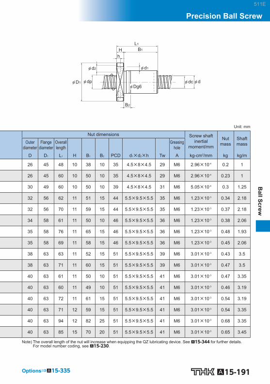
A15-191
Ball Screw
Precision Ball Screw
Options⇒A15-335
φ d2
B2
B1
φ D1 φ dp
φ d1
φ dc
hH
φ Dg6φ d
L1
Unit: mm
Nut dimensions Screw shaft inertial
moment/mm
Nut mass
Shaft mass Outer
diameter Flange
diameter Overall length Greasing
hole
D D 1 L 1 H B 1 B 2 PCD d 1 ×d 2 ×h Tw A kg-cm 2 /mm kg kg/m
26 45 48 10 38 10 35 4.5×8×4.5 29 M6 2.96×10 -4 0.2 1
26 45 60 10 50 10 35 4.5×8×4.5 29 M6 2.96×10 -4 0.23 1
30 49 60 10 50 10 39 4.5×8×4.5 31 M6 5.05×10 -4 0.3 1.25
32 56 62 11 51 15 44 5.5×9.5×5.5 35 M6 1.23×10 -3 0.34 2.18
32 56 70 11 59 15 44 5.5×9.5×5.5 35 M6 1.23×10 -3 0.37 2.18
34 58 61 11 50 10 46 5.5×9.5×5.5 36 M6 1.23×10 -3 0.38 2.06
35 58 76 11 65 15 46 5.5×9.5×5.5 36 M6 1.23×10 -3 0.48 1.93
35 58 69 11 58 15 46 5.5×9.5×5.5 36 M6 1.23×10 -3 0.45 2.06
38 63 63 11 52 15 51 5.5×9.5×5.5 39 M6 3.01×10 -3 0.43 3.5
38 63 71 11 60 15 51 5.5×9.5×5.5 39 M6 3.01×10 -3 0.47 3.5
40 63 61 11 50 10 51 5.5×9.5×5.5 41 M6 3.01×10 -3 0.47 3.35
40 63 60 11 49 10 51 5.5×9.5×5.5 41 M6 3.01×10 -3 0.46 3.19
40 63 72 11 61 15 51 5.5×9.5×5.5 41 M6 3.01×10 -3 0.54 3.19
40 63 71 12 59 15 51 5.5×9.5×5.5 41 M6 3.01×10 -3 0.54 3.35
40 63 94 12 82 25 51 5.5×9.5×5.5 41 M6 3.01×10 -3 0.68 3.35
40 63 85 15 70 20 51 5.5×9.5×5.5 41 M6 3.01×10 -3 0.65 3.45
Note) The overall length of the nut will increase when equipping the QZ lubricating device. See A15-344 for further details. For model number coding, see A15-230 .
511E

A15-192 Download data by searching for the corresponding model number on the Technical Support site. https://tech.thk.com
(Greasing hole)A
Tw
PCD
90°
22.5°
Model No.
Screw shaft outer diameter
Lead Ball center-to-center diameter
Thread minor
diameter
No. of loaded circuits
Basic load rating Rigidity
Ca C 0 a K
d Ph dp dc Rows × turns kN kN N/m
DIK 2805-6 28 5 28.75 25.2 3×1 10.5 26.4 560
DIK 2805-8 28 5 28.75 25.2 4×1 13.4 35.2 730
DIK 2806-6 28 6 29 24.4 3×1 14 32 530
DIK 2810-4 28 10 29.25 23.6 2×1 12.3 25 380
DIK 3204-6 32 4 32.5 30.1 3×1 6.4 19.6 580
DIK 3204-8 32 4 32.5 30.1 4×1 8.2 26.1 760
DIK 3204-10 32 4 32.5 30.1 5×1 10 32.7 940
DIK 3205-6 32 5 32.75 29.2 3×1 11.1 30.2 620
DIK 3205-8 32 5 32.75 29.2 4×1 14.2 40.3 810
DIK 3206-6 32 6 33 28.4 3×1 14.9 37.1 630
DIK 3206-8 32 6 33 28.4 4×1 19.1 49.5 820
DIK 3210-6 32 10 33.75 26.4 3×1 25.7 52.2 600
DIK 3212-4 32 12 33.75 26.4 2×1 18.8 37 430
DIK 3610-6 36 10 37.75 30.5 3×1 28.8 63.8 710
DIK 3610-8 36 10 37.75 30.5 4×1 36.8 85 940
DIK 3610-10 36 10 37.75 30.5 5×1 44.6 106.3 1160
DIK With Preload
DN value 70000
511E

A15-193
Ball Screw
Precision Ball Screw
Options⇒A15-335
φ d2
B2
B1
φ D1 φ dp
φ d1
φ dc
hH
φ Dg6φ d
L1
Unit: mm
Nut dimensions Screw shaft inertial
moment/mm
Nut mass
Shaft mass Outer
diameter Flange
diameter Overall length Greasing
hole
D D 1 L 1 H B 1 B 2 PCD d 1 ×d 2 ×h Tw A kg-cm 2 /mm kg kg/m
43 71 69 12 57 15 57 6.6×11×6.5 55 M6 4.74×10 -3 0.61 4.27
43 71 79 12 67 20 57 6.6×11×6.5 55 M6 4.74×10 -3 0.68 4.27
43 71 73 12 61 15 57 6.6×11×6.5 55 M6 4.74×10 -3 0.64 4.36
45 71 84 15 69 20 57 6.6×11×6.5 55 M6 4.74×10 -3 0.82 4.18
45 76 64 11 53 15 63 6.6×11×6.5 59 M6 8.08×10 -3 0.57 5.86
45 76 72 11 61 15 63 6.6×11×6.5 59 M6 8.08×10 -3 0.62 5.86
45 76 80 11 69 20 63 6.6×11×6.5 59 M6 8.08×10 -3 0.66 5.86
46 76 62 12 50 10 63 6.6×11×6.5 59 M6 8.08×10 -3 0.6 5.67
46 76 73 12 61 15 63 6.6×11×6.5 59 M6 8.08×10 -3 0.67 5.67
48 76 73 12 61 15 63 6.6×11×6.5 59 M6 8.08×10 -3 0.74 6.31
48 76 87 12 75 20 63 6.6×11×6.5 59 M6 8.08×10 -3 0.85 6.31
54 87 110 15 95 25 69 9×14×8.5 66 M6 8.08×10 -3 1.57 4.98
54 87 98 15 83 25 69 9×14×8.5 66 M6 8.08×10 -3 1.43 5.2
58 98 122 18 104 30 77 11×17.5×11 75 M6 1.29×10 -2 2.03 6.51
58 98 143 18 125 35 77 11×17.5×11 75 M6 1.29×10 -2 2.3 6.51
58 98 164 18 146 45 77 11×17.5×11 75 M6 1.29×10 -2 2.57 6.51
Note) The overall length of the nut will increase when equipping the QZ lubricating device. See A15-344 for further details. For model number coding, see A15-230 .
511E

A15-194 Download data by searching for the corresponding model number on the Technical Support site. https://tech.thk.com
(Greasing hole)A
Tw
PCD
90°
22.5°
Model No.
Screw shaft outer diameter
Lead Ball center-to-center diameter
Thread minor
diameter
No. of loaded circuits
Basic load rating Rigidity
Ca C 0 a K
d Ph dp dc Rows × turns kN kN N/m
DIK 4010-6 40 10 41.75 34.7 3×1 29.8 69.3 750
DIK 4010-8 40 10 41.75 34.7 4×1 38.1 92.4 1000
DIK 4012-6 40 12 41.75 34.4 3×1 30.6 72.3 790
DIK 4012-8 40 12 41.75 34.4 4×1 39.2 96.4 1030
DIK 4016-4 40 16 41.75 34.4 2×1 21.5 68.4 540
DIK 5010-6 50 10 51.75 44.4 3×1 33.9 90.7 940
DIK 5010-8 50 10 51.75 44.4 4×1 43.4 120.5 1230
DIK 5010-10 50 10 51.75 44.4 5×1 52.5 150.9 1530
DIK 5012-6 50 12 52.25 43.3 3×1 45.8 113 970
DIK 5012-8 50 12 52.25 43.3 4×1 58.6 150.6 1270
DIK 5016-4 50 16 52.25 43.3 2×1 32.3 75.5 660
DIK 5016-6 50 16 52.25 43.3 3×1 45.7 113.3 970
DIK With Preload
DN value 70000
511E

A15-195
Ball Screw
Precision Ball Screw
Options⇒A15-335
φ d2
B2
B1
φ D1 φ dp
φ d1
φ dc
hH
φ Dg6φ d
L1
Unit: mm
Nut dimensions Screw shaft inertial
moment/mm
Nut mass
Shaft mass Outer
diameter Flange
diameter Overall length Greasing
hole
D D 1 L 1 H B 1 B 2 PCD d 1 ×d 2 ×h Tw A kg-cm 2 /mm kg kg/m
62 104 113 18 95 25 82 11×17.5×11 79 R1/8 (PT1/8) 1.97×10 -2 2.09 8.22
62 104 137 18 119 35 82 11×17.5×11 79 R1/8 (PT1/8) 1.97×10 -2 2.42 8.22
62 104 138 18 120 35 82 11×17.5×11 79 R1/8 (PT1/8) 1.97×10 -2 2.44 8.5
62 104 163 18 145 45 82 11×17.5×11 79 R1/8 (PT1/8) 1.97×10 -2 2.78 8.5
62 104 120 18 102 30 82 11×17.5×11 79 R1/8 (PT1/8) 1.97×10 -2 2.19 8.83
72 123 114 18 96 30 101 11×17.5×11 92 R1/8 (PT1/8) 4.82×10 -2 2.65 13.38
72 123 137 18 119 35 101 11×17.5×11 92 R1/8 (PT1/8) 4.82×10 -2 3.03 13.38
72 123 160 18 142 45 101 11×17.5×11 92 R1/8 (PT1/8) 4.82×10 -2 3.41 13.38
75 129 145 22 123 35 105 14×20×13 98 R1/8 (PT1/8) 4.82×10 -2 3.83 12.74
75 129 170 22 148 45 105 14×20×13 98 R1/8 (PT1/8) 4.82×10 -2 4.31 12.74
75 129 129 22 107 30 105 14×20×13 98 R1/8 (PT1/8) 4.82×10 -2 3.52 13.41
75 129 175 22 153 45 105 14×20×13 98 R1/8 (PT1/8) 4.82×10 -2 4.41 13.41
Note) The overall length of the nut will increase when equipping the QZ lubricating device. See A15-344 for further details. For model number coding, see A15-230 .
511E

A15-196 Download data by searching for the corresponding model number on the Technical Support site. https://tech.thk.com
<Small> BNFN1605V/2805V/2806V/3205V
(Greasing hole) φ D1
L1
H B1
h
φ d1φ d2
PCD
φ dpA
φ dφ dc φ Dg6
Model No.
Screw shaft outer diameter
Lead Ball center-to-center diameter
Thread minor
diameter
No. of loaded circuits
Basic load rating Rigidity
Ca C 0 a K
d Ph dp dc Rows × turns kN kN N/m
BNFN 1605V-5 16 5 16.75 13.2 2×2.5 13.5 27.9 640
BNFN 2805V-7.5 28 5 28.75 25.2 3×2.5 24.8 73.8 1470
BNFN 2806V-7.5 28 6 28.75 25.2 3×2.5 24.8 73.8 1470
BNFN 3205V-7.5 32 5 32.75 29.2 3×2.5 26.2 84.4 1640
BNFN 2810V-2.5 28 10 29.75 22.4 1×2.5 24.3 49 560
BNFN 3610V-7.5 36 10 37.75 30.5 3×2.5 71 189.8 1990
BNFN 3616V-5 36 16 38 30.1 2×2.5 58.3 142.9 1380
BNFN 4016V-5 40 16 42 34.1 2×2.5 61.5 158.8 1500
BNFN 4510V-7.5 45 10 46.75 39.5 3×2.5 78.8 237.8 2370
BNFN 5010V-7.5 50 10 51.75 44.4 3×2.5 82.5 264.4 2580
BNFN-V Small/Medium With Preload
DN value Small 100000
Medium 130000
511E

A15-197
Ball Screw
Precision Ball Screw
Options⇒A15-335
<Medium> BNFN2810V/3610V/3616V/4016V/4510V/5010V
(Greasing hole)
L1
H B1
h
φ d1φ d2
φ D1
PCD
φ dφ dcφ dpA
φ Dg6
Unit: mm
Nut dimensions Screw shaft inertial
moment/mm
Nut mass
Shaft mass Outer
diameter Flange
diameter Overall length Greasing
hole
D D 1 L 1 H B 1 PCD d 1 ×d 2 ×h A kg-cm 2 /mm kg kg/m
40 60 106 10 96 50 4.5×8×4.5 M6 5.05×10 -4 0.88 1.37
55 85 134 12 122 69 6.6×11×6.5 M6 4.74×10 -3 1.88 4.45
55 85 158 12 149 69 6.6×11×6.5 M6 4.74×10 -3 2.16 4.52
58 85 136 12 124 71 6.6×11×6.5 M6 8.08×10 -3 1.93 5.89
65 106 146 18 128 85 11×17.5×11 M6 4.74×10 -3 3.41 4.15
75 120 261 18 243 98 11×17.5×11 M6 1.29×10 -3 6.93 7.1
78 123 268 18 250 100 11×17.5×11 M6 1.29×10 -3 7.8 7.99
84 126 280 22 258 104 11×17.5×11 M6 1.97×10 -2 9.27 9.09
88 132 261 18 243 110 11×17.5×11 R1/8 (PT1/8) 3.16×10 -2 8.92 11.36
93 135 253 18 235 113 11×17.5×11 R1/8 (PT1/8) 4.82×10 -2 9.19 14.16
Note) The overall length of the nut will increase when equipping the QZ lubricating device. See A15-344 for further details. For model number coding, see A15-230 .
511E

A15-198 Download data by searching for the corresponding model number on the Technical Support site. https://tech.thk.com
(Greasing hole)
PCD
A60°
Model No.
Screw shaft outer diameter
Lead Ball center-to-center diameter
Thread minor
diameter
No. of loaded circuits
Basic load rating Rigidity
Ca C 0 a K
d Ph dp dc Rows × turns kN kN N/m
BNFN 5510-2.5 55 10 56.75 49.5 1×2.5 33.4 97 970
BNFN 5510-5 55 10 56.75 49.5 2×2.5 60.7 194 1890
BNFN 5510-7.5 55 10 56.75 49.5 3×2.5 85.9 291.1 2770
BNFN 5512-2.5 55 12 57 49.2 1×2.5 39.3 108.8 990
BNFN 5512-3 55 12 57 49.2 2×1.5 46 131.3 1180
BNFN 5512-3.5 55 12 57 49.2 1×3.5 52.4 152.9 1360
BNFN 5512-5 55 12 57 49.2 2×2.5 71.3 218.5 1920
BNFN 5512-7.5 55 12 57 49.2 3×2.5 100.9 327.3 2830
BNFN 5516-2.5 55 16 57.7 47.9 1×2.5 76.1 201.9 1310
BNFN 5516-5 55 16 57.7 47.9 2×2.5 138.2 402.8 2550
BNFN 5520-2.5 55 20 57.7 47.9 1×2.5 76 201.9 1320
BNFN 5520-5 55 20 57.7 47.9 2×2.5 138.2 403.8 2550
BNFN 6310-2.5 63 10 64.75 57.7 1×2.5 35.4 111.7 1090
BNFN 6310-5 63 10 64.75 57.7 2×2.5 64.2 222.5 2100
BNFN 6310-7.5 63 10 64.75 57.7 3×2.5 90.9 334.2 3090
BNFN 6312A-2.5 63 12 65.25 56.3 1×2.5 48.1 139.2 1120
BNFN 6312A-5 63 12 65.25 56.3 2×2.5 87.4 278.3 2160
BNFN 6316-2.5 63 16 65.7 55.9 1×2.5 81.1 231.3 1470
BNFN 6316-5 63 16 65.7 55.9 2×2.5 147 462.6 2840
BNFN 6320-2.5 63 20 65.7 55.9 1×2.5 81 231.3 1470
BNFN 6320-5 63 20 65.7 55.9 2×2.5 147 463.5 2640
Note) The model numbers in dimmed type indicate semi-standard types. If desiring them, contact THK.
BNFN With Preload
DN value 70000
511E

A15-199
Ball Screw
Precision Ball Screw
Options⇒A15-335
φ d2
B1
φ D1 φ dp
φ d1
φ dc
hH
φ Dg6φ d
L1
Unit: mm
Nut dimensions Screw shaft inertial
moment/mm
Nut mass
Shaft mass Outer
diameter Flange
diameter Overall length Greasing
hole
D D 1 L 1 H B 1 PCD d 1 ×d 2 ×h A kg-cm 2 /mm kg kg/m
102 144 141 18 123 122 11×17.5×11 R1/8 (PT1/8) 7.05×10 -2 6.54 16.43
102 144 201 18 183 122 11×17.5×11 R1/8 (PT1/8) 7.05×10 -2 8.88 16.43
102 144 261 18 243 122 11×17.5×11 R1/8 (PT1/8) 7.05×10 -2 11.23 16.43
105 147 165 18 147 125 11×17.5×11 R1/8 (PT1/8) 7.05×10 -2 8.07 16.29
105 147 191 18 173 125 11×17.5×11 R1/8 (PT1/8) 7.05×10 -2 9.17 16.29
105 147 189 18 171 125 11×17.5×11 R1/8 (PT1/8) 7.05×10 -2 9.09 16.29
105 147 237 18 219 125 11×17.5×11 R1/8 (PT1/8) 7.05×10 -2 11.13 16.29
105 147 309 18 291 125 11×17.5×11 R1/8 (PT1/8) 7.05×10 -2 14.19 16.29
110 158 196 25 171 133 14×20×13 R1/8 (PT1/8) 7.05×10 -2 11.28 15.46
110 158 292 25 267 133 14×20×13 R1/8 (PT1/8) 7.05×10 -2 15.94 15.46
112 158 227 28 199 134 14×20×13 R1/8 (PT1/8) 7.05×10 -2 13.49 16.1
112 158 347 28 319 134 14×20×13 R1/8 (PT1/8) 7.05×10 -2 19.61 16.1
108 154 137 22 115 130 14×20×13 R1/8 (PT1/8) 1.21×10 -1 6.98 21.93
108 154 197 22 175 130 14×20×13 R1/8 (PT1/8) 1.21×10 -1 9.4 21.93
108 154 257 22 235 130 14×20×13 R1/8 (PT1/8) 1.21×10 -1 11.81 21.93
115 161 159 22 137 137 14×20×13 R1/8 (PT1/8) 1.21×10 -1 9.32 21.14
115 161 231 22 209 137 14×20×13 R1/8 (PT1/8) 1.21×10 -1 12.84 21.14
122 184 208 24 184 152 18×26×17.5 R1/8 (PT1/8) 1.21×10 -1 14.61 20.85
122 184 304 24 280 152 18×26×17.5 R1/8 (PT1/8) 1.21×10 -1 20.19 20.85
122 180 227 28 199 150 18×26×17.5 R1/8 (PT1/8) 1.21×10 -1 15.91 20.85
122 180 347 28 319 150 18×26×17.5 R1/8 (PT1/8) 1.21×10 -1 22.88 20.85
Note) The overall length of the nut will increase when equipping the QZ lubricating device. See A15-344 for further details. For model number coding, see A15-230 .
511E

A15-200 Download data by searching for the corresponding model number on the Technical Support site. https://tech.thk.com
(Greasing hole)
PCD
A60°
Model No.
Screw shaft outer diameter
Lead Ball center-to-center diameter
Thread minor
diameter
No. of loaded circuits
Basic load rating Rigidity
Ca C 0 a K
d Ph dp dc Rows × turns kN kN N/m
BNFN 7010-2.5 70 10 71.75 64.5 1×2.5 36.8 123.5 1180
BNFN 7010-5 70 10 71.75 64.5 2×2.5 66.9 247 2280
BNFN 7010-7.5 70 10 71.75 64.5 3×2.5 94.9 371.4 3350
BNFN 7012-2.5 70 12 72 64.2 1×2.5 43.5 139.2 1200
BNFN 7012-5 70 12 72 64.2 2×2.5 78.9 278.3 2320
BNFN 7012-7.5 70 12 72 64.2 3×2.5 111.7 417.5 3420
BNFN 7020-5 70 20 72.7 62.9 2×2.5 153.9 514.5 3090
BNFN 8010-2.5 80 10 81.75 75.2 1×2.5 38.9 141.1 1300
BNFN 8010-5 80 10 81.75 75.2 2×2.5 70.6 283.2 2530
BNFN 8010-7.5 80 10 81.75 75.2 3×2.5 100 424.3 3720
BNFN 8012-5 80 12 82.3 74.1 2×2.5 96.5 353.8 2620
BNFN 8020A-2.5 80 20 82.7 72.9 1×2.5 90.1 294 1770
BNFN 8020A-5 80 20 82.7 72.9 2×2.5 163.7 589 3430
BNFN 10020A-2.5 100 20 102.7 92.9 1×2.5 99 368.5 2110
BNFN 10020A-5 100 20 102.7 92.9 2×2.5 179.3 737 4080
BNFN 10020A-7.5 100 20 102.7 92.9 3×2.5 253.8 1105.4 6010
Note) The model numbers in dimmed type indicate semi-standard types. If desiring them, contact THK.
BNFN With Preload
DN value 70000
511E

A15-201
Ball Screw
Precision Ball Screw
Options⇒A15-335
φ d2
B1
φ D1 φ dp
φ d1
φ dc
hH
φ Dg6φ d
L1
Unit: mm
Nut dimensions Screw shaft inertial
moment/mm
Nut mass
Shaft mass Outer
diameter Flange
diameter Overall length Greasing
hole
D D 1 L 1 H B 1 PCD d 1 ×d 2 ×h A kg-cm 2 /mm kg kg/m
125 167 141 18 123 145 11×17.5×11 R1/8 (PT1/8) 1.85×10 -1 9.19 27.4
125 167 201 18 183 145 11×17.5×11 R1/8 (PT1/8) 1.85×10 -1 12.57 27.4
125 167 261 18 243 145 11×17.5×11 R1/8 (PT1/8) 1.85×10 -1 15.96 27.4
128 170 165 18 147 148 11×17.5×11 R1/8 (PT1/8) 1.85×10 -1 11.26 27.24
128 170 237 18 219 148 11×17.5×11 R1/8 (PT1/8) 1.85×10 -1 15.63 27.24
128 170 309 18 291 148 11×17.5×11 R1/8 (PT1/8) 1.85×10 -1 20 27.24
130 186 325 28 297 158 18×26×17.5 R1/8 (PT1/8) 1.85×10 -1 23.4 27
130 176 137 22 115 152 14×20×13 R1/8 (PT1/8) 3.16×10 -1 9.15 36.26
130 176 197 22 175 152 14×20×13 R1/8 (PT1/8) 3.16×10 -1 12.41 36.26
130 176 257 22 235 152 14×20×13 R1/8 (PT1/8) 3.16×10 -1 15.67 36.26
135 181 231 22 209 157 14×20×13 R1/8 (PT1/8) 3.16×10 -1 16.02 35.26
143 204 227 28 199 172 18×26×17.5 R1/8 (PT1/8) 3.16×10 -1 20.08 35.81
143 204 347 28 319 172 18×26×17.5 R1/8 (PT1/8) 3.16×10 -1 28.97 35.81
170 243 231 32 199 205 22×32×21.5 R1/8 (PT1/8) 7.71×10 -1 28.15 57.13
170 243 351 32 319 205 22×32×21.5 R1/8 (PT1/8) 7.71×10 -1 39.99 57.13
170 243 471 32 439 205 22×32×21.5 R1/8 (PT1/8) 7.71×10 -1 51.84 57.13
Note) The overall length of the nut will increase when equipping the QZ lubricating device. See A15-344 for further details. For model number coding, see A15-230 .
511E

A15-202 Download data by searching for the corresponding model number on the Technical Support site. https://tech.thk.com
(Greasing hole)A
Tw
PCD
90°
22.5°
B2
φ D1
φ d2
φ d1
φ dc φ dφ Dg6
φ dp
hB1H
L1
Unit: mm
Model No.
Screw shaft outer diameter
Lead Ball center-to-center diameter
Thread minor
diameter
No. of loaded circuits
Basic load rating Rigidity Nut dimensions
Ca C 0 a K Outer diameter
Flange diameter
Overall length
d Ph dp dc Rows × turns kN kN N/m D D 1 L 1
DKN 4020-3 40 20 41.75 34.7 3×1 29.4 69.3 750 62 104 223
DKN 5020-3 50 20 52.25 43.6 3×1 44.2 108.8 930 75 129 243
DKN 6320-3 63 20 65.7 55.9 3×1 83.5 229.3 1470 95 159 243
Model No.
Nut dimensions Screw shaft inertial
moment/mm
Nut mass
Shaft mass Greasing
hole
H B 1 B 2 PCD d 1 ×d 2 ×h Tw A kg-cm 2 /mm kg kg/m
DKN 4020-3 18 205 25 82 11×17.5×11 79 R1/8 (PT1/8) 1.97×10 -2 3.61 9.03
DKN 5020-3 28 215 30 105 14×20×13 98 R1/8 (PT1/8) 4.82×10 -2 6.0 13.8
DKN 6320-3 28 215 30 129 18×26×17.5 121 R1/8 (PT1/8) 1.21×10 -2 9.5 20.85
Note) The overall length of the nut will increase when equipping the QZ lubricating device. See A15-344 for further details. For model number coding, see A15-230 .
DKN With Preload
DN value 70000
511E

A15-203
Ball Screw
Precision Ball Screw
Options⇒A15-335
(Greasing hole)
4-φ d1
PCD
TwA
30°30° B1
B2 B3
N1
L1
H
φ D1φ D2φ Dg6 φ dc φ dφ dp
Unit: mm
Model No.
Screw shaft outer diameter
Lead Ball center-to-center diameter
Thread minor
diameter
No. of loaded circuits
Basic load rating Rigidity Nut dimensions
Ca C 0 a K Outer diameter
Flange diameter
Overall length
d Ph dp dc Rows × turns kN kN N/m D D 1 D 2 L 1 H BLW 1510-5.6 15 10 15.75 12.5 2×2.8 14.3 27.8 680 43 64 34 89 10 BLW 1616-3.6 16 16 16.65 13.7 2×1.8 7.1 14.3 440 41 60 32 84.5 10 BLW 2020-3.6 20 20 20.75 17.5 2×1.8 11.1 24.7 570 48 69 39 105 10 BLW 2525-3.6 25 25 26 21.9 2×1.8 16.6 38.7 700 57 82 47 124.5 12 BLW 3232-3.6 32 32 33.25 28.3 2×1.8 23.7 59.5 880 68 99 58 155 15 BLW 3636-3.6 36 36 37.4 31.7 2×1.8 30.8 78 980 79 116 66 181 17 BLW 4040-3.6 40 40 41.75 35.2 2×1.8 38.7 99.2 1090 84 121 73 191 17 BLW 5050-3.6 50 50 52.2 44.1 2×1.8 57.8 155 1340 106 149 90 245 20
Model No.
Nut dimensions Screw shaft inertial
moment/mm
Nut mass
Shaft mass Greasing
hole
B 1 B 2 B 3 PCD d 1 Tw N 1 A kg-cm 2 /mm kg kg/m BLW 1510-5.6 69 18.7 28.6 52 5.5 46 5 M6 3.9×10 -4 0.81 1.07 BLW 1616-3.6 65.5 18.1 27.1 49 4.5 44 6 M6 5.05×10 -4 0.67 1.42 BLW 2020-3.6 84 25 36 57 5.5 50 5 M6 1.23×10 -3 0.54 2.25 BLW 2525-3.6 101.5 33 44 68 6.6 60 5 M6 3.01×10 -3 0.94 3.52 BLW 3232-3.6 127 42.4 55.4 81 9 70 6 M6 8.08×10 -3 3.19 5.83 BLW 3636-3.6 147.9 49.4 65.4 95 11 82 7 M6 1.29×10 -2 5.99 7.34 BLW 4040-3.6 158 54.5 70.5 100 11 87 7 M6 1.97×10 -2 6.16 9.01 BLW 5050-3.6 203.8 70.7 91.7 126 14 108 8 M6 4.82×10 -2 9.06 14.08
Note) The overall length of the nut will increase when equipping the QZ lubricating device. See A15-344 for further details. For model number coding, see A15-230 . Model BLW cannot be attached with seal.
BLW With Preload
DN value 70000
511E

A15-204 Download data by searching for the corresponding model number on the Technical Support site. https://tech.thk.com
(Greasing hole)
PCD
A
60°
Model No.
Screw shaft outer diameter
Lead Ball center-to-center diameter
Thread minor
diameter
No. of loaded circuits
Basic load rating Rigidity
Ca C 0 a K
d Ph dp dc Rows × turns kN kN N/m BNF 1604V-5 16 4 16.5 13.8 2×2.5 7.8 17.4 290 BNF 1605V-2.5 16 5 16.75 13.2 1×2.5 7.4 13.9 170 BNF 1605V-5 16 5 16.75 13.2 2×2.5 13.5 27.9 320 BNF 2004V-2.5 20 4 20.5 17.8 1×2.5 4.8 10.9 180 BNF 2004V-5 20 4 20.5 17.8 2×2.5 8.6 21.8 350 BNF 2005V-2.5 20 5 20.75 17.2 1×2.5 8.3 17.5 200 BNF 2005V-5 20 5 20.75 17.2 2×2.5 15.1 35 380 BNF 2010V-2.5 20 10 20.75 17.2 1×2.5 8.3 17.6 197 BNF 2504V-2.5 25 4 25.5 22.8 1×2.5 5.2 13.7 210 BNF 2504V-5 25 4 25.5 22.8 2×2.5 9.5 27.4 410 BNF 2505V-2.5 25 5 25.75 22.2 1×2.5 9.2 21.9 240 BNF 2505V-5 25 5 25.75 22.2 2×2.5 16.7 43.9 460 BNF 2506V-2.5 25 6 26 21.4 1×2.5 12.4 27.4 250 BNF 2506V-5 25 6 26 21.4 2×2.5 22.6 54.8 470 BNF 2805V-2.5 28 5 28.75 25.2 1×2.5 9.7 24.6 250 BNF 2805V-5 28 5 28.75 25.2 2×2.5 17.5 49.2 500 BNF 2805V-7.5 28 5 28.75 25.2 3×2.5 24.8 73.8 740 BNF 2806V-2.5 28 6 28.75 25.2 1×2.5 9.6 24.6 250 BNF 2806V-5 28 6 28.75 25.2 2×2.5 17.5 49.2 500 BNF 2806V-7.5 28 6 28.75 25.2 3×2.5 24.8 73.8 740 BNF 3205V-2.5 32 5 32.75 29.2 1×2.5 10.2 28.1 280 BNF 3205V-5 32 5 32.75 29.2 2×2.5 18.5 56.3 560 BNF 3205V-7.5 32 5 32.75 29.2 3×2.5 26.2 84.4 810 BNF 3206V-2.5 32 6 33 28.4 1×2.5 13.9 35.2 290 BNF 3206V-5 32 6 33 28.4 2×2.5 25.2 70.3 580
BNF-V Small No Preload
DN value 100000
511E

A15-205
Ball Screw
Precision Ball Screw
LH B1
h
φ d1φ d2
φ d φ Dg6φ dcφ D1 φ dp
Unit: mm
Nut dimensions Screw shaft inertial
moment/mm
Nut mass
Shaft mass Outer
diameter Flange
diameter Overall length Greasing
hole
D D 1 L 1 H B 1 PCD d 1 ×d 2 ×h A kg-cm 2 /mm kg kg/m 36 59 53 11 42 47 5.5×9.5×5.5 M6 5.05×10 -4 0.42 1.42 40 60 41 10 31 50 4.5×8×4.5 M6 5.05×10 -4 0.37 1.37 40 60 56 10 46 50 4.5×8×4.5 M6 5.05×10 -4 0.49 1.37 40 63 37 11 26 51 5.5×9.5×5.5 M6 1.23×10 -3 0.3 2.22 40 63 49 11 38 51 5.5×9.5×5.5 M6 1.23×10 -3 0.49 2.22 44 67 41 11 30 55 5.5×9.5×5.5 M6 1.23×10 -3 0.46 2.19 44 67 56 11 45 55 5.5×9.5×5.5 M6 1.23×10 -3 0.6 2.19 46 74 58 15 43 59 5.5×9.5×5.5 M6 1.23×10 -3 0.68 2.46 46 69 36 11 25 57 5.5×9.5×5.5 M6 3.01×10 -3 0.21 3.6 46 69 48 11 37 57 5.5×9.5×5.5 M6 3.01×10 -3 0.55 3.6 50 73 40 11 29 61 5.5×9.5×5.5 M6 3.01×10 -3 0.52 3.52 50 73 55 11 44 61 5.5×9.5×5.5 M6 3.01×10 -3 0.68 3.52 53 76 44 11 33 64 5.5×9.5×5.5 M6 3.01×10 -3 0.61 3.43 53 76 62 11 51 64 5.5×9.5×5.5 M6 3.01×10 -3 0.91 3.43 55 85 44 12 32 69 6.6×11×6.5 M6 4.74×10 -3 1.02 4.45 55 85 59 12 47 69 6.6×11×6.5 M6 4.74×10 -3 1.06 4.45 55 85 74 12 62 69 6.6×11×6.5 M6 4.74×10 -3 1.16 4.45 55 85 50 12 38 69 6.6×11×6.5 M6 4.74×10 -3 0.87 4.52 55 85 68 12 56 69 6.6×11×6.5 M6 4.74×10 -3 1.09 4.52 55 85 86 12 74 69 6.6×11×6.5 M6 4.74×10 -3 1.3 4.52 58 85 41 12 29 71 6.6×11×6.5 M6 8.08×10 -3 0.76 5.89 58 85 56 12 44 71 6.6×11×6.5 M6 8.08×10 -3 0.94 5.89 58 85 71 12 59 71 6.6×11×6.5 M6 8.08×10 -3 1.13 5.89 62 89 45 12 33 75 6.6×11×6.5 M6 8.08×10 -3 0.94 5.88 62 89 63 12 51 75 6.6×11×6.5 M6 8.08×10 -3 1.21 5.88
Options⇒A15-335
Note) The overall length of the nut will increase when equipping the QZ lubricating device. See A15-344 for further details. For model number coding, see A15-230 .
511E

A15-206 Download data by searching for the corresponding model number on the Technical Support site. https://tech.thk.com
(Greasing hole)
PCD
A
60°
Model No.
Screw shaft outer diameter
Lead Ball center-to-center diameter
Thread minor
diameter
No. of loaded circuits
Basic load rating Rigidity
Ca C 0 a K
d Ph dp dc Rows × turns kN kN N/m BNF 2508V-2.5 25 8 26.25 20.5 1×2.5 15.8 32.9 250 BNF 2508V-3.5 25 8 26.25 20.5 1×3.5 21.1 46 340 BNF 2508V-5 25 8 26.25 20.5 2×2.5 28.7 65.7 480 BNF 2510V-2.5 25 10 26.25 21.5 1×2.5 15.8 32.9 250 BNF 2810V-2.5 28 10 29.75 22.4 1×2.5 24.3 49 280 BNF 3210V-2.5 32 10 33.75 26.4 1×2.5 26 56.2 310 BNF 3210V-3.5 32 10 33.75 26.4 1×3.5 34.8 78.6 440 BNF 3210V-5 32 10 33.75 26.4 2×2.5 47.3 112.3 620 BNF 3212V-3.5 32 12 34 26.1 1×3.5 40.4 88.5 440 BNF 3216V-5 32 16 33.75 26.4 2×2.5 47.1 113.1 616 BNF 3610V-2.5 36 10 37.75 30.5 1×2.5 27.6 63.3 350 BNF 3610V-5 36 10 37.75 30.5 2×2.5 50.1 126.5 680 BNF 3610V-7.5 36 10 37.75 30.5 3×2.5 71 189.8 990 BNF 3612V-2.5 36 12 38 30.1 1×2.5 32.2 71.2 350 BNF 3612V-5 36 12 38 30.1 2×2.5 58.4 142.3 690 BNF 3616V-2.5 36 16 38 30.1 1×2.5 32.1 71.5 350 BNF 3620V-1.5 36 20 37.75 30.5 1×1.5 17.7 38.4 215 BNF 4010V-2.5 40 10 41.75 34.4 1×2.5 29 70.4 380 BNF 4010V-3.5 40 10 41.75 34.4 1×3.5 38.8 98.5 520 BNF 4010V-5 40 10 41.75 34.4 2×2.5 52.7 140.7 740 BNF 4012V-2.5 40 12 42 34.1 1×2.5 33.9 79.2 390 BNF 4012V-3.5 40 12 42 34.1 1×3.5 45.3 110.8 530 BNF 4012V-5 40 12 42 34.1 2×2.5 61.6 158.3 750 BNF 4016V-5 40 16 42 34.1 2×2.5 61.5 158.8 740 BNF 4020V-5 40 20 41.75 34.4 2×2.5 52.4 142 736
BNF-V Medium No Preload
DN value 130000
511E

A15-207
Ball Screw
Precision Ball Screw
φ D1
LH B1
h
φ d1φ d2
φ d φ Dg6φ dcφ dp
Unit: mm
Nut dimensions Screw shaft inertial
moment/mm
Nut mass
Shaft mass Outer
diameter Flange
diameter Overall length Greasing
hole
D D 1 L 1 H B 1 PCD d 1 ×d 2 ×h A kg-cm 2 /mm kg kg/m 58 85 58 15 43 71 6.6×11×6.5 M6 3.01×10 -3 1.07 3.51 58 85 66 15 51 71 6.6×11×6.5 M6 3.01×10 -3 1.29 3.51 58 85 82 15 67 71 6.6×11×6.5 M6 3.01×10 -3 1.44 3.51 58 85 70 18 52 71 6.6×11×6.5 M6 3.01×10 -3 1.43 3.5 65 106 86 18 68 85 11×17.5×11 M6 4.74×10 -4 2.3 4.15 74 108 70 15 55 90 9×14×8.5 M6 8.08×10 -3 2.2 5.53 74 108 80 15 65 90 9×14×8.5 M6 8.08×10 -3 2.44 5.53 74 108 100 15 85 90 9×14×8.5 M6 8.08×10 -3 2.92 5.53 76 121 98 18 80 98 11×17.5×11 M6 8.08×10 -3 3.4 5.7 74 108 139 18 121 90 9×14×8.5 M6 8.08×10 -3 3.81 5.82 75 120 81 18 63 98 11×17.5×11 M6 1.29×10 -2 2.75 7.1 75 120 111 18 93 98 11×17.5×11 M6 1.29×10 -2 3.45 7.1 75 120 141 18 123 98 11×17.5×11 M6 1.29×10 -2 4.15 7.1 78 123 87 18 69 100 11×17.5×11 M6 1.29×10 -2 3.14 7.99 78 123 123 18 105 100 11×17.5×11 M6 1.29×10 -2 4.07 7.99 78 123 92 18 74 100 11×17.5×11 M6 1.29×10 -2 3.27 7.99 75 114 82 18 64 93 11×17.5×11 M6 1.29×10 -2 2.38 7.54 82 124 73 18 55 102 11×17.5×11 M6 1.97×10 -2 2.86 8.87 82 124 83 18 65 102 11×17.5×11 M6 1.97×10 -2 3.14 8.87 82 124 103 18 85 102 11×17.5×11 M6 1.97×10 -2 3.69 8.87 84 126 83 18 65 104 11×17.5×11 M6 1.97×10 -2 3.31 8.83 84 126 95 18 77 104 11×17.5×11 M6 1.97×10 -2 3.66 8.83 84 126 119 18 101 104 11×17.5×11 M6 1.97×10 -2 4.36 8.83 84 126 144 18 126 104 11×17.5×11 M6 1.97×10 -2 5.52 9.09 82 126 162 18 144 104 11×17.5×11 M6 1.97×10 -2 5.17 9.37
Options⇒A15-335
Note) The overall length of the nut will increase when equipping the QZ lubricating device. See A15-344 for further details. For model number coding, see A15-230 .
511E

A15-208 Download data by searching for the corresponding model number on the Technical Support site. https://tech.thk.com
(Greasing hole)
PCD
A
60°
Model No.
Screw shaft outer diameter
Lead Ball center-to-center diameter
Thread minor
diameter
No. of loaded circuits
Basic load rating Rigidity
Ca C 0 a K
d Ph dp dc Rows × turns kN kN N/m
BNF 4510V-2.5 45 10 46.75 39.5 1×2.5 30.6 79.3 420
BNF 4510V-3 45 10 46.75 39.5 2×1.5 35.8 95.1 500
BNF 4510V-5 45 10 46.75 39.5 2×2.5 55.6 158.5 800
BNF 4510V-7.5 45 10 46.75 39.5 3×2.5 78.8 237.8 1190
BNF 4512V-5 45 12 47 39.2 2×2.5 65.2 178.3 820
BNF 4520V-2.5 45 20 47 39.2 1×2.5 35.8 89.7 424
BNF 5010V-2.5 50 10 51.75 44.4 1×2.5 32.1 88.1 450
BNF 5010V-3.5 50 10 51.75 44.4 1×3.5 42.9 123.4 620
BNF 5010V-5 50 10 51.75 44.4 2×2.5 58.2 176.3 880
BNF 5010V-7.5 50 10 51.75 44.4 3×2.5 82.5 264.4 1290
BNF 5012V-2.5 50 12 52.25 43.3 1×2.5 43.4 110.1 470
BNF 5012V-3.5 50 12 52.25 43.3 1×3.5 58 154.1 640
BNF 5012V-5 50 12 52.25 43.3 2×2.5 78.8 220.2 910
BNF 5016V-2.5 50 16 52.7 42.9 1×2.5 72.6 183.1 620
BNF 5016V-5 50 16 52.7 42.9 2×2.5 131.8 366.2 1180
BNF 5020V-2.5 50 20 52.7 42.9 1×2.5 72.5 183.6 620
BNF-V Medium No Preload
DN value 130000
511E

A15-209
Ball Screw
Precision Ball Screw
φ D1
LH B1
h
φ d1φ d2
φ d φ Dg6φ dcφ dp
Unit: mm
Nut dimensions Screw shaft inertial
moment/mm
Nut mass
Shaft mass Outer
diameter Flange
diameter Overall length Greasing
hole
D D 1 L 1 H B 1 PCD d 1 ×d 2 ×h A kg-cm 2 /mm kg kg/m
88 132 81 18 63 110 11×17.5×11 R1/8 (PT1/8) 3.16×10 -2 3.43 11.36
88 132 94 18 76 110 11×17.5×11 R1/8 (PT1/8) 3.16×10 -2 3.83 11.36
88 132 111 18 93 110 11×17.5×11 R1/8 (PT1/8) 3.16×10 -2 4.35 11.36
88 132 141 18 123 110 11×17.5×11 R1/8 (PT1/8) 3.16×10 -2 5.26 11.36
90 130 119 18 101 110 11×17.5×11 R1/8 (PT1/8) 3.16×10 -2 4.74 11.32
90 130 102 18 84 110 11×17.5×11 R1/8 (PT1/8) 3.16×10 -2 4.28 11.1
93 135 73 18 55 113 11×17.5×11 R1/8 (PT1/8) 4.82×10 -2 3.33 14.16
93 135 83 18 65 113 11×17.5×11 R1/8 (PT1/8) 4.82×10 -2 3.66 14.16
93 135 103 18 85 113 11×17.5×11 R1/8 (PT1/8) 4.82×10 -2 4.31 14.16
93 135 133 18 115 113 11×17.5×11 R1/8 (PT1/8) 4.82×10 -2 5.28 14.16
100 146 87 22 65 122 14×20×13 R1/8 (PT1/8) 4.82×10 -2 4.57 13.82
100 146 99 22 77 122 14×20×13 R1/8 (PT1/8) 4.82×10 -2 5.05 13.82
100 146 123 22 101 122 14×20×13 R1/8 (PT1/8) 4.82×10 -2 6.02 13.82
105 152 116 25 91 128 14×20×13 R1/8 (PT1/8) 4.82×10 -2 6.98 13.71
105 152 164 25 139 128 14×20×13 R1/8 (PT1/8) 4.82×10 -2 9.18 13.71
105 152 141 28 113 128 14×20×13 R1/8 (PT1/8) 4.82×10 -2 8.32 14.05
Options⇒A15-335
Note) The overall length of the nut will increase when equipping the QZ lubricating device. See A15-344 for further details. For model number coding, see A15-230 .
511E

A15-210 Download data by searching for the corresponding model number on the Technical Support site. https://tech.thk.com
(Greasing hole)
PCD
A60°
Model No.
Screw shaft outer diameter
Lead Ball center-to-center diameter
Thread minor
diameter
No. of loaded circuits
Basic load rating Rigidity
Ca C 0 a K
d Ph dp dc Rows × turns kN kN N/m
BNF 5510-2.5 55 10 56.75 49.5 1×2.5 33.4 97 490
BNF 5510-5 55 10 56.75 49.5 2×2.5 60.7 194 950
BNF 5510-7.5 55 10 56.75 49.5 3×2.5 85.9 291.1 1390
BNF 5512-2.5 55 12 57 49.2 1×2.5 39.3 108.8 500
BNF 5512-3 55 12 57 49.2 2×1.5 46 131.3 590
BNF 5512-3.5 55 12 57 49.2 1×3.5 52.4 152.9 680
BNF 5512-5 55 12 57 49.2 2×2.5 71.3 218.5 960
BNF 5512-7.5 55 12 57 49.2 3×2.5 100.9 327.3 1420
BNF 5516-2.5 55 16 57.7 47.9 1×2.5 76.1 201.9 650
BNF 5516-5 55 16 57.7 47.9 2×2.5 138.2 402.8 1280
BNF 5520-2.5 55 20 57.7 47.9 1×2.5 76 201.9 660
BNF 5520-5 55 20 57.7 47.9 2×2.5 138.2 403.8 1280
BNF 6310-2.5 63 10 64.75 57.7 1×2.5 35.4 111.7 550
BNF 6310-5 63 10 64.75 57.7 2×2.5 64.2 222.5 1050
BNF 6310-7.5 63 10 64.75 57.7 3×2.5 90.9 334.2 1550
BNF 6312A-2.5 63 12 65.25 56.3 1×2.5 48.1 139.2 560
BNF 6312A-5 63 12 65.25 56.3 2×2.5 87.4 278.3 1090
BNF 6316-5 63 16 65.7 55.9 2×2.5 147 462.6 1420
BNF 6320-2.5 63 20 65.7 55.9 1×2.5 81 231.3 740
BNF 6310-5 63 20 65.7 55.9 2×2.5 147 463.5 1420
Note) The model numbers in dimmed type indicate semi-standard types. If desiring them, contact THK.
BNF No Preload
DN value 70000
511E

A15-211
Ball Screw
Precision Ball Screw
φ d2
B1
φ D1 φ dp
φ d1
φ dc
hH
φ Dg6φ d
L1
Unit: mm
Nut dimensions Screw shaft inertial
moment/mm
Nut mass
Shaft mass Outer
diameter Flange
diameter Overall length Greasing
hole
D D 1 L 1 H B 1 PCD d 1 ×d 2 ×h A kg-cm 2 /mm kg kg/m
102 144 81 18 63 122 11×17.5×11 R1/8 (PT1/8) 7.05×10 -2 4.19 16.43
102 144 111 18 93 122 11×17.5×11 R1/8 (PT1/8) 7.05×10 -2 5.36 16.43
102 144 141 18 123 122 11×17.5×11 R1/8 (PT1/8) 7.05×10 -2 6.54 16.43
105 147 93 18 75 125 11×17.5×11 R1/8 (PT1/8) 7.05×10 -2 5.01 16.29
105 147 107 18 89 125 11×17.5×11 R1/8 (PT1/8) 7.05×10 -2 5.6 16.29
105 147 105 18 87 125 11×17.5×11 R1/8 (PT1/8) 7.05×10 -2 5.52 16.29
105 147 129 18 111 125 11×17.5×11 R1/8 (PT1/8) 7.05×10 -2 6.54 16.29
105 147 165 18 147 125 11×17.5×11 R1/8 (PT1/8) 7.05×10 -2 8.07 16.29
110 158 116 25 91 133 14×20×13 R1/8 (PT1/8) 7.05×10 -2 7.4 15.46
110 158 164 25 139 133 14×20×13 R1/8 (PT1/8) 7.05×10 -2 9.73 15.46
112 158 127 28 99 134 14×20×13 R1/8 (PT1/8) 7.05×10 -2 8.4 16.1
112 158 187 28 159 134 14×20×13 R1/8 (PT1/8) 7.05×10 -2 11.45 16.1
108 154 77 22 55 130 14×20×13 R1/8 (PT1/8) 1.21×10 -1 4.57 21.93
108 154 107 22 85 130 14×20×13 R1/8 (PT1/8) 1.21×10 -1 5.77 21.93
108 154 137 22 115 130 14×20×13 R1/8 (PT1/8) 1.21×10 -1 6.98 21.93
115 161 87 22 65 137 14×20×13 R1/8 (PT1/8) 1.21×10 -1 5.8 21.14
115 161 123 22 101 137 14×20×13 R1/8 (PT1/8) 1.21×10 -1 7.56 21.14
122 184 160 24 136 152 18×26×17.5 R1/8 (PT1/8) 1.21×10 -1 11.82 20.85
122 180 127 28 99 150 18×26×17.5 R1/8 (PT1/8) 1.21×10 -1 10.1 21.57
122 180 187 28 159 150 18×26×17.5 R1/8 (PT1/8) 1.21×10 -1 13.58 21.57
Note) The overall length of the nut will increase when equipping the QZ lubricating device. See A15-344 for further details. For model number coding, see A15-230 .
Options⇒A15-335
511E

A15-212 Download data by searching for the corresponding model number on the Technical Support site. https://tech.thk.com
(Greasing hole)
PCD
A60°
Model No.
Screw shaft outer diameter
Lead Ball center-to-center diameter
Thread minor
diameter
No. of loaded circuits
Basic load rating Rigidity
Ca C 0 a K
d Ph dp dc Rows × turns kN kN N/m
BNF 7010-2.5 70 10 71.75 64.5 1×2.5 36.8 123.5 590
BNF 7010-5 70 10 71.75 64.5 2×2.5 66.9 247 1140
BNF 7010-7.5 70 10 71.75 64.5 3×2.5 94.9 371.4 1680
BNF 7012-2.5 70 12 72 64.2 1×2.5 43.5 139.2 600
BNF 7012-5 70 12 72 64.2 2×2.5 78.9 278.3 1160
BNF 7012-7.5 70 12 72 64.2 3×2.5 111.7 417.5 1710
BNF 7020-5 70 20 72.7 62.9 2×2.5 153.9 514.5 1550
BNF 8010-2.5 80 10 81.75 75.2 1×2.5 38.9 141.1 650
BNF 8010-5 80 10 81.75 75.2 2×2.5 70.6 283.2 1270
BNF 8010-7.5 80 10 81.75 75.2 3×2.5 100 424.3 1860
BNF 8020A-2.5 80 20 82.7 72.9 1×2.5 90.1 294 890
BNF 8020A-5 80 20 82.7 72.9 2×2.5 163.7 589 1720
BNF 8020A-7.5 80 20 82.7 72.9 3×2.5 231.6 883.2 2520
BNF 10020A-2.5 100 20 102.7 92.9 1×2.5 99 368.5 2110
BNF 10020A-5 100 20 102.7 92.9 2×2.5 179.3 737 4080
BNF 10020A-7.5 100 20 102.7 92.9 3×2.5 253.8 1105.4 6010
Note) The model numbers in dimmed type indicate semi-standard types. If desiring them, contact THK.
BNF No Preload
DN value 70000
511E

A15-213
Ball Screw
Precision Ball Screw
φ d2
B1
φ D1 φ dp
φ d1
φ dc
hH
φ Dg6φ d
L1
Unit: mm
Nut dimensions Screw shaft inertial
moment/mm
Nut mass
Shaft mass Outer
diameter Flange
diameter Overall length Greasing
hole
D D 1 L 1 H B 1 PCD d 1 ×d 2 ×h A kg-cm 2 /mm kg kg/m
125 167 81 18 63 145 11×17.5×11 R1/8 (PT1/8) 1.85×10 -1 5.8 27.4
125 167 111 18 93 145 11×17.5×11 R1/8 (PT1/8) 1.85×10 -1 7.49 27.4
125 167 141 18 123 145 11×17.5×11 R1/8 (PT1/8) 1.85×10 -1 9.19 27.4
128 170 93 18 75 148 11×17.5×11 R1/8 (PT1/8) 1.85×10 -1 6.89 27.24
128 170 129 18 111 148 11×17.5×11 R1/8 (PT1/8) 1.85×10 -1 9.08 27.24
128 170 165 18 147 148 11×17.5×11 R1/8 (PT1/8) 1.85×10 -1 11.26 27.24
130 186 185 28 157 158 18×26×17.5 R1/8 (PT1/8) 1.85×10 -1 14.5 27
130 176 77 22 55 152 14×20×13 R1/8 (PT1/8) 3.16×10 -1 5.9 36.26
130 176 107 22 85 152 14×20×13 R1/8 (PT1/8) 3.16×10 -1 7.53 36.26
130 176 137 22 115 152 14×20×13 R1/8 (PT1/8) 3.16×10 -1 9.15 36.26
143 204 127 28 99 172 18×26×17.5 R1/8 (PT1/8) 3.16×10 -1 12.68 35.81
143 204 187 28 159 172 18×26×17.5 R1/8 (PT1/8) 3.16×10 -1 17.12 35.81
143 204 247 28 219 172 18×26×17.5 R1/8 (PT1/8) 3.16×10 -1 21.56 35.81
170 243 131 32 99 205 22×32×21.5 R1/8 (PT1/8) 7.71×10 -1 18.28 57.13
170 243 191 32 159 205 22×32×21.5 R1/8 (PT1/8) 7.71×10 -1 24.2 57.13
170 243 251 32 219 205 22×32×21.5 R1/8 (PT1/8) 7.71×10 -1 30.12 57.13
Note) The overall length of the nut will increase when equipping the QZ lubricating device. See A15-344 for further details. For model number coding, see A15-230 .
Options⇒A15-335
511E

A15-214 Download data by searching for the corresponding model number on the Technical Support site. https://tech.thk.com
(Greasing hole)
60°
PCD
Tw
A
Model No.
Screw shaft outer diameter
Lead Ball center-to-center diameter
Thread minor
diameter
No. of loaded circuits
Basic load rating Rigidity
Ca C 0 a K
d Ph dp dc Rows × turns kN kN N/m
DK 1404-4 14 4 14.5 11.8 4×1 5.4 10.2 180
DK 1404-6 14 4 14.5 11.8 6×1 7.7 15.4 270
DK 1605-3 16 5 16.75 13.1 3×1 7.4 13 160
DK 1605-4 16 5 16.75 13.1 4×1 9.5 17.4 210
DK 2004-3 20 4 20.5 17.8 3×1 5.2 11.6 190
DK 2004-4 20 4 20.5 17.8 4×1 6.6 15.5 250
DK 2005-3 20 5 20.75 17.1 3×1 8.5 17.3 200
DK 2005-4 20 5 20.75 17.1 4×1 11 23.1 260
DK 2006-3 20 6 21 16.4 3×1 11.4 21.5 410
DK 2006-4 20 6 21 16.4 4×1 14.6 28.6 540
DK 2008-4 20 8 21 16.4 4×1 14.6 28.8 270
DK No Preload
DN value 70000
511E

A15-215
Ball Screw
Precision Ball Screw
L1
φ dφ Dg6
Hh
φ dc
φ d1
φ dpφ D1
B1
B2
φ d2
Unit: mm
Nut dimensions Screw shaft inertial
moment/mm
Nut mass
Shaft mass Outer
diameter Flange
diameter Overall length Greasing
hole
D D 1 L 1 H B 1 B 2 PCD d 1 ×d 2 ×h Tw A kg-cm 2 /mm kg kg/m
26 45 48 10 38 10 35 4.5×8×4.5 29 M6 2.96×10 -4 0.2 1
26 45 60 10 50 10 35 4.5×8×4.5 29 M6 2.96×10 -4 0.23 1
30 49 45 10 35 10 39 4.5×8×4.5 31 M6 5.05×10 -4 0.24 1.25
30 49 50 10 40 10 39 4.5×8×4.5 31 M6 5.05×10 -4 0.26 1.25
32 56 42 11 31 10 44 5.5×9.5×5.5 35 M6 1.23×10 -3 0.26 2.18
32 56 46 11 35 10 44 5.5×9.5×5.5 35 M6 1.23×10 -3 0.27 2.18
34 58 46 11 35 10 46 5.5×9.5×5.5 36 M6 1.23×10 -3 0.31 2.06
34 58 51 11 40 10 46 5.5×9.5×5.5 36 M6 1.23×10 -3 0.34 2.06
35 58 52 11 41 10 46 5.5×9.5×5.5 36 M6 1.23×10 -3 0.36 1.93
35 58 59 11 48 10 46 5.5×9.5×5.5 36 M6 1.23×10 -3 0.39 1.93
35 58 69 11 58 15 46 5.5×9.5×5.5 36 M6 1.23×10 -3 0.45 2.06
Options⇒A15-335
Note) The overall length of the nut will increase when equipping the QZ lubricating device. See A15-344 for further details. For model number coding, see A15-230 .
511E

A15-216 Download data by searching for the corresponding model number on the Technical Support site. https://tech.thk.com
(Greasing hole)
60°
PCD
Tw
A
L1
φ dφ Dg6
Hh
φ dc
φ d1
φ dpφ D1
B1
B2
φ d2
DK2504/2505/2506/2508/2510
Model No.
Screw shaft outer diameter
Lead Ball center-to-center diameter
Thread minor
diameter
No. of loaded circuits
Basic load rating Rigidity
Ca C 0 a K
d Ph dp dc Rows × turns kN kN N/m
DK 2504-3 25 4 25.5 22.8 3×1 5.7 15 230
DK 2504-4 25 4 25.5 22.8 4×1 7.4 19.9 310
DK 2505-3 25 5 25.75 22.1 3×1 9.7 22.6 250
DK 2505-4 25 5 25.75 22.1 4×1 12.4 30.3 320
DK 2506-3 25 6 26 21.4 3×1 12.8 27 250
DK 2506-4 25 6 26 21.4 4×1 16.8 37.4 330
DK 2508-3 25 8 26 21.4 3×1 13.1 28.1 500
DK 2508-4 25 8 26 21.4 4×1 16.8 37.5 330
DK 2510-3 25 10 26 21.6 3×1 12.7 27 250
DK 2510-4 25 10 26 21.6 4×1 16.7 37.6 330
DK 2805-3 28 5 28.75 25.2 3×1 10.5 26.4 270
DK 2805-4 28 5 28.75 25.2 4×1 13.4 35.2 360
DK 2806-3 28 6 29 24.4 3×1 14 32 280
DK 2806-4 28 6 29 24.4 4×1 18 42.5 370
DK 2810-4 28 10 29.25 23.6 4×1 22.4 50 370
DK No Preload
DN value 70000
511E

A15-217
Ball Screw
Precision Ball Screw
(Greasing hole)
22.5°
90°
PCD
Tw
A
L1
φ dφ Dg6
Hh
φ dc
φ d1
φ dpφ D1
B1
B2
φ d2
DK2805/2806/2810
Unit: mm
Nut dimensions Screw shaft inertial
moment/mm
Nut mass
Shaft mass Outer
diameter Flange
diameter Overall length Greasing
hole
D D 1 L 1 H B 1 B 2 PCD d 1 ×d 2 ×h Tw A kg-cm 2 /mm kg kg/m
38 63 43 11 32 10 51 5.5×9.5×5.5 39 M6 3.01×10 -3 0.33 3.5
38 63 47 11 36 10 51 5.5×9.5×5.5 39 M6 3.01×10 -3 0.35 3.5
40 63 46 11 35 10 51 5.5×9.5×5.5 41 M6 3.01×10 -3 0.38 3.35
40 63 51 11 40 10 51 5.5×9.5×5.5 41 M6 3.01×10 -3 0.41 3.35
40 63 52 11 41 10 51 5.5×9.5×5.5 41 M6 3.01×10 -3 0.41 3.19
40 63 60 11 49 10 51 5.5×9.5×5.5 41 M6 3.01×10 -3 0.46 3.19
40 63 62 12 50 10 51 5.5×9.5×5.5 41 M6 3.01×10 -3 0.48 3.35
40 63 71 12 59 15 51 5.5×9.5×5.5 41 M6 3.01×10 -3 0.54 3.35
40 63 80 15 65 15 51 5.5×9.5×5.5 41 M6 3.01×10 -3 0.62 3.45
40 63 85 15 70 20 51 5.5×9.5×5.5 41 M6 3.01×10 -3 0.65 3.45
43 71 49 12 37 10 57 6.6×11×6.5 55 M6 4.74×10 -3 0.48 4.27
43 71 54 12 42 10 57 6.6×11×6.5 55 M6 4.74×10 -3 0.51 4.27
43 71 53 12 41 10 57 6.6×11×6.5 55 M6 4.74×10 -3 0.5 4.36
43 71 61 12 49 10 57 6.6×11×6.5 55 M6 4.74×10 -3 0.56 4.36
45 71 84 15 69 20 57 6.6×11×6.5 55 M6 4.74×10 -3 0.82 4.18
Options⇒A15-335
Note) The overall length of the nut will increase when equipping the QZ lubricating device. See A15-344 for further details. For model number coding, see A15-230 .
511E

A15-218 Download data by searching for the corresponding model number on the Technical Support site. https://tech.thk.com
(Greasing hole)
22.5°
90°
PCD
Tw
A
Model No.
Screw shaft outer diameter
Lead Ball center-to-center diameter
Thread minor
diameter
No. of loaded circuits
Basic load rating Rigidity
Ca C 0 a K
d Ph dp dc Rows × turns kN kN N/m
DK 3204-3 32 4 32.5 30.1 3×1 6.4 19.6 290
DK 3204-4 32 4 32.5 30.1 4×1 8.2 26.1 380
DK 3205-3 32 5 32.75 29.2 3×1 11.1 30.2 300
DK 3205-4 32 5 32.75 29.2 4×1 14.2 40.3 400
DK 3205-6 32 5 32.75 29.2 6×1 20.1 60.4 600
DK 3206-3 32 6 33 28.4 3×1 14.9 37.1 310
DK 3206-4 32 6 33 28.4 4×1 19.1 49.5 410
DK 3210-3 32 10 33.75 26.4 3×1 25.7 52.2 300
DK 3210-4 32 10 33.75 26.4 4×1 33 69.7 390
DK 3212-4 32 12 33.75 26.4 4×1 34.2 73.9 420
DK 3610-3 36 10 37.75 30.5 3×1 28.8 63.8 350
DK 3610-4 36 10 37.75 30.5 4×1 36.8 85 470
DK 4010-3 40 10 41.75 34.4 3×1 29.8 69.3 380
DK 4010-4 40 10 41.75 34.4 4×1 38.1 92.4 500
DK 4012-3 40 12 41.75 34.4 3×1 30.6 72.3 390
DK 4012-4 40 12 41.75 34.4 4×1 39.2 96.4 520
DK 4016-4 40 16 41.75 34.4 4×1 39.1 96.8 520
DK 4020-3 40 20 41.75 34.7 3×1 29.4 69.3 750
DK No Preload
DN value 70000
511E

A15-219
Ball Screw
Precision Ball Screw
L1
φ dφ Dg6
Hh
φ dc
φ d1
φ dpφ D1
B1
B2
φ d2
Unit: mm
Nut dimensions Screw shaft inertial
moment/mm
Nut mass
Shaft mass Outer
diameter Flange
diameter Overall length Greasing
hole
D D 1 L 1 H B 1 B 2 PCD d 1 ×d 2 ×h Tw A kg-cm 2 /mm kg kg/m
45 76 44 11 33 10 63 6.6×11×6.5 59 M6 8.08×10 -3 0.44 5.86
45 76 48 11 37 10 63 6.6×11×6.5 59 M6 8.08×10 -3 0.47 5.86
46 76 47 12 35 10 63 6.6×11×6.5 59 M6 8.08×10 -3 0.5 5.67
46 76 52 12 40 10 63 6.6×11×6.5 59 M6 8.08×10 -3 0.53 5.67
46 76 62 12 50 10 63 6.6×11×6.5 59 M6 8.08×10 -3 0.6 5.67
48 76 53 12 41 10 63 6.6×11×6.5 59 M6 8.08×10 -3 0.58 6.31
48 76 61 12 49 10 63 6.6×11×6.5 59 M6 8.08×10 -3 0.65 6.31
54 87 80 15 65 15 69 9×14×8.5 66 M6 8.08×10 -3 1.22 4.98
54 87 90 15 75 20 69 9×14×8.5 66 M6 8.08×10 -3 1.34 4.98
54 87 98 15 83 25 69 9×14×8.5 66 M6 8.08×10 -3 1.43 5.2
58 98 82 18 64 15 77 11×17.5×11 75 M6 1.29×10 -2 1.52 6.51
58 98 93 18 75 20 77 11×17.5×11 75 M6 1.29×10 -2 1.66 6.51
62 104 83 18 65 15 82 11×17.5×11 79 R1/8 (PT1/8) 1.97×10 -2 3.14 8.22
62 104 93 18 75 20 82 11×17.5×11 79 R1/8 (PT1/8) 1.97×10 -2 3.41 8.22
62 104 90 18 72 20 82 11×17.5×11 79 R1/8 (PT1/8) 1.97×10 -2 1.77 8.5
62 104 103 18 85 25 82 11×17.5×11 79 R1/8 (PT1/8) 1.97×10 -2 1.95 8.5
62 104 120 18 102 30 82 11×17.5×11 79 R1/8 (PT1/8) 1.97×10 -2 2.19 8.83
62 104 123 18 105 30 82 11×17.5×11 79 R1/8 (PT1/8) 1.97×10 -2 2.23 9.03
Options⇒A15-335
Note) The overall length of the nut will increase when equipping the QZ lubricating device. See A15-344 for further details. For model number coding, see A15-230 .
511E

A15-220 Download data by searching for the corresponding model number on the Technical Support site. https://tech.thk.com
(Greasing hole)
22.5°
90°
PCD
Tw
A
Model No.
Screw shaft outer diameter
Lead Ball center-to-center diameter
Thread minor
diameter
No. of loaded circuits
Basic load rating Rigidity
Ca C 0 a K
d Ph dp dc Rows × turns kN kN N/m
DK 5010-3 50 10 51.75 44.4 3×1 33.9 90.7 470
DK 5010-4 50 10 51.75 44.4 4×1 43.4 120.5 610
DK 5010-6 50 10 51.75 44.4 6×1 62.7 186.8 930
DK 5012-3 50 12 52.25 43.3 3×1 45.8 113 490
DK 5012-4 50 12 52.25 43.3 4×1 58.6 150.6 640
DK 5016-3 50 16 52.25 43.3 3×1 45.7 113.3 490
DK 5016-4 50 16 52.25 43.3 4×1 58.5 151 640
DK 5020-3 50 20 52.25 43.6 3×1 44.2 108.8 470
DK 6310-4 63 10 64.75 57.7 4×1 49.5 160.7 780
DK 6310-6 63 10 64.75 57.7 6×1 70.3 242.1 1140
DK 6312-3 63 12 65.25 56.3 3×1 51.9 147.4 600
DK 6312-4 63 12 65.25 56.3 4×1 66.4 196.6 785
DK 6320-3 63 20 65.7 55.9 3×1 83.5 229.3 1470
DK No Preload
DN value 70000
511E

A15-221
Ball Screw
Precision Ball Screw
L1
φ dφ Dg6
Hh
φ dc
φ d1
φ dpφ D1
B1
B2
φ d2
Unit: mm
Nut dimensions Screw shaft inertial
moment/mm
Nut mass
Shaft mass Outer
diameter Flange
diameter Overall length Greasing
hole
D D 1 L 1 H B 1 B 2 PCD d 1 ×d 2 ×h Tw A kg-cm 2 /mm kg kg/m
72 123 83 18 65 15 101 11×17.5×11 92 R1/8 (PT1/8) 4.82×10 -2 2.14 13.38
72 123 93 18 75 20 101 11×17.5×11 92 R1/8 (PT1/8) 4.82×10 -2 2.3 13.38
72 123 114 18 96 30 101 11×17.5×11 92 R1/8 (PT1/8) 4.82×10 -2 2.65 13.38
75 129 97 22 75 20 105 14×20×13 98 R1/8 (PT1/8) 4.82×10 -2 2.91 12.74
75 129 110 22 88 25 105 14×20×13 98 R1/8 (PT1/8) 4.82×10 -2 3.16 12.74
75 129 111 22 89 25 105 14×20×13 98 R1/8 (PT1/8) 4.82×10 -2 3.18 13.41
75 129 129 22 107 30 105 14×20×13 98 R1/8 (PT1/8) 4.82×10 -2 3.52 13.41
75 129 136 28 108 30 105 14×20×13 98 R1/8 (PT1/8) 4.82×10 -2 3.94 13.8
85 146 97 22 75 20 122 14×20×13 110 R1/8 (PT1/8) 1.21×10 -1 3.28 21.93
85 146 118 22 96 30 122 14×20×13 110 R1/8 (PT1/8) 1.21×10 -1 3.7 21.93
90 146 98 22 76 20 122 14×20×13 110 R1/8 (PT1/8) 1.21×10 -1 3.71 21.14
90 146 111 22 89 25 122 14×20×13 110 R1/8 (PT1/8) 1.21×10 -1 4.04 21.14
95 159 136 28 108 30 129 18×26×17.5 121 R1/8 (PT1/8) 1.21×10 -1 6.17 21.57
Options⇒A15-335
Note) The overall length of the nut will increase when equipping the QZ lubricating device. See A15-344 for further details. For model number coding, see A15-230 .
511E

A15-222 Download data by searching for the corresponding model number on the Technical Support site. https://tech.thk.com
(Greasing hole)
60°
A
PCD
Tw
4-φ d1
B1
φ D1 φ dp φ dc
H
φ d
L1
φ Dg6
Unit: mm
Model No.
Screw shaft outer diameter
Lead Ball center-to-center diameter
Thread minor
diameter
No. of loaded circuits
Basic load rating Rigidity Nut dimensions
Ca C 0 a K Outer diameter
Flange diameter
Overall length
d Ph dp dc Rows × turns kN kN N/m D D 1 L 1 MDK 0401-3 4 1 4.15 3.4 3×1 0.29 0.42 35 9 19 13 MDK 0601-3 6 1 6.2 5.3 3×1 0.54 0.94 60 11 23 14.5 MDK 0801-3 8 1 8.2 7.3 3×1 0.64 1.4 80 13 26 15 MDK 0802-3 8 2 8.3 7 3×1 1.4 2.3 80 15 28 22 MDK 1002-3 10 2 10.3 9 3×1 1.5 2.9 100 17 34 22 MDK 1202-3 12 2 12.3 11 3×1 1.7 3.6 120 19 36 22 MDK 1402-3 14 2 14.3 13 3×1 1.8 4.3 190 21 40 23 MDK 1404-3 14 4 14.65 12.2 3×1 4.2 7.6 190 26 45 33 MDK 1405-3 14 5 14.75 11.2 3×1 7 11.6 140 26 45 42
Model No.
Nut dimensions Screw shaft inertial
moment/mm
Nut mass
Shaft mass Greasing
hole
H B 1 PCD d 1 Tw A kg-cm 2 /mm kg kg/m MDK 0401-3 3 10 14 2.9 13 — 1.97×10 -6 0.01 0.07 MDK 0601-3 3.5 11 17 3.4 15 — 9.99×10 -6 0.017 0.14 MDK 0801-3 4 11 20 3.4 17 — 3.16×10 -5 0.024 0.29 MDK 0802-3 5 17 22 3.4 19 — 3.16×10 -5 0.034 0.27 MDK 1002-3 5 17 26 4.5 21 — 7.71×10 -5 0.045 0.47 MDK 1202-3 5 17 28 4.5 23 — 1.6×10 -4 0.05 0.71 MDK 1402-3 6 17 31 5.5 26 — 2.96×10 -4 0.15 1 MDK 1404-3 6 27 36 5.5 28 — 2.96×10 -4 0.13 0.8 MDK 1405-3 10 32 36 5.5 28 M6 2.96×10 -4 0.18 0.91
Note) Models MDK0401, 0601 and 0801 are not provided with a seal. For model number coding, see A15-230 .
MDK No Preload
DN value 70000
511E

A15-223
Ball Screw
Precision Ball Screw
(Greasing hole)
(Greasing hole)
4-φ d1
PCD
Tw
30°30°
B1
N1
L1
H
φ D1 φ dcφ dφ dpWHF1530/1540/2020/2025/
2030/2040/2550 φ Dg6
4-φ d1
PCD
TwA
30°30°
WHF2525
A
Unit: mm
Model No.
Screw shaft outer diameter
Lead Ball center-to-center diameter
Thread minor
diameter
No. of loaded circuits
Basic load rating Rigidity Nut dimensions
Ca C 0 a K Outer diameter
Flange diameter
Overall length
d Ph dp dc Rows × turns kN kN N/m D D 1 L 1 WHF 1530-3.4 15 30 15.75 12.5 2×1.7 8 14.4 195 32 53 64.5 WHF 1540-3.4 15 40 15.75 12.5 2×1.7 7.7 16.3 209 34 57 81.6 WHF 2020-3.4 20 20 20.75 17.5 2×1.7 9.6 21 225 42 64 47.1 WHF 2025-3.4 20 25 20.75 17.6 2×1.7 9.8 22.3 236 39 62 56.2 WHF 2030-3.4 20 30 20.75 17.6 2×1.7 9.9 23.5 243 39 62 65.3 WHF 2040-3.4 20 40 20.75 17.5 2×1.7 9.6 20.3 256 37 57 82.7 WHF 2525-3.4 25 25 26 21.9 2×1.7 14.5 33.1 285 50 77 58.8 WHF 2550-3.4 25 50 26 21.9 2×1.7 14.4 31.9 323 45 69 103.3
Model No.
Nut dimensions Screw shaft inertial
moment/mm
Nut mass
Shaft mass Greasing
hole
H B 1 PCD d 1 Tw N 1 A kg-cm 2 /mm kg kg/m WHF 1530-3.4 10 47.5 43 5.5 33 5 M6 3.9×10 -4 0.38 1.26 WHF 1540-3.4 10 64.6 45 5.5 40 5 M6 3.9×10 -4 0.48 1.28 WHF 2020-3.4 10 24.1 53 5.5 46 5 M6 1.23×10 -3 0.49 2.25 WHF 2025-3.4 10 33.2 50 5.5 46 5 M6 1.23×10 -3 0.51 2.26 WHF 2030-3.4 10 43.3 50 5.5 46 5 M6 1.23×10 -3 0.55 2.28 WHF 2040-3.4 10 65.7 47 5.5 38 5 M6 1.23×10 -3 0.58 2.34 WHF 2525-3.4 12 31.3 63 6.6 56 6 M6 3.01×10 -3 0.65 3.52 WHF 2550-3.4 12 79.3 57 6.6 46 6 M6 3.01×10 -3 0.72 3.66
Note) Model WHF cannot be attached with seal. The overall length of the nut will increase when equipping the QZ lubricating device. See A15-344 for further details. For model number coding, see A15-230 .
WHF (Precision Ball Screw) No Preload
DN value 120000
Options⇒A15-335
511E

A15-224 Download data by searching for the corresponding model number on the Technical Support site. https://tech.thk.com
(Greasing hole)
4-φ d1
PCD
TwA
30°30°
Model No.
Screw shaft outer diameter
Lead Ball center-to-center diameter
Thread minor
diameter
No. of loaded circuits
Basic load rating Rigidity Ca C 0 a K
d Ph dp dc Rows × turns kN kN N/m
BLK 1510-5.6 15 10 15.75 12.5 2×2.8 14.3 27.8 340
BLK 1616-2.8 16 16 16.65 13.7 1×2.8 5.2 9.9 180
BLK 1616-3.6 16 16 16.65 13.7 2×1.8 7.1 14.3 220
BLK 2020-2.8 20 20 20.75 17.5 1×2.8 8.1 17.2 230
BLK 2020-3.6 20 20 20.75 17.5 2×1.8 11.1 24.7 290
BLK 2525-2.8 25 25 26 21.9 1×2.8 12.2 26.9 270
BLK 2525-3.6 25 25 26 21.9 2×1.8 16.6 38.7 350
BLK 3232-2.8 32 32 33.25 28.3 1×2.8 17.3 41.4 340
BLK 3232-3.6 32 32 33.25 28.3 2×1.8 23.7 59.5 440
BLK 3620-5.6 36 20 37.75 31.2 2×2.8 54.9 134.3 760
BLK 3624-5.6 36 24 38 30.7 2×2.8 63.8 151.9 770
BLK 3636-2.8 36 36 37.4 31.7 1×2.8 22.4 54.1 390
BLK 3636-3.6 36 36 37.4 31.7 2×1.8 30.8 78 490
BLK 4040-2.8 40 40 41.75 35.2 1×2.8 28.2 68.9 430
BLK 4040-3.6 40 40 41.75 35.2 2×1.8 38.7 99.2 550
BLK 5050-2.8 50 50 52.2 44.1 1×2.8 42.2 107.8 530
BLK 5050-3.6 50 50 52.2 44.1 2×1.8 57.8 155 670
BLK (Precision Ball Screw) No Preload
DN value 70000
511E
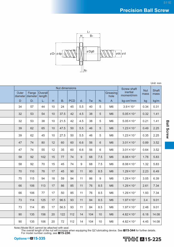
A15-225
Ball Screw
Precision Ball Screw
B1
N1
L1
H
φ D1φ Dg6 φ dc φ dφ dp
Unit: mm
Nut dimensions Screw shaft inertial
moment/mm Nut
mass Shaft mass Outer
diameter Flange
diameter Overall length Greasing
hole D D 1 L 1 H B 1 PCD d 1 Tw N 1 A kg-cm 2 /mm kg kg/m
34 57 44 10 24 45 5.5 40 5 M6 3.9×10 -4 0.34 0.31
32 53 54 10 37.5 42 4.5 38 5 M6 5.05×10 -4 0.32 1.41
32 53 38 10 21.5 42 4.5 38 5 M6 5.05×10 -4 0.21 1.41
39 62 65 10 47.5 50 5.5 46 5 M6 1.23×10 -3 0.49 2.25
39 62 45 10 27.5 50 5.5 46 5 M6 1.23×10 -3 0.35 2.25
47 74 80 12 60 60 6.6 56 6 M6 3.01×10 -3 0.89 3.52
47 74 55 12 35 60 6.6 56 6 M6 3.01×10 -3 0.64 3.52
58 92 102 15 77 74 9 68 7.5 M6 8.08×10 -3 1.78 5.83
58 92 70 15 45 74 9 68 7.5 M6 8.08×10 -3 1.32 5.83
70 110 78 17 45 90 11 80 8.5 M6 1.29×10 -2 2.23 6.49
75 115 94 18 59 94 11 86 9 M6 1.29×10 -2 3.05 6.39
66 106 113 17 86 85 11 76 8.5 M6 1.29×10 -2 2.61 7.34
66 106 77 17 50 85 11 76 8.5 M6 1.29×10 -2 1.93 7.34
73 114 125 17 96.5 93 11 84 8.5 M6 1.97×10 -2 3.4 9.01
73 114 85 17 56.5 93 11 84 8.5 M6 1.97×10 -2 2.48 9.01
90 135 156 20 122 112 14 104 10 M6 4.82×10 -2 6.18 14.08
90 135 106 20 72 112 14 104 10 M6 4.82×10 -2 4.45 14.08
Note) Model BLK cannot be attached with seal. The overall length of the nut will increase when equipping the QZ lubricating device. See A15-344 for further details. For model number coding, see A15-230 .
Options⇒A15-335
511E

A15-226 Download data by searching for the corresponding model number on the Technical Support site. https://tech.thk.com
A(Greasing hole)
4-φ d1
PCD
Tw
30°30°
Model No.
Screw shaft outer diameter
Lead Ball center-to-center diameter
Thread minor
diameter
No. of loaded circuits
Basic load rating Rigidity Ca C 0 a K
d Ph dp dc Rows × turns kN kN N/m WGF 0812-3 8 12 8.4 6.6 2×1.65 2.2 3.9 110 WGF 1015-3 10 15 10.5 8.3 2×1.65 3.3 6.2 140 WGF 1320-3 13 20 13.5 10.8 2×1.65 4.7 9.6 180 WGF 1520-1.5 15 20 15.75 12.5 1×1.5 4.4 7.9 100 WGF 1520-3 15 20 15.75 12.5 2×1.5 8.1 15.8 190 WGF 1530-1 15 30 15.75 12.5 2×0.6 3.5 5.4 90 WGF 1530-3 15 30 15.75 12.5 2×1.6 8.1 14.6 220 WGF 1540-1.5 15 40 15.75 12.5 2×0.75 3.9 7.4 110 WGF 2040-1 20 40 20.75 17.5 2×0.65 4.3 8 110 WGF 2040-3 20 40 20.75 17.5 2×1.65 9.5 20.2 280 WGF 2060-1.5 20 60 20.75 17.5 2×0.75 4.5 11 140 WGF 2550-1 25 50 26 21.9 2×0.65 6.4 12.5 140 WGF 2550-3 25 50 26 21.9 2×1.65 14.3 31.7 340 WGF 3060-1 30 60 31.25 26.4 2×0.65 8.9 18 170 WGF 3060-3 30 60 31.25 26.4 2×1.65 19.9 45.7 410 WGF 3090-1.5 30 90 31.25 26.4 2×0.75 9.7 25.8 200 WGF 4080-1 40 80 41.75 35.2 2×0.65 15 32.1 220 WGF 4080-3 40 80 41.75 35.2 2×1.65 33.4 81.4 530 WGF 50100-1 50 100 52.2 44.1 2×0.65 22.4 50.1 270 WGF 50100-3 50 100 52.2 44.1 2×1.65 49.9 127.2 650
WGF No Preload
DN value 70000
511E

A15-227
Ball Screw
Precision Ball Screw
B1
N1
L1
H
φ D1 φ dc φ dφ dpφ Dg6
Unit: mm
Nut dimensions Screw shaft inertial
moment/mm Nut
mass Shaft mass Outer
diameter Flange
diameter Overall length Greasing
hole D D 1 L 1 H B 1 PCD d 1 Tw N 1 A kg-cm 2 /mm kg kg/m 18 31 27 4 17 25 3.4 20 — — 3.16×10 -5 0.054 0.35 23 40 33 5 22 32 4.5 25 — — 7.71×10 -5 0.11 0.55 28 45 43 5 29 37 4.5 30 — — 2.2×10 -4 0.18 0.96 32 53 45 10 28 43 5.5 33 5 M6 3.9×10 -4 0.29 1.22 32 53 45 10 28 43 5.5 33 5 M6 3.9×10 -4 0.29 1.22 32 53 33 10 17 43 5.5 33 5 M6 3.9×10 -4 0.23 1.26 32 53 63 10 47 43 5.5 33 5 M6 3.9×10 -4 0.38 1.26 32 53 42 10 26.3 43 5.5 33 5 M6 3.9×10 -4 0.28 1.28 37 57 41 10 25 47 5.5 38 5.5 M6 1.23×10 -3 0.24 2.34 37 57 81 10 65 47 5.5 38 5.5 M6 1.23×10 -3 0.48 2.34 37 57 60 10 40.1 47 5.5 38 5 M6 1.23×10 -3 0.4 2.37 45 69 52 12 31.5 57 6.6 46 7 M6 3.01×10 -3 0.43 3.66 45 69 102 12 81.5 57 6.6 46 7 M6 3.01×10 -3 0.85 3.66 55 89 62 15 37 71 9 56 9 M6 6.24×10 -3 1.11 5.28 55 89 122 15 97 71 9 56 9 M6 6.24×10 -3 1.9 5.28 55 89 92 15 61.3 71 9 56 9 M6 6.24×10 -3 1.51 5.34 73 114 79 17 50.5 93 11 74 8.5 M6 1.97×10 -2 2.34 9.38 73 114 159 17 130.5 93 11 74 8.5 M6 1.97×10 -2 4.18 9.38 90 135 98 20 64 112 14 92 10 M6 4.82×10 -2 4.18 14.66 90 135 198 20 164 112 14 92 10 M6 4.82×10 -2 7.63 14.66
Note) Model WGF cannot be attached with seal. The overall length of the nut will increase when equipping the QZ lubricating device. See A15-344 for further details. For model number coding, see A15-230 .
Options⇒A15-335
511E

A15-228 Download data by searching for the corresponding model number on the Technical Support site. https://tech.thk.com
(Greasing hole)
W
W1
N2
B
TF
M(MAX)
A
4-S×ℓ
Model No.
Screw shaft outer diameter
Lead Ball center-to-center diameter
Thread minor
diameter
No. of loaded circuits
Basic load rating Rigidity Ca C 0 a K
d Ph dp dc Rows × turns kN kN N/m BNT 1404-3.6 14 4 14.4 11.5 1×3.65 6.8 12.6 190 BNT 1405-2.6 14 5 14.5 11.2 1×2.65 7.2 12.6 150 BNT 1605-2.6 16 5 16.75 13.5 1×2.65 7.8 14.7 170 BNT 1808-3.6 18 8 19.3 14.4 1×3.65 18.2 34.4 270 BNT 2005-2.6 20 5 20.5 17.2 1×2.65 8.7 18.3 200 BNT 2010-2.6 20 10 21.25 16.4 1×2.65 14.7 27.8 220 BNT 2505-2.6 25 5 25.5 22.2 1×2.65 9.6 23 240 BNT 2510-5.3 25 10 26.8 20.2 2×2.65 43.4 92.8 520 BNT 2806-2.6 28 6 28.5 25.2 1×2.65 10.1 25.8 270 BNT 2806-5.3 28 6 28.5 25.2 2×2.65 18.3 51.6 510 BNT 3210-2.6 32 10 33.75 27.2 1×2.65 27.3 59.5 330 BNT 3210-5.3 32 10 33.75 27.2 2×2.65 49.6 118.9 640 BNT 3610-2.6 36 10 37 30.5 1×2.65 28.7 65.6 360 BNT 3610-5.3 36 10 37 30.5 2×2.65 52.1 131.2 700 BNT 4512-5.3 45 12 46.5 39.2 2×2.65 68.1 186.7 860
BNT (Precision Ball Screw) No Preload
DN value 70000
511E

A15-229
Ball Screw
Precision Ball Screw
φ dc φ d
N1
L1
C
φ dp
Unit: mm
Nut dimensions Screw shaft inertial
moment/mm Nut
mass Shaft mass Outer
diameter Center height
Overall length Mounting hole Greasing
hole D F L 1 B C S×ℓ W 1 T M N 1 N 2 A kg-cm 2 /mm kg kg/m 34 13 35 26 22 M4×7 17 6 30 6 2 M6 2.96×10 ‒4 0.15 0.93 34 13 35 26 22 M4×7 17 6 31 6 2 M6 2.96×10 ‒4 0.15 0.92 42 16 36 32 22 M5×8 21 21.5 32.5 6 2 M6 5.05×10 ‒4 0.3 1.24 48 17 56 35 35 M6×10 24 10 44 8 3 M6 8.09×10 ‒4 0.47 1.46 48 17 35 35 22 M6×10 24 9 39 5 3 M6 1.23×10 ‒3 0.28 2.06 48 18 58 35 35 M6×10 24 9 46 10 2 M6 1.23×10 ‒3 0.5 1.99 60 20 35 40 22 M8×12 30 9.5 45 7 5 M6 3.01×10 ‒3 0.41 3.35 60 23 94 40 60 M8×12 30 10 55 10 — M6 3.01×10 ‒3 1.18 2.79 60 22 42 40 18 M8×12 30 10 50 8 — M6 4.74×10 ‒3 0.81 4.42 60 22 67 40 40 M8×12 30 10 50 8 — M6 4.74×10 ‒3 0.78 4.42 70 26 64 50 45 M8×12 35 12 62 10 — M6 8.08×10 ‒3 1.3 4.98 70 26 94 50 60 M8×12 35 12 62 10 — M6 8.08×10 ‒3 2 4.98 86 29 64 60 45 M10×16 43 17 67 11 — M6 1.29×10 ‒2 1.8 6.54 86 29 96 60 60 M10×16 43 17 67 11 — M6 1.29×10 ‒2 2.4 6.54
100 36 115 75 75 M12×20 50 20.5 80 13 — M6 3.16×10 ‒2 4.1 10.56
Note) The overall length of the nut will increase when equipping the QZ lubricating device. See A15-344 for further details. For model number coding, see A15-230 .
Options⇒A15-335
511E

A15-230
Model Number Coding
Seal symbol(Labyrinth seal attached to both ends)
Symbol for clearance in the axial direction
No. of circuits (Rows × turns)
Threading direction
Lead (in mm)
Screw shaft outer diameter (in mm)
Model number
Accuracy symbol
Overall screw shaft length (in mm)
No symbol: right-hand thread L: left-hand threadRL: Right and left hand thread
A,B: Unfinished Shaft EndsY: Finished Shaft Ends
Symbol for standard-stock type
BIF 25 05 L -5 RR G0 + 620L C5 A
Model number coding
511E

A15-231
Ball Screw
Precision Ball Screw
511E

A15-232
Precision Rotary Ball Screw Models DIR and BLR
Screw shaft
DeflectorBall screw nut
Retainer
Outer ring
Section A
Ball
Screw shaftSpacer
End cap
End cap
CollarSeal
Ball screw nutRetainer
Outer ring
Outer ring
Ball
Ball
Structure of Standard-Lead Rotary Nut Ball Screw Model DIR
Structure of Large Lead Rotary Nut Ball Screw Model BLR
Point of Selection A15-8 Options A15-336 Model No. A15-353 Precautions on Use A15-358 Accessories for Lubrication A24-1 Mounting Procedure and Maintenance B15-104
Accuracy Standards A15-236
Example of Assembly A15-238
Axial Clearance A15-19
Maximum Length of the Screw Shaft A15-24
DN Value A15-33
511E

A15-233
Ball Screw
Precision Rotary Ball Screw
Structure and Features
[Model DIR] Standard-Lead Rotary-Nut Ball Screw model DIR is a rotary-nut Ball Screw that has a struc-ture where a simple-nut Ball Screw is integrated with a support bearing. Its ball screw nut serves as a ball recirculation structure using deflectors. Balls travel along the groove of the defl ector mounted in the ball screw nut to the adjacent raceway, and then circulate back to the loaded area to complete an infi nite rolling motion. Being an offset preload nut, the single ball screw nut provides different phases to the right and left thread in the middle of the nut, thus to set the axial clearance below zero (a preload is provided). This allows more compact, smoother motion to be achieved than the conventional double-nut type (a spacer is inserted between two nuts).
The support bearing comprises of two rows of DB type angular bearings with a contact angle of 45 to provide a preload. The collar, previ-ously used to mount a pulley, is integrated with the ball screw nut. (See the A section.)
45°45°
Fig.1 Structure of the Support Bearing
Compact Because of the internal circulation mechanism using a defl ector, the outer diameter is only 70 to 80%, and the overall length is 60 to 80%, of that of the return-pipe nut, thus to reduce the weight and decrease the inertia during acceleration. Since the nut and the support bearing are integrated, a highly accurate, and a compact design is achieved. In addition, small inertia due to the lightweight ball screw nut ensures high responsiveness.
Capable of Fine Positioning Being a Standard-Lead Ball Screw, it is capable of fi ne positioning despite that the ball screw nut rotates.
Accuracy can Easily be Established As the support bearing is integrated with the outer ring, the bearing can be assembled with the nut housing on the end face of the outer ring fl ange. This makes it easy to center the ball screw nut and establish accuracy.
Well Balanced Since the defl ector is evenly placed along the circumference, a superb balance is ensured while the ball screw nut is rotating.
511E

A15-234
Stability in the Low-speed Range Traditionally, motors tend to have an uneven torque and a speed in the low-speed range due to the external causes. With model DIR, the motor can be connected independently with the screw shaft and the ball screw nut, thus to allow micro feeding within the motor’s stable rotation range.
[Model BLR] The Rotary Ball Screw is a rotary-nut ball screw unit that has an integrated structure consisting of a ball screw nut and a support bearing. The support bearing is an angular bearing that has a contact angle of 60, contains an increased number of balls and achieves large axial rigidity. Model BLR is divided into two types: Precision Ball Screw and Rolled Screw Ball.
Smooth Motion It achieves smoother motion than rack-and-pinion based straight motion.
Low Noise even in High-speed Rotation Model BLR produces very low noise when the balls are picked up along the end cap. In addition, the balls circulate by passing through the ball screw nut, allowing this model to be used at high speed.
High Rigidity The support bearing of this model is larger than that of the screw shaft rotational type. Thus, its axial rigidity is signifi cantly increased.
Compact Since the nut and the support bearing are integrated, a highly accurate, and a compact design is achieved.
Easy Installation By simply mounting this model to the housing with bolts, a ball screw nut rotating mechanism can be obtained. (For the housing’s inner-diameter tolerance, H7 is recommended.)
511E

A15-235
Ball Screw
Precision Rotary Ball Screw
Type
[Preload Type]
Model DIR Specifi cation Table⇒A15-240
[No Preload Type]
Model BLR Specifi cation Table⇒A15-242
511E

A15-236
Accuracy Standards
[Model DIR] The accuracy of model DIR is compliant with a the JIS standard (JIS B 1192-1997) except for the radial runout of the circumference of the ball screw nut from the screw axis (D) and the perpendicu-larity of the fl ange-mounting surface against the screw axis (C).
A
B
C A
D B
Unit: mm
Accuracy grades C3 C5 C7
Model No. C D C D C D
DIR 16□□ 0.013 0.017 0.016 0.020 0.023 0.035
DIR 20□□ 0.013 0.017 0.016 0.020 0.023 0.035
DIR 25□□ 0.015 0.020 0.018 0.024 0.023 0.035
DIR 32□□ 0.015 0.020 0.018 0.024 0.023 0.035
DIR 36□□ 0.016 0.021 0.019 0.025 0.024 0.036
DIR 40□□ 0.018 0.026 0.021 0.033 0.026 0.036
511E

A15-237
Ball Screw
Precision Rotary Ball Screw
[Model BLR] The accuracy of model BLR is compliant with a the JIS standard (JIS B 1192-1997) except for the radial runout of the circumference of the ball screw nut from the screw axis (D) and the perpendicu-larity of the fl ange-mounting surface against the screw axis (C).
A B
C A
D B
Unit: mm
Lead angle accuracy C3 C5 C7 Accuracy grades C3 C5 C7
Model No. C D C D C D BLR 1616 0.013 0.017 0.016 0.020 0.023 0.035 BLR 2020 0.013 0.017 0.016 0.020 0.023 0.035 BLR 2525 0.015 0.020 0.018 0.024 0.023 0.035 BLR 3232 0.015 0.020 0.018 0.024 0.023 0.035 BLR 3636 0.016 0.021 0.019 0.025 0.024 0.036 BLR 4040 0.018 0.026 0.021 0.033 0.026 0.046 BLR 5050 0.018 0.026 0.021 0.033 0.026 0.046
511E

A15-238
Example of Assembly
[Example of Mounting Ball Screw Nut Model DIR]
Installation to the housing can be performed on the end face of the outer ring flange.
[Example of Mounting Ball Screw Nut Model BLR]
Pulley Pulley
Standard installation method Inverted flange Note) If the fl ange is to be inverted, indicate “K” in the model number. (applicable only to model BLR)
Symbol for inverted flange (No symbol for standard flange orientation)Example: BLR 2020-3.6 K UU
[Important note concerning model BLR]
Nut bracket
PulleyOuter ring
Flange
Outer ringPulley
Nut bracketFlangeCorrect Incorrect
φD
H7
φD
Note) Since the outer rings are separable, it is necessary to include an internal diameter tolerance in the nut bracket so that
the outer ring on the side opposite from the fl ange does not shift. (H7 is recommended.)
511E

A15-239
Ball Screw
Precision Rotary Ball Screw
[Example of Mounting Model BLR on the Table] (1) Screw shaft free, ball screw nut fi xed
(Suitable for a long table)
LM Guide
Motor Ball Screw (Model BLR)
Table
Fig.2 Example of Installation on the Table (Ball Screw Nut Fixed)
(2) Ball screw nut free, screw shaft fi xed (Suitable for a short table and a long stroke)
LM Guide
Motor Ball Screw (Model BLR)
Table
Fig.3 Example of Installation on the Table (Screw Shaft Fixed)
511E

Model number coding
A15-240 Download data by searching for the corresponding model number on the Technical Support site. https://tech.thk.com
(60° equidistant)
(60° equidistant)
6-φ d1
6-S×t
P1
P2
Model No.
Screwshaftouter
diameter
Threadminor
diameter
Lead Ballcenter-to-
centerdiameter
Basic loadrating Rigidity
K
Ca C 0 a Outerdiameter
Flangediameter
Overalllength D 3
d dc Ph dp kN kN N/m D D 1 L 1 h7
DIR 1605-6 16 13.2 5 16.75 7.4 13 310 48 64 79 36
DIR 2005-6 20 17.2 5 20.75 8.5 17.3 310 56 72 80 43.5
DIR 2505-6 25
22.2 5 25.75 9.7 22.6 490 66 86 88 52
DIR 2510-4 21.6 10 26 9 18 330 66 86 106 52
DIR 3205-6
32
29.2 5 32.75 11.1 30.2 620 78 103 86 63
DIR 3206-6 28.4 6 33 14.9 37.1 630 78 103 97 63
DIR 3210-6 26.4 10 33.75 25.7 52.2 600 78 103 131 63
DIR 3610-6 36 30.5 10 37.75 28.8 63.8 710 92 122 151 72
DIR 4010-6 40
34.7 10 41.75 29.8 69.3 750 100 130 142 79.5
DIR 4012-6 34.4 12 41.75 30.6 72.3 790 100 130 167 79.5
Seal symbol (*1)
Accuracy symbol (*3)
Overall screw shaft length (in mm)
Symbol for clearance in the axial direction (*2)
Model number
DIR2005-6 RR G0 +520L C1
(*1) See A15-336 . (*2) See A15-19 . (*3) See A15-12 .
DIR With Preload
DN value 70000
511E

A15-241
Ball Screw
Precision Rotary Ball Screw
Options⇒A15-335
B5
H
φ D3φ D1 φ dcφ D2
φ Dg6φ dφ dp
B3
L1
B1
B4
Unit: mm
Ball screw dimensions Supportbearing basic
load rating
Nutinertial
moment Nut
mass Shaftmass
Ca C 0 a
D 2 B 5 B 4 B 3 P 1 P 2 H B 1 S t d 1 kN kN kg-cm 2 kg kg/m
30 8 21 50 56 30 6 15 M4 6 4.5 8.7 10.5 0.61 0.49 1.24
34 9 21 50 64 36 6 15 M5 8 4.5 9.7 13.4 1.18 0.68 2.05
40 13 25 50 75 43 7 18 M6 10 5.5 12.7 18.2 2.65 1.07 3.34
40 11 25 70 75 43 7 18 M6 10 5.5 12.7 18.2 2.84 1.16 3.52
46 11 25 50 89 53 8 17 M6 10 6.6 13.6 22.3 5.1 1.39 5.67
48 11 25 61 89 53 8 17 M6 10 6.6 13.6 22.3 5.68 1.54 5.47
54 11 25 95 89 53 8 17 M6 10 6.6 13.6 22.3 8.13 2.16 4.98
58 14 33 104 105 61 10 23 M8 12 9 20.4 32.3 14.7 3.25 6.51
62 14 33 95 113 67 10 23 M8 12 9 21.5 36.8 20.6 3.55 8.22
62 14 33 120 113 67 10 23 M8 12 9 21.5 36.8 22.5 3.9 8.5
Note) The rigidity values in the table represent spring constants, each obtained from the load and the elastic deformation when providing a preload equal to 10% of the ba-sic axial dynamic load rating (Ca) and applying an axial load three times greater than the pre-load. These values do not include the rigidity of the components related to mounting the ball screw nut. Therefore, it is normally appropriate to regard roughly 80% of the value in the table as the actual value. If the applied preload (Fa 0 ) is not 0.1 Ca, the rigidity value (K N ) is obtained from the following equation.
K: Rigidity value in the dimensional table.
1 3 Fa0
0.1Ca KN=K ( )
511E

Model number coding
A15-242 Download data by searching for the corresponding model number on the Technical Support site. https://tech.thk.com
(60° equidistant)6-φ d1
P1
P2
4-S θ
Model No.
Screwshaftouter
diameter
Threadminor
diameter
Lead Ballcenter-to-
centerdiameter
Basic load rating
Ca C 0 a Outerdiameter
Flangediameter
Overalllength
d dc Ph dp kN kN D D 1 L 1 D 3
BLR 1616-3.6 16 13.7 16 16.65 7.1 14.3 52 0 –0.007 68 43.5 40 0
–0.025
BLR 2020-3.6 20 17.5 20 20.75 11.1 24.7 62 0 –0.007 78 54 50 0
–0.025
BLR 2525-3.6 25 21.9 25 26 16.6 38.7 72 0 –0.007 92 65 58 0
–0.03
BLR 3232-3.6 32 28.3 32 33.25 23.7 59.5 80 0 –0.007 105 80 66 0
–0.03
BLR 3636-3.6 36 31.7 36 37.4 30.8 78 100 0 –0.008 130 93 80 0
–0.03
BLR 4040-3.6 40 35.2 40 41.75 38.7 99.2 110 0 –0.008 140 98 90 0
–0.035
BLR 5050-3.6 50 44.1 50 52.2 57.8 155 120 0 –0.008 156 126 100 0
–0.035
Flange orientation symbol (*1)
Accuracy symbol (*4)
Overall screw shaft length (in mm)
Symbol for clearance in the axial direction (*3)
Symbol for support bearing seal (*2)
Model number
BLR2020-3.6 K UU G1 +1000L C5
(*1) See A15-238 . (*2) UU: Seal attached on both ends No symbol: Without seal. (*3) See A15-19 . (*4) See A15-12 .
BLR (Precision Ball Screw) No Preload
DN value 70000
511E

A15-243
Ball Screw
Precision Rotary Ball Screw
Options⇒A15-335
B5
H
φ D4φ D3φ D1 φ D φ dcφ dφ dp
B4
L1
t
Te
Unit: mm
Ball screw dimensions Supportbearing basic
load rating
Nutinertial
moment Nut
mass Shaftmass
Ca C 0 a
D 4 H B 4 B 5 Te P 1 P 2 S t d 1 kN kN kg-cm 2 kg kg/m
32 +0.025 0 5 27.5 9 2 60 25 M4 12 4.5 40 19.4 19.2 0.48 0.38 1.41
39 +0.025 0 6 34 11 2 70 31 M5 16 4.5 40 26.8 29.3 1.44 0.68 2.25
47 +0.025 0 8 43 12.5 3 81 38 M6 19 5.5 40 28.2 33.3 3.23 1.1 3.52
58 +0.03 0 9 55 14 3 91 48 M6 19 6.6 40 30 39 6.74 1.74 5.83
66 +0.03 0 11 62 17 3 113 54 M8 22 9 40 56.4 65.2 16.8 3.2 7.34
73 +0.03 11 68 16.5 3 123 61 M8 22 9 50 59.3 74.1 27.9 3.95 9.01
90 +0.035 0 12 80 25 4 136 75 M10 28 11 50 62.2 83 58.2 6.22 14.08
511E

A15-244
Permissible Rotational Speeds for Rotary Ball Screws
The permissible rotational speeds for models DIR and BLR and rotary ball screws is restricted to whichever is lower of the support bearing permissible rotational speed, the DN value (70,000) and the critical speed of the screw. When using the product, do not exceed the permissible rotational speed.
Table1 Model DIR permissible rotational speed Unit:min -1
Model No.
Permissible Rotational Speed Ball Screw Unit Support bearing
Calculated using shaft length
Calculated using DN value Grease Lubrication Oil Lubrication
DIR1605
see A15-32 .
4179 4200 5600 DIR2005 3373 3500 4700 DIR2505 2718 2900 3900 DIR2510 2692 2900 3900 DIR3205 2137 2400 3300 DIR3206 2121 2400 3300 DIR3210 2074 2400 3300 DIR3610 1854 2100 2800 DIR4010 1676 1900 2600 DIR4012 1676 1900 2600
Table2 Model BLR permissible rotational speed Unit:min -1
Model No.
Permissible Rotational Speed Ball Screw Unit Support bearing
Calculated using shaft length
Calculated using DN value Grease Lubrication Oil Lubrication
BLR1616
see A15-32 .
4204 4000 5600 BLR2020 3373 3200 4300 BLR2525 2692 2800 3700 BLR3232 2105 2400 3300 BLR3636 1871 2000 2700 BLR4040 1676 1800 2400 BLR5050 1340 1600 2200
511E

A15-245
Ball Screw
Precision Rotary Ball Screw
511E

A15-246
Precision Ball Screw/Spline Models BNS-A, BNS, NS-A and NS
Spline nut
Seal
Seal
Seal
Seal
Shim plate
Shim plate
Outer ring
Outer ring
Outer ring
End cap
Collar Shaft
Outer ring Ball screw nut
Retainer
Retainer
Ball
Ball
Point of Selection A15-8 Options A15-336 Model No. A15-353 Precautions on Use A15-358 Accessories for Lubrication A24-1 Mounting Procedure and Maintenance B15-104
DN Value A15-33
Accuracy Standards A15-249
Action Patterns A15-250
Example of Assembly A15-253
Example of Use A15-254
Precautions on Use A15-255
511E

A15-247
Ball Screw
Precision Ball Screw/Spline
Structure and Features
The Ball Screw/Spline contains the Ball Screw grooves and the Ball Spline groove crossing one another. The nuts of the Ball Screw and the Ball Spline have dedicated support bearings directly embedded on the circumference of the nuts. The Ball Screw/Spline is capable of performing three (rotational, linear and spiral) modes of motion with a single shaft by rotating or stopping the spline nut. It is optimal for machines using a combination of rotary and straight motions, such as scholar robot’s Z-axis, assembly robot, automatic loader, and machining center’s ATC equipment.
[Zero Axial Clearance] The Ball Spline has an angular-contact structure that causes no backlash in the rotational direction, enabling highly accurate positioning.
[Lightweight and Compact] Since the nut and the support bearing are integrated, highly accurate, compact design is achieved. In addition, small inertia because of the lightweight ball screw nut ensures high responsiveness.
[Easy Installation] The Ball Spline nut is designed so that balls do not fall off even if the spline nut is removed from the shaft, making installation easy. The Ball Screw/Spline can easily be mounted simply by securing it to the housing with bolts. (For the housing’s inner-diameter tolerance, H7 is recommended.)
[Smooth Motion with Low Noise] As the Ball Screw is based on an end cap mechanism, smooth motion with low noise is achieved.
[Highly Rigid Support Bearing] The support bearing on the Ball Screw has a contact angle of 60 in the axial direction while that on the Ball Spline has a contact angle of 30 in the moment direction, thus to provide a highly rigid shaft support. In addition, a dedicated rubber seal is attached as standard to prevent entry of foreign materials.
45° 45°
Fig.1 Structure of Support Bearing Model BNS-A
Ball Screw
Ball Spline
(30°)
60°
(30°)60°
Fig.2 Structure of Support Bearing Model BNS
511E

A15-248
Type
[No Preload Type]
Model BNS-A Specifi cation Table⇒A15-256
(Compact type: linear-rotary motion)
Model BNS Specifi cation Table⇒A15-258
(Heavy-load type: linear-rotary motion)
Model NS-A Specifi cation Table⇒A15-260
(Compact type: straight motion)
Model NS Specifi cation Table⇒A15-262
(Heavy-load type: straight motion)
511E

A15-249
Ball Screw
Precision Ball Screw/Spline
Accuracy Standards
The Ball Screw/Spline is manufactured with the following specifi cations.
[Ball Screw] Axial clearance : 0 or less Lead angle accuracy : C5 (For detailed specifi cations, see A15-12 , A15-19 .)
[Ball Spline] Clearance in the rotational direction : 0 or less (CL: light preload) (For detailed specifi cations, see A3-30 .) Accuracy grade : class H (For detailed specifi cations, see A3-34 .)
Model NS Model BNS
Spline nut Ball screw nut
Spline nut Ball screw nut
A B
H A
I B A B
C A E A
D B F B
Unit: mm
Model No. C D E F H I
BNS 0812 NS 0812 0.014 0.017 0.014 0.016 0.010 0.013
BNS 1015 NS 1015 0.014 0.017 0.014 0.016 0.010 0.013
BNS 1616 NS 1616 0.018 0.021 0.016 0.020 0.013 0.016
BNS 2020 NS 2020 0.018 0.021 0.016 0.020 0.013 0.016
BNS 2525 NS 2525 0.021 0.021 0.018 0.024 0.016 0.016
BNS 3232 NS 3232 0.021 0.021 0.018 0.024 0.016 0.016
BNS 4040 NS 4040 0.025 0.025 0.021 0.033 0.019 0.019
BNS 5050 NS 5050 0.025 0.025 0.021 0.033 0.019 0.019
511E
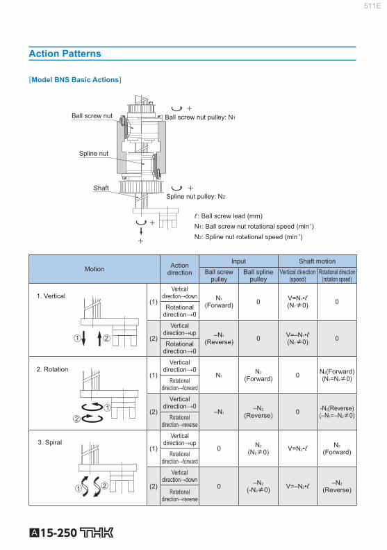
A15-250
Action Patterns
[Model BNS Basic Actions]
ℓ : Ball screw lead (mm)N1: Ball screw nut rotational speed (min‐1)
Ball screw nut Ball screw nut pulley: N1
Spline nut
Spline nut pulley: N2
N2: Spline nut rotational speed (min-1)
Shaft +
+
+
+
Motion Action direction
Input Shaft motion Ball screw
pulley Ball spline
pulley Vertical direction
(speed) Rotational direction
(rotation speed)
1. Vertical
1 2
(1)
Vertical direction→down N 1
(Forward) 0 V=N 1 •ℓ (N 1 ≠0) 0
Rotational direction→0
(2)
Vertical direction→up –N 1
(Reverse) 0 V=–N 1 •ℓ (N 1 ≠0) 0
Rotational direction→0
2. Rotation
1
2
(1)
Vertical direction→0
N 1 N 2 (Forward) 0 N 2 (Forward)
(N 1 =N 2 ≠0) Rotational direction→forward
(2)
Vertical direction→0
–N 1 –N 2 (Reverse) 0 -N 2 (Reverse)
(–N 1 = –N 2 ≠0) Rotational direction→reverse
3. Spiral
1 2
(1)
Vertical direction→up
0 N 2 (N 2 ≠0) V=N 2 •ℓ N 2
(Forward) Rotational direction→forward
(2)
Vertical direction→down
0 –N 2 (-N 2 ≠0) V=–N 2 •ℓ –N 2
(Reverse) Rotational direction→reverse
511E

A15-251
Ball Screw
Precision Ball Screw/Spline
[Model NS Basic Actions]
ℓ : Ball screw lead (mm)
N1: Ball screw nut rotational speed (min‐1)
Ball screw nut Ball screw nut pulley: N1
Spline nut
Shaft
+
+
Motion Action direction Input Shaft motion
Ball screw pulley Vertical direction(speed)
1. Vertical
1 2
(1)
Vertical direction→down
N 1 (Forward)
V=N 1 •ℓ (N 1 ≠0)
(2)
Vertical direction→up
–N 1 (Reverse)
V=–N 1 •ℓ (N 1 ≠0)
511E

A15-252
[Model BNS Extended Actions]
Motion Action direction
Input Shaft motion Ball screw
pulley Ball spline
pulley Vertical direction
(speed) Rotational direction(rotational speed)
→up→down→reverse 1. Up→down→forward
1
3
6
5 2 4
(1) Vertical direction→up
–N 1 (Reverse) 0 V=–N 1 •ℓ
(N 1 ≠0) 0
(2) Vertical direction→down
N 1 (Forward) 0 V=N 1 •ℓ
(N 1 ≠0) 0
(3) Rotational direction→forward N 1 N 2
(Forward) 0 N 2 (Forward) (N 1 =N 2 ≠0)
(4) Vertical direction→up –N 1 0 V=–N 1 •ℓ
(N 1 ≠0) 0
(5) Vertical direction→down N 1 0 V=N 1 •ℓ
(N 1 ≠0) 0
(6) Rotational direction→reverse –N 1 –N 2
(Reverse) 0 -N 2 (Reverse) (–N 1 =N 2 ≠0)
→down→up→reverse 2. Down→up→forward
3
6
4 2 5 1
(1) Vertical direction→down N 1 0 V=N 1 •ℓ
(N 1 ≠0) 0
(2) Vertical direction→up –N 1 0 V=–N 1 •ℓ
(N 1 ≠0) 0
(3) Rotational direction→forward N 1 N 2 0 N 2
(N 1 =N 2 ≠0)
(4) Vertical direction→down N 1 0 V=N 1 •ℓ
(N 1 ≠0) 0
(5) Vertical direction→up –N 1 0 V=–N 1 •ℓ
(N 1 ≠0) 0
(6) Rotational direction→reverse –N 1 –N 2 0 –N 2
(–N 1 =N 2 ≠0)
→up→reverse 3. Down→forward
1 3 2
4
(1) Vertical direction→down N 1 0 V=N 1 •ℓ
(N 1 ≠0) 0
(2) Rotational direction→forward N 1 N 2 0 N 2
(N 1 =N 2 ≠0)
(3) Vertical direction→up –N 1 0 V=–N 1 •ℓ
(N 1 ≠0) 0
(4) Rotational direction→reverse –N 1 –N 2 0 –N 2
(–N 1 =N 2 ≠0)
→reverse→forward 4. Down→up
1 3 2
4
(1) Vertical direction→down N 1 0 V=N 1 •ℓ
(N 1 ≠0) 0
(2) Vertical direction→up –N 1 0 V=–N 1 •ℓ
(N 1 ≠0) 0
(3) Rotational direction→reverse –N 1 –N 2 0 –N 2
(–N 1 =N 2 ≠0)
(4) Rotational direction→forward N 1 N 2 0 N 2
(N 1 =N 2 ≠0)
511E

A15-253
Ball Screw
Precision Ball Screw/Spline
Example of Assembly
Seal
Seal
Support bearing
Support bearing Ball screw nut
Shaft Spline nut
Pulley
Pulley
�Example of installing the ball screw nut pulley inside the housing.
�Example of installing the ball screw nut input pulley and the spline nut input pulley, both outside the housing. The housing length is minimized.
Fig.3 Example of Assembling Model BNS
Seal
ShaftSpline nut
Pulley
Support bearing
Ball screw nut
�Example of installing the ball screw nut pulley outside the housing. The housing length is minimized.
�Example of installing the ball screw nut pulley inside the housing.
Fig.4 Example of Assembling Model NS
511E

A15-254
Example of Use
Ball screw input motor
Spline input motor
Spline nut
Chuck
Stro
ke
Stro
ke
Ball screw nut
Shaft
Pulley
Pulley
Support bearing
Fig.5 Example of Using Model BNS
511E

A15-255
Ball Screw
Precision Ball Screw/Spline
Precautions on Use
[Lubrication] When lubricating the Ball Screw/Spline, attach the greasing plate to the housing in advance.
Greasing plate Grease nipple
Housing
Fig.6 Lubrication Methods
511E
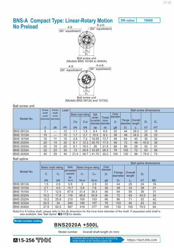
Model number coding
A15-256 Download data by searching for the corresponding model number on the Technical Support site. https://tech.thk.com
Ball screw unit
(Models BNS 0812A and 1015A)
(60° equidistant)(90° equidistant)
(90° equidistant)(90° equidistant)
Ball screw unit(Models BNS 1616A to 4040A)
6-φ d14-S
4-φ d14-S
P1P2
P1
P2
Ball screw unit
Model No.
Screwshaftouter
diameter
Screwshaftinner
diameter
Lead Ball screw dimensions Basic load rating Ball
center-to-centerdiameter
Threadminor
diameter
Outerdiameter
Ca C 0 a Flangediameter
Overalllength D 3 D 4 D
d db Ph kN kN dp dc g6 D 1 L 1 h7 H7 BNS 0812A 8 — 12 1.1 1.8 8.4 6.6 32 44 28.5 22 19 BNS 1015A 10 — 15 1.7 2.7 10.5 8.3 36 48 34.5 26 23 BNS 1616A 16 11 16 3.9 7.2 16.65 13.7 48 64 40 36 32 BNS 2020A 20 14 20 6.1 12.3 20.75 17.5 56 72 48 43.5 39 BNS 2525A 25 18 25 9.1 19.3 26 21.9 66 86 58 52 47 BNS 3232A 32 23 32 13 29.8 33.25 28.3 78 103 72 63 58 BNS 4040A 40 29 40 21.4 49.7 41.75 35.2 100 130 88 79.5 73
Ball spline
Model No.
Ball spline dimensions Basic load rating Static
permissiblemoment
Basic torque rating Outerdiameter
C C 0 C T C 0T D 7 Flangediameter
Overall length D 6
M A N-m kN kN N-m N-m g6 D 5 L 2 h7 BE 1
BNS 0812A 1.5 2.6 5.9 2 2.9 32 44 25 24 16 BNS 1015A 2.7 4.9 15.7 3.9 7.8 36 48 33 28 21 BNS 1616A 7.1 12.6 67.6 31.4 34.3 48 64 50 36 31 BNS 2020A 10.2 17.8 118 56.8 55.8 56 72 63 43.5 35 BNS 2525A 15.2 25.8 210 105 103 66 86 71 52 42 BNS 3232A 20.5 34 290 180 157 78 103 80 63 52 BNS 4040A 37.8 60.5 687 418 377 100 130 100 79.5 64 Note) For K hollow shaft, please refer to the db dimension for the inner bore diameter of the shaft. If requested solid shaft is
also available. See “Ball Spline” A3-112 for details.
Overall shaft length (in mm)Model number
BNS2020A +500L
BNS-A Compact Type: Linear-Rotary Motion No Preload
DN value 70000
511E

A15-257
Ball Screw
Precision Ball Screw/Spline
Options⇒A15-335
Unit: mm
Supportbearing basic
load rating
Nut inertial
moment
Screw shaftinertial
moment/mm Nut
mass Shaftmass
Ca C 0 a
BE H B 4 B 5 Te P 1 P 2 S t d 1 kN kN kg-cm 2 J kg-cm 2 /mm kg kg/m 19 3 10.5 7 1.5 38 14.5 M2.6 10 3.4 0.8 0.5 0.03 3.16×10 –5 0.08 0.35 23 3 10.5 8 1.5 42 18 M3 11.5 3.4 0.9 0.7 0.08 7.71×10 –5 0.15 0.52 32 6 21 10 2 56 25 M4 13.5 4.5 8.7 10.5 0.35 3.92×10 –4 0.31 0.8 39 6 21 11 2.5 64 31 M5 16.5 4.5 9.7 13.4 0.85 9.37×10 –4 0.54 1.21 47 7 25 13 3 75 38 M6 20 5.5 12.7 18.2 2.12 2.2×10 –3 0.88 1.79 58 8 25 14 3 89 48 M6 21 6.6 13.6 22.3 5.42 5.92×10 –3 1.39 2.96 73 10 33 16.5 3 113 61 M8 24.5 9 21.5 36.8 17.2 1.43×10 –2 3.16 4.51
Unit: mm
Support bearingbasic load rating
Nut inertialmoment
Nutmass
C C 0
H 1 B 6 B 7 H 2 P 3 P 4 S 1 ×t 1 d S1 kN kN kg-cm 2 kg 3 10.5 6 3 38 19 M2.6×3 3.4 0.6 0.2 0.03 0.08 3 10.5 9 — 42 23 M3×4 3.4 0.8 0.3 0.08 0.13 6 21 10 — 56 30 M4×6 4.5 6.7 6.4 0.44 0.35 6 21 12 — 64 36 M5×8 4.5 7.4 7.8 0.99 0.51 7 25 13 — 75 44 M5×8 5.5 9.7 10.6 2.2 0.79 8 25 17 — 89 54 M6×10 6.6 10.5 12.5 5.17 1.25
10 33 20 — 113 68 M6×10 9 16.5 20.7 16.1 2.51
(60° equidistant)(60° equidistant)
(90° equidistant)(90° equidistant)
Ball spline(Models BNS 1616A to 4040A)
Ball spline(Models BNS 1616A to 4040A)
Ball screw unit(Models BNS 0812A to 4040A)
Ball spline(Models BNS 0812A and 1015A)
Ball spline(Model BNS 1015A)
Ball spline(Model BNS 0812A)
6-S1×t16-φ dS1
4-φ dS14-S1×t1
P4
P3
L1
B5 B4
Ht
Te
φ D1φ D3φ D4
φ BE φ Dφ D7φ BE1
φ D5φ D6φ d
L2
B6B7
H1
φ dbφ dp
L2
B6B7
H1
φ D7 φ BE1
H2
φ D6φ D5
L2
B6 B7
φ D6φ D5
H1
φ D7 φ BE1
P4
P3
511E

Model number coding
A15-258 Download data by searching for the corresponding model number on the Technical Support site. https://tech.thk.com
(60° equidistant)
Ball screw unit
6-φ d1
4-S
P1
P2
θ
Ball screw unit
Model No.
Screwshaftouter
diameter
Screwshaftinner
diameter
Lead Ball screw dimensions Basic load
rating Ballcenter-
to-centerdiameter
Threadminor
diameter
Ca C 0 a Outer
diameter Flange
diameter Overalllength D 3
d db Ph kN kN dp dc D D 1 L 1 h7 BNS 1616 16 11 16 3.9 7.2 16.65 13.7 52 0
–0.007 68 43.5 40 BNS 2020 20 14 20 6.1 12.3 20.75 17.5 62 0
–0.007 78 54 50 BNS 2525 25 18 25 9.1 19.3 26 21.9 72 0
–0.007 92 65 58 BNS 3232 32 23 32 13 29.8 33.25 28.3 80 0
–0.007 105 80 66 BNS 4040 40 29 40 21.4 49.7 41.75 35.2 110 0
–0.008 140 98 90 BNS 5050 50 36 50 31.8 77.6 52.2 44.1 120 0
–0.008 156 126 100
Ball spline
Model No.
Ball spline dimensions Basic load rating Static
permissiblemoment
Basic torque rating
C C 0 C T C 0T Outerdiameter
Flangediameter
Overalllength
kN kN M A N-m N-m N-m D 7 D 5 L 2
BNS 1616 7.1 12.6 67.6 31.4 34.3 52 0 –0.007 68 50
BNS 2020 10.2 17.8 118 56.8 55.8 56 0 –0.007 72 63
BNS 2525 15.2 25.8 210 105 103 62 0 –0.007 78 71
BNS 3232 20.5 34 290 180 157 80 0 –0.007 105 80
BNS 4040 37.8 60.5 687 418 377 100 0 –0.008 130 100
BNS 5050 60.9 94.5 1340 842 768 120 0 –0.008 156 125
Note) Dimension U indicates the length from the head of the hexagonal-socket-head type bolt to the ball screw nut end. For K hollow shaft, please refer to the db dimension for the inner bore diameter of the shaft. If requested solid shaft is also available. See “Ball Spline” A3-112 for details.
Overall shaft length (in mm)Model number
BNS2525 +600L
BNS Heavy Load Type: Linear-Rotary Motion No Preload
DN value 70000
511E

A15-259
Ball Screw
Precision Ball Screw/Spline
Options⇒A15-335
(60° equidistant)
Note) U
Ball screw unit Ball splineBall spline
6-S1×t1 6-φ dS1
P3
L1 B5 B4
H t
Te
φ D1 φ D3 φ D4 φ D φ D7 φ dφD6φD5
L2
B6 B7
H1
φ dbφ dp
P4
Unit: mm
Supportbearing basic
load rating
Nutinertial
moment
Screw shaftinertial
moment/mm Nut
mass Shaftmass
D 4 Ca C 0 a
H7 H B 4 B 5 Te P 1 P 2 S t d 1 kN kN kg-cm 2 J kg-cm 2 /mm kg kg/m 32 5 27.5 9 2 60 25 M4 12 4.5 40 19.4 19.2 0.48 3.92×10 –4 0.38 0.8 39 6 34 11 2 70 31 M5 16 4.5 40 26.8 29.3 1.44 9.37×10 –4 0.68 1.21 47 8 43 12.5 3 81 38 M6 19 5.5 40 28.2 33.3 3.23 2.2×10 –3 1.1 1.79 58 9 55 14 3 91 48 M6 19 6.6 40 30 39 6.74 5.92×10 –3 1.74 2.96 73 11 68 16.5 3 123 61 M8 22 9 50 59.3 74.1 27.9 1.43×10 –2 3.95 4.51 90 12 80 25 4 136 75 M10 28 11 50 62.2 83 58.2 3.52×10 –2 6.22 7.16
Unit: mm
Support bearingbasic load rating
Nut inertialmoment
Nutmass
D 6 C C 0
h7 H 1 B 6 B 7 P 3 P 4 S 1 ×t 1 d S1 U kN kN kg-cm 2 kg
39.5 5 37 10 60 32 M5×8 4.5 5 12.7 11.8 0.52 0.51 43.5 6 48 12 64 36 M5×8 4.5 7 16.2 15.5 0.87 0.7 53 6 55 13 70 45 M6×8 4.5 8 17.6 18 1.72 0.93
65.5 9 60 17 91 55 M6×10 6.6 10 20.1 24 5.61 1.8 79.5 11 74 23 113 68 M6×10 9 13 37.2 42.5 14.7 3.9 99.5 12 97 25 136 85 M10×15 11 13 41.6 54.1 62.5 6.7
511E

Model number coding
A15-260 Download data by searching for the corresponding model number on the Technical Support site. https://tech.thk.com
Ball screw unit
(Models NS 0812A and 1015A)
Ball screw unit(Models NS 1616A to 4040A)
(60° equidistant)(90° equidistant)
(90° equidistant)(90° equidistant)
6-φ d14-S
4-φ d14-S
P1P2
P1
P2
Ball screw unit
Model No.
Screwshaftouter
diameter
Screwshaftinner
diameter
Lead Ball screw dimensions Basic load
rating Ball
center-to-centerdiameter
Threadminor
diameter
Outerdiameter
Ca C 0 a D Flangediameter
Overalllength D 3 D 4
d db Ph kN kN dp dc g6 D 1 L 1 h7 H7 NS 0812A 8 — 12 1.1 1.8 8.4 6.6 32 44 28.5 22 19 NS 1015A 10 — 15 1.7 2.7 10.5 8.3 36 48 34.5 26 23 NS 1616A 16 11 16 3.9 7.2 16.65 13.7 48 64 40 36 32 NS 2020A 20 14 20 6.1 12.3 20.75 17.5 56 72 48 43.5 39 NS 2525A 25 18 25 9.1 19.3 26 21.9 66 86 58 52 47 NS 3232A 32 23 32 13 29.8 33.25 28.3 78 103 72 63 58 NS 4040A 40 29 40 21.4 49.7 41.75 35.2 100 130 88 79.5 73 Ball spline
Model No.
Ball spline dimensions Basic load rating Static
permissiblemoment
Basic torque rating
C C 0 C T C 0T Outerdiameter
Flangediameter
kN kN M A N-m N-m N-m D 7 D 5 0
–0.2
NS 0812A 1.5 2.6 5.9 2 2.9 16 0 –0.011 32
NS 1015A 2.8 4.9 15.7 3.9 7.8 21 0 –0.013 42
NS 1616A 7.1 12.6 67.6 31.4 34.3 31 0 –0.013 51
NS 2020A 10.2 17.8 118 56.8 55.8 35 0 –0.016 58
NS 2525A 15.2 25.8 210 105 103 42 0 –0.016 65
NS 3232A 20.5 34 290 180 157 49 0 –0.016 77
NS 4040A 37.8 60.5 687 418 377 64 0 –0.019 100
Note) For K hollow shaft, please refer to the db dimension for the inner bore diameter of the shaft. If requested solid shaft is also available. See “Ball Spline” A3-112 for details.
Overall shaft length (in mm)Model number
NS2020A +500L
NS-A Compact Type: Linear Motion No Preload
DN value 70000
511E

A15-261
Ball Screw
Precision Ball Screw/Spline
Options⇒A15-335
Unit: mm
Supportbearing basic
load rating
Nutinertial
moment
Screw shaftinertial
moment/mm Nut
mass Shaftmass
Ca C 0 a
BE H B 4 B 5 Te P 1 P 2 S t d 1 kN kN kg-cm 2 J kg-cm 2 /mm kg kg/m 19 3 10.5 7 1.5 38 14.5 M2.6 10 3.4 0.8 0.5 0.03 3.16×10 –5 0.08 0.35 23 3 10.5 8 1.5 42 18 M3 11.5 3.4 0.9 0.7 0.08 7.71×10 –5 0.15 0.52 32 6 21 10 2 56 25 M4 13.5 4.5 8.7 10.5 0.35 3.92×10 –4 0.31 0.8 39 6 21 11 2.5 64 31 M5 16.5 4.5 9.7 13.4 0.85 9.37×10 –4 0.54 1.21 47 7 25 13 3 75 38 M6 20 5.5 12.7 18.2 2.12 2.2×10 –3 0.88 1.79 58 8 25 14 3 89 48 M6 21 6.6 13.6 22.3 5.42 5.92×10 –3 1.39 2.96 73 10 33 16.5 3 113 61 M8 24.5 9 21.5 36.8 17.2 1.43×10 –2 3.16 4.51
Unit: mm
Nutmass Mounting hole
Overalllength Greasing
hole
L 2 H 1 B 6 r d 0 P 3 d S1 d 2 h kg
25 5 7.5 0.5 1.5 24 3.4 6.5 3.3 0.04 33 6 10.5 0.5 1.5 32 4.5 8 4.4 0.09 50 0
–0.2 7 18 0.5 2 40 4.5 8 4.4 0.23 63 0
–0.2 9 22.5 0.5 2 45 5.5 9.5 5.4 0.33 71 0
–0.3 9 26.5 0.5 3 52 5.5 9.5 5.4 0.45 80 0
–0.3 10 30 0.5 3 62 6.6 11 6.5 0.58 100 0
–0.3 14 36 0.5 4 82 9 14 8.6 1.46
Ball spline(Models NS 0812A and 1015A)
Ball spline(Models NS 0812A and 1015A)
Ball screw unit(Models NS 0812A and 1015A)
4-φ dS1 through hole, φ d2 counter bore depth h
(90° equidistant)
4-φ dS1 through hole, φ d2 counter bore depth h
(90° equidistant)
Ball spline(Models NS 1616A to 4040A)
Ball screw unit(Models NS 1616A to 4040A)
Ball spline(Models NS 1616A to 4040A)
45°45°
P3
45°45°
P3
L1B5 B4
Ht
Te
φ D1φ D3
φ D3
φ D4
φ D4
φ BEφ Dφ D7
φ D5φ d
L2
B6 H1
φ dbφ dp
φ dpφ D1 φ D5
L2B6 H1
φ D7
r
3-φ d0
2-φ d0
rφ Dφ BE
φ d
Tet
HB5 B4
L1
511E

Model number coding
A15-262 Download data by searching for the corresponding model number on the Technical Support site. https://tech.thk.com
(60° equidistant)
Ball screw unit
6-φ d1
4-S
P1
P2
θ
Ball screw unit
Model No.
Screwshaft outer
diameter
Screwshaftinner
diameter
Lead Ball screw dimensions Basic load
rating Ball
center-to-centerdiameter
Threadminor
diameter
Ca C 0 a Outerdiameter
Flangediameter
Overalllength D 3
d db Ph kN kN dp dc D D 1 L 1 h7 NS 1616 16 11 16 3.9 7.2 16.65 13.7 52 0
–0.007 68 43.5 40 NS 2020 20 14 20 6.1 12.3 20.75 17.5 62 0
–0.007 78 54 50 NS 2525 25 18 25 9.1 19.3 26 21.9 72 0
–0.007 92 65 58 NS 3232 32 23 32 13 29.8 33.25 28.3 80 0
–0.007 105 80 66 NS 4040 40 29 40 21.4 49.7 41.75 35.2 110 0
–0.008 140 98 90 NS 5050 50 36 50 31.8 77.6 52.2 44.1 120 0
–0.008 156 126 100
Ball spline
Model No.
Ball spline dimensions Basic load rating Static
permissiblemoment
Basic torque rating
C C 0 C T C 0T Outerdiameter
kN kN M A N-m N-m N-m D 7
NS 1616 7.1 12.6 67.6 31.4 34.3 31 0 –0.013
NS 2020 10.2 17.8 118 56.9 55.9 35 0 –0.016
NS 2525 15.2 25.8 210 105 103 42 0 –0.016
NS 3232 20.5 34 290 180 157 49 0 –0.016
NS 4040 37.8 60.5 687 419 377 64 0 –0.019
NS 5050 60.9 94.5 1340 842 769 80 0 –0.019
Note) For K hollow shaft, please refer to the db dimension for the inner bore diameter of the shaft. If requested solid shaft is also available. See “Ball Spline” A3-112 for details.
Overall shaft length (in mm)Model number
NS2525 +600L
NS Heavy Load Type: Linear Motion No Preload
DN value 70000
511E

A15-263
Ball Screw
Precision Ball Screw/Spline
Options⇒A15-335
4-φ dS1 through hole, φ d2 counter bore depth h
(90° equidistant)
Ball screw unit Ball splineBall spline
L1
B5 B4
H t
Te
φ D φ D7
L2
B6 H1
φ dbφ dpφ D4φ D3φ D1
45°45°
P3
r
φ D5φ d
3-φ d0
Unit: mm
Supportbearing basic
load rating
Nutinertial
moment
Screw shaftinertial
moment/mm Nut
mass Shaftmass
D 4 Ca C 0 a
H7 H B 4 B 5 Te P 1 P 2 S t d 1 kN kN kg-cm 2 J kg-cm 2 /mm kg kg/m 32 5 27.5 9 2 60 25 M4 12 4.5 40 19.4 19.2 0.48 3.92×10 –4 0.38 0.8 39 6 34 11 2 70 31 M5 16 4.5 40 26.8 29.3 1.44 9.37×10 –4 0.68 1.21 47 8 43 12.5 3 81 38 M6 19 5.5 40 28.2 33.3 3.23 2.2×10 –3 1.1 1.79 58 9 55 14 3 91 48 M6 19 6.6 40 30 39 6.74 5.92×10 –3 1.74 2.96 73 11 68 16.5 3 123 61 M8 22 9 50 59.3 74.1 27.9 1.43×10 –2 3.95 4.51 90 12 80 25 4 136 75 M10 28 11 50 62.2 83 58.2 3.52×10 –2 6.22 7.16
Unit: mm
Nutmass Mounting hole
Flangediameter
Overalllength Greasing
hole
D 5 L 2 H 1 B 6 r d 0 P 3 d S1 d 2 h kg
51 50 0 –0.2 7 18 0.5 2 40 4.5 8 4.4 0.23
58 63 0 –0.2 9 22.5 0.5 2 45 5.5 9.5 5.4 0.33
65 71 0 –0.3 9 26.5 0.5 3 52 5.5 9.5 5.4 0.45
77 80 0 –0.3 10 30 0.5 3 62 6.6 11 6.5 0.58
100 100 0 –0.3 14 36 0.5 4 82 9 14 8.6 1.46
124 125 0 –0.3 16 46.5 1 4 102 11 17.5 11 2.76
511E

A15-264
Rolled Ball Screw Models JPF, BTK-V, MTF, WHF, BLK/WTF, CNF and BNT
Point of Selection A15-8 Options A15-336 Model No. A15-353 Precautions on Use A15-358 Accessories for Lubrication A24-1 Mounting Procedure and Maintenance B15-104
Lead Angle Accuracy A15-11
Accuracy of the Mounting Surface A15-14
Axial Clearance A15-19
Maximum Length of the Screw Shaft A15-24
DN Value A15-33
Support Unit A15-300
Recommended Shapes of Shaft Ends A15-308
Dimensions of Each Model with an Option Attached A15-344
511E

A15-265
Ball Screw
Rolled Ball Screw
Structure and Features
THK Rolled Ball Screws are low priced feed screws that use a screw shaft rolled with high accuracy and specially surface-ground, instead of a thread-ground shaft used in the Precision Ball Screws. The ball raceways of the ball screw nut are all thread-ground, thus to achieve a smaller axial clear-ance and smoother motion than the conventional rolled ball screw. In addition, a wide array of types are offered as standard in order to allow optimal products to be se-lected according to the application.
[Achieves Lead Angle Accuracy of Class C7] Screw shafts with travel distance error of classes C7 and C8 are also manufactured as the standard in addition to class C10 to meet a broad range of applications. Travel distance C7 : 0.05/300 (mm) C8 : 0.10/300 (mm) C10 : 0.21/300 (mm) (For maximum length of screw shaft by accuracy grade, see A15-25 .)
[Achieves Roughness of the Ball Raceways of the Screw Shaft at 0.20 a or Less] The surface of the screw shaft’s ball raceways is specially ground after the shaft is rolled to ensure surface roughness of 0.20 a or less, which is equal to that of the ground thread of the Precision Ball Screw.
[The Ball Raceways of the Ball Screw Nut are Finished by Grinding] THK finishes the ball raceways of Rolled Ball Screw nuts by grinding, just as the Precision Ball Screws, to secure the durability and the smooth motion.
[Low Price] The screw shaft is induction-hardened or carburized after being rolled, and its surface is then spe-cially ground. This allows the rolled Ball Screw to be priced lower than the Precision Ball Screw with a ground thread.
[Effects of high levels of dustproofi ng] The ball screw nut is incorporated with a compact labyrinth seal or a brush seal. This achieves low friction, high dust-prevention effect and a longer service life of the Ball Screw.
511E

A15-266
Types and Features
[Preload Type]
Model JPF Specifi cation Table⇒A15-270 This model achieves zero-backlash through a constant preloading method by shifting the phase, with the central part of the nut as a spring structure. The constant preload method allows the ball screw to absorb a pitch error and achieve a smooth motion.
Axial clearance: 0 or less
Direction of applied load The direction of the applied load during use must be in the recommended loading direction indicated in the fi gure. If a load is applied in the opposite direction, it may cause the spring structure to frac-ture, and therefore, the applied load must be 0.1 × Ca or less during use.
Appliedpreload
Appliedpreload
Spring structureRecommended loading direction
[No Preload Type]
Model BTK-V Specifi cation Table⇒A15-272 This Rolled Ball Screw feed achieves a DN value of 100,000 by using a new circulation structure. Since the nut outer diameter and the mount-ing holes of this model are dimensionally in-terchangeable with the previous model BTK, model BTK can be replaced with this model.
511E

A15-267
Ball Screw
Rolled Ball Screw
Model MTF Specifi cation Table⇒A15-274 A miniature type with a screw shaft diameter of 6 to 12 mm and a lead of 1 to 2 mm.
Model WHF Specifi cation Table⇒A15-275 This Ball Screw for high-speed feed achieves a DN value of 100,000 by using a new circulation structure. Since the nut outer diameter and the mount-ing holes of this model are dimensionally in-terchangeable with the previous model WTF, model WTF can be replaced with this model. (WHF1530, WHF2040 and WHF2550)
Models BLK/WTF Specifi cation Table⇒A15-276 Using an end-cap method, these models achieve stable motion in a high-speed rotation.
511E

A15-268
Model CNF Specifi cation Table⇒A15-282 With a combination of 4 rows of large-lead load-ed grooves and a long nut, a long service life is achieved.
Square Ball Screw Nut Model BNT Specifi cation Table⇒A15-280 Since the mounting screw holes are machined on the square ball screw nut, this model can compactly be mounted on the machine without a housing.
511E

A15-269
Ball Screw
Rolled Ball Screw511E

A15-270 Download data by searching for the corresponding model number on the Technical Support site. https://tech.thk.com
(Greasing hole)
PCD
A
60°
Model No.
Screw shaft outer
diameter
Lead Ball center-
to-center diameter
Thread minor
diameter
No. of loaded circuits
Basic load rating
Ca C 0 a Outer diameter
Flange diameter
Outer diameter
d Ph dp dc Rows × turns kN kN D D 1 D 2
JPF 1404-4 14
4 14.4 11.5 2×1 2.8 5.1 26 46 25.5 JPF 1405-4 5 14.5 11.2 2×1 3.9 8.6 26 46 25.5 JPF 1605-4 16 5 16.75 13.5 2×1 3.7 8.2 30 49 29.5 JPF 2005-6 20 5 20.5 17.2 3×1 6 16 34 57 33.5 JPF 2505-6
25 5 25.5 22.2 3×1 6.9 20.8 40 66 39.5
JPF 2510-4 10 26.8 20.2 2×1 11.4 24.5 47 72 46.5 JPF 2805-6
28 5 28.75 25.2 3×1 7.3 23.9 43 69 42.5
JPF 2806-6 6 28.5 25.2 3×1 7.3 23.9 43 69 42.5 JPF 3210-6 32 10 33.75 27.2 3×1 19.3 49.9 54 88 53.5 JPF 3610-6 36 10 37 30.5 3×1 20.6 56.2 58 98 57.5
JPF 4010-6 40 10 41.75 35.2 3×1 22.2 65.3 62 104 61.5
Seal symbol (*1)
Symbol for clearance in the axial direction
Accuracy symbol (*2)
Overall screw shaft length (in mm)
Symbol for rolled shaftModel No.
JPF1404-4 RR G0 +500L C7 T
(*1) See A15-336 . (*2) See A15-12 .
Model number coding
JPF With Preload
DN value 50000
511E

A15-271
Ball Screw
Rolled Ball Screw
Options⇒A15-335
φ d2
B1
(B2)
φ D1 φ dp
φ d1
φ dc
h
H
φDg6φ d
L1
φD2
Unit: mm
Nut dimensions Screw shaft inertial
moment/mm Nut
mass Shaft mass Overall
length Greasing
hole
L 1 H B 1 B 2 PCD d 1 ×d 2 ×h A kg-cm 2 /mm kg kg/m 52 10 42 16.5 36 4.5×8×4.5 M6 2.96×10 -4 0.22 1 60 10 50 20 36 4.5×8×4.5 M6 2.96×10 -4 0.24 0.99 60 10 50 19.5 39 4.5×8×4.5 M6 5.05×10 -4 0.3 1.34 80 11 69 26.5 45 5.5×9.5×5.5 M6 1.23×10 -3 0.46 2.15 80 11 69 26 51 5.5×9.5×5.5 M6 3.01×10 -3 0.6 3.45 112 12 100 42 58 6.6×11×6.5 M6 3.01×10 -3 1.2 3.26 80 12 68 25 55 6.6×11×6.5 M6 4.74×10 -3 0.66 4.27 90 12 78 35 55 6.6×11×6.5 M6 4.74×10 -3 0.72 4.44
135 15 120 53.5 70 9×14×8.5 M6 8.08×10 -3 1.84 5.49 138 18 120 53.5 77 11×17.5×11 M6 1.29×10 -2 2.22 6.91
138 18 120 53.5 82 11×17.5×11 R1/8 (PT1/8) 1.97×10 -2 2.42 8.81
Note) The ball screw nut and the screw shaft of model JPF are not sold separately. The basic load rating corresponds to the recommended loading direction. If a load is applied in the opposite direction, the value must be 0.1×Ca or less during use (see A15-266 ).
511E

A15-272 Download data by searching for the corresponding model number on the Technical Support site. https://tech.thk.com
Tw
PCD
4-φ d1
30°30°
Model No.
Screw shaft outer
diameter
Lead Ball center-
to-center diameter
Thread minor
diameter
No. of loaded circuits
Basic load rating Rigidity
Ca C 0 a K Outer diameter
Flange diameter
Overall length
d Ph dp dc Rows × turns kN kN N/m D D 1 L 1 H BTK 1006V-2.6 10 6 10.5 7.8 1×2.65 2.8 4.9 88 26 42 36 8 BTK 1208V-2.6 12 8 12.65 9.7 1×2.65 3.8 6.8 108 29 45 44 8 BTK 1404V-3.6 14 4 14.4 11.5 1×3.65 5.5 11.5 150 31 50 40 10 BTK 1405V-2.6 14 5 14.5 11.2 1×2.65 5 11.4 116 32 50 40 10 BTK 1605V-2.6 16 5 16.75 13.5 1×2.65 5.4 13.3 130 34 54 40 10 BTK 1808V-3.6 18 8 19.3 14.4 1×3.65 13.1 31 210 50 80 61 12 BTK 2005V-2.6 20 5 20.5 17.2 1×2.65 6 16.5 150 40 60 40 10 BTK 2010V-2.6 20 10 21.25 16.4 1×2.65 10.6 25.1 160 52 82 61 12 BTK 2505V-2.6 25 5 25.5 22.2 1×2.65 6.7 20.8 180 43 67 40 10 BTK 2510V-5.3 25 10 26.8 20.2 2×2.65 31.2 83.7 400 60 96 98 15 BTK 2806V-2.6 28 6 28.5 25.2 1×2.65 7 23.4 200 50 80 47 12 BTK 2806V-5.3 28 6 28.5 25.2 2×2.65 12.8 46.8 390 50 80 65 12 BTK 3210V-2.6 32 10 33.75 27.2 1×2.65 19.8 53.8 250 67 103 68 15 BTK 3210V-5.3 32 10 33.75 27.2 2×2.65 36 107.5 490 67 103 98 15 BTK 3610V-2.6 36 10 37 30.5 1×2.65 20.8 59.8 270 70 110 70 17 BTK 3610V-5.3 36 10 37 30.5 2×2.65 37.8 118.7 530 70 110 100 17 BTK 4010V-5.3 40 10 41.75 35.2 2×2.65 40.3 134.9 590 76 116 100 17 BTK 4512V-5.3 45 12 46.5 39.2 2×2.65 49.5 169 650 82 128 118 20
BTK 5016V-5.3 50 16 52.7 42.9 2×2.65 93.8 315.2 930 102 162 145 25
Recommended shaft ends shape code
Contamination protection accessory symbol (*1)
Accuracy symbol(*2)
Overall screw shaft length (in mm)
Symbol for rolled shaft
Model No.
BTK1405V-2.6 ZZ +500L C7 T H1K
(*1) See A15-336 . (*2) See A15-12 .
BTK-V No Preload
DN value 100000
Model number coding
511E

A15-273
Ball Screw
Rolled Ball Screw
Options⇒A15-335
A (Greasing hole)
φ D1 φ dp
H
L1
B1
φ dc φ d φ Dg6
N1
Unit: mm
Nut dimensions Screw shaft inertial
moment/mm Nut
mass Shaft mass Greasing
hole Axial clear-ance
Standard shaft length
B 1 PCD d 1 Tw N 1 A kg-cm 2 /mm kg kg/m 28 34 4.5 29 — 3 0.05 200, 300, 500, 1000 7.71×10 -5 0.12 0.48 36 37 4.5 32 — 3 0.05 200, 300, 500, 1000 1.6×10 -4 0.18 0.72 30 40 4.5 37 5 M6 0.1 500, 1000 2.96×10 -4 0.23 1 30 40 4.5 38 5 M6 0.1 500, 1000 2.96×10 -4 0.22 0.99 30 44 4.5 40 5 M6 0.1 500, 1000, 1500 5.05×10 -4 0.24 1.34 49 65 6.6 60 5 M6 0.1 500, 1000, 1500 8.09×10 -4 0.84 1.71 30 50 4.5 46 5 M6 0.1 500, 1000, 1500, 2000 1.23×10 -3 0.32 2.15 49 67 6.6 64 5 M6 0.1 500, 1000, 1500, 2000 1.23×10 -3 0.93 2.16 30 55 5.5 50 5 M6 0.1 500, 1000, 1500, 2000 3.01×10 -3 0.34 3.45 83 78 9 72 5 M6 0.1 500, 1000, 1500, 2000 3.01×10 -3 1.83 3.26 35 65 6.6 60 6 M6 0.1 500, 1000, 2000, 2500 4.74×10 -3 0.59 4.44 53 65 6.6 60 6 M6 0.1 500, 1000, 2000, 2500 4.74×10 -3 0.75 4.44 53 85 9 78 5 M6 0.14 500, 1000, 1500, 2000, 2500, 3000 8.08×10 -3 1.56 5.49 83 85 9 78 5 M6 0.14 500, 1000, 1500, 2000, 2500, 3000 8.08×10 -3 2.1 5.49 53 90 11 82 7 M6 0.17 500, 1000, 2000, 2500, 3000 1.29×10 -2 1.78 6.91 83 90 11 82 7 M6 0.17 500, 1000, 2000, 2500, 3000 1.29×10 -2 2.35 6.91 83 96 11 88 7 M6 0.17 1000, 1500, 2000, 2500, 3000, 3500 1.97×10 -2 2.6 8.81 98 104 14 94 8 M6 0.17 1000, 1500, 2000, 3000, 3500, 4000 3.16×10 -2 3.48 11.08
120 132 18 104 12.5 R1/8 (PT1/8) 0.2 1000, 1500, 2000, 3000,
3500, 4000 4.82×10 -2 6.52 13.66
Note) The overall length of the nut will increase when equipping the QZ lubricating device. See A15-344 for further details.
511E

A15-274 Download data by searching for the corresponding model number on the Technical Support site. https://tech.thk.com
Tw
PCD
2-φ d1
L1
H
φ D1
B1
φ dcφ dp φ d φ D
Unit: mm
Model No.
Screw shaft outer diameter
Lead Ball center-to-center diameter
Thread minor
diameter
No. of loaded circuits
Basic load rating Rigidity Nut dimensions
Ca C 0 a K Outer diameter
Flange diameter
Overall length
d Ph dp dc Rows × turns kN kN N/m D D 1 L 1 MTF 0601-3.7 6 1 6.15 5.3 1×3.7 0.7 1.2 70 13 30 21 MTF 0802-3.7 8 2 8.3 6.6 1×3.7 2.1 3.8 90 20 40 28 MTF 1002-3.7 10 2 10.3 8.6 1×3.7 2.3 4.8 110 23 43 28 MTF 1202-3.7 12 2 12.3 10.6 1×3.7 2.5 5.8 130 25 47 30
Model No.
Nut dimensions Screw shaft inertial
moment/mm Nut
mass Shaft mass Axial
clear-ance
Standard shaft length
H B 1 PCD d 1 Tw kg-cm 2 /mm kg kg/m MTF 0601-3.7 5 16 21.5 3.4 17 0.05 150, 250 9.99×10 -6 0.03 0.19 MTF 0802-3.7 6 22 30 4.5 24 0.05 150, 250 3.16×10 -5 0.08 0.31 MTF 1002-3.7 6 22 33 4.5 27 0.05 200, 300 7.71×10 -5 0.1 0.52 MTF 1202-3.7 8 22 36 5.5 29 0.05 200, 300 1.6×10 -4 0.13 0.77
Note) Model MTF cannot be attached with seal. Model MTF is only sold as sets (ball screw nut and screw shaft). Model MTF is applied only with anti-rust oil.
Accuracy code: (No code for Normal Grade)
Overall screw shaft length (in mm)
Symbol for rolled shaftModel No.
MTF 0802-3.7 +250L C7 T
MTF No Preload
DN value 50000
Model number coding
511E

A15-275
Ball Screw
Rolled Ball Screw
Options⇒A15-335
(Greasing hole)
4-φ d1
PCD
Tw
30°30°B1
N1
L1M1 M1
H
φ D1φ Dg6 φ dc φ dφ dp
A
Unit: mm
Model No.
Screw shaft outer
diameter
Lead Ball center-
to-center diameter
Thread minor
diameter
No. of loaded circuits
Basic load rating Rigidity Nut dimensions
Ca C 0 a K Outer diameter
Flange diameter
Overall length
d Ph dp dc Rows × turns kN kN N/m D D 1 L 1 H B 1 WHF 1530-3.4 15 30 15.75 12.5 2×1.7 5.5 12.2 195 32 53 64.5 10 47.5 WHF 2020-3.4 20 20 20.75 17.5 2×1.7 6.6 18.9 225 42 64 47.1 10 24.1 WHF 2040-3.4 20 40 20.75 17.5 2×1.7 6.6 17.2 256 37 62 82.7 10 65.7 WHF 2525-3.4 25 25 26 21.9 2×1.7 10.5 29.9 285 50 77 58.8 12 31.3 WHF 2550-3.4 25 50 26 21.9 2×1.7 10.4 27.1 323 45 69 103.3 12 79.3
Model No.
Nut dimensions Screw shaft inertial
moment/mm Nut
mass Shaft mass Greasing
hole Seal Axial clear-ance
Standard shaft length
PCD d 1 Tw N 1 A M 1 kg-cm 2 /mm kg kg/m WHF 1530-3.4 43 5.5 33 5 M6 3.5 0.1 500, 1000, 1500 3.9×10 -4 0.38 1.26 WHF 2020-3.4 53 5.5 46 5 M6 3.5 0.1 500, 1000, 1500 1.23×10 -3 0.49 2.25 WHF 2040-3.4 50 5.5 46 5 M6 3.5 0.1 500, 1000, 1500, 2000 1.23×10 -3 0.58 2.34 WHF 2525-3.4 63 6.6 56 6 M6 3.5 0.1 1000, 1500, 2000 3.01×10 -3 0.65 3.52 WHF 2550-3.4 57 6.6 46 6 M6 3.5 0.1 1000, 1500, 2000 3.01×10 -3 0.72 3.66
Note) WHF is available on a made-to-order basis. If planning to use this model, contact THK. The overall length of the nut will increase when equipping the QZ lubricating device. See A15-344 for further details.
Contamination protection accessory symbol (*1)
Accuracy symbol (*2)
Overall screw shaft length (in mm)
Symbol for rolled shaft
Recommended shaft ends shape code
Model No.
WHF2040-3.4 -ZZ +1500L C7 T T1K
(*1) See A15-336 . (*2) See A15-12 .
WHF (Rolled Ball Screw) No Preload
DN value 100000
Model number coding
511E

A15-276 Download data by searching for the corresponding model number on the Technical Support site. https://tech.thk.com
(Greasing hole)
30° 30°
ATw
PCD
4-φ d1
Model No.
Screw shaft outer
diameter
Lead Ball center-
to-center diameter
Thread minor
diameter
No. of loaded circuits
Basic load rating Rigidity
Ca C 0 a K Outer diameter
Flange diameter
Overall length
d Ph dp dc Rows × turns kN kN N/m D D 1 L 1 H BLK 1510-5.6 15 10 15.75 12.5 2×2.8 9.8 25.2 260 34 57 44 10 BLK 1616-3.6 16 16 16.65 13.7 2×1.8 5.8 12.9 170 32 53 38 10 BLK 1616-7.2 16 16 16.65 13.7 4×1.8 10.5 25.9 340 32 53 38 10 BLK 2020-3.6 20 20 20.75 17.5 2×1.8 7.7 22.3 210 39 62 45 10 BLK 2020-7.2 20 20 20.75 17.5 4×1.8 13.9 44.6 410 39 62 45 10 BLK 2525-3.6 25 25 26 21.9 2×1.8 12.1 35 270 47 74 55 12 BLK 2525-7.2 25 25 26 21.9 4×1.8 21.9 69.9 520 47 74 55 12 BLK 3232-3.6 32 32 33.25 28.3 2×1.8 17.3 53.9 330 58 92 70 15 BLK 3232-7.2 32 32 33.25 28.3 4×1.8 31.3 107.8 650 58 92 70 15 BLK 3620-5.6 36 20 37.75 31.2 2×2.8 39.8 121.7 570 70 110 78 17 BLK 3624-5.6 36 24 38 30.7 2×2.8 46.2 137.4 590 75 115 94 18 BLK 3636-3.6 36 36 37.4 31.7 2×1.8 22.4 70.5 370 66 106 77 17 BLK 3636-7.2 36 36 37.4 31.7 4×1.8 40.6 141.1 730 66 106 77 17 BLK 4040-3.6 40 40 41.75 35.2 2×1.8 28.1 89.8 420 73 114 85 17 BLK 4040-7.2 40 40 41.75 35.2 4×1.8 51.1 179.6 810 73 114 85 17 BLK 5050-3.6 50 50 52.2 44.1 2×1.8 42.1 140.4 510 90 135 106 20 BLK 5050-7.2 50 50 52.2 44.1 4×1.8 76.3 280.7 1000 90 135 106 20
Contamination protection accessory symbol (*1)
Accuracy symbol (*2)
Overall screw shaft length (in mm)
Symbol for rolled shaft
Recommended shaft ends shape code
Model No.
BLK3232-3.6 ZZ +1500L C7 T H1K
(*1) See A15-336 . (*2) See A15-12 .
BLK (Rolled Ball Screw) No Preload
DN value 70000
Model number coding
511E

A15-277
Ball Screw
Rolled Ball Screw
Options⇒A15-335
φ dp φ dφ dcφ Dg6φ D1
HM1M1 L1
N1
B1
Unit: mm
Nut dimensions Screw shaft inertial
moment/mm Nut
mass Shaft mass Greasing
hole Seal Axial clear-ance
Standard shaft length
B 1 PCD d 1 Tw N 1 A M 1 kg-cm 2 /mm kg kg/m 24 45 5.5 40 5 M6 3.5 0.1 500, 1000 3.9×10 -4 0.26 1.16
21.5 42 4.5 38 5 M6 3.5 0.1 500, 1000, 1500 5.05×10 -4 0.21 1.35 21.5 42 4.5 38 5 M6 3.5 0.1 500, 1000, 1500 5.05×10 -4 0.25 1.35 27.5 50 5.5 46 5 M6 3.5 0.1 500, 1000, 1500 1.23×10 -3 0.35 2.18 27.5 50 5.5 46 5 M6 3.5 0.1 500, 1000, 1500 1.23×10 -3 0.35 2.18 35 60 6.6 56 6 M6 3.5 0.1 500, 1000, 1500, 2000, 2500 3.01×10 -3 0.64 3.41 35 60 6.6 56 6 M6 3.5 0.1 500, 1000, 1500, 2000, 2500 3.01×10 -3 0.64 3.41 45 74 9 68 7.5 M6 3.8 0.14 1000, 1500, 2000, 2500, 3000 8.08×10 -3 1.14 5.69 45 74 9 68 7.5 M6 3.8 0.14 1000, 1500, 2000, 2500, 3000 8.08×10 -3 1.14 5.69 45 90 11 80 8.5 M6 5 0.17 1000, 1500, 2000, 2500, 3000 1.29×10 -2 1.74 7.09 59 94 11 86 9 M6 5 0.17 1000, 1500, 2000, 2500, 3000 1.29×10 -2 2.42 7.02 50 85 11 76 8.5 M6 5 0.17 1000, 1500, 2000, 2500, 3000 1.29×10 -2 1.74 7.12 50 85 11 76 8.5 M6 5 0.17 1000, 1500, 2000, 2500, 3000 1.29×10 -2 1.74 7.12
56.5 93 11 84 8.5 M6 5.4 0.17 1000, 1500, 2000, 2500, 3000, 4000 1.97×10 -2 2.16 8.76 56.5 93 11 84 8.5 M6 5.4 0.17 1000, 1500, 2000, 2500, 3000, 4000 1.97×10 -2 2.16 8.76 72 112 14 104 10 M6 5.4 0.2 1000, 1500, 2000, 3000, 4000 4.82×10 -2 3.89 13.79 72 112 14 104 10 M6 5.4 0.2 1000, 1500, 2000, 3000, 4000 4.82×10 -2 3.86 13.79
Note) The overall length of the nut will increase when equipping the QZ lubricating device. See A15-344 for further details.
511E

A15-278 Download data by searching for the corresponding model number on the Technical Support site. https://tech.thk.com
(Greasing hole)
4-φ d1
PCD
Tw
30°30°
A
Model No.
Screw shaft outer
diameter
Lead Ball center-
to-center diameter
Thread minor
diameter
No. of loaded circuits
Basic load rating Rigidity
Ca C 0 a K Outer diameter
Flange diameter
Overall length
d Ph dp dc Rows × turns kN kN N/m D D 1 L 1 H WTF 1520-3 15 20 15.75 12.5 2×1.5 5.5 14.2 140 32 53 45 10 WTF 1520-6 15 20 15.75 12.5 4×1.5 10.1 28.5 280 32 53 45 10 WTF 1530-2 15 30 15.75 12.5 4×0.6 4.3 9.3 120 32 53 33 10 WTF 1530-3 15 30 15.75 12.5 2×1.6 5.6 12.4 160 32 53 63 10 WTF 2040-2 20 40 20.75 17.5 4×0.65 5.4 13.6 160 37 57 41.5 10 WTF 2040-3 20 40 20.75 17.5 2×1.65 6.6 17.2 200 37 57 81.5 10 WTF 2550-2 25 50 26 21.9 4×0.65 8.5 21.2 200 45 69 52 12 WTF 2550-3 25 50 26 21.9 2×1.65 10.4 26.9 260 45 69 102 12 WTF 3060-2 30 60 31.25 26.4 4×0.65 11.8 30.6 240 55 89 62.5 15 WTF 3060-3 30 60 31.25 26.4 2×1.65 14.5 38.9 310 55 89 122.5 15 WTF 4080-2 40 80 41.75 35.2 4×0.65 19.8 54.5 320 73 114 79 17 WTF 4080-3 40 80 41.75 35.2 2×1.65 24.3 69.2 400 73 114 159 17 WTF 50100-2 50 100 52.2 44.1 4×0.65 29.6 85.2 390 90 135 98 20 WTF 50100-3 50 100 52.2 44.1 2×1.65 36.3 108.1 500 90 135 198 20
Contamination protection accessory symbol (*1)
Accuracy symbol (*2)
Overall screw shaft length (in mm)
Symbol for rolled shaft
Recommended shaft ends shape code
Model No.
WTF3060-3 ZZ +1500L C7 T H1K
(*1) See A15-336 . (*2) See A15-12 .
WTF No Preload
DN value 70000
Model number coding
511E
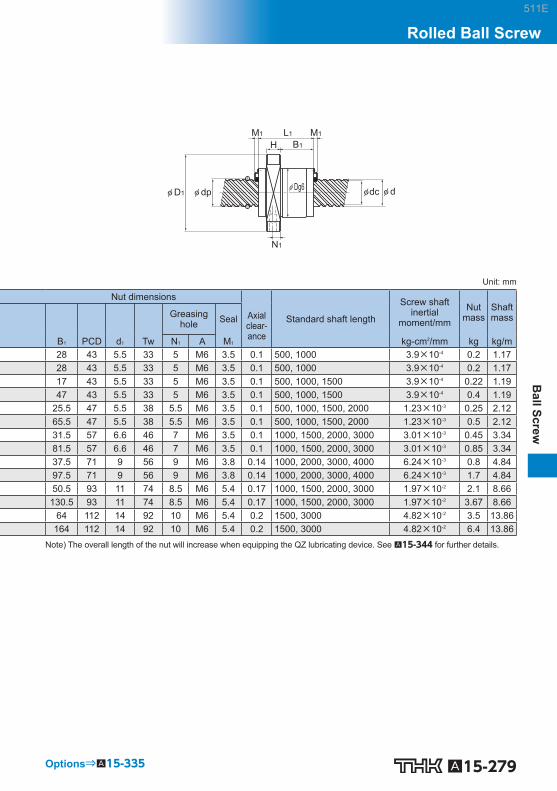
A15-279
Ball Screw
Rolled Ball Screw
Options⇒A15-335
B1
N1
L1M1 M1
H
φ D1φ Dg6 φ dc φ dφ dp
Unit: mm
Nut dimensions Screw shaft inertial
moment/mm Nut
mass Shaft mass Greasing
hole Seal Axial clear-ance
Standard shaft length
B 1 PCD d 1 Tw N 1 A M 1 kg-cm 2 /mm kg kg/m 28 43 5.5 33 5 M6 3.5 0.1 500, 1000 3.9×10 -4 0.2 1.17 28 43 5.5 33 5 M6 3.5 0.1 500, 1000 3.9×10 -4 0.2 1.17 17 43 5.5 33 5 M6 3.5 0.1 500, 1000, 1500 3.9×10 -4 0.22 1.19 47 43 5.5 33 5 M6 3.5 0.1 500, 1000, 1500 3.9×10 -4 0.4 1.19
25.5 47 5.5 38 5.5 M6 3.5 0.1 500, 1000, 1500, 2000 1.23×10 -3 0.25 2.12 65.5 47 5.5 38 5.5 M6 3.5 0.1 500, 1000, 1500, 2000 1.23×10 -3 0.5 2.12 31.5 57 6.6 46 7 M6 3.5 0.1 1000, 1500, 2000, 3000 3.01×10 -3 0.45 3.34 81.5 57 6.6 46 7 M6 3.5 0.1 1000, 1500, 2000, 3000 3.01×10 -3 0.85 3.34 37.5 71 9 56 9 M6 3.8 0.14 1000, 2000, 3000, 4000 6.24×10 -3 0.8 4.84 97.5 71 9 56 9 M6 3.8 0.14 1000, 2000, 3000, 4000 6.24×10 -3 1.7 4.84 50.5 93 11 74 8.5 M6 5.4 0.17 1000, 1500, 2000, 3000 1.97×10 -2 2.1 8.66
130.5 93 11 74 8.5 M6 5.4 0.17 1000, 1500, 2000, 3000 1.97×10 -2 3.67 8.66 64 112 14 92 10 M6 5.4 0.2 1500, 3000 4.82×10 -2 3.5 13.86
164 112 14 92 10 M6 5.4 0.2 1500, 3000 4.82×10 -2 6.4 13.86 Note) The overall length of the nut will increase when equipping the QZ lubricating device. See A15-344 for further details.
511E

A15-280 Download data by searching for the corresponding model number on the Technical Support site. https://tech.thk.com
(Greasing hole)
W
W1
N2
B
TF
M(MAX)
A
4-S×ℓ
Model No.
Screw shaft outer
diameter
Lead Ball center-
to-center diameter
Thread minor
diameter
No. of loaded circuits
Basic load rating Rigidity
Ca C 0 a K Width Center height
Overall length
d Ph dp dc Rows × turns kN kN N/m W F L 1 BNT 1404-3.6
14 4 14.4 11.5 1×3.65 5.5 11.5 150 34 13 35
BNT 1405-2.6 5 14.5 11.2 1×2.65 5 11.4 110 34 13 35 BNT 1605-2.6 16 5 16.75 13.5 1×2.65 5.4 13.3 130 42 16 36 BNT 1808-3.6 18 8 19.3 14.4 1×3.65 13.1 31 210 48 17 56 BNT 2005-2.6
20 5 20.5 17.2 1×2.65 6 16.5 150 48 17 35
BNT 2010-2.6 10 21.25 16.4 1×2.65 10.6 25.1 160 48 18 58 BNT 2505-2.6
25 5 25.5 22.2 1×2.65 6.7 20.8 180 60 20 35
BNT 2510-5.3 10 26.8 20.2 2×2.65 31.2 83.7 400 60 23 94 BNT 2806-2.6
28 6 28.5 25.2 1×2.65 7 23.4 200 60 22 42
BNT 2806-5.3 28.5 25.2 2×2.65 12.8 46.8 390 60 22 67 BNT 3210-2.6
32 10 33.75 27.2 1×2.65 19.8 53.8 250 70 26 64
BNT 3210-5.3 33.75 27.2 2×2.65 36 107.5 490 70 26 94 BNT 3610-2.6
36 10 37 30.5 1×2.65 20.8 59.3 270 86 29 64
BNT 3610-5.3 37 30.5 2×2.65 37.8 118.7 530 86 29 96 BNT 4512-5.3 45 12 46.5 39.2 2×2.65 49.5 169 650 100 36 115
Contamination protection accessory symbol (*1)
Model No.
Accuracy symbol (*2)
Overall screw shaft length (in mm)
Symbol for rolled shaft
Recommended shaft ends shape code
BNT2010-2.6 ZZ +1000L C7 T H1K
(*1) See A15-336 . (*2) See A15-12 .
BNT (Rolled Ball Screw) No Preload
DN value 50000
Model number coding
511E

A15-281
Ball Screw
Rolled Ball Screw
φ dc φ d
N1
L1
C
φ dp
Unit: mm
Nut dimensions Screw shaft inertial
moment/mm Nut
mass Shaft mass Mounting hole Axial
clear-ance B C S×ℓ W 1 T M N 1 N 2 A kg-cm 2 /mm kg kg/m
26 22 M4×7 17 6 30 6 2 M6 0.1 2.96×10 -4 0.15 1 26 22 M4×7 17 6 31 6 2 M6 0.1 2.96×10 -4 0.15 0.99 32 22 M5×8 21 21.5 32.5 6 2 M6 0.1 5.05×10 -4 0.3 1.34 35 35 M6×10 24 10 44 8 3 M6 0.1 8.09×10 -4 0.47 1.71 35 22 M6×10 24 9 39 5 3 M6 0.1 1.23×10 -3 0.28 2.15 35 35 M6×10 24 9 46 10 2 M6 0.1 1.23×10 -3 0.5 2.16 40 22 M8×12 30 9.5 45 7 5 M6 0.1 3.01×10 -3 0.41 3.45 40 60 M8×12 30 10 55 10 — M6 0.1 3.01×10 -3 1.18 3.26 40 18 M8×12 30 10 50 8 — M6 0.1 4.74×10 -3 0.81 4.44 40 40 M8×12 30 10 50 8 — M6 0.1 4.74×10 -3 0.78 4.44 50 45 M8×12 35 12 62 10 — M6 0.14 8.08×10 -3 1.3 5.49 50 60 M8×12 35 12 62 10 — M6 0.14 8.08×10 -3 2 5.49 60 45 M10×16 43 17 67 11 — M6 0.17 1.29×10 -2 1.8 6.91 60 60 M10×16 43 17 67 11 — M6 0.17 1.29×10 -2 2.4 6.91 75 75 M12×20 50 20.5 80 13 — M6 0.2 3.16×10 -2 4.1 11.08
Note) The overall length of the nut will increase when equipping the QZ lubricating device. See A15-344 for further details.
Options⇒A15-335
511E

A15-282 Download data by searching for the corresponding model number on the Technical Support site. https://tech.thk.com
(Greasing hole)
6-φ d1
PCD
A
30°30° B1
N1
L1M1 M1
H
φ D1φ Dg6 φ dc φ dφ dp
Unit: mm
Model No.
Screw shaft outer
diameter
Lead Ball center-
to-center diameter
Thread minor
diameter
No. of loaded circuits
Basic load rating Rigidity Nut dimensions
Ca C 0 a K Outer diameter
Flange diameter
Overall length
d Ph dp dc Rows × turns kN kN N/m D D 1 L 1 H B 1 CNF 1530-6 15 30 15.75 12.5 4×1.6 10.1 24.7 310 32 53 63 10 47 CNF 2040-6 20 40 20.75 17.5 4×1.65 12 34.4 400 37 57 81 10 65 CNF 2550-6 25 50 26 21.9 4×1.65 18.9 53.9 460 45 69 102 12 81.5 CNF 3060-6 30 60 31.25 26.4 4×1.65 26.2 77.7 600 55 89 122 15 97
Model No.
Nut dimensions Screw shaft inertial
moment/mm Nut
mass Shaft mass Greasing
hole Seal Axial clear-ance
Standard shaft length
PCD d 1 N 1 A M 1 kg-cm 2 /mm kg kg/m CNF 1530-6 43 5.5 5 M6 3.5 0.1 500, 1000, 1500 3.9×10 -4 0.42 1.19 CNF 2040-6 47 5.5 5.5 M6 3.5 0.1 500, 1000, 1500, 2000 1.23×10 -4 0.5 2.12 CNF 2550-6 57 6.6 7 M6 3.5 0.1 1000, 1500, 2000, 3000 3.01×10 -3 0.85 3.34 CNF 3060-6 71 9 9 M6 3.8 0.14 1000, 2000, 3000, 4000 6.24×10 -3 1.7 4.84
Note) The overall length of the nut will increase when equipping the QZ lubricating device. See A15-344 for further details.
Contamination protection accessory symbol (*1)
Accuracy symbol (*2)
Overall screw shaft length (in mm)
Symbol for rolled shaft
Recommended shaft ends shape code
Model No.
CNF2040-6 ZZ +1500L C7 T H1K
(*1) See A15-336 . (*2) See A15-12 .
CNF No Preload
DN value 70000
Model number coding
511E

Model number coding
A15-283
Ball Screw
Rolled Ball Screw
Model Number Coding
Model number
Model number
Ball Screw Nut
Screw Shaft
Combination of the Ball Screw Nut and the Screw Shaft
Screw shaft outer diameter (in mm)
Lead (in mm)
Overall screw shaft length (in mm)
Accuracy symbol (see ) (no symbol for class C10)
Symbol for rolled ball screw shaft
Overall screw shaft length (in mm)
Accuracy symbol (see ) (no symbol for class C10)
Symbol for rolled shaft
Seal symbolno symbol: without sealZZ: brush seal attached to both ends of the ball screw nut (see )
Seal symbolno symbol: without sealZZ: brush seal attached to both ends of the ball screw nut (see )
Model number
Rolled Ball Screw model JPF
Seal symbolno symbol: without sealRR: Labyrinth seal attached to both ends of the ball screw nut (see )
Accuracy symbol (see ) (no symbol for class C10)
Overall screw shaft length (in mm)
Axial clearance symbol
Symbol for rolled shaft
BTK1405V-2.6 ZZ
TS 14 05 +500L C7
BTK1405V-2.6 ZZ +500L C7 T
JPF1404-4 RR G0 +500L C7 T
A15-336
A15-336
A15-12
A15-12
A15-336
A15-12
511E

A15-284
Standard Unfi nished Shaft Ends Rolled Ball Screw Model MTF
Point of Selection A15-8 Options A15-336 Model No. A15-353 Precautions on Use A15-358 Accessories for Lubrication A24-1 Mounting Procedure and Maintenance B15-104
Accuracy of the Mounting Surface A15-14
DN Value A15-33
Support Unit A15-300
Recommended Shapes of Shaft Ends A15-308
511E
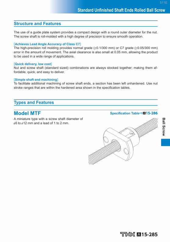
A15-285
Ball Screw
Standard Unfi nished Shaft Ends Rolled Ball Screw
Structure and Features
The use of a guide plate system provides a compact design with a round outer diameter for the nut. The screw shaft is roll-molded with a high degree of precision to ensure smooth operation.
[Achieves Lead Angle Accuracy of Class C7] The high-precision roll molding provides normal grade (0.1/300 mm) or C7 grade (0.05/300 mm) error in the amount of movement. The axial clearance is also small at 0.05 mm, allowing the product to be used in a wide range of applications.
[Quick delivery, low cost] Nut and screw shaft (standard sized) combinations are always stocked together; making them af-fordable, quick, and easy to deliver.
[Simple shaft end machining] To facilitate additional machining of screw shaft ends, a section has been left unhardened. Use nut stroke ranges that are within the hardened area shown in the specifi cation tables.
Types and Features
Model MTF Specifi cation Table⇒A15-286 A miniature type with a screw shaft diameter of 6 to 12 mm and a lead of 1 to 2 mm.
511E

Model number coding
A15-286 Download data by searching for the corresponding model number on the Technical Support site. https://tech.thk.com
Tw
PCD
2-φ d1
Model No.
Screwshaftouter
diameter
Lead Ballcenter-to-
centerdiameter
Threadminor
diameter
No. ofloadedcircuits
Basic load rating Rigidity
Ca C 0 a K Outer diameter
Flange diameter
d Ph dp dc Rows×turns kN kN N/m D D 1
MTF 0601-3.7 6 1 6.15 5.3 1×3.7 0.7 1.2 70 13 30
MTF 0802-3.7 8 2 8.3 6.6 1×3.7 2.1 3.8 90 20 40
MTF 1002-3.7 10 2 10.3 8.6 1×3.7 2.3 4.8 110 23 43
MTF 1202-3.7 12 2 12.3 10.6 1×3.7 2.5 5.8 130 25 47
Overall shaft length (in mm)
Lead (in mm)
Screw shaft outer diameter (in mm)
Model No. Symbol for ball screw shaft
Accuracy symbol (No symbol for Normal Grade)
MTF 08 02 -3.7 +250L C7 T
Note) Model MTF is only sold as sets (ball screw nut and screw shaft). Model MTF is applied only with anti-rust oil.
MTF (Unfi nished Shaft Ends)No Preload
DN value 50000
511E

A15-287
Ball Screw
Standard Unfi nished Shaft Ends Rolled Ball Screw
Hardened area : ℓ1(annealing range)
L1
L0
H
φ D1 φ dpφ dcφ d
B1
-0.05 -0.10 φ D
Unit: mm
Nut dimensions Axial
clearance
Standard shaft length
Screw shaft inertial
moment/mm Nut
mass Shaft mass Overall
length
L 1 H B 1 PCD d 1 T W ℓ 1 kg-cm 2 /mm kg kg/m
21 5 16 21.5 3.4 17 0.05 150 100
9.99×10 –6 0.03 0.19 250 200
28 6 22 30 4.5 24 0.05 150 95
3.16×10 –5 0.08 0.31 250 195
28 6 22 33 4.5 27 0.05 200 140
7.71×10 –5 0.1 0.52 300 240
30 8 22 36 5.5 29 0.05 200 140
1.6×10 –4 0.13 0.77 300 240
Options⇒A15-335
511E

A15-288
Rolled Rotary Ball Screw Model BLR
Ball
Ball
Outer ring
Outer ring
Retainer Ball screw nut
Seal Collar
End cap
End cap
Spacer Screw shaft
Fig.1 Structure of Large Lead Rotary Nut Ball Screw Model BLR
Point of Selection A15-8 Options A15-336 Model No. A15-353 Precautions on Use A15-358 Accessories for Lubrication A24-1 Mounting Procedure and Maintenance B15-104
Accuracy Standards A15-290
Example of Assembly A15-291
Axial Clearance A15-19
Maximum Length of the Screw Shaft A15-24
DN Value A15-33
511E

A15-289
Ball Screw
Rolled Rotary Ball Screw
Structure and Features
The Rotary Ball Screw is a rotary-nut ball screw unit that has an integrated structure consisting of a ball screw nut and a support bearing. The support bearing is an angular bearing that has a contact angle of 60, contains an increased number of balls and achieves a large axial rigidity. Model BLR is divided into two types: the Precision Ball Screw and the Rolled Screw Ball.
[Smooth Motion] It achieves smoother motion than rack-and-pinion based straight motion.
[Low Noise even in High-speed Rotation] Model BLR produces very low noise when the balls are picked up along the end cap. In addition, the balls circulate by passing through the ball screw nut, allowing this model to be used at high speed.
[High Rigidity] The support bearing of this model is larger than that of the screw shaft rotational type. Thus, its axial rigidity is signifi cantly increased.
[Compact] Since the nut and the support bearing are integrated, a highly accurate, and a compact design is achieved.
[Easy Installation] By simply mounting this model to the housing using bolts, a ball screw nut rotating mechanism can be obtained. (For the housing’s inner-diameter tolerance, H7 is recommended.)
Type
[No Preload Type]
Model BLR Specifi cation Table⇒A15-294
511E

A15-290
Accuracy Standards
The accuracy of model BLR is compliant with the JIS standard (JIS B 1192-1997) except for the ra-dial runout of the circumference of the ball screw nut from the screw axis (D) and the perpendicular-ity of the fl ange-mounting surface against the screw axis (C).
A B
C A
D B
Unit: mm
Lead angle accuracy C7, C8, C10 Accuracy grades C10
Model No. C D BLR 1616 0.035 0.065 BLR 2020 0.035 0.065 BLR 2525 0.035 0.065 BLR 3232 0.035 0.065 BLR 3636 0.036 0.066 BLR 4040 0.046 0.086 BLR 5050 0.046 0.086
511E

A15-291
Ball Screw
Rolled Rotary Ball Screw
Example of Assembly
[Example of Mounting Ball Screw Nut Model BLR]
Pulley Pulley
Standard installation method Inverted flange Note) If the fl ange is to be inverted, indicate “K” in the model number. (applicable only to model BLR)
Example: BLR 2020-3.6 K UU
Symbol for inverted flange (No symbol for standard fl ange orientation)
[Important note concerning model BLR]
Nut bracket
PulleyOuter ring
Flange
Outer ringPulley
Nut bracketFlangeCorrect Incorrect
φD
H7
φD
Note) Since the outer rings are separable, it is necessary to include an internal diameter tolerance in the nut bracket so that
the outer ring on the side opposite from the fl ange does not shift. (H7 is recommended.)
[Example of Mounting Model BLR on the Table] (1) Example of mounting on a long table
(Free screw shaft, fi xed ball screw nut)
LM Guide
Motor Ball Screw (Model BLR)
Table
Fig.2 Example of Installation on the Table (Ball Screw Nut Fixed)
511E

A15-292
(2) Example of mounting on a short table and long strokes (Free ball screw nut, fi xed screw shaft)
LM Guide
Motor Ball Screw (Model BLR)
Table
Fig.3 Example of Installation on the Table (Screw Shaft Fixed)
Note) A design incorporating tension mechanism is needed when using a timing belt. For belt tensions, see the belt manufacturer’s catalog. When used with a long stroke, apply tension to the screw shaft to reduce oscillations.
511E

A15-293
Ball Screw
Rolled Rotary Ball Screw511E

Model number coding
A15-294 Download data by searching for the corresponding model number on the Technical Support site. https://tech.thk.com
(60° equidistant)6-φ d1
P1
P2
4-S θ
Model No.
Screwshaftouter
diameter
Threadminor
diameter
Lead
Ballcenter-to-
centerdiameter
Basic load rating
Outerdiameter
Flangediameter
Overalllength Ca C 0 a
d dc Ph dp kN kN D D 1 L 1 D 3
BLR 1616-3.6 16 13.7 16 16.65 5.8 12.9 52 0 –0.007 68 43.5 40 0
–0.025
BLR 2020-3.6 20 17.5 20 20.75 7.7 22.3 62 0 –0.007 78 54 50 0
–0.025
BLR 2525-3.6 25 21.9 25 26 12.1 35 72 0 –0.007 92 65 58 0
–0.03
BLR 3232-3.6 32 28.3 32 33.25 17.3 53.9 80 0 –0.007 105 80 66 0
–0.03
BLR 3636-3.6 36 31.7 36 37.4 22.4 70.5 100 0 –0.008 130 93 80 0
–0.03
BLR 4040-3.6 40 35.2 40 41.75 28.1 89.8 110 0 –0.008 140 98 90 0
–0.035
BLR 5050-3.6 50 44.1 50 52.2 42.1 140.4 120 0 –0.008 156 126 100 0
–0.035
Flange orientation symbol (*1)
Accuracy symbol (*3)
Overall screw shaft length (in mm)
Symbol for rolled Ball Screw
Symbol for support bearing seal (*2)
Model number
BLR2020-3.6 K UU +1000L C7 T
(*1) See A15-291 . (*2) UU: seal attached on both ends; No symbol: without seal. (*3) See A15-12 . Note) For clearance in the axial direction, see A15-19 .
BLR (Rolled Ball Screw) No Preload
DN value 70000
511E

A15-295
Ball Screw
Rolled Rotary Ball Screw
Options⇒A15-335
B5
H
φ D4φ D3φ D1 φ D φ dc φ dφ dp
B4
L1
t
Te
Unit: mm
Ball screw dimensions Supportbearing basic
load rating
Nutinertial
moment Nut
mass Shaftmass
Ca C 0 a
D 4 H B 4 B 5 Te P 1 P 2 S t d 1 kN kN kg-cm 2 kg kg/m
32 +0.025 0 5 27.5 9 2 60 25 M4 12 4.5 40 19.4 19.2 0.48 0.38 1.35
39 +0.025 0 6 34 11 2 70 31 M5 16 4.5 40 26.8 29.3 1.44 0.68 2.17
47 +0.025 0 8 43 12.5 3 81 38 M6 19 5.5 40 28.2 33.3 3.23 1.1 3.41
58 +0.03 0 9 55 14 3 91 48 M6 19 6.6 40 30 39 6.74 1.74 5.69
66 +0.03 0 11 62 17 3 113 54 M8 22 9 40 56.4 65.2 16.8 3.2 7.12
73 +0.03 11 68 16.5 3 123 61 M8 22 9 50 59.3 74.1 27.9 3.95 8.76
90 +0.035 0 12 80 25 4 136 75 M10 28 11 50 62.2 83 58.2 6.22 13.79
511E

A15-296
Maximum Length of the Ball Screw Shaft
Table1 shows the manufacturing limit lengths of precision Ball Screws by accuracy grades, Table2 shows the manufacturing limit lengths of precision Ball Screws compliant with DIN standard by ac-curacy grades, and Table3 shows the manufacturing limit lengths of rolled Ball Screws by accuracy grades. If the shaft dimensions exceed the manufacturing limit in Table1 , Table2 or Table3 , contact THK.
Table1 Maximum Length of the Precision Ball Screw by Accuracy Grade Unit: mm
Screw shaftouter diameter
Overall screw shaft length
C0 C1 C2 C3 C5 C7
4 90 110 120 120 120 120
6 150 170 210 210 210 210
8 230 270 340 340 340 340
10 350 400 500 500 500 500
12 440 500 630 680 680 680
13 440 500 630 680 680 680
14 530 620 770 870 890 890
15 570 670 830 950 980 1100
16 620 730 900 1050 1100 1400
18 720 840 1050 1220 1350 1600
20 820 950 1200 1400 1600 1800
25 1100 1400 1600 1800 2000 2400
28 1300 1600 1900 2100 2350 2700
30 1450 1700 2050 2300 2570 2950
32 1600 1800 2200 2500 2800 3200
36
2000
2100 2550 2950 3250 3650
40 2400 2900 3400 3700 4300
45 2750 3350 3950 4350 5050
50 3100 3800 4500 5000 5800
55 3450 4150 5300 6050 6500
63
4000
5200 5800 6700 7700
70
6300
6450 7650 9000
80 7900 9000 10000
100 10000 10000
511E

A15-297
Ball Screw
Table2 Manufacturing limit lengths of precision Ball Screws (DIN standard compliant Ball Screws) Unit: mm
Shaft diameter Ground shaft CES shaft
C3 C5 C7 Cp3 Cp5 Ct5 Ct7
16 1050 1100 1400 1050 1100 1100 1400
20 1400 1600 1800 1400 1600 1600 1800
25 1800 2000 2400 1800 2000 2000 2400
32 2500 2800 3200 2500 2800 2800 3200
40 3400 3700 4300 3400 3700 3700 4300
50 4500 5000 5800 — — — —
63 5800 6700 7700 — — — —
Table3 Maximum Length of the Rolled Ball Screw by Accuracy Grade Unit: mm
Screw shaft outer diameter
Overall screw shaft length
C7 C8 C10
6 to 8 320 320 —
10 to 12 500 1000 —
14 to 15 1500 1500 1500
16 to 18 1500 1800 1800
20 2000 2200 2200
25 2000 3000 3000
28 3000 3000 3000
30 3000 3000 4000
32 to 36 3000 4000 4000
40 3000 5000 5000
45 3000 5500 5500
50 3000 6000 6000
511E

A15-298
511E

A15-299
Ball Screw
Ball Screw Peripherals
511E
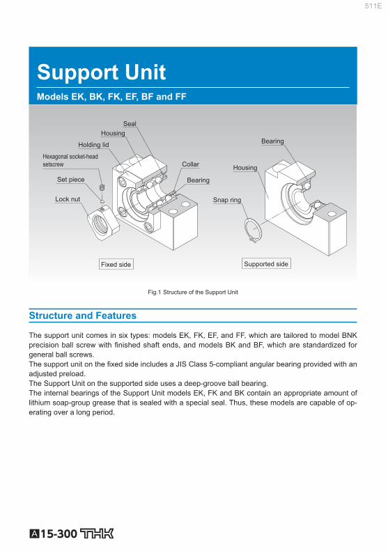
A15-300
Support Unit Models EK, BK, FK, EF, BF and FF
Fixed side Supported side
Bearing
Housing
Snap ring
Bearing
Collar
Housing
Lock nut
Set piece
Hexagonal socket-head setscrew
Holding lid
Seal
Fig.1 Structure of the Support Unit
Structure and Features
The support unit comes in six types: models EK, FK, EF, and FF, which are tailored to model BNK precision ball screw with fi nished shaft ends, and models BK and BF, which are standardized for general ball screws. The support unit on the fi xed side includes a JIS Class 5-compliant angular bearing provided with an adjusted preload. The Support Unit on the supported side uses a deep-groove ball bearing. The internal bearings of the Support Unit models EK, FK and BK contain an appropriate amount of lithium soap-group grease that is sealed with a special seal. Thus, these models are capable of op-erating over a long period.
511E

A15-301
Ball Screw
PeripheralsSupport Unit
[Uses the Optimal Bearing] To ensure the rigidity balance with the Ball Screw, the Support Unit uses an angular bearing (contact angle: 30; DF confi guration) with a high rigidity and a low torque. Miniature Support Unit models EK/FK 4, 5 and 6 are incorporated with a miniature angular bearing with a contact angle of 45 de-veloped exclusively for miniature Ball Screws. This bearing has a greater contact angle of 45 and an increased number of balls with a smaller diameter. The high rigidity and accuracy of the miniature angular bearing provides the stable rotational performance.
[Support Unit Shapes] The square and round shapes are available for the Support Unit to allow the selection according to the intended use.
Example of Installation
Square Type Round Type
[Compact and Easy Installation] The Support Unit is compactly designed to accommodate the space in the installation site. As the bearing is provided with an appropriately adjusted preload, the Support Unit can be assembled with a Ball Screw unit with no further machining. Accordingly, the required man-hours in the assembly can be reduced and the assembly accuracy can be increased.
511E

A15-302
Type
[For the Fixed Side]
Square Type Model EK Specifi cation Table⇒A15-310
(Inner diameter: 4 to 20)
Round Type Model FK Specifi cation Table⇒A15-314
(Inner diameter: 4 to 30)
Square Type Model BK Specifi cation Table⇒A15-312
(Inner diameter: 10 to 40)
[For the Supported Side]
Square Type Model EF Specifi cation Table⇒A15-318
(Inner diameter: 6 to 20)
Round Type Model FF Specifi cation Table⇒A15-322
(Inner diameter: 6 to 30)
Square Type Model BF Specifi cation Table⇒A15-320
(Inner diameter: 8 to 40)
511E

A15-303
Ball Screw
PeripheralsSupport Unit
Types of Support Units and Applicable Screw Shaft Outer Diameters
Inner diameter of fi xed-side
Support Unit (mm)
Inner diameter of supported-
side Support Unit (mm)
Applicable Model No.
of fi xed-side Support
Unit
Applicable model No. of the sup-ported side
Support Unit
Type BNK with Unfi nished Shaft Ends(Applicable
Model No.)
Recommended Shapes of Shaft Ends(Applicable Shaft Outer Diameter D)
Shaft End H (mm) Shaft End J (mm)
4 — EK 4 FK 4 — BNK0401
BNK0501 6 ————
5 — EK 5 FK 5 — BNK0601 8 ————
6 6 EK 6 FK 6
EF 6 FF 6
BNK0801 BNK0802 BNK0810
8 10 ————
8 6 EK 8 FK 8
EF 8 FF 6 BNK1002 12 ————
10 8 EK 10 FK 10 BK 10
EF 10 FF 10 BF 10
BNK1004 BNK1010 BNK1202 BNK1205 BNK1208
14 15
14 15
12 10 EK 12 FK 12 BK 12
EF 12 FF 12 BF 12
BNK1402 BNK1404 BNK1408 BNK1510 BNK1520 BNK1616
16 18
16 18
15 15 EK 15 FK 15
EF 15 FF 15
BNK2010 BNK2020
20 25 ————
BK 15 BF 15 ———— ———— 20 17 17 BK 17 BF 17 ———— ———— 25
20 20
EK 20 FK 20
EF 20 FF 20 BNK2520
28 30 32
————
BK 20 BF 20 ———— ———— 28 30 32
25 25 FK 25 FF 25 ———— 36 ———— BK 25 BF 25 ———— ———— 36
30 30 FK 30 FF 30 ———— 40 40 BK 30 BF 30 ———— 35 35 BK 35 BF 35 ———— ———— 45
40 40 BK 40 BF 40 ———— ———— 50 55
Note1) The Supports Units in this table apply only to those Ball Screw models with recommended shaft ends shapes H, J and K, indicated on A15-308 .
Note2) For Recommended Shapes of Shaft Ends H, J, and K; refer to pages A15-324 to A15-329 .
511E
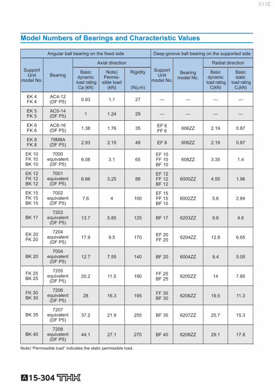
A15-304
Model Numbers of Bearings and Characteristic Values
Angular ball bearing on the fi xed side Deep-groove ball bearing on the supported side
SupportUnit
model No. Bearing
Axial direction Support
Unit model No.
Bearing model No.
Radial direction
Basic dynamic
load rating Ca (kN)
Note) Permis-
sible load (kN)
Rigidity
(N/m)
Basic dynamic
load rating C(kN)
Basic static
load rating C 0 (kN)
EK 4 FK 4
AC4-12 (DF P5) 0.93 1.1 27 — — — —
EK 5 FK 5
AC5-14 (DF P5) 1 1.24 29 — — — —
EK 6 FK 6
AC6-16 (DF P5) 1.38 1.76 35 EF 6
FF 6 606ZZ 2.19 0.87
EK 8 FK 8
79M8A (DF P5) 2.93 2.15 49 EF 8 606ZZ 2.19 0.87
EK 10 FK 10 BK 10
7000 equivalent (DF P5)
6.08 3.1 65 EF 10 FF 10 BF 10
608ZZ 3.35 1.4
EK 12 FK 12 BK 12
7001 equivalent (DF P5)
6.66 3.25 88 EF 12 FF 12 BF 12
6000ZZ 4.55 1.96
EK 15 FK 15 BK 15
7002 equivalent (DF P5)
7.6 4 100 EF 15 FF 15 BF 15
6002ZZ 5.6 2.84
BK 17 7203
equivalent (DF P5)
13.7 5.85 125 BF 17 6203ZZ 9.6 4.6
EK 20 FK 20
7204 equivalent (DF P5)
17.9 9.5 170 EF 20 FF 20 6204ZZ 12.8 6.65
BK 20 7004
equivalent (DF P5)
12.7 7.55 140 BF 20 6004ZZ 9.4 5.05
FK 25 BK 25
7205 equivalent (DF P5)
20.2 11.5 190 FF 25 BF 25 6205ZZ 14 7.85
FK 30 BK 30
7206 equivalent (DF P5)
28 16.3 195 FF 30 BF 30 6206ZZ 19.5 11.3
BK 35 7207
equivalent (DF P5)
37.2 21.9 255 BF 35 6207ZZ 25.7 15.3
BK 40 7208
equivalent (DF P5)
44.1 27.1 270 BF 40 6208ZZ 29.1 17.8
Note) “Permissible load” indicates the static permissible load.
511E

A15-305
Ball Screw
PeripheralsSupport Unit
Example of Installation
[Square Type Support Unit]
Fig.2 Example of Installing a Square Type Support Unit
[Round Type Support Unit]
Fig.3 Example of Installing a Round Type Support Unit
511E

A15-306
Mounting Procedure
[Installing the Support Unit] (1) Install the fi xed side Support Unit with the screw shaft. (2) After inserting the fi xed side Support Unit, secure the lock nut using the fastening set piece and
the hexagonal socket-head setscrews. (3) Attach the supported side bearing to the screw shaft and secure the bearing using the snap ring,
and then install the assembly to the housing on the supported side. Note1) Do no disassemble the Support Unit. Note2) When inserting the screw shaft to the Support Unit, take care not to let the oil seal lip turn outward. Note3) When securing the set piece with a hexagonal socket-head setscrew, apply an adhesive to the hexagonal socket-
head setscrew before tightening it in order to prevent the screw from loosening. If planning to use the product in a harsh environment, it is also necessary to take a measure to prevent other components/parts from loosening. Contact THK for details.
Supported side
Bearing Snap ring
Fixed side Collar
Set piece Hexagonal socket-head setscrew
Lock nut
[Installation onto the Table and the Base] (1) If using a bracket when mounting the ball screw nut to the table, insert the nut into the bracket
and temporarily fasten it. (2) Temporarily fasten the fi xed side Support Unit to the base.
In doing so, press the table toward the fi xed side Support Unit to align the axial center, and ad-just the table so that it can travel freely.
● If using the fi xed side Support Unit as the reference point, secure a clearance between the ball screw nut and the table or inside the bracket when making adjustment.
● If using the table as the reference point, make the adjustment either by using the shim (for a square type Support Unit), or securing the clearance between the outer surface of the nut and the inner surface of the mounting section (for a round type Support Unit).
(3) Press the table toward the fi xed-side Support Unit to align the axial center. Make the adjustment by reciprocating the table several times so that the nut travels smoothly throughout the whole stroke, and temporarily secure the Support Unit to the base.
Base
Fixed side support unitBracket Table Supported side support unit
511E
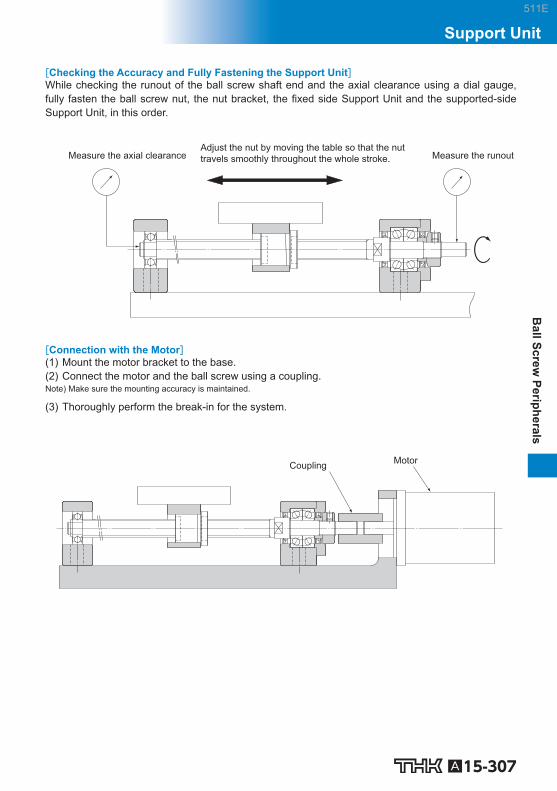
A15-307
Ball Screw
PeripheralsSupport Unit
[Checking the Accuracy and Fully Fastening the Support Unit] While checking the runout of the ball screw shaft end and the axial clearance using a dial gauge, fully fasten the ball screw nut, the nut bracket, the fi xed side Support Unit and the supported-side Support Unit, in this order.
Adjust the nut by moving the table so that the nut travels smoothly throughout the whole stroke. Measure the runoutMeasure the axial clearance
[Connection with the Motor] (1) Mount the motor bracket to the base. (2) Connect the motor and the ball screw using a coupling. Note) Make sure the mounting accuracy is maintained.
(3) Thoroughly perform the break-in for the system.
Motor Coupling
511E

A15-308
Types of Recommended Shapes of the Shaft Ends
To ensure speedy estimates and manufacturing of Ball Screws, THK has standardized the shaft end shapes of the screw shafts. The recommended shapes of shaft ends consist of shapes H, K and J, which allow standard Support Units to be used.
Mounting method
Symbol forshaft end
shape Shape Supported Support
Unit
Fixed H J
H1
FK EK
J1
BK
H2
FK EK
J2
BK
H3
FK EK
J3
BK
Supported K
FF EF BF
511E

A15-309
Ball Screw
PeripheralsSupport Unit
511E

A15-310 Download data by searching for the corresponding model number on the Technical Support site. https://tech.thk.com
EK Square Type Support Unit on the Fixed Side
2-φ d1 through hole, φ d2 counter bore depth h
2-φ d1 through hole
Models EK 4 and 5 Models EK 6 and 8
b
H1 h1
H
M
P
B1
B
φ d
L
L3 (L2)
L1
3
5 2 4
□T
1 7
6
Model No.
Shaftdiameter
d L L 1 L 2 L 3 B H b 0.02
EK 4 4 15 5.5 17.5 3 34 19 17
EK 5 5 16.5 5.5 18.5 3.5 36 21 18
EK 6 6 20 5.5 22 3.5 42 25 21
EK 8 8 23 7 26 4 52 32 26
EK 10 10 24 6 29.5 6 70 43 35
EK 12 12 24 6 29.5 6 70 43 35
EK 15 15 25 6 36 5 80 49 40
EK 20 20 42 10 50 10 95 58 47.5
Models EK 4 to 8
Part No. Part name No. of units
1 Housing 1 2 Bearing 1 set 3 Set nut 1 4 Collar 2 5 Seal 1 6 Lock Nut 1
7 Hexagonal socket-head setscrew (with a set piece) 1
511E
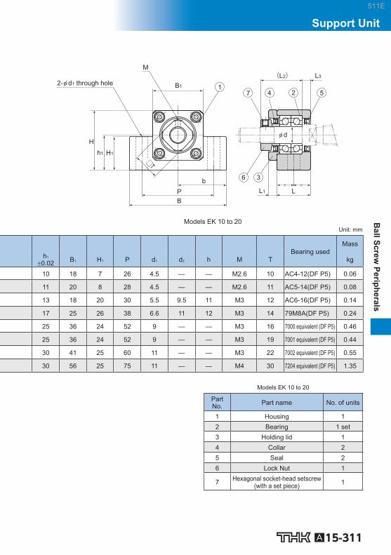
A15-311
Ball Screw
PeripheralsSupport Unit
2-φ d1 through hole
Models EK 10 to 20
(L2) L3
φ d
L1 L
□T
b
H1 h1
H
M
P
B1
B
5 2 4
3 6
7 1
Unit: mm
Bearing used
Mass
h 1 0.02 B 1 H 1 P d 1 d 2 h M T kg
10 18 7 26 4.5 — — M2.6 10 AC4-12(DF P5) 0.06
11 20 8 28 4.5 — — M2.6 11 AC5-14(DF P5) 0.08
13 18 20 30 5.5 9.5 11 M3 12 AC6-16(DF P5) 0.14
17 25 26 38 6.6 11 12 M3 14 79M8A(DF P5) 0.24
25 36 24 52 9 — — M3 16 7000 equivalent (DF P5) 0.46
25 36 24 52 9 — — M3 19 7001 equivalent (DF P5) 0.44
30 41 25 60 11 — — M3 22 7002 equivalent (DF P5) 0.55
30 56 25 75 11 — — M4 30 7204 equivalent (DF P5) 1.35
Models EK 10 to 20
Part No. Part name No. of units
1 Housing 1 2 Bearing 1 set 3 Holding lid 1 4 Collar 2 5 Seal 2 6 Lock Nut 1
7 Hexagonal socket-head setscrew (with a set piece) 1
511E

A15-312 Download data by searching for the corresponding model number on the Technical Support site. https://tech.thk.com
BK Square Type Support Unit on the Fixed Side
4-φ d1 through hole,φ d2 counter bore depth h
□T
b
H1h1
H
M
P
B1
B
1
Model No.
Shaftdiameter
d L L 1 L 2 L 3 B H b 0.02
h 1 0.02 B 1 H 1
BK 10 10 25 5 29 5 60 39 30 22 34 32.5
BK 12 12 25 5 29 5 60 43 30 25 35 32.5
BK 15 15 27 6 32 6 70 48 35 28 40 38
BK 17 17 35 9 44 7 86 64 43 39 50 55
BK 20 20 35 8 43 8 88 60 44 34 52 50
BK 25 25 42 12 54 9 106 80 53 48 64 70
BK 30 30 45 14 61 9 128 89 64 51 76 78
BK 35 35 50 14 67 12 140 96 70 52 88 79
BK 40 40 61 18 76 15 160 110 80 60 100 90
511E

A15-313
Ball Screw
PeripheralsSupport Unit
L3 (L2)
C2
φ d
C1
L1 L
5 2 4
3 6
7
Unit: mm
Mass
P C 1 C 2 d 1 d 2 h M T Bearing used kg
46 13 6 6.6 10.8 5 M3 16 7000 equivalent (DF P5) 0.39
46 13 6 6.6 10.8 1.5 M3 19 7001 equivalent (DF P5) 0.41
54 15 6 6.6 11 6.5 M3 22 7002 equivalent (DF P5) 0.57
68 19 8 9 14 8.5 M4 24 7203 equivalent (DF P5) 1.27
70 19 8 9 14 8.5 M4 30 7004 equivalent (DF P5) 1.19
85 22 10 11 17.5 11 M5 35 7205 equivalent (DF P5) 2.3
102 23 11 14 20 13 M6 40 7206 equivalent (DF P5) 3.32
114 26 12 14 20 13 M8 50 7207 equivalent (DF P5) 4.33
130 33 14 18 26 17.5 M8 50 7208 equivalent (DF P5) 6.5
Part No. Part name No. of units
1 Housing 1 2 Bearing 1 set 3 Holding lid 1 4 Collar 2 5 Seal 2 6 Lock Nut 1
7 Hexagonal socket-head setscrew (with a set piece) 1
511E

A15-314 Download data by searching for the corresponding model number on the Technical Support site. https://tech.thk.com
FK Round Type Support Unit on the Fixed Side
Mounting method A Models FK 4 to 8
(90° equidistant)
4-φ d1 through hole, φ d2 counter bore depth h
L F H
φ APCD
E R0.6MAX
φ dφ Dg6
T1
(L1)
M
□B
□T
1
5 2 4 6 3 7
Model No. Shaft
diameter
d L H F E D A PCD B
FK 4 4 15 6 9 17.5 18 –0.006 –0.017
32 24 25
FK 5 5 16.5 6 10.5 18.5 20 –0.007 –0.02
34 26 26
FK 6 6 20 7 13 22 22 –0.007 –0.02
36 28 28
FK 8 8 23 9 14 26 28 –0.007 –0.02
43 35 35
511E

A15-315
Ball Screw
PeripheralsSupport Unit
Mounting method B
φ d
L F H
E T2
(L2)
Unit: mm
Installationprocedure A
Installationprocedure B
Bearing used Mass
L 1 T 1 L 2 T 2 d 1 d 2 h M T kg
5.5 3 6.5 4 3.4 6.5 4 M2.6 10 AC4-12(DF P5) 0.05
5.5 3.5 7 5 3.4 6.5 4 M2.6 11 AC5-14(DF P5) 0.06
5.5 3.5 8.5 6.5 3.4 6.5 4 M3 12 AC6-16(DF P5) 0.08
7 4 10 7 3.4 6.5 4 M3 14 79M8A(DF P5) 0.15
Part No. Part name No. of units
1 Housing 1 2 Bearing 1 set 3 Set nut 1 4 Collar 2 5 Seal 1 6 Lock Nut 1
7 Hexagonal socket-head setscrew (with a set piece) 1
511E

A15-316 Download data by searching for the corresponding model number on the Technical Support site. https://tech.thk.com
FK Round Type Support Unit on the Fixed Side
Mounting method A
(90° equidistant)
Models FK 10 to 30
4-φ d1 through hole, φ d2 counter bore depth h
L F H
(L1)
5 2 4 6 3 7
φ APCD φ dφ Dg6
E R0.6MAX
T1
1 □B
□T
M
Model No. Shaft
diameter
d L H F E D A PCD B
FK 10 10 27 10 17 29.5 34 –0.009 –0.025
52 42 42
FK 12 12 27 10 17 29.5 36 –0.009 –0.025
54 44 44
FK 15 15 32 15 17 36 40 –0.009 –0.025
63 50 52
FK 20 20 52 22 30 50 57 –0.01 –0.029
85 70 68
FK 25 25 57 27 30 60 63 –0.01 –0.029
98 80 79
FK 30 30 62 30 32 61 75 –0.01 –0.029
117 95 93
511E

A15-317
Ball Screw
PeripheralsSupport Unit
Part No. Part name No. of units
1 Housing 1 2 Bearing 1 set 3 Holding lid 1 4 Collar 2 5 Seal 2 6 Lock Nut 1
7 Hexagonal socket-head setscrew (with a set piece) 1
Mounting method B
φ d
L F H
E T2
(L2)
Unit: mm
Installationprocedure A
Installationprocedure B
Bearing used Mass
L 1 T 1 L 2 T 2 d 1 d 2 h M T kg
7.5 5 8.5 6 4.5 8 4 M3 16 7000 equivalent (DF P5) 0.21
7.5 5 8.5 6 4.5 8 4 M3 19 7001 equivalent (DF P5) 0.22
10 6 12 8 5.5 9.5 6 M3 22 7002 equivalent (DF P5) 0.39
8 10 12 14 6.6 11 10 M4 30 7204 equivalent (DF P5) 1.09
13 10 20 17 9 15 13 M5 35 7205 equivalent (DF P5) 1.49
11 12 17 18 11 17.5 15 M6 40 7206 equivalent (DF P5) 2.32
511E

A15-318 Download data by searching for the corresponding model number on the Technical Support site. https://tech.thk.com
EF Square Type Support Unit on the Supported Side
2-φ d1 through hole, φ d2 counter bore depth h
Models EF 6 and 8
φ d
b P
B1
h1
H1 H
B L
2 3 1
THK EF*
Model No.
Shaftdiameter
d L B H b 0.02
h 1 0.02
B 1
EF 6 6 12 42 25 21 13 18
EF 8 6 14 52 32 26 17 25
EF 10 8 20 70 43 35 25 36
EF 12 10 20 70 43 35 25 36
EF 15 15 20 80 49 40 30 41
EF 20 20 26 95 58 47.5 30 56
Note) The area marked with “*” is imprinted with a numeric character(s) as part of the model number.
511E

A15-319
Ball Screw
PeripheralsSupport Unit
Part No. Part name No. of units
1 Housing 1 2 Bearing 1 3 Snap ring 1
2-φ d1 through hole
Models EF 10 to 20
b P
H1 h1
H
B1
B L
2
φ d
3 1
THK EF*
Unit: mm
Bearingused
Snap ring size
Mass
H 1 P d 1 d 2 h kg
20 30 5.5 9.5 11 606ZZ C6 0.07
26 38 6.6 11 12 606ZZ C6 0.13
24 52 9 — — 608ZZ C8 0.33
24 52 9 — — 6000ZZ C10 0.32
25 60 9 — — 6002ZZ C15 0.38
25 75 11 — — 6204ZZ C20 0.63
511E

A15-320 Download data by searching for the corresponding model number on the Technical Support site. https://tech.thk.com
BF Square Type Support Unit on the Supported Side
2-φ d1 through hole,φ d2 counter bore depth h
b
H1h1
H
P
B1
B
THK BF*
Model No.
Shaftdiameter
d L B H b 0.02
h 1 0.02
B 1 H 1
BF 10 8 20 60 39 30 22 34 32.5
BF 12 10 20 60 43 30 25 35 32.5
BF 15 15 20 70 48 35 28 40 38
BF 17 17 23 86 64 43 39 50 55
BF 20 20 26 88 60 44 34 52 50
BF 25 25 30 106 80 53 48 64 70
BF 30 30 32 128 89 64 51 76 78
BF 35 35 32 140 96 70 52 88 79
BF 40 40 37 160 110 80 60 100 90
Note) The area marked with “*” is imprinted with a numeric character(s) as part of the model number.
511E

A15-321
Ball Screw
PeripheralsSupport Unit
Part No. Part name No. of units
1 Housing 1 2 Bearing 1 3 Snap ring 1
L
3
φ d
2 1
Unit: mm
Bearing used Snap ring used
Mass
P d 1 d 2 h kg
46 6.6 10.8 5 608ZZ C8 0.29
46 6.6 10.8 1.5 6000ZZ C10 0.3
54 6.6 11 6.5 6002ZZ C15 0.38
68 9 14 8.5 6203ZZ C17 0.74
70 9 14 8.5 6004ZZ C20 0.76
85 11 17.5 11 6205ZZ C25 1.42
102 14 20 13 6206ZZ C30 1.97
114 14 20 13 6207ZZ C35 2.22
130 18 26 17.5 6208ZZ C40 3.27
511E

A15-322 Download data by searching for the corresponding model number on the Technical Support site. https://tech.thk.com
FF Round Type Support Unit on the Supported Side
(90° equidistant)
4-φ d1 through hole,φ d2 counter bore depth h
�B
Model No. Shaft
diameter
d L H F D A
FF 6 6 10 6 4 22 –0.007 –0.02 36
FF 10 8 12 7 5 28 –0.007 –0.02 43
FF 12 10 15 7 8 34 –0.009 –0.025 52
FF 15 15 17 9 8 40 –0.009 –0.025 63
FF 20 20 20 11 9 57 –0.01 –0.029 85
FF 25 25 24 14 10 63 –0.01 –0.029 98
FF 30 30 27 18 9 75 –0.01 –0.029 117
511E

A15-323
Ball Screw
PeripheralsSupport Unit
Part No. Part name No. of units
1 Housing 1 2 Bearing 1 3 Snap ring 1
φ APCD φ dφ Dg6
H F L
1 2 3
R0.6MAX
Unit: mm
Bearing used Snap ring used
Mass
PCD B d 1 d 2 h kg
28 28 3.4 6.5 4 606ZZ C6 0.04
35 35 3.4 6.5 4 608ZZ C8 0.07
42 42 4.5 8 4 6000ZZ C10 0.11
50 52 5.5 9.5 5.5 6002ZZ C15 0.2
70 68 6.6 11 6.5 6204ZZ C20 0.27
80 79 9 14 8.5 6205ZZ C25 0.67
95 93 11 17.5 11 6206ZZ C30 1.07
511E

A15-324 Download data by searching for the corresponding model number on the Technical Support site. https://tech.thk.com
Recommended Shapes of Shaft Ends - Shape H (H1, H2 and H3) (For Support Unit Models FK and EK)
Model EK Model FK Model FK
K1 K2
K3
Support Unit model No. Ball screwshaft outerdiameter
Shaft outerdiameter ofthe bearung
Metric screw thread
Model FK Model EK d A B E F M S
FK4 EK4 6 4 3 23 5 M4×0.5 7
FK5 EK5 8 5 4 25 6 M5×0.5 7
FK6 EK6 10 *1 6 4 30 8 M6×0.75 8
FK8 EK8 12 8 6 35 9 M8×1 10
FK10 EK10 14 10 8 36 15 M10×1 11
FK10 EK10 15 10 8 36 15 M10×1 11
FK12 EK12 16 12 10 36 15 M12×1 11
FK12 EK12 18 12 10 36 15 M12×1 11
FK15 EK15 20 15 12 49 20 M15×1 13
FK15 EK15 25 15 12 49 20 M15×1 13
FK20 EK20 28 20 17 64 25 M20×1 17
FK20 EK20 30 20 17 64 25 M20×1 17
FK20 EK20 32 20 17 64 25 M20×1 17
FK25 — 36 25 20 76 30 M25×1.5 20
FK30 — 40 30 25 72 38 M30×1.5 25 Note) Support Units are designed to have dimensions so that combinations of models FK and FF, models EK and EF or models
BK and BF are used on the same shaft. If desiring the shaft end to be machined at THK, add the shape symbol in the end of the Ball Screw model number. (Example) TS2505+500L-H2K (Shape H2 on the fi xed side; shape K on the supported side) For the perpendicularity of the end face of the bearing, refer to JIS B 1192-1997.
*1 FK6 and EK6 also support 8 mm outer diameter ball screws. Contact THK for details.
511E

A15-325
Ball Screw
PeripheralsSupport Unit
Shape H1
Shape H2
Shape H3
Width G, depth T
(Metric screw thread)
S
P R
J
P
F E N H
M
φ B h7
φ A h7
φ d
Unit: mm
Width across fl at Shape H2 Shape H3 Support Unit position
Keyway Cut fl at on two side Model FK Model EK
J N H G N9
T +0.1
0 P R P K 1 K 2 K 3
4 4 4 — — — 2.7 4 1.5 0.5 1.5
5 4 4 — — — 3.7 5 2 0.5 2
5 4 4 — — — 3.7 6 3.5 0.5 3.5
8 5 5 — — — 5.6 7 3.5 0.5 3.5
10 5 7 2 1.2 11 7.5 11 0.5 –0.5 –0.5
10 5 7 2 1.2 11 7.5 11 0.5 –0.5 –0.5
13 6 8 3 1.8 12 9.5 12 0.5 –0.5 –0.5
13 6 8 3 1.8 12 9.5 12 0.5 –0.5 –0.5
16 6 9 4 2.5 16 11.3 16 4 2 5
18 7 10 4 2.5 16 11.3 16 4 2 5
21 8 11 5 3 21 16 21 1 –3 1
24 8 12 5 3 21 16 21 1 –3 1
27 9 13 5 3 21 16 21 1 –3 1
27 10 13 6 3.5 25 19 25 5 –2 —
32 10 15 8 4 32 23.5 32 –3 –9 —
Note) The ball nut fl ange faces the fi xed side unless otherwise specifi ed. If desiring the fl ange to face the supported side, add symbol G in the end of the Ball Screw model number when placing an order. (Example) BIF2505-5RRGO+420LC5-H2KG
511E

A15-326 Download data by searching for the corresponding model number on the Technical Support site. https://tech.thk.com
Recommended Shapes of Shaft Ends - Shape J (J1, J2 and J3) (For Support Unit Model BK)
Model BK
Support Unitmodel No.
Ball screwshaft outerdiameter
Shaft outerdiameter ofthe bearung
Metric screw thread
Model BK d A B E F M
BK10 14 10 8 39 15 M10×1
BK10 15 10 8 39 15 M10×1
BK12 16 12 10 39 15 M12×1
BK12 18 12 10 39 15 M12×1
BK15 20 15 12 40 20 M15×1
BK17 25 17 15 53 23 M17×1
BK20 28 20 17 53 25 M20×1
BK20 30 20 17 53 25 M20×1
BK20 32 20 17 53 25 M20×1
BK25 36 25 20 65 30 M25×1.5
BK30 40 30 25 72 38 M30×1.5
BK35 45 35 30 83 45 M35×1.5
BK40 50 40 35 98 50 M40×1.5
BK40 55 40 35 98 50 M40×1.5
Note) Support Units are designed to have dimensions so that combinations of models FK and FF, models EK and EF or models BK and BF are used on the same shaft. If desiring the shaft end to be machined at THK, add the shape symbol in the end of the Ball Screw model number. (Example) TS2505+500L-J2K (Shape J2 on the fi xed side; shape K on the supported side) For the perpendicularity of the end face of the bearing, refer to JIS B 1192-1997.
511E

A15-327
Ball Screw
PeripheralsSupport Unit
Shape J1
Shape J2
Shape J3
(Metric screw thread)
Width G, depth T
F
S
P R
J
E
N H
φ d
M
P
φ B h7
φ A h7
Unit: mm
Width across fl at
Shape J2 Shape J3
Keyway Cut fl at on two side
S J N H G N9
T +0.1
0 P R P
16 10 5 7 2 1.2 11 7.5 11
16 10 5 7 2 1.2 11 7.5 11
14 13 6 8 3 1.8 12 9.5 12
14 13 6 8 3 1.8 12 9.5 12
12 16 6 9 4 2.5 16 11.3 16
17 18 7 10 5 3 21 14.3 21
15 21 8 11 5 3 21 16 21
15 24 8 12 5 3 21 16 21
15 27 9 13 5 3 21 16 21
18 27 10 13 6 3.5 25 19 25
25 32 10 15 8 4 32 23.5 32
28 36 12 15 8 4 40 28.5 40
35 41 14 19 10 5 45 33 45
35 46 14 20 10 5 45 33 45
Note) The ball nut fl ange faces the fi xed side unless otherwise specifi ed. If desiring the fl ange to face the supported side, add symbol G in the end of the Ball Screw model number when placing an order. (Example) BIF2505-5RRGO+420LC5-J2KG
511E

A15-328 Download data by searching for the corresponding model number on the Technical Support site. https://tech.thk.com
Recommended Shapes of Shaft Ends - Shape K (For Support Unit Models FF, EF and BF)
Model EF
Model BF Model FF Model FF
Support Unit model No. Ball screw shaftouter diameter
Shaft outer diameterof the bearung
Model FF Model EF Model BF d A
FF6 EF6 — 8 6
— EF8 — 12 6
FF10 EF10 BF10 14 8
FF10 EF10 BF10 15 8
FF12 EF12 BF12 16 10
FF12 EF12 BF12 18 10
FF15 EF15 BF15 20 15
FF15 EF15 BF15 25
15
— — BF17 * 17
FF20 EF20 BF20 ** 28 20
FF20 EF20 BF20 ** 30 20
FF20 EF20 BF20 ** 32 20
FF25 — BF25 36 25
FF30 — BF30 40 30
— — BF35 45 35
— — BF40 50 40
— — BF40 55 40
Note) Support Units are designed to have dimensions so that combinations of models FK and FF, models EK and EF or models BK and BF are used on the same shaft. If desiring the shaft end to be machined at THK, add the shape symbol in the end of the Ball Screw model number. (Example) TS2505+500L-H2K (Shape H2 on the fi xed side; shape K on the supported side) For the perpendicularity of the end face of the bearing, refer to JIS B 1192-1997.
511E

A15-329
Ball Screw
PeripheralsSupport Unit
Model K
G +0.14 0
F
E
φ d
φ A h7
φ B
+0.2 0
0 -0.2
Unit: mm
Snap ring groove
E B F G
9 5.7 6.8 0.8
9 5.7 6.8 0.8
10 7.6 7.9 0.9
10 7.6 7.9 0.9
11 9.6 9.15 1.15
11 9.6 9.15 1.15
13 14.3 10.15 1.15
13 14.3 10.15 1.15
16 16.2 13.15 1.15
19 (16) 19 15.35 (13.35) 1.35
19 (16) 19 15.35 (13.35) 1.35
19 (16) 19 15.35 (13.35) 1.35
20 23.9 16.35 1.35
21 28.6 17.75 1.75
22 33 18.75 1.75
23 38 19.95 1.95
23 38 19.95 1.95
Note) *When model BK17 (shaft end shape: J) is used on the fi xed side for a Ball Screw with a shaft outer diameter of 25 mm, the shaft end shape on the supported side is that for model BF17. **The dimensions in the parentheses in the table above are that of model BF20. They differ from those of models FF20
and EF20. When placing an order, be sure to specify the model number of the Support Unit to be used.
511E

A15-330
Nut Bracket Model MC
Nut bracket
Fig.1 Structure of the Nut Bracket
Structure and Features
The model MC nut bracket is designed for use with BNK fi nished shaft end precision ball screw nuts. Its low height and the fact that it can be assembled using only bolts means devices can be compact and reduces how long they take to put together.
Type
Nut Bracket Model MC Specifi cation Table⇒A15-331
511E

A15-331
Ball Screw
PeripheralsNut Bracket
Nut Bracket
Model No. Supported Ball Screw models
MC 1004 BNK1004,BNK1010
MC 1205 BNK1205
MC 1408 BNK1408,BNK1510,BNK1520,BNK1616
MC 2010 BNK2010
MC 2020 BNK2020
4-S×ℓ
4-S1×ℓ1
W
B
30°
30°
T
KF
PCD
B1
W1
φ D
±0.1
+ 0.1 0 C
L
C1
Unit: mm
Model No. Width Overalllength
W W 1 B B 1 L C C 1 F K MC 1004 48 24 40 4 32 16 10 20 32.5
MC 1205 60 30 47 6.5 36 24 6 21 37
MC 1408 60 30 50 5 36 20 10 21.5 37
MC 2010 86 43 70 8 50 30 10 31 54
MC 2020 86 43 70 8 40 24 8 28 51
Model No. Mass T D PCD S×ℓ S 1 ×ℓ 1 kg
MC 1004 9 26.4 36 M5×10 M4×7 0.24
MC 1205 9 30.4 40 M6×12 M4×7 0.38
MC 1408 9 34.4 45 M6×12 M5×7 0.34
MC 2010 16 46.4 59 M10×20 M6×10 1.04
MC 2020 16 39.4 59 M10×20 M6×10 0.83
511E

A15-332
Lock Nut Model RN
Lock nut
Set piece
Hexagonal socket-head setscrew
Fig.1 Structure of the Lock Nut
Structure and Features
The model RN ball screw lock nut is used for fi xing the angular bearings that set into ball screws. It can be fi xed in place with the hexagonal socket set screws using a set piece. This does not de-form the thread at the end of the ball screw shaft. This can be reused. Available in sizes M4 to M40. Screw pitches must be narrow.
Type
Lock Nut Model RN Specifi cation Table⇒A15-333
511E

A15-333
Ball Screw
PeripheralsLock Nut
Lock Nut
Lock nut
Hexagonal socket-head setscrew
Set piece
L
m
φ d φ D
M
t
□T
Unit: mm
Model No. Mass
M m D d L t T kg
RN 4 M4×0.5 M2.6 11.5 8 5 2.7 10 0.003
RN 5 M5×0.5 M2.6 13.5 9 5 2.7 11 0.004
RN 6 M6×0.75 M3 14.5 10 5 2.7 12 0.005
RN 8 M8×1 M3 17 13 6.5 4 14 0.008
RN 10 M10×1 M3 20 15 8 5.5 16 0.013
RN 12 M12×1 M3 22 17 8 5.5 19 0.014
RN 15 M15×1 M3 25 21 8 4.5 22 0.017
RN 17 M17×1 M4 30 25 13 9 24 0.042
RN 20 M20×1 M4 35 26 11 7 30 0.048
RN 25 M25×1.5 M5 43 33 15 10 35 0.096
RN 30 M30×1.5 M6 48 39 20 14 40 0.145
RN 35 M35×1.5 M8 60 46 21 14 50 0.261
RN 40 M40×1.5 M8 63 51 25 18 50 0.304
511E

A15-334
511E

A15-335
Ball Screw
Options
511E

A15-336
Contaminaton Protection If foreign material enters the interior of the ball screw, abnormal levels of abrasion and ball clogging are more likely to occur. This can also shorten the overall lifespan of the product. As such, foreign material needs to be prevented from entering. If there is a chance that foreign ma-terial may get in, it is important to choose an effective contamination protection product that suits the usage conditions.
Labyrinth seal (Precision Ball Screw)
(Rolled Ball Screw Model JPF) Symbol: RR
Screw shaft
Labyrinth seal
Ball screw nut
Brush seal (Rolled Ball Screw)
Symbol: ZZ
Brush seal
Ball screw nut
Screw shaft
Wiper ring Symbol: WW
Wiper ringSeal snap ring
Seal snap ringWiper ring
Ball screw nut
Ball screw shaft
Thin fi lm seal (SDA-V only) Symbol: TT
Thin film sealSeal Cap
Ball screw nutScrew shaft
A15-339~
A15-338
A15-338
511E

A15-337
Ball Screw
(Options)
Dust coverBellows
Screw cover
Screw cover Bellows
Lubrication To maximize the performance of the Ball Screw, it is necessary to select a lubricant and a lubrication method according to the conditions. For types of lubricants, characteristics of lubricants and lubrication methods, see the section on “Ac-cessories for Lubrication” on A24-2 . Also, QZ Lubricator is available as an optional accessory that signifi cantly increases the mainte-nance interval.
Air vent
Ball screw nut
QZ Lubricator
QZ fixing screwQZ Lubricator Ball screw shaft
QZ Lubricator
Corrosion Resistance (Surface Treatment, etc.) Depending on the service environment, the Ball Screw requires corrosion resistance treatment or a different material. For details of corrosion resistance treatment and material change, contact THK. (see B0-18 )
OptionsLubrication
A15-342~
A15-341
511E

A15-338
Contamination Protection Seal for Ball Screws
If the Ball Screw is used in an atmosphere free from foreign material but with suspended dust, a labyrinth seal (with symbol RR) and a brush seal (with symbol ZZ) can be used as contamination protection accessories. The labyrinth seal is designed to maintain a slight clearance between the seal and the screw shaft raceway so that torque does not develop and no heat is generated, though its effect in contamina-tion protection is limited. With Ball Screws except the large lead and super lead types, there is no difference in nut dimen-sions between those with and without a seal.
Labyrinth seal Symbol: RR (Precision Ball Screw)
(Rolled Ball Screw Model JPF)
Screw shaft
Labyrinth seal
Ball screw nut
Labyrinth seal
Brush seal Symbol: ZZ (Rolled Ball Screw)
Brush seal
Ball screw nut
Screw shaft
Brush seal
511E

Model number coding
A15-339
Ball Screw
(Options)
Wiper Ring W ●For the supported models and the ball screw nut dimension with Wiper ring W attached, see A15-344 to A15-351 .
With the wiper ring W, special resin with high wear resistance and low dust generation removes foreign material and prevents foreign material from entering the ball screw nut while elastically contacting the circumference of the ball screw shaft and the screw thread.
Wiper ringSeal snap ring
Seal snap ringWiper ring
Ball screw nut
Ball screw shaft
Appearance Drawing
Spring Multi-slit
Multi-slit
Foreign material
Ball screw shaft
Rotational direction Detail view of section A
A
Structural Drawing
[Features] ● A total of eight slits on the circumference remove foreign materials in succession, and prevent en-
trance of foreign material. ● Contacts the ball screw shaft to reduce the fl owing out of grease. ● Contacts the ball screw shaft at a constant pressure level using a spring, thus to minimize the
heat generation. ● Since the material is highly resistant to the wear and the chemicals, its performance will not easily be
deteriorated even if it is used over a long period.
Can be attached together with QZ Lubricator. For the applicable models and the ball screw nut dimensions after wiper ring W is attached, see A15-344 .
Seal snap ringWiper ring
QZ LubricatorQZ Lubricator
Wiper ringSeal snap ring
QZ Lubricator + Wiper ring
With QZLubricator
With wiper ring W
BIF2505V-5 QZ WW G0 +1000L C5
(*) See A15-344 .
OptionsWiper Ring W
511E

A15-340
Test in an environment exposed to contaminated environment [Test conditions]
Item Description Model No. BIF3210V‒5G0+1500LC5 Maximum
rotational speed 1000min -1
Maximum speed 10m/min Maximum
circumferential speed 1.8m/s
Time constant 60ms Dowel 1s Stroke 900mm Load
(through internal load) 1.31kN
Grease THK AFG Grease 8cm 3 (Initial lubrication to the ball screw nut only.)
Foundry dust FCD400 average particle diameter: 250m Volume of foreign material per shaft 5g/h
[Test result]
Type with wiper ring
Type with labyrinth seal
Distance traveled (km) Flaking occurrs on the ball screw shaft raceway No problem Flaking occurrs on the ball
0 400 800 1200 1600 2000 200 600 1000 1400 1800
● Type with wiper ring Slight fl aking occurred in the ball screw shaft at travel distant of 1,000 km.
● Type with labyrinth seal Flaking occurred throughout the circumfer-ence of the screw shaft raceway at travel distance of 200 km. Flaking occurred on the balls after traveling 1,500 km.
Change in the ball after traveling 2000 km
(1) Type with wiper ring (2) Type with labyrinth seal
Ball after traveling Unused ball Ball after traveling Unused ball
●Discolored, but no breakage ●Flaking occurs
Distance traveled (km)
Wea
r of b
all (μ
m) Type with labyrinth seal
Type with wiper ring
0 0
2
4
6
8
10
12
500 1000 1500 2000
● Type with wiper ring Wear of balls at a travel distance of 2,000 km: 1.4 m.
● Type with labyrinth seal Starts to be worn rapidly after 500 km, and the ball wear amount at the travel distance of 2,000 km: 11 m.
511E

A15-341
Ball Screw
(Options)
Heat Generation Test [Test conditions]
Item Description Model No. BLK3232‒3.6G0+1426LC5 Maximum
rotational speed 1000min -1
Maximum speed 32m/min Maximum
circumferential speed 1.7m/s
Time constant 100ms Stroke 1000mm Load
(through internal load) 0.98kN
Grease THK AFG Grease 5cm 3 (contained in the ball screw nut)
[Test result]
Travel time (min)
Tem
pera
ture
at s
haft
cent
er a
rea
(℃)
With wiper ringWithout seal
0 0
10
20
30
40
50
60
15 30 45 60 75 90
Unit: ℃
Item With wiper ring Without seal
Heat generationtemperature 37.1 34.5
Temperaturerise 12.2 8.9
Dust Cover for Ball Screws
Bellows/Screw cover
In the case of an environment with much dust and foreign material, be sure to prevent intrusion of foreign material by using bellows, a screw cover or the like. The contamination protection can be increased by also using a contamination protection seal. For details, contact THK. When conferring with us, please use the bellows specifi cations ( A15-352 ).
Screw cover Bellows
Dust cover
OptionsDust Cover for Ball Screws
511E

Model number coding
A15-342
QZ Lubricator ●For the supported models and the ball screw nut dimension with QZ attached, see A15-344 to A15-351 .
QZ Lubricator feeds a right amount of lubricant to the raceway of the ball screw shaft. This allows an oil fi lm to be constantly formed between the balls and the raceway, improves lubricity and signifi -cantly extends the lubrication maintenance interval. The structure of QZ Lubricator consists of three major components: (1) a heavily oil-impregnated fi ber net (stores the lubricant), (2) a high-density fi ber net (applies the lubricant to the raceway) and (3) an oil-control plate (adjusts the oil fl ow). The lubricant contained in the QZ Lubricator is fed by the capillary phenomenon, which is used also in felt pens and many other products.
Ball screw shaftQZ LubricatorQZ fixing screw
Ball screw nut
Air vent (Note)
QZ Lubricator
Appearance Drawing
Flow of lubricant ③Oil control plate②High-density fiber net
①Heavily oil-impregnated fiber net
Applied directly to the raceway
Ball screw shaft Sealed case Ball screw nut
Structural Drawing
[Features] ● Since it supplements an oil loss, the lubrication maintenance interval can be signifi cantly extended. ● Since the right amount of lubricant is applied to the ball raceway, an environmentally friendly lubri-
cation system that does not contaminate the surroundings is achieved. Note) Some types of QZ have a vent hole. Be careful not to block the hole with grease or other obstructions.
With QZLubricator
With wiper ring W
BIF2505V-5 QZ WW G0 +1000L C5
(*) See A15-344 .
511E

A15-343
Ball Screw
(Options)
Signifi cantly extended maintenance interval Since QZ Lubricator continuously feeds a lubricant over a long period, the maintenance interval can be signifi cantly extended.
No anomaly observed after running 10000kmQZ Lubricator only
Distance traveled [Linear travel distance](km)
0 2000 4000 6000 8000 10000
[Test conditions] Item Description
Ball Screw BIF2510V Maximum rota-
tional speed 2500min -1
Maximum speed 25m/min Stroke 500mm Load Internal preload only
Environmentally friendly lubrication system Since QZ Lubricator feeds the right amount of lubricant directly to the raceway, the lubricant can effectively be used without waste.
Model No.: BIF3610V-5G0+1500LC5Traveling speed: 20km/dTravel distance: 2500km
QZ Lubricator
Forced lubrication
Amount of oil (cm3)
Forced lubrication
(QZ Lubricator attached to both ends of the ball screw nut)
QZ Lubricator + THK AFA Grease
Reduced to approx.
Compared
15000
32
0 5000 10000 15000
0.25cm3/3min×24h×125d32cm3
1 470
=15000cm3
OptionsQZ Lubricator
511E

A15-344
Dimensions of Each Model with an Option Attached Dimensions of the Ball Screw Nut Attached with Wiper Ring W and QZ Lubricator
With WW (without QZ) With QZ and WW
QWL QWL
QWD
L AL
Unit: mm
Model No. WWavail-ability
QZavail-ability
Dimensions including
WW
Length of protrusion with QZ attached
Outer diame-ter of protru-sion with QZ
attached
Dimensions including QZ
and WW
L QWL QWD AL
EBA EBB EBC DIN
Standard
1605-4 ○ ○ 50 25 27 110 2005-3 ○ ○ 45 26.5 33 98 2505-3 ○ ○ 45 28 39 101 2510-3 ○ ○ 75 32 39 139 2510-4 ○ ○ 80 32 39 144 3205-3 ○ ○ 47 35 45 117 3205-4 ○ ○ 52 35 45 122 3205-6 ○ ○ 62 35 45 132 3210-3 ○ ○ 77 40 49 157 3210-4 ○ ○ 89 40 49 169 4005-6 ○ ○ 65 28.5 61 122 4010-3 ○ ○ 79 44 61 167 4010-4 ○ ○ 89 44 61 177 4020-3 ○ ○ 119 47 61 213 5010-4 ○ ○ 91 37 71 165 5020-3 ○ ○ 124 40 71 204 6310-6 ○ ○ 114 39 84 192 6320-3 ○ ○ 126 30.5 94 187
EPA EPB EPC DIN
Standard
1605-6 ○ ○ 60 25 27 115 2005-6 ○ ○ 61 26.5 33 114 2505-6 ○ ○ 61 28 39 117 2510-4 ○ ○ 80 32 39 144 3205-6 ○ ○ 62 35 45 132 3205-8 ○ ○ 73 35 45 143 3210-6 ○ ○ 107 40 49 187 4005-6 ○ ○ 65 28.5 61 122 4010-6 ○ ○ 109 44 61 197 4010-8 ○ ○ 133 44 61 221 5010-8 ○ ○ 135 37 71 209 6310-8 ○ ○ 137 39 84 215
Unit: mm
Model No. WWavail-ability
QZavail-ability
Dimensions including
WW
Length of protrusion with QZ attached
Outer diame-ter of protru-sion with QZ
attached
Dimensions including QZ
and WW
L QWL QWD AL
SBN Small Retainer
1604V-5 ○ ○ 53 29 31 111 1605V-5 ○ ○ 56 29 31 114 2004V-5 ○ ○ 49 27.5 39 104 2005V-5 ○ ○ 56 27.5 43 111 2010V-5 △ △ — — — — 2504V-5 ○ ○ 48 32.5 45 113 2505V-5 ○ ○ 55 32.5 45 120 2506V-5 ○ ○ 62 33 45 128 2805V-5 ○ ○ 59 22 54 103 3205V-5 ○ ○ 56 32 57 120 3206V-5 ○ ○ 63 32 57 127
SBN Medium Retainer
2508V-7 ○ ○ 98 34 45 166 2510V-5 ○ ○ 100 37 45 174 2810V-3 ○ △ 88 — — 154 3210V-7 ○ ○ 120 31 73 182 3212V-5 ○ ○ 117 33 73 183 3216V-5 △ △ — — — — 3610V-7 ○ ○ 123 33 64 189 3612V-7 ○ ○ 140 35 64 210 3616V-5 ○ ○ 140 32 64 204 3620V-3 ○ ○ 122 32 64 186 4010V-5 ○ ○ 103 37 66 177 4012V-5 ○ ○ 119 38 66 195 4016V-5 ○ ○ 144 42 66 228 4020V-5 △ △ — — — — 4510V-5 ○ △ 111 — — — 4512V-5 ○ ○ 119 35.5 79 190 4516V-5 ○ ○ 140 35.5 79 211 4520V-5 △ △ — — — — 5010V-5 ○ ○ 103 37.5 79 178 5012V-5 ○ ○ 123 38.5 79 200 5016V-5 ○ ○ 164 38.5 79 241 5020V-5 ○ ○ 201 40.5 79 282
○: available △: available per request ×: not available *Please contact THK for more information regarding the model numbers which do not support WW and QZ. Note) The L dimension indicates the length of the nut with WW.
For models BLW, BLK (precision and rolling), WGF, BNK1510 or larger (excluding BNK2010), WTF and CNF, fi t a wiper ring to the outside of the nut.
511E

A15-345
Ball Screw
(Options)
Unit: mm
Model No. WWavail-ability
QZavail-ability
Dimensions including
WW
Length of protrusion with QZ attached
Outer diame-ter of protru-sion with QZ
attached
Dimensions including QZ
and WW
L QWL QWD AL
SBK Retainer
1520-3.6 △ ○ — 22 31 98 1616-3.6 △ × — — — — 2010-5.6 △ ○ — 27 36 99 2020-3.6 ○ ○ 54 27 36 108 2030-3.6 △ ○ — 27 36 125 2520-3.6 ○ ○ 57 35.5 44 128 2525-3.6 ○ ○ 68 35.5 44 139 3220-5.6 ○ ○ 82 34.5 53 151 3232-5.6 △ ○ — 34.5 53 187 3620-7.6 ○ ○ 110 28 69 166 3636-5.6 ○ ○ 134 28 69 190 4020-7.6 ○ ○ 110 30.5 79 171 4030-7.6 ○ ○ 148 30.4 79 208.8 4040-5.6 ○ ○ 146 30.4 79 206.8 5020-7.6 ○ ○ 110 35 89 180 5030-7.6 ○ ○ 149 35 89 219 5036-7.6 ○ ○ 172 35 89 242 5050-5.6 ○ ○ 175 35 89 245 5520-7.6 ○ ○ 110 32 95 174 5530-7.6 ○ ○ 149 32 95 213 5536-7.6 ○ ○ 172 32 95 236
SDA Retainer
1505V-3 × × — — — — 1510V-3 × × — — — — 1520V-4 × × — — — — 1530V-4 × × — — — — 1605V-3 × × — — — — 1610V-3 × × — — — — 1616V-3 × × — — — — 2005V-3 × × — — — — 2010V-3 × × — — — — 2020V-3 × × — — — — 2030V-2 × × — — — — 2040V-2 × × — — — — 2505V-3 × × — — — — 2510V-3 × × — — — — 2520V-3 × × — — — — 2525V-3 × × — — — — 2530V-2 × × — — — — 2550V-2 × × — — — — 3110V-5 × × — — — — 3112V-5 × × — — — — 3116V-5 × × — — — — 3120V-5 × × — — — — 3132V-2 × × — — — — 3610V-5 × × — — — — 3612V-5 × × — — — — 3616V-5 × × — — — — 3620V-5 × × — — — —
Unit: mm
Model No. WWavail-ability
QZavail-ability
Dimensions including
WW
Length of protrusion with QZ attached
Outer diame-ter of protru-sion with QZ
attached
Dimensions including QZ
and WW
L QWL QWD AL
SDA Retainer
3636V-2 × × — — — — 3810V-5 × × — — — — 3812V-5 × × — — — — 3816V-5 × × — — — — 3820V-5 × × — — — — 3825V-4 × × — — — — 3830V-3 × × — — — — 3840V-2 × × — — — — 4510V-5 × × — — — — 4512V-5 × × — — — — 4516V-5 × × — — — — 4520V-5 × × — — — — 4525V-4 × × — — — — 4530V-4 × × — — — — 4540V-3 × × — — — — 5010V-5 × × — — — — 5012V-5 × × — — — — 5016V-5 × × — — — — 5020V-5 × × — — — — 5025V-4 × × — — — — 5030V-4 × × — — — — 5040V-3 × × — — — — 5050V-2 × × — — — —
HBN Retainer
3210-5 × △ — — — — 3610-5 × △ — — — — 3612-5 × △ — — — — 4010-7.5 × △ — — — — 4012-7.5 × △ — — — — 5010-7.5 × △ — — — — 5012-7.5 × △ — — — — 5016-7.5 × △ — — — — 6316-7.5 × △ — — — — 6316-10.5 × △ — — — — 6320-7.5 × △ — — — —
SBKH Retainer
6332-3.8 × △ — — — — 6340-7.6 × △ — — — — 8050-7.6 × △ — — — — 8060-7.6 × △ — — — — 10050-7.6 × △ — — — — 10060-7.6 × △ — — — — 12060-7.6 × △ — — — —
BNF Small
1604V-5 ○ ○ 53 29 31 111 1605V-2.5 ○ ○ 41 29 31 99 1605V-5 ○ ○ 56 29 31 114 2004V-2.5 ○ ○ 37 27.5 39 92 2004V-5 ○ ○ 49 27.5 39 104 2005V-2.5 ○ ○ 41 27.5 43 96 2005V-5 ○ ○ 56 27.5 43 111
○: available △: available per request ×: not available *Please contact THK for more information regarding the model numbers which do not support WW and QZ.
OptionsDimensions of Each Model with an Option Attached
511E

A15-346
Unit: mm
Model No. WWavail-ability
QZavail-ability
Dimensions including
WW
Length of protrusion with QZ attached
Outer diame-ter of protru-sion with QZ
attached
Dimensions including QZ
and WW
L QWL QWD AL
BNF Small
2010V-2.5 △ △ — — — — 2504V-2.5 ○ ○ 36 32.5 45 101 2504V-5 ○ ○ 48 32.5 45 113 2505V-2.5 ○ ○ 40 32.5 45 105 2505V-5 ○ ○ 55 32.5 45 120 2506V-2.5 ○ ○ 44 33 45 110 2506V-5 ○ ○ 62 33 45 128 2805V-2.5 ○ ○ 44 22 54 88 2805V-5 ○ ○ 59 22 54 103 2805V-7.5 ○ ○ 74 22 54 118 2806V-2.5 ○ △ 50 — — — 2806V-5 ○ △ 68 — — — 2806V-7.5 ○ △ 86 — — — 3205V-2.5 ○ ○ 41 32 57 105 3205V-5 ○ ○ 56 32 57 120 3205V-7.5 ○ ○ 71 32 57 135 3206V-2.5 ○ ○ 45 32 57 109 3206V-5 ○ ○ 63 32 57 127
BNF Medium
2508V-2.5 ○ ○ 58 34 45 126 2508V-3.5 ○ ○ 66 34 45 134 2508V-5 ○ ○ 82 34 45 150 2510V-2.5 ○ ○ 70 37 45 144 2810V-2.5 ○ △ 86 — — — 3210V-2.5 ○ ○ 70 31 73 132 3210V-3.5 ○ ○ 80 31 73 142 3210V-5 ○ ○ 100 31 73 162 3212V-3.5 ○ ○ 98 33 73 164 3216V-5 △ △ — — — — 3610V-2.5 ○ ○ 81 33 64 147 3610V-5 ○ ○ 111 33 64 177 3610V-7.5 ○ ○ 141 33 64 207 3612V-2.5 ○ ○ 87 35 64 157 3612V-5 ○ ○ 123 35 64 193 3616V-2.5 ○ ○ 92 32 64 156 3620V-1.5 ○ ○ 82 32 64 146 4010V-2.5 ○ ○ 73 37 66 147 4010V-3.5 ○ ○ 83 37 66 157 4010V-5 ○ ○ 103 37 66 177 4012V-2.5 ○ ○ 83 38 66 159 4012V-3.5 ○ ○ 95 38 66 171 4012V-5 ○ ○ 119 38 66 195 4016V-5 ○ ○ 144 42 66 228 4020V-5 △ △ — — — — 4510V-2.5 ○ △ 81 — — 152 4510V-3 ○ △ 94 — — 165 4510V-5 ○ △ 111 — — 182 4510V-7.5 ○ △ 141 — — 212 4512V-5 ○ ○ 119 35.5 79 190
Unit: mm
Model No. WWavail-ability
QZavail-ability
Dimensions including
WW
Length of protrusion with QZ attached
Outer diame-ter of protru-sion with QZ
attached
Dimensions including QZ
and WW
L QWL QWD AL
BNF Medium
4520V-2.5 △ △ — — — — 5010V-2.5 ○ ○ 73 37.5 79 148 5010V-3.5 ○ ○ 83 37.5 79 158 5010V-5 ○ ○ 103 37.5 79 178 5010V-7.5 ○ ○ 133 37.5 79 208 5012V-2.5 ○ ○ 87 38.5 79 164 5012V-3.5 ○ ○ 99 38.5 79 176 5012V-5 ○ ○ 123 38.5 79 200 5016V-2.5 ○ ○ 116 38.5 79 193 5016V-5 ○ ○ 164 38.5 79 241 5020V-2.5 ○ ○ 141 40.5 79 222
BNF
5510-2.5 ○ △ 81 — — — 5510-5 ○ △ 111 — — — 5510-7.5 ○ △ 141 — — — 5512-2.5 ○ △ 93 — — — 5512-3 ○ △ 107 — — — 5512-3.5 ○ △ 105 — — — 5512-5 ○ △ 129 — — — 5512-7.5 ○ △ 165 — — — 5516-2.5 ○ △ 116 — — — 5516-5 ○ △ 164 — — — 5520-2.5 ○ △ 127 — — — 5520-5 ○ △ 187 — — — 6310-2.5 ○ △ 77 — — — 6310-5 ○ △ 107 — — — 6310-7.5 ○ △ 137 — — — 6312A-2.5 △ △ — — — — 6312A-5 △ △ — — — — 6316-5 △ △ — — — — 6320-2.5 ○ △ 127 — — — 6320-5 ○ △ 187 — — — 7010-2.5 △ △ — — — — 7010-5 △ △ — — — — 7010-7.5 △ △ — — — — 7012-2.5 △ △ — — — — 7012-5 △ △ — — — — 7012-7.5 △ △ — — — — 7020-5 △ △ — — — — 8010-2.5 △ △ — — — — 8010-5 △ △ — — — — 8010-7.5 △ △ — — — — 8020A-2.5 △ △ — — — — 8020A-5 △ △ — — — — 8020A-7.5 △ △ — — — — 10020A-2.5 ○ △ 131 — — — 10020A-5 ○ △ 191 — — — 10020A-7.5 ○ △ 251 — — —
○: available △: available per request ×: not available *Please contact THK for more information regarding the model numbers which do not support WW and QZ.
511E

A15-347
Ball Screw
(Options)
Unit: mm
Model No. WWavail-ability
QZavail-ability
Dimensions including
WW
Length of protrusion with QZ attached
Outer diame-ter of protru-sion with QZ
attached
Dimensions including QZ
and WW
L QWL QWD AL
BNFN
1605V-5 ○ ○ 106 29 31 164 2805V-7.5 ○ ○ 134 22 54 178 2806V-7.5 ○ △ 158 — — — 3205V-7.5 ○ ○ 136 32 57 200 2810V-2.5 ○ △ 146 — — 212 3610V-7.5 ○ ○ 261 33 64 327 3616V-5 ○ ○ 268 32 64 332 4016V-5 ○ ○ 280 42 66 364 4510V-7.5 ○ △ 261 — — 332 5010V-7.5 ○ ○ 253 37.5 79 328 5510-2.5 ○ △ 141 — — — 5510-5 ○ △ 201 — — — 5510-7.5 ○ △ 261 — — — 5512-2.5 ○ △ 165 — — — 5512-3 ○ △ 191 — — — 5512-3.5 ○ △ 189 — — — 5512-5 ○ △ 237 — — — 5512-7.5 ○ △ 309 — — — 5516-2.5 ○ △ 196 — — — 5516-5 ○ △ 292 — — — 5520-2.5 ○ △ 227 — — — 5520-5 ○ △ 347 — — — 6310-2.5 ○ △ 137 — — — 6310-5 ○ △ 197 — — — 6310-7.5 ○ △ 257 — — — 6312A-2.5 △ △ — — — — 6312A-5 △ △ — — — — 6316-2.5 △ △ — — — — 6316-5 △ △ — — — — 6320-2.5 ○ △ 227 — — — 6320-5 ○ △ 347 — — — 7010-2.5 △ △ — — — — 7010-5 △ △ — — — — 7010-7.5 △ △ — — — — 7012-2.5 △ △ — — — — 7012-5 △ △ — — — — 7012-7.5 △ △ — — — — 7020-5 △ △ — — — — 8010-2.5 △ △ — — — — 8010-5 △ △ — — — — 8010-7.5 △ △ — — — — 8012-5 △ △ — — — — 8020A-2.5 △ △ — — — — 8020A-5 △ △ — — — — 10020A-2.5 ○ △ 231 — — — 10020A-5 ○ △ 351 — — — 10020A-7.5 ○ △ 471 — — —
Unit: mm
Model No. WWavail-ability
QZavail-ability
Dimensions including
WW
Length of protrusion with QZ attached
Outer diame-ter of protru-sion with QZ
attached
Dimensions including QZ
and WW
L QWL QWD AL
BIF Small
1604V-5 ○ ○ 53 29 31 111 1605V-5 ○ ○ 56 29 31 114 2004V-5 ○ ○ 49 27.5 39 104 2004V-10 ○ ○ 73 27.5 39 128 2005V-5 ○ ○ 56 27.5 43 111 2005V-10 ○ ○ 86 27.5 43 141 2010V-5 △ △ — — — — 2504V-5 ○ ○ 48 32.5 45 113 2504V-10 ○ ○ 72 32.5 45 137 2505V-5 ○ ○ 55 32.5 45 120 2505V-10 ○ ○ 85 32.5 45 150 2506V-5 ○ ○ 62 33 45 128 2506V-10 ○ ○ 98 33 45 164 2805V-5 ○ ○ 59 22 54 103 2805V-10 ○ ○ 89 22 54 133 2806V-5 ○ △ 68 — — — 2806V-10 ○ △ 104 — — — 3205V-5 ○ ○ 56 32 57 120 3205V-10 ○ ○ 86 32 57 150 3206V-5 ○ ○ 63 32 57 127 3206V-10 ○ ○ 99 32 57 163
BIF Medium
2508V-5 ○ ○ 82 34 45 150 2508V-7 ○ ○ 98 34 45 166 2508V-10 ○ ○ 130 34 45 198 2510V-5 ○ ○ 100 37 45 174 2810V-3 ○ △ 88 — — — 3210V-5 ○ ○ 100 31 73 162 3210V-7 ○ ○ 120 31 73 182 3210V-10 ○ ○ 160 31 73 222 3212V-5 ○ ○ 117 33 73 183 3212V-7 ○ ○ 146 33 73 212 3216V-5 △ △ — — — — 3610V-5 ○ ○ 111 33 64 177 3610V-7 ○ ○ 123 33 64 189 3610V-10 ○ ○ 171 33 64 237 3612V-5 ○ ○ 123 35 64 193 3612V-7 ○ ○ 140 35 64 210 3612V-10 ○ ○ 195 35 64 265 3616V-5 ○ ○ 140 32 64 204 3620V-3 ○ ○ 122 32 64 186 4010V-5 ○ ○ 103 37 66 177 4010V-7 ○ ○ 123 37 66 197 4010V-10 ○ ○ 163 37 66 237 4012V-5 ○ ○ 119 38 66 195 4012V-7 ○ ○ 143 38 66 219 4012V-10 ○ ○ 191 38 66 267 4016V-5 ○ ○ 144 42 66 228
○: available △: available per request ×: not available *Please contact THK for more information regarding the model numbers which do not support WW and QZ.
OptionsDimensions of Each Model with an Option Attached
511E

A15-348
Unit: mm
Model No. WWavail-ability
QZavail-ability
Dimensions including
WW
Length of protrusion with QZ attached
Outer diame-ter of protru-sion with QZ
attached
Dimensions including QZ
and WW
L QWL QWD AL
BIF Medium
4020V-5 △ △ — — — — 4510V-5 ○ △ 111 — — — 4510V-10 ○ △ 171 — — — 4512V-5 ○ ○ 119 35.5 79 190 4512V-10 ○ ○ 191 35.5 79 262 4516V-5 ○ ○ 140 35.5 79 211 4520V-5 △ △ — — — — 5010V-5 ○ ○ 103 37.5 79 178 5010V-7 ○ ○ 123 37.5 79 198 5010V-10 ○ ○ 163 37.5 79 238 5012V-5 ○ ○ 123 38.5 79 200 5012V-7 ○ ○ 147 38.5 79 224 5012V-10 ○ ○ 195 38.5 79 272 5016V-5 ○ ○ 164 38.5 79 241 5016V-10 ○ ○ 260 38.5 79 337 5020V-5 ○ ○ 201 40.5 79 282
DIK
1404-4 △ × — — — — 1404-6 △ × — — — — 1605-6 ○ △ 60 — — — 2004-6 ○ × 62 — — — 2004-8 ○ × 70 — — — 2005-6 ○ △ 61 — — — 2006-6 △ △ — — — — 2008-4 △ △ — — — — 2504-6 ○ △ 63 — — — 2504-8 ○ △ 71 — — — 2505-6 ○ △ 61 — — — 2506-4 ○ △ 60 — — — 2506-6 ○ △ 72 — — — 2508-4 ○ △ 71 — — — 2508-6 ○ △ 94 — — — 2510-4 ○ △ 85 — — — 2805-6 ○ △ 69 — — — 2805-8 ○ △ 79 — — — 2806-6 ○ △ 73 — — — 2810-4 ○ △ 84 — — — 3204-6 ○ △ 64 — — — 3204-8 ○ △ 72 — — — 3204-10 ○ △ 80 — — — 3205-6 ○ △ 62 — — — 3205-8 ○ △ 73 — — — 3206-6 ○ △ 73 — — — 3206-8 ○ △ 87 — — — 3210-6 ○ △ 110 — — — 3212-4 ○ △ 98 — — — 3610-6 ○ △ 122 — — — 3610-8 ○ △ 143 — — — 3610-10 ○ △ 164 — — —
Unit: mm
Model No. WWavail-ability
QZavail-ability
Dimensions including
WW
Length of protrusion with QZ attached
Outer diame-ter of protru-sion with QZ
attached
Dimensions including QZ
and WW
L QWL QWD AL
DIK
4010-6 ○ ○ 113 44 61 201 4010-8 ○ ○ 137 44 61 225 4012-6 ○ ○ 138 44 61 226 4012-8 ○ ○ 163 44 61 251 4016-4 ○ ○ 120 44 61 208 5010-6 ○ △ 114 — — — 5010-8 ○ △ 137 — — — 5010-10 ○ △ 160 — — — 5012-6 ○ △ 145 — — — 5012-8 ○ △ 170 — — — 5016-4 ○ △ 129 — — — 5016-6 ○ △ 175 — — — 6310-8 △ △ — — — — 6312-6 △ △ — — — — 6312-8 △ △ — — — —
DK
1404-4 △ × — — — — 1404-6 △ × — — — — 1605-3 ○ △ 45 — — — 1605-4 ○ △ 50 — — — 2004-3 ○ × 42 — — — 2004-4 ○ × 46 — — — 2005-3 ○ △ 46 — — — 2005-4 ○ △ 51 — — — 2006-3 △ △ — — — — 2006-4 △ △ — — — — 2008-4 △ △ — — — — 2504-3 ○ △ 43 — — — 2504-4 ○ △ 47 — — — 2505-3 ○ △ 46 — — — 2505-4 ○ △ 51 — — — 2506-3 ○ △ 52 — — — 2506-4 ○ △ 60 — — — 2508-3 ○ △ 62 — — — 2508-4 ○ △ 71 — — — 2510-3 ○ △ 80 — — — 2510-4 ○ △ 85 — — — 2805-3 ○ △ 49 — — — 2805-4 ○ △ 54 — — — 2806-3 ○ △ 53 — — — 2806-4 ○ △ 61 — — — 2810-4 ○ △ 84 — — — 3204-3 ○ △ 44 — — — 3204-4 ○ △ 48 — — — 3205-3 ○ △ 47 — — — 3205-4 ○ △ 52 — — — 3205-6 ○ △ 62 — — — 3206-3 ○ △ 53 — — — 3206-4 ○ △ 61 — — —
○: available △: available per request ×: not available *Please contact THK for more information regarding the model numbers which do not support WW and QZ.
511E

A15-349
Ball Screw
(Options)
Unit: mm
Model No. WWavail-ability
QZavail-ability
Dimensions including
WW
Length of protrusion with QZ attached
Outer diame-ter of protru-sion with QZ
attached
Dimensions including QZ
and WW
L QWL QWD AL
DK
3210-3 ○ △ 80 — — — 3210-4 ○ △ 90 — — — 3212-4 ○ △ 98 — — — 3610-3 ○ △ 82 — — — 3610-4 ○ △ 93 — — — 4010-3 ○ ○ 83 44 61 171 4010-4 ○ ○ 93 44 61 181 4012-3 ○ ○ 90 44 61 178 4012-4 ○ ○ 103 44 61 191 4016-4 ○ ○ 120 44 61 208 4020-3 ○ ○ 123 47 61 217 5010-3 ○ △ 83 — — — 5010-4 ○ △ 93 — — — 5010-6 ○ △ 114 — — — 5012-3 ○ △ 97 — — — 5012-4 ○ △ 110 — — — 5016-3 ○ △ 111 — — — 5016-4 ○ △ 129 — — — 5020-3 ○ △ 136 — — — 6310-4 △ △ — — — — 6310-6 △ △ — — — — 6312-3 △ △ — — — — 6312-4 △ △ — — — — 6320-3 △ △ — — — —
DKN 4020-3 ○ ○ 223 47 61 317 5020-3 ○ △ 243 — — — 6320-3 △ △ — — — —
BLW
1510-5.6 ○ ○ 96 25.5 31 140 1616-3.6 △ ○ — 25.5 31 (135.5) 2020-3.6 ○ △ 112 — — — 2525-3.6 ○ △ 131.5 — — — 3232-3.6 ○ ○ 162.6 37.5 53 230 3636-3.6 ○ △ 191 — — — 4040-3.6 ○ △ 201.8 — — — 5050-3.6 ○ △ 255.8 — — —
WHF (Preci-sion)
1530-3.4 × ○ — 25.5 31 115.5 1540-3.4 × ○ — 25.5 31 132.6 2020-3.4 × △ — — — — 2025-3.4 × △ — — — — 2030-3.4 × △ — — — — 2040-3.4 × △ — — — — 2525-3.4 × △ — — — — 2550-3.4 × △ — — — —
BLK (Preci-sion)
1510-5.6 ○ ○ 51 25.5 31 95 1616-2.8 △ ○ — 29 31 (112) 1616-3.6 △ ○ — 29 31 (96) 2020-2.8 ○ △ 72 — — — 2020-3.6 ○ △ 52 — — —
Unit: mm
Model No. WWavail-ability
QZavail-ability
Dimensions including
WW
Length of protrusion with QZ attached
Outer diame-ter of protru-sion with QZ
attached
Dimensions including QZ
and WW
L QWL QWD AL
BLK (Preci-sion)
2525-2.8 ○ △ 87 — — — 2525-3.6 ○ △ 62 — — — 3232-2.8 ○ ○ 109.6 37.5 53 177 3232-3.6 ○ ○ 77.6 37.5 53 145 3620-5.6 ○ △ 88 — — — 3624-5.6 △ △ — — — — 3636-2.8 ○ △ 123 — — — 3636-3.6 ○ △ 87 — — — 4040-2.8 ○ △ 135.8 — — — 4040-3.6 ○ △ 95.8 — — — 5050-2.8 ○ △ 166.8 — — — 5050-3.6 ○ △ 116.8 — — —
WGF
0812-3 × × — — — — 1015-3 × × — — — — 1320-3 × × — — — — 1520-1.5 ○ ○ 52 25.5 31 96 1520-3 ○ ○ 52 25.5 31 96 1530-1 × ○ — 25.5 31 (84) 1530-3 × ○ — 25.5 31 (114) 1540-1.5 × ○ — 25.5 31 (93) 2040-1 × △ — — — — 2040-3 × △ — — — — 2060-1.5 × △ — — — — 2550-1 × △ — — — — 2550-3 × △ — — — — 3060-1 × ○ — 37.5 53 (137) 3060-3 × ○ — 37.5 53 (197) 3090-1.5 × ○ — 37.5 53 (167) 4080-1 × △ — — — — 4080-3 × △ — — — — 50100-1 × △ — — — — 50100-3 × △ — — — —
BNK
0401-3 × × — — — — 0501-3 × × — — — — 0601-3 × × — — — — 0801-3 × × — — — — 0802-3 × × — — — — 0810-3 × × — — — — 1002-3 × × — — — — 1004-2.5 × × — — — — 1010-1.5 × × — — — — 1205-2.5 × × — — — — 1402-3 × × — — — — 1404-3 △ × — — — — 1408-2.5 △ △ — — — — 1510-5.6 ○ ○ 51 25.5 31 95 1520-3 △ ○ — 25.5 31 (96) 1616-3.6 △ ○ — 25.5 31 (93)
○: available △: available per request ×: not available ( ) indicates the dimensions with QZ but without WW. *Please contact THK for more information regarding the model numbers which do not support WW and QZ.
OptionsDimensions of Each Model with an Option Attached
511E

A15-350
Unit: mm
Model No. WWavail-ability
QZavail-ability
Dimensions including
WW
Length of protrusion with QZ attached
Outer diame-ter of protru-sion with QZ
attached
Dimensions including QZ
and WW
L QWL QWD AL
BNK 2010-2.5 ○ △ 54 — — — 2020-3.6 ○ △ 59 — — — 2520-3.6 △ △ — — — —
BNT (both Preci-sion and
Rolled)
1404-3.6 △ × — — — — 1405-2.6 △ × 35 — — — 1605-2.6 △ △ 36 29 31 94 1808-3.6 △ △ — — — — 2005-2.6 △ △ 35 — — — 2010-2.6 △ △ 58 — — — 2505-2.6 △ △ 35 — — — 2510-5.3 △ △ 94 — — — 2806-2.6 △ △ 42 — — — 2806-5.3 △ △ 67 — — — 3210-2.6 △ △ 64 — — — 3210-5.3 △ △ 94 — — — 3610-2.6 △ △ 64 — — — 3610-5.3 △ △ 96 — — — 4512-5.3 △ △ 115 — — —
WHF (Rolled)
1530-3.4 × ○ — 25.5 31 115.5 2020-3.4 × △ — — — — 2040-3.4 × △ — — — — 2525-3.4 × △ — — — — 2550-3.4 × △ — — — —
BLK (Rolled)
1510-5.6 ○ ○ 51 25.5 31 95 1616-3.6 △ ○ — 25.5 31 (89) 1616-7.2 △ ○ — 25.5 31 (89) 2020-3.6 ○ △ 52 — — — 2020-7.2 ○ △ 52 — — — 2525-3.6 ○ △ 62 — — — 2525-7.2 ○ △ 62 — — — 3232-3.6 ○ ○ 77.6 37.5 53 145 3232-7.2 ○ ○ 77.6 37.5 53 145 3620-5.6 ○ △ 88 — — — 3624-5.6 ○ △ 104 — — — 3636-3.6 △ △ — — — — 3636-7.2 △ △ — — — — 4040-3.6 △ △ — — — — 4040-7.2 △ △ — — — — 5050-3.6 △ △ — — — — 5050-7.2 △ △ — — — —
WTF
1520-3 ○ ○ 52 25.5 31 96 1520-6 ○ ○ 52 25.5 31 96 1530-2 × ○ — 25.5 31 (84) 1530-3 × ○ — 25.5 31 (114) 2040-2 × △ — — — — 2040-3 × △ — — — — 2550-2 × △ — — — — 2550-3 × △ — — — —
Unit: mm
Model No. WWavail-ability
QZavail-ability
Dimensions including
WW
Length of protrusion with QZ attached
Outer diame-ter of protru-sion with QZ
attached
Dimensions including QZ
and WW
L QWL QWD AL
WTF
3060-2 × ○ — 37.5 53 (137.5) 3060-3 × ○ — 37.5 53 (197.5) 4080-2 × △ — — — — 4080-3 × △ — — — — 50100-2 × △ — — — — 50100-3 × △ — — — —
CNF
1530-6 × ○ — 25.5 31 (114) 2040-6 × △ — — — — 2550-6 × △ — — — — 3060-6 × ○ — 37.5 53 (197)
MBF
0401-3.7 × × — — — — 0601-3.7 × × — — — — 0802-3.7 × × — — — — 1002-3.7 × × — — — — 1202-3.7 × × — — — — 1402-3.7 △ × — — — — 1404-3.7 △ × — — — —
BTK-V
1006-2.6 × △ — — — — 1208-2.6 × △ — — — — 1404-3.6 △ △ — — — — 1405-2.6 ○ △ 40 — — — 1605-2.6 ○ △ 40 — — — 1808-3.6 △ △ — — — — 2005-2.6 ○ △ 40 — — — 2010-2.6 ○ △ 61 — — — 2505-2.6 ○ △ 40 — — — 2510-5.3 ○ ○ 98 32.5 45 163 2806-2.6 ○ △ 47 — — — 2806-5.3 ○ △ 65 — — — 3210-2.6 ○ ○ 68 32 57 132 3210-5.3 ○ ○ 98 32 57 162 3610-2.6 ○ ○ 70 31 64 132 3610-5.3 ○ ○ 100 31 64 162 4010-5.3 ○ ○ 100 34 66 168 4512-5.3 △ △ — — — — 5016-5.3 ○ ○ 145 35 79 215
JPF
1404-4 △ × — — — — 1405-4 △ × — — — — 1605-4 ○ × 60 — — — 2005-6 ○ × 80 — — — 2505-6 ○ × 80 — — — 2510-4 ○ × 112 — — — 2805-6 ○ × 80 — — — 2806-6 ○ × 90 — — — 3210-6 ○ × 135 — — — 3610-6 ○ × 138 — — — 4010-6 ○ × 138 — — —
○: available △: available per request ×: not available ( ) indicates the dimensions with QZ but without WW. *Please contact THK for more information regarding the model numbers which do not support WW and QZ.
511E

Model number coding
A15-351
Ball Screw
(Options)
With QZ Lubricator
With wiper ring W
Accuracy symbol (*2)
Overall screw shaft length (in mm)
Symbol for clearancein the axial direction (*1)
Model number
BIF2505V-5 QZ WW G0 +1000L C5
(*1) See A15-19 . (*2) See A15-12 .
Note) QZ Lubricator and wiper ring W are not sold alone.
OptionsDimensions of Each Model with an Option Attached
511E

A15-352
Specifi cations of the Bellows
Bellows are available as a contamination protection accessory. Use this specifi cation sheet.
(Band type) (Flange type)
Number of Units To Be Manufactured:
Remarks:
Location:(indoor, outdoor)
Speed:( )mm/sec. mm/min.Motion: Installation direction:
How It Is Used
Permissible outer diameter:
Supported Ball Screw models:
Resistance to oil and water:(necessary, unnecessary)
Conditions
Oil name
Name Chemical resistance:
Dimensions of the Bellows
Stroke: MAX: MIN:
(horizontal, vertical, slant)(reciprocation, vibration)
Desired inner diameter:
Specifications of the Bellows
φ
MAX MIN
4-φMAX MIN
L
φ φ φφ ID φ OD
×
mm mm mm φ OD φ ID
%
511E

A15-353
Ball Screw
Model Number Coding
The model number confi guration for ball screws differs depending on the type. Table1 Refer to the corresponding confi guration example shown in Table3 . THK can also provide shaft end shapes matched to support units. These can also be denoted in the symbols, which should be used for this purpose.
[Precision ball screw types and sample model number confi gurations]
Table1
Model No. Shaft end shape Model number coding
Precision
SBN-V, SBK, SDA-V, HBN, SBKH, BIF-V, BNFN-V/BNFN, MDK, MBF, BNF-V/BNF, DIK, DKN, BLW, DK, MDK, WHF, BLK, WGF, BNT Fixed Side : H, J
Supported Side : K
[1]
Unfi nished Shaft Ends A MBF, MDK, BNF, BIF [2]
Unfi nished Shaft Ends B BNF, BIF Finished Shaft Ends BNK Y [3]
Rotary Ball Screw BLR, DIR Fixed Side : H, J Supported Side : K [4]
Ball Screw/Spline BNS-A, BNS, NS-A, NS — [5]
[Rolled ball screw types and sample model number confi gurations]
Table2
Model No. Shaft end shape Model number coding
Rolled
Unfi nished Shaft Ends MTF
Fixed Side : H, J Supported Side : K
[6] Ball screw nut and screw shaft combination products
JPF, BTK-V, MTF, WHF, BLK, WTF, CNF, BNT [7]
Rotary Ball Screw BLR [8] Standalone screw shafts TS
[9] Standalone ball screw nuts BTK-V, BLK, WTF, CNF, BNT,
BLR —
[Support unit, nut bracket and lock nut types and sample model number confi gurations]
Table3
Model No. Shaft end shape Model number coding
Support Unit EK, BK, FK, EF, BF, FF — [10] Nut brackets for BNK MC —
Lock Nut RN —
Ball Screw Model No.
511E

A15-354
[1 Precision Ball Screw] Models SBN-V, SBK, SDA-V, HBN, SBKH, BIF-V, BNFN-V/BNFN, MDK, MBF, BNF-V/BNF, DIK, DKN, BLW, DK, MDK, WHF, BLK, WGF and BNT
Symbol for clearance in the axial direction
No. of circuits (Rows × turns)
Lead (in mm)
Screw shaft outer diameter (in mm)
Model No.
Accuracy symbol
Recommended Shaft Ends Shapes (*1)H, J: fixed side symbol
K: supported side symbol
Overall screw shaft length (in mm)
Threading directionNo symbol: right-hand thread L: left-hand threadRL: Right and left hand thread
Direction of nut flange orientationNo symbol: faces fixed side
G: faces supported side (Note)
Seal symbolNo symbol: without seal
RR: labyrinth seal on both ends(*2)
BIF 25 05 L -5 RR G0 + 620L C5 - H1K - G
(*1) See A15-324 to A15-329 . (*2) See A15-336 .
Note) The ball nut fl ange faces the fi xed side unless otherwise specifi ed. If desiring the fl ange to face the supported side, add symbol G in the end of the Ball Screw model number when placing an order.
[2 Precision Ball Screw Unfi nished Shaft Ends] Models BIF, MDK, MBF and BNF
Unfinished shaft ends code (A or B)
BIF2505-5RRG0+720LC5A
Refer to A15-110 for the corresponding model number.
511E

A15-355
Ball Screw
[3 Precision Ball Screw Finished Shaft Ends] Model BNK
Finished shaft ends code
BNK2020-5+620LC5Y
Refer to A15-136 for the corresponding model number.
[4 Rotary Ball Screw] Models BLR and DIR
Flange orientation symbol
Accuracy symbol
Overall screw shaft length (in mm)
Symbol for clearance in the axial direction
Symbol for support bearing seal
Model No.
BLR2020-3.6 K UU G1 +1000L C5
[5 Ball Screw/Spline] Models BNS-A, BNS, NS-A and NS
Overall shaft length (in mm)Model No.
BNS2525 +600L
[6 Rolled Ball Screw Unfi nished Shaft Ends] Model MTF
Overall shaft length (in mm)
Lead (in mm)
Screw shaft outer diameter (in mm)
Model No.
Symbol for ball screw shaft Accuracy symbol (No symbol for Normal Grade)
Recommended Shaft Ends Shapes(See onward)
MTF 08 02 +250L C7 T - H1
Model No.
A15-324~
511E

A15-356
[7 Rolled Ball Screw] Models BTK-V, MTF, WHF, BLK, WTF, CNF and BNT(Rolled)
Model No.
Combination of the Ball Screw Nut and the Screw Shaft
Overall screw shaft length (in mm)
Accuracy symbol (see ) (no symbol for class C10)
Symbol for rolled shaft
Seal symbol no symbol: without seal ZZ: brush seal attached to both ends of the ball screw nut (see )
Recommended Shaft Ends Shapes (See onward)
�
BTK1405V-2.6 ZZ +500L C7 T - H1K
[8 Rolled Ball Screw] Model JPF
Model number
Seal symbol
Overall screw shaft length (in mm)
Symbol for rolled shaft
Rolled Ball Screw model JPF�
no symbol: without sealRR: Labyrinth seal attached to both ends of the ball screw nut (see )
Accuracy symbol (see ) (no symbol for class C10)
Axial clearance symbol
JPF1404-4 RR G0 +500L C7 T
[9 Rolled Rotary Ball Screw] Model BLR (Rolled)
Flange orientation symbol
Accuracy symbol
Overall screw shaft length (in mm)
Symbol for rolled Ball ScrewSymbol for support bearing seal
Model No.
BLR2020-3.6 K UU +1000L C7 T
Note) For clearance in the axial direction, see A15-19 .
A15-324~
A15-12
A15-336
A15-12
A15-336
511E

A15-357
Ball Screw
[10 Standalone rolled shafts/nuts] Models BTK-V, BLK/WTF, CNF, BNT(Rolled), BLR(Rolled) and TS
Screw shaft outer diameter (in mm)
Lead (in mm)
Overall screw shaft length (in mm)
Accuracy symbol(see page )(no symbol for class C10)
Symbol for rolled ball screw shaft
Model No. Seal symbolno symbol: without sealZZ: brush seal attached to both ends of the ball screw nut (see )
Nut onlyRolled shaft only
TS 14 05 +500L C7 BTK1405V-2.6 ZZ
[11 Support units, nut brackets and lock nuts] Models EK, BK, FK, EF, BF, FF, MC and RN
Model No.
EK12
[12 Ball screw options, W wiper rings and QZ lubricators]
With QZLubricator
With wiper ring W
BIF2505V-5 QZ WW G0 +1000L C5
(*) See A15-344 .
Notes on Ordering
[Options] The details of the product options differ according to the model number. Check before ordering. See A15-335 .
[Other notes on specifi cations] Contact THK separately for information on the specifi cations below. • Shaft end shape (for recommended shaft end shapes, indicate the symbol). • Surface Treatment (see B0-20 ) • Grease used • Nipple mounting
Model No.
A15-12
A15-336
511E

A15-358
[Handling] (1) Please use at least two people to move any product weighing 20 kg or more, or use a dolly or
another conveyance. Doing so may cause injury or damage. (2) Do not disassemble the parts. This will result in loss of functionality. (3) Tilting the Ball Screw shaft and the Ball Screw nut may cause them to fall by their own weight. (4) Take care not to drop or strike the Ball Screw. Failure to do so could cause injury or product
damage. Giving an impact to it could also cause damage to its function even if the product looks intact.
(5) When assembling, do not remove the Ball Screw nut from the Ball Screw shaft. (6) When handling the product, wear protective gloves, safety shoes, etc., as necessary to ensure
safety.
[Precautions on Use] (1) Prevent foreign material, such as cutting chips or coolant, from entering the product. Failure to
do so may cause damage. (2) If the product is used in an environment where cutting chips, coolant, corrosive solvents, water,
etc., may enter the product, use bellows, covers, etc., to prevent them from entering the product. (3) Do not use the product at temperature of 80℃ or higher. Except for the heat-resistant models,
exposure to higher temperatures may cause the resin/rubber parts to deform/be damaged. (4) If foreign material such as cutting chips adheres to the product, replenish the lubricant after
cleaning the product. (5) Micro-oscillation makes it diffi cult for oil fi lm to form on the raceway in contact with the rolling ele-
ment, and may lead to fretting. Accordingly, use grease offering excellent fretting toughness. It is also recommended that the Ball Screw nut be turned once or so on a regular basis to make sure oil fi lm is formed between the raceway and rolling element.
(6) Do not use undue force when fi tting parts (pin, key, etc.) to the product. This may generate pres-sure marks on the raceway, leading to loss of functionality.
(7) If an offset or skewing occurs with the Ball Screw shaft support and the Ball Screw nut, it may substantially shorten the service life. Pay much attention to components to be mounted and to the mounting accuracy.
(8) If any of the rolling elements falls from the Ball Screw nut, contact THK instead of using the prod-uct.
(9) When using this product with a vertical orientation, take preventive measures such as adding a safety mechanism to prevent falls. The own weight of the Ball Screw nut may cause it to fall.
(10) Do not use this product beyond its permissible rotational speed. Doing so may cause accidents or component damage. Be sure to use the product within the specifi cation range designated by THK.
(11) Do not cause the Ball Screw nut to overshoot. The ball may drop, circulating parts may be dam-aged, raceway in contact with the ball may develop pressure marks, etc., resulting in malfunc-tion. Continuing to use the product in this condition may lead to premature wear or damage to circulating parts.
(12) Use the Ball Screw by providing a LM Guide, Ball Spline or other guide element. Otherwise, the Ball Screw may be damaged.
(13) Insuffi cient rigidity or accuracy of mounting members causes the bearing load to concentrate on one point and the bearing performance will drop signifi cantly. Accordingly, give suffi cient consid-eration to the rigidity/accuracy of the housing and base and strength of the fi xing bolts.
Ball Screw Precautions on Use
511E

A15-359
Ball Screw
[Lubrication] (1) Thoroughly wipe off anti-rust oil and feed lubricant before using the product. (2) Do not mix different lubricants. Mixing greases using the same type of thickening agent may still
cause adverse interaction between the two greases if they use different additives, etc. (3) When using the product in locations exposed to constant vibrations or in special environments
such as clean rooms, vacuum and low/high temperature, use the grease appropriate for the specifi cation/environment.
(4) When lubricating the product having no grease nipple or oil hole, apply grease directly on the raceway and stroke the product several times to let the grease spread inside.
(5) The consistency of grease changes according to the temperature. Take note that the torque of the Ball Screw also changes as the consistency of grease changes.
(6) After lubrication, the rotational torque of the Ball Screw may increase due to the agitation resis-tance of grease. Be sure to perform a break-in to let the grease spread fully, before operating the machine.
(7) Excess grease may scatter immediately after lubrication, so wipe off scattered grease as neces-sary.
(8) The properties of grease deteriorate and its lubrication performance drops over time, so grease must be checked and added properly according to the use frequency of the machine.
(9) Although the lubrication interval may vary according to operating conditions and the service en-vironment, lubrication should be performed approximately every 100 km in travel distance (three to six months). Set the fi nal lubrication interval/amount based on the actual machine.
(10) Depending on the mounting orientation and access position, lubricant may not spread fully and poor lubrication may occur. Give full consideration to these factors in the design stage.
(11) When using a Ball Screw, it is necessary to provide effective lubrication. Using the product with-out lubrication may increase wear of the rolling elements or shorten the service life. Table1 ( B15-106 ) shows a guideline for the feed amount of oil.
[Storage] When storing the Ball Screw, enclose it in a package designated by THK and store it in a room in a horizontal orientation while avoiding high temperature, low temperature and high humidity. After the product has been in storage for an extended period of time, lubricant inside may have deteriorated, so add new lubricant before use.
[Disposal] Dispose of the product properly as industrial waste.
Precautions on Use
511E

A15-360
Precautions on Using Options for the Ball Screw QZ Lubricator for the Ball Screw For details regarding the QZ, see A15-342 .
[Precaution on Selection] Make sure the stroke length exceeds the total length of the screw shaft with the QZ Lubricator at-tached.
[Handling] Take care not to drop or strike the product, which could result in injury or damage. Keep air holes clear of grease or other obstructions. The QZ Lubricator lubricates the raceway only, so it must be used in combination with regular greas-ing or lubrication. In models equipped with the QZ Lubricator, raceways are provided with the minimum required level of lubrication. Please note: Use of the product in a vertical position, or other usage conditions, may cause lubricant to drip from the ball screw shaft.
[Service environment] Be sure the service temperature of this product is between ‒10 to 50℃, and do not clean the prod-uct by immersing it in an organic solvent or white kerosene, or leave it unpacked.
511E
Ball ScrewGeneral Catalog
B15-1
511E

B15-2
Ball ScrewGeneral Catalog
Features and Types ............................. B15-6Features of the Ball Screw .................... B15-6
• Driving Torque One Third of the Sliding Screw .. B15-6• Examples of Calculating Driving Torque ........ B15-8• Ensuring High Accuracy ........................ B15-9• Capable of Micro Feeding ..................... B15-10• High Rigidity without Backlash ............... B15-11• Capable of Fast Feed ........................... B15-12
Types of Ball Screws ............................. B15-14
Point of Selection ................................ B15-16Flowchart for Selecting a Ball Screw ..... B15-16Accuracy of the Ball Screw .................... B15-19
• Lead Angle Accuracy ............................ B15-19• Accuracy of the Mounting Surface .......... B15-22• Axial Clearance ................................... B15-27• Preload .............................................. B15-28• Example of calculating the preload torque ........ B15-31
Selecting a Screw Shaft ........................ B15-32• Maximum Length of the Screw Shaft ...... B15-32• Standard Combinations of Shaft Diameter and Lead for the Precision Ball Screw . B15-34• Standard Combinations of Shaft Diameter and Lead for the Rolled Ball Screw .. B15-35
Method for Mounting the Ball Screw Shaft .. B15-36Permissible Axial Load .......................... B15-38Permissible Rotational Speed ............... B15-40Selecting a Nut ...................................... B15-43
• Types of Nuts ...................................... B15-43Selecting a Model Number .................... B15-46
• Calculating the Axial Load ..................... B15-46• Static Safety Factor .............................. B15-47• Studying the Service Life ...................... B15-48
Studying the Rigidity .............................. B15-51• Axial Rigidity of the Feed Screw System .. B15-51
Studying the Positioning Accuracy ........ B15-55• Causes of Error in the Positioning Accuracy .. B15-55• Studying the Lead Angle Accuracy ......... B15-55• Studying the Axial Clearance ................. B15-55• Studying the Axial Clearance of the Feed Screw System .. B15-57• Example of considering the rigidity of a feed screw system .. B15-57• Studying the Thermal Displacement through Heat Generation ... B15-59• Studying the Orientation Change during Traveling .. B15-60
Studying the Rotational Torque ............. B15-61• Frictional Torque Due to an External Load .. B15-61• Torque Due to a Preload on the Ball Screw .. B15-62• Torque Required for Acceleration ........... B15-63• Investigating the Terminal Strength of Ball Screw Shafts .. B15-64
Studying the Driving Motor .................... B15-66• When Using a Servomotor .................... B15-66• When Using a Stepping Motor (Pulse Motor) .. B15-68
B Support BookExamples of Selecting a Ball Screw ...... B15-69
• High-speed Transfer Equipment (Horizontal Use) .. B15-69• Vertical Conveyance System ................. B15-83
Options ................................................. B15-95Contaminaton Protection ....................... B15-96Lubrication ............................................. B15-97Corrosion Resistance (Surface Treatment, etc.) .. B15-97Contamination Protection Seal for Ball Screws .. B15-98Wiper Ring W ........................................ B15-99Dust Cover for Ball Screws.................... B15-101QZ Lubricator......................................... B15-102
Mounting Procedure and Maintenance .. B15-104Mounting Procedure .............................. B15-104
• Installing the Support Unit ..................... B15-104• Installation onto the Table and the Base .. B15-104• Checking the Accuracy and Fully Fastening the Support Unit ... B15-105• Connection with the Motor ..................... B15-105
Maintenance Method ............................. B15-106• Amount of Lubricant ............................. B15-106
Model No. ............................................. B15-107• Model Number Coding .......................... B15-107• Notes on Ordering................................ B15-111
Precautions on Use ............................. B15-112Precautions on Using Options for the Ball Screw . B15-114
• QZ Lubricator for the Ball Screw ............ B15-114
511E

Types of Ball Screws ............................. A15-6
Point of Selection ................................ A15-8Flowchart for Selecting a Ball Screw ..... A15-8Accuracy of the Ball Screw .................... A15-11
• Lead Angle Accuracy ............................ A15-11• Accuracy of the Mounting Surface .......... A15-14• Axial Clearance ................................... A15-19• Preload .............................................. A15-20
Selecting a Screw Shaft ........................ A15-24• Maximum Length of the Screw Shaft ...... A15-24• Standard Combinations of Shaft Diameter and Lead for the Precision Ball Screw . A15-26• Standard Combinations of Shaft Diameter and Lead for the Rolled Ball Screw .. A15-27
Method for Mounting the Ball Screw Shaft .. A15-28Permissible Axial Load .......................... A15-30Permissible Rotational Speed ............... A15-32Selecting a Nut ...................................... A15-35
• Types of Nuts ...................................... A15-35Selecting a Model Number .................... A15-40
• Calculating the Axial Load ..................... A15-40• Static Safety Factor .............................. A15-41• Studying the Service Life ...................... A15-42
Studying the Rigidity .............................. A15-45• Axial Rigidity of the Feed Screw System .. A15-45
Studying the Positioning Accuracy ........ A15-49• Causes of Error in the Positioning Accuracy .. A15-49• Studying the Lead Angle Accuracy ......... A15-49• Studying the Axial Clearance ................. A15-49• Studying the Axial Clearance of the Feed Screw System .. A15-51• Studying the Thermal Displacement through Heat Generation ... A15-53• Studying the Orientation Change during Traveling .. A15-54
Studying the Rotational Torque ............. A15-55• Frictional Torque Due to an External Load .. A15-55• Torque Due to a Preload on the Ball Screw .. A15-56• Torque Required for Acceleration ........... A15-57• Investigating the Terminal Strength of Ball Screw Shafts .. A15-58
Studying the Driving Motor .................... A15-60• When Using a Servomotor .................... A15-60• When Using a Stepping Motor (Pulse Motor) .. A15-62
Features of Each Model ...................... A15-63Precision, Caged Ball ScrewModels SBN-V, SBK, SDA-V, HBN and SBKH .. A15-64
• Structure and Features ......................... A15-65• Ball Cage Effect ................................... A15-65• Types and Features ............................. A15-68• Examples of Assembling Models HBN and SBKH .. A15-70
Dimensional Drawing, Dimensional TableModel SBN-V ......................................... A15-72Model SBK............................................. A15-76Model SDA-V ......................................... A15-80Model HBN ............................................ A15-86Model SBKH .......................................... A15-88
Models EBA, EBB, EBC, EPA, EPB and EPC .. A15-90• Structure and Features ......................... A15-91• Types and Features ............................. A15-92• Accuracy Standards ............................. A15-93
Dimensional Drawing, Dimensional TableModel EBA (Oversized-ball preload type or non-preloaded type) .. A15-94Model EBB (Oversized-ball preload type or non-preloaded type) .. A15-96Model EBC (Oversized-ball preload type or non-preloaded type) .. A15-98Model EPA (Offset Preload Type) .......... A15-100Model EPB (Offset Preload Type) ......... A15-102Model EPC (Offset Preload Type) ......... A15-104
Unfi nished Shaft Ends Precision Ball Screw Models BIF, MDK, MBF and BNF .................. A15-106
• Structure and Features ......................... A15-107• Types and Features ............................. A15-108• Nut Types and Axial Clearance .............. A15-109
Dimensional Drawing, Dimensional TableUnfi nished Shaft Ends ........................... A15-110
Finished Shaft Ends Precision Ball ScrewModel BNK ............................................. A15-132
• Features ............................................. A15-133• Types and Features ............................. A15-133• Table of Ball Screw Types with Finished Shaft Ends
and the CorrespondingSupport Units and Nut Brackets .. A15-134
Dimensional Drawing, Dimensional TableBNK0401-3 Shaft diameter: 4; lead: 1 ... A15-136BNK0501-3 Shaft diameter: 5; lead: 1 ... A15-138BNK0601-3 Shaft diameter: 6; lead: 1 ... A15-140BNK0801-3 Shaft diameter: 8; lead: 1 ... A15-142BNK0802-3 Shaft diameter: 8; lead: 2 ... A15-144BNK0810-3 Shaft diameter: 8; lead: 10 .. A15-146BNK1002-3 Shaft diameter: 10; lead: 2 .. A15-148BNK1004-2.5 Shaft diameter: 10; lead: 4 .. A15-150BNK1010-1.5 Shaft diameter: 10; lead: 10 .. A15-152BNK1202-3 Shaft diameter: 12; lead: 2 .. A15-154BNK1205-2.5 Shaft diameter: 12; lead: 5 .. A15-156BNK1208-2.6 Shaft diameter: 12; lead: 8 .. A15-158
B15-3
A Product Descriptions (Separate)
511E

Rolled Ball ScrewModels JPF, BTK-V, MTF, WHF, BLK/WTF, CNF and BNT .. A15-264
• Structure and Features ......................... A15-265• Types and Features ............................. A15-266
Dimensional Drawing, Dimensional TablePreload Type of Rolled Ball Screw ........ A15-270No Preload Type of Rolled Ball Screw ... A15-272No Preload Type of Rolled Ball Screw (Square Nut) .. A15-280
• Model Number Coding .......................... A15-283
Standard Unfi nished Shaft Ends Rolled Ball ScrewModel MTF ................................................. A15-284
• Structure and Features ......................... A15-285• Types and Features ............................. A15-285
Dimensional Drawing, Dimensional TableUnfi nished Shaft Ends Rolled Ball Screw Model MTF .. A15-286
Rolled Rotary Ball ScrewModel BLR ............................................ A15-288
• Structure and Features ......................... A15-289• Type .................................................. A15-289• Accuracy Standards ............................. A15-290• Example of Assembly ........................... A15-291
Dimensional Drawing, Dimensional TableModel BLR Large Lead Rotary Nut Rolled Ball Screw .. A15-294
• Maximum Length of the Ball Screw Shaft .. A15-296
Ball Screw Peripherals ........................ A15-299Support UnitModels EK, BK, FK, EF, BF and FF .... A15-300
• Structure and Features ......................... A15-300• Type .................................................. A15-302• Types of Support Units and Applicable Screw Shaft Outer Diameters .. A15-303• Model Numbers of Bearings and Characteristic Values .. A15-304• Example of Installation .......................... A15-305• Mounting Procedure ............................. A15-306• Types of Recommended Shapes of the Shaft Ends .. A15-308
Dimensional Drawing, Dimensional TableModel EK Square Type Support Unit on the Fixed Side .. A15-310Model BK Square Type Support Unit on the Fixed Side .. A15-312Model FK Round Type Support Unit on the Fixed Side .. A15-314Model EF Square Type Support Unit on the Supported Side .. A15-318Model BF Square Type Support Unit on the Supported Side .. A15-320Model FF Round Type Support Unit on the Supported Side .. A15-322
BNK1402-3 Shaft diameter: 14; lead: 2 .. A15-160BNK1404-3 Shaft diameter: 14; lead: 4 .. A15-162BNK1408-2.5 Shaft diameter: 14; lead: 8 .. A15-164BNK1510-5.6 Shaft diameter: 15; lead: 10 .. A15-166BNK1520-3 Shaft diameter: 15; lead: 20 .. A15-168BNK1616-3.6 Shaft diameter: 16; lead: 16 .. A15-170BNK2010-2.5 Shaft diameter: 20; lead: 10 .. A15-172BNK2020-3.6 Shaft diameter: 20; lead: 20 .. A15-174BNK2520-3.6 Shaft diameter: 25; lead: 20 .. A15-176
Precision Ball ScrewModels BIF-V, DIK, BNFN-V/BNFN, DKN, BLW, BNF-V/BNF, DK, MDK, WHF, BLK/WGF and BNT .. A15-178
• Structure and Features ......................... A15-179• Types and Features ............................. A15-180
Dimensional Drawing, Dimensional TablePreload Type of Precision Ball Screw .... A15-184No Preload Type of Precision Ball Screw .. A15-204No Preload Type of Precision Ball Screw (Square Nut) .. A15-228
• Model Number Coding .......................... A15-230
Precision Rotary Ball ScrewModels DIR and BLR ........................... A15-232
• Structure and Features ......................... A15-233• Type .................................................. A15-235• Accuracy Standards ............................. A15-236• Example of Assembly ........................... A15-238
Dimensional Drawing, Dimensional TableModel DIR Standard Lead Rotary-Nut Ball Screw .. A15-240Model BLR Large Lead Rotary-Nut Ball Screw .. A15-242
• Permissible Rotational Speeds for Rotary Ball Screws .. A15-244
Precision Ball Screw/SplineModels BNS-A, BNS, NS-A and NS .... A15-246
• Structure and Features ......................... A15-247• Type .................................................. A15-248• Accuracy Standards ............................. A15-249• Action Patterns .................................... A15-250• Example of Assembly ........................... A15-253• Example of Use ................................... A15-254• Precautions on Use .............................. A15-255
Dimensional Drawing, Dimensional TableModel BNS-A Compact Type: Linear-Rotary Motion .... A15-256Model BNS Heavy Load Type: Linear-Rotary Motion ... A15-258Model NS-A Compact Type: Linear Motion .... A15-260Model NS Heavy Load Type: Linear Motion .. A15-262
B15-4
511E

Recommended Shapes of Shaft Ends - Shape H (H1, H2 and H3) (For Support Unit Models FK and EK) .. A15-324Recommended Shapes of Shaft Ends - Shape J (J1, J2 and J3) (For Support Unit Model BK) .. A15-326Recommended Shapes of Shaft Ends - Shape K (For Support Unit Models FF, EF and BF) .... A15-328
Nut Bracket (Model MC) ...................... A15-330• Structure and Features ......................... A15-330• Type .................................................. A15-330
Dimensional Drawing, Dimensional TableNut Bracket ............................................ A15-331
Lock Nut (Model RN) ........................... A15-332• Structure and Features ......................... A15-332• Type .................................................. A15-332
Dimensional Drawing, Dimensional TableLock Nut ................................................ A15-333
Options ................................................. A15-335Contaminaton Protection ....................... A15-336Lubrication ............................................. A15-337Corrosion Resistance (Surface Treatment, etc.) .. A15-337Contamination Protection Seal for Ball Screws .. A15-338Wiper Ring W ........................................ A15-339Dust Cover for Ball Screws.................... A15-341QZ Lubricator......................................... A15-342Dimensions of Each Model with an Option Attached .. A15-344
• Dimensions of the Ball Screw Nut Attached with Wiper Ring W and QZ Lubricator . A15-344• Specifi cations of the Bellows ................. A15-352
Model No. ............................................. A15-353• Model Number Coding .......................... A15-353• Notes on Ordering................................ A15-357
Precautions on Use ............................. A15-358Precautions on Using Options for the Ball Screw . A15-360
• QZ Lubricator for the Ball Screw ............ A15-360
B15-5
511E

Features of the Ball Screw Driving Torque One Third of the Sliding Screw
With the Ball Screw, balls roll between the screw shaft and the nut to achieve high effi ciency. Its required driving torque is only one third of the conventional sliding screw. (See Fig.1 and Fig.2 .) As a result, it is capable of not only converting rotational motion to straight motion, but also converting straight motion to rotational motion.
Ball Screw
Sliding screw
Lead angle (degree)
Pos
itive
effi
cien
cy η
1 (%
)
μ=0.003
μ=0.01
μ=0.2μ=
0.1
μ=0.005
100
90
80
70
60
50
40
30
20
10
1 0 2 3 4 5 6 7 8 9 10
Fig.1 Positive Effi ciency (Rotational to Linear)
Ball Screw
Sliding screw
Lead angle (degree)
Rev
erse
effi
cien
cy η
2 (%
)
μ=0.
1
μ=0.003
μ=0.01μ=0.005
100
90
80
70
60
50
40
30
20
10
1 0 2 3 4 5 6 7 8 9 10
Fig.2 Reverse Effi ciency (Linear to Rotational)
[Calculating the Lead Angle]
Ph tanβ = π • dP
: Lead angle () d P : Ball center-to-center diameter (mm) Ph : Feed screw lead (mm)
B15-6
Features and Types Ball Screw
511E

Ball Screw
[Relationship between Thrust and Torque] The torque or thrust generated when thrust or torque is applied is obtained from equations (1) to (3).
Driving Torque Required to Gain Thrust
………(1)T = Fa • Ph
2π • η1
T : Driving torque (N-mm) Fa : Frictional resistance on the guide surface (N) Fa=×mg
: Frictional coeffi cient of the guide surface g : Gravitational acceleration (9.8 m/s 2 ) m: Mass of the transferred object (kg)
Ph : Feed screw lead (mm) 1 : Positive effi ciency of feed screw (see Fig.1 on B15-6 )
Fa: Frictional resistance
T: Driving torque Feed screw
m: Mass
Guide surface
Thrust Generated When Torque is Applied
………(2)Fa = 2π • η1 • TPh
Fa : Thrust generated (N) T : Driving torque (N-mm) Ph : Feed screw lead (mm) 1 : Positive effi ciency of feed screw (see Fig.1 on B15-6 )
Torque Generated When Thrust is Applied
………(3)T =Ph• η2 • Fa
2π
T : Torque generated (N-m) Fa : Thrust generated (N) Ph : Feed screw lead (mm) Reverse effi ciency of feed screw (see Fig.2 on B15-6 )
Features and TypesFeatures of the Ball Screw
B15-7
511E

Examples of Calculating Driving Torque When moving an object with a mass of 500 kg using a screw with an effective diameter of 33 mm and a lead length of 10 mm (lead angle: 530’), the required torque is obtained as follows.
Rolling guide (= 0.003) Ball Screw (from = 0.003, = 0.96)
Fa: Frictional resistance
T: Driving torque m: Mass
Feed screw
Guide surface (Rolling friction coefficient μ= 0.003)
(Ball screw efficiency η= 96%)
(14.7N)
(500kg) (24N・mm)
Frictional resistance on the guide surface Driving torque
Fa=0.003×500×9.8=14.7N T = 14.7 × 10
2π× 0.96 = 24 N • mm
Rolling guide (= 0.003) Ball Screw (from = 0.2, = 0.32)
Fa: Frictional resistance
T: Driving torque Feed screw
Guide surface (Rolling friction coefficient μ= 0.003)
m: Mass
(Sliding screw efficiency η= 32%)
(14.7N)
(500kg) (73N・mm)
Frictional resistance on the guide surface Driving torque
Fa=0.003×500×9.8=14.7N T = 14.7 × 10
2π× 0.32 = 73 N • mm
B15-8
511E

Ball Screw
Ensuring High Accuracy
The Ball Screw is ground with the highest-level facilities and equipment at a strictly temperaturecon-trolled factory, Its accuracy is assured under a thorough quality control system that covers assembly to inspection.
Automatic lead-measuring machine using laser
Lead
dev
iatio
n (μ
m)
Length (mm)
ACCUMULATED LEAD
20
10
0
+MAX a = 0.9
0 100 200 300 400 500
–10
–20
–MAX a = –0.8
Fig.3 Lead Accuracy Measurement
[Conditions] Model No.: BIF3205-10RRG0+903LC2
Table1 Lead Accuracy Measurement Unit: mm
Item Standard value Actualmeasurement
Directionaltarget point 0 —
Representativetravel distance error 0.011 –0.0012
Fluctuation 0.008 0.0017
Features and TypesFeatures of the Ball Screw
B15-9
511E

Capable of Micro Feeding
The Ball Screw requires a minimal starting torque due to its rolling motion, and does not cause a slip, which is inevitable with a sliding motion. Therefore, it is capable of an accurate micro feeding. Fig.4 shows a travel distance of the Ball Screw in one-pulse, 0.1-m feeding. (LM Guide is used for the guide surface.)
Time (s)
Trav
el d
ista
nce
(μm
)
0.2μm
Fig.4 Data on Travel in 0.1-m Feeding
B15-10
511E

Ball Screw
High Rigidity without Backlash
Since the Ball Screw is capable of receiving a preload, the axial clearance can be reduced to below zero and the high rigidity is achieved because of the preload. In Fig.5 , when an axial load is applied in the positive (+) direction, the table is displaced in the same (+) direction. When an axial load is provided in the reverse (-) direction, the table is displaced in the same (-) direction. Fig.6 shows the relationship between the axial load and the axial displacement. As indicated in Fig.6 , as the direction of the axial load changes, the axial clearance occurs as a displacement. Additionally, when the Ball Screw is provided with a preload, it gains a higher rigidity and a smaller axial displacement than a zero clearance in the axial direction.
Axial displacement
Axial load
(+)
(+)
( ) ー
( ) ー
Fig.5
Axi
al d
ispl
acem
ent
Axial clearance: 0 Axial clearance: 0.02
Applied preload (0.1×Ca)
Axial load
( )
(+)
( ) (+)
ー
ー
Fig.6 Axial Displacement in Relation to Axial Load
Features and TypesFeatures of the Ball Screw
B15-11
511E

Capable of Fast Feed
Since the Ball Screw is highly effi cient and generates little heat, it is capable of a fast feed.
[Example of High Speed] Fig.7 shows a speed diagram for a large lead rolled Ball Screw operating at 2 m/s. [Conditions]
Item Description
Sample Large Lead Rolled Ball Screw
WTF3060 (Shaft diameter: 30mm; lead: 60mm)
Maximum speed 2m/s (Ball Screw rotational speed: 2,000 min -1 )
Guide surface LM Guide model SR25W
Time (ms)
Spe
ed (m
/s)
2000ms
0
2
Fig.7 Velocity diagram
B15-12
511E

Ball Screw
Features and TypesFeatures of the Ball Screw
B15-13
511E

Types of Ball Screws
Model SBN-VHigh Speed
Model SBK
PreloadModel HBN
High Load
No Preload
Ball Screw
Precision (for positioning)
Caged Ball Full-Ball
Square NutModel BNT
Slim NutModel DK
MiniatureModel MDK
Large LeadModel BLK
Super LeadModel WHF
Super LeadModel WGF
No PreloadModels BNF-V/BNF
Standard Nut
Model BIF-V
Model DIKSlim Nut
Model DKNSlim Nut
Model BLW
Large Lead
Preload
Models BNFN-V/BNFN
Model SBKH
Double-Nut
Standard Nut
Model DIRRotary Nut
PreloadModel BLR
Large LeadRotary Nut
No Preload
Model BIFStandard Nut
PreloadModel MDK
Miniature
Model MBFMiniature
Model BNFStandard Nut
No Preload
Model BNKStandard to Super Lead
Preload,No Preload
No PreloadModel NSModel BNS
Standard Nut
Precision Rotary
High LoadHigh Speed
Precision Ball Screw/Spline
Double-Nut
Double-Nut
High SpeedLarge Lead
Unfinished Shaft Ends
Finished Shaft Ends
Model SDA-V
CompactHigh Speed
Standard to Super Lead
Preload,No Preload
Standard Nut
Round-flange type
Type with one cut face
Type with two cut faces
Compact
Compact
Preload,No Preload
Model EB□
Model EBA
Model EBC
Model EBB
Model EPA
Model EPB
Model EPC
Model EP□
Type with one cut face
Type with two cut faces
Round-flange type
DIN69051
DIN69051
B15-14
511E

Ball Screw
MiniatureModel MTF
Square NutModel BNT
Large LeadModel BLK
Super LeadModel WHF
Super LeadModel WTF
Super LeadModel CNF
No PreloadModel BTK-V
Standard Nut
PreloadModel JPFConstant Pressure Preload
Slim Nut
Model BLRLarge LeadRotary Nut
No Preload
Rolled (Transport)
Full-Ball
Rolled Rotary
Model MTF
No Preload
Unfinished Shaft Ends
Ball Screw Peripherals
Nut BracketSupport Unit
Model EF
Model BF
Model MCLock NutModel RN
Model EK
Model BK
Model FK Model FF
Supported SideFixed Side
Miniature
Features and TypesTypes of Ball Screws
B15-15
511E

Selection StartsSelecting conditions
Estimating the shaft length
Studying the permissible axial load
Selecting the permissible rotational speed
Selecting lead
Selecting a shaft diameter
Selecting a method for mounting the screw shaft
Calculating the permissible axial load
Selecting a model number (type of nut)
Lead angle accuracy
Selecting Ball Screw accuracy
Selecting axial clearance
Axial clearance of Rolled Ball Screw
Axial clearance of Precision Ball Screw
Flowchart for Selecting a Ball Screw [Ball Screw Selection Procedure] When selecting a Ball Screw, it is necessary to make a selection while considering various param-eters. The following is a fl owchart for selecting a Ball Screw.
B15-18
B15-27 B15-27
B15-19~
B15-32~
B15-34~
B15-34~
B15-36~
B15-43~
B15-38~
B15-40~
B15-46~
B15-16
Point of Selection Ball Screw
511E

Ball Screw
Studying the rotational torque
Calculating the torque from the preload on the Ball Screw
Calculating the friction torque from an external load
Calculating the torque required for acceleration
Selection Completed
Studying the service life
Studying the rigidity
Studying the positioning accuracy
Studying the rotational torque
Studying the driving motor
Studying the rigidity
Calculating the rigidity of the nut
Calculating the axial rigidity of the screw shaft
Calculating the rigidity of the support bearing
Studying the lubrication and contamination protection
Safety design
Point of SelectionFlowchart for Selecting a Ball Screw
B15-48~
B15-55~
B15-51~B15-53~B15-54~
B15-61~B15-62~B15-63~
B15-66~
A15-336~
B15-17
511E

[Conditions of the Ball Screw] The following conditions are required when selecting a Ball Screw.
Transfer orientation (horizontal, vertical, etc.) Transferred mass m (kg) Table guide method (sliding, rolling) Frictional coeffi cient of the guide surface (—) Guide surface resistance f (N) External load in the axial direction F (N) Desired service life time L h (h) Stroke length ℓ S (mm) Operating speed V max (m/s) Acceleration time t 1 (s) Even speed time t 2 (s) Deceleration time t 3 (s)
Acceleration ) 2 (m/s α = Vmax
t1
Acceleration distance ℓ 1 =V max ×t 1 ×1000/2 (mm) Even speed distance ℓ 2 =V max ×t 2 ×1000 (mm) Deceleration distance ℓ 3 =V max ×t 3 ×1000/2 (mm) Number of reciprocations per minute n (min ‒1 ) Positioning accuracy (mm) Positioning accuracy repeatability (mm) Backlash (mm) Minimum feed amount s (mm/pulse)
Velocity diagram
(mm)
(m/s)
(mm)(s)
ℓ1 ℓ2 ℓ3
t1
Vmax
Vmax
t2 t3
ℓ1 ℓ2 ℓ3
t1 t2ℓS ℓS
t3
Driving motor (AC servomotor, stepping motor, etc.) The rated rotation speed of the motor N MO (min -1 ) Inertial moment of the motor J M (kg•m 2 ) Motor resolution (pulse/rev) Reduction ratio A (—)
B15-18
511E

Ball Screw
Accuracy of the Ball Screw Lead Angle Accuracy
The accuracy of the Ball Screw in the lead angle is controlled in accordance with the JIS standards (JIS B 1192 - 1997). Accuracy grades C0 to C5 are defi ned in the linearity and the directional property, and C7 to C10 in the travel distance error in relation to 300 mm.
Effective thread length
Nominal travel distance
Reference travel distance
Actual travel distance
Representative travel distance Repre
senta
tive t
ravel
distan
ce er
ror
Trav
el d
ista
nce
erro
r Target value for reference travel distance
Fluctuation/2π
Fluctuation
Fig.1 Terms on Lead Angle Accuracy
[Actual Travel Distance] An error in the travel distance measured with an actual Ball Screw.
[Reference Travel Distance] Generally, it is the same as nominal travel distance, but can be an intentionally corrected value of the nominal travel distance according to the intended use.
[Target Value for Reference Travel Distance] You may provide some tension in order to pre-vent the screw shaft from runout, or set the ref-erence travel distance in “negative” or “positive” value in advance given the possible expansion/contraction from external load or temperature. In such cases, indicate a target value for the reference travel distance.
[Representative Travel Distance] It is a straight line representing the tendency in the actual travel distance, and obtained with the least squares method from the curve that indi-cates the actual travel distance.
[Representative Travel Distance Error (in )] Difference between the representative travel distance and the reference travel distance.
[Fluctuation] The maximum width of the actual travel distance between two straight lines drawn in parallel with the representative travel distance.
[Fluctuation/300] Indicates a fluctuation against a given thread length of 300 mm.
[Fluctuation/2] A fl uctuation in one revolution of the screw shaft.
Point of SelectionAccuracy of the Ball Screw
B15-19
511E

Table1 Lead Angle Accuracy (Permissible Value) Unit: m
Precision Ball Screw
Rolled Ball Screw Accuracygrades C0 C1 C2 C3 C5 C7 C8 C10
Effective threadlength Representative
travel distance error
Fluc
tuat
ion
Representative travel distance
error
Fluc
tuat
ion
Representative travel distance
error
Fluc
tuat
ion
Representative travel distance
error
Fluc
tuat
ion
Representative travel distance
error
Fluc
tuat
ion
Traveldistance
error
Traveldistance
error
Traveldistance
error Above Or less
— 100 3 3 3.5 5 5 7 8 8 18 18
±50/ 300mm
±100/ 300mm
±210/ 300mm
100 200 3.5 3 4.5 5 7 7 10 8 20 18
200 315 4 3.5 6 5 8 7 12 8 23 18
315 400 5 3.5 7 5 9 7 13 10 25 20
400 500 6 4 8 5 10 7 15 10 27 20
500 630 6 4 9 6 11 8 16 12 30 23
630 800 7 5 10 7 13 9 18 13 35 25
800 1000 8 6 11 8 15 10 21 15 40 27
1000 1250 9 6 13 9 18 11 24 16 46 30
1250 1600 11 7 15 10 21 13 29 18 54 35
1600 2000 — — 18 11 25 15 35 21 65 40
2000 2500 — — 22 13 30 18 41 24 77 46
2500 3150 — — 26 15 36 21 50 29 93 54
3150 4000 — — 30 18 44 25 60 35 115 65
4000 5000 — — — — 52 30 72 41 140 77
5000 6300 — — — — 65 36 90 50 170 93
6300 8000 — — — — — — 110 60 210 115
8000 10000 — — — — — — — — 260 140
Note) Unit of effective thread length: mm
Table2 Fluctuation in Thread Length of 300 mm and in One Revolution (permissible value) Unit: m
Accuracy grades C0 C1 C2 C3 C5 C7 C8 C10
Fluctuation/300 3.5 5 7 8 18 — — —
Fluctuation/2 3 4 5 6 8 — — —
Table3 Types and Grades
Type Series symbol Grade Remarks
For positioning Cp 1, 3, 5 ISO compliant
For transport Ct 1, 3, 5, 7, 10
Note) Accuracy grades apply also to the Cp series and Ct series. Contact THK for details.
B15-20
511E

Ball Screw
Example: When the lead of a Ball Screw manufactured is measured with a target value for the refer-ence travel distance of ‒9 m/500 mm, the following data are obtained.
Table4 Measurement Data on Travel Distance Error Unit: mm
Command position (A) 0 50 100 150
Travel distance (B) 0 49.998 100.001 149.996
Travel distance error (A–B) 0 –0.002 +0.001 –0.004
Command position (A) 200 250 300 350
Travel distance (B) 199.995 249.993 299.989 349.985
Travel distance error (A–B) –0.005 –0.007 –0.011 –0.015
Command position (A) 400 450 500
Travel distance (B) 399.983 449.981 499.984
Travel distance error (A–B) –0.017 –0.019 –0.016
The measurement data are expressed in a graph as shown in Fig.2 . The positioning error (A-B) is indicated as the actual travel distance while the straight line represent-ing the tendency of the (A-B) graph refers to the representative travel distance. The difference between the reference travel distance and the representative travel distance appears as the representative travel distance error.
Fluctuation
Actual travel distance
Representative travel distance
Target value forreference travel distance
Representative travel distance error
Measurement point on the thread (mm)
Trav
el d
ista
nce
erro
r (μ
m) +10
0100 200 300 400 500
8.8μm
(A–B)
–7μm
–9μm/500mm
–10
–20
–30
Fig.2 Measurement Data on Travel Distance Error
[Measurements] Representative travel distance error: -7m Fluctuation: 8.8m
Point of SelectionAccuracy of the Ball Screw
B15-21
511E

Accuracy of the Mounting Surface
The accuracy of the Ball Screw mounting surface complies with the JIS standard (JIS B 1192-1997).
Table 9
Table 8
Table 7Table 6
Table 6Table 5 Note
Table 5
Square nut
C
C
CE
C
G
GF
EF
EFEF EF
EF
Note) For the overall radial runout of the screw shaft axis, refer to JIS B 1192-1997.
Fig.3 Accuracy of the Mounting Surface of the Ball Screw
B15-22
511E

Ball Screw
[Accuracy Standards for the Mounting Surface] Table5 to Table9 show accuracy standards for the mounting surfaces of the precision Ball Screw.
Table5 Radial Runout of the Circumference of the Thread Root in Relation to the Supporting Portion Axis of the Screw Shaft
Unit: m
Screw shaft outerdiameter (mm) Runout (maximum)
Above Or less C0 C1 C2 C3 C5 C7
— 8 3 5 7 8 10 14
8 12 4 5 7 8 11 14
12 20 4 6 8 9 12 14
20 32 5 7 9 10 13 20
32 50 6 8 10 12 15 20
50 80 7 9 11 13 17 20
80 100 — 10 12 15 20 30
Note) The measurements on these items include the effect of the runout of the screw shaft diameter. Therefore, it is neces-sary to obtain the correction value from the overall runout of the screw shaft axis, using the ratio of the distance be-tween the fulcrum and measurement point to the overall screw shaft length, and add the obtained value to the table above.
Example: model No. DIK2005-6RRGO+500LC5
V block Surface table Measurement point
L=500
L1=80
E1 E-F E2 E-F
E1 = e + ΔΔe e : Standard value in Table5 (0.012) e : Correction value
Δe = E2L1
L
L : Overall screw shaft length L 1 : Distance between the fulcrum and the measurement point E 2 : Overall radial runout of the screw shaft axis (0.06)
Note) For the overall radial runout of the screw shaft axis, refer to JIS B 1192-1997.
= × 0.06
= 0.01
= 0.022 E1 = 0.012 + 0.01
80 500
Point of SelectionAccuracy of the Ball Screw
B15-23
511E

Table6 Perpendicularity of the Supporting Portion End of the Screw Shaft to the Supporting Portion Axis
Unit: m
Screw shaft outerdiameter (mm) Perpendicularity (maximum)
Above Or less C0 C1 C2 C3 C5 C7
— 8 2 3 3 4 5 7
8 12 2 3 3 4 5 7
12 20 2 3 3 4 5 7
20 32 2 3 3 4 5 7
32 50 2 3 3 4 5 8
50 80 3 4 4 5 7 10
80 100 — 4 5 6 8 11
Table7 Perpendicularity of the Flange Mounting Surface of the Screw Shaft to the Screw Shaft Axis
Unit: m
Nut diameter (mm) Perpendicularity (maximum)
Above Or less C0 C1 C2 C3 C5 C7
— 20 5 6 7 8 10 14
20 32 5 6 7 8 10 14
32 50 6 7 8 8 11 18
50 80 7 8 9 10 13 18
80 125 7 9 10 12 15 20
125 160 8 10 11 13 17 20
160 200 — 11 12 14 18 25
Table8 Radial Runout of the Nut Circumference in Relation to the Screw Shaft Axis
Unit: m
Nut diameter (mm) Runout (maximum)
Above Or less C0 C1 C2 C3 C5 C7
— 20 5 6 7 9 12 20
20 32 6 7 8 10 12 20
32 50 7 8 10 12 15 30
50 80 8 10 12 15 19 30
80 125 9 12 16 20 27 40
125 160 10 13 17 22 30 40
160 200 — 16 20 25 34 50
Table9 Parallelism of the Nut Circumference (Flat Mounting Surface) to the Screw Shaft Axis
Unit: m
Mounting referencelength (mm) Parallelism (maximum)
Above Or less C0 C1 C2 C3 C5 C7
— 50 5 6 7 8 10 17
50 100 7 8 9 10 13 17
100 200 — 10 11 13 17 30
[Method for Measuring Accuracy of the Mounting Surface] Radial Runout of the Circumference of the Motor-mounting Shaft-end in Relation to the Bearing Journals of the Screw Shaft (see Table5 on B15-23 )
Support the end journal of the screw shaft on V blocks. Place a probe on the circumference of the motor-mounting shaft-end, and record the largest difference on the dial gauge as a measurement while rotating the screw shaft through one revolution.
Dial gauge
V block V block
Surface table
B15-24
511E

Ball Screw
Radial Runout of the Circumference of the Raceway Threads in Relation to the Bear-ing Journals of the Screw Shaft (see Table5 on B15-23 )
Support the end journal of the screw shaft on V blocks. Place a probe on the circumference of the nut, and record the largest difference on the dial gauge as a measurement while rotating the screw shaft by one revolution without rotating the nut.
Dial gauge
V block V block
Surface table
Perpendicularity of the End Journal of the Screw Shaft to the Bearing Journals (see Table6 on B15-24 )
Support the bearing journal portions of the screw shaft on V blocks. Place a probe on the screw shaft’s supporting portion end, and record the largest difference on the dial gauge as a measure-ment while rotating the screw shaft through one revolution.
Dial gauge
V block V block
Surface table
Perpendicularity of the Flange Mounting Surface of the Screw Shaft to the Bearing Journals (see Table7 on B15-24 )
Support the thread of the screw shaft on V blocks near the nut. Place a probe on the fl ange end, and record the largest difference on the dial gauge as a measurement while simultaneously rotating the screw shaft and the nut through one revolution.
Dial gauge
V block V block
Surface table
Point of SelectionAccuracy of the Ball Screw
B15-25
511E

Radial Runout of the Nut Circumference in Relation to the Screw Shaft Axis (see Table8 on B15-24 )
Support the thread of the screw shaft on V blocks near the nut. Place a probe on the circumference of the nut, and record the largest difference on the dial gauge as a measurement while rotating the nut through one revolution without rotating the screw shaft.
Dial gauge
V block V block
Surface table
Parallelism of the Nut Circumference (Flat Mounting Surface) to the Screw Shaft Axis (see Table9 on B15-24 )
Support the thread of the screw shaft on V blocks near the nut. Place a probe on the circumference of the nut (fl at mounting surface), and record the largest difference on the dial gauge as a measure-ment while moving the dial gauge in parallel with the screw shaft.
Dial gauge
V block V block
Surface table
Overall Radial Runout of the Screw Shaft Axis Support the supporting portion of the screw shaft on V blocks. Place a probe on the circumference of the screw shaft, and record the largest difference on the dial gauge at several points in the axial directions as a measurement while rotating the screw shaft through one revolution.
Dial gauge
V block V block
Surface table
Note) For the overall radial runout of the screw shaft axis, refer to JIS B 1192-1997.
B15-26
511E

Ball Screw
Axial Clearance
[Axial Clearance of the Precision Ball Screw] Table10 shows the axial clearance of the precision Screw Ball. If the manufacturing length exceeds the value in Table11 , the resultant clearance may partially be negative (preload applied). The manufacturing limit lengths of the Ball Screws compliant with the DIN standard are provided in Table12 . For the axial clearance of the Precision Caged Ball Screw, see A15-72 to A15-89 .
Table10 Axial Clearance of the Precision Ball Screw Unit: mm
Clearance symbol G0 GT G1 G2 G3 Axial Clearance 0 or less 0 to 0.005 0 to 0.01 0 to 0.02 0 to 0.05
Table11 Maximum Length of the Precision Ball Screw in Axial Clearance Unit: mm
Screw shaftouter diameter
Clearance GT Clearance G1 Clearance G2 C0 C1 C2•C3 C5 C0 C1 C2•C3 C5 C0 C1 C2 C3 C5 C7
4•6 80 80 80 100 80 80 80 100 80 80 80 80 100 120 8 230 250 250 200 230 250 250 250 230 250 250 250 300 300
10 250 250 250 200 250 250 250 250 250 250 250 250 300 300 12•13 440 500 500 400 440 500 500 500 440 500 630 680 600 500
14 500 500 500 400 500 500 500 500 530 620 700 700 600 500 15 500 500 500 400 500 500 500 500 570 670 700 700 600 500 16 500 500 500 400 500 500 500 500 620 700 700 700 600 500 18 720 800 800 700 720 800 800 700 720 840 1000 1000 1000 1000 20 800 800 800 700 800 800 800 700 820 950 1000 1000 1000 1000 25 800 800 800 700 800 800 800 700 1000 1000 1000 1000 1000 1000 28 900 900 900 800 1100 1100 1100 900 1300 1400 1400 1400 1200 1200
30•32 900 900 900 800 1100 1100 1100 900 1400 1400 1400 1400 1200 1200 36•40•45 1000 1000 1000 800 1300 1300 1300 1000 2000 2000 2000 2000 1500 1500
50•55•63•70 1200 1200 1200 1000 1600 1600 1600 1300 2000 2500 2500 2500 2000 2000 80•100 — — — — 1800 1800 1800 1500 2000 4000 4000 4000 3000 3000
* When manufacturing the Ball Screw of precision-grade accuracy C7 with clearance GT or G1, the resultant clearance is partially negative.
Table12 Manufacturing limit lengths of precision Ball Screws with axial clearances (DIN standard compliant Ball Screws) Unit: mm
Shaft diameter
Clearance GT Clearance G1 Clearance G2 C3, Cp3 C5, Cp5, Ct5 C3, Cp3 C5, Cp5, Ct5 C3, Cp3 C5, Cp5, Ct5 C7, Cp7
16 500 400 500 500 700 600 500 20, 25 800 700 800 700 1000 1000 1000
32 900 800 1100 900 1400 1200 1200 40 1000 800 1300 1000 2000 1500 1500
50, 63 1200 1000 1600 1300 2500 2000 2000 *When manufacturing the Ball Screw of precision-grade accuracy C7 (Ct7) with clearance GT or G1, the resultant clearance
is partially negative. [Axial Clearance of the Rolled Ball Screw] Table13 shows axial clearance of the rolled Ball Screw.
Table13 Axial Clearance of the Rolled Ball Screw Unit: mm
Screw shaft outer diameter Axial clearance (maximum) 6 to 12 0.05 14 to 28 0.1 30 to 32 0.14 36 to 45 0.17
50 0.2
Point of SelectionAccuracy of the Ball Screw
B15-27
511E

Preload
A preload is provided in order to eliminate the axial clearance and minimize the displacement under an axial load. When performing a highly accurate positioning, a preload is generally provided.
[Rigidity of the Ball Screw under a Preload] When a preload is provided to the Ball Screw, the rigidity of the nut is increased. Fig.4 shows elastic displacement curves of the Ball Screw under a preload and without a preload.
Without a preload
With a preload
Parallel
Axial load
Axi
al d
ispl
acem
ent 2δao
0
δao
Ft=3Fao
Fig.4 Elastic Displacement Curve of the Ball Screw
B15-28
511E

Ball Screw
Fig.5 shows a single-nut type of the Ball Screw.
Phase
External load: 0
B side A side
B side A side
Phase
External load: Fa
Fa0Fa0
Fa
FAFB
Fig.5
B sideA side
Axial displacement
Displacement of B side Displacement of A side
Axial load
δAδa0
δBδa0
δa
Fa0
Fa
Ft
FB
FA Fa'
Fa•Fa'
Fig.6
The A and B sides are provided with preload Fa 0 by changing the groove pitch in the center of the nut to create a phase. Because of the preload, the A and B sides are elastically displaced by a 0 each. If an axial load (Fa) is applied from outside in this state, the displacement of the A and B sides is calculated as follows.
δδB = δa0 -- δaδA = δa0 + δa
In other words, the loads on the A and B sides are expressed as follows:
FB = Fa0 -- Fa' FA = Fa0 + (Fa -- Fa')
Therefore, under a preload, the load that the A side receives equals to Fa‒Fa'. This means that since load Fa', which is applied when the A side receives no preload, is deducted from Fa, the dis-placement of the A side is smaller. This effect extends to the point where the displacement (a 0 ) caused by the preload applied on the B side reaches zero. To what extent is the elastic displacement reduced? The relationship between the axial load on the Ball Screw under no preload and the elastic displacement can be expressed by aFa 2/3 . From Fig.6 , the following equations are established.
constant 2δa0 = KFt
2/3
= 2 Ft = 23/2 Fa0 = 2.8Fa0 3Fa0 ( ) Ft
Fa0
2 3
δa0 = KFa02/3 (K: )
Thus, the Ball Screw under a preload is displaced by a 0 when an axial load (F t ) approximately three times greater than the preload is provided from outside. As a result, the displacement of the Ball Screw under a preload is half the displacement (2a 0 ) of the Ball Screw without a preload. As stated above, since the preloading is effective up to approximately three times the applied pre-load, the optimum preload is one third of the maximum axial load. Note that an excessive preload adversely affects the service life and heat generation. The maximum pre-load should be set at 10% of the basic dynamic load rating (Ca) in the axial direction.
Point of SelectionAccuracy of the Ball Screw
B15-29
511E
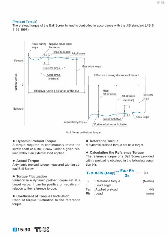
[Preload Torque] The preload torque of the Ball Screw in lead is controlled in accordance with the JIS standard (JIS B 1192-1997).
Actual starting torque
Actual starting torque
Negative actual-torque fluctuation
Positive actual torque fluctuation
Actual torque
Actual torque (minimum)
Actual torque
Actual torque
(maximum)
Effective running distance of the nut
Effective running distance of the nut
(Forward)
(Backward)
Mean actual torque
Mean actual torque
Reference torque
Reference torque
Torque fluctuation
Torque fluctuation
Fric
tion
torq
ue
0
(—)
(+)
(—)
(+)
Fig.7 Terms on Preload Torque
Dynamic Preload Torque A torque required to continuously rotate the screw shaft of a Ball Screw under a given pre-load without an external load applied.
Actual Torque A dynamic preload torque measured with an ac-tual Ball Screw.
Torque Fluctuation Variation in a dynamic preload torque set at a target value. It can be positive or negative in relation to the reference torque.
Coeffi cient of Torque Fluctuation Ratio of torque fluctuation to the reference torque.
Reference Torque A dynamic preload torque set as a target.
Calculating the Reference Torque The reference torque of a Ball Screw provided with a preload is obtained in the following equa-tion (4).
………(4)Tp = 0.05 (tanβ)–0.5 Fa0•Ph
2π T p : Reference torque (N-mm) : Lead angle Fa 0 : Applied preload (N) Rh : Lead (mm)
B15-30
511E

Ball Screw
Example of calculating the preload torque
When a preload of 3,000 N is provided to the Ball Screw model BIF4010-10G0 + 1500LC3 with a thread length of 1,300 mm (shaft diameter: 40 mm; ball center-to-center diameter:41.75 mm; lead: 10 mm), the preload torque of the Ball Screw is calculated in the steps below.
Calculating the Reference Torque : Lead angle
leadπ×ball center-to-center diameter
tanβ = = = 0.076210π×41.75
Fa 0 : Applied preload=3000N Ph : Lead = 10mm
3000 × 102π
Fa0•Ph2π
Tp = 0.05 (tanβ)–0.5 = 0.05 (0.0762)–0.5 = 865N • mm
Calculating the Torque Fluctuation
thread length screw shaft outer diameter
= = 32.5 ≦ 40 1300 40
Thus, with the reference torque in Table14 being between 600 and 1,000 N-mm, effective thread length 4,000 mm or less and accuracy grade C3, the coeffi cient of torque fl uctuation is obtained as ±30%. As a result, the torque fl uctuation is calculated as follows. 865×(10.3) = 606 N•mm to 1125 N•mm
Result Reference torque : 865 N-mn Torque fl uctuation : 606 N-mm to 1125 N-mm
Table14 Tolerance Range in Torque Fluctuation
Reference torque N•mm
Effective thread length
4000mm or less Above 4,000 mm and 10,000 mm or less
thread length screw shaft outer diameter
≦40
thread length screw shaft outer diameter 40< <60
—
Accuracy grades Accuracy grades Accuracy grades
Above Or less C0 C1 C3 C5 C7 C0 C1 C3 C5 C7 C3 C5 C7
200 400 30% 35% 40% 50% — 40% 40% 50% 60% — — — —
400 600 25% 30% 35% 40% — 35% 35% 40% 45% — — — —
600 1000 20% 25% 30% 35% 40% 30% 30% 35% 40% 45% 40% 45% 50%
1000 2500 15% 20% 25% 30% 35% 25% 25% 30% 35% 40% 35% 40% 45%
2500 6300 10% 15% 20% 25% 30% 20% 20% 25% 30% 35% 30% 35% 40%
6300 10000 — 15% 15% 20% 30% — — 20% 25% 35% 25% 30% 35%
Point of SelectionAccuracy of the Ball Screw
B15-31
511E

Selecting a Screw Shaft Maximum Length of the Screw Shaft
Table15 shows the manufacturing limit lengths of precision Ball Screws by accuracy grades, Table16 shows the manufacturing limit lengths of precision Ball Screws compliant with DIN standard by ac-curacy grades, and Table17 shows the manufacturing limit lengths of rolled Ball Screws by accuracy grades. If the shaft dimensions exceed the manufacturing limit in Table15 , Table16 or Table17 , contact THK.
Table15 Maximum Length of the Precision Ball Screw by Accuracy Grade Unit: mm
Screw shaftouter diameter
Overall screw shaft length
C0 C1 C2 C3 C5 C7
4 90 110 120 120 120 120
6 150 170 210 210 210 210
8 230 270 340 340 340 340
10 350 400 500 500 500 500
12 440 500 630 680 680 680
13 440 500 630 680 680 680
14 530 620 770 870 890 890
15 570 670 830 950 980 1100
16 620 730 900 1050 1100 1400
18 720 840 1050 1220 1350 1600
20 820 950 1200 1400 1600 1800
25 1100 1400 1600 1800 2000 2400
28 1300 1600 1900 2100 2350 2700
30 1450 1700 2050 2300 2570 2950
32 1600 1800 2200 2500 2800 3200
36
2000
2100 2550 2950 3250 3650
40 2400 2900 3400 3700 4300
45 2750 3350 3950 4350 5050
50 3100 3800 4500 5000 5800
55 3450 4150 5300 6050 6500
63
4000
5200 5800 6700 7700
70
6300
6450 7650 9000
80 7900 9000 10000
100 10000 10000
B15-32
511E

Ball Screw
Point of SelectionSelecting a Screw Shaft
Table16 Manufacturing limit lengths of precision Ball Screws (DIN standard compliant Ball Screws) Unit: mm
Shaft diameter Ground shaft CES shaft
C3 C5 C7 Cp3 Cp5 Ct5 Ct7
16 1050 1100 1400 1050 1100 1100 1400
20 1400 1600 1800 1400 1600 1600 1800
25 1800 2000 2400 1800 2000 2000 2400
32 2500 2800 3200 2500 2800 2800 3200
40 3400 3700 4300 3400 3700 3700 4300
50 4500 5000 5800 — — — —
63 5800 6700 7700 — — — —
Table17 Maximum Length of the Rolled Ball Screw by Accuracy Grade Unit: mm
Screw shaftouter diameter
Overall screw shaft length
C7 C8 C10
6 to 8 320 320 —
10 to 12 500 1000 —
14 to 15 1500 1500 1500
16 to 18 1500 1800 1800
20 2000 2200 2200
25 2000 3000 3000
28 3000 3000 3000
30 3000 3000 4000
32 to 36 3000 4000 4000
40 3000 5000 5000
45 3000 5500 5500
50 3000 6000 6000
B15-33
511E

Standard Combinations of Shaft Diameter and Lead for the Precision Ball Screw
Table18 shows standard combinations of shaft diameters and leads of precision Ball Screws, and Table19 shows standard combinations of shaft diameters and leads of precision Ball Screws compli-ant with DIN standard. For standard combinations of shaft diameter and lead of the Precision Caged Ball Screw, see A15-72 to A15-89 . If a Ball Screw not covered by the table is required,contact THK.
Table18 Standard Combinations of Screw Shaft and Lead (Precision Ball Screw) Unit: mm
Screw shaft outer diameter
Lead
1 2 4 5 6 8 10 12 15 16 20 24 25 30 32 36 40 50 60 80 90 100 4 ● 5 ● 6 ● 8 ● ● ● ○ 10 ● ● ● ○ 12 ● ● ● 13 ○ 14 ● ● ● ● 15 ● ● ○ ○ 16 ○ ● ○ ○ ● 18 ● 20 ○ ● ○ ○ ● ○ ● ○ ○ 25 ○ ● ○ ○ ● ○ ○ ● ○ ○ 28 ○ ● ○ ○ 30 ○ ○ 32 ○ ● ● ○ ● ○ ○ ○ 36 ○ ○ ● ○ ○ ○ ○ ○ 40 ○ ○ ○ ● ● ○ ○ ○ ○ ○ 45 ○ ○ ○ ○ ○ ○ 50 ○ ○ ● ○ ○ ○ ○ ○ ○ ○ 55 ○ ○ ○ ○ ○ ○ 63 ○ ○ ○ ○ 70 ○ ○ ○ 80 ○ ○ ○ 100 ○ 120
●: Standardized Screw Shafts (Unfi nished Shaft Ends/Finished Shaft Ends) ○: Semi-standard stock
Table19 Standard combinations of outer diameters and leads of the screw shafts (DIN standard compliant Ball Screws) Unit: mm
Shaft diameter Lead
5 10 20 16 ● — — 20 ● — — 25 ● ● — 32 ● ● — 40 ○ ● ○ * 50 — ○ ○ * 63 — ○ ○ *
●: Ground shaft, CES shaft ○: Ground shaft only *: Model EB (no preload) only
B15-34
511E

Ball Screw
Point of SelectionSelecting a Screw Shaft
Standard Combinations of Shaft Diameter and Lead for the Rolled Ball Screw
Table20 shows the standard combinations of shaft diameter and lead for the rolled Ball Screw.
Table20 Standard Combinations of Screw Shaft and Lead (Rolled Ball Screw) Unit: mm
Screw shaftouter diameter
Lead
1 2 4 5 6 8 10 12 16 20 24 25 30 32 36 40 50 60 80 100
6 ●
8 ●
10 ● ○
12 ● ○
14 ● ●
15 ● ● ●
16 ● ●
18 ●
20 ● ● ● ●
25 ● ● ● ●
28 ●
30 ●
32 ● ●
36 ● ● ● ●
40 ● ● ●
45 ●
50 ● ● ●
●: Standard stock ○: Semi-standard stock
B15-35
511E

B15-36
Method for Mounting the Ball Screw Shaft Fig.1 to Fig.4 show the representative mounting methods for the screw shaft. The permissible axial load and the permissible rotational speed vary with mounting methods for the screw shaft. Therefore, it is necessary to select an appropriate mounting method according to the conditions.
Distance between two mounting surfaces (permissible rotational speed)
Distance between two mounting surfaces (permissible axial load)
Fixed Fixed Free
Fig.1 Screw Shaft Mounting Method: Fixed - Free
Distance between two mounting surfaces (permissible axial load)
Distance between two mounting surfaces (permissible rotational speed)
Fixed Supported Fixed
Fig.2 Screw Shaft Mounting Method: Fixed - Supported
511E

Ball Screw
Distance between two mounting surfaces (permissible axial load)
Distance between two mounting surfaces (permissible rotational speed)
Fixed Fixed Fixed
Fig.3 Screw Shaft Mounting Method: Fixed - Fixed
Distance between two mounting surfaces (permissible axial load)
Fixed Fixed
Fixed
Fig.4 Screw Shaft Mounting Method for Rotary Nut Ball Screw: Fixed - Fixed
Point of SelectionMethod for Mounting the Ball Screw Shaft
B15-37
511E

Permissible Axial Load [Buckling Load on the Screw Shaft] With the Ball Screw, it is necessary to select a screw shaft so that it will not buckle when the maxi-mum compressive load is applied in the axial direction. Fig.5 on B15-39 shows the relationship between the screw shaft diameter and a buckling load. If determining a buckling load by calculation, it can be obtained from the equation (5) below. Note that in this equation, a safety factor of 0.5 is multiplied to the result.
………(5)P1 = 0.5 = η 2 104η1• π2• E • I
ℓa2
d14
ℓa2
P 1 : Buckling load (N) ℓ a : Distance between two mounting surfaces (mm) E : Young’s modulus (2.06×10 5 N/mm 2 ) I : Minimum geometrical moment of inertia of the shaft (mm 4 )
d1: screw-shaft thread minor diameter (mm) I = d14 π
64 1 , 2 =Factor according to the mounting method Fixed - free 1 =0.25 2 =1.3 Fixed - supported 1 =2 2 =10 Fixed - fi xed 1 =4 2 =20
[Permissible Tensile Compressive Load on the Screw Shaft] If an axial load is applied to the Ball Screw, it is necessary to take into account not only the buckling load but also the permissible tensile compressive load in relation to the yielding stress on the screw shaft. The permissible tensile compressive load is obtained from the equation (6).
………(6)P2 = σ d1
2 = 116d12π
4 P 2 : Permissible tensile compressive load (N) : Permissible tensile compressive stress (147 MPa) d 1 : Screw-shaft thread minor diameter (mm)
B15-38
511E

Ball Screw
Point of SelectionPermissible Axial Load
Fixed - free
Fixed - supported
Fixed - fixed
Mounting method Axial load (kN)
Dis
tanc
e be
twee
n tw
o m
ount
ing
surfa
ces
(mm
)
2 2 2 1 0.8 0.6 0.4 10 8 6 4 8 6 4 102
2 2 2 10 8 6 4 2 8 6 4 8 6 4 102
4 2 2 4 2 10 8 6 4 8 6 4 8 6 102
103
103
200
400
600
800
1000
2000
4000
6000
8000
10000
φ 45
φ 80
φ 70
φ 63
φ 55
φ 50
φ 100
φ 40
φ 36
φ 32φ 30
φ 28φ 25
φ 20
φ 18φ 16
φ 15φ 14
φ 12
φ 10
φ 8
φ 6
Fig.5 Permissible Tensile Compressive Load Diagram
B15-39
511E

Permissible Rotational Speed [Dangerous Speed of the Screw Shaft] When the rotational speed reaches a high magnitude, the Ball Screw may resonate and eventually become unable to operate due to the screw shaft’s natural frequency. Therefore, it is necessary to select a model so that it is used below the resonance point (dangerous speed). Fig.6 on B15-42 shows the relationship between the screw shaft diameter and a dangerous speed. If determining a dangerous speed by calculation, it can be obtained from the equation (7) below. Note that in this equation, a safety factor of 0.8 is multiplied to the result.
………(7)N1 = 0.8 = λ2• • 107d1
ℓb2
E 103• Iγ • A
60 • λ12
2π •ℓb2
N 1 : Permissible rotational speed determined by dangerous speed (min -1 ) ℓ b : Distance between two mounting surfaces (mm) E : Young’s modulus (2.06×10 5 N/mm 2 ) I : Minimum geometrical moment of inertia of the shaft (mm 4 )
d1: screw-shaft thread minor diameter (mm) I = d14
π
64 : Density (specifi c gravity) (7.85×10 -6 kg/mm 3 ) A : Screw shaft cross-sectional area (mm 2 )
A = d12
π
4 1 , 2 : Factor according to the mounting method Fixed - free 1 =1.875 2 =3.4 Supported - supported 1 =3.142 2 =9.7 Fixed - supported 1 =3.927 2 =15.1 Fixed - fi xed 1 =4.73 2 =21.9
B15-40
511E

Ball Screw
Point of SelectionPermissible Rotational Speed
[DN Value] The permissible rotational speed of the Ball Screw must be obtained from the dangerous speed of the screw shaft and the DN value. The permissible rotational speed determined by the DN value is obtained using the equations (8) to (16) below.
Pre
cisi
on
Caged Ball
Large Lead
Model SBK (SBK3636, SBK4040 and SBK5050)
………(8-1)N2 = 210000D
Model SBK (Other than the above model numbers and the small size model SBK * )
………(8-2)N2 = 160000D
Standard lead Model SBN-V (Medium)
………(9-1)N2 = 160000
D
Models SBN-V (Small), HBN, and SBKH
………(9-2)N2 = 130000D
Full- Complement Ball
Super Lead Model WHF
………(10-1)N2 = 120000
D
Model WGF
………(10-2)N2 = 70000D
Large Lead Models BLW, BLK, BLR, BNS and NS
………(11)N2 = 70000D
Standard lead
Models BIF-V (Medium), BNFN-V (Medium), and BNF (Medium)
………(12-1)N2 = 130000D
Models BIF-V (Small), BNFN-V (Small), and BNF (Small)
………(12-2)N2 = 100000D
Models BIF, DIK, BNFN, DKN, BNF, BNT, DK, MDK, MBF, BNK and DIR ………(12-3)N2 = 70000
D
Full-Complement Ball(DIN Standard Compliant) Standard lead Models EBA, EBB, EBC, EPA, EPB
and EPC ………(13)N2 = 100000
D
Rol
led Full-
Complement Ball
Super Lead Model WHF
………(14-1)N2 = 100000D
Models WTF and CNF ………(14-2)N2 = 70000
D
Large Lead Models BLK and BLR ………(15)N2 = 70000
D
Standard lead Model BTK-V
………(16-1)N2 = 100000D
Models JPF, BNT and MTF
………(16-2)N2 = 50000D
N 2 : Permissible rotational speed determined by the DN value (min -1 (rpm)) D : Ball center-to-center diameter (indicated in the specifi cation tables of the respective model number) Of the permissible rotational speed determined by dangerous speed (N 1 ) and the permissible rotational speed determined by DN value (N 2 ), the lower rotational speed is regarded as the permissible rotational speed. For small size SBK (SBK1520 to 3232) and SDA, the permissible rotational speed (N 2 ) is the maxi-mum permissible rotational speed shown in the dimensional tables.(See dimensional tables on pages A15-76 to A15-77 , and A15-80 to A15-85 ) If the service rotational speed exceeds N 2 , contact THK.
B15-41
511E

Fixed - free
Fixed - supported
Fixed - fixed
Mounting method
Rotational speed (min-1)
Dis
tanc
e be
twee
n tw
o m
ount
ing
surfa
ces
(mm
)
4 4 6 8 2 2 102 6 8 103
2 4 6 8 2 103 4 6 8 104
4 2 2 6 8 104 4 6 8 103
200
400
600
800
1000
2000
4000
6000
8000
10000
φ 100φ 80φ 70φ 63φ 55φ 50φ 45φ 40φ 32φ 30φ 28φ 25
φ 18φ 16φ 15φ 14φ 12
φ 36
φ 20
φ 10φ 8φ 6
Fig.6 Permissible Rotational Speed Diagram
B15-42
511E

Ball Screw
Point of SelectionSelecting a Nut
Selecting a Nut Types of Nuts
The nuts of the Ball Screws are categorized by the ball circulation method into the return-pipe type, the defl ector type and end the cap type. These three nut types are described as follows. In addition to the circulation methods, the Ball Screws are categorized also by the preloading method.
[Types by Ball Circulation Method] Return-Pipe Type (Models SBN-V (Medium), BIF-V (Medium), BIF, BNF-V (Medium), BNF, BNFN-V (Medium), BNFN, BNT, BTK-V), Return-Piece Type (Models SBN-V (Small), HBN, BIF-V (Small), BNF-V (Small), BNFN-V (Small))
These are most common types of nuts that use a return pipe for ball circulation. The return pipe allows balls to be picked up, pass through the pipe, and return to their original positions to complete infi nite motion.
Pipe presser
Return pipe
Screw shaft
Ball
Labyrinth seal
Ball screw nut
Ball screw nut
Example of Structure of Return-Pipe Nut
Defl ector Type (Models EB, EP, DK, DKN, DIK, JPF, DIR and MDK)
These are the most compact type of nut. The balls change their traveling direction with a deflector, pass over the circumference of the screw shaft, and return to their original positions to complete an infi nite motion.
Deflector Screw shaft
Ball
Greasing hole
Labyrinth seal
Ball screw nut
Example of Structure of Simple Nut
End-cap Type: Large lead Nut (Models SBK, SBKH, WHF, BLK, WGF, BLW, WTF, CNF and BLR)
These nuts are most suitable for the fast feed. The balls are picked up with an end cap, pass through the through hole of the nut, and return to their original positions to complete an infi nite motion.
End cap
Screw shaft
Ball
Greasing hole
End cap Ball screw nut
Example of Structure of Large lead Nut
B15-43
511E

[Types by Preloading Method] Fixed-point Preloading Double-nut Preload (Models BNFN-V, BNFN, DKN and BLW) A spacer is inserted between two nuts to provide a preload.
Model BLWModel DKNModels BNFN-V and BNFN
Applied preload Applied preload
(3.5 to 4.5) pitches + preloadSpacer
Offset Preload (Models SBN-V, EP, BIF-V, BIF, DIK, DIR and SBK) More compact than the double-nut method, the offset preloading provides a preload by changing the groove pitch of the nut without using a spacer.
Model SBKModel DIR
Models BIF-V and BIF Model DIKModel SBN-V
0.5 pitch + preload
Applied preload Applied preload
Model EPB
B15-44
511E

Ball Screw
Point of SelectionSelecting a Nut
Constant Pressure Preloading (Model JPF) With this method, a spring structure is installed almost in the middle of the nut, and it provides a pre-load by changing the groove pitch in the middle of the nut.
4 pitches - preload
Applied preloadApplied preload
Spring sectionModel JPF
B15-45
511E

Selecting a Model Number Calculating the Axial Load [In Horizontal Mount] With ordinary conveyance systems, the axial load (Fa n ) applied when horizontally reciprocating the work is obtained in the equation below.
(22) …………………
(21)
(20)
(19)
…………………
…………………
(18)
…………………………
…………………………
(17) …………………
Fa2= μμ • mg + f
Fa5= −μ • mg − fFa6= −μ • mg − f + mα
Fa4= −μ • mg − f − mαFa3= μ • mg + f − mα
Fa1= μ • mg + f + mα
V max : Maximum speed (m/s) t 1 : Acceleration time (m/s)
: Acceleration )2 (m/s α =
Vmax
t1
Fa 1 : Axial load during forward acceleration (N) Fa 2 : Axial load during forward uniform motion (N) Fa 3 : Axial load during forward deceleration (N) Fa 4 : Axial load during backward acceleration (N) Fa 5 : Axial load during uniform backward motion (N)
Axial load: Fan Mass: m
Guide surfaceFriction coefficient : μResistance without load : fGravitational acceleration: g
Fa 6 : Axial load during backward deceleration (N) m : Transferred mass (kg) : Frictional coeffi cient of the guide surface (–) f : Guide surface resistance (without load) (N)
[In Vertical Mount] With ordinary conveyance systems, the axial load (Fa n ) applied when vertically reciprocating the work is obtained in the equation below.
(28) …………………………
(27)
(26)
(25)
…………………………
…………………………
(24)
…………………………………
…………………………………
(23) …………………………
Fa5= mg − f Fa6= mg − f + mαα
Fa4= mg − f − mαFa3= mg + f − mα
Fa1= mg + f + mαFa2= mg + f
V max : Maximum speed (m/s) t 1 : Acceleration time (m/s)
: Acceleration ) 2 (m/s α =
Vmax
t1
Fa 1 : Axial load during upward acceleration (N) Fa 2 : Axial load during uniform upward motion (N) Fa 3 : Axial load during upward deceleration (N) Fa 4 : Axial load during downward acceleration (N) Fa 5 : Axial load during uniform downward motion (N)
Axial load: Fan
Mass: m
Guide surfaceFriction coefficient : μResistance without load: f
Des
cent
A
scen
t
Fa 6 : Axial load during downward deceleration (N) m : Transferred mass (kg) f : Guide surface resistance (without load) (N)
B15-46
511E

Ball Screw
Point of SelectionSelecting a Model Number
Static Safety Factor
The basic static load rating (C 0 a) generally equals to the permissible axial load of a Ball Screw. Depending on the conditions, it is necessary to take into account the following static safety factor against the calculated load. When the Ball Screw is stationary or in motion, unexpected external force may be applied through an inertia caused by the impact or the start and stop.
………(29)Famax = C0a
fS Fa max : Allowable Axial Load (kN) C 0 a : Basic static load rating * (kN) f S : Static safety factor (see Table1 )
Table1 Static Safety Factor (f S )
Machine usingthe LM system Load conditions Lower
limit of f S
General industrial machinery
Without vibration or impact 1.0 to 3.5
With vibration or impact 2.0 to 5.0
Machine tool Without vibration or impact 1.0 to 4.0
With vibration or impact 2.5 to 7.0
*The basic static load rating (C 0 a) is a static load with a constant direction and magnitude whereby the sum of the permanent deformation of the rolling element and that of the raceway on the contact area under the maximum stress is 0.0001 times the rolling element diameter. With the Ball Screw, it is defi ned as the axial load. (Specifi c values of each Ball Screw model are indicated in the specifi cation tables for the corresponding model number.)
[Permissible Load Safety Margin (Models HBN and SBKH)] High load Ball Screw model HBN and high-load high-speed Ball Screw model SBKH, in comparison to previous Ball Screws, are designed to achieve longer service lives under high load conditions, and for axial load it is necessary to consider the permissible load Fp. Permissible load Fp indicates the maxim axial load that the high load Ball Screw can receive, and this range should not be exceeded.
………(30)> 1 Fp
Fa Fp : Permissible Axial Load (kN) Fa : Applied Axial Load (kN)
B15-47
511E

Studying the Service Life
[Service Life of the Ball Screw] The Ball Screw in motion under an external load receives repeated stress on its raceways and balls. When the stress reaches the limit, the raceways break from fatigue and their surfaces fl akes like scales. This phenomenon is called fl aking. The service life of the Ball Screw is the total number of revolutions until the fi rst fl aking occurs on any of the raceways or the balls as a result of rolling fa-tigue of the material. The service life of the Ball Screw varies from unit to unit even if they are manufactured in the same process and used in the same operating conditions. For this reason, when determining the service life of a Ball Screw unit, the nominal life as defi ned below is used as a guideline. The nominal life is the total number of revolutions that 90% of identical Ball Screw units in a group achieve without developing fl aking (scale-like pieces of a metal surface) after they independently operate in the same conditions.
[Calculating the Rated Life] The service life of the Ball Screw is calculated from the equation (31) below using the basic dynamic load rating (Ca) and the applied axial load.
Nominal Life (Total Number of Revolutions)
………(31)L =
3
106 Ca
fW•Fa ( )
L : Nominal life (total number of revolutions) (rev) Ca : Basic dynamic load rating * (N) Fa : Applied axial load (N) f w : Load factor (see Table2 )
Table2 Load Factor (f W )
Vibrations/impact Speed(V) f W
Faint Very low V≦0.25m/s 1 to 1.2
Weak Slow 0.25<V≦1m/s 1.2 to 1.5
Medium Medium 1<V≦2m/s 1.5 to 2
Strong High V>2m/s 2 to 3.5
*The basic dynamic load rating (Ca) is used in calculations of service life when the ball screw is under an axial load. The basic dynamic load rating is defi ned as a load rating based on the movement of a set of identical ball screws with a rated life (L) of 10 6 revolutions, using a load applied in the axial direction that does not vary in either mass or direction. (The basic dynamic load ratings (Ca) for each model number are indicated in the specifi cation tables.)
*The rated service life is estimated by calculating the load on the premise that the product is set up in ideal mounting condi-tions with the assurance of good lubrication. The service life can be affected by the precision of the mounting materials used and any distortion.
B15-48
511E

Ball Screw
Point of SelectionSelecting a Model Number
Service Life Time If the revolutions per minute is determined, the service life time can be calculated from the equation (32) below using the nominal life (L).
………(32)Lh = = L
60 N L Ph
2 60 n ℓS L h : Service life time (h) N : Revolutions per minute (min ‒1 ) n : Number of reciprocations per minute (min ‒1 ) Ph : Ball Screw lead (mm) ℓ S : Stroke length (mm)
Service Life in Travel Distance The service life in travel distance can be calculated from the equation (33) below using the nominal life (L) and the Ball Screw lead.
………(33)LS = L Ph
106
L S : Service Life in Travel Distance (km) Ph : Ball Screw lead (mm)
Applied Load and Service Life with a Preload Taken into Account If the Ball Screw is used under a preload (medium preload), it is necessary to consider the applied preload in calculating the service life since the ball screw nut already receives an internal load. For details on applied preload for a specifi c model number, contact THK.
Average Axial Load If an axial load acting on the Ball Screw is present, it is necessary to calculate the service life by de-termining the average axial load. The average axial load (F m ) is a constant load that equals to the service life in fl uctuating the load conditions. If the load changes in steps, the average axial load can be obtained from the equation below.
………(34)
3
Fm = (Fa13ℓ1 + Fa2
3ℓ2 + •••• + Fan3ℓn)1
ℓ F m : Average Axial Load (N) Fa n : Varying load (N) ℓ n : Distance traveled under load (F n ) ℓ : Total travel distance
B15-49
511E

To determine the average axial load using a rotational speed and time, instead of a distance, calcu-late the average axial load by determining the distance in the equation below. ℓ = ℓ 1 + ℓ 2 + • • •ℓ n ℓ 1 = N 1 • t 1 ℓ 2 = N 2 • t 2 ℓ n = N n • t n N: Rotational speed t: Time
When the Applied Load Sign Changes If the sign (positive or negative) used for vari-able load is always the same, there are no problems with formula (34). However, if the vari-able load sign changes depending on the type of operation, calculate the average axial load for either positive or negative load, allowing for the load direction. (If the average axial load for positive load is calculated, the negative load is taken to be zero.) The larger of the two aver-age axial loads is taken as the average axial load when the service life is calculated. Example: Calculate the average axial load with
the following load conditions.
Operation No. Varying loadFa n (N)
Travel distanceℓ n (mm)
No.1 10 10
No.2 50 50
No.3 –40 10
No.4 –10 70
Positive-sign load
Negative-sign load
*The subscripts of the fl uctuating load symbol and the travel distance symbol indicate operation numbers. ● Average axial load of positive-sign load *To calculate the average axial load of the positive-sign load, assume Fa 3 and Fa 4 to be zero.
3
Fa13 × ℓ1 + Fa2
3 × ℓ2
ℓ1 + ℓ2 + ℓ3 + ℓ4Fm1 = = 35.5N
● Average axial load of negative-sign load *To calculate the average axial load of the negative-sign load, assume Fa 1 and Fa 2 to be zero.
Fa3 3 × ℓ3 + Fa4
3 × ℓ4
ℓ1 + ℓ2 + ℓ3 + ℓ4
Fm2 = = 17.2N3
Accordingly, the average axial load of the positive-sign load (F m1 ) is adopted as the average axial load (F m ) for calculating the service life.
B15-50
511E

Ball Screw
Point of SelectionStudying the Rigidity
Studying the Rigidity To increase the positioning accuracy of feed screws in NC machine tools or the precision machines, or to reduce the displacement caused by the cutting force, it is necessary to design the rigidity of the components in a well-balanced manner.
Axial Rigidity of the Feed Screw System
When the axial rigidity of a feed screw system is K, the elastic displacement in the axial direction can be obtained using the equation (35) below.
………(35)δ = Fa
K : Elastic displacement of a feed screw system in the axial direction (m) Fa : Applied axial load (N) The axial rigidity (K) of the feed screw system is obtained using the equation (36) below.
………(36) = + + + 1
K 1 KS
1 KN
1 KB
1 KH
K : Axial Rigidity of the Feed Screw System (N/m) K S : Axial rigidity of the screw shaft (N/m) K N : Axial rigidity of the nut (N/m) K B : Axial rigidity of the support bearing (N/m) K H : Rigidity of the nut bracket and the support bearing bracket (N/m)
[Axial rigidity of the screw shaft] The axial rigidity of a screw shaft varies depending on the method for mounting the shaft.
For Fixed-Supported (or -Free) Confi guration
………(37)KS = A•E
1000•L A : Screw shaft cross-sectional area (mm 2 )
π4
A = d12
d 1 : Screw-shaft thread minor diameter (mm) E : Young’s modulus (2.06×10 5 N/mm 2 ) L : Distance between two mounting surfaces (mm) Fig.7 on B15-52 shows an axial rigidity diagram for the screw shaft.
Fixed Supported (Free)
L
B15-51
511E

For Fixed-Fixed Confi guration
………(38)
A•E•L 1000•a•b KS =
KS becomes the lowest and the elastic displace-ment in the axial direction is the greatest at the
position of .
KS = 4A•E1000L
a = b = L2
Fig.8 on B15-53 shows an axial rigidity diagram of the screw shaft in this confi guration.
Fixed Fixed
L a b
Distance between two mounting surfaces (mm)
Rig
idity
of t
he s
crew
sha
ft (k
N/μ
m)
φ 100
φ 80φ 70φ 63φ 55φ 50φ 45φ 40φ 36φ 32φ 30φ 28φ 25
φ 20φ 18
φ 16φ 15
φ 14φ 12
φ 10φ 8
φ 6φ 4
10 8 6
4
2
1 8 6
4
8
8
6
6
4
4
2
2 102 8 6 103 4 2 8 6 104
10‐1
Fig.7 Axial Rigidity of the Screw Shaft (Fixed-Free, Fixed-Supported)
B15-52
511E

Ball Screw
Point of SelectionStudying the Rigidity
Distance between two mounting surfaces (mm)
Rig
idity
of t
he s
crew
sha
ft (k
N/μ
m)
φ 55φ 63
φ 70
φ 80φ 100
φ 50φ 45φ 40φ 36φ 32φ 30φ 28φ 25
φ 20φ 18φ 16φ 15φ 14φ 12
φ 10φ 8
φ 6
φ 4
10 8 6 4
2
1 8 6
4
8 6
4
2
8 6 4 2 102 8 6 103 4 2 8 6 104
10‐1
Fig.8 Axial Rigidity of the Screw Shaft (Fixed-Fixed)
[Axial rigidity of the nut] The axial rigidity of the nut varies widely with preloads.
No Preload Type The logical rigidity in the axial direction when an axial load accounting for 30% of the basic dynamic load rating (Ca) is applied is indicated in the specifi cation tables of the corresponding model num-ber. This value does not include the rigidity of the components related to the nut-mounting bracket. In general, set the rigidity at roughly 80% of the value in the table. The rigidity when the applied axial load is not 30% of the basic dynamic load rating (Ca) is calculated using the equation (39) below.
………(39)KN = K 0.8 ( ) Fa
0.3Ca
1 3
K N : Axial rigidity of the nut (N/m) K : Rigidity value in the specifi cation tables (N/m) Fa : Applied axial load (N) Ca : Basic dynamic load rating (N)
B15-53
511E

Preload Type The logical rigidity in the axial direction when an axial load accounting for 10% of the basic dynamic load rating (Ca) is applied is indicated in the dimensional table of the corresponding model number. This value does not include the rigidity of the components related to the nut-mounting bracket. In general, generally set the rigidity at roughly 80% of the value in the table. The rigidity when the applied preload is not 10% of the basic dynamic load rating (Ca) is calculated using the equation (40) below.
………(40)KN = K 0.8 ( ) Fa0
0.1Ca
1 3
K N : Axial rigidity of the nut (N/m) K : Rigidity value in the specifi cation tables (N/m) Fa 0 : Applied preload (N) Ca : Basic dynamic load rating (N)
[Axial rigidity of the support bearing] The rigidity of the Ball Screw support bearing varies depending on the support bearing used. The calculation of the rigidity with a representative angular contact ball bearing is shown in the equation (41) below.
………(41)
3Fa0
δa0KB
K B : Axial rigidity of the support bearing (N/m) Fa 0 : Applied preload of the support bearing (N) a 0 : Axial displacements (m)
Q =
( ) δa0 =
Fa0
Zsinα
1 3 Q2
Da 0.45sinα
Q : Axial load (N) Da : Ball diameter of the support bearing (mm) : Initial contact angle of the support bearing () Z : Number of balls For details of a specifi c support bearing, contact its manufacturer.
[Axial Rigidity of the Nut Bracket and the Support Bearing Bracket] Take this factor into consideration when designing your machine. Set the rigidity as high as possible.
B15-54
511E

Ball Screw
Point of SelectionStudying the Positioning Accuracy
Studying the Positioning Accuracy Causes of Error in the Positioning Accuracy
The causes of error in the positioning accuracy include the lead angle accuracy, the axial clearance and the axial rigidity of the feed screw system. Other important factors include the thermal displace-ment from heat and the orientation change of the guide system during traveling.
Studying the Lead Angle Accuracy
It is necessary to select the correct accuracy grade of the Ball Screw that satisfi es the required po-sitioning accuracy from the Ball Screw accuracies ( Table1 on B15-20 ). Table3 on B15-56 shows examples of selecting the accuracy grades by the application.
Studying the Axial Clearance
The axial clearance is not a factor of positioning accuracy in single-directional feed. However, it will cause a backlash when the feed direction is inversed or the axial load is inversed. Select an axial clearance that meets the required backlash from Table10 and Table13 on B15-27 .
B15-55
511E

Table3 Examples of Selecting Accuracy Grades by Application
Applications Shaft Accuracy grades
C0 C1 C2 C3 C5 C7 C8 C10
NC
mac
hine
tool
s
Lathe X ● ● ● ● Z ● ●
Machining center XY ● ● ● Z ● ● ●
Drilling machine XY ● ● Z ● ●
Jig borer XY ● ● Z ● ●
Surface grinder X ● ● Y ● ● ● ● Z ● ● ● ●
Cylindrical grinder X ● ● ● Z ● ● ●
Electric dischargemachine
XY ● ● ● Z ● ● ● ●
Electric dischargemachine
Wire cutting machine
XY ● ● ● Z ● ● ● ●
UV ● ● ● Punching press XY ● ● ●
Laser beam machine X ● ● ● Z ● ● ●
Woodworking machine ● ● ● ● General-purpose machine; dedicated machine ● ● ● ● ●
Indu
stria
l rob
ot
Cartesian coordinate Assembly ● ● ● ●
Other ● ● ● ●
Vertical articulated type Assembly ● ● ●
Other ● ● Cylindrical coordinate ● ● ●
Sem
icond
ucto
r m
anuf
actu
ring
mac
hine
Photolithography machine ● ● Chemical treatment machine ● ● ● ● ● ●
Wire bonding machine ● ● Prober ● ● ● ●
Printed circuit board drilling machine ● ● ● ● ● Electronic component inserter ● ● ● ●
3D measuring instrument ● ● ● Image processing machine ● ● ● Injection molding machine ● ● ●
Offi ce equipment ● ● ● ●
B15-56
511E

Ball Screw
Point of SelectionStudying the Positioning Accuracy
Studying the Axial Clearance of the Feed Screw System
Of the axial rigidities of the feed screw system, the axial rigidity of the screw shaft fl uctuates ac-cording to the stroke position. When the axial rigidity is large, such change in the axial rigidity of the screw shaft will affect the positioning accuracy. Therefore, it is necessary to take into account the rigidity of the feed screw system ( B15-51 to B15-54 ).
Example of considering the rigidity of a feed screw system
Example: Positioning error due to the axial rigidity of the feed screw system during a vertical transfer
L
1000N
500N
[Conditions] Transferred weight: 1,000 N; table weight: 500 N Ball Screw used: model BNF2512–2.5 (screw-shaft thread minor diameter d 1 = 21.9 mm) Stroke length: 600 mm (L=100 mm to 700 mm) Screw shaft mounting type: fi xed-supported
[Consideration] The difference in axial rigidity between L = 100 mm and L = 700 mm applied only to the axial rigidity of the screw shaft. Therefore, positioning error due to the axial rigidity of the feed screw system equals to the difference in the axial displacement of the screw shaft between L = 100 mm and L = 700 mm.
B15-57
511E

[Axial Rigidity of the Screw Shaft (see B15-51 and B15-52 )]
Ks = = =
4 π
4 πA = d1
2 = ×21.92 = 376.5mm2
E = 2.06×10⁵ N/mm2
77.6×10³
L 376.5×2.06×105
1000×L 1000L A•E
(1) When L = 100 mm
KS1 = = 776 N/μm
100 77.6×10³
(2) When L = 700mm
KS2 = = 111 N/μm
700 77.6×10³
[Axial Displacement due to Axial Rigidity of the Screw Shaft] (1) When L = 100 mm
δ1 = = = 1.9μm
KS1
Fa 776
1000+500
(2) When L = 700mm
δ2 = = = 13.5μm
KS2
Fa 111
1000+500
[Positioning Error due to Axial Rigidity of the Feed Screw System] Positioning accuracy= 1 – 2 =1.9–13.5 =–11.6m Therefore, the positioning error due to the axial rigidity of the feed screw system is 11.6 m.
B15-58
511E

Ball Screw
Point of SelectionStudying the Positioning Accuracy
Studying the Thermal Displacement through Heat Generation
If the temperature of the screw shaft increases during operation, the screw shaft is elongated due to heat thereby to lower the positioning accuracy. The expansion and contraction of the screw shaft is calculated using the equation (42) below.
………(42)ΔΔ ℓ = ρ Δt ℓ
ℓ : Axial expansion/contraction of the screw shaft (mm) : Thermal expansion coeffi cient (12×10 -6 /℃) t : Temperature change in the screw shaft (℃) ℓ : Effective thread length (mm) Thus, if the temperature of the screw shaft increases by 1℃, the screw shaft is elongated by 12 m per meter. Therefore, as the Ball Screw travels faster, the more heat is generated. So, as the tem-perature increases, the positioning accuracy lowers. Accordingly, if high accuracy is required, it is necessary to take measures to cope with the temperature increase.
[Measures to Cope with the Temperature Rise] Minimize the Heat Generation
● Minimize the preloads on the Ball Screw and the support bearing. ● Increase the Ball Screw lead and reduce the rotational speed. ● Select a correct lubricant. (See Accessories for Lubrication on A24-2 .) ● Cool the circumference of the screw shaft with a lubricant or air.
Avoid Effect of Temperature Rise through Heat Generation ● Set a negative target value for the reference travel distance of the Ball Screw.
Generally, set a negative target value for the reference travel distance assuming a temperature increase of 2℃ to 5℃ by heat. (–0.02mm to –0.06 mm/m)
● Preload the shaft screw with tension. (See Fig.3 of the structure on B15-37 .)
B15-59
511E

Studying the Orientation Change during Traveling
The lead angle accuracy of the Ball Screw equals the positioning accuracy of the shaft center of the Ball Screw. Normally, the point where the highest positioning accuracy is required changes accord-ing to the ball screw center and the vertical or horizontal direction. Therefore, the orientation change during traveling affects the positioning accuracy. The largest factor of orientation change affecting the positioning accuracy is pitching if the change occurs in the ball screw center and the vertical direction, and yawing if the change occurs in the horizontal direction. Accordingly, it is necessary to study the orientation change (accuracy in pitching, yawing, etc.) dur-ing the traveling on the basis of the distance from the ball screw center to the location where posi-tioning accuracy is required. Positioning error due to pitching and yawing is obtained using the equation (43) below.
………(43)A = ℓℓ sinθ A : Positioning accuracy due to pitching (or yawing) (mm) ℓ : Vertical (or horizontal) distance from the ball screw center (mm) (see Fig.9 ) : Pitching (or yawing) ()
θ
θ
ℓ
A
A
ℓ
Fig.9
B15-60
511E

Ball Screw
Point of SelectionStudying the Rotational Torque
Studying the Rotational Torque The rotational torque required to convert rotational motion of the Ball Screw into straight motion is obtained using the equation (44) below.
[During Uniform Motion]
………(44)( T1 + T2 + T4)• A T t : Rotation torque required during uniform motion (N-mm) T 1 : Friction torque due to an external load (N-mm) T 2 : Preload torque of the Ball Screw (N-mm) T 4 : Other torque (N-mm) (frictional torque of the support bearing and oil seal) A : Reduction ratio
[During Acceleration]
………(45)TK = Tt + T3 T K : Rotation torque required during acceleration (N-mm) T 3 : Torque required for acceleration (N-mm)
[During Deceleration]
………(46)Tg = Tt - T3 T g : Rotational torque required for deceleration (N-mm)
Frictional Torque Due to an External Load
Of the turning forces required for the Ball Screw, the rotational torque needed for an external load (guide surface resistance or external force) is obtained using the equation (47) below.
………(47)2π • η
Fa •Ph T1 =
T 1 : Friction torque due to an external load (N-mm) Fa : Applied load (N) Ph : Ball Screw lead (mm) : Ball Screw effi ciency (0.9 to 0.95)
B15-61
511E

Torque Due to a Preload on the Ball Screw
For a preload on the Ball Screw, see “Preload Torque” on B15-30 .
B15-62
511E

Ball Screw
Point of SelectionStudying the Rotational Torque
Torque Required for Acceleration
………(48)T3 = J ωω′ 103
T 3 : Torque required for acceleration (N-mm) J : Inertial moment (kg•m 2 ) ´ : Angular acceleration (rad/s 2 )
2πPh ( )
2
J = m • A2• 10-6 + JS• A2 + JA• A2 + JB
m : Transferred mass (kg) Ph : Ball Screw lead (mm) J S : Inertial moment of the screw shaft (kg•m 2 ) (indicated in the specifi cation tables of the respective model number) A : Reduction ratio J A : Inertial moment of gears, etc. attached to the screw shaft side (kg•m 2 ) J B : Inertial moment of gears, etc. attached to the motor side (kg•m 2 )
60t ω ′ = 2π•Nm
Nm : Motor revolutions per minute (min -1 ) t : Acceleration time (s) [Ref.] Inertial moment of a round object
J =
8•106 m•D2
J : Inertial moment (kg•m 2 ) m : Mass of a round object (kg) D : Screw shaft outer diameter (mm)
B15-63
511E

Investigating the Terminal Strength of Ball Screw Shafts
When torque is conveyed through the screw shaft in a ball screw, the strength of the screw shaft must be taken into consideration since it experiences both torsion load and bending load.
[Screw shaft under torsion] When torsion load is applied to the end of a ball screw shaft, use equation (49) to obtain the end diameter of the screw shaft.
and T = τa•ZP ZP = T
τa………(49)
T : Maximum torsion moment (N-mm) τ a : Permissible torsion stress of the screw Shaft (49 N/mm 2 ) Z P : Section modulus (mm 3 )
16 ZP = π•d3
T: Torsion moment
T
φd
[Screw shaft under bending] When bending load is applied to the end of a ball screw shaft, use equation (50) to obtain the end diameter of the screw shaft.
and M = σσ•Z Z = M
………(50)σ
M : Maximum bending moment (N-mm) : Permissible bending stress of the screw shaft (98 N/mm 2 ) Z : Section Modulus (mm 3 )
32 Z = π•d3
M: Bending moment
M
φd
B15-64
511E

Ball Screw
Point of SelectionStudying the Rotational Torque
[If the shaft experiences both torsion and bending] When torsion load and bending load are both applied simultaneously to the end of a ball screw shaft, calculate the diameter of the screw shaft separately for each, taking into consideration the corresponding bending moment (M e ) and the corresponding torsion moment (T e ). Then calculate the thickness of the screw shaft and use the largest of the values.
Equivalent torsion moment
Equivalent bending moment
Me = = 1 + 1 + 2
M + M2+ T2
2
Te = M2+ T2 = M • 1 + 2
T M
T M
M 2
Te = τa • ZP
Me = σ • Z
B15-65
511E

Studying the Driving Motor When selecting a driving motor required to rotate the Ball Screw, normally take into account the ro-tational speed, rotational torque and minimum feed amount.
When Using a Servomotor
[Rotational Speed] The rotation speed required for the motor is obtained using the equation (51) based on the feed speed, Ball Screw lead and reduction ratio.
………(51)NM = Ph
V 1000 60 A 1
N M : Required rotation speed of the motor (min ‒1 ) V : Feeding speed (m/s) Ph : Ball Screw lead (mm) A : Reduction ratio The rated rotational speed of the motor must be equal to or above the calculated value (N M ) above. N M ≦N R N R : The rated rotation speed of the motor (min ‒1 )
[Required Resolution] Resolutions required for the encoder and the driver are obtained using the equation (52) based on the minimum feed amount, Ball Screw lead and reduction ratio.
………(52)B = S
Ph•A
B : Resolution required for the encoder and the driver (p/rev) Ph : Ball Screw lead (mm) A : Reduction ratio S : Minimum feed amount (mm)
B15-66
511E

Ball Screw
Point of SelectionStudying the Driving Motor
[Motor Torque] The torque required for the motor differs between uniform motion, acceleration and deceleration. To calculate the rotational torque, see “Studying the Rotational Torque” on B15-61 . a. Maximum torque
The maximum torque required for the motor must be equal to or below the maximum peak torque of the motor. T max ≦Tp max T max : Maximum torque acting on the motor Tp max : Maximum peak torque of the motor
b. Effective torque value The effective value of the torque required for the motor must be calculated. The effective value of the torque is obtained using the equation (53).
………(53)Trms =
T12 t1 + T2
2 t2 + T32 t3
t T rms : Effective torque value (N-mm) T n : Fluctuating torque (N-mm) t n : Time during which the torque T n is applied (s) t : Cycle time (s) (t=t 1 +t 2 +t 3 )
The calculated effective value of the torque must be equal to or below the rated torque of the motor. T rms ≦T R T R : Rated torque of the motor (N-mm)
[Inertial Moment] The inertial moment required for the motor is obtained using the equation (54).
………(54)JM = C
J
J M : Inertial moment required for the motor (kg•m 2 ) C : Factor determined by the motor and the driver (It is normally between 3 to 10. However, it varies depending on the motor and the driver. Check the specifi c value in the catalog by the motor manufacturer.) The inertial moment of the motor must be equal to or above the calculated J M value.
B15-67
511E

When Using a Stepping Motor (Pulse Motor)
[Minimal Feed Amount(per Step)] The step angle required for the motor and the driver is obtained using the equation (55) based on the minimum feed amount, Ball Screw lead and reduction ratio.
………(55)E = 360S
Ph•A E : Step angle required for the motor and the driver () S : Minimum feed amount (mm) (per step) Ph : Ball Screw lead (mm) A : Reduction ratio
[Pulse Speed and Motor Torque] a. Pulse speed
The pulse speed is obtained using the equation (56) based on the feed speed and the minimum feed amount.
………(56)f =
S V 1000
f : Pulse speed (Hz) V : Feeding speed (m/s) S : Minimum feed amount (mm)
b. Torque required for the motor
The torque required for the motor differs between the uniform motion, the acceleration and the deceleration. To calculate the rotational torque, see “Studying the Rotational Torque” on B15-61 .
Thus, the pulse speed required for the motor and the required torque can be calculated in the man-ner described above. Although the torque varies depending on the motors, normally the calculated torque should be dou-bled to ensure safety. Check if the torque can be used in the motor’s speed-torque curve.
B15-68
511E

Ball Screw
Examples of Selecting a Ball Screw High-speed Transfer Equipment (Horizontal Use)
[Selection Conditions] Table Mass m 1 =60kg Work Mass m 2 =20kg Stroke length ℓ S =1000mm Maximum speed V max =1m/s Acceleration time t 1 = 0.15s Deceleration time t 3 = 0.15s Number of reciprocations per minute n =8min -1 Backlash 0.15mm Positioning accuracy 0.3 mm/1000 mm (Perform positioning from the negative direction)
Positioning accuracy repeatability 0.1 mm Minimum feed amount s = 0.02mm/pulse Desired service life time 30000h Driving motor AC servo motor Rated rotational speed: 3,000 min -1 Inertial moment of the motor J m =1×10 –3 kg•m 2 Reduction gear None (direct coupling)A=1 Frictional coeffi cient of the guide surface =0.003 (rolling) Guide surface resistance f=15 N (without load)
Work mass Table mass
Ball screw nut Ball screw shaft Motor
+
+ m2
m1
[Selection Items] Screw shaft diameter Lead Nut model No. Accuracy Axial clearance Screw shaft support method Driving motor
Point of SelectionExamples of Selecting a Ball Screw
B15-69
511E

[Selecting Lead Angle Accuracy and Axial Clearance] Selecting Lead Angle Accuracy
To achieve positioning accuracy of 0.3 mm/1,000 mm:
1000 300 = ±0.3 ±0.09
The lead angle accuracy must be 0.09 mm/300 mm or higher. Therefore, select the following as the accuracy grade of the Ball Screw (see Table1 on B15-20 ). C7 (travel distance error: 0.05mm/300mm) Accuracy grade C7 is available for both the Rolled and the Precision Ball Screws. Assume that a Rolled Ball Screw is selected here because it is less costly.
Selecting Axial Clearance To satisfy the backlash of 0.15 mm, it is necessary to select a Ball Screw with an axial clearance of 0.15 mm or less. Therefore, a Rolled Ball Screw model with a screw shaft diameter of 32 mm or less that meets the axial clearance of 0.15 mm or less (see Table13 on B15-27 ) meets the requirements. Thus, a Rolled Ball Screw model with a screw shaft diameter of 32 mm or less and an accuracy grade of C7 is selected.
[Selecting a Screw Shaft] Assuming the Screw Shaft Length
Assume the overall nut length to be 100 mm and the screw shaft end length to be 100 mm. Therefore, the overall length is determined as follows based on the stroke length of 1,000 mm. 1000 + 200 = 1200 mm Thus, the screw shaft length is assumed to be 1,200 mm.
Selecting a Lead With the driving motor’s rated rotational speed being 3,000 min -1 and the maximum speed 1 m/s, the Ball Screw lead is obtained as follows:
1×1000×60 3000
= 20 mm
Therefore, it is necessary to select a type with a lead of 20 mm or longer. In addition, the Ball Screw and the motor can be mounted in direct coupling without using a reduc-tion gear. The minimum resolution per revolution of an AC servomotor is obtained based on the resolution of the encoder (1,000 p/rev; 1,500 p/rev) provided as a standard accessory for the AC servomotor, as indicated below. 1000 p/rev(without multiplication) 1500 p/rev(without multiplication) 2000 p/rev(doubled) 3000 p/rev(doubled) 4000 p/rev(quadrupled) 6000 p/rev(quadrupled)
B15-70
511E

Ball Screw
To meet the minimum feed amount of 0.02 mm/pulse, which is the selection requirement, the follow-ing should apply. Lead 20mm —— 1000 p/rev 30mm —— 1500 p/rev 40mm —— 2000 p/rev 60mm —— 3000 p/rev 80mm —— 4000 p/rev
Selecting a Screw Shaft Diameter Those Ball Screw models that meet the requirements defi ned in Section [Selecting Lead Angle Accu-racy and Axial Clearance] on B15-70 : a rolled Ball Screw with a screw shaft diameter of 32 mm or less; and the requirement defined in Section [Selecting a Screw Shaft] on B15-70 : a lead of 20, 30, 40, 60 or 80 mm (see Table20 on B15-35 ) are as follows. Shaft diameter Lead 15mm —— 20mm 15mm —— 30mm 20mm —— 20mm 20mm —— 40mm 30mm —— 60mm Since the screw shaft length has to be 1,200 mm as indicated in Section [Selecting a Screw Shaft] on B15-70 , the shaft diameter of 15 mm is insufficient. Therefore, the Ball Screw should have a screw shaft diameter of 20 mm or greater. Accordingly, there are three combinations of screw shaft diameters and leads that meet the require-ments: screw shaft diameter of 20 mm/lead of 20 mm; 20 mm/40 mm; and 30 mm/60 mm.
Selecting a Screw Shaft Support Method Since the assumed type has a long stroke length of 1,000 mm and operates at high speed of 1 m/s, select either the fi xed-supported or fi xed-fi xed confi guration for the screw shaft support. However, the fi xed-fi xed confi guration requires a complicated structure, needs high accuracy in the installation. Accordingly, the fi xed-supported confi guration is selected as the screw shaft support method.
Point of SelectionExamples of Selecting a Ball Screw
B15-71
511E

Studying the Permissible Axial Load Calculating the Maximum Axial Load
Guide surface resistance f=15 N (without load) Table Mass m 1 =60 kg Work Mass m 2 =20 kg Frictional coeffi cient of the guide surface = 0.003 Maximum speed V max =1 m/s Gravitational acceleration g = 9.807 m/s 2 Acceleration time t 1 = 0.15s
Accordingly, the required values are obtained as follows. Acceleration:
α = = 6.67 m/s2Vmax
t1
During forward acceleration: Fa 1 = • (m 1 + m 2 ) g + f + (m 1 + m 2 ) • = 550 N During forward uniform motion: Fa 2 = • (m 1 + m 2 ) g + f = 17 N During forward deceleration: Fa 3 = • (m 1 + m 2 ) g + f – (m 1 + m 2 ) • = –516 N During backward acceleration: Fa 4 = –• (m 1 + m 2 ) g – f – (m 1 + m 2 ) • = –550 N During uniform backward motion: Fa 5 = –• (m 1 + m 2 ) g – f = – 17 N During backward deceleration: Fa 6 = –• (m 1 + m 2 ) g – f + (m 1 + m 2 ) • = 516 N Thus, the maximum axial load applied on the Ball Screw is as follows: Fa max = Fa 1 = 550 N Therefore, if there is no problem with a shaft diameter of 20 mm and a lead of 20 mm (smallest thread minor diameter of 17.5 mm), then the screw shaft diameter of 30 mm should meet the re-quirements. Thus, the following calculations for the buckling load and the permissible compressive and tensile load of the screw shaft are performed while assuming a screw shaft diameter of 20 mm and a lead of 20 mm.
B15-72
511E

Ball Screw
Buckling Load on the Screw Shaft Factor according to the mounting method 2 =20 (see B15-38 ) Since the mounting method for the section between the nut and the bearing, where buckling is to be considered, is “fi xed-fi xed: “ Distance between two mounting surfaces ℓ a =1100 mm (estimate) Screw-shaft thread minor diameter d 1 =17.5 mm
d14
ℓa2
17.54
11002 P1 = η2• ×104 = 20× ×104 = 15500 N
Permissible Compressive and Tensile Load of the Screw Shaft P 2 = 116 × d 1 2 = 116 × 17.5 2 = 35500 N
Thus, the buckling load and the permissible compressive and the tensile load of the screw shaft are at least equal to the maximum axial load. Therefore, a Ball Screw that meets these requirements can be used without a problem.
Studying the Permissible Rotational Speed Maximum Rotational Speed ● Screw shaft diameter: 20 mm; lead: 20 mm Maximum speed V max =1 m/s Lead Ph= 20 mm
Nmax = = 3000 min–1 Vmax×60×103
Ph ● Screw shaft diameter: 20 mm; lead: 40mm Maximum speed V max =1 m/s Lead Ph= 40 mm
Vmax×60×103
Ph Nmax = = 1500 min–1
● Screw shaft diameter: 30mm; lead: 60mm Maximum speed V max =1 m/s Lead Ph= 60 mm
Nmax = = 1000 min–1 Vmax×60×103
Ph
Point of SelectionExamples of Selecting a Ball Screw
B15-73
511E

Permissible Rotational Speed Determined by the Dangerous Speed of the Screw Shaft Factor according to the mounting method 2 =15.1 (see B15-40 ) Since the mounting method for the section between the nut and the bearing, where dangerous speed is to be considered, is “fi xed-supported: “ Distance between two mounting surfaces ℓ b =1100 mm (estimate)
● Screw shaft diameter: 20 mm; lead: 20 mm and 40 mm Screw-shaft thread minor diameter d 1 =17.5mm
ℓb2
d1
11002 17.5 N1 = λ2× 107 = 15.1× × 107 = 2180 min–1
● Screw shaft diameter: 30mm; lead: 60mm Screw-shaft thread minor diameter d 1 =26.4mm
ℓb2
d1
11002 26.4 N1 = λ2× 107 = 15.1× × 107 = 3294 min–1
Permissible Rotational Speed Determined by the DN Value ● Screw shaft diameter: 20 mm; lead: 20 mm and 40 mm (large lead Ball Screw) Ball center-to-center diameter D=20.75 mm
D 70000
20.75 70000 N2 = = = 3370 min–1
● Screw shaft diameter: 30 mm; lead: 60 mm (large lead Ball Screw) Ball center-to-center diameter D=31.25 mm
D 70000
31.25 70000 N2 = = = 2240 min–1
Thus, with a Ball Screw having a screw shaft diameter of 20 mm and a lead of 20 mm, the maximum rotational speed exceeds the dangerous speed. In contrast, a combination of a screw shaft diameter of 20 mm and a lead of 40 mm, and another of a screw shaft diameter of 30 mm and a lead of 60 mm, meet the dangerous speed and the DN value. Accordingly, a Ball Screw with a screw shaft diameter of 20 mm and a lead of 40 mm, or with a screw shaft diameter of 30 mm and a lead of 60 mm, is selected.
[Selecting a Nut] Selecting a Nut Model Number
Rolled Ball Screw models with a screw shaft diameter of 20 mm and a lead of 40 mm, or with a screw shaft diameter of 30 mm and a lead of 60 mm, are large lead Rolled Ball Screw model WTF variations.
WTF2040-2 (Ca=5.4 kN, C 0 a=13.6 kN) WTF2040-3 (Ca=6.6 kN, C 0 a=17.2 kN) WTF3060-2 (Ca=11.8 kN, C 0 a=30.6 kN) WTF3060-3 (Ca=14.5 kN, C 0 a=38.9 kN)
B15-74
511E

Ball Screw
Studying the Permissible Axial Load Study the permissible axial load of model WTF2040-2 (C 0 a = 13.6 kN). Assuming that this model is used in high-speed transfer equipment and an impact load is applied during deceleration, set the static safety factor (f S ) at 2.5 (see Table1 on B15-47 ).
C0a fS
13.6 2.5 = = 5.44 kN = 5440 N
The obtained permissible axial load is greater than the maximum axial load of 550 N, and therefore, there will be no problem with this model.
Calculating the Travel Distance Maximum speed V max =1 m/s Acceleration time t 1 = 0.15s Deceleration time t 3 = 0.15s
● Travel distance during acceleration
2 2 1×0.15
ℓ1, 4 = ×103 = ×103 = 75 mmVmax• t1
● Travel distance during uniform motion
1×0.15 + 1×0.1522
ℓ2, 5 = ℓS – ×103 = 1000 – ×103 = 850 mmVmax• t1 + Vmax• t3
● Travel distance during deceleration
2 21×0.15
ℓ3, 6 = ×103 = ×103 = 75 mmVmax• t3
Based on the conditions above, the relationship between the applied axial load and the travel dis-tance is shown in the table below.
Motion Applied axial load Fa N (N)
Travel distance ℓ N (mm)
No.1: Duringforward acceleration 550 75
No.2: Duringforward uniform motion 17 850
No.3: Duringforward deceleration –516 75
No.4: Duringbackward acceleration –550 75
No.5: Duringuniform backward motion –17 850
No.6: Duringbackward deceleration 516 75
* The subscript (N) indicates a motion number.
Since the load direction (as expressed in positive or negative sign) is reversed with Fa 3 , Fa 4 and Fa 5 , calculate the average axial load in the two directions.
Point of SelectionExamples of Selecting a Ball Screw
B15-75
511E

Average Axial Load ● Average axial load in the positive direction
Since the load direction varies, calculate the average axial load while assuming Fa 3, 4, 5 = 0N.
Fm1 = = 225 N
3
Fa13× ℓ1 + Fa2
3× ℓ2 + Fa63× ℓ6
ℓ1 + ℓ2 + ℓ3 + ℓ4 + ℓ5 + ℓ6
● Average axial load in the negative direction Since the load direction varies, calculate the average axial load while assuming Fa 1, 2, 6 = 0N.
Fm2 = = 225 N
3
Fa3 3× ℓ3 + Fa4
3× ℓ4 + Fa5 3× ℓ5
ℓ1 + ℓ2 + ℓ3 + ℓ4 + ℓ5 + ℓ6
Since F m1 = F m2 , assume the average axial load to be F m = F m1 = F m2 = 225 N.
Nominal Life Load factor f W = 1.5 (see Table2 on B15-48 ) Average load F m = 225 N Nominal life L (rev)
L = ×106 Ca ( )
3
fw · Fm
Assumed modelnumber
Dynamic load rating Ca(N)
Nominal life L(rev)
WTF 2040-2 5400 4.1×10 9
WTF 2040-3 6600 7.47×10 9
WTF 3060-2 11800 4.27×10 10
WTF 3060-3 14500 7.93×10 10
B15-76
511E

Ball Screw
Average Revolutions per Minute Number of reciprocations per minute n =8min -1 Stroke ℓ S =1000 mm
● Lead: Ph = 40 mm
Nm = = = 400 min–1
Ph 2×n×ℓs
40 2×8×1000
● Lead: Ph = 60 mm
Ph 2×n×ℓs
60 2×8×1000 Nm = = = 267 min–1
Calculating the Service Life Time on the Basis of the Nominal Life ● WTF2040-2
Nominal life L=4.1×10 9 rev Average revolutions per minute Nm = 400 min -1
60×Nm
L 60×400 4.1×10⁹
Lh = = = 171000 h
● WTF2040-3 Nominal life L=7.47×10 9 rev Average revolutions per minute Nm = 400 min -1
60×Nm
L 60×400 7.47×10⁹
Lh = = = 311000 h
● WTF3060-2 Nominal life L=4.27×10 10 rev Average revolutions per minute Nm = 267 min -1
60×Nm
L 60×267
4.27×10¹⁰
Lh = = = 2670000 h
● WTF3060-3 Nominal life L=7.93×10 10 rev Average revolutions per minute Nm = 267 min -1
60×Nm
L 60×267
7.93×10¹⁰
Lh = = = 4950000 h
Point of SelectionExamples of Selecting a Ball Screw
B15-77
511E
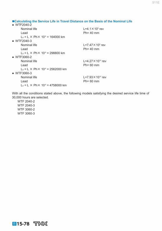
Calculating the Service Life in Travel Distance on the Basis of the Nominal Life ● WTF2040-2
Nominal life L=4.1×10 9 rev Lead Ph= 40 mm L S = L × Ph× 10 -6 = 164000 km
● WTF2040-3 Nominal life L=7.47×10 9 rev Lead Ph= 40 mm L S = L × Ph× 10 -6 = 298800 km
● WTF3060-2 Nominal life L=4.27×10 10 rev Lead Ph= 60 mm L S = L × Ph× 10 -6 = 2562000 km
● WTF3060-3 Nominal life L=7.93×10 10 rev Lead Ph= 60 mm L S = L × Ph× 10 -6 = 4758000 km
With all the conditions stated above, the following models satisfying the desired service life time of 30,000 hours are selected.
WTF 2040-2 WTF 2040-3 WTF 3060-2 WTF 3060-3
B15-78
511E

Ball Screw
[Studying the Rigidity] Since the conditions for selection do not include rigidity and this element is not particularly neces-sary, it is not described here.
[Studying the Positioning Accuracy] Studying the Lead Angle Accuracy
Accuracy grade C7 was selected in Section [Selecting Lead Angle Accuracy and Axial Clearance] on B15-70 .
C7 (travel distance error: 0.05mm/300mm)
Studying the Axial Clearance Since positioning is performed in a given direction only, axial clearance is not included in the positioning accuracy. As a result, there is no need to study the axial clearance.
WTF2040: axial clearance: 0.1 mm WTF3060: axial clearance: 0.14 mm
Studying the Axial Rigidity Since the load direction does not change, it is unnecessary to study the positioning accuracy on the basis of the axial rigidity.
Studying the Thermal Displacement through Heat Generation Assume the temperature rise during operation to be 5℃. The positioning accuracy based on the temperature rise is obtained as follows:
ℓ = ×t ×ℓ = 12 × 10 –6 × 5 × 1000 = 0.06 mm
Studying the Orientation Change during Traveling Since the ball screw center is 150 mm away from the point where the highest accuracy is required, it is necessary to study the orientation change during traveling. Assume that pitching can be done within 10 seconds because of the structure. The positioning er-ror due to the pitching is obtained as follows:
a = ℓ× sin = 150 × sin (10´´) = 0.007 mm
Thus, the positioning accuracy (p) is obtained as follows:
300 Δp = ± 0.007 + 0.06 = 0.234 mm ±0.05×1000
Since models WTF2040-2, WTF2040-3, WTF3060-2 and WTF3060-3 meet the selection require-ments throughout the studying process in Section [Selecting Lead Angle Accuracy and Axial Clear-ance] on B15-70 to Section [Studying the Positioning Accuracy] on B15-79 , the most compact model WTF2040-2 is selected.
Point of SelectionExamples of Selecting a Ball Screw
B15-79
511E

[Studying the Rotational Torque] Friction Torque Due to an External Load
The friction toruque is obtained as follows:
2×π×0.9
17×40 2π•η
Fa•Ph T1 = •A = × 1 = 120 N•mm
Torque Due to a Preload on the Ball Screw The Ball Screw is not provided with a preload.
Torque Required for Acceleration Inertial Moment Since the inertial moment per unit length of the screw shaft is 1.23 × 10 -3 kg•cm 2 /mm (see the spec-ifi cation table), the inertial moment of the screw shaft with an overall length of 1200 mm is obtained as follows. J s = 1.23 × 10 –3 × 1200 = 1.48 kg • cm 2 = 1.48 × 10 ‒4 kg • m 2
( )2
40 2×π( )
2 Ph 2×π
J = (m1+m2) •A2×10–6+Js•A2 = (60+20) ×12×10–6+1.48×10–4×12
= 3.39×10⁻³ kg•m2
Angular acceleration:
60×0.15 2π×1500ω′ = = = 1050 rad/s2
60• t1
2π•Nm
Based on the above, the torque required for acceleration is obtained as follows. T 2 = (J + J m ) ×´ = (3.39 × 10 –3 + 1 × 10 –3 ) × 1050 = 4.61N • m = 4.61 × 10 3 N • mm Therefore, the required torque is specifi ed as follows. During acceleration
T k = T 1 + T 2 = 120 + 4.61×10 3 = 4730 N • mm During uniform motion
T t = T 1 = 120 N • mm During deceleration
T g = T 1 – T 2 = 120 – 4.61×10 3 = – 4490 N • mm
B15-80
511E

Ball Screw
[Studying the Driving Motor] Rotational Speed
Since the Ball Screw lead is selected based on the rated rotational speed of the motor, it is unneces-sary to study the rotational speed of the motor.
Maximum working rotational speed : 1500 min –1 Rated rotational speed of the motor: 3000 min –1
Minimum Feed Amount As with the rotational speed, the Ball Screw lead is selected based on the encoder normally used for an AC servomotor. Therefore, it is unnecessary to study this factor.
Encoder resolution: 1000 p/rev. Doubled: 2000 p/rev
Motor Torque The torque during acceleration calculated in Section [Studying the Rotational Torque] on B15-80 is the required maximum torque.
T max = 4730 N • mm Therefore, the instantaneous maximum torque of the AC servomotor needs to be at least 4,730 N-mm.
Effective Torque Value The selection requirements and the torque calculated in Section [Studying the Rotational Torque] on B15-80 can be expressed as follows. During acceleration:
T k = 4730 N • mm t 1 = 0.15 s
During uniform motion: T t = 120 N • mm t 2 = 0.85 s
During deceleration: T g = 4490 N • mm t 3 = 0.15 s
When stationary: T S = 0 t 4 = 2.6 s
The effective torque is obtained as follows, and the rated torque of the motor must be 1305 N•mm or greater.
2 2 2 2 t4 t3 t2 44902 0 0.15 0.85 2.6 0.85 0.15 0.15
0.15 1202 47302 Ts Tg Tt Tk t1
t4 t3 t2 t1 Trms
1305 N mm
Point of SelectionExamples of Selecting a Ball Screw
B15-81
511E

Inertial Moment The inertial moment applied to the motor equals to the inertial moment calculated in Section [Studying the Rotational Torque] on B15-80 .
J = 3.39 × 10 –3 kg • m 2 Normally, the motor needs to have an inertial moment at least one tenth of the inertial moment ap-plied to the motor, although the specifi c value varies depending on the motor manufacturer. Therefore, the inertial moment of the AC servomotor must be 3.39 × 10 –4 kg-m 2 or greater. The selection has been completed.
B15-82
511E

Ball Screw
Vertical Conveyance System
[Selection Conditions] Table Mass m 1 =40kg Work Mass m 2 =10kg Stroke length ℓ s = 600mm Maximum speed V max =0.3m/s Acceleration time t 1 = 0.2s Deceleration time t 3 = 0.2s Number of reciprocations per minute n =5min -1 Backlash 0.1mm Positioning accuracy 0.7mm/600mm Positioning accuracy repeatability 0.05mm Minimum feed amount s = 0.01mm/pulse Service life time 20000h Driving motor AC servo motor Rated rotational speed: 3,000 min -1 Inertial moment of the motor J m =5×10 –5 kg•m 2 Reduction gear None (direct coupling) Frictional coeffi cient of the guide surface =0.003 (rolling) Guide surface resistance f=20 N (without load)
600
m1
m2
[Selection Items] Screw shaft diameter Lead Nut model No. Accuracy Axial clearance Screw shaft support method Driving motor
Point of SelectionExamples of Selecting a Ball Screw
B15-83
511E

[Selecting Lead Angle Accuracy and Axial Clearance] Selecting the Lead Angle Accuracy
To achieve positioning accuracy of 0.7mm/600mm:
600 300
= ±0.7 ±0.35
The lead angle accuracy must be 0.35mm/300 mm or higher. Therefore, the accuracy grade of the Ball Screw (see Table1 on B15-20 ) needs to be C10 (travel distance error: 0.21 mm/300 mm). Accuracy grade C10 is available for low priced, Rolled Ball Screws. Assume that a Rolled Ball Screw is selected.
Selecting the Axial Clearance The required backlashes is 0.1 mm or less. However, since an axial load is constantly applied in a single direction with vertical mount, the axial load does not serve as a backlash no matter how large it is. Therefore, a low price, rolled Ball Screw is selected since there will not be a problem in axial clear-ance.
[Selecting a Screw Shaft] Assuming the Screw Shaft Length
Assume the overall nut length to be 100 mm and the screw shaft end length to be 100 mm. Therefore, the overall length is determined as follows based on the stroke length of 600mm. 600 + 200 = 800 mm Thus, the screw shaft length is assumed to be 800 mm.
Selecting the Lead With the driving motor’s rated rotational speed being 3,000 min –1 and the maximum speed 0.3 m/s, the Ball Screw lead is obtained as follows:
0.3×60×1000 3000
= 6 mm
Therefore, it is necessary to select a type with a lead of 6mm or longer. In addition, the Ball Screw and the motor can be mounted in direct coupling without using a reduc-tion gear. The minimum resolution per revolution of an AC servomotor is obtained based on the resolution of the encoder (1,000 p/rev; 1,500 p/rev) provided as a standard accessory for the AC servomotor, as indicated below. 1000 p/rev(without multiplication) 1500 p/rev(without multiplication) 2000 p/rev(doubled) 3000 p/rev(doubled) 4000 p/rev(quadrupled) 6000 p/rev(quadrupled)
B15-84
511E

Ball Screw
To meet the minimum feed amount of 0.010mm/pulse, which is the selection requirement, the follow-ing should apply. Lead 6mm —— 3000 p/rev 8mm —— 4000 p/rev 10mm —— 1000 p/rev 20mm —— 2000 p/rev 40mm —— 2000 p/rev However, with the lead being 6 mm or 8 mm, the feed distance is 0.002 mm/pulse, and the starting pulse of the controller that issues commands to the motor driver needs to be at least 150 kpps, and the cost of the controller may be higher. In addition, if the lead of the Ball Screw is greater, the torque required for the motor is also greater, and thus the cost will be higher. Therefore, select 10 mm for the Ball Screw lead.
Selecting the Screw Shaft Diameter Those Ball Screw models that meet the lead being 10 mm as described in Section [Selecting Lead Angle Accuracy and Axial Clearance] on B15-84 and Section [Selecting a Screw Shaft] on B15-84 (see Table20 on B15-35 ) are as follows. Shaft diameter Lead 15mm —— 10mm 20mm —— 10mm 25mm —— 10mm Accordingly, the combination of a screw shaft diameter of 15 mm and a lead 10 mm is selected.
Selecting the Screw Shaft Support Method Since the assumed Ball Screw has a stroke length of 600 mm and operates at a maximum speed of 0.3 m/s (Ball Screw rotational speed: 1,800 min -1 ), select the fi xed-supported confi guration for the screw shaft support.
Point of SelectionExamples of Selecting a Ball Screw
B15-85
511E

Studying the Permissible Axial Load Calculating the Maximum Axial Load
Guide surface resistance f=20 N (without load) Table Mass m 1 =40 kg Work Mass m 2 =10 kg Maximum speed V max =0.3 m/s Acceleration time t 1 = 0.2s
Accordingly, the required values are obtained as follows. Acceleration
α = = 1.5 m/s2Vmax
t1
During upward acceleration: Fa 1 = (m 1 + m 2 ) •g + f + (m 1 + m 2 ) • = 585 N
During upward uniform motion: Fa 2 = (m 1 + m 2 ) •g + f = 510 N
During upward deceleration: Fa 3 = (m 1 + m 2 ) •g + f – (m 1 + m 2 ) • = 435 N
During downward acceleration: Fa 4 = (m 1 + m 2 ) •g – f – (m 1 + m 2 ) • = 395 N
During downward uniform motion: Fa 5 = (m 1 + m 2 ) •g – f = 470 N
During downward deceleration: Fa 6 = (m 1 + m 2 ) •g – f + (m 1 + m 2 ) • = 545 N
Thus, the maximum axial load applied on the Ball Screw is as follows: Fa max = Fa 1 = 585 N
Buckling Load of the Screw Shaft Factor according to the mounting method 2 =20 (see B15-38 ) Since the mounting method for the section between the nut and the bearing, where buckling is to be considered, is “fi xed-fi xed: ” Distance between two mounting surfaces ℓ a =700 mm (estimate) Screw-shaft thread minor diameter d 1 =12.5 mm
d14
ℓa2
12.54
7002 P1 = η2• ×104 = 20× ×104 = 9960 N
Permissible Compressive and Tensile Load of the Screw Shaft P 2 = 116d 1 2 = 116 × 12.5 2 = 18100 N
Thus, the buckling load and the permissible compressive and tensile load of the screw shaft are at least equal to the maximum axial load. Therefore, a Ball Screw that meets these requirements can be used without a problem.
B15-86
511E

Ball Screw
Studying the Permissible Rotational Speed Maximum Rotational Speed ● Screw shaft diameter: 15mm; lead: 10mm
Maximum speed V max =0.3 m/s Lead Ph= 10 mm
Vmax×60×103
Ph Nmax = = 1800 min–1
Permissible Rotational Speed Determined by the Dangerous Speed of the Screw Shaft Factor according to the mounting method 2 =15.1 (see B15-40 ) Since the mounting method for the section between the nut and the bearing, where dangerous speed is to be considered, is “fi xed-supported: ” Distance between two mounting surfaces ℓ b =700 mm (estimate)
● Screw shaft diameter: 15mm; lead: 10mm Screw-shaft thread minor diameter d 1 =12.5 mm
ℓb2
d1
700212.5N1 = λ2× 107 = 15.1× × 107 = 3852 min–1
Permissible Rotational Speed Determined by the DN Value ● Screw shaft diameter: 15mm; lead: 10mm (large lead Ball Screw)
Ball center-to-center diameter D=15.75 mm
D
70000 15.75 70000 N2 = = = 4444 min–1
Thus, the dangerous speed and the DN value of the screw shaft are met.
Point of SelectionExamples of Selecting a Ball Screw
B15-87
511E

[Selecting a Nut] Selecting a Nut Model Number
The Rolled Ball Screw with a screw shaft diameter of 15 mm and a lead of 10 mm is the following large-lead Rolled Ball Screw model.
BLK1510-5.6 (Ca=9.8 kN, C 0 a=25.2 kN)
Studying the Permissible Axial Load Assuming that an impact load is applied during an acceleration and a deceleration, set the static safety factor (f S ) at 2 (see Table1 on B15-47 ).
C0a fS
25.2 2 Famax = = = 12.6 kN = 12600 N
The obtained permissible axial load is greater than the maximum axial load of 585 N, and therefore, there will be no problem with this model.
Studying the Service Life Calculating the Travel Distance
Maximum speed V max =0.3 m/s Acceleration time t 1 = 0.2s Deceleration time t 3 = 0.2s
● Travel distance during acceleration
2 2 0.3×0.2
ℓ1, 4 = ×103 = ×103 = 30 mmVmax• t1
● Travel distance during uniform motion
0.3×0.2 + 0.3×0.2 2 2
ℓ2, 5 = ℓS – ×103 = 600 – ×103 = 540 mmVmax• t1 + Vmax• t3
● Travel distance during deceleration
2 2 0.3×0.2
ℓ3, 6 = ×103 = ×103 = 30 mmVmax• t3
Based on the conditions above, the relationship between the applied axial load and the travel dis-tance is shown in the table below.
Motion Applied axial load Fa N (N)
Travel distance ℓ N (mm)
No1: During upward acceleration 585 30 No2: During upward uniform motion 510 540
No3: During upward deceleration 435 30 No4: During downward acceleration 395 30
No5: During downward uniform motion 470 540 No6: During downward deceleration 545 30
* The subscript (N) indicates a motion number.
B15-88
511E

Ball Screw
Average Axial Load
3
Fm = (Fa13•ℓ1 + Fa2
3•ℓ2 + Fa33•ℓ3 + Fa4
3•ℓ4 + Fa53•ℓ5 + Fa6
3•ℓ6) = 492 N12× ℓS
Nominal Life Dynamic load rating Ca= 9800 N Load factor f W = 1.5 (see Table2 on B15-48 ) Average load F m = 492 N Nominal life L (rev)
L = ×106 = ×106 = 2.34×10⁹ revCa ( )
3
1.5×492 9800 ( )
3
fw · Fm
Average Revolutions per Minute Number of reciprocations per minute n = 5 min -1 Stroke ℓ S =600 mm Lead Ph= 10 mm
Ph 2×n×ℓs
10 2×5×600Nm = = = 600 min–1
Calculating the Service Life Time on the Basis of the Nominal Life Nominal life L=2.34×10 9 rev Average revolutions per minute N m = 600 min -1
L 60×600 2.34×10⁹
Lh = = = 65000 h60•Nm
Calculating the Service Life in Travel Distance on the Basis of the Nominal Life Nominal life L=2.34×10 9 rev Lead Ph= 10 mm L S = L × Ph× 10 -6 = 23400 km
With all the conditions stated above, model BLK1510-5.6 satisfi es the desired service life time of 20,000 hours.
Point of SelectionExamples of Selecting a Ball Screw
B15-89
511E

[Studying the Rigidity] Since the conditions for selection do not include rigidity and this element is not particularly neces-sary, it is not described here.
[Studying the Positioning Accuracy] Studying the Lead Angle Accuracy
Accuracy grade C10 was selected in Section [Selecting Lead Angle Accuracy and Axial Clearance] on B15-84 .
C10 (travel distance error: 0.21mm/300mm)
Studying the Axial Clearance Since the axial load is constantly present in a given direction only because of vertical mount, there is no need to study the axial clearance.
Studying the Axial Rigidity Since the lead angle accuracy is achieved beyond the required positioning accuracy, there is no need to study the positioning accuracy determined by axial rigidity.
Studying the Thermal Displacement through Heat Generation Since the lead angle accuracy is achieved beyond the required positioning accuracy, there is no need to study the positioning accuracy determined by the heat generation.
Studying the Orientation Change during Traveling Since the lead angle accuracy is achieved at a much higher degree than the required positioning ac-curacy, there is no need to study the positioning accuracy.
[Studying the Rotational Torque] Frictional Torque Due to an External Load
During upward uniform motion:
2×π×η 2×π×0.9
510×10 T1 = = = 900 N•mm Fa2•Ph
During downward uniform motion:
2×π×η 2×π×0.9
470×10 T2 = = = 830 N•mm Fa5•Ph
Torque Due to a Preload on the Ball Screw The Ball Screw is not provided with a preload.
B15-90
511E

Ball Screw
Torque Required for Acceleration Inertial Moment: Since the inertial moment per unit length of the screw shaft is 3.9 × 10 -4 kg•cm 2 /mm (see the speci-fi cation table), the inertial moment of the screw shaft with an overall length of 800mm is obtained as follows. J S = 3.9 × 10 –4 × 800 = 0.31 kg • cm 2 = 0.31 × 10 ‒4 kg • m 2
( )2 10
2×π( )2 Ph
2×πJ = (m1+m2) •A2×10–6+Js•A2 = (40+10) ×12×10–6+0.31×10–4×12
= 1.58×10⁻⁴ kg•m2
Angular acceleration:
60• t 60×0.2
2π×1800ω′ = = = 942 rad/s22π•Nmax
Based on the above, the torque required for acceleration is obtained as follows. T 3 = (J + J m ) •´ = (1.58 × 10 –4 + 5 × 10 –5 ) × 942 = 0.2 N•m = 200 N•mm
Therefore, the required torque is specifi ed as follows. During upward acceleration:
T k1 = T 1 + T 3 = 900 + 200 = 1100 N•mm During upward uniform motion:
T t1 = T 1 = 900 N•mm During upward deceleration:
T g1 = T 1 – T 3 = 900 – 200 = 700 N•mm During downward acceleration:
T k2 = 630 N•mm During downward uniform motion:
T t2 = 830 N•mm During downward deceleration:
T g2 = 1030 N•mm
Point of SelectionExamples of Selecting a Ball Screw
B15-91
511E

[Studying the Driving Motor] Rotational Speed
Since the Ball Screw lead is selected based on the rated rotational speed of the motor, it is unneces-sary to study the rotational speed of the motor.
Maximum working rotational speed : 1800 min –1 Rated rotational speed of the motor: 3000 min –1
Minimum Feed Amount As with the rotational speed, the Ball Screw lead is selected based on the encoder normally used for an AC servomotor. Therefore, it is unnecessary to study this factor.
Encoder resolution: 1000 p/rev.
Motor Torque The torque during acceleration calculated in Section [Studying the Rotational Torque] on B15-90 is the required maximum torque.
T max = T k1 = 1100 N•mm Therefore, the maximum peak torque of the AC servomotor needs to be at least 1100 N-mm.
Effective Torque Value The selection requirements and the torque calculated in Section [Studying the Rotational Torque] on B15-90 can be expressed as follows. During upward acceleration:
T k1 = 1100 N•mm t 1 = 0.2 s
During upward uniform motion: T t1 = 900 N•mm t 2 = 1.8 s
During upward deceleration: T g 1 = 700 N•mm t 3 = 0.2 s
During downward acceleration: T k2 = 630 N•mm t 1 = 0.2 s
During downward uniform motion: T t2 = 830 N•mm t 2 = 1.8 s
During downward deceleration: T g2 = 1030 N•mm t 3 = 0.2 s
When stationary(m 2 =0): T S = 658 N•mm t 4 = 7.6 s
B15-92
511E
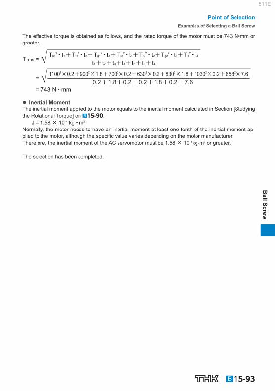
Ball Screw
The effective torque is obtained as follows, and the rated torque of the motor must be 743 N•mm or greater.
Trms =
=
Tk12• t1+Tt1
2• t2+Tg12• t3+Tk2
2• t1+Tt22• t2+Tg2
2• t3+Ts2• t4
t1+ t2+ t3+ t1+ t2+ t3+ t4
11002×0.2+9002×1.8+7002×0.2+6302×0.2+8302×1.8+10302×0.2+6582×7.6 0.2+1.8+0.2+0.2+1.8+0.2+7.6
= 743 N•mm
Inertial Moment The inertial moment applied to the motor equals to the inertial moment calculated in Section [Studying the Rotational Torque] on B15-90 .
J = 1.58 × 10 –4 kg • m 2 Normally, the motor needs to have an inertial moment at least one tenth of the inertial moment ap-plied to the motor, although the specifi c value varies depending on the motor manufacturer. Therefore, the inertial moment of the AC servomotor must be 1.58 × 10 –5 kg-m 2 or greater. The selection has been completed.
Point of SelectionExamples of Selecting a Ball Screw
B15-93
511E

B15-94
511E

B15-95
Ball Screw
Options
511E

Contaminaton Protection If foreign material enters the interior of the ball screw, abnormal levels of abrasion and ball clogging are more likely to occur. This can also shorten the overall lifespan of the product. As such, foreign material needs to be prevented from entering. If there is a chance that foreign ma-terial may get in, it is important to choose an effective contamination protection product that suits the usage conditions.
Labyrinth seal (Precision Ball Screw)
(Rolled Ball Screw Model JPF) Symbol: RR
Screw shaft
Labyrinth seal
Ball screw nut
Brush seal (Rolled Ball Screw)
Symbol: ZZ
Brush seal
Ball screw nut
Screw shaft
Wiper ring Symbol: WW
Wiper ringSeal snap ring
Seal snap ringWiper ring
Ball screw nut
Ball screw shaft
Thin fi lm seal (SDA-V only) Symbol: TT
Thin film sealSeal Cap
Ball screw nutScrew shaft
A15-339~
A15-338
A15-338
B15-96
511E

Ball Screw
(Options)
Dust coverBellows
Screw cover
Screw cover Bellows
Lubrication To maximize the performance of the Ball Screw, it is necessary to select a lubricant and a lubrication method according to the conditions. For types of lubricants, characteristics of lubricants and lubrication methods, see the section on “Ac-cessories for Lubrication” on A24-2 . Also, QZ Lubricator is available as an optional accessory that signifi cantly increases the mainte-nance interval.
Air vent
Ball screw nut
QZ Lubricator
QZ fixing screwQZ Lubricator Ball screw shaft
QZ Lubricator
Corrosion Resistance (Surface Treatment, etc.) Depending on the service environment, the Ball Screw requires corrosion resistance treatment or a different material. For details of corrosion resistance treatment and material change, contact THK. (see B0-18 )
OptionsLubrication
A15-341
A15-342~
B15-97
511E

B15-98
Contamination Protection Seal for Ball Screws
If the Ball Screw is used in an atmosphere free from foreign material but with suspended dust, a labyrinth seal (with symbol RR) and a brush seal (with symbol ZZ) can be used as contamination protection accessories. The labyrinth seal is designed to maintain a slight clearance between the seal and the screw shaft raceway so that torque does not develop and no heat is generated, though its effect in contamina-tion protection is limited. With Ball Screws except the large lead and super lead types, there is no difference in nut dimen-sions between those with and without a seal.
Labyrinth seal Symbol: RR (Precision Ball Screw)
(Rolled Ball Screw Model JPF)
Screw shaft
Labyrinth seal
Ball screw nut
Labyrinth seal
Brush seal Symbol: ZZ (Rolled Ball Screw)
Brush seal
Ball screw nut
Screw shaft
Brush seal
511E

Model number coding
Ball Screw
(Options)
B15-99
Wiper Ring W ●For the supported models and the ball screw nut dimension with Wiper ring W attached, see A15-344 to A15-351 .
With the wiper ring W, special resin with high wear resistance and low dust generation removes foreign material and prevents foreign material from entering the ball screw nut while elastically contacting the circumference of the ball screw shaft and the screw thread.
Wiper ringSeal snap ring
Seal snap ringWiper ring
Ball screw nut
Ball screw shaft
Appearance Drawing
Spring Multi-slit
Multi-slit
Foreign material
Ball screw shaft
Rotational direction Detail view of section A
A
Structural Drawing
[Features] ● A total of eight slits on the circumference remove foreign materials in succession, and prevent en-
trance of foreign material. ● Contacts the ball screw shaft to reduce the fl owing out of grease. ● Contacts the ball screw shaft at a constant pressure level using a spring, thus to minimize the
heat generation. ● Since the material is highly resistant to the wear and the chemicals, its performance will not easily be
deteriorated even if it is used over a long period.
Can be attached together with QZ Lubricator. For the applicable models and the ball screw nut dimensions after wiper ring W is attached, see A15-344 .
Seal snap ringWiper ring
QZ LubricatorQZ Lubricator
Wiper ringSeal snap ring
QZ Lubricator + Wiper ring
With QZLubricator
With wiper ring W
BIF2505V-5 QZ WW G0 +1000L C5
(*) See A15-344 .
OptionsWiper Ring W
511E

Test in an environment exposed to contaminated environment [Test conditions]
Item Description Model No. BIF3210V‒5G0+1500LC5 Maximum
rotational speed 1000min -1
Maximum speed 10m/min Maximum
circumferential speed 1.8m/s
Time constant 60ms Dowel 1s Stroke 900mm Load
(through internal load) 1.31kN
Grease THK AFG Grease 8cm 3 (Initial lubrication to the ball screw nut only.)
Foundry dust FCD400 average particle diameter: 250m Volume of foreign material per shaft 5g/h
[Test result]
Type with wiper ring
Type with labyrinth seal
Distance traveled (km) Flaking occurrs on the ball screw shaft raceway No problem Flaking occurrs on the ball
0 400 800 1200 1600 2000 200 600 1000 1400 1800
● Type with wiper ring Slight fl aking occurred in the ball screw shaft at travel distant of 1,000 km.
● Type with labyrinth seal Flaking occurred throughout the circumfer-ence of the screw shaft raceway at travel distance of 200 km. Flaking occurred on the balls after traveling 1,500 km.
Change in the ball after traveling 2000 km
(1) Type with wiper ring (2) Type with labyrinth seal
Ball after traveling Unused ball Ball after traveling Unused ball
●Discolored, but no breakage ●Flaking occurs
Distance traveled (km)
Wea
r of b
all (μ
m) Type with labyrinth seal
Type with wiper ring
0 0
2
4
6
8
10
12
500 1000 1500 2000
● Type with wiper ring Wear of balls at a travel distance of 2,000 km: 1.4 m.
● Type with labyrinth seal Starts to be worn rapidly after 500 km, and the ball wear amount at the travel distance of 2,000 km: 11 m.
B15-100
511E

Ball Screw
(Options)
Heat Generation Test [Test conditions]
Item Description Model No. BLK3232‒3.6G0+1426LC5 Maximum
rotational speed 1000min -1
Maximum speed 32m/min Maximum
circumferential speed 1.7m/s
Time constant 100ms Stroke 1000mm Load
(through internal load) 0.98kN
Grease THK AFG Grease 5cm 3 (contained in the ball screw nut)
[Test result]
Travel time (min)
Tem
pera
ture
at s
haft
cent
er a
rea
(℃)
With wiper ringWithout seal
0 0
10
20
30
40
50
60
15 30 45 60 75 90
Unit: ℃
Item With wiper ring Without seal
Heat generationtemperature 37.1 34.5
Temperaturerise 12.2 8.9
Dust Cover for Ball Screws
Bellows/Screw cover In the case of an environment with much dust and foreign material, be sure to prevent intrusion of foreign material by using bellows, a screw cover or the like. The contamination protection can be increased by also using a contamination protection seal. For details, contact THK. When conferring with us, please use the bellows specifi cations ( A15-352 ).
Screw cover Bellows
Dust cover
OptionsDust Cover for Ball Screws
B15-101
511E

Model number coding
QZ Lubricator ●For the supported models and the ball screw nut dimension with QZ attached, see A15-344 to A15-351 .
QZ Lubricator feeds a right amount of lubricant to the raceway of the ball screw shaft. This allows an oil fi lm to be constantly formed between the balls and the raceway, improves lubricity and signifi -cantly extends the lubrication maintenance interval. The structure of QZ Lubricator consists of three major components: (1) a heavily oil-impregnated fi ber net (stores the lubricant), (2) a high-density fi ber net (applies the lubricant to the raceway) and (3) an oil-control plate (adjusts the oil fl ow). The lubricant contained in the QZ Lubricator is fed by the capillary phenomenon, which is used also in felt pens and many other products.
Ball screw shaftQZ LubricatorQZ fixing screw
Ball screw nut
Air vent (Note)
QZ Lubricator
Appearance Drawing
Flow of lubricant ③Oil control plate②High-density fiber net
①Heavily oil-impregnated fiber net
Applied directly to the raceway
Ball screw shaft Sealed case Ball screw nut
Structural Drawing
[Features] ● Since it supplements an oil loss, the lubrication maintenance interval can be signifi cantly extended. ● Since the right amount of lubricant is applied to the ball raceway, an environmentally friendly lubri-
cation system that does not contaminate the surroundings is achieved. Note) Some types of QZ have a vent hole. Be careful not to block the hole with grease or other obstructions.
With QZLubricator
With wiper ring W
BIF2505V-5 QZ WW G0 +1000L C5
(*) See A15-344 .
B15-102
511E
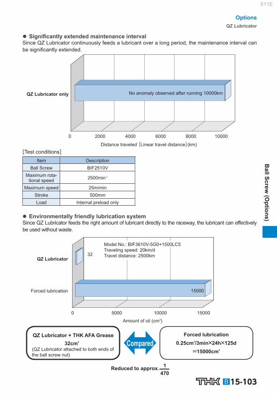
Ball Screw
(Options)
Signifi cantly extended maintenance interval Since QZ Lubricator continuously feeds a lubricant over a long period, the maintenance interval can be signifi cantly extended.
No anomaly observed after running 10000kmQZ Lubricator only
Distance traveled [Linear travel distance](km)
0 2000 4000 6000 8000 10000
[Test conditions] Item Description
Ball Screw BIF2510V Maximum rota-
tional speed 2500min -1
Maximum speed 25m/min Stroke 500mm Load Internal preload only
Environmentally friendly lubrication system Since QZ Lubricator feeds the right amount of lubricant directly to the raceway, the lubricant can effectively be used without waste.
Model No.: BIF3610V-5G0+1500LC5Traveling speed: 20km/dTravel distance: 2500km
QZ Lubricator
Forced lubrication
Amount of oil (cm3)
Forced lubrication
(QZ Lubricator attached to both ends of the ball screw nut)
QZ Lubricator + THK AFA Grease
Reduced to approx.
Compared
15000
32
0 5000 10000 15000
0.25cm3/3min×24h×125d32cm3
1 470
=15000cm3
OptionsQZ Lubricator
B15-103
511E

Mounting Procedure Installing the Support Unit
(1) Install the fi xed side Support Unit with the screw shaft. (2) After inserting the fi xed side Support Unit, secure the lock nut using the fastening set piece and
the hexagonal socket-head setscrews. (3) Attach the supported side bearing to the screw shaft and secure the bearing using the snap ring,
and then install the assembly to the housing on the supported side. Note1) Do no disassemble the Support Unit. Note2) When inserting the screw shaft to the Support Unit, take care not to let the oil seal lip turn outward. Note3) When securing the set piece with a hexagonal socket-head setscrew, apply an adhesive to the hexagonal socket-
head setscrew before tightening it in order to prevent the screw from loosening. If planning to use the product in a harsh environment, it is also necessary to take a measure to prevent other components/parts from loosening. Contact THK for details.
Supported side
Bearing Snap ring
Fixed side Collar
Set piece Hexagonal socket-head setscrew
Lock nut
Installation onto the Table and the Base
(1) If using a bracket when mounting the ball screw nut to the table, insert the nut into the bracket and temporarily fasten it.
(2) Temporarily fasten the fi xed side Support Unit to the base. In doing so, press the table toward the fi xed side Support Unit to align the axial center, and ad-just the table so that it can travel freely.
● If using the fi xed side Support Unit as the reference point, secure a clearance between the ball screw nut and the table or inside the bracket when making adjustment.
● If using the table as the reference point, make the adjustment either by using the shim (for a square type Support Unit), or securing the clearance between the outer surface of the nut and the inner surface of the mounting section (for a round type Support Unit).
(3) Press the table toward the fi xed-side Support Unit to align the axial center. Make the adjustment by reciprocating the table several times so that the nut travels smoothly throughout the whole stroke, and temporarily secure the Support Unit to the base.
Base
Fixed side support unitBracket Table Supported side support unit
B15-104
Mounting Procedure and Maintenance Ball Screw
511E

Ball Screw
Mounting Procedure and MaintenanceMounting Procedure
B15-105
Checking the Accuracy and Fully Fastening the Support Unit
While checking the runout of the ball screw shaft end and the axial clearance using a dial gauge, fully fasten the ball screw nut, the nut bracket, the fi xed side Support Unit and the supported-side Support Unit, in this order.
Adjust the nut by moving the table so that the nut travels smoothly throughout the whole stroke. Measure the runoutMeasure the axial clearance
Connection with the Motor
(1) Mount the motor bracket to the base. (2) Connect the motor and the ball screw using a coupling. Note) Make sure the mounting accuracy is maintained.
(3) Thoroughly perform the break-in for the system.
Motor Coupling
511E

B15-106
Maintenance Method Amount of Lubricant
If the amount of the lubricant to the Ball Screw is insuffi cient, it may cause a lubrication breakdown, and if it is excessive, it may generate heat and increase resistance. It is necessary to select an amount that meets the conditions.
[Grease] The feed amount of grease is generally approximately one third of the spatial volume inside the nut. For details on feed amount of grease, contact THK.
[Oil] Table 1 shows a guideline for the feed amount of oil. Note, that the amount varies according to the stroke, the oil type and the conditions (e.g., sup-pressed heat generation).
Table1 Guideline for the Feed Amount of Oil (Interval: 3 minutes)
Shaft diameter (mm) Amount of lubricant (cc)
4 to 8 0.03
10 to 14 0.05
15 to 18 0.07
20 to 25 0.1
28 to 32 0.15
36 to 40 0.25
45 to 50 0.3
55 to 63 0.4
70 to 100 0.5
511E

Ball Screw
Model Number Coding
The model number confi guration for ball screws differs depending on the type. Table2 Refer to the corresponding confi guration example shown in Table4 . THK can also provide shaft end shapes matched to support units. These can also be denoted in the symbols, which should be used for this purpose.
[Precision ball screw types and sample model number confi gurations]
Table2
Model No. Shaft end shape Model number coding
Precision
SBN-V, SBK, SDA-V, HBN, SBKH, BIF-V, BNFN-V/BNFN, MDK, MBF, BNF-V/BNF, DIK, DKN, BLW, DK, MDK, WHF, BLK, WGF, BNT Fixed Side : H, J
Supported Side : K
[1]
Unfi nished Shaft Ends A MBF, MDK, BNF, BIF [2]
Unfi nished Shaft Ends B BNF, BIF Finished Shaft Ends BNK Y [3]
Rotary Ball Screw BLR, DIR Fixed Side : H, J Supported Side : K [4]
Ball Screw/Spline BNS-A, BNS, NS-A, NS — [5]
[Rolled ball screw types and sample model number confi gurations]
Table3
Model No. Shaft end shape Model number coding
Rolled
Unfi nished Shaft Ends MTF
Fixed Side : H, J Supported Side : K
[6] Ball screw nut and screw shaft combination products
JPF, BTK-V, MTF, WHF, BLK, WTF, CNF, BNT [7]
Rotary Ball Screw BLR [8] Standalone screw shafts TS
[9] Standalone ball screw nuts BTK-V, BLK, WTF, CNF, BNT,
BLR —
[Support unit, nut bracket and lock nut types and sample model number confi gurations]
Table4
Model No. Shaft end shape Model number coding
Support Unit EK, BK, FK, EF, BF, FF — [10] Nut brackets for BNK MC —
Lock Nut RN —
B15-107
Model No. Ball Screw
511E

[1 Precision Ball Screw] Models SBN-V, SBK, SDA-V, HBN, SBKH, BIF-V, BNFN-V/BNFN, MDK, MBF, BNF-V/BNF, DIK, DKN, BLW, DK, MDK, WHF, BLK, WGF and BNT
Symbol for clearance in the axial direction
No. of circuits (Rows × turns)
Lead (in mm)
Screw shaft outer diameter (in mm)
Model No.
Accuracy symbol
Recommended Shaft Ends Shapes (*1)H, J: fixed side symbol
K: supported side symbol
Overall screw shaft length (in mm)
Threading directionNo symbol: right-hand thread L: left-hand threadRL: Right and left hand thread
Direction of nut flange orientationNo symbol: faces fixed side
G: faces supported side (Note)
Seal symbolNo symbol: without seal
RR: labyrinth seal on both ends(*2)
BIF 25 05 L -5 RR G0 + 620L C5 - H1K - G
(*1) See A15-324 to A15-329 . (*2) See B15-96 .
Note) The ball nut fl ange faces the fi xed side unless otherwise specifi ed. If desiring the fl ange to face the supported side, add symbol G in the end of the Ball Screw model number when placing an order.
[2 Precision Ball Screw Unfi nished Shaft Ends] Models BIF, MDK, MBF and BNF
Unfinished shaft ends code (A or B)
BIF2505-5RRG0+720LC5A
Refer to A15-110 for the corresponding model number.
B15-108
511E

Ball Screw
[3 Precision Ball Screw Finished Shaft Ends] Model BNK
Finished shaft ends code
BNK2020-5+620LC5Y
Refer to A15-136 for the corresponding model number.
[4 Rotary Ball Screw] Models BLR and DIR
Flange orientation symbol
Accuracy symbol
Overall screw shaft length (in mm)
Symbol for clearance in the axial direction
Symbol for support bearing seal
Model No.
BLR2020-3.6 K UU G1 +1000L C5
[5 Ball Screw/Spline] Models BNS-A, BNS, NS-A and NS
Overall shaft length (in mm)Model No.
BNS2525 +600L
[6 Rolled Ball Screw Unfi nished Shaft Ends] Model MTF
Overall shaft length (in mm)
Lead (in mm)
Screw shaft outer diameter (in mm)
Model No.
Symbol for ball screw shaft Accuracy symbol (No symbol for Normal Grade)
Recommended Shaft Ends Shapes(See onward)
MTF 08 02 +250L C7 T - H1
Model No.
A15-324~
B15-109
511E

[7 Rolled Ball Screw] Models BTK-V, MTF, WHF, BLK, WTF, CNF and BNT(Rolled)
Model No.
Combination of the Ball Screw Nut and the Screw Shaft
Overall screw shaft length (in mm)
Accuracy symbol (see ) (no symbol for class C10)
Symbol for rolled shaft
Seal symbol no symbol: without seal ZZ: brush seal attached to both ends of the ball screw nut (see )
Recommended Shaft Ends Shapes (See onward)
�
BTK1405V-2.6 ZZ +500L C7 T - H1K
[8 Rolled Ball Screw] Model JPF
Model number
Seal symbol
Overall screw shaft length (in mm)
Symbol for rolled shaft
Rolled Ball Screw model JPF�
no symbol: without sealRR: Labyrinth seal attached to both ends of the ball screw nut (see )
Accuracy symbol (see ) (no symbol for class C10)
Axial clearance symbol
JPF1404-4 RR G0 +500L C7 T
[9 Rolled Rotary Ball Screw] Model BLR (Rolled)
Flange orientation symbol
Accuracy symbol
Overall screw shaft length (in mm)
Symbol for rolled Ball ScrewSymbol for support bearing seal
Model No.
BLR2020-3.6 K UU +1000L C7 T
Note) For clearance in the axial direction, see B15-27 .
A15-324~
A15-12
A15-336
A15-12
A15-336
B15-110
511E

Ball Screw
Model No.
[10 Standalone rolled shafts/nuts] Models BTK-V, BLK/WTF, CNF, BNT(Rolled), BLR(Rolled) and TS
Screw shaft outer diameter (in mm)
Lead (in mm)
Overall screw shaft length (in mm)
Accuracy symbol(see page )(no symbol for class C10)
Symbol for rolled ball screw shaft
Model No. Seal symbolno symbol: without sealZZ: brush seal attached to both ends of the ball screw nut (see )
Nut onlyRolled shaft only
TS 14 05 +500L C7 BTK1405V-2.6 ZZ
[11 Support units, nut brackets and lock nuts] Models EK, BK, FK, EF, BF, FF, MC and RN
Model No.
EK12
[12 Ball screw options, W wiper rings and QZ lubricators]
With QZLubricator
With wiper ring W
BIF2505V-5 QZ WW G0 +1000L C5
(*) See A15-344 .
Notes on Ordering
[Options] The details of the product options differ according to the model number. Check before ordering. See B15-95 .
[Other notes on specifi cations] Contact THK separately for information on the specifi cations below. • Shaft end shape (for recommended shaft end shapes, indicate the symbol). • Surface Treatment (see B0-20 ) • Grease used • Nipple mounting
A15-12
A15-336
B15-111
511E

[Handling] (1) Please use at least two people to move any product weighing 20 kg or more, or use a dolly or
another conveyance. Doing so may cause injury or damage. (2) Do not disassemble the parts. This will result in loss of functionality. (3) Tilting the Ball Screw shaft and the Ball Screw nut may cause them to fall by their own weight. (4) Take care not to drop or strike the Ball Screw. Failure to do so could cause injury or product
damage. Giving an impact to it could also cause damage to its function even if the product looks intact.
(5) When assembling, do not remove the Ball Screw nut from the Ball Screw shaft. (6) When handling the product, wear protective gloves, safety shoes, etc., as necessary to ensure
safety.
[Precautions on Use] (1) Prevent foreign material, such as cutting chips or coolant, from entering the product. Failure to
do so may cause damage. (2) If the product is used in an environment where cutting chips, coolant, corrosive solvents, water,
etc., may enter the product, use bellows, covers, etc., to prevent them from entering the product. (3) Do not use the product at temperature of 80℃ or higher. Except for the heat-resistant models,
exposure to higher temperatures may cause the resin/rubber parts to deform/be damaged. (4) If foreign material such as cutting chips adheres to the product, replenish the lubricant after
cleaning the product. (5) Micro-oscillation makes it diffi cult for oil fi lm to form on the raceway in contact with the rolling ele-
ment, and may lead to fretting. Accordingly, use grease offering excellent fretting toughness. It is also recommended that the Ball Screw nut be turned once or so on a regular basis to make sure oil fi lm is formed between the raceway and rolling element.
(6) Do not use undue force when fi tting parts (pin, key, etc.) to the product. This may generate pres-sure marks on the raceway, leading to loss of functionality.
(7) If an offset or skewing occurs with the Ball Screw shaft support and the Ball Screw nut, it may substantially shorten the service life. Pay much attention to components to be mounted and to the mounting accuracy.
(8) If any of the rolling elements falls from the Ball Screw nut, contact THK instead of using the prod-uct.
(9) When using this product with a vertical orientation, take preventive measures such as adding a safety mechanism to prevent falls. The own weight of the Ball Screw nut may cause it to fall.
(10) Do not use this product beyond its permissible rotational speed. Doing so may cause accidents or component damage. Be sure to use the product within the specifi cation range designated by THK.
(11) Do not cause the Ball Screw nut to overshoot. The ball may drop, circulating parts may be dam-aged, raceway in contact with the ball may develop pressure marks, etc., resulting in malfunc-tion. Continuing to use the product in this condition may lead to premature wear or damage to circulating parts.
(12) Use the Ball Screw by providing a LM Guide, Ball Spline or other guide element. Otherwise, the Ball Screw may be damaged.
(13) Insuffi cient rigidity or accuracy of mounting members causes the bearing load to concentrate on one point and the bearing performance will drop signifi cantly. Accordingly, give suffi cient consid-eration to the rigidity/accuracy of the housing and base and strength of the fi xing bolts.
B15-112
Precautions on Use Ball Screw
511E

Ball Screw
[Lubrication] (1) Thoroughly wipe off anti-rust oil and feed lubricant before using the product. (2) Do not mix different lubricants. Mixing greases using the same type of thickening agent may still
cause adverse interaction between the two greases if they use different additives, etc. (3) When using the product in locations exposed to constant vibrations or in special environments
such as clean rooms, vacuum and low/high temperature, use the grease appropriate for the specifi cation/environment.
(4) When lubricating the product having no grease nipple or oil hole, apply grease directly on the raceway and stroke the product several times to let the grease spread inside.
(5) The consistency of grease changes according to the temperature. Take note that the torque of the Ball Screw also changes as the consistency of grease changes.
(6) After lubrication, the rotational torque of the Ball Screw may increase due to the agitation resis-tance of grease. Be sure to perform a break-in to let the grease spread fully, before operating the machine.
(7) Excess grease may scatter immediately after lubrication, so wipe off scattered grease as neces-sary.
(8) The properties of grease deteriorate and its lubrication performance drops over time, so grease must be checked and added properly according to the use frequency of the machine.
(9) Although the lubrication interval may vary according to operating conditions and the service en-vironment, lubrication should be performed approximately every 100 km in travel distance (three to six months). Set the fi nal lubrication interval/amount based on the actual machine.
(10) Depending on the mounting orientation and access position, lubricant may not spread fully and poor lubrication may occur. Give full consideration to these factors in the design stage.
(11) When using a Ball Screw, it is necessary to provide effective lubrication. Using the product with-out lubrication may increase wear of the rolling elements or shorten the service life. Table1 ( B15-106 ) shows a guideline for the feed amount of oil.
[Storage] When storing the Ball Screw, enclose it in a package designated by THK and store it in a room in a horizontal orientation while avoiding high temperature, low temperature and high humidity. After the product has been in storage for an extended period of time, lubricant inside may have deteriorated, so add new lubricant before use.
[Disposal] Dispose of the product properly as industrial waste.
Precautions on Use
B15-113
511E

Precautions on Using Options for the Ball Screw QZ Lubricator for the Ball Screw For details regarding the QZ, see B15-102 .
[Precaution on Selection] Make sure the stroke length exceeds the total length of the screw shaft with the QZ Lubricator at-tached.
[Handling] Take care not to drop or strike the product, which could result in injury or damage. Keep air holes clear of grease or other obstructions. The QZ Lubricator lubricates the raceway only, so it must be used in combination with regular greas-ing or lubrication. In models equipped with the QZ Lubricator, raceways are provided with the minimum required level of lubrication. Please note: Use of the product in a vertical position, or other usage conditions, may cause lubricant to drip from the ball screw shaft.
[Service environment] Be sure the service temperature of this product is between ‒10 to 50℃, and do not clean the prod-uct by immersing it in an organic solvent or white kerosene, or leave it unpacked.
B15-114
511E