Installation Manual - on Eric Farnet technical support page
174
Model No. KX-TDA0480 4-Channel VoIP Gateway Card Installation Manual Thank you for purchasing the Panasonic 4-Channel VoIP Gateway Card, KX-TDA0480. Please read this manual carefully before using this product and save this manual for future use.
-
Upload
khangminh22 -
Category
Documents
-
view
1 -
download
0
Transcript of Installation Manual - on Eric Farnet technical support page

Model No. KX-TDA0480
4-Channel VoIP Gateway Card
Installation Manual
Thank you for purchasing the Panasonic 4-Channel VoIP Gateway Card, KX-TDA0480.Please read this manual carefully before using this product and save this manual for future use.
Introduction
IntroductionThis document provides information and procedures needed to install a network of the KX-TDA0480. Although the KX-TDA0480 installation process is straightforward, careful planning will smooth the process and allow for trouble-free expansion and upgrading.Steps associated with assigning network addresses and creating a network telephone numbering system should be performed by persons experienced in network administration. For complex installations, it may be useful to create a diagram of the network similar to those used in various sections of this document. Planning issues are addressed in Section Planning: of this document.In addition to this introduction, this document is organised into the following sections:
• KX-TDA0480 Overview
• Planning
• Physical Installation
• Logical Installation
At the end of this document are appendices that provide detailed information on topics that will be useful during the planning and installation process.
"Appendix" sections deal with advanced topics related to installing and configuring a IP Gateway network. In the case of smaller networks it may not be necessary to refer to these topics. As networks grow in complexity, these topics will augment the information provided in the main body of this guide. Additionally, it may be necessary to refer to the KX-TDA0480 Programming Guide. The last appendix in this section contains worksheet reproduction masters that can be used in the IP Gateway network planning process.
2 Installation Manual

Table of Contents
Table of Contents1 KX-TDA0480 Overview1.1 KX-TDA0480 Overview .................................................................................................6
2 Planning2.1 Basic Configuration Overview ....................................................................................102.1.1 H.323 Version 2 Networks ..........................................................................................132.1.2 DNS .............................................................................................................................152.1.3 G3 Fax .........................................................................................................................152.1.4 DTMF Detection .........................................................................................................162.2 Worksheets ....................................................................................................................182.2.1 Network Worksheets....................................................................................................182.2.2 Network Units List Worksheet ....................................................................................182.2.3 Connection Information Worksheet ............................................................................212.2.4 Common Configuration Worksheet.............................................................................232.2.5 Unit Setup Worksheet..................................................................................................27
3 Physical Installation3.1 Installation Preconditions ............................................................................................423.2 Connect Cables .............................................................................................................433.3 Connect the Computer Terminal Unit with RS-232C Cable....................................443.4 Connect the Network Cable.........................................................................................463.5 Power-Up the KX-TDA0480 and Verify Operation...................................................48
4 Logical Installation4.1 Logical Installation Methods .......................................................................................504.2 Maintenance Console Software Overview..................................................................514.3 Install Maintenance Console Software .......................................................................524.4 Start Maintenance Console Software and Login.......................................................534.5 MCS Main Directory Window ....................................................................................544.6 Create a New Group.....................................................................................................564.7 Create New Units ..........................................................................................................594.7.1 RS232C Port Configuration ........................................................................................604.7.2 Create a New Gateway (KX-TDA0480 Unit) .............................................................624.7.3 Create a New Gatekeeper ............................................................................................734.7.4 Create an Other Unit....................................................................................................754.8 Create/Edit Common Configuration ..........................................................................774.9 Configure Units.............................................................................................................794.9.1 Configure Gateway Units (KX-TDA0480) .................................................................834.9.2 Configure a Gatekeeper Unit .....................................................................................1214.10 Transfer Setup and Configuration Files to Units ..................................................1294.11 Synchronise Unit Time and Date ............................................................................135
Appendix A AppendicesA1 Voice Over IP Addressing ..........................................................................................138A2 Numbering Systems....................................................................................................140A2.1 Numbering Plan Example..........................................................................................140
Installation Manual 3

Table of Contents
A2.2 Dialling Examples .................................................................................................... 140A3 DNS Configuration .................................................................................................... 142A3.1 KX-TDA0480 DNS Functions ................................................................................. 142A3.2 KX-TDA0480 Internal DNS Database ..................................................................... 142A4 Pad Control and AGC ............................................................................................... 146A4.1 PAD Controls ............................................................................................................ 146A4.2 AGC .......................................................................................................................... 146A5 Optimising Performance ........................................................................................... 147A5.1 Voice Volume............................................................................................................ 147A5.2 Transmission Delays................................................................................................. 147A5.3 Firewalls.................................................................................................................... 151A6 Configuration Files .................................................................................................... 153A7 FTP File Transfers ..................................................................................................... 155A8 Worksheet Masters .................................................................................................... 160
Glossary ............................................................................................... 165
4 Installation Manual
KX-TDA0480 Overview
Section 1
KX-TDA0480 Overview
Installation Manual 5

KX-TDA0480 Overview
1.1 KX-TDA0480 Overview
The KX-TDA0480 is self-contained H.323 Version 2 compliant communications device (Gateway) that allow organisations to route both voice and fax communications over any TCP/IP network.The KX-TDA0480 installed in the IP PBX can be used to seamlessly bridge PSTN and analogue telephone with digital data networks, allowing organisations to more fully exploit their existing intranet and internet facilities. Most importantly, since communications take place over digital data networks, the high cost of long distance communications over conventional telephone networks is virtually eliminated.In the simplest sense, the KX-TDA0480 converts outgoing voice or fax signals into a digital format, compresses and packages the signal for transmission over digital TCP/IP networks. On the incoming side, the KX-TDA0480 reverses this process, receiving voice or fax data packets and translating them back into appropriate voice and fax signals.
Simplified IP Gateway network connection
In summary, the KX-TDA0480 provides organisations with a reliable solution for high quality integrated voice and fax communications using existing LAN/WAN environments without interrupting or compromising ongoing data communications.The KX-TDA0480 incorporates many features that help to assure a robust and easy-to-use product that delivers high quality voice communication and error free fax transmission.
Fax InterfaceThe KX-TDA0480 IP Gateway card is capable of real-time fax transmission using IP (T.38) transmission, thereby taking full advantage of the data network's flow and data control (TCP or UDP transmission).
Router Router
PSTN PSTN
LANLAN
IP PBXIP PBXIP Network
6 Installation Manual

KX-TDA0480 Overview
DTMF Detect and RegenerationThe KX-TDA0480 is capable of detecting and regenerating DTMF signals. Sending units are able to detect and convert DTMF tones for reliable transmission. On the receiving end, the unit regenerates DTMF tones, assuring accurate transmission when interfacing with Auto Attendant/Voice Mail or Interactive Voice Response systems.
Voice QualityThe KX-TDA0480 provides high-quality voice compression encoding which can be configured on a priority basis to automatically select between 64kbps PCM stream as either G.729A (8kbps), G.723.1 (6.3kbps) or G.723.1 (5.3kbps) compression and packet priority control.In addition, proprietary dynamic jitter buffer and Dynamic Echo Cancellation further assure uninterrupted and natural speech communications.
Network ConnectivityThe KX-TDA0480 supports a 10BaseT Ethernet interface for network connection. WAN connectivity is provided through any IP router.
H.323 ComplianceThe KX-TDA0480 is H.323 Version 2 compliant.
When implemented within an H.323 network, units are simultaneously managed as H.323 compliant gateways, using H.323 Gatekeeper device call control, address management, and bandwidth control capabilities.
IP and Telephone Numbering ManagementThe KX-TDA0480 employs a unified telephone numbering management system. It is easy to create a numbering plan that conforms to numbering plans of PBX.IP to telephone number translation can be handled in a number of ways.
H.323Gateway
H.323Gatekeeper
H.323Terminal
H.323Terminal
H.323 MCU
H.323Terminal
Installation Manual 7

KX-TDA0480 Overview
1. In H.323 compliant networks (e.g., Gatekeeper devices are employed) translations are handled by an H.323 Gatekeeper device.
2. Finally, internal DNS capabilities can also be combined to optimise network performance.
SNMP CapabilitiesThe KX-TDA0480 can be configured to use network management control through SNMP (Simple Network Management Protocol - MIBII).
Remote Control and ManagementInstallation and configuration of the KX-TDA0480 is performed using Maintenance Console Software (MCS).For first-time installation the Maintenance Console Software is used in conjunction with a common RS232C interface in order to establish a unit's new IP addressing. Once this is done and units are on-line in the network, the Maintenance Console Software can be used to configure and troubleshoot units remotely.
Alternatively, the KX-TDA0480 configuration files can be manually configured and uploaded to units, or the KX-TDA0480 on-line configuration commands can be entered directly to a unit. The advanced unit configuration techniques are applied using an RS-232C, LAN, or a Telnet/FTP link.
T.38 ComplianceReal time Internet Fax communication in accordance with ITU-T recommendation T.38 is offered.
OR
H.323 Gatekeeper IP Gateway card internal DNS
8 Installation Manual

Planning
Section 2
Planning
The KX-TDA0480 provides versatile and reliable low cost voice and fax over IP networks. The equipment and software are designed to be easily integrated into existing data and telephony networks. Proper planning will make the installation process go more easily and will assure that the network can be easily maintained and upgraded. This section covers the following planning related topics; (1) General discussion of the KX-TDA0480 configurations and components. (2) Presentation and description of worksheets used to record information needed to install and configure a IP network.
Installation Manual 9

Planning
2.1 Basic Configuration Overview
The KX-TDA0480 is an H.323 Version 2 compliant Internet Voice Gateway card. Units are designed to provide voice and fax transmission over an IP network, permitting the creation of voice/fax networks over any IP compatible intranet and Internet.IP-to-telephone number translation can be managed using H.323 Gatekeeper functions or the KX-TDA0480's internal DNS functions.
A basic configuration is shown in Figure "Basic network configuration".
A few conditions must be met for the KX-TDA0480 installation.
• The KX-TDA0480 must be connected to the LAN using an Ethernet interface and must be connected to the WAN (e.g., IP network) using a router.
• Only one IP network (Internet, Intranet, and VPN) can be used to interconnect communicating devices.
• The KX-TDA0480 requires that the network used support static IP addressing.
Basic network configuration
Static addressing means that the IP addresses allocated to various devices in the network are represented by fixed values. In some network applications, particularly large ones, addresses are sometimes dynamically allocated (DHCP/BOOTP). When this is the case, a block of IP addresses must be allocated for static assignment for the KX-TDA0480.
Router Router
PSTN PSTN
LANLAN
IP PBXIP PBXIP Network
10 Installation Manual

Planning
Hybrid configurations such as those shown in Figure "Examples of undesirable network configurations" are not allowable. These configurations will produce large voice delays, voice quality deterioration, and unreliable connections.
Examples of undesirable network configurations
IP Network
IP Network 1
Telephone Network
IP Network 2
Installation Manual 11

Planning
Sample network configuration
In the sample network, the New York Main Office and the Los Angeles and San Francisco branch offices are using the KX-TDA0480 to realise low-cost voice and fax communications through the IP network.
This sample is used throughout this manual to illustrate network and unit configurations. Also see the IP addressing and numbering plan network diagrams in Appendices A1 and A2.And this network is configured using the KX-TDA0480's internal DNS functions to manage network IP address-to-telephone number translations. See Appendix A3 for details regarding this function.
Although the sample network described above illustrates many of the KX-TDA0480's capabilities, it represents only one of many possible network configurations. The various features and methods for implementing KX-TDA0480 products are discussed in greater detail in the following sections of this guide.
Whatever the configuration envisioned, when planning a network installation, take care to avoid configurations that introduce unnecessary delays in transmission time. This is especially important in the case of Firewall protection systems or VPN (Virtual Private Network) devices. See Appendix A5 Optimising Performance: for a discussion of methods for optimising communications.
Router PBX
Router
Router
PSTN
PSTN
PSTNNew York Main Office
Los Angels Branch Office
San Francisco Branch Office
IP PBX
IP PBX
IP PBX
IP PBX
IP Network
KX-TDA0480 (LA01)
KX-TDA0480 (NY01)KX-TDA0480 (NY02)
KX-TDA0480 (SF01)
Networkingor
12 Installation Manual

Planning
2.1.1 H.323 Version 2 Networks
The H.323 Version 2 standard is an important step toward the standardisation of equipment and software used in IP telephony. The KX-TDA0480 is compliant with the standards set forth under the H.323 specifications. The sample network used throughout this document is configured as H.323 and examples of the parameters needed for network configuration are provided. Below is a brief discussion of the H.323 standard and the role the KX-TDA0480 plays in the scheme of things.
H.323 Network OverviewH.323 is a device-independent, comprehensive set of multimedia communications standards set forth by the International Telecommunications Unit (ITU). Among others issues, H.323 sets forth standards for multimedia communications over IP-based Local Area Networks (LANs) and Wide Area Networks (WANs) and for end-point (terminal) devices which interact across the networks.When implemented within an H.323 network, the KX-TDA0480 compliance helps to insure that:
• The KX-TDA0480 is interoperable with other H.323 compliant devices, irrespective of manufacturer.
• Communications between various networks (LAN and WAN), and between end-point devices (terminals), is as seamless as possible.
• The impact of high network loads caused by bandwidth intensive applications such as video and telephony applications, are more easily handled through H.323 bandwidth management.
• The effects of variable LAN latency inherent in various networks are minimised.
• End-point terminals with differing capabilities (data, audio, and video) can interact.
The H.323 standard sets forth four major components that participate in an H.323 "conference".
H.323 Network Entities
• Terminals
• Gateways
• Gatekeepers
H.323Gateway
H.323Gatekeeper
H.323Terminal
H.323Terminal
H.323 MCU
H.323Terminal
H.323 Gatekeeper Zone
Installation Manual 13

Planning
• Multipoint Control Unit (MCU)
GatekeepersThe Gatekeeper is the vital link in an H.323 enabled network. It acts as the central point of management for all calls within its zone and it provides call control services to all registered endpoints.These devices perform several vital functions:
• Gatekeepers are the central points at which LAN identifiers for terminals and gateways (e.g., telephone numbers) are translated into IP and IPX addresses.
• Gatekeepers can perform bandwidth management tasks that help minimise the impact of high network loads produced by bandwidth intensive communications.
• Gatekeepers are also capable of providing additional services. For example, they can be used to balance call loads and to keep billing records for calls placed within their zone.*1
GatewaysIn an H.323 network, the KX-TDA0480 is classified as a Gateway device.Gateways can provide many different kinds of service but almost all provide translation services that enable end-point terminals of different types to communicate with one another seamlessly. TCP/IP network Interfaces are provided for analogue telephone and fax, a digital/analogue proprietary telephones, PBX, and PSTN networks.When the KX-TDA0480 is installed in an H.323 network, the unit is in continuous communication with the H.323 Gatekeeper and uses the call addressing and management services provided by the Gatekeeper.In addition, the KX-TDA0480 provides the interface between the worlds of voice and data communications, performing for example, voice compression/decompression and voice and fax data packetisation and de-packetisation.
TerminalsAt a minimum, H.323 terminals support voice communications, but may also support video and data. Three other required components are Q.931 for call signalling and call setup, Registration/Admissions/Status (RAS), which is used for Gatekeeper and Gateway communications, and support for RTP/RTCP sequencing of audio and video packet data. These requirements apply to all H.323 devices. Although the KX-TDA0480 is capable of communicating with other H.323 compliant devices, the current implementation is intended to communicate with PSTN terminal devices such as; analogue telephones, PBXs, Key Telephone Systems, and other telephone networking devices.
Multipoint Control Unit (MCU)MCUs manage the process by which calls involving three or more terminals are setup and managed. The capabilities may be implemented in stand-alone equipment or may be integrated into Gateway and/or terminal devices.
*1 Gatekeeper "additional services" vary based upon device manufacturer.
14 Installation Manual

Planning
2.1.2 DNS
In networks not using an H.323 Gatekeeper, DNS facilities are used to perform telephone number-to-IP address translations. When DNS is used, the DNS facility provides each KX-TDA0480 in the network with the network IP address-to-telephone number information needed to communicate with other units in the network.The KX-TDA0480 has an internal DNS facility that can be used to perform this task.
CharacteristicsFor the KX-TDA0480 internal DNS, this information is recorded and uploaded to all units using the KX-TDA0480 DNS.DAT file.The MCS is used to generate and upload the DNS.DAT file containing definitions for up to 511 units. The following information is entered during DNS.DAT file creation:
• Unit Code
• Number of digits in the unit's extension number
• Unit's IP address
• Connection port no.
Whenever units are added to a network or their number plans changed, all DNS configuration files must be updated. DNS configuration files should only be uploaded to units AFTER all network units have been setup in the MCS.
2.1.3 G3 Fax
The KX-TDA0480 is capable of transmitting faxes using the data network to which the unit is connected and will automatically differentiate between fax and voice transmissions. Fax communication over a data network uses error-checking flow control protocols that assure accurate transmission.When this feature is used, each unit supports up to four fax terminal connections. During fax transmission, the ports in use are temporarily unavailable for voice communication. The fax unit is connected to PBX unit port using a 2-wire line.The following information should be considered when installing and using the KX-TDA0480's fax features.
Characteristics• G3 fax conforms to ITU-T Rec. T.30 standards
• Up to four fax lines per unit
• Communication configuration is 14400, 9600, 7600, 4800 or 2400 bps with no fall back
Operational limits• Manual transmission and voice reservation functions of the G3 fax terminal cannot be used.
• Up to four fax communications per unit can be conducted at a time.
Installation Manual 15

Planning
• Under high network load and poor transmission conditions, a fax communication may be dropped.
• During a fax connection, the KX-TDA0480 sends a Ring Back Tone (RBT) until a fax connection is achieved.
2.1.4 DTMF Detection
The KX-TDA0480 provides DTMF detection and regeneration capabilities.
Characteristics• Sending units detect and convert DTMF tones for reliable TCP transmission.
• Receiving units regenerate DTMF tones.
• Assures accurate and reliable transmission when interfacing with Auto Attendant/Voice Mail or Interactive Voice Response systems.
• Selecting the DTMF signal method which the KX-TDA0480 sends from among Auto, Alphanumeric, and Signal.
Operational limits• When a unit is configured to use DTMF regeneration, the feature may introduce some
transmission delay.In most cases (Voice Mail, IVR, Auto Attendant), it will be the calling party which will need to send DTMF tones by dialling numbers. As a general rule it is best to avoid duplicating detection on two communicating KX-TDA0480. This can be accomplished by always selecting the DTMF detect Outgoing parameter when using DTMF regeneration.In the example shown in DTMF Detection, two units use DTMF regeneration and are configured so that the feature is enabled only once irrespective of which unit initiates communications.
DTMF Detection
IP Network
Voice path used
IP-Gateway Card(DTMF Outgoing)
IP-Gateway Card(DTMF Outgoing)
IP-Gateway Card(DTMF Disabled)
16 Installation Manual

Planning
In the case of the third unit, with no DTMF regeneration enabled, duplication is also avoided since units with DTMF regeneration detects the absence of the feature on the unit and transmits DTMF using the voice path.
Installation Manual 17

Planning
2.2 Worksheets
Because the KX-TDA0480 is designed to accommodate a variety of network scenarios, a wide range of parameters can be configured. Although in simpler installations, the default settings will often be sufficient, some applications may require that specific parameters be adjusted to match existing network interfaces.Whether the installation is simple or more complex, configuration information needs to be on-hand once the installation of the KX-TDA0480 begins. This information should be determined during the network planning process.At a minimum, IP addressing, telephone network, and telephone numbering plans must be provided. Additionally, Network, PBX, and PSTN interface parameters may be needed. Finally, information about special features to be implemented will need to be prepared.The worksheets described in this section are designed to assist in the network planning process and should be filled-out before beginning physical and logical installation. To make the process easier, they employ a top-down strategy, follow a recommended order of operations, and conform to the Maintenance Console Software's interface.Determining the information to be recorded on these worksheets requires a specific knowledge of any existing network, existing PBX telephone systems, and a thorough knowledge of IP network addressing methods and telephone numbering systems.Data from the Sample Network Diagram illustrated in Appendix A1 of this document are included. Where applicable, field defaults and applied values are indicated in the text by an underscore. Sample network IP addressing and telephone numbering examples are illustrated in Appendices A1 and A2.Reproduction masters for the worksheets can be found in Appendix A8.
2.2.1 Network Worksheets
The Network worksheets are designed to allow the planning process to be conducted using a top-down approach.Network worksheets organise information about the KX-TDA0480 in a summary fashion, so that the relationship between the network IP addressing and numbering plan can be easily seen.Also, if DNS facilities are used instead of an H.323 Gatekeeper, this information must be supplied to the DNS entities so that all KX-TDA0480 can be made aware of one another.Reproduction masters for all worksheets in this section are included Appendix A8 of this document.
2.2.2 Network Units List Worksheet
Use the Network Units List Worksheet to record unit identifications and IP addressing information to be installed in the network.This worksheet is designed for use as a master list of key unit information and is useful in planning the deployment of units.The seven fields are to be completed for each KX-TDA0480 installed in the network. The information contained on this worksheet will be transferred to individual unit setup worksheets discussed later in this section.See sections 4.7.2 Create a New Gateway (KX-TDA0480 Unit) and 4.7.3 Create a New
18 Installation Manual

Planning
Gatekeeper for Maintenance Console Software procedures to configure this information in the KX-TDA0480.A reproduction master for this worksheet is included in Appendix A8.
Group NameUse the Group Name field to assign a group in which to create and store the KX-TDA0480 in the Maintenance Console Software. Subgroups can also be created. The procedure for creating Groups is discussed in Section 4.6 of this document.Each KX-TDA0480 must be assigned to a Group. The New Group command is used to enter this information in the Maintenance Console Software. Although the Maintenance Console Software requires that this be done before units (Gateways) can be defined, it is used for unit identification only and is not recorded in the unit's configuration file (OFDD.VHO).DNS information is stored in the unit's DNS.DAT file.The Group Name field allows for entry of an unrestricted alphanumeric string.For convenience, the Group Names in the sample worksheet are designated as the names of the cities in which the units will be installed.
• This worksheet contains all of the information needed to initialise a network's KX-TDA0480 using the Maintenance Console Software Unit Setup Wizard.
• If this setup information is uploaded to each unit and the units are rebooted, it is possible to perform all remaining configuration tasks remotely using the Maintenance Console Software.
Group Name Unit Name Unit IP AddressSubnet Mask IP Address
Route IP Address 1
Route IP Address 2
Signal port no.
IP Gateway Network Units List Worksheet
New York
New York
San Francisco
San Francisco
Los Angels
Los Angels
NY01
NY02
SF01
SF02
LA01
LA02
133.149.1.91
133.149.1.92
206.184.223.95
206.184.223.96
206.45.11.34
206.45.11.35
255.255.255.0
255.255.255.0
255.255.255.0
255.255.255.0
255.255.255.0
255.255.255.0
133.149.1.1
133.149.1.1
206.184.223.1
206.184.223.1
206.45.11.1
206.45.11.1
1720
1720
1720
1720
1720
1720
Installation Manual 19

Planning
Unit NameUse the Unit Name field to record a name to be associated with each network unit (i.e., Gateway) in the Maintenance Console Software. Although the Maintenance Console Software requires this information before a unit can be defined and configured, it is used for unit identification only and is not recorded in the unit's configuration file (OFDD.VHO). The Unit Name field allows for the entry of an unrestricted alphanumeric string. In the sample worksheet the unit names are combination of office name and numbers (e.g., NY01, NY02, etc).
Unit IP Address (VHUB_IP)Use this field to record each network unit's unique IP address. This address must conform to Internet Protocol addressing requirements, e.g. nnn.nnn.nnn.nnn, where nnn is a value of 0 to 255 excluding 0.0.0.0 and 255.255.255.255.The default setting is 192.168.1.200.IP addressing information is typically supplied by a network administrator.
Subnet Mask (VHUB_SUBNET)Use this field to record each network unit's Subnet Mask IP address. This address must conform to Internet Protocol addressing requirements, e.g. nnn.nnn.nnn.nnn, where nnn is a value of 1 to 255 excluding 0.0.0.0 and 255.255.255.255. The default setting is 255.255.255.0.Subnet IP addressing information is typically supplied by a network administrator.
Route IP Address 1 (GW_IP)*1
Use the Route IP Address 1 field to record the IP address of the primary gateway to be associated with each of the network units.For each unit, the unit's Gateway 1 (i.e., primary Gateway) is the one that will be accessed by the unit during normal operation.The KX-TDA0480's gateway is typically a router or similar device. This address must conform to Internet Protocol addressing requirements, e.g. nnn.nnn.nnn.nnn, where nnn is a value of 0 to 255 excluding 0.0.0.0 and 255.255.255.255.There is no default value. IP addressing information is usually supplied by a network administrator.
• The IP and Gateway addresses must belong to the same Subnet. The unit will not operate properly and the alarm lamp will be lit when these values are incompatible. Although the MCS rejects conflicting addresses, care must be used if the VHUB_SUBNET parameter is configured manually, using the KX-TDA0480 on-line commands.
*1 The Gateway is the unit's link to Wide Area Network. The GW-IP refers to the IP address of the device (e.g., a router or similar device) to which the KX-TDA0480 forwards data packets for delivery to the IP network and from which the KX-TDA0480 receives data packets. In the case of an installation behind a firewall, this address is used to route the KX-TDA0480 data through the protection facilities. See Appendix A5 and the KX-TDA0480 Programming Guide for details regarding installation behind a Firewall.
20 Installation Manual

Planning
Route IP Address 2 (GW_IP)*1
Use the Route IP Address 2 field to record the IP address of the secondary (e.g., backup) gateway to be associated with each of the network units.For each unit, the unit's Gateway 2 is the one that will be accessed by the unit if Gateway 1 (i.e., the primary Gateway) fails. The KX-TDA0480's gateway is typically a router or similar device. This address must conform to Internet Protocol addressing requirements, e.g. nnn.nnn.nnn.nnn, where nnn is a value of 0 to 255 excluding 0.0.0.0 and 255.255.255.255.There is no default value.IP addressing information is usually supplied by a network administrator.
Signal port no.Specification of TCP port number for call control (incoming calls)Setting range is from 0 to 60000. The default setting is 1720.
2.2.3 Connection Information Worksheet
If the IP Gateway network’s internal DNS capabilities are to be used in the network, use the DNS Connection Information Worksheet to record summary information needed to configure these facilities. The IP address and Destination Office Code information on this worksheet is also used to configure Gatekeeper Inter-equipment Routing (TRS.DAT) information. A complete discussion of IP Gateway network DNS configuration is provided in Appendix A3 of this document. See section 4.9.1 Configure Gateway Units (KX-TDA0480) for Maintenance Console Software procedures for configuring this information in the KX-TDA0480. A reproduction master for this worksheet is included in Appendix A8 of this document.
*1 See previous footnote.
Connection Information Worksheet
Unit Name and IP Address
Signal port no.
Terminal Code
Remaining Digits
Comments
NY01 133.149.1.91 1720 215 2 Telephone extension
NY01 133.149.1.91 1720 217 2 G3 fax extension
NY01 133.149.1.91 1720 219 10 PSTN access
NY02 133.149.1.92 1720 215 3 Telephone extension
NY02 133.149.1.92 1720 217 3 G3 Fax extension
NY02 133.149.1.92 1720 219 10 PSTN access
NY02 133.149.1.92 1720 271 2 Telephone extension via PBX
SF01 206.184.223.95 1720 516 1 Telephone extension
Installation Manual 21

Planning
In the case of the KX-TDA0480 internal DNS functions, DNS information is recorded and uploaded to network units using the Maintenance Console Software. This is done only after all unit configuration files (OFDD.VHO) have been uploaded.The information is stored in the DNS.DAT files of all network units and is used to inform each unit of the existence, IP address, and telephone number of other units in the network.During network installation, this information is uploaded to every KX-TDA0480 in the network and must be held consistent in the network. If network units are later added, removed, or modified, the DNS.DAT information must be updated in all network units.Up to 511 IP address to telephone number translations can be included in the KX-TDA0480's internal DNS.DAT file.See Appendix A3 for details regarding Network DNS configuration.In the DNS.DAT file, PBX Office Code can be associated with multiple IP addresses corresponding to up to 30 KX-TDA0480.
Unit Name and IP AddressUse the Unit Name and IP Address field to record the unit name and IP address for each connection to be defined.This information can be transferred from the Network Units List Worksheet.
Connection port no.Specification of TCP port number for call control (incoming calls)Default: 1720
Terminal CodeUse the Terminal Code field to record the Terminal Codes for the immediate KX-TDA0480, PBX or Hunt Group being connected to.It is important to note that some of the KX-TDA0480 unit Terminal Codes in the sample network include a single digit from the destination number. For example, the PSTN destinations all have the digit 9, which is the PBX-PSTN Access Code. These extra digits speed connection time to the dialled extension by routing the call directly to
SF01 206.184.223.95 1720 519 10 PSTN access
SF02 206.184.223.96 1720 516 1 Telephone extension
SF02 206.184.223.96 1720 519 10 PSTN access
LA01 200.45.11.34 1720 612 2 Telephone extension
LA01 200.45.11.34 1720 619 10 PSTN access
LA02 200.45.11.35 1720 616 2 Telephone extension
LA02 200.45.11.35 1720 619 10 PSTN access
Connection Information Worksheet
Unit Name and IP Address
Signal port no.
Terminal Code
Remaining Digits
Comments
22 Installation Manual

Planning
the desired destination. The DNS facility therefore, has less look-up work to do.The number of extension digits included in the Terminal Code can be greater than that used in the sample, but the Remaining Digits field must be adjusted accordingly. See Remaining Digits, below.
• The Terminal Code is that of the PBX to which the unit is connected.In the sample network, NY01 is PBX Office Code 21. The digits 5, 7, and 9 have been added to facilitate routing to extensions 500-599, 700-799, and PSTN Access Code 9. The result is that the Terminal Codes for this unit are 215, 217, and 219.NY02 has the same destinations as those for NY01, but also includes the PBX Office Code 27 because this unit is associated with a Trunk Group routed to PBX 27. No additional digits are included so the Terminal Code is simply 27.
Remaining DigitsRecord the number of digits in addition to the Terminal Code digits to be associated with the destination unit. This is usually the number of digits used for the extension number.
• For the sample: NY01, most of the destinations have remaining digits set to 2. The one exception is the PSTN destination, in which case the remaining digits is 10, allowing PSTN numbers up to 10 digits in length to be accessed (e.g., 805- 555-1212). Setting remaining digits to 10 does not mean that the user must dial all 10 digits when calling a number.
CommentsUse the Comments field to record free text information regarding the unit. This information is for reference purposes and is recorded in MCS files only.
2.2.4 Common Configuration Worksheet
In most circumstances, some configuration information is common to all units within a network, or at least within a network group. The Maintenance Console Software provides a Common Configuration facility that makes it easy to configure parameters that are shared by all of the units in a group.
Use the Common Configuration worksheet to record values for parameters that are common to many units within a network. The common configuration items include DNS, SNMP, Gatekeeper, and Notify E-mail.
• These parameters can also be entered individually for each unit, using the Unit Configuration folders.
Installation Manual 23

Planning
DNS SetupUse the DNS Setup section to set the receiving figures of the KX-TDA0480 starting address translation.When an H.323 Gatekeeper is not used in the IP Gateway network, the KX-TDA0480 internal DNS are used to perform telephone number-to-IP address translation. See Appendix A3 of this document.
SNMP SetupIf an SNMP compatible network management system is present, use the SNMP Setup section of the worksheet to record information about available Trap IP addresses and the facility's Community name.SNMP Simple Network Management Protocol is a TCP/IP Protocol suite Application Layer utility that provides a mechanism to manage and control network equipment from a central console system. The KX-TDA0480 report any error codes or fault codes to the central console (Network Management System NMS) by sending out Traps.
Trap IP 1 (SNMP_TRPDST)Record the IP address for the first Trap Transmission facility. The IP address must conform to Internet Protocol addressing requirements, e.g. nnn.nnn.nnn.nnn, where nnn = a value of 0 to 255 excluding 0.0.0.0 and 255.255.255.255. There is no default value for this field. In the sample, there is no Trap 1 IP address.
Common Configuration Worksheet
Group Name(s)
DNS SETUP
Search Digits:(2)
SNMP Setup
Trap 1 IP: Trap 2 IP:
Trap 3 IP: CommunityName: (public)
Gatekeeper
Gatekeeper 1 IP: Gatekeeper 2 IP:
Notify E-mail
SNMP PrimaryIP:
SNMP SecondaryIP:
E-mail 1: E-mail 2:
24 Installation Manual

Planning
Trap IP 2 (SNMP_TRPDST)Record the IP address for a second Trap Transmission facility. The IP address must conform to Internet Protocol addressing requirements, e.g. nnn.nnn.nnn.nnn, where nnn = a value of 0 to 255 excluding 0.0.0.0 and 255.255.255.255. There is no default value for this field. In the sample, there is no Trap 2 IP address.
Trap IP 3 (SNMP_TRPDST)Record the IP address for a third Transmission facility. The IP address must conform to Internet Protocol addressing requirements, e.g. nnn.nnn.nnn.nnn, where nnn = a value of 0 to 255 excluding 0.0.0.0 and 255.255.255.255.There is no default value for this field.In the sample, there is no Trap 3 IP address.
Community Name (TRP_COMMU)Record the SNMP Community Name. The name may consist of a string of from 1 to 8 characters (e.g., public, proxy, private, etc.)
GatekeeperUse the Gatekeeper section of the worksheet to record the IP address for a primary and optional secondary Gatekeeper.
WARNINGTo configure other Gatekeeper devices refer to the manufacturer's documentation.
A Gatekeeper provides the telephone number-to-IP Address translation plus additional services, depending on the feature set of the Gatekeeper used. When an H.323 IP Gateway network is implemented, a Gatekeeper device must be configured as part of the network. Provisions are also made for a secondary (backup) device.*1
If no Gatekeeper is used, the KX-TDA0480 internal DNS features must be used. In this case, no entries are required for Gatekeeper devices.
Gatekeeper 1 IP (GK_IP)Use the Gatekeeper 1 IP field to record the IP address for a primary Gatekeeper device. This address must conform to Internet Protocol addressing requirements, e.g. nnn.nnn.nnn.nnn,
*1 H.323 Protocol recommends one H.323 Gatekeeper within a Zone and a secondary (redundant) Gatekeeper for the same zone. See the Gatekeeper unit's documentation for details.
• When an H.323 Gatekeeper address is entered during unit configuration, the Gatekeeper takes precedence over all other network management facilities. The KX-TDA0480 internal DNS settings will be ignored.
Installation Manual 25

Planning
where nnn = a value of 0 to 255 excluding 0.0.0.0 and 255.255.255.255. There is no default value for this field.In the sample, no secondary Gatekeeper device is defined.
Gatekeeper 2 IP (GK_IP)Use the Gatekeeper 2 IP field to record the IP address for a secondary Gatekeeper device. This address must conform to Internet Protocol addressing requirements, e.g. nnn.nnn.nnn.nnn, where nnn = a value of 0 to 255 excluding 0.0.0.0 and 255.255.255.255. There is no default value for this field. In the sample, no secondary Gatekeeper device is defined.
Notify E-mailThe KX-TDA0480 is capable of generating unit event e-mail notifications through the SMTP server interface. Events for which notifications are produced include Power-on, Command Reboot, Unit Reset, and Fan Fault. If the parameters for Notify E-mail are not configured, the feature is disabled.
Primary SMTP ServerRecord the IP address of the primary SMTP server. The IP address must conform to Internet Protocol addressing requirements, e.g. nnn.nnn.nnn.nnn, where nnn = a value of 0 to 255 excluding 0.0.0.0 and 255.255.255.255.There is no default value for this field.
Secondary SMTP ServerIf a secondary (backup) SMTP server is configured, record the IP address of the secondary server. The IP address must conform to Internet Protocol addressing requirements, e.g. nnn.nnn.nnn.nnn, where nnn = a value of 0 to 255 excluding 0.0.0.0 and 255.255.255.255.There is no default value for this field.
E-mail Address 1Record the e-mail address to which unit event notifications are to be sent.There is no default value for this field.
E-mail Address 2If desired, record a second e-mail address to which unit event notifications are to be sent.There is no default value for this field.
26 Installation Manual

Planning
2.2.5 Unit Setup Worksheet
The Unit Setup Worksheet is used to record all of the information needed to install and configure the KX-TDA0480. Some of this information can be transferred from the network worksheets discussed earlier in this section.
The worksheet has a front and backside. There is also an extension to the worksheet.
The worksheet is divided into sections that correspond to the Unit Setup Wizard and Edit Data configuration tabs in the Maintenance Console Software.Worksheet fields with default values are subtitled with these values in parentheses.
Worksheet examples in this section are for the named units in the Sample Network in Section 2.1 Basic Configuration Overview. Also see the network diagrams in Appendices A1 Voice Over IP Addressing and A2 Numbering Systems.
Once this worksheet is completed, the information is used to logically configure a unit. The logical parameters are configured using the Maintenance Console Software. Once this information is entered into the software, the configuration file is uploaded to the unit and is recorded in unit’s internal OFDD.VHO file.
The Maintenance Console Software procedures for entering and uploading unit configuration data are provided in Section 4 Logical Installation of this document.
This worksheet should be completed for each KX-TDA0480 to be installed in the network. Care must be taken to assure that the information provided is correct and complete. Inaccurate or incorrect information may result in problems that are difficult to diagnose once the network is operational.
Reproduction masters for these worksheets are included in Appendix A8 Worksheet Masters of this document.
Installation Manual 27

Planning
Unit Setup WorksheetGroup Name: New York Unit Name: NY01
GENERAL
TONE
NUMBERING
TRUNK DATA
HUNT PATTERN
TRUNK PRIORITY
VOICE MODE
NETWORK
CALL CONTROL
DNS SETUPSNMP SETUPGATEKEEPER
RECOVERY DELAY
OTHER
Unit IP(192.168.1.200)
Subnet IP(255.255.255.0)
Gateway 1 IP Gateway 2 IP
User PW:(user)
MaintenancePW:
(mainte)
Zone:(Default)
Office Code(20)
Fax Access Code(None)
Voice Access Code(None)
First/Last(First)
Trunk Group
(1)
Delete Digits
(0)
Length ofCall
Reference(2)
InterfaceType
(OtherInterface)
PAD in(0dB)
PAD out(0dB)
DTMFDetect
(Outgoing)
AGCdBm
(Disabled)
Protocol Type (QSIG)
Port 1Port 2
Pattern 1Pattern 2
Destination No.(PBX Code)
Hunt Pattern No.(1 or 2)
For additional items, use extension from BR-A
Priority 1 TrunkGroup No.
Priority 2 TrunkGroup No.
1
Port 1Port 2
Protocol:(H.323)
Qual/EfficPayload:(80byte)
Qual/EfficBandwidth:(12.0K bps)
Primary CODEC(G.729a)
Secondary CODEC(G.723.1)
Regular Timing: (0)Disconnect on Errors: (10)
Error Detect Timing: (3)Reconnect on Errors: (1)
Signalling Port: (1720)RTP Start Port: (5004)
H.245 Start Port: (1721)Connect Time: (30 seconds)
UDP Port No. forSupplementary Service
(5003)
See Common Configuration Worksheet
Max. Receive Buffer (1920 ms)Start Recovery (200 ms)
End Recovery (30 ms)Fan Fault Block/Non-Block (Block)
a-law/m-law Flag (m-law)
N/A
N/A
N/A
N/A
N/A
1 BasicBasicQSIG
111
00
2127
11
00
00
OutgoingOutgoing
DisableDisable
N/A
133.149.1.91
none
mainte
133.149.1.1
user
H.323H.323
8080
12.012.0
0
172050045003
192020030
m-law
1031
172130
G.729aG.729a
nonenone
28 Installation Manual

Planning
Unit Identification InformationUse the unit identification information line to record information used to identify a Group to which a unit belongs, and to identify the individual unit.
Group NameUse the Group Name field to assign a group in which to create and store the KX-TDA0480 in the Maintenance Console Software.
Each KX-TDA0480 must be assigned to a Group. The New Group command is used to enter this information in the Maintenance Console Software. This must be done before units (Gateways) can be created.
The Unit Name field allows for entry of an unrestricted alphanumeric string.
In the sample worksheet, the Group Name is New York.
Unit NameUse the Unit Name to enter a name to be associated with a unit (Gateway) in the Maintenance Console Software. The Maintenance Console Software requires this information before a unit can be defined and configured using the Maintenance Console Software.
The Unit Name field allows entry of an unrestricted alphanumeric string.
In the sample worksheet, the Unit Name is NY01.
GeneralUse the General section of the worksheet to record unit IP addressing and password access information.
See Appendix A1 Voice Over IP Addressing.
Unit IP (VHUB_IP)Use this field to record a unit's unique IP address.
This address must conform to Internet Protocol addressing requirements, e.g. nnn.nnn.nnn.nnn, where nnn = a value of 0 to 255 excluding 0.0.0.0 and 255.255.255.255. The default setting is 192.168.1.200.
IP addressing information is typically supplied by a network administrator.
In the sample worksheet the Unit IP is recorded as the default address, 133.149.1.91.
Installation Manual 29
Planning
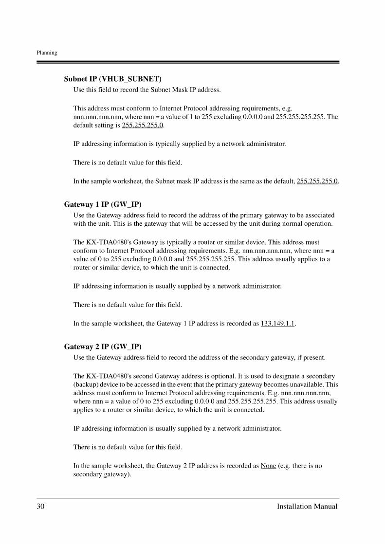
Subnet IP (VHUB_SUBNET)Use this field to record the Subnet Mask IP address.
This address must conform to Internet Protocol addressing requirements, e.g. nnn.nnn.nnn.nnn, where nnn = a value of 1 to 255 excluding 0.0.0.0 and 255.255.255.255. The default setting is 255.255.255.0.
IP addressing information is typically supplied by a network administrator.
There is no default value for this field.
In the sample worksheet, the Subnet mask IP address is the same as the default, 255.255.255.0.
Gateway 1 IP (GW_IP)Use the Gateway address field to record the address of the primary gateway to be associated with the unit. This is the gateway that will be accessed by the unit during normal operation.
The KX-TDA0480's Gateway is typically a router or similar device. This address must conform to Internet Protocol addressing requirements. E.g. nnn.nnn.nnn.nnn, where nnn = a value of 0 to 255 excluding 0.0.0.0 and 255.255.255.255. This address usually applies to a router or similar device, to which the unit is connected.
IP addressing information is usually supplied by a network administrator.
There is no default value for this field.
In the sample worksheet, the Gateway 1 IP address is recorded as 133.149.1.1.
Gateway 2 IP (GW_IP)Use the Gateway address field to record the address of the secondary gateway, if present.
The KX-TDA0480's second Gateway address is optional. It is used to designate a secondary (backup) device to be accessed in the event that the primary gateway becomes unavailable. This address must conform to Internet Protocol addressing requirements. E.g. nnn.nnn.nnn.nnn, where nnn = a value of 0 to 255 excluding 0.0.0.0 and 255.255.255.255. This address usually applies to a router or similar device, to which the unit is connected.
IP addressing information is usually supplied by a network administrator.
There is no default value for this field.
In the sample worksheet, the Gateway 2 IP address is recorded as None (e.g. there is no secondary gateway).
30 Installation Manual

Planning
User PW (PASS_U)Use the User PW field to record a User access level password.
Passwords may be from 1 to 10 alphanumeric characters long and are case sensitive. Upper and lower case characters can be freely mixed.
The default User password is user.
In the sample, the User password is entered as user (e.g., the default password).
Maintenance PW (PASS_M)Use the Maintenance PW field to record a Maintenance access level password.
Passwords may be from 1 to 10 alphanumeric characters long and are case sensitive. Upper and lower case characters can be freely mixed.
The default User password is mainte.
In the sample, the User password is entered as mainte (e.g., the default password).
ToneThis parameter is irrelevant to the setting of the KX-TDA0480.
NumberingThis parameter is irrelevant to the setting of the KX-TDA0480.
Trunk DataUse the Trunk Data section of the worksheet to record information needed to configure each of the active ports on the KX-TDA0480.
Port No. (ITRK)The Port # field indicates the port to be configured (e.g., ports 1 to 2). To the right of each port are fields for the port's setup parameters. Provide information for each of the unit's active ports.
• If a port on the KX-TDA0480 is not used, this should be indicated and, in the Maintenance Console Software, the Clear button should be used to remove all default settings. Failure to logically disable an unused port can result in calls being lost because they are erroneously routed to an inactive port.
Installation Manual 31

Planning
Trunk Group (ITRK)Use the Trunk Group Field to define from 1 to 2 Trunk Groups to be associated with the KX-TDA0480: Trunk Group 1 and Trunk Group 2.
A Trunk Group consists of a collection of trunks on the KX-TDA0480. At least one group must be defined and up to four Trunk Groups (ports 1 to 2) can be defined for the KX-TDA0480.
Trunk Groups
In the sample, the Trunk Group parameter for all ports is recorded as the default, 1 (e.g., All ports are members of the same Trunk Group).
Delete Digits (TGNINFO)Use the Delete Digits field to record the number of digits to be deleted from the received number.
In the sample, the Delete Digits parameter for all ports is configured to the default value of 0.
Length of Call Reference (ITRK)This parameter must always be set to "1".
Interface Type (ITRK)This parameter must always be set to "Basic Interface".
KX-TDA0480 PBX main unit
1 Trunk group
Port 1
Port 2
2 Trunk groups
Port 1
Port 2
32 Installation Manual

Planning
PAD In and PAD Out ( PAD_VALUE)For each port, use the PAD In and PAD Out fields to record the amount of PAD to be introduced into the communication between the KX-TDA0480 and the PBX main unit.
PAD is a voice line gain/loss function expressed in decibels (dB) which is introduced into communications between the KX-TDA0480 and the PBX main unit. This feature is used to emulate the loss normally generated in PSTN network transmission.
The following values are provided in the MCS list box.
+14dB, +12dB, +10dB, +8dB, +6dB, +4dB, +2dB, 0dB, -2dB, -4dB, -6dB, -8dB, -10dB,-12dB, -14dB, -40dB
The recommended value for the KX-TDA0480 is 0dB since the PBX introduces its own padding towards its extensions.
In the sample, the PAD In and PAD Out parameters for all ports are configured to the defaults for the KX-TDA0480, In = 0dB and Out = 0dB.
In a few cases, these settings may need to be adjusted. See Appendix A4 Pad Control and AGC for details. Adjustments of the nature must be performed on a case-by-case basis.
DTMF Detect (DTMF)The KX-TDA0480 capable of using of DTMF.
When DTMF is enabled, the unit passes digits after a call has been established, the KX-TDA0480 on the originating end detects the DTMF tones, captures them, and packetises them for TCP transmission to the destination KX-TDA0480 where regeneration occurs.
When DTMF is disabled, DTMF is transmitted over the voice path.
The available settings include:
• Care must be taken to calculate the end-to-end gain/loss when reconfiguring the PAD In and PAD Out parameters since these settings can have a cumulative effect when both are configured.
No: DTMF will not be detected.
Outgoing (Default): DTMF will be detected for outgoing calls.
Incoming: DTMF will be detected for incoming calls.
Both: DTMF will be detected for incoming and outgoing calls.
Installation Manual 33

Planning
As a general rule it is best to avoid duplicating detection on two communicating KX-TDA0480. This can be accomplished by always selecting the DTMF detect Outgoing parameter when using DTMF regeneration.
AGC (Automatic Gain Control)For each port, record the AGC function levels to be used if this feature is to be enabled.
The AGC (Automatic Gain Control) feature operates at the PAD In side of the unit. If this feature is to be enabled, the allowed values are recorded in dBm in the range of +3 to -60 dBm. It is recommended that the PAD In value be set to 0 dBm when AGC is enabled.
The default configuration is for AGC disabled.
Protocol Type (IPROT)Set a type of the ISDN Layer 3 signal protocol, or a call control signal. Only QSIG is supported.
Hunt PatternUse the Hunt Pattern section of the Worksheet to record information how called numbers are processed through the PBX main unit.
The Hunt Pattern defines which Trunk Group will be accessed when a call is processed and how the call will be routed through the PBX main unit.
Destination numbers always consist of one or more PBX Codes. Each Trunk Group defined in the Trunk Data folder can be associated with a PBX Code. When there are two or more Trunk Groups defined for a single KX-TDA0480, grouped ports can be associated with more than one PBX by configuring them with the appropriate PBX Codes. Conversely, the Trunk Groups of several units can be configured with the same PBX Code.
When a Trunk Group is associated with a PBX Code (Destination number), it is then associated with Hunt Pattern Number (1 or 2). The Hunt Pattern number is used to configure the Trunk Priority Feature discussed in the next topic.
From 1 to 2 Hunt Patterns can be defined (e.g., A pattern for each Trunk Group that has been defined for the unit). The relationship between ports, Trunk Groups, Hunt Patterns and PBX Codes is:
Per Unit Minimum Maximum
Ports 1 2
Trunk Groups 1 2
Hunt Patterns 1 2
Destination No. 1 128
34 Installation Manual

Planning
The default configuration is for one Trunk Group made up of all two ports. This configuration is defaulted to Hunt Pattern 1 and would be associated with a single PBX Code (Destination number). In the Trunk Priority folder settings this single group is defaulted to Priority one.
If the default configuration is used, then all that is necessary is to define the connection characteristics for the single Trunk Group (e.g., Trunk Group 1). Since no additional Trunk Groups are available, no additional Hunt Pattern information is required and the Trunk Priority section of this worksheet can be ignored.
If additional Trunk Groups are defined (e.g., Trunk Group2 etc.) then Hunt Patterns and Trunk Priorities must be configured.
See the next Topic in this section, "Trunk Priority".
Destination Number (HNTPTN)Use the Destination Number field to record the PBX Code to be accessed when calling through the KX-TDA0480 (8 digits maximum). Every Hunt Pattern must be associated with a PBX Code.
Hunt Pattern No. (HNTPTN)Use the Hunt Pattern No. field to record the number of the pattern to be associated with the Destination Number. Each Destination number will have a Hunt Pattern number associated with it (i.e., 1 or 2.).
Trunk PriorityUse the Trunk Priority section of the Worksheet to define the order (priority) in which alternate Trunk Groups will be searched in the event that a connection is not established within the first Trunk Group. This feature can be used to distribute traffic on PBX port.
Priority 1 is the first Trunk Group searched. If a connection cannot be established in the Priority 1 group, additional Trunk Groups are searched in priority order.
The Destination numbers searched using this feature are determined by the Hunt Pattern Number assigned in the Hunt Pattern section of the worksheet. (See previous Topic.)
• It is not possible to direct calls to a specific port within a Trunk Group.
• Trunk Groups must be defined using Trunk Data before Hunt Patterns can be configured.
Installation Manual 35
Planning
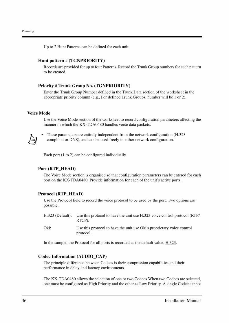
Up to 2 Hunt Patterns can be defined for each unit.
Hunt pattern # (TGNPRIORITY)Records are provided for up to four Patterns. Record the Trunk Group numbers for each pattern to be created.
Priority # Trunk Group No. (TGNPRIORITY)Enter the Trunk Group Number defined in the Trunk Data section of the worksheet in the appropriate priority column (e.g., For defined Trunk Groups, number will be 1 or 2).
Voice ModeUse the Voice Mode section of the worksheet to record configuration parameters affecting the manner in which the KX-TDA0480 handles voice data packets.
Each port (1 to 2) can be configured individually.
Port (RTP_HEAD)The Voice Mode section is organised so that configuration parameters can be entered for each port on the KX-TDA0480. Provide information for each of the unit’s active ports.
Protocol (RTP_HEAD)Use the Protocol field to record the voice protocol to be used by the port. Two options are possible.
In the sample, the Protocol for all ports is recorded as the default value, H.323.
Codec Information (AUDIO_CAP)The principle difference between Codecs is their compression capabilities and their performance in delay and latency environments.
The KX-TDA0480 allows the selection of one or two Codecs.When two Codecs are selected, one must be configured as High Priority and the other as Low Priority. A single Codec cannot
• These parameters are entirely independent from the network configuration (H.323 compliant or DNS), and can be used freely in either network configuration.
H.323 (Default): Use this protocol to have the unit use H.323 voice control protocol (RTP/RTCP).
Oki: Use this protocol to have the unit use Oki's proprietary voice control protocol.
36 Installation Manual

Planning
be assigned for both priorities.
When the KX-TDA0480 attempts to establish a connection with another VoIP gateway, the gateway goes through a capabilities exchange and negotiates the CODEC to be used.
The KX-TDA0480 will try to use the High Priority Codec first. If the remote gateway does not support the High Priority Codec, the Low Priority Codec is offered.
Use the Codec Information field to record the voice transmission Codec(s) to be used by all ports on the unit. Also specify the Codec priority when two Codecs are used. G723.1 is the default value for H.323 networks. G.729A can also be selected. The Efficiency to Quality settings will vary based on the Codec selected.
In the sample, G.729A is the only Codec configured for use.
Efficiency to Quality (VOICECOND)The ratio of Payload to Bandwidth for each Codec can be adjusted. The default values are shown in the following table.
The bytes and bandwidth values are inversely related in a predetermined ratio. In the Maintenance Console Software, the values are adjusted using a slide-bar control that maintains the correct ratio.
In the sample, Efficiency is recorded as the default value, 80 bytes/12.0 Kbps.
NetworkUse the Network section of the worksheet to record parameters used in checking network connectivity between the KX-TDA0480 and the immediate Ethernet switch or router to which the unit is connected.
To perform checks, the KX-TDA0480 transmits ICMP error checking packets on a defined error checking timing cycle. If no reply is detected, the link between the unit and Ethernet switch is broken.
This feature's information is typically used in cases where the KX-TDA0480 are working in groups associated with a PBX. In this case, failed links can be bypassed as calls are rerouted through active links.
Codec Default Parameters
Codec Payload Bandwidth
G.729A 80 bytes 12K
G.723.1 (5.3) 160 bytes 7.5K
G.723.1 (6.3) 192 bytes 8.46K
Installation Manual 37

Planning
Regular Timing (UPLINK)Regular Timing period in seconds. Every "Regular Timing" seconds, an error checking packet will be transmitted during normal operation. If "Regular Timing"=0, no checking is performed. Otherwise, "Regular Timing" should be in the range of 1 to 999.
The default setting for this value is 0 seconds.
Error Detect Timing (UPLINK)Error Detect period in seconds. Every "Error Detect Timing" seconds, an error checking packet will be transmitted during link failure. "Error Detect Timing" should be in the range of 1 to 999.
The default setting for this value is 3 seconds.
Generally, "Error Detect Timing" should be smaller than "Regular Timing" because more frequent checking is required when the link is down.
Disconnect on Errors (UPLINK)During Regular Timing checking, if "Disconnect on Errors" times bad packets are detected then "link failure" is declared. Regular Timing checking is halted, and Error Detect checking is started."Disconnect on Errors" should be in the range of 1 to 100.
The default setting for this value is 10 times.
Reconnect on Errors (UPLINK)During Error Detect checking, if "Reconnect on Errors" times good packets are detected then "normal link" is declared. Error Detect checking is halted, and Regular Timing is started."Reconnect on Errors" should be in the range of 1 to 100.
The default setting for this value is 1 times.
Call ControlUse the Call Control section of the worksheet to record parameters associated with Gateway-to-Gateway and Gateway-to-Gatekeeper communications and for control for the KX-TDA0480.
The start and signalling port parameters designate the signalling ports on which communication will be initialised and on which transmission will take place, respectively.
As a rule, the default values should be used.
38 Installation Manual

Planning
Signalling Port (CALL_PORT)Use the Signalling Port field to record the port on which transmission will be initiated.
In the sample, the unit is configured to the default value, 1720. This value affects one port only.
H.245 Start Port (H.245_PORT)Use the H.245 Start Port field to record the port on which H.245 signalling will be initiated.
In the sample, the unit is configured to the default value, 1721.
This value affects the four ports. The designated port and the next three ports in sequence (e.g., 1721, 1722, 1723, and 1724).
RTP Start Port (RTP_PORT)Use the RTP Start Port field to record the port on which RTP signalling will be initiated.
In the sample, the unit is configured to the default value, 5004.
This value affects eight ports. The designated port and the next seven ports in sequence. Even ports are RTP (e.g., 5004, 5006, 5008, and 5010). Odd ports are RTCP (e.g., 5005, 5007, 5009, and 5011).
Connect Time (NOCTIME)Use the Connect Time field to record the time allowed for a connection to be established.
This parameter defines the time frame during which the KX-TDA0480 will try to establish the call. If a call is not established within this time (e.g., the called KX-TDA0480 is not responding) a fast Busy Tone is returned. When implementing KX-TDA0480 in a dialup WAN scenario -WAN connection setup time must be included as a timing consideration.
The range of acceptable values includes from 1 to 99 seconds.
In the sample, the unit is configured to the default value, 30 seconds.
UDP Port No. for Supplementary Service (ISDN_ANF_PORT)A port used to transfer QSIG signals in an IP network when they are received, using the QSIG connectionless supplementary service. The default value of this port is 5003. When using this type of port, it will be necessary to unify it within the network.
DNS Setup, SNMP Setup, Gatekeeper, and Notify E-MailRefer to Section 2.2.4 Common Configuration Worksheet.
Installation Manual 39

Planning
Recovery DelayThe KX-TDA0480 Recovery Delay feature controls a secondary Jitter buffer that is activated dynamically when enabled. This feature allows the unit to recover from network delays by temporarily storing voice data in a Jitter (recovery) buffer. In the event of a network delay, the stored voice data is transmitted, assuring an uninterrupted conversation.
Several configuration parameters can be configured for this feature.
Maximum Receive Buffer Size (RX_BUFFER)Record the maximum allowable size of the Jitter buffer. In most cases, the default size (1920 ms) will provide the best results.
Start Recovery (RX_BUFFER)Record, in units of ms, the delay time threshold value for the start of recovery delay processing*1. In most cases, the default value (200 ms) will provide the best results.
End Recovery (RX_BUFFER)Record, in units of ms, the delay time threshold value for stopping the recovery delay processing which started at the time specified as Start Recovery data. In most cases, the default value (30 ms) will provide the best results.
Other
Cause of Fan Fault (FAN_FLT)This parameter is irrelevant to the setting of the KX-TDA0480.
A-law/m-law Flag (LAW_FLAG)Assign as appropriate to the network Codec set at the PBX.
The default setting for this field is m-law.
*1 Recovery Delay Processing is defined as the operation of discarding soundless voice packets from the jitter buffer.
40 Installation Manual

Physical Installation
Section 3
Physical Installation
Before beginning the KX-TDA0480 unit installation process, it is recommended that all planning worksheets be completed. The following sequenced steps make for a quick and efficient installation. With experience, installers may adopt variations on these procedures that suit their particular needs: (1) Connect Cables (2) Power-up Unit and Verify Physical Installation
Installation Manual 41

Physical Installation
3.1 Installation Preconditions
Verify that the following conditions are met before proceeding with the installation.
Electromagnetic InterferenceThis equipment can cause electromagnetic interference to nearby unshielded equipment. Take care to protect nearby equipment that may be affected.
Installation LocationThe KX-TDA0480 must be installed at appropriate slot of IP PBX.
CablingSeveral cables of appropriate lengths will be needed during the installation process. The lengths will depend on the specific installation.
• 10 Base-T (RJ45) cable will be needed to interconnect the KX-TDA0480 with routers, hubs, and/or Ethernet switches.
• For each unit port in use, a 2-wire printed inter-office cable will be needed to connect the KX-TDA0480 to its respective terminal devices (e.g., ordinary telephone sets and/or a G3 fax machine.)
The following table indicates the specifications for these cables.
Installation DataThe worksheets completed in the preceding section of this guide must be on hand to perform the physical and logical installation tasks described in this and the following section.
Maintenance Console Software TerminalDuring the logical installation process described in the next section, a computer terminal will be needed to run the Maintenance Console Software. In addition, the RS-232C serial cable described in Section 3.3 Connect the Computer Terminal Unit with RS-232C Cable will be required to initialise the unit.If units are to be configured remotely following initialisation, a LAN cable and appropriate adapters will also be needed to connect the terminal to the network.
Cable type Cores Diameter Remarks
Printed intra-office cable
2-wire 0.5 mm
10BaseT (RJ45) cable KX-TDA0480 to Ethernet connection
42 Installation Manual

Physical Installation
3.2 Connect Cables
The following connections must be made to complete the KX-TDA0480 cabling.
• RS-232C Cable
• LAN Cable
With the exception of the power cable, all cables must be prepared during the installation process. In addition, cable restraints should be installed.
WARNINGFollow all instructions when performing cabling procedures. Improper installation methods can result in damage to the KX-TDA0480 and injury to installation personnel.
Installation Manual 43

Physical Installation
3.3 Connect the Computer Terminal Unit with RS-232C Cable
To initialise a newly installed KX-TDA0480 using the Maintenance Console Software Unit Information Setup Wizard, a computer or terminal must be connected directly to the unit using an RS-232C serial cable (cross) with DB9 Female to DB9 Female connectors. The pin configuration for the serial cable is shown in Figure "RS-232C pin configuration".
RS-232C pin configuration
To connect the computer with the KX-TDA04801. Turn the computer power OFF.
2. Connect the RS-232C cable to one of the computer's com ports (e.g., Com 1) and to the Serial Port connector on the KX-TDA0480 front panel as shown in Figure "KX-TDA0480 serial port connection".
RS-232C port on the KX-TDA0480 COM port on the PC (9 pin)
Circuit Type(EIA)
Signal Name Pin No. Pin No.
Signal Name
Circuit Type(EIA)
BB RD (RXD) 2
BA SD (TXD) 3
CD ER (DTR) 4
AB SG 5
CC DR (DSR) 6
CA RS (RTS) 7
CB CS (CTS) 8
2 RD (RXD) BB
3 SD (TXD) BA
4 ER (DTR) CD
5 SG AB
6 DR (DSR) CC
7 RS (RTS) CA
8 CS (CTS) CB
RS-232C port on the KX-TDA0480 COM port on the PC (25 pin)
Circuit Type(EIA)
SignalName
Pin No.SignalName
Circuit Type(EIA)
BB RD (RXD) 2
BA SD (TXD) 3
CD ER (DTR) 4
AB SG 5
CC DR (DSR) 6
CA RS (RTS) 7
CB CS (CTS) 8
1 FG AA
3 RD (RXD) BB
2 SD (TXD) BA
20 ER (DTR) CD
7 SG AB
5 CS (CTS) CB
6 DR (DSR) CC
CF4 RS (RTS)
Pin No.
44 Installation Manual

Physical Installation
KX-TDA0480 serial port connection
• The Maintenance Console Software is configured for serial communications on the port Com 1. If a port other than Com 1 is to be used, the MCS serial communications parameter must be reconfigured. See Section 4.7 for details.
RS232C Serial Cable(Cross cable)
To COM port
Personal Computer
Installation Manual 45

Physical Installation
3.4 Connect the Network Cable
A standard 10BaseT cable with an RJ45 connector is used to interconnect the KX-TDA0480 with a network device.
To install the Network connector cable:1. Insert the RJ45 connector into the KX-TDA0480 UPLINK port located on the unit's front
panel.
Uplink connector location
2. Connect the other end of the 10BaseT cable to the remote LAN equipment (e.g., router, Ethernet switch, or hub.)
When connecting the KX-TDA0480 directly to a router use a 10BaseT Cross/Rollover cable. Use a 10baseT straight cable to connect the KX-TDA0480 to a hub or Ethernet switch.
IP Link Cable(Straight Cable)
Router
Switching HUB
IP Network
46 Installation Manual

Physical Installation
Router and Ethernet Switch cabling
• As cable lengths increase voice quality may become degraded. Line repeaters can be used when long cable lengths are required. Voice quality may also deteriorate when hubs are connected in tandem and tandem arrangements should never exceed more than three stages.
IP PBX
IP PBX
Router
10BaseT straight cable
10BaseT cross cable (Rollover)
Router
Switching HUB
Installation Manual 47
Physical Installation
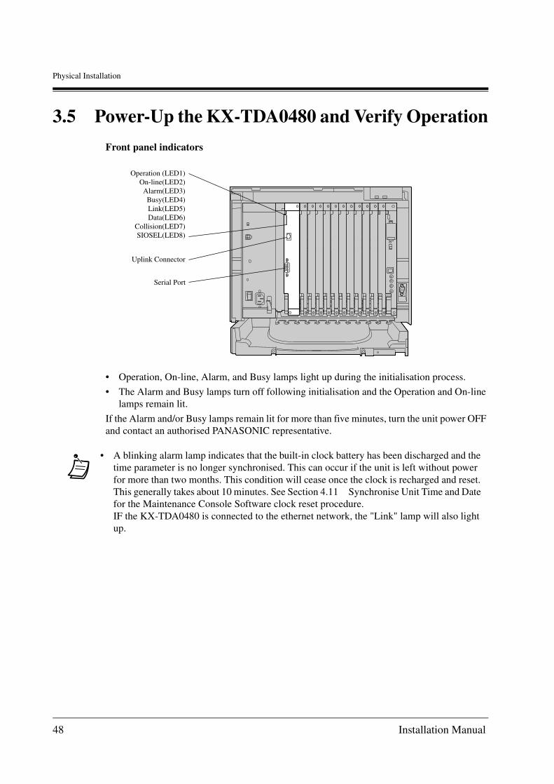
3.5 Power-Up the KX-TDA0480 and Verify Operation
Front panel indicators
• Operation, On-line, Alarm, and Busy lamps light up during the initialisation process.
• The Alarm and Busy lamps turn off following initialisation and the Operation and On-line lamps remain lit.
If the Alarm and/or Busy lamps remain lit for more than five minutes, turn the unit power OFF and contact an authorised PANASONIC representative.
• A blinking alarm lamp indicates that the built-in clock battery has been discharged and the time parameter is no longer synchronised. This can occur if the unit is left without power for more than two months. This condition will cease once the clock is recharged and reset. This generally takes about 10 minutes. See Section 4.11 Synchronise Unit Time and Date for the Maintenance Console Software clock reset procedure.IF the KX-TDA0480 is connected to the ethernet network, the "Link" lamp will also light up.
Operation (LED1)On-line(LED2)
Alarm(LED3)Busy(LED4)Link(LED5)Data(LED6)
Collision(LED7)SIOSEL(LED8)
Uplink Connector
Serial Port
48 Installation Manual

Logical Installation
Section 4
Logical Installation
Once the KX-TDA0480 has been physically installed, it must be logically configured for operation. The logical installation process described in this section involves the following operations; (1) Initialise the unit with new IP addressing information, (2) Configure unit specific parameters, (3) Upload configuration files and reboot the units. IP addressing and configuration parameters were discussed in detail in Section 2.2.2 of this document and the worksheets created at that time are used to perform the logical installation tasks described in this section.
Installation Manual 49

Logical Installation
4.1 Logical Installation Methods
There are several methods by which the logical configuration process can be performed.In all cases, each newly installed KX-TDA0480 must first be initialised with its new IP addressing through a direct RS-232C link to the unit. Once a unit has been initialised , it is possible to perform additional configuration tasks using one of the following methods.
• Use the KX-TDA0480 Maintenance Console Software to configure and upload configuration files. This can be done locally or remotely.
• Configure OFDD.VHO and DNS.DAT files off-line and use an FTP link to upload the configuration files to a unit.
• Configure a unit directly over a serial connection, line-by-line, using the terminal command line interface and on-line commands.
In this section, all configuration tasks will be performed using the Maintenance Console Software. Alternative methods for creating and uploading configuration files are described in Appendix A7 of this document.
The following procedures are discussed in this section.
• Install Maintenance Console Software
• Start Maintenance Console Software and Login
• Initialise Unit with Maintenance Console Software Setup Wizard
• Create/Edit Common Configuration
• Configure Unit Parameters
• Transfer Files and Reboot Units
50 Installation Manual

Logical Installation
4.2 Maintenance Console Software Overview
The KX-TDA0480 Maintenance Console Software (MCS) provides an easy-to-use interface for the installation and management of the KX-TDA0480. The MCS is a Microsoft® Windows® 98, Windows NT®, Windows 2000 or Windows XP compatible software product and will run on systems supporting that operating system. In addition, the computer terminal must have a floppy drive for installation and a serial port. Finally, to permit communication with the unit over the LAN, an Ethernet Network card using an RJ45 connector is also required.The Maintenance Console Software user's interface conforms to Windows 98, Windows NT, Windows 2000 or Windows XP conventions allowing users to use a mouse to pull down menus, point and click items, and select operational buttons to execute various operations. For additional information regarding the user interface, see the Windows 98, Windows NT, Windows 2000 or Windows XP user's documentation.In this section, procedures for using the Maintenance Console Software to install and configure the KX-TDA0480 is described. For a complete listing of all Maintenance Console Software features and functions, see the KX-TDA0480 Programming Guide.
Installation Manual 51

Logical Installation
4.3 Install Maintenance Console Software
The MCS is shipped on CD-ROM.
System RequirementsThe Maintenance Console Software is operable on an IBM® PC/AT® compatible platform capable of IP network connection that satisfies the following requirements:
• Microsoft Windows 98, Windows NT, Windows 2000 or Windows XP.
• i486™ or IntelDX4TM (i80486) processor-based personal computer.
• 64 megabytes (MB) of available RAM (regardless of the operating system).
• 24 MB of available hard-disk space.
Trademarks
• IBM and AT are registered trademarks of International Business Machines Corporation in the United States.
• Microsoft, Windows and Windows NT are either registered trademarks or trademarks of Microsoft Corporation in the United States and/or other countries.
• i486 and IntelDX4 are trademarks or registered trademarks of Intel Corporation or its subsidiaries in the United States and other countries.
• All other trademarks identified herein are the property of their respective owners.
• Screen shots reprinted with permission from Microsoft Corporation.
To install the MCS:1. Insert the CD-ROM into your PC's CD-ROM drive.
2. Click "Software Installer" on the initial screen.
3. Read the End-User Licence Agreement, and then click "OK".
4. Double-click the "Setup.EXE" icon.
5. Follow the instructions to install the MCS.
6. When the installation is complete, 3 icons will be created.
52 Installation Manual

Logical Installation
4.4 Start Maintenance Console Software and Login
To access the Maintenance Console Software interface, the user must first login.
To start the MCS software and log in to the system:1. Turn the computer power ON.
2. Click on the Start button located at the lower left-hand portion of the Windows desktop and choose Programs, "IVG Common Maintenance Console Software V1.2E*1", and click the "IVG MCS" icon.
3. The MCS startup screen displays for a few seconds and is then followed by the Startup Password dialogue box.
After a few seconds, the MCS displays the Startup Password dialogue box.
4. Click the mouse cursor in the Password field and type the default Password mcs, then click on the OK button to display and Maintenance Console Software main directory window.*2
*1 The version of the software is subject to change without notice.
• All previous versions of the MCS should be removed from the computer prior to running MCS Version 1.2.*1
*2 Following the first login, the Maintenance Console Software password can be changed by the user with the Options item on the Tools menu. The MCS password is case sensitive.
Installation Manual 53

Logical Installation
4.5 MCS Main Directory Window
The Maintenance Console Software's main directory window provides access to the various MCS menus for defining and displaying network Groups and Gateways (units).
The function and appearance of the MCS main directory window resembles that of the Windows Explorer program interface.
Title, Menu, and Tool BarsThe top line Title bar contains the programs name.The Menu bar is located immediately beneath the Title bar and contains the program menus; Unit, Edit, Tools, View, and Help.To view the contents of a menu, place the mouse cursor over the menu item and click the left mouse button, then select the desired item from the menu.Repeat this procedure for menu items containing submenus.Below the Menu bar is the Toolbar. This bar contains shortcut buttons to many of the frequently used menu items. When the mouse cursor is placed over a Toolbar button, a definition for the button appears on the left side of the Status bar.The Toolbar bar can be removed and restored to the display by selecting Tool Bar from the View menu.
Directory WindowThe directory window itself contains two window panes; the Groups pane and the Units pane.To adjust the relative width of the panes, left mouse-click and hold on the pane divider bar and drag the divider bar to the left or right of the screen.
Title Bar Menu Bar Tool Bar Unit Field Description and sort control
Groups Window Pane Units Window Pane Status Bar
54 Installation Manual

Logical Installation
Groups PaneThe Groups pane is used to create, display, and organise IP Gateway network Groups and sub-Groups.New Groups are created by mouse-clicking on the Main directory icon and selecting New and then Group from the Unit menu.A shortcut method to perform the same task is to click the right mouse button over the Main icon and select New Group from the Pop-up menu. If the procedure described above is performed while an existing Group is highlighted, a sub-Group is created within the selected group. Once created, groups can be expanded and collapsed by double-clicking the left mouse-button over a Group or Main icon.
Units PaneThe Units pane is used to create and display units (KX-TDA0480 Gateways and Gatekeepers and other) within groups and to edit unit data.A new Gateway or Gatekeeper or other unit is created using the Maintenance Console Software Unit Setup Wizard. The Setup Wizard is displayed by mouse-clicking a Group in which to create the unit, and selecting New and then Gateway or Gatekeeper or Other on the Unit Menu. A shortcut method to perform the same task is to click the right mouse button over a Group icon and select New Gateway from the Pop-up menu.Once a unit has been setup, its setup Information and its configuration Data can be edited by mouse-clicking on the unit and selecting Edit data and Edit configuration items on the Unit menu.A shortcut method to edit unit data is to click the right mouse button over a unit icon and select Edit configuration from the Pop-up menu.To sort the items shown in the units display, click on one of the field names at the top of the list. For example, to sort the list by IP address, click the mouse cursor on the IP address field.
Status LineThe status line is displayed beneath the Directory Window. It shows summary information about the current status of the Maintenance Console Software display.This bar can be removed and restored to the display by selecting Tool Bar from the View menu.
Installation Manual 55

Logical Installation
4.6 Create a New Group
When first setting up a IP Gateway network, unit Groups must first be created. Groups are used to help organise the network configuration and will usually consist of units that are related to one another. For example, they will be in the same location.Groups can be created all at once or one at a time as the network setup process proceeds.Use the information recorded in the Network and Unit Configuration worksheets described in Section 2.2 of this document.
To create new Group:1. Mouse-click on the Main icon in the directory window Groups pane and select New and
Group from the Unit menu.
Note
• Click the Toolbar Create Group icon.
56 Installation Manual

Logical Installation
• Click the right mouse button in the Groups windowpane and use the Pop-up New Group menu item.
The MCS displays the Create new group dialogue box.
2. Select the Group Name field and type a new group name. Also type comments into the Comment field if desired.
3. Click on the OK button to accept the information displayed in the fields or Cancel to abort the changes.
The MCS updates the directory window Groups pane with the new group.
Repeat this procedure to create additional groups.
Installation Manual 57

Logical Installation
In the sample network, four groups have been created.
58 Installation Manual
Logical Installation
4.7 Create New Units
Once a new Group has been created, new units can be added to the group; Gateways*1 and Gatekeepers*2 and Other Unit*3. The Maintenance Console Software Unit Information Setup Wizard is used to create both types of units in exactly the same manner.A new unit is shipped with the factory default IP addressing information (i.e., 192.168.1.200). Although this information can be used to establish a LAN type connection, it is usually easier to first reconfigure the unit's IP addressing information to match that of the existing LAN, using a direct RS-232C serial cable connection.The Maintenance Console Software's Unit Information Setup Wizard method for doing this is discussed in the following procedures.If desired, once a unit has been created using this direct method, the unit setup information can be edited remotely, using a network connection.
*1 A Gateway is the KX-TDA0480 IP Gateway card.*2 A Gatekeeper is an H.323 device that is used to manage H.323 Voice-Over-IP networks. Only H.323 networks use a Gatekeeper.
the IP Gateway networks may also be configured using internal DNS server management capabilities.*3 An Other Unit refers to Other Device excluding Gateway and Gatekeeper.
Installation Manual 59

Logical Installation
4.7.1 RS232C Port Configuration
In section 3.3 the RS233C cable was connected with the terminal to be used for initialising the KX-TDA0480. The Maintenance Console Software is configured by default to use the port Com 1 for serial data transfer. If a serial communications port other than Com 1 is being used on the computer terminal used for unit initialisation, the MCS Options item must be selected from the Tools menu to reconfigure the Com port.
To reconfigure the serial communications port:
1. Select Options from the MCS Tools menu.
The MCS displays the Options folders
2. In the first folder (General), use the Select RS-232C port pull-down list-box to choose the desired port.
60 Installation Manual

Logical Installation
3. Click on the OK button to accept the new port setting. Click the Cancel button to abort the change.
Installation Manual 61

Logical Installation
4.7.2 Create a New Gateway (KX-TDA0480 Unit)
To create a new Gateway mouse-click on a Group name in the directory window Groups pane and select New and Gateway from the Unit menu. The worksheet for this task is discussed in section 2.2.2 Network Units List Worksheet of this document.
Note
• Click the Toolbar Create Gateway icon.
• Click the right mouse button in the Groups window pane and use the pop-up New Gateway menu item.
The MCS then displays the first of six Unit Setup Wizard screens for the selected Group.
62 Installation Manual

Logical Installation
• Click the Cancel button at any Wizard screen to abort all of the edits made during the current configuration session.
Installation Manual 63

Logical Installation
Unit Setup Wizard 1 of 6Use the Setup Wizard screen 1 to enter the Unit Name, Type, and Comments. Name and Type are required fields.Be careful to select the correct unit Type, since this will determine the Data configuration options that are presented during unit configuration.
1. Select the Name field and type a name for the unit.
2. Use the pull-down lists to configure the three Equipment parameters; Unit, Version, and Interface. Select only BV1250GW, V1.62, and BRIT-QSIG respectively.
3. Select the Comment field to type comments if desired.
4. Click on the Next button when finished entering information or click on the Cancel button to exit the Wizard and lose all changes.
The MCS then displays the second of six Unit Setup Wizard screens.
64 Installation Manual

Logical Installation
Unit Setup Wizard 2 of 6Use the Setup Wizard screen 2 to enter the unit's IP addressing information. The IP Address, Subnet Mask, and Gateway 1 IP address fields are required. Be careful to insure that all IP addressing information is correctly entered. Errors in entering this data can produce problems that are difficult to diagnose later in the installation process.
1. Select the IP Address field and enter the IP Address for the unit.
2. Select the Subnet Mask field and enter the Subnet Mask IP address.
3. Select the Route IP Address 1 field and enter the address of the primary Gateway to which the unit is connected. This is usually the IP address of a router or similar network device.
4. If a secondary (e.g., backup) Gateway device is used in association with the unit, enter the Route IP Address 2.
5. Click on the Next button when finished entering information or click on the Cancel button to exit the Wizard and lose all changes.
If an IP address that is not allowed is entered, the MCS will issue an error message so that the value can be corrected.
Installation Manual 65

Logical Installation
Unit Setup Wizard 3 of 6
1. Click on the Next button when finished entering information or click on the Cancel button to exit the Wizard and lose all changes.
66 Installation Manual

Logical Installation
Unit Setup Wizard 4 of 6Use the Setup Wizard screen 4 to either accept the default Maintenance password or change the Maintenance password.The default Maintenance password is mainte typed in lower case characters. Be careful to make a record of any new password that is entered at this time*1.
1. If the default password is to be used, click on the Use Default check box and proceed to step 5.
2. If the Maintenance password is to be changed, select the Password field and type the new password. To enhance security, an * (asterisk) symbol will be echoed in place of each character typed.
WARNINGIf a password is lost, it cannot be recovered. In the event of a lost password, contact your maintenance staff, an service office, or an authorised agent.
3. Select the Confirm password field and retype the new password. To enhance security, an * (asterisk) symbol will again be echoed in place of each character typed.
4. Click on the Next button when finished entering information or click on the Cancel button to exit the Wizard and lose all changes.
*1 If the new password is lost, contact the Customer Support.
Installation Manual 67

Logical Installation
• If the password is changed and the Password and Confirm Password values are not identical, the MCS will issue an error message and redisplay screen 4 so that the password fields can be corrected. The passwords must match in order to proceed.
68 Installation Manual

Logical Installation
Unit Setup Wizard 5 of 6Use the Setup Wizard screen 5 to either accept the default User password or change the User password.The default User password is user typed in lower case characters. Be careful to make a record of any new password that is entered at this time*1.
1. If the default password is to be used, click on the Use Default check box and proceed to step 6.
2. If the User password is to be changed, select the Password field and type the new password. To enhance security, an * (asterisk) symbol will be echoed in place of each character typed.
WARNINGIf a password is lost, it cannot be recovered. In the event of a lost password, contact your maintenance staff, an service office, or an authorised agent.
3. Select the Confirm password field and retype the new password. To enhance security, an * (asterisk) symbol will again be echoed in place of each character typed.
4. Click on the Next button when finished entering information or click on the Cancel button to exit the Wizard and lose all changes.
*1 If the new password is lost, contact the Customer Support.
Installation Manual 69

Logical Installation
• If the password is changed and the Password and Confirm Password values are not identical, the MCS will issue an error message and redisplay screen 5 so that the password fields can be corrected. The passwords must match in order to proceed.
70 Installation Manual

Logical Installation
Unit Setup Wizard 6 of 6Use the Setup Wizard screen 6 to select the method for applying the unit setup information.
Two methods are available: Update Configuration File and Upload to Unit and Reboot.
Update Configuration FileUse the Update Configuration File to record the unit setup information to an MCS file for later upload to the unit. This method is not recommended for first time installation, since the unit IP addressing information entered in the Wizard must be written directly to the unit if the unit is to be accessed using a remote (e.g., LAN) connection.During subsequent remote (e.g., LAN) sessions, the Unit Information Setup Wizard can be accessed using the Edit Data and Change Unit Information item on the MCS Unit menu.
Upload to Unit and RebootUse the Upload to Unit and Reboot method for new units. In addition to recording the unit setup information to an MCS file, this method uploads the information directly to the unit, issues the unit "write to memory" command and reboots the unit.The settings configured using the Unit Information Setup Wizard take effect following the unit reboot, allowing the unit to be accessed over a LAN connection.
Installation Manual 71

Logical Installation
1. Click the Option radio button for method to be used; Update Configuration File or Upload to Unit and Reboot. Both methods will save the file to the MCS. If the Update Configuration File method is used, proceed to step 4.
2. If the Upload to Unit and Reboot method is selected, click the Reboot access method radio button for the method to be used to upload the data to the unit.
3. Click the RS232C radio button to select the upload method.
4. Click on the Finish button to complete the Wizard. Click on the Cancel button to exit the Wizard and lose all changes.
Once the Finish button is clicked the MCS will perform the specified operations.If the Update Configuration File method was used, the unit's updated OFDD.VHO file is saved, and the Main Directory windows will be redisplayed with the new unit displayed in the Units window pane. If the Upload to Unit and Reboot method is used, the MCS updates the Unit setup information in the unit and displays a confirmation message indicating the operation was successful. An error message will be displayed if a connection could not established.
In addition to the upload, the unit's updated OFDD.VHO file will be saved, and the Main Directory windows will be shown with the new unit displayed in the Units window pane.
• During the first time configuration (unit initialisation) the RS-232C cable must be connected to the unit and the COM port being used on the computer terminal must be properly selected to perform the following operation.
• During subsequent sessions, the unit setup (e.g., IP addresses) can be edited remotely using a LAN connection. This is done by selecting the Edit Data/Change Unit Information item on the MCS Unit menu. When this method is used, the computer and unit must be within the same subnet or communication will be lost after the new configuration becomes effective.
• As discussed in the previous note, the LAN upload method should only be selected for units that have been previously initialised and are already on-line in the network.
• The unit reboot process can take over a minute to complete. Observe the LED indications on the front panel of the unit to verify that the reboot process is complete before attempting to perform additional operations with the unit.
72 Installation Manual

Logical Installation
4.7.3 Create a New Gatekeeper
Gatekeepers are only created for H.323 managed networks. In the case of the KX-TDA0480, networks can also be managed through internal DNS facilities.When used, up to two Gatekeeper devices can be created for each H.323 Zone. The first device created is used as the primary device. Optionally, a secondary (e.g., backup) device can be created.
WARNINGThe Maintenance Console Software can only be used to configure an the Gatekeeper device. To configure other Gatekeeper devices refer to the manufacturer's documentation.
To create a Gatekeeper device, select the Group in which the device is to be located and then select the New Gatekeeper item from the Unit menu.
Note
• Click the Toolbar Create Gatekeeper icon.
• Click the right mouse button in the Groups window pane and use the pop-up New Gatekeeper menu item.
The MCS then displays the Setup Wizard for a Gatekeeper.
Installation Manual 73

Logical Installation
The process for setting-up a Gatekeeper unit is identical to that for a Gateway unit, except that the Type field is for a Gatekeeper only.Refer to the Setup Wizard procedures for a Gateway to set up the Gatekeeper.
74 Installation Manual

Logical Installation
4.7.4 Create an Other Unit
Other Unit refers to Other Device excluding Gateway and Gatekeeper.To create an Other Unit device, select the Group in which the device is to be located and then select the New Other Unit item from the Unit menu.
Note
• Click the Toolbar Create Other Unit icon.
• Click the right mouse button in the Groups window pane and use the pop-up New Other Unit menu item.
The information about Other Unit can be added easily to DNS.DAT by selecting Other Unit item from the devices list on priority connection information display.The MCS then displays the Setup Wizard for an Other Unit.
Installation Manual 75
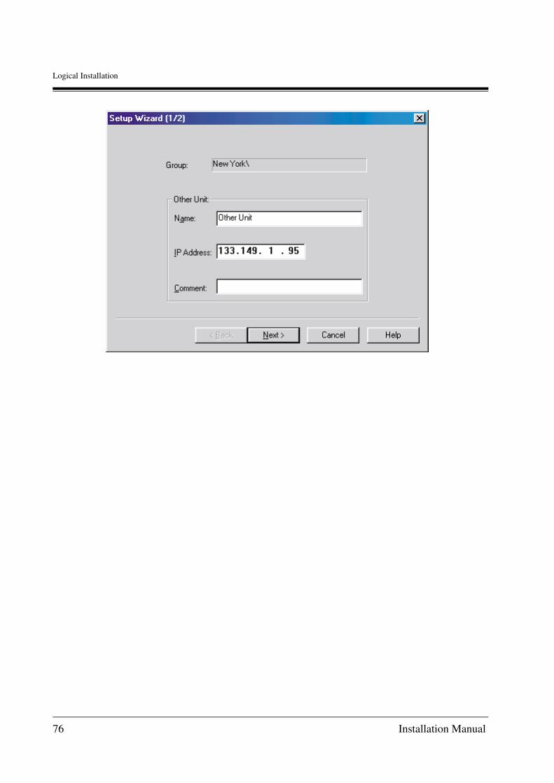
Logical Installation
76 Installation Manual

Logical Installation
4.8 Create/Edit Common Configuration
The Maintenance Console Software provides a Common Configuration facility that makes it easier and quicker to configure parameters that are shared by all of the units in a group. The common configuration items include; DNS, SNMP, Gatekeeper, and Notify E-mail. These parameters can also be configured for individual units using the Unit Configuration folders described later in this section. This may be better when adding only a few units to an existing network.
To use the Common Configuration feature:1. Select a Group in the Groups Pane or from within a group, select the units to be configured
using the methods described earlier in this document.
2. Select the Edit Common Configuration item from the Unit/Edit Data menu or from the pop-up menu displayed by right-clicking on the selected units.
The MCS then displays the folders for the Common Configuration items.
Installation Manual 77

Logical Installation
3. All parameters configured in this manner will be applied to all units in the selected group or to the units selected in the Units Pane. The new parameters will appear in the Configuration folders for each unit.
• If a Gatekeeper unit is a member of the selected group, only the SNMP parameters will be applied to that unit.
78 Installation Manual

Logical Installation
4.9 Configure Units
Once a Gateway or Gatekeeper unit has been created using the Unit Information Setup Wizard, the Maintenance Console Software has created a configuration file (OFDD.VHO) for the unit. This file must now be configured with data that will allow the unit to operate properly in the network environment in which it is installed.The Maintenance Console Software permits all configuration file data to be entered and edited while off-line. Once the configuration data for one or more units has been entered into the MCS, each unit's configuration file can be saved to a hard disk and /or uploaded to unit's using the network interface.*1
In the procedures discussed in this section, the completed configuration files will be uploaded to the units using a LAN connection.See Section 3.4 for additional information about the LAN connection. To begin the configuration process, highlight the unit to be configured by clicking on the unit's icon and then select Edit data and Edit configuration item from the Unit menu.
Note
• Click the Toolbar Edit Configuration icon.
*1 Additional methods for uploading and downloading configuration files are discussed in Appendix A7 of this document.
Installation Manual 79

Logical Installation
• Place the mouse cursor over the unit to be configured, click the right mouse button, and use the pop-up menu's Edit configuration item.
The MCS then displays an Edit Configuration dialogue box asking if the unit OFDD.VHO file to be edited is the one that is currently recorded on disk by the MCS or if the OFDD.VHO file currently stored in the unit should be downloaded for editing.
• In the case of a newly created unit, the Saved configuration file option (default) should be selected.
• If a unit has been previously configured and its configuration file is not recorded on the MCS terminal currently in use, it may be desirable to download the OFDD.VHO file from the unit. In order to do this, the terminal must have an active LAN link with the unit. In this case, select the Download configuration file from Unit radio button.
Once a method has been selected, click on the OK button to proceed.Assuming that the Saved File option is selected, the MCS then displays a file selection dialogue box.
80 Installation Manual

Logical Installation
• If this is a newly created unit, only one file will be displayed in the Options list of this dialogue box. The file date will be the date on which the Unit Information Setup Wizard was run.
• If this unit has been configured previously, there may be two or more versions of the OFDD.VHO file displayed.
The file named with the .VHO extension will always be the most recent version of the configuration file stored on the MCS terminal. Older backup or rollback versions of the configuration file will always be listed with the extension. OLD and will be listed in data sorted order with the most recent shown toward to the top of the list.
Installation Manual 81

Logical Installation
Click on the desired file version in the Options list by clicking on it, and then click on the OK button to proceed.The MCS then displays the tabbed configuration folders for the Type of unit being configured.
In most cases, the order in which folders are selected for data entry is not important. In the few cases where order is important, the MCS will issue a warning message.To view a configuration folder, click on a folder's tab.
• Click the Cancel button in any folder to abort all of the edits made during the current configuration session.
Folder tabs
82 Installation Manual

Logical Installation
4.9.1 Configure Gateway Units (KX-TDA0480)
The Maintenance Console Software display uses a set of tabbed folders to organise the unit configuration process. Each of these folders contains fields in which configuration data are entered.The data to be entered should have already been identified and recorded on a Unit Setup Worksheet for the unit being configured. Field definitions and parameter descriptions are provided in Section 2.2 of this document.Much of the data recorded during the unit configuration process is critical to the proper operation of the equipment and care must be taken to avoid errors.
Each of the unit configuration tabs is discussed as follows.
Installation Manual 83

Logical Installation
General FolderUse the General folder to display and reconfigure unit Setup Information. This is the first folder displayed when beginning unit configuration.The folder displays information that was entered using the Unit Information Setup Wizard. Usually, no changes will need to be entered for this tab.
Use the Unit section to view and edit unit IP addressing information.
UnitDisplays the unit's name. This field cannot be edited from this folder.To change a unit's name, exit the Edit Data configuration screen and return to the directory window. Click the mouse cursor once on the Unit Name in the MCS Units windowpane. When the cursor changes to a text edit cursor, make the desired changes and then click the mouse over another section of the MCS window. The change made will be reflected in the Unit Information Setup Wizard and the General configuration folder.
Use the Password section to view and edit unit IP addressing information.
84 Installation Manual

Logical Installation
PasswordThe Maintenance and User passwords can be changed by clicking one of the Change Password buttons. The change procedure is the same for both password types.When a Change Password button is clicked, the MCS displays a change password dialogue box.
WARNINGIf a password is lost, it cannot be recovered. In the event of a lost password, contact your maintenance staff, an service office, or an authorised agent.
To change a password:1. Type the current password into the Current Password field.
2. Type the new password into the New Password field.
3. Type the new password a second time in the Confirm new password field.
4. Click on the OK button. Click the Cancel button to abort the operation.
The MCS will then close the Change Password dialogue box and return to the General folder.If the current password is incorrect, or if the new password confirmation does not match the new password, the MCS displays an error message.
Use the IP Addresses section to view and edit unit IP addressing information.
IP AddressType an IP address for the KX-TDA0480.If the unit was setup on the terminal currently in use, this value should not need to be changed.
Subnet MaskType a Subnet Mask IP address.If the unit was setup on the terminal currently in use, this value should not need to be changed.
Installation Manual 85

Logical Installation
Route Address 1Type an IP address for the primary Gateway (e.g., router).If the unit was setup on the terminal currently in use, this value should not need to be changed.
Route Address 2Type an IP address for the secondary/backup Gateway (e.g., router).If the unit was setup on the terminal currently in use, this value should not need to be changed.
86 Installation Manual

Logical Installation
Tone FolderUse the Tone folder to configure the unit tone set.Although the KX-TDA0480 allows for the creation and installation of custom tone sets, the following procedure is for configuring the unit with a predefined tone set.
Use the Tone field to select a predefined Tone set.In the Information section, the Tone library list shows the values for the currently selected Zone setting.
Tone selectUse the pull-down list to view available and choose a predefined Tone set.
Installation Manual 87

Logical Installation
Numbering FolderUse the Numbering folder to configure the unit numbering plan. This information includes the unit's (KX-TDA0480) Office Code.
Use the Office Code section to view and edit the unit's Office Code.
Office CodeType the unit's 1 to 16 digit Office Code. This value is required
Voice AccessNot usable
Fax AccessNot usable
88 Installation Manual

Logical Installation
Access Code DiallingNot usable
Installation Manual 89

Logical Installation
Numbering2 FolderUse the Numbering2 folder to set the Originate-side called party number conversion information.
Before conversionEnter/edit Before conversion number.max. 32 digits
After conversionEnter/edit After conversion number.max. 32 digits
90 Installation Manual

Logical Installation
Numbering3 FolderUse the Numbering3 folder to set the Receiver-side called number conversion information.
Before conversionEnter/edit Before conversion number.max. 16 digits
After conversionEnter/edit After conversion number.max. 16 digits
Special numberSpecify a number to add when the called number is entered.
Installation Manual 91

Logical Installation
Trunk Data FolderUse the Trunk Data folder to configure each of the Trunks on the KX-TDA0480.
The KX-TDA0480 has 2 ports. 2 voice communication channels are included for each port.
On the KX-TDA0480, a Trunk Group can be made up from 1 to 2. Typically, all ports used to form a Trunk Group will share the same configuration. As discussed latter, the Hunt Pattern folder can be used to specify a priority order in which these groups are accessed.
The Port parameters list displays the configuration parameters for each unit port.
If the list columns exceed the width of the list window, use the horizontal scroll bar to move the display to the right or left.
Also, the column widths can be adjusted by placing the mouse cursor over the right or left edge of the column field title. When the cursor changes to a cross, drag the column border to the desired width.
Scroll bar
92 Installation Manual

Logical Installation
To configure a port, select the port in the Port parameters list and configure each of the fields provided in the area beneath the list.
Trunk GroupUse the pull-down list to select the Trunk Group number with which the port will be associated.
In the sample above, all of the ports are configured as members of Trunk Group 1.
Delete DigitsType the number of digits to be deleted from the dialled number when calling this Trunk.
The maximum number of Delete Digits is 32.
This parameter should normally be set to "0".
Length of Call ReferenceSet to "1" all the time.
Interface TypeSet to "Basic Interface" all the time.
PAD InUse the pull-down list to select the PAD value (in dB) to be applied to voice signals coming into the unit.
It is usually best to use the default value for this field until it is determined by observation, that adjustments are required.
PAD OutUse the pull-down list to select the PAD value (in dB) to be applied to voice signals going out from the unit.
It is usually best to use the default value for this field until it is determined by observation, that adjustments are required.
DTMF detectUse the pull-down list to select the DTMF detection method to be used by the unit; No (ne), Incoming, Outgoing, or Both.
It is recommended that this be set to Outgoing.
Installation Manual 93
Logical Installation
AGCTo enable the unit's Automatic Gain Control, check the AGC check box and configure the AGC sensitivity using the scroll box to change the AGC dB value.
It is recommended that the PAD In value be set to 0 dBm when using this feature.
Protocol TypeSet a type of the ISDN Layer 3 signal protocol, or a call control signal. Only QSIG is supported.
DTMF transfer signal patternSet DTMF signalling method: Auto, Alphanumeric, Signal.
Complete the fields listed above for each active port on the unit.
• If a port on the unit is inactive, select the port in the Port parameters list and click on the Clear button to logically disable the port.
• If this is not done, calls can be lost because they are erroneously routed to an inactive port.
94 Installation Manual

Logical Installation
Hunt Pattern FolderUse the Hunt Pattern folder to record information about how called numbers are to be routed through the KX-TDA0480 to the PBX. Up to 128 destination numbers can be entered for a unit.
From 1 to 2 Hunt Patterns are defined. If more than one Hunt Pattern is defined, then the Trunk Priority features are used to configure the priority order in which alternate Trunk Groups are searched in the event that a connection cannot be established within first group.
To configure a Hunt Pattern, complete the fields located beneath the Patterns list and click the Update button.
Once the Update button is clicked, the new Pattern list will be updated with the new Pattern information.
Destination NumberType the Destination Number for the Hunt Pattern. Up to 128 codes can be configured.
Installation Manual 95

Logical Installation
Under normal circumstances, assign the same value as the value assigned for the PBX code at the PBX to this parameter (8 digits maximum per code).
Hunt Pattern No.Use the pull-down list to select the Hunt Pattern No. (1 or 2) to be associated with the Destination number field.
96 Installation Manual

Logical Installation
Trunk Priority FolderUse the Trunk Priority section of the Worksheet to define the order (priority) in which alternate trunk routes will be selected in the event that the first Trunk Group accessed is busy.
Priority 1 will be the first group searched. If the destination number is not found on the associated Trunk Group, then the remaining group is searched in priority order.
Up to 2 Hunt Patterns can be defined for each unit.
The Hunt Pattern list provides records for each Hunt Pattern that was defined in the Hunt Patterns folder. To configure a Hunt Pattern, select the desired pattern in the Hunt Pattern list and complete the fields located beneath the Hunt Pattern list.
The Hunt Pattern list is updated as new values are configured in the fields.
PriorityUse the pull-down list to select a Priority setting (1 or 2).
Installation Manual 97

Logical Installation
Trunk group numberUse the pull-down list to select a Trunk Group (1 or 2) to be associated with the Priority settings.
Only Trunk Groups that were defined in the Trunk Data folder are listed.
98 Installation Manual
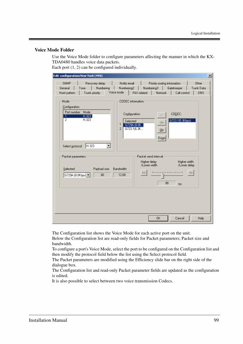
Logical Installation
Voice Mode FolderUse the Voice Mode folder to configure parameters affecting the manner in which the KX-TDA0480 handles voice data packets.Each port (1, 2) can be configured individually.
The Configuration list shows the Voice Mode for each active port on the unit.Below the Configuration list are read-only fields for Packet parameters; Packet size and bandwidth.To configure a port's Voice Mode, select the port to be configured on the Configuration list and then modify the protocol field below the list using the Select protocol field.The Packet parameters are modified using the Efficiency slide bar on the right side of the dialogue box.The Configuration list and read-only Packet parameter fields are updated as the configuration is edited.It is also possible to select between two voice transmission Codecs.
Installation Manual 99

Logical Installation
Select ProtocolUse the pull-down list to choose a protocol for the selected port (H.323).This setting affects only the method in which voice data is handled by the unit and has no effect upon the selection of a network H.323 Gatekeeper or DNS facilities.
Packet send intervalUse the Efficiency slide bar to adjust the packet size to bandwidth ratio for the selected port.
To operate the Packet send interval slide bar, click on the control handle and hold the mouse button. Drag the control handle to the left or right to adjust the ratio. The values in the read-only Packet parameter fields are updated as the slide bar is manipulated.
CODEC InformationUse the Up-arrow and Down-arrow to configure the Codecs on the Configuration list.Select the Codec(s) to be applied for voice transmission by highlighting the item on the Configuration list and clicking the >> button to transfer the item to the CODEC list.Once selected, the selected CODEC(s) appear in the Packet parameters Selected field.
100 Installation Manual

Logical Installation
FAX related FolderData for specifying the selection priority sequence for the protocol to use when performing T.38FAX communication. When performing communication between two KX-TDA0480, the specified priority protocol (priority 1 capability type) can be locked if the specifications are the same. Even when connecting to other company products, the protocol can be used in the same manner if the specifications are the same.
FAX capabilityThe configuration can be selected from TCP and UDP (Redundant). Default setting is TCP.Left window: Protocol used. The priority level of the protocol is specified.Right window: Protocol which can be used. The protocol not immediately used is specified.Up/Down: The priority level of the protocol is changed.
Note
Do not move the protocol from the left window to the right window using the button.
Installation Manual 101
Logical Installation
FAX redundantSpecifies the number of times each packet information is resent to the connecting device when performing T.38 FAX communication using UDP. Different from TCP, there is no procedure for response check, etc., for UDP. Thus, the number of times to send information can be increased to assure that packet information is sent correctly. However, there will be a decline in the transmission efficiency when increasing the number of times the information is sent.
Bit orderData for specifying the send sequence of bit arrays when sending T.38 packet data.When sending as advised, specify the normal direction.When reversing the send sequence of bit arrays, specify the reverse direction.Selection will be made according to the conditions of the other party's device.The default setting is the reverse direction.
IFP packet max sizeMaximum size of IFP (Internet Fax Packet) that can be sent at one time.Since data can be sent in smaller units by decreasing the size, connection problems can be resolved on networks with long delays. However, decreasing the size will increase the packet overhead and result in increased of the network load. The default value is 290 bytes.
102 Installation Manual

Logical Installation
Network FolderUse the Network folder to configure the network timing parameters used to monitor the link between a Gateway and router, hub, or switching device to which the unit is connected. When link failure is detected, the error condition is reported.
Use the Information Section to view and edit the network timing parameters.
Regular time periodType the timing cycle over which the error checking packets will be transmitted during normal operation.The seconds value can also be scrolled up and down with the scrolling arrows located to the right of the field.
Error detect time periodType the timing cycle over which the error checking packets will be transmitted after an error has been detected. This value is usually set to a higher frequency than Regular Timing. If a normal return is detected during this period, the Regular Timing is resumed.
Installation Manual 103
Logical Installation
The seconds value can also be scrolled up and down with the scrolling arrows located to the right of the field.
Disconnect after errorsType the number of times that an error can be detected before the link is failed.The Times value can also be scrolled up and down with the scrolling arrows located to the right of the field.
Reconnect after errorsType the number of times that a recovered link is to be detected before the link will be reestablished as normal.The value can also be scrolled up and down with the scrolling arrows located to the right of the field.
104 Installation Manual

Logical Installation
Call Control FolderUse the Call Control folder to configure parameters associated with gateway to gateway communications and control.The start and signalling port parameters designate the signalling ports on which communication will be initialised and on which transmission will take place, respectively.
Use the Information section fields to modify the H.245 call start and signalling parameters, RTP start parameters, T.38 call start, and connection timing.
Call signalling port numberType the number of the port on which transmission will occur.The default port number is 1720. From 4 to 65524 can be specified except FTP(20,21), telnet(23) ports.
• The default values conform to the H.323 protocol and should always be used unless there is a known network conflict. If a conflict is detected, refer to the H.323 protocol specifications before making adjustments.
Installation Manual 105

Logical Installation
The port number can also be scrolled up and down with the scrolling arrows located to the right of the field.
H.245 start port numberType the number of the port on which the H.245 signalling will be initiated.The default port number is 1721. From 4 to 65521 can be specified except FTP(20,21), telnet(23) ports.The port number can also be scrolled up and down with the scrolling arrows located to the right of the field.
RTP start port numberType the number of the port on which RTP/RTCP signalling will be initiated.The default port number is 5004. From 4 to 65516 can be specified except SNMP(161), RAS(1718,1719).The port number can also be scrolled up and down with the scrolling arrows located to the right of the field.
T.38 start port numberType the number of the port on which T.38 signalling will be initiated.The default port number is 5012. From 4 to 65521 can be specified except FTP(20,21), telnet(23) ports.The port number can also be scrolled up and down with the scrolling arrows located to the right of the field.
UDP Port No. Supplementary serviceA port used to transfer QSIG signals in an IP network when they are received, using the QSIG connectionless supplementary service.The default port number is 5003. From 4 to 65524 can be specified except FTP (20, 21), telnet (23) ports.When using this type of port, it will be necessary to unify it within the network.The port number can also be scrolled up and down with the scrolling arrows located to the right of the field.
Connect time to establishType the time (seconds) that will be allowed for call signalling to be established.The range of acceptable values include from 1 to 99 seconds. The default value is 30 seconds.The Time value can also be scrolled up and down with the scrolling arrows located to the right of the field.
Restore defaultsClick on the Restore defaults button to return the values for all fields to their default condition.
106 Installation Manual

Logical Installation
DNS FolderDNS folder is used to configure the number of digits to receive to start number translation.
When an H.323 Gatekeeper is not used in the IP Gateway network, the KX-TDA0480's internal DNS server are used to perform IP address-to-telephone number translation.Modifications to DNS are described in A3 DNS Configuration:
• This information is recorded on the Common Configuration worksheet described in Section 2.2.4 Common Configuration Worksheet of this document, and can also be entered for selected unit groups using the Edit Data/Edit Common Configuration items on the Unit menu. See Section 4.8 for the procedure using the Common Configuration facility in the Maintenance Console Software.
Domain Name Not usable
IP address for DNS 1 Not usable
Installation Manual 107

Logical Installation
Search DNS afterSpecify the number of digits to receive to start number translation. This is a data to shorten the number translation time. When the KX-TDA0480 receives the specified number of digits, it will start number translation. Set this data value to 1 when it is configured in priority connection information that IP address will be determined by 1 digit. The default value is 1 digit.The digits value can also be scrolled up and down with the scrolling arrows located to the right of the field.
DNS file formatNot usable
IP address for DNS 2 Not usable
IP address for DNS 3 Not usable
Access time Not usable
Access period Not usable
108 Installation Manual

Logical Installation
SNMP FolderIf an SNMP compatible network management system is present, use the SNMP folder to record information about available Trap IP addresses and the facility's Community name.
Use the Parameters section to configure the Trap IP address and the Community name.
• This information is recorded on the Common Configuration worksheet described in Section 2.2.4 Common Configuration Worksheet of this document, and can also be entered for selected unit groups using the Edit Data/Edit Common Configuration items on the Unit menu. See Section 4.8 for the procedure using the Common Configuration facility in the Maintenance Console Software.
IP address for Trap Transmission 1
Type the IP address for the first Trap Transmission facility.The IP address must conform to Internet Protocol addressing requirements.
Installation Manual 109
Logical Installation
IP address for Trap Transmission 2
Type the IP address for a second Trap Transmission facility.The IP address must conform to Internet Protocol addressing requirements.
IP address for Trap Transmission 3
Type the IP address for a third Trap Transmission facility.The IP address must conform to Internet Protocol addressing requirements.
Community name Type the SNMP Community Name. The name may consist of a string of from 1 to 8 characters (e.g., public, proxy, private, etc.) The default value is the name, public.
110 Installation Manual

Logical Installation
Gatekeeper FolderUse the Gatekeeper folder to enter the IP address for a primary and optional secondary Gatekeeper.
When an H.323 IP Gateway network is implemented, a Gatekeeper device must be configured as part of the network. Provisions are also made for a secondary (backup) device in the Gatekeeper Zone.If no Gatekeeper is used, the KX-TDA0480's internal DNS features must be used. In this case, no entries are required for Gatekeeper devices.
• This information is recorded on the Common Configuration worksheet described in Section 2.2.4 Common Configuration Worksheet of this document, and can also be entered for selected unit groups using the Edit Data/Edit Common Configuration items on the Unit menu. See Section 4.8 for the procedure using the Common Configuration facility in the Maintenance Console Software.
• When an H.323 Gatekeeper address is entered during unit configuration, the Gatekeeper takes precedence over all other network management facilities. The KX-TDA0480 internal DNS settings will be ignored.
Installation Manual 111

Logical Installation
Use the Configure Gatekeeper section to configure the IP addresses for up to two network Gatekeepers.
RRQ setting modeSet the alias format (E.164, H.323 ID, etc.) for registration when Gatekeeper is selected and entered.
H.323 IDSet H.323 ID format for alias to register with Gatekeeper.
Gatekeeper 1 Type the IP address for the first (primary) Gatekeeper. The IP address must conform to Internet Protocol addressing requirements.
Gatekeeper 2 Type the IP address for the second (secondary) Gatekeeper. The IP address must conform to Internet Protocol addressing requirements.
112 Installation Manual

Logical Installation
Recovery delay FolderUse the KX-TDA0480 Recovery delay feature to configure the unit to recover from network delays by temporarily storing voice data in a recovery buffer. In the event of a network delay, the stored voice data is transmitted, assuring an uninterrupted conversation.The buffer size and duration can be configured.
Use the Parameters section to configure the Recovery delay settings for the unit.
Maximum receive Buffer size
Type or scroll to the maximum allowable size of the recovery buffer. In most cases, the default size (1920 ms) will provide the best results.
Start recovery Type or scroll to the duration of the network interruption after which voice data should be retrieved from the recovery buffer. In most cases, the default value (200 ms) will provide the best results.
End recovery Type or scroll to the duration of the network interruption after which voice data retrieval should be stopped. In most cases, the default value (30 ms) will provide the best results.
Installation Manual 113
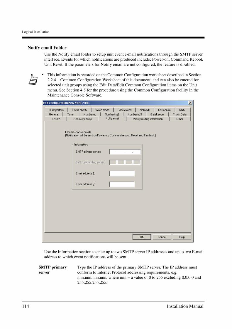
Logical Installation
Notify email FolderUse the Notify email folder to setup unit event e-mail notifications through the SMTP server interface. Events for which notifications are produced include; Power-on, Command Reboot, Unit Reset. If the parameters for Notify email are not configured, the feature is disabled.
Use the Information section to enter up to two SMTP server IP addresses and up to two E-mail address to which event notifications will be sent.
• This information is recorded on the Common Configuration worksheet described in Section 2.2.4 Common Configuration Worksheet of this document, and can also be entered for selected unit groups using the Edit Data/Edit Common Configuration items on the Unit menu. See Section 4.8 for the procedure using the Common Configuration facility in the Maintenance Console Software.
SMTP primary server
Type the IP address of the primary SMTP server. The IP address must conform to Internet Protocol addressing requirements, e.g. nnn.nnn.nnn.nnn, where nnn = a value of 0 to 255 excluding 0.0.0.0 and 255.255.255.255.
114 Installation Manual

Logical Installation
SMTP secondary server
If a secondary (backup) SMTP server is configured, type the IP address of the secondary server. The IP address must conform to Internet Protocol addressing requirements, e.g. nnn.nnn.nnn.nnn, where nnn = a value of 0 to 255 excluding 0.0.0.0 and 255.255.255.255.
Email Address 1 Type the e-mail address to which unit event notifications are to be sent.
Email Address 2 If desired, type a second e-mail address to which unit event notifications are to be sent.
Installation Manual 115

Logical Installation
Priority routing information FolderUse the Priority routing information folder to setup ToS (Type of Service) field of IP header.
Use the Information section fields to setup HEX, ToS and DiffServ.
HEXSpecify HEX field priority control. b7-b0
ToS
Priority: View priority level.
Delay: View delay priority.
Speed: View throughput priority.
116 Installation Manual

Logical Installation
DiffServDS field priority control.
DSCP(F)View DSCP Hex range (6 bit MSB).
Reliance: View reliance priority.
Expenses: View cost priority.
Installation Manual 117

Logical Installation
Other FolderUse the Other folder to configure additional parameters related to monitoring unit performance and generating notifications of fault conditions.
Use the A-law/m-law flag to configure the PCM coding and compression standard to be used by the unit.
Finish Gateway ConfigurationOnce all of the configuration parameters have been configured in the Maintenance Console Software, click on the OK button located at the bottom of the folders display.
Cause of Fan Fault Ignore this parameter.
A-law/m-law Flag m-law/A-law (default = m-law)
118 Installation Manual

Logical Installation
When the OK button is selected, the MCS saves the configuration information on disk in the unit's OFDD.VHO file and returns to the MCS directory window.
The updated OFDD.VHO file is now ready for upload to the unit using the Maintenance Console Software's file transfer features discussed in section 4.10 Transfer Setup and Configuration Files to Units.
Click the Cancel button in any folder to abort all of the edits made during the current configuration session.
The Maintenance Console Software then displays a confirmation dialogue box.
Select Yes to abandon all changes and return to the directory window.
Note
• Often, when many units need to be created and configured, several of the units will have similar configurations. When this is the case, a quick way to create and configure these additional units is to use the copy and paste commands to create copies of existing units.Once created, copied units can be quickly renamed and edited with new IP addressing and numbering information.
• Select the unit to be copied in the Units window pane and click the Copy button on the Toolbar.
• Click the mouse in a vacant area of the Units window pane to deselect the copied unit. Then click the Paste button on the Tools bar.
• The MCS names the copy "Copy of Unit ...".
Installation Manual 119

Logical Installation
• To rename the unit, click on its name in the Units pane and edit the name.
• Once the new unit has been renamed, use the Edit Data item on the Unit menu and select Change Unit Information to modify the setup parameters.
• Finally, use the Edit Data item on the Unit menu and select Edit configuration to modify the unit's configuration.
• The Cut, Copy, and Paste features are also displayed on the Unit's pane pop-up menus.
• Use these features to delete units, make copies of units, and move units from one group to another.
120 Installation Manual

Logical Installation
4.9.2 Configure a Gatekeeper Unit
Using the Maintenance Console Software to configure network Gatekeepers is very similar to the methods used to configure a Gateway but the number of configuration parameters is considerably fewer.
The Maintenance Console Software display uses a set of tabbed folders to organise the configuration process. Each of these folders contains fields in which configuration data are entered.
The data to be entered should have already been identified and recorded on a Unit Setup Worksheet for the unit being configured.
Much of the data recorded during the unit configuration process is critical to the proper operation of the equipment and care must be taken to avoid errors.As discussed earlier, when a unit is selected and the Edit Data command is used, the Maintenance Console Software asks if a saved file is to be edited or if the file in the unit should be downloaded.
If the saved file is to be edited, the Maintenance Console Software displays a dialogue box in which the file to be edited can be selected. See section 4.7 Create New Units to review this process.
Once the file to be edited has been selected, the Maintenance Console Software displays the configuration folders for the Gatekeeper unit.Each of these folders is discussed below.
• Only the Gatekeepers can be configured using the MCS. See the manufacturer's documentation for other Gatekeepers.
• When an H.323 Gatekeeper address is configured within the IP Gateway network, it takes precedence over all other network management facilities. The KX-TDA0480 internal DNS settings will be ignored.
Installation Manual 121

Logical Installation
General Folder (Gatekeeper)Use the General folder to display and reconfigure unit Setup Information. This is the first folder displayed when beginning unit configuration.The folder displays information that was entered using the Unit Information Setup Wizard. Usually, no changes will need to be entered for this tab.
Use the Unit section to view and edit unit IP addressing information.
Use the Password section to view and edit unit IP addressing information.
Unit Displays the unit's name. This field cannot be edited from this folder.To change a unit's name, exit the Edit Data configuration screen and return to the directory window. Click the mouse cursor once on the Unit Name in the MCS Units windowpane. When the cursor changes to a text edit cursor, make the desired changes and then click the mouse over another section of the MCS window. The change made will be reflected in the Unit Information Setup Wizard and the General configuration folder.
Password The Maintenance and User passwords can be changed by clicking one of the Change Password buttons. The change procedure is the same for both password types.When a Change Password button is clicked, the MCS displays a change password dialogue box.
122 Installation Manual

Logical Installation
WARNINGIf a password is lost, it cannot be recovered. In the event of a lost password, contact your maintenance staff, an service office, or an authorised agent.
To change a password:1. Type the current password into the Current Password field.
2. Type the new password into the New Password field.
3. Type the new password a second time in the Confirm new password field.
4. Click on the OK button. Click the Cancel button to abort the operation.
The MCS will then close the Change Password dialogue box and return to the General folder.If the current password is incorrect, or if the new password confirmation does not match the new password, the MCS displays an error message.
Use the IP Addresses section to view and edit unit IP addressing information.
IP Address Type an IP address for the KX-TDA0480.If the unit was setup on the terminal currently in use, this value should not need to be changed.
Subnet Mask Type a Subnet Mask IP address.If the unit was setup on the terminal currently in use, this value should not need to be changed.
Route IP Address 1
Type an IP address for the primary Gateway (e.g., router).If the unit was setup on the terminal currently in use, this value should not need to be changed.
Installation Manual 123

Logical Installation
Route IPAddress 2
Type an IP address for the secondary/backup Gateway (e.g., router).If the unit was setup on the terminal currently in use, this value should not need to be changed.
124 Installation Manual

Logical Installation
Network Folder Use the Network folder to configure network timing parameters used to monitor the link between a Gateway and router, hub, or switching device to which the unit is connected. When link failure is detected, the error condition is reported.Also use the folder to enter the Gatekeeper's ID, the location of a second Gatekeeper if present, and to configure Gatekeeper bandwidth management.
Use the Information Section to view and edit network timing parameters.
Regular timeperiod
Type the timing cycle over which the error checking packets will be transmitted during normal operation.The seconds value can also be scrolled up and down with the scrolling arrows located to the right of the field.
Error detect timeperiod
Type the timing cycle over which the error checking packets will be transmitted after an error has been detected. This value is usually set to a higher frequency than Regular Timing. If a normal return is detected during this period, the Regular Timing is resumed.The seconds value can also be scrolled up and down with the scrolling arrows located to the right of the field.
Disconnect aftererrors
Type the number of times that an error can be detected before the link is failed.The times value can also be scrolled up and down with the scrolling arrows located to the right of the field.
Installation Manual 125

Logical Installation
Use the Gatekeeper information section to configure Gatekeeper parameters.
Reconnect aftererrors
Type the number of times that a recovered link is to be detected before the link will be reestablished as normal.The times value can also be scrolled up and down with the scrolling arrows located to the right of the field.
Gatekeeper ID Type the unit ID number for the Gatekeeper.
Other GatekeeperIP address
If a another Gatekeeper is installed in the network, type the IP address of the other unit.
Use bandwidth management
Click on the radio button indicating that bandwidth management is to use (Yes) or not used (No).
126 Installation Manual

Logical Installation
SNMP FolderIf an SNMP compatible network management system is present, use the SNMP folder to record information about available Trap IP addresses and the facility's Community name.
Use the Parameters section to configure the Trap IP address and the Community name.
• This information is recorded on the Common Configuration worksheet described in Section 2.2.4 Common Configuration Worksheet of this document, and can also be entered for selected unit groups using the Edit Data/Edit Common Configuration items on the Unit menu. See Section 4.8 for the procedure using the Common Configuration facility in the Maintenance Console Software.When a Gateway unit is selected for Edit Common Configuration, the only values applied are those configured for SNMP. All other Common Configuration parameters are ignored.
IP Address for TrapTransmission 1
Type the IP address for the first Trap Transmission facility.The IP address must conform to Internet Protocol addressing requirements.
IP Address for TrapTransmission 2
Type the IP address for a second Trap Transmission facility. The IP address must conform to Internet Protocol addressing requirements.
Installation Manual 127

Logical Installation
IP Address for TrapTransmission 3
Type the IP address for a third Trap Transmission facility. The IP address must conform to Internet Protocol addressing requirements.
Community name Type the SNMP Community Name. The name may consist of a string of from 1 to 8 characters (e.g., public, proxy, private, etc.)The default value is the name, public.
128 Installation Manual
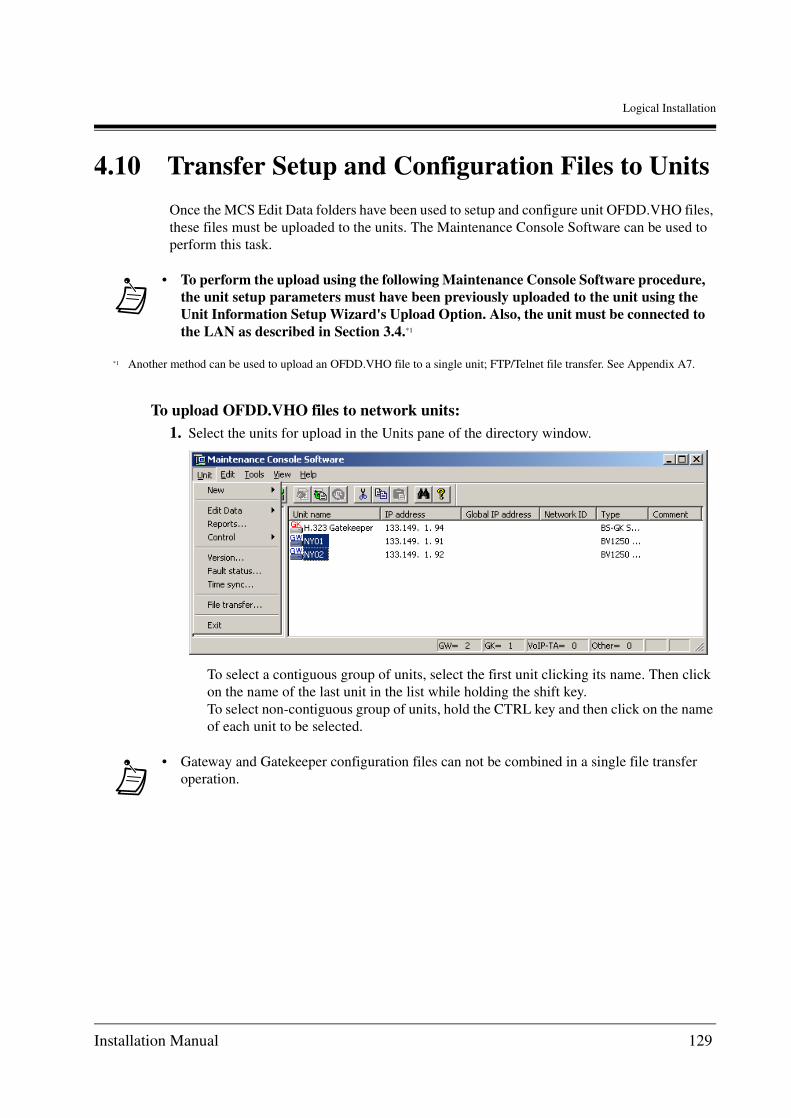
Logical Installation
4.10 Transfer Setup and Configuration Files to Units
Once the MCS Edit Data folders have been used to setup and configure unit OFDD.VHO files, these files must be uploaded to the units. The Maintenance Console Software can be used to perform this task.
To upload OFDD.VHO files to network units:1. Select the units for upload in the Units pane of the directory window.
To select a contiguous group of units, select the first unit clicking its name. Then click on the name of the last unit in the list while holding the shift key.To select non-contiguous group of units, hold the CTRL key and then click on the name of each unit to be selected.
• To perform the upload using the following Maintenance Console Software procedure, the unit setup parameters must have been previously uploaded to the unit using the Unit Information Setup Wizard's Upload Option. Also, the unit must be connected to the LAN as described in Section 3.4.*1
*1 Another method can be used to upload an OFDD.VHO file to a single unit; FTP/Telnet file transfer. See Appendix A7.
• Gateway and Gatekeeper configuration files can not be combined in a single file transfer operation.
Installation Manual 129

Logical Installation
2. Select the File Transfer item from the Units menu.The Maintenance Console Software displays the File selection dialogue box.
3. Use the mouse to click on the system file check boxes and configure all fields so that the only checked box is for Config file.
4. Click the radio button, Reboot after file transmission, so that the units will automatically be rebooted.
5. If desired, check the Log activity option to record a log of the transfer process. Use the radio buttons to have the file overwrite any existing log files or append the log data to the end of an existing file.
6. Click on the OK button to begin the file transfer. Click the Cancel button to abandon the file transfer process.
The Maintenance Console Software displays a confirmation dialogue box.
7. Click Yes to proceed with the transfer, or No to abandon the process.
• It is important that the Config. File option be the ONLY item checked.
130 Installation Manual

Logical Installation
When Yes is selected, a transfer status message is displayed showing the file transfer progress.
Once the transfer process is complete, the Maintenance Console Software displays a report.
The Configuration file column should show OFDD.VHO for each unit. All other columns should show a dashed line.
If the transfer process failed, the Configuration file column will show a value of NG (No Good). See the KX-TDA0480 Programming Guide, for a discussion of trouble shooting.
Installation Manual 131

Logical Installation
Once the OFDD.VHO files have been successfully transferred, each of the units must be rebooted to have the new configurations take effect.If the Reboot option was not selected during the file transfer process, the units can be rebooted using the Control/Reboot item on the Unit menu.
132 Installation Manual

Logical Installation
To reboot the units:1. Select the units for upload in the units pane of the directory window.
To select a contiguous group of units, select the first unit clicking its name. Then click on the name of the last unit in the list while holding the shift key.To select non-contiguous group of units, hold the CTRL key and then click on the name of each unit to be selected. The Maintenance Console Software displays a Reboot dialogue box allowing the reboot to be forced or causing the reboot to occur only after all in-process calls are terminated.
2. Click the radio-button for the desired option and click the OK button to proceed. Select the Cancel button to abandon the process.
Installation Manual 133

Logical Installation
The Maintenance Console Software then displays a list of units selected for reboot. The checkboxes in the list can be adjusted to reflect the units to be rebooted.
3. Configure the units to be rebooted if necessary and click the Execute button to proceed with the reboot. Select the Cancel button to abandon the process.
The Maintenance Console Software displays a confirmation dialogue box.
4. Click Yes to proceed with the transfer, or cancel to abandon the process.
Once the Maintenance Console Software completes the operation, a Reboot results list is displayed.The Result column should display OK. If Error is returned for a unit, there was a problem with the transmission. See the KX-TDA0480 Programming Guide, Trouble Shooting section.
134 Installation Manual
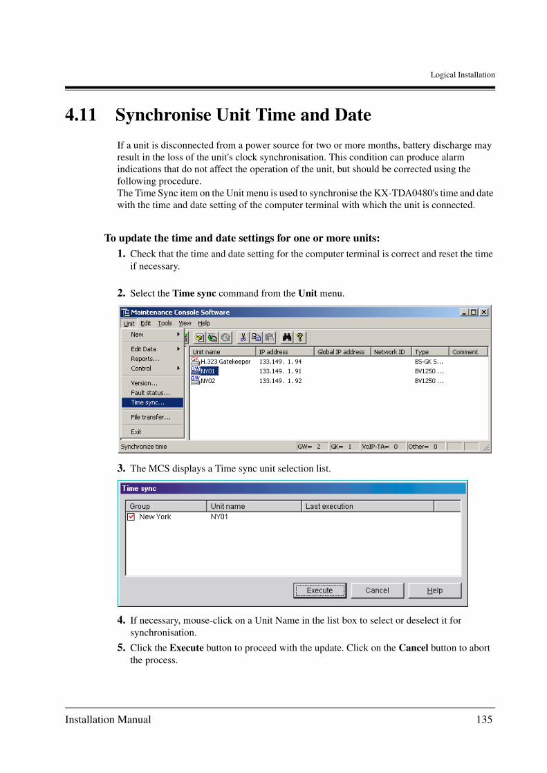
Logical Installation
4.11 Synchronise Unit Time and Date
If a unit is disconnected from a power source for two or more months, battery discharge may result in the loss of the unit's clock synchronisation. This condition can produce alarm indications that do not affect the operation of the unit, but should be corrected using the following procedure.The Time Sync item on the Unit menu is used to synchronise the KX-TDA0480's time and date with the time and date setting of the computer terminal with which the unit is connected.
To update the time and date settings for one or more units:1. Check that the time and date setting for the computer terminal is correct and reset the time
if necessary.
2. Select the Time sync command from the Unit menu.
3. The MCS displays a Time sync unit selection list.
4. If necessary, mouse-click on a Unit Name in the list box to select or deselect it for synchronisation.
5. Click the Execute button to proceed with the update. Click on the Cancel button to abort the process.
Installation Manual 135
Logical Installation
The MCS displays a message box showing the progress of the update and then displays a results list indicating if the process was successful for each of the selected units.
136 Installation Manual

Appendices
Appendix A
Appendices
Installation Manual 137

Appendices
A1 Voice Over IP Addressing
The KX-TDA0480 relies on static IP addressing for communications between network devices. This means that networks in which all addressing is allocated on the basis of dynamic IP addressing (DHCP/BOOTP) are incompatible with the KX-TDA0480 technology. Hybrid systems capable of employing both static and dynamic addressing are capable of employing the KX-TDA0480 technology.All IP addressing must conform to Internet Protocol addressing standards. The diagram below illustrates IP addressing for the sample network used in this document.
Sample network configuration
Overall
SubnettingIP addressing defines subnetting. Each network location has a subnet mask address that helps to define which digits of an IP address are used for the network address and the host address. In this case the sample network, the subnet address is the KX-TDA0480 default, 255.255.255.0. The subnet mask addresses for various networks may differ from the default subnets. In the case of the Internet, the subnet mask address will be provided by the regulating agency or the IP address provider.
• The following discussion does not attempt to address the subtleties of IP addressing.
Router PBX
Router
Router
PSTN
PSTN
PSTNNew York Branch Office
Los Angels Branch Office
San Francisco Branch Office
IP PBX
IP PBX
IP PBX
IP PBX
IP Network Networkingor
(Default Gateway) 206.184.223.1
(Default Gateway) 200.45.11.1
(SF01) 206.184.223.95
(LA01) 200.45.11.34
(Default Gateway) 133.149.1.1
(NY02) 133.149.1.92(NY01) 133.149.1.91
Subnet Mask: 255.255.255.0
138 Installation Manual

Appendices
Units at each location have unique IP addresses. These addresses fall within the same subnet as that of the gateway shared by the units. This means that the KX-TDA0480 connected to the same gateway will share the network portion of their IP address with the Gateway.Units at each location have unique IP addresses. These addresses fall within the same subnet as that of the gateway shared by the units. This means that all KX-TDA0480 connected to the same gateway will share the network portion of their IP address with the Gateway.
In the sample network, the San Francisco and Los Angeles offices are using a Class C address space (255.255.255.0), which means that all but the final octet (0) must be the same for all devices. The final octet for the device address cannot use the values 0 or 255.
Unit IP AddressingIn the sample network, the IP addresses have been allocated so that each KX-TDA0480 has a sequential number. For example, at the New York office, are addressed in sequence so that the last element of the NY01 address is .91, NY02 is .92. This sequencing is for convenience only and is not a requirement of the addressing scheme.
Finally, each location in the sample network has only a single router. Of course, there may be more than one router at each location, and each must be servicing its own subnet.
IP Addressing for the sample network
New York Main Office
The New York office has one router and IP PBX + KX-TDA0480 2 units.The IP addressing scheme for the New York office includes:
Gateway (router) IP: 133.149.1.1
NY01 IP: 133.149.1.91
NY02 IP: 133.149.1.92
San Francisco Office
The San Francisco office has IP PBX + KX-TDA0480 1 and a router.The IP addressing scheme for the San Francisco office includes:
Gateway (router) IP: 206.184.223.1
SF01 IP: 206.184.223.95
Los Angeles OfficeThe Los Angeles office has IP PBX + KX-TDA0480 1. As with the other locations, there is also a single router.The IP addressing scheme for the Los Angeles office includes:
Gateway (router) IP: 206.45.11.1
LA01 IP: 206.45.11.34
Installation Manual 139

Appendices
PBXe: 27)
r
-199
A2 Numbering Systems
The KX-TDA0480 network calling numbers are mapped to the IP addresses used in the network. This mapping may be configured with an H.323 Gatekeeper device and/or within the KX-TDA0480’s internal DNS.DAT file.
A2.1 Numbering Plan Example
The following sample network diagram shows the extension numberings, PBX Codes, and Trunk Access Codes.
Sample network configuration
In this sample network, the following call can be made through IP network.
• From an extension in each IP PBX to an extension in each IP PBX
• From an extension in each IP PBX to PSTN in each IP PBX
A2.2 Dialling Examples
The following examples describe the digits to be dialled when placing a call from various locations in the sample network. Trace the call paths listed here on the sample network diagram to better understand the sample numbering plan.
Router
PSTN PSTN
PSTN
New York Main Office
Los Angels Branch Office
San Francisco Branch Office
IP PBX (PBX Code: 51)
IP PBX (PBX Code: 61)
IP PBX (PBX Code: 21) (PBX Cod
IP PBX
(Max: 10 digits)
(Max: 10 digits)
(Max: 10 digits)
Networkingo
Router
IP Network
Router
Extensions 60-69
Extensions 200-299
Extensions 500-599
G3 Fax Extensions
700-799
Extensions 100
IP Trunk Access Code: 76
PSTN Trunk Access Code: 9
PSTN Trunk Access Code: 9
PSTN Trunk Access Code: 9
IP Trunk Access Code: 72
IP Trunk Access Code: 80
140 Installation Manual
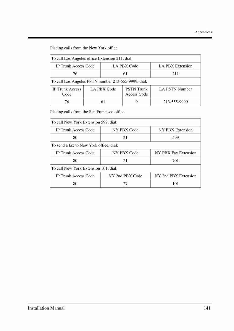
Appendices
Placing calls from the New York office.
Placing calls from the San Francisco office.
To call Los Angeles office Extension 211, dial:
IP Trunk Access Code LA PBX Code LA PBX Extension
76 61 211
To call Los Angeles PSTN number 213-555-9999, dial:
IP Trunk Access Code
LA PBX Code PSTN Trunk Access Code
LA PSTN Number
76 61 9 213-555-9999
To call New York Extension 599, dial:
IP Trunk Access Code NY PBX Code NY PBX Extension
80 21 599
To send a fax to New York office, dial:
IP Trunk Access Code NY PBX Code NY PBX Fax Extension
80 21 701
To call New York Extension 101, dial:
IP Trunk Access Code NY 2nd PBX Code NY 2nd PBX Extension
80 27 101
Installation Manual 141
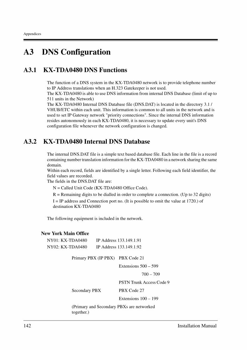
Appendices
A3 DNS Configuration
A3.1 KX-TDA0480 DNS Functions
The function of a DNS system in the KX-TDA0480 network is to provide telephone number to IP Address translations when an H.323 Gatekeeper is not used.The KX-TDA0480 is able to use DNS information from internal DNS Database (limit of up to 511 units in the Network)The KX-TDA0480 Internal DNS Database file (DNS.DAT) is located in the directory 3.1 / VHUB/ETC within each unit. This information is common to all units in the network and is used to set IP Gateway network "priority connections". Since the internal DNS information resides autonomously in each KX-TDA0480, it is necessary to update every unit's DNS configuration file whenever the network configuration is changed.
A3.2 KX-TDA0480 Internal DNS Database
The internal DNS.DAT file is a simple text based database file. Each line in the file is a record containing number translation information for the KX-TDA0480 in a network sharing the same domain.Within each record, fields are identified by a single letter. Following each field identifier, the field values are recorded.The fields in the DNS.DAT file are:
N = Called Unit Code (KX-TDA0480 Office Code).
R = Remaining digits to be dialled in order to complete a connection. (Up to 32 digits)
I = IP address and Connection port no. (It is possible to omit the value at 1720.) of destination KX-TDA0480
The following equipment is included in the network.
New York Main OfficeNY01: KX-TDA0480 IP Address 133.149.1.91
NY02: KX-TDA0480 IP Address 133.149.1.92
Primary PBX (IP PBX) PBX Code 21
Extensions 500 – 599
700 – 709
PSTN Trunk Access Code 9
Secondary PBX PBX Code 27
Extensions 100 – 199
(Primary and Secondary PBXs are networked together.)
142 Installation Manual

Appendices
San Francisco Branch OfficeSF01: KX-TDA0480 IP Address 206.184.223.95
Los Angeles Branch OfficeLA01: KX-TDA0480 IP Address 200.45.11.34
In the example, The New York office is setup so that on NY01 and NY02 are accessible to users on PBX 21, but users of PBX 27 can only access the port on NY02. The configuration provides for hunting on PBX 21. The Hunt Pattern is 91 ->92. Hunting for channel on PBX 27 is only 92.
The DNS.DAT database for the preceding configuration is:
PBX (IP PBX) PBX Code 51
Extensions 60 – 69
PSTN Trunk Access Code 9
PBX (IP PBX) PBX Code 61
Extensions 200 – 299
PSTN Trunk Access Code 9
N 215 R2 I 133.149.1.91;1720 I 133.149.1.92;1720
N 217 R2 I 133.149.1.91;1720 I 133.149.1.92;1720
N 219 R10 I 133.149.1.91;1720 I 133.149.1.92;1720
N 271 R2 I 133.149.1.92;1720
N 516 R1 I 206.184.223.95;1720
N 519 R10 I 206.184.223.95;1720
N 612 R2 I 200.45.11.34;1720
N 619 R10 I 200.45.11.34;1720
A
B
C
D
Installation Manual 143

Appendices
Sample network DNS. DAT file
A:N 215 R 2 I 133.149.1.91;1720 I 133.149.1.92;1720
N 217 R 2 I 133.149.1.91;1720 I 133.149.1.92;1720
N 219 R 10 I 133.149.1.91;1720 I 133.149.1.92;1720
Lines A consist of translation information for units connected to the voice and fax facilities of the PBX Code 21 and the PSTN.
The "I" values specify the IP addresses for each extension, fax and Public Switched Telephone Network (PSTN) associated with the unit.
The function of the three lines described above can also be achieved using the following single record in DNS. DAT.
N 21 R 11 I 133.149.1.91;1720 I 133.149.1.92;1720
N21 results in a greater number of remaining digits (R).
If the information is arranged in this manner, it will take longer to connect a call since dialling does not start until the inter-digit time out (5 sec) has occurred after dialling the extension or a fax number.
I 133.149.1.91;1720 I 133.149.1.92;1720
Specifies the IP address of the KX-TDA0480 adjacent to PBX Code 21.
N 215: Specifies the extension number 5nn (R-value being 2: 500 - 599) of PBX Code 21 as a called destination.
N 217: Specifies the extension number 7nn (R-value being 2: 700 - 799) of PBX Code 21 as a called destination.
N 219: Specifies the Access Code for PSTN access from the PBX Code 21. The R value is 10 (max 32) which allows the user to dial in a 10 digit PSTN number followed by any extension number for the user being called. For example, from CG01 the caller can call 21-9- 408-935-3303 and reach the person on (408) 935-3303 in the PSTN network.
• It is recommended that extensions for fax and PSTN be set separately.
144 Installation Manual

Appendices
B:N 271 R 2 I 133.149.1.92;1720
Line B provides translation information for terminating a call at PBX Code 27.The values for N, R, and I have the same purpose as those described in the preceding example.Any traffic to and from PBX Code 27 will use only the NY02.
C:N 516 R 1 I 206.184.223.95;1720
N 519 R 10 I 206.184.223.95;1720
Line C provides translation information for terminating a call at PBX Code 51.
D:N 612 R 2 I 200.45.11.34;1720
N 619 R 10 I 200.45.11.34;1720
Line D provides translation information for terminating a call at PBX Code code 61.
Installation Manual 145

Appendices
A4 Pad Control and AGC
PAD is a voice line gain/loss function expressed in decibels (dB). The KX-TDA0480 is able to insert a digital pad in the outgoing and/or incoming speech path in order to optimise the gain or loss level of the voice signal.
The KX-TDA0480's AGC (Automatic Gain Control) functions on the PAD In side in a manner similar to that of the PAD In function, but operates by automatically adjusting the voice signal to a preset level.
A4.1 PAD Controls
The default Pad settings can be modified by the user. This is usually done on a network-wide basis.
In most cases it should not be necessary to modify the default PAD In and PAD Out settings. Indications that some adjustment is required are:
The following issues should be considered when adjusting the pad control.
• The digital pad value for the KX-TDA0480 can be selected as -40,-38,c,-14, -12, -10, -8, -6, -4, -2, 0, +2, +4, +6, +8, +10, +12, +14 dB.
The unit default settings are:
PAD Out = 0 dB
PAD In = 0 dB
A4.2 AGC
When enabled, the AGC feature allows the KX-TDA0480 to adjust the voice signal strength to a predetermined level.
As a rule, it is recommended that the PAD In value be set to 0 dBm when using this feature.
Voice level too low: Increase gain by decreasing PAD level.
Voice loud/distorted: Decrease gain by increasing PAD level.
Excessive background noise: Decrease gain by increasing PAD level.
146 Installation Manual

Appendices
A5 Optimising Performance
Although the features of the KX-TDA0480 go a long way toward assuring clear voice communications and error free fax transmission over digital data networks, some network conditions can cause performance degradations.
Common causes include:
• Voice PAD settings not correctly configured.
• Many collisions among packets within the Local Area Network (LAN).
• Number of hops packets go through is too large.
• High traffic conditions are prevalent on the network.
• Routing through a firewall.
• Wide Area Network (WAN) transmission delays.
• Internet Service Provider (ISP) has inadequate service characteristics.
The methods used to prevent problems and optimise performance depend on the type and configuration of the network equipment in use. Below are some suggestions that may prove useful.
A5.1 Voice Volume
In some applications, voice volume may be either too low or too high. The gain control feature operates on both the incoming and outgoing sides and is referred to as the PAD control. The KX-TDA0480 is able to optimise the gain or loss level of the voice signals.
In most cases, it should not be necessary to modify the default PAD In (PAD value of the voice signals coming in to the unit)/PAD Out (PAD value of the voice signals going out from the unit) settings. Indications that some adjustment is required are:
Voice level too low: Increase gain by decreasing PAD level.
Voice loud/distorted: Decrease gain by increasing PAD level.
Excessive background noise: Decrease gain by increasing PAD level.
See section 4.9.1 Configure Gateway Units (KX-TDA0480) for configuring this information in the KX-TDA0480.
A5.2 Transmission Delays
Transmission delays can cause pauses and loss in voice communications and may result in delays and loss of fax transmissions. These conditions typically arise when there are high traffic loads (congestion) on the LAN and/or WAN. In the case of the LAN, the network design affects performance. In the case of the WAN the local router, the link to the ISP (i.e., ISDN,
Installation Manual 147

Appendices
FR, F/T1, and T1), and the Internet Service Provider (ISP) facilities also affect performance.
Transmission delays are caused by excessive packet collisions. The probability that this condition will affect the KX-TDA0480 performance can be minimised by taking steps to provide the KX-TDA0480 with clear transmission paths.
KX-TDA0480 LocationOne preventative measure is to install the KX-TDA0480 so that the number of transmission hops is kept to a minimum. In the figure below, the KX-TDA0480 is located as close to the WAN interface as possible.
Priority ControlSome routers permit the configuration of priority control features. This allows the router to be configured to give higher priority to packets with high priority flags.
The priority control feature should be used when available. The KX-TDA0480 port numbering for the various packet types is presented in the following table.
Item No.
Type of Communication Port No. TCP / UDP
1 Q.931 1720 TCP
2 H.245 1721, 1722, 1723, 1724 TCP
3 RAS 1718, 1719 UDP
4 RTP / RTCP 5004 - 5011 UDP
5 Telnet, FTP 21, 23 TCP
IP PBX
Router
Switch
Too many HOPS!
Switch
Hub
IP PBX
Router
Switch
Better!(IP PBX located nearestWAN access point)
Switch
Hub
148 Installation Manual

Appendices
Recovery Delay and Jitter Buffer
The KX-TDA0480 supports a secondary Jitter Buffer that activates in a dynamic manner. The following parameters can be programmed. This feature can be configured to help compensate for network congestion problems.
• Maximum Receive Buffer Size, defines the size of Jitter Buffer (max 1920ms).
• Start Recovery specifies the discard packets process limit once denoting that the buffer is full.
• End Recovery defines the limit beneath which the buffer continues to discard packets until the setting is reached.
The following diagram illustrates how the buffer process works.
6 ISDN Service 5003 UDP
7 SNMP 161 UDP
8 T38 5012, 5013, 5014, 5015 TCP
9 FTP for data 20 TCP
10 T38 5012, 5013, 5014, 5015 UDP
11 SMTP 25 TCP
• Port No. is the logical number used to manage the category of services used in TCP/UDP protocol. Refer to this number when setting the priority control of a router.
Item No.
Type of Communication Port No. TCP / UDP
Maximum Receive Buffer size
Start Recovery
End Recovery
Delay Time
(Min) (Max)
Installation Manual 149

Appendices
Internet, Intranet, and Virtual Private Networks (VPN)
Managed Networks (Intranet, Leased Lines, VPN, etc.) provide better quality of service as compared to unmanaged networks (e.g., the Internet).
When implementing a network of the KX-TDA0480, care must be taken when assessing bandwidth requirements. The KX-TDA0480 uses 12K per port when in use. Serialisation delays to the WAN are lower when higher bandwidths are used.
When using the Internet/VPN, the Internet Service Provider plays an important role in reducing the variable delay in the WAN. A regional or national ISP will usually have better connectivity with the backbone and will be able to guarantee greater service reliability than a local city ISP.
When using VPN facilities, delays may be introduced due to the additional processing time required for encryption processing.
150 Installation Manual

Appendices
A5.3 Firewalls
It is generally preferable that a IP Gateway network installation be connected with the IP network outside of any existing firewall installation. When for practical or policy reasons, an installation must be routed through a firewall some performance degradation may occur.
In the above example, the KX-TDA0480 is routed through a firewall. The Router IP address no longer serves as the KX-TDA0480’s Default Gateway IP address. Instead, the internal IP address of firewall becomes the Default Gateway IP address to be associated with the KX-TDA0480.
Also, when installing the IP Gateway network within a firewall, voice and fax packets must be routed through specified firewall ports using the information in the following table.
Item No. Type of Communication
Port No. TCP / UDP
Priority Control Assignment
(Recommended)
1 Q.931 1720 TCP Priority
2 H.245 1721, 1722, 1723, 1724
TCP Priority
3 RAS 1718, 1719 UDP Priority
4 RTP / RTCP 5004 - 5011 UDP Top Priority
5 Telnet, FTP 21, 23 TCP Normal
6 ISDN Service 5003 UDP Priority
Internal IP addressnnn.nnn.nnn.nnn
External IP addressnnn.nnn.nnn.nnn
Switch/HUB
Ethernet
IP PBX
Router
Fire Wall
IP Network
Workgroup
Installation Manual 151

Appendices
7 SNMP 161 UDP Normal
8 T38 5012, 5013, 5014, 5015
TCP Priority
9 FTP for data 20 TCP Normal
10 T38 5012, 5013, 5014, 5015
UDP Priority
11 SMTP 25 TCP Normal
Item No. Type of Communication
Port No. TCP / UDP
Priority Control Assignment
(Recommended)
152 Installation Manual

Appendices
A6 Configuration Files
The KX-TDA0480 OFDD.VHO configuration files are stored as plain text files and can be edited directly using a plain text editor on any computer device. For experienced planning and installation personnel, this method can be fast and efficient. Once files have been created, they can be uploaded directly to the KX-TDA0480 using the FTP method discussed in Appendix A7.Once an OFDD.VHO file has been manually modified, the MCS unit registration information will be no longer be synchronised. Therefore, it is recommended that the modified OFDD.VHO file not be reopened directly using the MCS. If it is necessary to establish conformance with the MCS, establish a LAN link with the unit. Next create a new unit using the MCS Setup Wizard (Section 4.7 Create New Units), using the IP addressing information for the unit. Finally, select the download option when configuring the unit (Section 4.7 Create New Units) and download the configuration data directly from the unit. The manually created settings will then appear in the MCS configuration folders.
Also, when working directly with configuration files it is very important to observe and comply with the directory structure used by the Maintenance Console Software. Any change to this structure will cause the MCS to fail.
The OFDD.VHO files for each group are located in the unit sub-directories for each group. The Group directories are Chicago, Los Angeles, New York, and San Francisco.. Within each group are the Unit directories using the Unit Names (e.g., NY01, NY02, etc.) Note the location of the _tone_current file and Tone sub-directory.
Note the two OFDD files, OFDD.VHO and OFDD.OLD. The file with the .VHO extension is the current version.
Installation Manual 153

Appendices
Refer to the KX-TDA0480 Programming Guide for complete explanations of the command lines and parameters.
Sample OFDD.VHO File
VHUB_IP 199.176.64.41 ;IP Address:(P1)IPVHUB_SUBNET 255.255.255.0 ;Subnet Address:(P1)IPGW_IP 199.176.64.1 ;Default GW Address:(P1)IP1 (P2)IP2UPLINK 0 3 10 1 ;Uplink Observation Information:(P1-P4)CALL_PORT 1720 ;Signalling Port:(P1)TCP Port[4-65535]H245_PORT 1721 ;H245 Starting Port:(P1)TCP Port[4-65532]RTP_PORT 5004 ;RTP Starting Port:(P1)UDP Port[4-65528]T38_PORT 5012 ; Start TCP port for T38 FAX: (P1) TCP Port [4-65532]NOCTIME 30 ;Call Setup Timeout:(P1)Timer[1-99]PASS_M 3014163d2c121e16110b1a ;Maintenance Password[Max 10 Digits]PASS_U 3014163d2c0a0c1a0d ;Generic Password[Max 10 Digits]VHUB_AREA "US" ;Zone:(P1)Zone[JP:Japan/US:North America/EU:Europe]AUDIO_CAP 1 2 ;Audio capability priority seq. i1:G.729A 2:G.723.1(6.3kbps) jFAX_CAP 1 2 ;FAX capability type priority seq. (1:TCP 2:UDP(Redundant))FAXREDUNDANT 0 ;FAX Redundant no. ==0 DTMF_TYPE 0 ;DTMF transfer method (automatic setting)ALIASREG 0 ;terminal no. registration specification (terminal no. registration)ToS 0 ;Priority control value of ToS field: (P1) Priority control value [00-FF]SNMP_TRPDST 133.149.1.252 ;SNMP IP Address:(P1)IP1 (P2)IP2 (P3)IP3TRP_COMMU "public" ;Community Name:(P1)Name[Max 8 Digits]PREFIX "41" ;Unit Office Code:(P1)Office Code[Max 8 Digits]GK_IP 133.149.1.253 ;GK IP:(P1)IP1 (P2)IP2DNS_SEANUM 1 ;DNS Search Digits:(P1)Digits[1-32]
154 Installation Manual

Appendices
A7 FTP File Transfers
Although the Maintenance Console Software provides file transfer tools, it is sometimes quicker to upload and download files over a network connection using the KX-TDA0480's FTP file transfer capabilities. This is especially true when updating a IP Gateway network's internal DNS settings.
DNS.DATThe KX-TDA0480's DNS.DAT file can be uploaded and downloaded using an FTP connection.*1 Since the DNS.DAT file must be common to the KX-TDA0480 in a network, this technique can be very useful.
A DNS.DAT file can be downloaded from a unit and then edited manually for a configuration update.
An updated DNS .DAT file created and saved either manually or with the Maintenance Console Software, can be uploaded to units in the network.
OFDD.VHOThe KX-TDA0480's OFDD.VHO file can be uploaded and downloaded using an FTP connection. This capability may be useful when manually configuring a large number of units. In this case, experienced installers can download a OFDD.VHO file, manually edit its configuration parameters for another unit, and then upload the new configuration file to the new unit.
A OFDD.VHO file can be downloaded from a unit and then edited manually.
A manually edited OFDD.VHO file created and saved either manually or with the Maintenance Console Software, can be uploaded to a unit in the network.
WARNINGThe commands discussed in the following procedures are CASE SENSITIVE. Please be careful to use the proper case when entering FTP commands and the KX-TDA0480 file names.
FTP LoginUse the following procedure to initiate an FTP session with the KX-TDA0480.*2
1. Use the Windows Start menu Run command to display the Run dialogue box.
*1 The file transfer functions require that the filename DNS.DAT be used. The KX-TDA0480 only recognised this filename.*2 The same commands described in this procedure (beginning with step 3) and the following two procedures apply when running
an FTP session that is started using the MCS Terminal Mode FTP Access menu item.
Installation Manual 155

Appendices
The FTP terminal window is then opened and a connection verification message and User name request appears.
Connected to 206.184.223.15.
220 206.184.223.15 BV1250 FTP server (V1.47) ready.
User (206.184.223.15:(none)):
2. At User prompt, type the user name. (default = mainte) and press the Enter key.
The terminal window then requests a Password.
331 Password required for mainte.
Password:
3. At the Password prompt, type the unit password (default = mainte) and press the Enter key.
The password characters are not echoed on the screen and the terminal window displays a confirmation of login.
230 User mainte logged in.
Configuration File Download
Use the following procedure to download a DNS.DAT or OFDD.VHO file from the KX-TDA0480 using an FTP session.
1. To access the OFDD.VHO file directory type following command at the FTP prompt and press the Enter key.
ftp> cd VHUB/OFD
The FTP terminal displays a confirmation of the directory change.
250 CWD command successful.
• The FTP session will be run in the current directory and all retrieved files will be recorded to that directory. To have the files retrieved to a directory other than the C: drive root, open the Windows Explorer first and select the desired directory before issuing the Run command.
156 Installation Manual

Appendices
2. At the FTP prompt, type the GET command and press the Enter key to retrieve the OFDD.VHO file.
ftp> get OFDD.VHO
200 PORT command successful.
150 Opening ASCII mode data connection for OFDD.VHO (4159 bytes).
226 Transfer complete.
4236 bytes received in 0.00 seconds (4236000.00Kbytes/sec)
3. At the FTP prompt, type the CD command to return to the KX-TDA0480's root directory.
ftp> cd ..
250 CWD command successful.
4. To access the DNS.DAT file directory type following command at the FTP prompt and press the Enter key.
ftp> cd ETC
The FTP terminal displays a confirmation of the directory change.
250 CWD command successful.
5. At the FTP prompt, type the GET command and press the Enter key to retrieve the DNS.DAT file.
ftp> get DNS.DAT
200 PORT command successful.
150 Opening ASCII mode data connection for DNS.DAT (58 bytes).
226 Transfer complete.
62 bytes received in 0.00 seconds (62000.00Kbytes/sec)
6. To end the FTP session and return to the Windows DOS prompt, type the BYE command following command and press the Enter key.
ftp> bye
221 Goodbye.
C:\>
7. Type EXIT at the C: prompt to end the Windows DOS session.
Installation Manual 157

Appendices
Configuration File Upload
Use the following procedure to upload a DNS.DAT or OFDD.VHO file to the KX-TDA0480 using an FTP session.
1. To access the OFDD.VHO file directory type following command at the FTP prompt and press the Enter key.
ftp> cd VHUB/OFD
250 CWD command successful.
2. At the FTP prompt, type the PUT command and press the Enter key to write the OFDD.VHO file to the KX-TDA0480.
ftp> put OFDD.VHO OFDD.VHO
200 PORT command successful.
150 Opening ASCII mode data connection for OFDD.VHO.
226 Transfer complete.
4236 bytes sent in 0.00 seconds (4236000.00Kbytes/sec)
3. At the FTP prompt, type the CD command to return to the KX-TDA0480's root directory.
ftp> cd ..
The FTP terminal displays a confirmation of the directory change.
250 CWD command successful.
4. To access the DNS.DAT file directory type following command at the FTP prompt and press the Enter key.
ftp> cd ETC
The FTP terminal displays a confirmation of the directory change.
250 CWD command successful.
5. At the FTP prompt, type the PUT command and press the Enter key to write the DNS.DAT file to the KX-TDA0480.
ftp> put DNS.DAT DNS.DAT
200 PORT command successful.
150 Opening ASCII mode data connection for DNS.DAT.
226 Transfer complete.
62 bytes sent in 0.00 seconds (62000.00Kbytes/sec)
158 Installation Manual

Appendices
6. To end the FTP session and return to the Windows DOS prompt, type the BYE command following command and press the Enter key.
ftp> bye
221 Goodbye.
C:\>
7. Type EXIT at the C: prompt to end the Windows DOS session.
Use the shutdown procedure described in Section 4.9 and then restart the unit to have the new configuration settings take effect in the target unit.
Installation Manual 159

Appendices
A8 Worksheet Masters
The following worksheets are described in Section 2.2 of this document. They are provided here as reproduction masters or templates.
IP Gateway Network Units List Worksheet
Group Name Unit Name Unit IP AddressSubnet Mask IP Address
Route IP Address 1
Route IP Address 2
Signal port no.
160 Installation Manual

Appendices
Common Configuration Worksheet
Group Name(s)
DNS SETUP
Search Digits:(2)
SNMP Setup
Trap 1 IP: Trap 2 IP:
Trap 3 IP: Community Name:(public)
Gatekeeper
Gatekeeper 1 IP: Gatekeeper 2 IP:
Notify E-mail
SNMP Primary IP: SNMP Secondary IP:
E-mail 1: E-mail 2:
Installation Manual 161

Appendices
KX-TDA0480 Unit Setup WorksheetGroup Name: Unit Name:
GENERAL
TONE
NUMBERING
TRUNK DATA
HUNT PATTERN
TRUNK PRIORITY
VOICE MODE
NETWORK
CALL CONTROL
DNS SETUPSNMP SETUPGATEKEEPER
RECOVERY DELAY
OTHER
Unit IP(192.168.1.200)
Subnet IP(255.255.255.0)
Gateway 1 IP Gateway 2 IP
User PW:(user)
MaintenancePW:
(mainte)
Zone:(Default)
Office Code(20)
Fax Access Code(None)
Voice Access Code(None)
First/Last(First)
Trunk Group
(1)
Delete Digits
(0)
Length ofCall
Reference(2)
InterfaceType
(OtherInterface)
PAD in(0dB)
PAD out(0dB)
DTMFDetect
(Outgoing)
AGCdBm
(Disabled)
Protocol Type (QSIG)
Port 1Port 2
Pattern 1Pattern 2
Destination No.(PBX Code)
Hunt Pattern No.(1 or 2)
For additional items, use extension from BR-A
Priority 1 TrunkGroup No.
Priority 2 TrunkGroup No.
1
Port 1Port 2
Protocol:(H.323)
Qual/EfficPayload:(80byte)
Qual/EfficBandwidth:(12.0K bps)
Primary CODEC(G.729a)
Secondary CODEC(G.723.1)
Regular Timing: (0)Disconnect on Errors: (10)
Error Detect Timing: (3)Reconnect on Errors: (1)
Signalling Port: (1720)RTP Start Port: (5004)
H.245 Start Port: (1721)Connect Time: (30 seconds)
UDP Port No. forSupplementary Service
(5003)
See Common Configuration Worksheet
Max. Receive Buffer (1920 ms)Start Recovery (200 ms)
End Recovery (30 ms)Fan Fault Block/Non-Block (Block)
a-law/m-law Flag (m-law)
N/A
N/A
N/A
N/A
N/A
1 BasicBasic1
N/A
162 Installation Manual

Appendices
KX-TDA0480 Unit Setup Worksheet Extension
Group Name: Unit Name:
HUNT PATTERN Destination No.(PBX Code)
Hunt Pattern No.(1 or 2)
BR-A(Use this section to list additional Hunt Pattern data)
Use additional worksheets, if needed.
Installation Manual 163

Appendices
164 Installation Manual

Glossary
Glossary
10BASE-T10BASE-T is a LAN transmission line specification stipulated in 1990 by IEEE. Transmission speed is 10 Mbps and the modulation technique is base-band modulation. The cable uses unshielded twisted pair, similar to a telephone wire.
A-lawThe PCM coding and compression standard used in Europe and in areas outside of North America influence. A Law Encoding is the method of encoding sampled audio waveforms used in 2.048Mbps, 30 channel PCM primary system known as E-carrier.
AGCAutomatic Gain Control is a feature of the KX-TDA0480 that allows the unit to automatically adjust the incoming voice signal to a user defined level in dBm.
Alphanumeric methodEncoding method of H.245 when transferring DTMF signals on an IP network. Although the purpose of this method is to transfer keypad input information, DTMF signals can also be transferred. For the KX-TDA0480, the method is selected when the communicating party is H.245 V3 or later.
Audible signal tonesAudible signal tones are identification tones used to control the connection process or provide status to telephone calling and called parties. The tones include dial tone (DT), busy tone (BT), ring-back tone (RBT), special dial tone (SDT), connection restriction tone (RDT), howler tone (HWT), and ring (RI).
Automatic drop outThe KX-TDA0480 function that automatically stops sending the ringing signal to the called side and automatically returns the line to an idle state when a received call is terminated by the calling party.
KX-TDA0480KX-TDA0480 is the model name for the Internet Voice Gateway, a device that achieves, via an IP (Internet Protocol) network, voice communication by a telephone set.
Installation Manual 165
Glossary
Call Signalling ChannelH.323 reliable channel used to convey call setup messages following the Q.931 protocol.
Communication serviceOne category of service functions supported by the KX-TDA0480. The telephony communication, including fax communication, supported by the KX-TDA0480 can be generalised, from the connection configuration point of view, in inter-extension communication, through IP network and communication via PBX. This category of service functions includes functions corresponding to each type of communication.
Communication through IP networkOne of the service functions supported by the KX-TDA0480. It provides a mutual communication, through the IP network, among the terminals (ordinary analogue telephone set, G3 fax machine) connected directly to another KX-TDA0480.
Direct CallGives capability of Gatekeeper priority. Connection procedure dependent of Gatekeeper only during address conversion. Although there is little Gatekeeper load, the communication status of the Gatekeeper cannot be managed completely.
DNS functionA number dialled by a telephone set is converted into an IP address. The IP address is the number used to actually set up a call over an IP network.
DNS informationThis information is used to convert the telephone number into an IP address, so that the call can go out over the IP network.
Dynamic address conversionAddress conversion method that assigns a variable global address each time a device within the space of a private address is connected to the Internet.
EndpointA Terminal Gateway or MCU in an H.323 network.
Equipment dataOne category of the office data used in the KX-TDA0480 configuration. Equipment data include information about the unit and the unit password.
FCQuick connection procedure according to Recommendation H.245 that simplifies the logical channel establishment procedure.
166 Installation Manual

Glossary
Getting JournalOne of the service functions supported by the KX-TDA0480. The KX-TDA0480 records the history of completed speech calls. A unit's record of completed calls is retrieved using the Maintenance Console Software.
GatekeeperAn H.323 entity that provides address translation, control access, and sometimes bandwidth management to the LAN for H.323 terminals, Gateways, and MCUs.
GatewayAn H.323 entity which provides real-time, two-way communications between two H.323 endpoints.
Global addressIP address assigned officially for use on Internet.
H.323 EntityAny H.323 component, including terminals, Gateways, and Gatekeepers.
H.245 Logical ChannelA channel carrying information streams between two H.323 endpoints.
IP (Internet Protocol)IP protocol is widely used in Internet and LAN networks. The purpose is to deliver data between computing equipment over the network. The protocol is generally effective but does not guarantee complete and accurate data communications.
IP AddressA number used to identify the location of a host device. It is expressed in numeric dot notation (e.g., 202.203.27.31).
Local Area NetworkA short distance data communications network used to link together computers and peripheral devices (such as printers) under some form of standard control.
JitterJitter refers to fluctuations in transmission delay time. In the case of voice data, conversations are packaged into packets (IP packetisation) and transmitted. Individual packets can take different routes through the varied networks that comprise the Internet. When the time interval for the arrival of the packets is not constant the timing fluctuations that may occur are referred to as "jitter".
Installation Manual 167

Glossary
Line dataLine data is a category of office data that includes both terminal and trunk data.
MCUMultipoint Control Unit. A bridging or switching device used in support of multipoint videoconferencing and supporting as many as 28 conference sites. The devices may be in the form of CPE (Customer Premises Equipment) or may be embedded in the WAN in support of carrier-based videoconferencing services.
M-lawThe PCM voice coding and compression standard used in Japan and North America. A PCM encoding algorithm where the analogue voice signal is sampled eight thousand times per second, with each sample being represented by an eight bit value, thus yielding raw 64kbps transmission rate. A sample consists of a sign bit, a three-bit segment specifying a logarithmic range, and a four-bit step offset into a range. All bits of the sample are inverted before transmission.
Maintenance Console SoftwareThe Maintenance Console Software (MCS) runs on a conventional PC type computer under the Windows 95 or Windows 98 or Windows NT operating system. The software provides a graphical user interface (GUI) for installing and maintaining the KX-TDA0480 and for configuring the KX-TDA0480 internal network features. MCS connection with the KX-TDA0480 is accomplished directly using an RS-232C cable or remotely over a LAN connection.
Numbering planIn a communications network, a numbering plan allocates specific numeric codes to identify each subscriber line, special lines, trunk lines, etc. Numbering plans can be divided into the numbering system and number assignments. The numbering system indicates the number of digits to be assigned and the basic scheme of number assignment. The assignment of specific codes is performed according to the numbering system.
Numbering plan dataNumbering plan data is a category of office data. It includes both numbering plan and routing information.
Office dataGeneric name of configuration data set and stored in the KX-TDA0480. Generally, office data is divided into four categories: equipment data, numbering plan data, line data, and operation data. Office data is configured during unit installation and general maintenance using the Maintenance Console software. Unit configuration files can also be edited directly and then can be uploaded directly to a unit.
168 Installation Manual

Glossary
Operation dataOperation data is a type of office data. It includes a general class of data related to Voice Control Basic Module (VBM), Domain Name System (DNS), and Simple Network Management Protocol (SNMP).
Pad controlA digital pad is inserted in a speech path to adjust the level of a speech signal to some optimum value. The insertion of a pad value is done on a Line basis.
PCM (Pulse Code Modulation)The most common digitisation technique for encoding an analogue voice signal into a digital bit stream. The most common PCM method is to sample a voice conversation at 8000 times per second. The theory is that if the sampling is at least twice the highest frequency on the channel, which produces satisfactory voice tones.
Port numberA port number is a logical number that manages the category of service supported and resources used in the TCP/UDP protocol. The port number is referred to when setting the priority control of a router.
Priority connection informationIn the KX-TDA0480, DNS information stored in the unit is referred to as priority connection information.
Priority controlWhen a packet to which a high priority indication flag has been assigned is sent, the packet is transferred with priority. The priority control function is used in a router or an exchange in order to minimise delay time. Voice or fax communication, in a network not using priority control, may be interrupted when network traffic increases.
Private addressIP address assigned within a closed network of each organisation that will not be connected to the Internet.
PSTNPublic Switched Telephone Network
Q.931H.323 signalling protocol for setup and termination of calls.
Installation Manual 169

Glossary
RAS ChannelAn unreliable channel used to convey the Registration, Admissions, and Status messages and bandwidth changes between two H.323 entities.
Reliable TransmissionConnection-oriented data transmission that guarantees sequenced, error-free, flow-controlled transmission of messages to the receiver.
Real-Time Protocol/Real-Time Control Protocol (RTP/RTCP)IETF specifications for audio and video signal management. Allows applications to synchronise and spool audio and video information.
Remote maintenanceOne of the service functions supported by the KX-TDA0480. The KX-TDA0480 can be maintained remotely over a network connection. The Maintenance Console Software supports remote maintenance functions.
Routed CallGives call status control of Gatekeeper priority.Path control signal (Q.931) is also sent to the calling terminal via the Gatekeeper. Although there will be more Gatekeeper load, logs can be collected accurately for accounting purposes, etc., since the communication status can be grasped completely.
Signal methodEncoding method of H.245 when transferring DTMF signals on an IP network. The purpose of this method is to transfer DTMP signals. The transmission time of DTMF signals can be specified on the receiving side (not available on the KX-TDA0480). For the KX-TDA0480, the method is selected when the communicating party is H.245 V3 or later.
Static address conversionAddress conversion method that assigns a fixed global address when connecting a device within the space of a private address to the Internet.
System functionSystem function is a category of the service functions supported by the KX-TDA0480. This category separates various functions that compose an internet/intranet telephony network from a system point of view. This category includes functions such as network building functions, functions to accommodate various kinds of terminals, and functions needed to monitor the connection lines.
TCPTransmission Control Protocol. A reliable networking layer on top of IP.
170 Installation Manual

Glossary
TerminalAn H.323 endpoint which provides for real-time, two-way communications which another Terminal, Gateway, or MCU. A terminal must provide audio and may also provide video and/or data.
Terminal modeTerminal mode is one of the operational modes of the Maintenance Console Software. The terminal mode includes functions like LAN maintenance, emergency maintenance, and FTP client startup.
Traffic measurementOne of the functions supported by the KX-TDA0480. The KX-TDA0480 has traffic counters in internal memory. These counters measure the number of originated calls and the number of terminated calls. Traffic information can be output to the maintenance console.
TrapOne of the signals included in the Simple Network Management Protocol (SNMP). A trap is sent to the Network Management System (NMS) in the event of an equipment fault for diagnostic purposes.
TRSOKI proprietary feature that allows Gatekeeper units to be configured by a system administrator for routing groups among the stacked/cascaded KX-TDA0480.
UDPUser Datagram Protocol. An unreliable networking layer that sits at the same level of the networking stack at TCP.
Unreliable TransmissionConnection-less transmission which provides best-effort delivery of data packets. Messages transmitted by the sender bay be lost, duplicated, or received out of sequence.
Voice compressionA high-quality voice compression function is incorporated in the KX-TDA0480 to achieve voice communication through the IP network. At the calling side, voice is compressed to 8 Kbps digital signal and then packaged (IP packetisation) and delivered to a router for transport across the network. On the receiving side, the KX-TDA0480 reassembles the IP packets and restores them to the digital signal. The original voice is regenerated by expanding (decompressing) the restored digital signal.
Installation Manual 171

Glossary
ZoneA collection of all H.323 Terminals, Gateways, and MCUs managed by a single H.323 Gatekeeper. A zone must include at least one Terminal and may include LAN segments connected using routers.
172 Installation Manual

Glossary
Installation Manual 173

Panasonic Communications Co., Ltd.1-62, 4-chome, Minoshima, Hakata-ku, Fukuoka 812-8531, Japan
Copyright:This manual is copyrighted by Panasonic Communications Co., Ltd. (PCC). You may print out this manual solely for internal use with this model. Except above, you may not reproduce this manual in any form, in whole or part, without the prior written consent of PCC.
© 2003 Panasonic Communications Co., Ltd. All Rights Reserved.
PSQX2538ZA KK0103AH0