Huawei DBS3900 Commissioning Procedure Huawei DBS3900 Commissioning Procedure
Upload
khangminh22Category
view
2download
0
FusionDC1000A Prefabricated All-in-One DataCenterV100R021C00
Commissioning Guide (IT Scenario)
Issue 01
Date 2021-04-20
HUAWEI TECHNOLOGIES CO., LTD.

Copyright © Huawei Technologies Co., Ltd. 2021. All rights reserved.
No part of this document may be reproduced or transmitted in any form or by any means without priorwritten consent of Huawei Technologies Co., Ltd. Trademarks and Permissions
and other Huawei trademarks are trademarks of Huawei Technologies Co., Ltd.All other trademarks and trade names mentioned in this document are the property of their respectiveholders. NoticeThe purchased products, services and features are stipulated by the contract made between Huawei andthe customer. All or part of the products, services and features described in this document may not bewithin the purchase scope or the usage scope. Unless otherwise specified in the contract, all statements,information, and recommendations in this document are provided "AS IS" without warranties, guaranteesor representations of any kind, either express or implied.
The information in this document is subject to change without notice. Every effort has been made in thepreparation of this document to ensure accuracy of the contents, but all statements, information, andrecommendations in this document do not constitute a warranty of any kind, express or implied.
Huawei Technologies Co., Ltd.Address: Huawei Industrial Base
Bantian, LonggangShenzhen 518129People's Republic of China
Website: https://www.huawei.com
Email: [email protected]
Issue 01 (2021-04-20) Copyright © Huawei Technologies Co., Ltd. i

About This Document
PurposeThis document describes how to power on and commission the FusionDC1000Aprefabricated all-in-one data center solution (FusionDC1000 for short) in terms ofsafety precautions, preparations, power-on check, power-on commissioning, jointcommissioning, power-off, and core device commissioning. It provides you a quickgrasp of how to commission the prefabricated all-in-one data center.
Intended AudienceThis document is intended for:
● Hardware installation engineers● Technical support engineers● Commissioning engineers● Maintenance engineers
Symbol ConventionsThe symbols that may be found in this document are defined as follows.
Symbol Description
Indicates a hazard with a high level of risk which,if not avoided, will result in death or seriousinjury.
Indicates a hazard with a medium level of riskwhich, if not avoided, could result in death orserious injury.
Indicates a hazard with a low level of risk which,if not avoided, could result in minor or moderateinjury.
FusionDC1000A Prefabricated All-in-One DataCenterCommissioning Guide (IT Scenario) About This Document
Issue 01 (2021-04-20) Copyright © Huawei Technologies Co., Ltd. ii

Symbol Description
Indicates a potentially hazardous situation which,if not avoided, could result in equipment damage,data loss, performance deterioration, orunanticipated results.NOTICE is used to address practices not related topersonal injury.
Supplements the important information in themain text.NOTE is used to address information not relatedto personal injury, equipment damage, andenvironment deterioration.
Change HistoryChanges between document issues are cumulative. The latest document issuecontains all the changes made in earlier issues.
Issue 01 (2021-04-20)This issue is the first official release.
FusionDC1000A Prefabricated All-in-One DataCenterCommissioning Guide (IT Scenario) About This Document
Issue 01 (2021-04-20) Copyright © Huawei Technologies Co., Ltd. iii

Contents
About This Document................................................................................................................ ii
1 Safety Information.................................................................................................................. 11.1 General Safety.......................................................................................................................................................................... 11.2 Personnel Requirements....................................................................................................................................................... 41.3 Electrical Safety........................................................................................................................................................................41.4 Installation Environment Requirements.......................................................................................................................... 61.5 Mechanical Safety................................................................................................................................................................... 81.6 Cooling System Safety.........................................................................................................................................................101.7 Pre-fab. Module Safety....................................................................................................................................................... 111.8 Battery Safety......................................................................................................................................................................... 121.9 Others....................................................................................................................................................................................... 14
2 Commissioning Guide Usage.............................................................................................. 15
3 Preparations for Power-On Commissioning....................................................................163.1 Tools.......................................................................................................................................................................................... 163.2 Reference Documentation................................................................................................................................................. 183.3 Commissioning Personnel Skill Requirements............................................................................................................ 183.4 Check Before Power-On......................................................................................................................................................19
4 Commissioning Core Devices.............................................................................................. 244.1 Commissioning the Integrated UPS................................................................................................................................244.1.1 (Optional) Commissioning the ATS............................................................................................................................ 244.1.2 Powering On and Starting the UPS.............................................................................................................................254.1.2.1 Powering On the UPS................................................................................................................................................... 254.1.2.2 Starting the Inverter......................................................................................................................................................264.1.2.3 Powering On Loads....................................................................................................................................................... 264.2 Commissioning the SmartLi.............................................................................................................................................. 274.2.1 Powering On Batteries..................................................................................................................................................... 274.2.2 Powering Off Batteries.................................................................................................................................................... 314.2.3 Performing EPO..................................................................................................................................................................314.2.4 Clearing the EPO State.................................................................................................................................................... 324.3 Commissioning Smart Cooling Products.......................................................................................................................324.4 Commissioning Monitoring Devices............................................................................................................................... 344.4.1 Commissioning the Access Control System.............................................................................................................. 34
FusionDC1000A Prefabricated All-in-One DataCenterCommissioning Guide (IT Scenario) Contents
Issue 01 (2021-04-20) Copyright © Huawei Technologies Co., Ltd. iv

4.5 Commissioning Fire Extinguishing Devices (Standard)........................................................................................... 354.5.1 Commissioning the Fire Alarm Control Panel (Standard)...................................................................................354.5.2 Commissioning the Emergency Light (Standard).................................................................................................. 364.6 Commissioning Fire Extinguishing Devices (CE)........................................................................................................ 374.6.1 Commissioning the Emergency Light (CE)............................................................................................................... 374.6.2 (Optional) Commissioning the ASD........................................................................................................................... 394.7 (Optional) NetEco Management.................................................................................................................................... 404.7.1 Preparations and WebUI Login..................................................................................................................................... 404.7.2 Performing Basic Operations Before Adding Devices........................................................................................... 434.7.2.1 IP Address Preinstallation Planning......................................................................................................................... 444.7.2.2 Obtaining the NetEco Software License................................................................................................................ 454.7.2.3 Logging In to the NetEco Client............................................................................................................................... 454.7.2.4 Loading the NetEco Software License.................................................................................................................... 464.7.2.5 Installing NE Adapters..................................................................................................................................................464.7.2.6 Creating a Management Domain.............................................................................................................................474.7.2.7 How Can I Set and Add a SmartLi (Modbus-TCP)?............................................................................................484.7.2.8 Process of adding a device..........................................................................................................................................494.7.3 Setting and Adding the ECC800 Collector................................................................................................................ 504.7.3.1 Setting NetEco Parameters......................................................................................................................................... 504.7.3.2 Setting the Transparent Transmission Function for the ECC800-Pro Collector.........................................52
5 System Commissioning........................................................................................................ 545.1 Switching Between Two Power Supplies...................................................................................................................... 545.2 Fire Extinguishing System Commissioning (Standard)............................................................................................ 555.3 Fire Extinguishing System Commissioning (CE)......................................................................................................... 615.4 System Power-Off.................................................................................................................................................................66
A Acronyms and Abbreviations............................................................................................. 68
FusionDC1000A Prefabricated All-in-One DataCenterCommissioning Guide (IT Scenario) Contents
Issue 01 (2021-04-20) Copyright © Huawei Technologies Co., Ltd. v

1 Safety Information
1.1 General Safety
StatementBefore installing, operating, and maintaining the equipment, read this documentand observe all the safety instructions on the equipment and in this document.
The "NOTICE", "CAUTION", "WARNING", and "DANGER" statements in thisdocument do not cover all the safety instructions. They are only supplements tothe safety instructions. Huawei will not be liable for any consequence caused bythe violation of general safety requirements or design, production, and usagesafety standards.
Ensure that the equipment is used in environments that meet its designspecifications. Otherwise, the equipment may become faulty, and the resultingequipment malfunction, component damage, personal injuries, or propertydamage are not covered under the warranty.
Follow local laws and regulations when installing, operating, or maintaining theequipment. The safety instructions in this document are only supplements to locallaws and regulations.
Huawei will not be liable for any consequences of the following circumstances:
● Operation beyond the conditions specified in this document● Installation or use in environments which are not specified in relevant
international or national standards● Unauthorized modifications to the product or software code or removal of the
product● Failure to follow the operation instructions and safety precautions on the
product and in this document● Equipment damage due to force majeure, such as earthquakes, fire, and
storms● Damage caused during transportation by the customer● Storage conditions that do not meet the requirements specified in this
document
FusionDC1000A Prefabricated All-in-One DataCenterCommissioning Guide (IT Scenario) 1 Safety Information
Issue 01 (2021-04-20) Copyright © Huawei Technologies Co., Ltd. 1

General Requirements● Do not install, use, or operate outdoor equipment and cables (including but
not limited to moving equipment, operating equipment and cables, insertingconnectors to or removing connectors from signal ports connected to outdoorfacilities, working at heights, and performing outdoor installation) in harshweather conditions such as lightning, rain, snow, and level 6 or stronger wind.
● Before installing, operating, or maintaining the equipment, remove anyconductive objects such as watches or metal jewelry like bracelets, bangles,and rings to avoid electric shock.
● When installing, operating, or maintaining the equipment, wear personalprotective equipment such as insulation gloves, goggles, and safety clothing,helmet, and shoes, as shown in the following figure.
● Follow the specified procedures for installation, operation, and maintenance.● Before handling a conductor surface or terminal, measure the contact point
voltage and ensure that there is no risk of electric shock.● After installing the equipment, remove idle packing materials such as cartons,
foam, plastics, and cable ties from the equipment area.● In the case of a fire, immediately leave the building or the equipment area,
and turn on the fire alarm bell or make an emergency call. Do not enter thebuilding on fire in any case.
● Do not stop using protective devices. Pay attention to the warnings, cautions,and related precautionary measures in this document and on the equipment.Promptly replace warning labels that have worn out.
● Keep irrelevant people away from the equipment. Only operators are allowedto access the equipment.
● Use insulated tools or tools with insulated handles, as shown in the followingfigure.
FusionDC1000A Prefabricated All-in-One DataCenterCommissioning Guide (IT Scenario) 1 Safety Information
Issue 01 (2021-04-20) Copyright © Huawei Technologies Co., Ltd. 2

● All cable holes should be sealed. Seal the used cable holes with firestop putty.Seal the unused cable holes with the caps delivered with the cabinet. Thefollowing figure shows the criteria for correct sealing with firestop putty.
● Do not scrawl, damage, or block any warning label on the equipment.● When installing devices, use a torque wrench with a proper measurement
range to tighten bolts. Ensure that the wrench is not skewed and the torqueerror does not exceed 10%.
● Do not work with power on during installation.● Repaint any paint scratches caused during equipment transportation or
installation in a timely manner. Equipment with scratches cannot be exposedto an outdoor environment for a long period of time.
● Before operations, ensure that the equipment is firmly secured to the floor orother solid objects, such as a wall or an installation rack.
● Do not use water to clean electrical components inside or outside of acabinet.
● Do not change the structure or installation sequence of equipment withoutpermission.
● Do not touch a running fan with your fingers, components, screws, tools, orboards before the fan is powered off or stops running.
FusionDC1000A Prefabricated All-in-One DataCenterCommissioning Guide (IT Scenario) 1 Safety Information
Issue 01 (2021-04-20) Copyright © Huawei Technologies Co., Ltd. 3

Personal Safety● If there is a probability of personal injury or equipment damage during
operations on the equipment, immediately stop the operations, report thecase to the supervisor, and take feasible protective measures.
● To avoid electric shock, do not connect safety extra-low voltage (SELV) circuitsto telecommunication network voltage (TNV) circuits.
● Do not power on the equipment before it is installed or confirmed byprofessionals.
1.2 Personnel Requirements● Personnel who plan to install or maintain Huawei equipment must receive
thorough training, understand all necessary safety precautions, and be able tocorrectly perform all operations.
● Only qualified professionals or trained personnel are allowed to install,operate, and maintain the equipment.
● Only qualified professionals are allowed to remove safety facilities and inspectthe equipment.
● Personnel who will operate the equipment, including operators, trainedpersonnel, and professionals, should possess the local national requiredqualifications in special operations such as high-voltage operations, workingat heights, and operations of special equipment.
● Professionals: personnel who are trained or experienced in equipmentoperations and are clear of the sources and degree of various potentialhazards in equipment installation, operation, maintenance
● Trained personnel: personnel who are technically trained, have requiredexperience, are aware of possible hazards on themselves in certain operations,and are able to take protective measures to minimize the hazards onthemselves and other people
● Operators: operation personnel who may come in contact with theequipment, except trained personnel and professionals
● Only professionals or authorized personnel are allowed to replace theequipment or components (including software).
1.3 Electrical Safety
Grounding● For the equipment that needs to be grounded, install the ground cable first
when installing the equipment and remove the ground cable last whenremoving the equipment.
● Do not damage the ground conductor.● Do not operate the equipment in the absence of a properly installed ground
conductor.● Ensure that the equipment is connected permanently to the protective
ground. Before operating the equipment, check its electrical connection toensure that it is securely grounded.
FusionDC1000A Prefabricated All-in-One DataCenterCommissioning Guide (IT Scenario) 1 Safety Information
Issue 01 (2021-04-20) Copyright © Huawei Technologies Co., Ltd. 4

General RequirementsUse dedicated insulated tools when performing high-voltage operations.
AC and DC Power
D ANGER
Do not connect or disconnect power cables with power on. Transient contactbetween the core of the power cable and the conductor will generate electric arcsor sparks, which may cause fire or personal injury.
● If a "high electricity leakage" tag is attached on the equipment, ground theprotective ground terminal on the equipment enclosure before connecting theAC power supply; otherwise, electric shock as a result of electricity leakagemay occur.
● Before installing or removing a power cable, turn off the power switch.● Before connecting a power cable, check that the label on the power cable is
correct.● If the equipment has multiple inputs, disconnect all the inputs before
operating the equipment.● A circuit breaker equipped with a residual current device (RCD) is not
recommended.● A damaged power cable must be replaced by the manufacturer, service agent,
or professionals to avoid risks.● High voltage operations and installation of AC-powered facilities must be
performed by qualified personnel.
Cabling● When routing cables, ensure that a distance of at least 30 mm exists between
the cables and heat-generating components or areas. This prevents damageto the insulation layer of the cables.
● Do not route cables behind the air intake and exhaust vents of theequipment.
● Ensure that cables meet the VW-1 or ZB flame spread rating requirements orhigher.
● Bind cables of the same type together. When routing cables of different types,ensure that they are at least 30 mm away from each other.
● If an AC input power cable is connected to the cabinet from the top, bend thecable in a U shape outside the cabinet and then route it into the cabinet.
● When the temperature is low, violent impact or vibration may damage theplastic cable sheathing. To ensure safety, comply with the followingrequirements:– Cables can be laid or installed only when the temperature is higher than
0°C. Handle cables with caution, especially at a low temperature.– Cables stored at subzero temperatures must be stored at room
temperature for at least 24 hours before they are laid out.
FusionDC1000A Prefabricated All-in-One DataCenterCommissioning Guide (IT Scenario) 1 Safety Information
Issue 01 (2021-04-20) Copyright © Huawei Technologies Co., Ltd. 5

● Do not perform any improper operations, for example, dropping cablesdirectly from a vehicle.
● When selecting, connecting, and routing cables, follow local safety regulationsand rules.
ESD
NO TICE
The static electricity generated by human bodies may damage the electrostatic-sensitive components on boards, for example, the large-scale integrated (LSI)circuits.
● Wear ESD gloves or a well-grounded ESD wrist strap when touching thedevice or handling boards or application-specific integrated circuits (ASICs).
● When holding a board, hold its edge without touching any components. Donot touch the components with your bare hands.
● Package boards with ESD packaging materials before storing or transportingthem.
Figure 1-1 Wearing an ESD wrist strap
Neutral-Ground VoltageIt is recommended that the three-phase loads be equalized and the neutral-ground voltage be kept at less than 2 V to meet power distribution requirements.
1.4 Installation Environment Requirements● To prevent fire due to high temperature, ensure that the ventilation vents or
heat dissipation system are not blocked when the equipment is running.● Install the equipment in an area far away from liquids. Do not install it under
areas prone to condensation, such as under water pipes and air exhaust vents,or areas prone to water leakage, such as air conditioner vents, ventilation
FusionDC1000A Prefabricated All-in-One DataCenterCommissioning Guide (IT Scenario) 1 Safety Information
Issue 01 (2021-04-20) Copyright © Huawei Technologies Co., Ltd. 6

vents, or feeder windows of the equipment room. Ensure that no liquid entersthe equipment to prevent faults or short circuits.
● If any liquid is detected inside the equipment, immediately disconnect thepower supply and contact the administrator.
● Do not expose the equipment to flammable or explosive gas or smoke. Donot perform any operation on the equipment in such environments.
● Ensure that the equipment room provides good heat insulation, and the wallsand floor are dampproof.
● Install a rat guard at the door of the equipment room.
Installation at Heights● Working at heights refers to operations that are performed at least 2 meters
above the ground.
● Do not work at heights if the steel pipes are wet or other potential dangerexists. After the preceding conditions no longer exist, the safety director andrelevant technical personnel need to check the involved equipment. Operatorscan begin working only after obtaining consent.
● When working at heights, comply with local relevant laws and regulations.
● Only trained and qualified personnel are allowed to work at heights.
● Before working at heights, check the climbing tools and safety gears such assafety helmets, safety belts, ladders, springboards, scaffolding, and liftingequipment. If they do not meet the requirements, take corrective measures ordisallow working at heights.
● Wear personal protective equipment such as the safety helmet and safety beltor waist rope and fasten it to a solid structure. Do not mount it on aninsecure moveable object or metal object with sharp edges. Make sure thatthe hooks will not slide off.
● Set a restricted area and eye-catching signs for working at heights to warnaway irrelevant personnel.
● Carry the operation machinery and tools properly to prevent them fromfalling off and causing injuries.
● Personnel involving working at heights are not allowed to throw objects fromthe height to the ground, or vice versa. Objects should be transported bytough slings, hanging baskets, highline trolleys, or cranes.
● Ensure that guard rails and warning signs are set at the edges and openingsof the area involving working at heights to prevent falls.
● Do not pile up scaffolding, springboards, or other sundries on the groundunder the area involving working at heights. Do not allow people to stay orpass under the area involving working at heights.
● Inspect the scaffolding, springboards, and workbenches used for working atheights in advance to ensure that their structures are solid and notoverloaded.
● Any violations must be promptly pointed out by the site manager or safetysupervisor and the involved personnel should be prompted for correction.Personnel who fail to stop violations will be forbidden from working.
FusionDC1000A Prefabricated All-in-One DataCenterCommissioning Guide (IT Scenario) 1 Safety Information
Issue 01 (2021-04-20) Copyright © Huawei Technologies Co., Ltd. 7

1.5 Mechanical Safety
Hoisting Devices● Do not walk under hoisted objects.● Only trained and qualified personnel should perform hoisting operations.● Check that hoisting tools are available and in good condition.● Before hoisting objects, ensure that hoisting tools are firmly secured onto a
load-bearing object or wall.● Ensure that the angle formed by two hoisting cables is no more than 90
degrees, as shown in the following figure.
● Do not drag steel ropes and hoisting tools or bump hoisted objects againsthard objects during hoisting.
Using Ladders● Use wooden or fiberglass ladders when you need to perform live working at
heights.● When a step ladder is used, ensure that the pull ropes are secured and the
ladder is held firm.● Before using a ladder, check that it is intact and confirm its load bearing
capacity. Do not overload it.● Ensure that the ladder is securely positioned. The recommended angle for a
ladder against the floor is 75 degrees, as shown in the following figure. Anangle rule can be used to measure the angle. Ensure that the wider end of theladder is at the bottom, or protective measures have been taken at thebottom to prevent the ladder from sliding.
FusionDC1000A Prefabricated All-in-One DataCenterCommissioning Guide (IT Scenario) 1 Safety Information
Issue 01 (2021-04-20) Copyright © Huawei Technologies Co., Ltd. 8

● When climbing a ladder, take the following precautions to reduce risks andensure safety:
– Keep your body steady.
– Do not climb higher than the fourth rung of the ladder from the top.
– Ensure that your body's center of gravity does not shift outside the legsof the ladder.
Drilling Holes
When drilling holes into a wall or floor, observe the following safety precautions:
NO TICE
Do not drill holes into the equipment. Doing so may affect the electromagneticshielding of the equipment and damage components or cables inside. Metalshavings from drilling may short-circuit boards inside the equipment.
● Obtain the consent from the customer and subcontractor before drilling.
● Wear goggles and protective gloves when drilling holes.
● When drilling holes, protect the equipment from shavings. After drilling, cleanup any shavings that have accumulated inside or outside the equipment.
Moving Heavy Objects
D ANGER
When removing a heavy or unstable component from a cabinet, be aware ofunstable or heavy objects on the cabinet.
● Be cautious to avoid injury when moving heavy objects.
FusionDC1000A Prefabricated All-in-One DataCenterCommissioning Guide (IT Scenario) 1 Safety Information
Issue 01 (2021-04-20) Copyright © Huawei Technologies Co., Ltd. 9

● When moving the equipment by hand, wear protective gloves to preventinjuries.
● Move or lift the equipment by holding its handles or lower edges. Do not holdthe handles of modules (such as power supply units, fans, and boards) thatare installed in the equipment because they cannot support the weight of theequipment.
● Avoid scratching the cabinet surface or damaging cabinet components andcables during equipment transportation.
● When transporting the equipment using a forklift truck, ensure that the forksare properly positioned to ensure that the equipment does not topple. Beforemoving the equipment, secure it to the forklift truck using ropes. Whenmoving the equipment, assign dedicated personnel to take care of it.
● Choose railways, sea, or a road with good condition for transportation toensure equipment safety. Avoid tilt or jolt during transportation.
● Move a cabinet with caution. Any bumping or falling may damage theequipment.
1.6 Cooling System Safety
Welding● At least two persons are required on a welding site.
● A welder must have a work permit.
● A welding site must be free from inflammables.
● Ensure that a fire extinguisher, wet wiper, and water container are available.
● A burning welding torch must not be placed on a component or on the floor,and must not be placed in a metal container with acetylene and oxygen.Otherwise, the gas may leak and cause a fire.
● High-temperature pipes after welding must be promptly cooled.
● Do not weld or cut on pressurized containers or pipes. Electric devices must bepowered off before welding.
High Temperature and Pressure● When maintaining or replacing components, pay attention to high-
temperature components (such as the compressor, refrigerant pipe, andelectric heater) to prevent scalds.
● When maintaining or replacing components, pay attention to high-pressurecomponents (such as the compressor and refrigerant pipe) to prevent therefrigerant system from being cracked or exploded due to misoperations.
FusionDC1000A Prefabricated All-in-One DataCenterCommissioning Guide (IT Scenario) 1 Safety Information
Issue 01 (2021-04-20) Copyright © Huawei Technologies Co., Ltd. 10

Refrigerant FrostbiteRefrigerant leakage may cause frostbite. Take protective measures (for example,wear antifreeze gloves) when handling refrigerant.
Storage and Recycling● Do not store devices near a heat source or under direct sunshine.● Keep devices away from fire or high-temperature objects, especially devices
injected with pressurized nitrogen or refrigerant; otherwise, explosion orrefrigerant leakage may occur, causing personal injury.
● The sign indicates that the product cannot be disposed of with otherwastes that have a shell in European Union (EU) areas. To avoid environmentpollution and harm to human health, wastes must be classified and recycled.This also promotes resource reuse. When recycling a device, fill in the deviceinformation in the recycling collection system or contact your dealer for help.The dealer can help you recycle devices in a safe and environment-friendlyway.
1.7 Pre-fab. Module Safety● Ensure that the installation environment meets the following requirements:
– The ground must be solid without spongy or soft soil, and is not prone tosubsidence.
– The site must be clean and far away from dust, oil fume, and harmfulgas.
– The site must be far away from corrosive, flammable, and explosivematerials.
– The site must be far away from sources of strong variation, loud noises,and strong electromagnetic interference.
– The site must not be located in a low-lying land or an area prone towater accumulation. It must be above the highest water level of the localarea.
● Do not install other equipment on the top of a pre-fab. module withoutevaluation by Huawei.
● When performing operations (such as installing an awning or outdoor unit)over the top of a pre-fab. module, take measures to protect the top of thepre-fab. module against damage. Do not perform operations such as arcwelding, drilling, and cutting on the top of a pre-fab. module.
● Do not smoke or use open flame inside a pre-fab. module.● Before performing fire operations inside a pre-fab. module, obtain the
customer's approval and the required work permit and fully evaluate risks.
FusionDC1000A Prefabricated All-in-One DataCenterCommissioning Guide (IT Scenario) 1 Safety Information
Issue 01 (2021-04-20) Copyright © Huawei Technologies Co., Ltd. 11

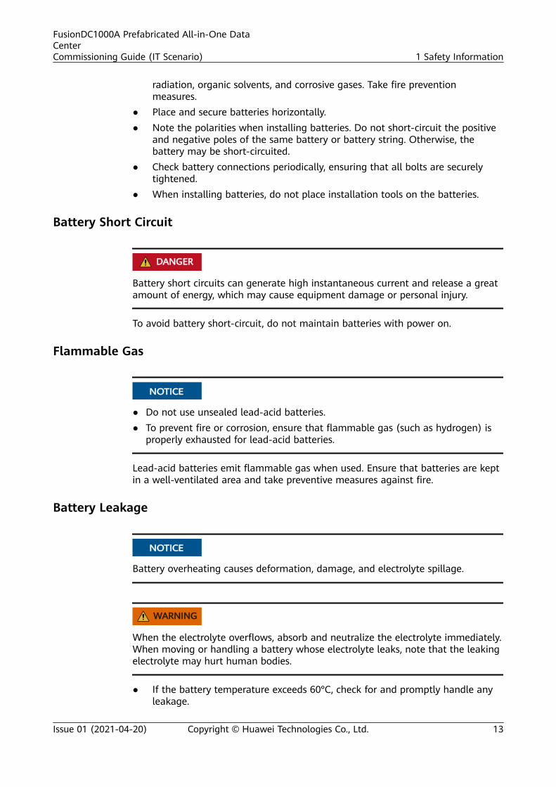
1.8 Battery Safety
Basic RequirementsBefore operating batteries, carefully read the safety precautions for batteryhandling and master the correct battery connection methods.
D ANGER
● Do not expose batteries at high temperatures or around heat-generatingdevices, such as sunlight, fire sources, transformers, and heaters. Excessive heatexposure may cause the batteries to explode.
● Do not burn batteries. Otherwise, the batteries may explode.● To avoid leakage, overheating, fire, or explosions, do not disassemble, alter, or
damage batteries, for example, insert sundries into batteries or immersebatteries in water or other liquids.
● Wear goggles, rubber gloves, and protective clothing to prevent skin contactwith electrolyte in the case of electrolyte overflow. If a battery leaks, protectthe skin or eyes from the leaking liquid. If the skin or eyes come in contactwith the leaking liquid, wash it immediately with clean water and go to thehospital for medical treatment.
● Use dedicated insulated tools.● Move batteries in the required direction. Do not place a battery upside down
or tilt it.● Keep the battery loop disconnected during installation and maintenance.● Use batteries of specified models. Using batteries of other models may
damage the batteries.● Dispose of waste batteries in accordance with local laws and regulations. Do
not dispose of batteries as household waste. If a battery is disposed ofimproperly, it may explode.
● The site must be equipped with qualified fire extinguishing facilities, such asfirefighting sands and powder fire extinguishers.
NO TICE
To ensure battery safety and battery management accuracy, use batteries providedwith the UPS by Huawei. Huawei is not responsible for any battery faults causedby batteries not provided by Huawei.
Battery InstallationBefore installing batteries, observe the following safety precautions:
● Install batteries in a well-ventilated, dry, and cool environment that is faraway from heat sources, flammable materials, moistures, extensive infrared
FusionDC1000A Prefabricated All-in-One DataCenterCommissioning Guide (IT Scenario) 1 Safety Information
Issue 01 (2021-04-20) Copyright © Huawei Technologies Co., Ltd. 12
radiation, organic solvents, and corrosive gases. Take fire preventionmeasures.
● Place and secure batteries horizontally.● Note the polarities when installing batteries. Do not short-circuit the positive
and negative poles of the same battery or battery string. Otherwise, thebattery may be short-circuited.
● Check battery connections periodically, ensuring that all bolts are securelytightened.
● When installing batteries, do not place installation tools on the batteries.
Battery Short Circuit
D ANGER
Battery short circuits can generate high instantaneous current and release a greatamount of energy, which may cause equipment damage or personal injury.
To avoid battery short-circuit, do not maintain batteries with power on.
Flammable Gas
NO TICE
● Do not use unsealed lead-acid batteries.● To prevent fire or corrosion, ensure that flammable gas (such as hydrogen) is
properly exhausted for lead-acid batteries.
Lead-acid batteries emit flammable gas when used. Ensure that batteries are keptin a well-ventilated area and take preventive measures against fire.
Battery Leakage
NO TICE
Battery overheating causes deformation, damage, and electrolyte spillage.
WARNING
When the electrolyte overflows, absorb and neutralize the electrolyte immediately.When moving or handling a battery whose electrolyte leaks, note that the leakingelectrolyte may hurt human bodies.
● If the battery temperature exceeds 60°C, check for and promptly handle anyleakage.
FusionDC1000A Prefabricated All-in-One DataCenterCommissioning Guide (IT Scenario) 1 Safety Information
Issue 01 (2021-04-20) Copyright © Huawei Technologies Co., Ltd. 13

● Electrolyte overflow may damage the equipment. It will corrode metal partsand boards, and ultimately damage the boards.
● If the electrolyte overflows, follow the instructions of the batterymanufacturer or neutralize the electrolyte by using sodium bicarbonate(NaHCO3) or sodium carbonate (Na2CO3).
Lithium Battery
The safety precautions for lithium batteries are similar to those for lead-acidbatteries except that you also need to note the precautions described in thissection.
WARNING
There is a risk of explosion if a battery is replaced with an incorrect model.
● A battery can be replaced only with a battery of the same or similar modelrecommended by the manufacturer.
● When handling a lithium battery, do not place it upside down, tilt it, or bumpit with other objects.
● Keep the lithium battery loop disconnected during installation andmaintenance.
● Do not charge a battery when the ambient temperature is below the lowerlimit of the operating temperature (charging is forbidden at 0°C). Low-temperature charging may cause crystallization, which will result in a shortcircuit inside the battery.
● Use batteries within the allowed temperature range; otherwise, the batteryperformance and safety will be compromised.
● Do not throw a lithium battery in fire.
● When maintenance is complete, return the waste lithium battery to themaintenance office.
1.9 Others● Exercise caution when shutting down the smart cooling product. Doing so
may cause equipment and room overheating, which will damage theequipment.
● Exercise caution when powering off the rPDU or PDU2000. Doing so mayaffect the power supply to equipment, which will interrupt services.
● Exercise caution when manually shutting down the UPS inverter fortransferring to bypass mode, or when adjusting the UPS output voltage levelor frequency. Doing so may affect the power supply to equipment.
● Exercise caution when setting battery parameters. Incorrect settings will affectthe power supply and battery lifespan.
FusionDC1000A Prefabricated All-in-One DataCenterCommissioning Guide (IT Scenario) 1 Safety Information
Issue 01 (2021-04-20) Copyright © Huawei Technologies Co., Ltd. 14

2 Commissioning Guide Usage
● Verify that the configurations of various systems in the FusionDC1000 areconsistent with the initial configuration tables.
● This manual describes how to perform power-on commissioning. For detailsabout drawings and initial configuration parameters required duringoperations, see the appendix.
● Conduct power-on commissioning only after the hardware is installed for theFusionDC1000 and the installation is verified.
● Power-on commissioning for each specific system must be performed underinstructions by qualified engineers.
● The initial configuration parameters are essential to the reliable running of allsystems. Improper modifications of parameters may cause abnormal runningstatus, or even damage to systems.
● The initial parameters of the FusionDC1000 are configured before delivery. Fordetails about how to modify the parameters, see the documents deliveredwith the components and the actual solution configuration.
● Prior to power-on commissioning, remove all the protective materials installedfor transporting the FusionDC1000A, such as the protective pads for smartcooling products and the securing tape for smoke and heat detectors.
● Before power-on commissioning, ensure that the aisle temperature is withinthe normal range.
● Do not perform power-on commissioning during a thunderstorm.● Verify that the upstream power supply is continuous during power-on
commissioning.● Operations marked as optional in chapters, sections, or procedures can be
performed depending on the actual situation.
Huawei assumes no liability for any loss caused by unauthorized changes to theinitial configuration parameters.
FusionDC1000A Prefabricated All-in-One DataCenterCommissioning Guide (IT Scenario) 2 Commissioning Guide Usage
Issue 01 (2021-04-20) Copyright © Huawei Technologies Co., Ltd. 15

3 Preparations for Power-OnCommissioning
3.1 ToolsThe following table lists the tools required for power-on commissioning.
Table 3-1 Tools
Tools
Phillips screwdriver Flat-head screwdriver Utility knife
Multimeter Electroprobe Network cable tester
Cable tie Insulation tape Marker
FusionDC1000A Prefabricated All-in-One DataCenterCommissioning Guide (IT Scenario) 3 Preparations for Power-On Commissioning
Issue 01 (2021-04-20) Copyright © Huawei Technologies Co., Ltd. 16

Tools
ESD gloves Step ladder (2 m) ESD wrist strap
Heat gun ESD floor suction plate Adjustable wrench
RJ45 crimping tool Wire stripper Flashlight
Hand-held thermometer Heat shrink tubing Phase-sequence meter
Clamp meter Insulationmegohmmeter
Point thermometer
NO TE
● This table may not list some tools required at specific sites. Onsite installation personneland technical support personnel should prepare tools based on site requirements.
● Some dedicated tools and installation materials provided with the equipment may notbe listed in this table.
FusionDC1000A Prefabricated All-in-One DataCenterCommissioning Guide (IT Scenario) 3 Preparations for Power-On Commissioning
Issue 01 (2021-04-20) Copyright © Huawei Technologies Co., Ltd. 17
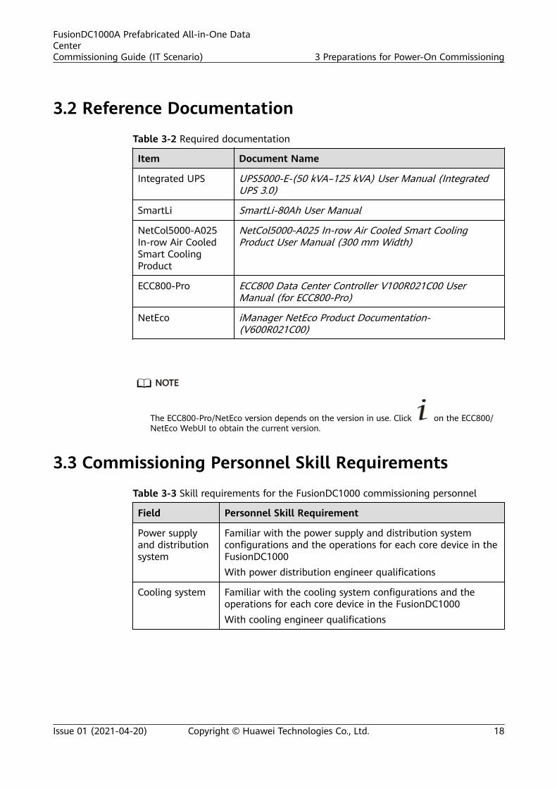
3.2 Reference Documentation
Table 3-2 Required documentation
Item Document Name
Integrated UPS UPS5000-E-(50 kVA–125 kVA) User Manual (IntegratedUPS 3.0)
SmartLi SmartLi-80Ah User Manual
NetCol5000-A025In-row Air CooledSmart CoolingProduct
NetCol5000-A025 In-row Air Cooled Smart CoolingProduct User Manual (300 mm Width)
ECC800-Pro ECC800 Data Center Controller V100R021C00 UserManual (for ECC800-Pro)
NetEco iManager NetEco Product Documentation-(V600R021C00)
NO TE
The ECC800-Pro/NetEco version depends on the version in use. Click on the ECC800/NetEco WebUI to obtain the current version.
3.3 Commissioning Personnel Skill Requirements
Table 3-3 Skill requirements for the FusionDC1000 commissioning personnel
Field Personnel Skill Requirement
Power supplyand distributionsystem
Familiar with the power supply and distribution systemconfigurations and the operations for each core device in theFusionDC1000With power distribution engineer qualifications
Cooling system Familiar with the cooling system configurations and theoperations for each core device in the FusionDC1000With cooling engineer qualifications
FusionDC1000A Prefabricated All-in-One DataCenterCommissioning Guide (IT Scenario) 3 Preparations for Power-On Commissioning
Issue 01 (2021-04-20) Copyright © Huawei Technologies Co., Ltd. 18

Field Personnel Skill Requirement
Managementsystem
With knowledge in the hardware and software of theprefabricated data center, familiar with basiccommunications protocols, familiar with equipmentinterfaces in extra-low voltage (ELV) systems, and proficientin operating the NetEco management systemWith ELV engineer qualifications
Fireextinguishingsystem
Familiar with the fire extinguishing system configurationsand the operations for each core device in the FusionDC1000With fire protection engineer qualifications
Lighting andstructuralsystems
Familiar with the overall configurations and layout of theFusionDC1000Experienced in data center maintenance
3.4 Check Before Power-On
PreparationsTools: multimeter, screwdriver, step ladder, insulation megohmmeter, pressuregauge
Documents: solution drawings and parameters
Skill requirement: power distribution engineer
FusionDC1000A Prefabricated All-in-One DataCenterCommissioning Guide (IT Scenario) 3 Preparations for Power-On Commissioning
Issue 01 (2021-04-20) Copyright © Huawei Technologies Co., Ltd. 19

Check Before Power-On
Table 3-4 Items to be checked before power-on
System
CheckItem
Operation Method Expected Result
Integratedcabling
Cableconnection
● Check cable connections.● Check the cable layout.● Check the cable labels.● Check the fastening status.
● Cables are neat, tidy notcoiled, and excessiveparts are cut.
● Power cables are atleast 20 mm away fromsignal cables.
● Power cables are boundat intervals of at most200 mm. For thickercables, the intervals canbe greater.
● Cable ties do notoverlap, and the jointsare evenly cut withoutburrs.
● Cables are placedproperly and not tenseat turning points.
● Cable routes are straightand smooth, and do notintersect inside acabinet.
● All PE cables, AC inputcables, and intra-cabinetcables are connectedcorrectly according tothe power system circuitdiagram, and all screwsare fastened. The inputand output cables arenot short-circuited.
Powersupplyanddistributionsystem
ATS status Verify ATS settings andremove the ATS handle.
● The ATS handle hasbeen removed.
● The motor operationmechanism is set to .
Powercableinsulation
Measure the insulation of thepower cables using aninsulation megohmmeter.
There is no electricityleakage in the powersupply and distributionsystem.
FusionDC1000A Prefabricated All-in-One DataCenterCommissioning Guide (IT Scenario) 3 Preparations for Power-On Commissioning
Issue 01 (2021-04-20) Copyright © Huawei Technologies Co., Ltd. 20

System
CheckItem
Operation Method Expected Result
Circuitbreakerstatus
● Verify the circuit breakerlabels by referring to thepower supply anddistribution systemdiagram.
● Verify that circuit breakerscan be smoothly switchedon and off.
● Check the circuit breakerstatus.
● Circuit breaker labels arecorrect, clear, complete,and attached properly.
● Ensure that all loadcircuit breakers arereliable and controllable.
● All PDF, PDB, and PDUcircuit breakers are inthe OFF state, and allSPD circuit breakers arein the ON state.
Phasesequence
Verify the phase sequences ofupstream and downstreampower distribution devices forthe FusionDC1000 using aphase sequence meter.
The phase sequences areconsistent.
Voltage Use a multimeter to measurethe input voltage of thePower PDB.
The voltage is in the rangeof 342–418 V.
Frequency Use a multimeter to measurethe input frequency of thePower PDB.
● Frequency range for the50 Hz scenario: 49–51Hz
● Frequency range for the60 Hz scenario: 59–61Hz
FusionDC1000A Prefabricated All-in-One DataCenterCommissioning Guide (IT Scenario) 3 Preparations for Power-On Commissioning
Issue 01 (2021-04-20) Copyright © Huawei Technologies Co., Ltd. 21

System
CheckItem
Operation Method Expected Result
Lithiumbattery
● Check the number oflithium batteries.
● Check lithium batteryconnection.
● Measure the lithiumbattery cell voltage using amultimeter.
● Measure the lithiumbattery string voltageusing a multimeter.
● The lithium batteries arecorrect in quantity andintact.
● Lithium batteries areconnected based on thedesign requirements andinstalled securely.Lithium batteryelectrodes are correctlyconnected.
● The voltage is within therated voltage range oflithium batteries. Thebattery string voltageequals the single batteryvoltage multiplied bythe number of batteries.
● The voltagemeasurement resultmeets the requirementof system power backup.
Coolingsystem
Phasesequenceof indoorandoutdoorunit cables
Verify that the L1, L2, L3, N,and PE wires are connectedfor the indoor and outdoorunits in the correct phasesequence using a phasesequence meter.
The phase sequence iscorrect.
Waterrefill forthe smartcoolingproducthumidifier
Check whether the water refillvalve is open, and whetherthe water refill pressuremeets the requirement.
The water refill valve isopen, and the water refillpressure is 0.1–0.7 MPa.
Outdoorunit airintake andexhaustvents
Check the outdoor unit airintake and exhaust vents.
Outdoor unit air intake andexhaust vents are notblocked.
Smartcoolingproductcompressor pads
Check the smart coolingproduct compressor.
All smart cooling productcompressor pads areremoved.
FusionDC1000A Prefabricated All-in-One DataCenterCommissioning Guide (IT Scenario) 3 Preparations for Power-On Commissioning
Issue 01 (2021-04-20) Copyright © Huawei Technologies Co., Ltd. 22

System
CheckItem
Operation Method Expected Result
Liquidleveldetectorfastener
Check the liquid level detectorfastener.
The liquid level detectorfastener has been removed.
Smartcoolingproductteamworkand signalcables
Check the connection ofsmart cooling productteamwork and signal cables.
Cables are securelyconnected and meet thedesign requirements.
Smartcoolingproductpipeconnection
Check the pipe connectionsfor the air-cooled precisionsmart cooling products.
The refrigerant circulationpipeline, humidifier waterrefill pipeline, andcondensate drainpipe areproperly installed, and thethermal insulation layersare intact.
Managementsystem
Componentinstallation andconnection
Check the monitoring deviceinstallation and connection.
● Devices are installedsecurely as shown in themonitoring device layoutdiagram.
● Cables are correctlyconnected.
Fireextinguishingsystem(CE)
Deviceinstallation andcableconnections
Check the fire extinguishingdevice installation and cableconnections.
● The pressure pointer ofthe fire cylinder is in thegreen zone.
● The dowel of the firecylinder is properlyinstalled and intact.
● All cables are correctlyand securely connected.
Lightingsystem
Componentinstallation andconnection
Check the lighting deviceinstallation and connection.
● Devices are installed inpositions shown in thelighting device layoutdiagram.
● Cables are correctlyconnected.
FusionDC1000A Prefabricated All-in-One DataCenterCommissioning Guide (IT Scenario) 3 Preparations for Power-On Commissioning
Issue 01 (2021-04-20) Copyright © Huawei Technologies Co., Ltd. 23

4 Commissioning Core Devices
4.1 Commissioning the Integrated UPS
4.1.1 (Optional) Commissioning the ATS
Context
CA UTION
Perform system commissioning and power-on strictly according to the systemmanual and ATS instructions. For any changes in operations and parameters,consult Huawei engineers. Otherwise, system commissioning or power-on mayfail, or even the cabinet is damaged.
Procedure
Step 1 Switch on all SPD circuit breakers in the integrated UPS.
Step 2 Switch on the upstream power input circuit breaker for the integrated UPS topower on the UPS cabinet. If the Power indicator in the upper part of theintegrated UPS lights up, the UPS cabinet is powered on properly.
Step 3 Turn on the circuit breakers of the ATS operation mechanism (Q1 and Q2 in theleft lower part at the rear of the cabinet) to power on the ATS.
Step 4 Check whether the ATS controller has alarms. If an alarm exists, rectify the faultfirst.
Step 5 Press the locking latch on the ATS panel, pull out the handle, and insert it into theslot.
Step 6 Check the ATS Motor/Manual selection lever, and flip it to the Motor (M) mode.
Step 7 Check the input and configuration status of the ATS by referring to the initialconfiguration table for the corresponding scenario in the power supply and
FusionDC1000A Prefabricated All-in-One DataCenterCommissioning Guide (IT Scenario) 4 Commissioning Core Devices
Issue 01 (2021-04-20) Copyright © Huawei Technologies Co., Ltd. 24

distribution drawings and parameters. After the AC input starts properly, the ATScontroller starts.
NO TE
● A password is required to log in to the configurations page. Set the password by usingthe Up, Down, and Enter buttons. The initial password is 0001.
● Language setting: Default screen > Main Menu > Device Configuration > Language.
● On the default screen, hold down . The main menu screen is displayed.
On the main menu screen, select system configuration and press .
● On the main menu screen, select device configuration and press . Onthe device configuration screen, you can set thresholds for parameters.
Step 8 Set the ATS controller to auto mode.
----End
4.1.2 Powering On and Starting the UPS
4.1.2.1 Powering On the UPS
PrerequisitesThe surge protection switch is turned on.
Before powering on the UPS, Measure the voltage and frequency of the upstreampower distribution switch of the UPS cabinet. Ensure that the phase voltage iswithin the range of 80–280 V AC and the frequency is within the range of 40–70Hz.
Procedure
Step 1 (Skip this step in the case of ATS input.) Turn on the MCCB.
Step 2 Turn on the UPS input circuit breaker QF1.
The UPS is powered by the mains and initialization begins. The LCD displays theHuawei logo and an initialization progress bar.
----End
FusionDC1000A Prefabricated All-in-One DataCenterCommissioning Guide (IT Scenario) 4 Commissioning Core Devices
Issue 01 (2021-04-20) Copyright © Huawei Technologies Co., Ltd. 25

4.1.2.2 Starting the Inverter
UPS System User List
Table 4-1 UPS system user list
Default User Preset Password
admin (administrator) LCD 000001
operator (common user) LCD 000001
Starting the UPS on the LCD
Step 1 Choose Common Functions > Inv. ON.
NO TE
You can also start the inverter by choosing System Info > Maintenance > Inv. ON.
Step 2 In the displayed login screen, select a user name and enter the password.
Step 3 In the displayed dialog box, tap Yes to start the inverter.
----End
4.1.2.3 Powering On LoadsAfter the inverter starts, the UPS works in normal mode. The Bypass mode alarmdisappears. Check that the UPS has transferred to normal mode by viewing thesystem running status diagram.
Procedure
Step 1 After confirming that the battery strings are properly connected, turn on thebattery string input switch. If there are multiple battery strings, turn on the switchfor each battery string and then the general switch between battery strings andthe UPS. After you turn on the battery string input switch, the No battery alarmdisappears.
Step 2 Turn on the UPS output circuit breaker QF3.
NO TICE
After the UPS is started for the first time, perform a battery capacity test to ensurethat battery parameters are correctly displayed.
Step 3 (Optional) Turn on the lighting output circuit breaker on the integrated UPS andcheck whether the PWR indicator on the AC actuator lights up. Press down thelighting button to power on the light.
Step 4 Turn on the smart cooling product circuit breaker on the integrated UPS to poweron the smart cooling products.
FusionDC1000A Prefabricated All-in-One DataCenterCommissioning Guide (IT Scenario) 4 Commissioning Core Devices
Issue 01 (2021-04-20) Copyright © Huawei Technologies Co., Ltd. 26

Step 5 Turn on the IT output circuit breakers on the integrated UPS, and then turn on therPDUs of the network cabinet and IT cabinet to power on the equipment in thenetwork cabinet and IT cabinet.
NO TE
● Do not turn on the reserved circuit breakers.
● When turning on the circuit breakers, observe whether there is any abnormal phenomenon,such as sparks or unsmooth turning on/off.
● After turning on the IT output circuit breakers, check whether the corresponding branchopen alarm has disappeared from the MDU.
● As for branch open alarms caused by reserved circuit breakers, you can mask these alarmson the UPS MDU. Path for masking alarms: System info. > Settings > PDU Param.>Branchbreaker open alarm enable.
Step 6 If a dual-bus system is used, set BSC mode.
----End
4.2 Commissioning the SmartLi
4.2.1 Powering On Batteries
Prerequisites● Turn on the ready switch on the BCU.
● Ensure that the UPS runs stably in normal mode and the rectifier in theenergy flow diagram is started.
Context
Table 4-2 Status of Indicators on the BCU
Status of Indicators on the BCU Description
The green indicator blinks at 4 Hz (atshort intervals).
Status after the switch button ispressed.
The green indicator blinks on for 1sand off for 4s (intermittently).
The SmartLi circuit breaker cannot beswitched on, and the UPS cannot becold started.
The green indicator blinks at 10 Hz(blinking at super short intervals), andthe red indicator is steady on.
The SmartLi circuit breaker can beswitched on, but the UPS cannot becold started.
The green indicator blinks at 1 Hz or issteady on (blinking at long intervals).
The UPS can be cold started.
FusionDC1000A Prefabricated All-in-One DataCenterCommissioning Guide (IT Scenario) 4 Commissioning Core Devices
Issue 01 (2021-04-20) Copyright © Huawei Technologies Co., Ltd. 27

Procedure
Step 1 On the UPS LCD screen, set System Info > Settings > Battery Settings > BatteryType to Lithium battery.
NO TICE
The UPS software needs to be upgraded to the version that supports lithiumbattery connection. See UPS5000 The Relationship of Software Version to checkthe version number.
Step 2 Press and hold the POWER ON/OFF button on the BCU for more than 2s. Thegreen indicator of the BCU blinks at short intervals.
NO TICE
● The BCB off alarm (the red indicator is steady on) is displayed on the UPS LCDand SmartLi LCD. No action is required. After the battery circuit breaker isswitched on, the alarm is automatically cleared.
● The green indicator blinks intermittently. After 1 minute, the BCU starts. Thegreen indicator blinks at super short intervals and the red indicator is steadyon.
● If multiple SmartLi cabinets are combined, press and hold the POWER ON/OFFbutton on the BCU of the master cabinet for more than 2s to power on themaster cabinet. Then, power on slave cabinets one by one in the same way.
Step 3 Set the language, time, date, network parameters, and system parameters on theSettings Wizard screen of the SmartLi.
FusionDC1000A Prefabricated All-in-One DataCenterCommissioning Guide (IT Scenario) 4 Commissioning Core Devices
Issue 01 (2021-04-20) Copyright © Huawei Technologies Co., Ltd. 28

Figure 4-1 Settings Wizard
Table 4-3 System Param.
Item Description DefaultValue
Value Range
Battery cabinetquantity
Total number of batterycabinets.
1 1–15
Pooling If this parameter is set toEnable, the system allowsbattery pooling.Currently, the system doesnot support pooling. Retainthe default value Disable.
Disable Disable, Enable
Charging mode Mode 1 can meet therequirements of mostcustomers.Mode 2 meets therequirements for chargingbatteries immediately afterdischarging is complete at ahigh temperature.
Mode 1 Mode 1, Mode 2
FusionDC1000A Prefabricated All-in-One DataCenterCommissioning Guide (IT Scenario) 4 Commissioning Core Devices
Issue 01 (2021-04-20) Copyright © Huawei Technologies Co., Ltd. 29

Item Description DefaultValue
Value Range
Cellundervoltageprotectionthreshold
You can adjust the EODthreshold as required.
2.5 2.5–2.9
Batteryundervoltageprotection time(h)
Maximum battery dischargetime.
48 24~3000
Table 4-4 Alarm Settings
Item Description DefaultValue
Value Range
Battery cabinetEPO
Emergency power-off(EPO) is performed onlywhen this parameter is setto Enable and the EPOswitch is triggered.When the value is changedfrom Disable to Enable,check that the EPO cable isconnected correctly.
Disable Disable, Enable
Copper barovertemperature
If this parameter is set toEnable, an alarm isreported when the copperbar is overheated.
Enable Disable, Enable
Abnormalpressure of firegas cylinder
If this parameter is set toEnable, an alarm isreported when the firecylinder pressure isabnormal.
Enable Disable, Enable
Batteryovercurrent(discharge)
If this parameter is set toDisable, no alarm isreported when batteryovercurrent occurs duringdischarging.If this parameter is set toEnable, an alarm isreported when batteryovercurrent occurs duringdischarging.
Disable Disable, Enable
FusionDC1000A Prefabricated All-in-One DataCenterCommissioning Guide (IT Scenario) 4 Commissioning Core Devices
Issue 01 (2021-04-20) Copyright © Huawei Technologies Co., Ltd. 30

Item Description DefaultValue
Value Range
Batteryovertemperature
If this parameter is set toDisable, no alarm isreported when batteryovertemperature occurs.If this parameter is set toEnable, an alarm isreported when batteryovertemperature occurs.
Disable Disable, Enable
Step 4 After the green indicator of the BCU blinks at super short intervals, switch on thebattery circuit breaker on the SmartLi.
Step 5 When multiple SmartLi cabinets are combined:
1. If the green indicator of one BCU blinks at super short intervals, switch on thebattery circuit breaker on any SmartLi. In this case, the green indicators of allBCUs blink intermittently, and you cannot switch on the battery circuitbreakers on other SmartLi cabinets or start the UPS in cold mode.
2. Wait for about 15s. After the green indicators of other BCUs blink at supershort intervals, switch on the battery circuit breaker on the SmartLi where theBCU blinks at super short intervals one by one.
----End
4.2.2 Powering Off Batteries
Procedure
Step 1 Switch off the SmartLi battery circuit breaker. (Perform this operation for multipleSmartLi cabinets one by one.)
Step 2 Press and hold the POWER ON/OFF button on the BCU for more than 5s. (Performthis operation for multiple SmartLi cabinets one by one.)
NO TICE
If batteries are powered off and will not be charged for more than a month,remove the BCU.
----End
4.2.3 Performing EPO
FusionDC1000A Prefabricated All-in-One DataCenterCommissioning Guide (IT Scenario) 4 Commissioning Core Devices
Issue 01 (2021-04-20) Copyright © Huawei Technologies Co., Ltd. 31

NO TICE
● After EPO is triggered, there is no SmartLi output.● After EPO is triggered, the system reports a Battery cabinet shutdown alarm.
Press the external EPO switch that connects to the dry contact card or remove the4-pin terminal on the EPO port of the dry contact card of the bypass unit.
4.2.4 Clearing the EPO State
Procedure
Step 1 Clear the EPO state. Ensure that the EPO button connected to the external EPO isnot in the EPO state.
Step 2 On the LCD screen, choose System Status > Alarms > Clear Faults. In thedisplayed dialog box, tap Yes. The Battery cabinet shutdown alarm is clearedsuccessfully.
Figure 4-2 Clear Faults
Step 3 View active alarms and ensure that the Battery cabinet shutdown alarm hasdisappeared from the alarm list.
----End
4.3 Commissioning Smart Cooling Products
Prerequisites
The power-on commissioning for the upstream PDF of air cooled precision smartcooling products is completed.
FusionDC1000A Prefabricated All-in-One DataCenterCommissioning Guide (IT Scenario) 4 Commissioning Core Devices
Issue 01 (2021-04-20) Copyright © Huawei Technologies Co., Ltd. 32

NO TICE
● Smart cooling products that use power crossfeed can be powered on only afterboth power inputs are connected.
● Teamwork settings can be performed only after all smart cooling products in agroup have been powered on.
PreparationsTools: none
Documents: power supply and distribution drawings and parameters, NetCol5000-A(025, 035) in-row air cooled smart cooling product user manual (300 mm width)
Skill requirement: cooling engineer
Procedure
Step 1 Switch on the input power circuit breakers for the air cooled precision smartcooling product indoor units in the upstream PDF, and switch on fan circuitbreakers in the electric control box for the smart cooling product indoor units topower on the smart cooling product indoor units.
Step 2 Switch on the outdoor unit circuit breakers in the electric control box for the aircooled precision smart cooling product indoor units and the circuit breakers of theoutdoor units to power on the smart cooling product outdoor units.
NO TICE
● Before the power-on commissioning, ensure that the air supply and returnvents of smart cooling products are not blocked.
● The humidifier water refill and drainage work properly, and smart coolingproduct condensate drainpipes are intact and not blocked.
● If any alarm is raised, rectify the fault before continuing the commissioning.● Before power-on, clear dust, dirt, and foreign matter from the cabinet;
otherwise, the water pump may be blocked, resulting in drainage failure orserious equipment malfunction.
Step 3 Verify the initial configuration of the air cooled precision smart cooling product.
NO TICE
Check the DIP switch settings of the T/H sensor, initial teamwork settings, andinitial temperature and humidity settings by referring to the cooling drawing andparameters.
Step 4 Tap Start on the main screen, and tap Confirm in the dialog box that appears. Ifthe start succeeds, the system prompts that the command is successfully executed.
----End
FusionDC1000A Prefabricated All-in-One DataCenterCommissioning Guide (IT Scenario) 4 Commissioning Core Devices
Issue 01 (2021-04-20) Copyright © Huawei Technologies Co., Ltd. 33

4.4 Commissioning Monitoring Devices
4.4.1 Commissioning the Access Control System
Prerequisites● You have powered on the access control system.
● You have configured the IC cards.
Preparations
Tools: step ladder, Phillips screwdriver
Documents: monitoring and fire extinguishing drawings and parameters
Skill requirement: ELV engineer familiar with the management system
Procedure
Step 1 Open the magnetic lock of the main entrance door by swiping an access card.
NO TE
If you do not open the main entrance door within 6s after swiping the card, the magneticlock will lock the door again.
Step 2 Rotate the door handle clockwise and pull the main entrance door.
NO TE
Normal response: The main entrance module door can be opened, and the managementsystem logs the door opening event.
Step 3 Enter the pre-fab. module and close the main entrance door.
Step 4 For the main entrance door, press the exit button and push the door lever to openthe door. For the emergency door, push the door lever to open the door.
Step 5 Check the main entrance door event or emergency door alarm event in themanagement system.
NO TE
Normal response: The pre-fab. module door can be opened, and the management systemlogs the door opening event.
Step 6 Insert the key delivered with the emergency door release button into the test holeto control the emergency door release button, and rotate the door handleclockwise. If the door of the pre-fab. module can be opened, the emergency doorrelease button functions properly.
----End
FusionDC1000A Prefabricated All-in-One DataCenterCommissioning Guide (IT Scenario) 4 Commissioning Core Devices
Issue 01 (2021-04-20) Copyright © Huawei Technologies Co., Ltd. 34
4.5 Commissioning Fire Extinguishing Devices(Standard)
4.5.1 Commissioning the Fire Alarm Control Panel (Standard)
Prerequisites
Initial configuration parameters have been set for the fire alarm control panelbefore delivery and do not need to be set onsite.
Preparations
Tools: none
Documents required: power supply and distribution system diagram, documentsdelivered with the fire alarm control panel, fire extinguishing system conceptualdiagram (standard), fire extinguishing device layout diagram (standard)
Skill requirement: fire engineer
NO TE
For the diagrams, see the initial configuration parameter manual for the solution in use.
Procedure
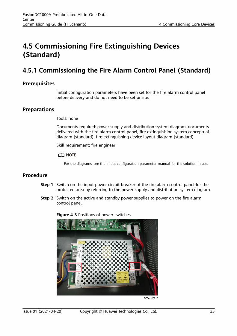
Step 1 Switch on the input power circuit breaker of the fire alarm control panel for theprotected area by referring to the power supply and distribution system diagram.
Step 2 Switch on the active and standby power supplies to power on the fire alarmcontrol panel.
Figure 4-3 Positions of power switches
FusionDC1000A Prefabricated All-in-One DataCenterCommissioning Guide (IT Scenario) 4 Commissioning Core Devices
Issue 01 (2021-04-20) Copyright © Huawei Technologies Co., Ltd. 35

NO TE
If the power indicator is on and other indicators are off, the power-on process succeeds. If ayellow fault indicator is on, rectify the fault before continuing follow-up operations.
Step 3 Unlock the keyboard.
The keyboard is locked to prevent misoperation.● To unlock the keyboard, press Keyboard and then enter the password (the
initial password is 111111).● To lock the keyboard, press Keyboard when the keyboard is unlocked.● The keyboard will be locked if no operation is performed within 5 minutes.
Step 4 Set the time displayed on the fire alarm control panel.
Choose System Setting > Time Setting, enter the correct date and time, and clickOK. The system saves the time you have set.
----End
4.5.2 Commissioning the Emergency Light (Standard)
PrerequisitesThe sockets of the emergency light have been powered on.
PreparationsTools: step ladder, Phillips screwdriver
Documents: power supply and distribution system diagram, fire extinguishingdevice layout diagram (standard)
Skill requirement: fire engineer
NO TE
For the diagrams, see the initial configuration parameter manual for the solution in use.
Procedure
Step 1 Press the emergency light test button and check whether the emergency lightenters the working mode.
FusionDC1000A Prefabricated All-in-One DataCenterCommissioning Guide (IT Scenario) 4 Commissioning Core Devices
Issue 01 (2021-04-20) Copyright © Huawei Technologies Co., Ltd. 36

Figure 4-4 Emergency light button
(1) Emergency light button
----End
4.6 Commissioning Fire Extinguishing Devices (CE)
4.6.1 Commissioning the Emergency Light (CE)
PrerequisitesThe sockets of the emergency light have been powered on.
PreparationsTools: step ladder, Phillips screwdriver
Documents: drawings and parameters for power supply and distribution as well asfire extinguishing
Skill requirement: fire engineer
Procedure
Step 1 Turn off the upstream switch for the emergency light power cable.
FusionDC1000A Prefabricated All-in-One DataCenterCommissioning Guide (IT Scenario) 4 Commissioning Core Devices
Issue 01 (2021-04-20) Copyright © Huawei Technologies Co., Ltd. 37

Figure 4-5 Emergency light
Step 2 Remove the protective cover of the emergency light.
Step 3 Remove the red pin of the emergency light. The emergency light turns on.
Figure 4-6 Removing the red pin
Step 4 Reinstall the protective cover of the emergency light.
Step 5 Turn on the upstream switch for the emergency light power cable.
NO TE
The emergency light turns off, and the power indicator turns on.
Step 6 Press the red button of the emergency light. The emergency light turns on. Whenyou release the red button, the emergency light turns off.
FusionDC1000A Prefabricated All-in-One DataCenterCommissioning Guide (IT Scenario) 4 Commissioning Core Devices
Issue 01 (2021-04-20) Copyright © Huawei Technologies Co., Ltd. 38

Figure 4-7 Red button of the emergency light
(1) Red button of the emergency light
NO TE
● The red button is located at one side of the emergency light.● If the result expected for each step appears, the emergency light is working properly.
----End
4.6.2 (Optional) Commissioning the ASD
PreparationsTool: smoke pistol
Documents: drawings and parameters for power supply and distribution as well asfire extinguishing, documents delivered with the ASD
Skill requirement: fire engineer
Procedure
Step 1 Switch on the input power circuit breaker for the ASD power box for the protectedarea and connect the ASD battery based on the power supply and distributionsystem diagram.
Step 2 (Optional) Perform power-on commissioning by following instructions indocuments delivered with the ASD.
NO TE
The ASD is commissioned before delivery. The ASD that is used as a replacement must becommissioned as instructed by the delivered documents.
Step 3 Reset the ASD.1. Rotate the knob switch Mode to position 0.2. Press the Set/Res button to start the reset.3. Wait until the two airflow LEDs in the middle turn on.4. Rotate the knob switch Mode to position 1.5. Press the Set/Res button to finish the reset.
FusionDC1000A Prefabricated All-in-One DataCenterCommissioning Guide (IT Scenario) 4 Commissioning Core Devices
Issue 01 (2021-04-20) Copyright © Huawei Technologies Co., Ltd. 39

Step 4 Release smoke in the protected area using the smoke pistol. Verify that the ASDalarm indicator lights up, and that an alarm is generated in the managementsystem.
NO TE
After the operation is complete, press the reset button to reset the ASD
----End
4.7 (Optional) NetEco Management
4.7.1 Preparations and WebUI Login
Prerequisites● Supported operating system: Windows 7 and later versions● It is recommended that the screen resolution be 1366 x 768 or higher.● Browser: Chrome, Firefox 32, Internet Explorer 11 or later
Procedure
Step 1 Connect a network cable between the PC network port and the WAN1 port(protected by a security mechanism) on the ECC800-Pro.
Table 4-5 Default IP addresses for the WAN and LAN ports on the ECC800-Pro
Port Default IP Address
WAN1 192.168.8.10
WAN2 192.168.0.10192.168.248.10 (FusionModule800)
LAN1 and LAN2 192.168.248.10
FusionDC1000A Prefabricated All-in-One DataCenterCommissioning Guide (IT Scenario) 4 Commissioning Core Devices
Issue 01 (2021-04-20) Copyright © Huawei Technologies Co., Ltd. 40

NO TICE
● In ECC800 V100R002C10 and earlier versions, the default IP address of portWAN_1 is 192.168.1.10.
● The WAN1 port IP address cannot be set to an IP address in any of thefollowing network segments: 192.168.0.x, 192.168.245.x, 192.168.246.x and192.168.248.x.
● IP addresses for the WAN1 and WAN2 ports should not be set in the samenetwork segment.
● In some customized scenarios, the default IP address for the WAN2 port is192.168.248.10. The default value may vary.
● WAN ports support the Internet access and LAN ports support the intranetaccess. Connect the PC network port to the WAN1 port or LAN port on theECC800-Pro based on the access network.
Step 2 Configure the PC IP address and the WAN1 IP address in the same networksegment.
If the WAN1 port IP address is 192.168.8.10, subnet mask is 255.255.255.0, anddefault gateway is 192.168.8.1, set the PC IP address to 192.168.8.12, subnet maskto 255.255.255.0, and default gateway to 192.168.8.1.
Step 3 Set LAN parameters.
NO TE
● If the ECC800-Pro connects to a LAN and a proxy server has been selected, perform Step3.3 and Step 3.4.
● If the ECC800-Pro connects to the Internet, and the PC in a LAN accesses the Internetover a proxy server, do not perform Step 3.3 and Step 3.4. Otherwise, you will fail toaccess the ECC800-Pro.
1. Open the Internet Explorer and choose Tools > Internet Options.2. Click the Advanced tab and select Use TLS1.1 and Use TLS1.2.3. (Optional) Click the Connections tab and select LAN settings.4. (Optional) On Proxy server, clear Use a proxy server for your LAN.5. Click OK.
Step 4 Set Internet Explorer parameters.1. When you use Internet Explorer for access, set Internet Explorer to ensure the
normal display of and operations on the WebUI. Choose Tools >Compatibility View, and add the web access address to the compatibilityview.
2. Choose Tools > Internet options > Security, choose Add the ECC800-Pro IPaddress to the list of trusted sites.
FusionDC1000A Prefabricated All-in-One DataCenterCommissioning Guide (IT Scenario) 4 Commissioning Core Devices
Issue 01 (2021-04-20) Copyright © Huawei Technologies Co., Ltd. 41

Figure 4-8 Adding an address
3. Enable file download and set the security level of the trusted site to low.
Figure 4-9 Setting parameters
NO TE
When switching between different versions of the ECC800-Pro on your PC, you areadvised to clear the historical Internet Explorer cache. Failing to do so may cause someinformation missed or exception after login. The following provides the details:1. Open Internet Explorer and choose Tools > Internet Options > General.2. Select Delete browsing history on exit and click Delete.3. In the Delete Browsing History dialog box, select all options except Password,
and click Delete.
Step 5 Log in to the ECC800-Pro WebUI.1. Enter https://monitoring IP address (such as monitoring IP address https://
192.168.8.10) in the address box of the browser, and then press Enter toenter the WebUI login page.
FusionDC1000A Prefabricated All-in-One DataCenterCommissioning Guide (IT Scenario) 4 Commissioning Core Devices
Issue 01 (2021-04-20) Copyright © Huawei Technologies Co., Ltd. 42

Figure 4-10 WebUI login page
2. On the login page, enter the preset user name admin and preset passwordChangeme, set the language, and click Log In.
NO TE
– After the first login, change the password in time to ensure account security andprevent unauthorized network attacks, such as data tampering. Huawei will not beliable for any security issues caused by your failure to change the preset passwordin time or password loss after changing.
– Change the password of the user account periodically.– Record and keep the password properly. If you forgot the password, you will be
unable to log in to the WebUI.– When the event notification is configured and the password retrieval mode is
configured under user management, the password can be retrieved.– An account is logged out due to timeout if no operation is performed within 10
minutes after system login.– A maximum of three users can log in to the ECC800-Pro WebUI at the same time.
----End
4.7.2 Performing Basic Operations Before Adding DevicesSoftware installation and commissioning are required before the devicecommissioning, collector commissioning, and NetEco commissioning. For details,see NetEco Product Documentation. Commission the software by referring torelevant sections in NetEco Software Installation and Commissioning Guide.
FusionDC1000A Prefabricated All-in-One DataCenterCommissioning Guide (IT Scenario) 4 Commissioning Core Devices
Issue 01 (2021-04-20) Copyright © Huawei Technologies Co., Ltd. 43

Table 4-6 Encryption algorithms
Insecure Encryption Algorithm Secure Encryption Algorithm
● DES/3DES (except the scenariowhere K1≠K2≠K3)
● SKIPJACK● RC2● RSA (1024-bit or shorter)● MD2/MD4● MD5 is used in scenarios where
digital signatures are generatedor passwords are encrypted forstorage.
● SHA1 is used in scenarios wheredigital signatures are generated.
● Symmetric encryption algorithm: AES(128-bit or longer)
● Asymmetric encryption algorithm: RSA(2048-bit or longer)
● Hash algorithm: SHA2 (256-bit orlonger)
● Hash-based message authenticationcode (HMAC) algorithm: HMAC-SHA2
Table 4-7 Communication protocols
Insecure Communication Protocol Secure Communication Protocol
SNMPv1/v2 SNMPv3
IPMI 1.5 IPMI 2.0
Non-SSL protocol, SSL 2.0, and SSL3.0
TLS 1.2
TLS 1.0 and TLS 1.1 N/A
NO TICE
● The device may use insecure algorithms and protocols, which may pose securityrisks. You are advised to replace the device with a device that supports securealgorithms and protocols or upgrade the device to a version that supportssecure algorithms and protocols.
● In transparent transmission channel management settings, the compatibilitymode has security risks. You are advised to select the security protocol mode.
4.7.2.1 IP Address Preinstallation Planning
The IP address must be in compliance with the following requirements:● The static IP address must be used.● The IP address must be unique on the live network.● You can plan only one IP address for one network interface. It is not allowed
to plan or set multiple IP addresses for the same network interface.
FusionDC1000A Prefabricated All-in-One DataCenterCommissioning Guide (IT Scenario) 4 Commissioning Core Devices
Issue 01 (2021-04-20) Copyright © Huawei Technologies Co., Ltd. 44

● The NetEco server can communicate with managed devices.● The NetEco server can communicate with Web clients.
NO TE
The subnet mask of all IP addresses is 255.255.255.0.
Table 4-8 IP address list
Item Preinstallation Setting Description
Server IPaddress
192.168.8.11 Used for logging in to the NetEco andPowerEcho.
4.7.2.2 Obtaining the NetEco Software LicenseThe NetEco software license is not provided together with software to thecustomer. Therefore, obtain the NetEco software license in advance.
Obtain the license from the Huawei's enterprise support website.● For enterprise users:
a. Log in to Huawei's enterprise support website https://support.huawei.com/enterprise.
b. Browse or search for NetEco License Application Guide, and apply forthe license of the NetEco software by referring to the guide.
● For carriers:
a. Log in to Huawei's carrier support website https://support.huawei.com.b. Browse or search for NetEco License Application Guide, and apply for
the license of the NetEco software by referring to the guide.
4.7.2.3 Logging In to the NetEco ClientThis section describes how to log in to the NetEco client using a web browser.
PrerequisitesValid user name and password are available.
Procedure
Step 1 In the browser address box, enter https://IP address of the NetEco server:31943,and then press Enter.
NO TE
● 192.168.8.11 is the default IP address of the NetEco.● Latest Chrome (Stable Channel) and Firefox (ESR Release) are recommended.● You are advised to set the display resolution as 1920*1080 or higher.● Make sure that the IP address of the NetEco server is not contained in the compatibility view
website.
FusionDC1000A Prefabricated All-in-One DataCenterCommissioning Guide (IT Scenario) 4 Commissioning Core Devices
Issue 01 (2021-04-20) Copyright © Huawei Technologies Co., Ltd. 45

Step 2 Enter the User Name, Password, and click Login.
NO TE
● The preset user of NetEco is admin, the preset password is Changeme_123. This userhas all the operation rights on the managed objects. After the first login, change thepassword in time to ensure account security and prevent unauthorized network attacks,such as data tampering. Huawei will not be liable for any security issues caused by yourfailure to change the preset password in time or password loss after changing.
● If the number of online users reaches the maximum number supported by the system, amessage is displayed, indicating that you cannot log in. In this case, contact the systemadministrator.
● After you enter the incorrect password for three consecutive times, you must enter theverification code upon the fourth login. After you enter the incorrect password for fiveconsecutive times, the user account or the IP address is locked for 10 minutes.
----End
4.7.2.4 Loading the NetEco Software LicenseThe NetEco license file is used to control the functions and managementcapabilities of the NetEco. Before using NetEco, you need to load a commerciallicense.
Prerequisites● You have obtained a license.● You have logged in to the NetEco client using a web browser.
Procedure
Step 1 Click Import License file when you log in to the NetEco at the first time.
Step 2 Click next to the License text box and select a license file.
Step 3 Click Upload.
The information about the imported license file is displayed.
Step 4 Click Apply.
----End
4.7.2.5 Installing NE Adapters
PrerequisitesYou have logged in to the NetEco client using a browser.
Procedure
Step 1 Obtain the adapter software installation packages.● For enterprise users:
a. Log in to Huawei's enterprise support website https://support.huawei.com/enterprise.
FusionDC1000A Prefabricated All-in-One DataCenterCommissioning Guide (IT Scenario) 4 Commissioning Core Devices
Issue 01 (2021-04-20) Copyright © Huawei Technologies Co., Ltd. 46

b. Obtain iManager NetEco 6000 V600R021C00SPCXXXReleaseDoc_ENG.zip, NetEco6000_V600R021C00SPCXXX_Adapters.zip,and NetEco6000_V600R021C00SPCXXX_DomainAdapters.zip fromSupport > Digital Power > Fusion Modular Data Center > iManagerNetEco 6000. Decompress the files and locate the mediation softwareinstallation packages in theNetEco6000_V600R021C00SPCXXX_Adapters andNetEco6000_V600R021C00SPCXXX_DomainAdapters folders based onthe NE types and versions in iManager NetEco 6000 V600R021 VersionMapping Table.
● For carriers:
a. Log in to Huawei's carrier support website https://support.huawei.com.b. Obtain iManager NetEco 6000 V600R021C00SPCXXX
ReleaseDoc_ENG.zip, NetEco6000_V600R021C00SPCXXX_Adapters.zip,and NetEco6000_V600R021C00SPCXXX_DomainAdapters.zip fromSupport > Product Support > Carrier Cloud & Data Center > DataCenter Facility > Fusion Modular Data Center > iManager NetEco6000. Decompress the files and locate the adapter software installationpackages in the NetEco6000_V600R021C00SPCXXX_Adapters andNetEco6000_V600R021C00SPCXXX_DomainAdapters folders based onthe NE types and versions in Manager NetEco 6000 V600R021 VersionMapping Table.
Step 2 Choose System > Service Settings > Adapter Management from the main menu.
Step 3 Click Upload. On the displayed Upload Adapter Package page, click + and selectthe files to be uploaded.
Step 4 Click Upload to upload the files.
Step 5 Select the NE adapter packages to be installed on the Adapter Managementpage, and click Install. Then, click Yes in the displayed dialog box. The timerequired for the installation is related to the number of adapters. Wait for theinstallation to complete.
----End
4.7.2.6 Creating a Management DomainThis section describes how to create a management domain.
Prerequisites● You have logged in to the NetEco client using a web browser.● The management domain adapter has been preconfigured or installed.
ContextThe management domains include Park, Building, Room, ContainerDC, Subnet,NetecoSite, FusionModule500, Modular, Room-ShapeNode, and Building-ShapeNode. You are advised to plan the subordinate relationship betweendomains and devices before performing operations.
The NetEco is preconfigured with management domains such as cabinets, batterycabinets, buildings, containers, floors, FusionModule500, smart modules, NetEco
FusionDC1000A Prefabricated All-in-One DataCenterCommissioning Guide (IT Scenario) 4 Commissioning Core Devices
Issue 01 (2021-04-20) Copyright © Huawei Technologies Co., Ltd. 47

sites, parks, PDCs, equipment rooms, and subnets. To use more managementdomains, you need to install the corresponding adapter software package on theNetEco.
Procedure
Step 1 Choose System > Service Settings > Data Center Planning from the main menu.The Data Center Planning page is displayed.
Step 2 Add a management domain.1. In the navigation tree, choose the upper-level node where you want to add a
management domain.2. In the Domain area which is below the navigation tree, drag a management
domain icon to the required position in the view.
NO TE
You can adjust the shape of Room, Room–ShapeNode, Building–ShapeNode, Floor–ShapeNode, Container–ShapeNode, and NetecoSite by: Holding down the Shift keyand the left mouse button and then clicking on the corresponding frame lines canincrease the small yellow dot. You can drag the small yellow dot to adjust the shapeof the managed domain icon.
To delete a domain, click the domain icon and select Delete under .
3. In the right side of the view area, set Management Info. Set parameters asrequired. The parameter marked with an asterisk (*) is mandatory.
NO TE
You can configure Management Info, Electricity Info, and Refrigeration Info for theequipment room management domain.
4. Click on the toolbar.
Repeat steps Step 2.1 to Step 2.4 until the configuration is complete.
Step 3 Click on the toolbar.
----End
4.7.2.7 How Can I Set and Add a SmartLi (Modbus-TCP)?
PrerequisitesOne end of the straight-through cable has been connected to the FE port on theSmartLi and the other end has been connected to the PoE port on the smart ETHgateway.
Procedure
Step 1 Set SmartLi monitoring parameters.1. On the home screen of the SmartLi, tap System Info.2. Choose System Info > Settings, enter the user name admin and password
000001, and tap .
FusionDC1000A Prefabricated All-in-One DataCenterCommissioning Guide (IT Scenario) 4 Commissioning Core Devices
Issue 01 (2021-04-20) Copyright © Huawei Technologies Co., Ltd. 48

3. Tap Communication to set IP address assign to Automatic(DHCP) on thedisplayed communication settings screen and the SmartLi is discovered byECC800-Pro automatically and is connected to the ECC800-Pro.
4. After the ECC800-Pro is directly identified and connected, set the lithiumbattery view on the ECC800-Pro WebUI.
5. Drag Lithium Battery Cabinet1 to the gray area to the right of the UPS.
Figure 4-11 Configuring the lithium battery cabinet
----End
4.7.2.8 Process of adding a device
Prerequisites● You have logged in to the NetEco client using a web browser.● You have the operation rights for Data Center Planning.
Interface Introduction
Figure 4-12 Adding a device
FusionDC1000A Prefabricated All-in-One DataCenterCommissioning Guide (IT Scenario) 4 Commissioning Core Devices
Issue 01 (2021-04-20) Copyright © Huawei Technologies Co., Ltd. 49

Table 4-9 Description of the page for adding a device
Area Operation
(1)Managementdomainnavigation tree
In the management domain navigation tree, select themanagement domain to which the device to be addedbelongs.
(2) Deviceselection area
Click the Device tab, select a device type from the drop-downlist box, and click the device to be added.
(3)Managementdomain
Drag the selected device to the management domain.
(4) Device Click the device. The parameter setting area is displayed in theright pane.
(5) Parametersetting area
Set device parameters in the parameter setting area.
(6) Save Click Save. The device is added.
4.7.3 Setting and Adding the ECC800 CollectorThe requirements for ECC800 WebUI login are as follows.
Computer operating system: Windows 7 or later supported
Browser: Chrome, Firefox, Internet Explorer 11 or later
4.7.3.1 Setting NetEco Parameters
Procedure
Step 1 Apply for a fixed IP address to the equipment room network administrator.
Step 2 Set the IP address, subnet mask, and default gateway on the ECC800-Pro WebUI.
Table 4-10 IP parameters
Path Parameter DefaultValue
Setting
SystemSettings >SystemParameters >Monitor IP> WAN_1
IP 192.168.8.10
Set this parameter based on the IPaddress assigned by the networkadministrator.
Subnetmask
255.255.255.0
Set this parameter based on thesubnet mask assigned by the networkadministrator.
FusionDC1000A Prefabricated All-in-One DataCenterCommissioning Guide (IT Scenario) 4 Commissioning Core Devices
Issue 01 (2021-04-20) Copyright © Huawei Technologies Co., Ltd. 50

Path Parameter DefaultValue
Setting
Defaultgateway
192.168.8.1 Set this parameter based on thedefault gateway address assigned bythe network administrator.
Step 3 Click Submit.
Step 4 Set NetEco communications parameters and authentication password on theECC800-Pro WebUI.
Table 4-11 NetEco parameters
Path Parameter DefaultValue
Setting
SystemSettings >NMSApplication> NetEco >CommunicationParameters
Server IP 192.168.8.11
IP address of the primary NetEcoserverNOTE
The NetEco IP address and the ECC800-Pro IP address must be configured inthe same network to ensure normalconnection between the NetEco andthe ECC800-Pro.
Port number 31220 31220
Network portfor link setup
WAN_1 WAN_1
Table 4-12 Setting an authentication password
Path Parameter DefaultValue
Setting
SystemSettings >NMSApplication> NetEco >SetAuthentication Password
Authentication password
Modifyme_123
Set this parameter based oncustomer requirements.NOTE
Requirements for setting passwords:'a~z','A~Z','0~9','~!@#^*_={}:,./?-`$'(8-32 characters that include at least three of the following types: lowercase letters, uppercase letters, digits, and special characters)
Confirmauthentication password
- -
Step 5 Click Submit.
----End
FusionDC1000A Prefabricated All-in-One DataCenterCommissioning Guide (IT Scenario) 4 Commissioning Core Devices
Issue 01 (2021-04-20) Copyright © Huawei Technologies Co., Ltd. 51

4.7.3.2 Setting the Transparent Transmission Function for the ECC800-ProCollector
Context● Using the transparent transmission function, the NMS can directly manage
southbound components that are not monitored by the ECC800-Pro.● A device connected to the COM port on the ECC800-Pro or UIM20A expansion
module can be connected to the NetEco using the transparent transmissionfunction.
● In this example, the COM2 port of the ECC800-Pro is used for transparenttransmission.
Procedure
Step 1 Log in to the ECC800-Pro WebUI as an administrator.
Step 2 Choose System Settings > NMS Application > Transparent TransmissionChannel.
Step 3 Set COM2(Port:3212) to Enable and click Submit.
NO TE
Mapping relationship: COM1 corresponds to port 3211, COM2 port 3212, COM3 port 3213, andCOM4 port 3214.
● If the port is set for the first time, you are prompted to set an authenticationpassword. On the Set Authentication Password tab page, setAuthentication password and Confirm authentication password and clickSubmit.
NO TE
Enable Security Authentication is set to Enable by default. If so, an authenticationpassword must be set. If Enable Security Authentication is set to Disable, there is noneed to set an authentication password but this is risky.
● If the port has been used, you will be prompted that the transparenttransmission function cannot be enabled and you need to select an idle port.
Step 4 Log in to the NetEco WebUI as an administrator.
Step 5 Choose System > Service Settings > Data Center Planning. The Data CenterPlanning page is displayed.
Step 6 Select the management domain to add a device.
NO TE
● Ensure that the ECC800-Pro connected to the device has been synchronized to theNetEco.
● Ensure that the management domain to add the device is the management domain orsub-management domain of the ECC800-Pro.
Step 7 (Optional) If the management domain is a rack, click the management domain
and choose Design under . The page for adding a device is displayed.Otherwise, skip this step.
FusionDC1000A Prefabricated All-in-One DataCenterCommissioning Guide (IT Scenario) 4 Commissioning Core Devices
Issue 01 (2021-04-20) Copyright © Huawei Technologies Co., Ltd. 52

Step 8 In the lower-left corner of the page, click the Device tab.
Step 9 Click the drop-down list box in Type and select Sensor.
Step 10 In this example, a Polymer temperature and humidity (T/H) sensor is added in theequipment room of the root node. Select the device to be added and drag its iconto the management domain.
Step 11 Click the device. In the device parameter area on the right, set device parameters.
NO TE
IP Address indicates the ECC800-Pro login IP address. Port indicates the ECC800-Pro COM2port (3212). Device Address indicates the Polymer T/H sensor address.
Step 12 Click to save the created device view.
Step 13 Choose System > Service Settings > Management > Transmission ChannelManagement.
Step 14 Click Modify after selecting the IP address of the ECC800-Pro connected to theNMS.● If Connection mode is set to Compatible, click Confirm.
NO TE
– On the ECC800-Pro WebUI, set Enable Security Authentication to Disable.– In transparent transmission channel management settings, the compatibility mode
has security risks. You are advised to select the security protocol mode.
● If Connection mode is set to Security protocol, enter the value of Confirmpassword that has been set on the ECC800-Pro WebUI, and click Confirm.
Figure 4-13 Page for managing transparent transmission channels
----End
FusionDC1000A Prefabricated All-in-One DataCenterCommissioning Guide (IT Scenario) 4 Commissioning Core Devices
Issue 01 (2021-04-20) Copyright © Huawei Technologies Co., Ltd. 53

5 System Commissioning
5.1 Switching Between Two Power Supplies
Prerequisites● The FusionDC1000 has been powered on and commissioned, and is running
properly.● Two power supplies are normal.
Procedure
Step 1 Ensure that the two external power supplies are normal.
Step 2 Disconnect the primary external power supply.
Step 3 Check whether the power supply to the downstream devices is normal.
Step 4 Connect the primary external power supply.
Step 5 Check whether the power supply to the downstream devices is normal.
Step 6 Disconnect the backup external power supply.
Step 7 Check whether the power supply to the downstream devices is normal.
Step 8 Connect the backup external power supply.
Step 9 Check whether the power supply to the downstream devices is normal.
NO TE
During the operation, if the power supply to the downstream devices is normal, theswitchover between the two power supplies is successful.
----End
FusionDC1000A Prefabricated All-in-One DataCenterCommissioning Guide (IT Scenario) 5 System Commissioning
Issue 01 (2021-04-20) Copyright © Huawei Technologies Co., Ltd. 54

5.2 Fire Extinguishing System Commissioning(Standard)
Prerequisites● The fire alarm control panel has been powered on.● The management system is working properly.
D ANGER
● Before commissioning the fire extinguishing system, disconnect all controlcables to the electromagnetic valve of the fire cylinder to avoid extinguishantrelease and damage to equipment due to misoperations during thecommissioning. After the commissioning is completed, reconnect cables to theelectromagnetic valve.
● Do not remove the safety pin before the fire extinguishing system iscommissioned; otherwise, extinguishant may be released by mistake.
● To avoid damaging the detector probe, keep a proper distance between theheating device and the heat detector.
PreparationsTools: multimeter, smoke pistol, heating device, Phillips screwdriver, flat-headscrewdriver
Documents: fire extinguishing system conceptual diagram (standard), fireextinguishing device layout diagram (standard)
Skill requirement: fire engineer
NO TE
For the diagrams, see the initial configuration parameter manual for the solution in use.
Procedure
Step 1 Press and hold the ON/OFF key on the encoder for 1 second to start the encoder.
Step 2 Press # to switch the mode. When 324 is displayed on the screen, use a dedicatedexternal connection cable to connect the terminal device and set the address codefor the device on the bus.
FusionDC1000A Prefabricated All-in-One DataCenterCommissioning Guide (IT Scenario) 5 System Commissioning
Issue 01 (2021-04-20) Copyright © Huawei Technologies Co., Ltd. 55

NO TE
● The encoding indicator is steady on. Press the number keys to enter the address code tobe encoded, and then press the Run/Stop key to encode the address code.
● After the encoding is successful, the address code is displayed on the screen, and thebuzzer sounds once.
● If the encoding fails, the screen blinks , and the buzzer sounds three times. In thiscase, check that the cable connection and terminal type are correct, and then performthe encoding again.
● If an incorrect address is entered, press Delete to delete the address and enter theaddress to be encoded again.
Step 3 On the screen of the fire alarm control panel, choose Operation > Auto Login toregister the preset address code in the fire alarm control panel.
Step 4 Choose Bus Setting > Detector/Module Setting, and check that the device typesof the gas release indicator, fire alarm horn/strobe, and input/output modulecorrespond to the gas release indicator, indoor fire alarm horn/strobe, and outdoorfire alarm horn/strobe respectively. If not, select the correct device type from thedrop-down list box.
Step 5 Disconnect cables from the electromagnetic valve.
Figure 5-1 Disconnecting cables from the electromagnetic valve
Step 6 Switch on the active and standby power supplies to the fire alarm control panel.
Step 7 Check whether the fire alarm control panel displays any alarm. If an alarm isdisplayed, clear the alarm before performing follow-up operations.
Step 8 Press Keyboard and enter the password (the initial password is 111111) to unlockthe keyboard. Then press Auto/Manual to set the fire alarm control panel to theAuto mode.
FusionDC1000A Prefabricated All-in-One DataCenterCommissioning Guide (IT Scenario) 5 System Commissioning
Issue 01 (2021-04-20) Copyright © Huawei Technologies Co., Ltd. 56

NO TE
● In Auto mode, the Auto/Manual indicator is on. In Manual mode, the Auto/Manualindicator is off.
● If the status is Manual, the fire alarm control panel generates no electromagnetic valvedriving voltage when fire alarms from the smoke detector and heat detector aretriggered.
Step 9 Blow smoke towards the smoke detector using a smoke pistol until the smokedetector indicator changes from blinking once every 6s to steady on to trigger asmoke detector fire alarm.
NO TE
When a fire alarm is triggered:
● The fire alarm indicator on the fire alarm control panel turns from off to red, and thefire alarm bell rings.
● Do not clear the alarm and proceed to the alarm simulation for the smoke detector.
Step 10 Heat the heat detector using a heating device until the heat detector indicatorchanges from blinking once every 6s to steady on to trigger a heat detector firealarm.
NO TE
● The fire alarm indicator on the fire alarm control panel stays red, and the fire alarm bellrings constantly.
● The fire alarm horn/strobe is triggered, and the gas release countdown starts. (Thecountdown time is configurable and is set to 30s by default.)
Step 11 After the countdown ends, use a multimeter to check the electromagnetic valvedrive voltage generated by the fire alarm control panel.
NO TE
The fire alarm control panel should generate a voltage of 24–27.5 V DC to activate theelectromagnetic valve, and the gas release indicator should turn on at the same time.
Figure 5-2 Measuring the voltage between the two terminals of theelectromagnetic valve
Step 12 Commission the pressure announciator.
FusionDC1000A Prefabricated All-in-One DataCenterCommissioning Guide (IT Scenario) 5 System Commissioning
Issue 01 (2021-04-20) Copyright © Huawei Technologies Co., Ltd. 57

1. Press Reset on the fire alarm control panel to reset the fire alarm controlpanel.
2. Set the fire alarm control panel to the Auto state.3. Disconnect the red and black cables from the pressure announciator, as
shown by (1) in Figure 5-3.4. Short-circuit the cables from the fire alarm control panel to the pressure
announciator, as shown by (2) in Figure 5-3.
NO TE
The gas release indicator turns on at the same time.
Figure 5-3 Short-circuiting the pressure announciator terminals
(1) Red and black cables to the pressureannounciator
(2) Cables to the fire alarm control panel
Step 13 Commission the emergency start/abort switch.
NO TICE
● Open the protective cover on the emergency start/abort button panel, andoperate the start and abort buttons, as shown in Figure 5-4.
● Reset the START and STOP buttons after the commissioning (the buttonsbounce up).
FusionDC1000A Prefabricated All-in-One DataCenterCommissioning Guide (IT Scenario) 5 System Commissioning
Issue 01 (2021-04-20) Copyright © Huawei Technologies Co., Ltd. 58

Figure 5-4 Emergency start/abort switch
NO TE
The figure on the left shows the position before the protective cover is opened, and the figureon the right shows the position after the protective cover is opened.
1. Press Reset on the fire alarm control panel to reset the fire alarm controlpanel.
2. Set the fire alarm control panel to the Auto state.3. Press the START button to trigger a gas release signal to the fire alarm
control panel. The release countdown starts.4. In the countdown period, if you press the STOP button, the countdown stops.
If you press the STOP button again, the countdown restarts.5. After the countdown ends, the fire alarm control panel generates an
electromagnetic valve drive voltage.
Step 14 Simulate a cable disconnection fault for a smoke detector or heat detector.1. Press Reset on the fire alarm control panel to reset the fire alarm control
panel.2. Set the fire alarm control panel to the Auto state.3. Hold the body of the smoke or heat detector, and turn the detector body to
separate it from the base.
Figure 5-5 Removing a detector
4. Hold the smoke detector body, align the smoke detector indicator with theposition shown by (1) in Figure 5-6, and turn the detector body clockwise tothe position shown by (2) in Figure 5-6 to install the smoke detector.
FusionDC1000A Prefabricated All-in-One DataCenterCommissioning Guide (IT Scenario) 5 System Commissioning
Issue 01 (2021-04-20) Copyright © Huawei Technologies Co., Ltd. 59

NO TE
– Reinstall the heat fire detector in a similar way as reinstalling the smoke detector, asshown in Figure 5-7.
– After the smoke detector or heat detector is reinstalled, the corresponding faultindicator turns off in about 3s.
Figure 5-6 Reference line for smoke detector installation
Figure 5-7 Reference line for heat detector installation
Step 15 Press Reset to reset the fire alarm control panel.
Step 16 (Optional) Check whether the fire alarm signals are reported to the managementsystem.
Step 17 Reconnect cables to the electromagnetic valve.
FusionDC1000A Prefabricated All-in-One DataCenterCommissioning Guide (IT Scenario) 5 System Commissioning
Issue 01 (2021-04-20) Copyright © Huawei Technologies Co., Ltd. 60

Figure 5-8 Connecting cables to the electromagnetic valve
Step 18 Remove the safety pin after verifying that the fire extinguishing system is workingproperly.
NO TICE
Verify that the safety pin is removed after the fire extinguishing system iscommissioned, accepted by the customer, and working properly; otherwise, theelectromagnetic valve may fail to start, and extinguishant may fail to be releasedin the case of fire.
1. Remove the safety pin.
Figure 5-9 Removing the safety pin
----End
5.3 Fire Extinguishing System Commissioning (CE)
Prerequisites● The extinguishant control panel has been powered on.
● The management system is working properly.
FusionDC1000A Prefabricated All-in-One DataCenterCommissioning Guide (IT Scenario) 5 System Commissioning
Issue 01 (2021-04-20) Copyright © Huawei Technologies Co., Ltd. 61

D ANGER
● Before commissioning the fire extinguishing system, remove the electricalactuator from the container valve of the fire cylinder. This prevents theextinguishant release due to misoperations, and prevents accidental damageduring the commissioning. After the commissioning of the fire extinguishingsystem, reinstall the container valve to the electrical actuator.
● To avoid damage to the heat detector, keep a proper distance between theheating device and the heat detector during the commissioning.
PreparationsTools: multimeter, smoke pistol, heat gun, flat-head screwdriver, Phillipsscrewdriver, step ladder
Documents: fire extinguishing drawings and parameters
Skill requirement: fire engineer
Procedure
Step 1 Remove the electrical actuator from the fire cylinder.
NO TE
If the electrical actuator is installed on the fire cylinder, remove the electrical actuator fromthe container valve of the fire cylinder.
Step 2 Switch on the input circuit breaker of the extinguishant control panel, and connectthe battery cables to the extinguishant control panel.
Step 3 Flip the key leftward to Auto & Manual, and set the extinguishant control panelto Auto & Manual.
Figure 5-10 Auto & Manual indicator position
FusionDC1000A Prefabricated All-in-One DataCenterCommissioning Guide (IT Scenario) 5 System Commissioning
Issue 01 (2021-04-20) Copyright © Huawei Technologies Co., Ltd. 62

Step 4 Check whether the fire alarm control panel displays any alarm. If an alarm isdisplayed, clear the alarm before performing follow-up operations.
Step 5 Blow smoke towards the smoke detector using a smoke pistol until the smokedetector indicator changes from blinking once every 6s to steady on to trigger asmoke detector fire alarm.
NO TE
● A smoke detector loop alarm is triggered, and the loop 1 fire alarm indicator on theextinguishant control panel is steady on. The fire alarm bell rings.
● Do not clear the alarm and proceed to the alarm simulation for the smoke detector.
Figure 5-11 Loop 1 FIRE RELAY indicator on
Step 6 Heat the heat detector using a heat gun until the heat detector indicator changesfrom blinking once every six seconds to steady on to trigger a heat detector FIRERELAY alarm.
NO TE
A heat detector loop alarm is triggered, and the loop 2 fire alarm indicator on theextinguishant control panel is steady on. The horn strobe is triggered, and the warning signblinks. The Release Imminent indicator on the extinguishant control panel turns on, andthe release countdown starts. When the countdown ends, the ejector of the electricalactuator pops up.
FusionDC1000A Prefabricated All-in-One DataCenterCommissioning Guide (IT Scenario) 5 System Commissioning
Issue 01 (2021-04-20) Copyright © Huawei Technologies Co., Ltd. 63

Figure 5-12 Loop 2 FIRE RELAY indicator on
Step 7 Reset the ejector of the electrical actuator.
Step 8 Reset the extinguishant control panel.
NO TE
Wait for one minute and turn the Enable Control key rightward. After the LCD changesfrom EEE to Ad, press Reset on the extinguishant control panel to reset the extinguishantcontrol panel.
Figure 5-13 Enable Control position
Step 9 Commission the pneumatic switch.
1. Open the cover of the pneumatic switch.
FusionDC1000A Prefabricated All-in-One DataCenterCommissioning Guide (IT Scenario) 5 System Commissioning
Issue 01 (2021-04-20) Copyright © Huawei Technologies Co., Ltd. 64
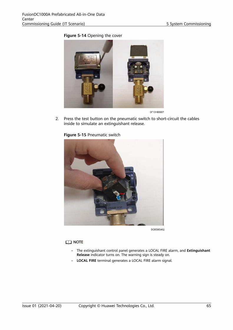
Figure 5-14 Opening the cover
2. Press the test button on the pneumatic switch to short-circuit the cablesinside to simulate an extinguishant release.
Figure 5-15 Pneumatic switch
NO TE
– The extinguishant control panel generates a LOCAL FIRE alarm, and ExtinguishantRelease indicator turns on. The warning sign is steady on.
– LOCAL FIRE terminal generates a LOCAL FIRE alarm signal.
FusionDC1000A Prefabricated All-in-One DataCenterCommissioning Guide (IT Scenario) 5 System Commissioning
Issue 01 (2021-04-20) Copyright © Huawei Technologies Co., Ltd. 65

Figure 5-16 Extinguishant Released indicator on
3. Reset the extinguishant control panel.
NO TE
Wait for one minute and turn the Enable Control key rightward. After the LCDchanges from EEE to Ad, press Reset on the extinguishant control panel to reset theextinguishant control panel.
Figure 5-17 Enable Control position
4. Reset the ejector of the electrical actuator.5. Press Reset again to check whether all fire alarms are cleared. After the
alarms are cleared, turn the Enable Control key leftward.
Step 10 (Optional) Check whether the fire alarm signals are reported to the managementsystem.
Step 11 Reinstall the electrical actuator on the container valve.
----End
5.4 System Power-Off
Prerequisites
The FusionDC1000 is powered on, commissioned, and working properly.
FusionDC1000A Prefabricated All-in-One DataCenterCommissioning Guide (IT Scenario) 5 System Commissioning
Issue 01 (2021-04-20) Copyright © Huawei Technologies Co., Ltd. 66

PreparationsTools: none
Documents: power supply and distribution drawings and parameters
Skill requirement: power distribution engineer
Procedure
Step 1 Power off the FusionDC1000.
NO TICE
● Save parameters before power-off.● Power off the devices in the normal power-off logic sequence.● During the power-off process, there is no fire or other exceptions, but the
extinguishant control panel displays a power failure alarm. Ignore the alarm.● After power-off, all circuit breakers should be OFF.
1. Shut down the loads connected to the rPDU.2. Shut down the ECC800-Pro.3. Shut down smart cooling products.
CA UTION
After the load temperature becomes normal, power off the smart coolingproducts.
4. Switch off the circuit breakers from the end to start of the power supply anddistribution system to power off devices. For details, see the power supply anddistribution system diagram.
5. Switch off the external input power circuit breaker for the FusionDC1000.
----End
FusionDC1000A Prefabricated All-in-One DataCenterCommissioning Guide (IT Scenario) 5 System Commissioning
Issue 01 (2021-04-20) Copyright © Huawei Technologies Co., Ltd. 67

A Acronyms and Abbreviations
A
ASD aspirating smoke detector
ATS automatic transfer switch
C
CE Conformite Europende
P
PDF power distribution frame
PDU power distribution unit
R
rPDU rack power distribution unit
U
UPS uninterruptible power system
FusionDC1000A Prefabricated All-in-One DataCenterCommissioning Guide (IT Scenario) A Acronyms and Abbreviations
Issue 01 (2021-04-20) Copyright © Huawei Technologies Co., Ltd. 68
Copyright © 2022 FDOKUMEN