User Manual (Low voltage) - Huawei Technical Support
234
UPS5000-E-(20 kVA-160 kVA) User Manual (Low voltage) Issue 04 Date 2020-11-10 HUAWEI TECHNOLOGIES CO., LTD. Part Number: 31010RSV
-
Upload
khangminh22 -
Category
Documents
-
view
1 -
download
0
Transcript of User Manual (Low voltage) - Huawei Technical Support

UPS5000-E-(20 kVA-160 kVA)
User Manual (Low voltage)
Issue 04
Date 2020-11-10
HUAWEI TECHNOLOGIES CO., LTD.
Part Number: 31010RSV

Copyright © Huawei Technologies Co., Ltd. 2020. All rights reserved.
No part of this document may be reproduced or transmitted in any form or by any means without priorwritten consent of Huawei Technologies Co., Ltd.
Trademarks and Permissions
and other Huawei trademarks are trademarks of Huawei Technologies Co., Ltd.All other trademarks and trade names mentioned in this document are the property of their respectiveholders.
NoticeThe purchased products, services and features are stipulated by the contract made between Huawei andthe customer. All or part of the products, services and features described in this document may not bewithin the purchase scope or the usage scope. Unless otherwise specified in the contract, all statements,information, and recommendations in this document are provided "AS IS" without warranties, guaranteesor representations of any kind, either express or implied.
The information in this document is subject to change without notice. Every effort has been made in thepreparation of this document to ensure accuracy of the contents, but all statements, information, andrecommendations in this document do not constitute a warranty of any kind, express or implied.
Huawei Technologies Co., Ltd.Address:
Website:
Huawei Industrial Base Bantian, Longgang Shenzhen 518129 People's Republic of China
https://e.huawei.com
Issue 04 (2020-11-10) Copyright © Huawei Technologies Co., Ltd. i

About This Document
PurposeThis document describes the UPS5000-E-(20 kVA–160 kVA) in terms of itsfeatures, performance, working principles, appearance as well as instructions forinstallation, and operation and maintenance (O&M). UPS is short foruninterruptible power system.
Intended AudienceThis document is intended for:
● Sales engineers● Technical support engineers● System engineers● Hardware installation engineers● Commissioning engineers● Data configuration engineers● Maintenance engineers
Symbol ConventionsThe symbols that may be found in this document are defined as follows.
Symbol Description
Indicates a hazard with a high level of risk which,if not avoided, will result in death or seriousinjury.
Indicates a hazard with a medium level of riskwhich, if not avoided, could result in death orserious injury.
Indicates a hazard with a low level of risk which,if not avoided, could result in minor or moderateinjury.
UPS5000-E-(20 kVA-160 kVA)User Manual (Low voltage) About This Document
Issue 04 (2020-11-10) Copyright © Huawei Technologies Co., Ltd. ii

Symbol Description
Indicates a potentially hazardous situation which,if not avoided, could result in equipment damage,data loss, performance deterioration, orunanticipated results.NOTICE is used to address practices not related topersonal injury.
Supplements the important information in themain text.NOTE is used to address information not relatedto personal injury, equipment damage, andenvironment deterioration.
Change HistoryChanges between document issues are cumulative. The latest document issuecontains all the changes made in earlier issues.
Issue 04 (2020-11-10)Adapted the UPS to SmartLi and updated the monitoring user interfaces.
Issue 03 (2020-04-27)Updated the user interface.
Issue 02 (2019-03-13)Updated the part number.
Issue 01 (2017-02-17)This is the first release.
UPS5000-E-(20 kVA-160 kVA)User Manual (Low voltage) About This Document
Issue 04 (2020-11-10) Copyright © Huawei Technologies Co., Ltd. iii

Contents
About This Document................................................................................................................ ii
1 Safety Information.................................................................................................................. 11.1 General Safety.......................................................................................................................................................................... 11.2 Personnel Requirements....................................................................................................................................................... 41.3 Electrical Safety........................................................................................................................................................................41.4 Installation Environment Requirements.......................................................................................................................... 61.5 Mechanical Safety................................................................................................................................................................... 81.6 Device Running Safety........................................................................................................................................................ 101.7 Battery Safety......................................................................................................................................................................... 121.8 Others....................................................................................................................................................................................... 15
2 Overview................................................................................................................................. 162.1 Model Description................................................................................................................................................................ 162.2 Benefits..................................................................................................................................................................................... 172.3 Working Principle..................................................................................................................................................................182.3.1 Conceptual Diagram.........................................................................................................................................................182.3.2 Working Modes.................................................................................................................................................................. 192.3.2.1 Normal Mode.................................................................................................................................................................. 192.3.2.2 Bypass Mode.................................................................................................................................................................... 202.3.2.3 Battery Mode................................................................................................................................................................... 212.3.2.4 Maintenance Bypass Mode.........................................................................................................................................222.3.2.5 ECO Mode......................................................................................................................................................................... 232.4 Overview.................................................................................................................................................................................. 242.4.1 Structure............................................................................................................................................................................... 252.4.2 Control Module.................................................................................................................................................................. 252.4.2.1 Overview........................................................................................................................................................................... 252.4.2.2 ECM..................................................................................................................................................................................... 262.4.2.3 Dry contact card............................................................................................................................................................. 282.4.2.4 Monitoring interface card........................................................................................................................................... 302.5 Typical Configurations......................................................................................................................................................... 352.5.1 Single UPS............................................................................................................................................................................ 352.5.2 1+1 Parallel System.......................................................................................................................................................... 362.5.3 Dual-Bus System................................................................................................................................................................ 36
UPS5000-E-(20 kVA-160 kVA)User Manual (Low voltage) Contents
Issue 04 (2020-11-10) Copyright © Huawei Technologies Co., Ltd. iv

2.6 List of Optional Components............................................................................................................................................37
3 Installation..............................................................................................................................393.1 Installation Preparations.................................................................................................................................................... 393.1.1 Site.......................................................................................................................................................................................... 393.1.1.1 Weight and Dimensions...............................................................................................................................................393.1.1.2 Installation Environment............................................................................................................................................. 403.1.1.3 Installation Clearances................................................................................................................................................. 413.1.2 Tools and Instruments..................................................................................................................................................... 413.1.3 Power Cables.......................................................................................................................................................................433.1.4 Unpacking and Checking................................................................................................................................................ 483.2 Installing a Single UPS........................................................................................................................................................ 503.2.1 Installing the Cabinet....................................................................................................................................................... 503.2.2 Installing Batteries............................................................................................................................................................ 543.2.3 Installing Optional Components.................................................................................................................................. 553.2.3.1 Installing Antiseismic Kits............................................................................................................................................553.2.3.2 Installing an IP21 Component................................................................................................................................... 573.2.4 UPS Cable Connection Reference.................................................................................................................................593.2.5 Routing Cables (60 kVA, 100 kVA).............................................................................................................................. 603.2.5.1 Top Cable Routing......................................................................................................................................................... 603.2.5.2 Bottom Cable Routing.................................................................................................................................................. 653.2.6 Routing Cables (160 kVA).............................................................................................................................................. 703.2.6.1 Top Cable Routing......................................................................................................................................................... 703.2.6.2 Bottom Cable Routing.................................................................................................................................................. 743.2.7 Remote EPO........................................................................................................................................................................ 803.2.8 Connecting Communications Cables.......................................................................................................................... 813.3 Installing a Parallel System............................................................................................................................................... 813.3.1 Installing the UPSs............................................................................................................................................................ 813.3.2 Connecting Power Cables............................................................................................................................................... 823.3.3 Connecting Signal Cables............................................................................................................................................... 853.4 Installation Verification.......................................................................................................................................................86
4 User Interface......................................................................................................................... 894.1 LCD Interface.......................................................................................................................................................................... 894.1.1 Main Menu.......................................................................................................................................................................... 894.1.2 System Info Screen............................................................................................................................................................904.1.2.1 Module Data Screen..................................................................................................................................................... 914.1.2.2 Running............................................................................................................................................................................. 914.1.2.3 Alarms Screen..................................................................................................................................................................954.1.2.4 Settings.............................................................................................................................................................................. 964.1.2.5 Maintenance..................................................................................................................................................................1214.1.2.6 About Screen................................................................................................................................................................. 1264.1.3 System Status................................................................................................................................................................... 1264.1.4 Common Functions........................................................................................................................................................ 126
UPS5000-E-(20 kVA-160 kVA)User Manual (Low voltage) Contents
Issue 04 (2020-11-10) Copyright © Huawei Technologies Co., Ltd. v

4.2 WebUI..................................................................................................................................................................................... 1274.2.1 Login.................................................................................................................................................................................... 1274.2.2 Home................................................................................................................................................................................... 1294.2.3 Monitoring......................................................................................................................................................................... 1294.2.4 Query...................................................................................................................................................................................1394.2.5 System Settings................................................................................................................................................................1404.2.6 Maintenance..................................................................................................................................................................... 1434.3 Old WebUI............................................................................................................................................................................ 1444.3.1 Login.................................................................................................................................................................................... 1444.3.2 Monitoring......................................................................................................................................................................... 1464.3.2.1 Parameter Settings...................................................................................................................................................... 1474.3.2.2 Communication Settings........................................................................................................................................... 1554.3.2.3 Control............................................................................................................................................................................. 1554.3.3 Query...................................................................................................................................................................................1554.3.3.1 Historical Alarms......................................................................................................................................................... 1564.3.3.2 Logs.................................................................................................................................................................................. 1564.3.4 Config.................................................................................................................................................................................. 1564.3.4.1 User Management.......................................................................................................................................................1564.3.4.2 Site Config...................................................................................................................................................................... 1574.3.4.3 RCCMD............................................................................................................................................................................ 1594.3.4.4 Managing the UPS by Using the NMS Complying with RFC1628 Standard........................................... 1674.3.5 Protecting the Server by Using the RCCMD Software........................................................................................1684.3.5.1 Introduction to the Software................................................................................................................................... 1684.3.5.2 RCCMD Event Shutdown and Message Sending.............................................................................................. 1694.3.5.3 UPS Alive Check Function......................................................................................................................................... 170
5 Operations............................................................................................................................ 1735.1 Powering On and Starting the UPS..............................................................................................................................1735.1.1 Powering On the UPS.................................................................................................................................................... 1735.1.2 Initial Startup....................................................................................................................................................................1735.1.2.1 Obtaining Startup Password.................................................................................................................................... 1745.1.2.2 Settings Wizard............................................................................................................................................................ 1745.1.3 Starting the Inverter.......................................................................................................................................................1765.1.4 Powering On Loads........................................................................................................................................................ 1795.1.5 (Optional) Setting Parameters for the BCB Box...................................................................................................1795.2 Shutting Down and Powering Off the UPS............................................................................................................... 1805.3 Starting the UPS in Battery Mode................................................................................................................................ 1825.4 Transferring to Bypass Mode.......................................................................................................................................... 1835.5 Setting ECO Mode.............................................................................................................................................................. 1835.6 Testing Batteries..................................................................................................................................................................1845.6.1 Lead-Acid Battery Test.................................................................................................................................................. 1845.6.1.1 Forced Equalized Charging Test..............................................................................................................................1855.6.1.2 Shallow Discharge Test.............................................................................................................................................. 186
UPS5000-E-(20 kVA-160 kVA)User Manual (Low voltage) Contents
Issue 04 (2020-11-10) Copyright © Huawei Technologies Co., Ltd. vi

5.6.1.3 Capacity Test................................................................................................................................................................. 1875.6.2 Lithium Battery Test....................................................................................................................................................... 1885.6.2.1 Shallow Discharge Test.............................................................................................................................................. 1885.6.2.2 Capacity Test................................................................................................................................................................. 1895.6.3 Test Data Download...................................................................................................................................................... 1905.7 Transferring to Maintenance Bypass Mode............................................................................................................... 1915.8 Transferring from Maintenance Bypass Mode to Normal Mode....................................................................... 1935.9 Performing EPO...................................................................................................................................................................1945.10 Clearing the EPO State...................................................................................................................................................1955.11 Exporting Data.................................................................................................................................................................. 1955.12 Setting Hibernation Mode............................................................................................................................................ 196
6 Routine Maintenance.........................................................................................................1996.1 UPS Maintenance............................................................................................................................................................... 1996.1.1 Monthly Maintenance................................................................................................................................................... 2006.1.2 Quarterly Maintenance................................................................................................................................................. 2006.1.3 Annual Maintenance......................................................................................................................................................2016.2 Battery Maintenance......................................................................................................................................................... 2026.2.1 Precautions for Battery Maintenance...................................................................................................................... 2026.2.2 Monthly Maintenance................................................................................................................................................... 2036.2.3 Quarterly Maintenance................................................................................................................................................. 2046.2.4 Annual Maintenance......................................................................................................................................................205
7 Troubleshooting...................................................................................................................206
8 Technical Specifications.....................................................................................................2098.1 Physical Specifications...................................................................................................................................................... 2098.2 Environmental Specifications......................................................................................................................................... 2098.3 Safety Regulations and EMC.......................................................................................................................................... 2108.4 Mains Input Electrical Specifications........................................................................................................................... 2108.5 Bypass Input Electrical Specifications.......................................................................................................................... 2118.6 Battery Specifications........................................................................................................................................................ 2118.7 Output Electrical Specifications..................................................................................................................................... 2128.8 System Electrical Specifications..................................................................................................................................... 213
A Alarm List............................................................................................................................. 214
B Acronyms and Abbreviations........................................................................................... 224
UPS5000-E-(20 kVA-160 kVA)User Manual (Low voltage) Contents
Issue 04 (2020-11-10) Copyright © Huawei Technologies Co., Ltd. vii

1 Safety Information
1.1 General Safety
StatementBefore installing, operating, and maintaining the equipment, read this documentand observe all the safety instructions on the equipment and in this document.
The "NOTICE", "CAUTION", "WARNING", and "DANGER" statements in thisdocument do not cover all the safety instructions. They are only supplements tothe safety instructions. Huawei will not be liable for any consequence caused bythe violation of general safety requirements or design, production, and usagesafety standards.
Ensure that the equipment is used in environments that meet its designspecifications. Otherwise, the equipment may become faulty, and the resultingequipment malfunction, component damage, personal injuries, or propertydamage are not covered under the warranty.
Follow local laws and regulations when installing, operating, or maintaining theequipment. The safety instructions in this document are only supplements to locallaws and regulations.
Huawei will not be liable for any consequences of the following circumstances:
● Operation beyond the conditions specified in this document● Installation or use in environments which are not specified in relevant
international or national standards● Unauthorized modifications to the product or software code or removal of the
product● Failure to follow the operation instructions and safety precautions on the
product and in this document● Equipment damage due to force majeure, such as earthquakes, fire, and
storms● Damage caused during transportation by the customer● Storage conditions that do not meet the requirements specified in this
document
UPS5000-E-(20 kVA-160 kVA)User Manual (Low voltage) 1 Safety Information
Issue 04 (2020-11-10) Copyright © Huawei Technologies Co., Ltd. 1

General Requirements● Do not install, use, or operate outdoor equipment and cables (including but
not limited to moving equipment, operating equipment and cables, insertingconnectors to or removing connectors from signal ports connected to outdoorfacilities, working at heights, and performing outdoor installation) in harshweather conditions such as lightning, rain, snow, and level 6 or stronger wind.
● Before installing, operating, or maintaining the equipment, remove anyconductive objects such as watches or metal jewelry like bracelets, bangles,and rings to avoid electric shock.
● When installing, operating, or maintaining the equipment, wear personalprotective equipment such as insulation gloves, goggles, and safety clothing,helmet, and shoes, as shown in the following figure.
● Follow the specified procedures for installation, operation, and maintenance.● Before handling a conductor surface or terminal, measure the contact point
voltage and ensure that there is no risk of electric shock.● After installing the equipment, remove idle packing materials such as cartons,
foam, plastics, and cable ties from the equipment area.● In the case of a fire, immediately leave the building or the equipment area,
and turn on the fire alarm bell or make an emergency call. Do not enter thebuilding on fire in any case.
● Do not stop using protective devices. Pay attention to the warnings, cautions,and related precautionary measures in this document and on the equipment.Promptly replace warning labels that have worn out.
● Keep irrelevant people away from the equipment. Only operators are allowedto access the equipment.
● Use insulated tools or tools with insulated handles, as shown in the followingfigure.
UPS5000-E-(20 kVA-160 kVA)User Manual (Low voltage) 1 Safety Information
Issue 04 (2020-11-10) Copyright © Huawei Technologies Co., Ltd. 2

● All cable holes should be sealed. Seal the used cable holes with firestop putty.Seal the unused cable holes with the caps delivered with the cabinet. Thefollowing figure shows the criteria for correct sealing with firestop putty.
● Do not scrawl, damage, or block any warning label on the equipment.● When installing devices, use a torque wrench with a proper measurement
range to tighten bolts. Ensure that the wrench is not skewed and the torqueerror does not exceed 10%.
● Do not work with power on during installation.● Repaint any paint scratches caused during equipment transportation or
installation in a timely manner. Equipment with scratches cannot be exposedto an outdoor environment for a long period of time.
● Before operations, ensure that the equipment is firmly secured to the floor orother solid objects, such as a wall or an installation rack.
● Do not use water to clean electrical components inside or outside of acabinet.
● Do not change the structure or installation sequence of equipment withoutpermission.
● Do not touch a running fan with your fingers, components, screws, tools, orboards before the fan is powered off or stops running.
UPS5000-E-(20 kVA-160 kVA)User Manual (Low voltage) 1 Safety Information
Issue 04 (2020-11-10) Copyright © Huawei Technologies Co., Ltd. 3

Personal Safety● If there is a probability of personal injury or equipment damage during
operations on the equipment, immediately stop the operations, report thecase to the supervisor, and take feasible protective measures.
● To avoid electric shock, do not connect safety extra-low voltage (SELV) circuitsto telecommunication network voltage (TNV) circuits.
● Do not power on the equipment before it is installed or confirmed byprofessionals.
1.2 Personnel Requirements● Personnel who plan to install or maintain Huawei equipment must receive
thorough training, understand all necessary safety precautions, and be able tocorrectly perform all operations.
● Only qualified professionals or trained personnel are allowed to install,operate, and maintain the equipment.
● Only qualified professionals are allowed to remove safety facilities and inspectthe equipment.
● Personnel who will operate the equipment, including operators, trainedpersonnel, and professionals, should possess the local national requiredqualifications in special operations such as high-voltage operations, workingat heights, and operations of special equipment.
● Professionals: personnel who are trained or experienced in equipmentoperations and are clear of the sources and degree of various potentialhazards in equipment installation, operation, maintenance
● Trained personnel: personnel who are technically trained, have requiredexperience, are aware of possible hazards on themselves in certain operations,and are able to take protective measures to minimize the hazards onthemselves and other people
● Operators: operation personnel who may come in contact with theequipment, except trained personnel and professionals
● Only professionals or authorized personnel are allowed to replace theequipment or components (including software).
1.3 Electrical Safety
Grounding● For the equipment that needs to be grounded, install the ground cable first
when installing the equipment and remove the ground cable last whenremoving the equipment.
● Do not damage the ground conductor.● Do not operate the equipment in the absence of a properly installed ground
conductor.● Ensure that the equipment is connected permanently to the protective
ground. Before operating the equipment, check its electrical connection toensure that it is securely grounded.
UPS5000-E-(20 kVA-160 kVA)User Manual (Low voltage) 1 Safety Information
Issue 04 (2020-11-10) Copyright © Huawei Technologies Co., Ltd. 4

General RequirementsUse dedicated insulated tools when performing high-voltage operations.
AC and DC Power
D ANGER
Do not connect or disconnect power cables with power on. Transient contactbetween the core of the power cable and the conductor will generate electric arcsor sparks, which may cause fire or personal injury.
● If a "high electricity leakage" tag is attached on the equipment, ground theprotective ground terminal on the equipment enclosure before connecting theAC power supply; otherwise, electric shock as a result of electricity leakagemay occur.
● Before installing or removing a power cable, turn off the power switch.● Before connecting a power cable, check that the label on the power cable is
correct.● If the equipment has multiple inputs, disconnect all the inputs before
operating the equipment.● A circuit breaker equipped with a residual current device (RCD) is not
recommended.● A damaged power cable must be replaced by the manufacturer, service agent,
or professionals to avoid risks.● High voltage operations and installation of AC-powered facilities must be
performed by qualified personnel.
Cabling● When routing cables, ensure that a distance of at least 30 mm exists between
the cables and heat-generating components or areas. This prevents damageto the insulation layer of the cables.
● Do not route cables behind the air intake and exhaust vents of theequipment.
● Ensure that cables meet the VW-1 or ZB flame spread rating requirements orhigher.
● Bind cables of the same type together. When routing cables of different types,ensure that they are at least 30 mm away from each other.
● If an AC input power cable is connected to the cabinet from the top, bend thecable in a U shape outside the cabinet and then route it into the cabinet.
● When the temperature is low, violent impact or vibration may damage theplastic cable sheathing. To ensure safety, comply with the followingrequirements:– Cables can be laid or installed only when the temperature is higher than
0°C. Handle cables with caution, especially at a low temperature.– Cables stored at subzero temperatures must be stored at room
temperature for at least 24 hours before they are laid out.
UPS5000-E-(20 kVA-160 kVA)User Manual (Low voltage) 1 Safety Information
Issue 04 (2020-11-10) Copyright © Huawei Technologies Co., Ltd. 5

● Do not perform any improper operations, for example, dropping cablesdirectly from a vehicle.
● When selecting, connecting, and routing cables, follow local safety regulationsand rules.
ESD
NO TICE
The static electricity generated by human bodies may damage the electrostatic-sensitive components on boards, for example, the large-scale integrated (LSI)circuits.
● Wear ESD gloves or a well-grounded ESD wrist strap when touching thedevice or handling boards or application-specific integrated circuits (ASICs).
● When holding a board, hold its edge without touching any components. Donot touch the components with your bare hands.
● Package boards with ESD packaging materials before storing or transportingthem.
Figure 1-1 Wearing an ESD wrist strap
Neutral-Ground VoltageIt is recommended that the three-phase loads be equalized and the neutral-ground voltage be kept at less than 2 V to meet power distribution requirements.
1.4 Installation Environment Requirements● To prevent fire due to high temperature, ensure that the ventilation vents or
heat dissipation system are not blocked when the equipment is running.● Install the equipment in an area far away from liquids. Do not install it under
areas prone to condensation, such as under water pipes and air exhaust vents,or areas prone to water leakage, such as air conditioner vents, ventilation
UPS5000-E-(20 kVA-160 kVA)User Manual (Low voltage) 1 Safety Information
Issue 04 (2020-11-10) Copyright © Huawei Technologies Co., Ltd. 6

vents, or feeder windows of the equipment room. Ensure that no liquid entersthe equipment to prevent faults or short circuits.
● If any liquid is detected inside the equipment, immediately disconnect thepower supply and contact the administrator.
● Do not expose the equipment to flammable or explosive gas or smoke. Donot perform any operation on the equipment in such environments.
● Ensure that the equipment room provides good heat insulation, and the wallsand floor are dampproof.
● Install a rat guard at the door of the equipment room.
Installation at Heights● Working at heights refers to operations that are performed at least 2 meters
above the ground.
● Do not work at heights if the steel pipes are wet or other potential dangerexists. After the preceding conditions no longer exist, the safety director andrelevant technical personnel need to check the involved equipment. Operatorscan begin working only after obtaining consent.
● When working at heights, comply with local relevant laws and regulations.
● Only trained and qualified personnel are allowed to work at heights.
● Before working at heights, check the climbing tools and safety gears such assafety helmets, safety belts, ladders, springboards, scaffolding, and liftingequipment. If they do not meet the requirements, take corrective measures ordisallow working at heights.
● Wear personal protective equipment such as the safety helmet and safety beltor waist rope and fasten it to a solid structure. Do not mount it on aninsecure moveable object or metal object with sharp edges. Make sure thatthe hooks will not slide off.
● Set a restricted area and eye-catching signs for working at heights to warnaway irrelevant personnel.
● Carry the operation machinery and tools properly to prevent them fromfalling off and causing injuries.
● Personnel involving working at heights are not allowed to throw objects fromthe height to the ground, or vice versa. Objects should be transported bytough slings, hanging baskets, highline trolleys, or cranes.
● Ensure that guard rails and warning signs are set at the edges and openingsof the area involving working at heights to prevent falls.
● Do not pile up scaffolding, springboards, or other sundries on the groundunder the area involving working at heights. Do not allow people to stay orpass under the area involving working at heights.
● Inspect the scaffolding, springboards, and workbenches used for working atheights in advance to ensure that their structures are solid and notoverloaded.
● Any violations must be promptly pointed out by the site manager or safetysupervisor and the involved personnel should be prompted for correction.Personnel who fail to stop violations will be forbidden from working.
UPS5000-E-(20 kVA-160 kVA)User Manual (Low voltage) 1 Safety Information
Issue 04 (2020-11-10) Copyright © Huawei Technologies Co., Ltd. 7

1.5 Mechanical Safety
Hoisting Devices● Do not walk under hoisted objects.● Only trained and qualified personnel should perform hoisting operations.● Check that hoisting tools are available and in good condition.● Before hoisting objects, ensure that hoisting tools are firmly secured onto a
load-bearing object or wall.● Ensure that the angle formed by two hoisting cables is no more than 90
degrees, as shown in the following figure.
● Do not drag steel ropes and hoisting tools or bump hoisted objects againsthard objects during hoisting.
Using Ladders● Use wooden or fiberglass ladders when you need to perform live working at
heights.● When a step ladder is used, ensure that the pull ropes are secured and the
ladder is held firm.● Before using a ladder, check that it is intact and confirm its load bearing
capacity. Do not overload it.● Ensure that the ladder is securely positioned. The recommended angle for a
ladder against the floor is 75 degrees, as shown in the following figure. Anangle rule can be used to measure the angle. Ensure that the wider end of theladder is at the bottom, or protective measures have been taken at thebottom to prevent the ladder from sliding.
UPS5000-E-(20 kVA-160 kVA)User Manual (Low voltage) 1 Safety Information
Issue 04 (2020-11-10) Copyright © Huawei Technologies Co., Ltd. 8

● When climbing a ladder, take the following precautions to reduce risks andensure safety:
– Keep your body steady.
– Do not climb higher than the fourth rung of the ladder from the top.
– Ensure that your body's center of gravity does not shift outside the legsof the ladder.
Drilling Holes
When drilling holes into a wall or floor, observe the following safety precautions:
NO TICE
Do not drill holes into the equipment. Doing so may affect the electromagneticshielding of the equipment and damage components or cables inside. Metalshavings from drilling may short-circuit boards inside the equipment.
● Obtain the consent from the customer and subcontractor before drilling.
● Wear goggles and protective gloves when drilling holes.
● When drilling holes, protect the equipment from shavings. After drilling, cleanup any shavings that have accumulated inside or outside the equipment.
Moving Heavy Objects
D ANGER
When removing a heavy or unstable component from a cabinet, be aware ofunstable or heavy objects on the cabinet.
● Be cautious to avoid injury when moving heavy objects.
UPS5000-E-(20 kVA-160 kVA)User Manual (Low voltage) 1 Safety Information
Issue 04 (2020-11-10) Copyright © Huawei Technologies Co., Ltd. 9

● When moving the equipment by hand, wear protective gloves to preventinjuries.
● Move or lift the equipment by holding its handles or lower edges. Do not holdthe handles of modules (such as power supply units, fans, and boards) thatare installed in the equipment because they cannot support the weight of theequipment.
● Avoid scratching the cabinet surface or damaging cabinet components andcables during equipment transportation.
● When transporting the equipment using a forklift truck, ensure that the forksare properly positioned to ensure that the equipment does not topple. Beforemoving the equipment, secure it to the forklift truck using ropes. Whenmoving the equipment, assign dedicated personnel to take care of it.
● Choose railways, sea, or a road with good condition for transportation toensure equipment safety. Avoid tilt or jolt during transportation.
● Move a cabinet with caution. Any bumping or falling may damage theequipment.
1.6 Device Running SafetyThe UPS is used for commercial and industrial purposes only. It cannot be used asa power supply for life support devices.
For power supply systems that are critical to significant economic interests orpublic order, such as the national computing center, military command system,emergency command center, railway signal system and control center, civilaviation and air traffic control center, airport command center, financial clearingcenter, and transaction center, the Tier 4 or 3 power architecture specified inTIA-942 must be used. That is, two power supplies must be used to supply powerto loads.
Ensure that the equipment is used in an environment that meets the productdesign specifications (including power grid, temperature, and humidity).Otherwise, the equipment may become faulty, and the resulting equipmentmalfunction and component damage are not covered under the warranty.
The UPS operating environment must meet the requirements for the climateindicator, mechanically active substance indicator, and chemically active substanceindicator in ETSI EN 300 019-1 class 3.6.
UPS5000-E-(20 kVA-160 kVA)User Manual (Low voltage) 1 Safety Information
Issue 04 (2020-11-10) Copyright © Huawei Technologies Co., Ltd. 10

NO TICE
● This is a category C3 UPS product for commercial and industrial application inthe second environment − installation restrictions or additional measures maybe needed to prevent disturbances.
● After unpacking the UPS, you are advised to power on the UPS as soon aspossible. If you temporarily do not use the UPS, take appropriate measures toprevent moisture, dust, and foreign matter from entering the UPS.
● After unpacking batteries, you are advised to connect the battery supply assoon as possible. If you temporarily do not use the batteries, store them in adry and clean environment. If batteries are stored for more than 90 days,charge them in time. Otherwise, the battery lifespan may be affected.
● Install the UPS in an area far away from liquids. Do not install it under areasprone to water leakage, such as air conditioner vents, ventilation vents, orfeeder windows of the equipment room. Ensure that no liquid enters the UPSto prevent short circuits. Ensure that there is no condensation inside theequipment or equipment room.
● If any liquid is detected inside the equipment, immediately disconnect thepower supply and contact the administrator.
D ANGER
● Do not expose the equipment to flammable or explosive gas or smoke. Do notperform any operation on the equipment in such environments.
● During installation and maintenance, ensure that sundries do not enter theUPS. Otherwise, equipment damage, load power derating, power failure, andpersonal injury may occur.
If the valid mains voltage exceeds 320 V AC, the UPS may be damaged.
A UPS can be used to serve resistive-capacitive loads, resistive loads, and micro-inductive loads. It is recommended that a UPS not be used for pure capacitiveloads, pure inductive loads, and half-wave rectification loads. A UPS does notapply to regeneration loads.
Any operation on any electrical device in an environment that has inflammable aircan cause extreme danger. Strictly obey the operating environmental requirementsspecified in related user manuals when using or storing the device.
The UPS can be configured with a backfeed protection dry contact to work withan external automatic circuit breaker, preventing the voltage from flowing back toinput terminals over static bypass circuits. If the installation and maintenancepersonnel do not need backfeed protection, paste labels on external mains andbypass input switches, informing that the UPS is connected to a backfeedprotection card. Disconnect the backfeed protection card from the UPS beforeoperating the UPS.
Do not use the UPS in the following places:
UPS5000-E-(20 kVA-160 kVA)User Manual (Low voltage) 1 Safety Information
Issue 04 (2020-11-10) Copyright © Huawei Technologies Co., Ltd. 11

● Environments that are close to flammable or explosive materials, dust,corrosive gases or dust, conductive or magnetic dust, abnormal vibration, orcollision
● Rooms or outdoor environments where temperature and humidity are notcontrolled (with high temperature, low temperature, moisture, direct sunlight,or heat sources)
● Non-confined environments near the ocean (0–3.7 km) and indoor or semi-indoor environments where the temperature and humidity are notcontrollable, such as simple equipment rooms, civil houses, garages, corridors,and direct ventilation cabinets near the sea; or houses with only roofs, railwaystation platforms, gymnasiums, and aquariums
● Environments that are conducive for the growth of microorganisms such asfungus or mildew
● Environments where rodents (such as mice) and insects exist
1.7 Battery Safety
Basic Requirements
Before operating batteries, carefully read the safety precautions for batteryhandling and master the correct battery connection methods.
D ANGER
● Do not expose batteries at high temperatures or around heat-generatingdevices, such as sunlight, fire sources, transformers, and heaters. Excessive heatexposure may cause the batteries to explode.
● Do not burn batteries. Otherwise, the batteries may explode.● To avoid leakage, overheating, fire, or explosions, do not disassemble, alter, or
damage batteries, for example, insert sundries into batteries or immersebatteries in water or other liquids.
● Wear goggles, rubber gloves, and protective clothing to prevent skin contactwith electrolyte in the case of electrolyte overflow. If a battery leaks, protectthe skin or eyes from the leaking liquid. If the skin or eyes come in contactwith the leaking liquid, wash it immediately with clean water and go to thehospital for medical treatment.
● Use dedicated insulated tools.● Move batteries in the required direction. Do not place a battery upside down
or tilt it.● Keep the battery loop disconnected during installation and maintenance.● Use batteries of specified models. Using batteries of other models may
damage the batteries.● Dispose of waste batteries in accordance with local laws and regulations. Do
not dispose of batteries as household waste. If a battery is disposed ofimproperly, it may explode.
UPS5000-E-(20 kVA-160 kVA)User Manual (Low voltage) 1 Safety Information
Issue 04 (2020-11-10) Copyright © Huawei Technologies Co., Ltd. 12

● The site must be equipped with qualified fire extinguishing facilities, such asfirefighting sands and powder fire extinguishers.
NO TICE
To ensure battery safety and battery management accuracy, use batteries providedwith the UPS by Huawei. Huawei is not responsible for any battery faults causedby batteries not provided by Huawei.
Battery Installation
Before installing batteries, observe the following safety precautions:
● Install batteries in a well-ventilated, dry, and cool environment that is faraway from heat sources, flammable materials, moistures, extensive infraredradiation, organic solvents, and corrosive gases. Take fire preventionmeasures.
● Place and secure batteries horizontally.● Note the polarities when installing batteries. Do not short-circuit the positive
and negative poles of the same battery or battery string. Otherwise, thebattery may be short-circuited.
● Check battery connections periodically, ensuring that all bolts are securelytightened.
● When installing batteries, do not place installation tools on the batteries.
Battery Short Circuit
D ANGER
Battery short circuits can generate high instantaneous current and release a greatamount of energy, which may cause equipment damage or personal injury.
To avoid battery short-circuit, do not maintain batteries with power on.
Flammable Gas
NO TICE
● Do not use unsealed lead-acid batteries.● To prevent fire or corrosion, ensure that flammable gas (such as hydrogen) is
properly exhausted for lead-acid batteries.
Lead-acid batteries emit flammable gas when used. Ensure that batteries are keptin a well-ventilated area and take preventive measures against fire.
UPS5000-E-(20 kVA-160 kVA)User Manual (Low voltage) 1 Safety Information
Issue 04 (2020-11-10) Copyright © Huawei Technologies Co., Ltd. 13

Battery Leakage
NO TICE
Battery overheating causes deformation, damage, and electrolyte spillage.
WARNING
When the electrolyte overflows, absorb and neutralize the electrolyte immediately.When moving or handling a battery whose electrolyte leaks, note that the leakingelectrolyte may hurt human bodies.
● If the battery temperature exceeds 60°C, check for and promptly handle anyleakage.
● Electrolyte overflow may damage the equipment. It will corrode metal partsand boards, and ultimately damage the boards.
● If the electrolyte overflows, follow the instructions of the batterymanufacturer or neutralize the electrolyte by using sodium bicarbonate(NaHCO3) or sodium carbonate (Na2CO3).
Lithium Battery
The safety precautions for lithium batteries are similar to those for lead-acidbatteries except that you also need to note the precautions described in thissection.
WARNING
There is a risk of explosion if a battery is replaced with an incorrect model.
● A battery can be replaced only with a battery of the same or similar modelrecommended by the manufacturer.
● When handling a lithium battery, do not place it upside down, tilt it, or bumpit with other objects.
● Keep the lithium battery loop disconnected during installation andmaintenance.
● Do not charge a battery when the ambient temperature is below the lowerlimit of the operating temperature (charging is forbidden at 0°C). Low-temperature charging may cause crystallization, which will result in a shortcircuit inside the battery.
● Use batteries within the allowed temperature range; otherwise, the batteryperformance and safety will be compromised.
● Do not throw a lithium battery in fire.● When maintenance is complete, return the waste lithium battery to the
maintenance office.
UPS5000-E-(20 kVA-160 kVA)User Manual (Low voltage) 1 Safety Information
Issue 04 (2020-11-10) Copyright © Huawei Technologies Co., Ltd. 14

1.8 Others● Exercise caution when manually shutting down the UPS inverter for
transferring to bypass mode, or when adjusting the UPS output voltage levelor frequency. Doing so may affect the power supply to equipment.
● Exercise caution when setting battery parameters. Incorrect settings will affectthe power supply and battery lifespan.
UPS5000-E-(20 kVA-160 kVA)User Manual (Low voltage) 1 Safety Information
Issue 04 (2020-11-10) Copyright © Huawei Technologies Co., Ltd. 15

2 Overview
2.1 Model Description
Figure 2-1 UPS model number
Table 2-1 Model number details
No. Item Description
1 Product category UPS
2 UPS family 5000
3 UPS subcategory E
4 Output capacity ● 60K: 60 kVA● 100K: 100 kVA● 160K: 160 kVA
5 Rack type ● F60: 60 kVA rack● F100: 100 kVA rack● F160: 160 kVA rack
This document describes the following UPS models:
● UPS5000-E-60K-F60
Output capacity: 20 kVA, 40 kVA, or 60 kVA
UPS5000-E-(20 kVA-160 kVA)User Manual (Low voltage) 2 Overview
Issue 04 (2020-11-10) Copyright © Huawei Technologies Co., Ltd. 16

● UPS5000-E-100K-F100Output capacity: 20 kVA, 40 kVA, 60 kVA, 80 kVA, or 100 kVA
● UPS5000-E-160K-F160Output capacity: 20 kVA, 40 kVA, 60 kVA, 80 kVA, 100 kVA, 120 kVA, 140 kVA,or 160 kVA
NO TE
● The UPS5000-E-60K-F60 with a capacity of 20 kVA, 40 kVA, or 60 kVA has the samespecifications as the UPS5000-E-100K-F100 with a capacity of 20 kVA, 40 kVA, or 60kVA respectively. The UPS5000-E-60K-F60 can respectively expand to a maximum of 60kVA.
● The UPS5000-E-100K-F100 can expand to a maximum of 100 kVA. When mentioningthe UPS5000-E-100K-F100, this document emphasizes its output capacity of 80 kVA or100 kVA.
● The UPS5000-E-160K-F160 can expand to a maximum of 160 kVA and is compatibledownwards to 20 kVA. This document focuses on the UPS with a capacity of 120 kVA,140 kVA, or 160 kVA.
2.2 Benefits
High Stability and Reliability● The UPS is suitable for poor power grids because it supports a wide range of
input frequencies which is 40–70Hz. The UPS works at full load when thephase voltage is 96–150 V AC and is linearly derated when the phase voltageis 80–96 V AC (excluding 96 V AC).
● The UPS5000-E has 5 kA lightning protection, higher than the industry level 2kA.
● The control module (CM) uses a redundant design. Fans have high faulttolerance capability: When a single fan is faulty, the UPS5000-E works at 50%load; when two fans are faulty, the UPS5000-E works at 30% load.
● The UPS5000-E has a high inverter overload capability.– 105% < load ≤ 110%: transfer to bypass mode after 60 min– 110% < load ≤ 125%: transfer to bypass mode after 10 min– 125% < load ≤ 150%: transfer to bypass mode after 1 min
● The UPS5000-E has a high bypass overload capability.– Load ≤ 135%: run continuously in bypass mode at 30°C or less– 1000% load: run in bypass mode for 100 ms
High Flexibility and Intelligent Management● The built-in parallel card supports parallel connection of UPS5000-Es. Built-in
bus synchronization controllers (BSCs) support dual-bus configuration.● Intelligent power mode allows you to intelligently control the diesel generator
(D.G.) and ensures uninterruptible power supply. The D.G. connection has twoscenarios: use with an AC transfer switch (ATS) and reuse.
● The UPS5000-E intelligently manages batteries. The number of batteries isadjustable. Batteries have a high fault tolerance capability and are easy tomaintain. All these features help increase the battery lifespan by 50%.
UPS5000-E-(20 kVA-160 kVA)User Manual (Low voltage) 2 Overview
Issue 04 (2020-11-10) Copyright © Huawei Technologies Co., Ltd. 17

● The UPS5000-E provides a variety of optional components to address variouscustomer requirements.
Ease of Use● The UPS5000-E is maintained from the front. UPS5000-E-60K-F60 and
UPS5000-E-100K-F100 can be installed back to back or in a row against thewall to save space.
● The UPS5000-E-100 kVA allows you to route cables from the top and bottom.The UPS5000-E-160 kVA allows you to route cables from the bottom; if youinstall a top entry cabinet, you can also route cables from the top.
● A user-friendly 7-inch liquid crystal display (LCD) provides the UPS5000-Estatus and operating data.
● If a surge protection box is configured, the UPS5000-E can provide the 5 kAsurge protection capability. If a surge protection box (20 kA) is configured, theUPS5000-E can provide level C surge protection.
2.3 Working PrincipleNO TE
● indicates an input mode.
● indicates the energy flow direction.
2.3.1 Conceptual DiagramThe UPS5000 is an online product. It uses a modular design, which facilitatesmaintenance and capacity expansion. The UPS5000 uses the digital signalprocessing (DSP) technology for intelligent control. Its power module consists of arectifier, inverter, and DC/DC converter. The UPS5000 converts inputs into purehigh-quality sine wave outputs by using the high-frequency switching technology.
UPS5000-E-(20 kVA-160 kVA)User Manual (Low voltage) 2 Overview
Issue 04 (2020-11-10) Copyright © Huawei Technologies Co., Ltd. 18

Figure 2-2 UPS conceptual diagram
2.3.2 Working Modes
2.3.2.1 Normal ModeIn normal mode, the rectifier converts AC power into DC power, then the inverterconverts DC power into high-precision AC outputs. The conversions protect loadsfrom interference such as input harmonics, glitches, and voltage transients.
UPS5000-E-(20 kVA-160 kVA)User Manual (Low voltage) 2 Overview
Issue 04 (2020-11-10) Copyright © Huawei Technologies Co., Ltd. 19

Figure 2-3 UPS conceptual diagram in normal mode
2.3.2.2 Bypass ModeThe UPS automatically transfers to bypass mode upon detecting power moduleovertemperature, overload, or other faults that may cause the inverter to shutdown. The bypass power supply is not protected by the UPS which means it maybe affected by mains outage, and incorrect AC voltage or frequency.
UPS5000-E-(20 kVA-160 kVA)User Manual (Low voltage) 2 Overview
Issue 04 (2020-11-10) Copyright © Huawei Technologies Co., Ltd. 20

Figure 2-4 UPS conceptual diagram in bypass mode
2.3.2.3 Battery ModeIf the mains input is abnormal or the rectifier becomes abnormal, the UPStransfers to battery mode. The power module obtains DC power from batteries,and the power is converted into AC output by the inverter.
UPS5000-E-(20 kVA-160 kVA)User Manual (Low voltage) 2 Overview
Issue 04 (2020-11-10) Copyright © Huawei Technologies Co., Ltd. 21

Figure 2-5 UPS conceptual diagram in battery mode
2.3.2.4 Maintenance Bypass ModeWhen the UPS works in maintenance bypass mode, the current flows through themaintenance bypass instead of the power module. You can maintain the circuitinside the cabinet.
UPS5000-E-(20 kVA-160 kVA)User Manual (Low voltage) 2 Overview
Issue 04 (2020-11-10) Copyright © Huawei Technologies Co., Ltd. 22

Figure 2-6 UPS conceptual diagram in maintenance bypass mode
2.3.2.5 ECO ModeThe economic control operation (ECO) mode is an economical working mode,which can be configured on the LCD or web user interface (WebUI). In ECO mode,when the bypass input is within the ECO voltage and frequency ranges and otherECO power supply conditions are met, the UPS works in bypass mode and theinverter is in standby state. When the bypass voltage is outside the ECO voltagerange, the UPS transfers from bypass mode to normal mode. In bypass mode ornormal mode, the rectifier keeps working and charges batteries using a charger.The ECO mode delivers a high efficiency.
UPS5000-E-(20 kVA-160 kVA)User Manual (Low voltage) 2 Overview
Issue 04 (2020-11-10) Copyright © Huawei Technologies Co., Ltd. 23

Figure 2-7 UPS conceptual diagram in ECO mode
NO TE
Manual startup is required to ensure that the inverter is in standby state and the powerflow has reached the inverter.
2.4 Overview
UPS5000-E-(20 kVA-160 kVA)User Manual (Low voltage) 2 Overview
Issue 04 (2020-11-10) Copyright © Huawei Technologies Co., Ltd. 24

2.4.1 Structure
Figure 2-8 Front view of the UPS5000-E-160K-F160 (with the door open)
(1) Monitor displayunit (MDU)
(2) Standby panels (3) Maintenancebypass switch
(4) Power distributionsubrack cover
(5) Control Module(CM)
(6) Bypass module (7) Power modules
NO TE
The UPS5000-E-160K-F160 cabinet is taken here as an example.
2.4.2 Control Module
2.4.2.1 OverviewIn a standard configuration, the control module consists of two ECMs, one drycontact card, and one monitoring interface card (from left to right). The four cards
UPS5000-E-(20 kVA-160 kVA)User Manual (Low voltage) 2 Overview
Issue 04 (2020-11-10) Copyright © Huawei Technologies Co., Ltd. 25

are hot swappable. One subrack is reserved above the dry contact card. Abackfeed protection card or dry contact extended card can be inserted into thissubrack.
Figure 2-9 Signal panel on the control module
(1) Ground terminal (2) Parallel port 1 (3) BSC port 1 (4) Ready switch onECM 1
(5) Indicators for ECM1
(6) Parallel port 2 (7) BSC port 2 (8) Ready switch onECM 2
(9) Indicators for ECM2
(10) Dry contact card (11) Dry contacts (12) MDU port
(13) RS485 port (14) Fast Ethernet (FE)port
(15) COM2 port (16) COM1 port
(17) Batterytemperature sensorport
(18) Optional cardsubrack cover
NO TE
Ports are protected by a security mechanism.
2.4.2.2 ECM
AppearanceThe control module consists of two energy control modules (ECMs) in active/standby mode.
Figure 2-10 ECM
UPS5000-E-(20 kVA-160 kVA)User Manual (Low voltage) 2 Overview
Issue 04 (2020-11-10) Copyright © Huawei Technologies Co., Ltd. 26

Table 2-2 Ports on the ECM
Silk Screen Description
PARALLEL The PARALLEL port transmits parallel signals between racks.
BSC The BSC port is used in a dual-bus system to synchronizeoutput frequencies and phases between UPS systems, ensuringthat two buses can switch with each other.BSC cables are hot-swappable.
NO TE
For a single UPS, the parallel cable is not needed.
Table 2-3 Indicator description
Indicator Color Status Description
NORMAL Green Steady on This ECM is the active ECM.
Blinking at0.5 Hz
This ECM is the standby ECM and it isready.
Off This ECM is not ready or the software ofthis ECM is being upgraded.
Blinking at 4Hz
The software of the ECM is beingupgraded or not configured.
ALM Yellow Steady on The ECM has a minor alarm, but it doesnot need to be replaced.
Off The ECM has no minor alarm or thesoftware of the ECM is being upgraded.
FAULT Red Steady on The ECM has a critical alarm.
Off The ECM has no critical alarm or thesoftware of the ECM is being upgraded.
Functions● As a control interface for the entire system, the ECM communicates with each
module and provides a bus to communicate with the dry contact card. TheECM ensures equalized output currents between modules so that load poweris equally shared.
● Provides module running information for the MDU.● Controls the running of a single UPS5000 and a parallel system, and reports
the UPS5000 status information to other monitoring modules.
UPS5000-E-(20 kVA-160 kVA)User Manual (Low voltage) 2 Overview
Issue 04 (2020-11-10) Copyright © Huawei Technologies Co., Ltd. 27
● The system provides three types of CAN communication: monitoring CANcommunication, intra-rack parallel CAN communication, and inter-rackparallel CAN communication.
Figure 2-11 Logical connections for CAN communication
Specifications● Hot-swappable● 1 U high
2.4.2.3 Dry contact card
Appearance
Figure 2-12 Dry contact card
Table 2-4 Ports on the dry contact card
Silk Screen Description Status InitialStatus
BTG Port for detecting batterygrounding faults
● Connected:batterygrounding fault
● Disconnected:no batterygrounding fault
Disconnected
0V Port for signal ground
UPS5000-E-(20 kVA-160 kVA)User Manual (Low voltage) 2 Overview
Issue 04 (2020-11-10) Copyright © Huawei Technologies Co., Ltd. 28

Silk Screen Description Status InitialStatus
GEN Port for detecting dieselgenerator (D.G.) mode
● Connected: D.G.mode
● Disconnected:non-D.G. mode
Disconnected
0V Port for signal ground
BCB_OL Port for detecting theBCB box
● Grounded: BCBbox connected
● Disconnected:BCB box notconnected
Grounded
BCB_STA Port for monitoring thebattery switch
● Connected:battery switchON
● Disconnected:battery switchOFF
Disconnected
BCB_DRV Controls battery circuitbreaker trip. When thevoltage is +12 V, thecircuit breaker trips.
● 0 V: batteryswitch nottripped
● 12 V: batteryswitch tripped
0 V
BCB_0V Port for signal ground
EPO_NO Emergency power-off(EPO) port
If the normallyopen (NO) port isconnected to theEPO_12V port, EPOis triggered.
Disconnected
EPO_12V +12 V
EPO_NC EPO port If the normallyclosed (NC) port isdisconnected fromthe EPO_12V port,EPO is triggered.
Connected
EPO_12V +12 V
SWITCHSTATUS_OUT
Port for monitoring theUPS output circuitbreaker
● Connected:circuit breakerON
● Disconnected:circuit breakerOFF
Connected
SWITCHSTATUS_0V
Port for signal ground
SWITCHSTATUS_MT
Port for monitoring themaintenance circuitbreaker
● Disconnected:circuit breakerON
● Connected:circuit breakerOFF
Disconnected
SWITCHSTATUS_0V
Port for signal ground
UPS5000-E-(20 kVA-160 kVA)User Manual (Low voltage) 2 Overview
Issue 04 (2020-11-10) Copyright © Huawei Technologies Co., Ltd. 29

Silk Screen Description Status InitialStatus
SWITCHSTATUS_BP
Port for monitoring thebypass input circuitbreaker
● Connected:circuit breakerON
● Disconnected:circuit breakerOFF
Connected
SWITCHSTATUS_0V
Port for signal ground
SPD Port for monitoring theinput AC surge protectivedevice (SPD)
● Connected: SPDenabled
● Disconnected:SPD disabled
Connected
0V Port for signal ground
NO TE
● The dry contact interface card takes effect only after it is set on the monitoring system.Set the unused dry contact signal to the unused status.
● Set the EPO port to NO or NC as required.● When multiple UPSs are paralleled, all dry contact signals to be used need to connect to
each UPS.● Single cables require dual-insulated twisted cables. If the length of a power cable is
within 25–50 m, its cross-sectional area must be 0.5 mm2 to 1.5 mm2.
FunctionsThe dry contact card allows the UPS to detect and manage the switch status ofthe battery system (including the external battery switch) and implement remoteemergency power-off (EPO).
Specifications● Hot-swappable● 0.5 U high
2.4.2.4 Monitoring interface card
NO TICE
● The FE port resembles the RS485 port. Follow the silk screen when connectingcommunications cables as, if the RS485 port is mistaken for the FE port duringcable connection, the WebUI cannot be connected. Conversely, if the FE port ismistaken for the RS485 port during cable connection, RS485 communicationfails.
● Dry contact signals take effect after you set them. Disable unused dry contactsignals on the monitoring system.
● In a parallel system, ensure that used dry contacts properly connect to eachUPS.
UPS5000-E-(20 kVA-160 kVA)User Manual (Low voltage) 2 Overview
Issue 04 (2020-11-10) Copyright © Huawei Technologies Co., Ltd. 30

The monitoring interface card provides external ports as well as monitoring andcontrol functions for the MDU. The ports include the ambient temperature andhumidity sensor port, iBattery port, FE port, battery temperature monitoring port,and network management port. The MDU monitors the UPS, allows users to setparameters, delivers commands, reports information, and displays the UPS keyinformation and parameters on the LCD.
Figure 2-13 Monitoring interface card
NO TE
DO_1 to DO_4 meet the maximum voltage and current requirements of 30 V DC/1 A or 60V DC/0.5 A.
Table 2-5 Ports on the monitoring interface card
Port SilkScreen
Description
DO_1 NO ● DO_1, DO_2, DO_3, and DO_4 indicatealarm outputs. Their default values areCritical alarm, Minor alarm, Bypassmode, and Battery mode, respectively.
● It can be set to Disable, Critical alarm,Minor alarm, Bypass mode, Batterymode, Low batt. volt., Low batterySOC, Abnormal mains, Sys maintbreaker enable, Sys outp breakerenable, Maint. breaker closed, Nopower supplied, Mains supplies power,ECO mode, Battery test, and Batt. Volt.Below Thres..
● Configure power segment settings basedon backup time.
COM
DO_2 NO
COM
DO_3 NO
COM
DO_4 NO
COM
DB26 MDU Provides FE, RS485, I2C, and CAN signals.
Battery temperaturesensor port
B_TEMP Connects to an indoor battery temperaturesensor.
UPS5000-E-(20 kVA-160 kVA)User Manual (Low voltage) 2 Overview
Issue 04 (2020-11-10) Copyright © Huawei Technologies Co., Ltd. 31

Port SilkScreen
Description
Southboundcommunicationsport 1
COM1 ● Supported protocol: Modbus-RTU.● Connects to an ambient temperature and
humidity sensor over two wires.
Southboundcommunicationsport 2
COM2 ● Supported protocol: Modbus-RTU.● Connects to a southbound device, such
as an iBattery.
Network port FE ● Supported protocols: Modbus-TCP,HTTPS, and SNMP.
● Connects to the network port on a PC.● Network port for connecting to the web
service and for SNMP networking.
Northboundcommunicationsport
RS485 ● Supported protocol: Modbus-RTU.● Connects to a northbound network
management device or a third-partynetwork management device over twowires.
NO TE
● Signal cables must be double-insulated twisted cables. If the cable length is 25–50 m,the cross-sectional area must be 0.5–1.5 mm2.
● RS485 cables and FE cables must be shielded cables.
Figure 2-14 and Figure 2-15 are recommended wiring methods for DO ports.
Figure 2-14 Wiring method 1
UPS5000-E-(20 kVA-160 kVA)User Manual (Low voltage) 2 Overview
Issue 04 (2020-11-10) Copyright © Huawei Technologies Co., Ltd. 32

Figure 2-15 Wiring method 2
Figure 2-16 COM1 pins
Table 2-6 COM1 pin definition
Pin Description
1 GND
2 N/A
3 RS485–
4 RS485+
5 N/A
6 12V_PORT
UPS5000-E-(20 kVA-160 kVA)User Manual (Low voltage) 2 Overview
Issue 04 (2020-11-10) Copyright © Huawei Technologies Co., Ltd. 33

Figure 2-17 COM2 pins
Table 2-7 COM2 pin definition
Pin Description
1 RS485+
2 RS485–
3 N/A
4 RS485+
5 RS485–
6 GND
7 CANH0
8 CANL0
Figure 2-18 RS485 pins
Table 2-8 RS485 pin definition
Pin Description
1 RS485_T+
UPS5000-E-(20 kVA-160 kVA)User Manual (Low voltage) 2 Overview
Issue 04 (2020-11-10) Copyright © Huawei Technologies Co., Ltd. 34

Pin Description
2 RS485_T–
3 N/A
4 RS485_R+
5 RS485_R–
6 GND
7 N/A
8 N/A
NO TE
If cables are prepared onsite, follow the three methods below:● Connect pin 1 and pin 2. Pin 1 connects to RS485+ and pin 2 connects to RS485–.● Connect pin 4 and pin 5. Pin 4 connects to RS485+ and pin 5 connects to RS485–.● Connect pins 1, 2, 4, and 5. Twist cables to pin 1 and pin 4 into one cable and then
connect it to RS485+. Twist cables to pin 2 and pin 5 into one cable and then connect itto RS485–.
2.5 Typical Configurations
Table 2-9 Typical configurations
Function Application Scenario
Single UPS A single UPS5000-E is applicable to scenarios with lightloads. Its power will be redundant when loads are light asit adopts modular design.
1 + 1 parallelsystem
A 1 + 1 parallel system supplies power to important loadsin small- and medium-sized equipment rooms. It featureshigh reliability and powerful transient overload capacity.
Dual-bus system The dual-bus system is suitable for scenarios where highlyreliable power supply is required. The dual-bus systemsupplies power to important loads in large- and medium-sized equipment rooms and data centers. The dual-bussystem is highly reliable, but its configuration is complex.
2.5.1 Single UPSThe UPS5000-E has a modular structure. Its power modules are connected inparallel to deliver a high loading capability. If a single power module develops afault, the other power modules continue working. So long as the load is not too
UPS5000-E-(20 kVA-160 kVA)User Manual (Low voltage) 2 Overview
Issue 04 (2020-11-10) Copyright © Huawei Technologies Co., Ltd. 35

large, this redundant capacity can continue to provide power and therefore helpsensure reliability.
2.5.2 1+1 Parallel SystemIn an 1+1 parallel system, mains input, bypass input, and AC output terminalsbetween cabinets are connected in parallel. Energy control modules (ECMs) oneach UPS are connected over parallel cables. The parallel connections synchronizethe UPS outputs to supply power to loads. If one UPS fails, the other UPSscontinue supplying power to loads.
Figure 2-19 Conceptual diagram of an 1+1 parallel system
2.5.3 Dual-Bus SystemA dual-bus system consists of two independent UPS systems. Each of these UPSsystems in turn consists of one or more UPSs connected in parallel. The dual-bussystem is highly reliable and is suitable for loads with multiple input terminals.You can install a static transfer switch (STS) to start the bus synchronizationcontroller (BSC), while the STS is optional, and the BSC is a standardconfiguration. Of the two UPS systems, one is a master system, and the other is aslave system. The UPS systems work in normal mode or bypass mode. .
UPS5000-E-(20 kVA-160 kVA)User Manual (Low voltage) 2 Overview
Issue 04 (2020-11-10) Copyright © Huawei Technologies Co., Ltd. 36

Figure 2-20 Conceptual diagram of a dual-bus system
2.6 List of Optional Components
The UPS5000-E provides optional components to meet various configurationrequirements.
Table 2-10 Optional components
Component Model Function
Surgeprotectionbox
N/A Improves the UPS surge protectioncapability. For details, see the UPS SurgeProtection Box Quick Installation Guide.
Surgeprotectionbox subrack
N/A Configured only when the surge protectionbox is used. The position for installing thesurge protection box subrack and ECMexpansion subrack is the same, andtherefore the two types of subracks cannotbe used simultaneously.
ECMextendedsubrack
N/A Install this subrack when the UPS isequipped with a backfeed protection cardand dry contact extended card. Theposition for installing the surge protectionbox subrack and ECM expansion subrack isthe same, and therefore the two types ofsubracks cannot be used simultaneously.
Antiseismickit
N/A Reinforces the cabinet so that the cabinetmeets the requirements of 9 degreeseismic fortification intensity.
UPS5000-E-(20 kVA-160 kVA)User Manual (Low voltage) 2 Overview
Issue 04 (2020-11-10) Copyright © Huawei Technologies Co., Ltd. 37

Component Model Function
IP21component
N/A Prevents water from dropping into thecabinet, protecting the cabinet to IP21.
Top outletkit
N/A If you need to install the cabinet against awall, install a top outlet kit to meet heatdissipation requirements. The top outletkit apply only to the UPS5000-E-60K-F60and UPS5000-E-100K-F100.
Top entrycabinet
N/A Install a top entry cabinet to route cablesfrom the top of the UPS5000-E-160K-F160cabinet.
Dry contactextendedcard
N/A Provides extended monitoring ports: fiverelay output ports and five input ports.
Backfeedprotectioncard
N/A Detects mains and bypass backfeed andprovides protection.
BMU N/A Monitors battery voltages andtemperatures as well as battery stringcharge and discharge currents.Communicates with the UPS over Modbus.
Ambienttemperatureandhumiditysensor
N/A Ambient temperature and humiditysampling board applicable to batteries.
Parallelcable
5 m, 10 m, or 15 m Connects UPSs in parallel.
BSC cable 5 m, 10 m, 15 m or60 m
Transmits bus synchronization signals in adual-bus system.
NO TE
The ECM extended subrack does not support onsite installation. If you require this optionalcomponent, inform Huawei when you purchase the UPS. Huawei installs it before delivery.
UPS5000-E-(20 kVA-160 kVA)User Manual (Low voltage) 2 Overview
Issue 04 (2020-11-10) Copyright © Huawei Technologies Co., Ltd. 38

3 Installation
3.1 Installation Preparations
3.1.1 Site
3.1.1.1 Weight and DimensionsEnsure that the floor or installation support can bear the weight of the UPS5000,batteries, and battery racks. The weight of batteries and battery racks depends onthe UPS configuration for the site.
Table 3-1 UPS weight
Model Capacity Weight
UPS5000-E-60K-F60 20 kVA 227 kg
40 kVA 259 kg
60 kVA 291 kg
UPS5000-E-100K-F100 80 kVA 323 kg
100 kVA 355 kg
UPS5000-E-160K-F160 20 kVA 253 kg
40 kVA 285 kg
60 kVA 317 kg
80 kVA 359 kg
100 kVA 381 kg
120 kVA 413 kg
140 kVA 445 kg
UPS5000-E-(20 kVA-160 kVA)User Manual (Low voltage) 3 Installation
Issue 04 (2020-11-10) Copyright © Huawei Technologies Co., Ltd. 39

Model Capacity Weight
160 kVA 477 kg
Figure 3-1 Dimensions (unit: mm)
(1) Front door (2) Foot (3) Caster (4) Base
(5) Rear panel (6) Base installationhole
(7) Beam (8) Side beam
3.1.1.2 Installation Environment● Do not install the UPS in high temperature, low temperature, or damp
environments.● Install the UPS away from water sources, heat sources, and flammable or
explosive materials. Keep the UPS away from direct sunlight, dust, volatilegases, corrosive materials, and air dense with salt particles.
UPS5000-E-(20 kVA-160 kVA)User Manual (Low voltage) 3 Installation
Issue 04 (2020-11-10) Copyright © Huawei Technologies Co., Ltd. 40

● Do not install the UPS in environments with conductive metal scraps in theair.
● The optimal operating temperatures for valve-regulated lead-acid batteries(VRLA batteries) are 20–30°C. Operating temperatures higher than 30°Cshorten the battery lifespan and operating temperatures lower than 20°Creduce the battery backup time.
3.1.1.3 Installation ClearancesReserve sufficient clearances around the cabinet to facilitate operations andventilation.
● Reserve a clearance of at least 800 mm from the front of the cabinet.● Reserve a clearance of at least 500 mm from the top of the cabinet.● When a top outlet kit is installed (no antiseismic kit is installed), you can
install the cabinet against a wall. When no top outlet kit is added, keep aclearance of at least 500 mm from the rear of the cabinet. If you need toperform operations at the rear of the cabinet, keep a clearance of at least 800mm.
Figure 3-2 Reserved clearances (unit: mm)
3.1.2 Tools and Instruments
CA UTION
Insulate installation tools to prevent electric shocks.
Prepare the following tools and meters indicated in Table 3-2 for installation.
UPS5000-E-(20 kVA-160 kVA)User Manual (Low voltage) 3 Installation
Issue 04 (2020-11-10) Copyright © Huawei Technologies Co., Ltd. 41

Table 3-2 Tools and meters
Tools and Meters
Electric pallettruck
Manual pallettruck
Ladder Rubber mallet
Hammer drill anddrill bit Φ16
Hand-heldelectric drill
Alloy hole saw Heat gun
Diagonal pliers Crimping tools Wire stripper Electric hydraulicpliers
Clamp meter Multimeter Cable tie Level instrument
Polyvinyl chloride(PVC) insulationtape
Cotton cloth Label Electrician's knife
Electrostaticdischarge (ESD)gloves
Protective gloves Insulated gloves Insulationprotective shoes
UPS5000-E-(20 kVA-160 kVA)User Manual (Low voltage) 3 Installation
Issue 04 (2020-11-10) Copyright © Huawei Technologies Co., Ltd. 42
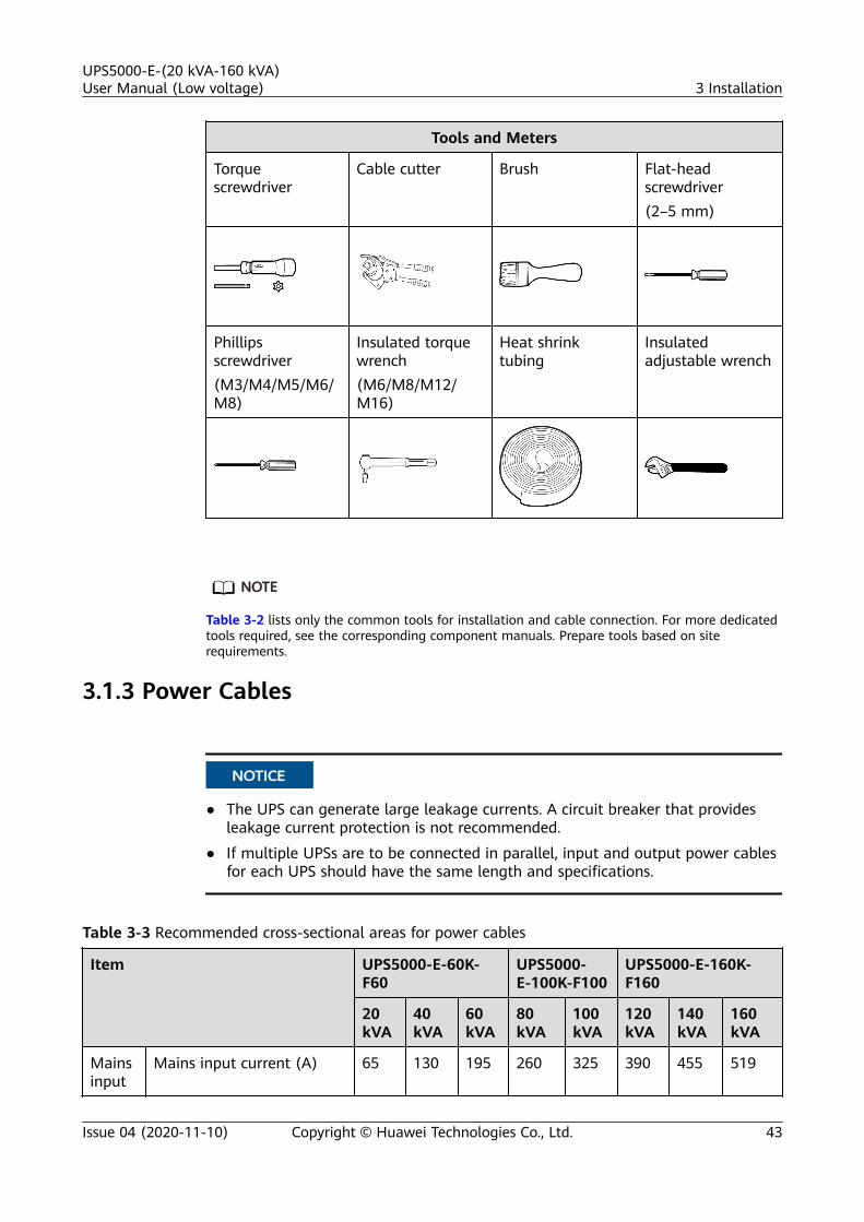
Tools and Meters
Torquescrewdriver
Cable cutter Brush Flat-headscrewdriver(2–5 mm)
Phillipsscrewdriver(M3/M4/M5/M6/M8)
Insulated torquewrench(M6/M8/M12/M16)
Heat shrinktubing
Insulatedadjustable wrench
NO TE
Table 3-2 lists only the common tools for installation and cable connection. For more dedicatedtools required, see the corresponding component manuals. Prepare tools based on siterequirements.
3.1.3 Power Cables
NO TICE
● The UPS can generate large leakage currents. A circuit breaker that providesleakage current protection is not recommended.
● If multiple UPSs are to be connected in parallel, input and output power cablesfor each UPS should have the same length and specifications.
Table 3-3 Recommended cross-sectional areas for power cables
Item UPS5000-E-60K-F60
UPS5000-E-100K-F100
UPS5000-E-160K-F160
20kVA
40kVA
60kVA
80kVA
100kVA
120kVA
140kVA
160kVA
Mainsinput
Mains input current (A) 65 130 195 260 325 390 455 519
UPS5000-E-(20 kVA-160 kVA)User Manual (Low voltage) 3 Installation
Issue 04 (2020-11-10) Copyright © Huawei Technologies Co., Ltd. 43

Item UPS5000-E-60K-F60
UPS5000-E-100K-F100
UPS5000-E-160K-F160
20kVA
40kVA
60kVA
80kVA
100kVA
120kVA
140kVA
160kVA
Recommended cross-sectional area(mm2)
L1 4 x16
4 x50
4 x95
2 x (4x 70)
2 x(4 x95)
2 x(4 x95)
2 x(4 x95)
2 x (4x 120)
L2
L3
N
Bypassinput
Bypass input current (A) 56 111 167 222 276 333 389 444
Recommended cross-sectional area(mm2)
L1 4 x16
4 x35
4 x70
2 x (4x 50)
2 x(4 x70)
2 x(4 x70)
2 x(4 x95)
2 x (4x 95)
L2
L3
N
Output
Output current (A) 56 111 167 222 276 333 389 444
Recommended cross-sectional area(mm2)
U 4 x16
4 x35
4 x70
2 x (4x 50)
2 x(4 x70)
2 x(4 x70)
2 x(4 x95)
2 x (4x 95)
V
W
N (If thevoltage isnon-linear,increasethe cross-sectionalarea of theneutralwire.)
Batteryinput(VRLAbattery)
Nominal discharge current(240 V current; twenty 12V batteries) (A)
110 219 329 439 548 658 768 877
Maximum dischargecurrent (end of dischargecurrent of twenty 12 Vbatteries, namely, 1.67 V/cell discharge current for120 2 V cells) (A)
131 263 394 525 657 788 919 1051
Recommended cross-sectional area(mm2)
+ 3 x35
3 x95
2 x(3 x70)
2 x (3x 95)
2 x(3 x150)
2 x(3 x120)
2 x(3 x150)
2 x (3x 185)
N
-
UPS5000-E-(20 kVA-160 kVA)User Manual (Low voltage) 3 Installation
Issue 04 (2020-11-10) Copyright © Huawei Technologies Co., Ltd. 44

Item UPS5000-E-60K-F60
UPS5000-E-100K-F100
UPS5000-E-160K-F160
20kVA
40kVA
60kVA
80kVA
100kVA
120kVA
140kVA
160kVA
Groundcable
Recommended cross-sectional area(mm2)
PE 1 x16
1 x25
1 x50
1 x70
1 x95
1 x95
1 x95
1 x120
NO TE
When selecting, connecting, and routing power cables, follow local safety regulations andrules.If external conditions such as cable layout or ambient temperatures change, performverification in accordance with the IEC-60364-5-52 or local regulations.The currents listed in the table are measured at a rated voltage of 208 V. If the ratedvoltage is 220 V, multiply the currents by 0.95. If the rated voltage is 230 V, multiply thecurrents by 0.92.If primary loads are non-linear loads, increase the cross-sectional areas of neutral wires 1.5–1.7 times.When the mains input and bypass input share a power source, configure both types ofinput power cables as mains input power cables. The cables listed in the table are used onlywhen the following requirements are met:● Cable routing mode: For the UPS5000-E-(20 kVA-160 kVA), route one layer of cables
along ladders or brackets in accordance with mode F in the IEC60364-5-52.● The ambient temperature is 30°C.● The AC voltage loss is less than 3%, and the DC voltage loss is less than 1%.● 20–160 kVA: single- or multi-core 90°C soft power cable with a copper conductor.● The AC power cable is no longer than 30 m, and the DC power cable is no longer than
40 m.
Table 3-4 Power cable connector requirements for the UPS5000-E-60 kVA and UPS5000-E-100 kVA
Connector Connection Mode Bolt Type Bolt HoleDiameter
Torque
Mains input connector Crimped OT terminals M10 10.5 mm 26 N·m
Bypass input connector Crimped OT terminals M10 10.5 mm 26 N·m
Battery input connector Crimped OT terminals M12 13 mm 46 N·m
Output connector Crimped OT terminals M10 10.5 mm 26 N·m
Grounding connector Crimped OT terminals M10 10.5 mm 26 N·m
UPS5000-E-(20 kVA-160 kVA)User Manual (Low voltage) 3 Installation
Issue 04 (2020-11-10) Copyright © Huawei Technologies Co., Ltd. 45

Table 3-5 Power cable connector requirements for the UPS5000-E-160 kVA
Connector Connection Mode Bolt Type Bolt HoleDiameter
Torque
Mains inputconnector
Crimped OT terminals M12 13.5 mm 46 N·m
Bypass inputconnector
Crimped OT terminals M12 13.5 mm 46 N·m
Battery inputconnector
Crimped OT terminals M12 13.5 mm 46 N·m
Outputconnector
Crimped OT terminals M12 13.5 mm 46 N·m
Groundingconnector
Crimped OT terminals M12 13.5 mm 46 N·m
Table 3-6 Upstream input circuit breaker configurations
Upstream InputCircuit Breaker
UPS5000-E-60K-F60 UPS5000-E-100K-F100
UPS5000-E-160K-F160
20 kVA 40 kVA 60 kVA 80 kVA 100kVA
120kVA
140kVA
160kVA
Upstream mainsinput switch
80A/3P
160A/3P
250A/3P
320A/3P
400A/3P
400A/3P
500A/3P
630A/3P
Upstream bypassinput switch
63A/3P
125A/3P
200A/3P
250A/3P
320A/3P
400A/3P
400A/3P
500A/3P
Table 3-7 Upstream input circuit breakers
Model UPSCapacity
Component Specifications Manufacturer
UPS5000-E-60K-F60
20 kVA Mains input circuit breaker T1N160 TMDR80 FFC 3P
ABB(recommendedwhen the short-circuit currentwhere theswitch is locatedis less than 36kVA.)
Bypass input circuitbreaker
T1N160 TMDR63 FFC 3P
40 kVA Mains input circuit breaker T1N160 TMDR160 FFC 3P
Bypass input circuitbreaker
T1N160 TMDR125 FFC 3P
60 kVA Mains input circuit breaker T3N250 TMDR250 FF 3P
UPS5000-E-(20 kVA-160 kVA)User Manual (Low voltage) 3 Installation
Issue 04 (2020-11-10) Copyright © Huawei Technologies Co., Ltd. 46

Model UPSCapacity
Component Specifications Manufacturer
Bypass input circuitbreaker
T3N250 TMDR200 FF 3P
UPS5000-E-100K-F100
80 kVA Mains input circuit breaker T5N400 TMAR320 FF 3P
Bypass input circuitbreaker
T3N250 TMDR250 FF 3P
100 kVA Mains input circuit breaker T5N400 TMAR400 FF 3P
Bypass input circuitbreaker
T5N400 TMAR320 FF 3P
UPS5000-E-160K-F160
120 kVA Mains input circuit breaker T5N400 TMAR400 FF 3P
Bypass input circuitbreaker
T5N400 TMAR400 FF 3P
140 kVA Mains input circuit breaker T5N630 TMAR500 FF 3P
Bypass input circuitbreaker
T5N400 TMAR400 FF 3P
160 kVA Mains input circuit breaker T6N630 TMAR630 FF 3P
Bypass input circuitbreaker
T5N630 TMAR500 FF 3P
NO TE
● The input upstream circuit breakers recommended in the table are for reference only.● If multiple loads are connected, specifications for branch circuit breakers must not
exceed the recommended specifications.● The circuit breaker selection principle is to protect loads and cables, and the cascading
principle is to realize specific protection.
UPS5000-E-(20 kVA-160 kVA)User Manual (Low voltage) 3 Installation
Issue 04 (2020-11-10) Copyright © Huawei Technologies Co., Ltd. 47

3.1.4 Unpacking and Checking
Context
NO TICE
● To prevent the UPS from falling over, secure it to a pallet truck using ropesbefore moving it.
● To prevent shocks or falls, move the UPS gently. After placing the UPS in theinstallation position, unpack it and take care to prevent scratches. Keep the UPSsteady during unpacking.
● To prevent dust from settling on the UPS, leave the original plastic coat on untilinstallation is required.
Procedure
Step 1 Use a pallet truck to transport the UPS to the installation position.
Step 2 Check the UPS packing.
Step 3 Hold the sliding plate steady. Cut and remove the binding tapes. Put down thesliding plate gently.
Figure 3-3 Removing binding tapes
Step 4 Remove packing materials.
UPS5000-E-(20 kVA-160 kVA)User Manual (Low voltage) 3 Installation
Issue 04 (2020-11-10) Copyright © Huawei Technologies Co., Ltd. 48

Figure 3-4 Removing packing materials
Step 5 Remove the plastic bag and take out the fittings box.
Step 6 Check that the UPS is intact.
1. Visually inspect the UPS appearance for shipping damage. If it is damaged,notify the carrier immediately.
2. Check that all fittings comply with the packing list. If some fittings aremissing or do not comply with the packing list, record this information andcontact your local Huawei office immediately.
Step 7 Remove the L-shaped bracket that secures the cabinet and the pallet, and securethe sliding plate to the pallet by using the two M12 screws that were removed.
Figure 3-5 Removing the L-shaped bracket
NO TE
Tighten the two screws in step 2 in Figure 3-5. Otherwise, the slide plate may move whenthe UPS is removed.
Step 8 Raise the four anchor bolts to the highest position using an adjustable wrench.
UPS5000-E-(20 kVA-160 kVA)User Manual (Low voltage) 3 Installation
Issue 04 (2020-11-10) Copyright © Huawei Technologies Co., Ltd. 49

Figure 3-6 Raising anchor bolts
Step 9 Push the cabinet along the sliding plate to the floor.
----End
3.2 Installing a Single UPS
NO TICE
● The top outlet kit apply only to the UPS5000-E-60K-F60 and UPS5000-E-100K-F100.
● The other components are optional for the three models of UPS5000-Es.
3.2.1 Installing the Cabinet
Secured Installation
Step 1 Determine the position for installing the cabinet. Mark mounting holes for theUPS based on the following figures:
UPS5000-E-(20 kVA-160 kVA)User Manual (Low voltage) 3 Installation
Issue 04 (2020-11-10) Copyright © Huawei Technologies Co., Ltd. 50

Figure 3-7 UPS mounting holes positioning (unit: mm)
Step 2 Use a hammer drill to drill four holes for installing expansion bolts and theninstall four expansion bolts in the holes. Figure 3-8 shows the composition of anexpansion bolt, and Figure 3-9 shows how to install an expansion bolt.
Figure 3-8 Expansion bolt composition
(1) M12 bolt (2) Spring washer (3) Flat washer (4) Expansion sleeve
NO TICE
Ensure the expansion tube of the expansion bolts fits completely into the hole.The expansion sleeves must be completely buried under the ground to properlyfacilitate subsequent installation.
UPS5000-E-(20 kVA-160 kVA)User Manual (Low voltage) 3 Installation
Issue 04 (2020-11-10) Copyright © Huawei Technologies Co., Ltd. 51

Figure 3-9 Installing expansion bolts (unit: mm)
1. Drill holes in the ground by using a hammer drill. The hole depth is 52 mm to60 mm.
2. Partially tighten the expansion bolt and vertically insert it into the hole. Hitthe expansion bolt using a rubber mallet until the expansion sleeve is fullyinserted into the hole.
3. Partially tighten the expansion bolt.4. Remove the bolt, spring washer, and flat washer.
Step 3 Move the cabinet over its castors to the installation position.
Step 4 (Optional) If the castors of the UPS need to be lifted from the ground, performsteps Step 1 to Step 2 in Unsecured Installation.
Step 5 Remove the rear panel of the cabinet, and then open the front door.
UPS5000-E-(20 kVA-160 kVA)User Manual (Low voltage) 3 Installation
Issue 04 (2020-11-10) Copyright © Huawei Technologies Co., Ltd. 52

Figure 3-10 Removing the rear panel
Step 6 Remove the four plugs from the bottom of the cabinet (two at the front and twoat the rear).
Figure 3-11 Removing plugs
Step 7 Insert four M12x115 expansion bolts into the expansion bolt holes in the floor,and tighten the expansion bolts in the direction.
UPS5000-E-(20 kVA-160 kVA)User Manual (Low voltage) 3 Installation
Issue 04 (2020-11-10) Copyright © Huawei Technologies Co., Ltd. 53
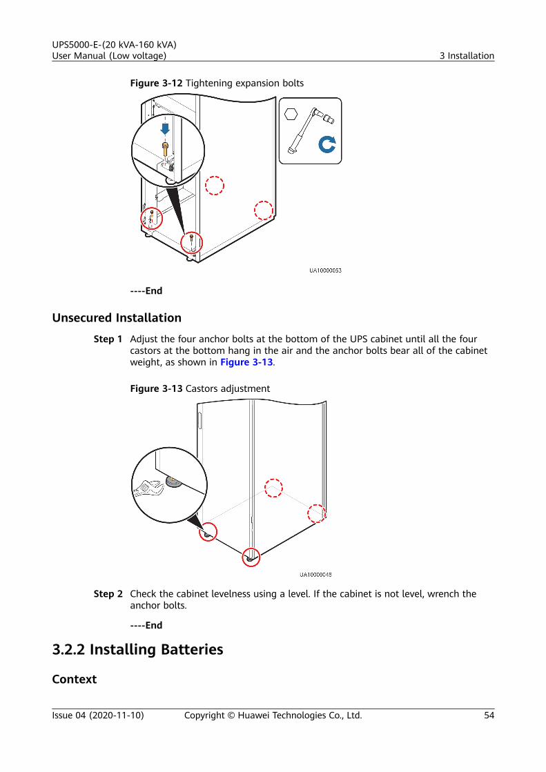
Figure 3-12 Tightening expansion bolts
----End
Unsecured Installation
Step 1 Adjust the four anchor bolts at the bottom of the UPS cabinet until all the fourcastors at the bottom hang in the air and the anchor bolts bear all of the cabinetweight, as shown in Figure 3-13.
Figure 3-13 Castors adjustment
Step 2 Check the cabinet levelness using a level. If the cabinet is not level, wrench theanchor bolts.
----End
3.2.2 Installing Batteries
Context
UPS5000-E-(20 kVA-160 kVA)User Manual (Low voltage) 3 Installation
Issue 04 (2020-11-10) Copyright © Huawei Technologies Co., Ltd. 54
D ANGER
● Before installing batteries, read through the battery safety precautions, obtainthe delivered battery installation guide, and install batteries as instructed.
● Place the batteries in a correct way to prevent vibrations and shocks.● Install the batteries from the lower layer to the upper layer to prevent falling
over due to imbalance.
Procedure
Step 1 Install a battery rack and batteries.
For details, see the battery installation guide delivered along with the batteries.
Step 2 (Optional) Install a BMU.
For details, see the UPS Battery Monitor Unit User Manual.
----End
3.2.3 Installing Optional Components
3.2.3.1 Installing Antiseismic Kits
Procedure
Step 1 Determine the UPS installation position:● (With a marking-off template) Determine the installation positions for the
antiseismic kits based on the delivered marking-off template, and markmounting holes.
● (Without a marking-off template) Mark mounting holes based on thefollowing figure.
UPS5000-E-(20 kVA-160 kVA)User Manual (Low voltage) 3 Installation
Issue 04 (2020-11-10) Copyright © Huawei Technologies Co., Ltd. 55

Figure 3-14 Antiseismic kit mounting hole positions (unit: mm)
Step 2 Drill holes for installing expansion bolts, and install expansion bolts.
Step 3 Secure two antiseismic kits to the front and rear of the cabinet:● (With a marking-off template) use twelve M5x16 and four M12 screws.
Figure 3-15 Securing the antiseismic kits to the cabinet (with a marking-offtemplate)
● (Without a marking-off template) use eight M6x20 and four M12 screws.
UPS5000-E-(20 kVA-160 kVA)User Manual (Low voltage) 3 Installation
Issue 04 (2020-11-10) Copyright © Huawei Technologies Co., Ltd. 56

Figure 3-16 Securing the antiseismic kits to the cabinet (without a marking-off template)
Step 4 Reinstall the rear panel.
Step 5 Adjust the cabinet position so that the expansion bolt holes are aligned with theeight holes at the bottom of the cabinet.
Step 6 Secure antiseismic kits to the floor at both the front and rear of the cabinet byusing eight M12 expansion bolts. The positioning is shown in Figure 3-17.
Figure 3-17 Securing the antiseismic kits to the floor
----End
3.2.3.2 Installing an IP21 Component
Procedure
Step 1 Install leveling feet at the bottom of the IP21 component, with two long feet onthe front and two short feet at the rear.
UPS5000-E-(20 kVA-160 kVA)User Manual (Low voltage) 3 Installation
Issue 04 (2020-11-10) Copyright © Huawei Technologies Co., Ltd. 57

NO TE
● Refer to the "front" and "back" silk screens on the surface of the IP21 component.● Select the mounting holes for leveling feet based on the cabinet width onsite.
Figure 3-18 Installing leveling feet
Step 2 Secure the IP21 component to the top of each cabinet using four M12 screws.
Figure 3-19 Installing the IP21 component
----End
UPS5000-E-(20 kVA-160 kVA)User Manual (Low voltage) 3 Installation
Issue 04 (2020-11-10) Copyright © Huawei Technologies Co., Ltd. 58

3.2.4 UPS Cable Connection Reference
Context
WARNING
● Keep away from cabinets when preparing cables to prevent cable scraps fromentering the cabinets. Cable scraps may cause ignition during power-on andresult in personal injury and device damage.
● After installing cables, clean the cabinet top, bottom, copper bar wiringpositions, and other positions. Ensure that there is no dust or scraps inside andaround cabinets.
● Prepare terminals onsite. The length of the copper wire should be the same asthat of the part of the terminal that covers the conductor.
Procedure
Step 1 Route a cable into the cabinet and bind it to a nearby beam.
Step 2 Pull the cable to the copper bar to which the cable is to be connected, determinethe cable length, and mark the cable at the position where the cable is to be cut.
Step 3 Pull the marked cable out of the cabinet, cut the cable from the marked position,strip the cable, and crimp a terminal.
Figure 3-20 Preparing a cable terminal outside the cabinet
NO TE
Choose an appropriate cabling route based on the actual situation. The figure is for referenceonly.
Step 4 Connect the cable with a crimped terminal to the corresponding copper bar.
Step 5 Clean foreign matter inside the cabinet.
----End
UPS5000-E-(20 kVA-160 kVA)User Manual (Low voltage) 3 Installation
Issue 04 (2020-11-10) Copyright © Huawei Technologies Co., Ltd. 59

3.2.5 Routing Cables (60 kVA, 100 kVA)
3.2.5.1 Top Cable Routing
Context
NO TICE
● The cable connection procedures for the UPS5000-E-60K-F60 and UPS5000-E-100K-F100 are the same. The following describes how to connect cables forthe UPS5000-E-100K-F100.
● Route cables for the UPS from inside out.
Procedure
Step 1 Ensure the maintenance bypass switch is OFF. Open the front door, and removethe cover from the power distribution subrack, as shown in Figure 3-21. Thepositioning of the copper bars is shown in Figure 3-22
Figure 3-21 Removing the cover
UPS5000-E-(20 kVA-160 kVA)User Manual (Low voltage) 3 Installation
Issue 04 (2020-11-10) Copyright © Huawei Technologies Co., Ltd. 60

Figure 3-22 Copper bar positions
(1) Battery input terminals (+,N, –)
(2) Mains input terminals(1L1–1L3, N)
(3) Maintenance bypass switch
(4) Bypass input terminals(2L1–2L3, N)
(5) Output terminals (U, V, W,and N)
Step 2 Remove the cable covers from the top of the cabinet.
Figure 3-23 Removing the cable covers from the top of the cabinet
Step 3 Connect ground cables, as shown in Figure 3-24.
UPS5000-E-(20 kVA-160 kVA)User Manual (Low voltage) 3 Installation
Issue 04 (2020-11-10) Copyright © Huawei Technologies Co., Ltd. 61

NO TICE
● Ensure that all UPS upstream input switches are turned off before connectingcables.
● Determine the actual number of ground cables based on Table 3-3 and the siterequirements. The following figure is for reference only.
● Prepare the OT terminals onsite to ensure that the length of the copper wire isthe same as that of the part of the OT terminal that covers the conductor.
Figure 3-24 Ground cable
NO TE
● : Internal equipotential connection
● : Protection ground
Step 4 Route power cables.● Dual mains
Remove the copper bars between mains and bypass input terminals, as shownin Figure 3-25.
UPS5000-E-(20 kVA-160 kVA)User Manual (Low voltage) 3 Installation
Issue 04 (2020-11-10) Copyright © Huawei Technologies Co., Ltd. 62

Figure 3-25 Removing copper bars
Figure 3-26 shows cables routed from the top by removing small covers, asan example.
Figure 3-26 Top cabling
Route a neutral wire from the middle of the positive and negative batterystrings.
The battery neutral wire is routed from the middle of positive and negativebattery strings, each consisting of 20 batteries.
UPS5000-E-(20 kVA-160 kVA)User Manual (Low voltage) 3 Installation
Issue 04 (2020-11-10) Copyright © Huawei Technologies Co., Ltd. 63

Figure 3-27 Neutral wire
● Single mainsFor single mains, the copper bars between the mains and bypass inputterminals do not need to be removed, and bypass input cables do not need tobe connected.
Step 5 Route the signal cables on the left side of subracks along the left side of thecabinet and the cables on the right side of subracks along the right side of thecabinet, and then bind the cables to the cabinet, as shown in Figure 3-28.
UPS5000-E-(20 kVA-160 kVA)User Manual (Low voltage) 3 Installation
Issue 04 (2020-11-10) Copyright © Huawei Technologies Co., Ltd. 64

Figure 3-28 Connecting signal cables
NO TE
The number and colors of signal cables in Figure 3-28 are for reference only.
----End
3.2.5.2 Bottom Cable Routing
Context
NO TICE
Route cables for the UPS from inside out.
Procedure
Step 1 Open the front door and remove the cover from the power distribution subrack.
Step 2 Determine the cabling mode.● Remove small covers for routing cables.
UPS5000-E-(20 kVA-160 kVA)User Manual (Low voltage) 3 Installation
Issue 04 (2020-11-10) Copyright © Huawei Technologies Co., Ltd. 65

Figure 3-29 Removing small covers from the bottom of the cabinet
● Drill holes into the large cover for routing cables.
a. Remove all the cable cover for signal cables and small covers from thebottom.
b. Remove the two large covers from the top of the cabinet, drill holes intothem, and install them to the positions where the small covers wereoriginally.
UPS5000-E-(20 kVA-160 kVA)User Manual (Low voltage) 3 Installation
Issue 04 (2020-11-10) Copyright © Huawei Technologies Co., Ltd. 66

Figure 3-30 Hole positions
NO TE
▪ The quantity of holes in the above figure is for reference only.
▪ If holes are drilled for routing cables, attach grommet strips on the hole edgesto protect cables.
Step 3 Connect ground cables.
UPS5000-E-(20 kVA-160 kVA)User Manual (Low voltage) 3 Installation
Issue 04 (2020-11-10) Copyright © Huawei Technologies Co., Ltd. 67
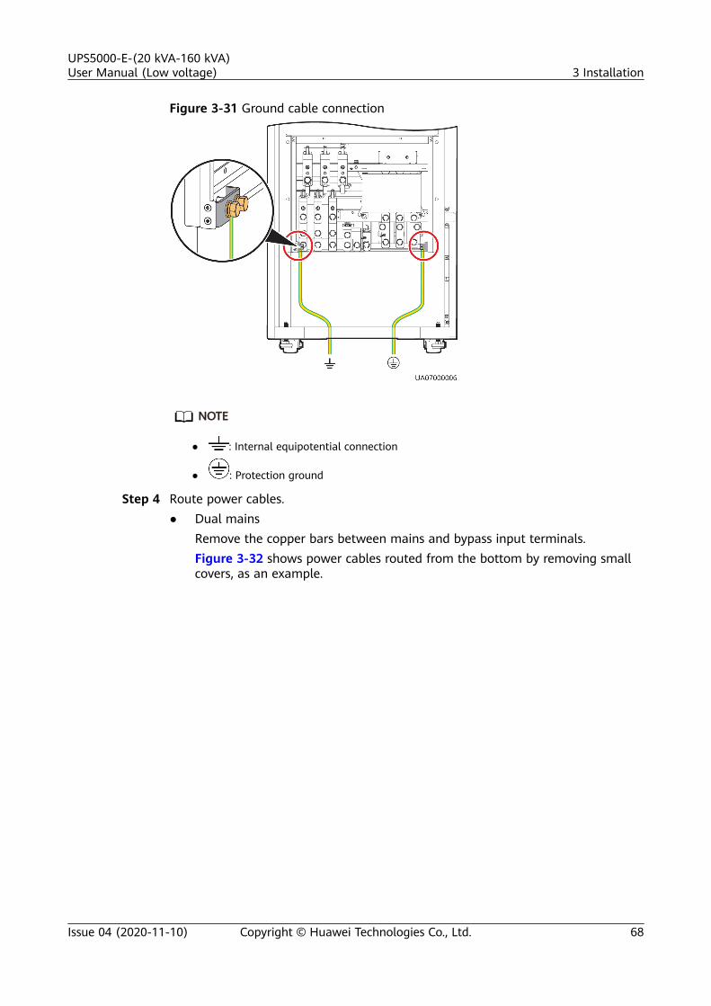
Figure 3-31 Ground cable connection
NO TE
● : Internal equipotential connection
● : Protection ground
Step 4 Route power cables.● Dual mains
Remove the copper bars between mains and bypass input terminals.Figure 3-32 shows power cables routed from the bottom by removing smallcovers, as an example.
UPS5000-E-(20 kVA-160 kVA)User Manual (Low voltage) 3 Installation
Issue 04 (2020-11-10) Copyright © Huawei Technologies Co., Ltd. 68

Figure 3-32 Bottom cabling
Route a neutral wire from the middle of the positive and negative batterystrings.
The battery neutral wire is routed from the middle of positive and negativebattery strings, each consisting of 20 batteries.
Figure 3-33 Neutral wire
UPS5000-E-(20 kVA-160 kVA)User Manual (Low voltage) 3 Installation
Issue 04 (2020-11-10) Copyright © Huawei Technologies Co., Ltd. 69

● Single mainsFor single mains, the copper bars between the mains and bypass inputterminals do not need to be removed, and bypass input cables do not need tobe connected.
Step 5 Route the signal cables on the left side of subracks along the left side of thecabinet and the cables on the right side of subracks along the right side of thecabinet, and then bind the cables to the cabinet, as shown in Figure 3-34.
Figure 3-34 Connecting signal cables
NO TE
The number and colors of signal cables in Figure 3-34 are for reference only.
----End
3.2.6 Routing Cables (160 kVA)
3.2.6.1 Top Cable Routing
Context
NO TICE
● Before using a top entry cabinet for cable routing, determine whether to placethe top entry cabinet on the left or right of the UPS5000-E cabinet.
● After routing cables, use sealing putty to fill in the gap between the cables andthe cabinet.
UPS5000-E-(20 kVA-160 kVA)User Manual (Low voltage) 3 Installation
Issue 04 (2020-11-10) Copyright © Huawei Technologies Co., Ltd. 70

Procedure
Step 1 Place the top entry cabinet on the left or right of the UPS based on actualrequirements.
Step 2 Remove the right panel from the UPS and the front panel from the top entrycabinet, and put the panel and screws away.
Step 3 Level the feet of the top entry cabinet to make it in the same plane with the UPS.
Step 4 Remove the top entry panel for the top entry cabinet and the cover for controlcables, use a hole saw to drill holes in the top entry panel, and reinstall the topcover on the top entry cabinet.
NO TE
If you choose to route cables by drilling holes, paste grommet strip to the hole edge toprotect cables.
Step 5 Install the connecting kit on the UPS. Combine the UPS and the top entry cabinetby using a connecting kit.
Figure 3-35 Combining the UPS and the top entry cabinet
Step 6 Short-circuit the UPS and the top entry cabinet using a parallel busbar.
UPS5000-E-(20 kVA-160 kVA)User Manual (Low voltage) 3 Installation
Issue 04 (2020-11-10) Copyright © Huawei Technologies Co., Ltd. 71

Figure 3-36 Installing a parallel busbar
Step 7 Connect power cables to the UPS through the top entry cabinet.
UPS5000-E-(20 kVA-160 kVA)User Manual (Low voltage) 3 Installation
Issue 04 (2020-11-10) Copyright © Huawei Technologies Co., Ltd. 72

Figure 3-37 Routing power cables from the top of the cabinet
(1) Battery cable (2) Bypass input powercable
(3) Mains input powercable
(4) Output powercable
Step 8 Connect signal cables to the UPS5000-E through the cable trough in the top entrycabinet.
UPS5000-E-(20 kVA-160 kVA)User Manual (Low voltage) 3 Installation
Issue 04 (2020-11-10) Copyright © Huawei Technologies Co., Ltd. 73

Figure 3-38 Routing signal cables from the top of the cabinet
NO TE
Install a cable trough near the front of the UPS5000-E cabinet. If the cable trough is nearthe rear of the UPS5000-E cabinet, move it to a place near the front of the cabinet.
Step 9 Install the side panel removed from the right of the UPS5000-E cabinet on theouter side of the top entry cabinet.
----End
3.2.6.2 Bottom Cable Routing
Context
NO TICE
Route cables for the UPS from inside out.
Procedure
Step 1 Open the front door, and remove the cover from the power distribution subrack,as shown in Figure 3-39. Figure 3-40 shows the positions of copper bars.
UPS5000-E-(20 kVA-160 kVA)User Manual (Low voltage) 3 Installation
Issue 04 (2020-11-10) Copyright © Huawei Technologies Co., Ltd. 74
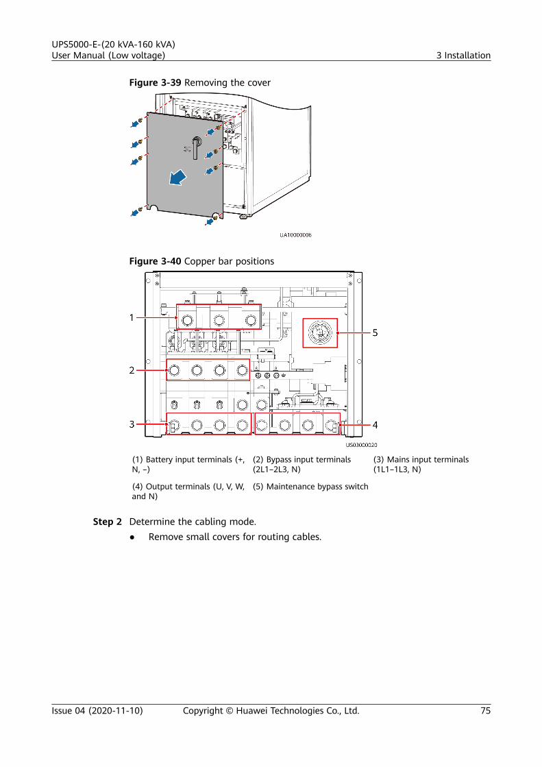
Figure 3-39 Removing the cover
Figure 3-40 Copper bar positions
(1) Battery input terminals (+,N, –)
(2) Bypass input terminals(2L1–2L3, N)
(3) Mains input terminals(1L1–1L3, N)
(4) Output terminals (U, V, W,and N)
(5) Maintenance bypass switch
Step 2 Determine the cabling mode.● Remove small covers for routing cables.
UPS5000-E-(20 kVA-160 kVA)User Manual (Low voltage) 3 Installation
Issue 04 (2020-11-10) Copyright © Huawei Technologies Co., Ltd. 75

Figure 3-41 Removing small covers from the bottom of the cabinet
● Drill holes into the large cover for routing cables.
a. Remove all small covers from the bottom of the cabinet.b. Remove the two large covers from the top of the cabinet, drill holes into
them, and install them to the positions where the small covers wereoriginally.
Figure 3-42 Hole positions
UPS5000-E-(20 kVA-160 kVA)User Manual (Low voltage) 3 Installation
Issue 04 (2020-11-10) Copyright © Huawei Technologies Co., Ltd. 76

NO TE
▪ The quantity of holes in the above figure is for reference only.
▪ If holes are drilled for routing cables, attach grommet strips to the hole edgesto protect cables.
Step 3 Connect ground cables, as shown in Figure 3-43.
Figure 3-43 Grounding
NO TE
● : Internal equipotential connection
● : Protection ground
Step 4 Route power cables.● Dual mains
Remove the copper bars between the mains and bypass input terminals, asshown in Figure 3-44.
UPS5000-E-(20 kVA-160 kVA)User Manual (Low voltage) 3 Installation
Issue 04 (2020-11-10) Copyright © Huawei Technologies Co., Ltd. 77

Figure 3-44 Removing copper bars
Figure 3-45 shows the power cables routed from the bottom of the cabinet.
UPS5000-E-(20 kVA-160 kVA)User Manual (Low voltage) 3 Installation
Issue 04 (2020-11-10) Copyright © Huawei Technologies Co., Ltd. 78

Figure 3-45 Connecting power cables
Route a neutral wire from the middle of the positive and negative batterystrings.The battery neutral wire is routed from the middle of positive and negativebattery strings, each consisting of 20 batteries.
Figure 3-46 Neutral wire
UPS5000-E-(20 kVA-160 kVA)User Manual (Low voltage) 3 Installation
Issue 04 (2020-11-10) Copyright © Huawei Technologies Co., Ltd. 79

● Single mainsFor single mains, the copper bars between the mains and bypass inputterminals do not need to be removed, and bypass input cables do not need tobe connected.
Step 5 Route the signal cables on the left side of subracks along the left side of thecabinet and the cables on the right side of subracks along the right side of thecabinet, and then bind the cables to the cabinet, as shown in Figure 3-47.
Figure 3-47 Connecting signal cables
NO TE
The number and colors of signal cables in Figure 3-47 are for reference only.
----End
3.2.7 Remote EPO
NO TICE
● Huawei does not provide the EPO switch or cable. If the cable is required, therecommended cable is 22 AWG.
● Equip the EPO switch with a protective cover to prevent misoperations, andcover the cable with protective tubing.
● Triggering EPO will shut down the rectifier, inverter, charger, and static bypass,but does not disconnect the UPS mains input. To power off the UPS completely,open the front-end input switch when triggering EPO.
Connect the requisite EPO switch to UPS dry contacts.● Figure 3-48 shows the cable connections for an NC EPO switch.● Figure 3-49 shows the cable connections for an NO EPO switch.
UPS5000-E-(20 kVA-160 kVA)User Manual (Low voltage) 3 Installation
Issue 04 (2020-11-10) Copyright © Huawei Technologies Co., Ltd. 80

Figure 3-48 Cable connection for an NC EPO switch
Figure 3-49 Cable connection for an NO EPO switch
NO TE
● When the EPO switch is in the NC state, remove the jumper between EPO_NC andEPO_12V before connection. When the EPO switch is turned off, EPO is triggered.
● When the EPO switch is in the NO state, ensure that the jumper is connected betweenEPO_NC and EPO_12V. When the EPO switch is turned on, EPO is triggered.
3.2.8 Connecting Communications Cables
Procedure
Step 1 Connect the external network management device to the RS485 port.
Step 2 Connect the network port on a PC to the FE port of the monitoring interface card.
----End
3.3 Installing a Parallel System
3.3.1 Installing the UPSs
NO TICE
Connect parallel plates to reinforce the cabinet combination.
UPS5000-E-(20 kVA-160 kVA)User Manual (Low voltage) 3 Installation
Issue 04 (2020-11-10) Copyright © Huawei Technologies Co., Ltd. 81

Procedure
Step 1 Install the UPSs in a parallel system using the single UPS installation methods.
Step 2 Unscrew the parallel plate and put it through the reserved holes to connect thetwo UPSs and then tighten the screws on the plate.
Figure 3-50 Connecting parallel plates
NO TE
You also need to connect parallel plates at the rear of the UPS.
----End
3.3.2 Connecting Power Cables
Context
The procedures for connecting parallel power cables to the UPS5000-E-160K-F160and UPS5000-E-100K-F100 are the same. The following procedure uses theUPS5000-E-100K-F100 as an example.
Procedure
Step 1 Ground each UPS in the parallel system.
Step 2 Connect power cables to each UPS in the parallel system.
UPS5000-E-(20 kVA-160 kVA)User Manual (Low voltage) 3 Installation
Issue 04 (2020-11-10) Copyright © Huawei Technologies Co., Ltd. 82

Step 3 Connect battery cables to each UPS in the parallel system.
Step 4 Select a parallel connection method to connect cables to the parallel system basedon the site configurations.
Figure 3-51 and Figure 3-52 show the typical conceptual diagram and cableconnections for a 1+1 parallel system.
Figure 3-51 Conceptual diagram of a 1+1 parallel system
Figure 3-52 Cable connections for a 1+1 parallel system
(1) Mains input powercables
(2) Bypass input powercables
(3) Battery cables (4) Output powercables
Figure 3-53 and Figure 3-54 show the conceptual diagram and cable connectionsfor a dual-bus system consisting of two UPS systems.
UPS5000-E-(20 kVA-160 kVA)User Manual (Low voltage) 3 Installation
Issue 04 (2020-11-10) Copyright © Huawei Technologies Co., Ltd. 83

Figure 3-53 Conceptual diagram of a dual-bus system
Figure 3-54 Cable connections for a dual-bus system
(1) Mains input powercable
(2) Bypass input powercable
(3) Battery cables (4) Output powercable
----End
UPS5000-E-(20 kVA-160 kVA)User Manual (Low voltage) 3 Installation
Issue 04 (2020-11-10) Copyright © Huawei Technologies Co., Ltd. 84

3.3.3 Connecting Signal Cables
Context
A maximum of two UPS5000-E-60K-F60s, UPS5000-E-100K-F100s and UPS5000-E-160K-F160s can be paralleled.
Procedure
Step 1 Connect the parallel ports on the UPSs in the parallel system over parallel cables.● Figure 3-55 and Figure 3-56 show the topology diagram and cable
connections for the 1+1 parallel system.
Figure 3-55 Topology diagram of an 1+1 parallel system
Figure 3-56 Connecting signal cables in a parallel system consisting of two UPSs
● Connect cables to BSC ports in the UPS systems. Figure 3-57 shows how toconnect signal cables in a dual-bus system.
UPS5000-E-(20 kVA-160 kVA)User Manual (Low voltage) 3 Installation
Issue 04 (2020-11-10) Copyright © Huawei Technologies Co., Ltd. 85

Figure 3-57 Connecting signal cables in a dual-bus system
Step 2 Connecting the signal cables to each single UPS in a parallel system.
----End
3.4 Installation VerificationTable 3-8 lists check items.
NO TICE
If the check results of listed items 8 and 9 in Table 3-8 do not meet theacceptance criteria, the UPS may be damaged.
Table 3-8 Installation checklist
No. Item Acceptance Criteria
01 UPS installation The UPS is securely installed and doesnot tilt due to vibration.
02 Neat arrangement The UPS and its adjacent cabinets areneatly arranged and secured withconnecting plates.
UPS5000-E-(20 kVA-160 kVA)User Manual (Low voltage) 3 Installation
Issue 04 (2020-11-10) Copyright © Huawei Technologies Co., Ltd. 86

No. Item Acceptance Criteria
03 Cable layout Cables are routed properly and cablerouting meets customer requirements.
04 Cable labels Both ends of a cable are labeled. Labelsare concise and easy to understand.
05 Cable ties Cable ties are secured evenly and no burrexists.
06 Cable connections The input, output, and battery cables aresecurely connected. For the cablessecured by screws, the spring washers areflattened.
07 Grounding The resistance between the UPS groundbar and the equipment room ground baris less than 0.1 ohm.
08 AC phase sequence For a single UPS, the mains input, bypassinput, and output phase sequences arecorrect.For a parallel system, the phasesequences of each UPS must beconsistent.
09 Battery cable connections The battery strings are correctlyconnected to the UPS.
10 Foreign matter cleaninginside the cabinet
The inside and outside of the cabinet,and other operating components, arefree from conductive dust.1. There is no foreign matter (such as
copper wires and screws) on the topof the cabinet.
2. There is no foreign matter on thecopper bar terminals.
3. There is no foreign matter aroundswitch terminals.
4. There is no foreign matter on thebottom plate of the cabinet.
5. There is no foreign matter on the rearmodule subrack.
UPS5000-E-(20 kVA-160 kVA)User Manual (Low voltage) 3 Installation
Issue 04 (2020-11-10) Copyright © Huawei Technologies Co., Ltd. 87

NO TE
1. In the scenarios where holes are drilled for routing cables or covers are removed forrouting cables, after routing cables and checking cable connections, use sealing putty tofill in the gap between the cables and the cabinet.
2. After verifying the installation, reinstall all the covers.3. Do not remove the dustproof cover before power-on to prevent dust inside the UPS.
Figure 3-58 Fill the holes with sealing putty
(1) Paper protective film (2) Sealing putty
Figure 3-59 Dustproof cover
UPS5000-E-(20 kVA-160 kVA)User Manual (Low voltage) 3 Installation
Issue 04 (2020-11-10) Copyright © Huawei Technologies Co., Ltd. 88

4 User Interface
4.1 LCD Interface
4.1.1 Main Menu
NO TICE
User interfaces displayed in this document correspond to the MDU versionV100R003C01SPC597 and are for reference only.
The LCD screen is divided into three parts: status bar, alarm bar and informationarea. Figure 4-1 numerically labels functions of the default main screen, andTable 4-1 describes these functions.
Figure 4-1 Main Menu screen
UPS5000-E-(20 kVA-160 kVA)User Manual (Low voltage) 4 User Interface
Issue 04 (2020-11-10) Copyright © Huawei Technologies Co., Ltd. 89

Table 4-1 Main screen description
Number
Area Function
1 Status bar Displays the UPS model, capacity, configuration,current date and time, USB flash drive status, andbuzzer status.
2 Alarm bar Displays active alarms in a scrolling list and thenumber of active alarms based on severity. Tap thealarm icon area to open the active alarm page.
3 Informationarea
Displays the power flow as well as key informationsuch as load and battery information. Tap theBypass, Mains, Battery, and Load icons to viewdetails.
Table 4-2 describes the functions of common buttons.
Table 4-2 Functions of common buttons
Button Function
Returns to the main screen.
Scrolls the page down.
Scrolls the page up.
Returns to the upper-level menu.
Logs a user out.
4.1.2 System Info ScreenOn the main screen, tap System Info. The System Info screen is displayed, asshown in Figure 4-2.
UPS5000-E-(20 kVA-160 kVA)User Manual (Low voltage) 4 User Interface
Issue 04 (2020-11-10) Copyright © Huawei Technologies Co., Ltd. 90

Figure 4-2 System Info screen
4.1.2.1 Module Data ScreenOn the System Info, tap the UPS picture. On the Module Data screen, select amodule to view its running data. indicates the selected module, as shown inFigure 4-3.
Figure 4-3 Module Data screen
4.1.2.2 Running
On the System Info screen, tap to access the Runn Info screen.
Figure 4-4 Running 1
UPS5000-E-(20 kVA-160 kVA)User Manual (Low voltage) 4 User Interface
Issue 04 (2020-11-10) Copyright © Huawei Technologies Co., Ltd. 91

Figure 4-5 Running 2
NO TE
● If the battery type is lead-acid battery and Number of iBOXs in System Info > Settings> iBOX Settings > Basic Param. is not 0, Battery System is displayed on the Runn Infoscreen.
● If Current equalization detection in Monitoring > UPS System > Running Parameter> Output Setting on the WebUI is set to Enable, and the number of inverter modules isgreater than or equal to 2, Mod. Cur. Eql. Data is displayed on the Runn. Info. screen.
Table 4-3 AC output
Item Description
Phase voltage (V) AC output phase voltage
Line voltage (V) AC output line voltage
Phase current (A) AC output phase current
Frequency (Hz) AC output frequency
Power factor Proportion of output active power to outputapparent power.
Table 4-4 UPS load
Item Description
Crest factor Proportion of the peak value of load current tothe valid value.
Load ratio (%) Load ratio of each phase on the UPS, that is,proportion of actual power to rated power.
Active power (kW) Output active power of each phase on the UPS.
Apparent power (kVA) Output apparent power of each phase on the UPS.
UPS5000-E-(20 kVA-160 kVA)User Manual (Low voltage) 4 User Interface
Issue 04 (2020-11-10) Copyright © Huawei Technologies Co., Ltd. 92

Item Description
Reactive power (kvar) Output reactive power of each phase on the UPS,that is, square root of the difference between thesquare of output apparent power and the squareof output active power.
Hist. Max. Load Ratio (%) Historical maximum load ratio of each phase onthe UPS.
Hist. Max. Active Power(kW)
Historical maximum active power of each phaseon the UPS.
Hist. Max. Apparent Power(kVA)
Historical maximum apparent power of eachphase on the UPS.
Table 4-5 Mains input
Item Description
Phase voltage (V) Mains input phase voltage
Line voltage (V) Mains input line voltage
Phase current (A) Mains input phase current
Frequency (Hz) Mains input frequency
Power factor Proportion of the mains input active power to themains input apparent power.
Table 4-6 Bypass input
Item Description
Phase voltage (V) Bypass input phase voltage
Line voltage (V) Bypass input line voltage
Phase current (A) Bypass input phase current
Frequency (Hz) Bypass input frequency
Power factor Proportion of the bypass input active power to thebypass input apparent power.
UPS5000-E-(20 kVA-160 kVA)User Manual (Low voltage) 4 User Interface
Issue 04 (2020-11-10) Copyright © Huawei Technologies Co., Ltd. 93

Table 4-7 Battery Status
Item Description
Battery Status Lead-acid battery: The value can be Notconnected, Equalized charging, Float charging,Hibernating, discharging, or Not chg. or dis.Lithium battery: The value can be Not connected,Float charging, discharging, or Not chg. or dis.
Voltage (V) Voltage of the battery string
Current (A) Current of the battery string (the current is +when batteries are being charged and – whendischarged)
Temperature (°C) (only forlead-acid batteries)
Current operating temperature of the battery (Abattery sensor is required. If no sensor isconnected, N/A is displayed.)
Backup time (min) Battery backup time estimated at the current load
Remaining cap. (%) Remaining battery capacity
SOH State of health
Maximum CellTemperature (°C) (only forlithium batteries)
-
Min Cell Temperature (°C)(only for lithium batteries)
-
Table 4-8 Total runtime
Item Description
Bypass runtime (h) Time for which the UPS runs in bypass mode.
Inv. runtime (h) Time for which the UPS runs in inverter mode.
NO TE
The value must be an integer. For example:● If the value is less than 1, the value takes 0.● If the value is greater than or equal to 1 and less than 2, the value takes 1.
UPS5000-E-(20 kVA-160 kVA)User Manual (Low voltage) 4 User Interface
Issue 04 (2020-11-10) Copyright © Huawei Technologies Co., Ltd. 94

Table 4-9 Environment data
Item Description
Ambient temperature (°C) Temperature measured by the ambienttemperature and humidity sensor. (An ambienttemperature and humidity sensor is required. If nosensor is connected, the ambient temperaturesampled by the bypass module is displayed.)
Ambient humid. (%RH) Humidity measured by the ambient temperatureand humidity sensor. If the sensor is not installed,N/A is displayed.
● Module Data: displays data of a module.● Battery System > Battery String Summary: displays data such as the
voltage, current, state of charge (SOC), and SOH of each battery string.● Battery System > Battery String N: displays the temperature, voltage,
internal resistance, current, SOC, and SOH of a single battery in the batterystring.
4.1.2.3 Alarms Screen
Tap on the System Info screen to enter the Alarms screen.
Figure 4-6 Alarms Screen
Active alarmsThis screen displays alarm information including the severity, name, ID, location,and generation time.
Figure 4-7 Active alarms
UPS5000-E-(20 kVA-160 kVA)User Manual (Low voltage) 4 User Interface
Issue 04 (2020-11-10) Copyright © Huawei Technologies Co., Ltd. 95

Historical alarmsThis screen displays alarm information including the severity, name, ID, location,generation time, and clear time.
Figure 4-8 Historical alarms
Buzzer OffTwo buzzer menus are available:
● Buzzer OnIf this selection is enabled, when a critical alarm, a minor alarm, or a certainwarning is generated the buzzer is activated.
● Buzzer OffIf this selection is enabled, the buzzer is muted.
If the buzzer is enabled, Buzzer Off is displayed on the operation screen.
TwinkleWhen the UPS communicates with the northbound NMS, the function determinesthe position of the UPS in the NMS layout diagram.
4.1.2.4 Settings
On the System Info screen, tap to access the Settings screen.
UPS5000-E-(20 kVA-160 kVA)User Manual (Low voltage) 4 User Interface
Issue 04 (2020-11-10) Copyright © Huawei Technologies Co., Ltd. 96

Figure 4-9 Settings 1
Figure 4-10 Settings 2
NO TE
If lead-acid batteries are used, iBOX Settings is displayed on the Settings screen.
Communication Settings
Figure 4-11 Comm. Settings (lead-acid battery)
Figure 4-12 Comm. Settings (lithium battery)
UPS5000-E-(20 kVA-160 kVA)User Manual (Low voltage) 4 User Interface
Issue 04 (2020-11-10) Copyright © Huawei Technologies Co., Ltd. 97
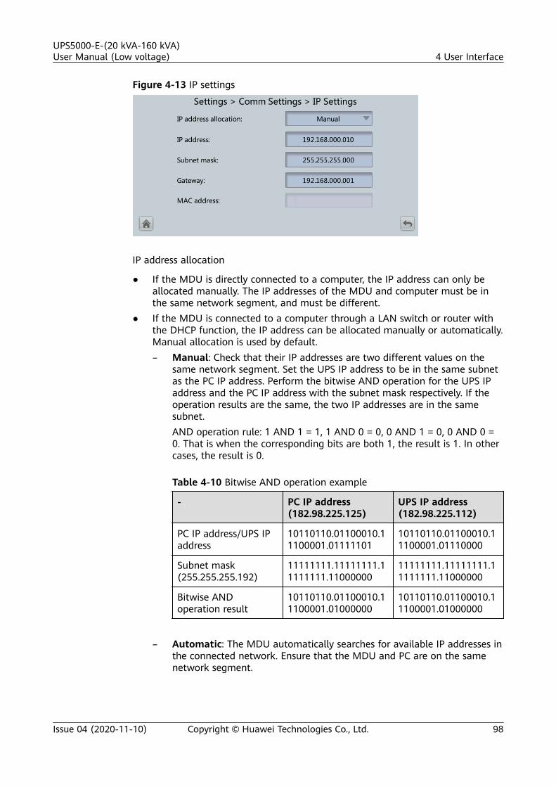
Figure 4-13 IP settings
IP address allocation
● If the MDU is directly connected to a computer, the IP address can only beallocated manually. The IP addresses of the MDU and computer must be inthe same network segment, and must be different.
● If the MDU is connected to a computer through a LAN switch or router withthe DHCP function, the IP address can be allocated manually or automatically.Manual allocation is used by default.– Manual: Check that their IP addresses are two different values on the
same network segment. Set the UPS IP address to be in the same subnetas the PC IP address. Perform the bitwise AND operation for the UPS IPaddress and the PC IP address with the subnet mask respectively. If theoperation results are the same, the two IP addresses are in the samesubnet.AND operation rule: 1 AND 1 = 1, 1 AND 0 = 0, 0 AND 1 = 0, 0 AND 0 =0. That is when the corresponding bits are both 1, the result is 1. In othercases, the result is 0.
Table 4-10 Bitwise AND operation example
- PC IP address(182.98.225.125)
UPS IP address(182.98.225.112)
PC IP address/UPS IPaddress
10110110.01100010.11100001.01111101
10110110.01100010.11100001.01110000
Subnet mask(255.255.255.192)
11111111.11111111.11111111.11000000
11111111.11111111.11111111.11000000
Bitwise ANDoperation result
10110110.01100010.11100001.01000000
10110110.01100010.11100001.01000000
– Automatic: The MDU automatically searches for available IP addresses in
the connected network. Ensure that the MDU and PC are on the samenetwork segment.
UPS5000-E-(20 kVA-160 kVA)User Manual (Low voltage) 4 User Interface
Issue 04 (2020-11-10) Copyright © Huawei Technologies Co., Ltd. 98

NO TE
After you restart the device, IP address allocation changes back to Manual. The IP addressis set to the IP address set previously.
Item Description Default Value Value Range
IP address Specifies the IP address forthe Ethernet.NOTICE
Ensure that the UPS IP addressis unique on the networksegment. Otherwise, the WebUIdisplay function may notfunction properly.
192.168.0.10 1.0.0.0–223.255.255.255
Subnet mask Specifies the subnet mask ofthe Ethernet.
255.255.255.0 0.0.0.0–255.255.255.255
Gateway Specifies the Ethernetgateway.
192.168.0.1 1.0.0.0–223.255.255.255
MAC address Defines the physical addressof network equipment and isnot configurable.
N/A N/A
Figure 4-14 RS485 settings
Item Description Default Value Value Range
Address This serial port address isallocated by the user.
1 1–254
Baud rate Select a baud rate to matchthe user's networkmanagement conditionsonsite.
9600 9600, 19200,115200
UPS5000-E-(20 kVA-160 kVA)User Manual (Low voltage) 4 User Interface
Issue 04 (2020-11-10) Copyright © Huawei Technologies Co., Ltd. 99

Item Description Default Value Value Range
Parity mode Verify the validity of RS485communication characters.When a device node adoptsRS485 communication,ensure that the parity modesfor the device nodes are setto the same mode.
None None, Odd,Even
Stop bit Stop bit in the Modbuscommunication frameformat. When the UPS isconnected over the serialport Modbus, set thisparameter based on theframe format that theupstream device Modbussupports.
1 1–2
Northboundprotocol type
Set Northbound protocoltype.
ModbusRTU ModbusRTU,YDN
Figure 4-15 Modbus TCP settings
Item Description Default Value Value Range
ModbusTCPencryption
If Modbus TCP is used forcommunication,communication links do notimplement encryption orimplement encryption basedon the selected encryptionmode.
Enable Disable,Enable
UPS5000-E-(20 kVA-160 kVA)User Manual (Low voltage) 4 User Interface
Issue 04 (2020-11-10) Copyright © Huawei Technologies Co., Ltd. 100

Figure 4-16 Ambient temperature and humidity sensor
Item Description Default Value Value Range
Start address N/A 32 32–44
Quantity Number of cascaded ambienttemperature and humiditysensors
0 0–4
Figure 4-17 Battery temperature sensor
Item Description Default Value Value Range
Start address N/A 16 16–28
Quantity Number of cascaded batterytemperature sensors
0 0–4
UPS5000-E-(20 kVA-160 kVA)User Manual (Low voltage) 4 User Interface
Issue 04 (2020-11-10) Copyright © Huawei Technologies Co., Ltd. 101

Figure 4-18 BMU
Item Description Default Value Value Range
Start address N/A 112 N/A
Quantity Number of cascaded BMUs 0 0–12
Figure 4-19 WiFi Settings
Item Description Default Value Value Range
Connect If this parameter is set toEnable, you can implementthe WiFi function byconnecting to the USB WiFimodule.
Disable Disable,Enable
UPS5000-E-(20 kVA-160 kVA)User Manual (Low voltage) 4 User Interface
Issue 04 (2020-11-10) Copyright © Huawei Technologies Co., Ltd. 102

Item Description Default Value Value Range
SSID When using the mobile appfor site deployment orinspection, set WiFi SSIDafter connecting a WiFimodule over a USB port toidentify the WiFi device towhich the mobile phone isconnected.
UPS_WIFI +Last sixcharacters ofthe MACaddress
N/A
Password The password for accessingWiFi
Changeme N/A
Figure 4-20 Access control
Item Description DefaultValue
Value Range
SSH Refers to a secure encryptedtransmission protocol used toaccess the UPS with a terminaltool.Disable: The SSH port isdisabled and cannot beaccessed.Enable: The SSH port isenabled and can be accessed.
Enable Disable,Enable
UPS5000-E-(20 kVA-160 kVA)User Manual (Low voltage) 4 User Interface
Issue 04 (2020-11-10) Copyright © Huawei Technologies Co., Ltd. 103

Item Description DefaultValue
Value Range
HTTPS Refers to a securetransmission protocol used toaccess the UPS through abrowser.Disable: The HTTPS servicesare unavailable.Read-only: Only operatorusers are allowed to accessthe services and have only theread permission.Enable: All functions areavailable.
Enable Disable,Enable, Read-only
ModbusTCP Refers to an Ethernet-basedModbus protocol used toconnect to the NetEco.Disable: The Modbus TCPservices are unavailable.Read-only: Only the readpermission is enabled. Settingsare not allowed.NetEco: The read permissionand the write permission onrelated parameters supportedby the NetEco are enabled.Enable: All functions areavailable.
Enable Disable,Enable, Read-only, NetEco
SNMP Refers to the Simple NetworkManagement Protocol used toconnect to the NetEco.Disable: The SNMP servicesare unavailable.Read-only: Only the readpermission is enabled. Settingsare not allowed.NetEco: The read permissionand the write permission onrelated parameters supportedby the NetEco are enabled.Enable: All functions areavailable.
Enable Disable,Enable, Read-only, NetEco
UPS5000-E-(20 kVA-160 kVA)User Manual (Low voltage) 4 User Interface
Issue 04 (2020-11-10) Copyright © Huawei Technologies Co., Ltd. 104

Item Description DefaultValue
Value Range
ModbusRTU Refers to a Modbus protocolbased on the RS485 bus,which is used to connect tothe NetEco.Disable: The Modbus RTUservices are unavailable.Read-only: Only the readpermission is enabled. Settingsare not allowed.NetEco: The read permissionand the write permission onrelated parameters supportedby the NetEco are enabled.Enable: All functions areavailable.
Enable Disable,Enable, Read-only, NetEco
Figure 4-21 Battery System
Item Description DefaultValue
ValueRange
SmartLi startaddress
SmartLi communicationaddress when the UPS queriesSmartLi data
80 N/A
UPS5000-E-(20 kVA-160 kVA)User Manual (Low voltage) 4 User Interface
Issue 04 (2020-11-10) Copyright © Huawei Technologies Co., Ltd. 105

System Settings
Figure 4-22 System settings 1
Figure 4-23 System settings 2
NO TE
If lead-acid batteries are used, you can set Batt. temp. sensor [B_TEMP].
Figure 4-24 System settings 3
UPS5000-E-(20 kVA-160 kVA)User Manual (Low voltage) 4 User Interface
Issue 04 (2020-11-10) Copyright © Huawei Technologies Co., Ltd. 106

Item Description Default Value Value Range
Single/Parallel
Specifies whether the UPSworks in single mode orparallel mode.
Single Single, Parallel
Requisitemodules
Matches the system capacity. 8 N/A
Redundantmodules
Set this parameter based onload capacity andredundancy requirements.
0 N/A
Workingmode
UPS working mode Normal mode Normal mode,ECO, Self-loadmode,Convertermode
ECO voltagerange
In ECO mode, when thedifference between thebypass voltage and the ratedvoltage is greater than thisvalue, the system determinesthat the ECO voltage isabnormal and transfers tonormal mode.
±5% ±5%, ±6%,±7%, ±8%,±9%, ±10%
UPS5000-E-(20 kVA-160 kVA)User Manual (Low voltage) 4 User Interface
Issue 04 (2020-11-10) Copyright © Huawei Technologies Co., Ltd. 107

Item Description Default Value Value Range
BSC mode ● Set this parameter toStandard BSC for a dual-bus system.
● After setting thisparameter to StandardBSC, you need to set thetwo UPS systems in thedual-bus system to BSCmaster system and BSCslave system respectivelyin the BSC master/slavesystem setting. (The twoUPS systems cannot beBSC master systems orBSC slave systems at thesame time. If you need tochange the settings in thefuture, perform operationsunder the guidance ofmaintenance engineers.)NOTE
Ensure that the BSC signalcable between the BSCmaster and slave systems isproperly connected and thatBSC-related hardware isproperly installed.
● When Huawei UPSs andUPSs of other brands forma dual-bus system, set theparameter to Opt. BSCcard mode.
Non-BSC Non-BSC,Standard BSCmode, andOpt. BSC cardmode
Altitude (m) Set this parameter based onthe altitude of the placewhere the rack is used.
≤ 1000 ≤ 1000, 1000–2000, 2000–3000, 3000–4000, 4000–5000
Top outlet fan Enable this parameter if atop outlet fan is configured.Then the fan running statuscan be checked.
Disable Disable,Enable
Air filtermaintenanceperiod (d)
Specifies the rack air filtermaintenance interval. If it isset to 0, there is no reminder.
0 0–365
Intra-rackpowermodule startdelay (s)
These two parameters enablethe UPS to control theinterval that each rack (ormodule) transfers from
2.0 0.5–120.0
UPS5000-E-(20 kVA-160 kVA)User Manual (Low voltage) 4 User Interface
Issue 04 (2020-11-10) Copyright © Huawei Technologies Co., Ltd. 108

Item Description Default Value Value Range
Inter-rackpowermodule startdelay (s)
battery mode to normalmode, which reduces theimpact on the generator orpower grid. In the case ofbattery undervoltage, thesystem automaticallyshortens the delay fortransferring to normal modeto 1/8 of the normal delay toaccelerate the transfer andprevent batteryoverdischarge. The startdelay of a module in a rackvaries depending on the racknumber and module number.#1 module in rack 1 does nothave a start delay.
5 2–120
Batt. temp.sensor[B_TEMP]
The optional negativetemperature coefficient(NTC) resistor monitors theambient temperature nearbatteries. It ensures thatbatteries work reliably andsafely.
Disable Disable,Enable
BCB trips ifUPS stopspower supply
Indicates whether the BCBtrips when the system stopssupplying power and theoutput power is off.
Enable Disable,Enable
Input Settings
Figure 4-25 Input settings
UPS5000-E-(20 kVA-160 kVA)User Manual (Low voltage) 4 User Interface
Issue 04 (2020-11-10) Copyright © Huawei Technologies Co., Ltd. 109

Item Description Default Value Value Range
D.G. mode Set this parameter to Enablewhen a D.G. connects to theinput PDC. The UPS entersthe D.G. mode when a D.G. isdetected over dry contacts.
Disable Disable,Enable
D.G. powerlimiting (kVA)
Set these two parameters tocontrol the valid inputcurrent and limiting inputcurrent, which prevents loadimpact and facilitates bettercooperation between theUPS and the D.G.
Depends onthe actualmodel.
0 kVA to 5000kVA
D.G. chargerpower ratio(%)
100 0–100
Input cur.limiting
Specifies whether to enableor disable input currentlimiting to protectgenerators.
Disable Disable,Enable
Input cur.limiting ratio(%)
Limits the input current toprotect the D.G.
200 50–200
Output Settings
Figure 4-26 Output settings
UPS5000-E-(20 kVA-160 kVA)User Manual (Low voltage) 4 User Interface
Issue 04 (2020-11-10) Copyright © Huawei Technologies Co., Ltd. 110

Item Description Default Value Value Range
Outputvoltage level(V)
Specifies the system outputvoltage level. This parameteris configurable only after theinverter shuts down. Afteryou change the voltage level,the upper limit of the bypassvoltage restores to thedefault value.
208 200, 208, 220,230
Output volt.adjustment(V)
The output voltage can beslightly adjusted based onthe onsite power distributioncondition to ensure aminimum difference betweenthe output voltage and thebypass voltage and facilitateuninterruptible power supplywhen the UPS transfers fromnormal mode to bypassmode.
120.0 114.0-126.0
Outputfrequency(Hz)
Specifies the system outputfrequency level.
50 50, 60
Output freq.track rate(Hz/s)
This parameter can beadjusted based on siterequirements. If Output freq.track rate (Hz/s) is slow, theinverter frequency is differentfrom the bypass frequencywhen the bypass frequencychanges. If output isoverloaded or the inverter isfaulty, an interruption (lessthan 20 ms) occurs when theUPS transfers from normalmode to bypass mode. IfOutput freq. track rate(Hz/s) is fast, the inverterfrequency is unstable.
0.6 0.1-2.0
UPS5000-E-(20 kVA-160 kVA)User Manual (Low voltage) 4 User Interface
Issue 04 (2020-11-10) Copyright © Huawei Technologies Co., Ltd. 111

Item Description Default Value Value Range
EOD restart If the mains is notfunctioning normally, theUPS will transfer to batterymode. When batteries reachthe EOD threshold, thebypass is disabled, and EODrestart is Enable, the UPSwill restart as soon as themains resumes.If EOD restart is disabled,clear the alarm manually orenable the restart functionfor the UPS.
Enable Disable,Enable
EOD restartdelay (min)
If EOD restart is set toEnable, the UPS startsworking after the time set forEOD restart delay when theinput recovers from thepower failure upon EOD.
10 1–1440
Bypass Settings
Figure 4-27 Bypass settings
UPS5000-E-(20 kVA-160 kVA)User Manual (Low voltage) 4 User Interface
Issue 04 (2020-11-10) Copyright © Huawei Technologies Co., Ltd. 112

Item Description Default Value Value Range
Maximumbypassvoltage
When the difference betweenthe bypass voltage and therated voltage exceeds theupper threshold for thebypass voltage, the systemdetermines that the bypassvoltage is not normal andthat the bypass isunavailable.
+20% 10%, 15%,20%, 25%
Minimumbypassvoltage
When the difference betweenthe bypass voltage and therated voltage exceeds theupper threshold for thebypass voltage, the systemdetermines that the bypassvoltage is not normal andthat the bypass isunavailable.
–20% –10%, –15%, –20%, –30%
Bypassfrequencyrange (Hz)
When the difference betweenthe bypass input frequencyand the rated frequency isgreater than the specifiedvalue, the system determinesthat the bypass frequency isabnormal, so the bypass isunavailable.
±2.0 ±0.5 to ±6.0
Battery Settings
NO TICE
Battery parameter settings impact battery maintenance, battery lifespan, and UPSdischarge time. When you set battery parameters, note the following:● Battery string sharing is unavailable when Single/Parallel is set as Single.● Battery string sharing affects the actual charge current and the estimated
discharge time. An incorrect setting will cause a high or low charge current,which may damage the batteries. An incorrect estimated discharge time maycause a data backup fault.
● When you set parameters, ensure the following: Dis. cur. 0.1C EOD ≥ Dis. cur.0.3C EOD ≥ Dis. cur. 0.5C EOD ≥ Dis. cur. 1.0C EOD.
● A cell consists of electrodes and electrolyte, which is the basic unit for thebattery. Each cell has a nominal voltage of 2 V. A battery is a module consistingof single or multiple cells in a shell. Each battery has a nominal voltage of 2 V,6 V, or 12 V.
UPS5000-E-(20 kVA-160 kVA)User Manual (Low voltage) 4 User Interface
Issue 04 (2020-11-10) Copyright © Huawei Technologies Co., Ltd. 113

Figure 4-28 Battery Settings (lead-acid battery)
Figure 4-29 Battery Settings (lithium battery)
Item Description Default Value Value Range
Battery type Specifies the type of batteriesconnected to the UPS.
VRLA batt. VRLA batt.,lithium batt.
Batterycapacity(Ah)
Specifies the capacity oflithium batteries connectedto the UPS (the value isautomatically obtained).
N/A N/A
Single batteryvoltage(V)
Specifies the voltage of eachbattery that is connected inseries in a battery string.
12 2, 6, 12
Single batterycapacity(Ah)
Specifies the capacity of eachbattery that is connected inseries in a battery string.
Depends onthe actualmodel.
5–9999
Batteries in abattery string
Specifies the number ofbatteries in a battery string.
Depends onthe model.
Depends onthe model.
Number ofbatterystrings
Specifies the number ofbattery strings connected inparallel.
1 1–6
Installationtime
A battery maintenancereminder is displayed whenthe maintenance time(counted from theinstallation time) comes.
N/A N/A
UPS5000-E-(20 kVA-160 kVA)User Manual (Low voltage) 4 User Interface
Issue 04 (2020-11-10) Copyright © Huawei Technologies Co., Ltd. 114

Item Description Default Value Value Range
Maintenanceperiod(d)
Specifies the interval forreminding users of batterymaintenance.
0 0–365
Cell floatvoltage(V/cell)
Specifies the battery floatcharging voltage.
2.25 2.23–2.30
Cell equalizedvolt.(V/cell)
Specifies the batteryequalized charging voltage.
2.35 2.30–2.40
Dis. curr. 0.1CEOD(V/cell)
Specifies the EOD thresholdwhen the discharge current is0.1C, 0.3C, 0.5C, or 1.0Crespectively.
1.80 1.80–1.90
Dis. curr. 0.3CEOD(V/cell)
1.80 1.80–1.90
Dis. curr. 0.5CEOD(V/cell)
1.75 1.75–1.85
Dis. curr. 1.0CEOD(V/cell)
1.60 1.60–1.75
Sched.shallow dis.test
When certain conditions aremet, the charger shuts down,and batteries supply powerto loads. The system recordsthe battery discharge data asa reference for batterycapacity and lifespan.
Disable Disable,Enable
Sched.shallow dis.test time
Specifies the time for ascheduled shallow dischargetest.
00:00 - 06:00 00:00 - 06:00,06:00 - 12:00,12:00 - 18:00,18:00 - 24:00
Sched.shallow dis.testinterval(d)
Specifies the interval for ascheduled shallow dischargetest.
60 30–90
Shallow dis.test dis.ratio(%)
Specifies the proportion ofthe discharge capacity to thetotal discharge capacity. Thevalue is configurable in anymode.
20 10–50
Cell chargevoltage(V/cell)
Specifies the charge voltageof lithium batteries (thevalue is automaticallyobtained).
N/A N/A
UPS5000-E-(20 kVA-160 kVA)User Manual (Low voltage) 4 User Interface
Issue 04 (2020-11-10) Copyright © Huawei Technologies Co., Ltd. 115
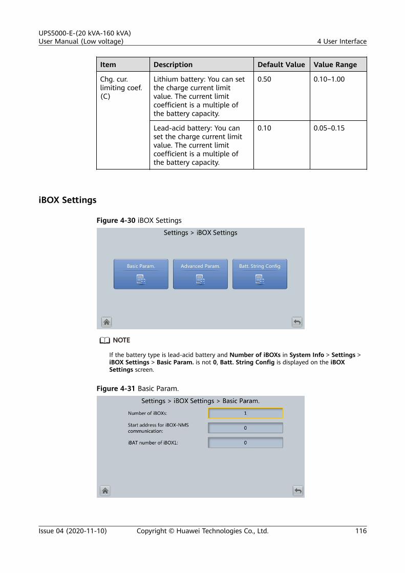
Item Description Default Value Value Range
Chg. cur.limiting coef.(C)
Lithium battery: You can setthe charge current limitvalue. The current limitcoefficient is a multiple ofthe battery capacity.
0.50 0.10–1.00
Lead-acid battery: You canset the charge current limitvalue. The current limitcoefficient is a multiple ofthe battery capacity.
0.10 0.05–0.15
iBOX Settings
Figure 4-30 iBOX Settings
NO TE
If the battery type is lead-acid battery and Number of iBOXs in System Info > Settings >iBOX Settings > Basic Param. is not 0, Batt. String Config is displayed on the iBOXSettings screen.
Figure 4-31 Basic Param.
UPS5000-E-(20 kVA-160 kVA)User Manual (Low voltage) 4 User Interface
Issue 04 (2020-11-10) Copyright © Huawei Technologies Co., Ltd. 116

Item Description Default Value Value Range
Number ofiBOXs
The number of iBOXsconnected to UPS.
0 0–6
Start addressfor iBOX-NMScommunication
Specifies the communicationaddress when thenorthbound device queriesiBOX data.
0 0–124
iBOX numberof iBATs
Specifies the number ofiBATs managed by the iBOX.
0 0–300
Figure 4-32 Advanced Param.
Item Description Default Value Value Range
Currentsource
Specifications of the Halleffect sensor used to detectiBOX current.
Hall sensor200A
Hall sensor200A, Hallsensor 600A
Batt.abnormalBCB trip
Specifies whether BCB tripswhen batteries are abnormal.
Disable Disable,Enable
Single batt.groupnumber ofhall
Single batt. group numberof hall is equal to thenumber of Hall effect sensorsat the positive or negativeterminal of a battery string(Single batt. group numberof hall≥ 1).
1 1–8
UPS5000-E-(20 kVA-160 kVA)User Manual (Low voltage) 4 User Interface
Issue 04 (2020-11-10) Copyright © Huawei Technologies Co., Ltd. 117

Figure 4-33 Batt. String Config
Set the iBOX and iBAT number for each battery string.
Dry Contact Set
NO TICE
● Set only the dry contacts that are needed. Otherwise, the UPS may not runproperly.
● When a dry contact card is disabled, its dry contact signals are disabled.● After a dry contact card is enabled, its dry contact signals can be displayed on
the LCD.● Disable all the dry contacts for a dry contact card that is not connected and all
the dry contacts that are not used to prevent false alarms.● ( ) encloses a unit, and [ ] encloses silk screen.
Specify dry contact settings on the following cards:
● Dry contact card (MUE05A): provides dry contact signals for the batterygrounding failure detector, D.G., BCB box, and PDCs.
● Backfeed protection board (MUE06A): provides backfeed protection signals.This board can be enabled or disabled.
● Monitoring interface card (MUS05A): provides four routes of configurableoutput dry contact signals.
● Dry contact extended card (MUE07A): provides five routes of input signalsand five routes of output signals.
Item Description
MUE05A connection Specifies the MUE05A connection status.Independent input signals can be enabled onlywhen this parameter is set to Enable.
Batter ground fault [BTG] Enable or disable battery grounding faultdetection.
UPS5000-E-(20 kVA-160 kVA)User Manual (Low voltage) 4 User Interface
Issue 04 (2020-11-10) Copyright © Huawei Technologies Co., Ltd. 118

Item Description
D.G. connection [GEN] Enable or disable D.G. connection detection.
BCB connection [OL] Enable or disable BCB connection detection.
Battery breaker [STA] Enable or disable battery circuit breaker statusdetection.
PDC output breaker [OUT] Enable or disable PDC output circuit breakerstatus detection.
PDC maintenance breaker[MT]
Enable or disable PDC maintenance circuitbreaker status detection.
BP/SYSMT Switch BP/SYSMT switch: bypass input/systemmaintenance switch.If the BP/SYSMT switch is set to Enable, theport has dry contact signal access. Using theport depends on the status of the BP/SYSMTswitch.
BP/SYSMT switch function If the BP/SYSMT switch is set to Enable, thisparameter is displayed on the screen. Set thisparameter to determine whether the port isused to detect the status of the PDU bypassinput switch, or system maintenance switch.
SPD/SYSOUT Switch SPD/SYSOUT switch: surge protector/systemoutput switch.If the SPD/SYSOUT switch is set to Enable, theport has dry contact signal access. How a useruses the port depends on the status of the SPD/SYSOUT switch.
SPD/SYSOUT switch function If the SPD/SYSOUT switch is set to Enable, thisparameter is displayed on the screen. Set thisparameter to determine whether the port isused to detect the status of the PDU input surgeprotector, or system output switch.
MUE06A connection Specifies the MUE06A connection status. If thisparameter is set to Enable, the mains andbypass backfeed protection is enabled.
MUS05A DO_1 Action,MUS05A DO_2 Action,MUS05A DO_3 Action,MUS05A DO_4 Action
Controls the status of DO ports on the MUS05Adry contact card.
MUE07A DO_1 Action,MUE07A DO_2 Action,MUE07A DO_3 Action,MUE07A DO_4 Action,MUE07A DO_5 Action
Controls the status of DO ports on the MUE07Aextended dry contact card.
UPS5000-E-(20 kVA-160 kVA)User Manual (Low voltage) 4 User Interface
Issue 04 (2020-11-10) Copyright © Huawei Technologies Co., Ltd. 119

Item Description
MUS05A DO_1, MUS05ADO_2, MUS05A DO_3,MUS05A DO_4
Corresponds to the signal of the output drycontact DO on the MUS05A.
MUE07A DO_1, MUE07ADO_2, MUE07A DO_3,MUE07A DO_4, MUE07ADO_5
Corresponds to the signal of the output drycontact DO on the MUE07A.
MUE07A DI_1, MUE07A DI_2,MUE07A DI_3, MUE07A DI_4,MUE07A DI_5
Corresponds to the signal of the input drycontact DI on the MUE07A.
User Settings
Figure 4-34 User settings
Item Description Default Value Value Range
Language Thirteen languages aresupported.
English English,Chinese,Spanish,Dutch, French,German,Italian, Polish,Portuguese,Russian,Swedish,Turkish,Japanese
Password N/A 000001 N/A
UPS5000-E-(20 kVA-160 kVA)User Manual (Low voltage) 4 User Interface
Issue 04 (2020-11-10) Copyright © Huawei Technologies Co., Ltd. 120

Item Description Default Value Value Range
Passwordcomplexitycheck
If the password complexitycheck is disabled, the userpassword is required to be astring of six to eight digits. Ifthe password complexitycheck is enabled, thepassword is required to be astring of 6–20 characters andcontain at least two types ofcharacters.
Enable Disable,Enable
NO TE
Set the date and time to the actual date and time.
Time Zone
Figure 4-35 Time zone
● Set the local time zone.● You can enable DST in areas where DST is used.
4.1.2.5 Maintenance
On the System Info screen, tap to display the Maintenance screen.
UPS5000-E-(20 kVA-160 kVA)User Manual (Low voltage) 4 User Interface
Issue 04 (2020-11-10) Copyright © Huawei Technologies Co., Ltd. 121

Figure 4-36 Maintenance screen 1
Figure 4-37 Maintenance screen 2
NO TE
If lead-acid batteries are used and Number of iBOXs in System Info > Settings > iBOXSettings > Basic Param. is not 0, iBOX Control is displayed on the Maintenance screen.
Battery Maint. screen
NO TICE
● Perform battery maintenance when no alarm is active on the UPS. Otherwise,the UPS may supply no power.
● A proportion of battery capacity will discharge during battery maintenance.This reduces the discharge time before the next charge.
● Do not perform battery maintenance when a D.G. is connected.
Battery maintenance includes Forced Equalized Charging, Shallow Dis. Test, andCapacity Test.
UPS5000-E-(20 kVA-160 kVA)User Manual (Low voltage) 4 User Interface
Issue 04 (2020-11-10) Copyright © Huawei Technologies Co., Ltd. 122

Figure 4-38 Battery Maint. (lead-acid battery)
Figure 4-39 Battery Maint. (lithium battery)
Item Description
Forced Equalized Charging Forcibly perform equalized charging on batteries.
Shallow Dis. Test Partially discharge batteries. A shallow dischargetest can be conducted to test the battery loopreliability and short-time discharge capacity whenthe batteries have not discharged for a long time.
Capacity Test Fully discharge batteries. A deep discharge test isconducted to obtain the battery dischargeperformance data.
USB OperationsYou can export Fault Data, and perform Upgrade Software, BSP Upgrade,Export Config., and Import Config. with USB.
Multi-brand is used to import the brand information of a partner to thecorresponding WebUI.
UPS5000-E-(20 kVA-160 kVA)User Manual (Low voltage) 4 User Interface
Issue 04 (2020-11-10) Copyright © Huawei Technologies Co., Ltd. 123

Figure 4-40 USB Operations 1
Starting or Shutting Down the InverterItem Description
Inv. ON The Inv. ON screen allows you to start the invertermanually.
Inv. OFF The Inv. OFF screen allows you to shut down theinverter manually.
ECM Switchover
NO TICE
● Only professional personnel are allowed to use this function.● Clear faults before performing ECM active/standby switchover.● After an ECM is inserted, active and standby switchover is supported only after
the ECM is configured and starts working properly (about 30 seconds).
If the ECM to be maintained is still working, perform ECM active/standbyswitchover on this screen (a dialog box is displayed for you to confirm thisoperation). After performing active/standby switchover, ensure that this ECM is instandby state (that is, the green indicator is blinking) and then maintain the ECM.
Wizard StartupThe wizard startup can be used to test the bypass, mains inverter, inverter/bypassswitch, battery inverter, battery charging capability, battery switch tripping and soon.
Perform operations as prompted.
UPS5000-E-(20 kVA-160 kVA)User Manual (Low voltage) 4 User Interface
Issue 04 (2020-11-10) Copyright © Huawei Technologies Co., Ltd. 124

NO TICE
Before starting the wizard, ensure that:● The system is a single UPS system.● No minor or critical alarm occurs.● The UPS works in normal mode with a load ratio fluctuation less than 10%.● The UPS generates no battery overtemperature, overvoltage, or overcurrent
alarm. No generator is connected to the UPS.● The mains, batteries, charger, and discharger are normal. No overload alarm is
generated.● SOC > 30%
Figure 4-41 Wizard startup
NO TE
On the System Info > Settings > Dry Contact Set screen, set MUE05A connection toEnable, and set BCB connection [OL] to Enable. Wizard-based startup can be used to testthe battery switch tripping function.
Bus Capacitor Life Estimate
If the service life of a capacitor is about to end, that is, Module X bus capacitorlife (y) is less than 1.0, contact Huawei technical support to replace the powermodule.
Fan Life Estimate● If the service life of a fan is about to end, that is, Module X fan life (y) is less
than Pre-warn. time for fan life(mon), contact Huawei technical support toreplace the power module.
UPS5000-E-(20 kVA-160 kVA)User Manual (Low voltage) 4 User Interface
Issue 04 (2020-11-10) Copyright © Huawei Technologies Co., Ltd. 125
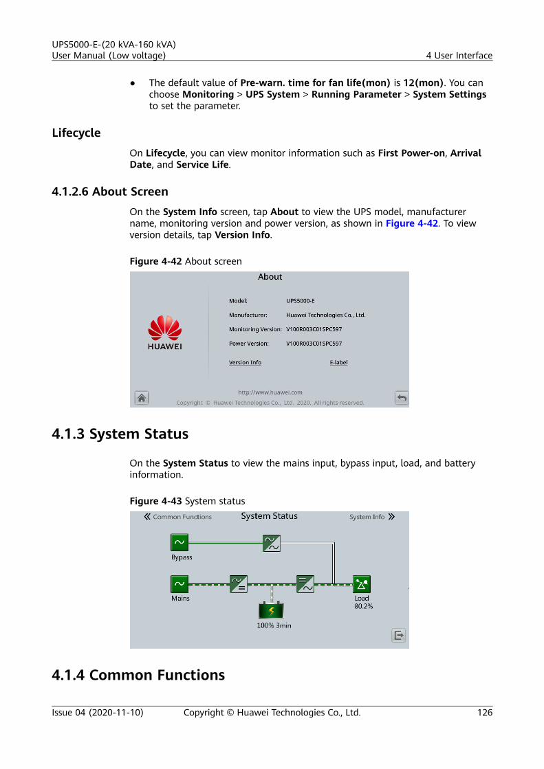
● The default value of Pre-warn. time for fan life(mon) is 12(mon). You canchoose Monitoring > UPS System > Running Parameter > System Settingsto set the parameter.
LifecycleOn Lifecycle, you can view monitor information such as First Power-on, ArrivalDate, and Service Life.
4.1.2.6 About ScreenOn the System Info screen, tap About to view the UPS model, manufacturername, monitoring version and power version, as shown in Figure 4-42. To viewversion details, tap Version Info.
Figure 4-42 About screen
4.1.3 System Status
On the System Status to view the mains input, bypass input, load, and batteryinformation.
Figure 4-43 System status
4.1.4 Common Functions
UPS5000-E-(20 kVA-160 kVA)User Manual (Low voltage) 4 User Interface
Issue 04 (2020-11-10) Copyright © Huawei Technologies Co., Ltd. 126

Figure 4-44 Common functions 1
Figure 4-45 Common functions 2
4.2 WebUI
4.2.1 Login
ContextInternet Explorer 11 is used as the example browser.
The system supports Internet Explorer 11 and Firefox 31.0.
Procedure
Step 1 Open the browser and choose Tools > Internet Options.
Step 2 On the Advanced tab page, ensure that Use TLS 1.0, and Use TLS 1.1 are selectedand click OK.
UPS5000-E-(20 kVA-160 kVA)User Manual (Low voltage) 4 User Interface
Issue 04 (2020-11-10) Copyright © Huawei Technologies Co., Ltd. 127

Figure 4-46 Settings in the Internet Options dialog box
Step 3 Enter https://UPS IP address in the address box of the browser, select a language,set User name and Password, and click Login.
NO TE
The preset UPS IP address is 192.168.0.10. You can set the UPS Ethernet IP address on theLCD or WebUI. The value range is 1.0.0.0–223.255.255.255.
Table 4-11 User description
Default User PresetPassword
User Rights
admin (systemadministrator)
Changeme Performs all operations on the LCD and WebUI,including system running informationbrowsing, system information exporting,parameter setting, system control, systemconfiguration, and system maintenance.
operator(common user)
Changeme Only browses the system running information,exports system information, starts/shuts downthe inverter, rectifies faults, and controls thebuzzer. Other control and maintenancefunctions that may affect system operation areinvisible and parameters cannot be set.
UPS5000-E-(20 kVA-160 kVA)User Manual (Low voltage) 4 User Interface
Issue 04 (2020-11-10) Copyright © Huawei Technologies Co., Ltd. 128

NO TE
● If an incorrect password is entered five consecutive times, the account will be logged outfor 5 minutes.
● After a user logs in to the WebUI, if another user logs in with the same user name, thecurrent account will be logged out.
● It is advised to change the password after the first login using User Mgmt. on theConfig. page to prevent unauthorized access.
----End
4.2.2 Home
Figure 4-47 Home
Item Description
System Overview View the operation status of the mains input, bypass input,battery and AC output of the system.
Active Alarm View the active alarms of the system.
4.2.3 MonitoringOn the Monitoring page, you can view the running information, including UPSsystem, Bypass, Module Summary, ECM Summary, Battery, and battery groupsummary.
Figure 4-48 Monitoring
UPS5000-E-(20 kVA-160 kVA)User Manual (Low voltage) 4 User Interface
Issue 04 (2020-11-10) Copyright © Huawei Technologies Co., Ltd. 129

Item Description
UPS System View Running Information of the UPS, set Running Parameterfor the UPS, and perform Running Control on the UPS.
Bypass View the bypass input Running Information and set RunningParameter.
ModuleSummary
Query the module Running Information and set RunningParameter.
ECMSummary
Set Running Parameter for the ECM.
BatterySystem
View the battery Running Information and set RunningParameter.
BatteryStringSummary
NOTEIf Number of iBOXs is not 0 and lead-acid batteries are used, BatteryString Summary is displayed on the Monitoring page.
Set parameters for the iBOX and iBAT connected to each batterystring.
UPS system
Table 4-12 System settings
Item Description DefaultValue
ValueRange
High ambienttemperaturealarmthreshold (°C)
An alarm is generated when theambient temperature reaches orexceeds the threshold specifiedby this parameter.
55 40–60
Low ambienttemperaturealarmthreshold (°C)
An alarm is generated when theambient temperature is lowerthan the threshold specified bythis parameter.
–10 –20 to 0
EPOdetection
Indicates whether to enableemergency power-off (EPO). EPOis performed only when thisparameter is enabled and theEPO switch is triggered.When EPO detection is changedfrom Disable to Enable, checkthat the EPO cable is connectedcorrectly.
Disable Disable,Enable
Bus capa. life If this parameter is set to Enable,the UPS detects the buscapacitor lifespan.
Enable Disable,Enable
UPS5000-E-(20 kVA-160 kVA)User Manual (Low voltage) 4 User Interface
Issue 04 (2020-11-10) Copyright © Huawei Technologies Co., Ltd. 130

Item Description DefaultValue
ValueRange
Paral. sys.hibernate
When customer loads are light,enable parallel hibernation toalternate modules in hibernationmode, which can prolong theirservice life and improve thesystem efficiency.
Disable Disable,Enable
Module cyclehiber. period(d)
Indicates the rotation interval ofmodules in hibernation mode.The default value is 30, whichmeans that the hibernatingmodule is rotated every 30 days.
30 1–100
D.G. ECObypass supply
Indicates whether ECO bypass isallowed to supply power in D.G.mode. When the D.G. isconnected to the dry contactsignal GEN:● If this parameter is set to
Enable, the system can enterECO bypass mode when theD.G. supplies power to thebypass and the ECO functionis enabled.
● If this parameter is set toDisable, the system is notallowed to enter ECO modewhen the D.G. supplies powerto the bypass.
Enable Disable,Enable
RAMverification
Enable or disable the memorycheck function. If this parameteris set to Enable, the control chipRAM working status is checkedregularly. If this parameter is setto Disable, regular check isdisabled.
Disable Disable,Enable
Collect real-time sitewaveform
If this parameter is set to Enable,one waveform can be storedmanually.
Disable Disable,Enable
Fan life Specifies whether to enable thelife detection for fans in thepower modules and bypassmodules.
Enable Disable,Enable
Pre-warn.time for fanlife(mon)
When the Fan lifespan left is lessthan the setting, an alarm isgenerated.
12 1~24
UPS5000-E-(20 kVA-160 kVA)User Manual (Low voltage) 4 User Interface
Issue 04 (2020-11-10) Copyright © Huawei Technologies Co., Ltd. 131

Item Description DefaultValue
ValueRange
Key updateinterval(d)
- 180 30–1095
BCB trips incase of EOD
If this parameter is set to Enable,the BCB will trip in case of EOD.
Enable Disable,Enable
Table 4-13 Input settings
Item Description DefaultValue
ValueRange
Inputadaptability
Input adaptability mode 1: It isapplicable to the normal powergrid and DGs, and DGs that aresensitive to the output reactivecomponent. Input adaptabilitymode 2: It is applicable to thenormal power grid and DGs, andinput power sources with highinternal resistance.
Mode 2 Mode 1,Mode 2
Table 4-14 Output settings
Item Description Default Value Value Range
Zero displaywith no loadoutput
If this parameter is set toEnable, the output current isdisplayed as 0 when no loadis output. The output loadrate is displayed as 3%.When this parameter is set toDisabled, the output currentand output load rate are notadjusted to zero.
Enable Disable,Enable
Calib. outputcurrent if noload
If this parameter is set toEnable, the current at noload will be calibrated onceautomatically. This functioncan be used only when theUPS carries no load.
Disable Disable,Enable
Outputinterruptiontransfer time(ms)
Set this parameter based onthe output interruption timeacceptable to loads.
0 0 ms, 40 ms,60 ms, 80 ms,100 ms, 120ms
UPS5000-E-(20 kVA-160 kVA)User Manual (Low voltage) 4 User Interface
Issue 04 (2020-11-10) Copyright © Huawei Technologies Co., Ltd. 132

Item Description Default Value Value Range
Max. BPMtransfer times
Cross currents occur duringthe transfer between bypassmode and normal mode,which impacts the system.This parameter specifies thenumber of transfers betweenbypass mode and normalmode within 1 hour, whichensures system security.
5 1–10
Currentequal.detection
Monitors the currentdifferences between racks ormodules. If this parameter isset to Enable, the Mod. Cur.Eql. Data can be viewed onthe running informationscreen.
Disable Disable,Enable
Inverterasync. alarm
Specifies whether anInverter asynchronousalarm can be displayed onthe LCD when the invertercannot track the bypassfrequency change. Normalpower supply is not affectedno matter whether thisparameter is set to Enable orDisable.
Disable Disable,Enable
Busovervoltagerecovery
Specifies whether toautomatically clear the alarmand restart the powermodule when the rectifier orinverter shuts down due to abus overvoltage alarm. If Busovervoltage recovery is setto Enable, the busovervoltage alarm isautomatically cleared, andthe rectifier and inverterautomatically start when thebus voltage recovers withinBus overvolt. recovery time.When Bus overvoltagerecovery is set to Disable,the bus overvoltage alarmcannot be automaticallycleared, and the rectifier andinverter cannot automaticallystart.
Enable Disable,Enable
UPS5000-E-(20 kVA-160 kVA)User Manual (Low voltage) 4 User Interface
Issue 04 (2020-11-10) Copyright © Huawei Technologies Co., Ltd. 133
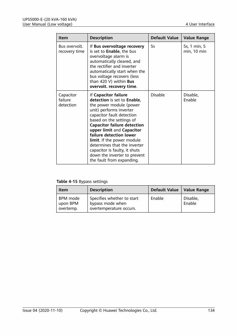
Item Description Default Value Value Range
Bus overvolt.recovery time
If Bus overvoltage recoveryis set to Enable, the busovervoltage alarm isautomatically cleared, andthe rectifier and inverterautomatically start when thebus voltage recovers (lessthan 420 V) within Busovervolt. recovery time.
5s 5s, 1 min, 5min, 10 min
Capacitorfailuredetection
If Capacitor failuredetection is set to Enable,the power module (powerunit) performs invertercapacitor fault detectionbased on the settings ofCapacitor failure detectionupper limit and Capacitorfailure detection lowerlimit. If the power moduledetermines that the invertercapacitor is faulty, it shutsdown the inverter to preventthe fault from expanding.
Disable Disable,Enable
Table 4-15 Bypass settings
Item Description Default Value Value Range
BPM modeupon BPMovertemp.
Specifies whether to startbypass mode whenovertemperature occurs.
Enable Disable,Enable
UPS5000-E-(20 kVA-160 kVA)User Manual (Low voltage) 4 User Interface
Issue 04 (2020-11-10) Copyright © Huawei Technologies Co., Ltd. 134

Item Description Default Value Value Range
LightloadBPM cur. eql.detect
Enable or disable the lightload bypass currentimbalance alarm. If thisparameter is set to Enable,the load is light (less than30% load), and the load rateof a certain rack is less than10%, the system willgenerate a bypass currentimbalance alarm and cannotenter the ECO mode. If thisparameter is set to Disable,the preceding detection isnot performed. Whether thebypass current is imbalanceddoes not affect the ECObypass mode.
Enable Disable,Enable
Battery
NO TICE
Battery parameter settings impact battery maintenance, battery lifespan, and UPSdischarge time. When you set battery parameters, note the following:● Retain default settings for Chg. cur. limiting coef. and Cell float voltage. Only
professional maintenance personnel are allowed to change the settings.● When you set parameters, ensure the following: Chg. cur. limiting coef. >
Transfer-to-equalized charging cur. coef.● Single batt. float chg. voltage deviation alarm thres. and Single batt. dis.
voltage deviation alarm thres. are used to check whether the batteries ineach battery string have the same charge voltage and discharge voltage. Whena value exceeds the specified range, an alarm is generated. The calculationformula is (Charge/Discharge voltage – Average voltage)/Average voltage x100%. The charge/discharge voltage and average voltage are obtained fromthe BMU. If the BMU is not configured, these two parameters do not need tobe set.
UPS5000-E-(20 kVA-160 kVA)User Manual (Low voltage) 4 User Interface
Issue 04 (2020-11-10) Copyright © Huawei Technologies Co., Ltd. 135
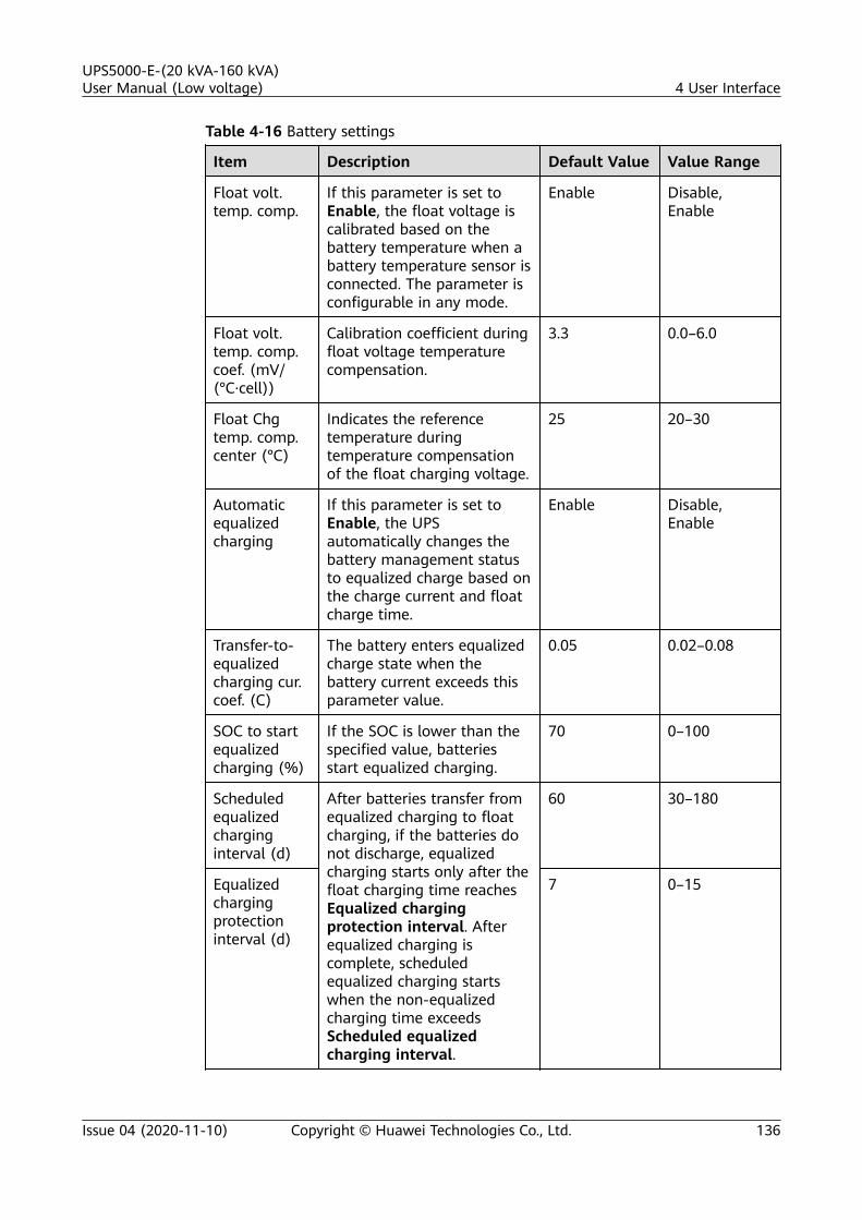
Table 4-16 Battery settings
Item Description Default Value Value Range
Float volt.temp. comp.
If this parameter is set toEnable, the float voltage iscalibrated based on thebattery temperature when abattery temperature sensor isconnected. The parameter isconfigurable in any mode.
Enable Disable,Enable
Float volt.temp. comp.coef. (mV/(°C·cell))
Calibration coefficient duringfloat voltage temperaturecompensation.
3.3 0.0–6.0
Float Chgtemp. comp.center (°C)
Indicates the referencetemperature duringtemperature compensationof the float charging voltage.
25 20–30
Automaticequalizedcharging
If this parameter is set toEnable, the UPSautomatically changes thebattery management statusto equalized charge based onthe charge current and floatcharge time.
Enable Disable,Enable
Transfer-to-equalizedcharging cur.coef. (C)
The battery enters equalizedcharge state when thebattery current exceeds thisparameter value.
0.05 0.02–0.08
SOC to startequalizedcharging (%)
If the SOC is lower than thespecified value, batteriesstart equalized charging.
70 0–100
Scheduledequalizedcharginginterval (d)
After batteries transfer fromequalized charging to floatcharging, if the batteries donot discharge, equalizedcharging starts only after thefloat charging time reachesEqualized chargingprotection interval. Afterequalized charging iscomplete, scheduledequalized charging startswhen the non-equalizedcharging time exceedsScheduled equalizedcharging interval.
60 30–180
Equalizedchargingprotectioninterval (d)
7 0–15
UPS5000-E-(20 kVA-160 kVA)User Manual (Low voltage) 4 User Interface
Issue 04 (2020-11-10) Copyright © Huawei Technologies Co., Ltd. 136

Item Description Default Value Value Range
Forcedequalizedchargingprotectiontime (h)
When batteries arecontinuously under floatcharging or hibernation,enable forced equalizedcharging. When the forcedequalized charging timereaches the value of thisparameter, batteriesautomatically transfer tofloat charging mode.
18 12–24
Max. batt. dis.time (h)
Set the maximum batterydischarge time. When thedischarge time reaches thisvalue, the UPS powers off.The battery discharge timecan be set only to 0 hours ora value only in the range of16–48 hours. If the time isset to 0 hours, batterydischarge protection is notimplemented.
24 0–48
Undertemp.alarm thresh.(°C)
Battery temperatures can bemonitored in a timelymanner. If a batteryovertemperature alarm isdetected, the chargingcurrent limit decreases to0.03 CA. Battery chargingstops if a batteryovertemperature protectionalarm (when thetemperature reaches the hightemperature threshold plus3°C) is generated.
–5 –20 to +5
Overtemp.alarm thresh.(°C)
50 35 to 55
Single batt.float chg.voltagedeviationalarm thres.(%)
Single batt. float chg.voltage deviation alarmthres. (%) and Single batt.dis. voltage deviation alarmthres. (%) are used to checkwhether the cells in eachbattery string have the samecharge voltage and dischargevoltage. When a valueexceeds the specified range,an alarm is generated.The calculation formula is(Charge/Discharge voltage –
10 5–30
UPS5000-E-(20 kVA-160 kVA)User Manual (Low voltage) 4 User Interface
Issue 04 (2020-11-10) Copyright © Huawei Technologies Co., Ltd. 137

Item Description Default Value Value Range
Single batt.dis. voltagedeviationalarm thres.(%)
Average voltage)/Averagevoltage x 100%.
20 10–30
Batt. chargingcapacitymismatch
After this function is enabled,an alarm is generated if theconfigured battery capacityexceeds the chargingcapacity of the rack.
Enable Disable,Enable
Batt. modeshut
In battery mode, the UPS canautomatically power offaccording to the presetshutdown delay time. If theparameter is disabled, thisfunction is not available.
Disable Disable,Enable
Bat modeshut delay (s)
Shutdown delay in batterymode.
7200 0–7200
Backup timewarning
An alarm is generated if thisparameter is set to Enableand the backup time is lessthan the warning threshold.
Disable Disable,Enable
Backup timewarningthresh. (min)
Backup time warningthreshold.
5 3 to 30
Remain. cap.warning
An alarm is generated if thisparameter is set to Enableand the remaining capacity isless than the warningthreshold.
Disable Disable,Enable
Remain. cap.warn. thresh.(%)
Remaining capacity warningthreshold
20 5–50
Intelligenthibernation
If this parameter is set toEnable, the intelligentbattery hibernation functionis enabled.
Disable Disable,Enable
Class 1 gridhiber. time(d)
Hibernation time for class 1power grids.
13 0–30
Class 2 gridhiber. time(d)
Hibernation time for class 2power grids.
6 0–15
UPS5000-E-(20 kVA-160 kVA)User Manual (Low voltage) 4 User Interface
Issue 04 (2020-11-10) Copyright © Huawei Technologies Co., Ltd. 138

Item Description Default Value Value Range
Thres. of lowbatt. SOCover drycontact (%)
If an output dry contact is setto Low battery SOC, and thebattery SOC is lower thanthis threshold, the output drycontact will output signals.
75 5–80
Thres. of lowbatt. volt.over drycontact (V/cell)Thres. of lowbatt. volt.over drycontact(V/cell)
If an output dry contact is setto Batt. Volt. BelowThreshold, and the batteryvoltage is lower than thisthreshold, the output drycontact will output signals.
1.70 1.70–2.10
Lead-acid battery: If Batt.Volt. Below Threshold is setfor an output dry contactand the battery voltage islower than this threshold, theoutput dry contact generatesa signal.Lithium battery: If Batt. Volt.Below Threshold is set foran output dry contact andthe minimumelectrochemical cell voltageis lower than the threshold,the output dry contactgenerates a signal.
1.702.80
1.70–2.102.60–3.20
Battery String SummaryItem Description
No. of iBOX Number of an iBOX connected to the UPS
iBAT start No. Start number of an iBAT connected to the iBOX
iBAT end No. End number of an iBAT connected to the iBOX
4.2.4 Query
On the Query page, you can query Historical Alarm, Operation Log, andPerformance Data, and perform Export Data.
Figure 4-49 Query
UPS5000-E-(20 kVA-160 kVA)User Manual (Low voltage) 4 User Interface
Issue 04 (2020-11-10) Copyright © Huawei Technologies Co., Ltd. 139

Item Description
HistoricalAlarm
Queries historical alarms of the system or components.
Battery TestRecords
Query and export Cap. test logs and Common test logs.
PerformanceData
Queries the performance data of the components related to thesystem.
Export Data Export Historical Alarm, Active Alarm, Operation Log, andPerformance Data.
4.2.5 System Settings
On the System Settings page, you can set Site Configuration, Time, IP Address,NetEco, ModbusTCP, Alarm Parameters, SNMP, Event Notice, and Outboxconfiguration.
Figure 4-50 System Settings (lead-acid battery)
Figure 4-51 System settings (lithium battery)
UPS5000-E-(20 kVA-160 kVA)User Manual (Low voltage) 4 User Interface
Issue 04 (2020-11-10) Copyright © Huawei Technologies Co., Ltd. 140

Site Configuration
Table 4-17 System type
Item Description
Name Site name.
Location Site location.
Contact information Site contact information.
Table 4-18 Network security certificate
Item Description
Select Certificate Format CRT format and PFX format are supported.
Please select a securitycertificate
Upload a network security certificate.
Select the network securitycertificate key to beuploaded
Upload the key of the network security certificate.
Export certificate file: Export the root certificate.
Time
Set the time zone and time for the site.
Comm. Settings
Set IP Settings, RS485 Settings, ModbusTCP Settings, Amb. T/H Sensor, Batt.Temp. Sensor, BMU, and WIFI Settings.
ModbusTCP
Table 4-19 Access ModbusTCP security certificate
Item Description
Upload CA certificate file Import a CA certificate for the UPS to verify thecertificate of the Modbus-TCP communicationaccess party.
Upload local certificate file Users can replace the UPS certificate with atrusted certificate.
Upload key file Key file of the certificate.
UPS5000-E-(20 kVA-160 kVA)User Manual (Low voltage) 4 User Interface
Issue 04 (2020-11-10) Copyright © Huawei Technologies Co., Ltd. 141

Item Description
Key password Decryption password of the key.
Confirm key password Confirm the decryption password of the key.
Set twice challenge prelim share code: Set the user authentication passwordbetween the NetEco and the UPS.
Alarm Parameters
Enable or disable alarm information for components in the system.
iBOX Settings
Set iBOX parameters.
Battery System
Check the SmartLi start address.
SNMP● The default SNMP version is SNMPv3, and the preset MD5/SHA password is
Changeme1, and the preset DES/AES password is Changeme2. Change thepassword after your first login, preventing unauthorized access.
NO TE
● The standard protocols SNMP V1 and SNMP V2 have security risks. You are advisedto use the secure protocol SNMP V3.
● The standard encryption algorithms MD5 and DES have security risks. You areadvised to use the secure encryption algorithms SHA and AES.
● To obtain the Mib file, choose System Settings > SNMP > Mib File > Export.
● The SNMP Trap is used to set the IP address of a server on which the NMSsoftware is installed. The trap port needs to be the same as that on the NMS.If SNMP Trap is incorrectly set or not set, system information will be lost ornot reported in time.
Event Notice● Mailbox Settings: Set the email address of the recipient in Mailbox Settings.
● Alarm Notification, set Alarm notification delay in Alarm NotificationParameter Settings, set Time of the first reminder and Interval in AlarmReminder Configuration, and perform the Add, Modify, or Delete operationon alarm notifications in Alarm Notification User Settings.
● After the Event Notice information is configured, alarms will be sent to theconfigured mailbox.
UPS5000-E-(20 kVA-160 kVA)User Manual (Low voltage) 4 User Interface
Issue 04 (2020-11-10) Copyright © Huawei Technologies Co., Ltd. 142

Outbox configuration
Table 4-20 Outbox settings
Item Description
Address type IP address is supported.
Mailbox server IP address After the IP address of the outbox server isconfigured, alarm notification emails will be sent tothe configured server.
Encryption mode TLS, SSL, and No encryption are supported.
SMTP port The default value is 587.
Outbox Outbox address.
User authentication formailbox server login
After Enable is selected, user authentication isrequired for server login.
User Name User name for authentication.
Password Password for authentication.
Mailbox Certificate: Upload the CA certificate file.
4.2.6 Maintenance
On the Maintenance page, you can perform Soft Upgrade and UserManagement, query Version Information, query and export E-label, export FaultInformation, and import and back up Configuration File.
Figure 4-52 Maintenance
Item Description
SoftwareUpgrade
Upgrades the software version of the system.
VersionInformation
Queries the software and hardware versions of devices in thesystem.
ConfigurationFile
Imports and exports system configuration files.
UPS5000-E-(20 kVA-160 kVA)User Manual (Low voltage) 4 User Interface
Issue 04 (2020-11-10) Copyright © Huawei Technologies Co., Ltd. 143

Item Description
E-label Queries and exports e-labels of devices in the system.
UserManagement
Allows users to perform Add, Modify, Delete, Lock, and Unlockoperations, and set passwords.
FaultInformation
Exports fault information.
BSP Upgrade Upgrades the BSP version.
Lifecycle View monitor information such as First Power-on, Arrival Date,and Service Life.
4.3 Old WebUINO TE
User interfaces displayed in this document correspond to the WebUI versionV100R001C35SPC001 and are for reference only.
4.3.1 Login
ContextInternet Explorer 11 is used as the example browser.
The system supports Internet Explorer 11 and Firefox 31.0.
Procedure
Step 1 Open the browser and choose Tools > Internet Options.
Step 2 On the Advanced tab page, ensure that Use TLS 1.0, and Use TLS 1.1 are selectedand click OK.
UPS5000-E-(20 kVA-160 kVA)User Manual (Low voltage) 4 User Interface
Issue 04 (2020-11-10) Copyright © Huawei Technologies Co., Ltd. 144

Figure 4-53 Settings in the Internet Options dialog box
Step 3 Enter https://UPS IP address in the address box of the browser, select a language,set User name and Password, and click Login.
NO TE
The preset UPS IP address is 192.168.0.10. You can set the UPS Ethernet IP address on theLCD or WebUI. The value range is 1.0.0.0–223.255.255.255.
Table 4-21 User description
Default User PresetPassword
User Rights
admin (systemadministrator)
Changeme Performs all operations on the LCD and WebUI,including system running informationbrowsing, system information exporting,parameter setting, system control, systemconfiguration, and system maintenance.
operator(common user)
Changeme Only browses the system running information,exports system information, starts/shuts downthe inverter, rectifies faults, and controls thebuzzer. Other control and maintenancefunctions that may affect system operation areinvisible and parameters cannot be set.
browser(browsinguser)
N/A Only browses the system running information.
UPS5000-E-(20 kVA-160 kVA)User Manual (Low voltage) 4 User Interface
Issue 04 (2020-11-10) Copyright © Huawei Technologies Co., Ltd. 145

NO TE
● If an incorrect password is entered five consecutive times, the account will be logged outfor 5 minutes.
● After a user logs in to the WebUI, if another user logs in with the same user name, thecurrent account will be logged out.
● It is advised to change the password after the first login using User Mgmt. on theConfig. page to prevent unauthorized access.
----End
4.3.2 Monitoring
Figure 4-54 Monitoring
NO TE
If NA is displayed for load ratio, the value is invalid or outside the range.
Table 4-22 Monitoring details
Number Area Function
1 Runningstatus area
Displays the power flow and UPS runninginformation.
2 Menu bar Displays alarms and real-time data, setsparameters, and provides control commands.The Active Alarms page is displayed by default.
3 Informationarea
Displays system monitoring information.
UPS5000-E-(20 kVA-160 kVA)User Manual (Low voltage) 4 User Interface
Issue 04 (2020-11-10) Copyright © Huawei Technologies Co., Ltd. 146

4.3.2.1 Parameter Settings
Figure 4-55 Parameter settings
System SettingsItem Description Default Value Value Range
High ambienttemperaturealarmthreshold (°C)
An alarm is generated whenthe ambient temperaturereaches or exceeds thethreshold specified by thisparameter.
55 40–60
Low ambienttemperaturealarmthreshold (°C)
An alarm is generated whenthe ambient temperature islower than the thresholdspecified by this parameter.
–10 –20 to 0
EPOdetection
Indicates whether to enableemergency power-off (EPO).EPO is performed only whenthis parameter is enabledand the EPO switch istriggered.When EPO detection ischanged from Disable toEnable, check that the EPOcable is connected correctly.
Disable Disable,Enable
Bus capa. life If this parameter is set toEnable, the UPS detects thebus capacitor lifespan.
Enable Disable,Enable
Paral. sys.hibernate
When customer loads arelight, enable parallelhibernation to alternatemodules in hibernationmode, which can prolongtheir service life and improvethe system efficiency.
Disable Disable,Enable
UPS5000-E-(20 kVA-160 kVA)User Manual (Low voltage) 4 User Interface
Issue 04 (2020-11-10) Copyright © Huawei Technologies Co., Ltd. 147

Item Description Default Value Value Range
Module cyclehiber. period(d)
Indicates the rotation intervalof modules in hibernationmode. The default value is30, which means that thehibernating module isrotated every 30 days.
30 1–100
D.G. ECObypass supply
Indicates whether ECObypass is allowed to supplypower in D.G. mode. Whenthe D.G. is connected to thedry contact signal GEN:● If this parameter is set to
Enable, the system canenter ECO bypass modewhen the D.G. suppliespower to the bypass andthe ECO function isenabled.
● If this parameter is set toDisable, the system is notallowed to enter ECOmode when the D.G.supplies power to thebypass.
Enable Disable,Enable
RAMverification
Enable or disable thememory check function. Ifthis parameter is set toEnable, the control chip RAMworking status is checkedregularly. If this parameter isset to Disable, regular checkis disabled.
Disable Disable,Enable
Collect real-time sitewaveform
If this parameter is set toEnable, one waveform canbe stored manually.
Disable Disable,Enable
BCB trips incase of EOD
If this parameter is set toEnable, the BCB will trip incase of EOD.
Enable Disable,Enable
UPS5000-E-(20 kVA-160 kVA)User Manual (Low voltage) 4 User Interface
Issue 04 (2020-11-10) Copyright © Huawei Technologies Co., Ltd. 148

Input SettingsItem Description Default Value Value Range
Inputadaptability
The value of Inputadaptability can be Strongor Weak. Strong inputadaptability applies to theD.G. or input sources whoseinput current has highfrequency oscillation. In thismode, the total distortion ofthe input current waveform(THDi) is poor, but thesystem is stable. Weak inputadaptability is suitable formains and AC input sources.
Strong Strong, Weak
Output SettingsItem Description Default Value Value Range
Zero displaywith no loadoutput
If this parameter is set toEnable, the output current isdisplayed as 0 when no loadis output. The output loadrate is displayed as 3%.When this parameter is set toDisabled, the output currentand output load rate are notadjusted to zero.
Enable Disable,Enable
Calib. outputcurrent if noload
If this parameter is set toEnable, the current at noload will be calibrated onceautomatically. This functioncan be used only when theUPS carries no load.
Disable Disable,Enable
Outputinterruptiontransfer time(ms)
Set this parameter based onthe output interruption timeacceptable to loads.
0 0 ms, 40 ms,60 ms, 80 ms,100 ms, 120ms
UPS5000-E-(20 kVA-160 kVA)User Manual (Low voltage) 4 User Interface
Issue 04 (2020-11-10) Copyright © Huawei Technologies Co., Ltd. 149

Item Description Default Value Value Range
Max. BPMtransfer times
Cross currents occur duringthe transfer between bypassmode and normal mode,which impacts the system.This parameter specifies thenumber of transfers betweenbypass mode and normalmode within 1 hour, whichensures system security.
5 1–10
Currentequal.detection
Monitors the currentdifferences between racks ormodules. If this parameter isset to Enable, the Mod. Cur.Eql. Data can be viewed onthe running informationscreen.
Disable Disable,Enable
Inverterasync. alarm
Specifies whether anInverter asynchronousalarm can be displayed onthe LCD when the invertercannot track the bypassfrequency change. Normalpower supply is not affectedno matter whether thisparameter is set to Enable orDisable.
Disable Disable,Enable
Busovervoltagerecovery
Specifies whether toautomatically clear the alarmand restart the powermodule when the rectifier orinverter shuts down due to abus overvoltage alarm. If Busovervoltage recovery is setto Enable, the busovervoltage alarm isautomatically cleared, andthe rectifier and inverterautomatically start when thebus voltage recovers (lessthan 420 V) within Busovervolt. recovery time.When Bus overvoltagerecovery is set to Disable,the bus overvoltage alarmcannot be automaticallycleared, and the rectifier andinverter cannot automaticallystart.
Enable Disable,Enable
UPS5000-E-(20 kVA-160 kVA)User Manual (Low voltage) 4 User Interface
Issue 04 (2020-11-10) Copyright © Huawei Technologies Co., Ltd. 150

Item Description Default Value Value Range
Bus overvolt.recovery time
If Bus overvoltage recoveryis set to Enable, the busovervoltage alarm isautomatically cleared, andthe rectifier and inverterautomatically start when thebus voltage recovers (lessthan 420 V) within Busovervolt. recovery time.
5s 5s, 1 min, 5min, 10 min
Capacitorfailuredetection
If Capacitor failuredetection is set to Enable,the power module (powerunit) performs invertercapacitor fault detectionbased on the settings ofCapacitor failure detectionupper limit and Capacitorfailure detection lowerlimit. If the power moduledetermines that the invertercapacitor is faulty, it shutsdown the inverter to preventthe fault from expanding.
Disable Disable,Enable
Bypass SettingsItem Description Default Value Value Range
BPM modeupon BPMovertemp.
Specifies whether to startbypass mode whenovertemperature occurs.
Enable Disable,Enable
UPS5000-E-(20 kVA-160 kVA)User Manual (Low voltage) 4 User Interface
Issue 04 (2020-11-10) Copyright © Huawei Technologies Co., Ltd. 151

Battery Settings
NO TICE
Battery parameter settings impact battery maintenance, battery lifespan, and UPSdischarge time. When you set battery parameters, note the following:● Retain default settings for Chg. cur. limiting coef. and Cell float voltage. Only
professional maintenance personnel are allowed to change the settings.● When you set parameters, ensure the following: Chg. cur. limiting coef. >
Transfer-to-equalized charging cur. coef.● Single batt. float chg. voltage deviation alarm thres. and Single batt. dis.
voltage deviation alarm thres. are used to check whether the batteries ineach battery string have the same charge voltage and discharge voltage. Whena value exceeds the specified range, an alarm is generated. The calculationformula is (Charge/Discharge voltage – Average voltage)/Average voltage x100%. The charge/discharge voltage and average voltage are obtained fromthe BMU. If the BMU is not configured, these two parameters do not need tobe set.
Item Description Default Value Value Range
Float volt.temp. comp.
If this parameter is set toEnable, the float voltage iscalibrated based on thebattery temperature when abattery temperature sensor isconnected. The parameter isconfigurable in any mode.
Enable Disable,Enable
Float volt.temp. comp.coef. (mV/°C·cell)
Calibration coefficient duringfloat voltage temperaturecompensation.
3.3 0.0–6.0
Float Chgtemp compcenter (°C)
Indicates the referencetemperature duringtemperature compensationof the float charging voltage.
25 20–30
Automaticequalizedcharging
If this parameter is set toEnable, the UPSautomatically changes thebattery management statusto equalized charge based onthe charge current and floatcharge time.
Enable Disable,Enable
Transfer-to-equalizedcharging cur.coef. (C10)
The battery enters equalizedcharge state when thebattery current exceeds thisparameter value.
0.05 0.02–0.08
UPS5000-E-(20 kVA-160 kVA)User Manual (Low voltage) 4 User Interface
Issue 04 (2020-11-10) Copyright © Huawei Technologies Co., Ltd. 152

Item Description Default Value Value Range
SOC to startequalizedcharging (%)
If the SOC is lower than thespecified value, batteriesstart equalized charging.
70 0–100
Scheduledequalizedcharginginterval (d)
After batteries transfer fromequalized charging to floatcharging, if the batteries donot discharge, equalizedcharging starts only after thefloat charging time reachesEqualized chargingprotection interval. Afterequalized charging iscomplete, scheduledequalized charging startswhen the non-equalizedcharging time exceedsScheduled equalizedcharging interval.
60 30–180
Equalizedchargingprotectioninterval (d)
7 0–15
Forcedequalizedchargingprotectiontime (h)
When batteries arecontinuously under floatcharging or hibernation,enable forced equalizedcharging. When the forcedequalized charging timereaches the value of thisparameter, batteriesautomatically transfer tofloat charging mode.
18 12–24
Max. batt. dis.time (h)
Set the maximum batterydischarge time. When thedischarge time reaches thisvalue, the UPS powers off.The battery discharge timecan be set only to 0 hours ora value only in the range of16–48 hours. If the time isset to 0 hours, batterydischarge protection is notimplemented.
24 0–48
Undertemp.alarm thresh.(°C)
Battery temperatures can bemonitored in a timelymanner. If a batteryovertemperature alarm isdetected, the chargingcurrent limit decreases to0.03 CA. Battery chargingstops if a batteryovertemperature protection
–5 –20 to +5
UPS5000-E-(20 kVA-160 kVA)User Manual (Low voltage) 4 User Interface
Issue 04 (2020-11-10) Copyright © Huawei Technologies Co., Ltd. 153

Item Description Default Value Value Range
Overtemp.alarm thresh.(°C)
alarm (when thetemperature reaches the hightemperature threshold plus3°C) is generated.
50 35 to 55
Single batt.float chg.voltagedeviationalarm thres.(%)
Single batt. float chg.voltage deviation alarmthres. (%) and Single batt.dis. voltage deviation alarmthres. (%) are used to checkwhether the cells in eachbattery string have the samecharge voltage and dischargevoltage. When a valueexceeds the specified range,an alarm is generated.The calculation formula is(Charge/Discharge voltage –Average voltage)/Averagevoltage x 100%.
10 5–30
Single batt.dis. voltagedeviationalarm thres.(%)
20 10–30
Batt. chargingcapacitymismatch
After this function is enabled,an alarm is generated if theconfigured battery capacityexceeds the chargingcapacity of the rack.
Disable Disable,Enable
Bat modeshut
In battery mode, the UPS canautomatically power offaccording to the presetshutdown delay time. If theparameter is disabled, thisfunction is not available.
Disable Disable,Enable
Backup timewarning
An alarm is generated if thisparameter is set to Enableand the backup time is lessthan the warning threshold.
Disable Disable,Enable
Remain. cap.warning
An alarm is generated if thisparameter is set to Enableand the remaining capacity isless than the warningthreshold.
Disable Disable,Enable
Intelligenthibernation
If this parameter is set toEnable, the intelligentbattery hibernation functionis enabled.
Disable Disable,Enable
UPS5000-E-(20 kVA-160 kVA)User Manual (Low voltage) 4 User Interface
Issue 04 (2020-11-10) Copyright © Huawei Technologies Co., Ltd. 154

Item Description Default Value Value Range
Thres. of lowbatt. SOCover drycontact (%)
If an output dry contact is setto Low battery SOC, and thebattery SOC is lower thanthis threshold, the output drycontact will output signals.
75 5–80
Thres. of lowbatt. volt.over drycontact (V/cell)
If an output dry contact is setto Batt. Volt. BelowThreshold, and the batteryvoltage is lower than thisthreshold, the output drycontact will output signals.
1.70 1.70–2.10
4.3.2.2 Communication Settings
Figure 4-56 Communication settings
4.3.2.3 Control
Figure 4-57 Control
4.3.3 Query
UPS5000-E-(20 kVA-160 kVA)User Manual (Low voltage) 4 User Interface
Issue 04 (2020-11-10) Copyright © Huawei Technologies Co., Ltd. 155

4.3.3.1 Historical AlarmsOn the homepage, click the Query tab to open the Historical Alarms page forquerying historical alarms based on severity, generation time, and clear time.
Figure 4-58 Historical alarms
4.3.3.2 LogsOn the Logs page, you can set Log to Historical logs, Cap. test logs, or Commontest logs, and query or export logs.
NO TE
Historical logs can be exported but not queried.
Figure 4-59 Logs
4.3.4 Config.
4.3.4.1 User ManagementOn the home page, choose Config. > User Mgmt.
UPS5000-E-(20 kVA-160 kVA)User Manual (Low voltage) 4 User Interface
Issue 04 (2020-11-10) Copyright © Huawei Technologies Co., Ltd. 156

Figure 4-60 User management
NO TE
● On the User Mgmt. page, you can add, modify, delete, lock, or unlock users and changeuser passwords.
● The WebUI user name cannot exceed 10 characters and can contain only uppercase andlowercase letters, digits, and underscores. The password contains 6 to 20 characters andat least two types of uppercase letters, lowercase letters, digits, and underscores.
● If the LUI password complexity check is disabled, the user password is required to be astring of six to eight digits. If the password complexity check is enabled, the userpassword is required to be a string of 6–20 characters and contain at least two types ofcharacters.
4.3.4.2 Site Config.On the home page, choose Config. > Site Config.
UPS5000-E-(20 kVA-160 kVA)User Manual (Low voltage) 4 User Interface
Issue 04 (2020-11-10) Copyright © Huawei Technologies Co., Ltd. 157
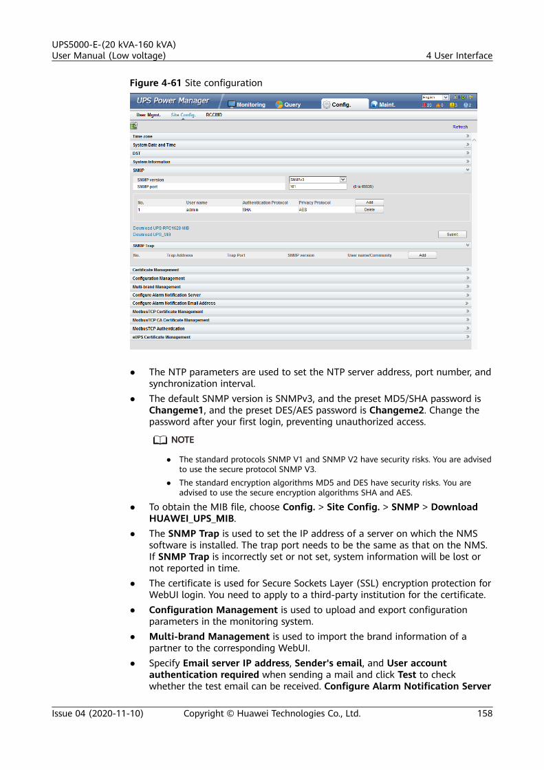
Figure 4-61 Site configuration
● The NTP parameters are used to set the NTP server address, port number, andsynchronization interval.
● The default SNMP version is SNMPv3, and the preset MD5/SHA password isChangeme1, and the preset DES/AES password is Changeme2. Change thepassword after your first login, preventing unauthorized access.
NO TE
● The standard protocols SNMP V1 and SNMP V2 have security risks. You are advisedto use the secure protocol SNMP V3.
● The standard encryption algorithms MD5 and DES have security risks. You areadvised to use the secure encryption algorithms SHA and AES.
● To obtain the MIB file, choose Config. > Site Config. > SNMP > DownloadHUAWEI_UPS_MIB.
● The SNMP Trap is used to set the IP address of a server on which the NMSsoftware is installed. The trap port needs to be the same as that on the NMS.If SNMP Trap is incorrectly set or not set, system information will be lost ornot reported in time.
● The certificate is used for Secure Sockets Layer (SSL) encryption protection forWebUI login. You need to apply to a third-party institution for the certificate.
● Configuration Management is used to upload and export configurationparameters in the monitoring system.
● Multi-brand Management is used to import the brand information of apartner to the corresponding WebUI.
● Specify Email server IP address, Sender's email, and User accountauthentication required when sending a mail and click Test to checkwhether the test email can be received. Configure Alarm Notification Server
UPS5000-E-(20 kVA-160 kVA)User Manual (Low voltage) 4 User Interface
Issue 04 (2020-11-10) Copyright © Huawei Technologies Co., Ltd. 158

is used to configure a server for receiving alarm emails from the monitoringsystem.
● Set Email and Alarm Severity and simulate an alarm. Check that the alarmemail can be received. Configure Alarm Notification Email Address is usedto configure the email address for receiving alarm emails from the monitoringsystem.
● ModbusTCP Certificate Management: ModbusTCP supports the TransportLayer Security (TLS) secure protocol for encrypted transmission andimplements access authentication through the bidirectional certificate.Customers can replace the UPS certificate with the certificate trusted by them.
● ModbusTCP CA Certificate Management: Import a CA certificate to verifythe validity of the ModbusTCP access certificate.
● ModbusTCP Authentication: Verify the identity legitimacy of both parties toensure data security for both parties in ModbusTCP communication.
● After eUPS certificate management is configured, a certificate can beimported on the WebUI to replace the preset eUPS certificate.
4.3.4.3 RCCMD
RCCMDRCCMD function is set to Disable by default, as shown in Figure 4-62. If required,set it to Enable upon first login. After you submit the setting, the page refreshes.The controls such as SSL Encrypted Transmission and Event Configuration willbe displayed on the page, as shown in Figure 4-63.
Figure 4-62 RCCMD function disabled
UPS5000-E-(20 kVA-160 kVA)User Manual (Low voltage) 4 User Interface
Issue 04 (2020-11-10) Copyright © Huawei Technologies Co., Ltd. 159

Figure 4-63 RCCMD function enabled
SSL Encrypted Transmission
NO TICE
The SSL encrypted transmission set on the page of the UPS5000 monitor displaymodule (MDU) must be the same as the setting on the RCCMD client.
SSL Encrypted Transmission is set to Enable by default, as shown in Figure 4-64.If it is set to Disable, the RCCMD certificate controls will not be displayed on thepage, as shown in Figure 4-65. If SSL Encrypted Transmission is set to Disable, amessage indicating there is a risk will be displayed.
UPS5000-E-(20 kVA-160 kVA)User Manual (Low voltage) 4 User Interface
Issue 04 (2020-11-10) Copyright © Huawei Technologies Co., Ltd. 160

Figure 4-64 SSL encrypted transmission enabled by default
Figure 4-65 SSL encrypted transmission disabled
Event Configuration
The MDU supports 17 alarm events, and a maximum of 50 jobs can be added foreach event, as shown in Figure 4-66. Figure 4-66 shows the buttons on the EventConfiguration page, and Table 4-23 describes these buttons.
Figure 4-66 Event configuration page
UPS5000-E-(20 kVA-160 kVA)User Manual (Low voltage) 4 User Interface
Issue 04 (2020-11-10) Copyright © Huawei Technologies Co., Ltd. 161
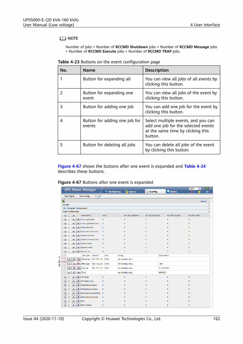
NO TE
Number of jobs = Number of RCCMD Shutdown jobs + Number of RCCMD Message jobs+ Number of RCCMD Execute jobs + Number of RCCMD TRAP jobs.
Table 4-23 Buttons on the event configuration page
No. Name Description
1 Button for expanding all You can view all jobs of all events byclicking this button.
2 Button for expanding oneevent
You can view all jobs of the event byclicking this button.
3 Button for adding one job You can add one job for the event byclicking this button.
4 Button for adding one job forevents
Select multiple events, and you canadd one job for the selected eventsat the same time by clicking thisbutton.
5 Button for deleting all jobs You can delete all jobs of the eventby clicking this button.
Figure 4-67 shows the buttons after one event is expanded and Table 4-24describes these buttons.
Figure 4-67 Buttons after one event is expanded
UPS5000-E-(20 kVA-160 kVA)User Manual (Low voltage) 4 User Interface
Issue 04 (2020-11-10) Copyright © Huawei Technologies Co., Ltd. 162

Table 4-24 Buttons after one event is expanded
No. Name Description
1 Button for modifying A dialog box for modifying a job isdisplayed after you click this button.You can modify the job.
2 Button for deleting one job You can delete the job by clickingthis button.
3 Button for test If you click this button, the job willbe performed and a messageshowing test succeeds or fails will bedisplayed on the page.
Adding one job for one event: Select one event (for example, Inverter on), clickthe button for adding one job, and the page for adding a job for the event isdisplayed.
When adding a job, the job types to be selected are: RCCMD Shutdown, RCCMDMessage, RCCMD Execute, and RCCMD TRAP. RCCMD Shutdown is selected bydefault. For different job types, you need to enter different contents.
● RCCMD Shutdown: You need to specify the RCCMD client IP address andport. When the RCCMD client receives the job, it will shut down the computer.
Figure 4-68 RCCMD shutdown
● RCCMD Message: Specify the RCCMD client IP address, port, and message tobe conveyed. The RCCMD client will receive the message. For example, enter"This is a test message".
UPS5000-E-(20 kVA-160 kVA)User Manual (Low voltage) 4 User Interface
Issue 04 (2020-11-10) Copyright © Huawei Technologies Co., Ltd. 163
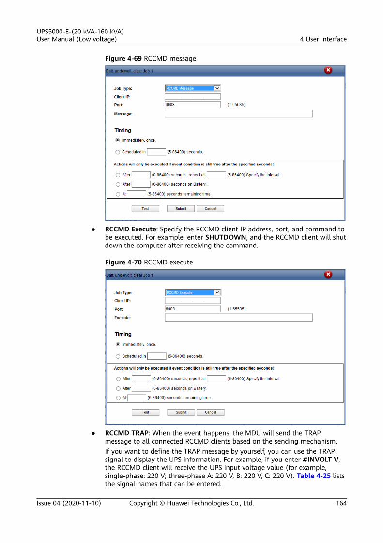
Figure 4-69 RCCMD message
● RCCMD Execute: Specify the RCCMD client IP address, port, and command tobe executed. For example, enter SHUTDOWN, and the RCCMD client will shutdown the computer after receiving the command.
Figure 4-70 RCCMD execute
● RCCMD TRAP: When the event happens, the MDU will send the TRAPmessage to all connected RCCMD clients based on the sending mechanism.If you want to define the TRAP message by yourself, you can use the TRAPsignal to display the UPS information. For example, if you enter #INVOLT V,the RCCMD client will receive the UPS input voltage value (for example,single-phase: 220 V; three-phase A: 220 V, B: 220 V, C: 220 V). Table 4-25 liststhe signal names that can be entered.
UPS5000-E-(20 kVA-160 kVA)User Manual (Low voltage) 4 User Interface
Issue 04 (2020-11-10) Copyright © Huawei Technologies Co., Ltd. 164

Figure 4-71 RCCMD TRAP
Table 4-25 RCCMD TRAP signal
Signal Name Description Unit in the UPS
#MODEL Device name N/A
#OUTPOWER Active power kW
#OUTVOLT Output voltage V
#OUTCURR Output current A
#OUTLOAD Output load rate %
#BATTCAP Remaining batterycapacity
%
#INVOLT Input voltage V
#BYPASSINVOLT Bypass input voltage V
#TEMPDEG Temperature inside theUPS
Celsius
#AUTONOMTIME Battery backup time minutes
#STATUS UPS status N/A
#RUNTIME UPS operating time minutes
#BATTVOLT Battery voltage V
#INFREQ Input frequency Hz
#BYPASSINFREQ Bypass input frequency Hz
#OUTFREQ Output frequency Hz
UPS5000-E-(20 kVA-160 kVA)User Manual (Low voltage) 4 User Interface
Issue 04 (2020-11-10) Copyright © Huawei Technologies Co., Ltd. 165

Signal Name Description Unit in the UPS
#CNT_PF Power supply failuretimes
N/A
#CNT_BL Low battery voltagetimes
N/A
#INPHASES Input phases N/A
#OUTPHASES Output phases N/A
When you add a job, five sending methods are available. The latter three methodscan take effect only when the event condition is still true after the specifiedseconds.
● Immediately, once: After the event happens, the job will be sent to theRCCMD client immediately.
● Scheduled in X seconds: After the event happens, the job will be sent to theRCCMD client once in X seconds. No matter whether the event disappears ornot within X seconds, the job will be sent.
● After X seconds, repeat all Y Specify the interval: After the event happens,the job will be sent once in X seconds, and then be sent once every Y seconds.
● After X seconds on Battery: After the battery mode is activated for Xseconds, the job will be sent to the RCCMD client once.
● At X seconds remaining time: When the battery backup time has only Xseconds left, the job will be sent to the RCCMD client once.
NO TE
X and Y are variables and stand for time.
RCCMD Certificate Management
NO TICE
● After replacing the certificate on the MDU WebUI, replace the certificate on theRCCMD client too. Otherwise, communication will fail. For details about thereplacing method, see the RCCMD user manual.
● The default certificate provided by the system has expired. Replace thecertificate immediately.
After SSL Encrypted Transmission is set to Enable, RCCMD CertificateManagement is displayed. The RCCMD certificate, RCCMD certificate key, andRCCMD CA certificate can be uploaded, as shown in Figure 4-72. If the RCCMDcertificate or RCCMD CA certificate is not uploaded, the default certificateprovided by the system is used for communication. After the certificate isuploaded successfully, click Submit. The WebUI of the MDU will restart, and theuploaded certificate will be used for communication.
UPS5000-E-(20 kVA-160 kVA)User Manual (Low voltage) 4 User Interface
Issue 04 (2020-11-10) Copyright © Huawei Technologies Co., Ltd. 166

Figure 4-72 RCCMD certificate management
NO TE
If the RCCMD certificate key has been encrypted, enable and enter the key password.
4.3.4.4 Managing the UPS by Using the NMS Complying with RFC1628Standard
Installing the UPS MIBThe MIB is in the MDU. Click Download UPS-RFC1628-MIB on the page of theweb browser to download the MIB file which allows the third-party NMS tomanage the UPS remotely.
Figure 4-73 Download the MIB
NO TE
The UPS-RFC1628-MIB has more alarms than RFC1628. Download the UPS-RFC1628-MIBbefore using.
UPS5000-E-(20 kVA-160 kVA)User Manual (Low voltage) 4 User Interface
Issue 04 (2020-11-10) Copyright © Huawei Technologies Co., Ltd. 167

Managing the UPS by Using the NMS● Applying for Access Rights
To manage the UPS by using the UNMS II of Generex over the MDU, apply tothe system administrator of the MDU for access rights and add the NMSinformation to the NMS access list of the MDU. The NMS address and accessright settings are used for adding information about the NMS accessing theMDU, including the NMS address, access right, and Trap port. For detailsabout how to add an NMS over a web browser, see Figure 4-74.
Figure 4-74 Setting the SNMP Trap
● Managing the UPS
Take the UNMS II of Generex for example. The method for managing the UPSby using the UNMS II is the same as the method for managing other devicesby using the UNMS II. For details, see the UNMS II user manual.
4.3.5 Protecting the Server by Using the RCCMD Software
4.3.5.1 Introduction to the Software
The RCCMD shutdown software is part of the centralized monitoring system of theGenerex network. The UPS5000 MDU integrates the functions of the GenerexRCCMD server:
● Sends the shutdown command, notification message, and Trap message tothe RCCMD client if the UPS system generates an alarm; executes commandson the RCCMD client.
● Receives the message "UPS alive check" sent by the RCCMD client and replieswith the system status.
● Configures and saves the address and port for receiving the shutdowncommand, and the message sending mechanism.
For the method of installing the RCCMD client, see the manual related to theRCCMD.
UPS5000-E-(20 kVA-160 kVA)User Manual (Low voltage) 4 User Interface
Issue 04 (2020-11-10) Copyright © Huawei Technologies Co., Ltd. 168
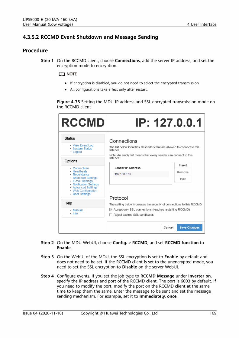
4.3.5.2 RCCMD Event Shutdown and Message Sending
Procedure
Step 1 On the RCCMD client, choose Connections, add the server IP address, and set theencryption mode to encryption.
NO TE
● If encryption is disabled, you do not need to select the encrypted transmission.
● All configurations take effect only after restart.
Figure 4-75 Setting the MDU IP address and SSL encrypted transmission mode onthe RCCMD client
Step 2 On the MDU WebUI, choose Config. > RCCMD, and set RCCMD function toEnable.
Step 3 On the WebUI of the MDU, the SSL encryption is set to Enable by default anddoes not need to be set. If the RCCMD client is set to the unencrypted mode, youneed to set the SSL encryption to Disable on the server WebUI.
Step 4 Configure events. If you set the job type to RCCMD Message under Inverter on,specify the IP address and port of the RCCMD client. The port is 6003 by default. Ifyou need to modify the port, modify the port on the RCCMD client at the sametime to keep them the same. Enter the message to be sent and set the messagesending mechanism. For example, set it to Immediately, once.
UPS5000-E-(20 kVA-160 kVA)User Manual (Low voltage) 4 User Interface
Issue 04 (2020-11-10) Copyright © Huawei Technologies Co., Ltd. 169

Step 5 On the Monitoring > Control page, start the UPS, and the inverter mode will betriggered. Send the message to the RCCMD client, indicating that the inverter ison.
Step 6 On the RCCMD client, you can view messages through the View Event Log at theupper left corner.
----End
4.3.5.3 UPS Alive Check Function
Context
NO TICE
Whether the RCCMD SSL encrypted transmission is enabled on the WebUI ofUPS5000 MDU and RCCMD client is irrelevant to the heartbeat detection function.Only when the SSL encryption is enabled on the RCCMD client, the logs recordedby the RCCMD client are marked with "(SSL...)".
On the RCCMD client, the IP address of the MDU that detects heartbeat needs tobe added. Then the UPS alive check function is supported; the RCCMD can checkwhether the UPS and RCCMD communicate properly; the RCCMD can receivemessages sent by the MDU.
Procedure
Step 1 On the RCCMD client, add the IP address of the MDU that detects heartbeat, asshown in Figure 4-76.
Step 2 The UPS5000 MDU supports both ways of heartbeat detection. If the jobconfigured for the MDU event is set to RCCMD TRAP, the RCCMD client needs tobe set to by the use of CS121/UPSMAN Traps. If by polling CS121/UPSMANevery x seconds... is selected as the method of detecting heartbeats, set thedetection method. The default interval is 1800s and detection is performed 100times, as shown in Figure 4-76.
UPS5000-E-(20 kVA-160 kVA)User Manual (Low voltage) 4 User Interface
Issue 04 (2020-11-10) Copyright © Huawei Technologies Co., Ltd. 170

Figure 4-76 Heartbeat detecting mode on the RCCMD client
You can also manually detect heartbeat by clicking Run alive check now....
UPS5000-E-(20 kVA-160 kVA)User Manual (Low voltage) 4 User Interface
Issue 04 (2020-11-10) Copyright © Huawei Technologies Co., Ltd. 171

Figure 4-77 Detecting heartbeat manually
Figure 4-78 Detecting heartbeat manually and successfully
----End
UPS5000-E-(20 kVA-160 kVA)User Manual (Low voltage) 4 User Interface
Issue 04 (2020-11-10) Copyright © Huawei Technologies Co., Ltd. 172

5 Operations
5.1 Powering On and Starting the UPS
5.1.1 Powering On the UPS
PrerequisitesBefore you power on the UPS, measure the voltage and frequency at the UPSexternal input switch. The voltage range is 80–150 V AC, and the frequency rangeis 40–70 Hz.
Context● The following operations are applicable to a single UPS. For parallel systems,
contact Huawei technical support.● Before powering on the UPS, ensure that the UPS has passed all check items
in the section "Installation Verification."● Before powering on the UPS, ensure that all the UPS switches and upstream
switch are OFF.
Procedure
Step 1 Close the upstream bypass and mains input switches.
After the UPS is powered on, initialization begins. The MDU displays the Huaweilogo and an initialization progress bar.
----End
5.1.2 Initial Startup
UPS5000-E-(20 kVA-160 kVA)User Manual (Low voltage) 5 Operations
Issue 04 (2020-11-10) Copyright © Huawei Technologies Co., Ltd. 173

NO TICE
● If the UPS is powered on for the first time, you need to obtain the startuppassword from the Service Expert app. Skip this step if the UPS is not poweredon for the first time.
● The Service Expert app can be downloaded from Google Play Store and canrun on Android.
● This document corresponds to the app version V100R003C01SPC530.
5.1.2.1 Obtaining Startup Password
Procedure
Step 1 Download and install the Service Expert app.
Step 2 On the app home screen, tap StartUp to access the Set Startup screen.
● Online Startup
a. Insert the WiFi module into the USB port on the MDU. Enable the mobilephone WLAN, search for the UPS_WIFI signal, and connect to the WiFisignal. The password is Changeme.
b. Set the Site and Device Type as required, and connect the device. Set IPto 192.168.0.10, Port to 443, Username to admin, Password toChangeme, and click Login.
c. After login, tap Power-on password activation on the screen. A messageis displayed, indicating whether to start the UPS. Tap OK.
● Offline Startup
a. Set Site and Device Type as required, and tap Offline Activation.
b. Enter Bar code and Verification code obtained from the LCD on theOffline Activation screen. Tap Generate PWD to generate a startuppassword.
c. Enter the generated password in the password text box on the LCD tostart the inverter.
----End
5.1.2.2 Settings Wizard
Procedure
Step 1 Set the language, time, network parameters, system parameters, and batteryparameters on the Settings Wizard screen.
UPS5000-E-(20 kVA-160 kVA)User Manual (Low voltage) 5 Operations
Issue 04 (2020-11-10) Copyright © Huawei Technologies Co., Ltd. 174

NO TICE
Set system parameters with caution because the settings determine normal UPSoperation.● Set Single/Parallel after double check. Incorrect setting may affect the normal
UPS operation.● Output voltage level refers to the line voltage level. Set it based on site
requirements.● Set Output frequency correctly; otherwise, loads may be affected and the UPS
may not work properly.● Battery parameter settings are critical to battery maintenance, battery lifespan,
and UPS discharge time.
Figure 5-1 Settings Wizard
UPS5000-E-(20 kVA-160 kVA)User Manual (Low voltage) 5 Operations
Issue 04 (2020-11-10) Copyright © Huawei Technologies Co., Ltd. 175

NO TE
● Set the time and date correctly. Incorrect time and date will cause false fault analysisduring maintenance or repair.
● After you set network parameters, connect the UPS to the network over a networkcable, which enables you to remotely manage the UPS. If you do not need remotemanagement, retain the default network parameter settings.
Step 2 After you set parameters on the Settings Wizard screen, the system displays theBypass mode and No battery alarms, which do not need to be handled. If there isany other alarm, you need to rectify the fault.
NO TE
● After you set parameters on the Settings Wizard screen, choose System Info > Settings> System Setting. Check that System Capacity, Power module capacity, Requisitemodules, and Redundant modules match the actual values.
● If dry contact signals are connected to the system, choose System Info > Settings > Drycontacts Set and check that the connected dry contacts have been enabled and that thedisconnected dry contacts have been disabled.
Step 3 If the system has connected to the remote EPO switch, you need to chooseMonitoring > UPS System > Running Parameter > System Settings on theWebUI and set EPO detection to Enable.
Step 4 View the system running diagram on the MDU to check that the UPS is working inbypass mode.
----End
5.1.3 Starting the Inverter
UPS System User List
Table 5-1 UPS system user list
Default User Preset Password
admin (administrator) LCD 000001
WebUI Changeme
operator (common user) LCD 000001
WebUI Changeme
browser (browsing user) Old WebUI N/A
Starting the UPS on the MDU
Step 1 Choose Common Functions > Inv. ON.
NO TE
You can also start the inverter by choosing System Info > Maintenance > Inv. ON.
UPS5000-E-(20 kVA-160 kVA)User Manual (Low voltage) 5 Operations
Issue 04 (2020-11-10) Copyright © Huawei Technologies Co., Ltd. 176

Step 2 In the displayed login screen, select a user name and enter the password.
Step 3 In the displayed dialog box, tap Yes to start the inverter.
----End
Starting the UPS on the WebUI
Step 1 Open a browser (Internet Explorer 11 for example) and choose Tools > InternetOptions.
Step 2 Click the Advanced tab, check that Use TLS 1.0 and Use TLS 1.1 are selected, andthen click OK.
Figure 5-2 Setting the Internet options
Step 3 In the address box of the browser, enter https://UPS IP address.
Step 4 Enter the correct user name and password and click Login.
Step 5 On the home page of the WebUI, choose Monitoring > UPS System > RunningControl, click Inv. ON, and confirm the operation to start the inverter.
Figure 5-3 Starting the inverter
UPS5000-E-(20 kVA-160 kVA)User Manual (Low voltage) 5 Operations
Issue 04 (2020-11-10) Copyright © Huawei Technologies Co., Ltd. 177

NO TE
If the power module receives a startup command when it cannot be started, the startupcommand will be kept for 1 minute. If the startup command is not cleared within 1 minute(for example, other faults occur on the module, or you perform shutdown or rectify faults)and the module can be started, the module responds to the startup command.
----End
Starting the UPS on the Old WebUI
Step 1 Open a browser (Internet Explorer 11 for example) and choose Tools > InternetOptions.
Step 2 Click the Advanced tab, check that Use TLS 1.0 and Use TLS 1.1 are selected, andthen click OK.
Figure 5-4 Setting the Internet options
Step 3 In the address box of the browser, enter https://UPS IP address.
Step 4 Enter the correct user name and password and click Login.
Step 5 On the home page of the WebUI, choose Monitoring > Control, click Inv. ON,and confirm the operation to start the inverter.
UPS5000-E-(20 kVA-160 kVA)User Manual (Low voltage) 5 Operations
Issue 04 (2020-11-10) Copyright © Huawei Technologies Co., Ltd. 178

Figure 5-5 Starting the inverter
NO TE
If the power module receives a startup command when it cannot be started, the startupcommand will be kept for 1 minute. If the startup command is not cleared within 1 minute(for example, other faults occur on the module, or you perform shutdown or rectify faults)and the module can be started, the module responds to the startup command.
----End
5.1.4 Powering On Loads
Context
After the inverter starts, the UPS works in normal mode. The Bypass mode alarmdisappears.
Procedure
Step 1 After confirming that the battery strings are properly connected, close the batterystring input circuit breaker. If there are multiple battery strings, close the circuitbreaker for each battery string and then the general circuit breaker betweenbattery strings and the UPS. The No battery alarm disappears from the MDU.
Step 2 Close the UPS downstream output switch to supply power to the loads.
----End
5.1.5 (Optional) Setting Parameters for the BCB Box
Prerequisites
A BCB box is installed.
Procedure
Step 1 On the System Info > Settings > Dry Contact Set screen, set MUE05Aconnection to Enable, and set BCB connection [OL] and Battery breaker [STA]to Enable.
UPS5000-E-(20 kVA-160 kVA)User Manual (Low voltage) 5 Operations
Issue 04 (2020-11-10) Copyright © Huawei Technologies Co., Ltd. 179

Figure 5-6 BCB connection setting
----End
5.2 Shutting Down and Powering Off the UPS
Context
NO TICE
After the inverter is shut down, if the bypass is normal, the UPS transfers tobypass mode; if the bypass is not normal, the UPS supplies no power. Beforeshutting down the UPS, ensure that all loads have shut down.
Procedure
Step 1 Shut down the inverter.
● On the LCD
On the main screen, tap Common Functions. Tap Inv. OFF.
NO TE
To shut down the inverter on the Maintenance screen, tap System Info >Maintenance.
● On the WebUI
Choose Monitoring > UPS System > Running Control , and click Inv. OFF. Inthe displayed dialog box, click OK to shut down the inverter.
● On the old WebUI
Choose Monitoring > Control, and click Inv. OFF. In the displayed dialog box,click OK to shut down the inverter.
After the inverter shuts down, the UPS works in bypass mode if the bypass isnormal, as shown in Figure 5-7; the UPS supplies no power and the loadspower off if the bypass is abnormal, as shown in Figure 5-8.
UPS5000-E-(20 kVA-160 kVA)User Manual (Low voltage) 5 Operations
Issue 04 (2020-11-10) Copyright © Huawei Technologies Co., Ltd. 180

Figure 5-7 Normal bypass
NO TE
After you shut down the inverter, the Bypass mode alarm is displayed on the LCD.
Figure 5-8 Abnormal bypass
NO TE
If you need to shut down the inverter and transfer the UPS to bypass mode, check that theUPS has not generated an alarm and perform step 1.
Step 2 After the inverter shuts down, open the downstream output switch.
Step 3 Open the battery string circuit breaker. If there are multiple battery strings, openthe general circuit breaker between battery strings and the UPS and then open thecircuit breaker for each battery string.
Step 4 Open the upstream mains input and bypass input switches.
----End
UPS5000-E-(20 kVA-160 kVA)User Manual (Low voltage) 5 Operations
Issue 04 (2020-11-10) Copyright © Huawei Technologies Co., Ltd. 181

5.3 Starting the UPS in Battery Mode
Lead-Acid Battery Cold Start
Step 1 Ensure that batteries have been connected properly. Use a multimeter to checkthat the absolute voltages of positive and negative battery strings are greater thana certain value (single battery voltage x number of batteries in the battery string).
Step 2 Open the upstream mains input and bypass input switches, and close the batterycircuit breaker. If there are multiple battery strings, close the circuit breaker foreach battery string and then the general circuit breaker between battery stringsand the UPS.
Step 3 Use a multimeter to measure the positive and negative battery string voltages atthe UPS battery input terminal. If the absolute values of the voltages are greaterthan a certain value (single battery voltage x number of batteries in the batterystring), the batteries are connected properly.
Step 4 Press and hold down the BATT START button on the bypass module for at least 2seconds. The system automatically enters the battery cold start status. The LCDdisplays the Huawei logo and an initialization progress bar.
Step 5 After LCD initialization, start the inverter on the LCD.
----End
Lithium Battery Cold Start
Step 1 Check that the cables between the UPS and the lithium battery cabinet areproperly connected.
Step 2 Open the upstream mains input and bypass input switches.
Step 3 Power on the lithium battery cabinet. For details, see the user manual for thelithium battery cabinet.
Step 4 Use a multimeter to measure the voltages of the positive and negative batterystrings connected to the UPS battery input terminals. If the measured values areconsistent with the voltages displayed on the System Status screen of the lithiumbattery cabinet, the batteries are properly connected.
Step 5 Check that the green indicator on the battery control unit in the lithium batterycabinet blinks at 1 Hz or is steady on. Then, press and hold down the BATT STARTbutton on the bypass module for at least 2 seconds. The system automaticallyenters the battery cold start status. The LCD displays the Huawei logo and aninitialization progress bar.
Step 6 After LCD initialization, start the inverter on the LCD.
----End
UPS5000-E-(20 kVA-160 kVA)User Manual (Low voltage) 5 Operations
Issue 04 (2020-11-10) Copyright © Huawei Technologies Co., Ltd. 182
5.4 Transferring to Bypass Mode
NO TICE
Before shutting down the inverter, ensure that the bypass is normal. If the bypassis not normal, after the inverter is shut down, the UPS supplies no power, and theloads shut down.
Shut down the UPS inverter. Shut down the inverter on the LCD or WebUI, and theUPS transfers to bypass mode.
NO TE
If the inverter is shut down when the input voltage or frequency exceeds the specifiedthreshold, the UPS supplies no power, and the loads shut down.
5.5 Setting ECO Mode
Prerequisites
The system is working in inverter mode.
Context● The UPS is set to non-ECO mode by default. Set the UPS to ECO mode when
energy saving is required.
● In ECO mode, the bypass takes priority over the inverter in supplying power. Ifthe bypass is disconnected, the UPS transfers to normal mode.
● Both a single UPS and the parallel system support the ECO mode for higherefficiency.
● To avoid frequent transfer between ECO mode and normal mode, do not setthe ECO mode when the bypass input is unstable or is sensitive to loadchanges.
● ECO mode is not recommended when the load is less than 10%.
● Before transferring the UPS to ECO mode, ensure that the bypass moduleworks properly.
Procedure
Step 1 On the LCD, set System Info > Settings > System Settings > Working mode toECO. The information indicating that the UPS works in ECO mode is displayed onthe LCD.
Step 2 Set the ECO voltage range.
UPS5000-E-(20 kVA-160 kVA)User Manual (Low voltage) 5 Operations
Issue 04 (2020-11-10) Copyright © Huawei Technologies Co., Ltd. 183

Figure 5-9 ECO parameters
Step 3 (Optional) If you set ECO mode in bypass mode, manually start the UPS inverter.
NO TICE
After the inverter starts, the UPS still works in bypass mode and the inverter is onstandby. If the bypass is not normal, the inverter supplies power immediately. Ifthe inverter is not started, the UPS may be disconnected.
Figure 5-10 System status in ECO mode
----End
5.6 Testing Batteries
5.6.1 Lead-Acid Battery Test
UPS5000-E-(20 kVA-160 kVA)User Manual (Low voltage) 5 Operations
Issue 04 (2020-11-10) Copyright © Huawei Technologies Co., Ltd. 184

5.6.1.1 Forced Equalized Charging Test
Context
NO TICE
Before a forced equalized charging test, ensure that:● The mains input is normal.● Batteries are properly connected.● Batteries are not in the equalized charging state.
Procedure
Step 1 On the home screen of the LCD, choose System Info > Maintenance > BatteryMaint.
Step 2 Tap Start next to Forced Equalized Charging to start a forced equalized chargingtest.
Figure 5-11 Starting a forced equalized charging test
NO TE
The forced equalized charging test automatically stops in any of the following cases:● The forced equalized charging test duration reaches the forced equalized charging
protection time (12–24 h, 18 h by default).● The UPS generates a battery overtemperature, overvoltage, or overcurrent alarm.● An alarm is generated.
----End
UPS5000-E-(20 kVA-160 kVA)User Manual (Low voltage) 5 Operations
Issue 04 (2020-11-10) Copyright © Huawei Technologies Co., Ltd. 185

5.6.1.2 Shallow Discharge Test
NO TICE
Before performing a shallow discharge test, ensure that:● The UPS works in normal mode with a load ratio fluctuation less than 10%.● The UPS generates no battery overtemperature, overvoltage, or overcurrent
alarm. No generator is connected to the UPS.● The mains, batteries, charger, and discharger are normal. No overload alarm is
generated.
Automatic Shallow Discharge Test
Step 1 On the home screen of the LCD, choose System Info > Settings > BatterySettings and set Sched. shallow dis. test to Enable.
Step 2 Set Sched. shallow dis. test time and Sched. shallow dis. test interval asrequired. After setting is complete, the system will perform automatic shallowdischarge tests based on the settings.
----End
Manual Shallow Discharge Test
Step 1 On the home screen of the LCD, choose System Info > Maintenance > BatteryMaint.
Step 2 Tap Start next to Shallow Dis. Test to start a shallow discharge test.
Figure 5-12 Starting a shallow discharge test
UPS5000-E-(20 kVA-160 kVA)User Manual (Low voltage) 5 Operations
Issue 04 (2020-11-10) Copyright © Huawei Technologies Co., Ltd. 186

NO TE
When the battery test is complete, the test data is used as common test data. Record thedata obtained from the latest five tests.
The shallow discharge test automatically stops in any of the following cases:
● The battery discharge capacity reaches the specified value (10%–50%, 20% by default).
● The discharge voltage reaches the warning threshold (calculated in real time).
● The load ratio fluctuation exceeds 10%.
● An alarm is generated.
----End
5.6.1.3 Capacity Test
Context
NO TICE
Before a capacity test, ensure that:● The UPS is working in normal mode; float charging or hibernation has lasted
for 2 hours after the state of charge (SOC) reaches 100%; and the load ratiofluctuation is less than 10%.
● The UPS has generated no battery overtemperature, overvoltage, or overcurrentalarm. No generator is connected to the UPS.
● The mains, batteries, charger, and discharger are normal. No overload alarm isgenerated.
Procedure
Step 1 On the home screen of the LCD, choose System Info > Maintenance > BatteryMaint.
Step 2 Tap Start next to Capacity Test to start a capacity test.
Figure 5-13 Starting a capacity test
UPS5000-E-(20 kVA-160 kVA)User Manual (Low voltage) 5 Operations
Issue 04 (2020-11-10) Copyright © Huawei Technologies Co., Ltd. 187

NO TE
The capacity test automatically stops in any of the following cases:
● The battery discharge voltage reaches the end of discharge (EOD) voltage plus 0.01 V.
● The load fluctuation exceeds 10%.
● An alarm is generated.
When the battery discharge voltage reaches the EOD voltage plus 0.01 V, the test iscomplete. The test data is used as capacity test data. Save the capacity test data recordwith the largest discharge capacity in a month as the capacity test data for the month. Amaximum of recent 36 capacity test records can be saved.
----End
5.6.2 Lithium Battery Test
5.6.2.1 Shallow Discharge Test
NO TICE
Before performing a shallow discharge test, ensure that:
● The UPS is working in normal mode; float charging or hibernation has lastedfor 2 hours after the state of charge (SOC) reaches 100%; and the load ratiofluctuation is less than 10%.
● The UPS generates no battery overtemperature, overvoltage, or overcurrentalarm. No generator is connected to the UPS.
● The mains, batteries, charger, and discharger are normal. No overload alarm isgenerated.
● The SmartLi has generated no alarms related to lithium batteries.
Automatic Shallow Discharge Test1. On the home screen of the UPS LCD, choose System Info > Settings >
Battery Settings and set Sched. shallow dis. test to Enable.
2. Set Sched. shallow dis. test time and Sched. shallow dis. test interval asrequired. After setting is complete, the system will perform automatic shallowdischarge tests based on the settings.
Manual Shallow Discharge Test1. On the home screen of the UPS LCD, choose System Info > Maintenance >
Battery Maint.
2. Tap Start next to Shallow Dis. Test to start a shallow discharge test.
UPS5000-E-(20 kVA-160 kVA)User Manual (Low voltage) 5 Operations
Issue 04 (2020-11-10) Copyright © Huawei Technologies Co., Ltd. 188

Figure 5-14 Starting a shallow discharge test
NO TE
When the battery test is complete, the test data is used as common test data. Recordthe data obtained from the latest five tests.
The shallow discharge test automatically stops in any of the following cases:
● The battery discharge capacity reaches the specified value (10%–50%, 20% bydefault).
● The discharge voltage reaches the warning threshold (calculated in real time).
● The load ratio fluctuation exceeds 10%.
● An alarm is generated.
5.6.2.2 Capacity Test
Context
NO TICE
Before a capacity test, ensure that:● The UPS is working in normal mode; float charging or hibernation has lasted
for 2 hours after the state of charge (SOC) reaches 100%; and the load ratiofluctuation is less than 10%.
● The UPS has generated no battery overtemperature, overvoltage, or overcurrentalarm. No generator is connected to the UPS.
● The mains, batteries, charger, and discharger are normal. No overload alarm isgenerated.
● The SmartLi has generated no alarms related to lithium batteries.
Procedure
Step 1 On the home screen of the UPS LCD, choose System Info > Maintenance >Battery Maint.
Step 2 Tap Start next to Capacity Test to start a capacity test.
UPS5000-E-(20 kVA-160 kVA)User Manual (Low voltage) 5 Operations
Issue 04 (2020-11-10) Copyright © Huawei Technologies Co., Ltd. 189

Figure 5-15 Starting a capacity test
NO TE
The capacity test automatically stops in any of the following cases:● The minimum cell voltage reaches 2.6 V.● The load fluctuation exceeds 10%.● An alarm is generated.The test is complete when the minimum cell voltage reaches 2.6 V. Data about the mostamount of energy discharged is stored once a month for 36 months.
----End
5.6.3 Test Data Download● Web
a. On the WebUI, choose Query > Operation Log, choose logs that need tobe queried from the Log drop-down list box, and click Query.
Figure 5-16 Operation Log
b. Choose logs that have been queried from the Log drop-down list box,and click Export.
● Old Weba. On the WebUI, choose Query > Logs, choose logs that need to be
exported from the Log drop-down list box, and click Query.
Figure 5-17 Logs
UPS5000-E-(20 kVA-160 kVA)User Manual (Low voltage) 5 Operations
Issue 04 (2020-11-10) Copyright © Huawei Technologies Co., Ltd. 190

b. Choose logs that have been queried from the Log drop-down list box,and click Export.
5.7 Transferring to Maintenance Bypass Mode
Context
NO TICE
● You are advised to install a lock on the maintenance bypass switch. The lockcore has a diameter of 5–10 mm.
● Strictly observe the following procedure to transfer the UPS to maintenancebypass mode. Otherwise, loads may power off.
● In maintenance bypass mode, the mains supplies power to the loads directlyover the maintenance bypass. If the mains is abnormal, the loads may poweroff.
ProcedureStep 1 Transfer the UPS to bypass mode.
Step 2 Turn on the maintenance bypass switch.
If the maintenance bypass switch is locked, unlock it first. Figure 5-18 shows alocked maintenance bypass switch. Turn on the switch to transfer the UPS tomaintenance bypass mode.
● For the UPS5000-E-60 kVA and UPS5000-E-100 kVA, the maintenance bypassswitch is OFF by default and the handle points right horizontally. Turn on theswitch by turning the handle clockwise 90 degrees until it points to theground, as shown in Figure 5-19.
● For the UPS5000-E-160 kVA, the maintenance bypass switch is OFF by defaultand the handle points to the ground. Turn on the switch by turning thehandle clockwise 90 degrees until it points left horizontally, as shown inFigure 5-20.
The Maint. breaker closed alarm is displayed in the alarm list, as shown in Figure5-21. The UPS transfers to maintenance bypass mode.
Figure 5-18 Locked maintenance bypass switch
UPS5000-E-(20 kVA-160 kVA)User Manual (Low voltage) 5 Operations
Issue 04 (2020-11-10) Copyright © Huawei Technologies Co., Ltd. 191

Figure 5-19 Turning on the maintenance bypass switch on the UPS5000-E-100kVA
Figure 5-20 Turning on the maintenance bypass switch on the UPS5000-E-160kVA
NO TE
Exercise force when turning on or off the bypass maintenance switch.
UPS5000-E-(20 kVA-160 kVA)User Manual (Low voltage) 5 Operations
Issue 04 (2020-11-10) Copyright © Huawei Technologies Co., Ltd. 192

Figure 5-21 Maint. breaker closed alarm
NO TE
After the UPS transfers to maintenance bypass mode, the Maint. breaker closed andBypass mode alarms are displayed on the LCD.
----End
5.8 Transferring from Maintenance Bypass Mode toNormal Mode
Context
NO TICE
Before you transfer the UPS from maintenance bypass mode to normal mode,ensure that the bypass input and output are normal.
Procedure
Step 1 Turn off the maintenance bypass switch.● For the UPS5000-E-60 kVA/100 kVA, the maintenance bypass switch points to
the ground when it is turned on. To turn off the switch, face the cabinet andturn the handle counterclockwise 90 degrees until it points right horizontally.
● For the UPS5000-E-160 kVA, the maintenance bypass switch points lefthorizontally when it is turned on. To turn off the switch, face the cabinet andturn the handle counterclockwise 90 degrees until it points to the ground.
The Maint. Breaker closed alarm disappears from the alarm list. Check whetherthe UPS works in bypass mode by viewing the system running status diagram onthe LCD or WebUI.
UPS5000-E-(20 kVA-160 kVA)User Manual (Low voltage) 5 Operations
Issue 04 (2020-11-10) Copyright © Huawei Technologies Co., Ltd. 193

Figure 5-22 Turning off the maintenance bypass switch on the UPS5000-E-100kVA
NO TE
This figure applies to the UPS5000-E-100 kVA.
Step 2 Start the inverter.
----End
5.9 Performing EPO
NO TICE
● After the EPO button is turned on, the UPS supplies no power and the loadsshut down.
● In maintenance bypass mode, the UPS continues to supply power even afterthe EPO button is turned on.
Press the external EPO switch that connects to the dry contact card or remove the4-pin terminal on the EPO port of the dry contact card of the bypass unit.
Figure 5-23 EPO ports
UPS5000-E-(20 kVA-160 kVA)User Manual (Low voltage) 5 Operations
Issue 04 (2020-11-10) Copyright © Huawei Technologies Co., Ltd. 194

After you press the EPO button, the EPO and No power supplied alarms aredisplayed on the LCD.
5.10 Clearing the EPO State
Procedure
Step 1 Clear the EPO state. Ensure that the EPO button connected to the dry contact isnot in the EPO state.
Step 2 Clear the EPO alarm.● On the LCD
On the LCD, choose System Info > Alarms and tap Clear Faults. In thedisplayed dialog box, tap Yes. The EPO alarm is cleared successfully.
● On the WebUIChoose Monitoring > UPS system > Running Control > Issued Order andclick Clear Fault. The EPO alarm is cleared successfully.
● On the old WebUIChoose Monitoring > Control > System Commands and Tests and clickClear Fault. The EPO alarm is cleared successfully.
Step 3 Check that the EPO alarm is cleared by viewing active alarms. If the system bypassinput is normal, the UPS transfers to bypass mode.● Viewing active alarms on the LCD
Choose System Info > Alarms > Active Alarms to check that the EPO alarmis cleared.
● Viewing active alarms on the WebUIChoose Home > Active Alarm to check that the EPO alarm is cleared.
● Viewing active alarms on the old WebUIChoose Monitoring > Active Alarms to check that the EPO alarm is cleared.
Step 4 Start the inverter.
----End
5.11 Exporting Data
The following data can be exported:● Historical Alarm● Active Alarms● Performance Data● Operation Log● E-Label● Fault Information
UPS5000-E-(20 kVA-160 kVA)User Manual (Low voltage) 5 Operations
Issue 04 (2020-11-10) Copyright © Huawei Technologies Co., Ltd. 195

NO TE
This topic describes how to export historical alarms.
Web1. Choose Query > Export Data > Export Historical Data. Set Encryption
Password for Export, and select Historical Alarm from the Data Type drop-down list.
Figure 5-24 Export Historical Data
2. Click Export Historical Data and save the displayed webpage.
Old Web1. Choose Query > Historical Alarms, and set Severity, Generated, and
Cleared. Click Query to view the historical alarm information.
Figure 5-25 Querying historical alarms
NO TE
You do not need to query logs. Choose Query > Logs, click Export, and save the file.
2. Click Export and save the displayed webpage.
5.12 Setting Hibernation Mode
When the load power is small and stable, you can shut down the inverters in somepower modules so that these power modules enter hibernation mode and otherpower modules bear all the load power. This improves the system efficiency in thecase of small load power and increases the power module service life. Thehibernation function can be set on the WebUI.
UPS5000-E-(20 kVA-160 kVA)User Manual (Low voltage) 5 Operations
Issue 04 (2020-11-10) Copyright © Huawei Technologies Co., Ltd. 196

NO TICE
● Ensure that the load power is stable. If the system load power fluctuation isgreater than the rated capacity of half a module (for example, the single-phaseload power fluctuation is greater than 8.33 kVA for a 50 kVA module), the UPSmay enter and exit from hibernation mode repeatedly.
● Check that the number of redundant power modules and racks are appropriate.If the number is insufficient, the UPS may not enter hibernation mode.
Web1. On the WebUI, choose Monitoring > UPS Sytem > Running Parameter >
System Settings and set Paral sys hibernate to Enable.2. Set the module cycle hibernation period to an integer ranging from 1 to 100.
The default value is 30.
Figure 5-26 Running Parameter
NO TE
Click Submit after setting parameters on the WebUI.
Old Web1. On the WebUI, choose Monitoring > Param. Settings > System Settings and
set Paral. sys. hibernate to Enable.2. Set the module cycle hibernation period to an integer ranging from 1 to 100.
The default value is 30.
UPS5000-E-(20 kVA-160 kVA)User Manual (Low voltage) 5 Operations
Issue 04 (2020-11-10) Copyright © Huawei Technologies Co., Ltd. 197

Figure 5-27 System settings
NO TE
Click Submit after setting parameters on the WebUI.
UPS5000-E-(20 kVA-160 kVA)User Manual (Low voltage) 5 Operations
Issue 04 (2020-11-10) Copyright © Huawei Technologies Co., Ltd. 198

6 Routine Maintenance
6.1 UPS Maintenance
NO TICE
● Only trained personnel are allowed to perform maintenance. Before performingoperations on the UPS, wear electrostatic discharge (ESD) clothes, ESD gloves,and an ESD wrist strap. Remove conductive objects such as jewelry or watchesduring operations to avoid electric shocks or burns.
● Use insulated tools when maintaining internal devices. Only trained personnelare allowed to perform maintenance. Customers are not allowed to maintaincomponents behind protective covers that can be removed only using tools. Ifthe components are to be maintained, contact Huawei technical support.
● Only maintenance engineers can maintain power modules and bypass modules.● Maintain UPSs regularly based on the following requirements. Otherwise, the
UPSs may fail to operate properly and the service life may be shortened.
UPS5000-E-(20 kVA-160 kVA)User Manual (Low voltage) 6 Routine Maintenance
Issue 04 (2020-11-10) Copyright © Huawei Technologies Co., Ltd. 199

6.1.1 Monthly Maintenance
Table 6-1 Monthly maintenance
Check Item Expected Result Troubleshooting
Operatingenvironment
● Ambient temperature: 0–40°C
● Humidity: 0–95% RH (non-condensing)
● Rodent-proof measureshave been taken for theequipment room.
● The equipment room isairtight.
● If the humidity ortemperature is abnormal,check the air conditionerstatus.
● Put rodent-proof baffleplates at the door of theUPS equipment room.
● Check that the equipmentroom is airtight and not ina direct ventilationenvironment.
Power gridenvironment
● Input voltage: 208 V AC,220 V AC, or 230 V AC (linevoltage)
● Output voltage: 208 V AC,220 V AC, or 230 V AC(tolerance ± 1%, linevoltage)
● Frequency: 40–70 Hz
● If the input voltage isabnormal, check the powergrid status and input cableconnection.
● If the output voltage isabnormal, check the UPSrunning status and checkwhether an alarm isgenerated.
Informationon the LCD
The status icons on the LCDindicate that all units areoperating properly, alloperating parameters arewithin their normal ranges,and no fault or alarminformation is displayed.
If an alarm is generated,rectify the fault by checkingthe device status andparameters.
6.1.2 Quarterly Maintenance
Table 6-2 Quarterly maintenance
Check Item Expected Result Troubleshooting
Cleanliness Wipe the cabinet surface usinga white paper and the paperdoes not turn black.
Remove the dust, especiallyfrom the air filter on the frontdoor, or replace the air filter.
UPS5000-E-(20 kVA-160 kVA)User Manual (Low voltage) 6 Routine Maintenance
Issue 04 (2020-11-10) Copyright © Huawei Technologies Co., Ltd. 200

Check Item Expected Result Troubleshooting
Parameterconfiguration
The configuration of theoutput voltage grade,frequency, number ofbatteries, and battery capacitymeets requirements.
Reset the parameters.
Status record Record the three-phase loadrate and output power factor.
If an exception occurs, checkthe load status.
Shallowdischarge test(recommended)
Conduct a shallow dischargetest when the UPS is backedup to verify that the batteriescan discharge normally.
If an alarm is generated, referto the alarm list.
6.1.3 Annual Maintenance
Table 6-3 Annual maintenance
Check Item Expected Result Troubleshooting
Grounding Check that the groundcables are connectedsecurely.
Tighten the screws.
Power cables andterminals (between theUPS and the powerdistribution cabinet)
The insulation layer ofcables is intact andterminals are free fromblack marks andnoticeable sparks.
● Replace the cables.● Secure the output
terminals.
Cables and circuitbreaker through-currentcapacity
The circuit breakers andcables meet loadrequirements.The actual cablethrough-current capacityis greater than the circuitbreaker specifications.
● Replace the circuitbreaker.
● Replace the cable.
To prevent system failures caused by the deterioration of some key UPScomponents, you are advised to check the key components on a regular basis andreplace them within the service life.
UPS5000-E-(20 kVA-160 kVA)User Manual (Low voltage) 6 Routine Maintenance
Issue 04 (2020-11-10) Copyright © Huawei Technologies Co., Ltd. 201

Table 6-4 Service life parameters for replaceable components and recommendedreplacement intervals
Key Component Design Service Life RecommendedReplacement Interval
Power module 15 years 10 years
Bypass module 15 years 10 years
Fan 15 years 10 years
LCD screen 10 years 8 years
6.2 Battery Maintenance
NO TICE
Before installing batteries, read through the battery user manuals and payattention to safety precautions and connection methods provided by batterymanufacture.When installing and maintaining batteries, pay attention to the following points:● Wrap tools with insulation tape to prevent electric shock.● Protect your eyes with relevant devices and apply other protective measures.● Wear insulated gloves and a protective coat in case of electrolyte overflow.● When moving batteries, avoid handling the battery upside down, handle
batteries gently, and pay attention to personal safety.● Keep the battery switch off when installing or maintaining the batteries.
6.2.1 Precautions for Battery Maintenance● Before battery maintenance, get the tools, such as handles, insulated. Do not
place other objects on the top of batteries.● Never use any organic solvent to clean batteries.● Never try to remove the safety valve or pour anything into batteries.● Never smoke or have an open flame around batteries.● After battery discharge, charge the battery in time to maintain a good service
life.● Only professionals are allowed to perform the maintenance tasks.
UPS5000-E-(20 kVA-160 kVA)User Manual (Low voltage) 6 Routine Maintenance
Issue 04 (2020-11-10) Copyright © Huawei Technologies Co., Ltd. 202

6.2.2 Monthly Maintenance
Table 6-5 Monthly maintenance
Item Expected Result Troubleshooting
Batterymanagementalarm
No battery managementalarm is generated.
Identify the cause of an alarmbased on the alarminformation.
Batteryappearance
1. The surface is clean andtidy without stains.
2. The battery terminals areintact.
3. Batteries are free fromdamage and cracks.
4. Batteries are free from acidleakage.
5. Batteries are not deformedor bulged.
If the battery appearance isabnormal, contact Huaweitechnical support.
Batteryoperatingtemperature
1. The ambient batterytemperature is 25±5°C.
2. The battery operatingtemperature is lower thanbattery temperature +20°C.
3. Battery charge anddischarge conditions meetthe requirements specifiedin the battery specifications.
1. Identify the cause of anabnormal battery operatingtemperature.
2. If the fault persists, contactHuawei technical support.
Chargevoltage ofbattery string
● Equalized charging voltage:2.35 V/cell ± 1% x numberof battery cells
● Float charging voltage: 2.25V/cell ± 1% x number ofbattery cells
1. If the voltage drop betweenthe battery string outputterminals and the batteryinput terminals at the UPSside is greater than 1% ofthe battery string voltage,check whether the cablebetween the battery stringand the UPS is excessivelylong, or the cable diameteris excessively small.
2. Check whether theequalized charging voltageand float charging voltageare correctly set for theUPS.
3. If the fault persists, contactHuawei technical support.
UPS5000-E-(20 kVA-160 kVA)User Manual (Low voltage) 6 Routine Maintenance
Issue 04 (2020-11-10) Copyright © Huawei Technologies Co., Ltd. 203

6.2.3 Quarterly Maintenance
Table 6-6 Quarterly maintenance
Item Expected Result Troubleshooting
Battery temperaturesensor measurementaccuracy
The difference betweenthe temperaturemeasured by thetemperature sensor andthe temperature displayedon the MDU is less than3°C.
1. Install the temperaturesensor in the correctposition.
2. Replace the batterytemperature sensor.
Battery managementparameter settings
The settings of batterymanagement parametersmeet the requirements inthe user manual.
Set parameters correctly.
Tightness of batteryscrews
The location of the signsmarked on batteryterminals indicating tightconnections does notchange.
Take photos from multipleangles and contact Huaweitechnical support.
Cables betweenbatteries
No cable deteriorates andthe insulation layer doesnot crack.
Replace the faulty cable.
Battery voltage ● Equalized chargingvoltage: 2.35 V/cell± 0.02 V/cell
● Float charging voltage:2.25 V/cell ± 0.02 V/cell
1. Check whether theequalized chargingvoltage and floatcharging voltage of abattery are normal.
2. If the charging voltageof a battery exceeds thespecificationsrequirement, perform acomplete forcibleequalized charging forthe battery, and checkagain whether thevoltage is normal.
3. If the fault persists,contact Huaweitechnical support.
UPS5000-E-(20 kVA-160 kVA)User Manual (Low voltage) 6 Routine Maintenance
Issue 04 (2020-11-10) Copyright © Huawei Technologies Co., Ltd. 204

Item Expected Result Troubleshooting
Shallow dischargetest (recommended)
Conduct a shallowdischarge test when theUPS is backed up to verifythat the batteries candischarge normally.
1. If the batteries cannotdischarge normally,locate the fault (forabnormal alarms, seethe alarm list).
2. If the fault persists,contact Huaweitechnical support.
6.2.4 Annual Maintenance
Table 6-7 Annual maintenance
Item Expected Result Troubleshooting
Capacity Test When the UPS is backed up,discharge a battery to theundervoltage alarm threshold,to refresh the capacity of thebattery.
1. Locate the cause when anexception is identified.
2. If the fault persists, contactHuawei technical support.
Batteryconnectionreliability
1. Each battery terminal isconnected reliably. (Whenbattery strings arepowered off, check thereliability of each terminalin the order from positiveterminals to negativeterminals.)
2. The tightening torque ofeach battery screw meetsthe requirements of thebattery manufacturer. (Atorque wrench is used forchecking the torque. Afterchecking that the batteryscrews meet therequirements, mark thescrews for later check.)
1. Rectify any abnormalconnection.
2. If the fault persists, contactHuawei technical support.
UPS5000-E-(20 kVA-160 kVA)User Manual (Low voltage) 6 Routine Maintenance
Issue 04 (2020-11-10) Copyright © Huawei Technologies Co., Ltd. 205

7 Troubleshooting
WARNING
If the UPS is faulty, alarm information is displayed on the LCD. Clear critical alarmsbefore powering on the UPS again. Otherwise, the fault scope expands or the UPSis damaged.
NO TICE
● If the LCD still displays the alarm information after a UPS is troubleshot andstarted, choose System Info > Alarms > Clear Faults to clear the alarm andthen start the inverter.
● When batteries reach EOD, the battery switch in the BCB box trips if the BCBbox is configured. To restore battery discharge, turn on the battery switch in theBCB box (if any) first.
● To restore battery discharge after batteries reach EOD, use one of the followingmethods: 1. Switch to another battery string. Ensure that each battery has avoltage greater than the EOD voltage and 11.3 V/cell. 2. Restore the mainspower supply to start the inverter. Turn on the battery switch and chargebatteries until each battery has a voltage greater than the EOD voltage and11.3 V/cell.
If any other unmentioned faults occur, see the chapter of alarm list and contactHuawei technical support.
UPS5000-E-(20 kVA-160 kVA)User Manual (Low voltage) 7 Troubleshooting
Issue 04 (2020-11-10) Copyright © Huawei Technologies Co., Ltd. 206

Table 7-1 Troubleshooting
Case Symptom Possible Cause Measure
Therectifier isabnormal.
The rectifier cannotwork, and the busvoltage is notboosted.
The mains voltageexceeds the upperthreshold 150 V oris less than thelower threshold 80V.
Check whether themains voltageexceeds thethreshold. If yes,contact the electricpower company.
PFC soft-startupfails.
Replace the powermodule.
The power moduleis faulty.
Replace the powermodule.
Theinverter isabnormal.
The buzzer buzzes,the Fault indicator ison, the inverter isfaulty, and the UPStransfers to bypassmode.
The UPS isoverloaded orshort-circuited.
Reduce load orrectify short circuits.
Inverterovertemperatureoccurs.
Install more airconditioners orventilation devicesto ensure normaltemperatures insidethe equipmentroom.
The power moduleis faulty.
Replace the powermodule.
Thechargergeneratesan alarm.
The buzzer buzzes,the Fault indicator ison, and the chargingfunction fails.
The charger fails. Replace the powermodule.
The chargerexperiencesovercurrent.
Replace the powermodule.
The chargerexperiencesundervoltage.
Check whether theconfigured numberof batteries iscorrect. If the valueis correct but thealarm persists,replace the powermodule.
The UPSworks inbypassmode anddoes nottransfer toinvertermode.
When the mains isnormal, the UPSworks in bypassmode and does nottransfer to invertermode.
Set the UPSworking mode toECO mode.
Set the workingmode correctly.
The bypass transfertimes reach theupper threshold.
Clear the bypasstransfer times onthe LCD.
UPS5000-E-(20 kVA-160 kVA)User Manual (Low voltage) 7 Troubleshooting
Issue 04 (2020-11-10) Copyright © Huawei Technologies Co., Ltd. 207
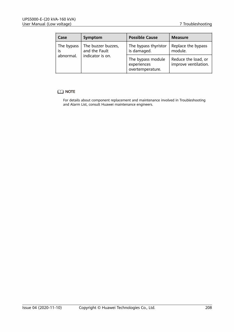
Case Symptom Possible Cause Measure
The bypassisabnormal.
The buzzer buzzes,and the Faultindicator is on.
The bypass thyristoris damaged.
Replace the bypassmodule.
The bypass moduleexperiencesovertemperature.
Reduce the load, orimprove ventilation.
NO TE
For details about component replacement and maintenance involved in Troubleshootingand Alarm List, consult Huawei maintenance engineers.
UPS5000-E-(20 kVA-160 kVA)User Manual (Low voltage) 7 Troubleshooting
Issue 04 (2020-11-10) Copyright © Huawei Technologies Co., Ltd. 208

8 Technical Specifications
8.1 Physical SpecificationsItem UPS5000-
E-60K-F60UPS5000-E-100K-F100
UPS5000-E-160K-F160
Cabling mode Cables are routed from the top orbottom.
Cables are routedfrom the bottom (atop entry cabinet canbe installed).
Protection level IP20 (or IP21)
Dimensions (Hx W x D)
2000 mm x 600 mm x 850 mm
Communication
Dry contacts, RS485, and SNMP
Weight ● UPS5000-E-60K-F60: 291 kg. Each power module is 32 kg.A maximum of three power modules are supported.
● UPS5000-E-100K-F100: 355 kg. Each power module is 32kg. A maximum of five power modules are supported.
● UPS5000-E-160K-F160: 477 kg. Each power module is 32kg. A maximum of eight power modules are supported.
8.2 Environmental SpecificationsItem Specifications
Operatingtemperature
0–40°C
UPS5000-E-(20 kVA-160 kVA)User Manual (Low voltage) 8 Technical Specifications
Issue 04 (2020-11-10) Copyright © Huawei Technologies Co., Ltd. 209
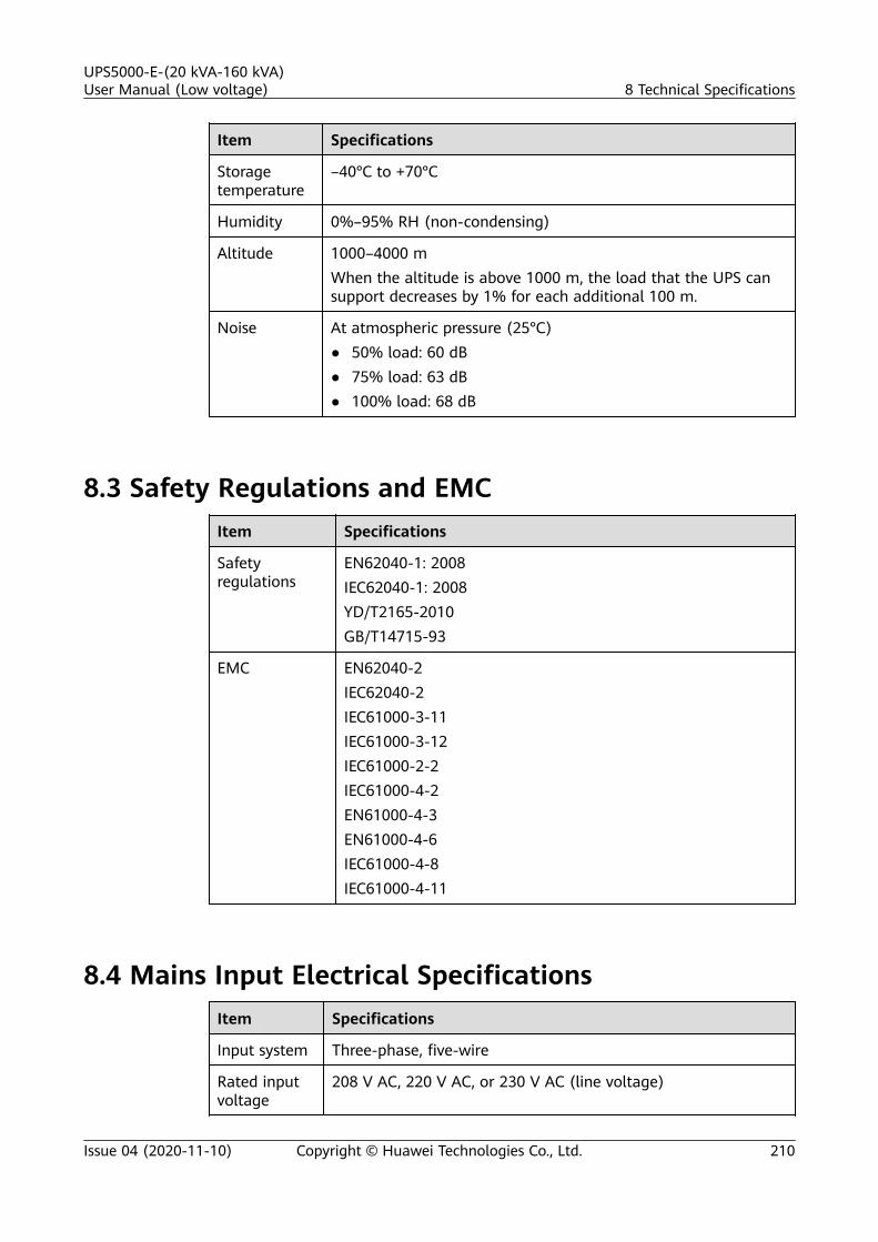
Item Specifications
Storagetemperature
–40°C to +70°C
Humidity 0%–95% RH (non-condensing)
Altitude 1000–4000 mWhen the altitude is above 1000 m, the load that the UPS cansupport decreases by 1% for each additional 100 m.
Noise At atmospheric pressure (25°C)● 50% load: 60 dB● 75% load: 63 dB● 100% load: 68 dB
8.3 Safety Regulations and EMCItem Specifications
Safetyregulations
EN62040-1: 2008IEC62040-1: 2008YD/T2165-2010GB/T14715-93
EMC EN62040-2IEC62040-2IEC61000-3-11IEC61000-3-12IEC61000-2-2IEC61000-4-2EN61000-4-3EN61000-4-6IEC61000-4-8IEC61000-4-11
8.4 Mains Input Electrical SpecificationsItem Specifications
Input system Three-phase, five-wire
Rated inputvoltage
208 V AC, 220 V AC, or 230 V AC (line voltage)
UPS5000-E-(20 kVA-160 kVA)User Manual (Low voltage) 8 Technical Specifications
Issue 04 (2020-11-10) Copyright © Huawei Technologies Co., Ltd. 210

Item Specifications
Input voltage 80–150 V AC (phase voltage)The UPS power is not derated at 96–150 V AC and is linearlyderated at 80–96 V AC.
Inputfrequency
40–70 Hz
Input PF ● 0.99 (full load)● 0.98 (half load)
THDi < 3%
8.5 Bypass Input Electrical SpecificationsItem Specifications
Input system Three-phase, five-wire
Rated inputvoltage
208 V AC, 220 V AC, or 230 V AC (line voltage)
Inputfrequency
50 Hz or 60 Hz (tolerance ± 6 Hz)
Bypasssynchronization trackingfrequency
50 Hz or 60 Hz (tolerance ± 6 Hz)
8.6 Battery Specifications
NO TICE
The UPS supports the SmartLi. For details about the parameters, see the SmartLiuser manual.
Item Specifications
Battery voltage(VRLA battery)
192–288 V DC (16–24 batteries, 20 by default).
Batterymonitoring(VRLA battery)
The BMU (optional) monitors batteries.
UPS5000-E-(20 kVA-160 kVA)User Manual (Low voltage) 8 Technical Specifications
Issue 04 (2020-11-10) Copyright © Huawei Technologies Co., Ltd. 211

Item Specifications
Batterymanagement
Intelligent battery management
One-buttoncold start
In the case of a mains failure, batteries can start the UPS topower loads.
Battery stringsharing (VRLAbattery)
The UPSs connected in parallel can share battery strings. Bydefault, battery strings are shared.
Charge voltage(VRLA battery)
● Equalized voltage: 2.35 V/cell● Float voltage: 2.25 V/cell
8.7 Output Electrical SpecificationsItem Specifications
Output system Three-phase, five-wire
Voltage 208 V AC, 220 V AC, or 230 V AC (tolerance ± 1%)
Frequency In normal mode, the mains frequency is synchronized with thebypass input frequency.In battery mode, the frequency is 50 Hz or 60 Hz (tolerance± 0.25%).
Total harmonicdistortion ofoutput voltage(THDv)
< 2% (full linear load); ≤ 5% (full non-linear load)
Output PF 1
Transfer time 0 ms
Output voltageunbalance
Voltage unbalance: ±3%; phase unbalance: ±2°
Overloadcapability
Inverter overload capability:● 105% < load < 110%: transfer to bypass mode after 60 min● 111% < load ≤ 125%: transfer to bypass mode after 10 min● 125% < load ≤ 150%: transfer to bypass mode after 1 minBypass overload capability:● Load ≤ 135%: run continuously at 30°C or lower● 1000% load: run for 100 ms
UPS5000-E-(20 kVA-160 kVA)User Manual (Low voltage) 8 Technical Specifications
Issue 04 (2020-11-10) Copyright © Huawei Technologies Co., Ltd. 212

8.8 System Electrical SpecificationsItem Specifications
Redundancydesign
The auxiliary power supplies, centralized controllers, and parallelsignals use redundancy design.
Number ofUPSsconnectedin parallel
2
UPS5000-E-(20 kVA-160 kVA)User Manual (Low voltage) 8 Technical Specifications
Issue 04 (2020-11-10) Copyright © Huawei Technologies Co., Ltd. 213

A Alarm List
Alarm ID(Alarm ID-Cause ID)
Alarm Name Severity Cause Solution
0001-2 The mainsvoltage isabnormal.
Minor The mains voltageis low abnormalor the mainsneutral wire isabsent.
1. Check the mains inputvoltage or cabledistribution.
2. Secure or connect theneutral wire to the cabinetif it is loose ordisconnected.
3. Check whether the neutralwire to the powerdistribution system isnormal.
0001-3 Minor The mainsfrequency isabnormal or themains neutralwire is absent.
1. Check the mains inputfrequency.
2. Secure or connect theneutral wire to the cabinetif it is loose ordisconnected.
3. Check whether the neutralwire to the powerdistribution system isnormal.
0004-1 Mains ph.Reversed
Minor Mains ph.Reversed.
Check whether the phasesequence is correct based onthe phase sequence table. Ifno multimeter is available,exchange the connectionpositions of any two cables.
UPS5000-E-(20 kVA-160 kVA)User Manual (Low voltage) A Alarm List
Issue 04 (2020-11-10) Copyright © Huawei Technologies Co., Ltd. 214

Alarm ID(Alarm ID-Cause ID)
Alarm Name Severity Cause Solution
0005-1 The mainsneutral wire isabsent.
Minor The mains neutralwire is absent.
1. Secure or connect theneutral wire to the cabinetif it is loose ordisconnected.
2. Check whether the neutralwire to the powerdistribution system isnormal.
0006-1 Mainsundervoltage
Minor Mainsundervoltage.
1. Check whether the mainsvoltage ranges from 80 Vto 96 V. If no, the detectioncircuit of the powermodule is faulty. Replacethe module.
0010-1 The bypassvoltage isabnormal.
Minor The bypassvoltage isabnormal orBypass neutralabsent.
1. Check the bypass inputvoltage or cabledistribution.
2. Check the voltage systemand bypass voltagethresholds set on theWebUI or LCD.
3. Secure or connect theneutral wire to the cabinetif it is loose ordisconnected.
4. Check whether the neutralwire to the powerdistribution system isnormal.
0010-2 Minor The bypassfrequency isabnormal.
1. Check the bypass inputfrequency.
2. Check the configured ratedfrequency and frequencyrange.
0011-1 Bypass phasereversed
Minor Bypass phasereversed.
Check whether the phasesequence is correct based onthe phase sequence table. Ifno multimeter is available,exchange the connectionpositions of any two cables.
UPS5000-E-(20 kVA-160 kVA)User Manual (Low voltage) A Alarm List
Issue 04 (2020-11-10) Copyright © Huawei Technologies Co., Ltd. 215

Alarm ID(Alarm ID-Cause ID)
Alarm Name Severity Cause Solution
0012-1 Bypass neutralabsent
Minor Bypass neutralabsent.
1. Secure or connect theneutral wire to the cabinetif it is loose ordisconnected.
2. Check whether the neutralwire to the powerdistribution system isnormal.
0020-1 Batteryconnectedreversely
Critical Battery connectedreversely.
1. Check whether batterypolarities are correctlyinstalled by using amultimeter. If no, correctthe installation.
2. Check whether the batteryinput voltage of the UPS isnormal. If yes, the batterysampling circuit of thepower module is faulty.Replace the module.
0021-1 Battery EOD Critical The batteryvoltage reachesthe EOD voltagethreshold due tocontinuousdischarge.
1. Check the mains, andcharge batteries in a timelymanner.
2. If a BCB box is configured,check whether it trips.
0022-1 No battery Minor No battery. 1. Check whether batterycables are correctlyconnected.
2. Check that the batteryterminal voltage is normal.
3. Check that the battery fusein the power module isintact.
0025-1 Batteryovervoltage
Minor The batteryvoltage is greaterthan theovervoltage alarmthreshold(equalized voltage+ 0.05 V/cell) for30 seconds.
1. Check the configurednumber of batteries.
2. Check that the batteryneutral wire is securelyconnected.
UPS5000-E-(20 kVA-160 kVA)User Manual (Low voltage) A Alarm List
Issue 04 (2020-11-10) Copyright © Huawei Technologies Co., Ltd. 216

Alarm ID(Alarm ID-Cause ID)
Alarm Name Severity Cause Solution
0026-1 Low batteryvoltage
Minor The batteryvoltage is lessthan the warningthreshold.
1. Check the mains input, andcharge batteries.
2. Check that the batteryneutral wire is securelyconnected.
0032-1 Batteryovervoltageprotection
Critical The batteryvoltage reachesthe overvoltageprotectionthreshold.
1. Check the battery voltage.2. Check that the configured
number of batteries isconsistent with the actualnumber.
3. Check that the actualnumber of batteries meetsrequirements.
0037-1 Batteriesexperienceundervoltage.
Critical Batteriesexperienceundervoltage.
1. Check whether the batteryvoltage is normal.
2. Check whether the UPS isoverloaded.
3. Check whether any batterycell is damaged. If yes,replace the battery.
4. Check any battery chargergenerates an alarm. If yes,replace the related faultypower module.
0040-7 Rectifierabnormal
Critical The moduleexperiencesovertemperature.
1. Check whether the fan isblocked. If yes, rectify thefault to resume the normaloperation of the fan.
2. Replace the power moduleif the fan is faulty.
0043-1 Fan abnormal Critical The rectifier PWMfan is abnormal.
Check whether fans areblocked. If yes, recover normalfan running, or replace themodule.0043-2 The bypass fan is
abnormal.
0043-3 Top outlet fan 1 isabnormal.
1. If the fan speed is normal,check the fan monitoringcable.
2. If the fan speed isabnormal, replace the fan.
0043-4 Top outlet fan 2 isabnormal.
UPS5000-E-(20 kVA-160 kVA)User Manual (Low voltage) A Alarm List
Issue 04 (2020-11-10) Copyright © Huawei Technologies Co., Ltd. 217

Alarm ID(Alarm ID-Cause ID)
Alarm Name Severity Cause Solution
0047-1 Not ready Critical The powermodule is notready.
Turn on the ready switch.
0047-2 The bypassmodule is notready.
0047-3 The ECM ejectorlevel is not closed.
1. Close the ejector level.2. If the fault persists, replace
the module.
0060-4 Inverterabnormal
Critical The inverteroutput short-circuits.
Check whether the moduleoutput short-circuits. If yes,replace the module. If not,check the load powerdistribution.
0061-7 Inverter alarm Minor The relay is notclosed due tolarge voltagedifferencesbetween bothends of the relay.
1. If not all modules generatethe alarm, start the UPSand transfer it to normalmode and replace thefaulty module.
2. If all modules generate thealarm, open the bypassinput circuit breaker. Afterthe inverter relay is closed,close the bypass inputcircuit breaker 10 secondslater.
0564-1 Module overloadtimeout
Critical The moduleoverload timesout.
1. Check that the load poweris within the appropriaterange.
2. Check that the modulepower is not derated dueto fan faults.
3. If the fault persists, replacethe module.
0565-1 The UPS transfersto bypass modedue to loadimpact.
Minor The UPS transfersto bypass modedue to loadimpact.
1. Check that a large-powerRCD load is not instantlyconnected.
2. Check that the output loaddoes not short-circuit.
3. If the load is normal,replace the module.
UPS5000-E-(20 kVA-160 kVA)User Manual (Low voltage) A Alarm List
Issue 04 (2020-11-10) Copyright © Huawei Technologies Co., Ltd. 218

Alarm ID(Alarm ID-Cause ID)
Alarm Name Severity Cause Solution
0566-1 The moduleoutput isoverloaded.
Minor The moduleoutput isoverloaded.
1. Check that the load poweris within the appropriaterange.
2. Check that the modulepower is not derated dueto fan faults.
3. If the fault persists, replacethe module.
0570-4 Bypass unitabnormal
Critical The bypassexperiencesovertemperature.
Check whether fans areblocked. If yes, recover normalfan running, or replace themodule.
0583-1 Inter-rack par.cable abnormal
Critical The inter-rackparallel CAN isfaulty.
1. Check the parallel cablesbetween UPSs are loose.Check whether the alarmis cleared by disconnectingand reconnecting thecables.
2. If the parallel cables arenot loose, replace thecables.
3. If the alarm persists,replace the ECU01A.
0583-4 The inter-rackindustrial-frequencysynchronizationfails.
1. Check whether the parallelcables between UPSs areloose. Check whether thealarm is cleared bydisconnecting andreconnecting the cables.
2. If the parallel cables arenot loose, replace thecables.
0583-5 The inter-rackcarriersynchronizationcable is faulty.
0583-6 The inter-rackINVBYP is faulty.
0584-2 Inter-rack par.cable alarm
Minor The inter-rackparallel cablegenerates analarm.
1. Check whether the parallelcables between UPSs areloose. Check whether thealarm is cleared bydisconnecting andreconnecting the cables.
2. If the parallel cables arenot loose, replace thecables.
UPS5000-E-(20 kVA-160 kVA)User Manual (Low voltage) A Alarm List
Issue 04 (2020-11-10) Copyright © Huawei Technologies Co., Ltd. 219

Alarm ID(Alarm ID-Cause ID)
Alarm Name Severity Cause Solution
0584-4 The inter-rackindustrial-frequencysynchronizationgenerates analarm.
0085-1 EPO Critical The UPS shutsdown in EPOmode.
Check the EPO switch status,and tap the Clear Faultbutton.
0086-1 Max. number ofBPS transfers
Minor The bypasstransfer timesexceed the limit.
Check the load status. Checkwhether overload timeout orload impact transfer-to-bypass frequently hasoccurred.
0087-1 System transfer-to-bypass
Warning The neighbor UPSrequests forbypass transfer.
Check the cause of theneighboring UPS transferringto bypass mode.
0088–1 Rack addressconflict
Critical The configuredrack addressconflicts withanother one.
Check the rack addresssetting.
0089-1 Rack outputoverload
Minor Rack outputoverload.
1. Remove some loads orexpand the UPS powercapacity if the UPS isoverloaded.
2. Check that the configuredUPS capacity meetsrequirements.
0090-1 Dry contactboard fault
Critical The dry contactboard MUE05AI2Ccommunicationfails.
Replace the dry contact boardMUE05A.
0090-2 The dry contactboard MUE06AI2Ccommunicationfails.
Replace the dry contact boardMUE06A.
0356 Battery Mode Minor Battery mode. Running status displayed. Seedetails about how to handleother alarms.
UPS5000-E-(20 kVA-160 kVA)User Manual (Low voltage) A Alarm List
Issue 04 (2020-11-10) Copyright © Huawei Technologies Co., Ltd. 220

Alarm ID(Alarm ID-Cause ID)
Alarm Name Severity Cause Solution
0359 No powersupplied
Warning No powersupplied.
Running status displayed. Seedetails about how to handleother alarms.
0332 Output disabled Minor The output isdisabled.
Running status displayed. Seedetails about how to handleother alarms.
0334 BSC mastersystem
Warning Master BSCsystem.
Running status displayed. Nosuggested measures.
0334 BSC slave system Warning Slave BSC system. Running status displayed. Nosuggested measures.
0337 PDC BPS inputbreaker open
Critical The bypass inputcircuit breaker onthe PDC is OFF.
Running status displayed. Nosuggested measures.
0338 The output circuitbreaker on thePDC is OFF.
Critical The output circuitbreaker on thePDC is OFF.
1. Check that all UPS outputswitches are ON.
2. On the LCD, check thatPDC output breaker openalarm has disappeared. Ifthe alarm persists, tap theClear Fault button to clearthe alarm.
0341 PDC Maint.breaker closed
Minor The maintenancecircuit breaker onthe PDC is ON.
Running status displayed. Nosuggested measures.
0342 Mains inputbreaker open
Critical The mains inputcircuit breaker isOFF.
Running status displayed. Nosuggested measures.
0343 Bypass inputbreaker OFF
Critical The bypass inputcircuit breaker isOFF.
Running status displayed. Nosuggested measures.
0340 Maint. breakerclosed
Minor The maintenancecircuit breaker isON.
Running status displayed. Nosuggested measures.
0345 Battery breakeropen
Critical The battery circuitbreaker is OFF.
Running status displayed. Seedetails about how to handleother alarms.
0335 D.G. connected Minor The generator isconnected.
Running status displayed. Nosuggested measures.
UPS5000-E-(20 kVA-160 kVA)User Manual (Low voltage) A Alarm List
Issue 04 (2020-11-10) Copyright © Huawei Technologies Co., Ltd. 221

Alarm ID(Alarm ID-Cause ID)
Alarm Name Severity Cause Solution
0594-1 The number ofredundant racksis insufficient.
Minor The number ofredundant racks isinsufficient.
Reduce the number ofredundant racks set on theMDU or add redundantcapacities.
0095-1 Insufficientredundantmodules
Minor The number ofredundantmodules isinsufficient.
Reduce the number ofredundant racks set on theMDU or add redundantcapacities.
0096-1 ECO volt.Abnormal
Minor The ECO bypassvoltage orfrequency isabnormal.
1. Check the bypass inputvoltage and frequency.
2. Check that the configuredrated voltage, ratedfrequency, ECO bypassvoltage range, andfrequency range meetrequirements.
3. Check that the bypasspower cable or circuitbreaker is connected.
0098-1 Bypass currentnot shared
Minor Bypass currentnot shared.
1. Check that the outputcircuit breaker and bypassinput circuit breaker oneach rack are ON.
2. Check that the length ofbypass input and outputpower cables on each rackmeets requirements.
3. If the fault persists, removethe bypass module, tap theClear Fault button, andinstall a new bypassmodule.
0150-1 Inverterasynchronous
Minor Inverterasynchronous.
1. Check that the bypassinput does not frequencychange fast.
2. Check that the configuredslew rate is correct.
UPS5000-E-(20 kVA-160 kVA)User Manual (Low voltage) A Alarm List
Issue 04 (2020-11-10) Copyright © Huawei Technologies Co., Ltd. 222

Alarm ID(Alarm ID-Cause ID)
Alarm Name Severity Cause Solution
0101-1 BSC signalabnormal
Minor BSC signalabnormal.
1. Check that the BSC systemis correctly configured.
2. Check that the rack BSCsynchronization cable isnot loose.
3. If the fault persists, replacethe inter-rack BSCsynchronization cable.
0102-1 The maintenancecircuit breakerexperiences amisoperation.
Critical The maintenancecircuit breakerexperiences amisoperation.
1. Follow the correctoperation procedure. Shutdown the inverter, andclose the maintenancecircuit breaker.
2. After maintenance, turn offthe maintenance bypassswitch, and start theinverter so that the UPStransfers to normal mode.
UPS5000-E-(20 kVA-160 kVA)User Manual (Low voltage) A Alarm List
Issue 04 (2020-11-10) Copyright © Huawei Technologies Co., Ltd. 223

B Acronyms and Abbreviations
A
ASIC application-specific integrated circuit
ATS AC transfer switch
AWG American wire gauge
B
BSC bus synchronization controller
BCB battery circuit breaker box
BBB battery bus bar box
BMU battery monitoring unit
C
CAN control area network
CM control module
D
D.G diesel generator
DSP digital signal processing
E
ECO energy control operation
EPO emergency power-off
ECM energy control module
EOD end of discharge
ESD electrostatic discharge
UPS5000-E-(20 kVA-160 kVA)User Manual (Low voltage) B Acronyms and Abbreviations
Issue 04 (2020-11-10) Copyright © Huawei Technologies Co., Ltd. 224

F
FE fast Ethernet
I
I2C Inter-Integrated Circuit
IEC International ElectrotechnicalCommission
L
LCD liquid crystal display
LSI large-scale integrated
M
MCCB molded case circuit breaker
MDU monitor display unit
N
NC normally closed
NO normally open
NTC negative temperature coefficient
O
O&M operation and maintenance
P
PCB Printed circuit board
PDC power distribution cabinet
PE protective earthing
PF power factor
PVC Polyvinyl chloride
R
RS485 Recommend Standard 485
S
SELV safety extra-low voltage
STS static transfer switch
UPS5000-E-(20 kVA-160 kVA)User Manual (Low voltage) B Acronyms and Abbreviations
Issue 04 (2020-11-10) Copyright © Huawei Technologies Co., Ltd. 225

SNMP Simple Network Management Protocol
SOC state of charge
SPD surge protective device
SSL Secure Sockets Layer
T
THDi total distortion of the input currentwaveform
THDv total harmonic distortion of outputvoltage
TNV telecommunication network voltage
U
UPS uninterruptible power system
USB Universal Serial Bus
V
VRLA valve-regulated lead acid battery
W
WebUI web user interface
UPS5000-E-(20 kVA-160 kVA)User Manual (Low voltage) B Acronyms and Abbreviations
Issue 04 (2020-11-10) Copyright © Huawei Technologies Co., Ltd. 226