Simplified syntheses of complex multifunctional nanomaterials
Upload
independentCategory
view
0download
0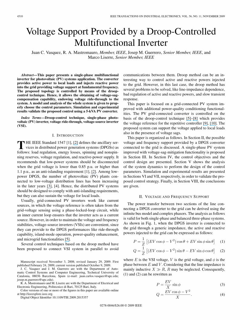
4510 IEEE TRANSACTIONS ON INDUSTRIAL ELECTRONICS, VOL. 56, NO. 11, NOVEMBER 2009
Voltage Support Provided by a Droop-ControlledMultifunctional Inverter
Juan C. Vasquez, R. A. Mastromauro, Member, IEEE, Josep M. Guerrero, Senior Member, IEEE, andMarco Liserre, Senior Member, IEEE
Abstract—This paper presents a single-phase multifunctionalinverter for photovoltaic (PV) systems application. The converterprovides active power to local loads and injects reactive powerinto the grid providing voltage support at fundamental frequency.The proposed topology is controlled by means of the droop-control technique. Hence, it allows the obtaining of voltage-sag-compensation capability, endowing voltage ride-through to thesystem. A model and analysis of the whole system is given to prop-erly choose the control parameters. Simulation and experimentalresults validate the proposed control using a 5-kVA PV converter.
Index Terms—Droop-control technique, single-phase photo-voltaic (PV) inverter, voltage ride-through, voltage-source inverter(VSI).
I. INTRODUCTION
THE IEEE Standard 1547 [1], [2] defines the ancillary ser-vices in distributed power generation systems (DPGSs) as
follows: load regulation, energy losses, spinning and nonspin-ning reserves, voltage regulation, and reactive-power supply. Itrecommends that low-power systems should be disconnectedwhen the grid voltage is lower than 0.85 p.u. or higher than1.1 p.u., as an anti-islanding requirement [1], [2]. Among low-power DPGS, the number of photovoltaic (PV) plants con-nected to low-voltage distribution lines has been increasingin the later years [3], [4]. Hence, the distributed PV systemsshould be designed to comply with anti-islanding requirements,but they can also sustain the voltage for local loads.
Usually, grid-connected PV inverters work like currentsources, in which the voltage reference is often taken from thegrid-voltage sensing using a phase-locked-loop circuit, whilean inner current loop ensures that the inverter acts as a currentsource. However, in order to maintain the voltage and frequencystabilities, voltage-source inverters (VSIs) are convenient, sincethey can provide to the DPGS performances like ride-throughcapability, island-mode operation, power-quality enhancement,and microgrid functionalities [5].
Several control techniques based on the droop method havebeen proposed to connect VSI system in parallel to avoid
Manuscript received November 3, 2008; revised January 29, 2009. Firstpublished February 24, 2009; current version published October 9, 2009.
J. C. Vasquez and J. M. Guerrero are with the Department of Auto-matic Control Systems and Computer Engineering, Technical University ofCatalonia, 08036 Barcelona, Spain (e-mail: [email protected];[email protected]).
R. A. Mastromauro and M. Liserre are with the Department of Electrical andElectronic Engineering, Politecnico di Bari, 70125 Bari, Italy.
Color versions of one or more of the figures in this paper are available onlineat http://ieeexplore.ieee.org.
Digital Object Identifier 10.1109/TIE.2009.2015357
communications between them. Droop method can be an in-teresting way to control active and reactive powers injectedto the grid. However, in this last case, the droop method hasseveral problems to be solved, like line-impedance dependence,bad regulation of active and reactive powers, and slow transientresponse.
This paper is focused on a grid-connected PV system im-proved with additional power-quality conditioning functional-ities. The PV grid-connected converter is controlled on thebasis of the droop-control technique [5]–[8] which providesthe voltage reference for the repetitive controller [9], [10]. Theproposed system can support the voltage applied to local loadsalso in the presence of voltage sags.
This paper is organized as follows. In Section II, the possiblevoltage and frequency support provided by a DPGS converterconnected to the grid is discussed. A single-phase PV systemimproved with voltage-sag-mitigation functionality is proposedin Section III. In Section IV, the control objectives and thecontrol design are presented. Section V shows the analysisof the system dynamics to perform the design of the controlparameters. Simulation and experimental results are presentedin Sections VI and VII, respectively, in order to validate the pro-posed control strategy. Finally, in Section VIII, the conclusionsare given.
II. VOLTAGE AND FREQUENCY SUPPORT
The power transfer between two sections of the line con-necting a DPGS converter to the grid can be derived using theinfinite bus model and complex phasors. The analysis as followsis valid for both single-phase and balanced three-phase systems.As shown in Fig. 1, when the DPGS inverter is connected tothe grid through a generic impedance, the active and reactivepowers injected to the grid can be expressed as follows:
P =1Z
[(EV cos φ − V 2) cos θ + EV sin φ sin θ
](1)
Q =1Z
[(EV cos φ − V 2) sin θ − EV sin φ cos θ
](2)
where E is the VSI voltage, V is the grid voltage, and φ is thephase between E and V . Considering that the line impedance ismainly inductive X � R, R may be neglected. Consequently,(1) and (2) can be rewritten as
P =EV
Xsin φ (3)
Q =EV cos φ − V 2
X. (4)
0278-0046/$26.00 © 2009 IEEE
VASQUEZ et al.: VOLTAGE SUPPORT PROVIDED BY A DROOP-CONTROLLED MULTIFUNCTIONAL INVERTER 4511
Fig. 1. Power flow through a line.
Arranging (3) and (4) and considering that the power angleφ is small, then sinφ ∼= φ and cos φ ∼= 1; the phase and thevoltage difference between the grid and the VSI can be calcu-lated as
φ ≈ X
EVP (5)
E − V ≈ X
VQ. (6)
From these equations, it is possible to deduce that the powerangle depends predominantly on the active power, whereasthe voltage difference E − V depends predominantly on thereactive power. In other words, the angle φ can be controlledby regulating the active power, whereas the inverter voltageE is controllable through the reactive power. The frequencycontrol dynamically controls the power angle and, hence, thereal power flow. Thus, by adjusting the active power P andthe reactive power Q independently, frequency and amplitudeof the grid voltage are determined. These conclusions formthe basis of the frequency and voltage droop control through,respectively, active and reactive powers.
III. MULTIFUNCTIONAL CONVERTER FOR
VOLTAGE-SAG MITIGATION
A. Shunt Converter for Voltage-Sag Mitigation
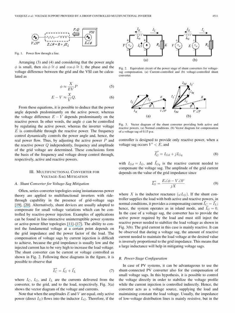
Often, series-converter topologies using instantaneous powertheory are applied to multifunctional inverters with ride-through capability in the presence of grid-voltage sags[19], [20]. Alternatively, shunt devices are usually adopted tocompensate for small voltage variations which can be con-trolled by reactive-power injection. Examples of applicationscan be found in line-interactive uninterruptible power systemsor active-power filter topologies [11]–[17]. The ability to con-trol the fundamental voltage at a certain point depends onthe grid impedance and the power factor of the load. Thecompensation of voltage sags by current injection is difficultto achieve, because the grid impedance is usually low and theinjected current has to be very high to increase the load voltage.The shunt converter can be current or voltage controlled asshown in Fig. 2. Following these diagrams in the figure, it ispossible to observe that
−→IC = �IG + �IL (7)
where IC , IG, and IL are the currents delivered from theconverter, to the grid, and to the load, respectively. Fig. 3(a)shows the vector diagram of the voltage and currents.
Note that when the amplitudes E and V are equal, only activepower (direct IG) flows into the inductor LG. Therefore, if the
Fig. 2. Equivalent circuit of the power stage of shunt converters for voltage-sag compensation. (a) Current-controlled and (b) voltage-controlled shuntconverter.
Fig. 3. Vector diagram of the shunt converter providing both active andreactive powers. (a) Normal conditions. (b) Vector diagram for compensationof a voltage sag of 0.15 p.u.
controller is designed to provide only reactive power, when avoltage sag occurs V ′ < E, and
−→I ′G = IGd + jIGq (8)
with IGd = IG, and �IGq is the reactive current needed tocompensate the voltage sag. The amplitude of the grid currentdepends on the value of the grid impedance since
−→IG =
E∠φ − V ∠0◦
jX(9)
where X is the inductor reactance (ωLG). If the shunt con-troller supplies the load with both active and reactive powers, innormal conditions, it provides a compensating current �IC = �IL;hence, the system operates as in island mode, and �IG = 0.In the case of a voltage sag, the converter has to provide theactive power required by the load and must still inject thereactive power needed to stabilize the load voltage as shown inFig. 3(b). The grid current in this case is mainly reactive. It canbe observed that during a voltage sag, the amount of reactivecurrent needed to maintain the load voltage at the desired valueis inversely proportional to the grid impedance. This means thata large inductance will help in mitigating voltage sags.
B. Power-Stage Configuration
In case of PV systems, it can be advantageous to use theshunt-connected PV converter also for the compensation ofsmall voltage sags. In this hypothesis, it is possible to controlthe voltage directly in order to stabilize the voltage profilewhile the current injection is controlled indirectly. Hence, theconverter acts as a voltage source, supplying the load andmaintaining constant the load voltage. Usually, the impedanceof low-voltage distribution lines is mainly resistive, but in the
4512 IEEE TRANSACTIONS ON INDUSTRIAL ELECTRONICS, VOL. 56, NO. 11, NOVEMBER 2009
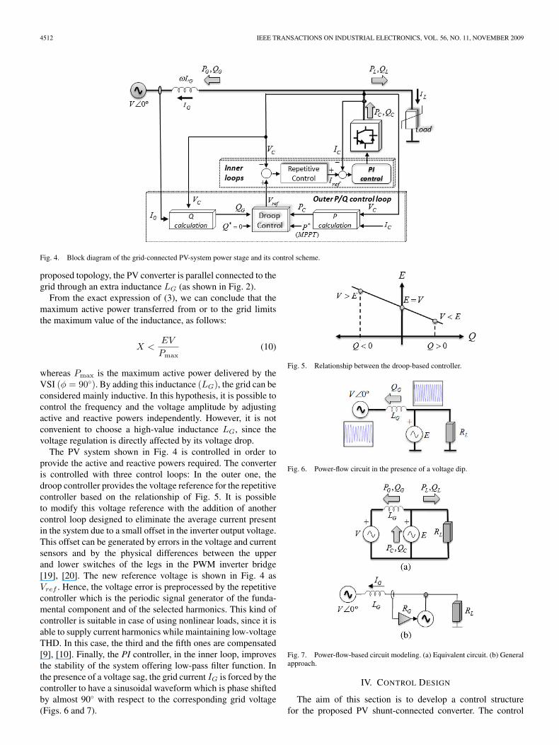
Fig. 4. Block diagram of the grid-connected PV-system power stage and its control scheme.
proposed topology, the PV converter is parallel connected to thegrid through an extra inductance LG (as shown in Fig. 2).
From the exact expression of (3), we can conclude that themaximum active power transferred from or to the grid limitsthe maximum value of the inductance, as follows:
X <EV
Pmax(10)
whereas Pmax is the maximum active power delivered by theVSI (φ = 90◦). By adding this inductance (LG), the grid can beconsidered mainly inductive. In this hypothesis, it is possible tocontrol the frequency and the voltage amplitude by adjustingactive and reactive powers independently. However, it is notconvenient to choose a high-value inductance LG, since thevoltage regulation is directly affected by its voltage drop.
The PV system shown in Fig. 4 is controlled in order toprovide the active and reactive powers required. The converteris controlled with three control loops: In the outer one, thedroop controller provides the voltage reference for the repetitivecontroller based on the relationship of Fig. 5. It is possibleto modify this voltage reference with the addition of anothercontrol loop designed to eliminate the average current presentin the system due to a small offset in the inverter output voltage.This offset can be generated by errors in the voltage and currentsensors and by the physical differences between the upperand lower switches of the legs in the PWM inverter bridge[19], [20]. The new reference voltage is shown in Fig. 4 asVref . Hence, the voltage error is preprocessed by the repetitivecontroller which is the periodic signal generator of the funda-mental component and of the selected harmonics. This kind ofcontroller is suitable in case of using nonlinear loads, since it isable to supply current harmonics while maintaining low-voltageTHD. In this case, the third and the fifth ones are compensated[9], [10]. Finally, the PI controller, in the inner loop, improvesthe stability of the system offering low-pass filter function. Inthe presence of a voltage sag, the grid current IG is forced by thecontroller to have a sinusoidal waveform which is phase shiftedby almost 90◦ with respect to the corresponding grid voltage(Figs. 6 and 7).
Fig. 5. Relationship between the droop-based controller.
Fig. 6. Power-flow circuit in the presence of a voltage dip.
Fig. 7. Power-flow-based circuit modeling. (a) Equivalent circuit. (b) Generalapproach.
IV. CONTROL DESIGN
The aim of this section is to develop a control structurefor the proposed PV shunt-connected converter. The control
VASQUEZ et al.: VOLTAGE SUPPORT PROVIDED BY A DROOP-CONTROLLED MULTIFUNCTIONAL INVERTER 4513
objectives of the droop-based controller can be summed up asfollows:
1) enhances the stability and the dynamic response by damp-ing the system;
2) provides all the active power given by the PV source andextracted in the previous stage by the maximum-powerpoint tracker (MPPT) [18];
3) supports the reactive power required by the grid whenvoltage sag is presented into the grid [21].
These three control objectives can be achieved by using thefollowing control loops: The first one is done by implementinga virtual resistor, via the VSI control [5]
Vref = V ∗ref − IG · RG. (11)
However, adding damping into the system implies that theimpedance seen by the VSI is not purely inductive, i.e., RG +jωLG.
Fig. 4 shows the block diagram of this proposed controlstrategy in which VC and IC denote the converter voltage andcurrent, respectively, and IG is the grid current. By multiplyingVC by IC and filtering the result, it is possible to obtain theactive power delivered by the converter (PC). On the otherhand, multiplying VC delayed 90◦ by IG, and then filtering theresulting value, the reactive power flow from/to the grid (QG)can be obtained
PC∼= 1
Z[V (E − V ) cos θ + EV · φ · sin θ] (12)
QG∼= 1
Z[(V (E − V ) sin θ − EV · φ · cos θ] (13)
where θ = X/R. Based on the information shown in Fig. 1, itis possible to calculate both the active P and reactive Q powersinjected to the grid by the VSI, as shown in (1) and (2). Forpossible simplifications, it is possible to transform P and Q tonovel variables defined as P ′ and Q′, which are independentfrom the magnitude and phase of the grid impedance
P ′ =PC sin θ − QG cos θ (14)Q′ =PC cos θ + QG sin θ. (15)
By substituting (12) and (13) into (14) and (15), the followingexpressions are yielded:
P ′ =EV
Zsinφ (16)
Q′ =EV
Zcos φ − V 2. (17)
Note that P ′ is mainly dependent on the phase φ, while Q′
depends on the voltage difference between the VSI and the grid(E − V ), as in purely inductive case (5) and (6).
These new control variables (P ′ and Q′) are independentfrom the grid-impedance angle θ, thus we can use them into thedroop method to control the active and reactive power flows.In order to inject the desired active power (P ∗
C , which shouldcoincide with the power given by the MPPT) and to compensatethe reactive power (normally Q∗
C = 0), the following droop-
method control loops which uses the transformation (14) and(15) are proposed:
φ = − Gp(s) [(PC−P ∗C) sin θ−(QG−Q∗
G) cos θ] (18)E =E∗−Gq(s) [(PC−P ∗
C) cos θ+(QG−Q∗G) sin θ] . (19)
A PI controller is proposed to ensure that the VSI injectsthe active power delivered by the MPPT stage. On the otherhand, a proportional controller is proposed for the reactive-power compensation defined as Gp(s) and Gq(s), respectively,
Gp(s) =mi + mps
s(20)
Gq(s) = np. (21)
For reactive-power compensation support, the coefficient np
must be properly adjusted. By using (4), (6), (19), and (21) withθ ∼= 90◦ and V = αE∗ (where α is the voltage-sag percentage),it is possible to obtain
np =E∗α(1 − α) − QmaxX
QmaxE∗α(22)
where Qmax is the maximum reactive-power flow that can bedelivered by the VSI. Fig. 8 shows details of the block-diagramimplementation of the droop controller, which is able to in-ject the desired active power P ∗
C and to compensate reactivepower QG.
V. SYSTEM DYNAMICS AND
CONTROL-DESIGN PARAMETERS
In this section, the system-dynamic model and the stabilityanalysis are provided to properly design mi and mp coefficientsof the PI compensator (20), corresponding to the active-power-injection control loop (18).
A small-signal analysis is provided in order to show the sys-tem stability and the transient response. The power-calculationblock uses a low-pass second-order filter in which the passbandis much smaller than the passband of the inverter-voltage con-trol. Hence, both the power and reactive output power measuredfrom the power-calculation block can be defined as
pmeas(s) =ω2
o
s2 + 2ζωos + ω2o
· p′(s) (23)
qmeas(s) =ω2
o
s2 + 2ζωos + ω2o
· q′(s) (24)
where ωo is the resonance frequency and ζ the damped co-efficient. By doing a small-signal approximation in order tolinearize the equations, it yields
pmeas(s) =ω2
o
s2 + 2ζωos + ω2o
[V sin Φe(s) + V E cos Φφ(s)
Z
]
(25)
qmeas(s) =ω2
o
s2 + 2ζωos + ω2o
[V cos Φe(s) − V E sin Φφ(s)
Z
]
(26)
4514 IEEE TRANSACTIONS ON INDUSTRIAL ELECTRONICS, VOL. 56, NO. 11, NOVEMBER 2009
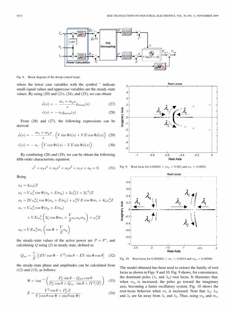
Fig. 8. Block diagram of the droop-control loops.
where the lower case variables with the symbol ∧ indicatesmall-signal values and uppercase variables are the steady-statevalues. By using (20) and (21), (24), and (25), we can obtain
φ(s) = − mi + mps
spmeas(s) (27)
e(s) = − niqmeas(s). (28)
From (26) and (27), the following expressions can bederived:
φ(s) = − mi + mps
s·(V sin Φe(s) + V E cos Φφ(s)
)(29)
e(s) = − ni ·(V cos Φe(s) − V E sin Φφ(s)
). (30)
By combining (28) and (29), we can be obtain the followingfifth-order characteristic equation:
s5 + a4s4 + a3s
3 + a2s2 + a1s + a0 = 0. (31)
Being
a4 = 4ωoζZ
a3 = V ω2o cos Φ(np + Emp) + 2ω2
o(1 + 2ζ2)Z
a2 = 2V ω2oζ cos Φ(np + Emp) + ω2
oV E cos Φmi + 4ζω3oZ
a1 = V ω4o cos Φ(np + Emp)
+ V Eω3o
(2ζ cos Φmi +
V
Zωonpmp
)+ ω4
oZ
a0 = V Eω4omi
(cos Φ +
V
Znp
)
the steady-state values of the active power are P = P ∗, andcalculating Q using (2) in steady state, defined as
Qss =1Z
[(EV cos Φ − V 2) sin θ − EV sin Φ cos θ
](32)
the steady-state phase and amplitudes can be calculated from(12) and (13), as follows:
Φ = tan−1
(P ∗
C sin θ − QSS cos θ
P ∗C cos θ + Qss · sin θ + (V 2/Z)
)(33)
E =V 2 cos θ + P ∗
CZ
V (cos θ cos Φ + sin θ sin Φ). (34)
Fig. 9. Root locus for 0.00002 < mp < 0.001 and mi = 0.0002.
Fig. 10. Root locus for 0.000002 < mi < 0.0018 and mp = 0.00006.
The model obtained has been used to extract the family of rootlocus as shown in Figs. 9 and 10. Fig. 9 shows, for convenience,the dominant poles (λ1 and λ2) root locus. It illustrates that,when mp is increased, the poles go toward the imaginaryaxis, becoming a faster oscillatory system. Fig. 10 shows theroot-locus behavior when mi is increased. Note that λ3, λ4,and λ5 are far away from λ1 and λ2. Thus, using mp and mi,
VASQUEZ et al.: VOLTAGE SUPPORT PROVIDED BY A DROOP-CONTROLLED MULTIFUNCTIONAL INVERTER 4515
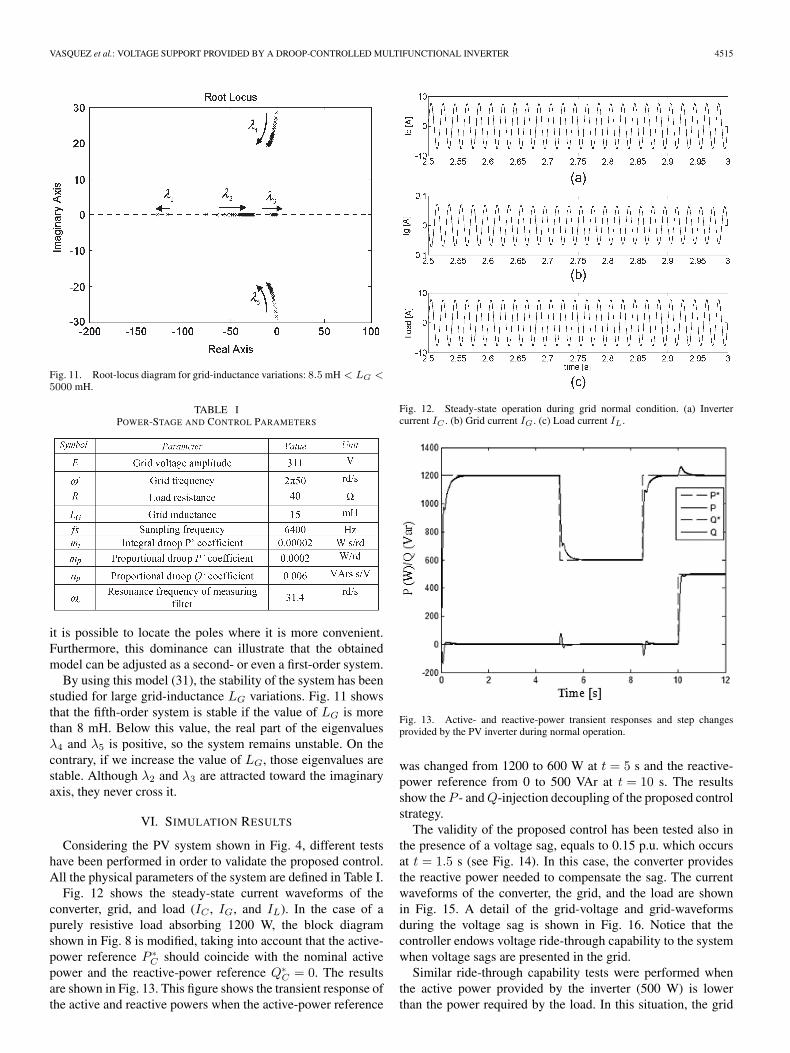
Fig. 11. Root-locus diagram for grid-inductance variations: 8.5 mH < LG <5000 mH.
TABLE IPOWER-STAGE AND CONTROL PARAMETERS
it is possible to locate the poles where it is more convenient.Furthermore, this dominance can illustrate that the obtainedmodel can be adjusted as a second- or even a first-order system.
By using this model (31), the stability of the system has beenstudied for large grid-inductance LG variations. Fig. 11 showsthat the fifth-order system is stable if the value of LG is morethan 8 mH. Below this value, the real part of the eigenvaluesλ4 and λ5 is positive, so the system remains unstable. On thecontrary, if we increase the value of LG, those eigenvalues arestable. Although λ2 and λ3 are attracted toward the imaginaryaxis, they never cross it.
VI. SIMULATION RESULTS
Considering the PV system shown in Fig. 4, different testshave been performed in order to validate the proposed control.All the physical parameters of the system are defined in Table I.
Fig. 12 shows the steady-state current waveforms of theconverter, grid, and load (IC , IG, and IL). In the case of apurely resistive load absorbing 1200 W, the block diagramshown in Fig. 8 is modified, taking into account that the active-power reference P ∗
C should coincide with the nominal activepower and the reactive-power reference Q∗
C = 0. The resultsare shown in Fig. 13. This figure shows the transient response ofthe active and reactive powers when the active-power reference
Fig. 12. Steady-state operation during grid normal condition. (a) Invertercurrent IC . (b) Grid current IG. (c) Load current IL.
Fig. 13. Active- and reactive-power transient responses and step changesprovided by the PV inverter during normal operation.
was changed from 1200 to 600 W at t = 5 s and the reactive-power reference from 0 to 500 VAr at t = 10 s. The resultsshow the P - and Q-injection decoupling of the proposed controlstrategy.
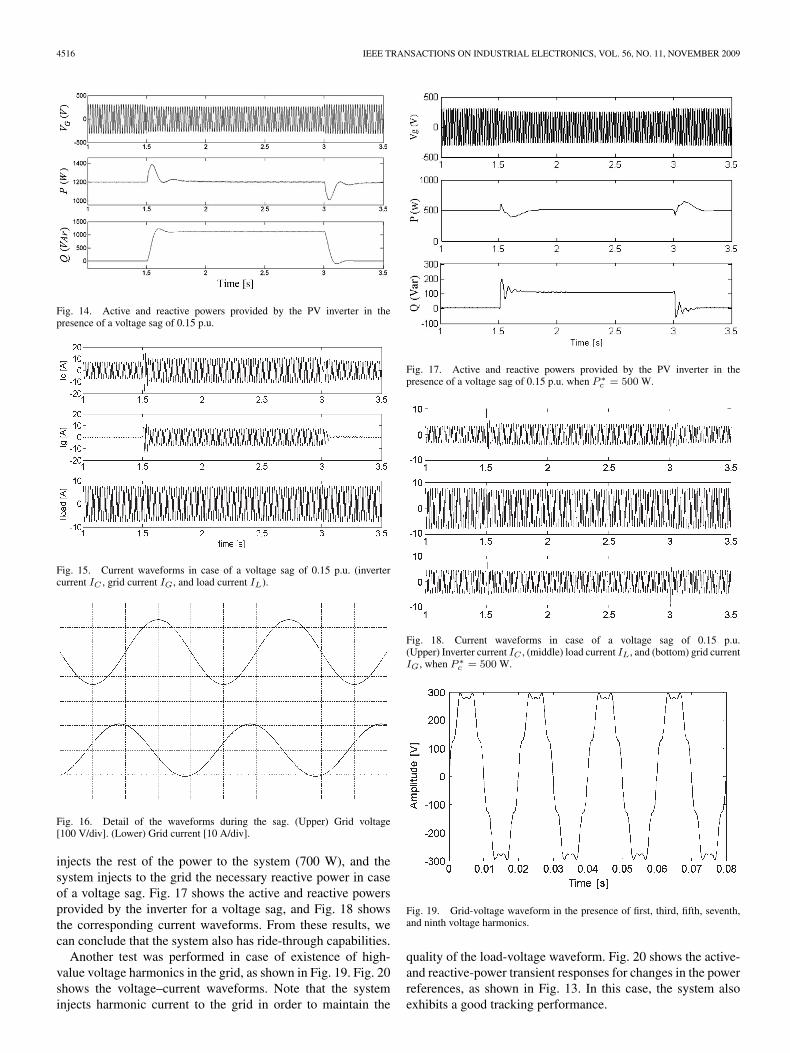
The validity of the proposed control has been tested also inthe presence of a voltage sag, equals to 0.15 p.u. which occursat t = 1.5 s (see Fig. 14). In this case, the converter providesthe reactive power needed to compensate the sag. The currentwaveforms of the converter, the grid, and the load are shownin Fig. 15. A detail of the grid-voltage and grid-waveformsduring the voltage sag is shown in Fig. 16. Notice that thecontroller endows voltage ride-through capability to the systemwhen voltage sags are presented in the grid.
Similar ride-through capability tests were performed whenthe active power provided by the inverter (500 W) is lowerthan the power required by the load. In this situation, the grid
4516 IEEE TRANSACTIONS ON INDUSTRIAL ELECTRONICS, VOL. 56, NO. 11, NOVEMBER 2009
Fig. 14. Active and reactive powers provided by the PV inverter in thepresence of a voltage sag of 0.15 p.u.
Fig. 15. Current waveforms in case of a voltage sag of 0.15 p.u. (invertercurrent IC , grid current IG, and load current IL).
Fig. 16. Detail of the waveforms during the sag. (Upper) Grid voltage[100 V/div]. (Lower) Grid current [10 A/div].
injects the rest of the power to the system (700 W), and thesystem injects to the grid the necessary reactive power in caseof a voltage sag. Fig. 17 shows the active and reactive powersprovided by the inverter for a voltage sag, and Fig. 18 showsthe corresponding current waveforms. From these results, wecan conclude that the system also has ride-through capabilities.
Another test was performed in case of existence of high-value voltage harmonics in the grid, as shown in Fig. 19. Fig. 20shows the voltage–current waveforms. Note that the systeminjects harmonic current to the grid in order to maintain the
Fig. 17. Active and reactive powers provided by the PV inverter in thepresence of a voltage sag of 0.15 p.u. when P ∗
c = 500 W.
Fig. 18. Current waveforms in case of a voltage sag of 0.15 p.u.(Upper) Inverter current IC , (middle) load current IL, and (bottom) grid currentIG, when P ∗
c = 500 W.
Fig. 19. Grid-voltage waveform in the presence of first, third, fifth, seventh,and ninth voltage harmonics.
quality of the load-voltage waveform. Fig. 20 shows the active-and reactive-power transient responses for changes in the powerreferences, as shown in Fig. 13. In this case, the system alsoexhibits a good tracking performance.
VASQUEZ et al.: VOLTAGE SUPPORT PROVIDED BY A DROOP-CONTROLLED MULTIFUNCTIONAL INVERTER 4517
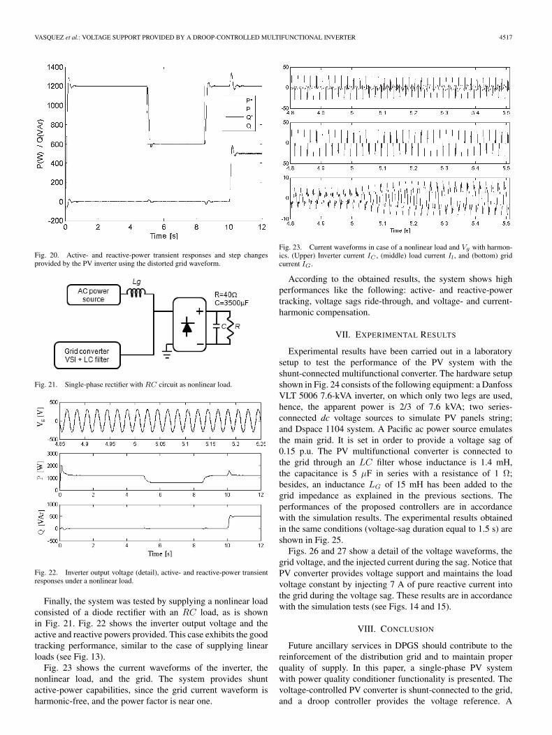
Fig. 20. Active- and reactive-power transient responses and step changesprovided by the PV inverter using the distorted grid waveform.
Fig. 21. Single-phase rectifier with RC circuit as nonlinear load.
Fig. 22. Inverter output voltage (detail), active- and reactive-power transientresponses under a nonlinear load.
Finally, the system was tested by supplying a nonlinear loadconsisted of a diode rectifier with an RC load, as is shownin Fig. 21. Fig. 22 shows the inverter output voltage and theactive and reactive powers provided. This case exhibits the goodtracking performance, similar to the case of supplying linearloads (see Fig. 13).
Fig. 23 shows the current waveforms of the inverter, thenonlinear load, and the grid. The system provides shuntactive-power capabilities, since the grid current waveform isharmonic-free, and the power factor is near one.
Fig. 23. Current waveforms in case of a nonlinear load and Vg with harmon-ics. (Upper) Inverter current IC , (middle) load current Il, and (bottom) gridcurrent IG.
According to the obtained results, the system shows highperformances like the following: active- and reactive-powertracking, voltage sags ride-through, and voltage- and current-harmonic compensation.
VII. EXPERIMENTAL RESULTS
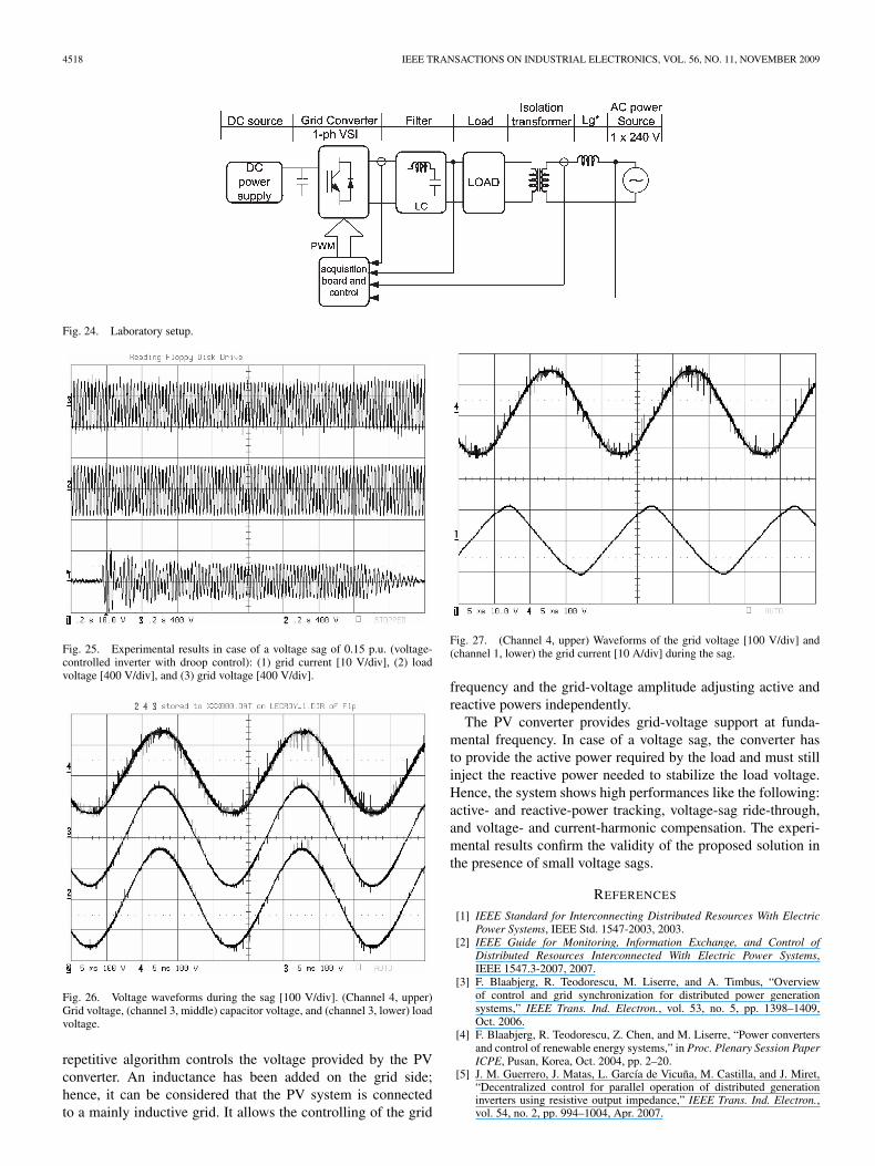
Experimental results have been carried out in a laboratorysetup to test the performance of the PV system with theshunt-connected multifunctional converter. The hardware setupshown in Fig. 24 consists of the following equipment: a DanfossVLT 5006 7.6-kVA inverter, on which only two legs are used,hence, the apparent power is 2/3 of 7.6 kVA; two series-connected dc voltage sources to simulate PV panels string;and Dspace 1104 system. A Pacific ac power source emulatesthe main grid. It is set in order to provide a voltage sag of0.15 p.u. The PV multifunctional converter is connected tothe grid through an LC filter whose inductance is 1.4 mH,the capacitance is 5 μF in series with a resistance of 1 Ω;besides, an inductance LG of 15 mH has been added to thegrid impedance as explained in the previous sections. Theperformances of the proposed controllers are in accordancewith the simulation results. The experimental results obtainedin the same conditions (voltage-sag duration equal to 1.5 s) areshown in Fig. 25.
Figs. 26 and 27 show a detail of the voltage waveforms, thegrid voltage, and the injected current during the sag. Notice thatPV converter provides voltage support and maintains the loadvoltage constant by injecting 7 A of pure reactive current intothe grid during the voltage sag. These results are in accordancewith the simulation tests (see Figs. 14 and 15).
VIII. CONCLUSION
Future ancillary services in DPGS should contribute to thereinforcement of the distribution grid and to maintain properquality of supply. In this paper, a single-phase PV systemwith power quality conditioner functionality is presented. Thevoltage-controlled PV converter is shunt-connected to the grid,and a droop controller provides the voltage reference. A
4518 IEEE TRANSACTIONS ON INDUSTRIAL ELECTRONICS, VOL. 56, NO. 11, NOVEMBER 2009
Fig. 24. Laboratory setup.
Fig. 25. Experimental results in case of a voltage sag of 0.15 p.u. (voltage-controlled inverter with droop control): (1) grid current [10 V/div], (2) loadvoltage [400 V/div], and (3) grid voltage [400 V/div].
Fig. 26. Voltage waveforms during the sag [100 V/div]. (Channel 4, upper)Grid voltage, (channel 3, middle) capacitor voltage, and (channel 3, lower) loadvoltage.
repetitive algorithm controls the voltage provided by the PVconverter. An inductance has been added on the grid side;hence, it can be considered that the PV system is connectedto a mainly inductive grid. It allows the controlling of the grid
Fig. 27. (Channel 4, upper) Waveforms of the grid voltage [100 V/div] and(channel 1, lower) the grid current [10 A/div] during the sag.
frequency and the grid-voltage amplitude adjusting active andreactive powers independently.
The PV converter provides grid-voltage support at funda-mental frequency. In case of a voltage sag, the converter hasto provide the active power required by the load and must stillinject the reactive power needed to stabilize the load voltage.Hence, the system shows high performances like the following:active- and reactive-power tracking, voltage-sag ride-through,and voltage- and current-harmonic compensation. The experi-mental results confirm the validity of the proposed solution inthe presence of small voltage sags.
REFERENCES
[1] IEEE Standard for Interconnecting Distributed Resources With ElectricPower Systems, IEEE Std. 1547-2003, 2003.
[2] IEEE Guide for Monitoring, Information Exchange, and Control ofDistributed Resources Interconnected With Electric Power Systems,IEEE 1547.3-2007, 2007.
[3] F. Blaabjerg, R. Teodorescu, M. Liserre, and A. Timbus, “Overviewof control and grid synchronization for distributed power generationsystems,” IEEE Trans. Ind. Electron., vol. 53, no. 5, pp. 1398–1409,Oct. 2006.
[4] F. Blaabjerg, R. Teodorescu, Z. Chen, and M. Liserre, “Power convertersand control of renewable energy systems,” in Proc. Plenary Session PaperICPE, Pusan, Korea, Oct. 2004, pp. 2–20.
[5] J. M. Guerrero, J. Matas, L. García de Vicuña, M. Castilla, and J. Miret,“Decentralized control for parallel operation of distributed generationinverters using resistive output impedance,” IEEE Trans. Ind. Electron.,vol. 54, no. 2, pp. 994–1004, Apr. 2007.

VASQUEZ et al.: VOLTAGE SUPPORT PROVIDED BY A DROOP-CONTROLLED MULTIFUNCTIONAL INVERTER 4519
[6] J. M. Guerrero, L. García de Vicuña, M. Castilla, and J. Miret, “Wireless-control strategy for parallel operation of distributed-generation inverters,”IEEE Trans. Ind. Electron., vol. 53, no. 5, pp. 1461–1470, Oct. 2006.
[7] J. M. Guerrero, L. García de Vicuña, J. Matas, M. Castilla, and J. Miret,“Output impedance design of parallel-connected UPS inverters with wire-less load-sharing control,” IEEE Trans. Ind. Electron., vol. 52, no. 4,pp. 1126–1135, Aug. 2005.
[8] J. M. Guerrero, L. García de Vicuña, J. Matas, M. Castilla, and J. Miret, “Awireless controller to enhance dynamic performance of parallel invertersin distributed generation systems,” IEEE Trans. Power Electron., vol. 19,no. 5, pp. 1205–1213, Sep. 2004.
[9] R. A. Mastromauro, M. Liserre, and A. Dell’Aquila, “Study of the effectsof inductor nonlinear behavior on the performance of current controllersfor single-phase PV grid converter,” IEEE Trans. Ind. Electron., vol. 55,no. 5, pp. 2043–2052, May 2008.
[10] R. A. Mastromauro, M. Liserre, and A. Dell’Aquila, “Frequency domainanalysis of inductor saturation in current controlled grid converters,” inProc. IEEE IECON, Nov. 5–8, 2007, pp. 1396–1401.
[11] T. Kawabata, N. Sashida, Y. Yamamoto, K. Ogasawara, andY. Yamasaki, “Parallel processing inverter system,” IEEE Trans.Power Electron., vol. 6, no. 3, pp. 442–450, Jul. 1991.
[12] M. Ashari, C. V. Nayar, and S. Islam, “Steady-state performance of agrid interactive voltage source inverter,” in Proc. IEEE Power Eng. Soc.Summer Meeting, 2001, pp. 650–655.
[13] C. V. Nayar, M. Ashari, and W. W. K. Keerthipala, “A grid-interactivephotovoltaic uninterruptible power supply system using battery storageand a back up diesel generator,” IEEE Trans. Energy Convers., vol. 15,no. 3, pp. 348–353, Sep. 2000.
[14] M. Ashari, C. V. Nayar, and W. W. K. Keerthipala, “A single phaseparallely connected uninterruptible power supply/demand side manage-ment system,” IEEE Trans. Energy Convers., vol. 15, no. 1, pp. 97–102,Mar. 2000.
[15] J. M. Guerrero, L. Garcia de Vicuna, and J. Uceda, “Uninterruptible powersupply systems provide protection,” IEEE Ind. Electron. Mag., vol. 1,no. 1, pp. 28–38, Spring 2007.
[16] H. Tao, J. L. Duarte, and M. A. M. Hendrix, “Line-interactive UPS using afuel cell as the primary source,” IEEE Trans. Ind. Electron., vol. 55, no. 8,pp. 3012–3021, Aug. 2008.
[17] M. Arias, A. Fernandez, D. G. Lamar, M. Rodriguez, andM. M. Hernando, “Simplified voltage-sag filler for line-interactiveuninterruptible power supplies,” IEEE Trans. Ind. Electron., vol. 55,no. 8, pp. 3005–3011, Aug. 2008.
[18] R. A. Mastromauro, M. Liserre, T. Kerekes, and A. Dell’Aquila,“A single-phase voltage controlled grid connected photovoltaic systemwith power quality conditioner functionality,” IEEE Trans. Ind. Electron.to be published.
[19] R. R. Sawant and M. C. Chandorkar, “Methods for multi-functional con-verter control in three-phase four-wire systems,” IET Power Electron.,vol. 2, no. 1, pp. 52–66, Jan. 2009.
[20] S.-J. Lee, H. Kim, S.-K. Sul, and F. Blaabjerg, “A novel controlalgorithm for static series compensator by use of PQR instantaneouspower theory,” IEEE Trans. Ind. Electron., vol. 19, no. 3, pp. 814–827,May 2004.
[21] C.-C. Shen and C.-N. Lu, “A voltage sag index considering compatibilitybetween equipment and supply,” IEEE Trans. Power Del., vol. 22, no. 2,pp. 996–1002, Apr. 2007.
[22] J. Gao, X. H. Zhao, X. Yang, and Z. A. Wang, “The research on avoidingflux imbalance in sinusoidal wave inverter,” in Proc. IEEE IPEMC, 2000,pp. 1122–1126.
[23] M.-Z. Li and Y. Xing, “Digital voltage regulation with flux bal-ance control for sine wave inverters,” in Proc. IEEE APEC, 2004,pp. 1709–1713.
Juan C. Vasquez received the B.S. degree in elec-tronics engineering from the Universidad Autonomade Manizales, Manizales, Colombia, in 2004. Heis currently working toward the Ph.D. degree inthe Department of Automatic Control Systemsand Computer Engineering, Technical University ofCatalonia, Barcelona, Spain.
He has been an Assistant Professor with the Uni-versidad Autonoma de Manizales, where he has beenteaching courses on digital circuits, servo systems,and flexible manufacturing systems. His research in-
terests include modeling, simulation, and management applied to the distributedgeneration in microgrids.
R. A. Mastromauro (S’05–M’09) received theM.Sc. and Ph.D. degrees in electrical engineeringfrom the Politecnico di Bari, Bari, Italy, in 2005 and2009, respectively.
Since 2005, she has been with the Converters,Electrical Machines and Drives Research Team, De-partment of Electrical and Electronic Engineering,Politecnico di Bari, where she is engaged in teachingcourses on power electronics. Her research interestsinclude power converter control for distributed pow-er generation systems based on renewable energies.
Dr. Mastromauro is a member of the IEEE Industrial Electronics Society,the IEEE Power Electronics Society, the IEEE Industrial Application Society,the IEEE Women in Engineering Society, and the Italian Electrotechnical andElectronic Association. She is a reviewer for IEEE conference proceedings andjournals.
Josep M. Guerrero (S’01–M’04–SM’08) receivedthe B.S. degree in telecommunications engineering,the M.S. degree in electronics engineering, and thePh.D. degree in power electronics from the TechnicalUniversity of Catalonia, Barcelona, Spain, in 1997,2000, and 2003, respectively.
He is currently an Associate Professor in theDepartment of Automatic Control Systems andComputer Engineering, Technical University ofCatalonia, where he currently teaches courses ondigital signal processing, control theory, micro-
processors, and renewable energy. Since 2004, he has been responsible forthe Renewable Energy Laboratory, Escola Industrial de Barcelona, Barcelona,Spain. His research interests include photovoltaics, wind-energy conversion,uninterruptible power supplies, storage-energy systems, and microgrids.
Dr. Guerrero is the Editor-in-Chief of the International Journal of IntegratedEnergy Systems. He is also an Associate Editor for the IEEE TRANSACTIONSON INDUSTRIAL ELECTRONICS, the IEEE TRANSACTIONS ON POWERELECTRONICS, the International Journal of Power Electronics, and the Inter-national Journal of Industrial Electronics and Drives.
Marco Liserre (S’00–M’02–SM’07) received theM.Sc. and Ph.D. degrees in electrical engineeringfrom the Polytechnic of Bari, Bari, Italy, in 1998 and2002, respectively.
Since January 2004, he has been an AssistantProfessor with the Polytechnic of Bari, where he isengaged in teaching courses on power electronics,industrial electronics, and electrical machines. Hehas been giving lectures in different universities. Hehas been a Visiting Professor with Aalborg Univer-sity, Denmark, Alcala de Henares, Spain, and with
Christian-Albrechts University of Kiel, Kiel, Germany. He has authored orcoauthored more than 127 technical papers, 28 of them published or to bepublished in international peer-reviewed journals, and three chapters of a book.These works have received more than 800 citations. His current research inter-ests include industrial electronics applications to distributed power generationsystems based on renewable energies.
Dr. Liserre is a Senior Member of the IEEE Industrial Electronics Society(IES), the IEEE Power Electronics Society, and the IEEE Industry ApplicationsSociety. He was a reviewer for international conferences and journals and hasbeen involved in the IEEE conferences organization in different capacities.Within the IES, he has been responsible for student activities and Region 8membership activities and has been an Administrative Committee Memberand an Editor of the newsletter. He has been giving tutorials for the IEEEEnergy Conversion Congress and Exposition (ECCE) 2009, the IEEE PowerElectronics Specialists Conference (PESC) 2008, the International Symposiumon Industrial Electronics (ISIE) 2008, the European Conference on PowerElectronics and Applications (EPE) 2007, the Annual Conference of the IEEEIndustrial Electronics Society (IECON) 2006, ISIE 2006, and IECON 2005.He is an Associate Editor of the IEEE TRANSACTIONS ON INDUSTRIALELECTRONICS. He is the Founder and has been the Editor-in-Chief of the IEEEINDUSTRIAL ELECTRONICS MAGAZINE in 2007–2009. He is the Founder andthe Chairman of the Technical Committee on Renewable Energy Systems of theIES. He has been a Guest Coeditor-in-Chief of the IEEE TRANSACTIONS ONINDUSTRIAL ELECTRONICS for the special section on “Voltage and CurrentControl of Power Converters.” He is also an organizer and a Guest Coeditor-in-Chief of the new special section on “Renewable Energy Systems” of the IEEETRANSACTIONS ON INDUSTRIAL ELECTRONICS. He will be the Cochairmanof ISIE 2010 that will be held in Bari, Italy, on July 4–7, 2010. He was therecipient of the IES 2009 Early Career Award.
Copyright © 2022 FDOKUMEN