Computational Modeling of Variable-Droop Leading Edge in Forward Flight
11
American Institute of Aeronautics and Astronautics 1 of 11 Computational Modeling of Variable Droop Leading Edge in Forward Flight Jeremy J. Bain 1 , Lakshmi N. Sankar 2 , JVR Prasad 3 , Oliver A. Bauchau 4 Georgia Institute of Technology, Atlanta, GA, USA 30332-0150 David A. Peters 5 Washington University, St. Louis MO, USA and Chengjian He 6 Advanced Rotorcraft Technology, Mountain View, CA, 94035 In recent years, there has been significant interest in On-Blade Concepts (OBC) that expand the operating envelope of helicopters without compromising the performance characteristics of the baseline rotor. The Variable Droop Leading Edge (VDLE) concept is explored in a modified version of the Navier-Stokes solver OVERFLOW. Modifications were made to the solver to allow deforming grid capability. This concept was explored in dynamic stall tests of the VR-12 and SC1095 helicopter airfoils. The VDLE airfoils have dramatically reduced drag and moment rises associated with dynamic stall. Using the results of these tests, a modified UH-60A rotor incorporating VDLE airfoils was analyzed using loose coupling CFD-CSD with OVERFLOW and DYMORE and compared to the standard UH- 60A rotor for high thrust case Flight 9017. Results show a reduction in the peak negative pitching moment. The rotor efficiency was shown to improve by 2.9% while the 4/rev component of vertical force reduced by 8%. Nomenclature c = chord C T = Thrust Coefficient F 4Z = 4/rev Vertical Hub Force k = Reduced Frequency, ωc/(2V ∞ ) L/De = Rotor lift per equivalent drag, (F Z /(F X -M Z Ω /V ∞ )) R = Main Rotor Radius VDLE = Variable Droop Leading Edge V ∞ = Free stream Velocity V Tip = Rotor Tip Speed (ΩR) µ = Advance Ratio, V ∞ /V Tip σ = Rotor Solidity Ω = Main Rotor Rotation Rate, rad/s ψ = Rotor Azimuth 1 Research Engineer, AIAA Student Member 2 Professor, Associate Fellow AIAA 3 Professor, Associate Fellow AIAA 4 Professor, Senior AIAA Member 5 Professor, AIAA Fellow 6 Director of Research and Development, Senior AIAA Member 4th Flow Control Conference<br> 23 - 26 June 2008, Seattle, Washington AIAA 2008-3872 Copyright © 2008 by the American Institute of Aeronautics and Astronautics, Inc. All rights reserved. Downloaded by GEORGIA INST OF TECHNOLOGY on December 5, 2014 | http://arc.aiaa.org | DOI: 10.2514/6.2008-3872
Transcript of Computational Modeling of Variable-Droop Leading Edge in Forward Flight

American Institute of Aeronautics and Astronautics
1 of 11
Computational Modeling of Variable Droop Leading Edge in
Forward Flight
Jeremy J. Bain1, Lakshmi N. Sankar
2, JVR Prasad
3, Oliver A. Bauchau
4
Georgia Institute of Technology, Atlanta, GA, USA 30332-0150
David A. Peters5
Washington University, St. Louis MO, USA
and
Chengjian He6
Advanced Rotorcraft Technology, Mountain View, CA, 94035
In recent years, there has been significant interest in On-Blade Concepts (OBC) that
expand the operating envelope of helicopters without compromising the performance
characteristics of the baseline rotor. The Variable Droop Leading Edge (VDLE) concept is
explored in a modified version of the Navier-Stokes solver OVERFLOW. Modifications were
made to the solver to allow deforming grid capability. This concept was explored in dynamic
stall tests of the VR-12 and SC1095 helicopter airfoils. The VDLE airfoils have dramatically
reduced drag and moment rises associated with dynamic stall. Using the results of these
tests, a modified UH-60A rotor incorporating VDLE airfoils was analyzed using loose
coupling CFD-CSD with OVERFLOW and DYMORE and compared to the standard UH-
60A rotor for high thrust case Flight 9017. Results show a reduction in the peak negative
pitching moment. The rotor efficiency was shown to improve by 2.9% while the 4/rev
component of vertical force reduced by 8%.
Nomenclature
c = chord
CT = Thrust Coefficient
F4Z = 4/rev Vertical Hub Force
k = Reduced Frequency, ωc/(2V∞)
L/De = Rotor lift per equivalent drag, (FZ/(FX-MZ Ω /V∞))
R = Main Rotor Radius
VDLE = Variable Droop Leading Edge
V∞ = Free stream Velocity
VTip = Rotor Tip Speed (ΩR)
µ = Advance Ratio, V∞/VTip
σ = Rotor Solidity
Ω = Main Rotor Rotation Rate, rad/s
ψ = Rotor Azimuth
1 Research Engineer, AIAA Student Member
2 Professor, Associate Fellow AIAA
3 Professor, Associate Fellow AIAA
4 Professor, Senior AIAA Member
5 Professor, AIAA Fellow
6 Director of Research and Development, Senior AIAA Member
4th Flow Control Conference<br>23 - 26 June 2008, Seattle, Washington
AIAA 2008-3872
Copyright © 2008 by the American Institute of Aeronautics and Astronautics, Inc. All rights reserved.
Dow
nloa
ded
by G
EO
RG
IA I
NST
OF
TE
CH
NO
LO
GY
on
Dec
embe
r 5,
201
4 | h
ttp://
arc.
aiaa
.org
| D
OI:
10.
2514
/6.2
008-
3872

American Institute of Aeronautics and Astronautics
2 of 11
I. Introduction
ETREATING blade stall is a dominating factor in forward flight and can limit the operational envelope of a
helicopter. In forward flight, the advancing blade encounters additional velocity due to the free stream and the
retreating blade encounters a reduced velocity. This leads to the same rotor span station required to have good low
drag transonic and high lift, low speed performance. In moderate speed cruise flight (µ = 0.3), the advancing blade
has 3.45 times the dynamic pressure at the tip and 16 times at the midspan than the retreating blade. To trim the
aircraft, the lift generated on the advancing and retreating sides need to be balanced to avoid a large rolling moment.
This leads to the retreating blade operating at or near its maximum lift capability while the advancing blade is at low
or negative incidence. This causes the blade to undergo dynamic stall cycles as the blade rapidly goes from low to
high incidence causing large negative pitching moments, high vibration, and buffeting. The high negative pitching
moment that occurs causes an elastic deformation that causes further pitch changes. These stall cycles limit the
helicopter’s maximum flight speed, maneuverability, and thrust.
A number of On-Blade Concepts (OBC) have been proposed that offer tremendous potential for improved
performance and reduced vibration for next generation helicopters. These concepts attempt to improve
aerodynamics on the retreating side while limiting their adverse effect on the advancing side. These include leading
edge slats1,2
, trailing edge flaps3,4
, variable camber5, and leading edge deformation.
6,7 A variable drooping leading
edge has been shown in two dimensional tests to greatly reduce the negative pitching moment peak and peak drag
while having small changes in lift in experimental and computational tests8,910
. The purpose of the current work is to
evaluate the effects of a drooping leading edge in two and three dimensional tests.
II. Numerical Methodology
The numerical simulations were done using the compressible Navier-Stokes Computational Fluid Dynamics
(CFD) code OVERFLOW11
. OVERFLOW, developed by NASA, uses overset structured grids for a wide variety of
problems including rotorcraft simulations12,13
. Version 2.0y with modifications made under the DARPA Helicopter
Quieting Program, as reported by Duque et al,14
was used with elastic blade motion capability as implemented per
Nygaard. For 2-D calculations, a C-grid of dimensions 547x105 was used with a y+ of one, 35,000 time steps per
loop and four Newton sub-iterations. Calculations were made with up to eight Newton sub-iterations but were found
to produce near identical results. The solutions were run for 2-2.5 cycles using 4th
order Central Differencing and the
KES turbulence model15
. Three dimensional runs were made using a coarse 125x82x33 node blade C-grid. The first
off body grid used spacing of 0.2 times the tip chord. The entire grid used approximately 4.6 Million grid points.
OVERFLOW used twenty time steps per degree of azimuth, the DES method turbulence model based upon Spalart-
Allmaras16,17
, and 4th
order Central Differencing.
For three dimensional modeling, the UH-60A Blackhawk
rotor was used. Extensive work has been done on the UH-60A
rotor using CFD-CSD coupling with a variety of solvers through
the UH-60A Airloads Program.18
Potsdam et al19
used loose
coupling with OVERFLOW and CAMRAD II for a variety of
level flight conditions. OVERFLOW has also been used with
other structural solvers RCAS and DYMORE.14,20
DYMORE21
is a finite element solver which uses a multi-
body dynamics approach for the modeling of the rotor as a
nonlinear elastic multi-body system. A four bladed UH-60A rotor
model is used that includes the blades, lag dampers, and push
rods. A dynamic wake is used for the initial aerodynamics. An
auto pilot algorithm is used to trim the rotor to the prescribed
thrust and moment targets. No changes were made to the
DYMORE model to account for the VDLE mechanical device.
A loose coupling trim method initially developed by Tung et
al was used22
and shown in Fig. 1. DYMORE is first run for
several revolutions to obtain the trim solution and blade motions.
The elastic blade motions are then transferred to OVERFLOW.
R
Figure 1. Loose Coupling Methodology
Dow
nloa
ded
by G
EO
RG
IA I
NST
OF
TE
CH
NO
LO
GY
on
Dec
embe
r 5,
201
4 | h
ttp://
arc.
aiaa
.org
| D
OI:
10.
2514
/6.2
008-
3872

American Institute of Aeronautics and Astronautics
3 of 11
Airloads are then calculated in OVERFLOW. Airloads and elastic deformations were calculated at eighty-one rotor
stations. Three components of force and moments calculated by OVERFLOW were exchanged in the hub frame.
This avoids any differences in the local frame due to changes in chord length and orientation that occurs when the
leading edge is deformed. The first exchange of airloads from OVERFLOW to DYMORE took place after a
periodic solution was obtained from two full rotor revolutions. Subsequent iterations passed airloads after two or
three quarter-revolutions. Care is required to ensure that the OVERFLOW loads have reach periodicity to avoid
discontinuities in the loads. DYMORE then trims the rotor applying the difference in loads calculated by
OVERFLOW and the lifting line airloads. Typically 6-10 iterations are required to produce a converged trim
solution. DYMORE ran for approximately four hours per iteration. OVERFLOW was run on an eight node 2.4 GHZ
AMD Athlon Processor cluster on 3-16 processors. Approximately 8 hours per revolution are required when using
16 processors.
A. Grid Deformation
Two different grid deformation techniques were implemented within OVERFLOW. The first method requires
several volume grids to be created before running OVERFLOW. OVERFLOW was modified to read in four grids
representing no droop, maximum droop and two intermediate droop values. The grid at each time step was then
calculated algebraically by interpolating between those grids for a particular droop angle. The second method used
followed that of Morton.23
This method was used by previous researches for similar VDLE deformations in
OVERFLOW.9
Once the deformed surface is calculated, the points in the normal direction are found by calculating
the local normal to the grid surface. This maintains grid orthogonality at each timestep. As the distance from the
surface increases, a cubic spline is used to smoothly blend the deformed grid and the original grid. This maintains
the outer boundary of the original grid. This results in some curving of the grid as shown in Fig. 2. Maintaining the
same outer boundary helps domain connectivity between the on and offbody grids during three dimensional
calculations. No differences between the two methods were seen in the computed results to plotting accuracy. The
second method has reduced memory requirements as only the four surface grids were kept in memory instead of all
four volume grids and small increase in computational time of 5%. In the three dimensional tests, the grid was
modified with the leading edge deformation at each time step before the elastic deformations are applied. The cubic
blending function was modified to be fully blended at 0.5 chord lengths from the blade surface to match the x-ray
spacing.
Figure 2. Grid Deformation Using Morton Scheme (Left) and Algebraic (Right) (Every Second Point Shown)
Dow
nloa
ded
by G
EO
RG
IA I
NST
OF
TE
CH
NO
LO
GY
on
Dec
embe
r 5,
201
4 | h
ttp://
arc.
aiaa
.org
| D
OI:
10.
2514
/6.2
008-
3872

American Institute of Aeronautics and Astronautics
4 of 11
III. Two Dimensional Computations
Two dimensional calculations were first done on a VR-12 airfoil with a both fixed and variable drooping leading
edge from the experiment of Chandrasekhara.8 This experiment used a VR-12 airfoil with up to a 25 degree leading
edge droop from the quarter chord. C-grids were made for fixed droop angles of 0, 5, 10, 15, 20 degrees by rotating
the leading edge down as shown in Fig. 3. The VDLE droop schedule is such that the first quarter chord of the
airfoil is always at zero degrees angle of attack. Fig. 4 shows the comparison between the experiment and computed
results. For clarity, the experimental data are on the left and the computed data are on the right. Overall, agreement
is fairly good for lift and drag characteristics but considerable difference in the pitching moment. The onset of stall
for the baseline airfoil is delayed in the computation resulting in a sharper drag and moment increases.
Computations did not show strong separation and the resulting drag and moment increases for the 10 degree droop.
The experiment has a mild backward facing step near the hinge line that resulted in some additional separation. The
pitching moment is sensitive to the turbulence model due to the requirement to model highly separated flows.
Next, the SC1095 airfoil was simulated. This is the primary airfoil on the UH-60A Blackhawk. Results of the
computations are shown in Figs. 5-7. The VDLE droop schedule was designed to maximize the L3/2
/D on the
upstroke using the results of the previous fixed droop runs as shown in Fig. 8. No advantage was seen in increasing
the droop from 15 to 20 degrees. The schedule maintains the baseline SC1095 airfoil from 0 to 5 degrees and then
transitions to 15 degrees droop keeping the angle of attack of the leading edge at 5 degrees. This design produced
the minimum peak pitching moment with a 58% reduction compared to the baseline airfoil. The maximum drag was
reduced by 72% and maximum lift reduced by 15%. Fig. 9 shows several vortices shed from the leading edge on the
baseline airfoil but only small trailing edge separation on the VDLE airfoil.
Figure 3. Surface of VR-12 Standard and Drooped Airfoils
Dow
nloa
ded
by G
EO
RG
IA I
NST
OF
TE
CH
NO
LO
GY
on
Dec
embe
r 5,
201
4 | h
ttp://
arc.
aiaa
.org
| D
OI:
10.
2514
/6.2
008-
3872

American Institute of Aeronautics and Astronautics
5 of 11
Experimental Data Computed
Figure 4. Lift, Drag and Pitching Moment Comparison, VR-12 M=0.3, k=0.1, αααα=10° + 10° sin(ωωωωt)
Dow
nloa
ded
by G
EO
RG
IA I
NST
OF
TE
CH
NO
LO
GY
on
Dec
embe
r 5,
201
4 | h
ttp://
arc.
aiaa
.org
| D
OI:
10.
2514
/6.2
008-
3872

American Institute of Aeronautics and Astronautics
6 of 11
Figure 5. Lift M=0.3, k=0.1,
αααα=10° + 10° sin(ωωωωt)
Figure 6. Drag M=0.3, k=0.1,
αααα=10° + 10° sin(ωωωωt)
Figure 7. Pitching Moment, M=0.3, k=0.1, αααα=10° + 10°
sin(ωωωωt)
Figure 8. Effect of Droop on L3/2
/D
Figure 9. Instantaneous Streamlines around baseline SC1095 (left) and VDLE (Right) at 19 degrees on Upstroke
Colored by Vorticity
Dow
nloa
ded
by G
EO
RG
IA I
NST
OF
TE
CH
NO
LO
GY
on
Dec
embe
r 5,
201
4 | h
ttp://
arc.
aiaa
.org
| D
OI:
10.
2514
/6.2
008-
3872
American Institute of Aeronautics and Astronautics
7 of 11
Figure 10. Droop Schedule Implemented for C9017
IV. UH60A based Computations
For the UH-60A based computations, Flight 9017 was used. This is a moderate speed (advance ratio µ =0.237)
high thrust (CW/σ = 0.1325) case that has two dynamic stall cycles. The two stalls occur at approximately ψ =270°
and ψ=330°. The first stall is due to the high control angles necessary for the high thrust and the second stall is
caused by the elastic deformation caused by the torsion dynamics24
. A droop schedule was designed to reduce the
effect of the two stalls. The extent of the VDLE airfoil part of the blade was limited to 25% of the span from r/R=0.7
to 0.95. The amount of time for the actuator to go from no deflection to a maximum of 15° was taken from a
requirement for a VDLE mechanical system from an Army SBIR that specified the mechanism be capable of atleast
5/rev motion25
. The droop schedule was implemented using a 4/rev motion that began to droop at ψ =220° achieving
a maximum of 15° droop at ψ =265°. The leading edge returns to the undeformed shape from ψ=305° to ψ =350° as
shown in Fig. 10.
The standard UH-60A and the VDLE based
rotor were run through 7 CFD-CSD coupling
iterations to converge to the desired thrust, rolling
moment, and pitching moment targets. Fig 12-13
shows the results for sectional pitching moment,
normal force and chordwise force polar plots. Fig.
14 shows the local sectional loads at r/R = 0.9. The
advancing side of the rotor for both cases is very
similar with only slight differences in the trim state.
The VDLE based rotor increases the pitching
moment when it begins to droop at ψ =220° but the
large peak moment in the baseline rotor at ψ =270°
from the dynamic stall has been reduced. The
second stall has also been reduced. From the polar
plot, a higher pitching moment is evident over the
wide area where the rotor droops but maximum
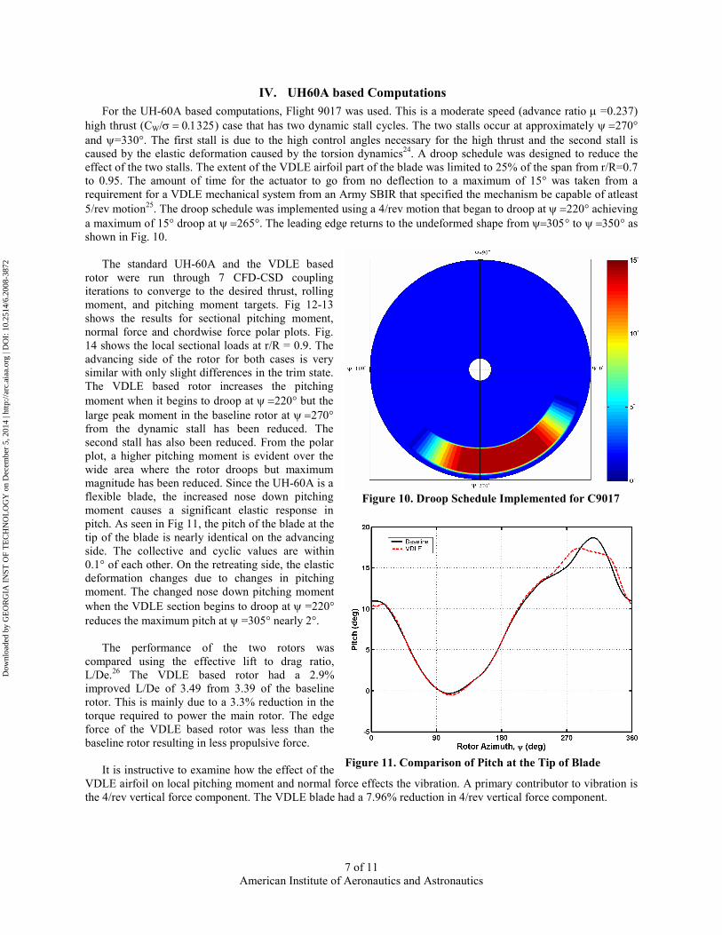
magnitude has been reduced. Since the UH-60A is a
flexible blade, the increased nose down pitching
moment causes a significant elastic response in
pitch. As seen in Fig 11, the pitch of the blade at the
tip of the blade is nearly identical on the advancing
side. The collective and cyclic values are within
0.1° of each other. On the retreating side, the elastic
deformation changes due to changes in pitching
moment. The changed nose down pitching moment
when the VDLE section begins to droop at ψ =220°
reduces the maximum pitch at ψ =305° nearly 2°.
The performance of the two rotors was
compared using the effective lift to drag ratio,
L/De.26
The VDLE based rotor had a 2.9%
improved L/De of 3.49 from 3.39 of the baseline
rotor. This is mainly due to a 3.3% reduction in the
torque required to power the main rotor. The edge
force of the VDLE based rotor was less than the
baseline rotor resulting in less propulsive force.
It is instructive to examine how the effect of the
VDLE airfoil on local pitching moment and normal force effects the vibration. A primary contributor to vibration is
the 4/rev vertical force component. The VDLE blade had a 7.96% reduction in 4/rev vertical force component.
Figure 11. Comparison of Pitch at the Tip of Blade
Dow
nloa
ded
by G
EO
RG
IA I
NST
OF
TE
CH
NO
LO
GY
on
Dec
embe
r 5,
201
4 | h
ttp://
arc.
aiaa
.org
| D
OI:
10.
2514
/6.2
008-
3872

American Institute of Aeronautics and Astronautics
8 of 11
Figure 12. Sectional Pitching Moment Polar Plot
Figure 13. Sectional Normal Force Polar Plot
Dow
nloa
ded
by G
EO
RG
IA I
NST
OF
TE
CH
NO
LO
GY
on
Dec
embe
r 5,
201
4 | h
ttp://
arc.
aiaa
.org
| D
OI:
10.
2514
/6.2
008-
3872

American Institute of Aeronautics and Astronautics
9 of 11
Figure 14. Sectional Forces at r/R = 0.9
Figure 14. Sectional Chordwise Force Polar Plot
Dow
nloa
ded
by G
EO
RG
IA I
NST
OF
TE
CH
NO
LO
GY
on
Dec
embe
r 5,
201
4 | h
ttp://
arc.
aiaa
.org
| D
OI:
10.
2514
/6.2
008-
3872

American Institute of Aeronautics and Astronautics
10 of 11
V. Conclusions
The OVERFLOW Navier-Stokes CFD code version 2.0y has been modified to allow for a leading edge
deformation. Two Variable Droop Leading Edge airfoils were analyzed in deep compressible dynamic stall. The
leading edge changes to have low local incidence to the incoming flow even at very high angles attack reducing the
peak pitching moment and drag. The moderate speed, high thrust case 9017 of the UH-60A was analyzed with the
baseline rotor and a VDLE airfoil based rotor. The rotor efficiency improved by 2.9%, reduced torque required by
3.3%, and 8% reduction in the 4/rev component of vertical force. The elastic effects of the changed pitching moment
require accurate prediction of the local pitching moment, accurate prediction of the elastic response, and autopilot
algorithm to trim the rotor. The change in pitching moment by the VDLE region of the blade affects the elastic
response and therefore the aerodynamics of the entire blade. Future work will likely include improving the pitching
moment prediction in separated flows, optimization of the droop schedule, analyzing the span wise and chord wise
extent of the VDLE airfoil, and examining high speed flight.
Acknowledgements
This work was funded by NASA Cooperative Agreement # NNX07AP33A entitled “Flight Mechanics and
Control Oriented Modeling for Next Generation On-Blade Control Concepts” with Dr. Wayne Johnson as Technical
Monitor. We would like to thank Bob Kufeld for providing the UH-60A data. This work expands on tools developed
under the DARPA Helicopter Quieting Project sponsored by Dan Newman. The authors would like to thank Alan
Egolf of Sikorsky Aircraft Corp for helpful comments and suggestions. The authors would also like to thank Eric
Lynch at Georgia Tech for use of his coupling and post processing scripts.
References
1 Carr L.W., Chandrasekhara M.S., Wilder W.C., and Noonan K.W., “Effect of Compressibility on Suppression of Dynamic Stall
Using a Slotted Airfoil”, Journal of Aircraft, Vol. 38, No. 2, pp.296-309, Mar-Apr. 2001. 2 Yu, Y. H., Lee, S., McAlister, K. W., and Tung, C., ”Dynamic Stall Control for Advanced Rotorcraft Application” AIAA
Journal, Vol 33, No. 2, February 1995 3 Chandrasekhara, M. S., Martin, P. B., and Tung, C., “Compressible Dynamic Stall Performance of a Variable
Droop Leading Edge Airfoil with a Gurney Flap,” AIAA-2004-0041, Reno, NV, Jan. 5-8, 2004. 4 Guzel, G., Sankar, L. N., ”Computational Investigation of the Effects of Gurney Flap on the Aerodynamic Performance of VR-
12 Airfoil” AIAA-4960 23rd AIAA Applied Aerodynamics Conference Toronto, Ontario, Canada, June 2005 5 Geissler, W. and Sobieczky, H., “Dynamic Stall Control by Variable Airfoil Camber,” AGARD, Aerodynamics and
Aeroacoustics of Rotorcraft, Aug. 01, 1995. 6 Chandrasekhara, M., "Compressible Dynamic Stall Control Using a Shape Adaptive Airfoil," AIAA 99-0650, 37th AIAA
Aerospace Sciences Meeting, Jan. 11-14, 1999, Reno, NV. 7 Sahin, M., Sankar, L. N., Chandrasekhara, M. S., Tung, C., ”Dynamic Stall Alleviation Using a Deformable Leading Edge
Concept – A Numerical Study” Journal of Aircraft Vol. 40, No. 1, January-February 2003 8 Chandrasekhara, M.S., Martin, P.B, Tung, C., ”Compressible Dynamic Stall Control using a Variable Droop Leading Edge
Airfoil”, AIAA 2003-48, 41st Aerospace Sciences Meeting and Exhibit, Reno, NV, January 2003 9 Kerho, M., “Adaptive Airfoil Dynamic Stall Control” AIAA-2005-1365 43rd Aerospace Sciences Meeting and Exhibit, Reno,
NV, January 2005 10
Martin, P.B., McAlister, K. W., Chandrasekhara, M.S., Geissler, W., ”Dynamic Stall Measurments and
Computations for a VR-12 Airfoil with a Variable Droop Leading Edge” Presented at the American Helicopter Society
59th Annual Forum, Phoenix, Arizona, May 6-8, 2003 11 Buning, P.G., Chiu, I.T., Obayashi, S., Rizk, Y.M. and Steger, J.L., “Numerical Simulation of the Integrated Space Shuttle
Vehicle in Ascent”, AIAA 88-4359, AIAA Atmospheric Flight Mechanics Meeting, Minneapolis, MN, Aug. 15-17, 1988. 12 Renaud, T., O'Brien, D. M., Smith, M. J., and Potsdam M., "Evaluation of Isolated Fuselage and Rotor-Fuselage Interaction
using CFD," Presented at the American Helicopter Society 60th Annual Forum, Baltimore, MD, June 7-10, 2004. 13 Bhagwat, M.J., Dimanlig, A., Saberi, H., Meadowcroft, E., Panda, B., and Strawn, R., “CFD/CSD Coupled Trim Solution for
the Dual-Rotor CH-47 Helicopter Including Fuselage Modeling,” AHS Specialist Conference on Aeromechanics, San Francisco,
CA, January 2008 14 Duque, E.P.N, Sankar, L.N, Menon, S., Bauchau, O., Ruffin, S., Smith, M., Ahuja, A., Brentner, K.S., Long, L.N., Morris, P.J.,
and Gandhi, F., “Revolutionary Physics-Based Design Tools for Quiet Helicopters” AIAA 2006-1068 44th AIAA Aerospace
Sciences Meeting and Exhibit, Reno, NV January 2006 15 Fang and Menon, “A Two-Equation Subgrid Model for Large-Eddy Simulation of High Reynolds Number Flows“, AIAA-
2006-0116, January 2006
Dow
nloa
ded
by G
EO
RG
IA I
NST
OF
TE
CH
NO
LO
GY
on
Dec
embe
r 5,
201
4 | h
ttp://
arc.
aiaa
.org
| D
OI:
10.
2514
/6.2
008-
3872

American Institute of Aeronautics and Astronautics
11 of 11
16 Spalart P.R. and Allmaras S.R, “A One-equation Turbulence Model for Aerodynamic Flows,” AIAA-92-0439, January 1992. 17 Scott, N.W. and Duque, E.P.N. , “Using Detached Eddy Simulation and Overset Grids to Predict Flow Around a 6:1 Prolate
Spheroid”, AIAA Paper 2005-1362. 18 Bousman, W., and Kufeld, R. M., “UH-60A Airloads Catalog,” Aeroflightdynamics Directorate (AMRDEC), U.S. Army
Research, Development, and Engineering Command, Ames, Research Center, Moffet Field, California, August 2005, NASA-
TM-2005-212827, AFDD/TR-05-003 19 Potsdam, M., Yeo, H., Johnson, W., “Rotor Aerodynamic Prediction using Loose Aerodynamic and Structural Coupling”,
American Helicopter Society 60th Annual Forum, Baltimore, MD, June 1994 20 Makinen, S., Hill, M., Gandhi, F., Long, L., Vasilescu, R., and Sankar, L., “A Study of the HART-I Rotor with Loose
Computational Fluid/Structural Dynamic Coupling”, American Helicopter Society 62th Annual Forum. Phoenix, AZ., 2006 21 Bauchau, O.A., Bottasso, C.L. and Nikishkov, Y.G., “Modeling Rotorcraft Dynamics with Finite Element Multibody
Procedures”, Mathematical and Computer Modeling, Vol. 33, 2001, pp 1113-1137. 22 Tung, C., Carradonna, F.X., and Johnson, W.R., “The Prediction of Transonic Flows on an Advancing Rotor,” American
Helicopter Society 40th Annual Forum, Arlington, VA 1984 23 Morton, S. A., Melville, R. B., Visbal, M. R., ”Accuracy and Coupling Issues of Aeroelastic Navier-Stokes Solutions on
Deforming Meshes” Journal of Aircraft, Vol. 35, No. 5, September – October 1998. 24 Datta, A., Chopra, I, “Prediction of UH-60A Dynamic Stall Loads in High Altitude Level Flight using CFD/CSD Coupling”
American Helicopter Society 61st Annual Forum, Grapevine, TX 2005 25 ARMY SBIR A05-067, “Dynamic Camber Control for Helicopters” 26 Bielawa, R., “Analytical Investigation of Helicopter Rotor Blade Appended Aeroelastic Devices” NASA Contractor Report
166525
Dow
nloa
ded
by G
EO
RG
IA I
NST
OF
TE
CH
NO
LO
GY
on
Dec
embe
r 5,
201
4 | h
ttp://
arc.
aiaa
.org
| D
OI:
10.
2514
/6.2
008-
3872