White-nose syndrome: is this emerging disease a threat to European bats
Upload
khangminh22Category
view
1download
0
www.ijsetr.com
ISSN 2319-8885
Vol.03,Issue.47
December-2014,
Pages:9629-9635
Copyright @ 2014 IJSETR. All rights reserved.
Design, Development & Analysis of Aircraft Droop Nose Ribs by using
Optimization Technique JINKA NARENDRA KUMAR
1, B. JITHENDRA KUMAR
2
1PG Scholar, Nova College of Engineering and Technology, Jangareddy Gudem, Wes Godavari (Dt), AP, India.
2Associate Professor, Nova College of Engineering and Technology, Jangareddy Gudem, Wes Godavari (Dt), AP, India.
Abstract: This master thesis work presents the development of a parameterized automated generic model for the structural
design of an aircraft wing. Furthermore, in order to perform finite element analysis on the aircraft wing geometry, the process
of finite element mesh generation is automated. The generic model that is developed in this regard is able to automate the
process of creation and modification of the aircraft wing geometry based on a series of parameters which define the geometrical
characteristics of wing panels, wing spars and wing ribs. Two different approaches are used for the creation of the generic
model of an aircraft wing which are “Knowledge Pattern” and “Power Copy with Visual Basic Scripting” using the CATIA V5
Software. A performance comparison of the generic wing model based on these two approaches is also performed. In the early
stages of the aircraft design process, an estimate of the structural characteristic of the aircraft wing is desirable for which a
surface structural analysis (using 2D mesh elements) is more suitable. In this regard, the process of finite element mesh
generation for the generic wing model is automated. Furthermore, the finite element mesh is updated based on any changes in
geometry and the shape of the wing panels, wing spars or wing ribs, and ensure that all the mesh elements are always properly
connected at the nodes. The automated FE mesh generated can be used for performing the structural analysis on an aircraft
wing. Topology optimization has for a considerable time been applied successfully in the automotive industry, but still has not
become a mainstream technology for the design of aircraft components.. Also, aircraft components are often stability designs
and the compliance based topology optimization method still lacks the ability to deal with any buckling criteria. The present
paper considers the use of the compliance formulated topology optimization method and detailed sizing/shape optimization
methods to the design of aircraft components but also discusses the difficulties in obtaining correct loading and boundary
conditions for finite element based analysis/optimization of components that are integral parts of a larger structure.
Keywords: Aircraft, Power Copy, 2D Mesh Elements.
I. INTRODUCTION
Aircraft design is a complex and multi-disciplinary
process that involves a large number of disciplines and
expertise in aerodynamics, structures, propulsion, flight
controls and systems amongst others. During the initial
conceptual phase of an aircraft design process, a large
number of alternative aircraft configurations are studied and
analyzed. Feasibility studies for different concepts and
designs are carried out and the goal is to come up with a
design concept that is able to best achieve the design
objectives. One of the crucial studies in any aircraft design
process is the conceptual design study of an aircraft wing.
The aircraft wing is one of the most critical components
of an aircraft not only from an aerodynamics point of view
but also from a structural point of view. The aircraft wing is
designed in such a way that it is able to provide the
requisite lift while minimizing the drag. Drag is critical
from the aerodynamics point of view because it directly
affects the performance of the aircraft like fuel efficiency
and range. Not only does the wing provide the necessary lift
during flight, the aircraft wing is designed structurally to
carry the entire weight of the aircraft. Also, in modern
commercial aircrafts and fighter airplanes, the aircraft wing
has more than one role. It not only carries the fuel required
for the flight but is also used to provide storage bays where,
the aircraft landing gears can be mounted and stowed during
takeoff (which are normally placed inside the wing root of
an aircraft). Furthermore, modern commercial airplanes
have padded engines which are placed below the wing.
This means that the aircraft wing has to be
sufficiently strong from the structural perspective to carry
the weight of these engines, fuel inside the wing box and
internal components. A variety of components are also
placed inside the aircraft wing which includes electro-
mechanical actuators, fuel lines, and hydraulic, pneumatic
and electrical systems amongst others. All of these
components are to be compactly placed inside the wing,
thus, the aircraft wing has to perform structurally and
aerodynamically well to deliver the desired performance.
Weight is one of the fundamental critical factors in any
aircraft design process and aircraft designers are always
on the lookout for ways to minimize the weight of the

JINKA.NARENDRA KUMAR, B.JITHENDRA KUMAR
International Journal of Scientific Engineering and Technology Research
Volume.03, IssueNo.47, December-2014, Pages: 9629-9635
aircraft. This means that a light weight aircraft should have
a light weight wing as shown in Fig.1. A light weight aircraft
is thus beneficial for increasing the design performance. In
the conceptual phase of an aircraft design process, different
design studies are carried out for different components of
the aircraft. One of the major portions of these studies is
dedicated towards the design of the aircraft wing both from
a structural and aerodynamics point of view. However, in
this stage High-end CAD software‟s are not employed as
they are thought to be too complex or demanding to be
used during this stage. Therefore, the promising design
configurations have to be remodelled again later in the
detail design process which increases cost and the time to
production. It can be very beneficial from a design
perspective, if these CAD software‟s are employed from
the start of the aircraft design process. This would enable
less remodelling of the design in the detail design process
and would also enable increased capability to do modelling
and simulation during the conceptual phase. A generic
model is thus required in this regard that would speed up the
design process of analyzing different aircraft win
configurations.
II. OBJECTIVE AND CHALLENGE OF DROOP NOSE
RIB
To the aerospace industry, the overall weight of an aircraft
is a critical design requirement due to the impact just a few
kilograms can have on fuel efficiency and co2 emissions.
Heavier aircraft use more fuel during flight which leads to
increased running costs for the airline carriers. When
designing the world‟s largest passenger aircraft, the airbus
wanted to ensure the design was as lightweight as possible
while maintaining all performance standards. To achieve
objective and challenge we are using this thesis work
presents the development of the generic parameterized
aircraft wing model by using CATIA V5 CAD software
which provides tools and features for automated geometry
generation and modification. In using this CAD software, A
structural mesh generation of the generic aircraft wing model
is also created. It is ensured that the mesh elements are
properly connected at the nodes and the mesh elements are of
good quality. Altair Hypermesh for pre-processing, Solver is
Altair Radioss, for post processing Altair Hyper view and for
achieving new design and less weight using Altair Optistruct.
Fig.1. Application of general wing model.
A. Applications The generic wing model that is developed in this thesis
work can not only be used for designing of the aircraft wing
which is its primary application, but, also can be used for
designing other types of wing shapes used in other
applications. The structure of the model is made as general
and generic as possible for enabling its use in different
applications. For example, the generic wing model can be
used for designing aircraft propeller blades, gas turbine
blades, wind turbine blades, car spoilers and ship propeller
blade etc.
B. Positioning and Shape Of Wing
When the positioning of the wing on the fuselage and the
shape of the wing is changed, different types of wing
configurations can be achieved, some of which are shown in
the fig.2 below,
Fig.2. Positioning and Shape of the Wing.
III. GENERIC AIRCRAFT STRUCTURAL WING
DESIGN CONCEPT
A. Aircraft Design Process
Aircraft design process is a complex undertaking,
however, the design process can generally be divided into
three phases which are outlined in the fig.3 below. There is a
certain amount of overlapping between these three phases
and the number of people, resources and cost associated with
the design gradually increases between these phases. The
different stages of the aircraft design process are,
Conceptual Design
Preliminary Design
Detail Design

Design, Development & Analysis of Aircraft Droop Nose Ribs by using Optimization Technique
International Journal of Scientific Engineering and Technology Research
Volume.03, IssueNo.47, December-2014, Pages: 9629-9635
Fig.3. General Overview of Aircraft Design Process.
B. Tools And Methods
A breakdown of the tools and methods used in this thesis
work is given in the fig.4
Fig.4. Tools and Methods used for creation of generic
aircraft wing model.
C. Modelling Of Wing RIB
Fig.5. 2D drawing Using CATIA V5R19 Software.
Fig.6. 3d model is developed in catia v5r19 software
model.
D. Solid Meshing
Using solid geometry, HyperMesh can utilize both standard
and advanced procedures to connect, separate or split solid
models for tetra-meshing or hexa-meshing. Partitioning these
models is fast and easy when combined with Hypermesh
powerful visualization features for solids. This allows users
to spend less time preparing geometries for solid meshing.
The solid-meshing module allows users to quickly generate
high quality meshes for multiple volumes as shown in Fig.7.
Fig7.Modern and Efficient CAE Modeling Environments.

JINKA.NARENDRA KUMAR, B.JITHENDRA KUMAR
International Journal of Scientific Engineering and Technology Research
Volume.03, IssueNo.47, December-2014, Pages: 9629-9635
IV. PREPROCESSING AND SOLVER
A. Preprocessing
Altair® HyperMesh® is a high-performance finite-
element pre-processor that provides a highly interactive and
visual environment to analyze product design performance.
With the broadest set of direct interfaces to commercial
CAD and CAE systems and a rich suite of easy-to-use tools
to build and edit CAE models, HyperMesh provides a
proven, consistent analysis platform for the entire enterprise.
B. Best In Class Meshing
HyperMesh presents users with an advanced suite of
easy-to-use tools to build and edit CAE models. For 2D and
3D model creation, users have access to a variety of mesh
generation capabilities, as well as Hypermesh‟s powerful
automeshing module.
C. High Fidelity Meshing
Surface Meshing
Solid map Hexa Mesh
Tetra Meshing
CFD Meshing
SPH Meshing
Surface Meshing: The surface meshing module in
HyperMesh contains a robust engine for mesh generation that
provides users with unparalleled flexibility and functionality.
This includes the ability to interactively adjust a variety of
mesh parameters, optimize a mesh based on a set of user-
defined quality criteria, and create a mesh using a wide range
of advanced techniques.
D. Automesh
Fig.8.Automesh using 20mm element size.
Thickness for Rib component:
Fig.9.
Analysis page- Constraints (FIX) and Pressure applied:
Go to analysis page it will shown some tools take constraints
option and fill the three circles of smaller diameter select
each node in each circle it will highlited as constraints for
every circle after that applying pressure in analysis page.
Fig.10.
Analysis page- Constraints (FIX) in all DOF, selected
nodes are highlighted.
V. RESULTS AND DISCUSSIONS
Aerodynamic load is applied to wing rib and solved
results are shown below Figs.11 & 21.
Displacement:
Fig.11. The value of Displacement is 1.935 mm.
Stress:
Fig.12. The value of Stress is 2.378*10
2 Mpa.
Design, Development & Analysis of Aircraft Droop Nose Ribs by using Optimization Technique
International Journal of Scientific Engineering and Technology Research
Volume.03, IssueNo.47, December-2014, Pages: 9629-9635
The value of stress in base model is 2.378*102 is converted
into is 237Mpa. After visualizing the static results
optimization will come I the picture to get innovative shape
of wing rib. Optimization techniques are shown below,
different techniques are explained in brief.
B.Re-Design of the Optimized Model and Pre-Processing
Methodology
Basic reference model is changed to the above design
after applying the OptiStruct application to that. Design
changes had been generated in Hypermesh using osssmooth
option.
Fig.13. New design of optimized result is meshed in hyper
mesh.
C. Results Of Base Model Aircraft Rib Wing
Displacement:
Fig.14. displacement for optimized model is 2.217 mm.
Stress:
Fig.15. Stress for optimized model is 2.355*10
2 tones.
The value of stress in optimized model is 2.355*102
is 238
Mpa.
D. Optimization Process
Optimization is done to the control arm model the steps
of optimization technique are mentioned below. First step is
user profile should change to Optistruct in hypermesh
interface.
Fig.16. User profile to solve Optistruct.
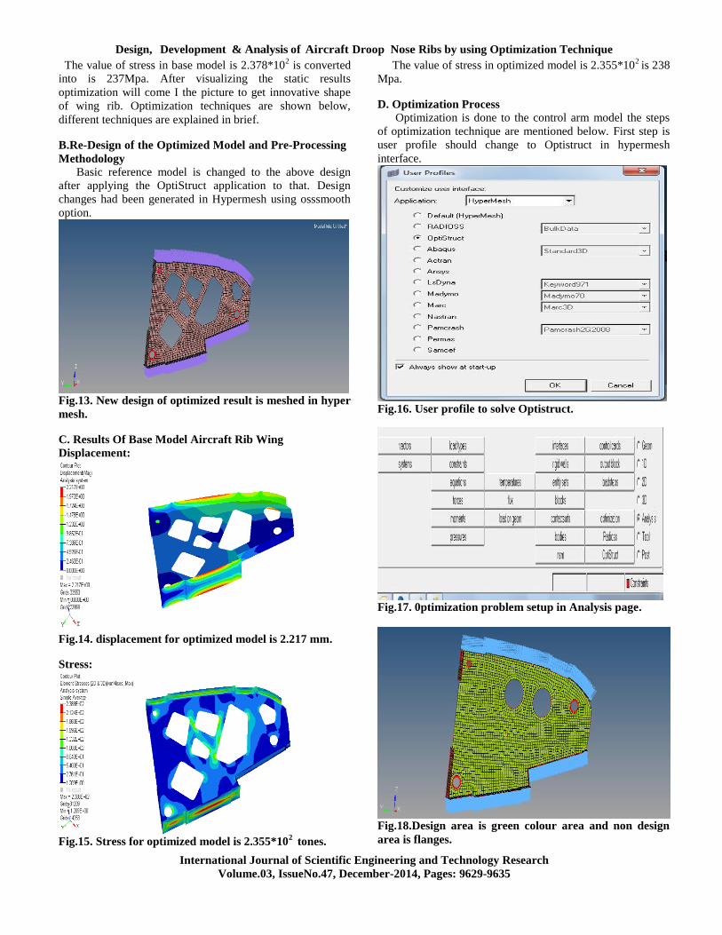
Fig.17. 0ptimization problem setup in Analysis page.
Fig.18.Design area is green colour area and non design
area is flanges.

JINKA.NARENDRA KUMAR, B.JITHENDRA KUMAR
International Journal of Scientific Engineering and Technology Research
Volume.03, IssueNo.47, December-2014, Pages: 9629-9635
E. Optimized Model Results
Optimization is completed and results are taken 6 iterations
to complete the thickness and topology optimization.
Fig.19. Iterations for free Size optimization.
Fig.20. Thickness optimization is given perfect results for
the given loads.
Topology method using Optistruct is shown in above
figure, steps are involved is same like free size optimization.
Response is given for volume fraction as 0.3% from the total
volume and weight compliance as a objective which will
reduce the weight of the component by giving innovative
shape to wing.
Fig.21. Present Dummy and trail prototype for Viewing
the thickness and optimized model.
VI. CONCLUSION
The present work illustrates how topology, sizing and
shape optimisation tools may be used in the design of aircraft
components. The technology has been successfully used in an
industrial environment with short industrial time scales and
has on a single application proved to be able to provide
efficient stress and stability component designs. Initial
studies have shown that care should be taken in the
modelling of the load and boundary conditions of the
components. For aircraft component design it is also
important to be aware of the impact of changing loading
situations. The truss type designs obtained using the topology
optimisation is highly specialised designs optimised for
certain loading situations. Load definitions generally change
as the design of an aircraft mature, and this could seriously
affect the optimality of the structure. It could therefore prove
important to carefully select applications for topology
optimisation and only use the technology on structures with
well efined loading conditions. The varaiation of pressure is
induced in optimized model ompared to base model as per
the requirement of below yield point stress which is 325 Mpa
and as well as the variation of displacement is induced in
optimized model compared to base model which is lower
than the 3 mm as per the requirement. As per the given
requirement the reduction of weight is 16% decreased
compared to reference model. Hence the cost analysis also
reduces by using the base model and optimized model
readings.
VII. REFERENCES
[1] „Topology Design of Structures‟, M P Bendsøe and C A
Mota Soares, NATO ASI Series, Kluver Academic
Publishers, Dortdrecht, The Netherlands, 1993.
[2] „Optimisation of Structural Topology, Shape and
Material‟, M P Bendsøe, Springer-Verlag, Heidelberg,
Germany, 1995.
[3] National Aeronautics and Space Administration.
[4] http://en.wikipedia.org/wiki/Aircraft.
[5] Lars Krog, Alastair Tucker and Gerrit Rollema Airbus
UK LTD, application of topology sizing and shape
optimization methods to optimal design of aircraft
components.
[6] “Modelling and Simulating Dynamics of Missles with
Deflettable Nose Control” Gao Yuan, Gu Liangxian, pan
Lei college of Astronautics, Northwestern Politechnical
University, Xian 710072, China.
[7] “Assessment of Aerodynamic and Dynamic models in a
comprehensive analysis for rotorcraft” wayne johnon NASA
Ames Research Center, Moffett Feild, CA 94405, U.S.A.
[8] Talke, F.E., “Optimization: Computer Aided Analysis and
Design.” Class Notes. MAE 292. UC San Diego, Spring
2006.
[9] Schneider, Detlef, and Erney, Thomas. “Combination of
Topology and Topography Optimization for Sheet Metal
Structures.” OptiCON 2000 Conference Proceedings.
[10] Altair Engineering. “Altair HyperMesh: Introduction to
FEA: Pre-Processing Volume I.” HyperWorks Training
Manual, 2004.

Design, Development & Analysis of Aircraft Droop Nose Ribs by using Optimization Technique
International Journal of Scientific Engineering and Technology Research
Volume.03, IssueNo.47, December-2014, Pages: 9629-9635
[11] Altair Engineering. “Altair OptiStruct: Concept Design
Using Topology and Topography Optimization.”
HyperWorks Training Manual, 2004.
[12] Fornace, L.V., Davis, A.E., Costabile, J.T., Hart, J.D.,
Arnold, D., “Traction Control Systems: FSAE Vehicle
Acceleration Optimization.” MAE 171B Final Report. UC
San Diego, 2005.
[13] Taylor, Rob. “F-35 Joint Strike Fighter Structural
Component Optimization: Lockheed Martin Aeronautics
Company.” Optimization Technology Conference. 27-28
September 2005. Troy, Michigan, USA.
Copyright © 2022 FDOKUMEN