In Tube Integrated Electronic Nose System on a Flexible Polymer Substrate
13
Sensors 2012, 12, 13681-13693; doi:10.3390/s121013681 OPEN ACCESS sensors ISSN 1424-8220 www.mdpi.com/journal/sensors Article In Tube Integrated Electronic Nose System on a Flexible Polymer Substrate Thomas Kinkeldei *, Christoph Zysset, Niko M ¨ unzenrieder, Luisa Petti and Gerhard Tr¨ oster Wearable Computing Lab, ETH Zurich, Gloriastarsse 35, 8092 Zurich, Switzerland; E-Mails: [email protected] (C.Z.); [email protected] (N.M.); [email protected] (L.P.); [email protected] (G.T.) * Author to whom correspondence should be addressed; E-Mail: [email protected]; Tel.: +41-44-632-4727. Received: 13 August 2012; in revised form: 13 September 2012 / Accepted: 25 September 2012 / Published: 12 October 2012 Abstract: The fabrication of electronic devices, such as gas sensors on flexible polymer substrates, enables the use of electronics in applications where conventional devices on stiff substrates could not be used. We demonstrate the development of a new intra-tube electronic-nose (e-nose) gas sensor device with multiple sensors fabricated and integrated on a flexible substrate. For this purpose, we developed a new method of fabricating a sensor array of four gas sensors on a flexible polymer substrate. The method allowed the use of lithography techniques to pattern different polymers with a broad range of solubility parameters. Conductive polymer composites were used as a gas sensitive layer due to the high stretchability of the material. Each of the 30 e-nose devices on one substrate was designed to fit on a polymer strip with a width of 2 mm. A single e-nose strip was successfully integrated into the inlet tube of a gas-measurement apparatus with an inner-tube diameter of 3 mm. Using the e-nose, we were able to differentiate between four different volatile solvent vapors. The tube-integrated e-nose outperformed a chamber-integrated e-nose of the same type in terms of response time and flow-rate influences. The sensor array inside the tube showed a faster response time and detected short pulses of analyte exposure compared to the same sensor array outside of the tube. We measured gas flow rates from 1,000 to 30 sccm without significant changes in sensor performance using this intra-tube e-nose prototype. The tube could be bent to radii <15 mm with a sensor performance similar to an unbent sensor.
Transcript of In Tube Integrated Electronic Nose System on a Flexible Polymer Substrate
Sensors 2012, 12, 13681-13693; doi:10.3390/s121013681OPEN ACCESS
sensorsISSN 1424-8220
www.mdpi.com/journal/sensors
Article
In Tube Integrated Electronic Nose System on a FlexiblePolymer SubstrateThomas Kinkeldei *, Christoph Zysset, Niko Munzenrieder, Luisa Petti and Gerhard Troster
Wearable Computing Lab, ETH Zurich, Gloriastarsse 35, 8092 Zurich, Switzerland;E-Mails: [email protected] (C.Z.); [email protected] (N.M.);[email protected] (L.P.); [email protected] (G.T.)
* Author to whom correspondence should be addressed; E-Mail: [email protected];Tel.: +41-44-632-4727.
Received: 13 August 2012; in revised form: 13 September 2012 / Accepted: 25 September 2012 /Published: 12 October 2012
Abstract: The fabrication of electronic devices, such as gas sensors on flexible polymersubstrates, enables the use of electronics in applications where conventional devices onstiff substrates could not be used. We demonstrate the development of a new intra-tubeelectronic-nose (e-nose) gas sensor device with multiple sensors fabricated and integratedon a flexible substrate. For this purpose, we developed a new method of fabricating asensor array of four gas sensors on a flexible polymer substrate. The method allowed theuse of lithography techniques to pattern different polymers with a broad range of solubilityparameters. Conductive polymer composites were used as a gas sensitive layer due tothe high stretchability of the material. Each of the 30 e-nose devices on one substratewas designed to fit on a polymer strip with a width of 2 mm. A single e-nose strip wassuccessfully integrated into the inlet tube of a gas-measurement apparatus with an inner-tubediameter of 3 mm. Using the e-nose, we were able to differentiate between four differentvolatile solvent vapors. The tube-integrated e-nose outperformed a chamber-integratede-nose of the same type in terms of response time and flow-rate influences. The sensor arrayinside the tube showed a faster response time and detected short pulses of analyte exposurecompared to the same sensor array outside of the tube. We measured gas flow rates from1,000 to 30 sccm without significant changes in sensor performance using this intra-tubee-nose prototype. The tube could be bent to radii <15 mm with a sensor performance similarto an unbent sensor.

Sensors 2012, 12 13682
Keywords: flexible electronics; gas sensing; conductive polymer composite
1. Introduction
The display and photovoltaic industries have shown that fabricating electronics on flexible substratescomposed of polymeric materials can compete or even outperform silicon devices. Flexible substratesmake electronics usable in new fields of applications, as such devices on flexible substrates are bendableand applicable to curved surfaces with radii <10 mm. Compared to silicon substrates, flexible substratesare light weight and can be installed unobtrusively onto objects in our surrounding environment [1].
Flexible substrates offer the possibility of operating e-nose devices in spatially-constrained locationswhere it would be impossible to install rigid sensors on silicon or glass. A new flexible sensor in themedical field allows integration of a glucose and temperature sensor into a micro-catheter with a diameter<1 mm, enabling chemical sensing inside the human body [2]. In another example, a flow sensor basedon a meander resistor, integrated into a tube with a diameter of 3 mm, allows gas flow monitoring inside atube [3]. An inside-tube sensor outperforms sensors mounted on the outside of the tube and reacts fasterdue to the time delay for heat transport through the side walls of the tube. A giant magneto resistance(GMR) sensor attached to the outside of a flexible tube is capable of detecting magnetic objects that passthe sensor inside the tube [4]. A carbon nanotube gas sensor was placed into a glas tube with a diameterof 5 mm, enabling the detection of dimethyl methylphosphonate vapors [5]. Compared to a flat sensorthe resistance response of the tube sensor slightly decreases by 5.6 %. In a similar way, gas sensing witharrays could benefit from sensor-integration directly into tubing.
To detect the quality of supply air or to monitor exhaust air gas sensor arrays are installed in roomsor chambers. The time of flight for an analyte to interact with the gas sensor can be long, or in case offlow inside a chamber, might even not occur. The benefit of sensor placement directly into tubing is thatsupply or exhaust air will be transported through the tube and interact with an integrated sensor arraywithout bypassing it due to air-flow dynamics within larger chamber spaces.
Materials for flexible substrate gas sensor integration have to be light weight, small and survivestrain introduced by bending. Organic sensor materials outperform inorganic materials due to theirductility. Devices made out of conductive polymers (CP) filled with carbon black (CB) have shown tobe stretchable above 50 % strain without losing their functionality [6].
Carbon black polymer gas sensors are chemiresistors and change their resistance due to swelling uponexposure to an analyte [7]. Such sensors are used to measure relative humidity [8], vapors of solventswith concentrations <10 ppm [9] or gases like CO2 [8]. The combination of several CB sensors made ofdifferent polymer materials can be used as sensor array, a so-called electronic nose (e-nose), that is usedto distinguish between gas mixtures [10].
Existing e-noses on flexible substrates are made of carbon nanotubes [11] used to differentiatebetween solvent vapours, or metal oxide nanoparticles [12] to detect toxic gases, but also of conductivepolymers [13,14]. Gas sensor arrays of conductive polymers are used to detect substances in fires [13]or volatile solvent vapors in air [14].

Sensors 2012, 12 13683
Inorganic layers such as metal oxides have the benefit of detecting analytes in the range of severalparts per billion (ppb) but are more influenced by bending strain and crack at a strain of about 2 % [15].Metal oxide gas sensors further need heating of the sensor to temperatures of about 200−300 ◦C.Compared with metal oxides, conductive polymer gas sensors show a reduced sensitivity but work atroom temperature and survive strains above 2 %.
Fabrication of CB/polymer e-noses is achieved by drop coating polymers onto several electrodes,on silicon [9] or on flexible substrates [14]. To fabricate devices <1 mm for the integration intotubes, micro-fabrication methods with lithography must be used. A significant problem arises fromthe solubility of the different CB/polymers in most of the standard lithography chemicals. This makesCB/polymer gas sensor fabrication incompatible when using standard lithography.
A new method of fabricating flexible and organic electronics is to use orthogonal lithography [16] thatcan be integrated on top of commonly-used CB/polymer gas sensors. By using dry etching, polymers canbe structured with feature sizes <0.1 mm and sensor arrays for the integration into tubes can be achieved.
The objective of this study was to test a new method for the fabrication of a gas sensor prototype arrayon flexible polymer substrates using orthogonal lithography. The aim was to pattern several conductivepolymer composite gas sensors that are designed to fit on a strip and successfully integrate into polymertubing of a gas flow measurement apparatus with an inner diameter of 3 mm.
2. Materials and Methods
2.1. Sensor Fabrication
Four non-conductive polymers were used: polyisoprene (PIS), polystyrene (PS), poly(N-vinylpyrrolidone) (PVP), polyvinylbutyral (PVB) (Scientific Polymer Products). The solventstetrahydrofuran (THF), toluene, acetone, methanol and isopropanol (IPA) were obtained from SigmaAldrich. As conductive filler, Ensaco G350 from Timcal was used. Details for the polymer preparationcan be found elsewhere [17]. Polyetherimide (PEI) foil (Ajedium Films) was used as flexible substratematerial. The substrate had a thickness of 50 µm and a surface area of 76 mm × 76 mm.
The fabrication scheme is depicted in Figure 1. The e-nose strip represents one of thirty e-nosestrips that were processed on a single substrate in one fabrication run. PEI substrates were cleaned withAcetone/IPA and preshrunk in an oven at 190 ◦C for one day. For electrodes and contacts we depositedTi/Au with a thickness of 5/100 nm using a Plassys e-beam evaporator Figure 1(b) and patterned it usinga standard lift-off technique. The pattern for the sensor design consisted of an array of four interdigitatedfinger electrodes representing the gas sensors Figure 1(c). The width of the fingers as well as the gapswere 40 µm.
The sensors were designed to fit on a strip with a width of 2 mm and a length of 50 mm. The e-nosecomprised 4 sensors, and 5 electrical contacts were necessary to connect each sensor individually. Acommon ground connected to all sensors and for each individual sensor element one contact.
The four CP sensing films (polyisoprene, polystyrene, poly(N-vinylpyrrolidone), polyvinylbutyral +CB) were deposited by spin-coating and patterned with a lift-off or dry etching technique. To be able tostructure all four polymers using lithography, a fluorine based photoresist (OSCoR, Orthogonal Inc) was
Sensors 2012, 12 13684
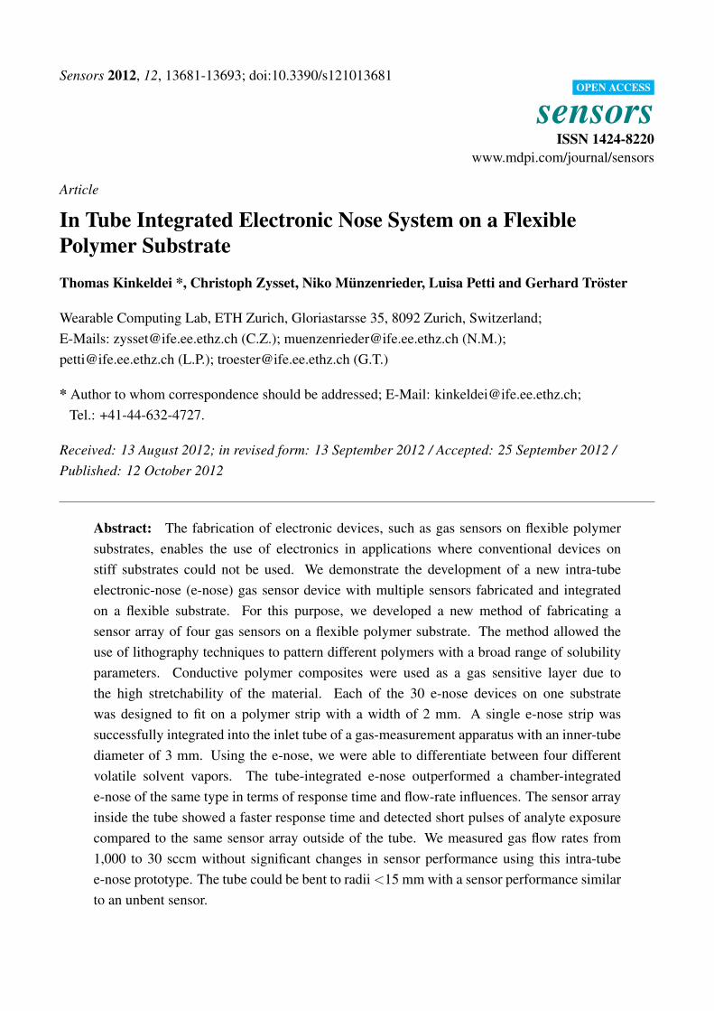
used. The PIS and PS sensors were patterned using a dry etching technique. On each half of the substratewe spin-coated the two different polymer solutions (Figure 1(d)). On top of the spin-coated films thefluorine photoresist was patterned as etching mask. An Oxford Plasmalab RIE system was subsequentlyused to dry etch the exposed gas sensing layers running a O2 plasma at 200 W, 700 µ and 70 standardcubic centimeters per minute (sccm) flow for 5 min. Remaining resist was stripped from the substratefollowed by cleaning in DI water (Figure 1(e)). A second fluorine resist layer was patterned as lift-offmask (Figure 1(f)). Again on each half of the substrate two different polymer solutions were spin-coated(Figure 1(g)). The resist was removed with the help of ultrasound, leaving the patterned polymer on thesubstrate (Figure 1(g)).
Figure 1. Fabrication process for the electronic nose using orthogonal resist: (a) cleaning ofthe substrate; (b) e-beam evaporation of gold; (c) patterned sensor structure; (d) gas sensitivelayer spin-coating; (e) dry etched gas sensitive layer; (f) patterned fluorinated resist; (g) gassensitive layer spin-coating; (h) lift-off patterned sensitive layer.
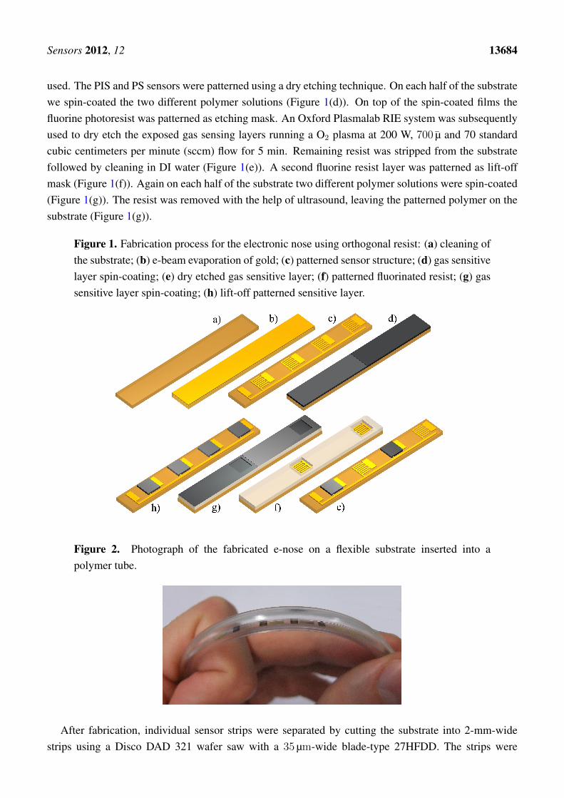
Figure 2. Photograph of the fabricated e-nose on a flexible substrate inserted into apolymer tube.
After fabrication, individual sensor strips were separated by cutting the substrate into 2-mm-widestrips using a Disco DAD 321 wafer saw with a 35 µm-wide blade-type 27HFDD. The strips were

Sensors 2012, 12 13685
connected via 40 µm thin isolated copper wires. For a stable contact, the wires were glued to the contactpads using Epo-Tek H20E. The e-nose was inserted into a PET tube that had an inner diameter of 3 mm
and served as gas inlet for a gas measurement chamber. A picture of the e-nose in the tube is shown inFigure 2.
2.2. Sensor Testing
Resistance measurements were done by connecting the wires to a multi-switch measure unit (Agilent34980A). In an exsiccator (2 L volume), sensor measurements to distinguish different solvents wereconducted at room temperature. The exsiccator was flushed with 1,000 sccm of synthetic air (80 % N2
5.0 and 20 % O2 5.0 with a humidity of 0 %RH) using a Voegtlin mass flow controller. The test solventswere isopropanol, acetone, toluene and methanol. For each exposure we bubbled 40 sccm of the totalflow through a bottle containing 40 mL of solvent and measured its response for 10 min. After theanalyte, we exposed the sensor for 10 min to pure synthetic air to recover to the baseline resistance.The procedure was repeated for all solvents. Calibration measurements with acetone were done using abottled gas standard containing a calibrated mixture of synthetic air plus 5,000 ppm acetone.
3. Results
3.1. E-nose Testing
An intra-tube integrated e-nose strip was exposed to four different volatile solvent vapors(isopropanol, acetone, toluene and methanol). In Figure 3, the normalized resistance of each sensorversus time and exposure to solvents is plotted.
Figure 3. Normalized Resistance vs. time and exposure to solvents for the four differentpolymer gas sensors (PIS, PS, PVP, PVB). The volatile solvent vapors are isopropanol,acetone, toluene and methanol.
The sensors showed a repeated resistance increase upon the exposure to a volatile solvent vapor.After the solvent exposure, the sensors returned to their original baseline values. The sensor showed acharacteristic resistance response for each combination of sensor element/solvent when exposed to the
Sensors 2012, 12 13686
four volatile solvent vapors. The PVP sensor had a signal to noise ratio lower than the other sensors withpeaks up to 0.2 percent of the resistance.
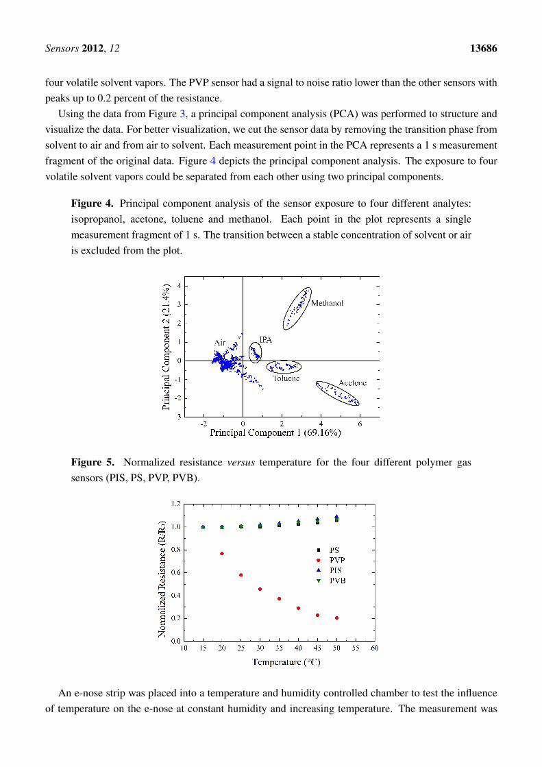
Using the data from Figure 3, a principal component analysis (PCA) was performed to structure andvisualize the data. For better visualization, we cut the sensor data by removing the transition phase fromsolvent to air and from air to solvent. Each measurement point in the PCA represents a 1 s measurementfragment of the original data. Figure 4 depicts the principal component analysis. The exposure to fourvolatile solvent vapors could be separated from each other using two principal components.
Figure 4. Principal component analysis of the sensor exposure to four different analytes:isopropanol, acetone, toluene and methanol. Each point in the plot represents a singlemeasurement fragment of 1 s. The transition between a stable concentration of solvent or airis excluded from the plot.
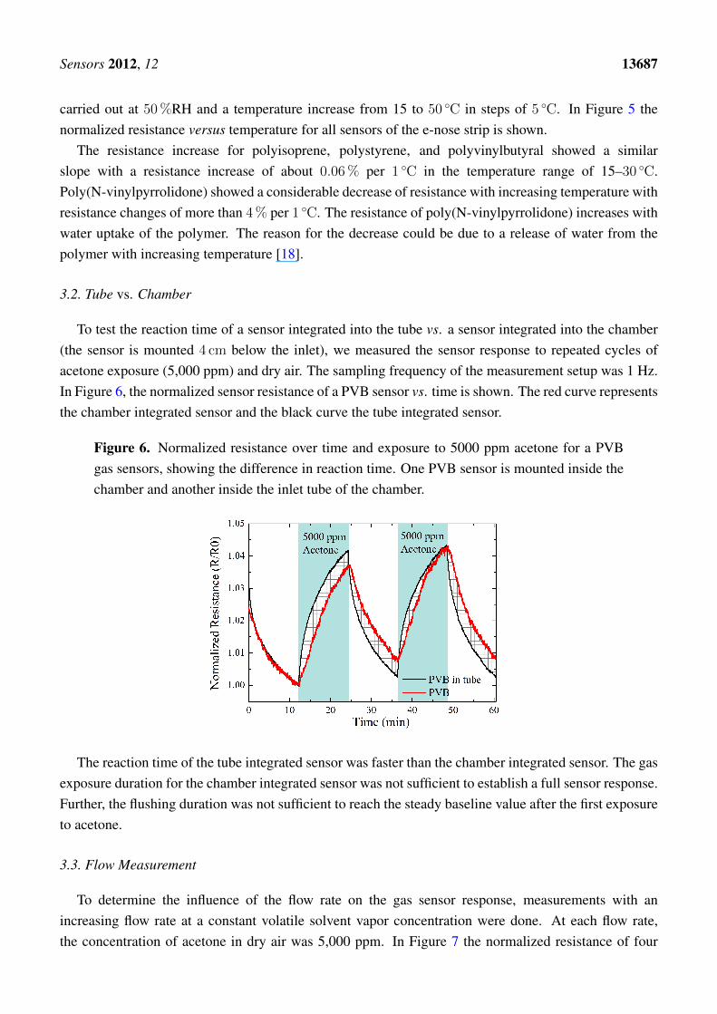
Figure 5. Normalized resistance versus temperature for the four different polymer gassensors (PIS, PS, PVP, PVB).
An e-nose strip was placed into a temperature and humidity controlled chamber to test the influenceof temperature on the e-nose at constant humidity and increasing temperature. The measurement was
Sensors 2012, 12 13687
carried out at 50 %RH and a temperature increase from 15 to 50 ◦C in steps of 5 ◦C. In Figure 5 thenormalized resistance versus temperature for all sensors of the e-nose strip is shown.
The resistance increase for polyisoprene, polystyrene, and polyvinylbutyral showed a similarslope with a resistance increase of about 0.06 % per 1 ◦C in the temperature range of 15–30 ◦C.Poly(N-vinylpyrrolidone) showed a considerable decrease of resistance with increasing temperature withresistance changes of more than 4 % per 1 ◦C. The resistance of poly(N-vinylpyrrolidone) increases withwater uptake of the polymer. The reason for the decrease could be due to a release of water from thepolymer with increasing temperature [18].
3.2. Tube vs. Chamber
To test the reaction time of a sensor integrated into the tube vs. a sensor integrated into the chamber(the sensor is mounted 4 cm below the inlet), we measured the sensor response to repeated cycles ofacetone exposure (5,000 ppm) and dry air. The sampling frequency of the measurement setup was 1 Hz.In Figure 6, the normalized sensor resistance of a PVB sensor vs. time is shown. The red curve representsthe chamber integrated sensor and the black curve the tube integrated sensor.
Figure 6. Normalized resistance over time and exposure to 5000 ppm acetone for a PVBgas sensors, showing the difference in reaction time. One PVB sensor is mounted inside thechamber and another inside the inlet tube of the chamber.
The reaction time of the tube integrated sensor was faster than the chamber integrated sensor. The gasexposure duration for the chamber integrated sensor was not sufficient to establish a full sensor response.Further, the flushing duration was not sufficient to reach the steady baseline value after the first exposureto acetone.
3.3. Flow Measurement
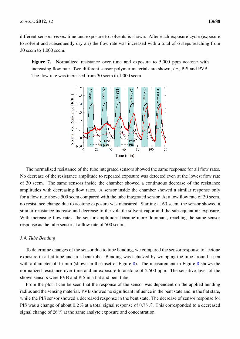
To determine the influence of the flow rate on the gas sensor response, measurements with anincreasing flow rate at a constant volatile solvent vapor concentration were done. At each flow rate,the concentration of acetone in dry air was 5,000 ppm. In Figure 7 the normalized resistance of four
Sensors 2012, 12 13688
different sensors versus time and exposure to solvents is shown. After each exposure cycle (exposureto solvent and subsequently dry air) the flow rate was increased with a total of 6 steps reaching from30 sccm to 1,000 sccm.
Figure 7. Normalized resistance over time and exposure to 5,000 ppm acetone withincreasing flow rate. Two different sensor polymer materials are shown, i.e., PIS and PVB.The flow rate was increased from 30 sccm to 1,000 sccm.
The normalized resistance of the tube integrated sensors showed the same response for all flow rates.No decrease of the resistance amplitude to repeated exposure was detected even at the lowest flow rateof 30 sccm. The same sensors inside the chamber showed a continuous decrease of the resistanceamplitudes with decreasing flow rates. A sensor inside the chamber showed a similar response onlyfor a flow rate above 500 sccm compared with the tube integrated sensor. At a low flow rate of 30 sccm,no resistance change due to acetone exposure was measured. Starting at 60 sccm, the sensor showed asimilar resistance increase and decrease to the volatile solvent vapor and the subsequent air exposure.With increasing flow rates, the sensor amplitudes became more dominant, reaching the same sensorresponse as the tube sensor at a flow rate of 500 sccm.
3.4. Tube Bending
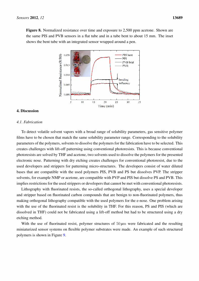
To determine changes of the sensor due to tube bending, we compared the sensor response to acetoneexposure in a flat tube and in a bent tube. Bending was achieved by wrapping the tube around a penwith a diameter of 15 mm (shown in the inset of Figure 8). The measurement in Figure 8 shows thenormalized resistance over time and an exposure to acetone of 2,500 ppm. The sensitive layer of theshown sensors were PVB and PIS in a flat and bent tube.
From the plot it can be seen that the response of the sensor was dependent on the applied bendingradius and the sensing material. PVB showed no significant influence in the bent state and in the flat state,while the PIS sensor showed a decreased response in the bent state. The decrease of sensor response forPIS was a change of about 0.2 % at a total signal response of 0.75 %. This corresponded to a decreasedsignal change of 26 % at the same analyte exposure and concentration.
Sensors 2012, 12 13689
Figure 8. Normalized resistance over time and exposure to 2,500 ppm acetone. Shown arethe same PIS and PVB sensors in a flat tube and in a tube bent to about 15 mm. The insetshows the bent tube with an integrated sensor wrapped around a pen.
4. Discussion
4.1. Fabrication
To detect volatile solvent vapors with a broad range of solubility parameters, gas sensitive polymerfilms have to be chosen that match the same solubility parameter range. Corresponding to the solubilityparameters of the polymers, solvents to dissolve the polymers for the fabrication have to be selected. Thiscreates challenges with lift-off patterning using conventional photoresists. This is because conventionalphotoresists are solved by THF and acetone, two solvents used to dissolve the polymers for the presentedelectronic nose. Patterning with dry etching creates challenges for conventional photoresist, due to theused developers and strippers for patterning micro-structures. The developers consist of water dilutedbases that are compatible with the used polymers PIS, PVB and PS but dissolves PVP. The strippersolvents, for example NMP or acetone, are compatible with PVP and PIS but dissolve PS and PVB. Thisimplies restrictions for the used strippers or developers that cannot be met with conventional photoresists.
Lithography with fluorinated resists, the so-called orthogonal lithography, uses a special developerand stripper based on fluorinated carbon compounds that are benign to non-fluorinated polymers, thusmaking orthogonal lithography compatible with the used polymers for the e-nose. One problem arisingwith the use of the fluorinated resist is the solubility in THF. For this reason, PS and PIS (which aredissolved in THF) could not be fabricated using a lift-off method but had to be structured using a dryetching method.
With the use of fluorinated resist, polymer structures of 50 µm were fabricated and the resultingminiaturized sensor systems on flexible polymer substrates were made. An example of such structuredpolymers is shown in Figure 9.

Sensors 2012, 12 13690
Figure 9. Micrograph of a structured gas sensor layer onto metal electrodes on a PI substrate.Structuring was achieved with dry etching. The inset shows a patterned polymer layer on aPI substrate with feature sizes below 50 µm.
4.2. Intra-tube vs. Chamber E-nose
Using flexible substrates, the integration of a complete e-nose into tubing of a gas-measurementapparatus was possible. The tube containing the e-nose was still fully flexible and could be used aschamber inlet of the gas-measurement apparatus. Bending of the inlet tubing was possible to a radiusof 15 mm before tube deformation such as folds or buckles occurred. The e-nose strip adapted to theapplied bending radii. Due to bending inside the tube, the sensor resistances changed with maximumchanges below 5 %. The maximal possible bending diameter of 15 mm corresponded to a calculatedstrain (according to [15]) of about 0.4 %. This value was still in the safe regime of bending whereonly elastic deformation occurs. Critical bending starts at tensile bending strain of about 1 % [15].Measurements with exposure to analytes showed that the sensitivity is partly altered by bending thee-nose. PVB did not show any change of performance during the exposure to solvents, while PIS showeda decreased performance with a decrease in signal amplitude of 26 %. This difference might be attributedto a difference of the local bending radius of parts of the strip inside the tube. The different bending radiilead to a changing ability of the e-nose to differentiate between solvents. To overcome this problem,single gas sensors have to be fabricated within closer distance to achieve a similar bending radius forboth sensors during bending. Having similar bending radii, each sensor then shows a similar resistancechange [17]. This information can be used to differentiate resistance changes due to bending with thosedue to gas exposure.
An advantage of the intra-tube e-nose was the faster reaction time. This benefit was achieved due tothe low volume inside the tube where the sensor was installed. As one would expect from standard gaskinematics, in the tube there is no dilution of the introduced gases with the air inside the chamber. Hencethe time for adsorption and the resulting swelling of the sensitive material are the limiting factors forthe sensor reaction, whereas the time for establishing a stable concentration inside the chamber is not.Along with the faster reaction time, the recovery time—from the full sensor response upon exposureback to the baseline resistance—also decreased. In Figure 6, for the second analyte exposure cycle, thechamber integrated e-nose could not return to the base line resistance after the exposure to acetone. Thisshowed that the adsorption and swelling is faster than the desorption and relaxing of the material. From
Sensors 2012, 12 13691
the experiment with increasing flow rates in Figure 7, it can also be seen that depending on what type ofpolymer is used, the reaction time differs. PIS reacted nearly immediately to the exposure of the solvent,while PVB has a delay in reaction time.
A further advantage of the intra-tube e-nose was the independence on the flow rate, again related tothe dilution of the introduced gases and according to standard gas kinematics. A small flow rate willtake a larger amount of time until the concentration inside the chamber is stabilized or that the localspace around the sensor below the inlet (the distance of inlet and sensor was 4 cm) has reached a certainconcentration. With the tube integrated sensor it was also possible to detect small traces of leakage insidethe tubing. Short pulses of solvent exposure of below 5 seconds could be detected even at flow rates of30 sccm, which was not detected by the chamber integrated sensor.
5. Conclusions
Substrate flexibility, large area manufacturing, unobtrusive installation and improved resilienceagainst bending strain are key advantages of electronics on flexible substrates. In this paper we makeuse of these properties by integrating an electronic nose system into the flexible inlet tubing of agas-measurement apparatus.
The e-nose consisted of four different polymer composite gas sensors on a flexible polymer foil.Due to solubility conflicts between common photoresists and the used gas sensitive polymer solutions,orthogonal lithography, based on fluorinated polymer resists, was used. It was possible to achieve featuresizes of the spin-coated gas sensitive layers <50 µm. Introducing orthogonal lithography to structurepolymer layers of an e-nose, we achieved a reduced integration density of multiple sensors on flexiblesubstrates compared with the state-of-the-art flexible sensors [14]. The reduced integration density aswell as the bendability allowed the installation of an e-nose inside the inlet-tube (inner dimension of3 mm) of a gas measurement setup.
The intra-tube integrated e-nose showed an improved behavior in terms of reaction time and flow ratecompared with a similar e-nose inside the chamber of the gas-measurement apparatus. The intra-tubeintegrated e-nose could further adapt to the curvature change of the used tubing and detect volatile solventvapors in the flat and in the bent state. Depending on the polymer, a change in sensor response beforeand after bending was observed.
The present approach is a first step to demonstrate the versatile use of gas sensor arrays or in generalof electronics on flexible substrates and the improvement of existing sensor solutions. Existing hurdlesfor electronics to be installed in point of need are often spatially-constrained locations, but also includethe change of environmental properties (such as thermal mass, friction, weight) or even acceptance byaesthetic reasons. Compared with bulky and rigid sensors on Si [9], these hurdles can be overcome withflexible electronics as they are thin, transparent, light weight, conformable and have a low thermal mass.These properties together can create new sensor solutions or improve existing technologies.
Sensors 2012, 12 13692
Acknowledgments
This project was financed with a grant from the Swiss Nano-Tera.ch initiative and evaluated by theSwiss National Science Foundation. The authors would like to thank Frank Clemens with his support onconductive polymer composites.
References
1. Rogers, J.A.; Someya, T.; Huang, Y. Materials and mechanics for stretchable electronics. Science2010, 327, 1603–1607.
2. Li, C.; Wu, P.M.; Han, J.; Ahn, C.H. A flexible polymer tube lab-chip integrated with microsensorsfor smart microcatheter. Biomed. Microdevices 2008, 10, 671–679.
3. Tan, Z.; Shikida, M.; Hirota, M.; Xing, Y.; Sato, K.; Iwasaki, T.; Iriye, Y. Characteristics of on-wallin-tube flexible thermal flow sensor under radially asymmetric flow condition. Sens. Actuators A2007, 138, 87–96.
4. Melzer, M.; Karnaushenko, D.; Makarov, D.; Baraban, L.; Calvimontes, A.; Monch, I.;Kaltofen, R.; Mei, Y.; Schmidt, O.G. Elastic magnetic sensor with isotropic sensitivity for in-flowdetection of magnetic objects. RSC Adv. 2012, 2, 2284–2288.
5. Wang, Y.; Yang, Z.; Hou, Z.; Xu, D.; Wei, L.; Kong, E.; Zhang, Y. Flexible gas sensors withassembled carbon nanotube thin films for DMMP vapor detection. Sens. Actuators B 2010,150, 708–714.
6. Shang, S.; Zeng, W.; Tao, X. Highly stretchable conductive polymer composited with carbonnanotubes and nanospheres. Adv. Mater. 2010, 123, 109–112.
7. Albert, K.J.; Lewis, N.S.; Schauer, C.L.; Sotzing, G.A.; Stitzel, S.E.; Vaid, T.P.; Walt, D.R.Cross-reactive chemical sensor arrays. Chem. Rev. 2000, 100, 2595–2626.
8. Emadi, T.A.; Shafai, C.; Freund, M.S.; Thomson, D.J.; Jayas, D.S.; White, N.D.G. Developmentof a polymer-based gas sensor—humidity and CO2 Sensitivity. In Proceedings of Microsystemsand Nanoelectronics Research Conference, Ottawa, Canada, 13–14 October 2009; pp. 112–115.
9. Kim, Y.S.; Ha, S.C.; Yang, Y.; Kim, Y.J.; Cho, S.M.; Yang, H.; Kim, Y.T. Portable electronicnose system based on the carbon black-polymer composite sensor array. Sens. Actuators B 2005,108, 285–291.
10. Ryan, M.A.; Manatt, K.S.; Gluck, S.; Shevade, A.V.; Kisor, A.K.; Zhou, H.; Lara, L.M.;Homer, M.L. The JPL Electronic Nose: Monitoring Air in the U.S. Lab on the International SpaceStation. In Proceedings of the IEEE Sensors Conference, Kona, HI, USA, 1–4 November 2010;pp. 1242–1247.
11. McAlpine, M.; Ahmad, H.; Wang, D.; Heath, J. Highly ordered nanowire arrays on plasticsubstrates for ultrasensitive flexible chemical sensors. Nat. Mater. 2007, 6, 379–384.
12. Yao, K.; Caruntu, D.; Wozny, S.; Huang, R.; Ikuhara, Y.; Cao, B.; O’Connor, C.; Zhou, W. Towardsone key to one lock: Catalyst modified indium oxide nanoparticle thin film sensor array for selectivegas detection. J. Mater. Chem. 2012, 22, 7308–7313.
13. Scorsone, E.; Pisanelli, A.M.; Persaud, K.C. Development of an electronic nose for fire detection.Sens. Actuators B 2006, 116, 55–61.

Sensors 2012, 12 13693
14. Kim, Y.S. Microheater-integrated single gas sensor array chip fabricated on flexible polyimidesubstrate. Sens. Actuators B 2006, 114, 410–417.
15. Suo, Z.; Ma, E.; Gleskova, H.; Wagner, S. Mechanics of rollable and foldable film-on-foilelectronics. Appl. Phys. Lett. 1999, 74, 1177.
16. Zakhidov, A.A.; Lee, J.K.; DeFranco, J.A.; Fong, H.H.; Taylor, P.G.; Chatzichristidi, M.;Ober, C.K.; Malliaras, G.G. Orthogonal processing: A new strategy for organic electronics.Chem. Sci. 2011, 2, 1178.
17. Kinkeldei, T.; Zysset, C.; Munzenrieder, N.; Troster, G. An electronic nose on flexible substratesintegrated into a smart textile. Sens. Actuators B 2012, 174, 81–86.
18. Ghosh, P.; Siddhanta, S.K.; Chakrabarti, A. Characterization of poly(vinyl pyrrolidone) modifiedpolyaniline prepared in stable aqueous medium. Eur. Polym. J. 1999, 35, 699–710.
c© 2012 by the authors; licensee MDPI, Basel, Switzerland. This article is an open access articledistributed under the terms and conditions of the Creative Commons Attribution license(http://creativecommons.org/licenses/by/3.0/).