Elimination of “Shimmy” Phenomenon in Case of Nose ...
12
RTO-MP-AVT-152 2 - 1 UNCLASSIFIED/UNLIMITED UNCLASSIFIED/UNLIMITED Elimination of “Shimmy” Phenomenon in Case of Nose Landing Gear of I-23 Manager Airplane Zbigniew Wolejsza, Wojciech Kowalski, Rafal Kajka [email protected] / [email protected] / [email protected] ABSTRACT When, during straight line movement, aircraft landing gear starts to oscillate about its caster axis, it means that “shimmy” vibrations occur. Shimmy phenomenon is a very dangerous vibration and if it takes place, it could lead to landing gear malfunction and even plane crash. The construction of the landing gear must eliminate or reduce this vibration at sufficient level. Damping of the shimmy vibrations is carried out in three stages: • Analytically, at the technical project level – proper damping level should be calculated • Experimentally, at the prototype test level – resistance of the landing gear in case of vibration should be checked • Experimentally, at the prototype level during final ground tests – last stage to prove safety of the landing gear. In this paper a proper way to achieve a landing gear safety from shimmy vibration will be shown. Analysis will be presented based on the nose landing gear of I-23 Manager airplane research. Kieldysz theory was chosen to analytically simulate tire – ground contact for three wheel (three single wheel landing gear) airplane. This theory says that on complete tire – ground contact surface, slip will not occur. Analytical equation for airplane nose landing gear in straight movement condition will be presented. Also sample results with boundary conditions and necessary data characterizing tire and undercarriage will be shown. Analytical simulation based on I23 Manager airplane landing gear shows that this particular L/G is not safe in case of shimmy phenomenon. Further experiment results for resistance of L/G on shimmy vibration will be presented as well as parameter ranges and charts e.g. angle vs. time. Short film showing experiment will be presented during presentation. Experiments show when L/G self positioning is not safe and a damper should be installed on it. During next step of L/G optimisation, proper damper is chosen and installed. This guarantees safe exploitation in all conditions. The paper will be illustrated with charts and photos from tests. Landing gears shimmy test carried out in Landing Gear Department of Institute of Aviation will be presented in the summary. 1.0 INTRODUCTION Both standard aircraft and helicopters use either nose landing gear or a rear one – either self adjustable or with detached steering. In such types of landing gear self-induced vibrations, called „shimmy”, can occur. This paper is devoted to the general subject of aircraft safety with particular attention to this dangerous vibration phenomenon. A precise assessment of landing gear movement stability is essential and should start from the stage of initial technical project. The mistake of over-evaluation of damping potential at this stage of design can eventually lead to shimmy phenomenon at the laboratory research or ground test stages, while construction changes or prototype improvements are costly and time consuming. On the other hand, under-valuation of potential will result in unnecessary mass increase. Safety during both experimental stage and routine exploitation as well as minimalization of aircraft units and systems are indeed the basic duties of designers, calculation experts and researchers. The solutions stemming from Kieldysz theory of tire and ground interaction were, so far, the only basis for stability reserve (potential?)
-
Upload
khangminh22 -
Category
Documents
-
view
1 -
download
0
Transcript of Elimination of “Shimmy” Phenomenon in Case of Nose ...

RTO-MP-AVT-152 2 - 1
UNCLASSIFIED/UNLIMITED
UNCLASSIFIED/UNLIMITED
Elimination of “Shimmy” Phenomenon in Case of Nose Landing Gear of I-23 Manager Airplane
Zbigniew Wolejsza, Wojciech Kowalski, Rafal Kajka
[email protected] / [email protected] / [email protected]
ABSTRACT
When, during straight line movement, aircraft landing gear starts to oscillate about its caster axis, it means that “shimmy” vibrations occur. Shimmy phenomenon is a very dangerous vibration and if it takes place, it could lead to landing gear malfunction and even plane crash. The construction of the landing gear must eliminate or reduce this vibration at sufficient level. Damping of the shimmy vibrations is carried out in three stages:
• Analytically, at the technical project level – proper damping level should be calculated
• Experimentally, at the prototype test level – resistance of the landing gear in case of vibration should be checked
• Experimentally, at the prototype level during final ground tests – last stage to prove safety of the landing gear.
In this paper a proper way to achieve a landing gear safety from shimmy vibration will be shown. Analysis will be presented based on the nose landing gear of I-23 Manager airplane research. Kieldysz theory was chosen to analytically simulate tire – ground contact for three wheel (three single wheel landing gear) airplane. This theory says that on complete tire – ground contact surface, slip will not occur. Analytical equation for airplane nose landing gear in straight movement condition will be presented. Also sample results with boundary conditions and necessary data characterizing tire and undercarriage will be shown. Analytical simulation based on I23 Manager airplane landing gear shows that this particular L/G is not safe in case of shimmy phenomenon. Further experiment results for resistance of L/G on shimmy vibration will be presented as well as parameter ranges and charts e.g. angle vs. time. Short film showing experiment will be presented during presentation. Experiments show when L/G self positioning is not safe and a damper should be installed on it. During next step of L/G optimisation, proper damper is chosen and installed. This guarantees safe exploitation in all conditions. The paper will be illustrated with charts and photos from tests. Landing gears shimmy test carried out in Landing Gear Department of Institute of Aviation will be presented in the summary.
1.0 INTRODUCTION
Both standard aircraft and helicopters use either nose landing gear or a rear one – either self adjustable or with detached steering. In such types of landing gear self-induced vibrations, called „shimmy”, can occur. This paper is devoted to the general subject of aircraft safety with particular attention to this dangerous vibration phenomenon. A precise assessment of landing gear movement stability is essential and should start from the stage of initial technical project. The mistake of over-evaluation of damping potential at this stage of design can eventually lead to shimmy phenomenon at the laboratory research or ground test stages, while construction changes or prototype improvements are costly and time consuming. On the other hand, under-valuation of potential will result in unnecessary mass increase. Safety during both experimental stage and routine exploitation as well as minimalization of aircraft units and systems are indeed the basic duties of designers, calculation experts and researchers. The solutions stemming from Kieldysz theory of tire and ground interaction were, so far, the only basis for stability reserve (potential?)
Elimination of “Shimmy” Phenomenon in Case of Nose Landing Gear of I-23 Manager Airplane
2 - 2 RTO-MP-AVT-152
UNCLASSIFIED/UNLIMITED
UNCLASSIFIED/UNLIMITED
valuation in The Landing Gear Department procedures. Commonly used hydraulic dampers are of nonlinear character, though. In addition, the damper propulsion system is also of nonlinear nature. The aim of this paper is to accommodate these nonlinear factors within the frames of the Kieldysz formula as well as to compare the experimental data with the theory. The theoretical part of this paper shows equations between tire disfiguration process and ground reaction factors. It also presents equations of rolling tire kinematic knots as well as equations relating to nose L/G movement of aircraft moving at constant linear velocity.
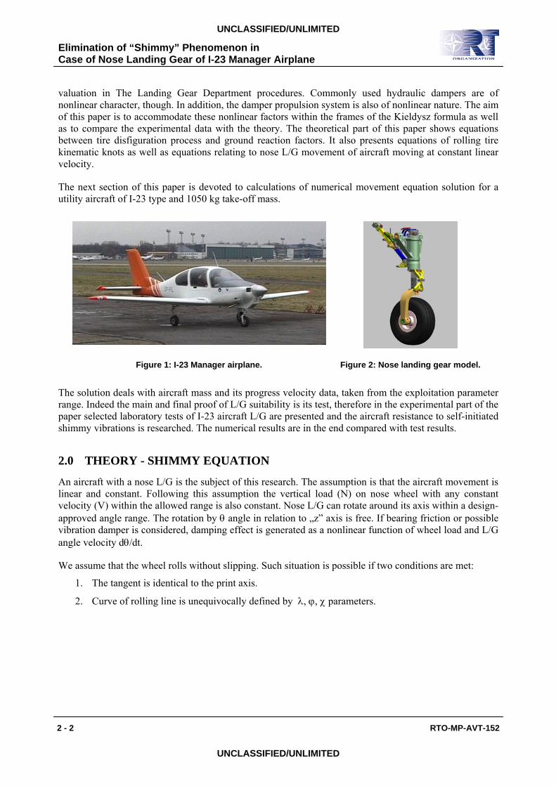
The next section of this paper is devoted to calculations of numerical movement equation solution for a utility aircraft of I-23 type and 1050 kg take-off mass.
Figure 1: I-23 Manager airplane. Figure 2: Nose landing gear model.
The solution deals with aircraft mass and its progress velocity data, taken from the exploitation parameter range. Indeed the main and final proof of L/G suitability is its test, therefore in the experimental part of the paper selected laboratory tests of I-23 aircraft L/G are presented and the aircraft resistance to self-initiated shimmy vibrations is researched. The numerical results are in the end compared with test results.
2.0 THEORY - SHIMMY EQUATION
An aircraft with a nose L/G is the subject of this research. The assumption is that the aircraft movement is linear and constant. Following this assumption the vertical load (N) on nose wheel with any constant velocity (V) within the allowed range is also constant. Nose L/G can rotate around its axis within a design-approved angle range. The rotation by θ angle in relation to „z” axis is free. If bearing friction or possible vibration damper is considered, damping effect is generated as a nonlinear function of wheel load and L/G angle velocity dθ/dt.
We assume that the wheel rolls without slipping. Such situation is possible if two conditions are met:
1. The tangent is identical to the print axis.
2. Curve of rolling line is unequivocally defined by λ, ϕ, χ parameters.

Elimination of “Shimmy” Phenomenon in Case of Nose Landing Gear of I-23 Manager Airplane
RTO-MP-AVT-152 2 - 3
UNCLASSIFIED/UNLIMITED
UNCLASSIFIED/UNLIMITED
Figure 3: Geometry of landing gear and wheel movement.
On meeting the above conditions we arrive at the following knot equations;
(1) ϕδθδψλθψ −−=++ cossin)( hldsd
(2) )sincos()cossin( δθδψγϕβλαϕδθδψ ++−=++−dsd
L/G movement equations, accommodating gyroscopic effect, will be:
(3) θ
ψ
ψθψ
θθψ
MMVrIII
MMVrIII
tlo
zzx
so
zxx
+−=−+
+−=++
•••••
•••••
whereas:
Ms − strut spring effect, Mθ, Mψ − relevant ground reaction effects, Mtł − nonlinear damping effect, r − tire radius, V − forward velocity of aircraft, ξ = yo − distance between centre of tire print and the state of balance, λ – distance between point „O” of tire parallel line and intersection of tire plane with earth, as shown in Fig.3, ψ − angle of strut rotation, δ − angle of strut attack, θ − angle of plane rotation in relation to vertical axis z, ϕ − angle between intersection line of wheel plane/ ground resistance plane and median line of tire print, lp − distance between strut fitting point and centre of contact projection on strut axis.
h
lψψ

Elimination of “Shimmy” Phenomenon in Case of Nose Landing Gear of I-23 Manager Airplane
2 - 4 RTO-MP-AVT-152
UNCLASSIFIED/UNLIMITED
UNCLASSIFIED/UNLIMITED
Relations between Mψ, Mθ, Ms i Mtl moments and ψ, θ, λ, ϕ variables are following:
(4) Ms = k (y) y
(5) Mψ = N ( ξ - λ ) cosδ + F lp - M sinδ + L cosδ
(6) )))((,.....,))((,))((()( 2 ntl fffPfM
•••
= θθθθθθθ
(7) Mθ = N [ ( ξ - λ ) sinδ + (hp cosδ - l sinδ ) ψ] +M cosδ + L sinδ + F hp
Movement equations are reduced to:
(8)
ϕδλδσθδδρδσδ
ψδρσδ
ψθθψ
)sin()cos()cossinsincos(
)cos(cos
)( 2
2
2
22
bNalltN
llN
ksd
dri
sddI
sddIV yzy
−+++−−+
+−−=
=+++
(9)
ϕδλδσθδρσδ
ψδρσδ
ψθψ
)cos()sin()sin(sin
)sin(cos
)( 2
2
2
22
bNahhhN
hhN
Msd
dri
sddI
sddIV tlzyz
++++−−+
+−−=
=+−+
The full set of above equations has been used for numerical solution of the problem. To solve the equations a simple GAUSS1 subprogramme, taken from (2), ws applied. On defining the right side of differential equations the solution was achieved with use of Runge - Kutta method and help of RGKS subprogramme taken from IBM math library. All remaining programmes and subprogrammes, essential for the numerical solution, have been written in FORTRAN by the author himself.
One of the basic aims of this paper is a comparison of numerical solution with the test results. Therefore the problem of initial conditions’ definition must be attended to. During the test the following values are predetermined: value of wheel vertical load –(N),circumferential wheel velocity (V), angle of wheel plane deviation against the symmetrical position (O). Values of initial variables .
Angle of deviation of average tire print from the wheel plane (ϕ) and „—„the distance between the intersection line of wheel and resistance planes and „O” centre of tire print (λ), are not measured.
The assumption that the ϕ0 angle roughly corresponds with θ angle (because the tire print at the moment of putting the wheel on the landing ground should be parallel to the direction of the movement) would be permissible. Yet the decision to numerically define the initial conditions has been made, therefore the above described set of equations has been solved. The assumption, corresponding to this stage of test, is that θ = θ0 , ψ = 0 ανδ δθ / δσ = δψ / δσ = 0. The solution has confirmed that ϕ0 = θ0, the initial value of variable λ0 has also been determined (Fig. 4). Also the conformity of defined initial values with the set of equations in. On determining the initial conditions several cases have been test-solved.

Elimination of “Shimmy” Phenomenon in Case of Nose Landing Gear of I-23 Manager Airplane
RTO-MP-AVT-152 2 - 5
UNCLASSIFIED/UNLIMITED
UNCLASSIFIED/UNLIMITED
Figure 4: Example of initial conditions’ determination.
Second numerical problem dealt with the change of value and sign of damping moment while direction of piston pin was changed from” in” to „out” and the other way round.
Function discontinuity for Vtł = 0 causes numerical disruption of the solution. To avoid this a following assumption has been adopted: for piston pin ,( meeting the requirement that abs(Vtł) ≤ Vtłmin ) damping moment is a linear function with border values resulting from the damping moment value for assumed velocity Vtłmin. The value of minimal velocity has been chosen with the use of numerical check method of solution possibility. For I-23 aircraft L/G Vtłmin = 1 10-5 [m/s].
3.0 RIGIDITY AND KINEMATIC PARAMETERS OF I-23 AIRCRAFT TIRE
Equations (8) – (9) are used for numerical solution.
On the basis of own research data and outside sources of information the following assumptions have been adopted:
N a b alfa(α) beta(β) R Mtł gamma(γ) N N/m Nm/rad 1/m^2 1/m m Nm -
1000 108000 275 526 89 0.170 15.1 5.8823 1500 100100 402 331 56 0.168 22.6 5.9523 2000 86300 580 236 39 0.166 30.2 6.0241 3000 79500 785 175 29 0.164 45.3 6.0975
N – vertical force on the wheel, a – side rigidity of tire, b – tire turning rigidity, α , β , γ – kinematic tire parameters,
0.00 0.10 0.20 0.30 0.40 0.50
-10.00
-8.00
-6.00
-4.00
-2.00
0.00
2.00
4.00
6.00
8.00
10.00
czas[sek]
fi [stopni]
-10�Minimum fi 10�Maximum fi
v=, 5.0,[m/sec] teta0=,-10.000,[stopni] teta0p=, .000,[rad/sec] lambda0=, -.030,[m] fi0=,-10.000,[stopni] st=, .063,[m] biz=, .250,[kg*m^2] sn=, 1300.0,[N] alfa=, 387.6,[1/m^2] beta=, 64.6,[1/m] a=, 101837.2,[N/m] b=, 362.2,[Nm/rad] tm=, 93.7,[Nm] tmc=, 100.3,[Nm]
0.00 0.10 0.20 0.30 0.40 0.50
-0.0400
-0.0200
0.0000
0.0200
0.0400
lambda [mm]
czas[sek]
v=, 5.0,[m/sec] teta0=,-10.000,[stopni] teta0p=, .000,[rad/sec] lambda0=, -.030,[m] fi0=,-10.000,[stopni] st=, .063,[m] biz=, .250,[kg*m^2] sn=, 1300.0,[N] alfa=, 387.6,[1/m^2] beta=, 64.6,[1/m] a=, 101837.2,[N/m] b=, 362.2,[Nm/rad] tm=, 93.7,[Nm] tmc=, 100.3,[Nm]
-0.03�Minimum0.0291�Maximum

Elimination of “Shimmy” Phenomenon in Case of Nose Landing Gear of I-23 Manager Airplane
2 - 6 RTO-MP-AVT-152
UNCLASSIFIED/UNLIMITED
UNCLASSIFIED/UNLIMITED
R – rolling tire radius, Mtł – bearing friction moment as function of vertical force, for u=0.18.
1000.00 1500.00 2000.00 2500.00 3000.00
100.00
200.00
300.00
400.00
500.00
600.00
[1/m^2]
Pz [N]
Parametr kinematyczny opony
dane doswiadczalne
=-5.7 10^-8 Pz + 4.565 10^-2 Pz^2 - 1.2605 Pz + 1387interpolacja
a (Pz)
Figure 5: Kinematic parameter α of vertical force Pz.
0 1 2 3 4 5 6 7 8 9 10 11 12 13 14 15 16 17
0
10
20
30
40
50
60
70
80
90
100
110
v [cm/sek]
P [daN]Wykres sily oporu w funkcji predkosci przesuwu tlokatlumik drgan shimmy rys. nr 106.42.550.00-0
wysuwanie tloka - dane doswiadczalne wsuwanie tloka - dane doswiadczalneinterpolacja interpolacja
Figure 6: Resistance force P of piston velocity v [cm/s].
4.0 NUMERICAL ANALYSIS
A number of simulations has been carried out on assumption of different initial conditions. Test conditions have been recreated. Initial conditions were corresponding to those during the tests. Results have been presented in form of diagrams of L/G turning angle and function of time.

Elimination of “Shimmy” Phenomenon in Case of Nose Landing Gear of I-23 Manager Airplane
RTO-MP-AVT-152 2 - 7
UNCLASSIFIED/UNLIMITED
UNCLASSIFIED/UNLIMITED
Figure 7: Angle of inclination wheel in time function landing gear without damper.
Figure 8: Angle of inclination wheel in time function landing gear with damper.
Figure 9: Angle of inclination wheel in time function L/G with dumper.
Figure 10: Angle of inclination wheel in time function L/G with dumper.
Additional outcome of numerical analysis is achieved by definition of value and time-related progress of variables which are difficult to capture and, during the tests described in this paper, were not measured.
It is also vital to research the interaction of L/G side rigidity and shimmy phenomenon. In case of I-23 aircraft this degree of freedom for practical reasons can be ignored. The L/G deviates (diagram 106) in accord with distribution of described above side force. This deviation occurs next to aircraft own vibrations of high frequency (65 Hz) and diminishing amplitude. Such vibrations, by the way, are disregarded in the current designing procedures.

Elimination of “Shimmy” Phenomenon in Case of Nose Landing Gear of I-23 Manager Airplane
2 - 8 RTO-MP-AVT-152
UNCLASSIFIED/UNLIMITED
UNCLASSIFIED/UNLIMITED
Figure 11: Damping force in time function.
Figure 12: Angle of deflection side landing gear in time function.
Figure 13: Distance between impress and wheel axis.
Figure 14: Piston rod velocity.

Elimination of “Shimmy” Phenomenon in Case of Nose Landing Gear of I-23 Manager Airplane
RTO-MP-AVT-152 2 - 9
UNCLASSIFIED/UNLIMITED
UNCLASSIFIED/UNLIMITED
Figure15: Damping moment (absolute value).
Figure 16: Side force on wheel.
5.0 L/G RESISTANCE TESTS TO SHIMMY VIBRATIONS
In the Institute of Aviation’s Landing Gear Department shimmy tests are conducted on special stand equipped with running track facility with inertial moment of max.843 kgs and diameter of 1400 mm. Maximum running track circumferential velocity amounts to 211 km/h.
Figure 17: Shimmy’s test machine. Figure 18: 10T drop test machine.
For laboratory test purposes following parameters have been determined:
- vertical forces Nmin=1300 [N]; Nmax=2270 [N].
Maximum vertical force equals maximum static L/G reaction for accepted aircraft weight. Minimal vertical force has been defined on basis of known L/G parameters. On impact of N= 1300[N] force the

Elimination of “Shimmy” Phenomenon in Case of Nose Landing Gear of I-23 Manager Airplane
2 - 10 RTO-MP-AVT-152
UNCLASSIFIED/UNLIMITED
UNCLASSIFIED/UNLIMITED
shock absorber can bend within 0 – 32 mm range. Occurrence of lower value reactions during the aircraft exploitation is hardly likely. Positioning of L/G on the stand is carried out with certain minimal, vertical velocity which is one of the test stand parameters. The actual achieved bend of shock absorber amounted to 20[mm] in case of minimal reaction and about 30[mm] for maximum load. In-between load values were not tested. The assumption was that on proving the correctness of numerical simulation results they will be presented when necessary.
Runway velocity (range of): v=5; 10; 20; 30; 40 [m/s] (the highest value equals 1.2 takeoff velocity). Angles of initial L/G deviation o= θ = 2.50; 50; 7.50 ; 100.
6.0 EXAMPLES OF TEST RESULTS
3.60 3.80 4.00 4.20 4.40 4.60 4.80 5.00
-30.00
-25.00
-20.00
-15.00
-10.00
-5.00
0.00
5.00
10.00
15.00
20.00
25.00
30.00
czas [sek]
I-23 proba shimmy zdj. 148 N = 1300[N] V = 5 [m/s]
θ stopni
0.80 1.00 1.20 1.40 1.60
-15.00
-10.00
-5.00
0.00
5.00
10.00
15.00
czas [sek]
I-23 proba shimmy zdj. 242 N = 1300[N] V = 10 [m/s]
Figure 19: Wheel angular displacement vs. time L/G without dumper
Figure 20: Wheel angular displacement vs. time L/G with dumper.
1.60 1.80 2.00 2.20 2.40
-15.00
-10.00
-5.00
0.00
5.00
10.00
15.00
czas [sek]
I-23 proba shimmy zdj. 244 N = 1300[N] V = 30 [m/s]
2.00 2.20 2.40 2.60 2.80 3.00 3.20
-15.00
-10.00
-5.00
0.00
5.00
10.00
15.00
czas [sek]
I-23 proba shimmy zdj. 196 N = 1300[N] V = 5 [m/s]
Figure 21: Wheel angular displacement vs. time L/G with dumper.
Figure 22: Wheel angular displacement vs. time L/G with dumper.

Elimination of “Shimmy” Phenomenon in Case of Nose Landing Gear of I-23 Manager Airplane
RTO-MP-AVT-152 2 - 11
UNCLASSIFIED/UNLIMITED
UNCLASSIFIED/UNLIMITED
7.0 COMPARISON OF TESTING RESULTS WITH SIMULATION RESULTS
Working conditions during tests and numerical analysis are the same.
Test Numerical analysis
Nr. Fig.
Frequency ν[Hz]
Amplituda A1[degree]
Chosen amplitudes Ai[degree]
Nr. Fig.
Frequency ν [Hz]
Amplituda A1[degree]
Chosen amplitudes Ai[degree]
19 7.1 13.8 A2>25 7 7.0 15 A2=23
20 10.5 5.8 A2=3 8 10.2 6.2 A2=2.7
21 Incomplete cycle
1.4 ⎯ 9 Incomplete cycle
2.8 ⎯
22 7.7 14.3 A6=5 10 7.5 12.5 A6=3.5
The comparison between the tests and numerical analysis is satisfactory. In quality terms the results are similar. Quantity errors in principle do not exceed 10% and from the technical point of view can be accepted. Only when the wheel plane does not fully rotate the quantity difference is much bigger. Again from the practical point of view it is of no consequence because such cases have no impact on designing process and are within the accepted vibration range. We can also say that the quantity accordance is satisfactory because in both cases the number of wheel plane deviations is practically identical.
8.0 SUMMARY
The I23 Manager nose L/G is connected with rudder on vertical stabilizer. The idea was to check behavior of the nose L/G connected to complete steering system as well as influence of the pilot on shimmy damping level. To check that idea a special test was prepared – airplane’s fuselage with complete steering system and vertical stabilizer with rudder were mounted on the test stand. Tests were repeated with fuselage and pilot to check behavior of the structure in case of shimmy vibration. The results of the tests show that the pilot is able to control shimmy vibration without any problems.
Figure 23: Airplane with nose landing gear during shimmy's tests.

Elimination of “Shimmy” Phenomenon in Case of Nose Landing Gear of I-23 Manager Airplane
2 - 12 RTO-MP-AVT-152
UNCLASSIFIED/UNLIMITED
UNCLASSIFIED/UNLIMITED
Figure 24: Airplane with nose landing gear during shimmy's tests.
9.0 REFERENCES
[1] M. Kiełdysz „Шимми переднего колеса трехколесного шасси” Труды ЦАГИ No 564, 1945
[2] J. Szmelter „Metody komputerowe w mechanice” Biblioteka Naukowa Inżyniera PWN 1980
[3] W. Kowalski Dobór charakterystyki tłumika minimalizującej drgania shimmy podwozia samolotu, PhD dissertation, Warszawa 2000