On the cumulative microslip phenomenon
21
European Journal of Mechanics A/Solids 26 (2007) 626–646 On the cumulative microslip phenomenon N. Antoni a,∗ , Q.-S. Nguyen b , J.-L. Ligier c , P. Saffré a , J. Pastor a a Laboratoire LOCIE, équipe MMSC, Université de Savoie, France b Laboratoire de Mécanique des Solides, Ecole Polytechnique, Palaiseau, France c RENAULT S.A.S., Direction de la Mécanique, Rueil Malmaison, France Received 18 May 2006; accepted 12 September 2006 Available online 18 January 2007 Abstract The cumulative microslip phenomenon is the accumulation of relative slips in a tangential direction on the contact interface of two solids under cyclic loadings. This leads to significant global relative displacement between components and can account for the failure of some assembly parts in mechanical structures. Practical examples from the automotive industry are presented in this paper to describe cumulative microslip effects in real situations. The phenomenon is then characterized from a theoretical point of view as an asymptotic behaviour for the contact interface under cyclic loads, by analogy with Ratcheting effects in elasto- plasticity. Accommodation and slip-shakedown are introduced in the same light. These various behaviours are illustrated with a reference discrete example that includes an original friction dissymmetry. Then we investigate the phenomenon’s occurrence in various models. The existence of a dissymmetry in the assembly turns out to be a necessary condition for the phenomenon to occur. However, this condition proves not sufficient and the additional characteristics required to reproduce it are analysed. As dissymmetries are bound to exist in some assemblies because of the prescribed environment at work, a theoretical analysis of the phenomenon is performed and a slip-shakedown theorem is proposed. It leads to the introduction of a safety coefficient with respect to slips when a standard friction law is assumed. The safety coefficient can be computed from two static and kinematic approaches in min–max duality, which are illustrated on the reference discrete example. © 2006 Published by Elsevier Masson SAS. Keywords: Cumulative microslip; Cyclic loads; Friction; Dissymmetry; Asymptotic behaviours; Slip-shakedown; Safety coefficient 1. Introduction Today, for modern structures such as automotive engines, the phenomenon called cumulative microslip can occur in mechanical assemblies when subjected to thermomechanical cyclic loadings. It is characterized by the accumulation of tangential small slips of one assembly element relative to another in a preferred direction at the contact interface. In reality, such unbounded cumulated microslips cause the failure of certain assembly parts of internal combustion engines and transmissions in the automotive industry. Although the cumulative microslip problem is definitely a risk, it is rarely considered in design analysis. Moreover, the few elementary tools used by engineers or designers to prevent its occurrence have been proved deficient in most cases. * Corresponding author. E-mail address: [email protected] (N. Antoni). 0997-7538/$ – see front matter © 2006 Published by Elsevier Masson SAS. doi:10.1016/j.euromechsol.2006.09.004
-
Upload
independent -
Category
Documents
-
view
0 -
download
0
Transcript of On the cumulative microslip phenomenon

European Journal of Mechanics A/Solids 26 (2007) 626–646
On the cumulative microslip phenomenon
N. Antoni a,∗, Q.-S. Nguyen b, J.-L. Ligier c, P. Saffré a, J. Pastor a
a Laboratoire LOCIE, équipe MMSC, Université de Savoie, Franceb Laboratoire de Mécanique des Solides, Ecole Polytechnique, Palaiseau, France
c RENAULT S.A.S., Direction de la Mécanique, Rueil Malmaison, France
Received 18 May 2006; accepted 12 September 2006
Available online 18 January 2007
Abstract
The cumulative microslip phenomenon is the accumulation of relative slips in a tangential direction on the contact interfaceof two solids under cyclic loadings. This leads to significant global relative displacement between components and can accountfor the failure of some assembly parts in mechanical structures. Practical examples from the automotive industry are presentedin this paper to describe cumulative microslip effects in real situations. The phenomenon is then characterized from a theoreticalpoint of view as an asymptotic behaviour for the contact interface under cyclic loads, by analogy with Ratcheting effects in elasto-plasticity. Accommodation and slip-shakedown are introduced in the same light. These various behaviours are illustrated with areference discrete example that includes an original friction dissymmetry. Then we investigate the phenomenon’s occurrence invarious models. The existence of a dissymmetry in the assembly turns out to be a necessary condition for the phenomenon tooccur. However, this condition proves not sufficient and the additional characteristics required to reproduce it are analysed. Asdissymmetries are bound to exist in some assemblies because of the prescribed environment at work, a theoretical analysis of thephenomenon is performed and a slip-shakedown theorem is proposed. It leads to the introduction of a safety coefficient with respectto slips when a standard friction law is assumed. The safety coefficient can be computed from two static and kinematic approachesin min–max duality, which are illustrated on the reference discrete example.© 2006 Published by Elsevier Masson SAS.
Keywords: Cumulative microslip; Cyclic loads; Friction; Dissymmetry; Asymptotic behaviours; Slip-shakedown; Safety coefficient
1. Introduction
Today, for modern structures such as automotive engines, the phenomenon called cumulative microslip can occur inmechanical assemblies when subjected to thermomechanical cyclic loadings. It is characterized by the accumulationof tangential small slips of one assembly element relative to another in a preferred direction at the contact interface.
In reality, such unbounded cumulated microslips cause the failure of certain assembly parts of internal combustionengines and transmissions in the automotive industry. Although the cumulative microslip problem is definitely a risk,it is rarely considered in design analysis. Moreover, the few elementary tools used by engineers or designers to preventits occurrence have been proved deficient in most cases.
* Corresponding author.E-mail address: [email protected] (N. Antoni).
0997-7538/$ – see front matter © 2006 Published by Elsevier Masson SAS.doi:10.1016/j.euromechsol.2006.09.004

N. Antoni et al. / European Journal of Mechanics A/Solids 26 (2007) 626–646 627
Consequently, cumulative microslip analysis has required further investigations and the recent literature (e.g. An-toni, 2005) has provided some results. A general presentation of these studies is given in this paper.
The basic description of the effects of cumulative microslip in real situations is important because it delineatesthe area of study and gives highly useful information on the conditions leading to its occurrence. Real cases fromautomotive industry will serve as examples.
Since the phenomenon clearly exhibits similarities with Ratcheting effects in elasto-plasticity, plastic strainsplaying the role of slips, it is characterized as a long-term behaviour for the contact interface under cyclic loads.Slip-shakedown and accommodation may be defined by using the same analogy. All these asymptotic behavioursare then illustrated with a reference discrete example involving a non-classical dissymmetry of friction. A numberof reference assembly models have been built to reproduce the phenomenon numerically and analyse its occurrence.They rely on the existence of a dissymmetry that appears as a necessary condition for the cumulative microslip tooccur. Since this condition seems not sufficient, the additional characteristics required for the phenomenon to occurare pointed out.
The discussion is finally completed here with a detailed slip-shakedown analysis based on an elasto-plastic analogyusing shakedown theorems and the definition of a safety coefficient for the relative slip at the contact interface.
2. The cumulative microslip phenomenon
2.1. Occurrence in the automotive industry
For engine designers, it is necessary to take the specific behaviour of the highly strained components intoaccount. With respect to standard mechanical analysis, it is usual to check the quality of these components inview of the risk of fatigue cracking, critical vibrations and contact with other parts caused by excessive elas-tic displacements. However, today two risks are not investigated. For modern engines, fretting and microslipcan occur and provoke engine breaks. During the engine design stage, fretting behaviour is rarely considered.Only a few authors have described a mechanical analysis with respect to this risk (see e.g. Hupperich, 2004;Merrit and Zhu, 2004). Even rarer are the papers or design analyses dealing with the risk of cumulative microslipoccurrence between two assembly components (Antoni, 2005), mainly because of the small number of recorded casesof microslip for the engines developed in mass production in the twentieth century. However, racing engine designershave been well aware of this type of problem for many years. Today, under the more severe running conditions, thecumulative microslip phenomenon can occur on mass production engines as well (Ligier and Baron, 2002).
To illustrate this point, it is interesting to recall that for diesel engines, a global translation of the small end bushwith respect to the conrod is sometimes observed (see Fig. 1). For a few millimeters of displacement, contact willoccur with the piston, which leads to the seizure of this bush.
In addition, for conrod bearings in gasoline and diesel engines, one can observe a global bearing shell rotationin the conrod housing of prototypes engines (see Fig. 2). This motion might lead to the seizure of the bearing. This
Fig. 1. Cumulative microslip in a conrod small end bush system. Fig. 2. Cumulative microslip in a conrod big end bearing system.
628 N. Antoni et al. / European Journal of Mechanics A/Solids 26 (2007) 626–646
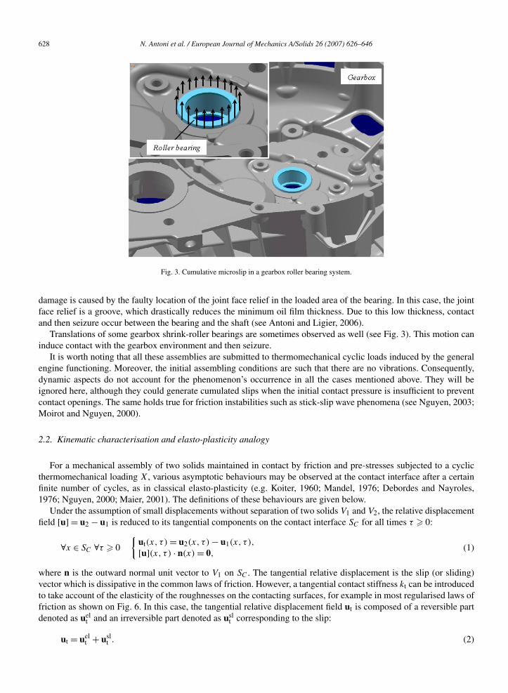
Fig. 3. Cumulative microslip in a gearbox roller bearing system.
damage is caused by the faulty location of the joint face relief in the loaded area of the bearing. In this case, the jointface relief is a groove, which drastically reduces the minimum oil film thickness. Due to this low thickness, contactand then seizure occur between the bearing and the shaft (see Antoni and Ligier, 2006).
Translations of some gearbox shrink-roller bearings are sometimes observed as well (see Fig. 3). This motion caninduce contact with the gearbox environment and then seizure.
It is worth noting that all these assemblies are submitted to thermomechanical cyclic loads induced by the generalengine functioning. Moreover, the initial assembling conditions are such that there are no vibrations. Consequently,dynamic aspects do not account for the phenomenon’s occurrence in all the cases mentioned above. They will beignored here, although they could generate cumulated slips when the initial contact pressure is insufficient to preventcontact openings. The same holds true for friction instabilities such as stick-slip wave phenomena (see Nguyen, 2003;Moirot and Nguyen, 2000).
2.2. Kinematic characterisation and elasto-plasticity analogy
For a mechanical assembly of two solids maintained in contact by friction and pre-stresses subjected to a cyclicthermomechanical loading X, various asymptotic behaviours may be observed at the contact interface after a certainfinite number of cycles, as in classical elasto-plasticity (e.g. Koiter, 1960; Mandel, 1976; Debordes and Nayroles,1976; Nguyen, 2000; Maier, 2001). The definitions of these behaviours are given below.
Under the assumption of small displacements without separation of two solids V1 and V2, the relative displacementfield [u] = u2 − u1 is reduced to its tangential components on the contact interface SC for all times τ � 0:
∀x ∈ SC ∀τ � 0
{ut(x, τ ) = u2(x, τ ) − u1(x, τ ),
[u](x, τ ) · n(x) = 0,(1)
where n is the outward normal unit vector to V1 on SC . The tangential relative displacement is the slip (or sliding)vector which is dissipative in the common laws of friction. However, a tangential contact stiffness kt can be introducedto take account of the elasticity of the roughnesses on the contacting surfaces, for example in most regularised laws offriction as shown on Fig. 6. In this case, the tangential relative displacement field ut is composed of a reversible partdenoted as uel
t and an irreversible part denoted as uslt corresponding to the slip:
ut = uelt + usl
t . (2)

N. Antoni et al. / European Journal of Mechanics A/Solids 26 (2007) 626–646 629
(a) (b) (c)
Fig. 4. Asymptotic behaviours of the contact interface under cyclic loads (a) slip-shakedown, (b) accommodation, (c) cumulative microslip.
In a closed cyclic (or periodic) load, when the periodic response in stress is obtained, the reversible part uelt satisfies:
∀x ∈ SC
∮cycle
u̇elt (x, τ )dτ = 0. (3)
This equation results in the integrations of u̇slt and u̇t being identically the same over a cycle.
Definition 1. The asymptotic behaviour for the contact interface is a shakedown of the slips if the irreversible slipvectors admit a limit:
∀x ∈ SC limτ→∞ usl
t (x, τ ) = ∞uslt (x). (4)
Some relative slips may exist during the first cycles but the response becomes purely elastic after a certain numberof cycles. Like in plasticity, such a number could be infinite with decreasing amplitude and with finite dissipation.This means that the irreversible part of the tangential relative displacement field usl
t tends to a fixed value ∞uslt (x) at
each point x of the contact interface SC (see Fig. 4(a)).As in elasto-plasticity, it is the asymptotic behaviour the engineer will naturally try to reach when dealing with the
reliability of the assembly with respect to the cumulative microslip phenomenon. A general slip-shakedown analysisis given in the last section of this paper in this spirit.
Definition 2. The asymptotic behaviour for the contact interface is an accommodation of the slips if ut becomesperiodic under a periodic load. In particular, when the periodic response is obtained, it satisfies:
∀x ∈ SC
∮cycle
u̇t(x, τ )dτ = 0. (5)
After a certain number of cycles, the response corresponds to a closed cycle of the slip rate. In other words, althoughthe tangential relative displacement field ut evolves during a cycle, its initial value is recovered at the end of the cycle(see Fig. 4(b)).
This is an asymptotic behaviour often observed at real contact interfaces which can induce fatigue and wearprocesses such as fretting.
Definition 3. The asymptotic behaviour for the contact interface is a cumulative microslip if ut is unbounded i.e. if itgrows indefinitely. In particular, if the loading is periodic, a periodic response in strain and stress can be expected. Inthis case, there is a cumulative microslip in the tangential direction t if:
∀x ∈ SC
∮u̇t(x, τ )dτ = Rt, R �= 0. (6)
cycle

630 N. Antoni et al. / European Journal of Mechanics A/Solids 26 (2007) 626–646
Fig. 5. One-dimensional discrete model. Fig. 6. A dissymmetric regularised Coulomb-like law of friction.
After a certain number of cycles, the accumulation at each cycle of small displacements of one assembly elementrelative to another in the tangential direction t is observed at each point x of the contact interface SC (see Fig. 4(c)).Note that this equation defines the incremental microslip R in the tangential direction t.
This kinematic characterisation of the cumulative microslip phenomenon has been built based on the elasto-plasticity analogy with Ratcheting effects (plastic strain playing the role of irreversible tangential slip). The latteris an incremental increase in the plastic strain which rapidly causes the structure to fail.
2.3. Analytical and numerical examples
In most simple examples, the existence of a dissymmetry in the assembly characteristics has been proved to be anecessary but not sufficient condition for the phenomenon to exist (e.g. Antoni, 2005). Indeed, with no dissymmetry,the phenomenon could not occur and the asymptotic behaviour for the contact interface would be an accommodationof the slips.
In this section, we emphasise this conjecture on various models including a dissymmetry which may be of thetribologic, loading or geometric types. The discussion is finally completed with an overall presentation of the requiredconditions.
(a) Friction dissymmetryLet us consider the discrete model of a simplified assembly made up of a contact elastic spring (coefficient of linear
thermal expansion αT and original length l0) with longitudinal stiffness (k), initially at the reference temperature T0.Both nodes are kept in contact on a fixed rigid support under the action of a time-constant normal nodal force Fn > 0.It follows that the normal displacement of each node is identically zero. The degree of freedom in translation of nodei is denoted as ui (i = 1,2), as depicted on Fig. 5.
The displacement of each contacting node is obviously controlled by friction conditions at the contact interface.Let Fi be the nodal tangential force applied by node i on the support (i = 1,2). To include frictional effects, let usassume that a dissymmetric regularised Coulomb-like law of friction holds pointwise on the contact interface, seeFig. 6.
This original law of friction enables us to take tangential contact stiffness kt and dissymmetric frictional conditionsinto account, as the value of the friction coefficient is assumed to be different depending on the slip path directionconsidered. Let μ+ (resp. μ−) be the friction coefficient in the x > 0-direction (resp. in the x < 0-direction).
Note that the classical regularised Coulomb’s law of friction is included in the model for μ+ = μ− and correspondsto symmetric (or isotropic from a two-dimensional point of view) frictional conditions. Due to its non-classical nature,we have paid particular attention to demonstrating its validity, from theoretical, experimental and numerical points ofview. In reality, this friction dissymmetry can result in the roughness’s orientation induced by a machining process(e.g. Antoni, 2005).
Let T be the uniform temperature imposed by the outside world onto the system. Next, we define the temperaturevariation �T = T − T0. Within the framework of small displacements (implying small slips at the contact interface),we analyse this assembly response under quasi-static thermal cyclic loading �T ∈ [�Tmin,�Tmax].
It is also assumed that �Tmax − �Tmin > 0. The history of loading states is pinpointed by integers r � 0 corre-sponding to virtual times, as depicted on Fig. 7.

N. Antoni et al. / European Journal of Mechanics A/Solids 26 (2007) 626–646 631
Fig. 7. Quasi-static thermal loading cycles.
The discrete problem to be solved is classically made up of the static equilibrium equations, the incremental for-mulation of the friction law and the incremental decomposition of the variables (ui,Fi,�T ). In the following, thesolution at time r � 0 is denoted as (rui,
rF i). The decomposition (2) is also assumed to hold.The asymptotic behaviours defined above can be obtained depending on the thermal loading conditions considered.
To that end, let us introduce the critical temperature variation denoted as �Tc which corresponds to the original contacttangential elasticity limit of the system. It is defined as:
�Tc = min(μ−,μ+)Fn
αT l0
(1
k+ 2
kt
). (7)
Proposition 1. The asymptotic behaviour is a shakedown of the slips if :
�Tmax − �Tmin < 2�Tc. (8)
This means that the irreversible part of each node displacement, tends to a fixed value. Indeed if condition (8)holds:
– In the case of symmetric frictional conditions (μ+ = μ− = μ, see Fig. 8(a)), the system response is then given by:
∀r � 0
⎧⎪⎪⎨⎪⎪⎩
2ru1 = −2ru2 = −1
2
(αT l0�Tmax − μFn
k
),
2r+1u1 = −2r+1u2 = −1
2
(αT l0�Tmin + μFn
k
)
and
{2rF 1 = −2r+1F1 = −μFn,2rF 2 = −2r+1F2 = μFn.
(9)
And, in terms of irreversible slips:
∀r � 0 2rusl1 = 2r+1usl
1 = −2rusl2 = −2r+1usl
2 = −1
2αT l0�Tmax + μFn
(1
2k+ 1
kt
)= ∞usl. (10)
– In the case of dissymmetric frictional conditions (μ+ > μ− for instance, see Fig. 8(b)), the system response isthen:

632 N. Antoni et al. / European Journal of Mechanics A/Solids 26 (2007) 626–646
(a) (b)
Fig. 8. Asymptotic behaviour in the case of symmetric (a) and dissymmetric friction (b) slip-shakedown if �Tmax − �Tmin < 2�Tc .
∀r � 0
⎧⎪⎪⎪⎪⎪⎪⎪⎪⎪⎪⎪⎨⎪⎪⎪⎪⎪⎪⎪⎪⎪⎪⎪⎩
⎧⎪⎪⎨⎪⎪⎩
2ru1 = −αT l0�Tmax + μ−Fn
(1
k+ 1
kt
),
2ru2 = μ−Fn
kt,⎧⎪⎪⎨
⎪⎪⎩2r+1u1 = −αT l0�Tmax + μ−Fn
(1
k+ 3
kt
),
2r+1u2 = αT l0(�Tmin − �Tmax) + μ−Fn
(2
k+ 3
kt
)
and
{2rF 1 = −2r+1F1 = −μ−Fn,2rF 2 = −2r+1F2 = μ−Fn
(11)
and, in terms of irreversible slips:
∀r � 0
⎧⎨⎩
2rusl1 = 2r+1usl
1 = −αrTl�Tmax + μFn
(1
k+ 2
kt
)= ∞usl
1 ,
2rusl2 = 2r+1usl
2 = 0 = ∞usl2 .
(12)
It follows that Eq. (4) is satisfied in each case.
Proposition 2. The asymptotic behaviour is an accommodation of the slips if :{�Tmax − �Tmin � 2�Tc,
μ+ = μ−.(13)
This means that the response can correspond to a closed cycle of total displacement at each node only in the caseof symmetric frictional conditions. Indeed, if condition (13) holds the response is then given by (μ+ = μ− = μ, seeFig. 9):
∀r � 0
⎧⎪⎪⎨⎪⎪⎩
2ru1 = −1
2
(αT l0�Tmax − μFn
k
),
2ru2 = 1
2
(αT l0�Tmax − μFn
k
) and
{2rF 1 = −μFn,2rF 2 = μFn,
(14)
∀r � 0
⎧⎪⎪⎨⎪⎪⎩
2r+1u1 = −1
2
(αT l0�Tmin + μFn
k
)2r+1u2 = 1
(αT l0�Tmin + μFn
) and
{2r+1F1 = μFn,2r+1F2 = −μFn.
(15)
2 k

N. Antoni et al. / European Journal of Mechanics A/Solids 26 (2007) 626–646 633
Fig. 9. Asymptotic behaviour in the case of symmetric friction: accommodation if �Tmax − �Tmin � 2�Tc .
It follows that Eq. (5) is satisfied since:
∀i = 1,2 ∀r � 0
{2r+2ui − 2rui = 0,2r+3ui − 2r+1ui = 0.
(16)
Proposition 3. The asymptotic behaviour is a cumulative microslip in the tangential direction x if :{�Tmax − �Tmin � 2�Tc,
μ+ �= μ−.(17)
Hence, the cumulative microslip phenomenon can occur only when the contact interface exhibits a friction dissym-metry. Indeed, if condition (17) holds the response is then given by (μ+ > μ− for instance, see Fig. 10):
∀r � 0
⎧⎪⎪⎨⎪⎪⎩
2ru1 = −αT l0((r + 1)�Tmax − r�Tmin
) + μ−Fn
(2r + 1
k+ 4r + 1
kt
),
2ru2 = rαT l0(�Tmin − �Tmax) + μ−Fn
(2r
k+ 4r + 1
kt
)
and
{2rF 1 = −μ−Fn,2rF 2 = μ−Fn
(18)
∀r � 0
⎧⎪⎪⎨⎪⎪⎩
2r+1u1 = −αT l0((r + 1)�Tmax − r�Tmin
) + μ−Fn
(2r + 1
k+ 4r + 3
kt
),
2r+1u2 = (r + 1)αT l0(�Tmin − �Tmax) + μ−Fn
(2(r + 1)
k+ 4r + 3
kt
)
and
{2r+1F1 = μ−Fn,2r+1F2 = −μ−Fn.
(19)
It follows that Eq. (6) is satisfied since:
∀i = 1,2 ∀r � 0
{2r+2ui − 2rui = αT l0(�Tmin − �Tmax + 2�Tc) < 0,2r+3ui − 2r+1ui = αT l0(�Tmin − �Tmax + 2�Tc) < 0.
(20)
The incremental nodal microslip R is identical for both nodes and is constant for each cycle. It is defined in thegeneral case (μ+ �= μ−) by:
R = sgn(μ− − μ+)αT l0(�Tmax − �Tmin − 2�Tc), (21)
634 N. Antoni et al. / European Journal of Mechanics A/Solids 26 (2007) 626–646
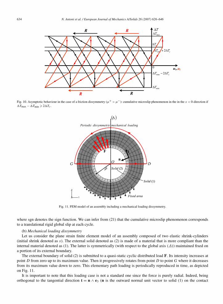
Fig. 10. Asymptotic behaviour in the case of a friction dissymmetry (μ+ > μ−): cumulative microslip phenomenon in the in the x < 0-direction if�Tmax − �Tmin � 2�Tc .
Fig. 11. FEM model of an assembly including a mechanical loading dissymmetry.
where sgn denotes the sign function. We can infer from (21) that the cumulative microslip phenomenon correspondsto a translational rigid global slip at each cycle.
(b) Mechanical loading dissymmetryLet us consider the plane strain finite element model of an assembly composed of two elastic shrink-cylinders
(initial shrink denoted as s). The external solid denoted as (2) is made of a material that is more compliant than theinternal material denoted as (1). The latter is symmetrically (with respect to the global axis (Δ)) maintained fixed ona portion of its external boundary.
The external boundary of solid (2) is submitted to a quasi-static cyclic distributed load F. Its intensity increases atpoint D from zero up to its maximum value. Then it progressively rotates from point D to point G where it decreasesfrom its maximum value down to zero. This elementary path loading is periodically reproduced in time, as depictedon Fig. 11.
It is important to note that this loading case is not a standard one since the force is purely radial. Indeed, beingorthogonal to the tangential direction t = n ∧ e3 (n is the outward normal unit vector to solid (1) on the contact
N. Antoni et al. / European Journal of Mechanics A/Solids 26 (2007) 626–646 635
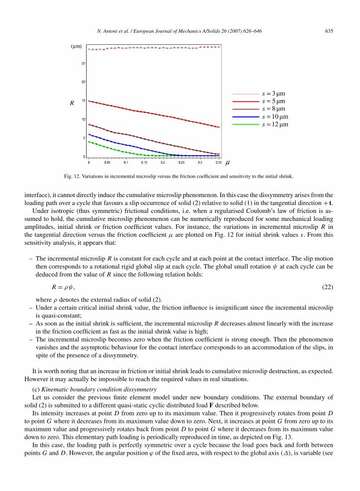
Fig. 12. Variations in incremental microslip versus the friction coefficient and sensitivity to the initial shrink.
interface), it cannot directly induce the cumulative microslip phenomenon. In this case the dissymmetry arises from theloading path over a cycle that favours a slip occurrence of solid (2) relative to solid (1) in the tangential direction + t.
Under isotropic (thus symmetric) frictional conditions, i.e. when a regularised Coulomb’s law of friction is as-sumed to hold, the cumulative microslip phenomenon can be numerically reproduced for some mechanical loadingamplitudes, initial shrink or friction coefficient values. For instance, the variations in incremental microslip R inthe tangential direction versus the friction coefficient μ are plotted on Fig. 12 for initial shrink values s. From thissensitivity analysis, it appears that:
– The incremental microslip R is constant for each cycle and at each point at the contact interface. The slip motionthen corresponds to a rotational rigid global slip at each cycle. The global small rotation ψ at each cycle can bededuced from the value of R since the following relation holds:
R = ρψ, (22)
where ρ denotes the external radius of solid (2).– Under a certain critical initial shrink value, the friction influence is insignificant since the incremental microslip
is quasi-constant;– As soon as the initial shrink is sufficient, the incremental microslip R decreases almost linearly with the increase
in the friction coefficient as fast as the initial shrink value is high;– The incremental microslip becomes zero when the friction coefficient is strong enough. Then the phenomenon
vanishes and the asymptotic behaviour for the contact interface corresponds to an accommodation of the slips, inspite of the presence of a dissymmetry.
It is worth noting that an increase in friction or initial shrink leads to cumulative microslip destruction, as expected.However it may actually be impossible to reach the required values in real situations.
(c) Kinematic boundary condition dissymmetryLet us consider the previous finite element model under new boundary conditions. The external boundary of
solid (2) is submitted to a different quasi-static cyclic distributed load F described below.Its intensity increases at point D from zero up to its maximum value. Then it progressively rotates from point D
to point G where it decreases from its maximum value down to zero. Next, it increases at point G from zero up to itsmaximum value and progressively rotates back from point D to point G where it decreases from its maximum valuedown to zero. This elementary path loading is periodically reproduced in time, as depicted on Fig. 13.
In this case, the loading path is perfectly symmetric over a cycle because the load goes back and forth betweenpoints G and D. However, the angular position ϕ of the fixed area, with respect to the global axis (Δ), is variable (see
636 N. Antoni et al. / European Journal of Mechanics A/Solids 26 (2007) 626–646
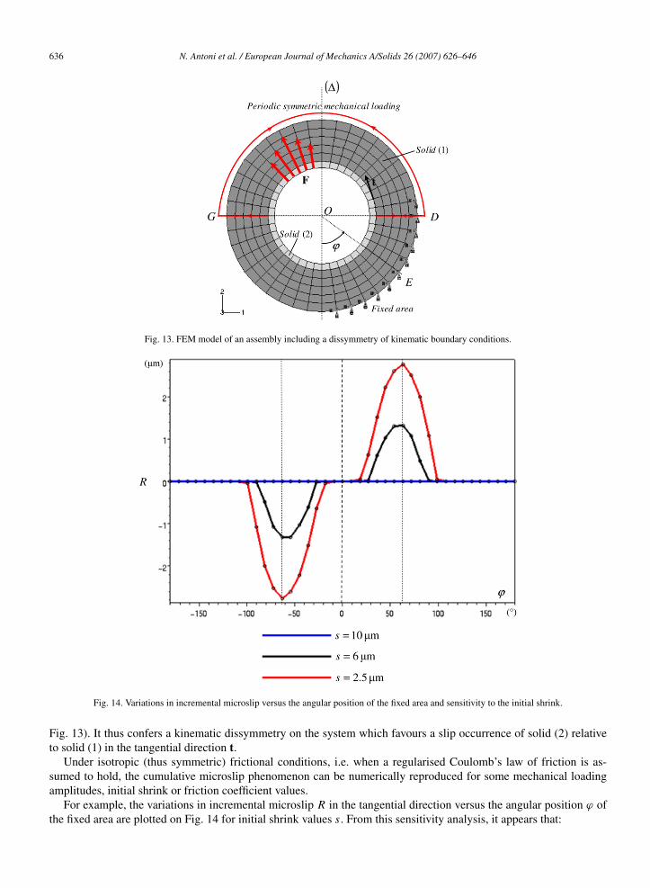
Fig. 13. FEM model of an assembly including a dissymmetry of kinematic boundary conditions.
Fig. 14. Variations in incremental microslip versus the angular position of the fixed area and sensitivity to the initial shrink.
Fig. 13). It thus confers a kinematic dissymmetry on the system which favours a slip occurrence of solid (2) relativeto solid (1) in the tangential direction t.
Under isotropic (thus symmetric) frictional conditions, i.e. when a regularised Coulomb’s law of friction is as-sumed to hold, the cumulative microslip phenomenon can be numerically reproduced for some mechanical loadingamplitudes, initial shrink or friction coefficient values.
For example, the variations in incremental microslip R in the tangential direction versus the angular position ϕ ofthe fixed area are plotted on Fig. 14 for initial shrink values s. From this sensitivity analysis, it appears that:

N. Antoni et al. / European Journal of Mechanics A/Solids 26 (2007) 626–646 637
Fig. 15. Overview of required conditions to produce the phenomenon.
– The incremental microslip R is constant for each cycle and at each point at the contact interface. The slip motionthen corresponds to a rotational rigid global slip at each cycle;
– For a perfect symmetric position of the fixed area (ϕ = 0), the cumulative microslip cannot occur. The incrementalmicroslip is identically zero, and an accommodation of the slips can be observed;
– As soon as the dissymmetry appears (ϕ �= 0), the incremental microslip R increases as fast as the initial shrinkvalue is low. It then decreases from its maximum value bit by bit as the fixed area gets closer to the loading zone;
– The incremental microslip becomes zero when the fixed area is located in the vicinity of the loading zone (inparticular for the symmetric case ϕ = π/2). Then the phenomenon vanishes and the asymptotic behaviour for thecontact interface corresponds to an accommodation of the slips, even though dissymmetry is present;
– When the angular position is reversed, the same holds true for the rotational effects.
(d) General viewAccording to the overall occurrence analysis presented in this section, the existence of a dissymmetry proves
necessary but not sufficient to observe the cumulative microslip phenomenon. Indeed, additional characteristics aregenerally required to reproduce it, such as initial contact, friction, loading conditions or certain mechanical properties.Moreover, when the phenomenon occurs, the slip motion is characterized by a rigid global slip at each cycle.
This set of situations leading to the phenomenon’s occurrence is obviously not exhaustive. In a more general case,we can observe a combination of rotational and translational effects corresponding to the most general global rigid slip.Additionally, the assembly characteristics can include several dissymmetries. An overall presentation of the requiredconditions to observe the phenomenon is depicted on Fig. 15.
It should be noted that a combination of a number of dissymmetries may be an interesting solution to prevent thephenomenon’s occurrence (e.g. Antoni, 2005). Other dissymmetries can also exist.
3. Slip-shakedown analysis
The analogy of the cumulative microslip phenomenon with the elastic-plastic response of structures has beenshown, especially concerning the possibility of shakedown under cyclic loads. This discussion is completed hereby a slip-shakedown analysis, bringing out shakedown theorems to prevent the phenomenon from occurring when astandard law of friction is assumed as in classical elasto-plasticity.

638 N. Antoni et al. / European Journal of Mechanics A/Solids 26 (2007) 626–646
3.1. Assumptions
(i) Assembly definitionA system of two solids, representing an assembly, is considered to describe the relative displacement problem.
A first solid denoted as V1 is assumed to be elastic (or rigid) and maintained by prescribed displacements u = 0 on aportion SU
1 of its boundary S1. A second elastic solid of volume V2 is maintained only by contact with friction andpre-stresses on a common portion SC = S1 ∩ S2 of the boundaries. Hence, the existence of a pre-stress field denotedas σ I in Vi , i = 1,2, is admitted.
(ii) Boundary conditions and loadingThe two solids are submitted to thermo-mechanical loadings composed of the field volume forces f in V = V1 ∪V2
and surface forces F on the complementary portions SF = SF1 ∪ SF
2 of the boundaries (SF1 = S1 − SU
1 − SC andSF
2 = S2 − SC ) and of the temperature field variation �T in V .Since cyclic loads have to be taken into account, let us assume as usual in shakedown analysis that an admissible
loading history consists of a linear combination Pj (fj ,Fj ,�Tj ) of n load systems where Pj (τ), j = 1, . . . , n, aren load parameters. These parameters may be considered as the components of a load point P defined in the loadparameter space Rn and the loading history is described by a given curve P(τ), 0 � τ � +∞. It is assumed that P(τ)
takes its values arbitrarily in an allowable polyhedral and convex domain Γ of corners Γ q , q = 1, . . . ,Q.
(iii) ContactIt is assumed that the contact interface SC is time-independent. Because of the slip motion, the contact interface
varies with the relative displacement in most examples. Since we are interested principally in the shakedown behav-iours, i.e. in limited displacements only, this assumption can be considered as meaningful.
It is also assumed that the contact is ensured for all 0 � τ � +∞. This means that the relative normal displacementis identically zero and the normal force is non-zero for all times τ :
∀x ∈ SC ∀τ � 0
{ [u](x, τ ) · n(x) = un(x, τ ) = 0,
σn(x, τ ) = n(x) · σ (x, τ ) · n(x) < 0,(23)
where [u] = u2 − u1 is the relative displacement field of V2 with respect to V1 at the contact interface SC and n is theoutward normal unit vector to V1 on SC (and to V on SF ). Consequently, there is no accumulation of relative normaldisplacements under cyclic loads.
(iv) FrictionThe tangential relative displacement field is denoted as ut on SC and the tangent force acting by V2 on V1 is σ t.
Starting from a given initial value ut(x,0), the variation of the tangential relative displacement ut is governed by afriction law on the contact interface SC under the considered loading. A standard regularised friction law is assumed.
On one hand, this means that the following decomposition of the tangential relative displacement field holds, as inelasto-plasticity:
∀x ∈ SC ∀τ � 0 ut(x, τ ) = uelt (x, τ ) + usl
t (x, τ ), (24)
where uelt denotes the elastic (reversible) part and usl
t denotes the irreversible tangential slip. A reversible behaviouris assumed to exist before irreversible slip occurrence, representing an elastic deformation of the contact interface:
∀x ∈ SC ∀τ � 0 uelt (x, τ ) = σ t(x, τ )
kt, (25)
where kt denotes the unique tangential contact stiffness when assuming an isotropic behaviour of roughnesses duringtheir elastic deformation. As in most cases surface textures of assembly parts exhibit this type of tangential contactelasticity, this assumption presents a physical sense. Nevertheless, the existence of a tangential stiffness is not essentialin our analysis. The classical Coulomb law which does not assume any tangential stiffness is discussed in the samemanner. The same equations hold by taking the limit kt → +∞.
On the other hand, the friction force σ t and the tangential slip rate u̇slt must satisfy the normality law for all x ∈ SC
and for all τ :{σ t ∈ C,
∀σ̂ ∈ C (σ − σ̂ ) · u̇sl � 0.(26)
t t t t

N. Antoni et al. / European Journal of Mechanics A/Solids 26 (2007) 626–646 639
The dissipation by friction per unit surface D is a positive homogeneous convex function of the tangential slip rate:
σ t · u̇slt = max
σ̂ t∈Cσ̂ t · u̇sl
t = D(u̇sl
t
). (27)
The given convex domain C of admissible tangential forces may depend on time, for example when the yield valuesof force depend on a prescribed time-varying temperature. The friction anisotropy can be taken into account from thegeometry of C. It is well known that the assumption of a standard law of friction is a restrictive condition. For instance,Coulomb’s law of friction does not satisfy this assumption since the associated admissible domain C depends on thenormal force σn which is not a given datum. However, it has been observed in some cumulative microslip cases thatthe normal force is due principally to the given pre-stress, i.e. σn ≈ n · σ I · n, and can be thus considered as a givendatum.
3.2. The governing equations
Under the previous assumptions, the governing equations of the system are, for all τ � 0, in a quasi-static transfor-mation:⎧⎪⎪⎪⎪⎪⎪⎪⎪⎪⎪⎪⎨
⎪⎪⎪⎪⎪⎪⎪⎪⎪⎪⎪⎩
∇ · σ + f = 0 in V,
σ = σ I + L : (∇u − αT �T I) in V,
σ · n = F on SF , u = 0 on SU1 ,
un = 0, ut = [u] on SC,
ut = σ t
kt+ usl
t on SC,
σ t = σ · n − σnn on SC,
σ t ∈ C, ∀σ̂ t ∈ C (σ t − σ̂ t) · u̇slt � 0 on SC,
u(x,0) = U0(x) initial conditions,
(28)
where L is the elasticity tensor, αT denotes the thermal dilatation coefficient (under isotropic assumption) and I is theunit tensor. In particular, at any time τ , the equilibrium can be written under the form of virtual work in V :∫
V
σ (u) : ∇δu dV =∫V
f · δu dV +∫SF
F · δu ds −∫SC
σ t(ut) · δut ds. (29)
For any compatible displacement field δu, i.e. satisfying [δu] · n = 0 and δut = [δu] on SC . Note that if au and budenote two solutions of (28) starting from two different initial conditions, then from (29) successively written for auand bu with δu = bu̇ − a u̇, it follows that:∫
V
(bε − aε) : L : (bε̇ − a ε̇)dV = −∫SC
(bσ t − aσ t) · (bu̇t − a u̇t)ds. (30)
On the other hand, since au and bu are two solutions of (28), the normality law (26) successively written for(aσ t,a u̇sl
t ) with bσ t ∈ C and (bσ t,bu̇slt ) with aσ t ∈ C leads to:∫
SC
(bσ t − aσ t) · (bu̇slt − a u̇sl
t )ds � 0 (31)
or, by using the partition (24) and the state law (25):∫SC
(bσ t − aσ t) · (bu̇t − a u̇t)ds � d
dτ
∫SC
1
2kt
(buel
t − auelt
)2 ds. (32)
It follows from (30) and (32) that the distance of au and bu in the elastic energy norm l(τ ) defined as:
l(τ ) =[∫
(bε − aε) : L : (bε − aε)dV +∫
kt(buel
t − auelt
)2 ds
]1/2
(33)
V SC
640 N. Antoni et al. / European Journal of Mechanics A/Solids 26 (2007) 626–646
satisfies l̇(τ ) � 0, thus l(τ ) must be a decreasing function of time. Consequently, there is a contraction of the distanceof two different solutions of (28) in stresses, strains and displacements.
It is interesting to introduce associated problems in view of the relative slip analysis. The following system ofequations is considered to describe the loading history:⎧⎪⎪⎪⎪⎪⎪⎪⎨
⎪⎪⎪⎪⎪⎪⎪⎩
∇ · σ + f = 0 in V,
σ = σ I + L : (∇u − αT �T I) in V,
σ · n = F on SF , u = 0 on SU1 ,
un = 0, ut = [u] on SC,
ut = σ t
kton SC,
σ t = σ · n − σnn on SC
(34)
in which the data are (f,F,σ I ,�T ) and the solution in displacement of this system is denoted as uE . The derivedtangential force σE
t follows uniquely from the loading history.A second associated problem is defined by the system:⎧⎪⎪⎪⎪⎨
⎪⎪⎪⎪⎩
∇ · σ + f = 0 in V,
σ = L : ∇u in V,
σ · n = 0 on SF , u = 0 on SU1 ,
un = 0, [u] = W on SC,
σ t = σ · n − σnn on SC
(35)
in which the datum is only the slip field W. The solution in displacement, strain and stress is denoted as (uW,εW,σW)
and the associated tangential force is denoted as σWt . It is clear that for a solution of (28), the following decomposition
holds:
∀x ∈ SC ∀τ � 0 σ t(x, τ ) = σEt (x, τ ) + σ
uslt
t (x, τ ). (36)
It is also interesting to introduce various definitions. Let SF be the space of self-tangential forces s defined on SC ,such that there exists at least a self-stress σ s defined in V , which admits s as the associated tangential force on SC :⎧⎪⎪⎨
⎪⎪⎩∇ · σ s = 0 in V,
σ s · n = 0 on SF ,[σ s
] · n = 0 on SC,
s = σ s · n − σ sn n on SC.
(37)
Let CS be the space of compatible slips on SC . By definition, a tangential relative displacement field w on SC is acompatible slip if at least a displacement field uw defined in V exists such that:{
uw = 0 on SU1 ,
uwn = 0,
[uw
] = w on SC.(38)
Since such a prolongation uw can be found for any regular tangential displacement field w on SC , the conditionw ∈ CS is only a regularity condition. In particular, it follows from (29) (by noting that δut = w ∈ CS and f = 0, F = 0for s ∈ SF) the following orthogonality relation holds:∫
V
σ s : εw dV +∫SC
s · w ds = 0 ∀w ∈ CS ∀s ∈ SF. (39)
3.3. Static shakedown theorem for the slip
The problem consists in obtaining a shakedown of the slips whatever the initial state and the admissible loadinghistory. Similar to the extended version of Melan’s theorem in elasto-plasticity (see Nguyen, 2000), the followingtheorem holds:
N. Antoni et al. / European Journal of Mechanics A/Solids 26 (2007) 626–646 641
Theorem 1. If a time-independent self-tangential force σ ∗t ∈ SF and a coefficient m > 1 exist such that the tangential
force σ̃qt (x) = m(σ ∗
t (x) + qσEt (x)) satisfies for all x ∈ SC and for all q = 1, . . . ,Q the condition σ̃
qt (x) ∈ Cq(x),
then there is necessarily a shakedown of the tangential slips whatever be the initial state and the admissible loadinghistory.
Note that (σqt ,qσE
t ) and Cq denote respectively the responses and the domain of admissible tangential forcesassociated with the values of load parameters at corners Γ q .
Proof. Let us assume the existence of a time-independent tangential force σ ∗t ∈ SF and a coefficient m > 1 such that
for all times τ � 0 and for all x ∈ SC , σ̃ t(x, τ ) = m(σ ∗t (x) + σE
t (x, τ )) ∈ C(x, τ).
On one hand, if uslt ∈ CS denotes a solution for (28), then it is also clear that u̇sl
t ∈ CS and σusl
tt ∈ SF, thus σ
uslt
t −σ ∗t ∈
SF. It follows from (39) with w = u̇slt and s = σ
uslt
t − σ ∗t that:∫
SC
(σ
uslt
t − σ ∗t
) · u̇slt ds = −
∫V
(σ usl
t − σσ ∗t) : ε̇usl
t dV. (40)
Since ε̇uslt = L−1 : σ̇ usl
t and σ̇ σ ∗t = 0 (σ ∗
t is assumed to be time-independent), the previous equation is equivalentto the following:∫
SC
(σ
uslt
t − σ ∗t
) · u̇slt ds = −
∫V
(σ usl
t − σσ ∗t) : L−1 : (σ̇ usl
t − σ̇ σ ∗t)
dV. (41)
On the other hand, since σ̃ t ∈ C, the normality law (26) for the solution σ t ∈ C of (28) results in:
(σ t − σ̃ t) · u̇slt = (
σ t − m(σ ∗
t + σEt
)) · u̇slt � 0. (42)
Taking the decomposition (36) into account i.e. σ t = σEt + σ
uslt
t , it follows from (42) with m > 1 that:
(σ
uslt
t − σ ∗t
) · u̇slt � m − 1
mσ t · u̇sl
t . (43)
Finally, Eqs. (41) and (43) lead to:
m − 1
m
∫SC
σ t · u̇slt ds � −1
2
dA
dτ, (44)
where A is a non-negative function since L−1 is a definite positive tensor:
A(τ) =∫V
(σ usl
t (x, τ ) − σσ ∗t (x)
) : L−1 : (σ uslt (x, τ ) − σσ ∗
t (x))
dV � 0. (45)
And for all times τ � 0, one obtains by taking account of definition (27):
m − 1
m
τ∫0
∫SC
D(u̇sl
t
)ds dτ � 1
2
(A(0) − A(τ)
)� 1
2A(0). (46)
It is concluded that the dissipated energy by friction is bounded for all times τ � 0 whatever the initial data U0(x)
and the admissible loading history. This property ensures the existence of limτ→∞ uslt (x, τ ). Thus the solution usl
tmust converge to a time-independent field at large times, which corresponds to the slip-shakedown definition (4). �3.4. A safety coefficient for the shakedown of slips
As in the theory of elasto-plasticity, a safety coefficient for the shakedown of the tangential relative displacementcan now be introduced. By definition, the safety coefficient ms is the maximum of m ensuring the assumptions ofTheorem 1:
642 N. Antoni et al. / European Journal of Mechanics A/Solids 26 (2007) 626–646
Definition 4. The static expression of the safety coefficient is:⎧⎪⎨⎪⎩
ms = maxσ ∗
t ∈SFm
such that∀x ∈ SC ∀q = 1, . . . ,Q σ̃
qt (x) = m
(σ ∗
t (x) + qσEt (x)
) ∈ Cq(x).
(47)
It is clear that if ms > 1 then the assumptions of Theorem 1 are fulfilled: the asymptotic behaviour for the contactinterface is a shakedown of the slips.
Static approachDefinition (47) leads to the resolution of a problem of optimisation under convex constraints. As in plastic shake-
down theory (Nguyen, 2006), an associated Lagrangian Λ can be introduced:
Λ(m,σ ∗
t , σ̃qt ,gq
) = m +Q∑
q=1
∫SC
[σ̃
qt (x) − m
(σ ∗
t (x) + qσEt (x)
)] · gq(x)ds
= m
[1 −
∫SC
σ ∗t (x) ·
Q∑q=1
gq(x)ds −Q∑
q=1
∫SC
qσEt (x) · gq(x)ds
]+
Q∑q=1
∫SC
σ̃qt (x) · gq(x)ds, (48)
where gq is the slip rate defined on SC associated with the values of load parameters at corners Γ q and represents theLagrange multipliers associated with the constraints σ̃
qt = m(σ ∗
t + qσEt ). The max–min problem:
ms = maxm,σ ∗
t ,σ̃qt
mingq
Λ(m,σ ∗
t , σ̃qt ,gq
)(49)
under the constraints gq ∈ CS, σ ∗t ∈ SF and σ̃
qt ∈ Cq for all q = 1, . . . ,Q leads to problem (47). Indeed, the result
of the minimisation of Λ with respect to gq gives mingq Λ = m if σ̃qt ∈ Cq for all q = 1, . . . ,Q and mingq Λ = −∞
otherwise.
Kinematic approachIt is also well known that the resolution of the dual problem:
mk = mingq
maxm,σ ∗
t ,σ̃qt
Λ(m,σ ∗
t , σ̃qt ,gq
)(50)
under the same constraints results in the definition of an expression of the safety coefficient by the kinematic approach.Indeed, it is clear that mk � ms and the equality mk = ms can be expected as usual in min–max duality.
For a given rate gq , q = 1, . . . ,Q, the first operation consists of searching for the maximum of Λ amongcoefficientsm, self-tangential forces σ ∗
t ∈ SF and tangential forces σ̃qt ∈ Cq . The following notation for the cycle
slip residue is introduced:
Q∑q=1
gq(x) =∮
cycle
g(x, τ )dτ = R(x). (51)
The result of the maximisation is:⎧⎪⎪⎪⎪⎪⎪⎪⎪⎪⎪⎪⎪⎪⎪⎪⎨⎪⎪⎪⎪⎪⎪⎪⎪⎪⎪⎪⎪⎪⎪⎪⎩
maxm,σ ∗
t ,q σ̃ t
Λ(m,σ ∗
t , σ̃qt ,gq
) =Q∑
q=1
∫SC
D(gq(x)
)ds
if∫SC
σ ∗t (x) · R(x)ds +
Q∑q=1
∫SC
qσEt (x) · gq(x)ds = 1
and if∫SC
δσ ∗t (x) · R(x)ds = 0 ∀δσ ∗
t ∈ SF,
otherwise max∗ q
Λ(m,σ ∗
t , σ̃qt ,gq
) = +∞.
(52)
m,σ t ,σ̃ t
N. Antoni et al. / European Journal of Mechanics A/Solids 26 (2007) 626–646 643
From (39), the last condition in (52) gives in particular with δσ ∗t = σ R
t :∫V
εR : L : εR dV = 0. (53)
Thus uR must be a rigid displacement in V1 and V2. Let RCS be the set of rigid compatible slips on SC . Bydefinition, W ∈ RCS means that a rigid displacement uW compatible with the relative slip W on SC can be found inV1 and V2 respectively (note that uW is necessarily zero in V1 because of prescribed displacements u = 0 on SU
1 ).Hence, the relative slip W is identical for all x ∈ SC . The problem is of interest when the set RCS is not void. In thiscase, the following statement results:
Theorem 2. The kinematic expression of the safety coefficient satisfies:⎧⎪⎪⎪⎪⎪⎪⎪⎪⎨⎪⎪⎪⎪⎪⎪⎪⎪⎩
mk = mingq
Q∑q=1
∫SC
D(gq(x)
)ds
among the slip rates gq such that
R =Q∑
q=1
gq(x) ∈ RCS and thatQ∑
q=1
∫SC
qσEt (x) · gq(x)ds = 1.
(54)
In particular, it follows that slip-shakedown is impossible if a slip rate gq exists such that:
R =Q∑
q=1
gq(x) ∈ RCS and thatQ∑
q=1
∫SC
D(gq(x)
)ds <
Q∑q=1
∫SC
qσEt (x) · gq(x)ds (55)
since this inequality leads to ms � mk < 1. As in elasto-plasticity, the kinematic approach clearly shows twomechanisms of non-shakedown which lead to asymptotic behaviours under cyclic loads defined by (5) or (6).Indeed, an alternating slip motion at each cycle without any cumulated relative displacements corresponds to acycle slip residue R = 0, while cumulated relative displacements at each cycle correspond to a cycle slip residueR �= 0.
The latter aspect is important since it gives a kinematic property inherent in the cumulative microslip phenom-enon’s occurrence. This result has been observed in most examples (see the previous section) and a proof of it hasbeen already established (see Antoni, 2005) with an approach different from the one proposed above which appearsmore natural because it results from analogies with classical elasto-plasticity. We can thus set out the following state-ment:
Proposition 4. Under a periodic load, the cumulative slip phenomenon is characterized by a rigid global slip at eachcycle, when the periodic response is obtained.
3.5. Example
To illustrate all these theoretical aspects, let us consider the one-dimensional discrete example (a) introduced in thefirst section of the present paper. The preliminary step consists in verifying that all the assumptions of the shakedownanalysis are well satisfied.
The elastic spring plays the role of solid (2) while the fixed rigid support represents solid (1). The system is onlysubjected to a periodic temperature variation �T taking its values at the corners of the segment Γ = [�Tmin,�Tmax](i.e. Q = 2 in this case) that completely characterises the loading history.
The interface is time-independent as contact properties are the same for all 0 � τ � +∞. In particular, the contactis ensured for all τ since the normal displacement of each node is identically zero under the application of a time-constant normal force Fn > 0.
The given convex domain C of admissible tangential forces is time-independent and it is defined in this case asthe set of nodal tangential forces Fi (i = 1,2) such that −K− � Fi � K+ with K− = μ−Fn and K+ = μ+Fn. The
644 N. Antoni et al. / European Journal of Mechanics A/Solids 26 (2007) 626–646
assumption of a standard law of friction is ensured since Fn is a given datum. The dissymmetry of friction is takeninto account from the geometry of the segment C = [−K−,K+].
According to Eq. (28), the governing equations of the system are given, for all times τ � 0, in a quasi-statictransformation by the following discrete system:⎧⎪⎪⎪⎪⎪⎪⎪⎨
⎪⎪⎪⎪⎪⎪⎪⎩
[k −k
−k k
]{u1u2
}=
{−kαT l0�T
kαT l0�T
}−
{F1F2
},
ui = Fi
kt+ usl
i ,
Fi ∈ C, ∀F̂i ∈ C (F̂i − Fi)u̇sli � 0, i = 1,2,
ui(0) = 0.
(56)
It is worth noting from the equilibrium that the tangential nodal forces (F1,F2) are linked by the relation F1 +F2 =0 for all times τ . According to Eq. (34), the derived tangential forces (FE
1 ,FE2 ) following uniquely from the loading
history are the solutions of the discrete system:⎧⎪⎪⎨⎪⎪⎩
[k −k
−k k
]{u1u2
}=
{−kαT l0�T
kαT l0�T
}−
{F1F2
},
ui = Fi
kt, i = 1,2.
(57)
It follows that:⎧⎪⎪⎨⎪⎪⎩
FE1 = −kktαT l0
kt + 2k�T,
FE2 = kktαT l0
kt + 2k�T .
(58)
Static approachThe static expression of the safety coefficient is given by (47) rewritten as:⎧⎪⎪⎨
⎪⎪⎩ms = max
(F ∗1 ,F ∗
2 )∈SFm
such that ∀i = 1,2
{m
(F ∗
i + maxFEi
) ∈ C,
m(F ∗
i + minFEi
) ∈ C,
(59)
where (maxFE1 ,maxFE
2 ) and (minFE1 ,minFE
2 ) denote, respectively, the responses in (58) respectively associated withthe values of �T at corners �Tmax and �Tmin of Γ . In this case, SF is the set of self-tangential forces (F ∗
1 ,F ∗2 ) such
that F ∗1 + F ∗
2 = 0.Finally, problem (59) consists of searching for the maximum of m among the self-tangential forces F ∗
1 such thatthe following system of inequalities is satisfied:⎧⎪⎪⎪⎪⎪⎪⎪⎪⎪⎪⎪⎨
⎪⎪⎪⎪⎪⎪⎪⎪⎪⎪⎪⎩
−K− � m
(F ∗
1 − kktαT l0
kt + 2k�Tmax
)� K+,
−K− � m
(−F ∗
1 + kktαT l0
kt + 2k�Tmax
)� K+,
−K− � m
(F ∗
1 − kktαT l0
kt + 2k�Tmin
)� K+,
−K− � m
(−F ∗
1 + kktαT l0
kt + 2k�Tmin
)� K+
(60)
which amounts to:⎧⎪⎪⎨⎪⎪⎩
−min(K−,K+) � m
(−F ∗
1 + kktαT l0
kt + 2k�Tmax
)� min(K−,K+),
−min(K−,K+) � m
(F ∗
1 − kktαT l0�Tmin
)� min(K−,K+)
(61)
kt + 2k

N. Antoni et al. / European Journal of Mechanics A/Solids 26 (2007) 626–646 645
or to:
−2 min(μ−,μ+)Fn � mkktαT l0
kt + 2k(�Tmax − �Tmin) � 2 min(μ−,μ+)Fn. (62)
Assuming �Tmax − �Tmin > 0 and introducing the critical temperature variation �Tc defined in (7), it followsfinally that:
− 2�Tc
�Tmax − �Tmin� m � 2�Tc
�Tmax − �Tmin. (63)
The result of the maximisation of m under constraints (63) is thus:
ms = 2�Tc
�Tmax − �Tmin. (64)
If ms > 1, i.e. if �Tmax −�Tmin < 2�Tc then the assumptions of Theorem 1 are fulfilled: the asymptotic behaviourfor the contact interface is a shakedown of the slips. The same result has been obtained in (8), by using a standardcalculation of the response.
Kinematic approachThe kinematic expression of the safety coefficient is given by (54) rewritten as:⎧⎪⎪⎪⎨
⎪⎪⎪⎩
mk = min(D
(gmax
1
) + D(gmin
1
) + D(gmax
2
) + D(gmin
2
))among the slip rates
(gmax
1 , gmin1 , gmax
2 , gmin2
)such that(
gmax1 + gmin
1 , gmax2 + gmin
2
) ∈ RCS
and that maxFE1 gmax
1 + minFE1 gmin
1 + maxFE2 gmax
2 + minFE2 gmin
2 = 1.
(65)
In this case, RCS is the set of compatible slips (g1, g2) such that g1 = g2. The latter condition defines a rigidcompatible slip on the contact interface.
The constraints in (65) then correspond to the set of slip rates (gmax1 , gmin
1 , gmax2 , gmin
2 ) such that the followingsystem of equations is satisfied:{
gmax1 + gmin
1 = gmax2 + gmin
2 ,
maxFE1 gmax
1 + minFE1 gmin
1 + maxFE2 gmax
2 + minFE2 gmin
2 = 1.(66)
Noting that FE2 = −FE
1 amounts to:{gmax
1 − gmax2 = gmin
2 − gmin1 ,(
gmax1 − gmax
2
)(maxFE
1 − minFE1
) = 1.(67)
Assuming �Tmax − �Tmin > 0 and introducing the critical temperature variation �Tc defined in (7), it finallyfollows from (58) that:
gmax1 − gmax
2 = gmin2 − gmin
1 = 1
min(K−,K+)
�Tc
�Tmax − �Tmin> 0 (68)
which gives two linear constraints as functions of |gmax1 − gmax
2 | and |gmin1 − gmin
2 |.The dissipation by friction D is defined as:
D(gi) = maxF̂i∈C
F̂igi . (69)
Since F̂1 = −F̂2, the minimum value of D(g1) + D(g2) as a linear function of |g1 − g2| is given bymin(K−,K+)|g1 − g2|.
Therefore, the minimum value of D(gmax1 ) + D(gmin
1 ) + D(gmax2 ) + D(gmin
2 ) as a linear function of |gmax1 − gmax
2 |and |gmin
1 − gmin2 | is given by min(K−,K+)(|gmax
1 − gmax2 | + |gmin
1 − gmin2 |).
Finally, the result of the minimisation under the constraints in (68) is:
mk = 2�Tc. (70)
�Tmax − �Tmin
646 N. Antoni et al. / European Journal of Mechanics A/Solids 26 (2007) 626–646
In this case, the static and kinematic approaches lead to the same expression of the safety coefficient:
ms = mk = 2�Tc
�Tmax − �Tmin. (71)
In particular, slip-shakedown is impossible if ms = mk � 1, i.e. if �Tmax − �Tmin � 2�Tc. We can then observetwo mechanisms of non-shakedown obtained in (13) and (17) by using a standard calculation of the response: an ac-commodation of the slips occurs for a friction symmetry, i.e. if K− = K+, and the cumulative microslip phenomenonoccurs for a friction dissymmetry, i.e. if K− �= K+.
4. Conclusion
The cumulative microslip problem is of interest as it recurrently affects some assemblies subjected to cyclic loads.This specific slip motion has been theoretically characterized as an asymptotic behaviour for the contact interfacebased on elasto-plastic analogies.
It can be numerically reproduced. In particular, in most simple examples, the existence of a dissymmetry in theassembly characteristics turns out to be a necessary condition for the phenomenon to occur. However, it is not sufficientand some additional conditions are required to observe it.
In the spirit of shakedown analysis in elasto-plasticity, a shakedown theorem has been established as a sufficientcondition to prevent cumulative microslip occurrence. A safety coefficient with respect to the slip motion has beenintroduced. Its expression has been given by two approaches in min–max duality. Its numerical computation on as-sembly models can be used as a reliable solution to design assemblies with respect to this risk.
Acknowledgements
This work is supported by RENAULT S.A.S. (Powertrain Engineering Division).
References
Antoni, N., 2005. Phénomène de microreptation des assemblages mécaniques. Thèse de l’Université de Savoie-Chambéry, France.Antoni, N., Ligier, J.-L., 2006. Cumulative microslip in conrod big end bearing system. In: Proceedings ICES 2006, ASME Internal Combustion
Engine Dr., Aachen, Germany.Debordes, O., Nayroles, B., 1976. Sur la théorie et le calcul à l’adaptation des structures elastoplastiques. J. Mécanique 20, 1–54.Hupperich, P., 2004. The development of the general electric GEVO engine. In: CIMAC Congress, Kyoto, Japon.Koiter, W.T., 1960. General problems for elastic-plastic solids. In: Sneddon, J.N., Hill, R. (Eds.), Progress in Solid Mechanics, vol. 4. North-
Holland, pp. 99–112.Ligier, J.-L., Baron, E., 2002. Acyclisme et Vibrations, vol. 2, Analyses avancées et expérimentales. Editions Technip, pp. 663–727.Maier, G., 2001. On some issues in shakedown analysis. J. Appl. Mech. 68, 799–808.Mandel, J., 1976. Adaptation d’une structure plastique ecrouissable. Mech. Res. Comm. 3, 251–256.Merrit, D., Zhu, G., 2004. The prediction of connecting rod fretting and fretting initiated fatigue fracture. SAE Paper, 2004-01-3015.Moirot, F., Nguyen, Q.S., 2000. An example of stick–slip waves. C. R. Acad. Sci. Paris, Ser. IIb 328, 663–669.Nguyen, Q.S., 2000. Stability and Nonlinear Solid Mechanics. Wiley, Chichester.Nguyen, Q.S., 2003. Instability and friction. C. R. Mecanique 331, 99–112.Nguyen, Q.S., 2006. Min–max duality and shakedown theorems in plasticity. In: Nonsmooth Mechanics and Analysis: Theoretical and Numerical
Advances, pp. 81–92.