A study of strengthening circular diaphragm by ring-shaped concentric ribs
20
15 Al-khwarizmi Engineering Journal Al-Khwarizmi Engineering Journal, Vol.2, No.1,pp 15-34, (2006) A Study Of Strengthening Circular Diaphragm By Ring-Shaped Concentric Ribs Dr. Somer M. Nacy Dr.Hikmat Al-Rawi Mohammed M. Hasan University of Baghdad University of Al-Anbar University of Al-Anbar (Received 21 September 2005; accepted 4 May 2006) Abstract:- This paper deals with the determination of stresses and deflections of clamped circular diaphragm strengthened by one or two ring-shaped concentric ribs, under uniform static and dynamic pressures. The simulation has been achieved by using the well-known engineering software finite element package MSC/NASTRAN. As a design study, the effect of using a clamped ring, and the effect of using a ring-shaped rib on both surfaces of diaphragm instead of one, has been discussed in this work. To show the effectiveness of this study, results of this work have been compared with published data [1]. In the conclusion, the authors underline the validity of the considered design study, and the optimization of strengthened diaphragms. Keywords : diaphragm, Nastran, Static, Dynamic. 1.Introduction The diaphragm is the subsystem that distributes lateral load to the perpendicular subsystems and that provides lateral support. Diaphragms are treated as horizontal beams. The upper (or lower) surface, which is analogous to the web of a wide-flange beam, is assumed to carry the shear; the edge, which is analogous to the flange, is assumed to carry the flexural stress [2]. Several researches have recently been published regarding the stress and deflection characteristics of diaphragms for application to pressure sensors [3,4], microvalves [5], microphones [6] and other acoustic devices. For these devices, the applied load is assumed to be constant over the diaphragm surface [7]. In this work, analytical investigation for a clamped circular diaphragm strengthened by one or two ring-shaped concentric ribs, with built- in stress and large deflections are presented. The advantages of the circular diaphragm consist of good technological, mechanical and measuring properties [1]. In general, analytical and exact variational solutions for diaphragm behavior are desirable because of their
Transcript of A study of strengthening circular diaphragm by ring-shaped concentric ribs
Dr. Somer M. Nacy /Al-khwarizmi Engineering Journal, Vol.2, No. 1,PP 15-34 (2006)
15
Al-khwarizmi
Engineering
Journal
Al-Khwarizmi Engineering Journal, Vol.2, No.1,pp 15-34, (2006)
A Study Of Strengthening Circular Diaphragm By
Ring-Shaped Concentric Ribs
Dr. Somer M. Nacy Dr.Hikmat Al-Rawi Mohammed M. Hasan University of Baghdad University of Al-Anbar University of Al-Anbar
(Received 21 September 2005; accepted 4 May 2006)
Abstract:- This paper deals with the determination of stresses and deflections of clamped circular
diaphragm strengthened by one or two ring-shaped concentric ribs, under uniform static
and dynamic pressures. The simulation has been achieved by using the well-known
engineering software finite element package MSC/NASTRAN.
As a design study, the effect of using a clamped ring, and the effect of using a
ring-shaped rib on both surfaces of diaphragm instead of one, has been discussed in this
work. To show the effectiveness of this study, results of this work have been compared
with published data [1].
In the conclusion, the authors underline the validity of the considered
design study, and the optimization of strengthened diaphragms.
Keywords : diaphragm, Nastran, Static, Dynamic.
1.Introduction The diaphragm is the subsystem that
distributes lateral load to the
perpendicular subsystems and that
provides lateral support. Diaphragms
are treated as horizontal beams. The
upper (or lower) surface, which is
analogous to the web of a wide-flange
beam, is assumed to carry the shear; the
edge, which is analogous to the flange,
is assumed to carry the flexural stress
[2].
Several researches have recently
been published regarding the stress
and deflection characteristics of
diaphragms for application to pressure
sensors [3,4], microvalves [5],
microphones [6] and other acoustic
devices. For these devices, the applied
load is assumed to be constant over the
diaphragm surface [7].
In this work, analytical
investigation for a clamped circular
diaphragm strengthened by one or two
ring-shaped concentric ribs, with built-
in stress and large deflections are
presented. The advantages of the
circular diaphragm consist of good
technological, mechanical and
measuring properties [1].
In general, analytical and exact
variational solutions for diaphragm
behavior are desirable because of their
Dr. Somer M. Nacy /Al-khwarizmi Engineering Journal, Vol.2, No. 1,PP 15-34 (2006)
16
, i.e.
ease of use and the insight they provide
to the designer. Specific geometric
effects can be ascertained from these
solutions. However, these solutions are
generally only applicable for small
deflections. Numerical techniques, such
as finite element analysis, boundary
element analysis, and finite difference
analysis, can be more accurate in
predicting stresses and deflections,
especially for large deflections.
Unfortunately, these techniques
generally require more effort to use and
may not supply the same insight as
analytical or exact variational solutions.
The use of plate theory is appropriate
for the analysis of diaphragms [7];
therefore, this work has been achieved
by using the finite element software
package MSC/NASTRAN with plate
bending and shell elements.
As a verification test, and to show
the effectiveness of this work, a model
similar to one used by a published
research [1] has been built in
MSC/NASTRAN in order to make a
comparison between this published
research, and the present work.
2.Finite Element Analysis
Finite element procedures have become
an important and frequently
indispensable part of engineering
analysis and design. Finite element
computer programs are now widely
used in practically all branches of
engineering [8].
Applications range from
deformation and stress analysis of
automotive, aircraft, building, and
bridge structures to field analysis of
heat flux, fluid flow, magnetic flux,
seepage, and other flow problems. With
the advances in computer technology
and CAD systems, complex problems
can be modeled with relative ease.
Several alternative configurations can
be tried out on a computer before the
first prototype is built [9].
The development of finite
element methods for the solution of
practical engineering problems began
with the advent of the digital computer.
That is, the essence of a finite element
solution of an engineering problem is
that a set of governing algebraic
equations is established and solved, and
it was only through the use of the
digital computer that this process could
be rendered effective and given general
applicability. These two properties-
effectiveness and general applicability
in engineering analysis are inherent in
the theory used and have been
developed to a high degree for practical
computations, so that finite element
methods have found wide appeal in
engineering practice.
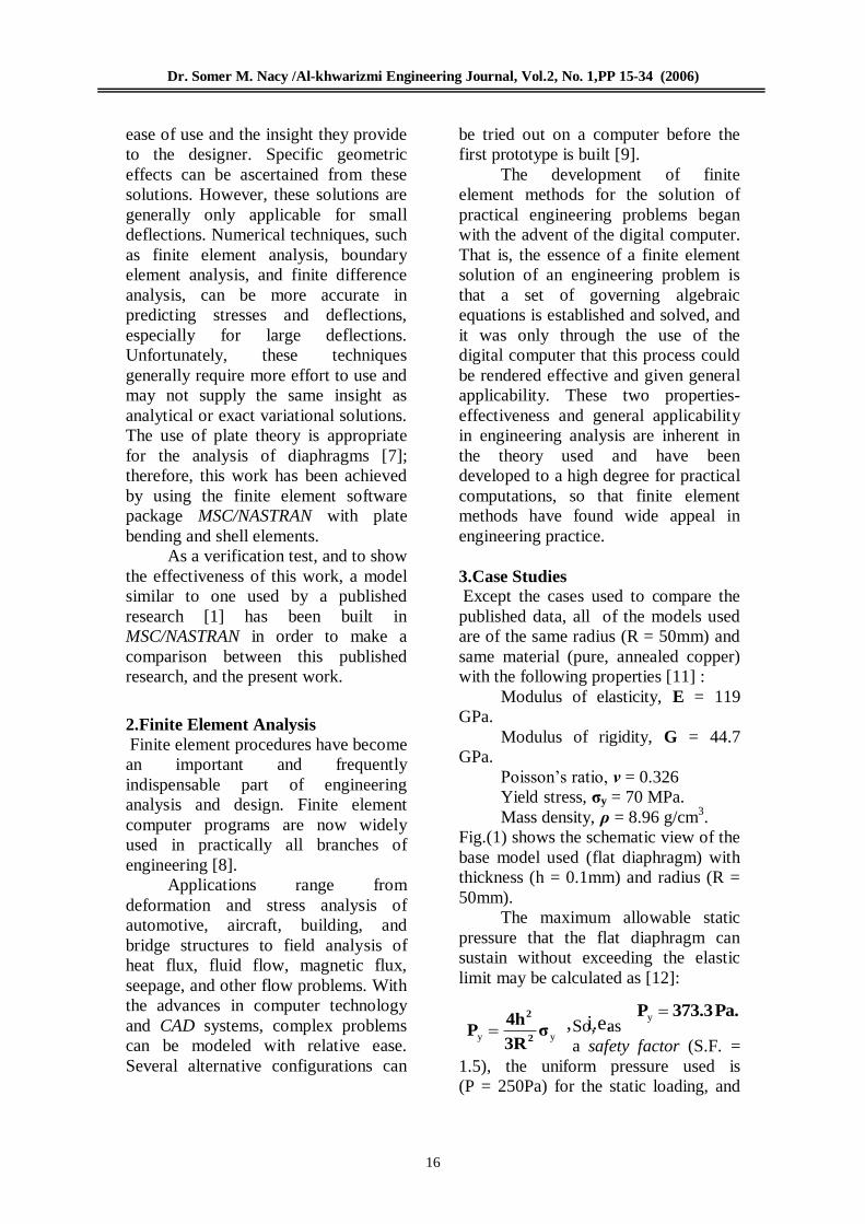
3.Case Studies
Except the cases used to compare the
published data, all of the models used
are of the same radius (R = 50mm) and
same material (pure, annealed copper)
with the following properties [11] :
Modulus of elasticity, E = 119
GPa.
Modulus of rigidity, G = 44.7
GPa.
Poisson’s ratio, ν = 0.326
Yield stress, σy = 70 MPa.
Mass density, ρ = 8.96 g/cm3.
Fig.(1) shows the schematic view of the
base model used (flat diaphragm) with
thickness (h = 0.1mm) and radius (R =
50mm).
The maximum allowable static
pressure that the flat diaphragm can
sustain without exceeding the elastic
limit may be calculated as [12]:
So, as
a safety factor (S.F. =
1.5), the uniform pressure used is
(P = 250Pa) for the static loading, and
yy σ3R
4hP
2
2
Pa.373.3P y
Dr. Somer M. Nacy /Al-khwarizmi Engineering Journal, Vol.2, No. 1,PP 15-34 (2006)
17
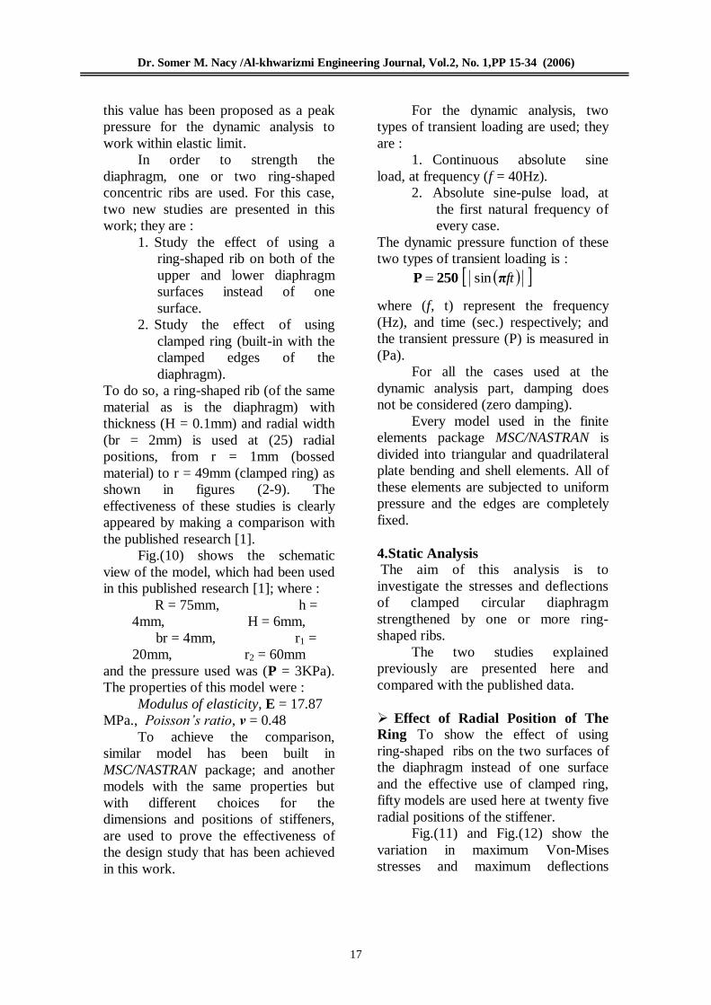
this value has been proposed as a peak
pressure for the dynamic analysis to
work within elastic limit.
In order to strength the
diaphragm, one or two ring-shaped
concentric ribs are used. For this case,
two new studies are presented in this
work; they are :
1. Study the effect of using a
ring-shaped rib on both of the
upper and lower diaphragm
surfaces instead of one
surface.
2. Study the effect of using
clamped ring (built-in with the
clamped edges of the
diaphragm).
To do so, a ring-shaped rib (of the same
material as is the diaphragm) with
thickness (H = 0.1mm) and radial width
(br = 2mm) is used at (25) radial
positions, from r = 1mm (bossed
material) to r = 49mm (clamped ring) as
shown in figures (2-9). The
effectiveness of these studies is clearly
appeared by making a comparison with
the published research [1].
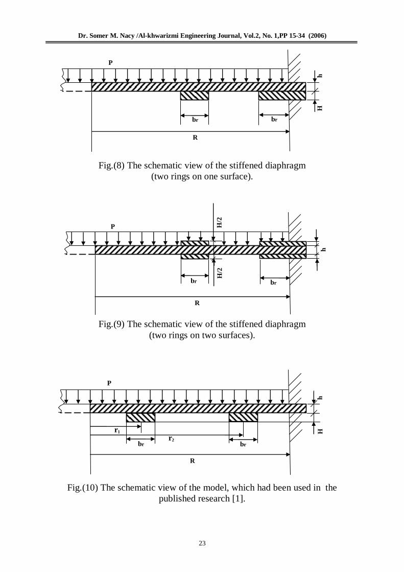
Fig.(10) shows the schematic
view of the model, which had been used
in this published research [1]; where :
R = 75mm, h =
4mm, H = 6mm,
br = 4mm, r1 =
20mm, r2 = 60mm
and the pressure used was (P = 3KPa).
The properties of this model were :
Modulus of elasticity, E = 17.87
MPa., Poisson’s ratio, ν = 0.48
To achieve the comparison,
similar model has been built in
MSC/NASTRAN package; and another
models with the same properties but
with different choices for the
dimensions and positions of stiffeners,
are used to prove the effectiveness of
the design study that has been achieved
in this work.
For the dynamic analysis, two
types of transient loading are used; they
are :
1. Continuous absolute sine
load, at frequency (f = 40Hz).
2. Absolute sine-pulse load, at
the first natural frequency of
every case.
The dynamic pressure function of these
two types of transient loading is :
ftπ250P sin
where (f, t) represent the frequency
(Hz), and time (sec.) respectively; and
the transient pressure (P) is measured in
(Pa).
For all the cases used at the
dynamic analysis part, damping does
not be considered (zero damping).
Every model used in the finite
elements package MSC/NASTRAN is
divided into triangular and quadrilateral
plate bending and shell elements. All of
these elements are subjected to uniform
pressure and the edges are completely
fixed.
4.Static Analysis The aim of this analysis is to
investigate the stresses and deflections
of clamped circular diaphragm
strengthened by one or more ring-
shaped ribs.
The two studies explained
previously are presented here and
compared with the published data.
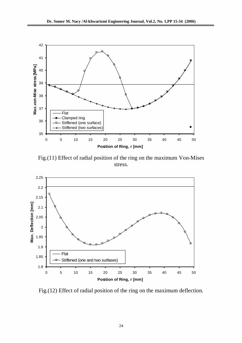
Effect of Radial Position of The
Ring To show the effect of using
ring-shaped ribs on the two surfaces of
the diaphragm instead of one surface
and the effective use of clamped ring,
fifty models are used here at twenty five
radial positions of the stiffener.
Fig.(11) and Fig.(12) show the
variation in maximum Von-Mises
stresses and maximum deflections

Dr. Somer M. Nacy /Al-khwarizmi Engineering Journal, Vol.2, No. 1,PP 15-34 (2006)
18
respectively, with the ring position (r)
for these cases.
Thickness of the diaphragm used
is (h= 0.1mm.) and dimensions of the
rings are (H= 0.1mm. , br = 2mm.).
Optimum Position : To show the
optimum ring position, which gives
minimum Von-Mises stress and
maximum deflection, Fig.(13) is drawn;
were, (S1) represents the maximum
Von-Mises stresses of stiffened
diaphragm (ring on one surface only)
divided by the maximum Von-Mises
stress of flat diaphragm, (S2) represents
the maximum Von-Mises stresses of
stiffened diaphragm (ring on two
surfaces) divided by the maximum
Von-Mises stress of flat diaphragm, (S)
represents the maximum Von-Mises
stress of stiffened diaphragm (clamped
ring) divided by the maximum Von-
Mises stress of flat diaphragm, and (D)
represents the maximum deflections of
stiffened diaphragm (ring on one or two
surfaces) divided by the maximum
deflection of flat diaphragm.
From these non-dimensional
curves, the optimum position appears at
(r = 35mm.) for using a ring on one or
two surfaces.
Optimum Case of Using Two
Rings : Mohammed M. Hasan [14]
found that the best choice of using two
ring-shaped concentric ribs is the use of
clamped ring with minimum thickness
(H) and a certain radial width (br) and
another ring at the optimum position
with high thickness and a certain radial
width (this would appear clearly from
the results of comparison with the
published data).
So, three cases of using two rings
are presented here :
Case (1) : clamped ring on one or
two surfaces (H= 0.1mm. ,
br = 10mm.), and another (at the
optimum position) on two surfaces
(H= 0.5mm. , br = 2mm.).
Case (2) : clamped ring on one or
two surfaces (H= 0.1mm. ,
br = 10mm.), and another (at the
optimum position) on two surfaces
(H= 0.4mm. , br = 10mm.).
Case (3) : clamped ring on one or
two surfaces (H= 0.1mm. ,
br = 10mm.) and another (at the
optimum position) on two surfaces
(H= 0.5mm. , br = 10mm.).
The results of these cases with the
percentage reduction in maximum Von-
Mises stress are recorded in table (1).
Comparison with a Published
Research : As explained previously, a
model similar to that of the published
research [1] is built in
MSC/NASTRAN program under the
same conditions.
The author of this published
research did not mention anything about
his choice to the dimensions and
positions of the two rings he used; the
only thing he had explained is that the
diaphragm was strengthened by these
two ring-shaped concentric ribs.
As shown in Fig.(10), the two
rings used in [1] were of the same
dimensions (H= 6mm., br = 4mm.) at
radial positions (r1 = 20mm., r2
= 60mm.).
So, eleven different cases are used
here to choose the optimum positions
and dimensions of the stiffeners, and to
compare the published data. These
cases are :
Case (1) : one ring (clamped ring)
on one or two surfaces (H= 6mm. , br =
4mm.).

Dr. Somer M. Nacy /Al-khwarizmi Engineering Journal, Vol.2, No. 1,PP 15-34 (2006)
19
Case (2) : one ring (clamped ring)
on one or two surfaces (H= 0.6mm. , br
= 4mm.).
Case (3) : one ring (clamped ring)
on one or two surfaces (H= 0.6mm. , br
= 10mm.).
Case (4) : one ring (at the optimum
position) on one or two surfaces (H=
6mm. , br = 4mm.).
Case (5) : one ring (at the optimum
position) on one or two surfaces (H=
10.5mm. , br = 4mm.).
Case (6) : one ring (at the position
which gives minimum stress) on one
surface ( H= 6mm., br = 4mm.).
Case (7) : one ring (at the position
which gives minimum stress) on two
surfaces ( H= 6mm., br = 4mm.).
Case (8) : two rings [ both case (1)
and case (4) ].
Case (9) : two rings [ both case (1)
and case (6) ].
Case (10) : two rings [ both case (1)
and case (7) ].
Case (11) { the optimum choice } : two rings [ both case (3) and case
(5) ].
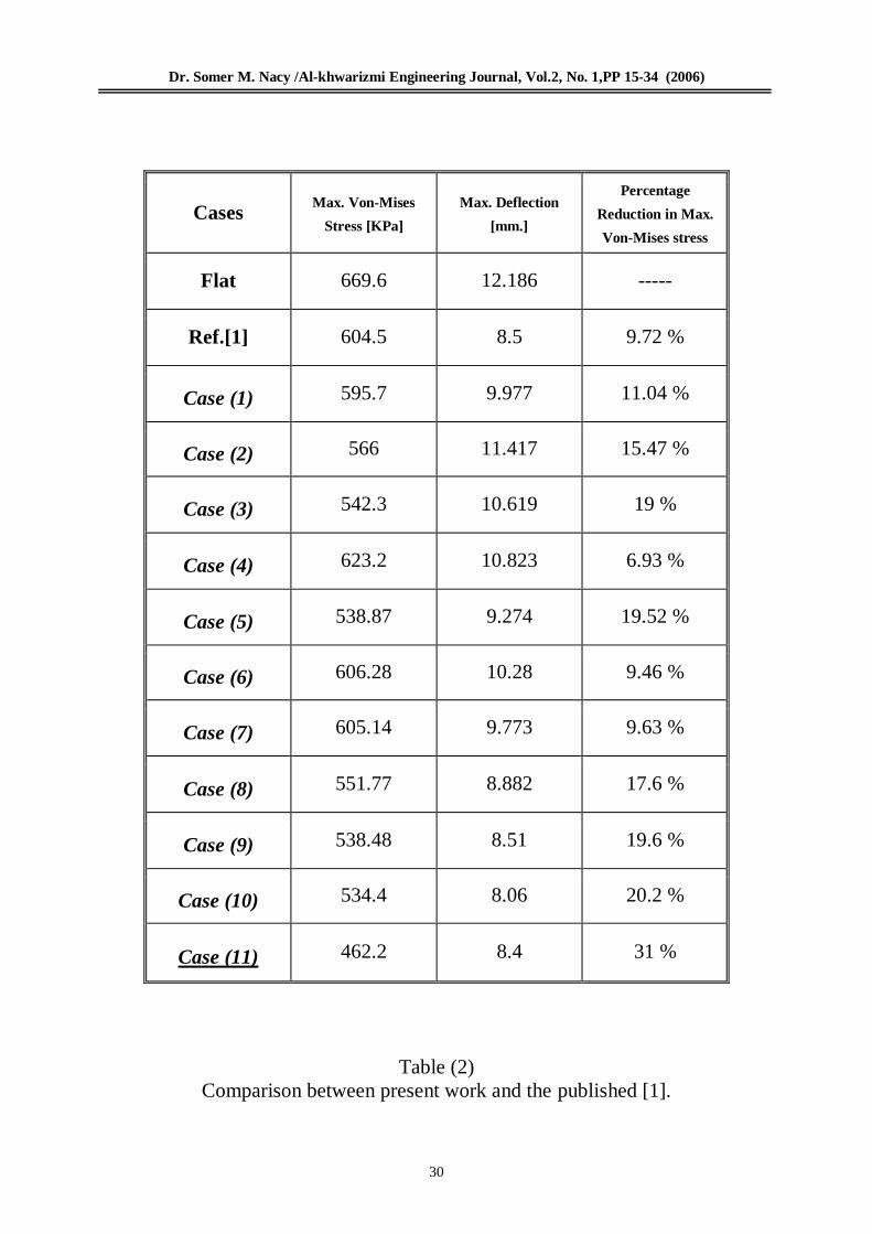
The results of maximum Von-
Mises stresses, maximum deflections
and the percentage reduction in
maximum Von-Mises stress of the
above cases are shown in table (2).
5.Dynamic Analysis
This part presents the analysis of
stresses and deflections of clamped
circular diaphragm subjected to
dynamic pressure. All of the models
used here are of the same dimensions
and properties of those used in static
part, and subjected to uniform dynamic
pressure with two types of transient
loading as discussed previously.
Fig.(14) shows the continuous positive
sine function (f = 40 Hz., Pmax.= 250
Pa), which is used for all models, and
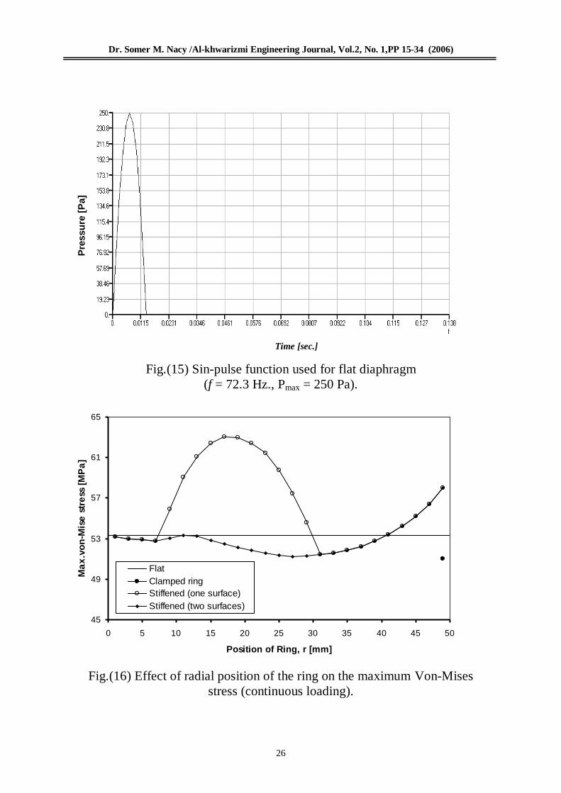
Fig.(15) shows the pulse function with
( f = 72.3Hz., Pmax.= 250 Pa), which is
used for the flat diaphragm of the base
model.
Effect of Radial Position of The
Ring : To show the effect of using
ring-shaped ribs on the two surfaces of
the diaphragm instead of one surface,
and the effective use of clamped ring,
one hundred cases are used here at
twenty five radial positions of the
stiffener.
Fig.(16) and Fig.(17) show the
variation in maximum Von-Mises
stresses and maximum deflections
respectively, with the radial position of
the ring (r), for continuous loading (f =
40 Hz., Pmax. = 250 Pa).
On the other hand, Fig.(18) and
Fig.(19) show the variation in
maximum Von-Mises stresses and
maximum deflections respectively, with
the radial position of the ring (r), for
sine-pulse loading [f = fn (mode 1),
Pmax. = 250 Pa].
Thickness of the diaphragm used
is (h= 0.1mm.) and dimensions of the
rings are (H= 0.1mm. , br = 2mm.).
Optimum Position : To show the
optimum ring position (which gives
minimum Von-Mises stress and
maximum deflection), Fig.(20) and
Fig.(21) are drawn for continuous and
pulse loading respectively; were, (S1)
represents the maximum Von-Mises
stresses of stiffened diaphragm (ring on
one surface only) divided by the
maximum Von-Mises stress of flat
diaphragm, (S2) represents the
maximum Von-Mises stresses of
stiffened diaphragm (ring on two
surfaces) divided by the maximum
Von-Mises stress of flat diaphragm, (S)
represents the maximum Von-Mises
stress of stiffened diaphragm (clamped
ring) divided by the maximum Von-
Mises stress of flat diaphragm, and (D)

Dr. Somer M. Nacy /Al-khwarizmi Engineering Journal, Vol.2, No. 1,PP 15-34 (2006)
20
represents the maximum deflections of
stiffened diaphragm (ring on one or two
surfaces) divided by the maximum
deflection of flat diaphragm.
From these non-dimensional
curves, the optimum position appears at
(r = 35mm.) for both continuous and
sine-pulse loading (ring on one or two
surfaces).
6.Conclusions : Clamped circular
diaphragms may be strengthened by one
or more ring-shaped rib in order to
reduce the stresses, when a static or
dynamic pressure is applied. However,
the proper choice to the dimensions and
positions of stiffeners may give
optimum results; otherwise, random use
of these stiffeners may give opposite
results. To get minimum stresses and
maximum deflections, a ring-shaped rib
with a certain dimensions may be used
on one or two of the diaphragm
surfaces, at a radial position equal to
(70%) of diaphragm radius. On the
other hand, a ring-shaped rib can be
divided into two equal layers to be used
on both of the two diaphragm surfaces
instead of one, to get better results for a
certain choices. The optimum choice
for using two ring-shaped concentric
ribs is that of using a clamped ring with
the favorite thickness and a certain
radial width, and another ring with
certain dimensions at the optimum
position.
Dr. Somer M. Nacy /Al-khwarizmi Engineering Journal, Vol.2, No. 1,PP 15-34 (2006)
21
h
R
P
b
P
H
h
R
R
h
b
H/2
H
/2
P
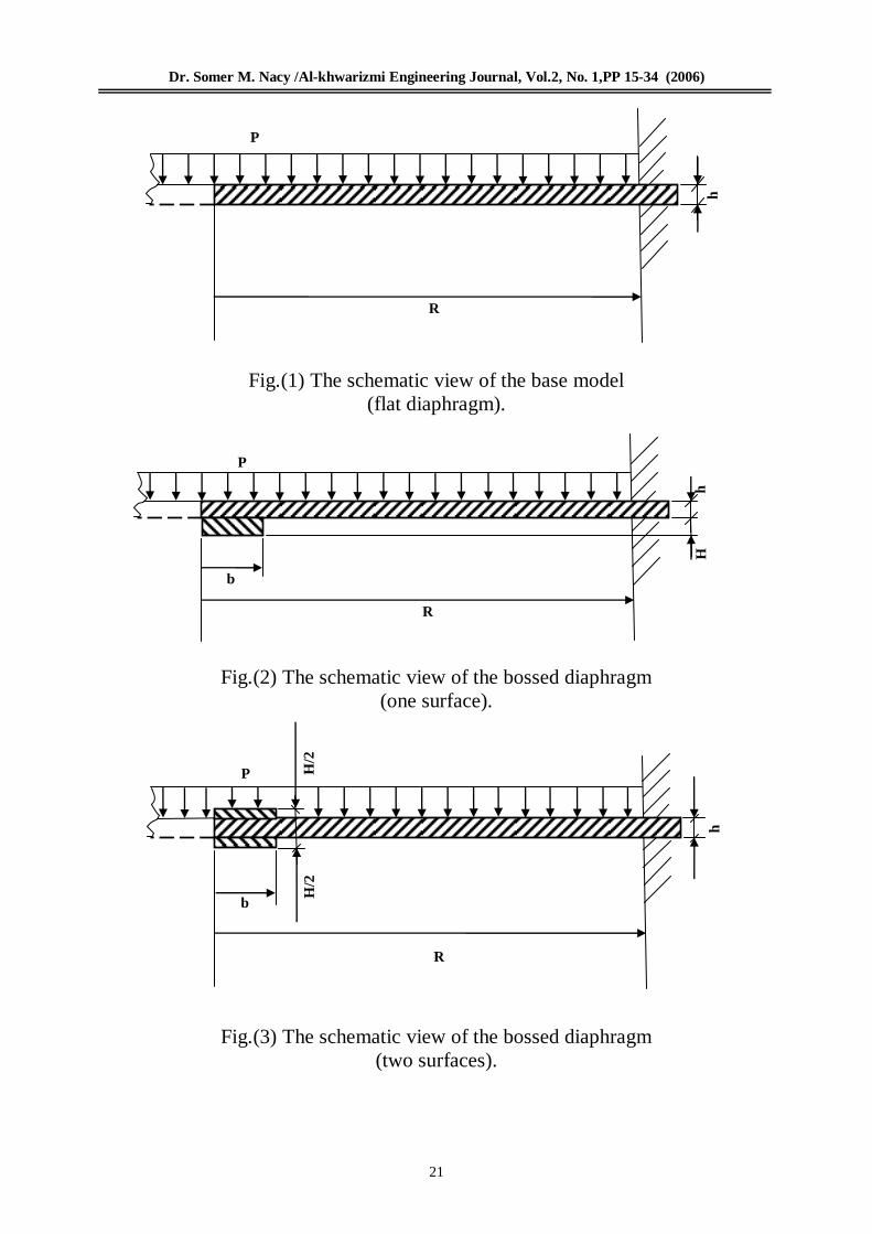
Fig.(1) The schematic view of the base model
(flat diaphragm).
Fig.(2) The schematic view of the bossed diaphragm
(one surface).
Fig.(3) The schematic view of the bossed diaphragm
(two surfaces).

Dr. Somer M. Nacy /Al-khwarizmi Engineering Journal, Vol.2, No. 1,PP 15-34 (2006)
22
br
P
H
R
h
h
R
H/2
H
/2
br
P
r
br
P
H
h
R
R
h
r
br
H/2
H
/2
P
Fig.(4) The schematic view of the stiffened diaphragm
(one ring on one surface).
Fig.(5) The schematic view of the stiffened diaphragm
(one ring on two surfaces).
Fig.(6) The schematic view of the stiffened diaphragm
(clamped ring on one surface).
Fig.(7) The schematic view of the stiffened diaphragm
(clamped ring on two surfaces).
Dr. Somer M. Nacy /Al-khwarizmi Engineering Journal, Vol.2, No. 1,PP 15-34 (2006)
23
H
h
R
br br
P
r1
br
P
H
h
R
br
r2
h
R
br
P H/2
H
/2
br
Fig.(8) The schematic view of the stiffened diaphragm
(two rings on one surface).
Fig.(9) The schematic view of the stiffened diaphragm
(two rings on two surfaces).
Fig.(10) The schematic view of the model, which had been used in the
published research [1].
Dr. Somer M. Nacy /Al-khwarizmi Engineering Journal, Vol.2, No. 1,PP 15-34 (2006)
24
35
36
37
38
39
40
41
42
0 5 10 15 20 25 30 35 40 45 50
Position of Ring, r [mm]
Ma
x.v
on
-Mis
e s
tre
ss [
MP
a]
Flat
Clamped ring
Stiffened (one surface)
Stiffened (two surfaces)
1.8
1.85
1.9
1.95
2
2.05
2.1
2.15
2.2
2.25
0 5 10 15 20 25 30 35 40 45 50
Position of Ring, r [mm]
Ma
x.
De
fle
cti
on
[m
m]
Flat
Stiffened (one and two surfases)
Fig.(11) Effect of radial position of the ring on the maximum Von-Mises
stress.
Fig.(12) Effect of radial position of the ring on the maximum deflection.

Dr. Somer M. Nacy /Al-khwarizmi Engineering Journal, Vol.2, No. 1,PP 15-34 (2006)
25
0.85
0.9
0.95
1
1.05
1.1
0 5 10 15 20 25 30 35 40 45 50
Position of Ring, r [mm]
No
n-d
ime
nsi
on
al
Unity
S
S1
S2
D
Pre
ssu
re [
Pa]
Fig.(13) Non-dimensional representation of stresses and deflections.
Time [sec.]
Fig.(14) Continuous sine-function used for all models
(f = 40 Hz., Pmax = 250 Pa).
Dr. Somer M. Nacy /Al-khwarizmi Engineering Journal, Vol.2, No. 1,PP 15-34 (2006)
26
45
49
53
57
61
65
0 5 10 15 20 25 30 35 40 45 50
Position of Ring, r [mm]
Ma
x.v
on
-Mis
e s
tre
ss [
MP
a]
Flat
Clamped ring
Stiffened (one surface)
Stiffened (two surfaces)
Pre
ssu
re [
Pa]
Time [sec.]
Fig.(15) Sin-pulse function used for flat diaphragm
(f = 72.3 Hz., Pmax = 250 Pa).
Fig.(16) Effect of radial position of the ring on the maximum Von-Mises
stress (continuous loading).

Dr. Somer M. Nacy /Al-khwarizmi Engineering Journal, Vol.2, No. 1,PP 15-34 (2006)
27
1.5
2
2.5
3
3.5
4
0 5 10 15 20 25 30 35 40 45 50
Position of Ring, r [mm]
Ma
x.
De
fle
cti
on
[m
m]
Flat
Stiffened (one and two surfases)
45
50
55
60
65
70
75
80
0 5 10 15 20 25 30 35 40 45 50
Position of Ring, r [mm]
Ma
x.v
on
-Mis
e s
tre
ss [
MP
a]
Flat
Clamped ring
Stiffened (one surface)
Stiffened (two surfaces)
Fig.(17) Effect of radial position of the ring on the maximum deflection
(continuous loading).
Fig.(18) Effect of radial position of the ring on the maximum Von-Mises
stress (sine-pulse loading).

Dr. Somer M. Nacy /Al-khwarizmi Engineering Journal, Vol.2, No. 1,PP 15-34 (2006)
28
2.5
2.7
2.9
3.1
3.3
3.5
3.7
3.9
4.1
4.3
0 5 10 15 20 25 30 35 40 45 50
Position of Ring, r [mm]
Ma
x.
De
fle
cti
on
[m
m]
Flat
Stiffened (one and two surfases)
0.85
0.9
0.95
1
1.05
1.1
1.15
1.2
0 5 10 15 20 25 30 35 40 45 50
Position of Ring [mm]
No
n-d
ime
nsi
on
al
Unity
S
S1
S2
D
Fig.(19) Effect of radial position of the ring on the maximum deflection
(sine-pulse loading).
Fig.(20) Non-dimensional representation of stresses and deflections
(continuous loading).

Dr. Somer M. Nacy /Al-khwarizmi Engineering Journal, Vol.2, No. 1,PP 15-34 (2006)
29
0.8
0.85
0.9
0.95
1
1.05
1.1
1.15
1.2
1.25
1.3
0 5 10 15 20 25 30 35 40 45 50
Position of Ring [mm]
No
n-d
ime
nsi
on
al
Unity
S
S1
S2
D
Fig.(21) Non-dimensional representation of stresses and deflections
(sine-pulse loading).
Table (1)
Stiffened diaphragm (two rings).
Cases Max. Von-Mises
Stress [MPa]
Max. Deflection
[mm.]
Percentage
Reduction in Max.
Von-Mises stress
Flat 38.9 2.206 -----
Case (1) 17.183 0.734 55.83 %
Case (2) 12.83 0.442 67.02 %
Case (3) 12.65 0.401 67.5 %
Dr. Somer M. Nacy /Al-khwarizmi Engineering Journal, Vol.2, No. 1,PP 15-34 (2006)
30
Table (2)
Comparison between present work and the published [1].
Cases Max. Von-Mises
Stress [KPa] Max. Deflection
[mm.]
Percentage
Reduction in Max.
Von-Mises stress
Flat 669.6 12.186 -----
Ref.[1] 604.5 8.5 9.72 %
Case (1) 595.7 9.977 11.04 %
Case (2) 566 11.417 15.47 %
Case (3) 542.3 10.619 19 %
Case (4) 623.2 10.823 6.93 %
Case (5) 538.87 9.274 19.52 %
Case (6) 606.28 10.28 9.46 %
Case (7) 605.14 9.773 9.63 %
Case (8) 551.77 8.882 17.6 %
Case (9) 538.48 8.51 19.6 %
Case (10) 534.4 8.06 20.2 %
Case (11) 462.2 8.4 31 %

Dr. Somer M. Nacy /Al-khwarizmi Engineering Journal, Vol.2, No. 1,PP 15-34 (2006)
31
Nomenclature
Symbol Description Unit
br Redial width of the ring m.
E Modulus of elasticity N/m2(Pa)
f Frequency Hz.
G Modulus of rigidity N/m2(Pa)
h Diaphragm thickness m.
H Ring thickness m.
P Pressure N/m2(Pa)
Py Yield pressure N/m2(Pa)
r Redial position of the stiffener m.
R Diaphragm radius m.
t time sec.
ν Poisson’s ratio ---
ρ Mass density Kg/m3
σy Yield stress N/m2(Pa)
ω Circular frequency rad./sec.
Dr. Somer M. Nacy /Al-khwarizmi Engineering Journal, Vol.2, No. 1,PP 15-34 (2006)
32
7.References
[1] Zlatan Kulenović, Analytical
and Experimental Analysis of
Stresses and Deflections of
Strengthened Diaphragm,
International Design Conference –
Design 2000, Dubrovnik, May 23 –
26, 2000.
[Online] Available http://www.io.tudelft.nl/research/ica/index_publication.html
[2] Procedures for Diaphragms. [Online] Available http://www.oshpd.cahwnet.gov/fdd/About_Us
[3] R. Steinmann, H. Friemann, C.
Prescher, and R. Schellin, Sensors
and Actuators A, 48, pp. 37-
46,1995. [Online] Available http://www.el.utwente.nl/tt/publications
[4] D. Maier-Schneider, J. Maibach,
and E. Obermeier, Journal of
Microelectromechanical Systems,
4(4), pp. 238-241,1995. [Online] Available http://touch.caltech.edu/publications/shuyun/mems95
[5] E.H. Yang, S.W. Han and S.S.
Yang, Fabrication and testing of a
pair of passive bivalvular
microvalves composed of p + silicon
diaphragms, Sensors and Actuators
A 57, pp.(75-78), 1996. [Online] Available http://www.elsevier.nl/locate/sna
[6] Rahul Saini, Sunil Bhardwaj,
Toshikazu Nishida and Mark
Sheplak, Scaling Relations for
Piezoresistive Microphones, Proceedings of IMECE,
International Mechanical
Engineering Congress and
Exposition, November 5-10, 2000,
Orlando, Florida. [Online] Available http://www.me.bringhamton.edu/miles
[7] W.P. Eaton, Fernando Bitsie,
J.H. Smith, and David W. Plummer,
A New Analytical Solution for
Diaphragm Deflection and its
Application to a Surface-
Micromachined Pressure Sensor,
Technical Proceedings of the
International Conference on
Molding and Simulation of
Microsystems,1999. [Online] Available http://www.comppub.com/publication/MSM/99/pdf [8] Klaus-Jürgen Bathe, Finite
Element Procedures, Prentice-Hall
International, Inc., 1996.
[9] Tirupathi R. Chandrupatla and
Ashok D. Belegundu, Introduction to
Finite Elements in Engineering,
Prentice-Hall of India, Private Limited, New Delhi, 1996. [10] Copper. [Online] Available http://www.hyperphysics.phy-astr.gsu.edu [11] Mechanical Properties of Materials, Spring 2002. [Online] Available http://web.mit.edu/3.22/www/ps8.pdf
[12] Joseph Edward Shigley, Mechanical Engineering Design, First Metric Edition, McGraw-Hill book company, 1986.
Dr. Somer M. Nacy /Al-khwarizmi Engineering Journal, Vol.2, No. 1,PP 15-34 (2006)
33
[13] E.J. Hearn, Mechanics of Materials, second Edition, Pergman Press Ltd., 1985. [14] S.P. Timoshinko and K.S. Woinowsky, Theory of Plates and Shells, Second Edition, Tokyo, McGraw-Hill Kogakusha Ltd, 1959.
[15] Mohammed M. Hasan,
Theoretical and Experimental
Investigation of Stresses and
Deflections of Stiffened Diaphragm
Subjected to Dynamic Pressure,
M.Sc. Thesis, University of Al-
Anbar, College of Engineering,
Department of Mechanical
Engineering, 2002.

Dr. Somer M. Nacy /Al-khwarizmi Engineering Journal, Vol.2, No. 1,PP 15-34 (2006)
34
حسن.حكمت الراوي محمد م.سومر متي ناسي د. د
قسم هنذسة عمليات التصنيع
كلية هنذسة الخوارزمي
جامعة بغذاد جامعة االنبار جامعة االنبار
:الخالصة تناول هذا البحث دراسة االجهادات و االنحرافات في األغشية الدائرية والمقواة بحلقة أو حلقتين مركزيتين
تمت عملية النمذجة باستخدام طريقة العناصر المحددة من . تحت تأثير ضغط استاتيكي أو ديناميكي منتظم . Nastranخالل برامجية
إلجراء دراسة تصميمية جديدة تم األخذ بنظر االعتبار تأثير حلقة التقوية المثبتة في الجوانب وتأثير تثبيت ( .1)لبيان فعالية نتائج هذه الدراسة تمت المقارنة مع نتائج المصدر . حلقات التقوية على سطحي الغشاء
. من نتائج هذه الدراسة يمكن استخالص صالحية التصميم االمثل لألغشية المقواة