On the separation of concentric elastic rings
16
Int. J. Mech. Sci. Vol. 35, No. 10, pp. 851-866, 1993 0020-7403/93 $6.00 + .00 Printed in Great Britain. © 1993 Pergamon Press Ltd ON THE SEPARATION OF CONCENTRIC ELASTIC RINGS W. J. BOTTEGA Department of Mechanical and Aerospace Engineering, Rutgers University, P.O. Box 909, Piscataway, NJ 08855-0909, U.S.A. (Received 26 June 1992; and in revised form 14 April 1993) Abstract--The problem of concentric smooth elastic rings subjected to self-equilibrating interracial point loading is considered. The problem is approached as a moving intermediate boundary problem in the calculus of variations, and a closed-form analytical solution is obtained. Numerical results are presented revealing the characteristic behavior of the system. These features include snap- through buckling and a characteristic limiting boundary angle partitioning the separated and unseparated regions at low load levels. ~D ~b b h,H K L{} N,g P Qo Qcr St, Sz t U, W a, ff ~,& b Ao 2 0 NOTATION normalized membrane, bending stiffness of inner ring normalized membrane, bending stiffness of outer ring D+6 normalized thickness of inner, outer ring ratio of elastic modulus of inner ring to that of outer ring differential operator normalized membrane force in inner, outer ring N/b ^ _ (N + N)/D normalized intensity of applied load critical (buckling) load domain of region of lift, region of contact h/H normalized circumferential, radial deflection of inner ring normalized circumferential, radial deflection of outer ring membrane force parameters variational operator relative crown point deflection (normalized opening displacement) normalized curvature change of inner, outer ring Lagrange multiplier angular coordinate lift zone/contact zone boundary angle 1. INTRODUCTION The problem of concentric cylindrical structures occurs in a variety of applications, from linings and covers used for acoustic or thermal insulation or for damage protection, or in vehicles such as submersibles and aircraft. Various aspects of the problem of a single constrained ring have been examined [1-12,1. These include the effects of circumferential load [1-4,1, inertial loading [5, 6!, a contracting boundary [7,1, external pressure [8, 9], a radially directed point load [10], and a point load combined with a radially contracting boundary [11,1. The effect of compliance of the constraining boundary is examined in Ref. [12] for the case of a radial point load. Recently, the problem of concentric rings simultaneously subjected to external pressure and interfacial pressure at a single and at symmetrically located imperfections has been considered [13,1. In the present work, we shall be interested in the interactive behavior of a pair of concentric elastic rings. As such structures are often subjected to interfacial loading, whether by the presence of secondary structures, imperfections, moisture, or invasionary debris, we consider the model problem of smooth concentric rings subjected to self-equilibrating radially directed point loads. If the system is loaded as in Fig. la, then it is anticipated that the two rings will separate in the vicinity of the loading and push on one another elsewhere. The rings are therefore 851
Transcript of On the separation of concentric elastic rings

Int. J . Mech. Sci. Vol. 35, No. 10, pp. 851-866, 1993 0020-7403/93 $6.00 + .00 Printed in Great Britain. © 1993 Pergamon Press Ltd
ON THE SEPARATION OF CONCENTRIC ELASTIC RINGS
W. J. BOTTEGA Department of Mechanical and Aerospace Engineering, Rutgers University, P.O. Box 909, Piscataway,
NJ 08855-0909, U.S.A.
(Received 26 June 1992; and in revised form 14 April 1993)
Abstract--The problem of concentric smooth elastic rings subjected to self-equilibrating interracial point loading is considered. The problem is approached as a moving intermediate boundary problem in the calculus of variations, and a closed-form analytical solution is obtained. Numerical results are presented revealing the characteristic behavior of the system. These features include snap- through buckling and a characteristic limiting boundary angle partitioning the separated and unseparated regions at low load levels.
~ D ~b
b h,H
K L{} N,g
P Qo Qcr
St, Sz t
U, W
a, ff ~,&
b Ao
2 0
N O T A T I O N
normalized membrane, bending stiffness of inner ring normalized membrane, bending stiffness of outer ring D+6 normalized thickness of inner, outer ring ratio of elastic modulus of inner ring to that of outer ring differential operator normalized membrane force in inner, outer ring N/b
^ _ (N + N)/D normalized intensity of applied load critical (buckling) load domain of region of lift, region of contact h/H normalized circumferential, radial deflection of inner ring normalized circumferential, radial deflection of outer ring membrane force parameters variational operator relative crown point deflection (normalized opening displacement) normalized curvature change of inner, outer ring Lagrange multiplier angular coordinate lift zone/contact zone boundary angle
1. I N T R O D U C T I O N
The problem of concentric cylindrical structures occurs in a variety of applications, from linings and covers used for acoustic or thermal insulation or for damage protection, or in vehicles such as submersibles and aircraft. Various aspects of the problem of a single constrained ring have been examined [1-12,1. These include the effects of circumferential load [1-4,1, inertial loading [5, 6!, a contracting boundary [7,1, external pressure [8, 9], a radially directed point load [10], and a point load combined with a radially contracting boundary [11,1. The effect of compliance of the constraining boundary is examined in Ref. [12] for the case of a radial point load. Recently, the problem of concentric rings simultaneously subjected to external pressure and interfacial pressure at a single and at symmetrically located imperfections has been considered [13,1. In the present work, we shall be interested in the interactive behavior of a pair of concentric elastic rings. As such structures are often subjected to interfacial loading, whether by the presence of secondary structures, imperfections, moisture, or invasionary debris, we consider the model problem of smooth concentric rings subjected to self-equilibrating radially directed point loads.
If the system is loaded as in Fig. la, then it is anticipated that the two rings will separate in the vicinity of the loading and push on one another elsewhere. The rings are therefore
851

852 W.J. BOTTEGA
( ~ o ' " "
(b)
FiG. 1. (a) Concentric elastic rings under self-equilibrating point loads. (b) Equivalent system.
considered to be divided into two regions; a region where the rings are lifted away from one another as a result of the applied loading, and a region in which the rings maintain sliding contact. For definiteness, one of the equal and opposite radially directed point loads acting at the interface of the two rings is replaced by a pinned support of the outer ring through the line of action of the loading (Fig. lb). The problem is approached as a moving intermediate boundary problem in the calculus of variations, with the intermediate boundary separating the region in which the rings are lifted away from one another from the region in which the rings are in contact being found as part of the solution. The same geometrically nonlinear (small deflection) mathematical model is used for the rings as was employed in Refs [7] and [10-12]. A closed-form analytical solution is obtained and numerical simulations are performed revealing the characteristic behavior of the system. Critical parameters such as a limiting boundary angle partitioning the separated and unseparated regions at low load levels and a buckling load are observed and are seen to occur for small values of the displacements for the cases considered.
2. PROBLEM FORMULATION
Consider two concentric elastic rings subjected to self-equilibrating point loads of magnitude (~o as shown in Fig. 1. The rings are assumed to be smooth and shall be divided into two regions. These two regions, which shall be referred to as the "'lift zone" and "'contact zone", are defined respectively on the domains $1 corresponding to 0 ~ 0 ~< q~ and $2 corresponding to q~ ~< 0 -%< ~, where 0 is the angular coordinate measured clockwise from the line of action of the applied loads. The implication of each region name is self-evident. Only half of the system will be analyzed as a result of the symmetry of the problem.
As in Refs [10-12], the problem will be approached as a moving boundary problem in the calculus of variations, with the intermediate boundary q~ being determined as part of the solution. The same mathematical model for the rings will be employed as for the cases previously mentioned. In what follows, all length scales are normalized with respect to the initial radius R of the inner ring, except where indicated.
Let us first consider the energy functional, H, defined by: 2
H = ~= {U~' + U~'} - W + A , (1)
where:
U~' ;" O ~z{ do + | D- ~c2~ dO ( i = 1 , 2 ) (2a) = O~ ,2
is the normalized bending energy in region i:
U~' ; s 1 3s, 2 - ~ f 1 ~2 = , d O (i = 1, 2) (2b)

Separation of concentric elastic rings 853
is the normalized membrane energy in region i:
W ~- QoWI (0)
is the normalized work of the applied load, and:
= f ~(W2 - - W2) A dO J s 2
is a constraint functional. In the above functionals:
(2c)
(2d)
xi = w7 +'wi (3a)
corresponds to the normalized curvature change on $5
Ni = - C(u'i - wl + ½w; 2) (3b)
is the normalized membrane force on Si, u~(0) and wi(O) respectively correspond to the normalized circumferential displacement (positive clockwise) and radial displacement (positive inward) of the material points of the segment of ring on S~, a superposed carat refers to the outer ring, and primes refer to total differentiation with respect to 0. Further, the parameter 2 in Eqn (2d) corresponds to a Lagrange multiplier and Qo = Q.oR2//5 is the normalized load intensity, where 15 is the (dimensional) bending stiffness of the inner ring. In addition, the normalized membrane stiffnesses C and t~, and the normalized bending stiffnesses D and/), are given by:
C = 12/h 2, D = 1, C =C / K t , D = 1 /K t 3,
where h - h /R ~. 1, H - I~/Ro ~. l, and t - h /H; /~ i s the thickness of the inner ring,/-7 is the thickness of the outer ring, and Ro is the initial radius of the outer ring. The parameter K corresponds to the ratio of the elastic modulus of the inner ring to that of the outer ring.
From the principle of stationary potential energy, we have:
61-I = 0, (4)
where 6 is the variational operator. Incorporating the expressions (2) and (3) into Eqn (1), substituting into Eqn (4) and performing the appropriate operations leads to the governing differential equations, boundary and matching conditions, and transversality condition for the problem at hand. We thus have:
l(,i' -~ Ki + (Niw~)' "f- Ni = Pi
N~ = 0
6 (;~7 + ~i) + OqAI)' + ~q, = P~
f', = 0
(5a) OeSi ( i=1,2),
(Sb)
(6a) OeS~ (i=1,2),
(6b)
w2 (0) = ~2 (0), 0 • $2,
Pl = 0, P2 ---- '~,
/~l=O, ,02=-2 ,
U 1 (0) ---- W'I(O) ---- O, ]-K~I -k NlW~I]O=O = QO,
a, (0) = ~,; (0) = ~1 (0) = 0,
u , ( ~ ) = u~(~) , a , ( ~ ) = a~(~),
W1 ((~) = I~ 1 ((~) = W 2 ((])) = I~ 2 ((~),
w'~ (4,) = ~'~ (4,) = wl (40 -- ~,i (4,),
[ ,q + 6 e d o = , = [,c2 + 15,~2]o=,,
(6c)
(7a, b)
(8a, b)
(9a, b, c)
(9d, e, f)
(lOa, b)
(lOc)
OOd)
OOe)
35:10-0

854 W.J. BOTTEGA
[~c'1 + Nlwl]o=4, + [l)~'x + Nlwl]o=4, [t¢'z + N2wz]o=¢
(10f)
N, (~b) = U2(q~), N1 (q~) = /V2(q~), (10g, h)
u2(n ) = ~2(n) = 0, ( l la , b)
wh (n) = v~ (n) = 0, (1 lc, d)
[~'2 + N2w'2]o=, + [19;:'z + N2~'2]o=, = 0 (1 le)
and after simplification via the above conditions, the transversality condition:
1 2 7[K1 + D~Z]o=, ½[K~ + O~]o=,. (12)
The conditions (9)-(11) are seen to be kinematic and natural conditions of the standard type relating displacements, rotations, transverse shear and bending moments of the various segments of the two rings involved. The transversality condition (12) may be interpreted as stating that values of ¢ corresponding to equilibrium configurations of the system are those which balance the bending energy densities at the "lift zone"/"contact zone" boundary.
Integrating Eqns (5b) and (6b) and employing the matching conditions (10g, h) we find:
and
N I ~ N2 = No = constant
/Vz = N = constant.
(13a)
(13b)
Upon incorporating Eqn (13a, b) into Eqns (5a) and (6a) for the case i = I, the governing equations for the lift zone become:
L{wl; No} = - No ) (14a) ; OES1,
L {~1; /V//9} = - ]V/D (14b)
where: d%' d2w
L{w; N} =- ~ g + (2 + N ) ~ + w. t15)
The problem is further simplified by exploiting Eqn (6c). Thus, upon adding Eqns (5a) and (6a) for the case i = 2, the governing equations in the contact zone reduce to:
L{~,; /~} = -- fi; Of~S2, (t6)
where:
and
~v(O)=wl(O)= wz(O), OeS2, (17)
P -- (No +/V)//) (18a)
/) = 1 + / ) . (18b)
The associated boundary and matching conditions for the transverse deflection combined with the transversality condition similarly reduce to:
% (0) = 0, w';'(O) = Q o ,
~', (0) = "1 (0) = 0 ,
w l ( ~ ) = % ( ¢ ) = ~ (¢ ) ,
% ( ~ ) = ~', (¢) = ~, (¢),
[w';' + f i~/ ; ' ]0=, = 6 ~ ' " ( ¢ ) ,
w'; ( ¢ ) = ~',' (¢) = ~" (¢),
~ ' (n) = ~ '" (n) = 0 .
(19a, b)
(19c, d)
(20a, b, c)
(21a, b, c)
(22j
(23a, b, c)
(24a, b)

Separation of concentric elastic rings 855
The conditions for the circumferential displacement, Eqns (9a), (9d), (10a, b) and (1 la, b), may be combined with the definition of the membrane force, Eqn (3b), to give the integrability conditions:
w, - ~wt )dO + ~ - ~w )dO = --~- (~r - 40,
- + - ,ve)dO = - 4,).
(25a)
(25b)
At this point, the problem has been recast into one in terms of the transverse displacements wt(O), ~1 (0) and ~(0), the membrane forces No and N, and the lift zone/contact zone boundary angle ~b. An analytical solution is presented next.
3. A N A L Y T I C A L S O L U T I O N
The solution for the moving boundary problem defined by Eqns (14)-(25) is expedited by first considering the global equilibrium of the system. By considering the free body diagram of a portion oftbe system, say 0 ~< 0 ~< ~/2, it may be seen that the resultant membrane force in the system/q -= No + N must vanish. Thus:
P - b ~ / / ) = 0 or N = - N o . (26)
The relation (26) renders Eqn (16) homogeneous and independent of the membrane force. In addition, Eqn (26) now replaces one of the integrability conditions, say Eqn (25b), as N is now known in terms of No explicitly. The differential Eqns (14a, b) and (16) can be solved directly as functions of 0 and No, and the corresponding boundary and matching conditions (19)-(24) imposed. The solution is then given as:
. (27a) w,(O) = a(~t)cos0t0 - B(g)cosO/ct - QoF(ot, O) - No , OeS l ,
~'1 (0) ,4(~)f(0) + /~(~)~(0) + Poh(O) (27b)
~(0) = 2(00cosO +/~(~)~(0) ; OeS2 , (27c)
with the normalized load intensity Qo given in terms of the remaining parameters of the system by:
[pAa2COS ~b - (PB/~2) cos ~b/o~ -- TACOS q~ + TBa (2)] Qo = Qo(ot, c~) = [(Qn/ot2)cosdp/o t _ QAg2cos 0t~ b _ F(2) + QAcos • -- QaO(2)] ' (28)
where the functions ~ and F are given by:
9(0) = [1 - (0/n)] sin 0, (29)
F(~, 0) = - T ~ _ 1 (sin ~0 - at 2 sin 0/~) (30)
and the membrane force parameter, g, is related to the normalized membrane force No, by:
~ t z = ½ [ N o + 2 + x / N o ( N o + 4 ) ] > l or No=(ge-1)z /~ t z. (31a, b)
In addition, the functions describing the deflection of the segment of the outer ring, defined on [0, ~], are dependent upon the parameter:
Po = No~ 15 (32)
f(O) = e-¢°sinr/0- #(0) ] (33a)
(0) = e ~° sin q0 - /~ (0) l ; Po < 4, (33b)
/~(0) = 1 - cosh ~0cos r/0 (33c)
and are g i ve n by:

856 W.J. BOTTEGA
where:
and:
or by:
where:
~ ( 0 ) . = ~ sinh ~0 cos qO
q = c o s z , ¢ = s i n z ,
X = 2 tan-~ [ ~ o ( 4 - Po)] 2 - Po
Z = ~ / 4 ( P o = 2 ) ,
( P o ¢ 2),
f(0) = cosh &0 - cosh 0/ i )
0(0) = sinh ~0 - iZsinhO/~ l ; /~(0) = 1 - cosh 0/~
~z = ~ [Po - 2 + v Po/~(P~ - 4)].
Using Eqn (27), the condition (25a) now takes the form:
sin e4~ ( = ) - - _
where:
Po > 4 ,
[-cos ~b - ~4 cos q~/~ + 1 ] B (~)~sin q~/a + ~ o L- ) 4 - - 1 No~b
2 [ill - sinfll] + [flz - sinfl2]
[sin_01 sin 02 ]
I sin//l sin/32 sin 01 sin ~2] Q~ f * 1+ + "t- (0~-7 1) 2 ~ 2fl2 01 I,//2 ]
~34~ Fsin2 ~b cos q/2 cos01 2:c ~ ] + Q°A(°O~-~-I[~ +-~-2 + 01 (~4_. lkb ]
osO2 cosOl "~-~0~-~-~1 [ ~/~ + 02 01 +(~ '*~ l )q5 ];
+ (re - 4~)cos~b - /T(cO- sinq~ /T
1 . 2
- ~(e) + - - (Tr - qS)cos2~ + ~sin24~ 7[
+)3 q~)2) si22q~
os2q) + (re - 4 , ) - - 5 - = ~ - ( ~ - q ~ ) ,
fl, = 2 ~ , 32 = 2~ /~ , ~2 __ ! ~2 + 1
O , - - - ~ , O z - ,.
(34)
(35a, b)
(36a)
(36b)
(33a')
(33b')
(33c')
(37)
(38)
(39a, b)
(39c, d)

Separation of concentric elastic rings 857
The coefficients A(g), B(~), .4(g), /~(~), ,4(g) and /~(~), appearing in Eqn (27), and the parameters PA, Ps, QA, QB, TA, Ts, QA and Q~, appearing in Eqn (28), are given below:
A (~) = QoQA + PA
B (ct) = QoQB + PB
~(~) = QO~A + ~'A
~(~) = Qo~.~ + f'.
A(~) = QoO~ + :',,
/~(00 = - [QoQs + TB],
QA = (ZAOA -- ZsQB + FA)/a sin a@,
PA = ( Z A T A - - ZBT'B "~ TA)/O~ sin aq~,
Q~ = (Z°QA - Z°O.B + Fs)/E~,
P~ = (z °¢',, - z °¢~ + r.)/e, , ,
QA = (XAQA -- )~BQs)/sin ~,
TA = ()(ATA -- )(S~PS + Po)(c)/sin ~b,
QB = (ZAOA -- ZBQB)/ZB,
Ts = (ZA TA -- Z s Ts + PoZc)/ZB,
O.A = &O,/(f~AX ° -- &XOA),
f A = ( & f , -- X ° f ~ ) / ( L X ° -- &X°) ,
O, = (xOO.A + O.1)/X °,
~. = ( X O f , + f , ) / X °,
YA = f12~ + (gA/tan ~) -- ZA (~{2~/Z-~),
Yn = 0¢2>+ ( X d t a n ~ ) - Zs (0{2~/Z~),
T2 =/~2} + (Xc/tan ~b) - Z,c (~{2}/Z,s),
QI = a2FA -- (Fs/a3Es)sin ~b/a - F {3},
~. = ~2 TA -- (Ts/a3Es) sin ~b/a + No/~{3~,
- / ~ P o IX, + 2~ (O{a)/ZB)],
X ° = ~t2ZA -- (Z°/m3Es) sin ~b/ot +/~f13~
- 6 [£A + 2, , (0~"/2.)] .
X 0 = 0[2ZB - - (Z°/otaEa)sin $/0t + D0 {3}
- ~ I X . + 2B (~{3~/2B)],
ZA = (Z°/ctEB) sin @/~t - f{'~,
Z s = (Z°/aEs)s in r~/~t - 0 {1} ,
FA = (Fs/otEa) sin O/ct -- F {1) ,
TA = (Ts/ctEs)sin @/ct -- Po/~ tx~ ,
TB = To0tsin ~t~ + Po/~ tl} cos ~@,
Es = (cos ~@ sin ~p/~t -- ~2sin c.p cos ~p/ct)/~.
Fs = F(°}0tsin ~t~ + F (1) cos 0@,
Z ° = f l%tsin cup + i l l ' cos ~@,

858 W . J . BOTTEGA
4 0
Z ° = O~°~sin a S + O~l~cos ~q~,
To = No + Po/~ ~°~,
-£A = 2~ (#~'~/2,,) - .?"L
2 . = 2 , (0">/2,,) - 0"'. .~¢ = 2¢ (~"'/2,,) - / ; " ' ,
2 , = f{o, sin 4~ + f¢" cos q~,
Z s = ,0 ~°~ sin ~b + ~{1 ~ cos ~ ,
Zc =/~o~ sin q) +/~{l~ cos ~b,
Z,s = ,~o~ sin 4~ + ,~ll~ cos 4~.
0
(a)
30
20
10 ¸
0 0.
I a | I
0.2 0 .3 0 .4 0 .5
P h i
3 0
20
O
10
0 I . I
0.1 0 .2 0 .3 0 .4 0 .5
(b) P h I
FIG. 2. Normal ized load intensity vs l i f t zone/contact zone boundary angle (C = 4 x 10⁸, K = 1.0): (a) t = 0.01; (b) t = 0.15; (c) t = 0.25; (d) t = 0.40. (Continued opposite.)

0
0 0.1
0
12
10
• - - I I I I
0.2 0.3 0.4 0.5
P h i
(c) I
0.6
0 (d) 0.0
-- ! | | I
0.2 0.4 0.6 0.8
P h i
Separation of concentric elastic rings 859
FIG. 2. (Continued.)
!
1.0
In the above, we have used the notation where, for a given function F (0):
Fin) d n F - dO n o=~" (40)
4. N U M E R I C A L R E S U L T S A N D D I S C U S S I O N
The solution presented in Section 3 gives the response of the system in terms of the membrane force parameter ~, the lift zone/contact zone boundary angle 4, and the load intensity Q0. Values of ~t, q~ and Qo corresponding to equilibrium configurations of the ring pair are those which satisfy the conditions (28) and (38). Thus, for given system parameters C, (~ and D, or equivalently C, K and t, Eqn (38) may, upon substitution of Eqn (28), be
860 W.J. BOTTEGA
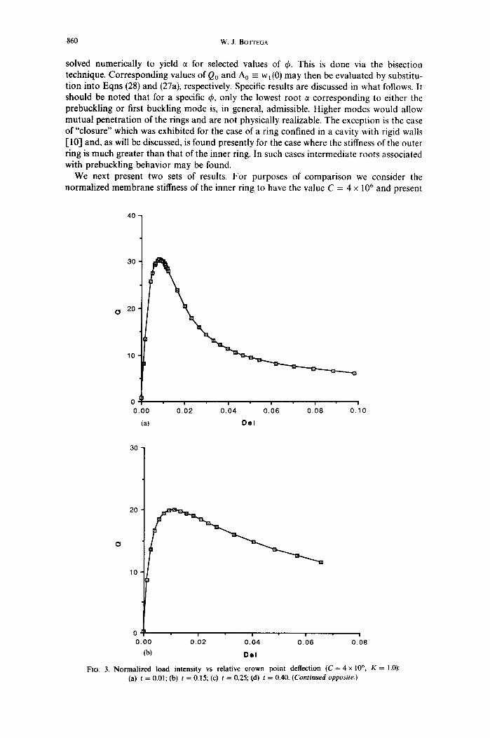
solved numerically to yield ~ for selected values of ~. This is done via the bisection technique. Corresponding values of Qo and A0 = wl (0) may then be evaluated by substitu- tion into Eqns (28) and (27a), respectively. Specific results are discussed in what follows. It should be noted that for a specific ~b, only the lowest root 7 corresponding to either the prebuckling or first buckling mode is, in general, admissible. Higher modes would allow mutual penetration of the rings and are not physically realizable. The exception is the case of"closure" which was exhibited for the case of a ring confined in a cavity with rigid walls [10-1 and, as will be discussed, is found presently for the case where the stiffness of the outer ring is much greater than that of the inner ring. In such cases intermediate roots associated with prebuckling behavior may be found.
We next present two sets of results. For purposes of comparison we consider the normalized membrane stiffness of the inner ring to have the value C = 4 × 10⁶ and present
40
30
O 20
10
0 0 . 0 0
(a)
u u u i u
0 . 0 2 0 . 0 4 0 . 0 6 0 . 0 8 0 , 1 0
O e l
30
20
O
10
m i u |
0 . 0 0 0 . 0 2 0 . 0 4 0 . 0 6 0 . 0 8
(b) Dol
FIG. 3. No rma l i zed load intensi ty vs relat ive c rown po in t def lect ion (C = 4 x ]06, K = 1.0): (a) t = 0.01; (b) t = 0.15; (c) t = 0.25; (d) t = 0.40. (Continued opposite.)

Separation of concentric elastic rings 861
12
10
8
0 6
4
2
0
O
0.00 0.01 0.02 0.03 0.04 0.05 0.06
(c) Del
5
3
2
1
0 I I I I l
0.00 0.02 0.04 0.06 0.08 0.10
(d) De l
FIG. 3. (Continued.)
results for a modulus ratio of K = 1.0 and varying thickness ratio t (Figs 2-4), and results for t = 1.0 and varying K (Figs 5 and 6). We note that the response of the system for the case where t = 0.01 is indistinguishable from the corresponding results for a ring with the same C constrained by a rigid wall [10].
Results corresponding to concentric rings possessing the same material properties (K = 1.0) are displayed in Fig. 2a-d for the specific thickness ratios t = 0.01, 0.15, 0.25 and 0.4, respectively. Both load vs boundary angle, ~b, and load vs crown point deflection, Ao, are shown for each case. A dominant characteristic seen in each case is the relative maximum indicating the onset of "snap-through" buckling. The variation of the critical buckling load Q0 = Qc, as a function of the thickness ratio, t, is displayed in Fig. 4.
An interesting characteristic exhibited for all cases is the existence of a minimum value of the boundary angle ~bmi,, below which no roots are found, and the property that

4 0
3 0
~, 20 O
10
! l I I
0.0 0.2 0.4 0.6 0.8
8 6 2 W , J. BOTTEGA
1.0 1.2
FIG. 4. Normalized buckling load vs thickness ratio ( C = 4 x 10⁶, K = 1.0).
~b -o 4o # 0 as Qo --* 0 ÷. We note that ~bo # ~min for the first case t = 0.01. This is consistent with the behavior exhibited by rings confined by rigid surfaces [5, 6, 10, 11], and also for the case of "stiff" compliant surfaces [12]. It may be observed that ~bo ~ 0.17 for each case shown in Fig. 2. This seemingly "universal" result may be explained as a consequence of the type of loading considered, rather than as an intrinsic property of the system. For the type of loading considered, it was seen that the "composite ring", formed by the segments of the two rings in contact, is essentially unloaded. Thus, while the inner ring is in compression and the outer ring in tension, the ring segments on ~b ~< 0 ~< n possess virtually no radial distortion. Hence, the radial deformation consists essentially of a rigid body motion resulting from the bending of the two rings in the lift zone. To this end, the rings thus behave as if constrained by a "rigid" but moveable surface in the contact zone. The initial contact angle ~bo should
0
40
30
20
10
0 I ! ! I
0.1 0,2 03. 0.4 0.5 (a) P h i
FiG. 5, Normalized load intensity vs.lift zone/contact zone boundary angle ( C = 4 x 10⁶, t = 1.0): (a) K = 1 0 - 6 ; (b) K = 10 - 3 ; (c) K = 0 .01; (d) K = 0 .10. (Continued opposite.)

Q
~
Q
0 f~
?
0 o
-rl
o
~ ~°
~
0 0 b,
0
Q !
0 o o
m
0 0
o |
Q |
0 ! 0 I

864 W . J . BOTTEGA
thus correspond to that for the case of a ring confined by a rigid wall. Comparison with the results of Refs [10] and [12] indeed show this to be the case. The explanation of the nonvanishing of 4o therefore parallels that presented in Ref. [ 10]. Therefore, as the rings are first loaded they primarily deform circumferentially. That is, the inner ring shrinks and the outer ring expands upon initial application of load. As loading progresses, however, the two rings bend away from one another with the crown point deflection increasing until Q0 = Q~r at which point snap-through of the system takes place and ~b and Ao increase to relatively large values. Closer examination of Figs 2-4 reveals the differences in behavior associated with varying the thickness ratio t. As mentioned earlier, the behavior of the system approaches that of a single ring confined by a rigid wall as t - , 0. This is certainly what one would expect since in this case the relative stiffness of the outer ring -* ~ . This may be seen upon examination of Fig. 4. Further, comparison of Figs 2a and 3a with the corresponding figures in Refs [10] and [12] shows virtually no difference in behavior. We also note that for
30
0 20
10
30
20
0
4 0 -
0 I | I I I
0.00 0 .02 0 .04 0 .06 0 .08 0.10
(a) D e l
0.00 0 .02 0 .04 0 .06 0.08 0.10
(b) D e l
FIG. 6. Normalized load intensity vs relative crown point deflection (C = 4 x 10⁶, t = 1.0): (a) K = 10-6; (b) K = 10-3; (c) K = 0.01; (d) K = 0.10. (Continued opposite.)

Separation of concentric elastic rings 865
2 0 -
O 1 0
! I
0 10 20
(c) Del x 10-2
3
0 2
0 |
(d) Del x 10-2
FIG. 6. (Continued.)
this case, and for other cases where t is small (not shown), the prebuckling behavior of the system differs qualitatively from that for larger t. This is manifested in the initial closing of the lift zone (~b decreasing) with increasing Qo as bending first comes into play. At some point, ~b achieves (~min and then ~b begins to increase as Qo increases with the two rings now bending away from one another, until Qo = Q=r and snap-through occurs. The closing and subsequent opening behavior is very slight and cannot be seen within the resolution of Fig. 2a, and so appears as a vertical line at ~b ~. 0.17.
As t increases, we observe in Figs 2 and 3 that the curves become smoother and the buckling load lowers indicating that when snap-through occurs, the instability is not as severe and the corresponding deflections and boundary angles do not evolve as drastically as t gets larger. This can be attributed to the fact that not as much strain energy is stored before the onset of snap-through as for lower t, and hence, not as much energy is released

866 W.J. BOTTEGA
upon buckling. In this sense the behavior resembles that of a ring confined by an elastic foundation (elastic walls) [12], although for that case, the limiting angle ~b o varied with the stiffness of the cavity wall as well.
Finally, it may be observed from Fig. 4 that the buckling load is most sensitive to the relative thicknesses of the rings in the approximate range 0.I ~< t ~< 0.3. Results for t > 1 indicate that buckling occurs at lower and lower loads as the outer ring becomes thinner and thinner as compared with the inner ring.
Figures 5 and 6 show parallel results for the case where t = 1.0 and K is varied. The corresponding discussion follows that for the previous case.
5. C O N C L U D I N G R E M A R K S
The problem of concentric elastic rings was considered for the case of self-equilibrating radially directed point loads. A closed-form analytical solution has been obtained and specific numerical results revealing characteristic behavior of the system have been pres- ented. Snap-through buckling was exhibited for all cases considered; the buckling load was seen to increase and the corresponding instability become more significant as the ratio of the stiffness of the outer ring to that of the inner ring increased. The limiting case approached that of a ring confined by a rigid surface and systems approaching this case were seen to exhibit qualitatively similar behavior, including initial shrink/expansion of the rings, closure in some cases followed by opening and then buckling. A characteristic boundary angle arising in all such cases was noted to be a consequence of the type of loading considered.
R E F E R E N C E S
1. P. T. Hsu, J. ELKON and T. H. H. PLAN, Note on the instability of circular rings confined to a rigid boundary. ASME J. Appl. Mech. 31, 559-562 (1964).
2. S. J. McMINN and H. C. CHAN, The stability of a uniformly compressed ring surrounded by a rigid circular surface. Int. J. Mech. Sci. 8, 433-442 0966).
3. L. L. BUCC1ARELLI, JR and T. H. H. PLAN, Effect of initial imperfections on the instability of a ring confined to an imperfect rigid boundary. ASME J. Appl. Mech. 34, 979-984 (1967).
4. R. CHICUREL, Shrink buckling of thin circular rings. ASME J. Appl. Mech. 35, 608-610 (1968). 5. G. HERRMANN and E. A. ZAGUSTIN, Stability of an elastic ring in a rigid cavity. ASME J. Appl. Mech. 34,
263-270 (1967). 6. R. D. McGH1E and D. O. BRUSH, Deformation of an inertia-loaded thin ring in a rigid cavity with initial
clearance. Int. J. Solids Structures 7, 1539-1553 (1971). 7. L. EL-BAYOUMY, Buckling of a circular elastic ring confined to a uniformly contracting boundary. ASME J.
Appl. Mech. 39, 758-766 (1972). 8. T. J. LARDNER, On the nonbuckling of a circular ring under a "wrapping" loading. ASME J. Appl. Mech. 47,
973 974 (1980). 9. S. KYRIAKIDES and S. K. YOUN, On the collapse ofcircular confined rings under external pressure. Int. J. Solids
Structures 20, 699 713 0984). 10. W. J. BOTTEGA, On the constrained elastic ring. J. Engng Math. 22, 43 51 (1988). 11. W. J. BOTTEGA, On the behavior of an elastic ring within a contracting cavity. Int. J. Mech. Sci. 31,349-357
(1989). 12. W. J. BOTTEGA, The effect of wall compliance on the behavior of a confined elastic ring. ASME J. Appl. Mech.
56, 712-715 (1989). 13. F.-S. Ll and S. KYR1AKIDES, On the response and stability of two concentric, contracting rings under external
pressure. Int. J. Solids Structures 27, 1-14 (1991).