
Metric dimensions of toroidal sealing rings ('O'
34
BRITISH STANDARD Specification for Metric dimensions of toroidal sealing rings ('O'-rings) and their housings BS 4518:1982 +A2:2014 ICS 21.140; 21.180
-
Upload
khangminh22 -
Category
Documents
-
view
3 -
download
0
Transcript of Metric dimensions of toroidal sealing rings ('O'

BRITISH STANDARD BS 4518:1982
Specification for
Metric dimensions of toroidal sealing rings ('O'-rings) and their housings
UDC 621-762.44
Confirmed 20
BS 4518:1982 +A2:2014
ICS 21.140; 21.180

BS 4518:1982
This British Standard, having been prepared under the direction of the Mechanical Engineering Standards Committee, was published under the authority of the board of BSI and comes into effect on30 April 1982
© BSI 08-1999
First published November 1969First revision July 1974Second revision April 1982
The following BSI references relate to the work on this standard:Committee reference MEE/109Draft for comment 81/73664 DC
ISBN 0 580 12648 X
Cooperating organizations
The Mechanical Engineering Standards Committee, under whose direction this British Standard was prepared, consists of representatives from the following:
Associated Offices Technical Committee Department of TransportAssociation of Consulting Engineers Electricity Supply Industry in England and Association of Hydraulic Equipment Wales
Manufacturers* Energy Industries CouncilAssociation of Mining Electrical and Engineering Equipment Users’ Association*
Mechanical Engineers Federation of Manufacturers of ConstructionBritish Compressed Air Society* Equipment and CranesBritish Electrical and Allied Manufacturers’ Health and Safety Executive
Association (BEAMA) Institution of Gas EngineersBritish Gas Corporation Institution of Mechanical EngineersBritish Gear Manufacturers’ Association Institution of Plant EngineersBritish Internal Combustion Engine Institution of Production Engineers
Manufacturers’ Association Lloyd’s Register of ShippingBritish Pump Manufacturers’ Association London Transport ExecutiveBritish Steel Corporation Machine Tool Industry Research AssociationBritish Steel Industry* Ministry of Defence*Chartered Institution of Building Services National Coal Board*Crown Agents for Oversea Governments and Oil Companies Materials Association
Administrations Process Plant AssociationDepartment of Industry, Mechanical Society of Motor Manufacturers and Traders
Engineering Limited*Department of Industry, National Engineering Telecommunication Engineering and
Laboratory Manufacturing Association (TEMA)Department of the Environment (PSA) Water-tube Boilermakers’ AssociationDepartment of Trade (Marine Division)
The organizations marked with an asterisk in the above list, together with the following, were directly represented on the Technical Committee entrusted with the preparation of this British Standard:
British Hydromechanics Research Association Society of British Aerospace CompaniesBritish Rubber Manufacturers’ Association Limited Hydraulic Press Manufacturers’ Association
Amendments issued since publication
Amd. No. Date of issue Comments
4625 July 1984 Indicated by a sideline in the margin
BS 4518:1982+A2:2014
ISBN 978 0 580 82813 3
Amendments/corrigenda issued since publication
Amd. No. Date Comments
4625 July 1984
A2 September 2014 See Foreword
This British Standard, having been prepared under the direction of the Mechanical Engineering Standards Committee, was published under the authority of the board of BSI and comes into effect on 30 April 1982
© The British Standards Institution 2014 Published by BSI Standards Limited 2014
First published November 1969 First revision July 1974 Second revision April 1982
The following BSI references relate to the work on this standard: Committee reference MEE/109 Drafts for comment 81/73664 DC, 14/30295993 DC
BS 4518:1982
© BSI 08-1999 i
Contents
PageCooperating organizations Inside front coverForeword ii1 Scope 12 References 13 “O”-rings 14 Housing grooves 1Appendix A “O”-ring selection charts 21Appendix B Obsolete series of “O”-rings 27Figure 1 — Toroidal sealing ring (“O”-ring) 2Figure 2 — Groove for diametral sealing 10Figure 3 — Groove for static face sealing 12Figure 4 — Triangular housing profile for static sealing 20Table 1 — Dimensions of “O”-rings and related nominal housing diameters for diametral sealing 3Table 2 — Groove dimensions for static diametral sealing 11Table 3 — Groove dimensions for dynamic diametral sealing in hydraulic applications 11Table 4 — Groove dimensions for dynamic diametral sealing in pneumatic applications 11Table 5 — Groove dimensions for static face sealing 13Table 6 — Dimensions of triangular housing for static sealing 20Table 7 — “O”-ring reference numbers for nominal cylinder diameters 21Table 8 — “O”-ring reference numbers for nominal shaft diameters 24Table B.1 — Dimensions of 4.1 mm section diameter “O”-rings and related nominal housing diameters for diametral sealing 27Table B.2 — Groove dimensions for static diametral sealing 28Table B.3 — Groove dimensions for dynamic diametral sealing in hydraulic applications 29Table B.4 — Groove dimensions for dynamic diametral sealing in pneumatic applications 29Table B.5 — Groove dimensions for static face sealing 29Table B.6 — Dimensions of triangular housing for static sealing 30Publications referred to Inside back cover
BS 4518:1982+A2:2014
i© The British Standards Institution 2014
1824
91117
10
10
1012171821
2425
26
26262728

BS 4518:1982
ii © BSI 08-1999
Foreword
This British Standard has been prepared under the direction of the Mechanical Engineering Standards Committee. It revises and supersedes the 1974 edition which is now withdrawn.The first edition of the standard, published in 1969, introduced a new range of metric sizes for elastomeric toroidal sealing rings which were based upon European practices. In order to permit the introduction of additional sizes, a reference numbering system, based upon the “O”-ring internal diameter and section diameter, was adopted.The first revision of the standard, published in 1974, introduced a further 4.1 mm diameter of “O”-ring section. The opportunity was also taken to improve the presentation of the information provided.In this second revision, additional sizes have been introduced to cater for the preferred range of cylinder bores and piston rod diameters specified in BS 5755 (ISO 3320). Groove dimensions for pneumatic applications have also been added. In addition, two charts have been included in Appendix A to aid selection of appropriate seals for given applications.In view of the advanced stage of ISO discussions relating to the standardization of limits for surface imperfections of “O”-rings, the small amount of detail that was contained in the previous edition of this standard has been omitted. A British Standard to reflect these ISO deliberations is in the course of preparation; reference is made in this specification to that standard.Because of the lack of demand for the 4.1 mm section rings which were introduced in the 1974 edition, requirements for these rings are not included in this revision. However, details of the rings are given in Appendix B for information if required for replacement purposes.It is stressed that the dimensions specified in this standard, although providing the necessary basis for standardization in the manufacture and application of “O”-rings, should not be regarded as providing all the information required for design purposes. Attention is drawn to the desirability of consultation between users and manufacturers of “O”-rings, when a particular application of this type of seal is being considered.It is recognized that inch series “O”-rings will continue to be required for replacement purposes. Requirements for such “O”-rings are specified in BS 1806.A British Standard does not purport to include all the necessary provisions of a contract. Users of British Standards are responsible for their correct application.
Compliance with a British Standard does not of itself confer immunity from legal obligations.
Summary of pagesThis document comprises a front cover, an inside front cover, pages i and ii, pages 1 to 30, an inside back cover and a back cover.This standard has been updated (see copyright date) and may have had amendments incorporated. This will be indicated in the amendment table on the inside front cover.
BS 4518:1982+A2:2014
ii © The British Standards Institution 2014
Foreword
This British Standard is published by BSI Standards Limited, under licence from the British Standards Institution, and came into effect on 30 April 1982.
This British Standard has been prepared under the direction of the Mechanical Engineering Standards Committee. It revises and supersedes the 1974 edition which is now withdrawn.
BS 4518:1982+A2:2014 supersedes BS 4518:1982, incorporating Amendment No. 1:1984, which is withdrawn.
Text introduced or altered by Amendment No. 2 is indicated in the text by tags . Minor editorial changes are not tagged. Previous amendments are not indicated.
Amendment No. 2 introduces the following principal changes:
a) Standards references have been updated.
b) Some additional preferred sizes in accordance with BS ISO 3320 have been cross-referred to in Table 1, Table 7, Table 8 and Table B.1.
The first edition of the standard, published in 1969, introduced a new range of metric sizes for elastomeric toroidal sealing rings which were based upon European practices. In order to permit the introduction of additional sizes, a reference numbering system, based upon the “O”-ring internal diameter and section diameter, was adopted.
The first revision of the standard, published in 1974, introduced a further 4.1 mm diameter of “O”-ring section. The opportunity was also taken to improve the presentation of the information provided.
In this second revision, additional sizes have been introduced to cater for the preferred range of cylinder bores and piston rod diameters specified in BS ISO 3320. Groove dimensions for pneumatic applications have also been added. In addition, two charts have been included in Appendix A to aid selection of appropriate seals for given applications.
Previous editions of this standard contained information on the limits for surface imperfections of “O”-rings. These are now covered by BS ISO 3601-3.
Because of the lack of demand for the 4.1 mm section rings which were introduced in the 1974 edition, requirements for these rings are not included in this revision. However, details of the rings are given in Appendix B for information if required for replacement purposes.
It is stressed that the dimensions specified in this standard, although providing the necessary basis for standardization in the manufacture and application of “O”-rings, should not be regarded as providing all the information required for design purposes. Attention is drawn to the desirability of consultation between users and manufacturers of “O”-rings, when a particular application of this type of seal is being considered.
It is recognized that inch series “O”-rings will continue to be required. Requirements for such “O”-rings are specified in BS ISO 3601-1 and BS ISO 3601-2.
This publication does not purport to include all the necessary provisions of a contract. Users are responsible for its correct application.
Compliance with a British Standard cannot confer immunity from legal obligations.
28,

BS 4518:1982
© BSI 08-1999 1
1 ScopeThis British Standard specifies the dimensions of elastomeric “O”-rings which are toroidal in shape and which are used for sealing components against ingress or egress of fluids under dynamic and static conditions.The standard also specifies the shape and dimensions of five types of associated housing grooves for the rings when used at pressures not normally exceeding 100 bar1).NOTE At pressures exceeding 100 bar, or when the diametral clearances of the grooves are in excess of those specified in this standard, it is recommended that these “O”-rings should be used in conjunction with anti-extrusion back-up rings. Spiral anti-extrusion back-up rings and their housings, the dimensions of which are specified in BS 5106, are suitable for pressures up to approximately 200 bar.
Two charts are provided in Appendix A to aid the selection of “O”-rings.
2 ReferencesThe titles of the publications referred to in this standard are listed on the inside back cover.
3 “O”-rings3.1 Dimensions. The dimensions and the tolerances of the “O”-rings shall be in accordance with Table 1.3.2 Surface imperfections. The acceptable limits for surface imperfections shall be such that they do not affect the sealing properties of the sealing ring.NOTE BS 6442 specifies acceptable limits of defined and assessed imperfections on elastomeric toroidal sealing rings.
3.3 Material. “O”-rings shall be manufactured from elastomeric materials that are compatible with the fluid contained by the seal.NOTE “O”-rings are normally supplied in nitrile rubber, but may also be produced in other elastomers, e.g. silicone, fluorocarbon.
3.4 Reference number. The “O”-rings shall be identified by a reference number consisting of the ring’s inside diameter followed by its section diameter, with the decimal points omitted.
4 Housing grooves4.1 General. The profile, dimensions and tolerances of the grooves shall be as specified in Table 1 and the following, according to type of sealing application:
a) static diametral sealing, hydraulic and pneumatic, Figure 2 and Table 2;b) static face sealing, hydraulic and pneumatic, Figure 3 and Table 5;c) static triangular housing sealing, hydraulic and pneumatic, Figure 4 and Table 6;d) dynamic diametral sealing, hydraulic only, Figure 2 and Table 3;e) dynamic diametral sealing, pneumatic only, Figure 2 and Table 4.
4.2 Tolerance of nominal housing diameter. The tolerance associated with diameter d1 or D12)
(Table 1) shall be chosen with respect to the tolerance specified for radial depth F (Table 2, Table 3 and Table 4) and an achievable tolerance for groove diameter d3 or D3, in accordance with Figure 2.4.3 Extrusion gap. To ensure that an acceptable extrusion gap is maintained the tolerance of the cylinder or shaft mating part diameter, d2 or D2, shall be selected with respect to the tolerance of the nominal housing diameter, d1 or D1, chosen in accordance with 4.2, and the maximum total diametral clearance G (Table 2, Table 3, Table 4 and Table 6), in accordance with Figure 2 and Figure 4.4.4 Lead-in chamfer. To facilitate assembly and to prevent damage to “O”-rings, components over which the “O”-ring passes during fitting shall incorporate an adequate smooth lead-in chamfer. All associated corners shall be radiused.Details are shown in Figure 2 and dimensions in Table 2, Table 3 or Table 4.
1) 1 bar = 102 kPa.2) BS 5242-1 specifies tolerances and classes of surface texture for the inside diameter of tubular steel cylinder barrels.
BS 4518:1982+A2:2014
1© The British Standards Institution 2014
NOTE BS ISO 3601-3 specifies acceptable limits of defined and assessed imperfections on elastomeric toroidal sealing rings.
3.1 Dimensions. The dimensions and the tolerances of the “O”-rings shall be in accordance with Table 1 (see Figure 1).
2) ISO 4394-1 specifies tolerances and classes of surface texture for the inside diameter of tubular steel cylinder barrels.

BS 4518:1982
2 © BSI 08-1999
4.5 Surface texture. The surface texture of the housing groove and associated surfaces3) shall not exceed the values given below and shown in Figure 2, Figure 3 and Figure 4.
3) Surface texture in accordance with BS 1134-1.
Dynamic sealing surfaces, 0.4 4m Ra3)
Static sealing surfaces, 0.8 4m Ra3)
Non-sealing surfaces, 1.6 4m Ra3)
Figure 1 — Toroidal sealing ring (“O”-ring)
BS 4518:1982+A2:2014
2 © The British Standards Institution 2014
3) Surface texture in accordance with BS 1134.
NOTE Further information on recommendations for “O”-ring housing surface finishes can be found in BS ISO 3601-2.

BS 4518:1982
© BSI 08-1999 3
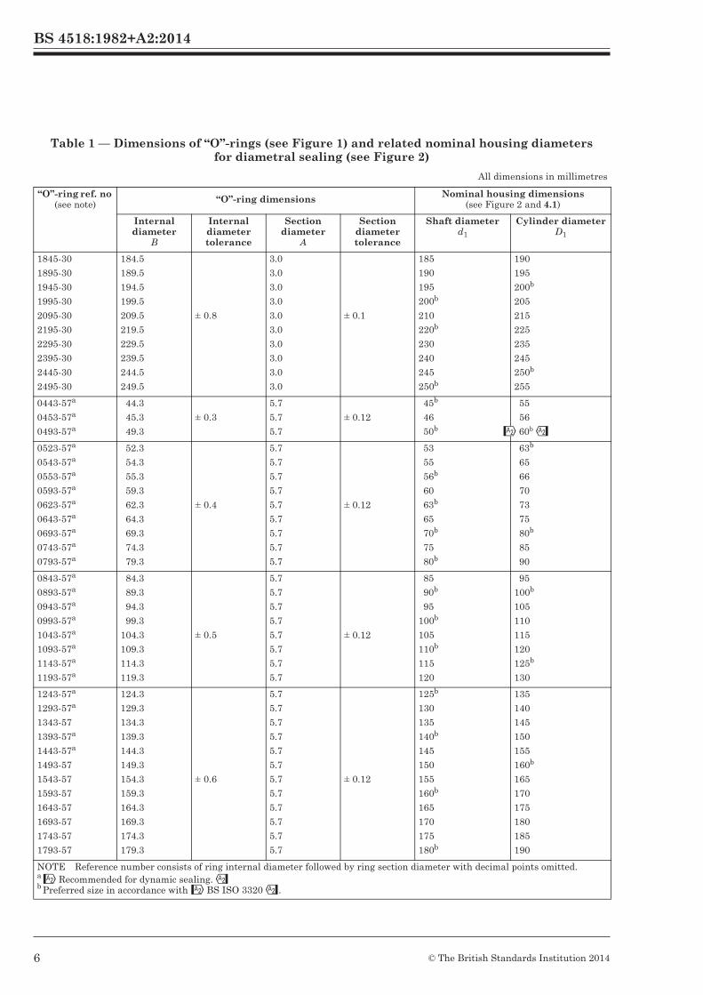
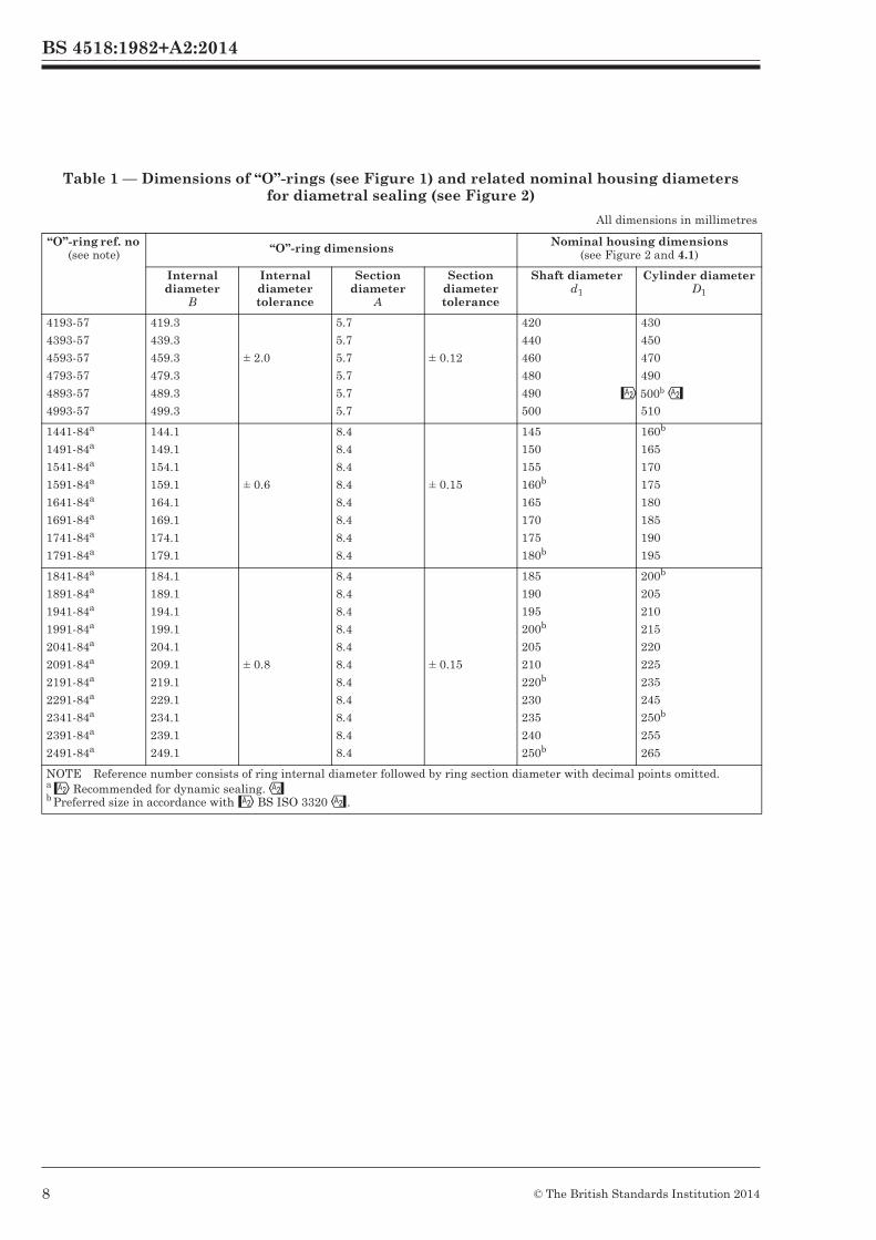
Table 1 — Dimensions of “O”-rings (see Figure 1) and related nominal housing diameters for diametral sealing (see Figure 2)
All dimensions in millimetres
“O”-ring ref. no (see note) “O”-ring dimensions Nominal housing dimensions
(see Figure 2 and 4.1)
Internal diameter
B
Internal diameter tolerance
Section diameter
A
Section diameter tolerance
Shaft diameterd1
Cylinder diameterD1
0031-16
0041-16
0051-16
0061-16
0071-16
0081-16
0091-16
3.1
4.1
5.1
6.1
7.1
8.1
9.1
± 0.15
1.6
1.6
1.6
1.6
1.6
1.6
1.6
± 0.08
3.5
4.5
5.5
6.5
7.5
8.5
9.5
6
7
8b
9
10b
11
12b
0101-16
0111-16
0121-16
0131-16
0141-16
0151-16
0161-16
0171-16
10.1
11.1
12.1
13.1
14.1
15.1
16.1
17.1
± 0.2
1.6
1.6
1.6
1.6
1.6
1.6
1.6
1.6
± 0.08
10.5
11.5
12.5
13.5
14.5
15.5
16.5
17.5
13
14
15
16b
17
18
19
20b
0181-16
0191-16
0221-16
0251-16
0271-16
0291-16
18.1
19.1
22.1
25.1
27.1
29.1
± 0.25
1.6
1.6
1.6
1.6
1.6
1.6
± 0.08
18.5
19.5
22.5
25.5
27.5
29.5
21
22
25b
28
30
32b
0321-16
0351-16
0371-16
32.1
35.1
37.1
± 0.3
1.6
1.6
1.6
± 0.08
32.5
35.5
37.5
35
38
40b
0036-24a
0046-24a
0056-24a
0066-24a
0076-24a
0086-24a
0096-24a
3.6
4.6
5.6
6.6
7.6
8.6
9.6
± 0.15
2.4
2.4
2.4
2.4
2.4
2.4
2.4
± 0.08
4b
5b
6b
7
8b
9
10b
8b
9
10b
11
12b
13
14
0106-24a
0116-24a
0126-24a
0136-24a
0146-24a
0156-24a
0166-24a
0176-24a
10.6
11.6
12.6
13.6
14.6
15.6
16.6
17.6
± 0.2
2.4
2.4
2.4
2.4
2.4
2.4
2.4
2.4
± 0.08
11
12b
13
14b
15
16b
17
18b
15
16b
17
18
19
20b
21
22
0186-24
0196-24
0206-24
0216-24
0246-24
0276-24
0296-24
18.6
19.6
20.6
21.6
24.6
27.6
29.6
± 0.25
2.4
2.4
2.4
2.4
2.4
2.4
2.4
± 0.08
19
20b
21
22b
25b
28b
30
23
24
25b
26
29
32b
34
NOTE Reference number consists of ring internal diameter followed by ring section diameter with decimal points omitted.a Only “O”-rings marked with an asterisk are recommended for dynamic sealing.b Preferred size in accordance with BS 5755.
BS 4518:1982+A2:2014
3© The British Standards Institution 2014
Recommended for dynamic sealing.Preferred size in accordance with BS ISO 3320.

BS 4518:1982
4 © BSI 08-1999
Table 1 — Dimensions of “O”-rings (see Figure 1) and related nominal housing diameters for diametral sealing (see Figure 2)
All dimensions in millimetres
“O”-ring ref. no (see note) “O”-ring dimensions Nominal housing dimensions
(see Figure 2 and 4.1)
Internal diameter
B
Internal diameter tolerance
Section diameter
A
Section diameter tolerance
Shaft diameterd1
Cylinder diameterD1
0316-24
0346-24
0356-24
0376-24
0396-24
0416-24
0446-24
0456-24
0476-24
0496-24
31.6
34.6
35.6
37.6
39.6
41.6
44.6
45.6
47.6
49.6
± 0.3
2.4
2.4
2.4
2.4
2.4
2.4
2.4
2.4
2.4
2.4
± 0.08
32b
35
36b
38
40b
42
45b
46
48
50b
36
39
40b
42
44
46
49
50b
52
54
0516-24
0546-24
0556-24
0576-24
0586-24
0596-24
0616-24
0626-24
0646-24
0676-24
0696-24
51.6
54.6
55.6
57.6
58.6
59.6
61.6
62.6
64.6
67.6
69.6
± 0.4
2.4
2.4
2.4
2.4
2.4
2.4
2.4
2.4
2.4
2.4
2.4
± 0.08
52
55
56b
58
59
60
62
63b
65
68
70b
56
59
60
62
63b
64
66
67
69
72
74
0195-30a
0215-30a
0225-30a
0245-30a
0255-30a
0265-30a
0275-30a
0295-30a
19.521.5
22.5
24.5
25.5
26.5
27.5
29.5
± 0.25
3.03.0
3.0
3.0
3.0
3.0
3.0
3.0
± 0.1
20b
22b
23
25b
26
27
28b
30
25b
27
28
30
31
32b
33
35
0315-30a
0325-30a
0345-30a
0355-30a
0365-30a
0375-30a
0395-30a
0415-30a
0425-30a
0445-30a
0495-30
31.5
32.5
34.5
35.5
36.5
37.5
39.5
41.5
42.5
44.5
49.5
± 0.3
3.0
3.0
3.0
3.0
3.0
3.0
3.0
3.0
3.0
3.0
3.0
± 0.1
32b
33
35
36b
37
38
40b
42
43
45b
50b
37
38
40b
41
42
43
45
47
48
50b
55
NOTE Reference number consists of ring internal diameter followed by ring section diameter with decimal points omitted.a Only “O”-rings marked with an asterisk are recommended for dynamic sealing.b Preferred size in accordance with BS 5755.
BS 4518:1982+A2:2014
4 © The British Standards Institution 2014
Recommended for dynamic sealing.Preferred size in accordance with BS ISO 3320.
60b

BS 4518:1982
6 © BSI 08-1999
Table 1 — Dimensions of “O”-rings (see Figure 1) and related nominal housing diameters for diametral sealing (see Figure 2)
All dimensions in millimetres
“O”-ring ref. no (see note) “O”-ring dimensions Nominal housing dimensions
(see Figure 2 and 4.1)
Internal diameter
B
Internal diameter tolerance
Section diameter
A
Section diameter tolerance
Shaft diameterd1
Cylinder diameterD1
0545-300555-30
0575-30
0595-30
0625-30
0645-30
0695-30
0745-30
0795-30
54.555.5
57.5
59.5
62.5
64.5
69.5
74.5
79.5
± 0.4
3.03.0
3.0
3.0
3.0
3.0
3.0
3.0
3.0
± 0.1
5556a
58
60
63a
65
70a
75
80a
6061
63a
65
68
70
75
80a
85
0845-300895-30
0945-30
0995-30
1045-30
1095-30
1145-30
1195-30
84.589.5
94.5
99.5
104.5
109.5
114.5
119.5
± 0.5
3.03.0
3.0
3.0
3.0
3.0
3.0
3.0
± 0.1
8590a
95
100a
105
110a
115
120
9095
100a
105
110
115
120
125a
1245-30
1295-30
1345-30
1395-30
1445-30
1495-30
1545-30
1595-30
1645-30
1695-30
1745-30
1795-30
124.5
129.5
134.5
139.5
144.5
149.5
154.5
159.5
164.5
169.5
174.5
179.5
± 0.6
3.0
3.0
3.0
3.0
3.0
3.0
3.0
3.0
3.0
3.0
3.0
3.0
± 0.1
125a
130
135
140a
145
150
155
160a
165
170
175
180a
130
135
140
145
150
155
160a
165
170
175
180
185
NOTE Reference number consists of ring internal diameter followed by ring section diameter with decimal points omitted.a Preferred size in accordance with BS 5755.
BS 4518:1982+A2:2014
5© The British Standards Institution 2014
Recommended for dynamic sealing.Preferred size in accordance with BS ISO 3320.
60bb
b
b
b
b
b
b
b
b
b
b
b
b
b
b
b
b
BS 4518:1982
© BSI 08-1999 7
Table 1 — Dimensions of “O”-rings (see Figure 1) and related nominal housing diameters for diametral sealing (see Figure 2)
All dimensions in millimetres
“O”-ring ref. no (see note) “O”-ring dimensions Nominal housing dimensions
(see Figure 2 and 4.1)
Internal diameter
B
Internal diameter tolerance
Section diameter
A
Section diameter tolerance
Shaft diameterd1
Cylinder diameterD1
1845-30
1895-30
1945-30
1995-30
2095-30
2195-30
2295-30
2395-30
2445-30
2495-30
184.5
189.5
194.5
199.5
209.5
219.5
229.5
239.5
244.5
249.5
± 0.8
3.0
3.0
3.0
3.0
3.0
3.0
3.0
3.0
3.0
3.0
± 0.1
185
190
195
200b
210
220b
230
240
245
250b
190
195
200b
205
215
225
235
245
250b
255
0443-57a
0453-57a
0493-57a
44.3
45.3
49.3
± 0.3
5.7
5.7
5.7
± 0.12
45b
46
50b
55
56
60
0523-57a
0543-57a
0553-57a
0593-57a
0623-57a
0643-57a
0693-57a
0743-57a
0793-57a
52.3
54.3
55.3
59.3
62.3
64.3
69.3
74.3
79.3
± 0.4
5.7
5.7
5.7
5.7
5.7
5.7
5.7
5.7
5.7
± 0.12
53
55
56b
60
63b
65
70b
75
80b
63b
65
66
70
73
75
80b
85
90
0843-57a
0893-57a
0943-57a
0993-57a
1043-57a
1093-57a
1143-57a
1193-57a
84.3
89.3
94.3
99.3
104.3
109.3
114.3
119.3
± 0.5
5.7
5.7
5.7
5.7
5.7
5.7
5.7
5.7
± 0.12
85
90b
95
100b
105
110b
115
120
95
100b
105
110
115
120
125b
130
1243-57a
1293-57a
1343-57
1393-57a
1443-57a
1493-57
1543-57
1593-57
1643-57
1693-57
1743-57
1793-57
124.3
129.3
134.3
139.3
144.3
149.3
154.3
159.3
164.3
169.3
174.3
179.3
± 0.6
5.7
5.7
5.7
5.7
5.7
5.7
5.7
5.7
5.7
5.7
5.7
5.7
± 0.12
125b
130
135
140b
145
150
155
160b
165
170
175
180b
135
140
145
150
155
160b
165
170
175
180
185
190
NOTE Reference number consists of ring internal diameter followed by ring section diameter with decimal points omitted.a Only “O”-rings marked with an asterisk are recommended for dynamic sealing.b Preferred size in accordance with BS 5755.
BS 4518:1982+A2:2014
6 © The British Standards Institution 2014
60b
Recommended for dynamic sealing.Preferred size in accordance with BS ISO 3320.

BS 4518:1982
8 © BSI 08-1999
Table 1 — Dimensions of “O”-rings (see Figure 1) and related nominal housing diameters for diametral sealing (see Figure 2)
Figure 1 — Toroidal sealing ring (“O”-ring)
All dimensions in millimetres
“O”-ring ref. no (see note) “O”-ring dimensions Nominal housing dimensions
(see Figure 2 and 4.1)
Internal diameter
B
Internal diameter tolerance
Section diameter
A
Section diameter tolerance
Shaft diameterd1
Cylinder diameterD1
1843-57
1893-57
1943-57
1993-57
2093-57
2193-57
2293-57
2393-57
2493-57
184.3
189.3
194.3
199.3
209.3
219.3
229.3
239.3
249.3
± 0.8
5.7
5.7
5.7
5.7
5.7
5.7
5.7
5.7
5.7
± 0.12
185
190
195
200b
210
220b
230
240
250b
195
200b
205
210
220
230
240
250b
260
2593-57
2693-57
2793-57
2893-57
2993-57
259.3
269.3
279.3
289.3
299.3
± 1.0
5.7
5.7
5.7
5.7
5.7
± 0.12
260
270
280b
290
300
270
280
290
300
310
3093-57
3193-57
3393-57
3593-57
3793-57
3893-57
3993-57
309.3
319.3
339.3
359.3
379.3
389.3
399.3
± 1.5
5.7
5.7
5.7
5.7
5.7
5.7
5.7
± 0.12
310
320b
340
360b
380
390
400
320b
330
350
370
390
400b
410
NOTE Reference number consists of ring internal diameter followed by ring section diameter with decimal points omitted.a Only “O”-rings marked with an asterisk are recommended for dynamic sealing.b Preferred size in accordance with BS 5755.
BS 4518:1982+A2:2014
7© The British Standards Institution 2014
400b
Recommended for dynamic sealing.Preferred size in accordance with BS ISO 3320.
BS 4518:1982
© BSI 08-1999 9
Table 1 — Dimensions of “O”-rings (see Figure 1) and related nominal housing diameters for diametral sealing (see Figure 2)
All dimensions in millimetres
“O”-ring ref. no (see note) “O”-ring dimensions Nominal housing dimensions
(see Figure 2 and 4.1)
Internal diameter
B
Internal diameter tolerance
Section diameter
A
Section diameter tolerance
Shaft diameterd1
Cylinder diameterD1
4193-57
4393-57
4593-57
4793-57
4893-57
4993-57
419.3
439.3
459.3
479.3
489.3
499.3
± 2.0
5.7
5.7
5.7
5.7
5.7
5.7
± 0.12
420
440
460
480
490
500
430
450
470
490
500
510
1441-84a
1491-84a
1541-84a
1591-84a
1641-84a
1691-84a
1741-84a
1791-84a
144.1
149.1
154.1
159.1
164.1
169.1
174.1
179.1
± 0.6
8.4
8.4
8.4
8.4
8.4
8.4
8.4
8.4
± 0.15
145
150
155
160b
165
170
175
180b
160b
165
170
175
180
185
190
195
1841-84a
1891-84a
1941-84a
1991-84a
2041-84a
2091-84a
2191-84a
2291-84a
2341-84a
2391-84a
2491-84a
184.1
189.1
194.1
199.1
204.1
209.1
219.1
229.1
234.1
239.1
249.1
± 0.8
8.4
8.4
8.4
8.4
8.4
8.4
8.4
8.4
8.4
8.4
8.4
± 0.15
185
190
195
200b
205
210
220b
230
235
240
250b
200b
205
210
215
220
225
235
245
250b
255
265
NOTE Reference number consists of ring internal diameter followed by ring section diameter with decimal points omitted.a Only “O”-rings marked with an asterisk are recommended for dynamic sealing.b Preferred size in accordance with BS 5755.
BS 4518:1982+A2:2014
8 © The British Standards Institution 2014
500b
Recommended for dynamic sealing.Preferred size in accordance with BS ISO 3320.

BS 4518:1982
10 © BSI 08-1999
Figure 2 — Groove for diametral sealing
BS 4518:1982+A2:2014
9© The British Standards Institution 2014

BS 4518:1982
© BSI 08-1999 11
Table 2 — Groove dimensions for static diametral sealing (see Figure 2)
Table 3 — Groove dimensions for dynamic diametral sealing in hydraulic applications (see Figure 2)
Table 4 — Groove dimensions for dynamic diametral sealing in pneumatic applications (see Figure 2)
All dimensions in millimetres
“O”-ring ref. no.
Cross section
diameterA
Radial depthF
Groove width
Total diametral clearanceG (max.)
Lead-in chamfer
C
Max. radiusR
max. min.
0031-16 to 0371-16
0036-24 to 0696-24
0195-30 to 2495-30
0443-57 to 4993-57
1441-84 to 2491-84
1.6
2.4
3.0
5.7
8.4
1.25
1.97
2.50
4.95
7.50
1.18
1.84
2.35
4.70
7.20
2.3
3.1
3.7
6.4
9.0
0.12
0.14
0.15
0.18
0.20
0.6
0.7
0.8
1.2
1.5
0.5
0.5
1.0
1.0
1.0
All dimensions in millimetres
“O”-ring ref. no.
Cross section
diameterA
Radial depthF
Groove width
Total diametral clearance G (max.)
Lead-in chamfer
C
Max. radiusR
max. min.
0036-24 to 0176-24
0195-30 to 0445-30
0443-57 to 1443-57
1441-84 to 2491-84
2.4
3.0
5.7
8.4
2.09
2.65
5.18
7.75
1.97
2.50
4.95
7.50
3.2
4.0
7.5
11.0
0.14
0.15
0.18
0.20
0.6
0.7
1.0
1.2
0.5
1.0
1.0
1.0
All dimensions in millimetres
“O”-ring ref. no.
Cross section
diameterA
Radial depthF
Groove width
Total diametral clearance G (max.)
Lead-in chamfer
C
Max. radiusR
max. min.
0036-24 to 0176-24
0195-30 to 0445-30
0443-57 to 1443-57
1441-84 to 2491-84
2.4
3.0
5.7
8.4
2.20
2.77
5.38
7.96
2.13
2.70
5.22
7.75
3.2
4.0
7.5
11.0
0.14
0.15
0.18
0.20
0.6
0.7
1.0
1.2
0.5
1.0
1.0
1.0
E+0.20
E+0.20
E+0.20
BS 4518:1982+A2:2014
10 © The British Standards Institution 2014

BS 4518:1982
12 © BSI 08-1999
Figure 3 — Groove for static face sealing
BS 4518:1982+A2:2014
11© The British Standards Institution 2014

BS 4518:1982
© BSI 08-1999 13
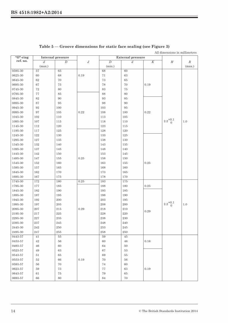
Table 5 — Groove dimensions for static face sealing (see Figure 3)
All dimensions in millimetres
“O”-ring ref. no.
Internal pressure External pressure
d(max.)
D J D(min.)
d K H R(max.)
0031-16
0041-16
0051-16
1.0
2.3
3.3
6.3
7.3
8.3 0.09
7.5
8.5
9.5
3.5
4.5
5.5
0.075
0061-16 4.3 9.3 10.5 6.5
0071-16
0081-16
0091-16
5.8
6.8
7.8
10.3
11.3
12.3
11.5
12.5
13.5
7.5
8.5
9.5
0.09
0101-16
0111-16
0121-16
0131-16
0141-16
8.8
9.8
10.8
11.8
12.8
13.3
14.3
15.3
16.3
17.3
0.11
14.5
15.5
16.5
17.5
18.5
10.5
11.5
12.5
13.5
14.5 0.11
0151-16
0161-16
0171-16
14.0
15
16
18.3
19.3
20.3
19.5
20.5
21.5
15.5
16.5
17.5
0.2
0181-16
0191-16
0221-16
0251-16
17
18
21
24
21.3
22.3
25.3
28.3
0.13 22.5
23.5
26.5
29.5
18.5
19.5
22.5
25.5 0.13
0271-16
0291-16
26
28
30.3
32.3
31.5
33.5
27.5
29.5
0321-16
0351-16
0371-16
31
34
36
35.3
38.3
40.3
0.16 36.5
39.5
41.5
32.5
35.5
37.5
0.16
0036-24
0046-24
0056-24
—
1.0
2.5
8.4
9.4
10.4
0.09
10
11
12
4
5
6
0.075
0066-24
0076-24
0086-24
0096-24
4.0
5.0
6.4
7.4
11.4
12.4
13.4
14.4
13
14
15
16
7
8
9
10
0.09
0106-24
0116-24
0126-24
0136-24
0146-24
0156-24
0166-24
8.4
9.5
10.5
11.5
12.5
13.5
14.5
15.4
16.4
17.4
18.4
19.4
20.4
21.4
0.11
17
18
19
20
21
22
23
11
12
13
14
15
16
17
0.11
0176-24
0186-24
0196-24
0206-24
0216-24
0246-24
15.5
16.5
17.5
18.5
19.5
22.5
22.4
23.4
24.4
25.4
26.4
29.4
0.13
24
25
26
27
28
31
18
19
20
21
22
25
0.13
0.5
0276-24
0296-24
25.5
27.5
32.4
34.4
34
36
28
30
1.2+0.10
1.7+0.10
BS 4518:1982+A2:2014
12 © The British Standards Institution 2014
0.16

BS 4518:1982
14 © BSI 08-1999
Table 5 — Groove dimensions for static face sealing (see Figure 3)
All dimensions in millimetres
“O”-ring ref. no.
Internal pressure External pressure
d(max.)
D J D(min.)
d K H R(max.)
0316-24
0346-24
0356-24
0376-24
0396-24
0416-24
0446-24
0456-24
29.5
32.5
33.5
35.5
37.5
39.5
42.5
43.5
36.4
39.4
40.4
42.4
44.4
46.4
49.4
50.4
0.16
38
41
42
44
46
48
51
52
32
35
36
38
40
42
45
46
0.16
0476-24
0496-24
45.5
47.5
52.4
54.4
54
56
48
50
0516-24
0546-24
0556-24
0576-24
0586-24
0596-24
0616-24
0626-24
0646-24
0676-24
0696-24
49.5
52.5
53.5
55.5
56.5
57.5
59.5
60.5
62.5
65.5
67.5
56.4
59.4
60.4
62.4
63.4
64.4
66.4
67.4
69.4
72.4
74.4
0.19
58
61
62
64
65
66
68
69
71
74
76
52
55
56
58
59
60
62
63
65
68
70
0.19
0195-30
0215-30
0225-30
0245-30
17
19
20
22
25
27
28
30
0.13
28
30
31
33
20
22
23
25
0255-30
0266-30
0275-30
0295-30
23
24
25
27
31
32
33
35
34
35
36
38
26
27
28
30
0.13
0315-30
0325-30
0345-30
0355-30
0365-30
0375-30
0395-30
0415-30
0425-30
0445-30
29
30
32
33
34
35
37
39
40
42
37
38
40
41
42
43
45
47
48
50
0.16
40
41
43
44
45
46
48
50
51
53
32
33
35
36
37
38
40
42
43
45
0.16
1.0
0495-30 47 55 58 50
0545-30
0555-30
0575-30
52
53
55
60
61
63
0.19 63
64
66
55
56
58
0.19
2.2+0.10
BS 4518:1982+A2:2014
13© The British Standards Institution 2014
BS 4518:1982
16 © BSI 08-1999
Table 5 — Groove dimensions for static face sealing (see Figure 3)
All dimensions in millimetres
“O”-ring ref. no.
Internal pressure External pressure
d(max.)
D J D(min.)
d K H R(max.)
0595-30
0625-30
0645-30
0695-30
0745-30
57
60
62
67
72
65
68
70
75
80
0.19
68
71
73
78
83
60
63
65
70
75
0.19
0795-30 77 85 88 80
0845-30
0895-30
0945-30
0995-30
1045-30
1095-30
1145-30
82
87
92
97
102
107
112
90
95
100
105
110
115
120
0.22
93
98
103
108
113
118
123
85
90
95
100
105
110
115
0.22
1.0
1195-30 117 125 128 120
1245-30
1295-30
1345-30
1395-30
1445-30
1495-30
1545-30
1595-30
1645-30
1695-30
122
127
132
137
142
147
152
157
162
167
130
135
140
145
150
155
160
165
170
175
0.25
133
138
143
148
153
158
163
168
173
178
125
130
135
140
145
150
155
160
165
170
0.25
1745-30 172 180 0.25 183 175
0.251795-30 177 185 188 180
1845-30
1895-30
1945-30
1995-30
2095-30
2195-30
2295-30
2395-30
2445-30
2495-30
182
187
192
197
207
217
227
237
242
247
190
195
200
205
215
225
235
245
250
255
0.29
193
198
203
208
218
228
238
248
253
258
185
190
195
200
210
220
230
240
245
250
0.29
1.0
0443-57
0453-57
0493-57
41
42
46
55
56
60
59
60
64
45
46
50
0.16
0523-57
0543-57
0553-57
0593-57
0623-57
0643-57
0693-57
49
51
52
56
59
61
66
63
65
66
70
73
75
80
0.19
67
69
70
74
77
79
84
53
55
56
60
63
65
70
0.19
2.2+0.10
2.2+0.10
BS 4518:1982+A2:2014
14 © The British Standards Institution 2014

BS 4518:1982
© BSI 08-1999 17
Table 5 — Groove dimensions for static face sealing (see Figure 3)
All dimensions in millimetres
“O”-ring ref. no.
Internal pressure External pressure
d(max.)
D J D(min.)
d K H R(max.)
0743-57
0793-57
71
76
85
90
89
94
75
80
0843-57
0893-57
0943-57
0993-57
1043-57
1093-57
81
86
91
96
101
106
95
100
105
110
115
120
0.22
99
104
109
114
119
124
85
90
95
100
105
110
0.22
1143-57
1193-57
111
116
125
130
129
134
115
120
1243-57
1293-57
1343-57
1393-57
1443-57
1493-57
1543-57
1593-57
1643-57
1693-57
121
126
131
136
141
146
151
156
161
166
135
140
145
150
155
160
165
170
175
180
0.25
139
144
149
154
159
164
169
174
179
184
125
130
135
140
145
150
155
160
165
170
0.25
1.0
1743-57
1793-57
171
176
185
190
189
194
175
180
1843-57
1893-57
1943-57
1993-57
2093-57
2193-57
2293-57
2393-57
181
185
190
195
205
215
225
235
195
199
204
209
219
229
239
249
0.29
199
204
209
214
224
234
244
254
185
190
195
200
210
220
230
240
0.29
2493-57 245 259 264 250
2593-57
2693-57
2793-57
2893-57
2993-57
255
265
275
285
295
269
279
289
299
309
0.32
275
285
295
305
315
261
271
281
291
301
0.32
3093-57
3193-57
3393-57
3593-57
3793-57
305
315
335
355
375
319
329
349
369
389
0.36
325
335
355
375
395
311
321
341
361
381
0.36
3893-57
3993-57
385
395
399
4090.40
405
415
391
4010.40
4.4+0.10
BS 4518:1982+A2:2014
15© The British Standards Institution 2014

BS 4518:1982
© BSI 08-1999 19
Table 5 — Groove dimensions for static face sealing (see Figure 3)
All dimensions in millimetres
“O”-ring ref. no.
Internal pressure External pressure
d(max.)
D J D(min.)
d K H R(max.)
4193-57
4393-57
4593-57
4793-57
4893-57
4993-57
415
435
455
475
485
495
429
449
469
489
499
509
0.40
436
456
476
496
506
516
422
442
462
482
492
502
0.40
1441-84
1491-84
1541-84
1591-84
1641-84
1691-84
140
145
150
155
160
165
160
165
170
175
180
185
0.25
165
170
175
180
185
190
145
150
155
160
165
170
0.25
1741-84
1791-84
170
175
190
195
195
200
175
180
1841-84
1891-84
1941-84
1991-84
2041-84
2091-84
2191-84
2291-84
2341-84
180
185
190
195
200
205
215
225
230
200
205
210
215
220
225
235
245
250
0.29
205
210
215
220
225
230
240
250
255
185
190
195
200
205
210
220
230
235
0.29
1.0
2391-84
2491-84
235
245
255
265 0.32
260
270
240
250
4.4+0.10
6.6+0.10
BS 4518:1982+A2:2014
16 © The British Standards Institution 2014

BS 4518:1982
20 © BSI 08-1999
Table 6 — Dimensions of triangular housing for static sealing (see Figure 4)
Figure 4 — Triangular housing profile for static sealing
All dimensions in millimetres
“O”-ring Spigot diameter
d1
Total diametral clearanceG (max.)
ChamferM
Maximum radius on spigot
T
Spigot lengthS (min.)
Ref. no. Cross section diameter
A
0031-16
to
0371-16
1.6 0.12 2.20 0.8 4.0
0036-24
to
0696-24
2.4 0.14 3.30 1.3 5.0
0195-30
to
2495-30
3.0
As in Table 1, column 6 0.15 4.20 2.0 6.0
0443-57
to
4993-57
5.7 0.18 7.80 3.0 10.0
1441-84
to
2491-84
8.4 0.20 11.50 4.0 14.0
+0.120
BS 4518:1982+A2:2014
17© The British Standards Institution 2014

BS 4518:1982
© BSI 08-1999 21
Appendix A “O”-ring selection chartsThe following tables are intended to aid selection of appropriate seals for given applications.Table 7 — “O’-ring reference numbers for nominal cylinder diameters
Nominal cylinder diameter
Section diameter
1.6 mm 2.4 mm 3.0 mm 5.7 mm 8.4 mm
mm
6
7
8b
9
10b
11
12b
13
14
15
16b
17
18
19
20b
21
22
23
24
25b
26
27
28
29
30
31
32b
33
34
35
36
37
38
39
40b
0031-16
0041-16
0051-16
0061-16
0071-16
0081-16
0091-16
0101-16
0111-16
0121-16
0131-16
0141-16
0151-16
0161-16
0171-16
0181-16
0191-16
0221-16
0251-16
0271-16
0291-16
0321-16
0351-16
0371-16
0036-24a
0046-24a
0056-24a
0066-24a
0076-24a
0086-24a
0096-24a
0106-24a
0116-24a
0126-24a
0136-24a
0146-24a
0156-24a
0166-24a
0176-24a
0186-24
0196-24
0206-24
0216-24
0246-24
0276-24
0296-24
0316-24
0346-24
0356-24
0195-30a
0215-30a
0225-30a
0245-30a
0255-30a
0265-30a
0275-30a
0295-30a
0315-30a
0325-30a
0345-30a
41
42
43
44
45
46
47
48
49
50b
0376-24
0396-24
0416-24
0446-24
0456-24
0355-30a
0365-30a
0375-30a
0395-30a
0415-30a
0425-30a
0445-30a
a Recommended for dynamic sealing.b Preferred size in accordance with BS 5755.
BS 4518:1982+A2:2014
18 © The British Standards Institution 2014
Preferred size in accordance with BS ISO 3320.

BS 4518:1982
22 © BSI 08-1999
Table 7 — “O”-ring reference numbers for nominal cylinder diametersNominal cylinder diameter
Section diameter
1.6 mm 2.4 mm 3.0 mm 5.7 mm 8.4 mm
mm
52
54
55
56
59
60
61
62
63b
0476-24
0496-24
0516-24
0546-24
0556-24
0576-24
0586-24
0495-30
0545-30
0555-30
0575-30
0443-57a
0453-57a
0493-57a
0523-57a
64
65
66
67
68
69
70
72
73
74
75
80b
85
90
95
100b
105
110
115
120
125b
130
135
140
145
150
0596-24
0616-24
0626-24
0646-24
0676-24
0696-24
0595-30
0625-30
0645-30
0695-30
0745-30
0795-30
0845-30
0895-30
0945-30
0995-30
1045-30
1095-30
1145-30
1195-30
1245-30
1295-30
1345-30
1395-30
1445-30
0543-57a
0553-57a
0593-57a
0623-57a
0643-57a
0693-57a
0743-57a
0793-57a
0843-57a
0893-57a
0943-57a
0993-57a
1043-57a
1093-57a
1143-57a
1193-57a
1243-57a
1293-57a
1343-57a
1393-57a
155
160b
165
170
175
180
185
190
195
200b
1495-30
1545-30
1595-30
1645-30
1695-30
1745-30
1795-30
1845-30
1895-30
1945-30
1443-57a
1493-57
1543-57
1593-57
1643-57
1693-57
1743-57
1793-57
1843-57
1893-57
1441-84a
1491-84a
1541-84a
1591-84a
1641-84a
1691-84a
1741-84a
1791-84
1841-84a
a Recommended for dynamic sealing.b Preferred size in accordance with BS 5755.
BS 4518:1982+A2:2014
19© The British Standards Institution 2014
Preferred size in accordance with BS ISO 3320.
60b

BS 4518:1982
© BSI 08-1999 23
Table 7 — “O’-ring reference numbers for nominal cylinder diametersNominal cylinder diameter
Section diameter
1.6 mm 2.4 mm 3.0 mm 5.7 mm 8.4 mm
mm
205
210
215
220
225
230
235
240
245
250b
255
260
265
270
280
290
300
310
320b
330
350
370
390
400b
410
430
450
470
490
500
510
1995-30
2095-30
2195-30
2295-30
2395-30
2445-30
2495-30
1943-57
1993-57
2093-57
2193-57
2293-57
2393-57
2493-57
2593-57
2693-57
2793-57
2893-57
2993-57
3093-57
3193-57
3393-57
3593-57
3793-57
3893-57
3993-57
4193-57
4393-57
4593-57
4793-57
4893-57
4993-57
1891-84a
1941-84a
1991-84a
2041-84a
2091-84a
2191-84a
2291-84a
2341-84a
2391-84a
2491-84a
a Recommended for dynamic sealing.b Preferred size in accordance with BS 5755.
BS 4518:1982+A2:2014
20 © The British Standards Institution 2014
Preferred size in accordance with BS ISO 3320.
500b

BS 4518:1982
24 © BSI 08-1999
Table 8 — “O”-ring reference numbers for nominal shaft diametersNominal
shaft diameter
Section diameter
1.6 mm 2.4 mm 3.0 mm 5.7 mm 8.4 mm
mm
3.5
4b
4.5
5b
5.5
6b
6.5
7
7.5
8b
8.5
9
9.5
10b
10.5
11
11.5
12b
12.5
13
13.5
14b
14.5
15
15.5
16b
16.5
17
17.5
18b
18.5
19
19.5
20b
21
22b
22.5
23
25b
25.5
26
27
27.5
28b
29.5
30
0031-16
0041-16
0051-16
0061-16
0071-16
0081-16
0091-16
0101-16
0111-16
0121-16
0131-16
0141-16
0151-16
0161-16
0171-16
0181-16
0191-16
0221-16
0251-16
0271-16
0291-16
0036-24a
0046-24a
0056-24a
0066-24a
0076-24a
0086-24a
0096-24a
0106-24a
0116-24a
0126-24a
0136-24a
0146-24a
0156-24a
0166-24a
0176-24a
0186-24
0196-24
0206-24
0216-24
0226-24
0276-24
0296-24
0195-30a
0215-30a
0225-30a
0245-30a
0255-30a
0265-30a
0275-30a
0295-30a
a Recommended for dynamic sealing.b Preferred size in accordance with BS 5755.
BS 4518:1982+A2:2014
21© The British Standards Institution 2014
Preferred size in accordance with BS ISO 3320.

BS 4518:1982
© BSI 08-1999 25
Table 8 — “O”-ring reference numbers for nominal shaft diametersNominal
shaft diameter
Section diameter
1.6 mm 2.4 mm 3.0 mm 5.7 mm 8.4 mm
mm
32b
32.5
33
35
35.5
36b
37
37.5
38
40b
42
43
45b
46
48
50b
52
0321-16
0351-16
0371-16
0316-24
0346-24
0356-24
0376-24
0396-24
0416-24
0446-24
0456-24
0476-24
0496-24
0516-24
0315-30a
0325-30a
0345-30a
0355-30a
0365-30a
0375-30a
0395-30a
0415-30a
0425-30a
0445-30
0495-30
0443-57a
0453-57a
0493-57a
53
55
56b
58
59
60
62
63b
65
68
70b
75
80b
85
90b
95
100b
105
110b
115
120
0546-24
0556-24
0576-24
0586-24
0596-24
0616-24
0626-24
0646-24
0676-24
0696-24
0545-30
0555-30
0575-30
0595-30
0625-30
0645-30
0695-30
0745-30
0795-30
0845-30
0895-30
0945-30
0995-30
1045-30
1095-30
1145-30
1195-30
0523-57a
0543-57a
0553-57a
0593-57a
0623-57a
0643-57a
0693-57a
0743-57a
0793-57a
0843-57a
0893-57a
0943-57a
0993-57a
1043-57a
1093-57a
1143-57a
1193-57a
a Recommended for dynamic sealing.b Preferred size in accordance with BS 5755.
BS 4518:1982+A2:2014
22 © The British Standards Institution 2014
Preferred size in accordance with BS ISO 3320.

BS 4518:1982
26 © BSI 08-1999
Table 8 — “O”-ring reference numbers for nominal shaft diametersNominal
shaft diameter
Section diameter
1.6 mm 2.4 mm 3.0 mm 5.7 mm 8.4 mm
mm
125b
130
135
140b
145
150
155
160b
165
170
175
180b
185
190
195
200b
205
210
220b
230
235
240
245
250b
260
270
280b
290
300
310
320b
340
360
380
390
400
420
440
460
480
490
500
1245-30
1295-30
1345-30
1395-30
1445-30
1495-30
1545-30
1595-30
1645-30
1695-30
1745-30
1795-30
1845-30
1895-30
1945-30
1995-30
2095-30
2195-30
2295-30
2395-30
2445-30
2495-30
1243-57a
1293-57a
1343-57a
1393-57a
1443-57a
1493-57
1543-57
1593-57
1643-57
1693-57
1743-57
1793-57
1843-57
1893-57
1943-57
1993-57
2093-57
2193-57
2293-57
2393-57
2493-57
2593-57
2693-57
2793-57
2893-57
2993-57
3093-57
3193-57
3393-57
3593-57
3793-57
3893-57
3993-57
4193-57
4393-57
4593-57
4793-57
4893-57
4993-57
1441-84a
1491-84a
1541-84a
1591-84a
1641-84a
1691-84a
1741-84a
1791-84a
1841-84a
1891-84a
1941-84a
1991-84a
2041-84a
2091-84a
2191-84a
2291-84a
2341-84a
2391-84a
2491-84a
a Recommended for dynamic sealing.b Preferred size in accordance with BS 5755.
BS 4518:1982+A2:2014
23© The British Standards Institution 2014
Preferred size in accordance with BS ISO 3320.
400b

BS 4518:1982
© BSI 08-1999 27
Appendix B Obsolete series of “O”-ringSee foreword. The relevant dimensions are recorded for information in the following tables which are numbered to correspond to those in the body of the standard.
Table B.1 — Dimensions of 4.1 mm section diameter “O”-rings (see Figure 1) and related nominal housing diameters for diametral sealing (see Figure 2)
All dimensions in millimetres
“O”-ring ref. no. “O”-ring dimensions Nominal housing dimensions
(see Figure 2 and 4.1)
Internal diameter
B
Internal diameter tolerance
Section diameter
A
Section diameter tolerance
Shaft diameterd1
Cylinder diameterD1
0294-41a
0314-41a
0324-41a
0344-41a
0354-41a
0364-41a
0374-41a
0394-41a
0414-41a
0424-41a
0444-41a
0454-41a
0494-41a
29.4
31.4
32.5
34.4
35.4
36.4
37.4
39.4
41.4
42.4
44.4
45.4
49.4
± 0.3
4.1
4.1
4.1
4.1
4.1
4.1
4.1
4.1
4.1
4.1
4.1
4.1
4.1
± 0.12
30
32b
33
35
36b
37
38
40b
42
43
45b
46
50b
37
39
40b
42
43
44
45
47
49
50b
52
53
57
0524-41a
0544-41a
0554-41a
0594-41a
0624-41a
0644-41a
0694-41a
0724-41a
0744-41a
0794-41a
52.4
54.4
55.4
59.4
62.4
64.4
69.4
72.4
74.4
79.4
± 0.4
4.1
4.1
4.1
4.1
4.1
4.1
4.1
4.1
4.1
4.1
± 0.12
53
55
56b
60
63b
65
70b
73
75
80b
60
62
63b
67
70
72
77
80b
82
87
0844-41a
0894-41a
0924-41a
0944-41a
0994-41a
1044-41
1094-41
1144-41
1174-41
1194-41
84.4
89.4
92.4
94.4
99.4
104.4
109.4
114.4
117.4
119.4
± 0.5
4.1
4.1
4.1
4.1
4.1
4.1
4.1
4.1
4.1
4.1
± 0.12
85
90b
93
95
100b
105
110b
115
118
120
92
97
100b
102
107
112
117
122
125b
127
NOTE Reference number consists of ring internal diameter followed by ring section diameter with decimal points omitted.a Only “O”-rings marked with an asterisk are recommended for dynamic sealing.b Preferred size in accordance with BS 5755.
BS 4518:1982+A2:2014
24 © The British Standards Institution 2014
Recommended for dynamic sealing.Preferred size in accordance with BS ISO 3320.
60b
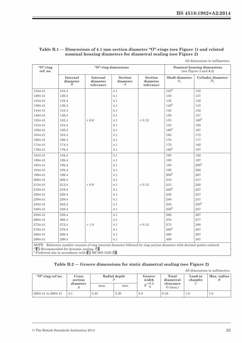
BS 4518:1982
28 © BSI 08-1999
Table B.1 — Dimensions of 4.1 mm section diameter “O”-rings (see Figure 1) and related nominal housing diameters for diametral sealing (see Figure 2)
Table B.2 — Groove dimensions for static diametral sealing (see Figure 2)
All dimensions in millimetres
“O”-ring ref. no.
“O”-ring dimensions Nominal housing dimensions (see Figure 2 and 4.1)
Internal diameter
B
Internal diameter tolerance
Section diameter
A
Section diameter tolerance
Shaft diameterd1
Cylinder diameterD1
1244-41
1294-41
1344-41
1394-41
1444-41
1494-41
1524-41
1544-41
1594-41
1644-41
1694-41
1744-41
1794-41
124.4
129.4
134.4
139.4
144.4
149.4
152.4
154.4
159.4
164.4
169.4
174.4
179.4
± 0.6
4.1
4.1
4.1
4.1
4.1
4.1
4.1
4.1
4.1
4.1
4.1
4.1
4.1
± 0.12
125a
130
135
140a
145
150
153
155
160a
165
170
175
180a
132
137
142
147
152
157
160a
162
167
172
177
182
187
1844-41
1894-41
1924-41
1944-1
1994-41
2094-41
2124-41
2194-41
2294-41
2394-41
2424-41
2494-41
184.4
189.4
192.4
194.4
199.4
209.4
212.4
219.4
229.4
239.4
242.4
249.4
± 0.8
4.1
4.1
4.1
4.1
4.1
4.1
4.1
4.1
4.1
4.1
4.1
4.1
± 0.12
185
190
193
195
200a
210
213
220a
230
240
243
250a
192
197
200a
202
207
217
220
227
237
247
250a
257
2594-41
2694-41
2724-41
2794-41
2894-41
2994-41
259.4
269.4
272.4
279.4
289.4
299.4
± 1.0
4.1
4.1
4.1
4.1
4.1
4.1
± 0.12
260
270
273
280a
290
300
267
277
280
287
297
307
NOTE Reference number consists of ring internal diameter followed by ring section diameter with decimal points omitted.a Preferred size in accordance with BS 5755.
All dimensions in millimetres
“O”-ring ref no. Cross section
diameter A
Radial depthF
Groove width
Total diametral clearanceG (max.)
Lead-in chamfer
C
Max. radiusR
max. min.
0294-41 to 2994-41 4.1 3.45 3.30 5.0 0.16 1.0 1.0
E +0.20
BS 4518:1982+A2:2014
25© The British Standards Institution 2014
Recommended for dynamic sealing.Preferred size in accordance with BS ISO 3320.
b
b
b
b
b
b
b
b
b
b
b
b
41

BS 4518:1982
© BSI 08-1999 29
Table B.3 — Groove dimensions for dynamic diametral sealing in hydraulic applications (see Figure 2)
Table B.4 — Groove dimensions for dynamic diametral sealing in pneumatic applications (see Figure 2)
Table B.5 — Groove dimensions for static face sealing (see Figure 3)
All dimensions in millimetres
“O”-ring ref. no. Cross section
diameter A
Radial depthF
Groove width
Total diametral clearanceG (max.)
Lead-in chamfer
C
Max. radiusR
max. min.
0294-41 to 2944-41 4.1 3.67 3.50 5.5 0.16 0.8 1.0
All dimensions in millimetres
“O”-ring ref. no. Cross section
diameter A
Radial depthF
Groove width
Total diametral clearanceG (max.)
Lead-in chamfer
C
Max. radiusR
max. min.
0294-41 to 2944-41 4.1 3.82 3.73 5.5 0.16 0.8 1.0
All dimensions in millimetres
“O”-ring ref. no.
Internal pressure External pressure
d(max.)
D J D d K H R(max.)
0294-41
0314-41
0324-41
0344-41
0354-41
0364-41
0374-41
0394-41
0414-41
0424-41
26.5
28.5
29.5
31.5
32.5
33.5
34.5
36.5
38.5
39.5
37
39
40
42
43
44
45
47
49
50
0.16
40.5
42.5
43.5
45.5
46.5
47.5
48.5
50.5
52.5
53.5
30
32
33
35
36
37
38
40
42
43
0.16
0444-41
0454-41
0494-41
41.5
42.5
46.5
52
53
57
55.5
56.5
60.5
45
46
50
0524-41
0544-41
0554-41
0594-41
0624-41
0644-41
0694-41
0724-41
49.5
51.5
52.5
56.5
59.5
61.5
66.5
69.5
60
62
63
67
70
72
77
80
0.19
63.5
65.5
66.5
70.5
73.5
75.5
80.5
83.5
53
55
56
60
63
65
70
73
0.19
0744-41
0794-41
71.5
76.5
82
87
85.5
90.5
75
80
0844-41
0894-41
0924-41
0944-41
0994-41
1044-41
1094-41
81.5
86.5
89.5
91.5
96.5
101.5
106.5
92
97
100
102
107
112
117
0.22
95.5
100.5
103.5
105.5
110.5
115.5
120.5
85
90
93
95
100
105
110
0.22
E +0.20
E +0.20
BS 4518:1982+A2:2014
26 © The British Standards Institution 2014

BS 4518:1982
30 © BSI 08-1999
Table B.5 — Groove dimensions for static face sealing (see Figure 3)
Table B.6 — Dimensions of triangular housing for static sealing (see Figure 4)
All dimensions in millimetres
“O”-ring ref. no.
Internal pressure External pressure
d(max.)
D J D d K H R(max.)
1144-41
1174-41
1194-41
111.5
114.5
116.5
122
125
127
125.5
128.5
130.5
115
118
120
1.0
1244-41
1294-41
1344-41
1394-41
1444-41
1494-41
1524-41
1544-41
1594-41
1644-41
1694-41
121.5
126.5
131.5
136.5
141.5
146.5
149.5
151.5
156.5
161.5
166.5
132
137
142
147
152
157
160
162
167
172
177
0.25
135.5
140.5
145.5
150.5
155.5
160.5
163.5
165.5
170.5
175.5
180.5
125
130
135
140
145
150
153
155
160
165
170
0.25
1744-41
1794-41
171.5
176.5
182
187
185.5
190.5
175
180
1844-41
1894-41
1924-41
1944-41
1994-41
2094-41
2124-41
2194-41
2294-41
2394-41
2424-41
181.5
186.5
189.5
191.5
196.5
206.5
209.5
216.5
226.5
236.5
239.5
192
197
200
202
207
217
220
227
237
247
250
0.29
195.5
200.5
203.5
205.5
210.5
220.5
223.5
230.5
240.5
250.5
253.5
185
190
193
195
200
210
213
220
230
240
243
0.29
2494-41 246.5 257 260.5 250
2594-41
2694-41
2724-41
2794-41
2894-41
2994-41
256.5
266.5
269.5
276.5
286.5
296.5
267
277
280
287
297
307
0.32
270.5
280.5
283.5
290.5
300.5
310.5
260
270
273
280
290
300
0.32
All dimensions in millimetres
“O”-ring Spigot diameter
d1
Diametral clearanceG (max.)
Chamfer Maximum radius on
spigotT
Spigot lengthS (min.)Ref. no. Cross section
diameter A
0294-41
to
2994-41
4.1
As inTable B.1, column 6
0.16 5.60 2.5 8.0
3.1 +0.10
M +0.120
BS 4518:1982+A2:2014
27© The British Standards Institution 2014

BS 4518:1982
© BSI 08-1999
Publications referred to
BS 1134, Method for the assessment of surface texture. BS 1134-1, Method and instrumentation. BS 1806, Dimensions of toroidal sealing rings (“O” seals and their housings)4). BS 5106, Dimensions of spiral anti-extrusion back-up rings and their housings. BS 5242, Tubes for fluid power cylinder barrels. BS 5242-1, Steel tubes with specially finished bores. BS 5755, Specification for dimensions of basic features of fluid power cylinders. BS 6442, Specification for limits of surface imperfections on elastomeric toroidal sealing rings (“O”-rings).
4) Referred to in the foreword only.
BS 4518:1982+A2:2014
28 © The British Standards Institution 2014
BS 1134, Assessment of surface texture — Guidance and general information.
BS 5106, Specification for dimensions of spiral anti-extrusion back-up rings and their housings.
BS ISO 3320, Fluid power systems and components — Cylinder bores and piston rod diameters and area ratios — Metric series.
BS ISO 3601-1, Fluid power systems — O-rings — Part 1: Inside diameters, cross-sections, tolerances and designation codes.
BS ISO 3601-2, Fluid power systems — O-rings — Part 2: Housing dimensions for general applications.
BS ISO 3601-3, Fluid power systems — O-rings — Part 3: Quality acceptance criteria.
ISO 4394-1, Fluid power systems and components — Cylinder barrels — Part 1: Requirements for steel tubes with specially finished bores.

blank

BS 4518:1982
BSI389 Chiswick High RoadLondonW4 4AL
BSI — British Standards InstitutionBSI is the independent national body responsible for preparing British Standards. It presents the UK view on standards in Europe and at the international level. It is incorporated by Royal Charter.
Revisions
British Standards are updated by amendment or revision. Users of British Standards should make sure that they possess the latest amendments or editions.
It is the constant aim of BSI to improve the quality of our products and services. We would be grateful if anyone finding an inaccuracy or ambiguity while using this British Standard would inform the Secretary of the technical committee responsible, the identity of which can be found on the inside front cover. Tel: 020 8996 9000. Fax: 020 8996 7400.
BSI offers members an individual updating service called PLUS which ensures that subscribers automatically receive the latest editions of standards.
Buying standards
Orders for all BSI, international and foreign standards publications should be addressed to Customer Services. Tel: 020 8996 9001. Fax: 020 8996 7001.
In response to orders for international standards, it is BSI policy to supply the BSI implementation of those that have been published as British Standards, unless otherwise requested.
Information on standards
BSI provides a wide range of information on national, European and international standards through its Library and its Technical Help to Exporters Service. Various BSI electronic information services are also available which give details on all its products and services. Contact the Information Centre. Tel: 020 8996 7111. Fax: 020 8996 7048.
Subscribing members of BSI are kept up to date with standards developments and receive substantial discounts on the purchase price of standards. For details of these and other benefits contact Membership Administration. Tel: 020 8996 7002. Fax: 020 8996 7001.
Copyright
Copyright subsists in all BSI publications. BSI also holds the copyright, in the UK, of the publications of the internationalstandardization bodies. Except as permitted under the Copyright, Designs and Patents Act 1988 no extract may be reproduced, stored in a retrieval system or transmitted in any form or by any means – electronic, photocopying, recording or otherwise – without prior written permission from BSI.
This does not preclude the free use, in the course of implementing the standard, of necessary details such as symbols, and size, type or grade designations. If these details are to be used for any other purpose than implementation then the prior written permission of BSI must be obtained.
If permission is granted, the terms may include royalty payments or a licensing agreement. Details and advice can be obtained from the Copyright Manager. Tel: 020 8996 7070.
BS 4518:1982 +A2:2014