
Advanced sealing solutions for demanding industrial ...
57
Advanced sealing solutions for demanding industrial applications Technical handbook Seals overview, guidelines for seal design and arrangement and material compatibility lists. © 2019 Seal Engineering AS. All rights reserved.
-
Upload
khangminh22 -
Category
Documents
-
view
7 -
download
0
Transcript of Advanced sealing solutions for demanding industrial ...

Advanced sealing solutions for demanding industrial applications
Technical handbook
Seals overview, guidelines for seal design and arrangement and material compatibility lists.
©2019 Seal Engineering AS. All rights reserved.
3SEAL ENGINEERING | sealengineering.no
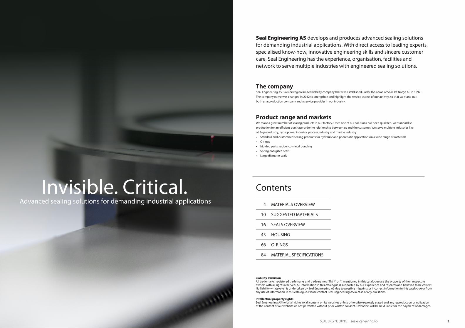
Seal Engineering AS develops and produces advanced sealing solutions for demanding industrial applications. With direct access to leading experts, specialised know-how, innovative engineering skills and sincere customer care, Seal Engineering has the experience, organisation, facilities and network to serve multiple industries with engineered sealing solutions.
The companySeal Engineering AS is a Norwegian limited liability company that was established under the name of Seal-Jet Norge AS in 1997.
The company name was changed in 2012 to strengthen and highlight the service aspect of our activity, so that we stand out
both as a production company and a service provider in our industry.
Product range and marketsWe make a great number of sealing products in our factory. Once one of our solutions has been qualified, we standardise
production for an efficient purchase-ordering relationship between us and the customer. We serve multiple industries like
oil & gas industry, hydropower industry, process industry and marine industry.
• Standard and customized sealing products for hydraulic and pneumatic applications in a wide range of materials
• O-rings
• Molded parts, rubber-to-metal bonding
• Spring energized seals
• Large diameter seals
Liability exclusionAll trademarks, registered trademarks and trade names [TM, © or ®] mentioned in this catalogue are the property of their respective owners with all rights reserved. All information in this catalogue is supported by our experience and research and believed to be correct. No liability whatsoever is undertaken by Seal Engineering AS due to possible misprints or incorrect information in this catalogue or from any use of information in this catalogue. Please contact Seal Engineering AS in case of any questions.
Intellectual property rightsSeal Engineering AS holds all rights to all content on its websites unless otherwise expressly stated and any reproduction or utilization of the content of our websites is not permitted without prior written consent. Offenders will be held liable for the payment of damages.
Contents
4 MATERIALS OVERVIEW
10 SUGGESTED MATERIALS
16 SEALS OVERVIEW
43 HOUSING
66 O-RINGS
84 MATERIAL SPECIFICATIONS
Invisible. Critical.Advanced sealing solutions for demanding industrial applications

54 SEAL ENGINEERING | sealengineering.no SEAL ENGINEERING | sealengineering.no
Materials overview
In order to optimize sealing effect, the key features are seal profile and seal material. This
chapter will give an overview of the standard materials which we use for the production
of seals, gaskets and other machined parts.
Seal Engineering AS considers the materials presented in this chapter as standard for
turning of seals, gaskets and other parts. All the listed materials are kept in stock in a
variety of dimensions, up to 1500 mm outside diameter, available for same day delivery.
We can also deliver seals in diameter up to 4000 mm (thermoplastic elastomers –
polyurethanes), 1500 mm (elastomers) and 2000 mm (thermoplastics).
For detailed specifications regarding chemical compatibility, mechanical, electrical and
thermal properties, please see chapter “Material Specifications”.
In addition to the materials presented here we are able to offer a large variety of different
materials to suit special applications. Contact Seal Engineering AS for datasheets or
technical advice.
Thermoplastic elastomers belong to the elastomer-family of materials. The elastomer-family consists of materials that can be highly expanded by exerting relatively little power. Because of their structure, elastomers have a high retractibility, which means the remaining deformation is very small.
Unlike elastomers (rubber), thermoplastic elastomers are
physically, but not chemically cross-linked, therefore they
can be melted at higher temperatures and can be processed
with traditional thermoplastic processing techniques.
Thermoplastic elastomers are soluble and generally they swell
less in comparison to their chemically cross-linked equivalents.
The thermoplastic elastomers Seal Engineering AS offers are
various types of polyurethanes, abbreviation PU.
Polyurethanes have superior mechanical properties compared
to elastomers and with the variety of different polyurethanes
presented here, PU will be the preferred material for many
sealing systems.
Thermoplastic elastomers
GENERAL DESCRIPTION: HPU is a hydrolysis-resistant thermoplastic polyurethane elastomer. HPU’s high resistance to
hydrolysis (hydrolysis is degradation in water) is rarely found in polyurethanes. It is stable in water up to +90°C and has an
outstanding resistance in mineral oil. Because of its resistance to hydrolysis, HPU is particularly recommended for the use in
purewater and seawater, for HFA and HFB fluids and biologically degradable hydraulic fluids (vegetable oils and synthetic
esters) and food articles. HPU is KTW approved and complies with FDA standards. HPU also has excellent resistance against
explosive decompression (ED).
GENERAL DESCRIPTION: LPU is a thermoplastic polyurethane elastomer which is modified for low temperature applications,
with a minimum service temperature of - 50°C. LPU has an high abrasive resistance, low compression set, high physical
properties and tear strength. Products made from this material can be used in mineral oil and in bio-degradable hydraulic oils
like vegetable oils and synthetic esters.
GENERAL DESCRIPTION: SPU is a polyurethane that has been optimized in regard of the tribological characteristics (friction
and wear), achieved by an addition of a synergetic combination of solid lubricants. This special material is therefore best suited
for the most severe applications for water hydraulics or badly lubricated systems as well as in oil-free pneumatics. Chemical
properties similar to HPU.
GENERAL DESCRIPTION: XHPU is a hard grade polyurethane (shore 60D) with chemical properties similar to HPU. This material
is specially developed to replace PTFE-based materials in sliding seals/composite seals (our profiles K08, S09 and others) in
systems with adequate temperature and media (up to 110ºC and media as for HPU). Used in composite seals, XHPU exhibits
greater resistance to extrusion, less leakage, longer life-time and easier installation properties than the traditional PTFE-based
seals. A comparison between XHPU and PTFE-based seals is shown in the “Suggested Materials” section.
GENERAL DESCRIPTION: XSPU is a hard grade polyurethane (shore 57D) that has been optimised in regard of the tribological
characteristics (friction and wear), achieved by an addition of a synergetic combination of solid lubricants. The chemical
properties are similar to HPU. This material replaces PTFE-based materials for the same seals as XHPU, but is better suited in
systems where low friction is crucial (water hydraulics, badly lubricated etc.).
TEMPERATURE RANGE: -20 ºC to 110 ºC
TEMPERATURE RANGE: -50 ºC to 110 ºC
TEMPERATURE RANGE: -20 ºC to 110 ºC
TEMPERATURE RANGE: -20 ºC to 110 ºC
TEMPERATURE RANGE: -20 ºC to 121 ºC
Material: HPU TM
Material: LPU TM
Material: SPU TM
Material: XHPU TM
Material: XSPU TM
MAT
ERIA
L OVE
RVIEW
SUGG
ESTE
D M
ATER
IALS
SEAL
S OVE
RVIEW
HOUS
ING
O-RIN
GSM
ATER
IAL S
PECIF
ICATIO
NSM
ATERIAL OVERVIEWSUGGESTED M
ATERIALSSEALS OVERVIEW
HOUSINGO-RINGS
MATERIAL SPECIFICATIONS
76 SEAL ENGINEERING | sealengineering.no SEAL ENGINEERING | sealengineering.no
Seal Engineering AS is dedicated to find the best overall sealing solutions and materials with special attention to functionality,
reliability and low overall life-cycle cost. Our engineered high-perfomance sealing solutions require state-of-the-art sealing
materials. Visit our website for more information.
Elastomers – rubbers – are materials that can be highly expanded by exerting relatively little
power. Because of their structure, elastomers have a high retractibility, which means the
remaining deformation is very small.
Elastomers
The rubber materials are polymers, which are formed by cross-
linked macromolecules with various vulcanization additives.
Due to their chemical bonds, they begin to decompose at high
temperatures and they do not melt. In addition the cross-link
ensures that rubber materials do not dissolve. However, they
do suffer more or less intensive swell or shrinkage depending
on the medium. Elastomers have in general inferior mechanical
properties compared to polyurethanes. However the different
elastomers display other qualities such as chemical and
temperature resistance combined with elasticity, and are widely
used for different types of seals.
GENERAL DESCRIPTION: RU6 is a tetraflourethylene-propylene material, often referred to as Aflas®, FEPM or TFE/P. This material
is well suited against HFA, HFB, HFC and HFD liquids. In addition this material has excellent resistance against steam and hot
water. Good resistance against various chemicals.
TEMPERATURE RANGE: -10 ºC to 200 ºC
GENERAL DESCRIPTION: RU5 is a silicone rubber, or VMQ. Owing to the poor mechanical properties, which are noticeably lower
in comparison to other rubbers, RU5 is mostly used for static applications. RU5 is highly resistant against weathering, ozone and
ageing, and also has a wide temperature range (-60 to +200 ºC). The compatibility with mineral oils depends on the content of
aromatic hydrocarbons in the oil. RU5 complies with FDA-recommendations.
TEMPERATURE RANGE: -60 ºC to 200 ºC
Material: RU5 TM
Material: RU6
TM
GENERAL DESCRIPTION: RU1 is a Nitrile Butadiene Rubber (NBR). RU1 has a good resistance to mineral oils and greases and HFA,
HFB and HFC pressure fluids. However, the material is not resistant to glycol-based brake fluids, HFD fluids, aromatic fluids (such
as benzene), esters, ketones and amines or concentrated acids and bases. RU1 is also on stock in a low-temperature grade, with a
minimum working temperature of – 50ºC.
GENERAL DESCRIPTION: RU2 is an elastomer based on fluororubber with similar properties to Viton® type B. This material is
also referred to as FKM (ISO). RU2 has high resistance against heat, weathering, ozone and many chemical ingredients. RU2 is
compatible with mineral oils and greases containing sulphur, HFD pressure fluids (nearly all phosphate esters and chlorinated
hydrocarbons), crude oil and sour gas. RU2 shows excellent resistance against explosive decompression (ED). RU2 is not
resistant against anhydrous ammonia, amines, ketones, esters, hot water and low molecular weight organic acids. RU2 is also
on stock in a FDA compliant grade and with different hardness (75º-95º shore A).
GENERAL DESCRIPTION: RU4 is a hydrogenated or saturated acrylonitrile-butadiene rubber, often referred to as H-NBR. RU4
is suitable for applications with aliphatic hydrocarbons like propane or butane and mineral oils and greases (for short times
up to 170°C) and also for sulfonated crude oil. Furthermore, it can be used in many diluted acids and bases and salt solutions
even at elevated temperatures and in glycol-water mixtures. RU4 is not compatible with fuels with a high content of aromatic
hydrocarbons (premium blend petrol), gasolines (petrol / alcohol blends) ketones, esters, ethers and chlorinated hydrocarbons
like trichloroethylene and tetrachloroethy-lene. RU4 complies with FDA-recommendations. RU4 is also on stock in hard grade
(93ºshore A), ED-grade, low-temperature grade (-40ºC) and ED/low-temperature grade (-30ºC).
GENERAL DESCRIPTION: RU3 is a perox-cured elastomer based on ethylene-propylene rubber, often referred to as EPDM. RU3
has an outstanding stability against hot water, steam, washing agents, polar organic solvents and glycol based brake fluids. RU3
is not resistant against mineral oil and other unpolar media. The stability to weathering, ozone and ageing is good. RU3 is also
on stock in a FDA compliant grade and a hard grade (93 º shore A).
TEMPERATURE RANGE: -30 ºC to 100 ºC
TEMPERATURE RANGE: -20 ºC to 200 ºC
TEMPERATURE RANGE: -25 ºC to 150 ºC
TEMPERATURE RANGE: -50 ºC to 150 ºC
Material: RU1 TM
Material: RU2 TM
Material: RU4 TM
Material: RU3
TM
Thermoplastics
PTFE (polytetrafluorethylene) and modified PTFE materials with
or without fillers, have extremely good resistance to chemicals
and will only be degraded by molten alkali metals and elementary
fluorine at high temperatures. However, for some of the PTFE-
based materials the fillers may be attacked and destroyed by
certain other chemicals. In addition these materials have a
general working area between -200ºC and +260ºC, making them
widely used for extreme conditions in respect to chemicals and
temperature.
Thermoplastics are polymer materials, which compared to elastomers, are essentially harder and
more rigid. Depending on the chemical structure, the properties vary from hard and stiff, to ductile
and flexible. Due to the morphological structure, extensive stretching is non-reversible and moulded
parts remain in the deformed state. We make a distinction between PTFE-based thermoplastics and
other thermoplastics.
High-performance sealing materials
• RU16™
• RU21™
• RU23™
• RU25™
• RU35™
• RU39™
• RU41™
• PL1™
• PL18™
-
-
-
-
-
-
-
-
-
FKM fluoroelastomer, peroxide-cured (Solvay Tecnoflon VPL85540)
DuPont™ Kalrez® FFKM
Based on Chemours´ Viton® Extreme ETP-600S
Based on Tecnoflon PFR 95HT
Based on a peroxide-cured FKM terpolymer
Based on a peroxide-cured, hydrogenated acrylonitrile-butadiene rubber (HNBR)
Based on Tecnoflon PFR LT
DuPont™ Vespel® CR 6100
Greene Tweed Arlon® 3000XT Enhanced PEEK
MAT
ERIA
L OVE
RVIEW
SUGG
ESTE
D M
ATER
IALS
SEAL
S OVE
RVIEW
HOUS
ING
O-RIN
GSM
ATER
IAL S
PECIF
ICATIO
NSM
ATERIAL OVERVIEWSUGGESTED M
ATERIALSSEALS OVERVIEW
HOUSINGO-RINGS
MATERIAL SPECIFICATIONS

98 SEAL ENGINEERING | sealengineering.no SEAL ENGINEERING | sealengineering.no
GENERAL DESCRIPTION: FL5 has the same chemical properties as PTFE-virgin, and is also defined as a homopolymer according
to ISO 12086. FL5 has highly improved mechanical properties in comparison to PTFE-virgin, see also the “Suggested Materials”
section. Seal Engineering AS considers FL5 to be our standard “PTFE-virgin”. FL5 is compliant with FDA-regulations.
GENERAL DESCRIPTION: Excellent compression and wear resistance, good thermal conductivity and low permeability. Suitable
for a wide range of applications.
GENERAL DESCRIPTION: FL14 has excellent wear resistance. The filler is very gentle to mating metal surfaces, making it a good
choice for rotary applications. FL14 is FDA approved and widely used in the food industry.
In addition to the PTFE-based materials described above
we can manufacture seals, gaskets and other details in a
variety of other PTFE materials with fillers specifically suited
for a given application. We have either in stock or with
Other PTFE-based materials
short delivery time approximately 20 different PTFE-based
materials to offer.
Contact Seal Engineering AS for special applications or
materials.
Other thermoplastic materials
GENERAL DESCRIPTION: PA1 is a cast polyamide with good sliding properties and is used for back-up rings, guide rings and
bearing components instead of POM1 for a diameters above 260 mm. PA1 can be used in mineral oils and water-based fire-
resistant hydraulic fluids. When designing parts with PA1 for an application in water or water-based fluids, the swelling of the
material must be taken into account, as PA1 absorbs water up to eight weight percent.
GENERAL DESCRIPTION: PE1 is extremely resistant to abrasion and is often used for pneumatic systems, or as sealing against
abrasive media. This material has excellent chemical resistance, low friction, very low water absorption and good extrusion
resistance. PE1 is compliant to FDA-regulations.
TEMPERATURE RANGE: -40 ºC to 110 ºC.
TEMPERATURE RANGE: -200 ºC to 80 ºC.
Material: PA1
Material: PE1
General thermoplastic materials
GENERAL DESCRIPTION: POM1 is a semi-crystalline polyacetal-copolymer which is used for backup-rings, guide-rings,
bushings, scrapers and for precision-machined parts with tight tolerances. POM1 is one of the most important engineering
thermoplastics with good physical properties, low water absorption and good chemical resistance. POM1 can be used in
mineral oils, in water-based fire-resistant hydraulic fluids (HFA, HFB and HFC fluids). Concentrated acids and bases will attack
and destroy it. POM1 (white) may be used in applications for food and drug, and is compliant with BGVV and EC-regulations.
GENERAL DESCRIPTION: PEEK1 is a polyetheretherketone with high tensile strength, stiffness, high temperature resistance and
good sliding and friction behaviour. In addition PEEK1 has good resistance against numerous chemicals, and is therefore often
used in demanding applications with regards to pressure, temperature and chemicals, or when there is a combination of these
parameters. PEEK1 is compliant with FDA-regulations.
TEMPERATURE RANGE: -45 ºC to 100 ºC.
TEMPERATURE RANGE: -100 ºC to 260 ºC.
Material: PEEK1
Material: POM1
In addition to the materials mentioned above, Seal
Engineering AS can manufacture seals and other machined
details in almost any other thermoplastic, each with unique
properties to suit a given application. Most of these materials
are also available with different fillers, widening the range of
applications even more.
Abbreviation Chemical name Abbreviation Chemical name
PA Polyamide PC Polycarbonate
POM Polyacetal (Polyoxymethylene) PSU Polysulphone
PET Polyethylene terpthalate PES Polyether Sulphone
PEEK Polyetheretherketone PPS Polyphenylene Sulphide
PE Polyethylene PPSU Polyphenylsulphone
PP Polypropylene PEI Polyetherimide
PVC Polyvinyl Chloride PAI Polyamideimide
PMMA Polymethyl methacrylate PBI Polybenzimidazole
ABS Acrylnitrile Butadiene Styrene PI Polyimide
PTFE-based thermoplastics
GENERAL DESCRIPTION: Because of its special composition, FL2 has good physical properties and distinctly better creep
behaviour than PTFE-virgin. Also higher wear resistance than most PTFE with fillers.
GENERAL DESCRIPTION: Excellent chemical and thermal resistance. FDA-approved. Limited mechanical properties. If improved
mechanical properties are required FL5™ or a filled PTFE should be considered.
GENERAL DESCRIPTION: FL3 material has good mechanical properties, and can be used at higher loads compared to FL2 and
FL5.
Material: FL3 TM PTFE filled with bronze
Material: FL14 TM PTFE filled with Ekonol®
Material: FL5 TM
Modified PTFE
Material: FL4 TM
Modified PTFE filled with carbon
Material: FL2 TM PTFE filled with with glass fibres/molybdenum disulphide
Material: FL1™ Virgin PTFE
MAT
ERIA
L OVE
RVIEW
SUGG
ESTE
D M
ATER
IALS
SEAL
S OVE
RVIEW
HOUS
ING
O-RIN
GSM
ATER
IAL S
PECIF
ICATIO
NSM
ATERIAL OVERVIEWSUGGESTED M
ATERIALSSEALS OVERVIEW
HOUSINGO-RINGS
MATERIAL SPECIFICATIONS
1110 SEAL ENGINEERING | sealengineering.no SEAL ENGINEERING | sealengineering.no
Choosing materials is a task that often requires a lot of investigation and compromises
between different desirable properties. For a given application there may be a number of
different materials that are well suited, but our job is to find the best suited material.
Solely looking at the procurement price is often very misleading, as this does not
consider actual life-cycle cost for a given product. Downtime, equipment failure and
repair cost due to a faulty seal is many times higher than the cost of the seal, even in
cases when some of the more expensive materials are chosen.
Seal Engineering AS is dedicated to find the best overall sealing solutions and materials
with special attention to functionality, reliability and low overall life-cycle cost.
Seals are faced with an ever increasing demand for higher pressure, temperature,
functionality and longevity.
This means that some of the “traditional” materials no longer are as well suited as they
used to be. Advances in material science are resulting in new and improved materials,
suited to meet these increased demands.
Progress made in the field of material science forces both suppliers and customers to
evaluate their previous material selection for a given application.
The following section will show some of the advances in material technology, and give
some guidelines for selecting the right material for a given application.
Suggestedmaterials
Improved material for sliding seals
Elastomer energized seals – often referred to as sliding seals, step seals or composite seals – have
traditionally consisted of a PTFE-based sealing element in addition to the elastomer energizer –
usually an O-ring.
PTFE-based sealing systems meet the demands of low friction
and stick-slip free operation very well. Often they cannot stand
up against increasing technological requirements, especially
with regards to wear-resistance, leakage behaviour and ease of
installation and assembly.
As an alternative to the PTFE-based seals we offer special hard
grade polyurethanes XHPU (60 shore D) and XSPU (57 shore
D). These materials meet all the necessary requirements:
• Low friction and no stick-slip behaviour
• Outstanding leakage performance
• Superior extrusion and wear characteristics
• Excellent installation properties
Due to these criteria, seals based on these special
polyurethanes are an ideal replacement for conventional
PTFE-based composite seals, provided that the temperature
range or pressure fluid are within the recommended
operating parameters. XHPU and XSPU can be used up to
110ºC, and for media such as mineral based hydraulic oil
fluids, HFA and HFB fluids, biologically degradable oils and
water.
Extensive test-rig investigations and finite element analysis
have shown that seals based on these special polyurethanes
are an ideal replacement of PTFE-based composite seals for
most common fluid power systems.
Hard grade polyurethanes
MAT
ERIA
L OVE
RVIEW
SEAL
S OVE
RVIEW
HOUS
ING
O-RIN
GSM
ATER
IAL S
PECIF
ICATIO
NSSUGGESTED M
ATERIALSSEALS OVERVIEW
HOUSINGO-RINGS
MATERIAL SPECIFICATIONS
MATERIAL OVERVIEW
SUGG
ESTE
D M
ATER
IALS
1312 SEAL ENGINEERING | sealengineering.no SEAL ENGINEERING | sealengineering.no
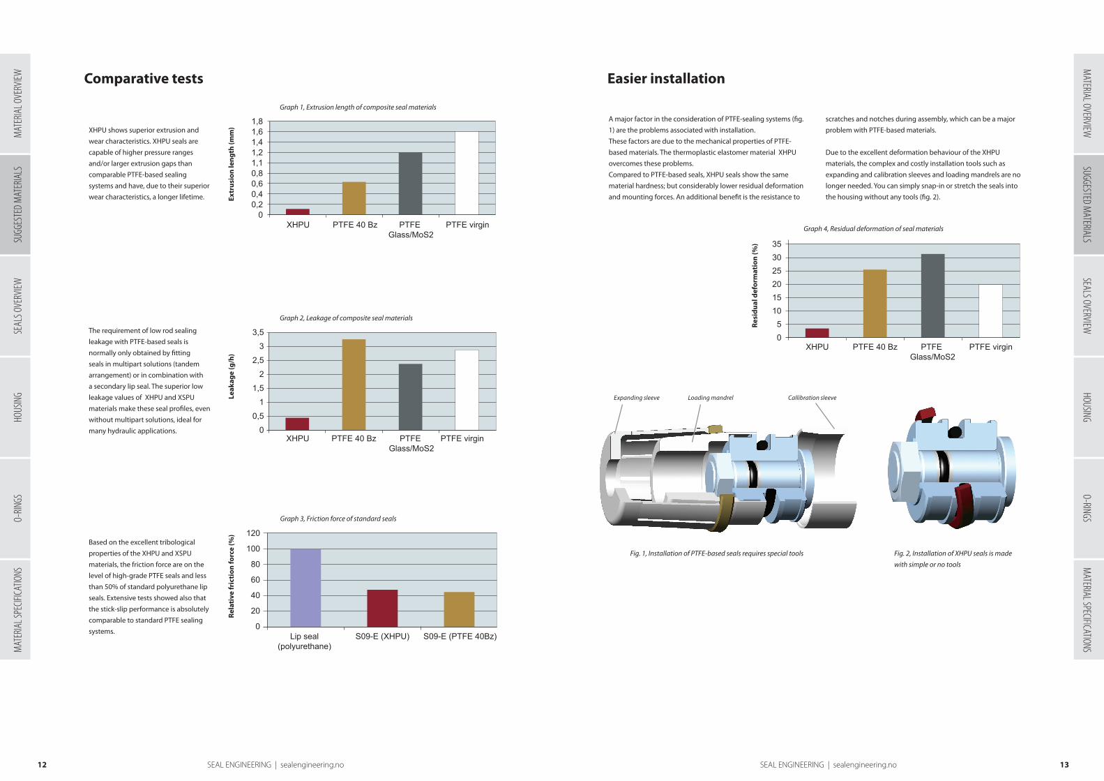
Pressure resistance / wear characteristics:
XHPU shows superior extrusion and
wear characteristics. XHPU seals are
capable of higher pressure ranges
and/or larger extrusion gaps than
comparable PTFE-based sealing
systems and have, due to their superior
wear characteristics, a longer lifetime.
Leakage behaviour:The requirement of low rod sealing
leakage with PTFE-based seals is
normally only obtained by fitting
seals in multipart solutions (tandem
arrangement) or in combination with
a secondary lip seal. The superior low
leakage values of XHPU and XSPU
materials make these seal profiles, even
without multipart solutions, ideal for
many hydraulic applications.
Friction/Stick-slip effectBased on the excellent tribological
properties of the XHPU and XSPU
materials, the friction force are on the
level of high-grade PTFE seals and less
than 50% of standard polyurethane lip
seals. Extensive tests showed also that
the stick-slip performance is absolutely
comparable to standard PTFE sealing
systems.
Rel
ativ
e fr
icti
on
forc
e (%
)
1,81,61,41,21,10,80,60,40,2
0XHPU PTFE 40 Bz PTFE virginPTFE
Glass/MoS2
3,5
3
2,5
2
1,5
1
0,5
0XHPU PTFE 40 Bz PTFE virginPTFE
Glass/MoS2
120
100
80
60
40
20
0Lip seal
(polyurethane)S09-E (XHPU) S09-E (PTFE 40Bz)
353025201510
50
XHPU PTFE 40 Bz PTFE virginPTFE Glass/MoS2
Extr
usi
on
len
gth
(mm
)
Graph 1, Extrusion length of composite seal materials
Leak
age
(g/h
)
Graph 2, Leakage of composite seal materials
Graph 3, Friction force of standard seals
Comparative tests
Fig. 1, Installation of PTFE-based seals requires special tools Fig. 2, Installation of XHPU seals is made
with simple or no tools
Expanding sleeve Loading mandrel Callibration sleeve
Res
idu
al d
efo
rmat
ion
(%)
Graph 4, Residual deformation of seal materials
A major factor in the consideration of PTFE-sealing systems (fig.
1) are the problems associated with installation.
These factors are due to the mechanical properties of PTFE-
based materials. The thermoplastic elastomer material XHPU
overcomes these problems.
Compared to PTFE-based seals, XHPU seals show the same
material hardness; but considerably lower residual deformation
and mounting forces. An additional benefit is the resistance to
scratches and notches during assembly, which can be a major
problem with PTFE-based materials.
Due to the excellent deformation behaviour of the XHPU
materials, the complex and costly installation tools such as
expanding and calibration sleeves and loading mandrels are no
longer needed. You can simply snap-in or stretch the seals into
the housing without any tools (fig. 2).
Easier installation
1,81,61,41,21,10,80,60,40,2
0XHPU PTFE 40 Bz PTFE virginPTFE
Glass/MoS2
3,5
3
2,5
2
1,5
1
0,5
0XHPU PTFE 40 Bz PTFE virginPTFE
Glass/MoS2
120
100
80
60
40
20
0Lip seal
(polyurethane)S09-E (XHPU) S09-E (PTFE 40Bz)
353025201510
50
XHPU PTFE 40 Bz PTFE virginPTFE Glass/MoS2
1,81,61,41,21,10,80,60,40,2
0XHPU PTFE 40 Bz PTFE virginPTFE
Glass/MoS2
3,5
3
2,5
2
1,5
1
0,5
0XHPU PTFE 40 Bz PTFE virginPTFE
Glass/MoS2
120
100
80
60
40
20
0Lip seal
(polyurethane)S09-E (XHPU) S09-E (PTFE 40Bz)
353025201510
50
XHPU PTFE 40 Bz PTFE virginPTFE Glass/MoS2
1,81,61,41,21,10,80,60,40,2
0XHPU PTFE 40 Bz PTFE virginPTFE
Glass/MoS2
3,5
3
2,5
2
1,5
1
0,5
0XHPU PTFE 40 Bz PTFE virginPTFE
Glass/MoS2
120
100
80
60
40
20
0Lip seal
(polyurethane)S09-E (XHPU) S09-E (PTFE 40Bz)
353025201510
50
XHPU PTFE 40 Bz PTFE virginPTFE Glass/MoS2
MAT
ERIA
L OVE
RVIEW
SEAL
S OVE
RVIEW
HOUS
ING
O-RIN
GSM
ATER
IAL S
PECIF
ICATIO
NSSUGGESTED M
ATERIALSSEALS OVERVIEW
HOUSINGO-RINGS
MATERIAL SPECIFICATIONS
MATERIAL OVERVIEW
SUGG
ESTE
D M
ATER
IALS

1514 SEAL ENGINEERING | sealengineering.no SEAL ENGINEERING | sealengineering.no
Comparison of XHPU and PTFE materials with FE-analysis
The step design of the dynamic sealing surface is also
used for seals of XHPU, however small modifications
of the XHPU design amplify the improvements which
are created by the excellent properties of the material.
The pictures from the FE-analysis show the difference.
Owing to the higher flexibility of the material compared
with PTFE compounds, the XHPU seals show a very
regular stress/strain allocation under a load of up to
several hundred bar.
The dynamic sealing edge is more evenly and not
as highly loaded as at the PTFE design which leads
to a minimum of wear and a long operation life at
simultaneously excellent sealing performance. Also
the extrusion endangered heel area of the seal shows
a strong stress reduction which leads to an excellent
extrusion resistance and an optimised back pumping
ability.
Fig. 4, S09-E in XHPU
PTFE-based Properties XHPU
3 Pressure 5
3 Wear 5
2 Leakage 5
5 Friction/stick-slip 4
1 Installation 5
1=Bad, 5=Excellent
The test results shown above are a clear evidence that
sliding seals made of XHPU and XSPU outperform
seals made of PTFE-based materials for a wide range
of applications. Only special fluids and/or elevated
temperatures are reasons to use PTFE-based seals.
The improved wear resistance achieved by the use of
seals made from XHPU and XSPU will not only lead to an
Conclusion
extended lifetime compared to PTFE-based systems, but
also have a lower demand for surface finish. Furthermore,
the better extrusion resistance allows higher pressure
range or larger component tolerances (extrusion gaps) than
comparable PTFE-based seals. These benefits along with less
leakage, good friction properties and easier installation give
XHPU and XSPU tremendous advantages compared to the
traditional PTFE-based seals.
Fig. 3, S09-E in PTFE
High High
Low Low
Table 1, Comparison of PTFE and XHPU
Modified PTFE
For applications with aggressive media and/or high
temperature, PTFE or PTFE with fillers are often the preferred
seal materials due to their excellent chemical and thermal
resistance. Unfortunately PTFE-virgin has poor mechanical
properties, and different fillers are needed to obtain enhanced
mechanical properties. However, these filled materials are
still restricted with regards to mechanical properties given
the PTFE-virgin basis, and may also experience less resistance
to some media (the fillers are attacked). In addition, some
applications require the homopolymer structure of PTFE- virgin
(food and drug applications, semiconductor etc.) with poor
mechanical properties as an undesirable effect.
For many applications the solution can be a modified PTFE
which has the same chemical and thermal resistance as PTFE-
virgin, but exhibits several enhanced properties. In addition,
according to ISO 12086, this material can still be classified as a
homopolymer.
The modified PTFE results in several enhanced properties
compared to PTFE-virgin. The most advantageous properties
are:
• Substantially lower deformation under load. About the
same cold flow as PTFE with 25% glass fibre. This is an
important feature where fillers may cause contamination
or reduced chemical resistance.
• Improved stress recovery, particularly at elevated
temperatures. This is an important feature for seals and
gaskets where improved stress recovery can translate to
longer sealability or less retorquing of parts.
• Reduced tensile strain/flow. This makes for easier
installation for parts that require stretching.
• Reduced permeation. This is an important feature when
the material is used to protect against aggressive media,
for instance as gaskets.
• Smoother surface of machined parts. This results in
greater contact area of the seal, important for sealing
against gas.
MAT
ERIA
L OVE
RVIEW
SEAL
S OVE
RVIEW
HOUS
ING
O-RIN
GSM
ATER
IAL S
PECIF
ICATIO
NSSUGGESTED M
ATERIALSSEALS OVERVIEW
HOUSINGO-RINGS
MATERIAL SPECIFICATIONS
MATERIAL OVERVIEW
SUGG
ESTE
D M
ATER
IALS

1716 SEAL ENGINEERING | sealengineering.no SEAL ENGINEERING | sealengineering.no16
The range of seals presented in this chapter is based on decades of experience in
dynamic and static sealing solutions. The use of modern finite element analysis
programs (FEA) for non-linear material behaviour in combination with best-practise
manufacturing know-how results in optimized seal profiles delivering excellent
sealing characteristics and reliable performance.
Seals overview
We have divided the material groups into five main categories
in the following manner:
• RU-group: RU1, RU2, RU3, RU4, RU5 and RU6.
• PU-group: HPU, LPU and SPU.
• XPU-group: XHPU and XSPU.
• FL- group: FL2, FL3, FL5, FL13 and other PTFE-based
materials.
• *– includes almost every polymer available for turning, but
also other materials such as various types of metal.
The material categories apply to the seal part of a seal set.
Material for energizer, backup ring, support ring, collar and
spring is depending on the application.
TemperatureThe indicated temperature ranges apply to the material group.
The specific temperature range depends on the application
(pressure, media, extrusion gap) and which material is selected
within the material group. For specific temperature range
of different materials see Materials Overview and Material
Specifications.
Maximum pressure
The specified pressure limits apply for normal operation
parameters for each seal type and is to be used as guiding only.
The pressure limit for a specific seal will depend on several
parameters such as radial gap, temperature, speed, seal profile
proportions and of course material selection.
Maximum speedThe specified maximum speed is depending on several factors,
such as lubrication, surface, temperature and seal geometry.
The speed limits apply for adequate lubrication and running
surface finishes as recommended. For PU the maximum speed
0.5, 0.7 and 1.4 m/s apply to SPU, for other PU materials the
values are 0.4, 0.5 and 1 m/s respectively.
This chapter is an introduction to our standard range of sealing profiles. The highlighted profiles
are described in more detail in the next chapter. The profiles presented here are available in many
different materials and even material groups.
Note:For design purposes please bear in mind that the operation
parameters for each seal represent general conditions.
Not all maximum values can be utilized at the same time.
However, depending on the application, higher pressure
and speed can be attained in most cases.
The lip of the wiper is designed to have a pre-load with the
piston rod, and this has an influence on the break-out friction.
Double acting wipers have the additional function of wiping
off residual fluid film passing the rod seal, to avoid any external
leakage.
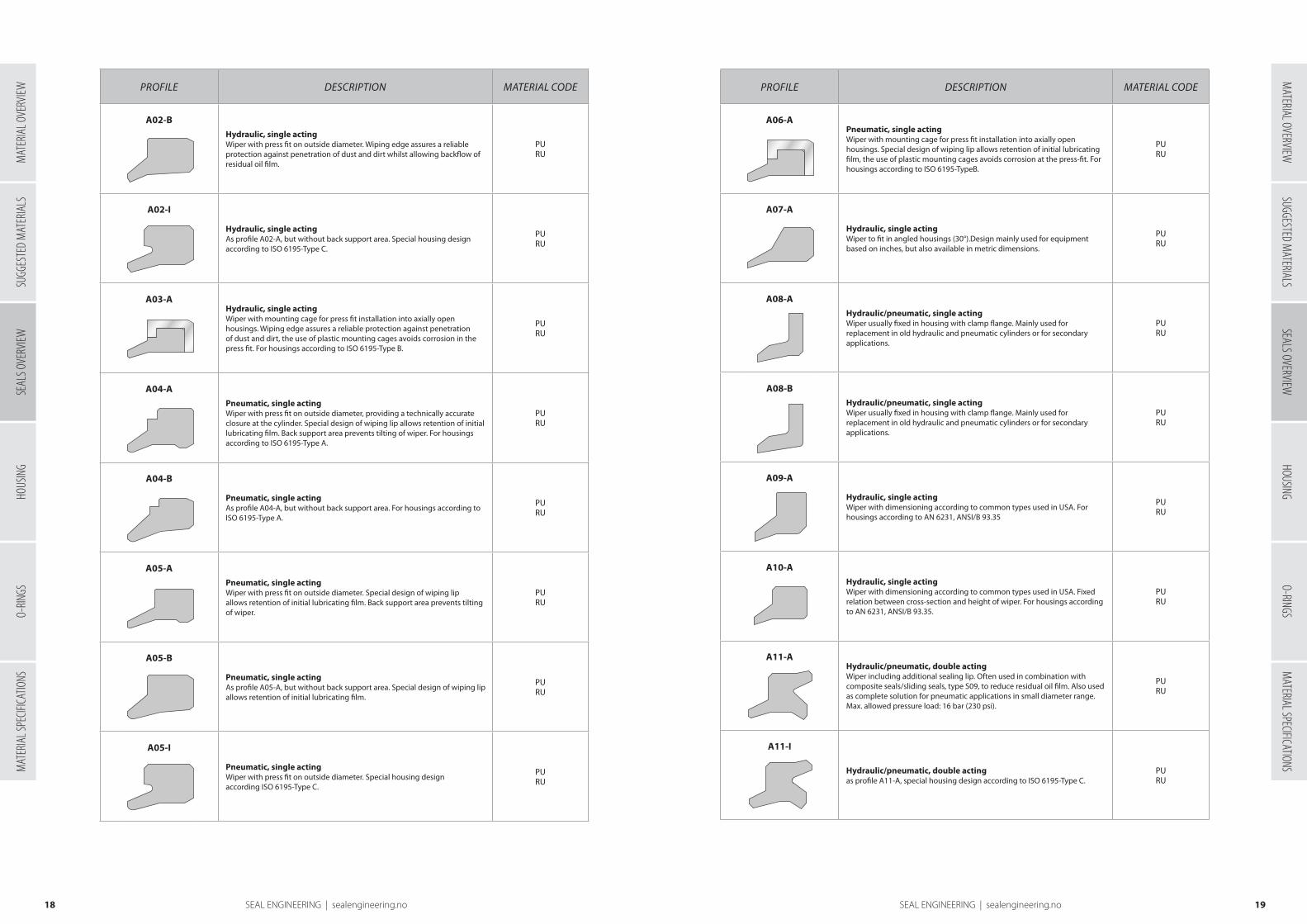
Wipers
ød inside diameter (rod)
øD outside diameter
øD1 outside diameter (if applicable)
L groove length
H total wiper height (if applicable)
Profiles overview
Profile DESCRIPTION MATERIAL CODE
A01-AHydraulic, single actingWiper with press fit on outside diameter, providing a technically accurate closure at the cylinder. Wiping edge assures a reliable protection against penetration of dust and dirt whilst allowing backflow of residual oil film. Back support area prevents tilting of wiper. For housings according to ISO 6195-Type A.
PURU
A01-B
Hydraulic, single actingAs profile A01-A, but without back support area. For housings according to ISO 6195-Type A.
PURU
A02-A
Hydraulic, single actingWiper with press fit on outside diameter. Wiping edge assures a reliable protection against penetration of dust and dirt whilst allowing backflow of residual oil film. Back support area prevents tilting of wiper.
PURU
The function of a wiper is to prevent particles from entering the components in a hydraulic or
pneumatic circuit, cylinders or valves. This helps prevent contamination of the media which will
damage the seals and metal surfaces.
Wipers are usually made from rubbers, polyurethanes
or thermoplastics. Some have metal casing for press fit
mounting. Special designs and different materials are
available for applications where compensation for large
radial movements, a stiffer inner lip, temperature or media
resistance is required.
Order detailsIn addition to seal profile and material, indicated
dimensions are required to process an order. Multi-element
wipers are generally supplied as a complete set, e.g. the
O-ring in A27 does not have to be ordered separately.
Table 1, Order details
Fig. 1, Housing for wiper.
WIPER
PISTON
ROD
ROD
ROD
INT GUIDE
EXT GUIDE
L1 L
øD1
ød øD
ød øD
ød øDød øD
ød øD
L +0,2
L +0,2
L +0,2
L +0,2
ød øD
c/s
L
ød øD
c/s
L
SUGG
ESTE
D M
ATER
IALS
SEAL
S OVE
RVIEW
HOUS
ING
O-RIN
GSM
ATER
IAL S
PECIF
ICATIO
NSM
ATERIAL OVERVIEWSUGGESTED M
ATERIALSSEALS OVERVIEW
HOUSINGO-RINGS
MATERIAL SPECIFICATIONS
MAT
ERIA
L OVE
RVIEW
1918 SEAL ENGINEERING | sealengineering.no SEAL ENGINEERING | sealengineering.no
PROFILE DESCRIPTION MATERIAL CODE
A02-BHydraulic, single actingWiper with press fit on outside diameter. Wiping edge assures a reliable protection against penetration of dust and dirt whilst allowing backflow of residual oil film.
PURU
A02-I
Hydraulic, single actingAs profile A02-A, but without back support area. Special housing design according to ISO 6195-Type C.
PURU
A03-AHydraulic, single actingWiper with mounting cage for press fit installation into axially open housings. Wiping edge assures a reliable protection against penetration of dust and dirt, the use of plastic mounting cages avoids corrosion in the press fit. For housings according to ISO 6195-Type B.
PURU
A04-APneumatic, single actingWiper with press fit on outside diameter, providing a technically accurate closure at the cylinder. Special design of wiping lip allows retention of initial lubricating film. Back support area prevents tilting of wiper. For housings according to ISO 6195-Type A.
PURU
A04-B
Pneumatic, single actingAs profile A04-A, but without back support area. For housings according to ISO 6195-Type A.
PURU
A05-APneumatic, single actingWiper with press fit on outside diameter. Special design of wiping lip allows retention of initial lubricating film. Back support area prevents tilting of wiper.
PURU
A05-B
Pneumatic, single actingAs profile A05-A, but without back support area. Special design of wiping lip allows retention of initial lubricating film.
PURU
A05-I
Pneumatic, single actingWiper with press fit on outside diameter. Special housing design according ISO 6195-Type C.
PURU
PROFILE DESCRIPTION MATERIAL CODE
A06-APneumatic, single actingWiper with mounting cage for press fit installation into axially open housings. Special design of wiping lip allows retention of initial lubricating film, the use of plastic mounting cages avoids corrosion at the press-fit. For housings according to ISO 6195-TypeB.
PURU
A07-A
Hydraulic, single actingWiper to fit in angled housings (30°).Design mainly used for equipment based on inches, but also available in metric dimensions.
PURU
A08-AHydraulic/pneumatic, single actingWiper usually fixed in housing with clamp flange. Mainly used for replacement in old hydraulic and pneumatic cylinders or for secondary applications.
PURU
A08-BHydraulic/pneumatic, single actingWiper usually fixed in housing with clamp flange. Mainly used for replacement in old hydraulic and pneumatic cylinders or for secondary applications.
PURU
A09-A
Hydraulic, single actingWiper with dimensioning according to common types used in USA. For housings according to AN 6231, ANSI/B 93.35
PURU
A10-AHydraulic, single actingWiper with dimensioning according to common types used in USA. Fixed relation between cross-section and height of wiper. For housings according to AN 6231, ANSI/B 93.35.
PURU
A11-AHydraulic/pneumatic, double actingWiper including additional sealing lip. Often used in combination with composite seals/sliding seals, type S09, to reduce residual oil film. Also used as complete solution for pneumatic applications in small diameter range. Max. allowed pressure load: 16 bar (230 psi).
PURU
A11-I
Hydraulic/pneumatic, double actingas profile A11-A, special housing design according to ISO 6195-Type C.
PURU
SUGG
ESTE
D M
ATER
IALS
SEAL
S OVE
RVIEW
HOUS
ING
O-RIN
GSM
ATER
IAL S
PECIF
ICATIO
NSM
ATERIAL OVERVIEWSUGGESTED M
ATERIALSSEALS OVERVIEW
HOUSINGO-RINGS
MATERIAL SPECIFICATIONS
MAT
ERIA
L OVE
RVIEW

2120 SEAL ENGINEERING | sealengineering.no SEAL ENGINEERING | sealengineering.no
PROFILE DESCRIPTION MATERIAL CODE
A12-A
Hydraulic, single actingWiper with technically accurate closure at the cylinder providing reliable protection, even for heavy contamination.
PURU
A12-BHydraulic, double actingWiper with technically accurate closure at the cylinder providing reliable protection, even for heavy contamination. Also including additional sealing lip. Used in combination with composite seals/sliding seals, type S09, to reduce residual oil film.
PURU
A13-AHydraulic/pneumatic, single actingScraper ring, mainly used in combination with wiper A02 or A01. Firmly clinging dirt and extremely heavy soiling (mud, tar, ice) is wiped off, following elastomeric wiper is protected from damage. Material properties should provide good dry running properties, high stiffness and breaking strength.
*
A25-FHydraulic/pneumatic, single actingWiper with O-ring as preloading element. O-ring maintains equal contact pressure. Good dry running properties, no "stick-slip". Excellent chemical and thermal resistance (depends on O-ring) with PTFE-materials. Improved wiping, longevity and easier installation with XPU.
XPUFL
A26-FHydraulic/pneumatic, double actingWiper with two O-rings as preloading elements. Wiping edge assures a reliable protection against penetration of dust and dirt. Additional sealing lip for reduction of residual oil film if used in combination with seals type S09. Excellent chemical and thermal resistance (depends on O-ring) with PTFE-material. Improved wiping, longevity and easier installation with XPU.
XPUFL
A27-FHydraulic/pneumatic, double actingWiper with O-ring as preloading element. Wiping edge assures a reliable protection against penetration of dust and dirt. Additional sealing lip for reduction of residual oil film if used in combination with seals type S09. Excellent chemical and thermal resistance (depends on O-ring) with PTFE-material. Improved wiping, longevity and easier installation with XPU.
XPUFL
Common material for A03/A06 housing/cage is POM or PEEK. Other material choices can be made depending on the application, e.g.
A25 in PEEK for ice wiper.
Material Max. speed
RU 4 m/s
PU 4 m/s (5 m/s for SPU)
XPU 5 m/s
FL 10 m/s
Maximum speedThe maximum speed is dependent on several factors
such as lubrication, surface, temperature and seal profile.
The maximum speeds apply for adequate lubrication and
running surfaces as recommended.
Table 2, Maximum speed
The technical demands are many and also diverse, good sealing
effect, media resistance, resistance against pressure/extrusion,
wear/operational reliability, resistance against high or low
temperature, low friction/stick-slip, good back-pumping ability,
simple installation and compact form.
Our rod seals meet these high expectations in combination
with good economic- and service life value.
Rod Seals
ød rod diameter
øD groove diameter
L groove length
WIPER
PISTON
ROD
ROD
ROD
INT GUIDE
EXT GUIDE
L1 L
øD1
ød øD
ød øD
ød øDød øD
ød øD
L +0,2
L +0,2
L +0,2
L +0,2
ød øD
c/s
L
ød øD
c/s
L
WIPER
PISTON
ROD
ROD
ROD
INT GUIDE
EXT GUIDE
L1 L
øD1
ød øD
ød øD
ød øDød øD
ød øD
L +0,2
L +0,2
L +0,2
L +0,2
ød øD
c/s
L
ød øD
c/s
L
Fig. 2, Housings for rod seals
The major function of the rod seal is to prevent the media from leaking trough the rod gland when
the cylinder is pressurized. In order to work properly a small lubrication film should pass under
the seal, and return (back-pumping) to the cylinder when the rod is retracting. Depending on the
application one or two (sometimes more) rod seals are used for maximum sealability. The primary
rod seal must withstand the system pressure.
Order detailsIn addition to seal profile and material, indicated dimensions
are required to process an order. Multi-element rod seals are
generally supplied as a complete set, e.g. the O-ring in S09 does
not have to be ordered separately.
Table 3, Order details
SUGG
ESTE
D M
ATER
IALS
SEAL
S OVE
RVIEW
HOUS
ING
O-RIN
GSM
ATER
IAL S
PECIF
ICATIO
NSM
ATERIAL OVERVIEWSUGGESTED M
ATERIALSSEALS OVERVIEW
HOUSINGO-RINGS
MATERIAL SPECIFICATIONS
MAT
ERIA
L OVE
RVIEW

2322 SEAL ENGINEERING | sealengineering.no SEAL ENGINEERING | sealengineering.no
Highlighted profile(s): Recommended by Seal Engineering AS. See chapter 4 for details.
PROFILE DESCRIPTION TEMPERATURE MAX. SPEED
MAX. PRESSURE
MATERIAL CODE
S01-PS01-R
Hydraulic, single actingAsymmetric rod seal for standard applications. Press fit on outside diameter maintains stable fit in the housing. Design provides ultimate sealing effect over a wide temperature range and good back-pumping ability. Also used as secondary seal in combination with seal type S09.
-50 °C ... +110 °C-50 °C ... +200 °C
0.7 m/s0.5 m/s
400 bar (5.800 psi)160 bar (2.300 psi)
PURU
Hydraulic, single actingAsymmetric rod seal for standard applications as S01, but due to design with active backup ring suitable for larger extrusion gaps or higher pressure range. S02-P/S02-R for standard housing design
-50 °C ... +110 °C-50 °C ... +200 °C
0.7 m/s0.5 m/s
700 bar (10.000 psi)400 bar (5.800 psi)
PURU
S02-PDS02-RD
Hydraulic, single actingAsymmetric rod seal for standard applications as S01, but due to design with active backup ring suitable for larger extrusion gaps or higher pressure range. S02-PD/S02-RD for short housings
-50 °C ... +110 °C-50 °C ... +200 °C
0.7 m/s0.5 m/s
700 bar (10.000 psi)400 bar (5.800 psi)
PURU
S02-S Hydraulic, single actingAsymmetric rod seal. Design with active backup ring suitable for larger extrusion gaps or higher pressure range. Good resistance to pressure shock. Always used as a primary seal in sealing systems.
-50 °C ... +110 °C 0.7 m/s 600 bar (8700 psi) PU
S03-P Hydraulic, single actingO-ring activated asymmetric rod seal. Press fit on outside diameter maintains stable fit in the housing. Design provides ultimate sealing effect. Especially suitable for short stroke applications (e.g. spindle seals, coupling actuators)
-50 °C ... +110 °C 0,7 m/s 400 bar (5800 psi) PU
S03-F Hydraulic, single actingO-ring activated asymmetric rod seal. Low friction, good dry running properties and adaptation possibilities for diverse temperatures and media by selection of suitable seal and O-ring material. Almost no dead spots as required for applications in food & pharmaceutical industry.
-60 °C ... +200 °C 1 m/s As designed *
S03-S Hydraulic, single actingHelicoil spring activated asymmetric rod seal. Low friction and good dry running properties, excellent chemical and thermal resistance. Mainly used in chemical, pharmaceutical and food industry.
-200 °C ...+260 °C 1 m/s As designed *
S02-PS02-R
Profiles overview
PROFILE DESCRIPTION TEMPERATURE MAX. SPEED
MAX. PRESSURE
MATERIAL CODE
S04-P Hydraulic, single actingAsymmetric rod seal for standard applications as S03-P, but due to design with active backup ring suitable for larger extrusion gaps or higher pressure range. S04-P for standard housing design
-50 °C ... +110 °C 0,7 m/s 700 bar (10.000 psi) PU
S04-PD Hydraulic, single actingAsymmetric rod seal for standard applications as S03-P, but due to design with active backup ring suitable for larger extrusion gaps or higher pressure range. S04-PD for short housings.
-50 °C ... +110 °C 0,7 m/s 700 bar (10.000 psi) PU
S05-PS05-R Pneumatic, single acting
Asymmetric rod seal, extremely wear resistant, for use in lubricated or dry pneumatic applications. Special design of sealing lip allows retention of initial lubricating film.
-50 °C ... +110 °C-50 °C ... +200 °C
1.4 m/s1 m/s
25 bar (360 psi)25 bar (360 psi)
PURU
S06-PS06-R
Hydraulic, single actingSymmetric rod seal for simple standard applications, not recommended for new designs (profile S01 should be preferred).
-50 °C ... +110 °C-50 °C ... +200 °C
0,7 m/s0,5 m/s
400 bar (5800 psi)160 bar (2300 psi)
PURU
S07-P
Hydraulic, single actingO-ring activated symmetric rod seal for simple standard applications, not recommended for new designs (profile S03-P preferred).
-50 °C ... +110 °C 0,7 m/s 400 bar (5800 psi) PU
S08-PS08-R
Hydraulic, single actingAsymmetric compact rod seal with stable fit in the housing. Compact design mainly used to seal high viscosity fluids or for extremely small housings, not suitable for high speed applications. S08-P compact design, no groove
-50 °C ... +110 °C-50 °C ... +200 °C
0,4 m/s0,3 m/s
400 bar (5800 psi)160 bar (2300 psi)
PURU
S08-PE Hydraulic, single actingAsymmetric compact rod seal with stable fit in the housing. Compact design mainly used to seal high viscosity fluids or for extremely small housings, not suitable for high speed applications. S08-PE with small groove.
-50 °C ... +110 °C 0,4 m/s 400 bar (5800 psi) PU
SUGG
ESTE
D M
ATER
IALS
SEAL
S OVE
RVIEW
HOUS
ING
O-RIN
GSM
ATER
IAL S
PECIF
ICATIO
NSM
ATERIAL OVERVIEWSUGGESTED M
ATERIALSSEALS OVERVIEW
HOUSINGO-RINGS
MATERIAL SPECIFICATIONS
MAT
ERIA
L OVE
RVIEW

2524 SEAL ENGINEERING | sealengineering.no SEAL ENGINEERING | sealengineering.no
PROFILE DESCRIPTION TEMPERATURE MAX. SPEED
MAX. PRESSURE
MATERIAL CODE
S09-E Hydraulic, single actingO-ring activated asymmetric rod seal. Low friction. In tandem design together with double acting wipers for extreme low or high speed or positioning functions. As primary seal in combination with secondary S01-P seal with good resistance to pressure shocks used in mobile hydraulics, machine tools, injection moulding machines, heavy hydraulics.
-50 °C ... +200 °C-20 °C ... +110 °C
10 m/s5 m/s
600 bar (8700 psi)600 bar (8700 psi)
FLXPU
S09-DHydraulic, double actingO-ring activated symmetric rod seal, low friction. For extreme low or high speed, suitable for positioning functions.
-50 °C ... +200 °C-20 °C ... +110 °C
10 m/s5 m/s
600 bar (8700 psi)600 bar (8700 psi)
FLXPU
S09-P Hydraulic, single actingO-ring activated asymmetric PU rod seal with excellent dynamic sealing capacity. Used as secondary seal in tandem design (together with primary S09-E) to minimize residual oil film. For mobile hydraulics, injection moulding machines, heavy hydraulics.
-50 °C ... +110 °C 1.4 m/s 400 bar (5800 psi) PU
S09-ES Hydraulic, single actingProfile ring-activated asymmetric rod seal, similar to S09-E, but special heavy duty design for heavy industry hydraulics or for special housing dimensions.
-50 °C ... +200 °C-20 °C ... +110 °C
10 m/s5 m/s
600 bar (8700 psi)600 bar (8700 psi)
FLXPU
S09-DS Hydraulic, double actingProfile ring-activated symmetric rod seal, similar to S09-D, but special heavy duty design for heavy industry hydraulics or for special housing dimensions.
-50 °C ... +200 °C-20 °C ... +110 °C
10 m/s5 m/s
600 bar (8700 psi)600 bar (8700 psi)
FLXPU
S1012-MHydraulic, single actingChevron sealing set, parting surface design. For heavy industry hydraulics. Due to different geometry type M cannot be interchanged with type T. Important with axial play in the groove to avoid extensive friction.
-50 °C ... +110 °C-50 °C ... +200 °C
0,7 m/s0,5 m/s
600 bar (8700 psi)400 bar (5800 psi)
PURU
S1012-T Hydraulic, single actingChevron sealing set, machined surface design. For heavy industry hydraulics. Due to different geometry type T cannot be interchanged with type M. Important with axial play in the groove to avoid extensive friction.
-50 °C ... +110 °C-50 °C ... +200 °C
0,7 m/s0,5 m/s
600 bar (8700 psi)400 bar (5800 psi)
PURU
Highlighted profile(s): Recommended by Seal Jet Engineering AS. See chapter 4 for details.
PROFILE DESCRIPTION TEMPERATURE MAX. SPEED
MAX. PRESSURE
MATERIAL CODE
S1315-T Hydraulic, single actingChevron sealing set, design with flexible sealing lips, good sealing ability in higher pressure range. For heavy industry hydraulics, water-hydraulic systems. Important with axial play in the groove to avoid extensive friction.
-50 °C ... +110 °C 0,7 m/s 600 bar (8700 psi) PU
S16-A Hydraulic/pneumatic, single actingSimple hat seal, usually fixed in housing with clamp flange. Mainly used for replacement in old hydraulic and pneumatic cylinders or for secondary applications.
-50 °C ... +110 °C-50 °C ... +200 °C
0,7 m/s0,5 m/s
100 bar (1450 psi) 60 bar (870 psi)
PU RU
S16-B Hydraulic/pneumatic, single actingSimple hat seal, usually fixed in housing with clamp flange. Mainly used for replacement in old hydraulic and pneumatic cylinders or for secondary applications.
-50 °C ... +110 °C-50 °C ... +200 °C
0,7 m/s0,5 m/s
100 bar (1450 psi) 60 bar (870 psi)
PU RU
S17-PS17-R
Hydraulic, single actingAsymmetric rod seal with additional sealing- respectively stabilizing lip. Press fit on outside diameter maintains stable fit in the housing. Design mainly used for telescopic cylinders, mobile hydraulic or for special housing dimensions.
-50 °C ... +110 °C-50 °C ... +200 °C
0,7 m/s0,5 m/s
400 bar (5800 psi)160 bar (2300 psi)
PURU
S18-PS18-R Hydraulic, single acting
Asymmetric rod seal as S17-P, but due to design with active backup ring suitable for larger extrusion gaps or higher pressure range.
-50 °C ... +110 °C -50 °C ... +200 °C
0,7 m/s0,5 m/s
600 bar (8700 psi)350 bar (5000 psi)
PURU
S19-FPTFE-rodseal, single actingFinger spring activated asymmetric PTFE rod seal, low friction and good dry running properties, excellent chemical and thermal resistance, mainly used in chemical, pharmaceutical and food industry. Hi-clean version available.
-200 °C ... +260 °C As designed As designed *
S20-R Hydraulic, double actingSpace saving, compact rod seal, fits standard O-ring housings. Advantage compared to O-ring: integrated active backup rings for high pressure, design with press fit on outside diameter maintains non-twisting in dynamic applications.
-50 °C ... +200 °C 0,5 m/s 700 bar (10000 psi) RU
SUGG
ESTE
D M
ATER
IALS
SEAL
S OVE
RVIEW
HOUS
ING
O-RIN
GSM
ATER
IAL S
PECIF
ICATIO
NSM
ATERIAL OVERVIEWSUGGESTED M
ATERIALSSEALS OVERVIEW
HOUSINGO-RINGS
MATERIAL SPECIFICATIONS
MAT
ERIA
L OVE
RVIEW
2726 SEAL ENGINEERING | sealengineering.no SEAL ENGINEERING | sealengineering.no
PROFILE DESCRIPTION TEMPERATURE MAX. SPEED
MAX. PRESSURE
MATERIAL CODE
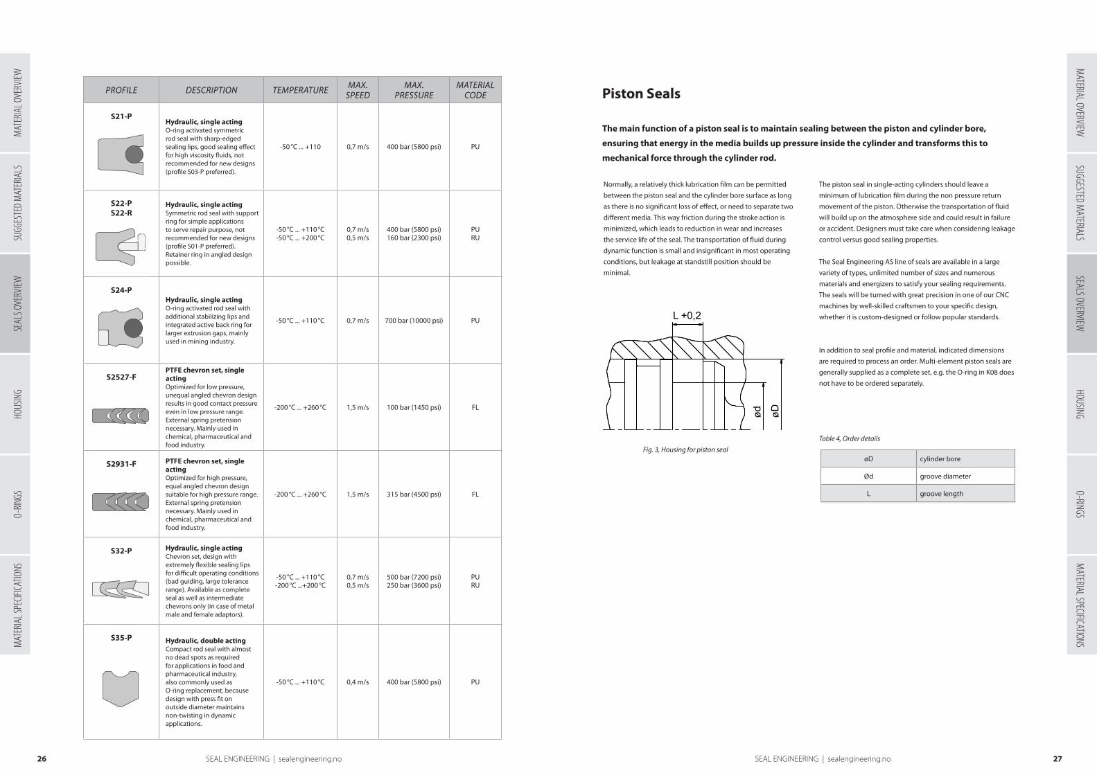
S21-PHydraulic, single actingO-ring activated symmetric rod seal with sharp-edged sealing lips, good sealing effect for high viscosity fluids, not recommended for new designs (profile S03-P preferred).
-50 °C ... +110 0,7 m/s 400 bar (5800 psi) PU
S22-PS22-R
Hydraulic, single actingSymmetric rod seal with support ring for simple applications to serve repair purpose, not recommended for new designs (profile S01-P preferred). Retainer ring in angled design possible.
-50 °C ... +110 °C-50 °C ... +200 °C
0,7 m/s0,5 m/s
400 bar (5800 psi)160 bar (2300 psi)
PURU
S24-PHydraulic, single actingO-ring activated rod seal with additional stabilizing lips and integrated active back ring for larger extrusion gaps, mainly used in mining industry.
-50 °C ... +110 °C 0,7 m/s 700 bar (10000 psi) PU
S2527-FPTFE chevron set, single actingOptimized for low pressure, unequal angled chevron design results in good contact pressure even in low pressure range. External spring pretension necessary. Mainly used in chemical, pharmaceutical and food industry.
-200 °C ... +260 °C 1,5 m/s 100 bar (1450 psi) FL
S2931-F PTFE chevron set, single actingOptimized for high pressure, equal angled chevron design suitable for high pressure range. External spring pretension necessary. Mainly used in chemical, pharmaceutical and food industry.
-200 °C ... +260 °C 1,5 m/s 315 bar (4500 psi) FL
S32-P Hydraulic, single actingChevron set, design with extremely flexible sealing lips for difficult operating conditions (bad guiding, large tolerance range). Available as complete seal as well as intermediate chevrons only (in case of metal male and female adaptors).
-50 °C ... +110 °C-200 °C ...+200 °C
0,7 m/s0,5 m/s
500 bar (7200 psi)250 bar (3600 psi)
PURU
S35-P Hydraulic, double actingCompact rod seal with almost no dead spots as required for applications in food and pharmaceutical industry, also commonly used as O-ring replacement, because design with press fit on outside diameter maintains non-twisting in dynamic applications.
-50 °C ... +110 °C 0,4 m/s 400 bar (5800 psi) PU
Piston Seals
acting sealsNormally, a relatively thick lubrication film can be permitted
between the piston seal and the cylinder bore surface as long
as there is no significant loss of effect, or need to separate two
different media. This way friction during the stroke action is
minimized, which leads to reduction in wear and increases
the service life of the seal. The transportation of fluid during
dynamic function is small and insignificant in most operating
conditions, but leakage at standstill position should be
minimal.Single-acting seals
øD cylinder bore
Ød groove diameter
L groove length
WIPER
PISTON
ROD
ROD
ROD
INT GUIDE
EXT GUIDE
L1 L
øD1
ød øD
ød øD
ød øDød øD
ød øD
L +0,2
L +0,2
L +0,2
L +0,2
ød øD
c/s
L
ød øD
c/s
L
Fig. 3, Housing for piston seal
The main function of a piston seal is to maintain sealing between the piston and cylinder bore,
ensuring that energy in the media builds up pressure inside the cylinder and transforms this to
mechanical force through the cylinder rod.
The piston seal in single-acting cylinders should leave a
minimum of lubrication film during the non pressure return
movement of the piston. Otherwise the transportation of fluid
will build up on the atmosphere side and could result in failure
or accident. Designers must take care when considering leakage
control versus good sealing properties.
The Seal Engineering AS line of seals are available in a large
variety of types, unlimited number of sizes and numerous
materials and energizers to satisfy your sealing requirements.
The seals will be turned with great precision in one of our CNC
machines by well-skilled craftsmen to your specific design,
whether it is custom-designed or follow popular standards.
Order detailsIn addition to seal profile and material, indicated dimensions
are required to process an order. Multi-element piston seals are
generally supplied as a complete set, e.g. the O-ring in K08 does
not have to be ordered separately.
Table 4, Order details
SUGG
ESTE
D M
ATER
IALS
SEAL
S OVE
RVIEW
HOUS
ING
O-RIN
GSM
ATER
IAL S
PECIF
ICATIO
NSM
ATERIAL OVERVIEWSUGGESTED M
ATERIALSSEALS OVERVIEW
HOUSINGO-RINGS
MATERIAL SPECIFICATIONS
MAT
ERIA
L OVE
RVIEW

2928 SEAL ENGINEERING | sealengineering.no SEAL ENGINEERING | sealengineering.no
PROFILE DESCRIPTION TEMPERATUREMAX.
SPEEDMAX.
PRESSURE MATERIAL
CODE
K01-PK01-R
Hydraulic, single actingAsymmetric piston seal for standard applications. Design provides stable fit in the housing, ultimate sealing effect over a wide temperature range. Avoids extensive drag pressure. Back-to-back arrangement for double acting pistons or to separate different fluids.
-50 °C ... +110 °C-50 °C ... +200 °C
0.7 m/s0.5 m/s
400 bar (5800 psi)160 bar (2300 psi)
PURU
K01-PEK01-RE
Hydraulic, single actingAsymmetric piston seal for standard applications. Design provides stable fit in the housing, ultimate sealing effect over a wide temperature range. Suitable for single acting cylinders due to improved static sealing.
-50 °C ... +110 °C-50 °C ... +200 °C
0.7 m/s0.5 m/s
400 bar (5800 psi)160 bar (2300 psi)
PURU
K02-PK02-R Hydraulic, single acting
Asymmetric piston seal for standard applications as K01, but due to design with active backup ring suitable for higher pressure range or larger extrusion gaps. K02-P/K02-R for standard housing design.
-50 °C ... +110 °C-50 °C ... +200 °C
0.7 m/s0.5 m/s
700 bar (10.000 psi)400 bar (5800 psi)
PURU
K02-PDK02-RD
Hydraulic, single actingAsymmetric piston seal for standard applications as K01, but due to design with active backup ring suitable for higher pressure or larger extrusion gaps. K02-PD/K02-RD for short housings.
-50 °C ... +110 °C-50 °C ... +200 °C
0.7 m/s0.5 m/s
700 bar (10.000 psi)400 bar (5800 psi)
PURU
K03-P Hydraulic, single actingO-ring activated asymmetric piston seal. Interference fit on inside diameter maintains stable fit in the housing. Design provides ultimate sealing effect. Especially suitable for short stroke applications (e.g. spindle seals, coupling actuators)
-50 °C ... +110 °C 0.7 m/s 400 bar (5800 psi) PU
K03-FHydraulic piston seal, single actingO-ring activated, asymmetric piston seal, low friction and no stick-slip effect. Good adaptation possibilities for various temperatures and media by selection of suitable seal and O-ring material, almost no dead spots as required for applications in food and pharmaceutical industry.
-60 °C ... +200 °C As designed As designed *
Highlighted profile(s): Recommended by Seal Engineering AS. See chapter 4 for details.
PROFILE DESCRIPTION TEMPERATUREMAX.
SPEEDMAX.
PRESSURE MATERIAL
CODE
K03-S Hydraulic piston seal, single actingHelicoil-spring activated, asymmetric piston seal, low friction and no stick-slip effect, excellent chemical and thermal resistance, mainly used in chemical, pharmaceutical and food industry or for valves.
-200 °C ...+260 °C
K04-PHydraulic, single actingAsymmetric piston seal for standard applications as K03-P, but due to design with active backup ring suitable for larger extrusion gaps or higher pressure. K04-P for standard housing design.
-50 °C ... +110 °C 0.7 m/s 700 bar (10.000 psi) PU
K04-PDHydraulic, single actingAsymmetric piston seal for standard applications as K03-P, but due to design with active backup ring suitable for larger extrusion gaps. K04-PD for short housings.
-50 °C ... +110 °C 0.7 m/s 700 bar (10.000 psi) PU
K05-PK05-R Pneumatic, single acting
Asymmetric piston seal, extremely wear resistant, for use in lubricated or dry pneumatic applications. Special design of sealing lip allows retention of initial lubricating film.
-50 °C ... +110 °C-50 °C ... +200 °C
1.4 m/s1 m/s
25 bar (360 psi)25 bar (360 psi)
PURU
K06-PK06-R Hydraulic, single acting
Symmetric piston seal for simple standard applications, not recommended for new designs (profile K01 preferred).
-50 °C ... +110 °C-50 °C ... +200 °C
0.7 m/s0.5 m/s
400 bar (5800 psi)160 bar (2300 psi)
PURU
K07-P Hydraulic, single actingO-ring activated symmetric piston seal for simple standard applications, not recommended for new designs (profile K03-P preferred).
-50 °C ... +110 °C 0.7 m/s 400 bar (5800 psi) PU
K08-EHydraulic, single actingO-ring activated asymmetric piston seal, low friction. For extreme low or high speed. Suitable for positioning functions.
-50 °C ... +200 °C-20 °C ... +110 °C
10 m/s5 m/s
600 bar (5800 psi)600 bar (5800 psi)
FLXPU
As designed
As designed *
Profiles overview
SUGG
ESTE
D M
ATER
IALS
SEAL
S OVE
RVIEW
HOUS
ING
O-RIN
GSM
ATER
IAL S
PECIF
ICATIO
NSM
ATERIAL OVERVIEWSUGGESTED M
ATERIALSSEALS OVERVIEW
HOUSINGO-RINGS
MATERIAL SPECIFICATIONS
MAT
ERIA
L OVE
RVIEW

3130 SEAL ENGINEERING | sealengineering.no SEAL ENGINEERING | sealengineering.no
PROFILE DESCRIPTION TEMPERATUREMAX.
SPEEDMAX.
PRESSURE MATERIAL
CODE
K08-D Hydraulic, double actingO-ring activated symmetric piston seal, low friction. For extreme low or high speed, suitable for positioning functions. For mobile hydraulics, machine tools, injection moulding machines, heavy hydraulics.
-50 °C ... +200 °C-20 °C ... +110 °C
10 m/s5 m/s
600 bar (8700 psi)600 bar (8700 psi)
FLXPU
K08-P
Hydraulic, double actingO-ring activated symmetric PU piston seal with excellent static and dynamic sealing capacity, extremely wear resistant.
-50 °C ... +110 °C 1.4 m/s 350 bar (5000 psi) PU
K08-ES Hydraulic, single actingProfile-ring activated asymmetric piston seal, similar to K08-E, but special heavy duty design. For heavy industry hydraulics or for special housing dimensions.
-50 °C ... +200 °C-20 °C ... +110 °C
10 m/s5 m/s
600 bar (8700 psi)600 bar (8700 psi)
FLXPU
K08-DS Hydraulic, double actingProfile-ring activated symmetric piston seal, similar to K08-D, but special heavy duty design. For heavy industry hydraulics or for special housing dimensions.
-50 °C ... +200 °C-20 °C ... +110 °C
10 m/s5 m/s
600 bar (8700 psi)600 bar (8700 psi)
FLXPU
K09-N Hydraulic, double actingProfile-ring activated compact piston seal with integrated guiding elements. Excellent static sealing capacity. Commonly used in standard cylinders.
-30 °C ... +110 °C 0.7 m/s 600 bar (8700 psi) PU
K09-D Hydraulic, double actingProfile-ring activated compact piston seal with integrated guiding elements. Excellent static and dynamic sealing capacity.
-30 °C ... +110 °C 0.7 m/s 600 bar (8700 psi) PU
K09-H Hydraulic, double actingProfile-ring activated compact piston seal with integrated guiding elements. Design for high pressure range, excellent static sealing capacity. Mainly used in mining/tunnelling industry.
-30 °C ... +110 °C 0.3 m/s As designed PU
Highlighted profile(s): Recommended by Seal Engineering AS. See chapter 4 for details.
PROFILE DESCRIPTION TEMPERATUREMAX.
SPEEDMAX.
PRESSURE MATERIAL
CODE
K09-FHydraulic, double actingProfile-ring activated compact piston seal with integrated guiding elements. Low friction, good chemical and thermal resistance with PTFE. Improved sealing, longevity and easier installation with XPU.
-30 °C ... +200 °C-20 ºC ... +110 ºC
10 m/s5 m/s
600 bar (8700 psi)600 bar (7200 psi)
FLXPU
K1012-THydraulic, single actingChevron sealing set, machined surface design. For back-to-back arrangement with one intermediate chevron, in single acting applications more intermediate chevrons possible. For heavy industry hydraulics. Due to different geometry type M cannot be interchanged with type T.
-50 °C ... +110 °C-50 °C ... +200 °C
0.7 m/s0.5 m/s
600 bar (8700 psi)400 bar (5800 psi)
PURU
K1012-MHydraulic, single actingChevron sealing set, parted surface design. For back-to-back arrangement with one intermediate chevron , in single acting applications more intermediate chevrons possible. For heavy industry hydraulics. Due to different geometry type T cannot be interchanged with type M.
-50 °C ... +110 °C-50 °C ... +200 °C
0.7 m/s0.5 m/s
600 bar (8700 psi)400 bar (5800 psi)
PURU
K1315-T
Hydraulic, single actingChevron sealing set, design with flexible sealing lips, good sealing ability. For heavy industry hydraulics, water hydraulic systems.
-50 °C ... +110 °C 0.7 m/s 600 bar (8700 psi) PU
K16-A Hydraulic/pneumatic, single actingSimple cup seal, usually fixed on the piston by means of a clamping plate. Mainly used for replacement in old hydraulic and pneumatic cylinders or for low-grade secondary applications. Also used for food filling/portioning equipment.
-50 °C ... +110 °C-50 °C ... +200 °C
0.7 m/s0.5 m/s
100 bar (1450 psi) 60 bar (870 psi)
PU RU
SUGG
ESTE
D M
ATER
IALS
SEAL
S OVE
RVIEW
HOUS
ING
O-RIN
GSM
ATER
IAL S
PECIF
ICATIO
NSM
ATERIAL OVERVIEWSUGGESTED M
ATERIALSSEALS OVERVIEW
HOUSINGO-RINGS
MATERIAL SPECIFICATIONS
MAT
ERIA
L OVE
RVIEW

3332 SEAL ENGINEERING | sealengineering.no SEAL ENGINEERING | sealengineering.no
PROFILE DESCRIPTION TEMPERATUREMAX.
SPEEDMAX.
PRESSURE MATERIAL
CODE
K16-B Hydraulic/pneumatic, single actingSimple cup seal, usually fixed on the piston by means of a clamping plate. Mainly used for replacement in old hydraulic and pneumatic cylinders or for low-grade secondary applications. Also used for food filling/portioning equipment.
-50 °C ... +110 °C-50 °C ... +200 °C
0.7 m/s0.5 m/s
100 bar (1450 psi) 60 bar (870 psi)
PU RU
K17-PK17-R Hydraulic, double acting
Space saving, compact piston seal with integrated guiding elements. Excellent static sealing capacity, suitable for small housings.
-50 °C ... +110 °C-50 °C ... +200 °C
0.7 m/s0.5 m/s
400 bar (5800 psi)250 bar (3600 psi)
PURU
K19-F PTFE-piston seal, single actingFinger-spring activated asymmetric PTFE piston seal, low friction and good dry running properties, excellent chemical and thermal resistance, mainly used in chemical, pharmaceutical and food industry. Hi-clean version available.
-200 °C ... +260 °C Asdesigned As designed *
K20-R Hydraulic, double actingSpace saving, compact piston seal, suitable for standard O-ring housings. Advantage compared to O-ring: integrated active backup rings for high pressure. Design with stretch fit on inside diameter prevents twisting in dynamic applications.
-50 °C ... +200 °C 0.5 m/s 700 bar (10000 psi) RU
K21-PHydraulic, single actingO-ring activated symmetric rod seal with sharp-edged sealing lips, good sealing effect for high viscosity fluids, not recommended for new designs (profile K03-P preferred).
-50 °C ... +110 °C 0.7 m/s 400 bar (5800 psi) PU
K22-PK22-R Hydraulic, single acting
Symmetric piston seal with support ring for simple applications to serve repair purpose, not recommended for new designs (profile K01-P preferred). Retainer ring in angled design possible.
-50 °C ... +110 °C-50 °C ... +200 °C
0.7 m/s0.5 m/s
400 bar (5800 psi)160 bar (2300 psi)
PURU
PROFILE DESCRIPTION TEMPERATUREMAX.
SPEEDMAX.
PRESSURE MATERIAL
CODE
K23-N Hydraulic, double actingProfile-ring activated compact piston seal with integrated backup rings, excellent static sealing capacity. External guiding elements required.
-30 °C ... +110 °C 0,7 m/s 600 bar (8700 psi) PU
K23-D Hydraulic, double actingProfile-ring activated compact piston seal with integrated backup rings. Excellent static and dynamic sealing capacity. External guiding elements required.
-30 °C ... +110 °C 0,7 m/s 600 bar (8700 psi) PU
K23-H Hydraulic, double actingProfile-ring activated compact piston seal with integrated backup rings. Design for high pressure range, excellent static sealing capacity. Mainly used in mining/tunnelling industry. External guiding elements required.
-30 °C ... +110 °C 0,3 m/s As designed PU
K23-F Hydraulic, double actingProfile-ring activated compact seal with integrated backup rings. Low friction, good chemical and thermal resistance with PTFE. Improved sealing, longevity and easier installation with XPU. External guiding elements required.
-30 °C ... +200 °C-20 ºC ... +110 ºC
1.5 m/s1.0 m/s
600 bar (8700 psi)600 bar (8700 psi)
FLXPU
K24-P Hydraulic, single actingChevron ring with flexible lip design. Replacement part for standard commercial housings (male and female adapter mainly made of metal).
-50 °C ... +110 °C-50 °C ... +200 °C
0,7 m/s0,5 m/s
500 bar (7200 psi)250 bar (3600 psi)
PURU
K32-P Hydraulic, single actingChevron sealing set, design with extremely flexible sealing lips for difficult operating conditions like bad guiding, large tolerance range. Available as total chevron sealing set as well as intermediate chevrons only (in case of metal male and female adapters).
-50 °C ... +110 °C-50 °C ... +200 °C
0,7 m/s0,5 m/s
500 bar (7200 psi)250 bar (3600 psi)
PURU
K35-P Hydraulic, double actingCompact piston seal with almost no dead spots as required for applications in food and pharmaceutical industry. Also commonly used as O-ring replacement. Design with press fit on outside diameter maintains non-twisting in dynamic applications.
-50 °C ... +110 °C 0,5 m/s 400 bar (5800 psi) PU
SUGG
ESTE
D M
ATER
IALS
SEAL
S OVE
RVIEW
HOUS
ING
O-RIN
GSM
ATER
IAL S
PECIF
ICATIO
NSM
ATERIAL OVERVIEWSUGGESTED M
ATERIALSSEALS OVERVIEW
HOUSINGO-RINGS
MATERIAL SPECIFICATIONS
MAT
ERIA
L OVE
RVIEW
3534 SEAL ENGINEERING | sealengineering.no SEAL ENGINEERING | sealengineering.no
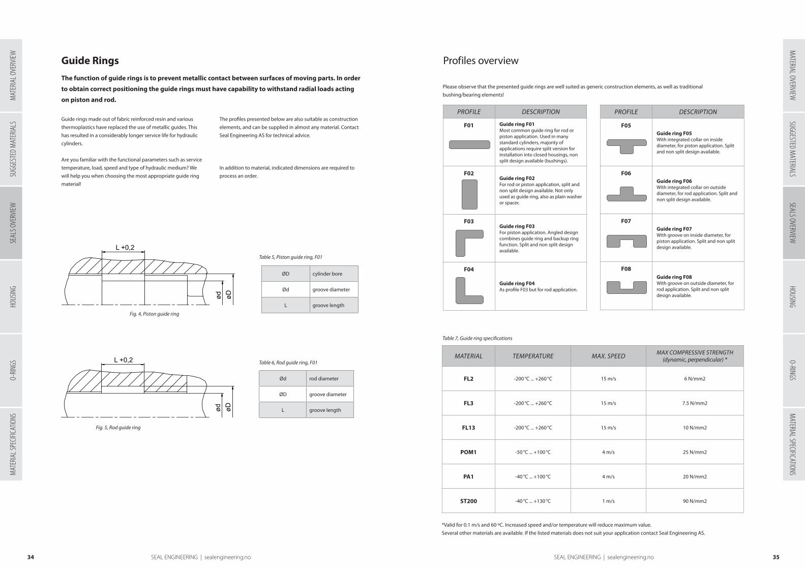
Guide Rings
Guide rings made out of fabric reinforced resin and various
thermoplastics have replaced the use of metallic guides. This
has resulted in a considerably longer service life for hydraulic
cylinders.
Are you familiar with the functional parameters such as service
temperature, load, speed and type of hydraulic medium? We
will help you when choosing the most appropriate guide ring
material!
Ød rod diameter
ØD groove diameter
L groove length
The function of guide rings is to prevent metallic contact between surfaces of moving parts. In order
to obtain correct positioning the guide rings must have capability to withstand radial loads acting
on piston and rod.
Table 5, Piston guide ring, F01
Table 6, Rod guide ring, F01
ØD cylinder bore
Ød groove diameter
L groove length
WIPER
PISTON
ROD
ROD
ROD
INT GUIDE
EXT GUIDE
L1 L
øD1
ød øD
ød øD
ød øDød øD
ød øD
L +0,2
L +0,2
L +0,2
L +0,2
ød øD
c/s
L
ød øD
c/s
L
The profiles presented below are also suitable as construction
elements, and can be supplied in almost any material. Contact
Seal Engineering AS for technical advice.
Order details (F01)In addition to material, indicated dimensions are required to
process an order.
WIPER
PISTON
ROD
ROD
ROD
INT GUIDE
EXT GUIDE
L1 L
øD1
ød øD
ød øD
ød øDød øD
ød øD
L +0,2
L +0,2
L +0,2
L +0,2
ød øD
c/s
L
ød øD
c/s
L
Fig. 4, Piston guide ring
Fig. 5, Rod guide ring
PROFILE DESCRIPTION
F01 Guide ring F01Most common guide ring for rod or piston application. Used in many standard cylinders, majority of applications require split version for installation into closed housings, non split design available (bushings).
F02Guide ring F02For rod or piston application, split and non split design available. Not only used as guide ring, also as plain washer or spacer.
F03Guide ring F03For piston application. Angled design combines guide ring and backup ring function. Split and non split design available.
F04
Guide ring F04As profile F03 but for rod application.
MATERIAL TEMPERATURE MAX. SPEEDMAX COMPRESSIVE STRENGTH
(dynamic, perpendicular) *
FL2 -200 °C ... +260 °C 15 m/s 6 N/mm2
FL3 -200 °C ... +260 °C 15 m/s 7.5 N/mm2
FL13 -200 °C ... +260 °C 15 m/s 10 N/mm2
POM1 -50 °C ... +100 °C 4 m/s 25 N/mm2
PA1 -40 °C ... +100 °C 4 m/s 20 N/mm2
ST200 -40 °C ... +130 °C 1 m/s 90 N/mm2
Profiles overview
Please observe that the presented guide rings are well suited as generic construction elements, as well as traditional
bushing/bearing elements!
*Valid for 0.1 m/s and 60 ºC. Increased speed and/or temperature will reduce maximum value.
Several other materials are available. If the listed materials does not suit your application contact Seal Engineering AS.
PROFILE DESCRIPTION
F05Guide ring F05With integrated collar on inside diameter, for piston application. Split and non split design available.
F06Guide ring F06With integrated collar on outside diameter, for rod application. Split and non split design available.
F07Guide ring F07With groove on inside diameter, for piston application. Split and non split design available.
F08Guide ring F08With groove on outside diameter, for rod application. Split and non split design available.
Table 7, Guide ring specifications
SUGG
ESTE
D M
ATER
IALS
SEAL
S OVE
RVIEW
HOUS
ING
O-RIN
GSM
ATER
IAL S
PECIF
ICATIO
NSM
ATERIAL OVERVIEWSUGGESTED M
ATERIALSSEALS OVERVIEW
HOUSINGO-RINGS
MATERIAL SPECIFICATIONS
MAT
ERIA
L OVE
RVIEW

3736 SEAL ENGINEERING | sealengineering.no SEAL ENGINEERING | sealengineering.no
Backup rings
O-rings are often used as static sealing elements in hydraulic systems. However, they tend to extrude into
the radial gap between the steel parts already at low pressures and are thereby destroyed. A possible
solution is to combine O-rings with backup rings.
Profiles overview
Several other materials are available. If the listed materials
does not suit your application contact Seal Engineering AS.
PROFILE DESCRIPTION
ST08Backup ringCommon inactive backup ring, mainly used with O-rings to avoid gap extrusion. Split and non split design available.
ST09Backup ringCommon active backup ring especially for O-rings to avoid gap extrusion. Split and non split design available
ST10 Backup ringStandard active backup ring for piston seal type PD. Normally already included in PD-type seal profiles, designed for automatic pressure activation. Split and non split design available.
PROFILE DESCRIPTION
ST11Backup ringStandard active backup ring for rod seal type PD. Normally already included in PD-type seal profiles, designed for automatic pressure activation. Split and non split design available.
ST12 Backup ringTriangular backup ring for rod applications. Fits in special shaped housings. Also used as integrated active backup ring in special high pressure or low friction seal profiles. Split and non split design available.
ST13 Backup ringTriangular backup ring for piston applications. Fits in special shaped housings. Also used as integrated active backup ring in special high pressure or low friction seal profiles. Split and non split design available.
Material Temperature
FL2 -200 °C ... +260 °C
FL3 -200 °C ... +260 °C
FL5 -200 °C ... +260 °C
FL13 -200 °C ... +260 °C
POM1 -50 °C ... +100 °C
PA1 -40 °C ... +100 °C
PEEK1 -60 ºC … +260 ºC
PU -50 °C ... +110 °C
XPU -20 ºC … +110 ºC
At high pressures other types of seals may also be in danger of
being extruded through the radial gap. The use of backup rings
is a widely used solution for this problem.
The right material must be selected to suit the need of the
application with respect to pressure, gap, temperature and
media.
Table 8, Temperature range for backup rings
Rotary seals
Rotary seals are used in a variety of applications, mainly for sealing of media against rotating shafts.
Rotary seals are used in various applications, and the type of seal used is dependant on many factors
such as type of movement (rotating, oscillating, spiral moving), velocity, pressure, temperature,
media and direction of pressure(s).
Order detailsIn addition to seal profile and material, indicated dimensions are required to
process an order. Multi-element rotary seals are generally supplied as a complete
set, e.g. the O-ring in R09 does not have to be ordered separately.
Table 9, Order details
WIPER
PISTON
ROD
ROD
ROD
INT GUIDE
EXT GUIDE
L1 L
øD1
ød øD
ød øD
ød øDød øD
ød øD
L +0,2
L +0,2
L +0,2
L +0,2
ød øD
c/s
L
ød øD
c/s
L
ød inside diameter
øD ouside diameter
L groove length
Fig 6, Housing for rotary seal
Profiles overview
PROFILE DESCRIPTION TEMPERATUREMAX
SPEEDMAX.
PRESSURE
MATERIAL
CODE
R01-P / R01-RSingle acting rotary shaft sealSpring-loaded lip seal with retainer ring for press-fit installation into axially open housings. Wide range of applications in every sector of industry, mainly as protecting element for bearings.
-40 °C ... +80 °C-50 °C ... +200 °C
6 m/s30 m/s
0.5 bar (7 psi)0.5 bar (7 psi)
PURU
R01-AF Single acting rotary shaft sealSpring- loaded lip seal with solid outer section for axially open housings with clamping plate fixation. Mainly used for rolling mills, large gear mechanisms in heavy duty machinery, for shipbuilding industry and civil engineering.
-40 °C ... +80 °C-50 °C ... +200 °C
6 m/s30 m/s
0.5 bar (7 psi)0.5 bar (7 psi)
PURU
R01-ASSingle acting rotary shaft sealSplit version of a spring-loaded lip seal with solid outer section for axially open housings with clamping plate fixation. Mainly used for repair purpose on rolling mills, large gear mechanisms in heavy duty machinery, for shipbuilding industry and civil engineering.
-40 °C ... +80 °C-50 °C ... +200 °C
6 m/s30 m/s
0.5 bar (7 psi)0.5 bar (7 psi)
PURU
SUGG
ESTE
D M
ATER
IALS
SEAL
S OVE
RVIEW
HOUS
ING
O-RIN
GSM
ATER
IAL S
PECIF
ICATIO
NSM
ATERIAL OVERVIEWSUGGESTED M
ATERIALSSEALS OVERVIEW
HOUSINGO-RINGS
MATERIAL SPECIFICATIONS
MAT
ERIA
L OVE
RVIEW

3938 SEAL ENGINEERING | sealengineering.no SEAL ENGINEERING | sealengineering.no
PROFILE DESCRIPTION TEMPERATUREMAX
SPEEDMAX
PRESSURE
MATERIAL
CODE
R01-FSingle acting rotary shaft sealSpring-loaded lip seal for press fit installation into axially open housing. Integrated O-ring necessary for static sealing in the housing. Excellent chemical and thermal resistance, suitable for high speed/pressure applications.
-100 ºC +260 ºC 10 m/s 15 bar (210 psi) FL
R02-P / R02-R
Single acting rotary shaft sealAs profile R01-P/R01-R, but with additional dust-lip to avoid ingress of dust and dirt.
-40 °C ... +80 °C-50 °C ... +200 °C
6 m/s30 m/s
0.5 bar (7 psi)0.5 bar (7 psi)
PURU
R03-P / R03-R Double acting rotary sealRotary seal with integrated backup rings for pivoting motion in hydraulic systems. Press fit on outside diameter maintains stable fit in the housing, backup rings permit larger extrusion gap / higher pressure. Mainly used for rotary pivots on excavators, grabs
-40 °C ... +100 °C-30 °C ... +200 °C
0.3 m/s0.2 m/s
400 bar (5800 psi)250 bar (3600 psi)
PURU
R04-ADouble acting rotary sealSpace saving rotary seal for pivoting motion in hydraulic systems. Press fit on outside diameter maintains stable fit in the housing, dynamic sealing lips on inside diameter.
-50 °C ... +110 °C-50 °C ... +200 °C
0.3 m/s0.2 m/s
160 bar (2300 psi)100 bar (1450 psi)
PURU
R05-ADouble acting rotary sealSpace saving rotary seal for pivoting motion in hydraulic systems. Interference fit on inside diameter maintains stable fit in the housing, dynamic sealing lips on outside diameter.
-50 °C ... +110 °C-50 °C ... +200 °C
0.3 m/s0.2 m/s
160 bar (2300 psi)100 bar (1450 psi)
PURU
R06-P / R06-R Axially acting rotary sealElastic, excellent wear resistant V-Ring with interference fit on the shaft, rotates with the shaft, sealing axially against shaft collars, thrust blocks or the outer race of roller bearings, protecting the bearing against dust, dirt, oil splash, water splash and similar media. Acting as a seal- and slinger ring.
-50 °C ... +110 °C-50 °C ... +200 °C
25 m/s25 m/s N/A PU
RU
PROFILE DESCRIPTION TEMPERATUREMAX
SPEEDMAX
PRESSURE
MATERIAL
CODE
R07-P / R07-R Axially acting rotary sealElastic, excellent wear resistant V-Ring with interference fit on the shaft, rotates with the shaft, sealing axially against shaft collars, thrust blocks or the outer race of roller bearings, protecting the bearing against dust, dirt, oil splash, water splash and similar media. Acting as a seal- and slinger ring.
-50 °C ... +110 °C-50 °C ... +200 °C
25 m/s25 m/s N/A PU
RU
R08-A
Single acting rotary sealSpring-less rotary lip seal with arbitrary preload on inside and outside diameter in order to design the seal to different specific needs.
As designed As designed As designed As designed
R09-F Double acting rotary sealO-ring activated, low friction rotary seal. Mainly used in applications with alternating pressure from one side of the seal to the other, such as hose reels, swivel joints, rotating track rings and machine tool hydraulics. Good chemical and thermal resistance achievable by selection of suitable O-ring material with PTFE-materials. Improved sealing, longevity and easier installation with XPU.
-50 °C ... +200 °C-20 ºC ... +110 ºC
0.4 m/s0,2 m/s
350 bar (5000 psi)350 bar (5000 psi)
FLXPU
R09-FSDouble acting rotary sealAs profile R09-F, but with a profile ring energizer instead of the O-ring. For heavy duty applications and non standard housings.
-30 °C ... +200 °C-30 ºC ... +100 °C
0.4 m/s0,2 m/s
350 bar (5000 psi)350 bar (5000 psi)
FLXPU
R10-FDouble acting rotary sealO-ring activated, low friction, rotary seal. Mainly used in applications with alternating pressure from one side of the seal to the other, such as hose reels, swivel joints, rotating track rings and machine tool hydraulics. Good chemical and thermal resistance achievable by selection of suitable O-ring material with PTFE-materials. Improved sealing, longevity and easier installation with XPU.
-50 °C ... +200 °C-20 ºC ... +110 ºC 0.4 m/s
0,2 m/s350 bar (5000 psi)350 bar (5000 psi)
FLXPU
SUGG
ESTE
D M
ATER
IALS
SEAL
S OVE
RVIEW
HOUS
ING
O-RIN
GSM
ATER
IAL S
PECIF
ICATIO
NSM
ATERIAL OVERVIEWSUGGESTED M
ATERIALSSEALS OVERVIEW
HOUSINGO-RINGS
MATERIAL SPECIFICATIONS
MAT
ERIA
L OVE
RVIEW
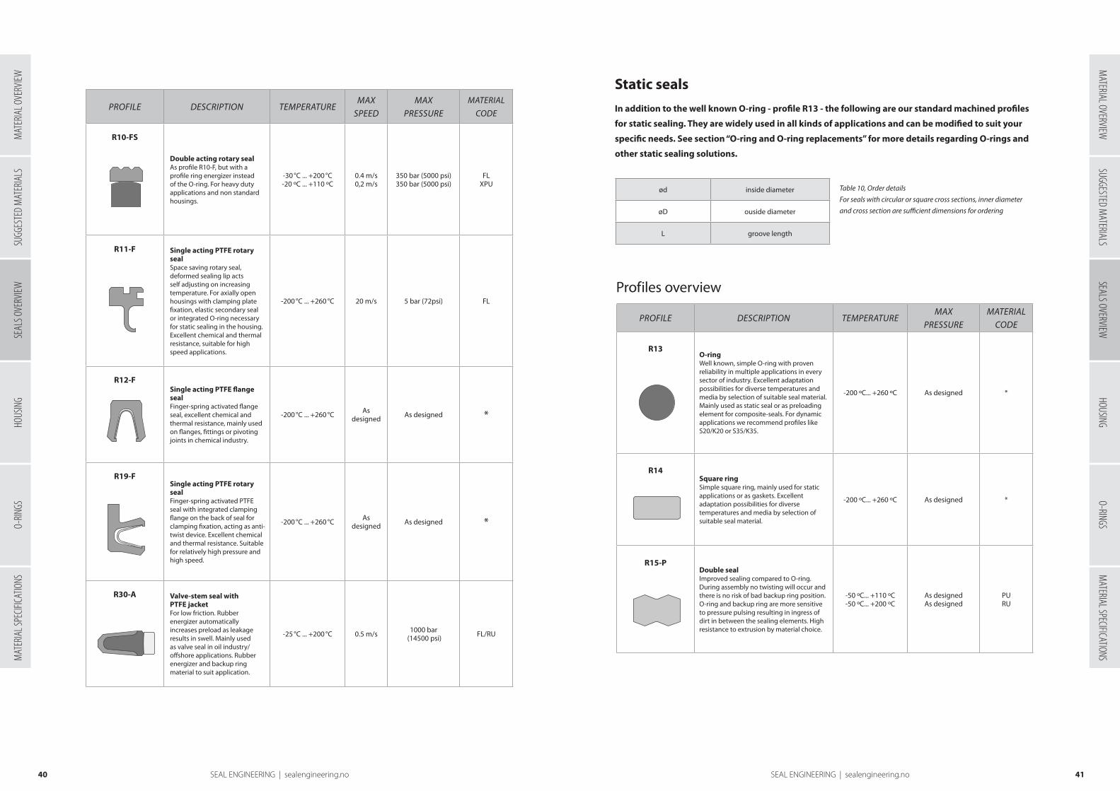
4140 SEAL ENGINEERING | sealengineering.no SEAL ENGINEERING | sealengineering.no
PROFILE DESCRIPTION TEMPERATUREMAX
SPEEDMAX
PRESSURE
MATERIAL
CODE
R10-FS
Double acting rotary sealAs profile R10-F, but with a profile ring energizer instead of the O-ring. For heavy duty applications and non standard housings.
-30 °C ... +200 °C-20 ºC ... +110 ºC
0.4 m/s0,2 m/s
350 bar (5000 psi)350 bar (5000 psi)
FLXPU
R11-F Single acting PTFE rotary sealSpace saving rotary seal, deformed sealing lip acts self adjusting on increasing temperature. For axially open housings with clamping plate fixation, elastic secondary seal or integrated O-ring necessary for static sealing in the housing. Excellent chemical and thermal resistance, suitable for high speed applications.
-200 °C ... +260 °C 20 m/s 5 bar (72psi) FL
R12-FSingle acting PTFE flange sealFinger-spring activated flange seal, excellent chemical and thermal resistance, mainly used on flanges, fittings or pivoting joints in chemical industry.
-200 °C ... +260 °C As designed As designed *
R19-FSingle acting PTFE rotary sealFinger-spring activated PTFE seal with integrated clamping flange on the back of seal for clamping fixation, acting as anti-twist device. Excellent chemical and thermal resistance. Suitable for relatively high pressure and high speed.
-200 °C ... +260 °C As designed As designed *
R30-A Valve-stem seal with PTFE jacketFor low friction. Rubber energizer automatically increases preload as leakage results in swell. Mainly used as valve seal in oil industry/offshore applications. Rubber energizer and backup ring material to suit application.
-25 °C ... +200 °C 0.5 m/s 1000 bar (14500 psi) FL/RU
Static seals
In addition to the well known O-ring - profile R13 - the following are our standard machined profiles
for static sealing. They are widely used in all kinds of applications and can be modified to suit your
specific needs. See section “O-ring and O-ring replacements” for more details regarding O-rings and
other static sealing solutions.
ød inside diameter
øD ouside diameter
L groove length
Table 10, Order details
For seals with circular or square cross sections, inner diameter
and cross section are sufficient dimensions for ordering
Profiles overview
PROFILE DESCRIPTION TEMPERATUREMAX
PRESSUREMATERIAL
CODE
R13O-ringWell known, simple O-ring with proven reliability in multiple applications in every sector of industry. Excellent adaptation possibilities for diverse temperatures and media by selection of suitable seal material. Mainly used as static seal or as preloading element for composite-seals. For dynamic applications we recommend profiles like S20/K20 or S35/K35.
-200 ºC... +260 ºC As designed *
R14Square ringSimple square ring, mainly used for static applications or as gaskets. Excellent adaptation possibilities for diverse temperatures and media by selection of suitable seal material.
-200 ºC... +260 ºC As designed *
R15-PDouble seal Improved sealing compared to O-ring. During assembly no twisting will occur and there is no risk of bad backup ring position. O-ring and backup ring are more sensitive to pressure pulsing resulting in ingress of dirt in between the sealing elements. High resistance to extrusion by material choice.
-50 ºC... +110 ºC-50 ºC... +200 ºC
As designedAs designed
PURU
SUGG
ESTE
D M
ATER
IALS
SEAL
S OVE
RVIEW
HOUS
ING
O-RIN
GSM
ATER
IAL S
PECIF
ICATIO
NSM
ATERIAL OVERVIEWSUGGESTED M
ATERIALSSEALS OVERVIEW
HOUSINGO-RINGS
MATERIAL SPECIFICATIONS
MAT
ERIA
L OVE
RVIEW
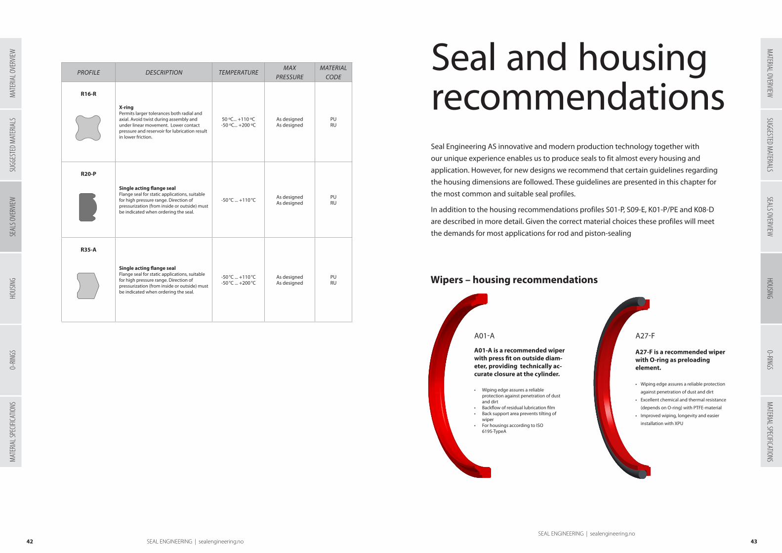
4342 SEAL ENGINEERING | sealengineering.noSEAL ENGINEERING | sealengineering.no
PROFILE DESCRIPTION TEMPERATUREMAX
PRESSUREMATERIAL
CODE
R16-R
X-ringPermits larger tolerances both radial and axial. Avoid twist during assembly and under linear movement. Lower contact pressure and reservoir for lubrication result in lower friction.
50 ºC... +110 ºC-50 ºC... +200 ºC
As designedAs designed
PURU
R20-P
Single acting flange sealFlange seal for static applications, suitable for high pressure range. Direction of pressurization (from inside or outside) must be indicated when ordering the seal.
-50 °C ... +110 °C As designedAs designed
PURU
R35-A
Single acting flange sealFlange seal for static applications, suitable for high pressure range. Direction of pressurization (from inside or outside) must be indicated when ordering the seal.
-50 °C ... +110 °C-50 °C ... +200 °C
As designedAs designed
PURU
Seal and housingrecommendationsSeal Engineering AS innovative and modern production technology together with
our unique experience enables us to produce seals to fit almost every housing and
application. However, for new designs we recommend that certain guidelines regarding
the housing dimensions are followed. These guidelines are presented in this chapter for
the most common and suitable seal profiles.
In addition to the housing recommendations profiles S01-P, S09-E, K01-P/PE and K08-D
are described in more detail. Given the correct material choices these profiles will meet
the demands for most applications for rod and piston-sealing
Wipers – housing recommendations
A01-A A27-F
A01-A is a recommended wiper with press fit on outside diam-eter, providing technically ac-curate closure at the cylinder.
• Wiping edge assures a reliable protection against penetration of dust and dirt • Backflow of residual lubrication film• Back support area prevents tilting of
wiper• For housings according to ISO
6195-TypeA
A27-F is a recommended wiper with O-ring as preloading element.
• Wiping edge assures a reliable protection
against penetration of dust and dirt
• Excellent chemical and thermal resistance
(depends on O-ring) with PTFE-material
• Improved wiping, longevity and easier
installation with XPU
SUGG
ESTE
D M
ATER
IALS
SEAL
S OVE
RVIEW
HOUS
ING
O-RIN
GSM
ATER
IAL S
PECIF
ICATIO
NSSUGGESTED M
ATERIALSSEALS OVERVIEW
HOUSINGO-RINGS
MATERIAL SPECIFICATIONS
MATERIAL OVERVIEW
MAT
ERIA
L OVE
RVIEW

A04-AA01-A
A02-A A05-A A11-A
Table 1, Wipers A01 and A04. Dimensions recommended for standard housing.
ød øD øD1 L L1 H* R1 (max) R2 (max)
6 – 100 ød+8 ød+6 4 1 7 0.4 0.3
100 – 150 ød+12 ød+9 5.5 1.5 10 0.4 0.4
> 150 ød+15 ød+11 6.5 2 13 0.4 0.6
* H=Total wiper height
ød øD øD1 L L1 H* R1 (max) R2 (max)
6 – 50 ød+8 ød+4 5 min. 2 8 0.4 0.3
50 – 100 ød+10 ød+5 6 min. 2 9.7 0.4 0.4
> 100 ød+15 ød+7.5 8.5 min. 2 13 0.4 0.6
Table 2, Wipers A02, A05 and A11. Dimensions recommended for standard housing.
* H=Total wiper height
A03-A A06-A
ød øD L H* C R1 (max)
6 – 10 ød+8 5 8 0.8 0.4
10 – 100 ød+10 7 10 1.0 0.4
100 – 200 ød+15 9 12 1.2 0.4
> 200 ød+20 12 16 1.5 0.4
Table 3, Wipers A03 and A06.
Dimensions recommended for standard housing.
* H=Total wiper height
Fig. 1, Housing for wiper A01, A02, A04, A05, A11.
Lead-in chamfer on the rod is designed to suit the rod seal used. For surface finish see end of section.
Fig. 2, Housing for wiper A03, A06.
Lead-in chamfer on the rod is designed to suit the rod seal used. For surface finish see end of section.
4544 SEAL ENGINEERING | sealengineering.noSEAL ENGINEERING | sealengineering.no
ød øD øD1 L L1 H* R1 (max) R2 (max)
11 – 100 ød+8 ød+4 3.1 1.5 10.5 0.4 0.3
100 – 150 ød+10 ød+5 6.0 2.0 13.0 0.4 0.4
150 – 600 ød+15 ød+7.5 8.5 3.0 19.0 0.4 0.4
ød øD øD1 L L1 H* R1 (max) R2 (max)
5 – 50 ød+8 ød+4 5 1.5 10.1 0.4 0.3
50 –100 ød+10 ød+5 6.0 2.0 12.6 0.4 0.4
100 – 600 ød+15 ød+7.5 8.6 3.0 18.4 0.4 0.4
Table 4, Wiper A12-A. Dimensions recommended for standard housing.
Table 5, Wiper A12-B. Dimensions recommended for standard housing.
*Total height
*Total height
Lead-in chamfer on the rod is designed to suit the rod seal used. For surface finish see end of section.
A12-A
Fig. 3, Housing for wiper A12.
A12-B
SUGG
ESTE
D M
ATER
IALS
SEAL
S OVE
RVIEW
O-RIN
GSM
ATER
IAL S
PECIF
ICATIO
NSSUGGESTED M
ATERIALSSEALS OVERVIEW
HOUSINGO-RINGS
MATERIAL SPECIFICATIONS
MATERIAL OVERVIEW
HOUS
ING
MAT
ERIA
L OVE
RVIEW

4746 SEAL ENGINEERING | sealengineering.noSEAL ENGINEERING | sealengineering.no
A27-F
ød øD øD1 L R1 (max) R2 (max) O-ring (2x)
20 – 50 ød+7.6 ød+1.0 4.2 0.4 0.2 BS 0xx/1.78
40 – 80 ød+8.8 ød+1.5 6.3 1.2 0.2 BS 1xx/2.62
70 – 165 ød+12.2 ød+2.0 8.1 2.0 0.2 BS 2xx/3.53
140 – 525 ød+16.5 ød+2.0 11.5 2.0 0.2 BS 3xx/5.33
400 – 650 ød+24.0 ød+2.5 15.5 2.0 0.2 BS 4xx/6.99
> 650 ød+27.3 ød+2.5 18.0 2.0 0.2 8.4
ød øD øD1 L R1 (max) R2 (max) O-ring
6 – 70 ød+4.8 ød+1.5 3.7 0.4 0.2 BS 0xx/1.78
12 – 155 ød+6.8 ød+1.5 5.0 0.7 0.2 BS 1xx/2.62
45 – 325 ød+8.8 ød+1.5 6.0 1.0 0.2 BS 2xx/3.53
145 – 540 ød+12.2 ød+2.0 8.4 1.5 0.2 BS 3xx/5.33
265 – 650 ød+16.0 ød+2.0 11.0 1.5 0.2 BS 4xx/6.99
> 400 ød+20.0 ød+2.5 14.0 2.0 0.2 8.4
Table 6, Wiper A26-F. Dimensions recommended for standard housing.
Table 7, Wiper A27-F. Dimensions recommended for standard housing.
A26-F
Lead-in chamfer on the rod is designed to suit the rod seal used. For surface finish see end of section.
Fig. 4 , Housing for wiper A26, A27.
S01-P profile
S01-P in HPU
Rod seals – housing recommendations
S01-P is our standard u-cup rod seal. This profile can be produced in different polyurethanes, with HPU being the most versatile and widely used.
S01-P
S01-P has the following advantages:
• Excellent static and dynamic sealing
• Good back-pumping ability
• High wear resistance/operational reliability
• Good chemical resistance
• Can be used as an individual seal or as
secondary seal within sealing systems
• Small cross sections possible
Technical data:
Material:
HPU
Pressure:
Up to 400 bar
Speed:
Up to 0.5 m/s (1.5 m/s possible if used as secondary seal)
Temperature:
- 20 ºC to 110 ºC
Media:
Mineral based hydraulic oils, HFA and HFB fluids,
biologically degradable oils and water (up to 90 ºC).
SUGG
ESTE
D M
ATER
IALS
SEAL
S OVE
RVIEW
O-RIN
GSM
ATER
IAL S
PECIF
ICATIO
NSSUGGESTED M
ATERIALSSEALS OVERVIEW
HOUSINGO-RINGS
MATERIAL SPECIFICATIONS
MATERIAL OVERVIEW
HOUS
ING
MAT
ERIA
L OVE
RVIEW

Lead-in chamfer, C, avoids damage to seal during installation. Surface roughness Rt < 4 µm. For surface finish see end of section.
Fig. 5, Housing for rod seal S01
Table 8, Dimensions recommended for standard housings for S01-P.
G: governed by design of guide ring groove or depending on the application
Rod ød øD L R1 (max) R2 (max) CMax radial extrusion gap “S”*
100 bar 200 bar 300 bar 400 bar
5 – 45 ød + 8 6.3 0.4 0.2 2.0 0.20 0.15 0.13 0.10
20 – 50 ød + 10 7.5 0.4 0.2 2.5 0.25 0.20 0.18 0.15
30 – 90 ød + 13 9.5 0.4 0.2 3.3 0.35 0.30 0.25 0.20
40 – 200 ød + 15 11 0.8 0.2 3.8 0.40 0.35 0.30 0.25
120 – 300 ød + 20 14.5 0.8 0.2 5.0 0.50 0.45 0.40 0.35
180 – 500 ød + 25 18 0.8 0.2 6.3 0.60 0.55 0.50 0.45
400 – 700 ød + 30 24 0.8 0.2 7.5 0.65 0.60 0.55 0.50
> 700 ød + 40 32 0.8 0.2 10.0 0.80 0.70 0.65 0.60
4948 SEAL ENGINEERING | sealengineering.noSEAL ENGINEERING | sealengineering.no
*specified extrusion gap is valid for a temperature of 50 ºC. Increased temperature will reduce permissible gap.
S01-P can also be produced to fit almost any non standard housing.
For applications demanding higher pressure or larger gaps, S02-P
(with active backup ring) is preferred. For demands regarding higher
temperatures or increased chemical resistance profiles S01 and S02
may also be produced in different kinds of rubbers, called S01-R and
S02-R.
Contact Seal Engineering AS for technical advice.
S09-E in XHPU
Profile S09-E is a single acting rod seal, consisting of a sealing
element and an elastomeric O-ring energizer. We supply profile
S09-E in XHPU/XSPU (hard grade polyurethanes) and PTFE-based
materials. S09-E in XHPU should be the preferred choice for standard
hydraulic; up to 110 ºC, whereas PTFE-based materials are the right
choice for elevated temperatures, excellent chemical resistance
or very low friction. Together these materials are able to meet the
demands of almost any application.
S09-E profile
S09-E in XHPU has the following advantages:
• Excellent static and dynamic sealing effect
• High wear resistance/operational reliability
• Excellent extrusion resistance (for high pressure/large gap sizes)
• Very good back-pumping ability (optimized sealing effect)
• Easy installation (no mounting and calibration tools necessary)
• Compact design
• Low friction, good stick-slip properties
Technical data:
Material:
XHPU
Pressure:
Up to 600 bar (for higher pressures contact Seal Engineering AS)
Speed:
Up to 5 m/s
Temperature:
- 20 ºC to 110 ºC
Media:
Mineral based hydraulic oils, HFA and HFB fluids, biologically degradable oils
and water (up to 90 ºC).
S09-E in XHPU/NBR
SUGG
ESTE
D M
ATER
IALS
SEAL
S OVE
RVIEW
O-RIN
GSM
ATER
IAL S
PECIF
ICATIO
NSSUGGESTED M
ATERIALSSEALS OVERVIEW
HOUSINGO-RINGS
MATERIAL SPECIFICATIONS
MATERIAL OVERVIEW
HOUS
ING
MAT
ERIA
L OVE
RVIEW

Lead-in chamfer, C, avoids damage to seal during installation. Surface roughness Rt < 4 µm. For surface finish see end of section.
Fig. 6, Housing for rod seal S09.
Rod ød øD L R1 (max) R2 (max) C O-ringMax radial extrusion gap “S”*
100 bar 200 bar 400 bar 600 bar
5 – 7.9 ød + 4.9 2.2 0.4 0.2 2.5 BS 0xx/1.78 0.3 0.3 0.2 0.1
8 – 18.9 ød + 7.3 3.2 0.6 0.2 3.5 BS 1xx/2.62 0.4 0.3 0.2 0.1
19 – 37.9 ød + 10.7 4.2 1.0 0.2 4.5 BS 2xx/3.53 0.5 0.4 0.3 0.2
38 – 199.9 ød + 15.1 6.3 1.3 0.2 5.0 BS 3xx/5.33 0.5 0.4 0.3 0.2
200 – 255.9 ød + 20.5 8.1 1.8 0.2 6.0 BS 4xx/6.99 0.7 0.5 0.4 0.2
256 – 649.9 ød + 24 8.1 1.8 0.2 8.0 BS 4xx/6.99 0.7 0.5 0.4 0.2
650 – 999.9 ød + 27.3 9.5 2.5 0.2 10.0 8.40 0.8 0.7 0.5 0.3
> 1000 ød + 38 13.8 3.0 0.2 12.0 12.0 1.1 0.8 0.7 0.4
*specified extrusion gap valid up to 80 ºC, between 80 ºC and 100 ºC the gap size must be reduced by 25%.
Table 9, Dimensions recommended for standard housing for S09-E.
Rod ød øD L R1 (max) R2 (max) C O-ringMax radial extrusion gap “S”*
100 bar 200 bar 400 bar 600 bar
5 – 7.9 ød + 4.9 2.2 0.4 0.2 2.5 BS 0xx/1.78 0.3 0.3 0.2 0.1
8 – 18.9 ød + 7.3 3.2 0.6 0.2 3.5 BS 1xx/2.62 0.4 0.3 0.2 0.1
19 – 37.9 ød + 10.7 4.2 1.0 0.2 4.5 BS 2xx/3.53 0.5 0.4 0.3 0.2
38 – 199.9 ød + 15.1 6.3 1.3 0.2 5.0 BS 3xx/5.33 0.5 0.4 0.3 0.2
200 – 255.9 ød + 20.5 8.1 1.8 0.2 6.0 BS 4xx/6.99 0.7 0.5 0.4 0.2
256 – 649.9 ød + 24 8.1 1.8 0.2 8.0 BS 4xx/6.99 0.7 0.5 0.4 0.2
650 – 999.9 ød + 27.2 9.5 2.5 0.2 10.0 8.40 0.8 0.7 0.5 0.3
> 1000 ød + 38 13.8 3.0 0.2 12.0 12.0 1.1 0.8 0.7 0.4
* specified extrusion gap is only valid for certain types of fillers and temperature.
Table 10, Dimensions recommended for standard housing for S09-E.
5150 SEAL ENGINEERING | sealengineering.noSEAL ENGINEERING | sealengineering.no
We can also supply S09-E or S09-ES to suit almost any non-standard housing.
Contact Seal Engineering AS for technical advice.
S09-E in PTFE-based materials has the following advantages:
• Excellent chemical resistance (depending on O-ring material)
• Excellent temperature resistance (depending on O-ring material)
• Very low friction, excellent stick-slip behaviour
• Suitable for high speed applications
• Excellent extrusion resistance (given suitable filler)
• Compact design
Technical data:
Material:
PTFE-based
Pressure:
Up to 600 bar (for higher pressures contact Seal Engineering AS)
Speed:
Up to 10 m/s
Temperature:
- 50 ºC to 200 ºC (for higher temperatures contact Seal Engineering AS)
Media:
Resistant to all chemicals except elementary fluorine and molten alkali metals
S09-E in FL2/RU2
We can also supply S09-E or S09-ES to suit almost any non-standard housing.
Contact Seal Engineering AS for technical advice.
S09-E in PTFE-based materials
SUGG
ESTE
D M
ATER
IALS
SEAL
S OVE
RVIEW
O-RIN
GSM
ATER
IAL S
PECIF
ICATIO
NSSUGGESTED M
ATERIALSSEALS OVERVIEW
HOUSINGO-RINGS
MATERIAL SPECIFICATIONS
MATERIAL OVERVIEW
HOUS
ING
MAT
ERIA
L OVE
RVIEW

S01-P S02-P S03-P S03-F S04-P
S05-P S17-P S18-P S24-P
S03-S
S19-F
Table 11, Dimensions recommended for standard housings for U-cup rod seals.
G: governed by design of guide ring groove or depending on the application
Rod ød øD L R1 (max) R2 (max) C
5 – 45 ød + 8 6.3 0.4 0.2 2.0
20 – 50 ød + 10 7.5 0.4 0.2 2.5
30 – 90 ød + 13 9.5 0.4 0.2 3.3
40 – 200 ød + 15 11 0.8 0.2 3.8
120 – 300 ød + 20 14.5 0.8 0.2 5.0
180 – 500 ød + 25 18 0.8 0.2 6.3
400 – 700 ød + 30 24 0.8 0.2 7.5
> 700 ød + 40 32 0.8 0.2 10.0
Table 12, Spring-energized rod seal S03-S. Dimensions recommended for standard housing. Use of
split groove is recommended, for closed or semi-closed groove please contact Seal Engineering AS.
Rod ød øD L R1 (max) R2 (max) C
10 – 70 ød + 6 4.7 0.4 0.2 5.0
15 – 100 ød + 8 5.5 0.4 0.2 5.0
20 – 200 ød + 10 8.0 0.4 0.2 5.0
30 – 300 ød + 12 8.5 0.4 0.2 7.5
40 – 500 ød + 15 11.5 0.8 0.2 7.5
50 – 1000 ød + 20 15.5 0.8 0.2 10.0
70 – 1400 ød + 25 18.5 0.8 0.2 10.0
100 – 1400 ød + 30 23.0 0.8 0.2 12.0
100 – 2000 ød + 40 30.5 0.8 12.0
Table 13, Spring-energized rod seal S19-F. Dimensions recommended for standard housing. Use of split groove is
recommended, for closed or semi-closed groove please contact Seal Engineering AS.
Rod ød øD L R1 (max) R2 (max) C (O-ring equivalent)
10 – 110 ød + 4.5 3.6 0.4 0.2 5.0 BS 1xx/2.62
20 – 220 ød + 6.2 4.8 0.4 0.2 5.0 BS 2xx/3.53
40 – 410 ød + 9.4 7.1 0.4 0.2 7.5 BS 3xx/5.33
120 – 1115 ød + 12.2 9.5 0.4 0.2 12.0 BS 4xx/6.99
> 1000 ød + 19 15 0.8 0.2 12.0
5352 SEAL ENGINEERING | sealengineering.noSEAL ENGINEERING | sealengineering.no
Other profiles
U-cup rod seals S01, S02, S03, S04, S05, S17, S18 and S24. Dimensions recommended for standard housing, partly based on ISO 5597.
Lead-in chamfer, C, avoids damage to seal during installation. Surface roughness Rt < 4 µm. For surface finish see end of section.
Fig. 7, Housing for rod seals S01, S02, S03, S04, S05, S17, S18, S24
Lead-in chamfer, C, avoids damage to seal during installation. Surface roughness Rt < 4 µm. For surface finish see end of section.
Fig. 8, Housing for rod seals S03-S, S19-S
SUGG
ESTE
D M
ATER
IALS
SEAL
S OVE
RVIEW
O-RIN
GSM
ATER
IAL S
PECIF
ICATIO
NSSUGGESTED M
ATERIALSSEALS OVERVIEW
HOUSINGO-RINGS
MATERIAL SPECIFICATIONS
MATERIAL OVERVIEW
HOUS
ING
MAT
ERIA
L OVE
RVIEW

S09-DS09-E S09-P
Rod seal housing details
Rod ød øD L R1 (max) R2 (max) C O-ring
5 – 7.9 ød + 4.9 2.2 0.4 0.2 2.5 BS 0xx/1.78
8 – 18.9 ød + 7.3 3.2 0.6 0.2 3.5 BS 1xx/2.62
19 – 37.9 ød + 10.7 4.2 1.0 0.2 4.5 BS 2xx/3.53
38 – 199.9 ød + 15.1 6.3 1.3 0.2 5.0 BS 3xx/5.33
200 – 255.9 ød + 20.5 8.1 1.8 0.2 6.0 BS 4xx/6.99
256 – 649.9 ød + 24 8.1 1.8 0.2 8.0 BS 4xx/6.99
650 – 999.9 ød + 27.3 9.5 2.5 0.2 10.0 8.40
> 1000 ød + 38 13.8 3.0 0.2 12.0 12.0
Table 14, Dimensions recommended for standard housing for rod seals S09-E, S09-P, S09-D.
Table 15
*Surface roughness recommendations are typical values only. Contact Seal Engineering AS for application specific recommendations.
Surface roughness* Rt (µm) Ra (µm)
Sliding surface for PU/RUBBER seals Sliding surface for PTFE seals
≤ 2.5≤ 2.0
≤ 0.1 - 0.5≤ 0.05 - 0.3
Bottom of groove (Rt1/Ra1) Groove face (Rt2/Ra2)
≤ 6.3≤ 15
≤ 0.8≤ 3.2
Bearing area, Rmr 50% – 95% (cutting depth 0.5 Rz , based on cref = 0%)
5554 SEAL ENGINEERING | sealengineering.noSEAL ENGINEERING | sealengineering.no
Lead-in chamfer, C, avoids damage to seal during installation. Surface roughness Rt < 4 µm. For surface finish see end of section.
Fig. 9, Housing for rod seals S09
K01-P in HPU
K01-P and K01-PE
K01 is our standard single acting u-cup seal piston seal. For single
acting cylinders K01-PE is the preferred profile, whereas K01-P is
preferred in back-to-back arrangements. These profiles can be
produced in different polyurethanes, with HPU being the most
versatile and widely used.
K01-P
Technical data:
Material:
HPU
Pressure:
Up to 400 bar
Speed:
Up to 0.5 m/s
Temperature:
- 20 ºC to 110 ºC
Media:
Mineral based hydraulic oils, HFA and HFB fluids,
biologically degradable oils and water (up to 90 ºC).
K01 has the following advantages:
• Excellent static and dynamic sealing
• Excellent holding/positioning capability for single acting cylinders (K01-PE)
• Back-to-back arrangements for double acting cylinders or for separation of fluids (K01-P)
• High wear resistance/operational reliability
• Good chemical resistance
• Small cross sections possible
K01-PE
Piston seals – housing recommendations
SUGG
ESTE
D M
ATER
IALS
SEAL
S OVE
RVIEW
O-RIN
GSM
ATER
IAL S
PECIF
ICATIO
NSSUGGESTED M
ATERIALSSEALS OVERVIEW
HOUSINGO-RINGS
MATERIAL SPECIFICATIONS
MATERIAL OVERVIEW
HOUS
ING
MAT
ERIA
L OVE
RVIEW

Bore øD ød L R1 (max) R2 (max) CMax radial extrusion gap “S”*
100 bar 200 bar 300 bar 400 bar
12 – 40 øD - 8 6 0.4 0.2 2.0 0.20 0.15 0.13 0.10
25 – 60 øD - 10 7 0.4 0.2 2.5 0.25 0.20 0.18 0.15
50 – 140 øD – 15 9.5 0.8 0.2 3.8 0.40 0.35 0.30 0.25
100 – 300 øD - 20 12.5 0.8 0.2 5.0 0.50 0.45 0.40 0.30
125 – 500 øD – 25 16 0.8 0.2 6.3 0.55 0.50 0.45 0.40
500 – 750 øD - 30 20 0.8 0.2 7.5 0.60 0.55 0.50 0.45
> 750 øD - 40 26 0.8 0.2 10.0 0.70 0.60 0.55 0.50
Table 16, Dimensions recommended for standard housings for K01-P.
G: governed by design of guide ring groove or depending on the application
5756 SEAL ENGINEERING | sealengineering.noSEAL ENGINEERING | sealengineering.no
*specified extrusion gap is valid for a temperature of 50 ºC. Increased temperature will reduce permissible gap.
K01 can also be produced to fit almost any non standard
housing.
For applications demanding higher pressure or larger gaps,
K02-P (with active backup ring) is preferred. For demands
regarding higher temperatures or increased chemical resistance
profiles K01 and K02 may also be produced in different kinds of
rubbers, called K01-R and K02-R.
Contact Seal Engineering AS for technical advice.
Lead-in chamfer, C, avoids damage to seal during installation. Surface roughness Rt < 4 µm. For surface finish see end of section.
Fig. 10, Housing for piston seals K01
K08-D
Profile K08-D is a double acting piston seal, consisting of a sealing
element and elastomeric O-ring energizer. We supply profile
K08-D in XHPU/XSPU (hard grade polyurethanes) and PTFE-based
materials. K08-D in XHPU should be the preferred choice for
standard hydraulic; up to 110 ºC, whereas PTFE-based materials
are the right choice for elevated temperatures, excellent chemical
resistance or very low friction. Together these materials are able to
meet the demands of almost any application.
K08-D in XHPU has the following advantages:
• Good static and dynamic sealing effect
• High wear resistance/operational reliability
• Excellent extrusion resistance (for high pressure/large gap sizes)
• Fast pressurisation/no “blow-by” effect
• Low friction, good stick-slip properties
• Easy installation (no mounting and calibration tools necessary)
• Compact design
Technical data:
Material:
XHPU
Pressure:
Up to 600 bar (for higher pressures contact Seal Engineering AS)
Speed:
Up to 5 m/s
Temperature:
- 30 ºC to 110 ºC
Media:
Mineral based hydraulic oils, HFA and HFB fluids,
biologically degradable oils and water (up to 90 ºC).
K08-D
K08-D in XHPU/RU1
SUGG
ESTE
D M
ATER
IALS
SEAL
S OVE
RVIEW
O-RIN
GSM
ATER
IAL S
PECIF
ICATIO
NSSUGGESTED M
ATERIALSSEALS OVERVIEW
HOUSINGO-RINGS
MATERIAL SPECIFICATIONS
MATERIAL OVERVIEW
HOUS
ING
MAT
ERIA
L OVE
RVIEW

Table 17, Dimensions recommended for standard housing for K08-D.
Standard bore øD
Extended bore øD ød L R1 (max) R2 (max) C O-ring
Max radial extrusion gap “S”*
100 bar 200 bar 400 bar 600 bar
8 – 14.9 8 – 40 øD - 4.9 2.2 0.4 0.2 2.5 BS 0xx/1.78 0.3 0.3 0.2 0.1
15 – 39.9 15 – 80 øD - 7.5 3.2 0.6 0.2 3.5 BS 1xx/2.62 0.4 0.3 0.2 0.1
40 – 79.9 15 – 133 øD - 11 4.2 1.0 0.2 4.5 BS 2xx/3.53 0.5 0.4 0.3 0.2
80 – 132.9 40 – 330 øD - 15.5 6.3 1.3 0.2 5.0 BS 3xx/5.33 0.5 0.4 0.3 0.2
133 – 329.9 80 – 670 øD - 21 8.1 1.8 0.2 6.0 BS 4xx/6.99 0.7 0.5 0.4 0.2
330 – 669.9 133 – 1000 øD - 24.5 8.1 1.8 0.2 8.0 BS 4xx/6.99 0.7 0.5 0.4 0.2
670 – 999.9 330 – 1000 øD - 28 9.5 2.5 0.2 10.0 8.4 0.8 0.7 0.5 0.3
> 1000 øD - 38 13.8 3.0 0.2 12.0 12.0 1.1 0.8 0.7 0.4
Table 18, Dimensions recommended for standard housing for K08-D. R2 = 0.2
Standard bore øD
Extended bore øD ød L R1
(max)R2
(max) C O-ringMax radial extrusion gap “S”*
100 bar 200 bar 400 bar 600 bar
8 – 14.9 8 – 40 øD - 4.9 2.2 0.4 0.2 2.5 BS 0xx/1.78 0.3 0.3 0.2 0.1
15 – 39.9 15 – 80 øD - 7.5 3.2 0.6 0.2 3.5 BS 1xx/2.62 0.4 0.3 0.2 0.1
40 – 79.9 15 – 133 øD - 11 4.2 1.0 0.2 4.5 BS 2xx/3.53 0.5 0.4 0.3 0.2
80 – 132.9 40 – 330 øD - 15.5 6.3 1.3 0.2 5.0 BS 3xx/5.33 0.5 0.4 0.3 0.2
133 – 329.9 80 – 670 øD - 21 8.1 1.8 0.2 6.0 BS 4xx/6.99 0.7 0.5 0.4 0.2
330 – 669.9 133 – 1000 øD - 24.5 8.1 1.8 0.2 8.0 BS 4xx/6.99 0.7 0.5 0.4 0.2
670 – 999.9 330 – 1000 øD - 28 9.5 2.5 0.2 10.0 8.4 0.8 0.7 0.5 0.3
> 1000 øD - 38 13.8 3.0 0.2 12.0 12.0 1.1 0.8 0.7 0.4
5958 SEAL ENGINEERING | sealengineering.noSEAL ENGINEERING | sealengineering.no
Lead-in chamfer, C, avoids damage to seal during installation. Surface roughness Rt < 4 µm. For surface finish see end of section.
Fig. 11, Housing for piston seals K08.
We can also supply K08D or K08-DS to suit almost any non-standard housing. Contact Seal Engineering AS for technical advice.
*specified extrusion gap valid up to 80 ºC, between 80 ºC and 100 ºC the gap size must be reduced by 25%
K08-D in PTFE-based materials has the following advantages:
• Excellent chemical resistance (depending on O-ring material)
• Excellent temperature resistance (depending on O-ring material)
• Very low friction, excellent stick-slip behaviour
• Suitable for high speed applications
• Fast pressurisation/no “blow-by” effect
• Excellent extrusion resistance (given suitable filler)
• Compact design
Technical data:
Material:
PTFE-based
Pressure:
Up to 600 bar (for higher pressures contact Seal Engineering AS)
Speed:
Up to 10 m/s
Temperature:
- 50 ºC to 200 ºC (for higher temperatures contact Seal Engineering AS)
Media:
Resistant to all chemicals except elementary fluorine and molten alkali metals
K08-D in FL13/RU2
* specified extrusion gap is only valid for certain types of fillers and temperature
We can also supply K08-D or K08-DS to suit almost any non-standard housing.
Contact Seal Engineering AS for tecnical advice.
SUGG
ESTE
D M
ATER
IALS
SEAL
S OVE
RVIEW
O-RIN
GSM
ATER
IAL S
PECIF
ICATIO
NSSUGGESTED M
ATERIALSSEALS OVERVIEW
HOUSINGO-RINGS
MATERIAL SPECIFICATIONS
MATERIAL OVERVIEW
HOUS
ING
MAT
ERIA
L OVE
RVIEW
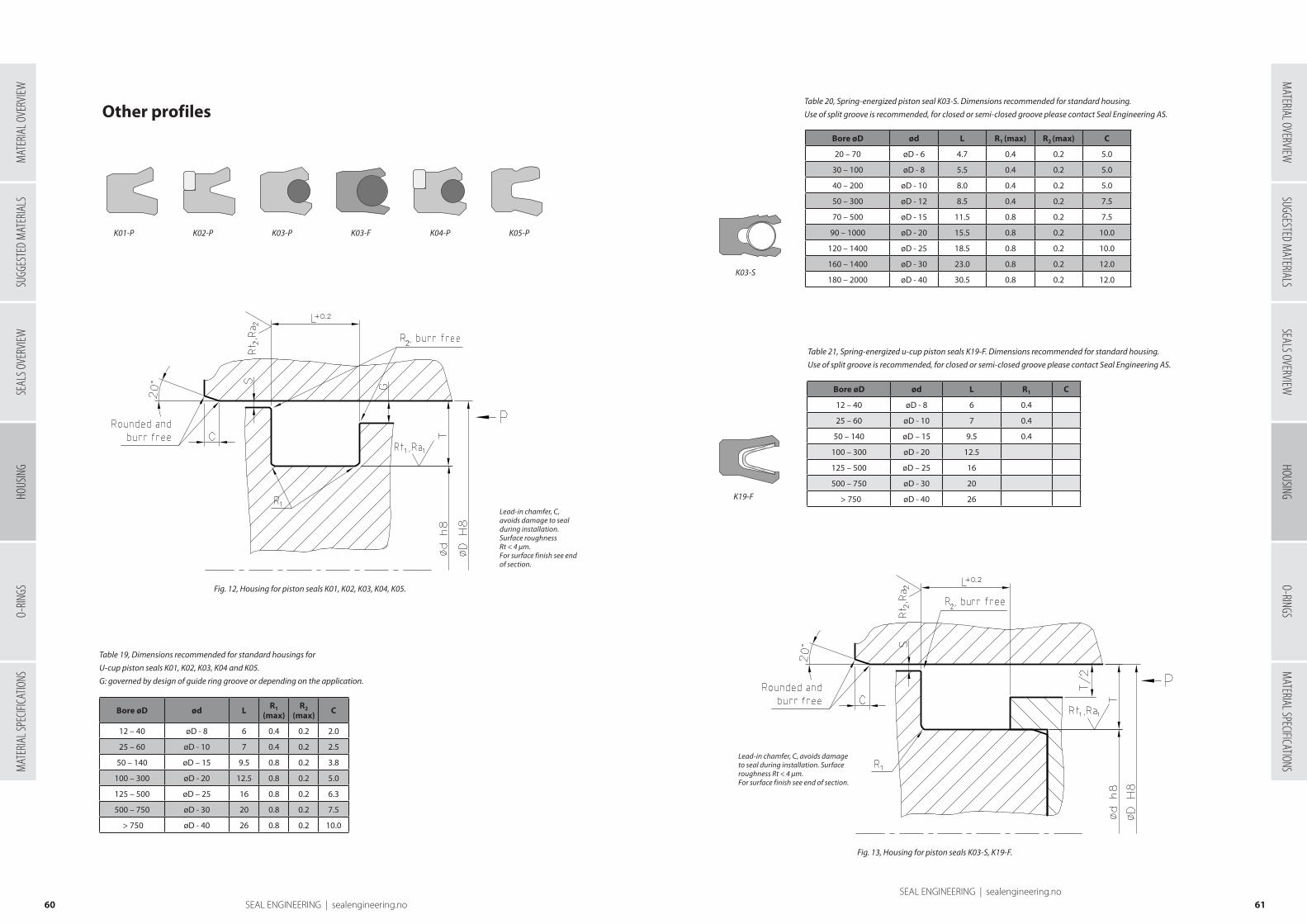
K03-S
K19-F
Table 19, Dimensions recommended for standard housings for
U-cup piston seals K01, K02, K03, K04 and K05.
G: governed by design of guide ring groove or depending on the application.
Bore øD ød L R1 (max)
R2 (max) C
12 – 40 øD - 8 6 0.4 0.2 2.0
25 – 60 øD - 10 7 0.4 0.2 2.5
50 – 140 øD – 15 9.5 0.8 0.2 3.8
100 – 300 øD - 20 12.5 0.8 0.2 5.0
125 – 500 øD – 25 16 0.8 0.2 6.3
500 – 750 øD - 30 20 0.8 0.2 7.5
> 750 øD - 40 26 0.8 0.2 10.0
Table 20, Spring-energized piston seal K03-S. Dimensions recommended for standard housing.
Use of split groove is recommended, for closed or semi-closed groove please contact Seal Engineering AS.
Table 21, Spring-energized u-cup piston seals K19-F. Dimensions recommended for standard housing.
Use of split groove is recommended, for closed or semi-closed groove please contact Seal Engineering AS.
Bore øD ød L R1 (max) R2 (max) C
20 – 70 øD - 6 4.7 0.4 0.2 5.0
30 – 100 øD - 8 5.5 0.4 0.2 5.0
40 – 200 øD - 10 8.0 0.4 0.2 5.0
50 – 300 øD - 12 8.5 0.4 0.2 7.5
70 – 500 øD - 15 11.5 0.8 0.2 7.5
90 – 1000 øD - 20 15.5 0.8 0.2 10.0
120 – 1400 øD - 25 18.5 0.8 0.2 10.0
160 – 1400 øD - 30 23.0 0.8 0.2 12.0
180 – 2000 øD - 40 30.5 0.8 0.2 12.0
Bore øD ød L R1 C
12 – 40 øD - 8 6 0.4
25 – 60 øD - 10 7 0.4
50 – 140 øD – 15 9.5 0.4
100 – 300 øD - 20 12.5
125 – 500 øD – 25 16
500 – 750 øD - 30 20
> 750 øD - 40 26
6160 SEAL ENGINEERING | sealengineering.noSEAL ENGINEERING | sealengineering.no
Other profiles
K01-P K02-P K03-P K03-F K04-P K05-P
Lead-in chamfer, C, avoids damage to seal during installation. Surface roughness Rt < 4 µm. For surface finish see end of section.
Fig. 12, Housing for piston seals K01, K02, K03, K04, K05.
Lead-in chamfer, C, avoids damage to seal during installation. Surface roughness Rt < 4 µm. For surface finish see end of section.
Fig. 13, Housing for piston seals K03-S, K19-F.
SUGG
ESTE
D M
ATER
IALS
SEAL
S OVE
RVIEW
O-RIN
GSM
ATER
IAL S
PECIF
ICATIO
NSSUGGESTED M
ATERIALSSEALS OVERVIEW
HOUSINGO-RINGS
MATERIAL SPECIFICATIONS
MATERIAL OVERVIEW
HOUS
ING
MAT
ERIA
L OVE
RVIEW
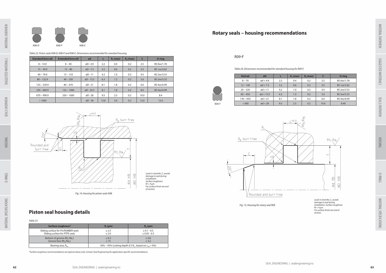
Table 22, Piston seals K08-D, K08-P and K08-E. Dimensions recommended for standard housing.
Standard bore øD Extended bore øD ød L R1 (max) R2 (max) C O-ring
8 – 14.9 8 – 40 øD - 4.9 2.2 0.4 0.2 2.5 BS 0xx/1.78
15 – 39.9 15 – 80 øD - 7.5 3.2 0.6 0.2 3.5 BS 1xx/2.62
40 – 79.9 15 – 133 øD - 11 4.2 1.0 0.2 4.5 BS 2xx/3.53
80 – 132.9 40 – 330 øD - 15.5 6.3 1.3 0.2 5.0 BS 3xx/5.33
133 – 329.9 80 – 670 øD - 21 8.1 1.8 0.2 6.0 BS 4xx/6.99
330 – 669.9 133 – 1000 øD - 24.5 8.1 1.8 0.2 8.0 BS 4xx/6.99
670 – 999.9 330 – 1000 øD - 28 9.5 2.5 0.2 10.0 8.4
> 1000 øD - 38 13.8 3.0 0.2 12.0 12.0
Table 23
*Surface roughness recommendations are typical values only. Contact Seal Engineering for application specific recommendations.
Surface roughness* Rt (µm) Ra (µm)
Sliding surface for PU/RUBBER seals Sliding surface for PTFE seals
≤ 2.5≤ 2.0
≤ 0.1 - 0.5≤ 0.05 - 0.3
Bottom of groove (Rt1/Ra1) Groove face (Rt2/Ra2)
≤ 6.3≤ 15
≤ 0.8≤ 3.2
Bearing area, Rmr 50% – 95% (cutting depth 0.5 Rz , based on cref = 0%)
Rod ød øD L R1 (max) R2 (max) C O-ring
8 – 70 ød + 4.9 2.2 0.4 0.2 2.5 BS 0xx/1.78
12 – 140 ød + 7.5 3.2 0.6 0.2 3.5 BS 1xx/2.62
20 – 320 ød + 11 4.2 1.0 0.2 4.5 BS 2xx/3.53
60 – 450 ød + 15.5 6.3 1.3 0.2 5.0 BS 3xx/5.33
130 – 650 ød + 21 8.1 1.8 0.2 6.0 BS 4xx/6.99
> 600 ød + 28 9.5 2.5 0.2 10.0 8.40
Table 24, Dimensions recommended for standard housing for R09-F.
6362 SEAL ENGINEERING | sealengineering.noSEAL ENGINEERING | sealengineering.no
Lead-in chamfer, C, avoids damage to seal during installation. Surface roughnessRt < 4 µm. For surface finish see end of section.
Fig. 14, Housing for piston seals K08
K08-D K08-P K08-E
Piston seal housing details
Rotary seals – housing recommendations
R09-F
R09-F
Lead-in chamfer, C, avoids damage to seal during installation. Surface roughness Rt < 4 µm. For surface finish see end of section.
Fig. 15, Housing for rotary seal R09
SUGG
ESTE
D M
ATER
IALS
SEAL
S OVE
RVIEW
O-RIN
GSM
ATER
IAL S
PECIF
ICATIO
NSSUGGESTED M
ATERIALSSEALS OVERVIEW
HOUSINGO-RINGS
MATERIAL SPECIFICATIONS
MATERIAL OVERVIEW
HOUS
ING
MAT
ERIA
L OVE
RVIEW

Bore øD ød LR1
(max)R2
(max) C O-ring
10 – 85 øD - 4.9 2.2 0.4 0.2 2.5 BS 0xx/1.78
20 – 160 øD - 7.5 3.2 0.6 0.2 3.5 BS 1xx/2.62
50 – 300 øD - 11 4.2 1.0 0.2 4.5 BS 2xx/3.53
70 – 500 øD - 15.5 6.3 1.3 0.2 5.0 BS 3xx/5.33
125 – 690 øD - 21 8.1 1.8 0.2 6.0 BS 4xx/6.99
> 600 øD - 28 9.5 2.5 0.2 10.0 8.40
Table 25, Dimensions recommended for standard housing for R10-F.
Table 26
*Surface roughness recommendations are typical values only. Contact Seal Engineering AS for application specific recommendations.
Surface roughness* Rt (µm) Ra (µm)
Sliding surface for PU/RUBBER seals Sliding surface for PTFE seals
≤ 2.5≤ 2.0
≤ 0.1 - 0.5≤ 0.05 - 0.3
Bottom of groove (Rt1/Ra1) Groove face (Rt2/Ra2)
≤ 6.3≤ 15
≤ 0.8≤ 3.2
Bearing area, Rmr 50% – 95% (cutting depth 0.5 Rz , based on cref = 0%)
Table 28, Guide ring F01 dimension recommendations
Diameter Cross section T
10-50 1.5–2.0
40-280 2.5-3.0
> 160 4.0
Table 27, Common groove widths for F01
L
4.2
5.6
9.7
15
20
25
30
50
6564 SEAL ENGINEERING | sealengineering.noSEAL ENGINEERING | sealengineering.no
R10-F
R10-F
Lead-in chamfer, C, avoids damage to seal during installation. Surface roughness Rt < 4 µm. For surface finish see end of section.
Fig. 16, Housing for rotary seal R10
Rotary seal housing details
Guide rings – housing recommendations
In addition to the listed values we are able to produce
guide rings within a much wider dimension range, to
suit existing groove dimensions or specific needs of your
application.
The minimum value for G and S is governed
by the fact that the maximum radial play
of the guide ring must be smaller than the
maximum radial play of the metal parts.
To ensure proper functioning and sufficient
axial support of the guide ring, the
maximum value of G is T/2.
The bore in front (pressure-side) of
single-acting seals is often governed by the
design of the guide ring groove.
The maximum allowable radial gap S
on the non-pressure side of the seal is
dependent on factors such as seal type,
pressure, material, temperature, speed,
medium etc., and may differ from the
values of G. For design purposes both G
and S must be within their respective limits.
Contact Seal Engineering AS for technical
advice.
Fig. 17, Housing for guide ring F01 (piston).
Fig. 18, Housing for guide ring F01 (rod).
SUGG
ESTE
D M
ATER
IALS
SEAL
S OVE
RVIEW
O-RIN
GSM
ATER
IAL S
PECIF
ICATIO
NSSUGGESTED M
ATERIALSSEALS OVERVIEW
HOUSINGO-RINGS
MATERIAL SPECIFICATIONS
MATERIAL OVERVIEW
HOUS
ING
MAT
ERIA
L OVE
RVIEW
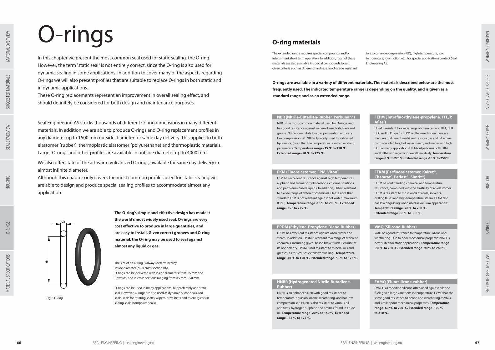
6766 SEAL ENGINEERING | sealengineering.no SEAL ENGINEERING | sealengineering.no
O-ring materials
In this chapter we present the most common seal used for static sealing, the O-ring.
However, the term “static seal” is not entirely correct, since the O-ring is also used for
dynamic sealing in some applications. In addition to cover many of the aspects regarding
O-rings we will also present profiles that are suitable to replace O-rings in both static and
in dynamic applications.
These O-ring replacements represent an improvement in overall sealing effect, and
should definitely be considered for both design and maintenance purposes.
Seal Engineering AS stocks thousands of different O-ring dimensions in many different
materials. In addition we are able to produce O-rings and O-ring replacement profiles in
any diameter up to 1500 mm outside diameter for same day delivery. This applies to both
elastomer (rubber), thermoplastic elastomer (polyurethane) and thermoplastic materials.
Larger O-rings and other profiles are available in outside diameter up to 4000 mm.
We also offer state of the art warm vulcanized O-rings, available for same day delivery in
almost infinite diameter.
Although this chapter only covers the most common profiles used for static sealing we
are able to design and produce special sealing profiles to accommodate almost any
application.
O-rings
The O-ring’s simple and effective design has made it
the world’s most widely used seal. O-rings are very
cost effective to produce in large quantities, and
are easy to install. Given correct grooves and O-ring
material, the O-ring may be used to seal against
almost any liquid or gas.
The size of an O-ring is always determined by
inside diameter (d1) x cross section (d2).
O-rings can be delivered with inside diameters from 0.5 mm and
upwards, and in cross sections ranging from 0.5 mm – 50 mm.
O-rings can be used in many applications, but preferably as a static
seal. However, O-rings are also used as dynamic piston seals, rod
seals, seals for rotating shafts, wipers, drive belts and as energizers in
sliding seals (composite seals).
Fig.1, O-ring
This drawing is the property of Seal-Jet Norge AS and shall neither be copied or presented to non authorized persons without the written consent of Seal-Jet Norge AS.
ISO-2768-1M
d1
d2
NAME DATE
DRAWN
CHECKED
TITLE
Cust.ref. TOLERANCE STANDARD:CLASS SIZE SCALE DWG NO REV
A4 1:1 O_RING_ORDER_DETAILS
POS QTY NAME MATERIAL / DIMENSION
RE
VIS
ION
HIS
TOR
Y
RE
V
-
DA
TE-
AP
PR
OV
ED
-
A-A
The extended range requires special compounds and/or
intermittent short term operation. In addition, most of these
materials are also available in special compounds to suit
given criteria such as different hardness, food-grade, resistant
to explosive decompression (ED), high-temperature, low
temperature, low friction etc. For special applications contact Seal
Engineering AS.
O-rings are available in a variety of different materials. The materials described below are the most
frequently used. The indicated temperature range is depending on the quality, and is given as a
standard range and as an extended range.
NBR (Nitrile-Butadien-Rubber, Perbunan®)NBR is the most common material used for O-rings, and
has good resistance against mineral based oils, fuels and
grease. NBR also exhibits low gas permeation and very
low compression set. NBR is typically used for oil-based
hydraulics, given that the temperature is within working
parameters. Temperature range -35 ºC to 110 ºC.
Extended range -50 ºC to 125 ºC.
FKM (Fluorelastomer, FPM, Viton®)FKM has excellent resistance against high temperatures,
aliphatic and aromatic hydrocarbons, chlorine solutions
and petroleum based liquids. In addition, FKM is resistant
to a wide range of different chemicals. Please note that
standard FKM is not resistant against hot water (maximum
80 ºC). Temperature range -15 ºC to 200 ºC. Extended
range -35 º to 275 ºC.
EPDM (Ethylene-Propylene-Diene-Rubber)EPDM has excellent resistance against ozon, water and
steam. In addition, EPDM is resistant to a range of different
chemicals, including glycol based brake fluids. Because of
its nonpolarity, EPDM is not resistant to mineral oils and
greases, as this causes extensive swelling. Temperature
range -40 ºC to 150 ºC. Extended range -50 ºC to 175 ºC.
HNBR (Hydrogenated Nitrile-Butadiene-HNBR (Hydrogenated Nitrile-Butadiene-Rubber)HNBR is an enhanced NBR with good resistance to
temperature, abrasion, ozone, weathering, and has low
compression set. HNBR is also resistant to various oil
additives, hydrogen sulphide and amines found in crude
oil. Temperature range -20 ºC to 150 ºC. Extended
range – 35 ºC to 175 ºC.
FEPM (Tetrafluorthylene-propylene, TFE/P, Aflas®) FEPM is resistant to a wide range of chemicals and HFA, HFB,
HFC and HFD liquids. FEPM is often used when there are
mixtures of different media such as sour gas and oil, amine
corrosion inhibitors, hot water, steam, and media with high
PH. For many applications FEPM outperforms both FKM
and FFKM with regards to overall sealability. Temperature
range -0 ºC to 225 ºC. Extended range -10 ºC to 250 ºC.
FFKM (Perfluorelastomer, Kalrez®, Chemraz®, Perlast®, Simriz®)FFKM has outstanding chemical and temperature
resistance, combined with the elasticity of an elastomer.
FFKM is resistant to most kinds of acids, solvents,
drilling fluids and high temperature steam. FFKM also
has low degassing when used in vacuum applications.
Temperature range -20 ºC to 260 ºC.
Extended range -30 ºC to 330 ºC.
VMQ (Silicone-Rubber)VMQ has good resistance to temperature, ozone and
weathering. Due to poor mechanical properties VMQ is
best suited for static applications. Temperature range
-60 ºC to 200 ºC. Extended range -90 ºC to 260 ºC.
FVMQ (Fluorsilicone-rubber)FVMQ is a modified silicone often used against oils and
fuels given large variations in temperature. FVMQ has the
same good resistance to ozone and weathering as VMQ,
and similar poor mechanical properties. Temperature
range -60 º C to 200 ºC. Extended range -100 ºC
to 210 ºC.
SUGG
ESTE
D M
ATER
IALS
SEAL
S OVE
RVIEW
HOUS
ING
MAT
ERIA
L SPE
CIFICA
TIONS
MATERIAL OVERVIEW
SUGGESTED MATERIALS
SEALS OVERVIEWHOUSING
O-RINGSM
ATERIAL SPECIFICATIONSO-
RINGS
MAT
ERIA
L OVE
RVIEW
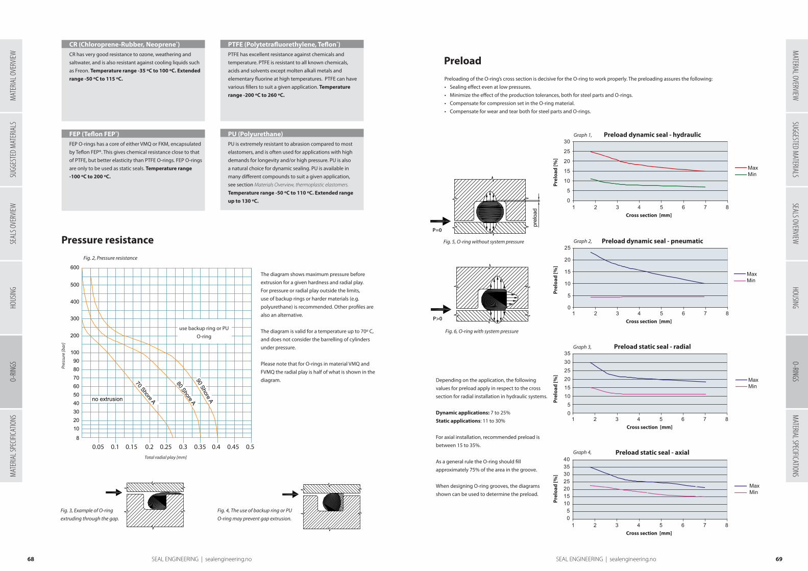
6968 SEAL ENGINEERING | sealengineering.no SEAL ENGINEERING | sealengineering.no
Cross section [mm]
Cross section [mm]
Cross section [mm]
Cross section [mm]
MaxMin
MaxMin
MaxMin
MaxMin
1 2 3 4 5 6 7 8
1 2 3 4 5 6 7 8
1 2 3 4 5 6 7 8
1 2 3 4 5 6 7 805
10152025
0
5
10
15
20
25
303540
05
101520253035
0
5
10
15
20
25
30
Cross section [mm]
Cross section [mm]
Cross section [mm]
Cross section [mm]
MaxMin
MaxMin
MaxMin
MaxMin
1 2 3 4 5 6 7 8
1 2 3 4 5 6 7 8
1 2 3 4 5 6 7 8
1 2 3 4 5 6 7 805
10152025
0
5
10
15
20
25
303540
05
101520253035
0
5
10
15
20
25
30
Cross section [mm]
Cross section [mm]
Cross section [mm]
Cross section [mm]
MaxMin
MaxMin
MaxMin
MaxMin
1 2 3 4 5 6 7 8
1 2 3 4 5 6 7 8
1 2 3 4 5 6 7 8
1 2 3 4 5 6 7 805
10152025
0
5
10
15
20
25
303540
05
101520253035
0
5
10
15
20
25
30
Cross section [mm]
Cross section [mm]
Cross section [mm]
Cross section [mm]
MaxMin
MaxMin
MaxMin
MaxMin
1 2 3 4 5 6 7 8
1 2 3 4 5 6 7 8
1 2 3 4 5 6 7 8
1 2 3 4 5 6 7 805
10152025
0
5
10
15
20
25
303540
05
101520253035
0
5
10
15
20
25
30
The diagram shows maximum pressure before
extrusion for a given hardness and radial play.
For pressure or radial play outside the limits,
use of backup rings or harder materials (e.g.
polyurethane) is recommended. Other profiles are
also an alternative.
The diagram is valid for a temperature up to 70º C,
and does not consider the barrelling of cylinders
under pressure.
Please note that for O-rings in material VMQ and
FVMQ the radial play is half of what is shown in the
diagram.
Pressure resistance
Fig. 3, Example of O-ring
extruding through the gap.
Fig. 4, The use of backup ring or PU
O-ring may prevent gap extrusion.
Fig. 2, Pressure resistance
Pres
sure
[bar
]
Total radial play [mm]
10
0.1 0.2 0.3Total diametral play (mm)
use back-up ringor
polyurethane o-ring
no extrusion
70 Shore A
80 Shore A90 Shore A
Pre
ssur
e (B
ar)
0.4 0.5 0.6 0.7 0.8 0.9 1.0
2030405060708090
100
200
300
400
500
600
8
use backup ring or PU
O-ring
0.05 0.1 0.15 0.2 0.25 0.3 0.35 0.4 0.45 0.5
CR (Chloroprene-Rubber, Neoprene®)CR has very good resistance to ozone, weathering and
saltwater, and is also resistant against cooling liquids such
as Freon. Temperature range -35 ºC to 100 ºC. Extended
range -50 ºC to 115 ºC.
FEP (Teflon FEP®)FEP O-rings has a core of either VMQ or FKM, encapsulated
by Teflon FEP®. This gives chemical resistance close to that
of PTFE, but better elasticity than PTFE O-rings. FEP O-rings
are only to be used as static seals. Temperature range
-100 ºC to 200 ºC.
PTFE (Polytetrafluorethylene, Teflon®)PTFE has excellent resistance against chemicals and
temperature. PTFE is resistant to all known chemicals,
acids and solvents except molten alkali metals and
elementary fluorine at high temperatures. PTFE can have
various fillers to suit a given application. Temperature
range -200 ºC to 260 ºC.
PU (Polyurethane)PU is extremely resistant to abrasion compared to most
elastomers, and is often used for applications with high
demands for longevity and/or high pressure. PU is also
a natural choice for dynamic sealing. PU is available in
many different compounds to suit a given application,
see section Materials Overview, thermoplastic elastomers.
Temperature range -50 ºC to 110 ºC. Extended range
up to 130 ºC.
Preload
Preloading of the O-ring’s cross section is decisive for the O-ring to work properly. The preloading assures the following:
• Sealing effect even at low pressures.
• Minimize the effect of the production tolerances, both for steel parts and O-rings.
• Compensate for compression set in the O-ring material.
• Compensate for wear and tear both for steel parts and O-rings.
Fig. 5, O-ring without system pressure
Depending on the application, the following
values for preload apply in respect to the cross
section for radial installation in hydraulic systems.
Dynamic applications: 7 to 25%
Static applications: 11 to 30%
For axial installation, recommended preload is
between 15 to 35%.
As a general rule the O-ring should fill
approximately 75% of the area in the groove.
When designing O-ring grooves, the diagrams
shown can be used to determine the preload.
P=0
Fig. 6, O-ring with system pressure
P>0
Preload dynamic seal - hydraulic
Preload dynamic seal - pneumatic
Preload static seal - radial
Preload static seal - axial
Graph 2,
Graph 3,
Graph 1,
Graph 4,
Prel
oad
[%]
Prel
oad
[%]
Prel
oad
[%]
Prel
oad
[%]
SUGG
ESTE
D M
ATER
IALS
SEAL
S OVE
RVIEW
HOUS
ING
MAT
ERIA
L SPE
CIFICA
TIONS
MATERIAL OVERVIEW
SUGGESTED MATERIALS
SEALS OVERVIEWHOUSING
O-RINGSM
ATERIAL SPECIFICATIONSO-
RINGS
MAT
ERIA
L OVE
RVIEW

N/c
m
Cross section compressed 10%
Cross section compressed 20%
O-ring cross section d₂ (mm)
NBR 90
NBR 80
NBR 70NBR 90
NBR 80
NBR 70
160
140
120
100
80
60
40
20
1 2 3 4 5 6 7 8 9 10
7170 SEAL ENGINEERING | sealengineering.no SEAL ENGINEERING | sealengineering.no
Elongation – compression
For installation in an internal groove (fig. 7 and 8) the O-ring
should be stretched between 1-3 % of the diameter. Maximum
elongation is 6%.
For installation in an external grove (fig. 9 and 10) the O-ring
should be compressed between 1-2%. Maximum compression
is 3%.
The reason for elongating or compressing the O-ring is to
minimize movement during pressure cycles, and to bridge
production tolerances on both steel parts and the O-ring,
thereby optimizing the service life of the O-ring.
For maximum sealability the O-ring should either be elongated or compressed when installed,
depending on the application. The following guidelines should be considered:
Exceeding these guidelines will result in either to much
decrease or increase of the O-ring’s cross section, which in turn
may have a negative effect on the service life of the O-ring. In
addition excessive compression will make the O-ring difficult or
impossible to install.
The decrease of cross section is approximately half of the
elongation, meaning that 1 % elongation yields 0.5% reduction
of cross section.
Fig. 8, Internal grooveFig. 7, Internal groove Fig. 9, External groove Fig. 10, External groove
Fig. 11, Compression forces
Compression forcesIn order to determine to force needed
for static installation of O-rings, we need
to know the compression forces. The
compression forces depend on the initial
preload of the cross section and the
hardness of the O-ring (Shore). The graph
shows the specific compression force per
cm of the seal circumference as a function
of the cross section.
A rectangular groove is preferred for all new designs. Designs with bevelled groove flanks up to 5º are
permissible. The radius r2 shown in the drawing should be maximum 0.4 mm.
Installation recommendations
CS
ød
h₁
h₂
Fig. 14, Backup-ring ST09
Fig. 15, O-rings, examples of different functions:
a) Static, radial sealing with no backup
b) Dynamic, radial sealing with one backup-ring
c) Dynamic, radial sealing with two backup-rings
d) Axial sealing
Fig. 13, O-ring groove with bevelled flanks
max. 5 0
Our backup ring profile ST09 is preferred for use in combinations
with O-rings. For ordering purposes measurement h1 is given. To
determine free space in the groove h2 should be used. Cross section
of the backup ring should be equal to the cross section of the
groove.
This drawing is the property of Seal-Jet Norge AS and shall neither be copied or presented to non authorized persons without the written consent of Seal-Jet Norge AS.
ISO-2768-1M
d1
d2
NAME DATE
DRAWN
CHECKED
TITLE
Cust.ref. TOLERANCE STANDARD:CLASS SIZE SCALE DWG NO REV
A4 1:1 O_RING_ORDER_DETAILS
POS QTY NAME MATERIAL / DIMENSION
RE
VIS
ION
HIS
TOR
Y
RE
V
-
DA
TE-
AP
PR
OV
ED
-
A-A
Fig. 12, O-ring
cs
ød
r1
r2
t 1
t 1
t
b₂
b₁
a)
b)
c)
b₃
Examples:
SUGG
ESTE
D M
ATER
IALS
SEAL
S OVE
RVIEW
HOUS
ING
MAT
ERIA
L SPE
CIFICA
TIONS
MATERIAL OVERVIEW
SUGGESTED MATERIALS
SEALS OVERVIEWHOUSING
O-RINGSM
ATERIAL SPECIFICATIONSO-
RINGS
MAT
ERIA
L OVE
RVIEW

Table 1
Installation recommendations for rectangular grooveCross
section Radial installation Axial installation
RadiusGroove depth Groove width Groove depth
Groove width
Static Dynamic No backup 1 backup 2 backups Backup ring
d2 t + 0.05 t1 + 0.05 b1 + 0.2 b2 + 0.2 b3 + 0.3 height h1/h2
h + 0.05 b4 + 0.2 r (max)
1.5 1.10 1.25 2.00 3.00 4.00 1.10/1.00 1.10 2.10 0.30
1.6 1.20 1.30 2.10 3.10 4.10 1.10/1.00 1.20 2.20 0.30
1.78 1.30 1.45 2.40 3.80 5.20 1.50/1.40 1.30 2.50 0.30
1.90 1.40 1.55 2.60 4.00 5.40 1.50/1.40 1.40 2.70 0.30
2.00 1.50 1.65 2.70 4.10 5.50 1.60/1.40 1.50 2.80 0.30
2.40 1.80 2.05 3.20 4.60 6.00 1.60/1.40 1.80 3.30 0.30
2.50 1.85 2.15 3.30 4.70 6.10 1.60/1.40 1.85 3.40 0.30
2.62 2.00 2.25 3.60 5.00 6.40 1.60/1.40 2.00 3.70 0.60
3.00 2.30 2.60 4.00 5.40 6.80 1.70/1.40 2.30 4.10 0.60
3.10 2.40 2.70 4.10 5.50 6.90 1.70/1.40 2.40 4.20 0.60
3.53 2.70 3.10 4.80 6.20 7.60 1.70/1.40 2.70 4.90 0.60
4.00 3.10 3.50 5.20 6.90 8.60 2.10/1.70 3.10 5.30 0.60
4.50 3.50 4.00 5.80 7.50 9.20 2.10/1.70 3.50 5.90 0.60
5.00 4.00 4.40 6.60 8.30 10.00 2.20/1.70 4.00 6.70 0.60
5.33 4.30 4.70 7.10 8.80 10.50 2.20/1.70 4.30 7.30 0.60
5.50 4.50 4.80 7.10 8.80 10.50 2.20/1.70 4.50 7.30 0.60
5.70 4.60 5.00 7.20 8.90 10.60 2.30/1.70 4.60 7.40 0.60
6.00 4.90 5.30 7.40 9.10 10.80 2.30/1.70 4.90 7.60 0.60
6.50 5.40 5.70 8.00 9.70 11.40 2.30/1.70 5.40 8.20 1.00
6.99 5.80 6.10 8.60 11.10 13.60 3.20/2.50 5.80 9.70 1.00
7.50 6.30 6.60 9.10 11.60 14.10 3.20/2.50 6.30 9.90 1.00
8.00 6.70 7.10 9.80 12.30 14.80 3.20/2.50 6.70 10.00 1.00
8.40 7.10 7.50 10.00 12.50 15.00 3.40/2.50 7.10 10.30 1.00
9.00 7.70 8.10 10.60 13.10 15.60 3.40/2.50 7.70 10.90 1.50
10.00 8.60 9.10 11.60 14.10 16.60 3.60/2.50 8.60 12.00 2.00
12.00 10.60 11.00 13.50 16.00 18.50 3.80/2.50 10.60 14.00 2.00
Groove recommendations only valid for normal swell of the O-ring. Higher than normal swell due to thermal and/or chemical influence
might require different groove size.
Installation triangular groove
Cross section Groove depth Groove depth
d2 t1 tolerance [+]
1.60 2.10 0.10
1.78 2.40 0.10
2.40 3.30 0.10
2.62 3.50 0.10
3.00 4.10 0.20
3.53 4.90 0.20
5.00 6.90 0.20
5.33 7.35 0.20
5.70 7.85 0.20
6.99 9.60 0.30
8.00 11.00 0.30
8.40 11.55 0.30
Table 2
Table 3
Installation recommendations for trapezoidal groove
Cross section
Groove depth
Grove width
Groove width Radius (max)
d2 h1± 0.05 b1± 0.05w b2± 0.05 r1 r2
3.53 2.90 2.90 3.20 0.80 0.25
4.00 3.20 3.40 3.70 0.80 0.25
5.00 4.20 4.30 4.60 0.80 0.25
5.33 4.60 4.60 4.90 0.80 0.25
5.70 4.80 4.75 5.25 0.80 0.40
6.00 5.10 5.05 5.55 0.80 0.40
6.99 6.00 6.00 6.50 1.60 0.40
8.00 6.90 6.85 7.45 1.60 0.50
8.40 7.30 7.25 7.85 1.60 0.50
Trapezoidal grooveThe trapezoidal groove is not recommended for standard
applications, but may prove useful in special cases. For
instance in overhead installations a trapezoidal groove will
prevent the O-ring from falling out of the groove.
The trapezoidal groove is only recommended for O-ring
cross section from 3.53 mm.
7372 SEAL ENGINEERING | sealengineering.no SEAL ENGINEERING | sealengineering.no
b₁
b₂
b₁
b₂
b₁b₂
Fig. 16, Trapezoidal groove
Fig. 17, Detail of trapezoidal groove
groove depth
Fig. 18, Triangular groove
Triangular grooveTriangular grooves can be used for threaded flanges
and caps.
For proper functioning of the O-ring the groove
must be machined according to the measurements
given in the table. The use of rectangular grooves is
preferred.
SUGG
ESTE
D M
ATER
IALS
SEAL
S OVE
RVIEW
HOUS
ING
MAT
ERIA
L SPE
CIFICA
TIONS
MATERIAL OVERVIEW
SUGGESTED MATERIALS
SEALS OVERVIEWHOUSING
O-RINGSM
ATERIAL SPECIFICATIONSO-
RINGS
MAT
ERIA
L OVE
RVIEW
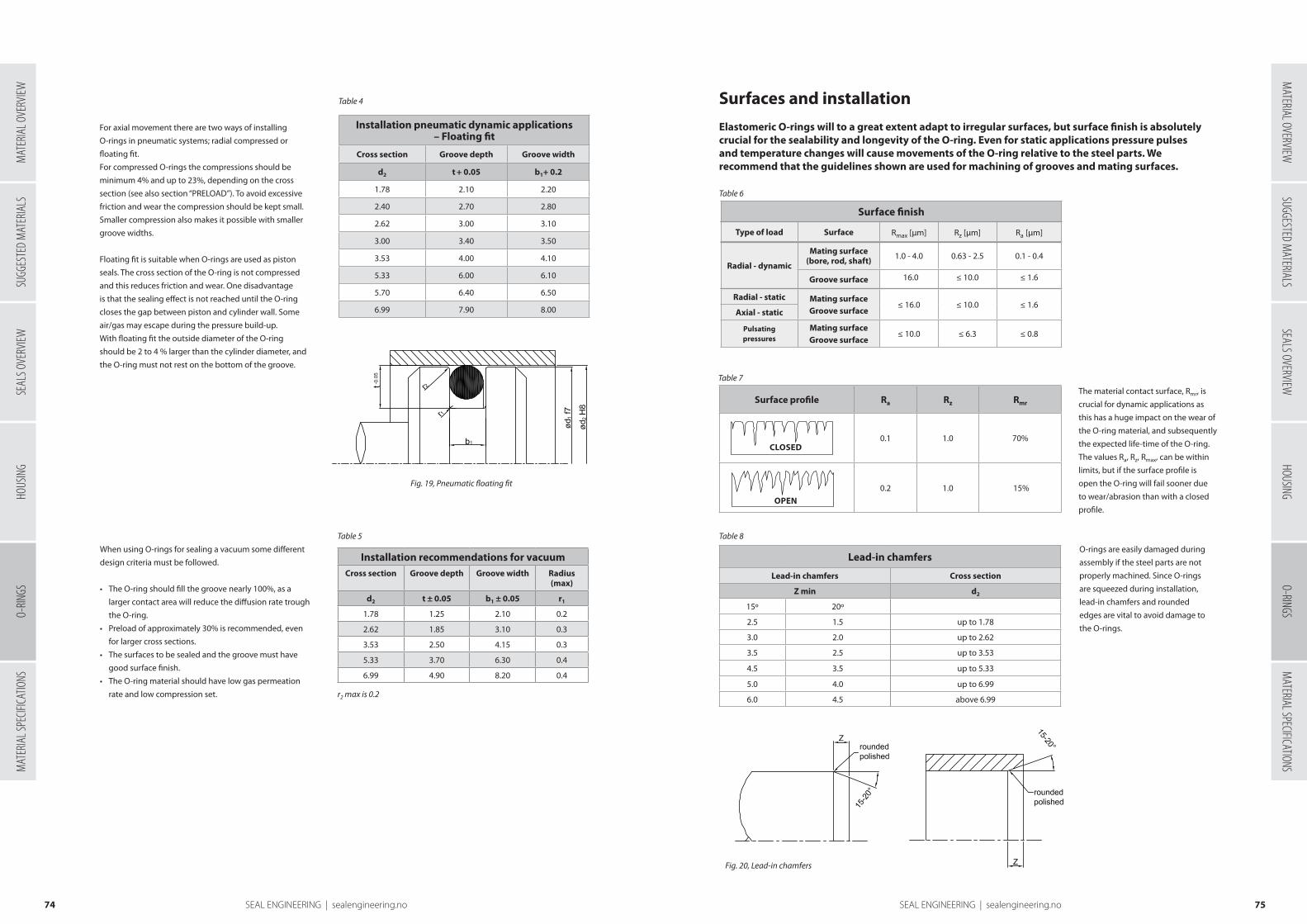
Table 4
Installation pneumatic dynamic applications– Floating fit
Cross section Groove depth Groove width
d2 t + 0.05 b1+ 0.2
1.78 2.10 2.20
2.40 2.70 2.80
2.62 3.00 3.10
3.00 3.40 3.50
3.53 4.00 4.10
5.33 6.00 6.10
5.70 6.40 6.50
6.99 7.90 8.00
Installation recommendations for vacuumCross section Groove depth Groove width Radius
(max)
d2 t ± 0.05 b1 ± 0.05 r1
1.78 1.25 2.10 0.2
2.62 1.85 3.10 0.3
3.53 2.50 4.15 0.3
5.33 3.70 6.30 0.4
6.99 4.90 8.20 0.4
Table 5
Lead-in chamfers
Lead-in chamfers Cross section
Z min d2
15º 20º
2.5 1.5 up to 1.78
3.0 2.0 up to 2.62
3.5 2.5 up to 3.53
4.5 3.5 up to 5.33
5.0 4.0 up to 6.99
6.0 4.5 above 6.99
Table 8
Surface profile Ra Rz Rmr
0.1 1.0 70%
0.2 1.0 15%
Surface finish
Type of load Surface Rmax [µm] Rz [µm] Ra [µm]
Radial - dynamic
Mating surface (bore, rod, shaft) 1.0 - 4.0 0.63 - 2.5 0.1 - 0.4
Groove surface 16.0 ≤ 10.0 ≤ 1.6
Radial - static Mating surfaceGroove surface
≤ 16.0 ≤ 10.0 ≤ 1.6Axial - static
Pulsating pressures
Mating surfaceGroove surface
≤ 10.0 ≤ 6.3 ≤ 0.8
CLOSED
OPEN
Table 7
Table 6
7574 SEAL ENGINEERING | sealengineering.no SEAL ENGINEERING | sealengineering.no
O-ring for pneumatic dynamic applicationsFor axial movement there are two ways of installing
O-rings in pneumatic systems; radial compressed or
floating fit.
For compressed O-rings the compressions should be
minimum 4% and up to 23%, depending on the cross
section (see also section “PRELOAD”). To avoid excessive
friction and wear the compression should be kept small.
Smaller compression also makes it possible with smaller
groove widths.
Floating fit is suitable when O-rings are used as piston
seals. The cross section of the O-ring is not compressed
and this reduces friction and wear. One disadvantage
is that the sealing effect is not reached until the O-ring
closes the gap between piston and cylinder wall. Some
air/gas may escape during the pressure build-up.
With floating fit the outside diameter of the O-ring
should be 2 to 4 % larger than the cylinder diameter, and
the O-ring must not rest on the bottom of the groove.
O-ring for vacuum applicationsWhen using O-rings for sealing a vacuum some different
design criteria must be followed.
• The O-ring should fill the groove nearly 100%, as a
larger contact area will reduce the diffusion rate trough
the O-ring.
• Preload of approximately 30% is recommended, even
for larger cross sections.
• The surfaces to be sealed and the groove must have
good surface finish.
• The O-ring material should have low gas permeation
rate and low compression set.
Fig. 19, Pneumatic floating fit
r2 max is 0.2
Elastomeric O-rings will to a great extent adapt to irregular surfaces, but surface finish is absolutely crucial for the sealability and longevity of the O-ring. Even for static applications pressure pulses and temperature changes will cause movements of the O-ring relative to the steel parts. We recommend that the guidelines shown are used for machining of grooves and mating surfaces.
Surfaces and installation
Material contact surfaceThe material contact surface, Rmr, is
crucial for dynamic applications as
this has a huge impact on the wear of
the O-ring material, and subsequently
the expected life-time of the O-ring.
The values Ra, Rz, Rmax, can be within
limits, but if the surface profile is
open the O-ring will fail sooner due
to wear/abrasion than with a closed
profile.
Lead-in chamfersO-rings are easily damaged during
assembly if the steel parts are not
properly machined. Since O-rings
are squeezed during installation,
lead-in chamfers and rounded
edges are vital to avoid damage to
the O-rings.
Fig. 20, Lead-in chamfers
SUGG
ESTE
D M
ATER
IALS
SEAL
S OVE
RVIEW
HOUS
ING
MAT
ERIA
L SPE
CIFICA
TIONS
MATERIAL OVERVIEW
SUGGESTED MATERIALS
SEALS OVERVIEWHOUSING
O-RINGSM
ATERIAL SPECIFICATIONSO-
RINGS
MAT
ERIA
L OVE
RVIEW

O-rings – SMS 1586 standard dimensions
d2 1,60 d2 2,40 d2 3,00 d2 5,70 d2 8,40
d1 d2 d1 d2 d1 d2 d1 d2 d1 d2
3,10 1,60 3,30 2,40 19,20 3,00 44,20 5,70 144,10 8,40
4,10 1,60 4,30 2,40 22,20 3,00 49,20 5,70 149,10 8,40
5,10 1,60 5,30 2,40 24,20 3,00 54,20 5,70 154,10 8,40
6,10 1,60 6,30 2,40 26,20 3,00 59,20 5,70 159,10 8,40
7,10 1,60 7,30 2,40 29,20 3,00 64,20 5,70 164,10 8,40
8,10 1,60 8,30 2,40 32,20 3,00 69,20 5,70 169,10 8,40
9,10 1,60 9,30 2,40 34,20 3,00 74,20 5,70 174,10 8,40
10,10 1,60 10,30 2,40 36,20 3,00 79,20 5,70 179,10 8,40
11,10 1,60 11,30 2,40 39,20 3,00 84,10 5,70 184,10 8,40
12,10 1,60 12,30 2,40 42,20 3,00 89,10 5,70 189,10 8,40
13,10 1,60 13,30 2,40 44,20 3,00 94,10 5,70 194,10 8,40
14,10 1,60 14,30 2,40 49,50 3,00 99,10 5,70 199,10 8,40
15,10 1,60 15,30 2,40 54,50 3,00 104,10 5,70 209,10 8,40
16,10 1,60 16,30 2,40 59,50 3,00 109,10 5,70 219,10 8,40
17,10 1,60 17,30 2,40 64,50 3,00 114,30 5,70 229,10 8,40
18,10 1,60 69,50 3,00 119,30 5,70 239,10 8,40
19,10 1,60 74,50 3,00 124,30 5,70 249,10 8,40
20,10 1,60 79,50 3,00 129,30 5,70
21,10 1,60 84,50 3,00 134,30 5,70
22,10 1,60 89,50 3,00 139,30 5,70
Table 10
7776 SEAL ENGINEERING | sealengineering.no SEAL ENGINEERING | sealengineering.no
Installation guidelines, O-rings
• Lead-in chamfer and rounded edges on all parts that passes the O-ring.
• All parts should be cleaned and free from particles and dirt.
• Threads should be covered by tape, shims or mounting tools.
• O-rings and opposite parts should be lubricated by O-ring lube or the medium to be sealed against.
• Never use tools with sharp edges.
• Do not roll the O-ring into the groove.
• Do not over-stretch the O-ring during assembly. Up to 50% elongation is usually permissible during assembly.
Pay extra attention for small diameters. Vulcanized O-rings are especially sensitive to elongation, and must not be
stretched in the joint.
Due to PU´s exceptional high resistance to abrasion and extrusion, this material is increasingly
used for O-rings and other seals.
PU O-rings
O-rings made of PU should be considered under the following
conditions:
• High pressure
• Large gaps
• Limited space (no room for backup-ring)
• Dynamic applications
• O-ring has to pass bores
• Couplings and connectors, or other applications with
frequent opening and closing
• Sealing against gas
Seal Engeneering AS offers a wide range of different
PU materials, each with unique properties to suit most
applications up to 110 ºC. Below is a short description of the
different materials (see also chapter “Materials overview”).
• HPU – resistant against hydrolysis, HFA and HFB-fluids, biological
degradable liquids and mineral based oils. FDA approved
• XHPU – harder grade of HPU for higher pressures or larger gaps
• SPU – same resistance as HPU, with enhanced friction properties
for use in gas, pneumatic or other applications where low
friction is desired
• XSPU – harder grade of SPU for higher pressures or larger gaps
• LPU – low temperature grade for applications down to -50 ºC
PU O-rings can be used in the same grooves as for elastomer
O-rings. Seal Engeneering AS manufactures O-rings up to 1500 mm
outside diameter, and cross section from 1.6 mm, with short lead
times (same day delivery if necessary). In addition we can supply
O-rings up to 4000 mm outside diameter.
Table 9
Installation recommendations for ptfe o-rings
Cross section Groove depth Groove width Radius (max)
d2 t ± 0.05 b1 + 0.1 r
1.60 1.4 1.80 0.3
1.78 1.6 2.00 0.4
2.00 1.8 2.20 0.5
2.40 2.15 2.60 0.5
2.62 2.35 2.90 0.6
3.00 2.70 3.30 0.8
3.53 3.15 3.90 1.0
4.00 3.60 4.40 1.0
5.00 4.50 5.50 1.0
5.33 4.80 5.90 1.2
5.70 5.10 6.30 1.2
6.00 5.60 6.60 1.2
6.99 6.30 7.70 1.5
8.00 7.20 8.80 1.5
8.40 7.55 9.20 2.0
r2 maximum 0.2
PTFE O-rings
O-rings can also be delivered in PTFE-based materials.
PTFE-based O-rings are only to be used as static seals, and
should be considered given the following conditions:
• High demands for chemical resistance
• High or low temperature
(260 ºC to – 200 ºC)
• Resistance against ageing
• Food or drug applications
Seal Engeneering AS manufactures O-rings in PTFE-based
materials up to 1500 mm outside diameter, cross section
from 1.6 mm. In addition we can supply PTFE O-rings up to
2000 mm outside diameter.
PTFE is a thermoplastic material with low elasticity, and has
limited possibility to be stretched or compressed during
installation.
Groove dimensions are different from those for elastomers,
and installation in axial easily accessible and radial spilt
grooves is recommended.
O-ring production
Seal Engineering AS has several thousand O-ring dimensions in different materials in stock, but we
are also able to manufacture O-rings either by turning or by warm vulcanization of O-ring cord. As
a result of this we are able offer same day delivery of any size up to 1500 mm outside diameter for
turned O-rings, and infinite diameter for warm vulcanized O-rings.
The major advantage of turned O-rings is the absence of the
somewhat weaker joint found in vulcanized or glued O-rings. In
addition Seal Engineering AS offers greater flexibility regarding
cross section for turned O-rings as all cross sections from 1.6
mm and upwards are available. Turned O-rings have all the
same application areas as moulded O-rings.
We offer turned O-rings in materials such as NBR, HNBR, FKM
(Viton®), EPDM, FEPM (Aflas®), VMQ (Silicone), different PU
materials and PTFE-based materials.
Warm vulcanization is a superior joining process compared
to gluing. However, these types of O-rings are mainly
recommended for static seals. We offer warm vulcanized
O-rings in materials such as NBR, EPDM, FKM, Viton®GF, VMQ
(Silicone) and PU . Other materials are available on request.
Tolerance on inside diameter for warm vulcanized O-rings is
± 0.5%.
O-ring dimensions
O-rings are available in almost any dimension, however some
dimensions are more widely used than others and act as a
standard both with regards to diameter and cross section.
From a designers viewpoint we recommend the use either of
standard “BS 1806” or “SMS 1586”. The following pages list the
dimensions for those two standards.
SUGG
ESTE
D M
ATER
IALS
SEAL
S OVE
RVIEW
HOUS
ING
MAT
ERIA
L SPE
CIFICA
TIONS
MATERIAL OVERVIEW
SUGGESTED MATERIALS
SEALS OVERVIEWHOUSING
O-RINGSM
ATERIAL SPECIFICATIONSO-
RINGS
MAT
ERIA
L OVE
RVIEW

O-rings – SMS 1586 standard dimensions
d2 1,60 d2 2,40 d2 3,00 d2 5,70 d2 8,40
d1 d2 d1 d2 d1 d2 d1 d2 d1 d2
23,10 1,60 94,50 3,00 144,30 5,70
24,10 1,60 99,50 3,00 149,30 5,70
25,10 1,60 104,50 3,00 154,30 5,70
26,10 1,60 108,50 3,00 159,30 5,70
27,10 1,60 114,50 3,00 164,30 5,70
28,10 1,60 119,50 3,00 169,30 5,70
29,10 1,60 124,50 3,00 174,30 5,70
30,10 1,60 129,50 3,00 179,30 5,70
31,10 1,60 134,50 3,00 184,30 5,70
32,10 1,60 139,50 3,00 189,30 5,70
33,10 1,60 144,50 3,00 194,30 5,70
34,10 1,60 199,30 5,70
35,10 1,60 209,30 5,70
36,10 1,60 219,30 5,70
37,10 1,60 229,30 5,70
239,50 5,70
249,30 5,70
259,30 5,70
269,30 5,70
279,30 5,70
289,30 5,70
299,30 5,70
319,30 5,70
339,30 5,70
359,30 5,70
379,30 5,70
399,30 5,70
419,30 5,70
439,30 5,70
459,30 5,70
479,30 5,70
499,30 5,70
BS standard dimensions
d2 1,78 d2 2,62 d2 3,53 d2 5,33 d2 6,99
BS no. d1 BS no. d1 BS no. d1 BS no. d1 BS no. d1
BS 001* 0,74 BS 102 1,24 BS 201 4,34 BS 309 10,46 BS 425 113,67
BS 002* 1,07 BS 103 2,06 BS 202 5,94 BS 310 12,07 BS 426 116,84
BS 003* 1,42 BS 104 2,84 BS 203 7,52 BS 311 13,64 BS 427 120,02
BS 004 1,78 BS 105 3,63 BS 204 9,12 BS 312 15,24 BS 428 123,19
BS 005 2,57 BS 106 4,42 BS 205 10,69 BS 313 16,81 BS 429 126,37
BS 006 2,90 BS 107 5,23 BS 206 12,29 BS 314 18,42 BS 430 129,54
BS 007 3,68 BS 108 6,02 BS 207 13,87 BS 315 19,99 BS 431 132,72
BS 008 4,47 BS 109 7,59 BS 208 15,47 BS 316 21,59 BS 432 135,89
BS 009 5,28 BS 110 9,19 BS 209 17,04 BS 317 23,16 BS 433 139,07
BS 010 6,07 BS 111 10,77 BS 210 18,64 BS 318 24,77 BS 434 142,24
BS 011 7,65 BS 112 12,37 BS 211 20,22 BS 319 26,34 BS 435 145,42
BS 012 9,25 BS 113 13,94 BS 212 21,82 BS 320 27,94 BS 436 148,59
BS 013 10,82 BS 114 15,54 BS 213 23,39 BS 321 29,51 BS 437 151,77
BS 014 12,42 BS 115 17,12 BS 214 24,99 BS 322 31,12 BS 438 158,12
BS 015 14,00 BS 116 18,72 BS 215 26,57 BS 323 32,69 BS 439 164,47
BS 016 15,60 BS 117 20,29 BS 216 28,17 BS 324 34,29 BS 440 170,82
BS 017 17,17 BS 118 21,89 BS 217 29,74 BS 325 37,47 BS 441 177,17
BS 018 18,77 BS 119 23,47 BS 218 31,34 BS 326 40,64 BS 442 183,52
BS 019 20,35 BS 120 25,07 BS 219 32,92 BS 327 43,82 BS 443 189,87
BS 020 21,95 BS 121 26,64 BS 220 34,52 BS 328 46,99 BS 444 196,22
BS 021 23,52 BS 122 28,24 BS 221 36,09 BS 329 50,17 BS 445 202,57
BS 022 25,12 BS 123 29,82 BS 222 37,69 BS 330 53,34 BS 446 215,27
BS 023 26,70 BS 124 31,42 BS 223 40,87 BS 331 56,52 BS 447 227,97
BS 024 28,30 BS 125 32,99 BS 224 44,04 BS 332 59,69 BS 448 240,67
BS 025 29,87 BS 126 34,59 BS 225 47,22 BS 333 62,87 BS 449 253,37
BS 026 31,47 BS 127 36,17 BS 226 50,39 BS 334 66,04 BS 450 266,07
BS 027 33,05 BS 128 37,77 BS 227 53,57 BS 335 69,22 BS 451 278,77
BS 028 34,65 BS 129 39,34 BS 228 56,74 BS 336 72,39 BS 452 291,47
BS 029 37,82 BS 130 40,94 BS 229 59,92 BS 337 75,57 BS 453 304,17
BS 030 41,00 BS 131 42,52 BS 230 63,09 BS 338 78,74 BS 454 316,87
BS 031 44,17 BS 132 44,12 BS 231 66,27 BS 339 81,92 BS 455 329,57
BS 032 47,35 BS 133 45,69 BS 232 69,44 BS 340 85,09 BS 456 342,27
BS 033 50,52 BS 134 47,29 BS 233 72,62 BS 341 88,27 BS 457 354,97
BS 034 53,70 BS 135 48,90 BS 234 75,79 BS 342 91,44 BS 458 367,67
BS 035 56,87 BS 136 50,47 BS 235 78,97 BS 343 94,62 BS 459 380,37
BS 036 60,05 BS 137 52,07 BS 236 82,14 BS 344 97,79 BS 460 393,07
BS 037 63,22 BS 138 53,64 BS 237 85,32 BS 345 100,97 BS 461 405,26
BS 038 66,40 BS 139 55,25 BS 238 88,49 BS 346 104,14 BS 462 417,96
BS 039 69,57 BS 140 56,82 BS 239 91,67 BS 347 107,32 BS 463 430,66
BS 040 72,75 BS 141 58,42 BS 240 94,84 BS 348 110,49 BS 464 443,36
BS 041 75,92 BS 142 59,99 BS 241 98,02 BS 349 113,67 BS 465 456,03
BS 042 82,27 BS 143 61,60 BS 242 101,19 BS 350 116,84 BS 466 468,76
BS 043 88,62 BS 144 63,17 BS 243 104,37 BS 351 120,02 BS 467 481,46
BS 044 94,97 BS 145 64,77 BS 244 107,54 BS 352 123,19 BS 468 494,16
Table 11
* cross section 1.02, 1.27, 1.52 respectively
7978 SEAL ENGINEERING | sealengineering.no SEAL ENGINEERING | sealengineering.no
SUGG
ESTE
D M
ATER
IALS
SEAL
S OVE
RVIEW
HOUS
ING
MAT
ERIA
L SPE
CIFICA
TIONS
MATERIAL OVERVIEW
SUGGESTED MATERIALS
SEALS OVERVIEWHOUSING
O-RINGSM
ATERIAL SPECIFICATIONSO-
RINGS
MAT
ERIA
L OVE
RVIEW

Operating conditions:
Material Temperature Max surface speed Max pressure*
HPU -20 to 110 ºC 0.4 m/s 400 bar
SPU -20 to 110 ºC 0.5 m/s 400 bar
LPU -50 to 110 ºC 0.4 m/s 400 bar
Table 12
8180 SEAL ENGINEERING | sealengineering.no SEAL ENGINEERING | sealengineering.no
BS standard dimensions
d2 1,78 d2 2,62 d2 3,53 d2 5,33 d2 6,99
BS no. d1 BS no. d1 BS no. d1 BS no. d1 BS no. d1
BS 045 101,32 BS 146 66,34 BS 245 110,72 BS 353 126,37 BS 469 506,86
BS 046 107,67 BS 147 67,95 BS 246 113,89 BS 354 129,54 BS 470 532,26
BS 047 114,02 BS 148 69,52 BS 247 117,07 BS 355 132,72 BS 471 557,66
BS 048 120,37 BS 149 71,12 BS 248 120,24 BS 356 135,89 BS 472 582,68
BS 049 126,72 BS 150 72,69 BS 249 123,42 BS 357 139,07 BS 473 608,08
BS 050 133,07 BS 151 75,87 BS 250 126,59 BS 358 142,24 BS 474 633,48
BS 152 82,22 BS 251 129,77 BS 359 145,42 BS 475 658,88
BS 153 88,57 BS 252 132,94 BS 360 148,59
BS 154 94,92 BS 253 136,12 BS 361 151,77
BS 155 101,27 BS 254 139,29 BS 362 158,12
BS 156 107,62 BS 255 142,47 BS 363 164,47
BS 157 113,97 BS 256 145,64 BS 364 170,82
BS 158 120,32 BS 257 148,82 BS 365 177,17
BS 159 126,67 BS 258 151,99 BS 366 183,52
BS 160 133,02 BS 259 158,34 BS 367 189,87
BS 161 139,37 BS 260 164,69 BS 368 196,22
BS 162 145,72 BS 261 171,04 BS 369 202,57
BS 163 152,07 BS 262 177,39 BS 370 208,92
BS 164 158,42 BS 263 183,74 BS 371 215,27
BS 165 164,77 BS 264 190,09 BS 372 221,62
BS 166 171,12 BS 265 196,44 BS 373 227,97
BS 167 177,47 BS 266 202,79 BS 374 234,32
BS 168 183,82 BS 267 209,14 BS 375 240,67
BS 169 190,17 BS 268 215,49 BS 376 247,02
BS 170 196,52 BS 269 221,84 BS 377 253,37
BS 171 202,87 BS 270 228,19 BS 378 266,07
BS 172 209,22 BS 271 234,54 BS 379 278,77
BS 173 215,57 BS 272 240,89 BS 380 291,47
BS 174 221,92 BS 273 247,24 BS 381 304,17
BS 175 228,27 BS 274 253,59 BS 382 329,57
BS 176 234,62 BS 275 266,29 BS 383 354,97
BS 177 240,97 BS 276 278,99 BS 384 380,37
BS 178 247,32 BS 277 291,69 BS 385 405,26
BS 278 304,39 BS 386 430,66
BS 279 329,79 BS 387 456,06
BS 280 355,19 BS 388 481,41
BS 281 380,59 BS 389 506,81
BS 282 405,26 BS 390 532,21
BS 283 430,66 BS 391 557,61
BS 284 456,06 BS 392 582,68
BS 393 608,08
BS 394 633,48
BS 395 658,88
Profile K35-P is a single piece double acting compact seal
developed for a wide range of static and dynamic applications.
The seal profile is optimized for PU materials, which in
combination with the compact seal geometry lead to high
pressure resistance and long service life.
Since the K35-P profile is designed with a radial preload of
the cross section, no activating pressure is needed for low
pressure ranges to obtain a compact sealing, as is often the
case for standard lipseals. At higher pressure the deformation
of the cross section generates a contact pressure distribution
in the area of the sealing gap which leads to excellent dynamic
sealing, also for increased speeds. Meanwhile the risk of gap
extrusion is minimised by the seal geometry and choice of
material.
The seal geometry has almost no dead spots, and this makes it
suitable for food and drug industry (cleaning and sterilization
purposes).
K35-P is available for outside diameters up to 1500 mm for
same day delivery, and can be supplied in outside diameter up
to 4000 mm.
For applications with working temperature above 110 ºC,
or media not suitable for polyurethane, K35-P can also be
supplied in elastomer materials. See “Materials overview” to
find the suitable material.
The K35-P is an optimized alternative to conventional O-rings,
especially for dynamic applications. The K35-P is for outside
sealing, but we also offer profile S35-P for inside sealing and
R35-P for axial sealing. The description of K35-P also applies for
S35-P and R35-P.
Please note that it is not
recommended to use all maximum
values simultaneously. Surface speed
limits apply only in the presence of
adequate lubrication.
* Pressure rating is dependent on the size of the extrusion gap.
K35-P R35-A
O-ring replacements
Although the O-ring is the worlds most widely used seal, the design has certain limitations
regarding sealability, pressure resistance and dynamic sealing.
Seal Engineering AS offers O-ring replacements suitable for improved sealing, higher pressures and
also for dynamic sealing, while maintaining the key features for the O-ring’s success: simple design,
easy assembly and relatively small grooves.
S35-P
K35-P for dynamic applications
SUGG
ESTE
D M
ATER
IALS
SEAL
S OVE
RVIEW
HOUS
ING
MAT
ERIA
L SPE
CIFICA
TIONS
MATERIAL OVERVIEW
SUGGESTED MATERIALS
SEALS OVERVIEWHOUSING
O-RINGSM
ATERIAL SPECIFICATIONSO-
RINGS
MAT
ERIA
L OVE
RVIEW
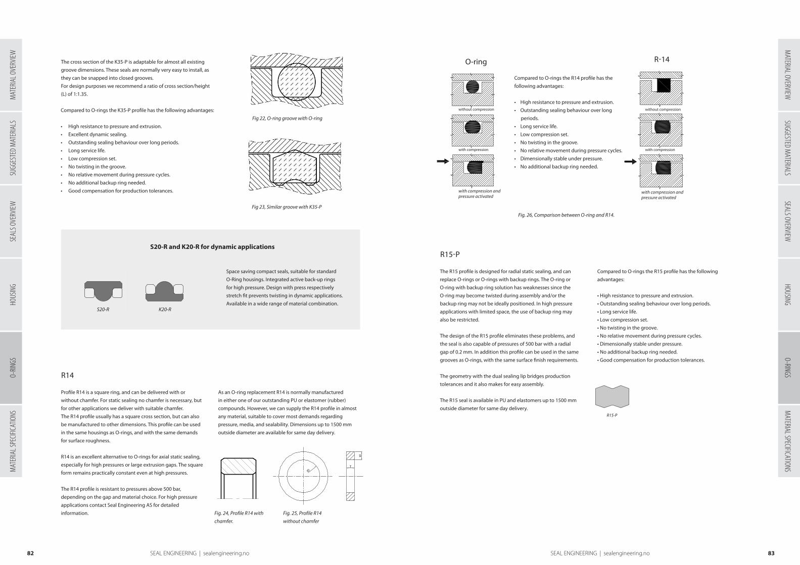
without compression
with compression
with compression and pressure activated
with compression and pressure activated
with compression
without compression
8382 SEAL ENGINEERING | sealengineering.no SEAL ENGINEERING | sealengineering.no
The cross section of the K35-P is adaptable for almost all existing
groove dimensions. These seals are normally very easy to install, as
they can be snapped into closed grooves.
For design purposes we recommend a ratio of cross section/height
(L) of 1:1.35.
Fig 23, Similar groove with K35-P
S20-R
Compared to O-rings the K35-P profile has the following advantages:
• High resistance to pressure and extrusion.
• Excellent dynamic sealing.
• Outstanding sealing behaviour over long periods.
• Long service life.
• Low compression set.
• No twisting in the groove.
• No relative movement during pressure cycles.
• No additional backup ring needed.
• Good compensation for production tolerances.
Housing and installation
K20-R
Space saving compact seals, suitable for standard
O-Ring housings. Integrated active back-up rings
for high pressure. Design with press respectively
stretch fit prevents twisting in dynamic applications.
Available in a wide range of material combination.
S20-R and K20-R for dynamic applications
Fig 22, O-ring groove with O-ring
Rotary seals:
ES 212.401-P ES 212.401-R ES 212.401-AF ES 212.401-AS ES 212.402-P
ES 212.402-R ES 212.403-P ES 212.403-R ES 212.404 ES 212.405
ES 212.406-P ES 212.406-R ES 212.407-P ES 212.407-R ES 212.408
ES 212.409 ES 212.409 ES 212.410 ES 212.410 ES 212.411
ES 212.412 ES 212.413 ES 212.414 ES 212.419 ES 212.420
ES 212.430 ES 212.435
Fig. 24, Profile R14 with
chamfer.
Fig. 25, Profile R14
without chamfer
Profile R14 is a square ring, and can be delivered with or
without chamfer. For static sealing no chamfer is necessary, but
for other applications we deliver with suitable chamfer.
The R14 profile usually has a square cross section, but can also
be manufactured to other dimensions. This profile can be used
in the same housings as O-rings, and with the same demands
for surface roughness.
R14 is an excellent alternative to O-rings for axial static sealing,
especially for high pressures or large extrusion gaps. The square
form remains practically constant even at high pressures.
The R14 profile is resistant to pressures above 500 bar,
depending on the gap and material choice. For high pressure
applications contact Seal Engineering AS for detailed
information.
R14
As an O-ring replacement R14 is normally manufactured
in either one of our outstanding PU or elastomer (rubber)
compounds. However, we can supply the R14 profile in almost
any material, suitable to cover most demands regarding
pressure, media, and sealability. Dimensions up to 1500 mm
outside diameter are available for same day delivery.
The R15 profile is designed for radial static sealing, and can
replace O-rings or O-rings with backup rings. The O-ring or
O-ring with backup ring solution has weaknesses since the
O-ring may become twisted during assembly and/or the
backup ring may not be ideally positioned. In high pressure
applications with limited space, the use of backup ring may
also be restricted.
The design of the R15 profile eliminates these problems, and
the seal is also capable of pressures of 500 bar with a radial
gap of 0.2 mm. In addition this profile can be used in the same
grooves as O-rings, with the same surface finish requirements.
The geometry with the dual sealing lip bridges production
tolerances and it also makes for easy assembly.
The R15 seal is available in PU and elastomers up to 1500 mm
outside diameter for same day delivery.
Compared to O-rings the R15 profile has the following
advantages:
• High resistance to pressure and extrusion.
• Outstanding sealing behaviour over long periods.
• Long service life.
• Low compression set.
• No twisting in the groove.
• No relative movement during pressure cycles.
• Dimensionally stable under pressure.
• No additional backup ring needed.
• Good compensation for production tolerances.
R15-P
Compared to O-rings the R14 profile has the
following advantages:
• High resistance to pressure and extrusion.
• Outstanding sealing behaviour over long
periods.
• Long service life.
• Low compression set.
• No twisting in the groove.
• No relative movement during pressure cycles.
• Dimensionally stable under pressure.
• No additional backup ring needed.
R15-P
Fig. 26, Comparison between O-ring and R14.
O-ring R-14
SUGG
ESTE
D M
ATER
IALS
SEAL
S OVE
RVIEW
HOUS
ING
MAT
ERIA
L SPE
CIFICA
TIONS
MATERIAL OVERVIEW
SUGGESTED MATERIALS
SEALS OVERVIEWHOUSING
O-RINGSM
ATERIAL SPECIFICATIONSO-
RINGS
MAT
ERIA
L OVE
RVIEW

PROPERTIES*Test
methodUnit HPU SPU LPU XHPU XSPU
Colour - - red antra-cithe blue dark
reddark grey
Density DIN 53479 g/cm3 1.2 1.24 1.17 1.22 1.26
THERMAL PROPERTIES
Glass transition temperature (1) - °C - - - - -
Max. Service temperature - °C 110 110 110 110 110
Min. service temperature - °C -20 -20 -50 -20 -20
MECHANICAL PROPERTIES
Tensile test (2)
-Tensile strength (3) DIN 53504 MPa 50 50 50 53 45
-Elongation at break (3) DIN 53504 % 330 380 450 350 350
-100% modulus (3) DIN 53504 MPa 13 17 12 20 24
Compression set (4)
-after 24h at 70°C/20% deformation - % 27 25 - 26 24
-after 24h at 100°C/20% deformation - % 33 30 - 30 30
-after 70h at 70°C/20% deformation DIN 53517 % 20 - 20 - -
Tear strength DIN 53515 N/mm 100 120 80 140 160
Rebound resilience 29 - 50 - -
Abrasion DIN 53516 mm3 17 17 15 20 20
Durometer hardness Shore A (5) DIN 53505 - 95 95 95 - -
Durometer hardness Shore D (5) DIN 53505 - - - - 60 57
ELECTRICAL PROPERTIES
-Electric strength (6) IEC 60243 kV/mm - - - - -
-Volume resistivity IEC 60093 Ω cm >1010 >1010 >1010 >1010 >1010
-Relative permittivity ER at 50Hz/ 1MHz IEC 60250 - -/- -/- -/- -/- -/-
-Dielectric dissipation factor tan d at 50Hz/1MHz IEC 60250 - -/- -/- -/- -/- -/-
CHEMICAL & ENVIRONMENTAL RESISTANCE (7)
Acids
-inorganic diluted + 0 - + +
-inorganic consentrated - - - - -
-organic diluted + + 0 + +
-organic consentrated 0 0 - 0 0
Alkalies -general 0 0 - 0 0
Alcohol -general (excl. Methanol) + + - + +
Biocides
-diluted + + 0 + +
-consentrated - - - - -
Brines -general + + 0 + +
Carbon dioxide + + 0 + +
Corrosion inhibitors
-amine based 0 0 - 0 0
-potassium based + + 0 + +
Crude oil
-sweet + + + + +
-sour; up to 5% H2S + + 0 + +
-sour; above 5% H2S + 0 - + 0
8584 SEAL ENGINEERING | sealengineering.no
In this chapter we present three tables with more detailed information regarding our standard
materials for turning of seals.
Table 1 lists general thermal, mechanical, electric and chemical properties.
Table 2 has more detailed information of material compatibility for various specific chemicals.
Table 3 lists material compatibility for many commonly used pressure fluids.
When using these tables to find a suitable material for your application pay extra attention
to temperature and concentration of the chemical whenever this is listed. These factors may
greatly influence on the mechanical and chemical properties of the material.
For technical advice, information for materials not listed or data sheets on specific materials
contact Seal Engineering AS.
Material specifications
Table 1
SUGG
ESTE
D M
ATER
IALS
SEAL
S OVE
RVIEW
HOUS
ING
O-RIN
GSM
ATER
IAL S
PECIF
ICATIO
NSM
ATERIAL OVERVIEWSUGGESTED M
ATERIALSSEALS OVERVIEW
HOUSINGO-RINGS
MATERIAL SPECIFICATIONS
MAT
ERIA
L OVE
RVIEW
SEAL ENGINEERING | sealengineering.no
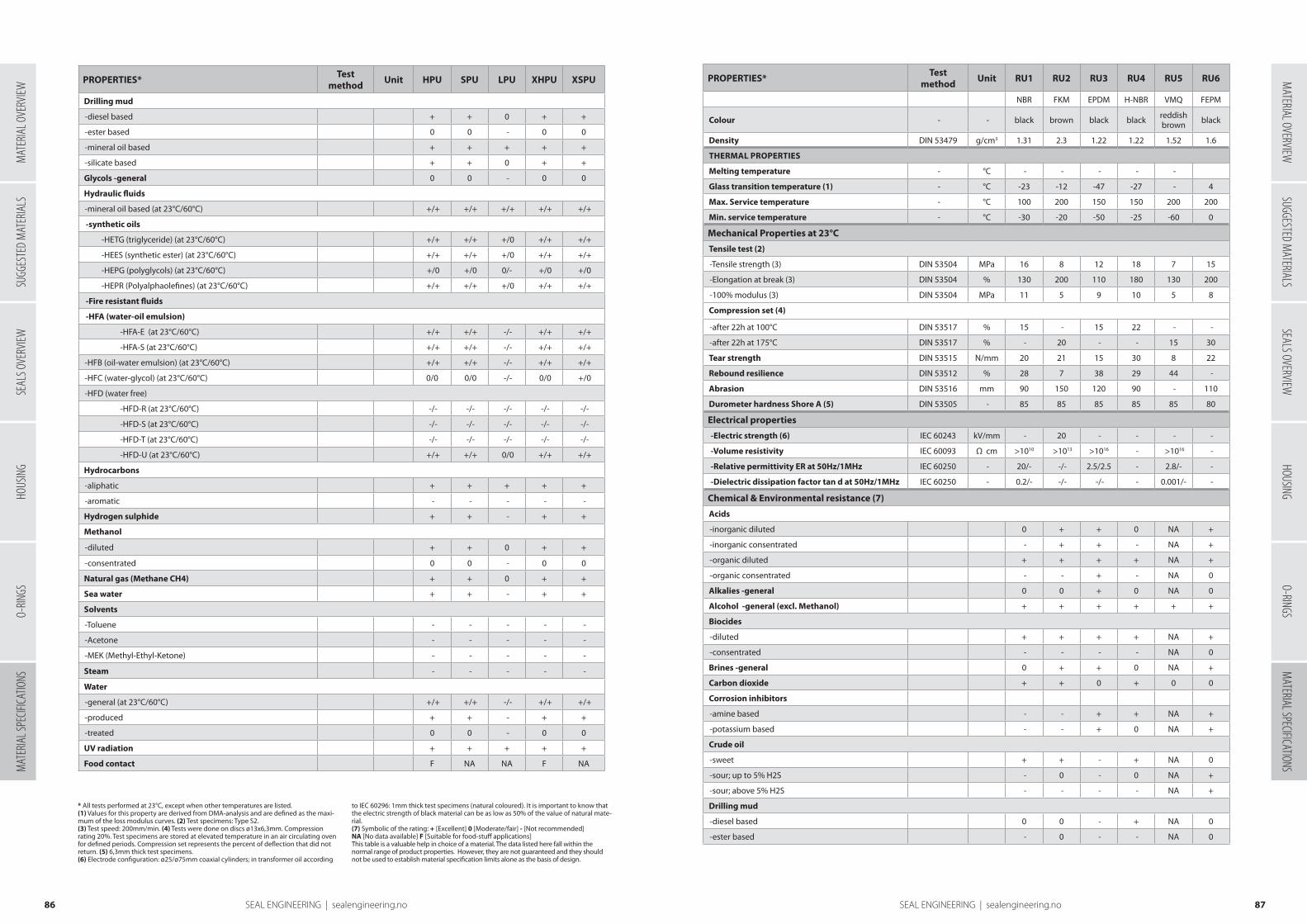
* All tests performed at 23°C, except when other temperatures are listed.(1) Values for this property are derived from DMA-analysis and are defined as the maxi-mum of the loss modulus curves. (2) Test specimens: Type S2. (3) Test speed: 200mm/min. (4) Tests were done on discs ø13x6,3mm. Compression rating 20%. Test specimens are stored at elevated temperature in an air circulating oven for defined periods. Compression set represents the percent of deflection that did not return. (5) 6,3mm thick test specimens. (6) Electrode configuration: ø25/ø75mm coaxial cylinders; in transformer oil according
to IEC 60296: 1mm thick test specimens (natural coloured). It is important to know that the electric strength of black material can be as low as 50% of the value of natural mate-rial. (7) Symbolic of the rating: + [Excellent] 0 [Moderate/fair] - [Not recommended]NA [No data available] F [Suitable for food-stuff applications]This table is a valuable help in choice of a material. The data listed here fall within the normal range of product properties. However, they are not guaranteed and they should not be used to establish material specification limits alone as the basis of design.
PROPERTIES*Test
methodUnit HPU SPU LPU XHPU XSPU
Drilling mud
-diesel based + + 0 + +
-ester based 0 0 - 0 0
-mineral oil based + + + + +
-silicate based + + 0 + +
Glycols -general 0 0 - 0 0
Hydraulic fluids
-mineral oil based (at 23°C/60°C) +/+ +/+ +/+ +/+ +/+
-synthetic oils
-HETG (triglyceride) (at 23°C/60°C) +/+ +/+ +/0 +/+ +/+
-HEES (synthetic ester) (at 23°C/60°C) +/+ +/+ +/0 +/+ +/+
-HEPG (polyglycols) (at 23°C/60°C) +/0 +/0 0/- +/0 +/0
-HEPR (Polyalphaolefines) (at 23°C/60°C) +/+ +/+ +/0 +/+ +/+
-Fire resistant fluids
-HFA (water-oil emulsion)
-HFA-E (at 23°C/60°C) +/+ +/+ -/- +/+ +/+
-HFA-S (at 23°C/60°C) +/+ +/+ -/- +/+ +/+
-HFB (oil-water emulsion) (at 23°C/60°C) +/+ +/+ -/- +/+ +/+
-HFC (water-glycol) (at 23°C/60°C) 0/0 0/0 -/- 0/0 +/0
-HFD (water free)
-HFD-R (at 23°C/60°C) -/- -/- -/- -/- -/-
-HFD-S (at 23°C/60°C) -/- -/- -/- -/- -/-
-HFD-T (at 23°C/60°C) -/- -/- -/- -/- -/-
-HFD-U (at 23°C/60°C) +/+ +/+ 0/0 +/+ +/+
Hydrocarbons
-aliphatic + + + + +
-aromatic - - - - -
Hydrogen sulphide + + - + +
Methanol
-diluted + + 0 + +
-consentrated 0 0 - 0 0
Natural gas (Methane CH4) + + 0 + +
Sea water + + - + +
Solvents
-Toluene - - - - -
-Acetone - - - - -
-MEK (Methyl-Ethyl-Ketone) - - - - -
Steam - - - - -
Water
-general (at 23°C/60°C) +/+ +/+ -/- +/+ +/+
-produced + + - + +
-treated 0 0 - 0 0
UV radiation + + + + +
Food contact F NA NA F NA
PROPERTIES*Test
methodUnit RU1 RU2 RU3 RU4 RU5 RU6
NBR FKM EPDM H-NBR VMQ FEPM
Colour - - black brown black black reddish brown black
Density DIN 53479 g/cm3 1.31 2.3 1.22 1.22 1.52 1.6
THERMAL PROPERTIES
Melting temperature - °C - - - - -
Glass transition temperature (1) - °C -23 -12 -47 -27 - 4
Max. Service temperature - °C 100 200 150 150 200 200
Min. service temperature - °C -30 -20 -50 -25 -60 0
Mechanical Properties at 23°C
Tensile test (2)
-Tensile strength (3) DIN 53504 MPa 16 8 12 18 7 15
-Elongation at break (3) DIN 53504 % 130 200 110 180 130 200
-100% modulus (3) DIN 53504 MPa 11 5 9 10 5 8
Compression set (4)
-after 22h at 100°C DIN 53517 % 15 - 15 22 - -
-after 22h at 175°C DIN 53517 % - 20 - - 15 30
Tear strength DIN 53515 N/mm 20 21 15 30 8 22
Rebound resilience DIN 53512 % 28 7 38 29 44 -
Abrasion DIN 53516 mm 90 150 120 90 - 110
Durometer hardness Shore A (5) DIN 53505 - 85 85 85 85 85 80
Electrical properties
-Electric strength (6) IEC 60243 kV/mm - 20 - - - -
-Volume resistivity IEC 60093 Ω cm >1010 >1013 >1016 - >1016 -
-Relative permittivity ER at 50Hz/1MHz IEC 60250 - 20/- -/- 2.5/2.5 - 2.8/- -
-Dielectric dissipation factor tan d at 50Hz/1MHz IEC 60250 - 0.2/- -/- -/- - 0.001/- -
Chemical & Environmental resistance (7)
Acids
-inorganic diluted 0 + + 0 NA +
-inorganic consentrated - + + - NA +
-organic diluted + + + + NA +
-organic consentrated - - + - NA 0
Alkalies -general 0 0 + 0 NA 0
Alcohol -general (excl. Methanol) + + + + + +
Biocides
-diluted + + + + NA +
-consentrated - - - - NA 0
Brines -general 0 + + 0 NA +
Carbon dioxide + + 0 + 0 0
Corrosion inhibitors
-amine based - - + + NA +
-potassium based - - + 0 NA +
Crude oil
-sweet + + - + NA 0
-sour; up to 5% H2S - 0 - 0 NA +
-sour; above 5% H2S - - - - NA +
Drilling mud
-diesel based 0 0 - + NA 0
-ester based - 0 - - NA 0
8786 SEAL ENGINEERING | sealengineering.no
SUGG
ESTE
D M
ATER
IALS
SEAL
S OVE
RVIEW
HOUS
ING
O-RIN
GSM
ATER
IAL S
PECIF
ICATIO
NSM
ATERIAL OVERVIEWSUGGESTED M
ATERIALSSEALS OVERVIEW
HOUSINGO-RINGS
MATERIAL SPECIFICATIONS
MAT
ERIA
L OVE
RVIEW
SEAL ENGINEERING | sealengineering.no
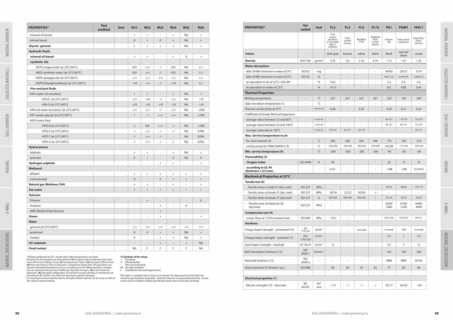
PROPERTIES*Test
methodUnit RU1 RU2 RU3 RU4 RU5 RU6
-mineral oil based + + - + NA +
-silicate based 0 + 0 + NA +
Glycols -general + + + + NA +
Hydraulic fluids
-mineral oil based + + - + 0 +
-synthetic oils
-HETG (triglyceride) (at 23°C/60°C) 0/0 +/+ -/- 0/0 NA +/+
-HEES (synthetic ester) (at 23°C/60°C) 0/0 +/+ -/- 0/0 NA +/+
-HEPG (polyglycols) (at 23°C/60°C) +/+ +/+ +/+ +/+ NA +/+
-HEPR (Polyalphaolefines) (at 23°C/60°C) +/0 +/+ -/- +/0 NA +/+
-Fire resistant fluids
-HFA (water-oil emulsion) + + - + NA +
-HFA-E (at 23°C/60°C) +/+ +/0 -/- +/+ NA +/0
-HFA-S (at 23°C/60°C) +/0 +/0 +/0 +/0 NA +/0
-HFB (oil-water emulsion) (at 23°C/60°C) +/+ +/+ -/- +/+ NA +/NA
-HFC (water-glycol) (at 23°C/60°C) + -/- +/+ +/+ NA +/NA
-HFD (water free)
-HFD-R (at 23°C/60°C) -/- 0/0 +/+ -/- NA +/NA
-HFD-S (at 23°C/60°C) -/- +/+ -/- -/- NA 0/NA
-HFD-T (at 23°C/60°C) -/- +/+ -/- - NA 0/NA
-HFD-U (at 23°C/60°C) -/- +/+ -/- -/- NA 0/NA
Hydrocarbons
-aliphatic + + - + NA +
-aromatic 0 + - 0 NA 0
Hydrogen sulphide - - + + - +
Methanol
-diluted + + + + + +
-consentrated 0 - 0 + + +
Natural gas (Methane CH4) + + - + - +
Sea water + + + + + +
Solvents
-Toluene - + - - - 0
-Acetone - - + - 0 -
-MEK (Methyl-Ethyl-Ketone) - - + - - -
Steam - - + - - +
Water
-general (at 23°C/60°C) +/+ +/+ +/+ +/+ +/+ +/+
-produced 0 0 + + NA +
-treated 0 - + + NA +
UV radiation - - + - + NA
Food contact NA F F F F NA
PROPERTIES*Test
methodUnit FL2 FL3 FL5 FL13 PA1 POM1 PEEK 1
PTFEw/glass
and MoSo2 w/15%glass
fibre + 5%MoS2
PTFE w/40% bronze
Modified PTFE
Modified PTFE
w/25% carbon
Polyam-ide
Poly-acetal- copolymer
Poly-Ether-Ether-
Ketone
Colour - - dark grey bronze white black black natural/black cream
Density ISO1183 g/cm3 2.25 3.0 2.16 2.10 1.15 1.41 1.32
Water absorption:
-after 24/96h immersion in water of 23°C ISO 62 mg - - - - 44/83 20/37 5/10
-after 24/96h immersion in water of 23°C ISO 62 % - - - - 0.65/1.22 0.24/0.45 0.06/0.12
-at saturation in air of 23°C/ 50% RH - % 0.02 - - - 2.2 0.2 0.2
-at saturation in water of 23°C - % <0.15 - - - 8.5 0.85 0.45
Thermal Properties
Melting temperature - °C 327 327 327 327 220 165 340
Glass transition temperature (1) - °C - - - - - - -
Thermal conductivity at 23°C - W/(m K) 0.48 - 0.35 - 0.29 0.31 0.25
Coefficient of lineær thermal expansion:
-average value between 23 and 60°C - m/(m K) - - - - 80 10-6 110 10-6 110 10-6
-average value between 23 and 100°C - m/(m K) - - - - 90 10-6 60 10-6 110 10-6
-average value above 150°C - m/(m K) 110 10-6 60 10-6 120 10-6 - - - 65 10-6
Max. Service temperature in air:
-for short periods (2) - °C 300 300 300 300 170 140 310
-continuously for 5000/20000 h (3) - °C 260/260 260/260 260/260 260/260 105/90 115/100 250/250
Min. service temperature (4) - °C -200 -200 -200 -200 -40 -50 -60
Flammability (5)
-Oxygen index ISO 4589 % 95 - - - 25 15 35
-according to UL 94 (thickness 1.5/3 mm) - - V-O/- - - - -/HB -/HB V-0/V-0
Mechanical Properties at 23°C
Tensile test (6)
-Tensile stress at yield (7) (dry /wet) ISO 527 MPa - - - 85/65 68/68 110/110
-Tensile stress at break (7) (dry /wet) ISO 527 MPa 18/18 22/22 30/30 -/- - - -
-Tensile strain at break (7) (dry/wet) ISO 527 % 200/200 280/280 360/360 -/- 25/>50 35/35 20/20
-Tensile mod. of elasticity (8) (dry/wet) ISO 527 MPa - - - - 3500/
18003100/3100
4400/4400
Compression test (9)
-compr. Stress at 1/2/5% nominal strain ISO 604 MPa -/14/- - - - 26/51/92 19/35/67 29/57/-
Hardness
Charpy impact strength - unnotched (10) ISO 179/1eU kJ/m2 - - no break - no break 150 no break
Charpy impact strength - notched (11) ISO 179/1eU
kJ/m2 - - - - 3.5 7 3.5
Izod impact strength - notched ISO 180/2A kJ/m2 12 - - - 3.5 7 6
Ball intendation hardness (12) ISO 2039-1 N/mm2 - - - - 165 140 230
Rockwell hardness (12) ISO 2039-2 - - - - - M88 M84 M105
Shore hardness D (Tested 3 sec.) ISO 868 - 60 64 59 65 77 82 86
Electrical properties (1)
-Electric strength (13) (dry/wet) IEC 60243
kV/mm -/13 -/- -/- -/- 25/17 20/20 -/24
•
•
•
• • • •
•
• • •
•
•
•
8988 SEAL ENGINEERING | sealengineering.no
* All tests performed at 23°C, except when other temperatures are listed. (1) Values for this property are derived from DMA-analysis and are defined as the maxi-mum of the loss modulus curves. (2) Test specimens: Type S. (3) Test speed: 200mm/min (4) Tests were done on discs ø13x6,3mm. Compression rating 20%. Test specimens are stored at elevated temperature in an air circulating oven for defined periods. Compres-sion set represents the percent of deflection that did not return. (5) 6,3mm thick test specimens. (6) Electrode configuration: ø25/ø75mm coaxial cylinders; in transformer oil according to IEC 60296: 1mm thick test specimens (natural coloured). It is important to know that the electric strength of black material can be as low as 50% of the value of natural material.
(7) Symbolic of the rating: + [Excellent] 0 [Moderate/fair] - [Not recommended] NA [No data available] F [Suitable for food-stuff applications] This table is a valuable help in choice of a material. The data listed here fall within the normal range of product properties. However, they are not guaranteed and they should not be used to establish material specification limits alone as the basis of design.
SUGG
ESTE
D M
ATER
IALS
SEAL
S OVE
RVIEW
HOUS
ING
O-RIN
GSM
ATER
IAL S
PECIF
ICATIO
NSM
ATERIAL OVERVIEWSUGGESTED M
ATERIALSSEALS OVERVIEW
HOUSINGO-RINGS
MATERIAL SPECIFICATIONS
MAT
ERIA
L OVE
RVIEW
SEAL ENGINEERING | sealengineering.no
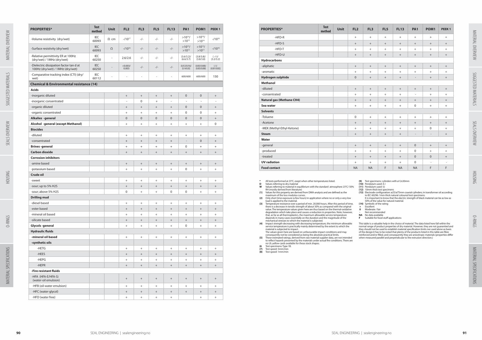
PROPERTIES*Test
methodUnit FL2 FL3 FL5 FL13 PA1 POM1 PEEK 1
-Volume resistivity (dry/wet) IEC 60093 Ω cm -/1017 -/- -/- -/- >1014/
>1012
>1014/>1014 -/1016
-Surface resistivity (dry/wet) IEC 60093 Ω -/1016 -/- -/- -/- >1013/
>1012>1013/ >1013 -/1016
- Relative permittivity ER at 100Hz (dry/wet) / 1MHz (dry/wet)
IEC 60250 - 2.6/2.6 -/- -/- -/- (3.6/3.2)/
(6.6/3.7)(3.8/3.8)/(3.8/3.8)
( -/-)/(3.2/3.2)
- Dielectric dissipation factor tan d at 100Hz (dry/wet) / 1MHz (dry/wet)
IEC 60250 - <0.003/
0.003 -/- -/- -/- (0.012/0.016)/(0.14/0.05)
(0.003/0.008)/(0.003/0.008)
(-/-)/ (0.001/0.002)
- Comparative tracking index (CTI) (dry/wet)
IEC 60112 - - - - - 600/600 600/600 150
Chemical & Environmental resistance (14)
Acids
-inorganic diluted + + + + 0 0 +
-inorganic consentrated - 0 + - - - -
-organic diluted + + + + 0 0 +
-organic consentrated + + + + 0 0 +
Alkalies -general 0 0 0 0 0 0 +
Alcohol -general (except Methanol) + + + + + + 0
Biocides
-diluted + + + + + + +
-consentrated + + + + - 0 +
Brines -general + + + + 0 + +
Carbon dioxide + + + + + + +
Corrosion inhibitors
-amine based + + + + + + +
-potassium based + + + + 0 + +
Crude oil
-sweet + + + + + + +
-sour; up to 5% H2S + + + + + + +
-sour; above 5% H2S 0 + + 0 0 + +
Drilling mud
-diesel based + + + + + + +
-ester based + + + + + + +
-mineral oil based + + + + + + +
-silicate based + + + + + + +
Glycols -general + + + + 0 + +
Hydraulic fluids
-mineral oil based + + + + + + +
-synthetic oils
-HETG + + + + + + +
-HEES + + + + + + +
-HEPG + + + + + + +
-HEPR + + + + + + +
-Fire resistant fluids
- HFA (HFA-E/HFA-S) (water-oil emulsion) + + + + + + +
-HFB (oil-water emulsion) + + + + + + +
-HFC (water-glycol) + + + + + + +
-HFD (water free) + + + + + +
•
PROPERTIES*Test
methodUnit FL2 FL3 FL5 FL13 PA1 POM1 PEEK 1
-HFD-R + + + + + + +
-HFD-S + + + + + + +
-HFD-T + + + + + + +
-HFD-U + + + + + + +
Hydrocarbons
-aliphatic + + + + + + +
-aromatic + + + + + + +
Hydrogen sulphide 0 + + + - + +
Methanol
-diluted + + + + + + +
-consentrated + + + + - + +
Natural gas (Methane CH4) + + + + + + +
Sea water + + + + 0 + +
Solvents
-Toluene 0 + + + + + +
-Acetone + + + + + + +
-MEK (Methyl-Ethyl-Ketone) + + + + + 0 +
Steam + + + + - - +
Water
-general + + + + 0 + +
-produced + + + + 0 + +
-treated + + + + 0 0 +
UV radiation + + + + 0 - -
Food contact NA NA F NA NA F F
9190 SEAL ENGINEERING | sealengineering.no
* All tests performed at 23°C, exept when other temperatures listed. D Values referring to dry material W Values referring to material in equilibrium with the standard atmosphere 23°C/ 50%
RH (mostly derived from literature) (1) Values for this property are derived from DMA-analysis and are defined as the
maximum of the loss modulus curves. (2) Only short time exposure (a few hours) in application where no or only a very low
load is applied to the material. (3) Temperature resistance over a period of min. 20.000 hours. After this period of time,
there is a decrease in tensile strength of about 50% as compared with the original value. The temperature values given here are thus based on the thermal-oxidative degradation which take place and causes a reduction in properties. Note, however, that, as far as all thermoplastics, the maximum allowable service temperature depends in many cases essentially on the duration and the magnitude of the mechanical stresses to which the material is subjected.
(4) Impact strength decreasing with decreasing temperature, the minimum allowable service temperature is practically mainly determined by the extent to which the material is subjected to impact. The values given here are based on unfavourable impact conditions and may consequently not be considered as being the absolute practical limits.
(5) These estimated ratings, derived from raw material supplier data, are not intended to reflect hazards presented by the materials under actual fire conditions. There are no UL-yellow cards available for these stock shapes.
(6 Test specimens: Type 1B. (7) Test speed: 5mm/min (8) Test speed: 1mm/min
(9) Test specimens: cylinders with ø12x30mm (10) Pendulum used: 4 J (11) Pendulum used: 5J (12) 10mm thick test specimens (13) Electrode configuration: ø25/ø75mm coaxial cylinders; in transformer oil according
to IEC 60296: 1mm thick natural coloured test specimens. It is important to know that the electric strength of black material can be as low as 50% of the value for natural material.
(14) Symbolic of the rating + Excellent 0 Moderate / fair - Not recommended NA No data available F Suitable for food-stuff applications
This table is a valuable help in the choice of material. The data listed here fall within the normal range of product properties of dry material. However, they are not guarantied and they should not be used to establish material specification limits nor used alone as basis of the design.It has to be noted that plenty of the products listed in this table are fibre reinforced and/or filled, and consequently they are anisotropic materials (properties differ when measured parallel and perpendicular to the extrusion direction.)
SUGG
ESTE
D M
ATER
IALS
SEAL
S OVE
RVIEW
HOUS
ING
O-RIN
GSM
ATER
IAL S
PECIF
ICATIO
NSM
ATERIAL OVERVIEWSUGGESTED M
ATERIALSSEALS OVERVIEW
HOUSINGO-RINGS
MATERIAL SPECIFICATIONS
MAT
ERIA
L OVE
RVIEW
SEAL ENGINEERING | sealengineering.no

Chemical resistance
TEM
P. [°
C]
TEM
P. [°
F]
HP
U
LPU
RU
1 (N
BR
)
RU
2 (F
KM
)
RU
3 (E
PD
M)
RU
4 (H
-NB
R)
RU
5 (V
MQ
)
PO
M1
PA1
FL5
ACETALDEHYDE 23 73 - - - - + - 0 + 0 +
ACETAMIDE 23 73 - - + + + + 0 + + +
ACETIC ACID, GLACIAL 70 158 - - 0 - + 0 0 - - +
ACETIC ACID 10 % 50 122 0 - - + + - + - -(0) +
ACETIC ACID 50 % 50 122 - - - - + - 0 - - +
ACETIC ANHYDRIDE 23 73 - - - - + - 0 - 0 +
ACETONE (DIMETHYLKETONE) 23 73 - - - - + - 0 + + +
ACETOPHENONE 23 73 - - - - + - 0 + + +
ACETYLCHLORIDE 23 73 - - - + - - - - - +
ACETYLENE 23 73 + + + + + + - + + +
ACETYLENE TETRACHLORIDE 23 73 - - - + - - - n.a. n.a. +
ACRYLONITRILE 23 73 - - - - - - - + + +
ADIPIC ACID AQ. SOL. 23 73 + 0 + + + + 0 n.a. 0 +
AEROSHELL FLUID 4 (SHELL) 80 176 + + + + - + - + + +
AEROSHELL 7A 50 122 + + + + - + 0 + + +
AEROSHELL 17 50 122 + + + + - + 0 + + +
AEROSHELL 750 50 122 n.a. - 0 + n.a. 0 - + + +
AIR, HOT [°C] (LIMITING VALUE) _ 110 110 80 200 130 130 200 100 100 260
AIR, HOT [°F] (LIMITING VALUE) _ 230 230 176 392 266 266 392 212 212 500
AIR, HOT (LONG TIME TEST) 100 212 + + - + + + + - 0 +
AIR, HOT (LONG TIME TEST) 200 392 - - - + - - + - - +
AIR (LONG TIME WEATHERING TEST) n.a. n.a. + + 0 + + + + (+) + +
ALCOHOL (DRINKING-ALCOHOL ~40 VOL.%) 23 73 0(+) - + + + + + + + +
ALUMINIUM ACETATE, AQ. SOL. 50 122 n.a. - + 0 + + - + + +
ALUMINIUM CHLORIDE, AQ. SOL. 50 122 + 0 + + + + 0 + + +
ALUMINIUM FLUORIDE, AQ. SOL. 50 122 0(+) - + + + + 0 + + +
ALUMINIUM NITRATE, AQ. SOL. 50 122 0(+) - + + + + 0 + + +
ALUMINIUM PHOSPHATE, AQ. SOL. 50 122 0(+) - + + + + + + 0 +
AMMONIA GAS, COLD 23 73 + 0 + - + + + n.a. n.a. +
AMMONIA GAS, HOT 80 176 - - 0 - 0 0 + n.a. n.a. +
AMMONIA SOLUTION 25% 23 73 0(+) - 0 0 + 0 + + 0 +
AMMONIUM CARBONATE, AQ. SOL. 50 122 0(+) - + + + + 0 + 0 +
AMMONIUM CHLORIDE, AQ. SOL. 50 122 0(+) - + + + + 0 + 0 +
AMMONIUM HYDROXIDE 25% 23 73 0(+) - + + + + + + 0 +
AMMONIUM PERSULFATE, AQ. SOL. 50 122 - - + + + + - + 0 +
AMMONIUM SULFIDE, AQ. SOL. 23 73 + 0 + - + + (+) + 0 +
AMYL ACETATE 23 73 - - - - + - - + + +
AMYL ALCOHOL (N-AMYL ALCOHOL) 50 122 (0) - + + + + - + + +
AMYL CHLORIDE 40 104 0 - - + - - - - + +
AMYL CHLORONAPHTHALENE 23 73 - - - + - - - n.a. n.a. +
ANILINE 23 73 - - - + + - + 0 0 +
ANILINE 100 212 - - - - + - n.a. 0 0 +
ANILINE HYDROCHLORIDE 23 73 - - - + + - - n.a. n.a. +
Chemical resistance TEM
P. [°
C]
TEM
P. [°
F]
HP
U
LPU
RU
1 (N
BR
)
RU
2 (F
KM
)
RU
3 (E
PD
M)
RU
4 (H
-NB
R)
RU
5 (V
MQ
)
PO
M1
PA1
FL5
AQUA REGIA 23 73 - - - + 0 - - - - +
ARAL VITAM GX 32 80 176 + + + + - + - + + +
ARAL VITAMOL 3865 80 176 + + + + - + - + + +
ARAL VITAMOL 4004 80 176 + + + + - + - + + +
ARGON 23 73 + + + + + + 0 + + +
ARSENIC ACID, AQ. SOL. 50 122 0 - + + + + + + 0 +
ASPHALT / BITUMEN 100 212 + 0 0 + - 0 - + + +
ASTM-REFERENCE FUEL A 23 73 + + + + - + - + + +
ASTM-REFERENCE FUEL B 23 73 0 0 0 + - - - + + +
ASTM-REFERENCE FUEL C 23 73 0 0 - + - - - + + +
ASTM-REFERENCE FUEL D 23 73 + + - + - - - + + +
ASTM-REFERENCE NO. 1 OIL 100 212 + + + + - + + + + +
ASTM-REFERENCE NO. 2 OIL 100 212 + 0 + + - + 0 + + +
ASTM-REFERENCE NO. 3 OIL 100 212 + 0 + + - + - + + +
AVIATION FUEL 23 73 + + + + - + - + + +
BARIUM CHLORIDE, AQ. SOL. 50 122 + - + + + + + + 0 +
BARIUM HYDROXIDE, AQ. SOL. 50 122 n.a. - + + + + + + 0 +
BEER 23 73 + - + + + + + + + +
BEER WORT 90 194 n.a. - + + 0 + 0 n.a. n.a. +
BENZALDEHYDE 23 73 - - - - + - 0 + 0 +
BENZALDEHYDE 100 212 - - - - + - - - - +
BENZENE 23 73 - - - + - - - + + +
BENZENE SULFONIC ACID 23 73 - - - + - - - n.a. n.a. +
BENZOIC ACID, AQ. SOL. 23 73 - - - + 0 - - 0 0 +
BENZOPHENONE 40 104 - - 0 + 0 0 - n.a. n.a. +
BENZYL ALCOHOL 23 73 - - - + 0 - 0 + -(0) +
BENZYL CHLORIDE 23 73 - - - + - - - + + +
BIOMIL H (HUNGARY) 80 176 + - - + - - - + + +
BISULFITE WASTE LIQUOR 23 73 n.a. - 0 + + 0 (+) + 0 +
BLAST-FURNACE GAS 23 73 - - - + - - + + + +
BLEACH LIQUOR 23 73 n.a. - - + + - 0 - -(0) +
BONE OIL 23 73 + (+) + + - (+) 0 + + +
BORAX, AQ. SOL. 50 122 (0) - + + + + 0 + 0 +
BORIC ACID 10% 23 73 + 0 + + + + 0 + 0 +
BP BIOHYD 46 80 176 + - - + - - - + + +
BP BIOHYD SE 46 80 176 + - - + - - - + + +
BP ENERGOL SF-C 15 50 122 0(+) - + 0 + + 0 + 0 +
BP ENERGOL SF-C 15 60 140 -(0) - + 0 + + 0 + 0 +
BRAKE FLUID (BASED ON GLYCOL, DOT-4) 50 122 - - - - + - 0 - - +
BRAKE FLUID (BASED ON GLYCOL, DOT-4) 100 212 - - - - + - 0 - - +
BRENNTAG TR 32 50 122 0 - + + - + + + + +
BRENNTAG TR 32 60 140 - - + + - + + + + +
BRENNTAG TR 46 50 122 + - + + - + + + + +
BRENNTAG TR 46 60 140 0 - + + - + + + + +
9392 SEAL ENGINEERING | sealengineering.no
Table 2
LEGEND: + Excellent 0 Moderate - Not recommended ( ) Presumedly n.a. not available LEGEND: + Excellent 0 Moderate - Not recommended ( ) Presumedly n.a. not available
SUGG
ESTE
D M
ATER
IALS
SEAL
S OVE
RVIEW
HOUS
ING
O-RIN
GSM
ATER
IAL S
PECIF
ICATIO
NSM
ATERIAL OVERVIEWSUGGESTED M
ATERIALSSEALS OVERVIEW
HOUSINGO-RINGS
MATERIAL SPECIFICATIONS
MAT
ERIA
L OVE
RVIEW
SEAL ENGINEERING | sealengineering.no
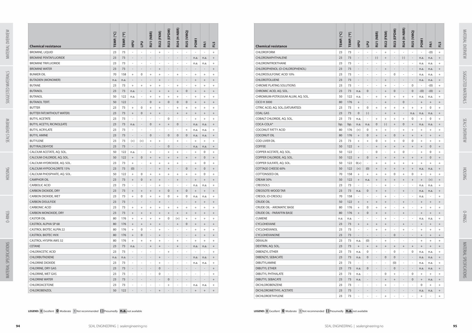
Chemical resistance TEM
P. [°
C]
TEM
P. [°
F]
HP
U
LPU
RU
1 (N
BR
)
RU
2 (F
KM
)
RU
3 (E
PD
M)
RU
4 (H
-NB
R)
RU
5 (V
MQ
)
PO
M1
PA1
FL5
BROMINE, LIQUID 23 73 - - - + - - - - - +
BROMINE PENTAFLUORIDE 23 73 - - - - - - - n.a. n.a. +
BROMINE TRIFLUORIDE 23 73 - - - - - - - n.a. n.a. +
BROMINE WATER 23 73 - - - + - - - - - +
BUNKER OIL 70 158 + 0 + + - + - + + +
BUTADIEN (MONOMER) n.a. n.a. - - - + - - - + + +
BUTANE 23 73 + + + + - + - + + +
BUTANOL 23 73 n.a. - + + + + 0 + + +
BUTANOL 50 122 n.a. - + + + + - + + +
BUTANOL TERT. 50 122 - - 0 + 0 0 0 + + +
BUTTER 23 73 + 0 + + - + + + + +
BUTTER FAT(WITHOUT WATER) 23 73 + 0 + + - + + + + +
BUTYL ACETATE 23 73 - - - - 0 - - + + +
BUTYL ACETYL RICINOLEATE 23 73 n.a. - 0 + + 0 - n.a. n.a. +
BUTYL ACRYLATE 23 73 - - - - - - + n.a. n.a. +
BUTYL AMINE 23 73 - - 0 - 0 0 0 n.a. n.a. +
BUTYLENE 23 73 (+) (+) + + - + - + + +
BUTYRALDEHYDE 23 73 - - - - 0 - - n.a. n.a. +
CALCIUM ACETATE, AQ. SOL. 50 122 n.a. - + - + + - + 0 +
CALCIUM CHLORIDE, AQ. SOL. 50 122 + 0 + + + + + + 0 +
CALCIUM HYDROXIDE, AQ. SOL. 23 73 + - + + + + - + 0 +
CALCIUM HYPOCHLORITE 15% 23 73 (0) - - + + - 0 + 0 +
CALCIUM PHOSPHATE, AQ. SOL. 50 122 + 0 + + + + + + 0 +
CAMPHOR OIL 23 73 + 0 + + - + - + + +
CARBOLIC ACID 23 73 - - - + - - - n.a. n.a. +
CARBON DIOXIDE, DRY 23 73 + + + + 0 + 0 + + +
CARBON DIOXIDE, WET 23 73 + 0 + + 0 + 0 n.a. n.a. +
CARBON DISULFIDE 23 73 - - - + - - - + + +
CARBONIC ACID 23 73 + + + + + + + + + +
CARBON MONOXIDE, DRY 23 73 + + + + + + + + + +
CASTOR OIL 80 176 + + + + 0 (+) + + + +
CASTROL ALPHA SP 68 80 176 + + + + - + 0 + + +
CASTROL BIOTEC ALPIN 22 80 176 + 0 - + - - - + + +
CASTROL BIOTEC HVX 80 176 + 0 - + - - - + + +
CASTROL HYSPIN AWS 32 80 176 + + + + - + - + + +
CETANE 23 73 n.a. - + + - + - n.a. n.a. +
CHLORACETIC ACID 23 73 - - - - + - - - - +
CHLORBUTADIENE n.a. n.a. - - - + - - - n.a. n.a. +
CHLORINE DIOXIDE 23 73 - - - + - - - n.a. n.a. +
CHLORINE, DRY GAS 23 73 - - - 0 - - - - - +
CHLORINE, WET GAS 23 73 - - - 0 - - - - - +
CHLORINE WATER 23 73 - - - - 0 - - - - +
CHLOROACETONE 23 73 - - - - + - - n.a. n.a. +
CHLOROBENZOL 50 122 - - - + - - - + + +
Chemical resistance TEM
P. [°
C]
TEM
P. [°
F]
HP
U
LPU
RU
1 (N
BR
)
RU
2 (F
KM
)
RU
3 (E
PD
M)
RU
4 (H
-NB
R)
RU
5 (V
MQ
)
PO
M1
PA1
FL5
CHLOROFORM 23 73 - - - + - - - - -(0) +
CHLORONAPHTHALENE 23 73 - - (-) + - (-) - n.a. n.a. +
CHLORONITROETHANE 23 73 - - - - - - - n.a. n.a. +
CHLOROPHENOL (O-CHLOROPHENOL) 23 73 - - - + - - - n.a. n.a. +
CHLOROSULFONIC ACID 10% 23 73 - - - - 0 - - n.a. n.a. +
CHLOROTOLUENE 23 73 - - - + - - - n.a. n.a. +
CHROME PLATING SOLUTIONS 23 73 - - - + - - 0 - -(0) +
CHROMIC ACID, AQ. SOL. 23 73 n.a. 0 - + 0 - 0 -(0) -(0) +
CHROMIUM-POTASSIUM ALUM, AQ. SOL. 50 122 n.a. - + + + + + n.a. n.a. +
CICO H 3000 80 176 + - - + - 0 - + + +
CITRIC ACID, AQ. SOL.(SATURATED) 23 73 + 0 + + + + + + 0 +
COAL GAS 23 73 0 (-) - + + - n.a. n.a. n.a. +
COBALT CHLORIDE, AQ. SOL. 23 73 n.a. - + + + + 0 + 0 +
COCA-COLA® bp. bp. n.a. n.a. 0 (-) + 0 + n.a. n.a. +
COCONUT FATTY ACID 80 176 (+) 0 + + - + + + + +
COCONUT OIL 80 176 + 0 + + 0 + + + + +
COD-LIVER OIL 23 73 + + 0 + + 0 0 + + +
COFFEE 50 122 + - + + + + + + 0 +
COPPER ACETATE, AQ. SOL. 50 122 - - 0 - + 0 - + 0 +
COPPER CHLORIDE, AQ. SOL. 50 122 + 0 + + + + + + 0 +
COPPER SULFATE, AQ. SOL. 50 122 0(+) - + + + + + + + +
COTTAGE CHEESE 60% 50 122 (+) (0) + + + + + n.a. n.a. +
COTTONSEED OIL 70 158 + + + + 0 + 0 + + +
CREAM 30% 50 122 + n.a. + + + + + + (+) +
CREOSOLS 23 73 - - - + - - - n.a. n.a. +
CREOSOTE-WOOD TAR 23 73 n.a. 0 + + - + - n.a. n.a. +
CRESOL (O-CRESOL) 70 158 - - - + - - - n.a. - +
CRUDE OIL 50 122 + + + + - + - + + +
CRUDE OIL - AROMATIC BASE 80 176 + 0 + + - + - + + +
CRUDE OIL - PARAFFIN BASE 80 176 + 0 + + - + - + + +
CUMENE n.a. n.a. - - - + - - - n.a. n.a. +
CYCLOHEXANE 23 73 + + + + - + - + + +
CYCLOHEXANOL 23 73 - - + + - + - + + +
CYCLOHEXANONE 23 73 - - - - 0 - - + + +
DEKALIN 23 73 n.a. (0) - + - - - + + +
DEXTRIN, AQ. SOL. 23 73 + + + + + + + + + +
DIBENZYL ETHER 23 73 n.a. 0 - - 0 - 0 n.a. n.a. +
DIBENZYL SEBACATE 23 73 n.a. 0 - 0 0 - - n.a. n.a. +
DIBUTYLAMINE 23 73 - - - - (0) - - n.a. n.a. +
DIBUTYL ETHER 23 73 n.a. 0 - - 0 - - n.a. n.a. +
DIBUTYL PHTHALATE 23 73 n.a. - - 0 + - 0 + + +
DIBUTYL SEBACATE 23 73 n.a. - - + + - 0 + n.a. +
DICHLOROBENZENE 23 73 - - - + - - - 0 + +
DICHLOROMETHYL ACETATE 23 73 - - - - - - - n.a. n.a. +
DICHLOROETHYLENE 23 73 - - - + - - - + - +
9594 SEAL ENGINEERING | sealengineering.no
LEGEND: + Excellent 0 Moderate - Not recommended ( ) Presumedly n.a. not available LEGEND: + Excellent 0 Moderate - Not recommended ( ) Presumedly n.a. not available
SUGG
ESTE
D M
ATER
IALS
SEAL
S OVE
RVIEW
HOUS
ING
O-RIN
GSM
ATER
IAL S
PECIF
ICATIO
NSM
ATERIAL OVERVIEWSUGGESTED M
ATERIALSSEALS OVERVIEW
HOUSINGO-RINGS
MATERIAL SPECIFICATIONS
MAT
ERIA
L OVE
RVIEW
SEAL ENGINEERING | sealengineering.no
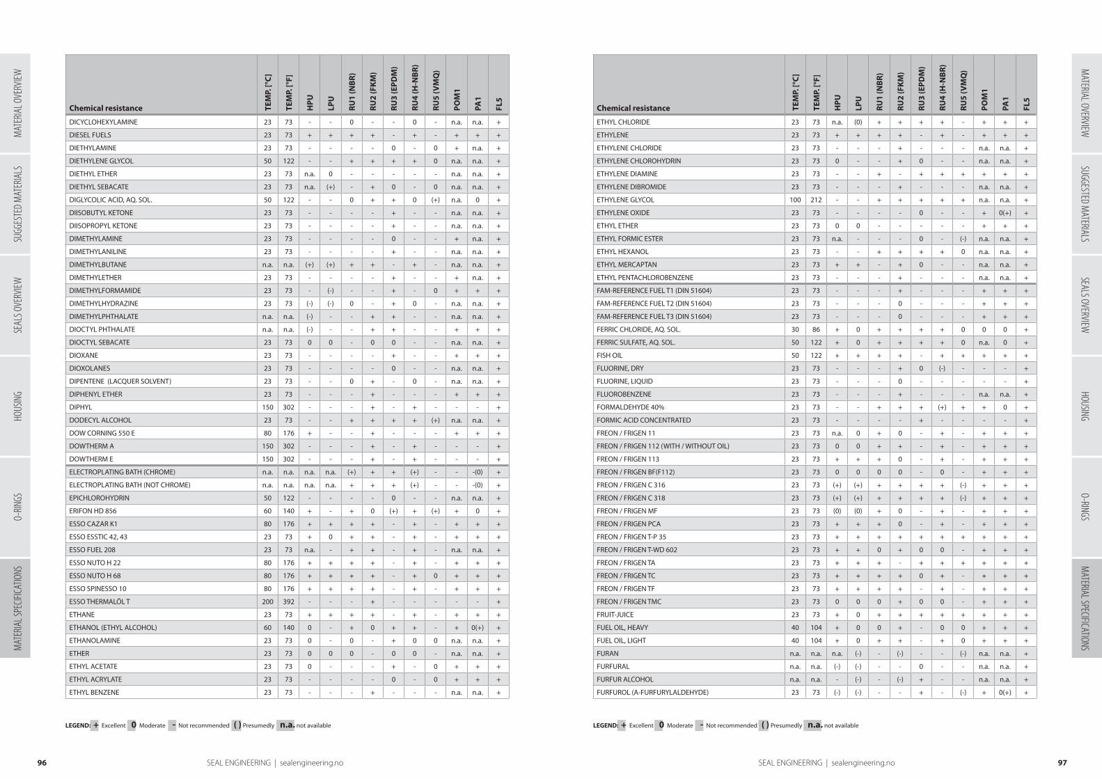
Chemical resistance TEM
P. [°
C]
TEM
P. [°
F]
HP
U
LPU
RU
1 (N
BR
)
RU
2 (F
KM
)
RU
3 (E
PD
M)
RU
4 (H
-NB
R)
RU
5 (V
MQ
)
PO
M1
PA1
FL5
DICYCLOHEXYLAMINE 23 73 - - 0 - - 0 - n.a. n.a. +
DIESEL FUELS 23 73 + + + + - + - + + +
DIETHYLAMINE 23 73 - - - - 0 - 0 + n.a. +
DIETHYLENE GLYCOL 50 122 - - + + + + 0 n.a. n.a. +
DIETHYL ETHER 23 73 n.a. 0 - - - - - n.a. n.a. +
DIETHYL SEBACATE 23 73 n.a. (+) - + 0 - 0 n.a. n.a. +
DIGLYCOLIC ACID, AQ. SOL. 50 122 - - 0 + + 0 (+) n.a. 0 +
DIISOBUTYL KETONE 23 73 - - - - + - - n.a. n.a. +
DIISOPROPYL KETONE 23 73 - - - - + - - n.a. n.a. +
DIMETHYLAMINE 23 73 - - - - 0 - - + n.a. +
DIMETHYLANILINE 23 73 - - - - + - - n.a. n.a. +
DIMETHYLBUTANE n.a. n.a. (+) (+) + + - + - n.a. n.a. +
DIMETHYLETHER 23 73 - - - - + - - + n.a. +
DIMETHYLFORMAMIDE 23 73 - (-) - - + - 0 + + +
DIMETHYLHYDRAZINE 23 73 (-) (-) 0 - + 0 - n.a. n.a. +
DIMETHYLPHTHALATE n.a. n.a. (-) - - + + - - n.a. n.a. +
DIOCTYL PHTHALATE n.a. n.a. (-) - - + + - - + + +
DIOCTYL SEBACATE 23 73 0 0 - 0 0 - - n.a. n.a. +
DIOXANE 23 73 - - - - + - - + + +
DIOXOLANES 23 73 - - - - 0 - - n.a. n.a. +
DIPENTENE (LACQUER SOLVENT) 23 73 - - 0 + - 0 - n.a. n.a. +
DIPHENYL ETHER 23 73 - - - + - - - + + +
DIPHYL 150 302 - - - + - + - - - +
DODECYL ALCOHOL 23 73 - - + + + + (+) n.a. n.a. +
DOW CORNING 550 E 80 176 + - - + - - - + + +
DOWTHERM A 150 302 - - - + - + - - - +
DOWTHERM E 150 302 - - - + - + - - - +
ELECTROPLATING BATH (CHROME) n.a. n.a. n.a. n.a. (+) + + (+) - - -(0) +
ELECTROPLATING BATH (NOT CHROME) n.a. n.a. n.a. n.a. + + + (+) - - -(0) +
EPICHLOROHYDRIN 50 122 - - - - 0 - - n.a. n.a. +
ERIFON HD 856 60 140 + - + 0 (+) + (+) + 0 +
ESSO CAZAR K1 80 176 + + + + - + - + + +
ESSO ESSTIC 42, 43 23 73 + 0 + + - + - + + +
ESSO FUEL 208 23 73 n.a. - + + - + - n.a. n.a. +
ESSO NUTO H 22 80 176 + + + + - + - + + +
ESSO NUTO H 68 80 176 + + + + - + 0 + + +
ESSO SPINESSO 10 80 176 + + + + - + - + + +
ESSO THERMALÖL T 200 392 - - - + - - - - - +
ETHANE 23 73 + + + + - + - + + +
ETHANOL (ETHYL ALCOHOL) 60 140 0 - + 0 + + - + 0(+) +
ETHANOLAMINE 23 73 0 - 0 - + 0 0 n.a. n.a. +
ETHER 23 73 0 0 0 - 0 0 - n.a. n.a. +
ETHYL ACETATE 23 73 0 - - - + - 0 + + +
ETHYL ACRYLATE 23 73 - - - - 0 - 0 + + +
ETHYL BENZENE 23 73 - - - + - - - n.a. n.a. +
Chemical resistance TEM
P. [°
C]
TEM
P. [°
F]
HP
U
LPU
RU
1 (N
BR
)
RU
2 (F
KM
)
RU
3 (E
PD
M)
RU
4 (H
-NB
R)
RU
5 (V
MQ
)
PO
M1
PA1
FL5
ETHYL CHLORIDE 23 73 n.a. (0) + + + + - + + +
ETHYLENE 23 73 + + + + - + - + + +
ETHYLENE CHLORIDE 23 73 - - - + - - - n.a. n.a. +
ETHYLENE CHLOROHYDRIN 23 73 0 - - + 0 - - n.a. n.a. +
ETHYLENE DIAMINE 23 73 - - + - + + + + + +
ETHYLENE DIBROMIDE 23 73 - - - + - - - n.a. n.a. +
ETHYLENE GLYCOL 100 212 - - + + + + + n.a. n.a. +
ETHYLENE OXIDE 23 73 - - - - 0 - - + 0(+) +
ETHYL ETHER 23 73 0 0 - - - - - + + +
ETHYL FORMIC ESTER 23 73 n.a. - - - 0 - (-) n.a. n.a. +
ETHYL HEXANOL 23 73 - - + + + + 0 n.a. n.a. +
ETHYL MERCAPTAN 23 73 + + - + 0 - - n.a. n.a. +
ETHYL PENTACHLOROBENZENE 23 73 - - - + - - - n.a. n.a. +
FAM-REFERENCE FUEL T1 (DIN 51604) 23 73 - - - + - - - + + +
FAM-REFERENCE FUEL T2 (DIN 51604) 23 73 - - - 0 - - - + + +
FAM-REFERENCE FUEL T3 (DIN 51604) 23 73 - - - 0 - - - + + +
FERRIC CHLORIDE, AQ. SOL. 30 86 + 0 + + + + 0 0 0 +
FERRIC SULFATE, AQ. SOL. 50 122 + 0 + + + + 0 n.a. 0 +
FISH OIL 50 122 + + + + - + + + + +
FLUORINE, DRY 23 73 - - - + 0 (-) - - - +
FLUORINE, LIQUID 23 73 - - - 0 - - - - - +
FLUOROBENZENE 23 73 - - - + - - - n.a. n.a. +
FORMALDEHYDE 40% 23 73 - - + + + (+) + + 0 +
FORMIC ACID CONCENTRATED 23 73 - - - - + - - - - +
FREON / FRIGEN 11 23 73 n.a. 0 + 0 - + - + + +
FREON / FRIGEN 112 (WITH / WITHOUT OIL) 23 73 0 0 + + - + - + + +
FREON / FRIGEN 113 23 73 + + + 0 - + - + + +
FREON / FRIGEN BF(F112) 23 73 0 0 0 0 - 0 - + + +
FREON / FRIGEN C 316 23 73 (+) (+) + + + + (-) + + +
FREON / FRIGEN C 318 23 73 (+) (+) + + + + (-) + + +
FREON / FRIGEN MF 23 73 (0) (0) + 0 - + - + + +
FREON / FRIGEN PCA 23 73 + + + 0 - + - + + +
FREON / FRIGEN T-P 35 23 73 + + + + + + + + + +
FREON / FRIGEN T-WD 602 23 73 + + 0 + 0 0 - + + +
FREON / FRIGEN TA 23 73 + + + - + + + + + +
FREON / FRIGEN TC 23 73 + + + + 0 + - + + +
FREON / FRIGEN TF 23 73 + + + + - + - + + +
FREON / FRIGEN TMC 23 73 0 0 0 + 0 0 - + + +
FRUIT-JUICE 23 73 + 0 + + + + + + + +
FUEL OIL, HEAVY 40 104 + 0 0 + - 0 0 + + +
FUEL OIL, LIGHT 40 104 + 0 + + - + 0 + + +
FURAN n.a. n.a. n.a. (-) - (-) - - (-) n.a. n.a. +
FURFURAL n.a. n.a. (-) (-) - - 0 - - n.a. n.a. +
FURFUR ALCOHOL n.a. n.a. - (-) - (-) + - - n.a. n.a. +
FURFUROL (A-FURFURYLALDEHYDE) 23 73 (-) (-) - - + - (-) + 0(+) +
9796 SEAL ENGINEERING | sealengineering.no
LEGEND: + Excellent 0 Moderate - Not recommended ( ) Presumedly n.a. not available LEGEND: + Excellent 0 Moderate - Not recommended ( ) Presumedly n.a. not available
SUGG
ESTE
D M
ATER
IALS
SEAL
S OVE
RVIEW
HOUS
ING
O-RIN
GSM
ATER
IAL S
PECIF
ICATIO
NSM
ATERIAL OVERVIEWSUGGESTED M
ATERIALSSEALS OVERVIEW
HOUSINGO-RINGS
MATERIAL SPECIFICATIONS
MAT
ERIA
L OVE
RVIEW
SEAL ENGINEERING | sealengineering.no

Chemical resistance TEM
P. [°
C]
TEM
P. [°
F]
HP
U
LPU
RU
1 (N
BR
)
RU
2 (F
KM
)
RU
3 (E
PD
M)
RU
4 (H
-NB
R)
RU
5 (V
MQ
)
PO
M1
PA1
FL5
FYRQUEL LT (AKZO NOBEL) 80 176 - - n.a. + - n.a. - n.a. n.a. +
GAMMA-RAYS 20 68 + + 0 - 0 0 0 - 0 -
GAS OIL 23 73 0(+) 0(+) + + - + - + + +
GASOLINE 23 73 0 0 + + - + - + + +
GASOLINE (20% ETHANOL) 23 73 - - 0 + - (0) - n.a. n.a. +
GASOLINE (20% METHANOL) 23 73 - - - 0 - - - n.a. n.a. +
GASOLINE HIGH-OCTANE 23 73 0 0 0 + - 0 - + + +
GASOLINE M-15 (15% METHANOL) 23 73 - - - 0 - - - + + +
GASOLINE, 92 OCTANE 23 73 0 0 + + - + - + + +
GASOLINE, 98 OCTANE 23 73 0 0 0 + - - - + + +
GASOLINE, REFINED 23 73 + + + + - + - + + +
GEAR LUBES, HYPOID LUBES, ATF 80 176 n.a. n.a. 0 + - + - -(0) + +
GEAR LUBES SAE 80 / SAE 90 80 176 n.a. n.a. + + - + 0 n.a. n.a. +
GELATINE, AQ. SOL. 50 122 n.a. 0 + + + + + + + +
GENERATOR GAS 23 73 + + + + - + 0 + + +
GLUCOSE, AQ. SOL. 50 122 + 0 + + + + + n.a. n.a. +
GLUE n.a. n.a. + + + + + + + + + +
GLYCERIN (GLYCEROL) 50 122 (+) - + + + + + + + +
GLYSANTINE (ANTIFREEZE) 60 140 - - + + + + + n.a. n.a. +
GLYSANTINE / WATER (40 : 60 VOL%) 100 212 n.a. (-) 0 + + 0 n.a. + 0(+) +
GREASE, ANIMAL BASE 50 122 + + + + 0 + + + + +
GREASE, PETROLEUM BASE 50 122 + + + + - + - + + +
GREASE, VEGETABLE BASE 50 122 + + + + - + + + + +
HALON 1211 (FIRE-EXTINGUISHING MEDIUM) 23 73 + + - 0 - - - n.a. n.a. +
HALON 1301 23 73 + + + + + + - n.a. n.a. +
HELIUM 23 73 + + + + + + + + + +
HEPTANE (n-HEPTANE) 23 73 n.a. + + + - + - + + +
HEPTANONE 23 73 - - - - 0 - - n.a. n.a. +
HESSOL BIOL HE 46 80 176 + 0 - + - - - + + +
HESSOL BIOL HR 37 80 176 + 0 - + - - - + + +
HEXACHLOROCYCLOHEXANE 23 73 n.a. 0 - + - - - + -(0) +
HEXANE (n-HEXANE) 23 73 + + + + - + - + + +
HEXYL ALCOHOL 23 73 - - 0 + 0 0 0 n.a. + +
HOUGHTO-SAFE 271, 620 50 122 0 - + 0 + + 0 + 0 +
HOUGHTO-SAFE 1010, 1055 50 122 - - - + + - - n.a. n.a. +
HOUGHTO-SAFE 5040 50 122 (+) - + + - + - + 0 +
HYDRAULIC FLUID HFA (OIL IN WATER) 50 122 + - + + - + 0 + 0 +
HYDRAULIC FLUID HFB (WATER IN OIL) 50 122 + - + + - + (+) + 0 +
HYDRAULIC FLUID HFC (POLYALKYLENE-GLYCOLS) 60 140 0 - + 0 + + (+) + 0 +
HYDRAULIC FLUID HFD-R (PHOSPHATE ESTER) 100 212 - - - + + - - n.a. n.a. +
HYDRAULIC FLUID HFD-S (CHLOR.HYDROCARB.) 100 212 - - - + - - (+) n.a. n.a. +
HYDRAULIC FLUID HFD-U (SYNTH. ESTER) 80 176 + -(0) - + - 0(+) (-) + + +
HYDRAULIC OIL (PETROLEUM BASE) 80 176 + + + + - + 0 + + +
HYDRA - VIS (HOUGHTON VAUGHAN) 70 158 - - - - - - - + 0 +
HYDRAZINE 23 73 - - 0 - + 0 - + n.a. +
Chemical resistance TEM
P. [°
C]
TEM
P. [°
F]
HP
U
LPU
RU
1 (N
BR
)
RU
2 (F
KM
)
RU
3 (E
PD
M)
RU
4 (H
-NB
R)
RU
5 (V
MQ
)
PO
M1
PA1
FL5
HYDROBROMIC ACID, AQ. SOL. 50 122 - - - + + - - - - +
HYDROCHLORIC ACID 10% 40 104 0 - 0 + + 0 0 - - +
HYDROCHLORIC ACID FUMING 23 73 - - - - 0 - - - - +
HYDROFLUORIC ACID 48% 23 73 - - - + + (-) - - - +
HYDROFLUORIC ACID 75% 23 73 - - - 0 + (-) - - - +
HYDROGEN CHLORIDE, GAS 23 73 - - - + + - - - - +
HYDROGEN FLUORIDE, DRY 23 73 - - - + 0 - - n.a. n.a. +
HYDROGEN, GAS 23 73 + + + + + + - + + +
HYDROGEN PEROXIDE 30% 23 73 + + - + + - 0 - - +
HYDROGEN PEROXIDE 90% 23 73 0 - - + 0 - 0 - - +
HYDROGEN SULFIDE 23 73 + - - - + + - + - +
HYDROLUBRIC 120 B (HOUGHTON VAUGHAN) 60 140 + - + + + + + + 0 +
HYDROQUINONE 23 73 - - - + 0 - - n.a. - +
HYDROXYL-AMINE SULFATE, AQ. SOL. 23 73 n.a. - + + + + + + 0 +
HYPOCHLOROUS ACID 23 73 - - - + + - - n.a. n.a. +
HY-TRANS-PLUS MS 1207 (CASE) 80 176 + + 0 + - + - n.a. n.a. +
H-17(HUNGARY) 60 140 + - + + - + - + 0 +
IODINE PENTAFLUORIDE 23 73 - - - - - - - n.a. n.a. +
IODOFORM 23 73 - n.a. n.a. n.a. + n.a. n.a. - - +
ISOPROPANOL 23 73 - - 0 + + 0 + + + +
ISOPROPYL CHLORIDE 23 73 - - - + - - - n.a. n.a. +
ISOPROPYL ETHER 23 73 n.a. 0 0 - - 0 - n.a. n.a. +
JAM 23 73 + 0 + + + + + + + +
JET FUEL A1 80 176 0(+) - + + - + - n.a. n.a. +
KEROSENE 23 73 + + + + - + - + + +
KETCHUP 50 122 + 0 + + + + + n.a. n.a. +
KLÜBER SYNTHESO D 220 - EP 80 176 n.a. n.a. 0 n.a. n.a. 0 n.a. n.a. n.a. n.a.
KLÜBER SYNTHESO PROBA 270 50 122 + + + + + + n.a. n.a. n.a. +
LARD, ANIMAL FAT 60 140 + + + + 0 + + + + +
LAUGHING GAS 23 73 + + + + + + + + + +
LAURYL ALCOHOL 23 73 - - + 0 + + (+) n.a. n.a. +
LAVENDER OIL 23 73 n.a. - 0 + - 0 - + + +
LEAD ACETATE 50 122 n.a. - 0 - + 0 - + + +
LIME SULFUR-WET 50 122 n.a. n.a. - + + (0) + n.a. n.a. +
LINSEED OIL 23 73 + + + + - + 0 + + +
LIQUEUR (MAX. 30% ALCOHOL) 23 73 (+) - + + + + + + 0 +
LITHIUM BROMIDE, AQ. SOL. 50 122 n.a. - + + + + + + 0 +
LUBRICATING OIL 80 176 + + + + - + - + + +
MAGNESIUM CHLORIDE, AQ. SOL. 50 122 + 0 + + + + + + 0 +
MAGNESIUM HYDROXIDE, AQ. SOL. 50 122 (+) - + + + + + + 0 +
MAGNESIUM SULFATE (EPSOM SALTS), AQ. SOL. 50 122 + 0 + + + + + + 0 +
MAIZE OIL n.a. n.a. + + + + - + + + + +
MALEIC ACID, AQ. SOL. 50 122 0 - 0 + + 0 - n.a. n.a. +
MALIC ACID 23 73 n.a. - + + - + 0 + 0 +
MARGARINE 40 104 n.a. - + + - + + + + +
9998 SEAL ENGINEERING | sealengineering.no
LEGEND: + Excellent 0 Moderate - Not recommended ( ) Presumedly n.a. not available LEGEND: + Excellent 0 Moderate - Not recommended ( ) Presumedly n.a. not available
SUGG
ESTE
D M
ATER
IALS
SEAL
S OVE
RVIEW
HOUS
ING
O-RIN
GSM
ATER
IAL S
PECIF
ICATIO
NSM
ATERIAL OVERVIEWSUGGESTED M
ATERIALSSEALS OVERVIEW
HOUSINGO-RINGS
MATERIAL SPECIFICATIONS
MAT
ERIA
L OVE
RVIEW
SEAL ENGINEERING | sealengineering.no
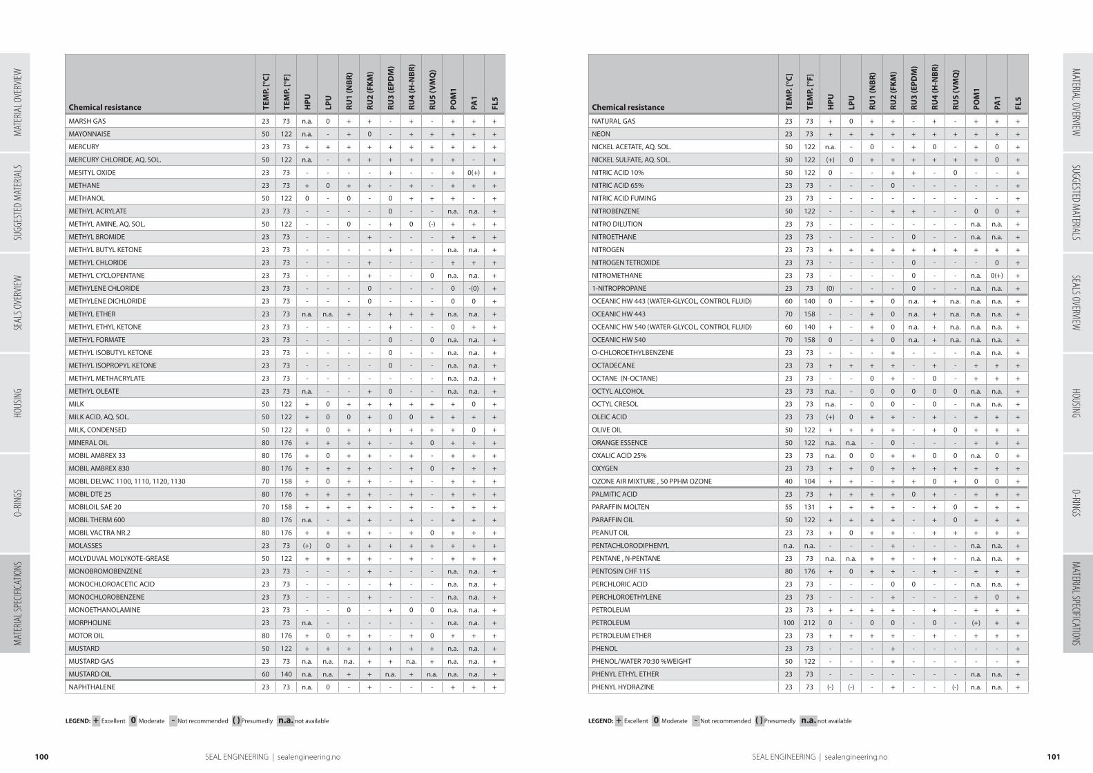
Chemical resistance TEM
P. [°
C]
TEM
P. [°
F]
HP
U
LPU
RU
1 (N
BR
)
RU
2 (F
KM
)
RU
3 (E
PD
M)
RU
4 (H
-NB
R)
RU
5 (V
MQ
)
PO
M1
PA1
FL5
MARSH GAS 23 73 n.a. 0 + + - + - + + +
MAYONNAISE 50 122 n.a. - + 0 - + + + + +
MERCURY 23 73 + + + + + + + + + +
MERCURY CHLORIDE, AQ. SOL. 50 122 n.a. - + + + + + + - +
MESITYL OXIDE 23 73 - - - - + - - + 0(+) +
METHANE 23 73 + 0 + + - + - + + +
METHANOL 50 122 0 - 0 - 0 + + + - +
METHYL ACRYLATE 23 73 - - - - 0 - - n.a. n.a. +
METHYL AMINE, AQ. SOL. 50 122 - - 0 - + 0 (-) + + +
METHYL BROMIDE 23 73 - - - + - - - + + +
METHYL BUTYL KETONE 23 73 - - - - + - - n.a. n.a. +
METHYL CHLORIDE 23 73 - - - + - - - + + +
METHYL CYCLOPENTANE 23 73 - - - + - - 0 n.a. n.a. +
METHYLENE CHLORIDE 23 73 - - - 0 - - - 0 -(0) +
METHYLENE DICHLORIDE 23 73 - - - 0 - - - 0 0 +
METHYL ETHER 23 73 n.a. n.a. + + + + + n.a. n.a. +
METHYL ETHYL KETONE 23 73 - - - - + - - 0 + +
METHYL FORMATE 23 73 - - - - 0 - 0 n.a. n.a. +
METHYL ISOBUTYL KETONE 23 73 - - - - 0 - - n.a. n.a. +
METHYL ISOPROPYL KETONE 23 73 - - - - 0 - - n.a. n.a. +
METHYL METHACRYLATE 23 73 - - - - - - - n.a. n.a. +
METHYL OLEATE 23 73 n.a. - - + 0 - - n.a. n.a. +
MILK 50 122 + 0 + + + + + + 0 +
MILK ACID, AQ. SOL. 50 122 + 0 0 + 0 0 + + + +
MILK, CONDENSED 50 122 + 0 + + + + + + 0 +
MINERAL OIL 80 176 + + + + - + 0 + + +
MOBIL AMBREX 33 80 176 + 0 + + - + - + + +
MOBIL AMBREX 830 80 176 + + + + - + 0 + + +
MOBIL DELVAC 1100, 1110, 1120, 1130 70 158 + 0 + + - + - + + +
MOBIL DTE 25 80 176 + + + + - + - + + +
MOBILOIL SAE 20 70 158 + + + + - + - + + +
MOBIL THERM 600 80 176 n.a. - + + - + - + + +
MOBIL VACTRA NR.2 80 176 + + + + - + 0 + + +
MOLASSES 23 73 (+) 0 + + + + + + + +
MOLYDUVAL MOLYKOTE-GREASE 50 122 + + + + - + - + + +
MONOBROMOBENZENE 23 73 - - - + - - - n.a. n.a. +
MONOCHLOROACETIC ACID 23 73 - - - - + - - n.a. n.a. +
MONOCHLOROBENZENE 23 73 - - - + - - - n.a. n.a. +
MONOETHANOLAMINE 23 73 - - 0 - + 0 0 n.a. n.a. +
MORPHOLINE 23 73 n.a. - - - - - - n.a. n.a. +
MOTOR OIL 80 176 + 0 + + - + 0 + + +
MUSTARD 50 122 + + + + + + + n.a. n.a. +
MUSTARD GAS 23 73 n.a. n.a. n.a. + + n.a. + n.a. n.a. +
MUSTARD OIL 60 140 n.a. n.a. + + n.a. + n.a. n.a. n.a. +
NAPHTHALENE 23 73 n.a. 0 - + - - - + + +
Chemical resistance TEM
P. [°
C]
TEM
P. [°
F]
HP
U
LPU
RU
1 (N
BR
)
RU
2 (F
KM
)
RU
3 (E
PD
M)
RU
4 (H
-NB
R)
RU
5 (V
MQ
)
PO
M1
PA1
FL5
NATURAL GAS 23 73 + 0 + + - + - + + +
NEON 23 73 + + + + + + + + + +
NICKEL ACETATE, AQ. SOL. 50 122 n.a. - 0 - + 0 - + 0 +
NICKEL SULFATE, AQ. SOL. 50 122 (+) 0 + + + + + + 0 +
NITRIC ACID 10% 50 122 0 - - + + - 0 - - +
NITRIC ACID 65% 23 73 - - - 0 - - - - - +
NITRIC ACID FUMING 23 73 - - - - - - - - - +
NITROBENZENE 50 122 - - - + + - - 0 0 +
NITRO DILUTION 23 73 - - - - - - - n.a. n.a. +
NITROETHANE 23 73 - - - - 0 - - n.a. n.a. +
NITROGEN 23 73 + + + + + + + + + +
NITROGEN TETROXIDE 23 73 - - - - 0 - - - 0 +
NITROMETHANE 23 73 - - - - 0 - - n.a. 0(+) +
1-NITROPROPANE 23 73 (0) - - - 0 - - n.a. n.a. +
OCEANIC HW 443 (WATER-GLYCOL, CONTROL FLUID) 60 140 0 - + 0 n.a. + n.a. n.a. n.a. +
OCEANIC HW 443 70 158 - - + 0 n.a. + n.a. n.a. n.a. +
OCEANIC HW 540 (WATER-GLYCOL, CONTROL FLUID) 60 140 + - + 0 n.a. + n.a. n.a. n.a. +
OCEANIC HW 540 70 158 0 - + 0 n.a. + n.a. n.a. n.a. +
O-CHLOROETHYLBENZENE 23 73 - - - + - - - n.a. n.a. +
OCTADECANE 23 73 + + + + - + - + + +
OCTANE (N-OCTANE) 23 73 - - 0 + - 0 - + + +
OCTYL ALCOHOL 23 73 n.a. - 0 0 0 0 0 n.a. n.a. +
OCTYL CRESOL 23 73 n.a. - 0 0 - 0 - n.a. n.a. +
OLEIC ACID 23 73 (+) 0 + + - + - + + +
OLIVE OIL 50 122 + + + + - + 0 + + +
ORANGE ESSENCE 50 122 n.a. n.a. - 0 - - - + + +
OXALIC ACID 25% 23 73 n.a. 0 0 + + 0 0 n.a. 0 +
OXYGEN 23 73 + + 0 + + + + + + +
OZONE AIR MIXTURE , 50 PPHM OZONE 40 104 + + - + + 0 + 0 0 +
PALMITIC ACID 23 73 + + + + 0 + - + + +
PARAFFIN MOLTEN 55 131 + + + + - + 0 + + +
PARAFFIN OIL 50 122 + + + + - + 0 + + +
PEANUT OIL 23 73 + 0 + + - + + + + +
PENTACHLORODIPHENYL n.a. n.a. - - - + - - - n.a. n.a. +
PENTANE , N-PENTANE 23 73 n.a. n.a. + + - + - n.a. n.a. +
PENTOSIN CHF 11S 80 176 + 0 + + - + - + + +
PERCHLORIC ACID 23 73 - - - 0 0 - - n.a. n.a. +
PERCHLOROETHYLENE 23 73 - - - + - - - + 0 +
PETROLEUM 23 73 + + + + - + - + + +
PETROLEUM 100 212 0 - 0 0 - 0 - (+) + +
PETROLEUM ETHER 23 73 + + + + - + - + + +
PHENOL 23 73 - - - + - - - - - +
PHENOL/WATER 70:30 %WEIGHT 50 122 - - - + - - - - - +
PHENYL ETHYL ETHER 23 73 - - - - - - - n.a. n.a. +
PHENYL HYDRAZINE 23 73 (-) (-) - + - - (-) n.a. n.a. +
101100 SEAL ENGINEERING | sealengineering.no
LEGEND: + Excellent 0 Moderate - Not recommended ( ) Presumedly n.a. not available LEGEND: + Excellent 0 Moderate - Not recommended ( ) Presumedly n.a. not available
SUGG
ESTE
D M
ATER
IALS
SEAL
S OVE
RVIEW
HOUS
ING
O-RIN
GSM
ATER
IAL S
PECIF
ICATIO
NSM
ATERIAL OVERVIEWSUGGESTED M
ATERIALSSEALS OVERVIEW
HOUSINGO-RINGS
MATERIAL SPECIFICATIONS
MAT
ERIA
L OVE
RVIEW
SEAL ENGINEERING | sealengineering.no
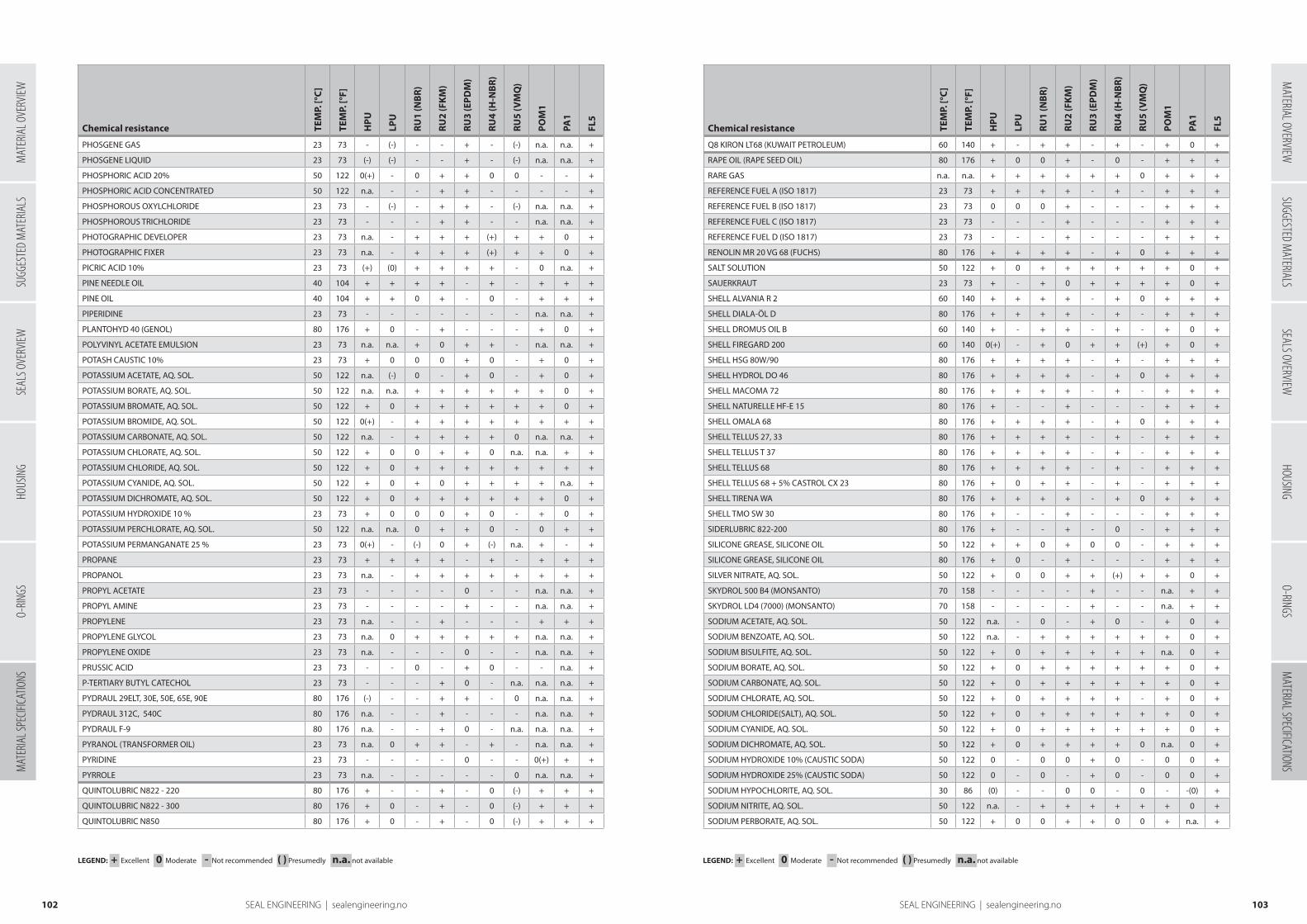
Chemical resistance TEM
P. [°
C]
TEM
P. [°
F]
HP
U
LPU
RU
1 (N
BR
)
RU
2 (F
KM
)
RU
3 (E
PD
M)
RU
4 (H
-NB
R)
RU
5 (V
MQ
)
PO
M1
PA1
FL5
PHOSGENE GAS 23 73 - (-) - - + - (-) n.a. n.a. +
PHOSGENE LIQUID 23 73 (-) (-) - - + - (-) n.a. n.a. +
PHOSPHORIC ACID 20% 50 122 0(+) - 0 + + 0 0 - - +
PHOSPHORIC ACID CONCENTRATED 50 122 n.a. - - + + - - - - +
PHOSPHOROUS OXYLCHLORIDE 23 73 - (-) - + + - (-) n.a. n.a. +
PHOSPHOROUS TRICHLORIDE 23 73 - - - + + - - n.a. n.a. +
PHOTOGRAPHIC DEVELOPER 23 73 n.a. - + + + (+) + + 0 +
PHOTOGRAPHIC FIXER 23 73 n.a. - + + + (+) + + 0 +
PICRIC ACID 10% 23 73 (+) (0) + + + + - 0 n.a. +
PINE NEEDLE OIL 40 104 + + + + - + - + + +
PINE OIL 40 104 + + 0 + - 0 - + + +
PIPERIDINE 23 73 - - - - - - - n.a. n.a. +
PLANTOHYD 40 (GENOL) 80 176 + 0 - + - - - + 0 +
POLYVINYL ACETATE EMULSION 23 73 n.a. n.a. + 0 + + - n.a. n.a. +
POTASH CAUSTIC 10% 23 73 + 0 0 0 + 0 - + 0 +
POTASSIUM ACETATE, AQ. SOL. 50 122 n.a. (-) 0 - + 0 - + 0 +
POTASSIUM BORATE, AQ. SOL. 50 122 n.a. n.a. + + + + + + 0 +
POTASSIUM BROMATE, AQ. SOL. 50 122 + 0 + + + + + + 0 +
POTASSIUM BROMIDE, AQ. SOL. 50 122 0(+) - + + + + + + + +
POTASSIUM CARBONATE, AQ. SOL. 50 122 n.a. - + + + + 0 n.a. n.a. +
POTASSIUM CHLORATE, AQ. SOL. 50 122 + 0 0 + + 0 n.a. n.a. + +
POTASSIUM CHLORIDE, AQ. SOL. 50 122 + 0 + + + + + + + +
POTASSIUM CYANIDE, AQ. SOL. 50 122 + 0 + 0 + + + + n.a. +
POTASSIUM DICHROMATE, AQ. SOL. 50 122 + 0 + + + + + + 0 +
POTASSIUM HYDROXIDE 10 % 23 73 + 0 0 0 + 0 - + 0 +
POTASSIUM PERCHLORATE, AQ. SOL. 50 122 n.a. n.a. 0 + + 0 - 0 + +
POTASSIUM PERMANGANATE 25 % 23 73 0(+) - (-) 0 + (-) n.a. + - +
PROPANE 23 73 + + + + - + - + + +
PROPANOL 23 73 n.a. - + + + + + + + +
PROPYL ACETATE 23 73 - - - - 0 - - n.a. n.a. +
PROPYL AMINE 23 73 - - - - + - - n.a. n.a. +
PROPYLENE 23 73 n.a. - - + - - - + + +
PROPYLENE GLYCOL 23 73 n.a. 0 + + + + + n.a. n.a. +
PROPYLENE OXIDE 23 73 n.a. - - - 0 - - n.a. n.a. +
PRUSSIC ACID 23 73 - - 0 - + 0 - - n.a. +
P-TERTIARY BUTYL CATECHOL 23 73 - - - + 0 - n.a. n.a. n.a. +
PYDRAUL 29ELT, 30E, 50E, 65E, 90E 80 176 (-) - - + + - 0 n.a. n.a. +
PYDRAUL 312C, 540C 80 176 n.a. - - + - - - n.a. n.a. +
PYDRAUL F-9 80 176 n.a. - - + 0 - n.a. n.a. n.a. +
PYRANOL (TRANSFORMER OIL) 23 73 n.a. 0 + + - + - n.a. n.a. +
PYRIDINE 23 73 - - - - 0 - - 0(+) + +
PYRROLE 23 73 n.a. - - - - - 0 n.a. n.a. +
QUINTOLUBRIC N822 - 220 80 176 + - - + - 0 (-) + + +
QUINTOLUBRIC N822 - 300 80 176 + 0 - + - 0 (-) + + +
QUINTOLUBRIC N850 80 176 + 0 - + - 0 (-) + + +
Chemical resistance TEM
P. [°
C]
TEM
P. [°
F]
HP
U
LPU
RU
1 (N
BR
)
RU
2 (F
KM
)
RU
3 (E
PD
M)
RU
4 (H
-NB
R)
RU
5 (V
MQ
)
PO
M1
PA1
FL5
Q8 KIRON LT68 (KUWAIT PETROLEUM) 60 140 + - + + - + - + 0 +
RAPE OIL (RAPE SEED OIL) 80 176 + 0 0 + - 0 - + + +
RARE GAS n.a. n.a. + + + + + + 0 + + +
REFERENCE FUEL A (ISO 1817) 23 73 + + + + - + - + + +
REFERENCE FUEL B (ISO 1817) 23 73 0 0 0 + - - - + + +
REFERENCE FUEL C (ISO 1817) 23 73 - - - + - - - + + +
REFERENCE FUEL D (ISO 1817) 23 73 - - - + - - - + + +
RENOLIN MR 20 VG 68 (FUCHS) 80 176 + + + + - + 0 + + +
SALT SOLUTION 50 122 + 0 + + + + + + 0 +
SAUERKRAUT 23 73 + - + 0 + + + + 0 +
SHELL ALVANIA R 2 60 140 + + + + - + 0 + + +
SHELL DIALA-ÖL D 80 176 + + + + - + - + + +
SHELL DROMUS OIL B 60 140 + - + + - + - + 0 +
SHELL FIREGARD 200 60 140 0(+) - + 0 + + (+) + 0 +
SHELL HSG 80W/90 80 176 + + + + - + - + + +
SHELL HYDROL DO 46 80 176 + + + + - + 0 + + +
SHELL MACOMA 72 80 176 + + + + - + - + + +
SHELL NATURELLE HF-E 15 80 176 + - - + - - - + + +
SHELL OMALA 68 80 176 + + + + - + 0 + + +
SHELL TELLUS 27, 33 80 176 + + + + - + - + + +
SHELL TELLUS T 37 80 176 + + + + - + - + + +
SHELL TELLUS 68 80 176 + + + + - + - + + +
SHELL TELLUS 68 + 5% CASTROL CX 23 80 176 + 0 + + - + - + + +
SHELL TIRENA WA 80 176 + + + + - + 0 + + +
SHELL TMO SW 30 80 176 + - - + - - - + + +
SIDERLUBRIC 822-200 80 176 + - - + - 0 - + + +
SILICONE GREASE, SILICONE OIL 50 122 + + 0 + 0 0 - + + +
SILICONE GREASE, SILICONE OIL 80 176 + 0 - + - - - + + +
SILVER NITRATE, AQ. SOL. 50 122 + 0 0 + + (+) + + 0 +
SKYDROL 500 B4 (MONSANTO) 70 158 - - - - + - - n.a. + +
SKYDROL LD4 (7000) (MONSANTO) 70 158 - - - - + - - n.a. + +
SODIUM ACETATE, AQ. SOL. 50 122 n.a. - 0 - + 0 - + 0 +
SODIUM BENZOATE, AQ. SOL. 50 122 n.a. - + + + + + + 0 +
SODIUM BISULFITE, AQ. SOL. 50 122 + 0 + + + + + n.a. 0 +
SODIUM BORATE, AQ. SOL. 50 122 + 0 + + + + + + 0 +
SODIUM CARBONATE, AQ. SOL. 50 122 + 0 + + + + + + 0 +
SODIUM CHLORATE, AQ. SOL. 50 122 + 0 + + + + - + 0 +
SODIUM CHLORIDE(SALT), AQ. SOL. 50 122 + 0 + + + + + + 0 +
SODIUM CYANIDE, AQ. SOL. 50 122 + 0 + + + + + + 0 +
SODIUM DICHROMATE, AQ. SOL. 50 122 + 0 + + + + 0 n.a. 0 +
SODIUM HYDROXIDE 10% (CAUSTIC SODA) 50 122 0 - 0 0 + 0 - 0 0 +
SODIUM HYDROXIDE 25% (CAUSTIC SODA) 50 122 0 - 0 - + 0 - 0 0 +
SODIUM HYPOCHLORITE, AQ. SOL. 30 86 (0) - - 0 0 - 0 - -(0) +
SODIUM NITRITE, AQ. SOL. 50 122 n.a. - + + + + + + 0 +
SODIUM PERBORATE, AQ. SOL. 50 122 + 0 0 + + 0 0 + n.a. +
103102 SEAL ENGINEERING | sealengineering.no
LEGEND: + Excellent 0 Moderate - Not recommended ( ) Presumedly n.a. not available LEGEND: + Excellent 0 Moderate - Not recommended ( ) Presumedly n.a. not available
SUGG
ESTE
D M
ATER
IALS
SEAL
S OVE
RVIEW
HOUS
ING
O-RIN
GSM
ATER
IAL S
PECIF
ICATIO
NSM
ATERIAL OVERVIEWSUGGESTED M
ATERIALSSEALS OVERVIEW
HOUSINGO-RINGS
MATERIAL SPECIFICATIONS
MAT
ERIA
L OVE
RVIEW
SEAL ENGINEERING | sealengineering.no
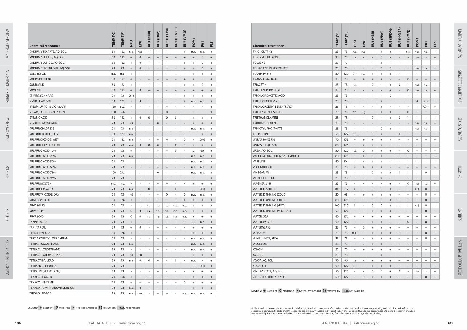
Chemical resistance TEM
P. [°
C]
TEM
P. [°
F]
HP
U
LPU
RU
1 (N
BR
)
RU
2 (F
KM
)
RU
3 (E
PD
M)
RU
4 (H
-NB
R)
RU
5 (V
MQ
)
PO
M1
PA1
FL5
SODIUM STEARATE, AQ. SOL. 50 122 n.a. n.a. + + + + + n.a. n.a. +
SODIUM SULFATE, AQ. SOL. 50 122 + 0 + + + + + + 0 +
SODIUM SULFIDE, AQ. SOL. 50 122 + 0 + + + + + + 0 +
SODIUM THIOSULFATE, AQ. SOL. 23 73 + 0 + + + + + + 0 +
SOLUBLE OIL n.a. n.a. + + + + - + - + + +
SOUP SOLUTION 50 122 + - + + + + + + 0 +
SOUR MILK 50 122 + - + + + + + + 0 +
SOYA OIL 50 122 + 0 + + - + - + + +
SPIRITS, SCHNAPS 23 73 0(+) - + + + + + + + +
STARCH, AQ. SOL. 50 122 + 0 + + + + + n.a. n.a. +
STEAM, UP TO 150°C / 302°F 150 302 - - - - + - - - - +
STEAM, UP TO 180°C / 356°F 180 356 - - - - 0 - - - - +
STEARIC ACID 50 122 + 0 0 + 0 0 - + + +
STYRENE, MONOMER 23 73 (0) - - 0 - - - + + +
SULFUR CHLORIDE 23 73 n.a. - - + - - - n.a. n.a. +
SULFUR DIOXIDE, DRY 50 122 n.a. - - + + - 0 - + +
SULFUR DIOXIDE, WET 50 122 n.a. - - + + - 0 - 0(+) +
SULFUR HEXAFLUORIDE 23 73 n.a. 0 0 0 + 0 0 + + +
SULFURIC ACID 10% 23 73 + - - + + 0 - 0 -(0) +
SULFURIC ACID 25% 23 73 n.a. - - + + - - n.a. n.a. +
SULFURIC ACID 50% 23 73 - - - + + - - n.a. n.a. +
SULFURIC ACID 60% 23 73 - - - + + - - n.a. n.a. +
SULFURIC ACID 75% 100 212 - - - 0 + - - n.a. n.a. +
SULFURIC ACID 96% 23 73 - - - + + - - - - +
SULFUR MOLTEN mp. mp. - - - + + - - + + +
SULFUROUS ACID 23 73 n.a. - 0 + + 0 - - 0(+) +
SULFUR TRIOXIDE, DRY 23 73 (+) - - + 0 - 0 n.a. n.a. +
SUNFLOWER OIL 80 176 + + + + - + + + + +
SUVA HP 62 23 73 + + n.a. n.a. n.a. n.a. n.a. + + +
SUVA 134a 23 73 0 0 n.a. n.a. n.a. n.a. n.a. + + +
SUVA 9000 23 73 0 0 n.a. n.a. n.a. n.a. n.a. + + +
TANNIC ACID 23 73 + + + + + + 0 0 n.a. +
TAR , TAR OIL 23 73 + 0 - + - - - + + +
TEBIOL HVI 32 A 80 176 + - - + - - - + + +
TERTIARY BUTYL MERCAPTAN 23 73 - - - + - - - n.a. n.a. +
TETRABROMOETHANE 23 73 n.a. - - + - - - n.a. n.a. +
TETRACHLOROETHANE 23 73 - - - + - - - n.a. n.a. +
TETRACHLOROMETHANE 23 73 (0) (0) - + - - - 0 + +
TETRAETHYL LEAD 23 73 n.a. 0 0 + - 0 - n.a. - +
TETRAHYDROFURAN 23 73 - - - - - - - 0 0(+) +
TETRALIN (SULFOLANE) 23 73 - - - + - - - + + +
TEXACO REGAL B 70 158 + + + + - + - + + +
TEXACO UNI-TEMP 23 73 + + + + - + 0 + + +
TEXAMATIC “A” TRANSMISSION-OIL 23 73 n.a. 0 + + - + - + + +
THIOKOL TP-90 B 23 73 n.a. n.a. - + + - n.a. n.a. n.a. +
Chemical resistance TEM
P. [°
C]
TEM
P. [°
F]
HP
U
LPU
RU
1 (N
BR
)
RU
2 (F
KM
)
RU
3 (E
PD
M)
RU
4 (H
-NB
R)
RU
5 (V
MQ
)
PO
M1
PA1
FL5
THIOKOL TP-95 23 73 n.a. n.a. - + + - n.a. n.a. n.a. +
THIONYL CHLORIDE 23 73 n.a. - - 0 - - - n.a. n.a. +
TOLUENE 23 73 - - - + - - - + + +
TOLUYLENE DIISOCYANATE 23 73 - - - 0 0 - - n.a. n.a. +
TOOTH-PASTE 50 122 (+) n.a. + + + + + + + +
TRANSFORMER OIL 23 73 + + + + - + 0 + + +
TRIACETIN 23 73 n.a. - 0 - + 0 + n.a. n.a. +
TRIBUTYL PHOSPHATE 23 73 - - - - + - 0 n.a. n.a. +
TRICHLOROACETIC ACID 23 73 - - - - 0 - - - - +
TRICHLOROETHANE 23 73 - - - + - - - 0 (+) +
TRICHLOROETHYLENE (TRIAD) 23 73 - - - + - - - - 0(+) +
TRICRESYL PHOSPHATE 23 73 n.a. (-) - + + - 0 + + +
TRIETHANOLAMINE 23 73 - - 0 - + 0 (-) + + +
TRINITROTOLUENE 23 73 - - - 0 - - - n.a. n.a. +
TRIOCTYL PHOSPHATE 23 73 - - - 0 + - - n.a. n.a. +
TURPENTINE 50 122 n.a. - 0 + - 0 - + + +
UNIVIS 40 (ESSO) 70 158 + + + + - + - + + +
UNIVIS J 13 (ESSO) 80 176 + + + + - + - + + +
UREA, AQ. SOL. 50 122 n.a. 0 + + + + 0 + + +
VACUUM PUMP OIL N 62 (LEYBOLD) 80 176 + + 0 + - + + + + +
VASELINE 40 104 + + + + - + + + + +
VEGETABLE OIL 23 73 + + + + - + + + + +
VINEGAR 5% 23 73 + - 0 + + 0 + + 0 +
VINYL CHLORIDE 23 73 - - - + 0 - - + + +
WAGNER 21 B 23 73 - - - - + - 0 n.a. n.a. +
WATER, DISTILLED 100 212 0 - 0 0 + + + (+) 0 +
WATER, DRINKING (COLD) 20 68 + + + + + + + + 0 +
WATER, DRINKING (HOT) 80 176 + - 0 0 + + + + 0 +
WATER, DRINKING (HOT) 100 212 0 - 0 0 + + + (+) (0) +
WATER, DRINKING (MINERAL) 50 122 + - + + + + + + 0 +
WATER, SEA 80 176 + - + + + + + + 0 +
WATER, WASTE 50 122 + - + + 0 + 0 + 0 +
WATERGLASS 23 73 + 0 + + + + + + + +
WHISKEY 23 73 0(+) - + + + + + + 0 +
WINE (WHITE, RED) 23 73 + - + + + + + + 0 +
WOOD OIL 23 73 + 0 + + - + - + + +
XENON 23 73 + + + + + + + + + +
XYLENE 23 73 - - - + - - - + + +
YEAST, AQ. SOL. 30 86 n.a. - + + + + + + + +
YOGHURT 50 122 (+) - + + + + + + + +
ZINC ACETATE, AQ. SOL. 50 122 - - 0 0 + 0 - n.a. n.a. +
ZINC CHLORIDE, AQ. SOL. 50 122 + 0 + + + + + + 0 +
105104 SEAL ENGINEERING | sealengineering.no
LEGEND: + Excellent 0 Moderate - Not recommended ( ) Presumedly n.a. not available All data and recommendations shown in this list are based on many years of experience with the production of seals, testing and on information from the specialised literature. In spite of all the experiences, unknown factors in the application of seals can influence the correctness of a general recommendation tremendously, for which reason the recommendations and proposals resulting from this list cannot be regarded as binding.
LEGEND: + Excellent 0 Moderate - Not recommended ( ) Presumedly n.a. not available
SUGG
ESTE
D M
ATER
IALS
SEAL
S OVE
RVIEW
HOUS
ING
O-RIN
GSM
ATER
IAL S
PECIF
ICATIO
NSM
ATERIAL OVERVIEWSUGGESTED M
ATERIALSSEALS OVERVIEW
HOUSINGO-RINGS
MATERIAL SPECIFICATIONS
MAT
ERIA
L OVE
RVIEW
SEAL ENGINEERING | sealengineering.no
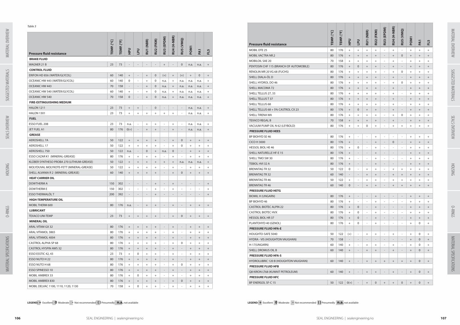
Pressure fluid resistance TEM
P. [°
C]
TEM
P. [°
F]
HP
U
LPU
RU
1 (N
BR
)
RU
2 (F
KM
)
RU
3 (E
PD
M)
RU
4 (H
-NB
R)
RU
5 (V
MQ
)
PO
M1
PA1
FL5
BRAKE FLUID
WAGNER 21 B 23 73 - - - - + - 0 n.a. n.a. +
CONTROL FLUID
ERIFON HD 856 (WATER/GLYCOL) 60 140 + - + 0 (+) + (+) + 0 +
OCEANIC HW 443 (WATER/GLYCOL) 60 140 0 - + 0 n.a. + n.a. n.a. n.a. +
OCEANIC HW 443 70 158 - - + 0 n.a. + n.a. n.a. n.a. +
OCEANIC HW 540 (WATER/GLYCOL) 60 140 + - + 0 n.a. + n.a. n.a. n.a. +
OCEANIC HW 540 70 158 0 - + 0 n.a. + n.a. n.a. n.a. +
FIRE-EXTINGUISHING MEDIUM
HALON 1211 23 73 + + - 0 - - - n.a. n.a. +
HALON 1301 23 73 + + + + + + - n.a. n.a. +
FUEL
ESSO FUEL 208 23 73 n.a. - + + - + - n.a. n.a. +
JET FUEL A1 80 176 0(+) - + + - + - n.a. n.a. +
GREASE
AEROSHELL 7A 50 122 + + + + - + 0 + + +
AEROSHELL 17 50 122 + + + + - + 0 + + +
AEROSHELL 750 50 122 n.a. - 0 + n.a. 0 - + + +
ESSO CAZAR K1 (MINERAL-GREASE) 80 176 + + + + - + - + + +
KLÜBER SYNTHESO PROBA 270 (LITHIUM-GREASE) 50 122 + + + + + + n.a. n.a. n.a. +
MOLYDUVAL MOLYKOTE-FETT (MINERAL-GREASE) 50 122 + + + + - + - + + +
SHELL ALVANIA R 2 (MINERAL-GREASE) 60 140 + + + + - + 0 + + +
HEAT CARRIER OIL
DOWTHERM A 150 302 - - - + - + - - - +
DOWTHERM E 150 302 - - - + - + - - - +
ESSO THERMALÖL T 200 392 - - - + - - - - - +
HIGH-TEMPERATURE OIL
MOBIL THERM 600 80 176 n.a. - + + - + - + + +
LUBRICANT
TEXACO UNI-TEMP 23 73 + + + + - + 0 + + +
MINERAL OIL
ARAL VITAM GX 32 80 176 + + + + - + - + + +
ARAL VITAMOL 3865 80 176 + + + + - + - + + +
ARAL VITAMOL 4004 80 176 + + + + - + - + + +
CASTROL ALPHA SP 68 80 176 + + + + - + 0 + + +
CASTROL HYSPIN AWS 32 80 176 + + + + - + - + + +
ESSO ESSTIC 42, 43 23 73 + 0 + + - + - + + +
ESSO NUTO H 22 80 176 + + + + - + - + + +
ESSO NUTO H 68 80 176 + + + + - + 0 + + +
ESSO SPINESSO 10 80 176 + + + + - + - + + +
MOBIL AMBREX 33 80 176 + 0 + + - + - + + +
MOBIL AMBREX 830 80 176 + + + + - + 0 + + +
MOBIL DELVAC 1100, 1110, 1120, 1130 70 158 + 0 + + - + - + + +
LEGEND: + Excellent 0 Moderate - Not recommended ( ) Presumedly n.a. not available LEGEND: + Excellent 0 Moderate - Not recommended ( ) Presumedly n.a. not available
Pressure fluid resistance TEM
P. [°
C]
TEM
P. [°
F]
HP
U
LPU
RU
1 (N
BR
)
RU
2 (F
KM
)
RU
3 (E
PD
M)
RU
4 (H
-NB
R)
RU
5 (V
MQ
)
PO
M1
PA1
FL5
MOBIL DTE 25 80 176 + + + + - + - + + +
MOBIL VACTRA NR.2 80 176 + + + + - + 0 + + +
MOBILOIL SAE 20 70 158 + + + + - + - + + +
PENTOSIN CHF 11S (BRANCH OF AUTOMOBILE) 80 176 + 0 + + - + - + + +
RENOLIN MR 20 VG 68 (FUCHS) 80 176 + + + + - + 0 + + +
SHELL DIALA-ÖL D 80 176 + + + + - + - + + +
SHELL HYDROL DO 46 80 176 + + + + - + 0 + + +
SHELL MACOMA 72 80 176 + + + + - + - + + +
SHELL TELLUS 27, 33 80 176 + + + + - + - + + +
SHELL TELLUS T 37 80 176 + + + + - + - + + +
SHELL TELLUS 68 80 176 + + + + - + - + + +
SHELL TELLUS 68 + 5% CASTROL CX 23 80 176 + 0 + + - + - + + +
SHELL TIRENA WA 80 176 + + + + - + 0 + + +
TEXACO REGAL B 70 158 + + + + - + - + + +
VACUUM PUMP OIL N 62 (LEYBOLD) 80 176 + + 0 + - + + + + +
PRESSURE FLUID HEES
BP BIOHYD SE 46 80 176 + - - + - - - + + +
CICO H 3000 80 176 + - - + - 0 - + + +
HESSOL BIOL HE 46 80 176 + 0 - + - - - + + +
SHELL NATURELLE HF-E 15 80 176 + - - + - - - + + +
SHELL TMO SW 30 80 176 + - - + - - - + + +
TEBIOL HVI 32 A 80 176 + - - + - - - + + +
BRENNTAG TR 32 50 122 0 - + + - + + + + +
BRENNTAG TR 32 60 140 - - + + - + + + + +
BRENNTAG TR 46 50 122 + - + + - + + + + +
BRENNTAG TR 46 60 140 0 - + + - + + + + +
PRESSURE FLUID HETG
BIOMIL H (UNGARN) 80 176 + - - + - - - + + +
BP BIOHYD 46 80 176 + - - + - - - + + +
CASTROL BIOTEC ALPIN 22 80 176 + 0 - + - - - + + +
CASTROL BIOTEC HVX 80 176 + 0 - + - - - + + +
HESSOL BIOL HR 37 80 176 + 0 - + - - - + + +
PLANTOHYD 40 (GENOL) 80 176 + 0 - + - - - + 0 +
PRESSURE FLUID HFA-E
HOUGHTO-SAFE 5040 50 122 (+) - + + - + - + 0 +
HYDRA - VIS (HOUGHTON VAUGHAN) 70 158 - - - - - - - + 0 +
H-17(UNGARN) 60 140 + - + + - + - + 0 +
SHELL DROMUS OIL B 60 140 + - + + - + - + 0 +
PRESSURE FLUID HFA-S
HYDROLUBRIC 120 B (HOUGHTON VAUGHAN) 60 140 + - + + + + + + 0 +
PRESSURE FLUID HFB
Q8 KIRON LT68 (KUWAIT PETROLEUM) 60 140 + - + + - + - + 0 +
PRESSURE FLUID HFC
BP ENERGOL SF-C 15 50 122 0(+) - + 0 + + 0 + 0 +
107106 SEAL ENGINEERING | sealengineering.no
Table 3
SUGG
ESTE
D M
ATER
IALS
SEAL
S OVE
RVIEW
HOUS
ING
O-RIN
GSM
ATER
IAL S
PECIF
ICATIO
NSM
ATERIAL OVERVIEWSUGGESTED M
ATERIALSSEALS OVERVIEW
HOUSINGO-RINGS
MATERIAL SPECIFICATIONS
MAT
ERIA
L OVE
RVIEW
SEAL ENGINEERING | sealengineering.no
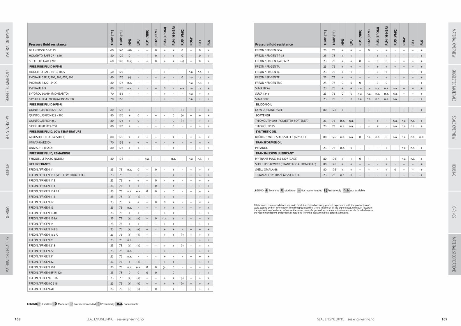
Pressure fluid resistance TEM
P. [°
C]
TEM
P. [°
F]
HP
U
LPU
RU
1 (N
BR
)
RU
2 (F
KM
)
RU
3 (E
PD
M)
RU
4 (H
-NB
R)
RU
5 (V
MQ
)
PO
M1
PA1
FL5
BP ENERGOL SF-C 15 60 140 -(0) - + 0 + + 0 + 0 +
HOUGHTO-SAFE 271, 620 50 122 0 - + 0 + + 0 + 0 +
SHELL FIREGARD 200 60 140 0(+) - + 0 + + (+) + 0 +
PRESSURE FLUID HFD-R
HOUGHTO-SAFE 1010, 1055 50 122 - - - + + - - n.a. n.a. +
PYDRAUL 29ELT, 30E, 50E, 65E, 90E 80 176 (-) - - + + - 0 n.a. n.a. +
PYDRAUL 312C, 540C 80 176 n.a. - - + - - - n.a. n.a. +
PYDRAUL F-9 80 176 n.a. - - + 0 - n.a. n.a. n.a. +
SKYDROL 500 B4 (MONSANTO) 70 158 - - - - + - - n.a. + +
SKYDROL LD4 (7000) (MONSANTO) 70 158 - - - - + - - n.a. + +
PRESSURE FLUID HFD-U
QUINTOLUBRIC N822 - 220 80 176 + - - + - 0 (-) + + +
QUINTOLUBRIC N822 - 300 80 176 + 0 - + - 0 (-) + + +
QUINTOLUBRIC N850 80 176 + 0 - + - 0 (-) + + +
SIDERLUBRIC 822-200 80 176 + - - + - 0 - + + +
PRESSURE FLUID, LOW TEMPERATURE
AEROSHELL FLUID 4 (SHELL) 80 176 + + + + - + - + + +
UNIVIS 40 (ESSO) 70 158 + + + + - + - + + +
UNIVIS J 13 (ESSO) 80 176 + + + + - + - + + +
PRESSURE FLUID, REMAINING
FYRQUEL LT (AKZO NOBEL) 80 176 - - n.a. + - n.a. - n.a. n.a. +
REFRIGERANTS
FREON / FRIGEN 11 23 73 n.a. 0 + 0 - + - + + +
FREON / FRIGEN 112 (WITH / WITHOUT OIL) 23 73 0 0 + + - + - + + +
FREON / FRIGEN 113 23 73 + + + 0 - + - + + +
FREON / FRIGEN 114 23 73 + + + 0 - + - + + +
FREON / FRIGEN 114 B2 23 73 n.a. n.a. 0 0 - 0 - + + +
FREON / FRIGEN 115 23 73 (+) (+) + + + + - + + +
FREON / FRIGEN 12 23 73 + + + 0 0 + - + + +
FREON / FRIGEN 13 23 73 n.a. - + + + + - + + +
FREON / FRIGEN 13 B1 23 73 + + + + + + - + + +
FREON / FRIGEN 134A 23 73 (+) (+) + 0 n.a. + - + + +
FREON / FRIGEN 14 23 73 + + + + + + - + + +
FREON / FRIGEN 142 B 23 73 (+) (+) + - + + - + + +
FREON / FRIGEN 152 A 23 73 (+) (+) + - + + (-) + + +
FREON / FRIGEN 21 23 73 n.a. - - - - - - + + +
FREON / FRIGEN 218 23 73 (+) (+) + + + + (-) + + +
FREON / FRIGEN 22 23 73 n.a. - - - + - - + + +
FREON / FRIGEN 31 23 73 n.a. - - - + - - + + +
FREON / FRIGEN 32 23 73 + (+) + - + + - + + +
FREON / FRIGEN 502 23 73 n.a. n.a. 0 0 (+) 0 - + + +
FREON / FRIGEN BF(F112) 23 73 0 0 0 0 - 0 - + + +
FREON / FRIGEN C 316 23 73 (+) (+) + + + + (-) + + +
FREON / FRIGEN C 318 23 73 (+) (+) + + + + (-) + + +
FREON / FRIGEN MF 23 73 (0) (0) + 0 - + - + + +
All data and recommendations shown in this list are based on many years of experience with the production of seals, testing and on information from the specialised literature. In spite of all the experiences, unknown factors in the application of seals can influence the correctness of a general recommendation tremendously, for which reason the recommendations and proposals resulting from this list cannot be regarded as binding.
Pressure fluid resistance TEM
P. [°
C]
TEM
P. [°
F]
HP
U
LPU
RU
1 (N
BR
)
RU
2 (F
KM
)
RU
3 (E
PD
M)
RU
4 (H
-NB
R)
RU
5 (V
MQ
)
PO
M1
PA1
FL5
FREON / FRIGEN PCA 23 73 + + + 0 - + - + + +
FREON / FRIGEN T-P 35 23 73 + + + + + + + + + +
FREON / FRIGEN T-WD 602 23 73 + + 0 + 0 0 - + + +
FREON / FRIGEN TA 23 73 + + + - + + + + + +
FREON / FRIGEN TC 23 73 + + + + 0 + - + + +
FREON / FRIGEN TF 23 73 + + + + - + - + + +
FREON / FRIGEN TMC 23 73 0 0 0 + 0 0 - + + +
SUVA HP 62 23 73 + + n.a. n.a. n.a. n.a. n.a. + + +
SUVA 134a 23 73 0 0 n.a. n.a. n.a. n.a. n.a. + + +
SUVA 9000 23 73 0 0 n.a. n.a. n.a. n.a. n.a. + + +
SILICON OIL
DOW CORNING 550 E 80 176 + - - + - - - + + +
SOFTENER
THIOKOL TP-90 B (POLYESTER-SOFTENER) 23 73 n.a. n.a. - + + - n.a. n.a. n.a. +
THIOKOL TP-95 23 73 n.a. n.a. - + + - n.a. n.a. n.a. +
SYNTHETIC OIL
KLÜBER SYNTHESO D 220 - EP (GLYCOL) 80 176 n.a. n.a. 0 n.a. n.a. 0 n.a. n.a. n.a. n.a.
TRANSFORMER OIL
PYRANOL 23 73 n.a. 0 + + - + - n.a. n.a. +
TRANSMISSION LUBRICANT
HY-TRANS-PLUS MS 1207 (CASE) 80 176 + + 0 + - + - n.a. n.a. +
SHELL HSG 80W/90 (BRANCH OF AUTOMOBILE) 80 176 + + + + - + - + + +
SHELL OMALA 68 80 176 + + + + - + 0 + + +
TEXAMATIC “A” TRANSMISSION-OIL 23 73 n.a. 0 + + - + - + + +
109108 SEAL ENGINEERING | sealengineering.no
LEGEND: + Excellent 0 Moderate - Not recommended ( ) Presumedly n.a. not available
LEGEND: + Excellent 0 Moderate - Not recommended ( ) Presumedly n.a. not available
SUGG
ESTE
D M
ATER
IALS
SEAL
S OVE
RVIEW
HOUS
ING
O-RIN
GSM
ATER
IAL S
PECIF
ICATIO
NSM
ATERIAL OVERVIEWSUGGESTED M
ATERIALSSEALS OVERVIEW
HOUSINGO-RINGS
MATERIAL SPECIFICATIONS
MAT
ERIA
L OVE
RVIEW
SEAL ENGINEERING | sealengineering.no

Inches Decimals 0” 1” 2” 3” 4” 5” 6” 7” 8” 9” 10” 11” 12”
0,000 25,40 50,80 76,20 101,60 127,00 152,40 177,8 203,2 228,6 254,0 279,4 304,8
1/64 0,016 0,397 25,80 51,20 76,60 102,00 127,39 152,79 178,2 203,6 229,0 254,4 279,8 305,2
1/32 0,031 0,794 26,19 51,59 76,99 102,39 127,79 153,19 178,6 204,0 229,4 254,8 280,2 305,6
3/64 0,047 1,191 26,59 51,99 77,39 102,79 128,19 153,59 179,0 204,4 229,8 255,2 280,6 307,0
1/16 0,063 1,587 26,99 52,39 77,59 103,19 128,59 153,98 179,4 204,8 230,2 255,6 281,0 306,4
5/64 0,078 1,984 27,38 52,78 78,18 103,58 128,98 154,38 179,8 205,2 230,6 256,0 281,4 306,8
3/32 0,094 2,381 27,78 53,18 78,58 103,98 129,38 154,78 180,2 205,6 231,0 256,4 281,8 307,2
7/64 0,109 2,778 28,18 53,58 78,98 104,38 129,78 155,18 180,6 206,0 231,4 256,8 282,2 307,6
1/8 0,125 3,175 28,57 53,97 79,37 104,77 130,17 155,57 181,0 206,4 231,8 257,2 282,6 308,0
9/64 0,141 3,572 28,97 54,37 79,77 105,17 130,57 155,97 181,4 206,8 232,2 257,6 283,0 308,4
5/32 0,156 3,969 29,37 54,77 80,17 105,57 130,97 156,37 181,8 207,2 232,6 258,0 283,4 308,8
11/64 0,172 4,366 29,77 55,16 80,56 105,96 131,36 156,76 182,2 207,6 233,0 258,4 283,8 309,2
3/16 0,188 4,762 30,16 55,56 80,96 106,36 131,76 157,16 182,6 208,0 233,4 258,8 284,2 309,6
13/64 0,203 5,159 30,56 55,96 81,36 106,76 132,16 157,56 183,0 208,4 233,8 259,2 284,6 310,0
7/32 0,219 5,556 30,96 56,36 81,75 107,15 132,55 157,95 183,4 208,8 234,2 259,6 285,0 310,4
15/64 0,234 5,953 31,35 56,75 82,15 107,55 132,95 158,35 183,7 209,1 234,5 259,9 285,3 310,7
1/4 0,250 6,350 31,75 57,15 82,55 107,95 133,35 158,75 184,1 209,5 234,9 260,3 285,7 311,1
17/64 0,266 6,747 32,15 57,55 82,95 108,34 133,74 159,14 184,5 209,9 234,3 260,7 286,1 311,5
9/32 0,281 7,144 32,54 57,94 83,34 108,74 134,14 159,54 184,9 210,3 235,7 261,1 286,5 311,9
19/64 0,297 7,540 32,94 58,34 83,74 109,14 134,54 159,94 185,3 210,7 236,1 261,5 286,9 312,3
5/16 0,313 7,937 33,34 58,74 84,14 109,54 134,94 160,33 185,7 211,1 236,5 261,9 287,3 312,7
21/64 0,328 8,334 33,73 59,13 84,53 109,93 135,33 160,73 186,1 211,5 236,9 262,3 287,7 313,1
11/32 0,344 8,731 34,13 59,53 84,93 110,33 135,73 161,13 186,5 211,9 237,3 262,7 288,1 313,5
23/64 0,359 9,128 34,53 59,93 85,33 110,73 136,13 161,53 186,9 212,3 237,7 263,1 288,5 313,9
3/8 0,375 9,525 34,92 60,32 85,72 111,12 136,52 161,92 187,3 212,7 238,1 263,5 288,9 314,3
25/64 0,391 9,922 35,32 60,72 86,12 111,53 136,92 162,32 187,7 213,1 238,5 263,9 289,3 314,7
13/32 0,406 10,319 35,72 61,12 86,52 111,92 137,32 162,72 188,1 213,5 238,9 264,3 289,7 315,1
27/64 0,422 10,715 36,11 61,51 86,91 112,31 137,71 163,11 188,5 213,9 239,3 264,7 290,1 315,5
7/16 0,438 11,112 36,51 61,91 87,31 112,71 138,11 163,51 188,9 214,3 239,7 265,1 290,5 315,9
29/64 0,453 11,509 36,91 62,31 87,71 113,11 138,51 163,91 189,3 214,7 240,1 265,5 290,9 316,3
15/32 0,469 11,906 37,31 62,71 88,10 113,50 138,90 164,30 189,7 215,1 240,5 265,9 291,3 316,7
31/64 0,484 12,303 37,70 63,10 88,50 113,90 139,30 164,70 190,1 215,5 240,9 266,3 291,7 317,1
1/2 0,500 12,700 38,10 63,50 88,90 114,30 139,70 165,10 190,5 215,9 241,3 266,7 292,1 317,5
33/64 0,516 13,097 38,50 63,90 89,30 114,69 140,09 165,49 190,9 216,3 241,7 267,1 292,5 317,9
17/32 0,531 13,493 38,89 64,29 89,69 115,09 140,49 165,89 191,3 216,7 242,1 267,5 292,9 318,3
35/64 0,547 13,890 39,29 64,69 90,09 115,49 140,89 166,29 191,7 217,1 242,5 267,9 293,3 318,7
9/16 0,563 14,287 39,69 65,09 90,49 115,89 141,28 166,68 192,1 217,5 242,9 268,3 293,7 319,1
37/64 0,578 14,684 40,08 65,48 90,88 116,28 141,68 167,08 192,5 217,9 243,3 268,7 294,1 319,5
19/32 0,594 15,081 40,48 65,88 91,28 116,68 142,08 167,49 192,9 218,3 243,7 269,1 294,5 319,9
39/64 0,609 15,478 40,88 66,28 91,68 117,08 142,48 167,88 193,3 218,7 244,1 269,5 294,9 320,3
5/8 0,625 15,875 41,27 66,67 92,07 117,47 142,87 168,27 193,7 219,1 244,5 269,9 295,3 320,7
41/64 0,641 16,272 41,67 67,07 92,47 117,87 143,27 168,67 194,1 219,5 244,9 270,3 295,7 321,1
21/32 0,656 16,668 42,07 67,47 92,87 118,27 143,67 169,07 194,5 219,9 245,3 270,7 296,1 321,5
43/64 0,672 17,065 42,46 67,86 93,26 118,66 144,06 169,46 194,9 220,3 245,7 271,1 296,5 321,9
11/16 0,688 17,462 42,86 68,26 93,66 119,06 144,46 169,86 195,3 220,7 246,1 271,5 296,9 322,3
45/64 0,703 17,859 43,26 68,66 94,06 119,46 144,86 170,26 195,7 221,1 246,5 271,9 297,3 322,7
23/32 0,719 18,256 43,66 69,05 94,45 119,85 145,25 170,65 196,1 221,5 246,9 272,3 297,7 323,1
47/64 0,734 18,653 44,05 69,45 94,85 120,25 145,65 171,05 196,4 221,8 247,2 272,6 298,0 323,4
3/4 0,750 19,050 44,45 69,85 95,25 120,65 146,05 171,45 196,8 222,2 247,6 273,0 298,4 323,8
49/64 0,766 19,447 44,85 70,25 96,65 121,04 146,44 171,84 197,2 222,6 248,0 273,4 298,8 324,2
25/32 0,781 19,843 45,24 70,64 96,04 121,44 146,84 172,24 197,6 223,0 248,4 273,8 299,2 324,6
51/64 0,797 20,240 45,64 71,04 96,44 121,84 147,24 172,64 198,0 223,4 248,8 274,2 299,6 325,0
13/16 0,813 20,637 46,04 71,44 96,84 122,24 147,63 173,03 198,4 223,8 249,2 274,6 300,0 325,4
53/64 0,828 21,034 46,43 71,83 97,23 122,63 148,03 173,43 198,8 224,2 249,6 275,0 300,4 325,8
27/32 0,844 21,431 46,83 72,23 97,63 123,03 148,43 173,83 199,2 224,6 250,0 275,4 300,8 326,2
55/64 0,859 21,828 47,23 72,63 98,03 123,43 148,83 174,22 199,6 225,0 250,4 275,8 301,2 326,6
7/8 0,875 22,225 47,62 73,02 98,42 123,82 149,22 174,62 200,0 225,4 250,8 276,2 301,6 327,0
57/64 0,891 22,621 48,02 73,42 98,82 124,22 149,62 175,02 200,4 225,8 251,2 276,6 302,0 327,4
29/32 0,906 23,018 48,42 73,82 99,22 124,62 150,02 175,42 200,8 226,2 251,6 277,0 302,4 327,8
59/64 0,922 23,415 48,81 74,21 99,61 125,01 150,41 175,81 201,2 226,6 252,0 277,4 302,8 328,2
15/16 0,938 23,812 49,21 74,61 100,01 125,41 150,81 176,21 201,6 227,0 252,4 277,8 303,2 328,6
61/64 0,953 24,209 49,61 75,01 100,41 125,81 151,21 176,61 202,0 227,4 252,8 278,2 303,6 329,0
31/32 0,969 24,606 50,01 75,40 100,80 126,20 151,60 177,00 202,4 227,8 253,2 278,6 304,0 329,4
63/64 0,984 25,003 50,40 75,80 101,20 126,60 152,00 177,40 202,8 228,2 253,6 279,0 304,4 329,8
110 SEAL ENGINEERING | sealengineering.no
Conversion chart
Inches – millimeters
SUGG
ESTE
D M
ATER
IALS
SEAL
S OVE
RVIEW
HOUS
ING
O-RIN
GSM
ATER
IAL S
PECIF
ICATIO
NSM
ATER
IAL O
VERV
IEW

Seal Engineering ASProduksjonsveien 12 N-1618 Fredrikstad
Phone: +47 69 38 17 70 E-mail: [email protected] www.sealengineering.no
©2019 Seal Engineering AS
All rights reserved