Seismic assessment of concentric X-braced steel frames
13
Seismic assessment of concentric X-braced steel frames Ernesto Grande ⇑ , Alessandro Rasulo Dep. of Civil and Mechanical Engineering – DICeM, University of Cassino and Southern Lazio, via G. Di Biasio 43, 03043 Cassino (FR), Italy article info Article history: Received 6 July 2012 Revised 13 September 2012 Accepted 8 January 2013 Available online 13 February 2013 Keywords: Concentric braced frames Assessment Retrofitting Direct displacement based design Overstrength Ductility abstract Aim of the present paper is to propose a simplified approach for the assessment of steel braced frames with X configuration (X-CBFs) according to a procedure developed in the light of the Direct Displacement Based Design method (DDBD). The whole procedure aims at to derive the nonlinear response of X-CBFs by examining the role of specific assessment parameters in terms of ductility and energy dissipation. Numerical applications are presented in the paper by applying the developed procedure. The comparison between the obtained results and the corresponding ones deduced from nonlinear static and dynamic time history F.E. analyses are carried out in order to check the reliability of the proposed approach. Ó 2013 Elsevier Ltd. All rights reserved. 1. Introduction Concentric braced frames (CBFs) represent a structural typology widely used in steel structures for resisting lateral forces due to wind and earthquakes thanks to the truss action characterizing the structural response. Differently of the past codes, where the de- sign approaches for CBFs are exclusively based on strength require- ments, recent years seismic codes [1,2] have introduced the ductility as an additional design requirement also for CBFs [3–6]. The change in the design approach of CBFs is strictly related both to the experimental evidences emerged from the tests performed by several researchers [7–9] and to the vulnerabilities showed by CBF structures during the past earthquakes, including the recent 1994 Northridge (California), 1995 Kobe (Japan) and 1999 Chi- Chi (Taiwan), 2011 Christchurch (New Zealand) events [10]. The most frequent damages observed in these structures con- cern the brace members (local buckling phenomena, yielding con- centrations, fractures, etc.) and the brace-column connections characterized by brittle fractures. These phenomena, responsible of the poor performance of this structural typology under severe ground motions, particularly govern the nonlinear response of CBFs designed according to past codes. In the light of the above considerations it emerges the impor- tance of the seismic assessment of existing CBF structures in order to detect possible deficiencies and to provide optimal interventions of retrofitting. In many research papers, the assessment of braced frames is performed on the basis of the results deduced from nonlinear static or dynamic analyses. For this aim, computer programs able to take into account both the post-buckling behavior of braces and the numerous parameters affecting their cyclic response are used. In practical applications, where linear static analyses or, less often, simplified nonlinear static analyses with the use of the plastic hinges concept are performed, the seismic assessment of braced frames can be either too simplicistic (losing the ability to capture the real extent of the problem) or too sophisticated (for the use re- quired by practitioners). In recent years, the displacement-based approach has emerged as an attractive alternative to the force-based methods since dis- placement-based parameters better quantify structural and non- structural damages in structures [11]. In particular, some authors developed procedures specifically devoted for the design and the assessment of structures [12–14]. In this paper a simple but effective approach for the seismic assessment of CBFs through a procedure based on the DDBD is pre- sented. Numerical applications are also reported in the paper with reference to different cases of study in order to better explain the procedure and to check its reliability. 2. Basic concepts of Direct Displacement Based Design (DDBD) In the following, for sake of clarity, some details of the basic concepts of DDBD are given, but the interested reader can find more details in the original sources [15–17]. As outlined in Fig. 1, the DDBD procedure is based on the reduction of the real structure to a simplified one (substitute structure): (i) involving a 0141-0296/$ - see front matter Ó 2013 Elsevier Ltd. All rights reserved. http://dx.doi.org/10.1016/j.engstruct.2013.01.002 ⇑ Corresponding author. Tel.: +39 0776 299 3478; fax: +39 0776 299 3392. E-mail address: [email protected] (E. Grande). Engineering Structures 49 (2013) 983–995 Contents lists available at SciVerse ScienceDirect Engineering Structures journal homepage: www.elsevier.com/locate/engstruct
Transcript of Seismic assessment of concentric X-braced steel frames

Engineering Structures 49 (2013) 983–995
Contents lists available at SciVerse ScienceDirect
Engineering Structures
journal homepage: www.elsevier .com/ locate /engstruct
Seismic assessment of concentric X-braced steel frames
0141-0296/$ - see front matter � 2013 Elsevier Ltd. All rights reserved.http://dx.doi.org/10.1016/j.engstruct.2013.01.002
⇑ Corresponding author. Tel.: +39 0776 299 3478; fax: +39 0776 299 3392.E-mail address: [email protected] (E. Grande).
Ernesto Grande ⇑, Alessandro RasuloDep. of Civil and Mechanical Engineering – DICeM, University of Cassino and Southern Lazio, via G. Di Biasio 43, 03043 Cassino (FR), Italy
a r t i c l e i n f o a b s t r a c t
Article history:Received 6 July 2012Revised 13 September 2012Accepted 8 January 2013Available online 13 February 2013
Keywords:Concentric braced framesAssessmentRetrofittingDirect displacement based designOverstrengthDuctility
Aim of the present paper is to propose a simplified approach for the assessment of steel braced frameswith X configuration (X-CBFs) according to a procedure developed in the light of the Direct DisplacementBased Design method (DDBD). The whole procedure aims at to derive the nonlinear response of X-CBFs byexamining the role of specific assessment parameters in terms of ductility and energy dissipation.Numerical applications are presented in the paper by applying the developed procedure. The comparisonbetween the obtained results and the corresponding ones deduced from nonlinear static and dynamictime history F.E. analyses are carried out in order to check the reliability of the proposed approach.
� 2013 Elsevier Ltd. All rights reserved.
1. Introduction
Concentric braced frames (CBFs) represent a structural typologywidely used in steel structures for resisting lateral forces due towind and earthquakes thanks to the truss action characterizingthe structural response. Differently of the past codes, where the de-sign approaches for CBFs are exclusively based on strength require-ments, recent years seismic codes [1,2] have introduced theductility as an additional design requirement also for CBFs [3–6].The change in the design approach of CBFs is strictly related bothto the experimental evidences emerged from the tests performedby several researchers [7–9] and to the vulnerabilities showed byCBF structures during the past earthquakes, including the recent1994 Northridge (California), 1995 Kobe (Japan) and 1999 Chi-Chi (Taiwan), 2011 Christchurch (New Zealand) events [10].
The most frequent damages observed in these structures con-cern the brace members (local buckling phenomena, yielding con-centrations, fractures, etc.) and the brace-column connectionscharacterized by brittle fractures. These phenomena, responsibleof the poor performance of this structural typology under severeground motions, particularly govern the nonlinear response ofCBFs designed according to past codes.
In the light of the above considerations it emerges the impor-tance of the seismic assessment of existing CBF structures in orderto detect possible deficiencies and to provide optimal interventionsof retrofitting.
In many research papers, the assessment of braced frames isperformed on the basis of the results deduced from nonlinear staticor dynamic analyses. For this aim, computer programs able to takeinto account both the post-buckling behavior of braces and thenumerous parameters affecting their cyclic response are used. Inpractical applications, where linear static analyses or, less often,simplified nonlinear static analyses with the use of the plastichinges concept are performed, the seismic assessment of bracedframes can be either too simplicistic (losing the ability to capturethe real extent of the problem) or too sophisticated (for the use re-quired by practitioners).
In recent years, the displacement-based approach has emergedas an attractive alternative to the force-based methods since dis-placement-based parameters better quantify structural and non-structural damages in structures [11]. In particular, some authorsdeveloped procedures specifically devoted for the design and theassessment of structures [12–14].
In this paper a simple but effective approach for the seismicassessment of CBFs through a procedure based on the DDBD is pre-sented. Numerical applications are also reported in the paper withreference to different cases of study in order to better explain theprocedure and to check its reliability.
2. Basic concepts of Direct Displacement Based Design (DDBD)
In the following, for sake of clarity, some details of the basicconcepts of DDBD are given, but the interested reader can findmore details in the original sources [15–17]. As outlined in Fig. 1,the DDBD procedure is based on the reduction of the real structureto a simplified one (substitute structure): (i) involving a

Feq
Heq
FdFy
Ko
Ke
Δy
Δd
(i) SDOF Simulation (ii) Effective Stiffness Ke
rKo
ns
i
1
eqMeq
f1
fi
fns
(iii) Equivalent damping vsductility (iv) Design Displacement Spectra
Displacement Ductility
0
20
40
60
Dam
ping
(%
)
1 2 3 4 5 6 0 1 2 3 4 5
Period (seconds)
0
0.1
0.2
0.3
0.4
0.5
Dis
plac
emen
t (m
)
5%
10%
15%20%
30%
Δeq
Teq
Elasto-Plastic
SteelFrame
Concrete Frame
Unbonded Prestressing
Fig. 1. Direct Displacement Based Design (DDBD) concepts (adapted from Priestley et al. [1]).
984 E. Grande, A. Rasulo / Engineering Structures 49 (2013) 983–995
transformation from a multi-degree-of-freedom (mdof) to single-of-degree-of-freedom (sdof) system; (ii) the linearization of thenonlinear behavior of the system using the secant stiffness; (iii)the use of the equivalent damping in order to account for the en-ergy dissipated by the structure and (iv) the use of displacementspectra as basis of design.
The Substitute Structure [18,19] is an equivalent SDOF linearsystem, whose properties (Keq and neq) correspond to the effectivelateral stiffness and equivalent viscous damping of the real struc-ture at the design displacement response.
Once obtained from the building (with number of stories equalto N) the vector of displacements, d, at relevant degrees of freedom(Fig. 1i) under a specified vector of external (seismic) forces, f:
d ¼ d1 . . . dNf g f ¼ f1 . . . fnstorey
� �ð1Þ
the equivalent force Feq corresponds to the base shear of the realstructure, whilst the equivalent displacement Deq has to be defined:
Feq ¼XN
i¼1
fi Deq ¼XN
i¼1
mid2i
,XN
i¼1
midi ð2Þ
Equivalent mass, Meq, is defined accordingly:
Meq ¼XN
i¼1
midi
,Deq ð3Þ
From the nonlinear force vs displacement relationship of theSDOF system, simplified as a bilinear curve, it is possible to identifythe equivalent stiffness, Keq, at a specified Limit State (with maxi-mum deformation and force respectively Dd and Fd) and the natu-ral vibration period of the substitute structure, Teq, as follows:
Keq ¼Fd
DdTeq ¼ 2p
ffiffiffiffiffiffiffiffiMeq
Keq
sð4Þ
The equivalent viscous damping [20], representative of thecombined elastic damping and the hysteretic energy absorbed dur-ing inelastic response, can be defined through the ratio betweenEhyst, the energy dissipated in a vibration cycle of the inelastic sys-tem, and Eel, the energy accumulated by the equivalent linear sys-tem at maximum deformation Dd:
neq ¼ nI þ1
4pEhyst
Eelð5Þ
where nI represents the inherent damping for the system until it re-mains in the elastic range (usually taken as nI = 5% for reinforcedconcrete and 3% for steel structures).
Finally, since the equivalent properties of the substitute struc-ture are elastic, a set of elastic displacement response spectrumcan be used for the design, obviously using the appropriate levelof equivalent damping, as indicated in Fig. 1iv.
3. Proposed approach
The proposed approach aims at to assess the seismic perfor-mance of steel X-CBFs throughout a simple procedure based onthree steps strictly correlated together. It is developed here consid-ering the specific case of a single braced bay, but it can be triviallyextended to more general configurations. The approach furnishesan estimation of the nonlinear response derived on the basis ofspecific parameters such as the over-strength level of diagonals, as-sumed as the main indicator able to identify potential plasticbehavior of diagonals, and the slenderness ratio of diagonals, ac-counted for estimating their contribution in terms of equivalentdamping.
In detail, the first step of the approach consists of a preliminaryexam of the braced frame focusing on the role of diagonal mem-bers. Using simple considerations the possibility of activation of a

E. Grande, A. Rasulo / Engineering Structures 49 (2013) 983–995 985
plastic mechanism controlled either by the yielding of a singlediagonal or of more diagonals is considered leading to two possiblecases denoted in the following as ‘‘lower bound (LB) ‘‘ and upperbound (UB)’’.
The second step consists in derive the approximate capacitycurve of the CBF. This operation implies to assess the possibilityof formation of a plastic mechanism (either in LB and UB condi-tions) against the formation of brittle mechanisms.
Finally, the third step of the approach consists of to assess thebraced frame according to the DDBD procedure. Indeed, once rep-resented the seismic input at the site as a displacement spectrumaccounting for the effective damping induced by structural dissipa-tive mechanisms, the deformation capacity is compared with thedemand of the substitute structure.
It is important to underline that the results deduced from eachstep of the proposed approach not only allow to assess the seismicperformance of a braced frame specifically, but they also furnishinformation about possible strategies of retrofitting.
3.1. characterization of diagonal members (Step 1)
The first step of the proposed approach consists of to examinethe diagonal members of the braced frame in the light of their con-tribution on the post-elastic behavior of X-CBFs. In particular, con-sidering a fixed profile of lateral forces, the force at the genericstory can be derived as:
Fi ¼ ci � Ftot ð6Þ
where Ftot is the base shear Ftot ¼PN
i¼1Fi
� �and the values of the
coefficients ci depend on the shape of the lateral load along theheight, N is the total number of stories of the CBF.
The axial forces in the diagonals due to these lateral forces andconsidering a configuration of X-CBF with tension only diagonals(Fig. 2), assume the following expression:
Ndiagi ¼ Ftot
cos hi
XN
k¼i
ck ð7Þ
where hi is the angle of the diagonal at the story i.
θ1
θ2
θn-1
θn
F1
F2
Fn-1
Fn
Fig. 2. Scheme of the CBF with tension-only diagonals.
Considering the plastic axial resistance Ndiagpl;i of each diagonal, it
is possible to derive the corresponding over-strength factor Xi [1]:
Xi ¼Ndiag
pl;i
Ndiagi
ð8Þ
Selecting the minimum value of the derived over-strength fac-tors of diagonals, Xmin = min(Xi)i=1. . .N, the following strength ratiocan be introduced for each diagonal of the braced frame:
xi ¼Xi
Xminð9Þ
It is evident that xi only represents a strength ratio: it expressesthe level of overstrength of each diagonal respect to the moststressed one. Indeed, the minimum value of xi is equal to 1 andit corresponds to the most stressed diagonal, and also the firstone which yield. Assuming an ultimate behavior of the bracedframe characterized by the yielding of just this diagonal (LB condi-tion) it is possible to derive the corresponding displacements pro-file. Indeed, taking into account the maximum ductility lLS
associated to the selected limit state, the plastic elongation of theyielded diagonal is derived and, consequently, the plastic intersto-ry drift at the story where the diagonal yield. In the present paper,the limit states included in [1,2] have been considered: significantdamage (SD): lSD = 7; near collapse (NC): lNC = 9.
On the other hand, by accounting the possibility of the yieldingof more than one diagonal thanks to the redistribution of forcesdue to the global overstrength of the braced frame, and the corre-sponding increase of forces in members and connections, a furtherultimate condition (UB condition) is introduced.
For this aim, the global overstrength of the system is taken intoaccount by introducing a maximum value of the strength ratio xi
denoted in the following as x�. Indeed, differently from the genericstrength ratio xi, the value of x� can be properly defined as anoverstrength factor: the activation of plastic mechanisms involvingmore than one diagonals depends on x�. In other words, the effectof the global overstrength of the CBF in redistributing the seismicforces when the progressive yielding of diagonals occurs for theUB condition, is taken into account by comparing the strength ra-tios xi of diagonals and the overstrength factor x�. In particular,the proposed procedure considers the following assumptions forthe UB condition:
– All the diagonals characterized by xi 6x� yield (effect of forcesredistribution).
– An increase of the plastic resistance of the yielded diagonalsproportional to the corresponding plastic excursion (effect ofthe overstrength).
In other words, the global overstrength of the system is ac-counted in terms of overstrength of diagonal members.
In detail, it is suggested to assume an increase of the axial forceof diagonals equal to x� � Ndiag
pl;i when the maximum ductility levelcorresponding to the limit state NC is attained (see Fig. 3). Onthe basis of this hypothesis and by simple geometric reasoningover Fig. 3 it is possible evaluate the ductility l of each diagonalof the CBF by considering the maximum ductility lLS associatedto the selected limit state taking into account the global over-strength of the CBFs (x�) and the corresponding strength ratio(xi) of each diagonal which yield (xi 6x�):
li ¼ 1þ 1þ ð1�x�Þ � lLS � 1lNC � 1
� �� 1xi� 1
� lNC � 1
1�x�ð10Þ
For the diagonals that yield (l P 1) it is then possible to evalu-ate the plastic elongation:
DLo;pl;i ¼ ðli � 1Þ � ey � Ld;i ð11Þ

ωω
μ μ
ω
Fig. 3. Axial force vs. ductility law assumed for braces.
986 E. Grande, A. Rasulo / Engineering Structures 49 (2013) 983–995
and, consequently, the corresponding increase of the interstorydrift:
dr;pl;i ¼DLd;pl;i
cos hið12Þ
where ey is the yield strain of diagonal material, Lb,i and hi arerespectively the length and the angle of the considered diagonal i.
3.2. Approximate capacity curves (Step 2)
The goal of the second step is to the derive the approximatecapacity curve representative of the global nonlinear response ofthe CBF. For this aim, taking into account the displacement profilesderived for both the LB and UB and the selected limit states, it ispossible to evaluate the corresponding forces in the diagonalsand, subsequently, the forces acting in the other elements compos-ing the braced frame: beams, columns and connections.
In particular, while in the case of LB the axial force of the onlyone yielded diagonal is assumed equal to the corresponding axialplastic resistance ðNdiag
pl Þ, in the case of the UB the plastic axialresistances of yielded diagonals are multiplied by the correspond-ing ratio xi for accounting the effect of the global overstrength ofthe braced frame.
Considering the derived forces in beams, columns and connec-tions for both LB and UB conditions, and the ones due to verticalloads, the resistance check of beams, columns and connections al-lows to appreciate the ultimate behavior of the braced frame. Inparticular, the authors consider three possible ultimate behaviors:
– A fragile behavior, when the forces corresponding to the LB aregreater than the resistance of members or connections (the fail-ure of the braced frame occurs before the yielding of diagonals).
– A high ductile behavior, when the forces derived for the UB arelower than the resistance of members or connections (the yield-ing of all diagonals characterizing the UB occurs before the col-lapse of the other members and connections).
0 0.05 0.10
100
200
300
400
500
top displacement [m]
base
she
ar [
kN]
500
0
0.150
Failure of beam, column or connection before the yielding ofdiagonals
Fig. 4. Possible capacity curves correspondin
– A intermediate ductile behavior, when the resistance of mem-bers or connections are greater than the forces derived for theLB but less than the forces corresponding to the UB (in this caseit is assumed that only the yielding of the more stressed diago-nal characterizes the ultimate behavior of the braced frame).
The capacity curve representing the fragile behavior is charac-terized by only a linear branch corresponding to the elastic behav-ior of the braced frame, whilst the capacity curves correspondingto the two ductile behaviors account for the plastic response ofCBF due to the yielding of diagonals (Fig. 4). It is important toemphasize that in the proposed procedure it is introduced the con-cept of overstrength only for evaluating the increase of axial forcesin the yielded braces and, consequently, in the other elements ofthe braced frame, whilst for the plastic branch of the approximatecapacity curve a perfectly-plastic behavior is assumed.
3.3. Assessment (Step 3)
The third step aims at to assess the seismic performance of theexamined braced frame in the light of the limit states SD and NC.
The step is based on the application of the DDBD method takinginto account the results emerged from the previous steps: the de-rived capacity curve and the characteristics of diagonals in terms ofslenderness ratio.
In fact, this step consists of to introduce the displacement spec-trum by accounting an appropriate equivalent damping ratio neq
deduced on the basis of the required ductility and the slendernessratio of diagonals. In [21] the following relations have been pro-posed with reference to a single brace (at jth story):
neq;j ¼ 0:23� k15
� �� ðl� 1Þl 6 2
neq;j ¼ 0:23� k15
� �l > 2
ð13Þ
where l is the required ductility and k is the slenderness ratio of thediagonal.
Once evaluated the equivalent damping in each structuralmember, the calculated terms can assembled using Eq. (5) where:
Ehyst is the hysteretic energy at global level can be estimated as:
Ehyst ¼Xnel
j¼1
Ehyst;j ¼ 4pXnel
j¼1
neq;j � Eel;j
¼ 4pXnel
j¼1
neq;j �12
Ab;jfsy;jdj cos hj
¼ 4p � 12
Xnel
j¼1
neq;j � Ab;jfsy;jdj cos hj ð14Þ
0 0.05 0.10
100
200
300
400
500
top displacement [m]
base
she
ar [
kN]
500
0
0.150
Considered limit states
g to the three ultimate behaviors of CBF.
E. Grande, A. Rasulo / Engineering Structures 49 (2013) 983–995 987
and Eel is the elastic energy and applying the virtual work principlecan be estimated as:
Eel ¼Xnel
j¼1
Eel;j ¼12
XN
i¼1
Fidi ð15Þ
Thus the damping of the whole CBF is:
neq ¼ 0:03þPnel
j¼1neq;j � Ab;jfsy;jdj cos hjPNi¼1Fidi
ð16Þ
In the above equations nel is the number of braces, Ab is thecross-section area of braces, fyb is the yield strength of materialcomposing the braces, dj is the generic interstory drift, Fi and di
are the applied seismic forces and the generic story displacementsrespectively.
It is important to note that in the above equation dj and di areboth equivalent elastic displacements calculated with the secantstiffness approach (Fig. 1ii) applied on the MDOF system at the lim-it state of interest.
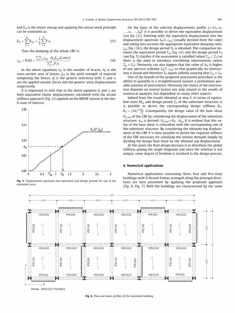
Fig. 5. Displacement spectrum and equivalent and design periods for one of theexamined cases.
BRACED FRAMES
X
Y
IPE300
IPE300
HEA220 HEA220 H
HEA240 HEA240 HEA240 H
HEA220 HEA220 H
IPE3
00
IPE3
00
IPE1
40
IPE1
40
IPE1
40
IPE1
40
IPE1
40
IPE1
40
4.5 4.5 4.5
27
Fig. 6. Plan and beam profiles
On the basis of the selected displacements profile d = [d1, d2,. . ., di, . . ., dN]T it is possible to derive the equivalent displacement(see Eq. (2)). Entering with the equivalent displacement into thedisplacement spectrum SD(T, neq) (usually derived from the code)and taking into account the appropriate equivalent damping ratio,neq (Eq. (16)), the design period TD is obtained. The comparison be-tween the equivalent period Teq (Eq. (4)) and the design period TD
(see Fig. 5) clarifies if the assessment is satisfied (when Teq 6 TD) orthere is the need to introduce retrofitting interventions (whenTeq > TD). Obviously can also happen that the value of Dd is higherof any spectral ordinate SD(T, neq) so that graphically no intersec-tion is found and therefore TD equals infinity assuring that Teq 6 TD.
One of the benefit of the proposed assessment procedure is theability to quantify in a straightforward manner a preliminary pos-sible solution of intervention. Obviously the choice of the interven-tion depends on several factors not only related to the results ofnumerical analyses, but dependent on many other aspects.
Indeed from the results obtained at step 3, in terms of equiva-lent mass Meq and design period TD of the substitute structure, itis possible to derive the corresponding design stiffness KD:
KD ¼ ð2pÞ2 Meq
T2D
. Consequently, the design value of the base shear
VD,real of the CBF by considering the displacement of the substitutestructure Deq is derived: VD,real = KD � Deq. It is evident that this va-lue of the base shear is coincident with the corresponding one ofthe substitute structure. By considering the ultimate top displace-ment of the CBF it is then possible to derive the required stiffnessof the CBF necessary for satisfying the seismic demand simply bydividing the design base shear by the ultimate top displacement.
At this point the final design decision is to distribute the globalstiffness among the single diagonals and since the solution is notunique, some degree of freedom is involved in the design process.
4. Numerical applications
Numerical applications concerning three, four and five-storybuildings with X-braced frames arranged along the principal direc-tions are here presented by applying the proposed approach(Fig. 6; Fig. 7). Both the buildings are characterized by the same
5.5
5.5
11IPE300
IPE300
EA220 HEA220
EA240 HEA240 HEA240
EA220 HEA220
IPE3
00
IPE3
00
IPE1
40
IPE1
40IP
E140
IPE1
40
4.5 4.5 4.5
of the examined building.

2L60x6
2L60x6
HEA
220
HEA
200
HEA
220
HEA
200
5.5
3.5
3.5
3.5
3.5
14
2L60x6
2L60x6
2L60x6
2L60x6
2L60x6
2L60x6
2L60x6
2L60x6
HEA
220
HEA
200
HEA
220
HEA
200
5.5
3.5
3.5
3.5
3.5
14
2L60x6
2L60x6
2L60x4
2L60x4
2L60x4
2L60x4
2L60x6
2L60x6
HEA
220
HEA
200
HEA
220
HEA
200
5.5
3.5
3.5
3.5
10.5
2L60x6
2L60x6
2L60x6
2L60x6
2L60x6
2L60x6
HEA
220
HEA
200
HEA
220
HEA
200
5.5
3.5
3.5
3.5
10.5
2L60x4
2L60x4
2L60x4
2L60x4
CBFy-4p-sol1 CBFy-4p-sol2
CBFy-3p-sol1 CBFy-3p-sol2
HEA
220
HEA
200
HEA
220
HEA
200
5.5
3.5
3.5
3.5
3.5
17.5
2L60x6
2L60x6
2L60x8
2L60x8
HEA
220
HEA
200
HEA
220
HEA
200
5.5
3.5
3.5
3.5
3.5
17.5
CBFy-5p-sol1 CBFy-5p-sol2
3.5
3.5
2L60x8
2L60x8
2L60x8
2L60x8
2L60x8
2L60x8
2L60x8
2L60x8
2L60x8
2L60x8
2L60x8
2L60x8
2L60x4
2L60x4
2L60x4
2L60x4
Fig. 7. Examined CBFs.
Table 1Vertical loads on the stories of the building.
Story Loads
5p: story 1–4 (Gk) 5.00 kN/mq4p: story 1–3 (Gk) 6.75 kN/ma
3p: story 1–2 (Qk) 2.00 kN/mqRoof (Gk) 3.20 kN/mq
(Qk) 1.50 kN/mq
Gk: dead loads.Qk: live loads.
a Perimeter walls.
988 E. Grande, A. Rasulo / Engineering Structures 49 (2013) 983–995
plan (27 � 11 m) with six bays along x-direction and two baysalong y-direction. The seismic resistant structural system of build-ings is characterized by four braced frames arranged along eachprincipal direction.
The members composing the structural system of the buildinghave been designed according to the provisions contained in theDM96 [22], an old Italian code which does not provide specific reg-ulations for CBFs. In particular, for what concerns the bracedframes, the columns and the beams are characterized by wideflange sections (HE and IPE European profiles) and the diagonalsare composed of two coupled L profiles. In addition, while forbeams and columns the same cross sections for all the examinedbuildings have been selected, brace elements present differentcross section sizes. For each building two different structural solu-tions have been analyzed and denoted in the following as ‘‘sol1’’and ‘‘sol2’’. The only difference between the two solutions con-cerns the diagonal members. In fact, while in the sol1 all the diag-onal members are characterized by the same cross section alongthe height, in the sol2 two different cross sections of diagonalshave been considered according to the schemes shown in Fig. 7.
For all members a steel grade S235 (fy = 235 MPa) has been con-sidered. Regarding the loads, vertical loads (dead and live loads ofthe stories and the roof) are summarized in Table 1; the seismic ac-tions have been derived by considering an intermediate seismicitylevel (equivalent to a peak ground acceleration ag = 0.07 g) whichcharacterizes the classification of the site according to the DM96(in Table 2 are reported both the values of seismic forces and theformulations contained in [22]).
For the analyses it has been only considered the braced frameslocated along the y-direction denoted in the following as ‘‘CBFy’’(Fig. 7) for both three, four and five-story buildings (denoted as‘‘3p’’, ‘‘4p’’ and ‘‘5p’’ respectively).
The assessment has been performed by considering an higherseismic level (ag = 0.35 g for SD and ag = 0.55 g for NC). This situa-tion is representative of some Italian locations, when consideringthe effects of both the enforcement of new seismic design provi-sions and a redefinition of seismic zonation (the actual one atmunicipality level provide a maximum seismic input slightly infe-rior to the case selected).
4.1. Step 1
According to the first step of the proposed approach, a prelimin-ary exam of diagonal members has been performed. In particular, ashape of the lateral forces acting on the CBF characterized by fac-tors ci assumed in this case equal to: ci ¼ mi � zi=
PNj¼1mj � zj; where
mi is the story mass and zi is the distance of the story respect to thebase of the CBF has been assumed. A maximum value of the over-strength x� = 1.25 has been selected according to the evidencesemerged from some studies available in literature [23].
From this exam it has been observed that all the diagonals arecharacterized by a non-dimensional slenderness ratio less than 2and values of the ratio xi (see Eq. (9)) less than 1.25 only for somestories (see Table 3). This is also evident from the displacement pro-files shown in Fig. 8 characterized by the yielding of the diagonals atthe first and the second story for the UB condition. In particular, theslenderness ratios of diagonals have been evaluated by consideringthe maximum value between the slenderness corresponding to the

Table 2Seismic forces on the building (DM96).
Building Wtot (kN) Ftot (kN) Seismic forces according to DM96
5p 9873 829 – Seismic weight: Wi ¼ Gk þ 0:33 � Qk
4p 7679 6453p 5485 461Wtot: building seismic weight Gk ¼ Gk � Ast
Ftot: building seismic force Qk ¼ Qk � Ast
Ast: story surface– Seismic force at the story i: Fi = C � R � e � b � ci �Wi
C ¼ 0:07R ¼ 1e ¼ 1b ¼ 1:2
ci ¼zi �PN
j¼1WjPN
j¼1Wj �zj
zi: Distance of the generic story i from the base of the CBF
Table 3Check of diagonals according to the step 1.
Story CBFy-3p-sol1 CBFy-3p-sol2
�k xi �k xi
1 1.9 1.0 1.9 1.12 1.9 1.3 1.9 1.0Roof 1.9 3.0 1.9 2.3
CBFy-4p-sol1 CBFy-4p-sol2
�k xi �k xi
1 1.9 1.0 1.9 1.02 1.9 1.1 1.9 1.13 1.9 1.6 1.9 1.1Roof 1.9 4.0 1.9 2.7
CBFy-5p-sol1 CBFy-5p-sol2
�k xi �k xi
1 1.9 1.0 1.9 1.02 1.9 1.1 1.9 1.13 1.9 1.3 1.9 1.04 1.9 1.9 1.9 1.0Roof 1.9 5.0 1.9 2.6
Fig. 8. Displacements profiles derived from the step 1for the four-story CBFs.
E. Grande, A. Rasulo / Engineering Structures 49 (2013) 983–995 989
out-of-plane buckling (by considering the whole length of the diag-onal and the maximum radius of the cross section) and the one cor-responding to the in-plane buckling (by considering one half of thelength of the diagonal and the minimum value of the radius of gyra-tion of the cross section).
4.2. Step 2
According to the step 2, the check of beams and columns ele-ments has been carried out. In particular, it has been observed thatall beams and columns are able to sustain the forces correspondingto the UB condition for both SD and NC limit states. According tothe proposed procedure, the ultimate mechanism of the examinedbraced frames is a high ductile behavior. Although this evidence, in
the following the authors report both the capacity curves corre-sponding to LB and UP in order to appreciate the reliability of theproposed approach.
4.3. Step 3
Finally, considering the slenderness ratio values characterizingthe diagonals, the equivalent damping ratio is derived for all con-sidered cases (Eq. (13)). Subsequently, by introducing the appropri-ate design spectra (calibrated on site seismic intensity level, limitstate and equivalent damping), the design period of the CBF hasbeen obtained and compared with Teq. This comparison has beencarried out for the two limit states (SD and NC) and for the lowerand upper bound. The results in terms of equivalent period and de-sign period are reported in Table 4.
They show that interventions of retrofit (Teq > TD) are necessaryalmost always. In particular it is possible to observe the influenceof the global overstrength accounted in the case of the upperbound condition in improving the seismic response of bracedframes. In fact, as expected, the lower bound (which considersthe yielding in the diagonals in just one story), is more severe inthe assessment of the considered structures, resulting in highervalues of the ratio Teq/TD.
In just one case (CBF-3p-sol1) the LB and UB approaches lead tothe same results. This is again justified by the distribution of diag-onal strength along the height: the second less resistant braceshows a ratio xi outside of the range 1–1.25, and therefore cannotyield even considering the upper bound.
4.4. Validation of the proposed approach via FEM analysis
The reliability of the proposed procedure for the seismic assess-ment of braced frames is strictly related to the prediction of theseismic response in terms of the capacity curve. In fact, if thecapacity curve satisfactorily reproduce the nonlinear response of

Table 4Results deduced from the step 3.
Limit state period CBFy-3p-sol1 CBF y-3p-sol2 CBFy-4p-sol1 CBF y-4p-sol2 CBFy-5p-sol1 CBF y-5p-sol2
LB UB LB UB LB UB LB UB LB UB LB UB
SDTeq (s) 1.142 1.142 1.014 1.083 1.403 1.405 1.422 1.507 1.552 1.67 1.516 1.958TD (s) 1.038 1.038 1.020 1.186 1.096 1.27 1.118 1.548 1.293 1.72 1.246 1Teq/TD 1.10 1.10 0.994 0.913 1.28 1.11 1.27 0.97 1.20 0.97 1.22 <1
NCTeq (s) 1.286 1.286 1.125 1.300 1.567 1.634 1.585 1.769 1.7 1.88 1.666 2.232TD (s) 0.835 0.835 0.829 1.039 0.877 1.111 0.891 1.389 1.0 1.415 0.97 1Teq/TD 1.540 1.540 1.357 1.251 1.79 1.47 1.78 1.27 1.7 1.33 1.71 <1
1: No intersection found.
990 E. Grande, A. Rasulo / Engineering Structures 49 (2013) 983–995
braced frames, the reliability of the assessment is consequentlyguaranteed by the DDBD procedure, widely investigated inliterature.
With this aim, static and dynamic time history analyses havebeen performed with reference to the examined cases. In particu-lar, for the modeling of diagonals the Ikeda–Mahin multi-linearmodel [24] has been selected by imposing the same energy dissipa-tion provided by the hysteretic model proposed by Georgescu et al.[25]. For this aim, the procedure used by Longo et al. [26] has beenconsidered (Fig. 9).
The numerical analyses have been performed by using the com-puter code PC-ANSR [27] where the Ikeda–Mahin model isimplemented.
The results deduced from push-over analyses in terms of baseshear vs. top displacement curves (Fbase–Dtop) are shown inFig. 10 together with the corresponding approximate curves de-rived from the proposed approach for both lower and upper bound.In particular, regarding the approximate pushover curves, the threetraces reported on each curve refer to the yielding of the first or thelast diagonal (first trace on the left), the maximum plastic defor-mation in the limit state SD (second trace from the left) and themaximum plastic deformation in the limit state NC (trace at theend of the horizontal branch). Although the difficulties in the termsof convergence, the curves deduced from FE analyses are in goodagreement with the corresponding ones deduced from the pro-posed approach. In particular as expected, a better approximationis furnished by the UB condition. From the plots it is evident agreater initial stiffness of the FEM curves due to the contribution
Fig. 9. Diagonals modeling: (left) linearization of P–DL diagram on the basis of the Geordeduced from time history analyses.
of compression diagonals in the pre-buckling stage. On the samecurves it is also relevant the progressive yielding of diagonalswhich leads to a rapid stiffness degradation of pushover curvesduring the analysis. The end of all the FEM curves corresponds tothe attainment of the maximum elongation of diagonals assumedequal to nine times the axial elongation at the yielding.
Time history analyses have been performed by scaling the inputPGA compatible with the threshold accelerations defined by localseismic hazard for the assessment Limit States (0.35 and 0.55 g).According to EC8 procedures, three natural accelerograms havebeen selected from the European Database of Strong Motion([28]; Table 5) considering the specific soil conditions at site andpossible compliance with the assessment spectrum used in step 3.
From the time history analyses two main results have been de-rived and compared with the results carried out from the proposedapproach. The first one concerns the displacement profiles corre-sponding to the minimum and maximum values exhibit by bracedframe during time histories. The obtained profiles in terms of inter-story drifts have been compared with the corresponding ones de-duced from the proposed approach (Fig. 11). Also in this case it isevident a remarkable agreement between simplified and FEM pro-files which confirm a good reliability of the proposed approach. Inparticular, also in this case the upper bound condition leads to abetter agreement with the results of time history analyses.
Form the time history analyses it has been also examined theresponse of braced frames in terms of base shear vs top displace-ment for the case of ag = 0.35 g. The obtained curves are shownin Fig. 12 together with the approximate pushover curves derived
gescu model and (right) hysteretic cycles of the diagonal of the brace CBFy-4p-sol1

Fig. 10. Comparison among pushover curves deduced from FE analyses (denoted ‘‘FEM’’) and the corresponding ones deduced from the proposed approach.
Table 5Earthquakes considered in time history analysis.
Earthquake Mw Station Soil
Montenegro (15/04/1979) 6.9 Ulcinj – Hotel Albatros RockIrpinia (23/11/1980) 6.9 Auletta RockGolbasi (05/05/1986) 6.0 DevletHastanesi Rock
E. Grande, A. Rasulo / Engineering Structures 49 (2013) 983–995 991
from the proposed approach. From the plots it is interesting to ob-serve that the pushover curves furnish a good prediction both interms of maximum load and in terms of maximum displacementsexhibited by the braced frames.
5. Considerations
From the above discussion it has emerged that the procedure atthe base of the proposed approach includes simplifications andimportant aspects characterizing the effective seismic responseof CBFs.
Among these, the introduction of the Upper Bound condition foraccounting the role of the global overstrength certainly representsone of the most important one. In fact, although the evaluation of
the forces in members and connections is based on a simplescheme with hinges at the beam-column-diagonal intersectionsby considering an elastic-plastic behavior of diagonals in tension,in the case of the UB it is specifically accounted the possibility ofthe redistribution of forces among the diagonals after one of theseyield. Consequently, the corresponding increase of forces in mem-bers and connections due to the global overstrength of the CBF isaccounted.
In several studies the overstrength and its influencing parame-ters have been investigated with particular regard to the case ofCBFs [23,29–33]. From these studies clearly emerges the role ofthe overstrength on the seismic response of CBFs.
The evaluation of the actual overstrength factor of structures re-quires to consider different sources of overstrength depending onvarious design aspects: rounding of sizes and dimensions, ratio ofactual ‘‘yield’’ to the considered minimum ‘‘yield’’, overstrengthdue to strain hardening and overstrength arising from mobilizingfull capacity of structure (collapse mechanism). In the case ofbraced frames this last source of overstrength assumes an impor-tant relevance particularly when the columns are continuous alongthe height. In fact, while soft-story mechanisms are generallyexpected when the columns of braced frames are not able totransfer bending moment, in the case of continuous columns a

Fig. 11. Displacements profiles derived from the time history analyses (thin lines) and from the proposed approach (thick lines).
992 E. Grande, A. Rasulo / Engineering Structures 49 (2013) 983–995
redistribution of damages and a consequent overstrength are ob-served thanks to the flexural stiffness and strength of the columns.In [33] it is emphasized how continuous seismic and gravity col-umns significantly decrease the possibility of large drift concentra-tions and in [23] values of overstrength due to the continuity ofcolumns varying between 1.2 and 1.33 were derived for one singlebay of X-braced frames.
In the present paper, the assumption of x� = 1.25 for accountingthe redistribution of axial forces among diagonals due to the pres-ence of continuous columns (Upper Bound condition) is both inagreement with the cited studies and, for the examined frames,it allows to have a good approximation both in terms of displace-ments profiles and in terms of the global resistance of CBFs. In fact,it has been observed that greater values of x� lead to a significantoverestimation of the global resistance of the braced frames byrequiring the yielding of diagonals which, on the contrary, in thelight of the results deduced from TH analyses, remain in the elasticrange.
In order to underline the effect of the overstrength on the seis-mic response of the examined CBFs, in Fig. 13, are reported for eachstory of the CBF the ratio between the maximum values of thestory drifts emerged from TH analyses and the value of the storydrift corresponding to the yielding of the diagonal at the consid-ered story. These ratios are reported in the plots by normalizing re-spect to the maximum value. They are denoted as PDCF (plasticdrift concentration factor) and they represent an indicator of thedamage concentration at the story level in terms of plastic excur-sion of diagonals. From the plots it is possible to observe the redis-tribution of damage along the braced frame height thanks to thepresence of continuous columns. In particular, in the case of thesolution 2, characterized by a more uniform stress levels of diago-nals, the plastic deformation is almost uniform in several stories. Itis evident that this redistribution influences the seismic perfor-mances of braced frames particularly in terms of ductility and en-ergy dissipation which, in the case of CBFs, are strictly dependenton the yielding process of diagonal members.
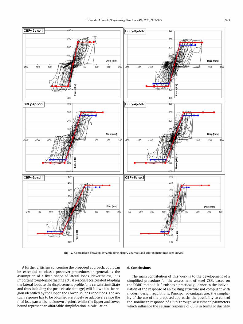
Fig. 12. Comparison between dynamic time history analyses and approximate pushover curves.
E. Grande, A. Rasulo / Engineering Structures 49 (2013) 983–995 993
A further criticism concerning the proposed approach, but it canbe extended to classic pushover procedures in general, is theassumption of a fixed shape of lateral loads. Nevertheless, it isimportant to underline that the actual response (calculated adaptingthe lateral loads to the displacement profile for a certain Limit Stateand thus including the post-elastic damage) will fall within the re-gion identified by the Upper and Lower Bounds conditions. The ac-tual response has to be obtained iteratively or adaptively since thefinal load pattern is not known a-priori, whilst the Upper and Lowerbound represent an affordable simplification in calculation.
6. Conclusions
The main contribution of this work is to the development of asimplified procedure for the assessment of steel CBFs based onthe DDBD method. It furnishes a practical guidance to the individ-uation of the response of an existing structure not compliant withmodern design regulations. Principal advantages are: the simplic-ity of the use of the proposed approach; the possibility to controlthe nonlinear response of CBFs through assessment parameterswhich influence the seismic response of CBFs in terms of ductility

Fig. 13. Plastic displacements concentration factors derived from TH analyses.
994 E. Grande, A. Rasulo / Engineering Structures 49 (2013) 983–995
and energy dissipation; the possibility to carry out indicationsabout preliminary retrofitting solutions based on different criteria.
The approach considers with particular regard specific assess-ment parameters which govern the seismic response of CBFs. Infact, a preliminary phase consists in the selection of the designparameters that control the nonlinear response of CBFs. In this con-text, a crucial role is played by the overstrength factor X of diago-nals which allows to deduce the activation of possible plasticmechanisms of CBFs involving the yielding of diagonals. Indeed,the ratio x introduced in the proposed approach by normalizingthe ovestrength factor of diagonals respect to the minimum onerepresents a reliable indicator for defining a possible range of diag-onals which contribute in terms of ductility and energy dissipationof CBFs thanks to their yielding. Nevertheless, it has been alsoemphasized the importance of the global overstrength of the CBFdependent on several aspects, such as the continuity of the col-umns of the braced frame, and which permits the progressiveyielding of the diagonals involved in the plastic mechanism. Forthis reason, the definition of the plastic mechanism characterizingthe ultimate response of the CBF by considering both the yieldingof one only diagonal (LB case) or the yielding of more diagonals (UBcase) has been carried out considering both the overstrength ratiosof diagonals and the global overstrength of the system.
The second phase consists in applying strength hierarchy rulesaimed at identifying the possible failure mechanism of CBFs. In-deed, by deriving the forces in beams, columns and connectionsin equilibrium with the forces in diagonals corresponding to thederived possible plastic mechanisms and performing a resistancecheck of the potentially brittle elements, it is possible to derivethe ultimate behavior of the braced frame: a fragile ultimatebehavior when the forces corresponding to the most unfavorableplastic mechanism are higher than the resistance of beams, col-umns or connections (the failure of the braced frame occurs beforethe yielding of diagonals); a ductile behavior when the forces cor-responding to the most favorable plastic mechanism are lowerthan the resistance of the aforementioned elements. For each ofthe aforementioned ultimate behaviors, the corresponding
capacity curve is carried out then deducing the approximate seis-mic response of the CBF. This phase is very important because it al-lows to understand specific criticisms of CBFs affecting the seismicresponse. Moreover, the results of this phase are also useful fordefining a preliminary strategy of retrofitting for improving theseismic response of CBFs. Indeed, the third phase, where seismiccapacity and demand are compared in order to verify if the CBFcomplies with the selected level of shaking, according to the DBDprocedure, can be also used for assessing the seismic response ofthe retrofitted structure.
The numerical applications presented in the paper have shownin detail the procedure at the base of the proposed approach byemphasizing all the above considerations. In addition, the compar-ison between the results deduced from the proposed simplified ap-proach and the finite element simulations based on dynamic timehistory analysis have underlined a good agreement in terms of:peak load, ultimate displacement, failure mechanism and displace-ment profiles.
Appendix A. Derivation of X-CBFs displacement profiles
Taking into account the considerations reported in the paperabout the derivation of the displacement profiles, it is possible toderive in a closed form a formulation for estimating the elastic dis-placement profiles of a CBF due to horizontal forces.
In fact, considering the horizontal forces corresponding to theattainment of the plastic resistance of the most stresses diagonal(which correspond Xmin), once obtained from the story forces, byequilibrium considerations, the value of shear, T, and bending mo-ment, M, at the jth story, it is possible to define the component ofdeformations as shear-like drift, dT, involving only the deformationof the diagonal in tension, and flexure-like rotation, uM, involvingonly the deformation of the columns, as depicted in Fig. 14:
dT;j ¼Ld;j
EsAd;j cos2 hjTj uM;j ¼
2hj
EsAc;jLbMj ð17Þ

Lb
HN
Hj
hjTj
Tj φ j
Mj
Mj
Δtop,MΔtop,T
Fig. 14. Components of lateral deformation of CBF: (left) shear-like drift (defor-mation of the diagonal in tension) and (right) flexure-like rotation (deformation ofthe columns).
E. Grande, A. Rasulo / Engineering Structures 49 (2013) 983–995 995
where Ld and Lb are the length of the diagonal and the bay, respec-tively, Ad and Ac are the area of the diagonal and the column, respec-tively, h is the story height and, finally, h is the angle of the diagonal.
The displacement of the top story of the CBF is obtained bysummation of the contributions at each story:
Dytop;T ¼
XN
j¼1
dT;j Dytop;M ¼
XN
j¼1
uM;jðHN � HjÞ ð18Þ
where HN and Hj are the total height from the foundation of the topstory (Nth) and jth story, respectively.
Obviously, since we have two distributions of forces, one forlower bound and one for upper bound, we can have:
Dytop;min ¼ Dy
top;T;min þ Dytop;M;min
Dytop;max ¼ Dy
top;T;max þ Dytop;M;max
ð19Þ
where the subscripts min and max are associated with the lowerbound and the upper bound respectively.
References
[1] European Committee for Standardization – Eurocode 8. Design of structures forearthquake resistance. Part 1: General rules. EN1998-1-2004. CEN, Brussels:Seismic Actions and Rules for Buildings.
[2] Building Seismic Safety Council – NEHRP recommended provisions for seismicregulations for new buildings and other structures (FEMA 450). Washington(DC): Federal Emergency Management Agency; 2003.
[3] Brandonisio G, De Luca A, Grande E, Mele E. Non-linear response of concentricbraced frames. In: The 5th international conference on behaviour of steelstructures in seismic areas – Stessa 2006, Yokohama, Japan; 2006. p. 99–405.
[4] De Luca A, Grande E, Mele E. Implications of code provisions in the seismicdesign of concentric braced frames. In: The 5th international conference onbehaviour of steel structures in seismic areas – Stessa 2006, Yokohama, Japan;2006. p. 855–61.
[5] De Luca A, Grande E, Mele E. Ductile design of CBF steel structures. In:Improvement of buildings’ structural quality by new technologies –proceedings of the final conference of COST action C12 2005, Innsbruck,Austria; 2005. p. 629–37.
[6] Brandonisio G, Toreno M, Grande E, Mele E, De Luca A. Seismic design of Xconcentric braced frames. J Constr Steel Res 2012;78:22–37.
[7] Black RG, Wenger WAB, Popov EP. Inelastic buckling of steel struts under cyclicload reversals. In: Rep. No. UCB/EERC-80/40. Berkeley, California; 1980.
[8] Goel SC. Earthquake resistant design of ductile braced steel structures. In:Stability and ductility of steel structures under cyclic loading. 1992; CRC Press.p. 297–308.
[9] Tremblay R. Inelastic seismic response of steel bracing members. J Constr SteelRes 2002;58:665–701.
[10] MCEER. Steel building damage from the Christchurch Earthquake of February22, 2011 by Michel Bruneau, Charles Clifton, Greg MacRae, Roberto Leon andAlistair Fussell.
[11] Borzi B, Elnashai AS. Assessment of inelastic response of buildings using force-and displacement-based approaches. Struct Des Tall Buil 2000;9:251–77.
[12] Calvi GM, Sullivan T. A model code for the displacement-based seismic designof structures. IUSSP-RESS; 2009.
[13] Goggins J, Sullivan T. Displacement-based seismic design of SDOFconcentrically braced frames. In: Mazzolani, Ricles, Sause, editors. Stessa2009 – paper N.411. London; 2009.
[14] Duan X, Willford M. Displacement-based seismic assessment of existingnonductile Steel concentrically braced frames. In: 13th World conference onearthquake engineering Vancouver, BC, Canada, August 1–6, 2004 [paper N.757].
[15] Kowalsky MJ, Priestley MJN, MacRae GA. Displacement-based design, amethodology for seismic design applied to sdof reinforced concretestructures. In: Report No. SSRP-94/16. San Diego (La Jolla, CA): University ofCalifornia; 1994.
[16] Calvi GM, Kingsley GR. Displacement based design of multi-degree-of-freedombridge structures. J Earthquake Eng Struct Dynam 1995;24:1247–66.
[17] Priestley N, Calvi GM, Kowalsky M. Displacement-based seismic design ofstructures. Iuss Press; 2007.
[18] Gulkan P, Sozen M. Inelastic response of reinforced concrete structures. ACI J1974;71(12):604–10.
[19] Shibata A, Sozen M. Substitute structure method for seismic design inreinforced concrete. J Struct Div 1976;102(12):3548–66.
[20] Jacobsen LS. Damping in composite structures. In: Proceedings of 2nd worldconference on earthquake engineering, Tokyo and Kyoto, Japan; 1970. p.1029–44.
[21] Wijesundara KK, Nascimbene R, Sullivan TJ. Equivalent viscous damping forsteel concentrically braced frame structures. Bull Earthquake Eng 2011;9(5):1535–58.
[22] Ministero dei Lavori Pubblici – Decreto Ministeriale del 16 gennaio 1996.Norme tecniche per le costruzioni in zone sismiche; 1996 [in Italian].
[23] Mahmoudi M, Zaree M. Evaluating the overstrength of concentrically bracedsteel frame systems considering members post-buckling strength. Int J CivilEng 2011;9(1):57–62.
[24] Ikeda K, Mahin SA. A refined physical theory model for predicting the seismicbehaviour of braced frames. Report UMEE 77R3. Department of CivilEngineering, The University of Michigan; 1984.
[25] Georgescu D, Toma C, Gosa O. Post-critical behaviour of ‘K’ braced frames. JConstr Steel Res 1991;21(1–3):115–33.
[26] Longo A, Montuori R, Piluso V. Failure mode control of X-braced frames underseismic actions. J Earthquake Eng 1998;12(5):728–59.
[27] Maison BF. PC-ANSR. A computer program for nonlinear structural analysis.Berkeley: University of California; 1992. <http://nisee.berkeley.edu/software/pcansr>.
[28] Ambraseys N, Smit P, Sigbjornsson R, Suhadolc P, Margaris B. Internet-site foreuropean strong-motion data. European Commission, Research-DirectorateGeneral, Environment and Climate Programme; 2002.
[29] Ostraas JD, Kraeinkler H. Strength and ductility considerations in seismicdesign. Report No. 90. Department of Civil and Environmental EngineeringStanford University; 1990.
[30] Rahgozar MA, Humar JL. Accounting for overstrength in seismic design of steelstructures. Can J Civil Eng 1998;25:1–15.
[31] Di Sarno L, Elnashai AS, Nethercot DA. Seismic response of stainless steelbraced frames. J Constr Steel Res 2008;64(7–8):914–25.
[32] Davaran A, Hoveidae N. Effect of midconnection detail on the behavior of X-bracing systems. J Constr Steel Res 2009;65(4):985–90.
[33] MacRae GA, Kimura Y, Roeder C. Effect of column stiffness on braced frameseismic behavior. J Struct Eng 2004;130(3):381–91.