User Manual (Full Configuration) - Huawei Technical Support
179
Part Number: 31010NRB NetCol5000-C030 In-row Chilled Water Smart Cooling Product User Manual (Full Configuration) Issue 07 Date 2019-01-15 HUAWEI TECHNOLOGIES CO., LTD.
-
Upload
khangminh22 -
Category
Documents
-
view
3 -
download
0
Transcript of User Manual (Full Configuration) - Huawei Technical Support

Part Number: 31010NRB
NetCol5000-C030 In-row Chilled Water Smart Cooling Product
User Manual (Full Configuration)
Issue 07
Date 2019-01-15
HUAWEI TECHNOLOGIES CO., LTD.

Issue 07 (2019-01-15) Copyright © Huawei Technologies Co., Ltd. i
Copyright © Huawei Technologies Co., Ltd. 2019. All rights reserved.
No part of this document may be reproduced or transmitted in any form or by any means without prior
written consent of Huawei Technologies Co., Ltd.
Trademarks and Permissions
and other Huawei trademarks are trademarks of Huawei Technologies Co., Ltd.
All other trademarks and trade names mentioned in this document are the property of their respective
holders.
Notice
The purchased products, services and features are stipulated by the contract made between Huawei and
the customer. All or part of the products, services and features described in this document may not be
within the purchase scope or the usage scope. Unless otherwise specified in the contract, all statements,
information, and recommendations in this document are provided "AS IS" without warranties, guarantees or
representations of any kind, either express or implied.
The information in this document is subject to change without notice. Every effort has been made in the
preparation of this document to ensure accuracy of the contents, but all statements, information, and
recommendations in this document do not constitute a warranty of any kind, express or implied.
Huawei Technologies Co., Ltd.
Address: Huawei Industrial Base
Bantian, Longgang
Shenzhen 518129
People's Republic of China
Website: http://e.huawei.com

NetCol5000-C030 In-row Chilled Water Smart Cooling
Product
User Manual (Full Configuration) About This Document
Issue 07 (2019-01-15) Copyright © Huawei Technologies Co., Ltd. ii
About This Document
Purpose
This document describes the full configuration of NetCol5000-C030 chilled water-cooled
in-row smart cooling product (NetCol5000-C-FC for short), in terms of its product description,
installation, commissioning, controller, operation and maintenance (O&M). It helps users
rapidly learn the operation and maintenance (O&M) of the NetCol5000-C-FC.
The figures provided in this document are for reference only.
Intended Audience
This document is intended for:
Sales personnel
Technical support personnel
System engineers
Hardware installation personnel
Commissioning personnel
Data configuration engineers
Maintenance personnel
Symbol Conventions
The symbols that may be found in this document are defined as follows.
Symbol Description
Indicates an imminently hazardous situation
which, if not avoided, will result in death or
serious injury.
Indicates a potentially hazardous situation
which, if not avoided, could result in death
or serious injury.
Indicates a potentially hazardous situation
which, if not avoided, may result in minor
or moderate injury.

NetCol5000-C030 In-row Chilled Water Smart Cooling
Product
User Manual (Full Configuration) About This Document
Issue 07 (2019-01-15) Copyright © Huawei Technologies Co., Ltd. iii
Symbol Description
Indicates a potentially hazardous situation
which, if not avoided, could result in
equipment damage, data loss, performance
deterioration, or unanticipated results.
NOTICE is used to address practices not
related to personal injury.
Calls attention to important information,
best practices and tips.
NOTE is used to address information not
related to personal injury, equipment
damage, and environment deterioration.
Change History
Changes between document issues are cumulative. The latest document issue contains all the
changes made in earlier issues.
Issue 07 (2019-01-15)
Updated the manual name and so on.
Issue 06 (2018-01-04)
This issue is the sixth official release, which incorporates the following changes:
Added glycol adding requirements.
Issue 05 (2016-01-04)
This issue is the fifth official release, which incorporates the following changes:
Modified the description of Teamwork Networking and Monitoring.
Added the specifications of ports on top and bottom plate.
Issue 04 (2014-11-15)
This issue is the fourth official release, which incorporates the following changes:
Modified the step of removing the plug for the chilled water pipes.
Added the method of fastening the condensate pipes.
Added the method of connecting the chilled water pipes.
Issue 03 (2014-07-30)
This issue is the third official release, which incorporates the following changes:
Modified the document description.

NetCol5000-C030 In-row Chilled Water Smart Cooling
Product
User Manual (Full Configuration) About This Document
Issue 07 (2019-01-15) Copyright © Huawei Technologies Co., Ltd. iv
Issue 02 (2013-12-10)
This issue is the second official release, which incorporates the following changes:
Modified the product name.
Issue 01 (2013-10-20)
This issue is the first official release.

NetCol5000-C030 In-row Chilled Water Smart Cooling
Product
User Manual (Full Configuration) Contents
Issue 07 (2019-01-15) Copyright © Huawei Technologies Co., Ltd. v
Contents
About This Document .................................................................................................................... ii
1 Safety Precautions ......................................................................................................................... 1
1.1 General Safety .............................................................................................................................................................. 1
1.2 Electrical Safety ............................................................................................................................................................ 3
1.3 Mechanical Safety ........................................................................................................................................................ 4
1.4 Running Safety ............................................................................................................................................................. 5
1.5 Others............................................................................................................................................................................ 5
2 Product Description ...................................................................................................................... 7
2.1 Model Description ........................................................................................................................................................ 7
2.2 Components .................................................................................................................................................................. 8
2.2.1 Cooling Components ................................................................................................................................................. 8
2.2.2 Controller ................................................................................................................................................................. 10
2.2.2.1 Appearance and Ports............................................................................................................................................ 10
2.2.2.2 Functions and Features ......................................................................................................................................... 13
2.2.3 Monitoring System .................................................................................................................................................. 13
2.3 Environment requirements .......................................................................................................................................... 14
2.4 Technical Specifications ............................................................................................................................................. 15
2.5 Performance Curves .................................................................................................................................................... 16
3 Installation Guide ....................................................................................................................... 23
3.1 Installation Precautions ............................................................................................................................................... 23
3.1.1 Tools ........................................................................................................................................................................ 23
3.1.2 Material Preparations ............................................................................................................................................... 25
3.1.3 Structural Specifications .......................................................................................................................................... 32
3.2 Transportation and Unpacking .................................................................................................................................... 33
3.3 Checking Fittings ........................................................................................................................................................ 35
3.4 Installation Flowchart ................................................................................................................................................. 36
3.5 Checking the Pressure ................................................................................................................................................. 38
3.6 Remove the Securing Plate ......................................................................................................................................... 40
3.7 Exhausting Nitrogen ................................................................................................................................................... 43
3.8 Installing the Water Pipe Adapter ............................................................................................................................... 43
3.9 Adjusting Balance and Fastening ................................................................................................................................ 45
3.10 Connecting the NetCol5000-C-FC with a Server Cabinet in Parallel ....................................................................... 46

NetCol5000-C030 In-row Chilled Water Smart Cooling
Product
User Manual (Full Configuration) Contents
Issue 07 (2019-01-15) Copyright © Huawei Technologies Co., Ltd. vi
3.11 Connecting the Condensate Drainpipes .................................................................................................................... 47
3.11.1 Connecting the Condensate Drainpipes (Routing from the top) ............................................................................ 47
3.11.2 Connecting the Condensate Drainpipes (Routing from the bottom) ...................................................................... 48
3.11.3 Connecting the Condensate Self-drainpipe ............................................................................................................ 49
3.12 Connecting the Water Inlet or Outlet Pipes ............................................................................................................... 51
3.13 Injecting Nitrogen ..................................................................................................................................................... 52
3.14 Filling water to exhausting air .................................................................................................................................. 52
3.15 Cable Connections .................................................................................................................................................... 53
3.15.1 Cable Connection and Precautions ........................................................................................................................ 53
3.15.2 Electrical Ports of an Indoor Unit .......................................................................................................................... 54
3.15.3 Connecting Power Cables ...................................................................................................................................... 55
3.15.4 Connecting the Voltage Jumper ............................................................................................................................. 56
3.15.5 Installing the T/H Sensor ....................................................................................................................................... 57
3.15.6 Teamwork Networking and Monitoring................................................................................................................. 60
3.15.7 Connecting Ground Cables .................................................................................................................................... 63
3.16 Checking After Installation ....................................................................................................................................... 64
4 Power-On Commissioning ........................................................................................................ 65
4.1 Commissioning Preparations ...................................................................................................................................... 65
4.2 Setting Parameter ........................................................................................................................................................ 65
4.2.1 Powering On the NetCol5000-C-FC ........................................................................................................................ 65
4.2.2 Commissioning Procedure ....................................................................................................................................... 66
4.3 Follow-up Procedure .................................................................................................................................................. 68
5 Controller Operate Guide.......................................................................................................... 69
5.1 LCD ............................................................................................................................................................................ 69
5.2 First Power-On ............................................................................................................................................................ 69
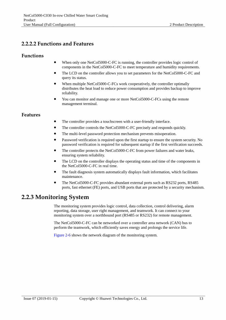
5.3 Startup Screen ............................................................................................................................................................. 69
5.4 Indicator ...................................................................................................................................................................... 70
5.5 Home screen ............................................................................................................................................................... 71
5.6 Start and Shutdown ..................................................................................................................................................... 72
5.7 Temperature and Humidity Curves ............................................................................................................................. 73
5.8 Common Functions ..................................................................................................................................................... 73
5.8.1 Status ....................................................................................................................................................................... 74
5.8.2 Operating Info .......................................................................................................................................................... 74
5.8.3 Query Historical Alarms .......................................................................................................................................... 75
5.9 Running ...................................................................................................................................................................... 76
5.9.1 Status ....................................................................................................................................................................... 76
5.9.2 System Information ................................................................................................................................................. 76
5.9.3 Device Details .......................................................................................................................................................... 76
5.10 Alarms ....................................................................................................................................................................... 77
5.10.1 Query Active Alarms ............................................................................................................................................. 78
5.10.2 Query Historical Alarms ........................................................................................................................................ 79

NetCol5000-C030 In-row Chilled Water Smart Cooling
Product
User Manual (Full Configuration) Contents
Issue 07 (2019-01-15) Copyright © Huawei Technologies Co., Ltd. vii
5.10.3 Delete Historical Alarms ........................................................................................................................................ 79
5.11 Settings ..................................................................................................................................................................... 80
5.11.1 User Settings .......................................................................................................................................................... 82
5.11.1.1 Setting User Parameters ...................................................................................................................................... 83
5.11.1.2 Restore the Default Password ............................................................................................................................. 84
5.11.2 Communications Settings ...................................................................................................................................... 85
5.11.3 Alarm Settings ........................................................................................................................................................ 86
5.11.4 System Settings ...................................................................................................................................................... 88
5.11.5 Basic Settings ......................................................................................................................................................... 93
5.11.6 Restore Defaults ..................................................................................................................................................... 94
5.12 Teamwork Settings ................................................................................................................................................... 95
5.13 Maintenance .............................................................................................................................................................. 99
5.13.1 Diagnostic Mode .................................................................................................................................................. 100
5.13.2 Log Maintenance ................................................................................................................................................. 102
5.13.3 Performance Maintenance ................................................................................................................................... 103
5.13.4 Sensor Adjust ....................................................................................................................................................... 104
5.13.5 Screen Calibration ............................................................................................................................................... 105
5.13.6 USB Operations ................................................................................................................................................... 106
5.14 About ...................................................................................................................................................................... 112
6 System Operation and Maintenance ..................................................................................... 115
6.1 Routine Maintenance ................................................................................................................................................ 115
6.1.1 Routine Maintenance Overview ............................................................................................................................ 115
6.1.2 Electrical Control Box Component Maintenance .................................................................................................. 116
6.1.3 Air Filter Maintenance ........................................................................................................................................... 117
6.1.4 Condensate Pump Maintenance ............................................................................................................................. 118
6.1.5 Indoor Fan Maintenance ........................................................................................................................................ 118
6.1.6 Electrical Control System Maintenance ................................................................................................................. 119
6.2 Alarm Reference ....................................................................................................................................................... 120
6.3 Troubleshooting ........................................................................................................................................................ 136
6.4 Parts Replacement .................................................................................................................................................... 139
6.4.1 Replacement Requirements ................................................................................................................................... 139
6.4.2 Replacing Components in the Electrical Control Box ........................................................................................... 139
6.4.3 Replacing an Air Filter ........................................................................................................................................... 140
6.4.4 Replacing a Condensate Pump .............................................................................................................................. 141
6.4.5 Replacing a Fan ..................................................................................................................................................... 143
6.4.6 Replacing a Water Sensor ...................................................................................................................................... 144
6.4.7 Replacing an Air Exhaust Temperature Sensor ...................................................................................................... 145
6.4.8 Replacing an Air Intake Temperature Sensor ......................................................................................................... 146
6.4.9 Replacing a Water Inlet or Outlet Temperature Sensor .......................................................................................... 147
6.4.10 Replacing a Monitoring Module .......................................................................................................................... 149
6.4.11 Replacing a Rectifier ............................................................................................................................................ 150

NetCol5000-C030 In-row Chilled Water Smart Cooling
Product
User Manual (Full Configuration) Contents
Issue 07 (2019-01-15) Copyright © Huawei Technologies Co., Ltd. viii
6.4.12 Replacing a Chilled Water Valve ......................................................................................................................... 151
6.4.13 Replacing a Float ................................................................................................................................................. 153
6.4.14 Replacing a Differential Pressure Sensor ............................................................................................................. 154
6.4.15 Replacing a Controller Panel ............................................................................................................................... 155
A Acronyms and Abbreviations ................................................................................................ 158
B Glycol Adding Requirements ................................................................................................ 159
C Controller Operation Rights Configuration Table ............................................................ 160
D Electric Diagram ....................................................................................................................... 165
E Controller Menu Structure...................................................................................................... 170

NetCol5000-C030 In-row Chilled Water Smart Cooling
Product
User Manual (Full Configuration) 1 Safety Precautions
Issue 07 (2019-01-15) Copyright © Huawei Technologies Co., Ltd. 1
1 Safety Precautions
1.1 General Safety
Declaration
Huawei shall not take responsibility for any damage caused by any of the following:
Operation under severe environments which are not specified in this document.
Usage under installation and operating environments which are not specified in related
international specifications.
Unauthorized product changes and software code modification.
Operation ignoring safety precautions and operation guidance specified in this document.
Damage caused by abnormal natural environments.
Overview To ensure the safety of people and equipment, pay attention to the safety symbols on the
equipment and all the safety instructions in this document.
The "NOTICE", "CAUTION", "WARNING", and "DANGER" statements in this
document do not represent all safety instructions. They are only supplements to the
safety instructions.
Pay attention to the safety symbols on the equipment and all safety instructions in this
document. The safety precautions given in this document do not cover all safety
precautions. Huawei will not be liable for any consequence caused by violation of the
safety operation regulations and design, production, and usage standards.
Appliances shall be classified according to the accessibility either as appliance not
accessible to the general public.
Local Safety Regulations
Follow local laws and regulations when operating the equipment. The safety instructions in
this document are only supplements to local laws and regulations.

NetCol5000-C030 In-row Chilled Water Smart Cooling
Product
User Manual (Full Configuration) 1 Safety Precautions
Issue 07 (2019-01-15) Copyright © Huawei Technologies Co., Ltd. 2
Personnel Requirements
Personnel who will install, operate, and maintain Huawei equipment must receive thorough
training, understand all necessary safety precautions, and be able to correctly perform all
operations.
Only trained and qualified personnel are allowed to install, operate, and maintain the
equipment.
Only personnel certified or authorized by Huawei are allowed to replace or modify the
equipment or components (including software).
Any fault or error that might cause safety problems must be reported immediately to a
supervisor.
Grounding Requirements When installing a device, always install the ground cable first. When uninstalling a
device, disconnect it at the very end.
Do not damage the ground conductor.
Do not operate the device without a properly installed ground conductor.
The device must be connected permanently to the protection ground.
Personal Safety Do not perform operations on the equipment or cables during thunderstorms.
Keep unauthorized personnel away from the equipment.
When operating the equipment, wear insulation shoes and gloves and take measures to
protect your eyes. Remove conductive objects such as jewelry and watches to avoid
electric shocks or burns.
Ensure that tools are insulated.
This appliance can be used by:
− Children aged from 8 years and above
− People with reduced physical, sensory, or mental capabilities
− People who lack of experience and knowledge
The prerequisite is that they have been given supervision or instruction concerning use of
the appliance in a safe way and understand the hazards involved.
Equipment Safety Put away the key to the cabinet door during installation, operation, and maintenance.
Only trained and qualified personnel are allowed to use the key.
Before operating the equipment, ensure that the equipment is secured to a floor or
another immovable object such as a wall or mounting rack.
Do not block any ventilation opening when the equipment is in operation.
Tighten screws using a tool when installing a panel.
After the installation is complete, remove packing materials from the equipment area.
Never use water to clean the electrical components in the interior and exterior of the
cabinet.

NetCol5000-C030 In-row Chilled Water Smart Cooling
Product
User Manual (Full Configuration) 1 Safety Precautions
Issue 07 (2019-01-15) Copyright © Huawei Technologies Co., Ltd. 3
1.2 Electrical Safety
High Voltage
The device is powered by a high-voltage power supply. Direct or indirect contact (through
damp or conductive objects) with high-voltage power sources will result in serious injury
or death.
Non-standard and improper high voltage operations may result in fire or electric shocks.
High Leakage Current
Ground the device components and the general ground cable before powering the device on.
Ensure that the ground continuity requirements stipulated in IEC61439-1:2011 is met, and the
ground resistance is 0.1 ohm at most. Otherwise, personal injury or device damage may be
caused by high leakage current.
Cover the exposed parts of cables inside the device with PVC insulation tape and place them
in appropriate positions.
Power Cable
Do not install or remove power cables when the equipment is powered on. Transient contact
between the core wire of a power cable and a conductor may generate electric arcs or sparks,
which may start a fire or cause eye injury.
Turn off the power switch before installing or removing a power cable.
Verify that the label on the power cable is correct before connecting the cable.
To ensure safety, damaged power cables must be replaced by the manufacturer, the
manufacturer's service agent, or similarly qualified persons.
Ensure that the equipment has a mechanism for disconnecting from the main power
supply. Contact intervals must be provided between different levels so that a circuit can
be disconnected under class III overvoltage conditions. Cables for the mechanism must
be incorporated into the fixed wiring based on the wiring rules.
Fuse

NetCol5000-C030 In-row Chilled Water Smart Cooling
Product
User Manual (Full Configuration) 1 Safety Precautions
Issue 07 (2019-01-15) Copyright © Huawei Technologies Co., Ltd. 4
To ensure that the equipment runs safely, replace blown fuses with new fuses of the same
model and specifications.
1.3 Mechanical Safety
Drilling Holes
Do not drill the cabinet at will. Drilling holes without complying with the requirements affects
the electromagnetic shielding performance of the cabinet and damages the cables inside the
cabinet. In addition, if the scraps caused by drilling enter the cabinet, the printed circuit
boards (PCBs) may be short circuited.
Drill holes with approval of the customer, contractor, and Huawei.
Before drilling holes on the rack, first remove the cables inside the rack.
To protect your eyes from metal shavings, wear a pair of goggles when drilling holes.
Before drilling holes, wear protective gloves.
After drilling, clean up the metal shavings.
Sharp Objects
Before you hold or carry a device, wear protective gloves to avoid getting injured by sharp
edges of the device.
Handling Fans When replacing a component, place the component, screws, and tools in a safe place.
Otherwise, if any of them fall into the operating fans, the fans may be damaged.
When replacing a component near fans, do not insert your fingers or boards into the
operating fans until the fans are switched off and stops running.
Moving Heavy Objects

NetCol5000-C030 In-row Chilled Water Smart Cooling
Product
User Manual (Full Configuration) 1 Safety Precautions
Issue 07 (2019-01-15) Copyright © Huawei Technologies Co., Ltd. 5
Wear protective gloves when moving heavy objects.
Be careful to prevent injury when moving heavy objects.
To prevent injury, when moving the chassis outwards, be aware of unfixed or heavy
objects on the chassis.
At least two persons are required to move the chassis. When moving the chassis, ensure
that it does not tilt at an angle that exceeds 15 degrees from the vertical direction.
When moving or lifting the chassis, well protect the chassis to avoid scratches or crashes.
When moving the chassis, do not use a part to support the body. Otherwise, the part may
be damaged.
Welding Hazard At least two persons are required at the welding site.
The operator must have licenses for welding.
No flammable materials are allowed in the welding area.
Ensure that fire extinguishers, wet cloths, and water containers are prepared.
Do not place a flaming welding torch on parts or the ground. Do not put welding torch
with residual acetylene and oxygen inside a metal container to avoid gas leakage and
burning.
Get the high-temperature pipe cooled down after welding.
Do not perform welding and cutting on a container under pressure. Power off the device
before any welding operation.
1.4 Running Safety High-speed running part: fan
High voltage: components inside the electric control box
1.5 Others
Binding Signal Cables
Signal cables must be bound separately from power cables with a spacing of at least 50 mm.
Laying Out Cables
In very low temperatures, violent impacts or vibration may crack the plastic cable jacket. To
ensure safety, comply with the following requirements:
Cables must be laid out and installed only when the temperature is higher than 0°C.

NetCol5000-C030 In-row Chilled Water Smart Cooling
Product
User Manual (Full Configuration) 1 Safety Precautions
Issue 07 (2019-01-15) Copyright © Huawei Technologies Co., Ltd. 6
Cables previously stored at subzero temperatures must be stored at room temperature for
at least 24 hours before they are laid out.
Handle cables with caution, especially at a low temperature. Do not drop cables from
vehicles to the ground.
Cables must be routed with a distance of at least 30 mm between the cables and the DC
busbar, shunt, and fuse. This prevents damage to and decelerates deterioration of the
insulation layer of the cables. Cables must be flame-retardant and must not be routed
behind the air inlets or outlets of the cabinet. The air inlets and outlets must not be
blocked.
Storage Ensure that the equipment is not located near heat sources or directly exposed to
sunlight.
To avoid explosion or refrigerant leaks, keep sources of ignition and high-temperature
objects far away from the equipment. This is especially important for equipment
containing high-pressure nitrogen or refrigerant.
Recycling
This marking indicates that this product may not be disposed of with other housed
wastes in the European Union's areas. Recycle the product to promote the sustainable reuse of
resources and to avoid possible environment pollution and harm to human health. To recycle
the product, use your local recycling system or contact the retailer where the product was
purchased. The retailer can recycle this product in a safe and environmentally friendly way.
Manual Loss
If you lose this manual, contact Huawei technical support to obtain the electronic document or
download it from http://www.huawei.com.

NetCol5000-C030 In-row Chilled Water Smart Cooling
Product
User Manual (Full Configuration) 2 Product Description
Issue 07 (2019-01-15) Copyright © Huawei Technologies Co., Ltd. 7
2 Product Description
2.1 Model Description
Figure 2-1 shows the naming rule for the NetCol5000-C-FC series products.
Figure 2-1 Naming rule for the NetCol5000-C-FC series products

NetCol5000-C030 In-row Chilled Water Smart Cooling
Product
User Manual (Full Configuration) 2 Product Description
Issue 07 (2019-01-15) Copyright © Huawei Technologies Co., Ltd. 8
2.2 Components
The NetCol5000-C-FC consists of cooling components, the controller, and monitoring
system.
2.2.1 Cooling Components
Dimensions of the NetCol5000-C-FC
NetCol5000-C-FC can be installed on a concrete floor or an ESD floor, is combined with IT
cabinets. It supports underfloor or overhead cabling and piping. It is maintained from the front
and rear doors without movement. Figure 2-2 shows three dimensions of the
NetCol5000-C-FC.
Figure 2-2 Dimensions of the NetCol5000-C-FC (unit: mm)

NetCol5000-C030 In-row Chilled Water Smart Cooling
Product
User Manual (Full Configuration) 2 Product Description
Issue 07 (2019-01-15) Copyright © Huawei Technologies Co., Ltd. 9
Physical Ports
Figure 2-3 Bottom and top views of the NetCol5000-C-FC (unit: mm)
(1) Bottom outlet for the power and
PE cables
(2) Bottom outlet for the signal cable and forcible
drainpipe
(3) Bottom water outlet pipe (4) Condensate drainpipe port
(5) Bottom water inlet pipe (6) Reserved hole for humidifier pipe
(7) Top water inlet pipe (8) Top outlet for the signal cable and forcible
drainpipe
(9) Top water outlet pipe (10) Top outlet for power line and PE line
Table 2-1 lists the diameter of pipes and cables requirements.
Table 2-1 The diameter of pipes and cables
Content Specification

NetCol5000-C030 In-row Chilled Water Smart Cooling
Product
User Manual (Full Configuration) 2 Product Description
Issue 07 (2019-01-15) Copyright © Huawei Technologies Co., Ltd. 10
Content Specification
Water inlet and outlet pipe DN25 (Recommended diameter, prepare it by yourself)
Forcible drainpipes Standard configuration: Φ=4 mm (outer diameter Φ=7
mm), length = 5 m
Condensate Drainpipes Standard configuration: Φ=10 mm (outer diameter Φ=14
mm), length = 2 m
Machine power supply core Double-insulated cables: 3 x 2.5 mm2 (Recommended
diameter, prepare it by yourself)
PE line (Outside the cabinet) ≥ 6 mm2 (Recommended diameter, prepare it by yourself)
Components
NetCol5000-C-FC consists of chilled water valve, electronic commutation (EC) fan, heat
exchanger, air filter, and condensate pump.
Chilled water valve
The brand name flow regulating valve is used, which features good environment
adaptability, precise adjustment and temperature control, energy efficient, high reliability,
long service life, and easy installation.
EC fan
The brand name fan features high reliability and long service life, and saves more energy
than common fans by 30%.
Heat exchanger
The finned-tube heat exchanger with a zinc-plated layer adopts the computational fluid
dynamics (CFD) to optimize the process design, which greatly improves the heat
exchange efficiency
Air filter
G3 air filter meet requirements for equipment room cleanness.
Condensate pump
The drainage system uses dual floats and double water pumps, achieving higher
reliability.
2.2.2 Controller
2.2.2.1 Appearance and Ports
Appearance
The controller provides a 7-inch true color touchscreen and man-machine interfaces for query,
setting, monitoring, and maintenance.
The indicator on the panel displays operating status of the smart cooling product. Figure 2-4
shows the position of the indicator. Table 2-2 describes the mapping between indicators,
buzzers, and alarms. If alarms of different severities (critical, major, minor, or warning) are
raised simultaneously, the indicator status corresponds to the alarm with the highest severity

NetCol5000-C030 In-row Chilled Water Smart Cooling
Product
User Manual (Full Configuration) 2 Product Description
Issue 07 (2019-01-15) Copyright © Huawei Technologies Co., Ltd. 11
level and the buzzer status corresponds to the unacknowledged alarm with the highest severity
level.
Figure 2-4 Display panel
(1) Indicator (2) Display panel
Table 2-2 Indicator and buzzer status description
Alarm Status Indicator Buzzer
The device is operating properly, or a
warning is generated.
Green No buzzing
There is an unacknowledged major
alarm.
Yellow Intermittent buzzing
There is an unacknowledged critical
alarm.
Red Constant buzzing

NetCol5000-C030 In-row Chilled Water Smart Cooling
Product
User Manual (Full Configuration) 2 Product Description
Issue 07 (2019-01-15) Copyright © Huawei Technologies Co., Ltd. 12
Ports
Figure 2-5 Controller side ports
Table 2-3 Ports
No. Name Note
1 MUS05A Reserved
2 FE (fast Ethernet) communications port
3 CAN communications port for the main control board and
LCD
4 RS485_1 Reserved
5 USB Host After installing the WiFi module, connect the WiFi
module to the smart cooling product using the app
on the mobile phone to obtain the initial startup
password (for V200R001C20 and above software
versions).
Insert the USB flash drive, import and export the
configuration file, export run logs, and upgrade
software.
6 RST restart switch for the display
7 SD Reserved
8 SW1-4 Dual in-line package (DIP) switch on LCD
NetCol5000-C030 In-row Chilled Water Smart Cooling
Product
User Manual (Full Configuration) 2 Product Description
Issue 07 (2019-01-15) Copyright © Huawei Technologies Co., Ltd. 13
2.2.2.2 Functions and Features
Functions When only one NetCol5000-C-FC is running, the controller provides logic control of
components in the NetCol5000-C-FC to meet temperature and humidity requirements.
The LCD on the controller allows you to set parameters for the NetCol5000-C-FC and
query its status.
When multiple NetCol5000-C-FCs work cooperatively, the controller optimally
distributes the heat load to reduce power consumption and provides backup to improve
reliability.
You can monitor and manage one or more NetCol5000-C-FCs using the remote
management terminal.
Features The controller provides a touchscreen with a user-friendly interface.
The controller controls the NetCol5000-C-FC precisely and responds quickly.
The multi-level password protection mechanism prevents misoperation.
Password verification is required upon the first startup to ensure the system security. No
password verification is required for subsequent startup if the first verification succeeds.
The controller protects the NetCol5000-C-FC from power failures and water leaks,
ensuring system reliability.
The LCD on the controller displays the operating status and time of the components in
the NetCol5000-C-FC in real time.
The fault diagnosis system automatically displays fault information, which facilitates
maintenance.
The NetCol5000-C-FC provides abundant external ports such as RS232 ports, RS485
ports, fast ethernet (FE) ports, and USB ports that are protected by a security mechanism.
2.2.3 Monitoring System
The monitoring system provides logic control, data collection, control delivering, alarm
reporting, data storage, user right management, and teamwork. It can connect to your
monitoring system over a northbound port (RS485 or RS232) for remote management.
The NetCol5000-C-FC can be networked over a controller area network (CAN) bus to
perform the teamwork, which efficiently saves energy and prolongs the service life.
Figure 2-6 shows the network diagram of the monitoring system.

NetCol5000-C030 In-row Chilled Water Smart Cooling
Product
User Manual (Full Configuration) 2 Product Description
Issue 07 (2019-01-15) Copyright © Huawei Technologies Co., Ltd. 14
Figure 2-6 Group control network diagram
2.3 Environment requirements
Table 2-4 describes the environment requirements for the NetCol5000-C-FC.
Table 2-4 Environment requirements
Item Environment Requirements
Product model NetCol5000-C030H2A2010020E0
Environment Class A environment in data centers
Operating temperature 4°C to 55°Ca
Operating humidity ≤ 95% RH
Altitude Less than 1000 m. The refrigerating capacity is derated when
the altitude is above 1000 m. For details, see Figure 2-9
Storage temperature –40°C to +70°C
Storage humidity ≤ 95% RH
Water requirements Filter need to be installed on the inlet pipe, PH value of
chilled water is 7.0 – 9.0
Maximum water
temperature
20°Cb
a: When the ambient temperature is below 0°C, the NetCol5000-C-FC need to increase
certain concentration of ethylene glycol solution, specifically refer to Glycol Correction
Coefficient Curves.
b: Adjust the alarm threshold when generating the high temperature alarms if the
temperature is over 20°C.

NetCol5000-C030 In-row Chilled Water Smart Cooling
Product
User Manual (Full Configuration) 2 Product Description
Issue 07 (2019-01-15) Copyright © Huawei Technologies Co., Ltd. 15
2.4 Technical Specifications
Table 2-5 lists the technical specifications of the NetCol5000-C-FC.
Table 2-5 Technical specifications
Item Description
Category Chilled water cooled in-row smart cooling product
Cooling
mode
Chilled water cooled
Cooling
capacity
30 kWa
Rating
power
1 kW
Air supply
mode
Horizontal air supply
Power
supply
200 V to 240 V 1 Ph 50/60 Hz
Primary power supply: rated voltage ±10% and rated frequency ±2 Hz
respectively
Input
power
Dual power supply: one primary power supply and one secondary power
supply
Fan
characterist
ic
EC fan
Fan speed
characterist
ic
Stepless speed adjustment
Total
airflow
5100 m3/h
Maximum
operating
pressure
1.6 MPa
Air filter G3 filter
Condensate
pump
Yes
Dimensions
(W x D x
H)
300 mm x 1000 mm x 2000 mm
300 mm x 1200 mm x 2000 mm
Packing
dimensions
(W x D x
H)
760 mm x 1350 mm x 2200 mm

NetCol5000-C030 In-row Chilled Water Smart Cooling
Product
User Manual (Full Configuration) 2 Product Description
Issue 07 (2019-01-15) Copyright © Huawei Technologies Co., Ltd. 16
Item Description
Net
weight/Gro
ss weigh
240 kg (depth: 1000 mm)
250 kg (depth: 1200 mm)
Pipe and
cable
routing
Installed on a concrete floor or an ESD floor
Environme
ntal
certificatio
n
RoHS, WEEE and REACH
a: The return air dry-bulb temperature/wet-bulb temperature is 37.8°C/20.8°C, the
temperature of chilled water is 10°C and flow is 5.04 m3/h.
2.5 Performance Curves
System specifications
With rated power and maximum air volume, the NetCol5000-C-FC has different performance
specifications for cooling capacity, sensitive heat, and water supply based on chilled water
temperatures and temperature rises. Table 2-6, Table 2-7, Table 2-8, Table 2-9, and Table 2-10
list the performance specifications.
Table 2-6 Specifications for a 5.5°C chilled water supply system
Item Performance Specifications
Return air
temperatur
e
Dry-bulb
temperature (°C)
40 37 35 32 28
Wet-bulb
temperature (°C)
21.4 20.5 19.8 18.9 17.6
5°C
temperatur
e rise
Cooling capacity
(kW)
40.63 36.79 33.21 29.27 23.98
Sensible cooling
capacity (kW)
39.62 35.76 33.21 29.27 23.98
Water supply
(m3/h)
7.02 6.36 5.73 5.04 4.13
6°C
temperatur
e rise
Cooling capacity
(kW)
38.56 34.63 31.82 27.87 22.52
Sensible cooling
capacity (kW)
38.26 34.63 31.82 27.87 22.52
Water supply 5.54 4.97 4.57 4.00 3.23

NetCol5000-C030 In-row Chilled Water Smart Cooling
Product
User Manual (Full Configuration) 2 Product Description
Issue 07 (2019-01-15) Copyright © Huawei Technologies Co., Ltd. 17
Item Performance Specifications
(m3/h)
7°C
temperatur
e rise
Cooling capacity
(kW)
36.91 33.07 30.44 26.49 21.12
Sensible cooling
capacity (kW)
36.91 33.07 30.44 26.49 21.12
Water supply
(m3/h)
4.54 4.05 3.74 3.25 2.59
Table 2-7 Performance specifications in a 7°C chilled water system
Item Performance Specifications
Return air
temperatur
e
Dry-bulb
temperature (°C)
40 37 35 32 28
Wet-bulb
temperature (°C)
21.4 20.5 19.8 18.9 17.6
5°C
temperatur
e rise
Cooling capacity
(kW)
37.70 33.91 31.29 27.26 21.92
Sensible cooling
capacity (kW)
37.70 33.91 31.29 27.26 21.92
Water supply
(m3/h)
6.48 5.90 5.44 4.68 3.74
6°C
temperatur
e rise
Cooling capacity
(kW)
36.33 32.51 29.92 25.95 20.58
Sensible cooling
capacity (kW)
36.33 32.51 29.92 25.95 20.58
Water supply
(m3/h)
5.18 4.68 4.32 3.74 2.95
7°C
temperatur
e rise
Cooling capacity
(kW)
35.05 31.11 28.41 24.55 19.14
Sensible cooling
capacity (kW)
35.05 31.11 28.41 24.55 19.14
Water supply
(m3/h)
4.32 3.82 3.46 3.02 2.34
Table 2-8 Performance specifications in a 10°C chilled water system
Item Performance Specifications
Return air Dry-bulb 40 37 35 32 28

NetCol5000-C030 In-row Chilled Water Smart Cooling
Product
User Manual (Full Configuration) 2 Product Description
Issue 07 (2019-01-15) Copyright © Huawei Technologies Co., Ltd. 18
Item Performance Specifications
temperatur
e
temperature (°C)
Wet-bulb
temperature (°C)
21.4 20.5 19.8 18.9 17.6
5°C
temperatur
e rise
Cooling capacity
(kW)
33.77 30.00 27.31 23.37 17.92
Sensible cooling
capacity (kW)
33.77 30.00 27.31 23.37 17.92
Water supply
(m3/h)
5.76 5.18 4.68 4.03 3.06
6°C
temperatur
e rise
Cooling capacity
(kW)
32.54 28.63 26.03 22.03 16.59
Sensible cooling
capacity (kW)
32.54 28.63 26.03 22.03 16.59
Water supply
(m3/h) 4.68 4.10 3.75 3.17 2.38
7°C
temperatur
e rise
Cooling capacity
(kW)
31.16 27.37 24.65 20.61 15.15
Sensible cooling
capacity (kW)
31.16 27.37 24.65 20.61 15.15
Water supply
(m3/h)
3.82 3.39 3.02 2.52 1.85
Table 2-9 Performance specifications in a 13°C chilled water system
Item Performance Specifications
Return air
temperatur
e
Dry-bulb
temperature (°C)
40 37 35 32 28
Wet-bulb
temperature (°C)
21.4 20.5 19.8 18.9 17.6
5°C
temperatur
e rise
Cooling capacity
(kW)
30.00 26.04 23.53 19.44 14.01
Sensible cooling
capacity (kW)
30.00 26.04 23.53 19.44 14.01
Water supply
(m3/h)
5.18 4.46 4.11 3.36 2.41
6°C
temperatur
e rise
Cooling capacity
(kW)
28.66 24.78 22.18 18.09 12.61
Sensible cooling 28.66 24.78 22.18 18.09 12.61

NetCol5000-C030 In-row Chilled Water Smart Cooling
Product
User Manual (Full Configuration) 2 Product Description
Issue 07 (2019-01-15) Copyright © Huawei Technologies Co., Ltd. 19
Item Performance Specifications
capacity (kW)
Water supply
(m3/h)
4.11 3.57 3.20 2.59 1.80
7°C
temperatur
e rise
Cooling capacity
(kW)
27.38 23.44 20.80 16.74 11.26
Sensible cooling
capacity (kW)
27.38 23.44 20.80 16.74 11.26
Water supply
(m3/h)
3.36 2.88 2.56 2.05 1.38
Table 2-10 Performance specifications in a 15°C chilled water system
Item Performance Specifications
Return air
temperatur
e
Dry-bulb
temperature (°C)
40 37 35 32 28
Wet-bulb
temperature (°C)
21.4 20.5 19.8 18.9 17.6
5°C
temperatur
e rise
Cooling capacity
(kW)
27.33 23.44 20.83 16.77 11.31
Sensible cooling
capacity (kW)
27.33 23.44 20.83 16.77 11.31
Water supply
(m3/h)
4.68 4.03 3.60 2.88 1.94
6°C
temperatur
e rise
Cooling capacity
(kW)
26.10 22.14 19.53 15.49 9.95
Sensible cooling
capacity (kW)
26.10 22.14 19.53 15.49 9.95
Water supply
(m3/h)
3.74 3.17 2.81 2.23 1.43
7°C
temperatur
e rise
Cooling capacity
(kW)
24.92 20.85 18.18 14.07 8.55
Sensible cooling
capacity (kW)
24.92 20.85 18.18 14.07 8.55
Water supply
(m3/h)
3.10 2.56 2.23 1.72 1.05

NetCol5000-C030 In-row Chilled Water Smart Cooling
Product
User Manual (Full Configuration) 2 Product Description
Issue 07 (2019-01-15) Copyright © Huawei Technologies Co., Ltd. 20
Chilled Water Drop Curve
Figure 2-7 Curve between the pressure drop and water flow
Air Volume Curve
Figure 2-8 Curve between the air volume and fan output
Test environment: The ambient temperature is 25°C.

NetCol5000-C030 In-row Chilled Water Smart Cooling
Product
User Manual (Full Configuration) 2 Product Description
Issue 07 (2019-01-15) Copyright © Huawei Technologies Co., Ltd. 21
Curve between the Cooling Capacity and Altitude
Figure 2-9 Curve between the cooling capacity and altitude
Glycol Correction Coefficient Curves
Figure 2-10 Cooling capacity and glycol solution density
The cooling capacity is obtained by multiplying the glycol solution density by the rated
cooling capacity.

NetCol5000-C030 In-row Chilled Water Smart Cooling
Product
User Manual (Full Configuration) 2 Product Description
Issue 07 (2019-01-15) Copyright © Huawei Technologies Co., Ltd. 22
Figure 2-11 The pressure drop coefficient and glycol solution density
The pressure drop is obtained by multiplying the glycol solution density by the standard
atmospheric pressure drop.

NetCol5000-C030 In-row Chilled Water Smart Cooling
Product
User Manual (Full Configuration) 3 Installation Guide
Issue 07 (2019-01-15) Copyright © Huawei Technologies Co., Ltd. 23
3 Installation Guide
3.1 Installation Precautions
To ensure the optimal operating condition and longest service life, install the
NetCol5000-C-FC correctly as required.
Check whether the environment meets the requirements before installation, and whether
reconstruction is needed for routing pipes and cables and constructing ventilation pipes.
Install the NetCol5000-C-FC according to the design drawing and reserve space for
maintenance.
Install the water inlet and outlet pipes to the predefined paths and reserve proper length
for connecting water inlet and outlet pipes.
3.1.1 Tools
Table 3-1, Table 3-2, and Table 3-3 list the tools for installing the NetCol5000-C-FC. Add or
delete tools as required.
Table 3-1 General tools
Appearance, Parameter, and Name
Flat-head
screwdriver
Phillips screwdriver Adjustable wrench Socket wrench
Hex key Open end torque
wrench
Diagonal pliers Wire stripper
Crimping tool Torch Knife Step ladder (2m)

NetCol5000-C030 In-row Chilled Water Smart Cooling
Product
User Manual (Full Configuration) 3 Installation Guide
Issue 07 (2019-01-15) Copyright © Huawei Technologies Co., Ltd. 24
Appearance, Parameter, and Name
Electrostatic
discharge (ESD)
gloves
Polyvinyl chloride
insulation tape
Vacuum cleaner Steel wire brush
Multimeter Claw hammer N/A N/A
N/A N/A
Table 3-2 Transportation and unpacking tools
Appearance, Parameter, and Name
Diesel pallet
truck
Manual pallet truck N/A N/A
N/A N/A
Table 3-3 Pipe installation tools
Appearance, Parameter, and Name
Nitrogen Pressure gauge Fluorine hose R22 Heat gun
Thread glue Reducing Valve N/A N/A

NetCol5000-C030 In-row Chilled Water Smart Cooling
Product
User Manual (Full Configuration) 3 Installation Guide
Issue 07 (2019-01-15) Copyright © Huawei Technologies Co., Ltd. 25
Appearance, Parameter, and Name
N/A N/A
3.1.2 Material Preparations
Pipe Connection
There are two kinds of pipe connections for NetCol5000-C-FC, with liquid distribution unit
NetCol520 (NetCol520 for short) and without the NetCol520. Figure 3-1 shows the
NetCol5000-C-FC with the NetCol520 when pipes are routed from the bottom. Figure 3-2
shows the NetCol5000-C-FC with the NetCol520 when pipes are routed from the top. Figure
3-3 shows the NetCol5000-C-FC without the NetCol520 when pipes are routed from the
bottom and top.
It is recommended to close the inlet valve in the unit when there is chilled water circulation in
system and the unit is not in use.
Figure 3-1 Routing pipe from the bottom (with the NetCol520)
(1) Check valve (2) Y filters

NetCol5000-C030 In-row Chilled Water Smart Cooling
Product
User Manual (Full Configuration) 3 Installation Guide
Issue 07 (2019-01-15) Copyright © Huawei Technologies Co., Ltd. 26
Figure 3-2 Routing pipe from the top (with the NetCol520)
(1) Check valve (2) Y filters
Figure 3-3 Routing pipe from the bottom and top (without the NetCol520)
(1) Check valve (2) Y filters

NetCol5000-C030 In-row Chilled Water Smart Cooling
Product
User Manual (Full Configuration) 3 Installation Guide
Issue 07 (2019-01-15) Copyright © Huawei Technologies Co., Ltd. 27
Engineering Auxiliary Materials
Figure 3-4 shows the two methods of connecting inlet and outlet chilled water pipelines.
Figure 3-4 Connecting method A and B
(1) Reserved joint: 1 inch, BSPT, male
adapter
(2) Conversion adapter: in the delivered
fittings
(3) Hoop: in the delivered fittings (4) Hose
(5) Corrugated pipe (6) Adapter
(7) Ball valve: screw thread or flanges
connecting
(8) Stainless steel pipe
If the NetCol520 is configured, method A is recommended. If no, the method is based on onsite
situation.
Prepare the materials list in Table 3-4. Table 3-5 shows the cables preparations.
Table 3-4 Pipes preparations
Class Parts Specifications Remarks
Pipe Rubber
hose
DN25
Material media is water
(0°C to 70°C, without
icing) and glycol.
Material heat resistant
is –40°C to +100°C.
Working pressure is 12
bar, and burst pressure
is 48 bar.
Inner layer is oil
resistant synthetic
Not configured. Need
engineering purchasing if
method A in Figure 3-4 is
adopted.

NetCol5000-C030 In-row Chilled Water Smart Cooling
Product
User Manual (Full Configuration) 3 Installation Guide
Issue 07 (2019-01-15) Copyright © Huawei Technologies Co., Ltd. 28
Class Parts Specifications Remarks
rubber. Insert layer is
one braided textile
insert. Outer layer is oil
resistant and
weatherproof synthetic
rubber.
Corrugated
pipe
The adapter is 1 inch BSPP
of female adapter. The
diameter and length are
recommended to be DN25
and 200 mm.
Not configured. Need
engineering purchasing if
method B in Figure 3-4 is
adopted.
Corrugated
pipe
adapter
Matching the corrugated
pipe.
Not configured. Need
engineering purchasing if
method B in Figure 3-4 is
adopted.
Ball valve Matching the galvanized
steel pipe
Not configured. Need
engineering purchasing if
method B in Figure 3-4 is
adopted.
Water inlet
and outlet
pipes
Galvanized steel pipe,
DN25
Not configured. Need
engineering purchasing.
Forcible
drainpipes
Φ = 4 mm (outer diameter
Φ = 7 mm), length = 5 m
Mandatory, shipped with the
device.
Condensat
e
Drainpipes
Φ = 10 mm (outer diameter
Φ = 14 mm), length = 2 m
Mandatory, shipped with the
device.
Main
chilled
water
supply and
return
pipes
It is recommended that
welded steel pipes or
seamless steel pipes be
used as the main chilled
water supply and return
pipes, DN80.
Not configured. Need
engineering purchasing.
Corrugated
pipe
DN80, length = 200 mm Not configured. Need
engineering purchasing.
The main
condensate
drainpipe
(tee fitting)
Galvanized steel pipe
connectors are
recommended.
Not configured. Need
engineering purchasing.
The main
condensate
drainpipe
(90°
elbow)
Galvanized steel pipe
connectors are
recommended.
Not configured. Need
engineering purchasing.
90° elbows DN80, at least four 90 Not configured. Need

NetCol5000-C030 In-row Chilled Water Smart Cooling
Product
User Manual (Full Configuration) 3 Installation Guide
Issue 07 (2019-01-15) Copyright © Huawei Technologies Co., Ltd. 29
Class Parts Specifications Remarks
for the
main
chilled
water
supply and
return
pipes
degree elbows are
purchased.
engineering purchasing.
Pipe fixed Pipe
Support
For the specifications, see
Pipe Support Preparations.
Not configured. Need
engineering purchasing.
Heat
insulation
pipe (for
rubber
hoses)
Determine the pipe
thickness based on the
water inlet temperature and
ambient temperature.
Not configured. Need
engineering purchasing.
Heat
insulation
pipe (for
the main
condensate
drainpipe)
The inner pipe diameter is
25 mm and the thickness is
9.52 mm.
Not configured. Need
engineering purchasing.
Adhesive
for heat
insulation
pipes
N/A Not configured. Need
engineering purchasing.
Adhesive
tape for
heat
insulation
pipes
N/A Not configured. Need
engineering purchasing.
Pipe
connector
sealing
adhesive
The sealant or seal tape
for screw threads must
be able to withstand
temperatures higher
than 85°C.
The sealant or seal tape
should apply to all pipe
material.
Anaerobic metal pipe
thread sealant with
polytetrafluorethylene
(PTFE for short) as the
filler.
Glycol solution
resistance, adapting to
the thread size with
pipeline.
Maximum seal gap is
Not configured. Need
engineering purchasing.

NetCol5000-C030 In-row Chilled Water Smart Cooling
Product
User Manual (Full Configuration) 3 Installation Guide
Issue 07 (2019-01-15) Copyright © Huawei Technologies Co., Ltd. 30
Class Parts Specifications Remarks
less than 0.5 mm.
The maximum pressure
is greater than 3 MPa.
Anaerobic
adhesive
Comply with fireproof and
environment protection
requirements.
Not configured. Need
engineering purchasing.
DN80 heat
insulation
pipe
You can replace them with
heat insulation panels.
Not configured. Need
engineering purchasing.
Flange and
gasket
DN80 Not configured. Need
engineering purchasing.
Butterfly
valve
DN80, providing a
pressure withstand capacity
of over 2.0 MPa
Not configured. Need
engineering purchasing.
Copper
gate valve
One for the main chilled
water supply pipe and one
for the main chilled water
return pipe, providing a
pressure withstand capacity
of over 2.0 MPa
Not configured. Need
engineering purchasing.
Y-shaped
filter
Pressure withstand
capacity of over 2 MPa and
20 filter meshes
Not configured. Based on the
system design.
Copper
gate valve
N/A Not configured. Based on the
system design.
Pressure
gauge
Precision: 2.5
Ambient temperature:
–40°C to +70°C
Temperature influence: ≤
0.4%/10°C (operating
temperature: 20±5°C)
Pressure: between 1.2–2.5
MPa
Not configured. Based on the
system design.
Support For the specifications, see
Support Preparations.
Optional
Hose
clamp
D16 Not configured. Need
engineering purchasing.
Table 3-5 Cables preparations
Cables Parameters Number Remarks

NetCol5000-C030 In-row Chilled Water Smart Cooling
Product
User Manual (Full Configuration) 3 Installation Guide
Issue 07 (2019-01-15) Copyright © Huawei Technologies Co., Ltd. 31
Cables Parameters Number Remarks
Power cables Power cable, 450/750 V,
H07RN-F, 2.5 mm2, 3
cores color (including
PE cable), 25 A.
1 PCS Not configured.
Need engineering
purchasing.
OT terminal: blue M3
and M6
M3: 10 PCS
M6: 4 PCS
Mandatory,
shipped with the
device.
External circuit
breaker
Air-break switch,
230/400 V AC, 16 A,
2P, 6 KA, C character
1 PCS Not configured.
Need engineering
purchasing.
Voltage jumper N/A N/A Mandatory,
shipped with the
device.
Temperature and
humidity (T/H)
sensor
10 m 1 PCS Mandatory,
shipped with the
device. Other five
pieces (at most)
are optional.
Cable to the group
control networking
and host
10 m 1 PCS Mandatory,
shipped with the
device.
Pipe Support Preparations
Figure 3-5 shows the support for water pipes. Determine detailed specifications based on
onsite situation. Stainless steel 304 for pipe support and pipe clamp are recommended.
Figure 3-5 Pipeline support (unit: mm)
Height of the U-shaped clamp H = Pipe diameter (with thermal insulation foam) – 5 mm.
The pipe supports need engineering purchasing.

NetCol5000-C030 In-row Chilled Water Smart Cooling
Product
User Manual (Full Configuration) 3 Installation Guide
Issue 07 (2019-01-15) Copyright © Huawei Technologies Co., Ltd. 32
Support Preparations
If water pipes need to be routed below the NetCol5000-C-FC, install a support under the
NetCol5000-C-FC for ease of pipe routing, Figure 3-6 shows the support specifications.
Figure 3-6 Support Specifications (unit: mm)
A support is optional, you can make it or buy it by yourself.
Make supports by referring the following recommendations:
1. Recommended to use angle steel, square steel or channel steel, and width is 45–60 mm,
thickness is 4–5 mm.
a. When the width of angle steel is less than 60 mm or equal, do not consider
avoiding.
b. When the width of angle steel is more than 60 mm, it is interfering with the holes
which routing cables, please cut out holes to avoid interfering.
2. The height of the support is more than 300 mm.
3. Please note that to control the welding process and avoid excessive error.
3.1.3 Structural Specifications
Figure 3-7 shows the structural specifications of the NetCol5000-C-FC.

NetCol5000-C030 In-row Chilled Water Smart Cooling
Product
User Manual (Full Configuration) 3 Installation Guide
Issue 07 (2019-01-15) Copyright © Huawei Technologies Co., Ltd. 33
Figure 3-7 Structural specifications
(1) Door lock (2) Control panel (3) Front door
(4) Caster (5) Leveling foot (6) Side panel
(7) Rear door (8) Top outlet for power line
and PE line
(9) Top outlet for the signal cable and
forcible drainpipe
(10) Top water
outlet pipe
(11) Top water inlet pipe
3.2 Transportation and Unpacking
Prerequisites

NetCol5000-C030 In-row Chilled Water Smart Cooling
Product
User Manual (Full Configuration) 3 Installation Guide
Issue 07 (2019-01-15) Copyright © Huawei Technologies Co., Ltd. 34
Only trained personnel are allowed to move the cabinet. Use a pallet truck to transport the
cabinet secured to a wooden support to the installation position. Insert the forks of the
pallet truck in the middle position to ensure balance.
When loading and unloading the cabinet, keep the gradient within 15 degrees, as shown in
Figure 3-8.
To prevent the cabinet from falling over, secure it to a pallet truck using ropes before
moving it.
To prevent shocks or falls, move the cabinet gently.
After placing the cabinet in the installation position, unpack it and take care to prevent
scratches. Keep the cabinet steady during unpacking.
Figure 3-8 Transportation Gradient
Context
To avoid damage during the transportation, remove the wooden case and pallets after the
device is moved most close to the installation position.
Procedure
Step 1 Visually inspect the outer packing for shipping damage. If any shipping damage is founded,
report it to the carrier immediately.
Step 2 Unpack the package, as shown in Figure 3-9.
1. Remove the straps.
2. Remove the top cover.
3. Remove external packing materials.
4. Remove cushioning materials.
5. Remove plastic materials.
6. Clear the surrounding impurities.

NetCol5000-C030 In-row Chilled Water Smart Cooling
Product
User Manual (Full Configuration) 3 Installation Guide
Issue 07 (2019-01-15) Copyright © Huawei Technologies Co., Ltd. 35
Figure 3-9 Unpacking
Step 3 Check that the fittings comply with the packing list. If some fittings are missing or do not
comply with the packing list, record the information and contact your local Huawei
immediately.
----End
3.3 Checking Fittings
Table 3-6 shows the standard fittings of the NetCol5000-C-FC.
Table 3-6 Standard fittings
No. Item Quantity Description
1 Condensate
drainage
pump
1 PCS Spare parts model: CNM-9
2 Pipe
connector
adapter
2 PCS N/A
3 Cable tie 10 PCS N/A
4 Condensate
drainpipe
2 PCS Connection a self-drainage pipe: Length: 2 m,
internal diameter: 10 mm
5 Hoop 2 PCS N/A
6 Fan fuse 2 PCS Spare parts model: ADA005/0326005.MXP
7 Fuse in the 2 PCS Spare parts model: ADA.250/0326.250MXP

NetCol5000-C030 In-row Chilled Water Smart Cooling
Product
User Manual (Full Configuration) 3 Installation Guide
Issue 07 (2019-01-15) Copyright © Huawei Technologies Co., Ltd. 36
No. Item Quantity Description
condensate
drainage
pump
8 Three-way
valve fuse
1 PCS Spare parts model:
BK1-S505H-1-R/UDE001/04770001.MXP
9 OT cord end
terminal
10 PCS Blue M3
10 OT cord end
terminal
4 PCS Blue M6
11 Air baffle 2 PCS N/A
12 Cascading
communicati
on cable
1 PCS Length: 10 m
13 Documentati
ons
2 PCS Chinese and English User Manuals
3.4 Installation Flowchart
Do not remove the protective plastic bag before installing the cabinet (during the construction
period such as decorating room), avoid dust generated by the construction process seriously
affect internal devices of the cabinet (such as water tray, water pump, float) functions.
Figure 3-10 shows the process for installing NetCol5000-C-FC.

NetCol5000-C030 In-row Chilled Water Smart Cooling
Product
User Manual (Full Configuration) 3 Installation Guide
Issue 07 (2019-01-15) Copyright © Huawei Technologies Co., Ltd. 37
Figure 3-10 Installing flowchart

NetCol5000-C030 In-row Chilled Water Smart Cooling
Product
User Manual (Full Configuration) 3 Installation Guide
Issue 07 (2019-01-15) Copyright © Huawei Technologies Co., Ltd. 38
3.5 Checking the Pressure
Prerequisites
Remove the doors and the air filters before checking pressure, and remove the side panel if
the site conditions is allowed.
Procedure
Step 1 Remove the cabinet doors.
Do not move the doors too far away from the cabinet. Otherwise, the cable connecting the
control panel and PE cable will be damaged.
1. Unlock the doors, and pull the doors outwards by using both hands.
2. Remove the cable from the control panel.
3. Push the doors upwards by using both hands until they are removed, as shown in Figure
3-11.
Figure 3-11 Removing the doors

NetCol5000-C030 In-row Chilled Water Smart Cooling
Product
User Manual (Full Configuration) 3 Installation Guide
Issue 07 (2019-01-15) Copyright © Huawei Technologies Co., Ltd. 39
4. Remove the rear door by following Step 1.1 to Step 1.3.
Step 2 Remove the filters
1. Rotate the six baffle plates at the top, middle, and bottom to remove them from the filters,
as shown in Figure 3-12.
Figure 3-12 Removing the filters
2. Pull the rope to the filters outwards.
The side with a metal mesh is the internal side.
3. Take out the desiccant bag from behind the column in the lower right corner beside the
rear door.
Step 3 (Optional) Remove the two screws from the side panel using a Phillips screwdriver and then
push the side panel upwards by using both hands until it is removed.
Step 4 Remove the bonnets from the needle valve anticlockwise, as shown by 1 in Figure 3-13.
Step 5 Use the hose with 1/4 inch needle valve to connect to the needle valve, as shown by 2 in
Figure 3-13.
If air is exhausted from the needle valve indicating system is normal, remove the hose
and fasten the bonnets.
If no air is exhausted from the needle valve, contact Huawei technical support.

NetCol5000-C030 In-row Chilled Water Smart Cooling
Product
User Manual (Full Configuration) 3 Installation Guide
Issue 07 (2019-01-15) Copyright © Huawei Technologies Co., Ltd. 40
Figure 3-13 Checking the pressure
----End
Follow-up Procedure
Check whether insulation cotton is securely pasted to internal pipes. The chilled water valve is
wrapped with insulation cotton without metal part exposed.
3.6 Remove the Securing Plate
Procedure
Step 1 Remove the eight screws from the securing plate, as shown in Figure 3-14.

NetCol5000-C030 In-row Chilled Water Smart Cooling
Product
User Manual (Full Configuration) 3 Installation Guide
Issue 07 (2019-01-15) Copyright © Huawei Technologies Co., Ltd. 41
Figure 3-14 Removing the screws from the securing plate
Put away the four screws of securing the front and rear doors. They can be used to securing
the device to the support (if the support is configured).
Step 2 Use the wrench to raise the leveling feet until the casters touch the ground, as shown in Figure
3-15.
Figure 3-15 Raising the leveling feet
Step 3 Place a slide plate beside the securing plate.
Step 4 Push the NetCol5000-C-FC to the installation position along the slide plate as shown in
Figure 3-16.

NetCol5000-C030 In-row Chilled Water Smart Cooling
Product
User Manual (Full Configuration) 3 Installation Guide
Issue 07 (2019-01-15) Copyright © Huawei Technologies Co., Ltd. 42
Take care to prevent the NetCol5000-C-FC from falling over.
Two people are required to hold the NetCol5000-C-FC on both sides and gently push it
towards the installation position.
Figure 3-16 Pushing the NetCol5000-C-FC
----End

NetCol5000-C030 In-row Chilled Water Smart Cooling
Product
User Manual (Full Configuration) 3 Installation Guide
Issue 07 (2019-01-15) Copyright © Huawei Technologies Co., Ltd. 43
3.7 Exhausting Nitrogen
Context
Exhaust the nitrogen from the rear door, and you can remove the side panel to operate if the
site conditions are allowed.
Procedure
Step 1 Loosen the air exhaust valve to exhaust nitrogen, as shown in Figure 3-17.
Figure 3-17 Exhausting nitrogen
Step 2 Fasten the air exhaust valve until no air exhaust from the exhaust valve.
----End
3.8 Installing the Water Pipe Adapter
Context
Installing the water pipe adapter for pipes routed from the bottom is similar to installing it
from the top, give the top installation for an example.
When removing the plug, do not touch the plug directly to prevent being burned.

NetCol5000-C030 In-row Chilled Water Smart Cooling
Product
User Manual (Full Configuration) 3 Installation Guide
Issue 07 (2019-01-15) Copyright © Huawei Technologies Co., Ltd. 44
Procedure
Step 1 Removing the plug for the pipe routed from the top.
1. Use a heat gun to heat the screw threads for about 10 minutes, keeping the gun two
centimeters away from the screw threads, until the thread rubber softens.
2. When removing a plug, use one adjustable wrench to hold the bolt firmly, and use
another to loosen the plug, as shown in Figure 3-18.
Figure 3-18 Removing the plug for the pipe routed from the top
(1) Water outlet (2) Water inlet
3. Remove residues from the screw threads using a steel brush and then clear the screw
threads. Ensure that the residues do not fall into the water pan.
Step 2 Install the water pipe adapter. Apply seal adhesive to the joint of external screw threads and
install the water pipe adapter for the inlet pipe and outlet pipe in sequence, as shown in Figure
3-19.

NetCol5000-C030 In-row Chilled Water Smart Cooling
Product
User Manual (Full Configuration) 3 Installation Guide
Issue 07 (2019-01-15) Copyright © Huawei Technologies Co., Ltd. 45
Figure 3-19 Installing the water pipe adapter
----End
3.9 Adjusting Balance and Fastening
Prerequisites If a support is needed, make the support as Figure 3-6 shows. If not, ignore the support
part.
NetCol5000-C-FC has been transported to the destination.
Procedure
Step 1 Secure the support onto the ground by using four M10x12 expansion bolts.
Step 2 Place the NetCol5000-C-FC on the support and align with the support mounting holes.
Step 3 Use the wrench to adjust the feet by using a measuring tape and level, keep the feet touch the
ground after leveling.
Make sure the parallel mounting holes in the NetCol5000–C-FC are aligned with those in the server
cabinets.
Step 4 Align the tapped hole, and secure the NetCol5000-C-FC onto the support by using bolts that
removed on removing the screws from the securing plate, as shown in Figure 3-20.

NetCol5000-C030 In-row Chilled Water Smart Cooling
Product
User Manual (Full Configuration) 3 Installation Guide
Issue 07 (2019-01-15) Copyright © Huawei Technologies Co., Ltd. 46
Figure 3-20 Securing the NetCol5000-C-FC onto a support
----End
3.10 Connecting the NetCol5000-C-FC with a Server Cabinet in Parallel
Prerequisites
Make sure the water pipe adaptors have been installed. Because it is difficult to maintain after
combining the cabinet.
Procedure
Step 1 Reinstall the side panel by referring to 3.5 Checking the Pressure. If the side panel is not
removed, skip this step.
Step 2 Remove the lower screws from the two connecting plates.
Step 3 Secure the lower screws to a server cabinet to connect the NetCol5000-C-FC with the server
cabinet in parallel.
----End

NetCol5000-C030 In-row Chilled Water Smart Cooling
Product
User Manual (Full Configuration) 3 Installation Guide
Issue 07 (2019-01-15) Copyright © Huawei Technologies Co., Ltd. 47
3.11 Connecting the Condensate Drainpipes
3.11.1 Connecting the Condensate Drainpipes (Routing from the top)
Prerequisites
Do not over bend the drainpipe when securing the drainpipe. Use the heat insulation cotton
to wrap the pipes after the connection.
Check that hoses at two ends of the condensate pump and hose to the three-way connector
T-junction valve are securely installed.
Procedure
Step 1 Loosen the drainpipe tie, and route the drainpipe from the right posts of the rear door to the
top, as shown in Figure 3-21.

NetCol5000-C030 In-row Chilled Water Smart Cooling
Product
User Manual (Full Configuration) 3 Installation Guide
Issue 07 (2019-01-15) Copyright © Huawei Technologies Co., Ltd. 48
Figure 3-21 Securing condensate drainpipes
Step 2 Pull the drainpipe out from the top main water pipe outlet, and secure the drainpipe on the
post using the fasteners and cable ties.
----End
3.11.2 Connecting the Condensate Drainpipes (Routing from the bottom)
Prerequisites

NetCol5000-C030 In-row Chilled Water Smart Cooling
Product
User Manual (Full Configuration) 3 Installation Guide
Issue 07 (2019-01-15) Copyright © Huawei Technologies Co., Ltd. 49
Do not over bend the drainpipe when securing the drainpipe. Use the heat insulation cotton
to wrap the pipes after the connection.
Check that hoses at two ends of the condensate pump and hose to the three-way connector
T-junction valve are securely installed.
Procedure
Step 1 Secure the drainpipe at the position shown in Figure 3-22 and route the drainpipe out the
cabinet from the bottom condensate water pipe outlet.
Figure 3-22 Securing condensate drainpipes
Step 2 Connect the condensate water pipe to the condensate drainpipe port in the equipment room.
----End
3.11.3 Connecting the Condensate Self-drainpipe
Prerequisites
If drainage ports exist onsite, connect the self-drainage port to the condensate self-drainpipe.
Procedure
Step 1 Loosen the bolt plug and remove the waterproof washer, as shown in Figure 3-23.

NetCol5000-C030 In-row Chilled Water Smart Cooling
Product
User Manual (Full Configuration) 3 Installation Guide
Issue 07 (2019-01-15) Copyright © Huawei Technologies Co., Ltd. 50
Figure 3-23 Connecting the condensate self-drainpipe
Step 2 Connect the self-drainpipe to the pagoda connector.
Step 3 Install and secure the hose clamp.
Prepare the hose clamp match with the diameter of self-drainpipe is Φ=14 mm.
----End
Follow-up Procedure
When connecting the condensate drainpipe and self-drainpipe to the main drainpipe, connect
the pipes by using cable ties and fasten them with adhesive tape. Figure 3-24 shows the way
how to connect them.
Figure 3-24 Fastening pipes

NetCol5000-C030 In-row Chilled Water Smart Cooling
Product
User Manual (Full Configuration) 3 Installation Guide
Issue 07 (2019-01-15) Copyright © Huawei Technologies Co., Ltd. 51
An angle about 45 degree is suggested to keep from the main drainpipe to the floor. It can ensure
smoothly flowing and avoid banding.
If DN25 is adopted for the main drainpipe, two condensate pipes could not be insert at the same time.
A adapter is needed to connect to the mouth of main drainpipe.
3.12 Connecting the Water Inlet or Outlet Pipes
Prerequisites
Install a Y filter on the chilled water inlet.
Context
Connect the water inlet or outlet pipes from inside to the outside and from the top to the
bottom. Routed it from the bottom is similar to the top, give the top routed and method A in
Figure 3-4 for an example.
Procedure
Step 1 Wrap the water inlet or outlet pipes with insulation cotton.
Step 2 Cut a cross shape hole on the glue circle and route the water pipe through the glue circle.
Figure 3-25 shows how to connect water inlet and outlet pipes.
Figure 3-25 Connecting the water inlet or outlet pipes
Step 3 Wrap the water pipes with insulation cotton.

NetCol5000-C030 In-row Chilled Water Smart Cooling
Product
User Manual (Full Configuration) 3 Installation Guide
Issue 07 (2019-01-15) Copyright © Huawei Technologies Co., Ltd. 52
1. When connecting the water pipes, apply lubricant, such as soap water around the water pipe adapter.
2. Before wrapping the water pipe with insulation cotton, hold one end of the insulation cotton and
pour soap water to the insulation cotton. Hold the other end of the insulation cotton, and shake the
insulation cotton back and forth to dump unnecessary soap water. Then wrap the water pipe with
insulation cotton.
3. When wrapping the water pipes with insulation cotton, apply glue to the surface of joints evenly.
After the water pipes are wrapped with insulation cotton, press the joints at both sides by using your
thumb to ensure that the joints are securely connected. Apply glue to the two ends of the insulation
cotton to seal the pipe. The glue width at two ends must be greater than the thickness of the
insulation cotton.
----End
3.13 Injecting Nitrogen
Prerequisites
Injecting nitrogen required after pipes of the NetCol5000-C-FC are connected.
Procedure
Step 1 Close the air exhaust valve of the NetCol5000-C-FC.
Step 2 Connect any needle valve of a NetCol5000-C-FC to the pressure gauge and blow 0.8 MPa
(stable up to 0.8 MPa) nitrogen to other needle valves of the NetCol5000-C-FC.
Step 3 After 24 hours, check whether the pressure decreases. If no, the pipes do not leak.
----End
3.14 Filling water to exhausting air
Prerequisites
Before exhausting the air, exhaust nitrogen used for stabilizing the pressure. For details, see
3.7 Exhausting Nitrogen.
Procedure
Step 1 Rotate the chilled water valve to the maximum openness.
Press down the button on the left when adjusting the handle.

NetCol5000-C030 In-row Chilled Water Smart Cooling
Product
User Manual (Full Configuration) 3 Installation Guide
Issue 07 (2019-01-15) Copyright © Huawei Technologies Co., Ltd. 53
Figure 3-26 Chilled water valve
Step 2 Open the general water supply valve of the NetCol5000-C-FC.
Step 3 Open the air exhaust valve to exhaust the air and chilled water, as shown in Figure 3-17.
Step 4 Adjust the air exhausting speed until no bubbles flows out the hose.
Step 5 Rotate the chilled water valve to the right after exhausting the air.
Step 6 Close the air exhaust valve.
----End
3.15 Cable Connections
3.15.1 Cable Connection and Precautions
Cable Connection
The following cables are to be connected onsite:
Power cables to the indoor unit
Cables to the voltage jumper
Cables to the humidity and temperature sensor (H/T sensor for short)
Communication cables to the indoor unit
PE cables

NetCol5000-C030 In-row Chilled Water Smart Cooling
Product
User Manual (Full Configuration) 3 Installation Guide
Issue 07 (2019-01-15) Copyright © Huawei Technologies Co., Ltd. 54
Precautions Connections of all power cables, control cables, and ground cables must comply with the
local electrical code, and the cable specifications should comply with the local cabling
specifications.
For details about the maximum current, see the NetCol5000-C-FC nameplate.
The voltage and frequency of the primary power supply is rated voltage ±10% and rated
frequency ±2 Hz respectively.
Only trained and qualified personnel are allowed to connect cables.
Before connecting cables, use a voltmeter to measure the input voltage and ensure that
the power supply is off.
All the NetCol5000-C-FCs should be safely grounded before powering on.
Keep cables away from the compressors, fans, and floats (otherwise, take protective
measures), and cables should be securely connected.
3.15.2 Electrical Ports of an Indoor Unit
Loosen screws on the cover of the electrical control box from the rear door and remove the
cover. Figure 3-27 shows the cables terminals of the electrical control box.
Figure 3-27 Electrical ports
(1) Port for the humidity and
temperature sensor J128
(2) LCD
communication port J72
(3) J73 group control
communications port
(4) Voltage jumper port (5) Ground PE port (6) AC Power input port
X200

NetCol5000-C030 In-row Chilled Water Smart Cooling
Product
User Manual (Full Configuration) 3 Installation Guide
Issue 07 (2019-01-15) Copyright © Huawei Technologies Co., Ltd. 55
(7) AC Power input port X100
Single power supply: X200 is the power input port.
Dual power supply: The primary power supply connects to the X100 port, and the
secondary power supply connects to the X200 port.
3.15.3 Connecting Power Cables
Prerequisites
Measure the voltage is less than 1 V between wires by using multimeter before connecting
power cables.
Context
The power cable mode support to route from the top or bottom, you can choose according to
the site conditions.
Procedure
Step 1 Take out the M3 OT terminals from the fitting bag, crimp the 2.5 mm2 and the OT terminals
by using crimping tool, as shown in Figure 3-28.
Crimp the cables firmly, and do not loose after pulling.
If the cable is not recommended specifications, you need to prepare the OT terminals by
yourself.
Figure 3-28 Making cables
(A) Cable core (B) Cable (C) Heat shrink tubing (D) OT terminal

NetCol5000-C030 In-row Chilled Water Smart Cooling
Product
User Manual (Full Configuration) 3 Installation Guide
Issue 07 (2019-01-15) Copyright © Huawei Technologies Co., Ltd. 56
If the OT terminal is insulating, only perform the 1, 2, and 3 as shown in Figure 3-28.
Step 2 Remove the transparent plastic cover of the terminal block, connect the OT terminals to the
power cables to L1 and N as shown in Figure 3-29.
Single power supply: X200 is the power input port.
Dual power supply: The primary power supply connects to the X100 port, and the
secondary power supply connects to the X200 port.
Figure 3-29 Connecting power cables
Step 3 Check whether exists a short circuit between L1 and N by multimeter.
Step 4 Cover the plastic cover after connecting power cables.
----End
3.15.4 Connecting the Voltage Jumper

NetCol5000-C030 In-row Chilled Water Smart Cooling
Product
User Manual (Full Configuration) 3 Installation Guide
Issue 07 (2019-01-15) Copyright © Huawei Technologies Co., Ltd. 57
Before connecting the voltage jumper, verify that the voltage jumper matches the mains
voltage.
Ensure that the voltage labeled on the voltage jumper is the same as of the local power supply.
Then connect the two voltage jumpers. Figure 3-30 shows the voltage jumpers. 4 in Figure
3-27 shows the interconnection position.
Figure 3-30 Voltage jumper
3.15.5 Installing the T/H Sensor
Context If no outside T/H sensor is configured, the inside one is proper to work without setting
dual in-line package (DIP) switches. Pull it out of the cabinet as Figure 3-31 shows and
put it in the measuring position if you need to measure the temperature and humidity
outside the cabinet.

NetCol5000-C030 In-row Chilled Water Smart Cooling
Product
User Manual (Full Configuration) 3 Installation Guide
Issue 07 (2019-01-15) Copyright © Huawei Technologies Co., Ltd. 58
Figure 3-31 Removing the humidity and temperature sensor
If one more T/H sensors are configured, you need to connect cables to the sensors and set
DIP switches for the sensor. Figure 3-32 shows a T/H sensor.
Figure 3-32 T/H sensor
Procedure
Step 1 Connect the RS485_OUT of the upstream sensor to RS485_IN of the downstream sensor.
Figure 3-33 shows cable connection of T/H sensors.

NetCol5000-C030 In-row Chilled Water Smart Cooling
Product
User Manual (Full Configuration) 3 Installation Guide
Issue 07 (2019-01-15) Copyright © Huawei Technologies Co., Ltd. 59
Figure 3-33 Cables routed outside the cabinet
The cable between the main control board and the T/H sensor is 10 m long, which is tied with cable
tie and installed at the server air intake vent and about 1.5 m above the ground.
A maximum of three T/H sensors can be connected in hot and cold aisle respectively.
Step 2 Set DIP switches of the T/H sensor, Table 3-7 lists how to set.
Table 3-7 DIP switches of the T/H sensor
Position
Name NO.1 NO.2 NO.3 NO.4 NO.5 NO.6
Cold
aisle
Humidity
and
temperat
ure
sensor 1
at the
cold aisle
ON ON OFF ON OFF OFF
Humidity
and
temperat
OFF OFF ON ON OFF OFF

NetCol5000-C030 In-row Chilled Water Smart Cooling
Product
User Manual (Full Configuration) 3 Installation Guide
Issue 07 (2019-01-15) Copyright © Huawei Technologies Co., Ltd. 60
Position
Name NO.1 NO.2 NO.3 NO.4 NO.5 NO.6
ure
sensor 2
at the
cold aisle
Humidity
and
temperat
ure
sensor 3
at the
cold aisle
ON OFF ON ON OFF OFF
Hot
aisle
Humidity
and
temperat
ure
sensor 1
at the hot
aisle
ON OFF ON OFF ON OFF
Humidity
and
temperat
ure
sensor 2
at the hot
aisle
OFF ON ON OFF ON OFF
Humidity
and
temperat
ure
sensor 3
at the hot
aisle
ON ON ON OFF ON OFF
By default, the DIP switches from 1 to 6 of a T/H sensor provided by Huawei are ON, OFF, OFF,
OFF, OFF, OFF.
No DIP switch operation is required for the last RS485_R port and keep the default status OFF.
After setting communications addresses for T/H sensors, choose Settings > System Settings > T/H
Sensor on the main menu and enable the T/H sensor in the aisle. Otherwise, the sensor does not
work.
----End
3.15.6 Teamwork Networking and Monitoring
To implement teamwork networking and monitoring, you need to connect communications
cables and set the DIP switch on the main control board.

NetCol5000-C030 In-row Chilled Water Smart Cooling
Product
User Manual (Full Configuration) 3 Installation Guide
Issue 07 (2019-01-15) Copyright © Huawei Technologies Co., Ltd. 61
Context
J73 teamwork networking ports J73UP and J73DOWN (as shown in Figure 3-34) on one side
of the electrical control box enable CAN group control networking communication between
smart cooling products, and communication between smart cooling products and the customer
monitoring system connecting over the RS485 bus.
Figure 3-34 shows positions of DIP switches on the main control board.
Figure 3-34 DIP switch position
(1) Teamwork communications ports J73UP and
J73DOWN
(2) DIP switches on the main
control board
(3) J127 FE port (reserved)
Procedure
Step 1 Connect the networked smart cooling product, as shown in Figure 3-35.
1. When only teamwork networking is deployed, reserve J73UP on the first unit, connect
J73DOWN of the unit to J73UP of the second unit, J73DOWN of the second unit to
J73UP of the third unit. In this way, connect all units involved in teamwork networking,
as shown by CAN bus in Figure 3-35.
2. When both teamwork networking and RS485 monitoring are deployed, connect COM1
of the first unit or COM2 of the last unit to the host over RS485, as shown by RS485 bus
in Figure 3-35.

NetCol5000-C030 In-row Chilled Water Smart Cooling
Product
User Manual (Full Configuration) 3 Installation Guide
Issue 07 (2019-01-15) Copyright © Huawei Technologies Co., Ltd. 62
Figure 3-35 Network diagram for teamwork communication and monitoring
The number of smart cooling products in the preceding figure is less than or equal to 32.
You can obtain the communications cables from Huawei or prepare them by yourself.
Use shielded communications cables. The external shield layer should be grounded rigorously. The
two RJ45 connectors connect to each other over the parallel network cables.
The monitoring devices should be rigorously grounded. If three-wire power cables are used,
ensure that the three-pin power socket is rigorously grounded.
Step 2 Set DIP switches on the main control board, as shown in Table 3-8.
Set the position of switch 7 onsite based on the application scenarios and ensure that other
DIP switches are in the default position, as shown in Table 3-8.
Table 3-8 Operation of the switches on the main control board
Switch
Default Value Description
1 OFF Remaining in OFF.
2 OFF Remaining in OFF.
3 ON Remaining in ON.

NetCol5000-C030 In-row Chilled Water Smart Cooling
Product
User Manual (Full Configuration) 3 Installation Guide
Issue 07 (2019-01-15) Copyright © Huawei Technologies Co., Ltd. 63
Switch
Default Value Description
4 ON Remaining in ON.
5 OFF Remaining in OFF.
6 ON Remaining in ON.
7 OFF When teamwork mode is not deployed, remain in OFF.
When teamwork mode is deployed, toggle switches on the main control
boards of the first and last units (such as smart cooling product 1 and
smart cooling product n shown in Figure 3-35) to ON and other remains in
OFF.
8 ON Remaining in ON.
----End
3.15.7 Connecting Ground Cables
Do not connect the ground cable to equipotential position as shown by 2 in Figure 3-36.
Connect grounded cables to the equipotential position 1 in the cabinet or route the PE cable
from the hole at the bottom of the cabinet and connect the cable to the grounded system, as
shown in Figure 3-36.

NetCol5000-C030 In-row Chilled Water Smart Cooling
Product
User Manual (Full Configuration) 3 Installation Guide
Issue 07 (2019-01-15) Copyright © Huawei Technologies Co., Ltd. 64
Figure 3-36 Connecting the ground cable
(1) Equipotential position 1 (2) Equipotential position 2
3.16 Checking After Installation
1. Check the drainpipes are securely installed, clear, free of leakage and not over bent.
2. Wrap the chilled water connector with heat insulation cotton tightly.
3. Check that the floats are leveled without cables and insulation cotton affecting float
operation. Cables are securely bound and not on the water pan.
4. Check that the differential pressure transparent hose in the internal side of the column of
the rear door is securely connected and not squashed.
5. Check that the distance between two chilled water pipes outside the cabinet is longer
than 25 mm, the hose is securely wrapped with insulation cotton, junctions are secured
by using glue.
6. Check that the pipe lines have completed pressure preservation and air tightness test.
7. Check that the cabinet is grounded (the ground cable need to be connected to the ground
bar directly in the equipment room).
8. Check that the power cable is connected properly, and the cable is fixed securely.

NetCol5000-C030 In-row Chilled Water Smart Cooling
Product
User Manual (Full Configuration) 4 Power-On Commissioning
Issue 07 (2019-01-15) Copyright © Huawei Technologies Co., Ltd. 65
4 Power-On Commissioning
4.1 Commissioning Preparations
Keep clear the dust and dirt position of the cabinet before the device start running, any dirty
position and foreign body in the water pan may cause pump congestion and poor drainage will
seriously affect the operation of the equipment.
1. All power parameters are the same as those specified in the nameplates, and power
cables are correctly connected.
2. Ensure that the active and standby power cables are correctly and securely connected.
4.2 Setting Parameter
4.2.1 Powering On the NetCol5000-C-FC
Prerequisites
Check the 1 to 4 circuit breakers on Figure 4-1 are switched off.
Context
Before commissioning the NetCol5000-C-FC, learn about the functions and positions of
circuit breakers. Figure 4-1 shows the positions of the circuit breakers.

NetCol5000-C030 In-row Chilled Water Smart Cooling
Product
User Manual (Full Configuration) 4 Power-On Commissioning
Issue 07 (2019-01-15) Copyright © Huawei Technologies Co., Ltd. 66
Figure 4-1 Circuit breakers
(1) Circuit breaker of the primary circuit (2) Circuit breaker of the secondary
circuit
(3) Circuit breaker controlling contactor
handover
(4) Circuit breaker controlling loops
Procedure
Step 1 Measure the input power voltage is within the normal operating range by using multimeter
after powering on the front-end.
Step 2 Sequentially switch on the 1 to 4 circuit breakers.
Circuit breakers 1 to 4 are powered on in sequence and powered off in an inverse order.
----End
4.2.2 Commissioning Procedure
Context

NetCol5000-C030 In-row Chilled Water Smart Cooling
Product
User Manual (Full Configuration) 4 Power-On Commissioning
Issue 07 (2019-01-15) Copyright © Huawei Technologies Co., Ltd. 67
If alarms generate during the procedure, see 6.2 Alarm Reference to deal with them.
User are classified into Admin, Engineer, Operator, and Guest users. The Admin user
has the highest permission, followed by the Engineer, Operator and Guest users. The
preset passwords for the Admin, Engineer, and Operator are all 000001. Enter the
Diagnostic Mode in Admin or Engineer. For system security purposes, please change the
preset password after first login. For details, see 5.11.1 User Settings.
Procedure
Step 1 Power on the NetCol5000-C-FC and switch on all circuit breakers in sequence.
Step 2 When the NetCol5000-C-FC is powered on for the first time, the screen will display an
information to enquiry you if the voltage is consistent with the mains, if yes to continue, else
to contact Huawei technical support.
Step 3 After the main menu is displayed on the LCD, tap the start button to power on the
NetCol5000-C-FC.
Step 4 Choose Settings > System Settings > T/H Sensor and set the corresponding aisle sensors to
Enable.
Step 5 Check whether alarms are generated after the NetCol5000-C-FC is running for about 3
minutes.
If alarms are generated, identify the causes and clear the alarms by following the
instructions provided in 6.2 Alarm Reference.
If no alarm is generated, choose Running > Device Details > T/H Sensor referring to
5.9.3 Device Details to query the water inlet and outlet temperature. If the water inlet
temperature is 4°C higher than the water outlet temperature, check whether the water
inlet and outlet pipes are correctly connected. If yes, check whether the water inlet and
outlet temperature sensors are correctly connected. If not, connect the water inlet and
outlet temperature sensors correctly.
Step 6 Choose Maint > Diagnostic Mode referring to 5.13.1 Diagnostic Mode, and set Indoor fan
to maximum, which is 30% by default. Check whether any alarm is generated. If alarms are
generated, identify the causes and clear the alarms by following the instructions provided in
6.2 Alarm Reference.
Step 7 Set the opening of the chilled water valve to 100%. The handle of the chilled water valve
should be rotated to the maximum value automatically. If the handle cannot be rotated to the
maximum openness, see chilled water valve-related contents in 6.3 Troubleshooting.
Step 8 Enter Running > Device Details > Drain Device by referring to 5.9.3 Device Details and
raise the low float for 5 seconds to start water pump 1 or 2. If no water pump is started, rectify
the fault by following the instructions provided in 6.3 Troubleshooting. Drop the low float
and raise the high float for 5 seconds to start both water pumps 1 and 2, the Abnormal
drainage alarm appeared, rectify the fault by following the instructions provided in 6.2 Alarm
Reference. If no water pump is started or only one water pump is started, rectify the fault by
following the instructions provided in 6.3 Troubleshooting.
Step 9 Exit diagnostic mode, for other parameters settings see 5 Controller Operate Guide.
Step 10 Make sure that equipment running trouble-free for more than 30 minutes after commissioning.
----End

NetCol5000-C030 In-row Chilled Water Smart Cooling
Product
User Manual (Full Configuration) 4 Power-On Commissioning
Issue 07 (2019-01-15) Copyright © Huawei Technologies Co., Ltd. 68
Follow-up Procedure
If the NetCol5000-C-FC drains water from the top and the ambient dew-point temperature
exceeds the upper threshold, the following symptoms occur:
1. When the NetCol5000-C-FC is running, a large amount of condensate water is generated
and the float floats, then condensate pump works.
2. The speed of generating condensate water is faster than the drainage speed of the water
pump. The high float floats, the full water alarm is generated, and the drain abnormal
alarm may be generated. In this case, the NetCol5000-C-FC shuts down the fan and
chilled water valve to enter standby mode.
3. The water pump drain condensate water until the high float drops. The
NetCol5000-C-FC restarts.
4. If the equipment room is overhumidity, steps 1 to 3 are repeatedly performed until the
humidity in the equipment room within the acceptable range, as shown in Figure 4-2.
Figure 4-2 Acceptable humidity in the equipment room
4.3 Follow-up Procedure
1. Install the electrical control box cover.
2. Install the air filters. For details, see removing filters in 3.5 Checking the Pressure.
3. Install the cabinet doors and lock the doors. For details, see removing doors in 3.5
Checking the Pressure.

NetCol5000-C030 In-row Chilled Water Smart Cooling
Product
User Manual (Full Configuration) 5 Controller Operate Guide
Issue 07 (2019-01-15) Copyright © Huawei Technologies Co., Ltd. 69
5 Controller Operate Guide
5.1 LCD
The NetCol5000-C has a 7-inch true color touch-sensitive LCD that provides a user-friendly
interface for you to perform query, settings, monitoring, and maintenance. The LCD backlight
automatically turns off if no operation is performed on the LCD in 3 minutes.
5.2 First Power-On
When the NetCol5000-C is powered on for the first time, the LCD displays the Basic Settings
screen. Configure parameters based on instructions, such as Language, Date, Time, Time
Zone, Monitoring mode. For detailed configuration steps, see 5.11.5 Basic Settings.
If you need to change temperature and humidity settings after first power-on, tap Settings >
System Settings, and then choose the T/H Sensor. If the teamwork mode is used, you are
required to configure related parameters for each NetCol5000-C. For details, see 5.12
Teamwork Settings.
5.3 Startup Screen
After the NetCol5000-C-FC is powered on, the startup screen is displayed, as shown in Figure
5-1. When the NetCol5000-C-FC is powered on for the first time, the LCD displays the Basic
Settings screen after the startup screen after the startup screen.
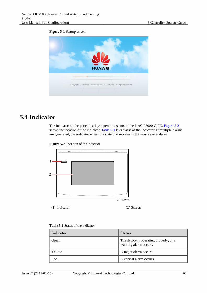
NetCol5000-C030 In-row Chilled Water Smart Cooling
Product
User Manual (Full Configuration) 5 Controller Operate Guide
Issue 07 (2019-01-15) Copyright © Huawei Technologies Co., Ltd. 70
Figure 5-1 Startup screen
5.4 Indicator
The indicator on the panel displays operating status of the NetCol5000-C-FC. Figure 5-2
shows the location of the indicator. Table 5-1 lists status of the indicator. If multiple alarms
are generated, the indicator enters the state that represents the most severe alarm.
Figure 5-2 Location of the indicator
(1) Indicator (2) Screen
Table 5-1 Status of the indicator
Indicator Status
Green The device is operating properly, or a
warning alarm occurs.
Yellow A major alarm occurs.
Red A critical alarm occurs.

NetCol5000-C030 In-row Chilled Water Smart Cooling
Product
User Manual (Full Configuration) 5 Controller Operate Guide
Issue 07 (2019-01-15) Copyright © Huawei Technologies Co., Ltd. 71
The following describes status of the buzzer when different alarms are generated:
Critical alarms: The buzzer is beeping.
Major alarms: The buzzer beeps intermittently every 500 ms.
Warning alarms or no alarms: The buzzer is silent.
5.5 Home screen
After the progress bar in the startup screen is full, the NetCol5000-C-FC enters the home
screen, as shown in Figure 5-3. You can tap the menu items, buttons, or icons on the screen to
enter related screens or perform operations.
Figure 5-3 Home screen
The following describes the icons on the home screen:
The uppermost bar is the status bar, under which is the alarm bar.
You can tap in the status bar to quickly mute the buzzer. Or, you can tap
in the alarm bar to enter the active alarm screen to mute the buzzer. If
you are already in the alarm screen, the buzzer cannot be muted even if you tap
. is changed to after the buzzer is muted.
You can tap in the alarm bar to enter the active alarm screen that
displays all active alarms.
in the status bar indicates that the display panel communicates properly with the main
control board. If is displayed in this position in the status bar, the communication fails.

NetCol5000-C030 In-row Chilled Water Smart Cooling
Product
User Manual (Full Configuration) 5 Controller Operate Guide
Issue 07 (2019-01-15) Copyright © Huawei Technologies Co., Ltd. 72
5.6 Start and Shutdown
Tap the Start or Shutdown buttons on the home screen to start or shutdown the
NetCol5000-C-FC.
Tap Start or Shutdown on the home screen. A warning is displayed, indicating whether to
start or shutdown the NetCol5000-C-FC, as shown in Figure 5-4 and Figure 5-5. Tap Yes. If
the device is successfully started, the system displays a message, indicating that the command
is successfully triggered.
If a power failure occurs and the NetCol5000-C-FC is powered on again, the
NetCol5000-C-FC automatically restores to the original state (start or shutdown) before the
power failure.
Figure 5-4 Starting the NetCol5000-C-FC
Figure 5-5 Shutdown the NetCol5000-C-FC

NetCol5000-C030 In-row Chilled Water Smart Cooling
Product
User Manual (Full Configuration) 5 Controller Operate Guide
Issue 07 (2019-01-15) Copyright © Huawei Technologies Co., Ltd. 73
5.7 Temperature and Humidity Curves
The T/H Curve screen displays temperature and humidity curves showing the recent
temperature and humidity changes. You can choose to display the curves in recent one hour,
one day, seven days, or 30 days.
Tap T/H Curve on the home screen to enter the T/H Curve screen, as shown in Figure 5-6.
The temperature curve (upper) and the humidity curve (lower) are displayed on the same screen. The
Temp set point is the midpoint temperature on the upper ordinate while the humidity set point is the
midpoint humidity on the lower ordinate.
Temperature and humidity curves show the average temperature and humidity of the current control
type.
You can zoom in or out the range of the temperature and humidity ordinate. The midpoint
temperature is the Temp set point of the T/H control type and the midpoint humidity is the humidity
set point of the T/H control type after the ordinate range is zoomed in or out.
The sampling period of the temperature and humidity varies according to the selected time. If the
temperature and humidity curve in the latest 1 hour is required, temperature and humidity data is
collected every 6 seconds. If the temperature and humidity curve in the latest one day is required,
temperature and humidity data is collected every 4 minutes. If the temperature and humidity curve in
the latest seven days is required, temperature and humidity data is collected every 30 minutes. If the
temperature and humidity curve in the latest 30 days is required, temperature and humidity data is
collected every 60 minutes.
You can view the temperatures from (temp set point -3°C) to (temp set point +3°C) at least and from
(temp set point -30°C) to (temp set point +30°C) at most.
You can view the humidity from (humidity set point -5%) to (humidity set point +5%) at least, and
from (humidity set point -50%) to (humidity set point +50%) at most.
Figure 5-6 T/H Curve
5.8 Common Functions
The Common Functions screen displays Status, Operating Info, and Query Hist. Alarms.
Tap Common Functions on the home screen to enter the Common Functions screen, as
shown in Figure 5-7.

NetCol5000-C030 In-row Chilled Water Smart Cooling
Product
User Manual (Full Configuration) 5 Controller Operate Guide
Issue 07 (2019-01-15) Copyright © Huawei Technologies Co., Ltd. 74
Figure 5-7 Common Functions
5.8.1 Status
On the Status screen, you can query operating status of the smart cooling product system,
including chilled water (CW) valve, indoor fan, condensate pump, remote on/off, and element
management system (EMS).
Tap Common Functions > Status on the home screen to enter the Status screen, as shown in
Figure 5-8.
The system on or EMS on function is available only when the remote dry contact is on the status of
system on (The remote dry contact does not connect to anything).
Figure 5-8 Status
5.8.2 Operating Info
The Operating Info screen displays the current detected temperature, humidity, voltage, dew
point temp, and anti-cond protection.

NetCol5000-C030 In-row Chilled Water Smart Cooling
Product
User Manual (Full Configuration) 5 Controller Operate Guide
Issue 07 (2019-01-15) Copyright © Huawei Technologies Co., Ltd. 75
Tap Common Functions > Operating Info on the home screen to enter the Operating Info
screen, as shown in Figure 5-9.
Figure 5-9 Operating Info
5.8.3 Query Historical Alarms
The Query Hist. Alarms screen can display a maximum of 500 historical alarms.
Tap Common Functions > Query Hist. Alarms on the home screen to enter the Query Hist.
Alarms screen, as shown in Figure 5-10.
Historical alarms are displayed based on the time when they are cleared. Alarms that are cleared most
recently are displayed at the top.
Figure 5-10 History Alarm

NetCol5000-C030 In-row Chilled Water Smart Cooling
Product
User Manual (Full Configuration) 5 Controller Operate Guide
Issue 07 (2019-01-15) Copyright © Huawei Technologies Co., Ltd. 76
5.9 Running
On the Running screen, you can query the operating status, system information, and device
list.
Tap Running on the home screen to enter the Running screen, as shown in Figure 5-11.
Figure 5-11 Running
5.9.1 Status
On the Status screen, you can query operating status of the smart cooling product system,
including CW valve, indoor fan, cond pump, remote on/off, and EMS.
Tap Running > Status on the home screen to enter screen as shown in Figure 5-8.
5.9.2 System Information
On the system information screen, you can query the temperature, humidity, voltage, dew
point temp, and anti-cond protection of NetCol5000-C-FC.
Tap Running > System Info on the home screen to enter the system information screen, as
shown in Figure 5-9.
5.9.3 Device Details
On the device Details screen, you can query names and operating status of components of the
NetCol5000-C, including T/H sensor, CW valve, indoor fan, drain device.
Tap Running > Device Details on the home screen to enter the device details screen, as
shown in Figure 5-12.

NetCol5000-C030 In-row Chilled Water Smart Cooling
Product
User Manual (Full Configuration) 5 Controller Operate Guide
Issue 07 (2019-01-15) Copyright © Huawei Technologies Co., Ltd. 77
Figure 5-12 Device details screen
You can tap buttons on the device details screen to query operating status of related devices.
Take cond pump as an example. To query running status of drain device, tap Running >
Device Details > Drain Device on the home screen. Figure 5-13 shows the running status of
cond pump 1, 2, low float, and high float.
Figure 5-13 Screen displaying operating status of drain device
The above takes the cond pump as an example to show the numbering rule for devices. Assume that the
personnel face the temperature control equipment. Cond pump on the left of the personnel is numbered 1
and that on the right of the personnel is numbered 2. This rule applies to other devices as well.
5.10 Alarms
On the Alarms screen, you can query active alarms, query hist alarms and delete hist alarms.
Tap Alarms on the home screen to enter the Alarms screen, as shown in Figure 5-14.

NetCol5000-C030 In-row Chilled Water Smart Cooling
Product
User Manual (Full Configuration) 5 Controller Operate Guide
Issue 07 (2019-01-15) Copyright © Huawei Technologies Co., Ltd. 78
Figure 5-14 Alarms
5.10.1 Query Active Alarms
The query active alarms screen displays active alarms.
Tap Alarms > Query Act. Alarms on the home screen to enter the active alarms screen, as
shown in Figure 5-15.
Active alarms are displayed based on the time when they are generated. Alarms that are generated
most recently are displayed on the top, followed by alarms that are generated earlier.
If active alarms exist, they are displayed on the alarm bar one by one.
On the query active alarms screen you can manually delete the alarms, such as CW valve abnormal
feedback, No refrig output, and Drain abnormal.
You can query an alarm on the alarm list based on the alarm identity (ID) to view causes of the alarm
and methods used to clear the alarm.
Figure 5-15 Active alarm screen

NetCol5000-C030 In-row Chilled Water Smart Cooling
Product
User Manual (Full Configuration) 5 Controller Operate Guide
Issue 07 (2019-01-15) Copyright © Huawei Technologies Co., Ltd. 79
5.10.2 Query Historical Alarms
The Query Hist. Alarms screen displays historical alarms. A maximum of 500 historical
alarms (200 critical alarms, 200 major alarms, and 100 warning alarms) can be displayed.
Tap Alarms > Query Hist. Alarms to enter the Query Hist. Alarms screen, as shown in
Figure 5-16.
Figure 5-16 Query Hist. Alarms
5.10.3 Delete Historical Alarms
The alarm deletion function supports one-click deletion of historical alarms.
Tap Alarms > Delete Hist. Alarms to enter the following screen, as shown in Figure 5-17.
If you need to delete alarms, log in as the Admin user.
Tap Delete Hist. Alarms. A dialog box is displayed, showing Are you sure you want to delete all
historical alarms?. Tap Yes to delete all historical alarms.
Figure 5-17 Deleting alarms

NetCol5000-C030 In-row Chilled Water Smart Cooling
Product
User Manual (Full Configuration) 5 Controller Operate Guide
Issue 07 (2019-01-15) Copyright © Huawei Technologies Co., Ltd. 80
5.11 Settings
Before configuring the system, you need to enter the user name and password on the screen
for logging in to the Settings screen, as shown in Figure 5-18. The system then authenticates
your user permission.
The Settings screen displays User Settings, Comm Settings, Alarm Settings, System
Settings, Basic Settings, and Restore Defaults buttons.
Tap Settings to enter the Settings screen, as shown in Figure 5-19.
The Guest user can only query parameters on screens. If you need to configure parameters, log in as
other types of users.
Take cond pump 1 exceed runtime as an example, tap Settings > Alarm Settings > Drain Device
enter the screen as show in Figure 5-20, select the cond pump 1 exceed runtime and put the
parameters.
When configuring the temperature and humidity parameters or other parameters, do not place the
cursor between the decimal point and the following digit of the value. Otherwise, the decimal point
cannot be deleted, and the parameter value fails to be configured.
After parameters are configured, tap to exit the screen.
Figure 5-18 Screen for logging in to the settings screen

NetCol5000-C030 In-row Chilled Water Smart Cooling
Product
User Manual (Full Configuration) 5 Controller Operate Guide
Issue 07 (2019-01-15) Copyright © Huawei Technologies Co., Ltd. 81
Figure 5-19 Settings
Figure 5-20 Drain device
Figure 5-21 Cond pump 1 exceed runtime

NetCol5000-C030 In-row Chilled Water Smart Cooling
Product
User Manual (Full Configuration) 5 Controller Operate Guide
Issue 07 (2019-01-15) Copyright © Huawei Technologies Co., Ltd. 82
5.11.1 User Settings
Settings Screen
On the user settings screen, you can configure the language, time, and password for the
system, and set the contrast, saturation, and brightness for the LCD.
Tap Settings > User Settings on the home screen to enter the user settings screen, as shown
in Figure 5-22.
Tap items on the user settings screen to configure parameters and query the value range of
parameters.
To perform user settings, log in as the Operator user or other types of users that have higher permission.
Figure 5-22 User settings screen
Changing Password
Tap Password to enter the password setting screen as shown in Figure 5-23.
The user changes only the password for the current user name. The password must be a string of six
digits. Letters and special characters are not supported.

NetCol5000-C030 In-row Chilled Water Smart Cooling
Product
User Manual (Full Configuration) 5 Controller Operate Guide
Issue 07 (2019-01-15) Copyright © Huawei Technologies Co., Ltd. 83
Figure 5-23 Password setting screen
Enter the old password, and tap to enter the new password setting
screen, follow the prompts to enter a new password in order.
5.11.1.1 Setting User Parameters
On the user settings screen, you can configure the language, time, and password for the
system, and set the contrast, saturation, and brightness for the LCD.
Tap Settings > User Settings on the home screen to enter the user settings screen, as shown
in Figure 5-24.
Tap items on the user settings screen to configure parameters and query the value range of
parameters.
To perform user settings, log in as the Operator user or other types of users that have higher
permission.
The user changes only the password for the current user name. The password must be a string of six
digits. Letters and special characters are not supported.

NetCol5000-C030 In-row Chilled Water Smart Cooling
Product
User Manual (Full Configuration) 5 Controller Operate Guide
Issue 07 (2019-01-15) Copyright © Huawei Technologies Co., Ltd. 84
Figure 5-24 User settings screen
5.11.1.2 Restore the Default Password
Context
If a user forgets the changed password, the user can use the DIP switch S2 on the main control
board to restore the password to the default password.
After password restoration is performed, passwords of all users are restored to default ones.
Other users may be affected. Therefore, exercise caution when performing password
restoration.
To ensure device security, operate the DIP switch after powering off the main power
supply of the device.
Procedure
Step 1 Disconnect the main power supply of the device.
Step 2 Set bits 1 and 3 of the DIP switch S2 to ON, and other bits to OFF. Figure 5-25 shows
positions of DIP switches on the main control board.

NetCol5000-C030 In-row Chilled Water Smart Cooling
Product
User Manual (Full Configuration) 5 Controller Operate Guide
Issue 07 (2019-01-15) Copyright © Huawei Technologies Co., Ltd. 85
Figure 5-25 DIP switch position
Step 3 Connect the main power supply of the device.
Wait 30 seconds. All user passwords are restored to the default ones.
Step 4 Disconnect the main power supply of the device.
Step 5 Set all bits of the DIP switch S2 to OFF.
Step 6 Connect the main power supply of the device.
----End
5.11.2 Communications Settings
On the communications settings screen, you can configure the protocol type, baud rate, and
communication address.
Tap Settings > Comm Settings on the home screen to enter the communications settings
screen, as shown in Figure 5-26.
Tap items on the communications settings screen to configure parameters and query the value
range of parameters.
Communications settings define parameters for communication with the northbound devices (the
EMS for example).
You can select only Modbus for Protocol. You can select from 9600, and 19200 for Baud rate. The
value of Comm address ranges from 1 to 255.
The Baud rate and communication address of a single device must be same as that of the EMS.
Communication addresses of two devices must be different.
To perform communications settings, log in as the Operator user or other types of users that have
higher permission.

NetCol5000-C030 In-row Chilled Water Smart Cooling
Product
User Manual (Full Configuration) 5 Controller Operate Guide
Issue 07 (2019-01-15) Copyright © Huawei Technologies Co., Ltd. 86
Figure 5-26 Communications settings screen
5.11.3 Alarm Settings
On the alarm settings screen, you can configure alarms for the T/H sensor, main board, CW
valve, indoor fan, drain device, and cooling system.
Tap Settings > Alarm Settings on the home screen to enter the alarm settings screen, as
shown in Figure 5-27.
Alarm settings including choosing the action for the alarm. The action for the alarms include
allow, block and disallow.
If alarms are allowed, they can be reported to the EMS. Active alarms are displayed on
the LCD and the system performs related protection actions.
If alarms are blocked, new alarms cannot be reported to the EMS. However, the EMS
can detect alarms that are generated before alarms are blocked. Active alarms are
displayed on the LCD and the system performs related protection actions.
If alarms are disallowed, they are not detected and no protection actions are performed.
If you need to change alarm settings, log in as Admin or Engineer users. Other types of users can only
query alarm parameters.

NetCol5000-C030 In-row Chilled Water Smart Cooling
Product
User Manual (Full Configuration) 5 Controller Operate Guide
Issue 07 (2019-01-15) Copyright © Huawei Technologies Co., Ltd. 87
Figure 5-27 Alarm settings screen
Be careful when configuring alarms. Only professional maintenance personnel can change
alarm settings.
You can tap buttons for related devices on the alarm settings screen to configure alarm
parameters.
The following describes how to configure alarms by taking the configuration of T/H sensor as
an example. Tap Settings > Alarm Settings > T/H Sensor on the home screen to enter T/H
sensor screen, as shown in Figure 5-28.
The supply-air high temperature (HT) alarm threshold plus 5°C cannot be greater than the return-air
HT alarm threshold.
The supply-air HT alarm threshold plus 5°C cannot be greater than the hot aisle HT alarm threshold.
The cold aisle HT alarm threshold plus 5°C cannot be greater than the hot aisle HT alarm threshold.
The cold aisle HT alarm threshold plus 5°C cannot be greater than the return air HT alarm threshold.
The supply-air low temperature (LT) alarm threshold plus 5°C cannot be greater than the return-air
LT alarm threshold.
The supply-air LT alarm threshold plus 5°C cannot be greater than the hot aisle LT alarm threshold.
The cold aisle LT alarm threshold plus 5°C cannot be greater than the hot aisle LT alarm threshold.
The cold aisle LT alarm threshold plus 5°C cannot be greater than the return air LT alarm threshold.

NetCol5000-C030 In-row Chilled Water Smart Cooling
Product
User Manual (Full Configuration) 5 Controller Operate Guide
Issue 07 (2019-01-15) Copyright © Huawei Technologies Co., Ltd. 88
Figure 5-28 T/H Sensor
5.11.4 System Settings
On the system settings screen, you can configure the system control, T/H sensor, CW valve,
indoor fan, and drain device.
Tap Settings > System Settings on the home screen to enter the system settings screen, as
shown in Figure 5-29.
Figure 5-29 System settings screen
If you need to change system settings, log in as users that have related permission. Except for
temperature and humidity items, only professional maintenance personnel are allowed to configure
related items.
System Control
On the system control screen, you can configure monitoring mode, unit start delay, disallow
on/off via EMS, dehumidification, MAX dehumid runtime, dew/sup water TD at dehumi,
anti-cond protection, anti-cond temp diff, anti-cond delay, and max diagnos mode duration.

NetCol5000-C030 In-row Chilled Water Smart Cooling
Product
User Manual (Full Configuration) 5 Controller Operate Guide
Issue 07 (2019-01-15) Copyright © Huawei Technologies Co., Ltd. 89
Tap Settings > System Settings > System Control on the home screen to enter the system
control screen, as shown in Figure 5-30.
Figure 5-30 System control screen
Tap items on the system control screen to configure parameters and query the value range of
parameters.
Log in as the Engineer user or other types of users that have higher permission.
Monitor mode defines the mode used by the EMS to monitor the NetCol5000-C-FC. The preset
mode is Single monitor.
Single Start delay defines the delay required by a NetCol5000-C-FC to respond to the operating
status delivered by the controller after the NetCol5000-C-FC is started. The value range of Single
Start delay is from 1s to 60s. The preset delay is 10s.
If EMS Start/off forbid is set to Yes, you cannot use the EMS to start or shut down the
NetCol5000-C-FC.
T/H Sensor
On the T/H sensor screen, you can configure T/H control type, supply-air temp set point,
supply-air humid set point, return-air temp set point, return-air humid set point, cold aisle
temp set point, cold aisle humid set point, hot aisle temp set point, hot aisle humid set point,
temp sampling period, temp p-band, temp deadband, temp p-coefficient, temp integ time
constant, temp diff time constant, humid sampling period, humid p-band, humid deadband,
humid p-coefficient, humid integ time constant, humid diff time constant, cold aisle sensor 1,
cold aisle sensor 2, cold aisle sensor 3, hot aisle sensor 1, hot aisle sensor 2, and hot aisle
sensor 3.
Tap Settings > System Settings > T/H Sensor on the home screen to enter the T/H sensor
screen, as shown in Figure 5-31.

NetCol5000-C030 In-row Chilled Water Smart Cooling
Product
User Manual (Full Configuration) 5 Controller Operate Guide
Issue 07 (2019-01-15) Copyright © Huawei Technologies Co., Ltd. 90
Figure 5-31 T/H Sensor
On the T/H sensor screen, the value range of parameters are displayed on the screen when you
click the corresponding items to set a parameter, take the cold aisle of T/H sensor as an
example, T/H control type select Cold aisle, cold aisle sensor select enable, as shown in
Figure 5-32.
Figure 5-32 T/H Sensor

NetCol5000-C030 In-row Chilled Water Smart Cooling
Product
User Manual (Full Configuration) 5 Controller Operate Guide
Issue 07 (2019-01-15) Copyright © Huawei Technologies Co., Ltd. 91
The Guest user can only query parameters on the temperature control screen. If you need to change
parameter values, log in as the Operator user or other types of users that have higher permission.
T/H control type is set to Supply-air by default.
You can only set the temperature and humidity set point whose control type are the same as the T/H
control type. Other Temperature and humidity set points are displayed in gray.
CW Valve
On the CW valve screen, you can configure the max adjust step, min valve opening for dehum,
anti-cond val regu ratio, and temp diff at no refrig.
Tap Settings > System Settings > CW Valve on the home screen to enter the CW valve
screen, as shown in Figure 5-33.
Figure 5-33 CW valve screen
Tap items on the CW valve screen to configure parameters and query the valve range of
parameters.
If you need to change CW valve settings, log in as the Admin user or other types of users that have
higher permission.
Indoor Fan Settings
On the indoor fan settings screen, you can configure the min speed, max speed, normal adjust
period, max adjust step, min ret/sup air temp diff, max ret/sup air temp diff, and max dehumid
speed.
Tap Settings > System Settings > Indoor Fan on the home screen to enter the settings screen,
as shown in Figure 5-34.

NetCol5000-C030 In-row Chilled Water Smart Cooling
Product
User Manual (Full Configuration) 5 Controller Operate Guide
Issue 07 (2019-01-15) Copyright © Huawei Technologies Co., Ltd. 92
Figure 5-34 Fan settings screen
Tap items on the Indoor fan settings screen to configure related parameters.
If you need to change fan settings, log in as the Engineer user or other types of users that have
higher permission.
Min speed cannot be greater than Max speed.
Min ret/sup air temp diff cannot be greater than Max ret/sup air temp diff.
Drain Device Settings
On the drain device settings screen, you can configure the low float fall pump off delay, high
float fall pump off delay, low float rise delay, high float rise delay, full water signal delay, l-flt
rise stdby pump on delay.
Tap Settings > System Settings > Drain Device on the home screen to enter the drain device
settings screen, as shown in Figure 5-35.
Figure 5-35 Drain device Settings
Tap items on the drain device settings screen to configure related parameters.

NetCol5000-C030 In-row Chilled Water Smart Cooling
Product
User Manual (Full Configuration) 5 Controller Operate Guide
Issue 07 (2019-01-15) Copyright © Huawei Technologies Co., Ltd. 93
You need to log in as the Admin user when changing drain device settings.
Low float fall pump off delay cannot be greater than High float fall pump off delay.
High float rise delay cannot be greater than Low float rise delay.
L-flt rise stdby pump on delay cannot be greater than Low float rise delay.
5.11.5 Basic Settings
Context
On the basic settings screen, you can set the language, time, date, and system.
Tap Settings > Basic Settings on the home screen to enter the basic settings screen.
The Guest user can perform basic settings only after the NetCol5000-C-FC is powered on for the first
time. Otherwise, if you need to perform basic settings, please log in as the Operator user or other types
of users that have higher permission.
Procedure
Step 1 Tap Settings > Basic Settings on the home screen to enter the language settings screen. You
can select from and , as shown in Figure 5-36.
Figure 5-36 Language Setting
Step 2 After the language is configured, tap Next to enter the Date & Time Settings screen, as
shown in Figure 5-37.
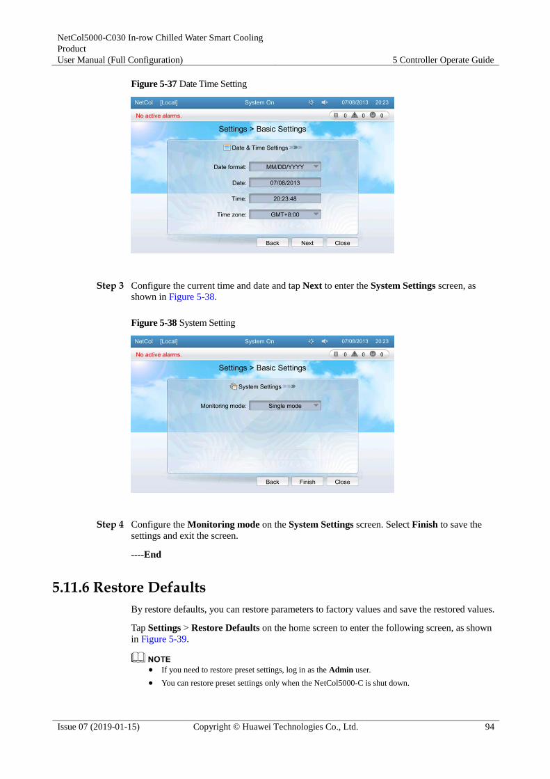
NetCol5000-C030 In-row Chilled Water Smart Cooling
Product
User Manual (Full Configuration) 5 Controller Operate Guide
Issue 07 (2019-01-15) Copyright © Huawei Technologies Co., Ltd. 94
Figure 5-37 Date Time Setting
Step 3 Configure the current time and date and tap Next to enter the System Settings screen, as
shown in Figure 5-38.
Figure 5-38 System Setting
Step 4 Configure the Monitoring mode on the System Settings screen. Select Finish to save the
settings and exit the screen.
----End
5.11.6 Restore Defaults
By restore defaults, you can restore parameters to factory values and save the restored values.
Tap Settings > Restore Defaults on the home screen to enter the following screen, as shown
in Figure 5-39.
If you need to restore preset settings, log in as the Admin user.
You can restore preset settings only when the NetCol5000-C is shut down.

NetCol5000-C030 In-row Chilled Water Smart Cooling
Product
User Manual (Full Configuration) 5 Controller Operate Guide
Issue 07 (2019-01-15) Copyright © Huawei Technologies Co., Ltd. 95
Tap Restore Defaults and then tap Yes. Parameters, except the current setting parameters, are
restored to the factory values. Perform this operation with caution.
When the restore defaults setting is done, the system would start automatically.
Figure 5-39 Screen for restoring preset settings
5.12 Teamwork Settings
Teamwork control is a solution for allocating the overall cooling and humidification capacity
of the data center, improving the usage efficiency of the smart cooling products by preventing
random operation. Multiple NetCol5000-Cs are interconnected and controlled in a central
control mode. In this manner, the teamwork function and rotation of the master and slave
NetCol5000-Cs can be implemented. A maximum of 32 NetCol5000-C can be interconnected
using the CAN bus bar. The device with the teamwork address as 1 is the master one, which
collects, processes, and delivers data.
Teamwork setting home page
After the teamwork is set successfully, the teamwork home page will be displayed as shown
in Figure 5-40.
Figure 5-40 Teamwork topology

NetCol5000-C030 In-row Chilled Water Smart Cooling
Product
User Manual (Full Configuration) 5 Controller Operate Guide
Issue 07 (2019-01-15) Copyright © Huawei Technologies Co., Ltd. 96
Table 5-2 Note for the page
No. Parameters Note
1 ON/OFF/NA ON indicates the NetCol5000-C is started and OFF
indicates the opposite. NA indicates the
NetCol5000-C is off-line.
2 01/02/03... Indicates the device address. 01 is the master one
and the rest are all slave ones.
3 Active/Standby Active indicates the active device and Standby
indicates the standby device (shut down), which is
started when activated or used in cascaded mode.
4 Frame:
green/non-green
A device with green frame indicates the device
itself, a non-green frame indicates the others.
5 Ground color: red,
bright grey, dark grey
Red indicates that a critical alarm is generated;
bright grey indicates that the device is operating
without any critical alarms; dark grey indicates that
the device is off-line.
Teamwork Settings
Set the teamwork function on the teamwork setting page. Parameters to be set for the master
device include Teamwork unit no., Teamwork unit address, Teamwork function,
Network, Total number of units, Number of running units, Standby mode rotation,
Rotation period, Rotation time, Forced rotation, and Requirement control and Cascade.
Click > Teamwork Settings on the home screen to enter pages shown in Figure
5-41 and Figure 5-42.
If you need to change teamwork settings, log in as the Admin or Engineer.
Figure 5-41 Teamwork setting page 1

NetCol5000-C030 In-row Chilled Water Smart Cooling
Product
User Manual (Full Configuration) 5 Controller Operate Guide
Issue 07 (2019-01-15) Copyright © Huawei Technologies Co., Ltd. 97
Figure 5-42 Teamwork setting page 2
Table 5-3 Teamwork settings
Parameter Description Configuration Principle
Teamwork unit
no.
A maximum of four groups (1 to
4) can be set.
Group the temperature control
devices in adjacent areas as one,
that is, assign one group number
for them.
Teamwork unit
address
Set an address (1 to 32) for each
temperature control device in
each group. Devices in the same
group cannot have the same
address and the address of the
master device in each group
should be 1.
Only one device in each group
can be set to 1.
Teamwork
function
Disable or enable the teamwork
function. If disabled, this device
is operating according to its own
control. If enabled, this device
works in harmony with others
that in the same group.
Set this parameter based on the
onsite device heat distribution.
Network Networking mode for the
teamwork.
Networked over CAN.
Total number of
units
Number of the temperature
control devices in this group (1 to
32 can be set).
Total number of the temperature
control devices in this group
Number of
running units
Number of the active devices (1
to [total number of units] can be
set). If the number is more than
the range, the excessive one(s)
cannot be group-controlled. If one
address is vacant, the topology
will display that the device is
Assign the devices to be active
ones by the device number,
beginning with the master one.
The rest will become the standby
ones.
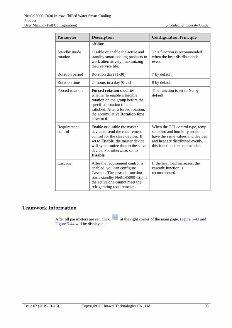
NetCol5000-C030 In-row Chilled Water Smart Cooling
Product
User Manual (Full Configuration) 5 Controller Operate Guide
Issue 07 (2019-01-15) Copyright © Huawei Technologies Co., Ltd. 98
Parameter Description Configuration Principle
off-line.
Standby mode
rotation
Disable or enable the active and
standby smart cooling products to
work alternatively, maximizing
their service life.
This function is recommended
when the heat distribution is
even.
Rotation period Rotation days (1-30) 7 by default
Rotation time 24 hours in a day (0-23) 0 by default
Forced rotation Forced rotation specifies
whether to enable a forcible
rotation on the group before the
specified rotation time is
satisfied. After a forced rotation,
the accumulative Rotation time
is set to 0.
This function is set to No by
default.
Requirement
control
Enable or disable the master
device to send the requirement
control for the slave devices. If
set to Enable, the master device
will synchronize data to the slave
device. For otherwise, set to
Disable.
When the T/H control type, temp
set point and humidity set point
have the same values and devices
and heat are distributed evenly,
this function is recommended.
Cascade After the requirement control is
enabled, you can configure
Cascade. The cascade function
starts standby NetCol5000-C(s) if
the active one cannot meet the
refrigerating requirements.
If the heat load increases, the
cascade function is
recommended.
Teamwork Information
After all parameters are set, click at the right corner of the main page. Figure 5-43 and
Figure 5-44 will be displayed.

NetCol5000-C030 In-row Chilled Water Smart Cooling
Product
User Manual (Full Configuration) 5 Controller Operate Guide
Issue 07 (2019-01-15) Copyright © Huawei Technologies Co., Ltd. 99
Figure 5-43 Teamwork information page 1
Figure 5-44 Teamwork information page 2
Information in Master/Slave and Active/Standby is only about this single device. Other information is
about the group.
5.13 Maintenance
The Maint screen consists of Diagnostic Mode, Log Maint, Performance Maint, Sensor
Adjust, Screen Calib, and USB Operations.
Tap Maint on the home screen to enter the Maint screen, as shown in Figure 5-45.

NetCol5000-C030 In-row Chilled Water Smart Cooling
Product
User Manual (Full Configuration) 5 Controller Operate Guide
Issue 07 (2019-01-15) Copyright © Huawei Technologies Co., Ltd. 100
Figure 5-45 Maintain
5.13.1 Diagnostic Mode
On the diagnostic mode screen, you can enable or disable various components, control the
speed of indoor fans and CW valve.
Tap Maint > Diagnostic Mode on the home screen to enter the diagnostic mode screen, as
shown in Figure 5-46.
If you need to manually power on or off system components in diagnostic mode, log in as the
Operator user or users that have higher permission. Ensure that the NetCol5000-C is powered on
before operation.
You cannot enter the diagnostic mode if the NetCol5000-C is shut down.
After entering the diagnostic mode, tap on the status bar to exit the diagnostic mode.
Tap Enter on the diagnostic mode screen and then tap Yes to enter the diagnostic mode, as shown in
Figure 5-47 and Figure 5-48.
Tap Exit on the diagnostic mode screen and then tap Yes to exit the diagnostic mode, as shown in
Figure 5-49.
The system automatically exits the diagnostic mode after cumulative 60 minutes.
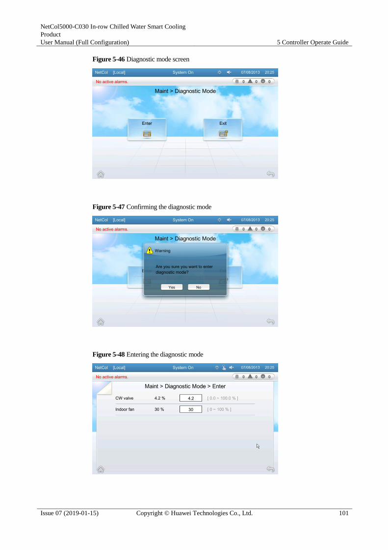
NetCol5000-C030 In-row Chilled Water Smart Cooling
Product
User Manual (Full Configuration) 5 Controller Operate Guide
Issue 07 (2019-01-15) Copyright © Huawei Technologies Co., Ltd. 101
Figure 5-46 Diagnostic mode screen
Figure 5-47 Confirming the diagnostic mode
Figure 5-48 Entering the diagnostic mode

NetCol5000-C030 In-row Chilled Water Smart Cooling
Product
User Manual (Full Configuration) 5 Controller Operate Guide
Issue 07 (2019-01-15) Copyright © Huawei Technologies Co., Ltd. 102
Figure 5-49 Exiting the diagnostic mode
5.13.2 Log Maintenance
On the log maintenance screen, you can query or delete logs. Logs record operations on the
system. Therefore, maintenance and technical service engineers can query logs to locate
operations on the system. You can delete logs in a one-click manner.
Tap Maint > Log Maint > Query Logs on the home screen to enter the log query screen, as
shown in Figure 5-50.
Tap Maint > Log Maint > Delete Logs on the home screen to enter the following screen, as
shown in Figure 5-51. Tap Yes to delete logs.
If you need to query logs, log in as the Operator user or other types of users that have higher
permission.
The log query screen displays 200 logs that are generated recently.
The operation, operation value, location, operation source, date and time, and user name of a log are
displayed.

NetCol5000-C030 In-row Chilled Water Smart Cooling
Product
User Manual (Full Configuration) 5 Controller Operate Guide
Issue 07 (2019-01-15) Copyright © Huawei Technologies Co., Ltd. 103
If you need to delete logs, log in as the Admin user. Be careful when deleting logs so that
device maintenance is not affected.
Exercise cautions when tap Delete Logs because all logs are deleted once you perform the
operation.
After logs are deleted, the log deletion operation is recorded in the first log that is
displayed.
Figure 5-50 Log query screen
Figure 5-51 Log deletion screen
5.13.3 Performance Maintenance
On the performance maintenance screen, you can query the accumulated running time of main
components and clear accumulated running time of certain values.
Tap Maint > Perform Maint on the home screen to enter the performance maintenance
screen, as shown in Figure 5-52.

NetCol5000-C030 In-row Chilled Water Smart Cooling
Product
User Manual (Full Configuration) 5 Controller Operate Guide
Issue 07 (2019-01-15) Copyright © Huawei Technologies Co., Ltd. 104
Tap Clear on the performance maintenance screen to clear the value of a parameter.
If you need to clear the value of a performance parameter, log in as the Admin or Engineer user.
Figure 5-52 Performance maintenance screen
5.13.4 Sensor Adjust
On the sensor adjust screen, you can configure the temperature and humidity deviations to
adjust the temperature and humidity collection board. If the temperature and humidity adjust
values for the return air are set to 5°C and 3% respectively, and the temperature and humidity
detected by the T/H sensor collection board are set to T and H respectively, calculate as
follows: Required return-air temperature = T + 5°C; Required return-air humidity = H + 3%.
Tap Maint > Sensor Adjust on the home screen to enter the sensor adjust screen, as shown in
Figure 5-53.
If you need to adjust the sensor, log in as the Engineer user or other types of users that have higher
permission.
Figure 5-53 Sensor adjust screen

NetCol5000-C030 In-row Chilled Water Smart Cooling
Product
User Manual (Full Configuration) 5 Controller Operate Guide
Issue 07 (2019-01-15) Copyright © Huawei Technologies Co., Ltd. 105
5.13.5 Screen Calibration
You can calibrate the screen by tapping the screen on the Screen Calib page or by DIP
switch.
Tapping the Screen on the Screen Calib Page
Prerequisite: The program of the display board works normally; the deviation between the
touching point and the responding point is small; the Screen Calib page can be entered over
the screen.
Tap Maint > Screen Calib to enter the following screen, as shown in Figure 5-54. Figure
5-55 is displayed when the screen calibration is complete.
Figure 5-54 Screen calibration page
Figure 5-55 Screen displayed when the calibration is complete

NetCol5000-C030 In-row Chilled Water Smart Cooling
Product
User Manual (Full Configuration) 5 Controller Operate Guide
Issue 07 (2019-01-15) Copyright © Huawei Technologies Co., Ltd. 106
Calibrating the Screen by DIP Switch
Prerequisite: The display board works normally; the deviation between the touching point and
the responding point is unfavorably big; or the screen does not respond when being tapped.
You can calibrate the screen by DIP switch only when the device is powered on for the
first time or only on the home page.
After the screen calibration is complete, flip all the toggle switches to OFF.
The toggle switches for the screen as shown by 3 in Figure 5-57. Flip the fourth toggle switch
to ON↓ and the rest to the opposite to calibrate the screen.
In 15 seconds, a dialog box indicating Are you sure you want to calibrate the screen? If
you do not process Yes or No, calibration will start automatically 10 seconds later. is
displayed, as shown in Figure 5-56.
Figure 5-56 Confirming to calibrate the screen
Tap Yes to enter the page shown in Figure 5-54. Tap the screen. Screen is displayed as Figure
5-55 when the calibration is complete.
5.13.6 USB Operations
Context
USB operations provide easy access for users to update controller programs.
Before the upgrade, connect the USB port of the controller LCD first. Figure 5-57 shows the
ports on the controller LCD.

NetCol5000-C030 In-row Chilled Water Smart Cooling
Product
User Manual (Full Configuration) 5 Controller Operate Guide
Issue 07 (2019-01-15) Copyright © Huawei Technologies Co., Ltd. 107
Figure 5-57 Ports on the controller LCD
(1) USB port (for
upgrade only)
(2) Communication port between main control and LCD
(connected before delivery)
(3) DIP switch on LCD
After the system is restarted, do not power off the system within 5 minutes. Otherwise, the
system fails to be upgraded.
Do not use the element management system (EMS) or remote to start the NetCol5000-C
during upgrade.
After the USB flash drive is successfully connected to the display panel, is displayed in the
status bar.
Controller programs can be upgraded only when the device is shut down completely.
Procedure
Step 1 Copy the update file to the USB flash drive. Format the file system of the USB flash drive to
FAT or FAT32. Insert the USB flash drive into the USB port on the display panel. If the USB
flash drive is successfully identified, the following message is displayed, as shown in Figure
5-58.

NetCol5000-C030 In-row Chilled Water Smart Cooling
Product
User Manual (Full Configuration) 5 Controller Operate Guide
Issue 07 (2019-01-15) Copyright © Huawei Technologies Co., Ltd. 108
Figure 5-58 Message displayed after the USB flash drive is identified
Step 2 Tap Maint > USB Operations > Version Upgrade on the home screen. The following
screen is displayed, as shown in Figure 5-59.
Figure 5-59 Screen for upgrading software
If you need to use the version update, please log in by the Admin user permission.
Step 3 Tap Search, the Select File screen is displayed. The system scans the USB flash drive for
files and displays the identified files in the Select File screen, as shown in Figure 5-60. Tap
the update file and then tap Next to upload the file, as shown in Figure 5-61.

NetCol5000-C030 In-row Chilled Water Smart Cooling
Product
User Manual (Full Configuration) 5 Controller Operate Guide
Issue 07 (2019-01-15) Copyright © Huawei Technologies Co., Ltd. 109
Figure 5-60 File Selection
Figure 5-61 Copying data
Step 4 After the file is successfully uploaded, the Version Upgrade window is displayed, as shown
in Figure 5-62. Select the software to be upgrade and tap Update.

NetCol5000-C030 In-row Chilled Water Smart Cooling
Product
User Manual (Full Configuration) 5 Controller Operate Guide
Issue 07 (2019-01-15) Copyright © Huawei Technologies Co., Ltd. 110
Figure 5-62 Software Upgrade
Step 5 During the upgrading process, the system displays the upgrading progress, as shown in Figure
5-63.
Figure 5-63 Information displayed during the upgrading process
Step 6 Figure 5-64 is displayed if the software is successfully upgraded. Figure 5-65 is displayed if
the software fails to be upgraded.

NetCol5000-C030 In-row Chilled Water Smart Cooling
Product
User Manual (Full Configuration) 5 Controller Operate Guide
Issue 07 (2019-01-15) Copyright © Huawei Technologies Co., Ltd. 111
Figure 5-64 Screen displayed when the software is successfully upgraded
Figure 5-65 Screen displayed when the software fails to be upgraded
Step 7 After the software is activated, the system automatically restarts. The control board and
display panel also restart.
Step 8 Remove the USB flash drive after the system is successfully upgraded. Tap Maint > USB
Operations > Remove USB on the home screen. A message is displayed, as shown in Figure
5-66.
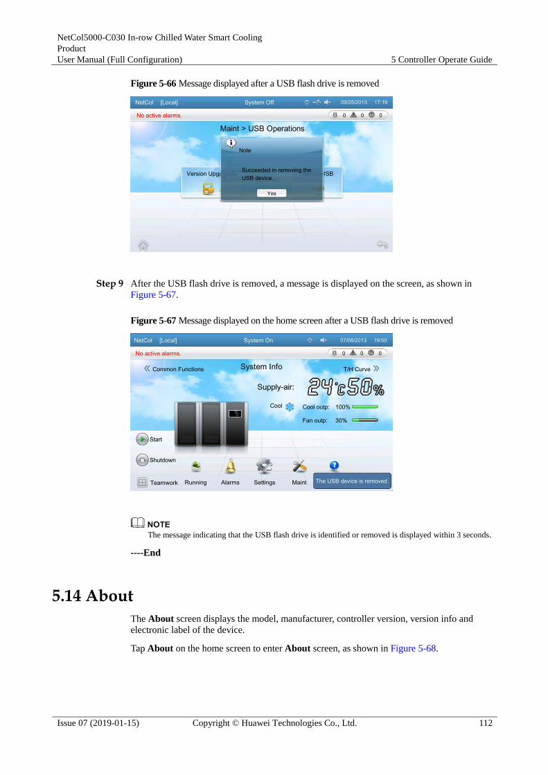
NetCol5000-C030 In-row Chilled Water Smart Cooling
Product
User Manual (Full Configuration) 5 Controller Operate Guide
Issue 07 (2019-01-15) Copyright © Huawei Technologies Co., Ltd. 112
Figure 5-66 Message displayed after a USB flash drive is removed
Step 9 After the USB flash drive is removed, a message is displayed on the screen, as shown in
Figure 5-67.
Figure 5-67 Message displayed on the home screen after a USB flash drive is removed
The message indicating that the USB flash drive is identified or removed is displayed within 3 seconds.
----End
5.14 About
The About screen displays the model, manufacturer, controller version, version info and
electronic label of the device.
Tap About on the home screen to enter About screen, as shown in Figure 5-68.

NetCol5000-C030 In-row Chilled Water Smart Cooling
Product
User Manual (Full Configuration) 5 Controller Operate Guide
Issue 07 (2019-01-15) Copyright © Huawei Technologies Co., Ltd. 113
Figure 5-68 About
The Version Info screen displays the version of display panel, control panel, T/H board, Tap
Version Info on the About screen to enter Version Info screen, as shown in Figure 5-69.
Figure 5-69 Version Info
The E-Label screen displays electronic labels of the entire system, main control board, and
display panel, on the About screen to tap E-label to enter the E-label screen as shown in
Figure 5-70.

NetCol5000-C030 In-row Chilled Water Smart Cooling
Product
User Manual (Full Configuration) 5 Controller Operate Guide
Issue 07 (2019-01-15) Copyright © Huawei Technologies Co., Ltd. 114
Figure 5-70 E-label

NetCol5000-C030 In-row Chilled Water Smart Cooling
Product
User Manual (Full Configuration) 6 System Operation and Maintenance
Issue 07 (2019-01-15) Copyright © Huawei Technologies Co., Ltd. 115
6 System Operation and Maintenance
6.1 Routine Maintenance
6.1.1 Routine Maintenance Overview
Definition
Routine maintenance refers to preventive and periodic check and maintenance carried out to
promptly identify and handle alarms and potential faults during the normal operation of the
equipment.
Precautions Routine maintenance is critical to the normal operation of equipment. Perform routine
maintenance regularly. Read the precautions and product documentation before
performing routine maintenance.
Follow local laws and safety instructions to minimize the risk of personal injury and
damage to equipment.
The "NOTICE", "CAUTION", "WARNING", and "DANGER" statements in this
document do not represent all safety instructions. They are only supplements to the
safety instructions.
Personnel who will install, operate, and maintain Huawei equipment must receive
thorough training, understand all necessary safety precautions, and be able to correctly
perform all operations.
Pay attention to the safety symbols on the equipment and all safety instructions in this
document. The safety precautions given in this document do not cover all safety
precautions. Huawei will not be liable for any consequence caused by violation of the
safety operation regulations and design, production, and usage standards.
Most maintenance tasks should be performed only after the power supply is disconnected
from the equipment. Do not connect the power supply during maintenance. If you need
to perform maintenance tasks such as measuring the current, voltage, and temperature
when the equipment is operating, connect the power supply only after you have finished
all equipment connections. Disconnect the power supply when you finish maintenance.
Take protective measures during electrical maintenance, such as wearing insulation
gloves and shoes.
Exercise caution when performing professional maintenance tasks. For details, consult Huawei technical support.

NetCol5000-C030 In-row Chilled Water Smart Cooling
Product
User Manual (Full Configuration) 6 System Operation and Maintenance
Issue 07 (2019-01-15) Copyright © Huawei Technologies Co., Ltd. 116
During component replacement, do not lean any material against the cabinet.
6.1.2 Electrical Control Box Component Maintenance
Context
Components of an electrical control box include main control board, terminal block, circuit
breakers, SPD, AC contactor, relay, and transformer. To maintain the preceding components.
Figure 6-1 shows the electrical control box components.
Figure 6-1 Electrical control box components
(1) Main control
board
(2) Circuit
breaker
(3) Relay, SPD, AC contractor(from left to
right)
(4) Transformer (5) Transformer (6) Terminal block
Procedure
Step 1 Remove the cover of the electrical control box and all terminals.
Step 2 Loosen two screws on the upper part of the electrical control box.
Step 3 Pull the electrical control box out.

NetCol5000-C030 In-row Chilled Water Smart Cooling
Product
User Manual (Full Configuration) 6 System Operation and Maintenance
Issue 07 (2019-01-15) Copyright © Huawei Technologies Co., Ltd. 117
The electrical control box is about 16 kg weight. Exercise caution when pull it out.
Step 4 Put the electrical control box on a flat floor and remove the electrical control box cover.
(Remove the upper part and then the lower part.)
Step 5 Maintain or replace components in the electrical control box.
Step 6 Install the electrical control box in an inverse order.
----End
6.1.3 Air Filter Maintenance
Table 6-1 lists the air filter monthly maintenance items.
Table 6-1 Air filter monthly maintenance item
No. Operations Troubleshooting Remarks
1 Clean the air filters with
water.
Clean the air filters with
water or replace the air
filters (for details, see
6.4.3 Replacing an Air
Filter)
Perform the operations
with the power off.
2 Check whether the air
filter is damaged or
deformed.
Replace an air filter by
referring to 6.4.3
Replacing an Air Filter if
necessary.
Perform the operations
with the power off.
3 Check whether the
differential pressure
sensor of the air filter
works properly.
1. Switch on the
external power
supply circuit
breaker. After the
unit operates
normally, choose
Settings > Alarm
settings > Main
Board to Enable the
alarm function of the
differential pressure
switch.
2. Block 75% of the air
return vent with
plastic material or
baffle plate. If the air
filter blocking alarm
is generated, the differential pressure
Check whether the
pressure tube of the air
filter clogging switch is
fixed properly. (The
pressure tube is fixed
under the air filter, and it
is on the right side of the
unit.) If the fault is not
rectified, contact Huawei
technical support to
replace the air filter
clogging switch.
Perform the operations
with the power on.

NetCol5000-C030 In-row Chilled Water Smart Cooling
Product
User Manual (Full Configuration) 6 System Operation and Maintenance
Issue 07 (2019-01-15) Copyright © Huawei Technologies Co., Ltd. 118
No. Operations Troubleshooting Remarks
sensor is working
properly. If the air
filter blocking alarm
is not generated,
check whether the
differential pressure
tube is correctly
connected.
6.1.4 Condensate Pump Maintenance
Table 6-2 lists the condensate pump monthly maintenance items.
Table 6-2 Condensate pump monthly maintenance item
No. Operations Troubleshooting Remarks
1 Check that screws fastening the
condensate pump are securely
connected.
Secure the screws
tightly.
Perform the
operations with the
power off.
2 Switch on the external power supply
circuit breaker. After the unit
operates normally do as follows.
Raise the high float, choose
Running > Status on the
controller to confirm that the float
status is ON.
Choose Alarms > Query Hist.
Alarms on the controller to check
if there are condensate pump
alarms and clear the alarms.
If the float status
is not ON,
replace the water
pump, see 6.4.4
Replacing a
Condensate
Pump.
Clear the
condensate pump
alarms by
referring to 6.2
Alarm
Reference.
Perform the
operations with the
power on.
3 Check whether two water pumps
drain water properly.
If a pump cannot
drain water, replace
the water pump, see
6.4.4 Replacing a
Condensate Pump.
Perform the
operations with the
power on.
6.1.5 Indoor Fan Maintenance
Table 6-3 lists the indoor fan monthly maintenance items.
Table 6-3 Indoor fan monthly maintenance item
No. Operations Troubleshooting Remarks
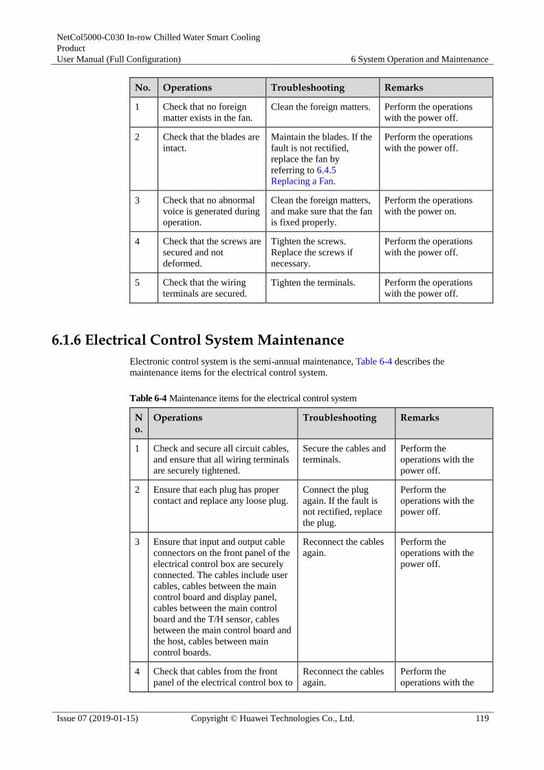
NetCol5000-C030 In-row Chilled Water Smart Cooling
Product
User Manual (Full Configuration) 6 System Operation and Maintenance
Issue 07 (2019-01-15) Copyright © Huawei Technologies Co., Ltd. 119
No. Operations Troubleshooting Remarks
1 Check that no foreign
matter exists in the fan.
Clean the foreign matters. Perform the operations
with the power off.
2 Check that the blades are
intact.
Maintain the blades. If the
fault is not rectified,
replace the fan by
referring to 6.4.5
Replacing a Fan.
Perform the operations
with the power off.
3 Check that no abnormal
voice is generated during
operation.
Clean the foreign matters,
and make sure that the fan
is fixed properly.
Perform the operations
with the power on.
4 Check that the screws are
secured and not
deformed.
Tighten the screws.
Replace the screws if
necessary.
Perform the operations
with the power off.
5 Check that the wiring
terminals are secured.
Tighten the terminals. Perform the operations
with the power off.
6.1.6 Electrical Control System Maintenance
Electronic control system is the semi-annual maintenance, Table 6-4 describes the
maintenance items for the electrical control system.
Table 6-4 Maintenance items for the electrical control system
No.
Operations Troubleshooting Remarks
1 Check and secure all circuit cables,
and ensure that all wiring terminals
are securely tightened.
Secure the cables and
terminals.
Perform the
operations with the
power off.
2 Ensure that each plug has proper
contact and replace any loose plug.
Connect the plug
again. If the fault is
not rectified, replace
the plug.
Perform the
operations with the
power off.
3 Ensure that input and output cable
connectors on the front panel of the
electrical control box are securely
connected. The cables include user
cables, cables between the main
control board and display panel,
cables between the main control
board and the T/H sensor, cables
between the main control board and
the host, cables between main
control boards.
Reconnect the cables
again.
Perform the
operations with the
power off.
4 Check that cables from the front
panel of the electrical control box to
Reconnect the cables
again.
Perform the
operations with the

NetCol5000-C030 In-row Chilled Water Smart Cooling
Product
User Manual (Full Configuration) 6 System Operation and Maintenance
Issue 07 (2019-01-15) Copyright © Huawei Technologies Co., Ltd. 120
No.
Operations Troubleshooting Remarks
fans, humidity and temperature
sensors, power supplies, chilled
water valves, condensate pump,
high and low float switches, water
sensors, and air filter block switch
are securely connected.
power off.
5 Use a brush or compressed dry air
to clean various electric
components, control components,
the main control board, and the
surge protection and voltage test
board.
N/A Perform the
operations with the
power off.
6 Check whether the display panel,
humidity and temperature sensor or
cables is aging on the surface.
Replace the
components or cables.
Perform the
operations with the
power off.
6.2 Alarm Reference
Table 6-5 describes the NetCol5000-C-FC alarm reference.
Table 6-5 Alarm reference
Alarm ID
Alarm Name
Severity
System Operation
Possible Causes
Recovery Measures
a001 Return-air
1/2 temp
invalid
Major The alarm is
generated.
1. The return
air
temperature
sensor is
faulty.
2. Cables to
the return air
temperature
sensor are
loose or
damaged.
1. Maintain or
replace the
return air
temperature
sensor.
2. Check cables
to the return
air
temperature
sensor.
a002 Return-air
HT
Critical The alarm is
generated. The
indoor fan has the
maximum output,
and the CW valve
has 100% outputs
in automatic
running mode.
1. The
return-air
high
temperature
alarm set
point is
inappropriat
e for the
working
conditions.
1. Adjust the
return-air
high
temperature
alarm set
point.
2. Maintain or
replace the
temperature and humidity

NetCol5000-C030 In-row Chilled Water Smart Cooling
Product
User Manual (Full Configuration) 6 System Operation and Maintenance
Issue 07 (2019-01-15) Copyright © Huawei Technologies Co., Ltd. 121
Alarm ID
Alarm Name
Severity
System Operation
Possible Causes
Recovery Measures
2. The
temperature
displayed on
the LCD is
different
from the
actual
temperature.
3. The chilled
water flow
is
insufficient,
or the
supply water
temperature
is high.
4. The chilled
water valve
is faulty.
5. The cooling
capacity of
the
NetCol5000
-C is
insufficient
due to high
load.
6. The ambient
temperature
is high.
sensor.
3. Check the
pressure and
temperature
of the
supplied
chilled water.
4. Maintain or
replace the
chilled water
valve.
5. Add more
NetCol5000-
C units.
6. Check the
ambient
temperature.
a003 Return-air
LT
Warning The alarm is
generated.
1. The
return-air
low
temperature
alarm set
point is
inappropriat
e for the
working
conditions.
2. The
temperature
displayed on
the LCD is
different
from the
actual
temperature.
3. The chilled
water valve is faulty.
1. Adjust the
return-air low
temperature
alarm set
point.
2. Maintain or
replace the
temperature
and humidity
sensor.
3. Maintain or
replace the
chilled water
valve.
4. Check the
ambient
temperature.

NetCol5000-C030 In-row Chilled Water Smart Cooling
Product
User Manual (Full Configuration) 6 System Operation and Maintenance
Issue 07 (2019-01-15) Copyright © Huawei Technologies Co., Ltd. 122
Alarm ID
Alarm Name
Severity
System Operation
Possible Causes
Recovery Measures
4. The ambient
temperature
is low.
a018 Indoor fan
1/2/3/4/5/6/
7/8 exceed
runtime
Warning The alarm is
generated.
The
accumulated
runtime of
indoor fan
exceeds the
alarm set point.
Maintain or
replace indoor
fan.
a025 Air filter
blocked
Warning The alarm is
generated.
1. The air
filters are
blocked.
2. Cables to
the
differential
pressure
switch are
loose or
damaged.
3. The
differential
pressure
switch is
faulty.
4. The
differential
pressure
tube is
blocked.
1. Clean or
replace air
filters.
2. Check cables
to the
differential
pressure
switch.
3. Replace the
differential
pressure
switch.
4. Check the
differential
pressure tube.
a026 Air filter
exceed
runtime
Warning The alarm is
generated.
The
accumulated
runtime of the
air filters
exceeds the
alarm set point.
Maintain or
replace the air
filters.
a027 Power loss Warning The alarm is
generated.
The
NetCol5000-C
is disconnected.
No recovery
measure is
required.
a041 Cond pump
1/2 fault
Major The alarm is
generated.
1. Condensate
pump is
faulty.
2. The fuse or
relay of
condensate
pump is
faulty.
3. The
drainage
1. Replace
condensate
pump.
2. Replace the
fuse or relay
of condensate
pump.
3. Check cables
to condensate
pump.
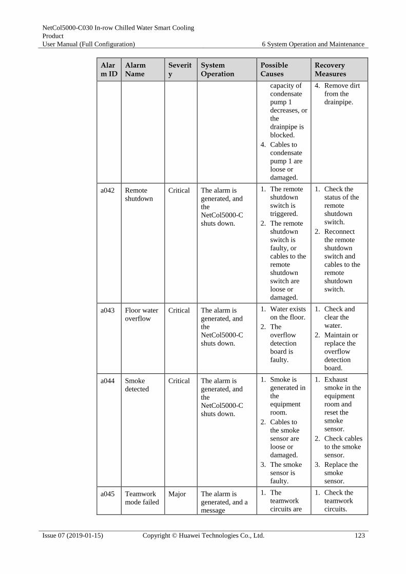
NetCol5000-C030 In-row Chilled Water Smart Cooling
Product
User Manual (Full Configuration) 6 System Operation and Maintenance
Issue 07 (2019-01-15) Copyright © Huawei Technologies Co., Ltd. 123
Alarm ID
Alarm Name
Severity
System Operation
Possible Causes
Recovery Measures
capacity of
condensate
pump 1
decreases, or
the
drainpipe is
blocked.
4. Cables to
condensate
pump 1 are
loose or
damaged.
4. Remove dirt
from the
drainpipe.
a042 Remote
shutdown
Critical The alarm is
generated, and
the
NetCol5000-C
shuts down.
1. The remote
shutdown
switch is
triggered.
2. The remote
shutdown
switch is
faulty, or
cables to the
remote
shutdown
switch are
loose or
damaged.
1. Check the
status of the
remote
shutdown
switch.
2. Reconnect
the remote
shutdown
switch and
cables to the
remote
shutdown
switch.
a043 Floor water
overflow
Critical The alarm is
generated, and
the
NetCol5000-C
shuts down.
1. Water exists
on the floor.
2. The
overflow
detection
board is
faulty.
1. Check and
clear the
water.
2. Maintain or
replace the
overflow
detection
board.
a044 Smoke
detected
Critical The alarm is
generated, and
the
NetCol5000-C
shuts down.
1. Smoke is
generated in
the
equipment
room.
2. Cables to
the smoke
sensor are
loose or
damaged.
3. The smoke
sensor is
faulty.
1. Exhaust
smoke in the
equipment
room and
reset the
smoke
sensor.
2. Check cables
to the smoke
sensor.
3. Replace the
smoke
sensor.
a045 Teamwork
mode failed
Major The alarm is
generated, and a message
1. The
teamwork
circuits are
1. Check the
teamwork
circuits.

NetCol5000-C030 In-row Chilled Water Smart Cooling
Product
User Manual (Full Configuration) 6 System Operation and Maintenance
Issue 07 (2019-01-15) Copyright © Huawei Technologies Co., Ltd. 124
Alarm ID
Alarm Name
Severity
System Operation
Possible Causes
Recovery Measures
"Networking
failed" is
displayed.
faulty.
2. The master
and slave
NetCol5000
-C units
have the
same
address.
3. The master
NetCol5000
-C is not
configured.
2. Change the
NetCol5000-
C addresses.
3. Configure the
master
NetCol5000-
C.
a047 No Refrig
Output Critical The alarm is
generated, and
the
NetCol5000-C
shuts down.
1. Cables to
the chilled
water valve
are loose or
damaged.
2. The chilled
water valve
is stuck or
faulty.
1. Check cables
to the chilled
water valve.
2. Maintain or
replace the
chilled water
valve.
a048 Supply-air
HT
Critical The alarm is
generated. The
indoor fan has the
maximum output,
and the value has
100% outputs in
automatic
running mode.
1. The
supply-air
high
temperature
alarm set
point is
inappropriat
e for the
working
conditions.
2. The
temperature
displayed on
the LCD is
different
from the
actual
temperature.
3. Cables to
the
supply-air
temperature
sensor are
loose or
damaged.
4. The chilled
water flow
is insufficient,
1. Adjust the
supply-air
high
temperature
alarm set
point.
2. Maintain or
replace the
supply air
temperature
sensor.
3. Check cables
to the
supply-air
temperature
sensor.
4. Check the
pressure and
temperature
of the
supplied
chilled water.
5. Maintain or
replace the
chilled water
valve.
6. Add more
NetCol5000-
C units.

NetCol5000-C030 In-row Chilled Water Smart Cooling
Product
User Manual (Full Configuration) 6 System Operation and Maintenance
Issue 07 (2019-01-15) Copyright © Huawei Technologies Co., Ltd. 125
Alarm ID
Alarm Name
Severity
System Operation
Possible Causes
Recovery Measures
or the
supply water
temperature
is high.
5. The chilled
water valve
is faulty.
6. The cooling
capacity of
the
NetCol5000
-C is
insufficient
due to high
load.
7. The ambient
temperature
is high.
7. Check the
ambient
temperature.
a049 Supply-air
LT
Warning The alarm is
generated.
1. The
supply-air
low
temperature
alarm set
point is
inappropriat
e for the
working
conditions.
2. The
temperature
displayed on
the LCD is
different
from the
actual
temperature.
3. Cables to
the supply
air
temperature
sensor are
loose or
damaged.
4. The chilled
water valve
is faulty.
5. The ambient
temperature
is low.
1. Adjust the
supply-air
low
temperature
alarm set
point.
2. Maintain or
replace the
supply air
temperature
sensor.
3. Check cables
to the
supply-air
temperature
sensor.
4. Maintain or
replace the
chilled water
valve.
5. Check the
ambient
temperature.
a050 Cold aisle Critical The alarm is 1. The 1. Adjust the

NetCol5000-C030 In-row Chilled Water Smart Cooling
Product
User Manual (Full Configuration) 6 System Operation and Maintenance
Issue 07 (2019-01-15) Copyright © Huawei Technologies Co., Ltd. 126
Alarm ID
Alarm Name
Severity
System Operation
Possible Causes
Recovery Measures
HT generated. The
indoor fan has the
maximum output,
and the CW value
has 100% outputs
in automatic
running mode.
return-air
high
temperature
alarm set
point is
inappropriat
e for the
working
conditions.
2. The
temperature
displayed on
the LCD is
different
from the
actual
temperature.
3. The chilled
water flow
is
insufficient,
or the
supply water
temperature
is high.
4. The chilled
water valve
is faulty.
5. The cooling
capacity of
the
NetCol5000
-C is
insufficient,
or the load
is high.
6. The ambient
temperature
is high.
return-air
high
temperature
alarm set
point.
2. Maintain or
replace the
temperature
and humidity
sensor.
3. Check the
pressure and
temperature
of the
supplied
chilled water.
4. Maintain or
replace the
chilled water
valve.
5. Add more
NetCol5000-
C units.
6. Check the
ambient
temperature.
a051 Hot aisle
HT
Critical The alarm is
generated. The
indoor fan has the
maximum output,
and the
electromagnetic
valve and
actuator has
100% outputs in
automatic
running mode.
1. The high
temperature
alarm set
point for the
hot aisle is
inappropriat
e for the
working
conditions.
2. The
temperature displayed on
1. Adjust the
high
temperature
alarm set
point for the
hot aisle.
2. Maintain or
replace the
temperature
and humidity
sensor.
3. Check the

NetCol5000-C030 In-row Chilled Water Smart Cooling
Product
User Manual (Full Configuration) 6 System Operation and Maintenance
Issue 07 (2019-01-15) Copyright © Huawei Technologies Co., Ltd. 127
Alarm ID
Alarm Name
Severity
System Operation
Possible Causes
Recovery Measures
the LCD is
different
from the
actual
temperature.
3. The chilled
water flow
is
insufficient,
or the
supply water
temperature
is high.
4. The chilled
water valve
is faulty.
5. The cooling
capacity of
the
NetCol5000
-C is
insufficient
due to high
load.
pressure and
temperature
of the
supplied
chilled water.
4. Maintain or
replace the
chilled water
valve.
5. Add more
NetCol5000-
C units.
a052 Supply-air
temp
invalid
Major The alarm is
generated.
1. The
temperature
sensor at
supply-air
vent is
faulty.
2. Cables to
the
temperature
sensor at
supply air
vent are
loose or
damaged.
1. Maintain or
replace the
temperature
sensor at
supply-air
vent.
2. Check cables
to the
temperature
sensor at
supply-air
vent.
a077 Indoor fan
1/2/3/4/5/6/
7/8 failure
Major The alarm is
generated.
1. The power
supply to the
indoor fans
is abnormal.
2. Cables to
indoor fan
are loose or
damaged.
3. Indoor fan is
faulty.
1. Check the
power supply
to the indoor
fans.
2. Check cables
to indoor fan.
3. Maintain or
replace
indoor fan.
a078 Full water Critical The alarm is
generated, and
1. The high float is
1. Replace the high float or

NetCol5000-C030 In-row Chilled Water Smart Cooling
Product
User Manual (Full Configuration) 6 System Operation and Maintenance
Issue 07 (2019-01-15) Copyright © Huawei Technologies Co., Ltd. 128
Alarm ID
Alarm Name
Severity
System Operation
Possible Causes
Recovery Measures
the
NetCol5000-C
shuts down.
faulty or
stuck.
2. The
condensate
pump is
faulty, or the
drainage
capacity of
the
condensate
pump
decreases.
3. The
drainpipe of
the
condensate
pump is
blocked.
clear the
obstacles.
2. Replace the
condensate
pump.
3. Clear
obstacles in
the drainpipe.
a079 Drain
abnormal
Major The alarm is
generated.
1. The low
float is
faulty or
stuck.
2. The high
float is
faulty or
stuck.
3. Cables to
the high or
low float are
loose or
damaged.
4. The
condensate
pump is
faulty, or the
drainage
capacity of
the
condensate
pump
decreases.
5. The
drainpipe of
the
condensate
pump is
blocked.
1. Maintain or
replace the
low float or
clear the
obstacles.
2. Maintain or
replace the
high float or
clear the
obstacles.
3. Check cables
to the faulty
float.
4. Maintain or
replace the
condensate
pump.
5. Clear
obstacles in
the drainpipe.
a080 CW value
exceed
runtime
Warning The alarm is
generated.
The
accumulated
runtime of the
Maintain or
replace the CW
value.
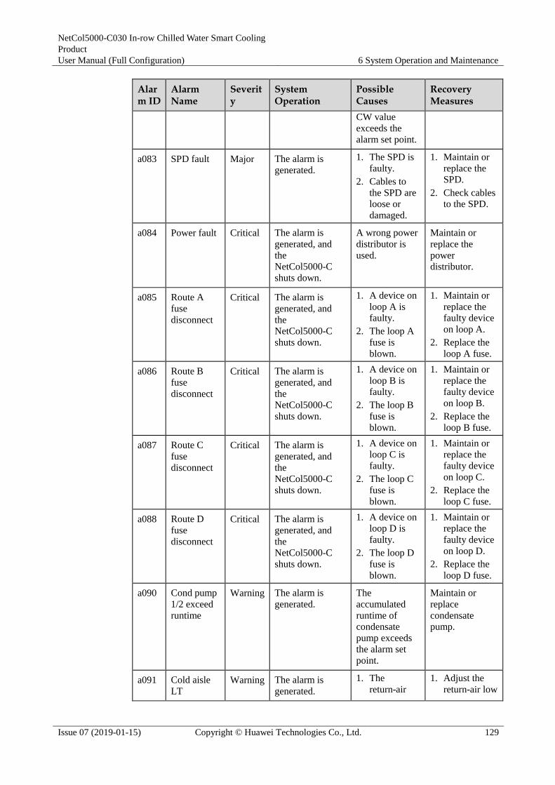
NetCol5000-C030 In-row Chilled Water Smart Cooling
Product
User Manual (Full Configuration) 6 System Operation and Maintenance
Issue 07 (2019-01-15) Copyright © Huawei Technologies Co., Ltd. 129
Alarm ID
Alarm Name
Severity
System Operation
Possible Causes
Recovery Measures
CW value
exceeds the
alarm set point.
a083 SPD fault Major The alarm is
generated.
1. The SPD is
faulty.
2. Cables to
the SPD are
loose or
damaged.
1. Maintain or
replace the
SPD.
2. Check cables
to the SPD.
a084 Power fault Critical The alarm is
generated, and
the
NetCol5000-C
shuts down.
A wrong power
distributor is
used.
Maintain or
replace the
power
distributor.
a085 Route A
fuse
disconnect
Critical The alarm is
generated, and
the
NetCol5000-C
shuts down.
1. A device on
loop A is
faulty.
2. The loop A
fuse is
blown.
1. Maintain or
replace the
faulty device
on loop A.
2. Replace the
loop A fuse.
a086 Route B
fuse
disconnect
Critical The alarm is
generated, and
the
NetCol5000-C
shuts down.
1. A device on
loop B is
faulty.
2. The loop B
fuse is
blown.
1. Maintain or
replace the
faulty device
on loop B.
2. Replace the
loop B fuse.
a087 Route C
fuse
disconnect
Critical The alarm is
generated, and
the
NetCol5000-C
shuts down.
1. A device on
loop C is
faulty.
2. The loop C
fuse is
blown.
1. Maintain or
replace the
faulty device
on loop C.
2. Replace the
loop C fuse.
a088 Route D
fuse
disconnect
Critical The alarm is
generated, and
the
NetCol5000-C
shuts down.
1. A device on
loop D is
faulty.
2. The loop D
fuse is
blown.
1. Maintain or
replace the
faulty device
on loop D.
2. Replace the
loop D fuse.
a090 Cond pump
1/2 exceed
runtime
Warning The alarm is
generated.
The
accumulated
runtime of
condensate
pump exceeds
the alarm set
point.
Maintain or
replace
condensate
pump.
a091 Cold aisle
LT Warning The alarm is
generated.
1. The
return-air
1. Adjust the
return-air low

NetCol5000-C030 In-row Chilled Water Smart Cooling
Product
User Manual (Full Configuration) 6 System Operation and Maintenance
Issue 07 (2019-01-15) Copyright © Huawei Technologies Co., Ltd. 130
Alarm ID
Alarm Name
Severity
System Operation
Possible Causes
Recovery Measures
low
temperature
alarm set
point is
inappropriat
e for the
working
conditions.
2. The
temperature
displayed on
the LCD is
different
from the
actual
temperature.
3. The chilled
water valve
is faulty.
4. The ambient
temperature
is low.
temperature
alarm set
point.
2. Maintain or
replace the
temperature
and humidity
sensor.
3. Maintain or
replace the
chilled water
valve.
4. Check the
ambient
temperature.
a092 Hot aisle
LT
Warning The alarm is
generated.
1. The low
temperature
alarm set
point for the
hot aisle is
inappropriat
e for the
working
conditions.
2. The
temperature
displayed on
the LCD is
different
from the
actual
temperature.
3. The chilled
water valve
is faulty.
4. The ambient
temperature
is low.
1. Adjust the
low
temperature
alarm set
point for the
hot aisle.
2. Maintain or
replace the
temperature
and humidity
sensor.
3. Maintain or
replace the
chilled water
valve.
4. Check the
ambient
temperature.
a093 High
humidity
Warning The alarm is
generated.
1. The high
humidity
alarm set
point is inappropriat
1. Adjust the
high
humidity
alarm set point.

NetCol5000-C030 In-row Chilled Water Smart Cooling
Product
User Manual (Full Configuration) 6 System Operation and Maintenance
Issue 07 (2019-01-15) Copyright © Huawei Technologies Co., Ltd. 131
Alarm ID
Alarm Name
Severity
System Operation
Possible Causes
Recovery Measures
e for the
working
conditions.
2. The
humidity
detected by
temperature
and
humidity
sensor is
higher than
the actual
value.
3. The
temperature
and
humidity
sensor is
located in an
inappropriat
e position.
4. The ambient
humidity is
high.
2. Maintain or
replace the
temperature
and humidity
sensor.
3. Adjust the
position of
the
temperature
and humidity
sensor.
4. Check the
ambient
humidity.
a094 Low
humidity
Warning The alarm is
generated.
1. The low
humidity
alarm set
point is
inappropriat
e for the
working
conditions.
2. The
humidity
detected by
temperature
and
humidity
sensor is
lower than
the actual
value.
3. The
temperature
and
humidity
sensor is
located in an
inappropriat
e position.
4. The ambient
1. Adjust the
low humidity
alarm set
point.
2. Maintain or
replace the
temperature
and humidity
sensor.
3. Adjust the
position of
the
temperature
and humidity
sensor.
4. Check the
ambient
humidity.

NetCol5000-C030 In-row Chilled Water Smart Cooling
Product
User Manual (Full Configuration) 6 System Operation and Maintenance
Issue 07 (2019-01-15) Copyright © Huawei Technologies Co., Ltd. 132
Alarm ID
Alarm Name
Severity
System Operation
Possible Causes
Recovery Measures
humidity is
low.
a096 Invalid
supply
water temp
Major The alarm is
generated.
1. The supply
water
temperature
sensor is
faulty.
2. Cables to
the supply
water
temperature
sensor are
loose or
damaged.
1. Maintain or
replace the
supply water
temperature
sensor.
2. Check cables
to the supply
water
temperature
sensor.
a097 Supply
water high
temp
Major The alarm is
generated.
1. The supply
water high
temperature
alarm set
point is
inappropriat
e for the
working
conditions.
2. The
temperature
displayed on
the LCD is
different
from the
actual
temperature.
3. Cables to
the supply
water
temperature
sensor are
loose or
damaged.
4. The
temperature
of chilled
water is
higher than
the high
temperature
alarm set
point.
1. Adjust the
supply water
high
temperature
alarm set
point.
2. Maintain or
replace the
supply water
temperature
sensor.
3. Check cables
to the supply
water
temperature
sensor.
4. Check the
temperature
of the
supplied
chilled water.
a098 Supply
water low temp
Warning The alarm is
generated.
1. The supply
water low
temperature
1. Adjust the
supply water
low

NetCol5000-C030 In-row Chilled Water Smart Cooling
Product
User Manual (Full Configuration) 6 System Operation and Maintenance
Issue 07 (2019-01-15) Copyright © Huawei Technologies Co., Ltd. 133
Alarm ID
Alarm Name
Severity
System Operation
Possible Causes
Recovery Measures
alarm set
point is
inappropriat
e for the
working
conditions.
2. The
temperature
displayed on
the LCD is
different
from the
actual
temperature.
3. The
temperature
of chilled
water is
lower than
the low
temperature
alarm set
point.
temperature
alarm set
point.
2. Maintain or
replace the
supply water
temperature
sensor.
3. Check the
temperature
of the
supplied
chilled water.
a099 Invalid
return water
temp
Major The alarm is
generated.
1. The return
water
temperature
sensor is
faulty.
2. Cables to
the return
water
temperature
sensor are
loose or
damaged.
1. Maintain or
replace the
return water
temperature
sensor.
2. Check cables
to the return
water
temperature
sensor.
a101 CW value
abnormal
feedback
Major The alarm is
generated.
1. Cables to
the chilled
water valve
are loose or
damaged.
2. The chilled
water valve
is faulty.
1. Adjust the
cables to the
chilled water
valve.
2. Maintain or
replace the
chilled water
valve.
a103 Indoor fan
power
alarm
Major The alarm is
generated, and
the indoor fan
output is less than
85%.
1. The indoor
fan power
module is
faulty.
2. Cables to
the indoor fan power
1. Maintain or
replace the
indoor fan
power
module.
2. Check cables to the dry

NetCol5000-C030 In-row Chilled Water Smart Cooling
Product
User Manual (Full Configuration) 6 System Operation and Maintenance
Issue 07 (2019-01-15) Copyright © Huawei Technologies Co., Ltd. 134
Alarm ID
Alarm Name
Severity
System Operation
Possible Causes
Recovery Measures
module are
loose or
damaged.
contact of the
indoor fan
power
module.
a104 In-cabinet
overflow
Critical The alarm is
generated, and
the
NetCol5000-C
shuts down.
1. Water exists
in the
overflow
pan.
2. The cabinet
overflow
sensor is
disconnecte
d.
1. Check and
clear the
water.
2. Maintain or
replace the
cabinet
overflow
sensor.
a105 Indoor fan
failure
Critical The alarm is
generated.
The number of
faulty indoor
fans is greater
than or equals
to six.
Maintain or
replace the
faulty indoor
fans.
a106 Cab
overflow
sensor fault
Major The alarm is
generated, and
the
NetCol5000-C
shuts down.
The cabinet
overflow sensor
is faulty.
Maintain or
replace the
cabinet overflow
sensor.
a108 Cold aisle
1/2/3 temp
invalid
Major The alarm is
generated.
1. The ambient
T/H sensor
fails to
communicat
e with the
NetCol5000
-A.
2. Dirt or water
exists
around the
board,
which leads
to a
detection
fault.
3. The ambient
T/H sensor
is faulty.
1. Clear the
return-air 2
T/H brd
comm fail
alarm.
2. Remove dirt
or water from
the board.
3. Maintain or
replace the
ambient T/H
sensor.
a109 Cold aisle
1/2/3 humid
invalid
Major The alarm is
generated.
1. The ambient
T/H sensor
fails to
communicat
e with the
NetCol5000
-A.
2. Dirt or water
1. Clear the
return-air 2
T/H brd
comm fail
alarm.
2. Remove dirt
or water from
the board.

NetCol5000-C030 In-row Chilled Water Smart Cooling
Product
User Manual (Full Configuration) 6 System Operation and Maintenance
Issue 07 (2019-01-15) Copyright © Huawei Technologies Co., Ltd. 135
Alarm ID
Alarm Name
Severity
System Operation
Possible Causes
Recovery Measures
exists
around the
board,
which leads
to a
detection
fault.
3. The ambient
T/H sensor
is faulty.
3. Maintain or
replace the
ambient T/H
sensor.
a110 Cold aisle
1/2/3 T/H
brd comm
fail
Major The alarm is
generated.
1. The DIP
switch is
incorrectly
set for the
ambient T/H
sensor.
2. The
communicat
ions cables
to the
ambient T/H
sensor are
loose or
damaged.
3. The ambient
T/H sensor
is faulty.
1. Correctly
set the DIP
switch for the
ambient T/H
sensor, as
shown in
3.15.5
Installing the
T/H Sensor.
2. Make sure
the
communicati
on cables to
the T/H
sensor is
connected
properly.
3. Maintain or
replace the
ambient T/H
sensor.
a111 Hot aisle
1/2/3 temp
invalid
Major The alarm is
generated.
1. The ambient
T/H sensor
fails to
communicat
e with the
NetCol5000
-A.
2. Dirt or water
exists
around the
board,
which leads
to a
detection
fault.
3. The ambient
T/H sensor
is faulty.
1. Clear the
return-air 2
T/H brd
comm fail
alarm.
2. Remove dirt
or water from
the board.
3. Maintain or
replace the
ambient T/H
sensor.
a112 Hot aisle Major The alarm is 1. The ambient 1. Clear the
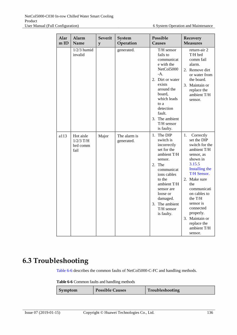
NetCol5000-C030 In-row Chilled Water Smart Cooling
Product
User Manual (Full Configuration) 6 System Operation and Maintenance
Issue 07 (2019-01-15) Copyright © Huawei Technologies Co., Ltd. 136
Alarm ID
Alarm Name
Severity
System Operation
Possible Causes
Recovery Measures
1/2/3 humid
invalid
generated. T/H sensor
fails to
communicat
e with the
NetCol5000
-A.
2. Dirt or water
exists
around the
board,
which leads
to a
detection
fault.
3. The ambient
T/H sensor
is faulty.
return-air 2
T/H brd
comm fail
alarm.
2. Remove dirt
or water from
the board.
3. Maintain or
replace the
ambient T/H
sensor.
a113 Hot aisle
1/2/3 T/H
brd comm
fail
Major The alarm is
generated.
1. The DIP
switch is
incorrectly
set for the
ambient T/H
sensor.
2. The
communicat
ions cables
to the
ambient T/H
sensor are
loose or
damaged.
3. The ambient
T/H sensor
is faulty.
1. Correctly
set the DIP
switch for the
ambient T/H
sensor, as
shown in
3.15.5
Installing the
T/H Sensor.
2. Make sure
the
communicati
on cables to
the T/H
sensor is
connected
properly.
3. Maintain or
replace the
ambient T/H
sensor.
6.3 Troubleshooting
Table 6-6 describes the common faults of NetCol5000-C-FC and handling methods.
Table 6-6 Common faults and handling methods
Symptom Possible Causes Troubleshooting

NetCol5000-C030 In-row Chilled Water Smart Cooling
Product
User Manual (Full Configuration) 6 System Operation and Maintenance
Issue 07 (2019-01-15) Copyright © Huawei Technologies Co., Ltd. 137
Symptom Possible Causes Troubleshooting
The fan does not
rotate after the
NetCol5000-C-FC
starts.
The power supply
module of the fan is
faulty or abnormal
(including the fuse of the
power supply module is
blown.)
The fan fuse is blown.
Cables to the fan are
faulty.
Ensure that the power supply
module of the fan is inserted to the
subrack. If the fault persists,
replace the power supply module
(or replace the fuse).
Replace the fan fuse.
Check whether the cables to the
fan short-circuit or are
disconnected.
The fan generates
loud noises.
The air filter is blocked.
Dirt exists at the fan air
exhaust vent.
The fan is not securely
installed.
The fan is faulty.
Clean the air filter.
Clear the fan air exhaust vent.
Fasten the fan screws
Replace the fan.
Drainage capacity
of the
NetCol5000-C-FC
decreases.
The drainpipe is bent by
a large angle or trap
exists.
The drainage system is
faulty. (The water pump,
floats, or drainpipes are
faulty.)
Check that self-drainpipes are not bent
by a large angle and traps do not exist.
Ensure that the height difference for
drainage is enough.
Check the pump drainage:
Check that the floats are working
properly.
Check whether fuses on circuits C
and D are blown. If yes, replace
the fuses.
Check whether the relay works
properly. If not, replace the relay.
Check whether the water pump
works properly. If not, replace the
water pump.
Check that the pipes are not bent
by a large angle.
The
NetCol5000-C-FC
leaks.
The thermal insulation
tube of the
NetCol5000-C-FC is
damaged.
The condensate
drainpipe is blocked.
The pipes leak.
Check whether thermal insulation
tube of the NetCol5000-C-FC is
securely installed and repair the
damaged thermal insulation tube.
Ensure that the drainpipes are not
bent by a large angle, the drainpipe
connectors are securely installed,
the condensate pump is not faulty,
and the floats are not faulty.
Check the pipes and weld the pipe
or fasten related bolts if the pipes
leak.
The temperature is The jumper cap of the chilled water valve is not
Check the W1 jumper of the chilled water valve controller.

NetCol5000-C030 In-row Chilled Water Smart Cooling
Product
User Manual (Full Configuration) 6 System Operation and Maintenance
Issue 07 (2019-01-15) Copyright © Huawei Technologies Co., Ltd. 138
Symptom Possible Causes Troubleshooting
abnormal. connected to the right
position.
The valve plug of the
chilled water valve is
reversely installed.
The chilled water valve
is stuck.
The humidity detected
by the humidity and
temperature sensor is
larger than the actual
humidity, which results
in anticond protection
being triggered
frequently for the
NetCol5000-C-FC.
The temperature and
humidity thresholds are
improper.
Alarms, such as full
water, in-cabinet
overflow, smoke sensor,
and no refrigerant output
are generated.
Ensure that the jumper cap is on
the right two pins.
Check that the chilled water valve
plug is correctly installed.
Replace the chilled water valve.
Check whether the ambient
temperature of the humidity and
temperature sensor is too high.
Ensure that the humidity and
temperature sensor is located at a
proper position. If the position is
proper but the fault persists,
replace the humidity and
temperature sensor.
Adjust the temperature and
humidity thresholds.
Check the alarm causes and clear
the alarm manually.
The humidity and
temperature sensor
cannot detect the
humidity and
temperature.
Parameter settings on
the controller are
incorrect.
DIP switches of the
humidity and
temperature sensor are
incorrectly set.
The humidity and
temperature sensor is
faulty.
Check that the humidity and
temperature sensor is enabled on
the controller.
Check that DIP switches of the
humidity and temperature sensor
map the corresponding aisle.
If the fault persists after the
preceding operations, replace the
humidity and temperature sensor.
The air return
temperature is high
or the fan
rotational speed is
fast. (The
temperature
fluctuation exceeds
± 1°C.)
Proportional, integral and
derivative (PID) control
related parameters are not
set properly.
Decrease the Kp value by 0.01 and do
not set Kp to a much smaller value.
Ensure that temperature fluctuation is
less than ±1°C.
Condensate water
exists on the
surfaces of the
front or rear
panels.
The operating
environment of the
NetCol5000-C-FC is
overhumidity.
The temperature
threshold is set to a
Enhance the airtightness of the
equipment room.
Adjust the temperature and
humidity thresholds.

NetCol5000-C030 In-row Chilled Water Smart Cooling
Product
User Manual (Full Configuration) 6 System Operation and Maintenance
Issue 07 (2019-01-15) Copyright © Huawei Technologies Co., Ltd. 139
Symptom Possible Causes Troubleshooting
much smaller value.
6.4 Parts Replacement
6.4.1 Replacement Requirements
Remove the cabinet front or rear door when replacing a component in the cabinet.
Ensure that a spare component is the same model as the faulty one is prepared before
replacing the faulty component.
Before removing cables from a faulty component, mark the cables with their
corresponding ports numbers for later connection.
Ensure that the cables are connected to the spare component properly.
Do not install or remove power cables when the device is on. Transient contact between
the core of the power cable and the conductor may generate electric arcs or sparks, which
may cause fire or hurt eyes.
Before installing or removing the power cable, turn off the power switch.
Before connecting a power cable, check that the label on the power cable is correct.
During the installation of AC power supply facilities, follow the local safety regulations.
When operating the high-voltage and AC-powered facilities, use dedicated tools.
6.4.2 Replacing Components in the Electrical Control Box
Prerequisites Components in the electrical control box, including the controller, AC contactor,
transformer, fuse, or fuse holder need to be replaced.
A spare and functional component is available.
Context
The control function of the NetCol5000-C-FC is unavailable.
Recommended tool: Phillips screwdriver (M6).
Preparations: remove the rear door, and power off the electrical control box.
Procedure
Step 1 Remove the rear door and air filters, remove the protective panel of the electrical control box
(as shown by 1 and 2 in Figure 6-2), remove all the terminals on the side panels.

NetCol5000-C030 In-row Chilled Water Smart Cooling
Product
User Manual (Full Configuration) 6 System Operation and Maintenance
Issue 07 (2019-01-15) Copyright © Huawei Technologies Co., Ltd. 140
Figure 6-2 Replacing components in the electrical control box
Step 2 Loose two screws at the upper part of the electrical control box. Pull the electrical control box
upwards, and pull it out along the guide rails, as shown by 3 and 4 in Figure 6-2, and place it
on the floor.
Step 3 Loosen the screws on the electrical control box cover manually and remove the fault
component.
Step 4 Replace the component.
Step 5 Connect cables according to the electric diagram and labels.
Step 6 Install the electrical control box, air filters, and rear door in the rack in sequence.
----End
6.4.3 Replacing an Air Filter
Prerequisites The air filter needs to be replaced.
The spare and functional air filters are available.
Context
Preparations: maintain from the rear door.

NetCol5000-C030 In-row Chilled Water Smart Cooling
Product
User Manual (Full Configuration) 6 System Operation and Maintenance
Issue 07 (2019-01-15) Copyright © Huawei Technologies Co., Ltd. 141
Procedure
Step 1 Unlock the rear door and pull the rear door upwards to remove the rear door from the cabinet.
Step 2 Rotate the baffle plate and remove the air filter. For details, see 3.5 Checking the Pressure.
Step 3 Replace the air filter and fix the baffle plate of the air filter.
Step 4 Insert the lower part of the rear door into the original position, install the upper part of the rear
door, and lock the rear door.
Step 5 Tap Maint > Performance Maint on the home screen to enter the performance maintenance
screen, and clear accumulated running time of the air filter.
----End
6.4.4 Replacing a Condensate Pump
Prerequisites The condensate pump needs to be replaced.
A spare and functional condensate pump valve is available.
Context
Recommended tool: Phillips screwdriver.
Preparations: maintain from the rear door, and power off the condensate pump.
Procedure
Step 1 Remove the rear door and air filters.
Step 2 Disconnect all circuit breakers.
Step 3 Remove bolts on the condensate pump using a Phillips screwdriver, as shown in Figure 6-3.

NetCol5000-C030 In-row Chilled Water Smart Cooling
Product
User Manual (Full Configuration) 6 System Operation and Maintenance
Issue 07 (2019-01-15) Copyright © Huawei Technologies Co., Ltd. 142
Figure 6-3 Removing the bolts on the condensate pump
Step 4 Remove the condensate drainpipes and control cables.
Step 5 Remove the screws fastening the condensate pump using a Phillips screwdriver and remove
the condensate pump, as shown in Figure 6-4.
Figure 6-4 Replacing the condensate pump
Preheat the condensate pump drain pipes before removing them to make them plug easier.

NetCol5000-C030 In-row Chilled Water Smart Cooling
Product
User Manual (Full Configuration) 6 System Operation and Maintenance
Issue 07 (2019-01-15) Copyright © Huawei Technologies Co., Ltd. 143
Do not reverse the condensate pump input cable when connecting.
Step 6 Install a new condensate pump.
Step 7 Install the rear door and air filters.
Step 8 Tap Maint > Performance Maint on the home screen to enter the performance maintenance
screen. Clear total runtime of the condensate pump and the run times of the two condensate
pumps.
----End
6.4.5 Replacing a Fan
Prerequisites The fan needs to be replaced.
A spare and functional fan is available.
Context
The fan supports to be replaced during powering on.
Recommended tool: Phillips screwdriver.
Preparation: maintain from the front door.
Procedure
Step 1 Unlock the front door and pull the door forwards until the upper part of the front door is
removed from the cabinet. Remove cables to the controller.
Step 2 Pull the door upwards to remove the lower part of the front door from the cabinet.
Step 3 Remove the four screws fastening the fan using a Phillips screwdriver and remove the faulty
fan, as shown in Figure 6-5.
Align the fastener and positioning pin at the bottom of the fan with related holes on the
NetCol5000-C-FC, and push the fan into the NetCol5000-C-FC gently to ensure that cables to
the fan are securely connected and the fan is working properly.

NetCol5000-C030 In-row Chilled Water Smart Cooling
Product
User Manual (Full Configuration) 6 System Operation and Maintenance
Issue 07 (2019-01-15) Copyright © Huawei Technologies Co., Ltd. 144
Figure 6-5 Replacing the fan
Step 4 Replace the fan and fix the new fan to the support using a Phillips screwdriver.
Step 5 Insert the lower part of the front door to the original position.
Step 6 Connect the signal cables, and lock the front door.
Step 7 Tap Maint > Performance Maint on the home screen to enter the performance maintenance
screen, and clear accumulated running time of the fan.
----End
6.4.6 Replacing a Water Sensor
Prerequisites The water sensor needs to be replaced.
A spare water sensor is available.
Context
Recommended tool: Phillips screwdriver.
Preparations: maintain from the rear door.
Procedure
Step 1 Remove the rear door and air filter.
Step 2 Remove signal cables from the water sensor.
Step 3 Remove screws fastening the water sensor and metal sheet components using a Phillips
screwdriver and remove the water sensor and metal sheet components, as shown in Figure
6-6.

NetCol5000-C030 In-row Chilled Water Smart Cooling
Product
User Manual (Full Configuration) 6 System Operation and Maintenance
Issue 07 (2019-01-15) Copyright © Huawei Technologies Co., Ltd. 145
Figure 6-6 Replacing a water sensor
Step 4 Replace the water sensor and connect control cables to the new water sensor.
Step 5 Secure the screws fastening the water sensor using a Phillips screwdriver.
Reserve 5 mm distance between the water sensor and the cabinet bottom.
Step 6 Install the air filters and rear door.
----End
6.4.7 Replacing an Air Exhaust Temperature Sensor
Prerequisites The air exhaust temperature sensor needs to be replaced.
A spare and functional temperature sensor is available.
Context
Recommended tools: diagonal pliers and cable ties.
Preparation: maintain from the front door.
Procedure
Step 1 Remove the front door and signal cables of the controller.
Step 2 Remove components of the fans (the second and the eighth from up to bottom).

NetCol5000-C030 In-row Chilled Water Smart Cooling
Product
User Manual (Full Configuration) 6 System Operation and Maintenance
Issue 07 (2019-01-15) Copyright © Huawei Technologies Co., Ltd. 146
Step 3 Remove the cable ties fastening the air exhaust temperature sensor.
Step 4 Remove the waterproof plug of the air exhaust temperature sensor probe and replace the
probe, as shown in Figure 6-7.
Figure 6-7 Replacing the air exhaust temperature sensor
Step 5 Use the cable tie to fix the new air exhaust temperature sensor to the original position.
Step 6 Reconnect the waterproof plug of the temperature sensor probe.
Step 7 Install the fan components.
Step 8 Connect the signal cables to the controller and install the front door.
----End
6.4.8 Replacing an Air Intake Temperature Sensor
Prerequisites The air intake temperature sensor needs to be replaced.
A spare and functional temperature sensor is available.
Context
Recommended tools: diagonal pliers and cable ties.

NetCol5000-C030 In-row Chilled Water Smart Cooling
Product
User Manual (Full Configuration) 6 System Operation and Maintenance
Issue 07 (2019-01-15) Copyright © Huawei Technologies Co., Ltd. 147
Preparation: maintain from the rear door.
Procedure
Step 1 Remove the rear door and air filters.
Step 2 Use a Phillips screwdriver to loosen the R-shaped cable pipe clamp fastening the temperature
sensor on the rear door post and remove the air intake temperature sensor, as shown in Figure
6-8.
Figure 6-8 Air intake temperature sensor
Step 3 Remove the waterproof plug of the temperature sensor probe and replace the probe.
Step 4 Secure the new air intake temperature sensor to the original position using the cable pipe
clamp and fix the temperature sensor probe using the R-shaped cable pipe clamp.
Step 5 Reconnect the waterproof plug of the temperature sensor probe.
Step 6 Install the air filters and the rear door.
----End
6.4.9 Replacing a Water Inlet or Outlet Temperature Sensor
Prerequisites The water inlet or outlet temperature sensor needs to be replaced.
A spare and functional temperature sensor is available.
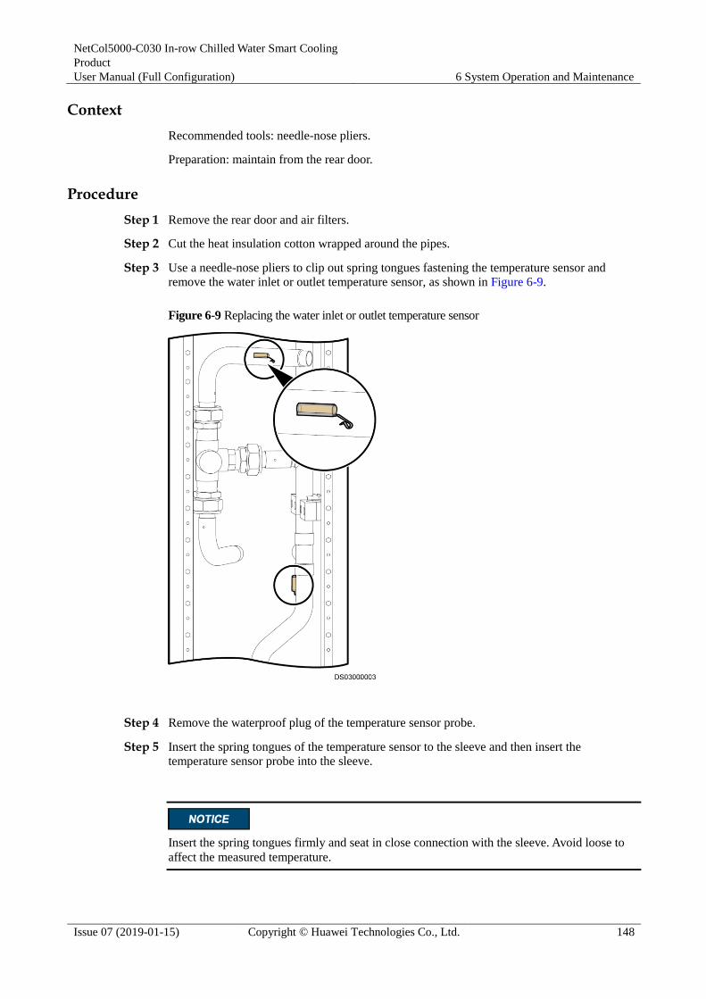
NetCol5000-C030 In-row Chilled Water Smart Cooling
Product
User Manual (Full Configuration) 6 System Operation and Maintenance
Issue 07 (2019-01-15) Copyright © Huawei Technologies Co., Ltd. 148
Context
Recommended tools: needle-nose pliers.
Preparation: maintain from the rear door.
Procedure
Step 1 Remove the rear door and air filters.
Step 2 Cut the heat insulation cotton wrapped around the pipes.
Step 3 Use a needle-nose pliers to clip out spring tongues fastening the temperature sensor and
remove the water inlet or outlet temperature sensor, as shown in Figure 6-9.
Figure 6-9 Replacing the water inlet or outlet temperature sensor
Step 4 Remove the waterproof plug of the temperature sensor probe.
Step 5 Insert the spring tongues of the temperature sensor to the sleeve and then insert the
temperature sensor probe into the sleeve.
Insert the spring tongues firmly and seat in close connection with the sleeve. Avoid loose to
affect the measured temperature.

NetCol5000-C030 In-row Chilled Water Smart Cooling
Product
User Manual (Full Configuration) 6 System Operation and Maintenance
Issue 07 (2019-01-15) Copyright © Huawei Technologies Co., Ltd. 149
Step 6 Reconnect the waterproof plug of the temperature sensor probe and wrap the temperature
sensor pipes with insulation cotton.
Step 7 Install the air filters and rear door.
----End
6.4.10 Replacing a Monitoring Module
Prerequisites The monitoring module needs to be replaced.
A spare and functional monitoring module is available.
Context
Preparation: maintain from the rear door.
Procedure
Step 1 Remove the rear door and air filters.
Step 2 Remove cables from the monitoring module front panel.
Step 3 Push up the buckle button on the monitoring module, as shown in 2 of Figure 6-10.
Figure 6-10 Replacing the monitoring module
Step 4 Pull out the buckle, as shown in 2 of Figure 6-10, and then pull out the monitoring module
from plug-in frame.

NetCol5000-C030 In-row Chilled Water Smart Cooling
Product
User Manual (Full Configuration) 6 System Operation and Maintenance
Issue 07 (2019-01-15) Copyright © Huawei Technologies Co., Ltd. 150
Make sure the buckle is on the lower right side when insert a new rectifier module.
Step 5 Replace the monitoring module, insert the new monitoring module to the corresponding slot
of the power distribution subrack, and connect cables to the monitoring module.
Step 6 Push the spare monitoring module to the plug-in frame and push downward the buckle button
to lock the monitoring module.
Step 7 Install the air filters and rear door.
----End
6.4.11 Replacing a Rectifier
Prerequisites The rectifier needs to be replaced.
A spare and functional rectifier is available.
Context
Preparations: Maintain from the rear door, and power off the rectifier.
Procedure
Step 1 Remove the rear door and air filters.
Step 2 Push up the buckle button on the power distribution subrack, as shown in 1 of Figure 6-11.

NetCol5000-C030 In-row Chilled Water Smart Cooling
Product
User Manual (Full Configuration) 6 System Operation and Maintenance
Issue 07 (2019-01-15) Copyright © Huawei Technologies Co., Ltd. 151
Figure 6-11 Replacing the rectifier
Step 3 Pull out the buckle, as shown in 2 of Figure 6-11, and then pull out the rectifier module from
plug-in frame.
Make sure the buckle is on the lower right side when insert a new rectifier module.
Step 4 Replace the rectifier and insert the new rectifier to the corresponding slot of the power
distribution subrack.
Step 5 Push the spare rectifier module to the plug-in frame and connect the cable, and then push
downward the buckle button to lock the rectifier module.
Step 6 Install the air filters and rear door.
----End
6.4.12 Replacing a Chilled Water Valve
Prerequisites The chilled water valve needs to be replaced.
A spare and functional chilled water valve is available.
Context
Recommended tools and materials: Phillips screwdriver, flat-head screwdriver, torque wrench
and insulation cotton

NetCol5000-C030 In-row Chilled Water Smart Cooling
Product
User Manual (Full Configuration) 6 System Operation and Maintenance
Issue 07 (2019-01-15) Copyright © Huawei Technologies Co., Ltd. 152
Preparations: stop supply chilled water and power, adjustment the chiller water valve
openness to 0
Procedure
Step 1 Remove the rear door and air filters.
Before removing the cables, you are advised to mark the cables with their corresponding ports
numbers for later connection.
Step 2 Remove the screws at the bottom of the chilled water valve controller, the cover, and the
signal and power cables.
Step 3 If only the chilled water valve controller needs to be replaced, remove the screws fastening
the chilled water valve controller using the flat-head screwdriver and remove the controller
according to the arrow direction.
Step 4 If the chilled water valve needs to be replaced, cut the insulation cotton wrapped the chilled
water valve, and remove the four screws that connect the chilled water valve and the support
using a Phillips screwdriver.
Step 5 Remove the chilled water valve controller, shaft, and support.
Step 6 Remove the three adjustable nuts that connect the chilled water valve and the pipe using a
torque wrench, and remove the chilled water valve, as shown in Figure 6-12.
Figure 6-12 Replacing the chilled water valve
(1) Screws fastening the chilled
water valve controller
(2) Screws connecting the chilled
water valve and the support
(3) Adjustable
nuts

NetCol5000-C030 In-row Chilled Water Smart Cooling
Product
User Manual (Full Configuration) 6 System Operation and Maintenance
Issue 07 (2019-01-15) Copyright © Huawei Technologies Co., Ltd. 153
Step 7 Replace the chilled water valve controller or the chilled water valve.
Step 8 Fasten the adjustable nuts using a torque wrench to a torque of 60 N•m and wrap the chilled
water valve with insulation cotton.
If only the chilled water valve controller is replaced, only the screws fastening the
controller needs to be secured and the securing card at the bottom needs to be tightened.
If the chilled water valve is replaced, install the new chilled water valve according to the
preceding steps.
Step 9 Connect cables to the chilled water valve controller and install the controller shell.
Step 10 Install the air filter and rear door.
Step 11 Tap Maint > Performance Maint on the home screen to enter the performance maintenance
screen, and clear accumulated running time of chilled water valve.
----End
6.4.13 Replacing a Float
Prerequisites The float needs to be replaced.
A spare and functional float is available.
Context
Recommended tool: open-end wrench.
Preparation: maintain from the rear door.
Procedure
Step 1 Remove the rear door and air filters.
Step 2 Remove terminals from the float.
Step 3 Remove the nuts fastening the float using the open-end wrench and remove the float, as
shown in Figure 6-13.

NetCol5000-C030 In-row Chilled Water Smart Cooling
Product
User Manual (Full Configuration) 6 System Operation and Maintenance
Issue 07 (2019-01-15) Copyright © Huawei Technologies Co., Ltd. 154
Figure 6-13 Replacing the float
Step 4 Replace the float and connect the connectors.
Corresponding to the high and low float when plugging (the high position is the high float, the
low position is the low float).
Step 5 Fasten the nuts using the open-end wrench and level the float.
Make sure the float is level and the float valve is in the vertical position.
Step 6 Install the air filter and rear door.
Step 7 Tap Maint > Performance Maint on the home screen to enter the performance maintenance
screen, and clear accumulated running time of the float.
----End
6.4.14 Replacing a Differential Pressure Sensor
Prerequisites The differential pressure sensor needs to be replaced.
A spare and functional differential pressure sensor is available.

NetCol5000-C030 In-row Chilled Water Smart Cooling
Product
User Manual (Full Configuration) 6 System Operation and Maintenance
Issue 07 (2019-01-15) Copyright © Huawei Technologies Co., Ltd. 155
Context
Recommended tool: Phillips screwdriver.
Preparation: maintain from the rear door.
Procedure
Step 1 Remove the rear door and air filters.
Step 2 Remove the differential pressure tube on the differential pressure sensor.
Step 3 Open the differential pressure sensor shell cover and remove the signal cables.
Step 4 Use the Phillips screwdriver to loosen the three screws fastening the differential pressure
sensor and remove the faulty differential pressure sensor, as shown in Figure 6-14.
Figure 6-14 Replacing the differential pressure sensor
Step 5 Replace the differential pressure sensor and connect cables to the new differential pressure
sensor.
Step 6 Set the pressure setting of the differential pressure sensor to 200 Pa.
Step 7 Insert the differential pressure tube into the pressure detection port on the differential pressure
sensor, guarantees gas tightness.
Step 8 Install the air filter and rear door.
Step 9 Tap Maint > Performance Maint on the home screen to enter the performance maintenance
screen, and clear accumulated running time of the differential pressure sensor.
----End
6.4.15 Replacing a Controller Panel
Prerequisites The controller panel needs to be replaced.

NetCol5000-C030 In-row Chilled Water Smart Cooling
Product
User Manual (Full Configuration) 6 System Operation and Maintenance
Issue 07 (2019-01-15) Copyright © Huawei Technologies Co., Ltd. 156
A spare controller panel with the correct software version is available. If the controller
software is incorrect, upgrade the software by following the instructions in the ACC
Upgrade Guide.
Context
Recommended tool: Phillips screwdriver.
Preparation: maintain from the front door.
Procedure
Step 1 Unlock the front door and pull the door upwards to remove the upper part of the front door
from the cabinet.
Be careful not to damage the controller cables.
Step 2 Remove cables from the controller panel.
Step 3 Pull the door upwards to remove the lower part of the front door from the cabinet.
Step 4 Loosen the four screws fastening the controller panel using a Phillips screwdriver. Push the
controller panel from the right or left side and remove the controller panel, as shown in Figure
6-15.
Pay attention to the fasteners when pushing the controller panel from the right or left side to
prevent the controller panel from being damaged.
Figure 6-15 Replacing the controller panel
Step 5 Replace the controller panel and use the Phillips screwdriver to fix the new controller panel to
the original position.
Step 6 Insert the lower part of the front door to the original position.

NetCol5000-C030 In-row Chilled Water Smart Cooling
Product
User Manual (Full Configuration) 6 System Operation and Maintenance
Issue 07 (2019-01-15) Copyright © Huawei Technologies Co., Ltd. 157
Step 7 Connect the signal cables to the controller panel, install the upper part of the front door and
lock the door.
----End

NetCol5000-C030 In-row Chilled Water Smart Cooling
Product
User Manual (Full Configuration) A Acronyms and Abbreviations
Issue 07 (2019-01-15) Copyright © Huawei Technologies Co., Ltd. 158
A Acronyms and Abbreviations
C
CAN Controller Area Network
CFD Computational Fluid Dynamics
D
DIP Dual in-line Package
E
EC Electronic Commutation
P
PUE Power Usage Effectiveness
PID Proportional, Integral and Derivative

NetCol5000-C030 In-row Chilled Water Smart Cooling
Product
User Manual (Full Configuration) B Glycol Adding Requirements
Issue 07 (2019-01-15) Copyright © Huawei Technologies Co., Ltd. 159
B Glycol Adding Requirements
Purchase glycol and corrosion inhibitor from a local qualified installation company.
Determine the glycol volume concentration based on the lowest temperature in record in
the area.
As the glycol solution is toxic, avoid skin contact with the glycol solution and splashing
it into your eyes. Dispose of the glycol solution in accordance with local laws.
To prevent glycol solution from corroding pipes and the heat exchanging coil, corrosion
inhibitor should be mixed into the glycol solution. For details about the mixing schemes,
consult glycol experts.
Check the quality of the glycol solution on a quarterly basis and evaluate the
anticorrosion effects. For details, consult local water treatment experts.
Table B-1 Glycol concentration requirements at lowest temperatures
Lowest Recorded Local Temperature
Glycol Volume Concentration
Freezing Point of Glycol Mixed Solution to Be Added
0°C 13.6% –5°C
–5°C to 0°C 22% –10°C
–10°C to –5°C 30% –15°C
–15°C to –10°C 35% –20°C
–20°C to –15°C 40% –25°C
–25°C to –20°C 45% –30°C
–30°C to –25°C 49% –35°C
–35°C to –30°C 52% –40°C
–40°C to –35°C 55% –45°C

NetCol5000-C030 In-row Chilled Water Smart Cooling
Product
User Manual (Full Configuration) C Controller Operation Rights Configuration Table
Issue 07 (2019-01-15) Copyright © Huawei Technologies Co., Ltd. 160
C Controller Operation Rights Configuration Table
Users include Admin, Engineer, Operator, and Guest users. The Admin users have the highest
permission, followed by the Engineer, Operator, and Guest users. Table C-1 describes the
operation rights for each configuration item.
Table C-1 Rights configuration table
Component
Item Admin Engineer Operator Guest
Settings
>
System
Settings
>
System
Control
Monitoring
mode
√ √ - -
Max diagnos
mode
duration
√ √ - -
Unit start
delay
√ √ - -
Disallow
on/off via
EMS
√ √ - -
Main screen
startup/shutd
own
√ √ √ √
Dehumidifica
tion
√ √ - -
Anti-cond
protection
√ √ - -
Max dehumid
runtime
√ - - -
Dew/sup
water TD at
dehumi
√ - - -
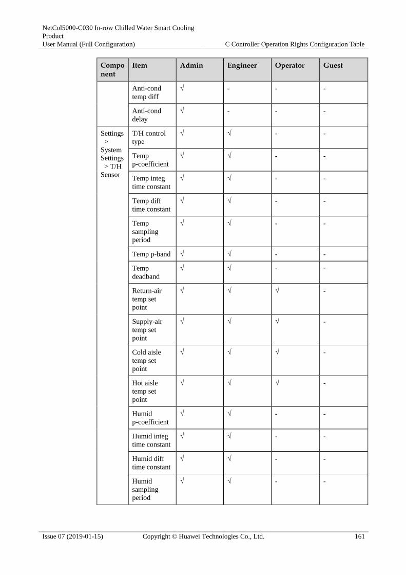
NetCol5000-C030 In-row Chilled Water Smart Cooling
Product
User Manual (Full Configuration) C Controller Operation Rights Configuration Table
Issue 07 (2019-01-15) Copyright © Huawei Technologies Co., Ltd. 161
Component
Item Admin Engineer Operator Guest
Anti-cond
temp diff
√ - - -
Anti-cond
delay
√ - - -
Settings
>
System
Settings
> T/H
Sensor
T/H control
type
√ √ - -
Temp
p-coefficient
√ √ - -
Temp integ
time constant
√ √ - -
Temp diff
time constant
√ √ - -
Temp
sampling
period
√ √ - -
Temp p-band √ √ - -
Temp
deadband
√ √ - -
Return-air
temp set
point
√ √ √ -
Supply-air
temp set
point
√ √ √ -
Cold aisle
temp set
point
√ √ √ -
Hot aisle
temp set
point
√ √ √ -
Humid
p-coefficient
√ √ - -
Humid integ
time constant
√ √ - -
Humid diff
time constant
√ √ - -
Humid
sampling
period
√ √ - -

NetCol5000-C030 In-row Chilled Water Smart Cooling
Product
User Manual (Full Configuration) C Controller Operation Rights Configuration Table
Issue 07 (2019-01-15) Copyright © Huawei Technologies Co., Ltd. 162
Component
Item Admin Engineer Operator Guest
Humid
p-band
√ √ - -
Humid
deadband
√ √ - -
Return-air
humid set
point
√ √ √ -
Supply-air
humid set
point
√ √ √ -
Cold aisle
humid set
point
√ √ √ -
Hot aisle
humid set
point
√ √ √ -
Cold aisle
sensor 1
√ √ - -
Cold aisle
sensor 2
√ √ - -
Cold aisle
sensor 3
√ √ - -
Hot aisle
sensor 1
√ √ - -
Hot aisle
sensor 2
√ √ - -
Hot aisle
sensor 3
√ √ - -
Maint >
Sensor
Adjust
Supply-air 1
temp adj
value
√ √ - -
Supply-air 2
temp adj
value
√ √ - -
Return-air 1
temp adj
value
√ √ - -
Return-air 2
temp adj
value
√ √ - -

NetCol5000-C030 In-row Chilled Water Smart Cooling
Product
User Manual (Full Configuration) C Controller Operation Rights Configuration Table
Issue 07 (2019-01-15) Copyright © Huawei Technologies Co., Ltd. 163
Component
Item Admin Engineer Operator Guest
Cold aisle 1
temp adj
value
√ √ - -
Cold aisle 1
humi adj
value
√ √ - -
Cold aisle 2
temp adj
value
√ √ - -
Cold aisle 2
humi adj
value
√ √ - -
Cold aisle 3
temp adj
value
√ √ - -
Cold aisle 3
humi adj
value
√ √ - -
Hot aisle 1
temp adj
value
√ √ - -
Hot aisle 1
humi adj
value
√ √ - -
Hot aisle 2
temp adj
value
√ √ - -
Hot aisle 2
humi adj
value
√ √ - -
Hot aisle 3
temp adj
value
√ √ - -
Hot aisle 3
humi adj
value
√ √ - -
Supply-water
temp adj
value
√ √ - -
Return-water
temp adj value
√ √ - -
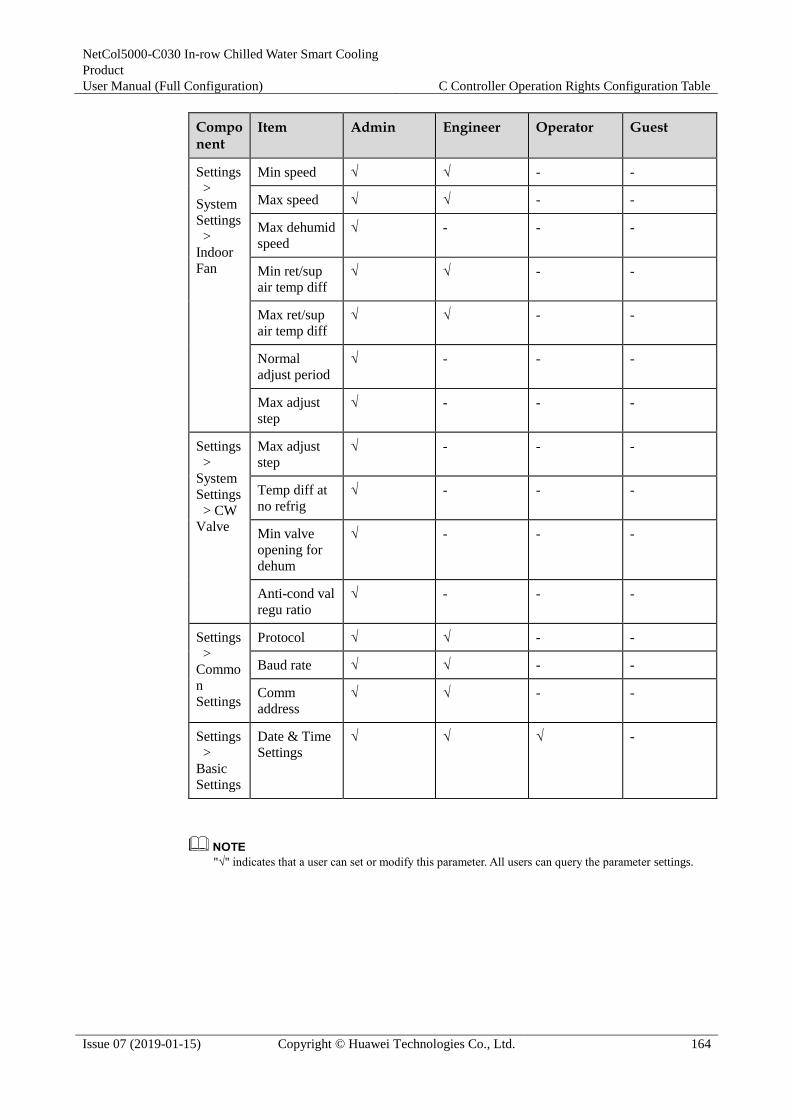
NetCol5000-C030 In-row Chilled Water Smart Cooling
Product
User Manual (Full Configuration) C Controller Operation Rights Configuration Table
Issue 07 (2019-01-15) Copyright © Huawei Technologies Co., Ltd. 164
Component
Item Admin Engineer Operator Guest
Settings
>
System
Settings
>
Indoor
Fan
Min speed √ √ - -
Max speed √ √ - -
Max dehumid
speed
√ - - -
Min ret/sup
air temp diff
√ √ - -
Max ret/sup
air temp diff
√ √ - -
Normal
adjust period
√ - - -
Max adjust
step
√ - - -
Settings
>
System
Settings
> CW
Valve
Max adjust
step
√ - - -
Temp diff at
no refrig
√ - - -
Min valve
opening for
dehum
√ - - -
Anti-cond val
regu ratio
√ - - -
Settings
>
Commo
n
Settings
Protocol √ √ - -
Baud rate √ √ - -
Comm
address
√ √ - -
Settings
>
Basic
Settings
Date & Time
Settings
√ √ √ -
"√" indicates that a user can set or modify this parameter. All users can query the parameter settings.

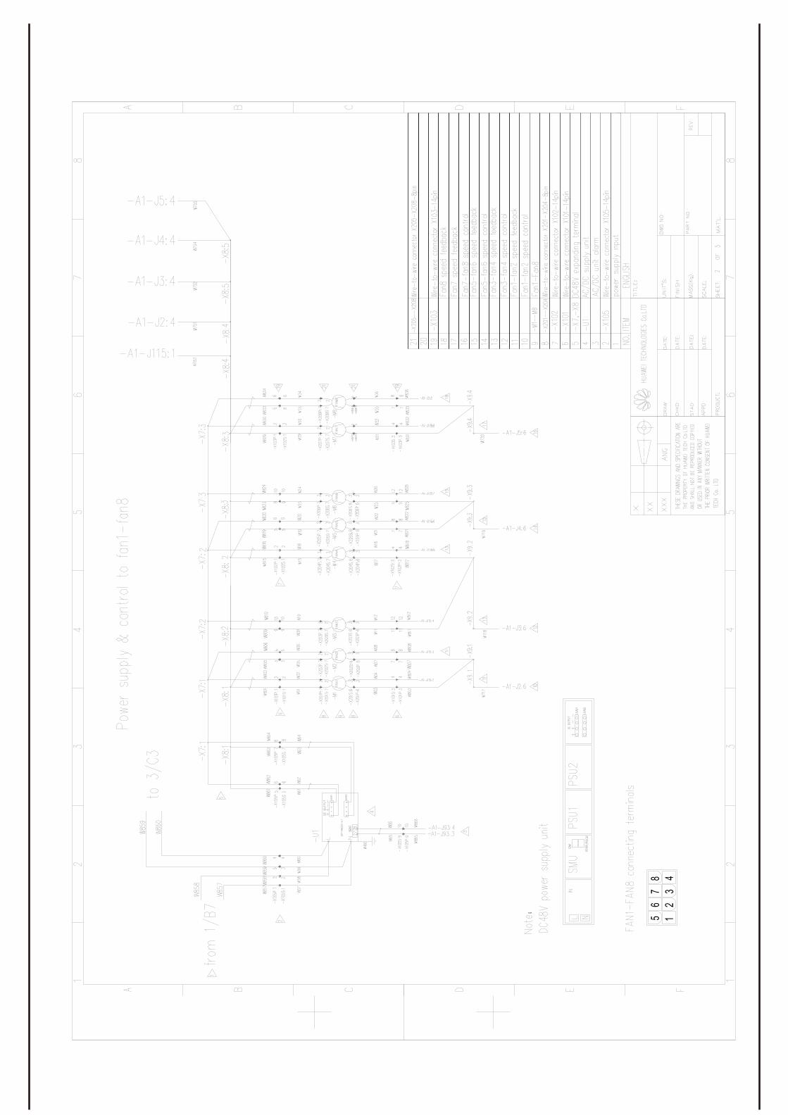

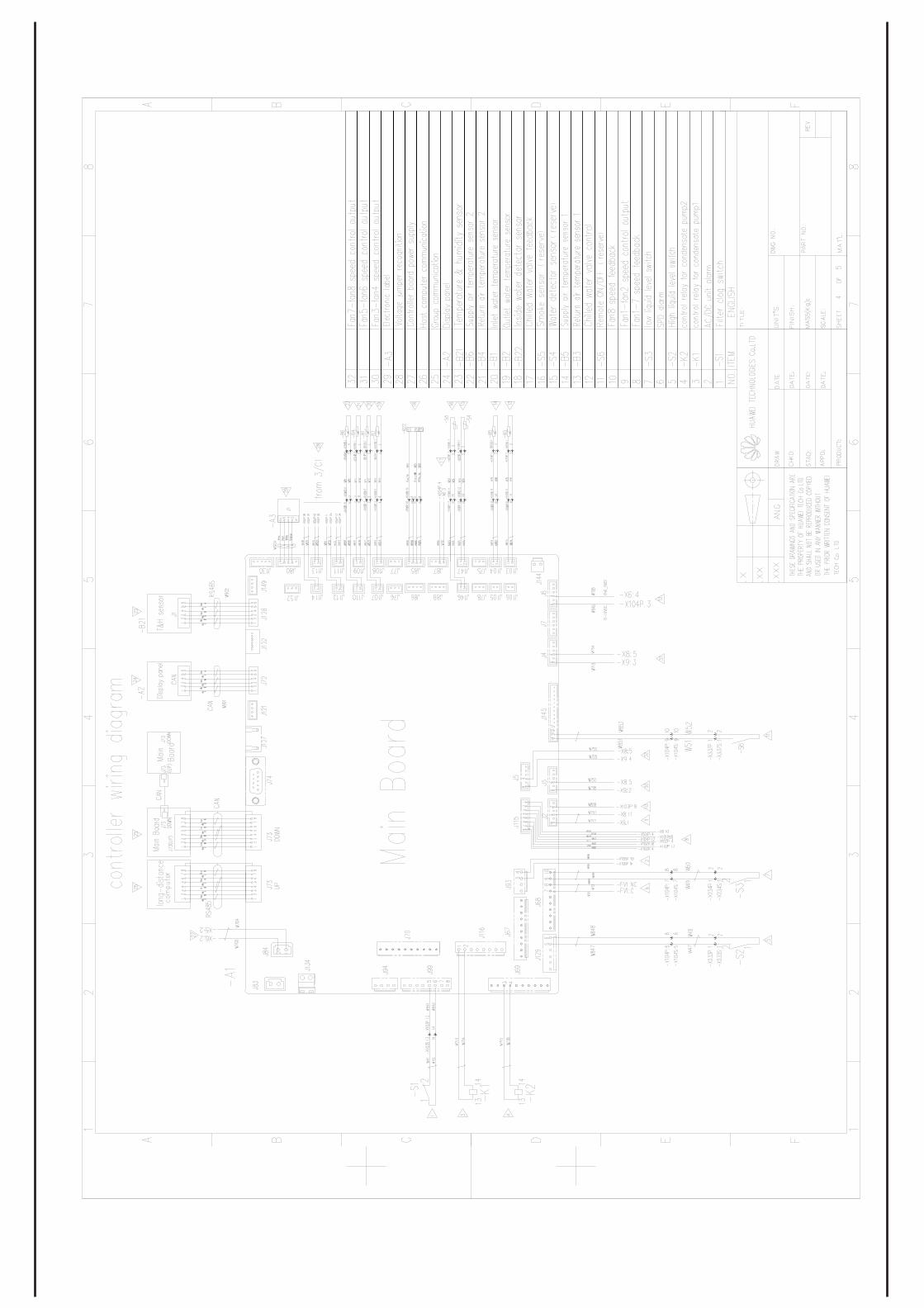


Sta
tus
Ope
ratin
g In
foD
evic
e D
etai
ls
Hum
idity
Tem
pera
ture
Running
EM
S
Indo
or fa
n 1
CW
val
ve
Indo
or fa
n 8
Indo
or fa
n 2
Con
d pu
mp
1
Dra
in d
evic
e
Indo
or fa
n
Que
ry A
ct. A
larm
sQ
uery
His
t. A
larm
sD
elet
e H
ist.
Ala
rms
Ala
rm 1
....
.
Ala
rm n
Ala
rm 1
....
.
Ala
rm n
Ala
rms
Use
r Set
tings
Ala
rm s
ettin
gsC
om s
ettin
gsS
yste
m S
ettin
gsB
asic
Set
tings
Res
tore
Def
ault
Set
tings
Sho
rtcut
Men
u
Indo
or fa
n 1
tota
l run
time
Indo
or fa
n 2
tota
l run
time
Hum
idifi
er to
tal r
untim
e
Air
filte
r tot
al ru
ntim
e
Adj
uste
d re
turn
air
hum
idity
Ret
urn
air t
emp
adju
st v
alue
Adj
ust r
etur
n ai
r tem
p
Ret
urn
air h
umid
adj
ust v
alue
Dia
gnos
tic M
ode
Log
Mai
ntS
enso
r Adj
ust
Abo
ut
Que
ry L
ogs
Del
ete
Logs
Mai
nt
Per
form
Mai
ntV
ersi
on In
fo
E-L
abel
Dat
e fo
rmat
Lang
uage
Dat
e
Pro
toco
l
Bau
d ra
te
Add
ress
Tim
e
Zone
Pas
swor
d
LCD
con
trast
LCD
sat
urat
ion
LCD
brig
htne
ss
Rem
ote
Rat
ed p
ower
vol
tage
Ant
i-con
d pr
otec
tion
T/H
sen
sor
Mai
n B
oard
CW
Vav
le
Indo
or F
anIn
door
Fan
Dra
in D
evic
e
Sys
tem
Con
trol
Coo
ling
syst
em
T/H
sen
sor
T/H
sen
sor
Indo
or F
an
Con
d pu
mp
tota
l run
time
Dew
poi
nt te
mp
......
.....
Con
d pu
mp
2
CW
val
ve
CW
Vav
le
Dra
in D
evic
e
CW
Vav
le
E
Con
trolle
r Men
u S
truct
ure