
CompactPCI ® Serial
26
CompactPCI ® Serial Specification Short Form Specification PICMG® CPCI-S.0 R1.0, Ratified March 2, 2011 FOR INFORMATION ONLY: DO NOT ATTEMPT TO DESIGN FROM THIS DOCUMENT
-
Upload
khangminh22 -
Category
Documents
-
view
3 -
download
0
Transcript of CompactPCI ® Serial

CompactPCI ® Serial
Specification Short Form Specification
PICMG® CPCI-S.0 R1.0, Ratified March 2, 2011
FOR INFORMATION ONLY: DO NOT ATTEMPT TO DESIGN FROM THIS DOCUMENT

ii PICMG CPCI-S.0 R1.0 CompactPCI® Serial Short Form Specification
© Copyright 2011, 2017, 2018 PCI Industrial Computer Manufacturers Group. The attention of adopters is directed to the possibility that compliance with or adoption of PICMG® specifications may require use of an invention covered by patent rights. PICMG® shall not be responsible for identifying patents for which a license may be required by any PICMG® specification or for conducting legal inquiries into the legal validity or scope of those patents that are brought to its attention. PICMG® specifications are prospective and advisory only. Prospective users are responsible for protecting themselves against liability for infringement of patents.
NOTICE:
The information contained in this document is subject to change without notice. The material in this document details a PICMG® specification in accordance with the license and notices set forth on this page. This document does not represent a commitment to implement any portion of this specification in any company's products.
WHILE THE INFORMATION IN THIS PUBLICATION IS BELIEVED TO BE ACCURATE, PICMG® MAKES NO WARRANTY OF ANY KIND, EXPRESS OR IMPLIED, WITH REGARD TO THIS MATERIAL INCLUDING, BUT NOT LIMITED TO, ANY WARRANTY OF TITLE OR OWNERSHIP, IMPLIED WARRANTY OF MERCHANTABILITY OR WARRANTY OF FITNESS FOR PARTICULAR PURPOSE OR USE.
In no event shall PICMG® be liable for errors contained herein or for indirect, incidental, special, consequential, reliance or cover damages, including loss of profits, revenue, data or use, incurred by any user or any third party. Compliance with this specification does not absolve manufacturers of equipment from the requirements of safety and regulatory agencies (UL, CSA, FCC, IEC, etc.).
IMPORTANT NOTICE:
This document includes references to specifications, standards or other material not created by PICMG. Such referenced materials will typically have been created by organizations that operate under IPR policies with terms that vary widely, and under process controls with varying degrees of strictness and efficacy. PICMG has not made any enquiry into the nature or effectiveness of any such policies, processes or controls, and therefore ANY USE OF REFERENCED MATERIALS IS ENTIRELY AT THE RISK OF THE USER. Users should therefore make such investigations regarding referenced materials, and the organizations that have created them, as they deem appropriate.
PICMG®, CompactPCI®, AdvancedTCA® ,ATCA®, CompactPCI® Express, COM Express®, SHB Express®, and the PICMG, CompactPCI Serial, cPCI Serial Space, AdvancedTCA, µTCA and ATCA logos are registered trademarks, and MicroTCA™, xTCA™, AdvancedMC™, IRTM™ and the IRTM logo are trademarks of the PCI Industrial Computer Manufacturers Group. All other brand or product names may be trademarks or registered trademarks of their respective holders.
.
Table of Contents
PICMG CPCI-S.0 R1.0 CompactPCI® Serial Short Form Specification iii
Table of Contents 1 Objective ......................................................................................................................................... 1
1.1 Identification ...................................................................................................................... 1 2 General ............................................................................................................................................ 2
2.1 Overview ........................................................................................................................... 2 2.2 CompactPCI® System Architecture .................................................................................. 2 2.3 Architecture Extension by CompactPCI® Serial ............................................................... 3 2.4 Migration from CompactPCI® to CompactPCI® Serial ..................................................... 3
3 Mechanical Requirements ............................................................................................................. 5 3.1 General ............................................................................................................................. 5 3.2 3U Mechanical Overview .................................................................................................. 5 3.3 6U Mechanical Overview .................................................................................................. 6 3.3.1 6U Split-Backplane Example ............................................................................................ 7 3.3.2 6U Monolithic Backplane Example ................................................................................... 9 3.3.3 6U User-Defined Backplane Example ............................................................................ 10 3.4 Connectors ..................................................................................................................... 11 3.4.1 Connector Types and Reference Designation ................................................................ 11 3.4.2 Front Board Connector Types and Reference Designation ............................................ 11 3.4.3 Rear Board Connector Types and Reference Designation ............................................. 14 3.5 Mezzanine Concept ........................................................................................................ 16 3.5.1 General ........................................................................................................................... 16 3.5.2 Backplane Guide Element .............................................................................................. 18 3.5.3 6U Backplane Guidance Rail .......................................................................................... 18 3.6 Conductive Cooled Assembly (CCA) .............................................................................. 19
4 Electrical Requirements ............................................................................................................... 21 4.1 Power Infrastructure........................................................................................................ 21 4.1.1 Backplane Power Distribution ......................................................................................... 21 4.1.2 Geographical Addressing ................................................................................................ 21 4.2 3U Hybrid System Geographical Addressing .................................................................. 22

List of Figures
iv PICMG CPCI-S.0 R1.0 CompactPCI® Serial Short Form Specification
List of Figures Figure 1 CompactPCI® System Architecture ................................................................................. 2 Figure 2 CompactPCI® Serial Architecture .................................................................................... 3 Figure 3 CompactPCI® PlusIO Architecture .................................................................................. 3 Figure 4 Mechanical Overview 3U Example ................................................................................... 5 Figure 5 Mechanical Overview 6U Example (Split-Backplane / Front view) ................................... 6 Figure 6 Backplane Example Drawings of 3U vs. 6U Variants ....................................................... 7 Figure 7 Mechanical Overview 6U Example (Split-Backplane / Side view) .................................... 8 Figure 8 Mechanical Overview 6U Example (Monolithic Backplane) .............................................. 9 Figure 9 Mechanical Overview 6U Example (User-Defined Backplane) ....................................... 10 Figure 10 3U Connector Plug Types A, B, C and D on Front Boards ............................................. 12 Figure 11 6U Connector Plug Types A, B, C and D on Front Boards ............................................. 13 Figure 12 Connector Plug Types H and G on Rear Boards ........................................................... 14 Figure 13 3U Mezzanine Concept .................................................................................................. 16 Figure 14 6U Mezzanine Concept .................................................................................................. 17 Figure 15 Guide Element Overview ................................................................................................ 18 Figure 16 Front Board Cassette ..................................................................................................... 19 Figure 17 CCA Enclosure ............................................................................................................... 20 Figure 18 3U Hybrid System .......................................................................................................... 22
1 Objective
PICMG CPCI-S.0 R1.0 CompactPCI® Serial Short Form Specification 1
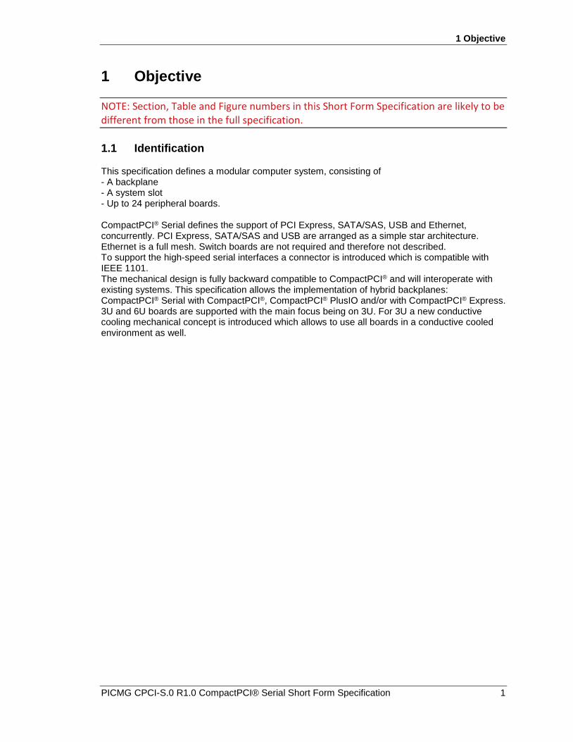
1 Objective
NOTE: Section, Table and Figure numbers in this Short Form Specification are likely to be different from those in the full specification.
1.1 Identification
This specification defines a modular computer system, consisting of - A backplane - A system slot - Up to 24 peripheral boards. CompactPCI® Serial defines the support of PCI Express, SATA/SAS, USB and Ethernet, concurrently. PCI Express, SATA/SAS and USB are arranged as a simple star architecture. Ethernet is a full mesh. Switch boards are not required and therefore not described. To support the high-speed serial interfaces a connector is introduced which is compatible with IEEE 1101. The mechanical design is fully backward compatible to CompactPCI® and will interoperate with existing systems. This specification allows the implementation of hybrid backplanes: CompactPCI® Serial with CompactPCI®, CompactPCI® PlusIO and/or with CompactPCI® Express. 3U and 6U boards are supported with the main focus being on 3U. For 3U a new conductive cooling mechanical concept is introduced which allows to use all boards in a conductive cooled environment as well.

2 General
2 PICMG CPCI-S.0 R1.0 CompactPCI® Serial Short Form Specification
2 General 2.1 Overview
CompactPCI® is a well-established industrial specification for modular computers. The IEEE 1101 compliant mechanics are robust and proven in use. The electrical interface is based on the parallel PCI bus. This technology will successively be replaced by serial, high speed, point-to-point connections. CompactPCI® Serial uses the mechanical concept of CompactPCI® and uses serial interconnect technology. CompactPCI® Serial does not need special infrastructure hardware. The migration from CompactPCI® to CompactPCI® Serial is made rather simple by using hybrid systems. Even for these, no dedicated switch or bridge boards are required because of specifications like PICMG 2.30. PICMG 2.30 brings a limited number of serial interconnects to the backplane so that modern peripheral cards can be inserted into legacy CompactPCI® systems. All mechanics are compatible to IEEE 1101.
2.2 CompactPCI® System Architecture
Figure 1 CompactPCI® System Architecture
SystemSlot
Per.Slot
1
Per.Slot
2
Per.Slot
3
Per.Slot
4
Per.Slot
5
Per.Slot
6
Per.Slot
7
Backplane32- / 64-Bit PCI
+12 Volts+5 Volts+3.3 Volts-12 Volts
The mechanics of CompactPCI® are fully compliant to IEEE 1101. Legacy PCI bus architecture is based on parallel buses to connect typical peripheral devices. The parallel bus limits the throughput. Low-performance devices influence and reduce the bandwidth of demanding applications. A passive backplane is used to connect a system slot to up to seven peripheral slots. There are several standard backplanes on the market with different numbers of slots. Some of them support rear I/O, some 64-bit operation. The system slot carries some special functions like clock generation or bus arbitration. Because of those single points of failure, it is common practice for mission critical systems to have two more CompactPCI® backplanes in one 19” rack. Usually Ethernet is used for inter-processor communication. Four different voltages are defined to supply a CompactPCI® PICMG 2.0 compliant system.

2 General
PICMG CPCI-S.0 R1.0 CompactPCI® Serial Short Form Specification 3
2.3 Architecture Extension by CompactPCI® Serial
Figure 2 CompactPCI® Serial Architecture
SystemSlot
Per.Slot
1
Per.Slot
2
Per.Slot
3
Per.Slot
4
Per.Slot
5
Per.Slot
6
Per.Slot
7
Per.Slot
8
Backplane6 x PCIe x 4 2x PCIe x8 8 x SATA8 x USB2/3 8 x BaseT Mesh
+12 Volts
CompactPCI® Serial uses all the mechanics of CompactPCI®. The specification is compliant to IEEE 1101. Just the 2-mm hard metric connector is replaced by a more modern higher-density connector which is able to support differential signals of 10 Gb/s and even more. Like in CompactPCI® the backplane is fully passive. Supply voltage within a 3U system is 12 Volts only and additional 48 Volts are supplied within a 6U system, which can be used for Power-Over-Ethernet applications. Like in CompactPCI® there is a dedicated system slot which provides the system with some minimal central infrastructure functions like reset and clock supply. This means that the smallest possible CompactPCI® Serial system consists of just one single slot, the system slot. Peripheral slots are connected by modern serial, high speed, point-to-point connections as in MicroTCA, but requiring no switch or hub. Instead, a full star architecture is realized on the backplane for PCI Express, SATA and USB. For Ethernet a full mesh network is implemented on the backplane. A system slot board can be used in a peripheral slot as well to do multiprocessing. The easiest way to communicate in this case is via Ethernet. Ethernet uses cable standards xxBase-T instead of dedicated backplane standards. This lowers the cost, guarantees better interoperability and offers currently up to 10 Gb/s data throughput. Rear I/O is also supported like in CompactPCI® systems but many more pins are available and higher speed is supported. CompactPCI® Serial uses the robust mechanics of CompactPCI®, the modern serial interconnects but does not need dedicated infrastructure boards. CompactPCI® Serial is designed for harsh environments and cost-critical applications demanding high throughput and reliability.
2.4 Migration from CompactPCI® to CompactPCI® Serial
Figure 3 CompactPCI® PlusIO Architecture
Backplane32- PCI 4 x PCIe x 1 4 x SATA
4 x USB2 2 x BaseT Mesh
+12 Volts+5 Volts+3.3 Volts-12 Volts
SystemSlot
Per.Slot
1
Per.Slot
2
Per.Slot
7
Per.Slot
1
Per.Slot
2
Per.Slot
3
Per.Slot
4

2 General
4 PICMG CPCI-S.0 R1.0 CompactPCI® Serial Short Form Specification
PICMG 2.30, so-called CompactPCI® PlusIO, defines the usage of connector J2 in legacy CompactPCI® systems in a way to bring some of the high speed serial interconnects to the backplane. A CompactPCI® system slot which is compliant to PICMG 2.30 can control up to seven 32-bit legacy CompactPCI® peripheral boards as well as up to four CompactPCI® Serial peripheral boards with limited functionality. This can easily be realized by means of a hybrid backplane carrying legacy boards as well as CompactPCI® Serial boards because the two specifications, PICMG 2.0 and PICMG CPCI-S.0, are IEEE 1101 compliant.

3 Mechanical Requirements
PICMG CPCI-S.0 R1.0 CompactPCI® Serial Short Form Specification 5
3 Mechanical Requirements 3.1 General
All dimensions that do not have explicit tolerances within a requirement and/or within technical drawings are for information only. Tolerances of these dimensions are X.XX ±0.10 mm and X.X ±0.10 mm. All dimensions that are not explicitly mentioned within a requirement but shown within a technical drawing are recommended only.
3.2 3U Mechanical Overview
A system based on CompactPCI® Serial consists of the same components as a legacy CompactPCI® system. Within this specification 3U systems as well as 6U systems are defined. A passive backplane is used to connect all front and rear boards. Every board is supplied with a front and rear panel. A handle (two handles for 6U) allows the user to plug-in and to remove a board from a rack. A maximum of six discrete connectors forms a slot and the amount of used connectors can vary depending on the application. Thereby maximum scalability and cost-effectiveness is achieved. Figure 4 shows an example of a nine-slot 3U system. In this example the maximum amount of connectors on the backplane are assembled, to offer maximum connectivity.
Figure 4 Mechanical Overview 3U Example

3 Mechanical Requirements
6 PICMG CPCI-S.0 R1.0 CompactPCI® Serial Short Form Specification
3.3 6U Mechanical Overview
Front and rear boards are defined for the 6U form factor. Compared to a 3U system one extra connector (J0/P0) is defined. This connector offers extra power (that will be needed in a 6U system) and also two further Ethernet connections, which can be used for system management (e.g. AMT). The backplane can be monolithic or split. Furthermore, it is possible to define a user backplane which is a mixture of both (see Figure 6).
Figure 5 Mechanical Overview 6U Example (Split-Backplane / Front view)

3 Mechanical Requirements
PICMG CPCI-S.0 R1.0 CompactPCI® Serial Short Form Specification 7
Figure 6 Backplane Example Drawings of 3U vs. 6U Variants
3U – Backplane 6U – Split - Backplane
Optional User Connector Area
e.g.- CPCI Connectors- User Connectors
User Connector Area
e.g.- CPCI Connectors- User Connectors
Zone 0
6U – Monolithic - Backplane 6U – User - Defined - Backplane
6U CPCI Area 3U CPCI Area Zone0 Area
Area for direct rear
IO
Comment: The number of slots as well as the number of connectors is not specified within this specification. This figure is only an example.
3.3.1 6U Split-Backplane Example
Figure 5 shows an example of a five-slot 6U split-backplane system. In this example also the maximum amount of I/O connectors on the backplane are assembled, to offer maximum

3 Mechanical Requirements
8 PICMG CPCI-S.0 R1.0 CompactPCI® Serial Short Form Specification
connectivity. Furthermore it is possible to place optional connectors within a “User IO Connector Area”, to connect front and rear board signals. In this case there is a direct user connection without backplane.
Figure 7 Mechanical Overview 6U Example (Split-Backplane / Side view)

3 Mechanical Requirements
PICMG CPCI-S.0 R1.0 CompactPCI® Serial Short Form Specification 9
3.3.2 6U Monolithic Backplane Example
Figure 8 shows an example of a five-slot 6U monolithic backplane system. In this example also the maximum amount of I/O connectors on the backplane are assembled, to offer maximum connectivity. Furthermore it is possible to place optional connectors within a “User IO Connector Area”, to connect front and rear board signals, or to build a user-defined interconnection between the 6U boards. It is also possible to place CompactPCI® J1/J2 connectors to build up a hybrid system.
Figure 8 Mechanical Overview 6U Example (Monolithic Backplane)

3 Mechanical Requirements
10 PICMG CPCI-S.0 R1.0 CompactPCI® Serial Short Form Specification
3.3.3 6U User-Defined Backplane Example
It is possible to mix both variants described in chapter 3.3.1 (6U Split-Backplane Example) and chapter 3.3.2 (6U Monolithic Backplane Example). Figure 9 shows such a backplane.
Figure 9 Mechanical Overview 6U Example (User-Defined Backplane)

3 Mechanical Requirements
PICMG CPCI-S.0 R1.0 CompactPCI® Serial Short Form Specification 11
3.4 Connectors
3.4.1 Connector Types and Reference Designation
Connectors used for CompactPCI® Serial are optimized for high-speed differential signal transmission. Shielding and impedance control is maintained through the connectors. The connector is arranged in rows with 12 pins each. 12 pins are sufficient for 4 high speed signal pairs. 4 pins in a row are required for ground. However the pins within the connector are not specialized. So a pin can be used for signals (differential or single ended), for ground, as well as for the supply voltage. For front boards receptacle connectors are used on the backplane, and right angle headers are used on the plug-in boards. On rear boards it is the converse. All connector types are designed for press-fit mounting. The press-in pin length in the PCB is just 1.6 mm to minimize the stub lengths thereby enhancing the signal integrity. To realize rear I/O, a plug connector is pressed on to the back of the backplane. This mirrors the pin assignment from the front to the back side. There are 10 different types of connector specified.
Table 1 Connector Types
Connector Type Rows Pins/Row Type Location
A 6 12 Plug Front board
B 8 12 Plug Front board
C 6 12 Plug Front board
D 8 12 Plug Front board
E 6 12 Receptacle Backplane
F 8 12 Receptacle Backplane
G 8 12 Receptacle Rear board
H 6 12 Receptacle Rear board
I 8 12 Plug Rear backplane
J 6 12 Plug Rear backplane
3.4.2 Front Board Connector Types and Reference Designation
To connect the front boards to the backplane, four different plug types of the same connector family are used.
Table 2 Front Board Connector Types
Designator Type Number of Rows Number of Walls Usage
P0 A 6 4 Optional
P1 A 6 4 Mandatory
P2 B 8 2 Optional
P3 B 8 2 Optional

3 Mechanical Requirements
12 PICMG CPCI-S.0 R1.0 CompactPCI® Serial Short Form Specification
P4 B 8 2 Optional
P5 C 6 2 Optional
P6 D 8 4 Optional
Figure 10 3U Connector Plug Types A, B, C and D on Front Boards

3 Mechanical Requirements
PICMG CPCI-S.0 R1.0 CompactPCI® Serial Short Form Specification 13
Figure 11 6U Connector Plug Types A, B, C and D on Front Boards
On the backplane there are just 2 different types of receptacles, type E – a six row version and type F – an eight row version. The six row receptacle connects to all type A as well as to type C plugs. The eight row receptacle connects to all type B as well as to type D plugs.
Table 3 Backplane Connector Types
Designator Type Number of Rows Usage
J0 E 6 Optional
J1 E 6 Mandatory
J2 F 8 Optional
J3 F 8 Optional
J4 F 8 Optional
J5 E 6 Optional

3 Mechanical Requirements
14 PICMG CPCI-S.0 R1.0 CompactPCI® Serial Short Form Specification
J6 F 8 Optional
3.4.3 Rear Board Connector Types and Reference Designation
To connect the rear boards to the backplane, two different receptacle types of the same connector family are used.
Table 4 Rear Board Connector Types
Designator Type Number of Rows Number of Walls Usage
rJ2 H 6 2 Optional
rJ3 G 8 2 Optional
rJ4 G 8 2 Optional
rJ5 H 6 2 Optional
Figure 12 Connector Plug Types H and G on Rear Boards
Table 5 Rear Backplane Connector Types
Designator Type Number of Rows Usage
rP2 J 6 Optional
rP3 I 8 Optional

3 Mechanical Requirements
PICMG CPCI-S.0 R1.0 CompactPCI® Serial Short Form Specification 15
rP4 I 8 Optional
rP5 J 6 Optional

3 Mechanical Requirements
16 PICMG CPCI-S.0 R1.0 CompactPCI® Serial Short Form Specification
3.5 Mezzanine Concept
3.5.1 General
Implementation of the Ethernet connection of a system board can be done with a mezzanine board. Due to this concept more flexibility will be achieved, because the usage of Ethernet does not depend on the system board itself. Furthermore different mezzanine boards can offer a different number of Ethernet connections, thereby obtaining maximum scalability. If this concept is implemented, the CompactPCI® Serial system board becomes a mezzanine host and the mezzanine board can be plugged onto this host. The connector P6 is then placed on the mezzanine board and a cut-out on the mezzanine host is provided. Only the interconnection between the mezzanine host to the CompactPCI® Serial backplane will be specified within this specification. As shown in Figure 13 and Figure 14 the mezzanine concept can be implemented within a 3U and a 6U system.
Figure 13 3U Mezzanine Concept

3 Mechanical Requirements
PICMG CPCI-S.0 R1.0 CompactPCI® Serial Short Form Specification 17
Figure 14 6U Mezzanine Concept

3 Mechanical Requirements
18 PICMG CPCI-S.0 R1.0 CompactPCI® Serial Short Form Specification
3.5.2 Backplane Guide Element
Figure 15 Guide Element Overview
3.5.3 6U Backplane Guidance Rail
To guarantee best fitting of the 6U board connectors into the 6U backplane connectors, also if a board will be plugged in harsh environments, a guidance rail on the backplane is defined.

3 Mechanical Requirements
PICMG CPCI-S.0 R1.0 CompactPCI® Serial Short Form Specification 19
3.6 Conductive Cooled Assembly (CCA)
Figure 16 Front Board Cassette

3 Mechanical Requirements
20 PICMG CPCI-S.0 R1.0 CompactPCI® Serial Short Form Specification
Figure 17 CCA Enclosure
4 Electrical Requirements
PICMG CPCI-S.0 R1.0 CompactPCI® Serial Short Form Specification 21
4 Electrical Requirements 4.1 Power Infrastructure
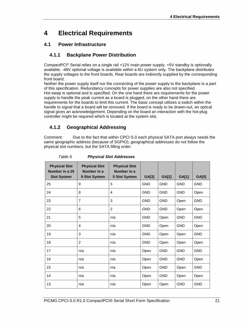
4.1.1 Backplane Power Distribution
CompactPCI® Serial relies on a single rail +12V main power supply. +5V standby is optionally available. -48V optional voltage is available within a 6U system only. The backplane distributes the supply voltages to the front boards. Rear boards are indirectly supplied by the corresponding front board. Neither the power supply itself nor the connecting of the power supply to the backplane is a part of this specification. Redundancy concepts for power supplies are also not specified. Hot-swap is optional and is specified. On the one hand there are requirements for the power supply to handle the peak current as a board is plugged, on the other hand there are requirements for the boards to limit this current. The basic concept utilizes a switch within the handle to signal that a board will be removed. If the board is ready to be drawn-out, an optical signal gives an acknowledgement. Depending on the board an interaction with the hot-plug controller might be required which is located at the system slot.
4.1.2 Geographical Addressing
Comment: Due to the fact that within CPCI-S.0 each physical SATA port always needs the same geographic address (because of SGPIO), geographical addresses do not follow the physical slot numbers, but the SATA filling order.
Table 6 Physical Slot Addresses
Physical Slot Number in a 25
Slot System
Physical Slot Number in a
9 Slot System
Physical Slot Number in a
5 Slot System GA[3] GA[2] GA[1] GA[0]
25 9 5 GND GND GND GND
24 8 4 GND GND GND Open
23 7 3 GND GND Open GND
22 6 2 GND GND Open Open
21 5 n/a GND Open GND GND
20 4 n/a GND Open GND Open
19 3 n/a GND Open Open GND
18 2 n/a GND Open Open Open
17 n/a n/a Open GND GND GND
16 n/a n/a Open GND GND Open
15 n/a n/a Open GND Open GND
14 n/a n/a Open GND Open Open
13 n/a n/a Open Open GND GND

4 Electrical Requirements
22 PICMG CPCI-S.0 R1.0 CompactPCI® Serial Short Form Specification
12 n/a n/a Open Open GND Open
11 n/a n/a Open Open Open GND
10 n/a n/a Open Open Open Open
9 n/a n/a Pulled GND GND GND
8 n/a n/a Pulled GND GND Open
7 n/a n/a Pulled GND Open GND
6 n/a n/a Pulled GND Open Open
5 n/a n/a Pulled Open GND GND
4 n/a n/a Pulled Open GND Open
3 n/a n/a Pulled Open Open GND
2 n/a n/a Pulled Open Open Open
1 (system slot) 1 (system slot) 1 (system slot) - - - -
Comment: A 25-slot system is the maximum supported by this specification.
4.2 3U Hybrid System Geographical Addressing
Tt is possible to build a hybrid system with a CompactPCI® PlusIO system card on the one side and up to four CPCI-S.0 peripheral cards on the other side. The physical slot number and its physical slot address defined by GA[3:0] are compliant to chapter 4.1.2.
Figure 18 3U Hybrid System PICMG 2.3
System SlotPICMG 2.0
Periph.
PICMG .CPCI-S.0
Periph.
PICMG 2.0Periph.
PICMG .CPCI-S.0
Periph.
PICMG .CPCI-S.0
Periph.
PICMG .CPCI-S.0
Periph.
1P12P2
PICMG 2.0Periph.
3P24P2 5J1 6J2 7J3 8J4
![North Carolina register [serial] - NC.gov](https://static.fdokumen.com/doc/165x107/6327f539e491bcb36c0b8a23/north-carolina-register-serial-ncgov.jpg)


![North Carolina register [serial] - NC OAH](https://static.fdokumen.com/doc/165x107/633bb631a24651471c0221d8/north-carolina-register-serial-nc-oah.jpg)


![The Rhododendron [serial] - Internet Archive](https://static.fdokumen.com/doc/165x107/63237b81117b4414ec0c57ee/the-rhododendron-serial-internet-archive.jpg)